В данном разделе размещено руководство по эксплуатации Рендж Ровер в кузове L322 от производителя
В данном разделе размещено два руководства по эксплуатации Рендж Ровер в кузове L322 от производителя
В данном разделе размещено руководство по эксплуатации Рендж Ровер в кузове L322 от производителя — LRL 38 02 55 102
В данном разделе размещено руководство по эксплуатации Рендж Ровер в кузове L322 от производителя — LRL 38 02 55 901
В данном разделе размещено руководство по эксплуатации Рендж Ровер в кузове L322 от производителя — LRL 38 02 55 801
В данном разделе размещено руководство по эксплуатации Рендж Ровер в кузове L322 от производителя — LRL 38 02 55 701
Хочу поделиться своей подборкой мануалов по ренжам. Выручали и не раз.
1. Таблица высоты калибровки пневмоподвески
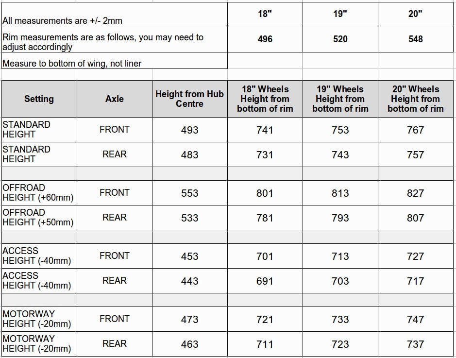
высоты калибровки пневмы в зависимости от размеров дисков на все режимы пневмы
2. Пособие по пневматической подвеске
yadi.sk/i/SlP44D9L3E4BLt
3. Электрическая библиотека (расшифровки разъемов, проводов и т.д.)
yadi.sk/i/l7WK4EdK3E4BVT
4. WORKSHOP MANUAL — SYSTEM DESCRIPTION AND OPERATION
— на русском
yadi.sk/i/fLlKPPD33E4Bs3
— на английском
yadi.sk/i/9cPTxEYp3E4C6X
5. Руководство по ремонту LRL0477RU
yadi.sk/i/vpPLjRsP3E4CAT
6. Руководство по ремонту с электросхемами (скан книги)
yadi.sk/i/wy00p5NV3E4CHp
7. AUX MFD E53
yadi.sk/i/y89ESnJA3E4CN9
Посмотреть инструкция для Land Rover Range Rover L322 (2005) бесплатно. Руководство относится к категории Автомобили, 11 человек(а) дали ему среднюю оценку 8.4. Руководство доступно на следующих языках: -. У вас есть вопрос о Land Rover Range Rover L322 (2005) или вам нужна помощь? Задайте свой вопрос здесь
Главная
Не можете найти ответ на свой вопрос в руководстве? Вы можете найти ответ на свой вопрос ниже, в разделе часто задаваемых вопросов о Land Rover Range Rover L322 (2005).
Как перевести мили в километры?
Где я могу узнать идентификационный номер транспортного средства Land Rover?
Что такое идентификационный номер транспортного средства (VIN)?
Когда транспортному средству Land Rover требуется техническое обслуживание?
Когда следует заменять тормозную жидкость на Land Rover?
В чем разница между топливом E10 и E5?
Одна или несколько дверей не открываются изнутри. Что мне делать?
Автомобильный радиоприемник не включается, что делать?
Инструкция Land Rover Range Rover L322 (2005) доступно в русский?
Не нашли свой вопрос? Задайте свой вопрос здесь
 Loading…
![]()
CONTENTS
1:General Information
100:Service Information
100-00: General Information
Description and Operation
About This Manual
How To Use This Manual
Important Safety Instructions
Standard Workshop Practices
General Service Information
Health and Safety Precautions
Solvents, Sealants and Adhesives
Special Tool Glossary
Road/Roller Testing
DTC: Module Name: Bluetooth Module
100-01: Identification Codes
Description and Operation
Identification Codes
100-02: Jacking and Lifting
Description and Operation
Jacking
Lifting
Vehicle Recovery
100-03: Maintenance Schedules
Description and Operation
Maintenance Schedules — Gasoline Engines
Maintenance Schedules — Diesel Engines
2:Chassis
204:Suspension
204-00: Suspension System — General Information
Specification
General Procedures
Front Camber, Caster and Toe Adjustment
Four-Wheel Alignment (57.65.04)
204-01: Front Suspension
Specification
Description and Operation
Front Suspension
Removal and Installation
Front Lower Arm (60.35.02) (60.35.03)
Front Lower Arm Bushing (60.35.26)
Front Shock Absorber (60.30.02)
Front Stabilizer Bar (60.10.01)
Front Stabilizer Bar Link (60.10.02/60.10.04)
Rear Lower Arm (60.40.09)
Rear Lower Arm Ball Joint (60.15.04)
Rear Lower Arm Bushing (60.35.26)
Shock Absorber and Spring Assembly (60.30.25/99)
Front Wheel Bearing and Wheel Hub (60.25.14)
Wheel Knuckle (60.25.01)
Disassembly and Assembly
Shock Absorber and Spring Assembly
204-02: Rear Suspension
Specification
Description and Operation
Rear Suspension
Removal and Installation
Lower Arm (64.35.54)
Lower Arm Ball Joint (64.15.08)
Lower Arm Bushing (64.35.15)
Lower Arm Rear Bushing (64.35.15)
Rear Stabilizer Bar (64.35.08)
Rear Stabilizer Bar Link (64.35.24)
Toe Link (64.35.70)
Upper Arm (64.35.60) — TDV8 3.6L Diesel
Upper Arm (64.35.60) — 4.4L NA V8 — AJ41/4.2L SC V8 — AJV8
Upper Arm Ball Joint (64.15.07)
Upper Arm Bushing (64.35.22) — TDV8 3.6L Diesel
Upper Arm Bushing (64.35.22) — 4.4L NA V8 — AJ41/4.2L SC V8 — AJV8
Upper Arm Front Bushing (64.35.20)
Upper Arm Rear Bushing (64.35.21)
Wheel Bearing and Wheel Hub (64.15.14)
Wheel Knuckle (64.35.10)
204-04: Wheels and Tires
Description and Operation
Wheels and Tires
Diagnosis and Testing
Wheels and Tires
Tire Pressure Monitoring System (TPMS)
Removal and Installation
Tire Low Pressure Sensor (74.10.05)
Tire Pressure Monitoring System (TPMS) Front Antenna (86.53.16)
Tire Pressure Monitoring System (TPMS) Module (86.54.05)
Tire Pressure Monitoring System (TPMS) Rear Antenna (86.53.17)
Wheel and Tire (60.25.06)
204-05: Vehicle Dynamic Suspension
Specification
Description and Operation
Vehicle Dynamic Suspension
General Procedures
Air Suspension System Depressurize and Pressurize (60.50.38)
Ride Height Adjustments (60.90.03)
Removal and Installation
Air Spring Solenoid Valve
Air Suspension Air Filter (64.50.12)
Air Suspension Compressor (60.50.10)
Air Suspension Compressor Drier (60.50.09)
Air Suspension Control Module (60.50.04)
Air Suspension Front Solenoid Valve Block (60.50.11)
Air Suspension Muffler (64.50.01)
Air Suspension Rear Solenoid Valve Block (64.50.11)
Air Suspension Reservoir (60.50.03)
Air Suspension Reservoir Solenoid Valve Block (60.50.05)
Air Suspension Solenoid Valve Block (60.50.11)
Air Suspension Switch
Fill Solenoid Valve
Front Air Shock Absorber (60.30.02.45)
Front Air Spring (60.21.01)
Front Vertical Accelerometer
Rear Air Shock Absorber (64.30.02.45)
Rear Air Spring (64.21.01)
Suspension Height Sensor (60.36.01)
204-06: Ride and Handling Optimization
Specification
Description and Operation
Ride and Handling Optimization
Diagnosis and Testing
Ride and Handling Optimization
Removal and Installation
Ride and Handling Optimization Switch (86.65.11)
205: Driveline
205-00: Driveline System — General Information
Specification
205-01: Driveshaft
Specification
Description and Operation
Driveshaft
Universal Joints
Removal and Installation
Front Driveshaft (47.15.02) — 4.4L NA V8 — AJ41/4.2L SC V8 — AJV8
Front Driveshaft (47.15.02) — TDV8 3.6L Diesel
Rear Driveshaft (47.15.03) — 4.4L NA V8 — AJ41/4.2L SC V8 — AJV8
Rear Driveshaft (47.15.03) — TDV8 3.6L Diesel
Disassembly and Assembly
Driveshaft Universal Joint (47.15.06)
Driveshaft Center Bearing
Driveshaft Slip Yoke
Driveshaft Alignment Bushing
205-02: Rear Drive Axle/Differential
Specification
Description and Operation
Rear Drive Axle and Differential
General Procedures
Differential Draining and Filling (51.25.02)
In-Vehicle Repair
Axle Housing Bushing (51.15.43) — 4.4L NA V8 — AJ41/4.2L SC V8 —
AJV8
Axle Housing Bushing (51.15.43) — TDV8 3.6L Diesel
Axle Shaft Seal
Differential Locking Module (51.30.01)
Differential Locking Motor (51.15.03)
Drive Pinion Seal (51.20.01)
Rear Axle Oil Temperature Sensor (51.15.06)
Removal and Installation
Axle Assembly (51.15.01)
Differential Support Insulator — 4.4L NA V8 — AJ41/4.2L SC V8 — AJV8
205-03: Front Drive Axle/Differential
Specification
Description and Operation
Front Drive Axle and Differential
General Procedures
Differential Draining and Filling (54.15.02)
In-Vehicle Repair
Drive Pinion Seal (54.10.20)
Removal and Installation
Differential Breather Tube
205-04: Front Drive Halfshafts
Specification
Description and Operation
Front Drive Halfshafts
Halfshaft Joint
Removal and Installation
Front Halfshaft LH (47.10.01)
Front Halfshaft RH (47.10.02)
Halfshaft Bearing (47.10.41)
Halfshaft Seal LH (54.10.18)
Halfshaft Seal RH (54.10.21)
205-05: Rear Drive Halfshafts
Specification
Description and Operation
Rear Drive Halfshafts
Removal and Installation
Rear Halfshaft (47.11.01)
Outer Constant Velocity (CV) Joint Boot (47.11.03)
Inner Constant Velocity (CV) Joint Boot (47.11.16)
Halfshaft Bearing (51.10.29)
206: Brake System
206-00: Brake System — General Information
Specification
General Procedures
Front Brake Disc Runout Check (70.12.15.01)
Rear Brake Disc Runout Check (70.12.36.01)
Brake System Bleeding (70.25.02) — Vehicles With: High Performance
Brakes
Brake System Bleeding (70.25.02) — Vehicles With: Standard Brakes
Brake System Pressure Bleeding (70.25.02)
Component Bleeding — Vehicles With: High Performance Brakes
Component Bleeding — Vehicles With: Standard Brakes
206-03: Front Disc Brake
Specification
Description and Operation
Front Disc Brake
Removal and Installation
Brake Disc (70.12.10) — Vehicles With: Standard Brakes
Brake Disc (70.12.10) — Vehicles With: High Performance Brakes
Brake Pads (70.40.02) — Vehicles With: Standard Brakes
Brake Pads (70.40.02) — Vehicles With: High Performance Brakes
Brake Caliper (70.55.24) — Vehicles With: Standard Brakes
Brake Caliper (70.55.24) — Vehicles With: High Performance Brakes
206-04: Rear Disc Brake
Specification
Description and Operation
Rear Disc Brake
Removal and Installation
Brake Disc (70.12.33)
Brake Pads (70.40.03)
Brake Caliper (70.55.25)
Disassembly and Assembly
Brake Caliper
206-05: Parking Brake and Actuation
Specification
Description and Operation
Parking Brake
General Procedures
Parking Brake Shoe and Lining Adjustment (70.40.11)
Parking Brake Shoes Bedding-In (70.40.12)
Removal and Installation
Parking Brake Actuator (70.35.48)
Parking Brake Cable LH
Parking Brake Cable RH
Parking Brake Shoes (70.40.09)
Parking Brake Switch (70.35.46)
206-06: Hydraulic Brake Actuation
Description and Operation
Hydraulic Brake Actuation
Removal and Installation
Brake Fluid Reservoir (70.25.31) — Vehicles With: Standard Brakes
Brake Fluid Reservoir (70.25.31) — Vehicles With: High Performance
Brakes
Brake Master Cylinder (70.30.08) — Vehicles With: Standard Brakes
Brake Master Cylinder (70.30.08) — Vehicles With: High Performance
Brakes
Brake Pedal (70.35.01) — Vehicles With: 6-Speed Automatic
Transmission — 6HP26
Brake Pedal and Bracket (70.35.03) — Vehicles With: 6-Speed Automatic
Transmission — 6HP26
Brake Pedal Motor
206-07: Power Brake Actuation
Specification
Description and Operation
Brake Booster
Removal and Installation
Brake Booster (70.50.01) — Vehicles With: Standard Brakes
Brake Booster (70.50.01) — Vehicles With: High Performance Brakes
Brake Vacuum Pump (70.50.19) — 4.4L NA V8 — AJ41/4.2L SC V8 — AJV8
206-09A: Anti-Lock Control — Traction Control
Specification
Description and Operation
Anti-Lock Control — Traction Control
Diagnosis and Testing
Anti-Lock Control — Traction Control — VIN Range: 263535->ONWARDS
Removal and Installation
Anti-Lock Brake System (ABS) Module (70.25.12) — Vehicles With:
Standard Brakes
Anti-Lock Brake System (ABS) Module (70.25.12) — Vehicles With: High
Performance Brakes
Front Wheel Speed Sensor (70.65.30)
Rear Wheel Speed Sensor (70.65.31)
206-09B: Anti-Lock Control — Stability Assist
Specification
Removal and Installation
Yaw Rate Sensor (70.70.35)
211: Steering System
211-00: Steering System — General Information
Specification
General Procedures
Power Steering System Filling and Bleeding
Power Steering System Flushing
211-02: Power Steering
Specification
Description and Operation
Power Steering
General Procedures
Removal and Installation
Power Steering Control Valve Actuator (57.10.05)
Power Steering Fluid Cooler (57.15.11) — 4.2L SC V8 — AJV8
Power Steering Pump (57.20.14) — 4.2L SC V8 — AJV8
Steering Angle Sensor (57.40.02)
211-03: Steering Linkage
Specification
Removal and Installation
Steering Gear Boot (57.10.29)
Tie Rod End (57.55.07) — 3-Door
Tie Rod End (57.55.07)
211-04: Steering Column
Specification
Description and Operation
Steering Column
Removal and Installation
Ignition Switch Lock Cylinder
Steering Column (57.40.01) (57.40.06)
Steering Column Shaft (57.40.22)
Steering Column Tilt Motor
Steering Column Telescopic Motor
Steering Wheel (57.61.01)
Tilt/Telescopic Motors
211-05: Steering Column Switches
Specification
Removal and Installation
Hazard Flasher Switch (86.65.50)
Ignition Switch (86.65.02)
Steering Column Control Switch
Steering Column Multifunction Switch LH (86.65.55)
3:Powertrain
303:Engine
303-00: Engine System — General Information Specification
Diagnosis and Testing
Engine (12.90.09.01) — 4.4L NA V8 — AJ41/4.2L SC V8 — AJV8 General Procedures
Bearing Inspection
Camshaft Bearing Journal Clearance
Camshaft Bearing Journal Diameter Camshaft End Play
Camshaft Lobe Lift Camshaft Surface Inspection Connecting Rod Cleaning
Connecting Rod Large End Bore Crankshaft End Play
Crankshaft Main Bearing Journal Clearance Cylinder Bore Out-of-Round
Cylinder Head Distortion
Exhaust Manifold Cleaning and Inspection Piston Inspection
Piston Pin Diameter
Piston Pin to Bore Diameter Piston Ring End Gap
Piston Ring-to-Groove Clearance Valve Spring Free Length
Valve Stem Diameter 303-01A: Engine — 4.2L SC V8 — AJV8
Specification
Description and Operation
Engine
General Procedures
Valve Clearance Check (12.29.73)
Valve Clearance Adjustment (12.29.76)
Engine Oil Draining and Filling (12.60.05)
In-Vehicle Repair
Camshafts RH (12.13.20)
Camshafts LH (12.13.21)
Crankshaft Pulley (12.21.01)
Crankshaft Front Seal (12.21.14)
Crankshaft Rear Seal (12.21.20)
Cylinder Head LH (12.29.04)
Timing Drive Components (12.65.13)
Valve Cover LH (12.29.43)
Valve Cover RH (12.29.44)
Engine Mount LH (12.45.11)
Engine Mount RH (12.45.12)
Flexplate (12.53.13)
Oil Level Indicator and Tube (12.60.09)
Auxiliary Oil Cooler Thermostat (12.60.17)
Oil Pump (12.60.26)
Oil Filter Housing (12.60.27)
Oil Pan (12.60.44)
Oil Cooler (12.60.68)
Engine Front Cover (12.65.01)
Exhaust Manifold LH (30.15.10)
Exhaust Manifold RH (30.15.11)
Auxiliary Oil Cooler
Removal and Installation
Crankshaft Main Bearing Carrier (12.21.42)
Removal
Engine (12.41.01.99)
Disassembly
Engine
Assembly
Engine
Installation
Engine (12.41.01.99)
303-03A: Engine Cooling — 4.2L SC V8 — AJV8
Specification
Description and Operation
Engine Cooling
General Procedures
Cooling System Draining, Filling and Bleeding (26.10.01)
Cooling System Pressure Test
Removal and Installation
Coolant Expansion Tank (26.15.01)
Cooling Fan (26.25.19)
Radiator (26.40.01)
Thermostat (26.45.01)
Coolant Pump (26.50.01)
Coolant Manifold (26.30.64)
303-03D: Supercharger Cooling
Specification
Description and Operation
Supercharger Cooling
General Procedures
Supercharger Cooling System Draining, Filling and Bleeding (19.46.01)
Removal and Installation
Coolant Pump (26.50.26)
Radiator (26.40.10)
Intercooler Hose
303-04A: Fuel Charging and Controls — 4.2L SC V8 — AJV8
Specification
Description and Operation
Fuel Charging and Controls
Removal and Installation
Fuel Rail (19.60.04)
Fuel Injector (19.60.10)
Throttle Body Gasket
303-04D: Fuel Charging and Controls — Turbocharger
Description and Operation
Turbocharger
Diagnosis and Testing
Turbocharger
Removal and Installation
Turbocharger LH
Turbocharger RH
Turbocharger Actuator Rod
303-05A: Accessory Drive — 4.2L SC V8 — AJV8
Specification
Description and Operation
Accessory Drive
Removal and Installation
Cooling Fan Belt (26.25.01)
Cooling Fan Belt Tensioner (26.25.02)
Accessory Drive Belt (86.10.03)
Accessory Drive Belt Tensioner (86.10.06)
Accessory Drive Belt Idler Pulley (86.10.23)
303-06A: Starting System — 4.2L SC V8 — AJV8
Specification
Description and Operation
Starting System
Removal and Installation
Starter Motor (86.60.01)
303-07A: Engine Ignition — 4.2L SC V8 — AJV8
Specification
Description and Operation
Engine Ignition
Removal and Installation
Spark Plugs (18.20.02)
Ignition Coil-On-Plug (18.20.44)
303-07C: Glow Plug System
Specification
Description and Operation
Glow Plug System
Diagnosis and Testing
Glow Plug System
Removal and Installation
Glow Plugs (19.60.31)
303-08B: Engine Emission Control — 4.2L SC V8 — AJV8
Description and Operation
Engine Emission Control
303-12A: Intake Air Distribution and Filtering — 4.2L SC V8 — AJV8
Specification
Description and Operation
Intake Air Distribution and Filtering
Removal and Installation
Air Cleaner (19.10.01)
Air Cleaner Element (19.10.10)
Supercharger (19.46.15)
Supercharger Outlet Pipe (19.46.16)
Intake Air Resonator (19.70.03)
Charge Air Cooler LH (19.46.19)
Charge Air Cooler RH (19.46.18)
Throttle Body Elbow (19.22.43)
303-13A: Evaporative Emissions — 4.2L SC V8 — AJV8
Specification
Description and Operation
Evaporative Emissions
General Procedures
Evaporative Emission System Leak Test (17.90.02.01)
Removal and Installation
Evaporative Emission Canister Purge Valve (17.15.39)
Evaporative Emission Canister Vent Solenoid
Evaporative Emission Canister (17.15.13)
303-14A: Electronic Engine Controls — 4.2L SC V8 — AJV8
Specification
Description and Operation
Electronic Engine Controls
Diagnosis and Testing
Electronic Engine Controls
General Procedures
Powertrain Control Module (PCM) Long Drive Cycle Self-Test
Powertrain Control Module (PCM) Short Drive Cycle Self-Test
Removal and Installation
Engine Oil Pressure (EOP) Sensor (12.60.50)
Oil Temperature Sensor (12.60.65)
Engine Coolant Temperature (ECT) Sensor (18.30.10)
Crankshaft Position (CKP) Sensor (18.30.12)
Throttle Position (TP) Sensor (18.30.17)
Camshaft Position (CMP) Sensor LH (18.30.25)
Camshaft Position (CMP) Sensor RH (18.30.26)
Knock Sensor (KS) (18.30.30)
Manifold Absolute Pressure (MAP) Sensor (18.30.56)
Fuel Temperature Sensor (19.22.08)
Heated Oxygen Sensor (HO2S) LH (19.22.16)
Mass Air Flow (MAF) Sensor (19.22.25)
Catalyst Monitor Sensor LH (19.22.71)
Intake Air Temperature (IAT) Sensor (18.30.09)
Fuel Rail Pressure (FRP) Sensor (19.22.29)
307: Automatic Transmission/Transaxle
307-01A: Automatic Transmission/Transaxle — 4.2L SC V8 — AJV8
Specification
Description and Operation
Automatic Transmission
General Procedures
Transmission Fluid Drain and Refill (44.24.02)
Transmission Fluid Level Check (44.24.06)
In-Vehicle Repair
Selector Shaft Seal (44.15.34)
Transmission Control Module (TCM) (44.15.46)
Output Shaft Seal (44.20.21)
Fluid Pan, Gasket and Filter (44.24.04)
Main Control Valve Body (44.40.01)
Transmission Support Insulator (12.45.08)
Removal and Installation
Transmission (44.20.01)
307-01D: Automatic Transmission/Transaxle — 3.6L V8 — TdV8/4.4L NA V8 — AJ41/4.2L SC
V8 — AJV8
Removal and Installation
Input Shaft Seal
307-02A: Transmission/Transaxle Cooling — 4.2L SC V8 — AJV8
Description and Operation
Transmission Cooling
Removal and Installation
Transmission Fluid Cooler (44.24.10)
307-05A: Automatic Transmission/Transaxle External Controls — 4.2L SC V8 — AJV8
Specification
Description and Operation
External Controls
General Procedures
Selector Lever Cable Adjustment (44.30.04)
308: Manual Transmission/Transaxle, Clutch and Transfer Case
308-07A: Four-Wheel Drive Systems
Specification
Description and Operation
Four-Wheel Drive Systems — 3.6L (TdV8) Diesel
Four-Wheel Drive Systems — 4.2L/4.4L
Removal and Installation
Transfer Case Shift Motor (41.30.03)
High/Low Range Sensor (41.30.07)
Transfer Case Clutch Solenoid (41.30.08)
308-07B: Transfer Case
Specification
Description and Operation
Transfer Case
General Procedures
Transfer Case Draining and Filling (41.20.04)
In-Vehicle Repair
Transfer Case Input Shaft Seal (41.20.50) — 4.2L SC V8 — AJV8
Transfer Case Front Output Shaft Seal (41.20.51) — 4.2L SC V8 — AJV8
Transfer Case Rear Output Shaft Seal (41.20.54) — 4.2L SC V8 — AJV8
Removal
Transfer Case (41.20.25.99) — 4.2L SC V8 — AJV8
Installation
Transfer Case (41.20.25) — 4.2L SC V8 — AJV8
309: Exhaust System
309-00A: Exhaust System — 4.2L SC V8 — AJV8
Specification
Description and Operation
Exhaust System
Removal and Installation
Catalytic Converter LH (17.50.03)
Catalytic Converter RH (17.50.04)
Exhaust System (30.10.08)
Tailpipe (30.10.22)
310: Fuel System
310-00: Fuel System — General Information
Specification
General Procedures
Diesel Filter Water Drain-Off
Fuel System Pressure Release (19.50.02) — 4.2L SC V8 — AJV8
Fuel System Pressure Check (19.50.13) — 4.4L NA V8 — AJ41/4.2L SC
V8 — AJV8
Fuel Tank Draining (19.55.02)
310-01A: Fuel Tank and Lines — 4.2L SC V8 — AJV8
Specification
Description and Operation
Fuel Tank and Lines
Removal and Installation
Fuel Pump Module (19.45.03)
Fuel Tank Filler Pipe (19.55.07)
Vapor Vent Box
Fuel Tank (19.55.01)
Fuel Filter (19.25.03)
310-02A: Acceleration Control — 4.2L SC V8 — AJV8
Description and Operation
Acceleration Control
303-01C: Engine — TDV8 3.6L Diesel
Specification
Description and Operation
Engine
Diagnosis and Testing
Engine
General Procedures
Engine Oil Draining and Filling (12.60.05)
In-Vehicle Repair
Camshaft LH (12.13.02)
Camshaft RH (12.13.03)
Crankshaft Front Seal (12.21.14)
Crankshaft Pulley (12.21.01)
Crankshaft Rear Seal (12.21.20)
Cylinder Head LH (12.29.04)
Cylinder Head RH (12.29.05)
Engine Mount LH (12.45.11)
Engine Mount RH (12.45.12)
Exhaust Manifold LH (30.15.10)
Exhaust Manifold RH (30.15.11)
Flexplate (12.53.13)
Intake Manifold Plenum Chamber
Oil Pan (12.60.44)
Oil Pump (12.60.26)
Timing Drive Components (12.65.13)
Valve Cover LH (12.29.43)
Valve Cover RH (12.29.44)
Removal
Engine (12.41.01.99)
Disassembly
Engine
Assembly
Engine
Installation
Engine (12.41.01.99)
303-03C: Engine Cooling — TDV8 3.6L Diesel
Specification
Description and Operation
Engine Cooling
Diagnosis and Testing
Engine Cooling
General Procedures
Cooling System Partial Draining, Filling and Bleeding
Cooling System Partial Draining and Vacuum Filling
Cooling System Pressure Test
Removal and Installation
Auxiliary Radiator
Coolant Expansion Tank (26.15.01)
Cooling Fan (26.25.19)
Cooling Fan Shroud (26.25.11)
Cooling Module
Coolant Pump (26.50.01)
Radiator (26.40.01)
Thermostat (26.45.01)
303-03D: Supercharger Cooling
Specification
Description and Operation
Supercharger Cooling
General Procedures
Supercharger Cooling System Draining, Filling and Bleeding (19.46.01)
Removal and Installation
Coolant Pump (26.50.26)
Radiator (26.40.10)
Intercooler Hose
303-04C: Fuel Charging and Controls — TDV8 3.6L Diesel
Specification
Description and Operation
Fuel Charging and Controls
Diagnosis and Testing
Fuel Charging and Controls
General Procedures
Fuel Injection Component Cleaning
Fuel Injector Balance and Spill Check (19.90.08)
Removal and Installation
Fuel Injectors LH
Fuel Injectors RH
Fuel Pump (19.45.08)
Fuel Rail LH
Fuel Rail RH
Throttle Body (19.22.44)
303-04D: Fuel Charging and Controls — Turbocharger
Description and Operation
Turbocharger
Diagnosis and Testing
Turbocharger
Removal and Installation
Turbocharger LH
Turbocharger RH
Turbocharger Actuator Rod
303-05C: Accessory Drive — TDV8 3.6L Diesel
Specification
Description and Operation
Accessory Drive
Diagnosis and Testing
Accessory Drive
Removal and Installation
Accessory Drive Belt (86.10.03)
Accessory Drive Belt Tensioner (86.10.06)
Accessory Drive Belt Idler Pulley (86.10.23)
303-06C: Starting System — TDV8 3.6L Diesel
Specification
Description and Operation
Starting System
Diagnosis and Testing
Starting System
Removal and Installation
Starter Motor (86.60.01)
303-07C: Glow Plug System
Specification
Description and Operation
Glow Plug System
Diagnosis and Testing
Glow Plug System
Removal and Installation
Glow Plugs (19.60.31)
303-08A: Engine Emission Control — TDV8 3.6L Diesel
Specification
Description and Operation
Engine Emission Control
Diagnosis and Testing
Engine Emission Control
Removal and Installation
Crankcase Vent Oil Separator (17.10.04)
Exhaust Gas Recirculation (EGR) Cooler (17.45.38)
Exhaust Gas Recirculation (EGR) Valve LH (17.45.16)
Exhaust Gas Recirculation (EGR) Valve RH (17.45.17)
Exhaust Gas Recirculation (EGR) Valve Outlet Tube (17.45.18)
303-12C: Intake Air Distribution and Filtering — TDV8 3.6L Diesel
Description and Operation
Intake Air Distribution and Filtering
Diagnosis and Testing
Intake Air Distribution and Filtering
Removal and Installation
Air Cleaner (19.10.01)
Air Cleaner Element (19.10.10)
Charge Air Cooler (19.46.19)
303-14C: Electronic Engine Controls — TDV8 3.6L Diesel
Specification
Description and Operation
Electronic Engine Controls
Diagnosis and Testing
Electronic Engine Controls — 3.6L (TdV8) Diesel
Removal and Installation
Camshaft Position (CMP) Sensor (18.30.24)
Crankshaft Position (CKP) Sensor (18.30.12)
Crankshaft Position (CKP) Sensor Ring (18.30.14)
Engine Control Module (ECM) (18.30.03)
Engine Coolant Temperature (ECT) Sensor (18.30.10)
Engine Oil Pressure (EOP) Sensor (12.60.50)
Exhaust Gas Temperature Sensor
Fuel Rail Pressure (FRP) Sensor (19.22.29)
Fuel Temperature Sensor (19.22.08)
Knock Sensor (KS) LH (18.30.28)
Knock Sensor (KS) RH (18.30.30)
Manifold Absolute Pressure and Temperature (MAPT) Sensor
Mass Air Flow (MAF) Sensor (19.22.25)
307: Automatic Transmission/Transaxle
307-01C: Automatic Transmission/Transaxle — TDV8 3.6L Diesel
Specification
Description and Operation
Automatic Transmission
General Procedures
Transmission Fluid Drain and Refill (44.24.02)
Transmission Fluid Level Check (44.24.06)
In-Vehicle Repair
Fluid Pan, Gasket and Filter (44.24.04)
Main Control Valve Body (44.40.01)
Output Shaft Seal (44.20.21)
Selector Shaft Seal (44.15.34)
Transmission Control Module (TCM) (44.15.46)
Transmission Support Insulator (12.45.08)
Removal and Installation
Transmission (44.20.01)
307-01D: Automatic Transmission/Transaxle — TDV8 3.6L Diesel/V8 4.4L Petrol/V8 S/C
4.2L Petrol
Removal and Installation
Input Shaft Seal
307-02C: Transmission/Transaxle Cooling — TDV8 3.6L Diesel
Specification
Description and Operation
Transmission Cooling
Removal and Installation
Transmission Fluid Cooler (44.24.10)
307-05C: Automatic Transmission/Transaxle External Controls — TDV8 3.6L Diesel
Specification
Description and Operation
External Controls
General Procedures
Selector Lever Cable Adjustment (44.30.04)
Removal and Installation
Selector Lever Assembly (44.15.04)
Selector Lever Cable (44.15.08)
Selector Lever Gate Finish Panel
Selector Lever Knob (44.15.07)
Selector Lever Position Sensor
308: Manual Transmission/Transaxle, Clutch and Transfer Case
308-07A: Four-Wheel Drive Systems
Specification
Description and Operation
Four-Wheel Drive Systems — TDV8 3.6L Diesel
Diagnosis and Testing
Four-Wheel Drive Systems
Removal and Installation
Transfer Case Shift Motor (41.30.03)
High/Low Range Sensor (41.30.07)
Transfer Case Clutch Solenoid (41.30.08)
308-07B: Transfer Case
Specification
Description and Operation
Transfer Case
General Procedures
Transfer Case Draining and Filling (41.20.04)
In-Vehicle Repair
Transfer Case Input Shaft Seal (41.20.50) — TDV8 3.6L Diesel
Transfer Case Front Output Shaft Seal (41.20.51) — TDV8 3.6L Diesel
Transfer Case Rear Output Shaft Seal (41.20.54) — TDV8 3.6L Diesel
Removal
Transfer Case (41.20.25.99) — TDV8 3.6L Diesel
Installation
Transfer Case (41.20.25) — TDV8 3.6L Diesel
309: Exhaust System
309-00C: Exhaust System — TDV8 3.6L Diesel
Specification
Description and Operation
Exhaust System
Removal and Installation
Catalytic Converter (17.50.01)
Catalytic Converter LH (17.50.03) — Vehicles Without: Diesel Particulate
Filter (DPF)
Catalytic Converter RH (17.50.04) — Vehicles Without: Diesel Particulate
Filter (DPF)
Catalytic Converter LH (17.50.03) — Vehicles With: Diesel Particulate
Filter (DPF)
Catalytic Converter RH (17.50.04) — Vehicles With: Diesel Particulate
Filter (DPF)
Diesel Particulate Filter (DPF)
Diesel Particulate Filter (DPF) Differential Pressure Sensor
Exhaust System (30.10.08) — Vehicles Without: Diesel Particulate Filter
(DPF)
Exhaust System (30.10.08) — Vehicles With: Diesel Particulate Filter
(DPF)
Tailpipe (30.10.22)
310: Fuel System
310-00: Fuel System — General Information
Specification
General Procedures
Diesel Filter Water Drain-Off
Fuel System Pressure Check (19.50.13) — TDV8 3.6L Diesel
Fuel Tank Draining (19.55.02)
High-Pressure Fuel System Bleeding — TDV8 3.6L Diesel
Low-Pressure Fuel System Bleeding (19.50.07) — TDV8 3.6L Diesel
310-01C: Fuel Tank and Lines — TDV8 3.6L Diesel
Specification
Description and Operation
Fuel Tank and Lines
Diagnosis and Testing
Fuel Tank and Lines
Removal and Installation
Auxiliary Fuel Cooler
Fuel Cooler
Fuel Filter Element (192502)
Fuel Tank (19.55.01)
Fuel Tank Filler Pipe (19.55.07)
310-02C: Acceleration Control — TDV8 3.6L Diesel
Specification
Description and Operation
Acceleration Control
Removal and Installation
Accelerator Pedal (19.20.01)
310-03B: Speed Control — TDV8 3.6L Diesel
Description and Operation
Speed Control
Removal and Installation
Speed Control Switch
4:Electrical
412:Climate Control System
412-00: Climate Control System — General Information
Specification
General Procedures
Air Conditioning (A/C) System Recovery, Evacuation and Charging
(82.30.02)
412-01: Air Distribution and Filtering
Specification
Description and Operation
Air Distribution and Filtering
Removal and Installation
Center Registers
Driver Side Register
Driver Side Register Trim Panel (76.46.12)
Passenger Side Register
Passenger Side Register Trim Panel (76.46.13)
Plenum Chamber (80.15.62)
Upper Center Registers
412-02A: Heating and Ventilation
Specification
Description and Operation
Heating and Ventilation
Removal and Installation
Blower Motor (80.20.15)
Heater Control Valve
Heater Core (80.20.29)
Heater Core and Evaporator Core Housing
412-02B: Auxiliary Heating
Specification
Description and Operation
Auxiliary Heater
Removal and Installation
Auxiliary Heater
Fuel Fired Booster Heater — 4.2L SC V8 — AJV8
412-03A: Air Conditioning
Specification
Description and Operation
Air Conditioning
Removal and Installation
Air Conditioning (A/C) Compressor (82.10.20) — 4.2L SC V8 — AJV8
Condenser Core (82.15.07) — 4.2L SC V8 — AJV8
Condenser Fan — 4.2L SC V8 — AJV8
Evaporator Core (82.25.20) (82.25.22)
Thermostatic Expansion Valve (82.25.01)
Air Conditioning (A/C) Compressor (82.10.20) — TDV8 3.6L Diesel
Condenser Core (82.15.07) — TDV8 3.6L Diesel
Condenser Fan — TDV8 3.6L Diesel
Evaporator Core (82.25.20) (82.25.22)
Receiver Drier (82.17.03) — TDV8 3.6L Diesel
Thermostatic Expansion Valve (82.25.01)
412-03B: Auxiliary Climate Control
Specification
Description and Operation
Auxiliary Climate Control
Removal and Installation
Auxiliary Climate Control Assembly (82.26.22)
Auxiliary Evaporator Outlet and Inlet Line
Auxiliary Footwell Vent/Duct Blend Door Actuator
Auxiliary Heater Core and Evaporator Core Housing
Auxiliary Temperature Blend Door Actuator (82.26.34)
Auxiliary Blower Motor (82.26.33)
Auxiliary Blower Motor Resistor
Evaporator Core (82.26.20)
Heater Core (82.26.19)
Register
412-04: Control Components
Description and Operation
Control Components
Removal and Installation
Ambient Air Temperature Sensor (80.40.31)
Climate Control Assembly (80.10.02)
Defrost Vent/Register Blend Door Actuator (80.10.36)
Driver Side Recirculation Blend Door Actuator
Driver Side Temperature Blend Door Actuator (80.10.37)
Footwell Vent/Duct Blend Door Actuator
Instrument Panel Blend Door Actuator (80.20.09)
In-Vehicle Temperature Sensor (82.20.93)
Passenger Side Recirculation Blend Door Actuator
Passenger Side Temperature Blend Door Actuator (80.10.38)
Sunload Sensor (82.20.92)
413: Instrumentation and Warning Systems
413-00: Instrument Cluster and Panel Illumination
Specification
Description and Operation
Instrument Cluster and Panel Illumination
413-01: Instrument Cluster
Specification
Description and Operation
Instrument Cluster
Removal and Installation
Instrument Cluster (80.20.01.99) (88.20.01)
413-06: Horn
Specification
Removal and Installation
Horn (86.30.09)
Horn Switch (86.30.01)
413-07: Clock
Removal and Installation
Clock (88.15.07)
413-08: Information and Message Center
Description and Operation
Information and Message Center
413-09A: Warning Devices
Specification
Removal and Installation
Low Washer Fluid Warning Indicator Switch
413-09B: Engine Protection System
Specification
Removal and Installation
Engine Protection System Module
413-13: Parking Aid
Specification
Description and Operation
Parking Aid
Diagnosis and Testing
Parking Aid
Removal and Installation
Front Inner Parking Aid Sensor (86.54.21)
Front Parking Aid Speaker
Front Outer Parking Aid Sensor (86.54.22)
Parking Aid Camera
Parking Aid Module (86.54.10)
Rear Parking Aid Sensor
Rear Parking Aid Speaker (86.54.19)
414: Battery and Charging System
414-00: Charging System — General Information
Specification
Description and Operation
Charging System
General Procedures
Battery Charging
414-01: Battery, Mounting and Cables
Specification
Description and Operation
Battery and Cables
Removal and Installation
Battery (86.15.01)
Battery Tray (76.10.30)
Auxiliary Battery Tray (76.10.31)
414-02A: Generator and Regulator — 4.2L SC V8 — AJV8
Specification
Description and Operation
Generator
Removal and Installation
Generator (86.10.02)
414-02C: Generator and Regulator — TDV8 3.6L Diesel
Specification
Description and Operation
Generator
Removal and Installation
Generator (86.10.02)
415: Information and Entertainment Systems
415-00: Information and Entertainment System — General Information
Diagnosis and Testing
Information and Entertainment System
Cellular Phone
415-01A: Audio Unit
Specification
Description and Operation
Audio System
Removal and Installation
Audio Unit (86.50.81)
Audio Unit Amplifier
Compact Disc (CD) Changer
Integrated Control Panel (ICP)
Rear Auxiliary Audio Controls
Satellite Radio Tuner
Steering Wheel Audio Controls
Subwoofer Amplifier
Television (TV) Amplifier
Television (TV) Amplifier and Fuel Fired Booster Heater Transceiver
Unit
Television (TV) Receiver
415-01B: Information and Entertainment System
Description and Operation
Intercom System
415-02: Antenna
Specification
Description and Operation
Antenna
Removal and Installation
Antenna
Antenna Module
Power Antenna
415-03: Speakers
Specification
Description and Operation
Speakers
Removal and Installation
Front Door Speaker (86.50.10)
Rear Door Speaker (86.50.12)
Instrument Panel Speaker (86.50.11)
Quarter Panel Speaker (86.50.48)
Tailgate Speaker (86.50.47)
415-07: Video System
Description and Operation
Video System
Diagnosis and Testing
Video System
Removal and Installation
Digital Versatile Disc (DVD) Player
Portable Camera
Portable Camera Docking Station
Rear Passenger Entertainment Control Panel
Video System Module
417: Lighting
417-01: Exterior Lighting
Specification
Description and Operation
Exterior Lighting
Diagnosis and Testing
Headlamps
General Procedures
Headlamp Adjustment (86.40.17)
Removal and Installation
Adaptive Front Lighting Module (86.54.06)
Front Fog Lamp (86.40.96)
Headlamp Assembly (86.40.49)
Headlamp Bulb (86.40.09)
Headlamp Switch (86.65.09)
High Mounted Stoplamp (86.41.32)
Lamp Outage Module
License Plate Lamp (86.40.86)
Rear Lamp Assembly (86.40.70)
Side Turn Signal Lamp (86.40.53)
Stoplamp Switch (70.35.42)
Trailer Module
417-02: Interior Lighting
Description and Operation
Interior Lighting
Removal and Installation
Center Interior Lamp
417-04: Daytime Running Lamps (DRL)
Description and Operation
Daytime Running Lamps (DRL)
418: Electrical Distribution
418-00: Module Communications Network
Specification
Description and Operation
Communications Network
Removal and Installation
Central Junction Box (CJB) (86.70.56)
Engine Junction Box (EJB)
418-01: Module Configuration
General Procedures
Module Configuration
418-02: Wiring Harnesses
Specification
Description and Operation
Wiring Harness
General Procedures
Wiring Harness Repair
Removal and Installation
Engine Wiring Harness (86.70.17) — 4.2L SC V8 — AJV8
Tailgate Wiring Harness
419: Electronic Feature Group
419-01A: Anti-Theft — Active
Specification
Description and Operation
Anti-Theft — Active
Removal and Installation
Anti-Theft Transceiver Module
Hood Switch (86.77.20)
Inclination Sensor
Intrusion Sensor
419-01B: Anti-Theft — Passive
Description and Operation
Anti-Theft — Passive
Removal and Installation
Passive Anti-Theft System (PATS) Module (86.77.07)
419-07: Navigation System
Description and Operation
Navigation System
Diagnosis and Testing
Navigation System
Removal and Installation
Navigation System Digital Versatile Disc (DVD) Unit
Navigation System Traffic Module
419-08: Cellular Phone
Description and Operation
Cellular Phone
Removal and Installation
Cellular Phone Antenna (86.53.11)
Microphone
Portable Support Electronics (PSE) Module
419-10: Multifunction Electronic Modules
Description and Operation
Module Controlled Functions
Removal and Installation
Generic Electronic Module (GEM)
Information and Entertainment Module
Multifunction Voice Activated Module
5: Body and Paint
501: Body and Paint
501-00: Body System — General Information
Specification
Description and Operation
Body
Body
Body
501-02: Front End Body Panels
Removal and Installation
Cowl Panel Grille
Engine Undershield (76.10.50)
Fender (76.10.24)
Fender Splash Shield (76.10.48)
Headlamp Mounting Bracket
Radiator Grille Support (76.10.12)
Radiator Splash Shield (76.11.81)
501-03: Body Closures
Description and Operation
Body Closures
Removal and Installation
Door
Liftgate Strut
Tailgate Strut
501-05: Interior Trim and Ornamentation
Specification
Removal and Installation
A-Pillar Trim Panel (76.13.26)
B-Pillar Trim Panel
C-Pillar Lower Trim Panel (76.13.34) (76.13.37)
C-Pillar Upper Trim Panel (76.13.35)
Cowl Side Trim Panel (76.13.27)
Engine Cover (12.30.50) — 4.2L SC V8 — AJV8
Front Door Speaker Grille
Front Door Trim Panel (76.34.01)
Front Scuff Plate Trim Panel (76.49.17)
Headliner (76.64.15)
Liftgate Lower Trim Panel
Liftgate Upper Trim Panel
Loadspace Trim Panel
Rear Door Trim Panel (76.34.04)
Rear Scuff Plate Trim Panel
Rear Quarter Trim Panel (76.13.12)
Sun Visor
Tailgate Trim Panel (76.49.23)
501-08: Exterior Trim and Ornamentation
Description and Operation
Exterior Trim
Exterior Trim
Exterior Trim
Diagnosis and Testing
Power Side Step
Removal and Installation
Front Fender Moulding (76.43.54)
Front Fender Trim Panel
Front Door Lower Moulding
Power Side Step
Power Side Step Hinge
Power Side Step Motor
Radiator Grille (76.55.03)
Rear Door Lower Moulding
Rear Fender Splash Shield (76.10.49)
Roof Moulding (76.43.68)
Rear Quarter Panel Moulding (76.43.55)
Rear Spoiler
Rocker Panel Moulding
Tailgate Moulding (76.43.99)
Towbar
501-09: Rear View Mirrors
Specification
Description and Operation
Rear View Mirrors
Removal and Installation
Exterior Mirror (76.11.10)
Exterior Mirror Glass (76.11.08)
Exterior Mirror Motor (76.11.09)
Interior Rear View Mirror
501-10: Seating
Description and Operation
Seats
Diagnosis and Testing
Seats
Removal and Installation
Climate Controlled Seat Switch
Front Seat (78.10.44/99)
Front Seat Backrest Cover (78.90.08)
Front Seat Backrest Lower Rear Cover
Front Seat Backrest Heater and Blower Assembly
Front Seat Cushion Heater and Blower Assembly
Front Seat Cushion Cover (78.30.01)
Front Seat Head Restraint — Vehicles With: Head Restraint Video
Display
Front Seat Head Restraint — Vehicles Without: Head Restraint Video
Display
Front Seat Head Restraint Motor
Front Seat Recliner Motor (78.70.34)
Lumbar Assembly
Lumbar Control Switch
Seat Armrest (78.10.01)
Seat Control Switch
Rear Seat (78.10.70/78.10.71)
Rear Seat Armrest
Rear Seat Backrest Cover (78.90.72)
Rear Seat Cushion Cover (78.40.70)
501-11: Glass, Frames and Mechanisms
Description and Operation
Glass, Frames and Mechanisms
Diagnosis and Testing
Glass, Frames and Mechanisms
General Procedures
Heated Window Grid Wire Repair
Lead Terminal Repair
Door Window Glass Adjustment
Door Window Glass Adjustment
Rear Quarter Window Glass Adjustment
Rear Quarter Window Glass Adjustment
Liftgate Window Glass Adjustment
Power Door Window Initialization
Power Door Window Initialization
Power Rear Window Initialization
Heated Window Grid Wire Repair
Lead Terminal Repair
Windshield Reseal
Door Window Glass and Rear Quarter Window Glass Adjustment
Removal and Installation
Driver Door Window Control Switch
Front Door Window Regulator Motor
Front Door Window Glass (76.31.01)
Liftgate Window Glass (76.31.22)
Rear Door Window Glass (76.31.02)
Rear Door Window Regulator Motor
Rear Quarter Window Glass (76.81.20)
Windshield Glass (76.81.01)
Windshield Moulding
Rear Door Fixed Window Glass (76.31.31)
501-12: Instrument Panel and Console
Description and Operation
Instrument Panel
Floor Console
Overhead Console
Removal and Installation
Floor Console (76.25.01)
Floor Console Cup Holder
Floor Console Extension
Floor Console Stowage Compartment
Floor Console Stowage Compartment Lid
Floor Console Upper Panel (76.25.11)
In-Vehicle Crossbeam
Instrument Panel Center Reinforcement (76.46.34)
Instrument Panel Lower Section (76.46.05)
Instrument Panel Reinforcement
Instrument Panel Upper Section (76.46.04)
Lower Center Registers Panel Assembly
Lower Glove Compartment
Lower Glove Compartment Lid
Overhead Console (76.25.02)
Upper Glove Compartment
Upper Glove Compartment Lid
501-14: Handles, Locks, Latches and Entry Systems
Description and Operation
Handles, Locks, Latches and Entry Systems
Diagnosis and Testing
Locks, Latches and Entry Systems
General Procedures
Tailgate Striker Adjustment (76.28.03)
Liftgate Striker Adjustment (76.37.28)
Removal and Installation
Exterior Front Door Handle (76.58.07)
Exterior Door Handle Mechanism
Front Door Latch (76.37.12)
Ignition Lock Cylinder (57.40.28)
Liftgate Latch (76.37.19)
Tailgate Latch (76.37.83)
Tailgate Latch Actuator
Tailgate Release Switch
501-16: Wipers and Washers
Specification
Description and Operation
Wipers and Washers
Removal and Installation
Rain Sensor (84.12.11)
Rear Window Wiper Motor (84.35.12)
Rear Window Wiper Pivot Arm
Windshield Washer Pump (84.10.21)
Windshield Washer Reservoir (84.10.03)
Windshield Wiper Intermittent Wipe Relay
Windshield Wiper Motor (84.15.12)
Windshield Wiper Pivot Arm
Wiper Linkage Assembly
501-17: Roof Opening Panel
Description and Operation
Roof Opening Panel
General Procedures
Roof Opening Panel Alignment (76.84.82)
Removal and Installation
Air Deflector
Roof Opening Panel Glass (76.84.03)
Lifter Arms
Roof Opening Panel (76.84.01)
Roof Opening Panel Motor (76.84.07)
Roof Opening Panel Shield
501-19: Bumpers
Specification
Removal and Installation
Front Bumper (76.22.49)
Front Bumper Cover (76.22.72)
Front Bumper Lower Cover (76.22.78)
Rear Bumper (76.22.52)
Rear Bumper Cover (76.22.74)
501-20A: Safety Belt System
Specification
Description and Operation
Safety Belt System
Removal and Installation
Front Safety Belt Buckle (76.73.30)
Front Safety Belt Retractor (76.73.13)
Rear Center Safety Belt Buckle (76.73.64)
Rear Center Safety Belt Retractor
Rear Safety Belt Buckle (76.73.30)
Rear Safety Belt Retractor
501-20B: Supplemental Restraint System
Specification
Description and Operation
Air Bag and Safety Belt Pretensioner Supplemental Restraint System
(SRS)
Diagnosis and Testing
Air Bag Supplemental Restraint System (SRS)
General Procedures
Air Bag Disposal
Removal and Installation
B-Pillar Side Impact Sensor (76.74.23)
Clockspring (76.74.20)
Driver Air Bag Module (76.74.01)
Driver Lower Air Bag Module
Front Seat Side Air Bag Module
Front Side Air Curtain Module
Occupant Classification Sensor (76.74.76)
Passenger Air Bag Deactivation (PAD) Switch (76.74.19)
Passenger Air Bag Module (76.74.02)
Side Air Bag Module (76.74.30)
Side Air Curtain Module (76.74.40)
501-25A: Body Repairs — General Information
Description and Operation
Sealer, Underbody Protection Material and Adhesives
501-25B: Body Repairs — Water Leaks
Description and Operation
Water Leaks
501-25C: Body Repairs — Corrosion Protection
Description and Operation
Corrosion Protection
501-26: Body Repairs — Vehicle Specific Information and Tolerance Checks
Description and Operation
Body and Frame
501-27: Front End Sheet Metal Repairs
Removal and Installation
Auxiliary Front Crossmember
Fender Apron Panel
Fender Apron Panel Closing Panel
Fender Apron Panel Front Extension
Fender Apron Panel Inner Reinforcement
Fender Apron Panel Reinforcement Front Section
Fender Apron Panel Reinforcement Rear Section
Front Side Member and Suspension Top Mount Assembly
Front Side Member Closing Panel
Front Side Member Extension
Hood Latch Panel (76.16.22)
Side Member Deformation Element
501-28: Roof Sheet Metal Repairs
Removal and Installation
Roof Panel
501-29: Side Panel Sheet Metal Repairs
Removal and Installation
A-Pillar Assembly
A-Pillar Reinforcement
B and C-Pillar Assembly
Rocker Panel (77.40.60)
Rocker Panel Inner Reinforcement
Rocker Panel Section
501-30: Rear End Sheet Metal Repairs
Removal and Installation
Inner Quarter Panel (77.40.37)
Quarter Panel (77.40.09)
Quarter Panel Lower Extension
Rear Crossmember
Rear Crossmember Section
Rear Floor Panel
Rear Floor Panel Section (77.70.02)
Rear Lamp Mounting Panel (77.80.25)
Rear Quarter Upper Panel
Rear Side Member
Rear Side Member Section (77.70.07)
Spare Wheel Well
501-36: Paint — General Information
Description and Operation
Tools and Equipment for Paint Repairs
502: Frame and Mounting
502-00: Uni-Body, Subframe and Mounting System
Removal and Installation
Rear Subframe Bushing — 4.4L NA V8 — AJ41/4.2L SC V8 — AJV8
502-02: Full Frame and Body Mounting
Specification
Removal and Installation
Transmission Support Crossmember (76.10.09 or 76.10.92) — 4.4L NA
V8 — AJ41/4.2L SC V8 — AJV8
Service Bulletins
Fuel Fired Burning Heater Diagnostic’s
Range Rover (LM) — Drone Noise on Supercharged Vehicles with 20 inch Wheels
E-Box Cooling Fan Noise
All Land Rover — Special Equipment Release Notification
All Land Rover — Electronic Product Quality Report (EPQR) Enhancements
All Land Rover — Special Service Tools on EPQR Range Rover (LM) — Sensor Cluster Fault Diagnosis
Range Rover (LM) — Internal Control Module Faults Relating to the ABS Module Diagnosis
Range Rover (LM) — CAN Faults Relating to the ABS Module Diagnosis
Range Rover (LM) — Wheel Speed Sensor Concerns Diagnosis Range Rover (LM) — Storage Location of Front Towing Eye Range Rover (LM) — Spare Key Location
Range Rover (LM) — Special Tool Notification Height Sensor Procedure Change
General Information — About This Manual
Description and Operation
Introduction
This manual has been written in a format that is designed to meet the needs of technicians worldwide. The objective is to use common formats and include similar content in each manual.
This manual provides general descriptions for accomplishing diagnosis and testing, service and repair work with tested and effective techniques. Following them will help to ensure reliability.
Important Safety Instructions
Appropriate service methods and correct repair procedures are essential for the safe, reliable operation of all motor vehicles as well as the personal safety of the individual carrying out the work.
Anyone who departs from the instructions provided in this manual must first establish that personal safety or vehicle integrity is not compromised by the choice of method, tools or components.
Warnings, Cautions and Notes in This Manual
 WARNING: Warnings are used to indicate that failure to follow a procedure correctly may result in personal injury.
 CAUTION: Cautions are used to indicate that failure to follow a procedure correctly may result in damage to the vehicle or equipment being used.
• NOTE: Notes are used to provide additional essential information required to carry out a complete and satisfactory repair.
Generic warnings or cautions are in their relevant description and operation procedure within section 100-00. If the generic warnings or cautions are required for a procedure, there will be a referral to the appropriate description and operation procedure.
If a warning, caution or note only applies to one step, it is placed at the beginning of the specific step.
Trustmark Authoring Standards (TAS) Removal and Installation Procedures
• NOTE: TAS style procedures can be identified by steps that have no accompanying step text and the magenta color of the electrical connectors and fasteners such as nuts, bolts, clamps or clips.
A TAS removal and installation procedure uses a sequence of color illustrations to indicate the order to be followed when removing/disassembling or installing/assembling a component.
Many of the TAS procedures will have the installation information within the removal steps. These procedures will have the following note at the beginning of the procedure:
• NOTE: Removal steps in this procedure may contain installation details.
Items such as O-ring seals, gaskets, seals, self-locking nuts and bolts are to be discarded and new components installed unless otherwise stated within the procedure. Coated nuts or bolts are to be reused, unless damaged or otherwise stated within the procedure.
Specification procedures will contain all technical data that are not part of a repair procedure.
TAS Graphics
Colors used in the graphic are as follows:

Blue — Indicates the target item, item to be removed/installed or disassembled/assembled
Green and Brown — Indicates a secondary item that needs to be detached, removed/installed or disassembled/assembled prior to the target item
Magenta — Indicates electrical connectors and fasteners such as nuts, bolts, clamps or clips
Pale Blue — is for the special tool(s) and general equipment.
There may be multiple steps assigned to one illustration.
Numbered pointers are used to indicate the number of electrical connectors and fasteners such as nuts, bolts, clamps or clips.
Items in the illustration can be transparent or use cutouts to show hidden detail(s).
TAS Symbols
Symbols are used inside the graphics and in the text area to enhance the information display. The following paragraphs describe the various types and categories of symbols.
Prohibition symbols advise on prohibited actions to either avoid damage or health and safety related risks.

Health and Safety symbols recommend the use of particular protection equipment to avoid or at least reduce the risk or severity of possible injuries.
Warning symbols are used to indicate potential risks resulting from a certain component or area.

Instruction symbols are used to apply sealer, lubricant, weight, tape or cleaning detergent to a component.
Location symbols are used to show the location of a component or system within the vehicle.

Gearshift lever or selector lever position symbols are used to show which gearshift lever or selector lever position is to be set.

Pointer symbols are used to draw the attention to components and give special instructions such as a required sequence or number of components. The number of components is reflected by the value inside the luty arrow. A sequence number is located inside the circle. Numbers inside circles are also used to allocate special information such as tightening torques or chemicals to a particular component.
Movement arrows are used to show three dimensional or rotational movements. These movements can include specific values inside the symbol if required.

Standard tool symbols recommend the use of certain standard tools. These tools can include dimension values if required.
The following graphic illustrates a set of symbols that are used to provide detailed information on where to apply a material.

Measurement symbols provide detailed information on where to carry out a specific measurement. These symbols can include specific values if required.
Special Tools and Torque Figure(s)
Special tools will be shown with the tool number in the illustration. The special tool number(s), general equipment, material(s) and torque figure(s) used for the procedure step will be shown in the text column.
General Information — How To Use This Manual
Description and Operation
Copyright Statement
Copyright.© Land Rover Ltd., 2005
All rights reserved. No part of this publication may be reproduced, stored in a retrieval system or transmitted in any form, electronic, mechanical, photocopying, recording or other means, without prior written permission of Land Rover Ltd., Banbury Road, Lighthorne, Warwick, CV35 0RG
How to use This Manual
This manual covers all aspects of 2006 model year updates in order to service the vehicle effectively, and is to be used in conjunction with the existing workshop manual Part number: LRL0477.
The manual is structured into five main sections, General Information, Chassis, Powertrain, Electrical and Body and Paint with each section dealing with a specific part of a vehicle system.
Each of the five main sections contain sub-sections dealing with items which form a part of that specific system.
Pages at the start of the manual list all sections available. Each section has a contents list detailing, where applicable, Specifications, Description and Operation, Diagnosis and Testing, General Procedures and Repair Procedures.
Where components need to be removed or disassembled in sequence, each operation in the sequence will be identified numerically and also graphically in an accompanying illustration.
• NOTE: Dimensions quoted are to design engineering specifications with service limits quoted, where applicable.
Workshop Manual Organization
The five main sections, together with the areas which they cover are given below:
Section 1 — General Information.
Section 2 — Chassis.
Section 3 — Powertrain.
Section 4 — Electrical.
Section 5 — Body and Paint.
Sub-section numbers appear after the initial section number, for example, Section 412-03 covers air conditioning, which is part of the electrical section.
In the number given above, the first digit of the number ‘4’ indicates the section i.e. Electrical.
The second and third digits ’12’ of the number indicate the vehicle system i.e. Air Conditioning.
The last two digits of the number ’03’ indicate the part of the system covered by the sub-section i.e. Air Conditioning Compressor.
General Information — Important Safety Instructions
Description and Operation
Safety Notice
Appropriate service methods and correct repair procedures are essential for the safe, reliable operation of all motor vehicles, as well as the safety of the person doing the work. This manual provides general directions for accomplishing service and repair work with tested effective techniques. Following them will help assure reliability.
There are numerous variations in procedures, techniques, tools, and parts for servicing vehicles, as well as in the skill of the person doing the work. This manual cannot possibly anticipate all such variations and provide advice or cautions as to each. Accordingly, anyone who departs from the instructions provided in the manual must first establish that neither personal safety or vehicle integrity is compromised from choices of methods, tools or parts.
General Information — Standard Workshop Practices
Description and Operation
Vehicle in Workshop
When working on a vehicle in the workshop always make sure that:
Where practicable, the parking brake is applied and the wheels are securely chocked to prevent the vehicle moving forwards or backwards.
Whenever possible, the ignition key is removed before any work is carried out on the vehicle.
If the engine is to be run, there is adequate ventilation, or an extraction hose is used to remove exhaust fumes.
There is adequate room to raise the vehicle and remove the wheels, if necessary.
Fender covers are always installed if any work is to be carried out in the engine compartment.
Where practicable, the battery is disconnected if working on the engine, underneath the vehicle, or if the vehicle is raised.
•CAUTIONS:
 Prior to disconnecting the battery, refer to the Electrical Section of this manual — Battery disconnection/connection and the following paragraphs.
For additional information, refer to: Specifications (414-00 Charging System — General Information, Specifications).
 When electric arc welding on a vehicle, always disconnect the generator wiring to prevent the possibility of a surge of current causing damage to the internal components of the generator.
If using welding equipment on the vehicle, a suitable fire extinguisher is readily available.
Battery — General
 WARNING: It is essential that a period of 10 minutes elapses after the battery is disconnected before any work is undertaken on any part of the SRS.
• CAUTIONS:
 After re-connecting the battery, the steering wheel must be turned to full left-hand and right-hand lock (with engine running). This allows the DSC system to relearn the steering wheel position. Failure to do so will result in a variety of instrument warning lights being illuminated.
 Prior to carrying out any procedures which involve disconnecting/connecting the battery, refer to the Electrical Section of this manual — Battery disconnection/connection.
For additional information, refer to: Specifications (414-01 Battery, Mounting and Cables, Specifications).
 A discharged battery condition may have been caused by an electrical short circuit. If this condition exists there will be an apparently live circuit on the vehicle even when all normal circuits are switched off. This can cause arcing when the jumper cables are connected.
Jump Starting a Vehicle
• CAUTIONS:
 While it is not recommended that a vehicle is jump started, it is recognized that this may occasionally be the only practical way to mobilize a vehicle. Reference should be made to the following and also to the Electrical Section of this manual — Jump Starting.
 It is advisable not to use starter/charger sets for jump starting but if this is unavoidable, make sure that the sets are not used in the ‘START’ mode.
Always make sure that the jumper cables are adequate for the task.
Always make sure that the slave battery is of the same voltage (12 volts) as the vehicle battery. The batteries must be connected in parallel.
Make sure that the battery terminals of both batteries are fully tightened.
Where another vehicle is used to jump start a disabled vehicle, make sure that the two vehicles are not touching.
It is advisable that the engine of the donor vehicle is switched off during jump starting; take care to make sure that the battery of the donor vehicle does not also become discharged.
Always make sure that switchable electric circuits are OFF before connecting jump cables. This reduces the risk of arcing occurring when the final connection is made.
Following jump starting of a disabled vehicle, the discharged battery must be checked for serviceability and recharged as soon as possible to avoid permanent damage.
Do not rely on the generator to restore a discharged battery. For a generator to recharge a battery, it would take in excess of eight hours continuous driving with no additional loads placed on the battery.
Trickle charging (defined as voltages <16 volts) may be carried out with the battery connected. Make sure that the battery terminals are fully tightened prior to trickle charging.
 CAUTION: Boost charging may only be carried out with the battery disconnected from the vehicle.
Towing the Vehicle
 WARNING: When towing is necessary, reference must be made to the Jacking, Lifting and Towing Section of this Manual.
When the vehicle is being towed the ignition switch must be in position II (steering lock released and warning lights illuminated). Only then will the steering, turn signal lamps, horn and stop lamps be operational. Failure to follow these instructions may result in personal injury. It must be noted that with the engine not running, the power steering and brake booster will be inoperative therefore, greater effort will be needed to steer the vehicle and apply the brakes.
General Installation Instructions
Component removal
Whenever possible, clean components and the surrounding area before removal.
Blank off openings exposed by component removal.
Following disconnection, seal fuel, oil or hydraulic lines immediately using suitable blanking plugs or caps.
Seal open ends of exposed oil ways using suitable tapered hardwood plugs or conspicuous plastic plugs.
Immediately a component is removed, place it in a suitable container; use a separate container for each component and its associated parts.
Clean bench and provide marking materials, labels and containers before disassembling components.
Disassembling
Observe scrupulous cleanliness when disassembling components, particularly when brake, fuel, air suspension or hydraulic system parts are disassembled. A particle of dirt or cloth fragment could cause a serious malfunction if trapped in these systems.
Blow out all tapped holes, crevices, oil ways and fluid passages with dry, compressed air.
 WARNING: Suitable eye protection must be worn.
Discard all seals and O-rings and replace with new when reassembling.
Use suitable marker ink to identify mating parts, do not use a scriber or centre punch as they could initiate cracks or distortion.
Wire or tape mating parts together where necessary to prevent accidental interchange.
Suitably identify parts which are to be renewed and parts requiring further inspection. Keep these parts separate.
To make sure that the correct replacement part has been obtained, do not discard a part due for renewal until after comparing it with the new part.
Cleaning components
Always use cleaning agents which are suitable for the work being undertaken and the components being cleaned. NEVER use gasoline (petrol) as a cleaning agent (degreaser). Always make sure that the component being cleaned is compatible with the cleaning agent.
Always follow the manufacturer’s instructions regarding the use of cleaning agents and make sure that the environment in which the work is being undertaken is suitable. See Health and Safety Precautions for further information regarding cleaning.
General inspection of components
All components should be inspected for wear or damage before reassembling.
Always make sure that component to be inspected is clean and free from oil or grease.
When a component is to be checked dimensionally against design specified values, use the appropriate measuring equipment i.e. micrometers, verniers, surface plates, dial test indicators (DTI).
Always make sure that all measuring equipment is correctly calibrated before use.
Reject a component which is not within specified values/limits or if it appears to be damaged.
A component may be reinstalled if dimensions obtained during checking are at the maximum tolerance limit and it is in an undamaged condition.
Bearing journal clearances should be checked where necessary using Plastigage.
Gaskets, seals and O-ring seals are to be re-used unless damaged.
Joints and Joint Faces
All gaskets should be installed dry unless stated otherwise. Always apply the specified lubricant to O-rings and install O-rings using the fingers only.
Use gasket removal spray and/or plastic scrapers to remove traces of old gasket.
 CAUTION: DO NOT use metal scrapers or emery cloth as these may damage the sealing surfaces.
Many joints use sealants instead of gaskets as the sealing medium. Where this is the case, the sealant together with its part number will be found listed in the relevant repair operation and also in the sealants table.
 CAUTION: Always remove all traces of the old sealant prior to reassembly. Use plastic scrapers, specified solvents where available or dry, lint free cloth. DO NOT use metal scrapers or emery cloth as these may damage the sealing surfaces. Make sure that sealing surfaces are free from oil or grease as sealants will not adhere properly to contaminated surfaces.
Do not allow sealant to enter tapped holes or oil ways.
Locking Devices
Always replace locking devices with one of the same design and of the correct size.
Tab washers
Always release locking tabs before loosening fixings, do not re-use tab washers.
Locknuts
Always use a backing spanner when loosening and tightening locknuts, brake and fuel pipe unions.
Roll pins
Always install new roll pins of the correct size.
Circlips
Always install new circlips ensuring that they are of the correct size for the groove.
Woodruff keys
Woodruff keys may be re-used provided there is no indication of wear or distortion.
Remove any burrs from edges of keyways using a fine file.
Split pins
Never attempt to straighten and re-use a split pin, always make sure that replacement pins are of the correct size for the hole in which they are to be installed.
Screw Threads
Damaged nuts, bolts and screws must always be discarded. Attempting to recut or repair damaged threads with a tap or die impairs the strength and fit of the threads and is not recommended.

• NOTE: During certain repair operations, it may be necessary to remove traces of thread locking agents using a tap. Where this is necessary, the instruction to do so will appear in the relevant operation and it is essential that a tap of the correct size and thread is used.
Some bolts are coated with a thread locking agent and unless stated otherwise, they must not be reused. New bolts having the same part number as the original must always be installed. When nuts or bolts are to be discarded, the repair operation and relevant torque chart will include an instruction to that effect. Do not use proprietary thread locking agents as they may not meet the specification required. See also Encapsulated (‘Patched’) Bolts and Screws.
Always make sure that replacement nuts and bolts are at least equal in strength to those that they are replacing. Castellated nuts must not be loosened to accept a split pin except in recommended cases when this forms part of an adjustment.
Do not allow oil or grease to enter blind holes, the hydraulic action resulting from tightening the bolt or stud can split the housing and also give a false torque reading.
Always tighten a nut, bolt or screw to the specified torque figure, damaged or corroded threads can give a false torque reading.
Nut and bolt loosening and tightening sequences, where given, must ALWAYS be followed. Distortion of components or faulty sealing of joints will result if the sequences are not followed. Where an instruction is given to tighten in stages, these stages must be adhered to; do not attempt to combine stages particularly where certain stages involve tightening by degrees.
To check or re-tighten a fixing to a specified torque, first loosen a quarter of a turn, then retighten to the specified torque figure.
Unless instructed otherwise, do not lubricate bolt or nut threads prior to installation.
Where it is stated that bolts and screws may be re-used, the following procedures must be carried out:
Check that threads are undamaged.
Remove all traces of locking agent from the threads.
 CAUTION: DO NOT use a wire brush; take care that threads are not damaged.
make sure that threads are clean and free from oil or grease.
Apply the specified locking agent to the bolt threads.
Bolt and Nut Identification
An ISO metric bolt or screw made of steel and larger than 6 mm in diameter can be identified by either of the symbols ISO M or M embossed or indented on top of the bolt head.
In addition to marks identifying the manufacturer, the top of the bolt head is also marked with symbols indicating the strength grade e.g. 8.8, 10.9, 12.9, 14.9. Alternatively, some bolts and screws have the M and strength grade symbol stamped on the flats of the hexagon.

Encapsulated (‘Patched’) bolts and screws
Encapsulated (‘patched’) bolts and screws have a thread locking agent applied to the threads during manufacture. Most thread locking agents are colored, the band of color extending for 360° around the thread. Some locking agents however, are neutral in color and may not be so easily identified apart from a slightly darker area of thread where the locking agent has been applied. The locking agent is released and activated by the tightening process and is then chemically cured to provide the locking action.
Self-locking bolts and screws
Unless stated in a specific repair procedure, self-locking bolts and screws i.e. nylon patched or trilobular thread can be re-used provided that resistance is felt when the locking portion enters the female thread.
Nylon patched bolts and screws have a locking agent either applied to, or inserted in the threaded portion. They are identified by the presence of a colored section of thread extending approximately 180° around the thread or by a colored plug inserted into the bolt.
Trilobular bolts have a special thread form which creates a slight interference with the thread of the hole or nut into which it is screwed.
 CAUTION: Do Not re-use self-locking fasteners in critical locations e.g. drive plates/flywheel or engine bearings. Do not install non self-locking fasteners where a self-locking fastener is specified.
Trilobular bolts should not be used as a substitute for patched bolts.

Nut identification
A nut with an ISO metric thread is marked on one face or one of the hexagonal flats with the strength grade symbol 8, 12, 14. Some nuts with the strength grade 4, 5 or 6 are also marked and some have the metric symbol M on the hexagonal flat opposite the strength grade marking.
A clock face system is sometimes used as an alternative method of indicating the strength grade. The external chamfers or a face of the nut is marked in a position relative to the appropriate hour mark on a clock face to indicate the strength grade.
A dot is used to locate the 12 o’clock position and a dash to indicate the strength grade. If the grade is above 12, two dots identify the 12 o’clock position.
When tightening a slotted or castellated nut, never loosen it to insert a split pin except where specified as part of an adjustment procedure. If difficulty is experienced in correctly positioning the slot, alternative washers or nuts should be selected.
Where a nut is tightened to adjust or maintain bearing pre-load, the tightening procedure must be adhered to.
Self-locking nuts
Unless stated otherwise, self-locking nuts once removed must be discarded and new nuts of the same type and strength grade installed.
Air Suspension
Always make sure that suitable eye protection is worn when working on the air suspension system.
Ball and Roller Bearings
When removing and installing bearings, make sure that the following practices are observed to make sure component serviceability:
 CAUTION: Service tools have been developed for removing the majority of bearings; these must always be used where specified.
Remove all traces from bearing under inspection by cleaning with a suitable degreasant; maintain absolute cleanliness throughout operations.
Conduct a visual inspection for markings on rolling elements, raceways, outer surfaces of outer or inner surfaces of inner rings. Reject any bearings found to be marked since marking in these areas indicates onset of wear.
Hold inner race of bearing between finger and thumb of one hand and rotate outer race to check that it revolves absolutely smoothly. Repeat holding outer race and rotating inner race. DO NOT spin the bearing.

Rotate outer ring gently using a reciprocating movement whilst holding inner ring; feel for any check or obstruction to rotation. Reject bearing if movement is not absolutely smooth.
Check bearing for blueing or signs of overheating.
Lubricate bearing with the specified lubricant.
Inspect bearing surface of shaft and bearing housing for discoloration or other markings which indicate overheating of bearing or movement between bearing and seating.
Before installing bearing, make sure that shaft and bearing housing are clean and free from burrs.
If one bearing of a pair shows signs of wear, overheating etc., it is advisable to replace bearings as a pair unless it is suspected that one bearing may have been faulty when installed, was installed incorrectly or the fault arose due to oil seal failure.
Never reinstall a bearing unless it is in a fully serviceable condition.
When installing a bearing to a shaft, only apply force to the inner ring of the bearing. When installing a bearing into a housing, only apply force to the outer ring of the bearing.
 CAUTION: Service tools have been developed for installing the majority of bearings; these must always be used where specified.
In the case of grease lubricated bearings, fill the space between the bearing and outer seal with the recommended grade of grease before installing the seal.
 CAUTION: When a waxed oil seal (installed dry) type of oil seal is to be installed, take great care that grease does not contaminate the running surface of the seal.
Always make suitable reference marks between the components of separable bearings e.g. taper roller bearings when disassembling to make sure correct location of components when assembling. Never install new rollers in an outer ring, always install a new bearing assembly.
Brake Pads and Linings
Always install the correct grade and specification of brake pads and linings. When replacing these items, always replace as complete axle sets.
Brake Hydraulics
Always observe the following recommendations when working on the braking system:
 WARNING: Do not mix brake fluid of different specifications.
Always use two spanners when loosening or tightening brake pipes or hose connections.
Make sure that hoses run in a natural curve and are not kinked or twisted.
Install brake pipes and hoses securely in their retaining clips and make sure that they cannot contact a potential chafing point.
Containers used for brake fluid must be kept absolutely clean.
Do not store brake fluid in unsealed containers, the fluid will absorb water which will lower the boiling point of the fluid.
Do not allow brake fluid to be contaminated with other fluids such as mineral oil and do not put brake fluid in a container which has previously been used for storing other fluids.
Do not re-use brake fluid which has been bled from the system.
Always use brake fluid or a suitable brake cleaning fluid to clean hydraulic components.
Unless stated otherwise, use only clean brake fluid to lubricate hydraulic seals and components.
Always install blanking plugs to hoses, pipes or components immediately after disconnection.
Check thread compatibility of original equipment with replacement components.
Observe absolute cleanliness when working with hydraulic components.
Pipes and Hoses
When removing or installing flexible hydraulic pipes and hoses, make sure that the following procedures are observed to make sure component serviceability:
Prior to removal, clean area around hose or pipe end which is to be disconnected.
Obtain appropriate blanking plugs or caps before disconnecting hose or pipe end fittings in order that connections can be plugged immediately following disconnection.
Always install blanking plugs or caps to pipes and unions immediately following disconnection.
Clean hose or pipe and blow through with an air line.
 WARNING: Suitable eye protection must be worn.
Check hoses externally for cracks, separation of plies, security of end fittings and external damage; replace faulty hoses.
Check pipes for signs of corrosion and chafing, replace as necessary.
 CAUTION: If pipes are found to be chafed, rectify clips, mounting points etc., to prevent further problems in service.
When installing hoses, make sure that no unnecessary bends are introduced and that hoses are not kinked, twisted or positioned close to potential chafing points.
When installing pipes, make sure that pipes are positioned and clipped clear of potential chafing points.
Always replace sealing washers installed to banjo bolts, sealing plugs etc.
Always use a backing spanner when tightening unions and do not over tighten union nuts or banjo bolts.
After engagement of ‘quick-fit’ connection hoses, perform a ‘tug’ test to make sure connection is secure.
After any work on hydraulic systems, always check for fluid leaks whilst a second operator applies working pressure to the brake pedal or operates the system that has been worked on.
Fuel system hoses
Some fuel hoses are made up of two laminations, an armoured rubber outer sleeve and an inner viton core. Whenever a hose is removed, make sure that the inner bore is inspected to check that the viton lining has not become separated from the outer sleeve.
 WARNING: Never attempt to repair fuel hoses or rectify leaking ‘quick-fit’ connectors. The fuel hose and connectors must be replaced as an assembly.

Fuel system hose clips
Certain fuel system hose clips are of the ‘break-off head’ type where a slot in the screw head shears off when the clip is tightened to a specific torque. These clips may be removed using a screwdriver and must be replaced with new clips on reassembly. Clips must be tightened until the portion of the slot shears off. Do not attempt to tighten clips by any other method, do not install any other type of clip.
‘Quick-fit’ connections are also installed to certain fuel hoses. After engagement of ‘quick-fit’ connections, perform a ‘tug’ test to make sure connection is secure.
Other fuel system hose clips are of the ‘Jubilee’ type and there may be a tamper proof cover installed over the screw head. This cover must be carefully removed before slackening the clip and should be replaced after final tightening, ensuring that the internal hexagon on the cover is correctly located on the clip screw.
Cooling system hoses
 CAUTION: The following precautions must be observed to make sure that the integrity of the cooling system hoses and their connection to the system is maintained.
Hose orientation and connection
Correct orientation of cooling system hoses is important to make sure that hoses do not become fatigued or damaged through contact with adjacent components.
Where orientation marks are provided on the hose and corresponding component, the marks must be aligned when the hose is installed. Hoses must be installed fully on to their connection points, usually a moulded form on a pipe provides a positive indicator.

Hose clips
Markings are usually provided on the hose to indicate the correct clip position. If no markings are provided, position the clip directly behind the retaining lip at the end of the stub pipe. Worm drive clips should be orientated with the crimped side of the drive housing facing towards the end of the hose or the hose may become pinched between the clip and the stub pipe retaining lip. Unless otherwise stated, worm drive clips should be tightened to 3 Nm (2 lb-ft). Make sure that hose clips do not foul adjacent components.
Oetiker clips may be removed by bending the tag (arrowed) and releasing the free end of the clip. Clips must not be re-used. When installing new clips, make sure clip is positioned on hose before tightening and make sure that when clip is tightened, the tag is located in the longitudinal slot in the free end of the clip (arrowed in illustration).
‘Quick-fit’ connections are also installed to certain hoses/pipes. Inspect ‘quick-fit’ connections for damage, prior to connection. Replace if damaged. After engagement of ‘quick-fit’ connections, perform a ‘tug’ test to make sure connection is secure.
Heat protection
Always make sure that heat shields and protective sheathing are in good condition; replace if damage is evident. Particular care must be taken when routing hoses close to hot engine components such as the exhaust manifolds and exhaust gas recirculation (EGR) pipes. Hoses will relax and deflect slightly when hot, make sure this movement is taken into account when routing and securing hoses.
Electrical Precautions
General
The following guidelines are intended to make sure the safety of the operator whilst preventing damage to the electrical and electronic components of this vehicle.

- Форум
- Модели Range Rover
- Range Rover III L322
- Руководство по эксплуатации Range Rover 2012


-
13.10.2011 21:52
#1
Администратор
Руководство по эксплуатации Range Rover 2012
Руководство по эксплуатации Range Rover 2012 на русском языке
-
3 пользователей сказали cпасибо Range Rover Club за это полезное сообщение:
Diverss (23.10.2014), вяз1 (06.12.2014)

Похожие темы
-
Ответов: 0
Последнее сообщение: 29.12.2012, 01:09
-
Ответов: 0
Последнее сообщение: 13.10.2011, 21:44
-
Ответов: 0
Последнее сообщение: 13.10.2011, 15:08
-
Ответов: 0
Последнее сообщение: 13.10.2011, 15:05
-
Ответов: 0
Последнее сообщение: 13.10.2011, 15:03
Пользователи, которые читали эту тему: 0

В данный момент нет участников для отображения в списке.
Метки этой темы
Ваши права
- Вы не можете создавать новые темы
- Вы не можете отвечать в темах
- Вы не можете прикреплять вложения
- Вы не можете редактировать свои сообщения
- BB коды Вкл.
- Смайлы Вкл.
- [IMG] код Вкл.
- [VIDEO] код Вкл.
- HTML код Выкл.
Правила форума