Материал из BikesWiki — энциклопедия японских мотоциклов
Перейти к: навигация, поиск

Yamaha R1 (YZF-R1)
Ниже представлены прямые ссылки на скачку сервисной документации.
Для Yamaha R1 (YZF-R1)
- Руководство пользователя (Owners Manual) для Yamaha YZF-R1 (1998)
- Руководство пользователя (Owners Manual) для Yamaha YZF-R1 (1999)
- Руководство пользователя (Owners Manual) для Yamaha YZF-R1 (2001, на русском)
- Руководство пользователя (Owners Manual) для Yamaha YZF-R1 (2002)
- Руководство пользователя (Owners Manual) для Yamaha YZF-R1 (2004-2006, на русском)
- Руководство пользователя (Owners Manual) для Yamaha YZF-R1 (2005)
- Руководство пользователя (Owners Manual) для Yamaha YZF-R1 (2006)
- Руководство пользователя (Owners Manual) для Yamaha YZF-R1 (2007-2008, на русском)
- Руководство пользователя (Owners Manual) для Yamaha YZF-R1 (2009)
- Сервисный мануал (Service Manual) на Yamaha YZF-R1 (1998)
- Сервисный мануал (Service Manual) на Yamaha YZF-R1 (2000)
- Сервисный мануал (Service Manual) на Yamaha YZF-R1 (2002)
- Сервисный мануал (Service Manual) на Yamaha YZF-R1 (2004)
- Сервисный мануал (Service Manual) на Yamaha YZF-R1 (2006)
- Сервисный мануал (Service Manual) на Yamaha YZF-R1 (2007)
- Сервисный мануал (Service Manual) на Yamaha YZF-R1 (2007-2008, на русском)
- Сервисный мануал (Service Manual) на Yamaha YZF-R1 (2009)
- Каталог запчастей (микрофиши) для Yamaha YZF-R1 (1999)
- Каталог запчастей (микрофиши) для Yamaha YZF-R1 (2000)
- Каталог запчастей (микрофиши) для Yamaha YZF-R1 (2001)
- Каталог запчастей (микрофиши) для Yamaha YZF-R1 (2002)
- Каталог запчастей (микрофиши) для Yamaha YZF-R1 (2003)
- Каталог запчастей (микрофиши) для Yamaha YZF-R1 (2004)
- Каталог запчастей (микрофиши) для Yamaha YZF-R1 (2006)
- Каталог запчастей (микрофиши) для Yamaha YZF-R1 (2007)
- Каталог запчастей (микрофиши) для Yamaha YZF-R1 (2008)
Обзор модели
- Yamaha R1 (YZF-R1)
Источник — «https://bikeswiki.ru/index.php?title=Yamaha_YZF-R1:_мануалы&oldid=13360»
Категория:
- Сервисная документация
-
Page 3
FOREWORD This Supplementary Service Manual has been prepared to introduce new service and data for the YZF-R1 2000. For complete service information procedures it is necessary to use this Supplementary Service Manual together with the following manual. YZF-R1 SERVICE MANUAL: 4XV1-AE1… -
Page 4: Important Manual Information
EB001000 NOTICE This manual was produced by the Yamaha Motor Company, Ltd. primarily for use by Yamaha dealers and their qualified mechanics. it is not possible to include all the knowledge of a mechanic in one manu- al. Therefore, anyone who uses this book to perform maintenance and repairs on Yamaha vehicles should have a basic understanding of mechanics and the techniques to repair these types of vehicles.
-
Page 5: How To Use This Manual
EB003000 HOW TO USE THIS MANUAL This manual is intended as a handy, easy-to-read reference book for the mechanic. Comprehensive explanations of all installation, removal, disassembly, assembly, repair and check procedures are laid out with the individual steps in sequential order. 1 The manual is divided into chapters.
-
Page 6
EB004000 SYMBOLS The following symbols are not relevant to every SPEC vehicle. INFO Symbols 1 to 9 indicate the subject of each chapter. 1 General information 2 Specifications 3 Periodic checks and adjustments 4 Engine 5 Cooling system 6 Carburetor(-s) COOL CARB 7 Chassis… -
Page 7: Table Of Contents
CONTENTS SPECIFICATIONS GENERAL SPECIFICATIONS ……. . ENGINE SPECIFICATIONS ……..CHASSIS SPECIFICATIONS .
-
Page 8
ELECTRICAL INSTRUMENT FUNCTIONS ……. . . INDICATOR LIGHTS ……..COOLANT TEMPERATURE WARNING LIGHT . -
Page 9: Specifications
SPEC GENERAL SPECIFICATIONS SPECIFICATIONS GENERAL SPECIFICATIONS Item Standard Limit Dimensions Overall length 2,035 mm 2,095 mm (for AUS) Overall width 695 mm Overall height 1,105 mm Seat height 815 mm Wheelbase 1,395 mm Minimum ground clearance 140 mm Minimum turning radius 3,400 mm Weight Wet (with oil and a full fuel tank)
-
Page 10: Engine Specifications
SPEC ENGINE SPECIFICATIONS ENGINE SPECIFICATIONS Item Standard Limit Engine Engine type Liquid-cooled, 4-stroke, DOHC Displacement 998 cm Cylinder arrangement Forward-inclined parallel 4-cylinder Bore stroke 58 mm Compression ratio 11.8 : 1 1,000 X 1,100 r/min Engine idling speed Vacuum pressure at engine idling 29.3 kPa (220 mm Hg) speed Standard compression pressure…
-
Page 11
SPEC ENGINE SPECIFICATIONS Item Standard Limit Camshafts Drive system Chain drive (right) 24.500 X 24.521 mm Camshaft cap inside diameter 24.459 X 24.472 mm Camshaft journal diameter 0.028 X 0.062 mm Camshaft-journal-to-camshaft- cap clearance Intake camshaft lobe dimensions 32.5 X 32.6 mm Measurement A 32.4 mm 24.95 X 25.05 mm… -
Page 12
SPEC ENGINE SPECIFICATIONS Item Standard Limit Valves, valve seats, valve guides Valve clearance (cold) 0.11 X 0.20 mm Intake 0.21 X 0.25 mm Exhaust Valve dimensions Head Diameter Face Width Seat Width Margin Thickness Valve head diameter A 22.9 X 23.1 mm Intake 24.4 X 24.6 mm Exhaust… -
Page 13
SPEC ENGINE SPECIFICATIONS Item Standard Limit Transmission Transmission type Constant mesh, 6-speed Primary reduction system Spur gear Primary reduction ratio 68/43 (1.581) Secondary reduction system Chain drive Secondary reduction ratio 43/16 (2.688) Operation Left-foot operation Gear ratios 1st gear 35/14 (2.500) 2nd gear 35/19 (1.842) 3rd gear… -
Page 14: Chassis Specifications
SPEC CHASSIS SPECIFICATIONS CHASSIS SPECIFICATIONS Item Standard Limit Front tire Tire type Tubeless Size 120/70 ZR17 (58W) Model (manufacturer) MEZ3Y FRONT (METZELER) D207FQ (DUNLOP) Tire pressure (cold) 0 X 90 kg 250 kPa (2.5 kg/cm , 2.5 bar) 90 X 197 kg 250 kPa (2.5 kg/cm , 2.5 bar) High-speed riding…
-
Page 15
SPEC CHASSIS SPECIFICATIONS Item Standard Limit Front suspension Suspension type Telescopic fork Front fork type Coil spring/oil damper Front fork travel 135 mm Spring Free length 255 mm Spacer length 85 mm Installed length 242.4 mm Spring rate (K1) 7.35 N/mm (0.75 kgf/mm) 0 X 135 mm Spring stroke (K1) Optional spring available… -
Page 16
SPEC CHASSIS SPECIFICATIONS Item Standard Limit Rear suspension Suspension type Swingarm (link suspension) Rear shock absorber assembly Coil spring/gas-oil damper type Rear shock absorber assembly 65 mm travel Spring Free length 176 mm Installed length 162.5 mm Spring rate (K1) 78.4 N/mm (7.84 kgf/mm) 0 X 65 mm Spring stroke (K1) -
Page 17: Electrical Specifications
Turn signal light 12 V 21 W Meter light Electric starting system System type Constant mesh Starter motor Model (manufacturer) 5JJ (YAMAHA) Power output 0.75 kW Brushes Overall length 9.8 mm 3.65 mm 4.88 X 7.32 N (488 X 732 gf) Spring force 0.009 X 0.011…
-
Page 18
SPEC ELECTRICAL SPECIFICATIONS Item Standard Limit Thermo unit Model (manufacturer) 5JJ (NIPPON THERMOSTAT) Fuses (amperage quantity) Main fuse 30 A Headlight fuse 20 A Signaling system fuse 20 A Ignition fuse 15 A Radiator fan fuse 10 A Backup fuse (odometer) 10 A Reserve fuse 30 A… -
Page 19: Tightening Torques
SPEC TIGHTENING TORQUES TIGHTENING TORQUES ENGINE TIGHTENING TORQUES Tightening Thread torque Item Fastener Q’ty Remarks size size Nm mSkgf Cylinder head Cylinder head Cap nut Generator rotor Bolt Oil/water pump assembly driven Bolt sprocket cover Air induction system hose Clamp Crankcase Bolt See NOTE…
-
Page 20: Chassis Tightening Torques
SPEC TIGHTENING TORQUES CHASSIS TIGHTENING TORQUES Tightening Item Item Thread size Thread size Remarks Remarks mSkgf Lower ring nut See NOTE. Engine mounting Front mounting bolts Rear upper mounting bolt Rear under mounting bolts Pinch bolts Exhaust pipe bracket Rear master cylinder NOTE: 1.
-
Page 21: Lubrication Points And Lubricant Types
SPEC LUBRICATION POINTS AND LUBRICANT TYPES E202000 LUBRICATION POINTS AND LUBRICANT TYPES ENGINE LUBRICATION POINTS AND LUBRICANT TYPES Lubrication point Lubricant Connecting rod bolts and nuts –13–…
-
Page 22: Oil Flow Diagrams
SPEC OIL FLOW DIAGRAMS EB203000 OIL FLOW DIAGRAMS Intake camshaft Exhaust camshaft Crankshaft Oil cooler Oil pipe Oil strainer Oil pump –14–…
-
Page 23
SPEC OIL FLOW DIAGRAMS Exhaust camshaft Intake camshaft Oil filter –15–… -
Page 24
SPEC OIL FLOW DIAGRAMS Cylinder head Crankshaft –16–… -
Page 25: Coolant Flow Diagrams
SPEC COOLANT FLOW DIAGRAMS EB203000 COOLANT FLOW DIAGRAMS Thermostat Radiator cap Coolant reservoir Radiator Oil cooler Water jacket joint –17–…
-
Page 26
SPEC COOLANT FLOW DIAGRAMS Thermostat housing Water pump Radiator Radiator fan –18–… -
Page 27
SPEC COOLANT FLOW DIAGRAMS Radiator Thermo unit –19–… -
Page 28: Cable Routing
SPEC CABLE ROUTING EB206000 CABLE ROUTING Clutch cable A Properly insert the meter assembly coupler and rubber boot into the Left handlebar switch lead meter assembly. Starter cable B Route the meter assembly lead through the left side of the headlight Main switch lead housing.
-
Page 29
SPEC CABLE ROUTING G Fasten the headlight lead with a plastic clamp at N Route the thermo switch / temperature sender sub- white tape mark. wire harness to the outside of the radiator cap. H Fasten the wire harness to the headlight housing O Route the right handlebar switch lead behind the boss with a plastic locking tie. -
Page 30
SPEC CABLE ROUTING Rollover valve (California only) C Route the rollover-valve-to-fuel-tank hose to the in- Charcoal canister (California only) side of the fuel hose (California only). Rear brake switch lead D Route the coolant reservoir breather hose over the Timing chain tensioner. timing chain tensioner. -
Page 31
SPEC CABLE ROUTING Starter cable Fuel tank overflow hose and fuel tank breather hose Air induction system vacuum Drive chain sprocket cover hose Coolant hose Air induction system hose EXUP servomotor Sidestand switch lead A Route the air filter case breather hose and air induction system hose Oil level switch lead to the inside of the wire harness. -
Page 32
SPEC CABLE ROUTING C To the connector cover. J Route the sidestand switch lead and oil level switch D Route the seat lock cable over the wire harness. lead to the inside of the drive sprocket cover. E Fasten the wire harness with a plastic clamp. K Do not crush the water pump breather hose and F Make sure the rear flasher light lead coupler and plastic clip. -
Page 33
SPEC CABLE ROUTING N Pass the fuel tank breather hose and the air filter Q To the air filter. drain hose through the inside of the coolant hose. R To the fuel tank. No hose must be inserted into the under cowling. S Insert the fuel tank breather hose into a back side O Pass the air filter drain hose and the coolant reser- nipple of fuel tank. -
Page 34
SPEC CABLE ROUTING Speed sensor lead D Route the EXUP cables behind the swing arm head Charcoal canister (California only) pipe. EXUP cables E Fasten the EXUP cables and engine mount with a EXUP plastic locking tie. A Route the EXUP cables behind the cross tube. B Route the neutral switch lead direct to upper right side. -
Page 35
SPEC CABLE ROUTING Headlight sub-wire harness Neutral switch connector Left handlebar switch lead Battery negative lead Main switch lead Rear brake switch coupler Starter cable Speed sensor coupler Right handlebar switch coupler EXUP cable Throttle cables Fuel tank overflow hose Engine air vent hose Fuel tank breather hose (except for California) EXUP servomotor coupler… -
Page 36
SPEC CABLE ROUTING Engine oil level switch lead Air filter case drain hose Air induction system hose Ignition coil Cover Rivet Screw Coupler Main harness Frame Rear fender –28–… -
Page 37
SPEC CABLE ROUTING A Make sure the headlight lead in the rubber cover. G To the carburetor. B Route the horn lead over the horn bracket and H Route the coolant reservoir tank breather hose up- make sure that the lead has no slack. per the air vent surge tank. -
Page 38
SPEC CABLE ROUTING L Fasten the fuel pump lead, speed sensor lead, tank breather hose have each white mark. neutral switch lead, rear brake light lead, fuel send- S 30 mm (1.17 in) er lead, starter motor lead and EXUP cable with a T Fasten the battery positive lead and starter motor plastic clamp. -
Page 39
SPEC CABLE ROUTING X Fasten the main harness with a plastic band on the D’ At the back side of turning point, battery negative rear fender. lead is fixed to wire harness. Y Position the ground coupler over the main harness. E’… -
Page 40
SPEC CABLE ROUTING I’ Fasten the main harness with a plastic clamp. In- should be not exceed just behind 30 mm of all coupler. O’ 0 X 30 mm sert the plastic clamp into the hole on the frame. J’ Route the charcoal canister hose under the engine P’… -
Page 41: Periodic Checks And Adjustments
PERIODIC MAINTENANCE AND LUBRICATION INTERVALS EB300000 PERIODIC CHECKS AND ADJUSTMENTS INTRODUCTION This chapter includes all information necessary to perform recommended checks and adjustments. If followed, these preventive maintenance procedures will ensure more reliable vehicle operation, a longer service life and reduce the need for costly overhaul work. This information applies to vehicles already in service as well as to new vehicles that are being prepared for sale.
-
Page 42
S Adjust headlight beam if necessary. * Since these items require special tools, data and technical skills, have a Yamaha dealer perform the service. NOTE: D The annual checks must be performed once a year unless a 10,000 km or 20,000 km maintenance was performed in the same year. -
Page 43: Cowlings
COWLINGS EB302020 COWLINGS 5 Nm (0.5 mSkg) Order Job/Part Q’ty Remarks Removing the cowlings Remove the parts in the order listed. Rider and passenger seats Refer to “SEATS”. Rear cowling Bottom cowling Front cowling inner panel (left) Front cowling inner panel (right) Left side cowling Right side cowling Windshield…
-
Page 44: Air Filter Case And Ignition Coil Plate
AIR FILTER CASE AND IGNITION COIL PLATE EB302040 AIR FILTER CASE AND IGNITION COIL PLATE Order Job/Part Q’ty Remarks Removing the air filter case and Remove the parts in the order listed. ignition coil plate Rider seat and fuel tank Refer to “SEATS”…
-
Page 45: Overhauling The Engine
ENGINE OVERHAULING THE ENGINE AIR INDUCTION SYSTEM 4 Nm (0.4 mSkg) Order Job/Part Q’ty Remarks Removing the air induction system Remove the parts in the order listed. Air induction pipe Air cutoff valve Carburetor joint hose Air intake hose For installation, reverse the removal procedure.
-
Page 46: Engine
ENGINE ENGINE 24 Nm (2.4 mSkg) 40 Nm (4.4 mSkg) 55 Nm (5.5 mSkg) 40 Nm (4.0 mSkg) 55 Nm (5.5 mSkg) 24 Nm (2.4 mSkg) Order Job/Part Q’ty Remarks Removing the engine Remove the parts in the order listed. NOTE: Place a suitable stand under the frame and engine.
-
Page 47: Installing The Engine
ENGINE EB400700 INSTALLING THE ENGINE 1. Install: S engine assembly a. Install the spacer 1 to the frame. b. Temporally tighten the right front mounting bolt 2 , left front mounting bolt 3 , and wash- ers 4 5 . c.
-
Page 48: Cylinder Head
CYLINDER HEAD EB402000 CYLINDER HEAD 50 Nm (5.0 mSkg) 65 Nm (6.5 mSkg) 12 Nm (1.2 mSkg) Order Job/Part Q’ty Remarks Removing the cylinder head Remove the parts in the order listed. Engine Refer to “ENGINE”. Intake and exhaust camshafts Refer to “CAMSHAFTS”.
-
Page 49: Crankcase
CRANKCASE CRANKCASE 10 Nm (1.0 mSkg) 10 Nm (1.0 mSkg) Order Job/Part Q’ty Remarks Separating the crankcase Remove the parts in the order listed. Engine Refer to “ENGINE”. Cylinder head Refer to “CYLINDER HEAD”. Pickup coil and pickup coil rotor Refer to “PICKUP COIL”.
-
Page 50
CRANKCASE 10 Nm (1.0 mSkg) 10 Nm (1.0 mSkg) Order Job/Part Q’ty Remarks Oil/water pump assembly drive sprocket Washer Plate Lower crankcase Dowel pin For installation, reverse the removal procedure. –42–… -
Page 51: Assembling The Crankcase
2. Apply: S sealant (onto the crankcase mating surfaces and the groove a of the oil baffle plate) Yamaha bond No. 1215 90890-85505 NOTE: Do not allow any sealant to come into contact with the oil gallery or crankshaft journal bear- ings.
-
Page 52
CRANKCASE 6. Install: S lower crankcase 1 (onto the upper crankcase 2 ) CAUTION: Before tightening the crankcase bolts, make sure that the transmission gears shift cor- rectly when the shift drum assembly is turned by hand. 7. Install: S crankcase bolts NOTE: S Lubricate the bolt threads with engine oil. -
Page 53: Cooling System
COOL RADIATOR EB500000 COOLING SYSTEM RADIATOR 10 Nm (1.0 mSkg) 20 Nm (2.0 mSkg) 9 Nm (0.9 mSkg) 23 Nm (2.3 mSkg) 4.5 Nm (0.45 mSkg) Order Job/Part Q’ty Remarks Removing the radiator Remove the parts in the order listed. Rider seat and fuel tank Refer to “SEATS”…
-
Page 54
COOL RADIATOR 10 Nm (1.0 mSkg) 20 Nm (2.0 mSkg) 9 Nm (0.9 mSkg) 23 Nm (2.3 mSkg) 4.5 Nm (0.45 mSkg) Order Job/Part Q’ty Remarks Thermo unit Thermostat assembly breather hose Disconnect. Radiator inlet hose Oil cooler outlet hose Disconnect. -
Page 55: Carburetors
CARB AIR INDUCTION SYSTEM EAS00507 CARBURETORS AIR INDUCTION SYSTEM AIR INJECTION The air induction system burns unburned ex- haust gases by injecting fresh air (secondary air) into the exhaust port, reducing the emission of hydrocarbons. When there is negative pressure at the exhaust port, the reed valve opens, allowing secondary air to flow into the exhaust port.
-
Page 56: Air Induction System Diagrams
CARB AIR INDUCTION SYSTEM EAS00509 AIR INDUCTION SYSTEM DIAGRAMS 1 Reed valve A To the air cutoff valve 2 Air cleaner B To cylinder #1 3 Air cutoff valve D To cylinder #2 4 Carburetor joint (cylinder #1) D To cylinder #3 E To cylinder #4 –48–…
-
Page 57: Checking The Air Induction System
CARB AIR INDUCTION SYSTEM EAS00510 CHECKING THE AIR INDUCTION SYSTEM 1. Check: S hoses Loose connection ! Connect properly. Cracks/damage ! Replace. S pipes Cracks/damage ! Replace. 2. Check: S fibre reed 1 S fibre reed stopper S reed valve seat S Cracks/damage ! Replace.
-
Page 58: Chassis
CHAS FRONT WHEEL AND BRAKE DISCS EB700002 CHASSIS FRONT WHEEL AND BRAKE DISCS 6 Nm (0.6 mSkg) 72 Nm (7.2 mSkg) 40 Nm (4.0 mSkg) 18 Nm (1.8 mSkg) Order Job/Part Q’ty Remarks Removing the front wheel and brake Remove the parts in the order listed. NOTE: discs Place the motorcycle on a suitable stand…
-
Page 59: Installing The Front Wheel
CHAS FRONT WHEEL AND BRAKE DISCS EB700725 INSTALLING THE FRONT WHEEL 1. Lubricate: S wheel axle S oil seal lips Recommended lubricant Lithium soap base grease 2. Install: S brake discs 1 18 Nm (1.8 mSkg) NOTE: S Apply LOCTITE 648 to the threads of the brake disc bolts.
-
Page 60: Front And Rear Brakes
CHAS FRONT AND REAR BRAKES EB702202 FRONT AND REAR BRAKES REAR BRAKE MASTER CYLINDER AND BRAKE FLUID RESERVOIR 5 Nm (0.5 mSkg) 30 Nm (3.0 mSkg) 23 Nm (2.3 mSkg) Order Job/Part Q’ty Remarks Removing the rear brake master Remove the parts in the order listed. cylinder and brake fluid reservoir Brake fluid Drain.
-
Page 61: Electrical Instrument Functions
3. Push the start switch. If the warning light does not come on while pushing the start switch, have a Yamaha dealer check the electrical circuit. NOTE: This model is equipped with a selfdiagnosis de- vice for the fuel level warning light circuit.
-
Page 62: Coolant Temperature Warning Light
3. Push the start switch. If the warning light 1 Coolant temperature gauge does not come on while pushing the start 2 Coolant temperature warning light “ ” switch, have a Yamaha dealer check the electrical circuit. CAUTION: Do not operate the engine if it is overheated. Coolant…
-
Page 63: Speedometer Unit
ELEC INSTRUMENT FUNCTIONS SPEEDOMETER UNIT The speedometer unit is equipped with the fol- lowing: S a digital speedometer (which shows riding speed) S an odometer (which shows the total distance traveled) S two tripmeters (which show the distance traveled since they were last set to zero) S a fuel reserve tripmeter (which shows the di- stance traveled on the fuel reserve) S a clock…
-
Page 64
ELEC INSTRUMENT FUNCTIONS Clock mode To change the display to the clock mode, push the “SELECT” button for at least one second. To change the display back to the odometer modes, push the “SELECT” button. To set the clock: 1. Push the “SELECT” button and “RESET” button together for at least two seconds. -
Page 65: Electric Starting System
ELEC ELECTRIC STARTING SYSTEM ELECTRIC STARTING SYSTEM STARTER MOTOR 5 Nm (0.5 mSkg) 7 Nm (0.7 mSkg) Order Job/Part Q’ty Remarks Removing the starter motor Remove the parts in the order listed. Rider seat Refer to “SEATS” in chapter 3. Fuel tank Refer to “FUEL TANK”…
-
Page 66
ELEC ELECTRIC STARTING SYSTEM EB803501 5 Nm (0.5 mSkg) Order Job/Part Q’ty Remarks Disassembling the starter motor Disassembly the parts in the order listed. Starter motor rear cover Bearing Starter motor yoke O-ring Armature assembly Brush Brush holder Starter motor front cover Bearing For assembly, reverse the disassembly procedure… -
Page 67
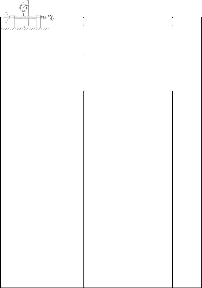
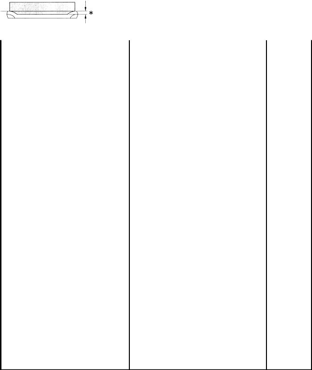
ELEC ELECTRIC STARTING SYSTEM EB803511 Checking The Starter Motor 1. Check: S commutator Dirt ! Clean with 600 grit sandpaper. 2. Measure: S commutator diameter a Out of specification ! Replace the starter motor. Min. commutator diameter 23.5 mm 3. Measure: S mica undercut a Out of specification ! Scrape the mica to the proper measurement with a hacksaw blade… -
Page 68
ELEC ELECTRIC STARTING SYSTEM 5. Measure: S brush length a Out of specification ! Replace the brushes as a set. Min. brush length 3.65 mm 6. Measure: S brush spring force Out of specification ! Replace the brush springs as a set. Brush spring force 5.28 X 7.92 N 7. -
Page 69
ELEC ELECTRIC STARTING SYSTEM 3. Install: S starter motor yoke 2 S O-rings 1 S starter motor rear cover 3 S bolts 5 Nm (0.5 mSkg) NOTE: Align the match marks a on the starter motor yoke with the match marks b on the front and rear covers. -
Page 70: Cooling System
ELEC COOLING SYSTEM EB807000 COOLING SYSTEM CIRCUIT DIAGRAM Main switch Battery Main fuse Thermo unit Combination meter Radiator fan motor Radiator fan motor relay Radiator fan motor fuse –62–…
-
Page 71: Troubleshooting
ELEC COOLING SYSTEM EB807010 EB802401 TROUBLESHOOTING 2. Battery S The radiator fan motor fails to turn. S Check the condition of the battery. S The coolant temperature meter needle Refer to “CHECKING AND CHARGING fails to move when the engine is warm. THE BATTERY”…
-
Page 72
ELEC COOLING SYSTEM EB807400 EB807402 7. Thermo unit 5. Fan motor relay S Disconnect the fan motor relay coupler. S Remove the thermo unit from the radiator. S Connect the pocket tester ( S Connect the pocket tester ( 1) and bat- 1) to the ther- tery (12V) to the fan motor relay coupler as mo unit… -
Page 73
ELEC COOLING SYSTEM S Does the thermo unit operate properly as de- scribed above? Replace the thermo unit. EB807403 8. Wiring S Check the entire cooling system’s wiring. Refer to “CIRCUIT DIAGRAM”. S Is the cooling system’s wiring properly con- nected and without defects? This circuit is OK. -
Page 74: Self-Diagnosis
ELEC SELF-DIAGNOSIS EB812000 SELF-DIAGNOSIS The YZF-R1 features a self-diagnosing system for the following circuit(-s): S throttle position sensor S EXUP S speed sensor S fuel level warning light If any of these circuits are defective, their respective condition codes will be displayed on the tachome- ter when the main switch is set to “ON”…
-
Page 75: Troubleshooting
ELEC SELF-DIAGNOSIS EB812010 2. Speed sensor TROUBLESHOOTING S Place the motorcycle on a suitable stand so The tachometer starts to display the self- that the rear wheel is elecated. diagnosis sequence. S Connect the pocket tester (DC 20V) to the Check: speed sensor connector.
-
Page 77: Yzf-R1 Wiring Diagram (For Eur)
Main switch Backup fuse (odometer) YZF-R1 WIRING DIAGRAM (For EUR) Rectifier/ regulator Generator Battery Main fuse Starter relay Starter motor Relay unit Starting circuit cutoff relay Fuel pump relay Fuel pump Sidestand switch EXUP servomotor Throttle position sensor Ignition unit Ignition coil Spark plug Pickup coil…
-
Page 78: Yzf-R1 Wiring Diagram (For Oce)
YZF-R1 WIRING DIAGRAM (For OCE) Main switch Backup fuse (odometer) Rectifier/ regulator Generator Battery Main fuse Starter relay Starter motor Relay unit Starting circuit cutoff relay Fuel pump relay Fuel pump Sidestand switch EXUP servomotor Throttle position sensor Ignition unit Ignition coil Spark plug Pickup coil…

Руководство по эксплуатации и техническому обслуживанию мотоциклов Yamaha YZF-R1.
- Издательство: Yamaha Motor Co., Ltd.
- Год издания: 2003
- Страниц: 120
- Формат: PDF
- Размер: 3,4 Mb

Руководство по эксплуатации и техническому обслуживанию мотоциклов Yamaha YZF-R1.
- Издательство: Yamaha Motor Co., Ltd.
- Год издания: 2011
- Страниц: 114
- Формат: PDF
- Размер: 4,9 Mb

Руководство по эксплуатации и техническому обслуживанию мотоциклов Yamaha YZF-R6.
- Издательство: Yamaha Motor Co., Ltd.
- Год издания: 2002
- Страниц: 140
- Формат: PDF
- Размер: 3,9 Mb

Руководство по эксплуатации и техническому обслуживанию мотоциклов Yamaha YZF-R6.
- Издательство: Yamaha Motor Co., Ltd.
- Год издания: 2007
- Страниц: 114
- Формат: PDF
- Размер: 2,9 Mb

Сборник руководств на английском языке по эксплуатации и техническому обслуживанию мотоциклов Yamaha моделей YZF600 Thundercat и YZF1000 Thunderace различных модификаций.
- Издательство: Yamaha Motor Co., Ltd.
- Год издания: —
- Страниц: —
- Формат: PDF
- Размер: 43,3 Mb

Сборник руководств на английском языке по эксплуатации и техническому обслуживанию мотоциклов Yamaha моделей YZF-R1, YZF-R6 и YZF-R125 различных модификаций.
- Издательство: Yamaha Motor Co., Ltd.
- Год издания: —
- Страниц: —
- Формат: PDF
- Размер: 213,3 Mb

Руководство на английском языке по техническому обслуживанию и ремонту мотоциклов Yamaha FZS600 Fazer и YZF600R Thundercat 1996-2003 годов выпуска.
- Издательство: Haynes Publishing
- Год издания: —
- Страниц: 219
- Формат: PDF
- Размер: 12,1 Mb
Руководство на английском языке по ремонту мотоциклов Yamaha YZF600RJ.
- Издательство: Yamaha Motor Co., Ltd.
- Год издания: 1996
- Страниц: 373
- Формат: PDF
- Размер: 66,3 Mb
Руководство по эксплуатации и ремонту мотоциклов Yamaha YZF750R/YZF750SP 1993-1998 и YZF1000 Thunderace 1996-2000 годов выпуска.
- Издательство: Монолит
- Год издания: 2011
- Страниц: 280
- Формат: PDF
- Размер: 195,4 Mb

Руководство на английском языке по техническому обслуживанию и ремонту мотоциклов Yamaha YZF750R/YZF750SP 1993-1998 и YZF1000 Thunderace 1996-2000 годов выпуска.
- Издательство: Haynes Publishing
- Год издания: 2000
- Страниц: 147
- Формат: PDF
- Размер: 45,9 Mb
Руководство на английском языке по ремонту мотоциклов Yamaha моделей YZF1000RJ и YZF1000RJC.
- Издательство: Yamaha Motor Co., Ltd.
- Год издания: 1996
- Страниц: 407
- Формат: PDF
- Размер: 36,5 Mb
Сборник руководств на английском языке по ремонту мотоциклов Yamaha YZF-R1 различных модификаций 1998-2009 годов выпуска.
- Издательство: Yamaha Motor Co., Ltd.
- Год издания: 1997-2008
- Страниц: —
- Формат: PDF
- Размер: 85,7 Mb

Руководство на английском языке по установке комплекта гоночных запчастей для мотоциклов Yamaha YZF-R1 2009 года выпуска.
- Издательство: —
- Год издания: —
- Страниц: 81
- Формат: PDF
- Размер: 3,0 Mb

Руководство на английском языке по установке комплекта гоночных запчастей для мотоциклов Yamaha YZF-R6 2004 года выпуска.
- Издательство: —
- Год издания: —
- Страниц: 73
- Формат: PDF
- Размер: 3,6 Mb
Сборник руководств на английском языке по ремонту мотоциклов Yamaha YZF-R6 различных модификаций 1999-2008 годов выпуска.
- Издательство: Yamaha Motor Co., Ltd.
- Год издания: 1998-2007
- Страниц: —
- Формат: PDF
- Размер: 108,9 Mb

Руководство на английском языке по ремонту мотоциклов Yamaha YZF-R7.
- Издательство: Yamaha Motor Co., Ltd.
- Год издания: 1999
- Страниц: 381
- Формат: PDF
- Размер: 15,9 Mb

Руководство на английском языке по ремонту мотоциклов Yamaha YZF-R125.
- Издательство: MBK Industrie
- Год издания: 2008
- Страниц: 356
- Формат: PDF
- Размер: 10,4 Mb

Сборник руководств на английском, французском, немецком, испанском и итальянском языках по ремонту мотоциклов Yamaha моделей YZF-R1, YZF-R6 и др.
- Издательство: Yamaha
- Год издания: —
- Страниц: —
- Формат: ISO
- Размер: 1,7 Gb

FOREWORD
This Supplementary Service Manual has been prepared to introduce new service and data for the YZF-R1 2000. For complete service information procedures it is necessary to use this Supplementary Service Manual together with the following manual.
YZF-R1 SERVICE MANUAL: 4XV1-AE1
YZF-R1 2000
SUPPLEMENTARY
SERVICE MANUAL1999 by Yamaha Motor Co., Ltd.
First Edition, December 1999 Any reproduction or unauthorized use
without the written permission of Yamaha Motor Co., Ltd. is expressly prohibited.
EB001000
NOTICE
This manual was produced by the Yamaha Motor Company, Ltd. primarily for use by Yamaha dealers and their qualified mechanics. it is not possible to include all the knowledge of a mechanic in one manual. Therefore, anyone who uses this book to perform maintenance and repairs on Yamaha vehicles should have a basic understanding of mechanics and the techniques to repair these types of vehicles. Repair and maintenance work attempted by anyone without this knowledge is likely to render the vehicle unsafe and unfit for use.
Yamaha Motor Company, Ltd. is continually striving to improve all of its models. Modifications and significant changes in specifications or procedures will be forwarded to all authorized Yamaha dealers and will appear in future editions of this manual where applicable.
NOTE:
Designs and specifications are subject to change without notice.
EB002000
IMPORTANT MANUAL INFORMATION
Particularly important information is distinguished in this manual by the following.
|
The Safety Alert Symbol means ATTENTION! BECOME ALERT! YOUR |
||||
|
SAFETY IS INVOLVED! |
||||
|
WARNING |
Failure to follow WARNING instructions could result in severe injury or death to |
|||
|
the motorcycle operator, a bystander or |
||||
|
a person checking or repairing the mo- |
||||
|
torcycle. |
||||
|
CAUTION: |
A CAUTION indicates special precautions that must be taken to avoid damage |
|||
|
NOTE: |
to the motorcycle. |
|||
|
A NOTE provides key information to make procedures easier or clearer. |
EB003000
HOW TO USE THIS MANUAL
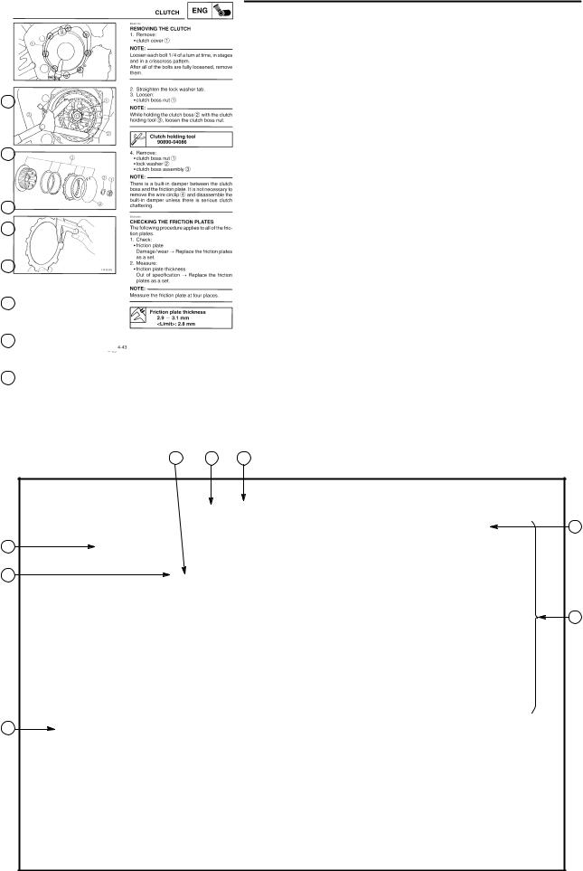
This manual is intended as a handy, easy-to-read reference book for the mechanic. Comprehensive explanations of all installation, removal, disassembly, assembly, repair and check procedures are laid out with the individual steps in sequential order.
1The manual is divided into chapters. An abbreviation and symbol in the upper right corner of each page indicate the current chapter.
Refer to ªSYMBOLSº.
2Each chapter is divided into sections. The current section title is shown at the top of each page, except in Chapter 3 (ªPERIODIC CHECKS AND ADJUSTMENTSº), where the sub-section title(-s) appears.
3Sub-section titles appear in smaller print than the section title.
4To help identify parts and clarify procedure steps, there are exploded diagrams at the start of each removal and disassembly section.
5Numbers are given in the order of the jobs in the exploded diagram. A circled number indicates a disassembly step.
6Symbols indicate parts to be lubricated or replaced.
Refer to ªSYMBOLSº.
7A job instruction chart accompanies the exploded diagram, providing the order of jobs, names of parts, notes in jobs, etc.
8Jobs requiring more information (such as special tools and technical data) are described sequentially.
6 2 1
3
4
5
8
7

|
GEN |
SPEC |
|
|
INFO |
||
|
3 |
4 |
|
|
CHK |
ENG |
|
|
ADJ |
||
|
5 |
6 |
|
|
COOL |
CARB |
|
|
7 |
8 |
|
|
CHAS |
ELEC |
|
|
9 |
10 |
|
|
TRBL |
||
|
SHTG |
||
|
11 |
12 |
EB004000
SYMBOLS
The following symbols are not relevant to every vehicle.
Symbols 1 to 9 indicate the subject of each chapter.
1General information
2Specifications
3Periodic checks and adjustments
4Engine
5Cooling system
6Carburetor(-s)
7Chassis
8Electrical system
9Troubleshooting
Symbols 10 to 17 indicate the following.
10Serviceable with engine mounted
11Filling fluid
12Lubricant
13Special tool
14Tightening torque
15Wear limit, clearance
16Engine speed
17Electrical data
Symbols 18 to 23 in the exploded diagrams indicate the types of lubricants and lubrication points.
18Engine oil
19Gear oil
20Molybdenum disulfide oil
21Wheel bearing grease
22Lithium soap base grease
23Molybdenum disulfide grease
Symbols 24 to 25 in the exploded diagrams indicate the following.
24Apply locking agent (LOCTITE )
25Replace the part

CONTENTS
SPECIFICATIONS
GENERAL SPECIFICATIONS . . . . . . . . . . . . . . . . . . . . . . . . . . . . . . . . 1 ENGINE SPECIFICATIONS . . . . . . . . . . . . . . . . . . . . . . . . . . . . . . . . . . 2 CHASSIS SPECIFICATIONS . . . . . . . . . . . . . . . . . . . . . . . . . . . . . . . . . 6 ELECTRICAL SPECIFICATIONS . . . . . . . . . . . . . . . . . . . . . . . . . . . . . 9 TIGHTENING TORQUES . . . . . . . . . . . . . . . . . . . . . . . . . . . . . . . . . . . . 11
ENGINE TIGHTENING TORQUES . . . . . . . . . . . . . . . . . . . . . . . . . 11 CHASSIS TIGHTENING TORQUES . . . . . . . . . . . . . . . . . . . . . . . 12
LUBRICATION POINTS AND LUBRICANT TYPES . . . . . . . . . . . . . 13 ENGINE LUBRICATION POINTS AND LUBRICANT TYPES . . 13 OIL FLOW DIAGRAMS . . . . . . . . . . . . . . . . . . . . . . . . . . . . . . . . . . . . . . 14 COOLANT FLOW DIAGRAMS . . . . . . . . . . . . . . . . . . . . . . . . . . . . . . . 17 CABLE ROUTING . . . . . . . . . . . . . . . . . . . . . . . . . . . . . . . . . . . . . . . . . . 20
PERIODIC CHECKS AND ADJUSTMENTS
INTRODUCTION . . . . . . . . . . . . . . . . . . . . . . . . . . . . . . . . . . . . . . . . . . . 33
PERIODIC MAINTENANCE AND LUBRICATION INTERVALS . . . 33
COWLINGS . . . . . . . . . . . . . . . . . . . . . . . . . . . . . . . . . . . . . . . . . . . . . . . . 35
AIR FILTER CASE AND IGNITION COIL PLATE . . . . . . . . . . . . . . . 36
OVERHAULING THE ENGINE
AIR INDUCTION SYSTEM . . . . . . . . . . . . . . . . . . . . . . . . . . . . . . . . . . . 37 ENGINE . . . . . . . . . . . . . . . . . . . . . . . . . . . . . . . . . . . . . . . . . . . . . . . . . . . 38 INSTALLING THE ENGINE . . . . . . . . . . . . . . . . . . . . . . . . . . . . . . . 39 CYLINDER HEAD . . . . . . . . . . . . . . . . . . . . . . . . . . . . . . . . . . . . . . . . . . 40 CRANKCASE . . . . . . . . . . . . . . . . . . . . . . . . . . . . . . . . . . . . . . . . . . . . . . 41 ASSEMBLING THE CRANKCASE . . . . . . . . . . . . . . . . . . . . . . . . . 43
COOLING SYSTEM
RADIATOR . . . . . . . . . . . . . . . . . . . . . . . . . . . . . . . . . . . . . . . . . . . . . . . . 45
CARBURETORS
AIR INDUCTION SYSTEM . . . . . . . . . . . . . . . . . . . . . . . . . . . . . . . . . . . 47 AIR INJECTION . . . . . . . . . . . . . . . . . . . . . . . . . . . . . . . . . . . . . . . . . 47 AIR CUTOFF VALVE . . . . . . . . . . . . . . . . . . . . . . . . . . . . . . . . . . . . . 47 AIR INDUCTION SYSTEM DIAGRAMS . . . . . . . . . . . . . . . . . . . . . 48 CHECKING THE AIR INDUCTION SYSTEM . . . . . . . . . . . . . . . . 49
CHASSIS
FRONT WHEEL AND BRAKE DISCS . . . . . . . . . . . . . . . . . . . . . . . . . 50 INSTALLING THE FRONT WHEEL . . . . . . . . . . . . . . . . . . . . . . . . 51 FRONT AND REAR BRAKES . . . . . . . . . . . . . . . . . . . . . . . . . . . . . . . . 52
REAR BRAKE MASTER CYLINDER AND BRAKE
FLUID RESERVOIR . . . . . . . . . . . . . . . . . . . . . . . . . . . . . . . . . . 52

ELECTRICAL
INSTRUMENT FUNCTIONS . . . . . . . . . . . . . . . . . . . . . . . . . . . . . . . . . 53 INDICATOR LIGHTS . . . . . . . . . . . . . . . . . . . . . . . . . . . . . . . . . . . . . 53 COOLANT TEMPERATURE WARNING LIGHT . . . . . . . . . . . . . . 54 SPEEDOMETER UNIT . . . . . . . . . . . . . . . . . . . . . . . . . . . . . . . . . . . 55 ELECTRIC STARTING SYSTEM . . . . . . . . . . . . . . . . . . . . . . . . . . . . . 57 STARTER MOTOR . . . . . . . . . . . . . . . . . . . . . . . . . . . . . . . . . . . . . . 57 COOLING SYSTEM . . . . . . . . . . . . . . . . . . . . . . . . . . . . . . . . . . . . . . . . . 62 CIRCUIT DIAGRAM . . . . . . . . . . . . . . . . . . . . . . . . . . . . . . . . . . . . . . 62 TROUBLESHOOTING . . . . . . . . . . . . . . . . . . . . . . . . . . . . . . . . . . . 63 SELF-DIAGNOSIS . . . . . . . . . . . . . . . . . . . . . . . . . . . . . . . . . . . . . . . . . . 66 TROUBLESHOOTING . . . . . . . . . . . . . . . . . . . . . . . . . . . . . . . . . . . 67
YZF-R1 WIRING DIAGRAM (For EUR)
YZF-R1 WIRING DIAGRAM (For OCE)

|
GENERAL SPECIFICATIONS |
SPEC |
||||
|
SPECIFICATIONS |
|||||
|
GENERAL SPECIFICATIONS |
|||||
|
Item |
Standard |
Limit |
|||
|
Dimensions |
|||||
|
Overall length |
2,035 mm |
||||
|
2,095 mm (for AUS) |
|||||
|
Overall width |
695 mm |
||||
|
Overall height |
1,105 mm |
||||
|
Seat height |
815 mm |
||||
|
Wheelbase |
1,395 mm |
||||
|
Minimum ground clearance |
140 mm |
||||
|
Minimum turning radius |
3,400 mm |
||||
|
Weight |
|||||
|
Wet (with oil and a full fuel tank) |
194 kg |
||||
|
Dry (without oil and fuel) |
175 kg |
||||
|
Maximum load (total of cargo, rider, |
201 kg |
||||
|
passenger, and accessories) |
|||||
±1±
|
ENGINE SPECIFICATIONS |
SPEC |
||||
|
ENGINE SPECIFICATIONS |
|||||
|
Item |
Standard |
Limit |
|||
|
Engine |
|||||
|
Engine type |
Liquid-cooled, 4-stroke, DOHC |
||||
|
Displacement |
998 cm3 |
||||
|
Cylinder arrangement |
Forward-inclined parallel 4-cylinder |
||||
|
Bore stroke |
74 58 mm |
||||
|
Compression ratio |
11.8 : 1 |
||||
|
Engine idling speed |
1,000 1,100 r/min |
||||
|
Vacuum pressure at engine idling |
29.3 kPa (220 mm Hg) |
||||
|
speed |
1,450 kPa (14.5 kgf/cm2) at 400 r/min |
||||
|
Standard compression pressure |
|||||
|
(at sea level) |
|||||
|
Fuel |
|||||
|
Recommended fuel |
Regular unleaded gasoline |
||||
|
Unleaded fuel (for AUS) |
|||||
|
Fuel tank capacity |
|||||
|
Total (including reserve) |
18 L |
||||
|
Reserve only |
3.8 L |
||||
|
Engine oil |
|||||
|
Lubrication system |
Wet sump |
||||
|
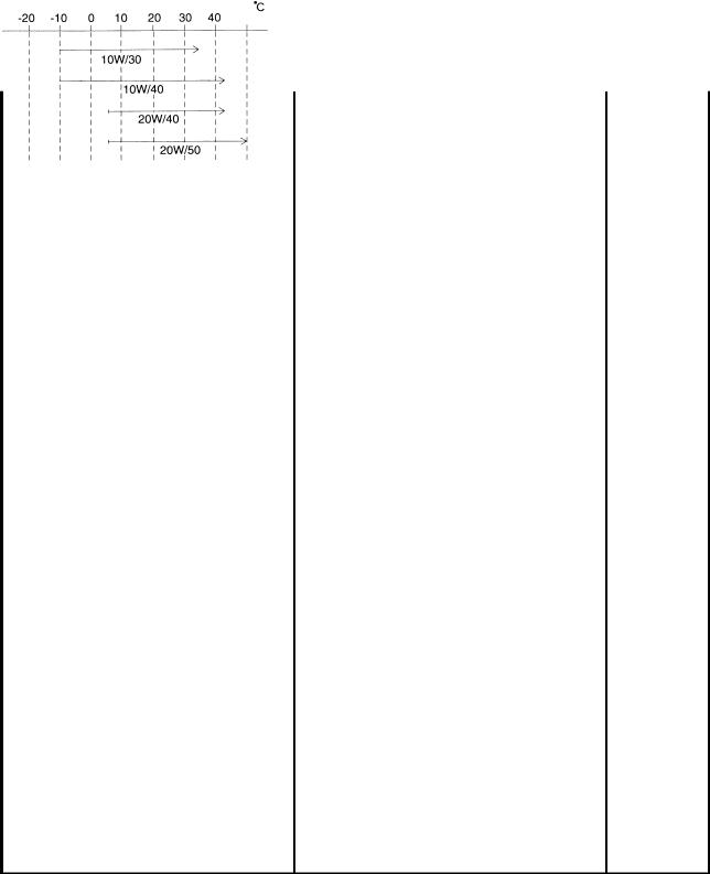
Recommended oil |
|||||
|
Temp. |
|||||
|
SAE20W40SE or SAE10W30SE |
|
Quantity |
||
|
Total amount |
3.6 L |
|
|
Without oil filter cartridge |
2.7 L |
|
|
replacement |
||
|
With oil filter cartridge replacement |
2.9 L |
|
|
Oil pressure (hot) |
45 kPa at 1,100 r/min |
|
|
(0.45 kgf/cm2 at 1,100 r/min) |
||
|
Relief valve opening pressure |
490 570 kPa (4.9 5.7 kgf/cm2) |
±2±
![]()
|
ENGINE SPECIFICATIONS |
SPEC |
|||
|
Item |
Standard |
Limit |
||
|
Camshafts |
||||
|
Drive system |
Chain drive (right) |
|||
|
Camshaft cap inside diameter |
24.500 X 24.521 mm |
|||
|
Camshaft journal diameter |
24.459 X 24.472 mm |
|||
|
Camshaft-journal-to-camshaft- |
0.028 X 0.062 mm |
|||
|
cap clearance |
||||
|
Intake camshaft lobe dimensions |
|
Measurement A |
32.5 X 32.6 mm |
32.4 mm |
|
Measurement B |
24.95 X 25.05 mm |
24.85 mm |
|
Measurement C |
7.45 X 7.65 mm |
Exhaust camshaft lobe dimensions
|
Measurement A |
32.95 X 33.05 mm |
32.85 mm |
|
Measurement B |
24.95 X 25.05 mm |
24.85 mm |
|
Measurement C |
7.75 X 7.95 mm |
|
|
Max. camshaft runout |
0.03 mm |
±3±
|
ENGINE SPECIFICATIONS |
SPEC |
|||||
|
Item |
Standard |
Limit |
||||
|
Valves, valve seats, valve guides |
||||||
|
Valve clearance (cold) |
||||||
|
Intake |
0.11 X 0.20 mm |
|||||
|
Exhaust |
0.21 X 0.25 mm |
|||||
|
Valve dimensions |
||||||
|
Head Diameter |
Face Width |
Seat Width |
Margin Thickness |
|
Valve head diameter A |
|||
|
Intake |
22.9 X 23.1 mm |
||
|
Exhaust |
24.4 X 24.6 mm |
||
|
Valve face width B |
|||
|
Intake |
1.76 X 2.90 mm |
||
|
Exhaust |
1.76 X 2.90 mm |
||
|
Valve seat width C |
|||
|
Intake |
0.9 X 1.1 mm |
||
|
Exhaust |
0.9 X 1.1 mm |
||
|
Valve margin thickness D |
|||
|
Intake |
0.5 X 0.9 mm |
||
|
Exhaust |
0.5 X 0.9 mm |
||
|
Valve stem diameter |
|||
|
Intake |
3.975 X 3.990 mm |
3.945 mm |
|
|
Exhaust |
4.465 X 4.480 mm |
4.43 mm |
|
|
Valve guide inside diameter |
|||
|
Intake |
4.000 X 4.012 mm |
4.05 mm |
|
|
Exhaust |
4.500 X 4.512 mm |
4.55 mm |
|
|
Valve-stem-to-valve-guide clearance |
|||
|
Intake |
0.010 X 0.037 mm |
0.08 mm |
|
|
Exhaust |
0.020 X 0.047 mm |
0.1 mm |
|
|
Valve stem runout |
0.01 mm |
|
Valve seat width |
||
|
Intake |
0.9 X 1.1 mm |
|
|
Exhaust |
0.9 X 1.1 mm |
|
|
Connecting rods |
||
|
Crankshaft-pin-to-big-end-bearing |
0.031 X 0.055 mm |
|
|
clearance |
||
|
Bearing color code |
±1 = Violet 0 = White 1 = Blue 2 = Black |
±4±
|
ENGINE SPECIFICATIONS |
SPEC |
|||||
|
Item |
Standard |
Limit |
||||
|
Transmission |
||||||
|
Transmission type |
Constant mesh, 6-speed |
|||||
|
Primary reduction system |
Spur gear |
|||||
|
Primary reduction ratio |
68/43 (1.581) |
|||||
|
Secondary reduction system |
Chain drive |
|||||
|
Secondary reduction ratio |
43/16 (2.688) |
|||||
|
Operation |
Left-foot operation |
|||||
|
Gear ratios |
||||||
|
1st gear |
35/14 (2.500) |
|||||
|
2nd gear |
35/19 (1.842) |
|||||
|
3rd gear |
30/20 (1.500) |
|||||
|
4nd gear |
28/21 (1.333) |
|||||
|
5th gear |
30/25 (1.200) |
|||||
|
6th gear |
29/26 (1.115) |
|||||
|
Max. main axle runout |
0.08 mm |
|||||
|
Max. drive axle runout |
0.08 mm |
|||||
|
Carburetors |
||||||
|
Model (manufacturer) quantity |
BDSR40 (MIKUNI) 4 |
|||||
|
Throttle cable free play (at the |
3 5 mm |
|||||
|
flange of the throttle grip) |
||||||
|
ID mark |
5JJ1 00 |
|||||
|
Main jet |
#130 |
|||||
|
Main air jet |
Carburetors 1 and 4: #60 |
|||||
|
Carburetors 2 and 3: #65 |
||||||
|
Jet needle |
6DEY5-53-3 |
|||||
|
Needle jet |
P-OM |
|||||
|
Pilot air jet |
#120 |
|||||
|
Pilot outlet |
1.0 |
|||||
|
Pilot jet |
#15 |
|||||
|
Bypass 1 |
0.8 |
|||||
|
Bypass 2 |
0.9 |
|||||
|
Bypass 3 |
0.8 |
|||||
|
Pilot screw turns out |
3.125 |
|||||
|
Valve seat size |
1.5 |
±5±
|
CHASSIS SPECIFICATIONS |
SPEC |
|||
|
CHASSIS SPECIFICATIONS |
||||
|
Item |
Standard |
Limit |
||
|
Front tire |
||||
|
Tire type |
Tubeless |
|||
|
Size |
120/70 ZR17 (58W) |
|||
|
Model (manufacturer) |
MEZ3Y FRONT (METZELER) |
|||
|
D207FQ (DUNLOP) |
||||
|
Tire pressure (cold) |
250 kPa (2.5 kg/cm2, 2.5 bar) |
|||
|
0 90 kg |
||||
|
90 197 kg |
250 kPa (2.5 kg/cm2, 2.5 bar) |
|||
|
High-speed riding |
250 kPa (2.5 kg/cm2, 2.5 bar) |
|||
|
Min. tire tread depth |
1.6 mm |
|||
|
Rear tire |
||||
|
Tire type |
Tubeless |
|||
|
Size |
190/50 ZR17 (73W) |
|||
|
Model (manufacturer) |
MEZ3Y (METZELER)/D207N (DUNLOP) |
|||
|
Tire pressure (cold) |
250 kPa (2.5 kg/cm2, 2.5 bar) |
|||
|
0 90 kg |
||||
|
90 197 kg |
290 kPa (2.9 kg/cm2, 2.9 bar) |
|||
|
High-speed riding |
250 kPa (2.5 kg/cm2, 2.5 bar) |
|||
|
Min. tire tread depth |
1.6 mm |
|||
|
Rear brake |
||||
|
Brake type |
Single-disc brake |
|||
|
Operation |
Right-foot operation |
|||
|
Brake pedal position (from the top |
35 40 mm |
|||
|
of the brake pedal to the bottom of |
||||
|
the rider footrest bracket) |
||||
|
Recommended fluid |
DOT 4 |
|||
|
Brake discs |
||||
|
Diameter thickness |
245 5 mm |
|||
|
Min. thickness |
4.5 mm |
|||
|
Max. deflection |
0.1 mm |
|||
|
Brake pad lining thickness |
5.5 mm |
0.5 mm |
|
Master cylinder inside diameter |
12.7 mm |
|
|
Caliper cylinder inside diameter |
38.2 mm |
±6±

|
CHASSIS SPECIFICATIONS |
SPEC |
|||||
|
Item |
Standard |
Limit |
||||
|
Front suspension |
||||||
|
Suspension type |
Telescopic fork |
|||||
|
Front fork type |
Coil spring/oil damper |
|||||
|
Front fork travel |
135 mm |
|||||
|
Spring |
||||||
|
Free length |
255 mm |
|||||
|
Spacer length |
85 mm |
|||||
|
Installed length |
242.4 mm |
|||||
|
Spring rate (K1) |
7.35 N/mm (0.75 kgf/mm) |
|||||
|
Spring stroke (K1) |
0 X 135 mm |
|||||
|
Optional spring available |
No |
|||||
|
Fork oil |
||||||
|
Recommended oil |
Suspension oil ª01º or equivalent |
|||||
|
Quantity (each front fork leg) |
482 cm3 |
|||||
|
Level (from the top of the inner |
74 mm |
|||||
|
tube, with the inner tube fully |
||||||
|
compressed, and without the |
||||||
|
fork spring) |
||||||
|
Damper adjusting rod locknut |
11 mm |
|||||
|
distance |
||||||
|
Spring preload adjusting positions |
||||||
|
Minimum |
8 |
|||||
|
Standard |
6 |
|||||
|
Maximum |
1 |
|||||
|
Rebound damping adjusting |
||||||
|
positions |
||||||
|
Minimum* |
11 |
|||||
|
Standard* |
5 |
|||||
|
Maximum* |
1 |
|||||
|
Compression damping adjusting |
||||||
|
positions |
||||||
|
Minimum* |
9 |
|||||
|
Standard* |
5 |
|||||
|
Maximum* |
1 |
|||||
|
*with the adjusting screw fully turned |
||||||
|
in position |
||||||
±7±

|
CHASSIS SPECIFICATIONS |
SPEC |
|||||
|
Item |
Standard |
Limit |
||||
|
Rear suspension |
||||||
|
Suspension type |
Swingarm (link suspension) |
|||||
|
Rear shock absorber assembly |
Coil spring/gas-oil damper |
|||||
|
type |
||||||
|
Rear shock absorber assembly |
65 mm |
|||||
|
travel |
||||||
|
Spring |
||||||
|
Free length |
176 mm |
|||||
|
Installed length |
162.5 mm |
|||||
|
Spring rate (K1) |
78.4 N/mm (7.84 kgf/mm) |
|||||
|
Spring stroke (K1) |
0 X 65 mm |
|||||
|
Optional spring available |
No |
|||||
|
Standard spring preload gas/air |
1,200 kPa (12 kgf/cm2) |
|||||
|
pressure |
||||||
|
Spring preload adjusting positions |
||||||
|
Minimum |
1 |
|||||
|
Standard |
4 |
|||||
|
Maximum |
9 |
|||||
|
Rebound damping adjusting |
||||||
|
positions |
||||||
|
Minimum* |
11 |
|||||
|
Standard* |
7 |
|||||
|
Maximum* |
1 |
|||||
|
Compression damping adjusting |
||||||
|
positions |
||||||
|
Minimum* |
11 |
|||||
|
Standard* |
9 |
|||||
|
Maximum* |
1 |
|||||
|
*with the adjusting screw fully turned |
||||||
|
in position |
||||||
±8±
|
ELECTRICAL SPECIFICATIONS |
SPEC |
|||||
|
ELECTRICAL SPECIFICATIONS |
||||||
|
Item |
Standard |
Limit |
||||
|
System voltage |
12 V |
|||||
|
Ignition system |
||||||
|
Ignition system type |
Transistorized coil ignition |
|||||
|
Ignition timing |
5_ BTDC at 1,050 r/min |
|||||
|
Advanced timing |
55_ BTDC at 5,000 r/min |
|||||
|
Advancer type |
Throttle position sensor and electrical |
|||||
|
Pickup coil resistance/color |
248 372 W/Gy-B |
|||||
|
Transistorized coil ignition unit |
TNDF54 (DENSO) |
|||||
|
model (manufacturer) |
||||||
|
Voltage regulator |
||||||
|
Regulator type |
Semiconductor short circuit |
|||||
|
Model |
SH650A-12 |
|||||
|
No-load regulated voltage |
14.1 14.9 V |
|||||
|
Bulbs (voltage/wattage quantity) |
||||||
|
Headlight |
12 V 60 W/55 W 2 |
|||||
|
Auxiliary light |
12 V 5 W 2 |
|||||
|
Tail/brake light |
12 V 5 W/21 W 2 |
|||||
|
Turn signal light |
12 V 21 W 4 |
|||||
|
Meter light |
LED |
|||||
|
Electric starting system |
||||||
|
System type |
Constant mesh |
|||||
|
Starter motor |
||||||
|
Model (manufacturer) |
5JJ (YAMAHA) |
|||||
|
Power output |
0.75 kW |
|||||
|
Brushes |
||||||
|
Overall length |
9.8 mm |
3.65 mm |
||||
|
Spring force |
4.88 7.32 N (488 732 gf) |
|||||
|
Commutator resistance |
0.009 0.011 Ω |
|||||
|
Commutator diameter |
24.5 mm |
23.5 mm |
||||
|
Mica undercut |
1.5 mm |
|||||
|
Turn signal relay |
||||||
|
Relay type |
Full-transistor |
|||||
|
Model (manufacturer) |
FE246BH (DENSO) |
|||||
|
Self-cancelling device built-in |
No |
|||||
|
Turn signal blinking frequency |
75 95 cycles/min. |
|||||
|
Wattage |
21 W 2 |
|||||
|
Oil level switch model |
4XV (DENSO) |
|||||
|
(manufacturer) |
||||||
|
Fuel pump relay model |
G8R-30Y-M (OMRON) |
|||||
|
(manufacturer) |
±9±
|
ELECTRICAL SPECIFICATIONS |
SPEC |
|||||
|
Item |
Standard |
Limit |
||||
|
Thermo unit |
||||||
|
Model (manufacturer) |
5JJ (NIPPON THERMOSTAT) |
|||||
|
Fuses (amperage quantity) |
||||||
|
Main fuse |
30 A 1 |
|||||
|
Headlight fuse |
20 A 1 |
|||||
|
Signaling system fuse |
20 A 1 |
|||||
|
Ignition fuse |
15 A 1 |
|||||
|
Radiator fan fuse |
10 A 1 |
|||||
|
Backup fuse (odometer) |
10 A 1 |
|||||
|
Reserve fuse |
30 A 1 |
|||||
|
20 A 1 |
||||||
|
15 A 1 |
||||||
|
10 A 1 |
||||||
±10±
|
TIGHTENING TORQUES |
SPEC |
||||||||||
|
TIGHTENING TORQUES |
|||||||||||
|
ENGINE TIGHTENING TORQUES |
|||||||||||
|
Thread |
Tightening |
||||||||||
|
Item |
Fastener |
Q’ty |
torque |
Remarks |
|||||||
|
size |
|||||||||||
|
Nm |
m kgf |
||||||||||
|
Cylinder head |
Nut |
M10 |
8 |
50 |
5.0 |
||||||
|
Cylinder head |
Cap nut |
M10 |
2 |
65 |
6.5 |
||||||
|
Generator rotor |
Bolt |
M10 |
1 |
65 |
6.5 |
||||||
|
Oil/water pump assembly driven |
Bolt |
M6 |
1 |
12 |
1.2 |
||||||
|
sprocket cover |
|||||||||||
|
Air induction system hose |
Clamp |
M7 |
4 |
4 |
0.4 |
||||||
|
Crankcase |
Bolt |
M9 |
10 |
See NOTE |
|||||||
|
Crankcase |
Bolt |
M6 |
2 |
||||||||
|
14 |
1.4 |
||||||||||
|
Crankcase |
Bolt |
M6 |
14 |
12 |
1.2 |
||||||
|
Crankcase |
Bolt |
M8 |
2 |
24 |
2.4 |
||||||
|
Ignitor unit |
Screw |
M5 |
2 |
7 |
0.7 |
||||||
NOTE:
After tightening to 15 Nm (1.5 m kg), tighten another 45_ X 50_
±11±
|
TIGHTENING TORQUES |
SPEC |
|||||||
|
CHASSIS TIGHTENING TORQUES |
||||||||
|
Item |
Thread size |
Tightening |
Remarks |
|||||
|
Nm |
m kgf |
|||||||
|
Lower ring nut |
M30 |
9 |
0.9 |
See NOTE. |
||||
|
Engine mounting |
||||||||
|
Front mounting bolts |
M10 |
40 |
4.0 |
|||||
|
Rear upper mounting bolt |
M10 |
55 |
5.5 |
|||||
|
Rear under mounting bolts |
M10 |
55 |
5.5 |
|||||
|
Pinch bolts |
M8 |
24 |
2.4 |
|||||
|
Exhaust pipe bracket |
M8 |
24 |
2.4 |
|||||
|
Rear master cylinder |
M8 |
18 |
1.8 |
|||||
NOTE:
1.First, tighten the ring nut to approximately 18 Nm (1.8 m kg) with a torque wrench, then loosen the ring nut completely.
2.Retighten the ring nut to specification.
±12±
![]()
LUBRICATION POINTS AND LUBRICANT TYPES SPEC 
E202000
LUBRICATION POINTS AND LUBRICANT TYPES
ENGINE LUBRICATION POINTS AND LUBRICANT TYPES
|
Lubrication point |
Lubricant |
Connecting rod bolts and nuts
±13±
|
Всего инструкций в разделе: 172 |
|
Инструкции по эксплуатации для мопеда, мотоцикла, снегохода YAMAHA находятся в данном разделе. Скачайте бесплатно, также можно посмотреть онлайн. Важная информация по обслуживанию, эксплуатации и ремонту изложенная в руководстве пользователя должна быть всегда под рукой. |
Добро пожаловать на Yamaha R1 Forum
 |
Добро пожаловать на Yamaha R1 Forum, Форум о мотоцикле Yamaha R1. Тут вы найдете множество технической/тематической информации о данной модели. Вы должны войти или зарегистрироваться, чтобы увидеть или писать сообщения. Вы сможете
|

-
 Тема закрыта
 Тема закрыта
В этой теме нет ответов
#1
![]()
Omen1911
-
- Главные администраторы
-
- 4 197 сообщений
Мастер-Ломастер
-
Откуда:Не резиновая столица
- Пол:Мужской
- Мотоцикл:Aprilia RSV4 APRC 2013
- Год выпуска:2013

Отправлено 26 марта 2013 — 11:09
-
1

- Наверх
Темы с аналогичным тегами мануалы, manuals, manual, мануал
Количество пользователей, читающих эту тему: 0
0 пользователей, 0 гостей, 0 анонимных
- Yamaha R1 Forum
- → Гараж
- → Ремонт
- Политика Конфиденциальности
- Общие правила ·