Материал из BikesWiki — энциклопедия японских мотоциклов
Перейти к: навигация, поиск

Yamaha XV250 Virago / V-Star 250
Ниже представлены прямые ссылки на скачку сервисной документации.
Для Yamaha XV250 Virago (V-Star 250)
- Руководство пользователя (Owners Manual) для Yamaha XV250 Virago
- Сервисный мануал (Service Manual) для Yamaha XV250 Virago
- Каталог запчастей (микрофиши) для Yamaha XV250 Virago
Обзор модели
- Yamaha XV250 Virago
Источник — «https://bikeswiki.ru/index.php?title=Yamaha_XV250_Virago:_мануалы&oldid=11237»
Категория:
- Сервисная документация
-
Contents
-
Table of Contents
-
Troubleshooting
-
Bookmarks
Quick Links
OWNER’S MANUAL
XV250P
4TN-28199-E2
Related Manuals for Yamaha Virago XV250P
Summary of Contents for Yamaha Virago XV250P
-
Page 1
OWNER’S MANUAL XV250P 4TN-28199-E2… -
Page 3
XV250P OWNER’S MANUAL Congratulations on your purchase of the ©2003 by Yamaha Motor Co., Ltd. Yamaha XV250P. This model is the result of 1st Edition, January 2003 Yamaha’s vast experience in the production All rights reserved. Any reprinting or of fine sporting, touring, and pacesetting rac- unauthorized use without the written ing machines. -
Page 4: Important Manual Information
EAA10603 IMPORTANT MANUAL CAUTION: INFORMATION A CAUTION indicates special precautions that must be taken to avoid damage to the Particularly important information is distin- motorcycle. guished in this manual by the following nota- tions: NOTE: A NOTE provides key information to make procedures easier or clearer.
-
Page 5
Therefore, while this manual contains the most current product information avail- able at the time of printing, there may be minor discrepancies between your motorcycle and this manual. If there is any question concerning this manual, please consult your Yamaha dealer. -
Page 6: Table Of Contents
EAA30001 CONTENTS GIVE SAFETY THE RIGHT OF WAY ..1-1 Fuel cock ……….4-8 Starter “CHOKE” ……..4-9 DESCRIPTION ……….2-1 Steering lock ……..4-10 Seat …………4-10 MOTORCYCLE IDENTIFICATION …3-1 Rear shock absorber adjustment..4-11 Identification numbers ……3-1 Sidestand ……….4-11 Key identification number …….3-1 Ignition circuit cut-off system….
-
Page 7
Fuel…………5-10 Front brake lever free play adjustment ……..7-15 OPERATION AND IMPORTANT Rear brake adjustment……7-16 RIDING POINTS……..6-1 Brake light switch adjustment ….7-18 Starting and warming up a cold Checking the front brake pads and engine……….6-1 rear brake shoes……. 7-18 Starting a warm engine ……6-3 Inspecting the brake fluid level …. -
Page 8
Replenishing the battery fluid ….7-30 Fuse replacement………7-31 Headlight bulb replacement….7-31 Front wheel removal ……7-33 Front wheel installation……7-34 Rear wheel removal……7-35 Rear wheel installation ……7-37 Troubleshooting……..7-38 Troubleshooting chart……7-39 CLEANING AND STORAGE…..8-1 A. Cleaning ……….8-1 B. Storage……….8-2 SPECIFICATIONS……..9-1 Conversion table……..9-5… -
Page 9: Give Safety The Right Of Way
EUU75901 GIVE SAFETY THE RIGHT OF WAY Motorcycles are fascinating vehicles, which can give you an unsurpassed feeling of power and freedom. However, they also impose certain limits, which you must accept; even the best motorcycle does not ignore the laws of physics. Regular care and maintenance are essential for preserving your motorcycle’s value and operating condition.
-
Page 10: Description
EAA50000 DESCRIPTION 1. Tail/brake light 11. Rear wheel 2. Rear turn signal light 12. Main switch 3. Tool kit 13. Shift pedal 4. Seat 14. Steering lock 5. Air filter 15. Front wheel 6. Front turn signal light 16. Clutch lever 7.
-
Page 11: Motorcycle Identification
Record the key identification number, frame serial number and model label information in the spaces provided for assistance when or- dering spare parts from a Yamaha dealer or for reference in case the vehicle is stolen. 1. KEY IDENTIFICATION NUMBER: 2.
-
Page 12: Frame Serial Number
(See page 4-10 for seat removal pro- cedures.) Record the information on this label in the space provided. This information will be needed to order spare parts from your Yamaha dealer. 1. Frame serial number 1. Model label…
-
Page 13: Control Functions
EAB00000 EAB00600 CONTROL FUNCTIONS OFF: All electrical circuits are switched off. The key EAB00100 can be removed in this position. Main switch The main switch controls the ignition and light- EAB02002 ing systems. Its operation is described below. P (Parking) The taillight and auxiliary light come on but all other circuits are off.
-
Page 14: Indicator Lights
EAB10000 EAB13200 Indicator lights High beam indicator light “ ” This indicator comes on when the headlight high beam is used. EAB40005 Speedometer The speedometer shows riding speed. This speedometer is equipped with an odometer and trip odometer. The trip odometer can be reset to “0”…
-
Page 15: Handlebar Switches
EAB60000 EAB60101 Handlebar switches Dimmer switch “LIGHTS” Turn the switch to “HI” for the high beam and to “LO” for the low beam. EAB62102 Turn signal switch “TURN” To signal a right-hand turn, push the switch to the right. To signal a left-hand turn, push the switch to the left.
-
Page 16
EAB60902 EAB62802 Engine stop switch “ENGINE STOP” Hazard switch “HAZARD” The engine stop switch is a safety device for The hazard switch should be turned on under use in an emergency such as when the motor- emergency or hazardous conditions. All turn cycle overturns or if trouble occurs in the throt- signal lights will flash simultaneously when tle system. -
Page 17
Position Siren switch “SIREN” Accessory The siren (if equipped) sounds intermittently Patrol light when this switch is set to “SIREN”. The siren Turn signal light can only be used with the main switch in the Microphone “ON” position. Siren Microphone switch “MIC” The microphone (if equipped) can be used when this switch is set to “MIC”… -
Page 18: Clutch Lever
EAB70003 Clutch lever The clutch lever is located on the left handle- bar, and the ignition circuit cut-off system is in- corporated in the clutch lever holder. Pull the clutch lever to the handlebar to disengage the clutch, and release the lever to engage the clutch.
-
Page 19: Fuel Tank Cap
EAC00101 EUU01200 Fuel tank cap NOTE: TO OPEN: This tank cap cannot be closed unless the key Insert the key and turn it 1/4 turn clockwise. is in the lock. The key cannot be removed if The lock will be released and the cap can be the cap is not locked properly.
-
Page 20: Fuel Cock
EAC10205 Fuel cock RES: This stands for “reserve”. If you are run- The fuel cock supplies fuel from the tank to ning out of fuel while riding with the fuel the carburetors while also filtering it. cock in the “ON” position, quickly turn The fuel cock has three positions, which the lever to this position.
-
Page 21: Starter «Choke
EAC20502 PRI: This stands for “prime”. If the engine Starter “CHOKE” has been allowed to run out of fuel, turn Starting a cold engine requires a richer air-fuel the lever to the “PRI” position to send mixture. A separate starter circuit supplies this fuel directly to the carburetors.
-
Page 22: Steering Lock
EAC30201 EAC41503 Steering lock Seat To lock the steering, turn the handlebars all To remove the rider seat, remove the bolts. the way to the right. Open the steering lock cover, turn the key 1/8 counterclockwise then push the key in and turn it 1/8 turn clockwise. After checking to see that the steering is locked, remove the key from the lock and close the cover.
-
Page 23: Rear Shock Absorber Adjustment
Left Right EAI57804 EAD30101 Rear shock absorber adjustment Sidestand This shock absorber is equipped with a spring This model is equipped with an ignition circuit preload adjuster. Adjust spring preload as fol- cut-off system. The motorcycle must not be lows. Turn the adjusting ring in direction a to ridden when the sidestand is down.
-
Page 24: Ignition Circuit Cut-Off System
Yamaha dealer Periodically check the operation of the ignition immediately for repair. circuit cut-off system according to the follow- ing procedure. EW000045 WARNING If a malfunction is noted, have a Yamaha dealer check the system before riding. CD-01E 4-12…
-
Page 25
5. Push the start switch. Does the engine start? The neutral switch may be defective. The motorcycle should not be ridden until checked by a Yamaha dealer. With the engine still running: 6. Move the sidestand up. 7. Keep the clutch lever pulled. -
Page 26: Pre-Operation Checks
PRE-OPERATION CHECKS Before using this motorcycle, check the following points: Item Routine Page • Check operation, free play, fluid level and fluid leakage. Front brake • Top-up with DOT4 (or DOT 3) brake fluid if necessary. 5-3 ~ 5-4, 7-15 ~ 7-21 •…
-
Page 27
Item Routine Page • Check all chassis fittings and fasteners. Chassis fasteners • Tighten/Adjust if necessary. Fuel tank • Check fuel level/top-up as required. 5-10 ~ 5-11 Lights, signals and • Check for proper operation. 5-10, 7-31 ~ 7-33 switches Battery •… -
Page 28: Brakes
Do a Yamaha dealer. not operate the motorcycle until the failure in the brake system is corrected. Ask a Yamaha dealer for immediate repairs. A EAE11303 soft, spongy feeling could indicate a haz- Front brake fluid leakage ardous condition in the brake system.
-
Page 29: Clutch
Make sure the grip returns by spring Such leakage could indicate a hazardous force when released. There should be a free condition. play of 3 ~ 5 mm at the throttle grip. If the free play is incorrect, ask a Yamaha dealer to make this adjustment.
-
Page 30: Engine Oil
EAE40105 EUU32303 Engine oil CAUTION: Make sure the engine oil is at the specified Do not put in any chemical additives. Also, level. Fill with oil as necessary. (See page 7-6 be sure not to use oils labeled “ENERGY for details.) CONSERVING II”…
-
Page 31: Tires
EAE97900 COPY CE-32ECE-32E Tires Maximum load*: 180 kg To ensure maximum performance, long ser- Cold tire pressure: Front Rear vice and safe operation, note the following: 175 kPa 200 kPa Up to 90 kg (1.75 kgf/cm (2.0 kgf/cm 1. Tire air pressure 1.75 bar) 2.0 bar) Always check and adjust the tire pres-…
-
Page 32
Do not carry or if the side wall is cracked, contact a loosely packed items that can shift. Se- Yamaha dealer immediately and have curely pack your heaviest items close to the tire replaced. the center of the motorcycle, and distrib- ute the weight evenly from side to side. -
Page 33
Manufacturer Size Type CHENG SHIN 3.00-18 47P C916 should also be left to a Yamaha deal- REAR: 2. Patching a punctured tube is not rec- Manufacturer Size Type CHENG SHIN 130/90-15 M/C 66P C915 ommended. If it is absolutely neces-… -
Page 34: Cast Wheels
1. Always inspect the wheels before a ride. bolts and screws before a ride. Take the Check for cracks, bends, or warpage of motorcycle to a Yamaha dealer or refer to the the wheels. If any abnormal condition ex- Service Manual for correct tightening torque.
-
Page 35: Lights, Signals And Switches
EAE71500 EAE80000 Lights, signals and switches Fuel Check all the lights, meter lights and indicator Make sure there is sufficient fuel in the tank. lights to make sure they are in working condi- EUU61000 tion. WARNING Check the operation of the handlebar switch- Do not overfill the fuel tank.
-
Page 36
EUU39302 CAUTION: Always wipe off spilled fuel immediately with a dry and clean soft cloth. Fuel may deteriorate painted surfaces or plastic parts. EAE80300 Recommended fuel: Regular unleaded gasoline Fuel tank capacity: Total: 9.5 L Reserve: 2.6 L 5-11… -
Page 37: Operation And Important Riding Points
Starting and warming up a cold engine controls and their functions. Consult EUU07401 a Yamaha dealer regarding any con- NOTE: This motorcycle is equipped with an ignition trol or function that you do not thor- circuit cut-off system.
-
Page 38
When the transmission is in neutral, the neu- hard with a cold engine. tral indicator light should be on. If the light 7. After warming up the engine, turn off the does not come on, ask a Yamaha dealer to in- starter completely. spect it. EUU02701 NOTE: 4. -
Page 39: Starting A Warm Engine
EAF10802 EUU31501 Starting a warm engine CAUTION: The starter “CHOKE” is not required when the 1. Do not coast for long periods with the engine is warm. engine off, and do not tow the motor- EUU31401 cycle a long distance. Even with gears CAUTION: in neutral, the transmission is only See the “Engine break-in”…
-
Page 40: Engine Break-In
Vary CAUTION: the speed of the motorcycle from time to If any engine trouble should occur during time. Do not operate it at one set throttle the break-in period, consult a Yamaha position. dealer immediately.
-
Page 41: Parking
EAF40001 Parking When parking the motorcycle, stop the engine and remove the key. EUU63001 WARNING The exhaust system is hot. Park the motor- cycle in a place where pedestrians or chil- dren are not likely to touch the motorcycle. Do not park the motorcycle on a slope or soft ground;…
-
Page 43: Periodic Maintenance And Minor Repair
WARNING MAINTENANCE AND If you are not familiar with motorcycle ser- MINOR REPAIR vice, this work should be done by a Yamaha dealer. EAH00400 Periodic inspection, adjustment and lubrica- tion will keep your motorcycle in the safest EAH10300 and most efficient condition possible. Safety is Tool kit an obligation of the motorcycle owner.
-
Page 44
EUU67100 WARNING Modifications to this motorcycle not ap- proved by Yamaha may cause loss of per- formance, and render it unsafe for use. Consult a Yamaha dealer before attempt- ing any changes. 1. Tool kit EUU18500 NOTE: If you do not have necessary tools required during a service operation, take your motor- cycle to a Yamaha dealer for service. -
Page 45: Periodic Maintenance/Lubrication
PERIODIC MAINTENANCE/LUBRICATION EVERY BREAK-IN 6,000 km 12,000 km ITEM ROUTINE 1,000 km 6 months 12 months • Check valve clearance. Valve(s)* • Adjust if necessary. • Check condition. Spark plug(s) • Clean or replace if necessary. • Clean. Air filter •…
-
Page 46
EVERY BREAK-IN 6,000 km 12,000 km ITEM ROUTINE 1,000 km 6 months 12 months • Check rear arm assembly for looseness. • Correct if necessary. Rear arm pivot* • Moderately repack every 24,000 km or 24 months.** • Check balance/damage/runout/spoke tightness. Wheels* •… -
Page 47
• Check specific gravity. Battery* • Check breather pipe for proper operation. • Correct if necessary. : It is recommended that these items be serviced by a Yamaha dealer. : Lithium soap base grease NOTE: Brake fluid replacement: 1. When disassembling the master cylinder or caliper cylinder, replace the brake fluid. Normally check the brake fluid level and fill the master cylinder with fluid as required. -
Page 48: Engine Oil
EAH44705 Engine oil 1. Oil level inspection a. Place the motorcycle on a level place and hold it in an upright position. Warm up the engine for several minutes. EUU03901 NOTE: Be sure the motorcycle is positioned straight up when checking the oil level. A slight tilt to- ward the side can result in false readings.
-
Page 49
2. Engine oil and oil filter element replace- ment a. Warm up the engine for a few minutes. b. Stop the engine. Place an oil pan under the engine and remove the oil filler cap. 1. Drain plug d. Remove the oil filter cover bolts, oil filter and O-ring. -
Page 50
e. Reinstall the drain plug and tighten it to Tightening torque: the specified torque. Oil filter cover bolt: 7 Nm (0.7 m·kgf) Tightening torque: Drain plug: EUU04101 34 Nm (3.4 m·kgf) NOTE: Make sure the O-ring is seated properly. f. Install the new oil filter, new O-ring and the filter cover. -
Page 51: Air Filter
EUU32401 EAH600A0 Air filter CAUTION: The element should be cleaned at the speci- Do not put in any chemical additives. fied intervals. It should be cleaned more fre- Engine oil also lubricates the clutch quently if you are riding in unusually wet or and additives could cause clutch slip- dusty areas.
-
Page 52
4. Remove the air filter case cover. 1. Bolt (× 2) 3. Remove the hoses and the air filter case. 1. Screw (× 2) 5. Remove the wing bolt. 1. Hose (× 2) 1. Wing bolt 7-10… -
Page 53
6. Pull out the element. 7. Remove the element from its guide and clean it with solvent. After cleaning, re- move the remaining solvent by squeez- ing the element. 9. Install by reversing the removal proce- dures. EUU35701 1. Air filter element 2. -
Page 54: Carburetor Adjustment
EUU47100 CAUTION: CAUTION: The engine should never be run without The carburetors were set at the Yamaha factory after many tests. If they are the air filter element installed; excessive changed, poor engine performance and piston and/or cylinder wear may result.
-
Page 55: Throttle Cable Free Play Inspection
Throttle cable free play inspection There should be a free play of 3 ~ 5 mm at the throttle grip. If the free play is incorrect, ask a Yamaha dealer to make this adjustment. 1. Throttle stop screw Standard idle speed:…
-
Page 56: Valve Clearance Adjustment
The correct valve clearance changes with yourself. Instead, take the motorcycle to a use, resulting in improper fuel/air supply or Yamaha dealer. You should periodically re- engine noise. To prevent this, the valve clear- move and inspect the spark plugs because ance must be adjusted regularly.
-
Page 57: Front Brake Lever Free Play Adjustment
EUU03802 NOTE: If a torque wrench is not available when you are installing a spark plug, a good estimate of the correct torque is 1/4 to 1/2 turn past finger tight. Have the spark plug tightened to the specified torque as soon as possible. EAH80104 Front brake lever free play adjustment 1.
-
Page 58: Rear Brake Adjustment
Have a Yamaha dealer inspect and bleed the system if necessary. EAH87103 Rear brake adjustment EUU64301 WARNING It is advisable to have a Yamaha dealer 1. Locknut 2. Adjusting bolt 3. Free play make this adjustment. EUU81500 1. Pedal height WARNING a.
-
Page 59
EUU64400 WARNING After adjusting the pedal height adjust brake pedal free play. 2. Free play The rear brake pedal free play should be adjusted to 20 ~ 30 mm at the brake ped- al end. Turn the adjuster on the brake rod clockwise to reduce free play or counter- clockwise to increase free play. -
Page 60: Brake Light Switch Adjustment
EUU69800 WARNING 1. The rear brake pedal adjustment must be checked whenever the chain is ad- justed or the rear wheel is removed and then reinstalled. 2. Check the operation of the brake light after adjusting the rear brake. EAH83301 1.
-
Page 61
Apply the brake and inspect the wear indica- tor. If the brake pads are worn to the wear lim- tor. it, have a Yamaha dealer replace the pads. If the indicator reaches the wear limit line, ask a Yamaha dealer to replace the shoes. -
Page 62: Inspecting The Brake Fluid Level
2. Use only the designated quality brake flu- 6. Have a Yamaha dealer check the cause id. Otherwise, the rubber seals may dete- if the brake fluid level goes down. riorate, causing leakage and poor brake performance.
-
Page 63: Brake Fluid Replacement
EAH83501 Brake fluid replacement 1. Complete fluid replacement should be done only by trained Yamaha service personnel. 2. Have a Yamaha dealer replace the fol- lowing components during periodic main- 1. Locknut 2. Adjuster a. Free play tenance or when they are damaged or leaking.
-
Page 64: Drive Chain Slack Check
30 ~ 40 mm. If the slack exceeds 40 mm, adjust. 1. Locknut 2. Adjuster EUU17800 NOTE: If proper adjustment cannot be obtained or the clutch does not work correctly, ask a Yamaha dealer to inspect the internal clutch mechanism. 7-22…
-
Page 65: Drive Chain Slack Adjustment
2. Remove the cotter pin from the axle nut. a. Drive chain slack EAI40102 1. Axle nut 2. Cotter pin 3. Locknut Drive chain slack adjustment 4. Adjuster 5. Alignment marks 1. Loosen the rear brake adjuster. 3. Loosen the axle nut. 4.
-
Page 66
the swingarm and a match mark on each chain adjuster. Use these marks to align the rear wheel. EUU33301 CAUTION: Too little chain slack will overload the en- gine and other vital parts. Keep the slack within the specified limits. 5. -
Page 67: Drive Chain Lubrication
Use Lubricate the inner cable and the cable end. If only kerosene to clean the drive chain. Wipe it it does not operate smoothly, ask a Yamaha dry, and thoroughly lubricate it with SAE 30 ~ dealer to replace them.
-
Page 68: Throttle Cable And Grip Lubrication
WARNING surface of the grip assembly with a suitable If the sidestand does not move smoothly, all-purpose grease. consult a Yamaha dealer. EAI30601 Brake and shift pedals Lubricate the pivoting parts. EAI31300 Rear suspension Recommended lubricant: Lubricate the pivoting parts.
-
Page 69: Front Fork Inspection
Push down hard on the handlebars seve- ral times and check if the fork rebounds smoothly. EUU42500 CAUTION: If any damage or unsmooth movement is found with the front fork, consult a Yamaha dealer. 7-27…
-
Page 70: Steering Inspection
EAI60201 move them forward and backward. If any free Wheel bearings play can be felt, ask a Yamaha dealer to in- If there is play in the front or rear wheel hub or spect and adjust the steering. Inspection is if the wheel does not turn smoothly, have a easier if the front wheel is removed.
-
Page 71
EUU33601 EUU65800 WARNING CAUTION: When inspecting the battery, be sure the Battery electrolyte is poisonous and dan- breather pipe is routed correctly. If the gerous, causing severe burns, etc. It con- breather pipe is positioned in such a way tains sulfuric acid. Avoid contact with as to cause battery electrolyte or gas to skin, eyes or clothing. -
Page 72: Replenishing The Battery Fluid
EAI70401 EUU65901 Replenishing the battery fluid WARNING A poorly maintained battery will corrode and Take care not to spill battery fluid on the discharge quickly. The battery fluid should be chain. Battery fluid may weaken the chain checked at least once a month. causing shorter chain life and possibly re- 1.
-
Page 73: Fuse Replacement
Turn on the switches and see if bulb headlight. If the headlight bulb burns out, the electrical device operates. If the fuse replace the bulb as follows: immediately blows again, consult a 1. Remove the screws holding the light unit Yamaha dealer. assembly. 7-31…
-
Page 74
3. Turn the bulb holder counterclockwise to remove it and remove the defective bulb. 1. Light unit assembly 2. Screw (× 2) 2. Disconnect the headlight coupler, remove the light unit assembly and then the cover. 1. Bulb holder EUU66001 WARNING Keep flammable products and your hands away from the bulb while it is on, as it is… -
Page 75: Front Wheel Removal
EUU66201 EUU34100 WARNING CAUTION: It is advisable to have a Yamaha dealer Avoid touching the glass part of the bulb. service the wheel. Keep it free from oil; otherwise, the trans- EUU65700 parency of the glass, life of the bulb, and il- WARNING luminous flux will be adversely affected.
-
Page 76: Front Wheel Installation
EAJ28400 2. Loosen the pinch bolt and wheel axle. Front wheel installation When installing the front wheel, reverse the removal procedure. Pay attention to the fol- lowing points: 1. Make sure the wheel hub and the speed- ometer gear unit are installed with the projections meshed into the slots.
-
Page 77: Rear Wheel Removal
EAJ31202 Rear wheel removal EUU66201 WARNING It is advisable to have a Yamaha dealer service the wheel. EUU65700 WARNING 4. Make sure the wheel axle is properly Securely support the motorcycle so there torqued.
-
Page 78
1. Tension bar 2. Cotter pin 1. Axle nut 2. Cotter pin 3. Locknut 3. Nut (tension bar bolt) 4. Brake rod 4. Adjuster 5. Alignment marks 5. Brake adjuster 5. Remove the axle nut cotter pin and the 3. Remove the brake adjuster and brake axle nut. -
Page 79: Rear Wheel Installation
EAJ34001 EUU64500 Rear wheel installation WARNING When installing the rear wheel, reverse the re- Check the operation of the brake light after moval procedure. Pay attention to the follow- adjusting the rear brake. ing points: 1. Adjust the drive chain. 2.
-
Page 80: Troubleshooting
The troubleshooting chart describes a quick, easy procedure for making checks. If your motorcycle requires any repair, bring it to a Yamaha dealer. The skilled technicians at a Yamaha dealership have the tools, experi- ence, and know-how to properly service your motorcycle.
-
Page 81: Troubleshooting Chart
Remove the spark plugs and check the electrodes. The engine does not start. Have a Yamaha dealer check the vehicle. Check the battery. 4. Battery The engine turns over The battery is good.
-
Page 82: Cleaning And Storage
EAK00000 EUU34602 CLEANING AND CAUTION: STORAGE Excessive hose pressure may cause water seepage and deterioration of wheel bear- EAK02000 ings, front fork, brakes, transmission A. CLEANING seals and electrical parts. Frequent, thorough cleaning of your motor- Many expensive repair bills have resulted cycle will not only enhance its appearance but from improper high pressure detergent ap- will improve its general performance and ex-…
-
Page 83: Storage
7. Clean the seat with a vinyl upholstery 2. Remove the empty fuel tank, pour a cup cleaner to keep the cover pliable and of SAE 10W30 or 20W40 motor oil in the glossy. tank, shake the tank to coat the inner sur- 8.
-
Page 84
7. Tie a plastic bag over the exhaust pipe outlet to prevent moisture from entering. 8. If storing in a humid or salt-air atmo- sphere, coat all exposed metal surfaces with a light film of oil. Do not apply oil to any rubber parts or the seat cover. -
Page 85: Specifications
SPECIFICATIONS Model XV250P Dimension: Overall length 2,215 mm Overall width 770 mm Overall height 1,150 mm Seat height 695 mm Wheel base 1,495 mm Minimum ground clearance 150 mm Basic weight: With oil and full fuel tank 150 kg Minimum turning radius:…
-
Page 86
Model XV250P Air filter: Wet type element Fuel: Type Regular unleaded gasoline Tank capacity 9.5 L Reserve amount 2.6 L Carburetor: Type/Manufacturer BDS26/MIKUNI Spark plug: Type/Manufacturer CR6HSA/NGK or U20FSR-U/DENSO 0.6 ~ 0.7 mm Clutch type: Wet, multi-disc Transmission: Primary reduction system… -
Page 87
Model XV250P Chassis: Frame type Double cradle ° Caster angle 32.0 Trail 119 mm Tire: Type With tube Size Front 3.00-18 47P Rear 130/90-15 M/C 66P Brake: Front brake type Single, disc brake Operation Right hand operation Rear brake type… -
Page 88
Model XV250P Headlight type: Halogen bulb Bulb wattage × Quantity: 12V 60W/55W × 1 Headlight 12V 5W/21W × 1 Tail/brake light 12V 21W × 4 Turn signal light 12V 1.7W × 1 Meter light 12V 3.4W × 1 Auxiliary light Indicator light wattage ×… -
Page 89: Conversion Table
EAU04513 Conversion table CS-04E Conversion table All specification data in this manual are listed METRIC SYSTEM TO IMPERIAL SYSTEM in SI and METRIC UNITS. Conversion fac- Metric unit Imperial unit × m·kgf 7.233 ft·lbf × Use this table to convert METRIC unit values m·kgf 86.794 in·lbf…
-
Page 92
YAMAHA MOTOR CO., LTD. PRINTED ON RECYCLED PAPER PRINTED IN JAPAN 2003.02-0.3×1 CR… -
Page 93: Wiring Diagram
WIRING DIAGRAM Or R/B (BLACK) B/R W/B (BLACK) R/B B/Y MAIN HARNESS ING. COIL (BLACK) (BLACK) Start switch Hazard switch Thermo switch (option) Patrol fuse Rear patrol light (BLUE) (BLUE) Carburetor heater Diode Br/W Br/W Signal fuse Siren fuse (BLACK) (BLACK) Microphone Siren…

- Manuals
- Brands
- Yamaha Manuals
- Motorcycle
- VIRAGO XV250S
- Owner’s manual
-
Contents
-
Table of Contents
-
Troubleshooting
-
Bookmarks
Quick Links
OWNER’S MANUAL
XV250S
XV250SC
LIT-11626-17-28
2UJ-28199-1C
Related Manuals for Yamaha VIRAGO XV250S
Summary of Contents for Yamaha VIRAGO XV250S
-
Page 1
OWNER’S MANUAL XV250S XV250SC LIT-11626-17-28 2UJ-28199-1C… -
Page 2
EAU10041… -
Page 3
It repre- sents the high degree of craftsmanship and reliability that have made Yamaha a leader in these fields. This manual will give you an understanding of the operation, inspection, and basic maintenance of this motorcycle. -
Page 4: Important Manual Information
This manual should be considered a permanent part of this motorcycle and should remain with it even if the motorcycle is subsequently sold. Yamaha continually seeks advancements in product design and quality. Therefore, while this manual contains the most current product information available at the time of printing, there may be minor discrepancies between your motorcycle and this manual.
-
Page 5
IMPORTANT MANUAL INFORMATION EAU10192 AFFIX DEALER LABEL HERE XV250S/XV250SC OWNER’S MANUAL ©2003 by Yamaha Motor Corporation, U.S.A. 1st edition, May 2003 All rights reserved. Any reprinting or unauthorized use without the written permission of Yamaha Motor Corporation, U.S.A. is expressly prohibited. -
Page 6: Table Of Contents
TABLE OF CONTENTS SAFETY INFORMATION ….1-1 Pre-operation check list ….4-2 Adjusting the clutch lever free Location of important labels ….1-5 play ……….. 6-17 OPERATION AND IMPORTANT Adjusting the brake lever free DESCRIPTION ……..2-1 RIDING POINTS……… 5-1 play ……….. 6-18 Left view ……….2-1 Starting and warming up a cold Adjusting the brake pedal position…
-
Page 7
STORAGE ……….7-1 Care ……….7-1 Storage ………..7-3 SPECIFICATIONS ……8-1 CONSUMER INFORMATION…..9-1 Identification numbers ….9-1 Reporting safety defects ….9-3 Motorcycle noise regulation ….9-4 Maintenance record ……9-5 YAMAHA MOTOR CORPORATION, U.S.A. STREET AND ENDURO MOTORCYCLE LIMITED WARRANTY …….9-7 YAMAHA EXTENDED SERVICE (Y.E.S.) ……..9-9… -
Page 8: Safety Information
SAFETY INFORMATION EAU10250 AND/OR WHEN MADE NECES- • Ride where other motorists can SARY BY MECHANICAL CONDI- see you. Avoid riding in another MOTORCYCLES SINGLE TIONS. motorist’s blind spot. TRACK VEHICLES. THEIR SAFE USE Many motorcycle accidents in- AND OPERATION ARE DEPENDENT Safe riding volve inexperienced operators.
-
Page 9
Modifications made to this motorcycle other motorists can see you. the single most critical factor in the pre- not approved by Yamaha, or the re- The posture of the operator and vention or reduction of head injuries. moval of original equipment, may ren- passenger is important for proper Always wear an approved helmet. -
Page 10
Since Yamaha cannot should be kept to a minimum. 195 kg (430 lb) (CAL) / 196 kg (432 lb) test all other accessories that may be •… -
Page 11
SAFETY INFORMATION Gasoline and exhaust gas • Do not park the motorcycle on a GASOLINE IS HIGHLY FLAMMA- slope or soft ground, otherwise it BLE: may fall over. • Always turn the engine off when • Do not park the motorcycle near refueling. -
Page 12: Location Of Important Labels
SAFETY INFORMATION EAU10381 Location of important labels Please read the following important labels carefully before operating this vehicle.
-
Page 13
SAFETY INFORMATION California only California only… -
Page 14: Description
DESCRIPTION EAU10410 Left view 1. Headlight (page 6-31) 10.Shift pedal (page 3-4) 2. Steering lock (page 3-8) 3. Fuel tank (page 3-5) 4. Battery (page 6-28) 5. Fuses (page 6-30) 6. Helmet holder (page 3-9) 7. Shock absorber assembly spring preload adjusting ring (page 3-9) 8.
-
Page 15: Right View
DESCRIPTION EAU10420 Right view 1. Tail/brake light 2. Rear turn signal lights 3. Rider seat (page 3-8) 4. Air filter element (page 6-12) 5. Front turn signal/position lights 6. Brake pedal (page 3-4) 7. Footrest 8. Owner’s tool kit (page 6-1) 9.
-
Page 16: Controls And Instruments
DESCRIPTION EAU10430 Controls and instruments 1. Clutch lever (page 3-3) 2. Left handlebar switches (page 3-2) 3. Speedometer unit (page 3-2) 4. Indicator lights (page 3-1) 5. Right handlebar switches (page 3-2) 6. Brake lever (page 3-4) 7. Throttle grip (page 6-14) 8.
-
Page 17: Instrument And Control Functions
INSTRUMENT AND CONTROL FUNCTIONS EAU10450 EAU10810 EAU10980 Main switch P (Parking) Indicator lights The taillight and position lights are on, but all other electrical systems are off. The key can be removed. The key must be pushed in from the “OFF”…
-
Page 18: Speedometer Unit
INSTRUMENT AND CONTROL FUNCTIONS EAU11090 EAU11630 EAU12341 High beam indicator light “HIGH Speedometer unit Handlebar switches BEAM” Left This indicator light comes on when the high beam of the headlight is switched 1. Odometer 2. Tripmeter 1. Dimmer switch “LIGHTS” 3.
-
Page 19: Clutch Lever
INSTRUMENT AND CONTROL FUNCTIONS EAU12410 ECA10050 EAU12820 Dimmer switch “LIGHTS” Clutch lever CAUTION: Set the switch to “HI” for the high beam See page 5-1 for starting instruc- and to “LO” for the low beam. tions prior to starting the engine. EAU12440 Turn signal switch “TURN”…
-
Page 20: Shift Pedal
INSTRUMENT AND CONTROL FUNCTIONS EAU12870 EAU12890 EAU12941 Shift pedal Brake lever Brake pedal 1. Shift pedal 1. Brake lever 1. Brake pedal The shift pedal is located on the left The brake lever is located at the right The brake pedal is on the right side of side of the engine and is used in com- handlebar grip.
-
Page 21: Fuel Tank Cap
INSTRUMENT AND CONTROL FUNCTIONS EAU13040 EAU13210 Fuel tank cap NOTE: Fuel The fuel tank cap cannot be closed un- less the key is in the lock. In addition, the key cannot be removed if the cap is not properly closed and locked. EWA11090 WARNING Make sure that the fuel tank cap is…
-
Page 22: Fuel Cock
10%. Gasohol 9.2 L (2.43 US gal) (2.02 Imp.gal) containing methanol is not recom- (CAL) mended by Yamaha because it can 9.5 L (2.51 US gal) (2.09 Imp.gal) (U49) cause damage to the fuel system or ve- Fuel reserve amount: hicle performance problems.
-
Page 23: Starter (Choke) Lever
INSTRUMENT AND CONTROL FUNCTIONS EAU13630 Starter (choke) lever 1. Arrow mark positioned over “RES” 1. Arrow mark positioned over “PRI” 1. Starter (choke) lever This indicates reserve. With the fuel This indicates prime. With the fuel cock Starting a cold engine requires a richer cock lever in this position, the fuel re- lever in this position, the engine can be air-fuel mixture, which is supplied by…
-
Page 24: Steering Lock
INSTRUMENT AND CONTROL FUNCTIONS EAU13730 To unlock the steering EAU14220 Steering lock Rider seat 1. Open the steering lock cover, and then insert the key. To remove the rider seat 2. Push the key in, turn it 1/8 turn Remove the bolts, and then pull the rid- counterclockwise so that it moves er seat off.
-
Page 25: Helmet Holder
INSTRUMENT AND CONTROL FUNCTIONS EAU14280 EAU14880 Helmet holder Adjusting the shock absorber assemblies 1. Projection 2. Seat holder 1. Helmet holder 2. Place the rider seat in the original 2. Unlock. 1. Spring preload adjusting ring position, and then tighten the bolts. 2.
-
Page 26: Sidestand
INSTRUMENT AND CONTROL FUNCTIONS EWA10210 EAU15300 below and have a Yamaha dealer re- Sidestand WARNING pair it if it does not function proper- The sidestand is located on the left side Always adjust both shock absorber of the frame. Raise the sidestand or…
-
Page 27: Ignition Circuit Cut-Off System
Periodically check the operation of the ignition circuit cut-off system according to the following procedure. EWA10250 WARNING If a malfunction is noted, have a Yamaha dealer check the system be- fore riding. 3-11…
-
Page 28
5. Push the start switch. Does the engine start? The neutral switch may be defective. The motorcycle should not be ridden until checked by a Yamaha dealer. With the engine still running: 6. Move the sidestand up. 7. Keep the clutch lever pulled. -
Page 29: Pre-Operation Checks
PRE-OPERATION CHECKS EAU15591 The condition of a vehicle is the owner’s responsibility. Vital components can start to deteriorate quickly and unexpectedly, even if the vehicle remains unused (for example, as a result of exposure to the elements). Any damage, fluid leakage or loss of tire air pressure could have serious consequences.
-
Page 30: Pre-Operation Check List
• Make sure that operation is smooth. • Check cable free play. Throttle grip 6-14, 6-25 • If necessary, have Yamaha dealer adjust cable free play and lubricate cable and grip housing. • Make sure that operation is smooth. Control cables 6-25 •…
-
Page 31
• Correct if necessary. • Check operation of ignition circuit cut-off system. Sidestand switch 3-10 • If system is defective, have Yamaha dealer check vehicle. • Check fluid level. Battery 6-28 • Fill with distilled water if necessary. -
Page 32: Operation And Important Riding Points
Become thoroughly familiar system to enable starting, one of the Yamaha dealer check the electrical cir- with all operating controls and following conditions must be met: cuit. their functions before riding. The transmission is in the neutral Consult a Yamaha dealer re- position.
-
Page 33: Starting A Warm Engine
OPERATION AND IMPORTANT RIDING POINTS ECA11130 EAU16640 EAU16671 Starting a warm engine Shifting CAUTION: Follow the same procedure as for start- For maximum engine life, always ing a cold engine with the exception warm the engine up before starting that the starter (choke) is not required off.
-
Page 34
OPERATION AND IMPORTANT RIDING POINTS ECA10260 4. At the recommended shift points 3. Shift the transmission into the neu- CAUTION: shown in the following table, close tral position when the motorcycle the throttle, and at the same time, is almost completely stopped. The Even with the transmission in quickly pull the clutch lever in. -
Page 35: Engine Break-In
Do not park on a slope or on soft during the engine break-in period, tle operation or any condition that might ground, otherwise the vehicle immediately have a Yamaha dealer result in engine overheating must be may overturn. check the vehicle.
-
Page 36: Periodic Maintenance And Minor Repair
MENT. YAMAHA DEALERS ARE TRAINED AND EQUIPPED TO PER- NOTE: FORM THESE PARTICULAR SER- If you do not have the tools or experi- VICES. ence required for a particular job, have a Yamaha dealer perform it for you.
-
Page 37
PERIODIC MAINTENANCE AND MINOR REPAIR EWA10340 WARNING Modifications approved Yamaha may cause loss of perfor- mance, excessive emissions, and render the vehicle unsafe for use. Consult a Yamaha dealer before at- tempting any changes. -
Page 38: Periodic Maintenance Chart For The Emission Control System
• Replace gasket(s) if necessary. Evaporative emis- • Check control system for dam- √ √ sion control system age. (For California only) • Replace if necessary. * Since these items require special tools, data and technical skills, have a Yamaha dealer perform the service.
-
Page 39: General Maintenance And Lubrication Chart
PERIODIC MAINTENANCE AND MINOR REPAIR EAU32161 General maintenance and lubrication chart INITIAL ODOMETER READINGS 600 mi 4000 mi 7000 mi 10000 mi 13000 mi 16000 mi ITEM ROUTINE (1000 km) (6000 km) (11000 km) (16000 km) (21000 km) (26000 km) 1 month 6 months 12 months…
-
Page 40
PERIODIC MAINTENANCE AND MINOR REPAIR INITIAL ODOMETER READINGS 600 mi 4000 mi 7000 mi 10000 mi 13000 mi 16000 mi ITEM ROUTINE (1000 km) (6000 km) (11000 km) (16000 km) (21000 km) (26000 km) 1 month 6 months 12 months 18 months 24 months 30 months… -
Page 41
• Lubricate the throttle grip housing and cable. * Since these items require special tools, data and technical skills, have a Yamaha dealer perform the service. NOTE: From 19000 mi (31000 km) or 36 months, repeat the maintenance intervals starting from 7000 mi (11000 km) or 12 months. -
Page 42
PERIODIC MAINTENANCE AND MINOR REPAIR EAU17620 NOTE: The air filter needs more frequent service if you are riding in unusually wet or dusty areas. Hydraulic brake system • When disassembling the master cylinder or caliper cylinder, always replace the brake fluid. Check the brake fluid level regularly and fill as required. -
Page 43: Checking The Spark Plugs
1. Spark plug cap 1. Spark plug gap problems yourself. Instead, have a 2. Remove the spark plug as shown, Yamaha dealer check the vehicle. Spark plug gap: with the spark plug wrench includ- 0.6–0.7 mm (0.024–0.028 in) ed in the owner’s tool kit.
-
Page 44: Canister (For California Only)
PERIODIC MAINTENANCE AND MINOR REPAIR 2. Clean the surface of the spark plug EAU19680 Make sure that the canister breath- Canister (for California only) gasket and its mating surface, and er is not blocked, and if necessary, then wipe off any grime from the clean it.
-
Page 45: Engine Oil And Oil Filter Element
PERIODIC MAINTENANCE AND MINOR REPAIR EAU19751 2. Place an oil pan under the engine Engine oil and oil filter NOTE: to collect the used oil. The engine oil should be between the element 3. Remove the engine oil filler cap minimum and maximum level marks.
-
Page 46
PERIODIC MAINTENANCE AND MINOR REPAIR Tightening torque: NOTE: Engine oil drain bolt: Skip steps 4–6 if the oil filter element is 34 Nm (3.4 m·kgf, 25 ft·lbf) not being replaced. 8. Add the specified amount of the 4. Remove the oil filter element cover recommended engine oil, and then by removing the bolts. -
Page 47: Cleaning The Air Filter Element
PERIODIC MAINTENANCE AND MINOR REPAIR Make sure that no foreign mate- EAU32730 Cleaning the air filter element rial enters the crankcase. The air filter element should be cleaned 9. Start the engine, and then let it idle at the intervals specified in the periodic for several minutes while checking maintenance and lubrication chart.
-
Page 48
The air filter element should be wet but filter joint clamp screw. not dripping. 12. Install the bolts. 1. Wing nut Recommended oil: 2. Air filter case Yamaha foam air filter oil or other quality air filter oil 6-13… -
Page 49: Adjusting The Carburetor
To prevent this adjustment. Therefore, carburetor ad- from occurring, the valve clearance justments should be left to Yamaha must be adjusted by a Yamaha dealer dealer, who has the necessary profes- at the intervals specified in the periodic sional knowledge and experience.
-
Page 50: Tires
PERIODIC MAINTENANCE AND MINOR REPAIR EAU32520 and check the condition and pres- Tire air pressure (measured on cold Tires sure of your tires. NEVER OVER- tires): To maximize the performance, durabil- LOAD YOUR VEHICLE. Make sure 0–90 kg (0–198 lb): ity, and safe operation of your motor- Front: that the total weight of the cargo, rid-…
-
Page 51: Spoke Wheels
This motorcycle is equipped with spoke To maximize the performance, durabil- tact a Yamaha dealer immediately and wheels and tube tires. ity, and safe operation of your motor- have the tire replaced.
-
Page 52: Accessories And Replacement Parts
(a). To decrease the clutch Yamaha cannot be held liable for lever free play, turn the adjusting bolt in direction (b). 6-17…
-
Page 53: Adjusting The Brake Lever Free Play
PERIODIC MAINTENANCE AND MINOR REPAIR 3. If the specified clutch lever free 7. Tighten the locknut at the clutch le- EAU22091 Adjusting the brake lever free play could be obtained as de- ver and the crankcase. play scribed above, tighten the locknut and skip the rest of the procedure, otherwise proceed as follows.
-
Page 54: Adjusting The Brake Pedal Position And Free Play
1. Locknut EWA10670 trol and an accident. WARNING 2. Brake pedal position adjusting bolt It is advisable to have a Yamaha 3. Tighten the locknut. dealer make these adjustments. EWA11230 WARNING After adjusting the brake pedal posi-…
-
Page 55: Adjusting The Rear Brake Light Switch
The brake pedal free play should mea- obtained as described, have a switch sure 20.0–30.0 mm (0.79–1.18 in) at Yamaha dealer make this ad- the brake pedal end. Periodically check justment. the brake pedal free play and, if neces- After adjusting the brake pedal sary, adjust it as follows.
-
Page 56: Checking The Front Brake Pads And Rear Brake Shoes
Observe these precautions: the wear indicator groove. If a brake the wear limit line, have a Yamaha When checking the fluid level, pad has worn to the point that the wear dealer replace the brake shoes as a make sure that the top of the brake set.
-
Page 57: Changing The Brake Fluid
EAU22760 Changing the brake fluid Drive chain slack brake fluid, otherwise the rubber Have a Yamaha dealer change the The drive chain slack should be seals may deteriorate, causing brake fluid at the intervals specified in checked before each ride and adjusted…
-
Page 58
PERIODIC MAINTENANCE AND MINOR REPAIR 2. Remove the cotter pin from the axle nut, and then loosen the axle nut. 3. Loosen the chain puller locknut at each end of the swingarm. 4. To tighten the drive chain, turn the adjusting nut at each end of the swingarm in direction (a). -
Page 59: Lubricating The Drive Chain
PERIODIC MAINTENANCE AND MINOR REPAIR 7. Adjust the brake pedal free play. EAU23020 Tightening torque: Lubricating the drive chain (See page 6-19.) Axle nut: The drive chain must be cleaned and EWA10660 104 Nm (10.4 m·kgf, 75 ft·lbf) lubricated at the intervals specified in WARNING the periodic maintenance and lubrica- 6.
-
Page 60: Checking And Lubricating The Cables
If a cable is damaged periodic maintenance chart. or does not move smoothly, have a Yamaha dealer check or replace it. Recommended lubricant: Yamaha Chain and Cable Lube or engine oil SAE 10W-30 (API SE)
-
Page 61: Checking And Lubricating The Brake And Shift Pedals
Recommended lubricant: EWA10730 Lithium-soap-based grease (all-pur- Lithium-soap-based grease (all-pur- WARNING pose grease) pose grease) If the sidestand does not move up and down smoothly, have a Yamaha dealer check or repair it. Recommended lubricant: Lithium-soap-based grease (all-pur- pose grease) 6-26…
-
Page 62: Checking The Front Fork
Securely support the vehicle so that fork does not operate smoothly, damage and excessive oil leakage. there is no danger of it falling over. have a Yamaha dealer check or re- pair it. To check the operation 2. Hold the lower ends of the front 1.
-
Page 63: Checking The Wheel Bearings
Yamaha dealer check tervals specified in the periodic mainte- the wheel bearings. nance and lubrication chart.
-
Page 64
PERIODIC MAINTENANCE AND MINOR REPAIR • INTERNAL: Drink large quan- tities of water or milk and im- mediately call a physician. • EYES: Flush with water for 15 minutes and seek prompt medical attention. Batteries produce explosive hy- drogen gas. Therefore, keep sparks, flames, cigarettes, etc., away from the battery and pro- 1. -
Page 65: Replacing The Fuses
4. If the fuse immediately blows 1. Main fuse again, have a Yamaha dealer 2. Signaling system fuse check the electrical system. The main fuse and the signaling sys- tem fuse holders are located under the rider seat.
-
Page 66: Replacing The Headlight Bulb
PERIODIC MAINTENANCE AND MINOR REPAIR EAU23780 EWA10790 Replacing the headlight bulb WARNING This model is equipped with a quartz Headlight bulbs get very hot. There- bulb headlight. If the headlight bulb fore, keep flammable products away burns out, replace it as follows. from a lit headlight bulb, and do not 1.
-
Page 67: Supporting The Motorcycle
1. Stabilize the rear of the motorcycle ing the screws. by using a motorcycle stand or, if 7. Have a Yamaha dealer adjust the an additional motorcycle stand is headlight beam if necessary. not available, by placing a jack un- der the frame in front of the rear wheel.
-
Page 68: Front Wheel
EAU24360 Front wheel EAU24600 To remove the front wheel EWA10820 WARNING It is advisable to have a Yamaha dealer service the wheel. Securely support the motor- cycle so that there is no danger 1. Wheel axle 1. Speedometer gear unit of it falling over.
-
Page 69: Rear Wheel
EAU32750 8. Connect the speedometer cable. To remove the rear wheel EWA10820 WARNING It is advisable to have a Yamaha dealer service the wheel. Securely support the motor- cycle so that there is no danger 1. Speedometer gear unit of it falling over.
-
Page 70
PERIODIC MAINTENANCE AND MINOR REPAIR EAU32760 To install the rear wheel 1. Install the drive chain onto the rear sprocket, and then install the wheel by inserting the wheel axle from the right-hand side. 2. Install the brake rod onto the brake camshaft lever, and then install the brake pedal free play adjusting nut onto the brake rod. -
Page 71: Troubleshooting
WARNING self. However, should your motorcycle After adjusting the brake pedal free require any repair, take it to a Yamaha play, check the operation of the dealer, whose skilled technicians have brake light. the necessary tools, experience, and know-how to service the motorcycle properly.
-
Page 72: Troubleshooting Chart
Remove the spark plugs and check the electrodes. The engine does not start. Have a Yamaha dealer check the vehicle. Check the battery. 4. Battery The engine turns over The battery is good.
-
Page 73: Motorcycle Care And Storage
MOTORCYCLE CARE AND STORAGE EAU26040 ucts onto seals, gaskets, sprock- cleaning products, solvent or Care ets, the drive chain and wheel thinner, fuel (gasoline), rust re- While the open design of a motorcycle axles. Always rinse the dirt and de- movers or inhibitors, brake flu- reveals the attractiveness of the tech- greaser off with water.
-
Page 74
MOTORCYCLE CARE AND STORAGE After normal use ECA10790 4. To prevent corrosion, it is recom- CAUTION: Remove dirt with warm water, a mild mended to apply a corrosion pro- detergent, and a soft, clean sponge, tection spray metal, Do not use warm water since it in- and then rinse thoroughly with clean including chrome- and nickel-plat- creases the corrosive action of the… -
Page 75: Storage
NOTE: and spark plugs. To prevent corrosion, avoid Consult a Yamaha dealer for advice on b. Pour a teaspoonful of engine oil damp cellars, stables (because what products to use. into each spark plug bore.
-
Page 76
MOTORCYCLE CARE AND STORAGE EWA10950 °C (90 °F)]. For more information WARNING on storing the battery, see page To prevent damage or injury from 6-28. sparking, make sure to ground the NOTE: spark plug electrodes while turning Make any necessary repairs before the engine over. -
Page 77: Specifications
SPECIFICATIONS Dimensions: Engine oil: Carburetor: Overall length: Type: Manufacturer: 2190 mm (86.2 in) YAMALUBE 4, SAE10W30 or SAE20W40 MIKUNI Overall width: Type x quantity: 815 mm (32.1 in) BDS26 x 1 Overall height: Spark plug(s): 0° 10° 30° 50° 70° 90° 110° 130°F 1140 mm (44.9 in) Manufacturer/model:…
-
Page 78
SPECIFICATIONS Gear ratio: Loading: Operation: 1st: Right hand operation Maximum load: 37/14 (2.643) Recommended fluid: 195 kg (430 lb) (CAL) 2nd: Dot 4 196 kg (432 lb) (U49) 32/19 (1.684) Rear brake: (Total weight of rider, passenger, cargo and 3rd: accessories) Type: 29/23 (1.261) -
Page 79
SPECIFICATIONS Headlight: Bulb type: Halogen bulb Bulb voltage, wattage x quantity: Headlight: 12 V, 60 W/55.0 W × 1 Tail/brake light: 12 V, 8 W/27.0 W × 1 Front turn signal/position light: 12 V, 27 W/8.0 W × 2 Rear turn signal light: 12 V, 27.0 W ×… -
Page 80: Consumer Information
Record the key identification number, vehicle identification number and mod- el label information in the spaces pro- vided below for assistance when ordering spare parts from a Yamaha dealer or for reference in case the vehi- cle is stolen. KEY IDENTIFICATION NUMBER: 1.
-
Page 81
1. Model label The model label is affixed to the frame under the rider seat. (See page 3-8.) Record the information on this label in the space provided. This information will be needed when ordering spare parts from a Yamaha dealer. -
Page 82: Reporting Safety Defects
If you believe that your vehicle has a defect which could cause a crash or could cause injury or death, you should immediately inform the National Highway Traffic Safety Administration (NHTSA) in addition to notifying Yamaha Motor Corporation, U.S.A. If NHTSA receives similar complaints, it may open an investigation, and if it finds that a safety defect exists in a group of vehicles, it may order a recall and remedy campaign.
-
Page 83: Motorcycle Noise Regulation
CONSUMER INFORMATION EAU26560 Motorcycle noise regulation TAMPERING WITH NOISE CONTROL SYSTEM PROHIBITED: Federal law prohibits the following acts or the causing thereof: (1) The removal or rendering inoperative by any person other than for purposes of maintenance, repair, or replacement of any device or element of design incorporated into any new ve- hicle for the purpose of noise control prior to its sale or delivery to the ultimate purchaser or while it is in use or (2) the use of the vehicle after such device or element of design has been removed or rendered inoperative by any person.
-
Page 84: Maintenance Record
CONSUMER INFORMATION EAU26611 Maintenance record Copies of work orders and/or receipts for parts purchased and installed on your motorcycle will be required to document that maintenance has been completed in accordance with the emissions warranty. The chart below is printed only as a reminder that maintenance work is required.
-
Page 85
CONSUMER INFORMATION Maintenance Date of Servicing dealer Mileage Remarks interval service name and address 28000 mi (46000 km) or 54 months 31000 mi (51000 km) or 60 months… -
Page 86: Yamaha Motor Corporation, U.s.a. Street And Enduro Motorcycle Limited Warranty
CONSUMER INFORMATION EAU26661 YAMAHA MOTOR CORPORATION, U.S.A. STREET AND ENDURO MOTORCYCLE LIMITED WARRANTY…
-
Page 87
CONSUMER INFORMATION… -
Page 88: Yamaha Extended Service (Y.e.s.)
This excellent Y.E.S. plan coverage is only available to dealer to see how comforting uninterrupted factory- Yamaha owners like you, and only while your Yamaha is still backed protection can be. within the Yamaha Limited Warranty period. So visit your authorized Yamaha dealer to get all the facts.
-
Page 89
Yamaha Limited Warranty expires. A special note: If visiting your dealer isn’t convenient, contact Yamaha with your Primary ID number (your frame number). We’ll be happy to help you get the Y.E.S. coverage you need. -
Page 90
INDEX Accessories and replacement parts..6-17 Front fork, checking ……6-27 Rear brake light switch, adjusting ..6-20 Air filter element, cleaning….. 6-12 Fuel…………3-5 Rider seat……….3-8 Fuel cock ……….3-6 Fuel tank cap ………. 3-5 Battery……….. 6-28 Safety defects, reporting ……9-3 Fuses, replacing …….. -
Page 91
INDEX Vehicle identification number….9-1 Warranty, extended …….. 9-9 Warranty, limited……..9-7 Wheel bearings, checking ….6-28 Wheel (front) ……… 6-33 Wheel (rear)………. 6-34 Wheels……….6-16… -
Page 92
YAMAHA MOTOR CO., LTD. PRINTED ON RECYCLED PAPER PRINTED IN JAPAN 2003.06-0.4×1 CR…
инструкцияYamaha XV250TC Virago (2004)

PRINTED IN JAPAN
2004.05-0.6×1 CR
(E)
PRINTED ON RECYCLED PAPER
YAMAHA MOTOR CO., LTD.
2UJ-28199-1DLIT-11626-18-21
XV250T
XV250TC
OWNER’S MANUAL
Посмотреть инструкция для Yamaha XV250TC Virago (2004) бесплатно. Руководство относится к категории Мотоциклы, 1 человек(а) дали ему среднюю оценку 8.3. Руководство доступно на следующих языках: английский. У вас есть вопрос о Yamaha XV250TC Virago (2004) или вам нужна помощь? Задайте свой вопрос здесь
- Introduction
- Table of Contents
- Safety Information
- Description
- Pre-Operation Checks
- Periodic Maintenance and Minor Repair
- Motorcycle Care and Storage
- Specifications
- Consumer Information
- Index
Нужна помощь?
У вас есть вопрос о Yamaha а ответа нет в руководстве? Задайте свой вопрос здесь Дай исчерпывающее описание проблемы и четко задайте свой вопрос. Чем детальнее описание проблемы или вопроса, тем легче будет другим пользователям Yamaha предоставить вам исчерпывающий ответ.
Количество вопросов: 0

Главная
| Yamaha | |
| XV250TC Virago (2004) | |
| Мотоцикл | |
| английский | |
| Руководство пользователя (PDF) |
Не можете найти ответ на свой вопрос в руководстве? Вы можете найти ответ на свой вопрос ниже, в разделе часто задаваемых вопросов о Yamaha XV250TC Virago (2004).
Как перевести мили в километры?
В чем разница между топливом E10 и E5?
Какова рекомендуемая частота замены масляного фильтра в двигателе Yamaha?
Как часто следует менять масло в двигателе Yamaha?
Как удалить ржавчину с устройства Yamaha Мотоцикл?
Инструкция Yamaha XV250TC Virago (2004) доступно в русский?
Не нашли свой вопрос? Задайте свой вопрос здесь
Нет результатов

Triumph Street Triple 675 (2009)
инструкция150 страниц(ы)

Triumph Tiger 1050 (2008)
инструкция130 страниц(ы)

Triumph Bonneville (2004)
инструкция126 страниц(ы)

Triumph Street Triple 675 (2008)
инструкция150 страниц(ы)

Triumph Speedmaster (2004)
инструкция104 страниц(ы)

Triumph Tiger 1050 (2007)
инструкция130 страниц(ы)

Triumph Street Triple R (2014)
инструкция180 страниц(ы)

Triumph Daytona 675 R (2014)
инструкция180 страниц(ы)

Triumph Speedmaster (2005)
инструкция104 страниц(ы)

Hero Xpulse 200T (2021)
инструкция91 страниц(ы)
Посмотреть все Yamaha руководства Посмотреть все Yamaha Мотоцикл руководства
 Loading…

OWNER’S MANUAL
XV250P
XV250PC
|
LIT-11626-15-02 |
2UJ-28199-1A |
EAU03438
Congratulations on your purchase of the Yamaha XV250/XV250C. This model is the result of Yamaha’s vast experience in the production of fine sporting, touring, and pacesetting racing machines. It represents the high degree of craftsmanship and reliability that have made Yamaha a leader in these fields.
This manual will give you an understanding of the operation, inspection, and basic maintenance of this motorcycle. If you have any questions concerning the operation or maintenance of your motorcycle, please consult a Yamaha dealer.
The design and manufacture of this Yamaha motorcycle fully comply with the emissions standards for clean air applicable at the date of manufacture. Yamaha has met these standards without reducing the performance or economy of operation of the motorcycle. To maintain these high standards, it is important that you and your Yamaha dealer pay close attention to the recommended maintenance schedules and operating instructions contained within this manual.
IMPORTANT MANUAL INFORMATION |
EAU00003 |
Particularly important information is distinguished in this manual by the following notations:
The Safety Alert Symbol means ATTENTION! BECOME ALERT! YOUR SAFETY IS
INVOLVED!
|
WARNING |
Failure to follow WARNING instructions could result in severe injury or death to the |
|
|
motorcycle operator, a bystander or a person inspecting or repairing the motorcycle. |
||
|
CAUTION: |
A CAUTION indicates special precautions that must be taken to avoid damage to the |
|
|
motorcycle. |
||
NOTE: A NOTE provides key information to make procedures easier or clearer.
NOTE:
●This manual should be considered a permanent part of this motorcycle and should remain with it even if the motorcycle is subsequently sold.
●Yamaha continually seeks advancements in product design and quality. Therefore, while this manual contains the most current product information available at the time of printing, there may be minor discrepancies between your motorcycle and this manual. If you have any questions concerning this manual, please consult your Yamaha dealer.
IMPORTANT MANUAL INFORMATION
EW000000
 WARNING
PLEASE READ THIS MANUAL AND THE “YOU AND YOUR MOTORCYCLE: RIDING TIPS” BOOKLET CAREFULLY AND COMPLETELY BEFORE OPERATING THIS MOTORCYCLE. DO NOT ATTEMPT TO OPERATE THIS MOTORCYCLE UNTIL YOU HAVE ATTAINED ADEQUATE KNOWLEDGE OF ITS CONTROLS AND OPERATING FEATURES AND UNTIL YOU HAVE BEEN TRAINED IN SAFE AND PROPER RIDING TECHNIQUES. REGULAR INSPECTIONS AND CAREFUL MAINTENANCE, ALONG WITH GOOD RIDING SKILLS, WILL ENSURE THAT YOU SAFELY ENJOY THE CAPABILITIES AND THE RELIABILITY OF THIS MOTORCYCLE.
IMPORTANT MANUAL INFORMATION
AFFIX DEALER
LABEL HERE
EAU03336
XV250P/XV250PC
OWNER’S MANUAL
© 2001 by Yamaha Motor Corporation, U.S.A. 1st Edition, March 2001
All rights reserved.
Any reprinting or unauthorized use without the written permission of Yamaha Motor Corporation, U.S.A. is expressly prohibited.
Printed in Japan.
P/N LIT-11626-15-02

|
EAU00009 |
TABLE OF CONTENTS |
|
1 |
SAFETY INFORMATION ……………………………… |
1-1 |
|
|
Safe riding |
1-1 |
||
|
Protective apparel ………………………………………. |
1-3 |
||
|
Modifications ……………………………………………… |
1-3 |
||
|
Loading and accessories …………………………….. |
1-3 |
||
|
Gasoline and exhaust gas……………………………. |
1-5 |
||
|
Location of important labels ………………………… |
1-7 |
||
|
2 |
DESCRIPTION …………………………………………… |
2-1 |
|
|
Left view |
2-1 |
||
|
Right view …………………………………………………. |
2-2 |
||
|
Controls and instruments ……………………………. |
2-3 |
||
|
3 |
INSTRUMENT AND CONTROL FUNCTIONS … |
3-1 |
|
|
Main switch |
3-1 |
||
|
Indicator lights …………………………………………… |
3-1 |
||
|
Speedometer unit ………………………………………. |
3-2 |
||
|
Handlebar switches ……………………………………. |
3-2 |
||
|
Clutch lever ………………………………………………. |
3-3 |
||
|
Shift pedal ………………………………………………… |
3-3 |
||
|
Brake lever ……………………………………………….. |
3-4 |
||
|
Brake pedal ………………………………………………. |
3-4 |
||
|
Fuel tank cap …………………………………………….. |
3-4 |
||
|
Fuel …………………………………………………………. |
3-5 |
||
|
Fuel cock ………………………………………………….. |
3-6 |
||
|
Starter (choke) lever …………………………………… |
3-7 |
||
|
Steering lock …………………………………………….. |
3-8 |
||
|
Rider seat …………………………………………………. |
3-8 |
|
Helmet holder ……………………………………………. |
3-9 |
|
Adjusting the shock absorber assemblies ……. |
3-10 |
|
Sidestand ……………………………………………….. |
3-10 |
|
Ignition circuit cut-off system ……………………… |
3-11 |
|
4 |
PRE-OPERATION CHECKS …………………………. |
4-1 |
|
|
Pre-operation check list |
4-1 |
||
|
5 |
OPERATION AND IMPORTANT RIDING |
||
|
POINTS |
5-1 |
||
|
Starting and warming up a cold engine …………. |
5-2 |
||
|
Starting a warm engine ………………………………. |
5-3 |
||
|
Shifting …………………………………………………….. |
5-4 |
||
|
Engine break-in …………………………………………. |
5-5 |
||
|
Parking …………………………………………………….. |
5-6 |
||
|
6 |
PERIODIC MAINTENANCE AND MINOR |
||
|
REPAIR |
6-1 |
||
|
PERIODIC MAINTENANCE ………………………… |
6-1 |
||
|
Owner’s tool kit ………………………………………….. |
6-2 |
||
|
Periodic maintenance chart for the emission |
|||
|
control system ……………………………………….. |
6-3 |
||
|
General maintenance and lubrication chart …… |
6-4 |
||
|
Checking the spark plugs ……………………………. |
6-6 |
||
|
Canister (for California only) ……………………….. |
6-8 |
||
|
Engine oil and oil filter element ……………………. |
6-8 |
||
|
Cleaning the air filter element ……………………. |
6-11 |
||
|
Adjusting the carburetor ……………………………. |
6-13 |

TABLE OF CONTENTS
|
Adjusting the throttle cable free play …………… |
6-13 |
|
Adjusting the valve clearance ……………………. |
6-14 |
|
Tires ………………………………………………………. |
6-14 |
|
Spoke wheels ………………………………………….. |
6-16 |
|
Accessories and replacement parts ……………. |
6-16 |
|
Adjusting the clutch lever free play …………….. |
6-17 |
|
Adjusting the brake lever free play ……………… |
6-18 |
|
Adjusting the brake pedal position and free |
|
|
play …………………………………………………….. |
6-18 |
|
Adjusting the rear brake light switch …………… |
6-20 |
|
Checking the front brake pads and rear brake |
|
|
shoes ………………………………………………….. |
6-20 |
|
Checking the brake fluid level ……………………. |
6-21 |
|
Changing the brake fluid …………………………… |
6-22 |
|
Drive chain slack ……………………………………… |
6-22 |
|
Lubricating the drive chain ………………………… |
6-25 |
|
Checking and lubricating the cables …………… |
6-25 |
|
Checking and lubricating the throttle |
|
|
grip and cable ………………………………………. |
6-26 |
|
Checking and lubricating the brake and shift |
|
|
pedals …………………………………………………. |
6-26 |
|
Checking and lubricating the brake and clutch |
|
|
levers ………………………………………………….. |
6-27 |
|
Checking and lubricating the sidestand ………. |
6-27 |
|
Checking the front fork ……………………………… |
6-28 |
|
Checking the steering ………………………………. |
6-28 |
|
Checking the wheel bearings …………………….. |
6-29 |
|
Battery ……………………………………………………. |
6-30 |
|
Replacing the fuses …………………………………. |
6-32 |
|
Replacing the headlight bulb ……………………… |
6-32 |
|
Supporting the motorcycle ………………………… |
6-34 |
|
Front wheel …………………………………………….. |
6-34 |
|
Rear wheel ……………………………………………… |
6-36 |
|
Troubleshooting ………………………………………. |
6-38 |
|
Troubleshooting chart ………………………………. |
6-39 |
|
7 |
MOTORCYCLE CARE AND STORAGE …………. |
7-1 |
|
|
Care |
7-1 |
||
|
Storage ……………………………………………………. |
7-4 |
||
|
8 |
SPECIFICATIONS……………………………………….. |
8-1 |
|
|
Specifications |
8-1 |
||
|
9 |
CONSUMER INFORMATION………………………… |
9-1 |
|
|
Identification numbers |
9-1 |
||
|
Key identification number ……………………………. |
9-1 |
||
|
Vehicle identification number ………………………. |
9-1 |
||
|
Model label ……………………………………………….. |
9-2 |
||
|
Reporting safety defects …………………………….. |
9-3 |
||
|
Motorcycle noise regulation ………………………… |
9-4 |
||
|
Maintenance record …………………………………… |
9-5 |
||
|
Street and enduro motorcycle limited |
|||
|
warranty…………………………………………………. |
9-7 |
||
|
Yamaha extended service (Y.E.S.) ………………. |
9-9 |

SAFETY INFORMATION |
EAU03633 |
|
|
MOTORCYCLES ARE SINGLE TRACK VEHICLES. THEIR SAFE USE AND OPERATION ARE DE- |
||
|
PENDENT UPON THE USE OF PROPER RIDING TECHNIQUES AS WELL AS THE EXPERTISE OF |
||
|
1 |
THE OPERATOR. EVERY OPERATOR SHOULD KNOW THE FOLLOWING REQUIREMENTS BE- |
|
|
FORE RIDING THIS MOTORCYCLE. |
HE OR SHE SHOULD:
1.OBTAIN THOROUGH INSTRUCTIONS FROM A COMPETENT SOURCE ON ALL ASPECTS OF MOTORCYCLE OPERATION.
2.OBSERVE THE WARNINGS AND MAINTENANCE REQUIREMENTS IN THE OWNER’S MANUAL.
3.OBTAIN QUALIFIED TRAINING IN SAFE AND PROPER RIDING TECHNIQUES.
4.OBTAIN PROFESSIONAL TECHNICAL SERVICE AS INDICATED BY THE OWNER’S MANUAL AND/OR WHEN MADE NECESSARY BY MECHANICAL CONDITIONS.
Safe riding
1.Always make pre-operation checks. Careful checks may help prevent an accident.
2.This motorcycle is designed to carry the operator and a passenger.
3.The failure of motorists to detect and recognize motorcycles in traffic is the predominating cause of automobile/motorcycle accidents. Many accidents have been caused by an automobile driver who did not see the motorcycle. Making yourself conspicuous appears to be very effective in reducing the
chance of this type of accident. Therefore:
a.Wear a brightly colored jacket.
b.Use extra caution when approaching and passing through intersections, since intersections are the most likely places for motorcycle accidents to occur.
c.Ride where other motorists can see you. Avoid riding in another motorist’s blind spot.
1-1


 SAFETY INFORMATION
4.Many motorcycle accidents involve inexperienced operators. In fact, many operators who have been involved in accidents do not even have a current motorcycle license.
a. Make sure that you are qualified and that you only lend your motorcycle to other qualified opera-
b.Know your skills and limits. Staying within your limits may help you to avoid an accident.
c.We recommend that you practice riding your motorcycle where there is no traffic until you have become thoroughly familiar with the motorcycle and all of its controls.
5.Many motorcycle accidents have been caused by error of the motorcycle operator. A typical error made by the operator is veering wide on a turn due to EXCESSIVE SPEED or undercornering (insufficient lean angle for the speed).
a.Always obey the speed limit and never travel faster than warranted by road and traffic conditions.
b.Always signal before turning or changing lanes. Make sure that other motorists can see you.
6.The posture of the operator and passenger is important for proper control.
a.The operator should keep both hands on the handlebar and both feet on the operator footrests during operation to maintain control of the motorcycle.
b.The passenger should always hold onto the operator, seat strap, or grab bar, if equipped, with both hands and keep both feet on the passenger footrests.
c.Never carry a passenger unless he or she can firmly place both feet on the passenger footrests.
7.Never ride under the influence of alcohol or other drugs.
8.This motorcycle is designed for on-road use only, therefore, it is not suitable for off-road use.
1-2
![]()
|
SAFETY INFORMATION |
|
|
Protective apparel |
|
|
The majority of fatalities from motorcycle accidents are the result of head injuries. The use of a safety |
|
|
1 |
helmet is the single most critical factor in the prevention or reduction of head injuries. |
1.Always wear an approved helmet.
2.Wear a face shield or goggles. Wind in your unprotected eyes could contribute to an impairment of vision which could delay seeing a hazard.
3.The use of a jacket, heavy boots, trousers, gloves, etc., is effective in preventing or reducing abrasions or lacerations.
4.Never wear loose-fitting clothes, otherwise they could catch on the control levers, footrests, or wheels and cause injury or an accident.
5.Never touch the engine or exhaust system during or after operation. They become very hot and can cause burns. Always wear protective clothing that covers your legs, ankles, and feet.
6.Passengers should also observe the precautions mentioned above.
Modifications
Modifications made to this motorcycle not approved by Yamaha, or the removal of original equipment, may render the motorcycle unsafe for use and may cause severe personal injury. Modifications may also make your motorcycle illegal to use.
Loading and accessories
Adding accessories or cargo to your motorcycle can adversely affect stability and handling if the weight distribution of the motorcycle is changed. To avoid the possibility of an accident, use extreme caution when adding cargo or accessories to your motorcycle. Use extra care when riding a motorcycle that has added cargo or accessories. Here are some general guidelines to follow if loading cargo or adding accessories to your motorcycle:
1-3


 SAFETY INFORMATION
Loading
The total weight of the operator, passenger, accessories and cargo must not exceed the maximum load limit of XV250: 432 lb (196 kg) / XV250C: 430 lb (195 kg). When loading within this weight limit, keep the 1 following in mind:
1.Cargo and accessory weight should be kept as low and close to the motorcycle as possible. Make sure to distribute the weight as evenly as possible on both sides of the motorcycle to minimize imbalance or instability.
2.Shifting weights can create a sudden imbalance. Make sure that accessories and cargo are securely attached to the motorcycle before riding. Check accessory mounts and cargo restraints frequently.
3.Never attach any large or heavy items to the handlebar, front fork, or front fender. These items, including such cargo as sleeping bags, duffel bags, or tents, can create unstable handling or slow steering response.
Accessories
Genuine Yamaha accessories have been specifically designed for use on this motorcycle. Since Yamaha cannot test all other accessories that may be available, you must personally be responsible for the proper selection, installation and use of non-Yamaha accessories. Use extreme caution when selecting and installing any accessories.
Keep the following guidelines in mind, as well as those provided under “Loading” when mounting accessories.
1.Never install accessories or carry cargo that would impair the performance of your motorcycle. Carefully inspect the accessory before using it to make sure that it does not in any way reduce ground clearance or cornering clearance, limit suspension travel, steering travel or control operation, or obscure lights or reflectors.
1-4


 SAFETY INFORMATION
a.Accessories fitted to the handlebar or the front fork area can create instability due to improper weight distribution or aerodynamic changes. If accessories are added to the handlebar or front
fork area, they must be as lightweight as possible and should be kept to a minimum.
1 b. Bulky or large accessories may seriously affect the stability of the motorcycle due to aerodynamic effects. Wind may attempt to lift the motorcycle, or the motorcycle may become unstable in cross winds. These accessories may also cause instability when passing or being passed by large vehicles.
c.Certain accessories can displace the operator from his or her normal riding position. This improper position limits the freedom of movement of the operator and may limit control ability, therefore, such accessories are not recommended.
2.Use caution when adding electrical accessories. If electrical accessories exceed the capacity of the motorcycle’s electrical system, an electric failure could result, which could cause a dangerous loss of lights or engine power.
Gasoline and exhaust gas
1.GASOLINE IS HIGHLY FLAMMABLE:
a.Always turn the engine off when refueling.
b.Take care not to spill any gasoline on the engine or exhaust system when refueling.
c.Never refuel while smoking or in the vicinity of an open flame.
2.Never start the engine or let it run for any length of time in a closed area. The exhaust fumes are poisonous and may cause loss of consciousness and death within a short time. Always operate your motorcycle in an area that has adequate ventilation.
3.Always turn the engine off before leaving the motorcycle unattended and remove the key from the main switch. When parking the motorcycle, note the following:
1-5


 SAFETY INFORMATION
a.The engine and exhaust system may be hot, therefore, park the motorcycle in a place where pedestrians or children are not likely to touch these hot areas.
b.Do not park the motorcycle on a slope or soft ground, otherwise it may fall over.
c. Do not park the motorcycle near a flammable source (e.g. a kerosene heater, or near an open 1 flame), otherwise it could catch fire.
4.When transporting the motorcycle in another vehicle, make sure that it is kept upright and that the fuel cock is turned to “ON” or “RES” (for vacuum type) / “OFF” (for manual type). If it should lean over, gasoline may leak out of the carburetor or fuel tank.
5.If you should swallow any gasoline, inhale a lot of gasoline vapor, or allow gasoline to get into your eyes, see your doctor immediately. If any gasoline spills on your skin or clothing, immediately wash the affected area with soap and water and change your clothes.
1-6


 SAFETY INFORMATION
EAU02977
Location of important labels
Please read the following important labels carefully before operating this motorcycle.
1
1-7
Left view
2
|
1. Headlight |
(page 6-32) |
6. Shock absorber assembly spring |
|
|
2. Fuel tank |
(page 3-5) |
preload adjusting ring |
(page 3-10) |
|
3. Battery |
(page 6-30) |
7. Main switch |
(page 3-1) |
|
4. Fuses |
(page 6-32) |
8. Fuel cock |
(page 3-6) |
|
5. Helmet holder |
(page 3-9) |
9. Shift pedal |
(page 3-3) |
2-1

DESCRIPTION
Right view
2
|
10. Tail/brake light |
14. Front turn signal/position light |
||
|
11. Rear turn signal light |
15. Brake pedal |
(page 3-4) |
|
|
12. Rider seat |
(page 3-8) |
16. Footrest |
|
|
13. Air filter element |
(page 6-11) |
17. Shock absorber assembly spring |
|
|
preload adjusting ring |
(page 3-10) |
2-2

DESCRIPTION
Controls and instruments
2
|
1. Clutch lever |
(page 3-3) |
5. Right handlebar switches |
(page 3-3) |
|
2. Left handlebar switches |
(page 3-2) |
6. Brake lever |
(page 3-4) |
|
3. Speedometer unit |
(page 3-2) |
7. Throttle grip |
(page 6-13) |
|
4. Indicator lights |
(page 3-1) |
8. Fuel tank cap |
(page 3-4) |
2-3

|
EAU00027 |
INSTRUMENT AND CONTROL FUNCTIONS |
EAU00050
P (Parking)
The taillight and position lights are on, but all other electrical systems are off. The key can be removed.
The key must be pushed in from the “OFF” position to be turned to “P”.
Main switch
ECA00043
CAUTION:
Do not use the parking position for EAU00028 an extended length of time, other-
wise the battery may discharge.
3
1.High beam indicator light “HIGH BEAM”
2.Neutral indicator light “NEUTRAL”
3.Turn signal indicator light “TURN”
The main switch controls the ignition and lighting systems. The various main switch positions are described below.
EAU00032
ON
All electrical systems are supplied with power, the headlight, meter lighting, taillight and front position lights come on, and the engine can be started. The key cannot be removed.
EAU00056
Indicator lights
EAU00064
High beam indicator light “HIGH BEAM”
This indicator light comes on when the high beam of the headlight is switched on.
EAU00062
Neutral indicator light “NEUTRAL”
This indicator light comes on when the transmission is in the neutral position.
EAU00059
EAU00038
OFF
All electrical systems are off. The key can be removed.
Turn signal indicator light “TURN”
This indicator light flashes when the turn signal switch is pushed to the left or right.
3-1
![]()
INSTRUMENT AND CONTROL FUNCTIONS
3
1.Odometer
2.Tripmeter
3.Reset knob
4.Speedometer
EAU00095
Speedometer unit
The speedometer unit is equipped with a speedometer, an odometer and a tripmeter. The speedometer shows riding speed. The odometer shows the total distance traveled. The tripmeter shows the distance traveled since it was last set to zero with the reset knob. The tripmeter can be used to estimate the distance that can be traveled with a full tank of fuel. This information will enable you to plan future fuel stops.
1.Dimmer switch “LIGHTS”
2.Turn signal switch “TURN”
3.Horn switch “HORN”
EAU00118
Handlebar switches
EAU00122
Dimmer switch “LIGHTS”
Set the switch to “HI” for the high beam and to “LO” for the low beam.
EAU00125
Turn signal switch “TURN”
To signal a right-hand turn, push this switch to the right. To signal a left-hand turn, push this switch to the left. When released, the switch returns to the cen-
ter position. To cancel the turn signal lights, push the switch in after it has returned to the center position.
EAU00130
Horn switch “HORN”
Press this switch to sound the horn.
3-2

INSTRUMENT AND CONTROL FUNCTIONS
1.Engine stop switch “ENGINE STOP”
2.Start switch “START”
EAU00137
Engine stop switch “ENGINE STOP”
Set this switch to “OFF” to stop the engine in case of an emergency, such as when the motorcycle overturns or when the throttle cable is stuck.
EAU00141
Start switch “START”
Push this switch to crank the engine with the starter.
EC000005
CAUTION:
See page 5-2 for starting instructions prior to starting the engine.
1. Clutch lever
EAU00152
Clutch lever
The clutch lever is located at the left handlebar grip. To disengage the clutch, pull the lever toward the handlebar grip. To engage the clutch, release the lever. The lever should be pulled rapidly and released slowly for smooth clutch operation.
The clutch lever is equipped with a clutch switch, which is part of the ignition circuit cut-off system. (See page 3-11 for an explanation of the ignition circuit cut-off system.)
3
1. Shift pedal
EAU00157
Shift pedal
The shift pedal is located on the left side of the engine and is used in combination with the clutch lever when shifting the gears of the 5-speed con- stant-mesh transmission equipped on this motorcycle.
3-3
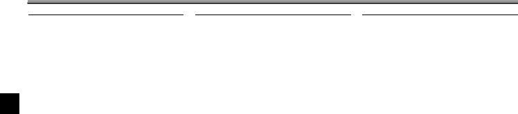
INSTRUMENT AND CONTROL FUNCTIONS
3
1. Brake lever
EAU00158
Brake lever
The brake lever is located at the right handlebar grip. To apply the front brake, pull the lever toward the handlebar grip.
1. Brake pedal
EAU00162
Brake pedal
The brake pedal is on the right side of the motorcycle. To apply the rear brake, press down on the brake pedal.
1.Fuel tank cap
2.Unlock.
EAU03756
Fuel tank cap
To remove the fuel tank cap
Insert the key into the lock and turn it 1/4 turn clockwise. The lock will be released and the fuel tank cap can be removed.
To install the fuel tank cap
1.Push the fuel tank cap into position with the key inserted in the lock.
2.Turn the key counterclockwise to the original position, and then remove it.
3-4
INSTRUMENT AND CONTROL FUNCTIONS
NOTE:
The fuel tank cap cannot be installed unless the key is in the lock. In addition, the key cannot be removed if the cap is not properly installed and locked.
EWA00032
 WARNING
Make sure that the fuel tank cap is properly installed before riding.
1.Fuel tank filler tube
2.Fuel level
EAU03753
Fuel
Make sure that there is sufficient fuel in the tank. Fill the fuel tank to the bottom of the filler tube as shown.
EW000130
 WARNING
●Do not overfill the fuel tank, otherwise it may overflow when the fuel warms up and expands.
●Avoid spilling fuel on the hot engine.
EAU00185
CAUTION:
@
Immediately wipe off spilled fuel with a clean, dry, soft cloth, since fuel may deteriorate painted surfaces or plastic parts.
@
EAU04194
3
Recommended fuel: UNLEADED FUEL ONLY
Fuel tank capacity: Total amount:
XV250 9.5 L
(2.1 Imp gal, 2.5 US gal) XV250C
9.2 L
(2.0 lmp gal, 2.4 US gal) Reserve amount:
2.6 L (0.6 Imp gal, 0.7 US gal)
ECA00102
CAUTION:
_
Use only unleaded gasoline. The use of leaded gasoline will cause severe damage to the engine internal parts such as valves, piston rings, exhaust system, etc.
INSTRUMENT AND CONTROL FUNCTIONS
Your Yamaha engine has been designed to use regular unleaded gasoline with a pump octane number [(R+M)/2] of 86 or higher, or a research octane number of 91 or higher. If knocking (or pinging) occurs, use a gasoline of a different brand or premi-
3um unleaded fuel. Use of unleaded fuel will extend spark plug life and reduce maintenance costs.
Gasohol
There are two types of gasohol: gasohol containing ethanol and that containing methanol. Gasohol containing ethanol can be used if the ethanol content does not exceed 10%. Gasohol containing methanol is not recommended by Yamaha because it can cause damage to the fuel system or vehicle performance problems.
ON: normal position
1. Arrow mark positioned over “ON”
EAU03236
Fuel cock
This motorcycle is equipped with a negative pressure fuel cock. The fuel cock supplies fuel from the tank to the carburetors while also filtering it.
The fuel cock lever positions are explained as follows and shown in the illustrations.
ON
With the fuel cock lever in this position, fuel flows to the carburetor when the engine is running. Turn the fuel cock lever to this position when starting the engine and riding.
RES: reserve position
1. Arrow mark positioned over “RES”
RES
This indicates reserve. With the fuel cock lever in this position, the fuel reserve is made available. Quickly turn the fuel cock lever to this position if you run out of fuel while riding, otherwise the engine may stall and will have to be primed (see “PRI”). After turning the fuel cock lever to “RES”, refuel as soon as possible and be sure to turn the fuel cock lever back to “ON”!
3-6
INSTRUMENT AND CONTROL FUNCTIONS
PRI: priming position
1. Arrow mark positioned over “PRI”
PRI
This indicates prime. With the fuel cock lever in this position, the engine can be “primed”. Turn the fuel cock lever to this position when the engine has been allowed to run out of fuel. This sends fuel directly to the carburetor, which will make starting easier. After the engine has started, be sure to turn the lever to “ON” (or “RES” if you have not refueled yet).
3
1. Starter (choke) lever
EAU00211
Starter (choke) lever
Starting a cold engine requires a richer air-fuel mixture, which is supplied by the starter (choke).
Move the lever in direction a to turn on the starter (choke).
Move the lever in direction b to turn off the starter (choke).
3-7
INSTRUMENT AND CONTROL FUNCTIONS
To unlock the steering
1.Open the steering lock cover, and then insert the key.
2.Push the key in, turn it 1/8 turn counterclockwise so that it moves out, and then release it.
3.Remove the key, and then close the lock cover.
1. Bolt (× 2)
|
EAU02934 |
EAU01072 |
|
|
Steering lock |
Rider seat |
|
|
To lock the steering |
To remove the rider seat |
|
|
1. |
Turn the handlebar all the way to |
Remove the bolts, and then pull the rid- |
|
right. |
er seat off. |
|
|
2. |
Open the steering lock cover, and |
|
|
then insert the key. |
||
|
3. |
Turn the key 1/8 turn counter- |
|
|
clockwise, push it in while turning |
||
|
the handlebar slightly to the left, |
||
|
and then turn the key 1/8 turn |
||
|
clockwise. |
||
|
4. |
Check that the steering is locked, |
|
|
remove the key, and then close |
||
|
the lock cover. |
3-8
INSTRUMENT AND CONTROL FUNCTIONS
1.Projection
2.Seat holder
To install the rider seat
1.Insert the projection on the front of the rider seat into the seat holder as shown.
2.Place the rider seat in the original position, and then tighten the bolts.
NOTE:
Make sure that the rider seat is properly secured before riding.
3
1.Helmet holder
2.Unlock.
EAU00260
Helmet holder
To open the helmet holder, insert the key into the lock, and then turn the key as shown.
To lock the helmet holder, place it in the original position, and then remove the key.
EW000030
 WARNING
Never ride with a helmet attached to the helmet holder, since the helmet may hit objects, causing loss of control and possibly an accident.
3-9
INSTRUMENT AND CONTROL FUNCTIONS
3
1.Spring preload adjusting ring
2.Position indicator
EAU00300
Adjusting the shock absorber assemblies
Each shock absorber assembly is equipped with a spring preload adjusting ring.
EC000015
CAUTION:
Never attempt to turn an adjusting mechanism beyond the maximum or minimum settings.
EW000040
 WARNING
Always adjust both shock absorber assemblies equally, otherwise poor handling and loss of stability may result.
Adjust the spring preload as follows. To increase the spring preload and thereby harden the suspension, turn the adjusting ring on each shock absorber assembly in direction a. To decrease the spring preload and thereby soften the suspension, turn the adjusting ring on each shock absorber assembly in direction b.
NOTE:
Align the appropriate notch in the adjusting ring with the position indicator on the shock absorber.
|
Setting |
|
|
Minimum (soft) |
1 |
|
Standard |
2 |
|
Maximum (hard) |
5 |
EAU00330
Sidestand
The sidestand is located on the left side of the frame. Raise the sidestand or lower it with your foot while holding the motorcycle upright.
NOTE:
@
The built-in sidestand switch is part of the ignition circuit cut-off system, which cuts the ignition in certain situations. (See further down for an explanation of the ignition circuit cut-off system.)
@
3-10
INSTRUMENT AND CONTROL FUNCTIONS
EW000044
 WARNING
The motorcycle must not be ridden with the sidestand down, or if the sidestand cannot be properly moved up (or does not stay up), otherwise the sidestand could contact the ground and distract the operator, resulting in a possible loss of control. Yamaha’s ignition circuit cut-off system has been designed to assist the operator in fulfilling the responsibility of raising the sidestand before starting off. Therefore, check this system regularly as described below and have a Yamaha dealer repair it if it does not function properly.
EAU03720
Ignition circuit cut-off system
The ignition circuit cut-off system (comprising the sidestand switch, clutch switch and neutral switch) has the following functions.
● It prevents starting when the trans-
mission is in gear and the side-
3
stand is up, but the clutch lever is not pulled.
●It prevents starting when the transmission is in gear and the clutch lever is pulled, but the sidestand is still down.
●It cuts the running engine when
the transmission is in gear and the sidestand is moved down.
Periodically check the operation of the ignition circuit cut-off system according to the following procedure.
EW000045
 WARNING
If a malfunction is noted, have a Yamaha dealer check the system before riding.
3-11
Если у вас отсутствует техническая возможность для скачивания Руководство по эксплуатации для Yamaha 2003 Virago 250
вы можете прочесть документ прямо на нашем сайте или
Скачать Yamaha 2003 Virago 250 Руководство по эксплуатации

- 1
- 2
- 3
- 4
- 5
- 6
- 7
- 8
- 9
- 10
- 11
- 12
- 13
- 14
- 15
- 16
- 17
- 18
- 19
- 20
- 21
- 22
- 23
- 24
- 25
- 26
- 27
- 28
- 29
- 30
- 31
- 32
- 33
- 34
- 35
- 36
- 37
- 38
- 39
- 40
- 41
- 42
- 43
- 44
- 45
- 46
- 47
- 48
- 49
- 50
- 51
- 52
- 53
- 54
- 55
- 56
- 57
- 58
- 59
- 60
- 61
- 62
- 63
- 64
- 65
- 66
- 67
- 68
- 69
- 70
- 71
- 72
- 73
- 74
- 75
- 76
- 77
- 78
- 79
- 80
- 81
- 82
- 83
- 84
- 85
- 86
- 87
- 88
- 89
- 90
- 91
- 92
- 93
- 94
- 95
- 96
- 97
- 98
Инструкции для прочих Yamaha Мотоциклы Star Motorcycles
Инструкции для прочих Yamaha
Меню сайта
-
Мотообъявления
-
Мануалы скачать
-
Мануалы читать
-
Обратная связь
-
Гостевая книга
-
Мотоновости
-
Фотоальбом
-
Микрофиши
-
Мотостатьи
| Поиск по сайту |
| Категории раздела | ||||||||||||||||||
|
| Статистика |
|
Онлайн всего: 1 Онлайн гостей: 1 Онлайн пользователей: 0 |
| Наш опрос |
|
В поездке документы на Ваш мотоцикл находятся Дома В кармане В мотоцикле Нет документов [ Результаты · Архив опросов ] Всего ответов: 248 мануалы для:[ИЖ П] |
 |
 |
 |
Воскресенье, 23.04.2023, 11:34 Приветствую Вас Гость | RSS | Вход |
| Все мото здесь!!! | |||
|
| Главная » Файлы » YAMAHA |
Virago XV250S
[  СКАЧАТЬ БЕСПЛАТНО МАНУАЛ ДЛЯ YAMAHA Virago XV250S (9.52 Mb) СКАЧАТЬ БЕСПЛАТНО МАНУАЛ ДЛЯ YAMAHA Virago XV250S (9.52 Mb)
] |
03.06.2014, 11:43 |
|
Название: Manual del Propietario Virago XV250S |
|
Категория: YAMAHA | Добавил: vsemoto |
|
| Просмотров: 1608 | Загрузок: 165
| Рейтинг: 0.0/0 |
Похожие файлы:
- XT225
- SR250G
- WR250FR
- RD350LC
- Diversion XJ400S
- SR500/XT500
- Virago XV535M/XV535MC
- SRX600
- Seca II XJ600SK/XJ600SKC
- Fazer FZS600
- FZ6-SS/FZ6-SSC 2004
- FZS600(P)
- YZF-R6L/YZF600RRL
- YZF-R6
- Drag Star XVS650L(C)/XVS650AL(C)
| Всего комментариев: 0 | |
Войдите:
![]()
2015-03-13
: Yamaha 2003-Virago-250-Owners-Manual yamaha-2003-virago-250-owners-manual-648369 yamaha pdf
Open the PDF directly: View PDF ![]() .
.
Page Count: 97
OWNER’S MANUAL

XV250R
XV250RC

YAMAHA MOTOR CO., LTD.

PRINTED ON RECYCLED PAPER

PRINTED IN JAPAN
2002.05-0.5×1 CR
(E)

LIT-11626-16-21

2UJ-28199-1B

EAU03438

E_U2UJ1B.book Page 1 Wednesday, May 29, 2002 1:56 PM

EAU00002

INTRODUCTION

Congratulations on your purchase of the Yamaha XV250/XV250C. This model is the
result of Yamaha’s vast experience in the production of fine sporting, touring, and
pacesetting racing machines. It represents the high degree of craftsmanship and
reliability that have made Yamaha a leader in these fields.
This manual will give you an understanding of the operation, inspection, and basic
maintenance of this motorcycle. If you have any questions concerning the operation
or maintenance of your motorcycle, please consult a Yamaha dealer.
The design and manufacture of this Yamaha motorcycle fully comply with the emissions standards for clean air applicable at the date of manufacture. Yamaha has met
these standards without reducing the performance or economy of operation of the
motorcycle. To maintain these high standards, it is important that you and your
Yamaha dealer pay close attention to the recommended maintenance schedules and
operating instructions contained within this manual.

E_U2UJ1B.book Page 1 Wednesday, May 29, 2002 1:56 PM

IMPORTANT MANUAL INFORMATION
Particularly important information is distinguished in this manual by the following notations:
The Safety Alert Symbol means ATTENTION! BECOME ALERT! YOUR SAFETY IS
INVOLVED!
Failure to follow WARNING instructions could result in severe injury or death to the
motorcycle operator, a bystander or a person inspecting or repairing the motorcycle.

WARNING

CAUTION:

A CAUTION indicates special precautions that must be taken to avoid damage to the
motorcycle.

NOTE:

A NOTE provides key information to make procedures easier or clearer.

NOTE:
● This manual should be considered a permanent part of this motorcycle and should remain
with it even if the motorcycle is subsequently sold.
● Yamaha continually seeks advancements in product design and quality. Therefore, while
this manual contains the most current product information available at the time of printing,
there may be minor discrepancies between your motorcycle and this manual. If you have
any questions concerning this manual, please consult your Yamaha dealer.
@

@

EAU00003

E_U2UJ1B.book Page 2 Wednesday, May 29, 2002 1:56 PM

IMPORTANT MANUAL INFORMATION
EW000000

WARNING
PLEASE READ THIS MANUAL AND THE “YOU AND YOUR MOTORCYCLE: RIDING
TIPS” BOOKLET CAREFULLY AND COMPLETELY BEFORE OPERATING THIS MOTORCYCLE. DO NOT ATTEMPT TO OPERATE THIS MOTORCYCLE UNTIL YOU HAVE ATTAINED ADEQUATE KNOWLEDGE OF ITS CONTROLS AND OPERATING FEATURES
AND UNTIL YOU HAVE BEEN TRAINED IN SAFE AND PROPER RIDING TECHNIQUES.
REGULAR INSPECTIONS AND CAREFUL MAINTENANCE, ALONG WITH GOOD RIDING
SKILLS, WILL ENSURE THAT YOU SAFELY ENJOY THE CAPABILITIES AND THE RELIABILITY OF THIS MOTORCYCLE.
@

@

E_U2UJ1B.book Page 3 Wednesday, May 29, 2002 1:56 PM

IMPORTANT MANUAL INFORMATION

AFFIX DEALER
LABEL HERE

EAU04247

XV250R/XV250RC
OWNER’S MANUAL
©2002 by Yamaha Motor Corporation, U.S.A.
1st edition, April 2002
All rights reserved.
Any reprinting or unauthorized use
without the written permission of
Yamaha Motor Corporation, U.S.A.
is expressly prohibited.
Printed in Japan.
P/N LIT-11626-16-21

E_U2UJ1B.book Page 1 Wednesday, May 29, 2002 1:56 PM

TABLE OF CONTENTS

EAU00009

1

SAFETY INFORMATION ....................................1-1
Safe riding ..........................................................1-1
Protective apparel ..............................................1-3
Modifications ......................................................1-3
Loading and accessories ...................................1-3
Gasoline and exhaust gas..................................1-5
Location of important labels ..............................1-7

2

DESCRIPTION ...................................................2-1
Left view ............................................................2-1
Right view ..........................................................2-2
Controls and instruments ..................................2-3

3

INSTRUMENT AND CONTROL FUNCTIONS ...3-1
Main switch .......................................................3-1
Indicator lights ...................................................3-1
Speedometer unit ..............................................3-2
Handlebar switches ...........................................3-2
Clutch lever .......................................................3-3
Shift pedal .........................................................3-3
Brake lever ........................................................3-4
Brake pedal .......................................................3-4
Fuel tank cap .....................................................3-4
Fuel ...................................................................3-5
Fuel cock ...........................................................3-6
Starter (choke) lever ..........................................3-7
Steering lock .....................................................3-8
Rider seat ..........................................................3-8

Helmet holder ....................................................3-9
Adjusting the shock absorber assemblies .......3-10
Sidestand ........................................................3-10
Ignition circuit cut-off system ...........................3-11

4

PRE-OPERATION CHECKS ...............................4-1
Pre-operation check list .....................................4-1

5

OPERATION AND IMPORTANT RIDING
POINTS ...............................................................5-1
Starting and warming up a cold engine .............5-2
Starting a warm engine .....................................5-3
Shifting ..............................................................5-4
Engine break-in .................................................5-5
Parking ..............................................................5-6

6

PERIODIC MAINTENANCE AND MINOR
REPAIR................................................................6-1
Periodic maintenance ........................................6-1
Owner’s tool kit ..................................................6-2
Periodic maintenance chart for the emission
control system ...............................................6-3
General maintenance and lubrication chart ......6-4
Checking the spark plugs ..................................6-6
Canister (for California only) .............................6-8
Engine oil and oil filter element .........................6-8
Cleaning the air filter element .........................6-11
Adjusting the carburetor ..................................6-13

E_U2UJ1B.book Page 2 Wednesday, May 29, 2002 1:56 PM

TABLE OF CONTENTS
Adjusting the throttle cable free play ............... 6-13
Adjusting the valve clearance ......................... 6-14
Tires ................................................................ 6-14
Spoke wheels .................................................. 6-16
Accessories and replacement parts ................ 6-16
Adjusting the clutch lever free play ................. 6-17
Adjusting the brake lever free play .................. 6-18
Adjusting the brake pedal position and free
play .............................................................. 6-18
Adjusting the rear brake light switch ............... 6-20
Checking the front brake pads and rear brake
shoes ........................................................... 6-20
Checking the brake fluid level ......................... 6-21
Changing the brake fluid ................................. 6-22
Drive chain slack ............................................. 6-22
Lubricating the drive chain .............................. 6-25
Checking and lubricating the cables ............... 6-25
Checking and lubricating the throttle grip and
cable ............................................................ 6-26
Checking and lubricating the brake and
shift pedals .................................................. 6-26
Checking and lubricating the brake and
clutch levers ................................................ 6-26
Checking and lubricating the sidestand .......... 6-27
Checking the front fork .................................... 6-27
Checking the steering ..................................... 6-28
Checking the wheel bearings .......................... 6-28
Battery ............................................................. 6-29

Replacing the fuses ........................................6-31
Replacing the headlight bulb ...........................6-32
Supporting the motorcycle .............................. 6-33
Front wheel .....................................................6-34
Rear wheel ......................................................6-36
Troubleshooting ..............................................6-37
Troubleshooting chart .....................................6-38

7

MOTORCYCLE CARE AND STORAGE ............. 7-1
Care .................................................................. 7-1
Storage ............................................................. 7-4

8

SPECIFICATIONS............................................... 8-1
Specifications .................................................... 8-1

9

CONSUMER INFORMATION.............................. 9-1
Identification numbers ....................................... 9-1
Key identification number .................................. 9-1
Vehicle identification number ............................ 9-1
Model label ........................................................ 9-2
REPORTING SAFETY DEFECTS .................... 9-3
MOTORCYCLE NOISE REGULATION ............ 9-4
Maintenance record .......................................... 9-5
Street and enduro motorcycle limited
warranty.......................................................... 9-7
Yamaha extended service (Y.E.S.) ................... 9-9

E_U2UJ1B.book Page 1 Wednesday, May 29, 2002 1:56 PM

SAFETY INFORMATION

EAU03633

1-

1

MOTORCYCLES ARE SINGLE TRACK VEHICLES. THEIR SAFE USE AND OPERATION ARE DEPENDENT UPON THE USE OF PROPER RIDING TECHNIQUES AS WELL AS THE EXPERTISE OF
THE OPERATOR. EVERY OPERATOR SHOULD KNOW THE FOLLOWING REQUIREMENTS BEFORE RIDING THIS MOTORCYCLE.
HE OR SHE SHOULD:
1. OBTAIN THOROUGH INSTRUCTIONS FROM A COMPETENT SOURCE ON ALL ASPECTS OF
MOTORCYCLE OPERATION.
2. OBSERVE THE WARNINGS AND MAINTENANCE REQUIREMENTS IN THE OWNER’S MANUAL.
3. OBTAIN QUALIFIED TRAINING IN SAFE AND PROPER RIDING TECHNIQUES.
4. OBTAIN PROFESSIONAL TECHNICAL SERVICE AS INDICATED BY THE OWNER’S MANUAL
AND/OR WHEN MADE NECESSARY BY MECHANICAL CONDITIONS.

Safe riding
1. Always make pre-operation checks. Careful checks may help prevent an accident.
2. This motorcycle is designed to carry the operator and a passenger.
3. The failure of motorists to detect and recognize motorcycles in traffic is the predominating cause of
automobile/motorcycle accidents. Many accidents have been caused by an automobile driver who
did not see the motorcycle. Making yourself conspicuous appears to be very effective in reducing the
chance of this type of accident.
Therefore:
a. Wear a brightly colored jacket.
b. Use extra caution when approaching and passing through intersections, since intersections are
the most likely places for motorcycle accidents to occur.
c. Ride where other motorists can see you. Avoid riding in another motorist’s blind spot.

1-1

E_U2UJ1B.book Page 2 Wednesday, May 29, 2002 1:56 PM

SAFETY INFORMATION
4. Many motorcycle accidents involve inexperienced operators. In fact, many operators who have been
involved in accidents do not even have a current motorcycle license.
a. Make sure that you are qualified and that you only lend your motorcycle to other qualified operators.
b. Know your skills and limits. Staying within your limits may help you to avoid an accident.
c. We recommend that you practice riding your motorcycle where there is no traffic until you have
become thoroughly familiar with the motorcycle and all of its controls.
5. Many motorcycle accidents have been caused by error of the motorcycle operator. A typical error
made by the operator is veering wide on a turn due to EXCESSIVE SPEED or undercornering (insufficient lean angle for the speed).
a. Always obey the speed limit and never travel faster than warranted by road and traffic conditions.
b. Always signal before turning or changing lanes. Make sure that other motorists can see you.
6. The posture of the operator and passenger is important for proper control.
a. The operator should keep both hands on the handlebar and both feet on the operator footrests
during operation to maintain control of the motorcycle.
b. The passenger should always hold onto the operator, seat strap, or grab bar, if equipped, with
both hands and keep both feet on the passenger footrests.
c. Never carry a passenger unless he or she can firmly place both feet on the passenger footrests.
7. Never ride under the influence of alcohol or other drugs.
8. This motorcycle is designed for on-road use only, therefore, it is not suitable for off-road use.

1-2

1

E_U2UJ1B.book Page 3 Wednesday, May 29, 2002 1:56 PM

SAFETY INFORMATION
Protective apparel
1

The majority of fatalities from motorcycle accidents are the result of head injuries. The use of a safety
helmet is the single most critical factor in the prevention or reduction of head injuries.
1. Always wear an approved helmet.
2. Wear a face shield or goggles. Wind in your unprotected eyes could contribute to an impairment of vision which could delay seeing a hazard.
3. The use of a jacket, heavy boots, trousers, gloves, etc., is effective in preventing or reducing abrasions or lacerations.
4. Never wear loose-fitting clothes, otherwise they could catch on the control levers, footrests, or wheels
and cause injury or an accident.
5. Never touch the engine or exhaust system during or after operation. They become very hot and can
cause burns. Always wear protective clothing that covers your legs, ankles, and feet.
6. Passengers should also observe the precautions mentioned above.

Modifications
Modifications made to this motorcycle not approved by Yamaha, or the removal of original equipment,
may render the motorcycle unsafe for use and may cause severe personal injury. Modifications may also
make your motorcycle illegal to use.

Loading and accessories
Adding accessories or cargo to your motorcycle can adversely affect stability and handling if the weight
distribution of the motorcycle is changed. To avoid the possibility of an accident, use extreme caution
when adding cargo or accessories to your motorcycle. Use extra care when riding a motorcycle that has
added cargo or accessories. Here are some general guidelines to follow if loading cargo or adding accessories to your motorcycle:
1-3

E_U2UJ1B.book Page 4 Wednesday, May 29, 2002 1:56 PM

SAFETY INFORMATION
Loading
The total weight of the operator, passenger, accessories and cargo must not exceed the maximum load
limit of XV250: 432 lb (196 kg) / XV250C: 430 lb (195 kg). When loading within this weight limit, keep the
following in mind:
1. Cargo and accessory weight should be kept as low and close to the motorcycle as possible. Make
sure to distribute the weight as evenly as possible on both sides of the motorcycle to minimize imbalance or instability.
2. Shifting weights can create a sudden imbalance. Make sure that accessories and cargo are securely
attached to the motorcycle before riding. Check accessory mounts and cargo restraints frequently.
3. Never attach any large or heavy items to the handlebar, front fork, or front fender. These items, including such cargo as sleeping bags, duffel bags, or tents, can create unstable handling or slow
steering response.
Accessories
Genuine Yamaha accessories have been specifically designed for use on this motorcycle. Since
Yamaha cannot test all other accessories that may be available, you must personally be responsible for
the proper selection, installation and use of non-Yamaha accessories. Use extreme caution when selecting and installing any accessories.
Keep the following guidelines in mind, as well as those provided under “Loading” when mounting accessories.
1. Never install accessories or carry cargo that would impair the performance of your motorcycle. Carefully inspect the accessory before using it to make sure that it does not in any way reduce ground
clearance or cornering clearance, limit suspension travel, steering travel or control operation, or obscure lights or reflectors.

1-4

1

E_U2UJ1B.book Page 5 Wednesday, May 29, 2002 1:56 PM

SAFETY INFORMATION

1

a. Accessories fitted to the handlebar or the front fork area can create instability due to improper
weight distribution or aerodynamic changes. If accessories are added to the handlebar or front
fork area, they must be as lightweight as possible and should be kept to a minimum.
b. Bulky or large accessories may seriously affect the stability of the motorcycle due to aerodynamic
effects. Wind may attempt to lift the motorcycle, or the motorcycle may become unstable in cross
winds. These accessories may also cause instability when passing or being passed by large vehicles.
c. Certain accessories can displace the operator from his or her normal riding position. This improper position limits the freedom of movement of the operator and may limit control ability, therefore,
such accessories are not recommended.
2. Use caution when adding electrical accessories. If electrical accessories exceed the capacity of the
motorcycle’s electrical system, an electric failure could result, which could cause a dangerous loss of
lights or engine power.

Gasoline and exhaust gas
1. GASOLINE IS HIGHLY FLAMMABLE:
a. Always turn the engine off when refueling.
b. Take care not to spill any gasoline on the engine or exhaust system when refueling.
c. Never refuel while smoking or in the vicinity of an open flame.
2. Never start the engine or let it run for any length of time in a closed area. The exhaust fumes are poisonous and may cause loss of consciousness and death within a short time. Always operate your
motorcycle in an area that has adequate ventilation.
3. Always turn the engine off before leaving the motorcycle unattended and remove the key from the
main switch. When parking the motorcycle, note the following:

1-5

E_U2UJ1B.book Page 6 Wednesday, May 29, 2002 1:56 PM

SAFETY INFORMATION
a. The engine and exhaust system may be hot, therefore, park the motorcycle in a place where pedestrians or children are not likely to touch these hot areas.
b. Do not park the motorcycle on a slope or soft ground, otherwise it may fall over.
c. Do not park the motorcycle near a flammable source (e.g. a kerosene heater, or near an open
flame), otherwise it could catch fire.
4. When transporting the motorcycle in another vehicle, make sure that it is kept upright and that the fuel
cock is turned to “ON” or “RES” (for vacuum type) / “OFF” (for manual type). If it should lean over,
gasoline may leak out of the carburetor or fuel tank.
5. If you should swallow any gasoline, inhale a lot of gasoline vapor, or allow gasoline to get into your
eyes, see your doctor immediately. If any gasoline spills on your skin or clothing, immediately wash
the affected area with soap and water and change your clothes.

1-6

1

E_U2UJ1B.book Page 7 Wednesday, May 29, 2002 1:56 PM

SAFETY INFORMATION
EAU02977

Location of important labels
1

Please read the following important labels carefully before operating this motorcycle.

1-7

E_U2UJ1B.book Page 8 Wednesday, May 29, 2002 1:56 PM

SAFETY INFORMATION
1

4

California only
1

2

5

3

1-8

California only

E_U2UJ1B.book Page 1 Wednesday, May 29, 2002 1:56 PM

DESCRIPTION

EAU00026

2-

Left view

2

1. Headlight
2. Steering lock
3. Fuel tank
4. Battery
5. Fuses
6. Helmet holder

7. Shock absorber assembly spring
preload adjusting ring
8. Main switch
9. Fuel cock
10. Shift pedal

(page 6-32)
(page 3-8)
(page 3-4)
(page 6-29)
(page 6-31)
(page 3-9)

2-1

(page 3-10)
(page 3-1)
(page 3-6)
(page 3-3)

E_U2UJ1B.book Page 2 Wednesday, May 29, 2002 1:56 PM

DESCRIPTION
Right view

2

11. Tail/brake light
12. Rear turn signal light
13. Rider seat
14. Air filter element

15. Front turn signal/position light
16. Brake pedal
17. Footrest
18. Owner’s tool kit
19. Shock absorber assembly spring
preload adjusting ring

(page 3-8)
(page 6-11)

2-2

(page 3-4)
(page 6-2)
(page 3-10)

E_U2UJ1B.book Page 3 Wednesday, May 29, 2002 1:56 PM

DESCRIPTION
Controls and instruments

2

1. Clutch lever
2. Left handlebar switches
3. Speedometer unit
4. Indicator lights

5. Right handlebar switches
6. Brake lever
7. Throttle grip
8. Fuel tank cap

(page 3-3)
(page 3-2)
(page 3-2)
(page 3-1)

2-3

(page 3-3)
(page 3-4)
(page 6-13)
(page 3-4)

E_U2UJ1B.book Page 1 Wednesday, May 29, 2002 1:56 PM

INSTRUMENT AND CONTROL FUNCTIONS

EAU00027

3-

EAU00050

P (Parking)
The taillight and position lights are on,
but all other electrical systems are off.
The key can be removed.
The key must be pushed in from the
“OFF” position to be turned to “P”.
ECA00043

CAUTION:
Do not use the parking position for
an extended length of time, otherwise the battery may discharge.

3

@

EAU00028

Main switch
The main switch controls the ignition
and lighting systems. The various main
switch positions are described below.

1. High beam indicator light “HIGH BEAM”
2. Neutral indicator light “NEUTRAL”
3. Turn signal indicator light “TURN”
EAU00056

@

Indicator lights
EAU00064

High beam indicator light
“HIGH BEAM”
This indicator light comes on when the
high beam of the headlight is switched
on.

EAU00032

ON
All electrical systems are supplied with
power, the headlight, meter lighting,
taillight and front position lights come
on, and the engine can be started. The
key cannot be removed.

EAU00062

Neutral indicator light “NEUTRAL”
This indicator light comes on when the
transmission is in the neutral position.
EAU00059

Turn signal indicator light “TURN”
This indicator light flashes when the
turn signal switch is pushed to the left
or right.

EAU00038

OFF
All electrical systems are off. The key
can be removed.
3-1

E_U2UJ1B.book Page 2 Wednesday, May 29, 2002 1:56 PM

INSTRUMENT AND CONTROL FUNCTIONS
ter position. To cancel the turn signal
lights, push the switch in after it has returned to the center position.
EAU00130

Horn switch “HORN”
Press this switch to sound the horn.
3
1.
2.
3.
4.

Odometer
Tripmeter
Tripmeter reset knob
Speedometer

1. Dimmer switch “LIGHTS”
2. Turn signal switch “TURN”
3. Horn switch “HORN”
EAU00118
EAU00095

Speedometer unit
The speedometer unit is equipped with
a speedometer, an odometer and a
tripmeter. The speedometer shows
riding speed. The odometer shows the
total distance traveled. The tripmeter
shows the distance traveled since it
was last set to zero with the reset knob.
The tripmeter can be used to estimate
the distance that can be traveled with a
full tank of fuel. This information will enable you to plan future fuel stops.

Handlebar switches
EAU00122

Dimmer switch “LIGHTS”
Set the switch to “HI” for the high beam
and to “LO” for the low beam.
EAU00125

Turn signal switch “TURN”
To signal a right-hand turn, push this
switch to the right. To signal a left-hand
turn, push this switch to the left. When
released, the switch returns to the cen-

3-2

E_U2UJ1B.book Page 3 Wednesday, May 29, 2002 1:56 PM

INSTRUMENT AND CONTROL FUNCTIONS

3
1. Engine stop switch “ENGINE STOP”
2. Start switch “START”

1. Clutch lever

1. Shift pedal
EAU00152

EAU04822

Engine stop switch “ENGINE STOP”
Set this switch to “RUN” before starting
the engine. Set this switch to “OFF” to
stop the engine in case of an emergency, such as when the motorcycle overturns or when the throttle cable is
stuck.
EAU00141

Start switch “START”
Push this switch to crank the engine
with the starter.
EC000005

EAU00157

Clutch lever

Shift pedal

The clutch lever is located at the left
handlebar grip. To disengage the
clutch, pull the lever toward the handlebar grip. To engage the clutch, release
the lever. The lever should be pulled
rapidly and released slowly for smooth
clutch operation.
The clutch lever is equipped with a
clutch switch, which is part of the ignition circuit cut-off system. (See page
3-11 for an explanation of the ignition
circuit cut-off system.)

The shift pedal is located on the left
side of the engine and is used in combination with the clutch lever when
shifting the gears of the 5-speed constant-mesh transmission equipped on
this motorcycle.

CAUTION:
See page 5-2 for starting instructions prior to starting the engine.
@

@

3-3

E_U2UJ1B.book Page 4 Wednesday, May 29, 2002 1:56 PM

INSTRUMENT AND CONTROL FUNCTIONS

3
1. Brake lever

1. Brake pedal
EAU00158

EAU00162

Brake lever

Brake pedal

The brake lever is located at the right
handlebar grip. To apply the front
brake, pull the lever toward the handlebar grip.

The brake pedal is on the right side of
the motorcycle. To apply the rear
brake, press down on the brake pedal.

1. Fuel tank cap
2. Unlock.
EAU03712

Fuel tank cap
To open the fuel tank cap
Insert the key into the lock and turn it
1/4 turn clockwise. The lock will be released and the fuel tank cap can be
opened.
To close the fuel tank cap
1. Push the fuel tank cap into position with the key inserted in the
lock.
2. Turn the key counterclockwise to
the original position, and then remove it.

3-4

E_U2UJ1B.book Page 5 Wednesday, May 29, 2002 1:56 PM

INSTRUMENT AND CONTROL FUNCTIONS
EAU00185

NOTE:
The fuel tank cap cannot be closed unless the key is in the lock. In addition,
the key cannot be removed if the cap is
not properly closed and locked.
_

CAUTION:
Immediately wipe off spilled fuel
with a clean, dry, soft cloth, since
fuel may deteriorate painted surfaces or plastic parts.
@

_

EWA00025

@

WARNING
Make sure that the fuel tank cap is
properly closed before riding.

EAU04265

_

_

1. Fuel tank filler tube
2. Fuel level
EAU03753

Fuel
Make sure that there is sufficient fuel in
the tank. Fill the fuel tank to the bottom
of the filler tube as shown.
EW000130

_

WARNING
● Do not overfill the fuel tank, otherwise it may overflow when the
fuel warms up and expands.
● Avoid spilling fuel on the hot
engine.

_

3-5

Recommended fuel:
UNLEADED GASOLINE ONLY
Fuel tank capacity:
Total amount:
XV250
9.5 L
(2.1 Imp gal, 2.5 US gal)
XV250C
9.2 L
(2.0 lmp gal, 2.4 US gal)
Reserve amount:
2.6 L (0.6 Imp gal, 0.7 US gal)

3

E_U2UJ1B.book Page 6 Wednesday, May 29, 2002 1:56 PM

INSTRUMENT AND CONTROL FUNCTIONS
ECA00104

CAUTION:
Use only unleaded gasoline. The
use of leaded gasoline will cause severe damage to internal engine
parts, such as the valves and piston
rings, as well as to the exhaust system.
_

3

_

Your Yamaha engine has been designed to use regular unleaded gasoline with a pump octane number
[(R+M)/2] of 86 or higher, or a research
octane number of 91 or higher. If
knocking (or pinging) occurs, use a
gasoline of a different brand or premium unleaded fuel. Use of unleaded fuel
will extend spark plug life and reduce
maintenance costs.

Gasohol
There are two types of gasohol: gasohol containing ethanol and that containing methanol. Gasohol containing
ethanol can be used if the ethanol content does not exceed 10%. Gasohol
containing methanol is not recommended by Yamaha because it can
cause damage to the fuel system or vehicle performance problems.

ON: normal position

1. Arrow mark positioned over “ON”
EAU04484

Fuel cock
This motorcycle is equipped with a
negative pressure fuel cock. The fuel
cock supplies fuel from the tank to the
carburetor while also filtering it.
The fuel cock lever positions are explained as follows and shown in the illustrations.
ON
With the fuel cock lever in this position,
fuel flows to the carburetor when the
engine is running. Turn the fuel cock lever to this position when starting the
engine and riding.
3-6

E_U2UJ1B.book Page 7 Wednesday, May 29, 2002 1:56 PM

INSTRUMENT AND CONTROL FUNCTIONS
RES: reserve position

PRI: priming position

3
1. Arrow mark positioned over “RES”

1. Arrow mark positioned over “PRI”

RES
This indicates reserve. With the fuel
cock lever in this position, the fuel reserve is made available. Quickly turn
the fuel cock lever to this position if you
run out of fuel while riding, otherwise
the engine may stall and will have to be
primed (see “PRI”). After turning the
fuel cock lever to “RES”, refuel as soon
as possible and be sure to turn the fuel
cock lever back to “ON”!

PRI
This indicates prime. With the fuel cock
lever in this position, the engine can be
“primed”. Turn the fuel cock lever to
this position when the engine has been
allowed to run out of fuel. This sends
fuel directly to the carburetor, which will
make starting easier. After the engine
has started, be sure to turn the lever to
“ON” (or “RES” if you have not refueled
yet).

3-7

1. Starter (choke) lever
EAU00211

Starter (choke) lever
Starting a cold engine requires a richer
air-fuel mixture, which is supplied by
the starter (choke).
Move the lever in direction a to turn on
the starter (choke).
Move the lever in direction b to turn off
the starter (choke).

E_U2UJ1B.book Page 8 Wednesday, May 29, 2002 1:56 PM

INSTRUMENT AND CONTROL FUNCTIONS
To unlock the steering
1. Open the steering lock cover, and
then insert the key.
2. Push the key in, turn it 1/8 turn
counterclockwise so that it moves
out, and then release it.
3. Remove the key, and then close
the lock cover.

3
1. Steering lock

1. Bolt (× 2)
EAU02934

EAU01072

Steering lock

Rider seat

To lock the steering
1. Turn the handlebar all the way to
right.
2. Open the steering lock cover, and
then insert the key.
3. Turn the key 1/8 turn counterclockwise, push it in while turning
the handlebar slightly to the left,
and then turn the key 1/8 turn
clockwise.
4. Check that the steering is locked,
remove the key, and then close
the lock cover.

To remove the rider seat
Remove the bolts, and then pull the rider seat off.

3-8

E_U2UJ1B.book Page 9 Wednesday, May 29, 2002 1:56 PM

INSTRUMENT AND CONTROL FUNCTIONS

3
1. Projection
2. Seat holder

To install the rider seat
1. Insert the projection on the front of
the rider seat into the seat holder
as shown.
2. Place the rider seat in the original
position, and then tighten the
bolts.
NOTE:
Make sure that the rider seat is properly secured before riding.

1. Helmet holder
2. Unlock.
EAU00260

Helmet holder
To open the helmet holder, insert the
key into the lock, and then turn the key
as shown.
To lock the helmet holder, place it in
the original position, and then remove
the key.
EW000030

@

@

WARNING
Never ride with a helmet attached to
the helmet holder, since the helmet
may hit objects, causing loss of
control and possibly an accident.
@

@

3-9

E_U2UJ1B.book Page 10 Wednesday, May 29, 2002 1:56 PM

INSTRUMENT AND CONTROL FUNCTIONS
EAU00330

EW000040

WARNING
Always adjust both shock absorber
assemblies equally, otherwise poor
handling and loss of stability may
result.
@

Sidestand
The sidestand is located on the left side
of the frame. Raise the sidestand or
lower it with your foot while holding the
motorcycle upright.

@

3
1. Spring preload adjusting ring
2. Position indicator
EAU00300

Adjusting the shock absorber
assemblies
Each shock absorber assembly is
equipped with a spring preload adjusting ring.
EC000015

CAUTION:
Never attempt to turn an adjusting
mechanism beyond the maximum
or minimum settings.
@

Adjust the spring preload as follows.
To increase the spring preload and
thereby harden the suspension, turn
the adjusting ring on each shock absorber assembly in direction a. To decrease the spring preload and thereby
soften the suspension, turn the adjusting ring on each shock absorber assembly in direction b.
NOTE:
Align the appropriate notch in the adjusting ring with the position indicator
on the shock absorber.
@

@

CI-10E

Setting

@

Minimum (soft)

1

Standard

2

Maximum (hard)

5

3-10

NOTE:
The built-in sidestand switch is part of
the ignition circuit cut-off system, which
cuts the ignition in certain situations.
(See further down for an explanation of
the ignition circuit cut-off system.)
@

@

E_U2UJ1B.book Page 11 Wednesday, May 29, 2002 1:56 PM

INSTRUMENT AND CONTROL FUNCTIONS
EW000044

WARNING
The motorcycle must not be ridden
with the sidestand down, or if the
sidestand cannot be properly
moved up (or does not stay up), otherwise the sidestand could contact
the ground and distract the operator, resulting in a possible loss of
control. Yamaha’s ignition circuit
cut-off system has been designed to
assist the operator in fulfilling the
responsibility of raising the sidestand before starting off. Therefore,
check this system regularly as described below and have a Yamaha
dealer repair it if it does not function
properly.
@

@

EAU03720

Ignition circuit cut-off system
The ignition circuit cut-off system (comprising the sidestand switch, clutch
switch and neutral switch) has the following functions.
● It prevents starting when the transmission is in gear and the sidestand is up, but the clutch lever is
not pulled.
● It prevents starting when the transmission is in gear and the clutch
lever is pulled, but the sidestand is
still down.
● It cuts the running engine when
the transmission is in gear and the
sidestand is moved down.
Periodically check the operation of the
ignition circuit cut-off system according
to the following procedure.
EW000045

WARNING
If a malfunction is noted, have a
Yamaha dealer check the system
before riding.
_

_

3-11

3

E_U2UJ1B.book Page 12 Wednesday, May 29, 2002 1:56 PM

INSTRUMENT AND CONTROL FUNCTIONS
CD-01E

NOTE:
This check is most reliable if performed with
a warmed-up engine.

With the engine turned off:
1. Move the sidestand down.
2. Make sure that the engine stop switch is set to “RUN”.
3. Turn the key to “ON”.
4. Shift the transmission into the neutral position.
5. Push the start switch.
Does the engine start?

3

YES

NO

The neutral switch may be defective.
The motorcycle should not be ridden until
checked by a Yamaha dealer.

NO

The sidestand switch may be defective.
The motorcycle should not be ridden until
checked by a Yamaha dealer.

NO

The clutch switch may be defective.
The motorcycle should not be ridden until
checked by a Yamaha dealer.

With the engine still running:
6. Move the sidestand up.
7. Keep the clutch lever pulled.
8. Shift the transmission into gear.
9. Move the sidestand down.
Does the engine stall?

YES
After the engine has stalled:
10. Move the sidestand up.
11. Keep the clutch lever pulled.
12. Push the start switch.
Does the engine start?

YES

The system is OK. The motorcycle can be ridden.

3-12

E_U2UJ1B.book Page 1 Wednesday, May 29, 2002 1:56 PM

PRE-OPERATION CHECKS

EAU01114

4-

The condition of a vehicle is the owner’s responsibility. Vital components can start to deteriorate quickly and unexpectedly,
even if the vehicle remains unused (for example, as a result of exposure to the elements). Any damage, fluid leakage or loss
of tire air pressure could have serious consequences. Therefore, it is very important, in addition to a thorough visual inspection, to check the following points before each ride.
EAU03439

Pre-operation check list
CO-01E

ITEM
Fuel

Engine oil

Front brake

Rear brake

Clutch

Throttle grip

Control cables

CHECKS
Check fuel level in fuel tank.
Refuel if necessary.
Check fuel line for leakage.
Check oil level in engine.
If necessary, add recommended oil to specified level.
Check vehicle for oil leakage.
Check operation.
If soft or spongy, have Yamaha dealer bleed hydraulic system.
Check lever free play.
Adjust if necessary.
Check fluid level in reservoir.
If necessary, add recommended brake fluid to specified level.
Check hydraulic system for leakage.
Check operation.
Check pedal free play.
Adjust if necessary.
Check operation.
Lubricate cable if necessary.
Check lever free play.
Adjust if necessary.
Make sure that operation is smooth.
Check cable free play.
If necessary, have Yamaha dealer adjust cable free play and lubricate cable and
grip housing.
• Make sure that operation is smooth.
• Lubricate if necessary.

•
•
•
•
•
•
•
•
•
•
•
•
•
•
•
•
•
•
•
•
•
•
•

4-1

PAGE
3-5

4
6-8–6-9

6-18, 6-20–6-22

6-18–6-21

6-17

6-13

6-25

E_U2UJ1B.book Page 2 Wednesday, May 29, 2002 1:56 PM

PRE-OPERATION CHECKS
ITEM
Drive chain

Wheels and tires

Brake and shift pedals
Brake and clutch levers

4

Sidestand
Chassis fasteners
Instruments, lights, signals
and switches
Sidestand switch
Battery

•
•
•
•
•
•
•
•
•
•
•
•
•
•
•
•
•
•
•
•
•
•

CHECKS
Check chain slack.
Adjust if necessary.
Check chain condition.
Lubricate if necessary.
Check for damage.
Check tire condition and tread depth.
Check air pressure.
Correct if necessary.
Make sure that operation is smooth.
Lubricate pedal pivoting points if necessary.
Make sure that operation is smooth.
Lubricate lever pivoting points if necessary.
Make sure that operation is smooth.
Lubricate pivot if necessary.
Make sure that all nuts, bolts and screws are properly tightened.
Tighten if necessary.
Check operation.
Correct if necessary.
Check operation of ignition circuit cut-off system.
If system is defective, have Yamaha dealer check vehicle.
Check fluid level.
Fill with distilled water if necessary.

PAGE
6-22–6-23

6-14–6-16

6-26
6-26
6-27
—
—
3-10–3-11
6-29–6-30

NOTE:
Pre-operation checks should be made each time the motorcycle is used. Such an inspection can be accomplished in a very
short time; and the added safety it assures is more than worth the time involved.
_

_

EWA00033

WARNING
If any item in the Pre-operation check list is not working properly, have it inspected and repaired before operating
the motorcycle.
_

_

4-2

E_U2UJ1B.book Page 1 Wednesday, May 29, 2002 1:56 PM

EAU00372
5-

@

OPERATION AND IMPORTANT RIDING POINTS

EAU00373

EAU00376

WARNING
● Become thoroughly familiar
with all operating controls and
their functions before riding.
Consult a Yamaha dealer regarding any control or function
that you do not thoroughly
understand.
● Never start the engine or operate
it in a closed area for any length
of time. Exhaust fumes are poisonous, and inhaling them can
cause loss of consciousness
and death within a short time. Always make sure that there is adequate ventilation.
● Before starting out, make sure
that the sidestand is up. If the
sidestand is not raised completely, it could contact the
ground and distract the operator, resulting in a possible loss
of control.

CAUTION:
● Make sure not to store personal
items near the air cleaner intake, otherwise air intake will be
blocked and performance will
suffer.
● Make sure not to put anything
near the battery and its terminals, otherwise electrical failure
and acid corrosion may result.

@

@

5

@

5-1

E_U2UJ1B.book Page 2 Wednesday, May 29, 2002 1:56 PM

OPERATION AND IMPORTANT RIDING POINTS
EAU04683

Starting and warming up a
cold engine
In order for the ignition circuit cut-off
system to enable starting, one of the
following conditions must be met:
● The transmission is in the neutral
position.
● The transmission is in gear with
the clutch lever pulled and the
sidestand up.

1. Turn the fuel cock lever to “ON”.
2. Turn the key to “ON” and make
sure that the engine stop switch is
set to “RUN”.
3. Shift the transmission into the neutral position.

4. Turn the starter (choke) on and
completely close the throttle. (See
page 3-7 for starter (choke) operation.)
5. Start the engine by pushing the
start switch.

NOTE:
When the transmission is in the neutral
position, the neutral indicator light
should be on, otherwise have a
Yamaha dealer check the electrical circuit.

NOTE:
If the engine fails to start, release the
start switch, wait a few seconds, and
then try again. Each starting attempt
should be as short as possible to preserve the battery. Do not crank the engine more than 10 seconds on any one
attempt.

EW000054

5
_

WARNING
Before starting the engine,
check the function of the ignition circuit cut-off system according to the procedure
described on page 3-12.
● Never ride with the sidestand
down.
●

_

_

_

_

_

5-2

E_U2UJ1B.book Page 3 Wednesday, May 29, 2002 1:56 PM

OPERATION AND IMPORTANT RIDING POINTS
6. After starting the engine, move the
starter (choke) back halfway.
ECA00055

utes with the starter (choke) in the halfway position.
_

CAUTION:
For maximum engine life, always
warm the engine up before starting
off. Never accelerate hard when the
engine is cold!
_

EAU01258

Starting a warm engine
Follow the same procedure as for starting a cold engine with the exception
that the starter (choke) is not required
when the engine is warm.

_

7. When the engine is warm, turn the
starter (choke) off.
NOTE:
The engine is warm when it responds
normally to the throttle with the starter
(choke) turned off. To avoid the possibility of excessive exhaust emissions,
never leave the starter (choke) on longer than necessary. The time necessary
for starter (choke) use depends upon
the ambient temperature. Temperatures above 10 °C (50 °F) require about
7 seconds of starter (choke) use and
temperatures below 10 °C (50 °F) require about 35 seconds with the starter
(choke) turned on, then about 2.5 min-

5

_

5-3

E_U2UJ1B.book Page 4 Wednesday, May 29, 2002 1:56 PM

OPERATION AND IMPORTANT RIDING POINTS
EC000048

@

1. Shift pedal
N. Neutral position
EAU00423

5

Shifting
Shifting gears lets you control the
amount of engine power available for
starting off, accelerating, climbing hills,
etc.
The gear positions are shown in the
illustration.

CAUTION:
● Even with the transmission in
the neutral position, do not
coast for long periods of time
with the engine off, and do not
tow the motorcycle for long distances. The transmission is
properly lubricated only when
the engine is running. Inadequate lubrication may damage
the transmission.
● Always use the clutch while
changing gears to avoid damaging the engine, transmission,
and drive train, which are not
designed to withstand the
shock of forced shifting.

@

NOTE:
To shift the transmission into the neutral position, press the shift pedal down
repeatedly until it reaches the end of its
travel, and then slightly raise it.
@

EAU02988

To start out and accelerate
1. Pull the clutch lever to disengage
the clutch.
2. Shift the transmission into first
gear. The neutral indicator light
should go out.
3. Open the throttle gradually, and at
the same time, release the clutch
lever slowly.
4. At the recommended shift points
shown in the table on page 5-5,
close the throttle, and at the same
time, quickly pull the clutch lever
in.
5. Shift the transmission into second
gear. (Make sure not to shift the
transmission into the neutral
position.)
6. Open the throttle part way and
gradually release the clutch lever.
7. Follow the same procedure when
shifting to the next higher gear.
NOTE:
Always shift gears at the recommended shift points.
@

@

@

5-4

E_U2UJ1B.book Page 5 Wednesday, May 29, 2002 1:56 PM

OPERATION AND IMPORTANT RIDING POINTS
EAU00427

EAU02974

To decelerate
1. Apply both the front and the rear
brakes to slow the motorcycle.
2. Shift the transmission into first
gear when the motorcycle reaches
20 km/h (12.5 mi/h). If the engine
is about to stall or runs very roughly, pull the clutch lever in and use
the brakes to stop the motorcycle.
3. Shift the transmission into the neutral position when the motorcycle
is almost completely stopped. The
neutral indicator light should come
on.

Recommended shift points
The recommended shift points during
acceleration and deceleration are
shown in the table below.
CF-04E

1st
2nd
3rd
4th

→
→
→
→

2nd
3rd
4th
5th

Acceleration
shift point
km/h (mi/h)

Deceleration
shift point
km/h (mi/h)

16 (9.9)
24 (14.9)
32 (19.9)
40 (24.9)

20 (12.5)
20 (12.5)
20 (12.5)
20 (12.5)

5-5

EAU01128

Engine break-in
There is never a more important period
in the life of your engine than the period
between 0 and 1,600 km (1,000 mi).
For this reason, you should read the
following material carefully.
Since the engine is brand new, do not
put an excessive load on it for the first
1,600 km (1,000 mi). The various parts
in the engine wear and polish themselves to the correct operating clearances. During this period, prolonged
full-throttle operation or any condition
that might result in engine overheating
must be avoided.

5

E_U2UJ1B.book Page 6 Wednesday, May 29, 2002 1:56 PM

OPERATION AND IMPORTANT RIDING POINTS
EAU00452*

0–1,000 km (0–600 mi)
Avoid prolonged operation
1/3 throttle.

EAU00460

Parking
above

When parking, stop the engine, and
then remove the key from the main
switch.

1,000–1,600 km (600–1,000 mi)
Avoid prolonged operation above
1/2 throttle.

EW000058

@

1,600 km and beyond
The vehicle can now be operated normally.
5

EC000059*

_

CAUTION:
● After 1,000 km (600 mi) of operation, the engine oil must be
changed, the oil filter element
replaced, and the oil strainer
cleaned.
● If any engine trouble should occur during the engine break-in
period, immediately have a
Yamaha dealer check the vehicle.

WARNING
Since the engine and exhaust
system can become very hot,
park in a place where pedestrians or children are not likely to
touch them.
● Do not park on a slope or on
soft ground, otherwise the
motorcycle may overturn.
●

@

_

5-6

E_U2UJ1B.book Page 1 Wednesday, May 29, 2002 1:56 PM

PERIODIC MAINTENANCE AND MINOR REPAIR

EAU00462

6-

EAU01790

Safety is an obligation of the owner.
Periodic inspection, adjustment and lubrication will keep your vehicle in the
safest and most efficient condition possible. The most important points of
motorcycle inspection, adjustment, and
lubrication are explained on the following pages.
Maintenance, replacement, or repair
of the emission control devices and
systems may be performed by any
repair establishment or individual
that is certified (if applicable).
EW000060

WARNING
If you are not familiar with motorcycle maintenance work, have a
Yamaha dealer do it for you.
@

@

EAU00467

PERIODIC MAINTENANCE
PROPER PERIODIC MAINTENANCE
OF YOUR MOTORCYCLE IS IMPORTANT IN ORDER TO ENJOY LONG,
PLEASURABLE SERVICE. ESPECIALLY IMPORTANT ARE THE
MAINTENANCE SERVICES RELATED TO EMISSIONS CONTROL.
THESE CONTROLS NOT ONLY
FUNCTION TO ENSURE CLEANER
AIR, BUT ARE ALSO VITAL TO
PROPER ENGINE OPERATION AND
MAXIMUM PERFORMANCE. IN THE
FOLLOWING PERIODIC MAINTENANCE CHARTS, THE SERVICES
RELATED TO EMISSIONS CONTROL ARE GROUPED SEPARATELY. THESE SERVICES REQUIRE
SPECIALIZED DATA, KNOWLEDGE,
AND EQUIPMENT. YAMAHA DEALERS ARE TRAINED AND EQUIPPED
TO PERFORM THESE PARTICULAR
SERVICES.

6-1

6

E_U2UJ1B.book Page 2 Wednesday, May 29, 2002 1:56 PM

PERIODIC MAINTENANCE AND MINOR REPAIR
EW000062

WARNING
Modifications not approved by
Yamaha may cause loss of performance, excessive emissions, and
render the vehicle unsafe for use.
Consult a Yamaha dealer before attempting any changes.
@

@

1. Owner’s tool kit
EAU00468

Owner’s tool kit

6

The service information included in this
manual and the tools provided in the
owner’s tool kit are intended to assist
you in the performance of preventive
maintenance and minor repairs. However, additional tools such as a torque
wrench may be necessary to perform
certain maintenance work correctly.
NOTE:
If you do not have the tools or experience required for a particular job, have
a Yamaha dealer perform it for you.
@

@

6-2

E_U2UJ1B.book Page 3 Wednesday, May 29, 2002 1:56 PM

PERIODIC MAINTENANCE AND MINOR REPAIR
EAU00471

Periodic maintenance chart for the emission control system
No.

ITEM

ROUTINE

INITIAL
600 mi
(1,000km)
or
1 month

4,000 mi
(6,000km)
or
6 months

√

ODOMETER READINGS
7,000 mi
10,000 mi
(11,000km)
(16,000km)
or
or
12 months
18 months

13,000 mi
(21,000km)
or
24 months

1 * Valve clearance

• Check and adjust valve clearance when engine is cold.

√

√

√

√

2

• Check condition.
• Adjust gap and clean.
• Replace every 7,000 mi (11,000 km) or 12 months .

√

Replace.

√

Replace.

Crankcase ventilation
3 *
system

• Check ventilation hose for cracks or damage.
• Replace if necessary.

√

4 * Fuel line

• Check fuel hose and vacuum hose for cracks or damage.
• Replace if necessary.

√

√

√

√

5 * Exhaust system

• Check for leakage.
• Tighten if necessary.
• Replace gasket(s) if necessary.

√

√

√

√

6 * Idle speed

• Check and adjust engine idle speed.
• Adjust cable free play.

√

√

√

√

Evaporative emission
7 * control system (for
California only)

• Check control system for damage.
• Replace if necessary.

Spark plugs

√

√

* Since these items require special tools, data and technical skills, have a Yamaha dealer perform the service.

6-3

√

6

E_U2UJ1B.book Page 4 Wednesday, May 29, 2002 1:56 PM

PERIODIC MAINTENANCE AND MINOR REPAIR
EAU00472

General maintenance and lubrication chart
No.

1

6

ITEM

Engine oil

ROUTINE

• Warm-up engine before
draining.

TYPE

See page 8-1.

Engine oil filter
2 *
element

• Replace.

3 * Air filter element

• Wet type filter must be
washed and damped with
oil.

4 * Brake system

• Adjust free play.
• Replace pads if necessary.
(front)
• Replace shoes if necessary.
(rear)

–

5 * Clutch

• Adjust free play.

–

6

Drive chain

• Check chain condition.
• Adjust and lubricate chain
thoroughly.

7

Control and meter
cable

Yamaha Chain and Cable Lube
• Apply chain lube thoroughly. or engine oil SAE 10W-30
(API SE)

8 * Swingarm pivot shaft

• Check swingarm assembly
for looseness.
• Moderately repack.

INITIAL
600 mi
(1,000km)
or
1 month

4,000 mi
(6,000km)
or
6 months

√

√

√

–

√

√

√

13,000 mi
(21,000km)
or
24 months

√
√

√

√

√

√

√

√

√

√

√

√

√

√

√

√

Engine oil

Every 300 mi (500 km)

SAE 30W-50W motor oil

Lithium-soap-based grease
(all-purpose grease)

ODOMETER READINGS
7,000 mi
10,000 mi
(11,000km)
(16,000km)
or
or
12 months
18 months

√

√

√

√

√

Check

√

√

√

√

9

Brake and clutch lever
• Apply chain lube lightly.
pivot shafts

Lithium-soap-based grease
(all-purpose grease)

√

√

√

√

10

Brake and shift pedal
pivot shafts

• Lubricate.
• Apply chain lube lightly.

Lithium-soap-based grease
(all-purpose grease)

√

√

√

√

• Check operation and
lubricate.
• Apply chain lube lightly.

Lithium-soap-based grease
(all-purpose grease)

√

√

√

√

11 * Sidestand pivot

6-4

E_U2UJ1B.book Page 5 Wednesday, May 29, 2002 1:56 PM

PERIODIC MAINTENANCE AND MINOR REPAIR
No.

ITEM

ROUTINE

TYPE

12 * Front fork

• Check operation and
leakage.

13 * Steering bearings

• Check bearings assembly
for looseness.
• Moderately repack every
10,000 mi (16,000 km) or
18 months.

14 * Wheel bearings

• Check bearings for smooth
operation.

15

• Check specific gravity and
breather pipe for proper
operation.
• Check and clean or replace
if necessary.

–

Battery

16 * Sidestand switch

INITIAL
600 mi
(1,000km)
or
1 month

4,000 mi
(6,000km)
or
6 months

ODOMETER READINGS
7,000 mi
10,000 mi
(11,000km)
(16,000km)
or
or
12 months
18 months

13,000 mi
(21,000km)
or
24 months

√

√

√

√

√

√

Repack.

√

–

√

√

√

√

–

√

√

√

√

√

√

√

√

–

Lithium-soap-based grease
(all-purpose grease)

√

* Since these items require special tools, data and technical skills, have a Yamaha dealer perform the service.

6
EAU03906

NOTE:
From 16,000 mi (26,000 km) or 30 months, repeat the maintenance intervals starting from 4,000 mi (6,000 km) or 6 months.
_

_

EAU03057

NOTE:
● The air filter needs more frequent service if you are riding in unusually wet or dusty areas.
● Hydraulic brake system
• When disassembling the master cylinder or caliper cylinder, always replace the brake fluid. Check the brake fluid level
regularly and fill as required.
• Replace the oil seals on the inner parts of the master cylinder and caliper cylinder every two years.
• Replace the brake hoses every four years or if cracked or damaged.
@

@

6-5

E_U2UJ1B.book Page 6 Wednesday, May 29, 2002 1:56 PM

PERIODIC MAINTENANCE AND MINOR REPAIR
NOTE:
If any spark plug shows a distinctly different color, the engine could be defective. Do not attempt to diagnose such
problems yourself. Instead, have a
Yamaha dealer check the motorcycle.
@

@

1. Spark plug cap

1. Spark plug wrench
EAU03329

Checking the spark plugs

6

The spark plugs are important engine
components, which are easy to check.
Since heat and deposits will cause any
spark plug to slowly erode, the spark
plugs should be removed and checked
in accordance with the periodic maintenance and lubrication chart. In addition,
the condition of the spark plugs can reveal the condition of the engine.
To remove a spark plug
1. Remove the spark plug cap.

2. Remove the spark plug as shown,
with the spark plug wrench included in the owner’s tool kit.
To check the spark plugs
1. Check that the porcelain insulator
around the center electrode on
each spark plug is a medium-tolight tan (the ideal color when the
motorcycle is ridden normally).
2. Check that all spark plugs installed
in the engine have the same color.

6-6

3. Check each spark plug for electrode erosion and excessive carbon or other deposits, and replace
it if necessary.
Specified spark plug:
C6HSA (NGK) or
U20FS-U (DENSO)

E_U2UJ1B.book Page 7 Wednesday, May 29, 2002 1:56 PM

PERIODIC MAINTENANCE AND MINOR REPAIR
Tightening torque:
Spark plug:
12.5 Nm (1.25 m·kgf, 9.0 ft·lbf)
NOTE:
If a torque wrench is not available when
installing a spark plug, a good estimate
of the correct torque is 1/4–1/2 turn
past finger tight. However, the spark
plug should be tightened to the specified torque as soon as possible.
@

a. Spark plug gap

To install a spark plug
1. Measure the spark plug gap with a
wire thickness gauge and, if necessary, adjust the gap to specification.

@

4. Install the spark plug cap.
6

Spark plug gap:
0.6–0.7 mm (0.02–0.03 in)
2. Clean the surface of the spark
plug gasket and its mating surface, and then wipe off any grime
from the spark plug threads.
3. Install the spark plug with the
spark plug wrench, and then tighten it to the specified torque.

6-7

E_U2UJ1B.book Page 8 Wednesday, May 29, 2002 1:56 PM

PERIODIC MAINTENANCE AND MINOR REPAIR
EAU00499

EAU04613

Canister (for California only)

Engine oil and oil filter
element

This model is equipped with a canister
to prevent the discharging of fuel vapor
into the atmosphere. Before operating
this motorcycle, make sure to check
the following:
● Check each hose connection.
● Check each hose and canister for
cracks or damage. Replace if
damaged.
● Make sure that the canister
breather is not blocked, and if necessary, clean it.
6

The engine oil level should be checked
before each ride. In addition, the oil
must be changed and the oil filter element replaced at the intervals specified
in the periodic maintenance and lubrication chart.
To check the engine oil level
1. Place the motorcycle on a level
surface and hold it in an upright
position.

1. Canister cover
2. Canister breather
3. Canister

NOTE:
Make sure that the motorcycle is positioned straight up when checking the oil
level. A slight tilt to the side can result in
a false reading.
_

_

6-8

E_U2UJ1B.book Page 9 Wednesday, May 29, 2002 1:56 PM

PERIODIC MAINTENANCE AND MINOR REPAIR

1. Engine oiil level check window
2. Maximum level mark
3. Minimum level mark

2. Start the engine, warm it up for
several minutes, and then turn it off.
3. Wait a few minutes until the oil settles, and then check the oil level
through the check window located
at the bottom-right side of the
crankcase.

1. Engine oil filler cap

1. Engine oil drain bolt

To change the engine oil (with or
without oil filter element replacement)
1. Start the engine, warm it up for
several minutes, and then turn it
off.
2. Place an oil pan under the engine
to collect the used oil.

NOTE:
The engine oil should be between the
minimum and maximum level marks.
_

_

4. If the engine oil is below the minimum level mark, add sufficient oil
of the recommended type to raise
it to the correct level.
6-9

3. Remove the engine oil filler cap
and drain bolt to drain the oil from
the crankcase.
NOTE:
Skip steps 4–6 if the oil filter element is
not being replaced.
_

_

6

E_U2UJ1B.book Page 10 Wednesday, May 29, 2002 1:56 PM

PERIODIC MAINTENANCE AND MINOR REPAIR

1. Bolt (× 3)
2. Oil filter element cover

4. Remove the oil filter element cover
by removing the bolts.
5. Remove and replace the oil filter
element and O-ring.
6. Install the oil filter element cover
by installing the bolts, then tightening them to the specified torque.

6

Tightening torque:
Oil filter element cover bolt:
7 Nm (0.7 m·kgf, 5.1 ft·lbf)

Recommended engine oil:
See page 8-1.
Oil quantity:
With oil filter element
replacement:
1.6 L (1.4 Imp qt, 1.7 US qt)
Without oil filter element
replacement:
1.4 L (1.2 Imp qt, 1.5 US qt)
Total amount (dry engine):
1.8 L (1.6 Imp qt, 1.9 US qt)

1. Oil filter element
2. O-ring

7. Install the engine oil drain bolt, and
then tighten it to the specified
torque.

ECA00133

_

Tightening torque:
Engine oil drain bolt:
34 Nm (3.4 m·kgf, 25 ft·lbf)
8. Add the specified amount of the
recommended engine oil, and
then install and tighten the oil filler
cap.

NOTE:
Make sure that the O-ring is properly
seated.
_

_

_

6-10

CAUTION:
● In order to prevent clutch slippage (since the engine oil also
lubricates the clutch), do not
mix any chemical additives. Do
not use oils with a diesel specification of “CD” or oils of a
higher quality than specified. In
addition, do not use oils labeled
“ENERGY CONSERVING II” or
higher.
● Make sure that no foreign material enters the crankcase.

E_U2UJ1B.book Page 11 Wednesday, May 29, 2002 1:56 PM

PERIODIC MAINTENANCE AND MINOR REPAIR
9. Start the engine, and then let it idle
for several minutes while checking
it for oil leakage. If oil is leaking,
immediately turn the engine off
and check for the cause.
10. Turn the engine off, and then
check the oil level and correct it if
necessary.
1. Bolt (× 2)
EAU04182*

Cleaning the air filter element
The air filter element should be cleaned
at the intervals specified in the periodic
maintenance and lubrication chart.
Clean the air filter element more frequently if you are riding in unusually
wet or dusty areas.
1. Remove the air filter case cover by
removing the bolts and loosening
the clamp screw.

6-11

1. Clamp screw
2. Air filter case cover
3. Air filter case

6

E_U2UJ1B.book Page 12 Wednesday, May 29, 2002 1:56 PM

PERIODIC MAINTENANCE AND MINOR REPAIR

1. Screw (× 2)

2. Remove the air filter element cover by removing the screws.

1. Wing nut
2. Air filter case

1. Sponge material
2. Air filter element frame

3. Remove the air filter element by
removing the wing nut.

4. Remove the sponge material from
the air filter element frame, clean it
with solvent, and then squeeze the
remaining solvent out.
5. Apply oil of the recommended type
to the entire surface of the sponge
material, and then squeeze the excess oil out.

6

NOTE:
The air filter element should be wet but
not dripping.
_

_

Recommended oil:
Engine oil
6-12

E_U2UJ1B.book Page 13 Wednesday, May 29, 2002 1:56 PM

PERIODIC MAINTENANCE AND MINOR REPAIR
6. Pull the sponge material over the
air filter element frame.
7. Insert the element into the air filter
case, and then tighten the wing
nut.
EC000082*

_

CAUTION:
● Make sure that the air filter element is properly seated in the
air filter case.
● The engine should never be operated without the air filter element installed, otherwise the
pistons and/or cylinders may
become excessively worn.

EAU01752

Adjusting the carburetor
The carburetor is an important part of
the engine and its emission control system, which requires very sophisticated
adjustment. Therefore, carburetor adjustments should be left to Yamaha
dealer, who has the necessary professional knowledge and experience.
a. Throttle cable free play
EAU00635

Adjusting the throttle cable
free play
The throttle cable free play should
measure 3–5 mm (0.12–0.20 in) at the
throttle grip. Periodically check the
throttle cable free play and, if necessary, have a Yamaha dealer adjust it.

_

8. Install the air filter element cover
by installing the screws.
9. Install the air filter case cover by
installing the bolts.
10. Tighten the clamp screw.

6-13

6

E_U2UJ1B.book Page 14 Wednesday, May 29, 2002 1:56 PM

PERIODIC MAINTENANCE AND MINOR REPAIR
EAU00637

EW000082

Adjusting the valve clearance
@

The valve clearance changes with use,
resulting in improper air-fuel mixture
and/or engine noise. To prevent this
from occurring, the valve clearance
must be adjusted by a Yamaha dealer
at the intervals specified in the periodic
maintenance and lubrication chart.
1. Sidewall
2. Tire wear indicator
a. Tire tread depth
EAU03360

Tires
6

To maximize the performance, durability, and safe operation of your motorcycle, note the following points
regarding the specified tires.
Tire air pressure
The tire air pressure should be
checked and, if necessary, adjusted
before each ride.

WARNING
● The tire air pressure must be
checked and adjusted on cold
tires (i.e., when the temperature
of the tires equals the ambient
temperature).
● The tire air pressure must be
adjusted in accordance with the
riding speed and with the total
weight of rider, passenger, cargo, and accessories approved
for this model.

@

CE-22E

Tire air pressure
(measured on cold tires)
Load*

Front

Rear

Up to 90 kg (198 lb)

175 kPa
200 kPa
(1.75 kgf/cm2, (2.00 kgf/cm2,
25 psi)
29 psi)

90 kg (198 lb)–
maximum

200 kPa
225 kPa
(2.00 kgf/cm2, (2.25 kgf/cm2,
29 psi)
33 psi)

CE-07E

Maximum load*

XV250: 196 kg (432 lb)
XV250C: 195 kg (430 lb)

* Total weight of rider, passenger, cargo and
accessories

6-14

E_U2UJ1B.book Page 15 Wednesday, May 29, 2002 1:56 PM

PERIODIC MAINTENANCE AND MINOR REPAIR
EW000083

WARNING
Proper loading of your motorcycle
is important for several characteristics of your motorcycle, such as
handling, braking, performance and
safety. Do not carry loosely packed
items that can shift. Securely pack
your heaviest items close to the
center of the motorcycle, and distribute the weight evenly from side
to side. Properly adjust the suspension for your load, and check the
condition and pressure of your tires.
NEVER OVERLOAD YOUR MOTORCYCLE. Make sure the total weight
of the cargo, rider, passenger, and
accessories (cowling, saddlebags,
etc. if approved for this model) does
not exceed the maximum load of the
motorcycle. Operation of an overloaded motorcycle could cause tire
damage, an accident, or even injury.
@

Tire inspection
Always check the tires before operating
the motorcycle. If a tire tread shows
crosswise lines (minimum tread depth),
if the tire has a nail or glass fragments
in it, or if the sidewall is cracked, contact a Yamaha dealer immediately and
have the tire replaced.

EAU00680

@

CE-10E

FRONT
Manufacturer

Size

Model

CHENG SHIN

3.00-18 47P

C-916

Size

Model

REAR
Manufacturer

CHENG SHIN 130/90-15M/C 66P

C-915

CE-23E

Minimum tire tread depth
(front and rear)

1.0 mm (0.04 in)

@

@

6-15

WARNING
● It is dangerous to ride with a
worn-out tire. When a tire tread
begins to show crosswise lines,
have a Yamaha dealer replace
the tire immediately.
● The replacement of all wheeland brake-related parts, including the tires, should be left to a
Yamaha dealer, who has the
necessary professional knowledge and experience.
● It is not recommended to patch
a punctured tube. If unavoidable, however, patch the tube
very carefully and replace it as
soon as possible with a highquality product.

6

E_U2UJ1B.book Page 16 Wednesday, May 29, 2002 1:56 PM

PERIODIC MAINTENANCE AND MINOR REPAIR
EAU00685

Spoke wheels

6

To maximize the performance, durability, and safe operation of your motorcycle, note the following points
regarding the specified wheels.
● The wheel rims should be checked
for cracks, bends or warpage, and
the spokes for looseness or damage before each ride. If any damage is found, have a Yamaha
dealer replace the wheel. Do not
attempt even the smallest repair to
the wheel. A deformed or cracked
wheel must be replaced.
● The wheel should be balanced
whenever either the tire or wheel
has been changed or replaced. An
unbalanced wheel can result in
poor performance, adverse handling characteristics, and a shortened tire life.
● Ride at moderate speeds after
changing a tire since the tire surface must first be “broken in” for it to
develop its optimal characteristics.

EAU00691

Accessories and replacement
parts
EW000098

WARNING
This motorcycle is not designed to
pull a trailer or to be attached to a
sidecar. The accessories or replacement parts you choose for your
motorcycle should be designed specifically for this model, and they
must be securely mounted to maintain the inherent stability of the original design. Genuine Yamaha Parts
and Accessories are designed and
tested to be compatible with your
motorcycle. Please consider Genuine Yamaha Parts and Accessories
before making a purchase. Use of
non-Yamaha-approved accessories
or replacement parts may cause
loss of handling stability and riding
safety. Since Yamaha cannot control the quality of accessories or
parts manufactured by other companies, Yamaha cannot be held lia@

6-16

ble for any consequences caused
by the use of items which have not
been approved by Yamaha.
@

E_U2UJ1B.book Page 17 Wednesday, May 29, 2002 1:56 PM

PERIODIC MAINTENANCE AND MINOR REPAIR
7. Tighten the locknut at the clutch
lever and the crankcase.

1. Locknut
2. Clutch lever free play adjusting bolt
c. Clutch lever free play

1. Locknut
2. Clutch lever free play adjusting nut
EAU00694

Adjusting the clutch lever free
play
The clutch lever free play should measure 10–15 mm (0.4–0.6 in) as shown.
Periodically check the clutch lever free
play and, if necessary, adjust it as
follows.
1. Loosen the locknut at the clutch
lever.
2. To increase the clutch lever free
play, turn the adjusting bolt in direction a. To decrease the clutch
lever free play, turn the adjusting
bolt in direction b.

3. If the specified clutch lever free
play could be obtained as described above, tighten the locknut
and skip the rest of the procedure,
otherwise proceed as follows.
4. Fully turn the adjusting bolt at the
clutch lever in direction a to loosen the clutch cable.
5. Loosen the locknut at the
crankcase.
6. To increase the clutch lever free
play, turn the adjusting nut in direction a. To decrease the clutch
lever free play, turn the adjusting
nut in direction b.
6-17

6

E_U2UJ1B.book Page 18 Wednesday, May 29, 2002 1:56 PM

PERIODIC MAINTENANCE AND MINOR REPAIR
EW000099

@

1. Locknut
2. Brake lever free play adjusting bolt
c. Brake lever free play
EAU00696

6

Adjusting the brake lever free
play
The brake lever free play should measure 2–5 mm (0.08–0.20 in) as shown.
Periodically check the brake lever free
play and, if necessary, adjust it as
follows.
1. Loosen the locknut at the brake
lever.
2. To increase the brake lever free
play, turn the adjusting bolt in direction a. To decrease the brake
lever free play, turn the adjusting
bolt in direction b.
3. Tighten the locknut.

WARNING
● After adjusting the brake lever
free play, check the free play
and make sure that the brake is
working properly.
● A soft or spongy feeling in the
brake lever can indicate the
presence of air in the hydraulic
system. If there is air in the hydraulic system, have a Yamaha
dealer bleed the system before
operating the motorcycle. Air in
the hydraulic system will diminish the braking performance,
which may result in loss of control and an accident.

@

1. Footrest
a. Distance between brake pedal and footrest
b. Brake pedal free play
EAU03778

Adjusting the brake pedal
position and free play
EW000104

WARNING
It is advisable to have a Yamaha
dealer make these adjustments.
_

_

Brake pedal position
The top of the brake pedal should be positioned approximately 60 mm (2.4 in)
above the top of the footrest as shown.
Periodically check the brake pedal position and, if necessary, adjust it as follows.
6-18

E_U2UJ1B.book Page 19 Wednesday, May 29, 2002 1:56 PM

PERIODIC MAINTENANCE AND MINOR REPAIR
EW000106

_

1. Locknut
2. Brake pedal position adjusting bolt

1. Brake pedal free play adjusting nut

1. Loosen the locknut at the brake
pedal.
2. To raise the brake pedal, turn the
adjusting bolt in direction a. To
lower the brake pedal, turn the adjusting bolt in direction b.
3. Tighten the locknut.
EWA00044

WARNING
After adjusting the brake pedal position, the brake pedal free play must
be adjusted.
_

Brake pedal free play
The brake pedal free play should measure 20–30 mm (0.8–1.2 in) at the
brake pedal end. Periodically check the
brake pedal free play and, if necessary,
adjust it as follows.
To increase the brake pedal free play,
turn the adjusting nut at the brake rod
in direction a. To decrease the brake
pedal free play, turn the adjusting nut in
direction b.

_

6-19

WARNING
● After adjusting the drive chain
slack or removing and installing
the rear wheel, always check
the brake pedal free play.
● If proper adjustment cannot be
obtained as described, have a
Yamaha dealer make this adjustment.
● After adjusting the brake pedal
free play, check the operation of
the brake light.

_

6

E_U2UJ1B.book Page 20 Wednesday, May 29, 2002 1:56 PM

PERIODIC MAINTENANCE AND MINOR REPAIR
EAU00720

Checking the front brake pads
and rear brake shoes

Front

The front brake pads and the rear
brake shoes must be checked for wear
at the intervals specified in the periodic
maintenance and lubrication chart.

1. Rear brake light switch
2. Rear brake light switch adjusting nut

1. Brake pad wear indicator groove
EAU00725

Front brake pads
Each front brake pad is provided with a
wear indicator groove, which allows
you to check the brake pad wear without having to disassemble the brake.
To check the brake pad wear, check
the wear indicator groove. If a brake
pad has worn to the point that the wear
indicator groove has almost disappeared, have a Yamaha dealer replace
the brake pads as a set.

EAU00713

Adjusting the rear brake light
switch
6

The rear brake light switch, which is activated by the brake pedal, is properly
adjusted when the brake light comes
on just before braking takes effect. If
necessary, adjust the brake light switch
as follows.
Turn the adjusting nut while holding the
rear brake light switch in place. To
make the brake light come on earlier,
turn the adjusting nut in direction a. To
make the brake light come on later,
turn the adjusting nut in direction b.
6-20

E_U2UJ1B.book Page 21 Wednesday, May 29, 2002 1:56 PM

PERIODIC MAINTENANCE AND MINOR REPAIR
Observe these precautions:
● When checking the fluid level,
make sure that the top of the brake
fluid reservoir is level.
● Use only the recommended quality brake fluid, otherwise the rubber
seals may deteriorate, causing
leakage and poor braking performance.

Rear

1. Brake shoe wear indicator
2. Brake shoe wear limit line

1. Minimum level mark
EAU04856
EAU04502

Rear brake shoes
The rear brake is provided with a wear
indicator, which allows you to check the
brake shoe wear without having to disassemble the brake. To check the
brake shoe wear, check the position of
the wear indicator while applying the
brake. If a brake shoe has worn to the
point that the wear indicator reaches
the wear limit line, have a Yamaha
dealer replace the brake shoes as a
set.

Checking the brake fluid level
Insufficient brake fluid may allow air to
enter the brake system, possibly causing it to become ineffective.
Before riding, check that the brake fluid
is above the minimum level mark and
replenish if necessary. A low brake fluid level may indicate worn brake pads
and/or brake system leakage. If the
brake fluid level is low, be sure to check
the brake pads for wear and the brake
system for leakage.

6-21

Recommended brake fluid: DOT 4
●

Refill with the same type of brake
fluid. Mixing fluids may result in a
harmful chemical reaction and
lead to poor braking performance.
● Be careful that water does not enter the brake fluid reservoir when
refilling. Water will significantly
lower the boiling point of the fluid
and may result in vapor lock.

6

E_U2UJ1B.book Page 22 Wednesday, May 29, 2002 1:56 PM

PERIODIC MAINTENANCE AND MINOR REPAIR
●

Brake fluid may deteriorate painted surfaces or plastic parts. Always clean up spilled fluid
immediately.
● As the brake pads wear, it is normal for the brake fluid level to
gradually go down. However, if the
brake fluid level goes down suddenly, have a Yamaha dealer
check the cause.

6

EAU03985

Changing the brake fluid
Have a Yamaha dealer change the
brake fluid at the intervals specified in
the NOTE after the periodic maintenance and lubrication chart. In addition,
have the oil seals of the brake master
cylinder and caliper as well as the
brake hose replaced at the intervals
listed below or whenever they are damaged or leaking.
● Oil seals: Replace every two
years.
● Brake hose: Replace every four
years.

a. Drive chain slack
EAU00744

Drive chain slack
The drive chain slack should be
checked before each ride and adjusted
if necessary.
To check the drive chain slack
1. Place the motorcycle on a level
surface and hold it in an upright
position.
NOTE:
When checking and adjusting the drive
chain slack, the motorcycle should be
positioned straight up and there should
be no weight on it.
@

@

6-22

E_U2UJ1B.book Page 23 Wednesday, May 29, 2002 1:56 PM

PERIODIC MAINTENANCE AND MINOR REPAIR
2. Shift the transmission into the neutral position.
3. Move the rear wheel by pushing
the motorcycle to locate the tightest portion of the drive chain, and
then measure the drive chain
slack as shown.
Drive chain slack:
30–40 mm (1.2–1.6 in)

1. Brake pedal free play adjusting nut
EAU01076

4. If the drive chain slack is incorrect,
adjust it as follows.

To adjust the drive chain slack
1. Loosen the brake pedal free play
adjusting nut.

6-23

1.
2.
3.
4.
5.

Axle nut
Cotter pin
Chain puller locknut
Drive chain slack adjusting nut
Alignment marks

2. Remove the cotter pin from the
axle nut, and then loosen the axle
nut.
3. Loosen the chain puller locknut at
each end of the swingarm.
4. To tighten the drive chain, turn the
adjusting nut at each end of the
swingarm in direction a. To loosen the drive chain, turn the adjusting nut at each end of the
swingarm in direction b, and then
push the rear wheel forward.

6

E_U2UJ1B.book Page 24 Wednesday, May 29, 2002 1:56 PM

PERIODIC MAINTENANCE AND MINOR REPAIR
EW000103

NOTE:
Using the alignment marks on each
side of the swingarm, make sure that
both chain pullers are in the same position for proper wheel alignment.

WARNING
After adjusting the brake pedal free
play, check the operation of the
brake light.

@

@

@

@

EC000096

CAUTION:
Improper drive chain slack will overload the engine as well as other vital
parts of the motorcycle and can lead
to chain slippage or breakage. To
prevent this from occurring, keep
the drive chain slack within the
specified limits.
@

6

1. Cotter pin

6. Insert a new cotter pin into the axle
nut, and then bend its ends as
shown.
NOTE:
Make sure that two notches in the axle
nut are aligned with the hole through
the wheel axle, otherwise further tighten the axle nut until they are.
@

@

5. Tighten the locknuts, and then
tighten the axle nut to the specified
torque.

@

Tightening torque:
Axle nut:
104 Nm (10.4 m·kgf, 75 ft·lbf)

EW000110

WARNING
Always use a new cotter pin for the
axle nut.
@

@

7. Adjust the brake pedal free play.
(See page 6-19 for brake pedal
free play adjustment procedures.)
6-24

E_U2UJ1B.book Page 25 Wednesday, May 29, 2002 1:56 PM

PERIODIC MAINTENANCE AND MINOR REPAIR
EAU03006

Lubricating the drive chain
The drive chain must be cleaned and
lubricated at the intervals specified in
the periodic maintenance and lubrication chart, otherwise it will quickly wear
out, especially when riding in dusty or
wet areas. Service the drive chain as
follows.

ECA00052

CAUTION:
Do not use engine oil or any other
lubricants for the drive chain, as
they may contain substances that
could damage the O-rings.
@

@

EC000097

CAUTION:
The drive chain must be lubricated
after washing the motorcycle or
riding in the rain.

EAU03297

Checking and lubricating the
cables
The operation of all control cables and
the condition of the cables should be
checked before each ride, and the cables and cable ends should be lubricated if necessary. If a cable is damaged
or does not move smoothly, have a
Yamaha dealer check or replace it.

@

Recommended lubricant:
Yamaha Chain and Cable Lube
or engine oil SAE 10W-30
(API SE)

@

1. Clean the drive chain with kerosene and a small soft brush.

EW000111

ECA00053

WARNING
Damage to the outer housing of cables may result in internal rusting
and cause interference with cable
movement. Replace damaged cables as soon as possible to prevent
unsafe conditions.

CAUTION:
To prevent damaging the O-rings,
do not clean the drive chain with
steam
cleaners,
high-pressure
washers or inappropriate solvents.

@

@

@

2. Wipe the drive chain dry.
3. Thoroughly lubricate the drive
chain with a special O-ring chain
lubricant.

@

6-25

6

E_U2UJ1B.book Page 26 Wednesday, May 29, 2002 1:56 PM

PERIODIC MAINTENANCE AND MINOR REPAIR
EAU04034

EAU03370

EAU03164

Checking and lubricating the
throttle grip and cable

Checking and lubricating the
brake and shift pedals

Checking and lubricating the
brake and clutch levers

The operation of the throttle grip should
be checked before each ride. In addition, the cable should be lubricated or
replaced at the intervals specified in
the periodic maintenance chart.

The operation of the brake and shift
pedals should be checked before each
ride, and the pedal pivots should be lubricated if necessary.

The operation of the brake and clutch
levers should be checked before each
ride, and the lever pivots should be lubricated if necessary.

Recommended lubricant:
Lithium-soap-based grease
(all-purpose grease)

6

6-26

Recommended lubricant:
Lithium-soap-based grease
(all-purpose grease)

E_U2UJ1B.book Page 27 Wednesday, May 29, 2002 1:56 PM

PERIODIC MAINTENANCE AND MINOR REPAIR
EAU03165

Checking and lubricating the
sidestand
The operation of the sidestand should
be checked before each ride, and the
sidestand pivot and metal-to-metal
contact surfaces should be lubricated if
necessary.

EAU02939

Checking the front fork
The condition and operation of the front
fork must be checked as follows at the
intervals specified in the periodic maintenance and lubrication chart.
To check the condition

EW000113

EW000115

WARNING
If the sidestand does not move up
and down smoothly, have a Yamaha
dealer check or repair it.

WARNING
Securely support the motorcycle so
that there is no danger of it falling
over.

@

@

@
@

Recommended lubricant:
Lithium-soap-based grease
(all-purpose grease)

Check the inner tubes for scratches,
damage and excessive oil leakage.

To check the operation
1. Place the motorcycle on a level
surface and hold it in an upright
position.
2. While applying the front brake,
push down hard on the handlebars several times to check if the
front fork compresses and rebounds smoothly.
EC000098

CAUTION:
If any damage is found or the front
fork does not operate smoothly,
have a Yamaha dealer check or repair it.
@

@

6-27

6

E_U2UJ1B.book Page 28 Wednesday, May 29, 2002 1:56 PM

PERIODIC MAINTENANCE AND MINOR REPAIR
EAU00794

Checking the wheel bearings

Worn or loose steering bearings may
cause danger. Therefore, the operation
of the steering must be checked as follows at the intervals specified in the periodic maintenance and lubrication
chart.
1. Place a stand under the engine to
raise the front wheel off the
ground.

The front and rear wheel bearings must
be checked at the intervals specified in
the periodic maintenance and lubrication chart. If there is play in the wheel
hub or if the wheel does not turn
smoothly, have a Yamaha dealer
check the wheel bearings.

EW000115

WARNING
Securely support the motorcycle so
that there is no danger of it falling
over.
@

6

EAU01144

Checking the steering

2. Hold the lower ends of the front
fork legs and try to move them forward and backward. If any free
play can be felt, have a Yamaha
dealer check or repair the steering.

@

6-28

E_U2UJ1B.book Page 29 Wednesday, May 29, 2002 1:56 PM

PERIODIC MAINTENANCE AND MINOR REPAIR
NOTE:
Make sure that the motorcycle is positioned straight up when checking the
electrolyte level.
@

@

2. Check the electrolyte level in the
battery.
NOTE:
The electrolyte should be between the
minimum and maximum level marks.
@

1. Battery
2. Battery breather hose

@

1. Maximum level mark
2. Minimum level mark

3. If the electrolyte is at or below the
minimum level mark, add distilled
water to raise it to the maximum
level mark.

EAU01071

Battery
A poorly maintained battery will corrode and discharge quickly. The electrolyte level, battery lead connections
and breather hose routing should be
checked before each ride and at the intervals specified in the periodic maintenance and lubrication chart.
To check the electrolyte level
1. Place the motorcycle on a level
surface and hold it in an upright
position.

6-29

6

E_U2UJ1B.book Page 30 Wednesday, May 29, 2002 1:56 PM

PERIODIC MAINTENANCE AND MINOR REPAIR
●

Take care not to spill electrolyte
on the drive chain, as this may
weaken it, shorten chain life and
possibly result in an accident.
● KEEP THIS AND ALL BATTERIES OUT OF THE REACH OF
CHILDREN.

EW000117

@

6

WARNING
● Electrolyte is poisonous and
dangerous since it contains sulfuric acid, which causes severe
burns. Avoid any contact with
skin, eyes or clothing and always shield your eyes when
working near batteries. In case
of contact, administer the following FIRST AID.
• EXTERNAL: Flush with plenty
of water.
• INTERNAL: Drink large quantities of water or milk and immediately call a physician.
• EYES: Flush with water for
15 minutes and seek prompt
medical attention.
● Batteries produce explosive hydrogen gas. Therefore, keep
sparks, flames, cigarettes, etc.,
away from the battery and provide sufficient ventilation when
charging it in an enclosed
space.

@

EC000100

CAUTION:
Use only distilled water, as tap water
contains minerals that are harmful
to the battery.
@

@

4. Check and, if necessary, tighten
the battery lead connections and
correct the breather hose routing.

6-30

To store the battery
1. If the motorcycle will not be used
for more than one month, remove
the battery, fully charge it, and
then place it in a cool, dry place.
2. If the battery will be stored for
more than two months, check the
specific gravity of the electrolyte at
least once a month and fully
charge the battery whenever
necessary.
3. Fully charge the battery before
installation.
4. After installation, make sure that
the battery leads are properly connected to the battery terminals and
that the breather hose is properly
routed, in good condition, and not
obstructed.

E_U2UJ1B.book Page 31 Wednesday, May 29, 2002 1:56 PM

PERIODIC MAINTENANCE AND MINOR REPAIR
EC000099

Specified fuses:
Main fuse:
Signaling system fuse:

CAUTION:
If the breather hose is positioned in
such a way that the frame is exposed to electrolyte or gas expelled
from the battery, the frame could
suffer structural and external
damages.
@

20 A
10 A
EC000103

CAUTION:
Do not use a fuse of a higher amperage rating than recommended to
avoid causing extensive damage to
the electrical system and possibly a
fire.
_

@

1. Main fuse
2. Signaling system fuse
EAU04201

Replacing the fuses
The main fuse and the signaling system fuse holders are located under the
rider seat. (See page 3-8 for rider seat
removal and installation procedures.)
If a fuse is blown, replace it as follows.
1. Turn the key to “OFF” and turn off
the electrical circuit in question.
2. Remove the blown fuse, and then
install a new fuse of the specified
amperage.

6-31

_

3. Turn the key to “ON” and turn on
the electrical circuit in question to
check if the device operates.
4. If the fuse immediately blows
again, have a Yamaha dealer
check the electrical system.

6

E_U2UJ1B.book Page 32 Wednesday, May 29, 2002 1:56 PM

PERIODIC MAINTENANCE AND MINOR REPAIR

1. Screw (× 2)
EAU04187

Replacing the headlight bulb

6

This motorcycle is equipped with a
quartz bulb headlight. If the headlight
bulb burns out, replace it as follows.
1. Remove the headlight unit by removing the screws.

1. Headlight coupler
2. Headlight bulb cover

1. Headlight bulb holder

3. Remove the headlight bulb holder
by turning it counterclockwise, and
then remove the defective bulb.

2. Disconnect the headlight coupler,
and then remove the bulb cover.

EW000119

WARNING
Headlight bulbs get very hot. Therefore, keep flammable products away
from a lit headlight bulb, and do not
touch the bulb until it has cooled
down.
_

_

4. Place a new headlight bulb into
position, and then secure it with
the bulb holder.

6-32

E_U2UJ1B.book Page 33 Wednesday, May 29, 2002 1:56 PM

PERIODIC MAINTENANCE AND MINOR REPAIR
EAU01579

Supporting the motorcycle

1. Do not touch the glass part of the bulb.
EC000105

CAUTION:
Do not touch the glass part of the
headlight bulb to keep it free from
oil, otherwise the transparency of
the glass, the luminosity of the bulb,
and the bulb life will be adversely affected. Thoroughly clean off any dirt
and fingerprints on the headlight
bulb using a cloth moistened with
alcohol or thinner.

Since this model is not equipped with a
centerstand, follow these precautions
when removing the front and rear
wheel or performing other maintenance requiring the motorcycle to
stand upright. Check that the motorcycle is in a stable and level position
before starting any maintenance. A
strong wooden box can be placed under the engine for added stability.

To service the rear wheel
Raise the rear wheel off the ground by
using a motorcycle stand or, if a motorcycle stand is not available, by placing
a jack either under each side of the
frame in front of the rear wheel or under
each side of the swingarm.

_

_

5. Install the headlight bulb cover,
and then connect the coupler.
6. Install the headlight unit by installing the screws.
7. Have a Yamaha dealer adjust the
headlight beam if necessary.

To service the front wheel
1. Stabilize the rear of the motorcycle
by using a motorcycle stand or, if
an additional motorcycle stand is
not available, by placing a jack under the frame in front of the rear
wheel.
2. Raise the front wheel off the
ground by using a motorcycle
stand.

6-33

6

E_U2UJ1B.book Page 34 Wednesday, May 29, 2002 1:56 PM

PERIODIC MAINTENANCE AND MINOR REPAIR

1. Speedometer cable
EAU03239

1. Wheel axle
2. Front wheel axle pinch bolt

Front wheel

EW000122

@

WARNING
● It is advisable to have a Yamaha
dealer service the wheel.
● Securely support the motorcycle so that there is no danger
of it falling over.

@

1. Disconnect the speedometer cable from the front wheel.

EAU04423

2. Loosen the front wheel axle pinch
bolt, then the wheel axle.
3. Lift the front wheel off the ground
according to the procedure on
page 6-33.
4. Pull the wheel axle out, and then
remove the wheel.

To remove the front wheel
6

1. Speedometer gear unit

ECA00048

CAUTION:
Do not apply the brake after the
wheel has been removed together
with the brake disc, otherwise the
brake pads will be forced shut.
@

To install the front wheel
1. Install the speedometer gear unit
into the wheel hub so that the projections mesh with the slots.
2. Lift the wheel up between the fork
legs.
NOTE:
Make sure that there is enough space
between the brake pads before inserting the brake disc and that the slot in
the speedometer gear unit fits over the
retainer on the fork leg.
_

_

3. Insert the wheel axle.
4. Lower the front wheel so that it is
on the ground.

@

6-34

E_U2UJ1B.book Page 35 Wednesday, May 29, 2002 1:56 PM

PERIODIC MAINTENANCE AND MINOR REPAIR
Tightening torque:
Front wheel axle pinch bolt:
20 Nm (2.0 m·kgf, 14 ft·lbf)
7. Push down hard on the handlebar
several times to check for proper
fork operation.
8. Connect the speedometer cable.
1. Speedometer gear unit
2. Retainer
3. Speedometer cable

5. Tighten the wheel axle to the
specified torque.
6

Tightening torque:
Wheel axle:
59 Nm (5.9 m·kgf, 43 ft·lbf)
6. Tighten the front wheel axle pinch
bolt to the specified torque.

6-35

E_U2UJ1B.book Page 36 Wednesday, May 29, 2002 1:56 PM

PERIODIC MAINTENANCE AND MINOR REPAIR

1.
2.
3.
4.
5.
6.

6

Brake torque rod
Brake torque rod cotter pin
Brake torque rod bolt and nut
Brake rod
Brake pedal free play adjusting nut
Brake cam shaft lever

1.
2.
3.
4.
5.
EAU04850

Rear wheel
To remove the rear wheel
EW000122

_

WARNING
It is advisable to have a Yamaha
dealer service the wheel.
● Securely support the motorcycle so that there is no danger
of it falling over.
●

_

Axle nut
Axle nut cotter pin
Chain puller locknut
Drive chain slack adjusting nut
Alignment marks

1. Remove the axle nut cotter pin
and the brake torque rod cotter
pin.
2. Loosen the chain puller locknut
and the drive chain slack adjusting
nut on both ends of the swingarm.
3. Loosen the axle nut and the brake
torque rod nut at the brake shoe
plate.
4. Remove the brake pedal free play
adjusting nut, and then disconnect
the brake rod at the brake camshaft lever.
6-36

5. Disconnect the brake torque rod
from the brake shoe plate by removing the nut and the bolt.
6. Lift the rear wheel off the ground
according to the procedure on
page 6-33.
7. Remove the axle nut.
8. Pull the wheel axle out, and then
remove the wheel.

E_U2UJ1B.book Page 37 Wednesday, May 29, 2002 1:56 PM

PERIODIC MAINTENANCE AND MINOR REPAIR
5. Adjust the drive chain slack. (See
page 6-23 for drive chain slack adjustment procedures.)
6. Tighten the axle nut to the specified torque, and then insert a new
cotter pin into the axle nut.

EAU04851

To install the rear wheel
1. Insert the wheel axle from the
right-hand side, and then install
the drive chain onto the rear
sprocket.
2. Install the axle nut, and then lower
the rear wheel so that it is on the
ground.
3. Install the brake rod onto the brake
camshaft lever, and then install
the brake pedal free play adjusting
nut onto the brake rod.
4. Install the brake torque rod bolt at
the brake shoe plate, tighten it to
the specified torque, and then install the cotter pin.

Tightening torque:
Axle nut:
104 Nm (10.4 m·kgf, 75 ft·lbf)
7. Adjust the brake pedal position
and free play. (See page 6-18 for
brake pedal position and free play
adjustment procedures.)
EW000103

WARNING
After adjusting the brake pedal free
play, check the operation of the
brake light.
_

Tightening torque:
Brake torque rod bolt:
23 Nm (2.3 m·kgf, 17 ft·lbf)

_

EW000110

WARNING
Always use a new cotter pin for the
axle nut.
_

_

6-37

EAU01008

Troubleshooting
Although Yamaha motorcycles receive
a thorough inspection before shipment
from the factory, trouble may occur during operation. Any problem in the fuel,
compression, or ignition systems, for
example, can cause poor starting and
loss of power.
The following troubleshooting chart
represents a quick and easy procedure
for checking these vital systems yourself. However, should your motorcycle
require any repair, take it to a Yamaha
dealer, whose skilled technicians have
the necessary tools, experience, and
know-how to service the motorcycle
properly.
Use only genuine Yamaha replacement parts. Imitation parts may look
like Yamaha parts, but they are often
inferior, have a shorter service life and
can lead to expensive repair bills.

6

E_U2UJ1B.book Page 38 Wednesday, May 29, 2002 1:56 PM

PERIODIC MAINTENANCE AND MINOR REPAIR
EAU01562

Troubleshooting chart
EW000125

WARNING
Keep away open flames and do not smoke while checking or working on the fuel system.
@

@

1. Fuel
There is enough fuel.

Check the compression.

There is no fuel.

Supply fuel.

There is compression.

Check the ignition.

There is no compression.

Have a Yamaha dealer
check the vehicle.

Check the fuel level in
the fuel tank.

The engine does not start.
Check the compressoin.

2. Compression
Operate the electric starter.

6
3. Ignition

Wet

Wipe off with a dry cloth and correct the
spark plug gaps, or replace the spark plugs.

Open the throttle halfway and
operate the electric starter.

Dry

Have a Yamaha dealer check the vehicle.

The engine does not start.
Check the battery.

Remove the spark plugs
and check the electrodes.

4. Battery

The engine turns over
quickly.

The battery is good.

Operate the electric starter.
The engine turns over
slowly.

Check the electrolyte and battery
lead connections, and charge the
battery if necessary.

6-38

The engine does not start.
Have a Yamaha dealer
check the vehicle.

E_U2UJ1B.book Page 1 Wednesday, May 29, 2002 1:56 PM

EAU03430
7-

Care
While the open design of a motorcycle
reveals the attractiveness of the technology, it also makes it more vulnerable. Rust and corrosion can develop
even if high-quality components are
used. A rusty exhaust pipe may go unnoticed on a car, however, it detracts
from the overall appearance of a
motorcycle. Frequent and proper care
does not only comply with the terms of
the warranty, but it will also keep your
motorcycle looking good, extend its life
and optimize its performance.

MOTORCYCLE CARE AND STORAGE

Before cleaning
1. Cover the muffler outlets with plastic bags after the engine has
cooled down.
2. Make sure that all caps and covers
as well as all electrical couplers
and connectors, including the
spark plug caps, are tightly installed.
3. Remove extremely stubborn dirt,
like oil burnt onto the crankcase,
with a degreasing agent and a
brush, but never apply such products onto seals, gaskets, sprockets, the drive chain and wheel
axles. Always rinse the dirt and
degreaser off with water.

7-1

Cleaning
ECA00010

@

CAUTION:
● Avoid using strong acidic wheel
cleaners, especially on spoked
wheels. If such products are
used on hard-to-remove dirt, do
not leave the cleaner on the affected area any longer than instructed. Also, thoroughly rinse
the area off with water, immediately dry it, and then apply a
corrosion protection spray.
● Improper cleaning can damage
windshields, cowlings, panels
and other plastic parts. Use
only a soft, clean cloth or
sponge with mild detergent and
water to clean plastic.

7

E_U2UJ1B.book Page 2 Wednesday, May 29, 2002 1:56 PM

MOTORCYCLE CARE AND STORAGE
●

7

Do not use any harsh chemical
products on plastic parts. Be
sure to avoid using cloths or
sponges which have been in
contact with strong or abrasive
cleaning products, solvent or
thinner, fuel (gasoline), rust removers or inhibitors, brake fluid, antifreeze or electrolyte.
● Do not use high-pressure washers or steam-jet cleaners since
they cause water seepage and
deterioration in the following areas: seals (of wheel and swingarm bearings, fork and brakes),
electric components (couplers,
connectors, instruments, switches and lights), breather hoses
and vents.

●

For motorcycles equipped with
a windshield: Do not use strong
cleaners or hard sponges as
they will cause dulling or
scratching. Some cleaning
compounds for plastic may
leave scratches on the windshield. Test the product on a
small hidden part of the windshield to make sure that it does
not leave any marks. If the windshield is scratched, use a quality plastic polishing compound
after washing.

After riding in the rain, near the sea or
on salt-sprayed roads
Since sea salt or salt sprayed on roads
during winter are extremely corrosive in
combination with water, carry out the
following steps after each ride in the
rain, near the sea or on salt-sprayed
roads.
NOTE:
Salt sprayed on roads in the winter may
remain well into spring.
@

@

1. Clean the motorcycle with cold
water and a mild detergent, after
the engine has cooled down.

@

ECA00012

After normal use
Remove dirt with warm water, a mild
detergent, and a soft, clean sponge,
and then rinse thoroughly with clean
water. Use a toothbrush or bottlebrush
for hard-to-reach areas. Stubborn dirt
and insects will come off more easily if
the area is covered with a wet cloth for
a few minutes before cleaning.

7-2

CAUTION:
Do not use warm water since it increases the corrosive action of the
salt.
@

@

2. After drying the motorcycle, apply
a corrosion protection spray on all
metal, including chrome- and nickel-plated, surfaces to prevent
corrosion.

E_U2UJ1B.book Page 3 Wednesday, May 29, 2002 1:56 PM

MOTORCYCLE CARE AND STORAGE
After cleaning
1. Dry the motorcycle with a chamois
or an absorbing cloth.
2. Immediately dry the drive chain
and lubricate it to prevent it from
rusting.
3. Use a chrome polish to shine
chrome, aluminum and stainlesssteel parts, including the exhaust
system. (Even the thermally induced discoloring of stainlesssteel exhaust systems can be removed through polishing.)
4. To prevent corrosion, it is recommended to apply a corrosion protection spray on all metal,
including chrome- and nickel-plated, surfaces.
5. Use spray oil as a universal cleaner to remove any remaining dirt.
6. Touch up minor paint damage
caused by stones, etc.
7. Wax all painted surfaces.
8. Let the motorcycle dry completely
before storing or covering it.

EWA00001

NOTE:
Consult a Yamaha dealer for advice on
what products to use.
@

@

WARNING
● Make sure that there is no oil or
wax on the brakes or tires. If
necessary, clean the brake
discs and brake linings with a
regular brake disc cleaner or acetone, and wash the tires with
warm water and a mild detergent.
● Before operating the motorcycle test its braking performance and cornering behavior.

@

@

ECA00013

@

CAUTION:
● Apply spray oil and wax sparingly and make sure to wipe off
any excess.
● Never apply oil or wax to any
rubber and plastic parts, but
treat them with a suitable care
product.
● Avoid using abrasive polishing
compounds as they will wear
away the paint.

@

7-3

7

E_U2UJ1B.book Page 4 Wednesday, May 29, 2002 1:56 PM

MOTORCYCLE CARE AND STORAGE
Storage
Short-term
Always store your motorcycle in a cool,
dry place and, if necessary, protect it
against dust with a porous cover.
ECA00014

@

7

CAUTION:
● Storing the motorcycle in a
poorly ventilated room or covering it with a tarp, while it is still
wet, will allow water and humidity to seep in and cause rust.
● To prevent corrosion, avoid
damp cellars, stables (because
of the presence of ammonia)
and areas where strong chemicals are stored.

a. Remove the spark plug caps
and spark plugs.
b. Pour a teaspoonful of engine
oil into each spark plug bore.
c. Install the spark plug caps onto
the spark plugs, and then place
the spark plugs on the cylinder
head so that the electrodes are
grounded. (This will limit sparking during the next step.)
d. Turn the engine over several
times with the starter. (This will
coat the cylinder walls with oil.)
e. Remove the spark plug caps
from the spark plugs, and then
install the spark plugs and the
spark plug caps.

Long-term
Before storing your motorcycle for
several months:
1. Follow all the instructions in the
“Care” section of this chapter.
2. Turn the fuel cock lever to “ON”.
3. Drain the carburetor float chambers by loosening the drain bolts;
this will prevent fuel deposits from
building up. Pour the drained fuel
into the fuel tank.
4. Fill up the fuel tank and add fuel
stabilizer (if available) to prevent
the fuel tank from rusting and the
fuel from deteriorating.
5. Perform the following steps to protect the cylinders, piston rings, etc.
from corrosion.

EWA00003

WARNING
To prevent damage or injury from
sparking, make sure to ground the
spark plug electrodes while turning
the engine over.

@

@

@

7-4

E_U2UJ1B.book Page 5 Wednesday, May 29, 2002 1:56 PM

MOTORCYCLE CARE AND STORAGE
6. Lubricate all control cables and
the pivoting points of all levers and
pedals as well as of the sidestand/
centerstand.
7. Check and, if necessary, correct
the tire air pressure, and then lift
the motorcycle so that both of its
wheels are off the ground. Alternatively, turn the wheels a little every
month in order to prevent the tires
from becoming degraded in one
spot.
8. Cover the muffler outlets with plastic bags to prevent moisture from
entering them.

9. Remove the battery and fully
charge it. Store it in a cool, dry
place and charge it once a month.
Do not store the battery in an excessively cold or warm place [(less
than 0 °C (30 °F) or more than
30 °C (60 °F)]. For more information on storing the battery, see
page 6-30.
NOTE:
Make any necessary repairs before
storing the motorcycle.
@

@

7

7-5

E_U2UJ1B.book Page 1 Wednesday, May 29, 2002 1:56 PM

SPECIFICATIONS

EAU01038

8-

Specifications
CS-01E

Model

XV250/XV250C

Engine oil
Type

Dimensions
Overall length
Overall width
Overall height

685 mm (27.0 in)
1,490 mm (58.7 in)

XV250C

-20 -10

145 mm (5.7 in)
Recommended engine oil
classification

2,800 mm (110.2 in)

8

70

90

110 130 ˚F

Air-cooled 4-stroke, SOHC
V-type 2-cylinder

Displacement

249 cm3

Bore × Stroke

49 × 66 mm (1.93 × 2.60 in)

Compression ratio

10:1

Starting system

Electric starter

Lubrication system

Wet sump

10

20

30

40

50 ˚C

API Service SE, SF, SG or
higher

In order to prevent clutch slippage (since the engine oil also
lubricates the clutch), do not mix any chemical additives. Do
not use oils with a diesel specification of “CD” or oils of a
higher quality than specified. In addition, do not use oils labeled “ENERGY CONSERVING II” or higher.

148 kg (326 lb)

Cylinder arrangement

0

CAUTION:

147 kg (324 lb)

Engine
Engine type

50

YAMALUBE 4 (20W-40)
or SAE 20W-40

Basic weight (with oil and full
fuel tank)
XV250

30

1,140 mm (44.9 in)

Wheelbase

Minimum turning radius

10

YAMALUBE 4 (10W-30)
or SAE 10W-30

815 mm (32.1 in)

Seat height

Ground clearance

0

2,190 mm (86.2 in)

Quantity
Without oil filter element
replacement

1.6 L (1.4 Imp qt, 1.7 US qt)

Total amount (dry engine)

1.8 L (1.6 Imp qt, 1.9 US qt)

Air filter

8-1

1.4 L (1.2 Imp qt, 1.5 US qt)

With oil filter element
replacement

Wet element

E_U2UJ1B.book Page 2 Wednesday, May 29, 2002 1:56 PM

SPECIFICATIONS
Fuel

Gear ratio

Type

UNLEADED GASOLINE ONLY

Fuel tank capacity

1st

2.643

2nd

1.684

XV250

9.5 L (2.1 Imp gal, 2.5 US gal)

3rd

1.261

XV250C

9.2 L (2.0 Imp gal, 2.4 US gal)

4th

1.000

5th

0.821

Fuel reserve amount

2.6 L (0.6 Imp gal, 0.7 US gal)

Carburetor

Chassis

Manufacturer

MIKUNI

Frame type

Double cradle

Model × quantity

BDS26 × 1

Caster angle

32°

Trail

120 mm (4.7 in)

Spark plug
Model/manufacturer

C6HSA / NGK or
U20FS-U / DENSO

Gap

0.6–0.7 mm (0.02–0.03 in)

Tires
Front
Type

With tube

Wet, multiple-disc

Size

3.00-18 47P

Primary reduction system

Spur gear

Manufacturer/
model

CHENG SHIN / C-916

Primary reduction ratio

3.130

Secondary reduction system

Chain drive

Type

With tube

Secondary reduction ratio

2.812

Size

130/90-15M/C 66P

Number of drive chain
sprocket teeth (front/rear)

16/45

Manufacturer/
model

CHENG SHIN / C-915

Clutch type
Transmission

Transmission type

Constant mesh 5-speed

Operation

Left foot

Rear

8-2

8

E_U2UJ1B.book Page 3 Wednesday, May 29, 2002 1:56 PM

SPECIFICATIONS
Maximum load*

Rear

XV250

196 kg (432 lb)

Type

Drum brake

XV250C

195 kg (430 lb)

Operation

Right foot

Tire air pressure (measured
on cold tires)

Suspension

Up to 90 kg (198 lb)*
Front

175 kPa (1.75 kgf/cm2, 25 psi)

Rear

200 kPa (2.00 kgf/cm2, 29 psi)
200 kPa (2.00 kgf/cm2, 29 psi)

Rear

225 kPa (2.25 kgf/cm2, 33 psi)

Telescopic fork

Rear

Swingarm

Spring/shock absorbers

90 kg (198 lb)–maximum*
Front

Front

Front

Coil spring / oil damper

Rear

Coil spring / oil damper

Wheel travel

* Total weight of rider, passenger, cargo and accessories
Wheels

Front

140 mm (5.5 in)

Rear

100 mm (3.9 in)

Electrical system

Front

Ignition system
Type

Spoke wheel

Size

18 × 1.60

Rear

8

Type

Spoke wheel

Size

15M/C × MT 2.75

Type

A.C. magneto

Standard output

14 V, 25 A @ 5,000 r/min

Model

GM10-3A-2

Voltage, capacity

12 V, 10 Ah

Battery

Brakes
Front

Headlight type
Type

Single disc brake

Operation

Right hand

Fluid

DOT 4

T.C.I. (digital)

Charging system

8-3

Quartz bulb (halogen)

E_U2UJ1B.book Page 4 Wednesday, May 29, 2002 1:56 PM

SPECIFICATIONS
Bulb voltage, wattage × quantity
Headlight

12 V, 60/55 W × 1

Tail/brake light

12 V, 8/27 W × 1

Front turn signal /
position light

12 V, 27/8 W × 2

Rear turn signal light

12 V, 27 W × 2

Meter lighting

14 V, 3 W × 1

Neutral indicator light

14 V, 3 W × 1

High beam indicator light

12 V, 1.7 W × 1

Turn signal indicator light

14 V, 3 W × 1

Fuses
Main fuse

20 A

Signaling system fuse

10 A

8

8-4

E_U2UJ1B.book Page 1 Wednesday, May 29, 2002 1:56 PM

CONSUMER INFORMATION

EAU01039

9-

EAU02944

Identification numbers
Record the key identification number,
vehicle identification number and model label information in the spaces provided below for assistance when
ordering spare parts from a Yamaha
dealer or for reference in case the vehicle is stolen.
1. Key identification number

1. KEY IDENTIFICATION NUMBER:
CA-02E

2. VEHICLE IDENTIFICATION
NUMBER:

EAU01043

EAU01042

Key identification number

Vehicle identification number

The key identification number is
stamped into the key. Record this number in the space provided and use it for
reference when ordering a new key.

The vehicle identification number is
stamped into the steering head pipe.
Record this number in the space provided.
NOTE:
The vehicle identification number is
used to identify your motorcycle and
may be used to register your motorcycle with the licensing authority in
your area.

CA-02E

9

1. Vehicle identification number

@

3. MODEL LABEL INFORMATION:
CA-01E

@

9-1

E_U2UJ1B.book Page 2 Wednesday, May 29, 2002 1:56 PM

CONSUMER INFORMATION

1. Model label
EAU01804

Model label
The model label is affixed to the frame
under the rider seat. (See page 3-8 for
rider seat removal and installation procedures.) Record the information on
this label in the space provided. This information will be needed when ordering
spare parts from a Yamaha dealer.

9

9-2

E_U2UJ1B.book Page 3 Wednesday, May 29, 2002 1:56 PM

CONSUMER INFORMATION
EAU01051

REPORTING SAFETY DEFECTS
If you believe that your vehicle has a defect which could cause a crash or could cause injury or death, you should immediately inform the National Highway Traffic Safety Administration (NHTSA) in addition to notifying Yamaha Motor Corporation,
U.S.A. If NHTSA receives similar complaints, it may open an investigation, and if it finds that a safety defect exists in group
of vehicles, it may order a recall and remedy campaign. However, NHTSA cannot become involved in individual problems
between you, your dealer, or Yamaha Motor Corporation, U.S.A.
To contact NHTSA, you may either call the Auto Safety Hotline toll-free at 1-800-424-9393 (or 366-0123 in Washington, D.C.
area) or write to: NHTSA, U.S. Department of Transportation, Washington, D.C. 20590. You can also obtain other information about motor vehicle safety from the Hotline.

9

9-3

E_U2UJ1B.book Page 4 Wednesday, May 29, 2002 1:56 PM

CONSUMER INFORMATION
EAU01053

MOTORCYCLE NOISE REGULATION
TAMPERING WITH NOISE CONTROL SYSTEM PROHIBITED:
Federal law prohibits the following acts or the causing thereof: (1) The removal or rendering inoperative by any person other
than for purposes of maintenance, repair, or replacement of any device or element of design incorporated into any new vehicle for the purpose of noise control prior to its sale or delivery to the ultimate purchaser or while it is in use or (2) the use of
the vehicle after such device or element of design has been removed or rendered inoperative by any person.
“AMONG THOSE ACTS PRESUMED TO CONSTITUTE TAMPERING ARE THE ACTS LISTED BELOW”.
These acts include tampering with the following systems; i.e., modification, removal, etc.
CL-01E

Muffler
Exhaust pipe
Silencer

Exhaust system

Air cleaner case
Air cleaner element
Intake duct

Intake system

9

9-4

E_U2UJ1B.book Page 5 Wednesday, May 29, 2002 1:56 PM

CONSUMER INFORMATION
EAU03052

Maintenance record
Copies of work orders and/or receipts for parts purchased and installed on your motorcycle will be required to document that
maintenance has been completed in accordance with the emissions warranty. The chart below is printed only as a reminder
that maintenance work is required. It is not acceptable proof of maintenance work.
CL-06E

Maintenance
interval

Date of
service

Servicing dealer
name and address

Mileage

600 mi
(1,000 km) or
1 month
4,000 mi
(6,000 km) or
6 months
7,000 mi
(11,000 km) or
12 months
10,000 mi
(16,000 km) or
18 months
13,000 mi
(21,000 km) or
24 months

9

16,000 mi
(26,000 km) or
30 months
19,000 mi
(31,000 km) or
36 months
9-5

Remarks

E_U2UJ1B.book Page 6 Wednesday, May 29, 2002 1:56 PM

CONSUMER INFORMATION
Maintenance
interval

Date of
service

Servicing dealer
name and address

Mileage

Remarks

22,000 mi
(36,000 km) or
42 months
25,000 mi
(41,000 km) or
48 months
28,000 mi
(46,000 km) or
54 months
31,000 mi
(51,000 km) or
60 months

9

9-6

E_U2UJ1B.book Page 7 Wednesday, May 29, 2002 1:56 PM

CONSUMER INFORMATION
EAU02918

YAMAHA MOTOR CORPORATION, U.S.A.
STREET AND ENDURO MOTORCYCLE LIMITED WARRANTY

9

9-7

E_U2UJ1B.book Page 8 Wednesday, May 29, 2002 1:56 PM

CONSUMER INFORMATION

9

9-8

E_U2UJ1B.book Page 9 Wednesday, May 29, 2002 1:56 PM

CONSUMER INFORMATION
EAU01063

YAMAHA EXTENDED SERVICE (Y.E.S.)

9

9-9

E_U2UJ1B.book Page 10 Wednesday, May 29, 2002 1:56 PM

CONSUMER INFORMATION

9

9-10

OWNER’S MANUAL

XV250R
XV250RC

YAMAHA MOTOR CO., LTD.

PRINTED ON RECYCLED PAPER

PRINTED IN JAPAN
2002.05-0.5×1 CR
(E)

LIT-11626-16-21

2UJ-28199-1B
Source Exif Data:
File Type                       : PDF
File Type Extension             : pdf
MIME Type                       : application/pdf
PDF Version                     : 1.4
Linearized                      : Yes
Encryption                      : Standard V1.2 (40-bit)
User Access                     : Fill forms, Extract, Assemble, Print high-res
Create Date                     : 2002:05:29 13:59:07Z
Modify Date                     : 2003:04:16 12:31:12-07:00
Page Count                      : 97
Has XFA                         : No
Page Mode                       : UseOutlines
Page Layout                     : SinglePage
Creation Date                   : 2002:05:29 13:59:07Z
Producer                        : Acrobat Distiller 4.05 for Windows
Author                          : YMC Ltd
Mod Date                        : 2003:04:16 12:31:12-07:00
Metadata Date                   : 2003:04:16 12:31:12-07:00
Creator                         : YMC Ltd
Title                           : Virago
EXIF Metadata provided by EXIF.tools