-
Contents
-
Table of Contents
-
Troubleshooting
-
Bookmarks
Quick Links
Related Manuals for Man D 2866 LE 401
Summary of Contents for Man D 2866 LE 401
-
Page 2
We reserve the right to make technical modifications in the course of further development. 1999 MAN Nutzfahrzeuge Aktiengesellschaft Reprinting, copying or translation, even in the form of excerpts, is forbidden without the written permission of MAN. MAN expressly reserves all rights in accordance with the law on copyright. MTDA / 05.99 51.99493-8428… -
Page 3: Table Of Contents
Contents Page Safety instructions …………General information on the overhaul of engines .
-
Page 4
Contents Cylinder head Removing and installing cylinder head ……..Setting valve clearance . -
Page 5: General Information
Safety instructions General information This brief overview summarises important instructions and is structured into areas of main concern in order to impart the knowledge necessary to prevent accidents involving injury to persons, damage to the engine or other property and harm to the environment. Additional notes are included in the operator’s manual for the engine.
-
Page 6: Safety Instructions
Safety instructions D When checking the injection nozzles, do not hold your hands in the fuel jet. Do not in- hale fuel mist. D When working on the electrical system, unplug earth cable from battery first and recon- nect it last to avoid short-circuits. D Observe the manufacturer’s instructions for handling batteries.
-
Page 7
D In the event of operational faults immediately identy the cause and rectify to prevent more serious dam- age. D Always use genuine MAN parts only. Installation of ”equally” good parts from other suppliers may cause severe damage for which the workshop carrying out the work is responsible. -
Page 8
Safety instructions 4. Instructions for handling used engine oil * Prolonged or repeated contact of any kind of engine oil with the skin causes the skin to degrease, which may result in dryness, irritation or inflammation. Old engine oil also contains hazardous substances which in animal experiments have caused skin cancer. -
Page 9: General Information On The Overhaul Of Engines
Regular interim inspections and overhauls frequently carried out on large engines (e.g. on those from MAN Augsburg) are generally not necessary on MAN Diesel engines from the MAN Nuremberg works.
-
Page 10: Trouble Shooting Table
Trouble shooting table Faults and possible causes We recommend Repair work is to be considered complete only after the damage which has occurred and the possible causes have been eliminated. Ascertaining the causes of damage is frequently more difficult than eliminat- ing the damage caused.
-
Page 11
Trouble shooting table Fault Probable cause Remedy (This column is filled in only if the ”probable cause” gives no clue as to what must be done). Starter does not crank D Battery main switch in ”off” position the engine or only too D Batteries flat slowly D Crankgear blocks… -
Page 12
Trouble shooting table Fault Probable cause Remedy (This column is filled in only if the ”probable cause” gives no clue as to what must be done). Engine speed variations D Too little fuel in fuel tank during operation D Air in fuel system D Fuel lines leaky D Fuel high-pressure part leaky D Injection nozzles defective, worn… -
Page 13
Trouble shooting table Fault Probable cause Remedy (This column is filled in only if the ”probable cause” gives no clue as to what must be done). Coolant temperature D Coolant level too low too high, coolant loss D Air in coolant circuit D Proportion of anti-freeze / anticorrosion D See ”Fuels, Lubricants …”… -
Page 14
Trouble shooting table Fault Probable cause Remedy (This column is filled in only if the ”probable cause” gives no clue as to what must be done). Fuel consumption too D Constant full-load operation high D Speed resistance owing to incrustation of hull, shaft system and propeller with foreign matter D Poor efficiency of the drive system… -
Page 15
Trouble shooting table Fault Probable cause Remedy (This column is filled in only if the ”probable cause” gives no clue as to what must be done). Vibrations, droning D Drive system not or inaccurately aligned noise, structure-borne D Unsuitable clutch sound D Unsuitable engine/gearbox mounts D Elastic mounts unequally loaded (height… -
Page 16
Trouble shooting table Fault Probable cause Remedy (This column is filled in only if the ”probable cause” gives no clue as to what must be done). Starter D Battery insufficiently charged D Pinion does not turn D Terminals loose or oxidised, poor earth or turns too slowly connection D Terminals or carbon brushes have short-… -
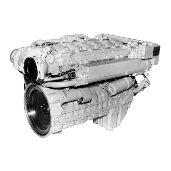
Page 17: Engine Views, D 2866 Le401
Engine views, D 2866 LE401…
-
Page 18
Engine views, D 2866 LE401… -
Page 19
Cross section of engine… -
Page 20
Longitudinal section… -
Page 21: Schematic Diagram Of Engine Lubrication System
Schematic diagram of engine lubrication system 2033 1 Oil suction pipe 6 Bypass valve 2 Distributor pipe 7 Oil filter 3 Oil spray nozzle 8 Turbocharger 4 Oil pump 9 Oil cooler 5 Oil pressure relief valve 10 Injection pump…
-
Page 22: Schematic Diagram Of Fuel System
Schematic diagram of fuel system 1 Fuel tank 6 Fuel injection pump 2 Fuel prefilter 7 Overflow valve 3 Fuel delivery pump 8 Fuel injector 4 Fuel filter 9 Suction pipe 5 Bleed screw 10 Return pipe…
-
Page 23: Schematic Diagram Of Cooling System
Schematic diagram of cooling system 10 11 2583 1 Water pump housing with 9 Expansion tank integrated thermostat housing 10 Over/underpressure valve 2 Water pump impeller 11 Coolant filler neck 3 Engine oil cooler 12 Heating lead and return line 4 Crankcase 13 Measuring point for cooling water temperature 5 Exhaust manifold, liquid-cooled…
-
Page 24: Checking And Adjusting Start Of Fuel Delivery
Checking and adjusting start of fuel delivery Checking start of delivery Fig. 1 For the purpose of checking the start-of-delivery setting, an ”OT” (= TDC) mark and a scale (2) from 10 … 50_ before TDC are engraved on a disc fitted in front of the torsional vibration damper.
-
Page 25
Checking and adjusting start of fuel delivery Fig. 5 Remove screw plug (1) on governor housing. If fitted, take out blocking pin (2). If the pointer is exactly in the centre of the inspection hole, the pump plunger for cylinder no. 1 is at start of delivery. -
Page 26
Checking and adjusting start of fuel delivery Fig. 8 The light signal transmitter KDEP 1601 (Fig.) is energized by its own power supply. 3393 b. Sleeve ø15 Fig. 9 ø12 ø9 If a light signal transmitter is not available, good measurement results can also be achieved with a plug-in sleeve. -
Page 27
Checking and adjusting start of fuel delivery Adjusting start of delivery If the check according to method a) or b) should prove that the delivery start is not correct, proceed as follows: Fig. 10 Remove timing case cover (13mm). 3394 Fig. -
Page 28: Removing And Installing Injection Pump
Removing and installing injection pump Removing injection pump Fig. 1 Close cut–off valve from fuel tank to engine. Remove all fuel and air (LDA) connections from the injection pump and detach the injection lines. Caution: The lines contain fuel. Catch emerging fuel in a container. 3396 Fig.
-
Page 29
Removing and installing injection pump Installing injection pump Fig. 5 Important: If the injection pump is blocked the camshaft must on no account be loaded or turned be- cause parts of the blocking pin may break off and fall into the governor. Non-compliance with this may result in severe damage to the injection pump. -
Page 30
Removing and installing injection pump Fig. 8 Insert the injection pump and tighten the mounting bolts. 3401 Fig. 9 Apply an initial torque of 5 Nm to all mounting bolts on the gear through the inspection hole. Two com- plete engine turns are necessary for this operation. Now tighten all mounting bolts to 30 Nm. -
Page 31: Removing And Installing Fuel Injectors
Removing and installing fuel injectors Removing fuel injectors Fig. 1 Remove leakage fuel return lines. 3402 Fig. 2 Remove injection lines. 3403 Fig. 3 Remove pressure screw from fuel injector using a pin spanner. 3378 Fig. 4 Bolt inertia puller on to fuel injector and knock out the injector.
-
Page 32
Removing and installing fuel injectors Fig. 5 Take out injector and injector seal. Check and repair injector. 3405 Installing fuel injectors Fig. 6 Apply ”Never Seeze” to contact areas of injector. Screw in injector with new seal. 3406 Fig. 7 Screw in injector with new seal. -
Page 33: Checking And Repairing Fuel Injectors
Checking and repairing fuel injectors Checking fuel injectors Fig. 1 The nozzle tester (manual test stand) is used to check the – opening pressure – tightness – spray pattern of the injection nozzle. Use pure testing oil or pure Diesel fuel for the test. Prior to testing, clean nozzle and check it for wear.
-
Page 34
Checking and repairing fuel injectors Disassembling fuel injectors Fig. 3 Insert injector assembly (the inlet orifice facing downwards) into the clamping device and hold in a vice. Remove union nut and take out nozzle body, intermediate washer, pressure pin, compression spring and shim. -
Page 35
Checking and repairing fuel injectors Fig. 7 Dip nozzle body and nozzle needle separately into filtered Diesel fuel and check their gliding quality. When pulled out of the nozzle body by up to a third of its length the nozzle needle must sink back to its seat under its own weight when released. -
Page 36: Cleaning Fuel Prefilter
Cleaning fuel prefilter Fig. 1 Shut cut-off valve from fuel tank to engine. Remove round nut and take off filter housing with sieve. Use a bowl to catch fuel that may emerge. 3407 Fig. 2 Wash out filter housing and gauze filter in clean Diesel fuel and blow them out with compressed air.
-
Page 37: Changing Fuel Filter Cartridges
Changing fuel filter cartridges Fig. 1 1 Disposable filter 2 Screw plug 3 Bleed screw 3590 Fig. 2 Use tape wrench to loosen filter cartridge and re- move cartridge by hand. Fit a new seal. Lightly coat seal on the filter cartridge with fuel. Screw on filter cartridge and firmly tighten it by hand.
-
Page 38: Draining And Filling With Coolant
Draining and filling with coolant Draining coolant Drain coolant as follows when the engine is cold: Caution: Risk of scalding if hot coolant is drained! Drain coolant into a container and dispose of it in accordance with local regulations Fig. 1 Remove cap (arrow) from filler neck on the coolant 3412 expansion tank.
-
Page 39
Draining and filling with coolant Filling up with coolant Fig. 4 The engine’s cooling system is to be filled up with a mixture of potable tap water and antifreeze agent on ethylene glycol basis or anticorrosion agent. See publication ”Fuels, Lubricants, Coolants for Industrial and Marine Diesel Engines”. -
Page 40: Removing And Installing Thermostat
Removing and installing thermostat Fig. 1 D Drain coolant, see page 37 D Remove expansion tank, see page 45 Once the expansion tank has been removed the thermostats in the water pump housing are visible. 3428 Fig. 2 Take out thermostat. Check the function of the thermostat as follows.
-
Page 41: Removing And Installing Water Pump
Removing and installing water pump D Take off V-belt, see page 118 D Drain coolant, see page 37 D Detach expansion tank, see page 45 D Take out thermostats, see page 39 Note: If the water pump is to be disassembled at a later date, remove V-belt pulley before the disassembly and pull off water pump hub with a stable three-arm puller.
-
Page 42: Repairing Water Pump
Unclip the circlip from the water-pump housing. 3434 Fig. 3 Press impeller off the shaft, using a suitable man- drel. For this purpose align water–pump housing horizontally on a stable support. The picture shows an assembly device for this. If such a device is not available, use a support ring (special tool, see page 134).
-
Page 43: Repairing Water Pump
Repairing water pump Assembling water pump Fig. 5 Press in water pump bearing. Use hollow mandrel to press on the outer bearing ring and not on the bearing shaft. For this purpose align water-pump housing hori- zontally on a stable support. 3437 Fig.
-
Page 44
Repairing water pump Fig. 8 Press impeller on to bearing shaft. For this purpose place water-pump bearing shaft on a stable support. The correct gap dimension (see ”Engineering S Data S Setting values”) is achieved if the outer face of the impeller is flush with the front face of the bearing shaft. -
Page 45
Install mechanical seal while ”wet”, i.e. to install it, coat holding sleeve (1) and water pump shaft (2) with a mixture of either 50 % water and 50 % cleaning spirit or 35 % to 50 % antifreeze agent as per MAN 324 and water. -
Page 46: Removing And Attaching Expansion Tank
Removing and attaching expansion tank D Drain coolant, see page 37 Fig. 1 Remove hollow bolt from bleeder line. Remove coolant level sensor. 3424 Figs. 2 and 3 Remove the mounting bolts from the brackets of the expansion tank (13 mm and 19 mm). 3425 3426 Fig.
-
Page 47: Removing And Installing Heat Exchanger
Removing and installing heat exchanger D Drain coolant, see page 37 Fig. 1 Remove mounting bolts from the coolant elbow between expansion tank and raw-water heat ex- changer (13 mm, 17 mm). 3440 Figs. 2 and 3 The raw-water connecting pipe from the intercooler is fastened to the heat exchanger by means of a plug connection.
-
Page 48
Removing and installing heat-exchanger pipe set D Remove raw-water heat exchanger, see page 46 Fig. 1 Match-mark the position of the covers relative to the heat-exchanger housing (arrow) and remove both covers (13 mm). 3443 Fig. 2 Take off cover. At the flywheel end of the heat exchanger the col- lar of the pipe cluster (arrow) is visible. -
Page 49: Cleaning Heat Exchanger Pipe Set
Cleaning heat exchanger pipe set Internal cleaning of the pipe set in raw water heat exchangers Deposits may form on the sea–water side of the pipe cluster in the heat exchanger, impairing the heat tran- sition to such an extent that the coolant heat can no longer be sufficiently conducted away. This is bound to cause an increase in the coolant temperature.
-
Page 50: Raw Water Pump
Raw water pump Removing and installing raw-water pump Note: The raw–water pump shown in these pic- tures was used up to engine no..8120 999 ..From engine no..8121 001 … onwards double pumps have been in use for improved cooling. However, the assembly steps are the same in principle.
-
Page 51
Raw water pump Changing impeller Fig. 1 Remove cover (8 mm). 3421 Fig. 2 The impeller can be removed only together with the cam. Note: The impeller will be destroyed if it is forcibly pulled out without the cam. To do this, remove the cap screw in the pump housing between the suction and the compression neck using a screwdriver. -
Page 52: Changing Oil Filter
Changing oil filter Fig. 1 Open oil drain plug on oil filter can (19 mm) and use container to catch oil that may emerge. Refit oil drain plug with new seal. 3447 Fig. 2 Remove mounting bolt of filter bowl (17 mm). 3448 Fig.
-
Page 53: Removing And Installing Oil Cooler
Removing and installing oil cooler D Drain engine oil D Drain coolant, see page 37. D Remove oil filter, see page 51. Fig. 1 Remove hose clamp on the coolant outlet pipe leading from the oil cooler housing. Remove the mounting bolts from the oil cooler housing (17 mm).
-
Page 54: Removing And Installing Oil Pump
Removing and installing oil pump Removing oil pump D Drain engine oil. Fig. 1 Remove oil pan (13 mm). Note: Various oil pan variants are possible. The picture shows a deep oil pan for inclinations of up to 30_. 3453 Figs.
-
Page 55
Removing and installing oil pump Fig. 5 Remove oil pump. Note: Depending on the engine model and oil pan variant, various oil pump versions are possible. In engines with tandem pumps, first remove the 2nd pump À with intermediate shaft Á, connection sleeves Â… -
Page 56
Removing and installing oil pump Fig. 8 Remove oil pump drive gear. To do this, lay pump on suitable support and press off drive gear using a mandrel. Place drive gear on the shaft and press it into place. Thereby support opposite shaft end. Pres- sing force see ”Engineering S Data S Setting va- lues”. -
Page 57
Removing and installing oil pump Installing oil pump Fig. 10 Before installing, check whether the oil pump(s) run(s) smoothly and then fit it/them free of tension (13 mm). 3588 Figs. 11 and 12 Fit the oil intake lines À with seals and the oil re- turn lines Á… -
Page 58: Oil Spray Nozzle
Oil spray nozzle Removing oil spray nozzle D Drain engine oil D Remove oil pan, see page 53 Fig. 1 Remove oil spray nozzle valve (arrow) and take out oil spray nozzle. Fig. 2 1 Oil spray nozzle valve 2 Oil spray nozzle 3462 Note: The oil spray nozzles are provided with two…
-
Page 59: Removing And Installing Vibration Damper, Changing Front Crankshaft Seal
Removing and installing vibration damper, changing front crankshaft seal Removing vibration damper D Turn engine to TDC to facilitate the installation of the scale disc during the assembly. D Block the crankgear. D Release the tension and take off the V-belt(s). Figs.
-
Page 60
Removing and installing vibration damper, changing front crankshaft seal Changing front crankshaft seal Fig. 5 Remove cover (13 mm). Replace front crankshaft seal only as a complete unit, i.e. race and radial shaft seal. 3479 Fig. 6 To remove the race, a puller (special tool, see page 127, item 13) is necessary. -
Page 61
Removing and installing vibration damper, changing front crankshaft seal Fig. 9 The adapter must contact the crankshaft free of play so that the correct pressing depth for the race is ensured. Pull in race using collar nut and pressing plate È and É… -
Page 62
Removing and installing vibration damper, changing front crankshaft seal Installing vibration damper Fig. 12 Place vibration damper on two guide pins (M16 x 1.5). Ensure that the position of the graduated disc relative to the crankshaft is correct. 3584 Fig. 13 Tighten mounting bolts (24 mm) to specified torque. -
Page 63: Removing And Installing Flywheel, Replacing Gear Ring
Removing and installing flywheel, replacing gear ring Removing flywheel Fig. 1 Loosen mounting bolts (24 mm), securing the en- gine against turning if necessary. Note: Owing to the high initial torque a reinforced socket (for machine screws) in connection with a 1/2” tool is required. 3466 Fig.
-
Page 64
Removing and installing flywheel, replacing gear ring Fig. 5 Lightly oil new mounting bolts (elasticated bolts) , screw them in and tighten alternately on opposite sides of the ring gear to specified torque (see ”Engineering S Data S Setting values”). 3470 Changing starter gear ring Fig. -
Page 65: Removing And Installing Crankshaft Seal (Flywheel End)
Removing and installing crankshaft seal (flywheel end) D Remove flywheel, see page 62 Removing crankshaft seal Fig. 1 Use a screwdriver to prise seal out of the timing case. 3472 Installing crankshaft seal Fig. 2 Insert new shaft seal into the flywheel housing. Fig.
-
Page 66: Exchanging Bearing Race
Do not damage flywheel. Do not use a chisel. Fig. 2 Insert the new bearing race into the pressing man- drel (special tool, see page 127 , item 14) so that for the subsequent assembly the internally cham- fered side faces the flywheel.
-
Page 67: Crankshaft Seals
Crankshaft seals General remarks on crankshaft seals As a matter of fundamental principle only radial shaft seals made of polytetrafluor ethylene (PTFE), trade name Teflon, are used. PTFE seals can be easily distinguished from the former elastomer seals by their considerably wider and flat sealing lip which is no longer pre-loaded by means of a tubular spring.
-
Page 68: Removing And Installing Intake Manifold
Removing and installing intake manifold D Drain coolant, see page 37 D Remove intercooler, see page 77 Note: When carrying out work on the intake sys- tem, ensure meticulous cleanliness to pre- vent dirt and foreign matter from penetrating into the system. Removing intake manifold Fig.
-
Page 69
Removing and installing exhaust manifold D Drain coolant, see page 37. D Remove turbocharger, see page 73. D Remove heat exchanger, see page 46. Removing exhaust manifold Fig. 1 Remove the mounting bolts from the exhaust pipe (17 mm). 3494 Fig. -
Page 70
Removing and installing exhaust manifold Fig. 5 Fit exhaust pipe with new seals. 3498 Fig. 6 Tighten the mounting bolts to specified torque (see ”Engineering S Data S Setting values”). 3499… -
Page 71: Turbocharger, Trouble Shooting
Turbocharger, trouble shooting Before removing the turbocharger carry out the following checks Turbochargers are frequently exchanged if the oil consumption is too high, the output too low or the intake and/or exhaust gas noises appear to be abnormal. Subsequent inspections by the manufacturer of the sup- posedly defective parts frequently prove the turbochargers to be in order.
-
Page 72
Turbocharger, trouble shooting When there is unusual intake or exhaust noise – Check the intake and exhaust system in the area of the charger group. – Defective gaskets can lead you to think the turbocharger is defective. Replace them. – If there are still unusual noises, check the bearing clearance. –… -
Page 73: Checking The Charge-Air Pressure
Checking the charge-air pressure Why must the charge-air pressure be checked? Sufficient charge-air pressure is indispensable for full power output and clean combustion. Checking the charge-air pressure helps detect damage to the turbocharger, operating faults in the waste- gate and leaks in the intercooler and in the charge-air pipes. Extreme operating conditions (full-load operation and high air temperature) and the use of unsuitable en- gine oils (also see publication ”Fuels, Lubricants, Coolants for Industrial and Marine Diesel Engines”) may cause deposits on the compressor as well as in the intercooler, which results in a reduction in charge-air…
-
Page 74: Removing And Installing Turbocharger
3503 Fig. 3 Remove the coolant supply line from the turbo- charger. 3504 Fig. 4 Remove the mounting bolts from the exhaust man- ifold (17 mm). Remove the coolant line between the turbine hous- ing and the exhaust manifold. 3505…
-
Page 75
Removing and installing turbocharger Fig. 5 Take off exhaust manifold. 3506 Fig. 6 Remove the four (self–locking) nuts from the turbo- charger flange (17 mm). Take off turbocharger. Note: Ensure meticulous cleanliness when putting the turbocharger aside to prevent dirt and foreign matter from penetrating into the inte- rior of the turbocharger. -
Page 76: Checking Axial And Radial Play Of Turbocharger Rotor Shaft
Checking axial and radial play of turbocharger rotor shaft D Remove turbocharger, see page 73 Fig. 1 Mark turbine housing relative to the bearing hous- ing and remove turbine housing. Axial play Fig. 2 Remove turbocharger. Mark turbine housing rela- tive to the bearing housing and remove turbine housing.
-
Page 77: Exchanging Waste Gate
Exchanging waste gate Fig. 1 D 2866 LE4.. engines are equipped with waste gates (arrow). Their task is to limit the charge-air pressure to a precisely defined value. Manipulation or modification of the setting is not permitted. 3512 Fig. 2 The waste gates are maintenance-free.
-
Page 78: Removing And Installing Intercooler
Removing and installing intercooler D Drain coolant from crankcase and intercooler, see page 37 Fig. 1 Remove the pipes from the fuel filter and detach the fuel filter. The coolant lines are fastened by means of plug connections. To remove them, unscrew pressure flange.
-
Page 79
Removing and installing intercooler Disassembling and cleaning intercooler Fig. 5 Remove charge-air elbow (13 mm). 3487 Fig. 6 Clean the fins on the intercooler of oil and resi- dues, using a steam jet cleaner. Do not damage the fins. 3489… -
Page 80: Removing And Installing Cylinder Head
Removing and installing cylinder head Removing cylinder head D Drain coolant, see page 37 Note: The intake and exhaust pipes need not be detached for removing the cylinder head. Fig. 1 Remove the injection nozzles, see page 30. Take off the cylinder head covers (13 mm). 3406 Fig.
-
Page 81
Removing and installing cylinder head Fig. 5 Take out push rods. 3516 Fig. 6 Remove cylinder head bolts in reverse order of tightening. Note: Use reinforced socket (screw–driving ma- chine) to loosen and tighten the cylinder head bolts. 3517 Fig. 7 Remove the mounting bolts from the intake and exhaust pipes for the respective cylinder head. -
Page 82
20 Nm. If a steel ruler is not available, mount ex- haust manifold and tighten to 20 Nm. D Tighten cylinder head bolts as specified. D Remove steel ruler. D Tighten exhaust manifold and intake man- ifold to specified torque. 3522… -
Page 83
Removing and installing cylinder head Fig. 13 Check push rods for distortion. When inserting the push rods ensure that they fit into the seat of the valve tappet. Put rocker arms and push rods in place. Screw in the mounting bolts without washers and tighten them slightly. -
Page 84
Removing and installing cylinder head General notes: The sealing effect of the cylinder head gasket largely depends on whether the required initial tension for the cylinder head bolts is reached and maintained. Use calibrated torque wrenches to tighten the cylinder head bolts. When the specified final torque is applied it must be maintained for at least 5 seconds. -
Page 85: Setting Valve Clearance
Setting valve clearance Fig. 1 Remove cylinder head cover (13mm). 3389 Figs. 2 and 3 Use barring device to turn engine so that the pis- ton in the cylinder to be set is at TDC and the two valves are closed. At this point both inlet and ex- haust valves will be open i.e.
-
Page 86
Setting valve clearance Fig. 5 Push feeler gauge between valve stem and rocker arm. Loosen lock nut (17 mm) and turn adjusting screw with screwdriver until feeler gauge can be moved with slight resistance. Tighten lock nut to the specified torque (see ”Engineering S Data S Setting values”) using screw- driver to prevent adjusting screw from turning. -
Page 87: Disassembling And Assembling Rocker Arms
Disassembling and assembling rocker arms Fig. 1 Remove rocker arms. 3524 Fig. 2 Unclip circlip. 3525 Fig. 3 Take rocker arms off the rocker arm shaft. Note: If the rocker arm bearing bushes have to be exchanged, ready-to-install new or recondi- tioned rocker arms are to be used.
-
Page 88: Removing And Installing Valves
Removing and installing valves D Remove rocker arms. Take off cylinder head see page 79. Removing valves Fig. 1 Screw valve assembly lever on to cylinder head. Note: Valve spring and valve spring retainer can also be replaced with the cylinder head installed.
-
Page 89
Removing and installing valves Installing valves Fig. 5 Apply oil to valve stern and insert valves into valve guides. Note: Minor damage to the valve seat can be elimi- nated by lapping using valve lapping paste. New valves must always be lapped until an even valve seat has been achieved. -
Page 90
Removing and installing valves Fig. 9 Insert discs and valve springs. The word ”TOP” facing upwards, the tight coils fac- ing downwards. Replace damaged or weak springs. Fit valve discs and tapered elements. 1 Valve 2 Valve stem seal (on the inlet valve only) 3 Washer 4 Outer valve spring 5 Washer… -
Page 91: Removing And Installing Valve Guides
Removing and installing valve guides D For removing and installing cylinder head, see page 79 D For removing and installing valves, see page 87 Fig. 1 Press valve guide out of the combustion chamber side using pressing mandrel (special tool, see page 129, item 20).
-
Page 92: Replacing Valve Seat Insert
Replacing valve seat insert Removing valve seat insert Note: If the valve seat inserts have to be changed it is necessary to change the valve guides too, as other- wise exact refacing of the valve seat inserts after the replacement cannot be guaranteed. For these reasons previously mentioned the tool for removing and installing valve guides and valve seat inserts was also designed in such a way that if this tool is used valve seat inserts can be re- placed only together with the valve guides, i.e.
-
Page 93
Replacing valve seat insert Installing valve seat insert Fig. 4 Heat cylinder head to approx. 80_C (175_F) in water bath. Cool new valve seat insert to approx. –200_C (–330_F) and insert it in the cylinder head. Carry out check by driving it in until the stop is reached using pressing tool. -
Page 94: Reworking Valve Seat
Select suitable guide mandrel, screw it in with a spanner (12 mm) and tighten it. Note: For extreme precision work the guide man- drel must fit snugly. Select and insert the tool with the corresponding seat width and the corresponding seat angle.
-
Page 95
Reworking valve seat Fig. 4 Release Jaccard lever, place magnetic flange flush on the clamping plate and set the height so that the tool does not contact the valve seat. Set toggle switch to position 1. Tighten the Jaccard lever. 3361 Fig. -
Page 96
Reworking valve seat Fig. 8 Note: When dressing the valve seat inserts, re- move as little material as possible from the seat face. The valve retrusion is to be used as refer- ence value. If the cylinder head interface is to be machined (max. -
Page 97: Refacing Valves
Refacing valves Fig. 1 Apply abrasive paste to tapered area on the valve seat. Oil valve guide and insert valve. 3535 Fig. 2 Use valve refacer to reface valve seat by applying moderate axial pressure and describing a turning motion. Important: Keep valve stem and valve guide free of abrasive paste.
-
Page 98: Checking Compression
Checking compression Fig. 1 D Check valve clearance and adjust, if necessary, see page 84 D Let engine warm up D Remove all fuel injectors, see page 30 D For compression guideline values, see publica- tion ”Engineering S Data S Setting values” Start with 1st cylinder (water pump end).
-
Page 99: Removing And Installing Timing Case
Removing and installing timing case D Remove starter, see page 116 D Remove flywheel, see page 62 Fig. 1 Remove the mounting bolts (17 mm). The bottom of the timing case is bolted to the oil pan. 3536 Fig. 2 Take off the timing case.
-
Page 100: Removing And Installing Camshaft, Exchanging Camshaft Bearing
Removing and installing camshaft, exchanging camshaft bearing Removing camshaft D Drain coolant, see page 37 D Remove oilpan, see page 53 D Remove starter, see page 116 D Remove flywheel and timing case, see page 98 D Remove the rocker arms and take out the push rods, see page 79 Note: For removing the camshaft the engine must…
-
Page 101
Removing and installing camshaft, exchanging camshaft bearing Exchanging the camshaft bearings Remove the cylinder heads, the pistons with the connecting rods and the crankshaft, before remov- ing camshaft bearings Fig. 5 Remove camshaft bearing bushes with suitable mandrel and drive in new bushes. Ensure that the oil supply bores are in correct position. -
Page 102: Checking Valve Timing
Checking valve timing Note: If the valve timing is incorrect, serious dam- age to the engine may result. For this rea- son, if faults occur in the engine which could lead to the shrunk-fitted camshaft gear turn- ing, check that the gear is correctly seated by checking the valve timing.
-
Page 103: Removing And Installing Crankshaft
Removing and installing crankshaft Removing crankshaft D ,Remove oil pan and oil pump see page 53 D Remove timing case, see page 98 D Remove the front cover for sealing the crank- shaft and the cylinder heads, see page 79 Fig.
-
Page 104
Removing and installing crankshaft Checking spread of bearing shells Fig. 5 Position bearing shells together on flat surface. Measure and note down spread dimensions ”A” and ”B”. Spread dimension = A – B 2376 Installing crankshaft Fig. 6 Clean oil ducts in crankcase and in crankshaft with dry compressed air. -
Page 105
Removing and installing crankshaft Checking axial play Fig. 9 The axial play of the crankshaft is determined by the centre crankshaft bearing (thrust bearing). 3550 Fig. 10 D Fit dial gauge holder with dial gauge to crank- case. D Move crankshaft in axial direction to and fro and read off play on dial gauge. -
Page 106: Removing And Installing Piston With Connecting Rod
Removing and installing piston with connecting rod Removing piston with connecting rod D Remove oil pan, oil suction pipe, see page 53 D Remove cylinder heads, see page 79 Fig. 1 Remove bolts from connecting rod bearing cap. 3724 Fig. 2 Take off connecting rod bearing caps with bearing shells, expediting the procedure by means of light strokes with a synthetic hammer if necessary.
-
Page 107
Removing and installing piston with connecting rod Installing piston with connecting rod Note: If the pistons must be changed, ascertain by measuring the pistons or reading the mea- surement on the top of the piston whether undersized pistons were installed. If this is the case, undersized pistons must be used. -
Page 108
Removing and installing piston with connecting rod Fig. 9 Put connecting rod bearing caps in place. Important: The numbers on the connecting rod bearing cap and connecting rod big end must be on one side. 3560 Fig. 10 Screw in connecting rod bearing bolts and tighten them in stages to specified value. -
Page 109: Detaching Piston From And Attaching To Connecting Rod
Detaching piston from and attaching to connecting rod checking — changing connecting rod Detaching piston from and attaching to connecting rod Fig. 1 Remove piston with connecting rod. Clamp connecting rod in a vice using soft jaws. Remove gudgeon pin circlip. 3562 Fig.
-
Page 110
Removing piston from and attaching to connecting rod checking — changing connecting rod Fig. 5 Clean connecting rod and inspect for external damage; scrap any defective rods. Check connecting rod to see whether the piston pin bore is parallel or twisted relative to the bearing shell bore. -
Page 111: Removing, Installing And Changing Piston Rings
Removing, installing and changing piston rings Piston ring arrangement Fig. 1 1 Compression ring (double-sided keystone ring) 2 Compression ring (tapered compression ring) 3 Oil scraper ring (bevelled-edge ring) 2873 Removing piston rings Fig. 2 Remove piston with connecting rod. Clamp connecting rod in a vice using soft jaws.
-
Page 112
Removing, installing and changing piston rings Installing piston rings Figs. 5 and 6 Use piston ring pliers to place piston rings in the correct piston ring grooves (”TOP” mark facing up- wards). 2879 3729 Checking piston ring axial clearance Fig. 7 Use feeler gauge to ascertain the piston ring clear- ance at several points in each groove. -
Page 113: Replacing Cylinder Liners
Replacing cylinder liners Removing cylinder liners Note: Observe oversizes for cylinder liner outer diameters and collar heights (see ”Engineering S Data S Setting values”). D Remove cylinder head D Remove piston Fig. 1 3570 Mark cylinder liner position relative to engine so that it can be reinstalled in the same position if re- used.
-
Page 114
Replacing cylinder liners Checking cylinder liner protrusion Fig. 4 Clean basic bore and cylinder liner. Insert cylinder liner without O-rings into crankcase, observing the marking (ensure that it is identical with the position prior to removal). Measure cylinder liner protrusion at at least four different points, using gauge holder and gauge. -
Page 115
Replacing cylinder liners Installing cylinder liners Fig. 6 Insert dry new O-rings for the lower seal (144×4) into the crankcase. Fig. 7 Insert new O-rings for the upper seal (138×2) into the grooves on the cylinder liner. Do not overstretch the O-rings. 3574 Fig. -
Page 116: Measuring Piston Protrusion
Measuring piston protrusion Fig. 1 Remove cylinder heads. Move piston to be measured to TDC. Apply dial gauge in holder to crankcase sealing face. Set dial gauge to — 0 -. 3577 Fig. 2 Carefully slew dial gauge holder round, lifting the dial gauge tip as you do so.
-
Page 117: Removing And Installing Starter
Removing and installing starter Fig. 1 Disconnect minus cable from battery or switch off battery main switch if fitted. Disconnect cable from terminal 31 (minus terminal, thick cable), terminal 30 (plus terminal, thick cable) and terminal 50 from starter. Remove mounting nuts (19 mm). Note: A curved wrench is advantageous for the inner bolts (see Fig.).
-
Page 118: V-Belts
V-belts Checking condition Fig. 1 D Check V-belts for cracks, oiling, overheating and wear. D Change damaged V-belts. 2642 Checking tension Figs. 2 and 3 Use belt tension indicator to check V-belt tension. D Lower the gauge arm À in the scale. D Position the tension indicator in the centre of the belt between the two pulleys so that the 2905…
-
Page 119
V-belts Tensioning V-belts Figs. 5 and 6 Remove the mounting bolts from both the alterna- tor and the tensioning device. 3386 3386 Fig. 7 D Loosen lock nut À D Turn adjusting nut Á until the V-belts are cor- rectly tensioned D Retighten lock nut and mounting bolts 3388… -
Page 120: Coolant Level Probe
Coolant level probe Monitoring the coolant level All engines are equipped with either one or two coolant level probes for monitoring the coolant level in the coolant expansion tank. This probe is of the capacitative type. The sensor and the evaluating electronics form a unit.
-
Page 121
Transmitters Checking the coolant temperature transmitter by measuring the resistance Ω Dip temperature sensor up to the lower edge of the hex section into a mixture of water and 30 % anti– freeze/anti–corrosion agent. The liquid must be circulated during this measurement. Check the temperature with a thermometer as the liquid is heated. -
Page 122
Transmitters Checking the oil pressure transmitter by measuring the resistance Ω If the oil pressure transmitter is to be checked, the oil pressure must be measured with a second, indepen- dent instrument. Disconnect the gauge from the transmitter. Measure the resistance and compare it with the calibrated curves. -
Page 123
Transmitters Checking the exhaust gas temperature transmitter by measuring the voltage If the exhaust gas temperature transmitter is to be checked, the exhaust gas temperature must be measu- red with a second, independent instrument. Disconnect the gauge from the transmitter. Measure the vol- tage and compare it with the calibrated curve (_F = 1.8_C + 32). -
Page 124: Special Tools
Special tools…
-
Page 125: Special Tools
Special tools…
-
Page 126
Special tools Fig. no. Designation Item number Test connection for compression recorder 80.99607–0002 V-belt tension indicator 81.66814–6001 Valve gauge 80.99607–0076 Valve setting spanner 83.09195–0002 Spanner for nuts on injection lines (17 mm) 80.99603–0025 Socket spanner set for fuel injector 4-groove 80.99603–0049 4-groove with fixing screw 80.99603–0121… -
Page 127
Special tools 12.2 12.1 14.1 15.6 15.7 15.4 15.3 15.1 15.3 15.5 15.1 15.2 18.1… -
Page 128
Special tools Fig. no. Designation Item number Puller for water pump pulley 80.99601–0037 Pressing mandrel for cassette seal in conjunction with handle 14.1 80.99617–0091 Driving mandrel for seal in timing case consisting of: 12.1 Guide sleeve 80.99604–0068 12.2 Pressing plate in conjunction with handle 14.1 80.99604–0069 Puller for front crankshaft bearing race 80.99601–0076… -
Page 129
Special tools 19.1 19.2 20.1 20.2 25.1 25.2 27.1 27.2… -
Page 130
Special tools Fig. no. Designation Item number Sleeves for valve stem seal 19.1 Insert sleeve for valve stem seal 80.99616–0004 19.2 Pressing sleeve for valve stem seal 80.99604–0005 Pressing tool for valve guide 20.1 Pressing mandrel for valve guide 80.99617–0013 20.2 Pressing rings in conjunction with 20.1 80.99616–0003… -
Page 131
Special tools… -
Page 132
Special tools Fig. no. Designation Item number Valve assembly lever 80.99606–0031 Dial gauge holder for measuring valve retrusion and piston protrusion 90.99605–0172 Pressure gauge + accessories for charge-air pressure measurement 80.99605–0160… -
Page 133
Special tools Fig. no. Designation Item number Measuring combination, consisting of: (1) Dial gauge 08.71000–1205 (2) Tracer pin for dial gauge 80.99605–0197 (3) Dial gauge holder 80.99605–0179 (4) Contact pin 80.99605–0180 (5) Dial gauge holder 80.99605–6006 (6) Dial gauge holder 80.99605–0172 Press–on measuring plate 80.99605–0195… -
Page 134
Special tools Pressing mandrel for cap, dia. 50.1 mm Pressing mandrel for cap, dia. 62.1 mm 2843… -
Page 135
Special tools Special tools for water pump repair for local manufacture (Material: steel as available) Support ring for pressing out the water pump bearing Ø 68 Ø 56… -
Page 136: Index
Index Bleeding fuel system Heat exchanger Cleaning Removing and installing Camshaft, Removing Heat exchanger pipe cluster Camshaft , Installing Camshaft bearings Charge–air pressure, Checking Impeller (raw water pump) Compression (checking) Injection nozzle (checking) Conrod, Checking Injection nozzles (repairing) Coolant Injection pump Draining Installing Filling…
-
Page 137
Index Piston V–belts 117–118 Detaching from conrod, Attaching to conrod Valve guides, Removing and Installing Valve recess Installing Valve seat, Reworking Removing Valve seat insert Piston protrusion Installing Piston ring axial play Removing Piston ring gap Valve timing Piston rings Valves Installing Installing…
[ Скачать с сервера ]

(МАН) MAN
инструкция по ремонту.обучающий материал для автосервисов.
Файл PDF
210 страниц.
в архиве RAR
размер 6 Mb
язык русский
качество отличное.
ОПИСАНИЕ
компрессор
система EDC MS6.1
установка подьемного раздвижного ТНВД
центр подготовки топлива KSC
SEPAR 2000
указания по эксплуатационным материалам
система смазки двигателя
датчики двигателя
наддув
турбокомпрессор с WASTE GATE
турбонагнетатель
интеркюллер
система охлаждения
тормоз замедлитель
и прочее
качество отличное язык русский
СКАЧАТЬ
мотор D2866-76 руководство для ремонта.
СКРИН ИЗ МАТЕРИАЛА
СОДЕРЖАНИЕ ………………………………………………………………………… 3
ОПИСАНИЕ ДВИГАТЕЛЯ …………………………………………………………. 4
СООТНОШЕНИЕ АГРЕГАТОВ С КОНСТРУКТИВНЫМ РЯДОМ /
ТИПОМ ТРАНСПОРТНОГО СРЕДСТВА ……………………………………. 6
ОБЪЯСНЕНИЕ КОДОВ ДВИГАТЕЛЕЙ И КОДИРОВАННЫХ
ОБОЗНАЧЕНИЙ ТИПОВ…………………………………………………………… 8
ОРИЕНТИРОВОЧНЫЕ ЗНАЧЕНИЯ КРУТЯЩЕГО МОМЕНТА……. 10
МОНТАЖНЫЕ ЗАЗОРЫ И ПРЕДЕЛЬНЫЕ ЗНАЧЕНИЯ ИЗНОСА.18
УПЛОТНИТЕЛИ И СМАЗКИ…………………………………………………….. 22
ТЕХНИЧЕСКИЕ ДАННЫЕ ДВИГАТЕЛЯ……………………………………. 24
ТЕХНИЧЕСКИЕ ПАРАМЕТРЫ ДВИГАТЕЛЯ …………………………….. 26
ТЕХНИЧЕСКИЕ ПАРАМЕТРЫ ДВИГАТЕЛЯ …………………………….. 28
ТЕХНИЧЕСКИЕ ДАННЫЕ ДВИГАТЕЛЯ……………………………………. 30
ТЕХНИЧЕСКИЕ ДАННЫЕ ДВИГАТЕЛЯ……………………………………. 32
ТЕХНИЧЕСКИЕ ПАРАМЕТРЫ ДВИГАТЕЛЯ ……………………………. 34
КАРТЕР ДВИГАТЕЛЯ……………………………………………………………… 36
КОЛЕНЧАТЫЙ ВАЛ………………………………………………………………… 40
ШАТУН ………………………………………………………………………………….. 42
ПОРШЕНЬ……………………………………………………………………………… 44
МАХОВИК ……………………………………………………………………………… 52
КРЕПЛЕНИЕ ГОЛОВКИ ЦИЛИНДРА ……………………………………….. 54
ГОЛОВКА ЦИЛИНДРА ……………………………………………………………. 56
УПЛОТНЕНИЕ ВЫПУСКНОГО КОЛЛЕКТОРА ………………………….. 62
ПРИВОД КЛАПАНОВ ……………………………………………………………… 64
EVB = EXHAUST VALVE BRAKE =ТОРМОЗ С ВЫПУСКНЫМ
КЛАПАНОМ……………………………………………………………………………. 66
НАСТРОЙКА ЗАЗОРА ВЫПУСКНЫХ КЛАПАНОВ EVB:…………….. 72
ТОРМОЗ С ВЫПУСКНЫМИ КЛАПАНАМИ ……………………………….. 74
РАСПРЕДЕЛИТЕЛЬНЫЙ ВАЛ…………………………………………………. 76
ОСЬ ПОДШИПНИКА ПРОМЕЖУТОЧНОЙ ШЕСТЕРНИ. ……………. 80
ФАЗЫ ГАЗОРАСПРЕДЕЛЕНИЯ ………………………………………………. 84
СМАЗКА ДВИГАТЕЛЯ …………………………………………………………….. 88
ОБЩИЕ УКАЗАНИЯ ПО ЭКСПЛУАТАЦИОННЫМ МАТЕРИАЛАМ 96
ДВИЖЕНИЕ ТОПЛИВА В РАСПРЕДЕЛИТЕЛЬНОМ ТНВД………… 98
ОПИСАНИЕ СИСТЕМЫ EDC MS 6.4 (VP 44) …………………………. 100
ТНВД VP44…………………………………………………………………………… 102
ДИАГНОСТИКА ……………………………………………………………………. 116
СПИСОК МИГАЮЩИХ СВЕТОВЫХ КОДОВ …………………………… 118
ДЕМОНТАЖ РАСПРЕДЕЛИТЕЛЬНОГО НАСОСА ТНВД VP44 … 120
МОНТАЖ РАСПРЕДЕЛИТЕЛЬНОГО ТНВД VP44……………………. 122
КОРПУС РАСПЫЛИТЕЛЯ ФОРСУНКИ…………………………………… 124
СИСТЕМА ОХЛАЖДЕНИЯ…………………………………………………….. 132
ВЯЗКОСТНАЯ МУФТА ………………………………………………………….. 136
ВОДЯНОЙ НАСОС……………………………………………………………….. 138
КОМПРЕССОР …………………………………………………………………….. 140
НАДДУВ……………………………………………………………………………….. 144
ДАВЛЕНИЕ НАДДУВА…………………………………………………………… 146
ТУРБОНАДДУВ…………………………………………………………………….. 147
ГАЗОТУРБИННЫЙ НАДДУВ С WASTE GATE ………………………… 150
ОХЛАДИТЕЛЬ НАДДУВОЧНОГО ВОЗДУХА …………………………… 152
СИСТЕМА РЕЦИРКУЛЯЦИИ ОГ AGR …………………………………… 154
ИНФОРМАЦИЯ: РЯДНЫЕ ДВИГАТЕЛИ D0836..EURO2 / EURO3
(SD 203)……………………………………………………………………………….. 156

Вы здесь
РАЗЪЯСНЕНИЯ
ПО
ТИПОВОЙ
ТАБЛИЧКЕ
ДВИГАТЕЛЯ
Разъяснения
по
типовой
табличке
Поле
N I / N II
I
Отклонение
от
номинального
размера
0,1
мм
II
Отклонение
от
номинального
размера
0,25
мм
P
Коренная
шейка
шатуна
H
Шейка
коренного
подшипника
S
Грибовидный
толкатель
распределительного
вала
Обозначение
типа
двигателя
D2876 LF 04
D
………..
Вид
топлива
,
дизель
28
……….
+ 100 =
Диаметр
цилиндра
,
напр
. 128
мм
∅
7
…………
Характеризует
ход
поршня
: 6 = 155
мм
, 7 = 166
мм
6
…………
Кол
—
во
цилиндров
: 6 = 6
цилиндров
, 0 = 10
цилиндров
2 = 12
цилиндров
L……….
Вид
наддува
:
турбо
—
наддув
с
охлаждением
надувочного
воздуха
F
…………
Размещение
двигателя
:
F
Грузовик
с
кабиной
над
двигателем
,
вертикальный
двигатель
OH
Автобус
с
установкой
двигателя
в
задней
части
,
вертикальный
двигатель
UH
Автобус
с
установкой
двигателя
в
задней
части
,
горизонтальный
двигатель
04
Вариант
исполнения
двигателя
,
имеет
особое
значение
при
приобретении
запасных
частей
Технические
характеристики
и
регулируемые
величины
MAN — Werk Nürnberg
Typ
Motor-Nr. / Engine-no
N I / N II
D2876 LF 04
5459170015B2E1
P1
ИДЕНТИФИКАЦИОННЫЙ
НОМЕР
ДВИГАТЕЛЯ
Пример
:
248
7840
027
B
2
8
1
A
B
C
D
E
FG
T2876028
A
………
248
…………..
Код
типа
двигателя
B
………
7840
…………
День
сборки
C
………
027
…………..
Последовательность
сборки
(
Последующее
число
в
день
сборки
)
D
………
B
……………..
Обзор
Маховик
E
………
2
………………
Обзор
Регулирование
ТНВД
F
………
8
………………
Обзор
Компрессор
G
………
1
………………
Специальное
оборудование
,
как
напр
.
механизм
отбора
мощности
,
зависимый
от
двигателя
МОНТАЖНЫЙ
ЗАЗОР
И
ПРЕДЕЛ
ИЗНОСА
Монтажный
размер
Предел
износа
Диаметр
шейки
коренного
подшипника
,
стандартный
размер
103,98 — 104,00
мм
Внутренний
диаметр
коренного
подшипника
,
стандартный
размер
104,066 — 104,112
мм
Коренной
подшипник
коленчатого
вала
/
шейка
коренного
подшипника
0,060 — 0,126
мм
Разжим
вкладыша
коренного
подшипника
0,3 — 1,2
мм
Разжим
вкладыша
регулировочного
подшипника
0,1 — 0,5
мм
Осевой
зазор
коленчатого
вала
0,190 — 0,312
мм
макс
. 1,25
мм
Внутренний
диаметр
шейки
шатунного
подшипника
,
стандартный
размер
89,98 — 90,00
мм
Внутренний
диаметр
шатунного
подшипника
,
стандартный
размер
90,060 — 90,102
мм
Шатунный
подшипник
/
Шейка
0,062 — 0,104
мм
Разжим
0,6 — 1,5
мм
Втулка
шатуна
/
поршневой
палец
0,055 — 0,071
мм
Выступ
гильзы
цилиндра
0,030 — 0,080
мм
минимум
0,03
мм
Выступ
поршня
над
верхним
краем
картера
0,013 — 0,331
мм
Высота
головки
поршня
–
стандартный
размер
(
нижний
предел
0,2 — 0,4 — 0,6)
89,750 — 89,800
мм
Монтажный
зазор
Предел
износа
Стыковые
зазоры
поршневых
колец
1
уплотнительное
кольцо
–
стыковой
зазор
(Götze, TRW, Thompson,
0,350 — 0,550
мм
1,50
мм
Riken)
0,450 — 0,650
мм
1,50
мм
2
уплотнительное
кольцо
(Götze,
0,450 — 0,700
мм
1,50
мм
Riken,
0,450 — 0,650
мм
1,50
мм
TRW, Thomps
с
on)
0,500 — 0,750
мм
1,50
мм
Маслосъемное
поршневое
кольцо
(Götze, Riken, TRW, Thom
л
/
с
on)
0,250 — 0,400
мм
1,50
мм
Осевой
зазор
поршневых
колец
1,50
мм
Отставание
выпускного
клапана
0,700 — 1,300
мм
Отставание
впускного
клапана
0,700 — 1,300
мм
Высота
головки
впускного
клапана
3,400 — 3,500
мм
Высота
головки
выпускного
клапана
3,000 — 3,100
мм
.. ..
Комментарии
Книга по устройству автомобиля и каталог деталей MAN F90 / F2000 c двигателями D2840 / D2866/76 в формате PDF
Только оригинальные руководства
Доступно сразу после оплаты
Полное соответствие бумажным изданиям
100% защита ваших оплат
(9)
Издательство: © «Диез»
ISBN: 5-90268-223-1v
Количество страниц: 482
Формат: файл PDF
О руководстве
Типы двигателей: D2840 / D2866/76
В руководстве вы найдете
- каталог деталей
- номенклатуру сборочных единиц
- помощь по разборке и сборке автомобиля
Только оригинальные руководства
Доступно сразу после оплаты
Полное соответствие бумажным изданиям
100% защита ваших оплат
Издательство: © «Диез»
ISBN: 5-90268-223-1v
Количество страниц: 482
Формат: файл PDF
О руководстве
Типы двигателей: D2840 / D2866/76
В руководстве вы найдете
- каталог деталей
- номенклатуру сборочных единиц
- помощь по разборке и сборке автомобиля
Содержание
Двигатель D2840
- Картер механизма газораспределения
- Картер
- Детали картера
- Маховик
- Коленчатый вал
- Шкивы коленчатого вала двигателей D2840 LF 460 D2840 LXF
- Шкивы коленчатого вала, двигателей 2840 LF 520
- Шатун и поршень
- Маховик
- Головка цилиндра D2840 LF 460/520
- Головка цилиндра D2840 LXF
- Распределительный вал, клапана
- Распределительный вал и шестерня распределительного вала с регулировкой момента впрыска
- Масляный насос D2840 LF, D2840 LXF
- Масляный насос стандартной емкости
- Масляный насос D2840 LF 500
- Канал масляного насоса D2840 LF 520
- Масляный поддон двигателей d2840 LF 460, d2840 LXF
- Масляный поддон 02840 LF 520
- Масляный фильтр, маслоохладитель
- Ремкомплект водяного насоса
- Ремкомплект водяного насоса малый
- Водяной насос
- Линии охлаждающей жидкости
- Вентилятор на коленчатом валу d2840LF 520
- Ролик d2840 LF 460, d2840 LXF
- Вентилятор
- Вентилятор с 2-ступенчатым электромагнитным сцеплением
- Впускной трубопровод
- Выпускное колено
- Устройство облегчения пуска двигателя
- Турбокомпрессор
- Нагнетательный трубопроводтурбокомпрессора
- Возвратный трубопровод турбокомпрессора
- Нагнетательный трубопровод турбокомпрессора
- Корпус форсунки
- Топливный насос, двигатель d2840 LF 520
- Блокирующий цилиндр сцепления
- Топливный насос
- Детали топливного насоса 51.11102-7932
- Регулятор постоянной скорости,топливный насос 51.11102-7778
- Топливный насос, двигатель d2840 LXF / d 2842 LXF
- Детали двухкаскадного топливного фильтра bosch 51.12501-7069
- Детали двухкаскадного топливного фильтра knecht 51.12501-7068
- Предварительный топливный фильтр Детали стартера 51,26201-7125+ 51.26201-7127
- Картер сцепления и сцепление VULKANKARDAN-P Крепление генератора К1-28В/35А (N1-28B/55A)
- Детали генератора N1-28B/55A25, 51.26101-7144
- Детали генератора К1-28В/35А, 51.26101-7133
- Отбор мощности, гидравлический насос Отбор мощности
- Отбор мощности с клиновым ремнем (до 1988 г.), двигатель d2840 UF
- Отбор мощности с клиновым ремнем (с 1989 г.)
- 2-цилиндровый компрессор с водяным охлаждением
- 2-цилиндровый компрессор с водяным охлаждением
- 1-цилиндровый воздушный компрессор с водяным охлаждением
- 1-цилиндровый воздушный компрессор с водяным охлаждением
- Головка цилиндра и трубопроводы 2-цилиндрового воздушного компрессора с водяным охлаждением
- Головка цилиндра и трубопроводы 1-цилиндрового воздушного компрессора
- Головка цилиндра и трубопроводы 2-цилиндрового воздушного компрессора
- Детали головки цилиндра воздушного компрессора 51.54114-6045/6063/6054
- Детали холодильного компрессора 81.61906-6007
- Детали холодильног
- Шкив натяжения для холодильного компрессора
- Картер механизма газораспределения
Двигатели D2866/76
- Отбор мощности
- Картер
- Гильза цилиндра и маслораспылитель
- Сапун двигателя и маслоотделитель, монтажные детали
- Крышка картера маховика
- Монтажные детали крышки картера маховика
- Заменяемые части картера маховика
- Передняя крышка коленчатого вала на картере
- Маховик
- Поршень и шатун
- Маховик
- Дополнительный двухручейковый шкив натяжения
- Коленчатый вал
- Монтажные детали опорного подшипника коленчатого вала
- Клиновой шкив 6-ручейковый
- Дополнительный 3-ручейковый клиновой шкив
- Коленчатый вал
- Клиновой шкив и дополнительный клиновой шкив
- Коленчатый вал
- Головка цилиндра
- Монтажные детали головки цилиндра с нерегулируемой системой EVB
- Крышка головки цилиндра
- Головка цилиндра
- Верхняя часть головки цилиндра
- Крышка головки цилиндра
- Распределительный вал и шестерня распределительного вала с установкой момента впрыскивания
- Клапана и управление двигателем
- Приводная шестерня воздушного компрессора
- Клапана
- Кронштейн коромысел
- Штанга толкателя
- Клапаны
- Подшипниковый узел коромысла (рокера
- Клапаны, штанга толкателя
- Клапаны
- Распределительный вал и шестерня распределительного вала без установки момента впрыскивания
- Масляный насос стандартной производительности
- Картер коленвала и маслосборник
- Масляный поддон
- Масляный фильтр и маслоохладитель
- Масляный насос
- Масляный насос высокой производительности
- Шкив натяжения без автоматической регулировки
- 2-фланцевый охлаждающий насос для механической коробки передач
- Термостат
- Шкив натяжения для автоматической регулировки
- Жесткий вентилятор с гибким соединением
- Жесткий вентилятор с промежуточным фланцем
- Охлаждающий насос 51.06500-7036/7043 с рециркуляцией выхлопных газов
- Вентилятор
- Ремкомплект водяного насоса (большой)
- Ремкомплект водяного насоса (малый)
- Устройство облегчения пуска двигателя
- Выпускное колено
- Устройство облегчения пуска двигателя
- Впускной воздушный трубопровод
- Выпускное колено и защитные пластины
- Турбокомпрессор
- Корпус форсунки (цилиндр 1)
- Корпус форсунки
- Корпус форсунки с датчиком перемещения иглы (цилиндр 1)
- Установочные детали форсунок
- Топливный насос
- Детали стартера 51.26201-7125/7127/7130
- Детали генератора 51.26101-7232/7235/7242/7247
- Топливный фильтр с подогревом
- Крепление двигателя и подвеска м16х1.5х180
- Детали генератора переменного тока 51.26101-7215
- Шкив натяжения 51.95800-6054
- Шкив натяжения гидравлического насоса
- Шкив натяжения охлаждающего компрессора KIKI
- 1-цилиндровый компрессор с воздушным охлаждением
- 2-цилиндровый рядный компрессор
- Гидравлический насос, монтажные детали
- Крепление двигателя
- Фильтрующий элемент масляного фильтра двигателя
- Расширительный бачок
- Крепление радиатора
- Двигатель D2866 LF
- Трубопроводы охлаждающей жидкости
- Решетка радиатора
- Трубопроводы охлаждающей жидкости к интардеру
- Трубопроводы охлаждающей жидкости к ретардеру
- Решетка радиатора
- Нижнее крепление радиатора
- Верхнее крепление радиатора
- Трубопроводы охлаждающей жидкости интардера
- Защитный экран
- Интеркулер
- Впускные трубопроводы двигателя
- Входной трубопровод
- Впускной патрубок
- Детали воздушного фильтра
- Впускной трубопровод с предварительной очисткой
- Фильтрующий элемент воздушного фильтра
- Вакуумный индикатор без предварительной очистки F92R25S
- Вентиляционная заслонка
- Распределительный клапан топливного бака
- Предварительный топливный фильтр
- Топливный фильтр с нагревателем
- Крепление глушителя
- Выпускная труба перед гибким шлангом
- Тормоз на выхлопе, воздушный цилиндр 81.15600-6103/6104
- Выпускная труба
- 3/2-ходовой клапан
- Пневматический блокиратор
Сцепление
- Педаль акселератора
- Трос боудена управления двигателем с регулятором постоянной скорости RQ F92L
- Регулятор холостого хода на акселераторе с регулятором скорости RQV F92L25S
- Рычаг ручного управления
- Концевой переключатель
- Цилиндр блокировки акселератора
- Управление двигателем
- Педаль акселератора с датчиком положения
- Ограничитель скорости
- Система центральной смазки (1 или 2 точки смазки)
- Педаль акселератора без датчика положения
- Датчик уровня жидкости
- Резервуар рабочей жидкости сцепления
- Картер сцепления
- Управление сцеплением и тормозами
- Рабочий цилиндр сцепления WABC0
- Управление сцеплением
- Сцепление FICHTEL & SACHS
- Трубопровод от главного цилиндра к рабочему цилиндру
- Крепление картера сцепления и рабочего цилиндра
- Рабочий цилиндр сцепления KNORR
- Рабочий цилиндр сцепления KONGSBERG
- Рабочий цилиндр сцепления WABCO
- Рабочий цилиндр сцепления KONGSBERG
- Трубопровод
- Детали сцепления
- Управление сцеплением
Коробка передач
- Распылительная трубка и масляный фильтр
- Рычаг переключения передач
- Главный вал, передние компоненты
- Планетарная передача и синхронизатор
- Рычаг переключения передач
- Коробка передач 2F 16S-151/221, КАБИНА F92L
- Рычаг переключения передач
- Картер трансмиссии и детали сцепления
- Главный вал, задние компоненты
- Управление переключением передач
- Крышка картера планетарной передачи
- Пневматическое управление
- Картер трансмиссии и детали сцепления
- Кронштейн и шпилька
- Крепление коробки передач
- Ведущий вал и соединительная пластина
- Промежуточный вал и шестерня заднего хода
- Сервоулравление
- Шток переключения
- Коробка управления переключением передач
- Планетарная передача и синхронизатор
- Крышка картера
- Интардер
- Шток переключения
- Крепление крышки картера
- Теплообменник
- Рычаг переключения передач
- Ведущий вал и соединительная пластина
- Промежуточный вал с насосом и шестерней заднего хода
- Коробка управления переключением передач
- Крышка коробки управления переключением передач
- Клапаны теплообменника
- Управление
- Каналы охлаждения теплообменника коробки передач
- Крепление коробки передач
- Управляющий вал
- Картер трансмиссии
- Ведущий вал
- Главный вал
- Промежуточные валы
- Шестерня заднего хода
- Картер делителя
- Крышка коробки передач
- Переключающий цилиндр
- Переключающая вилка и управляющий вал
- Управление переключением передач
- Промежуточный картер
- Детали ретардера
- Каналы подачи масла
- Ведущий вал и соединительная плита
- Крышка коробки передач
- Задние элементы главного вала
- Сервоуправление (228-301KW) F92L
- Комплект уплотнений интардера
- Датчик нейтрального положения
- Комплект уплотнений коробки передач
- Теплообменник
- Картер сцепления
- Промежуточная шестерня отбора мощности
- Ведущий вал и соединительная плита
- Отбор мощности
- Управление отбором мощности
- Ретардер 115Н
- Картер интардера
- Управление интардером
- Крепление картера интардера
- Насос интардера
- Картер трансмиссии
- Система смазки
- Картер сцепления
- Картер сцепления
- Главный вал
- Картер делителя
- Делитель
- Цилиндр делителя и переключающий цилиндр
- Размыкающие детали
- Трансмиссионный замедлитель
- Система управления
- Фильтр регулятор
- Коробка управления переключением передач и управляющий вал
- Сервопривод
- Детали коробки управления переключением передач
- Крышка
- Планетарная передача
- Синхронизатор
- Передние компоненты главного вала
- Управляющая скоба
- Планетарная передача
- Теплообменник
- Болты картера сцепления
- Вилка сцепления
- Рычаг переключения передач
- Каналы охлаждения теплообменника коробки передач
- Рычаг переключения передач
- Ведущий вал
- Соединительная плита
- Картер трансмиссии
- Детали гидропневматического блока на теплообменнике
Задний мост
- Крышка подшипника конической шестерни
- Картер моста и блокировка дифференциала
- Крышка вала
- Вал, блокировка дифференциала
- Планетарная конечная передача
- Ступица заднего колеса
- Вал блокировки дифференциала
- Подшипник конической шестерни
- Картер моста с блокировкой дифференциала
- Крышка ведущего вала
- Ведущий вал блокировки дифференциала
- Ступица колеса
- Планетарная конечная передача
- Карданный вал
- Промежуточный подшипник
- Карданный вал
Передний мост
- Поворотные кулаки переднего моста
- Рулевые тяги, рулевые рычаги
- Поворотные кулаки переднего моста
- Рулевые тяги, рулевые рычаги
- Поворотные кулаки переднего моста
- Поворотные кулаки
- Поворотные кулаки переднего моста
Рама
- Пластмассовый бампер с панелью
- Передняя поперечина
- Спойлер под бампером
- Спойлер под бампером
- Подножка спойлера под бампером
- Подножка спойлера под пластмассовым бампером
- Прокладки
- Стальной бампер, 3-части
- Решетка фар ближнего света для стального бампера, 3-части
- Кронштейн стального бампера, 3 части
- Передние кронштейны
Подвеска
- Стабилизатор переднего моста
- Трапециевидная рессора 10-листовая
- 4 Амортизатор со стабилизатором
- Параболическая рессора 3-листовая
- Параболическая рессора 3-листовая, 4-листовая
- Монтажные детали передней рессоры со стабилизатором
- Трапециевидная рессора 10-листовая
- Крепление задней рессоры со стабилизатором
- Резиновый упор со стабилизатором
- Параболическая рессора 3-листовая
- Стабилизатор заднего моста со стабилизатором
- Стабилизатор заднего моста со стабилизатором
- Стремянка со стабилизатором
- Амортизатор (параболическая рессора) 7,1 т со стабилизатором
- Стабилизатор переднего моста со стабилизатором
- Трапециевидная рессора 15-листовая без стабилизатора
- Трапециевидная 7-листовая рессора
- Параболическая рессора 3-листовая
- Параболическая рессора 4-листовая
- Крепление передней рессоры со стабилизатором
- Трапециевидная 5-листовая рессора
- Параболическая рессора 4-листовая со стабилизатором
Рулевое управление
- Рулевая сошка, продольная рулевая тяга
- Детали лопастного насоса 81.47101-6031
- Ремкомплекты лопастного насоса 81.47101-6122
- Регулируемая рулевая колонка
- Детали продольной рулевой тяги 81.46610-6779
- Детали продольной рулевой тяги 81.46610-6721
- Универсальный вал рулевого управления
- Регулируемое рулевое управление, комплект уплотнений
- Ремкомплекты лопастного насоса
- Продольная рулевая тяга 81.46611-6004
- Рулевая сошка, продольная рулевая тяга 14/96
- Рулевая сошка, продольная рулевая тяга
- Ремкомплекты лопастного насоса
- Комплект уплотнений рулевого управления для 81.46200-6288; 81.46200-6286
- Продольная рулевая тяга
- Поворотные кулаки переднего моста
Тормозная система
- Тормозной барабан
- Ремкомплект регулятора зазора
- Датчик скорости
- Валик тормозного кулака, левый тормозной рычаг
- Валик тормозного кулака, правый тормозной рычаг
- Анкерный тормозной кронштейн
- Ступица заднего колеса
- Импульсное колесо
- Ступица колеса
- Кронштейн датчика скорости
- Индикатор износа тормозной накладки
- Ступица колеса
- Тормозная колодка с тормозной накладкой JURID-538
- Анкерный тормозной кронштейн
- Тормозная колодка с тормозной накладкой ROULUNDS
- Тормозная колодка с тормозными накладками BERAL
- Тормозная колодка с тормозными накладками beral-1561
- Валиктормозного кулака. Левый тормозной рычаг
- Валиктормозного кулака, правый тормозной рычаг
- Тормозной барабан, подшипник ступицы
- Датчик скорости
- Тормозная накладка JURID
- Тормозная накладка, ремонтный размер 1
- Ремкомплекты суппорта дискового тормоза
- Тормозной диск, подшипник ступицы
- Кронштейны тормозных цилиндров
- Тормозной рычаг суппорт дискового тормоза
- Ремкомплекты суппорта дискового тормоза
- Ступица переднего колеса, дисковые тормоза
- Тормозная диаграмма
- Схема тормоза на выхлопе
- Тормозная диаграмма
- Тормозная диаграмма, трубка из полиамида 12 мм + 9 мм
- Схема тормозной системы из полиамидных трубок
- Тормозная диаграмма ABS, рессорная подвеска переднего моста
- Тормозная диаграмма
- Тормозная диаграмма 4-колесного стояночного тормоза с клапаном быстрого растормаживания
- Импульсное колесо
Сцепное устройство
- Заднее сцепное устройство
- Ремкомплекты сцепного устройства
- Монтажная схема сцепного устройства
- Заднее сцепное устройство
- Сцепное устройство
Система центральной смазки
- Система центральной смазки (1 или 2 точки смазки)
Кабина
- Ветровое стекло
- Боковые кромки передней панели
- Передняя сервисная решетка
- Форточка двери левая
- Стеклоподъемник левый электрический
- Амортизатор механизма наклона кабины
- Передняя панель, комплект для ремонта, 3 части
- Боковое окно
- Фиксатор кабины
- Боковые кромки передней панели
- Подъемный насос, компоненты 81.41723-6059
- Фиксация кабины, пневмоподвеска
- Потолочная панель (высокая кабина со спальным местом)
- Схема пневмоподвески кабины
- Фиксатор кабины, компоненты 81.61851-6023
- Передняя панель. Комплект для ремонта. 4 части
- Левое окно двери
- Механизм наклона кабины
- Дверная петля, левая и правая
- Схема пневмоподвески кабины
- Поперечный усилитель жесткости
- Ограничитель открывания и арматура замка левой двери
- Уплотняющие рамки дверей
- Зеркало заднего вида
- Ребро жесткости передней панели
- Газовая пружина передней сервисной дверцы
- Левая дверная петля и арматура замка
- Амортизатор механизма наклона кабины
- Фиксатор кабины
- Схема электрической системы наклона кабины
- Фиксатор кабины
- Левое окно
- Нагревательные трубопроводы
- Левые дверные панели
- Насос и арматура стеклоомывателя
- Переключатель давления
- Фонари (BOSCH) для стального бампера
- Центральная электрическая система с реле и предохранителями
- Стеклоочиститель BOSCH
- Бачок стеклоочистителя
- Емкость для воды
- Электродвигатель стеклоочистителя
- Насос стеклоочистителя
Написать отзыв
Ваше Имя:
Ваш отзыв:
Оценка:
Отзывы покупателей
По работе постоянно сталкиваюсь с ремонтом подобных автомобилей. И скажу по опыту, сложно найти руководство, в котором настолько доступно все описано.