ПРОБЛЕМА:
Так как основные работы по ремонту, обслуживанию и улучшению автомобиля я делаю сам,
и владение ИЖ 21261-070 4х4 в свое время меня научило надеяться только на свои силы,
так как аппарат был ещё реже чем AXIOM, и никакой сервис бы мне не помог либо это стоило баснословных средств. Поэтому знакомство всегда начинаю с приобретение Руководства или Справочника по автомобилю.
Так как AXIOM выпускался сравнительно не долго 2001-2004 (как и ИЖ 21261-070 2004-2005), + в стране их не так много — дельного руководства на русском языке нет.
Слава богу есть большой труд на 2100 страниц на английском языке.
Вот ссылка на него
Руководство общее на английском — yadi.sk/i/2YBkSUzOzOs95A
Но в этом ворохе страниц легко запутаться, тем более тем кто не особо силен в техническом английском.
РЕШЕНИЕ:
1. Разделить общее руководство на темы
2. Перевести на русский язык
Потратив один выходной сделал себе базу — надеюсь кому-то пригодится
1. Isuzu Axiom-1-26 — Общее yadi.sk/i/QGunXh45ufwXQQ
2. Isuzu Axiom-27-151 — Отопление и Кондиционер yadi.sk/i/RATeDFnN3YfNaw
3. Isuzu Axiom-152-201 — Рулевое yadi.sk/i/DhxVlWQEJyoE8Q
4. Isuzu Axiom-202-226- Передняя подвеска yadi.sk/i/DfK8FCKgaKP8dw
5. Isuzu Axiom-226-262- Задняя подвеска yadi.sk/i/2i8KymQ6TMGTDg
6. Isuzu Axiom-263-313-Управление подвеской и шины yadi.sk/i/dZtc3mHzyvcy9w
7. Isuzu Axiom-314-372 — Мосты yadi.sk/i/eg-9kany—8eYw
8. Isuzu Axiom-373-497 — Схема TOD yadi.sk/i/t9R8h4e_uJMPHA
9. Isuzu Axiom-498-583-Карданы, привода ступицы yadi.sk/i/2XVcEHMGBs9fxw
10. Isuzu Axiom-584-619 — Раздатка yadi.sk/i/rpugLN4OVBFcKg
11. Isuzu Axiom-620-676 — Тормоза система управления yadi.sk/i/EQXLmOXsa1FyFw
12. Isuzu Axiom-620-810 — Тормоза основное yadi.sk/i/xwRl-uM_VEC_ow
13. Isuzu Axiom-677-681 — Тормоза ABS yadi.sk/i/SocauYT5TqgPWA
14. Isuzu Axiom-811-1559 — Двигатель_механическая часть yadi.sk/i/7jNV3PdtdoP2zw
15. Isuzu Axiom-811-1559 — Двигатель_Система охлаждения yadi.sk/i/YrkZfp6uQApA8A
16. Isuzu Axiom-811-1559 — Двигатель_Стартер, Генератор, АКБ yadi.sk/i/3U4Qls1bFNf2YQ
17. Isuzu Axiom-811-1559 — Двигатель_Топливная система yadi.sk/i/ANfcgNmAgN35Dg
18. Isuzu Axiom-811-1559 — Двигатель_ЭБУ, датчики диагностика yadi.sk/i/fHa8-W7j_ZpgBg
19. Isuzu Axiom-1560-1567 — Выхлоп yadi.sk/i/ZYfTcBJWMXkgaw
20. Isuzu Axiom-1568-1584 Двигатель дополнение yadi.sk/i/VTAN8b2grHIelQ
21. Isuzu Axiom-1585-1776 -АКПП yadi.sk/i/Wx3n9WrF_iJxZA
22. Isuzu Axiom-1777-1798- Освещение yadi.sk/i/ZTp4mf4HPaQtGA
23. Isuzu Axiom-1799-1812 — Омыватель yadi.sk/i/e3Y7kreIc81IDA
24. Isuzu Axiom-1813-1835- Мультимедиа yadi.sk/i/kF49cOCNyXDIEg
25. Isuzu Axiom-1836-1876 — Электрика yadi.sk/i/dSLhcvQy_R56dg
26. Isuzu Axiom-1877-1938 — Кузов yadi.sk/i/0tqRSF-_ZylxzQ
27. Isuzu Axiom-1939-1969 — Замки и сиденья yadi.sk/i/-PhKnaUsP9ddWw
28. Isuzu Axiom-1979-2014 — Салон yadi.sk/i/cxQzirf7vJPOTg
29. Isuzu Axiom-2015-2100 — SRS и круиз yadi.sk/i/rjanpEFRTpxMNA
Всем ровных дорог!
Руководство на английском языке по техническому обслуживанию и ремонту Isuzu Amigo/Axiom/Trooper/Rodeo/VehiCross 1999-2002 годов выпуска.
- Автор: —
- Издательство: Isuzu Motors
- Год издания: —
- Страниц: 23403
- Формат: PDF
- Размер: 122,9 Mb
Схемы электрооборудования на английском языке Isuzu Axiom 2002 года выпуска.
- Автор: —
- Издательство: Isuzu Motors
- Год издания: —
- Страниц: —
- Формат: PDF
- Размер: 2,4 Mb
Схемы электрооборудования на английском языке Isuzu Axiom 2003 года выпуска.
- Автор: —
- Издательство: Isuzu Motors
- Год издания: —
- Страниц: —
- Формат: PDF
- Размер: 13,3 Mb

Get your hands on the complete Isuzu factory workshop software
Instruments — MID Unit ‘ERROR’ in ‘RESET’ Mode
Instrument Panel Control Module: Technical Service Bulletins Instruments — MID Unit ‘ERROR’ in
‘RESET’ Mode
BULLETIN NUMBER: IB01-04-S005
ISSUE DATE: JUNE 2001
GROUP: ELECTRICAL
AXIOM MID UNIT: SETTING «ERROR» IN «RESET» MODE
AFFECTED VEHICLES All 2002 Axiom models.
SERVICE INFORMATION
All 2002 Axiom models have the MID Unit as standard equipment with six selection buttons:
^ «ILLUM» for the MID indicator brightness only.
^ «SERVICE» for changing the Calendar mode to Service mode and Service mode to Calendar
mode.
^ «RESET» for resetting the Average Fuel Economy and Elapsed Time only.
^ «COMP MODE» for computer mode which will display the Possible running Distance, Average
Fuel Economy, Instantaneous Fuel Economy, and Direction Angle.
^ «CLOCK» will display and change the time and display the elapsed time.
^ «ON/OFF» will turn vehicle information and temperature outside of the vehicle on/off. If the button
is held down for greater than 2 seconds, the indication of units is changed from US to metric and
back.
If the «RESET» button is depressed more than once while moving the «COMP MODE» from AVG. to
INST. to COMPASS, the display of «ERROR» on the lower center portion of the MID Unit will occur
(Figure 1). This occurs because the reset has already been performed. This is not a problem and
the MID Unit does not require service.
Disclaimer
Page 363
Abbreviations Chart 2
Page 163
PCM Pinout Table, 80-Way Red Connector _ Row»S61 — 70″ — View/Index — 1
Locations
9. Right Rear of Engine Compartment
Page 209
Suspension Control Module: Service and Repair
Removal
1. Disconnect the battery ground cable. 2. Remove the front console assembly. 3. Disconnect the
connector from the control unit.
View A
4. Remove 4 nuts. 5. Disconnect the control unit with brackets. 6. Remove 4 screws. 7. Disconnect
the control unit from the brackets.
Installation
To install, follow the removal steps in the reverse order, noting the following points. Torque: Nut (1)
8 Nm (69 inch lbs.)
Locations
12. Fuse/Relay Box (Cover Removed)
Page 368
Seat Belt, Lamps-On, And Key-In Ignition Warning System Image 73-1
Description and Operation
Lateral Accelerometer: Description and Operation
G-Sensor
The G-sensor installed inside the EHCU detects the vehicle deceleration speed and sends a signal
to the EHCU. In 4WD operation, all four wheels may be decelerated in almost the same phase,
since all wheels are connected mechanically. This tendency is noticeable particularly on roads with
low friction coefficient, and the ABS control is adversely affected. The G-sensor judges whether the
friction coefficient of road surface is low or high, and changes the EHCU’s operating system to
ensure ABS control.
Page 336
Solar Sensor: Service and Repair
Sun Sensor
Removal
1. Disconnect the battery ground cable. 2. Remove the center cluster upper. 3. Disconnect the sun
sensor connector. 4. Remove the sun sensor.
Installation
To install, follow the removal step in the reverse order.
Page 132
PCM Pinout Table, 80-Way Blue Connector _ Row»F61 — 80″ — View/Index — 2
Page 167
1. Install the PCM to bracket and fix with the clip. 2. Connect the PCM electrical connectors.
3. Install the two screws to PCM electrical connectors.
Page 154
Engine Control Module: Pinout Values and Diagnostic Parameters
PCM Pinout Table, 80-way Blue Connector — Row «F1 — 20»
Page 12
Abbreviations Chart 2
Page 80
Abbreviations Chart 5
Page 351
Dimmer Switch: Service and Repair
Illumination Controller
Removal
1. Disconnect the battery ground cable.
2. Remove the meter cluster panel cover assembly (2).
— Refer to Instrument Panel Assembly in Body Structure section.
3. Remove the illumination controller (1).
— Disconnect the controller connector.
— Remove the controller knob (4).
— Remove the nut (3).
— Remove the controller from the back side of the meter cluster panel assembly.
Installation
To install, follow the removal steps in the reverse order.
Page 120
Illustration Arrows Part 2
Component Tests and General Diagnostics
Engine Control Module: Component Tests and General Diagnostics
To read and clear diagnostic trouble codes, use a Tech 2.
Important: Use of a Tech 2 is recommended to clear diagnostic trouble codes from the PCM
memory.Diagnostic trouble codes can also be cleared by turning the ignition «OFF» and
disconnecting the battery power from the PCM for 30 seconds.Turning off the ignition and
disconnecting the battery power from the PCM will cause all diagnostic information in the PCM
memory to be cleared. Therefore, all the diagnostic tests will have to be re-run.
Since the PCM can have a failure which may affect only one circuit, following the diagnostic
procedures will determine which circuit has a problem and where it is. If a diagnostic chart indicates
that the PCM connections or the PCM is the cause of a problem, and the PCM is replaced, but this
does not correct the problem, one of the following may be the reason:
— There is a problem with the PCM terminal connections.The terminals may have to be removed
from the connector in order to check them properly.
— EEPROM program is not correct for the application. Incorrect components or reprogramming the
PCM with the wrong EEPROM program may cause a malfunction and may or may not set a DTC.
— The problem is intermittent. This means that the problem is not present at the time the system is
being checked. In this case, refer to Symptom Diagnosis and make a careful physical inspection of
all component and wiring associated with the affected system.
— There is a shorted solenoid, relay coil, or harness. Solenoids and relays are turned «ON» and
«OFF» by the PCM using internal electronic switches called drivers. A shorted solenoid, relay coil,
or harness will not damage the PCM but will cause the solenoid or relay to be inoperative.
Locations
16. Right Rear Corner of Engine Compartment
Page 76
Abbreviations Chart 1
Page 26
Keyless Entry Module: Service and Repair Anti-Theft & Keyless Entry Controller
Removal
1. Disconnect the battery ground cable.
2. Remove the glove box from the instrument panel assembly (1).
— Refer to Instrument Panel Assembly in Body Structure section.
3. Remove the anti-theft & keyless entry controller (2).
— Disconnect the connector.
— Remove two fixing screws.
Installation
To install, follow the removal steps in the reverse order.
Diagram Information and Instructions
A/T Shift Indicator Module: Diagram Information and Instructions
Illustration Arrows Part 1
Page 16
General Module: Electrical Diagrams
Alarm And Relay Control Unit
Page 383
10. Disconnect the wiring harness connectors located under the steering column then remove
combination switch and SRS coil assembly.
Installation
1. Install combination switch and SRS coil assembly. After installation of combination switch
assembly, connect the combination switch wiring
harness connector and the SRS 2-way connector located under the steering column. Then turn the
SRS coil counter clockwise to full, return about 3 turns and align the neutral mark.
Caution: Turn the SRS coil counter clockwise until some resistance is felt, or damage may occur to
the SRS coil.
Page 365
Abbreviations Chart 4
Page 147
Engine Control Module: Description and Operation PCM Function
The PCM supplies either 5 or 12 volts to power various sensors or switches.The power is supplied
through resistances in the PCM which are so high in value that a test light will not light when
connected to the circuit.In some cases, even an ordinary shop voltmeter will not give an accurate
reading because its resistance is too low. Therefore, a digital voltmeter with at least 10 megohms
input impedance is required to ensure accurate voltage readings. Tool J 39200 meets this
requirement.The PCM controls output circuits such as the injectors, fan relays, etc., by controlling
the ground or the power feed circuit through transistors or through either of the following two
devices:
— Output Driver Module (ODM)
— Quad Driver Module (QDM)
Page 176
Fuel Pump Relay: Description and Operation
In order to control the FPS operation, the FPS relay is provided. When the starter switch is turned
to «ON» position, the FPS relay operates the FPS for 2 seconds.
When the key turned to «START» position, the Engine Control Module receives the reference pulse
from the Ignition Control Module and it operates the relay, again causing the FPS to feed fuel.
Page 18
Alarm And Relay Controls Image 70-1
Locations
93. Bottom of Tailgate Door (Panel Removed)
Page 17
Alarm And Relay Controls Image 70
Locations
82. Left Front Door (Right Similar)
Locations
Brake Light Switch: Locations
51. Below Left Side of I/P
Page 117
26. Left Side of Engine Compartment
Page 367
Key Reminder Switch: Electrical Diagrams
Seat Belt, Lamps-On, And Key-In Ignition Warning System Image 73
Page 345
Abbreviations Chart 1
Page 126
Abbreviations Chart 4
Page 133
PCM Pinout Table, 80-Way Red Connector _ Row»S1 — 20″ — View/Index — 1
Locations
13. Fuse/Relay Box (Cover Removed)
Page 366
Abbreviations Chart 5
Page 280
Front Wheel Speed Sensor and Associated Parts
Page 359
Illustration Arrows Part 2
Page 308
Ambient Temperature Sensor / Switch HVAC: Testing and Inspection
Ambient Sensor
1. Disconnect the connector (C-19) on the ambient sensor.
2. Measure resistance between the ambient sensor side terminals.
Locations
44. Dash Fuse Box
Diagrams
Page 21
General Module: Service and Repair
Alarm and Relay Control Unit
Removal
1. Disconnect the battery ground cable. 2. Remove the grove box (1). 3. Remove the alarm and
relay control unit (2).
4. Disconnect the connector.
Installation
To install, follow the removal steps in the reverse order.
Page 150
— Quad Driver Module (QDM)
PCM Voltage Description
The PCM supplies a buffered voltage to various switches and sensors. It can do this because
resistance in the PCM is so high in value that a test light may not illuminate when connected to the
circuit.An ordinary shop voltmeter may not give an accurate reading because the voltmeter input
impedance is too low. Use a 10-megohm input impedance digital voltmeter (such as J 39200) to
assure accurate voltage readings.
The input/output devices in the PCM include analog-to-digital converters, signal buffers, counters,
and special drivers. The PCM controls most components with electronic switches which complete a
ground circuit when turned «ON.»These switches are arranged in groups of 4 and 7, called either a
surface-mounted quad driver module (QDM), which can independently control up to 4 output
terminals, or QDMs which can independently control up to 7 outputs. Not all outputs are always
used.
PCM Inputs/Outputs
Inputs — Operating Conditions Read
— Air Conditioning «ON» or «OFF»
— Engine Coolant Temperature
— Crankshaft Position
— Exhaust Oxygen Content
— Electronic Ignition
— Manifold Absolute Pressure
— Battery Voltage
— Throttle Position
— Vehicle Speed
— Fuel Pump Voltage
— Power Steering Pressure
— Intake Air Temperature
— Mass Air Flow
— Engine Knock
— Acceleration Position
Outputs — Systems Controlled
— EVAP Canister Purge
— Exhaust Gas Recirculation (EGR)
— Ignition Control
— Fuel Control
— ION Sensing Module
— Electric Fuel Pump
— Air Conditioning
— Diagnostics Malfunction Indicator Lamp
— Data Link Connector (DLC)
— Data Output
— Transmission Control Module
Locations
76. Front of Roof (Headliner Removed)
Page 128
Engine Control Module: Connector Views
PCM Pinout Table, 80-way Blue Connector — Row «F1 — 20″
Page 196
diagnostic trouble code should be referenced. The SDM should not be replaced for a history
diagnostic trouble code.
2. This test checks for a malfunction introduced into the SRS during the diagnostic process. It is
extremely unlikely that a malfunctioning SDM
would cause a new malfunction to occur during the diagnostic process.
3. When all circuitry outside the SDM has been found to operate properly, as indicated by the
appropriate diagnostic chart, then and only then should
the SDM be replaced.
Page 155
PCM Pinout Table, 80-Way Blue Connector _ Row»F20 — 40″ — View/Index
Diagram Information and Instructions
Dimmer Switch: Diagram Information and Instructions
Illustration Arrows Part 1
Page 110
Relay / Fuse Box (Engine Room) Part 2
Page 156
PCM Pinout Table, 80-Way Blue Connector _ Row»F41 — 60″ — View/Index
Page 313
1. Dismount the in car sensor from the automatic heater/air conditioner control unit. Connect (+)
end and (-) end of the battery to the aspirator motor
side terminals No. I17-1 and No. I17-2, respectively, then check if the motor runs normally.
Locations
32. Left Front of Engine
Page 350
Illumination Light
Page 360
Illustration Arrows Part 3
Page 370
Key Reminder Switch: Service and Repair
Key Remind Switch (Starter Switch)
Removal and Installation
Refer to Lock Cylinder in Steering System.
Page 198
2. Connect the SDM harness connector (2) and after that, put CPA into connector (1). 3. Install air
conditioning duct for rear seat to normal position. 4. Return carpet normal position. 5. Install right
side stay between instrument panel and floor, tighten to the specified torque.
Torque: 10 N.m ± 3 N.m (87 lb in ± 26 lb in)
6. Install PCM with bracket and tighten to the specified torque.
Torque: 10 N.m ± 3 N.m (87 lb in ± 26 lb in)
7. Reconnect three connector to PCM. 8. Install the center console. 9. Install the transfer shift lever
knob.
10. Install the dressing panel around the radio and reconnect cigar lighter harness.
11. Enable the SRS. Refer to Enabling the SRS in this section.
Page 36
Sunroof / Moonroof Module: Service and Repair
Sunroof Control Unit
Removal
1. Disconnect the battery ground cable.
2. Remove the headlining.
— Refer to Headlining in Exterior/Interior Trim section.
3. Remove the sunroof control unit (1).
— Disconnect two connectors.
— Remove two screws.
Installation
To install, follow the removal steps in the reverse order.
Service and Repair
Sunroof / Moonroof Switch: Service and Repair
Removal
1. Disconnect the battery ground cable.
2. Remove the sunroof switch (1).
— Remove the switch by pushing the spring with the tip of a screwdriver.
— Disconnect the switch connector.
Installation
To install, follow the removal steps in the reverse order.
Locations
69. Under Front of Center Console
Page 240
4. Remove the inside handle.
— Open the screw corer (1) and remove the screw.
— Disconnect the cable.
5. Remove the door mirror cover.
6. Pull the door trim panel at the 8 clip positions (1).
— Disconnect the courtesy light and tweeter harness connectors.
7. Remove the pull box bracket.
8. Remove the inside lock bracket.
— Disconnect the cable.
9. Remove the waterproof sheet.
— Taking notice of the door harness, peel the waterproof sheet off the door panel carefully.
10. Raise the glass up to the uppermost position.
Page 20
General Module: Description and Operation
Circuit Operation
The alarm and relay control unit controls the UPSHIFT INDICATOR lamp (2.2L), Key-in ignition
warning, seat belt warning, horns, windshield wiper/washer system, and the rear wiper/washer
system.
Locations
11. Fuel Relay Box (Cover Removed)
Page 83
A/T Shift Indicator Module: Description and Operation
Circuit Operation
With the starter switch in ON OR START battery voltage is applied to the automatic transmission
mode switch through the C-14 BACKUP TURN fuse. The automatic transmission mode switch
sends a signal to the powertrain control module (PCM) and the multi-plexed indicator control unit
corresponding to the gear selected. The multi-plexed indicator control unit applies voltage to the
appropriate A/T shift indicator lamp in the meter assembly, causing it to come on.
Page 327
Pressure Switch And Associated Parts
Page 290
Engine Temperature Sensor: Description and Operation
The engine coolant temperature (ECT) sensor is a thermistor (a resistor which changes value
based on temperature) mounted in the engine coolant stream. Low coolant temperature produces a
high resistance of 100,000 ohms at -40 °C (-40 °F). High temperature causes a low resistance of
70 ohms at 130 °C (266 °F).The PCM supplies a 5-volt signal to the ECT sensor through resistors
in the PCM and measures the voltage.The signal voltage will be high when the engine is cold and
low when the engine is hot.By measuring the voltage, the PCM calculates the engine coolant
temperature. Engine coolant temperature affects most of the systems that the PCM controls.
The Tech 2 displays engine coolant temperature in degrees. After engine start-up, the temperature
should rise steadily to about 85 °C (185 °F).It then stabilizes when the thermostat opens.If the
engine has not been run for several hours (overnight), the engine coolant temperature and intake
air temperature displays should be close to each other.A hard fault in the engine coolant sensor
circuit will set DTC P0177 or DTC P0118. An intermittent fault will set a DTC P1114 or P1115.
Page 160
PCM Pinout Table, 80-Way Red Connector _ Row»S1 — 20″ — View/Index — 2
Page 158
PCM Pinout Table, 80-Way Blue Connector _ Row»F61 — 80» — View/Index — 2
Page 279
110. Right Rear of Transfer Case
113. Under Rear of Vehicle, on Differential
Page 384
2. When installing the steering column cover, be sure to route each wire harness as illustrated so
that the harnesses do not catch on any moving parts. 3. Align the setting marks made when
removing then install steering wheel.
Caution: Never apply force to the steering wheel shaft a hammer or other impact tools in an
attempt to remove the steering wheel. The steering shaft is designed as an energy absorbing unit.
4. Tighten the steering wheel fixing nut to the specified torque.
Torque: 34 Nm (25 ft. lbs.)
5. Support the inflator module and carefully connect the SRS connector and horn lead.
Note: Pass the lead wire through the tabs on the plastic cover (wire protector) of inflator to prevent
lead wire from being pinched.
6. Tighten bolts to specified torque.
Torque: 9 (78 inch lbs.)
7. Install driver knee bolster (reinforcement). 8. Install instrument panel lower cover then Install the
engine hood opening lever. 9. Connect the SRS connector.
10. Connect the battery «-» terminal cable. 11. Turn the ignition switch to the «ON» position and
observe the warning lamp. The lamp should flash 7 times. If the lamp does not operate correctly,
refer to Restraint Systems.
Page 231
Hood Sensor/Switch (For Alarm): Service and Repair
Engine Hood Switch
Removal
1. Disconnect the battery ground cable. 2. Disconnect the connector.
3. Remove the engine hood switch (1).
Installation
To install, follow the removal steps in the reverse order.
Page 178
2. Press down until the catch engages.
— An audible «click» will be heard.
3. Install the fuse and relay box cover.
Page 56
Blower Motor Relay: Testing and Inspection Heater (X-1) and Compressor (X-2) Relay
Heater (X-1) And Compressor (X-2) Relay
1. Disconnect relays and check for continuity and resistance between relay terminals.
— For handling of these relays, refer to Heater Relay in this section.
Page 349
Abbreviations Chart 5
Page 239
Door Lock Cylinder Switch: Service and Repair
Door Lock Key Switch
Removal
1. Disconnect the battery ground cable.
2. Remove the pull box.
— Remove the one fixing screw.
3. Remove the power window switch (1).
— Pry the power window switch and remove the connector.
Page 281
Wheel Speed Sensor: Description and Operation
Wheel Speed Sensor
It consists of a sensor and a rotor. The sensor is attached to the knuckle on the front wheels and to
the rear axle case on the rear differential. The front sensor rotor is attached to the each brake rotor
by bolts. The rear rotor is press-fit in the differential case. The magnetic flux generated from
electrodes magnetized by a magnet in the sensor varies due to rotation of the rotor, and the
electromagnetic induction generates alternating voltage in the coil. This voltage draws a «sine
curve» with the frequency proportional to rotor speed and it allows detection of wheel speed.
Page 186
Ignition Control Module: Service and Repair
Removal Procedure
1. Disconnect the negative battery cable. 2. Disconnect the ION sensing module connector.
3. Remove the bolts and the ION sensing module from the common chamber.
Installation Procedure
1. Install the ION sensing module on the common chamber with the bolts.
Tighten Tighten the ION sensing module to 4 N-m (35 lb in.).
2. Connect the ION sensing module connectors as shown in the illustration. 3. Connect the
negative battery cable.
Page 81
A/T Shift Indicator Module: Electrical Diagrams
A/T Shift Indicator Image 89
Page 364
Abbreviations Chart 3
Page 348
Abbreviations Chart 4
Page 125
Abbreviations Chart 3
Page 191
Sensing And Diagnostic Module: Description and Operation
The SRS consists of the Sensing and Diagnostic Module (SDM), the driver air bag assembly, the
SRS coil assembly, the passenger air bag assembly, and the «AIR BAG» warning lamp in the
instrument cluster. The SDM, SRS coil assembly (driver side only), driver air bag assembly,
passenger air bag assembly and connector wire make up the deployment loops. The function of
the deployment loops is to supply current through air bag assembly, which will cause deployment
of the air bags in the event of a frontal crash of sufficient force, up to 30 degrees off the centerline
of the vehicle. The air bag assemblies are only supplied enough current to deploy when the SDM
detects vehicle velocity changes severe enough to warrant deployment.
The SDM contains a sensing device which converts vehicle velocity change to an electrical signal.
The electrical signal generated is processed by the SDM and then compared to a value stored in
memory. When the generated signal exceeds the stored value, the SDM will cause current to flow
through the air bag assembly deploying the air bags.
Page 44
Electronic Brake Control Module: Description and Operation
Electronic Hydraulic Control Unit (EHCU)
The EHCU consists of ABS control circuits, fault detector, and a fail-safe. The signal received from
each sensor activates the hydraulic unit accordingly and cancels the ABS to return to normal
braking if a malfunction occurs in the ABS system. The EHCU has a self-diagnosing function which
can indicate faulty circuits during diagnosis. The EHCU is mounted on the engine compartment
rear right side. It consists of a Motor, Plunger Pump, Solenoid Valves.
Solenoid Valves: Reduces or holds the caliper fluid pressure for each front disc brake or both rear
disc brakes according to the signal sent from the EHCU. Reservoir: Temporarily holds the brake
fluid that returns from the front and rear disc brake caliper so that pressure of front disc brake
caliper can be reduced smoothly. Plunger Pump: Feeds the brake fluid held in the reservoir to the
master cylinder. Motor: Drives the pump according to the signal from EHCU. Check Valve: Controls
the brake fluid flow.
Locations
57. Behind Glove Box
Locations
10. Right Rear of Engine Compartment
Locations
18. Top Rear of Engine
Locations
Headlamp Relay: Locations
11. Fuel Relay Box (Cover Removed)
12. Fuse/Relay Box (Cover Removed)
Page 322
Discharge Air Temperature Sensor / Switch: Service and Repair Duct Sensor
Duct Sensor
Duct Sensor
Removal
1. Disconnect the battery ground cable. 2. Remove the evaporator assembly.
— Refer to Evaporator Assembly in this section.
3. Remove the duct sensor assembly.
Installation
To install, follow the removal step in the reverse order.
Page 347
Abbreviations Chart 3
Page 321
9. Remove evaporator core.
10. Remove expansion valve.
— Tear off the insulator carefully.
— Remove the sensor fixing clip.
— Use a back-up wrench when disconnecting all refrigerant pipes.
Installation
To install, follow the removal steps in the reverse order, noting the following points:
1. The sensor is installed on the core with the clip. 2. The sensor must not interfere with the
evaporator core.
3. When installing the new evaporator core, install the duct sensor (2) to the evaporator core (1)
specified position with the clip in the illustration. 4. O-rings cannot be reused. Always replace with
new ones. 5. Be sure to apply new compressor oil to the O-rings when connecting lines. 6. Be sure
to install the sensor and the insulator on the place where they were before. 7. To install a new
evaporator core, add 50 cc (1.7 fl. oz.) of new compressor oil to the new core. 8. Tighten the
refrigerant lines to the specified torque. Refer to Main Data and Specifications for Torque
Specifications in this section. 9. Apply an adhesive to the parting face of the lining when
assembling the evaporator assembly.
Page 138
PCM Pinout Table, 80-Way Red Connector _ Row»S71 — 80″ — View/Index — 2
Page 108
Relay / Fuse Box (instrument Panel) Part 2
Engine Control Module
Engine Control Module: Service and Repair Engine Control Module
Removal Procedure
1. Disconnect the negative battery cable. 2. Block the wheels. 3. Remove the two screws from the
PCM electrical connectors.
4. Disconnect the PCM electrical connectors.
5. After removing the clip which fixes the PCM to the bracket, remove PCM.
Installation Procedure
Page 382
Warning: THE INFLATOR MODULE SHOULD ALWAYS BE CARRIED WITH THE TRIM COVER
AWAY FROM YOUR BODY AND SHOULD ALWAYS BE LAID ON A FLAT SURFACE WITH THE
URETHANE SIDE UP. THIS IS NECESSARY BECAUSE FREE SPACE IS PROVIDED TO
ALLOW THE AIR CUSHION TO EXPAND IN THE UNLIKELY EVENT OF ACCIDENTAL
DEPLOYMENT. OTHERWISE, PERSONAL INJURY MAY RESULT.
8. Apply a setting mark (1) across the steering wheel and shaft so parts can be reassembled in
their original position. Move the front wheels to the
straight ahead position, then use steering wheel remover J-29752 to remove the steering wheel.
Caution: Never apply force to the steering wheel shaft a hammer or other impact tools in an
attempt to remove the steering wheel. The steering shaft is designed as an energy absorbing unit.
9. Remove steering column cover.
Page 362
Abbreviations Chart 1
Page 137
PCM Pinout Table, 80-Way Red Connector _ Row»S61 — 70″ — View/Index — 1
Page 146
Engine Control Module: Description and Operation EEPROM
General Description
The Electronically Erasable Programmable Read Only Memory (EEPROM) is a permanent memory
that is physically soldered within the PCM. The EEPROM contains program and calibration
information that the PCM needs to control powertrain operation.
EEPROM Programming
1. Set-up — Ensure that the following conditions have been met:
— The battery is fully charged.
— The ignition is «ON.»
— The Vehicle Interface Module cable connection at the DLC is secure.
2. Program the PCM using the latest software matching the vehicle. Refer to up-to-date Techline
equipment user»s instructions. 3. If the PCM fails to program, proceed as follows:
— Ensure that all PCM connections are OK.
— Check the Techline equipment for the latest software version.
— Attempt to program the PCM. If the PCM still cannot be programmed properly, replace the PCM.
The replacement PCM must be programmed.
Functional Check
1. Perform the On-Board Diagnostic System Check. 2. Start the engine and run for one minute. 3.
Scan for DTCs using the Tech 2.
Service and Repair
Fuel Gauge Sender: Service and Repair
Removal Procedure
Refer to Fuel Gauge Unit in Engine Fuel section.
Page 276
NOTE:
Pay careful attention not to damage the sensor rotor and hubmating surface. Do not allow debris to
enter inside the hub housing.
4. Apply silicone gasket sealer Isuzu P/N 2-90067-801-0 around the flange surface (see figure 3).
NOTE:
Do not allow excess silicone and/or debris to enter the sensor housing.
5. Position the speed sensor on the hub as shown (see figure 4).
Locations
43. Dash Fuse Box
Page 32
Keyless Entry Module: Service and Repair Anti-Theft & Keyless Entry Controller
Removal
1. Disconnect the battery ground cable.
2. Remove the glove box from the instrument panel assembly (1).
— Refer to Instrument Panel Assembly in Body Structure section.
3. Remove the anti-theft & keyless entry controller (2).
— Disconnect the connector.
— Remove two fixing screws.
Installation
To install, follow the removal steps in the reverse order.
Page 208
Suspension Control Module: Service Precautions
Computer System Service Precautions
The Intelligent Suspension Control interfaces directly with the Control Unit which is a control
computer that is similar in some regards to the Powertrain Control Module. These modules are
designed to withstand normal current draws associated with vehicle operation. However care must
be taken to avoid overloading any of the Control Unit circuits. In testing for opens or shorts, do not
ground or apply voltage to any of the circuits unless instructed to do so by the appropriate
diagnostic procedure. These circuits should only be tested with a high impedance multimeter
(J-39200) or special tools. Power should never be removed or applied to any control module with
the ignition in the «ON» position. Before removing or connecting battery cables, fuses or
connectors, always turn the ignition switch to the «OFF» position.
Technician Safety Information
Engine Control Module: Technician Safety Information
NOTE: To prevent possible electrostatic discharge damage to the PCM, do not touch the connector
pins or soldered components on the circuit board.
Page 381
Combination Switch: Service and Repair
Removal
1. Turn the steering wheel so that the vehicle’s wheels are pointing straight ahead. 2. Turn the
ignition switch to «LOCK». 3. Disconnect the battery ground cable, and wait at least 5 minutes. 4.
Disconnect the yellow 2-way SRS connector located under the steering column.
Caution: The wheels of the vehicle must be straight ahead and the steering column in the «LOCK»
position before disconnecting the steering wheel. Failure to do so will cause the coil assembly to
become uncentered which will cause damage to the coil assembly.
5. Remove the engine hood opening lever, then remove instrument panel lower cover. 6. Remove
the driver knee bolster (reinforcement).
7. Loosen the inflator module fixing bolt from behind the steering wheel assembly using a TORX
driver or equivalent until the inflator module can
be released from steering assembly. Disconnect the yellow 2-way SRS connector and horn lead
located behind the inflator module, then remove inflator module.
Page 14
Abbreviations Chart 4
Page 164
PCM Pinout Table, 80-Way Red Connector _ Row»S71 — 80″ — View/Index — 2
Locations
34. Bottom Center Front of Engine
Anti-Theft & Keyless Entry Control Unit Replacement
Keyless Entry Module: Service and Repair Anti-Theft & Keyless Entry Control Unit Replacement
Anti-theft & Keyless Entry Control Unit Replacement
1. Remove and install the control unit.
— Refer to Anti-Theft & Keyless Entry Controller in this section.
2. Register ID code.
— Refer to ID Code Registration in this section.
3. Check that the keyless entry system works normally.
Page 135
PCM Pinout Table, 80-Way Red Connector _ Row»S21 — 40″ — View/Index
Page 343
Illustration Arrows Part 3
Page 346
Abbreviations Chart 2
Page 157
PCM Pinout Table, 80-Way Blue Connector _ Row»F61 — 80″ — View/Index — 1
Diagram Information and Instructions
Key Reminder Switch: Diagram Information and Instructions
Illustration Arrows Part 1
Page 375
Brake Light Switch: Adjustments
Brake Switch
Adjustment
1. Check that the brake pedal (3) is fully returned by pedal return spring. 2. Disconnect the switch
connector. 3. Loosen the lock nut (2). 4. Rotate the brake switch (1) by hand until push rod
disappears from brake switch tip (4). 5. Return the brake switch by a half turn. 6. Tighten the lock
nut.
7. Connect the switch connector.
Page 344
Illustration Arrows Part 4
Page 277
6. Place the hub assembly and speed sensor face down on J-39825 Bearing Remover. Using a
hydraulic press, press until the hub and speed sensor are fully mated, applying 1.5 TONS (see
figure 5).
NOTE:
To avoid speed sensor breakage DO NOT use excessive force when pressing the sensor into
place.
7. To reinstall the front hub assembly to the knuckle refer to the Front Hub and Disc section of the
Service Manual (refer to figure 1).
Disclaimer
Locations
82. Left Front Door (Right Similar)
Page 129
PCM Pinout Table, 80-Way Blue Connector _ Row»F20 — 40″ — View/Index
Locations
8. Right Side of Engine Compartment
Page 161
PCM Pinout Table, 80-Way Red Connector _ Row»S21 — 40″ — View/Index
Page 77
Abbreviations Chart 2
Locations
68. Below Center of I/P (Console Removed)
Page 130
PCM Pinout Table, 80-Way Blue Connector _ Row»F41 — 60″ — View/Index
Page 43
Page 57
Blower Motor Relay: Testing and Inspection Thermostat (X-8) Relay
Thermostat (X-8) Relay
1. Disconnect relays and check for continuity and resistance between relay terminals.
— For handling of these relays, refer to Heater (X-1) And Compressor (X-2) Relay in this section.
Locations
117. Left Side of Driver’s Seat (Right Front Similar)
Page 143
Engine Control Module: Vehicle Damage Warnings
PCM Service Precautions
The PCM is designed to withstand normal current draws associated with vehicle operation.Avoid
overloading any circuit.When testing for opens and shorts, do not ground or apply voltage to any of
the PCM»s circuits unless instructed to do so.These circuits should only be tested using digital
voltmeter J 39200.The PCM should remain connected to the PCM or to a recommended breakout
box.
Electrostatic Discharge Damage
Electronic components used in the PCM are often designed to carry very low voltage.Electronic
components are susceptible to damage caused by electrostatic discharge.Less than 100 volts of
static electricity can cause damage to some electronic components.By comparison, it takes as
much as 4000 volts for a person to feel even the zap of a static discharge.
There are several ways for a person to become statically charged. The most common methods of
charging are by friction and induction.
— An example of charging by friction is a person sliding across a vehicle seat.
— Charge by induction occurs when a person with well insulated shoes stands near a highly
charged object and momentary touches ground. Charges of the same polarity are drained off
leaving the person highly charged with the opposite polarity. Static charges can cause damage,
therefore it is important to use care when handling and testing electronic components.
NOTE: To prevent possible electrostatic discharge damage, follow these guidelines: —
Do not touch the PCM connector pins or soldered components on the PCM circuit board.
— Do not open the replacement part package until the part is ready to be installed.
— Before removing the part from the package, ground the package to a known good ground on the
vehicle.
— If the part has been handled while sliding across the seat, while sitting down from a standing
position, or while walking a distance, touch a known good ground before installing the part.
Reprogramming the PCM
Reprogramming of the PCM is done without removing it from the vehicle . This provides a flexible
and cost-effective method of making changes in software calibrations.
Refer to the latest Techline information on reprogramming or flashing procedures.
Page 140
PCM-2
Page 134
PCM Pinout Table, 80-Way Red Connector _ Row»S1 — 20″ — View/Index — 2
Page 284
Wheel Speed Sensor: Service and Repair Rear Wheel Speed Sensor
Removal
1. Disconnect harness connector (1). 2. Remove sensor fixing bolt (2). 3. Remove speed sensor
(3).
Inspection and Repair
1. Check speed sensor pole piece for presence of foreign materials; remove any dirt, etc. 2. Check
the pole piece for damage, and replace speed sensor if necessary. 3. Check speed sensor cable
for short or open, and replace with a new one if necessary. To check for cable short or open, bend
or stretch the cable
while checking for continuity.
4. Check the sensor ring for damage including tooth chipping, and if damaged, replace the axle
shaft assembly.
Installation
1. Install speed sensor (3). 2. Tighten the sensor fixing bolt (2) to the specified torque.
Torque: 24 Nm (17 ft. lbs.)
3. Connect harness connector (1).
Service and Repair
Cruise Control Switch: Service and Repair
Cruise Control Main Switch
Removal
1. Disconnect the battery ground cable. 2. Remove the meter cluster assembly (1).
— Refer to Instrument Panel Assembly in Body Structure section.
3. Remove the cruise control main switch (2).
— Disconnect the switch connector.
— Push the lock from the back side of the instrument panel cluster assembly.
Installation
To install, follow the removal steps in the reverse order.
Locations
30. Left Side of Engine Compartment
Page 331
Refrigerant Pressure Sensor / Switch: Service and Repair
Pressure Switch
Removal
1. Disconnect the battery ground cable.
2. Discharge and recover refrigerant.
— Refer to Refrigerant Recovery in this section.
3. Remove the front bumper assembly.
— Refer to Front Bumper in Body Structure section.
4. Remove the front side turn signal light (LH). 5. Remove the head light (LH). 6. Disconnect
pressure switch connector.
7. Disconnect pressure switch.
— When removing the switch connected part, the connecting part should immediately be plugged or
capped to prevent foreign matter from being mixed into the line.
Installation
To install, follow the removal steps in the reverse order, noting the following point:
1. O-ring cannot be reused. Always replace with a new one. 2. Be sure to apply new compressor oil
to the O-ring when connecting pressure switch.
3. Tighten the pressure switch to the specified torque.
Torque: 13 N.m (113 lb in)
Page 122
Illustration Arrows Part 4
Page 75
Illustration Arrows Part 4
Page 197
Sensing And Diagnostic Module: Service and Repair
WARNING:
— DURING SERVICE PROCEDURES, BE VERY CAREFUL WHEN HANDLING SDM. NEVER
STRIKE OR JAR SDM. UNDER SOME CIRCUMSTANCES, IT COULD CAUSE DEPLOYMENT
AND RESULT IN PERSONAL INJURY OR IMPROPER OPERATION OF THE SUPPLEMENTAL
RESTRAINT SYSTEM (SRS). SDM MOUNTING BRACKET BOLTS MUST BE CAREFULLY
TORQUED TO ASSURE PROPER OPERATION. NEVER POWER UP THE SRS WHEN SDM IS
NOT RIGIDLY ATTACHED TO THE VEHICLE. THE SDM COULD BE ACTIVATED WHEN
POWERED WHILE NOT RIGIDLY ATTACHED TO THE VEHICLE WHICH COULD CAUSE
DEPLOYMENT AND RESULT IN PERSONAL INJURY.
— PROPER OPERATION OF THE SENSING AND DIAGNOSTIC MODULE (SDM) REQUIRES
THE SDM TO BE RIGIDLY ATTACHED TO THE VEHICLE STRUCTURE AND THAT THE
ARROW ON THE SENSOR BE POINTING TOWARD THE FRONT OF THE VEHICLE.
SDM is specifically calibrated and is keyed to the SDM location SRS wiring harness. Caution
should be used to ensure proper location of the SDM. The keying of the SDM to its location and
wiring harness connectors should never be modified in the field.
Removal
1. Disable the SRS. Refer to Disabling the SRS in this section. 2. Remove dressing panel around
the radio and disconnect cigar lighter harness. 3. Remove the transfer sift lever knob. 4. Remove
the center console. 5. Remove three connector from PCM. 6. Remove PCM with bracket.(Fixed
four bolts) 7. Remove right side stay between instrument panel and floor. 8. Remove driver and
passenger seat. 9. Turn over carpet to rear side.
10. Remove air conditioning duct for rear seat. (Transform the duct during removing it) 11. Pull
CPA (1) (Connector Position Assurance-red color) out and push connector lock down to disconnect
the SDM harness connector (2).
12. Remove the three SDM fixing bolts (4) and remove SDM (3).
Installation
1. Install the SDM (3) on bracket and fixing bolts (4) and tighten the fixing bolts to the specified
torque.
Torque: 10 N.m ± 3 N.m (87 lb in ± 26 lb in)
Triple Pressure Switch (V 6, A/T)
Refrigerant Pressure Sensor / Switch: Testing and Inspection Triple Pressure Switch (V 6, A/T)
1. Disconnect the connector and check for continuity between pressure switch side connector
terminals (1) and (2).
2. Reconnect the connector to activate the A/C switch, and check to see if there is continuity
between the chassis side connector terminals (3) and (4)
and the fan operates.
Diagram Information and Instructions
General Module: Diagram Information and Instructions
Illustration Arrows Part 1
Page 124
Abbreviations Chart 2
Page 8
Illustration Arrows Part 2
Page 177
Fuel Pump Relay: Service and Repair
Removal Procedure
1. Remove the fuse and relay box cover from under the hood. 2. Consult the diagram on the cover
to determine which is the correct relay.
3. Insert a small screwdriver into the catch slot on the forward side of the fuel pump relay.
— The screwdriver blade will release the catch inside.
4. Pull the relay straight up and out of the fuse and relay box.
Installation Procedure
1. Insert the relay into the correct place in the fuse and relay box with the catch slot facing forward.
Component Locations
Relay Box: Component Locations
Relay / Fuse Box Location
Page 82
A/T Shift Indicator Image 89-1
Page 67
3. Install the fuse and relay box cover.
Service and Repair
Power Mirror Switch: Service and Repair
Power Door Mirror System
Door Mirror Switch
Removal
1. Disconnect the battery ground cable. 2. Remove the instrument panel lower cover (2). 3.
Remove the door mirror switch (1).
Locations
70. Under Center Console
Page 11
Abbreviations Chart 1
Diagrams
Disassembled View
Page 326
3. Left Front of Vehicle Behind Grill
Page 168
Engine Control Module: Service and Repair PCM Connectors and Terminals
Removal Procedure
1. Remove the connector terminal retainer. 2. Push the wire connected to the affected terminal
through the connector face so that the terminal is exposed. 3. Service the terminal as necessary.
Installation Procedure
1. Bend the tab on the connector to allow the terminal to be pulled into position within the
connector. 2. Pull carefully on the wire to install the connector terminal retainer.
Testing and Inspection
Cabin Temperature Sensor / Switch: Testing and Inspection
Individual Inspection
In Car Sensor
1. Disconnect the in car sensor connector (I-17).
2. Measure resistance between the in car sensor side terminal No. I17-3 and No. I17-4.
In Car Sensor
1. Turn on the ignition switch (the engine is started). Start the air conditioner in «Auto». 2. Make
sure that the in car sensor suctions cigarette smokes and such.
In Car Sensor
Page 292
3. Connect the electrical connector. 4. Fill the radiator with coolant. Refer to Draining and Refilling
Cooling System in Engine Cooling section. 5. Connect the negative battery cable.
Duct Sensor, Evaporator Core and/or Expansion Valve
Discharge Air Temperature Sensor / Switch: Service and Repair Duct Sensor, Evaporator Core
and/or Expansion Valve
Disassembled View
Duct Sensor, Evaporator Core and/or Expansion Valve
Removal
1. Disconnect the battery ground cable.
2. Discharge and recover refrigerant.
— Refer to Refrigerant Recovery in this section.
3. Remove evaporator assembly.
— Refer to Evaporator Assembly in this section.
4. Remove the duct sensor fixing clip.
Pull the sensor from the evaporator assembly.
5. Remove clip. 6. Remove attaching screw.
Page 162
PCM Pinout Table, 80-Way Red Connector _ Row»S41 — 60″ — View/Index
Page 330
Refrigerant Pressure Sensor / Switch: Testing and Inspection Triple Pressure Switch
Triple Pressure Switch
1. Disconnect the connector and check for continuity between pressure switch side connector
terminals (1) and (2).
2. Reconnect the connector to activate the A/C switch, and check to see if there is continuity
between the chassis side connector terminal (3) and (4)
and the fan operates.
Front Wheel Speed Sensor
Wheel Speed Sensor: Service and Repair Front Wheel Speed Sensor
Removal
1. Remove speed sensor connector. 2. Remove sensor cable fixing bolt (Upper side). 3. Remove
sensor cable fixing bolt (Lower side). 4. Remove the speed sensor cable fixing bolt. 5. Remove
speed sensor.
Inspection and Repair
1. Check the speed sensor pole piece for presence of foreign materials; remove any dirt, etc. 2.
Check the pole piece for damage; replace speed sensor if necessary. 3. Check the speed sensor
cable for short or open circuit, and replace with a new one if necessary. To check for cable short or
open, bend or stretch
the cable while checking for continuity.
4. Check the sensor ring for damage including tooth chipping, and if damaged, replace the sensor
ring assembly.
Installation
1. Install speed sensor and take care not to hit the speed sensor pole piece during installation. 2.
Install speed sensor fixing bolt and tighten the fixing bolt to the specified torque.
Torque: 11 Nm (95 inch lbs.)
3. Install speed sensor cable fixing bolt (Lower side) and tighten the fixing bolt to the specified
torque.
Torque: 24 Nm (17 ft. lbs.)
4. Install speed sensor cable fixing bolt (Upper side) and tighten the fixing bolt to the specified
torque.
Torque: 6 Nm (52 inch lbs.)
NOTE: Confirm that a white line marked on the cable is not twisted when connecting the speed
sensor cable.
5. Install speed sensor connector.
Anti-Theft & Keyless Entry Control Unit Replacement
Keyless Entry Module: Service and Repair Anti-Theft & Keyless Entry Control Unit Replacement
Anti-theft & Keyless Entry Control Unit Replacement
1. Remove and install the control unit.
— Refer to Anti-Theft & Keyless Entry Controller in this section.
2. Register ID code.
— Refer to ID Code Registration in this section.
3. Check that the keyless entry system works normally.
Page 278
Wheel Speed Sensor: Locations
1. Behind Left Front Wheel (Right Wheel Similar)
108. Right Rear of Transfer Case
Page 149
Engine Control Module: Description and Operation
Powertrain Control Module (PCM)
The powertrain control module (PCM) is located in the engine compartment.
The PCM controls the following:
— Fuel metering system.
— Transmission shifting (automatic transmission only).
— Ignition timing.
— On-board diagnostics for powertrain functions.
The PCM constantly observes the information from various sensors. The PCM controls the
systems that affect vehicle performance. The PCM performs the diagnostic function of the system.
It can recognize operational problems, alert the driver through the MIL (Check Engine lamp), and
store diagnostic trouble codes (DTCs). DTCs identify the problem areas to aid the technician in
making repairs.
EEPROM
General Description
The Electronically Erasable Programmable Read Only Memory (EEPROM) is a permanent memory
that is physically soldered within the PCM. The EEPROM contains program and calibration
information that the PCM needs to control powertrain operation.
EEPROM Programming
1. Set-up — Ensure that the following conditions have been met:
— The battery is fully charged.
— The ignition is «ON.»
— The Vehicle Interface Module cable connection at the DLC is secure.
2. Program the PCM using the latest software matching the vehicle. Refer to up-to-date Techline
equipment user»s instructions. 3. If the PCM fails to program, proceed as follows:
— Ensure that all PCM connections are OK.
— Check the Techline equipment for the latest software version.
— Attempt to program the PCM. If the PCM still cannot be programmed properly, replace the PCM.
The replacement PCM must be programmed.
Functional Check
1. Perform the On-Board Diagnostic System Check. 2. Start the engine and run for one minute. 3.
Scan for DTCs using the Tech 2.
PCM Function
The PCM supplies either 5 or 12 volts to power various sensors or switches.The power is supplied
through resistances in the PCM which are so high in value that a test light will not light when
connected to the circuit.In some cases, even an ordinary shop voltmeter will not give an accurate
reading because its resistance is too low. Therefore, a digital voltmeter with at least 10 megohms
input impedance is required to ensure accurate voltage readings. Tool J 39200 meets this
requirement.The PCM controls output circuits such as the injectors, fan relays, etc., by controlling
the ground or the power feed circuit through transistors or through either of the following two
devices:
— Output Driver Module (ODM)
Page 9
Illustration Arrows Part 3
Locations
13. Fuse/Relay Box (Cover Removed)
Page 45
Electronic Brake Control Module: Service and Repair
Removal
1. Remove brake pipes.
^ After disconnecting brake pipe, cap or tape the openings of the brake pipe to prevent the entry of
foreign matter.
2. Remove three bracket fixing bolts.
3. Disconnect red clip from harness connector. 4. Remove harness connector. 5. Remove
Electronic Hydraulic Control Unit (EHCU) ASM. 6. Remove EHCU.
Disassembly
1. Remove fixing bolts from EHCU. 2. Remove coil integrated module from hydraulic unit.
Reassembly
To reassembly, follow the disassembly steps in the reverse order, noting the following points:
Torque: Fixing Bolts: 4.4 Nm (39 inch lbs.)
Installation
To install, follow the removal steps in the reverse order, noting the following points Torque:
Hydraulic unit fixing nuts: 22 Nm (16 ft. lbs.) Ground cable: 14 Nm (10 ft. lbs.) Brake pipe (joint
bolts): 16 Nm (12 ft. lbs.) ^
After installing the hydraulic unit, bleed brakes completely. Refer to Brake Bleeding.
Page 159
PCM Pinout Table, 80-Way Red Connector _ Row»S1 — 20″ — View/Index — 1
Specifications
Refrigerant Pressure Sensor / Switch: Specifications
PRESSURE SWITCH
Type……………………………………………………………………………………………………………………………………
………………………………………….Triple pressure switch
Low pressure control
— ON: 206.0+ / — 30.0 kPa (29.8 + / -4.3 psi)
— OFF: 176.5+ / -19.6 kPa (25.6+ / -2.8 psi)
Medium pressure control
— ON: 1471.0+ / -98.1 kPa (213.3+ / -14.2 psi)
— OFF: 1078.7+ / -117.7 kPa (156.4+ / -17.7 psi)
High pressure control
— ON: 2353.6+ / -196.1 kPa (341.3+ / -28.4 psi)
Page 320
7. Remove upper case.
8. Remove lower case.
— Slit the case parting face with a knife since the lining is separated when removing the evaporator.
— Lift to remove the upper case.
Page 74
Illustration Arrows Part 3
Page 121
Illustration Arrows Part 3
ABS — Front Wheel Speed Sensor Replacement
Wheel Speed Sensor: Technical Service Bulletins ABS — Front Wheel Speed Sensor Replacement
TSB SBO3-09-S002
2WD Front Wheel Speed Sensor Replacement (Service Manual Replacement)
ISSUE DATE: MARCH 2003
Affected Vehicles
^ 2002.7-2003 Axiom (UP), 2WD models.
^ 2002-2003 Rodeo (UE) and Rodeo Sport (UA), 2WD models.
Service Information
Front wheel speed sensor is now available for individual installation.
NOTE:
If diagnosis leads to replacement of the sensor with related DTC, do not replace the complete hub
assembly.
Service Procedure
1. Diagnose speed sensor according to the Brake Control System section in the Service Manual.
2. Remove the front hub assembly from the knuckle. Refer to the Front Hub and Disc section of the
Service Manual (see figure 1).
3. Insert J-37228 Seal Cutter between the hub mating surface and remove the speed sensor from
the hub (see figure 2).
Page 241
11. Remove the door lock assembly.
— Disconnect the locking links and harness connector.
— Remove the 3 fixing TORX screws and bolt.
Installation
To install, follow the removal steps in the reverse order, noting the following points:
1. Apply chassis grease to the lock assembly and striker moving surface. 2. Tighten the door lock
assembly fixing screws to the specified torque.
Torque: 7 N.m (61 lb.in)
3. Check that the door lock operates smoothly.
Page 151
58X Reference PCM Input
The powertrain control module (PCM) uses this signal from the crankshaft position (CKP) sensor to
calculate engine RPM and crankshaft position at all engine speeds.The PCM also uses the pulses
on this circuit to initiate injector pulses.If the PCM receives no pulses on this circuit, DTC P0337 will
set. The engine will not start and run without using the 58X reference signal.
PCM Service Precautions
The PCM is designed to withstand normal current draws associated with vehicle operation.Avoid
overloading any circuit.When testing for opens and shorts, do not ground or apply voltage to any of
the PCM»s circuits unless instructed to do so.These circuits should only be tested using digital
voltmeter J 39200.The PCM should remain connected to the PCM or to a recommended breakout
box.
Reprogramming the PCM
Reprogramming of the PCM is done without removing it from the vehicle . This provides a flexible
and cost-effective method of making changes in software calibrations.
Refer to the latest Techline information on reprogramming or flashing procedures.
Engine Controls — ECM Reprogramming
Recommendations
Engine Control Module: Technical Service Bulletins Engine Controls — ECM Reprogramming
Recommendations
Information IB03-14-S002
Reprogramming of Powertrain Control Modules (PCM)
ISSUE DATE: FEBRUARY 2003
Affected Vehicles All Isuzu Vehicles.
Service Information
American Isuzu Motors Inc. continually strives to provide the most technically advanced vehicles
possible to meet the ever-increasing demands of the SUV market place. One such area of constant
change is the calibrations used within the vehicles Powertrain Control Module (PCM). These
changes are made as a part of on going product improvements and may take place at anytime
including during mid-year production.
WHEN SHOULD A PCM CALIBRATION BE UPDATED?
Emission Related — Anytime Isuzu determines that a vehicle’s calibration may cause emissions
non-conformity, Isuzu will release a campaign bulletin. Vehicle owners and dealership personnel
will be notified of the campaign. If re-programming is required, all vehicles listed as affected in the
campaign bulletin should have the PCM programmed with the updated calibration.
Symptom Related — Some vehicles operated under certain conditions may exhibit symptoms that
lead to a customer concern. Information relating to symptoms that may be affected by an updated
calibration can be found in the comment section of the calibration selection tables. Vehicles should
be diagnosed using the symptom description diagnostic tables first, repaired and verified. If (after
repairs are completed and verified) the customer’s symptom closely match a symptom listed in the
comment section of a calibration table for the vehicle, the PCM should be programmed with the
updated calibration. All diagnostics, symptoms, Diagnostic Trouble Codes, and broadcast codes
must be documented on the dealership repair order.
(Reference Section 14 Service Policy and Procedure manual)
Diagnostic Trouble Code (DTC) Related — Some vehicles operated under certain conditions may
illuminate the Malfunction Indicator Light (MIL). Information relating to DTC’s that may be affected
by an updated calibration can be found in the comment section of the calibration selection tables.
Vehicles should be diagnosed using the DTC diagnostic tables first, repaired and verified. If (after
repairs are completed and verified) the customers DTC match a DTC listed in the comment section
of a calibration table for the vehicle, the PCM should be programmed with the updated calibration.
All diagnostics, symptoms, Diagnostic Trouble Codes and broadcast codes must be documented
on the dealership repair order. (Reference Section 14 Service Policy and Procedure manual)
Technical Service Bulletin (TSB) — Anytime when performing the operations listed in a TSB and you
are directed to program with an updated calibration.
WHEN SHOULD A PCM CALIBRATION NOT BE UPDATED?
No Problem Found (NPF) — Unless specifically directed by an Isuzu Service Bulletin, a PCM should
not be programmed with an updated calibration before repairs have been diagnosed, repaired and
verified.
Vehicle is found not to have the latest calibration available — Do not reprogram a PCM with an
updated calibration under warranty solely because a later version is available. Do not assume all
vehicle operators will benefit from changes made in later calibration releases. Beginning with the
2000 model year lsuzu PCM’s have an adaptive learning function. During the «learning» cycle,
engine performance and transmission shift characteristics will be altered that could lead to
customer complaints. Programming a PCM with an updated calibration is warrantable only as a
result of a failure as listed above. Isuzu does not warrant that vehicles will be provided product
improvements made after manufacture.
Disclaimer
Locations
12. Fuse/Relay Box (Cover Removed)
Page 107
Relay Box: Connector Locations
Relay / Fuse Box (Instrument Panel) Part 1
Page 127
Abbreviations Chart 5
Page 139
Engine Control Module: Electrical Diagrams
PCM-1
Service and Repair
Control Module: Service and Repair
TOD Control Unit
Removal
1. Disconnect the battery ground cable. 2. Disconnect the harness connector from the TOD control
unit. 3. Remove the bracket retaining nuts (3 pieces) and the bracket with TOD control unit. 4.
Remove the TOD control unit from the bracket.
Installation
1. Install the TOD control unit to the bracket. 2. Install the bracket with TOD control unit to the
chassis. 3. Connect the harness connector to the TOD control unit. 4. Connect the battery ground
cable.
Locations
43. Dash Fuse Box
Page 19
Alarm And Relay Controls Image 70-2
Page 136
PCM Pinout Table, 80-Way Red Connector _ Row»S41 — 60″ — View/Index
Service and Repair
Control Module HVAC: Service and Repair
Removal Procedure
1. Remove the fuse and relay box cover from under the hood. 2. Consult the diagram on the cover
to determine which is the correct relay.
3. Insert a small screwdriver into the catch slot on the forward side of the fuel pump relay.
— The screwdriver blade will release the catch inside.
4. Pull the relay straight up and out of the fuse and relay box.
Installation Procedure
1. Insert the relay into the correct place in the fuse and relay box with the catch slot facing forward.
2. Press down until the catch engages.
— An audible «click» will be heard.
Diagram Information and Instructions
Engine Control Module: Diagram Information and Instructions
Illustration Arrows Part 1
Locations
64. Top Center of I/P
Page 123
Abbreviations Chart 1
Page 10
Illustration Arrows Part 4
Page 377
3. Install lock nut (3).
Locations
74. Front of Roof (Headliner Removed)
Page 15
Abbreviations Chart 5
Service and Repair
Air Door Position Sensor / Switch: Service and Repair
Tailgate Lock Switch
Removal
1. Disconnect the battery ground cable.
2. Remove the tailgate outside handle.
— Refer to Tailgate Lock Outside Handle in Security and Locks section.
3. Remove the tail gate lock switch (1).
— Disconnect the switch connector (2) and lock actuator connectors (3).
Installation
To install, follow the removal steps in the reverse order.
Page 335
Solar Sensor: Testing and Inspection
Sun Sensor
1. Disconnect the sun sensor connector (I-15).
2. Measure the current value on the sun sensor when placed it approximately 15 cm away from 60
W incandescent lamp.
Page 342
Illustration Arrows Part 2
Max Hi Relay
Blower Motor Relay: Testing and Inspection Max Hi Relay
MAX HI Relay
1. Remove the MAX — HI relay connector (C-35) from the blower assembly.
2. Check the conduction between the MAX — HI relay side terminals.
Page 13
Abbreviations Chart 3
Page 109
Relay / Fuse Box (Engine Room) Part 1
Page 369
Key Reminder Switch: Description and Operation
Circuit Operation
Key-In Ignition Warning
The alarm and relay control unit sounds when the key remind switch is closed, with the starter
switch in the OFF position, and the key left in.
Seat Belt Warning
With the starter switch in ON or START voltage is applied to the seat belt reminder lamp. If the
driver does not fasten his or her seat belt, the switch remains closed, which grounds the circuit,
illuminating the seat belt reminder lamp.
Lamps-on Warning
With the lamp switch in HEAD or PARK, the alarm and relay control unit sounds when the starter
switch is in the OFF position.
Initial Inspection and Diagnostic Overview
Sensing And Diagnostic Module: Initial Inspection and Diagnostic Overview
CAUTION: Certain SRS components must be replaced after a frontal crash involving air bag
deployment.
In all types of accidents regardless of «Air Bag» deployment, visually inspect all of the following
components and replace as required:
— Driver air bag assembly
— Passenger air bag assembly
— Steering wheel
— SRS coil assembly
— Steering column
— Knee bolster and instrument panel mounting attachments
— Driver seat and belt
— Passenger seat and belt
— SDM
SDM always should be checked according to «SDM Replacement Guidelines».
CAUTION: Refer to Sensing and Diagnostic Module (SDM) below for important information on
SDM replacement in both deployment and non-deployment crashes.
Inspect SRS coil assembly wiring and steering wheel for any signs of scorching, meting, or damage
due to excessive heat. If coil assembly wire or steering wheel is damaged, replace them. The
steering column and wheel must be dimensionally checked to determine if they are damaged.
Never use SRS parts from another vehicle. This does not include remanufactured parts purchased
from an authorized Retailer; they may be used for SRS repairs.
Do not attempt to repair the SDM, the SRS harness, the SRS coil assembly, the air bag assembly,
the steering wheel, or the steering column. Service of these items is replacement only. Verify
replacement part numbers.
CAUTION: Proper operation of the SDM and Supplemental Restraint System (SRS) requires that
any repairs to the vehicle structure return it to its original production configuration.
Page 73
Illustration Arrows Part 2
Locations
93. Bottom of Tailgate Door (Panel Removed)
Page 79
Abbreviations Chart 4
Page 291
Engine Temperature Sensor: Service and Repair
Removal Procedure
NOTE: Care must be taken when handling the engine coolant temperature (ECT) sensor.Damage
to the ECT sensor will affect proper operation of the fuel injection system.
1. Disconnect the negative battery cable. 2. Drain the radiator coolant.Refer to Draining and
Refilling Cooling System in Engine Cooling section.
3. Disconnect the electrical connector.
4. Remove the ECT sensor from the coolant crossover.
Installation Procedure
1. Apply sealer or the equivalent to the threads of the ECT sensor.
2. Install the ECT sensor in the coolant crossover.
Tighten Tighten the ECT sensor to 30 N-m (22 lb ft.).
Powertrain Control Module (PCM)
Engine Control Module: Description and Operation Powertrain Control Module (PCM)
The powertrain control module (PCM) is located in the engine compartment.
The PCM controls the following:
— Fuel metering system.
— Transmission shifting (automatic transmission only).
— Ignition timing.
— On-board diagnostics for powertrain functions.
The PCM constantly observes the information from various sensors. The PCM controls the
systems that affect vehicle performance. The PCM performs the diagnostic function of the system.
It can recognize operational problems, alert the driver through the MIL (Check Engine lamp), and
store diagnostic trouble codes (DTCs). DTCs identify the problem areas to aid the technician in
making repairs.
Page 78
Abbreviations Chart 3
Page 195
Step 1 — 4
Chart Test Description
Number(s) below refer to step number(s) on the diagnostic chart
1. This test Confirm s a current malfunction. If no current malfunction is occurring (history DTC set)
the «Diagnostic Aids» for the appropriate
Page 131
PCM Pinout Table, 80-Way Blue Connector _ Row»F61 — 80″ — View/Index — 1
Page 361
Illustration Arrows Part 4
Page 194
Sensing And Diagnostic Module: Component Tests and General Diagnostics
Circuit Description
When the SDM recognizes ignition 1″ voltage, applied to terminals 12″, is greater than 9 volts, the
«AIR BAG» warning lamp is flashed 7 times to verify operation. At this time the SDM performs
«Turn-ON» tests followed by «Continuous Monitoring» tests. When a malfunction is detected, the
SDM sets a current diagnostic trouble code and illuminates the «AIR BAG» warning lamp. The SDM
will clear current diagnostic trouble codes and move them to a history file when the malfunction is
no longer detected and/or the ignition switch is cycled, except for DTCs 51, 53 and 71. DTC 71 can
only be cleared using a scan tool «Clear Codes» command in case that the malfunction on DTC 71
has been solved and no DTCs 51 and 53 were remained. DTCs 51, 53 and 71 can not be cleared
after a «Clear Codes» command is issued.
Page 376
Brake Light Switch: Service and Repair
Removal
1. Disconnect connector (1). 2. Remove lock nut (3). 3. Remove switch (2).
Installation
1. Adjust the stop light switch to the specified clearance (between switch housing and brake pedal)
by rotating the switch housing.
Clearance: 0 — 0.2 mm (0 — 0.08 inch)
Note: Do not attempt to force the push rod into position during the stop light switch installation and
adjustment procedure.
2. Connect connector (1).
Locations
9. Right Rear of Engine Compartment
Page 106
8. Right Side of Engine Compartment
14. Fuse/Relay Box (Cover Removed)
Electronic Hydraulic Control Unit and Associated Parts
Page 314
Cabin Temperature Sensor / Switch: Service and Repair
In Car Sensor
Removal
1. Disconnect the battery ground cable. 2. Remove the meter cluster.
— Refer to Instrument Panel Assembly in Body Structure section.
3. Remove the in car sensor.
Installation
To install, follow the removal step in the reverse order.
Page 246
Hood Sensor/Switch (For Alarm): Service and Repair
Engine Hood Switch
Removal
1. Disconnect the battery ground cable. 2. Disconnect the connector.
3. Remove the engine hood switch (1).
Installation
To install, follow the removal steps in the reverse order.
Locations
3. Left Front of Vehicle Behind Grill
Page 148
Engine Control Module: Description and Operation PCM Voltage Description
The PCM supplies a buffered voltage to various switches and sensors. It can do this because
resistance in the PCM is so high in value that a test light may not illuminate when connected to the
circuit.An ordinary shop voltmeter may not give an accurate reading because the voltmeter input
impedance is too low. Use a 10-megohm input impedance digital voltmeter (such as J 39200) to
assure accurate voltage readings.
The input/output devices in the PCM include analog-to-digital converters, signal buffers, counters,
and special drivers. The PCM controls most components with electronic switches which complete a
ground circuit when turned «ON.»These switches are arranged in groups of 4 and 7, called either a
surface-mounted quad driver module (QDM), which can independently control up to 4 output
terminals, or QDMs which can independently control up to 7 outputs. Not all outputs are always
used.
Locations
43. Dash Fuse Box
Locations
13. Fuse/Relay Box (Cover Removed)
Page 309
Ambient Temperature Sensor / Switch HVAC: Service and Repair
Ambient Sensor
Ambient Sensor
Removal
1. Disconnect the battery ground cable. 2. Remove the horn (LH). 3. Disconnect the ambient
sensor connector. 4. Remove the ambient sensor.
Installation
To install, follow the removal step in the reverse order.
- 5929

Техническое обслуживание и смазка, отопления, вентиляции и кондиционирования воздуха, передняя подвеска, задняя подвеска, колеса и шины система, интеллектуальная система подвески, трансмиссия Control System, System Drive Shaft, раздаточная коробка (TOD), Brake Control System, Anti -Lock Brake System, Power-Assisted тормозная система, стояночный тормоз системы (4’4 модели), система стояночного тормоза (4’2 модель)
Двигатель Механическая, охлаждения двигателя, моторного топлива, Электрическая система двигателя, системы зажигания, запуска и зарядки системы, управляемость и выбросов, выхлопных газов двигателя, смазки двигателя, числа оборотов двигателя системы управления, индукционные
передача
Автоматическая коробка передач, системы управления передачей Кузов и аксессуары
Система освещения, стеклоочистителей / омывателей системы, Развлечения, система электропроводки, конструкция кузова, сидений, безопасности и замки, крыши Sun Экстерьер / Интерьер Trim
Скачать Isuzu Axiom
Добавлять комментарии могут только зарегистрированные пользователи.
[
Регистрация
|
Вход
]
#1
![]()
Отправлено 18 октября 2010 — 20:10
Avilon
-

- Members
- 273 сообщений

- Москва, СВАО
-
Isuzu Axiom 2004 XS, Ford F-450 2008 King Ranch 6.4 4×4, Ford Focus 2 2007 2.0 Ghia Sedan
Пипл, есть ли в природе сервисный мануал на 2004 Аксиом? Я нашел только сервисный мануал на 1999 — 2002 года, но в плане двигателя он по понятным причинам мало применим.И еще, где можно посмотреть расшифровки кодов ошибок на сей вундерваген? У мну ошибка P1350 (или P1372, смотря какой прогой залезать), Юрин Tech-2 пишет, что это пропуск зажигания во 2 цилиндре, а в веховодской теме (http://forum.4x4club…=55155&hl=P1350), это P1350 Bypass Line Monitor.
- Наверх
#2
![]()
Дядя Ася
Отправлено 18 октября 2010 — 20:27
Дядя Ася
-
- Admin
- 26 187 сообщений

- Зеленоград/Красногорск
-
AMC Jeep Cherokee 5.9, AMC Eagle 4.2, Kia Picanto 1.2
У меня, возможно, есть в формате Folio на Акс 03 года, но оно ставится только под XP, насколько я помню. Если очень надо, то могу попробовать поставить.Веховскую тему не читай, там хрень неизвестно откуда взятая. Лучше по 02 году ориентироваться — оно надёжнее.
- Наверх
#3
![]()
Avilon
Отправлено 18 октября 2010 — 20:59
Avilon
-
- Members
- 273 сообщений
- Москва, СВАО
-
Isuzu Axiom 2004 XS, Ford F-450 2008 King Ranch 6.4 4×4, Ford Focus 2 2007 2.0 Ghia Sedan
У меня, возможно, есть в формате Folio на Акс 03 года, но оно ставится только под XP, насколько я помню. Если очень надо, то могу попробовать поставить.Веховскую тему не читай, там хрень неизвестно откуда взятая. Лучше по 02 году ориентироваться — оно надёжнее.
Выложи, если не затруднит, на рапиде (http://www.rapdishare.com). Я посмотрю (у мну ХР + 7). Если там 2004 модельный год (08/2003) — то супер.По 2002 (да и по Вехам впринципе темболее) ориентироваться в вопросах двигателя во многих случаях бесполезно — фактически другой двигатель и другой ЭБУ.
- Наверх
#4
![]()
Дядя Ася
Отправлено 19 октября 2010 — 14:54
Дядя Ася
-
- Admin
- 26 187 сообщений
- Зеленоград/Красногорск
-
AMC Jeep Cherokee 5.9, AMC Eagle 4.2, Kia Picanto 1.2
Поставил, посмотрел. Написано MY2003, всё совпадает с 2002-м.
- Наверх
#5
![]()
Avilon
Отправлено 19 октября 2010 — 16:27
Avilon
-
- Members
- 273 сообщений
- Москва, СВАО
-
Isuzu Axiom 2004 XS, Ford F-450 2008 King Ranch 6.4 4×4, Ford Focus 2 2007 2.0 Ghia Sedan
Нашел я свое счастье в Mitchell on Demand 5. Там все подробно расписанно по моему вундер дрыгателю. И эта ошибка (P1350) кстати — это ошибка работы системы изменения фаз газораспределения во второй голове (правая, если смотреть со стороны бампера) — P1350 Variable Valve Timing System (Bank 2) Fault. Судя по всему помер соленоидный клапан.
- Наверх
#6
![]()
Игорь52
Отправлено 16 января 2011 — 16:25
Игорь52
-
- Members
- 22 сообщений

- Нижний Новгород
-
Исудзу Аксиом
Просьба к Avilon! Может быть у тебя есть электрические схемы подключения коробки передач и раздатки к основным проводам.Сломали фишку с коробки передач.Нужны схемы подключения по проводки.Заранее спасибо .У меня тоже такой же Isuzu Axiom 2004 XS.
- Наверх
#7
![]()
Avilon
Отправлено 16 января 2011 — 23:32
Avilon
-
- Members
- 273 сообщений
- Москва, СВАО
-
Isuzu Axiom 2004 XS, Ford F-450 2008 King Ranch 6.4 4×4, Ford Focus 2 2007 2.0 Ghia Sedan
Просьба к Avilon! Может быть у тебя есть электрические схемы подключения коробки передач и раздатки к основным проводам.Сломали фишку с коробки передач.Нужны схемы подключения по проводки.Заранее спасибо .У меня тоже такой же Isuzu Axiom 2004 XS.
Невопрос, лови:Эл. схема АКПП: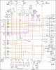
Эл. схема раздатки: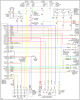
- Наверх
#8
![]()
Игорь52
Отправлено 18 января 2011 — 11:15
Игорь52
-
- Members
- 22 сообщений
- Нижний Новгород
-
Исудзу Аксиом
Спасибо Avilon! ёще просьба не можем правильно соединить провода в черной колодке на 16 контактов у нас мама есть а папа фишка сломалась и провода переломались.не можем определить какие провода куда и некоторые провода не совпадают по цветам .Просьба к тебе нескинешь фото разьемов папа и мама соединяющие провода по цветам а то мы в электрике плохо шарим.Есть провод в колодке черный с двумя метками а на другой колодке провода черного нет а есть синий тоже с двумя метками.Заранее спасибо.Спасибо Avilon! ёще просьба не можем правильно соединить провода в черной колодке на 16 контактов у нас мама есть а папа фишка сломалась и провода переломались.не можем определить какие провода куда и некоторые провода не совпадают по цветам .Просьба к тебе нескинешь фото разьемов папа и мама соединяющие провода по цветам а то мы в электрике плохо шарим.Есть провод в колодке черный с двумя метками а на другой колодке провода черного нет а есть синий тоже с двумя метками.Заранее спасибо.
- Наверх
#9
![]()
Игорь52
Отправлено 18 января 2011 — 14:16
Игорь52
-
- Members
- 22 сообщений
- Нижний Новгород
-
Исудзу Аксиом
ЕЩЁ ОДНА ПРОБЛЕМА НЕ МОЖЕМ ЗАПУСТИТЬ ДВИГАТЕЛЬ.ДОЛГО СТОЯЛ СНИМАЛИ ДВИГАТЕЛЬ И АККОМУЛЯТОР.ГОВОРЯТ ЧТО СЛЕТЕЛ ИММОБИЛАЗАР.МОЖЕТ КТО ПОМОЖЕТ
- Наверх
#10
![]()
Avilon
Отправлено 18 января 2011 — 16:14
Avilon
-
- Members
- 273 сообщений
- Москва, СВАО
-
Isuzu Axiom 2004 XS, Ford F-450 2008 King Ranch 6.4 4×4, Ford Focus 2 2007 2.0 Ghia Sedan
Спасибо Avilon! ёще просьба не можем правильно соединить провода в черной колодке на 16 контактов у нас мама есть а папа фишка сломалась и провода переломались.не можем определить какие провода куда и некоторые провода не совпадают по цветам .Просьба к тебе нескинешь фото разьемов папа и мама соединяющие провода по цветам а то мы в электрике плохо шарим.Есть провод в колодке черный с двумя метками а на другой колодке провода черного нет а есть синий тоже с двумя метками.Заранее спасибо.
К сожалению у меня на сегодняшний день отсутствует физическая возможность это сделать — автомобиль стоит на стоянке сервиса с разобранным двигателем, ждет деталей.Наверное я в ближайшие дни поеду к вам в Нижний Новгород по работе (я электроникой какраз занимаюсь) — если это случится, можем пересечся и попробовать коллективным мозговым штурмом решить твою проблему  .
.
ЕЩЁ ОДНА ПРОБЛЕМА НЕ МОЖЕМ ЗАПУСТИТЬ ДВИГАТЕЛЬ.ДОЛГО СТОЯЛ СНИМАЛИ ДВИГАТЕЛЬ И АККОМУЛЯТОР.ГОВОРЯТ ЧТО СЛЕТЕЛ ИММОБИЛАЗАР.МОЖЕТ КТО ПОМОЖЕТ
Дружище, писать с зажатым CapsLock`ом — это моветон.Иммобилайзер пошел с середины 2003 года, если у тебя авто выпущен раньше — это бред.Первый симптом того, что иммо блокирует работу двигателя — начинает мигать значек в виде ключа зажигания на приборной панеле, если этого нет, то значит, что иммобилайзер не виноват.»Слететь» (всмысле «забыть ключ») иммо не может, у него все хранится в энергонезависимой памяти. Скорее всего обрыв в проводке или разъеме (после снятия двигателя) подключения антенны иммобилайзера в замке зажигания или в проводке от иммобилайзера до ЭБУ.Схему эл. проводки иммобилайзера я уже где-то выкладывал — проверьте всю проводку:Сам блок иммо находится под «торпедо» справа от рулевой колонки. Там у него: 2) земля (черный)3) + питания от замка зажигания (черно-желтый, на нем + только когда включено зажигание)4) + питания от предохранителя иммо (красно-зеленый, на нем всегда +)5) провод, идущий к OBDII разъему (оранжево-черный, по этому проводу иммо програмируется)6) провод, идущий от датчика скорости (черно-желтый)7) провод, идущей к лампочке «Ключ» на приборной панеле, он так же связан с проводом от ЭБУ, на этот провод иммо или ЭБУ дают — питания и лампочка зажигается (фиолетово-красный)8) шина обмена данными с ЭБУ (черно-оранжевый)а так же еще идут двойной провод к антенне в замке зажигания
- Наверх
#11
![]()
Игорь52
Отправлено 18 января 2011 — 19:42
Игорь52
-
- Members
- 22 сообщений
- Нижний Новгород
-
Исудзу Аксиом
Avilon! Авто 2004 года март месяц,мой тел.сот 89202530289 когда будешь в Нижнем Новгороде звони встречу.Ключ зажигания на приборной панеле не горит.
- Наверх
#12
![]()
Avilon
Отправлено 18 января 2011 — 20:26
Avilon
-
- Members
- 273 сообщений
- Москва, СВАО
-
Isuzu Axiom 2004 XS, Ford F-450 2008 King Ranch 6.4 4×4, Ford Focus 2 2007 2.0 Ghia Sedan
Avilon! Авто 2004 года март месяц,мой тел.сот 89202530289 когда будешь в Нижнем Новгороде звони встречу.Ключ зажигания на приборной панеле не горит.
Ок. Я правда пока не знаю, поеду ли вообще, но если поеду — то на выходных или след. неделе.Если значек ключа на приборке не мигает — то с иммо скорее всего все ОК.
- Наверх
#13
![]()
Игорь52
Отправлено 18 января 2011 — 21:20
Игорь52
-
- Members
- 22 сообщений
- Нижний Новгород
-
Исудзу Аксиом
Avilon! А у тебя нет прошивки на блок АЭРБЭКА а то обе подушки стрельнули,Новые есть но надо блок прошивать.
- Наверх
#14
![]()
Игорь52
Отправлено 19 января 2011 — 08:49
Игорь52
-
- Members
- 22 сообщений
- Нижний Новгород
-
Исудзу Аксиом
Avilon! Если можешь то сфотографируй провода на черной фишке с 16 контактами провода соединений.
- Наверх
#15
![]()
Avilon
Отправлено 19 января 2011 — 11:04
Avilon
-
- Members
- 273 сообщений
- Москва, СВАО
-
Isuzu Axiom 2004 XS, Ford F-450 2008 King Ranch 6.4 4×4, Ford Focus 2 2007 2.0 Ghia Sedan
Avilon! А у тебя нет прошивки на блок АЭРБЭКА а то обе подушки стрельнули,Новые есть но надо блок прошивать.
Нет. Там насколько я понимаю Tech 2 нужен.
Avilon! Если можешь то сфотографируй провода на черной фишке с 16 контактами провода соединений.
К сожалению у меня на сегодняшний день отсутствует физическая возможность это сделать — автомобиль стоит на стоянке сервиса с разобранным двигателем, ждет деталей.
- Наверх
#16
![]()
Игорь52
Отправлено 19 января 2011 — 12:16
Игорь52
-
- Members
- 22 сообщений
- Нижний Новгород
-
Исудзу Аксиом
Avilon!А нам и нужно только сфоткать черную фишку 16 контактную соединение проводки автомата раздатки там 3 фишки черная,серая и белая.Вот нам нужна черная и её провода какие.
- Наверх
#17
![]()
Дядя Ася
Отправлено 19 января 2011 — 12:42
Дядя Ася
-
- Admin
- 26 187 сообщений
- Зеленоград/Красногорск
-
AMC Jeep Cherokee 5.9, AMC Eagle 4.2, Kia Picanto 1.2
Avilon! Если можешь то сфотографируй провода на черной фишке с 16 контактами провода соединений.
А это не проводка от датчика положения коробки? Там же на картинке всё расписано…
- Наверх
#18
![]()
Игорь52
Отправлено 20 января 2011 — 09:55
Игорь52
-
- Members
- 22 сообщений
- Нижний Новгород
-
Исудзу Аксиом
Avilon! напиши пожалуйста телефон сотовый чтобы с тобой созвониться.
- Наверх
#19
![]()
Avilon
Отправлено 22 января 2011 — 00:39
Avilon
-
- Members
- 273 сообщений
- Москва, СВАО
-
Isuzu Axiom 2004 XS, Ford F-450 2008 King Ranch 6.4 4×4, Ford Focus 2 2007 2.0 Ghia Sedan
Avilon!А нам и нужно только сфоткать черную фишку 16 контактную соединение проводки автомата раздатки там 3 фишки черная,серая и белая.Вот нам нужна черная и её провода какие.
Фоты разъема: http://www.sendspace.com/file/48klgf
- Наверх
#20
![]()
Игорь52
Отправлено 22 января 2011 — 02:54
Игорь52
-
- Members
- 22 сообщений
- Нижний Новгород
-
Исудзу Аксиом
ОГРОМНОЕ СПАСИБО СЕРГЕЙ !!!!!
- Наверх