Комментарии
2
Войдите или зарегистрируйтесь, чтобы писать комментарии, задавать вопросы и участвовать в обсуждении.
Войти
Зарегистрироваться

sapan8374
Я езжу на Toyota bB (QNC20)
А можно книжку купить или заказать. Артикул 4477 (автолегион дата). Сам такой пользуюсь.
1 год

Yozhik9225
Автор
Я езжу на Audi A4 (B5)
можно! даже нужно! но как то не задавался такой задачей! довольствовался инфой с интернета!))
1 год
- Manuals
- Brands
- Subaru Manuals
- Automobile
- 1998 Impreza
- Owner’s manual
-
Contents
-
Table of Contents
-
Bookmarks
Related Manuals for Subaru 1998 Impreza
Summary of Contents for Subaru 1998 Impreza
-
Page 1
1 9 9 8 O W N E R ’ S M A N U A L Wear Seat Belts at All Times for Your Own Safety. -
Page 2
Foreword Congratulations on choosing a SUBARU vehicle. This Owner’s Manual has all the information necessary to keep your SUBARU in excellent condition and to properly maintain the emission control system for minimizing emission pollutants. We urge you to read this manual carefully so that you may understand your vehicle and its operation. -
Page 3: Doors And Locks
This chapter informs you how to operate interior equipment. Chapter 7: Starting and operating This chapter informs you how to start and operate your SUBARU. Chapter 8: In case of emergency This chapter informs you what to do if you have a problem while driving, such as a flat tire or engine overheating.
-
Page 4: Specifications
Please read these safety warnings as well as all other portions of this manual carefully in order to gain a better understanding of how to use your SUBARU vehicle safely. WARNING A WARNING indicates a situation in which serious injury or death could result if the warning is ignored.
-
Page 5
J Safety symbol You will find a circle with a slash through it in this manual. This symbol means “Do not”, “Do not do this”, or “Do not let this happen”. Safety precautions when driving SEAT BELT AND SRS AIRBAG WARNING D All persons in the vehicle should fasten their seat belts BE- FORE the vehicle starts to move. -
Page 6
AIRBAG needs much space for deployment, the driver should al- ways sit upright and well back in the seat as far from the steering wheel as practical while still maintaining full vehicle control and the front passenger should move the seat as far back as possible and sit upright and well back in the seat. -
Page 7
THE CHILD BY PLACING THE CHILD’S HEAD TOO CLOSE TO THE SRS AIRBAG. D Always use the child safety locks whenever a child rides in the rear seat. Serious injury could result if a child accidentally opened the door and fell out. Refer to the Door Lock section in chapter 1. -
Page 8
D If at any time you suspect that exhaust fumes are entering the vehicle, have the problem checked and corrected as soon as pos- sible. If you must drive under these conditions, drive only with all windows fully open. D Keep the trunk lid or rear gate closed while driving to prevent exhaust gas from entering the vehicle. -
Page 9
If you are taking any drugs, check with your doctor or pharmacist or read the literature that accompanies the medication to determine if the drug you are taking can impair your driving ability. Do not drive after taking any medications that can make you drowsy or otherwise affect your abil- ity to safely operate a motor vehicle. -
Page 10
MODIFICATION OF YOUR VEHICLE CAUTION Your vehicle should not be modified. Modification could affect its performance, safety or durability, and may even violate govern- mental regulations. In addition, damage or performance problems resulting from modification may not be covered under warranties. DRIVING WITH PETS Unrestrained pets can interfere with your driving and distract your atten- tion from driving. -
Page 11: Table Of Contents
Table of contents Doors and locks Seat, seatbelt and SRS AIRBAG Instruments and controls Climate control Audio Interior equipment Starting and operating In case of emergency Appearance care Maintenance and service Specifications Consumer information and Reporting safety defects Index – CONTINUED –…
-
Page 12
ABS (Anti-Lock Brake system) ABS warning light …………..ACC (Ignition switch) Accessories installing Accessory power socket… -
Page 13
Back seat getting into …………Back-up light (Bulb replacement) Battery . -
Page 14
Capacities …………….Carbon monoxide (Engine exhaust gas) Cargo anchorage eyelets Cargo area (See “Luggage room”) -
Page 15
Manual transmission gear oil level Power steering fluid level Rear differential gear oil level Tire pressure …………Windshield washer fluid Child restraint systems . -
Page 16
Clutch (Manual transmission) Clutch fluid …………. Clutch pedal Coat hook . -
Page 17
Doors Child safety lock Door open warning light Door locks …………. . Power door locking switches Drive belts . -
Page 18
Engine oil …………….Changing the oil and oil filter Checking the oil level Oil capacity… -
Page 19
Fog light Fog light switch Bulb replacement Front differential gear oil (Automatic transmission vehicles) Oil leak …………..Oil capacity . -
Page 20
Glove compartment (box) Hazard warning flasher Headlights Aiming …………..Bulb replacement Daytime running light Headlight flasher… -
Page 21
Flat tires …………..Hazard warning flasher Jump starting . -
Page 22
Fuel filler door Sedan and coupe (Trunk lid) Wagon (Rear gate) Light controls …………..Daytime running light Fog light switch Hazard warning flasher switch… -
Page 23
Maintenance tools Parking brake stroke Seat belts …………. . . Malfunction indicator lamp (see “Warning light”) Manual transmission . -
Page 24
Parking light switch Parking tips Pedal Brake pedal Clutch pedal Polishing (Exterior) …………. . . Periodic inspections . -
Page 25
Reserve tank Brake fluid …………. . Clutch fluid . -
Page 26
Rear seat …………. . . Rear seat access for front seat (Coupe) Reclining the seatback for front seat Synthetic leather cleaning… -
Page 27
During cold weather Flooded engine Manual transmission vehicles State emission testing …………Steering wheels Horn . -
Page 28
Changing tools Jack and jack handle Rotation …………..Snow tires . -
Page 29
Warning lights (Indicator lights) ABS warning light AIRBAG warning light AT OIL TEMP warning light Brake system warning light Charge warning light CHECK ENGINE warning light Door open warning light FWD warning light High beam indicator light Low fuel warning light Malfunction indicator lamp Oil pressure warning light Seat belt warning light… -
Page 30
Windshield washer fluid 10-36 ……….Wiper control switch 3-21 . -
Page 31
Warranties J Warranties for U.S.A. All SUBARU vehicles distributed by Subaru of America, Inc. and sold at retail by an authorized SUBARU dealer in the continental U.S., Alaska and Hawai come with the following warranties: D SUBARU Limited Warranty D Emission Control Systems Warranty… -
Page 32
Doors and locks Keys …………….Master, submaster and valet key Key number . -
Page 33: Keys
Keys Submaster key Master key J Master, submaster and valet key Three types of keys are provided for your vehicle. Master key, submaster key and valet key. The master key and submaster key fit all locks on your vehicle. D Ignition switch D Doors D Trunk or Rear gate D Glove compartment…
-
Page 34: Doors And Locks
Door locks J Locking and unlocking from the outside B For Vehicles with power door locking switches Unlock To lock the door from the outside with the key, turn the key toward the rear. To unlock the door, turn the key toward the front. Lift the outside door handle to open an unlocked door.
-
Page 35
the same time. Always make sure that all doors and the rear gate (for wagon) are locked before leaving your vehicle. NOTE Make sure that you do not leave the key inside the vehicle before locking the doors from the outside without the key. B For vehicles without power door locking switches Unlock To lock the door from the outside with the key, turn the key toward the… -
Page 36: Locking And Unlocking From The Inside
To lock the rear door from the outside without the key, press the end of the lock lever down on the door and then close the door. Always make sure that all doors and the rear gate (for wagon) are locked before leaving your vehicle.
-
Page 37: Power Door Locks
J Power door locking switches (if equipped) Driver’s switch Front passenger’s switch Unlock Unlock Lock Lock HG0335 All doors and the rear gate can be locked and unlocked by the power door locking switches at the driver’s side and the front passenger’s side doors.
-
Page 38: Child Safety Locks
J Child safety locks Unlock Lock WARNING Always use the child safety lock whenever a child rides in the rear seat. Serious injury could result if a child accidentally opened the door and fell out. Each rear door has a child safety lock that prevents the doors from being opened even if the inside door handle is pulled.
-
Page 39: Door Open Warning Lights
Door open warning lights HG0336 The door open warning light comes on if any door is not fully closed. Always make sure this light is out before starting to drive. Windows HG0270 Turn the handle to open or close the window.
-
Page 40: Power Windows (If Equipped)
Power windows (if equipped) WARNING D When operating power windows, be extremely careful to pre- vent anyone’s fingers or head from being caught in the window. D Always lock the passenger’s windows using the lock switch when children are riding in the vehicle. D Before leaving the vehicle, always remove the key from the ignition switch for safety if a child remains in the vehicle.
-
Page 41
Lock Close Automatically open All door windows can be controlled by the power window switch cluster at the driver side door. B To open or close the driver’s window AUTO switch: This switch has two functions. Push the switch down until it clicks and release it, and the window will fully open. -
Page 42: Passenger’s Switches
J Passenger’s switches Close Open To open the window, push the switch down and hold it until the window reaches the desired position. To close the window, pull the switch up and hold it until the window reaches the desired position. When the lock switch on the power window switch cluster, located on the driver’s side door, is in the “LOCK”…
-
Page 43: To Open And Close The Trunk Lid From Outside
J To open and close the trunk lid from outside Open OM-H0016 To open the trunk lid from outside, insert the key in the keyhole and turn it clockwise. To close the trunk lid, lightly press the trunk lid down until the latch engages.
-
Page 44: Rear Gate (Wagon)
B To cancel the trunk lid release The inside trunk lid release can be cancelled to help prevent unautho- rized entry into the trunk. To cancel the trunk lid release, set the lid release cancel lever (located on the inside of the trunk lid, mounted to the trunk lid latch) to the “CANCEL”…
-
Page 45: To Open And Close The Rear Gate
J To open and close the rear gate Unlock Lock OM-H0019 To unlock the rear gate, insert the key in the keyhole and turn it clock- wise. To lock the rear gate, insert the key in the keyhole and turn it coun- terclockwise.
-
Page 46: Fuel Filler Door And Cap
Never add any cleaning agents to the fuel tank. The addition of a cleaning agent may cause damage to the fuel system. For choosing the right fuel for your SUBARU, refer to the “Fuel Require- ments” section located in chapter 7.
-
Page 47: Fuel Filler Cap
D Make sure that the cap is tightened until it clicks to prevent fuel spillage in the event of an accident. D Always use a genuine SUBARU fuel filler cap. If you use the wrong cap, it may not fit or have proper venting, and your fuel tank and emission control system might be damaged.
-
Page 48: Engine Hood
Engine hood WARNING Always check that the hood is properly locked before you start driving. If it is not, it might fly open while the vehicle is moving, blocking your view which may cause an accident and serious bodily injury. To open the hood: 1.
-
Page 49: Sunroof (If Equipped)
To close the hood: 1. Lift the hood slightly and remove the hood prop from the slot in the hood and return the prop to its retainer. 2. Lower the hood until it approaches about 6 in. (15 cm) from the closed position and let it drop.
-
Page 50
Doors and locks OM-H0027 B To open the sunroof Push the rear side of the switch marked “Y”, and the sunroof will tilt Release the switch once and push it again to slide the sunroof open. After washing the vehicle or after there is rain, wipe away any water on the roof prior to opening the sunroof to prevent water drops from falling into the passenger compartment. -
Page 51: Manual Operation
3. Insert the wrench in the end of the motor shaft. D To lower the sunroof, turn the wrench clockwise. D To close the sunroof, turn the wrench counterclockwise. Have your vehicle checked by an authorized SUBARU dealer. Roof rack (if equipped) CAUTION…
-
Page 52: When Luggage Is Put On The Slats
Doors and locks Roof rack HG0294 When you carry cargo on the roof using the roof rack, never exceed maximum load limit explained below. In addition, be careful that your ve- hicle does not exceed the Gross Vehicle Weight Rating (GVWR) and front and rear Gross Axle Weight Rating (GAWR).
-
Page 53
Seat, seat belt and SRS AIRBAG Front seats …………..Fore and aft adjustment Reclining the seatback Head restraint adjustment… -
Page 54: Front Seats
Front seats WARNING D Never adjust the seat while driving to avoid the possibility of loss of vehicle control and of personal injury. D Never drive the vehicle with the head restraints removed be- cause they are designed to reduce the risk of serious neck injury in the event that the vehicle is struck from the rear.
-
Page 55: Seat, Seatbelt And Srs Airbag
than adults, their risk of being injured from deployment is greater. For that reason, we strongly recommend that ALL children (includ- ing those in child seats and those that have outgrown child re- straint devices) sit in the REAR seat properly restrained at all times in a child restraint device or in a seat belt, whichever is ap- propriate for the child’s age, height and weight.
-
Page 56: Fore And Aft Adjustment
J Fore and aft adjustment OM-H0031 OM-H0032 Pull the lever upward and slide the seat to the desired position. Then re- lease the lever and move the seat back and forth to make sure that it is securely locked into place. J Reclining the seatback Pull the reclining lever up and adjust the seatback to the desired posi- tion.
-
Page 57: Rear Seat Access (Coupe)
The best position for the head restraint is just above or level with the top of the ears. J Rear seat access (Coupe) CAUTION D Never operate the reclining pedal with your fingers or with bare feet. Doing so could result in injury to your fingers or toes. D Never allow children to operate the reclining pedal or lever.
-
Page 58: Rear Seats
Reclining lever Reclining pedal OM-H0425 Rear seats WARNING D Seat belts provide maximum restraint when the occupant sits well back and upright in the seat. Do not put cushions or any other materials between occupants and seatbacks or seat cushions. If you do so, the risk of sliding under the lap belt and of the lap belt sliding up over the abdomen will increase, and both can result in serious internal injury or death.
-
Page 59: Fold Down Rear Seat — Wagon
Sit well back and upright. J Fold down rear seat — Wagon WARNING After returning the rear seat to its original position, be certain to place all of the seat belts and the tab attached to the seat cushion above the seat cushion. And make certain that the shoulder belts are fully visible.
-
Page 60
B Folding down the seat cushion and seatback 1. Move the front seat forward. 2. Store the seat belts in the seat belt pocket to prevent them falling below the cushion. Buckle (center seatbelt) 3. Raise the seat cushion by pulling up the tab. 4. -
Page 61
Seat, seat belt and SRS AIRBAG OM-H0042 To return the rear seat to its original position, raise the seatback and seat cushion until it locks into place and make sure that they are securely locked. Make sure that the rear seat belts are not under the seat cushion or seat- back. -
Page 62: 3-Point Type Seat Belts (Combination Lap/Shoulder Belts)
3-point type seat belts (Combination lap/shoulder belts) WARNING D Never use a belt that is twisted or reversed. In an accident, this can increase the risk or severity of injury. D Never place the shoulder belt under the arm or behind the back.
-
Page 63
whichever is appropriate for the child’s age, height and weight. Be sure to secure ALL types of child restraint devices (including forward facing child seats) in the REAR seats at all times. NEVER INSTALL A REARWARD FACING CHILD SEAT IN THE FRONT SEAT. -
Page 64: Seat Belt Warning Light And Chime
J Seat belt warning light and chime HG0340 Your vehicle is equipped with a seat belt warning device at the driver’s seat. This device causes the seat belt warning light on the instrument panel to light up for about six seconds when the ignition switch is turned to “ON” to remind the driver to wear the seat belt.
-
Page 65: Fastening The Seat Belt
J Fastening the seat belt CAUTION Metallic parts of the seat belt can become very hot in a vehicle that has been closed up in sunny weather; they could burn an oc- cupant. Do not touch such hot parts. 1. Adjust the seat position: Driver’s seat: Move the seat back as far from the steering wheel as practical while still maintaining full vehicle control and adjust the seat- back to the upright position.
-
Page 66: Unfastening The Belt
5. To make the lap part tight, pull up on the shoulder belt. And place the lap belt as low as possible on your hips, not on your waist. J Unfastening the belt Front Push Push the button on the buckle. Before closing the door, make sure that the belts are retracted properly to avoid catching the belt webbing in the door.
-
Page 67: Seat Belt Guide (Coupe)
The shoulder belt anchor height should be adjusted to the position best for you. To adjust the anchor height, pull the release knob and move the anchor to the desired position so that the shoulder belt passes over the middle of the shoulder without touching the neck. J Seat belt guide (Coupe) WARNING The seat belt guide must be in its fully raised position when the…
-
Page 68: Seat Belt Guide (Coupe)
Starting position 2-point type seat belt (lap only belt) WARNING D Seat belts provide maximum restraint when the occupant sits well back and upright in the seat. Do not put cushions or any other materials between occupants and seatbacks or seat cush- ions.
-
Page 69: Fastening The Seat Belt
Always wear the seat belt correctly. Sit well back and upright. CAUTION Metallic parts of the seat belt can become very hot in a vehicle that has been closed up in sunny weather; they could burn an oc- cupant. Do not touch such hot parts. The 2-point type seat belt has a manual adjustment device.
-
Page 70: Unfastening The Belt
into the buckle marked “CENTER”. If the belt is not long enough for you, hold the tongue plate at a right angle to the belt and pull the belt to extend. 3. To make the belt tight, pull up on the belt. And place the lap belt as low as possible on your hips, not on your waist.
-
Page 71: Seat Belt Safety Tips
Seat belt safety tips WARNING D All persons in the vehicle should fasten their seat belts BE- FORE the vehicle starts to move. Otherwise, the possibility of se- rious injury becomes greater in the event of a sudden stop or ac- cident.
-
Page 72: Expectant Mothers
J Expectant mothers Expectant mothers also need to use the seat belts. They should consult their doctor for specific recommendations. The lap belt should be worn securely and as low as possible over the hips, not over the waist. J Maintenance CAUTION D Keep the belts free of polishes, oils, chemicals and particularly battery acid.
-
Page 73: Child Restraint Systems
Seat, seat belt and SRS AIRBAG Child restraint systems WARNING D Never let a passenger hold a child on his or her lap while the vehicle is moving. The passenger cannot protect the child from injury in a collision, because the child will be caught between the passenger and objects inside the vehicle.
-
Page 74
Secure child restraint devices in the REAR seats at all times. Never allow a child to stand up, or to kneel on the front passenger’s seat or any other seat. WARNING D Child restraint systems and seat belts can become hot in a ve- hicle that has been closed up in sunny weather;… -
Page 75: Installing Child Restraint Systems In The 2-Point Type
Seat, seat belt and SRS AIRBAG propriate for the child’s age and size. All child restraint systems are de- signed to be secured in the vehicle seats by lap belts or the lap portion of a lap/shoulder belt. Children could be endangered in an accident if their child restraints are not properly secured in the vehicle.
-
Page 76: Position (Rear Center Seating Position)
If the child restraint system requires a top strap, latch the hook onto the top strap anchor and tighten the top strap. J Installing child restraint systems in the 3-point type seat belt position NOTE When the child restraint system is no longer in use, remove it and restore the ELR function of the retractor.
-
Page 77: Top Strap Anchors
pulled out (ALR properly functioning). If the child restraint system requires a top strap, latch the hook onto the top strap anchor and tighten the top strap. J Top strap anchors CAUTION Always use a genuine top strap anchor. B Installation point For center seat For right seat For left seat…
-
Page 78
the rear luggage compartment. B Top strap anchor installation (for Canada models) All vehicles built for sale in Canada include an anchor kit in the glove compartment. Cover Anchor bolt assembly (5/16 in.) Anchor plate Spacer Setting washer 1. Take the anchor kit out and make sure that it is assembled as shown in the illustration above. -
Page 79
Vehicles built for sale in U.S. do not include an anchor kit in the glove compartment. However, the anchor kit and installation instructions are available from your SUBARU dealer. You can also follow the installa- tion instructions for Canada models. -
Page 80: Srs Airbag (Supplemental Restraint System Airbag)
*SRS AIRBAG (Supplemental Restraint System Airbag) *SRS: This stands for supplemental restraint system. This name is used because the AIRBAG system supplements the vehicle’s seat belts. J Vehicle with driver’s and front passenger’s SRS AIRBAGs and lap/shoulder restraints WARNING D To obtain maximum protection in the event of an accident, the driver and all passengers in the vehicle should always wear seat belts when the vehicle is moving.
-
Page 81
the front passenger should move the seat as far back as possible and sit upright and well back in the seat. D Do not place any objects over the SRS AIRBAG cover or between you and the SRS AIRBAG. If the SRS AIRBAG deploys, those objects could interfere with its proper operation and could be propelled inside the car and cause injury. -
Page 82
For instructions and precautions concerning the child restraint system, see the Child Restraint System section in this chapter. D NEVER INSTALL A REARWARD FACING CHILD SEAT IN THE FRONT SEAT. DOING SO RISKS SERIOUS INJURY OR DEATH TO THE CHILD BY PLACING THE CHILD’S HEAD TOO CLOSE TO THE SRS AIRBAG. -
Page 83
In the event that the SRS AIRBAG is deployed, re- placement of the system should be performed only by an authorized SUBARU dealer. When the components of the SRS AIRBAG are re- placed, use only genuine SUBARU parts. -
Page 84: Srs Airbag System Operation
NOTE When you sell your vehicle, we urge you to explain to the buyer that it is equipped with SRS AIRBAGs by alerting him or her to the appli- cable section in this owner’s manual. J SRS AIRBAG System operation CAUTION D When the SRS AIRBAG deploys, some smoke will be released.
-
Page 85
Front sensor (LH) Driver’s side SRS AIRBAGs deploy as soon as a collision occurs. After deployment, SRS AIRBAGs start to deflate im- mediately so that the driver’s vision is not obstructed. Seat, seat belt and SRS AIRBAG SRS AIRBAG module (Driver’s side) Front sensor (RH) SRS AIRBAG module… -
Page 86
The SRS AIRBAG can function only when the ignition switch is in the “ON” position. If the front sensor and the impact sensor in the airbag control module detect a certain predetermined amount of force during a frontal or front- angled collision, the control module sends signals to the airbag modules instructing them to inflate the SRS AIRBAGs. -
Page 87
B Examples of the types of accidents in which the SRS AIRBAG is unlikely to deploy. There are many types of collisions which might not necessarily require SRS AIRBAG deployment. If the vehicle strikes an object, such as a telephone pole or sign pole, or if it slides under a truck’s load bed, or if it sustains an oblique offset frontal impact, the SRS AIRBAG may not deploy depending on the level of accident forces involved. -
Page 88: System Monitors
D All related wiring In the event of a malfunction indicated by any of following, the vehicle should be taken promptly to your nearest SUBARU dealer to have the system checked. Unless checked and repaired, the SRS AIRBAG will not function reliably: D Flashing or flickering of the warning light.
-
Page 89: System Servicing
SUBARU dealer perform the work. To ensure its long-term reliability, the SRS AIRBAG must be inspected by a SUBARU dealer ten years after the date of manufacture, which is shown on the certification plate attached to the driver’s door jamb.
-
Page 90: Precautions For Vehicle Modification
J Precautions for vehicle modification WARNING D Do not put any objects over the steering wheel pad and dash- board. If the SRS AIRBAG deploys, those objects could interfere with its proper operation and could be propelled inside the vehi- cle and cause injury.
-
Page 91
D Installation of a tire of different size and construction from the original tire’s listed on the tire placard attached to the door jamb. Always consult your SUBARU dealer if you want to install any accessory parts to your vehicle. -
Page 92
Instruments and controls Instrument panel overview Combination meter overview Gauges …………… Speedometer . -
Page 93: Instrument Panel Overview
Instrument panel overview Cruise control main switch (page 7-24) Combination meter (page 3-3) Hazard warning flasher switch (page 3-14) Rear window defogger switch (page 3-24) Cup holder (page 6-6) SRS AIRBAG (page 2-28) Glove compartment (page 6-3) 2 34 5 Heater or air conditioner con- trol (page 4-2) Audio (page 5-2)
-
Page 94: Instruments And Controls
Combination meter overview Fuel gauge (page 3-6) Clock adjusting knob (page 3-14) Clock (page 3-14) SRS AIRBAG warning light (page 3-8) Turn signal indicator light (page 3-13) Speedometer (page 3-5) High beam indicator light (page 3-13) Tachometer (page 3-6) Brake system warning lights (page 3-9) Charge warning light (page 3-9) CHECK ENGINE warning light/…
-
Page 95
J Light controls/Wiper controls Parking light switch (page 3-18) Hazard warning flasher switch (page 3-14) Rear window defogger switch (page 3-24) Rear window wiper and washer switch (page 3-22) Windshield washer (page 3-21) Mist (page 3-21) Windshield wiper (page 3-21) Wiper control (page 3-20) Light control (page 3-15) Illumination brightness control… -
Page 96: Speedometer
Gauges J Speedometer The speedometer shows the vehicle speed. J Odometer/Trip meter This meter displays the odometer and trip meter when the ignition switch is in the “ON” position. To change the mode indication, briefly push the knob. The odometer shows the total distance that the vehicle has been driven. The trip meter shows the distance that the vehicle has been driven since you last set it to zero.
-
Page 97: Fuel Gauge
pushing the knob and keep the knob pushed for more than 2 seconds. NOTE If the connection between the combination meter and battery is broken for any reason such as vehicle maintenance or fuse replacement, the data recorded on the trip meter will be lost. J Tachometer (if equipped) CAUTION Do not operate the engine with the pointer of the tachometer in…
-
Page 98: Temperature Gauge
J Temperature gauge CAUTION If the pointer exceeds the normal operating range, safely stop the vehicle as soon as possible. See “In case of emergency” in this manual. Normal operating range The temperature gauge shows engine coolant temperature when the ignition switch is in the “ON”…
-
Page 99: Warning And Indicator Lights
If any lights fail to come on, it indicates a burned-out bulb or a malfunc- tion of the corresponding system. Consult your authorized SUBARU dealer for repair. J Seat belt warning light and chime When the ignition switch is turned to the “ON” position, the seat belt warning light will come on and the reminder chime will sound to remind driver to fasten the seat belt.
-
Page 100: Charge Warning Light
If the oil level is low, add oil immediately. If the engine oil is at the proper level but the light remains on, contact your nearest SUBARU dealer immediately.
-
Page 101: Check Engine Warning Light
B If the light comes on steadily: If the light comes on steadily while driving or does not go out after the engine starts, an emission control system malfunction has been de- tected. You should have your vehicle checked by an authorized SUBARU dealer immediately. 3-10…
-
Page 102: Abs Warning Light
Tightening the cap will not make the CHECK ENGINE warning light turn off immediately. It may take several driving trips. If the light does not go out, take your vehicle to your authorized SUBARU dealer immediately. B If the light is blinking: If the light is blinking while driving, an engine misfire condition has been detected which may damage the emission control system.
-
Page 103: At Oil Temperature Warning Light
When the warning light is on, the ABS function shuts down; however, the conventional brake system continues to operate normally. If this occurs, have the ABS system repaired at the first available opportunity by your SUBARU dealer. NOTE If the warning light behavior is as shown below, the ABS system may be considered normal.
-
Page 104: Door Open Warning Lights
Contact your nearest SUBARU dealer for service immediately. J Door open warning lights The door open warning light comes on if any door or rear gate (for wagon) is not fully closed.
-
Page 105: Clock
Clock HG0345 The clock displays the time when the ignition switch is in the “ACC” or “ON” positions. J Setting the clock To set the hour, press the “H” button. To set the minutes, press the “M” button. Hazard warning flasher HS0053 The hazard warning flasher is used to warn other drivers when you have to park your vehicle under emergency conditions.
-
Page 106: Light Controls
flasher works with the ignition switch in any position. When you have to park your vehicle under emergency conditions, pull off the road safely and park away from the traffic if it is possible. To turn on the hazard warning flasher, push the hazard warning button on the instrument panel.
-
Page 107: Daytime Running Light
lever. first position Parking lights, instrument panel illumination, tail lights, side marker lights and license plate light are on. second position Headlights, parking lights, instrument panel illumination, tail lights, side marker lights and license plate light are on. B High/low beam change (dimmer) To change from low beam to high beam, push the turn signal lever forward.
-
Page 108
The low beam headlights will automatically come on at reduced brightness when the engine has started, under the following condi- tions: D The parking brake is fully released. D The automatic transmission selector lever is set at other than the “P” position. D The light switch is in the “OFF”… -
Page 109: Illumination Brightness Control
J Illumination brightness control Brighten Darken When the lighting switch is in the “p” or “a” position, you can adjust brightness of the instrument panel illumination for better visibility. To brighten, turn the control dial counterclockwise. To darken, turn the control dial clockwise. J Parking light switch The parking light switch operates regardless of the ignition switch posi- tion.
-
Page 110: Fog Light Switch (If Equipped)
Instruments and controls – license plate lights To turn off, push the front end of the parking light switch. Avoid leaving these lights on for a long time because that will run down the battery. J Fog light switch (if equipped) The fog lights operate only when the headlights are on low beam.
-
Page 111: Wiper Controls
Wiper controls WARNING In freezing weather, do not use the windshield washer until the windshield is sufficiently warmed by the defroster. Otherwise the washer fluid can freeze on the windshield, blocking your view. CAUTION D Do not operate the washer continuously for more than ten se- conds, or when the washer fluid tank is empty.
-
Page 112: Windshield Wipers And Washer Switch
D Clean your wiper blades and windshield periodically with a wind- shield washer solution to prevent streaking, and to remove accumula- tions of road salt or road film. Keep the windshield washer button depressed at least for 1 second so that washer solution will be sprinkled all over the windshield or rear window.
-
Page 113: Wiper And Washer Switch
To turn the wipers off, return the lever to the “OFF” position. B Mist (for a single wipe) For a single wipe of the wipers, pull the lever toward you. The wipers operate until you release the lever. B Washer To wash the windshield, push the washer button at the end of the wip- er control lever.
-
Page 114
Check washer fluid level fre- quently, such as at fuel stops. D Use clean water if windshield washer fluid is unavailabale. In areas where water freezes in winter, use SUBARU Windshield Washer Fluid or the equivalent. (See Windshield Washer Fluid section in chapter 10.) Also, when driving the vehicle when there are freezing tempera- tures, use non-freezing type wiper blades. -
Page 115: Rear Window Defogger Switch
Rear window defogger switch CAUTION D Do not use sharp instruments or window cleaner containing abrasives to clean the inner surface of the rear window. They may damage the conductors printed on the window. D To prevent the battery from being discharged, do not operate the defogger continuously for any longer than necessary.
-
Page 116: Horn
Instruments and controls Horn OM-H0440 To sound the horn, push the horn pad. Mirrors Always check that the inside and outside mirrors are properly adjusted before you start driving. J Inside mirror HG0019 The inside mirror has a day and night position. Pull the tab at the bottom of the mirror toward you for the night position.
-
Page 117: Outside Mirrors
J Outside mirrors WARNING Objects look smaller in a convex mirror (passenger side) and far- ther away than when viewed in a flat mirror. Do not use the con- vex mirror to judge the distances of vehicles behind you when changing lanes.
-
Page 118: Remote Control Mirror Switch
Instruments and controls B Remote control mirror switch (if equipped) The remote control mirrors operate only when the ignition switch is in the “ON” or “ACC” position. Direction control knob Selection switch HG0344 1. Press either end of the selection switch; “L” for the left and “R” for the right.
-
Page 119: Heater Operation
Climate control Ventilator …………..Heating and air conditioning Air flow control dial .
-
Page 120
Ventilator Move the thumb-wheel up and down or right and left to adjust the air flow direction Oepn Close Move the thumb-wheel up and down or right and left to adjust the air flow direction Move the thumb-wheel up and down or right and left to adjust the air flow direction Oepn… -
Page 121: Climate Control
Heating and air conditioning Temperature control dial Fan speed control lever J Air flow control dial This dial has following five positions: : Air flows through the instrument panel outlets. : Air flows through the instrument panel outlets and the foot out- lets.
-
Page 122: Air Conditioner Button (If Equipped)
J Air inlet selection lever WARNING Continued operaton in the “ dows. Switch to the “ dusty condition clears. : Interior air is recirculated inside the passenger comparment. : Outside air is drawn into the passenger compartment. J Air conditioner button (if equipped) The air conditioner operates only when the engine is running.
-
Page 123: Heating And Defrosting
4. Set the fan speed control lever to the highest speed. Warm air also comes out from the right and left air outlets. To stop warm air flow from these outlets, turn the corresponding thumb-wheel to the “ ” position. J Heating and defrosting To direct warm air toward the floor and the windshield: 1.
-
Page 124
J Heating To direct warm air toward the floor: 1. Set the air inlet selection lever to the “ 2 Set the air outlet control dial to the “ 3. Set the temperature control dial to the most comfortable level. 4. -
Page 125
warmer than from the instrument panel outlet. 1. Set the air inlet selection lever to the “ 2. Set the air outlet control dial to the “ 3. Set the temperature control dial to the desired temperature level. 4. Set the fan speed control lever to the desired speed. Setting the temperature control dial fully turned to the red area or blue area decreases the temperature difference between the air from the instrument panel outlets and the air from the foot outlets. -
Page 126: Air Conditioner Operation
AIR CONDITIONER OPERATION J Cooling or dehumidifying ON position For cooling and dehumidification of the passenger compartment, air flows through the instrument panel outlets: 1. Set the air inlet selection lever to the “ 2. Set the air outlet control dial to the “ 3.
-
Page 127: Operating Tips For Heater And Air Conditioner
Climate control ON position HS0072 HS0073 To direct warm air to the windshield and front door windows: 1. Set the air inlet selection lever to the “ ” position. 2. Set the air outlet control dial to the “ ” position. 3.
-
Page 128: Efficient Cooling After Parking In Direct Sunlight
J Checking air conditioning system before summer season Check the air conditioner unit for refrigerant leaks, hose conditions, and proper operation each spring. This check is best performed by your SUBARU dealer. J Cooling and dehumidifying in high humidity and low temperature weather condition Under certain weather conditions (high relative humidity, low tempera- tures, etc.) a small amount of water vapor emission from the air outlets…
-
Page 129: Air Filtration System (Option)
CFC12 (freon). Consult your SUBARU dealer for ser- vice. Repairs needed as a result of using the wrong refrigerant are not covered under warranty. Air filtration system (option) If your vehicle’s air conditioning system is equipped with a optional air filtration system, replace the filter element according to the replacement schedule shown below.
-
Page 130
2. Remove the old filter. Plastic tab New filter 3. Insert a new filter with the plastic tab facing forward. 4. Install rubber seal on the duct opening. CAUTION Make certain that the rubber seal is evenly seated on the duct opening. -
Page 131: Antenna
Audio Radio …………….Manual antenna .
-
Page 132: Radio
Radio J Manual antenna Before listening to the radio, extend the antenna to its full length for bet- ter reception and reproduction quality. OM-H0115 J FM reception Although FM is normally static free, reception can be affected by the sur- rounding area, atmospheric conditions, station strength and transmitter distance.
-
Page 133: Audio
AM/FM stereo radio with cassette player (if equipped) The radio will operate only when the ignition switch is in the “ACC” or “ON” positions. RADIO OPERATION Stereo Waveband indicator indicator Press station Frequency number SCAN button Tone and balance Power switch and control button volume control Tuning buttons…
-
Page 134
J Power switch and volume control (ON/VOL) Volume control The same knob is used for both power (on/off) and volume control. The radio is turned on and off by pushing the knob and the volume is con- trolled by turning the knob. The volume control has total of 34 volume levels (V: 0 for minimum, V: 33 for maximum). -
Page 135
Volume Bass (VOL) (BAS) B Bass control Bass volume control indication Select the Bass control mode by pressing the “T/B” button. In the bass control mode, the display shows the indication as shown. The bass control has total of 13 volume levels (B: –6 for minimum, 0 for middle, B: +6 for maximum). -
Page 136
Select the Treble control mode by pressing the “T/B” button. In the treble control mode, the display shows the indication as shown. The treble control has total of 13 volume levels (TR: –6 for minimum, 0 for middle, TR: +6 for maximum). Choose desired treble volume level by turning the volume control knob. -
Page 137: Fm/Am Selection Switch
B Balance control Balance control indication Select the Balance control mode by pressing the “T/B” button. In the balance control mode, the display shows the indication as shown. The balance control has total of 25 settings (L: 12 for left side maxi- mum and right side minimum, 0 for neutral, R: 12 for left side mini- mum and right side maximum).
-
Page 138: Automatic Tuning (Scn)
J Automatic tuning (SCN) Press the “SCN” button to change the radio to the SCAN mode. In this mode, the radio scans through the radio band until a station is found. The radio will stop at the station for five seconds while displaying the fre- quency, after which scanning will continue until the entire band has been scanned from the low end to the high end.
-
Page 139: Cassette Player Operation
CASSETTE PLAYER OPERATION Tape travel indicator Cassette player operation indicator Tape program sensor button NOTE D Only use good quality cassettes (cassettes longer than C-90 are not recommended). D Put cassettes back in their boxes immediately after use to protect them from dust and dirt and to prevent the tape from unwinding.
-
Page 140
J Program switching buttons (PROG) When the program switching buttons (“ pressed at the same time during playback, the tape travel indicators will switch and the player will begin playing back the opposite side of the tape. The same mechanism is automatically activated when the end of the tape is reached. -
Page 141: Clock Function
D When the blanks between selections are shorter than five seconds. D When there are no blanks between selections (live concerts, etc.). J Dolby NR button (BNR) Press “BNR” button when playing tapes recorded using the Dolby NR system*. The “BNR” indicator will light up and high-frequency noise on the tape will be reduced for clearer sound reproduction.
-
Page 142: Setting The Time
If this occurs, it is necessary to reset the time. Installation of accessories Always consult your SUBARU dealer before installing a citizen band ra- dio or other transmitting device in your vehicle. Such devices may cause the electronic control system to malfunction if they are incorrectly installed or if they are not suited for the vehicle.
-
Page 143
Interior equipment Sun visors …………..Vanity mirror (if equipped) Storage compartment Glove compartment… -
Page 144: Sun Visors
Sun visors To block out glare, swing down the visors. To use the sun visor at a side window, swing it down and move it sideways. J Vanity mirror (if equipped) To use the vanity mirror, swing down the passenger side visor. Storage compartment CAUTION D Always keep the storage compartment closed while driving to…
-
Page 145: Interior Equipment
J Glove compartment To open the glove compartment, pull the handle. To close it, push the lid firmly upward. To lock the glove compartment, insert the master key and turn it clock- wise. To unlock it, insert the masterkey and turn it counterclockwise. J Center console To open the lid, pull up the lock release.
-
Page 146: Lid Tray
B Lid tray WARNING Objects must not be placed on the lid tray while the vehicle is moving. In the event of sudden braking, sudden steering, or a collision, objects on the lid tray could be thrown toward the vehicle’s occupants and could cause injuries. CAUTION If drinks are placed on the tray, take care to prevent them from spilling.
-
Page 147: Dashboard Storage Compartment
Interior equipment J Dashboard storage compartment Push HS0094 To open the dashboard compartment, push the button and pull up on the lid. Be sure to close the compartment fully before driving. J Coin tray HS0096 To open the coin tray, pull the upper edge of the lid. –…
-
Page 148: Cup Holder
Cup holder CAUTION D When not in use, always keep the holder stored while driving to reduce the risk of injury in the event of a sudden stop or an accident. D Do not pick up a cup from the cup holder or put a cup in the holder while you are driving, as this may distract you and lead to an accident.
-
Page 149: In The Luggage Compartment
CAUTION The electrical power socket located on the lower part of the instrument panel is designed to use only a SUBARU genuine cig- arette lighter plug. Do not use non-genuine cigarette lighter plugs or any “plug-in” type electrical accessories in the socket. Doing so may cause a short-circuit and overheating, resulting in a fire.
-
Page 150
D Do not place any foreign objects, especially metal ones such as coins or aluminum foil, into the accessory power socket. That could cause a short circuit. Always put the cap on the accessory power socket when it is not in use. D Use only electrical appliances which are designed for 12V DC and which consume less than 120W. -
Page 151: Cigarette Lighter And Front Ashtray (Option)
“plug-in” type electrical accessories in the socket. Doing so may cause a short-circuit and overheating, resulting in a fire. D You should install a SUBARU genuine ashtray if you smoke in the vehicle. The pocket located near the socket is not designed to sustain high temperatures.
-
Page 152: Front Ashtray
J Cigarette lighter WARNING To avoid being burned, never grasp the lighter by the end with the heating element. Doing so could result in injury and could also damage the heating element. CAUTION Do not hold the lighter pushed in, because it will overheat. The cigarette lighter operates only when the ignition switch is in the “ON”…
-
Page 153: Rear Ashtray
To open the ashtray, pull the lid out. To remove the ashtray for cleaning, open it and pull it out while pushing the inner plate down. Rear ashtray CAUTION Do not use ashtrays as waste receptacles or leave a lighted ciga- rette in an ashtray.
-
Page 154: Coat Hook
Coat hook CAUTION Never hang anything on the coat hook that might obstruct the driver’s view. And do not hang items on the coat hook that weigh 2.2 lb (1 kg) or more. Interior light The interior light switch has three positions: 6-12 HG0307 OM-H0133…
-
Page 155: Spotlight (If Equipped)
Interior equipment ON: The light stays on continuously. Middle position: The light comes on only when any door is opened. OFF: The light stays off. When leaving your vehicle, make sure the light is turned off to avoid bat- tery discharge. Spotlight (if equipped) OM-H0134 To turn on the spotlight, push the switch.
-
Page 156: Luggage Cover (Wagon Only)
Luggage cover (Wagon only) CAUTION D Do not place anything on the extended cover. Putting exces- sive weight on the extended cover can break it and an object on the cover could tumble forward in the event of a sudden stop or collision.
-
Page 157: To Remove The Cover Housing
Interior equipment J To remove the cover housing Match mark HG0099, HG0190 1. Rewind the cover. 2. Pull either sleeve on the end of the cover housing to shorten its length. 3. Take it off the retainer. 4. Store the cover housing in the luggage area. J To install the cover housing 1.
-
Page 158: Shopping Bag Hook (Wagon Only)
Shopping bag hook (Wagon only) The shopping bag hook is attached to the left side of the luggage compartment. You can hook a light shopping bag or something similar on it. Cargo anchorage eyelets (if equipped) CAUTION The cargo anchorage eyelets are designed only for securing light luggage.
-
Page 159: Maintenance Tools
Anchorage eyelets The luggage compartment is equipped with four anchorage eyelets for securing luggage with a luggage net or ropes. When using the anchorage eyelets, raise them up from under the cutouts of the luggage compartment mat. When not in use, put the eyelets down into the storing recesses.
-
Page 160
Starting and operating New vehicle break-in driving The first 1,000 miles (1,600 km) Fuel requirements …………Fuel octane rating . -
Page 161
Cruise control (if equipped) To set cruise control To temporarily cancel the cruise control To turn off the cruise control To change the cruising speed Parking your vehicle Parking brake …………Parking tips . -
Page 162: Starting And Operating
New vehicle break-in driving J The first 1,000 miles (1,600 km) The performance and long life of your vehicle are dependent on how you handle and care for your vehicle while it is new. Follow these instructions during the first 1,000 miles (1,600 km): D Do not race the engine.
-
Page 163: Fuel Requirements
Do not let fuel spill on the exterior surfaces of the vehicle. Fuels containing alcohol may cause paint damage, which is not cov- ered under the SUBARU Limited Warranty. Your use of gasoline with detergent additives will help prevent deposits…
-
Page 164
Many gasolines are now blended with materials called oxygenates. Use of these fuels can also help keep the air cleaner. SUBARU approves the use of oxygenated blend fuels, such as MTBE (Methyl Tertiary Butyl Ether) or ethanol (ethyl or grain alcohol). -
Page 165: State Emission Testing (U.s. Only)
State I/M Programs should test affected SUBARU AWD models using any other EPA-91 approved performance warranty short test. SUBARU models equipped with the AWD feature should be tested on a four-wheel drive dynamometer or the State I/M Program may elect to use…
-
Page 166: Exhaust Gas
stances should the rear wheels be jacked off the ground, nor should the drive-shaft be disconnected for I/M testing. Engine exhaust gas (Carbon monoxide) WARNING D Never inhale engine exhaust gas. Engine exhaust gas contains carbon monoxide, a colorless and odorless gas which is danger- ous, or even lethal, if inhaled.
-
Page 167: Catalytic Converter
D Keep your engine tuned-up. If you feel the engine running rough (mis- firing, backfiring or incomplete combustion), have your vehicle checked and repaired by an authorized SUBARU dealer. D Do not apply undercoating or rust prevention treatment to the heat…
-
Page 168: Driver’s Side
Fuel economy hints The following suggestions will help to save your fuel. D Select the proper gear position for the speed and road conditions. D Avoid sudden acceleration or deceleration. Always accelerate gently until you reach the desired speed. Then try to maintain that speed for as long as possible.
-
Page 169: Driving In Foreign Countries
NOTE Engine oil, engine coolant, brake fluid, washer fluid and other fluid levels should be checked daily, weekly or at fuel stops. Driving in foreign countries When planning to use your vehicle in another country: D Confirm the availability of the correct fuel. (Refer to Fuel Require- ment section in this chapter.) D Comply with all regulations and requirements of each country.
-
Page 170: Lock
J LOCK The key can only be inserted or removed in this position. The ignition switch will lock the steering wheel when you remove the key. If turning the key is difficult, turn the steering wheel slightly to the right and left as you turn the key.
-
Page 171: Manual Transmission
B Manual transmission vehicles The key can be turned from “ACC” to “LOCK” only when the key is pushed in while turning it. J ACC In this position the electrical accessories (radio, accessory socket, etc.) can be used. J ON This is the normal operating position after the engine is started.
-
Page 172: Key Interlock Release (At Vehicles Only)
3. Remove the undercover of the steering column. 4. Turn the ignition key while pressing the key interlock release lever. Take your vehicle to the nearest SUBARU dealer immediately to have the key interlock system repaired. Starting the engine…
-
Page 173: Automatic Transmission Vehicles
Hold the clutch pedal to the floor while starting the engine. The starter motor will only operate when the clutch pedal is pressed fully to the floor. 4. Turn the ignition switch to the “ON” position and check the operation of the warning and indicator lights.
-
Page 174: During Cold Weather Below -4 F (-20 C)
the ignition switch to the “START” position again while depressing the ac- celerator pedal half way down. 6. Confirm that all warning and indicator lights have gone out after the engine has started. The fuel injection system automatically lowers the idle speed as the engine warms up.
-
Page 175: Manual Transmission
Manual transmission CAUTION Shift into reverse ONLY when the vehicle has completely stopped. It may cause damage to the transmission to try shifting into reverse when the vehicle is moving. The manual transmission is a fully synchromeshed 5-forward and 1-re- verse speed transmission.
-
Page 176: Maximum Speeds
Shift up 1st to 2nd 2nd to 3rd 3rd to 4th 4th to 5th J Maximum speeds B Vehicle with tachometer Never drive with the tachometer needle in the critical engine speed range except for brief acceleration in an emergency. B Vehicle without tachometer Never exceed the speed limits below for each gear position except for brief acceleration in an emergency.
-
Page 177: Automatic Transmission
brake pad life. In this way, the engine provides a braking effect. Remember, if you “ride” (over use) the brakes while descending a hill, they may overheat and not work properly. Automatic transmission WARNING Do not shift from the “P” or “N” position into the “D”, “3”, “2”, “1”…
-
Page 178: Selector Lever
J Selector lever Release button The selector lever has seven positions. The release button must be pushed to select the “P”, “R”, or “2” posi- tions. B P (Park) This position is for parking the vehicle and starting the engine. In this position, the transmission is mechanically locked to prevent the vehicle from rolling freely.
-
Page 179
B R (Reverse) This position is for backing the vehicle. To shift from the “N” to “R” position, first stop the vehicle completely then move the lever to the “R” position while pushing the release but- ton. B N (Neutral) This position is for restarting a stalled engine. -
Page 180: Maximum Speeds
Use this position when starting off form a standstill on slippery road surfaces such as mud or snow. It will ensure greater traction. B 1 (First) This position is for driving up or down very steep grades, or driving through mud or sand, or on slippery surfaces. In this position, the transmission holds in the 1st gear.
-
Page 181
“P” to the “N” position. 8. Remove the shaft from the hole. Depress the brake pedal and start the engine. Take your vehicle to the nearest SUBARU dealer immediately to have the system repaired. 7-22… -
Page 182: Steering
Steering J Tilt steering wheel WARNING Do not adjust the steering tilt position while driving. This may cause loss of vehicle control and result in personal injury. B Tilt adjustment 1. Adjust the seat position. Refer to Front Seat section (chapter 2). 2.
-
Page 183: Cruise Control (If Equipped)
If you lose power steering assist because the engine stops or the system fails to function, you can steer but it will take much more effort. Cruise control (if equipped) WARNING Do not use the cruise control under any of the following condi- tions.
-
Page 184: To Temporarily Cancel The Cruise Control
The vehicle will maintain the desired speed. Vehicle speed can be temporarily increased while driving with the cruise control activated. Simply depress the accelerator pedal to accelerate the vehicle. When the accelerator pedal is released, the vehicle will return to and maintain the previous cruising speed.
-
Page 185: Parking Brake
sired speed. 2. Push the control lever downward in the “SET, COAST” direction once. Now the desired speed is set and the vehicle will keep running at that speed without depressing the accelerator pedal. B To decrease the speed 1. Push the control lever downward in the “SET, COAST” direction and hold it until the vehicle reaches the desired speed.
-
Page 186: Parking Tips
Release button To release the parking brake, pull the lever up slightly, press the release button, then lower the lever while keeping the button pressed. When the parking brake is set while the engine is running, the parking brake warning light comes on. After starting the vehicle, be sure that the warning light has gone out before the vehicle is driven.
-
Page 187: Braking Tips
When parking your vehicle, always set the parking brake firmly and put the shift lever in the “1” (1st) for an upgrade or “R” (Reverse) for a down grade for manual transmission vehicles, or in the “P” (Park) position for automatic transmission vehicles.
-
Page 188: Brake System
Starting and operating B When the brakes get wet When driving in rain, in puddle or after washing the vehicle, the brakes may get wet. As a result, brake stopping distance will be long- er. To dry the brakes, drive the vehicle at a safe speed while lightly depressing the brake pedal to heat up the brakes.
-
Page 189: Disc Brake Pad Wear Warning Indicators
The disc brake pad wear warning indicators on the disc brakes give a warning noise when the brake pads are worn. If a squeaking or scraping noise is heard from the disc brakes while braking, immediately have your vehicle checked by your SUBARU deal- J ABS (Anti-Lock Brake System) (if equipped) WARNING Always use the utmost care in driving –…
-
Page 190
D When you feel the ABS system operating, you should maintain constant brake pedal pressure. Do not pump the brake pedal since doing so may defeat the operation of the ABS system. The ABS system prevents the lock-up of wheels which may occur during sudden braking or braking on slippery road surfaces. -
Page 191
If this occurs, have the ABS system repaired at the first available opportuni- ty by your SUBARU dealer. NOTE If the warning light behavior is as shown below, the ABS system may be considered normal. -
Page 192: Driving Tips For Awd Vehicles
By shifting power between the front and rear wheels, SUBARU AWD can also pro- vide added traction during acceleration and added engine braking force during deceleration.
-
Page 193: Off Road Driving
ence in handling, however, during extremely sharp turns or sudden brak- ing. Therefore, when driving down a slope or turning corners, be sure to reduce your speed and maintain an ample distance from other vehicles. D When replacing a tire, make sure you use only the same size, construc- tion, brand, and load range as the original tires listed on the tire placard.
-
Page 194
But please keep in mind that an AWD Subaru is a passenger car and is neither a conventional off-road vehicle nor an all-terrain vehicle. If you do take your Subaru off-road, cer-… -
Page 195
ness and ensure that the bed of the stream is flat. Drive slowly and com- pletely through the stream. The water should be shallow enough that it does not reach the vehicle’s undercarriage. Water entering the engine air intake or the exhaust pipe or water splashing onto electrical parts may damage your vehicle and may cause it to stall. -
Page 196: Winter Driving
Warranty and Maintenance Booklet. Remember that damage done to your Subaru while operating if off-road and not using common sense precautions such as those listed above is not eligible for warranty coverage.
-
Page 197
Use a windshield washer fluid that contains an antifreeze solution. Do not use engine antifreeze or other substitutes because they may damage the paint of the vehicle. B Before driving your vehicle Before entering the vehicle, remove any snow or ice from your shoes because that could make the pedals slippery and dangerous. -
Page 198: Driving On Snowy And Icy Roads
When an antifreeze additive is used, its effect lasts longer if the tank is refilled whenever the fuel level reaches half empty. If your SUBARU is not going to be used for an extended period, it is best to have the fuel tank filled to capacity.
-
Page 199: Snow Tires
to the windshield or rear window, use the defroster with the airflow control dial in the “ turned fully to the right until the wiper blades are completely thawed out. To thaw out the rear wiper blade, use the rear window defogger. When driving in snow, if frozen snow starts to stick on the surface of the windshield despite wiper operation, use the defroster with the air- flow control dial in “…
-
Page 200: Tire Chains
same tire size, construction, brand, and load range as the original tires. The recommended tire sizes and pressure are provided on the tire label, which can be found on the driver’s side door jamb under the latch. Remember to drive with care at all times regardless of the type of tires on your vehicle.
-
Page 201: Corrosion Protection
J Corrosion protection Refer to the Corrosion Protection section (chapter 9). Loading your vehicle WARNING D Never allow passengers to ride on the folded rear seatback in the trunk or in the cargo area. Doing so may result in serious in- jury.
-
Page 202: Vehicle Capacity Weight
Starting and operating J Vehicle capacity weight Tire information label HG0347 HG0278 The load capacity of your vehicle is determined by weight, not by avail- able cargo space. The maximum load you can carry in your vehicle is shown as the Vehicle Capacity Weight on the tire information label at- tached to the driver’s side door jamb.
-
Page 203: Trailer Towing
Rating). The GVW (Gross Vehicle Weight) must never exceed the GVWR. GAW is the combined total of weight of the vehicle, fuel, driver, all passengers, luggage, any optional equipment and trailer tongue load. Therefore, the GVW changes depending on the situation. The GVWR equals Curb Weight (actual weight of your vehicle –…
-
Page 204: Warranties And Maintenance
SUBARU assumes no responsibility for injuries or vehicle damage that result from trailer towing equipment, or from any errors or omissions in the instructions accompanying such equipment or for your failure to fol- low the proper instructions.
-
Page 205: Trailer Hitches
D Adequate size trailer brakes are required when the trailer and its cargo exceed 700 lbs (318 kg) total weight. Choose a proper hitch for your vehicle and trailer. SUBARU does not of- fer accessory trailer hitches. Consult with a professional hitch supplier to assist you in choosing an appropriate hitch for your vehicle.
-
Page 206: Trailer Lights
Consult your authorized SUBARU dealer concerning the connection of wires for trailer lights. Check for correct operation of the turn signals and brake lights each time you hitch up.
-
Page 207: Trailer Towing Tips
HG0278 Trailer tire condition, size, load rating and proper inflation pressure should be in accordance with the trailer and tire manufacturer’s specifi- cations. In the event your vehicle gets a flat tire when towing a trailer, ask a com- mercial road service to repair the flat tire. If you carry a regular size spare tire in your vehicle or trailer as a precau- tion against getting a flat tire, be sure that the spare tire is firmly secured.
-
Page 208
Starting and operating at moderate engine rpm. Avoid uneven steering, sharp turns and rapid lane changes. Slow down before turning. Make a longer than normal turning radius be- cause the trailer wheels will be closer than the vehicle wheels to the in- side of the turn. -
Page 209
5. Shift into 1st or reverse gear (manual transmission) or “P” (automatic transmission) and shut off the engine. If the ABS warning light illuminates while the vehicle is in motion, stop towing the trailer and have repairs carried out immediately by the nearest SUBARU dealer. 7-50… -
Page 210
In case of emergency Hazard warning flasher Engine overheating …………If steam is coming from the engine compartment If no steam is coming from the engine compartment Jump starting… -
Page 211: Hazard Warning Flasher
Hazard warning flasher Day or night, if your vehicle becomes a traffic hazard, use the hazard warning flasher. Avoid stopping on the road. It is best to safely pull off the road if a problem occurs. The hazard warning flasher can be acti- vated regardless of the ignition switch position.
-
Page 212: In Case Of Emergency
2. Open the hood to ventilate the engine compartment. Confirm that the cooling fan is turning. If the fan is not turning, immedi- ately turn the engine off and contact your authorized SUBARU dealer for repair. 3. After the engine coolant temperature has dropped, turn off the en- gine.
-
Page 213: Jump Starting
Jump starting WARNING D Battery fluid is SULFURIC ACID. Do not let it come in contact with the eyes, skin, clothing or the vehicle. If battery fluid gets on you, thoroughly flush the exposed area with water immediately. Get medical help if the fluid has entered your eyes.
-
Page 214: Jump Starting
When your vehicle does not start due to a run down (discharged) bat- tery, the vehicle may be jump started by connecting your battery to another battery (called the booster battery) with jumper cables. Jump starting is dangerous if it done incorrectly. If you are unsure about the proper procedure for jump starting, consult a competent mechanic.
-
Page 215: Flat Tires
moderate speed. Then start the engine of the vehicle that has the dis- charged battery. 6. When finished, carefully disconnect the cables in exactly the reverse order. Flat tires WARNING D Do not jack up the vehicle on an incline or a loose road sur- face.
-
Page 216
In case of emergency 1. Park on a hard, level surface, whenever possible, then stop the en- gine. 2. Set the parking brake securely and shift a manual transmission ve- hicle in reverse or an automatic transmission vehicle in the “P” (Park) position. -
Page 217
Locking type wheel cover Regular type wheel cover HG0105 HG0348 7. Loosen the wheel nuts using the wheel nut wrench but do not remove the nuts. OM-H0376 8. Place the jack under the side sill at the front or rear jack-up point clos- est to the flat tire. -
Page 218
9. Insert the jack handle into the jackscrew, and turn the handle clock- wise until the tire clears the ground. Do not raise the vehicle higher than necessary. 10. Remove the wheel nuts and the flat tire. 11. Before putting the spare tire on, clean the mounting surface of the wheel and hub with a cloth. -
Page 219
OM-H0172 HG0104 12. Put on the spare tire. Replace the wheel nuts. Tighten them by hand. 13. Turn the jack handle counterclockwise to lower the vehicle. 14. Use the wheel nut wrench to securely tighten the wheel nuts to the specified torque, following the tightening order in the illustration. -
Page 220: Temporary Spare Tire
en the attaching bolt firmly. Attaching bolt Flat tire Spacer Also store the jack and wheel nut wrench in their storage locations. See Tire changing tools in this section. J Temporary spare tire WARNING Never tow a trailer when the temporary spare tire is used. The temporary spare tire is not designed to sustain the towing load.
-
Page 221
kPa, 4.2 kg/cm ) periodically to keep the tire ready for use. When using the temporary spare tire, note the following: D Do not exceed 50 mph (80 km/h). D Do not put a tire chain on the temporary spare tire. Because of the smaller tire size, a tire chain will not fit properly . -
Page 222: Spare Tire
ter re-installing the conventional tire, remove the spare fuse from the FWD connector in order to reactivate all wheel drive. J Tire changing tools B Spare tire The spare tire is stored under the floor of the trunk or the luggage compartment.
-
Page 223: Towing
The jack handle is stored under the spare tire cover. Towing If towing is necessary, it is best done by your SUBARU dealer or a com- mercial towing service. Observe the following procedures for safety. J Transporting your vehicle using a flat-bed truck This is the best way to transport your vehicle.
-
Page 224: Towing With The Front Wheels Raised Off The Ground
J Towing with the front wheels raised off the ground WARNING Never tow manual transmission AWD vehicles with the front wheels raised off the ground while the rear wheels are on the ground. This will cause the vehicle to spin away due to the opera- tion or deterioration of the viscous coupling.
-
Page 225: Towing With All Wheels On The Ground
J Towing with all wheels on the ground WARNING D Never turn the ignition switch to the “LOCK” position while the vehicle is being towed because the steering wheel and the direc- tion of the wheels will be locked. D Remember that the brake booster and power steering do not function when the engine is not running.
-
Page 226: Towing Eyelets
We do not recommend this method of towing. Use this method only when towing service by a SUBARU dealer or a commercial towing service is not available. 1. Check the transmission and differential oil levels and add oil to bring it to the upper level if necessary.
-
Page 227
Never use tie-down eyelet for towing purposes. The towing eyelets should be used only in an emergency (e.g., to free a stuck vehicle from mud, sand or snow). 8-18 HG0111… -
Page 228: Appearance Care
Appearance care Exterior care …………..Washing .
-
Page 229: Exterior Care
Exterior care J Washing CAUTION D When washing the vehicle, the brakes may get wet. As a result, the brake stopping distance will be longer. To dry the brakes, drive the vehicle at a safe speed while lightly pressing the brake pedal to heat up the brakes.
-
Page 230: Waxing And Polishing
Frequent polishing with a compound or an incorrect polishing technique will result in removing the paint layer and exposing the undercoat. When in doubt, it is always best to contact your SUBARU dealer or an auto paint specialist. Appearance care – CONTINUED –…
-
Page 231: Corrosion Protection
Corrosion protection Your SUBARU has been designed and built to resist corrosion. Special materials and protective finishes have been used on most parts of the vehicle to help maintain fine appearance, strength, and reliable opera- tion. J Most common causes of corrosion The most common causes of corrosion are: 1.
-
Page 232: Cleaning Aluminum Wheels
Appearance care form this kind of maintenance and treatment if you need assistance. Repair chips and scratches in the paint as soon as you find them. Check the interior of the vehicle for water and dirt accumulation under the floor mats because that could cause corrosion. Occasionally check under the mats to make sure the area is dry.
-
Page 233: Cleaning The Interior
Use the cleaner according to its instruction. J Synthetic leather upholstery The synthetic leather material used on the SUBARU may be cleaned us- ing mild soap or detergent and water, after first vacuuming or brushing away loose dirt. Allow the soap to soak in for a few minutes and wipe off with a clean, damp cloth.
-
Page 234
Maintenance and service Maintenance precautions Before checking or servicing in the engine compartment When you do the checking or servicing in the engine compartment while the engine is running Engine compartment overview Engine, transmission, and differential gear oil leaks Engine oil . -
Page 235
Brake fluid …………..Checking the fluid level Recommended brake fluid Clutch fluid (2.5 liter MT models) -
Page 236: Maintenance And Service
Maintenance precautions When maintenance and service are required, it is recommended that all work be done by an authorized SUBARU dealer. If you perform maintenance and service by yourself, you should familiar- ize yourself with the information provided in this section on general main- tenance and service for your SUBARU.
-
Page 237: Before Checking Or Servicing In The Engine Compartment
D Because the fuel system is under pressure, replacement of the fuel filter should be performed only by your SUBARU dealer. D The SRS AIRBAG has no user-serviceable parts. Tampering with or disconnecting the system’s wiring could result in acci- dental inflation of the airbag or could make the system inopera- tive, which may result in serious injury.
-
Page 238: Engine Compartment Overview
Engine compartment overview B 2.2 liter model Manual transmission oil level gauge (MT) (page 10-24) or Differential gear oil level gauge (AT) (page 10-27) Automatic transmission fluid level gauge (page 10-25) Brake fluid reservoir (page 10-32) Fuel filter Windshield washer tank (page 10-36) Fuse box (page 10-49) Battery (page 10-35)
-
Page 239
B 2.5 liter model Manual transmission oil level gauge (MT) (page 10-24) or Differential gear oil level gauge (AT) (page 10-27) Automatic transmission fluid level gauge (page 10-25) Clutch fluid reservoir (page 10-33) Brake fluid reservoir (page 10-32) Fuel filter Windshield washer tank (page 10-36) Fuse box (page 10-49) -
Page 240: Leak
Oil filter mating area Mating area between the engine and transmission Around the rear differential case cover (AWD vehicles only) Each drain plug and filler plug If you find any leaks, contact with your SUBARU dealer. Maintenance and service Differential OM-H0187 –…
-
Page 241: Engine Oil
Engine oil WARNING Never let engine oil contact your eyes because engine oil can be harmful to your eyes. If engine oil gets in your eyes, immediately flush them thoroughly with clean water. For safety, when perform- ing this work, wearing eye protection is advisable. J Checking the oil level Check the engine oil level at each fuel stop.
-
Page 242: Engine Oil And Oil Filter
Maintenance and service may be in a range between the upper level and the notch mark. This is caused by thermal expansion of the engine oil. To prevent overfilling the engine oil, do not add any additional oil above the upper level when the engine is cold. J Changing the oil and oil filter Change the oil and oil filter according to the maintenance schedule in the warranty and maintenance booklet.
-
Page 243
5. Wipe the seating surface of the drain plug with a clean cloth and tighten it securely with a new sealing washer after the oil has completely drained out. Sealing washer Drain plug 6. Remove the oil filter with an oil filter wrench. 7. -
Page 244: Recommended Grade And Viscosity
When adding oil, different brands may be used together as long as they are the same API classification and SAE viscosity as those recom- mended by SUBARU. Engine oil viscosity (thickness) affects fuel economy. Oils of lower vis- cosity provide better fuel economy. However, in hot weather, oil of higher viscosity is required to properly lubricate the engine.
-
Page 245: Recommended Grade And Viscosity Under Severe Driving Conditions
SAE viscosity number and applicable temperature J Recommended grade and viscosity under severe driving condi- tions If the vehicle is used in desert areas, in areas with very high tempera- tures, or used for heavy-duty applications such as towing a trailer, use of oil with the following grade and viscosities is recommended.
-
Page 246
Check the fuse and replace it if nec- essary. If the fuse is not blown, have the cooling system checked by your SUBARU dealer. If frequent addition of coolant is necessary, there may be a leak in the engine cooling system. -
Page 247: Engine Coolant
Engine coolant J Checking the coolant level WARNING D Never attempt to remove the radiator cap until the engine has been shut off and has cooled down completely. Since the coolant is under pressure, you may suffer serious burns by a spray of boiling hot coolant when the cap is removed.
-
Page 248
–33 F (–36 C). For adding, use genuine SUBARU coolant or an equivalent: a mixture of 50% soft water and 50% ethylene-glycol basis coolant. Use of improper coolants may result in corrosion in the cooling system. -
Page 249: Changing The Coolant
J Changing the coolant WARNING D Never let engine coolant contact your eyes because engine coolant can be harmful to your eyes. If engine coolant gets in your eyes, immediately flush them thoroughly with clean water. For safety, when performing this work, wearing eye protection is advisable.
-
Page 250
Drain plug 2. Loosen the radiator cap to drain the coolant from the radiator. Then drain the coolant from the reserve tank. Tighten the drain plug secure- Fill up to here 3. Slowly pour the coolant and fill to the radiator filler neck and to the reserve tank’s “FULL”… -
Page 251
Rubber gaskets HG0115 4. Put the radiator cap back on and tighten firmly. At this time, make sure that the rubber gaskets in the radiator cap is correctly in place. 5. Start and run the engine for more than five minutes at 2,000 to 3,000 rpm. -
Page 252
2. Loosen the radiator cap to drain the coolant from the radiator. Then drain the coolant from the reserve tank. Tighten the drain plug secure- 3. Remove the air vent plug from the radiator. Filler neck Fill up to here 4. -
Page 253: Air Cleaner Element
Rubber gaskets 6. Put the radiator cap back on and tighten firmly. At this time, make sure that the rubber gasket in the radiator cap is correctly in place. 7. Start and run the engine for more than five minutes at 2,000 to 3,000 rpm.
-
Page 254: Replacing The Air Cleaner Element
Under extremely dusty condi- tions, replace it more frequently. It is recommended that you always use genuine SUBARU parts. 1. Unsnap the two clamps holding the air cleaner case cover. 2. Open the air cleaner case cover and remove the air cleaner element.
-
Page 255: Spark Plugs
Spark plugs J Replacing the spark plugs CAUTION D When disconnecting the spark plug cables, always grasp the spark plug cap, not the cables. D Make sure the cables are replaced in the correct order. CORRECT DO NOT HOLD the cable. Replace the spark plugs according to the maintenance schedule in the warranty and maintenance booklet.
-
Page 256: Drive Belts
98 N (22 lb, 10 kg) midway between the pulleys by using a spring scale. Belt deflection should be the amount specified. If a belt is loose, cracked, or worn, contact your SUBARU dealer.
-
Page 257: Manual Transmission Oil
Manual transmission oil J Checking the oil level WARNING Never let transmission oil contact your eyes because transmis- sion oil can be harmful to your eyes. If transmission oil gets in your eyes, immediately flush them thoroughly with clean water. For safety, when performing this work, wearing eye protection is advisable.
-
Page 258: Automatic Transmission Fluid
SAE viscosity No. and Applicable Temperature Automatic transmission fluid WARNING Never let automatic transmission fluid contact your eyes because automatic transmission fluid can be harmful to your eyes. If auto- matic transmission fluid gets in your eyes, immediately flush them thoroughly with clean water. For safety, when performing this work, wearing eye protection is advisable.
-
Page 259: Checking The Fluid Level When The Fluid Is Cold
C) is normal. 2. Park the vehicle on a level surface and set the parking brake. 3. First shift the selector lever in each position. Then shift it in the “P” position, and run the engine at idling speed. Front of vehicle Dipstick Drain plug 4.
-
Page 260: Front Differential Gear Oil (Automatic Transmission)
Front differential gear oil (Automatic transmission) J Checking the oil level WARNING Never let gear oil contact your eyes because gear oil can be harmful to your eyes. If gear oil gets in your eyes, immediately flush them thoroughly with clean water. For safety, when perform- ing this work, wearing eye protection is advisable.
-
Page 261: Rear Differential Gear Oil
For safety, when perform- ing this work, wearing eye protection is advisable. CAUTION If the vehicle requires frequent refilling, there may be an oil leak. If you suspect a problem, have the vehicle checked at your SUBARU dealer. 10-28 OM-H0212…
-
Page 262: Recommended Grade And Viscosity
Maintenance and service Filler plug Oil level Filler hole Drain plug Drain hole OM-H0213 OM-H0214 Filler hole Oil level Filler hole Drain hole Drain hole HB0077 HB0078 Remove the plug from the filler hole and check the oil level. The oil level should be kept even with the bottom of the filler hole.
-
Page 263: Power Steering Fluid
SAE viscosity No. and Applicable Temperature Power steering fluid WARNING Never let power steering fluid contact your eyes because power steering fluid can be harmful to your eyes. If power steering fluid gets in your eyes, immediately flush them thoroughly with clean water.
-
Page 264: Checking The Fluid Level When The Fluid Is Cold
If the fluid level is extreme low, it may indicate possible leakage. Consult your SUBARU dealer for inspection. J Checking the fluid level when the fluid is cold When the fluid level has to be checked without warming up the power steering system (approximately 70 F [21 C]), read the fluid level on the “COLD”…
-
Page 265: Brake Fluid
D If the vehicle requires frequent refilling, there may be a leak. If you suspect a problem, have the vehicle checked at your SUBARU dealer. CAUTION D Never use different brands of brake fluid together.
-
Page 266: Recommended Brake Fluid
D Clutch fluid absorbs moisture from the air. Any absorbed moisture can cause improper clutch operation. D If the vehicle requires frequent refilling, there may be a leak. If you suspect a problem, have the vehicle checked at your SUBARU dealer. Maintenance and service HG0319 – CONTINUED –…
-
Page 267: Recommended Clutch Fluid
J Checking brake booster operation If the brake booster does not operate as described below, have it checked by your SUBARU dealer. 1. With the engine off, depress the brake pedal several times, applying the same pedal force each time. The distance the pedal travels should not vary.
-
Page 268: Battery
4. Start the engine again and run for about one minute then turn it off. Depress the brake pedal several times to check the brake booster. Brake booster operates properly if the pedal stroke decreases with each depression. Battery WARNING D Before beginning work on or near any battery, be sure to extin- guish all cigarettes, matches, and lighters.
-
Page 269: Checking The Fluid Level
In areas where water freezes in winter, use an anti-freeze type windshield washer fluid. SUBARU Windshield Washer Fluid contains 58.5% methyl alcohol and 41.5% surfactant, by volume. Its freezing temperature varies according to how much it is diluted, as indicated below.
-
Page 270: Replacement Of Windshield Wiper Blades
Washer Fluid Concentration 100% Replacement of windshield wiper blades Grease, wax, insects, or other material on the windshield or the wiper blade results in jerky wiper operation and streaking on the glass. If you cannot remove those streaks after operating the windshield washer or if the wiper operation is jerky, clean the outer surface of the windshield (or rear window) and the wiper blades using a sponge or soft cloth with a neutral detergent or mild-abrasive cleaner.
-
Page 271
If you cannot eliminate the streaking ever after following this method, replace the wiper blades using the following procedures: 1. Raise the wiper arm off the windshield. 2. Remove the wiper blade assembly by holding its pivot area and push- ing it in the direction shown by the arrow while depressing the wiper blade stopper. -
Page 272
Maintenance and service Metal spines HS0192 5. Align the claws of the metal support with the grooves in the rubber and slide the blade rubber assembly into the metal support until it locks. Be sure to position the claws at the end of the metal support between the stoppers on the rubber as shown. -
Page 273: Brake Pedal
10 N (2 lb., 1 kg). If the free play is not within proper specification, contact your SUBARU dealer. J Checking the brake pedal reserve distance More than 2.56 in…
-
Page 274: Clutch Pedal (Manual Transmission)
2.2L MT models Lightly press the clutch pedal down with your finger until you feel resis- tance, and check the free play. If the free play is not within proper specification, contact your SUBARU dealer. Maintenance and service 0.11 — 5.59 in (3.0 —…
-
Page 275: Replacement Of Brake Pad Wear And Lining
If you hear this scraping noise each time you apply the brake pedal, have the brake pads serviced by your SUBARU dealer as soon as pos- sible. CAUTION…
-
Page 276: Parking Brake Stroke
(about 196 N, 44 lb., 20 kg). If the parking brake lever stroke is not within the specified range, have the brake system checked and adjusted at your SUBARU dealer. Maintenance and service –…
-
Page 277: Tire Pressure
7 to 8 notches Tires and wheels J Inspection and rotation WARNING D When replacing a tire, make sure you use only the same size, construction brand, and load range as the original tires listed on the tire placard. Using other sizes or construction may result in severe mechanical damage to the drive train of your vehicle and may affect ride, handling, braking, speedometer/odometer cal- ibration, and clearance between the body and tires.
-
Page 278
specifications. Check the tire pressure when the tires are cold. Cold means that the vehicle has been parked for three hours or has been driven less than 1 mile (1.6 km). The recommended tire pressure and sizes are provided on the tire placard, which is located under the door latch on the driver’s side. -
Page 279
J Wheel covers (Locking type wheel covers) B Removing the wheel cover CAUTION If it becomes necessary to remove the wheel cover, NEVER use a screwdriver or other prying tool. Doing so will severely damage or destroy the wheel cover. Grasp the wheel cover with both hands by the spokes and twist sharply in a counterclockwise direction until you feel the detent release. -
Page 280
Lock pin 2. Grasp the wheel cover with both hands by the spokes and twist sharply in a clockwise direction until you feel the detent locking. After twisting the wheel cover, make sure the wheel cover is locked securely by lightly turning the wheel cover right and left. NOTE When any of the wheels is removed and replaced for tire rotation or to change a flat tire, always check the tightness of the wheel nuts after driv-… -
Page 281
J Wheel covers (Regular type wheel covers) B Removing the wheel cover Insert the wheel cover remover into the notch provided, and pry the wheel cover off. B Installing the wheel cover Align the valve with the valve hole in the cover, then fit the cover on the wheel by tapping your hand evenly around the circumference of the cover. -
Page 282: Maintenance
D Be sure to fit tire chains on uniformly and completely around the tire, otherwise the chains may scratch the wheel. D When wheel nuts, balance weights, or the center cap are replaced, be sure to replace them with genuine SUBARU parts designed for alumi- num wheels. Fuses…
-
Page 283: Fuses
Good J Replacing a fuse CAUTION Never replace a fuse with one having a higher rating or with mate- rial other than a fuse because serious damage or a fire could re- sult. B Fuse box (behind the coin tray) 1.
-
Page 284
6. If the same fuse blows again, this indicates that its system has a problem. Contact your SUBARU dealer for repairs. B Main fuse box (in the engine compartment) 1. Turn the ignition switch to the “LOCK” position and turn off all elec- trical accessories. -
Page 285: Main Fuse And Fusible Link
7. If the same fuse blows again, this indicates that its system has a problem. Contact your SUBARU dealer for repairs. Main fuse and fusible link The main fuses and fusible link are designed to melt during an overload to prevent damage to the wiring harness and electrical equipment.
-
Page 286: Installation Of Accessories
SUBARU dealer. Installation of accessories Always consult your SUBARU dealer before installing fog lights or any other electrical equipment in your vehicle. Such accessories may cause the electronic system to malfunction if they are incorrectly installed or if they are not suited for the vehicle.
-
Page 287
Horizontal beam angle gauge Vertical beam angle gauge Bubble 1. Look at the vertical beam angle gauge. The bubble on the gauge should not deviate from the center of the gauge by more than four seg- ments on either side of the gauge. Horizontal beam angle gauge Red line 10-54… -
Page 288: Replacing Bulbs
If the beam angle gauge deviates from the acceptable range, take the vehicle to your SUBARU dealer for adjustment of the headlight aim. Replacing bulbs J Headlight CAUTION Halogen headlight bulbs become very hot while in use.
-
Page 289: Fog Light (If Equipped)
J Fog light (if equipped) CAUTION Halogen light bulbs become very hot while in use. If you touch the bulb surface with bare hands or greasy gloves, finger prints or grease on the bulb surface develop into hot spots, causing the bulb to break.
-
Page 290: Parking Light
Maintenance and service 5. Disconnect the connector behind the case cap. 6. Release the retainer spring. 7. Replace the bulb with a new one. Then reconnect the connectors and reinstall the removed parts in the reverse order of removal. J Parking light OM-H0244 1.
-
Page 291: Side Turn Signal Light
J Front turn signal light HG0194 1. Remove the front turn signal light assembly mounting screws using the phillips screwdriver. 2. Remove the lens from the front turn signal light assembly. 3. Remove the bulb from the socket by pushing it in and turning counter- clockwise.
-
Page 292: Rear Combination Lights
turning it counterclockwise. 3. Pull the bulb out of the socket. Install a new bulb. 4. Set the bulb holder into the side turn signal light assembly and turn it clockwise until it locks. 5. Reinstall the side turn signal light assembly on the side of the front fender.
-
Page 293
5. Remove the bulb holder from the rear combination light assembly by turning it counterclockwise. 6. Remove the bulb from the socket by pushing it and turning coun- terclockwise. Install a new bulb. 7. Set the bulb holder into the rear combination light assembly and turn it clockwise until it locks. -
Page 294: License Plate Light
terclockwise. Install a new bulb. 4. Set the bulb holder into the rear combination light assembly and turn it clockwise until it locks. 5. Close the cover and latch the lock. J License plate light 1. Remove the mounting screws using a phillips screwdriver. 2.
-
Page 295
1. Remove the lens by prying the edge of the lens with a regular screw- driver. 2. Pull the bulb out of the socket. Install a new bulb. 3. Reinstall the lens. 10-62… -
Page 296
Specifications Specifications …………. . Dimensions . -
Page 297: Specifications
Specifications These specifications are subject to change without notice. Dimensions Overall length Overall width Overall height Ground clearance Front tread Rear tread Wheelbase : OUTBACK : RS Maximum load limits Gross vehicle weight rating Gross axle weight rating Engine 2500 cc Engine model Engine type Engine displacement…
-
Page 298: Specifications
2200 cc Engine model Engine type Engine displacement Bore Stroke Compression ratio Firing order Electrical system Battery Type Reserve capacity Cold cranking ampere Alternator Spark plugs 2500 cc models 2200 cc models Spark plug gap Capacities 2.5 Liter models Fuel tank Engine oil Transmission oil Automatic transmission fluid 10.0 US qt (9.5 liter, 8.4 Imp qt)
-
Page 299: Tires
Transmission oil (AWD) Automatic transmission fluid 8.3 US qt (7.9 liter, 7.0 Imp qt) AT differential gear oil AWD rear differential gear oil 0.8 US qt (0.8 liter, 0.7 Imp qt) Power steering fluid Engine coolant Tires Type Size Front and rear Spare Pressure Front…
-
Page 300: Fuses And Circuits
Fuses and circuits J Fuse panel located behind the coin tray Fuse panel Fuse rating Empty Empty Circuit D Heater fan D Heater fan D Front accessory power socket D Cigarette lighter D Remote controlled rear view mirrors D Tail light D Parking light D SRS AIRBAG D ABS solenoid…
-
Page 301
Fuse panel Fuse rating Empty Empty 11-6 Circuit D Engine ignition system D SRS AIRBAG D Illumination brightness control D ABS control D Cruise control D Windshield wiper and washer D Rear window wiper and washer D Brake light D Air conditioner D Backup light D Turn light D SRS AIRBAG warning light… -
Page 302: Fuse Panel Located In The Engine Compartment
J Fuse panel located in the engine compartment Fusible link Fuse panel Fuse rating FWD socket Circuit D Radiator cooling fan (Main) D Radiator cooling fan (Sub) D Rear window defogger D Hazard warning flasher D Horn D Power door lock D Automatic transmission control unit D Alternator D Headlight (right side)
-
Page 303: Bulb Chart
Bulb chart Description Headlight Front turn signal Side marker/Parking Side turn signal Rear combination light Brake/tail and Marker Turn signal Back-up High mount stop light (Sedan) High mount stop light (Wagon) License plate light Interior light Fog light 11-8 Wattage Bulb No.
-
Page 304: Certification Plate
Vehicle identification Chassis number Emission control label Vacuum hose piping label Vehicle identification number plate Tire placard Certification plate Model number plate Specifications HG0196 – CONTINUED – 11-9…
-
Page 305: Consumer Information And Reporting Safety Defects
Consumer information and Reporting safety defects Uniform tire quality grading standards Treadwear …………..Traction A, B, C .
-
Page 306: Uniform Tire Quality Grading Standards
For U.S.A. The following information has been compiled according to Code of Fed- eral Regulations “Title 49, Part 575”. Uniform tire quality grading standards This information indicates the relative performance of passenger car tires in the area of treadwear, traction, and temperature resistance. This is to aid the consumer in making an informed choice in the purchase of tires.
-
Page 307
Consumer information and Reporting safety defects J Temperature A, B, C The temperature grades are A (highest), B and C, representing the tire’s resistance to generation of heat and its ability to dissipate heat when tested under controlled conditions on a specified indoor laboratory test wheel. -
Page 308
However, NHTSA cannot become involved in individual problems between you, your dealer, or Subaru of America, Inc. To contact NHTSA, you may either call the Auto Safety Hotline toll-free at 1-800-424-9393 (or 366-0123 in the Washington D.C. area) or write to: NHTSA, U.S.
#1
alexeyarza
-

- Администратор
-
- 1 255 сообщений
Псих на табуретке

Отправлено 21 апреля 2011 — 20:30
Уважаемые форумчане!
Представляю Вашему вниманию Руководство по обслуживанию и эксплуатации Subaru Impreza 1992 — 1998 г.г. на английском языке.

Скачать Руководство по обслуживанию и эксплуатации Subaru Impreza 1992 — 1998 (43,9 Мб — доступно только для
зарегистрированных пользователей во вложении)

Subaru_Impreza_Manualas_1992-1998_ENG.rar 43,97МБ
199 Количество загрузок:
А так же Руководство по эксплуатации, техническому обслуживанию и ремонту Subaru Impreza 1993 — 2005 г.г.
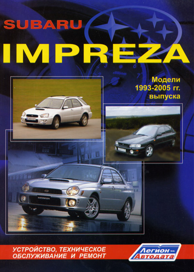
Скачать Руководство по эксплуатации, техническому обслуживанию и ремонту Subaru Impreza 1993 — 2005 г.г. (139 Мб — доступно только для
зарегистрированных пользователей во вложении)
Subaru_Impreza_93_05_RUS.rar 139,63МБ
484 Количество загрузок:
Subaru Impreza WRX STi coupe 22B
полный привод DCCD =)

- Наверх
#2
bass300
bass300
-
- Гражданин
-
- 29 сообщений
Что такое поршень?


- Город:Кондопога
- Автомобиль:Subaru Impreza GC8, 1998 г.в.
- Имя:Сергей
Отправлено 12 апреля 2013 — 07:01
купил вторую книгу, книжка зачет!!! рекомендую!
- Наверх
#3
Zhenek
Zhenek
-
- Гражданин
-
- 74 сообщений
Знаком с оппозитом
- Город:Москва
- Автомобиль:Subaru Impreza 1999
- Имя:Евгений
Отправлено 14 мая 2015 — 09:17
Спасибо.
Сообщение отредактировал Dream791: 14 мая 2015 — 09:19
- Наверх
#4
Keksel
Keksel
-
- Гражданин
- 3 сообщений
Заблудшая душа

- Город:Москва
Отправлено 28 сентября 2016 — 13:46
Благодарю автора!
Оч нужная литература!
- Наверх
#5
mast62
mast62
-
- Гражданин
- 1 сообщений
Заблудшая душа

- Город:Spassk-Dalny
Отправлено 11 апреля 2017 — 12:03
Спасибо! Очень помогло.
- Наверх
#6
avtozu
avtozu
-
- Гражданин
- 4 сообщений
Заблудшая душа
- Город:Нижневартовск
- Автомобиль:Subaru Legasy 2006
- Имя:Татьяна
Отправлено 02 мая 2017 — 11:20
 bass300 (12 апреля 2013 — 07:01) писал:
купил вторую книгу, книжка зачет!!! рекомендую!
Другъ где покупал бумаги?
- Наверх
#7
alexeyarza
alexeyarza
-
- Администратор
-
- 1 255 сообщений
Псих на табуретке
Отправлено 02 мая 2017 — 21:29
avtozu (02 мая 2017 — 11:20) писал:
Другъ где покупал бумаги?
Издатель книг Легион-Автодата, перечень по Импрезам есть тут.
Subaru Impreza WRX STi coupe 22B
полный привод DCCD =)
- Наверх
#8
avtozu
avtozu
-
- Гражданин
- 4 сообщений
Заблудшая душа
- Город:Нижневартовск
- Автомобиль:Subaru Legasy 2006
- Имя:Татьяна
Отправлено 03 мая 2017 — 16:54
Спасибки!
- Наверх
#9
Alekssim
Alekssim
-
- Гражданин
- 1 сообщений
Заблудшая душа

- Город:Владивосток
- Автомобиль:Impreza WRX GC8 my93
- Имя:Александр
Отправлено 24 июля 2017 — 06:04
Автору спасибо!
- Наверх

Сборник руководств на английском языке по техническому обслуживанию и ремонту автомобиля Subaru Impreza gthdjuj gjrjktybz 1996-2000 годов выпуска.
- Автор: —
- Издательство: Fuji Heavy Industries Ltd.
- Год издания: —
- Страниц: —
- Формат: PDF
- Размер: 413,7 Mb
Сборник руководств на английском языке по техническому обслуживанию и ремонту автомобилей Subaru Impreza и Subaru Impreza WRX второго поколения 2000-2007 годов выпуска.
- Автор: —
- Издательство: Fuji Heavy Industries Ltd.
- Год издания: —
- Страниц: —
- Формат: PDF
- Размер: 1,3 Gb
Сборник руководств на английском языке по техническому обслуживанию и ремонту автомобилей Subaru Impreza/Impreza WRX/Impreza WRX STI третьего поколения 2008-2014 годов выпуска.
- Автор: —
- Издательство: Fuji Heavy Industries Ltd.
- Год издания: —
- Страниц: —
- Формат: PDF
- Размер: 686,5 Mb
Сборник руководств на английском языке по техническому обслуживанию и ремонту автомобилей Subaru Impreza/Impreza WRX/Impreza WRX STI четвертого поколения 2013-2015 годов выпуска.
- Автор: —
- Издательство: Fuji Heavy Industries Ltd.
- Год издания: —
- Страниц: —
- Формат: PDF
- Размер: 465,8 Mb
Руководство по эксплуатации, техническому обслуживанию и ремонту + каталог расходных запчастей автомобиля Subaru Impreza 2000-2007 годов выпуска с бензиновыми двигателями объемом 1,5/1,6/2,0/2,5 л.
- Автор: —
- Издательство: Легион-Автодата
- Год издания: 2014
- Страниц: 696
- Формат: —
- Размер: —
Руководство по эксплуатации и ремонту автомобилей Subaru Impreza и Subaru Impreza WRX STI с 2008 года выпуска с бензиновыми двигателями объемом 1,5/2,0/2,5 л.
- Автор: —
- Издательство: Монолит
- Год издания: —
- Страниц: 454
- Формат: —
- Размер: —
Руководство по техническому обслуживанию и ремонту автомобиля Subaru Impreza 2004 модельного года.
- Автор: —
- Издательство: Fuji Heavy Industries Ltd.
- Год издания: —
- Страниц: 3581
- Формат: PDF
- Размер: 96,7 Mb
Руководство по техническому обслуживанию и ремонту автомобиля Subaru Impreza 2008 модельного года.
- Автор: —
- Издательство: Fuji Heavy Industries Ltd.
- Год издания: —
- Страниц: 3744
- Формат: PDF
- Размер: 65,4 Mb
Руководство по эксплуатации и техническому обслуживанию автомобиля Subaru Impreza 2005 года выпуска.
- Автор: —
- Издательство: Fuji Heavy Industries Ltd.
- Год издания: 2004
- Страниц: 512
- Формат: PDF
- Размер: 10,0 Mb
Руководство по эксплуатации и техническому обслуживанию автомобиля Subaru Impreza 2007 года выпуска.
- Автор: —
- Издательство: Fuji Heavy Industries Ltd.
- Год издания: 2006
- Страниц: 464
- Формат: PDF
- Размер: 9,3 Mb
Руководство по эксплуатации и техническому обслуживанию автомобиля Subaru Impreza 2009 года выпуска.
- Автор: —
- Издательство: Fuji Heavy Industries Ltd.
- Год издания: 2008
- Страниц: 497
- Формат: PDF
- Размер: 7,7 Mb
Руководство по эксплуатации и техническому обслуживанию автомобией Subaru Impreza и Subaru XV 2012 года выпуска.
- Автор: —
- Издательство: Fuji Heavy Industries Ltd.
- Год издания: 2011
- Страниц: —
- Формат: PDF
- Размер: 184,2 Mb

Руководство по эксплуатации и техническому обслуживанию автомобиля Subaru Impreza 2000-2007 годов выпуска.
- Автор: —
- Издательство: MoToR
- Год издания: —
- Страниц: 512
- Формат: —
- Размер: —
Руководство по техническому обслуживанию и ремонту автомобиля Subaru Impreza 1993-2002 годов выпуска с бензиновыми двигателями объемом 1,5/1,6/1,8/2,0 л.
- Автор: —
- Издательство: Легион-Автодата
- Год издания: —
- Страниц: 656
- Формат: —
- Размер: —
Руководство по техническому обслуживанию и ремонту автомобилей Subaru Impreza/Impreza WRX/Impreza WRX STI с 2007 года выпуска с бензиновыми двигателями объемом 1,5/2,0/2,5 л.
- Автор: —
- Издательство: Легион-Автодата
- Год издания: 2012
- Страниц: 600
- Формат: —
- Размер: —

- Manuals
- Brands
- Subaru Manuals
- Automobile
- 1997-1998 Impreza
- Service manual
-
Contents
-
Table of Contents
-
Bookmarks
Quick Links
Impreza 1997-1998
III
S U
RU
RA.
Related Manuals for Subaru 1997-1998 Impreza
Summary of Contents for Subaru 1997-1998 Impreza
-
Page 1
Impreza 1997-1998… -
Page 2
. � � -_..� Service manual • General information… -
Page 3: Specifications
1 -1 SPECIFICATIONS [S1AO] 4-door Sedan 1 . 4-door Sedan A: DIMENSIONS 2000 TURBO 2000 TURBO 1800 1600 Model 4,340 (170.9) mm(in) 4.350 (171.3), 4,375 (172.2r’ Overall length 1,690 (66.5) Overall width mm(in) t,415 (55.7) 1,415 (55.7) 1,415 (55.7) 1,400 (55.1) mm(in) 1,400 (55.1 r2, 1,415 (55.7)
-
Page 4
1- 1 SPECIFICATIONS (5100) 4-door Sedan Model 2000 TURBO 1600 2000 Non TURBO — Australia spec. vehicles — Horizontally opposed, liquid cooled, 4-cylinder, 4-stroke gasoline engine Engine type Valve arrangement Overhead camshaft type 87.9 x 65.8 92 x 75 Bore x Stroke mm(in) (3.461 x 2.591) (3.62 x 2.95) -
Page 5
· 1 [S100] SPECIFICATIONS 4·door Sedan 1 8 00 1 600 odel 5MT’2 4AP2 5MP2 ‘ansmission type DSPD IUlch type DSPD 3.545 2.785 ear ratio 1 sl 3.545 1 .545 2.111 2.111 1 .448 1 .448 1 .000 1 .088 1 .088 0. -
Page 6
[SliD] SPECIFICATIONS 4 -door Sedan E: STEERING Model Non TURBO TURBO (ft) Rack and Pinion Type Turns, l ock to lock Minimum turning circle Curb to curb: 10.2 (33.5) Curb to curb: 10.4 (34. 1 ) Curb t o curb: 10.8 (35.4) F: SU SPENSION Front Macpherson strut type, Independent, C oil spring… -
Page 7
[S1 J1] SPECIFICATIONS 4-door Sedan WEIGHT 1 _ EUROPE, GENERAL SPEC_ VEHICLE 1 800 1 600 Model Curb weight (CW.) Front kg (Ib) 6 1 5 (1 .455) (1 .380) (1 .475) (1 ,420) ( 1 ,435) (1 ,445) (1 ,510) ( 1 .355) 47 5 Rear… -
Page 9: General Information
Scribe alignment mark corresponding with mediately have it repaired. centerline of rear wheels on floor. Use only genuine SUBARU AT fluid in the Back up vehicle so that centerline of free transmission. rollers are aligned with mark scribed in step above.
-
Page 10
GENERAL INFORMATION [OlE3] General Precautions 4. CHASSIS DYNAMOMETER TEST since this may cause vehicle to jump off test machine. Locate vehicle onto chassis dynamometer • Avoid abrupt braking after tests. tester. Locate rear wheels onto free rollers. Perform dynamic performance tests. WARNING: •… -
Page 12
GENERAL INFORMATION [01 F1) General Precautions • 2. TOWING Do not tow vehicle with front wheels raised under any circumstances since this will Loading vehicle onto dolly or flat-bed truck damage bumper. CAUTION: • Transport vehicle using a dolly or flat-bed truck whenever possible. -
Page 13
GEN ERAL INFORMATION [01G2) General Precautions G : TURBO AT MODELS 1 . SPEEDOMETER TEST (Jack-up method) Position vehicle so that front wheels are between rollers of speedometer test machine. Jack u p vehicle until rear wheels clear the floor, s upport with safety stands. Start engine with selector lever set in «2nd.»… -
Page 14
GENERAL INFORMATION [01G3) General Precautions WARNING: 4. TOWING • Secure a rope or wire to the front and rear Loading vehicle onto dolly or flat -bed truck towing or tie-down hook to prevent the lat CAUTION eral runout of front wheels. •… -
Page 15
[01G4] 1 -3 GENERAL INFORMATION General Precautions Towing with front or rear wheels raised CAUTION: • Do not tow vehicle with only front or rear wheels placed on towing dolly or flat-bed truck. This may degrade multi-plate clutch (L.S.D.) performance or cause vehicle to jump off dolly or truck. -
Page 16
2. Precaution for Supplemental Restraint System (Airbag) 2. Precaution for Supplemental Restraint System (Airbag) The Supplemental Restraint System (Airbag) has been implemented in some Subaru vehicles. For proper and safe maintenance of this system, please ensure that you carefully read the precaution… -
Page 17
[0400] GENERAL INFORMATION 4. Identification Number and Label Locations 4. Identification Number and Label Locations Engine, transmission and vehicle identification numbers are used for factory communica tions such as Technical Information, Service Bulletins and other information. Vehicle identification Emission conlrol label Emission control label number (Non-turbo model) -
Page 18
(0400) � � 1 — 3 E R A L IN F O R M A T IO N I de nt ifi c a ti o n N u m b er an d L a b el L oc ENGINE Transmission serial number B1H01 73A… -
Page 19
GENERAL INFORMATION [O S BO) 5. Recommended Fuel, Lubricants, Sealants and Adhesives Do not use such fuels unless the gasoline/alco 5. Recommended Fuel, Lubri hol blend is suitable for your vehicle as ex cants, Sealants and Adhesives plained at right: •… -
Page 20
Automatic transmission fluid • • • Power steering fluid DEXRON or fIE or fIl type Genuine SUBARU Coolant (Part No. For further coolant specifications. refer • Coolant 00001621 (Anti-freeze, anti-corro- to the following table. • sive ethylene glycol base) •… -
Page 21
E: COOLANT CAUTION: • Avoid using any coolant or only water other than this designated type to prevent corro sion. • SUBARU’s engine is aluminum alloy, and so special care is necessary. Coolant Specifications Lowest antici- SUBARU Specification gravity paled atmo-… -
Page 22
[OSFO) 1 -3 GEN ERAL INFORMATION Recommended Fuel, Lubricants, Sealants and Adhesives F: SEALANTS Equivalent Application Recommended Three Bond 1105 Rear differential oil drain plug, bearing cap (#5), Dow Corning’s No. 7038 etc. (PIN 00440301 0) Three Bond 1 2 1 5 Matching surface of oil pump, transmission case, Dow Corning’s No. -
Page 23
[06BO] 1 -3 GENERAL INFORMATION Nuts Tightening Torque of Standard Bolts and 6. Tightening Torque of Standard Bolts and Nuts A: ENGINE AND TRANSMISSION Unit· N m (kg-m tt-Ib) Dia. Pitch (mm) 3.0 — 3.5 1 .0 — 1.5 1.5 — 2.0 2.5 — 3.0 0.75 (0.255 — 0.305, 1 .8 — 2.2) -
Page 24
1 -3 [0 7 00 ] GENERAL INFORMATION Lifting, Towing and Tie-down Points Lifting, Towing and Tie-down Points WARNING: • Never get under the vehicle while it is supported by a jack. • When jacking up the vehi.cle, place chocks to hold wheels. •… -
Page 25
1- 3 [0 7 6 0) GENERAL INFORMATION Lifting, Towing and Tie-down Points PANTOGRAPH JACK, SAFETY STA N D AND LIFT WARNING: • Never get under the vehicle while it is supported only by the jack. Always use safety stands to support body when you have to get under the car. -
Page 26
1 -3 [0 7 BO] GENERAL I N FORMATION Lifting, Towing and Tie-down Points Support locations H1 H0457A… -
Page 27
[07 CO] GENERAL INFORMATION Lifting, Towing and Tie-down Points c: TOWING AND TIE-DOWN HOOKS Front Rear Hook for towing and tle·down H1 H0458A CAUTION: • Avoid towing another car with front towing hooks_ • Do not tow a vehicle which is heavier than towing vehicle_ •… -
Page 28
[D8AD] 1 -3 G ENERAL I N FORMATION Front Hood Stay Installation Front Hood Stay Installation A: AT THE CHECK AND GENERAL MAINTENANCE H 1 H0444 WHEN WIDER HOOD OPENING IS N ECESSARY Set stay into the hole of hood inner as shown in the figure below. H1 H0445… -
Page 29
[0000) PERIODIC MAINTENANCE SERVICES SCHEDULE OF INSPECTION AND MAINTENANCE SERVICES Symbols used: Continue periodic maintenance beyond 1 00,000 km R: Replace (60,000 miles) or 48 months by returning to the first I: Inspect, and then adjust, correct or replace if necessary. column of the maintenance schedule and adding P: Perform 1 00,000 krn (60,000 miles) or 48 months to the col-… -
Page 30
1 — 5 [0000] PERIODIC MAINTENANCE SERVICES NOTES: 1 ) When the vehicle is used under severe driving conditions mentioned below·, the engine oil and oil filter should be changed more frequently. 2) When the vehicle is used under severe driving conditions mentioned below·, the air cleaner element should be replaced more frequently. -
Page 31
[0 1 AO] PERIODIC MAINTENANCE SERVICES Drive Belt(s) [Except Camshaft] (Inspect drive belt tension) MAINTENANCE INTERVAL Drive 8elt(s) [Number of months of km (miles) whichever occurs first] Months [Except Camshaft] x1 ,000 (Inspect drive belt tension) 1 .6 1 00 x1 ,000 miles (10 kg, 22 1b) -
Page 32
[0183] PERIODIC MAINTENANCE SERVICES Drive 8elt(s) [Except Camshaft] (Inspect drive belt tension’ 2. FRONT SIDE BELT (Driving Power Steering Oil Pump and Gen erator) 1 ) Loosen the lock bolt on the slider bolt. 2) Loosen the slider bolt. 3) Remove the front side belt. 4) I nstall a new belt, and tighten the slider bolt so as to obtain the specified belt tension showr on the previous page. -
Page 33: Timing Belt
[02A1] PERIODIC MAINTENANCE SERVICES 2. Camshaft Drive Belt (Timing Belt) MAINTENANCE INTERVAL 2. Camshaft Drive Belt [Number of months of km (miles) whichever occurs first] Months (Timing Belt) x l ,000 1 .6 l Oa xl ,000 miles A : REPLACEMENT 1 .
-
Page 34
[02A1) PERIODIC MAINTENANCE SERVICES 1 -5 2. Camshaft Drive Bell (Timing Bell) 5) Remove V-belt cover. Remove V-belts. [Refer to «Drive Belt(s)» .) 7) Remove air conditioning compressor drive belt tensioner. H1H0458 Remove pulley bolt. To lock crankshaft use 499977000 CRANKSHAFT PULLEY WRENCH 9) Remove crankshaft pulley. -
Page 35
[02A2) PERIODIC MAINTENANCE SERVICES 2. Camshaft Drive Bell (Timing Bell) (2) Using white paint, put alignment and/or arrow marks on timing belts in relation to the sprockets. 1 1 ) Loosen tensioner adjuster mounting bolts. 1 2) Remove belt idler. 1 3) Remove belt idler No. -
Page 36
1 -5 [ 0 2C1] PERIODIC MAINTENANCE SERVICES C a msh a f t Driv e B el t (Timi n g B el t) Loosen tensioner adjuster mounting bolts. -��-�- 9) Remove belt idler. 1 0) Remove belt idler NO.2. 1 1 ) Remove timing belt. -
Page 37
[02C2) PERIODIC MAINTENANCE SERVICES 2. Camshaft Drive Belt (Timing Belt) 2. DOHC MODEL 1 ) Remove left and right timing belt covers CD and @. 2) While cranking engine at least four rotations, check timing belt back surface for cracks or damage. -
Page 39
API classification and SAE viscosity No. designated by SUBARU . • As for the turbo models, SAE 5W-30 is not recommended for sustained high speed OM·Hl027… -
Page 40
PERIODIC MAINTENANCE SERVICES [0380] Engine B: INSPECTION 1 ) Park vehicle on a level surface. 2) Remove oil level gauge and wipe it clean 3) Reinsert the level gauge all the way. Be su upp er leve l 1 .0 that the level gauge is correctly inserted and Abo ut «… -
Page 42
[0 5 A1 ) PERIODIC MAINTENANCE SERVICES Replace Engine Coolant and Inspect Cooling System, Hoses and Connection MAINTENANCE INTERVAL 5. Replace Engine Coolant [Number of months or km (miles) whichever occurs first] Months and Inspect Cooling xl ,000 System, Hoses and 1 .6 1 00 Connections… -
Page 44
PERATURE of coolant The concentration and safe operating tempera 1 . 1 00 ture of the SUBARU coolant is shown in the dia gram. Measuring the temperature and specific 1 .090 gravity of the coolant will provide this informa 1 .080 �… -
Page 46
PERIODIC MAINTENANCE SERVICES [0580] 5. Replace Engine Coolant and Inspect Cooling System, Hoses and Con nee 2) Check the radiator cap valve open pres using radiator cap tester. Raise the pressure until the needle of ga stops and see if the pressure can be retaine( five to six seconds. -
Page 47
1 -5 [06AO) PERIODIC MAINTENANCE SERVICES Replace Fuel Filter and Inspect Fuel System, lines and Connections MAINTENANCE INTERVAL 6. Replace Fuel Filter and [Number of months of km (miles) whichever occurs first] Months Inspect Fuel System, x1 ,000 Lines and Conne.ctions 1 .6 1 00 x1 ,000… -
Page 48
1 — 5 [0681] PERIODIC MAINTENANCE SERVICES Replace Fuel Filter and Inspect Fuel System, Lines and Connections 4) Replace fuel filter with a new one. (in) Unit: 5) I nstall the hoses as shown in the figure. Tightening torque: Hose FIHing 1.0 — 1.5 N.m (0. -
Page 50
[08A2] 1 -: PERIODIC MAINTENANCE SERVICES Spark Plug MAINTENANCE INTERVAL Spark Plugs [Number of months of km (miles) whichever occurs firstl Months x1 ,000 1 .6 1 00 x1 ,000 miles For Non· Turbo Turbo A: REPLACEMENT 1 . NON-TURBO MODEL Disconnect spak plug cord. -
Page 51
1 -5 [09A1] PERIODIC MAINTENANCE SERVICES 9. Idle Mixture [Except for Catalyst Model] MAINTENANCE INTERVAL Idle Mixture [Number of monlhs of km (miles) whichever occurs first] Months [Except for Catalyst x1 ,OOO Model] 1 .6 1 00 x1 ,OOO miles A: INSPECTION AND ADJUSTMENT IDLE MIXTURE (Not necessary for cata… -
Page 52
1 — 5 [09A l ] PERIODIC MAINTENANCE SERVICES 9. Idle Mixture [Except for Catalyst Model) Non-TURBO 2000 cc model: < Ref. «Troubleshooting Section» 2-7b [T1 1 PO] or [T1 2QO] > adiusting ( 1 ) Select function mode «F25» . (2) If out of specified data, adjust the incre… -
Page 54
[010A2) PERIODI C MAINTEN ANCE SERVICE S 1 0. Transmission/Differential (Front and rear) Lubricants (Gear oil) • Recommended oil ITEM Transmission gear oil • CAUTION: API Classif ication Each oil manufacturer has its base oil and GL-5 (OF) additives. Thus, do not mix two or more (Oe) SAE Viscosi ty No. -
Page 55
[010A3) PERIODIC MAINTENANCE SERVICES Transmission/Differential (Front and rear) Lubricants (Gear oil) 3. REAR DIFFERENTIAL (AWD MODEL) Except 2000’cc Non-turbo MT and Turbo model ® ® 1 ) Drain oil by removing drain bolt or plug. 2) Remove filler bolt or plug for quick draining oil. -
Page 56: Tightening Torque
[011AO) PERIODIC MAINTENANCE SERVICES 1 1 . Automatic Transmission MAINTENANCE INTERVAL II» 1 1 . Automatic Transmission [Number of months of km (miles) whichever occurs Months Fluid xl ,000 1 .6 xl ,000 miles A: REPLACEMENT 1 ) Drain ATF (Automatic Transmission Fluid drain plug removing drain plug after allowing the engin cool for 3 to 4 hours.
-
Page 57
[012AO] 1 -5 PERIODIC MAINTENANCE SERVICES 1 2 . Brake Fluid MAINTENANCE INTERVAL [Number of months of km (miles) whichever occurs firstl 1 2. Brake Fluid Months x1 .000 1 00 1 .6 x1 .000 miles A: REPLACEM ENT 1 ) Either jack up vehicle and place a safety stand under it, or lift up vehicle. -
Page 58
[012AO] 1 -5 PERIODIC MAINTENANCE SERVICES Brake Fluid • For convenience and safety, it is advisable to have two men working . • The amount of brake fluid required is approxi mately 500 me (1 6.9 US fl 1 7.6 Imp fl oz) for total brake system. -
Page 59
[013A1] PERIODIC MAINTENANCE SERVICES Disc Brake Pads and Discs/Front and Rear Axle Boots and Axle Shaft Joint Portions MAINTENANCE INTERVAL Disc Brake Pads and [Number of months of km (miles) whichever occurs first) 1 3. Months Discs/Front and Rear Axle 1 .6 xl ,OOO Boots and Axle Shaft Joint… -
Page 60
[01 3 A 2 ] PERIODIC MAINTENANCE SERVICES 1 · Disc Brake Pads and Discs/Front and Rear Axle Boots and Axle Shaft Joint Portior 1 3. 2. FRONT AND REAR AXLE BOOTS Inspect front and rear axle boots for deforme tion , damage or failure. -
Page 61
1 -5 [014A1) PERIODIC MAINTENANCE SERVICES Brake Linings and Drums MAINTENANCE INTERVAL Brake Linings and Drums [Number of months of km (miles) whichever occurs first] 1 4. Months xl ,000 1 .6 xl ,000 miles A: INSPECTION REAR DRUM BRAKE i»… -
Page 62
1 4 . [014A2) PERIODIC MAINTENANCE SERVICES 1 -5 Brake Linings and Drums Brake drum inner diameter Standard value: 228.6 mm (9.000 in) Service limit: 230.6 mm (9.079 in) If deformation or wear of back plate, shoe. etc. is noticeable, replace the affected parts. Me.lsuring inside diameter G 1 H0101 2. -
Page 63
1 4. 1 -5 (01481) PERIODIC MAINTENANCE SERVICES Brake Linings and Drums 3) If the deformation or wear of back plate, shoe, etc. is noticeable, replace them . 4) When the shoe return spring tension is ex cessively weakened , replace it, taking care to identify upper and lower springs. -
Page 64
1 -5 PERIODIC MAINTENANCE SERVICES [015B1] 1 5. Inspect Brake Lines and Check Operation of Parking and Service Brake System MAINTENANCE INTERVAL firsll 1 5. lnspect Brake Lines and [Number of months of km (miles) whichever occurs Monlhs Check Operation of xl ,000 Parking and Service Brake 1 .6… -
Page 65
1 -5 [01581) PERIODIC MAINTENANCE SERVICES 1 5. I nspect Brake Lines and Check Operation of Parking and Service Brake System If the free play is out of specifications above, ad just the brake pedal as follows: Brake switch ( 1 ) Be sure engine is off. (No vacuum is ap plied to brake booster.) (2) There should be play between brake Adjusting nut… -
Page 66
1 -5 [01583] PERIODIC MAINTENANCE SERVICES 1 5. Inspect Brake Lines and Check Operation of Parking and Service Brake System 2. PARKING BRAKE SYSTEM Parking brake lever 1 ) Operation of parking brake is normal if is ap plied at sixth notch of ratchet when brake lever is pulled by force of about 1 96 N (20 kg , 44 Ib). -
Page 67: Mechanical Clutch Type
[016A1) PERIODIC MAINTENANCE SERVICES 1 6. Clutch and H ill-holder System MAINTENANCE INTERVAL Clutch and Hill — holder [Number of months of km (miles) whichever occurs firstl 1 6. Months System ,000 1 .6 ,000 miles A: INSPECTION AND ADJUSTMENT 1 .
-
Page 68: Hill-Holder
[016A2] PERIODIC MAINTENANCE SERVICES 1 6 . Clutch and Hill-holder System lower end of front panel (intersection of front panel with floor) . Check that the measured value is within the specified standard. Standard: 80 mm (3. 15 in) or more 3) Pedal height Check that the clutch pedal pad surface is level with or h igher than brake pedal pad surface.
-
Page 69
[016A3) PERIODIC MAINTENANCE SERVICES Clutch and Hill-holder System 3. HYDRAULIC CLUTCH TYPE 1 ) Push the release fork to retract the push rod of the operating cylinder and check if the fluid level in the clutch reservoir tank rises or not. 2) If the fluid level rises, pedal free play is cor… -
Page 70
1 -5 PERIODIC MAINTENANCE SERVICES [017A1] 1 7. Steering and Suspension System [Number km (miles) whichever occurs first] 1 7. MAINTENANCE INTERVAL Steering and Suspension of months of System xl ,OOO miles 1 .6 1 00 xl ,000 A: INSPECTION play Free 1 . -
Page 71
1 -5 [017A2] PERIODIC MAINTENANCE SERVICES 1 7. Steering and Suspension System 2. STEERING SHAFT JOINT 1 ) When steering wheel free play is excessive, disconnect universal joint of steering shaft and check it for any play and yawing torque (at the point of the crossing d i rection). -
Page 72
1 -5 [017A5] PERIODIC MAINTENANCE SERVICES 1 7. Steering and Suspension System 4. TIE-ROD 1 ) Check tie-rod and tie-rod ends for bends, scratches or other damage. 2) Check connections of knuckle ball joints for play, inspect for damage on dust seals, and check free play of ball studs. -
Page 73
1 -5 1 7. [017A6] PERIODIC MAINTENANCE SERVICES Steering and Suspension System Recommended fluid Manufacturer B.P. CAlTEX CASTROl «Dexron II, liE or type I I I» MOBil SHEll TEXACO Fluid capacity: 0. 7 (0. 7 US qt, 0.6 Imp qt) POWER STEERING FLUID FOR LEAKS I nspect the underside of oil pump and gearbox for power steering system, hoses, piping and… -
Page 74
1 -5 1 7 . [017A11] PERIODIC MAINTENANCE SERVICES Steering and Suspension System 9. GEARBOX BOOTS Apply grease I nspect both sides of gearbox boots as follows, and correct the defects if necessary. © 1 ) ® and positions of gearbox boot are fitted ©… -
Page 75
1 -5 [017A11] PERIODIC MAINTENANCE SERVICES 1 7 . Steering and Suspension System 2) Damage of dust seal ..Inspect every 25,000 km (1 2,000 miles) or 1 2 months, which ever occurs first. Visually inspect ball joint dust seal. If it is dam aged, remove transverse link as instructed in chapter 4-1 and measure free play of ball joint. -
Page 76
PERIODIC MAINTENANCE SERVICES [017A11) 1 7. Steering and Suspension System (Adjusting procedure) — Front suspension alignment (a) Caster angles are not adjustable. When caster angl e does not conform to standard value, visually inspect following compo nents and replace deformed parts. •… -
Page 77
1 -5 1 7. PERIODIC MAINTENANCE SERVICES [017A1 1 ] Steering and Suspension System 5) Tightness of bolts and nuts ..I nspect ev FRONT ery 50,000 km (30,000 m iles) or 24 months, whichever occurs first. Check bolts shown in the figure for looseness. -
Page 78
PERIODIC MAINTENANCE SERVICES 1 -! [017A1 1 ] 1 7. Steering and Suspension Systen 6) Damage to suspension parts Check the following parts and the fastening por tion of the car body for deformation or excessivE rusting which impairs the suspension. If neces sary, replace damaged parts with new ones. -
Page 79
1 -5 PERIODIC MAINTENANCE SERVICES [01 8AO) 1 8. Front and Rear Wheel Bearing Lubricant MAINTENANCE INTERVAL Front and Rear Wheel [Number of months of km (miles) whichever occurs first] 1 8. Months Bearing Lubricant x1 ,000 1 . 6 1 00 x1 ,000 miles… -
Page 80
[018A2] 1 -5 PERIODIC MAINTENANCE SERVICES 1 8. Front and Rear Wheel Bearing Lubricant FWD MODEL 2. REAR WHEEL BEARING Jack up the rear of vehicle. 2) While holding rear wheel by hand, swing it in and out to check bearing free play. unit 3) Loosen wheel nuts and remove rear wheel . -
Page 81: Valve Clearance
[019A1) 1 -5 PERIODIC MAINTENANCE SERVICES 19. Valve Clearance MAINTENANCE INTERVAL Valve Clearance [Number of months or km (miles) whichever occurs first) 1 9. Months x1 ,000 1 .6 1 00 x1 ,000 miles Inspect every 1 00,000 km (60,000 miles) Europe Except Inspect every 1 00,000 km (60,000 miles)
-
Page 82
[M1 00] EMISSION CONTROL SYSTEM AND VACUUM FITTING 1 . System Application System Application There are three emission control systems which are as follows: Crankcase emission control system Exhaust emission controf system • Three-way catalyst system • A/F control system •… -
Page 83
EMISSION CONTROL SYSTEM AND VACUUM FITTING [M2CO] . Schematic Drawing TURBO MODEL .: : — — — — I H2H1 849A… -
Page 84
2 — 1 [M2CO] EMISSION CONTROL SYSTEM AND VACUUM FITTING Schematic Drawing ® � � Engine conlrol module (ECM) Oxygen sensor Ignition coil Radiator fan (§) Ignitor Radiator fan relay Crankshaft position sensor Knock sensor ®> Camshaft position sensor NC compressor Ql>… -
Page 85
[M400) EMISSION CONTROL SYSTEM AND VACUUM FITTING 3. Crankcase Emission Control System Three-way Catalyst B: TURBO MODEL • The positive crankcase ventilation (PCV) system is employed to prevent air pollution which will be caused by blow-by gas being emitted from the crankcase. The system consists of a sealed oil filler cap , rocker covers with fresh air inlet, connecting hoses, PCV valve and an air intake duct. -
Page 86
[ M 500) EMISSION CONTROL SYSTEM AND VACU U M FITTING 5. AlF Control System Ignition Control System 5. AlF Control System • The air/fuel control system compensates for the basic amount of fuel injection in response to a signal sent from the oxygen Sensor to provide proper feedback control of the mixture. Thus, the theoretical air-fuel ratio is maintained to provide effective operation of the three-way catalyst. -
Page 87: Evaporative Emission Control System
: -1 [M7AO] EMISSION CONTROL SYSTEM AND VACUUM FITTING Evaporative Emission Control System ‘. Evaporative Emission Control System GENERAL The evaporative emission contrql system is employed to prevent evaporative fuel from being dis harged into ambient atmosphere. This system includes a canister, purge control solenoid valve, Jel cut valve, their connecting lines, etc.
-
Page 88
[ M 7 BO ] EMISSION CONTROL SYSTEM AND VACUUM FITTING Evaporative Emission Control System 3. 2000 cc TURBO MODEL Purge control solenoid valve Thronle body � � Two-way valve purg t rol valve Fuel cut valve Canister Fuel tank H2H1 855A B: FUEL CUT VALVE On AWD model, the fuel cut valve is built onto the evaporation pipe of the fuel tank cap. -
Page 89
[M 7C1] EMISSION CONTROL SYSTEM AND VACUUM FITTING Evaporative Emission Control System C: FUEL CAP The relief valve is adopted to prevent the development of vacuum in the fuel tank which may occur in case of trouble in the fuel vapor line. In normal condition, the filler pipe is sealed at and at the packing pressed against the filler pipe end. -
Page 90
[M7D2] 2 -1 EMISSION CONTROL SYSTEM AND VAC U U M FITTING Evaporative Emission Control System D: CANISTER The canister temporarily stores the evaporation gas. When the purge control solenoid valve is opened from a signal sent from the ECM, the evaporation gas is sent into the collector chamber after being mixed with fresh external air. -
Page 91
[M 7 E O ] 2 -1 EMISSION CONTROL SYSTEM AND VACUUM FITTI NG Evaporative Emission Control System E: PURGE CONTROL SOLENOID VALVE The purge control solenoid valve is on the evaporation line between canister and throttle body. It is built on the inside of intake manifold. To canister T o intake manifold B2H0148… -
Page 92
[MBCO] EMISSION CONTROL SYSTEM AND VACUUM FITTING Vacuum Fitting C: 2000 cc TURBO MODEL _ : HOSE = : PIPE (1) Pressure regulator FRONT OF VEHICLE H2H1 856A � Purge control solenoid valve ‘4’ Pressure sensor (Z; Thraili. bady Pressure sources switching solenoid valve… -
Page 93
‘ENG INE SEC TION… -
Page 94
2-3b ENGINE (DOHC) … Page M MECHANISM AND FUNCTION ..General …………..Timing Belt . -
Page 95
2-3b ENGINE (DOHC) [Ml 00) General General The engine is made from aluminum alloy and is horizontally opposed, it is a 4-stroke cycle, water cooled, DOHC 1 6-valve, turbocharged engine. The fuel injection system utilizes an MFI design. A summary of the major construction and function features is as follows: •… -
Page 96
2-3b ENGINE (DOHC) [M200] Timing Belt Timing Belt single timing belt drives four camshafts (intake and exhaust camshafts on each bank). The back of the belt also drives the water pump. The timing belt teeth have a specially designed round profile to provide quiet operation. The timing belt i s composed of a strong and inflexible core wire, a wearresistant canvas and heat-resistant rubber material. -
Page 97
2-3 b ENGINE (DOHC) [M300) 3. Belt Tensjoner Adjuster Belt Tensioner Adjuster The belt tensioner adjuster provides a constant value of tension for the timing belt. Proper belt ten sion is maintained using an adjuster rod to push the timing belt via tensioner pulley. The location of the tensioner pulley shaft center is offset in relation to the center of the pulley’s outside diameter. -
Page 98: Belt Cover
2-3b ENGINE (DOHC) [M400] Belt Cover Belt Cover • The belt cover i s made of synthetic resin molding which is lightweight and heat resistant. It has a total ly enclosed design that utilizes rubber packing at the mating surface of the cylinder block. This eliminates the chance of dust and liquid from entering the interior.
-
Page 99
2-3b ENGINE (DOHC) [MSOO] 5. Camshaft 5. Camshaft The DOHC engine uses four camshafts in all; intake and exhaust camshafts on the RH bank and intake and exhaust camshafts on the LH bank. The cam nose part is finished with «chill» treatment to i ncrease wear resistance and anti-scuffing properties. -
Page 100: Cylinder Head
2 -3 b (DOHC) ENGINE [M600] Cylinder Head Cylinder Head • The cylinder head is made from aluminium die casting. • Combustion chamber in the cylinder head is a compact, pentroof design and spark plug is lo cated at the center of combustion chamber which feature a wide «squish» area for i ncreased com bustion efficiency.
-
Page 101: Cylinder Block
2- 3 b ENGINE (DOHC) [M700] Cylinder Block Crankshaft Cylinder Block • The cylinder block is made from aluminum die casting. The cylinder perimeter has an open deck design which is lightweight, highly rigid and has superb cooling efficiency. • The cylinder liners are made from cast iron and are dry types which are total ly cast with aluminum journal block designs are employed to increase stiffness and quiet op…
-
Page 102
2- 3 b ENGINE (DOHC) [M900] 9. Piston 9. Piston • The piston skirt has a «slipper» design to reduce weight and sliding. The oil control ring groove utilizes a slit design. • The piston pin is located in an offset position. The Nos. 1 and 3 pistons are offset in the lower direction while the Nos. -
Page 103
E N G I N E COO L I N G SYSTEM MECHANISM AND FUNCTION Page ……General . -
Page 106: Engine Cooling System
3 . Water [M3CO) ENGINE COOLING SYSTEM Pump 4. Mechanical Seal C: TURBO MODEL H2H1 033A Thermostat Pulley Mechanical seal Thermostat case Ball bearing Impeller 4. Mechanical Seal u n i t . The mechanical seal has its seat pressed into the water pump shaft to form the seal and water pump as a single With this design, the water ouma cannot be disassembled.
-
Page 107
[MSOO] 2 -5 ENGINE COOLING SYSTEM 5. Thermostat 5. Thermostat The thermostat is powered to open the valve by a totally-enclosed wax pellet which expands w ith increased temperature. It provides the sure open-close operation of the valve and features high durability. -
Page 108: Radiator Fan
2 -5 [MSAO] ENGINE COOLING SYSTEM Radiator Fan Radiator Fan • A: DESCRIPTION fan is made of plastic. That is installed to the electric motor, and is located onto ra radiator • diator straight by shroud . The vehicle without air conditioning has the radiator main fan only. Thus, the vehicle with air conditioning has the radiator sub fan, too.
-
Page 109
2 -5 E N G I N E COOLIN G SYSTEM [M6Bl] adia FUNCTION WITHOUT Ale MODEL The ON-OFF (and Hi-Low: Turbo model) control of the radiator fan is governed by the ECM or ECMI TCM which receives signals sent from the engine coolant temperature sensor. Non-turbo model pe r (Less… -
Page 110
2 -5 [M6B2) ENGINE COOLING SYSTEM Radiator Fan 2. WITH Ale MODEL On models which are equipped with an air conditioning system, the ECM or ECMfTCM receives signals sent from the engine coolant temperature sensor, vehicle speed sensor 2 and AlC sWitch. These signals simultaneously turn ON or OFF (and Hi or Low: Turbo model) the radiator main fan and radiator sub fan . -
Page 111
EXHAUST SYSTEM [M1 AO] General General A: NON-TURBO MODEL • The exhaust system consists of a front exhaust pipe, a front catalytic converter, a center exhaust pipe, a rear exhaust pipe and a muffler. The front catalytic converter is located immediately behind the front exhaust pipe, and the rear catalytic converter is incorporated in the center exhaust pipe. -
Page 112: Exhaust System
2 — 9 EXHAUST SYSTEM [M2BO) 2. Composition B: TURBO MODEL H2H1 835A ‘1″ Exhaust manifold LH @ Front catalytic converter ® Rear exhaust pipe Front jOint pipe r:tJ Center exhaust pipe <lID Muffler Oxygen sensor @ Rear catalytic converter Exhaust manifold RH…
-
Page 114
FUEL INJ ECTION SYSTEM 2- 7c [TU RBO MODEL] Page M MECHANISM AND FUNCTION ……….General . -
Page 115
2-7c FUEL INJECTION SYSTEM [TURBO MODEL] [M100) 1 . General General • The Multipoint Fuel I njection (MFI) system is a system that supplies the optimum air-fuel m ixture to the engine for all the various operating conditions through the use of the latest electronic technol •… -
Page 116
2. Air Line 2-7c FUEL INJECTION SYSTEM [TURBO MODEL] [M2CO] Air Line GENERAL Air which is drawn in and filtered by the air cleaner is metered by the mass air flow sensor. Air is the supercharged by the turbocharger and cooled down by the intercooler, and sent to the throttle body. -
Page 117
2-7c FUEL INJECTION SYSTEM [TURBO MODEL] [M2DO] Air Line D: THROTTLE POSITION SENSOR • A throttle position sensor is provided with a potentiometer which is interlocked with the throttle valve shaft. • This throttle position sensor sends the ECM a potentiometer output signal corresponding to the opening of the throttle valve. -
Page 118
2-7c FUEL INJECTION SYSTEM [TURBO MODEL] [M2EO) 2. Air Line IDLE AIR CONTROL SOLENOID VALVE • Idle air control solenoid valve consists of an air cut valve, duty control valve, intake air passage and a coolant passage. • Air cut valve contains a bimetallic substance which responds to coolant temperature, and a duty control valve which is operated by a signal sent from ECM. -
Page 119: Fuel Line
2-7c FUEL INJECTION SYSTEM [TURBO MODEL] [M3AO) Fuel Line Fuel Line A: GENERAL • Fuel pressurized by the fuel pump built into the fuel tank is delivered to fuel injectors by way of the fuel pipe and fuel filter. Fuel is regulated to the optimum pressure level by the pressure regula tor on the way to the injectors .
-
Page 120
[M3CO] 2-7c FUEL INJECTION SYSTEM [TURBO MODEL] 3. Fuel Line PRESSURE REGULATOR • The pressure regulator is divided into the fuel chamber and the spring chamber by the dia phragm as illustrated below. Fuel is fed to the fuel chamber through the fuel inlet connected with the injector. -
Page 121: Turbocharger System
[M4AO] FUEL INJECTION SYSTEM [TURBO MODEL] Turbocharger System Turbocharger System GENERAL This turbocharger system consists of a water-cooled turbocharger, air-cooled intercooler, waste The outlet side turbine, rotated by the energy of exhaust gas it receives, rotates the inlet side The intake air, heated when passed through the turbocharger unit, is cooled as it passes through he intercooler.
-
Page 122
[M4BO] 2-7c FUEL INJECTION SYSTEM [TURBO MODEL] Turbocharger System TURBOCHARGER UNIT The turbocharger is water-cooled, and utilizes a wastegate valve to normalize supercharged pres sure. The turbine is constructed of a lightweight, thin walled, and heat-resistant casting. The com pressor is a thin wall aluminum alloy casting. The bearing section uses a full-floating metal system. Lubricating oil inlet Wastegale controller… -
Page 123
2-7c [M4CO] FUEL INJECTION SYSTEM [TURBO MODEL] Turbocharger System C: LUBRICATION OF TURBOCHARGER The turbocharger is lubricated by the engine oil branched out from the oil pump. Since the turbo charger turbine and the compressor shaft reach a maximum of several h undred thousand revolu tions per minute, the full-floating type bearings are used to form desirable l u brication films on their inside and outside during running. -
Page 124
[M4E1J 2-7c FUEL INJECTION SYSTEM [TURBO MODEL] Turbocharger System E: REGULATION OF SUPERCHARGING PRESSURE 1 . BASIC FUNCTION O F THE WASTEGATE VALVE 20,000 1 50,000 As the engine speed increases with the opening of the throttle valve, the amount of exhaust gas increases. -
Page 125
2-7c [M4E2] FUEL INJECTION SYSTEM [TURBO MODEL] Turbocharger System When it reaches the predetermined level, the wastegate controller lets the supercharging pressure to press the diaphragm, causing the linked wastegate valve to open. With the wastegate-valve opened, a part of the exhaust gas is allowed to flow into the exhaust gas pipe by bypassing the turbine. -
Page 126: Wastegate Control Solenoid Valve
[M4GO) 2-7c FUEL INJECTION SYSTEM [TURBO MODEL] Turbocharger System F: INTERCOOLER • Since the intake air passed through the turbocharger unit i;3 heated to a very high temperature, the air itself is expanded, resulting in a lower engine charging efficiency. To lower the temperature of the intake air, therefore, the intercooler is provided just before the throttle body .
-
Page 127
2-7c [M4HO) FUEL INJECTION SYSTEM [TURBO MODEL] Turbocharger System H: PRESSURE SENSOR The pressure sensor alternately receives the intake air pressure in the collector chamber and the atmospheric pressure, converts the pressure values into signals, and sends the signals to ECM . Switchover between the intake air pressure and atmospheric pressure is accomplished b y the pressure exchange solenoid valve. -
Page 128
[M4JO] 2-7c FUEL INJECTION SYSTEM [TURBO MODEL] Turbocharger System AIR BY-PASS VALVE When a throttle valve is suddenly closed, low air suction noise may occur due to a sudden rise of the air pressure in the passage between the turbocharger and throttle body. To prevent this, an air by-pass valve and air passage are provided. -
Page 129
2-7c [M5AO) FUEL INJECTION SYSTEM [TURBO MODEL] Sensor and Switch 5. Sensor and Switch OXYGEN SENSOR • The oxygen sensor is used to sense oxygen concentration in the exhaust gas. If the fuel ratio is leaner than the stoichiometric ratio in the mixture (i.e. excessive amount of air), the exhaust gas contains more oxygen. -
Page 130
2-7c FUEL INJECTION SYSTEM [TURBO MODEL] [M5AO) 5. Sensor and Switch • When rich air-fuel mixture is burnt in the cylinder, the oxygen i n the exhaust gases reacts almost completely through the catalytic action of the platinum coating on the surface of the zirconia tube. This results is a very large difference in the oxygen concentration between the inside and outside, and the electromotive force generated is large. -
Page 131
[M5BO] FUEL INJECTION SYSTEM [TURBO MODEL] 2-7c 5. Sensor and Switch B: ENGINE COOLANT TEMPERATURE SENSOR The engine coolant temperature sensor is located on the engine coolant pipe which is made of aluminum alloy, Its thermistor changes resistance with respect to temperature. A engine coolant temperature signal converted into resistance is transmitted to the ECM to control the amount of fuel •… -
Page 132
[M5DO) 2-7c FUEL INJECTION SYSTEM [TURBO MODEL] 5. Sensor and Switch • The crankshaft sprocket is provided with six protrusions. Crankshaft rotation causes these pro trusions to cross the crankshaft position sensor so that magnetic fluxes in the coil change with the change in air gap between the sensor pickup and the sprocket. -
Page 133
[M5EO] 2-7c FUEL INJECTION SYSTEM [TU RBO MODEL] 5. Sensor and Switch E: KNOCK SENSOR • The knock sensor is installed on the cylinder block, and senses knocking signals. • This knock sensor is a piezo-electric type which converts knocking vibrations into electric sig nals. -
Page 134: Control System
. . . — [M6BO] 2-7c FUEL INJECTION SYSTEM [TURBO MODEL] 6. Control System Control System GENERAL The ECM (Engine Control Module) receives signals sent from various sensors and switches to judge the engine operating condition and emits output signals to provide the optimum control andl or functioning of various systems.
-
Page 135
[M6CO) 2-7c FUEL I NJECTION SYSTEM [TURBO MODEL] 6. Control System Function Unit Fuel Injector Inject fuel. Turns primary ignition current ON or OFF. Ignition signal Turns the fuel pump relay ON or OFF. Fuel pump relay Turns NC control relay ON or OFF. NC control relay Radiator fan control relay Turns radiator fan control relay ON or OFF. -
Page 136
[M6C2] 2-7c FUEL INJECTION SYSTEM [TURBO MODEL] 6. Control System 2. CORRECTION COEFFICIENTS Correction coefficients are used to correct the basic duration of fuel injection so that the air-fuel ratio meets the requirements of varying engine operations. These correction coefficients are classified as follows: 1 ) Air-fuel ratio coefficient: Allotted to provide the optimum air-fuel ratio in relation to engine speed and the basic amount of fuel injected . -
Page 138
[M6C2] 2-7c FUEL INJECTION SYSTEM [TURBO MODEL] 6. Control System Full increment coefficient: Increases the amount of fuel injected by a signal emitted from the throttle position sensor in relation to ‘a signal emitted from the mass air flow sensor. Amount of intake air (Throttle valve posilionj Full increment charactew:.lic… -
Page 140
[M6DO] 2-7c FUEL INJECTION SYSTEM [TURBO MODEL] 6. Control System D: IGNITION SYSTEM CONTROL • The ECM receives signals emitted from the mass air flow sensor, engine coolant temperature sensor, crankshaft position sensor, camshaft position sensor, etc., to judge the operating condition of the engine. -
Page 141
2-7c [M6DO) FUEL INJECTION SYSTEM [TU RBO MODEL] 6. Control System number Cylinder 97° 65° 10° 97° 65° 10° 97° 65° 1 0° 97° 65° 10° Crank angle pulse (BTDC) 20° 5° 20° 20° 20° Cam angle pulse (ATDC) 0 . 3 CD . -
Page 142
[M6FO] 2-7c FUEL INJECTION SYSTEM [TURBO MODEL] 6. Control System E: IDLE AIR CONTROL • The ECM activates the idle air control solenoid valve in advance to control the amount of by-pass air flowing through the throttle valve in relation to signals emitted from the crankshaft position sen sor, camshaft position sensor, engine coolant temperature sensor and AlC switch, so that the prop… -
Page 143
[M6GO] 2-7c FUEL INJECTION SYSTEM [TU R BO MODEL] 6. Control System G : RADIATOR FAN CONTROL • The Hi-Low control of the radiator fan is governed by the ECM which receives signals sent from the engine coolant temperature sensor and vehicle speed sensor Engine coolant temperature More than 96°C Less than 92°C… -
Page 144
[M6JO) 2-7c FUEL INJECTION SYSTEM [TURBO MODEL] 6. Control System AlC CUT CONTROL When the ECM receives a «full-open» signal emitted from the throttle position sensor while the air conditioning system is operating, the AlC cut relay turns off for a certain period of time to stop the compressor. -
Page 145
2-7c FUEL INJECTION SYSTEM [TU RBO MODEL] [M7AO) 7. On-board Diagnosis System On — board Diagnosis System A: GEN ERAL • The on-board diagnosis system detects and indicates a fault in various inputs and outputs the complex electronic control . The malfunction indicator lamp (CHECK ENGINE light) on the instrument panel indicates occurrence of a fault or trouble. -
Page 146
[M7DO) 2-7c FUEL INJECTION SYSTEM [TURBO MODEL] 7. On-board Diagnosis System BASIC OPERATION OF ON-BOARD DIAGNOSIS SYSTEM • NO TROUBLE Read memory Mode Test mode connector Condition CHECK ENGINE light connector Ignition swilch ON (Engine OFF) U-check DISCONNECT DISCONNECT Engine ON Ignition switch ON Blink (Engine OFF) -
Page 147
[M7EO] 2-7c FUEL I NJ ECTION SYSTEM [TU RBO MODEL] 7. On-board Diagnosis System E: TROU BLI;: CODES AND FAIL-SAFE OPERATION Trouble Fail-safe operation Item Contents of diagnosis code No signal entered from crankshah posi- Crankshaft position tion sensor, but signal (corresponding to sensor at least one rotation of crankshah) en- tered from camshah position sensor. -
Page 148: Fuel System
[M1 B2) FUEL SYSTEM Fuel Lines 2. TURBO MODEL ..Fuel hne E e M � Evaporation line CD Purge control solenoid valve � Auxiliary purge control valve @ Jet pump Q) Pressure regulator @ Fuel cut valve H2Ht B34A <1J Fuel pump @’ Thrallie body…
-
Page 149
[M2BO] FUEL SYSTEM Fuel Tank B: TURBO MODEL • The fuel tank is located under the rear seat and secured with hold down bands. The fuel tank utilizes a dented desig n to prevent interference with the rear differential. • The fuel tank has two chambers, and is provided with a suction jet pump which transfers fuel from one chamber to another. -
Page 151: Fuel Filter
[M400 ] FUEL SYSTEM 4. Fuel Filter Fuel Filter The fuel filter utilizes a pressure-withstanding, cartridge design. It has a filter element built into the metal case. With this design, fuel flows from the perimeter of the element to the interior of the filter. I I I G2HOO59…
-
Page 152
[MSOO) FUEL SYSTEM Jet Pump (Turbo model) et Pump (Turbo model) e jet pump utilizes the velocity of fuel returning from the engine to produce negative pressure e the jet pump. is negative pressure allows fuel to be sucked up. len the return line nozzle is clogged, the fuel sent back through the return line flows back into Jel tank via the relief valve. -
Page 153
FU EL I NJ ECTION SYSTE M 2-7c [TU R B O M ODEL] Page , …………. . . 2 T DIAGNOSTICS 4″AiKin . -
Page 156
2-7c FUEL INJECTION SYSTEM [TU RBO MO DEL] [T3AO] 3. Electrical Unit Location 3. Electrical U nit Location A: SENSOR AND SOLENOID VALVE H2M2160A <D Wastegate control solenoid valve @ Throttle position sensor ® Pressure sensor ® Idle air control solenoid valve @ Pressure sources switching solenoid valve @ Camshaft position sensor @ Mass air flow sensor… -
Page 157
[T3AO] 2-7c FUEL INJECTION SYSTEM [TURBO MODEL] 3. Electrical U n i t Location 82M0213G… -
Page 158
2-7c FUEL INJECTION SYSTEM [TU RBO MODEL] [T3AO] Electrical Unit Location H2M2164A @ Oxygen sensor… -
Page 159
2-7c FUEL INJ ECTION SYSTEM [TU RBO MODEL] [T3BO] Electrical Unit Location B: M O DULE AND RELAY LHO model H2M15278 RHO model H2M15396 (j) ECM @ Data link connector @ Fuel pump ® Main relay @ Read memory connector pump !J) Fuel relay… -
Page 160
2-7c FUEL INJECTION SYSTEM [TURBO MODEL] [T3BO] 3. Eleclrical Unit Location RHO model B2Ml383A 82M02158 LHO model B2M0216A 82M02178 RHO model B2M1384A B2M0216D RHO model… -
Page 162
2-7c FUEL INJECTION SYSTEM [TU RBO MODEL] [T4BO] 4. Schematic B: AT VEHICLES !» !» !» ® !» a 1 3 a 1 2 a1 1 b 1 7 b 1 3 ® @ …,iltI�- — —1 ‘1 : With immobiliser: be Without immobiliser: b 1 0 °… -
Page 163
2-7c FUEL INJECTION SYSTEM [TU RBO MODEL] [T500] 5. Control Module I/O Signal 5 . Control Module 110 Signal 5 4 3 23 22 21 20 19 18 17 1 6 B2M02 1 9F Signal (V) Connector Terminal Note Content Ignition SW Signal ( + ) Engine ON (Idling) -
Page 164
FUEL INJECTION SYSTEM [TU RBO MODEL] 2-7c (T500] 5. Control Module Signal Signal (V) Connector Terminal Note Ignition SW Content Engine ON (Idling) ON (Engine OFF) 8 1 36 When connected: 0 Read memory connector Back-up power supply 8 1 37 1 0 — 13 1 3 — 14 Control unit power… -
Page 166
2-7c FUEL INJECTION SYSTEM [TU RBO MODEL] [T6B1] 6. Diagnostics Chart for On-board Diagnosis System B: TROU BLE CODE HOW TO READ TROU BLE CODE The malfu nction indicator lamp flashes the code corre sponding to the faulty parts. The long segment ( t .3 sec onds ON) indicates a «ten», and the short segment (0.2 seconds ON) signifies «one». -
Page 167
FUEL INJECTION SYSTEM [TUR B O MODEL] 2-7c [T6B2] 6, Diagnostics Chart for On-board Diagnosis System 2. LIST OF TROUBLE CODE • Contents of diagnosis Item Trouble code No signal entered from crankshaft position sensor when starter • switch is ON. Crankshaft position sensor The harness connector between ECM and crankshaft position •… -
Page 168
FUEL INJECTION SYSTEM [TURBO MODEL] 2-7c [T6CO) 6. Diagnostics Chart for On-board Diagnosis System C: READ M EMORY MODE Vehicle returned t o dealer. Turn ignition switch to OFF. Connect read memory connector. Turn ignition switch to ON (engine OFF). Malfunction indicator lamp is turned ON. -
Page 169
2-7c FUEL INJECTION SYSTEM [TURBO MODEL] [T6DO] 6. Diagnostics Chart for On-board Diagnosis System D: D-CHECK MODE Start and warm-up the engine. Turn ignition switch to OFF. • • Set shift lever to neutral position. (MT vehicles) Set selector lever to «P» position. (AT vehicles) Connect test mode connector. -
Page 170
FUEL INJ ECTION SYSTEM [TU RBO MODEL] 2-7c [T6EO) 6. Diagnostics Chart for On-board Diagnosis System E: CLEAR MEM ORY MODE Start a n d warm-up the engine. Turn ignition switch to OFF. • • Set shift lever to neutral position. (MT vehicles) Set selector lever to «P»… -
Page 171
FUEL INJECTION SYSTEM [TU RBO MODEL] 2-7c [T7AO) Diagnostics Chart for Engine Starting Failure 7. Diagnostics Chart for Engine Starting Failu re A: BASIC DIAGNOSTICS CHART When eng ine cranks but does not start, perform d i ag nos tics in accordance with the following c hart. Not O.K. -
Page 172
2-7c FUEL INJECTION SYSTEM [TU RBO MODEL] (T7BO] Diagnostics Chart for Engine Starting Failure B: CONTROL UNIT POWER S UPPLY AND GROUND LINE Replace main relay. Check main relay. O. K . Repair or replace harness connector of power Check power supply circuit of ECM. supply circuit. -
Page 173
FUEL INJECTION SYSTEM [TU RBO MODEL] 2-7c [T7B3] Diagnostics Chart for Engine Starting Failure CHECK MAIN RELAY. 1 ) T u rn the ignition switch to OFF. 2) Remove main relay. 3) Con nect battery to main relay terminals No. 1 and No. -
Page 174
2-7c FUEL INJ ECTION SYSTEM [TU R B O MODEL] [T7CO] Diagnostics Chart for Engine Starting Failure C: C RANKSHAFT POSITION SENSOR CIRCUIT Check poor contact In ECM connectors. < ReI. to O.K. 1 . Check Input signal lor ECM. FOREWORD (T3C1). -
Page 175
FUEL INJECTION SYSTEM [TU RBO MODEL] 2-7c [T7DO) 7. Diagnostics Chart for Engine Starting Failure D: CAMSHAFT POSITION SENSOR CIRCUIT Check poor contact in ECM connectors. < Rei. to Check Input signal lor ECM. FOREWORD (T3C 1 J . > Not O.K. -
Page 176
2-7c FUEL INJ ECTION SYSTEM [TU RBO MODEL] [T1EO] Diagnostics Chart for Engine Starting Failure E: IGNITION CONTROL SYSTEM Check fuel pump system. Check tgnllion system for sparks. Not O.K. Not O.K. Replace each spark plug cord. Check each spark plug cord. Not O.K. -
Page 177
FUEL INJECTION SYSTEM [TU RBO MODEL] 2-7c [T7EOl Diagnostics Chart for Engine Starting Failure . @l> ., @l> re . ® ® (ill) d1ml H2M2171… -
Page 178
2-7c FUEL INJECTION SYSTEM [TURBO MODEL] [T7E1] 7. Diagnostics Chart for Engine Starting Failure CHECK IGNITION SYSTEM FOR SPARKS. 1 ) Remove plug cord cap from each spark p lu g. 2) I n stall new spark plug o n plug cord cap. CAUTION: not remove from e… -
Page 179
FUEL INJECTION SYSTEM [TU RBO MODEL] 2-7c (T7E8) 7. Diagnostics Chart for Engine Starting Failure CHECK HARNESS CONNECTOR BETWEEN IGNITOR AND IGNITION COIL. 1 ) Turn ignition switch to OFF. 2) Disconnect con nector from ignitor. & 3) Measure resistance of harness connector between ig nition coil and ig n itor. -
Page 180
[T7E8] 2-7c FUEL INJECTION SYSTEM [TU RBO MODEL] 7. Diagnostics Chart for Engine Starting Failure & 3) Measure resistance of harness connector between ECM and body to m ake sure that circ u i t does not short. Connector terminal Specified resistance: (B137) No. -
Page 181
2-7c FUEL INJECTION SYSTEM [TUR B O MODEL] [T7FO] Diagnostics Chart for Engine Starting Failure F: FUEL PUMP C I RCUIT O.K. Fuel injector circuit. Check operating sound of fuel pump . Not O X Repair or replace harness connector. Check ground circuit of fuel pump. -
Page 182
FUEL INJECTION SYSTEM [TURBO MODEL] 2-7c [T7FO) Diagnostics Chart for Engine Starting Failure fuel fuel pump . pump reley I · With immobiliser Without immobil iser @b @ ® ® SBF-, ® ® S8F-4 No. 1 6 ®D ®D ® ® ®… -
Page 183
2-7c FUEL INJECTION SYSTEM [TURBO MODEL] [T7F1] Diagnostics Chart for Engine Starting Failure 1 . CHECK OPERATING SOUND OF FUEL PUMP. Make sure that fuel p u m p is i n operation for two seconds when turning ignition switch to ON. CHECK G ROUND CIRCUIT OF FUEL PUMP. -
Page 184
[T7F6] FUEL INJECTION SYSTEM [TU RBO MODEL] 2-7c 7. Diagnostics Chart for Engine Starting Failure 6. CHECK HARNESS CONNECTOR BETWEEN ECM (S�D (B�0 WITHOUT IMMOBILISER AND FUEL PUMP RELAY. 1 ) Disconneci conneClors from ECM. & 2) Measure resislance of harness con neclor belween 7 8 9 1 1 1 1 1 2 2 2 ECM and fuel pump relay. -
Page 185
FUEL INJ ECTION SYSTEM [TURBO MODEL] 2-7c [T7GO] Diagnostics Chart for Engine Starting Failure G: FUEL INJECTOR CIRCUIT < > O. K . Check fuel pressure. Ref. t o 2-8 I W 2AO] . 1 . Check operation of each luel lnjector. Not O. -
Page 186
FUEL INJECTION SYSTEM [TU RBO MODEL] 2-7c [T7GO] Diagnostics Chart for Engine Starting Failure Main re ® � r= ® SBF-2 ® ® ® ® ® ® @ @) H2M2175 Ml!lin rela ® ® . , @j) SBF-2 ® ® ® . -
Page 188
FUEL INJECTION SYSTEM [TU RBO MODEL] 2-7c [T8AO] 8. Diagnostics Chart with Trouble Code Diagnostics Chart with Trouble Code A: TROUBLE CODE • Contents of di a gnosi s Page Troubl e code I t em No si g nal entered from crankshaft posi t i o n sensor when starter swi t ch i s ON. -
Page 189: Crankshaft Position Sensor
2-7c FUEL INJECTION SYSTEM [TUR B O MO DEL] [T8BO] 8. Diagnostics Chart with Trouble Code B: TROUBLE CODE (1 1 ) — CRANKSHAFT POSITION SENSOR DIAGNOSIS: • signal entered from crankshaft position sensor when starter switch is ON. • The harness con nector between ECM and cran kshaft position sensor i s in short or o pe n .
-
Page 190
FUEL INJECTION SYSTEM [TU RBO MODEL] 2-7c [TSBO) Diagnostics Chart with Trouble Code LH D � CraQ�shaft position sensor . : With immobiliser Without immobil iser Crankshllft ® sprocket H2M2177 @ ® � Cra��shaft position . : With immobiliser sensor Without immobiliser Crankshllft ®… -
Page 191
2-7c FUEL INJECTION SYSTEM [TU RBO MODEL] [TaBl] Diagnostics Chart with Trouble Code 1 . CHECK INPUT SIGNAL FOR ECM. WITHOUT IMMOBILISER & 1 ) Set the positive ( + ) probe and earth lead of oscillo scope at ECM connector term inals. Connector terminal: Without immobiliser:… -
Page 192
2-7c FUEL INJECTION SYSTEM [TU R BO MODEL] [ T 8B3] 8. Diagnostics Chart with Trouble Code & Connector terminal Specified resistance: WITH IMMOBILISER With immobiliser: (B136) No. 8 — (£10) No. 1 Less than 2 3 4 5 (B136) No. 9 — (£10) No. 2 Less than 1 7 8 9 1 1 1 1 1 1 1 1… -
Page 193: Starter Switch
2-7c FUEL INJECTION SYSTEM [TU RBO MODEL] [T8CO] 8. Diagnostics Chart with Trouble Code C: TROUBLE CODE (12) — STARTER SWITCH DIAGNOSIS: • The starter switch signal is abnormal. • The harness connector between ECM and starter switch is i n short or open. TROUBLE SYMPTOM: •…
-
Page 194
[T8CO] FUEL INJECTION SYSTEM [TU RBO MODEL] 2-7c 8. Diagnostics Chart with Trouble Code SBF-4 FL 1 .25B @) @ (LHD model only) H2M2179 SBF-4 ® ® H2M2164… -
Page 195
2-7c FUEL INJECTION SYSTEM [TU RBO MODEL] [T8e1] 8. Diagnostics Chart with Trouble Code 1 . CHECK OPERATION OF STARTER M OTOR. Turn ignition switch to «ST» to ensure that starter motor f u nctions. CHECK INI’UT SIGNAL FOR ECM. &… -
Page 196: Camshaft Position Sensor
2-7c FUEL INJECTION SYSTEM [TU RBO MODEL] [T8DO] 8. Diagnostics Chart with Trouble Code D: TROUBLE CODE (13) — CAMSHAFT POSITION SENSOR DIAGNOSIS: • No signal entered from camshaft position sensor, signal entered from cran kshaft position sensor. • The harness connector between ECM and camshaft position sensor is in short or open.
-
Page 197
2-7c FUEL INJECTION SYSTEM [TU RBO MODEL] [T8DO] 8. Diagnostics Chart with Trouble Code ,cemSheft spr o cket POSi t i o n sensor .’ Wi t h i m mobi t i s er Wi t hout i m mobi l i s er ®… -
Page 198
2-7c FUEL INJECTION SYSTEM [TU RBO MODEL] [T8D1J 8. Diagnostics Chart with Trouble Code 1 . CHECK INPUT SIGNAL FOR ECM. WITHOUT IMMOBILISER ( + ) & 1 ) Set the positive probe and earth lead of oscillo scope at ECM connector terminals. Connector terminal: Without immobiliser:… -
Page 200
2-7c FUEL INJECTION SYSTEM [TU R BO MODEL] [T8EO] 8. Diagnoslics CharI wilh Trouble Code E: TROU BLE CODE (21 ) — ENGINE COOLANT TEMPERATU RE SENSOR — DIAGNOSIS: • engine c001ant temperature sensor signal is a bnor mal. • The harness connector between ECM and engine cool… -
Page 201
2-7c FUEL INJECTION SYSTEM [TURBO MODEL] [T8EO] Diagnostics Chart with Trouble Code coolent Engine temperllture sensor ® ® C® H2M2182 Engine coolant temperoture sensor ® ® ® ® • H2M2183… -
Page 202
2-7c FUEL INJECTION SYSTEM [TURBO MODEL] [TSE1] 8. Diagnostics Chart with Trouble Code 1 . CHECK ENGINE COOLANT TEM PERATURE SENSOR. 1 ) Turn ignition switch to O F F. 2) Disconnect connector from engine coolant tempera t u re sensor. 3) Measure resistance between engine coolant tempera… -
Page 203: Knock Sensor
[TBFO) 2-7c FUEL INJECTION SYSTEM [TU RBO MODEL] 8. Diagnostics Chart with Trouble Code F: TROUBLE CODE (22) — KNOCK SENSOR — DIAGNOSIS: • The knock sensor signal is abnormal. • The harness connector between E C M and knock sen sor is in short or open.
-
Page 204
2-7c FUEL INJECTION SYSTEM [TU RBO MODEL] [TaFOl 8. Diagnostics Chart with Trouble Code LH D Knock sensor ® H2M2185 Knock sensor ® H2M2186… -
Page 205
2-7c FUEL INJECTION SYSTEM [TU RBO MODEL] [TSF1] 8. Diagnostics Chart with Trouble Code 1 . INPUT SIGNAL FOR ECM. 1 ) Turn ignition switch to ON. & 2) Measure voltage between ECM con nector term inal and 11 1 body. -
Page 206
2-7c FUEL INJECTION SYSTEM [TURBO MODEL] [T8GO] 8. Diagnostics Chart with Trouble Code G: TROUBLE CODE (23) — MASS AIR FLOW SENSOR DIAGNOSIS: • The mass air flow sensor signal is abnormal. • The harness connector between ECM and mass air flow sensor is in short or open. -
Page 207
[TeGO] 2-7c FUEL INJECTION SYSTEM [TUR MODEL] M ai n r e l a 8. Diagnostics C a h rt with Trouble Code ® ® SM J H2M»., SBF-2 ® H2M218B… -
Page 208
2-7c FUEL INJECTION SYSTEM [TU R B O MODEL] [T8G1] 8. Diagnostics Chart with Trouble Code 1 . CHECK INPUT SIGNAL FOR ECM. & 1 ) Tu rn ignition switch to ON. 2) Measure voltage between ECM and body. Connector terminal Specified voltage: 1 1 1 9 8 7 6 5 4 3 2 1… -
Page 209: Idle Air Control Solenoid Valve
2-7c FUEL INJECTION SYSTEM [TU R B O MODEL] [T8HO] 8. Diagnostics Chart with Trouble Code H: TROUBLE CODE (24) — IDLE AIR CONTROL SOLENOID VALVE DIAGNOSIS: • The idle air control solenoid valve is not i n f u nction. •…
-
Page 210
[T8H3] FUEL INJECTION SYSTEM [TU RBO MODEL] 2-7c Diagnostics Chart with Trouble Code Main rela SBF-2 ® • • ; , control solenoid valve ® ® §m H2M2190 1 . CHECK INPUT SIGNAL FOR ECM. & 1 ) T u rn ignition switch to ON. (BED 2) Measure voltage between ECM and body. -
Page 211: Throttle Position Sensor
[T810] 2-7c FUEL INJECTION SYSTEM [TU RBO MODEL] 8. Diagnostics Chart with Trouble Code I: TROU BLE CODE (31) — THROTTLE POSITION SENSOR DIAGNOSIS: • The throttle position sensor signal is abnormal. • The throttle position sensor is i nstalled abnormally. •…
-
Page 212
FUEL INJECTION SYSTEM [TUR BO MODEL] 2-7c [T810) Diagnostics Chart with Trouble Code LH D H2M2195 H2M2196… -
Page 215
2-7c FUEL INJECTION SYSTEM [TU RBO MODEL] [TSJO) Diagnostics Chart with Trouble Code J : TROU BLE CODE (32) — OXYGEN SENSOR — DIAGNOSIS: • The oxygen sensor is not in function. • The harness connector between ECM and oxygen sen sor is in short or open. -
Page 216
[T8JO) FUEL INJECTION SYSTEM [TU RBO MODEL] 2-7c Diagnostics Chart with Trouble Code LH D M�in rela H2M2197 Main rell!: co» ® H2M2196… -
Page 217
2-7c FUEL INJECTION SYSTEM [TU R B O MODEL] [T8J1] 8. Diagnostics Chart with Trouble Code CHECK HARNESS CONNECTOR BETWEEN ECM AND OXYGEN SENSOR. 1) Disconnect connectors from ECM and oxygen sensor. & 2) Measure resistance of harness c on nector between ECM and oxygen sensor. -
Page 218: Vehicle Speed Sensor
2·7c FUEL INJECTION SYSTEM [TU R B O MODEL] [T8KO] Diagnostics Chart with Trouble Code K: TROUBLE CODE (33) — VEHICLE SPEED SENSOR 2 DIAGNOSIS: • The vehicle speed sensor 2 is not i n function. • The harness con nector between ECM and vehicle speed sensor 2 is in short or open.
-
Page 219
2-7c FUEL INJECTION SYSTEM [TU RBO MODEL] [T8KO] Diagnostics Chart with Trouble Code LH D Combinetion meter No.15 S8F-4 Fl1.258 ® m�lfiml%�I�1 1111�1�1;j 1i1 1W_ H2M21gg Combinetion meter No. 1 S SBF-4 FL1.258 ® H2M2200… -
Page 220
[T8K1] 2-7c FUEL INJECTION SYSTEM [TURBO MODEL] Diagnostics Chart with Trouble Code 1 . CHECK INPUT SIGNAL FOR ECM. 1 ) Lift-up the vehicle, or set the vehicle on Iree roller & 2) Set the positive ( + ) terminal and earth lead of osci llo 8 7 6 5 4 3 2 1 1 1 1 scope at ECM con nector termi nals. -
Page 221
FUEL INJECTION SYSTEM [TU RBO MODEL] 2-7c (TSK4] Diagnostics Chart with Trouble Code 4. CHECK POWER SUPPLY CIRCUIT OF VEHICLE SPEED SENSOR 2. 1 ) Tu rn ignition switch to ON. & 2) Measure power su pply voltage to vehicle speed sensor Connector terminal Sp.f!cified vql/age:… -
Page 222
2-7c FUEL INJECTION SYSTEM [TU RBO MODEL] [TSlO] Diagnostics Chart with Trouble Code L: TROUBLE CODE (38) — TORQUE CONTROL SIGNAL DIAGNOSIS: • Abnormal signal is entered from TCM . • The harness connector between ECM and TCM is in short or open. -
Page 224
[T8MO] 2-7c FUEL INJECTION SYSTEM [TU RBO MODEL] Diagnostics Chart with Trouble Code M : TROUBLE CODE (44) — WASTEGATE CONTROL SOLENOID VALVE — DIAGNOSIS: • The wastegate control solenoid valve is not in fu n ction. • The harness con nector between ECM a nd wastegate control solenoid valve is in short or open. -
Page 225
FUEL INJECTION SYSTEM [TURBO MO DEL] 2-7c [T8M3) Diagnostics Chart with Trouble Code Main rele No . 1 6 S8F-2 H2M2209 1 . CHECK INPUT SIGNAL FOR ECM. & 1 ) T u rn ignition switch to ON. 2) Measure signal voltage between ECM and body. Connector terminal Specified voltage:… -
Page 226
2-7c FUEL INJECTION SYSTEM [TURBO MO DEL] [TSNO] Diagnostics Chart with Trouble Code N : TROU BLE CODE (45) — PRESSURE SENSOR, PRESS U R E SOURCES SWITCHING SOLENOID VALVE — DIAGNOSIS: • The pressure s�nsor sig nal is abnormal. •… -
Page 227
[T8NO] 2-7c FUEL INJECTION SYSTEM [TURBO MODEL] Diagnostics Chart with Trouble Code Mei n reJ e LH D P r e ss ure No . 1 6 @ ® SBF-2 s wi t chi . n 9 s ol e nOi d vel v e ®… -
Page 228
2-7c FUEL INJ ECTION SYSTEM [TURBO MODEL] [T8Nl] Diagnostics Chart with Trouble Code CHECK INPUT AND OUTPUT SIGNALS ON ECM. 1 ) Turn ignition switch to ON. & 2) Measure voltage between ECM con nector terminal and body. Connector terminal Specified voltage: (B136) No. -
Page 229
FUEL INJ ECTION SYSTEM [TU RBO MODEL] 2-7c [T8N7] Diagnostics Chart with Trouble Code 5. CHECK HARNESS CONNECTOR BETWEEN ECM AND PRESSURE SENSOR. 1 ) Discon nect connectors from ECM. 3 4 5 & 2) Measure resistance of harness connector between ECM and pressure sensor connector. -
Page 230
2-7c FUEL INJECTION SYSTEM [TURBO MODEL] [TBOO] Diagnostics Chart with Trouble Code TROUBLE CODE (51 ) — NEUTRAL POSITION SWITCH (MT VEH ICLE) — DIAGNOSIS: • The neutral position switch signal is abnormal. • The harness con nector between ECM and neutral posi tion switch is in short o r open. -
Page 231
2-7c FUEL INJ ECTION SYSTEM [TURBO MODEL] [T803) Diagnostics Chart with Trouble Code 1 . CHECK INPUT SIGNAL FOR ECM. & 1 ) Turn ignition switch to ON. 2) Measure voltage between ECM and body. Connector terminal Specified voltage: 8 7 6 5 4 3 2 (B135) No. -
Page 232
2-7c FUEL INJ ECTION SYSTEM [TURBO MO DEL] (T8PO] Diagnostics Chart with Trouble Code P: TROUBLE CODE (51 ) — PARK/NEUTRAL POSITION SWITCH (AT) DIAGNOSIS: • The park/neutral position switch signal is abnormal. • The shift cable is connected abnormally. •… -
Page 233
2-7c FUEL INJECTION SYSTEM [TU RBO MODEL] [T8P3) Diagnostics Chart with Trouble Code 1 . CHECK INPUT SIGNAL FOR ECM. & 1 ) Turn ignition switch to ON. 2) Measure voltage between ECM and body. Connector terminal Specified voltage: (B135) No. 9 — Body 0 V («P»… -
Page 234
:’J»»H A NSMISSION AND DIFFERENTIAL SECTION… -
Page 235
[M1 AO] 2-1 0 CLUTCH Outline Outline NON-TU RBO MODEL • The clutch control is of a simple yet reliable design using a cable which directly moves the re lease fork back and forth. This ensures smooth and reliable clutch control with minimum frictional resistance. -
Page 236
[M2BO) 2-1 0 CLUTCH Operation Operation NON-TURBO MODEL slide on the guide, pressing the diaphragm spring in the center. The spring is warped and the push type clutch has the point of action at the tips of the diaphragm spring fingers, through rupted, the diaphragm spring is forced to warp using the pivots established on the inward side of spring finger tips (on the principle of the lever and fulcrum) to disengage the pressure plate fr o m the clutch disc. -
Page 237
[M3BO) 2-1 0 CLUTCH 3. Cross Sectional View HYDRAU LIC APPLICATION TYPE <D Spring bracket CL Clutch disc ® Spring H2H1 736A @ Clutch cover @ Operating cylinder (J> @ TransmIssion main shaft Release lever Ball bearing ®’l Release bearing @ Flywheel… -
Page 238
MANUAL TRANSMISSION AND DIFFERENTIAL 3- 1 [M3AO] 3. Reverse Check Mechanism Reverse Check Mechanism A: CONSTRUCTION The sleeve G) is bolted to the transmission case. The shaft 0 is inserted in the sleeve G). On the smaller-diameter side of this shaft 0, the cam ® is loosely mounted so that it can rotate, and the sleeve G) holds the cam in place with its stepped part. -
Page 239
[M3B1] 3 -1 MANUAL TRANSMISSION AND DIFFERENTIAL 3. Reverse Check Mechanism OPERATION As shown in the previous figure, the sleeve and shaft have a notch, and the arm is placed between the notches. The position of the arm shown is the neutral position (hereafter referred to as (N) posi tion). -
Page 241
[M3B4) 3- 1 MANUAL TRANSMISSION AND DIFFERENTIAL 3. Reverse Check Mechanism WHEN SHIFT IS MADE TO REVERSE arm again moves to the 5th and reverse side. When the shift is made to reverse, the arm moves reverse position while pushing the shaft and cam together. F,avI»sa check sleeve Reverse accent shaft Reverse check cam… -
Page 242: Center Differential
[M4 AO] MANUAL TRANSMISSION AND DIFFERENTIAL Center Differential Center Differential A: CONSTRUCTION The center differential utilizes a «shaft-to-shaft» design which connects the front-wheel drive pinion shaft and the rear-wheel drive. transfer drive gear shaft via viscous coupling to achieve compact construction .
-
Page 243
3 — 1 MANUAL TRANSMISSION AND DI FFERENTIAL [M4B1] Center Differential MECHANISM OF VISCOUS COU PLING The viscous coupling housing contains a number of inner and outer plates which are arranged al ternately. The inner plate has its internal perimeter fitted to the external hub splines while the outer plate has its external perimeter fitted to the internal housing splines. -
Page 244
[M4B2) MANUAL TRANSMISSION AND DIFFERENTIAL . Center Differential •. «HUMP» PHENOMENON ous coupling so that the silicone oil «charging rate» will increase. As differential action continues, he «hump» phenomenon eliminates the rotating speed difference between the housing and hub FUNCTION :enter differential delivers drive power to the front and rear wheels at a torque ratio of 50:50. -
Page 245
[M 4C3] MAN UAL TRANSMISSION AND DIFFERENTIAL Center Differential DURING TURNS AT LOW SPEEDS During turns at low speeds, a rotating speed difference occurs between the front and rear wheels, as well as the left and right wheels. I n other words, the front wheels rotate faster than the rear wheels. -
Page 246
MANUAL TRANSMISSION AND DIFFERENTIAL [M4C4) Center Differential 4. DRIVING ON ROUGH ROADS When one of the wheels begins to spin during rough-road driving, the rotating speed difference between the shafts is increased by the differential’s action. At this point, the viscous coupling deliv ers large torque to the differential on the side which is not spin ring. -
Page 247
[M2CO] AWD SVSTEM 2. Rear Differential T-TVPE (TURBO MODEL) The rear differential is a limited slip differential (LSD) incorporating outer plates, inner plates, and viscous coupling with silicon oil. H3H1409… -
Page 248
3- 4 AWD SYSTEM [M300] 3. Limited Slip Differential (LSD) 3. Limited Slip Differential (LSD) A viscous coupling (VC) type LSD has been adopted so as to ensure safe and smooth transfer increased power under various driving conditions. This VC type LSD features ease of turning while maintaining excellent stability when driving over slippery roads or when using engine brake, thus… -
Page 249
[M3B1] AWD SYSTEM 3 . Limited Slip Differential (LSD) OPERATION WHEN RIGHT AND LEFT WHEELS TURN AT EQUAL SPEED. During normal straight-road driving where the right and left wheels run at an equal speed, the dif ferential case and side gears rotate together. just as in conventional differentials. As a result. driv ing torque is transmitted equally to the right and left side gears. -
Page 251: Front Suspension
!M1AO] 4 — 1 SUSPENSION Front Suspension Front Suspension A: OUTLINE The front suspension i s a strut-type independent suspension, with cylindrical double-acting oil damper and coil sving. The top of the strut assembly’s is mounted on the body through the cushion rubber, which has resulted in elimination of any vibratior, by combined use of other rubbers im·…
-
Page 252: Rear Suspension
[M2AO] SUSPENSION Rear Suspension Rear Suspension OUTLINE The rear suspension is an i ndependent. dual link strut type. It consists of two parallel lateral links, trail ing link, and strut assembly’s. The strut assembly consists of a cylindrical double-acting oil damper and coil spring.
-
Page 253: Front Axle
WHEELS AND AXLES [M1 AO) 1 . Front Axle Front Axle A: GENERAL • The inboard end of the axle shaft is connected to the transmission via a constant velocity joru (double offset joint: DOJ) which provides flexible capabilities in the longitudinal direction while the outboard end is supported by taper roller bearings located inside the housing via a bell joint (BJ) which features a large operating angle.
-
Page 254
4- 2 [M1 BO] WHEELS AND AXLES Front Axle FRONT DRIVE SHAFT • moved The constant-velocity jOint on the differential side is a double offset joint (DOJ) which can be dis assembled for maintenance. It provides the maximum operating angle of 23° and can also be in the axial direction . -
Page 255
WHEELS AND AXLES [M2CO] Rear Axle c: AWD TURBO MODEL • The inboard end of the axle shaft is connected to the transmission via a constant velocity joint (double offset joint: DOJ) which provides flexible capabilities in the longitudinal direction. »llilva (8J) •… -
Page 256
WHEELS AND AXLES [M2DO] 2. Rear Axle be diS’ D: REAR DRIVE SHAFT • The constant-velocity joint on the differential side is a double offset joint (DOJ) which can assembled for maintenance. It provides the maximum operating angle of 23° and can be moved in the axial direction. -
Page 257: Steering System
STEERING SYSTEM [M1 AO] 1 . Tilt Steering Column 1 . Tilt Steering Column A: TILT MECHANISM • The steering wheel vertical position can easily be adjusted within mm ( 1 . 1 8 in) range, by us ing the tilt lever to release the steering column and locking it at the desired position. H4H1131A CD Tilt steering column �…
-
Page 258
STEERING SYSTEM [M1CO) Tilt Steering Column VEHICLES WITH AIRBAG When vehicle is involved in a frontal collision, the bolt located between outer and inner column pipes acts to give plastic strain to the two pipes in relation to relative movement of the two pipes . The result is effective collision absorption. -
Page 259: Power Steering System
STEERING SYSTEM [M2AO] Power Steering System Power Steering System A: HYDRAULIC SYSTEM Vane pump CD is belt-driven from the engine to discharge oil under pressure. O i l under pressure is controlled by the flow control valve @ located inside the oil pump assem· bly in response to engine speed and is delivered to control valve 0 via hose A @.
-
Page 262
STEERING SYSTEM [M2B2) 2. Power Steering System RHO model �, .. Torsion bar Rotor Pinion Flow paSSa Pinion Rotor Flow passage V Groove C Torsion bar Cross-secllon view fail-safe function Cross-section view of oil passage switching circuit G4H0775… -
Page 263: Operating Principle
STEERING SYSTEM 4- 3 [M2B2] Power Steering System Operating principle pas· V 1 , V2, V 3 When the torsion bar twists in relation to the steering force, a relative rotational displacement oc curs between the rotor and sleeve. This displacement changes the cross-sectional area of oil sages which in turn switches oil passages and controls oil pressure.
-
Page 264
[M2B2] STEERING SYSTEM Power Steering System When steering force is applied: When the steering wheel is turned to the right, for example, oil passages V, and V 2 open while oil passages V 2 and V4 nearly close. At this point, oil under pressure in chamber A increases in response to the throttle position of oil passages V2 and V 4 so that the rack piston moves to the right. -
Page 266
[M2C2] STEERING SYSTEM Power Steering System VANE PUMP The vane pump consists of a rotor, cam rings, and ten vanes. When the rotor rotates, the vane located in each groove of the rotor is radially swung out by centrifu gal force and pressed against the cam ring. The tip of the vane slides along the inner oval wall of the cam ring so that oil is delivered to the chamber formed by the rotor, cam ring and vane by way of a pea-shaped groove. -
Page 267
STEERING SYSTEM [M2C2] Power Steering System When the pump begins to rotate, P increases, and the valve spool i s moved to the right by this pressure. I n the pump speed range A to B, the total amount of oil delivered by the pump is sent to the gear box through orifice •… -
Page 268
[M2C2] STEERING SYSTEM Power Steering System 2) As the pump speed increases, P1 increases further, and the valve spool is pushed further to opens. Accordingly, a constant flow of oil is maintained . right. As a result, orifice • Pump speed range B to D 2000 model LHO TURBO… -
Page 270
SUBARU r::a R EZ� �ER J(I� l lAN £i.U . -
Page 272: Master Cylinder
[M300) BRAKES 3. Master Cylinder 3. Master Cylinder • A sealed reservoir tank is adopted to extend the service life of the brake fluid • fluid level indicator is built into the reservoir tank for easy and correct monitoring flUid level when adding brake flu,id .
-
Page 273: Brake Booster
BRAKES [M4A1] Brake Booster 4. Brake Booster The brake booster is a tandem type that utilizes two small diameter diaphragms to provide high brake boosting effects. 1> Push rod ($I Filter G4H0039 Valve body 4l Key :� RelUrn spring Silencer Plunger valve JJ., Operal1ng rod…
-
Page 274
4 — 4 [M4A2] B RA KES Brake Booster the operal 2. BRAKE BOOSTER «ON» Reaction disc Variable-pressure chamber When the brake pedal is depressed, ing rod pushes the plunger valve so that poppet valve comes in contact with vacuum valve of the valve body. -
Page 275
4 — 4 BRAKES [M4A5] Brake Booster Variable-pressure chamber 4. BRAKE BOOSTER UNDER FU LL-LOAD Reaction disc CON DITIONS When pedal depression i ncreases to such an extent that the variable-pressure chamber is maintained at atmospheric pressure, the maxi mum pressure differential acts on the dia phragm plate. -
Page 276
BRA KES [M4A6] 4. Brake Booster BRAKE BOOSTER WITH NO VACUUM Variable-pressure chamber When the brake pedal is depressed while constant- and variable-pressure chambers held at atmospheric pressure, the operating rod valve moves to the left. This moves the plunger which in turn pushes the hub via the key. -
Page 277: Proportioning Valve
[M5AO] BRAKES Proportioning Proportioning Valve The proportioning valve for dual piping systems is adopted for controlling the braking fore In case of failure To rear wheel cylinder (RH) To rear wheel cylinder in one (LH) Stopper Seal Circuli 7.846 (80. 1 . 1 38) Rear wheel 5.884 (60.
-
Page 278
BRAKES [M5B1] Valve 5. Proportioning B: OPERATION I N CASE OF CIRCUIT FAILURE 1 . FAILURE OF PRIMARY CIRCUIT In this That If the primary circuit fails, the fail-safe piston and balance piston are moved rightward by the Iluid In the pressure in the master cyliQder in the secondary circuit until the piston contacts the plug. -
Page 279
BRAKES [M6AO] Proportioning Valve (with models) Proportion ing Valve (with ABS models) Rear wheel 7.846 (80. 1 . 1 38) cylinder fluid 5,884 853) pressure (50, 3,923 (40, 569) 1 ,961 (20, 284) (0, 0) pSI) ° 1 ,961 3,923 5,884 7,864 (kg/crT», (20, (40,… -
Page 280
BRAKES [M6AO] 6, Proportioning Valve (with models) Operation near the split point Force «f, » , applied to piston CD by spring @, is one-half of spring force «F», In other words, «f, » » F » , Force «f2″ is also applied to piston CD in the direction opposite to spring force » F » d u e to fluid pres sure «P2″… -
Page 281: Anti-Lock Brake System (Abs)
Hydraulic control unit sensor (only AWD vehicle) j) Tone wheel ® Relay box ® Proportioni’lg valve ASS control module @ Wheel cylinder TransmissIon control module ASS warning light � (only AT vehicle) Data link connector (for SUBARU selecor monitor) ABS sensor…
-
Page 282
• self diagnosis. When anything wrong is detected, the module cuts off the system. Communicates with the Subaru select monitor. Hydraulic unit (H/U) In the ASS operation mode, the H/U changes fluid passages to control the fluid pressu:-e of the wheel cylinders in response to an instruction from the ASSCM. -
Page 283
[M8S0) BRAKES 8. Anti-lock Brake System (ABS) . _ . _ . _ . I» 84M0787A 3″ Hydraulic control unit (2. Fronl left inlel solenoid valve .1.; (ill -3> Front left outlet solenoid valve Motor SlOp light switch Transmission control module Stop light (only AT module) sensor (only AWO model) -
Page 284
BRAKES [MBCO] Anti-lock Brake System (ABS) THEORY OF ABS CONTROL When the brake pedal is depressed during operation, wheel speed as well as vehicle speed de creases. The difference which occurs between wheel speed and vehicle speed is called the «slip» phenomenon. -
Page 285
(Select-low control) • Select monitor associated functions The Subaru select monitor may be used to perform the following operations. To read out analog data i n t… -
Page 286
BRAKES [MBFO] 8. Anti-lock Brake System (ABS) ABS CONTROL CYCLE CURVES As the brake pedal is depressed, brake fluid pressure increases correspondingly, which in turn decreases wheel speed. When brake fluid pressure reaches point «A» (where wheel deceleration exceeds «- b o «), the control module transmits a «hold» signal to hold the brake fluid pressure in wheel cylinder at that point. -
Page 287
BRAKES [M8GO] 8 . Anti-lock Brake System (ABS) G: ABS WA RNING LIGHT brake When a signal system or the ABS control module becomes inoperative, the warning light combination meter comes on to indicate that the system or control module is malfunctioning. the same time, current flowing through the hydraulic control unit is interrupted so that the system functions as conventional brake system. -
Page 288
BRAKES [M8HO] Anti-lock Brake System (ABS) H: G SENSOR The G sensor detects a change in G in the longitudinal direction. It detects the motion of the moving electrode built i nto the sensor i n terms of a change in the capaci tance of the capacitor and outputs it to the ABSC M in terms of a change in voltage. -
Page 289
BRAKES [M810] Anti-lock Brake System (ABS) � I: HYDRAULIC CONTROL UNIT (H/U) The H/U is a fluid pressure controller comprising a motor, solenoid valve, housing, relay, etc constitutes two diagonally independent brake fluid circuits for a cross piping vehicle. • The pump motor r ? tates an eccentric cam to let the plunger pump generate a hydraulic pres·… -
Page 290
[MBI1] BRAKES 8. Anti-lock Brake System (ABS) DURING NORMAL BRAKING (EXPLAINED WITH ONE WHEEL’S CONTROL AS AN EXAM PLE) i :l Since no current is supplied to the inlet and outlet solenoid valves, no solenoid valve attracting force is generated. So the valves remain stationary. Accordingly, the inlet port of the inlet solenoid valve is an opened state, whereas the outlet port of the outlet solenoid valve is in a closed state. -
Page 291
BRAKES [MBI2] Anti-lock Brake System (ABS) PRESSURE «DECREASE» ACTION WITH ABS IN OPERATION (EXPLAINED WITH WHEEL’S CONTROL AS AN EXAMPLE) Current is supplied to the inlet and outlet solenoid valves, and the generated solenoid valve attract· ing forces close the inlet port and open the outlet port. Accordingly, the wheel cylinder is isolated from the master cylinder and becomes clear to the res… -
Page 292
BRAKES [M813) 8. Anti-lock Brake System (ABS) PRESSURE «HOLD» ACTION WITH ABS IN O PERATION (EXPLAINED WITH ONE WHEEL’S CONTROL AS AN EXAMPLE) Current is supplied to the inlet solenoid valve, and the generated solenoid valve attracting force closes the inlet port. Since no current is supplied to the outlet solenoid valve, the output port remains in a closed state. -
Page 293
[M814] BRAKES 8. Anti-lock Brake System (ABS) PRESSURE «INCREASE» ACTION WITH ABS IN OPERATION (EXPLAINED WITH WHEEL’S CONTROL AS AN EXAMPLE) port Since no current is supplied to the inlet and outlet solenoid valves, no solenoid valve attracting force is generated. So the valves remain stationary. Accordingly, the inlet 130rt of the inlet solenoid valve is in an opened state, whereas the outlet of the outlet solenoid valve is in a closed state. -
Page 294
[M900] BRAKES Parking Brake (Rear Disc Brake) Parking Brake (Rear Disc Brake) The rear disc brake has its parking brake drum housed the disc rotor for improved performance. G4H0074… -
Page 295
BRAKES [M9A1) Parking Brake (Rear Disc Brake) A: OPERATION Ie· 1 . SET PARKING BRAKE «A» When the parking brake lever is moved back, ver @ located on the end of the parking !:lrake cable CD moves strut @ i n the direction of with point «P»… -
Page 296
[M1 000] BRAKES 1 0. Parking Brake (Rear Drum Brake) Parking Brake (Rear Drum Brake) 1 0. When the parking brake lever is moved up, a lever in the drum brake moves with point «A» as a fulcrum so that the trailing shoe expands. The leading shoe also expands by way of the adjuster assembly. -
Page 297
B RAKES 41’*I1n Page T DIAGNOSTICS ………. -
Page 299
[T 2B1] B RAKES 2. Pre-inspection B: ELECTRICAL INSPECTION 1 . WARNING LIGHT ILLUMINATION PATTERN START Ignition key switch Illuminates. Goes oul. Goes out. warning light 84M0781A 1 ) When the ABS warning light does not illum inate in accordance with this illumination pattern, there m ust be an electrical malfunction. -
Page 300
@ ASS d i agnosis connector @ G sensor (only AWD vehicle) @ ASS warning light @ Brake switch @ Data l i n k connector (for Subaru select monitor) @ Master cylinder <V Transmission control module (only AT vehicle) ® Relay box… -
Page 301
BRAKES [T300] 3. Electrical Compo nents Location 84M0783A H4M1099A H4M1100A B4M06468 84MO&t5B… -
Page 303
B RAKES [Ts011 Control Module Signal Control Module Signal SIGNAL VOLTAGE ASS conUol module connector J J J JJ J’:U , 9900 D’,,, -e-eOV 0,»», JJ J , J , ‘:»JJJ�;:’ • � � � � � � � � �… -
Page 304
B RAKES [TS01] Signal 5. Control Module 1/0 Input/Output signal Terminal Contents Measured value and measuring conditions 4s . -19 Front left wheel ABS sensor Front right wheel 14-15 (Wheel 0.1 2 — 1 V speed (When i1 is 20 Hz.) Rear lett wheel 1&—17 sensor) -
Page 305
B RAKES [TS02] Control Module I/O Signal SIGNAL DIAGRAM r — — — — — — — — — — — — — — — — — Hydraulic control unit Ignition key switch FA inlet solenoid valve Battery FA outlet solenoid valve Front right FL Inlet… -
Page 306
BRAKES (T6AO) Diagnostics Chart for On-board Diagnosis System 6. Diagnostics Chart for O n-board Diagnosis System A: BASIC DIAGNOSTICS PROCEDURE TROUBLE OCCURS. Diagnostic Chari with Select Is Selecl Monitor available? Monitor. Ask the customer when and how the trouble occurred using interview check list. -
Page 307
B RAKES [T6BO] Diagnostics Chart lor On-board Diagnosis System B : CHECK LIST FOR INTERVIEW Check the following items about the vehicle’s stale. THE STATE OF THE ABS WARNING LIGHT ASS warning light Always comes on. Sometimes Only once • Does not come on When thow long does it come on?: Ignition key position… -
Page 308
B RAKES [T6BO] Diagnostics Chart for On-board Diagnosis Sys a} Directional stability cannot be obtained or steering arm refuses to work when applying brakes : Behavior of vehicle • Vehicle 1urns to right When : Vehicle turns to leU Spins Others : b) Directional stability cannot be obtained or steering arm refuses to work when accelerating : •… -
Page 309
B RAKES [T6BO] Diagnostics Chart for On-board Diagnosis System Deceleration : Condition a) Brakes Continuous D lntermittenl Acceleration : b) Accelerator Continuous Intermittent km/h c) Vehicle speed Advancing Accelerating Reducing speed Low speed Turning Others : Front RH lire : d) Tire inflation pressure Front LH tire : Rear RH tire :… -
Page 311
B R AKES [T6D2] Diagnostics Chart for On-board Diagnosis System CLEARING MEMORY After calling u p a trouble code, disconnect ABS diag nosis connector term inal 2 from d iagnosis terminal. 2) Repeat 3 times within approx. 1 2 seconds; connecting and d isconnecting terminal 2 and d iagnOSis term inal for at least 0.05 seco nds each time. -
Page 312
B RAKES [T7AO] Diagnostics Chart for ASS Warning light Circuit and Diagnosis Circuit Failure Diagnostics Chart for Warn ing Light C i rcuit and Diagnosis Circuit Failure A: ABS WARNING LIGHT DOES NOT COME DIAGNOSIS: • ASS warning light circuit is open or shorted. TROUBLE SYMPTOM: •… -
Page 313
B RAKES [T7AO) Diagnostics Chart for ABS Warning Light Circuit and Diagnosis Circuit Failure RHD mod e l IGN sw S8 F- 4 FL1.258 Fuse Ne .1 6 Fuse Reley bOll — — — — — — — No. 15 Combination @ �… -
Page 314
B RAKES [T7A11 7. Diagnostics Chart for ASS Warning light Circuit and Diagnosis Circuit Failure CHECK IF OTHER WAR NING LIGHTS TURN <§t<�0 Turn ig nition sWitch to ON (engi n e OFF) . Do other warning lights turn on? �… -
Page 315
B RAKES [T7A7] Diagnostics Chart for ASS Warning Light Circuit and Diagnosis Circuit Failure Disconnect connector from relay box. & 2) Measure voltage between relay box and chassis ground. Connector terminal (ABS4) No. 2 ) — Chassis ground (-): Is the voltage less than 1 V? (�s) (§) 7A6. -
Page 316
B RAKES [T7BO] Diagnostics Chart for ASS Warning Light Circuit and Diagnosis Circuit Failure B: ABS WARNING LIGHT DOES NOT GO OFF. DIAGNOSIS: • ABS warni ng light circuit is open or shorted. TROUBLE SYMPTOM: • When starting the engine and while ABS warn ing light is kept ON. -
Page 317
B RAKES [T7BO) Diagnostics Chart for ASS Warning Light Circuit and Diagnosis Circuit Failure R H D mod e l leN sw SSf-4 fL1.2SS Fuse Fuse Rl!!! l ay box — — — — — — — — — @ ® Turbo model Non-Turbo model �… -
Page 318
B RAKES [T7B1] Diagnostics Chart for ASS Warning Light Circuit and Diagnosis Circuit Failure CHECK INSTALLATION OF ABSCM CON NECTOR. 0<� T u rn Ignition switch to OFF. Is ABSCM connector inserted into ABSCM until the clamp locks onto it? �… -
Page 320
BRAKES [T7B8] Diagnostics Chart for ASS Warning Light Circuit and Diagnosis Circuit Failure 12 V f—tll Connect battery to valve relay term inals No. 85 and No. 2) Measure resistance between valve relay term inals. Terminals No. 30 No. 87: : Is the resistance less than 0.5 O? (§) 789. -
Page 321
B RAKES [T7B14] Diagnostics Chart for ASS Warning light Circuit and Diagnosis Circuit Failure CHECK HYDRAULIC CONTROL UNIT. 1 ) T u r n ignition switch to OFF. 2) Connect connector (ABS1 ) to hydra u lic c ontrol u n it. 3) Turn ign ition switch to ON. -
Page 322
B RAKES (T781S] Diagnostics Chart for ASS Warning light Circuit and Diagnosis Circuit Failure CHECK POOR CONTACT IN A8SCM CON 7815 NECTOR. Is there poor contact in ABSCM connector? ReI. to FOREWORD [T3C1J. > < Repair connector. Replace ABSCM. -
Page 323
BRAKES [TICO] Diagnostics Chart for ASS Warning Light Circuit and Diagnosis Circuit Failure C: TROUBLE CODE DOES NOT APPEAR. DIAGNOSIS: • Diag nosis circuit is open. TROUBLE SYMPTOM: • wa rning light t u rns on or off normally but the start code cannot be read out in the dia gnostic mode. -
Page 324
7. Diagnostics Chart for ASS Warning Light Circuit and Diagnosis Circuit Failure ICNsw RHD mode l No.1 S FL1.2SS SSf-4 fuse RelClY — — — — — — — — — No.1S @ Combinetion @ � Valve relay , Turbo model Non-Turbo model relay -2 :… -
Page 325
B RAKES [T7C1] 7. Diagnostics Chart for ASS Warning Light Circuit and Diagnosis Circuit Failure CHECK DIAGNOSIS TERMINAl. Measure resistance between d iagnosis term inals ( B8 1 ) and c hassis g round. Terminals Diagnosis ter:ninal (A) — Chassis ground: Diagnosis terminal (B) — Chassis ground: Is the resistance less than 0.5 n? (�) -
Page 326
B RAKES [T8AO) Diagnostics Chart with Trouble Code by Warning light Diagnostics Chart with Trouble Code Warning Light A : LIST OF TROUBLE CODE Contents o f diagnosis Ret. to Trouble code • Start code • Trouble code is shown after start code. Only start code is shown in normal condition. -
Page 327
B RAKES [T8BO) Diagnostics Chart with Trouble Code by ASS Warning Light B : TROUBLE CODE 21 (FRONT RH) C: TROU BLE CODE 23 (FRONT LH) D: TROU BLE CODE 25 (REAR RH) E: TROUBLE CODE 27 (REAR LH) — ABNORMAL ABS SENSOR (OPEN CIRCUIT O R INPUT VOLTAGE TOO HIGH) DIAGNOSIS: •… -
Page 328
BRAKES [T8EO] Diagnostics Chart with Trouble Code by ASS Warning light R H D mod e l � ������� Front ASS ® sensor RH •• , A8S control senso r lH module < • ., A8S ® ® ® @ ® H4Ml201… -
Page 329
[TSE1] B RAKES 8. Diagnostics Chart with Trouble Code by ASS Warning Light CHECK ABS SENSOR. 1 ) T u rn ignition switch to OFF. 2) Disconnect connector from ASS sensor. 3) Measure resistance of ASS sensor con nector terminals. Terminal Front RH No. -
Page 330
B RAKES [TSE4] Diagnostics Chart with Trouble Code by ASS Warning light CHECK BATTERY SHORT OF ABS SENSOR. 1 ) T u rn ignition switch to ON. 2) Measure voltage between ABS sensor and chassis g round. Terminal Front RH No. 1 — Chassis ground ( ( + ) Front LH No. -
Page 331
B RAKES [T8E5] 8. Diagnostics Chart with Trouble Code by ASS Warning light (F�9) » » » � � � � � » & � � 41 « � � � � Measure voltage between ABSCM con nector and c hassis ground. -
Page 332
B RAKES [TSE11) Diagnostics Chart with Trouble Code by ASS Warning Light Tightening torque: 1 3 ± 3 N’m (1.3 ± 0.3 kg-m. 9 ± 2.2 ft-Ib) : Are the tone wheel instal/ation bolls tight ened securely? BE9. Go to step Tighten tone wheel installation bolts securely. -
Page 333
[T8E12] B RAKES Diagnostics Chart with Trouble Code by ABS Warning Light 1 ) Connect all con nectors. 2) Erase the memory. 3) Perform inspection mode. 4) Read out the trouble code. Is the same trouble code as in the current diagnosis still being output? C§) Replace ABSCM. -
Page 334
B RAKES 4 — 4 [T8FO] Diagnostics Chart with Trouble Code by ASS Warning light F: TROU BLE CODE 22 (FRONT RH) G: TROUBLE CODE 24 (FRONT LH) H: TROU BLE CODE 26 (REAR RH) I : TROU BLE CODE 28 (REAR LH) — ABNORMAL ABS SENSOR (ABNORMAL ABS SENSOR SIGNAL) — DIAGNOSIS:… -
Page 335
B RAKES [T810) Warning L Diagnostics Chart with Trouble Code by ASS R H D mod e l control module joint Shield ® ® ® @) H4M1201… -
Page 336
[T811] B RAKES Diagnostics Chari with Trouble Code by ASS Warning light Tightening torque: 32 ± 10 N’m (3.3 ± 1 .0 kg-m, 24 ± 7 ft-Ib) Are the ASS sensor installation bolts tight ened securely? (�) S12. Go to step C§… -
Page 337
B RAKES [T81S] 4.4 8. Diagn ostics Chart with Troub le Code by ASS Warn ing Light CHECK ABS SENSOR SIGNAL. Band Connec’or cover 1 ) Raise all four wheels of g rou nd. 2 ) T u rn ignition switch OFF. 3) Disco n nect con nector from A8S control modu le. -
Page 338
BRAKES [T816] Diagnostics Chart with Trouble Code by ASS Warning light 1 1 ) Rotate wheels and measure voltage at specified fre q uency. NOTE: • � • � � � � � � � & When this inspection is completed, the ABS control mod u le sometimes stores the trouble code 29. -
Page 339
[T 811 0] B RAKES 4- 4 8. Diag nosli cs Char t with Trou ble Code by ASS Warn ing Light 1 ) Turn ignition switch OFF. 2) Disconnect con nector from ABS sensor. 3) Measure resistance between ABS sensor connector ter minals. -
Page 340
B RAKES 4 — 4 [TSI 1 1 ] 8. Diagnostics Chart with Trouble Code by ASS Warning light » C1=�9) 8111 » » «p CHECK HARNESS/CONNECTOR BETWEEN � � � � � � � » � � � ABSCM AND ABS SENSOR. Connect connector to ABS sensor. -
Page 341
B RAKES [TSt17] Diagnostics Chart with Trouble Code ASS Warning Light Is there poor contact in connectors between A BSCM and ABS sensor? Ref. to FORE < WORD [T3C1j. > Repair connector. 811 5. Go to step : Is the car telephone or the wireless transmit- ter properly installed? 811 6. -
Page 342
B R AKES [TSllS] Diagnoslics Chart wilh Trouble Code by ASS Warning lighl • LHD turbo model LHD turbo model Trouble code 22 (8100) No. N6 — Chassis ground: Trouble code 24 (8100) No. P2 — Chassis ground: Trouble code 26 Go to step 8118. -
Page 343
B RAKES 4 -4 [T 81 19 ] Oiagnoslic s Chart wilh Trouble Code by ASS Warning Ughl CHECK ANY OTHER TROUBLE CODES 811 9 APPEARANCE. Are other trouble codes being output? Proceed with the diag nosis correspo nding to the trouble code. -
Page 344
B RAKES [TSJO) Diagnosti cs Chart with Trouble Code by ASS Warning Light J : TROUBLE CODE 29 — ABNORMAL ABS SENSOR SIGNAL (ANY ONE OF FOUR) — DIAGNOSIS: • Fau lty ABS sensor signal ( noise, irregular signal, etc.) •… -
Page 345
[TBJO ] 4-4 B RAKES Diagnostics Chart with Trouble Code by ASS Warning Ught R H D mod e l r,on’ A SS � ��� � �� ® @ ASS control modul e � EE=Q �:�� : , S L S H Re., ASS sensorRH ®… -
Page 346
B RAKES [T8J1] Diagnostics Chart with Trouble Code by ASS Warning Light CHECK IF THE WHEELS HAVE TURNED FREELY FOR A LONG TIME. Check if the wheels have been turned freely for more than one minute, such as when the vehicle is jacked-up, under full-lock corner… -
Page 347
B RAKES [T8J9 ] Diagnostics Chart with Trouble Code by ASS Warning light Front Measure tone wheel to pole piece gap over entire perIm eter of the wheel. Is the gap within the specifications shown in the following table? Front wheel Rear wheel 0.9 — 1.4 mm 0.7 — 1 .2 mm… -
Page 348
4-4 [T8J 9] BRA KES Diagnostics Chart with Trouble Code by ASS Warning Light 7) Remove connector cover. �Ml026 NOTE: • To in stall, reverse above removal procedu res • Align connector cover rib with connector hole before installation. Connect connector to ASS control mod ule. 9) Connect the oscilloscope to the ASS control module connector in accordance with trouble code. -
Page 349
[T8J14] B RAKES Diagnos tics Chart with Troubl e Code b y ABS Warnin g Light 8J10 CHECK CONTAMINATION O F ABS SENSO R O R TONE WHEEl. Remove disc rotor from hub. : Is the ABS sensor pole piece o r the tone wheel contaminated by dirt or other foreig n matter? Thoroughly remove dirt or other foreign matter. -
Page 350
B RAKES [T8KO) Diagnostics Chart with Trouble Code by ASS Warning Light K: TROUBLE CODE 31 (FRONT RH) L: TROUBLE CODE 33 (FRONT LH) M: TROUBLE CODE 35 (REAR RH) N: TROUBLE CODE 37 (REAR LH) — ABNORMAL INLET SOLENOID VALVE CIRCUIT(S) IN HYDRAULIC U N IT — DIAGNOSIS: •… -
Page 351
B RAKES [T8N2] 8. Diag nosti cs Char t with Trou ble Code by ASS Warn ing light Q�g) Q�§> CHECK RESISTANCE OF SOLENOID VALVE. 1 ) Turn ignition switch to OFF . 2) Disconnect two connectors (ABS 1 , F9) from hyd raulic u n it. -
Page 352
4-4 [T 8N3] B R A KES Diagnostics Chart with Trouble Code by ABS Warning light CHECK BATTERY SHORT OF SOLENOID VALVE. 1 ) Disconnect connector from ABSCM. & 2) Measure voltage between hydraulic unit connector and chassis g round. Connector terminal Trouble code 31… -
Page 353
B RAKES [T8N6] Diagnostics Chart with Trouble Code by ABS Warning Light � � � � � � � 1 ) T u rn ignition switch to OFF. � v � & 2) Measure voltage between ABSCM connector and chas •… -
Page 355
B RAKES [TSN ll] 4-4 S. Diagnost ics Chart with Trouble Code by ASS Warning Light 1 ) Connect all connectors. 2) Erase the memory. 3) Perform inspection mode. 4) Read out the trouble code. Is the same trouble code as in the current diagnosis still being output? �… -
Page 356
B RAKES [T800) Diagnostics Chart with Trouble Code by ASS Warning Light TROUBLE CODE 32 (FRONT RH) P: TROUBLE CODE 34 (FRONT LH) Q: TROUBLE CODE 36 (REAR RH) R : TROUBLE CODE 38 (REAR LH) — ABNOR MAL OUTLET SOLENOID VALVE CIRCU IT(S) IN HYDRAULIC UNIT DIAGNOSIS: •… -
Page 357
B RAKES [TSR2] Diagnostics Chart with Trouble Code by ASS Warning Ughl CHECK RESISTANCE OF SOLENOID VALVE. 1 ) T u rn ignition switch to OFF. 2) Disconnect two con nectors (ABS 1 , F9) from hyd raulic unit. & 3) Measure resistance between hydraulic u n i t connector terminals. -
Page 358
B RAKES 4-4 [TBR3) Diagnostics Chart with Trouble Code by ASS Warning Light CHECK BATTERY SHORT OF SOLENOID 0�§) VALVE. 1 ) Disconnect con nector from ABSCM. & 2) Measure voltage between hydraulic unit connector and chassis ground. Connector terminal Trouble code 32 (ABS5) No. -
Page 359
BRAKES [T8R6] Diagnostics Chart with Trouble Code by ABS Warning Lighl (F�9) » Tu rn ignition switch to OFF. � � � � � � � � & » • � • � • � � 2) Measure voltage between ABSCM connector and chas sis ground. -
Page 361
[T8R 1 1 ] BRAKES Diagnostics Chart with Trouble Code by ASS Warning Light 1 ) Connect all connectors. 2) Erase the memory. 3) Perform inspection mode. 4) Read out the trouble code. Is the same trouble code as in the current diagnosis still being output? C§) Replace ABSCM. -
Page 362
B RAKES [T8S0] 8. Diagnostics Chart with Trouble Code by ABS Warning Light S : TROUBLE CODE 41 — ABNORMAL ABS CONTROL MODULE — DIAGNOSIS: • Fau lty ASSCM TROU BLE SYMPTOM: • ASS does not operate. WIRING DIAGRAM: control module B4MOB37 �… -
Page 363
B RAKES [Tass] 8. Diagnostics Chart with Trouble Code by Warning Light Is the resistance less than (�) 85 2 . C§) Go to step Repair ABSCM ground h arness. Is there poor contact in connectors between battery, ignition switch and ABSCM? Ref. -
Page 364
B RAKES 4 — 4 [T8TO] 8. Diagnostics Chart with Trouble Code by ASS Warning light T: TROUBLE CODE 42 — SOURCE VOLTAGE IS LOW. DIAGNOSIS: • Power source voltage of the ABSCM is low. TROUBLE SYMilTOM: • ABS does not operate. WIRING DIAGRAM: LH D mode l Non — Turbo model… -
Page 365
B RAKES 4 — 4 [T Sl O] S. Diagno stics Chart with Troub le Code by ASS Warni ng Light R H O mod e l @ @) SBF-4 FL 1 .25B Fuse No. 1 6 >- control module Generator H4Ml203… -
Page 366
B RAKES [TST1] 8. Diagnostics Chart with Trouble Code by ABS Warning Light 1 ) Start engi ne. 2) Id ling after warm-up. 3 ) Measure voltage between generator B terminal an chassis grou nd. Terminal <§-<�cV Generator B terminal — Chassis ground: Is the voltage between 10 V and 1 5 V? C§) ST2. -
Page 367
B RAKES [T8T7] 4-4 8. Diagno stics Ch a rt with Troubl e Code by ASS Warnin g Light : Is there poor contact in connectors between generator, battery and ABSCM? Ref. to < FOREWORD [T3C1J. > Repair connector. 8TG. Go to step 1 ) Con nect all connectors. -
Page 368
4-4 [T8UO] B RAKES 8. Diagnostics Chart with Trouble Code by ASS Warning Light U: TROUBLE CODE — A COMBINATION OF AT CONTROL ABNORMAL — DIAGNOSIS: • Combination of AT control fau lts TROUBLE SYMPTOM: • ASS does not operate. WIRING DIAGRAM: LH D m od e l n g i… -
Page 369
4- 4 B RAKES [T8 UO ] 8. Diagnostics Chart with Trouble Code by ASS Warning Light RHO mod e l tren smis sion cotr o cc .nd 1 800 cc mod u (t 600 model> <ill) � control trensmission module (Non -Turbo 2000 cc cotrol module… -
Page 370
BRAKES 4 — 4 [T8U1J 8. Diagnostics Chart with Trouble Code by ASS Warning light <§H�3:> Check specifications of the plate attached to the ABSCh Is an ABSCM for A T model installed on a Mi model? (§) Replace ABSCM. SU2. -
Page 371
B RAKES [T8U6] 8. Diagnosti cs Chart with Trouble Code by ASS Warning Light B 1 35 1 600 ee, 1800 ec model CHE CK TCM . 8 7 6 5 4 3 2 1 1 ) Turn ignition switch to OFF. �… -
Page 372
BRAKES [T8U7] 8. Diagnostics Chart with Trouble Code by ASS Warning Light » » » CHECK OPEN CIRCUIT OF HARNESS. & Measure voltage between ABSCM connector and chassis g ro u n d . Connector terminal (F49) No. 1 2 ( + ) Chassis ground ( (F49) No. -
Page 373
B RAKES [T8VOI 8. Diagnostics Chart with Trouble Code by ABS Warning Light V: TROUBLE CODE 46 — ABNORMAL G SENSOR POWER SUPPLY VOLTAGE — DIAGNOSIS: • Fau lty G sensor power supply voltage TROUBLE SYMPTOM: • ASS does n ot operate. WIRING DIAGRAM: LH D m od e l �Ss�nsor… -
Page 374
B RAKES [T8Vlj 4 — 4 8. Diagnostics Chart with Trouble Code by ASS Warnin g Light R H O mod e l ® control ® module Shield joint connector H4M1207 CHEC K G SENS OR. 1 ) T urn ign ition switch to OFF. 2) Remove console box. -
Page 375
4·4 B RAKES [T8V2) 8. Diagnostics Chart with Trouble Code by ABS Warning Light CHECK G ROUND SHORT OF G SENSOR. Measure resistance between G sensor and bracket. Terminal No. 3 — Bracket: Is the resistance more than 1 Mf2? SV3 . -
Page 376
B RAKES [T8V7] Diagnostics Chart with Trouble Code by ASS Warning Light CHECK SA TTERY SHORT OF HARNESS. � � � & Measure voltage between ABSCM connector and chassis � � � � � � � � » » » «… -
Page 377
B RAKES [Tava] 8. Diagnostics Chart with Trouble Code by ASS Warning light CHECK ABSCM. 1 ) Turn ignition switch to O F F. 2) Connect all connectors. 3) Erase the memory. 4) Perform inspection mode. 5) Read out the trouble code. Is the same trouble code as in the current diagnosis still being output? 8V9. -
Page 378
[T8WOj B RAKES 4 — 4 8. Diagnostics Chart with Trouble Code by ABS Warning Light W: TROUBLE CODE 51 — ABNORMAL VALVE RELAY DIAGNOSIS: • Faulty valve relay TROUBLE SYMPTOM: • ASS does not operate. WIRING DIAGRAM: Fuse 1 . -
Page 379
B RAKES [T8W3) 4-4 Diagnostics Chart with Trouble Code by ASS Warning Light 1 ) T u r n ign ition switch to OFF. 2) Remove valve relay from relay box. 3) Measure resistance between valve relay termi nals. Terminals No. -
Page 380
B RA KES [T8W4] 4 — 4 8. Diagnostics Chart with Trouble Code by ASS Warning light 1 ) Disconnect battery from valve relay terminals. 2) Measure resistance between valve relay terminals. Terminals <§.�;y No. 30 — No. 87: Is the resistance more than 1 Mn? (�) 8WS. -
Page 381
B RAKES [T8W 9) 4-4 Diagnostics Chart with Trouble Code by ASS Warning light (F�o) 1 ) Turn i g n ition switch to OFF. 2) Disconnect con nector ( FSO) from relay box. & 3) Measure resistance between relay box connector and chassis ground. -
Page 382
B RAKES· 4 — 4 [TBW101 8. Diagnostics Chart with Trouble Code by ABS Warning light CHECK OPEN CIRCUIT IN CONTACT POINT 8W10 CIRCUIT OF RELAY BOX. 1 ) Turn Ign ition switch to OFF. & 2) Measure resistance between hydraulic u nit con nector and valve relay i nstalling pOint. -
Page 383
[T8W15] 4-4 B RAKES 8. Diagnostics Chart with Trouble Code by ASS Warning Light CHECK BATTERY SHORT IN CONTACT SW13 POINT CIRCUIT OF RELAY BOX. 1 ) Turn I g n ition switch to ON. & 2) Measure voltage between hydraulic u n it con nector a n d chassis ground. -
Page 384
[T8W16j B RAKES 8. Diagnostics Chart with Trouble Code by ASS Warning Light Q�) CHECK BATTERY SHORT IN G ROUND CIR 8W1 6 CUIT OF RELAY BOX. & Measure voltage between relay box con nector a n d chas sis ground . •… -
Page 385
B RAKES [T8W21] 8. Diagnostics Chart with Trouble Code by ABS Warning Light CHECK GROUND SHORT IN CONTROL CIR 8W1 9 CUIT OF RELAY BOX. & Measure resistance between relay box connector and chassis ground. Connector terminal (ABS4) No. 1 — Chassis ground: Is the resistance more than 1 MO.? C§) 8W20. -
Page 386
4 — 4 B RAKES [T8W22) 8. Diagnostics Chart with Trouble Code by ABS Warning Light CHECK OPEN CIRCUIT IN CONTROL SYS 8W22 (F�9) TEM HARNESS OF VALVE RELAY. » • 7 1 ) Turn ignition sWitch to OFF. 2) Connect connector (F50) to relay box . �… -
Page 387
B RAKES [T8W25j 8. Diagnostics Chart with Trouble Code by ASS Warning Light (Fig) CHECK BATTERY SHORT IN CONTROL SYS 8W24 � TEM HARNESS OF VALVE RELAY. & Measure voltage between ABSCM con nector and chassis � � � � �… -
Page 388
B RAKES [T8W26] 8. Diagnostics Chart with Trouble Code by ASS Warning Light CHECK RESISTANCE OF INLET SOLENOID 8W26 VALVE. O F F . 1 ) T u rn ignition switch to 2) Disconnect connector from h ydraulic u n it. &… -
Page 389
B RAKES [T8W31] 8. Diagnostics Chart with Trouble Code by ASS Warning light 8W 2 9 CHECK BATTERY SHORT OF SOLENOID VALVE. & Measure voltage between hyd raulic unit connector a n d chassis g round. Connector terminal (ABS5) No. 4 ( + ) — Chassis ground ( Is the voltage less than 1 V? SW30. -
Page 391
B RAKES [T8W36] Diagnostics Chart with Trouble Code by ASS Warning Light . , » 8 CHECK HARNESS/CONNECTOR BETWEEN 8W34 ABSCM AND HYDRAULIC UNIT. 1 ) Connect con nector to hydraulic u nit. & 2) Measure resistance between ABSCM con nector termi «… -
Page 392
B RAKES (T8W37] Diagnostics Chart with Trouble Code by ASS Warning Light CHECK ABSCM. 1 ) Connect all connectors. 2) Erase the memory. 3) Perform inspection mode. <§H�0 4) Read out H- , e trouble code. : Is the same trouble code as in the current diagnosis still being output? (§) Replace ABSCM. -
Page 393
B R AKES [T8XO] 8. Diagnostics Chart with Trouble Code by ASS Warning Light TROUBLE CODE 52 — ABNORMAL MOTOR AND/OR M OTOR R ELAY — DIAGNOSIS: • Faulty motor • Faulty motor relay • Fau lty harness connector TROUBLE SYMPTOM: •… -
Page 394
B RAKES [TaX3] Diagnostics Chart with Trouble Code by ASS Warning light 1 ) Turn ignit ion switch to OFF. 2) Remove motor relay from relay box. 3) Measure resistance between motor relay term inals. Terminals No. 85 — No. 86: ��… -
Page 395
B RAKES [T8X4J 8. Diagnostics Chart with Trouble Code by ABS Warning Light Measure resistance between motor relay termi nals. Terminals No. 85 — No. No. 85 — No. 87: 1 Mn? Is the resistance more than aX5. � Go to step Replace motor relay. -
Page 396
[T8X9] 4-4 B RAKES Light 8. Diagnostics Chart with Trouble Code by ABS Warning CHECK OPEN CIRCUIT IN CONTACT POINT CIRCUIT OF RELAY BOX. 1 ) Turn Ignit io n sWitch to OFF. 2) Discon nect connector (ABS1 ) from hydraulic u nit. &… -
Page 397
B RAKES [T8X10] 8. Diagnostics Chart with Trouble Code by ASS Warning Light CHECK BATIERY SHORT IN CONTACT 8X1 0 POINT CIRCUIT OF RELAY BOX. 1 ) Turn ign ition switch to ON. & 2) Measure voltage between ABSCM connector and chas sis ground. -
Page 398
B RAKES [T8X14j 8. Diagnostics Chart with Trouble Code by ASS Warning light CHECK OPEN CIRCUIT I N CONTROL CIR 8X12 CUIT OF RELAY BOX. 1 ) Remove valve relay from relay box. & 2) Measure resistance between motor relay in stalling point and valve relaj installing pOint. -
Page 399
4-4 [T8X15j B RAKES 8. Diagnostics Chart with Trouble Code by ASS Warning Light CHECK BATTERY SHORT IN CONTROL CIR· 8X1 5 CUlT OF RELAY BOX. & Measure voltage between motor relay installing pOint an chassis ground. Connector terminal Motor relay installing point ( + ) No. 86 — Chassis ground ( ( + ) Motor relay installing point… -
Page 400
[T8X18j 4-4 B RAKES 8. Diagnostics Chart with Trouble Code by ASS Warning Light CHECK OPEN CIRCUIT IN MONITOR SYS 8X17 TEM HARNESS. 1 ) Turn Ign ition sWitch to OFF. 4 5 6 2) Connect between terminals No. 10 and No. 1 of ABSCM connector ( F49) with a lead wire. -
Page 401
B RAKES [T8X19j 8. Diagnostics Chart with Trouble Code by ASS Warning light (F�9) CHECK GROUND SHORT IN HARNESS 8X19 � � � � BETWEEN RELAY BOX AND ABSCM. � � � � � � � � 1 ) Disconnect connector (F50) from relay box. &… -
Page 402
(T8X23] <f-<f Ij H A I t;. � 8. Diagno stics Chart with Trouble Code by ASS Warnin g Light CHECK BATTERY SHORT IN HARNESS 8X21 � � � � BETWEEN RELAY BOX AND ABSCM. � � � � � �… -
Page 403
B RAKES 4 — 4 [T8X24] Diagnostics Chart with Trouble Code by ASS Warning Light NOTE: • To install, reverse above removal procedures . • Align connector cover rib with connector hole befo re installation. Hole 5) Connect all connectors. &… -
Page 404
B RAKES [T8X29] 8. Diagnostics Chart with Trouble Code by ASS Warning Light � � � � � � � • » CHECK ABSCM MOTOR D R IVE TERMINAL. (F�9) » » «‘ & 1 ) Operate the check sequence. < Ref. to 4-4 [W 1 5D 1 ] . > •… -
Page 406
B RAKES 4 — 4 [T8YOj 8. Diagnost ics Chart with Trouble Code by ABS Warning light Y: TROU BLE CODE 54 — ABNORMAL STOP LIGHT SWITCH DIAGNOSIS: • Fau lty stop light switch TROU BLE SYMPTOM: • ABS does not operate. WIRING DIAGRAM: LH D m od e l 1 .258… -
Page 407
B RAKES [T8VOI 8. Diagnostic s Chart with Trouble Code by ABS Warning Light R H D mod e l FL 1 .25B Fuse No. 1 2 @ � » Stop l ight � sw itch .� :5 :5 � � control (Without cruise control) module… -
Page 408
B RAKES [T8Y1] Diagnostics Chart with Trouble Code by ASS Warning light (�) Do stop lights come on? C§ SY2. Go to step Repair stop lig hts circuit. CHECK OPEN CIRCUIT IN HARNESS. � � � � � � � I �… -
Page 409
B RAKES [T8Z0j Diagnostics Chart with Trouble Code by ASS Warning Light TROUBLE CODE 56 — ABNORMAL G SENSOR OUTPUT VOLTAGE — DIAGNOSIS: • Fau lty G sensor output voltage TROUBLE SYMPTOM: • ABS does not operate. WIRING DIAGRAM: LH D mode l �… -
Page 410
tJ tl� » r;: ;;o 8. Diagnostics Chart with Trouble Code by ASS Warning Llglll RHO mode l ® ® control ® module Shield joint connector H4Ml207 CHECK ALL FOUR WHEELS FOR FREE TURNING. Have the wheels been turned freely such as when the vehicle is lifted up, or operated on a rolling road? The ABS is normal. -
Page 411
[T8Z3) B RAKES Diagnostics Chart with Trouble Code by ABS Warning Light 1 ) Tu rn ignition switch to OFF. 2) Remove console box. 3) Disconnect G sensor from body. ( Do not di sc on ne ct connector.) 4) Turn ignition switch to ON. &… -
Page 412
[T8Z7] 4 — 4 B RAKES 8. Diagnostics Chart with Trouble Code by ASS Warning Light (F�9) CHECK GROUND SHORT IN G SENSOR � OUTPUT HARNESS. 1 ) Disconnect con nector from G sensor. � � � � � � �… -
Page 413
B RAKES [T8Z8j 8. Diagnostics Chart with Trouble Code by ASS Warning Light CHECK G SENSOR. 1 ) T u rn ignition switch to OFF. 2) Remove G sensor from vehicle, 3) Connect connector to G sensor. 4) Connect connector to ABSCM. 5) Turn ignition switch to ON. -
Page 414
B RAKES [T8Z13] Diagnostics Chart with Trouble Code by Warning Light 1 ) Connect all connectors. 2) Erase the memory. 3) Perform inspection mode. 4) Read out the trouble code. Is the same trouble code as in the current diagnosis still being output? aZ13. -
Page 415
PEDAL SYSTEM AND CONTROL CABLES Pedal Effort Reducing Mechanism Effort 1 . Pedal Reducing Mechan ism The pedal effort reducing mechanism uses a mechanical turnover system as shown below. installed on vehicles wh ich require a large force for the clutch pedal . bush… -
Page 416
PEDAL SYSTEM AND CONTROL CABLES [M2AO) 2. Hydraulic Clutch Pedal System [TU P · Hydraulic Clutch Pedal System [TU RBO] CONSTRUCTION • LHD model The hydraulic clutch pedal is connected to the master cylinder which produces oil pressure a rod. The accelerator pedal and brake pedal are secured to the same bracket. G4HO’ Brake ant! clutch pedal bracket 2 Clutch pedal… -
Page 417
HEATER AND VENTILATOR [M1 00] Heater System 1 . Heater System with The heater control unit is located i n the middle portion of the instrument panel. The heater unit is provided with mode doors and an air mix door. The intake unit is provided an intake door and blower motor. -
Page 418
[M200] HEATER AND VENTILATOR 2. Switch Function Switch Function I»dicator ·ON NC switch Compressor .: When fan switch is «ON», indicator light and compressor turn «ON». Switch positicll Recire switch Intake door position Recire Fresh Switch position Fan switch Fan speed 1 st Temperature control Outlet air temperature can be variably controlled from COLD to HOT. -
Page 419
[M3AO] HEATER AND VENTILATOR Mode Selector Switch and Air Flow Mode Selector Switch and Air Flow A: AIR FLOW Air flow Mode ..ctor IWitch LHD model RHD model DEFIHEAT HEAT » ,,,,r—I , ,·n » 81 — LEVEL VENT H4Hl… -
Page 420
[M3BO] HEATER AND VENTILATOR Mode Selector Switch and Flow B: AIR DISTRIBUTION RATIO Figure shows air distribution ratios corresponding to mode door position. (% ) VENT I FOOT VENT BILEV HEAT HEAT/DEF Mode door position G4H0030 SYSTEM FLOW Vent door f��?�… -
Page 421
[M400] HEATER AND VENTILATOR Blower System 4. Blower System Operation of the blower relay is controlled by turning ON and OFF the ignition switch. When the ignition switch is ON and the fan switch is operated from st to 4th speed, electric current from the battery goes through the blower motor, the resistor, the fan switch and ground. -
Page 422
AIR CONDITIONING SYSTEM [M1M] 1 . Air Conditioning Cy:le 1 . Air Conditioning Cycle A: GENERAL The refrigerant flows in the standard pattern, that is, through the compressor, the condenser, the receiver drier, through the evaporator, and back to the compressor. The refrigerant flow through the evaporator coil is controlled by an externally equalized expansion valve, located inside the evaporator case. -
Page 423
[M2Al) AIR CONDITIONING SYSTEM 2. Compressor 2. Compressor A: LHD MODEL 1 . G ENERAL The vane rotor type compressor turns around the center axis of the elliptical cyli nder, and the vanes, with their ends in contact with the inside wall of the cylinder, move up and down the rotor grooves. -
Page 425
[M2A2J AIR CONDITIONING SYSTEM 2. Compressor 3) Discharge When continuous compression causes the pressure in the cylinder chamber to rise to the extent that the pressure exceeds the pressure in the high p’essure chamber, the refrigerant gas is dis charged. Even when the pressure in the cylinder chamber is lower than that in the high pressure chamber, the cylinder gas never flows back to the cylinder chamber, as the d!scharge valve is pressed into the closed position by the pressure in the high pressure chamber. -
Page 426
[M2A3] AIR CONDIT!ONING SYSTEM Compressor 3. TRIGGER VALVE To ensure that when the compressor is started, the vanes move out smoothly under all conditions. and minimize the noise that will De produced when the vanes strike the cylinder at the time, a mech· anism combining the low pressure side check valve and high pressure side trigger valve has been adopted. -
Page 427: Air Conditioning System
[M2A3) AIR CONDITIONING SYSTEM 2. Compressor When compressor is stopped The pressure in the compressor is maintained constant, as the valves are kept in the opened state by springs. 2) When compressor is restarted t;le When the compressor resumes rotation, the high pressure side trigger valve is placed in the opened state, thereby applying the high pressure side pressure directly to back plane of vane to cause the vane to move out.
-
Page 428
[M2A4] AIR CONDITIONING SYSTEM 2. Compressor 4. COMPRESSOR SAVING SENSOR The compressor saving sensor, mounted on the surface of the compressor case, forces the com pressor to the OFF state when the gas temperature rises or the case surface temperature becomes abnormally high due to poor l ubrication . -
Page 429
[M2AS] AIR CONDITIONING SYSTEM Compressor 5. MAGNET CLUTCH The magnet clutch serve to transmit engine power to the compressor unit. It is built into the com pressor shaft. When current flow through the magnet clutch coil , the drive plate is attracted so that the pulley and compressor shaft rotate as a unit. -
Page 430
AIR CONDITIONING SYSTEM [M2B1] Compressor B: RHO MODEL 1. GENERAL The vane rotary type compressor has five vanes fitted in the rotor mounted on the shaft. The centrif· ugal force produced by rotation of the rotor in the elliptical cylinder causes the vanes to move out and change the volumes in the areas surrounded by the rotor and cylinder. -
Page 431
[M2B2J AIR CONDITIONING SYSTEM 2.Compressor 2. FUNCTION Rotation of the shaft changes the volumes in the areas surrounded by the rotor, vanes, cylinder and side block, thereby accomplishing the functions of suction, compression and discharge. 1) Suction The low-pressure gaseous refrigerant forced out from the evaporator by rotation of the compressor passes from the suction side of the rear head through the check valve and enters the low pressure chamber in the rear head . -
Page 432
[M2B3] AIR CONDITIONING SYSTEM 2. Compressor 3) Discharge When the refrigerant pressure in the cylinder chamber exceeds the high pressure value, the roll valve opens to discharge the refrigerant through the pipe portion jointly provided in the front side block into the high pressure chamber in the front head . The gaseous refrigerant in the high pres sure chamber is led through a baffle to separate the compressor oil contained in the gaseous re… -
Page 434
[M2B4] AIR CONDITIONING SYSTEM 2. Compressor 4. CHECK VALVE A plate and spring are provided on the suction side of the rear head. When there is a large differ· ence between the high and low pressures immediately after the compressor has stopped, reverse rotation of the compressor could cause counter flow to the evaporator, as no suction valve is pro·… -
Page 435: Conditioning System
[M2B6) CONDITIONING SYSTEM 2.Compressor TEMPERATURE SENSOR The temperature sensor is provided on the front head. When the compressor becomes abnormally hot because of shortage of the refrigerant, etc . , the magnetic clutch is caused to disengage to stop the compressor for protection. When the temperature in the compressor falls, a reset is made to let the compressor resume operation.
-
Page 436
[M3AO] AIR CONDITIONING SYSTEM 3. Condenser 3. Condenser A: MECHANISM The high-temperature and high-pressure gaseous refrigerant discharged from the compressor cooled down and turned into the liquid state in the condenser which is cooled by the ambient delivered by the cooling fan. The condenser is composed of tubes and radiating fins. -
Page 437
[M4A1J AIR CONDITIONING SYSTEM Receiver Drier 4. Receiver Drier A: M ECHANISM The amount of refrigerant circulating varies with the heat load changes. The receiver drier supplies the amount of refrigerant necessary for the cycle according to such changes. It removes bubbles from the condensed refrigerant so that only liquid refrigerant may be deliv ered to the expansion valve. -
Page 438
[M4A2] AIR CONDITIONING SYSTEM 4. Receiver Drier 2. RHO MODEL ® Outlet C’> Body (J) Inlet <B) Inside pipe H4Hl171A Head block — flat @ Retainer lower @ Retainer upper @ Pressure switch @ Desiccant ill) Fusible plug… -
Page 439
[M4B1] AIR CONDITIONING SYSTEM Receiver Drier DUAL SWITCH LHD MODEL The dual switch is located in the high-pressure line of the refrigeration cycle. It consists of a dia phragm which receives pressure, diaphragm springs, pin and contact points. Two types of con tact points are used. -
Page 441
[M4B1J AIR CONDITIONING SYSTEM 4. Receiver Drier Abnormal high-pressure operation When refrigerant pressure is greater than 2,746 kPa (28 kg/cm 2 , 398 psi), diaphragm spring is In verted so that high switch is opened (OFF) and low switch is closed (ON). High switch ·OFF»… -
Page 442
AIR CONDITIONING SYSTEM [M4B2) 4. Receiver Drier a dia· 2. RHO MODEL actio The dual switch is located in the high-pressure line of the refrigeration cycle, It consists of phragm which receives pressure, diaphragm springs, pin and contact points. Contact point (during vates when the internal pressure is low or when it is too high, •… -
Page 445
4- 7 [MSAO] AIR CONDITIONING SYSTEM 5. Evaporator Evaporator A: MECHANISM An airstream produced by a blower passes through the cooling fins and tubes. This air is warmer than the refrigerant and gives up its heat to the fins, tubes and then to the refrigerant itself. As the low pressure refrigerant moves through the evaporator, heat given up by the air passing through the evaporator causes the refrigerant to begin to boil. -
Page 446: Expansion Valve
[MSA1] AIR CONDITIONING SYSTEM Expansion Valve Expansion Valve A: LHD MODEL 1 . MECHANISM · The expansion valve is attached to the evaporator inlet and outlet pipe. It converts high pressure liquid refrigerant which comes from the liquid tank to misty, low pressure refrigerant, and delivers to the evaporator.
-
Page 447
[M6B1) AIR CONDITIONING SYSTEM 6. Expansion Valve B: RHD MODEL MECHANISM The expansion valve atomizes the high pressure liquid refrigerant from the receiver/drier by the throttle orifice. It controls the orifice valve (needle valve) opening to obtain the optimum heat ex change in the evaporator. -
Page 448
[M6B2] AIR CONDITIONING SYSTEM Expansion Valve 2. FUNCTION The operation of the external equalizer type is as follows. The expansion valve opening is automatically controlled by the functions of three force: the pres· (P 2 ). sure of the temperature-sensing bulb ( P , ) containing gas, the pressure at the evaporator inlet and the force of the spring (F). -
Page 449
[M8AO] AIR CONDITIONING SYSTEM Compressor Control System Compressor Clutch Delay System «ON» Compressor Clutch «ON» Delay System When air conditioning system relay operates, a signal is entered into engine control module. En cut relay. Maximum clutch gine control module then judges engine operation and activates «ON»… -
Page 450
[M8BO] AIR CONDITIONING SYSTEM Compressor Control System B: THERMO CONTROL AMPLIFIER The thermo control amplifier disconnects the magnet clutch circuit to prevent the evaporator from becoming frosted when the temperature of the evaporator fin drops close to «2°C (36°F)» . As the evaporator is cooled, the thermistor ( located on the evaporator fin) interrupts the «base»… -
Page 451
[M8DOl AIR CONDITIONING SYSTEM B. Compressor Control System D: EI.C.D. The F. I .CD. increases engine idle speed when the compressor is turned ON. The Engine Control module activates the by-pass air control solenoid valve in advance to control the amount of by-pass air flowing through the throttle body in relation to the signal emitted from the NC switch, so that the proper idle speed specified for each engine load is achieved. -
Page 453: Body Section
— � BODY SECTION…
-
Page 454
[M13A1] BODY AND EXTERIOR 1 3. Sunroof 1 3. Sunroof The sunroof has two operating mechanisms. One raises the rear of the s l ide panel for ventilation and the other fully opens the panel. The sunroof also has the following features: •… -
Page 455
[M13B1] BODY AND EXTERIOR Sunroof B: SUNROOF MOTOR 1 . CONSTRUCTION The sunroof motor consists essentially of a motor, timing gear and l imit switch. The timing gear is provided with a pinion gear cam mechanism, and the limit switch turns the relay on or off according to the tilt-up position of the slide panel . -
Page 456
[M13D2) BODY AND EXTERlOR 1 3. Sunroof SYSTEM OPERATION 1 . SLIDE OPERATION The slide panel continuously opens while the «OPEN» switch is pressed, and stops at the specified tilt-up position. When the switch is released and pressed again , the slide panel continues to move to the fully open position. -
Page 457
5- 1 [M 13D3] BODY AND EXTERIOR 1 3. Sunroof • When the «OPEN» switch is released, the P. U .T. turns OFF. The circuit is then held in a stand-by mode for ready operation. RELAY Close switch Open switch Banery Limit switch GSH0071… -
Page 458
1 3. [M1 3D3] BODY AND EXTERIOR Sunrool • The limit switch turns from ON to OFF (the P. U.T. turns ON), and the motor will stop. C lose switch RELAY Open switch Battery Limit switch — ON G5H0074 • When the «CLOSE»… -
Page 459
[M1 3EO) BODY AND EXTERIOR 1 3. Sunroof E: DRAIN TUBE LAYOUT The front drain tube is routed to the inner side of the front wheel arch through the front pillar. rear drain tube is routed to the back of the rear bumper through the side rail and rear pillar. 5 door H5H0757A… -
Page 461: Doors And Windows
5- 2 [M300) DOORS AND WINDOWS 2. Window Glass — 3. Rear Gate 2. Window G lass The window glass aligns with the body paneling at surface level difference of approximately 5 mm (0.2 in). GSH010B 3. Rear Gate The rear gate borders on the body paneling by the rear window glass. The rear window glass has an end cap molding whose top section has a spoiler-like shape.
-
Page 462
SUBARU r::a R EZ� !C’LNVAl. ::’ER ttl RESTRAIfl’ � SUPPl.E’I I£HTAl • SYSTEM… -
Page 463
[M1 A1] SUPPLEMENTAL RESTRAINT SYSTEM 1 . LHD MODEL Inflator Airbag module (Passenger) connector (Yellow) Front sensor (LH) Airbag control con n ector module (Yellow) connector (Blue) connector (Yellow) connector (Orange) G5H0580… -
Page 464
[M1 BO] SUPPLEMENTAL R ESTRAINT SYSTEM SRS Airbag System B. FUNCTION The SRS airbag is provided as an auxiliary driver and passenger sit in front seat restraint system to be used i n combination with the seat belt. When an impact greater than a set level is applied to the front of the vehicle, the sensor senses it and generates an electrical pulse to inflate the in the airbag module: thus preventing the driver and passenger sit in front seat of upper bodies from impacting the steering wheel, instrument panel and windshield. -
Page 465
[M2AO) SUPPLEM ENTAL RESTRAINT SYSTEM 2. Construction 2. Construction A: GENERAL The SRS airbag consists of an airbag control module, left and right front sensors, safety sensor built into the control module, and airbag modules of driver and passenger containing an inflator and airbag. -
Page 466
[M2BO) SUPPLEMENTAL R ESTRAINT SYSTEM Construction B: AIRBAG CONTROL MODULE The airbag control module is installed ahead of the front floor tunnel. I t detects the vehicle’s decel eration by receiving electrical signals from the sensors and judges whether to fire the airbag. This control module has a built-in self-diagnosis function. -
Page 467
[M2D2) SUPPLEMENTAL RESTRAINT SYSTEM Construction SAFETY SENSOR WITH PASSENGER AIRBAG MODEL Safety sensor is built into the airbag control module. If the dual pole rotary type sensor receives a frontal impact exceeding a certain set limit. The ec centric rotor rotates to turn the switch ON. Eccentric Sp rin g to rc e Eccentric rotor… -
Page 468: Supplemental Restraint System
[M2EO] SUPPLEMENTAL RESTRAINT SYSTEM Construction E: AIRBAG MODULE The driver’s air bag module is located at the center of the steering wheel, and passenger’s airbag module is located at upper side of i nstrument panel, and it each contains an airbag and i nflater. If a collision occurs, the inflator produces a large volume of nitrogen gas i nflating the nylon airbag in a very short time.
-
Page 469
[M2F2J SUPPLEMENTAL RESTRAINT SYSTEM Construction F: AIRBAG CONNECTOR The SRS airbag adopts a connector which has a double lock mechanism and coupling error detec tion mechanism for enhanced reliability. If coupling is incomplete, the airbag warning light comes on in the combination meter. CONNECTOR COUPLED TO AIR BAG CONTROL MODULE To disconnect the connector, press wire CD of the control module as illustrated below until the green lever @ tilts up. -
Page 470
[M2GO] SUPPLEMENTAL R ESTRAINT SYSTEM Construction G: STEERING ROLL CONNECTOR The steering roll connector is located between the steering column and steering wheel. A flat cable stored in a spiral form transmits the electrical signal from the airbag control module to the steering wheel from the body harness. -
Page 471: Electrical Components Location
SUPPLEM ENTAL RESTRAINT SYSTEM [T1AO] Electrical Components Location Electrical Components Location A: LHD MODEL Fron! sensor Front sensor AH Front sensor harness I � I I Airbag main harness AS 3 AS 6 AS 2 safely sensor � ne c! or HSM0738A (AB6) (AB9)
-
Page 472
SUPPLEMENTAL RESTRAINT SYSTEM [T2BO] Schematic B: WITH PASSENGER’S AIRBAG MODEL Front Front sensor sensor meter (RH) (LH) Booster l�fIDl;1 @ (A�0 ( 1 SA) 1 �� � �:�:� � D’agnosls sensor InUator (Driver) 0 0 0 Inflater ( p assenge r) Q.�0 @ Allbag control modu’. -
Page 474
SUPPLEMENTAL RESTRAINT SYSTEM [T3BO] Tools for Diagnostics B: TEST HARNESS B2 PN 98299PA011 2 3 4 5 6 7 8 9 10 1 1 1 I 1 4 1 1 1 7 1 1920 1 0 00 1 2 3 4 5 6 7 8 9 1 0 I I I I I’ GSM0593… -
Page 475
SUPPLEMENTAL RESTRAINT SYSTEM [T3CO] 3. Tools for Diagnostics TEST HARNESS C PN 98299PA020 ® ® ® BSM011 3 A… -
Page 476
SUPPLEMENTAL RESTRAINT SYSTEM [T3 DO] 3 . To ol s fo r Di ag no st ic s AIR BAG RESISTOR The airbag resistor is used d u ring diagnostics. The airbag resistor has the same resistance as the airbag mod u le and thus provides safety when used instead of the airbag mod… -
Page 477: Diagnostic System
SUPPLEMENTAL RESTRAINT SYSTEM 5·5 [T4A1] Diagnostic s Chart for On-board Diagnostic System D iagnostics Chart for On-board Diagnostic System A: BASIC DIAGNOSTICS PROCEDURE CHECK AIRBAG WARNING LIGHT ILLUM I· NATES. 1 ) Alrbag warning light comes ON. 2) Turn ignition switch to ON (engine OFF). 3 ) Check a irbag warning light i l l u m inates.
-
Page 478
SUPPLEMENTAL RESTRAINT SYSTEM [T4CO] Diagnostics Chart for On-board Diagnostic System B : ON-BOARD DIAGNOSTIC Diagnosis connector When the airbag system is in functioning condition. the airbag warning light will remain on for about 7 seconds and go out when the ignition switch is set to ON. If there is any malfunction, the airbag warning light will either stay on or off continuously. -
Page 480
[T4D1J SUPPLEMENTAL RESTRAINT SYSTEM Diagnostics Chart for On-board Diagnostic System 10) If «NO», connect test harness C connector ( l C) to (ABS) < Ref. to 5-4 (W1AO).> with airbag resistor attached to test harness C connector (3C). GSM0429 1 1 ) Turn ignition switch «ON», Does airbag warning light go «OFF» after about 7 seconds and remain off for more than 30 seconds? See notes and 2}. -
Page 481
SUPPLE MENTAL R ESTRAINT SYSTEM [T4D2] Diagnostics Chart for On-board Diagnostic System WITH PASSENGER’S AIR BAG MODEL Airbag warning light stays on atter about 7 seconds. 1 ) Perform on·board diagnostic. < Ref. to 5-5 [T480). > 2) Are trouble codes 2, 4, 12, 13, 22, 23, 24 or 32 indicated? < Ref. to 5-5 IT5A2J. > Record trouble codes. -
Page 482
[T4D2] SUPPLEMENTAL RESTRAINT SYSTEM 4. Diagnostics Chart lor On-board Diagnostic System 1 2 ) Turn ignition. switch «OFF» disconnect battery ground cable, and wait 20 seconds. Connect connector (AB3) to (ABS). Disconnect passenger side airbag module connec tor (AB9) to (AB10). < Ref. to 5-5 (W3A2]. > Connect test harness C connector ( 1 C ) to (AB9). -
Page 483
SUPPLE MENTAL RESTRAINT SYSTEM [T402] Diagno stics Chart for On-boa rd Diagno stic System Turn ignition switch «OFF», disconnect battery ground cable, and wait 20 seconds. Remove driver side airbag module and connect test harness C connector (1C) to (AB7) < Ref. to 5-5 (W3A 1 ) . > with airbag resistor attached to test harness C connector (3C). -
Page 484
SUPPLEMENTAL RESTRAINT SYSTEM [TSA1J Diagnostics Chart with Trouble Code Diagnostics Chart with Trouble Code A: TROUBLE CODES 1 . LIST OF TROUBLE CODES Trouble codel Contents of diagnosis Index No. Memory function Conlents of troubles Front sensor harness is shorted. Airbag main harness is shorted. -
Page 485
SUPPLEMENTAL R ESTRAINT SYSTEM [TSA2) Diagnostics Chart with Trouble Code Trouble codel Index No. Contents of diagnosis Memory function Contents of troubles Airbag warning light is faulty. Airbag control module to airbag warning light harness circuit is shorted or open. Grounding circuit is faulty. -
Page 486
5. Diagno stics Chart with Trouble Code SUPPLEM ENTAL R ESTRAINT SYSTEM [T5BO] B: TROUBLE CODE 02 DIAGNOSIS: • Front sensor harness is shorted. • Airbag main harness is shorted. • Airbag mod ule harness (Driver or passenger) is shorted. •… -
Page 487
SUPPLEMENTAL RESTRAINT SYSTEM [TSB2] Diagnostics Chart Trouble Code with FRONT SENSOR AND HARNESS INSPECTION 1 ) Disconnect con nectors (A84) and (A85) from ai rbag control mod u le. < Ref. to 5-5 [W6AOj. > 2) Connect connectors (A84) and (AB5) to con nector (88) of test harness 82. -
Page 488
SUPPLEMENTAL RESTRAINT SYSTEM [TSCO) 5. Diagnostics Chart with Trouble Code C : TROUBLE CODE 03 DIAGNOSIS: • Front sensor harness c i rcuit is open . • Front sensor un it circuit is open. 1. Front sensor (LH and RH) Inspection Identify faulty sensor a n d replace front sensor. -
Page 489
SUPPLEM ENTAL RESTRAINT SYSTEM [TS01) Diagnostics Chart with Trouble Code D : TROU BLE CODE 04 DIAGNOSIS: • Airbag main harness circuit is shorted. • Airbag mod ule harness ( passenger) circuit is shorted . • Airbag control mod ule is faulty. Not O.K. -
Page 490
5. Diagnostics Chart with Trouble Code S U P P LE MENTAL RESTRAINT SYSTEM (T5EO] E: TROUBLE CODE 1 1 DIAGNOSIS: • Airbag control mod ule is faulty. • Airbag main harness circuit is open. • Fuse No. 8 is blown. •… -
Page 491
SUPPLEMENTAL RESTRAINT SYSTEM [TSE3] Diagnostics Chart with Trouble Code AIRBAG MAIN HARNESS INSPECTION 1 ) Go to step 2) below after performing diagnostics on airbag system as per flowchart u nder » 1 . AIR BAG CON TROL MODULE INSPECTION» previously outlined. 2) Tu rn ignition switch «OFF», disconnect battery ground termin al and then wait at least 20 seconds. -
Page 492
SUPPLEMENTAL RESTRAINT SYSTEM [T5FO] Diagnostics Chart with Trouble Code F: TROUBLE CODE 1 2 DIAGNOSIS: • Airbag main harness circuit is open. • Ai rbag mod ule harness (Driver) circ u i t is open. • Roll connector circuit is open. •… -
Page 493
SUPPLEMENTAL RESTRAINT SYSTEM [T5G11 Diagnostics Chart with Trouble Code G: TROUBLE CODE 1 3 DIAGNOSIS: • Airbag main harness circuit is shorted. • Airbag mod ule harness (Driver) is shorted. • Roll connector circuit is shorted. • Airbag control module is faulty. Not O.K. -
Page 494
SUPPLEMENTAL RESTRAINT SYSTEM [TSHO] 5. Diagnostics Chart with Trouble Code H: TROUBLE CODE 1 4 DIAGNOSIS: • (AB9) and (AB 1 0) are not connected properly. • (AB2) and (AB7) are not connected properly. • (AB3) and (AB8) are not connected properly. •… -
Page 496
SUPPLEM ENTAL RESTRAINT SYSTEM [T510] 5. Diagnostics Chart with Trouble Code I: TROUBLE CODE 21 DIAGNOSIS: • Airbag control module is faulty. Replace airbag control module. CAUTION: Before performing diagnostics on airbag system, turn ignition switch «OFF», disconnect battery ground terminal, and then wait at least 20 seconds. -
Page 497
SUPPLEMENTAL RESTRAINT SYSTEM [T5Jl] 5-5 Diagnostics Chart with Trouble Code J: TROUBLE CODE 22 DIAGNOSIS: • Airbag main harness circuit is open. • Airbag module harness (passenger) circuit is open. • Airbag control module is faulty. Not O.K. 1. Alrbag main harness Inspection Replace airbag main harness. -
Page 498
5·5 S U PPLEMENTAL RESTRAINT SYSTEM [T5KO] Diagnostics Chart with Trouble Code K: TROU BLE CODE 23 DIAGNOSIS: • Airbag main harness is shorted to power supply. • Front sensor harness is shorted to power s u pply. • Airbag mod u le harness (Driver or passenger) is dam aged. -
Page 499
SUPPLEMENTAL RESTRAINT SYSTEM [TSK2] 5. Diagnostics Chart with Trouble Code FRONT SENSOR INSPECTION 1 ) Disconnect connectors (AB4) and (AB5) from airbag control module. < Ref. to 5-5 [W6AOJ. > 2 ) Connect connectors (AB4) and (AB5) to test harness B2 connector (88). -
Page 500
SUPPLEMENTAL R ESTRAINT SYSTEM [T5LO] 5. Diagnostics Chart with Trouble Code L: TROUBLE CODE 24 DIAGNOSIS: • Airbag main harness circuit is open. • Airbag module harness ( Driver) circuit is open. • Roll connector circuit is open. • Ai rbag control module is faulty. •… -
Page 501
SUPPLEM ENTAL R ESTRA1NT SYSTEM [TSMO] Diagnostics Chart with Trouble Code M : TROU BLE CODE 31 DIAGNOSIS: • Airbag control mod u le is faulty. • Ai rbag main harness c i rc u it is open. • Fuse No. 16 is blown. •… -
Page 503
5. Diagnostics Chart with Trouble Code SUPPLEMENTAL RESTRAINT SYSTEM [TSNO] C’ J,l Jl- ‘iJ!i:. N: TROUBLE CODE 32 • P drbag main harness circuit is open. • ,/Iirbag modLle harness (Passenger) circuit is open. • P (‘ irbag contnl module is faulty. •… -
Page 504
SUPPLEMENTAL R ESTRAINT SYSTEM [T500] 5. Diagno stics Chart with Troubl e Code AIR BAG WARNING LIGHT REMAINS’ DIAGNOSIS: • Airbag warning light is faulty. • Airbag control mod ule to air bag warning light harness circuit is shorted or open. •… -
Page 505
[TS02) SUPPLEMENTAL RESTRAINT SYSTEM Diagnostics Chart with Trouble Code INSPECTION OF BODY HARNESS, CONNECTOR AND AIRBAG WARNING LIGHT 1 ) Turn ignition switch » OF F» a n d connect con nector (831 ) to test connector A connector ( 1 A) . 2 ) Connect battery g round cable and turn ig nition switch «ON», (engine off) and connect connectors (3A) and (4A) to check if warning light goes out. -
Page 506
5·5 SUPPLEM ENTAL RESTRAINT SYSTEM [T503] Diagnostics Chart with Trouble Code 3. G ROU NDING CIRCUIT INSPECTION 1 ) Turn ignition switch «OFF», disconnect battery ground cable and then wait at least 20 seconds. Disco nnect con nector (AB1 ) from bulk harness connector ( B3 1 ) , and con nect connector (B31 ) to test harness A connector ( 1 A) . -
Page 507
5·5 SUPPLEM ENTAL R ESTRAINT SYSTEM [TSPO] Diagnostics Chart with Trouble Code P: AIRBAG WARNING LIGHT REMAINS OFF. DIAGNOSIS: • Fuse No. 15 is blown. • Body harness circuit is open. • Ai rbag warning light is faulty. • Airbag main harness is faulty. •… -
Page 508
SUPPLEMENTAL R ESTRAINT SYSTEM [T5P4] Diagnostics Chart with Trouble Code 3. AIR BAG WARNING LIGHT U N IT (IN COMB INATION METER) INSPECTION 1 ) Turn ignition switch «OFF», disconnect battery g rou nd cable a nd then wait at least 20 seconds. 2) Disconnect bulk harness connector (B3 1 ) from con… -
Page 509
SUPPLEMENTAL RESTRAINT SYSTEM 5 ·5 [TSQO] Diagnostics Chart with Trouble Code Q: WARNING LIGHT INDICATES TROUBLE CODE, THEN NORMAL CODE. — FLASHING TROUBLE CODE. DIAGNOSIS: • Airbag system comoonent parts are faulty. Selecllon of check parts O. K . Alrbag component parts appearance Replace faulty parts. -
Page 510
[T5Ql] SUPPLEM ENTAL RESTRAINT SYSTEM 5. Diagnostics Chart with Code Trouble 1 . SELECTION OF CHECK PARTS 1 ) Conduct on-board diagnostic a nd call up trouble codes stored in memory. < Ref. to [T4BO]. > 2) Select trouble code required to c heck a irbag compo· nent parts from those listed in table and reproduce symp… -
Page 511
SUPPLEMENTAL RESTRAINT SYSTEM [T5Q2] 5. Diagnostics Chart with Trouble Code 2. A I RBAG COMPONENT PARTS APPEARANCE INSPECTION 1 ) Cond uct appearance inspection on parts selected. NOTE: Also check connector terminals, wiring harness, case, etc. for damage. 3. AIR BAG COMPONENT PARTS VIBRATION INSPECTION 1 ) Gently shake check parts (to determine faults.). -
Page 512
SUPPLEMENTAL RESTRAINT SYSTEM [TSRO] 5. Diagnostics Chart with Trouble Code R : WARNING LIGHT INDICATES TROUBLE CODE, THEN NORMAL CODE. — FLASHING NORMAL CODE. DIAGNOSIS: • Airbag con nector is faulty. • Fuse No. 1 6 is blown. • Airbag m a i n harness is faulty. •… -
Page 513
SUPPLEMENTAL RESTRAINT SYSTEM [TSRS] Diagnostics Chart with Trouble Code 2. SHOWERING INSPECTION TO BODY 1 ) Spray water on vehicle body. CAUTION: Do not directly spray water on ai rbag components. 2) Check passenger compartmen t for traces of leaking. NOTE: If leaks are noted, also check wiring harnesses as water may leak along them and wet airbag con nectors. -
Page 514
SUBARU r::a R EZ� !C’LNVAl. ::’ER ttl • 6- 2 (IIII MOBIUSER SYSTEJa) BODV l!1.ECTRICAl SYSTEM… -
Page 515
ENGINE ELECTRICAL SYSTEM [M100] Starter — Generator 1 . Starter The starter is of reduction type. Its output is 1 .0 kW on the MT model and 1 .4 kW on the AT model. ® G6HOOOl Magnet switch Yoke Internal gear Armature Shift lever Brush holder… -
Page 516
[M3CO] 6 — 1 ENGINE ELECTRICAL SYSTEM Ignition Coil and Ignitor C : TURBO MODEL The ignition system is of a 2-cylinder simultaneous ignition design. In response to the signal from the ECM, the igniter supplies another signal to the ignition coil to ignite a pair of cylinders # 1 and #2 or #3 and #4 simultaneously. -
Page 518
[M1 BO ] BODY ELECTRICAL SYSTEM 1 . Fuse B: JOINT BOX The joint box is i nstalled under the instrument panel on driver’s side. The fuses are installed in the joint box as described below. Tail and Illumination relay Rear delogge r relay Main fan relay d l l… -
Page 519: Ignition Switch
[M2A O] BODY ELECTRICAL SYSTEM Ignition Switch 2. Ignition Switch DESCRIPTION • When turning the i gnition key from «ACC» to «LOCK» position, it is necessary to push the key into the key cylinder (arrow 1 . in the illustration) and then turn the key to «LOCK» position (arrow 2) . •…
-
Page 520: Front Wiper And Washer
[M3A3] BODY ELECTRICAL SYSTEM Front Wiper and Washer 3. Front Wiper and Washer A: DESCRIPTION 1 . FRONT WIPER The front wiper is of a tandem type featuring wide wiping area. The blade is installed to the arm by means of U-hook joint to improve serviceability. The front wiper operates in three modes of speed;…
-
Page 521: Rear Wiper And Washer
[M4A1] BODY ELECTRICAL SYSTEM Rear Wiper and Washer 4. Rear Wiper and Washer A: DESCRIPTION REAR WIPER The rear wiper has· 1 80 degree wide wiping area. The wiper link is installed to the wiper motor shaft through the rear window glass. The wiper blade is attached to the arm by means of U-hook jOint in the same way as the front wiper blade.
-
Page 523
[M SA O ] BODY ELECTRICAL SYSTEM 6 -2 5. Combination Meter Accor. d ing to ignition switch position, the warning lights will come on and/or go off under normal conditions as follows: Warning/Indicator light Ignition switch position OFF/ACC While engine is running <D Brake fluid level Malfunction indicator… -
Page 525
[M5CO] BODY ELECTRICAL SYSTEM 5. Combination Meter According to ignition switch position, the telltales will come on and/or go off under normal condi tions as follows: Ignition switch position Telltale light While engine is running OFF/ACC • Blink Blink Blink Turn signal •… -
Page 526
[MSDO) BODY ELECTRICAL·SYSTEM 5. Combination Meter D: WATER TEMPERATURE GAUGE The water temperature gauge is a cross-coil type. The water temperature signal is input from thermo gauge installed on the engine. The resistance of thermo gauge changes according to engine coolant temperature. Therefore, the current input to water temperature gauge also changes according to engine coolant temperature. -
Page 527
[M5E1] BODY ELECTRICAL SYSTEM 5. Combination Meter E: FUEL GAUGE 1. GENERAL The fuel gauge is a resistance type and indicates the fuel level in the tank even when the ignition switch is in OFF positior.1. Turbo model is equipped with two fuel meter units. Two fuel meter units are installed in the fuel tank, one each at the right and left side, because the fuel tank is divided into main and sub tank area. -
Page 528
6-� [M5E3) BODY ELECTRICAL SYSTEM 5. Combination Mete CIRCUIT DIAGRAM Fuel gauge DC12V Non-turbo model ‘— Sub fuel meter unit (Turbo model) Main fuel meter unit H6H0422A… -
Page 529
BODY ELECTRICAL SYSTEM [M6AO) Power Window 6. Pow�r Window A: CONSTRUCTION The power window system consists of regulator motor and switch (installed in each door), relay and circuit breaker unit. Each door window opens/closes by pushing down/pulling up the switch. Only driver’s door window switch has a 2-stage mechanism;… -
Page 530: Power Door Lock
[M7A1) BODY ELECTRICAL SYSTEM 7. Power Door Power Door Lock A: CONSTRUCTION The power door lock system consists of driver’s door lock switch, passenger’s door lock actu, rear door lock actuators, and rear gate lock actuator (WAGON). When driver locks or releases the driver’s door using the lock knob, the other doors and the gate (WAGON) are also locked or released ..
-
Page 531
6 -2 [M SAO] BODY ELECTRICAL SYSTEM Vehicle Speed Sensor 2 (Turbo model) Vehicle Speed Sensor (Turbo model) A: DESCRIPTION The vehicle speed sensor 2 is a rotating type that utilizes a magnetic resistance element MRE. The MRE is a two-dimensicnal magnetic sensor whose resistance value varies with changes in the direction of the magnetic field. -
Page 532: Immobiliser System
BODY ELECTRICAL SYSTEM [M9AO) 9. Immobiliser System Immobiliser System A: CONSTRUCTION The immobiliser system consists of the following components: an indicator light in the combination meter, an immobiliser controller module ( I M M ECM), an engine control module (ECM), a trans ponder inside the ignition key, and an antenna amp.
-
Page 533
BODY ELECTRIC AL SYSTEM (IMMOBIL ISER SYSTEM) [T200) Elec trica l Com pon ents Loca tion E lect rica l Com pon ents Loc atio n H6M0442A CD Antenna amp_ @ Immobiliser indicator light (LED bulb) Immobiliser control module (IMM ECM): LHD model NOTE: IMM ECM location for RHO model is symmetrically opposite. -
Page 534
BODY ELECTRICAL SYSTEM (IMMOBILISER SYSTEM. [T300] 3. Schematic 3. Schematic • Combination meter immObi’iser function indicator light Ignition switch Antenna amp. Transponder Immobiliser control module (IMM ECM) Engine control module (ECM) 8SM0614… -
Page 535
BODY ELECTRICAL SYSTEM (IMMOBILISER SYSTEM) [T4AO] 4. Diagnostics Chart for On-board Diagnosis System Diagnostics Chart for On-board Diagnosis System A: P RECAUTIONS • While diagnostic items are being checked, do not No good operate radios, portable telephones, etc. which emit electromagnetic waves near or inside the vehicle. -
Page 536
BODY ELECTRICAL SYSTEM (IMMOB ILISER SYSTEM) [T4B1] 4. Diagnos tics Chart for On-boa rd Diagnos is System B: BASIC DIAG NOSTICS P R OCEDURE 1 . MALFUNCTION IND ICATOR LIGHT BLINKS Trouble occurs. Malfunction indicator light blinks. < Ref. to 6-2 [T4CO). -
Page 537
BODY ELECTRICAL SYSTEM (IMMOB ILISER SYSTEM) [T4B2] 4. Diagnostics Chart for On-board Diagnosis System 2. I M MOBILISER INDICATOR LIGHT REMAINS OFF Trouble occurs. Immobiliser indicator light does not flash even after ignition switch has been turned to «OFF» or «ACe» for more than 10 seconds. -
Page 538
BODY ELECTRICAL SYSTEM ( I M MOBILISER SYSTEM) [T4CO] 4. Diagnostics Chart for On-board Diagnosis System C : HOW TO READ TROUBLE CODE The malfunction ind icator l i g h t blinks the code corre sponding to the faulty paris. The long segment ( 1 .3 sec onds ON) ind icates a «ten», and Ihe short segment (0.2 seconds ON) signifies «one». -
Page 539
BODY ELECTRICAL SYSTEM ( I M M O BILISER SYSTEM) [T4DO] Diagnostics Cha r t for On-board Diagnosis System D: CLEAR MEMORY NOTE: Repair according to trouble code and diag nostic item. After repairs, make su re trou ble code no longer a ppears on screen. -
Page 540
BODY ELECTRICAL SYSTEM ( I M MOBILISER SYSTEM) [T500j Diagnostics Chart for Ind icator Light Diagnostics Chart for Indicator Light L H D m o d e No.16 SBF-4 SBF-2 ffi 9 Combi n ati o n model ) � @ @ SMJ (Refer to I m mobil i s er-… -
Page 541
BODY ELECTRICAL SYSTEM (IMMOBILISER SYSTEM) [TS02] Diagnostics Chart lor Indicator light CHECK IM MOBILISER INDICATOR LIGHT COMES ON. 1 ) Turn ignition sWitch to OFF. 2) Discon nect connector from IMM ECM. 3) Connect between IMM ECM connector (B1 4 1 ) No. 1 1 and chassis ground. -
Page 542
BODY ELECTRICAL SYSTEM (IMMOBILISER SYSTEM) [T S03] Diagnostics Chart for Indicator Light & � 4) Turn ignition switch to OFF. : Connector terminal (8141) No. 4 ( + ) — Chassis ground ( (�) Is the voltage more than 10 Replace IMM ECM. -
Page 543
BODY ELECTRICAL SYSTEM (IMM OB ILISER SYSTEM) [TS04] Diagnostics Chart for Indicator Light & RHD NON-TU RBO MODEL : Connector terminal (i10) No. 10 ( + ) — Chassis ground ( Is the voltage more than 10 Go to step 3). Repair harness or con nector. -
Page 544
BODY ELECTRICAL SYSTEM (IMMOB ILISER SYSTEM) [T504] Diagnostics Chart for Indicator Light «e·) 2) Measure resistance between indicator light circuit ter No. 16 -0-) No. 10 (Terminal TO (§) NO. 6 «(Terminal minal. No. 1 c§-<e0 «0»; LHD NON-TURBO MODEL «… -
Page 545
BODY ELECTRICAL SYSTEM (IMMOBILISER SYSTEM) [TS04) 5. Diagnostics Chart for Indicator Light liB » TURBO MODEL No. 16 No. 1 1 (Terminal -0-) «C») Terminal (Terminal NO. 1 Terminal Terminal «e» : 1 0 O? Is the resistance less than Replace LED bulb. -
Page 546
BODY ELECTRICAL SYSTEM (IMMOBILISER SYSTEM) [T6AO] Diagnostics Chart with Select Monitor D iagnostics Chart with Select M onitor A: BASIC DIAGNOSTIC PROCED U R E Trouble occurs. 2. Malfunction indicator light blinks. 3 . Ignition switch turned OFF. Connect select monitor. 4. -
Page 547
—- … -.�— # .—:. — -; Service manual Wiring diagram •… -
Page 548: Working Precautions
W I R I N G DIAGRAM Page D WIRING DIAGRAM ………………General Description .
-
Page 550
WIRING D IAGRAM [0102] General Description 2) The n u m ber of poles or pi nS, presence of a lock, and pin n u m ber of each lerminal are indicated i n Ihe sketcll of each connector. In the sketch, the hig hest pole n u mber relers to the num ber of poles which the con nector has. -
Page 551: Wiring Diagram
WIRING DIAGRAM [0102] General Description 4) The sketch of each connector in the wiring d iagram usu ally shows the «A» side of the connector. The relation ® ship between the wire color, terminal n umber and connec tor is described in figure. NOTE: A wire which r u n s i n one direction from a connector ter…
-
Page 552
WIRING DIAGRAM [01 02] General Description The table below lists the nominal sectional areas and allowable cu rrents of the wires. Outside Nominal Allowable No. of strandsl diameter of current sectional area finished wiring strand diameter m m ‘ Amps/40’C 0 . -
Page 553
WIR ING DIAGRAM [0102] General Description 1 0) Relays are classified as normally-open or norma lly closed. The normally-closed relay has one or more contacts. The wiring d iagram shows the relay mode when the ener g izing circuit is O FF. 0- — — Relay type Energizing circuit ON… -
Page 554
6· 3 WIRING DIAGRAM [0200] General Description Basic Diagnostics Procedures 1 1 ) Each connector n u m ber shown in the wiring diagram corresponds to that in Ihe wiring harness. The location each connector in the actual veh icle IS determined by reading the first character of the connector (for example, a «… -
Page 555
WIRING DIAGRAM [02E1] 2. Basic Diagnostics Procedures E: INSPECTION To power Light FUSE Switch VOLTAGE MEASUREMENT supply 1 ) Using a voltmeter, connect the negative lead to a good ground point or negative battery terminal and the posit ive lead to t he connector o r component terminal. 2) Contact the positive probe of the voltmeter on connec… -
Page 556
WIRING DIAGRAM [02E4] 2. Basic Diagnostics Procedures 3. HOW TO DETERMINE AN OPEN CIRCUIT open circuit or wiring 1 ) Voltmeter Method An open circuit i s determined by measuring the voltage between respective connectors and ground using a voltmeter, start ing with the con nector closest to the power supply. -
Page 557
WIRING DIAGRAM [0301] 3. Working Precautions 3. Working Precautions PRECAUTIONS WHEN WORKING WITH T H E PARTS MOUNTED ON THE VEHICLE 1 ) When working under a vehicle which is jacked-up, always be sure to use safety stands. 2) The parking brake m u st always be applied du ring working. -
Page 558
WIRING DIAGRAM [0302] 3. Working Precautions 5) Some connectors are provided with a lock. One type o f Example such a connector i s disconnected b y pushing the lock, and the other, by moving the lock up. In either type the LE FT lock shape must be identified before attempting to d i scon… -
Page 559
[0400] WIRING DIAGRAM 4. How to Use Wiring Diagram How to Use Wiring Diagram —- -;[ 1 ::�:: ‘1.:’ G6M0286 & & A: RELAY D: FUSE No_ RATING The «FUSE No. RATING» corresponds with symbol used to i n d icate a relay. that used i n the f u se box (main f u se box, fuse CONNECTOR-1 and joint box) . -
Page 560
WIRING DIAGRAM [D4LO] How to Use Wiring Diagram F: CONNECTO R SKETCH K: POWER SUPPLY ROUTING 1 . Each connector sketch clearly ident ifies the «MB-5», «MB-6», A symbol is used to ind icate the power supply shape and color of a connector as well as in each wiring diagram. -
Page 561
W I R ING DIAGRAM [0500] How to Use Super Multiple Junction (SMJ) How to Use Super M u ltiple J u nction T h e «SMJ» (SMJ ) ind icated in wiring diagram is shown i n a sim plified form. -
Page 562
6- 3 WIRING DIAGRAM [0 50 0) How to Use Super Multiple Junction (SMJ) EXPLANATION OF SMJ SHOWN IN THE WIRING DIAGRAM ® B4 B5 86 (Eog) ® E4 E5 E6 S MJ [ R e fe r t o fo l d o u t p a g e . -
Page 563
WIRING D IAGRAM (0601) Diagram W i r i n g Wiring D iagram L H D model 1 . POWER SUPPLY ROUTING • — Battery current ignition switch I G termin!!ll Current from from ignition switch terminol — — — — Current cu rrents — — — — Other f se… -
Page 564
WIRING DIAGRAM (0601) 6. Wiring Diagram {Refer to foldout pege . 1 (Turbo model) ® @l (Non-turbo model) : -..: i< •• ignition s., t eh ® ® (Non-turbo modell ® & Fuse No. 1 1 20A r — — — — — — — — — — — — — — — — — — — — �… -
Page 565
W I R ING DIAGRAM [0603] 6. Wiring Diagram 3. AIR CONDITIONING SYSTEM • LHD model To Power Supply Routing fUS[1Io.15 fUS[ 110. 15 FB- 2 1 FB-23 IGSW Ai r conditioning rel ay normal � (Turbo model) clu ch <§g) [Refer to (Non-turbo… -
Page 566
Wi r i n g Di a gram WIRING DIAGRAM [0603] Mode co n trol penel Ref. to Li g hti n g stem. [ o i l I l l umi.l ( : & ON OFF swi t ch — — — Fan swi t ch B l ower motor… -
Page 567
WIR ING DIAGRAM [0604] Wiring Diagram ANTI-LOCK BRAKE SYSTEM • model Combi n ati o n To Power Suppl y Routi n g meter St� F. li g ht FB-31 FB-21 FB-36 FB-23 FB-S SBF-6 flS[No.15 flS[No.19 S&» IIXOO! fIS[ No. 18 flS[No.15 flS[No.12 Val v e… -
Page 568
� WIRING DIAGRAM [0604] 6. Wiring Diagram Engi n e end trensmi s si o n control modul e (1600 Check Dete i n k 1800 engi n e ngi n to Engi n e el e dri c el system. Ref. -
Page 570
WIRING DIAGRAM. (0607) 6. Wiring Diagram 7. BACK-UP LIGHT SYSTEM To Power Supply Routing . 1 LHO model . 2 , RHO model FB- 1 8 FUl l: No. I Inhibitor switch (AT> Back-up l ight SWitch <MTl system. · 3 Door model ‘ Br Other models — — — -… -
Page 571: Charging System
WIRING DIAGRAM [0608) Wiring Diagram 8. CHARGING SYSTEM To Power S u p p l y Rout FS — 2 1 (LHDl FUSE No. 1 5 F S — 2 2 (RHDl ALT — 1 ( L H O ( R H O t u r b o n o n — tu rbo [Refe r t o…
-
Page 573
Wi r i n g Di a gram WIRING DIAGRAM [0601 1] 1 1 . DOOR LOCK SYSTEM To Power Suppl y Routi n g MB- 7 FB-7 110 . FUS[ FUS[1Io.2S : LHD model RHD model . 2 : ( L H D n on-turbo (LHD model ) -
Page 574
WIRING DIAG RAM [0601 2] 6. Wiring Diagram 1 2. ENG INE ELECTRICAL SYSTEM • turbo model To Power Suppl y Routi n g ICSW Check connec t or Combi n eti o n meter FS- 2 1 MS-2 FS-23 FS- 4 F1JS[ 110. -
Page 575
6. Wiring Diagram WIRING DIAGRAM [06012] Vehi c l e speed sensor Data i n k connector Test mode Read memory � » I I I I …J I Ref. to Ai r condi t i o ni n g system. Ref. -
Page 576
WIRING DIAGRAM [06012) Diagram 6. Wiring Engi n e cool l) n t Power steeri n g I d l e ai r control Throttl e oi l pressure posi t i o n temperature Boost sol e noi d sensor sensor Joi n t… -
Page 577
6·3 WIRING DIAGRAM [06012] Wiring Diagram o : @ c : @ control b : @ module ® page. J [Refer to foldout 1>4 I> 1 Fuel injector ® (Li g ht gray) <Dork gray) — — — — — — — — — — — — — — — — — — — — — — — — — — — — — — — — — — — — — — — — — — — @ <liD ®… -
Page 578
WIRING DIAG RAM (06013) 6. Wiring Diagram 13. FRONT FOG LIGHT SYSTEM • model To Power Supply Routing FUSE No. 6 FUSE No. 9 FB-38 FB-29 Ref. to Rear fog ight system. Lightin sWItch CD @ D iode CD @ Front fog l ight swttcn… -
Page 579: Front Wiper And Washer System
WIRING DIAGRAM [06014] 6. Wiring Diagram FRONT WIPER AND WASHER SYSTEM To Power S u p p l y Rout i n g FUSE No. 2 FUSE No. 2 F B — l FB- 1 3 I Refer to . 1 : LHO m o d e l foldout page .
-
Page 580
6·3 WIR ING DIAGRAM [06015] Wiring Diagram 1 5. FUEL GAUGE SYSTEM To Power Supply Routing ruSE No. 15 FB-2 1 (LHDl FB-22 (RHDl . 1 : RHO non-turbo model -2 : Other models LHO model Combination -4 : RHO model meter (Sub module) Fue l… -
Page 581
WIRING DIAGRAM [06016] . Wiring Diagram 1 6. FULL TIME DUAL-RANGE SYSTEM To Power S u p p l y Rout i n g FUSE F 8 — 2 1 ( L H O J F B — 2 2 ( R H O J <D ‘»… -
Page 582
WIRING DIAGRAM 6 -3 [06017] Wiring Diagram 1 7. HORN AND CIGARETTE LIGHTER SYSTEM FB — 1 1 To Power S u p p l y Rout i n g fJSE No. 11 fJSE No. 3 F B — 3 2 (LHO) FB- 3 1 ( R H O >… -
Page 583
WIRING DIAGRAM [06018] 6. Wiring Diagram 1 8. HEADLIGHT BEAM LEVELER SYSTEM S u ppl y To Power Routing FB-23 rUSE No. 1 5 model . , : LHD ·2 : RHD model l e vel Headl ight switch ¥. Ref. -
Page 584
WIRING DIAGRAM [06019] Wiring Diagram HEADLIGHT WASHER SYSTEM • model MS- I FS-21 To Power S u p p l y R o u t i n g SBF -I , USE No. 1 5 H e a d l i g h t w a s h e r motor pa ge .J… -
Page 585
WIRING DIAGRAM (06020) 6. Wiring Diagram 20. IM MOBILISER SYSTEM • LHD model To Power S u ppl y Routi n g fUSE No. 1 6 FB-4 MB-2 MB-7 SBf-1 fUSE No.1S > ® ® Combi n atI o n meter ( T u rbo model ) <… -
Page 586
WIRING DIAGRAM [06021) Wiring Diagram 21 . LIGHTING (HEADLIGHT) SYSTEM • model <Turbo mod e l ) M B — 6 M B — 4 M B — 5 To Power S u p p l y R o u t i n g HOOLIGHT FUSE FUSE… -
Page 587
WIRING DIAGRAM [06022] 6. Wiring Diagram 22. LIGHTING (TAIL L1G HT· ILLUM INATION LIGHT· ETC.) SYSTEM • model To Power Supply Routing FB-34 FB 27 FB-6 FB-35 FB-29 FB-37 l�llll 1 lJjl . FJS[ No. 4 FJS[ No. 5 FJS[ No. 9 FJS[ No. -
Page 588
WIRING DIAGRAM [06022) Wiring Diagram Hazard swi t ch Headli g ht washer Rear swi t ch II l u mi . illumi . swi t ch i l Combi n ati o n � ‘Q:i :.g � Radi o i l l u mi . li g ht Front fog CD illumi . -
Page 589
WIRING DIAG RAM (06023) 6. Wiring Diagram 23. O i l PRESSURE AND TEMPERATURE GAUGE SYSTEM • lHD model To Power Supply Routing Combin»tion FB-2 1 meter ftJS( Ill . pressure warn mg a : @ l ight Temperature gauge [Ref. -
Page 590
W I R ING DIAGRAM [06024] Wiring Diagram PARKING BRAKE AND BRAKE FLUID LEVEL WARNING SYSTEM • LHD model To Power Supply Routing FB-21 ALT — l fUS[ No. 1 5 Generator Brake fluid level switch [Ref. to ® . ®… -
Page 591
WIRING DIAG RAM [06025] 6. Wiring Diagram POWER WINDOW SYSTEM To Power Supply Routing FlJS[ No. 15 MB-l FB-23 ,® ® turbo non-turbo model) model) (LHD Power w indow c i rc u i t breaker Power window sunroof Front power window sub w itch s ide) -
Page 592
WIRING DIAGRAM [06025] 6. Wiring Diagram Power wi n dow mai n swi t ch Position «- «- Front power Switch :::> :::> wi n dow motor ..� � (Dri v er si d e) ® .. -
Page 593
WIRING DIAGRAM [06026] Wiring Diagram 26. RADIATOR FAN SYSTEM • LHD turbo with Ale model To Power Supply Routing FB-3 FB-2 MB-8 FB-39 > IGSl! M!NoJ SlIlfAH SlIlfAH C: @ Eng me control module Fl1.258 R£lAY-1 RIIAY-1 [Refer to foldout page.J Main fan motor… -
Page 594
WIRING DIAGRAM [06027] Wiring Diagram 27. REAR FOG LIGHT SYSTEM • ef. t o ront fog LHD model i g ht system. To Power Suppl y Routi n g Di o de r� I W i t h FB-21 MB-6 FB-29 FB-23 FB-28… -
Page 595
WIRING DIAGRAM [06028] Wiring Diagram 28. REAR WINDOW DEFOGGER SYSTEM To Power Suppl y Routi n g FB-16 FB-17 FB- 21 (LHDl FB-22 (RHD flJS[!rIo. 15 R»rdef»l’J<! R»rdef»l’J<! relDY reler Combi n ati o n ., : RHO non-turbo model met e r -2: Other model s Rear… -
Page 596
WIRING DIAG RAM [06029] 6. Wiring Diagram REAR WIPER AND WAS HER SYSTEM • model To Power S u p p l y R o u t i n g ruSE No. 2 FUSE No. 2 FS — l FS- 1 3 ��… -
Page 597
WIR ING DIAGRAM [06030] Wiring Diagram 30. R EMOTE CONTROL REARVIEW M IRROR SYSTEM Rearview mirror To Power Supply Routing FB- 1 2 (LHD) FB- 1 HRHD) FUS[No.l LHD model ·1 *2 : RHO model Re;arvlew mirror ® ® ® ®… -
Page 598
WIRING D IAGRAM [06032] Wiring Diagram SPOT LIGHT, ROOM LIGHT, LUGGAGE AND TRUNK ROOM LIGHT SYSTEM • LHD model To Power Supply Routing MB-7 fIS[ No. 2; Spot I , ht ® nurbo ® (Non-turbo [Ref. to foldout page.] CombinatIon meter Door @ ®… -
Page 599
W I R ING DIAGRAM [06033] Wiring Diagram SRS (AIR BAG SYSTEM) To Power Supply Routing FB-24 FB-2 5 FB-23 FB-22 (LHDl �B- 2 1 (RHDI fUSE No. fUS[ No. I ; rUSE No.8 fUSE No. 1 6 D iagnosis terminal Combination (ii) -
Page 600
WIRING DIAGRAM [06034) Wiring Diagra m STARTING SYSTEM Battery terminal To P o w e r S u p p l y Rou t i ng IGSW ® I n h i b i to r s w i tc h (AT) c o n t r o l system. -
Page 601
WIR ING DIAGRAM (06035) 6. Wiring Diagram 3 5. STOP LIGHT SYSTEM To P o w e r S u p p l y Ro u t i ng FUS£ & FB — 3 1 ® ( W i t h c r u i s e c o n t ro l ) ®… -
Page 602
WIRING DIAGRAM [06036) Wiring Diagram 36. SUNROOF SYSTEM FB-23 MB-l To Power Supply Routing flJSUIo. 15 Power window SIIf — 1 sunroof circuit breaker (LHD non-turbo (LHD turbo Power model) window sunroof Sunroof motor Sunroof Sunroof switch & Tilt Sl ide ®… -
Page 603
WIRING DIAGRAM [06037] 6. Wiring Diagram TURN SIGNAL AND HAZARD SYSTEM • LHD model To Power Supply Routing FB-20 FB-9 fIS[ No I fIS[ No 12 • & Turn sign�l H�zard mOdu le Hazard switch Combination meter ® Turn Non- (Turbo turbo W �… -
Page 604
WIRING DIAGRAM [0701] Electrical Wiring Harness and Ground Point FRONT WIR ING HARNESS AND GROUND POINT (LHD MODEL) Connector Connector Connecting Connecting to Pole Color Name Pole Color Name Bulkhead wiring harness Rear washer motor B l oo (Non-turbo model) SBF holder Bulkhead wiring harness Gray… -
Page 605
WIR ING DIAGRAM [0701] Electrical Wiring Harness and Ground Point H6M047 1 A 1 1 3… -
Page 606
WIRING DIAGRAM [0702) Electrical Wiring Harness and Ground Point 2. BULK HEAD WIRING HARNESS AND GROUND POINT (IN ENGINE ROOM) • · turbo model Connector Connecting to Name Pole Col p r Brown Pressure exchange solenoid valve Black Boost sensor Gray Mass air flow sensor Gray… -
Page 607
WIRING DIAGRAM [0702] Electrical Wiring Harness and Ground POint H6M0474A 1 1 9… -
Page 608
WIRING DIAGRAM [0703) Eleclrical Wiring Harness and Ground Point ENGINE WIRING HARNESS, TRANSMISSION CORD AND GROUND POINT (Turbo engine Connecting to Connector Name Pole Color Gray ‘820 Bulkhead wiring harness Front wiring harness (LHD model) Gray Bulkhead wiring harness (RHO model) Front wiring harness (LHO model) Gray Bulkhead wiring harness (RHO model) -
Page 609
WIRING D IAGRAM [0703] Electrical ng Harness and Ground Poinl H6M0479A 1 29… -
Page 610
WIR ING DIAGRAM [0704] Electrical Wiring Harness and Ground Point BU LKHEAD WIRING HARNESS (IN COMPARTMENT) • model Connecting to Conneclor Connecting to Connector Pole Color Name N o . Pole Color Name Evaporator thermoswitch Front door cord LH Brown Yellow SAS (Airbag) harness Door lock timer… -
Page 611
WIRING DIAGRAM (0704) Electrical Wiring Harness and Ground Point ‘ 1 : Without airbag model «2’ With alrbag model (2000 engine model) (2000 engine model) (1600 and 1800 engine model) H6M04BOA 1 3 1… -
Page 612
WIRING DIAGRAM (0705) Electrical Wiring Harness and Ground Point 5. INSTRUMENT PANEL WIRING HARNESS AND GROUND POINT (lHD MODEL) Connecting to Connector Pole Name Color Black Bulkhead wiring harness Blue Gray Remote control rearview mirror switch Brown Front fog l i ght switch i 1 0 Gray Combination meter… -
Page 613
WIR ING DIAGRAM [0705] Electrical Wiring Harness and Ground Point H6M0482A 1 35… -
Page 614
WIRING DIAGRAM [0706] Electrical Harness and Ground Point 6. REAR WIRING HARNESS AND GROUND POINT (LHD MODEL) Connector Connecting to Color Pole Name Black Bulkhead wiring harness Black Parking brake switch Seat belt switch Brown Front door switch LH A l l Rear door adapter cord LH A 1 2 Brown… -
Page 615
WIRING DIAGRAM [0706] Electrical Wiring Harness and Ground Poinl H6M0484A 1 39…
 (Anti-freeze, anti-corro- to the following table. • sive ethylene glycol base) •…