
PDF инструкция · 322 страниц(ы) русский
инструкцияVolvo S60 (2008)

P2 (S60); 5; 3 2008-02-29T18:56:39+01:00; Page 1
evastarck
VOLVO S60
Руководство По Эксплуатации
Посмотреть инструкция для Volvo S60 (2008) бесплатно. Руководство относится к категории Автомобили, 1 человек(а) дали ему среднюю оценку 8.6. Руководство доступно на следующих языках: русский. У вас есть вопрос о Volvo S60 (2008) или вам нужна помощь? Задайте свой вопрос здесь
Главная
Не можете найти ответ на свой вопрос в руководстве? Вы можете найти ответ на свой вопрос ниже, в разделе часто задаваемых вопросов о Volvo S60 (2008).
Как перевести мили в километры?
Где я могу узнать идентификационный номер транспортного средства Volvo?
Что такое идентификационный номер транспортного средства (VIN)?
Когда транспортному средству Volvo требуется техническое обслуживание?
Когда следует заменять тормозную жидкость на Volvo?
В чем разница между топливом E10 и E5?
Одна или несколько дверей не открываются изнутри. Что мне делать?
Автомобильный радиоприемник не включается, что делать?
Инструкция Volvo S60 (2008) доступно в русский?
Не нашли свой вопрос? Задайте свой вопрос здесь

Данная инструкция на русском языке предназначена для автомобиля
Volvo S60 (2004 — 2009), описывает принцип работы и основные моменты эксплуатации устройства.
Производитель настойчиво рекомендует перед включением автомобиля
внимательно изучить настоящую инструкцию.
Инструкция для автомобиля
представлена в формате PDF. Все современные браузеры уже поддерживают данный формат и сложностей с открытием файла возникнуть не должно.
Но если открыть инструкцию все же не удается, то необходимо установить на компьютер программу для чтения PDF файлов, например, Acrobat Reader. Если у вас возникли сложности с открытием инструкции на смартфоне под управлением Android, нужно установить, например, Adobe Acrobat Reader.
Комментарии (0)
Комментарии про другие Автомобили
Другие Автомобили Volvo
Требуется руководство для вашей Volvo S60 (2008)? Ниже вы можете просмотреть и загрузить бесплатно руководство в формате PDF. Кроме того, приведены часто задаваемые вопросы, рейтинг изделия и отзывы пользователей, что позволит оптимально использовать ваше изделие. Если это не то руководство, которое вы искали, – свяжитесь с нами.
Ваше устройство неисправно, и в руководстве отсутствует решение? Перейдите в Repair Café для получения бесплатных ремонтных услуг.
Руководство

Рейтинг
Сообщите нам, что вы думаете о Volvo S60 (2008), оставив оценку продукта. Хотите поделиться вашими впечатлениями от данного изделия или задать вопрос? Вы можете оставить комментарий в нижней части страницы.
Довольны ли вы данным изделием Volvo?
Да Нет
Будьте первым, кто оценит это изделие
0 голоса
Часто задаваемые вопросы
Наша служба поддержки выполняет поиск полезной информации по изделиям и отвечает на часто задаваемые вопросы. Если вы заметили неточность в наших часто задаваемых вопросах, сообщите нам об этом с помощью нашей контактной формы.
В моей машине есть цепь ГРМ. С каким интервалом ее нужно менять? Проверенный
При нормальной эксплуатации цепь ГРМ должна прослужить весь срок службы автомобиля и не нуждается в замене.
Это было полезно (2216)
Почему я не могу открыть одну или несколько дверей изнутри? Проверенный
Вероятно, в машине активирован детский замок. Обычно его можно разблокировать с помощью механизма в двери.
Это было полезно (669)
Как часто следует менять масло? Проверенный
Практически для каждого автомобиля есть свои точные рекомендации, однако в целом масло разумно менять каждые 10 000–15 000 км пробега или один раз в год. Загрязненное масло может со временем серьезно повредить двигатель.
Это было полезно (568)
Когда следует отключать подушку безопасности сбоку от пассажирского сиденья? Проверенный
При движении с ребенком в автокресле на пассажирском сиденье необходимо выключить подушку безопасности с этой стороны. Это также рекомендуется для детей до 12 лет, которые размещаются на пассажирском сиденье. Это необходимо для предотвращения травм в случае аварии.
Это было полезно (536)
Ключи от машины больше не будут открывать машину на расстоянии, почему? Проверенный
Автомобильные ключи, которые можно разблокировать на расстоянии, обычно работают от аккумулятора. Когда он закончится, ключ перестанет работать. Замените аккумулятор и попробуйте еще раз.
Это было полезно (497)
Приведет ли более низкое давление в шинах к большему сцеплению с дорожным покрытием при езде по снегу? Проверенный
Нет, несмотря на то что при снижении давления пятно контакта шин с дорогой увеличивается, автомобиль становится менее устойчивым. Садитесь за руль, только если в шинах правильное давление!
Это было полезно (299)
Я залил в машину не то топливо, что мне делать? Проверенный
Не садитесь за руль! Неважно, заливаете ли вы дизельное топливо в автомобиль с бензиновым двигателем или бензин в автомобиль с дизельным двигателем. В обоих случаях это может привести к повреждению машины и / или других частей автомобиля. Обратитесь в службу технической поддержки на дорогах.
Это было полезно (195)
Где я могу найти VIN-номер моей машины? Проверенный
Это может варьироваться в зависимости от марки и модели, но на многих автомобилях номер VIN можно найти на дверном косяке, под капотом или на металлическом полу переднего сиденья.
Это было полезно (163)
Как часто нужно менять щетки дворников? Проверенный
Желательно заменять щетки стеклоочистителя не реже одного раза в год. Признаками необходимости замены лезвий являются полосы, дымка, шум или отслоение резины.
Это было полезно (148)
Какой номер VIN? Проверенный
VIN означает идентификационный номер автомобиля и является уникальным номером, который есть у каждого автомобиля. Это делает автомобиль не идентифицируемым, например, после аварии или в случае отзыва. Это также позволяет идентифицировать автомобиль в случае отсутствия номерных знаков.
Это было полезно (118)
Сколько миль в одном километре? Проверенный
1 километр равен 0,621 мили. 10 километров равны 6,21 мили. 1 миля равна 1,609 километра. 10 миль равны 16,09 километра.
Это было полезно (117)
Могу ли я использовать дворники, когда на лобовом стекле обледенел? Проверенный
Нет, это не рекомендуется. Лед острый и может повредить резину на щетках стеклоочистителя.
Это было полезно (115)
После замены шин мой Volvo выдает ошибку. Это почему? Проверенный
Это может произойти после смены шин. Откалибруйте систему контроля давления в шинах. Если это не помогает, обратитесь к производителю.
Это было полезно (47)
VOLVO S60 РУКОВОДСТВО ПО ЭКСПЛУАТАЦИИ WEB EDITION
УВАЖАЕМЫЕ ВЛАДЕЛЬЦЫ АВТОМОБИЛя VOLVO! СПАСИБО ЗА ВАШ ВЫБОР АВТОМОБИЛЯ VOLVO! Мы надеемся, что Вы в течение многих лет будете получать наслаждение от управления Вашим автомобилем Volvo. Этот автомобиль создан для обеспечения комфорта и безопасности Вам и Вашим пассажирам. Volvo — это один из самых
Содержание 00 Введение 01 Безопасность Введение ……………………………………. 6 Volvo Car Corporation и окружающая среда …………………… 7 Ремни безопасности …………………. 12 Система Airbag …………………………. 14 Надувные подушки безопасности (SRS)
Содержание 03 Климатическая установка 04 Интерьер салона 05 Замки и сигнализация Общие сведения о климатической установке …………………………………. 70 Климатическая установка с ручным управлением, АС ………… 72 Электронный климат-контроль, ЕСС (опция)
Содержание 06 Запуск двигателя и вождение Общая информация …………………. 110 Заправка топливом …………………. 112 Пуск двигателя ……………………….. 114 Механическая коробка передач . 116 Автоматическая коробка передач …………………………………….117 Полный
Содержание 09 Уход и техобслуживание Плановое техобслуживание Volvo ……………………………………….. 182 Уход за автомобилем своими силами ……………………………………. 183 Капот и двигательный отсек ……. 184 Дизель ……………………………………. 185
Введение Введение Руководство по эксплуатации Лучший способ познакомиться с Вашим новым автомобилем – это прочитать настоящее руководство, желательно до первой поездки. Это позволит Вам познакомиться с новыми функциями, узнать, как лучше управлять автомобилем в разных ситуациях и как наиболее
Введение Volvo Car Corporation и окружающая среда Volvo Car Corporation Экологическая концепция Забота об окружающей среде, безопасность и качество являются тремя основополагающими принципами деятельности всех подразделений Volvo Car Corporation. Мы также верим, что наши клиенты разделяют нашу
Введение Volvo Car Corporation и окружающая среда Эффективная очистка отработавших газов был чище, чем снаружи в транспортном потоке. Ваш автомобиль Volvo произведен в соответствии с концепцией Чистота внутри и снаружи. Эта концепция предусматривает как чистую среду в салоне, так и высокую степень
Введение Volvo Car Corporation и окружающая среда Охрана окружающей среды Вы можете внести свой вклад в охрану окружающей среды, например, экономичным вождением, приобретением экологической продукции по уходу за автомобилем, а также выполняя рекомендации по уходу и техобслуживанию автомобиля,
Ремни безопасности …………………………………………………………………… 12 Система Airbag …………………………………………………………………………… 14 Надувные подушки безопасности (SRS) ………………………………………. 15
БЕЗОПАСНОСТЬ 01
01 Безопасность 01 Ремни безопасности Обязательно пристегивайтесь ремнем безопасности Пристегивание ремня безопасности – Медленно вытяните ремень безопасности и застегните его, вставив язычок в замок. Громкий щелчок указывает на фиксацию ремня безопасности. Отстегивание ремня безопасности – Нажмите
01 Безопасность Ремни безопасности Ремни безопасности и беременность необходимости. Следите также за тем, чтобы ремень не был перекручен. 01 Напоминатель ремня безопасности Вследствие того, что беременность изменяет фигуру спереди, беременным водителям следует регулировать кресло и рулевое колесо с
01 Безопасность 01 Система Airbag Натяжитель ремня безопасности Все ремни безопасности (за исключением среднего места сзади) оснащены преднатяжителем ремня. Механизм в натяжителе ремня натягивает ремень безопасности при достаточно сильном столкновении. При этом ремень безопасности более эффективно
01 Безопасность Надувные подушки безопасности (SRS) Подушка безопасности (SRS) на стороне водителя Надувная подушка безопасности (SRS) на стороне пассажира 01 ПРЕДОСТЕРЕЖЕНИЕ Для максимальной травмобезопасности при срабатывании надувной подушки безопасности пассажир должен сидеть как можно прямее,
01 Безопасность 01 Надувные подушки безопасности (SRS) Система SRS ПРЕДОСТЕРЕЖЕНИЕ ВНИМАНИЕ Ремонт может выполняться только на официальной станции техобслуживания Volvo. Любое вмешательство в систему SRS может привести к ее неправильному функционированию или серьезным травмам. Датчики срабатывают
01 Безопасность Надувные подушки безопасности (SRS) 01 Расположение надувной подушки безопасности на стороне пассажира, автомобили с левосторонним и правосторонним управлением соответственно ПРЕДОСТЕРЕЖЕНИЕ Не кладите какие-либо предметы перед или на приборную панель там, где находится надувная
01 Безопасность 01 Активирование/отключение подушки безопасности (SRS) PACOS (опция) Активирование/отключение Переключатель подушки безопасности пассажира расположен в торце приборной панели на стороне пассажира и доступен, когда дверь открыта (см. ниже в разделе Переключатель PACOS). Проверьте
01 Безопасность Активирование/отключение подушки безопасности (SRS) 01 Переключатель PACOS ПРЕДОСТЕРЕЖЕНИЕ Расположение переключателя. 1. Подушка безопасности активирована. Если переключатель находится в этом положении, пассажир ростом выше 140 см может сидеть на переднем кресле, а ребенок в
01 Безопасность 01 Боковая подушка безопасности (SIPS-bag) Боковые подушки безопасности – подушки SIPS ПРЕДОСТЕРЕЖЕНИЕ Боковая подушка безопасности является дополнением к ремню безопасности. Обязательно пристегивайтесь ремнем безопасности. ПРЕДОСТЕРЕЖЕНИЕ Ремонт может выполняться только на
01 Безопасность Боковая подушка безопасности (SIPS-bag) 01 G020343 Подушки SIPS Место водителя, автомобиль с левосторонним управлением Место пассажира, автомобиль с левосторонним управлением Система подушек S IPS состоит из боковых подушек безопасности и датчиков. Датчики реагируют на достаточно
01 Безопасность 01 Надувной занавес IC Назначение Надувной занавес IC (Inflatable Curtain) является дополнением к SIPS и подушкам безопасности. Он смонтирован в облицовке потолка вдоль боковин автомобиля и защищает все внешние места в автомобиле. При достаточно сильном столкновении датчики
01 Безопасность WHIPS 01 Защита от плетевых травм шеи – WHIPS Система WHIPS (Whiplash Protection System) состоит из энергопоглощающей спинки и специально модернизированного для данной системы подголовника в передних креслах. Система активируется в момент удара сзади, и ее срабатывание зависит от
01 Безопасность 01 WHIPS Не создавайте помех для функционирования системы WHIPS ПРЕДОСТЕРЕЖЕНИЕ Если сиденье подвергается сильной перегрузке, например, в момент удара сзади, систему WHIPS следует проверить на официальной станции техобслуживания Volvo. Защитные свойства системы WHIPS могут быть
01 Безопасность Когда срабатывают системы Система Активирование Натяжитель ремня безопасности При фронтальном столкновении Надувные подушки безопасности SRS При фронтальном столкновении1 Боковые подушки безопасности SIPS При боковом столкновении1 Надувной занавес IC При боковом столкновении1 Защита
01 Безопасность 01 Безопасность детей Дети должны сидеть так, чтобы им было удобно и безопасно Место ребенка в автомобиле и нужное для него оборудование выбирается в зависимости от веса и роста ребенка. Подробную информацию см. стр. 29. ВНИМАНИЕ В разных странах существуют разные правила,
01 Безопасность Безопасность детей Не закрепляйте крепежные ленты детского кресла на штоке продольного перемещения кресла, пружинах или салазках и балках под сидением. Острые края могут повредить крепежные ленты. Спинка детского кресла должна опираться на приборную панель. Это относится к
01 Безопасность 01 Безопасность детей Табличка подушки безопасности Наклейка на торце приборной панели 28 Табличка в торце приборной панели (только для Австралии).
01 Безопасность Безопасность детей 01 Рекомендуемое оборудование для защиты детей Вес/возраст Переднее сиденье1 Внешнее место заднего сидения Среднее место заднего сидения Группа 0 <10 кг (0–9 месяцев) Детское кресло Volvo – Повернутое назад детское защитное кресло с креплением ремнем безопасности
01 Безопасность 01 Безопасность детей Встроенные фиксируемые ремнем опорные подушки (опция) Откидывание фиксируемой ремнем подушки • Отрегулируйте подголовник по высоте точно по положению головы ребенка. ПРЕДОСТЕРЕЖЕНИЕ Встроенная фиксируемая ремнем опорная подушка Volvo для среднего места заднего
01 Безопасность Безопасность детей 01 Складывание фиксируемой ремнем подушки – Опустите вниз верхнюю часть (А). – Закрепите «липучую» ленту (В). – Поднимите подушку обратно на место в спинке заднего сидения (С). ВНИМАНИЕ Следите за тем, чтобы перед складыванием обе части были скреплены «липучей»
01 Безопасность 01 Безопасность детей Система креплений ISOFIX для детских кресел (опция) Точки крепления системы ISOFIX спрятаны сзади в нижней части спинки внешних мест заднего сидения. Такие точки крепления обозначены символами на обивке спинки (см. рисунок выше). Чтобы получить доступ к точкам
01 Безопасность 01 33
Обзор, автомобили с левосторонним управлением ……………………………………………………….36 Обзор, автомобили с правосторонним управлением …………………….38 Комбинированный прибор …………………………………………………………..40 Контрольные и
ПРИБОРЫ И ОРГАНЫ УПРАВЛЕНИЯ 02
02 Приборы и органы управления Обзор, автомобили с левосторонним управлением 02 36
02 Приборы и органы управления Обзор, автомобили с левосторонним управлением 15. Аварийные мигающие сигналы 38. Переключатели, стеклоподъемники 16. Отделение для перчаток 17. Вентиляционное сопло 39. Органы управления, внешние зеркала заднего вида 18. Дисплей 40. Активное шасси Four C 19. Указатель
02 Приборы и органы управления Обзор, автомобили с правосторонним управлением 02 38
02 Приборы и органы управления Обзор, автомобили с правосторонним управлением 14. Панель переключателей 15. Аварийные мигающие сигналы 16. Отделение для перчаток 17. Вентиляционное сопло 18. Контрольные и предупреждающие символы 19. Указатель топлива 20. Указатель наружной температуры, часы,
02 Приборы и органы управления Комбинированный прибор 02 1. Указатель температуры 3. Спидометр 6. Одометр Показывает температуру в системе охлаждения двигателя. Если температура становится ненормально высокой, и стрелка перемещается в красный сектор, на дисплее появляется сообщение. Помните, что
02 Приборы и органы управления Комбинированный прибор 10. Индикация автоматической коробки передач Здесь показывается выбранная программа переключения передач. Если автомобиль оснащен автоматической коробкой передач Geartronic, а Вы управляете автомобилем в ручном режиме, то показывается включенная
02 Приборы и органы управления Контрольные и предупреждающие символы Проверка функционирования, символы 02 Предупреждающий символ в центре прибора Все контрольные и предупреждающие символы1 загораются после поворота ключа зажигания в положение II перед пуском двигателя. Так проверяется
02 Приборы и органы управления Контрольные и предупреждающие символы Неисправность в тормозной системе Этот символ загорается при возможном низком уровне тормозной жидкости. – Остановите автомобиль в безопасном месте и проверьте уровень тормозной жидкости в бачке. Если уровень жидкости в бачке ниже
02 Приборы и органы управления Контрольные и предупреждающие символы Генератор не дает тока 02 Если этот символ загорается во время езды, то в системе электрооборудования, вероятно, возникла неисправность. Обратитесь на официальную станцию техобслуживания Volvo. Предпусковой подогреватель двигателя
02 Приборы и органы управления Информационный дисплей Сообщение на дисплее Когда загорается предупреждающий или контрольный символ, на мониторе также появляется сообщение. Как только Вы прочтете и поймете смысл сообщения, Вы можете нажать кнопку READ (A). Прочитанное сообщение удаляется с монитора
02 Приборы и органы управления Переключатели на средней консоли 02 ВНИМАНИЕ Взаимное расположение кнопок может быть иным. Активное шасси, FOUR-C (опция) Нажмите на клавишу для выбора установки режима шасси Comfort или Sport, см. стр. 126. На дисплее в течение 10 секунд показывается существующая
02 Приборы и органы управления Переключатели на средней консоли Из соображений безопасности всегда оставляйте крышку на розетке, когда она не используется. Макс. сила тока 10 А. Если наружное зеркало было случайно сложено или раскрыто, проделайте следующее: Опускание внешних подголовников заднего
02 Приборы и органы управления Переключатели на средней консоли Активные Би-ксеноновые фары (Active Bi-Xenon Lights) ABL (опция) 02 Во время движения форма светового пятна от фар ABL следует за движением рулевого колеса. Эта функция активируется автоматически при пуске двигателя и может
02 Приборы и органы управления Панель освещения Фары Автоматический ближний свет фар (некоторые страны) Ближний свет включается автоматически при повороте ключа зажигания в положение II, исключением является среднее положение ручки регулировки света (1). При необходимости автоматическое включение
02 Приборы и органы управления Панель освещения Подсветка приборов 02 Подсветка приборов включается при повороте ключа зажигания в положение II, когда ручка регулировки света (1) находится в одном из крайних положений. Интенсивность подсветки автоматически снижается в дневное время и может
02 Приборы и органы управления Левый подрулевой рычаг Положения подрулевого рычага Указатели поворотов Непрерывное мигание – Переместите подрулевой рычаг вверх или вниз в крайнее положение (2). 1. Непродолжительное мигание, указатели поворотов 2. Непрерывное мигание, указатели поворотов 3. Мигание
02 Приборы и органы управления Бортовой компьютер Бортовой компьютер (опция) • SPEED IN MILES PER HOUR1 • • • • INSTANTANEOUS AVERAGE KILOMETRES TO EMPTY TANK STC/DSTC, см. стр. 124 Average speed 02 Органы управления Для получения доступа к информации в бортовом компьютере необходимо повернуть
02 Приборы и органы управления Правый подрулевой рычаг Очистители ветрового стекла Интервальный режим работы Вы можете установить удобный интервал работы стеклоочистителей. Поверните регулировочное кольцо (1) вверх, чтобы уменьшить интервал между ходами и вниз, чтобы увеличить интервал. Непрерывный
02 Приборы и органы управления Правый подрулевой рычаг 02 При переводе рычага вверх датчик дождя остается в активном состоянии, щетки совершают один дополнительный ход и, когда рычаг отпускается обратно в положение 0, возвращаются в положение датчика дождя. Датчик дождя выключается автоматически по
02 Приборы и органы управления Система поддержания постоянной скорости (опция) Активирование Увеличение или уменьшение скорости Временное отключение Нажмите на 0 для временного отключения системы поддержания постоянной скорости. В комбинированном приборе появляется CRUISE. Ранее запрограммированная
02 Приборы и органы управления Регулировка положения рулевого колеса, стояночный тормоз Регулировка рулевого колеса Стояночный тормоз (ручной тормоз) 02 – Отпустить ножной тормоз и проверить, не движется ли автомобиль. – Если автомобиль катится, рычаг следует затянуть еще больше. – При постановке
02 Приборы и органы управления Электрическое гнездо, прикуриватель Электрическое гнездо, заднее сидение ПРЕДОСТЕРЕЖЕНИЕ Из соображений безопасности всегда оставляйте крышку на розетке, когда она не используется. Прикуриватель (опция) 02 – Для активирования вдавите прикуриватель. Когда прикуриватель
02 Приборы и органы управления Электрические стеклоподъемники Управление 02 Бортовой компьютер Автоматическое управление – Нажмите или потяните вверх, а затем отпустите одну из клавиш (А) или (В). При этом боковые стекла открываются или закрываются автоматически. Если стекло встречает препятствие,
02 Приборы и органы управления Электрические стеклоподъемники Блокировка стеклоподъемников в задней двери Лампа в выключателе не горит Место пассажира, впереди Управление стеклами задних дверей возможно, как клавишами соответствующих дверей, так и клавишами с двери водителя. ВНИМАНИЕ 02 Если задние
02 Приборы и органы управления Электрические стеклоподъемники Стеклоподъемники в задних дверях 02 Управление стеклами задних дверей возможно клавишами соответствующих дверей или переключателем с двери водителя. Если в выключателе блокировки стеклоподъемников задних дверей (расположенном на панели
02 Приборы и органы управления Зеркала заднего вида Внутреннее зеркало заднего вида Автоматическая защита от ослепления (опция) В случае яркого свет сзади зеркало заднего вида затемняется автоматически. Внутреннее зеркало заднего вида с компасом (опция некоторые рынки) ВНИМАНИЕ 02 Регулятор на
02 Приборы и органы управления Зеркала заднего вида Чтобы отключить или включить компас, нажмите утопленную кнопку на задней стороне компаса с помощью, например, распрямленной скрепки. Кнопка утоплена в корпус зеркала прим. на 2,5 см. Настройка компаса на правильную зону 02 Земной шар делится на 15
02 Приборы и органы управления Зеркала заднего вида 02 Магнитные зоны компаса Калибровка Калибровка компаса необходима для получения правильных показаний. Для наиболее точной калибровки отключите все мощные потребители питания, как, например, освещение салона, вентилятор салона, электрообогрев
02 Приборы и органы управления Зеркала заднего вида Внешние зеркала заднего вида Зеркала заднего вида с функцией памяти (опция) Водо- и грязеотталкивающее покрытие (опция) Если автомобиль имеет зеркала заднего вида с функцией памяти, они действуют вместе с функцией памяти кресла, см. стр. 83. На
02 Приборы и органы управления Электроуправляемый люк в крыше (опция) Открытые положения Положение вентиляции Открыть: 3 1 – Отжать вверх задний край регулятора (5). 4 Закрыть: 2 5 6 – Потянуть вниз задний край регулятора (6). Из положения вентиляции можно перейти непосредственно в положение
02 Приборы и органы управления Электроуправляемый люк в крыше (опция) Управление вручную Солнцезащитная шторка Открыть: 02 ПРЕДОСТЕРЕЖЕНИЕ – Отведите регулятор назад до положения сопротивления (3). Люк в крыше двигается в направлении полного открытия до тех пор, пока регулятор нажат. Защита от
02 Приборы и органы управления 02 67
Общие сведения о климатической установке ………………………………. 70 Климатическая установка с ручным управлением, АС ………………….72 Электронный климат-контроль, ЕСС (опция) ……………………………….. 74 Распределение воздуха
КЛИМАТИЧЕСКАЯ УСТАНОВКА 03
03 Климатическая установка Общие сведения о климатической установке 03 Кондиционирование воздуха Поиск неисправностей и ремонт Боковые окна и люк в крыше Климатическая установка охлаждает или нагревает, а также осушает воздух в салоне. Автомобиль оснащен системой ручного управления микроклиматом
03 Климатическая установка Общие сведения о климатической установке Распределение воздуха Вентиляционные сопла в приборной панели Вентиляционные сопла в стойках дверей 03 Поступающий воздух распределяется через несколько сопел, расположенных в разных местах автомобиля. А. Открыто В. Закрыто С.
03 Климатическая установка Климатическая установка с ручным управлением, АС Панель управления N O P Q R 03 U T 1. АС – Вкл/Выкл 2. Рециркуляция 3. Распределение воздуха 4. Электрообогрев заднего стекла и наружных зеркал заднего вида 5. Электрообогрев передних кресел 6. Обогрев/Охлаждение – правая
03 Климатическая установка Климатическая установка с ручным управлением, АС Электрообогрев передних кресел Для включения обогрева переднего кресла (кресел), делайте следующее: – Нажмите один раз: интенсивный обогрев – обе лампы в переключателе горят. – Нажмите еще один раз: пониженный обогрева –
03 Климатическая установка Электронный климат-контроль, ЕСС (опция) Панель управления 2 P Q R S T U 03 N V NM NN NO NP 1. АС – Вкл/Выкл 12. Температура – левая сторона 2. Рециркуляция/Мультифильтр с датчиком 13. Вентилятор 3. Рециркуляция 4. AUTO AUTO 5. Распределение воздуха 6. Датчик температуры
03 Климатическая установка Электронный климат-контроль, ЕСС (опция) Вентилятор Скорость вентилятора можно увеличить или уменьшить поворотом ручки. Если выбрана функция AUTO, скорость вентилятора регулируется автоматически. Ранее установленная скорость вентилятора отключается. ВНИМАНИЕ Если ручка
03 Климатическая установка Электронный климат-контроль, ЕСС (опция) – Нажмите еще один раз: обогрева отключен – не горит ни одна лампа в выключателе. Температуру можно отрегулировать на официальной станции техобслуживания Volvo. 03 Рециркуляция Рециркуляцию можно выбрать для предотвращения
03 Климатическая установка Распределение воздуха Распределение воздуха Используется: Распределение воздуха Воздух через передние и задние вентиляционные сопла. Когда требуется хорошее охлаждение в жаркую погоду. Воздушный поток подается на пол. Определенное количество воздуха поступает в
03 Климатическая установка Топливный стояночный отопитель (опция) Общие сведения ное время непрерывной работы стояночного отопителя составляет 60 минут. Если несмотря на повторные попытки стояночный отопитель не включается, на дисплей выводится сообщение. Обратитесь на официальную станцию
03 Климатическая установка Топливный стояночный отопитель (опция) Настройка TIMER 1 или 2 По соображениям безопасности, можно запрограммировать время только на ближайшие сутки, но не на несколько дней подряд. – С помощью регулировочного кольца (В) выведите на дисплей TIMER 1. – Слегка нажмите на
Передние кресла …………………………………………………………………………82 Освещение салона ………………………………………………………………………84 Места для хранения вещей в салоне ……………………………………………86 Заднее
ИНТЕРЬЕР САЛОНА 04
04 Интерьер салона Передние кресла Посадка 4. Регулировка опоры поясницы 2, поворот ручки. 5. Регулировка наклона спинки сидения, вращение рукоятки 6. Панель управления кресла с электроприводом. ПРЕДОСТЕРЕЖЕНИЕ Придайте сиденью водителя правильное положение перед поездкой, ни в коем случае не во
04 Интерьер салона Передние кресла Кресло с электроприводом (опция) следует отключить зажигание и подождать мгновение перед повторной установкой кресла. Одновременно можно включать только один электродвигатель кресла. Кресло с функцией памяти (опция) отпустить, перемещение кресла прекращается.
04 Интерьер салона Освещение салона Лампы для чтения и освещение салона Автоматический режим освещения Все лампы для чтения и освещение салона отключаются автоматически через 10 минут после выключения двигателя. До истечения этого времени все эти лампы можно отключить вручную. Освещение салона
04 Интерьер салона Освещение салона Автоматический режим можно отключить, если удерживать кнопку (2) нажатой более 3 секунд. Кратким нажатием этой кнопки автоматический режим вновь подключается. Косметическое зеркало1 Запрограммированные интервалы времени, 30 секунд и 10 минут, можно изменить на
04 Интерьер салона Места для хранения вещей в салоне 04 86
04 Интерьер салона Места для хранения вещей в салоне Места для хранения вещей 1. Отделение для хранения солнечных очков, со стороны водителя (опция) Отделение для хранения в центральной консоли 3. Розетка 12 В 4. Пепельница (опция) Подстаканник в заднем отделении для хранения у заднего сиденья 2.
04 Интерьер салона Места для хранения вещей в салоне Подстаканник в переднем отделении для хранения (опция) Подстаканник можно без труда вынуть: – Надавите подстаканник вперед (1) и одновременно приподнимите за задний край (2). Подстаканник в приборной панели (опция) – Подайте подстаканник назад
04 Интерьер салона Места для хранения вещей в салоне Отделение для перчаток Вешалка для одежды Держатель бутылки у заднего сиденья (опция) 04 Отделение для перчаток может использоваться для хранения таких предметов, как руководство по эксплуатации, карты, ручки и карточки для заправки бензином.
04 Интерьер салона Места для хранения вещей в салоне Подстаканник в подлокотнике, заднее сидение (опция) 04 90
04 Интерьер салона Заднее сиденье Подголовник заднего сидения Складывание спинок заднего сидения 04 Регулировка подголовника по высоте. Подголовник среднего места регулируется по высоте соответственно росту пассажира. При необходимости потяните подголовник вверх. Чтобы опустить подголовник вниз,
04 Интерьер салона Багажное отделение Люк для длинномерных грузов ВНИМАНИЕ Держатель пакетов с покупками (опция) Если в автомобиле имеется встроенная опорная подушка для детей, в первую очередь опустите ее. Снятие – Откройте крышку на 30°. – Потяните вверх. Установка на место 04 – Вставьте крышку в
04 Интерьер салона Багажное отделение К аксессуарам, включенным в массу снаряженного автомобиля, относятся смонтированные буксирный крюк, багажник на крыше, короб на крыше и др. Допустимая нагрузка автомобиля снижается в зависимости от количества пассажиров и их веса. ПРЕДОСТЕРЕЖЕНИЕ Динамические
Ключи и пульт дистанционного управления …………………………………96 Запирание и отпирание ……………………………………………………………….99 Блокировка для безопасности детей …………………………………………. 103 Сигнализация (опция)
ЗАМКИ И СИГНАЛИЗАЦИЯ 05
05 Замки и сигнализация Ключи и пульт дистанционного управления Ключи 1. Главный ключ Этот ключ открывает все замки. 2. Сервисный ключ 1 Этот ключ может использоваться только для передней двери, замка зажигания и замка руля. N Ваш автомобиль поставляется с двумя главными ключами и одним сервисным
05 Замки и сигнализация Ключи и пульт дистанционного управления Функции пульта дистанционного управления N S O P Если красную кнопку (3) удерживать нажатой в течение не менее трех секунд или нажать дважды в течение трех секунд, включаются мигающие сигналы и подается звуковой сигнал. Сигнализация
05 Замки и сигнализация Ключи и пульт дистанционного управления Замена батареек в пульте дистанционного управления – Поставьте крышку на место. Убедитесь, что резиновая прокладка расположена правильно и не повреждена, чтобы не проникала вода. Сдайте старую батарейку на станцию техобслуживания
05 Замки и сигнализация Запирание и отпирание Запирание/отпирание снаружи Автоматическое повторное запирание Автоматическое запирание Если ни одна из дверей или крышка багажника не открываются в течение двух минут после отпирания, то все замки вновь автоматически запираются. Эта функция снижает
05 Замки и сигнализация Запирание и отпирание – Нажмите кнопку READ на левом подрулевом рычаге для подтверждения возможных сообщений на дисплее. – Удерживайте нажатой кнопку центрального замка до появления на дисплее нового сообщения о статусе замков. Запирание и отпирание изнутри Чтобы отпереть
05 Замки и сигнализация Запирание и отпирание Отпирание крышки багажника главным ключом Сервисное запирание, крышка багажника (некоторые страны) Активирование сервисного запирания – Поверните главный ключ в положение II. – Нажмите на кнопку. Лампа в кнопке горит, когда эта функция активирована, а
05 Замки и сигнализация Запирание и отпирание Блокировка замков1 У Вашего автомобиля имеется специальная функция заблокированного запертого положения, которая означает, что двери не могут быть открыты изнутри, если они заперты. 05 Временное отключение блокировки запертого положения и возможных
05 Замки и сигнализация Блокировка для безопасности детей Механическая блокировка замков для безопасности детей – задние двери В. Безопасное для детей положение отключено – двери можно открыть изнутри; поверните внутрь. ПРЕДОСТЕРЕЖЕНИЕ Помните, что в результате аварии пассажиры на заднем сидении не
05 Замки и сигнализация Сигнализация (опция) Система сигнализации Подключение сигнализации При включенной охранной сигнализации осуществляется непрерывный мониторинг всех охраняемых входов. Сигнализация срабатывает: Нажмите на кнопку LOCK на пульте дистанционного управления. Длинный мигающий сигнал
05 Замки и сигнализация Сигнализация (опция) Отключение сработавшей сигнализации Если Вы хотите отключить сработавшую звуковую сигнализацию, нажмите кнопку UNLOCK на пульте дистанционного управления. Два коротких мигания указателей поворотов подтверждают это. Временное отключение датчиков
05 Замки и сигнализация Сигнализация (опция) Если система сигнализации не функционирует правильным образом, обратитесь на станцию обслуживания Volvo для проверки автомобиля. ВАЖНО Не пытайтесь самостоятельно производить ремонт или модифицировать компоненты системы сигнализации. Все попытки такого
05 Замки и сигнализация 05 107
Общая информация ………………………………………………………………….. 110 Заправка топливом …………………………………………………………………… 112 Пуск двигателя
ЗАПУСК ДВИГАТЕЛЯ И ВОЖДЕНИЕ 06
06 Запуск двигателя и вождение Общая информация Экономичное вождение Экономичное вождение предусмотрительное, магкое вождения с умением адаптировать свой стиль вождения и скорость к дорожной ситуации. Всегда помните следующее: • Как можно скорее прогрейте двигатель! Другими словами, не давайте
06 Запуск двигателя и вождение Общая информация . ВАЖНО Не допускайте, чтобы автомобиль долго находился в воде, уровень которой превышает пороги, так как это может стать причиной неисправности в электрической системе автомобиля. Если двигатель заглох в воде, не пытайтесь его запустить. Отбуксируйте
06 Запуск двигателя и вождение Заправка топливом Открытие крышки топливного бака Пробка заливной горловины При высокой наружной температуре в баке может образовываться избыточное давление. Поэтому открывайте крышку медленно. ВНИМАНИЕ После заправки, установите на место крышку и поверните, пока не
06 Запуск двигателя и вождение Заправка топливом Аварийное открытие крышки топливного бака Если открытие в обычном режиме невозможно, крышку топливного бака можно открыть вручную. 06 В правой панели багажного отделения находится крышка. Откройте ее и рукой найдите электрический замок крышки
06 Запуск двигателя и вождение Пуск двигателя Перед пуском двигателя – Затяните стояночный тормоз. Автоматическая коробка передач – Селектор передач в положении P или N. Механическая коробка передач Установите рычаг переключения передач в нейтральное положение и удерживайте полностью выжатой педаль
06 Запуск двигателя и вождение Пуск двигателя Начните регенерацию фильтра, проехав в автомобиле, желательно, по шоссе или автостраде, с тем чтобы была достигнута нормальная рабочая температура двигателя. Затем автомобиль должен находиться в движении еще прим. 20 минут. Во время регенерации
06 Запуск двигателя и вождение Механическая коробка передач Положения рычага переключения передач, пять передач 06 Полностью выжимайте педаль сцепления при каждом переключении передачи. Снимайте ногу с педали сцепления между переключениями передач. Следуйте указанной схеме переключения передач. Для
06 Запуск двигателя и вождение Автоматическая коробка передач Холодный старт Система безопасности При пуске при низких температурах переключение передач иногда может быть несколько затруднено. Это связано с повышенной вязкостью трансмиссионного масла при низких температурах. Для снижения выбросов
06 Запуск двигателя и вождение Автоматическая коробка передач Положения ручного режима R – Положение передачи заднего хода Автомобиль должен стоять неподвижно, когда Вы выбираете положение R. N – Нейтральное положение N – это нейтральное положение. Ни одна из передач не включена и можно запускать
06 Запуск двигателя и вождение Автоматическая коробка передач Geartronic W – Зимний режим Клавишей W у рычага переключения передач подключается и отключается зимняя программа W. Если зимняя программа активирована, в комбинированном приборе показывается символ W. Положения ручного переключения,
06 Запуск двигателя и вождение Автоматическая коробка передач Во время движения Kick-down Режим ручного переключения передач можно включать во время езды в любое время. Выбранная передача фиксируется до тех пор, пока не будет выбрана другая передача. Однако, если автомобиль замедляется до очень
06 Запуск двигателя и вождение Полный привод – AWD (All Wheel Drive) Полный привод всегда подключен Полный привод означает, что все четыре колеса являются ведущими. Усилие распределяется автоматически между передними и задними колесами. Электронно-управляемая система сцепления распределяет усилие
06 Запуск двигателя и вождение Тормозная система Сервоусилитель тормозов При откатывании или буксировке автомобиля с выключенным двигателем необходимо прикладывать к педали тормоза примерно в пять раз большую силу, чем при торможении с работающим двигателем. Если удерживать педаль тормоза выжатой
06 Запуск двигателя и вождение Тормозная система После запуска двигателя и достижения скорости приблизительно 20 км/час можно ощутить и услышать кратковременную самодиагностику. Когда система ABS в действии, Вы слышите и ощущаете пульсацию педали тормоза. Это абсолютно нормально. ВНИМАНИЕ Вы должны
06 Запуск двигателя и вождение Система динамической стабилизации и силы тяги, опция Общие сведения Функция антиюза Система динамической стабилизации и силы тяги STC/DSTC (Dynamic Stability and Traction Control) повышает проходимость автомобиля и помогает водителю избежать заноса. При торможении или
06 Запуск двигателя и вождение Система динамической стабилизации и силы тяги, опция – Удерживайте RESET (2) пока не изменится меню STC/ DSTC. Одновременно горит символ , который напоминает о том, что действие системы ограничено. Этот режим сохраняется до следующего пуска двигателя. ПРЕДОСТЕРЕЖЕНИЕ
06 Запуск двигателя и вождение Активное шасси – FOUR-C Активное шасси – FOUR-C1 Переключатель в центральной консоли для FOUR-C Автомобиль оборудован технически самой современной системой активного шасси – Continuously Controlled Chassis Concept – с электронным управлением. Работа системы основана
06 Запуск двигателя и вождение Помощь при парковке Общие сведения1 ПРЕДОСТЕРЕЖЕНИЕ Помощь при парковке никогда не может заменить собственную ответственность водителя во время парковки. У датчиков имеются «мертвые зоны», в которых они не могут обнаруживать предметы. Особое внимание уделяйте детям
06 Запуск двигателя и вождение Помощь при парковке Помощь при парковке впереди Вкл/Выкл Очистка датчиков Расположение кнопок в этом ряду может отличаться. Датчики системы помощи при парковке. Расстояние, измеряемое перед автомобилем, составляет прим. 0,8 м. Звуковой сигнал поступает из переднего
06 Запуск двигателя и вождение Буксировка и эвакуация Запрещается запускать двигатель буксировкой Пуск двигателя путем буксировки автомобиля, оборудованного механической коробкой передач, приводит к повреждению каталитического нейтрализатора. Автомобиль с автоматической коробкой передач заводить
06 Запуск двигателя и вождение Буксировка и эвакуация Установка буксирной скобы Чтобы снять пластмассовый винт, используйте баллонный ключ из набора инструментов. После применения верните пластмассовый винт на место. ВНИМАНИЕ Если в автомобиле смонтирован буксирный крюк, буксирная скоба не может
06 Запуск двигателя и вождение Пуск от вспомогательного источника Пуск от вспомогательной аккумуляторной батареи – Если вспомогательный аккумулятор находится в другом автомобиле, остановите двигатель того автомобиля и удостоверьтесь, что автомобили не соприкасаются. – Подсоедините красный кабель
06 Запуск двигателя и вождение Вождение автомобиля с прицепом Общие сведения На автомобиль следует устанавливать разрешенное буксирное устройство. Торговый представитель Volvo может посоветовать Вам, какое буксирное устройство следует использовать. • Груз в прицепе разместите так, чтобы давление на
06 Запуск двигателя и вождение Вождение автомобиля с прицепом Вождение с прицепом – автоматическая коробка передач • При парковке на уклонах следует натягивать стояночный тормоз перед тем, как устанавливать селектор передач в положение P. Когда Вы запускаете двигатель на уклоне, следует сначала
06 Запуск двигателя и вождение Буксирное устройство Буксирные крюки Шаровое устройство требуется регулярно чистить и смазывать пластичной смазкой. Если на шаре используется чехол с демпфером, шаровое устройство в смазке не нуждается. ВНИМАНИЕ Кабель прицепа Обязательно снимайте шаровое устройство
06 Запуск двигателя и вождение Буксирное устройство Технические характеристики Расстояния до точек крепления (мм) A Несъемный крюк, стандарт Несъемный крюк с Nivomat C D Е F G 06 83 1058 Съемный крюк, стандарт Съемный крюк с Nivomat B 94 1069 305 91 1083 542 122 50 316 100 1 Боковая балка 2 Центр
06 Запуск двигателя и вождение Съемный буксирный крюк Установка шарового устройства – Выньте заглушку. 06 136 – Повернув ключ по часовой стрелке, убедитесь, что механизм находится в незапертом положении. – Убедитесь, что индикатор в окошке (3) имеет красный цвет. Если в окошке красный цвет
06 Запуск двигателя и вождение Съемный буксирный крюк – Вставьте и вдавите шаровое устройство до щелчка. – Убедитесь, что индикаторное окошко имеет зеленый цвет. – Поверните ключ против часовой стрелки в запертое положение. Выньте ключ из замка. 06 137
06 Запуск двигателя и вождение Съемный буксирный крюк ВНИМАНИЕ 06 138 Проверьте крепление шарового устройства, потянув вверх, вниз и назад. Если шаровой шарнир установлен неправильно, его следует снять и установить вновь в соответствии с указанными ранее пунктами ВНИМАНИЕ Зацепите страховочный трос
06 Запуск двигателя и вождение Съемный буксирный крюк Снятие шарового устройства – Вставьте ключ и поверните по часовой стрелке да незапертого положения. – Нажмите стопорную ручку (1) и поверните против часовой стрелки (2) до щелчка. – Поверните вниз до упора стопорную ручку и, удерживая ее,
06 Запуск двигателя и вождение Съемный буксирный крюк – Вставьте заглушку. 06 140
06 Запуск двигателя и вождение Груз на крыше Общие сведения Допустимая нагрузка зависит от дополнительного оборудования, установленного на автомобиле, например, буксирного крюка, багажника и кофра на крыше, суммарного веса всех пассажиров и пр., а также давления на сцепной шар. Допустимая нагрузка
06 Запуск двигателя и вождение Груз на крыше Монтаж багажника – Проверьте, чтобы крючок был надежно зафиксирован в креплении крыши. – Затяните маховички попеременно с натягом. – Опустите накладную крышку. – Проверьте, чтобы багажник на крыше был надежно закреплен. ВНИМАНИЕ Периодически проверяйте
06 Запуск двигателя и вождение Регулировка направления света фар Правильная форма светового пятна при правостороннем или левостороннем движении Маскировку разместите исходя из точки (5) на стекле фары. Базовые размеры (Х) служат для расчета расстояния от точки (5) до угла маскировки, отмеченного
06 Запуск двигателя и вождение Регулировка направления света фар Галогенные фары Размещение маскировки на галогенных фарах, 1 и 2 левостороннее управление, 3 и 4 правостороннее управление 06 144 Вариант для левостороннего движения Вариант для правостороннего движения Скопируйте шаблон 1 и 2,
06 Запуск двигателя и вождение Регулировка направления света фар xx Маскировочные шаблоны для галогенных фар, левостороннее рулевое управление 06 Маскировочные шаблоны для галогенных фар, правостороннее рулевое управление 145
06 Запуск двигателя и вождение Регулировка направления света фар Би-ксеноновые фары Размещение маскировки на Би-ксеноновых фарах, 1 и 2 левостороннее управление, 3 и 4 правостороннее управление 06 146
06 Запуск двигателя и вождение Регулировка направления света фар Вариант для левостороннего движения Вариант для правостороннего движения Скопируйте шаблон 1 и 2, проверьте соответствие размеров. Перенесите шаблон на самоклеящийся водостойкий материал и вырежьте его. Скопируйте шаблон 3 и 4,
06 Запуск двигателя и вождение Регулировка направления света фар Маскировочные шаблоны для Би-ксеноновых фар, левостороннее рулевое управление 06 Маскировочные шаблоны для Би-ксеноновых фар, правостороннее рулевое управление 148
06 Запуск двигателя и вождение BLIS (Blind Spot Information System) – опция внимание водителя к тому, что в мертвой зоне находится транспортное средство. ВНИМАНИЕ B A 1 – камера BLIS, 2 – Индикаторная лампа, 3 – символ BLIS BLIS является информационной системой, которая указывает на наличие в т.н.
06 Запуск двигателя и вождение BLIS (Blind Spot Information System) – опция Условия работы BLIS Система работает, если Ваш автомобиль двигается со скоростью выше 10 км/ч. Функционирование системы в дневное и темное время суток В дневное время Когда Вы обгоняете другой автомобиль Система реагирует,
06 Запуск двигателя и вождение BLIS (Blind Spot Information System) – опция Чистка Для оптимальной работы объективов камер BLIS они должны быть чистыми. Объективы можно очищать мягкой тканью или влажной губкой. Очищайте объективы осторожно, избегайте царапин. Отключение и восстановление системы
06 Запуск двигателя и вождение BLIS (Blind Spot Information System) – опция Сообщения системы BLIS 06 Значение Текст на дисплее Система BLIS включена BLIND-SPOT INFO SYSTEM ON BLIS не работает BLIND-SPOT SYST SERVICE REQUIRED Правая камера заблокирована BLIND-SPOT SYST R CAMERA BLOCKED Левая камера
06 Запуск двигателя и вождение 06 153
Общая информация ………………………………………………………………….. 156 Давление воздуха в шинах ………………………………………………………… 159 Треугольный знак аварийной остановки и запасное колесо ……….. 161 Система контроля давления в шинах
КОЛЕСА И ШИНЫ 07
07 Колеса и шины Общая информация Управляемость автомобиля и шины Для управляемости автомобилем шины имеют очень большое значение. От типа шин, размера, давления в шинах и класса скорости зависит поведение автомобиля. При замене шин убедитесь, что на всех четырех колесах установлены шины
07 Колеса и шины Общая информация Возраст шины можно определить по маркировке DOT, см. рисунок выше. Равномерный износ и уход за шинами техобслуживания Volvo, если у Вас есть сомнения относительно высоты рисунка протектора шин. Колеса следует хранить в горизонтальном или подвешенном состоянии, их
07 Колеса и шины Общая информация Цепи для езды по снегу Летние и зимние колеса Цепи противоскольжения можно устанавливать только на передние колеса; это правило распространяется и на полноприводные автомобили. С цепями противоскольжения нельзя превышать скорость 50 км/ч. Старайтесь не ездить с
07 Колеса и шины Давление воздуха в шинах Рекомендуемое давление в шинах Проверка давления в шинах Регулярно проверяйте давление в шинах. ВНИМАНИЕ Со временем давление в шинах падает – это естественное явление. Давление в шинах также зависит от температуры окружающего воздуха. Правильное давление в
07 Колеса и шины Давление воздуха в шинах Таблица давления в шинах Вариант Размер шин T5 205/55R16 215/55R16 225/45R17 235/40R18 195/65R15 205/55R16 215/55R16 225/45R17 235/40R18 T125/80R17 Прочие Запасное колесо, Temp. spare 07 160 Груз, 1-3 человека Скорость Макс. груз (км/ч) Задние (кПа)
07 Колеса и шины Треугольный знак аварийной остановки и запасное колесо Треугольный знак аварийной остановки (некоторые страны) – Разверните обе красные стороны треугольника. Установите предупредительный треугольник на месте, подходящем для дорожной ситуации. Запасное колесо, инструменты и домкрат
07 Колеса и шины Треугольный знак аварийной остановки и запасное колесо – Извлеките домкрат и набор инструментов. – Отвинтите запасное колесо и выньте его. Если автомобиль снабжен держателем для пакетов с покупками: – Поверните два зажима, расположенных у заднего угла коврика, на 90 градусов. –
07 Колеса и шины Система контроля давления в шинах (опция) Система контроля давления в шинах TPMS Tyre Pressure Monitoring System предупреждает водителя о низком давлении в одной или нескольких шинах автомобиля. В системе используются датчики, расположенные в каждом колесе внутри воздушного
07 Колеса и шины Система контроля давления в шинах (опция) Для повторного активирования системы повторите шаги 1 –3 так, чтобы на дисплее появилось: TYRE PRESSURE SYSTEM ON. Рекомендации Только колеса, установленные на заводе, оснащены датчиками TPMS в ниппелях. • В запасном колесе Temporary spare
07 Колеса и шины Замена колес Демонтаж колес Помните о том, что необходимо устанавливать предупредительный треугольник, если Вам необходимо поменять колесо в зоне с интенсивным транспортным движением. Запасное колесо находится под пластиком в багажном отделении. – Затяните стояночный тормоз и
07 Колеса и шины Замена колес Монтаж колеса ВАЖНО Если выбрана система TPMS, после установки такие шины следует откалибровать. Прочтите раздел «Регулировка давления в шинах», см. стр. 163. – Очистите контактные поверхности колеса и ступицы. – Установите на место колесо. Закрутите колесные болты. –
07 Колеса и шины Временная герметизация шин Общие сведения Шиноремонтный комплект1 используется для герметизации проколов, а также проверки и регулировки давления в шинах. В него входит компрессор и упаковка с жидким герметиком. Комплект предназначен для временного ремонта шин. Банка с жидким
07 Колеса и шины Временная герметизация шин Обзор Накачка шин Оригинальные шины автомобиля можно накачивать компрессором. – Компрессор должен быть отключен. Убедитесь, что переключатель находится в положении 0 и достаньте провод и воздушный шланг. – Снимите колпачок ниппеля шины и наверните вентиль
07 Колеса и шины Временная герметизация шин Герметизация прокола в шине ПРЕДОСТЕРЕЖЕНИЕ Жидкий герметик может вызвать раздражение кожи. При попадании на кожу немедленно промойте водой и мылом. – Открутите оранжевую крышку и пробку на банке. ПРЕДОСТЕРЕЖЕНИЕ При работе компрессора никогда не стойте
07 Колеса и шины Временная герметизация шин ПРЕДОСТЕРЕЖЕНИЕ Если давление ниже 1,8 бар, прокол в шине слишком большого размера. Следует отказаться от дальнейшей поездки и обратиться в специализированную шиноремонтную мастерскую. – Отключите компрессор и отсоедините провод от гнезда на 12 В. –
07 Колеса и шины 07 171
Чистка ……………………………………………………………………………………… 174 Восстановление лакокрасочного покрытия ……………………………….. 177 Антикоррозионная защита ………………………………………………………… 178 172
УХОД ЗА АВТОМОБИЛЕМ 08
08 Уход за автомобилем Чистка Мойка автомобиля Мойте автомобиль, как только он становится грязным. Используйте автошампунь. Грязь и соль на дороге могут легко вызвать коррозию. 08 174 • Не ставьте автомобиль под прямые солнечные лучи. Лакокрасочное покрытие сильно нагреется и это может привести к
08 Уход за автомобилем Чистка Пластмассовые, резиновые и декоративные внешние детали раньше. Не полируйте и не наносите воск на прямых солнечных лучах. Для чистки окрашенных пластмассовых, резиновых и декоративных деталей, например, блестящих планок, рекомендуется использовать специальное чистящее
08 Уход за автомобилем Чистка приобрести у торгового представителя Volvo. Другие химические средства могут снижать огнестойкие свойства обивки. ВАЖНО Острые предметы и «липучие» застежки могут повредить ткань обивки. Обработка пятен на обивке из кожи Кожаная обивка автомобилей Volvo не содержит
08 Уход за автомобилем Восстановление лакокрасочного покрытия Лакокрасочное покрытие Сколы и царапины Лакокрасочное покрытие является важным компонентом антикоррозийной защиты автомобиля и поэтому нуждается в регулярных проверках. Во избежание образования ржавчины повреждения лакокрасочного
08 Уход за автомобилем Антикоррозионная защита Контроль и уход Ваш автомобиль прошел очень тщательную и всеобъемлющую антикоррозионную обработку на заводе. Части кузова состоят из горячеоцинкованного стального листа. На днище автомобиля нанесен износостойкий антикоррозионный состав. Внутренние
08 Уход за автомобилем 08 179
Плановое техобслуживание Volvo ……………………………………………… 182 Уход за автомобилем своими силами ………………………………………… 183 Капот и двигательный отсек ……………………………………………………… 184 Дизель
УХОД И ТЕХОБСЛУЖИВАНИЕ 09
09 Уход и техобслуживание 09 Плановое техобслуживание Volvo Программа техобслуживания Volvo Перед тем, как автомобиль покинул завод, он прошел тщательные испытания. Он был снова проверен в соответствии с правилами Volvo Car Corporation перед тем, как был передан Вам. Для поддержания на высоком
09 Уход и техобслуживание Уход за автомобилем своими силами Перед началом работ в автомобиле Подъем автомобиля Аккумуляторная батарея Проверьте правильность подсоединения и надежность крепления проводов аккумуляторной батареи. Никогда не отключайте аккумуляторную батарею при работающем двигателе
09 Уход и техобслуживание 09 Капот и двигательный отсек Открытие капота Автомобиль с лево- и правосторонним управлением соответственно Открытие капота: Моторный отсек 6. Вентилятор радиатора. – Потяните ручку слева под приборной панелью. Вы услышите, как откроется замок. – Заведите руку под
09 Уход и техобслуживание Дизель Топливная система Дизельное топливо должно соответствовать нормам EN 590 или JIS K2204. Дизельные двигатели чувствительны к загрязнению, например, повышенному содержанию частиц серы. Пользуйтесь дизельным топливом только известных производителей. Не заправляйте
09 Уход и техобслуживание 09 Масла и жидкости Наклейка в двигательном отсеке с указанием марки масла Разрешается использовать масла более высокого по сравнению с указанным качества. При эксплуатации в неблагоприятных условиях Volvo рекомендует использовать масло более высокого качества по сравнению
09 Уход и техобслуживание Масла и жидкости Volvo использует различные системы предупреждения о низком уровне масла или низком давлении масла. В некоторых вариантах, где установлен датчик давления масла, используется лампа давления масла. В других вариантах, где установлен датчик уровня масла,
09 Уход и техобслуживание 09 Масла и жидкости Бачок с жидкостью стеклоомывателя Охлаждающая жидкость количестве охлаждающей жидкости в смеси. ПРЕДОСТЕРЕЖЕНИЕ Охлаждающая жидкость может быть очень горячей. В случае необходимости доливки охлаждающей жидкости, когда двигатель прогрет до рабочей
09 Уход и техобслуживание Масла и жидкости Бачок для жидкости тормозов и сцепления ПРЕДОСТЕРЕЖЕНИЕ 09 Бачок с жидкостью сервоусилителя рулевого управления Если уровень тормозной жидкости находится ниже отметки MIN в бачке тормозной жидкости, то дальнейшее движение автомобиля разрешается только
09 Уход и техобслуживание 09 Щетки стеклоочистителей Смена щеток стеклоочистителей ВНИМАНИЕ Обратите внимание на то, что на стороне водителя щетка длинне, чем на стороне пассажира. – Отведите рычаг стеклоочистителя и удерживайте щетку. – Нажмите на рифленую замковую пружину шетки, одновременно
09 Уход и техобслуживание Аккумулятор Уход за аккумуляторной батареей Срок службы и рабочее состояние аккумуляторной батареи зависит от числа пусков двигателя, разрядов, манеры вождения, условий эксплуатации, климата и т.д. ВНИМАНИЕ Если аккумуляторная батареи многократно разряжается, это
09 Уход и техобслуживание 09 Аккумулятор Замена аккумулятора – Отсоедините отрицательный провод. – Освободите нижнюю консоль, удерживающую аккумулятор. Избегайте искр открытого огня. – Отсоедините положительный провод после, возможно, отведения в сторону пластмассовой крышки. – Освободите дренажный
09 Уход и техобслуживание Замена ламп накаливания Общие сведения Список всех ламп накаливания приведен на стр. 262. Лампы накаливания и точечные лампы специального типа или лампы, замена которых возможна только на станции техобслуживания: ВАЖНО 09 Замена ламп накаливания впереди Никогда не
09 Уход и техобслуживание 09 Замена ламп накаливания Расположение ламп в фаре Ближний свет фар, галоген 1. Боковой габаритный огонь Снятие лампы накаливания Монтаж 2. Мигающие сигналы – Выключите освещение и поверните ключ зажигания в положение 0. – Установите новую лампу накаливания. Ее можно
09 Уход и техобслуживание Замена ламп накаливания Дальний свет 09 Габаритный/стояночный свет Галогенные и биксеноновые фары Активные биксеноновые фары Снятие лампы накаливания Снятие лампы накаливания – Выключите освещение и поверните ключ зажигания в положение 0. – Снимите крышку, где находится
09 Уход и техобслуживание 09 Замена ламп накаливания Указатель поворота, левая сторона Указатель поворота, правая сторона Снятие лампы накаливания – Выключите освещение и поверните ключ зажигания в положение 0. – Выключите освещение и поверните ключ зажигания в положение 0. – Поверните патрон лампы
09 Уход и техобслуживание Замена ламп накаливания Боковые габаритные фонари Противотуманные фары (опция) Багажное отделение – Поверните ламподержатель по часовой стрелке и, потянув, выньте его. Снятие лампы накаливания – Вставьте отвертку и осторожно поверните ее, чтобы корпус лампы высвободился. –
09 Уход и техобслуживание 09 Замена ламп накаливания Освещение номерного знака – Выключите освещение и поверните ключ зажигания в положение 0. – Открутите винт отверткой. – Осторожно возьмитесь за весь корпус лампы и извлеките его. Поверните контакт против часовой стрелки и извлеките лампу
09 Уход и техобслуживание Замена ламп накаливания 09 Задняя комби-фара Расположение ламп накаливания 1. Тормозной фонарь 2. Габаритные/стояночные огни 3. Задний противотуманный фонарь ( с одной стороны) 4. Боковые габаритные огни 5. Мигающие сигналы – Выключите освещение и поверните ключ зажигания
09 Уход и техобслуживание 09 Замена ламп накаливания Освещение порогов Освещение порогов расположено под приборной панелью на стороне водителя и пассажира. – Вставьте отвертку и осторожно поверните ее, чтобы корпус лампы высвободился. – Снимите лампу накаливания. – Установите новую лампу. –
09 Уход и техобслуживание Предохранители 09 Общие сведения Протяжка проводки может различаться в зависимости от варианта двигателей. При этом сохраняется однотипное расположение компонентов, приведенных в списке. Все электрические функции и детали защищены плавкими предохранителями, предохраняющими
09 Уход и техобслуживание 09 Предохранители Реле/предохранители в двигательном отсеке Нажмите пластмассовые фиксаторы на коротких сторонах блока и потяните крышку вверх. 1. ABS ………………………………………………………………………………….. 30 A 2. ABS
09 Уход и техобслуживание Предохранители 09 18. — ……………………………………………………………………………………. 19. Блок управления двигателем (ЕСМ), питание, реле двигателя ……………………………………………………………. 5 A 20. Габаритные
09 Уход и техобслуживание 09 Предохранители Предохранители в салоне в торце панели приборов на стороне водителя Наклейка с указанием позиции предохранителей и числа ампер расположена под крышкой торцевого блока. 1. Кресло водителя с электроприводом ………………………………… 25 A 2.
09 Уход и техобслуживание Предохранители 09 Предохранители в салоне за звуковым барьером на стороне водителя 1. Обогрев сидения, правая сторона …………………………………….. 15 A 2. Обогрев сидения, левая сторона ………………………………… 15 A 11. Электрическая розетка,
09 Уход и техобслуживание 09 Предохранители 21. Блок управления связью (ТСМ), блокировка передачи заднего хода (М66) …………………………………………………….. 10 A 22. Дальний свет фар, слева ……………………………………………. 10 A 23. Дальний свет фар, справа
09 Уход и техобслуживание Предохранители Предохранители в багажнике 09 1. Фонарь заднего хода ………………………………………………………… 10 A 2. Габаритные огни, противотуманные фары, освещение багажного отделения, освещение номерного знака, лампы стоп-сигналов ………. 20
09 Уход и техобслуживание 09 Предохранители 24. Four-C SUM ………………………………………………………………. 15 A 25. — ……………………………………………………………………………………. 26. Помощь при парковке
09 Уход и техобслуживание 09 209
Обзор HU-450 …………………………………………………………………………… 212 Обзор HU-650 …………………………………………………………………………… 213 Обзор HU-850
ИНФОРМАЦИОННО-РАЗВЛЕКАТЕЛЬНАЯ СИСТЕМА 10
10 Информационно-развлекательная система Обзор HU-450 10 1. POWER (вкл./выкл.) – Нажать VOLUME – Вращать 2. PRESET/CD PUSH MENU – Радиостанции в памяти Чейнджер компакт-дисков (опция) 3. SOURCE PUSH MENU – Открыть главное меню – Нажать Повернуть, чтобы выбрать: Pадио – FM, AM Кассета Чейнджер
10 Информационно-развлекательная система Обзор HU-650 10 1. POWER (вкл./выкл.) – Нажать VOLUME – Вращать 2. 1-6 – Кнопки запрограммированных станций/выбор позиции на чейнджере компакт-дисков CD Чейнджер CD (опция) 8. SCAN – Автоматический поиск радиостанций 4. TREBLE – Выжать и вращать 5. BALANCE –
10 Информационно-развлекательная система Обзор HU-850 10 1. POWER (вкл./выкл.) – Нажать VOLUME – Вращать 2. 1-6 – Кнопки запрограммированных станций/выбор позиции на чейнджере компакт-дисков 16. RND – Случайный выбор на компактдиске 8. SCAN – Автоматический поиск радиостанций 17. FМ (ЧМ) – быстрый
10 Информационно-развлекательная система Аудиосистема HU-450/650/850 Выключатель вкл/ выкл Регулятор громкости – TP/PTY/ NEWS Нажмите на ручку, чтобы включить или выключить радио. Если во время воспроизведения кассеты или компакт-диска радио принимает дорожное сообщение, выпуск новостей или
10 Информационно-развлекательная система Аудиосистема HU-450 10 Регулировка громкости – AUX – Нажмите SOURCE, поверните до появления ADVANCED MENU и выберите, нажав на SOURCE. – Нажмите SOURCE, поверните до появления AUDIO SETTINGS и выберите, нажав на SOURCE. – Нажмите SOURCE, поверните до
10 Информационно-развлекательная система Аудиосистема HU-650/850 Balance – Баланс справа/слева Bass – Бас Для регулировки баланса выжмите ручку, вытяните ее и вращайте влево и вправо. В среднем положении баланс «нормальный». После настройки нажмите ручку в исходное положение. Для регулировки
10 Информационно-развлекательная система Радиоаппаратура HU-450/650/850 Выбор источника звука 10 Источники звучания могут выбираться двумя способами: Кнопками быстрого выбора AM, FM, TAPE или ручкой SOURCE. Вращайте ручку SOURCE для выбора Radio (FM1, FM2, FM3 и AM1, AM2). Этой же ручкой Вы также
10 Информационно-развлекательная система Радиоаппаратура HU-450 Программирование радиостанций – Настройка на желаемую частоту. – Кратко нажмите на ручку PRESET/CD. – Выберите число поворотом вперед или назад. Вновь нажмите для сохранения выбранной частоты или станции. Предварительно установленные
10 Информационно-развлекательная система Радиоаппаратура HU-650/850 Сохранение станций в памяти 10 Автоматическое сохранение радиостанций AUTO осуществляет автоматический поиск и ввод в отдельную память до десяти мощных станций в диапазоне АМ или FМ. Если найдено более десяти станций, выбираются
10 Информационно-развлекательная система Радиоаппаратура HU-450/650/850 Radio Data System – RDS RDS — это система, которая объединяет радиостанции в единую сеть. Она используется, например, для настройки на правильную частоту независимо от передатчика, сигналы которого принимаются в данный момент,
10 Информационно-развлекательная система Радиоаппаратура HU-450/650/850 10 Активирование TP Station – Кнопкой FМ выберите режим радио и нажмите SOURCE. – Поверните SOURCE, выберите – – – – ADVANCED MENU (дополнительное меню) и нажмите SOURCE. Поверните SOURCE, выберите RADIO SETTINGS
10 Информационно-развлекательная система Радиоаппаратура HU-450/650/850 – Поверните SOURCE, выберите RADIO SETTINGS (радионастройки) и нажмите SOURCE. – Поверните SOURCE, выберите NEWS STATION (станция новостей) и нажмите SOURCE. – Поверните SOURCE, выберите SET CURRENT (текущая) и нажмите SOURCE.
10 Информационно-развлекательная система Радиоаппаратура HU-450/650/850 Режим ожидания PTY 10 Затем PTY находится в режиме ожидания момента начала трансляции выбранного типа программы. Радиоприемник автоматически включает радиостанцию, передающую выбранный тип программы. Отключение – Кнопкой FМ
10 Информационно-развлекательная система Радиоаппаратура HU-450/650/850 Отключение REG – Кнопкой FМ выберите режим радио и нажмите SOURCE (источник). – Поверните SOURCE, выберите ADVANCED MENU (дополнительное меню) и нажмите SOURCE. – Поверните SOURCE, выберите RADIO SETTINGS MENU (меню
10 Информационно-развлекательная система Кассетный магнитофон HU-450 Кассетный люк 10 пленки. На дисплее показывается, какая сторона воспроизводится. Выброс кассеты При нажатии на кнопку кассета останавливается и выбрасывается. Поверните ручку SOURCE для выбора другого источника. Кассету можно
10 Информационно-развлекательная система Проигрыватель компакт-дисков HU-650 Проигрыватель КД Вставьте КД. Если это уже сделано, выберите cd, повернув для этого ручку SOURCE или нажав кнопку быстрого поиска CD. Выдвижение компакт-диска При нажатии на кнопку, показанную на иллюстрации, проигрыватель
10 Информационно-развлекательная система Внутреннее устройство смены КД HU-850 10 Чейнджер компакт-дисков в салоне Выбор номера компакт-диска В HU-850 имеется встроенный чейнджер на 6 дисков. Нажмите кнопку быстрого выбора CD или поверните ручку SOURCE, чтобы включить проигрыватель. Он возобновит
10 Информационно-развлекательная система Внешний чейнджер компакт-дисков HU-450/650/850 (опция) Чейнджер компакт-дисков Выбор позиции Выберите диска для проигрывания, повернув для этого ручку PRESET/CD (HU-450) или используя цифровые кнопки 1-6 (HU-650/850). Номера диска и дорожки выводятся на
10 Информационно-развлекательная система Dolby Surround Pro Logic II HU-850 Общая информация 10 230 Dolby Surround Pro Logic II является дальнейшим усовершенствованием прежней системы и предлагает значительно улучшенную картину звучания. Это улучшение особенно сильно заметно пассажирам на заднем
10 Информационно-развлекательная система Технические данные Выходная мощность Выходной импеданс Напряжение запуска Внешний усилитель HU-450 HU-650 HU-850 4 x 25 Вт 4 x 25 Вт 1 х 25 Вт (центральный динамик) – Радиочасть Частоты U (FM) M (AM) L (AM) 1HU-850 4 Ом 12 В, отриц. заземление 4 x 50 Вт либо
10 Информационно-развлекательная система Функции телефона (опция) 10 Элементы телефонной системы 232
10 Информационно-развлекательная система Функции телефона (опция) Общие правила • В первую очередь думайте о безопасности движения! Если Вам как водителю приходится пользоваться телефонной трубкой в подлокотнике, сначала припаркуйте автомобиль в безопасном месте. • Выключите телефон во время
10 Информационно-развлекательная система Функции телефона (опция) SIM-карта Включите и выключите телефон Активный режим Функциями телефона можно пользоваться только тогда, когда телефон находится в активном режиме (не касается входящих звонков). Активируйте телефон, нажав на клавиатуре центральной
10 Информационно-развлекательная система Функции вызова Дисплей Для ответа на входящий звонок Телефонная трубка Нажмите (или поднимите трубку). Вы можете также использовать автоответчик, см. меню 4.3. Звучание аудио установки может отключаться автоматически во время телефонного разговора. УРовень
10 Информационно-развлекательная система Функции вызова 10 Быстрый вызов Функции во время разговора Запоминание номеров быстрого набора Во время текущего разговора доступны следующие функции: – Чтобы сделать выбор, перелистайте с помощью стрелок и нажмите YES. Номер, сохраненный в телефонной
10 Информационно-развлекательная система Функции вызова Если Вы выбрали Join (подключить) и имеете два текущих разговора, доступны следующие функции: – Чтобы сделать выбор, перелистайте с помощью стрелок и нажмите YES. Secret mode/ Secret mode off Handset/Handsfree Memory Секретный режим
10 Информационно-развлекательная система Функции памяти Сохранение в памяти 10 Телефонные номера и имена могут храниться либо в памяти телефона, либо в памяти SIM-карты. Когда Вы отвечаете на вызов и этот телефон находится в памяти, имя вызывающего Вас абонента появляется на дисплее. В памяти
10 Информационно-развлекательная система Функции меню Общая информация При помощи функции меню Вы можете проверять, изменять установки и программировать новые функции Вашей системы. На дисплее показываются различные варианты меню. Прямые переходы Варианты меню пронумерованы и могут выбираться
10 Информационно-развлекательная система Функции меню 10 3. Edit memory (Редактирование памяти) 3.1. Enter item (Ввести позицию) 3.2. Search (Поиск) 3.2.1. Edit (Редактировать) 3.2.2. Erase (Стереть) 3.2.3. Copy (Копировать) 3.2.4. Move (Переместить) 3.3. Copy all (Скопировать все) 3.3.1. SIM to
10 Информационно-развлекательная система Функции меню Пункты меню, описание 1. Call register (Регистрация звонка) 1.1. Missed calls (Пропущенные звонки) Показывается список пропущенных звонков. Вы можете выбрать: позвонить, стереть или сохранить номер в памяти телефона или SIM-карты для последующих
10 Информационно-развлекательная система Функции меню 3.2.2. 10 Erase (Стереть): Удаление сохраненного имени. 3.2.3. Copy (Копировать): Копирование сохраненного имени. 3.2.4. Move (Переместить): Переместить информацию между памятью телефона и памятью SIM-карты. 3.3. Copy all (Скопировать все)
10 Информационно-развлекательная система Функции меню 5.2.1. AUTO 5.2.2. Manual (Вручную) 5.3. Language (Язык) Здесь Вы можете выбрать язык сообщений на дисплее телефона. 5.3.1. English UK (Британский английский) 5.3.2. English US (Американский английский) 5.3.3. Svenska (Шведский) 5.3.4. Dansk
10 Информационно-развлекательная система Дополнительная информация Радио/Телефон Двойная SIM-карта1 Технические характеристики Выходная мощность SIM-карта Позиции памяти 10 SMS (Short Message Service, Служба коротких сообщений) Компьютер/Факс Двойной диапазон 2W Маленькая 2551 Да Нет Да (900/1800)
10 Информационно-развлекательная система 10 245
Обозначение типа …………………………………………………………………….. 248 Размеры и массы ……………………………………………………………………….249 Технические характеристики двигателя ……………………………………..251 Масло для
ТЕХНИЧЕСКИЕ ХАРАКТЕРИСТИКИ 11
11 Технические характеристики Обозначение типа 11 Общение с дилером Volvo или заказ запасных частей и аксессуаров для автомобиля существенно упрощается, если Вам известны обозначение типа, номер шасси и номер двигателя автомобиля. 1. Обозначение типа, номер шасси, максимально разрешенные веса,
11 Технические характеристики Размеры и массы Размеры 11 Обозначение на рисунке Размеры A Колесная база 2715 B Длина 4603 C Длина груза, пол, сложенное сидение 1661 D Длина груза, пол 824 Е Высота 1428 F Ширина передней колеи 1561 G Ширина задней колеи 1542 Н Ширина 1804 I Ширина, включая зеркала
11 Технические характеристики Размеры и массы Массы Прицеп с тормозами: Масса снаряженного автомобиля учитывает вес водителя, массу заполненного на 90 % топливного бака, остальные омывающие/охлаждающие жидкости и т. д. 11 Вес пассажиров и установленного дополнительного оборудования, например,
11 Технические характеристики Технические характеристики двигателя 2.4 BIFUEL (CNG) 2.4 2.0T 2.5T 2.4T B5244S2 B5244SG B5244S B5204T5 B5254T2 B52 44T42 Мощность (кВт/ об/м) 103/4500 103/5800 125/6000 132/5500 154/5000 162/5500 (л.с./ об/мин.) 140/4500 140/5800 170/6000 180/5500 210/5000 220/5500
11 Технические характеристики Технические характеристики двигателя Обозначение 11 двигателя1 D 2.4D D5 D5244T7 D5244T5 D5244T4 136/4000 Мощность (кВт/ об/м) 191/5500 92/4000 120/5500 (л.с./ об/мин.) 260/5500 126/4000 163/5500 185/4000 350/2100-5000 300/1750-2250 340/1750-2750 400/2000-2750 Крутящий
11 Технические характеристики Масло для двигателя Неблагоприятные условия эксплуатации Проверяйте уровень масла более часто при длительной эксплуатации: • при буксировке кемпера или прицепа • в гористой местности • на высокой скорости • при температуре ниже –30 °C или выше +40 °C. Это может
11 Технические характеристики Масло для двигателя Наклейка с указанием масла Если приведенная рядом наклейка расположена в двигательном отсеке, имеет место следующее. Размещение см. на стр. 248. Качество масла: ACEA A3/B3/В4 Вязкость: SAE 0W–30 11 При эксплуатации в неблагоприятных условиях
11 Технические характеристики Масло для двигателя Наклейка с указанием масла Если приведенная выше наклейка расположена в двигательном отсеке, имеет место следующее. Размещение см. на стр. 248. Качество масла: ACEA A5/B5 Вязкость: SAE 0W–30 Вариант двигателя 2.0T Объем заливаемого масла между
11 Технические характеристики Жидкости и смазочные средства Жидкость 11 Масло для Ручная, 5 передач (M56/М58) коробки передач Механическая, 6-ступенчатая (M66) Автоматическая коробка передач (AW55-50, AW55-51) Автоматическая коробка передач (TF-80SC) 2,1 2,0 7,2 7,0 Охлаждающая жидкость 8,0 9,0
11 Технические характеристики Топливо Расход, выбросы и объемы Двигатель 2.4 B5244S2 Би-топливный 2.4 2.0T 2.5T Расход литры/100 км Выброс диоксида углерода (CO2) г/км Объем бака литры Механическая, 5-ступенчатая (M56) 8,8 209 70 Автоматическая коробка передач (AW55-51) 9,5 226 Механическая,
11 Технические характеристики Топливо 11 Выброс диоксида углерода (CO2) г/км Объем бака литры Автоматическая коробка передач (TF-80SC) 7,5 199 70 Механическая, 6-ступенчатая (M66) 6,6 174 Автоматическая коробка передач (TF-80SC) 7,5 199 Механическая, 6-ступенчатая (M66) 6,6 174 Механическая,
11 Технические характеристики Топливо Расход топлива и выброс диоксида углерода Официальные значения расхода топлива получены в ходе стандартного цикла движения в соответствии с директивой ЕС 80/1268 comb. Расход топлива может иметь другое значение, если автомобиль оснащен дополнительным
11 Технические характеристики Катализатор Общие сведения 11 260 Катализатор предназначен для очистки отработанных газов. Он располагается в потоке этих газов вблизи двигателя, чтобы быстро достигалась рабочая температура. Катализатор представляет собой монолит (из керамики или металла), пронизанный
11 Технические характеристики Электросистема Общая информация Система напряжением 12 В с генератором переменного тока, регулируемого напряжением. Однополюсная система, где шасси и станина двигателя используются как проводники. 11 Аккумулятор Напряжение 12 В Способность холодного старта (ССА) 590 A
11 Технические характеристики Электросистема Лампы накаливания 11 Освещение Мощность Вт Ближний свет 55 H7 Би-ксенон 35 D2S Дальний свет 55 HB3 Стоп-сигналы, фонарь заднего хода, задний противотуманный свет 21 BA15s Мигающие сигналы, спереди/сзади (желтый) 21 BAU15s Задание габаритные/стояночные
11 Технические характеристики 11 263
Алфавитный указатель 264 А Б В Автоматическая защита от ослепления .61 Автоматическая коробка передач ………117 буксировка и эвакуация ………………..129 клавиша W ……………………………………119 прицеп ………………………………………….132 система безопасности
Алфавитный указатель Д Давление масла, см. также Масло для двигателя …………………………..43 Давление ECO таблица ………………………………………..160 экономичный расход топлива ………..159 Дальний свет фар ……………………………….51 выкл/вкл
Алфавитный указатель Климатическая установка, общие сведения …………………………………………….70 КЛИМАТ-КОНТРОЛЬ …………………………..74 Ключ …………………………………………………..96 пульт дистанционного управления ….96 Ключи зажигания
Алфавитный указатель автоматический режим освещения ….84 активные биксеноновые фары ………..48 ближний свет фар …………………………..49 в салоне …………………………………………84 внешнее ………………………………………….49 габаритные/стояночные огни
Алфавитный указатель Предупреждающий символ, система AIRBAG ………………………………….14 Приборы, общий вид автомобиль с левосторонним управлением …………..36 автомобиль с правосторонним управлением ………..38 Прикуриватель ……………………………………46
Алфавитный указатель Т У Тахометр …………………………………………….40 Тексты под рубрикой «Важно» ……………….6 Тексты под рубрикой «Внимание» ………….6 Тексты под рубрикой «Предостережение» ………………………………6 Текущий разговор, функции
Алфавитный указатель направление вращения ………………….158 обозначение размера ……………………156 общие сведения ……………………………156 система контроля давления в шинах ……………………………………………163 ходовые свойства
Volvo Car Corporation TP 9497 (Russian), AT 0720 Printed in Sweden, Göteborg 2007, Copyright © 2000-2007 Volvo Car Corporation

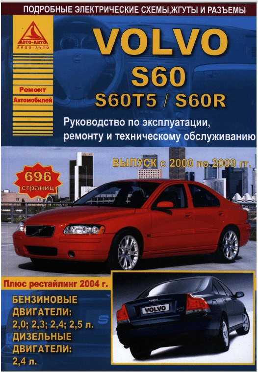
Книга- руководство по ремонту и эксплуатации Volvo S60 I с 2000 по 2008 год (S60 2,4, S60T5, D5 и S60R), 696 страниц, ч/б, скан PDF русский доступна на форуме (clubvolvo.ru/threads/ruko…96-str-ch-b-a4-299.126456) для приобретения по традиционной символической цене 299 руб. Для скачивания доступно два варианта: книга целиком (700 Мб) и по главам (500 Мб). В интернетах отсутствует, только англ язык (доступна бесплатно, ссылка в той же теме)
Войдите или зарегистрируйтесь, чтобы писать комментарии, задавать вопросы и участвовать в обсуждении.
WEB EDITION
VOLVO S60
owners manual
DEAR VOLVO OWNER THANK YOU FOR CHOOSING VOLVO
We hope that you will enjoy many years of driving pleasure in your Volvo. The car has been designed for the safety and comfort of you and your passengers. Volvo is one of the safest cars in the world. Your Volvo has also been designed to satisfy all current safety and environmental requirements.
In order to increase your enjoyment of the car, we recommend that you familiarise yourself with the equipment, instructions and maintenance information contained in this owners manual.
Contents
2
00 Introduction Introduction ………………………………….6 Volvo Cars and the environment ………7
01 Safety Seatbelts …………………………………… 12 Airbag system ……………………………. 14 Airbags (SRS) …………………………….. 15 Activating/deactivating the airbag (SRS) …………………………. 18 Side airbags (SIPS bags)……………… 20 Inflatable Curtain (IC) ………………….. 22 WHIPS………………………………………. 23 When the systems deploy……………. 25 Child safety ……………………………….. 26
02 Instruments and controls Overview, left-hand drive car …………36 Overview, right-hand drive car ……….38 Combined instrument panel ………….40 Indicator and warning symbols ………42 Information display ………………………45 Switches in the centre console ………46 Lighting panel ……………………………..49 Left-hand stalk switch ………………….51 Trip computer ………………………………52 Right-hand stalk switch ………………..53 Cruise control (option) ………………….55 Steering wheel adjustment, parking brake ………………………………………….56 Electrical socket, cigarette lighter …..57 Power windows ……………………………58 Rearview and door mirrors ……………61 Power sunroof (option) ………………….65
Contents
3
03 Climate control General information on climate control ………………………………………. 70 Manual climate control, AC ………….. 72 Electronic climate control, ECC (option) ……………………………………… 74 Air distribution ……………………………. 77 Fuel-driven heater (option) …………… 78
04 Interior Front seats ………………………………….82 Interior lighting …………………………….84 Storage spaces in the passenger compartment ………………………………86 Rear seat …………………………………….91 Cargo area ………………………………….92
05 Locks and alarm Keys and remote controls…………….. 96 Locking and unlocking …………………99 Child safety locks ……………………… 103 Alarm (option) …………………………… 104
Contents
4
06 Starting and driving General ……………………………………. 110 Refuelling …………………………………. 112 Starting the car …………………………. 114 Manual gearbox ………………………… 116 Automatic gearbox ……………………..117 All-wheel drive AWD ……………….. 121 Brake system ……………………………. 122 Stability and traction control system, option ……………………………………… 124 Active chassis FOUR-C …………… 126 Parking assistance …………………….. 127 Towing and recovery ………………….. 129 Start assistance ………………………… 131 Driving with a trailer …………………… 132 Towing equipment …………………….. 134 Detachable towbar ……………………. 136 Load on the roof ……………………….. 141 Adjusting headlamp pattern ……….. 143 BLIS (Blind Spot Information System) option ……………………….. 149
07 Wheels and tyres General ……………………………………. 156 Tyre pressure ……………………………. 159 Warning triangle and spare wheel .. 161 Tyre pressure monitoring (option) … 163 Changing wheels ………………………. 165 Emergency puncture repair ………… 167
08 Car care Cleaning …………………………………… 174 Touching up paintwork ………………..177 Rustproofing ……………………………..178
Contents
5
09 Maintenance and service Volvo service ……………………………. 182 Self-maintenance ……………………… 183 Bonnet and engine compartment .. 184 Diesel ………………………………………. 185 Oils and fluids ………………………….. 186 Wiper blades ……………………………. 190 Battery …………………………………….. 191 Replacing bulbs ……………………….. 193 Fuses ………………………………………. 201
10 Infotainment system Overview HU-450 ……………………….212 Overview HU-650………………………. 213 Overview HU-850………………………. 214 Audio functions HU-450/650/850 …215 Audio functions HU-450 ……………..216 Audio functions HU-650/850 ……….217 Radio functions HU-450/650/850 …218 Radio functions HU-450 ……………..219 Radio functions HU-650/850 ……….220 Radio functions HU-450/650/850 …221 Cassette player HU-450 ………………226 CD player HU-650 ………………………227 Internal CD changer HU-850 ……….228 External CD changer HU-450/650/850 (option) …………….229 Dolby Surround Pro Logic II HU-850 …………………………………….230 Technical data ……………………………231 Phone functions (option) ……………..232 Call options ……………………………….235 Memory functions ………………………238 Menu functions ………………………….239 Miscellaneous information …………..244
11 Technical data Type designation ………………………..248 Dimensions and weights …………….249 Engine specifications …………………251 Engine oil ………………………………….253 Fluids and lubricants ………………….256 Fuel ………………………………………….257 Catalytic converter …………………….260 Electrical system ……………………….261
Introduction
6
Introduction
Owners Manual
A good way of getting to know your new car is to read the owners manual, ideally before your first journey. This will give you the opportunity to familiarise yourself with new functions, to see how best to handle the car in different situations, and to make the best use of all the cars features.
Please pay attention to the safety instruc- tions contained in the manual.
The equipment described in the owners manual is not present in all models. In addi- tion to standard equipment, this manual also describes options (factory fitted equipment) and certain accessories (extra equipment).
The specifications, design features and illus- trations in this owners manual are not bind- ing. We reserve the right to make modifica- tions without prior notice.
Contact your Volvo dealer for more informa- tion.
Volvo Car Corporation
WARNING
«Warning!» texts indicate where there is a risk of personal injury in the event of the instructions not being followed.
IMPORTANT
«Important!» texts indicate a risk of damage to the car in the event of the instructions not being followed.
NOTE
Volvo cars are adapted for the varying requirements of different markets, as well as for national or local legal requirements and regulations. If you are uncertain over what is standard, an option or an accessory then contact your Volvo dealer.
Introduction
7
Volvo Cars and the environment
Volvo Car Corporations environmental philosophy
Environmental care, safety and quality are the three core values which influence all operations of the Volvo Car Corporation. We also believe that our customers share our consideration for the environment.
Your Volvo complies with strict international environmental standards and is also manu- factured in one of the cleanest and most resource-efficient plants in the world. Volvo Car Corporation has global ISO certification, which includes the environmental standard (ISO 14001) covering factories, central func-
tions, as well as several of our other units. We also set requirements for our partners so that they work systematically with environ- mental issues.
EPI (Environmental Product Information) is supplied for all Volvo models. Here you can see how the environment is affected during the entire lifecycle of the car.
Read more at www.volvocars.com/EPI.
Fuel consumption Volvo cars have competitive fuel consump- tion in each of their respective classes. Lower fuel consumption generally results in lower emission of the greenhouse gas, car- bon dioxide.
It is possible for the driver to influence fuel consumption. For more information read under the heading Reducing environmental impact on page 9.
Introduction
8
Volvo Cars and the environment
Efficient emission control Your Volvo is manufactured following the concept Clean inside and out a concept that encompasses a clean interior environ- ment as well as highly efficient emission con- trol. In many cases the exhaust emissions are well below the applicable standards.
In addition there is a special radiator coating, PremAir1, which can convert hazardous ground-level ozone into pure oxygen when the ozone passes the radiator. The higher the ozone content in the air the more ozone is converted.
Clean air in the passenger compartment A passenger compartment filter prevents dust and pollen from entering the passenger compartment via the air intake.
A sophisticated air quality system, IAQS2 (Interior Air Quality System) ensures that the incoming air is cleaner than the air in the traf- fic outside.
The system consists of an electronic sensor and a carbon filter. The incoming air is moni-
tored continuously and if there is an increase in the level of certain unhealthy gases such as carbon monoxide then the air intake is closed. Such a situation may arise in heavy traffic, queues and tunnels for example.
The entry of nitrous oxides, ground-level ozone and hydrocarbons is prevented by the carbon filter.
Textile standard The interior of a Volvo is designed to be pleasant and comfortable, even for people with contact allergies and for asthma suffer- ers. All of our upholstery and interior textiles are tested with respect to certain unhealthy substances and allergens as well as emis- sions. This means that all textiles fulfil the requirements in the ko-Tex 100 standard3, a major advance towards a healthier passen- ger compartment environment.
ko-Tex certification covers seatbelts, car- pets, thread and fabrics for example. The leather in the upholstery undergoes chro- mium-free tanning with natural plant sub- stances and fulfils the certification require- ments.
Volvo workshops and the environment Regular maintenance creates the conditions for a long service life and low fuel consump- tion for your car, and in this way you contrib- ute to a cleaner environment. When Volvos workshops are entrusted with the service and maintenance of your car it becomes part of our system. We make clear demands regarding the way in which our workshops are designed in order to prevent spills and discharges into the environment. Our work- shop staff have the knowledge and the tools required to guarantee good environmental care.
1 Option for 5-cylinder engines. PremAir is a registered trademark of Engelhard Corporation.
2 Option 3 More information on www.oekotex.com
Introduction
9
Volvo Cars and the environment
Reducing environmental impact You can easily help reduce environmental impact, for example, by driving economically, by purchasing eco-labelled car care prod- ucts and by servicing and maintaining the car in accordance with the instructions in the owners manual.
The following hints will help you to do your bit for the environment:
Decrease fuel consumption by choosing ECO tyre pressure, see page 160.
Since a roof load and ski box increase air resist- ance, leading to signifi- cantly higher fuel consumption, they should be removed im- mediately after use.
Remove unnecessary items from the car — the greater the load the higher the fuel consumption.
Is your car equipped with an engine block heater? If so, use it for a few hours before starting from cold to reduce fuel con- sumption and exhaust emissions.
Drive gently and avoid braking too hard.
Drive in the highest gear possible. Low engine speeds result in lower fuel consumption.
Ease back on the acceler- ator on downhill gradi- ents.
Use engine braking to slow down. Avoid idling. Take consideration of local
regulations. Switch off the engine in longer stationary traffic.
Always dispose of envi- ronmentally hazardous waste, such as batteries and oils, in an environ- mentally responsible manner. If uncertain, con- sult an authorised Volvo workshop for advice.
Service your car regularly. High speed increases consumption con-
siderably due to increased wind resist- ance. A doubling of speed increases wind resistance four times.
These hints will help you to reduce your fuel consumption without increasing your travel time or lessening the enjoyment of driving. Apart from being kind to your car, youll be saving money — and the Earths resources.
10
Seatbelts …………………………………………………………………………………….. 12 Airbag system ……………………………………………………………………………… 14 Airbags (SRS) ………………………………………………………………………………. 15 Activating/deactivating the airbag (SRS) …………………………………………………………………………… 18 Side airbags (SIPS bags) ………………………………………………………………. 20 Inflatable Curtain (IC) ……………………………………………………………………. 22 WHIPS………………………………………………………………………………………… 23 When the systems deploy……………………………………………………………… 25 Child safety …………………………………………………………………………………. 26
01 Safety
12
Seatbelts01
Always use a seatbelt
Tensioning the hip strap. The belt must be positioned low down.
Heavy braking can have serious conse- quences if the seatbelts are not used, so make sure that all passengers use their seat- belts. It is important that the seatbelt lies against the body so it can provide maximum protection. Do not lean the backrest too far back. The seatbelt is designed to protect in a normal seating position.
Putting on a seatbelt Pull the seatbelt out slowly and secure it
by pressing the buckle into the lock. A loud «click» indicates that the seatbelt has locked.
Releasing the seatbelt Press the red lock button and then let the
seatbelt retract. If the seatbelt does not retract fully, feed the seatbelt in by hand so that it does not hang loose.
The seatbelt locks and cannot be withdrawn if it is pulled out too quickly. during braking and acceleration. if the car leans heavily.
Keep in mind the following: do not use clips or anything else that can
prevent the seatbelt from fitting properly ensure that the seatbelt is not twisted or
caught on anything the hip strap must be positioned low down
(not over the abdomen). tension the hip strap over the lap by
pulling the diagonal shoulder belt as illustrated
WARNING
The seatbelts and airbags interact. If a seat- belt is not used or is used incorrectly, this may diminish the protection provided by the airbag in the event of a collision.
WARNING
Each seatbelt is designed for only one per- son.
WARNING
Never modify or repair the seatbelt your- self. Contact an authorised Volvo work- shop. If the seatbelt has been subjected to a major load, such as in a collision, the entire seatbelt must be replaced. Some of the seatbelts protective properties may have been lost even if the seatbelt does not appear damaged. The seatbelt must also be replaced if it shows signs of wear or damage. The new seatbelt must be type- approved and designed for installation at the same location as the replaced seatbelt.
01 Safety
13
Seatbelts 01
Seatbelts and pregnancy
The seatbelt should always be worn during pregnancy. But it is crucial that it be worn in the correct way. The diagonal section of the seatbelt should wrap over the shoulder then be routed between the breasts and to the side of the abdomen. The lap section of the seatbelt should lay flat over the thighs and as low as possible under the abdomen. It must never be allowed to ride upward. Remove all slack from the seatbelt and ensure that it fits close to the body. In addi- tion, check that there are no twists in the seatbelt.
As a pregnancy progresses, pregnant driv- ers should adjust their seats and steering wheel such that they can easily maintain con- trol of the vehicle as they drive (which means that they must be able to easily operate the foot pedals and steering wheel). They should strive to position the seat with as large a dis- tance as possible between their abdomen and the steering wheel.
Seatbelt reminder
The seatbelt warning symbol in the com- bined instrument panel and above the rear- view mirror illuminates until the driver buck- les the seatbelt. The seatbelt reminder switches off after 6 seconds if speed is below 10 km/h.
If the driver has not buckled the seatbelt then the reminder switches on if speed exceeds 10 km/h and switches off if speed drops below 5 km/h. If the seatbelt is released, the function reactivates when speed exceeds 10 km/h.
The seatbelt reminder is intended for adults.
01 Safety
14
Airbag system01
Seatbelt tensioner All the seatbelts (except the centre rear seat- belt) are equipped with seatbelt tensioners. A mechanism in the seatbelt tensioner tightens the seatbelt in the event of a sufficiently vio- lent collision. The seatbelt then provides more effective restraint for occupants.
Warning symbol in combined instrument panel
The airbag system1 is continually monitored by the system control module. The warning symbol in the combined instrument panel illuminates when the ignition key is turned to position I, II or III. The symbol goes out after approx. 6 seconds provided the airbag sys- tem1 is working correctly.
As well as the warning sym- bol, a message may appear on the display in appropriate cases. If the warning symbol malfunctions, the warning tri- angle illuminates and the message SRS AIRBAG SERVICE URGENT appears in the display. Contact an
authorised Volvo workshop urgently.
1 Includes SRS and seatbelt tensioner, SIPS and IC.
WARNING
If the warning symbol for the airbag system remains on or illuminates while driving, it means that the airbag system does not have full functionality. The symbol can indi- cate a fault in the seatbelt tensioner system, SIPS, the SRS system or the IC system. Contact an authorised Volvo workshop immediately.
01 Safety
15
Airbags (SRS) 01
Airbag (SRS) on the drivers side
The car has an SRS airbag (Supplemental Restraint System) in the steering wheel to supplement the protection afforded by the seatbelt. This airbag is fitted into the centre of the steering wheel. The steering wheel is marked SRS AIRBAG.
Passenger airbag (SRS)
The car has an airbag to supplement the pro- tection afforded by the seatbelt on the pas- senger side1 and the airbag is folded up into a compartment above the glovebox. The cover panel is marked SRS AIRBAG.
WARNING
The seatbelts and airbags interact. If a seat- belt is not used or is used incorrectly, this may diminish the protection provided by the airbag in the event of a collision.
1 Not all cars have a passenger airbag (SRS). This can be unselected when the car is or- dered.
WARNING
To minimise the risk of injury if the airbag deploys, passengers must sit as upright as possible with their feet on the floor and backs against the backrest. Seatbelts must be secured.
WARNING
Never place a child in a child seat or on a booster cushion in the front seat if the air- bag (SRS) is activated1. Never allow a child to stand or sit in front of the front passenger seat. No one shorter than 140 cm should sit in the front passen- ger seat if the airbag (SRS) is activated. Failure to follow the advice given above can endanger the life of the child.
1For information on activated/deactivated airbag (SRS) see page 18.
01 Safety
16
Airbags (SRS)01
SRS system
SRS system, left-hand drive.
The SRS system consists of airbags and sensors. A sufficiently violent collision trips the sensors and the airbag(s) are inflated with hot gas. To cushion the impact, the airbag deflates when compressed. When this occurs, smoke escapes into the car. This is completely normal. The entire process, including inflation and deflation of the airbag, takes place within tenths of a second.
SRS system, right-hand drive
s
WARNING
Repairs must only be performed by an authorised Volvo workshop. Work on the SRS system can cause mal- function and result in serious personal injury.
NOTE
The sensors react differently depending on the course of the collision and whether the seatbelts on the driver and passenger sides are being used. It is therefore possible that only one (or none) of the airbags may inflate in a collision. The SRS system senses the force of the collision on the vehicle and adapts accordingly so that one or more air- bags is deployed. The capacities of the air- bags are also adapted to the collision force to which they are subjected.
NOTE
The airbags have a function whereby their capacities are adapted to the collision force to which the car is subjected.
01 Safety
17
Airbags (SRS) 01
Location of the passenger airbag in left-hand drive and right-hand drive cars
WARNING
Do not put objects in front of or above the instrument panel where the passenger air- bag is located.
01 Safety
18
Activating/deactivating the airbag (SRS)01
PACOS (option)
Indicator showing that the passenger airbag (SRS) is deactivated.
The airbag (SRS) for the front passenger seat can be deactivated if the car is equipped with PACOS, see page 19.
Message A text message in the roof panel indicates that the airbag (SRS) for the front passenger seat is deactivated (see illustration above).
Activating/deactivating The switch for the passenger airbag is locat- ed on the passenger end of the instrument panel and is accessible when the passenger
door is open (see under the heading, Switch PACOS below).
Check that the switch is in the required posi- tion. Volvo recommends that the key blade be used to change position (other items with a shape similar to a key can also be used).
WARNING
Failure to follow the advice given above can endanger life.
WARNING
If the car is equipped with a front passenger airbag (SRS), but does not have PACOS, the airbag will always be activated.
WARNING
Never place a child in a child seat or on a booster cushion in the front seat if the air- bag is activated. Failure to follow this advice can endanger the life of the child.
WARNING
Do not allow anyone to sit in the front pas- senger seat if the text message in the roof panel indicates that the airbag (SRS) is deactivated and the airbag system warning symbol is displayed in the combined instru- ment panel. This indicates that there has been a severe malfunction. Visit an author- ised Volvo workshop urgently.
01 Safety
19
Activating/deactivating the airbag (SRS) 01
Switch — PACOS
Switch location.
1. The airbag is activated. With the switch in this position, persons taller than 140 cm can sit in the front passenger seat, but never children in a child seat or on a booster cushion.
2. The airbag is deactivated. With the switch in this position, children in a child seat or on a booster cushion can sit in the front passenger seat, but never anybody taller than 140 cm.
WARNING
Activated airbag (passenger seat): Never place a child in a child seat or on a booster cushion in the front passenger seat when the airbag is activated. This also applies to anyone shorter than 140 cm. Deactivated airbag (passenger seat): No one taller than 140 cm should ever sit in the front passenger seat when the airbag is deactivated. Failure to follow the advice given above can endanger life.
01 Safety
20
Side airbags (SIPS bags)01
Side airbags SIPS bag
Side airbag locations.
A large proportion of the collision force is transferred by the SIPS (Side Impact Protec- tion System) to beams, pillars, the floor, the roof and other structural parts of the body. The side airbags at the drivers and front pas- senger seats protect the chest area and are an important part of the system. The side air- bags are located in the front seat backrests.
Child seats and side airbags The side airbag does not diminish the protec- tion provided by the car to children seated in a child seat or on a booster cushion.
A child seat or booster cushion can be placed on the front passenger seat provided that the car does not have an activated1 pas- senger airbag.
WARNING
Side airbags are a supplement the seat- belts. Always wear your seatbelt.
WARNING
Repairs must only be performed by an authorised Volvo workshop. Work on the SIPS bag system could cause malfunction and result in serious personal injury.
WARNING
Do not put objects in the area between the outside of the seat and the door panel, since this area is required by the side air- bag.
WARNING
Use only Volvo genuine car seat covers, or seat covers approved by Volvo. Other seat covers may impede the operation of the side air bags.
1 For information on activated/deactivated air- bag (SRS) see page 18
01 Safety
21
Side airbags (SIPS bags) 01
SIPS bags
Drivers seat, left-hand drive
The SIPS bag system consists of side air- bags and sensors. A sufficiently violent colli- sion trips the sensors and the side airbags are inflated.
Front passenger seat, left-hand drive
The airbag inflates between the occupant and the door panel and thereby cushions the initial impact. The airbag deflates when com- pressed. The side airbag is normally only deployed on the side of the collision.
Location of airbag decal in door opening on front passenger side
G 02 03 43
01 Safety
22
Inflatable Curtain (IC)01
Properties
The inflatable curtain IC (Inflatable Curtain) is a supplement to the SIPS and the airbags . It is fitted in the headlining along both sides of the roof and protects all of the vehicles outer seats. A sufficiently violent collision trips the sensors and the inflatable curtain is inflated. The inflatable curtain helps to prevent the driver and passengers from striking their heads on the inside of the car during a colli- sion.
WARNING
Never hang or fasten anything on the roof handles. The hook is only intended for light outer garments (not for hard objects such as umbrellas). Do not screw or fit anything to the headlin- ing, door pillars or side panels. This could compromise the intended protection. Only use Volvo genuine parts that are approved for placement in these areas.
WARNING
Do not load the car higher than 50 mm under the top edge of the rear passenger windows. Otherwise, the intended protec- tion of the inflatable curtain, which is hidden in the headlining, may be compromised.
WARNING
The inflatable curtain is a supplement to the seatbelts. Always wear your seatbelt.
01 Safety
23
WHIPS 01
Protection against whiplash injury WHIPS
The whiplash protection system (WHIPS) consists of energy absorbing backrests and specially designed head restraints for the front seats. The system is actuated by a rear- end collision, where the angle and speed of the collision, and the nature of the colliding vehicle all have an influence.
Properties of the seat When the WHIPS system is deployed, the front seat backrests fall backward to alter the position of the driver and front seat passen- ger. This diminishes the risk of whiplash injury.
WHIPS system and child seats/booster cushions The WHIPS system does not diminish the protection provided by the car to children seated in a child seat or on a booster cushion.
Correct seating position For the best possible protection, the driver and front seat passenger should sit in the centre of the seat with as little space as pos- sible between the head and the head restraint.
WARNING
The WHIPS system is a supplement to the seatbelts. Always wear your seatbelt.
WARNING
Never modify or repair the seat or WHIPS system yourself. Contact an authorised Volvo workshop.
01 Safety
24
WHIPS01
Do not obstruct the WHIPS system
WARNING
Do not squeeze rigid objects between the rear seat cushion and the front seat back- rest. Make sure you do not to obstruct the function of the WHIPS system.
WARNING
If a rear seat backrest is folded down, the corresponding front seat must be moved forward so that it does not touch the folded backrest.
WARNING
If a seat has been subjected to extreme forces, such as due to a rear-end collision, the WHIPS system must be checked by an authorised Volvo workshop. Part of the WHIPS systems protective capacity may have been lost even if the seat appears to be undamaged. Contact an authorised Volvo workshop to have the system checked even after a minor rear-end collision.
01 Safety
25
When the systems deploy 01
If the airbags have been deployed, the fol- lowing is recommended:
Have the car transported to an authorised Volvo workshop. Do not drive with deployed airbags.
Have an authorised Volvo workshop replace components in the cars safety system.
Always contact a doctor.
System Triggered
Seatbelt tensioner In a frontal collision Airbags SRS In a frontal collision1
Side airbags SIPS In a side-impact accident1
Inflatable Curtain IC In a side-impact accident1
Whiplash protection WHIPS In a rear-end collision
1The bodywork of the car could be greatly deformed in a collision without airbag deployment. A number of factors such as the rigidity and weight of the object hit, the speed of the car, the angle of the collision etc. affects how the different safety systems of the car are activated.
NOTE
The SRS, SIPS, IC and belt tensioner sys- tems are deployed only once during a colli- sion
WARNING
The airbag system control module is located in the centre console. If the centre console is drenched with water or other liq- uid, disconnect the battery cables. Do not attempt to start the car since the airbags may deploy. Have the car transported to an authorised Volvo workshop.
WARNING
Never drive with deployed airbags. They can make steering difficult. Other safety systems may also be damaged. The smoke and dust created when the airbags are deployed can cause skin and eye irritation after intensive exposure. In case of irrita- tion, wash with cold water. The rapid deployment sequence and airbag fabric may cause friction injury and burns to the skin.
01 Safety
26
Child safety01
Children should sit comfortably and safely
The position of a child in the car and the choice of equipment is dictated by the childs weight and size, for more information see page 29.
Children of all ages and sizes must always sit correctly secured in the car. Never allow a child to sit on the knee of a passenger.
Volvos own child safety equipment is designed for your car. Use Volvo genuine equipment to best ensure that the mounting points and attachments are correctly posi- tioned and are sufficiently strong.
Child seats
Child seats and airbags are not compatible.
Volvo has child safety products that are designed for and tested by Volvo.
Do not attach the straps for the child seat to the horizontal adjustment bar, springs, rails or beams under the seat. Sharp edges can damage the straps. Allow the back of the child seat to rest against the instrument
panel. This applies to cars without a passen- ger airbag, or where the airbag is deacti- vated.
Location of child seats You may place:
a child seat or booster cushion on the front passenger seat, provided the pas- senger airbag is not activated (for informa- tion on activating/deactivating the airbag (SRS), see page 18)
a rear-facing child seat in the rear seat that uses the back of the front seat as support.
Always place a child in the rear seat if the passenger airbag is activated. A child in a child seat on the front passenger seat may suffer serious injury if the airbag deploys.
NOTE
Regulations regarding the placement of children in cars vary from country to coun- try. Check what laws apply.
NOTE
If problems arise when fitting child safety products, contact the manufacturer for clearer instructions.
NOTE
When using child safety products it is important to read the installation instruc- tions included with the product.
WARNING
Never place the child seat in the front seat if the car is equipped with an activated1 front passenger airbag. If problems arise when fitting child safety products, contact the manufacturer for clearer instructions.
1 For information on activated/deactivated air- bag (SRS) see page 18.
01 Safety
27
Child safety 01
WARNING
Booster cushions/child seats with steel braces or some other design that could rest on the seatbelt buckles opening button must not be used, as they could cause the seatbelt buckle to open accidentally. Do not allow the upper section of the child seat to rest against the windscreen.
01 Safety
28
Child safety01
Airbag decal
Decal located on instrument panel end face. Decal located on instrument panel end face (Australia only).
01 Safety
29
Child safety 01
Recommended child seats
Weight/age Front seat1 Outer rear seat Centre rear seat
Group 0 <10 kg (09 months)
Volvo Child seat rear-facing child seat, secured with the cars seatbelt and straps.
Type approval: E5 03135
Volvo Child seat rear-facing child seat, secured with the cars seatbelt, straps and support legs.
Type approval: E5 03135
Volvo Child seat rear-facing child seat, secured with the cars seatbelt, straps and support legs.
Type approval: E5 03135
Britax Baby Safe Plus rear-facing child seat with ISOFIX fixture system.
Type approval: E1 03301146
Britax Baby Safe Plus rear-facing child seat with ISOFIX fixture system.
Type approval: E1 03301146
Britax Baby Safe Plus rear-facing child seat secured with the cars seatbelt.
Type approval: E1 03301146
Group 1 918 kg (936 months)
Volvo Child seat rear-facing child seat, secured with the cars seatbelt and straps.
Type approval: E5 03135
Volvo Child seat rear-facing child seat, secured with the cars seatbelt, straps and support legs.
Type approval: E5 03135
Volvo Child seat rear-facing child seat, secured with the cars seatbelt, straps and support legs.
Type approval: E5 03135
Britax Freeway rear-facing child seat, secured with the ISOFIX fixture system and straps.
Type approval: E5 03171
Britax Freeway rear-facing child seat, secured with the ISOFIX fixture system and straps.
Type approval: E5 03171
Group 2/3 1536 kg (312 years)
Volvo Booster cushion with or without backrest.
Type approval: E5 03139
Volvo Booster cushion with or without backrest.
Type approval: E5 03139
Volvo Booster cushion with or without backrest.
Type approval: E5 03139
Volvo Integrated booster cushion available as an option.
Type approval: E5 03140
1For information on activated/deactivated airbag (SRS) see page 15.
For other child seats your car should be included in the manufacturers enclosed list of vehicles or be universally approved in accordance with the ECE R44 legal requirement.
01 Safety
30
Child safety01
Integrated booster cushions (option)
Volvos integrated booster cushion for the centre rear seat is specially designed to pro- vide optimum safety for children. Combined with the normal seatbelt, the integrated booster cushion is approved for children weighing between 15 and 36 kg.
Folding out the booster cushion
fold down the booster cushion pull apart the Velcro raise the upper portion back into place
Check that: the seatbelt is in contact with the childs
body and is not slack or twisted, and that the seatbelt is positioned correctly across the shoulder.
the lap belt is low over the pelvis for optimum protection.
the seatbelt does not lie across the childs throat or below the shoulder.
Carefully adjust the position of the head restraint to suit the child.
WARNING
Repair or replacement should only be per- formed by an authorised Volvo workshop. Do not make any modifications or additions to the booster cushion. If an integrated booster cushion has been subjected to a major load, such as in con- junction with a collision, the entire booster cushion must be replaced. Even if the booster cushion appears to be undamaged, it may not afford the same level of protec- tion. The booster cushion must also be replaced if it is heavily worn.
01 Safety
31
Child safety 01
Folding in the booster cushion
Fold down the upper section (A). Fasten the Velcro (B). Raise the booster cushion into the rear
seat backrest (C).
NOTE
Make sure that both sections of the booster cushion are secured with the Velcro strap (B) before folding down. Otherwise the upper section (A) could become trapped in the rear seat backrest (C) when the booster cushion is folded out again.
01 Safety
32
Child safety01
ISOFIX fixture system for child seats (option)
Mounting points for the ISOFIX fixture sys- tem are concealed behind the lower section of the rear seat backrest, in the outer seats.
The location of the mounting points is indi- cated by symbols in the backrest upholstery (see illustration above).
Press the seat cushion down to access the mounting points.
Always follow the manufacturers installation instructions when connecting a child seat to the ISOFIX mounting points.
34
Overview, left-hand drive car ………………………………………………………….36 Overview, right-hand drive car ………………………………………………………..38 Combined instrument panel ……………………………………………………………40 Indicator and warning symbols ……………………………………………………….42 Information display ………………………………………………………………………..45 Switches in the centre console ……………………………………………………….46 Lighting panel ……………………………………………………………………………….49 Left-hand stalk switch ……………………………………………………………………51 Trip computer ……………………………………………………………………………….52 Right-hand stalk switch …………………………………………………………………53 Cruise control (option) ……………………………………………………………………55 Steering wheel adjustment, parking brake ………………………………………..56 Electrical socket, cigarette lighter ……………………………………………………57 Power windows …………………………………………………………………………….58 Rearview and door mirrors ……………………………………………………………..61 Power sunroof (option) …………………………………………………………………..65
02 INSTRUMENTS AND CONTROLS
02 Instruments and controls
36
Overview, left-hand drive car
02
02 Instruments and controls
37
Overview, left-hand drive car
02
1. Fog lamps 2. Headlamps, position/parking lights 3. Rear fog lamp 4. Direction indicators, beam selection 5. Cruise control 6. Horn 7. Combined instrument panel 8. Keypad for phone/audio 9. Windscreen wipers 10.Parking brake 11.Switch panel 12.Climate control 13.Audio system 14.Electric socket, Cigarette lighter 15.Hazard warning flashers
16.Glovebox 17.Panel vents 18.Display 19.Temperature gauge 20.Odometer, trip meter/cruise control 21.Speedometer 22.Direction indicators 23.Tachometer 24.Outside temperature, clock, gear
position 25.Fuel gauge 26. Indicator and warning symbols 27.Panel vents 28. Instrument lighting 29.Headlamp levelling 30.Lighting panel 31.Reading lamps 32. Interior lighting 33.Control, sunroof 34.Seatbelt reminder 35.Rearview mirror 36.Lock button, for all doors 37.Blocking power windows in the rear
doors 38.Controls, power windows 39.Controls, power door mirrors
40.Active chassis FOUR-C
02 Instruments and controls
38
Overview, right-hand drive car
02
02 Instruments and controls
39
Overview, right-hand drive car
02
Drivers door control panel
1. Rear fog lamp 2. Headlamps, position/parking lights 3. Fog lamps 4. Windscreen wipers 5. Keypad for phone/audio 6. Horn 7. Combined instrument panel 8. Cruise control 9. Direction indicators, beam selection 10.Parking brake 11.Electric socket, Cigarette lighter 12.Climate control 13.Audio system 14.Switch panel
15.Hazard warning flashers 16.Glovebox 17.Panel vents 18. Indicator and warning symbols 19.Fuel gauge 20.Outside temperature, clock, gear
position 21.Tachometer 22.Direction indicators 23.Speedometer 24.Odometer, trip meter/cruise control 25.Temperature gauge 26.Display 27.Panel vents 28.Lighting panel 29.Headlamp levelling 30. Instrument lighting 31.Reading lamps 32. Interior lighting 33.Control, sunroof 34.Seatbelt reminder 35.Rearview mirror 36.Lock button, for all doors 37.Blocking power windows in the rear
doors 38.Controls, power windows
39.Controls, power door mirrors 40.Active chassis FOUR-C
02 Instruments and controls
40
Combined instrument panel
02
1. Temperature gauge Displays the temperature of the engine cool- ing system. If the temperature is abnormally high and the needle enters the red zone, a message is shown in the display. Bear in mind that extra lamps in front of the radiator grille reduce the cooling capacity at high out- side temperature and high engine loads.
2. Display Information and warning messages are shown in the display.
3. Speedometer Shows the speed of the car.
4. Trip meter, T1 and T2 The trip meters are used for measuring short distances. The right-hand digit displays tenths of a kilometre. Press the button for more than 2 seconds to reset. Switch between trip meters with one quick press of the button.
5. Cruise control indicator See page 55.
6. Trip meter The odometer indicates the total distance the car has travelled.
7. Main beam indicator
8. Warning symbol If a fault arises, the symbol illuminates and a message is shown in the display.
9. Tachometer Indicates engine speed in thousands of revo- lutions per minute (RPM). Do not allow the needle of the tachometer to enter the red field.
10. Automatic gearbox indicator The selected gearshift programme is dis- played here. If you have Geartronic auto-
02 Instruments and controls
41
Combined instrument panel
02
matic gearbox and drive using the manual function, the current manual gear is dis- played.
11. Outside temperature gauge Displays outside temperature. When the tem- perature lies between +2 C to 5 C, a snowflake symbol is shown in the display. This symbol serves as a warning for slippery road surfaces. When the car is or was sta- tionary, the outside temperature gauge may display a higher reading than the actual tem- perature.
12. Clock Turn the button to set the clock.
13. Fuel gauge When the lamp in the instrument panel lights, approximately 8 litres of usable fuel remain in the tank.
14. Indicator and warning symbols
15. Direction indicators left/right.
02 Instruments and controls
42
Indicator and warning symbols
02
Indicator and warning symbols
All indicator and warning symbols1 illuminate when the ignition key is turned to position II before starting. This is to check that the sym- bols are working. When the engine starts, all the symbols should go out except the hand- brake symbol, which extinguishes when the handbrake is released.
If the engine does not start within five seconds, all symbols extin- guish except the symbols for a fault in the cars emissions sys- tem and for low oil pressure. Cer- tain symbols may have no func- tion, depending on the cars specifications.
Warning symbols in the centre of the instrument panel
These symbols illuminate with a red or amber glow depending on the severity of the fault.
Red symbol Stop the car in a safe place. Do not drive
the car further. Read the information on the display. Rectify the fault as instructed or contact
an authorised Volvo workshop. Symbol and message text are visible until the fault has been rectified.
Yellow symbol Read the message on the display. Action. The message text is cleared using the READ button, see page 45, or disappears automati- cally after 2 minutes.
When the message text TIME FOR REGULAR SERVICE is shown, the symbol lamp and message text are cleared using the READ button, or disappear automatically after 2 minutes.
ABS fault If this symbol illuminates, the system is not working. The cars regular brake system continues to work, but without the ABS function.
Stop the car in a safe place and turn off the engine.
Restart the engine. If the warning symbol remains illuminated, drive to an authorised Volvo workshop to have the ABS system checked.
Fault in brake system If this symbol illuminates, the brake fluid level may be too low.1 For certain engine variants, the symbol for low
oil pressure is not used. Warnings are given via display text, see page 186.
02 Instruments and controls
43
Indicator and warning symbols
02
Stop the car in a safe place and check the brake fluid reservoir level.
If the reservoir level is below MIN, the car should not be driven further. Have it towed to an authorised Volvo workshop to have the brake system checked.
If the warning symbols for BRAKE and ABS illuminate at the same time, there may be a fault in the brake force distribution sys- tem.
Stop the car in a safe place and switch off the engine. Restart the engine.
If both symbols go out, it was an indicator error.
If the warning symbols remain illuminated, check the level in the brake fluid reservoir. See page 189.
If the reservoir level is below MIN, the car should not be driven further. Have it towed to an authorised Volvo workshop to have the brake system checked.
If the brake fluid level is normal and the symbols remain illuminated, drive the car carefully to the nearest authorised Volvo workshop to have the brake system checked.
Seatbelt reminder This symbol illuminates until the driver buckles up.
Low oil pressure1
If this symbol illuminates during driving then the engines oil pres- sure is too low. Stop the engine immediately and check the engine oil level. If the symbol illu-
minates and the oil level is normal, contact an authorised Volvo workshop.
Fault in cars emissions system Drive to an authorised Volvo workshop to have the system checked.
Fault in SRS If this symbol remains on or illu- minates while driving, it means a fault has been detected in the SRS system (airbags). Drive to an authorised Volvo workshop to
have the system checked.
Alternator not charging If this symbol illuminates while driving, there is probably a fault in the electrical system. Contact an authorised Volvo workshop.
Engine preheater (diesel) This symbol indicates engine preheating. You can start the car when the symbol switches off. Applies to diesel cars only.
Parking brake applied The symbol illuminates when the parking brake is applied. Always pull the parking brake lever to the end position.
WARNING
If the warning symbols for BRAKE and ABS illuminate at the same time, there is a risk that the rear of the car will have a tendency to slide during heavy braking.
1 For certain engine variants, the symbol for low oil pressure is not used. Warnings are given via display text, see page 186.
NOTE
The symbol illuminates irrespective of how hard the parking brake is applied.
02 Instruments and controls
44
Indicator and warning symbols
02
Rear fog lamp This symbol is illuminated when the fog lamp is on.
Trailer indicator lamp Flashes when the direction indi- cators of the car and trailer are used. If the symbol does not flash, one of the direction indica- tor lamps on the trailer or car is defective.
Stability systems STC/DSTC The systems different functions and symbols are described on page 124.
02 Instruments and controls
45
Information display
02
Messages in the display A message appears in the display whenever a warning or indicator symbol illuminates. Once you have read and understood the message, press the READ button (A). Read messages are then erased from the display and stored in a memory. Messages regarding faults remain in the memory until the fault has been remedied.
Very serious fault messages cannot be erased from the display. They remain in the display until the fault is remedied.
Messages stored in the memory can be read again. Press the READ button (A) to see stored messages. Scroll through the mes- sages stored in the memory by pressing the READ button.
Press the READ button to return read mes- sages to the memory.
NOTE
If a warning message interrupts when you are in the trip computer menu or wish to use the phone, you must first acknowledge the message by pressing the READ button (A).
Message Specification STOP SAFELY Stop the car in a safe manner and turn off the engine. Serious risk of damage. STOP ENGINE Stop the car in a safe manner and turn off the engine. Serious risk of damage. SERVICE URGENT Have the car checked by an authorised Volvo workshop immediately. SEE MANUAL Read the owners manual. SERVICE REQUIRED Have the car checked by an authorised Volvo workshop as soon as possible. FIX NEXT SERVICE Have your car checked at the next service interval. TIME FOR REGULAR SERVICE Time for regular service at an authorised Volvo workshop. The timing is determined by the number of
kilometres driven, number of months since the last service and engine running time. SOOT FILTER FULL SEE MANUAL Diesel particle filter requires regeneration, see page 114. STC/DSTC SPIN CONTROL OFF The function of the stability and traction control system is reduced, see page 124 for more variants.
02 Instruments and controls
46
Switches in the centre console
02
Active chassis, FOUR-C (option) Press the button to select the Comfort or Sport chas- sis setting, see page 126. The display shows the cur- rent setting for 10 seconds.
BLIS (Blind Spot Infor- mation System) option
Press the button to deacti- vate or reactivate the func- tion. For further information, see page 149.
DSTC system This button is used to reduce or reactivate the functions of the DSTC system.
When the lamp in the but- ton is illuminated, the DSTC
system is activated (assuming there is no fault).
Hold the button depressed for at least half a second to reduce the function of the DSTC system. The lamp in the button goes out and the text DSTC ANTI-SKID OFF is shown in the display.
The DSTC system is reactivated when the engine is restarted. For more information, see page 149.
Electric socket/Cigarette lighter (option)
The electric socket can be used for various 12 V accessories, e. g. mobile phone or a cooler box.
The ignition key must be at least in position I so that the
socket can supply power.
The cigarette lighter is activated by pressing in the button. Once the lighter has been
NOTE
The order of the buttons may vary. WARNING
Keep in mind that cars driving characteris- tics may change if you deactivate the DSTC system.
02 Instruments and controls
47
Switches in the centre console
02
heated, the button pops out again. Pull out the lighter to use it. For safety reasons, always keep the cover in place when the socket is not in use. Maximum current tap 10 A.
Lowering the outer head restraints in the rear seat (option)
Do not lower the head restraints if there is a pas- senger in one of the outer seats.
Turn the ignition key to position I or II.
Press the button to tilt the rear head restraints forward for a better rear view.
The head restraints are moved back manually.
The head restraints must be in their upright positions if the rear backrests are to be folded down.
Retractable power door mirrors (option)
This button is used to fold in the door mirrors if they are folded out or to fold them out if they are folded in.
Proceed as follows if a door mirror has been accidentally folded in or out:
Manually fold the door mirror forward as far as possible.
Turn the ignition key to position II. Fold the door mirror inward and then
outward using the button. The door mirrors have now returned to their original fixed positions.
Parking assistance (option) The system is always acti- vated when the car is started. Press the button to deactivate/reactivate park- ing assistance. See also page 127.
Locking the boot lid (certain countries) Press this button in order to lock the boot lid. The boot lid remains locked even if the doors are unlocked manually with the master key, the master key remote control or the service key.
Deactivation of the deadlocks and detectors
Use this button if you wish to switch off the deadlock function (doors cannot be opened from the inside when locked). This button can also be used when deactivating the alarm sys-
tems movement and tilt detectors1 e.g. when transporting the car by ferry. The lamp illuminates when the functions are deacti- vated.
Auxiliary lamps (accessory) Use this button if you want the auxiliary lamps of the car to come on together with the main beam or to deactivate this function. The lamp in the button is illuminated when the func-
tion is active.
1 Option
02 Instruments and controls
48
Switches in the centre console
02
Active Bi-Xenon Lights, ABL (option) The ABL headlamps head- lamp pattern follows the movements of the steering wheel during driving. The function is activated auto- matically when the car is started and can be deacti-
vated/activated by pressing the button. The lamp in the button illuminates when the func- tion is activated.
Shifting headlamp pattern for right/left- hand traffic Hold the button depressed for at least five seconds. The car must be stationary when the headlamp pattern is shifted.
The message DIPPED BEAM SETT. F. RIGHT TRAFFIC or DIPPED BEAM SETT. F. LEFT TRAFFIC is shown in the display. For more information and adapting headlamp pattern for halogen or Bi-Xenon headlamps, see page 143.
Hazard warning flashers
Use the hazard warning flashers (all direction indicators flash) when the car is stopped where it could be a traffic hazard or obstruc- tion. Press the button to activate the func- tion.
Door mirror and rear window defrosters
Heating is used to quickly remove mist- ing and ice from the rear window and door mirrors.
Press the switch to start defrosting the rear window and door mirrors. The lamp in the switch illuminates.
Defrosting is automati- cally disconnected after about 12 minutes.
Heated front seats See page 73 or page 75 for further information.
NOTE
Regulations regarding the use of hazard warning flashers vary from country to coun- try.
02 Instruments and controls
49
Lighting panel
02
Headlamps
Automatic dipped beam (certain countries) Dipped beam comes on automatically when the ignition key is turned to position II, except when the headlamp control (1) is in the centre position. If necessary the auto-
matic dipped beam can be deactivated by an authorised Volvo workshop.
Automatic dipped beam, main beam Turn the ignition key to position II. Dipped beam is activated by means of
turning the headlamp control (1) clockwise to the end position.
Main beam is activated by means of mov- ing the left-hand stalk switch towards the steering wheel to the end position and releasing it, see page 51.
The lamps are switched off automatically when the ignition key is turned to position I or 0.
Position/parking lamps Position/parking lamps can be switched on irrespective of ignition key position.
Turn the headlamp control (1) to the centre position.
When the ignition key is in position II the position/parking lamps and number plate lighting are always on.
Headlamp levelling The load in the car changes the vertical align- ment of the headlamp beam, which could dazzle oncoming motorists. Avoid this by adjusting the height of the beam.
Turn the ignition key to position II. Turn the headlamp control (1) to one of the
end positions. Roll the control (3) up or down respec-
tively to raise or lower beam alignment. Cars with Active Bi-Xenon and Bi-Xenon headlamps1 have automatic headlamp level- ling, so there is no control (3).
Instrument lighting The instrument lighting is switched on when the ignition key is in position II and the head- lamp control (1) is in one of the end positions. The lighting is automatically dimmed during the day and can be controlled manually at night.
Roll the control up or down (5) for brighter or dimmer lighting.
Position Specification Automatic/deactivated dipped beam. Only main beam flash. Position/parking lamps
Automatic dipped beam. Main beam and main beam flash work in this position.
1 Option.
02 Instruments and controls
50
Lighting panel
02
Fog lamp
2 Front fog lamps (option) The front fog lamps can be switched on along with the headlamps or the position lamps/parking lamps.
Press the button (2). The light in the button (2) illuminates when the front fog lamps are switched on.
4 Rear fog lamp The rear fog lamp can only be switched on with the headlamps or the front fog lamps.
Press the button (4). The rear fog lamp indicator symbol on the combined instrument panel and the light in the button (4) illuminate when the rear fog lamp is switched on.
Active Bi-Xenon Lights, ABL (option)
The ABL headlamps headlamp pattern fol- lows the movements of the steering wheel during driving. The function is activated auto- matically when the car is started and can be deactivated/activated using the button in the centre console, see page 48.
NOTE
Regulations for use of fog lamps vary from country to country.
02 Instruments and controls
51
Left-hand stalk switch
02
Stalk switch positions
1. Short flash sequence, direction indicators 2. Continuous flash sequence, direction
indicators 3. Main beam flash 4. Switching, main and dipped beam, and
home safe lighting
Direction indicators
Continuous flash sequence Move the stalk switch up or down to end
position (2). The stalk switch remains in its end position and is moved back manually, or automati- cally by steering wheel movement.
Short flash sequence Move the stalk switch up or down to
position (1) and release, the stalk switch then returns to its home position, or move the stalk switch to position (2) and move it directly back to the home position.
The direction indicators flash three times.
Short flash sequence interrupted immedi- ately if indicating is started in the opposite direction.
Switching, main and dipped beam The ignition key must be in position II for main beam to be switched on.
Turn the headlamp control clockwise to the end position, see page 49.
Move the stalk switch towards the steer- ing wheel to the end position (4) and release.
Main beam flash Move the stalk switch gently towards the
steering wheel to position (3). Main beam comes on until the stalk switch is released.
Home safe lighting Some exterior lights can be kept lit and serve as home safe lighting after the car has been locked. The standard delay is 30 seconds1, but can be changed to 60 or 90 seconds.
Remove the key from the ignition switch. Move the stalk switch towards the steer-
ing wheel to the end position (4) and release.
Get out of the car and lock the door.
1 Factory settings.
02 Instruments and controls
52
Trip computer
02
Trip computer (option)
Controls To scroll through trip computer information, turn the thumbwheel (B) in steps, either upward or downward. Continue turning to return to the starting point.
Functions The trip computer displays the following information:
AVERAGE SPEED
SPEED IN MILES PER HOUR1
INSTANTANEOUS
AVERAGE KILOMETRES TO EMPTY TANK
STC/DSTC, see page 124
Average speed The average speed since the last reset (RESET). When the ignition is switched off, the average speed is stored and used as the basis of the new value when you continue driving. This can be reset with the RESET button (C) on the stalk switch.
Speed in miles per hour1
Current speed is displayed in mph if the speedometer is graduated in km/h. If it is graduated in mph then the current speed is shown in mph.
Instantaneous Continuous information on current fuel con- sumption, calculated each second. The fig- ure in the display is updated every couple of seconds. When the car is stationary, «—-» is shown in the display.
Average The average fuel consumption since the last reset. Reset using RESET.
Kilometres to empty tank The calculation is based on the average fuel consumption over the last 30 km and the remaining driveable fuel quantity. The display shows the approximate distance that can be driven with the fuel quantity remaining in the tank. When fuel for less than 20 km remains then the display shows «—-«.
NOTE
If a warning message interrupts while you are using the trip computer, this message must be acknowledged. Acknowledge by pressing the READ button (A) and revert to the trip computer function.
1 Certain countries.
NOTE
There may be a slight error in the reading if a fuel-driven heater is used.
NOTE
There may be a slight error in the reading if a fuel-driven parking heater (option/acces- sory) has been used.
NOTE
There may be a slight error in the reading if a fuel-driven parking heater (option/acces- sory) has been used or if driving style has been changed.
02 Instruments and controls
53
Right-hand stalk switch
02
Windscreen wipers
Windscreen wipers off The windscreen wipers are off when the stalk switch is in position 0.
Single sweep Raise the stalk switch to make a single sweep.
Intermittent wiping You can set a suitable delay between the sweeps. Turn the thumbwheel (1) up for a shorter
interval between sweeps. Turn it down to increase the delay.
Continuous wiping The wipers sweep at normal speed.
The wipers sweep at high speed.
Rain sensor (option) The rain sensor automatically activates the windscreen wipers based on how much water it detects on the windscreen. The sen- sitivity of the rain sensor can be adjusted using the thumbwheel (1).
Turn the thumbwheel upwards for higher sensitivity and downwards for lower sensitiv- ity. (An extra sweep is made when the thum- bwheel is turned upwards.)
On/Off When activating the rain sensor, the ignition key must be in position I or II and the wind- screen wiper stalk switch must be in position 0 (not activated).
To activate the rain sensor:
press the button (2). A lamp in the button illuminates to indicate that the rain sensor is active.
To turn the rain sensor off, either:
press the button (2) or press the stalk switch downward to
another wiper programme.
If the stalk switch is raised, the rain sensor will remain active, the wipers make an extra sweep and
then return to rain sensor mode when the stalk is released to position 0.
The rain sensor is automatically deactivated when the key is removed from the ignition switch or five minutes after the ignition is switched off.
IMPORTANT
Use plenty of washer fluid when the wipers are cleaning the windscreen. The wind- screen must be wet when the windscreen wipers are operating.
IMPORTANT
In an automatic car wash: Turn off the rain sensor by pressing the but- ton (2) while the ignition key is in position I or II. Otherwise, the windscreen wipers may start and be damaged.
02 Instruments and controls
54
Right-hand stalk switch
02
Windscreen washer Pull the stalk switch towards the steering wheel to start the windscreen washers. The wipers will make several more sweeps once the stalk switch is released.
Headlamp washers (option certain markets) Use of the windscreen washer automatically activates the headlamp washer.
High-pressure headlamp washing consumes a large quantity of washer fluid. To save fluid, the headlamps are only washed every fifth wash cycle (within a ten minute period). When ten minutes have elapsed following the latest windscreen washing, the headlamps are again washed with high-pressure with the first windscreen washing. Turn the stalk switch toward the steering wheel to wash the windscreen only.
Reduced washing If only approx. one litre of washer fluid remains in the reservoir, the supply to the headlamps is cut off in order to prioritise cleaning of the windscreen.
02 Instruments and controls
55
Cruise control (option)
02
Activating
The controls for cruise control are to the left of the steering wheel.
Setting the desired speed: Press the CRUISE button. CRUISE is
shown on the combined instrument panel. Touch + or to lock the vehicle speed.
CRUISE-ON appears on the combined instrument panel.
Cruise control cannot be engaged at speeds below 30 km/h or above 200 km/h.
Increasing or decreasing speed
Increase or decrease the speed by press- ing and holding + or . The speed of the car when the button is released is set as the new speed.
A brief press (less than half a second) on + or changes the speed by 1 km/h.
Temporary disengagement Press 0 to disengage the cruise control tem- porarily. CRUISE will be shown on the com- bined instrument panel. The speed set earlier is stored in the memory.
The cruise control is also temporarily disen- gaged when:
the brake pedal or clutch pedal is depressed
speed falls below 2530 km/h when travelling uphill1
the gear selector is moved to position N wheel spin or wheel lock-up occurs. a temporary increase in speed lasts longer
than one minute.
Return to the set speed Press this button to resume the previously set speed. CRUISE-ON appears on the combined instrument panel.
Disengaging Press CRUISE to disengage the cruise con- trol. CRUISE-ON goes out on the combined instrument panel.
NOTE
A temporary increase in speed (less than one minute) using the accelerator, such as while overtaking, does not affect the cruise control setting. When you release the accel- erator, the car will return to the pro- grammed speed.
1 Depending on engine type
02 Instruments and controls
56
Steering wheel adjustment, parking brake
02
Steering wheel adjustment
The steering wheel can be adjusted for both height and reach. Press down the control on the left-hand
side of the steering column. Then adjust the steering wheel to the
position that suits you best. Press the control back into place to lock
the steering wheel. If this is difficult, press the steering wheel slightly while pressing the control back.
Parking brake (handbrake)
The lever is located between the front seats.
How to apply the parking brake Press the foot brake down firmly. Pull up the parking brake lever up firmly to
its full extent. Release the foot brake and make sure that
the car is stationary. If the vehicle rolls, the parking brake lever
must be pulled more firmly.
When parking a vehicle always put the gear selector in position 1 (for manual transmission) or P (for automatic transmis- sion).
Parking on a hill If the car is parked facing uphill; turn the wheels away from the kerb.
If the car is parked facing downhill, turn the wheels towards the kerb.
How to release the parking brake Press the foot brake down firmly. Pull the parking brake lever up slightly,
press the button, release the parking brake lever and release the button.
WARNING
Adjust the steering wheel before driving off, never while driving. Before driving, check that the steering wheel is fixed in position.
NOTE
The warning lamp symbol in the combined instrument panel comes on irrespective of how hard the parking brake is applied.
02 Instruments and controls
57
Electrical socket, cigarette lighter
02
Electrical socket in rear seat
The electrical socket can be used for acces- sories, such as a mobile phone charger or a cooler, and it is designed for 12 V. The maxi- mum current is 10 A.
The ignition key must be at least in position I for the socket to supply power.
Cigarette lighter (option) Press in the lighter to activate it. The button pops out when the lighter is hot. Pull out the lighter and light a cigarette on the heated coils.
WARNING
For reasons of safety, always keep the cover in place when the socket is not in use.
02 Instruments and controls
58
Power windows
02
Operating
The power windows are operated using the controls in the doors. The ignition key must be in position I and II for the power windows to operate. The windows continue to work when the car is stopped and ignition key removed, provided none of the doors is opened. Operate the windows with caution.
To open a window: Depress the front of the control.
To close a window: Raise the front of the control.
Drivers door
Controls, power windows. A. Front B. Rear.
The driver can operate all power windows from the drivers seat.
The windows can be opened and closed in two ways:
Manual operation Depress one of the controls (A) or (B) gen-
tly or raise it gently. The power window opens or closes as long as the switch is actuated.
Automatic operation Fully depress one of the controls (A) or (B)
or raise it fully, then release. The side
window will then open or close automati- cally. If the window is obstructed by an object, the movement will stop.
WARNING
Make sure that children and other passen- gers cannot be trapped in any way when closing the windows. Pay close attention if the rear door windows are controlled from the drivers door or if the windows are closed with the remote control.
WARNING
The function that interrupts the movement of the windows in the event of blocking works only with automatic closing, not with manual.
WARNING
If there are children in the car: Remember to switch off the supply to the power windows by removing the ignition key if the driver leaves the car. Make sure that children and other passen- gers cannot be trapped in any way when closing the windows.
02 Instruments and controls
59
Power windows
02
Blocking power windows in the rear doors
Blocking rear power windows and electric child safety locks1.
The rear power windows can be blocked using the switch on the drivers door control panel.
The light in the switch is illuminated The rear door windows can only be operated from the drivers door.
The light in the switch is extinguished The rear door windows can be operated both with the controls on each rear door and with the controls on the drivers door.
Front passenger seat
Front passenger seat
The control in the front passenger door oper- ates that window only.
1 Option.
NOTE
If the car has electric child safety locks on the rear doors, the light indicates that these are also activated. The doors then cannot be opened from the inside. A text message is shown on the display when the electric child safety locks are activated.
02 Instruments and controls
60
Power windows
02
Rear power windows
The rear door windows can be operated with the control on each rear door or with the switch on the drivers door.
If the light in the switch for blocking the rear power windows (located in the control panel in the drivers door) is lit, the rear door win- dows can only be operated from the drivers door.
The windows in the rear doors are operated in the same way as the windows in the front doors.
02 Instruments and controls
61
Rearview and door mirrors
02
Interior rearview mirror
Bright light from behind could be reflected in the rearview mirror and dazzle the driver. Use dimming when disturbed by light from behind.
Dimming A. Normal position
B. Dimmed position.
Automatic dimming (option) Bright light from behind is automatically dimmed by the rearview mirror.
Rearview mirror with compass (option in certain markets)
The upper left-hand corner of the rearview mirror has an integrated display that shows the compass direction in which the front of the car is pointing.
Eight different directions are shown with English abbreviations: N (north), NE (north east), E (east), SE (south east), S (south), SW (south west), W (west) and NW (north west).
If the compass is activated then it starts automatically in ignition position II or when the engine is running.
NOTE
The control is not available on mirrors with automatic dimming.
02 Instruments and controls
62
Rearview and door mirrors
02
Switch the compass on or off by pressing the button set into the rear of the mirror. Use a straightened paper clip for example. The but- ton is countersunk approximately 2.5 cm in the mirror.
Set the correct zone for the compass
The earth is divided into 15 magnetic zones. The correct zone must be selected for the compass to function correctly.
Ignition position II. Press and hold the button on the rear of
the mirror for approximately 3 seconds until ZONE is shown (use a straightened paper clip for example). The number for the current area is shown.
Press the button several times until the number for the required geographic area (1 15) is shown. After several seconds the display returns to show the compass direction, this means that the change of zone is complete.
02 Instruments and controls
63
Rearview and door mirrors
02
Magnetic zones for the compass
Calibration The compass may need calibrating to display correctly. For best results, switch off all major power consumers such as interior lighting, ventilation fan, heated rear window etc. and avoid having metal objects and magnetic objects close to the mirror.
Stop the car in a wide open area with the engine running.
Press and hold the button on the rear of the mirror (use a paper clip for example) until CAL is shown (approx. 6 seconds).
Drive slowly in a circle at a speed of no more than 8 km/h until CAL disappears
from the display, which is when calibration is complete.
Alternative calibration method Drive off as usual. CAL disappears from the display when calibration is complete.
02 Instruments and controls
64
Rearview and door mirrors
02
Door mirrors
The controls for adjusting the two door mir- rors are at the front of the drivers door arm- rest.
Press the L button for the left-hand door mirror or R for the right-hand door mirror. The light in the button illuminates.
Adjust the position with the joystick in the centre.
Press the L or R button again. The lamp goes out.
Door mirrors with memory function (option) If the car has door mirrors with memory func- tion, they work together with the memory setting of the seat, see page 83.
Folding in the door mirrors, see page 47.
Memory function in remote control When you unlock the car with one of the remote controls and change the setting of the door mirrors, these new settings are saved in the remote control. The next time you unlock the car with the same remote control and open the drivers door within five minutes, the mirrors will assume their stored positions.
Laminated side windows (option) The laminated windows in the front and rear doors improve sound insulation in the pas- senger compartment and provide better pro- tection against unauthorised entry.
Water and dirt-repellent coating (option) The front windows and/or door mirrors are treated with a coating that ensures that the view through the windows or in the mirrors is good even if it is raining.
Side windows and mirrors treated with the water and dirt-repellent coating are marked with a small sym- bol. For information on glass care, see page 175.
Rearview and door mirrors In certain weather conditions, the function of the dirt-repellent coating is improved if the door mirror defrosters are used, see page 73 or 75.
Defrost the door mirrors:
if they are covered with ice or snow. in heavy rain and dirty road conditions. if they are misted.
WARNING
Adjust the mirrors before you begin driving.
WARNING
The driver-side door mirror is wide angled to provide optimal vision. Objects may appear further away than they actually are.
IMPORTANT
Do not use a scraper to remove ice from the mirrors as this could scratch the glass and the water and dirt-repellent coating could be damaged.
02 Instruments and controls
65
Power sunroof (option)
02
Open positions
The sunroof controls are located in the roof panel. The sunroof can be opened to two positions: Ventilation position, up at the rear edge Sliding/comfort position1, backwards/
forwards The ignition key must be in position I or II.
1. Closing, automatic
2. Closing, manual
3. Opening, manual
4. Opening, automatic
5. Opening, ventilation position
6. Closing, ventilation position
Ventilation position
To open: Press the rear edge of the control (5)
upward. To close: Pull the rear edge of the control (6) down-
ward.
Switch from ventilation position to comfort position; pull the control rearwards to its end position (4) and release.
Sliding position
Automatic operation Pull the control past the point of
resistance (3) to the rear end position (4) or past the point of resistance (2) to the forward end position (1) and release. The sunroof opens/closes completely.
In order to open from comfort position to maximum opening: Pull the control to the rear once more to
the end position (4) and release. Manual operation To open:
Pull the control rearward to the point of resistance (3). The sunroof moves toward the fully open position as long as the button is held in this position.
To close: Press the control forward to the point of
resistance (2). The sunroof moves toward the closed position as long as the button is held in this position.
1 In comfort position, the sunroof is not com- pletely open in order to reduce the level of wind noise.
WARNING
If there are children in the car: Switch off the supply to the power sunroof by removing the ignition key if the driver leaves the car.
1 2 3 4
5
6
WARNING
The sunroofs pinch-protection function only operates during automatic closing, not manual.
02 Instruments and controls
66
Power sunroof (option)
02
Sunscreen
The sunroof features a manual, sliding inte- rior sunscreen. The sunscreen slides back automatically when the sunroof is opened. Grip the handle and slide the screen forwards to close it.
Pinch protection The sunroofs pinch protection function is activated if the hatch is blocked by an object. If blocked, the sunroof will stop and automat- ically open to the previous position.
WARNING
The sunroofs pinch protection function only operates during automatic closing, not during manual closing. Make sure childrens hands are clear when closing the sunroof.
02 Instruments and controls
67
02
68
General information on climate control …………………………………………….70 Manual climate control, AC …………………………………………………………….72 Electronic climate control, ECC (option) ………………………………………….. 74 Air distribution ………………………………………………………………………………77 Fuel-driven heater (option) ……………………………………………………………..78
03 Climate control
70
General information on climate control
03
Air conditioning The climate control system cools or heats, and dehumidifies the air entering the passen- ger compartment. The car is equipped with either manual (AC) or electronic climate con- trol (ECC).
Misting windows Reduce the problem of windows misting up on the inside by cleaning the windows. Use a regular window cleaner.
Particle filter Make sure that the multifilter/particle filter is replaced regularly. Consult an authorised Volvo workshop.
Ice and snow Remove ice and snow from the climate con- trol system air intake (the grille between the bonnet and the windscreen).
Fault tracing and repair Entrust fault tracing and repair of the climate control system to an authorised Volvo work- shop only.
Refrigerant The air conditioning system contains R134a refrigerant. This refrigerant contains no chlo- rine, which means that it is harmless to the ozone layer. The system must only be charged with R134a refrigerant. Have an authorised Volvo workshop carry out this work.
Cars with ECC
Actual temperature The temperature you select corresponds to the physical experience with reference to air speed, humidity, exposure to sun, etc. which affect the interior and exterior of the car.
Sensors The sun sensor is on the upper portion of the instrument panel. Remember not to cover it. Do not cover the passenger compartment temperature sensor on the climate control panel.
Side windows and sunroof To ensure that the air conditioning works sat- isfactorily, close all side windows and the sunroof (if fitted). Also, make sure the air ducts in the parcel shelf are not blocked.
Acceleration The air conditioning system switches off temporarily at full acceleration. You may feel a temporary rise in temperature.
Condensation In warm weather, condensation from the air conditioning system may drip under the car. This is normal.
Fuel economy With ECC, the air conditioning system is con- trolled automatically and is used just enough to cool the passenger compartment and dehumidify the incoming air. This provides better fuel economy compared to conven- tional systems where the air conditioning cools the air to just above freezing point.
NOTE
The air conditioning can be switched off, but to ensure the best possible air in the passenger compartment and prevent the windows from misting, it should always be on.
03 Climate control
71
General information on climate control
03
Air distribution
Incoming air is distributed through several different vents located throughout the car.
Panel vents in the instrument panel
A. Open
B. Closed
C. Lateral airflow
D. Vertical airflow
Aim the outer vents towards the side win- dows to remove misting from the front side windows.
Cold weather: Close the centre vents for optimum comfort and best demisting.
Panel vents in the door pillars
A. Open
B. Closed
C. Lateral airflow
D. Vertical airflow.
Aim the vents toward the rear side win- dows to remove misting.
Aim the vents inwards in the car for a comfortable climate in the rear seat.
Bear in mind that small children can be sensi- tive to airflow and draughts.
03 Climate control
72
Manual climate control, AC
03
Control panel
1. AC ON/OFF 2. Recirculation 3. Air distribution 4. Rear window and door mirror defroster 5. Heated front seats 6. Heating/Cooling right-hand side 7. Heating/Cooling left-hand side 8. Fan You must turn the fan knob (8) from the 0 position to engage the air conditioning.
Use the air conditioning at low temperatures as well (015 C) to dehumidify incoming air.
AC ON/OFF ON: The air conditioning is on. It is controlled by the systems AUTO function. This way, incoming air is cooled and dehumidified. OFF: Off.
When the defroster function is activated the air conditioning is automatically switched on (can be switched off with the A/C button).
Heating/Cooling left/right-hand side Turn to set how warm or cold the incoming air shall be. For cooler air, the air conditioning must be engaged.
1 2 3 4
7 6
5
8
03 Climate control
73
Manual climate control, AC
03
Heated front seats Proceed as follows for heated front seat(s):
Press once: High heat both lamps in the switch illuminate.
Press twice: Low heat one lamp in the switch illuminates.
Press again: Heating switched off no lamps in the switch illuminate.
An authorised Volvo workshop can adjust the temperature.
Fan Fan speed can be increased or decreased by turning the knob. If the knob is set to 0 then the air conditioning is not engaged.
Rear window and door mirror defrosters
Use this button to quickly remove misting and ice from the rear window and door mirrors, see page 47 for fur- ther information about this
function.
Recirculation Recirculation can be used to shut out bad air, exhaust, etc. from the passenger compartment. The air in the passenger compartment is
then recirculated, i.e. no air from outside the car is taken into the car when this function is activated. Recirculation (together with the air conditioning system) cools the passenger compartment more quickly in a warm cli- mate.
If you allow the air in the car to recirculate, there is a risk of icing and misting, especially in winter. The timer function minimises the risk of ice, misting and bad air.
Activate the function as follows:
Press for more than 3 seconds. The lamp flashes for 5 seconds. The air recirculates in the car for 312 minutes depending on the outside temperature.
The timer function is activated each time you press .
To switch off the timer function:
Press again for more than 3 seconds. The lamp illuminates for 5 seconds to confirm your selection.
Air distribution Use the air distribution con- trol positions (marked with dots) between the different symbols to fine-tune air dis- tribution for maximum com- fort.
Defroster The defroster on the air dis- tribution control is used to quickly remove misting and ice from the windscreen and side windows. Air flows to
the windows at high speed.
When the function is selected the following also takes place to provide maximum dehu- midification of the air in the passenger com- partment:
the air conditioning (AC) is automatically engaged (can be switched off with the A/C button)
recirculation is automatically disengaged. When the defroster is switched off, the cli- mate control returns to the previous settings.
03 Climate control
74
Electronic climate control, ECC (option)
03
Control panel
1. AC On/Off 2. Recirculation/Multifilter with sensor 3. Recirculation 4. AUTO 5. Air distribution 6. Passenger compartment temperature
sensor 7. Defroster, windscreen and side
windows 8. Rear window and door mirror defroster 9. Seat heater right-hand side 10.Seat heater left-hand side 11.Temperature right-hand side 12.Temperature left-hand side
13.Fan
AUTO The AUTO function automatically regulates climate control so that the selected temperature is attained. The automatic
function controls heating, air conditioning, air quality sensor, fan speed, recirculation, and air distribution. If you select one or more functions manually, the other functions continue operating automatically. All manual settings are switched off when AUTO is pressed.
Temperature The two knobs can be used to set the temperature for the passenger and drivers sides of the car. Remember that the car does not heat up or cool down any more
quickly even if you select a higher or lower temperature than you want in the passenger compartment.
2 3
1
13
64 5
9
7 8
9
12
10
11
03 Climate control
75
Electronic climate control, ECC (option)
03
Fan Fan speed can be increased or decreased by turning the knob. If AUTO is selected, fan speed is controlled automatically. The previ-
ously set fan speed is disconnected.
Rear window and door mirror defrosters
Use this button to quickly remove misting and ice from the rear window and door mirrors, see page 48 for further information
about this function.
Defroster, windscreen and side windows
Used to quickly remove misting and ice from the windscreen and side win- dows. Air flows to the win- dows at high speed. The
lamp in the defroster button illuminates when this function is engaged.
When the function is selected, the following also takes place to provide maximum dehu- midification of the air in the passenger com- partment:
the air conditioning (AC) is automatically engaged (can be switched off with the AC button)
recirculation is automatically disengaged. When the defroster is switched off the climate control returns to the previous set- tings.
Air distribution Air to windows
Air to head and body
Air to legs and feet
Press AUTO to return to automatic air distri- bution.
AC ON/OFF ON: The air conditioning in on. It is controlled by the systems AUTO function. This way, incoming air is cooled and dehumidified.
OFF: Off.
When the defroster function is activated the air conditioning is automatically switched on (can be switched off with the AC button).
Heated front seats Proceed as follows for heated front seat(s):
Press once: High heat both lamps in the switch illuminate.
Press twice: Low heat one lamp in the switch illuminates.
Press again: Heating switched off no lamps in the switch illuminate.
An authorised Volvo workshop can adjust the temperature.
NOTE
If the knob for the fan has been turned so far that the left lamp above the knob illuminates with an orange light, the fan and the air con- ditioning system are switched off.
03 Climate control
76
Electronic climate control, ECC (option)
03
Recirculation Recirculation can be used to shut out bad air, exhaust, etc. from the passenger compartment. The air in the passenger compartment is then recirculated, i.e. no air from outside the car is taken into the car when this func- tion is activated.
If you allow the air in the car to recirculate, there is a risk of icing and misting, especially in winter.
The timer function (cars with Multifilter and air quality sensor have no timer function) minimises the risk for ice, misting and bad air.
Activate the function as follows:
Press for more than 3 seconds. The lamp flashes for 5 seconds. The air recirculates in the car for 312 minutes depending on the outside temperature.
The timer function is activated each time you press .
To switch off the timer function:
Press again for more than 3 seconds. The lamp illuminates for 5 seconds to con- firm your selection.
Air quality system (option) The air quality system con- sists of a multifilter and a sensor. The filter separates gases and particles, thereby reducing the volume of
odours and pollutants entering the passen- ger compartment. When the sensor detects contaminated outside air, the air intake is closed and the air in the passenger compart- ment is recirculated.
When the air quality sensor is active, the
green AUT lamp illuminates in .
Operation
Press to activate the air quality sensor (normal setting).
Or:
Select one of the following three functions by pressing repeatedly.
The lamp for AUT illuminates. The air quality sensor is now activated.
No lamp illuminates. Recirculation is not activated unless needed to cool in a warm climate.
The lamp for MAN illuminates. Recircula- tion is now activated.
Keep the following in mind:
Make it a rule to have the air quality sensor activated at all times.
Recirculation is limited in cold weather to avoid misting.
If misting occurs, you should deactivate the air quality sensor.
If misting occurs, you can use the defroster functions for the windscreen, side windows and rear window, see page 75.
Follow the Volvo service programme for the recommended replacement interval of the Multifilter. If the car is used in environments where more contaminants are present, it may be necessary to change the Multifilter more often.
03 Climate control
77
Air distribution
03
Air distribution Use: Air distribution Use:
Air through front and rear panel vents.
When you want good cooling in a warm climate.
Air to floor. There is a certain amount of airflow to the panel vents and the defroster vents for the windscreen and side windows.
When you want to warm your feet.
Air to windows Air is not recirculated in this position. Air conditioning is always engaged. There is a certain amount of airflow to the panel vents.
When you want to remove ice and misting. High fan speed is good for this.
Air to floor and panel vents.
In sunny weather with cool outside tempera- tures.
Air to both floor and windows. There is a certain amount of airflow to the panel vents.
When you want comfortable conditions and good demisting in a cold climate. Not too low a fan speed.
03 Climate control
78
Fuel-driven heater (option)
03
General
The electrical system must be «awakened» before the parking heater can be pro- grammed.
This is most easily done by:
pressing the READ button or activating main beam or turning on the ignition. The parking heater can be started immedi- ately or set with two different start times using TIMER 1 and TIMER 2. Start time refers to the time the car should be heated and ready.
The cars electronic system calculates when heating should be started based on the out- side temperature. If the outside temperature exceeds 25 C, the heater does not switch
on. At temperatures of 10 C and below, the maximum running time of the parking heater is 60 minutes.
If the parking heater does not start despite repeated attempts, a message is shown in the display. Contact an authorised Volvo workshop.
Messages in the display Once the settings for TIMER 1, TIMER 2 and Direct Start are activated, the amber warn- ing symbol in the combined instrument panel illuminates and explanatory text is shown in the display.
When you leave the car, you will receive a message regarding the current settings of the system. The message disappears when the car is locked from the outside using the remote control.
Warning decal on fuel filler flap.
Parking on a hill If you park your car on a steep incline, the front of the car should be facing up the slope to ensure the supply of fuel to the parking heater.
Car clock/timer For safety reasons, all timer settings will be cleared if the car clock is reset after timer settings have been made.
WARNING
The car must be outdoors when the parking heater is used. Switch off the parking heater before refuel- ling. Spilled fuel could be ignited. Check in the display that the parking heater is off. (When the parking heater is running, PARK HEAT ON is shown in the display.)
03 Climate control
79
Fuel-driven heater (option)
03
Setting TIMER 1 and 2 For reasons of safety, you can only pro- gramme times for the following 24 hours, not several days in a row.
Scroll with the thumbwheel (B) until TIMER 1 is shown in the display.
Briefly press the RESET button (C) so that the hours setting starts to flash.
Scroll with the thumbwheel (B) to the desired hour.
Briefly press the RESET button so that the minutes setting starts to flash.
Scroll with the thumbwheel (B) to the desired minute.
Briefly press the RESET button to confirm your setting.
Press the RESET button to activate the timer.
After setting TIMER 1, toggle to TIMER 2. Settings are made the same way as for TIMER 1.
Deactivating timer-started parking heater Proceed as follows to manually switch off the parking heater before the set time has elapsed:
Press the READ button (A).
Scroll with the thumbwheel (B) to the text PARK HEAT TIMER 1 (or 2). The text ON flashes in the display.
Press the RESET button (C). The text OFF is shown with a constant glow and the parking heater is switched off.
Direct start of the parking heater Scroll with the thumbwheel (B) until
DIRECT START is shown in the display. Press the RESET button (C) to make the
ON and OFF options available. Select ON. The parking heater will now run for 60 minutes. Heating of the passenger com- partment will begin as soon as the engine coolant has reached an adequate tempera- ture.
Deactivating direct-started parking heater Scroll with the thumbwheel (B) until
DIRECT START is shown in the display. Press the RESET button (C) to make the
ON and OFF options available. Select OFF.
Battery and fuel If the battery is not sufficiently charged or the petrol tank is close to empty, the parking heater will be switched off.
If this is the case, a message will appear in the display. Acknowledge the message using the READ button (A).
Additional heater (diesel)1
Extra heat from the additional heater may be required in cold weather to reach the correct temperature in the passenger compartment.
The additional heater starts automatically when extra heat is required if the engine is running. It is switched off automatically when the correct temperature is reached or when the engine is switched off.
IMPORTANT
Repeated use of the parking heater com- bined with short journeys may discharge the battery and impair starting. If the parking heater is used regularly, the car must be driven for the same time as the parking heater is used in order to ensure that the alternator has time to charge the battery.
1 Certain countries
80
Front seats …………………………………………………………………………………..82 Interior lighting ……………………………………………………………………………..84 Storage spaces in the passenger compartment ………………………………..86 Rear seat ……………………………………………………………………………………..91 Cargo area ……………………………………………………………………………………92
04 Interior
82
Front seats
04
Seating position
The drivers and passenger seats can be adjusted to the optimum sitting and driving positions
1. Forward/backward: lift the handle to ad- just the distance to the steering wheel and pedals. Check that the seat is locked after changing position.
2. Raise/lower front edge of seat cushion: pump up/down1.
3. Raise/lower seat: pump up/down. 4. Lumbar support2, turn the wheel.
5. Backrest rake: turn the wheel. 6. Control panel for power seat.
Lowering the front seat backrest (option)
The passenger seat backrest can be folded forward to make room for long loads.
Move the seat as far back as possible. Adjust the backrest to an upright position
90 degrees. Lift the catches on the rear of the backrest
while folding it forwards. Slide the seat forward so that the head
restraint is «locked in place» under the glovebox.
Floor mats (option) Volvo supplies floor mats especially pro- duced for your car. .
1 The control panel (2) is not available with certain upholstery alternatives.
2 Also applies to power seat.
WARNING
Adjust the position of the drivers seat before setting off, never while driving. Check that the seat is locked in position.
WARNING
The floor mat at the drivers seat must be firmly fitted and secured in the attachment clips to prevent it from being trapped around and under the pedals.
04 Interior
83
Front seats
04
Power seat (option)
The seats can be adjusted for a certain time after unlocking the door with the remote con- trol without the key being inserted into the ignition switch. The seats can always be set when the ignition is on.
Power seat (option) 1. Front edge of seat cushion up/down 2. Seat forward/rearward 3. Seat up/down 4. Backrest rake Overload protection is deployed if any seat is blocked. If this occurs, switch off the ignition and wait a short time before operating the
seat again. Only one of the seats motors can be used at a time.
Seat with memory function (option)
Buttons for memory function
Store setting Adjust seat. Press and hold button MEM while press-
ing button 1, 2 or 3 at the same time.
Using a stored setting Press one of the memory buttons 1 3 until the seat stops. If you release the button then the movement of the seat will stop.
Key memory in remote control key The drivers seat positions are stored in the key memory when the car has been locked with the remote control key. When the car is unlocked with the same remote control key the drivers seat and rearview mirrors adopt the stored positions when the drivers door is opened.
Emergency stop If the seat accidentally begins to move, press one of the buttons to stop the function.
NOTE
The key memory is independent of the seat memory.
WARNING
Risk of crushing. Make sure that children do not play with the controls. Check that there are no objects in front of, behind or under the seat during adjustment. Ensure that none of the rear seat passen- gers can be trapped.
04 Interior
84
Interior lighting
04
Reading lamps and interior lighting
Passenger compartment lighting and reading lamps.
1. Reading lamp left-hand front 2. Interior lighting 3. Reading lamp right-hand front The front reading lamps are switched on and off using button (1) or (3).
The interior lighting is switched on and off with a short press on button (2).
Rear reading lamps
4. Reading lamp left-hand rear 5. Reading lamp right-hand rear The rear reading lamps are switched on and off using button (4) or (5).
Automatic lighting All reading lamps and interior lighting are switched off automatically after 10 minutes from when the engine is switched off. Each type of lighting can be switched off manually before this. The interior lighting is switched on automati- cally1 and remains on for 30 seconds when: the car is unlocked from the outside using
the key or remote control the engine is switched off and the key is
turned to the 0 position. The interior lighting is switched on and remains on for 10 minutes when: one of the doors is open if the interior
lighting is not switched off. The interior lighting is switched off when: the engine is started when the car is locked from the outside
using the key or remote control. Automatic lighting can be disengaged by pressing and holding button (2) for more than 3 seconds. A short press on the button re- engages automatic lighting. The programmed times, 30 seconds and 10 minutes, can be changed by a Volvo workshop.
1 The function is light-dependent and is only activated when it is dark.
04 Interior
85
Interior lighting
04
Vanity mirror1
The light illuminates automatically when the cover is lifted.
1 Option in certain markets.
04 Interior
86
Storage spaces in the passenger compartment
04
04 Interior
87
Storage spaces in the passenger compartment
04
Storage spaces
1. Sunglasses compartment, drivers side (option).
2. Storage pocket. 3. Ticket clip. 4. Cup holder (option). 5. Glovebox. 6. Storage compartment in the centre
console. 7. Compartment in door panel. 8. Cup holder in the armrest, rear seat. 9. Storage pocket.
Storage compartment in centre console
1. Rear storage compartment The rear storage compartment of the centre console can be used to store CDs and similar.
This storage compartment can be equipped with privacy handset + holder (option)
2. Front storage compartment (roller cover) This storage compartment can be equipped with the following options:
Cup holder (option) Ashtray (option) 3. 12 V socket 4. Ashtray (option)
Rear storage compartment cup holder for rear seat passengers
To access the storage compartment/privacy handset, press the button on the left-hand side of the armrest and fold the tunnel com- partment cover back.
To use the cup holder, press the button on the right-hand side of the armrest and fold the upper part of the tunnel compartment cover back. The cup holder and cover can be closed separately.
WARNING
Ensure that no hard, sharp or heavy objects lie or protrude in such a way that they could cause injury during heavy braking. Always secure large and heavy objects with a seatbelt or cargo retaining straps.
04 Interior
88
Storage spaces in the passenger compartment
04
Cup holder in front storage compartment (option)
The cup holder can be easily removed:
Press the cup holder forwards (1), while lifting it at the rear edge (2).
Push the cup holder back (3), into the cut- out, under the roller cover.
Angle the front edge (4) of the cup holder up and lift out.
Repeat the procedure in reverse order to refit the cup holder.
Instrument panel cup holder (option)
Press the holder to open. Press the holder in after use.
NOTE
Never use glass bottles. Remember also that hot drinks may cause burns.
04 Interior
89
Storage spaces in the passenger compartment
04
Glovebox
The glovebox can be used to store things such as the owners manual, maps, pens and petrol cards.
Coat hanger
The coat hanger is only intended for light gar- ments.
Bottle holder for rear seat passengers (option)
Proceed as follows to use the bottle holder:
Open the holder. Insert the bottle. The bottle holder can also serve as a waste bin. Insert a bag into the holder and fold it over the edges.
NOTE
The bin does not require special bags. Use a regular plastic bag.
04 Interior
90
Storage spaces in the passenger compartment
04
Cup holder in armrest, rear seat (option)
04 Interior
91
Rear seat
04
Head restraints in the rear seat
Adjusting the vertical position of the head restraint.
The centre seat head restraint can be adjusted vertically to suit the height of the passenger. Raise the head restraint as needed. The release button on one of the supports must be pressed to push the head restraint down. See the illustration!
Lowering the rear seat backrest
Both rear seat backrests can be tipped for- ward, together or individually. This makes it easier to transport long objects.
Fold the rear seat backrests as follows:
First check that the head restraints have not been lowered.
Pull the handle in the cargo area as shown in the illustration.
Fold the backrest forward.
A hatch in the right-hand rear backrest allows you to transport long objects such as skis and planks. Open the hatch as follows:
Fold the left-hand backrest and centre armrest forwards.
Release the hatch by pushing the catch upward while folding the hatch forward.
Tip the backrest back into position with the hatch open.
04 Interior
92
Cargo area
04
Hatch for long objects
Use the seatbelt to secure the load.
Integrated booster cushion The cover on the armrest/child seat has no hinge. The cover must be removed before the ski hatch is used.
When removing Open the cover 30. Pull straight up.
When fitting Move the cover back in the grooves
behind the upholstery. Close the cover.
Carrier bag holder (option)
Open the hatch in the cargo area. Hang or secure your grocery bags using the tension- ing strap.
General Payload depends on the cars total kerb weight, including any accessories that are mounted.
Kerb weight includes the driver, the weight of the fuel tank when filled to 90 % and various fluids, such as washer fluid and coolant.
Mounted accessories, i.e. towbar, load carri- ers, space box, etc., are included in the kerb weight.
NOTE
If the car is equipped with integrated booster cushion, fold this out first.
WARNING
Always secure the load. During heavy brak- ing the load may otherwise shift, causing personal injury. Cover sharp edges with something soft. Turn off the engine and apply the parking brake when loading or unloading long objects! Otherwise you may accidentally knock the gear lever or gear selector with the load and cause a gear to engage and the car to move off.
04 Interior
93
Cargo area
04
The load capacity of the car is reduced by the number of passengers and their weight.
WARNING
The driving characteristics of the car change based on its kerb weight and how heavily it is loaded.
94
Keys and remote controls ……………………………………………………………… 96 Locking and unlocking …………………………………………………………………..99 Child safety locks ……………………………………………………………………….. 103 Alarm (option) …………………………………………………………………………….. 104
05 Locks and alarm
96
Keys and remote controls
05
Keys 1. Master key This key opens all locks.
2. Service key1
This key is for the front door, ignition switch and steering wheel lock only.
Your car is delivered with two master keys and one service key1. One of the master keys is collapsible and equipped with an inte- grated remote control.
Loss of key If you should lose one of your keys, bring the remaining keys to an authorised Volvo work- shop. As a crime prevention measure, the code for the lost key is erased from the sys- tem and the other keys must be re-coded in the system.
The key blades unique code is available at authorised Volvo workshops, who can order new key blades.
A maximum of six remote controls/key blades can be programmed and used for one single car.
Immobiliser The keys are equipped with coded chips. This code must match the reader in the igni- tion switch. The car can only be started if the correct key with the correct code is used.
Ignition keys and electronic immobiliser The ignition key must not hang with other keys or metal objects on the same key ring. The electronic immobiliser could be activated erroneously and the car will not start.
2
1
1 Certain markets only.
NOTE
The master key blade (1) must be fully extended (as illustrated) when starting the car. Otherwise there is a risk that the immo- biliser function will prevent the car from starting.
05 Locks and alarm
97
Keys and remote controls
05
Remote control functions
Unlocking Press the button (1) once to unlock all doors, the boot lid and the fuel filler flap.
Boot lid Press the button (2) twice to unlock the boot lid only.
Panic alarm function The panic alarm function can be used to attract attention in an emergency.
Press and hold the red button (3) for at least three seconds or press it twice during the
same time to activate the direction indicators and the horn.
The panic alarm is deactivated automatically after 25 seconds or by pressing any of the buttons on the remote control.
Approach lighting Do the following when you approach the car:
Press the yellow button (4) on the remote control.
The interior lighting, position/parking lamps, number plate lighting and door mirror lamps (option) will switch on. These lamps will remain lit for 30, 60 or 90 seconds. An authorised Volvo workshop can select a suit- able time setting.
To extinguish the approach lighting:
Press the yellow button again.
Locking Lock all doors, boot lid and fuel filler flap with button (5).
There is a delay of approx. 10 minutes for the fuel filler flap.
Folding/opening key The key can be folded by pressing button (6) while folding the key blade into the keypad.
The folding key will open automatically with one press of the button.
6 3
2
5
1
4
05 Locks and alarm
98
Keys and remote controls
05
Changing the remote control battery
Replace the battery after repeated failure by the locks to respond when remote control signals are transmitted within a normal dis- tance.
Remove the cover by carefully prising up the rear edge of with a small screwdriver.
Replace the battery (type CR 2032, 3 V) with the plus side facing up. Avoid touch- ing the battery and its contact surfaces with your fingers.
Refit the cover. Make sure the rubber seal is properly fitted and free from damage to prevent water from entering.
Turn the old battery in to your Volvo work- shop so that it can be disposed of in an envi- ronmentally friendly manner.
05 Locks and alarm
99
Locking and unlocking
05
Locking/unlocking the car from outside
The master key or remote control locks/ unlocks all side doors and the boot lid simul- taneously. The side door lock buttons and inside handles are disengaged.1
The fuel filler flap can be opened when the car is unlocked. The flap remains unlocked for 10 minutes after the car has been locked.
The car can be locked1 even if a door or the boot lid is open. When the door is closed there is a risk that the keys will be locked in.
Automatic relocking If none of the doors or the boot lid is opened within two minutes of unlocking, all are locked again automatically. This function prevents the car from being left unlocked unintentionally. For cars with alarms, see page 104.
Automatic locking
Automatic locking is activated and reacti- vated from the control panel in the drivers door.
The function operates by locking the doors automatically when the speed of the car exceeds 7 km/h. They remain locked until a door is opened from the inside or when all doors are unlocked from the control panel.
Activating/deactivating automatic locking The ignition key must be in position I or II. Press the READ button in the left-hand
stalk switch to acknowledge any mes- sages in the display.1 Applies to certain markets
05 Locks and alarm
100
Locking and unlocking
05
Press and hold the button for central locking until a new message for lock sta- tus is shown in the display.
The messages AUTOLOCK ACTIVATED (the car is also locked when it moves) and AUTOLOCK DEACTIVATED respectively are shown in the display.
Locking and unlocking the car from the inside
All the doors and the boot lid can be locked or unlocked simultaneously using the control panel in the drivers door (or passenger door).
All doors can be locked using the lock button on the control panel by each respective door.
If the car is not locked from the outside then it can be unlocked by opening the door with the handle.1
Unlocking/locking the boot lid with the remote control Proceed as follows in order to unlock the boot lid only:
Press twice on the remote control button to open the boot lid. The boot lid is unlocked and opened slightly at the same time.
If all doors are locked when the boot lid closes, it locks automatically.
1 Applies to certain markets
05 Locks and alarm
101
Locking and unlocking
05
Unlocking the boot lid with the master key
The master key should be used when unlock- ing the boot lid manually during emergencies only, e.g. if the remote control does not func- tion or the car is without power. Open the boot lid as follows:
Insert the master key into the upper or lower section of the lid covering the lock.
Twist up or down in order to prise the lid off.
Unlock the boot lid.
Service locking, boot lid (certain countries)
This function is beneficial if the car is left for service, with a hotel parking valet or the like. The service key is left with the staff, who can open and drive the car but do not have access to the boot lid (or the glovebox if it is locked with the master key).
To activate service locking Turn the master key to position II. Press the button. A lamp in the button
illuminates when the function is activated and a message is shown in the display.
To deactivate service locking Turn the master key to position II and
press the button again.
Locking the glovebox The glovebox can only be locked/opened using the master key not with the service key.
Deadlocks1
Your car has a special deadlock function, which means that the doors cannot be opened from the inside if they are locked.
Deadlocks can only be activated from the outside by the drivers door being locked with the key or remote control. All doors must be closed before deadlocks can be acti- vated. Once activated, the doors cannot be opened from the inside. The car can only be unlocked from the outside via the drivers door or by using the remote control.
Deadlocks are engaged after a 25 second delay once the doors have been closed
1 Certain countries
05 Locks and alarm
102
Locking and unlocking
05
Temporary deactivation of the deadlocks and any detectors
If others prefer to remain seated in the car with the doors locked from the outside e.g. during transport by ferry it is possible to deactivate the deadlocks.
Insert the key into the ignition switch, turn it to position II and then back to position I or 0.
Press the button. If the car is equipped with an alarm, move- ment and tilt detectors are also deactivated. See page 105.
The lamp in the button illuminates until the car is locked with the key or remote control.
A message is shown in the display as long as the key remains in the ignition switch. The sensors will be reactivated the next time the ignition is switched on.
WARNING
Do not allow anyone to remain in the car without first deactivating the deadlock.
05 Locks and alarm
103
Child safety locks
05
Mechanical child safety locks rear doors
Control for child safety lock left-hand rear door.
The controls for the child safety locks are in the rear edge of each rear door and are only accessible when the door is open. Use a flat metal object, such as a screwdriver, to turn the control and thus activate or deactivate the child safety lock.
Child safety lock controls right-hand rear door.
A. Child-safe position the doors cannot be opened from inside; turn outwards.
B. Not child-safe position the doors can be opened from inside; turn inwards.
WARNING
Remember that in the event of an accident, rear seat passengers cannot open the rear doors from the inside if the child safety locks are activated. Therefore, keep the doors unlocked while driving. In the event of an accident, rescue personnel will then be able to enter the car from the outside.
05 Locks and alarm
104
Alarm (option)
05
The alarm system
When the alarm is armed, it continually moni- tors all alarm inputs. The alarm is triggered if:
the bonnet is opened. the boot lid is opened. a side door is opened. the ignition switch is turned with a non-
approved key or subjected to force. movement is detected in the passenger
compartment (if a motion sensor is fitted option for certain markets only).
the car is raised or towed away (if a tilt sensor is fitted option for certain markets only).
a battery cable is disconnected. anyone tries to disconnect the siren.
Activating the alarm Press the LOCK button on the remote con- trol. A long flash signal from the direction indicators of the car confirms that the alarm is armed and all doors are closed. In certain markets, the key or the control in the drivers door can be used to arm the alarm.
Deactivating the alarm Press the UNLOCK button on the remote control. Two short flashes from the cars direction indicators confirm that the alarm has been deactivated.
If the remote control batteries are discharged then the alarm can be disarmed by turning the key to ignition position II.
Automatic alarm activation If none of the doors or the boot lid is opened within two minutes of the alarm being dis- armed, and the car was unlocked with the remote control, the car re-arms the alarm automatically. The car locks at the same time. This function prevents you from acci- dentally leaving the car without the alarm on.
In certain countries (e.g. Belgium, Israel) the alarm is reactivated after a certain delay if the drivers door was opened and closed but the car was not re-locked.
Deactivating a triggered alarm Press the UNLOCK button on the remote control if the alarm sounds and you wish to deactivate it. Two short flashes of the direc- tion indicators signal confirmation.
Audio signal Alarm The audio signal is given from a siren with a reserve battery. Each alarm signal lasts 25 seconds.
Visual signal Alarm When the alarm is triggered, all direction indi- cators flash for 5 minutes or until the alarm is deactivated as described earlier.
IMPORTANT
The alarm is fully armed when the cars di- rection indicators have made one long flash and the light on the instrument panel flash- es once every other second.
05 Locks and alarm
105
Alarm (option)
05
Temporary deactivation of detectors and deadlocks
To avoid inadvertently triggering of the alarm, for example when leaving a dog in the car or during a ferry crossing, the movement and tilt detectors can be temporarily deactivated:
1. Insert the key in the ignition switch, turn it to position II and then back to position I or 0.
2. Press the button. The lamp in the button is illuminated until you lock the car with the key or remote control.
A message will be shown in the display as long as the key remains in the ignition switch.
The sensors will be reactivated when the ignition is restarted.
If your car has deadlocks, they are reacti- vated at the same time. See page 101.
Indicator lamp on the instrument panel (certain countries) An indicator lamp at the top of the instrument panel indicates alarm status:
Lamp not lit: Alarm is deactivated. The lamp flashes once every other second
after the cars direction indicators have made one long flash signal: Alarm is armed.
Lamp flashes quickly, after deactivating the alarm and until the ignition is switched on: The alarm has been triggered.
If there is a fault in the alarm system, a mes- sage appears in the display.
If the alarm system does not function cor- rectly, have an authorised Volvo workshop examine the car.
IMPORTANT
Do not attempt to repair or modify alarm system components. All such attempts can affect terms of insurance.
05 Locks and alarm
106
Alarm (option)
05
Testing the alarm system
Testing the passenger compartment motion sensor: Open all the windows. Activate the alarm. Alarm activation is
confirmed with a slow flash of the lamp. Wait 30 seconds. Test the movement detector in the pas-
senger compartment by lifting a bag or similar from the seat cushion. The alarm will now sound and flash.
Deactivate the alarm by unlocking the car with the remote control.
Testing the doors Arm the alarm. Wait 30 seconds. Unlock the drivers door with the key
blade. Open one of the doors. The alarm system
will sound and flash. Repeat the test for the other doors. Deactivate the alarm by unlocking the car
with the remote control.
Testing the bonnet Get into the car and deactivate the move-
ment detector. Arm the alarm (remain in the car and lock
the doors with the button on the remote control).
Wait 30 seconds. Open the bonnet with the handle under
the instrument panel. The alarm will now sound and flash.
Deactivate the alarm by unlocking the car with the remote control.
Testing the boot lid: Arm the alarm. Wait 30 seconds. Unlock with the key on the drivers side
without opening any of the doors. Open the boot lid with the handle. The
alarm will now sound and flash. Deactivate the alarm by unlocking the car
with the remote control.
05 Locks and alarm
107
05
108
General ……………………………………………………………………………………… 110 Refuelling ………………………………………………………………………………….. 112 Starting the car ………………………………………………………………………….. 114 Manual gearbox …………………………………………………………………………. 116 Automatic gearbox ……………………………………………………………………… 117 All-wheel drive AWD …………………………………………………………………. 121 Brake system …………………………………………………………………………….. 122 Stability and traction control system, option ………………………………….. 124 Active chassis FOUR-C …………………………………………………………….. 126 Parking assistance ……………………………………………………………………… 127 Towing and recovery …………………………………………………………………… 129 Start assistance …………………………………………………………………………. 131 Driving with a trailer ……………………………………………………………………. 132 Towing equipment ………………………………………………………………………. 134 Detachable towbar ……………………………………………………………………… 136 Load on the roof …………………………………………………………………………. 141 Adjusting headlamp pattern …………………………………………………………. 143 BLIS (Blind Spot Information System) option ………………………………………………………………………… 149
06 Starting and driving
110
General
06
Economical driving Economical driving results from driving gen- tly with anticipation and adapting your driv- ing style and speed to the situation.
Keep in mind the following:
Drive the engine to operating temperature as soon as possible! That is to say: do not let the engine idle, but drive with a light load as soon as you can.
A cold engine consumes more fuel than a warm one.
Avoid driving short distances where the engine never has time to reach operating temperature.
Drive gently! Avoid unnecessary quick accelerations and heavy braking.
Do not drive with unnecessary, heavy loads in the car.
Do not use winter tyres when the roads are clear and dry.
Remove the load carrier when it is not in use.
Do not open side windows unnecessarily.
Do not drive with an open boot lid! If you drive with the boot lid open, some of the exhaust gases and poisonous carbon monoxide could be sucked into the car through the cargo area. If you must drive a short distance with the boot lid open, pro- ceed as follows:
Close all windows. Distribute the air between the windscreen
and floor while running the fan at high speed.
Your new car slippery road surfaces Driving on a slippery road may feel different depending on whether you choose a car with a manual or an automatic gearbox. Practice skid driving under controlled conditions so that you know how your new car reacts.
Driving in water The car can be driven through water at a maximum depth of 25 cm at a maximum speed of 10 km/h. Extra caution should be exercised when passing through flowing water.
When driving in water, maintain a low speed and do not stop the car. When the water has been passed, depress the brake pedal lightly and check that full brake function is achieved. Water and mud for example can make the brake linings wet resulting in delayed brake function.
.
IMPORTANT
Engine damage can occur if water enters the air filter. In greater depths, water can enter the trans- mission. This reduces the lubricating ability of the oils and shortens the service life of these systems.
NOTE
Clean the electric contacts of the electric engine block heater and trailer coupling after driving in water and mud.
IMPORTANT
Do not let the car stand with water over the sills for any long period of time. This could cause electrical malfunctions. In the event of stalling in water, do not try to restart. Tow the car out of the water.
06 Starting and driving
111
General
06
Do not overload the battery The electrical functions in the car load the battery to varying degrees. Avoid having the ignition key in position II when the engine is turned off. Use position I instead, as less power is used. The 12 volt outlet in the cargo area supplies power even when the ignition key is removed.
Examples of functions that use a lot of power:
ventilation fan windscreen wipers audio system parking lights Also, be aware of different accessories that load the electrical system. Do not use func- tions which use a lot of power when the engine is switched off.
A text is shown in the display in the com- bined instrument panel if battery voltage is low and remains until the engine has started.
The energy-saving function shuts down cer- tain functions or reduces the load on the bat- tery by, for example, slowing the ventilation fan and switching off the audio system.
Charge the battery by starting the engine.
Do not allow the engine and cooling system to overheat Under certain conditions, e.g. when driving in hilly terrain and with a heavy load, especially in warm weather, there is a risk of the engine and cooling system overheating.
To avoid overheating in the cooling system: Drive at low speeds if driving with a trailer
up a long incline. Switch off the air conditioning temporarily. Avoid letting the engine idle. Do not turn the engine off immediately you
stop, if the car has been driven hard. Remove any auxiliary lamps from in front
of the grille if driving in extreme high temperatures.
To avoid the engine overheating: Do not exceed engine speeds of 4500 rpm (diesel engine: 3500 rpm) if driving with a trailer or caravan in hilly terrain. The oil tem- perature can become too high.
06 Starting and driving
112
Refuelling
06
Opening the fuel filler flap
The fuel cap is inside the fuel filler flap on the right-hand rear wing and hangs up on the inside of the fuel filler flap.
The fuel filler flap can be opened when the car is unlocked.
Fuel filler flap High outside temperatures can cause some overpressure in the tank. Open the cap slowly.
Refuelling with petrol Do not overfill the tank but fill until the pump nozzle cuts out.
Refuelling with diesel At low temperatures (5 C till 40 C), a par- affin precipitate may form in the diesel fuel, which can lead to ignition problems. Make sure you use a special winter grade fuel dur- ing cold periods.
NOTE
The filler flap remains unlocked for ten min- utes after the car has been locked.
NOTE
After refuelling, replace the fuel cap and turn until one or more clicks is heard.
WARNING
Never carry an activated mobile phone when refuelling the ring signal could cause spark build-up and ignite petrol fumes, leading to fire and injury.
NOTE
Excess fuel in the tank can overflow in hot weather. Do not add cleaning additives unless spe- cifically recommended by a Volvo work- shop.
IMPORTANT
Petrol-powered cars must always be refu- elled with unleaded petrol so as not to dam- age the catalytic converter.
06 Starting and driving
113
Refuelling
06
Emergency opening of the fuel filler flap
The fuel filler flap can be opened manually when necessary if it cannot be opened normally.
There is a detachable hatch on the right- hand panel of the cargo area. Undo this, insert your hand and locate the flaps electri- cal lock location is approximately inside the rear edge of the fuel filler flap. Pull the lock plunger straight back.
WARNING
There are sharp edges behind the panel so move your hands slowly and carefully.
06 Starting and driving
114
Starting the car
06
Before starting the engine Apply the parking brake.
Automatic gearbox Gear selector in position P or N.
Manual gearbox Shift the gear lever into neutral and hold the clutch pedal fully depressed. This is particu- larly important in very cold conditions.
Starting the engine
Petrol Turn the ignition key to the start position. If the engine does not start within 5-10 seconds, release the key and repeat the start attempt.
Diesel Turn the ignition key to the drive position. An indicator symbol in the combined instru- ment panel illuminates to show that engine preheating is underway, see page 43.
Turn the ignition key to the start position when the indicator symbol goes out.
Diesel particle filter (DPF) Diesel cars are equipped with a particle filter, which results in more efficient emission con- trol. The particles in the exhaust gases are collected in the filter during normal driving. So-called «regeneration» is started in order to burn away the particles and empty the filter. This requires the engine to have reached nor- mal operating temperature.
Regeneration of the filter takes place auto- matically at an interval of approximately 300900 km depending on driving condi- tions. Regeneration normally takes between 10 and 20 minutes. During this time fuel con- sumption may increase slightly.
Regeneration in cold weather If the car is frequently driven short distances in cold weather then the engine does not reach normal operating temperature. This means that regeneration of the diesel particle filter does not take place and the filter is not emptied. When the filter has become approximately 80 % full of particles, a yellow warning trian- gle illuminates on the instrument panel, and the message, SOOT FILTER FULL SEE MANUAL is shown on the instrument panel display. Start regeneration of the filter by driving the car until the engine reaches normal operating temperature, preferably on a main road or motorway. The car should then be driven for approximately 20 minutes more. When regeneration is underway the engine power is reduced. When regeneration is complete the warning message is cleared automatically. Use the parking heater (option) in cold weather so that the engine reaches normal operating temperature more quickly.
WARNING
Never remove the ignition key from the steering lock while driving or when the car is being towed. The steering lock could other- wise be activated, making it impossible to steer the car. The ignition key must be in position II when the car is being towed.
NOTE
The idling speed can be noticeably higher than normal for certain engine types during cold starting. This is so that the emissions system can reach normal operating temper- ature as quickly as possible, which mini- mises exhaust emissions and protects the environment. The master key blade must be fully extended (as illustrated on page 96) when starting the car. Otherwise there is a risk that the immobiliser function will prevent the car from starting.
IMPORTANT
If the filter fills up it may be incapable of functioning. Then it can be difficult to start the engine and there is a risk that the filter will have to be replaced.
06 Starting and driving
115
Starting the car
06
Ignition keys and electronic immobiliser The ignition key must not hang with other keys or metal objects on the same key ring. The electronic immobiliser could otherwise be activated accidentally. If this happens, remove the excess keys and restart the car.
Never rev the engine hard straight after a cold start! If the engine does not start or mis- fires, contact a Volvo workshop.
Ignition switch and steering lock
0 Locked position The steering wheel locks when the ignition key is removed.
I Radio position Certain electrical compo- nents can be switched on. The engines electrical sys- tem is not activated.
II Driving position The key position when driv- ing. The cars entire electri- cal system is connected.
III Start position Starter motor. The starter motor is connected. Release the key once the engine has started. The key automatically springs back to the driving position. If the
key is hard to turn, the front wheels may be turned in such a way that there is tension in the steering wheel lock. In which case, turn the wheel back and forth to make it easier to turn the key.
Ensuring that the steering wheel is locked when you leave the car minimises the risk of theft.
Speed related power steering1
If the car is equipped with speed related power steering this means that it is easier to steer at low speeds, which in turn facilitates parking etc.
As speed is increased the steering force is adapted to give the driver enhanced sensitivity.
WARNING
Never remove the ignition key from the steering wheel lock while driving or when the car is being towed! Never switch off the ignition (key to position 0) or remove the ignition key while the car is in motion. The steering wheel lock could be activated, making the car impossible to steer.
1 Option
06 Starting and driving
116
Manual gearbox
06
Gear positions, five-speed
Depress the clutch pedal fully with each gear change. Remove your foot from the clutch pedal between gear changes. Follow the appropriate shifting pattern.
For the best possible fuel economy, use the highest gear possible as often as possible.
Reverse gear inhibitor
Only engage reverse gear when the car is stationary.
To put the car in reverse, the gear lever must first be moved to neutral (between 3rd and 4th gear). Thus, reverse cannot be directly selected from 5th gear due to the reverse gear inhibitor.
Gear positions, six-speed
Depress the clutch pedal fully with each gear change. Remove your foot from the clutch pedal between gear changes. Follow the appropriate shifting pattern.
For the best possible fuel economy, use the highest gear possible as often as possible.
06 Starting and driving
117
Automatic gearbox
06
Cold start When starting in low temperatures, the gear changes can sometimes feel hard. This is due to the gearbox oils viscosity at low tem- peratures. To minimise engine emissions, the gearbox shifts up later than normal when the engine is started at low temperatures.
Turbo engine When the engine is cold, the transmission shifts gears at higher revs. This allows the catalytic converter to reach normal operat- ing temperature more quickly, with less exhaust emissions.
Adaptive system The gearbox is controlled by what is known as an adaptive system. The system continu- ally monitors how the gearbox is behaving and senses every gear change for optimum change quality.
Lock-up function The gears have a lock-up function (locked gears), which gives better engine braking and lower fuel consumption.
Safety systems Cars with an automatic gearbox have special safety systems:
Keylock To remove the ignition key, the gear selector must be in the P position. The key is locked in all other positions.
Parking position (P) Stationary car with engine running:
Hold your foot on the brake pedal when moving the gear selector to another posi- tion.
Electric gear inhibitor Shiftlock Parking position (P position) To be able to move the gear selector from the P position to other gear positions, the ignition key must be in position I or II and the brake pedal must be depressed.
Neutral position (N position) The brake pedal must be depressed to move the gear selector from position N to other gear positions when the ignition key is in position I or II.
Mechanical gear selector inhibitor
The gear selector can be moved freely between N and D. Other positions are locked with a latch that is released with the inhibitor button on the gear selector.
Press the inhibitor button to move the lever forward or back between the different gear positions.
06 Starting and driving
118
Automatic gearbox
06
Manual positions
P Park Select this position when you wish to start the engine or park the car.
The car should be stationary when you select P!
In P the gearbox is mechanically locked. Always apply the parking brake when parking the car.
R Reverse The car should be stationary when you select R.
N Neutral N is the neutral position. No gear is engaged and the engine can be started. Apply the parking brake when the car is stationary with the gear selector in position N.
D Drive D is the normal driving position. The car automatically shifts between the different gears of the gearbox based on the level of acceleration and speed. The car should be stationary when selecting D from position R.
4 Low gear Up and downshifts between 1st, 2nd, 3rd and 4th are automatic. There is no upshift to 5th gear.
Position 4 can be used:
for mountain driving when driving with a trailer to increase engine braking
3 Low gear Up and downshifts between 1 st, 2 nd, and 3 rd are automatic. There is no upshift to 4 th gear.
Position 3 can be used:
for mountain driving
when driving with a trailer to increase engine braking
L Low gear Select L if you wish to drive in 1st or 2nd. Position L gives the best engine braking for mountain driving, etc.
06 Starting and driving
119
Automatic gearbox
06
Geartronic
Manual positions To move from the automatic driving position D to a manual position, move the gear selector to the left.
To go from position MAN to the automatic driving position D, move the selector to the right to position D.
W — Winter mode When the winter programme is selected the gearbox starts in 3rd gear in order to reduce the risk of wheel spin on slippery road sur- faces, see also the heading W — Winter.
W Winter The W button by the gear selector engages and dis- engages the winter programme W. The symbol W is shown in the combined instrument panel when the winter pro-
gramme is activated.
The winter programme starts the gearbox in 3rd gear to make it easier to pull off on slip- pery roads. When the programme is engaged, lower gears are activated only by kick-down.
The W programme can only be selected in position D.
Manual positions, Geartronic
To move from the automatic driving position D to a manual position, move the gear selector to the left. To go from the MAN position to the automatic driving posi- tion, move the selector to position D.
While driving The manual gearshift mode can be selected at any time while driving. The engaged gear is locked until you choose another gear. The car will only shift down automatically if you slow down to a very slow speed. If the gear selector is moved to (minus) the car changes down a gear and engine brakes at the same time. If the gear selector is moved to + (plus) the car changes up a gear.
06 Starting and driving
120
Automatic gearbox
06
Kick-down When the accelerator is pressed all the way to the floor, beyond the position normally regarded as full acceleration, a lower gear is immediately engaged. This is known as kick- down.
When maximum speed for this gear is reached, or if the accelerator is released from the kick-down position, the gearbox auto- matically changes up.
Kick-down is used when maximum accelera- tion is needed, such as for overtaking.
To prevent overrevving, the gearbox control program has a protective downshift inhibitor.
The kick-down function1 cannot be used in the manual positions. Return to automatic position D.
1 Applies to Geartronic only.
06 Starting and driving
121
All-wheel drive AWD
06
All-wheel drive is always engaged
All-wheel drive means that all four road wheels are driven at the same time. Power is automatically distributed between front and rear wheels. An electronically controlled clutch system distributes the power to the pair of wheels that grips best. This provides the best traction and prevents wheel spin.
Under normal driving conditions, the majority of power is transmitted to the front wheels.
All-wheel drive improves driving safety in rain, snow and icy conditions.
06 Starting and driving
122
Brake system
06
Brake servo
If the car is rolling or is being towed with the engine turned off, the brake pedal must be pressed about five times harder than when the engine is running. If the brake pedal is pressed when the engine is started, you will feel the pedal drop. This is normal and due to the brake servo becoming active. This may be more noticeable if the car has emergency brake assistance (EBA).
Brake circuits This symbol illuminates if a brake circuit is not working.
If a fault should occur in one of the circuits, it is still possible to brake
the car. The brake pedal will travel further and may feel softer than normal. Harder
pressure on the pedal is needed to produce the normal braking effect.
Dampness can affect braking characteristics Brake components become wet when the car is driven in heavy rain, through pools of water or when the car is washed. This may alter brake pad friction characteristics so that there is a delay before braking effect is noticed.
Press the brake pedal lightly from time to time if driving for long stretches in rain or slushy snow, as well as after setting off in very damp or cold weather. This warms up the braking surfaces and dries off any water. It is also recommended to do this before parking the car for a long period in such weather conditions.
If the brakes are used heavily When driving in the Alps or other roads with similar characteristics, the cars brakes are heavily loaded even if the brake pedal is not being depressed especially hard.
Because speed is often low, the brakes are not cooled as effectively as when driving on flat roads at higher speed.
So as not to overload the brakes, shift down when driving downhill instead of using the foot brake. Use the same gear driving down- hill as you would use driving uphill. This method uses engine braking more efficiently and requires the foot brake for only brief peri- ods.
Bear in mind that driving with a trailer puts an additional load on the cars brakes.
Anti-lock braking system (ABS) The ABS system (Anti-lock Braking System) is designed so that the wheels do not lock when braking. This retains the best possible steer-
ing response when braking. This improves your ability to swerve to avoid obstacles. The ABS system does not increase your total braking capacity. However, as the driver you have increased ability to steer and thus bet- ter control over the car, which in turn increases safety.
After the engine has started and reached a speed of about 20 km/h, a short self-test can be both heard and felt. When the ABS sys- tem functions, you can hear and feel pulses in the brake pedal. This is completely normal.
WARNING
The brake servo only works when the engine is running.
NOTE
If braking with the engine switched off, press the brake pedal sharply once, not repeatedly.
06 Starting and driving
123
Brake system
06
The ABS symbol illuminates: for approximately two seconds during the
system test when the car is started. if the ABS system has shut down due to a
fault.
Electronic brake force distribution system EBD The Electronic Brakeforce Distribution sys- tem (EBD) is an integrated part of the ABS system. The EBD system controls the brake force to the rear wheels so that the best pos- sible braking force is always available. Pulses will be heard and felt through the brake pedal when the system regulates brake force.
Emergency Brake Assistance EBA The Emergency Brake Assistance function (EBA) is integrated in the DSTC system and is designed to provide immediate maximum brake force whenever rapid braking is neces- sary. The system detects the need for heavier braking by registering how quickly the brake pedal is applied.
The EBA function is active at all speeds. For safety reasons, it cannot be switched off.
When the EBA function is activated, the brake pedal sinks while maximum braking force is applied. Continue braking without releasing the brake pedal. The EBA function disengages when the pressure on the brake pedal is released.
NOTE
You must depress the brake pedal fully to take maximum advantage of the ABS sys- tem. Do not release the pedal when you hear and feel the ABS pulses. Practice braking with the ABS system at a suitable location such as a skid pan to prac- tice skidding.
WARNING
If the BRAKE and ABS warning symbols are illuminated at the same time, a fault may have occurred in the brake system. If the level in the brake fluid reservoir is normal, drive carefully to the nearest authorised Volvo workshop to have the brake system checked. If the brake fluid is under the MIN level in the brake fluid reservoir, do not drive further before topping up the brake fluid. The reason for the loss of brake fluid must be investigated.
NOTE
When EBA is activated the brake pedal low- ers slightly more than usual, depress (hold) the brake pedal as long as necessary. If the brake pedal is released then all braking ceases.
06 Starting and driving
124
Stability and traction control system, option
06
General
The Dynamic Stability and Traction Control system (STC/DSTC) improves the cars trac- tion and helps the driver to avoid skidding.
A pulsing sound may be noticed during brak- ing or acceleration when the system is in action. The car may accelerate more slowly than expected.
The car is equipped with either STC or DSTC depending on market. The table shows the integral functions of the respective systems.
Active Yaw Control The function limits the driving and brake force of the wheels individually in order to stabilise the car.
Spin Control The function prevents the driving wheels from spinning against the road surface dur- ing acceleration.
Traction control system The function is active at low speed and trans- fers power from the driving wheel that is spinning to the one that is not.
Reduced operation
System operation during skidding and accel- eration can be partially deactivated.
Operation during skidding is delayed and so allows more skidding which provides greater freedom for dynamic driving.
Traction in deep snow or sand is improved as acceleration is no longer limited.
Operation Turn the thumbwheel (1) until the STC/
DSTC menu is shown. DSTC ON means that the system function is unchanged.
DSTC SPIN CONTROL OFF means that sys- tem operation is reduced.
Press and hold RESET (2) until the STC/ DSTC menu is changed.
Function/system STC DSTC1
1Option in certain markets.
Active Yaw Control X
Spin Control X X
Traction control system X X
06 Starting and driving
125
Stability and traction control system, option
06
At the same time the symbol illuminates as a reminder that the system has been reduced. The system remains reduced until the engine is next started.
Messages in the display TRACTION CONTROL TEMPORARILY OFF means that the system has been temporarily reduced due to excessive brake disc temper- ature.
The function is reactivated automatically when the brakes have cooled.
ANTI-SKID SERVICE REQUIRED means that the system has been disabled due to a fault.
Stop the car in a safe place and turn off the engine.
If the message remains when the engine is restarted, drive to an authorised Volvo work- shop.
Symbols in the combined instrument panel
Symbol for STC/DSTC The symbol has different meanings depending on how it is shown.
The symbol illuminates and goes out again after approx. two seconds Indicates system check when the engine
is started. The symbol flashes Indicates that the system is operating. The symbol illuminates and stays lit ANTI-SKID SERVICE REQUIRED is shown in the display at the same time.
Fault indicator in STC/DSTC system:
Stop the car in a safe place and turn off the engine.
Restart the car. If the warning symbol goes out, the fault
was temporary and it is not necessary to visit a workshop.
If the warning symbol remains lit, drive to an authorised Volvo workshop to have the system checked.
The symbol illuminates and stays lit DSTC SPIN CONTROL OFF is shown in the display at the same time.
Reminds that the STC/DSTC system has been reduced.
Symbol for Warning
The symbol illuminates with a constant yellow glow.
TRACTION CONTROL TEMPORARILY OFF is shown in the display at the same time. Indicates that the system has been tem-
porarily reduced due to excessive brake temperature.
Automatic reactivation of the function takes place when the brake temperature has returned to normal.
WARNING
Suppressing system function may alter the driving characteristics of the car.
NOTE
DSTC ON is shown for several seconds in the display each time the engine is started.
WARNING
Under normal driving conditions, the STC/ DSTC system improves the cars road safety, but this should not be taken as a reason to increase speed. Always follow the usual precautions for safe cornering and driving on slippery road sur- faces.
06 Starting and driving
126
Active chassis FOUR-C
06
Active chassis FOUR-C1
Switch in centre console for FOUR-C
The car is equipped with an extremely advanced active chassis system Continu- ously Controlled Chassis
Concept that is regulated electronically. The functions of the system are based on a number of sensors that continually monitor the cars movements and reactions, such as vertical and lateral acceleration, vehicle speed and wheel movements.
The FOUR-C control unit analyses data from the sensors and performs the necessary shock absorber setting adjustments up to 500 times per second. This results in extremely fast and accurate individual shock absorber control, which contributes to varia- tions in chassis characteristics.
Chassis characteristics can be modified at any time while driving, when the nature of the road changes or when you desire a change in driving style. This change occurs in a matter of milliseconds.
Comfort Comfort mode adjusts the chassis setting so that the body is insulated from uneven sec- tions of the road surface, which allows for better «glide». Shock absorption is softer and body movements are minimal. This setting is recommended for long-distance driving or driving on slippery road surfaces.
When the ignition is switched off in Comfort setting, the chassis will resume the same mode when the car is re-started.
Sport In Sport mode, steering responses are quicker than in Comfort mode. Damping is harder and the body follows the road surface to minimise rolling during quick cornering. The car feels sportier.
When the ignition is switched off in Sport setting, the chassis will resume the same mode when the car is re-started.
1 Option in certain markets.
06 Starting and driving
127
Parking assistance
06
General1
Parking assistance front and rear.
Parking assistance is used as an aid to park- ing. A signal indicates the distance to a detected object.
Variants Parking assistance is available in two variants:
Rear only Both front and rear.
Function The system is switched on automatically when the car is started at which point the lamp in the switch for parking assistance illu- minates. The display shows the text mes- sage PARK ASSIST ACTIVE if reverse gear is engaged or if the front sensors detect an object.
Parking assistance is active at speeds below 15 km/h. The system is deactivated at higher speeds. The system is reactivated when the speed falls below 10 km/h again.
The frequency of the signal increases as you come closer to an object in front of or behind the car. If the volume of another sound source from the audio system is high, this is automatically muted.
The tone becomes constant at a distance of about 30 cm. If there are objects within this distance behind or in front of the car, the sig- nal alternates between left and right-hand speakers.
Rear parking assistance The distance covered to the rear of the car is about 1.5 m. Rear parking assistance is acti- vated when reverse gear is engaged. The sig- nal comes from the rear loudspeakers.
The system must be deactivated when reversing with a trailer, or bike carrier on the towbar or similar. Otherwise the trailer or bike carrier would trigger the sensors.
Rear parking assistance is deactivated auto- matically when towing a trailer if a Volvo gen- uine trailer cable is used.
Front parking assistance The distance covered to the front of the car is about 0.8 metres. The signal comes from the front loudspeakers.
Front parking assistance cannot be com- bined with extra lights because the sensors are affected by the extra lights.
1 Depending on the market, the Parking assist- ance system may be either Standard, Option or Accessory.
WARNING
Parking assistance does not relinquish the drivers own responsibility during parking. The sensors have blind spots where objects cannot be detected. Be aware of children and animals near the car.
06 Starting and driving
128
Parking assistance
06
Fault indicator If the yellow warning symbol illumi- nates and the display shows PARK ASSIST SERVICE REQUIRED then parking assistance is disengaged.
Off/On
Button position in the row may vary.
Parking assistance can be deactivated with the button in the switch panel. The lamp in the switch goes out. Parking assistance is switched on again with the switch and the lamp illuminates.
Cleaning the sensors
Parking assistance sensors.
The sensors must be cleaned regularly to ensure that they work properly. Clean them with water and car shampoo.
IMPORTANT
In certain conditions the parking assistance system may produce incorrect warning sig- nals that are caused by external sound sources that emit the same ultrasonic fre- quencies that the system works with. Examples of such sources include horns, wet tyres on asphalt, pneumatic brakes and exhaust noises from motorcycles etc.
NOTE
Dirt, ice and snow covering the sensors may cause incorrect warning signals.
06 Starting and driving
129
Towing and recovery
06
Do not tow the car to bump start it
If you bump start a car with manual gearbox, the catalytic converter may be damaged. Cars with automatic gearbox cannot be bump started. Use a booster battery if the battery is flat.
If the car must be towed Unlock the steering wheel lock so that the
car can be steered. Keep in mind the highest legally permissi-
ble speed. Bear in mind that the brake and power
steering servos do not function when the engine is off. Approx. five times more pressure must be exerted on the brake pedal and steering requires much more force than usual.
Drive gently. Keep the towline taut in order to avoid
unnecessary jerking.
For automatic gearboxes The gear selector should be in position N. The maximum permissible speed when
towing a car with automatic gearbox is 80 km/h.
Longest permitted distance: 80 km. The engine cannot be towed to start
(bump started). See «Jump starting» on the next page.
Towing eye, rear
Towing eye, front
The towing eye is located in the tool kit in the cargo area. You must screw the towing eye into place before towing. The sockets and covers for the towing eye are located on the right-hand side of each bumper.
To fit the towing eye
Towing eye, rear
Release the (A) cover1 by carefully prizing in the groove with a coin for example.
Screw the (B) towing eye securely into place up to the flange (C). You can use a wheel wrench.
After use, unscrew the towing eye and refit the cover.
To screw in the rear towing eye, you must first remove a plastic bolt from the bracket for the rear towing eye. Use the wheel wrench from the tool kit to unscrew the plastic bolt. Refit the plastic bolt after use.
1 The method of opening the cover may vary.
06 Starting and driving
130
Towing and recovery
06
Recovery The towing eye may only be used for towing on roads, not for recovery after driving into a ditch or the like. Professional help should be called for recovery.
NOTE
The towing eye cannot be fitted in the rear bracket on cars with towbar. In which case, secure the tow rope in the towbar. For this reason, it is advisable to always store the detachable towbar in the car.
06 Starting and driving
131
Start assistance
06
Starting with a donor battery
If for some reason the battery in your car is discharged, you can «borrow» current from a spare battery or another cars battery to start the engine. Always check that the clamps are fastened properly to prevent sparking during the start attempt.
To avoid the risk of explosion, we recom- mend you do exactly as follows.
Turn the ignition key to position 0. Ensure that the donor battery is 12 volt. If the booster battery is in another car,
stop the engine of that car and make sure the cars are not touching.
Connect the red cable between the booster battery positive terminal (1+) and the red connection in the engine compart- ment (2+). Attach the clamp to the contact
point located beneath a small black cover with a plus sign which is integrated in the fuse box cover.
Connect one clamp of the black cable to the negative terminal of the booster bat- tery (3).
Connect the other clamp of the black cable to the lifting eye on the cars engine (4).
Start the engine of the «booster car». Let the engine run a few minutes at a speed slightly higher than idle, 1500 rpm.
Start the engine of the car with the flat battery.
Remove the clamps in reverse order.
NOTE
Do not remove the clamps during the start attempt (risk of spark build-up).
WARNING
The battery can generate oxyhydrogen gas, which is highly explosive. One spark, which can be generated if you connect the jump leads incorrectly, is sufficient to make the battery explode. The battery contains sulphuric acid, which can cause serious burns. If the acid comes into contact with eyes, skin or clothing, flush with large quantities of water. If acid splashes into the eyes, seek medical atten- tion immediately.
06 Starting and driving
132
Driving with a trailer
06
General
The towing bracket on the car must be approved. Your Volvo dealer can advise you as to which towing bracket to use.
Distribute the load on the trailer so that the weight on the towing bracket follows the specified maximum towball load.
Increase tyre pressure so that it corre- sponds to the pressure for full load. See the tyre pressure table!
Clean the towing bracket regularly and grease the towball1 and all moving parts to prevent unnecessary wear.
Do not drive with a heavy trailer when your car is brand new! Wait until it has driven at least 1000 km.
The brakes are loaded much more than usual on long and steep downhill slopes. Downshift to a lower gear and adjust your speed.
If the car is driven with a heavy load in a hot climate, the engine and gearbox may overheat. The temperature gauge in the combined instrument panel goes into the red zone when the car overheats. Stop and let the engine idle a few minutes.
If the car overheats, the air conditioning system can be temporarily switched off.
The gearbox reacts with a built-in protec- tion function if the car overheats. See the message in the display!
The engine is loaded more heavily than usual when driving with a trailer.
For reasons of safety, you should not drive faster than 80 km/h, even if the laws of certain countries permit higher speeds.
If you park with a trailer, apply the parking brake first, and then move the gear selec- tor into position P (automatic gearbox) or select a gear (manual gearbox). If you park on a steep hill, put chocks under the wheels.
Avoid driving on inclines exceeding 12 % if the trailer weight exceeds 1200 kg. Do not drive with a trailer at all on inclines exceeding 15 %.
Trailer weights See page 250 for permitted trailer weights.
1 Does not apply to ball hitch with vibration damper.
NOTE
The stated maximum permitted trailer weights are those permitted by Volvo. National vehicle regulations can further limit trailer weights and speeds. Towbars can be certified for higher towing weights than the car can actually tow.
WARNING
Follow the stated recommendations for trailer weights. Otherwise, the rig may be difficult to control during evasive manoeu- vres and braking.
06 Starting and driving
133
Driving with a trailer
06
Driving with trailer automatic gearbox When parking on hills, apply the parking
brake before moving the gear selector to P. When starting on a hill, first put the gear selector in drive and then release the parking brake.
Select a low gear in the gearbox when driving on steep inclines or when driving slowly. This prevents the gearbox from upshifting if you have an automatic gear- box. The gearbox oil will be cooler.
If you have a Geartronic gearbox, do not use a higher manual gear than the engine can «handle». It is not always economical to drive in high gears.
Levelling
If your car is equipped with automatic level- ling, the rear suspension always retains the correct ride height regardless of load. When the car is stationary, the rear suspension sinks. This is completely normal. When start- ing with a load, the level is pumped up after a certain distance.
NOTE
Some models require an oil cooler for the automatic gearbox when driving with a trailer. Check with your nearest Volvo dealer as to what applies to your car if you have a retrofitted towbar.
06 Starting and driving
134
Towing equipment
06
Towbars
The towball must be cleaned and greased regularly. If a towball hitch with vibration damper is used, it is not necessary to grease the towball.
If the car is equipped with a detachable tow- bar, the towball installation instructions must be followed carefully, see page 136.
Trailer cable
An adapter is required if the cars towbar has 13 pin electrics and the trailer has 7 pin electrics. Use an adapter cable approved by Volvo. Make sure the cable does not drag on the ground.
WARNING
Be sure to attach the trailers safety cable to the correct place.
WARNING
If the car is fitted with a Volvo detachable towbar: Follow the assembly instructions for the towball section carefully. The towball section must be locked with the key before setting off. Check that the indicator window shows green.
NOTE
Always remove the towball section after use. Keep it in the cargo area.
06 Starting and driving
135
Towing equipment
06
Specifications
Dimensions for mounting points (mm)
A B C D E F G
Fixed towbar standard 1058
83
1083 542 122 50
305 Fixed towbar with Nivomat 91
Detachable towbar standard 1069
94 316
Detachable towbar with Nivomat 100
1 Side member
2 Ball centre
06 Starting and driving
136
Detachable towbar
06
Fitting the towball
Remove the guard plug. Ensure that the mechanism is in the unlocked position by turning the key clockwise.
Check that the indicator window (3) shows red. If the window does not show red, press in (1) and turn the locking wheel anticlockwise (2) until you hear a click.
06 Starting and driving
137
Detachable towbar
06
Insert the towball section until you hear a click.
Check that the indicator window shows green.
Turn the key anticlockwise to the locked position. Remove the key from the lock.
06 Starting and driving
138
Detachable towbar
06
NOTE
Check that the towball section is secure by pulling it up, down and back. If the towball section is not fitted correctly then it must be removed and refitted in accordance with the previous steps.
NOTE
The trailers safety cable must be attached to the attachment on the towbar.
06 Starting and driving
139
Detachable towbar
06
Removing the towball
Insert the key and turn it clockwise to the unlocked position.
Push in the locking wheel (1) and turn it anticlockwise (2) until you hear a click.
Turn the locking wheel down fully, until it comes to a stop. Hold it in this position while pulling the towball rearward and upward.
06 Starting and driving
140
Detachable towbar
06
Insert the guard plug.
06 Starting and driving
141
Load on the roof
06
General
The load capacity is affected by extra acces- sories mounted on the car, such as a towbar, load carriers, space box, the passengers combined weight etc. as well as towball load. The load capacity of the car is reduced by the number of passengers and their weight. For information on permitted weights, see page 250.
Using load carriers (accessory)
To avoid damaging your car and to achieve the best level of safety when driving, we rec- ommend that you only use load carriers that Volvo has specially designed for your car.
Check periodically that the load carriers and load are properly secured. Lash the load securely with retaining straps.
Distribute the load evenly over the load carriers. Do not load lopsidedly. Place the heaviest items at the bottom.
Remember that the cars centre of gravity and driving characteristics change if you have a load on the roof.
Keep in mind that the cars wind resist- ance and fuel consumption increase in proportion to the size of the load.
Drive gently. Avoid quick accelerations, heavy braking and taking curves hard.
Remove the load carrier when it is not in use. This reduces wind resistance and fuel consumption.
WARNING
The cars driving characteristics change depending on how heavily it is loaded and how the load is distributed.
WARNING
Load no more than 100 kg on the roof, including the load carriers and any space box. The cars centre of gravity and driving char- acteristics are altered by roof loads.
06 Starting and driving
142
Load on the roof
06
Fitting load carriers
Make sure that the load carrier is fitted in
the right direction (see the marking on the decal under the cover).
Fit the guide pins into the guide holes (1). Carefully lower the bracket on the other
side to the roof. Screw the knob up a bit. Press the knob against the roof bracket
and catch the hook in the roof bracket under the roof rail.
Screw the load carrier in place. Fit the guide pins of the other brackets
into the guide holes. Screw the load carrier in place.
Check that the hook is properly secured in the roof bracket.
Tighten the knobs alternately until the car- rier feels secure.
Replace the cover. Check that the roof rack is properly
secured.
NOTE
Check the knobs regularly to see that they are properly tightened.
06 Starting and driving
143
Adjusting headlamp pattern
06
Correct light pattern for right or left- hand traffic
A. Headlamp pattern for left-hand traffic. B. Headlamp pattern for right-hand traffic.
So as not to dazzle oncoming drivers, the headlamp beam pattern can be altered by masking the headlamps. The quality of the beam pattern may not be as good.
Headlamp masking Copy the templates and transfer the pattern to a self-adhesive, waterproof material such as opaque tape or the like.
The mask is positioned using the dot (5) in the headlamp lens as a reference point. The reference measurement (X) indicates the dis-
tance from the dot (5) to the corner of the mask, marked with an arrow.
After copying the templates located on the next page, check the measurements so that the reference measurements cover enough of the beam pattern.
Adjusting headlamp pattern for Active Bi-Xenon Lights ABL see page 50.
06 Starting and driving
144
Adjusting headlamp pattern
06
Halogen headlamps
Location of halogen headlamp masks, 1 and 2 = LHD variant, 3 and 4 = RHD variant
LHD variant Copy templates 1 and 2. Check the meas- urements to ensure they are correct. Transfer the template to a self-adhesive, waterproof material and cut it out.
Reference measurements Template 1. (3) = 70 mm, (4) = 40 mm
Distance to dot in headlamp lens: (5) = 13 mm.
Template 2. (6) = 55 mm, (7) = 40 mm Distance to dot in headlamp lens: (8) = 18 mm.
RHD variant Copy templates 3 and 4. Check the meas- urements to ensure they are correct. Transfer the template to a self-adhesive, waterproof material and cut it out.
Reference measurements Template 3. (1) = 55 mm, (2) = 41 mm
Distance to dot in headlamp lens: (5) = 17 mm.
Template 4. (6) = 70 mm, (7) = 39 mm
Distance to dot in headlamp lens: (8) = 14 mm.
06 Starting and driving
145
Adjusting headlamp pattern
06
xx
Masking templates for halogen headlamps, LHD variant
Masking templates for halogen headlamps, RHD variant
06 Starting and driving
146
Adjusting headlamp pattern
06
Bi-Xenon headlamps
Location of Bi-Xenon headlamp masks, 1 and 2 = LHD variant, 3 and 4 = RHD variant
06 Starting and driving
147
Adjusting headlamp pattern
06
LHD variant Copy templates 1 and 2. Check the meas- urements to ensure they are correct. Transfer the template to a self-adhesive, waterproof material and cut it out.
Reference measurements Template 1. (3) = 56 mm, (4) = 43 mm
Distance to dot in headlamp lens: (5) = 29 mm.
Template 2. (6) = 56 mm, (7) = 42 mm
Distance to dot in headlamp lens: (8) = 6 mm.
RHD variant Copy templates 3 and 4. Check the meas- urements to ensure they are correct. Transfer the template to a self-adhesive, waterproof material and cut it out.
Reference measurements Template 3. (1) = 56 mm, (2) = 42 mm
Distance to dot in headlamp lens: (5) = 29 mm.
Template 4. (6) = 56 mm, (7) = 41 mm
Distance to dot in headlamp lens: (8) = 0 mm.
06 Starting and driving
148
Adjusting headlamp pattern
06
Masking templates for Bi-Xenon headlamps, LHD variant
Masking templates for Bi-Xenon headlamps, RHD variant
06 Starting and driving
149
BLIS (Blind Spot Information System) option
06
1 BLIS camera, 2 Indicator lamp, 3 BLIS symbol
BLIS is an information system which indi- cates whether there is another vehicle mov- ing in the same direction in the so-called «blind spot».
Blind spots covered by BLIS Distance A = approx. 9.5 m Distance B = approx. 3 m
The system is designed to work most effec- tively when driving in dense traffic on multi- lane highways.
BLIS is based on digital camera technology. The cameras (1) are fitted under the door mir- rors.
When a camera has detected a vehicle inside the blind spot zone then an indicator lamp is lit in the door panel (2). The light illuminates with a constant glow to draw the drivers attention to a vehicle in the blind spot.
BLIS also has an integrated function which warns the driver if a fault should arise in the system. If, for example, the systems cam- eras are obscured then the BLIS indicator lamp flashes and a message is shown in the instrument panel display (see the table on page 151). In such cases, check and clean the lenses. If necessary, the system can be switched off temporarily by pressing the BLIS button (see page 151).
WARNING
The system is a supplement to, and not a replacement for, the existing rearview mir- rors. It can never replace the awareness and responsibility of the driver. The respon- sibility for changing lanes safely rests with the driver.
A B
NOTE
The lamp illuminates on the side of the car where the system has detected the vehicle. If the car is overtaken on both sides at the same time then both lamps illuminate.
IMPORTANT
Repair of the BLIS system components must only be performed by an authorised Volvo workshop.
06 Starting and driving
150
BLIS (Blind Spot Information System) option
06
When BLIS operates The system operates when the car is driven at a speed above 10 km/h.
When you overtake another vehicle The system reacts if you overtake another vehicle at a speed of up to 10 km/h faster than the other vehicle.
When you are overtaken by another vehicle The system reacts if you are overtaken by a vehicle travelling up to 70 km/h faster than you are travelling.
System function in daylight and darkness
Daylight In daylight the system reacts to the shape of the surrounding vehicles. The system is designed to detect motor vehicles such as cars, trucks, buses and motorcycles
Darkness In darkness the system reacts to the head- lamps of surrounding vehicles. If its head- lamps are not switched on then the system does not detect the vehicle. This means for example that the system does not react to a trailer without headlamps which is towed behind a car or truck.
Cleaning In order to work most effectively the BLIS camera lenses must be clean. The lenses can be cleaned with a soft cloth or damp sponge. Clean the lenses carefully so that they are not scratched.
WARNING
BLIS does not work in sharp bends. BLIS does not work when the car is revers- ing. A wide trailer coupled to the car can con- ceal other vehicles in adjacent lanes. It can prevent the vehicle in the screened area from being detected by BLIS.
WARNING
The system does not react to bicycles or mopeds. The BLIS cameras can be disrupted by intensive light or when driving in the dark when there are no light sources (e.g. street lighting or other vehicles). The system may then interpret the lack of light as if the cam- eras have been blocked. In both cases a message is shown on the display. When driving in such conditions system performance may be temporarily reduced (see the information on the next page). When the text message disappears the sys- tem returns to full functionality. The BLIS cameras have the same limita- tions as the human eye, i.e. they «see» worse in heavy snowfall or thick fog for example.
IMPORTANT
The lenses are electrically heated to melt ice or snow. If necessary, brush snow away from the lenses.
06 Starting and driving
151
BLIS (Blind Spot Information System) option
06
Switching off and reactivating BLIS
BLIS is activated automatically each time the ignition is switched on. The indicator lamps in the door panels flash three times when the ignition is switched on.
The system can be switched off by press- ing the BLIS button in the switch panel in the centre console (see illustration above). The lamp in the button goes out when the system is switched off and a text message is shown in the display in the instrument panel.
BLIS can be reactivated by pressing the button. A lamp in the button then illumi- nates, a new text message is shown in the display and the indicator lamps in the door
panels flash three times. Press the READ button, see page 45, to clear the text message.
BLIS system messages
Specification Text in the display
BLIS system on BLIND-SPOT INFO SYSTEM ON
BLIS not functioning
BLIND-SPOT SYST SERVICE REQUIRED
Right-hand camera blocked
BLIND-SPOT SYST R CAMERA BLOCKED
Left-hand camera blocked
BLIND-SPOT SYST L CAMERA BLOCKED
Both cameras blocked
BLIND-SPOT SYST CAMERAS BLOCKED
The BLIS camera is disrupted by fog or strong sunlight shining directly into the camera. The camera resets itself when the environment has returned to normal.
BLIS FUNCTION REDUCED
BLIS system off BLIND-SPOT INFO SYSTEM OFF
06 Starting and driving
152
BLIS (Blind Spot Information System) option
06
The messages above are only shown if the ignition key is in position II (or if the engine is running) and BLIS is active (i.e. if the driver has not switched off the system).
Limitations In some situations the BLIS indicator lamp may illuminate despite there being no other vehicle within the blind spot.
Here are several examples of situations where the BLIS indicator lamp may illuminate even if there is no other vehicle within the blind spot.
Reflection from shiny wet road surface.
Own shadow on large, light, smooth surface, e.g. noise barrier or concrete road surface.
Low sun in the camera.
NOTE
If the BLIS indicator lamp illuminates on iso- lated occasions despite there being no other vehicle within the blind spot then this does not mean that a fault has arisen in the system. In the event of a fault in the BLIS system the display shows the text BLIS Serv. required.
06 Starting and driving
153
06
154
General ……………………………………………………………………………………… 156 Tyre pressure ……………………………………………………………………………… 159 Warning triangle and spare wheel …………………………………………………. 161 Tyre pressure monitoring (option) ………………………………………………….. 163 Changing wheels ………………………………………………………………………… 165 Emergency puncture repair ………………………………………………………….. 167
07 Wheels and tyres
156
General
07
Driving characteristics and tyres
The tyres greatly affect the cars driving char- acteristics. The type of tyre, dimensions, tyre pressure and speed rating are important for how the car performs.
When changing tyres, ensure that tyres of the same type and dimensions, and preferably also the same make, are fitted to all four wheels. Follow the recommended tyre pres- sures specified on the tyre pressure label, see page 159.
Designation of dimensions The dimensions are stated on all car tyres. Example: 205/55R16 91 W.
Speed ratings The car has «Whole Vehicle Type Approval», which means that dimensions and speed rat- ings must not differ from those specified on the vehicles registration document. The only exception to these conditions is winter tyres (both those with studs and those without). If such a tyre is chosen, the car must not be driven faster than the speed rating of the tyre (for example, class Q can be driven at a max- imum of 160 km/h).
Remember that traffic regulations determine how fast a car can be driven, not the speed class of the tyres.
Note! Maximum permitted speeds indicated.
New tyres Tyres are perishable. After a few years they begin to harden at the same time as the friction capacity/char- acteristics gradually deteri- orate. Therefore aim to get as fresh tyres as possible
when you replace them. This is especially important with regard to winter tyres. The week and year of manufacture, the tyres DOT marking (Department of Transportation), are stated with four digits, for example 1502. The tyre in the illustration was manufactured in week 15 of 2002.
Tyre age All tyres older than six years should be checked by an expert even if they seem undamaged. The reason for this is that tyres age and decompose, even if they are hardly ever or never used. The function can there- fore be affected due to the tyres constituent materials being broken down. In such a case the tyre should then not be used. This also applies to spare tyres, winter tyres and tyres saved for future use. Examples of external signs which indicate that the tyre is unsuita- ble for use are cracks or discoloration. The age of the tyre can be determined by the DOT marking, see illustration above.
205 Section width (mm) 55 Ratio between section height and
width (%) R Radial ply 16 Rim diameter in inches («) 91 Tyre load index (in this case 615 kg) W Speed rating (in this case 270 km/h).
Q 160 km/h (used only on winter tyres)
T 190 km/h H 210 km/h V 240 km/h W 270 km/h Y 300 km/h
07 Wheels and tyres
157
General
07
More even wear and maintenance
The correct tyre pressure results in more even wear, see page 160. To achieve the best traction and more even wear on the tyres, the regular switching of the front and rear tyres with each other is recommended. The first change should be after 5000 km and then at intervals of 10000 km, this is to avoid differences in tread depth. Tyres with the greatest tread depth should always be fitted to the rear wheels to decrease the risk of skidding. Contact an authorised Volvo work- shop if you are uncertain about tread depth.
Wheels should be stored lying down or hang- ing up, and not standing up.
Tyres with tread wear indicators Tread wear indicators are narrow treadless bands across the width of the tread. On the side of the tyre are the letters TWI (Tread Wear Indicator). When the tyres tread depth is down to 1.6 mm, the tread depth will be level in height with the tread wear indicators. Change to new tyres as soon as possible. Remember that tyres with little tread depth provide very poor grip in rain and snow.
Winter tyres Volvo recommends winter tyres with particu- lar dimensions. These are stated on the tyre pressure label, see page 159 for its location. The tyre dimensions are dependent on the engine variant. When driving on winter tyres, they must be fitted to all four wheels.
Studded tyres Studded winter tyres should be run in gently for 5001000 km so the studs settle properly into the tyre. This gives the tyre, and espe- cially the studs, a longer lifespan.
Tread depth Road conditions with ice, slush and low tem- peratures place considerably higher demands on tyres than summer conditions. It is therefore not recommended to drive on winter tyres that have a tread depth of less than four mm.
Snow chains Snow chains may only be used on the front wheels. This also applies to all-wheel-drive cars.
Never drive faster than 50 km/h with snow chains. Avoid driving on bare ground as this wears out both the snow chains and tyres. Never use quick-fit snow chains as the space between the brake discs and the wheels is too small.
WARNING
A damaged tyre can lead to loss of control of the car.
NOTE
Ask a Volvo dealer which rim and tyre types are most suitable.
NOTE
The legal provisions for the use of studded tyres vary from country to country.
07 Wheels and tyres
158
General
07
Locking wheel bolts Locking wheel bolts can be used on both alu- minium and steel rims. If steel rims with lock- ing wheel bolts are used in combination with wheel covers then the locking wheel bolts must be fitted furthest from the air valve. Otherwise the wheel cover cannot be fitted on the rim.
Summer and winter wheels
The arrow shows the tyres direction of rotation
When summer and winter wheels are changed the wheels should be marked with which side of the car they were mounted on, for example L for left and R for right.
Tyres with tread patterns which are designed to only rotate in one direction have the direc- tion of rotation marked with an arrow on the tyre. The tyre should always rotate in the same direction throughout its lifespan.
Tyres should only be switched between front and rear positions, never between left and right-hand sides, or vice versa. If the tyre is mounted incorrectly, the cars braking char-
acteristics and capacity to force rain, snow and slush out of the way are adversely affected.
Tyres with the greatest tread depth should always be fitted to the rear of the car (to decrease the risk of skidding).
Contact an authorised Volvo workshop if you are uncertain about tread depth.
IMPORTANT
Use Volvo genuine snow chains or equiva- lent chains designed for the correct car model, and tyre and rim dimensions. Con- sult an authorised Volvo workshop
07 Wheels and tyres
159
Tyre pressure
07
Recommended tyre pressure
The tyre pressure decal on the drivers side door pillar (between frame and rear door) shows which pressures the tyres should have at different loads and speed conditions.
Stated on the decal:
Tyre pressure for the cars recommended wheel size
ECO pressure Spare wheel pressure (Temporary Spare).
Checking the tyre pressure Check the tyre pressure regularly.
The correct tyre pressure is specified in the tyre pressure table on page 160. The speci- fied tyre pressures refer to «cold tyres». («Cold tyres» means the tyres are the same temperature as the ambient temperature.)
Even after several kilometres of driving the tyres warm up and the pressure increases, so air must not be released if the pressure is checked when the tyres are warm, while the pressure must be increased if it is too low.
Inadequately inflated tyres increase fuel con- sumption, shorten tyre lifespan and impair the cars roadholding. Driving on tyres with tyre pressure that is too low can also result in the tyres overheating and disintegrating. For information on the correct tyre pressure, refer to the tyre pressure table.
Fuel economy, ECO pressure At speeds under 160 km/h, the general tyre pressure for full load is recommended in order to obtain optimum fuel economy.
Tyre pressure affects travelling comfort, road noise and steering characteristics.
NOTE
Tyre pressure decreases over time, this is a natural phenomenon. Tyre pressure also varies depending on ambient temperature.
07 Wheels and tyres
160
Tyre pressure
07
Tyre pressure table
Variant Tyre size Speed (km/h)
Load, 1-3 persons Front (kPa1) Rear (kPa)
Max. load Front (kPa) Rear (kPa)
T5 205/55R16 215/55R16 225/45R17 235/40R18
0 160 220 220 260 260 160 + 260 260 280 280
0 160 2602 2602 2602 2602
Others 195/65R15 205/55R16 215/55R16 225/45R17 235/40R18
0 160 220 220 260 260 160 + 250 250 280 280
0 160 2602 2602 2602 2602
Spare wheel, Temp. spare
T125/80R17 0 80 420 420 420 420
1In certain countries there is the «bar» unit beside the SI unit «Pascal»: 1 bar = 100 kPa (260 kPa = 2.60 bar) 2ECO pressure, see page 159
07 Wheels and tyres
161
Warning triangle and spare wheel
07
Warning triangle (certain countries)
Follow the warning triangle regulations of the country you are in.
Use the warning triangle as follows:
Turn both attachment screws to the verti- cal position.
Carefully remove the warning triangle case.
Remove the warning triangle from its case (A).
Fold out the four support legs on the warning triangle.
Fold out both red sides of the warning triangle. Place the warning triangle in a
location that is appropriate for the traffic situation.
After use Pack everything in reverse order.
Make sure the warning triangle and its case are properly secured in the boot lid.
Spare wheel, tools and jack
1. Spare wheel1
2. Mounting 3. Tool kit1 with towing eye 4. Jack1
The spare wheel and jack and tool kit are located under the floor of the cargo area. Remove the spare wheel as follows:
Fold the rear edge of the floor mat for- ward.
Remove the jack and tool kit. Unscrew the spare wheel and lift it out.
1 Option for certain variants and markets
3
4
2
1
07 Wheels and tyres
162
Warning triangle and spare wheel
07
If the car is equipped with a carrier bag holder: Turn the two clips located at the rear
corner of the mat 90 degrees. Pull the front of the floor mat back towards
the boot lid opening. Lift the mat slightly and turn 90 degress to
lift it out. Lift the mat out of the cargo area. Unscrew the spare wheel and lift it out. Return and secure everything in reverse order. Make sure that the spare wheel is securely in place and that the jack and tool kit are properly secured.
Spare wheel, «Temporary spare» The spare wheel1 «Temporary Spare» should only be used for the short time it takes to repair or replace the normal tyre.
By law, it is only legal to use the spare wheel/ tyre temporarily in connection with damage to a tyre. A wheel/tyre of this type should be replaced with a normal wheel/tyre as soon as possible.
Remember also that this tyre combined with the normal tyres will affect driving character- istics. The maximum speed with the «Temporary Spare» — spare wheel is therefore 80 km/h.
1 Option for certain variants and markets
IMPORTANT
Only use the cars own genuine spare wheel! Tyres with other dimensions may cause damage to your car. Only one spare wheel may be used at a time.
07 Wheels and tyres
163
Tyre pressure monitoring (option)
07
Tyre pressure monitoring TPMS
The Tyre Pressure Monitoring System warns the driver when the pressure is too low in one or more of the cars tyres. It uses sensors located inside the air valve in each wheel. When the car is driven at approximately 40 km/h the system detects the tyre pres- sure. If the pressure is too low then a warning lamp on the instrument panel illuminates and a message is shown in the display.
Always check the system after changing a wheel in order to ensure that replacement wheels work with the system.
For information on correct tyre pressure, see page 159 160.
The system does not replace normal tyre maintenance.
Adjusting tyre pressure monitoring Tyre pressure monitoring can be adjusted in order to follow Volvos tyre pressure recom- mendations, when driving with a heavy load for example.
Inflate the tyres to the required pressure. Select key position I or II. Turn the thumbwheel on the left-hand
stalk switch until the text TYRE PRESSURE CALIBRATION is shown in the display.
Press and hold the RESET button until the text TYRE PRESSURE CALIBRATED is shown.
Rectifying low tyre pressure When the message LOW TYRE PRESS. CHECK TYRES is shown in the display:
Check the tyre pressure in all four tyres. Inflate the tyre(s) to the correct pressure. Drive the car for at least 1 minute in total
at a minimum of 40 km/h and check that the message disappears.
Deactivating tyre pressure monitoring
Key position I or II. Turn the thumbwheel on the left-hand
stalk switch until the text TYRE PRESS. SYST ON is shown in the display.
Press and hold the RESET button until the text TYRE PRESS. SYST OFF is shown.
To reactivate the system repeat the same steps 13, so that TYRE PRESS. SYST ON is shown in the display.
Recommendations Only factory fitted wheels are equipped with TPMS sensors in the valves.
The temporary spare wheel does not have this sensor.
If wheels without TPMS sensors are used then TYRE PRESS. SYST SERVICE REQUIRED will be shown every time the car is driven faster than 40 km/h for more than 10 minutes.
Volvo recommends that TPMS sensors are fitted to all wheels on the car (summer and winter wheels).
Volvo recommends that sensors are not moved between different wheels.
IMPORTANT
If a fault should arise in the tyre pressure system a warning lamp on the instrument panel will illuminate. The message TYRE PRESS. SYST SERVICE REQUIRED will be shown. This can be for various reasons, e.g. fitting a wheel not equipped with a sen- sor adapted for Volvos tyre pressure moni- toring system.
NOTE
The engine must not be running.
NOTE
The engine must not be running.
07 Wheels and tyres
164
Tyre pressure monitoring (option)
07
Driveable punctured tyres (option) If Self Supporting run flat Tyres (SST) have been selected then the car is also equipped with TPMS.
This type of tyre has a specially reinforced side wall that makes continued driving possi- ble despite the tyre losing some air. These tyres are fitted on a special rim. (Normal tyres can also be fitted to this rim).
If an SST tyre loses tyre pressure then the yellow TPMS lamp on the instrument panel illuminates and a message is shown in the text panel. If this occurs, reduce speed to max. 80 km/h. The tyre must be replaced as soon as possible.
Drive carefully, in some cases it can be diffi- cult to see which tyre is faulty. In order to establish which tyre needs attention, check all four tyres.
WARNING
When inflating a tyre equipped with TPMS, hold the nozzle of the pump directly against the valve to avoid damaging the valve.
WARNING
SST tyres should only be fitted by individu- als with expertise on SST tyres. SST tyres must only be fitted together with TPMS. After a fault message on low tyre pressure has been shown, do not drive faster than 80 km/h. Maximum driving distance to tyre change is 80 km. Avoid hard driving. SST tyres must be replaced if they are damaged or punctured.
07 Wheels and tyres
165
Changing wheels
07
Removing wheels
Remember to set out the warning triangle if you must change a wheel in a trafficked area. The spare wheel is under the plastic trough in the cargo area.
Apply the parking brake and engage 1st gear on cars with manual gearbox position P on cars with automatic gear- box.
Place chocks in front of and behind the wheels which will remain on the ground. Use heavy wooden blocks or large stones.
Cars with steel wheel rims have removable wheel covers. Prise off the wheel cover with a thick screwdriver or the like. If tools are not available, the wheel cover can be prised off by hand. Use protective gloves. When refitting the wheel cover, make sure the cover is properly aligned over the air valve.
Loosen the wheel bolts 1/2-1 with the socket wrench. Loosen the nuts by turning them anticlockwise.
There are two jacking points on each side of the car. Hold the jack against the pin in the jacking point as illustrated and crank the foot of the jack down so it is pressed squarely on the ground. Check that the jack sits in the anchorage as illustrated and that the foot is posi- tioned vertically under the anchorage.
Lift the car so that the wheel is free. Remove the wheel bolts and lift off the
wheel.
07 Wheels and tyres
166
Changing wheels
07
Fitting the wheel
Clean the contract surfaces on the wheel and hub.
Fit the wheel. Screw the wheel nuts. Lower the car so that the wheel cannot
rotate. Tighten the wheel nuts crosswise. It is
important that the wheel nuts are tight- ened properly. Tighten to 140 Nm. Check the torque with a torque wrench.
Put on the wheel cover (steel rim).
Certain variants
WARNING
Never crawl under the car when it is raised on the jack. Passengers must leave the car when it is raised on the jack. Ensure that passengers wait with the car — or preferably a crash barrier — between them and the road.
IMPORTANT
If TPMS is specified then the tyres must be calibrated after fitting. Read «Adjusting tyre pressure», see page 163.
07 Wheels and tyres
167
Emergency puncture repair
07
General
The emergency puncture repair kit1 is used to seal the puncture and to check and adjust the tyre pressure. It consists of a compressor and a bottle with sealing fluid. The kit works as a temporary repair. The sealing fluid bottle must be replaced before its expiration date and after use.
The sealing fluid effectively seals tyres punc- tured in the tread.
The emergency puncture repair kit has lim- ited abilities to seal tyres which have punc- tures in the wall of the tyre. Do not seal tyres with the emergency puncture repair kit if they have larger slits, cracks or similar damage.
12 V sockets for the compressor are located by the centre console in the front, by the rear seat and in the cargo area. Choose the elec- trical socket that is nearest the punctured tyre.
Taking out the emergency puncture repair kit The emergency puncture repair kit with com- pressor and tools are found under the floor in the cargo area.
Fold away the rear edge of the floor mat, forward from the back.
Lift up the emergency puncture repair kit.
1 Certain variants and markets.
NOTE
The emergency puncture repair kit is only intended for sealing tyres with a puncture in the tread.
NOTE
The jack is an option on cars equipped with emergency puncture repair kit.
WARNING
You must not drive faster than 80 km/h after the emergency tyre repair kit has been used. Contact an authorised Volvo work- shop for inspection of the sealed tyre (maxi- mum driving distance is 200 km). The staff there can determine whether or not the tyre can be repaired or if it needs to be replaced..
07 Wheels and tyres
168
Emergency puncture repair
07
Overview
1. Decal, maximum permitted speed 2. Switch 3. Cable 4. Bottle holder (orange cap) 5. Protective cap 6. Pressure reducing valve 7. Air hose 8. Sealing fluid bottle 9. Pressure gauge
Inflating the tyres The cars original tyres can be inflated by the compressor.
The compressor must be switched off. Make sure that the switch is in position 0 and locate the cable and air hose.
Unscrew the wheels dust cap and screw in the air hose valve connection to the bottom of the thread on the tyres air valve.
Connect the cable to one of the cars 12 V sockets and start the car.
Start the compressor by flicking the switch to position I.
Inflate the tyre to the pressure specified on the tyre pressure decal. (Release air using the pressure reducing valve if the tyre pressure is too high.)
Switch off the compressor. Detach the air hose and cable.
Refit the dust cap.
WARNING
Inhaling car exhaust fumes can result in danger to life. Never leave the engine run- ning in enclosed areas or areas that lack sufficient ventilation.
IMPORTANT
Risk of overheating. The compressor must not run for more than 10 minutes.
07 Wheels and tyres
169
Emergency puncture repair
07
Sealing punctured tyres
For information on the function of the parts, see the illustration on page 168.
Open the lid of the emergency puncture repair kit.
Detach the decal for maximum permitted speed and affix it to the steering wheel.
Check that the switch is in position 0 and locate the cable and the air hose.
Unscrew the orange cap and unscrew the bottles stopper.
Screw the bottle into its holder.
Unscrew the wheels dust cap and screw in the air hose valve connection to the bottom of the thread on the tyres air valve.
Plug the cable into the 12 V socket and start the car.
Flick the switch to position I.
Inflate the tyre for 7 minutes.
Switch off the compressor to check the pressure on the pressure gauge. Minimum pressure is 1.8 bar and maximum is 3.5 bar.
Switch off the compressor and unplug the cable from the 12 V socket.
Detach the hose from the tyre valve and fit the valve cap.
As soon as possible, drive approximately 3 km at a maximum speed of 80 km/h so that the sealing fluid can seal the tyre.
WARNING
The sealing fluid can irritate the skin. In the case of contact with skin, wash away the fluid with soap and water.
NOTE
Do not break the bottle seal. The seal is bro- ken when the bottle is screwed in.
WARNING
Do not unscrew the bottle, it is equipped with a reverse catch to prevent leakage.
WARNING
Never stand next to the tyre when the com- pressor is running. If cracks or unevenness arise then the compressor must be switched off immediately. The journey should not be continued. Contact an authorised tyre centre.
NOTE
When the compressor starts, the pressure can increase up to 6 bar but the pressure drops after approximately 30 seconds.
IMPORTANT
Risk of overheating. The compressor must not run for more than 10 minutes.
WARNING
If the pressure is below 1.8 bar then the hole in the tyre is too big. The journey should not be continued. Contact an authorised tyre centre.
07 Wheels and tyres
170
Emergency puncture repair
07
Rechecking the repair and pressure Reconnect the equipment. Read the tyre pressure on the pressure
gauge. If it is below 1.3 bar then the tyre is
insufficiently sealed. The journey should not be continued. Contact a tyre centre.
If the tyre pressure is higher than 1.3 bar, the tyre must be inflated to the pressure specified on the tyre pressure decal. Release air using the pressure reducing valve if the tyre pressure is too high.
Switch off the compressor. Detach the air hose and cable. Refit the dust cap.
Return the emergency puncture repair kit to the cargo area.
Drive to the nearest authorised Volvo workshop for the replacement/repair of the damaged tyre. Advise the workshop that the tyre contains sealing fluid.
Changing the sealing fluid canister Replace the bottle when the expiration date has passed. Treat the old bottle as environ- mentally hazardous waste.
WARNING
Do not unscrew the bottle, it is equipped with a reverse catch to prevent leakage.
NOTE
The sealing fluid bottle and hose must be replaced after use. Replacement must be performed by an authorised Volvo work- shop.
WARNING
Check the tyre pressure regularly.
WARNING
You must not drive faster than 80 km/h after the emergency tyre repair kit has been used. Contact an authorised Volvo work- shop for inspection of the sealed tyre (maxi- mum driving distance is 200 km). The staff there can determine whether or not the tyre can be repaired or if it needs to be replaced.
IMPORTANT
Read the safety instructions on the bottom of the bottle.
07 Wheels and tyres
171
07
172
Cleaning ……………………………………………………………………………………. 174 Touching up paintwork ………………………………………………………………… 177 Rustproofing ……………………………………………………………………………… 178
08 Car care
174
Cleaning
08
Washing the car
Wash the car as soon as it becomes dirty. Use car shampoo. Dirt and road salt can lead to corrosion.
Do not park the car in direct sunshine. Washing a car with hot paintwork can cause permanent paintwork damage. Wash the car in a car wash with waste water separator.
Thoroughly rinse dirt off the underbody of the car.
Rinse the entire car to remove loose dirt. When using a pressure washer: Make sure that the nozzle of the pressure washer is not closer than 30 cm to the bodywork. Do not spray directly at the locks.
Wash using a sponge, car shampoo and plenty of lukewarm water.
If the dirt is difficult to dislodge, wash the car using a cold degreasing agent.
Dry the car using a clean, soft chamois or a water scraper.
Clean the wiper blades with a lukewarm soap solution or car shampoo.
Removing bird droppings Wash bird droppings off the paintwork as soon as possible. Bird droppings contain chemicals that affect and discolour paint- work very quickly. This discoloration can only be removed by a specialist.
Chromed wheels
Automatic car washes An automatic car wash is a simple and quick way of washing the car, but it can never replace a proper handwashing. The brushes of an automatic car wash cannot reach everywhere.
Press the brake pedal lightly from time to time if driving for long periods in rain or slush. This heats and dries the brake pads. You should also do this when you begin driving in extremely damp or cold weather.
Exterior plastic, rubber and trim components A special cleaning agent available from Volvo dealers is recommended for cleaning col- oured plastic parts, rubber and trim compo- nents, such as glossy trim mouldings. When using such a cleaning agent the instructions must be followed carefully.
WARNING
Always have the engine cleaned by a work- shop. There is a risk of fire if the engine is hot.
NOTE
Outside lighting such as headlamps, fog lamps and rear lamps may temporarily have condensation on the inside of the lens. This is a natural phenomenon, all outside lighting is designed to withstand this. Condensation is normally vented out of the lamp when it has been switched on for a time.
IMPORTANT
Rim cleaning agents can cause stains on chrome-plated wheels. Wash using a sponge, car shampoo and plenty of luke- warm water.
WARNING
Always test the brakes after washing the car, including the parking brake, to ensure that moisture and corrosion do not attack the brake pads and reduce braking per- formance.
IMPORTANT
Washing by hand is gentler to the paintwork than an automatic car wash. Paintwork is also more sensitive when it is new. For this reason, handwashing is recommended dur- ing the first few months with a new car.
08 Car care
175
Cleaning
08
Polishing and waxing Polish and wax the car if the paintwork is dull or to give the paintwork extra protection.
The car does not need to be polished until it is at least one year old. However, the car can be waxed during this time. Do not polish or wax the car in direct sunlight.
Wash and dry the car thoroughly before you begin polishing or waxing. Clean off asphalt and tar stains using Volvo tar remover or white spirit. More stubborn stains can be removed using fine rubbing paste designed for car paintwork.
Polish first with a polish and then wax with liquid or solid wax. Follow the instructions on the packaging carefully. Many preparations contain both polish and wax.
Cleaning door mirrors with water- repellent surface (option) Never use products such as car wax, degreaser or similar on mirror surfaces as this could ruin their water-repellent proper- ties.
Take care when cleaning so as not to dam- age the glass surface.
To avoid damaging glass surfaces when removing ice only use plastic ice scrapers.
There is natural wear of the water-repellent coating.
Treatment with a special finishing agent available from Volvo dealers is recom- mended in order to maintain the water-repel- lent properties. This should first be used after three years and then each year.
IMPORTANT
Avoid waxing and polishing on plastic and rubber. Polishing glossy trim mouldings could wear away or damage the glossy surface. Polishing agent that contains abrasive must not be used.
IMPORTANT
Paint treatment such as preserving, sealing, protection, lustre sealing or similar could damage the paintwork. Paintwork damage caused by such treatment is not covered by Volvo warranty.
08 Car care
176
Cleaning
08
Cleaning the interior
Treating stains on fabric upholstery A special cleaning agent, available from Volvo dealers, is recommended for cleaning the fabric upholstery. Other chemicals can impair the fire retardant qualities of the upholstery.
Treating stains on leather upholstery Volvo leather upholstery is chromium-free and approved in accordance with the ko-Tex 100 standard.
The leather is refined and processed so that it retains its natural characteristics. It is given a protective coating, but regular cleaning is required in order to maintain both character- istics and appearance. Volvo offers a com- prehensive product for the cleaning and treatment of leather upholstery which, when used in accordance with the instructions, preserves the leathers protective coating.
After a period of use the natural appearance of the leather will nevertheless emerge, depending more or less on the surface tex-
ture of the leather. This is a natural maturing of the leather and shows that it is a natural product.
To achieve best results Volvo recommends cleaning and application of the protective cream once to four times per year (or more if required). Ask a Volvo dealer about Volvos Leather care product.
Washing instructions for leather upholstery Pour the leather cleaner on the dampened
sponge and squeeze out a strong foam. Work the dirt away with gentle circular
movements. Dab the sponge accurately on the stains.
Allow the sponge to absorb the stain. Do not rub.
Wipe off with soft paper or a cloth and allow the leather to dry completely.
Protective treatment of leather upholstery Pour a small amount of the protective
cream on the felted cloth and massage in a thin layer of cream with gentle circular movements on the leather.
Allow the leather to dry for 20 minutes before use.
The leather has now been given improved protection against stains and improved UV protection.
Treating stains on interior plastic, metal and wood parts A special cleaning agent, available from Volvo dealers, is recommended for cleaning interior plastic parts and surfaces. Do not scrape or rub stains. Never use strong stain removers.
Cleaning seatbelts Use water and a synthetic detergent. A spe- cial textile cleaning agent is available from you Volvo dealer. Make sure the seatbelt is dry before allowing it to retract.
IMPORTANT
Sharp objects and Velcro may damage the fabric upholstery.
IMPORTANT
Never use strong solvents. Such products may damage fabric, vinyl and leather uphol- stery.
IMPORTANT
Note that materials with colour that runs when dry (new jeans, suede garments etc.) may discolour the upholstery material.
08 Car care
177
Touching up paintwork
08
Paintwork
Paint is an important part of the cars rust- proofing and should therefore be checked regularly. To avoid the onset of rust, dam- aged paintwork must be rectified immedi- ately. The most common types of paintwork damage are stone chips, scratches, and marks on the edges of wings and doors.
Colour code
Data plate
It is important that the correct colour is used. The colour code number (1) is shown on the data plate, see page 248.
Stone chips and scratches
Before touching up paintwork, the car must be clean and dry and at a temperature above 15 C.
Materials Primer in a can Paint in a can or touch-up pen Brush Masking tape
Minor stone chips and scratches If the stone chip has not penetrated to the bare metal and there is an undamaged colour coat, you can paint straight after cleaning the damaged area.
If the stone chip has penetrated to the bare metal Fasten a piece of masking tape over the
damaged surface. Then remove the tape, removing any paint residue.
Stir the primer well and apply using a fine brush or matchstick. Apply paint using a brush once the primer is dry.
For scratches, proceed as above, but mask around the damaged area to protect the undamaged paintwork.
After a few days, polish the touched-up areas. Use a soft rag and a small amount of lapping paste.
08 Car care
178
Rustproofing
08
Inspection and maintenance
Your car received a thorough and complete rustproofing at the factory. Parts of the body are made of galvanised sheet metal. The underbody is protected by a wear-resistant anti-corrosion compound. And, a thin, pene- trating rustproofing fluid was sprayed into the members, cavities and closed sections.
Maintaining the cars rustproofing.
Keep the car clean. Hose down the under- body. If using a pressure washer, keep the nozzle at least 30 cm from the painted surfaces.
Regularly check and touch-up the rust- proofing treatment as necessary.
The cars rustproofing does not normally require treatment for approximately12 years. After that time, it should be treated at three year intervals. If the car requires treatment, consult an authorised Volvo workshop.
180
Volvo service ……………………………………………………………………………… 182 Self-maintenance ……………………………………………………………………….. 183 Bonnet and engine compartment …………………………………………………. 184 Diesel ……………………………………………………………………………………….. 185 Oils and fluids ……………………………………………………………………………. 186 Wiper blades ……………………………………………………………………………… 190 Battery ………………………………………………………………………………………. 191 Replacing bulbs …………………………………………………………………………. 193 Fuses ………………………………………………………………………………………… 201
09 MAINTENANCE AND SERVICE
09 Maintenance and service
182
Volvo service09
Volvo service programme
Before the car left the factory, it was thor- oughly test driven. It was checked again in accordance with Volvo Car Corporation reg- ulations before it was handed over to you.
To keep your Volvo as safe and reliable as possible, follow the Volvo service pro- gramme specified in the Service and War- ranty Booklet. Have an authorised Volvo workshop carry out service and maintenance work. Volvo workshops have the personnel, special tools and service literature to guaran- tee the highest quality of service.
Special service measures Certain service measures, which affect the cars electrical system, can only be per- formed using electronic equipment specially developed for your car. Always contact an authorised Volvo workshop before beginning or performing service work that affects the electrical system.
Installing accessories The incorrect connection and installation of accessories can negatively affect the cars electrical system. Certain accessories only function when the appropriate software has been programmed into the cars electrical system. Always contact an authorised Volvo workshop before installing accessories which are connected to or affect the electri- cal system.
Recording vehicle data One or more of the computers in your Volvo are capable of recording detailed informa- tion. This information is intended for use in research to enhance safety and for diagnos- ing faults in some of the in-car systems. The data may include details regarding seatbelt use by the driver and passengers, the func- tions of various vehicle systems and mod- ules, and status information about the engine, throttle, steering, brakes and other systems. This data can also include details of the way the car is driven. This type of infor- mation can include, without being limited to, specific details such as vehicle speed, the use of the brake and accelerator pedals and steering wheel position. This latter type of data can be stored for a limited period while the car is being driven and subsequently dur- ing a collision or a near-collision. Volvo Car
Corporation will not disclose the stored infor- mation without consent. However, Volvo Car Corporation may be forced to disclose the information due to national legislation. Volvo Car Corporation and authorised Volvo work- shops may also read and use the informa- tion.
IMPORTANT
For the Volvo warranty to apply, check and follow the instructions in the Service and Warranty Booklet.
09 Maintenance and service
183
Self-maintenance 09
Before starting work on the car
Battery Check that the battery cables are correctly connected and tightened.
Never disconnect the battery when the engine is running (e.g. if replacing the bat- tery).
Never use a quick charger to charge the bat- tery. The battery cables must be discon- nected when charging the battery.
The battery contains acid that is both corro- sive and toxic. Handle the battery in an envi- ronmentally-suitable way. Let your Volvo dealer assist you.
Lifting the car
If the car is lifted with a workshop jack, it should sit with the front edge on the engine support arm. Do not damage the splash- guard under the engine. Ensure that the jack is positioned so that the car cannot slide off the jack. Always use axle stands or the like.
If you raise the car using a two pillar work- shop lift, ensure that the front and rear lift arms are fixed under the lifting points on the door sill. See the illustration.
Check regularly Check the following at regular intervals, for example, when refuelling:
Coolant The level must be between the MIN and MAX marks on the expansion tank.
Engine oil The level must be between the MIN and MAX marks.
Power steering fluid The level must be between the MIN and MAX marks.
Washer fluid The reservoir should be well filled. Use washer antifreeze at tempera- tures around freezing.
Brake and clutch fluid The level must be between the MIN and MAX marks.
WARNING
The car ignition system has very high volt- age! The voltage in the ignition system is danger- ous! Do not touch spark plugs, ignition cables or the ignition coil when the engine is running or the ignition is switched on! The ignition should be switched off when:
Conducting engine tests. Replacing parts in the ignition system, such
as spark plugs, ignition coil, distributor, ignition cables, etc.
WARNING
Bear in mind that the radiator fan may start automatically some time after the engine has been switched off. Always have the engine cleaned by a work- shop. There is a risk of fire if the engine is hot.
09 Maintenance and service
184
Bonnet and engine compartment09
Opening the bonnet
Left and right-hand drive cars.
To open the bonnet:
Pull the handle on the far left under the instrument panel. You will hear when the catch releases.
Insert your hand under the centre of the front edge of the bonnet and press the safety catch to the right.
Open the bonnet.
Engine compartment The appearance of the engine compartment may vary slightly due to engine variant. How- ever, the components listed are in the same positions.
1. Expansion tank, cooling system 2. Power steering fluid reservoir. 3. Washer fluid reservoir 4. Engine oil dipstick 5. Radiator 6. Radiator fan
7. Engine oil filler pipe 8. a) Clutch/brake fluid reservoir
(left-hand drive car). b) Clutch/brake fluid reservoir (right-hand drive car).
9. Relay/fuse box. 10.Air filter. (The cover has a different
design depending on engine variant.) 11.Battery (in cargo area)
WARNING
Check that the bonnet locks properly when closed.
09 Maintenance and service
185
Diesel 09
Fuel system Diesel must fulfil the EN 590 or JIS K2204 standards. Diesel engines are sensitive to contaminants such as high volumes of sul- phur particles for example. Only use diesel fuel from a well-known producers. Never use diesel of dubious quality.
At low temperatures (40 C to 6 C), a par- affin precipitate may form in the diesel fuel, which can lead to ignition problems. Special diesel fuel designed for low temperatures around freezing point is available from the major oil companies. This fuel is less viscous at low temperatures and reduces the risk of paraffin precipitate.
The risk of condensation in the fuel tank is reduced if the tank is kept well filled. When refuelling, check that the area around the fuel filler pipe is clean. Avoid spilling fuel onto the paintwork. Wash off any spillage with deter- gent and water.
Empty tank No special procedures are required if the tank is run dry. The fuel system is bled auto- matically if the ignition switch is kept in position II for approx. 60 seconds before the start attempt.
Draining condensation from the fuel filter The fuel filter separates condensation from the fuel. Condensation can disrupt engine operation.
The fuel filter must be drained at the intervals specified in the Service and Warranty Book- let or if you suspect that the car has been filled with contaminated fuel.
IMPORTANT
Only ever use fuel that fulfils the European diesel standard, see page 259.
IMPORTANT
Diesel type fuels which must not be used: special additives, Marine Diesel Fuel, fuel oil, RME1 (Rape Methyl Ester) and vegeta- ble oil. These fuels do not fulfil the require- ments in accordance with Volvo recommendations and they generate in- creased wear and engine damage not cov- ered by the Volvo warranty.
1 Diesel fuel may contain a certain amount of RME, but further amounts must not be added.
IMPORTANT
For model year 2006 or later the sulphur content must be a maximum of 50 ppm.
IMPORTANT
Certain special additives remove the water separation in the fuel filter.
09 Maintenance and service
186
Oils and fluids09
Engine compartment decal for oil grade
Volvo recommends Castrol oil products.
Using oil of a higher than specified grade is permitted. Volvo recommends using an oil of a higher grade than that specified on the
decal for adverse driving conditions. See page 255.
Adverse driving conditions Check the oil level more frequently for long journeys:
towing a caravan or trailer. in mountainous regions. at high speeds. in temperatures colder than 30 C or
hotter than +40 C. shorter driving distances (shorter than
10 km) at low temperatures (under 5 C) This may result in abnormally high oil temper- ature or oil consumption.
Checking and changing the engine oil and oil filter Change the oil and oil filter in accordance with the intervals specified in the Service and Warranty Booklet.
Volvo uses different systems for warning of low oil level or low oil pressure. Certain vari- ants have an oil pressure sensor, and then a lamp is used for oil pressure. Other variants have an oil level sensor, and then the driver is informed via the warning symbol in the centre of the instrument unit as well as by display texts.
IMPORTANT
Always use oil of the prescribed grade, see the engine compartment decal. Check the oil level frequently and change the oil regularly. The engine will be damaged if lower grade oil is used or if the car is driven with the oil level too low.
IMPORTANT
When filling oil to top up a low oil level, the oil being filled must be of the same grade and viscosity as the oil in the engine.
IMPORTANT
In order to fulfil the requirements for the en- gines service intervals all engines are filled with a specially adapted synthetic engine oil at the factory. The choice of oil has been made very carefully with regard to service life, starting characteristics, fuel consump- tion and environmental impact. An approved engine oil must be used in order that the recommended service inter- vals can be applied. Only use a prescribed grade of oil (see the engine compartment decal) for both filling and oil change, otherwise you will risk affecting service life, starting characteris- tics, fuel consumption and environmental impact. Volvo Car Corporation disclaims all war- ranty liability if engine oil of the prescribed grade and viscosity is not used.
09 Maintenance and service
187
Oils and fluids 09
Certain models have both variants. Contact an authorised Volvo dealer for more informa- tion.
Checking the oil level in a new car is espe- cially important before the first scheduled oil change. The Service and Warranty Booklet specifies the odometer readings for oil changes.
Volvo recommends checking the oil level every 2500 km. The most accurate measure- ments are made on a cold engine before starting. The measurement will be inaccurate if taken immediately after the engine is switched off. The dipstick will indicate that the level is too low because the oil has not had time to flow down into the oil sump.
Checking the oil
The oil level must be within the area marked on the dipstick.
Checking the oil in a cold engine: Wipe the dipstick clean before checking
the level. Check the oil level using the dipstick. The
oil level must be between the MIN and MAX marks.
If the level is close to the MIN mark, start by topping up with 0.5 litres of oil. Top up until the oil level is nearer the MAX than the MIN mark on the dipstick. See page 254255 for capacities.
Checking the oil in a warm engine: Park the car on a level surface, switch off
the engine and wait 1015 minutes to allow the oil time to run back to the sump.
Wipe the dipstick clean before checking the level.
Check the oil level using the dipstick. The oil level must be between the MIN and MAX marks.
If the level is close to the MIN mark, start by topping up with 0.5 litres of oil. Top up until the oil level is nearer the MAX than the MIN mark on the dipstick. See page 254255 for capacities.
WARNING
Do not spill oil onto the hot exhaust mani- fold due to the risk of fire.
IMPORTANT
Never fill above the MAX mark. Oil con- sumption may increase if too much oil is poured into the engine.
09 Maintenance and service
188
Oils and fluids09
Washer fluid reservoir
Washer fluid reservoir.
The windscreen and headlamp washers have the same fluid reservoir. See capacities and recommended grade for fluids on page 256.
Use washer fluid during the winter so that the fluid does not freeze in the pump, reservoir and hoses.
Tip: clean the wiper blades when topping up washer fluid. Mix the washer antifreeze with water before filling the reservoir.
Coolant
Coolant reservoir.
Check the coolant regularly. The level should lie between the MIN and MAX marks on the expansion tank. Top up with fluid when the level has fallen to the MIN mark.
See capacities and recommended grade for fluids and oils on page 256.
When topping up the coolant, follow the instructions on the packaging. It is important that the mixture of coolant concentrate and water is correct for the prevailing weather conditions. Never top up with water only. The risk of freezing increases with both too little and too much coolant concentrate.
WARNING
The coolant may be very hot. If the coolant requires topping up when the engine is at operating temperature, unscrew the expan- sion tank cap slowly to gently release the overpressure.
IMPORTANT
Always use coolant with anti-corrosion agent as recommended by Volvo. New cars are filled with coolant that can withstand temperatures down to approximately 35 C. The engine must only be run with a well- filled cooling system. High temperatures can occur, causing a risk of damage (cracks) to the cylinder head.
09 Maintenance and service
189
Oils and fluids 09
Clutch and brake fluid reservoir
Location dependent on whether car is left or right-hand drive.
The brake and clutch fluid have a common reservoir1. The fluid level must be between the MIN and MAX marks. Check the level regularly. Change the brake fluid every other year or at every other regular service.
See capacities and recommended grade for fluids and oils on page 256.
Power steering fluid reservoir
Check the level at every service. It is not nec- essary to change the fluid. The level should lie between the ADD and FULL marks.
See capacities and recommended grade for fluids and oils on page 256.
1 Location dependent on whether car is left or right-hand drive.
WARNING
If the brake fluid is under the MIN level in the brake fluid reservoir, do not drive further before topping up the brake fluid. The reason for the loss of brake fluid must be investigated.
NOTE
The fluid should be changed annually on cars driven in conditions requiring hard, fre- quent braking, such as driving in mountains or tropical climates with high humidity.
NOTE
It is possible to steer if a fault should occur in the power steering system or if the car loses electrical power and requires towing. Bear in mind that steering will be more diffi- cult than normal and more force will be required to turn the steering wheel.
09 Maintenance and service
190
Wiper blades09
Replacing windscreen wiper blades
Fold out the wiper arm and grasp the wiper blade.
Press in the ribbed spring catch on the wiper blade while lifting it off at the arm extension.
Fit the new blade in reverse order and check that it is properly secured.
TIP! Clean the wiper blades when topping up washer fluid. Mix the washer antifreeze with water before filling the reservoir.
NOTE
Bear in mind that the wiper blade on the drivers side is longer than the one on the passenger side.
09 Maintenance and service
191
Battery 09
Battery care
The service life and function of the battery is influenced by factors such as the number of starts, discharging, driving style, driving con- ditions and climatic conditions.
Symbols on the battery
Use protective goggles.
Further information in the owners manual.
Store the battery out of the reach of children.
The battery contains corrosive acid.
Avoid sparks and naked flames.
Risk of explosion.
NOTE
An expended battery must be recycled in an environmentally responsible manner as it contains lead.
WARNING
Batteries can generate oxyhydrogen gas, which is highly explosive. One spark, which can be generated if you connect the jump leads incorrectly, is sufficient to make the battery explode. The battery contains sulphuric acid, which can cause serious burns. If the acid comes into contact with eyes, skin or clothing, flush with large quantities of water. If acid splashes into the eyes, seek medical atten- tion immediately.
NOTE
The life of the battery is shortened if it becomes discharged repeatedly.
09 Maintenance and service
192
Battery09
Changing the battery
Removing the battery Switch off the ignition and remove the key. Wait at least 5 minutes before touching
any electrical terminals. This allows time for the information in the cars electrical system to be stored in the control mod- ules.
Undo the screws from the lock brace over the battery and remove the brace.
Bend up the plastic cover over the nega- tive battery terminal or unscrew the cover from the battery.
Disconnect the negative battery lead.
Detach the lower console holding the bat- tery.
Bend aside the plastic cover and discon- nect the positive cable.
Undo the evacuation hose. Remove the battery.
Fitting the battery Fit the battery into position. Position the lower console and screw it in
place. Connect the positive cable, press in and
fold down the plastic cover. Connect the negative cable, fold down the
plastic cover. Fit the plastic cover or the cover over the
battery. Make sure the evacuation hose is cor-
rectly connected to both the battery and the outlet in the bodywork.
Fit the lock brace over the battery and tighten the screws.
09 Maintenance and service
193
Replacing bulbs 09
General
All bulb specifications are given on page 262.
The following list contains bulbs and point- source lamps that are specialised or unsuita- ble for changing except at a workshop:
Active Bi-Xenon and Bi-Xenon lamp General interior lighting in the roof Reading lamps Glovebox lighting Direction indicators in the door mirrors Approach lighting in the door mirrors High-level brake light LED lights in rear lamp cluster.
Changing front bulbs
All front bulbs (except for fog lamps) are changed by first removing the lamp housing from the engine compartment.
WARNING
On cars with Bi-Xenon and Active Bi-Xenon headlamps the replacement of the Xenon lamp must be carried out by an authorised Volvo workshop. The headlamps must be handled with extreme care due to the high- voltage unit in the Xenon lamp.
IMPORTANT
Never touch the bulbs glass with your fin- gers. Grease and oils from your fingers are vaporised by the heat, coating and damag- ing the reflector.
NOTE
If you experience difficulty when replacing a bulb then we recommend that you contact an authorised Volvo workshop.
09 Maintenance and service
194
Replacing bulbs09
Location of the bulbs in the headlamp
1. Side marker lamp 2. Direction indicator 3. Dipped beam lamp, position lamp
(halogen and Bi-Xenon) 4. Main beam lamp, position lamp
(Active Bi-Xenon) On certain variants, a white plastic sleeve may impede bulb replacement. This can be broken off and discarded.
Dipped beam, halogen
To remove the bulb Switch off all lights and turn the ignition
key to position 0. Remove the cover. Unplug the connector. Disconnect the spring clamp. First push to
the right so that the spring disconnects and then out and down.
Pull out and remove the bulb.
To fit Fit the new bulb. In can only be positioned
one way. Press the clamp spring upwards and a
little to the left so that it secures in its catch.
Plug in the connector. Refit the cover.
09 Maintenance and service
195
Replacing bulbs 09
Main beam
To remove the bulb Switch off all lights and turn the ignition
key to position 0. Remove the cover. Turn the bulb anticlockwise and pull it out. Undo the connector by pressing the catch
out and then pulling.
To fit Plug the connector into the bulb, a click is
heard. Refit the bulb, turn it in position. Refit the cover.
Position/parking lamps
Halogen and Bi-Xenon headlamps
To remove the bulb Switch off all lights and turn the ignition
key to position 0. Remove the cover (same cover as for
dipped beam). Pull out the lamp. Unplug the connector.
To fit Fit the new bulb. Plug in the connector. Refit the cover.
Active Bi-Xenon headlamps
To remove the bulb Switch off all lights and turn the ignition
key to position 0. Remove the cover (same cover as for
dipped beam). Pull out the lamp. Unplug the connector.
To fit Fit the new bulb. Plug in the connector. Refit the cover.
09 Maintenance and service
196
Replacing bulbs09
Direction indicator, left-hand side
To remove the bulb Switch off all lights and turn the ignition
key to position 0. Twist the bulb holder anticlockwise and
remove it. Press the bulb inwards, turn it anticlock-
wise and remove it from the bulb holder.
To fit Fit the new bulb by pressing it in and
turning it clockwise. Refit the bulb holder in the lamp housing
and turn it clockwise.
Direction indicator, right-hand side
Switch off all lights and turn the ignition key to position 0.
Remove the radiator hose (1) from the radiator.
Remove the screw (2) to the filler pipe. Pull the pipe (3) straight up. Remove the ventilation hose (4) from the
pipe. Replace the bulb. Check that the washer fluid reservoir gas-
ket between the filler pipe and the holder is properly secured.
Put the filler pipe (3) back into place.
Refit the ventilation hose onto the filler pipe (4).
Screw in the screw (2) to the filler pipe and refit the radiator hose to the radiator (1).
09 Maintenance and service
197
Replacing bulbs 09
Side marker lamps
Turn the bulb holder clockwise and pull it out.
Replace the bulb. Refit the bulb holder by turning it anti-
clockwise.
Front fog lamps (option)
To remove the bulb Switch off all lights and turn the ignition
key to position 0. Turn the bulb holder slightly anticlockwise. Pull out and remove the bulb.
To fit Fit the new bulb. In can only be positioned
one way. Refit the bulb holder, turn it clockwise
slightly. The «TOP» mark must be upward.
Cargo area
Insert a screwdriver and gently turn so that the lamp housing comes loose.
Remove the bulb. Fit a new bulb. Refit the lamp housing.
09 Maintenance and service
198
Replacing bulbs09
Number plate lighting
Switch off all lights and turn the ignition key to position 0.
Remove the screw with a screwdriver. Carefully remove the entire lamp housing
and pull it out. Turn the contact anticlock- wise and pull out the bulb.
Fit the new bulb. Plug in the connector and turn it clockwise
in the lamp housing. Refit the entire lamp housing and screw it
into place.
09 Maintenance and service
199
Replacing bulbs 09
Rear light cluster
Location of bulbs 1. Brake light 2. Position/parking lamps 3. Rear fog lamp (one side) 4. Side marker lamps 5. Direction indicators 6. Reversing lamp
Removing All bulbs in the rear lamp cluster can be replaced from inside the cargo area.
Bulb specifications can be found on page 262.
Switch off all lights and turn the ignition key to position 0.
Unlock and fold down the side panel to access the bulbs.
The bulbs are located in two separate bulb holders, an upper and a lower. Each bulb holder has a locking pin.
To replace the bulb Detach the connector from the bulb
holder.
Press the catches together and pull out the holder.
Remove the bulb. Fit the new bulb in the holder. Plug in the connector. Close and secure the side panel.
NOTE
If the message BULB FAILURE/CHECK STOP LAMP remains after a faulty bulb has been replaced then an authorised Volvo workshop must be consulted.
09 Maintenance and service
200
Replacing bulbs09
Courtesy lighting
There is courtesy lighting under the instrument panel on the driver and passenger sides. Insert a screwdriver and gently turn so that
the lamp housing comes loose. Remove the bulb. Fit a new bulb. Refit the lamp housing.
Vanity mirror lighting
Vanity mirror, different versions
Insert a screwdriver and turn so that the lamp lens releases.
Remove the bulb. Fit a new bulb. First press the bottom of the lamp glass
back into place above the four hooks. Then press the top in place.
09 Maintenance and service
201
Fuses 09
General
Cable routing may vary slightly due to engine variant. However, the components listed are in the same positions.
All electrical functions and components are fused to protect your cars electrical system from damage by short circuiting and overloading.
Fuses are housed in four different locations in the car:
1. Relay/fuse box in the engine compart- ment.
2. Fuse box in the passenger compart- ment within the sound barrier on the drivers side.
3. Fuse box in the passenger compart- ment at dashboard end on drivers side.
4. Fuse box in cargo area.
Changing If an electrical component or function does not work, this may be because the compo- nents fuse was temporarily overloaded and blew.
Look in the fuse diagram to locate the fuse.
Pull out the fuse and check from the side to see whether the curved wire has blown.
If this is the case, replace it with a new fuse of the same colour and amperage.
There are a number of spare fuses in the cover on the end of the dashboard. There are also pliers which facilitate the removal and fitting of fuses.
If the same fuse blows repeatedly, there is a fault in the component, and you should con- tact an authorised Volvo workshop to have it checked.
09
09 Maintenance and service
202
Fuses
Relay/fuse box in the engine compartment
Press in the plastic catches on the short sides of the box and pull the cover upward.
1. ABS………………………………………………………………………………. 30 A 2. ABS ……………………………………………………………………….. 30 A 3. High-pressure washer, headlamps……………………………… 35 A 4. Parking heater (option)……………………………………………… 25 A 5. Auxiliary lamps (option)……………………………………………… 20 A 6. Starter motor relay…………………………………………………… 35 A 7. Windscreen wipers …………………………………………………… 25 A 8. Fuel pump ………………………………………………………………. 15 A 9. Transmission control module (TCM), diesel …………………… 15 A 10. Ignition coils (petrol), engine control module (ECM),
injection valves (diesel) ……………………………………………… 20 A
11.Accelerator pedal sensor (APM), AC compressor, fan electronics box ………………………………………………….. 10 A
12.Engine control module (ECM) (petrol) injection valves (petrol), … mass air flow sensor (petrol)………………………………………. 15 A mass air flow sensor (diesel) ……………………………………….. 5 A
13.Electronic throttle module (ETM), (petrol)……………………… 10 A Electronic throttle module (ETM), air mixing valve, fuel pressure regulator, solenoid valve, (diesel) …………….. 15 A
14.Lambda-sond (petrol)……………………………………………….. 20 A Lambda-sond (diesel) ………………………………………………. 10 A
15.Crankcase ventilation heater, solenoid valves (petrol)…….. 10 A solenoid valves, glow plugs (diesel) …………………………….. 15 A
16.Dipped beam, left ……………………………………………………. 20 A
09
09 Maintenance and service
203
Fuses
17.Dipped beam, right …………………………………………………… 20 A 18.- ………………………………………………………………………………….- 19.Engine control module (ECM) supply, engine relay ……………5 A 20.Position lamps …………………………………………………………. 15 A 21. ……………………………………………………………………………………-
09
09 Maintenance and service
204
Fuses
Fuses in the passenger compartment at instrument panel end face on drivers side
A decal which indicates the positions and amperages of the fuses is located in the end box cover.
1. Power drivers seat …………………………………………………………. 25 A 2. Power passenger seat ………………………………………………. 25 A 3. Climate control system fan ………………………………………… 30 A 4. Control module, right front door………………………………….. 25 A 5. Control module, left front door ……………………………………. 25 A 6. General lighting, ceiling (RCM)
Upper electronic module (UEM) ………………………………….. 10 A 7. Sunroof ………………………………………………………………….. 15 A 8. Ignition switch, SRS system, engine control module (ECM)
deactivating SRS passenger side, (PACOS), electronic immobiliser (IMMO), transmission control module (TCM), diesel, …………………. 7.5 A
9. OBDII, light switch (LSM), Steering Angle Sensor (SAS), Steering Wheel Module (SWM) …………………………………….. 5 A
10.Audio …………………………………………………………………….. 20 A 11.Amplifier ………………………………………………………………… 30 A 12.RTI display ……………………………………………………………… 10 A 13.Phone ……………………………………………………………………… 5 A 14. 38……………………………………………………………………………. —
09
09 Maintenance and service
205
Fuses
Fuses in the passenger compartment within the sound barrier on the drivers side
1. Seat heating, right side ……………………………………………………. 15 A 2. Seat heating, left side ……………………………………………….. 15 A 3. Horn ………………………………………………………………………. 15 A 4. — ………………………………………………………………………………….- 5. — ………………………………………………………………………………….- 6. Reserve ………………………………………………………………………..- 7. Reserve ………………………………………………………………………..- 8. Siren…………………………………………………………………………5 A 9. Brake lamp switch feed ……………………………………………….5 A 10.Combined instrument panel (DIM), climate control (CCM),
parking heater, power drivers seat ……………………………… 10 A
11.Front and rear seat socket ………………………………………… 15 A 12.-…………………………………………………………………………………. — 13.Reserve ………………………………………………………………………. — 14. -…………………………………………………………………………………. — 15.ABS, STC/DSTC ……………………………………………………….. 5 A 16.Electronic power steering (ECPS), Active Bi-Xenon (HCM),
headlamp levelling …………………………………………………….10 A 17.Fog lamp, front left………………………………………………….. 7.5 A 18.Fog lamp, front right ……………………………………………….. 7.5 A 19.Reserve ………………………………………………………………………. — 20.Reserve ………………………………………………………………………. —
09
09 Maintenance and service
206
Fuses
21.Transmission Control Module (TCM), reverse gear inhibitor (M66) ……………………………………….. 10 A
22.Main beam, left ………………………………………………………… 10 A 23.Main beam, right………………………………………………………. 10 A 24.- ………………………………………………………………………………….- 25. — ………………………………………………………………………………….- 26.Reserve ………………………………………………………………………..- 27.Reserve ………………………………………………………………………..- 28.Power passenger seat, audio ………………………………………..5 A 29.BiFuel, fuel pump…………………………………………………….. 7,5 A 30.BLIS …………………………………………………………………………5 A 31.Reserve ………………………………………………………………………..- 32.Reserve ………………………………………………………………………..- 33.Vacuum pump …………………………………………………………. 20 A 34.- ………………………………………………………………………………….- 35. — ………………………………………………………………………………….- 36. — ………………………………………………………………………………….-
09
09 Maintenance and service
207
Fuses
Fuses in the cargo area 1. Reversing lamp………………………………………………………………..10 A 2. Position lamps, fog lamps, cargo area lighting,
number plate lighting, lamps in brake lighting ………………. 20 A 3. Accessories (AEM) …………………………………………………… 15 A 4. Reserve ………………………………………………………………………. — 5. REM electronics ………………………………………………………. 10 A 6. CD changer, TV, RTI………………………………………………… 7.5 A 7. Towing bracket wiring (30-feed) …………………………………. 15 A 8. Cargo area socket……………………………………………………. 15 A 9. Rear right door: power window, power window lock………. 20 A 10.Rear left door: power window, power window lock ………… 20 A 11.Reserve ………………………………………………………………………. — 12.Reserve ………………………………………………………………………. — 13.Diesel filter heater ……………………………………………………. 15 A 14.-…………………………………………………………………………………. — 15.Reserve ………………………………………………………………………. — 16.Reserve ………………………………………………………………………. — 17.Audio accessories……………………………………………………… 5 A 18.Reserve ………………………………………………………………………. — 19.Foldable head restraint …………………………………………….. 15 A 20.Towing bracket wiring (15-feed) …………………………………. 20 A 21.Reserve ………………………………………………………………………. — 22. -…………………………………………………………………………………. — 23.AWD …………………………………………………………………….. 7.5 A 24.Four-C SUM……………………………………………………………. 15 A 25.-…………………………………………………………………………………. —
09
09 Maintenance and service
208
Fuses
26.Parking assistance …………………………………………………….. 5 A 27.Main fuse: Towing bracket wiring, Four-C,
Parking assistance, AWD …………………………………………… 30 A 28.Central locking system (PCL) ……………………………………… 15 A 29.Trailer lighting, left: position lamps, direction indicator …… 25 A 30.Trailer lighting, right: brake lamp, rear fog lamp,
direction indicator ……………………………………………………. 25 A 31.Main fuse: Fuse 37, 38………………………………………………. 40 A 32.- ………………………………………………………………………………….- 33. — ………………………………………………………………………………….- 34. — ………………………………………………………………………………….- 35. — ………………………………………………………………………………….- 36. — ………………………………………………………………………………….- 37.Heated rear window………………………………………………….. 20 A 38.Heated rear window………………………………………………….. 20 A
09 Maintenance and service
209
09
210
Overview HU-450 ……………………………………………………………………….. 212 Overview HU-650……………………………………………………………………….. 213 Overview HU-850……………………………………………………………………….. 214 Audio functions HU-450/650/850 …………………………………………………. 215 Audio functions HU-450 ………………………………………………………………. 216 Audio functions HU-650/850 ……………………………………………………….. 217 Radio functions HU-450/650/850 …………………………………………………. 218 Radio functions HU-450 ……………………………………………………………… 219 Radio functions HU-650/850 ………………………………………………………..220 Radio functions HU-450/650/850 ………………………………………………….221 Cassette player HU-450 ……………………………………………………………….226 CD player HU-650 ……………………………………………………………………….227 Internal CD changer HU-850 …………………………………………………………228 External CD changer HU-450/650/850 (option) ……………………………….229 Dolby Surround Pro Logic II HU-850 ……………………………………………..230 Technical data …………………………………………………………………………….231 Phone functions (option) ………………………………………………………………232 Call options ………………………………………………………………………………..235 Memory functions ……………………………………………………………………….238 Menu functions …………………………………………………………………………..239 Miscellaneous information ……………………………………………………………244
10 Infotainment system
212
Overview HU-450
10
1. POWER (On/Off) Press VOLUME Turn
2. PRESET/CD PUSH MENU Stored radio stations CD changer (option)
3. SOURCE PUSH MENU Opens main menu Press Turn to select: Radio FM, AM Cassette CD changer (option)
4. FADER Press out and turn BAL Press out, pull and turn
5. SCAN Automatic station search 6. EXIT Scroll back in the menu 7. Navigation buttons
CD/radio seek/change station or track Cassette Fast forward/rewind/select next/previous track
8. Display 9. FM Shortcut between FM1, FM2, FM3 10.AM Shortcut between AM1, AM2 11.TAPE Shortcut
12.AUTO Automatic station preset 13.BASS Press out and turn
TREBLE Press out, pull and turn 14.REV Cassette Direction select
CD changer (option) Random 15.Cassette opening 16.Cassette eject
10 Infotainment system
213
Overview HU-650
10
1. POWER (on/off) Press VOLUME Turn
2. 1-6 Station setting buttons/selecting CD changer position
3. BASS Press out and turn 4. TREBLE Press out and turn 5. BALANCE Press out and turn 6. FADER Press out and turn 7. SOURCE
PUSH MENU Opens main menu Press Turn to select: Radio FM, AM
CD CD changer (option)
8. SCAN Automatic station search 9. EXIT Scroll back in the menu 10.Navigation buttons
seek/change station or track 11.CD eject 12.CD slot 13.RND CD random 14. FM Shortcut between FM1, FM2, FM3 15.AM Shortcut between AM1, AM2 16.CD Shortcut
17.AUTO Automatic station preset 18.Display
10 Infotainment system
214
Overview HU-850
10
1. POWER (On/Off) Press VOLUME Turn
2. 1-6 Station setting buttons/selecting CD changer position
3. BASS Press out and turn 4. TREBLE Press out and turn 5. BALANCE Press out and turn 6. FADER Press out and turn 7. SOURCE
PUSH MENU Opens main menu Press Turn to select: Radio FM, AM
CD CD changer (option)
8. SCAN Automatic station search 9. EXIT Scroll back in the menu 10.Navigation buttons
seek/change station or track 11.CD eject 12.Dolby Surround Pro Logic II 13.OFF 2-channel stereo 14.3-CH 3-channel stereo 15.CD slot 16.RND CD random
17.FM Shortcut between FM1, FM2, FM3 18.AM Shortcut between AM1, AM2 19.CD Shortcut 20.AUTO Automatic station preset 21.Display
10 Infotainment system
215
Audio functions HU-450/650/850
10
On/Off switch Press the knob to turn on or switch off the radio.
Volume control Turn the knob clockwise to increase volume. Volume
control is electronic and lacks an end stop. If you have a steering wheel keypad, increase or decrease volume with (+) or () buttons.
Low battery voltage If battery voltage is low, a text appears in the combined instrument unit display. The energy economy function of the car may switch off the radio. Charge the battery by starting the engine.
Volume control TP/PTY/NEWS If a cassette or CD is playing when the radio receives a traffic bulletin, news or selected programme type, the function is interrupted and the bulletin or message is broadcast with the volume selected for traffic information, news or programme type.
When the bulletin or message is finished, the unit immediately returns to the previously set volume and resumes playing the cassette or CD.
The audio system can be equipped with dif- ferent options and different versions. There are three audio system versions:
Performance High Performance Premium Sound. FM and AM radio with RDS and CD player is however included in each version.
AUX
Input for external audio source (AUX) 3.5 mm
The AUX input can be used for connecting an MP3 player for example.
Sometimes the AUX external audio source can be heard at a different volume to the internal audio sources, e.g. the CD player. If the audio volume of the external audio source is too high then the sound quality may be impaired. Prevent this by adjusting the input volume of the AUX input.
10 Infotainment system
216
Audio functions HU-450
10
Volume control AUX Press SOURCE, turn to ADVANCED
MENU and select by pressing SOURCE. Press SOURCE, turn to AUDIO SET-
TINGS and select by pressing SOURCE. Press SOURCE, turn to AUX INPUT
LEVEL and select by pressing SOURCE. In this mode the volume can be adjusted by turning SOURCE.
Optimum sound reproduction The audio system is calibrated for optimum sound reproduction by means of digital sig- nal processing.
This calibration takes into account loud- speakers, amplifiers, passenger compart- ment acoustics, listener position etc. for each combination of car model and audio system.
There is a also a dynamic calibration that takes into account the level set for the vol- ume control, radio reception and vehicle speed.
The controls explained in these operating instructions, e.g. Bass, Treble and Equalizer, are only intended for the user to be able to adapt the sound reproduction according to personal taste.
Bass Adjust the bass by press- ing out the knob and turn- ing it to the left or right.
The bass is «normalised» in the centre position. Press the knob back into its origi-
nal position after adjustment.
Treble Adjust the treble by press- ing the knob, pulling it out farther and turning it to the left or right. The treble is «normalised» in the centre position. Press the knob back into its original posi-
tion after adjustment.
Fader Balance front/rear Set a suitable balance between the front and rear speakers by pressing the knob and turning it right (more sound from front pair) or left (more sound from rear pair). The balance is
«normalised» in the centre position. Press the knob back into its original position after adjustment.
10 Infotainment system
217
Audio functions HU-650/850
10
Balance right/left Adjust balance by pressing and pulling out the knob and turning it left or right. The balance is «normalised» in the centre position. Press the knob back into its origi- nal position after
adjustment.
Selecting the sound source There are two ways to select sound source:
Either with the shortcut keys AM, FM, TAPE or with the SOURCE knob. Turn the SOURCE knob to select
between radio settings (FM1, FM2, FM3 and AM1, AM2). If a cassette player or CD changer (option) is connected, it can also be selected with the knob.
Press the AM and FM but- ton repeatedly to toggle between FM1, FM2, FM3 and AM1, AM2.
The selected sound source is shown in the display.
Bass
Adjust the bass by pressing out the knob and turning it to the left or right.
The bass is «normalised» in the centre posi- tion. Press the knob back into its original position after adjustment.
Treble Adjust the treble by pressing the knob and turning it to the left or right. The treble is «normalised» in the centre position. Press the knob back into its original position after adjustment.
Balance right/left Adjust balance by pressing the knob and turning it left or right. The balance is «normal- ised» in the centre position. Press the knob back into its original position after adjust- ment.
Fader Balance front/rear Set a suitable balance between the front and rear speakers by pressing the knob and turn- ing it right (more sound from front pair) or left (more sound from rear pair). The balance is «normalised» in the centre position. Press the knob back into its original position after adjustment.
10 Infotainment system
218
Radio functions HU-450/650/850
10
Selecting the sound source There are two ways to select sound source:
Either with the shortcut keys AM, FM, TAPE or with the SOURCE knob.
Turn the SOURCE knob to select between radio settings (FM1, FM2, FM3 and AM1, AM2). If a cassette player or CD changer (option) is connected, it can also be selected with the knob.
Press the AM and FM but- ton repeatedly to toggle between FM1, FM2, FM3 and AM1, AM2.
The selected sound source is shown in the display.
Scanning Press the SCAN button to start the search. When the radio finds a station, it stops there for about 10 seconds and then con- tinues its search. To listen to the station, press the
SCAN or EXIT button.
Tuning Press or to seek lower or higher fre- quencies. The radio searches for the next audible station and then stops. Press the button again to continue the search.
Manual tuning Press and hold or . MAN is shown in the display. The radio slowly scrolls in the desired direction, increasing its tempo after a few seconds. Release the button when the desired frequency appears in the display.
The frequency can then be adjusted by briefly pressing one of the arrow keys or . Manual adjusting mode remains avail- able for five seconds after the last press.
Steering wheel keypad If you have a keypad in the steering wheel, press the right or left arrow to select preset stations.
Switch off the phone by pressing . If there is no SIM card in the phone, switch it off, see page 212.
NOTE
If the car is equipped with an integrated phone, the steering wheel keypad cannot be used for radio functions while the phone is in active mode. Phone information is con- tinuously displayed while the phone is in active mode.
10 Infotainment system
219
Radio functions HU-450
10
Programming stations
Set the desired frequency. Briefly press the PRESET/CD knob. Select a number by turning forward or
back. Press again to store the desired frequency and station.
Preset To select a preset radio programme, turn the PRESET/CD knob to the stored number. The preset programme is shown in the display.
Autostoring stations This function automatically seeks and stores up to 10 strong AM or FM sta- tions in a separate mem- ory. The function is espe- cially useful in areas in which you are unfamiliar
with the radio stations or their frequencies.
Select radio mode using the FM or AM button.
Start the search by pressing and holding AUTO (more than 2 seconds).
AUTO is shown in the display and a number of strong stations (max. 10) from the set frequency band are saved in the autostore memory. If there are no stations with sufficient signal strength, NO STATION is displayed.
Briefly press the AUTO button or one of the arrows of the steering wheel keypad to scroll to another of the automatically pre- set stations.
AUTO is shown in the display when the radio is in Autostore mode. The text disappears when you return to normal Radio mode.
Returning to normal Radio mode Press FM, AM or EXIT or turn the
PRESET/CD knob. Returning to Autostore mode Briefly press AUTO.
10 Infotainment system
220
Radio functions HU-650/850
10
Storing stations
To store stations on the preset buttons 1-6:
Set the desired station. Press and hold the desired station storage
button. The sound mutes a few seconds. STATION STORED is shown in the dis- play.
Up to 6 stations each can be stored under AM1, AM2, FM1, FM2 and FM3, a total of 30 stations.
Autostoring stations AUTO seeks and stores up to ten strong AM or FM sta- tions in a separate mem- ory. If more than ten sta- tions are found, the ten strongest are selected. This function is particularly use-
ful areas in which you are unfamiliar with the radio stations and their frequencies.
Select radio mode using the AM or FM button.
Start the search by pressing and holding AUTO (more than 2 seconds).
AUTO is shown in the display and a number of strong stations (max. 10) from the set fre- quency band are saved in the Autostore memory. If there are no stations with suffi- cient signal strength, then NO STATION is displayed.
Briefly press the AUTO button or one of the arrows of the steering wheel keypad to scroll to another of the automatically pre- set stations.
AUTO is shown in the display when the radio is in Autostore mode. The text disappears when you return to normal Radio mode.
Returning to normal Radio mode Press the FM, AM or EXIT button.
Returning to Autostore mode Briefly press AUTO.
10 Infotainment system
221
Radio functions HU-450/650/850
10
Radio Data System RDS
RDS is a system that links together specific network transmitters. It is used, for example, to tune the correct frequency of a station irre- spective of the transmitter or the active audio source (e.g. CD). The system can also be used for receiving traffic information and for finding broadcasts of a specific type. Radio text is also a component of RDS. A radio sta- tion can, for example, transmit information about the radio programme currently being broadcast.
Some radio stations do not use RDS or only use a limited range of its features.
PI seek (automatic search for stations) When listening to an RDS transmitter, various information, such as traffic information, is stored in the radio.
When a preset RDS transmitter is later selected, the radio updates the transmitters RDS information. If the radio is at the bound- ary or just outside of the transmitters range, the radio automatically seeks the strongest possible transmitter of that channel.
If there is no audible transmitter, the radio quiets and the PI SEEK appears in the dis- play until the station is found.
Traffic information TP station Traffic information from RDS stations inter- rupts other sound sources. The message is heard at the volume set for this specific fea- ture. As soon as the message ends, the audio system returns to the previous sound source and volume setting.
Activating traffic information Select radio mode using the FM button
and press SOURCE. Select TP and press SOURCE. Turn SOURCE, select TP ON (flashing
text) and press SOURCE. Press EXIT.
Deactivate TP Select radio mode using the FM button
and press SOURCE. Select TP and press SOURCE. Turn SOURCE, select TP OFF (flashing
text) and press SOURCE. Press EXIT. TP is shown in the display when this function is active.
Press EXIT if you do not wish to listen to a traffic bulletin. However, the TP function remains active and the radio waits for the next traffic bulletin.
Activate traffic information from a special channel Select radio mode using the FM button. Activate the station from which traffic
information is to be received. Press SOURCE. Turn SOURCE, select ADVANCED MENU
and press SOURCE. Turn SOURCE, select RADIO SETTINGS
and press SOURCE. Turn SOURCE, select TP STATION and
press SOURCE. Turn SOURCE, select SET CURRENT and
press SOURCE. Press EXIT.
Deactivating TP Station Select radio mode using the FM button
and press SOURCE. Turn SOURCE, select ADVANCED MENU
and press SOURCE. Turn SOURCE, select RADIO SETTINGS
and press SOURCE. Turn SOURCE, select TP STATION and
press SOURCE. Turn SOURCE, select TP STATION OFF
and press SOURCE. Press EXIT.
10 Infotainment system
222
Radio functions HU-450/650/850
10
Alarm «Alarm!» is shown in the radio display when an alarm message is broadcast. This function is used to warn motorists of major accidents and catastrophes, such as a bridge collapse or an accident at a nuclear plant.
TP search This function allows you to listen to traffic information when travelling between different areas and countries without selecting a sta- tion.
Select radio mode using the FM button and press SOURCE.
Turn SOURCE, select ADVANCED MENU and press SOURCE.
Turn SOURCE, select RADIO SETTINGS and press SOURCE.
Turn SOURCE, select TP SEARCH and press SOURCE.
Turn SOURCE, select TP SEARCH ON or TP SEARCH OFF (flashing text) and press SOURCE.
Press EXIT.
News Messages with a programme code (such as news from RDS stations) will interrupt other sound sources at the volume set for this spe- cific feature. As soon as the news broadcast
is finished, the audio system returns to the previous sound source and volume setting.
Activating News Select radio mode using the FM button
and press SOURCE. Turn SOURCE, select NEWS and
press SOURCE. Turn SOURCE, select NEWS ON (flashing
text) and press SOURCE. Press EXIT. NEWS appears in the display.
Deactivating News Select radio mode using the FM button
and press SOURCE. Turn SOURCE, select NEWS and
press SOURCE. Turn SOURCE, select NEWS OFF (flash-
ing text) and press SOURCE. Press EXIT. NEWS disappears from the display.
Press EXIT if you do not wish to listen to a news broadcast. However, the News func- tion remains active and the radio waits for the next news programme.
Interruptions for news from the current station Select radio mode using the FM button. Activate the station from which traffic
information is to be received. Press SOURCE. Turn SOURCE, select ADVANCED MENU
and press SOURCE. Turn SOURCE, select RADIO SETTINGS
and press SOURCE. Turn SOURCE, select NEWS STATION
and press SOURCE. Turn SOURCE, select SET CURRENT and
press SOURCE. Press EXIT.
Deactivating News Station Select radio mode using the FM button
and press SOURCE. Turn SOURCE, select ADVANCED MENU
and press SOURCE. Turn SOURCE, select RADIO SETTINGS
and press SOURCE. Turn SOURCE, select NEWS STATION
and press SOURCE. Turn SOURCE, select NEWS STN OFF
and press SOURCE. Press EXIT.
10 Infotainment system
223
Radio functions HU-450/650/850
10
Programme type PTY Use the PTY function to select between the various programme types.
Select radio mode using the FM button and press SOURCE.
Turn SOURCE, select PTY and press SOURCE.
Turn SOURCE, select PTY in the menu and press SOURCE.
The radio begins seeking the selected pro- gramme type.
If you do not wish to listen to the station found by the radio, continue the search using the left or right arrow key.
If the radio does not find a station with the selected programme type, it returns to the previous frequency.
Not all radio stations have a PTY designation.
PTY standby PTY mode is then in standby until the selected programme type is broadcast. When this happens, the radio automatically
switches to the station broadcasting the selected programme type.
Deactivating Select radio mode using the FM button
and press SOURCE. Turn SOURCE, select PTY and
press SOURCE. Turn SOURCE, select PTY OFF and
press SOURCE. Press EXIT. The symbol PTY goes out and
the radio returns to normal mode.
PTY language Select the language for the radio display (English, German, French or Swedish).
Select radio mode using the FM button and press SOURCE.
Turn SOURCE, select ADVANCED MENU and press SOURCE.
Turn SOURCE, select RADIO SETTINGS and press SOURCE.
Turn SOURCE, select PTY LANGUAGE and press SOURCE.
Turn SOURCE, select language and press SOURCE.
Press EXIT.
Programme type Display shows OFF PTY OFF Current affairs Current Religion Spiritual Country music Country Documentary Document Finance Finance Folk music Folk Leisure and hobby Leisure
Childrens progs Childrens progs Oldies music «Oldies» Information Info Jazz music Jazz Serious classic Classical Culture and Art Culture Light classic L Class Easy listening Easy list National music Nation M News News Pop music Pop Travel and holiday Travel Rock music Rock Social affairs Social Sport Sport Drama Drama Phone In Phone Entertainment Enterta Education Educ Science Science Weather & Metro Weather & Metro Other music Other M
Programme type Display shows
10 Infotainment system
224
Radio functions HU-450/650/850
10
Automatic frequency updating The AF function is normally activate and ensures that the radio tunes to the strongest available transmitter.
Activating AF Select radio mode using the FM button
and press SOURCE. Turn SOURCE, select ADVANCED MENU
and press SOURCE. Turn SOURCE, select RADIO SETTINGS
MENU and press SOURCE. Turn SOURCE, select AF ON (flashing
text) and press SOURCE. Press EXIT.
Deactivating AF Select radio mode using the FM button
and press SOURCE. Turn SOURCE, select ADVANCED MENU
and press SOURCE. Turn SOURCE, select
RADIO SETTINGS MENU and press SOURCE.
Turn SOURCE, select AF OFF (flashing text) and press SOURCE.
Press EXIT.
Regional radio programmes The regional function is normally deactivated. When the function is activated you can con- tinue to listen to a regional broadcasts even if the signal is weak.
Activating REG Select radio mode using the FM button
and press SOURCE. Turn SOURCE, select ADVANCED MENU
and press SOURCE. Turn SOURCE, select
RADIO SETTINGS MENU and press SOURCE.
Turn SOURCE, select REG ON (flashing text) and press SOURCE.
Press EXIT.
Deactivating REG Select radio mode using the FM button
and press SOURCE. Turn SOURCE, select ADVANCED MENU
and press SOURCE. Turn SOURCE, select RADIO SETTINGS
MENU and press SOURCE. Turn SOURCE, select REG OFF (flashing
text) and press SOURCE. Press EXIT.
EON Local/Distant (Enhanced Other Networks) When EON is activated, the radio programme is interrupted for traffic bulletins, news broadcasts or the like from other channels.
The function has two levels Local only interrupts if the signal is strong.
Distant also interrupts with weaker signals.
Select radio mode using the FM button and press SOURCE.
Turn SOURCE, select ADVANCED MENU and press SOURCE.
Turn SOURCE, select RADIO SETTINGS MENU and press SOURCE.
Turn SOURCE, select EON (flashing text) and press SOURCE.
Turn SOURCE, select Local or Distant and press SOURCE.
Press EXIT.
Resetting RDS functions Resets all radio settings to the original fac- tory settings.
Select radio mode using the FM button and press SOURCE.
Turn SOURCE, select ADVANCED MENU and press SOURCE.
10 Infotainment system
225
Radio functions HU-450/650/850
10
Turn SOURCE, select RESET TO DEFAULT and press SOURCE.
Press EXIT.
ASC (Active Sound Control) The ASC function automatically adapts the volume of the radio to vehicle speed.
Activating ASC: Select radio mode using the FM button
and press SOURCE. Turn SOURCE, select ADVANCED MENU
and press SOURCE. Turn SOURCE, select AUDIO SETTINGS
MENU and press SOURCE. Turn SOURCE, select ASC LEVEL and
press SOURCE. Turn SOURCE select LOW, MEDIUM,
HIGH or Off and press SOURCE.
Radio text Some RDS stations broadcast information, such as about programme content and art- ists.
Hold the FM button depressed a few sec- onds to access any transmitted radio text, which then appears in the display.
After the text is shown twice, the radio once again displays the station/frequency.
A brief press on EXIT ends the radio text dis- play.
10 Infotainment system
226
Cassette player HU-450
10
Cassette opening
Insert the cassette in the slot with the wider part to the right. TAPE Side A appears in the display.
When one side is finished, the cassette player automatically plays back the other side (auto reverse).
To play a cassette that is already in the cas- sette player, turn the SOURCE knob or press the TAPE shortcut key.
Changing tape direction Press the REV button in order to play the other side of the cassette; the side being played will be shown in the display.
Cassette eject If you press the button, the tape stops and the cassette is ejected. Turn the SOURCE knob to select a new programme source. The cassette can be inserted or ejected even if
the system is switched off.
Dolby B Noise Reduction This is a preset function which can be switched off as follows: press and hold the REV button until the Dolby symbol disap- pears from the display. Press the same button again in order to reactivate the Dolby function.
Dolby Noise Reduction is manufactured under license of Dolby Laboratories Licensing Corporation. Dolby and the double D symbol are trademarks of Dolby Laboratories Licensing Corporation.
Scanning Scan plays the first ten sec- onds of each track.
Press the SCAN or EXIT button when you find a track you wish to listen to.
Fast forward/reverse The tape is fast forwarded by pressing and holding and is rewound with . «FF» (fast forward) or «REW» (rewind) is shown in the display during this time. Press the button again to
stop fast forwarding/rewinding.
Next track Previous track Pressing automatically fast forwards the tape to the next track.
Pressing automatically rewinds the tape to the previous track. For this function to be operational, there must be a five second pause between tracks.
If the car is equipped with a steering wheel keypad, the arrows can also be used.
10 Infotainment system
227
CD player HU-650
10
CD player
Insert a CD. If there is already a CD in the player, activate it by turning the SOURCE knob or pressing the CD shortcut key.
CD eject If you press the button shown in the illustration, the CD player stops playing and the disc is ejected.
Fast forward/reverse and change track
Press and hold down the right or left-hand arrow key to fast forward/reverse a track or the whole disc. Fast forward/reversing can- not be done using the steering wheel keypad.
Briefly press the left or right-hand arrow key to go to the previous or next track. The steer- ing wheel keypad can also be used for this. Track numbers are shown in the display.
Scanning Scan plays the first ten seconds of each track.
Press the SCAN or EXIT button when you find a track you wish to listen to.
Random Press RND (random) to connect the random func- tion. The system plays tracks from the disc in ran- dom order. «RND» is dis- played as long as this func- tion is activated.
CD discs Using CD discs burned at home could result in poor or non-existent sound. Music CD discs complying with the ISO 60908 stand- ard provide the best sound quality.
NOTE
For reasons of traffic safety, you have twelve seconds to handle the ejected disc. Otherwise, the CD is drawn back into the player and resumes with the most recently played track.
IMPORTANT
Only use standard discs (12 cm in diame- ter). Do not use CDs with that have disc la- bels. The heat from the CD player could cause the label to come loose from the disc. The CD player could then be damaged.
10 Infotainment system
228
Internal CD changer HU-850
10
Internal CD changer
HU-850 contains an internal 6-disc CD changer. Press the CD shortcut key or turn the SOURCE knob to activate the CD player. The CD player resumes with the most recently played CD.
Up to 6 discs can be inserted in the CD player. An empty slot in the player must be selected when inserting a disc. This is done by selecting from buttons 1-6. An available position is shown in the display. Make sure «LOAD DISC» is shown before inserting a new disc.
CD eject If you press the button shown in the illustration, the CD player stops playing and the disc is ejected.
Selecting disc number Use buttons 1-6 to select which disc is to be played. The disc and track numbers are shown in the display.
Fast forward/reverse and change track
Press and hold down the right or left-hand arrow key to fast forward/reverse a track or the whole disc. Fast forward/reversing can- not be done using the steering wheel keypad.
Briefly press the left or right-hand arrow key to go to the previous or next track. The steer- ing wheel keypad can also be used for this. Track numbers are shown in the display.
Scanning Scan plays the first ten seconds of each track.
Press the SCAN or EXIT button when you find a track you wish to listen to.
Random Press RND (random) to connect the random func- tion. A randomly selected disc plays a randomly selected track. A new disc and track are then chosen the same way. «RND» is
displayed as long as this function is acti- vated.
CD discs Using CD discs burned at home could result in poor or non-existent sound. Music CD discs complying with the ISO 60908 stand- ard provide the best sound quality.
NOTE
For reasons of traffic safety, you have twelve seconds to handle the ejected disc. Otherwise, the CD is drawn back into the player and resumes with the most recently played track.
IMPORTANT
Only use standard discs (12 cm in diame- ter). Do not use CDs with that have disc la- bels. The heat from the CD player could cause the label to come loose from the disc. The CD player could then be damaged.
10 Infotainment system
229
External CD changer HU-450/650/850 (option)
10
CD changer
The external CD changer is mounted behind the panel on the rear left-hand side of the cargo area.
Activate the CD changer mode by turning the SOURCE knob; the CD changer resumes playing the most recently played disc and track. If the CD player cartridge* is empty, «LOAD CARTRIDGE» will be shown in the display.
Loading discs in the CD changer Slide open the CD changer cover Press the cartridge eject button on the
changer.
Pull out the CD cartridge and insert the discs.
Reinsert the cartridge in the CD changer. Selecting discs Select which disc is to be played by turning the PRESET/CD knob (HU-450) or using but- tons 1-6 (HU-650/850). The disc and track numbers are shown in the display.
Some CD changers take 10 discs. Press and hold button 6 for a couple of seconds to select discs 7-10.
Fast forward/reverse and change track Press and hold down the right or left-hand arrow key to fast forward/reverse a track or the whole disc. Fast forward/reversing can- not be done using the steering wheel keypad.
Briefly press the left or right-hand arrow key to go to the previous or next track. The steer- ing wheel keypad can also be used for this. Track numbers are shown in the display.
Scanning Scan plays the first ten seconds of each track.
Press the SCAN or EXIT button when you find a track you wish to listen to.
Random Press RND (HU-650 and 850) to activate the Ran- dom function. For radio HU-450, it is activated with the REV button.
A randomly selected track is played from a randomly selected disc. A new track or disc is then selected the same way. «RND» is displayed while this function is active.
CD discs Using CD discs burned at home could result in poor or non-existent sound. Music CD discs complying with the ISO 60908 stand- ard provide the best sound quality.
IMPORTANT
Only use standard discs (12 cm in diame- ter). Do not use CDs with that have disc la- bels. The heat from the CD player could cause the label to come loose from the disc. The CD player could then be damaged.
10 Infotainment system
230
Dolby Surround Pro Logic II HU-850
10
General Dolby Surround Pro Logic II is a further refinement of the previous system and pro- vides a significantly improved sound experi- ence. This improvement is especially notice- able to rear seat passengers.
Dolby Surround Pro Logic II together with a centre speaker in the instrument panel offers a sound experience very close to being there.
The normal left-right stereo channels are divided into left-centre-right. In addition, sur- round sound is produced by the rear speak- ers. Dolby Surround Pro Logic II works in CD mode.
3-channel stereo (3-CH) is recommended for AM and FM radio transmissions.
Dolby Surround Pro Logic II is a registered trademark of Dolby Laboratories Licensing Corporation. Dolby Pro Logic II Surround System is licensed from Dolby Laboratories Licensing Corporation.
Dolby Surround Pro Logic II Mode To select Dolby Surround Pro Logic II Mode, press » PL II«. » PL II» is shown in the display. Press OFF to return to 2-channel stereo.
3-channel stereo Select 3-channel stereo by pressing 3-CH. «3 ch» will be shown in the display. Resume 2-channel stereo function by pressing OFF.
Centre Level This function is used to set the level of the centre channel.
Press SOURCE. Turn SOURCE, select ADVANCED MENU
and press SOURCE. Turn SOURCE, select AUDIO SETTINGS
and press SOURCE. Turn SOURCE, select CENTRE LEVEL
and press SOURCE. Turn SOURCE, select level and
press SOURCE. Press EXIT.
Surround Level This function is used to set the output level of the rear channels.
Press SOURCE. Turn SOURCE, select ADVANCED MENU
and press SOURCE. Turn SOURCE, select AUDIO SETTINGS
and press SOURCE. Turn SOURCE, select SURROUND
LEVEL and press SOURCE. Turn SOURCE, select level and
press SOURCE. Press EXIT.
Mid EQ Level This function is used to fine-tune the sound from the speakers.
Press SOURCE. Turn SOURCE, select ADVANCED MENU
and press SOURCE. Turn SOURCE, select AUDIO SETTINGS
and press SOURCE. Turn SOURCE, select MID EQ LEVEL and
press SOURCE. Turn SOURCE, select level and
press SOURCE. Press EXIT.
10 Infotainment system
231
Technical data
10HU-450 HU-650 HU-850 Output 4 x 25 W 4 x 25 W 1 x 25 W (centre loudspeaker) Impedance 4 Ohm Operating voltage 12 V, negative ground External amplifier 4 x 50 W or 4 x 75 W (option) 4 x 50 W or 4 x 75 W1
Radio Frequency U (FM) 87.5 108 MHz M (AM) 522 1611 kHz L (AM) 153 279 kHz
1HU-850 must be connected to an external amplifier.
10 Infotainment system
232
Phone functions (option)
10
Phone system components
10 Infotainment system
233
Phone functions (option)
10
General rules Put traffic safety first! If when driving you
require to use the privacy handset in the armrest, park the car in a safe place first.
Switch off the phone when refuelling. Switch off the phone in areas where blast-
ing work is being carried out. Only allow authorised personnel service
your phone.
Emergency calls Emergency calls to emergency services can be made without the ignition key or the SIM card.
Press the On/Off button. Ring the emergency number that applies
to your region (within EU: 112). Press the green button .
Phone system components
1. Keypad on centre console All phone functions can be controlled via the keypad in the centre console.
2. Steering wheel keypad The majority of phone functions can be con- trolled via the steering wheel keypad.
When the phone is active, the keypad can only be used for phone functions. Phone information is always shown in the display when the phone is activated. The phone must be deactivated in order to use the but- tons for radio settings, see page 234.
3. Display The display will show menu functions, mes- sages, phone numbers, etc.
4. Privacy handset The privacy handset can be used for private conversations when you do not wish to be disturbed.
5. SIM card The SIM card is inserted below the keypad in the centre console.
Switch off the phone whenever a SIM card is not in use. Otherwise, messages from other functions cannot be shown in the display.
6. Microphone The microphone is integrated in the rearview mirror.
7. Loudspeaker The speaker is integrated in the drivers seat head restraint.
8. Antenna The antenna is mounted against the wind- screen in front of the rearview mirror.
10 Infotainment system
234
Phone functions (option)
10
SIM card
The phone can only be used with a valid SIM card (Subscriber Identity Module). Your net- work operator supplies this card.
Always use the SIM card during phone use; the name of your network operator will be displayed.
Switch off the phone whenever a SIM card is not in use. Otherwise, messages from other functions cannot be displayed and the radio controls in the steering wheel keypad cannot be used.
Switching the phone on and off
To switch the phone on Turn the ignition key to position I. Press the button marked in the illustration.
To switch the phone off Press the same button for three seconds. If you switch off the cars ignition while the phone is switched on, it will be on the next time you switch on the ignition.
Phone calls cannot be received if the phone is switched off.
Active mode The phone must be in active mode for its functions to be available for use (does not apply to receiving calls). Activate the phone
by pressing in the keypad in the centre console or in the steering wheel keypad.
Phone information is shown continuously in the display when the phone is activated.
Press to deactivate the phone.
10 Infotainment system
235
Call options
10
Display
The display will show the function in use, for example menu selections, messages, phone numbers or settings.
Making and receiving calls
To dial Dial the number and press on the steer- ing wheel or centre console keypad (or lift the handset).
To receive an incoming call
Press (or lift the handset). You can also use Automatic Answer. See menu function 4.3.
The car audio system will be muted automat- ically while a phone conversation is in progress. Refer to menu function 5.6.5 on page 243 for information about audio system volume levels.
Ending a call To end a call, press on one of the key- pads or hang up the handset. The audio sys- tem resumes its previous mode.
Last dialled numbers The phone automatically stores the last phone numbers/names called.
Press on the steering wheel or centre console keypad.
Use the arrows to scroll forward or backward through the last numbers dialled.
Press (or lift the privacy handset) to make the call.
Privacy handset
If you wish to talk undisturbed, use the pri- vacy handset. Lift the handset. Dial the number on the centre console
keypad. Press to dial. Adjust the volume with the dial on the side of the handset. The call is ended when you replace the handset in its holder.
If you wish to switch to handsfree without ending the call Press and select Handsfree.
Press and put the handset down, see page 235.
10 Infotainment system
236
Call options
10
Speed dial
Storing speed dial numbers A number stored in the phone book can be linked to a speed dial button (1-9) as follows:
Scroll with to Edit memory (menu 3) and press .
Scroll to Speed dial (Menu 3.4) and press .
Choose the digit that is to be the speed dial number. Press to confirm.
Find the desired name or phone number in the memory and press to select it.
Using speed dial Press the desired speed dial button for about two seconds to make a call.
Functions during a call The following functions are available during a call:
Scroll with the arrows and press YES to make a selection.
The following functions are available when you have a current call and a parked call:
Scroll with the arrows and press YES to make a selection.
The following functions are available when you have selected Three-way calling and have two calls in progress:
Scroll with the arrows and press YES to make a selection.
NOTE
Once you switch on the phone, wait a moment before using speed dial. If you wish to use a speed dial number, Menu 4.5 must be activated, see page 217.
Secret mode/ Secret mode off
Secret mode
Hold/Dont hold Choose whether or not the call is to be put on hold
Handset/Handsfree Use the handset or handsfree
Memory Show stored numbers
Secret mode/ Secret mode off
Secret mode
Handset/Handsfree Use the handset or handsfree
Memory Show stored numbers
Three-way calling Speak with both parties simultane- ously (conference call)
Switch Switch between the two calls
Secret mode/ Secret mode off
Secret mode
Handset/Handsfree Use the handset or handsfree
Memory Show stored numbers
10 Infotainment system
237
Call options
10
Call waiting If you hear a tone in the speaker when the phone is engaged followed by a two-tone signal, another party is placing a call to your phone. The two-tone signal will repeat until you answer the call or ringing ceases. When this occurs, you may accept or decline the call.
If you do not wish to take the call, press or do nothing. If you do wish to take the call,
press . Your current call will be put in
«park mode». If you press , both calls will be terminated.
SMS A single two-tone signal indicates that you have received an SMS message.
Volume Raise the volume with the (+) button in the steering wheel keypad. Lower the volume with the () button.
When the phone is activated, the steering wheel keypad only controls the phone func- tions.
If you wish to adjust radio settings using these buttons you must first deactivate the phone, see page 234.
10 Infotainment system
238
Memory functions
10
Storing in the memory
Phone numbers and names can be stored in either the phone memory or the SIM card memory.
When you accept a phone call from a party whose number is stored in the memory, their name will be shown in the display.
The phone memory can store up to 255 names.
Storing phone numbers with names
Press and toggle to Edit memory (Menu 3). Press .
Scroll to Add (Menu 3.1) and press .
Enter a number and press .
Enter a name and press .
Choose in which memory to save with and press .
Enter a name (or message) Press the button with the desired character: once for the first character, twice for the sec- ond, etc. Press 1 to enter a space.
Dialling from the memory Press in the centre console or in the
steering wheel keypad. Choose from the following alternatives:
Press in the centre console or in the steering wheel keypad and browse with the arrows until you locate the required name.
Press the key of the first letter in the name (or enter the name) and press .
Press to dial the selected number.
space 1 — ? ! , . : ‘ ( )
a b c 2
d e f 3
g h i 4
j k l 5
m n o 6
p q r s 7
t u v 8
w x y z 9
if you enter two letters in a row from the same button, press * between them or wait a few seconds + 0 @ * # & $ / %
change between upper and lower case letters delete the last letter or number entered. If you press for a long time, the enter number or text is deleted.
10 Infotainment system
239
Menu functions
10
General
Use the menu function when checking func- tions, changing settings and programming new functions in your system. The various menu selections will be shown in the display.
Press to access the menu function.
The following applies in the menu function:
A long press on means you exit the menu function.
A short press on means that you retract, cancel or reject an alternative.
A press on means that you confirm or select, or that you scroll from a submenu to the next submenu.
The right arrow leads to the next side menu.
The left arrow leads to the previous side menu.
Shortcuts The menu options are numbered and can be selected directly using the number keys
and . The numbers are shown in the dis- play together with the menu option.
Traffic safety For reasons of safety, the menu system can- not be accessed at speeds in excess of 8 km/h. You may only complete activities in the menu system that have already been started.
The speed limiter can be disconnected using menu function 5.7.
Main menus/submenus
1. Call register 1.1. Missed calls 1.2. Received calls 1.3. Dialled calls 1.4. Erase list
1.4.1. All 1.4.2. Missed 1.4.3. Received 1.4.4. Dialled
1.5. Call duration 1.5.1. Last call 1.5.2. Number of calls 1.5.3. Total time 1.5.4. Clear
2. Messages 2.1. Read 2.2. Write 2.3. Voice message 2.4. Settings
2.4.1. SMSC number 2.4.2. Validity 2.4.3. Type
10 Infotainment system
240
Menu functions
10
3. Edit memory 3.1. Enter item 3.2. Search
3.2.1. Edit 3.2.2. Erase 3.2.3. Copy 3.2.4. Move
3.3. Copy all 3.3.1. SIM to phone 3.3.2. Phone to SIM
3.4. Speed dial 3.5. Empty SIM 3.6. Empty memory 3.7. Status
4. Call options 4.1. Transmit number 4.2. Call waiting 4.3. Automatic answer 4.4. Automatic redial 4.5. Speed dial 4.6. Call divert service
4.6.1. All calls 4.6.2. When busy 4.6.3. When not answered 4.6.4. Not available 4.6.5. Fax calls 4.6.6. Data calls 4.6.7. Cancel all diverts
5. Settings 5.1. Factory settings 5.2. Network selection 5.3. Language
5.3.1. English UK 5.3.2. English US 5.3.3. Svenska 5.3.4. Dansk 5.3.5. Suomi 5.3.6. Deutsch 5.3.7. Nederlands 5.3.8. Franais FR 5.3.9. Franais CAN 5.3.10. Italiano 5.3.11. Espaol 5.3.12. Portugus P 5.3.13. Portugus BR
5.4. SIM security 5.4.1. On 5.4.2. Off 5.4.3. AUTO
5.5. Change codes 5.5.1. PIN code 5.5.2. Phone code
5.6. Volume 5.6.1. Ringer volume 5.6.2. Ring signal 5.6.3. Button click
5.6.4. Speed volume 5.6.5. Radio Auto Suppression 5.6.6. New SMS
5.7. Traffic safety
10 Infotainment system
241
Menu functions
10
Menu options, description
1. Call register 1.1. Missed calls
A list of missed calls is shown here. You can choose to call, erase or store the number in the phone or SIM card memory for later use.
1.2. Received calls A list of received calls is shown here. You can choose to call, erase or store the number in the phone or SIM card memory for later use.
1.3. Dialled calls A list of dialled numbers is shown here. You can choose to call, erase or store the number in the phone or SIM card memory for later use.
1.4. Erase list This option can be used to erase the list of menus 1.1, 1.2 and 1.3 as follows.
1.4.1. All 1.4.2. Missed 1.4.3. Received 1.4.4. Dialled
1.5. Call duration Here you can see the duration of all your calls or the most recent. You can also see the number of calls and clear the call timer.
1.5.1. Last call
1.5.2. Number of calls 1.5.3. Total time 1.5.4. Clear
Resetting the call timer requires the phone code (see Menu 5.5).
2. Messages 2.1. Read
Here you can read received text messages. You can then choose to erase the message, forward it, change or save the entire mes- sage or parts of it.
2.2. Write You can write a text message using the key- pad. Then choose to save or send it.
2.3. Voice message Listen to received messages.
2.4. Settings Enter the number (SMSC number) of the message centre to which you want your mes- sages transferred. Specify how the message is to reach the addressee and how long it is to be stored in the message centre.
2.4.1. SMSC number 2.4.2. Validity 2.4.3. Type
Contact your service provider for information on these settings and for an SMSC number.
3. Edit memory 3.1. Enter item
You can store names and phone numbers in the phone or SIM card memory. See the sec- tion on memory functions for more informa- tion.
3.2. Search Changes in the memory can be made here.
3.2.1. Edit: Change data in the different memories.
3.2.2. Erase: Remove a saved name.
3.2.3. Copy: Copy a saved name. 3.2.4. Move: Transfer information
between the memory of the phone and the SIM card.
3.3. Copy all: Copy phone numbers and names from the SIM card to the phone memory.
3.3.1. From SIM to phone memory
3.3.2. From phone to SIM memory
3.4. Speed dial A number stored in the phone book can be stored as a speed dial number.
10 Infotainment system
242
Menu functions
10
3.5. Empty SIM The entire memory of the SIM card can be erased.
3.6. Empty memory The entire memory of the phone can be erased.
3.7. Status See how many places in the SIM card or phone memory are occupied by names and numbers.
4. Call options 4.1. Transmit number
Select whether or not your own number should be displayed to the person you call. Contact your network operator regarding permanently withheld numbers.
4.2. Call waiting Choose whether or not you want to be alerted during a phone call that there is another call coming in.
4.3. Automatic answer Chose to answer without using the keypad.
4.4. Automatic redial Choose to call a previously dialled number that was busy.
4.5. Speed dial Here you set whether or not speed dial is to be active. The function must be activated if you wish to dial using speed dial numbers.
4.6. Diversions Here you can choose when and what type of calls are to be diverted to a specified phone number.
4.6.1. All calls (this setting only applies during the call in progress).
4.6.2. When busy 4.6.3. When not answered 4.6.4. Not available 4.6.5. Fax calls 4.6.6. Data calls 4.6.7. Cancel all diverts
5. Settings 5.1. Factory settings
Function to return to the systems factory settings.
5.2. Network selection Choose a network automatically or manually.
5.2.1. AUTO 5.2.2. Manual
5.3. Language Here you can choose which language the phone is to display.
5.3.1. English UK 5.3.2. English US 5.3.3. Svenska 5.3.4. Dansk 5.3.5. Suomi 5.3.6. Deutsch 5.3.7. Nederlands 5.3.8. Franais FR 5.3.9. Franais CAN 5.3.10. Italiano 5.3.11. Espaol 5.3.12. Portugus P 5.3.13. Portugus BR
5.4. SIM security Choose if the PIN code is to be on, off, or automatic.
5.4.1. On 5.4.2. Off 5.4.3. AUTO
5.5. Change codes Change the PIN code or phone code.
5.5.1. PIN code
10 Infotainment system
243
Menu functions
10
5.5.2. Phone code (use 1234 until you change to your own code). The phone code is used to reset the call timer.
5.6. Volume 5.6.1. Ringer volume: Here you
can choose the volume of the ringer for incoming calls.
5.6.2. Ring signal: You have eight different types of ring signals to choose from.
5.6.3. Button click: On or Off. 5.6.4. Speed volume: Choose
whether the volume should be adjusted according to speed.
5.6.5. Radio Auto Suppression: Here you choose whether or not the volume of the radio should remain the same during phone calls.
5.6.6. New SMS: Select whether or not you wish the phone
to notify of new SMS messages with an audible signal.
5.7. Traffic safety Here you can choose to disengage the speed limiter for the menu system, i.e. choose to use the menu system even while driving.
NOTE
Make a note of your code as save it in a safe place.
10 Infotainment system
244
Miscellaneous information
10
Radio/Phone
The four lower buttons on the steering wheel keypad are common to the audio system and phone.
The phone must be in active mode in order to adjust the phone functions with these but- tons, see page 234.
If you wish to adjust radio settings using these buttons you must first deactivate the phone.
Press .
Double SIM cards1
Many network operators offer double SIM cards — one for your car and one for another phone. A double SIM card allows you to have the same number for two different phones.
Ask your network operator about the options available and the use of double SIM cards.
Specifications
IMEI number To block the phone, you must provide your network operator with the phones IMEI number. This is a 15-digit serial number that is programmed in the phone.
Dial *#06# to show this number in the display.
Make a note of this number and keep it in a safe place.
1 Certain markets
Output 2 W SIM card Small Memory entries 2551
1The phone memory contains 255 positions. The number of SIM card memory positions varies depending on your subscription.
SMS (Short Message Service)
Yes
Data/Fax No Dualband Yes (900/1800)
10 Infotainment system
245
10
246
Type designation …………………………………………………………………………248 Dimensions and weights ………………………………………………………………249 Engine specifications …………………………………………………………………..251 Engine oil ……………………………………………………………………………………253 Fluids and lubricants ……………………………………………………………………256 Fuel ……………………………………………………………………………………………257 Catalytic converter ………………………………………………………………………260 Electrical system …………………………………………………………………………261
11 Specifications
248
Type designation
11
Knowing the cars type designation, vehicle identification and engine numbers can facili- tate all contact with a Volvo dealer regarding the car and when ordering spare parts and accessories.
1. Type designation, vehicle identification number, maximum permissible weights, codes for colour and upholstery and type approval number.
2. Decal for parking heater. 3. Engine type designation, component
and serial number. 4. The engine oil decal (certain engine
variants) specifies oil grade and viscosity.
5. Gearbox type designation and serial number. a: Manual gearbox. b: Automatic gearbox AW.
6. VIN number (type and model year designation plus chassis number).
Further information on the car is presented in the registration document.
11 Specifications
249
Dimensions and weights
11
Dimensions
Position in illustration
Dimensions mm
A Wheelbase 2715 B Length 4603 C Load length, floor, folded
seat 1661
D Load length, floor 824 E Height 1428 F Front track 1561 G Rear track 1542 H Width 1804 I Width including door
mirrors 2071
11 Specifications
250
Dimensions and weights
11
Weights Kerb weight includes the driver, the weight of the fuel tank when filled to 90 % and various fluids, such as washer fluid and coolant etc.
The weight of passengers and accessories, such as a towbar, load carriers, space box etc. and towball load (when a trailer is hitched, see table), influences the payload and must not be included in the kerb weight.
Permitted weight (in addition to driver) = Gross vehicle weight Kerb weight.
1. Max. total weight 2. Max. train weight (car+trailer) 3. Max. front axle load 4. Max. rear axle load Maximum load: See registration document.
Maximum roof load: 100 kg
Trailer with brakes
Trailer without brakes
WARNING
The cars driving characteristics change depending on how heavily it is loaded and how the load is distributed.
Maximum trailer weight (kg)
Maximum towball load
(kg)
0-1200 50 1201-1600 75
Maximum trailer weight kg
Maximum towball load
kg
750 50
11 Specifications
251
Engine specifications
11
2.4 BIFUEL (CNG) 2.4 2.0T 2.5T 2.4T
Engine designation1 B5244S2 B5244SG B5244S B5204T5 B5254T2 B52 44T42
Output (kW/rpm) 103/4500 103/5800 125/6000 132/5500 154/5000 162/5500 (hp/rpm) 140/4500 140/5800 170/6000 180/5500 210/5000 220/5500 Torque (Nm/rpm) 220/3300 192/4500 225/4500 240/2600-5000 320/1500-4500 350/2100-4000 No. of cylinders 5 5 5 5 5 5 Bore (mm) 83 83 83 81 83 81 Stroke (mm) 90 90 90 77 93.2 93.2 Swept volume (litres) 2.44 2.44 2.44 1.98 2.52 2.4 Compression ratio 10.3:1 10.3:1 10.3:1 9.5:1 9.0:1 8.5:1
1Engine type designation, component and serial number can be read on the engine, see page 248. 2Thailand, Malaysia
11 Specifications
252
Engine specifications
11
T5 D 2.4D D5
Engine designation1 B5244T5 D5244T7 D5244T5 D5244T4
Output (kW/rpm) 191/5500 92/4000 120/5500 136/4000 (hp/rpm) 260/5500 126/4000 163/5500 185/4000 Torque (Nm/rpm) 350/2100-5000 300/1750-2250 340/1750-2750 400/2000-2750 No. of cylinders 5 5 5 5 Bore (mm) 81 81 81 81 Stroke (mm) 93.2 93.2 93.2 93.2 Swept volume (litres) 2.40 2.40 2.40 2.40 Compression ratio 8.5:1 17.0:1 17.0:1 17.0:1
1Engine type designation, component and serial number can be read on the engine, see page 248.
11 Specifications
253
Engine oil
11
Adverse driving conditions
Check the oil level more frequently for long journeys:
towing a caravan or trailer. in mountainous regions. at high speeds. in temperatures colder than 30 C or
hotter than +40 C. This can produce abnormally high oil temper- ature or oil consumption.
Also check the oil level more often if the car is often driven short distances (less than 10 km) when temperatures are low (below +5 C).
Choose a fully synthetic engine oil for adverse driving conditions. It provides extra protection for the engine.
Volvo recommends Castrol oil products.
Viscosity chart IMPORTANT
In order to fulfil the requirements for the en- gines service intervals all engines are filled with a specially adapted synthetic engine oil at the factory. The choice of oil has been made very carefully with regard to service life, starting characteristics, fuel consump- tion and environmental impact. An approved engine oil must be used in order that the recommended service inter- vals can be applied. Only use a prescribed grade of oil (see the engine compartment decal) for both filling and oil change, other- wise you will risk affecting service life, start- ing characteristics, fuel consumption and environmental impact. Volvo Car Corporation disclaims all war- ranty liability if engine oil of the prescribed grade and viscosity is not used.
11 Specifications
254
Engine oil
11
Oil decal When the oil decal shown alongside here is in the cars engine compartment, the following applies. See location on page 248.
Oil grade: ACEA A3/B3/B4 Viscosity: SAE 0W30
When driving under adverse conditions, use ACEA A5/B5 SAE 0W-30.
Engine variant Volume between MINMAX (litres) Volume1 (litres)
Bi-fuel B5244SG 1.2 5.8
1Including filter change.
11 Specifications
255
Engine oil
11
Oil decal When the oil decal shown alongside here is in the cars engine compartment, the following applies. See location on page 248.
Oil grade: ACEA A5/B5
Viscosity: SAE 0W30
Engine variant Volume between MINMAX (litres) Volume1 (litres)
2.0T B5204T5
1.2 5.5 2.4
B5244S
B5244S2
2.4T B5244T42
T5 B5244T5
2.5T B5254T2
D5 D5244T4
2.0 6.22.4D D5244T5
D D5244T7
1 Including filter change. 2 Thailand, Malaysia
11 Specifications
256
Fluids and lubricants
11
Fluid System Volume (litres)
Recommended oil grade
Gearbox oil Manual 5 speed (M56/M58) 2.1 Transmission fluid MTF 97309Manual 6-speed (M66) 2.0
Automatic gearbox (AW55-50, AW55-51) 7.2 Transmission fluid JWS 3309Automatic gearbox (TF-80SC) 7.0
Coolant Petrol engine without turbo 8.0 Coolant with corrosion inhibitor mixed with water, see packaging. The thermostat starts opening at: 90 C in petrol engines and at 82 C in diesel engines.
Petrol engine with turbo 9.0 Diesel 12.5
Air conditioning1 Oil: PAG Refrigerant R134a (HFC134a)
Brake fluid 0.6 DOT 4+ Power steering System:
of which reservoir 0.9 0.2
Power steering fluid: WSS M2C204-A or equivalent product.
Washer fluid without high-pressure washing 4.5 Use a washer antifreeze recommended by Volvo, mixed with water for temperatures below freezing.with high-pressure washing 6.4
1 Weights can vary depending on the engine variant. Contact an authorised Volvo workshop for the exact information.
IMPORTANT
The recommended transmission fluid must be used to prevent damage to the gearbox. Do not mix with any other transmission flu- id. If the transmission is topped up with a different fluid, contact an authorised Volvo workshop for servicing.
NOTE
Under normal driving conditions the gear- box oil does not need changing during its service life. However, it may be necessary under adverse driving conditions, see page 253.
11 Specifications
257
Fuel
11
Consumption, emissions and volume
Engine Gearbox Consumption litre/100 km
Emissions of CO2 (g/km)
Tank volume (litres)
2.4 B5244S2 Manual 5 speed (M56) 8.8 209 70 Automatic gearbox (AW55-51) 9.5 226
Bi-fuel B5244SG Manual 5 speed (M56) 8.7 208 30 Automatic gearbox (AW55-50) 9.5 228
2.4 B5244S Manual 5 speed (M56) 8.9 212 70 Automatic gearbox (AW55-51) 9.5 226
2.0T B5204T5 Manual 5 speed (M56) 8.9 212 70 Automatic gearbox (AW55-51) 9.5 227
2.5T B5254T2 Manual 5 speed (M56) 9.1 217 70 Automatic gearbox (AW55-51) 9.8 234
AWD Manual 5-speed (M58) 9.7 232 72 Automatic gearbox (AW55-51) 10.2 244
2.4T B5244T41 70
T5 B5244T5 Manual 6-speed (M66) 9.3 220 70 Automatic gearbox (AW55-51) 9.8 234
1 Certain countries
11 Specifications
258
Fuel
11
Engine Gearbox Consumption litre/100 km
Emissions of CO2 (g/km)
Tank volume (litres)
D5 D5244T4 Automatic gearbox (TF-80SC) 7.5 199 70 Manual 6-speed (M66) 6.6 174
2.4D D5244T5 Automatic gearbox (TF-80SC) 7.5 199 Manual 6-speed (M66) 6.6 174 Manual 5 speed (M56) 6.4 169
D D5244T7 Manual 5 speed (M56) 6.4 169
11 Specifications
259
Fuel
11
Fuel consumption and emissions of carbon dioxide
Official fuel consumption figures are based on a standard driving cycle in accordance with EU Directive 80/1268 comb. Fuel con- sumption figures may change if the car is equipped with extra equipment that affects the cars weight. The manner in which the car is driven and other non-technical factors can also affect fuel consumption. Consumption is higher and power output lower for fuel with an octane rating of 91 RON.
Petrol Most engines can be run with octane ratings of 91, 95 and 98 RON.
91 RON must not be used for 4-cylinder engines and should only be used in exceptional cases with other engines.
95 RON can be used for normal driving. 98 RON is recommended for optimum
performance and minimum fuel consump- tion.
When driving in temperatures above +38 C, it is recommended to use fuel with the high- est possible octane rating for optimum per- formance and fuel economy.
Petrol Norm EN 228
Diesel The diesel engines fuel system is sensitive to contaminants. Only use diesel from well- known oil companies, see page 185.
Diesel Norm EN 590 or JIS K2204
NOTE
Extreme weather conditions, towing a trailer or driving at high altitudes in combination with fuel grade are factors that could affect the cars performance. IMPORTANT
Use only unleaded petrol to avoid damag- ing the catalytic converter. In order for the Volvo warranty to apply, never mix alcohol with petrol, the fuel system could be dam- aged.
11 Specifications
260
Catalytic converter
11
General
The purpose of the catalytic converter is to purify exhaust gases. It is located in the flow of exhaust gases close to the engine so that it quickly reaches operating temperature. The catalytic converter consists of a monolith (ceramic or metal) with channels. The chan- nel walls are lined with a thin layer of plati- num, rhodium and palladium. These metals act as catalysts, i.e. they participate in and accelerate a chemical reaction without being used up themselves.
Lambda-sondTM oxygen sensor The Lambda-sond is part of a control system intended to reduce emissions and improve fuel economy.
An oxygen sensor monitors the oxygen con- tent of the exhaust gases leaving the engine. This value is fed into an electronic system that continuously controls the injection valves. The ratio of air to fuel is continuously adjusted. These adjustments create optimal conditions for efficient combustion, and together with the three-way catalytic con- verter reduce harmful emissions (hydrocar- bons, carbon monoxide and nitrous oxides).
11 Specifications
261
Electrical system
11
General
12 V system with a voltage-regulated alterna- tor. Single pole system in which the chassis and engine block are used as conductors.
Battery
If the battery is changed, replace it with a battery of the same cold start capacity and reserve capacity as the original (see the decal on the battery).
Voltage 12 V 12 V 12 V
Cold start capacity (CCA) 590 A 600 A1 700 A2
Reserve capacity (RC) 100 min 120 min 135 min Capacity (Ah) 60 70 80
1 Cars equipped with High Performance audio system. 2 Cars equipped with diesel, keyless drive, audio system Premium Sound, fuel-driven heater
or RTI.
11 Specifications
262
Electrical system
11
Bulbs
Lighting Output W Socket
Dipped beam 55 H7 Bi-Xenon 35 D2S Main beam 55 HB3 Brake lights, reversing lamps, rear fog lamp 21 BA15s Direction indicators, rear/front (yellow) 21 BAU15s Rear position/parking lamps, rear side marker lamps 5 BAY15d Courtesy lighting, cargo area lighting, number plate lighting
5 SV8.5
Vanity mirror 1.2 SV5.5 Front position/parking lamps, front side marker lamps 5 W2.1×9.5d Direction indicators in door mirrors (yellow) 5 W2.1×9.5d Fog lamps 55 H11 Glovebox lighting 3 BA9
Alphabetical index
264
A ABS …………………………………………………..122
ABS fault …………………………………………42 AC …………………………………………………72, 75 Active Bi-Xenon Lights, ABL …………………..48 Active chassis ………………………………………46 Active chassis FOUR-C ………………………126 Active Yaw Control ……………………………..124 Adaptive system …………………………………117 Additional heater …………………………………..79 Air conditioning ……………………………….72, 75
ECC ………………………………………………..74 general ……………………………………………70
Air distribution ………………………………………77 ECC ………………………………………………..75
Air distribution, A/C ……………………………….73 Airbag
drivers and front passenger side ……….15 Alarm
arming …………………………………………..104 automatic alarm activation ……………….104 deactivating a triggered alarm ………….104 disarming ………………………………………104 general ………………………………………….104 indicator lamp ………………………………..105
Alarm detectors …………………………………….47 All-wheel drive …………………………………….121
Audio functions HU-450/650/850 …………………………… 215
Audio HU-450, overview …………………….. 212 Audio HU-850, overview …………………….. 214 AUTO CLIMATE …………………………………… 74 Automatic car wash ……………………………. 174 Automatic dimming ……………………………… 61 Automatic gearbox …………………………….. 117
safety systems ……………………………… 117 towing and recovery ………………………. 129 trailer …………………………………………… 132 W button ………………………………………. 119
Automatic locking ………………………………… 99 Auxiliary lamps ……………………………………. 47 Average fuel consumption …………………….. 52 AWD ………………………………………………… 121
B Backrest rear seat, tipping ……………………. 91 Battery
care …………………………………………….. 191 jump starting ………………………………… 131 overload ……………………………………….. 111 replacement …………………………………. 192 replacing the battery in the remote control …………………………………………… 98 symbols on the battery …………………… 191
Blind spot (BLIS) ………………………………… 149 BLIS ……………………………………………. 46, 149
Bonnet ……………………………………………… 184 Booster cushion
lowering …………………………………………. 31 raising ……………………………………………. 30
Booster cushion, integrated ………………….. 30 Boot lid
automatic locking ……………………………. 99 driving with open boot lid ……………….. 110 locking/unlocking …………………………….. 96
Bottle holder for rear seat passengers ……. 89 Brake fluid, checking and topping up ……. 189 Brake system ……………………………… 122, 189 Brakes, handbrake ……………………………….. 56 Bulb holder
location of the bulbs ………………………. 199 number plate lighting ……………………… 198 removal ………………………………………… 199
Bulbs replacement ………………………………….. 193 specifications ………………………………… 262
C Car care, leather upholstery ………………… 176 Car upholstery …………………………………… 176 Car wash …………………………………………… 174 Cargo area
bag holder ………………………………………. 92 loading …………………………………………. 141 locking …………………………………………… 47
Alphabetical index
265
Cassette player, HU-450 ………………………226 Catalytic converter ………………………………260
recovery ………………………………………..129 CD changer, external …………………………..229 CD player, HU-650 ………………………………227 Checks
fluids and oils …………………………………186 Child
child seats and airbags ……………………..26 Children
child safety locks ……………………………103 child seats and side airbags ………………20 location in car, table ………………………….29 safety ……………………………………………..30 safety equipment ……………………………..26
Cigarette lighter …………………………………….46 Cigarette lighter socket, rear seat ……………57 Clean inside and out ……………………………….8 Cleaning
automatic car wash …………………………174 car wash ………………………………………..174 seatbelts ………………………………………..176 upholstery ……………………………………..176 water-repellent surface ……………………175
Climate control settings AUTO ……………………………………………..74
Climate control, general …………………………70 Clock, setting ……………………………………….41 Clutch fluid, checking and topping up ……189
Coat hanger ………………………………………… 89 Collision
collision sensors ……………………………… 22 inflatable curtain ……………………………… 22
Collision, see Collision …………………………. 22 Colour code, paint ……………………………… 177 Combined instrument panel ………………….. 40 Compass ……………………………………………. 61
calibration ………………………………………. 63 setting the zone ………………………………. 62
Condensation ……………………………………. 185 Coolant, checking and topping up ……….. 188 Coolant, filling ……………………………………. 188 Cooling system ………………………………….. 111 Cruise control ……………………………………… 55
D Deadlocks ……………………………………. 47, 101
temporary deactivation ………………….. 102 Defroster …………………………………………….. 73
rear window ……………………………………. 73 Defroster, door mirrors …………………………. 73 Designation of dimensions ………………….. 156 Diesel ……………………………………………….. 185 Diesel filter ………………………………………… 185 Diesel particle filter …………………………….. 114 Dipped beam ………………………………………. 49 Direction indicators ……………………………… 51
Display, messages ……………………………….. 45 Door mirrors ………………………………………… 64
defrosting ……………………………………….. 64 Driveable punctured tyres ……………………. 164 Drivers door control panel ……………………. 58 Driving
adverse driving conditions ………………. 186 cooling system ………………………………. 111 economical …………………………………… 110 in water ………………………………………… 110 slippery driving conditions ………………. 110 with open boot lid ………………………….. 110 with trailer …………………………………….. 132
DSTC, see also stabiliser system …………… 46 symbol …………………………………………… 44
DSTC, see also Stability control system … 124 DSTC, see also Stability system
deactivating/activating ……………………. 124 symbol …………………………………………… 44
E ECC, electronic climate control ……………… 70 ECO pressure
fuel economy ………………………………… 159 table …………………………………………….. 160
Economical driving …………………………….. 110 Electrical socket
centre console ………………………………… 46 rear seat …………………………………………. 57
Alphabetical index
266
Electronic immobiliser ……………………………96 Emergency puncture repair …………………..167 Emissions …………………………………………..257
carbon dioxide ……………………………….259 Emissions system, fault indicator ……………43 Engine ……………………………………………….184 Engine compartment ……………………………184 Engine oil ……………………………………………186
adverse driving conditions ……………….253 capacities ………………………………………254 changing ……………………………………….186 filter ………………………………………………186 oil grade ………………………………………..253 oil pressure ……………………………………..43
Engine specifications …………………………..251 Expectant mothers, safety ……………………..13
F Fan
AC ………………………………………………….73 ECC ………………………………………………..75
Floor mats ……………………………………………82 Fluids and oils
checks …………………………………………..186 Fluids, capacities ………………………………..256 FOUR-C Active chassis ………………………126 Front seats, heated ……………………………….48
Fuel consumption ………………………………… 257 fuel consumption, display ………………… 52 fuel economy ………………………………… 159 fuel filter ……………………………………….. 185 fuel system …………………………………… 185 parking heater ………………………………… 79 refuelling ………………………………………. 112
Fuel filler flap, emergency opening ………. 113 Fuel gauge ………………………………………….. 40 Functions during a call ……………………….. 236 Fuses
box in cargo area ………………………….. 207 box in engine compartment ……………. 202 box in passenger compartment .. 204, 205 changing ………………………………………. 201 general …………………………………………. 201
G Gearbox
automatic …………………………………….. 117 manual …………………………………………. 116
Glovebox ……………………………………………. 89 locking …………………………………………. 101
Gross vehicle weight ………………………….. 250
H Handbrake …………………………………….. 43, 56 Head restraint
centre seat, rear ……………………………… 91
Head restraints lowering …………………………………………. 47
Headlamp pattern ………………………………. 143 Headlamps ………………………………………… 194
headlamp washers …………………………… 54 off/on …………………………………………….. 49
Heating front seats …………………………………. 73, 75
Home safe lighting ……………………………….. 51 HU-450, overview ………………………………. 212 HU-850, overview ………………………………. 214
I Ignition keys ………………………………………. 115 IMEI number ……………………………………… 244 Immobiliser ………………………………….. 96, 115 «Important!» texts …………………………………… 6 Indicator lamp ……………………………………. 105 Instrument lighting ……………………………….. 49 Instrument overview
left-hand drive car ……………………………. 36 right-hand drive car …………………………. 38
Integrated booster cushion ……………………. 30 Interior lighting …………………………………….. 84 Interior rearview mirror ………………………….. 61 Intermittent wiping ……………………………….. 53 ISOFIX, fixture system ………………………….. 32
Alphabetical index
267
J Jack …………………………………………………..161 Jump starting ……………………………………..131
K Kerb weight ………………………………………..250 Key ……………………………………………………..96
remote control ………………………………….96 Kick-down, automatic gearbox ……………..120
L Lambda-sond ……………………………………..260 Leather upholstery, washing instructions .176 Levelling …………………………………………….133 Lighting
Active Bi-Xenon Lights ………………………48 automatic lighting …………………………….84 automatic lighting, dipped beam ………..49 bulb replacement, general ……………….193 bulbs, specifications ……………………….262 dipped beam ……………………………………49 exterior ……………………………………………49 headlamp levelling ……………………………49 home safe lighting …………………………….51 in the passenger compartment …………..84 lighting panel ……………………………………49 main/dipped beam ……………………………51 position/parking lamps ……………………..49 reading lamps ………………………………….84
rear fog lamp ………………………………….. 50 switching headlamp pattern right/left-hand traffic, ABL ………………… 48
Lighting, bulb replacement cargo area ……………………………………. 197 courtesy lighting ……………………………. 200 dipped beam ………………………………… 194 direction indicators ………………………… 196 fog lamp ………………………………………. 197 front …………………………………………….. 193 location of the bulbs in the bulb holder 199 main beam ……………………………………. 195 parking lamps ……………………………….. 195 position lamps ………………………………. 195 rear lamp ……………………………………… 199 side marker lamps …………………………. 197 vanity mirror lighting ………………………. 200
Loading general …………………………………………. 141 load capacity ………………………………… 141
Locking ………………………………………………. 99 from inside ……………………………………. 100 from outside …………………………………… 99 unlocking ……………………………………….. 99
Lock-up function ……………………………….. 117 Lubricants, capacities ………………………… 256
M Main beam ………………………………………….. 51
off/on …………………………………………….. 49 switching and flashing ……………………… 51
Main beam «flash» ……………………………….. 51 Maintenance, rustproofing …………………… 178 Manual gearbox …………………………………. 116 Misting
attending to the windows …………………. 70 rear window ……………………………………. 73 removing with defroster function ….. 73, 75 timer function, ECC …………………………. 76
N «Note» texts ………………………………………….. 6
O Oil pressure, see also Engine oil …………….. 43 Outside temperature gauge ……………… 40, 41 Oxyhydrogen gas ……………………………….. 131
P PACOS ……………………………………………….. 18 Paint
paintwork damage and touching up …. 177 Paintwork
colour code …………………………………… 177 Panel vents …………………………………………. 71 Parking assistance ………………………… 47, 127
sensors for parking assistance ………… 128 Parking brake …………………………………. 43, 56 Parking heater
battery and fuel ……………………………….. 79
Alphabetical index
268
general ……………………………………………78 parking on a hill ………………………………..78 time setting ……………………………………..79
Parking lamps ………………………………………49 Petrol grade ……………………………………….259 Phone system …………………………………….232 PI seek ………………………………………………221 Pinch protection, sunroof ……………………….66 Polishing …………………………………………….175 Position lamps ……………………………………..49 Power seat …………………………………………..83 Power steering ……………………………………115 Power steering fluid, checking and topping up ………………………………………….189 Power windows …………………………………….58
blocking ………………………………………….59 passenger seat …………………………………59 rear seat ………………………………………….60
Privacy handset ………………………………….235
R Radio functions
general ………………………………………….218 HU-450 ………………………………………….219 HU-650/850 …………………………………..220
Rain sensor ………………………………………….53 Reading lamps ……………………………………..84 Rear window, defrosting ………………………..48
Rearview mirrors …………………………………. 61 defrosting ………………………………………. 48 door …………………………………………. 47, 64 interior …………………………………………… 61
Recirculation A/C ……………………………………………….. 73 ECC ………………………………………………. 76
Recommended child seats, table …………… 29 Recovery ………………………………………….. 129 Refrigerant ………………………………………….. 70 Refuelling
fuel cap ………………………………………… 112 refuelling ………………………………………. 112
Relay/fuse box in cargo area ………………………………… 207 in engine compartment ………………….. 202 in passenger compartment ……… 204, 205
Remote control ……………………………………. 96 functions ………………………………………… 96 replacing the battery ……………………….. 98
Remote control functions ……………………… 97 Reverse gear inhibitor, five-speed ………… 116 Rustproofing ……………………………………… 178
S Safety ………………………………………………… 12
safety systems, table ……………………….. 25 Seat
power seat ……………………………………… 83
Seatbelt ………………………………………………. 12 pregnancy ………………………………………. 13 seatbelt tensioner ……………………………. 14
Seatbelt reminder ………………………………… 13 Seatbelt tensioner ………………………………… 14 Seats
manual setting ………………………………… 82 Service locking …………………………………… 101 Service programme ……………………………. 182 Side airbags ………………………………………… 20 SIM card …………………………………………… 234 SIM cards, double ………………………………. 244 SIPS bags …………………………………………… 20 Soot filter …………………………………….. 45, 114 SOOT FILTER FULL ……………………………. 114 Spare wheel ………………………………………. 161
Temporary spare …………………………… 162 Speed classes, tyres …………………………… 156 Speed dial …………………………………………. 236 Speed related power steering ………………. 115 Speedometer ………………………………………. 40 Spin Control ………………………………………. 124 SRS system
general …………………………………………… 16 SST Self Supporting run flat Tyres ………. 164 Stability control system ………………………. 124 Stains ……………………………………………….. 176
Alphabetical index
269
Standby mode, phone …………………………234 Starting from cold, automatic gearbox …..117 Starting the engine ………………………………114 STC …………………………………………………..124 Steering lock ………………………………………115 Steering wheel
cruise control …………………………………..55 keypad left-hand side ……………………….55 steering wheel adjustment …………………56
Stone chips and scratches …………………..177 Storage compartment ……………………………86 Storage spaces in the passenger compartment …………………………………..86, 87 Storing radio stations …………………………..219 Sunroof ……………………………………………….65
pinch protection ……………………………….66 sunscreen ………………………………………..66
Sunscreen, sunroof ……………………………….66 Symbols …………………………………………….125
warning symbols ………………………………42
T Tachometer ………………………………………….40 Tank volume ……………………………………….257 Temperature
actual temperature ……………………………70 passenger compartment, electronic climate control …………………………………74
passenger compartment, manual climate control ………………………………… 72
Tools ………………………………………………… 161 Towbar, see Towing equipment …………… 134 Towing ……………………………………………… 129 Towing equipment
general …………………………………………. 134 installation ……………………………………. 136 removing ………………………………………. 139 specifications ……………………………….. 135
Towing eye ……………………………………….. 129 TPMS Tyre Pressure Monitoring System 163 Traction control …………………………………. 124 Traction control system ………………………. 124 Trailer
cable ……………………………………………. 134 driving with a trailer ……………………….. 132 trailer weight …………………………………. 250
Trip computer ……………………………………… 52 Trip meter …………………………………………… 40 Tuning, radio ……………………………………… 218 Type designation ……………………………….. 248 Tyre
pressure ………………………………………. 159 Tyres
designation of dimensions ……………… 156 direction of rotation ……………………….. 158 driving characteristics ……………………. 156
ECO pressure ……………………………….. 160 general …………………………………………. 156 puncture repair ……………………………… 167 speed classes ……………………………….. 156 summer and winter wheels ……………… 158 tread wear indicators ……………………… 157 tyre pressure monitoring …………………. 163 winter tyres …………………………………… 157
U Unlocking
from inside ……………………………………. 100 from outside ……………………………………. 99 keyless …………………………………………… 99
V Vehicle data ………………………………………. 182 Ventilation …………………………………………… 71 Volume, phone …………………………………… 237
W Warning lamp
Stability and traction control system … 124 Warning symbol, AIRBAG system ………….. 14 «Warning!» texts …………………………………….. 6 Warning triangle …………………………………. 161 Washer fluid, topping up ……………………… 188 Washers
for headlamps …………………………………. 54 for windscreen ………………………………… 54
Alphabetical index
270
Washing the car ………………………………….174 Waxing ………………………………………………175 Wheels
fitting …………………………………………….166 removing ……………………………………….165
Whiplash injury WHIPS ………………………….23 WHIPS …………………………………………………23
child seat/booster cushion …………………23 Windscreen wipers
rain sensor ………………………………………53 washers …………………………………………..54
Windscreen wipers and washers …………….53 Winter driving ……………………………………..114 Winter tyres ………………………………………..157 Wiper blades
replacing, windscreen ……………………..190