- Manuals
- Brands
- Yamaha Manuals
- Motorcycle
- 2006 FJR1300A
- Service manual
-
Contents
-
Table of Contents
-
Troubleshooting
-
Bookmarks
Related Manuals for Yamaha 2006 FJR1300A
Summary of Contents for Yamaha 2006 FJR1300A
-
Page 1
2006 FJR1300A(V) SERVICE MANUAL 3P6-28197-E0… -
Page 2
EAS20040 FJR1300A(V) 2006 SERVICE MANUAL ©2006 by Yamaha Motor Co., Ltd. First edition, January 2006 All rights reserved. Any reproduction or unauthorized use without the written permission of Yamaha Motor Co., Ltd. is expressly prohibited. -
Page 3
EAS20070 NOTICE This manual was produced by the Yamaha Motor Company, Ltd. primarily for use by Yamaha dealers and their qualified mechanics. It is not possible to include all the knowledge of a mechanic in one man- ual. Therefore, anyone who uses this book to perform maintenance and repairs on Yamaha vehicles should have a basic understanding of mechanics and the techniques to repair these types of vehicles. -
Page 4: How To Use This Manual
EAS20090 HOW TO USE THIS MANUAL This manual is intended as a handy, easy-to-read reference book for the mechanic. Comprehensive explanations of all installation, removal, disassembly, assembly, repair and check procedures are laid out with the individual steps in sequential order. •…
-
Page 5: Symbols
EAS20100 1. Serviceable with engine mounted SYMBOLS 2. Filling fluid The following symbols are used in this manual 3. Lubricant for easier understanding. 4. Special tool NOTE: 5. Tightening torque The following symbols are not relevant to every 6. Wear limit, clearance vehicle.
-
Page 7: Table Of Contents
EAS20110 TABLE OF CONTENTS GENERAL INFORMATION SPECIFICATIONS PERIODIC CHECKS AND ADJUSTMENTS CHASSIS ENGINE COOLING SYSTEM FUEL SYSTEM ELECTRICAL SYSTEM TROUBLESHOOTING…
-
Page 9: General Information
GENERAL INFORMATION IDENTIFICATION ……………….. 1-1 VEHICLE IDENTIFICATION NUMBER …………. 1-1 MODEL LABEL………………1-1 FEATURES…………………. 1-2 OUTLINE OF THE FI SYSTEM…………..1-2 FI SYSTEM………………..1-3 OUTLINE OF THE UNIFIED BRAKE SYSTEM ……..1-4 OUTLINE OF THE ABS…………….1-5 ABS COMPONENT FUNCTIONS …………1-10 ABS OPERATION ……………….
-
Page 10: Identification
IDENTIFICATION EAS20130 IDENTIFICATION EAS20140 VEHICLE IDENTIFICATION NUMBER The vehicle identification number “1” is stamped into the right side of the steering head pipe. EAS20150 MODEL LABEL The model label “1” is affixed to the frame. This information will be needed to order spare parts.
-
Page 11: Features
FEATURES EAS20170 FEATURES ET2C01025 OUTLINE OF THE FI SYSTEM The main function of a fuel supply system is to provide fuel to the combustion chamber at the optimum air-fuel ratio in accordance with the engine operating conditions and the atmospheric temperature. In the conventional carburetor system, the air-fuel ratio of the mixture that is supplied to the combustion chamber is created by the volume of the intake air and the fuel that is metered by the jet used in the respective carburetor.
-
Page 12: Fi System
FEATURES ET3P61042 FI SYSTEM The fuel pump delivers fuel to the fuel injector via the fuel filter. The pressure regulator maintains the fuel pressure that is applied to the fuel injector at only 324 kPa (3.24 kg/cm², 46.1 psi). Accordingly, when the energizing signal from the ECU energizes the fuel injector, the fuel passage opens, causing the fuel to be injected into the intake manifold only during the time the passage remains open.
-
Page 13: Outline Of The Unified Brake System
OUTLINE OF THE UNIFIED BRAKE SYSTEM The Yamaha unified brake system is a system that operates one set of pistons in the front brakes to- gether with the rear brake when the brake pedal is depressed. Compared to conventional brake sys- tems, the ability to slow the vehicle using the simple operation of the brake pedal is improved.
-
Page 14: Outline Of The Abs
ET3P61019 OUTLINE OF THE ABS 1. The Yamaha ABS (anti-lock brake system) features an electronic control system, which acts on the front and rear brakes independently. However, one set of pistons in the right front brake caliper is operated together with the rear brake and this set of pistons is operated only if the force used to de- press the brake pedal exceeds a preset level.
-
Page 15
9. Rear wheel sensor rotor The operation of the Yamaha ABS brakes is the same as conventional brakes on other vehicles, with a brake lever for operating the front brake and a brake pedal for operating the rear brake. However, part of the front brake is operated together with rear brake. -
Page 16
FEATURES • Slip ratio: When the brakes are applied, slipping occurs between the tires and the road surface. This causes a difference between the wheel speed and the chassis speed. Slip ratio is the value that shows the rate of wheel slippage and is defined by the following formula. Chassis speed –… -
Page 17
FEATURES The difference between the chassis speed and the wheel speed calculated in the slip ratio formula is equal to the wheel slip. When the wheel speed is suddenly reduced, the wheel has a tendency to lock. When the wheel slip and the wheel speed reduction rate exceed the preset values, the ABS ECU de- termines that the wheel has a tendency to lock. -
Page 18
Slip ratio (%) b. Brake force Electronic ABS features The Yamaha ABS (anti-lock brake system) has been developed with the most advanced electronic technology. The ABS control is processed with good response under various vehicle travel conditions. The ABS also includes a highly developed self-diagnosis function. The ABS detects any problem con- dition and allows normal braking even if the ABS is not operating properly. -
Page 19: Abs Component Functions
FEATURES ABS block diagram 1. Rear brake master cylinder 10. Rear wheel sensor 2. Hydraulic unit 11. Metering valve 3. Front brake master cylinder 12. ABS ECU 4. ABS motor 13. Left front brake caliper 5. Hydraulic pump 14. Front wheel sensor 6.
-
Page 20
FEATURES 3. At high speed 6. Wheel sensor 4. At low speed 5. Wheel sensor rotor ABS warning light The ABS warning light “1” comes on to warn the rider if a malfunction in the ABS occurs. When the main switch is turned to “ON”, the ABS warning light comes on for 2 seconds, then goes off, so that the rider can check if the ABS warning light is disconnected and check if the ABS is operating properly. -
Page 21
FEATURES When the ABS is activated, the flow control valve regulates the flow of brake fluid to the brake and the solenoid valve decreases and increases the brake fluid pressure. 1. When the brakes are operated normally, the solenoid valve “2” is closed, the spool “3” of the flow control valve does not move, and the hydraulic line between the brake master cylinder and brake caliper is open. -
Page 22
FEATURES 1. Buffer chamber (pressurized) 3. Raised piston 2. Buffer chamber (depressurized) ABS ECU (electronic control unit) The ABS ECU “1” controls the ABS and is installed under the storage compartment. To protect the ABS ECU from water damage, it is protected by a cover “2”. As shown in the block following diagram, the ABS ECU receives wheel sensor signals from the front and rear wheels and also receives signals from other monitor circuits. -
Page 23
FEATURES 1. Battery 16. Unified brake system solenoid 2. AC magneto 17. Rear brake solenoid 3. Rectifier/regulator 18. Front brake solenoid 4. Main fuse 19. Meter assembly 5. Main switch 20. ABS warning light 6. ABS fuse 21. Speedometer 7. ABS motor fuse 22. -
Page 24
FEATURES 1. Software operation flow 2. Main switch “ON” 3. Initialize 4. Self-diagnosis (when static) 5. Self-diagnosis (when riding) 6. Receive signals 7. Control operation 8. Depressurize/pressurize A. 8/1000th of a second ABS motor relay The ABS motor relay “1” controls the power supply of the hydraulic unit and is located beside the hy- draulic unit. -
Page 25: Abs Operation
FEATURES 1. ABS ECU 9. ABS warning light 2. Pump motor monitor 10. Battery 3. Power supply 11. ABS motor relay 4. Pump motor relay coil 12. Hydraulic unit 5. Power supply 13. ABS motor 6. Front brake solenoid 14. Solenoid valves 7.
-
Page 26
FEATURES Normal braking (ABS not activated) When the ABS is not activated, port D “11” of the solenoid valve is closed because a control signal has not been transmitted from the ABS ECU and port A “7” and port B “9” of the flow control valve are open. Therefore, when the brake lever is squeezed, the hydraulic pressure in the brake master cylinder in- creases and the brake fluid is sent to the brake caliper via port A and port B. -
Page 27
FEATURES Emergency braking (ABS activated) 1. Depressurized state When the front wheel is about to lock, port D “11” of the solenoid valve is opened by the “depressur- ization” signal transmitted from the ABS ECU. When this occurs, the spool of the flow control valve compresses the return spring and closes port B “9”. -
Page 28
FEATURES 2. Pressurized state Port D “11” is closed by the “pressurization” signal transmitted from the ABS ECU. Before this oc- curs, the spool of the flow control valve has compressed the return spring and closed port B “9”. Brake fluid that has entered through port A “7” is further restricted by the orifice “10” and the brake fluid is sent to the brake caliper via port A “7”… -
Page 29: Abs Self-Diagnosis Function
FEATURES ET3P61053 ABS SELF-DIAGNOSIS FUNCTION ABS warning light The ABS warning light “1” comes on when a malfunction is detected by the ABS self-diagnosis. It is located in the meter assembly. Instances when the ABS warning light comes on 1. The ABS warning light comes on when the main switch is turned to “ON”. The ABS warning light comes on for 2 seconds while the ABS is performing a self-diagnosis, then goes off if there are no problems.
-
Page 30
FEATURES 3. The ABS warning light comes on while riding. If the ABS warning light comes on while riding, a malfunction has been detected in the ABS. The ABS hydraulic control will not be performed. The ABS will have recourse to manual braking if this occurs. -
Page 31: Abs Warning Light And Operation
FEATURES ET3P61054 ABS WARNING LIGHT AND OPERATION ABS warning light • When the main switch is turned to “ON”, the ABS warning light comes on for 2 seconds, then goes off. • The ABS warning light comes on while the start switch is being pushed. •…
-
Page 32
FEATURES • Depending on the road conditions, the braking distance may be longer compared to that of vehicles not equipped with ABS. Therefore, ride at a safe speed and keep a safe distance between yourself and other vehicles. • The braking of the vehicle, even in the worst case, is principally executed when the vehicle is advanc- ing straight ahead. -
Page 33: Instrument Functions
FEATURES Multi-function display ET3P61043 INSTRUMENT FUNCTIONS Speedometer 1. Multi-function display 2. “SELECT” button 3. “RESET” button 1. Tachometer 2. Speedometer EW3P61020 WARNING 3. Multi-function display Be sure to stop the vehicle before making The speedometer shows the riding speed. any setting changes to the multi-function When the key is turned to “ON”, the speedome- display.
-
Page 34
FEATURES Odometer and tripmeter modes Clock 1. Odometer/tripmeter/fuel reserve tripmeter 1. Clock 2. “SELECT” button 2. “SELECT” button 3. “RESET” button 3. “RESET” button Pushing the “SELECT” button switches the dis- To set the clock: play between the odometer mode “ODO” and 1. -
Page 35
FEATURES Coolant temperature meter Ambient temperature, instantaneous fuel consumption and average fuel consumption modes (except for the UK) 1. Coolant temperature meter With the key in the “ON” position, the coolant 1. Ambient temperature/instantaneous fuel temperature meter indicates the temperature of consumption/average fuel consumption the coolant. -
Page 36
FEATURES Instantaneous fuel consumption mode NOTE: • To switch between the two average fuel con- sumption displays, push the “RESET” button for 1 second when either display is shown. • After resetting an average fuel consumption display, “_ _” will be shown for that display until the vehicle has traveled 1 km. -
Page 37
FEATURES NOTE: NOTE: • If the ambient temperature falls below -9 °C, a • To reset the average fuel consumption display, lower temperature than -9 °C will not be dis- push the “RESET” button to select the mode played. again, and then push the “RESET” button for 1 •… -
Page 38
FEATURES NOTE: If the multi-function display indicates fault code 52, this could be caused by transponder interfer- ence. If this fault code appears, try the following. 1. Use the code re-registering key to start the engine. NOTE: Make sure there are no other immobilizer keys close to the main switch, and do not keep more than one immobilizer key on the same key ring! Immobilizer system keys may cause signal inter-… -
Page 39: Important Information
5. Keep all parts away from any source of fire. EAS20200 REPLACEMENT PARTS Use only genuine Yamaha parts for all replace- ments. Use oil and grease recommended by Yamaha for all lubrication jobs. Other brands may be similar in function and appearance, but inferior in quality.
-
Page 40: Bearings And Oil Seals
IMPORTANT INFORMATION EAS20230 BEARINGS AND OIL SEALS Install bearings “1” and oil seals “2” so that the manufacturer’s marks or numbers are visible. When installing oil seals, lubricate the oil seal lips with a light coat of lithium-soap-based grease. Oil bearings liberally when installing, if appropriate.
-
Page 41: Checking The Connections
CHECKING THE CONNECTIONS EAS20250 CHECKING THE CONNECTIONS Pocket tester 90890-03112 Check the leads, couplers, and connectors for Analog pocket tester stains, rust, moisture, etc. YU-03112-C 1. Disconnect: • Lead NOTE: • Coupler • If there is no continuity, clean the terminals. •…
-
Page 42: Special Tools
SPECIAL TOOLS EAS20260 SPECIAL TOOLS The following special tools are necessary for complete and accurate tune-up and assembly. Use only the appropriate special tools as this will help prevent damage caused by the use of inappropriate tools or improvised techniques. Special tools, part numbers or both may differ depending on the country. When placing an order, refer to the list provided below to avoid any mistakes.
-
Page 43
SPECIAL TOOLS Reference Tool name/Tool No. Illustration pages Compression gauge 3-11 90890-03081 Engine compression tester YU-33223 Oil filter wrench 3-13 90890-01426 YU-38411 Oil pressure gauge set 3-14 90890-03120 Oil pressure adapter B 3-14 90890-03124 Steering nut wrench 3-26, 4-77 90890-01403 Spanner wrench YU-33975 Damper rod holder… -
Page 44
YM-01471 Pivot shaft wrench adapter 5-6, 5-7 90890-01476 Rotor holding tool 5-11, 5-14 90890-01235 Universal magneto & rotor holder YU-01235 Yamaha bond No. 1215 5-16, 5-32, 90890-85505 5-35, 5-79, ® 6-13 (Three Bond No.1215 Valve spring compressor 5-22, 5-27 90890-04019… -
Page 45
SPECIAL TOOLS Reference Tool name/Tool No. Illustration pages Valve spring compressor attachment 5-22, 5-27 90890-04114 Valve spring compressor adapter 19.5 mm YM-04114 Valve guide remover (ø5) 5-23 90890-04097 Valve guide remover (5.0 mm) YM-04097 Valve guide installer (ø5) 5-23 90890-04098 Valve guide installer (5.0 mm) YM-04098 Valve guide reamer (ø5) -
Page 46
SPECIAL TOOLS Reference Tool name/Tool No. Illustration pages Thickness gauge 5-49 0.15 0.10 0.05 90890-03180 0.20 0.03 0.50 Feeler gauge set 0.25 0.30 YU-26900-9 0.35 0.40 Bearing retainer wrench 5-67, 5-69 90890-04137 Middle drive shaft bearing retainer wrench YM-04137 Damper spring compressor 5-67, 5-68 90890-04090 Bearing retainer wrench… -
Page 47
SPECIAL TOOLS Reference Tool name/Tool No. Illustration pages Weight 5-99 90890-01084 YU-01083-3 YU-01083-3 Radiator cap tester 90890-01325 Radiator pressure tester YU-24460-01 YU-24460-01 Radiator cap tester adapter 90890-01352 Radiator pressure tester adapter YU-33984 YU-33984 Mechanical seal installer 6-13 90890-04078 Water pump seal installer YM-33221-A Middle driven shaft bearing driver 6-13… -
Page 48
SPECIAL TOOLS Reference Tool name/Tool No. Illustration pages Fuel pressure adapter 90890-03176 YM-03176 Digital circuit tester 90890-03174 Model 88 Multimeter with tachometer YU-A1927 Ignition checker 8-162 90890-06754 Opama pet-4000 spark checker YM-34487 1-39… -
Page 49: Specifications
SPECIFICATIONS GENERAL SPECIFICATIONS ……………. 2-1 ENGINE SPECIFICATIONS …………….2-2 CHASSIS SPECIFICATIONS …………….2-9 ELECTRICAL SPECIFICATIONS …………..2-12 TIGHTENING TORQUES …………….2-15 GENERAL TIGHTENING TORQUE SPECIFICATIONS……2-15 ENGINE TIGHTENING TORQUES…………2-16 CHASSIS TIGHTENING TORQUES…………2-20 LUBRICATION POINTS AND LUBRICANT TYPES ……..2-25 ENGINE………………..
-
Page 50: General Specifications
GENERAL SPECIFICATIONS EAS20280 GENERAL SPECIFICATIONS Model Model 3P61 (Europe except (B) and (F)) (ZA) 3P62 (B) (F) 3P63 (AUS) Dimensions Overall length 2230 mm (87.8 in) Overall width 750 mm (29.5 in) Overall height 1450 mm (57.1 in) Seat height 800 mm (31.5 in) Wheelbase 1545 mm (60.8 in)
-
Page 51: Engine Specifications
ENGINE SPECIFICATIONS EAS20290 ENGINE SPECIFICATIONS Engine Engine type Liquid cooled 4-stroke, DOHC Displacement 1298.0 cm³ (79.20 cu.in) Cylinder arrangement Forward-inclined parallel 4-cylinder Bore × stroke 79.0 × 66.2 mm (3.11 × 2.61 in) Compression ratio 10.80 :1 Standard compression pressure (at sea level) 1600 kPa/400 r/min (228 psi/400 r/min) (16.0 kgf/cm²/400 r/min) Minimum–maximum…
-
Page 52
ENGINE SPECIFICATIONS Coolant reservoir capacity (up to the maximum level mark) 0.25 L (0.26 US qt) (0.22 Imp.qt) Radiator cap opening pressure 93.3–122.7 kPa (13.5–17.8 psi) (0.93–1.23 kgf/cm²) Valve relief pressure 4.9 kPa (0.7 psi) (0.05 kgf/cm²) Thermostat Model/manufacturer 4FM/NIPPON THERMOSTAT Valve opening temperature 69.0–73.0 °C (156.20–163.40 °F) Valve full open temperature… -
Page 53
ENGINE SPECIFICATIONS Limit 24.897 mm (0.9802 in) Camshaft runout limit 0.030 mm (0.0012 in) Timing chain Model/number of links 92RH2015/136 Tensioning system Automatic Valve, valve seat, valve guide Valve clearance (cold) Intake 0.15–0.22 mm (0.0059–0.0087 in) Exhaust 0.18–0.25 mm (0.0071–0.0098 in) Valve dimensions Valve head diameter A (intake) 29.90–30.10 mm (1.1772–1.1850 in) -
Page 54
ENGINE SPECIFICATIONS Valve-stem-to-valve-guide clearance (intake) 0.010–0.037 mm (0.0004–0.0015 in) Limit 0.080 mm (0.0032 in) Valve-stem-to-valve-guide clearance (exhaust) 0.020–0.047 mm (0.0008–0.0019 in) Limit 0.105 mm (0.0041 in) Valve stem runout 0.010 mm (0.0004 in) Cylinder head valve seat width (intake) 0.90–1.10 mm (0.0354–0.0433 in) Cylinder head valve seat width (exhaust) 0.90–1.10 mm (0.0354–0.0433 in) Valve spring… -
Page 55
ENGINE SPECIFICATIONS Height H 5.0 mm (0.20 in) Offset 0.50 mm (0.0197 in) Offset direction Intake side Piston pin bore inside diameter 19.004–19.015 mm (0.7482–0.7486 in) Limit 19.045 mm (0.7498 in) Piston pin outside diameter 18.991–19.000 mm (0.7477–0.7480 in) Limit 18.971 mm (0.7469 in) Piston-pin-to-piston-pin-bore clearance 0.004–0.024 mm (0.00016–0.00094 in) -
Page 56
ENGINE SPECIFICATIONS Connecting rod ® Oil clearance (using plastigauge 0.031–0.048 mm (0.0012–0.0019 in) Bearing color code 1.Blue 2.Black 3.Brown 4.Green 5.Yellow 6.Pink Small end inside diameter 19.005–19.018 mm (0.7482–0.7487 in) Crankshaft Width A 61.60–63.20 mm (2.425–2.488 in) Width B 325.10–326.30 mm (12.80–12.85 in) Runout limit C 0.030 mm (0.0012 in) Big end side clearance D… -
Page 57
ENGINE SPECIFICATIONS 26/28 (0.929) Main axle runout limit 0.08 mm (0.0032 in) Drive axle runout limit 0.08 mm (0.0032 in) Shifting mechanism Shift mechanism type Shift drum and guide bar Shift fork guide bar bending limit 0.100 mm (0.0039 in) Air filter Air filter element Dry element… -
Page 58: Chassis Specifications
CHASSIS SPECIFICATIONS EAS20300 CHASSIS SPECIFICATIONS Chassis Frame type Diamond Caster angle 26.00° Trail 109.0 mm (4.29 in) Front wheel Wheel type Cast wheel 17M/C × MT3.50 Rim size Rim material Aluminum Wheel travel 135.0 mm (5.31 in) Radial wheel runout limit 1.0 mm (0.04 in) Lateral wheel runout limit 0.5 mm (0.02 in)
-
Page 59
CHASSIS SPECIFICATIONS Front disc brake Disc outside diameter × thickness 320.0 × 4.5 mm (12.60 × 0.18 in) Brake disc thickness limit 4.0 mm (0.16 in) Brake disc deflection limit 0.10 mm (0.0039 in) Brake pad lining thickness (inner) 5.5 mm (0.22 in) Limit 0.5 mm (0.02 in) Brake pad lining thickness (outer) -
Page 60
CHASSIS SPECIFICATIONS Optional spring available Recommended oil Suspension oil M1 or ohlins R & T43 Quantity 696.0 cm³ (23.53 US oz) (24.55 Imp.oz) Level 92.0 mm (3.62 in) Rear suspension Type Swingarm (link suspension) Spring/shock absorber type Coil spring/gas-oil damper Rear shock absorber assembly travel 60.0 mm (2.36 in) Spring free length… -
Page 61: Electrical Specifications
ELECTRICAL SPECIFICATIONS EAS20310 ELECTRICAL SPECIFICATIONS Voltage System voltage 12 V Ignition system Ignition system Transistorized coil ignition (digital) Ignition timing (B.T.D.C.) 5.0°/1050 r/min Engine control unit Model/manufacturer FUA0008/MITSUBISHI (Europe except (B) and (F)) (ZA) (AUS) FUA0009/MITSUBISHI (B) (F) Ignition coil Model/manufacturer JO383/DENSO Minimum ignition spark gap…
-
Page 62
ABS warning light Immobilizer system indicator light Electric starting system System type Constant mesh Starter motor Model/manufacturer 3P6/YAMAHA Power output 0.80 kW 0.024–0.030 Ω at 20 °C (68 °F) Armature coil resistance Brush overall length 10.8 mm (0.43 in) Limit 3.65 mm (0.14 in) -
Page 63
ELECTRICAL SPECIFICATIONS Starting circuit cut-off relay Model/manufacturer G8R-30Y-V3/OMRON 180.0 Ω Coil resistance Headlight relay Model/manufacturer ACM33211 M05/MATSUSHITA 96.0 Ω Coil resistance Radiator fan Model/manufacturer 3P6/DENSO Running rpm 4250 r/min Fan motor relay Model/manufacturer ACM33211 M05/MATSUSHITA 96.0 Ω Coil resistance Thermo unit Model/manufacturer 25978/MITSUBISHI 290.0–390.0 Ω… -
Page 64: Tightening Torques
TIGHTENING TORQUES EAS20320 TIGHTENING TORQUES EAS20330 GENERAL TIGHTENING TORQUE SPECIFICATIONS This chart specifies tightening torques for stan- dard fasteners with a standard ISO thread pitch. Tightening torque specifications for special com- ponents or assemblies are provided for each chapter of this manual. To avoid warpage, tight- en multi-fastener assemblies in a crisscross pat- tern and progressive stages until the specified tightening torque is reached.
-
Page 65: Engine Tightening Torques
TIGHTENING TORQUES EAS20340 ENGINE TIGHTENING TORQUES Thread Item Q’ty Tightening torque Remarks size Spark plug 13 Nm (1.3 m·kg, 9.4 ft·lb) Cylinder head bolt See NOTE. Cylinder head bolt 12 Nm (1.2 m·kg, 8.7 ft·lb) Camshaft cap bolt 10 Nm (1.0 m·kg, 7.2 ft·lb) Cylinder head cover bolt 10 Nm (1.0 m·kg, 7.2 ft·lb) Engine oil check bolt…
-
Page 66
TIGHTENING TORQUES Thread Item Q’ty Tightening torque Remarks size Oil pump housing cover bolt 12 Nm (1.2 m·kg, 8.7 ft·lb) Oil level switch bolt 10 Nm (1.0 m·kg, 7.2 ft·lb) Throttle body joint clamp screw 3 Nm (0.3 m·kg, 2.2 ft·lb) Air filter case joint clamp screw 4 Nm (0.4 m·kg, 2.9 ft·lb) Air filter case and rear lower fuel… -
Page 67
TIGHTENING TORQUES Thread Item Q’ty Tightening torque Remarks size Clutch spring bolt 8 Nm (0.8 m·kg, 5.8 ft·lb) Clutch release cylinder bolt 10 Nm (1.0 m·kg, 7.2 ft·lb) Clutch hose union bolt 30 Nm (3.0 m·kg, 22 ft·lb) Bleed screw (clutch release cylin- 6 Nm (0.6 m·kg, 4.3 ft·lb) der) Main axle assembly screw… -
Page 68
TIGHTENING TORQUES NOTE: Cylinder head bolt Tighten the cylinder head bolts to 25 Nm (2.5 m·kg 18 ft·lb) in the proper tightening sequence, loosen and retighten the bolts to 25 Nm (2.5 m·kg 18 ft·lb) in the proper tightening sequence, and then tighten them further to reach the specified angle 175–185°… -
Page 69: Chassis Tightening Torques
TIGHTENING TORQUES EAS20350 CHASSIS TIGHTENING TORQUES Thread Item Q’ty Tightening torque Remarks size Engine mounting bolts (right front 49 Nm (4.9 m·kg, 35 ft·lb) lower side) Engine mounting bolts (right front 49 Nm (4.9 m·kg, 35 ft·lb) upper side) Engine mounting bolts (left front 49 Nm (4.9 m·kg, 35 ft·lb) lower side) Engine mounting bolts (left front…
-
Page 70
TIGHTENING TORQUES Thread Item Q’ty Tightening torque Remarks size Lower ring nut (final tightening 18 Nm (1.8 m·kg, 13 ft·lb) torque) NOTE. Handlebar bolt 23 Nm (2.3 m·kg, 17 ft·lb) Handlebar nut 65 Nm (6.5 m·kg, 47 ft·lb) Clutch master cylinder holder bolt 10 Nm (1.0 m·kg, 7.2 ft·lb) Front brake master cylinder hold- 10 Nm (1.0 m·kg, 7.2 ft·lb) -
Page 71
TIGHTENING TORQUES Thread Item Q’ty Tightening torque Remarks size T-bar bolt 37 Nm (3.7 m·kg, 27 ft·lb) Rear fender bolt 7 Nm (0.7 m·kg, 5.1 ft·lb) Rear fender nut 7 Nm (0.7 m·kg, 5.1 ft·lb) Front wheel axle bolt 91 Nm (9.1 m·kg, 66 ft·lb) NOTE. -
Page 72
TIGHTENING TORQUES Thread Item Q’ty Tightening torque Remarks size Shift arm pinch bolt 10 Nm (1.0 m·kg, 7.2 ft·lb) Shift rod locknut 7 Nm (0.7 m·kg, 5.1 ft·lb) Drive shaft dust cover bolt 4 Nm (0.4 m·kg, 2.9 ft·lb) Final gear oil drain bolt 23 Nm (2.3 m·kg, 17 ft·lb) Final gear oil filler bolt 23 Nm (2.3 m·kg, 17 ft·lb) -
Page 73
TIGHTENING TORQUES 2-24… -
Page 74: Lubrication Points And Lubricant Types
LUBRICATION POINTS AND LUBRICANT TYPES EAS20360 LUBRICATION POINTS AND LUBRICANT TYPES EAS20370 ENGINE Lubrication point Lubricant Oil seal lips O-rings Bearings Crankshaft pins Piston surfaces Piston pins Connecting rod bolts and nuts Crankshaft journals Camshaft lobes Camshaft journals Balancer absorbers, weights, gears and shafts Valve stems (intake and exhaust) Valve stem ends (intake and exhaust) Water pump impeller shaft…
-
Page 75
LUBRICATION POINTS AND LUBRICANT TYPES Lubrication point Lubricant ® Cylinder head cover mating surface Three Bond 1541 Yamaha bond No.1215 Cylinder head cover gasket (Three Bond ® No.1215 Yamaha bond No.1215 Crankcase mating surface (Three Bond ® No.1215 Yamaha bond No.1215… -
Page 76: Chassis
LUBRICATION POINTS AND LUBRICANT TYPES EAS20380 CHASSIS Lubrication point Lubricant Steering bearings and upper bearing cover lip Lower bearing dust seal lip Front wheel oil seal lips (right and left) Rear wheel oil seal lips Rear wheel drive hub oil seal Rear wheel drive hub mating surface Rear brake pedal pivoting point Footrest assembly pivoting point…
-
Page 77
LUBRICATION POINTS AND LUBRICANT TYPES 2-28… -
Page 78: Lubrication System Chart And Diagrams
LUBRICATION SYSTEM CHART AND DIAGRAMS EAS20390 LUBRICATION SYSTEM CHART AND DIAGRAMS EAS20400 ENGINE OIL LUBRICATION CHART 2-29…
-
Page 79
LUBRICATION SYSTEM CHART AND DIAGRAMS 1. Oil strainer 2. Oil pump 3. Relief valve assembly 4. Oil filter 5. Oil cooler 6. Main gallery 7. Front balancer shaft 8. Rear balancer shaft 9. Oil nozzle 10. Intake camshaft 11. Exhaust camshaft 12. -
Page 80: Lubrication Diagrams
LUBRICATION SYSTEM CHART AND DIAGRAMS EAS20410 LUBRICATION DIAGRAMS 2-31…
-
Page 81
LUBRICATION SYSTEM CHART AND DIAGRAMS 1. Intake camshaft 2. Cylinder head 3. Exhaust camshaft 4. Oil check bolt 5. Main gallery bolt 6. Crankshaft 7. Oil nozzle 2-32… -
Page 82
LUBRICATION SYSTEM CHART AND DIAGRAMS 2-33… -
Page 83
LUBRICATION SYSTEM CHART AND DIAGRAMS 1. Main axle 2. Drive axle 3. Oil delivery pipe 1 2-34… -
Page 84
LUBRICATION SYSTEM CHART AND DIAGRAMS 2-35… -
Page 85
LUBRICATION SYSTEM CHART AND DIAGRAMS 1. Oil check bolt 2. Crankshaft 3. Oil cooler 4. Oil strainer 5. Oil delivery pipe 3 6. Oil pump 2-36… -
Page 86
LUBRICATION SYSTEM CHART AND DIAGRAMS 2-37… -
Page 87
LUBRICATION SYSTEM CHART AND DIAGRAMS 1. Rear balancer 2. Oil delivery pipe 2 3. Engine oil drain bolt 4. Oil level switch 5. Crankshaft 6. Front balancer 7. Crank pin 8. Oil delivery pipe 3 9. Relief valve assembly 2-38… -
Page 88
LUBRICATION SYSTEM CHART AND DIAGRAMS 2-39… -
Page 89
LUBRICATION SYSTEM CHART AND DIAGRAMS 1. Oil strainer 2. Oil delivery pipe 2 3. Oil cooler 4. Engine oil drain bolt 5. Oil level switch 6. Oil filter cartridge 7. Oil delivery pipe 3 8. Oil pan 9. Oil pump 2-40… -
Page 90: Cooling System Diagrams
COOLING SYSTEM DIAGRAMS EAS20420 COOLING SYSTEM DIAGRAMS 2-41…
-
Page 91
COOLING SYSTEM DIAGRAMS 1. Thermostat inlet pipe 1 2. Thermostat inlet hose 1 3. Plunger control unit hose 1 4. Plunger control unit hose 2 5. Oil cooler outlet hose 6. Radiator 7. Coolant reservoir breather hose 8. Thermostat inlet pipe 2 9. -
Page 92
COOLING SYSTEM DIAGRAMS 2-43… -
Page 93
COOLING SYSTEM DIAGRAMS 1. Thermostat inlet pipe 1 2. Thermostat inlet hose 2 3. Radiator inlet hose 4. Radiator 5. Radiator outlet hose 6. Oil cooler outlet hose 7. Water jacket joint inlet hose 8. Water pump outlet pipe 9. Water pump outlet hose 10. -
Page 94: Cable Routing
CABLE ROUTING EAS20430 CABLE ROUTING 2-45…
-
Page 95
CABLE ROUTING 1. Brake hose (front brake master cylinder to hydraulic unit) 2. Right handlebar switch lead 3. Clutch hose 4. Left handlebar switch lead 5. Main switch lead 6. Immobilizer unit lead 7. Left horn (low) 8. Brake hose (hydraulic unit to left front brake caliper) 9. -
Page 96
CABLE ROUTING 14 15 2-47… -
Page 97
CABLE ROUTING 1. O sensor lead H. Align the rear end of the right radiator fan motor coupler with the tape on the wire harness as 2. Engine idling speed adjusting cable shown in the illustration. 3. Starter motor lead Fasten the wire harness, right horn (high) leads, 4. -
Page 98
CABLE ROUTING 2-49… -
Page 99
CABLE ROUTING 1. Rear wheel sensor lead 2. Rear brake fluid reservoir 3. Rear brake light switch lead 4. Hydraulic unit 5. Brake hose (front brake master cylinder to hydraulic unit) 6. Brake hose (hydraulic unit to proportioning valve) 7. Brake hose (hydraulic unit to metering valve) 8. -
Page 100
CABLE ROUTING 2-51… -
Page 101
CABLE ROUTING 1. Auxiliary DC jack 2. Left radiator fan motor lead 3. Accessory box solenoid 4. Wire harness 5. Front cowling wire harness 6. Radiator inlet hose 7. Left radiator fan 8. Coolant reservoir breather hose 9. Left horn (low) 10. -
Page 102
CABLE ROUTING 2-53… -
Page 103
CABLE ROUTING 1. Grip warmer couplers (for optional grip warmers) K. Pass the air filter case breather hose through the guide on the muffler bracket. 2. Handlebar switch couplers – – L. 43 53 mm (1.69 2.09 in) 3. Right handlebar switch lead –… -
Page 104
CABLE ROUTING 2-55… -
Page 105
CABLE ROUTING 1. Wire harness 2. ECU (engine control unit) 3. ABS ECU (electronic control unit) 4. Tail/brake light 5. Rear turn signal light 6. Tail/brake light assembly lead 7. License plate light lead 8. Seat lock cable 9. Hydraulic unit breather hose 10. -
Page 106
CABLE ROUTING 3 4 5 6 7 8 9 10 2-57… -
Page 107
CABLE ROUTING 1. Spark plug lead #1 L. Route the stator coil lead to the inside of the engine bracket (top) and under the crankcase 2. Spark plug lead #2 breather hose. 3. Clutch hose M. Route the wire harness (to sub-wire harness) 4. -
Page 108
CABLE ROUTING 2-59… -
Page 109
CABLE ROUTING 1. License plate light lead 2. Tail/brake light assembly lead 3. Seat lock cable 4. Intake air temperature sensor A. Route the tail/brake light assembly lead and license plate light lead between the rib and the U- lock holder on the rear fender, making sure that the leads are not routed on top of the holder. -
Page 110
CABLE ROUTING 2-61… -
Page 111
CABLE ROUTING 1. Windshield drive unit O. Route the right headlight beam adjusting cable between the right headlight lead and the thermistor 2. Relay unit lead. 3. Thermistor – – P. Position the plastic locking tie 20 30 mm (0.79 4. -
Page 112
CABLE ROUTING 2-63… -
Page 113
CABLE ROUTING 1. Hydraulic unit 2. Proportioning valve 3. Brake hose (proportioning valve to rear brake caliper) 4. Brake hose (rear brake master cylinder to hydraulic unit) 5. Brake hose (hydraulic unit to metering valve) 6. Brake hose (hydraulic unit to front brake calipers) 7. -
Page 114
CABLE ROUTING 2-65… -
Page 115: Periodic Checks And Adjustments
PERIODIC CHECKS AND ADJUSTMENTS PERIODIC MAINTENANCE …………….3-1 INTRODUCTION ………………3-1 PERIODIC MAINTENANCE AND LUBRICATION CHART……. 3-1 ENGINE ………………….3-3 ADJUSTING THE VALVE CLEARANCE ……….3-3 SYNCHRONIZING THE THROTTLE BODIES………. 3-5 ADJUSTING THE EXHAUST GAS VOLUME ……….. 3-7 ADJUSTING THE ENGINE IDLING SPEED ……….3-8 ADJUSTING THE THROTTLE CABLE FREE PLAY ……..
-
Page 116
CHASSIS ………………….. 3-21 ADJUSTING THE FRONT DISC BRAKE……….3-21 ADJUSTING THE REAR DISC BRAKE ……….3-21 CHECKING THE BRAKE FLUID LEVEL……….3-22 CHECKING THE FRONT BRAKE PADS ……….3-22 CHECKING THE REAR BRAKE PADS ……….3-23 CHECKING THE BRAKE HOSES…………3-23 ADJUSTING THE REAR BRAKE LIGHT SWITCH ……… -
Page 118: Periodic Maintenance
• From 50000 km, repeat the maintenance intervals starting from 10000 km. • Items marked with an asterisk should be performed by a -Yamaha dealer as they require special tools, data and technical skills. ODOMETER READING (× 1000 km)
-
Page 119
PERIODIC MAINTENANCE ODOMETER READING (× 1000 km) ANNU- ITEM CHECK OR MAINTENANCE JOB CHECK Shock absorber as- √ √ √ √ 18 * • Check operation and shock absorber for oil leakage. sembly √ √ √ √ Rear suspension re- •… -
Page 120: Engine
ENGINE EAS20470 ENGINE Valve clearance (cold) Intake 0.15–0.22 mm (0.0059–0.0087 in) EAS20490 ADJUSTING THE VALVE CLEARANCE Exhaust The following procedure applies to all of the 0.18–0.25 mm (0.0071–0.0098 in) valves. M MMM M MMM M MMM M MMM M MMM NOTE: a.
-
Page 121
ENGINE • Measure the valve clearance in the following M MMM M MMM M MMM M MMM M MMM a. Remove the valve lifter “1” and the valve pad sequence. “2” with a valve lapper “3”. Valve clearance measuring sequence Valve lapper Cylinder #1 →… -
Page 122: Synchronizing The Throttle Bodies
ENGINE Example: • Install the valve lifter and the valve pad in the If the valve pad is marked “155”, the pad correct place. thickness is 1.55 mm (0.061 in). g. Install the exhaust and intake camshafts, tim- d. Calculate the sum of the values obtained in ing chain and camshaft caps.
-
Page 123
ENGINE 2. Remove: M MMM M MMM M MMM M MMM M MMM a. With throttle body #3 as standard, adjust • Rider seat throttle bodies #1, #2, and #4 using the air Refer to “GENERAL CHASSIS” on page 4-1. screw “1”. -
Page 124: Adjusting The Exhaust Gas Volume
ENGINE 9. Measure: 3. Press the “SELECT” button to select the CO • Engine idling speed adjustment mode “Co” “1” or the diagnostic Out of specification → Adjust. mode “dIAG”. Make sure that the vacuum pressure is within specification. 10.Stop the engine and remove the measuring equipment.
-
Page 125: Adjusting The Engine Idling Speed
ENGINE NOTE: Direction “a” The CO adjustment volume appears on the Engine idling speed is increased. odometer/tripmeter/fuel reserve tripmeter LCD. Direction “b” • To decrease the CO adjustment volume, press Engine idling speed is decreased. the “RESET” button. • To increase the CO adjustment volume, press the “SELECT”…
-
Page 126: Checking The Spark Plugs
ENGINE 2. Remove: e. Slide the rubber covers to its original position. • Rider seat Refer to “GENERAL CHASSIS” on page 4-1. • Fuel tank Refer to “FUEL TANK” on page 7-1. • T-bar Refer to “GENERAL CHASSIS” on page 4-1. 3.
-
Page 127: Checking The Ignition Timing
ENGINE • Insulator “2” 2. Remove: Abnormal color → Replace the spark plug. • Right side cowling Normal color is medium-to-light tan. • Rider seat 6. Clean: Refer to “GENERAL CHASSIS” on page 4-1. • Spark plug • Fuel tank (with a spark plug cleaner or wire brush) Refer to “FUEL TANK”…
-
Page 128: Measuring The Compression Pressure
ENGINE b. Check that pointer “a” on the pickup rotor cov- • T-bar er is within the firing range “b” on the pickup Refer to “GENERAL CHASSIS” on page 4-1. rotor. 4. Disconnect the all spark plug caps. Incorrect firing range → Check the ignition 5.
-
Page 129: Checking The Engine Oil Level
ENGINE c. If the compression pressure is above the maximum specification, check the cylinder head, valve surfaces and piston crown for carbon deposits. Carbon deposits → Eliminate. d. If the compression pressure is below the min- imum specification, pour a teaspoonful of en- gine oil into the spark plug bore and measure again.
-
Page 130: Changing The Engine Oil
ENGINE EAS20780 CHANGING THE ENGINE OIL 1. Start the engine, warm it up for several min- utes, and then turn it off. 2. Place a container under the engine oil drain bolt. 3. Remove: • Engine oil filler cap “1” •…
-
Page 131: Measuring The Engine Oil Pressure
ENGINE b. Slightly loosen the engine oil check bolt “1”. 5. Install: • Oil pressure gauge set “1” • Oil pressure adapter B “2” Oil pressure gauge set 90890-03120 Oil pressure adapter B 90890-03124 c. Start the engine and keep it idling until engine oil starts to seep from the oil gallery bolt.
-
Page 132: Adjusting The Clutch Lever
ENGINE EAS20860 EWA13370 ADJUSTING THE CLUTCH LEVER WARNING 1. Adjust: • Use only the designated clutch fluid. Other • Clutch lever position clutch fluids may cause the rubber seals to (distance “a” from the handlebar grip to the deteriorate, causing leakage and poor clutch lever) clutch performance.
-
Page 133: Cleaning The Air Filter Element
ENGINE M MMM M MMM M MMM M MMM M MMM 2. Clean: a. Add the recommended clutch fluid to the • Air filter element proper level. Apply compressed air to the outer surface of b. Install the clutch master cylinder reservoir di- the air filter element.
-
Page 134: Checking The Fuel Line
ENGINE • Fuel tank Refer to “FUEL TANK” on page 7-1. • Rider seat Refer to “GENERAL CHASSIS” on page 4-1. EAS21070 CHECKING THE CRANKCASE BREATHER HOSE 1. Remove: • Rider seat Refer to “GENERAL CHASSIS” on page 4-1. 3. Install: •…
-
Page 135: Checking The Coolant Level
ENGINE • Gasket “3” 3. Check: Exhaust gas leaks → Replace. • Coolant level 3. Check: The coolant level should be between the min- • Tightening torque imum level mark “a” and maximum level mark • Exhaust pipe assembly nuts “4” “b”.
-
Page 136: Changing The Coolant
ENGINE • Water pump outlet hose “10” EAS21130 CHANGING THE COOLANT Cracks/damage → Replace. 1. Remove: Refer to “RADIATOR” on page 6-1, “OIL • Front cowling COOLER” on page 6-4, “THERMOSTAT” on Refer to “GENERAL CHASSIS” on page 4-1. page 6-6 and “WATER PUMP” on page 6-10. 2.
-
Page 137
ENGINE • If coolant is swallowed, induce vomiting and get immediate medical attention. ECA13480 CAUTION: • Adding water instead of coolant lowers the antifreeze content of the coolant. If water is used instead of coolant check, and if nec- essary, correct the antifreeze concentra- tion of the coolant. -
Page 138: Chassis
CHASSIS EAS21140 CHASSIS Brake pedal position 42.0 mm (1.65 in) (below the top of the rider footrest) EAS21160 ADJUSTING THE FRONT DISC BRAKE 1. Adjust: • Brake lever position (distance “a” from the throttle grip to the brake lever) M MMM M MMM M MMM M MMM…
-
Page 139: Checking The Brake Fluid Level
CHASSIS air must be removed by bleeding the brake system. Air in the brake system will consid- erably reduce braking performance. ECA13510 CAUTION: After adjusting the brake pedal position, make sure there is no brake drag. L LLL L LLL L LLL L LLL L LLL…
-
Page 140: Checking The Rear Brake Pads
CHASSIS 1. Operate the brake. Refer to “FRONT BRAKE” on page 4-25, 2. Check: “REAR BRAKE” on page 4-37 and “ABS (AN- • Front brake pad TI-LOCK BRAKE SYSTEM)” on page 4-50. Wear indicator grooves “1” almost disap- peared → Replace the brake pads as a set. EAS21330 ADJUSTING THE REAR BRAKE LIGHT Refer to “FRONT BRAKE”…
-
Page 141
CHASSIS • 1st step: Front brake calipers • 2nd step: Right front brake caliper (unified brake system) • 3rd step: Rear brake caliper EW3P61010 WARNING Bleed the ABS whenever: • the system is disassembled. • a brake hose is loosened, disconnected, or replaced. -
Page 142: Adjusting The Shift Pedal
CHASSIS EC3P61029 CAUTION: Direction “a” Shift pedal is raised. Make sure that the main switch is turned to Direction “b” “OFF” before checking the operation of the Shift pedal is lowered. hydraulic unit. k. After operating the ABS, repeat steps (e) to NOTE: (i), and then fill the brake master cylinder res- Check that the groove “c”…
-
Page 143: Changing The Final Gear Oil
CHASSIS 4. Install: NOTE: • Final gear oil filler bolt Place the vehicle on a suitable stand so that the front wheel is elevated. Final gear oil filler bolt 23 Nm (2.3 m·kg, 17 ft·lb) 2. Check: • Steering head Grasp the bottom of the front fork legs and EAS21470 CHANGING THE FINAL GEAR OIL…
-
Page 144: Adjusting The Handlebar Position
CHASSIS c. Loosen the lower ring nut completely and then tighten it to specification with a steering nut wrench. EWA13140 WARNING Do not overtighten the lower ring nut. Lower ring nut (final tightening torque) 18 Nm (1.8 m·kg, 13 ft·lb) 2.
-
Page 145: Checking The Front Fork
CHASSIS e. Install the handlebar bolts “3” and nuts “2” EAS21580 ADJUSTING THE FRONT FORK LEGS temporarily. The following procedure applies to both of the front fork legs. EWA13150 WARNING • Always adjust both front fork legs evenly. Uneven adjustment can result in poor han- dling and loss of stability.
-
Page 146: Adjusting The Rear Shock Absorber Assembly
CHASSIS Compression damping ECA13590 CAUTION: Never go beyond the maximum or minimum adjustment positions. 1. Adjust: • Compression damping M MMM M MMM M MMM M MMM M MMM a. Turn the adjusting screw “1” in direction “a” or “b”. 2.
-
Page 147: Adjusting The Side Panels
CHASSIS 1. Adjust: • Spring preload M MMM M MMM M MMM M MMM M MMM a. Move the adjusting lever “1” in direction “a” or “b”. b. Adjust the adjusting lever to “HARD” or “SOFT”. Direction “a” Spring preload is increased (suspen- sion is harder).
-
Page 148: Adjusting The Rider Seat Height
CHASSIS L LLL L LLL L LLL L LLL L LLL a. Low position b. High position M MMM M MMM M MMM M MMM M MMM To close a side panel 2. Remove: a. Remove the quick fastener screws “1”. •…
-
Page 149: Checking The Tires
CHASSIS b. Install the rider seat height position adjuster “2” so that the “L” mark “a” is aligned with the match mark “b”. c. Insert the projection “c” on the front of the rid- er seat into seat holder (for high position) “3” as shown.
-
Page 150
CHASSIS 2. Check: • Tire surfaces Damage/wear → Replace the tire. EWA13180 WARNING • The tire pressure should only be checked and regulated when the tire temperature 1. Tire tread depth equals the ambient air temperature. 2. Side wall • The tire pressure and the suspension must 3. -
Page 151: Checking The Wheels
NOTE: en if a tire combination other than one approved by Yamaha is used on this vehicle. After a tire or wheel has been changed or re- placed, always balance the wheel. Front tire…
-
Page 152: Lubricating The Sidestand
CHASSIS Recommended lubricant Lithium-soap-based grease EAS21720 LUBRICATING THE SIDESTAND Lubricate the pivoting point and metal-to-metal moving parts of the sidestand. Recommended lubricant Lithium-soap-based grease EAS21730 LUBRICATING THE CENTERSTAND Lubricate the pivoting point and metal-to-metal moving parts of the centerstand. Recommended lubricant Lithium-soap-based grease EAS21740 LUBRICATING THE REAR SUSPENSION…
-
Page 153: Electrical System
ELECTRICAL SYSTEM 6. Install: EAS21750 ELECTRICAL SYSTEM • Headlight bulb Secure the new headlight bulb with the head- EAS21760 CHECKING AND CHARGING THE BATTERY light bulb holder. Refer to “ELECTRICAL COMPONENTS” on ECA13690 CAUTION: page 8-145. Avoid touching the glass part of the head- light bulb to keep it free from oil, otherwise EAS21770 CHECKING THE FUSES…
-
Page 154
ELECTRICAL SYSTEM Direction “a” Headlight beam moves to the left. Direction “b” Headlight beam moves to the right. Right headlight Direction “a” Headlight beam moves to the right. Direction “b” Headlight beam moves to the left. L LLL L LLL L LLL L LLL L LLL… -
Page 155
CHASSIS GENERAL CHASSIS………………4-1 REMOVING THE SIDE PANELS ………….. 4-7 INSTALLING THE FRONT COWLING LEFT INNER PANEL 2 ….4-7 INSTALLING THE FRONT COWLING RIGHT INNER PANEL 2….4-8 INSTALLING THE SIDE PANELS…………. 4-8 FRONT WHEEL………………… 4-13 REMOVING THE FRONT WHEEL…………4-15 DISASSEMBLING THE FRONT WHEEL………. -
Page 156
REAR BRAKE ………………..4-37 INTRODUCTION ………………4-43 CHECKING THE REAR BRAKE DISC………… 4-43 REPLACING THE REAR BRAKE PADS……….4-43 REMOVING THE REAR BRAKE CALIPER ……….4-44 DISASSEMBLING THE REAR BRAKE CALIPER ……..4-45 CHECKING THE REAR BRAKE CALIPER……….4-45 ASSEMBLING THE REAR BRAKE CALIPER ……..4-45 INSTALLING THE REAR BRAKE CALIPER……….. -
Page 157
SWINGARM………………..4-83 REMOVING THE SWINGARM…………..4-85 CHECKING THE SWINGARM …………..4-85 INSTALLING THE SWINGARM ………….. 4-85 SHAFT DRIVE ………………..4-87 TROUBLESHOOTING …………….4-91 CHECKING THE FINAL DRIVE OIL FOR CONTAMINATION AND CHECKING THE SHAFT DRIVE FOR LEAKS……..4-92 MEASURING THE FINAL GEAR BACKLASH ……..4-92 ADJUSTING THE FINAL GEAR BACKLASH ……… -
Page 158: General Chassis
GENERAL CHASSIS EAS21830 GENERAL CHASSIS Removing the seats and covers 7 Nm (0.7 m kg, 5.1 ft • • 7 Nm (0.7 m kg, 5.1 ft • • 21 Nm (2.1 m kg, 15 ft • • 7 Nm (0.7 m kg, 5.1 ft •…
-
Page 159
GENERAL CHASSIS Removing the front cowling assembly 10 Nm (1.0 m kg, 7.2 ft • • 32 Nm (3.2 m kg, 23 ft • • 17 19 Order Job/Parts to remove Q’ty Remarks Open the accessory box lid. Left side panel Left side cowling Front left turn signal light coupler Disconnect. -
Page 160
GENERAL CHASSIS Removing the front cowling assembly 10 Nm (1.0 m kg, 7.2 ft • • 32 Nm (3.2 m kg, 23 ft • • 17 19 Order Job/Parts to remove Q’ty Remarks Handlebar switch coupler Disconnect. Front cowling wire harness coupler Disconnect. -
Page 161
GENERAL CHASSIS Disassembling the front cowling assembly 10 Nm (1.0 m kg, 7.2 ft 7 Nm (0.7 m kg, 5.1 ft • • • • 7 Nm (0.7 m kg, 5.1 ft • • 7 Nm (0.7 m kg, 5.1 ft •… -
Page 162
GENERAL CHASSIS Removing the headlight assembly Order Job/Parts to remove Q’ty Remarks Refer to “Disassembling the front cowling Front cowling assembly”. Headlight assembly For installation, reverse the removal proce- dure. -
Page 163
GENERAL CHASSIS Removing the windshield drive unit, meter assembly, and relays 10 Nm (1.0 m kg, 7.2 ft • • 10 Nm (1.0 m kg, 7.2 ft • • 10 Nm (1.0 m kg, 7.2 ft • • 10 Nm (1.0 m kg, 7.2 ft •… -
Page 164: Removing The Side Panels
GENERAL CHASSIS ET3P61037 REMOVING THE SIDE PANELS 1. Remove: • Side panel “1” NOTE: To release a pin on the side panel “1” from its corresponding hinge on the side cowling “2”, push the end “a” of the hinge with a flathead screwdriver.
-
Page 165: Installing The Front Cowling Right Inner Panel 2
GENERAL CHASSIS e. Fit the lower right corner of inner panel 2 into the front cowling assembly, making sure to align the bolt hole in the panel with the bolt hole in the cowling. i. Insert the adjusting knob shaft into the hole in inner panel 2, making sure to align the projec- tion “a”…
-
Page 166
GENERAL CHASSIS… -
Page 167
GENERAL CHASSIS Removing the T-bar 37 Nm (3.7 m kg, 27 ft • • 37 Nm (3.7 m kg, 27 ft • • Order Job/Parts to remove Q’ty Remarks Refer to “GENERAL CHASSIS” on page Rider seat 4-1. Fuel tank Refer to “FUEL TANK”… -
Page 168
GENERAL CHASSIS Removing the air filter case 18 Nm (1.8 m kg, 13 ft • • 7 Nm (0.7 m kg, 5.1 ft • • (11) 8 Nm (0.8 m kg, 5.8 ft • • 4 Nm (0.4 m kg, 2.9 ft •… -
Page 169
GENERAL CHASSIS Removing the air filter case 18 Nm (1.8 m kg, 13 ft • • 7 Nm (0.7 m kg, 5.1 ft • • (11) 8 Nm (0.8 m kg, 5.8 ft • • 4 Nm (0.4 m kg, 2.9 ft •… -
Page 170: Front Wheel
FRONT WHEEL EAS21880 FRONT WHEEL Removing the front wheel, brake discs, wheel sensor, and sensor housing 7 Nm (0.7 m kg, 5.1 ft 7 Nm (0.7 m kg, 5.1 ft • • • • 6 Nm (0.6 m kg, 4.3 ft •…
-
Page 171
FRONT WHEEL Disassembling the front wheel Order Job/Parts to remove Q’ty Remarks Oil seal Wheel bearing Spacer For assembly, reverse the disassembly pro- cedure. 4-14… -
Page 172: Removing The Front Wheel
FRONT WHEEL EAS21900 REMOVING THE FRONT WHEEL 1. Stand the vehicle on a level surface. EWA13120 WARNING Securely support the vehicle so that there is no danger of it falling over. 2. Remove: • Front wheel sensor • Front brake calipers L LLL L LLL L LLL…
-
Page 173: Maintenance Of The Front Wheel Sensor And Sensor Rotor
FRONT WHEEL 2. Measure: • Front wheel sensor resistance Out of specification → Replace. Regulated resistance 1.2–1.6 kΩ at 20 °C (68 °F) M MMM M MMM M MMM M MMM M MMM a. Connect the pocket tester (Ω × 1k) to the front wheel sensor coupler terminals as shown.
-
Page 174: Assembling The Front Wheel
FRONT WHEEL EAS21960 ASSEMBLING THE FRONT WHEEL 1. Install: • Wheel bearings • Oil seals M MMM M MMM M MMM M MMM M MMM a. Install the new wheel bearings and oil seals in the reverse order of disassembly. EC3P61021 CAUTION: c.
-
Page 175: Installing The Front Wheel (Front Brake Discs)
FRONT WHEEL c. If the heavy spot does not stay in that posi- 2. Check: tion, install a heavier weight. • Front brake discs d. Repeat steps (b) and (c) until the front wheel Refer to “CHECKING THE FRONT BRAKE is balanced.
-
Page 176
FRONT WHEEL M MMM M MMM M MMM M MMM M MMM • To route the front wheel sensor lead, refer a. Insert the front wheel axle from the right side to “CABLE ROUTING” on page 2-45. and tighten it with the front wheel axle bolt EWA13500 from the left side to 91 Nm (9.1 m·kg, 66 ft·lb). -
Page 177: Rear Wheel
REAR WHEEL EAS22030 REAR WHEEL Removing the rear wheel, brake disc, wheel sensor, and sensor housing 7 Nm (0.7 m kg, 5.1 ft • • 125 Nm (12.5 m kg, 90 ft • • 30 Nm (3.0 m kg, 22 ft •…
-
Page 178
REAR WHEEL Disassembling the rear wheel Order Job/Parts to remove Q’ty Remarks Dust cover Rear wheel drive hub Dust seal Wheel bearing Rear wheel drive hub damper Oil seal Circlip Wheel bearing Spacer Spacer Oil seal Bearing For assembly, reverse the disassembly pro- cedure. -
Page 179: Removing The Rear Wheel
REAR WHEEL Refer to “CHECKING THE TIRES” on page EAS22050 REMOVING THE REAR WHEEL 3-32 and “CHECKING THE WHEELS” on 1. Stand the vehicle on a level surface. page 3-34. EWA13120 3. Measure: WARNING • Radial wheel runout Securely support the vehicle so that there is •…
-
Page 180: Adjusting The Rear Wheel Static Balance
REAR WHEEL 2. Check: 2. Rear wheel • Rear brake disc 2. Install: Refer to “CHECKING THE REAR BRAKE • Wheel bearings DISC” on page 4-43. 3. Lubricate: • Oil seals • Oil seal lips Refer to “ASSEMBLING THE FRONT WHEEL”…
-
Page 181
REAR WHEEL 5. Tighten: • Brake torque rod nuts • Rear wheel axle nut • Rear wheel axle pinch bolt Brake torque rod nut 30 Nm (3.0 m·kg, 22 ft·lb) Rear wheel axle nut 125 Nm (12.5 m·kg, 90 ft·lb) Rear wheel axle pinch bolt 23 Nm (2.3 m·kg, 17 ft·lb) 6. -
Page 182: Front Brake
FRONT BRAKE EAS22210 FRONT BRAKE Removing the front brake pads 6 Nm (0.6 m kg, 4.3 ft • • 6 Nm (0.6 m kg, 4.3 ft • • 7 Nm (0.7 m kg, 5.1 ft • • 40 Nm (4.0 m kg, 29 ft •…
-
Page 183
FRONT BRAKE Removing the front brake master cylinder Order Job/Parts to remove Q’ty Remarks Drain. Brake fluid Refer to “BLEEDING THE HYDRAULIC BRAKE SYSTEM (ABS)” on page 3-23. Brake master cylinder reservoir cap Brake master cylinder reservoir diaphragm hold- Brake master cylinder reservoir diaphragm Brake lever Front brake light switch connector Disconnect. -
Page 184
FRONT BRAKE Disassembling the front brake master cylinder Order Job/Parts to remove Q’ty Remarks Brake master cylinder push rod Dust boot Circlip Brake master cylinder kit Brake master cylinder body For assembly, reverse the disassembly pro- cedure. * Apply silicon grease 4-27… -
Page 185
FRONT BRAKE Removing the front brake calipers 7 Nm (0.7 m kg, 5.1 ft • • 40 Nm (4.0 m kg, 29 ft • • 30 Nm (3.0 m kg, 22 ft • • Order Job/Parts to remove Q’ty Remarks The following procedure applies to both of the front brake calipers. -
Page 186
FRONT BRAKE Disassembling the front brake calipers 6 Nm (0.6 m kg, 4.3 ft • • 6 Nm (0.6 m kg, 4.3 ft • • 17 Nm (1.7 m kg, 12 ft • • Order Job/Parts to remove Q’ty Remarks The following procedure applies to both of the front brake calipers. -
Page 187: Introduction
FRONT BRAKE e. Measure the deflection 1.5 mm (0.06 in) be- EAS22220 INTRODUCTION low the edge of the brake disc. EWA14100 WARNING Disc brake components rarely require disas- sembly. Therefore, always follow these pre- ventive measures: • Never disassemble brake components un- less absolutely necessary.
-
Page 188: Replacing The Front Brake Pads
FRONT BRAKE d. Measure the brake disc deflection. 2. Install: e. If out of specification, repeat the adjustment • Brake pads steps until the brake disc deflection is within • Brake pad spring specification. NOTE: f. If the brake disc deflection cannot be brought Always install new brake pads and a new brake within specification, replace the brake disc.
-
Page 189: Removing The Front Brake Calipers
FRONT BRAKE 3. Lubricate: EAS22300 REMOVING THE FRONT BRAKE CALIPERS • Brake pad bolts The following procedure applies to both of the brake calipers. Recommended lubricant Lithium-soap-based grease NOTE: Before removing the brake caliper, drain the ECA14150 brake fluid from the entire brake system. CAUTION: 1.
-
Page 190: Checking The Front Brake Calipers
FRONT BRAKE EWA13560 WARNING EAS22410 ASSEMBLING THE FRONT BRAKE • Cover the brake caliper pistons with a rag. CALIPERS Be careful not to get injured when the pis- EWA13620 tons are expelled from the brake caliper. WARNING • Never try to pry out the brake caliper pis- •…
-
Page 191
FRONT BRAKE • When refilling, be careful that water does ECA14170 CAUTION: not enter the brake master cylinder reser- When installing the brake hose onto the voir and brake fluid reservoir. Water will brake caliper “1”, make sure the brake pipe significantly lower the boiling point of the “a”… -
Page 192: Removing The Front Brake Master Cylinder
FRONT BRAKE EAS22490 EAS22520 REMOVING THE FRONT BRAKE MASTER ASSEMBLING THE FRONT BRAKE MASTER CYLINDER CYLINDER EWA13520 NOTE: WARNING Before removing the front brake master cylinder, • Before installation, all internal brake com- drain the brake fluid from the entire brake sys- ponents should be cleaned and lubricated tem.
-
Page 193
FRONT BRAKE EWA13530 ECA13540 WARNING CAUTION: Proper brake hose routing is essential to in- Brake fluid may damage painted surfaces sure safe vehicle operation. Refer to “CABLE and plastic parts. Therefore, always clean up ROUTING” on page 2-45. any spilt brake fluid immediately. EC3P61025 4. -
Page 194
REAR BRAKE EAS22550 REAR BRAKE Removing the rear brake pads Order Job/Parts to remove Q’ty Remarks Rear brake caliper bolt Rear brake caliper Brake pad shim Rear brake pad Brake pad spring For installation, reverse the removal proce- dure. 4-37… -
Page 195
REAR BRAKE Removing the rear brake master cylinder 30 Nm (3.0 m kg, 22 ft • • 28 Nm (2.8 m kg, 20 ft • • 28 Nm (2.8 m kg, 20 ft • • 18 Nm (1.8 m kg, 13 ft •… -
Page 196
REAR BRAKE Removing the rear brake master cylinder 30 Nm (3.0 m kg, 22 ft • • 28 Nm (2.8 m kg, 20 ft • • 28 Nm (2.8 m kg, 20 ft • • 18 Nm (1.8 m kg, 13 ft •… -
Page 197
REAR BRAKE Disassembling the rear brake master cylinder Order Job/Parts to remove Q’ty Remarks Dust boot Circlip Brake master cylinder push rod Brake master cylinder kit Brake master cylinder body For assembly, reverse the disassembly pro- cedure. * Apply silicon grease 4-40… -
Page 198
REAR BRAKE Removing the rear brake caliper Order Job/Parts to remove Q’ty Remarks Drain. Brake fluid Refer to “BLEEDING THE HYDRAULIC BRAKE SYSTEM (ABS)” on page 3-23. Brake hose union bolt Copper washer Brake hose (proportioning valve to rear brake caliper) Rear brake caliper bolt Loosen. -
Page 199
REAR BRAKE Disassembling the rear brake caliper Order Job/Parts to remove Q’ty Remarks Rear brake caliper bolt Brake pad shim Rear brake pad Brake pad spring Rear brake caliper bracket Brake caliper piston Brake caliper piston seal Bleed screw For assembly, reverse the disassembly pro- cedure. -
Page 200: Rear Brake
REAR BRAKE EAS22560 INTRODUCTION Brake disc thickness limit EWA14100 4.5 mm (0.18 in) WARNING Disc brake components rarely require disas- 5. Adjust: sembly. Therefore, always follow these pre- • Brake disc deflection ventive measures: Refer to “CHECKING THE FRONT BRAKE •…
-
Page 201: Removing The Rear Brake Caliper
REAR BRAKE NOTE: Rear brake caliper bolt Always install new brake pads, brake pad shims, 27 Nm (2.7 m·kg, 19 ft·lb) and brake pad springs as a set. 4. Check: M MMM M MMM M MMM M MMM M MMM •…
-
Page 202: Disassembling The Rear Brake Caliper
REAR BRAKE 1. Check: EAS22600 DISASSEMBLING THE REAR BRAKE • Brake caliper piston “1” CALIPER Rust/scratches/wear → Replace the brake 1. Remove: caliper pistons. • Brake caliper piston “1” • Brake caliper cylinder “2” • Brake caliper piston seals “2” Scratches/wear →…
-
Page 203
REAR BRAKE • Rear wheel axle nut 3. Install: NOTE: • Copper washers • Do not install the brake pads, brake pad shims, • Brake hose (proportioning valve to rear brake and brake pad springs. caliper) “1” • Align the slot “a” of the rear wheel sensor hous- •… -
Page 204: Removing The Rear Brake Master Cylinder
REAR BRAKE 1. Remove: EWA13090 WARNING • Brake hose union bolt “1” • Use only the designated brake fluid. Other • Copper washers “2” brake fluids may cause the rubber seals to • Brake hose (rear brake master cylinder to hy- deteriorate, causing leakage and poor draulic unit) “3”…
-
Page 205: Installing The Rear Brake Master Cylinder
REAR BRAKE 3. Fill: Recommended fluid • Brake fluid reservoir DOT 4 (with the specified amount of the recom- mended brake fluid) EAS22740 INSTALLING THE REAR BRAKE MASTER Recommended fluid CYLINDER DOT 4 1. Install: EWA13090 • Copper washers WARNING •…
-
Page 206
REAR BRAKE 7. Adjust: • Brake pedal position Refer to “ADJUSTING THE REAR DISC BRAKE” on page 3-21. 8. Adjust: • Rear brake light operation timing Refer to “ADJUSTING THE REAR BRAKE LIGHT SWITCH” on page 3-23. 4-49… -
Page 207: Abs (Anti-Lock Brake System)
ABS (ANTI-LOCK BRAKE SYSTEM) EAS22760 ABS (ANTI-LOCK BRAKE SYSTEM) ET3P61060 ABS COMPONENTS CHART 15 2 9,10 1. Brake hose (metering valve to right front brake caliper) 2. Brake hose (hydraulic unit to front brake calipers) 3. Brake hose (front brake master cylinder to hydraulic unit) 4.
-
Page 208
ABS (ANTI-LOCK BRAKE SYSTEM) Removing the rear fender assembly 7 Nm (0.7 m kg, 5.1 ft • • 7 Nm (0.7 m kg, 5.1 ft • • 7 Nm (0.7 m kg, 5.1 ft • • Order Job/Parts to remove Q’ty Remarks Refer to “GENERAL CHASSIS”… -
Page 209
ABS (ANTI-LOCK BRAKE SYSTEM) Removing the hydraulic unit 7 Nm (0.7 m kg, 5.1 ft • • 16 Nm (1.6 m kg, 11 ft • • 30 Nm (3.0 m kg, 22 ft • • 30 Nm (3.0 m kg, 22 ft •… -
Page 210
ABS (ANTI-LOCK BRAKE SYSTEM) Removing the hydraulic unit 7 Nm (0.7 m kg, 5.1 ft • • 16 Nm (1.6 m kg, 11 ft • • 30 Nm (3.0 m kg, 22 ft • • 30 Nm (3.0 m kg, 22 ft •… -
Page 211: Removing The Hydraulic Unit
ABS (ANTI-LOCK BRAKE SYSTEM) • Brake hose “3” (hydraulic unit to front brake ET3P61055 REMOVING THE HYDRAULIC UNIT calipers) ECA14510 • Brake hose “4” (hydraulic unit to proportion- CAUTION: ing valve) Do not remove the hydraulic unit to check • Brake hose “5” (hydraulic unit to metering the resistance of the solenoid valves and the valve) ABS motor for continuity.
-
Page 212: Checking The Proportioning Valve And Metering Valve
ABS (ANTI-LOCK BRAKE SYSTEM) 4. Install: ET3P61057 • Copper washers CHECKING THE PROPORTIONING VALVE • Brake hose “1” (hydraulic unit to metering AND METERING VALVE valve) 1. Check: • Brake hose “2” (hydraulic unit to proportion- • Proportioning valve Cracks/damage → Replace the proportioning ing valve) •…
-
Page 213: Hydraulic Unit Operation Tests
ABS (ANTI-LOCK BRAKE SYSTEM) • Brake fluid reservoir • Hydraulic unit operation test 1: this test checks (with the specified amount of the recom- the function of the ABS after the system was mended brake fluid) disassembled, adjusted, or serviced. •…
-
Page 214
ABS (ANTI-LOCK BRAKE SYSTEM) 6. Turn the main switch to “ON” while operating a. ABS warning light the brake lever and the brake pedal simulta- b. Main switch “ON” neously. c. Comes on d. Goes off NOTE: e. Flashes This check cannot be performed unless both the f. -
Page 215
ABS (ANTI-LOCK BRAKE SYSTEM) • If the pulse is hardly felt in either the brake lever or brake pedal, check that the brake hoses are connected correctly to the hy- draulic unit. • If the operation of the hydraulic unit is normal, delete all of the malfunction codes. -
Page 216: Trial Run
ABS (ANTI-LOCK BRAKE SYSTEM) 9. After releasing the start switch, operate the brake lever and the brake pedal simulta- neously. 12.After the pulsating action has stopped in the brake pedal, it is generated in the brake lever 0.5 second later and continues for approxi- 10.A reaction-force pulsating action is generated mately 2 seconds.
-
Page 217: Handlebars
HANDLEBARS EAS22850 HANDLEBARS Removing the left handlebar Order Job/Parts to remove Q’ty Remarks Clutch switch coupler Disconnect. Clutch master cylinder holder Clutch master cylinder assembly Left handlebar Lead holder Left handlebar switch Grip end Handlebar grip For installation, reverse the removal proce- dure.
-
Page 218
HANDLEBARS Removing the right handlebar Order Job/Parts to remove Q’ty Remarks Front brake light switch connector Disconnect. Front brake master cylinder holder Front brake master cylinder assembly Grip end Throttle cable housing Throttle cable Disconnect. Throttle grip Right handlebar Lead holder Right handlebar switch For installation, reverse the removal proce- dure. -
Page 219: Removing The Handlebars
HANDLEBARS EAS22870 EWA13700 REMOVING THE HANDLEBARS WARNING 1. Stand the vehicle on a level surface. Do not touch the handlebar grip until the rub- EWA13120 ber adhesive has fully dried. WARNING Securely support the vehicle so that there is NOTE: no danger of it falling over.
-
Page 220
HANDLEBARS • Left handlebar • There should be 1–3 mm (0.04–0.12 in) of clearance “c” between the throttle grip and the NOTE: grip end. Fit the projections on each handlebar into the holes in the upper bracket, making sure that the handlebars are installed in the same position. -
Page 221
HANDLEBARS Clutch master cylinder holder bolt 10 Nm (1.0 m·kg, 7.2 ft·lb) NOTE: • Install the clutch master cylinder holder with the “UP” mark facing up • Align the mating surfaces of the clutch master cylinder holder with the punch mark “a” on the left handlebar. -
Page 222: Front Fork
FRONT FORK EAS22950 FRONT FORK Removing the front fork legs Order Job/Parts to remove Q’ty Remarks The following procedure applies to both of the front fork legs. Refer to “GENERAL CHASSIS” on page Front cowling assembly 4-1. Front wheel Refer to “FRONT WHEEL” on page 4-13. Battery holder Negative battery lead Disconnect.
-
Page 223
FRONT FORK Disassembling the front fork legs Order Job/Parts to remove Q’ty Remarks The following procedure applies to both of the front fork legs. Cap bolt O-ring Damper adjusting rod Spacer Washer Fork spring Dust seal Oil seal clip Oil seal Washer Damper rod assembly bolt Copper washer… -
Page 224
FRONT FORK Disassembling the front fork legs Order Job/Parts to remove Q’ty Remarks Inner tube Outer tube bushing 1 D = 52 mm (2.05 in), l = 12 mm (0.47 in) Outer tube bushing 2 D = 51 mm (2.01 in), l = 15 mm (0.59 in) Inner tube bushing Outer tube For assembly, reverse the disassembly pro-… -
Page 225: Removing The Front Fork Legs
FRONT FORK 1. Hold the nut “1” and loosen the cap bolt “2”. EAS22960 REMOVING THE FRONT FORK LEGS The following procedure applies to both of the front fork legs. 1. Stand the vehicle on a level surface. EWA13120 WARNING Securely support the vehicle so that there is no danger of it falling over.
-
Page 226: Checking The Front Fork Legs
FRONT FORK M MMM M MMM M MMM M MMM M MMM a. Pull up the inner tube completely, fill it with oil up to the top, and then install the cap bolt. NOTE: Do not install the fork spring. b.
-
Page 227: Assembling The Front Fork Legs
FRONT FORK • Before assembling the front fork leg, make Fork spring free length sure all of the components are clean. 262.0 mm (10.31 in) 1. Install: Limit 257.0 mm (10.12 in) • Inner tube bushing “1” • Oil flow stopper “2” •…
-
Page 228
FRONT FORK 6. Install: • Oil seal “1” (with the fork seal driver “2”) Fork seal driver 90890-01502 YM-A0948 ECA14220 CAUTION: 4. Install: Make sure the numbered side of the oil seal • Outer tube bushing 2 (D = 51 mm (2.01 in), l faces up. -
Page 229
FRONT FORK 8. Install: 11.Slowly stroke the inner tube “1” up and down. • Dust seal “1” (with the fork seal driver “2”) Fork seal driver 90890-01502 YM-A0948 12.Before measuring the fork oil level, wait ten minutes until the oil has settled and the air bubbles have dispersed. -
Page 230: Installing The Front Fork Legs
FRONT FORK 16.Install: NOTE: • Cap bolt Install the fork spring so that the end “A” shown (to the outer tube) in the illustration is facing up. NOTE: Temporarily tighten the cap bolt. EAS23050 INSTALLING THE FRONT FORK LEGS The following procedure applies to both of the front fork legs.
-
Page 231
FRONT FORK 3. Adjust: • Spring preload • Rebound damping • Compression damping Refer to “ADJUSTING THE FRONT FORK LEGS” on page 3-28. 4-74… -
Page 232: Steering Head
STEERING HEAD EAS23090 STEERING HEAD Removing the lower bracket 115 Nm (11.5 m kg, 85 ft • • 1st 52 Nm (5.2 m kg, 37 ft • • 2nd 18 Nm (1.8 m kg, 13 ft • • 7 Nm (0.7 m kg, 5.1 ft •…
-
Page 233
STEERING HEAD Removing the lower bracket 115 Nm (11.5 m kg, 85 ft • • 1st 52 Nm (5.2 m kg, 37 ft • • 2nd 18 Nm (1.8 m kg, 13 ft • • 7 Nm (0.7 m kg, 5.1 ft •… -
Page 234: Removing The Lower Bracket
STEERING HEAD b. Remove the bearing race from the lower EAS23110 REMOVING THE LOWER BRACKET bracket “3” with a floor chisel “4” and ham- 1. Stand the vehicle on a level surface. mer. EWA13120 c. Install new bearing races. WARNING ECA14270 Securely support the vehicle so that there is CAUTION:…
-
Page 235
STEERING HEAD • Lock washer “4” Refer to “CHECKING AND ADJUSTING THE STEERING HEAD” on page 3-26. 3. Install: • Upper bracket • Steering stem nut NOTE: Temporarily tighten the steering stem nut. 4. Install: • Front fork legs Refer to “FRONT FORK” on page 4-65. NOTE: Temporarily tighten the upper and lower bracket pinch bolts. -
Page 236: Rear Shock Absorber Assembly
REAR SHOCK ABSORBER ASSEMBLY EAS23160 REAR SHOCK ABSORBER ASSEMBLY Removing the rear shock absorber assembly 7 Nm (0.7 m kg, 5.1 ft • • 64 Nm (6.4 m kg, 46 ft • • 40 Nm (4.0 m kg, 29 ft •…
-
Page 237
REAR SHOCK ABSORBER ASSEMBLY Removing the rear shock absorber assembly 7 Nm (0.7 m kg, 5.1 ft • • 64 Nm (6.4 m kg, 46 ft • • 40 Nm (4.0 m kg, 29 ft • • 15 12 16 16 15 14 40 Nm (4.0 m kg, 29 ft… -
Page 238: Handling The Rear Shock Absorber
REAR SHOCK ABSORBER ASSEMBLY EAS23180 NOTE: HANDLING THE REAR SHOCK ABSORBER Place the vehicle on a suitable stand so that the EWA13740 WARNING rear wheel is elevated. This rear shock absorber contains highly 2. Remove: compressed nitrogen gas. Before handling •…
-
Page 239: Checking The Connecting Arm And Relay Arm
REAR SHOCK ABSORBER ASSEMBLY • Rear shock absorber Gas leaks/oil leaks → Replace the rear shock absorber assembly. • Spring Damage/wear → Replace the rear shock ab- sorber assembly. • Bushing Damage/wear → Replace the rear shock ab- sorber assembly. •…
-
Page 240
SWINGARM EAS23330 SWINGARM Removing the swingarm 23 Nm (2.3 m kg, 17 ft • • 125 Nm (12.5 m kg, 90 ft • • 10 Nm (1.0 m kg, 7.2 ft • • 115 Nm (11.5 m kg, 85 ft •… -
Page 241
SWINGARM Removing the swingarm 23 Nm (2.3 m kg, 17 ft • • 125 Nm (12.5 m kg, 90 ft • • 10 Nm (1.0 m kg, 7.2 ft • • 115 Nm (11.5 m kg, 85 ft • • 28 Nm (2.8 m kg, 20 ft •… -
Page 242: Swingarm
SWINGARM EAS23350 EAS23360 REMOVING THE SWINGARM CHECKING THE SWINGARM 1. Stand the vehicle on a level surface. 1. Check: • Swingarm EWA13120 WARNING Bends/cracks/damage → Replace. Securely support the vehicle so that there is 2. Check: no danger of it falling over. •…
-
Page 243
SWINGARM 3. Swingarm 4. Connecting arm A. Left side B. Right side 3. Tighten: • Pivot shaft Pivot shaft 23 Nm (2.3 m·kg, 17 ft·lb) • Pivot shaft locknut Pivot shaft locknut 115 Nm (11.5 m·kg, 85 ft·lb) • Pivot shaft nut Pivot shaft nut 125 Nm (12.5 m·kg, 90 ft·lb) 4-86… -
Page 244: Shaft Drive
SHAFT DRIVE EAS23550 SHAFT DRIVE Removing the final drive assembly Order Job/Parts to remove Q’ty Remarks Drain. Final gear oil Refer to “CHANGING THE ENGINE OIL” on page 3-13. Rear wheel Refer to “REAR WHEEL” on page 4-20. Final drive assembly For installation, reverse the removal proce- dure.
-
Page 245
SHAFT DRIVE Removing the universal joint Order Job/Parts to remove Q’ty Remarks Shift arm Left footrest assembly Sidestand switch coupler Disconnect. Sidestand Drive shaft dust cover Universal joint dust cover Universal joint For installation, reverse the removal proce- dure. 4-88… -
Page 246
SHAFT DRIVE Disassembling the final drive assembly Order Job/Parts to remove Q’ty Remarks Circlip Oil seal Drive shaft Spring Ring gear bearing housing Dust cover Oil seal Stopper bolt Left-hand threads Stopper bolt shim(s) Ring gear shim(s) Ring gear Bearing Thrust washer Coupling gear nut Coupling gear… -
Page 247
SHAFT DRIVE Disassembling the final drive assembly Order Job/Parts to remove Q’ty Remarks Final drive pinion gear Bearing Final drive pinion gear shim(s) Final drive pinion gear bearing Ring gear bearing Oil seal Collar Final gear case For assembly, reverse the disassembly pro- cedure. -
Page 248: Troubleshooting
SHAFT DRIVE EAS23560 TROUBLESHOOTING Symptom Possible cause 1. A pronounced hesitation or jerky movement A. Bearing damage during acceleration, deceleration or sus- B. Improper gear backlash tained speeds (not to be confused with en- C. Damaged gear teeth gine surging or transmission-related D.
-
Page 249: Checking The Final Drive Oil For Contamination And Checking The Shaft Drive For Leaks
SHAFT DRIVE NO → 2. Place the vehicle on a suitable Rear wheel bearings and shaft drive bear- stand so that the rear wheel is ele- ings are probably not damaged. Repeat vated and then spin the rear wheel. the test or remove and check the compo- Is the wheel bearing damaged? nents.
-
Page 250: Adjusting The Final Gear Backlash
SHAFT DRIVE f. Remove the dial gauge, final gear backlash Final gear backlash band, and bolt. 0.22–0.45 mm (0.0087–0.0177 in) g. Rotate the final drive pinion gear 90°. h. Reinstall the bolt, final gear backlash band, M MMM M MMM M MMM M MMM M MMM…
-
Page 251: Measuring The Ring-Gear-To-Stopper-Bolt Clearance
SHAFT DRIVE Final gear backlash is in- Thinner shim creased. Final gear backlash is de- Thicker shim creased. b. If it is necessary to increase the final gear backlash by more than 0.2 mm, reduce the thrust washer thickness by 0.2 mm for every 0.2 mm increase of ring gear shim thickness.
-
Page 252: Disassembling The Final Drive Assembly
SHAFT DRIVE ® • Apply LOCTITE onto the stopper bolt. 3. Remove: • Bearing retainer 4. Measure: (with the bearing retainer wrench “1”) • Ring-gear-to-stopper-bolt clearance Bearing retainer wrench Ring-gear-to-stopper-bolt clear- 90890-04050 ance Pinion bearing retainer & remov- 0.30–0.60 mm (0.0118–0.0236 in) YM-04050 NOTE: ECA14330…
-
Page 253: Removing And Installing The Bearings
(with an appropriate press tool “4” and press) • Bearing “3” NOTE: (with an appropriate press tool “4” and an ap- The bearing can be reused, but Yamaha recom- propriate support for the final gear case) mends installing a new one. 3. Remove: •…
-
Page 254
SHAFT DRIVE Final drive pinion gear shims Thickness (mm) 0.30 0.40 0.50 Since the final drive pinion gear shims are only available in 0.10 mm increments, round off to the hundredths digit. Hundredth Rounded value 0, 1, 2 3, 4, 5, 6, 7 8, 9 In the example above, the calculated final drive pinion gear shim thickness is 0.51 mm. -
Page 255
SHAFT DRIVE f = the ring gear bearing thickness constant. ECA14350 CAUTION: Ring gear bearing thickness The bearing retainer has left-hand threads. 13.00 mm (0.51 in) To tighten the bearing retainer, turn it coun- terclockwise. Example: If the final gear case is marked “51”, the ring Bearing retainer wrench gear bearing housing is marked “35”, the ring 90890-04050… -
Page 256: Checking The Drive Shaft
SHAFT DRIVE 4. Stake the coupling gear nut “1” at a cutout “a” in the final drive pinion gear. Ring-gear-to-thrust-washer clear- ance 5. Install: 0.10–0.20 mm (0.0039–0.0079 in) • Ring gear bearing housing (along with the ring gear, but without the f.
-
Page 257: Installing The Drive Shaft And Final Drive Assembly
SHAFT DRIVE • Left footrest assembly EAS23660 INSTALLING THE DRIVE SHAFT AND FINAL DRIVE ASSEMBLY Left footrest assembly/sidestand 1. Lubricate: bolt • Drive shaft spline (final drive pinion gear side) 65 Nm (6.5 m·kg, 47 ft·lb) Left footrest assembly bolt (M8) Recommended lubricant 28 Nm (2.8 m·kg, 20 ft·lb) Molybdenum disulfide grease…
-
Page 258
SHAFT DRIVE 4-101… -
Page 259: Engine
ENGINE ENGINE REMOVAL ………………5-1 REMOVING THE ENGINE ……………. 5-6 INSTALLING THE ENGINE…………… 5-6 CAMSHAFTS………………..5-9 REMOVING THE CAMSHAFTS………….. 5-11 CHECKING THE CAMSHAFTS ………….. 5-12 CHECKING THE CAMSHAFT SPROCKETS ……… 5-13 CHECKING THE TIMING CHAIN GUIDES……….5-13 CHECKING THE TIMING CHAIN TENSIONER……..5-13 INSTALLING THE CAMSHAFTS …………
-
Page 260
CLUTCH ………………….5-41 REMOVING THE CLUTCH …………..5-48 CHECKING THE FRICTION PLATES…………. 5-48 CHECKING THE CLUTCH PLATES …………5-49 CHECKING THE CLUTCH SPRING PLATE……….. 5-49 CHECKING THE CLUTCH HOUSING ………… 5-49 CHECKING THE CLUTCH BOSS…………5-49 CHECKING THE PRESSURE PLATE ………… 5-50 CHECKING THE CLUTCH PUSH RODS ………. -
Page 261
CRANKCASE ………………..5-74 DISASSEMBLING THE CRANKCASE………… 5-78 CHECKING THE CRANKCASE ………….. 5-78 CHECKING THE OIL DELIVERY PIPES ……….5-78 CHECKING THE BEARINGS AND OIL SEAL ……..5-78 CHECKING THE TIMING CHAIN AND OIL PUMP DRIVE CHAIN..5-78 ASSEMBLING THE CRANKCASE…………5-78 CONNECTING RODS AND PISTONS ………… -
Page 262: Engine Removal
ENGINE REMOVAL EAS23710 ENGINE REMOVAL Removing the exhaust pipe assembly 17 Nm (1.7 m kg, 12 ft • • 25 Nm (2.5 m kg, 18 ft • • 20 Nm (2.0 m kg, 14 ft • • 12 Nm (1.2 m kg, 8.7 ft •…
-
Page 263
ENGINE REMOVAL Disconnecting the leads and hoses 10 Nm (1.0 m kg, 7.2 ft • • Order Job/Parts to remove Q’ty Remarks Front fender Refer to “FRONT WHEEL” on page 4-13. Refer to “GENERAL CHASSIS” on page Air filter case 4-1. -
Page 264
ENGINE REMOVAL Disconnecting the leads and hoses 10 Nm (1.0 m kg, 7.2 ft • • Order Job/Parts to remove Q’ty Remarks Oil level switch coupler Disconnect. Crankshaft position sensor coupler Disconnect. Gear position switch coupler Disconnect. Ground lead Disconnect. Spark plug cap For installation, reverse the removal proce- dure. -
Page 265
ENGINE REMOVAL Removing the engine 8 Nm (0.8 m kg, 5.8 ft 45 Nm (4.5 m kg, 32 ft • • 49 Nm (4.9 m kg, 35 ft • • • • 45 Nm (4.5 m kg, 32 ft • •… -
Page 266
ENGINE REMOVAL Removing the engine 8 Nm (0.8 m kg, 5.8 ft 45 Nm (4.5 m kg, 32 ft • • 49 Nm (4.9 m kg, 35 ft • • • • 45 Nm (4.5 m kg, 32 ft • •… -
Page 267: Removing The Engine
ENGINE REMOVAL ET3P61023 NOTE: REMOVING THE ENGINE • Lubricate the engine mounting bolt (rear lower 1. Loosen: side) threads with engine oil. • Spacer bolt • Do not fully tighten the bolts. NOTE: Loosen the spacer bolt with the pivot shaft wrench “1”…
-
Page 268
ENGINE REMOVAL 11.Tighten: Pivot shaft wrench • Engine mounting bolts (top) “15” 90890-01471 (temporarily tighten) Frame spanner socket • Engine bracket bolts (top) “13” YM-01471 (temporarily tighten) Pivot shaft wrench adapter NOTE: 90890-01476 When temporarily tightened, the bolts “15” and 6. -
Page 269
ENGINE REMOVAL NOTE: Do not fully tighten the bolts. 14.Tighten: • Engine bracket bolt (left rear side) “2” Engine bracket bolt (left rear side) 32 Nm (3.2 m·kg, 23 ft·lb) 15.Tighten: • Engine mounting bolts (left rear side) “3” Engine mounting bolt (left rear side) 16 Nm (1.6 m·kg, 11 ft·lb) 16.Install:… -
Page 270: Camshafts
CAMSHAFTS EAS23760 CAMSHAFTS Removing the cylinder head cover 10 Nm (1.0 m kg, 7.2 ft • • 13 Nm (1.3 m kg, 9.4 ft • • Order Job/Parts to remove Q’ty Remarks Refer to “GENERAL CHASSIS” on page Right side cowling 4-1.
-
Page 271
CAMSHAFTS Removing the camshafts Order Job/Parts to remove Q’ty Remarks Throttle bodies Refer to “THROTTLE BODIES” on page 7-4. Pickup rotor cover Refer to “PICKUP ROTOR” on page 5-34. Timing chain tensioner Timing chain tensioner gasket Intake camshaft cap Exhaust camshaft cap Intake camshaft Exhaust camshaft Intake camshaft sprocket… -
Page 272: Removing The Camshafts
CAMSHAFTS EAS23810 REMOVING THE CAMSHAFTS 1. Align: • “T” mark on the pickup rotor (with the crankcase mating surface) M MMM M MMM M MMM M MMM M MMM a. Turn the crankshaft clockwise. b. When piston #1 is at TDC on the compres- sion stroke, align the “T”…
-
Page 273: Checking The Camshafts
CAMSHAFTS 3. Measure: EAS23850 • Camshaft runout CHECKING THE CAMSHAFTS Out of specification → Replace. 1. Check: • Camshaft lobes Camshaft runout limit Blue discoloration/pitting/scratches → Re- 0.030 mm (0.0012 in) place the camshaft. 2. Measure: • Camshaft lobe dimensions “a” and “b” Out of specification →…
-
Page 274: Checking The Camshaft Sprockets
CAMSHAFTS NOTE: • Tighten the camshaft cap bolts in stages and in a crisscross pattern, working from the inner caps out. • Do not turn the camshaft when measuring the camshaft journal-to-camshaft cap clearance ® with the Plastigauge Camshaft cap bolt 10 Nm (1.0 m·kg, 7.2 ft·lb) a.
-
Page 275: Installing The Camshafts
CAMSHAFTS 2. Install: L LLL L LLL L LLL L LLL L LLL • Timing chain “1” EAS24010 • Exhaust camshaft “2” INSTALLING THE CAMSHAFTS • Intake camshaft “3” 1. Install: (with the camshaft sprockets) • Exhaust camshaft sprocket ECA13740 •…
-
Page 276
CAMSHAFTS ECA13730 CAUTION: The camshaft cap bolts must be tightened evenly or damage to the cylinder head, cam- shaft caps, and camshafts will result. NOTE: Tighten the camshaft cap bolts in stages and in a crisscross pattern, working from the inner caps out. -
Page 277
L LLL L LLL L LLL L LLL L LLL • Apply Yamaha bond No.1215 “2” onto the mat- ing surfaces of the cylinder head cover gasket 7. Turn: and cylinder head. • Crankshaft • Tighten the cylinder head cover bolts in stages (several turns clockwise) and in a crisscross pattern. -
Page 278
CAMSHAFTS 5-17… -
Page 279: Cylinder Head
CYLINDER HEAD EAS24100 CYLINDER HEAD Removing the cylinder head (10) 25 Nm (2.5 m kg, 18 ft • • 2nd 25 Nm (2.5 m kg, 18 ft • • Final Specified angle 175–185˚ 12 Nm (1.2 m kg, 8.7 ft •…
-
Page 280: Removing The Cylinder Head
CYLINDER HEAD M MMM M MMM M MMM M MMM M MMM EAS24120 REMOVING THE CYLINDER HEAD a. Place a straightedge “1” and a thickness 1. Remove: gauge “2” across the cylinder head. • Cylinder head bolts NOTE: • Loosen the bolts in the proper sequence as shown.
-
Page 281
CYLINDER HEAD Cylinder head bolt (M10) 25 Nm (2.5 m·kg, 18 ft·lb) e. Tighten the cylinder head bolts further to reach the specified angle 175–185° in the proper tightening sequence as shown. Cylinder head bolt (M10) Final L LLL L LLL L LLL L LLL L LLL… -
Page 282
VALVES AND VALVE SPRINGS EAS24270 VALVES AND VALVE SPRINGS Removing the valves and valve springs Order Job/Parts to remove Q’ty Remarks Cylinder head Refer to “CYLINDER HEAD” on page 5-18. Valve lifter Valve pad Valve cotter Upper spring seat Intake valve spring Exhaust valve spring Intake valve Exhaust valve… -
Page 283: Valves And Valve Springs
VALVES AND VALVE SPRINGS EAS24280 NOTE: REMOVING THE VALVES Remove the valve cotters by compressing the The following procedure applies to all of the valve spring with the valve spring compressor valves and related components. “1” and the valve spring compressor attachment NOTE: “2”.
-
Page 284
VALVES AND VALVE SPRINGS 1. Measure: • Valve-stem-to-valve-guide clearance Out of specification → Replace the valve guide. • Valve-stem-to-valve-guide clearance = Valve guide inside diameter “a” — Valve stem diameter “b” Valve-stem-to-valve-guide clear- ance (intake) b. Install the new valve guide with the valve 0.010–0.037 mm (0.0004–0.0015 guide installer “2”… -
Page 285: Checking The Valve Seats
VALVES AND VALVE SPRINGS 3. Eliminate: EAS24300 CHECKING THE VALVE SEATS • Carbon deposits The following procedure applies to all of the (from the valve face and valve seat) valves and valve seats. 4. Check: 1. Eliminate: • Valve face •…
-
Page 286: Checking The Valve Springs
VALVES AND VALVE SPRINGS 4. Lap: • Valve face • Valve seat NOTE: After replacing the cylinder head or replacing the valve and valve guide, the valve seat and valve face should be lapped. M MMM M MMM M MMM M MMM M MMM a.
-
Page 287: Checking The Valve Lifters
VALVES AND VALVE SPRINGS 2. Measure: EAS24320 • Compressed valve spring force “a” CHECKING THE VALVE LIFTERS Out of specification → Replace the valve The following procedure applies to all of the spring. valve lifters. 1. Check: Installed compression spring •…
-
Page 288
VALVES AND VALVE SPRINGS Valve spring compressor 90890-04019 YM-04019 Valve spring compressor attach- ment 90890-04114 Valve spring compressor adapt- er 19.5 mm YM-04114 4. Install: • Lower spring seat “1” • Valve stem seal “2” • Valve “3” • Valve spring “4” •… -
Page 289: Generator And Starter Clutch
GENERATOR AND STARTER CLUTCH EAS24480 GENERATOR AND STARTER CLUTCH Removing the generator rotor and starter clutch Order Job/Parts to remove Q’ty Remarks Fuel tank Refer to “FUEL TANK” on page 7-1. Refer to “GENERAL CHASSIS” on page Air filter case 4-1.
-
Page 290
GENERATOR AND STARTER CLUTCH Removing the generator rotor and starter clutch Order Job/Parts to remove Q’ty Remarks Starter clutch For installation, reverse the removal proce- dure. 5-29… -
Page 291
GENERATOR AND STARTER CLUTCH Removing the stator coil assembly Order Job/Parts to remove Q’ty Remarks Stator coil assembly lead holder Stator coil assembly For installation, reverse the removal proce- dure. 5-30… -
Page 292: Removing The Generator
GENERATOR AND STARTER CLUTCH EAS24490 EAS24560 REMOVING THE GENERATOR REMOVING THE STARTER CLUTCH 1. Remove: 1. Remove: • Generator rotor bolt “1” • Starter clutch bolts “1” • Washer NOTE: NOTE: While holding the generator rotor with the While holding the generator rotor “2” with the sheave holder, remove the starter clutch bolts.
-
Page 293: Installing The Starter Clutch
Sheave holder 90890-01701 Primary clutch holder 3. Apply: YS-01880-A • Sealant (onto the stator coil assembly lead grommet) Yamaha bond No. 1215 90890-85505 ® (Three Bond No.1215 EAS24500 INSTALLING THE GENERATOR 1. Install: • Woodruff key •…
-
Page 294
GENERATOR AND STARTER CLUTCH NOTE: Tighten the generator cover bolts in stages and in a crisscross pattern. 5-33… -
Page 295: Pickup Rotor
PICKUP ROTOR EAS24520 PICKUP ROTOR Removing the pickup rotor 12 Nm (1.2 m kg, 8.7 ft • • 15 Nm (1.5 m kg, 11 ft • • 45 Nm (4.5 m kg, 32 ft • • 4 Nm (0.4 m kg, 2.9 ft •…
-
Page 296: Removing The Pickup Rotor
When installing the pickup rotor, align the groove “a” in the crankshaft sprocket with the projection “b” in the pickup rotor. 3. Apply: • Sealant (onto the crankshaft position sensor lead grommet) Yamaha bond No. 1215 90890-85505 ® (Three Bond No.1215 5-35…
-
Page 297
PICKUP ROTOR 4. Install: • Pickup rotor cover gasket • Pickup rotor cover Pickup rotor cover bolt 12 Nm (1.2 m·kg, 8.7 ft·lb) NOTE: Tighten the pickup rotor cover bolts in stages and in a crisscross pattern. 5-36… -
Page 298: Electric Starter
ELECTRIC STARTER EAS24780 ELECTRIC STARTER Removing the starter motor Order Job/Parts to remove Q’ty Remarks Throttle bodies Refer to “THROTTLE BODIES” on page 7-4. Starter motor lead Disconnect. Starter motor assembly For installation, reverse the removal proce- dure. 5-37…
-
Page 299
ELECTRIC STARTER Disassembling the starter motor Order Job/Parts to remove Q’ty Remarks O-ring Starter motor front cover Brush Brush seat (along with brushes) Washer Lock washer Oil seal Bearing Starter motor rear cover Collar O-ring Starter motor yoke Armature assembly For assembly, reverse the disassembly pro- cedure. -
Page 300: Checking The Starter Motor
ELECTRIC STARTER EAS24790 CHECKING THE STARTER MOTOR Pocket tester 1. Check: 90890-03112 • Commutator Analog pocket tester Dirt → Clean with 600 grit sandpaper. YU-03112-C 2. Measure: • Commutator diameter “1” Armature coil Out of specification → Replace the starter Commutator resistance “1”…
-
Page 301: Assembling The Starter Motor
ELECTRIC STARTER 7. Check: • Gear teeth Damage/wear → Replace the gear. 8. Check: • Bearing • Oil seal Damage/wear → Replace the defective part(s). EAS24800 ASSEMBLING THE STARTER MOTOR 1. Install: • Brush seat “1” NOTE: Align the slot “a” on the brush seat with the tab “b”…
-
Page 302
CLUTCH EAS25060 CLUTCH Removing the clutch cover 12 Nm (1.2 m kg, 8.7 ft • • (10) 12 Nm (1.2 m kg, 8.7 ft 12 Nm (1.2 m kg, 8.7 ft • • • • Order Job/Parts to remove Q’ty Remarks Refer to “GENERAL CHASSIS”… -
Page 303
CLUTCH Removing the clutch 90 Nm (9.0 m kg, 65 ft • • 18 17 10 Nm (1.0 m kg, 7.2 ft • • 11 10 9,12 8 Nm (0.8 m kg, 5.8 ft • • Order Job/Parts to remove Q’ty Remarks Rear balancer… -
Page 304
CLUTCH Removing the clutch 90 Nm (9.0 m kg, 65 ft • • 18 17 10 Nm (1.0 m kg, 7.2 ft • • 11 10 9,12 8 Nm (0.8 m kg, 5.8 ft • • Order Job/Parts to remove Q’ty Remarks Thrust washer… -
Page 305
CLUTCH Removing the clutch master cylinder Order Job/Parts to remove Q’ty Remarks Drain. Clutch fluid Refer to “BLEEDING THE HYDRAULIC CLUTCH SYSTEM” on page 3-15. Clutch master cylinder reservoir cap Clutch master cylinder reservoir diaphragm holder Clutch master cylinder reservoir diaphragm Clutch lever Clutch master cylinder push rod pin Clutch switch coupler… -
Page 306
CLUTCH Disassembling the clutch master cylinder Order Job/Parts to remove Q’ty Remarks Clutch master cylinder push rod Dust boot Circlip Washer Clutch master cylinder kit Clutch master cylinder body For assembly, reverse the disassembly pro- cedure. * Apply silicon grease 5-45… -
Page 307
CLUTCH Removing the clutch release cylinder Order Job/Parts to remove Q’ty Remarks Drain. Clutch fluid Refer to “BLEEDING THE HYDRAULIC CLUTCH SYSTEM” on page 3-15. Clutch hose union bolt Copper washer Clutch hose Disconnect. Clutch release cylinder Dowel pin Plate For installation, reverse the removal proce- dure. -
Page 308
CLUTCH Disassembling the clutch release cylinder 6 Nm (0.6 m kg, 4.3 ft • • Order Job/Parts to remove Q’ty Remarks Clutch release cylinder piston Clutch release cylinder spring Clutch release cylinder piston seal Bleed screw Clutch release cylinder body For assembly, reverse the disassembly pro- cedure. -
Page 309: Clutch
CLUTCH EAS25080 NOTE: REMOVING THE CLUTCH • Insert a cross-headed screwdriver into one of 1. Remove: the holes of the clutch housing and primary • Clutch cover “1” driven gear, and then rotate the inner primary NOTE: driven gear until both primary drive gears are Loosen each bolt 1/4 of a turn at a time, in stag- aligned.
-
Page 310: Checking The Clutch Plates
CLUTCH EAS25130 CHECKING THE CLUTCH SPRING PLATE 1. Check: • Clutch spring plate Damage → Replace. 2. Check: • Clutch spring plate seat Damage → Replace. EAS25150 CHECKING THE CLUTCH HOUSING A. Friction plate 1, 3 1. Check: B. Friction plate 2 •…
-
Page 311: Checking The Pressure Plate
CLUTCH EAS25250 INSTALLING THE CLUTCH 1. Install: • Clutch housing “1” NOTE: • Make sure that the projections “a” in the clutch housing align with the slots “b” in the oil pump drive sprocket. • Make sure that the primary driven gear teeth and primary drive gear teeth mesh correctly.
-
Page 312: Disassembling The Clutch Master Cylinder
CLUTCH • Lock washer “2” Recommended lubricant • Clutch boss nut “3” Engine oil Clutch boss nut 7. Install: 90 Nm (9.0 m·kg, 65 ft·lb) • Friction plates • Clutch plates NOTE: NOTE: • Install the clutch boss nut with its large inner di- First, install a friction plate and then alternate be- ameter side facing inward as shown in the illus- tween a clutch plate and a friction plate.
-
Page 313: Checking The Clutch Master Cylinder
CLUTCH • If any connection on the hydraulic clutch 1. Check: system is disconnected, the entire clutch • Clutch master cylinder body Cracks/damage → Replace the clutch mas- system must be disassembled, drained, cleaned, properly filled, and bled after reas- ter cylinder.
-
Page 314
CLUTCH EWA13370 WARNING • Use only the designated clutch fluid. Other clutch fluids may cause the rubber seals to deteriorate, causing leakage and poor clutch performance. • Refill with the same type of clutch fluid that is already in the system. Mixing clutch flu- ids may result in a harmful chemical reac- tion, leading to poor clutch performance. -
Page 315: Removing The Clutch Release Cylinder
CLUTCH • Never use solvents on internal clutch com- ET3P61024 REMOVING THE CLUTCH RELEASE ponents as they will cause the piston seal CYLINDER to swell and distort. 1. Remove: • Whenever a clutch release cylinder is dis- • Clutch hose union bolt “1” assembled, replace the piston seal.
-
Page 316
CLUTCH EWA13370 WARNING • Use only the designated clutch fluid. Other clutch fluids may cause the rubber seals to deteriorate, causing leakage and poor clutch performance. • Refill with the same type of clutch fluid that is already in the system. Mixing clutch flu- ids may result in a harmful chemical reac- tion, leading to poor clutch performance. -
Page 317: Shift Shaft
SHIFT SHAFT EAS25410 SHIFT SHAFT Removing the shift shaft and stopper lever Order Job/Parts to remove Q’ty Remarks Clutch housing Refer to “CLUTCH” on page 5-41. Oil baffle plate 1 Shift arm Circlip Shift shaft Shift shaft spring Spacer Stopper lever spring Stopper lever Circlip Collar…
-
Page 318: Checking The Shift Shaft
SHIFT SHAFT 3. Install: EAS25420 CHECKING THE SHIFT SHAFT • Shift arm “1” 1. Check: • Shift shaft Shift arm bolt Bends/damage/wear → Replace. 10 Nm (1.0 m·kg, 7.2 ft·lb) • Shift shaft spring Damage/wear → Replace. NOTE: Align the punch mark “a” in the shift shaft with EAS25430 the slot in the shift arm.
-
Page 319: Oil Pump
OIL PUMP EAS24920 OIL PUMP Removing the oil pan and oil pump Order Job/Parts to remove Q’ty Remarks Drain. Engine oil Refer to “CHANGING THE ENGINE OIL” on page 3-13. Throttle bodies Refer to “THROTTLE BODIES” on page 7-4. Exhaust pipe assembly Refer to “ENGINE REMOVAL”…
-
Page 320
OIL PUMP Removing the oil pan and oil pump Order Job/Parts to remove Q’ty Remarks Relief valve assembly For installation, reverse the removal proce- dure. 5-59… -
Page 321
OIL PUMP Disassembling the oil pump Order Job/Parts to remove Q’ty Remarks Oil pump housing cover Oil pump inner rotor Oil pump outer rotor Washer Oil pump driven sprocket Oil pump housing For assembly, reverse the disassembly pro- cedure. 5-60… -
Page 322: Checking The Oil Pump
OIL PUMP EAS24960 CHECKING THE OIL PUMP Inner-rotor-to-outer-rotor-tip 1. Check: clearance • Oil pump driven sprocket Less than 0.12 mm (0.0047 in) • Oil pump housing Limit 0.20 mm (0.0079 in) • Oil pump housing cover Cracks/damage/wear → Replace the defec- Outer-rotor-to-oil-pump-housing clearance tive part(s).
-
Page 323: Checking The Oil Strainer
OIL PUMP 1. Check: • Oil pan • Oil delivery pipes Oil pan bolt Damage → Replace. 12 Nm (1.2 m·kg, 8.7 ft·lb) Obstruction → Wash and blow out with com- pressed air. NOTE: Tighten the oil pan bolts in stages and in a criss- EAS24990 CHECKING THE OIL STRAINER cross pattern.
-
Page 324: Middle Gear
MIDDLE GEAR EAS25710 MIDDLE GEAR Removing the middle gear Order Job/Parts to remove Q’ty Remarks Engine Refer to “ENGINE REMOVAL” on page 5-1. Oil pan/Oil pump Refer to “OIL PUMP” on page 5-58. Middle gear case cover Middle gear case cover gasket Dowel pin Damper cover Damper…
-
Page 325
MIDDLE GEAR Removing the middle gear Order Job/Parts to remove Q’ty Remarks Spacer Middle driven gear Bearing retainer Bearing Middle drive pinion gear shim Bearing For installation, reverse the removal proce- dure. 5-64… -
Page 326
MIDDLE GEAR Disassembling the middle drive shaft assembly Order Job/Parts to remove Q’ty Remarks Spring retainer Spring seat Damper spring Damper driven cam Damper drive cam Middle drive shaft For assembly, reverse the disassembly pro- cedure. 5-65… -
Page 327
MIDDLE GEAR Disassembling the middle driven shaft assembly Order Job/Parts to remove Q’ty Remarks Oil seal Middle driven pinion gear nut Middle driven shaft Middle driven pinion gear Bearing retainer Bearing Middle driven shaft bearing housing For assembly, reverse the disassembly pro- cedure. -
Page 328: Removing The Middle Drive Shaft Assembly
MIDDLE GEAR EAS25730 REMOVING THE MIDDLE DRIVE SHAFT ASSEMBLY 1. Remove: • Middle drive pinion gear nut “1” • Lock washer “2” M MMM M MMM M MMM M MMM M MMM a. Straighten the lock washer tab. b. Loosen the middle drive pinion gear nut. NOTE: While holding the middle drive shaft.
-
Page 329: Checking The Middle Drive Shaft Assembly
MIDDLE GEAR 4. Check: • Bearings Damage/pitting → Replace. EAS25790 CHECKING THE MIDDLE DRIVEN SHAFT ASSEMBLY 1. Check: • Middle driven pinion gear Galling/pitting/wear → Replace. 2. Check: c. Remove the middle driven pinion gear nut. • Bearings L LLL L LLL L LLL L LLL…
-
Page 330: Installing The Middle Drive Shaft Assembly
MIDDLE GEAR Bearing retainer 110 Nm (11.0 m·kg, 80 ft·lb) L LLL L LLL L LLL L LLL L LLL EAS25860 INSTALLING THE MIDDLE DRIVE SHAFT ASSEMBLY d. Lock the threads with a drift punch. 1. Tighten: • Bearing retainer “1” M MMM M MMM M MMM…
-
Page 331: Installing The Middle Driven Shaft Assembly
MIDDLE GEAR M MMM M MMM M MMM M MMM M MMM NOTE: a. Tighten the middle drive pinion gear nut to Finger tighten the middle driven shaft bearing specification. housing bolts. Middle drive pinion gear nut 110 Nm (11.0 m·kg, 80 ft·lb) NOTE: •…
-
Page 332: Measuring The Middle Gear Backlash
MIDDLE GEAR EAS25880 EAS25900 MEASURING THE MIDDLE GEAR ADJUSTING THE MIDDLE GEAR BACKLASH BACKLASH 1. Loosen: 1. Measure: • Middle driven shaft bearing housing bolts • Middle gear backlash 2. Remove: Out of specification → Refer to “ADJUSTING • Middle driven pinion gear shim(s) THE MIDDLE GEAR BACKLASH”…
-
Page 333: Aligning The Middle Gear
MIDDLE GEAR 6. Measure: 11.Measure: • Crankcase-to-middle-driven-shaft-bearing- • Middle gear backlash Out of specification → Refer to “MEASUR- housing clearance (with a thickness gauge) ING THE MIDDLE GEAR BACKLASH” on 7. Select: page 5-71. • Middle driven pinion gear shim(s) “1” EAS25930 ALIGNING THE MIDDLE GEAR NOTE:…
-
Page 334
MIDDLE GEAR Middle drive pinion gear shim thickness “A” = “c” — “a” — “b” “a”= 65.00 “b”= 18.94 “c”= a numeral on the lower crankcase, to be divided by 100 and added to “84” “e” = Measured value “f” = a numeral on the lower crankcase, to be divided by 100 and added to “87”. -
Page 335: Crankcase
CRANKCASE EAS25540 CRANKCASE Separating the crankcase 10 Nm (1.0 m kg, 7.2 ft 20 Nm (2.0 m kg, 14 ft • • • • 2nd 20 Nm (2.0 m kg, 14 ft (10) • • 24 Nm (2.4 m kg, 17 ft •…
-
Page 336
CRANKCASE Separating the crankcase 10 Nm (1.0 m kg, 7.2 ft 20 Nm (2.0 m kg, 14 ft • • • • 2nd 20 Nm (2.0 m kg, 14 ft • • (10) 24 Nm (2.4 m kg, 17 ft •… -
Page 337
CRANKCASE Removing the oil baffle plate and bearings 10 Nm (1.0 m kg, 7.2 ft • • 70 Nm (7.0 m kg, 50 ft • • 12 Nm (1.2 m kg, 8.7 ft • • 10 Nm (1.0 m kg, 7.2 ft •… -
Page 338
CRANKCASE Removing the oil baffle plate and bearings 10 Nm (1.0 m kg, 7.2 ft • • 70 Nm (7.0 m kg, 50 ft • • 12 Nm (1.2 m kg, 8.7 ft • • 10 Nm (1.0 m kg, 7.2 ft •… -
Page 339: Disassembling The Crankcase
CRANKCASE EAS25550 EAS25580 DISASSEMBLING THE CRANKCASE CHECKING THE CRANKCASE 1. Place the engine upside down. 1. Thoroughly wash the crankcase halves in a 2. Remove: mild solvent. • Crankcase bolts 2. Thoroughly clean all the gasket surfaces and crankcase mating surfaces. NOTE: 3.
-
Page 340
CRANKCASE Recommended lubricant Engine oil 2. Apply: • Sealant (onto the crankcase mating surfaces and oil baffle plate 2) Yamaha bond No. 1215 90890-85505 ECA13980 ® (Three Bond No.1215 CAUTION: Before tightening the crankcase bolts, make NOTE: sure the transmission gears shift correctly… -
Page 341
CRANKCASE EW3P61014 WARNING If the bolt is tightened more than the speci- fied angle, do not loosen the bolt and then re- tighten it. Instead, replace the bolt with a new one and perform the procedure again. 13 21 19 22 EC3P61033 CAUTION: •… -
Page 342
CRANKCASE Crankcase bolt “11”, “12” 24 Nm (2.4 m·kg, 17 ft·lb) Crankcase bolt “13”, “14” 12 Nm (1.2 m·kg, 8.7 ft·lb) Crankcase bolt “15”–“31” 10 Nm (1.0 m·kg, 7.2 ft·lb) NOTE: Tighten the crankcase bolts in the proper tight- ening sequence as shown. 13 21 19 22 5-81… -
Page 343: Connecting Rods And Pistons
CONNECTING RODS AND PISTONS ET3P61027 CONNECTING RODS AND PISTONS Removing the connecting rods and pistons Order Job/Parts to remove Q’ty Remarks Separate. Crankcase Refer to “CRANKCASE” on page 5-74. Connecting rod cap Big end lower bearing Piston pin clip Piston pin Piston Connecting rod Big end upper bearing…
-
Page 344: Removing The Connecting Rods And Pistons
CONNECTING RODS AND PISTONS EAS26030 REMOVING THE CONNECTING RODS AND PISTONS The following procedure applies to all of the con- necting rods and pistons. 1. Remove: • Connecting rod cap “1” NOTE: Identify the position of each connecting rod so that it can be reinstalled in its original place.
-
Page 345: Checking The Piston Rings
CONNECTING RODS AND PISTONS d. If out of specification, replace the piston and NOTE: piston rings as a set. Measure cylinder bore “C” by taking side-to-side e. Calculate the piston-to-cylinder clearance and front-to-back measurements of the cylinder. with the following formula. Then, find the average of the measurements.
-
Page 346: Checking The Piston Pin
CONNECTING RODS AND PISTONS 2. Install: 2. Measure: • Piston ring • Piston pin outside diameter “a” Out of specification → Replace the piston pin. (into the cylinder) NOTE: Piston pin outside diameter Level the piston ring into the cylinder with the 18.991–19.000 mm (0.7477–…
-
Page 347: Checking The Connecting Rods
CONNECTING RODS AND PISTONS ET3P61028 CHECKING THE CONNECTING RODS 1. Measure: • Crankshaft-pin-to-big-end-bearing clearance Out of specification → Replace the big end bearings. Oil clearance (using plasti- ® gauge 0.031–0.048 mm (0.0012–0.0019 d. Assemble the connecting rod halves. NOTE: M MMM M MMM M MMM M MMM…
-
Page 348: Installing The Connecting Rods And Pistons
CONNECTING RODS AND PISTONS For example, if the connecting rod P and the crankshaft web P numbers are 6 and 1 re- spectively, then the bearing size for P (connecting rod) — P (crankshaft) 6 — 1 = 5 (yellow) Bearing color code 1.Blue 2.Black 3.Brown 4.Green L LLL…
-
Page 349
CONNECTING RODS AND PISTONS • Reinstall each piston into its original cylinder Recommended lubricant (numbering order starting from the left: #1 to Molybdenum disulfide oil #4). 6. Lubricate: • Crankshaft pins • Big end bearings • Connecting rod inner surface (with the recommended lubricant) Recommended lubricant Engine oil… -
Page 350
CONNECTING RODS AND PISTONS EWA13400 WARNING If the connecting rod nut is tightened more than the specified angle, do not loosen the nut and then retighten it. Instead, replace the connecting rod bolt and nut with a new one and perform the procedure again. ECA13950 CAUTION: Do not use a torque wrench to tighten the… -
Page 351: Crankshaft
CRANKSHAFT EAS25950 CRANKSHAFT Removing the crankshaft Order Job/Parts to remove Q’ty Remarks Separate. Crankcase Refer to “CRANKCASE” on page 5-74. Front balancer weight Refer to “BALANCERS” on page 5-103. Refer to “CONNECTING RODS AND PIS- Connecting rod caps TONS” on page 5-82. Crankshaft Crankshaft journal upper bearing Crankshaft journal lower bearing…
-
Page 352: Removing The Crankshaft Journal Bearings
CRANKSHAFT EAS26040 REMOVING THE CRANKSHAFT JOURNAL Journal oil clearance (using plas- BEARINGS ® tigauge 1. Remove: 0.027–0.045 mm (0.0011–0.0018 • Crankshaft journal upper bearings (from the upper crankcase) • Crankshaft journal lower bearings ECA13920 CAUTION: (from the lower crankcase) Do not interchange the crankshaft journal NOTE: bearings.
-
Page 353: Installing The Crankshaft
CRANKSHAFT e. Install the crankshaft journal lower bearings • If J –J are the same, use the same size for all “3” into the lower crankcase and assemble of the bearings. the crankcase halves. NOTE: • Align the projections “c” of the crankshaft jour- nal lower bearings with the notches “d”…
-
Page 354
CRANKSHAFT NOTE: • Align the projections “a” on the crankshaft jour- nal bearings “1” with the notches “b” in the crankcases. • Be sure to install each crankshaft journal bear- ing in its original place. 5-93… -
Page 355: Transmission
TRANSMISSION EAS26240 TRANSMISSION Removing the transmission, shift drum assembly, and shift forks Order Job/Parts to remove Q’ty Remarks Separate. Crankcase Refer to “CRANKCASE” on page 5-74. Stopper lever Refer to “SHIFT SHAFT” on page 5-56. Drive axle assembly Bearing Washer Bearing Shift drum retainer Long shift fork guide bar…
-
Page 356
TRANSMISSION Removing the transmission, shift drum assembly, and shift forks Order Job/Parts to remove Q’ty Remarks Main axle assembly For installation, reverse the removal proce- dure. 5-95… -
Page 357
TRANSMISSION Disassembling the main axle assembly Order Job/Parts to remove Q’ty Remarks 2nd pinion gear Toothed lock washer Toothed lock washer retainer 5th pinion gear Toothed spacer Toothed washer Circlip 3rd pinion gear 4th pinion gear Collar Main axle/1st pinion gear Bearing Main axle bearing housing For assembly, reverse the disassembly pro-… -
Page 358
TRANSMISSION Disassembling the drive axle assembly Order Job/Parts to remove Q’ty Remarks Middle drive gear Washer 2nd wheel gear Collar Washer 5th wheel gear Circlip Toothed washer 3rd wheel gear Toothed spacer Toothed lock washer Toothed lock washer retainer 4th wheel gear Washer 1st wheel gear Bearing… -
Page 359
TRANSMISSION Disassembling the drive axle assembly Order Job/Parts to remove Q’ty Remarks Drive axle For assembly, reverse the disassembly pro- cedure. 5-98… -
Page 360: Removing The Transmission
TRANSMISSION EAS26250 REMOVING THE TRANSMISSION 1. Remove: • Main axle assembly NOTE: Remove the main axle assembly with the slide hammer bolts “1” and weight. Slide hammer bolt 90890-01083 3. Check: Slide hammer bolt 6 mm • Shift fork movement YU-01083-1 (along the shift fork guide bar) Weight…
-
Page 361: Assembling The Main Axle And Drive Axle
TRANSMISSION 5. Check: Main axle runout limit • Transmission gear movement 0.08 mm (0.0032 in) Rough movement → Replace the defective part(s). 6. Check: • Circlips Bends/damage/looseness → Replace. ET3P61030 ASSEMBLING THE MAIN AXLE AND DRIVE AXLE 1. Install: • Toothed washer “1” •…
-
Page 362: Installing The Transmission
TRANSMISSION • Stake the main axle bearing housing bolts at a cutout “a” in the main axle bearing housing. A. Main axle B. Drive axle 3. Install: 2. Install: • 2nd pinion gear “1” • Shift fork-C • Shift drum assembly NOTE: •…
-
Page 363
TRANSMISSION NOTE: • The bearing pin “1” must face towards the rear of the upper crankcase. • Make sure the bearing circlip “2” is inserted into the groove in the upper crankcase. 5. Check: • Transmission Rough movement → Repair. NOTE: Oil each gear, shaft, and bearing thoroughly. -
Page 364: Balancers
BALANCERS ET3P61031 BALANCERS Removing the front balancer Order Job/Parts to remove Q’ty Remarks Separate. Crankcase Refer to “CRANKCASE” on page 5-74. Front balancer lever Front balancer shaft Washer Bearing Front balancer gear Damper Front balancer weight For installation, reverse the removal proce- dure.
-
Page 365
BALANCERS Removing the rear balancer Order Job/Parts to remove Q’ty Remarks Throttle bodies Refer to “THROTTLE BODIES” on page 7-4. Pickup rotor cover Refer to “PICKUP ROTOR” on page 5-34. Clutch cover Refer to “CLUTCH” on page 5-41. Rear balancer cover Rear balancer cover gasket Rear balancer lever Rear balancer shaft… -
Page 366: Checking The Balancers
BALANCERS 2. Align: EAS26120 CHECKING THE BALANCERS • “T” mark on the pickup rotor 1. Check: (with the crankcase mating surface) • Front balancer gear M MMM M MMM M MMM M MMM M MMM Damage/wear → Replace the front balancer a.
-
Page 367: Installing The Rear Balancer
BALANCERS Front balancer lever bolt 14 Nm (1.4 m·kg, 10 ft·lb) Front balancer shaft pinch bolt 10 Nm (1.0 m·kg, 7.2 ft·lb) NOTE: Make sure that the balancer shaft does not ro- tate. L LLL L LLL L LLL L LLL L LLL 4.
-
Page 368
BALANCERS b. Align the balancer gear punch mark “c” with the primary driven gear point “d” as shown. NOTE: • Make sure that the rear balancer gear teeth and the primary driven gear teeth mesh cor- rectly. • Make sure that the balancer gear punch mark “c”… -
Page 369
BALANCERS Rear balancer lever bolt 14 Nm (1.4 m·kg, 10 ft·lb) Rear balancer shaft pinch bolt 10 Nm (1.0 m·kg, 7.2 ft·lb) NOTE: Make sure that the balancer shaft does not ro- tate. L LLL L LLL L LLL L LLL L LLL 4. -
Page 370
BALANCERS 5-109… -
Page 371: Cooling System
COOLING SYSTEM RADIATOR …………………. 6-1 CHECKING THE RADIATOR…………..6-3 INSTALLING THE RADIATOR…………..6-3 OIL COOLER………………..6-4 CHECKING THE OIL COOLER …………..6-5 INSTALLING THE OIL COOLER ………….. 6-5 THERMOSTAT ………………..6-6 CHECKING THE THERMOSTAT………….. 6-8 INSTALLING THE THERMOSTAT ASSEMBLY ……..6-8 WATER PUMP………………..
-
Page 372: Radiator
RADIATOR EAS26380 RADIATOR Removing the radiator 7 Nm (0.7 m kg, 5.1 ft 10 Nm (1.0 m kg, 7.2 ft • • • • 10 Nm (1.0 m kg, 7.2 ft • • 7 Nm (0.7 m kg, 5.1 ft •…
-
Page 373
RADIATOR Removing the radiator 7 Nm (0.7 m kg, 5.1 ft 10 Nm (1.0 m kg, 7.2 ft • • • • 10 Nm (1.0 m kg, 7.2 ft • • 7 Nm (0.7 m kg, 5.1 ft • • 10 Nm (1.0 m kg, 7.2 ft •… -
Page 374: Checking The Radiator
RADIATOR EAS26390 CHECKING THE RADIATOR 1. Check: • Radiator fins Obstruction → Clean. Apply compressed air to the rear of the radia- tor. Damage → Repair or replace. NOTE: Straighten any flattened fins with a thin, flat-head b. Apply the specified pressure for ten seconds screwdriver.
-
Page 375
OIL COOLER EAS26410 OIL COOLER Removing the oil cooler Order Job/Parts to remove Q’ty Remarks Drain. Engine oil Refer to “CHANGING THE ENGINE OIL” on page 3-13. Drain. Coolant Refer to “CHANGING THE COOLANT” on page 3-19. Radiator Refer to “RADIATOR” on page 6-1. Exhaust pipe assembly Refer to “ENGINE REMOVAL”… -
Page 376: Oil Cooler
OIL COOLER EAS26420 CHECKING THE OIL COOLER 1. Check: • Oil cooler Cracks/damage → Replace. 2. Check: • Oil cooler inlet hose • Oil cooler outlet hose • Water pump outlet hose • Water pump outlet pipe • Water jacket joint inlet hose Cracks/damage/wear →…
-
Page 377: Thermostat
THERMOSTAT EAS26440 THERMOSTAT Removing the thermostat assembly 18 Nm (1.8 m kg, 13 ft • • 10 Nm (1.0 m kg, 7.2 ft • • 10 Nm (1.0 m kg, 7.2 ft • • 7 Nm (0.7 m kg, 5.1 ft •…
-
Page 378
THERMOSTAT Removing the thermostat assembly 18 Nm (1.8 m kg, 13 ft • • 10 Nm (1.0 m kg, 7.2 ft • • 10 Nm (1.0 m kg, 7.2 ft • • 7 Nm (0.7 m kg, 5.1 ft • •… -
Page 379: Checking The Thermostat
THERMOSTAT 2. Check: EAS26450 CHECKING THE THERMOSTAT • Thermostat housing 1. Check: Cracks/damage → Replace. • Thermostat 3. Check: Does not open at 71–85 °C (159.8–185.0 °F) • Thermostat hoses → Replace. • Thermostat pipes • Radiator inlet hose • Thermostat cover/radiator filler pipe •…
-
Page 380
THERMOSTAT 5. Measure: • Radiator cap opening pressure Below the specified pressure → Replace the radiator cap. Refer to “CHECKING THE RADIATOR” on page 6-3. -
Page 381: Water Pump
WATER PUMP EAS26500 WATER PUMP Removing the water pump Order Job/Parts to remove Q’ty Remarks It is not necessary to remove the water pump unless the coolant level is extremely low or the coolant contains engine oil. Refer to “GENERAL CHASSIS” on page Right side cowling 4-1.
-
Page 382
WATER PUMP Disassembling the water pump Order Job/Parts to remove Q’ty Remarks Water pump housing cover O-ring Circlip Impeller shaft Rubber damper holder Rubber damper Water pump seal Oil seal Bearing Water pump housing For assembly, reverse the disassembly pro- cedure. -
Page 383: Disassembling The Water Pump
NOTE: • Install the water pump seal with the special tools. • Before installing the water pump seal, apply Yamaha bond No.1215 (Three Bond ® No.1215 ) “2” to the water pump housing “3”. 6-12…
-
Page 384: Installing The Water Pump
90890-04078 0.15 mm (0.006 in) Water pump seal installer YM-33221-A Middle driven shaft bearing driv- 90890-04058 Bearing driver 40 mm YM-04058 Yamaha bond No. 1215 90890-85505 ® (Three Bond No.1215 1. Straightedge 2. Impeller 5. Install: • Impeller “1” • Circlip…
-
Page 385
WATER PUMP 2. Fill: • Cooling system (with the specified amount of the recom- mended coolant) Refer to “CHANGING THE COOLANT” on page 3-19. 3. Check: • Cooling system Leaks → Repair or replace any faulty part. 4. Measure: • Radiator cap opening pressure Below the specified pressure →… -
Page 386
WATER PUMP 6-15… -
Page 387: Fuel System
FUEL SYSTEM FUEL TANK………………… 7-1 REMOVING THE FUEL TANK …………..7-2 REMOVING THE FUEL PUMP …………..7-2 CHECKING THE FUEL PUMP BODY…………7-2 INSTALLING THE FUEL PUMP…………..7-2 INSTALLING THE FUEL TANK…………..7-2 THROTTLE BODIES ………………7-4 CHECKING THE INJECTORS …………..7-7 CHECKING THE THROTTLE BODIES………….
-
Page 388: Fuel Tank
FUEL TANK EAS26620 FUEL TANK Removing the fuel tank 10 Nm (1.0 m kg, 7.2 ft 4 Nm (0.4 m kg, 2.9 ft • • 16 Nm (1.6 m kg, 11 ft • • • • Order Job/Parts to remove Q’ty Remarks Refer to “GENERAL CHASSIS”…
-
Page 389: Removing The Fuel Tank
FUEL TANK EAS26630 EAS26670 REMOVING THE FUEL TANK CHECKING THE FUEL PUMP BODY 1. Extract the fuel in the fuel tank through the 1. Check: fuel tank cap with a pump. • Fuel pump body Obstruction → Clean. 2. Remove: Cracks/damage →…
-
Page 390
FUEL TANK • To install the fuel hose onto the fuel rail, slide the fuel hose connector cover “1” on the end of the hose in the direction of the arrow shown. 2. Install: • Fuel hose (fuel pump side) •… -
Page 391: Throttle Bodies
THROTTLE BODIES EAS26970 THROTTLE BODIES Removing the throttle bodies 3 Nm (0.3 m kg, 2.2 ft • • 3 Nm (0.3 m kg, 2.2 ft • • Order Job/Parts to remove Q’ty Remarks Fuel tank Refer to “FUEL TANK” on page 7-1. Refer to “GENERAL CHASSIS”…
-
Page 392
THROTTLE BODIES Removing the throttle bodies 3 Nm (0.3 m kg, 2.2 ft • • 3 Nm (0.3 m kg, 2.2 ft • • Order Job/Parts to remove Q’ty Remarks Plunger control unit hose 2 Disconnect. Throttle body joint For installation, reverse the removal proce- dure. -
Page 393
THROTTLE BODIES Removing the injectors 4 Nm (0.4 m kg, 2.9 ft • • 3.5 Nm (0.35 m kg, 2.53 ft • • Order Job/Parts to remove Q’ty Remarks Throttle position sensor coupler Disconnect. Intake air pressure sensor coupler Disconnect. Cylinder-#1 injector coupler Disconnect. -
Page 394: Checking The Injectors
THROTTLE BODIES EAS26980 CHECKING THE INJECTORS Pressure gauge 1. Check: 90890-03153 • Injectors YU-03153 Damage → Replace. Fuel pressure adapter 90890-03176 YM-03176 EAS26990 CHECKING THE THROTTLE BODIES 1. Check: • Throttle bodies Cracks/damage → Replace the throttle bod- ies as a set. 2.
-
Page 395
THROTTLE BODIES Digital circuit tester 90890-03174 Model 88 Multimeter with ta- chometer YU-A1927 c. Turn the main switch to “ON”. d. Measure the throttle position sensor voltage. e. Adjust the throttle position sensor angle so that the voltage is within the specified range. Output voltage (at idle) 0.63–0.73 V f. -
Page 396: Air Induction System
AIR INDUCTION SYSTEM EAS27040 AIR INDUCTION SYSTEM…
-
Page 397
AIR INDUCTION SYSTEM 1. Reed valve assembly 2. Air induction system hose (3-way joint to reed valve cover) 3. Air induction system hose (air cut-off valve to 3-way joint) 4. Air induction system hose (3-way joint to air cut-off valve) 5. -
Page 398
AIR INDUCTION SYSTEM Removing the air cut-off valve Order Job/Parts to remove Q’ty Remarks Fuel tank Refer to “FUEL TANK” on page 7-1. Refer to “GENERAL CHASSIS” on page T-bar 4-1. Air induction system solenoid coupler Disconnect. Air induction system hose (air filter case joint assembly to 3-way joint) Air induction system hose (3-way joint to hose plug) -
Page 399
AIR INDUCTION SYSTEM Removing the reed valves 14 Nm (1.4 m kg, 10 ft • • Order Job/Parts to remove Q’ty Remarks Thermostat inlet pipe 1 Refer to “THERMOSTAT” on page 6-6. Reed valve cover (cylinder-#1) Reed valve cover (cylinders-#2/#3) Reed valve cover (cylinder-#4) Reed valve assembly Reed valve plate… -
Page 400: Checking The Pressure Regulator
AIR INDUCTION SYSTEM 1. Check: EAS27050 CHECKING THE PRESSURE REGULATOR • Hoses 1. Check: Loose connections → Connect properly. • Pressure regulator Cracks/damage → Replace. Damage → Replace. • Pipes Cracks/damage → Replace. EAS27060 CHECKING THE AIR INDUCTION SYSTEM 2. Check: •…
-
Page 401: Electrical System
ELECTRICAL SYSTEM IGNITION SYSTEM ………………8-1 CIRCUIT DIAGRAM (1/2)…………….8-1 CIRCUIT DIAGRAM (2/2)…………….8-3 ENGINE STOPPING DUE TO SIDESTAND OPERATION……. 8-5 TROUBLESHOOTING …………….8-6 ELECTRIC STARTING SYSTEM …………..8-9 CIRCUIT DIAGRAM (1/2)…………….8-9 CIRCUIT DIAGRAM (2/2)……………. 8-11 STARTING CIRCUIT CUT-OFF SYSTEM OPERATION ……8-13 TROUBLESHOOTING …………….
-
Page 402: General Information
WINDSHIELD DRIVE SYSTEM…………..8-87 CIRCUIT DIAGRAM (1/2)……………. 8-87 CIRCUIT DIAGRAM (2/2)……………. 8-89 TROUBLESHOOTING …………….8-91 ACCESSORY BOX SYSTEM……………. 8-93 CIRCUIT DIAGRAM (1/2)……………. 8-93 CIRCUIT DIAGRAM (2/2)……………. 8-95 TROUBLESHOOTING …………….8-97 IMMOBILIZER SYSTEM…………….8-99 CIRCUIT DIAGRAM (1/2)……………. 8-99 CIRCUIT DIAGRAM (2/2)…………..8-101 GENERAL INFORMATION …………..8-103 PART REPLACEMENT AND KEY CODE REGISTRATION REQUIREMENTS……………..8-103…
-
Page 403
ELECTRICAL COMPONENTS…………..8-145 CHECKING THE SWITCHES ……………8-149 CHECKING THE BULBS AND BULB SOCKETS ………8-152 CHECKING THE FUSES …………..8-153 CHECKING AND CHARGING THE BATTERY……..8-154 CHECKING THE RELAYS …………..8-157 CHECKING THE ABS MOTOR RELAY ……….8-159 CHECKING THE TURN SIGNAL/HAZARD RELAY……8-160 CHECKING THE RELAY UNIT (DIODE) ……….8-160 CHECKING THE SPARK PLUG CAPS……….8-161 CHECKING THE IGNITION COILS…………8-161 CHECKING THE IGNITION SPARK GAP……….8-162… -
Page 404
IGNITION SYSTEM EAS27090 IGNITION SYSTEM EAS27110 CIRCUIT DIAGRAM (1/2) -
Page 405
IGNITION SYSTEM 1. Main switch 7. Main fuse 8. Battery 13.Gear position switch 14.Coupler 1 (wire harness–front cowling wire harness) 17.Coupler 2 (wire harness–front cowling wire harness) 31.Coupler 3 (wire harness–front cowling wire harness) 32.Sidestand switch 33.Cylinders-#1/#4 ignition coil 34.Spark plug 35.Cylinders-#2/#3 ignition coil 41.ECU (engine control unit) 42.Crankshaft position sensor… -
Page 406
IGNITION SYSTEM ET3P61001 CIRCUIT DIAGRAM (2/2) Front cowling wire harness… -
Page 407
IGNITION SYSTEM 14.Coupler 1 (front cowling wire harness–wire harness) 17.Coupler 2 (front cowling wire harness–wire harness) 31.Coupler 3 (front cowling wire harness–wire harness) 52.Coupler 5 (front cowling wire harness–wire harness) 69.Engine stop switch 79.Relay unit 95.Lean angle sensor… -
Page 408
IGNITION SYSTEM ET3P61002 ENGINE STOPPING DUE TO SIDESTAND OPERATION When the engine is running and the transmission is in gear, the engine will stop if the sidestand is moved down. This is because the electric current from the ignition coils does not flow to the ECU when both the gear position switch (neutral circuit) and sidestand switch are set to “OFF”, thereby preventing the spark plugs from producing a spark. -
Page 409: Ignition System
IGNITION SYSTEM EAS27140 TROUBLESHOOTING The ignition system fails to operate (no spark or intermittent spark). NOTE: • Before troubleshooting, remove the following part(s): 1. Front cowling assembly 2. Fuel tank 3. T-bar 4. Throttle bodies NG → 1. Check the fuses. (Main and ignition) Replace the fuse(s).
-
Page 410
IGNITION SYSTEM NG → 8. Check the main switch. Refer to “CHECKING THE Replace the main switch/immobilizer unit. SWITCHES” on page 8-149. OK ↓ NG → 9. Check the engine stop switch. Refer to “CHECKING THE Replace the right handlebar switch. SWITCHES”… -
Page 411
IGNITION SYSTEM… -
Page 412: Electric Starting System
ELECTRIC STARTING SYSTEM EAS27160 ELECTRIC STARTING SYSTEM EAS27170 CIRCUIT DIAGRAM (1/2)
-
Page 413
ELECTRIC STARTING SYSTEM 1. Main switch 7. Main fuse 8. Battery 10.Starter relay 11.Starter motor 13.Gear position switch – 17.Coupler 2 (wire harness front cowling wire harness) – 31.Coupler 3 (wire harness front cowling wire harness) 32.Sidestand switch – 52.Coupler 5 (wire harness front cowling wire harness) 57.Ignition fuse… -
Page 414
ELECTRIC STARTING SYSTEM ET3P61003 CIRCUIT DIAGRAM (2/2) Front cowling wire harness 8-11… -
Page 415
ELECTRIC STARTING SYSTEM 17.Coupler 2 (front cowling wire harness–wire harness) 31.Coupler 3 (front cowling wire harness–wire harness) 52.Coupler 5 (front cowling wire harness–wire harness) 69.Engine stop switch 70.Start switch 73.Clutch switch 79.Relay unit 80.Starting circuit cut-off relay 8-12… -
Page 416
ELECTRIC STARTING SYSTEM EAS27180 STARTING CIRCUIT CUT-OFF SYSTEM OPERATION If the engine stop switch is set to “ ” and the main switch is turned “ON” (both switch circuits are closed), the starter motor can only operate if at least one of the following conditions is met: •… -
Page 417
ELECTRIC STARTING SYSTEM EAS27190 TROUBLESHOOTING The starter motor fails to turn. NOTE: • Before troubleshooting, remove the following part(s): 1. Front cowling assembly 2. Fuel tank 3. T-bar 4. Throttle bodies NG → 1. Check the fuses. (Main and ignition) Replace the fuse(s). -
Page 418
ELECTRIC STARTING SYSTEM NG → 8. Check the main switch. Refer to “CHECKING THE Replace the main switch/immobilizer unit. SWITCHES” on page 8-149. OK ↓ NG → 9. Check the engine stop switch. Refer to “CHECKING THE Replace the right handlebar switch. SWITCHES”… -
Page 419
ELECTRIC STARTING SYSTEM 8-16… -
Page 420
CHARGING SYSTEM EAS27200 CHARGING SYSTEM EAS27210 CIRCUIT DIAGRAM Br/L Br/W R/G B2 B/W BB Br/L Br/R Y/W B/Y L/W P L/W P B/R Y/W B/Y R R/L Br/R Br/R Br/L Br/L L G/R Br/L (GRAY) Br/R (BLACK) Br/B Br/R Br/B R/L B (DARK GREEN) Br/B… -
Page 421
CHARGING SYSTEM 2. Rectifier/regulator 3. AC magneto 7. Main fuse 8. Battery 8-18… -
Page 422
CHARGING SYSTEM EAS27230 TROUBLESHOOTING The battery is not being charged. NOTE: • Before troubleshooting, remove the following part(s): 1. Front cowling right inner panel 1 NG → 1. Check the fuse. (Main) Replace the fuse. Refer to “CHECKING THE FUS- ES”… -
Page 423
CHARGING SYSTEM 8-20… -
Page 424
LIGHTING SYSTEM EAS27240 LIGHTING SYSTEM EAS27250 CIRCUIT DIAGRAM (1/2) 8-21… -
Page 425
LIGHTING SYSTEM 1. Main switch 7. Main fuse 8. Battery 26.License plate light 28.Tail/brake light 31.Coupler 3 (wire harness–front cowling wire harness) 41.ECU (engine control unit) 52.Coupler 5 (wire harness–front cowling wire harness) 53.Headlight relay (on/off) 54.Hazard lighting fuse 56.Headlight fuse 57.Ignition fuse 8-22… -
Page 426
LIGHTING SYSTEM ET3P61004 CIRCUIT DIAGRAM (2/2) Front cowling wire harness 8-23… -
Page 427
LIGHTING SYSTEM 31.Coupler 3 (front cowling wire harness–wire harness) 52.Coupler 5 (front cowling wire harness–wire harness) 74.Pass switch 75.Dimmer switch 90.Meter light 91.High beam indicator light 99.Headlight relay (dimmer) 101.Auxiliary light 102.Headlight 8-24… -
Page 428
LIGHTING SYSTEM EAS27260 TROUBLESHOOTING Any of the following fail to light: headlights, high beam indicator light, taillight, license plate light, auxiliary lights or meter light. NOTE: • Before troubleshooting, remove the following part(s): 1. Front cowling assembly 2. Fuel tank 3. -
Page 429
LIGHTING SYSTEM NG → 8. Check the headlight relay (dimmer). Refer to “CHECKING THE RE- Replace the headlight relay (dimmer). LAYS” on page 8-157. OK ↓ NG → 9. Check the entire lighting system wiring. Properly connect or repair the lighting sys- Refer to “CIRCUIT DIAGRAM (1/2)”… -
Page 430
SIGNALING SYSTEM EAS27270 SIGNALING SYSTEM EAS27280 CIRCUIT DIAGRAM (1/2) 8-27… -
Page 431
SIGNALING SYSTEM 1. Main switch 4. ABS ECU fuse 7. Main fuse 8. Battery 13.Gear position switch – 14.Coupler 1 (wire harness front cowling wire harness) 16.Fuel sender – 17.Coupler 2 (wire harness front cowling wire harness) 19.ABS ECU (electronic control unit) 21.Rear wheel sensor 24.Rear brake light switch 25.Brake light relay… -
Page 432
SIGNALING SYSTEM ET3P61005 CIRCUIT DIAGRAM (2/2) Front cowling wire harness 8-29… -
Page 433
SIGNALING SYSTEM 14.Coupler 1 (front cowling wire harness–wire harness) 17.Coupler 2 (front cowling wire harness–wire harness) 31.Coupler 3 (front cowling wire harness–wire harness) 49.Coupler 4 (front cowling wire harness–wire harness) 52.Coupler 5 (front cowling wire harness–wire harness) 65.Turn signal/hazard relay 68.Front brake light switch 71.Hazard switch 77.Turn signal switch… -
Page 434
SIGNALING SYSTEM EAS27290 TROUBLESHOOTING • Any of the following fail to light: turn signal light, brake light or indicator light. • The horn fails to sound. • The fuel meter fails to come on. • The speedometer fails to operate. NOTE: •… -
Page 435
SIGNALING SYSTEM NG → 2. Check the horns. Refer to “CHECKING THE Replace the horn(s). HORNS” on page 8-165. OK ↓ NG → 3. Check the entire signaling system wiring. Properly connect or repair the signaling Refer to “CIRCUIT DIAGRAM (1/2)” system wiring. -
Page 436
SIGNALING SYSTEM The turn signal light, turn signal indicator light or both fail to blink. NG → 1. Check the turn signal light bulbs and sockets. Replace the turn signal light bulb, socket or Refer to “CHECKING THE BULBS both. AND BULB SOCKETS”… -
Page 437
SIGNALING SYSTEM NG → 3. Check the entire signaling system wiring. Properly connect or repair the signaling Refer to “CIRCUIT DIAGRAM (1/2)” system wiring. on page 8-27 and “CIRCUIT DIA- GRAM (2/2)” on page 8-29. OK ↓ Replace the windshield drive unit. The shift indicator fails to come on. -
Page 438
SIGNALING SYSTEM NG → 2. Check the entire signaling system wiring. Properly connect or repair the signaling Refer to “CIRCUIT DIAGRAM (1/2)” system wiring. on page 8-27 and “CIRCUIT DIA- GRAM (2/2)” on page 8-29. OK ↓ Replace the meter assembly. The speedometer fails to operate. -
Page 439
SIGNALING SYSTEM 8-36… -
Page 440
COOLING SYSTEM EAS27300 COOLING SYSTEM EAS27310 CIRCUIT DIAGRAM 8-37… -
Page 441
COOLING SYSTEM 1. Main switch 7. Main fuse 8. Battery 41.ECU (engine control unit) 44.Coolant temperature sensor 57.Ignition fuse 60.Radiator fan motor relay 61.Left radiator fan motor fuse 62.Left radiator fan motor 63.Right radiator fan motor fuse 64.Right radiator fan motor 8-38… -
Page 442
COOLING SYSTEM EAS27320 TROUBLESHOOTING The radiator fan motor fails to turn. NOTE: • Before troubleshooting, remove the following part(s): 1. Front cowling assembly 2. Fuel tank 3. T-bar NG → 1. Check the fuses. (Main, ignition, left radiator fan mo- tor, and right radiator fan motor) Replace the fuse(s). -
Page 443
COOLING SYSTEM 8-40… -
Page 444
FUEL INJECTION SYSTEM EAS27330 FUEL INJECTION SYSTEM EAS27340 CIRCUIT DIAGRAM (1/2) 8-41… -
Page 445
FUEL INJECTION SYSTEM 1. Main switch 4. ABS ECU fuse 5. Fuel injection system fuse 7. Main fuse 8. Battery 13.Gear position switch 14.Coupler 1 (wire harness–front cowling wire harness) 15.Fuel pump 17.Coupler 2 (wire harness–front cowling wire harness) 19.ABS ECU (electronic control unit) 21.Rear wheel sensor 31.Coupler 3 (wire harness–front cowling wire harness) -
Page 446
FUEL INJECTION SYSTEM ET3P61006 CIRCUIT DIAGRAM (2/2) Front cowling wire harness 8-43… -
Page 447
FUEL INJECTION SYSTEM 14.Coupler 1 (front cowling wire harness–wire harness) 17.Coupler 2 (front cowling wire harness–wire harness) 31.Coupler 3 (front cowling wire harness–wire harness) 52.Coupler 5 (front cowling wire harness–wire harness) 69.Engine stop switch 74.Pass switch 75.Dimmer switch 79.Relay unit 81.Fuel pump relay 87.Multi-function meter 89.Engine trouble warning light… -
Page 448
FUEL INJECTION SYSTEM EAS27350 ECU SELF-DIAGNOSTIC FUNCTION The ECU is equipped with a self-diagnostic function in order to ensure that the fuel injection system is operating normally. If this function detects a malfunction in the system, it immediately operates the en- gine under substitute characteristics and illuminates the engine trouble warning light to alert the rider that a malfunction has occurred in the system. -
Page 449
FUEL INJECTION SYSTEM a. Main switch “OFF” d. Engine trouble warning light on for 1.4 seconds b. Main switch “ON” c. Engine trouble warning light off EAS27380 SELF-DIAGNOSTIC FUNCTION TABLE If the ECU detects an abnormal signal from a sensor while the vehicle is being driven, the ECU illumi- nates the engine trouble warning light and provides the engine with alternate operating instructions that are appropriate for the type of malfunction. -
Page 450
FUEL INJECTION SYSTEM Able / un- Fault Able / un- Item Symptom able to code No. able to start drive Intake air tempera- Intake air temperature sensor: ture sensor Able Able open or short circuit detected. (open or short circuit) sensor No normal signal is received from Able… -
Page 451
FUEL INJECTION SYSTEM Able / un- Fault Able / un- Item Symptom able to code No. able to start drive Faulty ECU memory. (When this ECU internal malfunc- malfunction is detected in the Unable Unable tion ECU, the fault code number might not appear on the meter.) Communication error with the meter Able / un-… -
Page 452
FUEL INJECTION SYSTEM 5. Erase the malfunction history in the diagnos- The engine operation is not normal but the tic mode. Refer to “Sensor operation table engine trouble warning light does not come (Diagnostic code No. 62)”. 1. Check the operation of following sensors and NOTE: actuators in the Diagnostic mode. -
Page 453
FUEL INJECTION SYSTEM “d:01 d:70” “d:70 d:01” 7. Verify the operation of the sensor or actuator. • Sensor operation The data representing the operating conditions of the sensor appears on the trip LCD. • Actuator operation Set the engine stop switch to “ ”… -
Page 454
FUEL INJECTION SYSTEM Fault Diagnostic code Symptom Probable cause of malfunction code No. • Open or short circuit in front cowling wire A break or disconnection of harness. the black/red lead of the • Open or short circuit in wire harness. ECU is detected. -
Page 455
FUEL INJECTION SYSTEM Fault Diagnostic code Symptom Probable cause of malfunction code No. • Open or short circuit in front cowling wire Malfunction detected in the harness. primary wire of the cylin- • Open or short circuit in wire harness. ders-#1/#4 ignition coil. -
Page 456
FUEL INJECTION SYSTEM Fault Diagnostic code Symptom Probable cause of malfunction code No. • Open or short circuit in front cowling wire No signals are received harness. Er-2 from the ECU within the • Open or short circuit in wire harness. —… -
Page 457
FUEL INJECTION SYSTEM Diag- nostic Item Meter display Checking method code Lean angle sensor Remove the lean angle sensor and incline it more • Upright 0.4–1.4 than 65 degrees. • Overturned 3.7–4.4 Fuel system voltage Set the engine stop switch (battery voltage) Approximately 12.0 to “… -
Page 458
FUEL INJECTION SYSTEM Diag- nostic Item Meter display Checking method code Malfunction history code erasure • No history — • History exists • Displays the total number of To erase the history, set the malfunctions, including the engine stop switch from current malfunction, that “… -
Page 459
FUEL INJECTION SYSTEM Diag- nostic Item Actuation Checking method code Actuates the injector #4 five times at one-second inter- Check the operating sound Injector #4 vals. of the injector #4 five times. Illuminates the engine trou- ble warning light. Actuates the air induction system solenoid five times at Check the operating sound Air induction system sole-… -
Page 460
FUEL INJECTION SYSTEM Fault code No.: Code number displayed on the meter when the engine failed to work normally. Refer to “Self-Diagnostic Function table”. Diagnostic code No.: Diagnostic code number to be used when the diagnostic mode is operated. Refer to “DIAGNOSTIC MODE”… -
Page 461
FUEL INJECTION SYSTEM Fault code No. Symptom No normal signals are received from the crankshaft posi- tion sensor. Diagnostic code No. — — Order Item/components and probable Check or maintenance job Reinstatement cause method Installed condition of crankshaft posi- Check for looseness or pinching. Cranking the tion sensor engine. -
Page 462
FUEL INJECTION SYSTEM Fault code No. Symptom Intake air pressure sensor: open or short circuit detected. Diagnostic code No. Intake air pressure sensor Order Item/components and probable Check or maintenance job Reinstatement cause method Connections • Check the coupler for any pins Turning the •… -
Page 463
FUEL INJECTION SYSTEM Fault code No. Symptom Throttle position sensor: open or short circuit detected. Diagnostic code No. Throttle position sensor Order Item/components and probable Check or maintenance job Reinstatement cause method Installed condition of throttle position Check for looseness or pinching. Turning the sensor. -
Page 464
FUEL INJECTION SYSTEM Fault code No. Symptom Stuck throttle position sensor is detected. Diagnostic code No. Throttle position sensor Order Item/components and probable Check or maintenance job Reinstatement cause method Installed condition of throttle position Check for looseness or pinching. Starting the en- sensor. -
Page 465
FUEL INJECTION SYSTEM Fault code No. Symptom A break or disconnection of the black/red lead of the ECU is detected. Diagnostic code No. Sidestand switch Order Item/components and probable Check or maintenance job Reinstatement cause method Connections • Execute the diagnostic mode. If the transmis- •… -
Page 466
FUEL INJECTION SYSTEM Fault code No. Symptom Coolant temperature sensor: open or short circuit detect- Diagnostic code No. Coolant temperature sensor Order Item/components and probable Check or maintenance job Reinstatement cause method Installed condition of coolant tempera- Check for looseness or pinching. Turning the ture sensor main switch to “ON”. -
Page 467
FUEL INJECTION SYSTEM Fault code No. Symptom Intake air temperature sensor: open or short circuit de- tected. Diagnostic code No. Intake air temperature sensor Order Item/components and probable Check or maintenance job Reinstatement cause method Installed condition of intake air tem- Check for looseness or pinching. -
Page 468
FUEL INJECTION SYSTEM Fault code No. Symptom No normal signal is received from the O sensor. Diagnostic code No. — — Order Item/components and probable Check or maintenance job Reinstatement cause method Installed condition of O sensor Check for looseness or pinching. Starting the en- gine, warming it Connections •… -
Page 469
FUEL INJECTION SYSTEM Fault code No. Symptom Latch up detected. No normal signal is received from the lean angle sensor. Diagnostic code No. Lean angle sensor Order Item/components and probable Check or maintenance job Reinstatement cause method The vehicle has overturned. Raise the vehicle upright. -
Page 470
FUEL INJECTION SYSTEM Fault code No. Symptom The amount of air-fuel ratio feedback compensation is maintained continuously in the vicinity of the upper limit (lean air-fuel ratio). Diagnostic code No. Throttle position sensor Order Item/components and probable Check or maintenance job Reinstatement cause method… -
Page 471
FUEL INJECTION SYSTEM Fault code No. Symptom The amount of air-fuel ratio feedback compensation is maintained continuously in the vicinity of the upper limit (lean air-fuel ratio). Diagnostic code No. Throttle position sensor Order Item/components and probable Check or maintenance job Reinstatement cause method… -
Page 472
FUEL INJECTION SYSTEM Fault code No. Symptom The amount of air-fuel ratio feedback compensation is maintained continuously in the vicinity of the lower limit (rich air-fuel ratio). Diagnostic code No. Throttle position sensor Order Item/components and probable Check or maintenance job Reinstatement cause method… -
Page 473
FUEL INJECTION SYSTEM Fault code No. Symptom The amount of air-fuel ratio feedback compensation is maintained continuously in the vicinity of the lower limit (rich air-fuel ratio). Diagnostic code No. Throttle position sensor Order Item/components and probable Check or maintenance job Reinstatement cause method… -
Page 474
FUEL INJECTION SYSTEM Fault code No. Symptom Malfunction detected in the primary wire of the cylinders- #1/#4 ignition coil. Diagnostic code No. Cylinders-#1/#4 ignition coil Order Item/components and probable Check or maintenance job Reinstatement cause method Connections • Check the coupler for any pins Starting the en- •… -
Page 475
FUEL INJECTION SYSTEM Fault code No. Symptom Malfunction detected in the primary wire of the cylinders- #2/#3 ignition coil. Diagnostic code No. Cylinders-#2/#3 ignition coil Order Item/components and probable Check or maintenance job Reinstatement cause method Connections • Check the coupler for any pins Starting the en- •… -
Page 476
FUEL INJECTION SYSTEM Fault code No. Symptom Lean angle sensor: open or short circuit detected. Diagnostic code No. Lean angle sensor Order Item/components and probable Check or maintenance job Reinstatement cause method Connections • Check the coupler for any pins Turning the •… -
Page 477
FUEL INJECTION SYSTEM Fault code No. Symptom A. No normal signals are received from the rear wheel sensor. B. Open or short circuit is detected in the neutral circuit of the gear position switch. Diagnostic code No. Rear wheel sensor Gear position switch (neutral circuit) Order Item/components and probable Check or maintenance job… -
Page 478
FUEL INJECTION SYSTEM Fault code No. Symptom A. No normal signals are received from the rear wheel sensor. B. Open or short circuit is detected in the neutral circuit of the gear position switch. Diagnostic code No. Rear wheel sensor Gear position switch (neutral circuit) Order Item/components and probable Check or maintenance job… -
Page 479
FUEL INJECTION SYSTEM Fault code No. Symptom The ECU is unable to monitor the battery voltage (an open or short circuit in the line to the ECU). Diagnostic code No. Fuel system voltage Order Item/components and probable Check or maintenance job Reinstatement cause method… -
Page 480
FUEL INJECTION SYSTEM Fault code No. Symptom An error is detected while reading or writing on EEPROM (CO adjustment value). Diagnostic code No. EEPROM fault cylinder No. Order Item/components and probable Check or maintenance job Reinstatement cause method Malfunction in ECU. •… -
Page 481
FUEL INJECTION SYSTEM Fault code No. Symptom Power supply to the fuel injection system is not normal. Diagnostic code No. — — Order Item/components and probable Check or maintenance job Reinstatement cause method Connections • Check the coupler for any pins Starting the en- •… -
Page 482
FUEL INJECTION SYSTEM Fault code No. Er-1 Symptom No signals are received from the ECU. Diagnostic code No. — — Order Item/components and probable Check or maintenance job Reinstatement cause method Connections • Check the coupler for any pins Turning the •… -
Page 483
FUEL INJECTION SYSTEM Fault code No. Er-3 Symptom Data from the ECU cannot be received correctly. Diagnostic code No. — — Order Item/components and probable Check or maintenance job Reinstatement cause method Connections • Check the coupler for any pins Turning the •… -
Page 484
FUEL PUMP SYSTEM EAS27550 FUEL PUMP SYSTEM EAS27560 CIRCUIT DIAGRAM (1/2) 8-81… -
Page 485
FUEL PUMP SYSTEM 1. Main switch 5. Fuel injection system fuse 7. Main fuse 8. Battery 15.Fuel pump 17.Coupler 2 (wire harness–front cowling wire harness) 41.ECU (engine control unit) 52.Coupler 5 (wire harness–front cowling wire harness) 57.Ignition fuse 8-82… -
Page 486
FUEL PUMP SYSTEM ET3P61007 CIRCUIT DIAGRAM (2/2) Front cowling wire harness 8-83… -
Page 487
FUEL PUMP SYSTEM 17.Coupler 2 (front cowling wire harness–wire harness) 52.Coupler 5 (front cowling wire harness–wire harness) 69.Engine stop switch 79.Relay unit 81.Fuel pump relay 8-84… -
Page 488
FUEL PUMP SYSTEM EAS27570 TROUBLESHOOTING If the fuel pump fails to operate. NOTE: • Before troubleshooting, remove the following part(s): 1. Front cowling assembly 2. Fuel tank 3. T-bar NG → 1. Check the fuses. (Main, ignition, and fuel injection system) Replace the fuse(s). -
Page 489
FUEL PUMP SYSTEM 8-86… -
Page 490
WINDSHIELD DRIVE SYSTEM EAS27610 WINDSHIELD DRIVE SYSTEM EAS27620 CIRCUIT DIAGRAM (1/2) 8-87… -
Page 491
WINDSHIELD DRIVE SYSTEM 1. Main switch 6. Backup fuse (odometer, clock, immobilizer system, and windshield drive system) 7. Main fuse 8. Battery – 17.Coupler 2 (wire harness front cowling wire harness) – 52.Coupler 5 (wire harness front cowling wire harness) 55.Signaling system fuse 8-88… -
Page 492
WINDSHIELD DRIVE SYSTEM ET3P61008 CIRCUIT DIAGRAM (2/2) Front cowling wire harness 8-89… -
Page 493
WINDSHIELD DRIVE SYSTEM – 17.Coupler 2 (front cowling wire harness wire harness) – 52.Coupler 5 (front cowling wire harness wire harness) 76.Windshield position switch 105.Windshield drive unit 8-90… -
Page 494
WINDSHIELD DRIVE SYSTEM EAS27630 TROUBLESHOOTING The windshield fails to operate. NOTE: • Before troubleshooting, remove the following part(s): 1. Front cowling assembly 2. Fuel tank 3. T-bar NG → 1. Check the fuses. (Main, signaling system, and back- Replace the fuse(s). Refer to “CHECKING THE FUS- ES”… -
Page 495
WINDSHIELD DRIVE SYSTEM 8-92… -
Page 496
ACCESSORY BOX SYSTEM ET3P61009 ACCESSORY BOX SYSTEM ET3P61010 CIRCUIT DIAGRAM (1/2) Br/L Br/W R/G B2 B/W BB Br/L Br/R R R/L Br/R Br/R Br/L Br/L Br/L (GRAY) Br/R (BLACK) Br/B Br/B Br/R Br/B Br/B Br/L Br/R Br/L (BLACK) (BLACK) Br/L Br/B (BLACK) (BLACK) -
Page 497
ACCESSORY BOX SYSTEM 1. Main switch 7. Main fuse 8. Battery 52.Coupler 5 (wire harness–front cowling wire harness) 55.Signaling system fuse 8-94… -
Page 498
ACCESSORY BOX SYSTEM ET3P61011 CIRCUIT DIAGRAM (2/2) Front cowling wire harness 8-95… -
Page 499
ACCESSORY BOX SYSTEM 52.Coupler 5 (front cowling wire harness–wire harness) 82.Accessory box solenoid 8-96… -
Page 500
ACCESSORY BOX SYSTEM ET3P61012 TROUBLESHOOTING The accessory box fails to operate. NOTE: • Before troubleshooting, remove the following part(s): 1. Front cowling assembly NG → 1. Check the fuses. (Main and signaling system) Replace the fuse(s). Refer to “CHECKING THE FUS- ES”… -
Page 501
ACCESSORY BOX SYSTEM 8-98… -
Page 502
IMMOBILIZER SYSTEM EAS27640 IMMOBILIZER SYSTEM EAS27650 CIRCUIT DIAGRAM (1/2) 8-99… -
Page 503
IMMOBILIZER SYSTEM 1. Main switch 6. Backup fuse (odometer, clock, immobilizer system, and windshield drive system) 7. Main fuse 8. Battery 12.Immobilizer unit 14.Coupler 1 (wire harness–front cowling wire harness) 17.Coupler 2 (wire harness–front cowling wire harness) 31.Coupler 3 (wire harness–front cowling wire harness) 41.ECU (engine control unit) 52.Coupler 5 (wire harness–front cowling wire… -
Page 504
IMMOBILIZER SYSTEM ET3P61013 CIRCUIT DIAGRAM (2/2) Front cowling wire harness 8-101… -
Page 505
IMMOBILIZER SYSTEM 14.Coupler 1 (front cowling wire harness–wire harness) 17.Coupler 2 (front cowling wire harness–wire harness) 31.Coupler 3 (front cowling wire harness–wire harness) 52.Coupler 5 (front cowling wire harness–wire harness) 86.Immobilizer system indicator light 87.Multi-function meter 8-102… -
Page 506
IMMOBILIZER SYSTEM EAS27670 GENERAL INFORMATION This vehicle is equipped with an immobilizer system to help prevent theft by re-registering codes in the standard keys. This system consists of the following: • a code re-registering key (with a red bow) • two standard keys (with a black bow) that can be re-registered with new codes •… -
Page 507
IMMOBILIZER SYSTEM Parts to be replaced Main switch/immo- Key registration re- Accesso- bilizer unit Standard quirement ry lock* Main Immobiliz- and key switch er unit √ Standard key is lost New standard key All keys have been Code re-registering √ √… -
Page 508
IMMOBILIZER SYSTEM Standby mode a. Main switch “ON” e. Standby mode on b. Main switch “OFF” f. Standby mode off c. LED on d. LED off Standard key registration: Standard key registration is required when a standard key is lost and needs to be replaced, or when the code re-registering key is re-registered after the immobilizer unit or ECU are replaced. -
Page 509
IMMOBILIZER SYSTEM Standard key registration a. Main switch “ON” B. Immobilizer system indicator light stops flashing when the registration of the second b. Main switch “OFF” standard key is complete. c. LED on d. LED off e. Less than 5.0 s f. -
Page 510
IMMOBILIZER SYSTEM NG → 1. Check the fuses. (Main, ignition, and backup) Replace the fuse(s). Refer to “CHECKING THE FUS- ES” on page 8-153. OK ↓ NG → 2. Check the battery. Refer to “CHECKING AND • Clean the battery terminals. CHARGING THE BATTERY”… -
Page 511
IMMOBILIZER SYSTEM Fault Part Symptom Cause Action code IMMOBILIZER Codes between the 1. Signal received from 1. Place the immo- UNIT key and immobilizer other transponder bilizer unit at unit do not match. (failed to recognize least 50 mm code after ten con- away from the secutive attempts). -
Page 512
IMMOBILIZER SYSTEM a. Light on b. Light off 8-109… -
Page 513
IMMOBILIZER SYSTEM 8-110… -
Page 514
ABS (ANTI-LOCK BRAKE SYSTEM) EAS28790 ABS (ANTI-LOCK BRAKE SYSTEM) EAS27730 CIRCUIT DIAGRAM (1/2) 8-111… -
Page 515
ABS (ANTI-LOCK BRAKE SYSTEM) 1. Main switch 4. ABS ECU fuse 7. Main fuse 8. Battery 9. ABS motor fuse 10.Starter relay 14.Coupler 1 (wire harness–front cowling wire harness) 17.Coupler 2 (wire harness–front cowling wire harness) 18.ABS test coupler 19.ABS ECU (electronic control unit) 20.Front wheel sensor 21.Rear wheel sensor 22.ABS motor relay… -
Page 516
ABS (ANTI-LOCK BRAKE SYSTEM) ET3P61021 CIRCUIT DIAGRAM (2/2) Front cowling wire harness 8-113… -
Page 517
ABS (ANTI-LOCK BRAKE SYSTEM) 14.Coupler 1 (front cowling wire harness–wire harness) 17.Coupler 2 (front cowling wire harness–wire harness) 31.Coupler 3 (front cowling wire harness–wire harness) 52.Coupler 5 (front cowling wire harness–wire harness) 68.Front brake light switch 69.Engine stop switch 70.Start switch 79.Relay unit 80.Starting circuit cut-off relay 85.ABS warning light… -
Page 518
ABS (ANTI-LOCK BRAKE SYSTEM) EAS27740 ABS COMPONENTS CHART 11,12 1. ABS test coupler 2. ABS warning light 3. ABS ECU fuse 4. ABS motor fuse 5. ABS motor relay 6. ABS ECU (electronic control unit) 7. Hydraulic unit (HU) 8. Rear wheel sensor 9. -
Page 519
ABS (ANTI-LOCK BRAKE SYSTEM) 8-116… -
Page 520
ABS (ANTI-LOCK BRAKE SYSTEM) EAS27750 ABS COUPLER LOCATION CHART B/Y Y/W Y/L L L Y/L Y/W B/Y L/W Y/G W/L G/W G/W W/L Y/G L/W Ch Dg R/G B/W G/R Sb B/L B/W W G/B G/R G/B B/R P B/R G/B G/R B/R L/W Y/W P B/Y R/W G/W Y/L Sb/W Y R/G R/L B/R L/Y L/Y B/R R/L R/G… -
Page 521
ABS (ANTI-LOCK BRAKE SYSTEM) 1. Meter assembly coupler 2. ABS test coupler 3. ABS motor relay coupler 4. Hydraulic unit solenoid coupler 5. ABS motor coupler 6. Rear wheel sensor coupler 7. ABS ECU coupler 8. Wire harness–ABS wire harness coupler 9. -
Page 522
ABS (ANTI-LOCK BRAKE SYSTEM) EAS27760 ABS ECU AND ABS MOTOR RELAY Removing the ABS ECU and ABS motor relay Order Job/Parts to remove Q’ty Remarks Refer to “GENERAL CHASSIS” on page Rear side cover 4-1. Refer to “GENERAL CHASSIS” on page Storage compartment 4-1. -
Page 523
ABS (ANTI-LOCK BRAKE SYSTEM) EAS27770 NOTE: MAINTENANCE OF THE ABS ECU Measure the resistance of the front brake, rear brake, and unified brake system solenoid Checking the ABS ECU valves. 1. Check: • Terminals “1” of the ABS ECU M MMM M MMM M MMM M MMM… -
Page 524
ABS (ANTI-LOCK BRAKE SYSTEM) • Positive tester probe → Pocket tester terminals “1”, “2”, “3”, “4”, “5”, and “6” 90890-03112 • Negative tester probe → Analog pocket tester negative battery terminal YU-03112-C • Positive tester probe → terminal “1” • Negative tester probe → terminal “2”… -
Page 525
ABS (ANTI-LOCK BRAKE SYSTEM) Self-diagnosis and servicing The ABS ECU has a self-diagnosis function. By utilizing this function, quick problem identification and service are possible. Previous malfunctions can be checked since the ABS ECU also stores the mal- function history. In case malfunctions are detected: The light cannot be used to recall the malfunction codes from the memory of the ABS ECU if the ABS warning light is already on. -
Page 526
ABS (ANTI-LOCK BRAKE SYSTEM) EAS27810 BASIC PROCESS FOR TROUBLESHOOTING Does not come on. Comes on for 2 seconds, then goes off. Check the ABS warning light. Flashing. Remains on. [B-1] [B-3] [B-2] [B-5] [B-4] The ABS warning light The ABS warning The ABS warning Present Past… -
Page 527
ABS (ANTI-LOCK BRAKE SYSTEM) NOTE: Do not delete the malfunction codes during the troubleshooting procedures. Be sure to delete the codes when the service is finished. EW3P61011 WARNING When maintenance or checks have been performed on components related to the ABS, be sure to perform a final check before delivering the vehicle to the customer. -
Page 528
ABS (ANTI-LOCK BRAKE SYSTEM) 1. The malfunction code “1” is displayed on the multi-function display (example: malfunction code 11). 2. The ABS warning light flashes every 0.5 second for more than 6 seconds. The ABS warning light flashes every 0.5 second if a malfunction code for a past malfunction is not stored in the memory of the ABS ECU. -
Page 529
ABS (ANTI-LOCK BRAKE SYSTEM) 1. ABS test coupler 7. ABS warning light terminal (green/red) 2. Lock plate 8. Test coupler adapter 3. Protective cap 9. Light green lead 4. Ground terminal (black) 10. Black lead 5. T/C terminal (sky blue) 11. -
Page 530
ABS (ANTI-LOCK BRAKE SYSTEM) EAS27840 [C-1] ONLY THE ABS WARNING LIGHT FAILS TO COME ON WHEN THE MAIN SWITCH IS TURNED TO “ON” Disconnect the ABS ECU couplers and meter assembly coupler, and then connect the test coupler adapter to the ABS test coupler. 1. -
Page 531
ABS (ANTI-LOCK BRAKE SYSTEM) W/B Br/B Br/W B B/W G/R G/Y W/Y Lg R/B B W/G W/L W/Y Y/G Sb B2 W/L R/W Br/G B R/B 5. ABS ECU 8. Starter relay 6. Start switch 9. Starter motor 7. Relay unit (starting circuit cut-off relay) ET3P61066 [C-4] THE ABS WARNING LIGHT FLASHES With the engine off, check the front and rear brake light switches. -
Page 532
ABS (ANTI-LOCK BRAKE SYSTEM) ET3P61068 [C-6] THE ABS WARNING LIGHT REMAINS ON 1. The battery voltage is low. • Check the condition of the battery. Refer to “CHECKING AND CHARGING THE BATTERY” on page 8-154. • If the battery voltage is low, clean the battery terminals and recharge it, or replace the battery. 2. -
Page 533
ABS (ANTI-LOCK BRAKE SYSTEM) Information for the malfunction codes from the ABS ECU, for both past and present malfunctions, is contained in the following table. Refer to the following table for troubleshooting. NOTE: Record all of the malfunction codes displayed and inspect the check points. Malfunc- Problem Check point… -
Page 534
ABS (ANTI-LOCK BRAKE SYSTEM) Malfunc- Problem Check point Reference tion code Hydraulic unit solenoid circuit is broken • ABS wire harness (ABS cir- Malfunction or short-circuited. cuit) code 21 • Hydraulic unit solenoid cou- (See page pler 8-135.) • Hydraulic unit solenoids •… -
Page 535
ABS (ANTI-LOCK BRAKE SYSTEM) Malfunc- Problem Check point Reference tion code ABS ECU circuit is broken or short-cir- Malfunction cuited. • Wire harness and ABS wire code 32 harness (ABS circuit) (See page • ABS ECU 8-140.) • ABS motor fuse ABS motor is defective (ABS motor •… -
Page 536
ABS (ANTI-LOCK BRAKE SYSTEM) NOTE: Malfunction codes 15 (front wheel) and 16 (rear wheel) are indicated if a defective connection is detect- ed in the front or rear wheel sensor when the vehicle is not being ridden. Malfunction code 11 (Front wheel sensor signal is not received properly.) Turn the main switch to “OFF”, then back to “ON”… -
Page 537
ABS (ANTI-LOCK BRAKE SYSTEM) • ABS ECU coupler terminal is disconnected. Refer to “MAINTENANCE OF THE ABS ECU” on page 8-120. 2. The ABS warning light comes on for 2.0 seconds, then goes off. a. With the rear wheel stopped, the front wheel was rotated at a speed faster than about 11 km/h. This is not a malfunction. -
Page 538
ABS (ANTI-LOCK BRAKE SYSTEM) 2. Teeth surfaces of the sensor rotors are defective. • Check if there are flaws on the surfaces of the sensor rotor teeth. Also, check for any foreign mate- rials. Refer to “MAINTENANCE OF THE FRONT WHEEL SENSOR AND SENSOR ROTOR” on page 4-16, “INSTALLING THE FRONT WHEEL (FRONT BRAKE DISCS)”… -
Page 539
ABS (ANTI-LOCK BRAKE SYSTEM) W/B Br/B Br/W B B/W G/R G/Y W/Y Lg R/W R/W R/B B W/G W/L W/Y Y/G Sb B2 11.ABS ECU 14.Rear brake solenoid 12.Hydraulic unit 15.Unified brake system solenoid 13.Front brake solenoid • Check the insulation of the hydraulic unit solenoid circuits and the negative battery terminal. Malfunction code 23 (Front or rear brake light switch is defective.) 1. -
Page 540
ABS (ANTI-LOCK BRAKE SYSTEM) Malfunction code 24 (Brake light is defective.) 1. Wire harness and ABS wire harness • Check the entire anti-lock brake system wiring. Refer to “CIRCUIT DIAGRAM (1/2)” on page 8-111 and “CIRCUIT DIAGRAM (2/2)” on page 8-113. 2. -
Page 541
• Check the brake hose lines for kinks and deterioration. EW3P61005 WARNING Only use genuine Yamaha parts. Using other brake pipes, hoses and union bolts may close the brake hose lines. • Check that the connections of the brake hose lines from the brake master cylinder to the hydraulic unit and from the hydraulic unit to the front brake calipers and the metering valve are correct. -
Page 542
EW3P61005 WARNING Only use genuine Yamaha parts. Using other brake pipes, hoses and union bolts may close the brake hose lines. • Check that the connections of the brake hose lines from the brake master cylinder to the hydraulic unit and from the hydraulic unit to the proportioning valve are correct. -
Page 543
ABS (ANTI-LOCK BRAKE SYSTEM) • If the brake hoses (to the proportioning valve and the metering valve) are switched during assembly, the brakes will continue to operate as normal. However, the reduction of the hydraulic pressure for the rear brake and part of the right front brake will be reversed during the ABS operation when the final check on page “[D-3] FINAL CHECK”… -
Page 544
ABS (ANTI-LOCK BRAKE SYSTEM) 2. ABS motor relay • Check if the ABS motor relay operates correctly. Refer to “MAINTENANCE OF THE ABS MOTOR RELAY” on page 8-120. 3. Wire harness and ABS wire harness • Remove the ABS motor relay and ABS motor fuse, and then check for continuity between the red/blue terminal of ABS wire harness and the starter relay ABS motor fuse terminal “1”… -
Page 545
ABS (ANTI-LOCK BRAKE SYSTEM) W/B Br/B Br/W B B/W G/R G/Y W/Y Lg R/W R/W R/B B W/G W/L W/Y Y/G Sb B2 5. ABS ECU 8. Rear brake solenoid 6. Hydraulic unit 9. Unified brake system solenoid 7. Front brake solenoid 3. -
Page 546
ABS (ANTI-LOCK BRAKE SYSTEM) 5. The multi-function display switches to the ET3P61020 [D-2] DELETE FUNCTION TEST odometer/tripmeter/fuel reserve tripmeter 1. Place the vehicle on the centerstand. display and the ABS warning light flashes in 2. Turn the main switch to “OFF”. 0.5 second-intervals while the malfunction 3. -
Page 547
ABS (ANTI-LOCK BRAKE SYSTEM) M MMM M MMM M MMM M MMM M MMM Pocket tester a. Connect the pocket tester (DC 12 V) to the 90890-03112 ABS ECU couplers. Analog pocket tester Pocket tester YU-03112-C 90890-03112 Analog pocket tester •… -
Page 548
ELECTRICAL COMPONENTS EAS27970 ELECTRICAL COMPONENTS 8-145… -
Page 549
ELECTRICAL COMPONENTS 1. Windshield drive unit 2. Battery 3. Starter relay 4. ABS motor fuse 5. Front brake light switch 6. Clutch switch 7. Fuse box 2 8. Fuse box 1 9. Right radiator fan motor 10. Left radiator fan motor 11. -
Page 550
ELECTRICAL COMPONENTS 8-147… -
Page 551
ELECTRICAL COMPONENTS 1. Coolant temperature sensor 2. Throttle position sensor 3. Intake air pressure sensor 4. Intake air temperature sensor 5. ABS motor relay 6. Hydraulic unit 7. ECU (engine control unit) 8. ABS (ECU) 9. Cylinder identification sensor 10. O sensor 11. -
Page 552: Checking The Switches
ELECTRICAL COMPONENTS EAS27980 CHECKING THE SWITCHES Y R/Y Br/W R/Y Y Lg B Sb DOWN R/Y L/B Dg Br/W Ch B Br/W Ch Br/L Br/R Br/R R/W R/B Br/L L/W B Br/W (BROWN) (BLACK) (BLUE) 8-149…
-
Page 553
ELECTRICAL COMPONENTS 1. Front brake light switch 2. Main switch 3. Rear brake light switch 4. Gear position switch 5. Sidestand switch 6. Clutch switch 7. Hazard switch 8. Start switch 9. Engine stop switch 10. Horn switch 11. Dimmer switch 12. -
Page 554
ELECTRICAL COMPONENTS Check each switch for continuity with the pocket tester. If the continuity reading is incorrect, check the wiring connections and if necessary, replace the switch. ECA14370 CAUTION: Never insert the tester probes into the coupler terminal slots “a”. Always insert the probes from the opposite end of the coupler, taking care not to loosen or damage the leads. -
Page 555
ELECTRICAL COMPONENTS 1. Remove: EAS27990 CHECKING THE BULBS AND BULB • Bulb SOCKETS EW3P61001 WARNING NOTE: Do not check any of the lights that use LEDs. Since headlight bulbs get extremely hot, keep flammable products and your hands Check each bulb and bulb socket for damage or away from them until they have cooled wear, proper connections, and also for continuity down. -
Page 556
ELECTRICAL COMPONENTS NOTE: Set the pocket tester selector to “Ω × 1”. Pocket tester 90890-03112 Analog pocket tester YU-03112-C b. If the pocket tester indicates “∞”, replace the fuse. L LLL L LLL L LLL L LLL L LLL Checking the condition of the bulb sockets 3. -
Page 557
ELECTRICAL COMPONENTS • Charging time, charging amperage and EWA13310 WARNING charging voltage for an MF battery are dif- Never use a fuse with an amperage rating ferent from those of conventional batteries. other than that specified. Improvising or us- The MF battery should be charged accord- ing a fuse with the wrong amperage rating ing to the appropriate charging method. -
Page 558
ELECTRICAL COMPONENTS ECA13670 NOTE: CAUTION: • The charge state of an MF battery can be • Never remove the MF battery sealing caps. checked by measuring its open-circuit voltage • Do not use a high-rate battery charger (i.e., the voltage when the positive battery ter- since it forces a high-amperage current minal is disconnected). -
Page 559
ELECTRICAL COMPONENTS M MMM M MMM M MMM M MMM M MMM NOTE: Charging method using a variable-current Voltage should be measured 30 minutes after (voltage) charger the engine is stopped. a. Measure the open-circuit voltage prior to charging. b. Connect a charger and ammeter to the bat- tery and start charging. -
Page 560
ELECTRICAL COMPONENTS Relay unit (starting circuit cut-off relay) Recommended lubricant Dielectric grease 10.Install: • Front cowling right inner panel 1 Refer to “GENERAL CHASSIS” on page 4-1. EAS28040 CHECKING THE RELAYS Check each switch for continuity with the pocket tester. If the continuity reading is incorrect, re- 1. -
Page 561
ELECTRICAL COMPONENTS Headlight relay (on/off) Second step: 1. Positive battery terminal 1. Positive battery terminal 2. Negative battery terminal 2. Negative battery terminal 3. Positive tester probe 3. Positive tester probe 4. Negative tester probe 4. Negative tester probe 5. Negative tester probe Result Result Continuity… -
Page 562
ELECTRICAL COMPONENTS Second step: Pocket tester 90890-03112 Analog pocket tester YU-03112-C • Positive tester probe → red/white “1” • Negative tester probe → white/black “2” Y /G 1. Positive battery terminal 2. Negative battery terminal 3. Positive tester probe 4. Negative tester probe Result No continuity (between “3”… -
Page 563
ELECTRICAL COMPONENTS ET3P61014 CHECKING THE TURN SIGNAL/HAZARD Pocket tester RELAY 90890-03112 1. Check: Analog pocket tester • Turn signal/hazard relay input voltage YU-03112-C Out of specification → The wiring circuit from • Positive tester probe → the main switch to the turn signal/hazard re- lay coupler is faulty and must be repaired. -
Page 564
ELECTRICAL COMPONENTS c. Check the relay unit (diode) for continuity. Continuity d. Check the relay unit (diode) for no continuity. Positive tester probe → sky blue L LLL L LLL L LLL L LLL L LLL “1” Negative tester probe → EAS28070 CHECKING THE SPARK PLUG CAPS black/yellow “2”… -
Page 565
ELECTRICAL COMPONENTS c. Measure the secondary coil resistance. Pocket tester L LLL L LLL L LLL L LLL L LLL 90890-03112 Analog pocket tester ET3P61015 CHECKING THE IGNITION SPARK GAP YU-03112-C 1. Check: • Ignition spark gap • Positive tester probe → Out of specification →… -
Page 566
ELECTRICAL COMPONENTS 2. Check: Pocket tester • Crankshaft position sensor resistance 90890-03112 Out of specification → Replace the crank- Analog pocket tester shaft position sensor. YU-03112-C Crankshaft position sensor resis- • Positive tester probe → tance 421–569 Ω at 20 °C (68 °F) yellow/green “1”… -
Page 567
ELECTRICAL COMPONENTS b. Check the starter motor operation. b. Measure the stator coil resistance. L LLL L LLL L LLL L LLL L LLL L LLL L LLL L LLL L LLL L LLL EAS28150 EAS28170 CHECKING THE STATOR COIL CHECKING THE RECTIFIER/REGULATOR 1. -
Page 568
ELECTRICAL COMPONENTS EAS28180 CHECKING THE HORNS The following procedure applies to both of the horns. 1. Check: • Horn resistance Out of specification → Replace. Coil resistance 1.01–1.11 Ω at 20 °C (68 °F) L LLL L LLL L LLL L LLL L LLL M MMM… -
Page 569
ELECTRICAL COMPONENTS b. Move the fuel sender float to minimum “3” b. Measure the oil level switch resistance. and maximum “4” level position. L LLL L LLL L LLL L LLL L LLL EAS28220 CHECKING THE FUEL SENDER 1. Disconnect: •… -
Page 570
ELECTRICAL COMPONENTS EAS28260 CHECKING THE COOLANT TEMPERATURE Coolant temperature sensor SENSOR 18 Nm (1.8 m·kg, 13 ft·lb) 1. Remove: • Coolant temperature sensor EAS28300 CHECKING THE THROTTLE POSITION EWA14130 WARNING SENSOR • Handle the coolant temperature sensor 1. Remove: with special care. •… -
Page 571
ELECTRICAL COMPONENTS M MMM M MMM M MMM M MMM M MMM EAS28370 CHECKING THE AIR INDUCTION SYSTEM a. Connect the pocket tester (DC 20 V) to the SOLENOID cylinder identification sensor coupler (wire 1. Check: harness side) as shown. •… -
Page 572
ELECTRICAL COMPONENTS • Positive tester probe → pink/white “1” • Negative tester probe → black/blue “2” b. Immerse the intake air temperature sensor “1” in a container filled with water “2”. NOTE: Make sure that the intake air temperature sensor terminals do not get wet. -
Page 573
ELECTRICAL COMPONENTS c. Measure the accessory box solenoid resis- tance. L LLL L LLL L LLL L LLL L LLL 8-170… -
Page 574
ELECTRICAL COMPONENTS 8-171… -
Page 575: Troubleshooting
TROUBLESHOOTING TROUBLESHOOTING………………9-1 GENERAL INFORMATION …………… 9-1 STARTING FAILURES…………….9-1 INCORRECT ENGINE IDLING SPEED ………… 9-1 POOR MEDIUM-AND-HIGH-SPEED PERFORMANCE ……9-2 FAULTY GEAR SHIFTING……………. 9-2 SHIFT PEDAL DOES NOT MOVE …………9-2 JUMPS OUT OF GEAR…………….9-2 FAULTY CLUTCH ………………9-2 OVERHEATING ………………
-
Page 576
TROUBLESHOOTING Electrical system EAS28450 TROUBLESHOOTING 1. Battery • Discharged battery EAS28460 • Faulty battery GENERAL INFORMATION 2. Fuse(s) NOTE: • Blown, damaged or incorrect fuse The following guide for troubleshooting does not • Improperly installed fuse cover all the possible causes of trouble. It should 3. -
Page 577
TROUBLESHOOTING • Improperly adjusted engine idling speed • Seized shift fork (throttle stop screw) • Bent shift fork guide bar • Improper throttle cable free play Transmission • Flooded throttle body • Seized transmission gear • Faulty air induction system •… -
Page 578
TROUBLESHOOTING • Match marks not aligned EAS28610 OVERCOOLING 2. Engine oil • Incorrect oil level Cooling system • Incorrect oil viscosity (high) 1. Thermostat • Deteriorated oil • Thermostat stays open EAS28600 EAS28620 OVERHEATING POOR BRAKING PERFORMANCE • Worn brake pad Engine •… -
Page 579
TROUBLESHOOTING • Damaged ball bearing or bearing race Tail/brake light does not come on 2. Front fork leg(s) • Wrong tail/brake light bulb • Uneven oil levels (both front fork legs) • Too many electrical accessories • Unevenly tensioned fork spring (both front •… -
Page 580: Wiring Diagram
EAS28740 51. Anti-theft alarm (OPTION) EAS28750 WIRING DIAGRAM COLOR CODE 52. Coupler 5 (wire harness–front Black cowling wire harness) FJR1300A(V) 2006 Brown 53. Headlight relay (on/off) 1. Main switch Chocolate 54. Hazard lighting fuse 2. Rectifier/regulator Dark green 55. Signaling system fuse 3.
-
Page 582
YAMAHA MOTOR CO., LTD. 2500 SHINGAI IWATA SHIZUOKA JAPAN… -
Page 583
FJR1300A(V) 2006 FJR1300A(V) 2006 FJR1300A(V) 2006 FJR1300A(V) 2006 FJR1300A(V) 2006 WIRING DIAGRAM (1/2) SCHÉMA DE CÂBLAGE (1/2) SCHALTPLAN (1/2) SCHEMA ELETTRICO (1/2) DIAGRAMA ELÉCTRICO (1/2) L R/L R/B G/B G/B R/B R/L L W/Y W Sb W L/W W/L Y/G Br/W Br/W Y/G W/L L/W Y Gy/W L/B O/B O/B L/B Gy/W Y… -
Page 584
FJR1300A(V) 2006 FJR1300A(V) 2006 FJR1300A(V) 2006 FJR1300A(V) 2006 FJR1300A(V) 2006 WIRING DIAGRAM (2/2) SCHÉMA DE CÂBLAGE (2/2) SCHALTPLAN (2/2) SCHEMA ELETTRICO (2/2) DIAGRAMA ELÉCTRICO (2/2) Front cowling wire harness Frontverkleidungs-Kabelbaum Mazo de cables del carenado delantero Faisceau de fils au carénage avant Cablaggio elettrico del cupolino Sb/W R L/W… -
Page 585
FJR1300A(V) 2006 FJR1300A(V) 2006 FJR1300A(V) 2006 FJR1300A(V) 2006 FJR1300A(V) 2006 WIRING DIAGRAM (1/2) SCHÉMA DE CÂBLAGE (1/2) SCHALTPLAN (1/2) SCHEMA ELETTRICO (1/2) DIAGRAMA ELÉCTRICO (1/2) (GRAY) (GRAY) WIRE HARNESS ABS WIRE HARNESS WIRE HARNESS ABS WIRE HARNESS WIRE HARNESS ABS WIRE HARNESS WIRE HARNESS SUB-WIRE HARNESS (GRAY) -
Page 586
FJR1300A(V) 2006 FJR1300A(V) 2006 FJR1300A(V) 2006 FJR1300A(V) 2006 FJR1300A(V) 2006 WIRING DIAGRAM (2/2) SCHÉMA DE CÂBLAGE (2/2) SCHALTPLAN (2/2) SCHEMA ELETTRICO (2/2) DIAGRAMA ELÉCTRICO (2/2) Front cowling wire harness Frontverkleidungs-Kabelbaum Mazo de cables del carenado delantero Faisceau de fils au carénage avant Cablaggio elettrico del cupolino (BLACK) (BLACK)
- Manuals
- Brands
- Yamaha Manuals
- Motorcycle
- 2006 FJR1300AS
- Service manual
-
Contents
-
Table of Contents
-
Troubleshooting
-
Bookmarks
Quick Links
2006
FJR1300AS(V)
SUPPLEMENTARY
SERVICE MANUAL
3P6-28197-E1
Related Manuals for Yamaha 2006 FJR1300AS
Summary of Contents for Yamaha 2006 FJR1300AS
-
Page 1
2006 FJR1300AS(V) SUPPLEMENTARY SERVICE MANUAL 3P6-28197-E1… -
Page 2
Service Manual together with the following manual. FJR1300A(V) SERVICE MANUAL: 3P6-28197-E0 EAS20040 FJR1300AS(V) 2006 SUPPLEMENTARY SERVICE MANUAL ©2006 by Yamaha Motor Co., Ltd. First edition, February 2006 All rights reserved. Any reproduction or unauthorized use without the written permission of Yamaha Motor Co., Ltd. -
Page 3
EAS20070 NOTICE This manual was produced by the Yamaha Motor Company, Ltd. primarily for use by Yamaha dealers and their qualified mechanics. It is not possible to include all the knowledge of a mechanic in one man- ual. Therefore, anyone who uses this book to perform maintenance and repairs on Yamaha vehicles should have a basic understanding of mechanics and the techniques to repair these types of vehicles. -
Page 4: How To Use This Manual
EAS20090 HOW TO USE THIS MANUAL This manual is intended as a handy, easy-to-read reference book for the mechanic. Comprehensive explanations of all installation, removal, disassembly, assembly, repair and check procedures are laid out with the individual steps in sequential order. •…
-
Page 5: Symbols
EAS20100 1. Serviceable with engine mounted SYMBOLS 2. Filling fluid The following symbols are used in this manual 3. Lubricant for easier understanding. 4. Special tool NOTE: 5. Tightening torque The following symbols are not relevant to every 6. Wear limit, clearance vehicle.
-
Page 6: Table Of Contents
EAS20110 CONTENTS FEATURES………………….1 OUTLINE OF THE YCC-S (Yamaha Chip Controlled-Shift) SYSTEM ..1 SPECIAL TOOLS ………………..4 GENERAL SPECIFICATIONS …………….6 ENGINE SPECIFICATIONS …………….7 CHASSIS SPECIFICATIONS …………….8 ELECTRICAL SPECIFICATIONS …………..9 TIGHTENING TORQUES …………….. 10 ENGINE TIGHTENING TORQUES…………10 CHASSIS TIGHTENING TORQUES…………
-
Page 7
SHAFT DRIVE ………………..46 INSTALLING THE DRIVE SHAFT AND FINAL DRIVE ASSEMBLY ..46 ENGINE REMOVAL ………………47 REMOVING THE GEAR POSITION SENSOR ………. 49 REMOVING THE ENGINE …………….. 49 INSTALLING THE GEAR POSITION SENSOR……… 49 ADJUSTING THE GEAR POSITION SENSOR ……… 50 CLUTCH …………………. -
Page 8
YCC-S (Yamaha Chip Controlled-Shift) SYSTEM……… 85 CIRCUIT DIAGRAM (1/2)…………….85 CIRCUIT DIAGRAM (2/2)…………….87 TROUBLESHOOTING …………….89 MAINTENANCE OF THE MCU …………..90 MCU (motor control unit) SELF-DIAGNOSTIC FUNCTION ……. 90 SELF-DIAGNOSTIC FUNCTION TABLE ……….. 91 TROUBLESHOOTING METHOD…………… 94 DIAGNOSTIC MODE …………….. 95 TROUBLESHOOTING DETAILS …………… -
Page 10: Features
FEATURES EAS20170 FEATURES ET2D21013 OUTLINE OF THE YCC-S (Yamaha Chip Controlled-Shift) SYSTEM Concept YCC-S offers more enjoyable and easy riding by eliminating the need for the user to operate the clutch, which also reduces fatigue during long touring. YCC-S is not an automatic transmission, although it allows the user to shift gears by foot or hand ac- cording to preference.
-
Page 11
FEATURES 1. YCC-S test coupler 8. MCU (motor control unit) 2. YCC-S control relay 9. Shift actuator 3. YCC-S indicator and warning light 10. Clutch actuator 4. YCC-S motor control fuse 11. Foot shift switch 5. Hand shift switch 12. YCC-S speed sensor 6. -
Page 12
• If the YCC-S indicator and warning light come on while riding, stop the vehicle, park it in a safe place, and then contact a Yamaha dealer. Because the YCC-S system stops automatically when the YCC-S indicator and warning light come on, it is impossible to shift since clutch operation is stopped. -
Page 13: Special Tools
SPECIAL TOOLS EAS20260 SPECIAL TOOLS The following special tools are necessary for complete and accurate tune-up and assembly. Use only the appropriate special tools as this will help prevent damage caused by the use of inappropriate tools or improvised techniques. Special tools, part numbers or both may differ depending on the country. When placing an order, refer to the list provided below to avoid any mistakes.
-
Page 14: Tool Name/Tool No
SPECIAL TOOLS Reference Tool name/Tool No. Illustration pages Pivot shaft wrench adapter 90890-01476 Digital circuit tester 50, 60 90890-03174 Model 88 Multimeter with tachometer YU-A1927 Test coupler adapter 90890-03149 Pocket tester 129, 130, 132, 90890-03112 133, 134 Analog pocket tester YU-03112-C –…
-
Page 15: General Specifications
GENERAL SPECIFICATIONS EAS20280 GENERAL SPECIFICATIONS Model Model 2D21(Europe except (B)and(F))(ZA) 2D22(B)(F) 2D23(AUS) Weight With oil and fuel 295.0 kg (650 lb) Maximum load 208 kg (459 lb) – 6 –…
-
Page 16: Engine Specifications
ENGINE SPECIFICATIONS EAS20290 ENGINE SPECIFICATIONS Clutch Clutch type Wet, multiple-disc Clutch release method Hydraulic inner push Clutch lever free play 1.9–20.7 mm (0.07–0.81 in) Friction plate thickness 2.90–3.10 mm (0.114–0.122 in) Wear limit 2.80 mm (0.1102 in) Plate quantity 9 pcs Clutch plate thickness 1.90–2.10 mm (0.075–0.083 in) Plate quantity…
-
Page 17: Chassis Specifications
CHASSIS SPECIFICATIONS EAS20300 CHASSIS SPECIFICATIONS Tire air pressure (measured on cold tires) Loading condition 0–90 kg (0–198 lb) Front 270 kPa (39 psi) (2.70 kgf/cm²) Rear 290 kPa (42 psi) (2.90 kgf/cm²) Loading condition 90–208 kg (198–459 lb) Front 270 kPa (39 psi) (2.70 kgf/cm²) Rear 290 kPa (42 psi) (2.90 kgf/cm²) High-speed riding…
-
Page 18: Electrical Specifications
ELECTRICAL SPECIFICATIONS EAS20310 ELECTRICAL SPECIFICATIONS Gear position sensor Output voltage (at neutral position) 0.71–0.91 V Resistance 4.0–6.0 kΩ Foot shift switch Output voltage 2.4–2.6 V Resistance 4.0–6.0 kΩ Grip warmer 1.21–1.48 Ω at 20 °C (68 °F) Resistance Fuses Main fuse 50.0 A Headlight fuse 25.0 A…
-
Page 19: Tightening Torques
TIGHTENING TORQUES EAS20320 TIGHTENING TORQUES EAS20340 ENGINE TIGHTENING TORQUES Thread Item Q’ty Tightening torque Remarks size Clutch fluid reservoir bolt 7 Nm (0.7 m·kg, 5.1 ft·lb) Clutch actuator bracket bolt 19 Nm (1.9 m·kg, 13 ft·lb) Clutch actuator bracket bolt 10 Nm (1.0 m·kg, 7.2 ft·lb) Gear position sensor cover 10 Nm (1.0 m·kg, 7.2 ft·lb)
-
Page 20: Chassis Tightening Torques
TIGHTENING TORQUES EAS20350 CHASSIS TIGHTENING TORQUES Thread Item Q’ty Tightening torque Remarks size Shift pedal bolt 7 Nm (0.7 m·kg, 5.1 ft·lb) Shift pedal pivot bolt 16 Nm (1.6 m·kg, 11 ft·lb) Pivot shaft locknut retainer bolt 10 Nm (1.0 m·kg, 7.2 ft·lb) –…
-
Page 21
TIGHTENING TORQUES – 12 –… -
Page 22: Cable Routing
CABLE ROUTING EAS20430 CABLE ROUTING 12 11 – 13 –…
-
Page 23
CABLE ROUTING 1. Brake hose (front brake master cylinder to M. Fasten the right handlebar switch lead, right grip hydraulic unit) warmer lead, and main switch lead with a plastic locking tie at the location shown in the illustration. 2. Right handlebar switch lead Position the buckle of the plastic locking tie under 3. -
Page 24
CABLE ROUTING 41 42 14 15 – 15 –… -
Page 25
CABLE ROUTING 1. O sensor lead F. Route the positive battery lead between the battery stay and the battery box. 2. Engine idling speed adjusting cable G. To front cowling wire harness 3. Starter motor lead H. Align the rear end of the right radiator fan motor 4. -
Page 26
CABLE ROUTING – 17 –… -
Page 27
CABLE ROUTING 1. Rear wheel sensor lead 2. Rear brake fluid reservoir 3. Rear brake light switch lead 4. Clutch actuator motor lead 5. Clutch actuator sensor lead 6. Hydraulic unit 7. Brake hose (front brake master cylinder to hydraulic unit) 8. -
Page 28
CABLE ROUTING – 19 –… -
Page 29
CABLE ROUTING 1. Auxiliary DC jack 2. Left radiator fan motor lead 3. Accessory box solenoid 4. Wire harness 5. Front cowling wire harness 6. Radiator inlet hose 7. Grip warmer control unit leads 8. Left radiator fan 9. Coolant reservoir breather hose 10. -
Page 30
CABLE ROUTING 31 32 12 13 – 21 –… -
Page 31
CABLE ROUTING 1. Grip warmer couplers E. Fasten the sidestand switch lead, stator coil lead, and oil level switch lead with a plastic locking tie, 2. Hand shift switch coupler making sure to bundle and fasten the sidestand 3. Handlebar switch couplers switch lead so that the coupler is positioned to the 4. -
Page 32
CABLE ROUTING – 23 –… -
Page 33
CABLE ROUTING 1. Wire harness L. Route the leads between the left tail/brake light bulb socket and the rear left turn signal light bulb 2. ECU (engine control unit) socket. 3. ABS ECU (electronic control unit) M. Route the tail/brake light assembly lead between 4. -
Page 34
CABLE ROUTING 3 4 5 6 7 8 9 – 25 –… -
Page 35
CABLE ROUTING 1. Spark plug lead #1 L. Route the stator coil lead to the inside of the engine bracket (top) and under the crankcase 2. Spark plug lead #2 breather hose. 3. Front wheel sensor lead M. Route the wire harness (to sub-wire harness) 4. -
Page 36
CABLE ROUTING – 27 –… -
Page 37
CABLE ROUTING 1. Clutch actuator motor lead 2. Clutch actuator sensor lead 3. License plate light lead 4. Tail/brake light assembly lead 5. Seat lock cable 6. Intake air temperature sensor A. Connect the clutch actuator motor lead and clutch actuator sensor lead, install the rubber cover around the leads, and then place the cover between the hydraulic unit and the frame. -
Page 38: Periodic Maintenance
• From 50000 km, repeat the maintenance intervals starting from 10000 km. • Items marked with an asterisk should be performed by a -Yamaha dealer as they require special tools, data and technical skills. ODOMETER READING (× 1000 km)
-
Page 39
PERIODIC MAINTENANCE ODOMETER READING (× 1000 km) ANNU- ITEM CHECK OR MAINTENANCE JOB CHECK Shock absorber as- √ √ √ √ 18 * • Check operation and shock absorber for oil leakage. sembly √ √ √ √ Rear suspension re- •… -
Page 40: Engine
ENGINE EAS20470 NOTE: ENGINE In order to ensure a correct reading of the clutch fluid level, make sure the top of the reservoir is EAS20890 CHECKING THE CLUTCH FLUID LEVEL horizontal. 1. Stand the vehicle on a level surface. 4. Install: NOTE: •…
-
Page 41: Vacuum/Pressure Pump Gauge Set
ENGINE b. Turn the main switch to “ON” and check that l. Repeat steps (i) to (k) until all of the air bub- the transmission is in neutral. bles have disappeared from the clutch fluid in c. Add the recommended clutch fluid to the the plastic hose of the vacuum/pressure proper level.
-
Page 42: Checking The Vehicle After Bleeding The Hydraulic Clutch System
ENGINE g. If the pressure plate stroke is out of specifica- tion, repeat steps (j) to (l) in the procedure for step “2. Bleed” until clutch pressure plate stroke is within specification. L LLL L LLL L LLL L LLL L LLL 4.
-
Page 43: Cleaning The Air Filter Element
ENGINE b. Start the engine. • Left side cover c. Shift the transmission from neutral to 1st gear Refer to “GENERAL CHASSIS” on page 37. and back to neutral ten times. • Shift actuator d. Shift the transmission into 1st gear, and then Refer to “SHIFT ACTUATOR AND SHIFT apply the rear brake.
-
Page 44: Chassis
CHASSIS EAS21140 CHASSIS ET2D21002 ADJUSTING THE SHIFT PEDAL 1. Check: • Shift pedal position NOTE: The shift pedal “1” can be adjusted to three po- sitions to suit the rider’s preference as shown. 2. Adjust: • Shift pedal position M MMM M MMM M MMM M MMM…
-
Page 45: Electrical System
ELECTRICAL SYSTEM EAS21750 ECA13690 ELECTRICAL SYSTEM CAUTION: Avoid touching the glass part of the head- EAS21790 light bulb to keep it free from oil, otherwise REPLACING THE HEADLIGHT BULBS the transparency of the glass, the life of the The following procedure applies to both of the bulb and the luminous flux will be adversely headlight bulbs.
-
Page 46: General Chassis
GENERAL CHASSIS EAS21830 GENERAL CHASSIS Removing the front cowling assembly 10 Nm (1.0 m kg, 7.2 ft • • 32 Nm (3.2 m kg, 23 ft • • Order Job/Parts to remove Q’ty Remarks Open the accessory box lid. Left side panel Left side cowling Front left turn signal light coupler Disconnect.
-
Page 47
GENERAL CHASSIS Removing the front cowling assembly 10 Nm (1.0 m kg, 7.2 ft • • 32 Nm (3.2 m kg, 23 ft • • Order Job/Parts to remove Q’ty Remarks Front cowling left inner panel 2 Plastic band Disconnect. Plastic holder Disconnect. -
Page 48
GENERAL CHASSIS Removing the air filter case 18 Nm (1.8 m kg, 13 ft • • 7 Nm (0.7 m kg, 5.1 ft • • (11) 8 Nm (0.8 m kg, 5.8 ft • • 4 Nm (0.4 m kg, 2.9 ft •… -
Page 49
GENERAL CHASSIS Removing the air filter case 18 Nm (1.8 m kg, 13 ft • • 7 Nm (0.7 m kg, 5.1 ft • • (11) 8 Nm (0.8 m kg, 5.8 ft • • 4 Nm (0.4 m kg, 2.9 ft •… -
Page 50: Handlebars
HANDLEBARS EAS22850 HANDLEBARS Removing the left handlebar Order Job/Parts to remove Q’ty Remarks Left handlebar Left grip warmer lead Hand shift switch lead Left handlebar switch lead Lead holder 1 Hand shift switch Lead holder 2 Left handlebar switch Grip end Handlebar grip For installation, reverse the removal proce- dure.
-
Page 51
HANDLEBARS Removing the right handlebar Order Job/Parts to remove Q’ty Remarks Front brake light switch connector Disconnect. Front brake master cylinder holder Front brake master cylinder assembly Grip end Throttle cable housing Throttle cable Disconnect. Throttle grip Right handlebar Right grip warmer lead Right handlebar switch lead Lead holder Right handlebar switch… -
Page 52: Installing The Handlebars
HANDLEBARS EAS22900 INSTALLING THE HANDLEBARS 1. Stand the vehicle on a level surface. EWA13120 WARNING Securely support the vehicle so that there is no danger of it falling over. 2. Install: • Handlebar grip • Grip end “1” 4. Install: M MMM M MMM M MMM…
-
Page 53
HANDLEBARS es to the rear of the other section of the lead, NOTE: and route the lead through the throttle cable Fit the projections on each handlebar into the housing. holes in the upper bracket, making sure that the • When installing the throttle cable housing, handlebars are installed in the same position. -
Page 54
HANDLEBARS • First, tighten the upper bolt, then the lower bolt. 11.Adjust: • Throttle cable free play Refer to “ADJUSTING THE THROTTLE CA- BLE FREE PLAY” in chapter 3. (Manual No.: 3P6-28197-E0) Throttle cable free play 3.0–5.0 mm (0.12–0.20 in) –… -
Page 55: Shaft Drive
SHAFT DRIVE EAS23550 SHAFT DRIVE EAS23660 INSTALLING THE DRIVE SHAFT AND FINAL Installed depth “a” DRIVE ASSEMBLY 8.5–10.0 mm (0.33–0.39 in) 1. Lubricate: • Drive shaft spline (final drive pinion gear side) Recommended lubricant Molybdenum disulfide grease 2. Lubricate: • Drive shaft spline (universal joint side) Recommended lubricant Lithium-soap-based grease 3.
-
Page 56: Engine Removal
ENGINE REMOVAL EAS23710 ENGINE REMOVAL Disconnecting the leads and hoses 10 Nm (1.0 m kg, 7.2 ft • • 4 Nm (0.4 m kg, 2.9 ft • • Order Job/Parts to remove Q’ty Remarks Refer to “FRONT WHEEL” in chapter 4. Front fender (Manual No.: 3P6-28197-E0) Air filter case…
-
Page 57
ENGINE REMOVAL Disconnecting the leads and hoses 10 Nm (1.0 m kg, 7.2 ft • • 4 Nm (0.4 m kg, 2.9 ft • • Order Job/Parts to remove Q’ty Remarks Refer to “SHIFT ACTUATOR AND SHIFT Gear position sensor cover ROD”… -
Page 58: Removing The Gear Position Sensor
ENGINE REMOVAL ET2D21003 REMOVING THE GEAR POSITION SENSOR 1. Disconnect: • Gear position sensor coupler 2. Remove: • Gear position sensor NOTE: Remove only the screws “1” when removing the gear position sensor. Do not remove the screws “2”. ET2D21004 INSTALLING THE GEAR POSITION SENSOR 1.
-
Page 59: Adjusting The Gear Position Sensor
ENGINE REMOVAL 3. Check: ET2D21005 ADJUSTING THE GEAR POSITION SENSOR • Gear position setting 1. Check: Refer to “Diagnostic code table (Diagnostic • Gear position sensor code No. Sh_ _65)”. Refer to “CHECKING THE GEAR POSITION SENSOR” on page 132. 2.
-
Page 60: Clutch
CLUTCH EAS25060 CLUTCH Removing the clutch actuator and clutch master cylinder 7 Nm (0.7 m kg, 5.1 ft • • 19 Nm (1.9 m kg, 13 ft • • 10 Nm (1.0 m kg, 7.2 ft • • 30 Nm (3.0 m kg, 22 ft •…
-
Page 61
CLUTCH Removing the clutch actuator and clutch master cylinder 7 Nm (0.7 m kg, 5.1 ft • • 19 Nm (1.9 m kg, 13 ft • • 10 Nm (1.0 m kg, 7.2 ft • • 30 Nm (3.0 m kg, 22 ft •… -
Page 62
CLUTCH Disassembling the clutch master cylinder ∗ Order Job/Parts to remove Q’ty Remarks Clutch master cylinder kit Clutch master cylinder body For assembly, reverse the disassembly pro- cedure. * Apply silicon grease – 53 –… -
Page 63
CLUTCH Removing the clutch release cylinder Order Job/Parts to remove Q’ty Remarks Drain. Clutch fluid Refer to “BLEEDING THE HYDRAULIC CLUTCH SYSTEM” on page 31. Clutch hose union bolt Copper washer Clutch hose Disconnect. Clutch release cylinder Dowel pin Plate For installation, reverse the removal proce- dure. -
Page 64: Breaking In The Friction Plates After Replacement
CLUTCH ET2D21037 BREAKING IN THE FRICTION PLATES AFTER REPLACEMENT 1. If the friction plates are replaced, perform the following procedure to break them in. M MMM M MMM M MMM M MMM M MMM a. Start the engine and warm it up until at least three segments appear on the coolant tem- perature meter “1”…
-
Page 65: Installing The Clutch Actuator
CLUTCH ET2D21039 Pressure plate INSTALLING THE CLUTCH ACTUATOR Action stroke 1. Install: • Clutch actuator Pressure plate stroke • Clutch master cylinder before replacing the • Clutch hose clutch master cylin- Select diagnostic der kit was 2.90 mm code No. Sh_ _66 in •…
-
Page 66: Shift Actuator And Shift Rod
SHIFT ACTUATOR AND SHIFT ROD ET2D21006 SHIFT ACTUATOR AND SHIFT ROD Removing the shift actuator, shift rod and foot shift switch 4 Nm (0.4 m kg, 2.9 ft • • 20 Nm (2.0 m kg, 14 ft • • 10 Nm (1.0 m kg, 7.2 ft •…
-
Page 67
SHIFT ACTUATOR AND SHIFT ROD Removing the shift actuator, shift rod and foot shift switch 4 Nm (0.4 m kg, 2.9 ft • • 20 Nm (2.0 m kg, 14 ft • • 10 Nm (1.0 m kg, 7.2 ft •… -
Page 68: Removing The Shift Actuator
SHIFT ACTUATOR AND SHIFT ROD ET2D21007 REMOVING THE SHIFT ACTUATOR 1. Remove: • Shift actuator M MMM M MMM M MMM M MMM M MMM a. Pass a suitable 5 mm diameter rod “1” through the holes in the rear shift arm and shift actuator to secure the shift rod.
-
Page 69: Adjusting The Foot Shift Switch
SHIFT ACTUATOR AND SHIFT ROD 4. Adjust: Shift pedal pivot bolt • Foot shift switch 16 Nm (1.6 m·kg, 11 ft·lb) Refer to “ADJUSTING THE FOOT SHIFT ® LOCTITE SWITCH” on page 60. NOTE: ET2D21010 ADJUSTING THE FOOT SHIFT SWITCH •…
-
Page 70: Installing The Left Footrest Assembly
SHIFT ACTUATOR AND SHIFT ROD Shift actuator rear bolt 20 Nm (2.0 m·kg, 14 ft·lb) Shift actuator front bolt 20 Nm (2.0 m·kg, 14 ft·lb) L LLL L LLL L LLL L LLL L LLL ET2D21011 INSTALLING THE LEFT FOOTREST ASSEMBLY 1.
-
Page 71
SHIFT ACTUATOR AND SHIFT ROD Shift rod front locknut 7 Nm (0.7 m·kg, 5.1 ft·lb) Shift rod rear locknut 10 Nm (1.0 m·kg, 7.2 ft·lb) h. Pull out the rod from the holes. L LLL L LLL L LLL L LLL L LLL –… -
Page 72: Shift Shaft
SHIFT SHAFT EAS25410 SHIFT SHAFT EAS25450 INSTALLING THE SHIFT SHAFT 1. Install: • Stopper lever “1” • Stopper lever spring “2” NOTE: • Hook the ends of the stopper lever spring onto the stopper lever and the crankcase boss “3”. •…
-
Page 73: Middle Gear
MIDDLE GEAR EAS25710 MIDDLE GEAR Removing the middle gear Order Job/Parts to remove Q’ty Remarks Refer to “ENGINE REMOVAL” in chapter 5. Engine (Manual No.: 3P6-28197-E0) Refer to “OIL PUMP” in chapter 5. (Manual Oil pan/Oil pump No.: 3P6-28197-E0) Middle gear case cover Middle gear case cover gasket Dowel pin Damper cover…
-
Page 74
MIDDLE GEAR Removing the middle gear Order Job/Parts to remove Q’ty Remarks Middle drive shaft assembly Spacer Middle driven gear Bearing retainer Bearing Middle drive pinion gear shim Bearing For installation, reverse the removal proce- dure. – 65 –… -
Page 75: Crankcase
CRANKCASE EAS25540 CRANKCASE Separating the crankcase 10 Nm (1.0 m kg, 7.2 ft 20 Nm (2.0 m kg, 14 ft • • • • 2nd 20 Nm (2.0 m kg, 14 ft • • (10) 24 Nm (2.4 m kg, 17 ft •…
-
Page 76
CRANKCASE Separating the crankcase 10 Nm (1.0 m kg, 7.2 ft 20 Nm (2.0 m kg, 14 ft • • • • 2nd 20 Nm (2.0 m kg, 14 ft (10) • • 24 Nm (2.4 m kg, 17 ft •… -
Page 77: Transmission
TRANSMISSION EAS26240 TRANSMISSION Removing the transmission, shift drum assembly, and shift forks Order Job/Parts to remove Q’ty Remarks Separate. Crankcase Refer to “CRANKCASE” in chapter 5. (Man- ual No.: 3P6-28197-E0) Refer to “SHIFT SHAFT” in chapter 5. (Man- Stopper lever ual No.: 3P6-28197-E0) Gear position sensor bracket Oil seal…
-
Page 78
TRANSMISSION Removing the transmission, shift drum assembly, and shift forks Order Job/Parts to remove Q’ty Remarks Shift drum assembly Shift fork-C Main axle assembly For installation, reverse the removal proce- dure. – 69 –… -
Page 79
TRANSMISSION – 70 –… -
Page 80: Electric Starting System
ELECTRIC STARTING SYSTEM EAS27160 ELECTRIC STARTING SYSTEM EAS27170 CIRCUIT DIAGRAM (1/2) – 71 –…
-
Page 81
ELECTRIC STARTING SYSTEM 1. Main switch 7. Main fuse 8. Battery 10.Starter relay 11.Starter motor 12.Diode 1 17.Coupler 2 (wire harness–front cowling wire harness) 18.Neutral switch 25.Rear brake light switch 27.Brake light relay 33.Coupler 3 (wire harness–front cowling wire harness) 34.Sidestand switch 56.MCU (motor control unit) 64.YCC-S control relay… -
Page 82: Circuit Diagram (2/2)
ELECTRIC STARTING SYSTEM ET3P61003 CIRCUIT DIAGRAM (2/2) Front cowling wire harness – 73 –…
-
Page 83
ELECTRIC STARTING SYSTEM 17.Coupler 2 (front cowling wire harness–wire harness) 33.Coupler 3 (front cowling wire harness–wire harness) 65.Coupler 6 (front cowling wire harness–wire harness) 82.Front brake light switch 83.Engine stop switch 84.Start switch 92.Relay unit 93.Starting circuit cut-off relay – 74 –… -
Page 84: Starting Circuit Cut-Off System Operation
ELECTRIC STARTING SYSTEM EAS27180 STARTING CIRCUIT CUT-OFF SYSTEM OPERATION If the engine stop switch is set to “ ” (the switch circuit is closed), the main switch is turned “ON” (the switch circuit is closed), and the brake lever is squeezed (the front brake light switch circuit is open) or the brake pedal is depressed (the rear brake light switch circuit is open), the starter motor can only op- erate if at least one of the following conditions is met: •…
-
Page 85: Troubleshooting
ELECTRIC STARTING SYSTEM EAS27190 TROUBLESHOOTING The starter motor fails to turn. NOTE: • Before troubleshooting, remove the following part(s): 1. Front cowling assembly 2. Fuel tank 3. T-bar 4. Throttle bodies NG → 1. Check the fuses. (Main, signaling system, and igni- tion) Replace the fuse(s).
-
Page 86
ELECTRIC STARTING SYSTEM NG → 7. Check the starter relay. Refer to “CHECKING THE RE- Replace the starter relay. LAYS” on page 130. OK ↓ NG → 8. Check the brake light relay. Refer to “CHECKING THE RE- Replace the brake light relay. LAYS”… -
Page 87
ELECTRIC STARTING SYSTEM NG → 17.Check the entire starting system wiring. Properly connect or repair the starting sys- Refer to “CIRCUIT DIAGRAM (1/2)” tem wiring. on page 71 and “CIRCUIT DIA- GRAM (2/2)” on page 73. OK ↓ Replace the MCU or diode 1. –… -
Page 88: Grip Warmer System
GRIP WARMER SYSTEM ET2D21014 GRIP WARMER SYSTEM ET2D21015 CIRCUIT DIAGRAM (1/2) – 79 –…
-
Page 89
GRIP WARMER SYSTEM 1. Main switch 7. Main fuse 8. Battery 43.ECU (engine control unit) 65.Coupler 6 (wire harness–front cowling wire harness) 66.Headlight (on/off)/grip warmer relay 68.Signaling system fuse 69.Headlight fuse 72.Grip warmer control unit – 80 –… -
Page 90: Circuit Diagram (2/2)
GRIP WARMER SYSTEM ET2D21016 CIRCUIT DIAGRAM (2/2) Front cowling wire harness R L/W L/W L/Y R/W L/G B/R S W/L R/W R/W L/W Br/G B R/B R/B B Br/W Ch G/Y R/W G/L G/L R/W Br/B L/R R/B L/Y Br/R R/B L/R Br/B Br/B Br/G…
-
Page 91
GRIP WARMER SYSTEM 65.Coupler 6 (front cowling wire harness–wire harness) 122.Right grip warmer 123.Left grip warmer – 82 –… -
Page 92: Troubleshooting
GRIP WARMER SYSTEM ET2D21017 TROUBLESHOOTING • The grip warmers do not become warm at all. • The grip warmers are abnormally hot while the engine is idling. • The grip warmers do not become very warm while the vehicle is traveling. NOTE: •…
-
Page 93
GRIP WARMER SYSTEM NG → 2. Disconnect the grip warmer control unit coupler (white/yellow and black/green) and check that the Replace the ECU. temperature does not drop while the engine is running. OK ↓ Replace the grip warmer control unit. The grip warmers do not become very warm while the vehicle is traveling. -
Page 94: Ycc-S (Yamaha Chip Controlled-Shift) System
YCC-S (Yamaha Chip Controlled-Shift) SYSTEM ET2D21018 YCC-S (Yamaha Chip Controlled-Shift) SYSTEM ET2D21019 CIRCUIT DIAGRAM (1/2) – 85 –…
-
Page 95
YCC-S (Yamaha Chip Controlled-Shift) SYSTEM 1. Main switch 7. Main fuse 8. Battery 14.Coupler 1 (wire harness–front cowling wire harness) 17.Coupler 2 (wire harness–front cowling wire harness) 20.ABS ECU (electronic control unit) 25.Rear brake light switch 27.Brake light relay 33.Coupler 3 (wire harness–front cowling wire harness) 34.Sidestand switch… -
Page 96: Circuit Diagram (2/2)
YCC-S (Yamaha Chip Controlled-Shift) SYSTEM ET2D21020 CIRCUIT DIAGRAM (2/2) Front cowling wire harness – 87 –…
-
Page 97
YCC-S (Yamaha Chip Controlled-Shift) SYSTEM 14.Coupler 1 (front cowling wire harness–wire harness) 17.Coupler 2 (front cowling wire harness–wire harness) 33.Coupler 3 (front cowling wire harness–wire harness) 58.Coupler 4 (front cowling wire harness–wire harness) 60.Coupler 5 (front cowling wire harness–wire harness) 65.Coupler 6 (front cowling wire harness–wire… -
Page 98: Troubleshooting
YCC-S (Yamaha Chip Controlled-Shift) SYSTEM ET2D21035 TROUBLESHOOTING • The hand shift select indicator light fails to come on. • The transmission gear display on the multi-function meter fails to indicate the selected gear. NOTE: • Before troubleshooting, remove the following part(s): 1.
-
Page 99: Maintenance Of The Mcu
YCC-S (Yamaha Chip Controlled-Shift) SYSTEM The transmission gear display on the multi-function meter fails to indicate the selected gear. NG → 1. Check the gear position sensor. Refer to “CHECKING THE GEAR POSITION SENSOR” on page 132 Replace the gear position sensor.
-
Page 100: Self-Diagnostic Function Table
YCC-S (Yamaha Chip Controlled-Shift) SYSTEM SHIFT Checking the YCC-S indicator and warning light The YCC-S indicator and warning light come on for 1.4 seconds after the main switch has been turned to “ON” and they come on while the start switch is being pushed. If the YCC-S indicator and warning light does not come on under these conditions, the warning light (LED) may be defective.
-
Page 101
YCC-S (Yamaha Chip Controlled-Shift) SYSTEM Able/un- Fault Able/un- able to Symptom Malfunction detecting condition code No. able to start change the shift Overcurrent to clutch Detected current in clutch actuator Sh_ _13* Unable Unable actuator motor motor is too high. -
Page 102
YCC-S (Yamaha Chip Controlled-Shift) SYSTEM Able/un- Fault Able/un- able to Symptom Malfunction detecting condition code No. able to start change the shift Engine speed signal from ECU Engine speed signal Sh_ _31 does not match multi-function Unable Unable is abnormal. -
Page 103: Troubleshooting Method
YCC-S (Yamaha Chip Controlled-Shift) SYSTEM Able/un- Fault Able/un- able to Symptom Malfunction detecting condition code No. able to start change the shift Braking signal is not No braking signal is received by Sh_ _47 detected while brak- MCU (motor control unit) when ve-…
-
Page 104: Diagnostic Mode
YCC-S (Yamaha Chip Controlled-Shift) SYSTEM 5. Erase the malfunction history in the diagnos- tic mode. Refer to “Diagnostic code table (Di- agnostic code No. Sh_ _62)”. NOTE: Turning the main switch to “OFF” will not erase the malfunction history. ET2D21031…
-
Page 105
YCC-S (Yamaha Chip Controlled-Shift) SYSTEM Diagnostic code table Diagnos- Data displayed on tic code Item meter (reference Checking method value) Sh_ _61 Malfunction history code display • No history Sh_ _61 — • History exists Fault code numbers If fault codes are stored in the malfunction Sh_ _11–Sh_ _52… -
Page 106
YCC-S (Yamaha Chip Controlled-Shift) SYSTEM Diagnos- Data displayed on tic code Item meter (reference Checking method value) Sh_ _63 Clutch actuation op- Sh_ _63 The clutch actuator can be operated in this eration mode. 1. The hand shift select indicator light NOTE: comes on when the clutch is engaged. -
Page 107
YCC-S (Yamaha Chip Controlled-Shift) SYSTEM Diagnos- Data displayed on tic code Item meter (reference Checking method value) Sh_ _65 Gear position setting Sh_ _65 The gear position can be set in this mode. 1. Make sure that the transmission is in neutral. -
Page 108: Troubleshooting Details
YCC-S (Yamaha Chip Controlled-Shift) SYSTEM Diagnos- Data displayed on tic code Item meter (reference Checking method value) Sh_ _66 Adjust the clutch en- Sh_ _66 This mode adjust the clutch engagement gagement position point manually. The clutch engagement point while the ve-…
-
Page 109
YCC-S (Yamaha Chip Controlled-Shift) SYSTEM Fault code No. Sh_ _11 Symptom Too low or too high voltage is supplied to the YCC-S system. Order Item/components and probable Check or maintenance job Reinstatement cause method Connections • Check the coupler for any pins Repairing the •… -
Page 110
YCC-S (Yamaha Chip Controlled-Shift) SYSTEM Fault code No. Sh_ _13 Symptom Over current to clutch actuator motor. Order Item/components and probable Check or maintenance job Reinstatement cause method Connections • Check the coupler for any pins Turning the • Wire harness MCU (motor control that may be pulled out. -
Page 111
YCC-S (Yamaha Chip Controlled-Shift) SYSTEM Fault code No. Sh_ _14 Symptom Over current to shift actuator motor. Order Item/components and probable Check or maintenance job Reinstatement cause method • Connections • Check the coupler for any pins Turning the • Wire harness MCU (motor control that may be pulled out. -
Page 112
YCC-S (Yamaha Chip Controlled-Shift) SYSTEM Fault code No. Sh_ _15 Symptom Abnormal current is detected in clutch or shift actuator motor drive circuit. Order Item/components and probable Check or maintenance job Reinstatement cause method Connections • Check the coupler for any pins Turning the •… -
Page 113
YCC-S (Yamaha Chip Controlled-Shift) SYSTEM Fault code No. Sh_ _16 Symptom Malfunction of clutch or shift actuator motor drive circuit in the MCU (motor control unit). Order Item/components and probable Check or maintenance job Reinstatement cause method Connections • Check the coupler for any pins Turning the •… -
Page 114
YCC-S (Yamaha Chip Controlled-Shift) SYSTEM Fault code No. Sh_ _17 Symptom Detected clutch actuator position is incorrect. Order Item/components and probable Check or maintenance job Reinstatement cause method Connections • Check the coupler for any pins Turning the • Wire harness MCU (motor control that may be pulled out. -
Page 115
YCC-S (Yamaha Chip Controlled-Shift) SYSTEM Fault code No. Sh_ _18 Symptom Detected shift actuator position is incorrect. Order Item/components and probable Check or maintenance job Reinstatement cause method Connections • Check the coupler for any pins Turning the • Wire harness MCU (motor control that may be pulled out. -
Page 116
YCC-S (Yamaha Chip Controlled-Shift) SYSTEM Fault code No. Sh_ _19 Symptom Output signal of shift actuator sensor is abnor- mal. Order Item/components and probable Check or maintenance job Reinstatement cause method Connections • Check the coupler for any pins Turning the •… -
Page 117
YCC-S (Yamaha Chip Controlled-Shift) SYSTEM Fault code No. Sh_ _21 Symptom Output signal of gear position sensor is abnor- mal. Order Item/components and probable Check or maintenance job Reinstatement cause method Connections • Check the coupler for any pins Repairing the •… -
Page 118
YCC-S (Yamaha Chip Controlled-Shift) SYSTEM Fault code No. Sh_ _23 Symptom No input signal from sidestand switch. Order Item/components and probable Check or maintenance job Reinstatement cause method Connections • Check the coupler for any pins Repairing the • Wire harness MCU (motor control that may be pulled out. -
Page 119
YCC-S (Yamaha Chip Controlled-Shift) SYSTEM Fault code No. Sh_ _26 Symptom Abnormal clutch movement is detected during check when main switch is turned to “ON”. Order Item/components and probable Check or maintenance job Reinstatement cause method Clutch fluid • Check for clutch fluid leakage. -
Page 120
YCC-S (Yamaha Chip Controlled-Shift) SYSTEM Fault code No. Sh_ _31 Symptom Engine speed signal is abnormal. Order Item/components and probable Check or maintenance job Reinstatement cause method Connections • Check the coupler for any pins Repairing the • Wire harness MCU (motor control that may be pulled out. -
Page 121
YCC-S (Yamaha Chip Controlled-Shift) SYSTEM Fault code No. Sh_ _34 Symptom TPS (throttle position sensor) signal is abnor- mal. Order Item/components and probable Check or maintenance job Reinstatement cause method Connections • Check the coupler for any pins Repairing the •… -
Page 122
YCC-S (Yamaha Chip Controlled-Shift) SYSTEM Fault code No. Sh_ _36 Symptom Output signal of clutch actuator sensor is ab- normal. Order Item/components and probable Check or maintenance job Reinstatement cause method Connections • Check the coupler for any pins Repairing the •… -
Page 123
YCC-S (Yamaha Chip Controlled-Shift) SYSTEM Fault code No. Sh_ _37 Symptom Power supply to clutch or shift actuator motor is abnormal. Order Item/components and probable Check or maintenance job Reinstatement cause method Connections • Check the coupler for any pins Turning the •… -
Page 124
YCC-S (Yamaha Chip Controlled-Shift) SYSTEM Fault code No. Sh_ _38 Symptom Malfunction of hand shift lever switch (shift up or shift down). Order Item/components and probable Check or maintenance job Reinstatement cause method Connections • Check the coupler for any pins Repairing the •… -
Page 125
YCC-S (Yamaha Chip Controlled-Shift) SYSTEM Fault code No. Sh_ _41 Symptom Coolant temperature sensor signal is abnormal. Order Item/components and probable Check or maintenance job Reinstatement cause method Connections • Check the coupler for any pins Repairing the • Wire harness MCU (motor control that may be pulled out. -
Page 126
YCC-S (Yamaha Chip Controlled-Shift) SYSTEM Fault code No. Sh_ _43 Symptom Communication between MCU (motor control unit) and ABS ECU is abnormal. Order Item/components and probable Check or maintenance job Reinstatement cause method Connections • Check the coupler for any pins Repairing the •… -
Page 127
YCC-S (Yamaha Chip Controlled-Shift) SYSTEM Fault code No. Sh_ _45 Symptom Shift operation and gear position do not match. Order Item/components and probable Check or maintenance job Reinstatement cause method Shift rod • Check the shift rod pin hole lo- Turning the cation. -
Page 128
YCC-S (Yamaha Chip Controlled-Shift) SYSTEM Fault code No. Sh_ _47 Symptom Braking signal is not detected while braking. Order Item/components and probable Check or maintenance job Reinstatement cause method Connections • Check the coupler for any pins Repairing the • Wire harness MCU (motor control that may be pulled out. -
Page 129
YCC-S (Yamaha Chip Controlled-Shift) SYSTEM Fault code No. Sh_ _49 Symptom Engine idling speed is too high when vehicle is started. Order Item/components and probable Check or maintenance job Reinstatement cause method Clutch operation. • Check the clutch stroke. Turning the Refer to “BLEEDING THE HY-… -
Page 130
YCC-S (Yamaha Chip Controlled-Shift) SYSTEM Fault code No. Sh_ _52 Symptom Main switch signal is abnormal. Order Item/components and probable Check or maintenance job Reinstatement cause method Connections • Check the coupler for any pins Turning the • Wire harness MCU (motor control that may be pulled out. -
Page 131
YCC-S (Yamaha Chip Controlled-Shift) SYSTEM – 122 –… -
Page 132: Electrical Components
ELECTRICAL COMPONENTS EAS27970 ELECTRICAL COMPONENTS – 123 –…
-
Page 133
ELECTRICAL COMPONENTS 1. Windshield drive unit 2. Battery 3. Starter relay 4. ABS motor fuse 5. Front brake light switch 6. Fuse box 2 7. Fuse box 1 8. Right radiator fan motor 9. Left radiator fan motor 10. Neutral switch 11. -
Page 134
ELECTRICAL COMPONENTS – 125 –… -
Page 135
ELECTRICAL COMPONENTS 1. Coolant temperature sensor 2. Throttle position sensor 3. Intake air pressure sensor 4. Intake air temperature sensor 5. ABS motor relay 6. Hydraulic unit 7. MCU (motor control unit) 8. ECU (engine control unit) 9. ABS (ECU) 10. -
Page 136: Checking The Switches
ELECTRICAL COMPONENTS EAS27980 CHECKING THE SWITCHES Br/W R/Y Y Lg B Sb DOWN R/Y L/B Dg Br/W Ch O/W Br/L O/B B R/B G/R B/L G/B Shift down Shift up Br/L Br/L Br/R Br/R PUSH Br/L B Br/W Ch R/W R/B (BROWN) L/W B Br/W…
-
Page 137
ELECTRICAL COMPONENTS 1. Front brake light switch 2. Main switch 3. Rear brake light switch 4. Neutral switch 5. Sidestand switch 6. Hazard switch 7. Start switch 8. Engine stop switch 9. Hand shift select button 10. Hand shift lever switch (shift up) 11. -
Page 138
ELECTRICAL COMPONENTS Check each switch for continuity with the pocket tester. If the continuity reading is incorrect, check the wiring connections and if necessary, replace the switch. ECA14370 CAUTION: Never insert the tester probes into the coupler terminal slots “a”. Always insert the probes from the opposite end of the coupler, taking care not to loosen or damage the leads. -
Page 139: Checking The Relays
ELECTRICAL COMPONENTS EAS28040 CHECKING THE RELAYS Result Check each switch for continuity with the pocket Continuity tester. If the continuity reading is incorrect, re- (between “3” and “4”) place the relay. Relay unit (fuel pump relay) Pocket tester 90890-03112 Analog pocket tester YU-03112-C 1.
-
Page 140
ELECTRICAL COMPONENTS Headlight relay (dimmer) Brake light relay First step: First step: 1. Positive tester probe 1. Positive tester probe 2. Negative tester probe 2. Negative tester probe 3. Negative tester probe Result Continuity Result (between “1” and “2”) Continuity (between “1”… -
Page 141: Checking The Ycc-S Speed Sensor
ELECTRICAL COMPONENTS M MMM M MMM M MMM M MMM M MMM Result a. Connect the pocket tester (DC 20 V) to the No continuity YCC-S speed sensor coupler (wire harness (between “1” and “2”) side) as shown. Second step: Pocket tester 90890-03112 Analog pocket tester…
-
Page 142: Checking The Foot Shift Switch
ELECTRICAL COMPONENTS • Positive tester probe → Resistance blue “1” 4.0–6.0 kΩ • Negative tester probe → black/blue “2” M MMM M MMM M MMM M MMM M MMM a. Connect the pocket tester (Ω × 1k) to the gear position sensor terminals as shown.
-
Page 143: Checking The Grip Warmer Control Unit
ELECTRICAL COMPONENTS ET2D21026 CHECKING THE DIODE 2 1. Check: • Diode 2 Out of specification → Replace. Pocket tester 90890-03112 Analog pocket tester YU-03112-C c. Measure the grip warmer resistance. NOTE: L LLL L LLL L LLL L LLL L LLL The pocket tester and the analog pocket tester readings are shown in the following table.
-
Page 144
ELECTRICAL COMPONENTS – 135 –… -
Page 145: Wiring Diagram
EAS28740 52. Shift actuator motor 107.Lean angle sensor WIRING DIAGRAM 53. Shift actuator sensor 108.Thermistor 54. Clutch actuator sensor 109.Hand shift switch FJR1300AS(V) 2006 55. Clutch actuator motor 110.Hand shift lever switch (shift 1. Main switch 56. MCU (motor control unit) 2.
-
Page 146
Pink/White Red/Black Red/Green Red/Blue Red/White Red/Yellow Sb/W Sky blue/White White/Black White/Green White/Blue White/Yellow Yellow/Black Yellow/Green Yellow/Blue Yellow/White… -
Page 148
YAMAHA MOTOR CO., LTD. 2500 SHINGAI IWATA SHIZUOKA JAPAN… -
Page 149: Fjr1300As(V) 2006 Wiring Diagram
FJR1300AS(V) 2006 FJR1300AS(V) 2006 FJR1300AS(V) 2006 FJR1300AS(V) 2006 FJR1300AS(V) 2006 WIRING DIAGRAM (1/2) SCHALTPLAN (1/2) DIAGRAMA ELÉCTRICO (1/2) SCHÉMA DE CÂBLAGE (1/2) SCHEMA ELETTRICO (1/2) L R/L R/B G/B G/B R/B R/L L W/Y W Sb W Br/W Y/G W/L L/W Y Gy/W L/B O/B L/W W/L Y Br/W O/B L/B Gy/W Y…
-
Page 150
FJR1300AS(V) 2006 FJR1300AS(V) 2006 FJR1300AS(V) 2006 FJR1300AS(V) 2006 FJR1300AS(V) 2006 WIRING DIAGRAM (2/2) SCHALTPLAN (2/2) DIAGRAMA ELÉCTRICO (2/2) SCHÉMA DE CÂBLAGE (2/2) SCHEMA ELETTRICO (2/2) Front cowling wire harness Faisceau de fils au carénage avant Frontverkleidungs-Kabelbaum Cablaggio elettrico del cupolino Mazo de cables del carenado delantero Sb/W R L/W…

Руководство по эксплуатации и техническому обслуживанию мотоциклов Yamaha FJR1300A.
- Издательство: Yamaha Motor Co., Ltd.
- Год издания: 2010
- Страниц: 105
- Формат: PDF
- Размер: 6,0 Mb

Руководство по эксплуатации и техническому обслуживанию мотоциклов Yamaha FJR1300AS.
- Издательство: Yamaha Motor Co., Ltd.
- Год издания: 2009
- Страниц: 105
- Формат: PDF
- Размер: 4,1 Mb

Сборник руководств на английском языке по эксплуатации и техническому обслуживанию мотоциклов Yamaha моделей FJR13AD(C)/AEV(C)/AEY(C)/AV(C)/AX(C)/AZ(C).
- Издательство: Yamaha Motor Co., Ltd.
- Год издания: 2005-2012
- Страниц: —
- Формат: PDF
- Размер: 23,8 Mb

Сборник руководств на английском языке по эксплуатации и техническому обслуживанию мотоциклов Yamaha моделей FJR1300/A/AP/AS(C)/AT(C)/N/R/RC/S(C)/T(C).
- Издательство: Yamaha Motor Co., Ltd.
- Год издания: 2001-2010
- Страниц: —
- Формат: PDF
- Размер: 64,7 Mb
Руководство на английском языке по ремонту мотоциклов Yamaha моделей FJR1300 и FJR1300N 2001 года выпуска.
- Издательство: Yamaha Motor Co., Ltd.
- Год издания: —
- Страниц: 617
- Формат: PDF
- Размер: 15,2 Mb
Руководство на английском языке по ремонту мотоциклов Yamaha моделей FJR1300A и FJR1300AV 2006 года выпуска.
- Издательство: Yamaha Motor Co., Ltd.
- Год издания: 2006
- Страниц: 586
- Формат: PDF
- Размер: 23,3 Mb
Руководство (дополнение) на английском языке по ремонту мотоциклов Yamaha моделей FJR1300, FJR1300A, FRJ1300AS и FRJ1300S 2004 года выпуска.
- Издательство: Yamaha Motor Co., Ltd.
- Год издания: 2003
- Страниц: 44
- Формат: PDF
- Размер: 1,7 Mb

Сборник руководств на английском, французском, немецком, испанском и итальянском языках по ремонту мотоциклов Yamaha моделей FJR1300, FJR1300A и др.
- Издательство: Yamaha
- Год издания: —
- Страниц: —
- Формат: ISO
- Размер: 1,7 Gb

|
Каталог файлов
Наклейки на авто Наклейки на авто Мои файлы | Мануалы и руководства по FJR1300. Разные мануалы и рукаводства для FJR разных годов… Мануалы | 5JW1-AE5 FJR1300(A) 2004 Supplementary Service Manual.pdf Supplementary Service Manual Мои файлы | 5JW1-AE4 FJR1300(A) 2003 Supplementary Service Manual.pdf Supplementary Service Manual Мои файлы | Сравнительная таблица Yamaha FJR1300. Сравнение разных поколений и годов выпуска. Мои файлы | РОН ЭЙРС «НА МИЛЮ ДАЛЬШЕ» Секреты мотодальнобоя из первых рук Мои файлы | FJR1300 2002 Supplementary Service Manual Руководство по обслуживанию и ремонту FJR1300 2002. Использовать совместно с руководством FJR1300 2001. Мои файлы | Электрическая схема FJR1300 (USA) (2003) Цветная схема. Мои файлы | Маркировки аккумуляторов Найден в интернете экселевский файлик с расшифровкой маркировок аккумуляторов. Мои файлы | Part Numbers Найден в интернете экселевский файли с партнамберами. Мои файлы | 1-10 11-14 |
Download Service manual of Yamaha 2006 FJR1300AS Motorcycle, Motorcycles for Free or View it Online on All-Guides.com.

1

2

3

4

5

6

7

8

9

10

11

12

13

14

15

16

17

18

19

20

21

22

23

24

25

26

27

28

29

30

31

32

33

34

35

36

37

38

39

40

41

42

43

44

45

46

47

48

49

50

51

52

53

54

55

56

57

58

59

60

61

62

63

64

65

66

67

68

69

70

71

72

73

74

75

76

77

78

79

80

81

82

83

84

85

86

87

88

89

90

91

92

93

94

95

96

97

98

99

100

101

102

103

104

105

106

107

108

109

110

111

112

113

114

115

116

117

118

119

120

121

122

123

124

125

126

127

128

129

130

131

132

133

134

135

136

137

138

139

140

141

142

143

144

145

146

147

148

149

150

 Loading…

3P6-28199-20

INTRODUCTION
EAU10100
Welcome to the Yamaha world of motorcycling!
As the owner of the FJR1300AV, you are benefiting from Yamaha’s vast experience and newest technology regarding the design and manufacture of high-quality products, which have earned Yamaha a reputation for dependability.
Please take the time to read this manual thoroughly, so as to enjoy all advantages of your FJR1300AV. The owner’s manual does not only instruct you in how to operate, inspect and maintain your motorcycle, but also in how to safeguard yourself and others from trouble and injury.
In addition, the many tips given in this manual will help keep your motorcycle in the best possible condition. If you have any further questions, do not hesitate to contact your Yamaha dealer.
The Yamaha team wishes you many safe and pleasant rides. So, remember to put safety first!
IMPORTANT MANUAL INFORMATION
EAU10151
Particularly important information is distinguished in this manual by the following notations:
The Safety Alert Symbol means ATTENTION! BECOME ALERT! YOUR SAFETY IS
INVOLVED!
|
Failure to follow WARNING instructions could result in severe injury or death to the |
||||
|
WARNING |
motorcycle operator, a bystander, or a person inspecting or repairing the motor- |
|||
|
cycle. |
||||
|
A CAUTION indicates special precautions that must be taken to avoid damage to |
||||
|
CAUTION: |
||||
|
the motorcycle. |
||||
|
NOTE: |
A NOTE provides key information to make procedures easier or clearer. |
|||
NOTE:
●This manual should be considered a permanent part of this motorcycle and should remain with it even if the motorcycle is subsequently sold.
●Yamaha continually seeks advancements in product design and quality. Therefore, while this manual contains the most current product information available at the time of printing, there may be minor discrepancies between your motorcycle and this manual. If you have any questions concerning this manual, please consult your Yamaha dealer.
EWA10030
 WARNING
PLEASE READ THIS MANUAL CAREFULLY AND COMPLETELY BEFORE OPERATING THIS MOTORCYCLE.
*Product and specifications are subject to change without notice.
IMPORTANT MANUAL INFORMATION
EAU10200
FJR1300AV
OWNER’S MANUAL ©2005 by Yamaha Motor Co., Ltd.
1st edition, December 2005 All rights reserved.
Any reprinting or unauthorized use without the written permission of Yamaha Motor Co., Ltd.
is expressly prohibited. Printed in Japan.

TABLE OF CONTENTS
|
SAFETY INFORMATION ……………… |
1-1 |
|
Location of important labels ………… |
1-5 |
|
DESCRIPTION ……………………………. |
2-1 |
|
Left view …………………………………… |
2-1 |
|
Right view …………………………………. |
2-2 |
|
Controls and instruments…………….. |
2-3 |
|
INSTRUMENT AND CONTROL |
|
|
FUNCTIONS ………………………………… |
3-1 |
|
Immobilizer system ……………………. |
3-1 |
|
Main switch/steering lock ……………. |
3-2 |
|
Indicator and warning lights ………… |
3-3 |
|
Speedometer ……………………………. |
3-5 |
|
Tachometer ……………………………… |
3-5 |
|
Multi-function display …………………. |
3-6 |
|
Handlebar switches …………………. |
3-11 |
|
Clutch lever …………………………….. |
3-13 |
|
Shift pedal ………………………………. |
3-13 |
|
Brake lever …………………………….. |
3-14 |
|
Brake pedal ……………………………. |
3-14 |
|
ABS ………………………………………. |
3-14 |
|
Fuel tank cap ………………………….. |
3-15 |
|
Fuel ……………………………………….. |
3-16 |
|
Catalytic converter …………………… |
3-17 |
|
Seats …………………………………….. |
3-17 |
|
Adjusting the rider seat height …… |
3-18 |
|
Storage compartments …………….. |
3-20 |
|
Accessory box ………………………… |
3-21 |
|
Adjusting the headlight beams ….. |
3-22 |
|
Handlebar position …………………… |
3-22 |
|
Opening and closing the |
|
|
cowlings ……………………………… |
3-22 |
|
Rear view mirrors ……………………. |
3-23 |
|
Adjusting the front fork …………….. |
3-24 |
|
Adjusting the shock absorber |
|
|
assembly …………………………….. |
3-25 |
|
Locks for the optional sidecases |
|
|
and travel trunk ……………………. |
3-27 |
|
Sidestand ………………………………. |
3-27 |
|
Ignition circuit cut-off system …….. |
3-28 |
|
Auxiliary DC jack …………………….. |
3-30 |
|
PRE-OPERATION CHECKS …………. |
4-1 |
|
Pre-operation check list ……………… |
4-2 |
|
OPERATION AND IMPORTANT |
|
|
RIDING POINTS…………………………… |
5-1 |
|
Starting the engine ……………………. |
5-1 |
|
Shifting ……………………………………. |
5-2 |
|
Tips for reducing fuel |
|
|
consumption …………………………. |
5-3 |
|
Engine break-in ………………………… |
5-3 |
|
Parking ……………………………………. |
5-4 |
|
PERIODIC MAINTENANCE AND |
|
|
MINOR REPAIR …………………………… |
6-1 |
|
Owner’s tool kit …………………………. |
6-1 |
|
Periodic maintenance and |
|
|
lubrication chart …………………….. |
6-2 |
|
Removing and installing panels ….. |
6-5 |
|
Checking the spark plugs …………… |
6-8 |
|
Engine oil and oil filter cartridge ….. |
6-9 |
|
Final gear oil ………………………….. |
6-12 |
|
Coolant …………………………………. |
6-13 |
|
Cleaning the air filter element …… |
6-15 |
|
Checking the engine idling |
|
|
speed …………………………………. |
6-16 |
|
Checking the throttle cable free |
|
|
play ……………………………………. |
6-17 |
|
Valve clearance ……………………… |
6-17 |
|
Tires ……………………………………… |
6-17 |
|
Cast wheels …………………………… |
6-20 |
|
Clutch lever ……………………………. |
6-20 |
|
Adjusting the rear brake light |
|
|
switch ………………………………… |
6-20 |
|
Checking the front and rear brake |
|
|
pads …………………………………… |
6-21 |
|
Checking the brake and clutch |
|
|
fluid levels …………………………… |
6-21 |
|
Changing the brake and clutch |
|
|
fluids ………………………………….. |
6-23 |
|
Checking and lubricating the |
|
|
cables ………………………………… |
6-23 |
|
Checking and lubricating the |
|
|
throttle grip and cable …………… |
6-23 |
|
Checking and lubricating the |
|
|
brake and shift pedals ………….. |
6-24 |
|
Checking and lubricating the |
|
|
brake and clutch levers ………… |
6-24 |
|
Checking and lubricating the |
|
|
centerstand and sidestand ……. |
6-25 |

TABLE OF CONTENTS
|
Lubricating the swingarm |
|
|
pivots ………………………………….. |
6-25 |
|
Lubricating the rear suspension … |
6-26 |
|
Checking the front fork …………….. |
6-26 |
|
Checking the steering ………………. |
6-27 |
|
Checking the wheel bearings ……. |
6-27 |
|
Battery …………………………………… |
6-28 |
|
Replacing the fuses …………………. |
6-29 |
|
Replacing a headlight bulb ……….. |
6-30 |
|
Front turn signal light ……………….. |
6-32 |
|
Replacing a rear turn signal light |
|
|
bulb or a tail/brake light bulb ….. |
6-32 |
|
Replacing the license plate light |
|
|
bulb ……………………………………. |
6-33 |
|
Replacing an auxiliary light bulb … |
6-33 |
|
Troubleshooting ………………………. |
6-34 |
|
Troubleshooting charts …………….. |
6-35 |
|
MOTORCYCLE CARE AND |
|
|
STORAGE …………………………………… |
7-1 |
|
Care ………………………………………… |
7-1 |
|
Storage ……………………………………. |
7-3 |
|
SPECIFICATIONS ……………………….. |
8-1 |
|
CONSUMER INFORMATION…………. |
9-1 |
|
Identification numbers ……………….. |
9-1 |
|
Motorcycle noise regulation |
|
|
(for Australia) ………………………… |
9-2 |

 SAFETY INFORMATION
 SAFETY INFORMATION
EAU10281
MOTORCYCLES ARE SINGLE
1TRACK VEHICLES. THEIR SAFE USE AND OPERATION ARE DEPENDENT UPON THE USE OF PROPER RIDING TECHNIQUES AS WELL AS THE EXPERTISE OF THE OPERATOR. EVERY OPERATOR SHOULD KNOW THE FOLLOWING REQUIREMENTS BEFORE RIDING THIS MOTORCYCLE.
HE OR SHE SHOULD:
●OBTAIN THOROUGH INSTRUCTIONS FROM A COMPETENT SOURCE ON ALL ASPECTS OF MOTORCYCLE OPERATION.
●OBSERVE THE WARNINGS AND MAINTENANCE REQUIREMENTS IN THE OWNER’S MANUAL.
●OBTAIN QUALIFIED TRAINING IN SAFE AND PROPER RIDING TECHNIQUES.
●OBTAIN PROFESSIONAL TECHNICAL SERVICE AS INDICATED BY THE OWNER’S MANUAL
AND/OR WHEN MADE NECESSARY BY MECHANICAL CONDITIONS.
Safe riding
●Always make pre-operation checks. Careful checks may help prevent an accident.
●This motorcycle is designed to carry the operator and a passenger.
●The failure of motorists to detect and recognize motorcycles in traffic is the predominating cause of automobile/motorcycle accidents. Many accidents have been caused by an automobile driver who did not see the motorcycle. Making yourself conspicuous appears to be very effective in reducing the chance of this type of accident.
Therefore:
•Wear a brightly colored jacket.
•Use extra caution when you are approaching and passing through intersections, since intersections are the most likely places for motorcycle accidents to occur.
•Ride where other motorists can see you. Avoid riding in another motorist’s blind spot.
●Many accidents involve inexperienced operators. In fact, many operators who have been involved in accidents do not even have a current motorcycle license.
•Make sure that you are qualified and that you only lend your motorcycle to other qualified operators.
•Know your skills and limits. Staying within your limits may help you to avoid an accident.
•We recommend that you practice riding your motorcycle where there is no traffic until you have become thoroughly familiar with the motorcycle and all of its controls.
●Many accidents have been caused by error of the motorcycle operator. A typical error made by the operator is veering wide on a turn
1-1

 SAFETY INFORMATION
due to EXCESSIVE SPEED or undercornering (insufficient lean angle for the speed).
•Always obey the speed limit and never travel faster than warranted by road and traffic conditions.
•Always signal before turning or changing lanes. Make sure that other motorists can see you.
●The posture of the operator and passenger is important for proper control.
•The operator should keep both hands on the handlebar and both feet on the operator footrests during operation to maintain control of the motorcycle.
•The passenger should always hold onto the operator, the seat strap or grab bar, if equipped, with both hands and keep both feet on the passenger footrests.
•Never carry a passenger unless he or she can firmly place both feet on the passenger footrests.
●Never ride under the influence of alcohol or other drugs.
●This motorcycle is designed for onroad use only. It is not suitable for off-road use.
Protective apparel
The majority of fatalities from motorcycle accidents are the result of head injuries. The use of a safety helmet is the single most critical factor in the prevention or reduction of head injuries.
●Always wear an approved helmet.
●Wear a face shield or goggles. Wind in your unprotected eyes could contribute to an impairment of vision that could delay seeing a hazard.
●The use of a jacket, heavy boots, trousers, gloves, etc., is effective in preventing or reducing abrasions or lacerations.
●Never wear loose-fitting clothes, otherwise they could catch on the control levers, footrests, or wheels and cause injury or an accident.
●Never touch the engine or exhaust system during or after operation. They become very hot and can
cause burns. Always wear protective clothing that covers your legs, ankles, and feet.
● A passenger should also observe 1 the above precautions.
Modifications
Modifications made to this motorcycle not approved by Yamaha, or the removal of original equipment, may render the motorcycle unsafe for use and may cause severe personal injury. Modifications may also make your motorcycle illegal to use.
Loading and accessories
Adding accessories or cargo to your motorcycle can adversely affect stability and handling if the weight distribution of the motorcycle is changed. To avoid the possibility of an accident, use extreme caution when adding cargo or accessories to your motorcycle. Use extra care when riding a motorcycle that has added cargo or accessories. Here are some general guidelines to follow if loading cargo or adding accessories to your motorcycle:
1-2
 SAFETY INFORMATION
Loading
The total weight of the operator, passenger, accessories and cargo must
1 not exceed the maximum load limit.
Maximum load:
212 kg (467 lb)
When loading within this weight limit, keep the following in mind:
●Cargo and accessory weight should be kept as low and close to the motorcycle as possible. Make sure to distribute the weight as evenly as possible on both sides of the motorcycle to minimize imbalance or instability.
●Shifting weights can create a sudden imbalance. Make sure that accessories and cargo are securely attached to the motorcycle before riding. Check accessory mounts and cargo restraints frequently.
●Never attach any large or heavy items to the handlebar, front fork, or front fender. These items, including such cargo as sleeping
bags, duffel bags, or tents, can create unstable handling or a slow steering response.
Accessories
Genuine Yamaha accessories have been specifically designed for use on this motorcycle. Since Yamaha cannot test all other accessories that may be available, you must personally be responsible for the proper selection, installation and use of non-Yamaha accessories. Use extreme caution when selecting and installing any accessories.
Keep the following guidelines in mind, as well as those provided under “Loading” when mounting accessories.
●Never install accessories or carry cargo that would impair the performance of your motorcycle. Carefully inspect the accessory before using it to make sure that it does not in any way reduce ground clearance or cornering clearance,
limit suspension travel, steering travel or control operation, or obscure lights or reflectors.
•Accessories fitted to the handlebar or the front fork area can create instability due to improper weight distribution or aerodynamic changes. If accessories are added to the handlebar or front fork area, they must be as lightweight as possible and should be kept to a minimum.
•Bulky or large accessories may seriously affect the stability of the motorcycle due to aerodynamic effects. Wind may attempt to lift the motorcycle, or the motorcycle may become unstable in cross winds. These accessories may also cause instability when passing or being passed by large vehicles.
•Certain accessories can displace the operator from his or her normal riding position. This improper position limits the freedom of movement of the opera-
1-3
![]()
 SAFETY INFORMATION
tor and may limit control ability, therefore, such accessories are not recommended.
●Use caution when adding electrical accessories. If electrical accessories exceed the capacity of the motorcycle’s electrical system, an electric failure could result, which could cause a dangerous loss of lights or engine power.
Gasoline and exhaust gas
●GASOLINE IS HIGHLY FLAMMABLE:
•Always turn the engine off when refueling.
•Take care not to spill any gasoline on the engine or exhaust system when refueling.
•Never refuel while smoking or in the vicinity of an open flame.
●Never start the engine or let it run for any length of time in a closed area. The exhaust fumes are poisonous and may cause loss of consciousness and death within a short time. Always operate your motorcycle in an area that has adequate ventilation.
●Always turn the engine off before leaving the motorcycle unattended and remove the key from the main switch. When parking the motorcycle, note the following:
•The engine and exhaust system may be hot, therefore, park the motorcycle in a place where pedestrians or children are not likely to touch these hot areas.
•Do not park the motorcycle on a slope or soft ground, otherwise it may fall over.
•Do not park the motorcycle near a flammable source, (e.g., a kerosene heater, or near an open flame), otherwise it could catch fire.
●When transporting the motorcycle in another vehicle, make sure that it is kept upright. If the motorcycle should lean over, gasoline may leak out of the fuel tank.
●If you should swallow any gasoline, inhale a lot of gasoline vapor, or allow gasoline to get into your eyes, see your doctor immediately. If any gasoline spills on your skin
or clothing, immediately wash the affected area with soap and water and change your clothes.
1
1-4

 SAFETY INFORMATION
EAU10381
Location of important labels
Please read the following important labels carefully before operating this vehicle.
1
1-5
 SAFETY INFORMATION
 Before you operate this vehicle, read the owner’s manual.
 Prima di usare il veicolo, leggete il manuale di istruzioni.
 Lire le manuel du propriétaire avant d’utiliser ce véhicule.
 Lesen Sie die Bedienungsanleitung bevor Sie dieses Fahrzeug fahren.
  Antes de conducir este vehículo, lea el Manual del Propietario.
5PA-21568-00
2
1
270 kPa, {2.70 kgf/cm2}, 39psi
290 kPa, {2.90 kgf/cm2}, 42psi
270 kPa, {2.70 kgf/cm2}, 39psi
290 kPa, {2.90 kgf/cm2}, 42psi
3P6-21668-00
1-6

DESCRIPTION
EAU10410
Left view
2
1.Accessory box (page 3-21)
2.Front fork spring preload adjusting bolt (page 3-24)
3.Front fork rebound damping force adjusting knob (page 3-24)
4.Owner’s tool kit (page 6-1)
5.Rider seat (page 3-17)
6.Passenger seat (page 3-17)
7.Final gear oil filler bolt (page 6-12)
8.Final gear oil drain bolt (page 6-12)
9. Shock absorber assembly spring preload adjusting lever (page 3-25) 10.Air filter element (page 6-15)
11.Shift pedal (page 3-13) 12.Engine oil filler cap (page 6-9)
13.Engine oil filter cartridge (page 6-9) 14.Engine oil level check window (page 6-9)
2-1

DESCRIPTION
EAU10420
Right view
2
1.Storage compartment (page 3-20)
2.Fuel tank cap (page 3-15)
3.Fuse box (page 6-29)
4.Windshield (page 3-11)
5.Battery (page 6-28)
6.Main fuse (page 6-29)
7.Front fork compression damping force adjusting screw (page 3-24)
8.Brake pedal (page 3-14)
9.Shock absorber assembly rebound damping force adjusting knob (page 3-25)
10.Rear brake fluid reservoir (page 6-21)
2-2
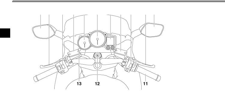
DESCRIPTION
EAU10430
Controls and instruments
2
1.Rear view mirror (page 3-23)
2.Clutch lever (page 3-13)
3.Left handlebar switches (page 3-11)
4.Clutch fluid reservoir (page 6-21)
5.Tachometer (page 3-5)
6.Speedometer (page 3-5)
7.Multi-function display (page 3-6)
8.Front brake fluid reservoir (page 6-21)
9. Right handlebar switches (page 3-11) 10.Brake lever (page 3-14)
11.Throttle grip (page 6-17)
12.Main switch/steering lock (page 3-2) 13.Headlight beam adjusting knob (page 3-22)
2-3
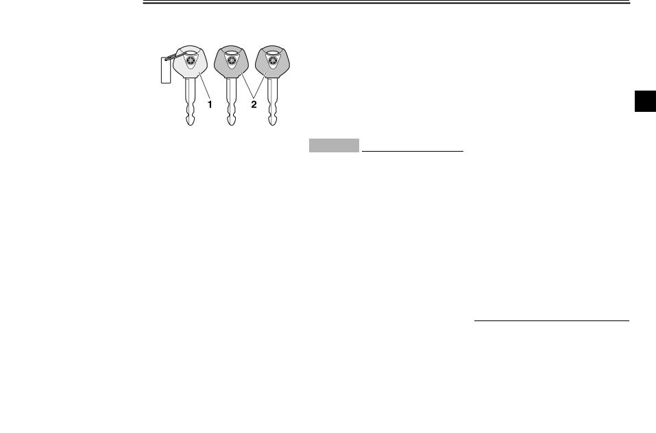
INSTRUMENT AND CONTROL FUNCTIONS
EAU10972
Immobilizer system
1.Code re-registering key (red bow)
2.Standard keys (black bow)
This vehicle is equipped with an immobilizer system to help prevent theft by re-registering codes in the standard keys. This system consists of the following.
●a code re-registering key (with a red bow)
●two standard keys (with a black bow) that can be re-registered with new codes
●a transponder (which is installed in the code re-registering key)
●an immobilizer unit
●an ECU
● an immobilizer system indicator light (See page 3-3.)
The key with the red bow is used to register codes in each standard key. Since re-registering is a difficult process, take the vehicle along with all three keys to a Yamaha dealer to have them re-reg- istered. Do not use the key with the red bow for driving. It should only be used for re-registering the standard keys. Always use a standard key for driving.
ECA11820
CAUTION:
●DO NOT LOSE THE CODE REREGISTERING KEY! CONTACT YOUR DEALER IMMEDIATELY IF IT IS LOST! If the code re-reg- istering key is lost, registering new codes in the standard keys is impossible. The standard keys can still be used to start the vehicle, however if code reregistering is required (i.e., if a new standard key is made or all keys are lost) the entire immobilizer system must be replaced. Therefore, it is highly recom-
mended to use either standard key and keep the code re-regis- tering key in a safe place.
●Do not submerse any key in water.
●Do not expose any key to excessively high temperatures.
●Do not place any key close to
|
magnets (this includes, but not |
3 |
|
limited to, products such as |
|
|
speakers, etc.). |
●Do not place heavy items on any key.
●Do not grind any key or alter its shape.
●Do not disassemble the plastic part of any key.
●Do not put two keys of any immobilizer system on the same key ring.
●Keep the standard keys as well as keys of other immobilizer systems away from this vehicle’s code re-registering key.
●Keep other immobilizer system keys away from the main switch as they may cause signal interference.
3-1

INSTRUMENT AND CONTROL FUNCTIONS
|
EAU10471 |
EAU26811 |
To lock the steering |
|
|
Main switch/steering lock |
ON |
3
The main switch/steering lock controls the ignition and lighting systems, and is used to lock the steering.
NOTE:
Be sure to use the standard key (black bow) for regular use of the vehicle. To minimize the risk of losing the code reregistering key (red bow), keep it in a safe place and only use it for code reregistering.
All electrical circuits are supplied with power; the meter lighting, taillights, license plate light and auxiliary lights come on, and the engine can be started. The key cannot be removed.
NOTE:
The headlights come on automatically when the engine is started and stay on until the key is turned to “OFF”.
EAU10660
OFF
All electrical systems are off. The key can be removed.
EAU10690
LOCK
The steering is locked, and all electrical systems are off. The key can be removed.
1.Push.
2.Turn.
1.Turn the handlebars all the way to the left or right.
2.Push the key in from the “OFF” position, and then turn it to “LOCK” while still pushing it.
3.Remove the key.
3-2
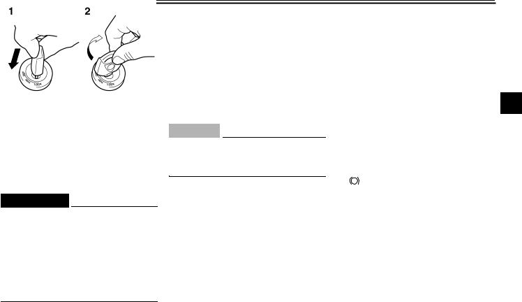
INSTRUMENT AND CONTROL FUNCTIONS
To unlock the steering
1.Push.
2.Turn.
Push the key into the main switch, and then turn it to “OFF” while still pushing it.
EWA10060
 WARNING
Never turn the key to “OFF” or “LOCK” while the vehicle is moving, otherwise the electrical systems will be switched off, which may result in loss of control or an accident. Make sure that the vehicle is stopped before turning the key to “OFF” or “LOCK”.
EAU39460
 (Parking)
The steering is locked, and the taillights, license plate light and auxiliary lights are on. The hazard lights and turn signal lights can be turned on, but all other electrical systems are off. The key can be removed.
The steering must be locked before the key can be turned to “ ”.
”.
ECA11020
CAUTION:
Do not use the parking position for an extended length of time, otherwise the battery may discharge.
EAU11003
Indicator and warning lights
3
1.Left turn signal indicator light “ ”
”
2.Right turn signal indicator light “ ”
”
3.Engine trouble warning light “  ”
”
4.Anti-lock Brake System (ABS) warning light
“ ABS ”
5.Neutral indicator light “  ”
”
6.High beam indicator light “  ”
”
7.Oil level warning light “ 

 ”
”
8.Immobilizer system indicator light
EAU11030
Turn signal indicator lights “ ” and
” and
“ ”
”
The corresponding indicator light flashes when the turn signal switch is pushed to the left or right.
3-3
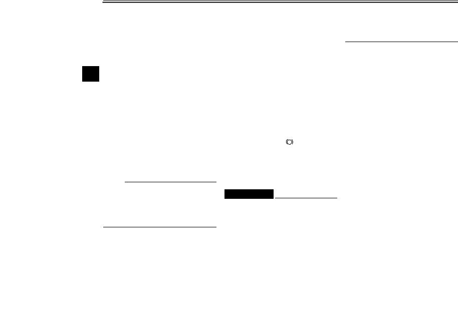
INSTRUMENT AND CONTROL FUNCTIONS
EAU11060
Neutral indicator light “  ”
”
This indicator light comes on when the transmission is in the neutral position.
EAU11080
High beam indicator light “ ”
”
This indicator light comes on when the high beam of the headlight is switched
3 on.
EAU11120
Oil level warning light “

 ”
”
This warning light comes on when the engine oil level is low.
The electrical circuit of the warning light can be checked by turning the key to “ON”.
If the warning light does not come on for a few seconds, then go off, have a Yamaha dealer check the electrical circuit.
NOTE:
Even if the oil level is sufficient, the warning light may flicker when riding on a slope or during sudden acceleration or deceleration, but this is not a malfunction.
EAU11530
Engine trouble warning light “  ”
”
This warning light comes on or flashes when an electrical circuit monitoring the engine is defective. When this occurs, have a Yamaha dealer check the selfdiagnosis system. (See page 3-6 for an explanation of the self-diagnosis device.)
The electrical circuit of the warning light can be checked by turning the key to “ON”. If the warning light does not come on for a few seconds, then go off, have a Yamaha dealer check the electrical circuit.
EAU39500
ABS warning light “ ABS ”
If this warning light comes on or flashes while riding, the ABS may be defective. If this occurs, have a Yamaha dealer check the system as soon as possible. (See page 3-14.)
EWA10081
 WARNING
If the ABS warning light comes on or flashes while riding, the brake system reverts to conventional braking. Therefore, be careful not to cause the wheels to lock during emergen-
cy braking. If the warning light comes on or flashes while riding, have a Yamaha dealer check the brake system as soon as possible.
The electrical circuit of the warning light can be checked by turning the key to “ON”.
If the warning light does not come on or remains on, have a Yamaha dealer check the electrical circuit.
EAU38620
Immobilizer system indicator light
The electrical circuit of the indicator light can be checked by turning the key to “ON”.
If the indicator light does not come on for a few seconds, then go off, have a Yamaha dealer check the electrical circuit.
When the key is turned to “OFF” and 30 seconds have passed, the indicator light will start flashing indicating the immobilizer system is enabled. After 24 hours have passed, the indicator light will stop flashing, however the immobilizer system is still enabled.
3-4
![]()
INSTRUMENT AND CONTROL FUNCTIONS
|
This model is also equipped with a self- |
EAU11601 |
EAU11872 |
|
diagnosis device for the immobilizer |
Speedometer |
Tachometer |
|
system. (See page 3-6 for an explana- |
||
|
tion of the self-diagnosis device.) |
3
1.Tachometer
2.Speedometer
3.Multi-function display
The speedometer shows the riding speed.
When the key is turned to “ON”, the speedometer needle will sweep once across the speed range and then return to zero in order to test the electrical circuit.
1.Tachometer
2.Tachometer red zone
The electric tachometer allows the rider to monitor the engine speed and keep it within the ideal power range.
When the key is turned to “ON”, the tachometer needle will sweep once across the r/min range and then return to zero r/min in order to test the electrical circuit.
ECA10031
CAUTION:
Do not operate the engine in the tachometer red zone.
Red zone: 9000 r/min and above
3-5
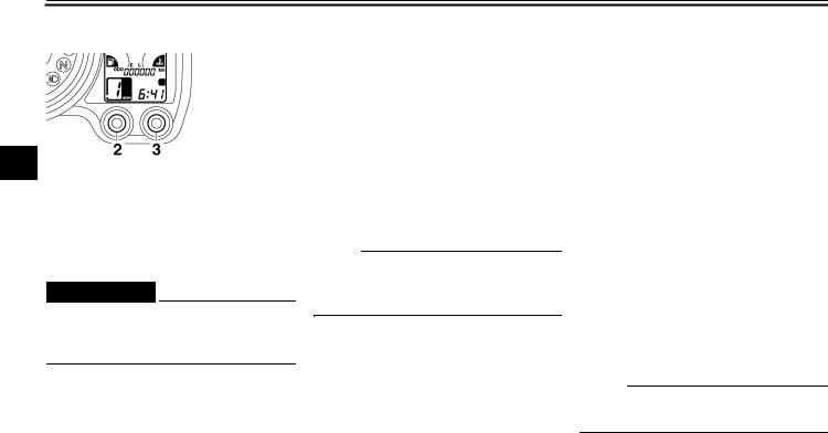
INSTRUMENT AND CONTROL FUNCTIONS
EAU40241
Multi-function display
3
1.Multi-function display
2.“SELECT” button
3.“RESET” button
EWA14430
 WARNING
Be sure to stop the vehicle before making any setting changes to the multi-function display.
The multi-function display is equipped with the following:
●an odometer (which shows the total distance traveled)
●two tripmeters (which show the distance traveled since they were last set to zero)
●a fuel reserve tripmeter (which shows the distance traveled on the fuel reserve)
●a clock
●a fuel meter
●a coolant temperature meter
●a transmission gear display
●an ambient temperature display
●a fuel consumption display (instantaneous and average consumption functions)
●a self-diagnosis device
NOTE:
Be sure to turn the key to “ON” before using the “SELECT” and “RESET” buttons.
Odometer and tripmeter modes
1.Odometer/tripmeter/fuel reserve tripmeter
2.“SELECT” button
3.“RESET” button
Pushing the “SELECT” button switches the display between the odometer mode “ODO” and the tripmeter modes “TRIP 1” and “TRIP 2” in the following order:
ODO → TRIP 1 → TRIP 2 → ODO
NOTE:
When selecting “TRIP 1” or “TRIP 2”, the display flashes for five seconds.
When approximately 5.5 L (1.45 US gal) (1.21 Imp.gal) of fuel remains in the fuel tank, the display will automatically change to the fuel reserve tripmeter mode “F-TRIP” and start counting the
3-6

INSTRUMENT AND CONTROL FUNCTIONS
distance traveled from that point. In that case, pushing the “SELECT” button switches the display between the various tripmeter and odometer modes in the following order:
F-TRIP → TRIP 1 → TRIP 2 → ODO → F-TRIP
To reset a tripmeter, select it by pushing the “SELECT” button, and then push the “SELECT” button for at least one second. If you do not reset the fuel reserve tripmeter manually, it will reset itself automatically and the display will return to the prior mode after refueling and traveling 5 km (3 mi).
Clock
To set the clock:
1.Push the “SELECT” button and “RESET” button together for at least two seconds.
2.When the hour digits start flashing, push the “RESET” button to set the hours.
3.Push the “SELECT” button, and the minute digits will start flashing.
4.Push the “RESET” button to set the minutes.
5.Push the “SELECT” button and then release it to start the clock.
Fuel meter
wards “E” (Empty) as the fuel level decreases. When the last segment starts flashing, refuel as soon as possible. When the key is turned to “ON”, all of the display segments of the fuel meter will appear one after the other and then disappear in order to test the
electrical circuit.
3
NOTE:
This fuel meter is equipped with a selfdiagnosis system. If the electrical circuit is defective, all the display segments will start flashing. If this occurs, have a Yamaha dealer check the electrical circuit.
Coolant temperature meter
1.Clock
2.“SELECT” button
3.“RESET” button
1. Fuel meter
The fuel meter indicates the amount of
fuel in the fuel tank. The display seg-
1. Coolant temperature meter
ments of the fuel meter disappear to-
3-7

INSTRUMENT AND CONTROL FUNCTIONS
With the key in the “ON” position, the coolant temperature meter indicates the temperature of the coolant. When the key is turned to “ON”, all of the display segments of the coolant temperature meter will appear one after the other and then disappear in order to test the electrical circuit. The coolant
3temperature varies with changes in the weather and engine load. If the top segment flashes, stop the vehicle and let the engine cool. (See page 6-35.)
ECA10020
CAUTION:
Do not operate the engine if it is overheated.
Transmission gear display
1.Transmission gear display
2.Neutral indicator light “  ”
”
This display shows the selected gear. The neutral position, however, is not displayed, it is indicated by the neutral indicator light.
Ambient temperature, instantaneous fuel consumption and average fuel consumption modes
1.Ambient temperature/instantaneous fuel consumption/average fuel consumption
2.“SELECT” button
3.“RESET” button
Push the “RESET” button to switch the display between the ambient temperature mode “Air”, the instantaneous fuel consumption mode “km/L” or “L/100 km” and the average fuel consumption mode “AV_ _ km/L” or “AV_ _ L/100 km” in the following order:
Air → km/L or L/100 km → AV_ _ km/L or AV_ _ L/100 km → Air
3-8

INSTRUMENT AND CONTROL FUNCTIONS
Ambient temperature mode
1. Ambient temperature
This display shows the ambient temperature from –9 °C to 50 °C in 1 °C increments. The temperature displayed may vary from the ambient temperature.
NOTE:
●If the ambient temperature falls below –9 °C, a lower temperature than –9 °C will not be displayed.
●If the ambient temperature climbs above 50 °C, a higher temperature than 50 °C will not be displayed.
●The accuracy of the temperature reading may be affected when riding slowly (approximately under 20 km/h) or when stopped at traffic signals, railroad crossings, etc.
Instantaneous fuel consumption mode
●When the display is set to “L/100 km”, the amount of fuel necessary to travel 100 km under the current riding conditions is shown.
NOTE:
●To switch between the two instantaneous fuel consumption dis-
plays, push the “RESET” button for 3 1 second when either display is shown.
●If traveling at speeds under 10 km/h, “_ _” will be displayed.
Average fuel consumption mode
1. Instantaneous fuel consumption
The instantaneous fuel consumption display can be set to either “km/L” or “L/100 km”.
●When the display is set to “km/L”, the distance that can be traveled
|
on 1.0 L of fuel under the current |
|
|
riding conditions is shown. |
1. Average fuel consumption |
|
This display shows the average fuel |
|
|
consumption since it was last reset. |
3-9
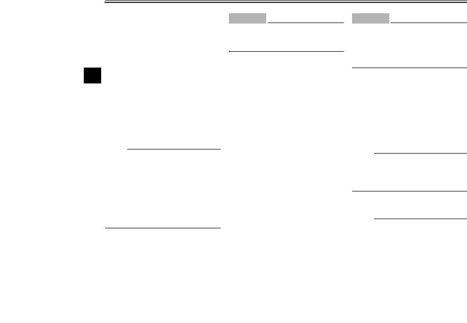
INSTRUMENT AND CONTROL FUNCTIONS
The average fuel consumption display can be set to either “AV _ _ km/L” or “AV _ _ L/100 km”.
When the average fuel consumption mode is selected, the display flashes for five seconds, and then, depending on the unit set, “AV _ _ km/L” (average distance that can be traveled using 1.0
3L of fuel) or “AV _ _ L/100 km” (average amount of fuel necessary to travel 100 km) is displayed.
To reset the average fuel consumption display, push the “RESET” button to select the mode again, and then push the “RESET” button for 1 second while the display is flashing.
NOTE:
●To switch between the two average fuel consumption displays, push the “RESET” button for 1 second when either display is shown.
●After resetting an average fuel consumption display, “_ _” will be shown for that display until the vehicle has traveled 1 km.
ECA15471
CAUTION:
If there is a malfunction, “– –” will be displayed. Have a Yamaha dealer check the vehicle.
Self-diagnosis device
1.Error code display
2.Immobilizer system indicator light
This model is equipped with a self-diag- nosis device for various electrical circuits.
If any of those circuits are defective, the multi-function display will indicate a two-digit error code (e.g., 11, 12, 13).
If the multi-function display indicates such an error code, note the code number, and then have a Yamaha dealer check the vehicle.
ECA11790
CAUTION:
If the multi-function display indicates an error code, the vehicle should be checked as soon as possible in order to avoid engine damage.
This model is also equipped with a selfdiagnosis device for the immobilizer system.
If any of the immobilizer system circuits are defective, the immobilizer system indicator light will flash, and then the multi-function display will indicate a two-digit error code (e.g., 51, 52, 53) when the key is turned to “ON”.
NOTE:
If the multi-function display indicates error code 52, this could be caused by transponder interference. If this error appears, try the following.
1.Use the code re-registering key to start the engine.
NOTE:
Make sure there are no other immobilizer keys close to the main switch, and do not keep more than one immobilizer
3-10
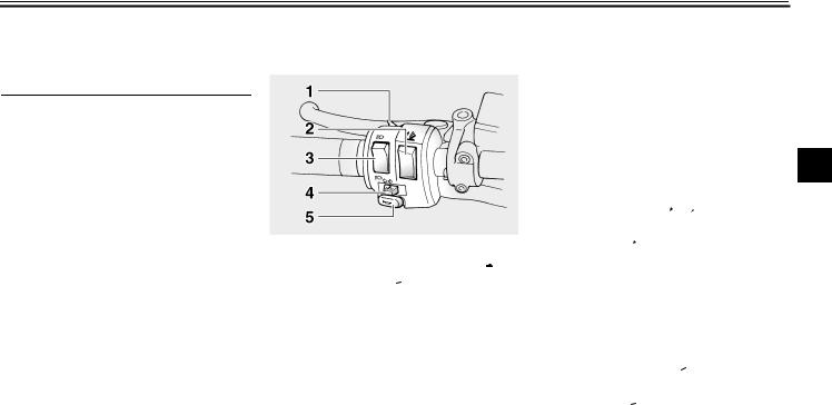
INSTRUMENT AND CONTROL FUNCTIONS
key on the same key ring! Immobilizer system keys may cause signal interference, which may prevent the engine from starting.
2.If the engine starts, turn it off, and try starting the engine with the standard keys.
3.If one or both of the standard keys do not start the engine, take the
vehicle, the code re-registering key and both standard keys to a Yamaha dealer and have the standard keys re-registered.
If the multi-function display indicates any error codes, note the code number, and then have a Yamaha dealer check the vehicle.
EAU12344
Handlebar switches
Left
1.Pass switch “  ”
”
2.Windshield position adjusting switch “ ”
”
3.Dimmer switch “  /
/ ”
”
4.Turn signal switch “ /
/  ”
”
5.Horn switch “  ”
”
Right
3
1.Engine stop switch “ /
/ ”
”
2.Hazard switch “ ”
”
3.Start switch “ ”
”
EAU12380
Pass switch “ ”
”
Press this switch to flash the headlights.
EAU12400
Dimmer switch “ /
/ ”
”
Set this switch to “ ” for the high beam and to “
 ” for the low beam.
EAU12460
Turn signal switch “ /
/ ”
”
To signal a right-hand turn, push this switch to “ ”. To signal a left-hand turn, push this switch to “
 ”. When released, the switch returns to the center
3-11
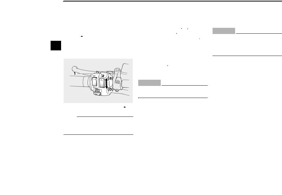
INSTRUMENT AND CONTROL FUNCTIONS
position. To cancel the turn signal lights, push the switch in after it has returned to the center position.
EAU12493
Windshield position adjusting switch “ ”
”
To move the windshield up, push this
3switch in direction (a). To move the windshield down, push the switch in direction (b).
1. Windshield position adjusting switch “ ”
”
NOTE:
When the key is turned to “OFF”, the windshield will automatically return to the lowest position.
EAU12500
Horn switch “  ”
”
Press this switch to sound the horn.
EAU12660
Engine stop switch “ /
/ ”
”
Set this switch to “ ” before starting the engine. Set this switch to “
 ” to stop the engine in case of an emergency, such as when the vehicle overturns or when the throttle cable is stuck.
EAU12710
Start switch “ ”
”
Push this switch to crank the engine with the starter.
ECA10050
CAUTION:
See page 5-1 for starting instructions prior to starting the engine.
EAU12733
Hazard switch “ ”
”
With the key in the “ON” or “ ” position, use this switch to turn on the hazard lights (simultaneous flashing of all turn signal lights).
The hazard lights are used in case of an emergency or to warn other drivers when your vehicle is stopped where it might be a traffic hazard.
ECA10061
CAUTION:
Do not use the hazard lights for an extended length of time with the engine not running, otherwise the battery may discharge.
3-12

INSTRUMENT AND CONTROL FUNCTIONS
|
Clutch lever |
EAU12830 |
Make sure that the appropriate setting |
Shift pedal |
on the adjusting dial is aligned with the arrow mark on the clutch lever.
The clutch lever is equipped with a clutch switch, which is part of the ignition circuit cut-off system. (See page 3-28.)
1.Clutch lever
2.Arrow mark
3.Clutch lever position adjusting dial
4.Distance between clutch lever and handlebar grip
The clutch lever is located at the left handlebar grip. To disengage the clutch, pull the lever toward the handlebar grip. To engage the clutch, release the lever. The lever should be pulled rapidly and released slowly for smooth clutch operation.
The clutch lever is equipped with a clutch lever position adjusting dial. To adjust the distance between the clutch lever and the handlebar grip, turn the adjusting dial while holding the lever pushed away from the handlebar grip.
1. Shift pedal
The shift pedal is located on the left side of the engine and is used in combination with the clutch lever when shifting the gears of the 5-speed con- stant-mesh transmission equipped on this motorcycle.
3-13
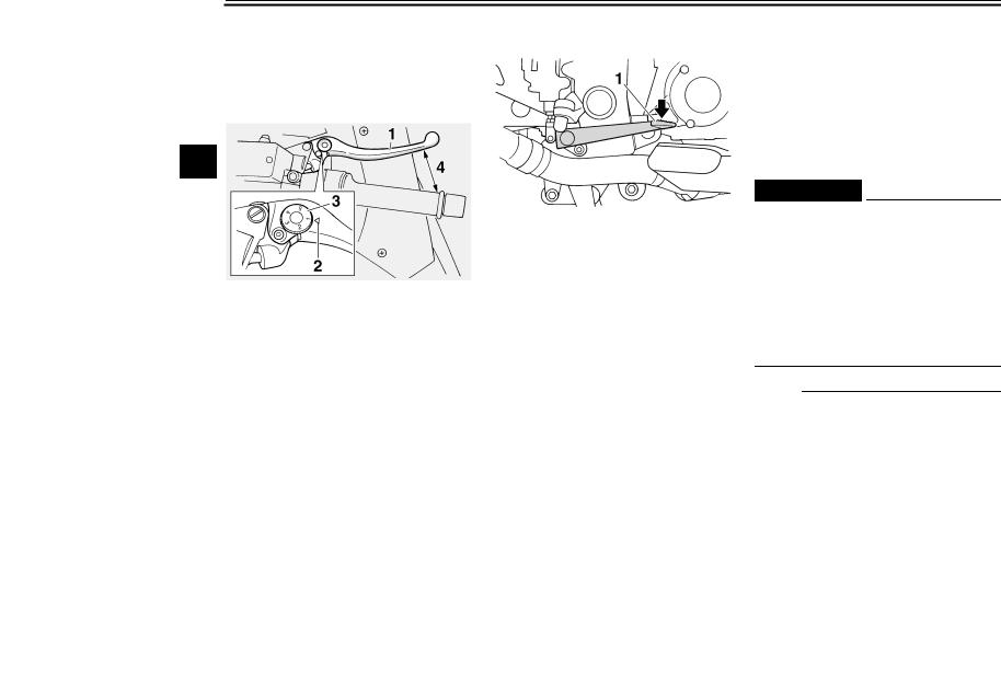
INSTRUMENT AND CONTROL FUNCTIONS
EAU26822
Brake lever
The brake lever is located at the right handlebar grip. To apply the front brake, pull the lever toward the handlebar grip.
3
1.Brake lever
2.“ ” mark
3.Brake lever position adjusting dial
4.Distance between brake lever and handlebar grip
The brake lever is equipped with a position adjusting dial. To adjust the distance between the brake lever and the handlebar grip, turn the adjusting dial while holding the lever pushed away from the handlebar grip. Make sure that the appropriate setting on the adjusting dial is aligned with the “ ” mark on the brake lever.
EAU39540
Brake pedal
1. Brake pedal
The brake pedal is on the right side of the vehicle.
This model is equipped with a unified brake system.
When pressing down on the brake pedal, the rear brake and a portion of the front brake are applied. For full braking performance, apply both the brake lever and the brake pedal simultaneously.
EAU39530
ABS
The Yamaha ABS (Anti-lock Brake System) features a dual electronic control system, which acts on the front and rear brakes independently. The ABS is monitored by an ECU (Electronic Control Unit), which will have recourse to manual braking if a malfunction occurs.
EWA10090
 WARNING
●The ABS performs best on long braking distances.
●On certain (rough or gravel) roads, the braking distance may be longer with than without the ABS. Therefore, always keep a sufficient distance to the vehicle ahead to match the riding speed.
NOTE:
●When the ABS is activated, the brakes are operated in the usual way. A pulsating action may be felt at the brake lever or brake pedal, but this does not indicate a malfunction.
3-14
![]()
INSTRUMENT AND CONTROL FUNCTIONS
●This ABS has a test mode which allows the owner to experience the pulsating at the brake lever or brake pedal when the ABS is operating. However, special tools are required, so please consult your Yamaha dealer when performing this test.
|
Fuel tank cap |
EAU13070 |
|
NOTE: |
The fuel tank cap cannot be closed unless the key is in the lock. In addition, the key cannot be removed if the cap is not properly closed and locked.
|
EWA11090 |
|||||
|
WARNING |
|||||
|
3 |
|||||
|
Make sure that the fuel tank cap is |
|||||
|
properly closed before riding. |
|||||
1.Fuel tank cap lock cover
2.Unlock.
To open the fuel tank cap
Open the fuel tank cap lock cover, insert the key into the lock, and then turn it 1/4 turn clockwise. The lock will be released and the fuel tank cap can be opened.
To close the fuel tank cap
1.Push the fuel tank cap into position with the key inserted in the lock.
2.Turn the key counterclockwise to the original position, remove it, and then close the lock cover.
3-15