
Полный размер
В архиве по ссылке три мануала.
1. Dodge Caravan, Plymouth Voyager, Chrysler Town & Country. Руководство по ремонту и эксплуатации. Бензиновые двигатели 2.4, 3.0, 3.3, 3.8 литра.
2. Dodge Caravan, Ram Van. Chrysler (Grand) Voyadger. Дизельные двигатели 2.5 и 2.8 CRDI 2001-2007 года. Электросхемы.
3. Crysler Voyager (Dodge Caravan) 2001-2004г., руководство по эксплуатации.
Формат — PDF.
Язык — Русский.
Вдруг кому понадобится, а искать лень.
Google Drive


Руководство на английском языке по ремонту и эксплуатации Chrysler Town & Country/Voyager, Dodge Caravan и Plymouth Voyager 1992 года выпуска.
- Автор: —
- Издательство: DaimlerChrysler Corporation
- Год издания: —
- Страниц: —
- Формат: PDF
- Размер: 56,1 Mb
Подборка руководств на английском языке по ремонту и эксплуатации + схемы электрооборудования Chrysler Town & Country/Voyager, Dodge Caravan и Plymouth Voyager 1997-2000 годов выпуска.
- Автор: —
- Издательство: DaimlerChrysler Corporation
- Год издания: 1997/1998/2000
- Страниц: —
- Формат: PDF
- Размер: 157,5 Mb
Подборка руководств на английском языке по ремонту и эксплуатации Chrysler Town & Country/Voyager и Dodge Caravan 2001-2007 годов выпуска.
- Автор: —
- Издательство: DaimlerChrysler Corporation
- Год издания: —
- Страниц: —
- Формат: PDF
- Размер: 240,0 Mb
Руководство по эксплуатации Dodge Caravan/Grand Caravan с 2004 года выпуска.
- Автор: —
- Издательство: Монолит
- Год издания: —
- Страниц: 254
- Формат: —
- Размер: —
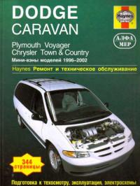
Руководство по ремонту и техническому обслуживанию Chrysler Town & Country, Dodge Caravan и Plymouth Voyager 1996-2002 годов выпуска.
- Автор: —
- Издательство: Алфамер Паблишинг
- Год издания: —
- Страниц: 344
- Формат: —
- Размер: —

Руководство по ремонту и техническому обслуживанию Chrysler Town & Country/Voyager и Dodge Caravan 2003-2006 годов выпуска.
- Автор: —
- Издательство: Алфамер Паблишинг
- Год издания: —
- Страниц: 328
- Формат: —
- Размер: —
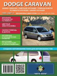
Руководство по ремонту и эксплуатации автомобилей Chrysler Town & Country/Voyager, Dodge Caravan/Grand Caravan и Plymouth Voyager/Grand Voyager 1995-2001 годов выпуска с бензиновыми двигателями.
- Автор: —
- Издательство: Автоклуб
- Год издания: —
- Страниц: 334
- Формат: —
- Размер: —

Руководство по ремонту и эксплуатации Chrysler Town & Country, Dodge Caravan и Plymouth Voyager 1996-2005 годов выпуска с бензиновыми двигателями.
- Автор: —
- Издательство: ГУСИ-ЛЕБЕДИ
- Год издания: 2005
- Страниц: 317
- Формат: PDF
- Размер: 90,4 Mb
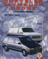
Руководство по ремонту и эксплуатации Chrysler Town & Country/Voyager/Grand Voyager, Dodge Caravan/Grand Caravan и Plymouth Voyager/Grand Voyager 1983-1996 годов выпуска с бензиновыми двигателями.
- Автор: —
- Издательство: ПЕТИТ
- Год издания: 2002
- Страниц: 273
- Формат: PDF
- Размер: 52,7 Mb

Руководство по ремонту и эксплуатации Chrysler Voyager/Grand Voyager/Town & Country и Dodge Caravan/Grand Caravan с 2001 года выпуска с бензиновыми двигателями.
- Автор: —
- Издательство: Монолит
- Год издания: —
- Страниц: 304
- Формат: —
- Размер: —
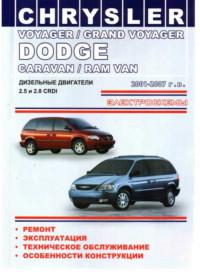
Руководство по ремонту, эксплуатации и техническому обслуживанию Chrysler Voyager/Grand Voyager и Dodge Caravan/Ram Van 2001-2007 годов выпуска с дизельными двигателями 2,5/2,8 CRDI.
- Автор: —
- Издательство: ОДЕССА
- Год издания: 2009
- Страниц: 262
- Формат: PDF
- Размер: 210,7 Mb

Руководство по ремонту и эксплуатации Chrysler Town & Country/Voyager/Grand Voyager и Dodge Caravan/Grand Caravan 2000-2007 годов выпуска с бензиновыми и дизельными двигателями.
- Автор: —
- Издательство: Арго-Авто
- Год издания: —
- Страниц: 552
- Формат: —
- Размер: —

-
Contents
-
Table of Contents
-
Bookmarks
Quick Links
IN
Introduction
0
Lubrication & Maintenance
2
Suspension
3
Differential & Driveline
5
Brakes
6
Clutch
7
Cooling
7a
Cooling — 2.5L Turbo Diesel
8A
Audio
8B
Chime/Buzzer
8E
Electronic Control Modules
8Ea
Electronic Control Modules
8F
Engine Systems
8Fa
Engine Systems
8G
Heated Systems
8H
Horn
8I
Ignition Control
8Ia
Ignition Control
8J
Instrument Cluster
8L
Lamps
8M
Message Systems
GROUP TAB LOCATOR
8N

8P
8Q
8R
8W
9
9a
11
11a
13
14
14a
19
21
22
23
24
25
25a
Power Systems
Restraints
Speed Control
Vehicle Theft Security
Wipers/Washers
Wiring
Engine
Engine
Exhaust System
Exhaust System and Turbocharger
Frame & Bumpers
Fuel System
Fuel System
Steering
Transmission
Tires/Wheels
Body
Heating & Air Conditioning
Emissions Control
Emissions Control 2.5L Turbo Diesel
Service Manual Comment Forms
Chapters
Summary of Contents for Chrysler Dodge Caravan 2002
- Manuals
- Brands
- Dodge Manuals
- Automobile
- Grand Caravan
- Owner’s manual
-
Contents
-
Table of Contents
-
Troubleshooting
-
Bookmarks
Related Manuals for Dodge Grand Caravan
Summary of Contents for Dodge Grand Caravan
-
Page 1
Grand Caravan 2 0 1 7 O W N E R ’ S M A N U A L… -
Page 2
VEHICLES SOLD IN CANADA This manual illustrates and describes the operation of With respect to any Vehicles Sold in Canada, the name FCA features and equipment that are either standard or op- US LLC shall be deemed to be deleted and the name FCA tional on this vehicle. -
Page 3: Introduction 3
TABLE OF CONTENTS SECTION PAGE INTRODUCTION …………..3 THINGS TO KNOW BEFORE STARTING YOUR VEHICLE .
-
Page 5: Table Of Contents
INTRODUCTION CONTENTS INTRODUCTION ……4 VEHICLE IDENTIFICATION NUMBER ..6 HOW TO USE THIS MANUAL .
-
Page 6: Introduction
4 INTRODUCTION INTRODUCTION HOW TO USE THIS MANUAL Congratulations on selecting your new FCA US LLC ve- Consult the Table of Contents to determine which section hicle. Be assured that it represents precision workmanship, contains the information you desire. distinctive styling, and high quality. Since the specification of your vehicle depends on the items This Owner’s Manual has been prepared with the assis- of equipment ordered, certain descriptions and illustra-…
-
Page 7
INTRODUCTION 5… -
Page 8: Vehicle Identification Number
6 INTRODUCTION WARNINGS AND CAUTIONS This Owner’s Manual contains WARNINGS against oper- ating procedures that could result in a collision, bodily injury and/or death. It also contains CAUTIONS against procedures that could result in damage to your vehicle. If you do not read this entire Owner’s Manual, you may miss important information.
-
Page 9: Vehicle Modifications/Alterations
INTRODUCTION 7 VEHICLE MODIFICATIONS/ALTERATIONS WARNING! Any modifications or alterations to this vehicle could seriously affect its roadworthiness and safety and may lead to a collision resulting in serious injury or death. Stamped VIN Location NOTE: It is illegal to remove or alter the VIN.
-
Page 11
THINGS TO KNOW BEFORE STARTING YOUR VEHICLE CONTENTS ▫ Security System Manual Override … .17 A WORD ABOUT YOUR KEYS ….11 ▫… -
Page 12
10 THINGS TO KNOW BEFORE STARTING YOUR VEHICLE ▫ To Exit Remote Start Mode And Drive The ▫ Power Liftgate — If Equipped ….41 Vehicle …….27 OCCUPANT RESTRAINT SYSTEMS . -
Page 13: A Word About Your Keys
THINGS TO KNOW BEFORE STARTING YOUR VEHICLE 11 A WORD ABOUT YOUR KEYS Your vehicle uses a keyless ignition system. This system consists of a Remote Keyless Entry (RKE) key fob and a Wireless Ignition Node (WIN) with integral ignition. You can insert the key fob into the ignition switch with either side up.
-
Page 14
12 THINGS TO KNOW BEFORE STARTING YOUR VEHICLE The emergency key allows for entry into the vehicle should the battery in the vehicle or the key fob go dead. The emergency key is also for locking the lower glove compart- ment. -
Page 15: Removing Key Fob From Ignition
THINGS TO KNOW BEFORE STARTING YOUR VEHICLE 13 Removing Key Fob From Ignition WARNING! (Continued) Place the gear selector in PARK. Turn the key fob to the • Allowing children to be in a vehicle unattended is OFF position and then remove the key fob. dangerous for a number of reasons.
-
Page 16: Key-In-Ignition Reminder
14 THINGS TO KNOW BEFORE STARTING YOUR VEHICLE Key-In-Ignition Reminder addition, if the light begins to flash after the bulb check, it indicates that someone used an invalid key fob to start the Opening the driver’s door when the key fob is in the engine.
-
Page 17: Customer Key Fob Programming
THINGS TO KNOW BEFORE STARTING YOUR VEHICLE 15 2. This device must accept any interference received, includ- CAUTION! ing interference that may cause undesired operation. Always remove the key fobs from the vehicle and lock NOTE: Changes or modifications not expressly approved all doors when leaving the vehicle unattended.
-
Page 18: To Arm The System
16 THINGS TO KNOW BEFORE STARTING YOUR VEHICLE To Arm The System NOTE: • The driver’s door key cylinder and the liftgate button on the Follow these steps to arm the vehicle security alarm: key fob cannot arm or disarm the vehicle security alarm. 1.
-
Page 19: Tamper Alert
THINGS TO KNOW BEFORE STARTING YOUR VEHICLE 17 Tamper Alert “Dome ON” position (rotate horizontal thumb wheel on the bottom of the switch to the far right detent position). If something has triggered the vehicle security alarm in your absence, the horn will sound three times and the The illuminated entry system will not operate if the exterior lights blink three times when you unlock the dimmer control is in the “Dome OFF”…
-
Page 20: Using The Key Fob
18 THINGS TO KNOW BEFORE STARTING YOUR VEHICLE NOTE: Inserting the key fob into the ignition switch disables the system from responding to any button pushes from that key fob. Driving at speeds 5 mph (8 km/h) and above disables the system from responding to all key fob buttons for all key fobs.
-
Page 21
THINGS TO KNOW BEFORE STARTING YOUR VEHICLE 19 Seven-button key fobs will provide functions that allow the Remote Key Unlock On First Press same basic operation as the three-button, but may also be This feature lets you program the system to unlock either used to operate the power liftgate (optional), power sliding the driver’s side, or all doors, on the first push of the doors, and Remote Start feature (optional). -
Page 22
20 THINGS TO KNOW BEFORE STARTING YOUR VEHICLE 4. Test the feature while outside of the vehicle by pushing (Customer-Programmable Features)” in “Understanding the lock/unlock buttons on the key fob with the ignition Your Instrument Panel” for further information. switch in the OFF position and the key fob removed. •… -
Page 23: Power Open/Close Power Liftgate — If Equipped
THINGS TO KNOW BEFORE STARTING YOUR VEHICLE 21 Using The Panic Alarm The power liftgate may also be opened and closed by pushing the liftgate button located on the overhead con- To turn the Panic Alarm feature on or off, push and hold sole.
-
Page 24
22 THINGS TO KNOW BEFORE STARTING YOUR VEHICLE • For vehicles not equipped with the instrument cluster Power Open/Close Right Power Sliding Door — If Equipped display, perform the following steps: Push the right power sliding door button twice on the key 1. -
Page 25: Programming Additional Key Fobs
THINGS TO KNOW BEFORE STARTING YOUR VEHICLE 23 Programming Additional Key Fobs 1. Remove the emergency key by sliding the mechanical latch at the top of the key fob sideways with your thumb If you do not have a programmed key fob, contact your and then pull the key out with your other hand.
-
Page 26
24 THINGS TO KNOW BEFORE STARTING YOUR VEHICLE 2. Insert the tip of the emergency key or a #2 flat blade screwdriver into the slot and gently pry the two halves of the key fob apart. Make sure not to damage the seal during removal. -
Page 27: General Information
THINGS TO KNOW BEFORE STARTING YOUR VEHICLE 25 General Information NOTE: • The vehicle must be equipped with an automatic trans- The following regulatory statement applies to all Radio mission to be equipped with Remote Start. Frequency (RF) devices equipped in this vehicle: •…
-
Page 28: Remote Start Abort Messages
26 THINGS TO KNOW BEFORE STARTING YOUR VEHICLE • Ignition in OFF position The instrument cluster display message stays active until the ignition is turned to the ON/RUN position. WARNING! To Enter Remote Start Mode • Do not start or run an engine in a closed garage or Push and release the Remote Start button on the key fob confined area.
-
Page 29: To Enter The Vehicle After Remote Start
THINGS TO KNOW BEFORE STARTING YOUR VEHICLE 27 To Enter The Vehicle After Remote Start Cancel Remote Start To enter the vehicle while the engine is running during a Remote Starting will also cancel if any of the following remote start, you must first unlock the vehicle using the occur: unlock button on the key fob.
-
Page 30: When To Reset Remote Start
28 THINGS TO KNOW BEFORE STARTING YOUR VEHICLE When To Reset Remote Start DOOR LOCKS The vehicle can be started remotely up to a maximum of Manual Door Locks two times. The vehicle is also allowed a maximum of one Lock the front doors by pushing down on the lock knobs failed start, where the remote starting sequence was initi- on each door trim panel.
-
Page 31
THINGS TO KNOW BEFORE STARTING YOUR VEHICLE 29 If the lock knob is rearward when you shut either side WARNING! sliding door, the door will lock. Make sure the keys are not • For personal security and safety in the event of a inside the vehicle before closing the door. -
Page 32: Power Door Locks — If Equipped
30 THINGS TO KNOW BEFORE STARTING YOUR VEHICLE Power Door Locks — If Equipped Power door lock switches are located on each front door trim panel. Use these switches to lock or unlock the doors. Front Passenger Power Door Switches 1 —…
-
Page 33: Windows
THINGS TO KNOW BEFORE STARTING YOUR VEHICLE 31 Unlock Doors Automatically On Exit — If Equipped WINDOWS The Unlock Doors Automatically On Exit feature unlocks Power Vent Windows — If Equipped all of the vehicle doors when any door is opened. This will The power vent window switch located on the driver’s occur only after the gear selector has been placed into the door trim panel allows the driver to operate the two vent…
-
Page 34: Power Windows
32 THINGS TO KNOW BEFORE STARTING YOUR VEHICLE Power Windows Power Window Lockout Switch — If Equipped You can control either the front or rear windows using the The driver may lock out the rear power windows by window switches located on the driver’s door trim panel. pushing the power window lockout switch just below the The switches will operate only when the ignition switch is power window switches.
-
Page 35
THINGS TO KNOW BEFORE STARTING YOUR VEHICLE 33 Front Passenger Power Window Switch Auto-Down Feature — If Equipped There is a single window switch on the front passenger’s Both the driver and front passenger window switches have door trim panel which operates the passenger door win- an Auto-Down feature. -
Page 36
34 THINGS TO KNOW BEFORE STARTING YOUR VEHICLE NOTE: If the window runs into any obstacle during Sliding Side Door Power Window Switch — If Auto-Up, it will reverse direction and then go back down. Equipped Remove the obstacle and use the window switch again to Second row passengers may open and close the sliding close the window. -
Page 37: Sliding Side Door
THINGS TO KNOW BEFORE STARTING YOUR VEHICLE 35 NOTE: To keep your door operating properly, observe the follow- ing guidelines: • The window switches will not operate if the driver has • Always open the door smoothly. activated the Power Window Lockout. •…
-
Page 38: Power Sliding Side Door — If Equipped
36 THINGS TO KNOW BEFORE STARTING YOUR VEHICLE Power Sliding Side Door — If Equipped NOTE: The power sliding side door must be unlocked before the power sliding door switches will operate. The power sliding door may be opened or closed manually or by using the buttons on the key fob, overhead console switch, or rear door switch.
-
Page 39
THINGS TO KNOW BEFORE STARTING YOUR VEHICLE 37 NOTE: WARNING! • The power sliding side door switches will not open the You, or others, could be injured if caught in the path of power sliding door if the gear selector is in gear or the the sliding door. -
Page 40
38 THINGS TO KNOW BEFORE STARTING YOUR VEHICLE Power Sliding Side Door Power Switch To provide a safer environment for small children riding in the rear seats, the second row sliding door switches and handles may be overridden by pushing the OFF side of the Power Switch located in the front overhead console. -
Page 41: Sliding Side Door Child Protection Lock
THINGS TO KNOW BEFORE STARTING YOUR VEHICLE 39 Sliding Side Door Child Protection Lock To provide a safer environment for small children riding in the rear seats, the sliding doors are equipped with a Child Protection Door Lock system. NOTE: When the Child Protection Door Lock system is engaged, the door can be opened only by using the outside door handle even though the inside door lock is in the unlocked position.
-
Page 42: Liftgate
40 THINGS TO KNOW BEFORE STARTING YOUR VEHICLE • The power sliding side door will operate from the 3. Repeat Steps 1 and 2 on the opposite sliding door (if switches located on the B-pillar trim panel, just in front equipped).
-
Page 43: Power Liftgate — If Equipped
THINGS TO KNOW BEFORE STARTING YOUR VEHICLE 41 To open the liftgate, push the liftgate release handle located The power liftgate may also be opened and closed by on the underside of the license plate bar and pull the pushing the button located on the overhead console. liftgate open with one fluid motion.
-
Page 44
42 THINGS TO KNOW BEFORE STARTING YOUR VEHICLE The power liftgate may be closed by pushing the button, WARNING! located in the upper left trim in the liftgate opening. Pushing once will only close the liftgate. This button During power operation, personal injury or cargo cannot be used to open the liftgate. -
Page 45: Occupant Restraint Systems
THINGS TO KNOW BEFORE STARTING YOUR VEHICLE 43 • If the liftgate release button is activated while the power WARNING! liftgate is closing, the liftgate will reverse to the full open • Driving with the liftgate open can allow poisonous position.
-
Page 46: Important Safety Precautions
44 THINGS TO KNOW BEFORE STARTING YOUR VEHICLE Some of the safety features described in this section may be restraints or belt-positioning booster seats should ride standard equipment on some models, or may be optional properly buckled up in a vehicle with a rear seat. equipment on others.
-
Page 47: Seat Belt Systems
THINGS TO KNOW BEFORE STARTING YOUR VEHICLE 45 Enhanced Seat Belt Use Reminder System (BeltAlert) WARNING! Driver And Passenger BeltAlert — If Equipped • Never place a rear-facing child restraint in front of an BeltAlert is a feature intended to remind the driver air bag.
-
Page 48
46 THINGS TO KNOW BEFORE STARTING YOUR VEHICLE BeltAlert Warning Sequence The outboard front passenger seat BeltAlert is not active when the outboard front passenger seat is unoccupied. The BeltAlert warning sequence is activated when the BeltAlert may be triggered when an animal or other items vehicle is moving above a specified vehicle speed range are placed on the outboard front passenger seat or when and the driver or outboard front seat passenger is unbuck-… -
Page 49
THINGS TO KNOW BEFORE STARTING YOUR VEHICLE 47 and reduce your risk of striking the inside of the vehicle or WARNING! (Continued) being thrown out of the vehicle. driver, should always wear their seat belts whether or not an air bag is also provided at their seating WARNING! position to minimize the risk of severe injury or •… -
Page 50
48 THINGS TO KNOW BEFORE STARTING YOUR VEHICLE WARNING! (Continued) WARNING! (Continued) • A twisted seat belt may not protect you properly. In • A shoulder belt placed behind you will not protect a collision, it could even cut into you. Be sure the seat you from injury during a collision. -
Page 51
THINGS TO KNOW BEFORE STARTING YOUR VEHICLE 49 2. The seat belt latch plate is above the back of the front 3. When the seat belt is long enough to fit, insert the latch seat, and next to your arm in the rear seat (for vehicles plate into the buckle until you hear a “click.”… -
Page 52
50 THINGS TO KNOW BEFORE STARTING YOUR VEHICLE Lap/Shoulder Belt Untwisting Procedure Use the following procedure to untwist a twisted lap/ shoulder belt. 1. Position the latch plate as close as possible to the anchor point. 2. At about 6 to 12 inches (15 to 30 cm) above the latch plate, grasp and twist the seat belt webbing 180 degrees to create a fold that begins immediately above the latch plate. -
Page 53
THINGS TO KNOW BEFORE STARTING YOUR VEHICLE 51 NOTE: The adjustable upper shoulder belt anchorage is equipped with an Easy Up feature. This feature allows the shoulder belt anchorage to be adjusted in the upward position without pushing or squeezing the release button. To verify the shoulder belt anchorage is latched, pull downward on the shoulder belt anchorage until it is locked into position. -
Page 54
52 THINGS TO KNOW BEFORE STARTING YOUR VEHICLE Third Row Center Seat Belt Operating Instructions 2. Grasp the mini-latch plate and pull the seat belt over the seat. The third row center seat belt features a seat belt with a mini-latch plate and buckle, which allows the seat belt to detach from the lower anchor when the seat is folded. -
Page 55
THINGS TO KNOW BEFORE STARTING YOUR VEHICLE 53 3. Route the shoulder belt to the inside of the left head restraint. Connect Mini-Latch To Buckle 5. Sit back in seat. Slide the regular latch plate up the webbing as far as necessary to allow the seat belt to go Mini-Latch And Buckle Connected around your lap. -
Page 56
54 THINGS TO KNOW BEFORE STARTING YOUR VEHICLE Rear Center Seat Belt Buckled Rear Center Seat Belt Buckled 6. When the seat belt is long enough to fit, insert the latch 7. Position the lap belt so that it is snug and lies low across plate into the buckle until you hear a “click.”… -
Page 57
THINGS TO KNOW BEFORE STARTING YOUR VEHICLE 55 10. To disengage the mini-latch plate from the mini-buckle Seat Belt Extender for storage, insert the regular latch plate into the center If a seat belt is not long enough to fit properly, even when red slot on the mini-buckle. -
Page 58
56 THINGS TO KNOW BEFORE STARTING YOUR VEHICLE Seat Belts And Pregnant Women Seat Belt Pretensioner The front seat belt system is equipped with pretensioning devices that are designed to remove slack from the seat belt in the event of a collision. These devices may improve the performance of the seat belt by removing slack from the seat belt early in a collision. -
Page 59
THINGS TO KNOW BEFORE STARTING YOUR VEHICLE 57 Switchable Automatic Locking Retractors (ALR) — If Equipped The seat belts in the passenger seating positions may be equipped with a Switchable Automatic Locking Retractor (ALR) which is used to secure a child restraint system. For additional information, refer to “Installing Child Restraints Using The Vehicle Seat Belt”… -
Page 60
58 THINGS TO KNOW BEFORE STARTING YOUR VEHICLE In Automatic Locking Mode, the shoulder belt is automati- 3. Allow the seat belt to retract. As the seat belt retracts, cally pre-locked. The seat belt will still retract to remove you will hear a clicking sound. This indicates the seat any slack in the shoulder belt. -
Page 61
THINGS TO KNOW BEFORE STARTING YOUR VEHICLE 59 Supplemental Active Head Restraints (AHR) Active Head Restraint (AHR) Components: These head restraints are passive deployable components, and vehicles with this equipment cannot be readily iden- tified by any markings, only through visual inspection of the head restraint. -
Page 62
60 THINGS TO KNOW BEFORE STARTING YOUR VEHICLE Resetting Active Head Restraints (AHR) WARNING! (Continued) If the Active Head Restraints are triggered during a colli- restraints are placed in their proper positions in sion, the front half of the head restraint will be extended order to minimize the risk of neck injury in the event forward and separated from the rear half of the head of a collision. -
Page 63: Supplemental Restraint Systems (Srs)
THINGS TO KNOW BEFORE STARTING YOUR VEHICLE 61 • Knee Impact Bolsters WARNING! • Driver and Front Passenger Air Bags Deployed AHRs are not able to best protect you in all • Supplemental Side Air Bags types of collisions. Have deployed AHRs reset by an authorized dealer immediately.
-
Page 64
62 THINGS TO KNOW BEFORE STARTING YOUR VEHICLE ON/RUN position. After the self-check, the Air Bag Warn- NOTE: If the speedometer, tachometer, or any engine ing Light will turn off. If the ORC detects a malfunction in related gauges are not working, the Occupant Restraint any part of the system, it turns on the Air Bag Warning Controller (ORC) may also be disabled. -
Page 65
THINGS TO KNOW BEFORE STARTING YOUR VEHICLE 63 WARNING! (Continued) to reach the steering wheel or instrument panel. • Never place a rear-facing child restraint in front of an air bag. A deploying passenger front air bag can cause death or serious injury to a child 12 years or younger, including a child in a rear-facing child restraint. -
Page 66
64 THINGS TO KNOW BEFORE STARTING YOUR VEHICLE driver or front passenger seat belt is buckled. The seat belt WARNING! (Continued) buckle switch may adjust the inflation rate of the Ad- collisions, air bags won’t deploy at all. Always wear vanced Front Air Bags. -
Page 67
THINGS TO KNOW BEFORE STARTING YOUR VEHICLE 65 When the ORC detects a collision requiring the front air Supplemental Driver Knee Air Bag bags, it signals the inflator units. A large quantity of This vehicle is equipped with a Supplemental Driver Knee non-toxic gas is generated to inflate the front air bags. -
Page 68
66 THINGS TO KNOW BEFORE STARTING YOUR VEHICLE When the SAB deploys, it opens the seam on the outboard side of the seatback’s trim cover. The inflating SAB deploys through the seat seam into the space between the occupant and the door. The SAB moves at a very high speed and with such a high force that it could injure occupants if they are not seated properly, or if items are positioned in the area where the SAB inflates. -
Page 69
THINGS TO KNOW BEFORE STARTING YOUR VEHICLE 67 belted and seated properly, or if items are positioned in the area where the SABICs inflate. Children are at an even greater risk of injury from a deploying air bag. WARNING! • Do not stack luggage or other cargo up high enough to block the deployment of the SABICs. -
Page 70
68 THINGS TO KNOW BEFORE STARTING YOUR VEHICLE severity and type of collision. Vehicle damage by itself is WARNING! not a good indicator of whether or not Side Air Bags should • Side Air Bags need room to inflate. Do not lean have deployed. -
Page 71
THINGS TO KNOW BEFORE STARTING YOUR VEHICLE 69 Bags deploy independently; a left side impact deploys the sensing-system may also deploy the seat belt pretension- left Side Air Bags only and a right side impact deploys the ers, with or without the Side Air Bags, on both sides of the right Side Air Bags only. -
Page 72
70 THINGS TO KNOW BEFORE STARTING YOUR VEHICLE • Seat Track Position Sensors inflation. These airborne particles may irritate the skin, eyes, nose, or throat. If you have skin or eye irritation, • Seat Belt Buckle Switch rinse the area with cool water. For nose or throat If A Deployment Occurs irritation, move to fresh air. -
Page 73
THINGS TO KNOW BEFORE STARTING YOUR VEHICLE 71 Enhanced Accident Response System Maintaining Your Air Bag System In the event of an impact, if the communication network WARNING! remains intact, and the power remains intact, depending on the nature of the event, the ORC will determine whether •… -
Page 74: Child Restraints
72 THINGS TO KNOW BEFORE STARTING YOUR VEHICLE • These data can help provide a better understanding of WARNING! (Continued) the circumstances in which crashes and injuries occur. dealer. Only manufacturer approved seat accessories NOTE: EDR data are recorded by your vehicle only if a may be used.
-
Page 75
THINGS TO KNOW BEFORE STARTING YOUR VEHICLE 73 Children 12 years or younger should ride properly buckled Before buying any restraint system, make sure that it has a up in a rear seat, if available. According to crash statistics, label certifying that it meets all applicable Safety Stan- children are safer when properly restrained in the rear dards. -
Page 76
74 THINGS TO KNOW BEFORE STARTING YOUR VEHICLE Summary Of Recommendations For Restraining Children In Vehicles Recommended Type Of Child Child Size, Height, Weight Or Age Restraint Infants and Toddlers Children who are two years old or Either an Infant Carrier or a Convert- younger and who have not reached ible Child Restraint, facing rearward the height or weight limits of their… -
Page 77
THINGS TO KNOW BEFORE STARTING YOUR VEHICLE 75 Infant And Child Restraints WARNING! Safety experts recommend that children ride rear-facing in Do not install a rear-facing car seat using a rear support the vehicle until they are two years old or until they reach leg in this vehicle. -
Page 78
76 THINGS TO KNOW BEFORE STARTING YOUR VEHICLE Older Children And Child Restraints WARNING! Children who are two years old or who have outgrown • Improper installation can lead to failure of an infant their rear-facing convertible child seat can ride forward- or child restraint. -
Page 79
THINGS TO KNOW BEFORE STARTING YOUR VEHICLE 77 Children Too Large For Booster Seats 5. Can the child stay seated like this for the whole trip? Children who are large enough to wear the shoulder belt If the answer to any of these questions was “no,” then the comfortably, and whose legs are long enough to bend over child still needs to use a booster seat in this vehicle. -
Page 80
78 THINGS TO KNOW BEFORE STARTING YOUR VEHICLE Recommendations For Attaching Child Restraints Restraint Type Combined Use Any Attachment Method Shown With An “X” Below Weight of the LATCH – Lower Seat Belt Only LATCH – Lower Seat Belt + Top Child + Child Anchors Only Anchors + Top… -
Page 81
THINGS TO KNOW BEFORE STARTING YOUR VEHICLE 79 Lower Anchors And Tethers For CHildren (LATCH) vehicle anchor points for installing LATCH-equipped child Restraint System seats. There are two lower anchorages located at the back of the seat cushion where it meets the seatback and one top tether anchorage located behind the seating position. -
Page 82
80 THINGS TO KNOW BEFORE STARTING YOUR VEHICLE LATCH Positions For Installing Child Restraints In This Vehicle 2nd Row Quad Seating – Same For Stow ‘n Go And Non Stow ‘n Go • Lower Anchorage Symbol 2 anchorages per seating position 2nd Row Bench Seat –… -
Page 83
THINGS TO KNOW BEFORE STARTING YOUR VEHICLE 81 Frequently Asked Questions About Installing Child Restraints With LATCH What is the weight limit (child’s 65 lbs (29.5 kg) Use the LATCH anchorage system weight + weight of the child re- until the combined weight of the straint) for using the LATCH anchor- child and the child restraint is 65 lbs age system to attach the child… -
Page 84
82 THINGS TO KNOW BEFORE STARTING YOUR VEHICLE Frequently Asked Questions About Installing Child Restraints With LATCH Can the rear-facing child restraint The child seat may touch the back of touch the back of the front passenger the front passenger seat if the child seat? restraint manufacturer also allows contact. -
Page 85
THINGS TO KNOW BEFORE STARTING YOUR VEHICLE 83 Locating The LATCH Anchorages WARNING! Always make sure the head restraint is in its upright The lower anchorages are round bars that are position when the seat is to be used by an occupant found at the rear of the seat cushion where it who is not in a child restraint. -
Page 86
84 THINGS TO KNOW BEFORE STARTING YOUR VEHICLE 2nd Row Quad Seat LATCH Lower Anchorages 3rd Row 60/40 Seat LATCH Lower Anchorages… -
Page 87
THINGS TO KNOW BEFORE STARTING YOUR VEHICLE 85 Locating The Upper Tether Anchorages Bench Seat There are tether strap anchorages behind each rear seating position located on the back of the seat, near the floor. Quad Seats There are tether strap anchorages located behind the second row seating positions and the third row center Tether Strap Anchorages (Third Row 60/40 Anchorage seating position. -
Page 88
86 THINGS TO KNOW BEFORE STARTING YOUR VEHICLE Center Seat LATCH 1. Loosen the adjusters on the lower straps and on the tether strap of the child seat so that you can more easily If a child restraint installed in the center position blocks the attach the hooks or connectors to the vehicle anchor- seat belt webbing or buckle for the outboard position, do ages. -
Page 89
THINGS TO KNOW BEFORE STARTING YOUR VEHICLE 87 6. Test that the child restraint is installed tightly by pulling WARNING! (Continued) back and forth on the child seat at the belt path. It should Follow the child restraint manufacturer’s directions not move more than 1 inch (25.4 mm) in any direction. -
Page 90
88 THINGS TO KNOW BEFORE STARTING YOUR VEHICLE Retractor (ALR) or a cinching latch plate or both. Both Lap/Shoulder Belt Systems For Installing Child types of seat belts are designed to keep the lap portion of Restraints In This Vehicle the seat belt tight around the child restraint so that it is not necessary to use a locking clip. -
Page 91
THINGS TO KNOW BEFORE STARTING YOUR VEHICLE 89 Second Row Quad Seats • ALR = Switchable Automatic Locking Retractor • Top Tether Anchorage Symbol • Cinch = Cinching Latch Plate Frequently Asked Questions About Installing Child Restraints With Seat Belts What is the weight limit (child’s Weight limit of the Child Restraint Always use the tether anchor when… -
Page 92
90 THINGS TO KNOW BEFORE STARTING YOUR VEHICLE Frequently Asked Questions About Installing Child Restraints With Seat Belts Can the rear-facing child restraint Contact between the front passenger touch the back of the front passenger seat and the child restraint is al- seat? lowed, if the child restraint manufac- turer also allows contact. -
Page 93
THINGS TO KNOW BEFORE STARTING YOUR VEHICLE 91 Installing A Child Restraint With A Switchable WARNING! (Continued) Automatic Locking Retractor (ALR): who is not in a child restraint. Sitting in a seat with the Child restraint systems are designed to be secured in head restraint in its lowered position could result in vehicle seats by lap belts or the lap belt portion of a serious injury or death in a collision. -
Page 94
92 THINGS TO KNOW BEFORE STARTING YOUR VEHICLE 3. Slide the latch plate into the buckle until you hear a 9. Test that the child restraint is installed tightly by pulling “click.” back and forth on the child seat at the belt path. It should not move more than 1 inch (25.4 mm) in any 4. -
Page 95
THINGS TO KNOW BEFORE STARTING YOUR VEHICLE 93 position to make room for the child seat. You may also Any seat belt system will loosen with time, so check the move the front seat forward to allow more room for the belt occasionally, and pull it tight if necessary. -
Page 96
94 THINGS TO KNOW BEFORE STARTING YOUR VEHICLE WARNING! (Continued) strap of a rear-facing car seat to the tether anchorage that is approved for that seating position, located behind the top of the vehicle seat. See the section “Lower Anchors and Tethers for CHildren (LATCH) Restraint System”… -
Page 97: Transporting Pets
THINGS TO KNOW BEFORE STARTING YOUR VEHICLE 95 4. Remove slack in the tether strap according to the child restraint manufacturer’s instructions. WARNING! • An incorrectly anchored tether strap could lead to increased head motion and possible injury to the child.
-
Page 98: Engine Break-In Recommendations
96 THINGS TO KNOW BEFORE STARTING YOUR VEHICLE ENGINE BREAK-IN RECOMMENDATIONS NOTE: A new engine may consume some oil during its first few thousand miles (kilometers) of operation. This A long break-in period is not required for the engine and should be considered a normal part of the break-in and not drivetrain (transmission and axle) in your vehicle.
-
Page 99: Exhaust Gas
THINGS TO KNOW BEFORE STARTING YOUR VEHICLE 97 Exhaust Gas vehicle, or when the underside or rear of the vehicle is damaged, have a competent mechanic inspect the complete exhaust system and adjacent body areas for broken, dam- WARNING! aged, deteriorated, or mispositioned parts. Open seams or Exhaust gases can injure or kill.
-
Page 100
98 THINGS TO KNOW BEFORE STARTING YOUR VEHICLE have the system inspected at an authorized dealer as WARNING! soon as possible. This light will illuminate with a single chime when a fault with the Air Bag Warning Light has An improperly attached, damaged, folded, or stacked been detected, it will stay on until the fault is cleared. -
Page 101: Periodic Safety Checks You Should Make Outside
THINGS TO KNOW BEFORE STARTING YOUR VEHICLE 99 WARNING! (Continued) WARNING! (Continued) vehicle properly parked with the engine off, fully interference with the accelerator, brake, or clutch depress the accelerator, the brake, and the clutch pedals then re-install the floor mats. •…
-
Page 102
100 THINGS TO KNOW BEFORE STARTING YOUR VEHICLE Door Latches Check for proper closing, latching, and locking. Fluid Leaks Check area under vehicle after overnight parking for fuel, engine coolant, oil, or other fluid leaks. Also, if gasoline fumes are detected or if fuel, power steering fluid (if equipped), or brake fluid leaks are suspected. -
Page 103
UNDERSTANDING THE FEATURES OF YOUR VEHICLE CONTENTS ▫ General Information …..116 MIRRORS ……106 ▫… -
Page 104
102 UNDERSTANDING THE FEATURES OF YOUR VEHICLE ▫ Power Seats — If Equipped ….146 ▫ Memory Position Recall ….173 ▫… -
Page 105
UNDERSTANDING THE FEATURES OF YOUR VEHICLE 103 ▫ Flash-To-Pass ……181 ▫ To Accelerate For Passing ….188 ▫… -
Page 106
104 UNDERSTANDING THE FEATURES OF YOUR VEHICLE ▫ Rear Overhead Consoles — If Equipped..200 ▫ Sunshade Operation …..210 ▫… -
Page 107
UNDERSTANDING THE FEATURES OF YOUR VEHICLE 105 ▫ Umbrella Holder ….. . .221 ▫ Super Console — If Equipped ….228 ▫… -
Page 108: Mirrors
106 UNDERSTANDING THE FEATURES OF YOUR VEHICLE MIRRORS Automatic Dimming Mirror — If Equipped This mirror automatically adjusts for headlight glare from Inside Day/Night Mirror — If Equipped vehicles behind you. You can turn the feature on or off by A two-point pivot system allows for horizontal and vertical pushing the button at the base of the mirror.
-
Page 109: Outside Mirrors
UNDERSTANDING THE FEATURES OF YOUR VEHICLE 107 Driver’s Outside Automatic Dimming Mirror — If CAUTION! Equipped To avoid damage to the mirror during cleaning, never The driver’s outside mirror will automatically adjust for spray any cleaning solution directly onto the mirror. glare from vehicles behind you.
-
Page 110: Heated Mirrors — If Equipped
108 UNDERSTANDING THE FEATURES OF YOUR VEHICLE Left and Right side power mirror preselected positions can be controlled by the optional Driver Memory Seat Feature. Refer to “Driver Memory Seat” in “Understanding The Features Of Your Vehicle” for further information. Heated Mirrors —…
-
Page 111: Illuminated Vanity Mirrors — If Equipped
UNDERSTANDING THE FEATURES OF YOUR VEHICLE 109 • The mirrors come out of the unfolded position. • The mirrors shake and vibrate at normal driving speeds. To reset the power folding mirrors: fold and unfold them by pushing the button. (this may require multiple button pushes).
-
Page 112: Blind Spot Monitoring (Bsm) — If Equipped
110 UNDERSTANDING THE FEATURES OF YOUR VEHICLE BLIND SPOT MONITORING (BSM) — IF EQUIPPED The Blind Spot Monitoring (BSM) system uses two radar sensors, located inside the rear bumper fascia, to detect highway licensable vehicles (automobiles, trucks, motor- cycles, etc.) that enter the blind spot zones from the rear/front/side of the vehicle.
-
Page 113
UNDERSTANDING THE FEATURES OF YOUR VEHICLE 111 NOTE: The BSM system monitors the detection zone from three different entry points (side, rear, front) while driving to see • The BSM system does NOT alert the driver about if an alert is necessary. The BSM system will issue an alert rapidly approaching vehicles that are outside the detec- during these types of zone entries. -
Page 114
112 UNDERSTANDING THE FEATURES OF YOUR VEHICLE Entering From The Rear Overtaking Traffic Vehicles that come up from behind your vehicle on either If you pass another vehicle slowly (with a relative speed of side and enter the rear detection zone with a relative speed less than 15 mph (24 km/h) and the vehicle remains in the of less than 31 mph (50 km/h). -
Page 115
UNDERSTANDING THE FEATURES OF YOUR VEHICLE 113 The BSM system is designed not to issue an alert on The BSM system will not alert you of objects that are stationary objects such as guardrails, posts, walls, foliage, traveling in the opposite direction of the vehicle in adjacent berms, etc. -
Page 116: Rear Cross Path (Rcp)
114 UNDERSTANDING THE FEATURES OF YOUR VEHICLE Rear Cross Path (RCP) The Rear Cross Path (RCP) feature is intended to aid the driver when backing out of parking spaces where their vision of oncoming vehicles may be blocked. Proceed slowly and cautiously out of the parking space until the rear end of the vehicle is exposed.
-
Page 117: Modes Of Operation
UNDERSTANDING THE FEATURES OF YOUR VEHICLE 115 (5 km/h), to objects moving a maximum of approximately Modes Of Operation 20 mph (32 km/h), such as in parking lot situations. Modes Of Operation With Instrument Cluster Display NOTE: In a parking lot situation, oncoming vehicles can be Three selectable modes of operation are available in the obscured by vehicles parked on either side.
-
Page 118: General Information
116 UNDERSTANDING THE FEATURES OF YOUR VEHICLE the visual and audio alerts will be issued. In addition to the General Information audible alert the radio (if on) volume will be reduced. This vehicle has systems that operate on radio frequency that comply with Part 15 of the Federal Communications NOTE: Commission (FCC) rules and with Industry Canada Stan-…
-
Page 119
UNDERSTANDING THE FEATURES OF YOUR VEHICLE 117 NOTE: The Uconnect Phone requires a mobile phone phone can be used with the system at a time. The system is equipped with the Bluetooth “Hands-Free Profile,” Version available in English, Spanish, or French languages. 0.96 or higher. -
Page 120: Operation
118 UNDERSTANDING THE FEATURES OF YOUR VEHICLE • For certain operations, compound commands can be The Uconnect Phone can be used with any Hands-Free Profile certified Bluetooth mobile phone. See the Uconnect used. For example, instead of saying “Setup” and then website for supported phones.
-
Page 121
UNDERSTANDING THE FEATURES OF YOUR VEHICLE 119 To activate the Uconnect Phone, simply push the Phone 4. When prompted, after the beep, say “Pair a Device” and button and follow the audible prompts for direc- follow the audible prompts. tions. Uconnect Phone sessions begin with a push of the •… -
Page 122
120 UNDERSTANDING THE FEATURES OF YOUR VEHICLE • For example, you can say “John Doe,” where John Doe call. You can select to use a lower priority mobile phone at any time (refer to “Advanced Phone Connectivity” in this is a previously stored name entry in the Uconnect section for further information). -
Page 123
UNDERSTANDING THE FEATURES OF YOUR VEHICLE 121 • Depending on the maximum number of entries down- 3. When prompted, say the name of the new entry. loaded, there may be a short delay before the latest • Use of long names helps the Voice Command and is downloaded names can be used. -
Page 124
122 UNDERSTANDING THE FEATURES OF YOUR VEHICLE Edit Uconnect Phonebook Entries “Phonebook Edit Entry” can be used to add another phone number to a name entry that already exists in the phone- NOTE: book. For example, the entry John Doe may have a mobile •… -
Page 125
UNDERSTANDING THE FEATURES OF YOUR VEHICLE 123 entry that you wish to delete or you can say “List 3. After confirmation, the phonebook entries will be de- Names” to hear a list of the entries in the phonebook leted. from which you choose. To select one of the entries from List All Names In The Uconnect Phonebook the list, push the Voice Command button while the… -
Page 126: Phone Call Features
124 UNDERSTANDING THE FEATURES OF YOUR VEHICLE Phone Call Features NOTE: The Uconnect Phone compatible phones in the market today do not support rejecting an incoming call The following features can be accessed through the when another call is in progress. Therefore, the user can Uconnect Phone if the feature(s) are available on your only answer an incoming call or ignore it.
-
Page 127
UNDERSTANDING THE FEATURES OF YOUR VEHICLE 125 Toggling Between Calls Call Termination If two calls are in progress (one active and one on hold), To end a call in progress: push the Phone button until you hear a single beep, 1. -
Page 128: Uconnect Phone Features
126 UNDERSTANDING THE FEATURES OF YOUR VEHICLE • After the “Ready” prompt and the following beep, say Call Continuation the name of the language you wish to switch to English, Call continuation is the progression of a phone call on the Espanol, or Francais.
-
Page 129
UNDERSTANDING THE FEATURES OF YOUR VEHICLE 127 paired mobile phone to call the emergency number. This Roadside Assistance/Towing Assistance feature is supported in the U.S., Canada, and Mexico. If you need roadside assistance: NOTE: • Push the Phone button to begin. •… -
Page 130
128 UNDERSTANDING THE FEATURES OF YOUR VEHICLE Working With Automated Systems “Send.” The system will prompt you to enter the name or number and say the name of the phonebook entry This method is used in instances where one generally has you wish to send. -
Page 131
UNDERSTANDING THE FEATURES OF YOUR VEHICLE 129 Turning Confirmation Prompts ON/OFF number with your paired Bluetooth mobile phone, the audio will be played through your vehicle’s audio system. Turning confirmation prompts off will stop the system The Uconnect Phone will work the same as if you dial the from confirming your choices (e.g., the Uconnect Phone number using Voice Command. -
Page 132: Advanced Phone Connectivity
130 UNDERSTANDING THE FEATURES OF YOUR VEHICLE Advanced Phone Connectivity 2. After the “Ready” prompt and the following beep, say “Setup Phone Pairing.” Transfer Call To And From Mobile Phone 3. When prompted, say “List Phones.” The Uconnect Phone allows ongoing calls to be transferred from your mobile phone to the Uconnect Phone without The Uconnect Phone will play the phone names of all terminating the call.
-
Page 133: Things You Should Know About Your Uconnect
UNDERSTANDING THE FEATURES OF YOUR VEHICLE 131 The selected phone will be used for the next phone call. If Voice Training the selected phone is not available, the Uconnect Phone For users experiencing difficulty with the system recogniz- will return to using the highest priority phone present in or ing their voice commands or numbers, the Uconnect Phone near (approximately within 30 ft [9 m]) the vehicle.
-
Page 134
132 UNDERSTANDING THE FEATURES OF YOUR VEHICLE • Low-to-medium vehicle speed Reset • Low road noise To Reset all settings using Voice Command: • Smooth road surface 1. Push the Phone button. • Fully closed windows 2. After the “Ready” prompt and the following beep, say “Setup,”… -
Page 135
UNDERSTANDING THE FEATURES OF YOUR VEHICLE 133 • You can say “O” (letter “O”) for “0” (zero). • In a convertible vehicle, system performance may be compromised with the convertible top down. • Even though international dialing for most number combinations is supported, some shortcut dialing num- Recent Calls ber combinations may not be supported. -
Page 136
134 UNDERSTANDING THE FEATURES OF YOUR VEHICLE Send Messages: List of Preset Messages: 1. Yes 11. See You in 15 minutes You can send messages using Uconnect Phone. To send a new message: 2. No 12. I am on my way 1. -
Page 137
UNDERSTANDING THE FEATURES OF YOUR VEHICLE 135 Turn SMS Incoming Announcement ON/OFF Bluetooth Communication Link Mobile phones have been found to lose connection to the Turning the SMS Incoming Announcement OFF will stop Uconnect Phone. When this happens, the connection can the system from announcing the new incoming messages. -
Page 138
136 UNDERSTANDING THE FEATURES OF YOUR VEHICLE… -
Page 139
UNDERSTANDING THE FEATURES OF YOUR VEHICLE 137… -
Page 140
138 UNDERSTANDING THE FEATURES OF YOUR VEHICLE… -
Page 141
UNDERSTANDING THE FEATURES OF YOUR VEHICLE 139 Voice Commands Primary Alternate (s) Primary Alternate (s) delete zero dial download edit three emergency four English five erase all Espanol seven Francais eight help nine home star (*) language plus (+) list names pound (#) list phones add location… -
Page 142: General Information
140 UNDERSTANDING THE FEATURES OF YOUR VEHICLE General Information Primary Alternate (s) This device complies with Part 15 of the FCC rules and RSS pair a phone 210 of Industry Canada. Operation is subject to the follow- phone pairing pairing ing conditions: phonebook phone book…
-
Page 143: Commands
UNDERSTANDING THE FEATURES OF YOUR VEHICLE 141 NOTE: Take care to speak into the Voice Interface System interrupted, and after the beep, you can add or change as calmly and normally as possible. The ability of the Voice commands. This will become helpful once you start to Interface System to recognize user voice commands may be learn the options.
-
Page 144
142 UNDERSTANDING THE FEATURES OF YOUR VEHICLE • “Disc” (to switch to the disc mode) Universal commands are available at all times. Local commands are available if the supported radio mode is • “USB” (to switch to USB mode) active. •… -
Page 145
UNDERSTANDING THE FEATURES OF YOUR VEHICLE 143 • “Previous Station” (to select the previous station) • “Next Track” (to play the next track) • “Menu Radio” (to switch to the radio menu) • “Previous Track” (to play the previous track) •… -
Page 146
144 UNDERSTANDING THE FEATURES OF YOUR VEHICLE Memo Mode Setup To switch to the voice recorder mode, say “Memo.” In this To switch to system setup, you may say one of the mode, you may say the following commands: following: •… -
Page 147: Voice Training
UNDERSTANDING THE FEATURES OF YOUR VEHICLE 145 Voice Training SEATS For users experiencing difficulty with the system recogniz- Seats are a part of the Occupant Restraint System of the ing their voice commands or numbers the Uconnect Voice vehicle. “Voice Training” feature may be used. WARNING! 1.
-
Page 148: Power Seats — If Equipped
146 UNDERSTANDING THE FEATURES OF YOUR VEHICLE Power Seats — If Equipped WARNING! Some models may be equipped with eight-way power • Adjusting a seat while driving may be dangerous. seats for the driver and front passenger. The power seat Moving a seat while driving could result in loss of switches are located on the outboard side of the seat.
-
Page 149: Power Lumbar — If Equipped
UNDERSTANDING THE FEATURES OF YOUR VEHICLE 147 Adjusting The Seat Forward Or Rearward WARNING! The seat can be adjusted both forward and rearward. Push • Adjusting a seat while driving may be dangerous. the seat switch forward or rearward. The seat will move in Moving a seat while driving could result in loss of the direction of the switch.
-
Page 150: Heated Seats — If Equipped
148 UNDERSTANDING THE FEATURES OF YOUR VEHICLE seat. Push the switch forward to increase the lumbar WARNING! support. Push the switch rearward to decrease the lumbar • Persons who are unable to feel pain to the skin support. because of advanced age, chronic illness, diabetes, spinal cord injury, medication, alcohol use, exhaus- tion or other physical condition must exercise care when using the seat heater.
-
Page 151
UNDERSTANDING THE FEATURES OF YOUR VEHICLE 149 Front Heated Seats Rear Heated Seats There are two heated seat switches that allow the driver On some models, the second row seats are equipped with and passenger to operate the seats independently. The heaters. -
Page 152: Manual Front/Second Row Seat Adjuster
150 UNDERSTANDING THE FEATURES OF YOUR VEHICLE You can choose from HI, LO or OFF heat settings. Amber indicator lights in each switch indicate the level of heat in use. Two indicator lights will illuminate for HI, one for LO and none for OFF.
-
Page 153: Manual Reclining Seats — If Equipped
UNDERSTANDING THE FEATURES OF YOUR VEHICLE 151 normal position. Using body pressure, lean forward and WARNING! (Continued) rearward on the seat to be sure the seatback has latched. • Seats should be adjusted before fastening the seat belts and while the vehicle is parked. Serious injury WARNING! or death could result from a poorly adjusted seat belt.
-
Page 154
152 UNDERSTANDING THE FEATURES OF YOUR VEHICLE To raise the head restraint, pull upward on the head WARNING! (Continued) restraint. To lower the head restraint, push the adjustment • Head restraints should never be adjusted while the button, located at the base of the head restraint, and push vehicle is in motion. -
Page 155
UNDERSTANDING THE FEATURES OF YOUR VEHICLE 153 For comfort the Active Head Restraints can be tilted forward and rearward. To tilt the head restraint closer to the back of your head, pull forward on the bottom of the head restraint. Push rearward on the bottom of the head restraint to move the head restraint away from your head. -
Page 156
154 UNDERSTANDING THE FEATURES OF YOUR VEHICLE Head Restraints — Second Row Quad Seats WARNING! To raise the head restraint, pull upward on the head • All occupants, including the driver, should not oper- restraint. To lower the head restraint, push the adjustment ate a vehicle or sit in a vehicle’s seat until the head button, located at the base of the head restraint, and push restraints are placed in their proper positions in… -
Page 157: Stow ‘N Go Seating — If Equipped
UNDERSTANDING THE FEATURES OF YOUR VEHICLE 155 Head Restraints — Second Row Bench 3. Raise the armrests on the second row seat. If your vehicle is equipped with a second row bench seat, NOTE: Seat will not stow in the storage bin unless the the head restraints are not adjustable.
-
Page 158
156 UNDERSTANDING THE FEATURES OF YOUR VEHICLE 5. Pull upward on the seatback recliner lever located on The non-adjustable head restraint and seatback will fold the outboard side of the seat. automatically during the seat tumble. No additional actua- tion is necessary. Seatback Recliner Lever, Seat Tumble, And Head Restraint Fold Lever Non-Adjustable Head Restraint… -
Page 159
UNDERSTANDING THE FEATURES OF YOUR VEHICLE 157 Tumbled Second Row Seat Automatic Folding Seatback NOTE: You may experience deformation in the seat cush- The seat will automatically tumble into position for easy ion from the seat belt buckles if the seats are left folded for storage. -
Page 160
158 UNDERSTANDING THE FEATURES OF YOUR VEHICLE CAUTION! The storage bin cover must be locked and flat to avoid damage from contact with the front seat tracks, which have minimal clearance to the cover. To Unstow Second Row Seats 1. Pull up on the storage bin latch to open the cover. 2. -
Page 161
UNDERSTANDING THE FEATURES OF YOUR VEHICLE 159 WARNING! (Continued) • Sitting in a seat with the head restraint in its lowered position could result in serious injury or death in a collision. Always make sure the head restraints are in their upright positions when the seat is to be occu- pied. -
Page 162
160 UNDERSTANDING THE FEATURES OF YOUR VEHICLE 2. Return the head restraint to the upright position. Seatback Recliner Lever, Seat Tumble, And Head Restraint Fold Lever Raising The Head Restraint The seat will automatically fold into position for easy entry 3. -
Page 163: Quad Seats — If Equipped
UNDERSTANDING THE FEATURES OF YOUR VEHICLE 161 Quad Seats — If Equipped While sitting in the seat, pull up on the handle and slide the seat forward or rearward. Release the bar once you have Both Quad seats are adjustable forward or rearward. The reached the desired position.
-
Page 164
162 UNDERSTANDING THE FEATURES OF YOUR VEHICLE Manual Recline WARNING! To recline, lean forward slightly, lift the lever, then push Do not ride with the seatback reclined so that the back to the desired position and release the lever. Lean shoulder belt is no longer resting against your chest. -
Page 165
UNDERSTANDING THE FEATURES OF YOUR VEHICLE 163 Easy Entry For passengers seated in the third row, there is a pull strap located on the outboard side of the seat near the bottom of The Quad seats can be tilted forward for easy entry into the the seat back. -
Page 166: Second Row Bench Seat — If Equipped
164 UNDERSTANDING THE FEATURES OF YOUR VEHICLE Removal Second Row Bench Seat — If Equipped The Quad seats can be removed if additional storage is While the bench seat does not stow in the floor, it is needed. With the seat in the easy entry position, push the removable for added cargo space.
-
Page 167: Third Row Power Recline — If Equipped
UNDERSTANDING THE FEATURES OF YOUR VEHICLE 165 Third Row Power Recline — If Equipped The power recline feature, located on the side of the seat cushion, adjusts the seatback angle forward/rearward for occupant comfort. Release Handles To reinstall the seat, align the seat into the detent positions on the floor.
-
Page 168: Third Row Power Folding Seat — If Equipped
166 UNDERSTANDING THE FEATURES OF YOUR VEHICLE Third Row Power Folding Seat — If Equipped The switch is only functional when the liftgate is open and the vehicle is in PARK. A one-touch power folding seat switch is located in the left rear trim panel as part of a switch bank.
-
Page 169
UNDERSTANDING THE FEATURES OF YOUR VEHICLE 167 Left and right third row seats can be folded individually or NOTE: together. The third row power folding seat adjusts to the • Disconnect the center shoulder belt from the small following positions using the switch bank located on the buckle and lower the head restraints before attempting left rear trim panel: to fold/stow the power third row seats. -
Page 170: Manually Folding Third Row Seats — If Equipped
168 UNDERSTANDING THE FEATURES OF YOUR VEHICLE Manually Folding Third Row Seats — If Equipped 3. Pull release strap marked “2” located on the rear of the seat to lower the seatback. 1. Lower the center head restraint down to the seatback by pushing the button on the guide and pushing the head restraint down.
-
Page 171
UNDERSTANDING THE FEATURES OF YOUR VEHICLE 169 4. Pull release strap marked “3” to release the anchors. 5. Pull release strap marked “4” and tumble the seat rearward into the storage bin. Release Strap “3” Release Strap “4”… -
Page 172
170 UNDERSTANDING THE FEATURES OF YOUR VEHICLE 3. Pulling strap “4” releases the seatback to return to its full upright position. 4. Raise the head restraint to its upright position. WARNING! • In a collision, you or others in your vehicle could be injured if seats are not properly latched to their floor attachments. -
Page 173: Plastic Grocery Bag Retainer Hooks
UNDERSTANDING THE FEATURES OF YOUR VEHICLE 171 WARNING! To avoid serious injury or death, never operate the vehicle with occupants in the third row seat while in the tailgate mode. Plastic Grocery Bag Retainer Hooks Retainer hooks which will hold plastic grocery bag handles are built into the seatbacks of all rear seats and some front seats.
-
Page 174: Linking And Unlinking The Remote Keyless Entry Key Fob To Memory
172 UNDERSTANDING THE FEATURES OF YOUR VEHICLE 3. Push and release the set (S) button on the memory To program your key fobs, perform the following: switch. 1. Cycle the vehicle’s ignition to the OFF position. 4. Within five seconds, push and release either of the 2.
-
Page 175: Memory Position Recall
UNDERSTANDING THE FEATURES OF YOUR VEHICLE 173 Memory Position Recall Easy Entry/Exit Seat (Available With Memory Seat Only) NOTE: The vehicle must be in PARK to recall memory This feature provides automatic driver seat positioning to positions. If a recall is attempted when the vehicle is not in enhance driver mobility when entering and exiting the PARK, a message will be displayed in the instrument vehicle.
-
Page 176: To Open And Close The Hood
174 UNDERSTANDING THE FEATURES OF YOUR VEHICLE • The Easy Entry/Easy Exit feature is disabled when the TO OPEN AND CLOSE THE HOOD driver seat position is less than 0.9 inches (22.7 mm) To open the hood, two latches must be released. forward of the rear stop.
-
Page 177
UNDERSTANDING THE FEATURES OF YOUR VEHICLE 175 2. Move to the front of the vehicle and look inside the Use the hood prop rod to secure the hood in the open center of the hood opening. Locate, then push the safety position. -
Page 178: Lights
176 UNDERSTANDING THE FEATURES OF YOUR VEHICLE CAUTION! To prevent possible damage, do not slam the hood to close it. Lower hood to approximately 12 inches (30 cm) and drop the hood to close. Make sure hood is fully closed for both latches. Never drive vehicle unless hood is fully closed, with both latches engaged.
-
Page 179: Headlights On With Wipers — If Equipped
UNDERSTANDING THE FEATURES OF YOUR VEHICLE 177 stay on for up to 90 seconds after you turn the ignition begins when headlight switch is turned off. If the head- switch OFF. To turn the Automatic System off, turn the lights or parking lights are turned back on or the ignition headlight switch clockwise to the O (off) position.
-
Page 180: Daytime Running Lights — If Equipped
178 UNDERSTANDING THE FEATURES OF YOUR VEHICLE Daytime Running Lights — If Equipped Dimmer Controls The headlights on your vehicle will illuminate when the The dimmer switch is located next to the headlight switch. engine is started and the transmission is in any gear except PARK.
-
Page 181
UNDERSTANDING THE FEATURES OF YOUR VEHICLE 179 Interior lights are also turned on when a door or liftgate is Halo Lights — If Equipped opened, the remote keyless entry key fob is activated, or Halo lights are strategically placed soft lighting that help to when the dimmer control is moved to the extreme top. -
Page 182: Multifunction Lever
180 UNDERSTANDING THE FEATURES OF YOUR VEHICLE Multifunction Lever Turn Signals The multifunction lever is located on the left side of the Move the multifunction lever up or down and the arrows steering column. on each side of the instrument cluster display will flash to show proper operation of the front and rear turn signal lights.
-
Page 183: High/Low Beam Switch
UNDERSTANDING THE FEATURES OF YOUR VEHICLE 181 High/Low Beam Switch WINDSHIELD WIPER AND WASHERS When the headlights are turned on, pushing the multifunc- The wipers and washers are operated by a switch within tion lever toward the instrument panel will switch from the multifunction lever.
-
Page 184: Intermittent Wiper System
182 UNDERSTANDING THE FEATURES OF YOUR VEHICLE Rotate the end of the lever upward to the second detent WARNING! past the intermittent settings for high-speed wiper opera- tion. Sudden loss of visibility through the windshield could lead to a collision. You might not see other vehicles or Windshield Washers other obstacles.
-
Page 185: Rear Wiper And Washer
UNDERSTANDING THE FEATURES OF YOUR VEHICLE 183 Rear Wiper And Washer NOTE: • The Rain Sensing feature will not operate when the Rotating the rotary ring to the first detent activates the rear wiper speed is in the low or high position. intermittent wipers.
-
Page 186: Tilt/Telescoping Steering Column
184 UNDERSTANDING THE FEATURES OF YOUR VEHICLE • Neutral Wipe Inhibit — The Rain Sensing feature will not operate when the ignition is ON, and the transmis- sion gear selector is in the NEUTRAL position, and the vehicle speed is less than 5 mph (8 km/h), unless the wiper control on the multifunction lever is moved or the gear selector is moved out of the NEUTRAL position.
-
Page 187: Heated Steering Wheel — If Equipped
UNDERSTANDING THE FEATURES OF YOUR VEHICLE 185 NOTE: The engine must be running for the heated steering WARNING! wheel to operate. Do not adjust the steering column while driving. Vehicles Equipped With Remote Start Adjusting the steering column while driving or driv- On models that are equipped with remote start, the heated ing with the steering column unlocked, could cause the steering wheel can be programed to come on during a…
-
Page 188: Speed Control — If Equipped
186 UNDERSTANDING THE FEATURES OF YOUR VEHICLE SPEED CONTROL — IF EQUIPPED NOTE: In order to ensure proper operation, the Speed Control System has been designed to shut down if multiple When engaged, the Speed Control takes over accelerator Speed Control functions are operated at the same time. If operations at speeds greater than 25 mph (40 km/h).
-
Page 189: To Set A Desired Speed
UNDERSTANDING THE FEATURES OF YOUR VEHICLE 187 To Set A Desired Speed The driver’s preferred units can be selected through the instrument panel settings if equipped. Refer to “Under- Turn the Speed Control on. When the vehicle has reached the standing Your Instrument Panel”…
-
Page 190: To Accelerate For Passing
188 UNDERSTANDING THE FEATURES OF YOUR VEHICLE The driver’s preferred units can be selected through the Using Speed Control On Hills instrument panel settings if equipped. Refer to “Under- The transmission may downshift on hills to maintain the standing Your Instrument Panel” for more information. vehicle set speed.
-
Page 191: Parksense Sensors
UNDERSTANDING THE FEATURES OF YOUR VEHICLE 189 parking maneuver. Refer to “ParkSense System Usage ParkSense Warning Display Precautions” in this section for limitations of this system The ParkSense Warning screen will only be displayed if and recommendations. Sound and Display is selected from the Customer- Programmable Features section of the instrument cluster ParkSense will retain the last system state (enabled or display.
-
Page 192: Parksense Display
190 UNDERSTANDING THE FEATURES OF YOUR VEHICLE ParkSense Display When the vehicle is in REVERSE, the warning display will turn on indicating the system status. Park Assist System Off Park Assist System On…
-
Page 193
UNDERSTANDING THE FEATURES OF YOUR VEHICLE 191 The system will indicate a detected obstacle by showing three solid arcs and will produce a one-half second tone. As the vehicle moves closer to the object the instrument cluster display will show fewer arcs and the sound tone will change from slow, to fast, to continuous. -
Page 194
192 UNDERSTANDING THE FEATURES OF YOUR VEHICLE The vehicle is close to the obstacle when the instrument cluster display shows one flashing arc and sounds a continuous tone. The following chart shows the warning alert operation when the system is detecting an obstacle: Continuous Tone WARNING ALERTS Rear Distance… -
Page 195: Enabling/Disabling Parksense
UNDERSTANDING THE FEATURES OF YOUR VEHICLE 193 NOTE: ParkSense will reduce the radio volume, if on, SYSTEM” message. Refer to “Instrument Cluster Display” when the system is sounding an audio tone. in “Understanding Your Instrument Panel” for further information. When the gear selector is moved to REVERSE Enabling/Disabling ParkSense and the system has detected a faulted condition, the ParkSense can be enabled and disabled through the…
-
Page 196: Parksense System Usage Precautions
194 UNDERSTANDING THE FEATURES OF YOUR VEHICLE ParkSense System Usage Precautions obstacle behind the fascia/bumper, or it could provide a false indication that an obstacle is behind the fascia/ NOTE: bumper. • Ensure that the rear bumper is free of snow, ice, mud, •…
-
Page 197: Parkview Rear Back Up Camera — If Equipped
UNDERSTANDING THE FEATURES OF YOUR VEHICLE 195 PARKVIEW REAR BACK UP CAMERA — IF WARNING! (Continued) EQUIPPED not used for towing. Failure to do so can result in Your vehicle may be equipped with the ParkView Rear injury or damage to vehicles or obstacles because the Back Up Camera that allows you to see an on-screen image hitch ball will be much closer to the obstacle than the of the rear surroundings of your vehicle whenever the gear…
-
Page 198
196 UNDERSTANDING THE FEATURES OF YOUR VEHICLE When displayed, static grid lines will illustrate the width of will help indicate the distance to the rear of the vehicle. The the vehicle while a dashed center-line will indicate the following table shows the approximate distances for each center of the vehicle to assist with aligning to a hitch/ zone: receiver. -
Page 199: Overhead Consoles
UNDERSTANDING THE FEATURES OF YOUR VEHICLE 197 OVERHEAD CONSOLES Front Overhead Console Two versions of the overhead console are available. The base front overhead console model featured fixed incan- descent courtesy/reading lights, flip-down sunglass stor- age and conversation mirror. The premium front overhead console model features a LED focused light that illumi- nates the instrument panel cupholders, two swiveling LED lights, flip-down sunglass storage, conversation mirror,…
-
Page 200: Sunglass Storage (Non-Sunroof Only) Sunglass Storage
198 UNDERSTANDING THE FEATURES OF YOUR VEHICLE The courtesy lights also function as reading lights. Push in Sunglass Storage (Non-Sunroof Only) Sunglass on each lens to turn these lights on while inside the vehicle. Storage Push a second time to turn each light off. You may adjust At the front of the overhead console, a compartment is the direction of these lights by pushing the outside ring, provided for the storage of two pairs of sunglasses.
-
Page 201
UNDERSTANDING THE FEATURES OF YOUR VEHICLE 199 The door will slowly rotate to the full open position. Conversation Mirror Position NOTE: From the “conversation mirror” position, the door Full Open Position can only be closed. From this position, the door can be fully closed or, by rotating upward about 3/4 of the way and releasing, To return to the full open position, the door must first be positioned for conversation mirror use. -
Page 202: Rear Courtesy/Reading Lights — If Equipped
200 UNDERSTANDING THE FEATURES OF YOUR VEHICLE Rear Courtesy/Reading Lights — If Equipped Rear Overhead Consoles — If Equipped The overhead console has two sets of courtesy lights. The The rear overhead storage system is available in two lights turn on when a front door, a sliding door or the versions: with or without sunroof.
-
Page 203: Garage Door Opener — If Equipped
UNDERSTANDING THE FEATURES OF YOUR VEHICLE 201 Rear Console Halo Lighting The HomeLink buttons, located on either the overhead console, headliner or sunvisor, designate the three different The rear overhead console has recessed halo lighting HomeLink channels. The HomeLink indicator is located around the perimeter of the console base.
-
Page 204: Before You Begin Programming Homelink
202 UNDERSTANDING THE FEATURES OF YOUR VEHICLE To erase the channels, place the ignition in the ON/RUN position and push and hold the two outside HomeLink buttons (I and III) for up 20 seconds or until the red indicator flashes. NOTE: •…
-
Page 205
UNDERSTANDING THE FEATURES OF YOUR VEHICLE 203 2. Place the hand-held transmitter 1 to 3 inches (3 to 8 cm) away from the HomeLink button you wish to program while keeping the HomeLink indicator light in view. 3. Push and hold the HomeLink button you want to program while you push and hold the hand-held trans- mitter button. -
Page 206: Programming A Non-Rolling Code
204 UNDERSTANDING THE FEATURES OF YOUR VEHICLE 6. Return to the vehicle and push the programmed 2. Push and hold the desired HomeLink button until the HomeLink button twice (holding the button for two indicator light begins to flash after 20 seconds. Do not seconds each time).
-
Page 207: Canadian/Gate Operator Programming
UNDERSTANDING THE FEATURES OF YOUR VEHICLE 205 4. Continue to hold both buttons and observe the indicator NOTE: For vehicles equipped with Keyless Enter-N-Go, light. The HomeLink indicator will flash slowly and place the ignition in the RUN position with the engine ON. then rapidly after HomeLink has received the frequency Make sure while programming HomeLink with the engine signal from the hand-held transmitter.
-
Page 208
206 UNDERSTANDING THE FEATURES OF YOUR VEHICLE It may be helpful to unplug the device during the cycling 5. Push and hold the programmed HomeLink button and process to prevent possible overheating of the garage door observe the indicator light. or gate motor. -
Page 209: Using Homelink
UNDERSTANDING THE FEATURES OF YOUR VEHICLE 207 2. Push and hold the desired HomeLink button until the Troubleshooting Tips indicator light begins to flash after 20 seconds. Do not If you are having trouble programming HomeLink, here release the button. are some of the most common solutions: 3.
-
Page 210: General Information
208 UNDERSTANDING THE FEATURES OF YOUR VEHICLE 2. This device must accept any interference received, in- WARNING! (Continued) cluding interference that may cause undesired opera- or other objects are in the path of the door or gate. tion. Only use this transceiver with a garage door opener NOTE: that has a “stop and reverse”…
-
Page 211: Power Sunroof — If Equipped
UNDERSTANDING THE FEATURES OF YOUR VEHICLE 209 POWER SUNROOF — IF EQUIPPED WARNING! (Continued) The power sunroof switch is located between the sun children. Occupants, particularly unattended chil- visors on the overhead console. dren, can become entrapped by the power sunroof while operating the power sunroof switch.
-
Page 212: Opening Sunroof — Manual Mode
210 UNDERSTANDING THE FEATURES OF YOUR VEHICLE Opening Sunroof — Manual Mode the path of the sunroof is detected, the sunroof will auto- matically retract. Remove the obstruction if this occurs. To open the sunroof, push and hold the switch rearward. The sunroof will move rearward and automatically stop at full NOTE: If three consecutive sunroof close attempts result in open position.
-
Page 213: Sunroof Maintenance
UNDERSTANDING THE FEATURES OF YOUR VEHICLE 211 can be minimized. If the buffeting occurs with the rear ELECTRICAL POWER OUTLETS — IF EQUIPPED windows open, open the front and rear windows together Two 12 Volt (13 Amp) power outlets are located on the to minimize the buffeting.
-
Page 214
212 UNDERSTANDING THE FEATURES OF YOUR VEHICLE CAUTION! • Do not exceed the maximum power of 160 Watts (13 Amps) at 12 Volts. If the 160 Watt (13 Amp) power rating is exceeded the fuse protecting the system will need to be replaced. •… -
Page 215
UNDERSTANDING THE FEATURES OF YOUR VEHICLE 213 Power Outlet Fuses Super Console Power Outlets 1 — M7 Fuse 20 A Yellow Power Outlet Center Seat (Opt) Or With The outlet in the rear quarter panel near the liftgate and the Console Rear upper outlet in the instrument panel are both controlled by 2 —… -
Page 216: Power Inverter — If Equipped
214 UNDERSTANDING THE FEATURES OF YOUR VEHICLE WARNING! (Continued) CAUTION! (Continued) • Do not touch with wet hands. • Power outlets are designed for accessory plugs only. • Close the lid when not in use and while driving the Do not hang any type of accessory or accessory vehicle.
-
Page 217: Cupholders
UNDERSTANDING THE FEATURES OF YOUR VEHICLE 215 The power inverter switch is located on the instrument WARNING! panel below the climate controls. To avoid serious injury or death: To turn on the power outlet, push the switch once. Push the •…
-
Page 218: Instrument Panel Cupholders
216 UNDERSTANDING THE FEATURES OF YOUR VEHICLE Instrument Panel Cupholders Super Console — If Equipped The instrument panel cupholders are located in a pull-out On models equipped with the Super Console, there are two drawer just above the lower storage bin. cupholders located in the center of the console.
-
Page 219: Premium Console Cupholders — If Equipped
UNDERSTANDING THE FEATURES OF YOUR VEHICLE 217 For rear passengers two cupholders are located in the Premium Console Cupholders — If Equipped pull-out drawer, located in the back of the Super Console. On models equipped with premium center consoles, there Pull the drawer out to the first position to use the cuphold- are four cupholders located on the top of the console.
-
Page 220: Interior Bottle Holders
218 UNDERSTANDING THE FEATURES OF YOUR VEHICLE Interior Bottle Holders There are four bottle holders located in the interior. One bottle holder is molded into each front interior door trim panels, and one bottle holder is molded into each side sliding interior door trim panel.
-
Page 221: Smoker’s Package Kit — If Equipped
UNDERSTANDING THE FEATURES OF YOUR VEHICLE 219 Smoker’s Package Kit — If Equipped STORAGE With the optional authorized dealer installed Smoker’s Glove Compartments Package Kit, a removable ash receiver is inserted into one The glove compartment is located on the passenger side of of the two cupholders in the center front instrument panel.
-
Page 222: Door Trim Panel Storage
220 UNDERSTANDING THE FEATURES OF YOUR VEHICLE Upper Glove Compartment Lower Glove Compartment To open the upper compartment, push in the button To open the glove compartment, pull the release handle. located on the left side of the upper door. The door will automatically open.
-
Page 223: Driver Seatback Storage — If Equipped
UNDERSTANDING THE FEATURES OF YOUR VEHICLE 221 Driver Seatback Storage — If Equipped Umbrella Holder The driver’s seatback has a primary storage pocket on all An umbrella holder has been conveniently molded into the models and an optional secondary mesh pocket. left front door entry scuff molding.
-
Page 224: Second Row Seat Storage Bins — If Equipped
222 UNDERSTANDING THE FEATURES OF YOUR VEHICLE Second Row Seat Storage Bins — If Equipped WARNING! The seat storage bins are located on the floor in front of the In a collision, serious injury could result if the seat second row seats. The area below the covers can be used storage bin covers are not properly latched.
-
Page 225: Coat Hooks
UNDERSTANDING THE FEATURES OF YOUR VEHICLE 223 WARNING! (Continued) • Do not allow children to have access to the second row seat storage bins. Once in the storage bin, young children may not be able to escape. If trapped in the storage bin, children can die from suffocation or heat stroke.
-
Page 226: Cargo Area Storage
224 UNDERSTANDING THE FEATURES OF YOUR VEHICLE Cargo Area Storage CONSOLE FEATURES The liftgate sill plate has a raised line with the statement There are three consoles available: Basic, Premium and “Load To This Line”. This line indicates how far rearward Super.
-
Page 227: Premium Console — If Equipped
UNDERSTANDING THE FEATURES OF YOUR VEHICLE 225 To Remove The Basic Floor Console Premium Console — If Equipped The three-compartment console with sliding storage bin, 1. Remove the front anchor cup plug and clip. sliding upper tray with storage and large console storage 2.
-
Page 228
226 UNDERSTANDING THE FEATURES OF YOUR VEHICLE holder insert for both cavities can easily be removed for Position 2 shows the raised storage tray revealing a large cleaning. The cupholders will also accommodate large size storage area below. cups and 20 oz (.6 L) bottles. Position 1 shows the console closed with four cupholders and a convenient storage tray. -
Page 229
UNDERSTANDING THE FEATURES OF YOUR VEHICLE 227 Dual Storage Bins Position 4 shows the complete console in its rearmost position. Again, lifting second latch handle at the front of Position 3 shows the top portion of the console in a the console, allows complete access to a lower storage bin rearward position. -
Page 230: Super Console — If Equipped
228 UNDERSTANDING THE FEATURES OF YOUR VEHICLE 3. Pull rearward to disengage from floor and remove Super Console — If Equipped console. The Super Console contains multiple storage areas, front To Reinstall The Premium Floor Console: lower pass through, top forward bin, top rearward bin and rear pull out drawer.
-
Page 231
UNDERSTANDING THE FEATURES OF YOUR VEHICLE 229 The Super Console tambour doors are opened by pushing NOTE: The front cupholder light ring and pass through down on the finger tabs and sliding the door. The front lighting is controlled by a dimming switch located on the tambour door slides forward, the rear tambour door slides instrument panel, refer to “Lights”… -
Page 232: Rear Window Features
230 UNDERSTANDING THE FEATURES OF YOUR VEHICLE REAR WINDOW FEATURES CAUTION! Rear Window Defroster Failure to follow these cautions can cause damage to the heating elements: The rear window defroster button is located on the • Use care when washing the inside of the rear win- climate control (Mode) knob.
-
Page 233: Roof Luggage Rack — If Equipped
UNDERSTANDING THE FEATURES OF YOUR VEHICLE 231 If the leveled vehicle is not moved for approximately 15 hours, the leveling system will bleed itself down. The vehicle must be driven to reset the system. ROOF LUGGAGE RACK — IF EQUIPPED The crossbars on your vehicle are delivered stowed within the roof rack side rails.
-
Page 234: Deploying The Crossbars
232 UNDERSTANDING THE FEATURES OF YOUR VEHICLE Deploying The Crossbars Bend the crossbar supports at each end, taking care to keep hand clear of pivoting joint. Slide the thumb screw down. To deploy the crossbars, completely loosen the thumb screws at both ends of the crossbar and lift the crossbar from its stowed position in the side rail.
-
Page 235
UNDERSTANDING THE FEATURES OF YOUR VEHICLE 233 NOTE: The crossbars are identical and can be placed in any two of the three deploy positions. Deployed Position Then, position the crossbars across the roof. Deploy Positions – Choose Two Of Three… -
Page 236
234 UNDERSTANDING THE FEATURES OF YOUR VEHICLE Make sure the directional arrows on the crossbars align Once the crossbars are set into position, tighten the thumb with the directional arrows on the side rails. Set the screws completely. crossbars into the deployed positions. Tightening Crossbar Crossbar To Side Rail Installation Stowing The Crossbars… -
Page 237
UNDERSTANDING THE FEATURES OF YOUR VEHICLE 235 NOTE: Load should always be secured to crossbars first, WARNING! (Continued) with rail tie down loops used as additional securing points or property damage. Follow the roof rack cautions if needed. Tie loops are intended as supplementary tie when carrying cargo on your roof rack. -
Page 238: Sun Screens — If Equipped
236 UNDERSTANDING THE FEATURES OF YOUR VEHICLE CAUTION! (Continued) • Travel at reduced speeds and turn corners carefully when carrying large or heavy loads on the roof rack. Wind forces, due to natural causes or nearby truck traffic, can add sudden upward lift to a load. This is especially true on large flat loads and may result in damage to the cargo or your vehicle.
-
Page 239
UNDERSTANDING THE FEATURES OF YOUR VEHICLE 237 Sun Screen Extended To lower the sun screen, gently lift the tab upward to disengage the hooks, and feed the screen back into the base sill. -
Page 241
UNDERSTANDING YOUR INSTRUMENT PANEL CONTENTS ▫ Trip Info ……272 INSTRUMENT PANEL FEATURES …242 ▫… -
Page 242
240 UNDERSTANDING YOUR INSTRUMENT PANEL ▫ Operating Instructions (Uconnect Phone) — If IPOD/USB/MP3 CONTROL — IF EQUIPPED . . .300 Equipped ……281 ▫… -
Page 243
UNDERSTANDING YOUR INSTRUMENT PANEL 241 ▫ Locking The Remote Control ….313 ▫ CD Player ……327 ▫… -
Page 244: Instrument Panel Features
242 UNDERSTANDING YOUR INSTRUMENT PANEL INSTRUMENT PANEL FEATURES Instrument Panel 1 — Air Vents 5 — Upper Glove Compartment 9 — Storage Bin 13 — Hood Release 2 — Instrument Cluster 6 — Lower Glove Compartment 10 — Cup Holders 14 —…
-
Page 245: Instrument Cluster
UNDERSTANDING YOUR INSTRUMENT PANEL 243 INSTRUMENT CLUSTER Base Instrument Cluster…
-
Page 246
244 UNDERSTANDING YOUR INSTRUMENT PANEL Premium Instrument Cluster Instrument Cluster Display— If Equipped 1. Tachometer • This gauge measures engine revolutions per minute The instrument cluster display features a driver-interactive display that is located in the instrument cluster. Refer to (RPM x 1000). -
Page 247
UNDERSTANDING YOUR INSTRUMENT PANEL 245 Odometer Display / Trip Odometer Display The odom- Message Display Area eter display shows the total distance the vehicle has been When the appropriate conditions exist, the following driven. odometer messages will display: U.S. Federal regulations require that upon transfer of vehicle ownership, the seller certify to the purchaser the door . -
Page 248
246 UNDERSTANDING YOUR INSTRUMENT PANEL LoW tirE oil change interval. The engine oil change indicator system is duty cycle-based, which means the engine oil change When the appropriate condition exists, the odometer will interval may fluctuate dependent upon your personal toggle between LoW and tirE for three cycles. -
Page 249: Warning And Indicator Lights
UNDERSTANDING YOUR INSTRUMENT PANEL 247 WARNING AND INDICATOR LIGHTS WARNING! The warning/indicator lights switch on in the instrument A hot engine cooling system is dangerous. You or panel together with a dedicated message and/or acoustic others could be badly burned by steam or boiling signal when applicable.
-
Page 250: Red Telltale Indicator Lights
248 UNDERSTANDING YOUR INSTRUMENT PANEL Red Telltale Indicator Lights Air Bag Warning Light Red Telltale What It Means Light Air Bag Warning Light This light will turn on for four to eight seconds as a bulb check when the ignition is placed in the ON/RUN position.
-
Page 251
UNDERSTANDING YOUR INSTRUMENT PANEL 249 Brake Warning Light Red Telltale What It Means Light Brake Warning Light This light monitors various brake functions, including brake fluid level and parking brake appli- cation. If the brake light turns on it may indicate that the parking brake is applied, that the brake fluid level is low, or that there is a problem with the anti-lock brake system reservoir. -
Page 252
250 UNDERSTANDING YOUR INSTRUMENT PANEL Operation of the Brake Warning Light can be checked by WARNING! placing the ignition in the ON/RUN position. The light should illuminate for approximately two seconds. The light Driving a vehicle with the red brake light on is should then turn off unless the parking brake is applied or dangerous. -
Page 253
UNDERSTANDING YOUR INSTRUMENT PANEL 251 Battery Charge Warning Light Red Telltale What It Means Light Battery Charge Warning Light This light illuminates when the battery is not charging properly. If it stays on while the engine is running, there may be a malfunction with the charging system. Contact your authorized dealer as soon as possible. -
Page 254
252 UNDERSTANDING YOUR INSTRUMENT PANEL Electronic Throttle Control (ETC) Warning Light Red Telltale What It Means Light Electronic Throttle Control (ETC) Warning Light This light informs you of a problem with the Electronic Throttle Control (ETC) system. If a prob- lem is detected while the engine is running, the light will either stay on or flash depending on the nature of the problem. -
Page 255
UNDERSTANDING YOUR INSTRUMENT PANEL 253 Oil Pressure Warning Light Red Telltale What It Means Light Oil Pressure Warning Light This light indicates low engine oil pressure. If the light turns on while driving, stop the vehicle and shut off the engine as soon as possible. A chime will sound when this light turns on. Do not operate the vehicle until the cause is corrected. -
Page 256
254 UNDERSTANDING YOUR INSTRUMENT PANEL Transmission Temperature Warning Light Red Telltale What It Means Light Transmission Temperature Warning Light This light indicates that the transmission fluid temperature is running hot. This may occur with severe usage. If this light turns on, safely pull over and stop the vehicle. Then, place the trans- mission into NEUTRAL and run the engine at idle speed or apply light foot pressure to increase the engine speed RPM until the Transmission Temperature light turns off. -
Page 257
UNDERSTANDING YOUR INSTRUMENT PANEL 255 Door Open Warning Light — If Equipped Red Telltale What It Means Light Door Open Warning Light This indicator will illuminate when a door is ajar/open and not fully closed. NOTE: If the vehicle is moving, there will also be a single chime. Liftgate Open Warning Light —… -
Page 258: Yellow Telltale Indicator Lights
256 UNDERSTANDING YOUR INSTRUMENT PANEL Yellow Telltale Indicator Lights Anti-Lock Brake (ABS) Indicator Light Yellow Telltale What It Means Light Anti-Lock Brake (ABS) Indicator Light This light monitors the Anti-Lock Brake System (ABS). The light will turn on when the ignition is placed in the ON/RUN position and may stay on for as long as four seconds.
-
Page 259
UNDERSTANDING YOUR INSTRUMENT PANEL 257 Electronic Stability Control (ESC) Indicator Light — If Equipped Yellow Telltale What It Means Light Electronic Stability Control (ESC) Indicator Light — If Equipped The “ESC Indicator Light” in the instrument cluster will come on when the ignition is placed in the ON/RUN position, and when ESC is activated. -
Page 260
258 UNDERSTANDING YOUR INSTRUMENT PANEL Electronic Stability Control (ESC) OFF Indicator Light — If Equipped Yellow Telltale What It Means Light Electronic Stability Control (ESC) OFF Indicator Light — If Equipped This light indicates the Electronic Stability Control (ESC) is off. Loose Fuel Filler Cap Indicator Light —… -
Page 261
UNDERSTANDING YOUR INSTRUMENT PANEL 259 Low Washer Fluid Indicator Light — If Equipped Yellow Telltale What It Means Light Low Washer Fluid Indicator Light — If Equipped This indicator will illuminate when the windshield washer fluid is low. Engine Check/Malfunction Indicator Light (MIL) Yellow Telltale What It Means Light… -
Page 262
260 UNDERSTANDING YOUR INSTRUMENT PANEL WARNING! CAUTION! A malfunctioning catalytic converter, as referenced Prolonged driving with the Malfunction Indicator above, can reach higher temperatures than in normal Light (MIL) on could cause damage to the vehicle operating conditions. This can cause a fire if you drive control system. -
Page 263
UNDERSTANDING YOUR INSTRUMENT PANEL 261 can lead to tire failure. Under-inflation also reduces fuel CAUTION! efficiency and tire tread life, and may affect the vehicle’s handling and stopping ability. Do not continue driving with one or more flat tires as handling may be compromised. -
Page 264
262 UNDERSTANDING YOUR INSTRUMENT PANEL ensure that the replacement or alternate tires and wheels allow the TPMS to continue to function properly. CAUTION! The TPMS has been optimized for the original equip- ment tires and wheels. TPMS pressures and warning have been established for the tire size equipped on your vehicle. -
Page 265: Green Telltale Indicator Lights
UNDERSTANDING YOUR INSTRUMENT PANEL 263 Green Telltale Indicator Lights Turn Signal Indicator Lights Green Telltale What It Means Light Turn Signal Indicator Lights The instrument cluster directional arrow will flash independently for the left or right turn signal as selected, as well as the exterior turn signal lamp(s) (front and rear) as selected when the multi- function lever is moved down (left) or up (right).
-
Page 266: Blue Telltale Indicator Lights
264 UNDERSTANDING YOUR INSTRUMENT PANEL Front Fog Indicator Light — If Equipped Green Telltale What It Means Light Front Fog Indicator Light — If Equipped This indicator will illuminate when the front fog lights are on. Blue Telltale Indicator Lights High Beam Indicator Light Blue Telltale What It Means…
-
Page 267: White Telltale Indicator Lights
UNDERSTANDING YOUR INSTRUMENT PANEL 265 White Telltale Indicator Lights Cruise Control Cancelled Light White Telltale What It Means Light Cruise Control Cancelled Light This light will turn on when the cruise control has been cancelled by the driver. Refer to “Speed Control”…
-
Page 268: Instrument Cluster Display- If Equipped
266 UNDERSTANDING YOUR INSTRUMENT PANEL • Messages INSTRUMENT CLUSTER DISPLAY— IF EQUIPPED • Units The instrument cluster display features a driver-interactive display that is located in the instrument cluster. • System Setup (Personal Settings) • Turn Menu Off The system allows the driver to select information by pushing the following buttons mounted on the steering wheel: Instrument Cluster Display…
-
Page 269: Instrument Cluster Display
UNDERSTANDING YOUR INSTRUMENT PANEL 267 • Up Button • BACK Button Push and release the up button to scroll upward Push and release the BACK button to scroll back through the main menu items (Fuel Economy, to a previous menu or sub-menu. Vehicle Info, Tire PSI, Cruise, Messages, Units, System Setup).
-
Page 270
268 UNDERSTANDING YOUR INSTRUMENT PANEL and then returns to the previous screen. Most of the and then returns to the previous screen. Examples of this messages of this type are then stored (as long as the message type are Memory System Unavailable — Not in condition that activated it remains active) and can be Park and Automatic High Beams On. -
Page 271
UNDERSTANDING YOUR INSTRUMENT PANEL 269 • Vehicle Not In Park • Right Front Turn Signal Light Out • Key Left Vehicle • Right Rear Turn Signal Light Out • Key Not Detected • Park Assist Disabled • Press Brake Pedal And Push Button To Start •… -
Page 272: Oil Change Required
270 UNDERSTANDING YOUR INSTRUMENT PANEL Oil Change Required NOTE: If the indicator message illuminates when you start the engine, the oil change indicator system did not reset. If Your vehicle is equipped with an engine oil change indi- necessary, repeat these steps. cator system.
-
Page 273: Vehicle Speed
UNDERSTANDING YOUR INSTRUMENT PANEL 271 FUEL” message. This display will continue until the ve- hicle runs out of fuel. Adding a significant amount of fuel to the vehicle will turn off the “LOW FUEL” message and a new DTE value will display. Current Fuel Economy (MPG or L/100 km) This display shows the instantaneous MPG or L/100 km in bar graph form while driving.
-
Page 274: Trip Info
272 UNDERSTANDING YOUR INSTRUMENT PANEL Trip Info To Reset A Trip Function Push and release the up or down arrow button until “Trip Reset will only occur while a resettable function is selected Info” is highlighted in the instrument cluster display and (highlighted).
-
Page 275: Vehicle Info (Customer Information Features)
UNDERSTANDING YOUR INSTRUMENT PANEL 273 Vehicle Info (Customer Information Features) more than one message to step through the remaining stored messages. Pushing the BACK button takes you back Push and release the up or down arrow button until to the Main Menu. “Vehicle Info”…
-
Page 276
274 UNDERSTANDING YOUR INSTRUMENT PANEL Manual Compass Calibration differences the variance should be set for the zone where the vehicle is driven, per the zone map. Once properly set, If the compass appears erratic and the CAL indicator does the compass will automatically compensate for the differ- not appear in the instrument cluster display, you must put ences, and provide the most accurate compass heading. -
Page 277: Turn Menu Off
UNDERSTANDING YOUR INSTRUMENT PANEL 275 1. Turn the ignition switch ON. Push and release the up or down arrow button until System Setup is highlighted in the main menu of the 2. Push and release the up or down arrow button until the instrument cluster display.
-
Page 278
276 UNDERSTANDING YOUR INSTRUMENT PANEL Enable/Disable The Rear Park Assist System — If make your selection, push and release the right arrow Equipped button until a check-mark appears next to the feature showing the system has been activated, or the check-mark The Rear Park Assist system will scan for objects behind is removed showing the system has been deactivated. -
Page 279
UNDERSTANDING YOUR INSTRUMENT PANEL 277 the feature showing the system has been activated or the selection, push and release the right arrow button until a check-mark is removed showing the system has been check-mark appears next to the feature showing the system deactivated. -
Page 280
278 UNDERSTANDING YOUR INSTRUMENT PANEL 10 seconds after the wipers are turned on. The headlights will remain active for up to 10 minutes after the ignition will also turn off when the wipers are turned off if they switch is turned OFF. Opening either front vehicle door were turned on by this feature. -
Page 281
UNDERSTANDING YOUR INSTRUMENT PANEL 279 Flashers With Sliding Door Tilt Mirror In Reverse — If Equipped When this feature is selected, the signal lamps activate When this feature is selected and the vehicle is placed in a when power or manual sliding doors are in operation, reverse gear, the driver’s side mirror will tilt downward to signaling other drivers that someone may be exiting or allow the driver to see into the previous blind spot and… -
Page 282: Cybersecurity
280 UNDERSTANDING YOUR INSTRUMENT PANEL To make your selection, push and release the right arrow Your vehicle may be equipped with certain security fea- button until a check-mark appears next to the feature, tures to reduce the risk of unauthorized and unlawful showing the system has been activated, or the check-mark access to vehicle systems and wireless communications.
-
Page 283: Radio 430/430N Cd/Dvd/Hdd/Nav
UNDERSTANDING YOUR INSTRUMENT PANEL 281 Privacy of any wireless and wired communications cannot WARNING! (Continued) be assured. Third parties may unlawfully intercept infor- • ONLY insert media (e.g., USB, SD card, or CD) into mation and private communications without your consent. your vehicle if it came from a trusted source.
-
Page 284: Radio 130
282 UNDERSTANDING YOUR INSTRUMENT PANEL RADIO 130 Electronic Volume Control The electronic volume control turns continuously (360 degrees) in either direction, without stopping. Turning the ON/VOLUME control knob to the right increases the volume, and to the left decreases it. When the audio system is turned on, the sound will be set at the same volume level as last played.
-
Page 285
UNDERSTANDING YOUR INSTRUMENT PANEL 283 3. After adjusting the hours, push the right side TUNE/ Push the rotary TUNE/SCROLL control knob a second SCROLL control knob to set the minutes. The minutes time and MID will display. Turn the TUNE/SCROLL will begin to blink. -
Page 286: Operation Instructions — Cd Mode For Cd And Mp3 Audio Play
284 UNDERSTANDING YOUR INSTRUMENT PANEL SET/RND Button — To Set The Pushbutton Memory DISC Button When you are receiving a station that you wish to commit Pushing the DISC button will allow you to switch from to pushbutton memory, push the SET/RND button. The AM/FM modes to Disc modes.
-
Page 287
UNDERSTANDING YOUR INSTRUMENT PANEL 285 track number, and index time in minutes and seconds. Play NOTE: Ejecting with the ignition OFF is not allowed on will begin at the start of track 1. convertible or soft-top models (if equipped.) SEEK Button CAUTION! Push the right SEEK button for the next selection on the •… -
Page 288: Notes On Playing Mp3 Files
286 UNDERSTANDING YOUR INSTRUMENT PANEL SET/RND Button (Random Play Button) Level 1 and Level 2, the radio may fail to read files properly and may be unable to play the file normally. UDF and Push this button while the CD is playing to activate Apple HFS formats are not supported.
-
Page 289
UNDERSTANDING YOUR INSTRUMENT PANEL 287 writing are most likely multi-session discs. The use of MPEG Specifi- Sampling Fre- Bit Rate (kbps) multi-session for CD audio or MP3 playback may result in cation quency (kHz) longer disc loading times. MPEG-2 Audio 24, 22.05, 16 160, 128, 144, Supported MP3 File Formats… -
Page 290: Operation Instructions — Auxiliary Mode
288 UNDERSTANDING YOUR INSTRUMENT PANEL • Number of files and folders — Loading times will increase RADIO 130 WITH SATELLITE RADIO with more files and folders To increase the speed of disc loading, it is recommended to use CD-R media and single-session discs. To create a single-session disc, enable the “Disc at Once”…
-
Page 291
UNDERSTANDING YOUR INSTRUMENT PANEL 289 Electronic Volume Control If your vehicle is not equipped with or this feature is not available on your vehicle, a “Not Equipped With Uconnect The electronic volume control turns continuously (360 Phone” message will display on the radio screen. degrees) in either direction, without stopping. -
Page 292
290 UNDERSTANDING YOUR INSTRUMENT PANEL 4. Adjust the minutes using the right side TUNE/SCROLL TUNE Control control knob. Push the TUNE/SCROLL control knob to Turn the rotary TUNE/SCROLL control knob clockwise to save time change. increase or counterclockwise to decrease the frequency. 5. -
Page 293
UNDERSTANDING YOUR INSTRUMENT PANEL 291 Push the rotary TUNE/SCROLL control knob a fifth time 16-Digit Character Program Type and FADE will display. Turn the TUNE/SCROLL control Display knob to the left or right to adjust the sound level between Classic Rock Cls Rock the front and rear speakers. -
Page 294
292 UNDERSTANDING YOUR INSTRUMENT PANEL AM/FM Button 16-Digit Character Program Type Display Push the button to select either AM or FM mode. Talk Talk SET/RND Button — To Set The Pushbutton Memory Top 40 Top 40 When you are receiving a station that you wish to commit Weather Weather to pushbutton memory, push the SET/RND button. -
Page 295: Operation Instructions — Cd Mode For Cd And Mp3 Audio Play
UNDERSTANDING YOUR INSTRUMENT PANEL 293 Buttons 1 — 6 If a CD does not go into the slot more than 1.0 inch (2.5 cm), a disc may already be loaded and must be ejected before a These buttons tune the radio to the stations that you new disc can be loaded.
-
Page 296: Notes On Playing Mp3 Files
294 UNDERSTANDING YOUR INSTRUMENT PANEL EJECT Button — Ejecting A CD RW/FF Push and hold FF (Fast Forward) and the CD player will Push the EJECT button to eject the CD. begin to fast forward until FF is released or RW or another CD button is pushed.
-
Page 297
UNDERSTANDING YOUR INSTRUMENT PANEL 295 Supported Media (Disc Types) Maximum number of characters in file/folder names: • Level 1: 12 (including a separator . and a three- The MP3 file recording media supported by the radio are character extension) CDDA, CD-R, CD-RW, MP3, and CDDA+MP3. •… -
Page 298: List Button — Cd Mode For Mp3 Play
296 UNDERSTANDING YOUR INSTRUMENT PANEL are also supported. The majority of MP3 files use a 44.1 kHz Loading times for playback of MP3 files may be affected by sampling rate and a 192, 160, 128, 96 or VBR bit rates. the following: •…
-
Page 299: Info Button — Cd Mode For Mp3 Play
UNDERSTANDING YOUR INSTRUMENT PANEL 297 INFO Button — CD Mode For MP3 Play TIME Button (Auxiliary Mode) Pushing the INFO button repeatedly will scroll through the Push this button to change the display to time of day. The following TAG information: Song Title, Artist, File Name, time of day will display for five seconds (when the ignition and Folder Name (if available).
-
Page 300
298 UNDERSTANDING YOUR INSTRUMENT PANEL Electronic Serial Number/Sirius Identification Satellite Antenna Number (ESN/SID) To ensure optimum reception, do not place items on the Please have the following information available when roof around the rooftop antenna location. Metal objects calling: placed within the line of sight of the antenna will cause decreased performance. -
Page 301
UNDERSTANDING YOUR INSTRUMENT PANEL 299 Operating Instructions — Uconnect (Satellite) Mode RW/FF Pushing the RW (Rewind) or FF (Fast Forward) buttons NOTE: The ignition switch must be in the ON/RUN or causes the tuner to search for the next channel in the ACC position to operate the radio. -
Page 302: Operating Instructions (Uconnect Phone) — If Equipped
300 UNDERSTANDING YOUR INSTRUMENT PANEL SETUP Button Every time a preset button is used, a corresponding button number will display. Pushing the SETUP button allows you to select the follow- ing items: Buttons 1 — 6 • Display Sirius ID number — Push the AUDIO/SELECT These buttons tune the radio to the channels that you button to display the Sirius ID number.
-
Page 303: Connecting The Ipod Or External Usb Device
UNDERSTANDING YOUR INSTRUMENT PANEL 301 NOTE: • If the radio has a USB port, refer to the appropriate Uconnect Owner’s Manual Supplement for iPod or external USB device support capability. • Connecting an iPod or consumer electronic audio device to the AUX port located in the radio faceplate, plays media, but does not use the iPod / MP3 control feature to control the connected device.
-
Page 304: Using This Feature
302 UNDERSTANDING YOUR INSTRUMENT PANEL audio device starts charging and is ready for use by Switch to USB. Once in the AUX/USB/MP3 control pushing radio switches, as described below. mode, audio tracks (if available from audio device) start playing over the vehicle’s audio system. NOTE: If the audio device battery is completely dis- charged, it may not communicate with the iPod/USB/MP3 Play Mode…
-
Page 305: List Or Browse Mode
UNDERSTANDING YOUR INSTRUMENT PANEL 303 • A single push backward << RW or forward FF >> will • RND button (available on sales code RES radio only): jump backward or forward respectively, for five seconds. Pushing this button toggles between Shuffle ON and Shuffle OFF modes for the iPod or external USB device, •…
-
Page 306
304 UNDERSTANDING YOUR INSTRUMENT PANEL During all List modes, the iPod displays all lists in “wrap- display the next sub-menu list item on the audio device, around” mode. So if the track is at the bottom of the list, then follow the same steps to go to the desired track in just turn the wheel backward (counterclockwise) to get to that list. -
Page 307: Bluetooth Streaming Audio (Btsa)
UNDERSTANDING YOUR INSTRUMENT PANEL 305 Bluetooth Streaming Audio (BTSA) 3. Say the name of the audio device or ask the Uconnect phone system to list the audio devices. Music can be streamed from your cellular phone to the Uconnect phone system. Next Track Refer to the Uconnect Owner’s Manual Supplement for Use the SEEK UP button, or push the VR…
-
Page 308: Getting Started
306 UNDERSTANDING YOUR INSTRUMENT PANEL NOTE: The screen is located in the 2nd row overhead console. Getting Started • Screen located in the overhead console: Unfold the overhead LCD screen(s) by pushing the button on the overhead console behind the screen(s). •…
-
Page 309
UNDERSTANDING YOUR INSTRUMENT PANEL 307 Using The Remote Control Using The Touchscreen Radio Controls 1. Push the MODE button on the Remote Control. 1. Push the MENU button on the radio faceplate. 2. While looking at the video screen, highlight VES AUX 1, 2. -
Page 310: Play A Dvd Using The Touchscreen Radio
308 UNDERSTANDING YOUR INSTRUMENT PANEL Play A DVD Using The Touchscreen Radio Using The Touchscreen Radio Controls NOTE: Headunit DVD player does not play Blu-ray Discs. 1. Push the MENU button on the radio faceplate. 1. Push the OPEN/CLOSE or LOAD button on the radio 2.
-
Page 311: Play A Dvd Using The Ves Player — If Equipped
UNDERSTANDING YOUR INSTRUMENT PANEL 309 NOTE: Play A DVD Using The VES Player — If Equipped • To view a DVD on the radio push the RADIO/MEDIA Insert the DVD with the label facing up. The VES player button on the radio faceplate, then press the DISC tab automatically selects the appropriate mode after the disc is button on the touchscreen and then the VIEW VIDEO recognized and starts playing the DVD.
-
Page 312
310 UNDERSTANDING YOUR INSTRUMENT PANEL Using The Touchscreen Radio Controls 1. Push the MENU button on the radio faceplate. 2. Press the Rear VES button on the touchscreen to display the Rear VES Controls. If a channel list is displayed, press the HIDE LIST button on the touchscreen to display the Rear VES Controls screen. -
Page 313: Ves Remote Control — If Equipped
UNDERSTANDING YOUR INSTRUMENT PANEL 311 VES Remote Control — If Equipped 3. Light – Turns the remote control backlighting on or off. The remote backlighting turns off automatically after five seconds. 4. Channel/Screen Selector Switch — Indicates which chan- nel is being controlled by the remote control. When the selector switch is in the Channel 1 position, the remote controls the functionality of headphone Channel 1 (left side of the screen).
-
Page 314
312 UNDERSTANDING YOUR INSTRUMENT PANEL 9. ▪ (Stop) – Stops disc play. 15. SETUP – When in a video mode, push the SETUP button to access the display settings (see the display 10. PROG Up/Down / Rewind/skip back and fast fwd/ settings section) to access the DVD setup menu, select skip forward –… -
Page 315: Remote Control Storage
UNDERSTANDING YOUR INSTRUMENT PANEL 313 Remote Control Storage Locking The Remote Control The video screen comes with a built in storage compart- All remote control functionality can be disabled as a ment for the remote control which is accessible when the parental control feature.
-
Page 316: Headphones Operation
314 UNDERSTANDING YOUR INSTRUMENT PANEL Headphones Operation Front seat occupants receive some headphone audio cov- erage to allow them to adjust the headphone volume for the young rear seat occupants that may not be able to do so for themselves. If no audio is heard after increasing the volume control, verify that the screen is turned on and in the down position and that the channel is not muted.
-
Page 317: Controls
UNDERSTANDING YOUR INSTRUMENT PANEL 315 Controls pressed the first time the “Play” button is pressed, and the second time the “Play” button is pressed it will perform the The headphone power indicator and controls are located “Play” function. The accessibility feature can be turned on on the right ear cup.
-
Page 318: System Information
316 UNDERSTANDING YOUR INSTRUMENT PANEL What Does This Warranty Not Cover? This warranty does PRODUCTS, AND IS IN LIEU OF ALL OTHER WARRAN- not cover any damage or defect that results from misuse, TIES (EXPRESS OR IMPLIED), INCLUDING ANY WAR- abuse or modification of the Product other than by Un- RANTY OR MERCHANTABILITY OR FITNESS FOR A wired.
-
Page 319
UNDERSTANDING YOUR INSTRUMENT PANEL 317 When in shared disc mode both the radio and the VES have Disc Menu control of the video functions. The VES has the ability to When listening to a CD Audio or CD Data disc, pushing control the following video modes: the remote control’s POP UP/MENU button displays a list of all commands which control playback of the disc. -
Page 320
318 UNDERSTANDING YOUR INSTRUMENT PANEL • DVD-Audio discs (2 channel audio output only) Listening To Audio With The Screen Closed • Audio Compact Discs (CDs) To listen to only audio portion of the channel with the screen closed: • CD Data discs with MP3 and WMA compressed audio format files 1. -
Page 321
UNDERSTANDING YOUR INSTRUMENT PANEL 319 • Mixed media recordable DVD formats will only play the Recorded Discs Video_TS portion of the disc. The DVD player will play CD-R and CD-RW discs re- corded in CD-Audio or Video-CD format, or as a CD-ROM If you are still having trouble writing a disc that is playable containing MP3, WMA. -
Page 322
320 UNDERSTANDING YOUR INSTRUMENT PANEL • For MP3 files, only version 1 ID3 tag data (such as artist Disc Errors name, track title, album, etc.) are supported. If the DVD player is unable to read the disc, a Disc Error •… -
Page 323
UNDERSTANDING YOUR INSTRUMENT PANEL 321 Display To enter a new language code, activate the DVD Setup Menu. To enter DVD Setup Menu stop the DVD, enter Other Language Setup radio disc mode, then DVD setup and follow these addi- tional instructions: •… -
Page 324
322 UNDERSTANDING YOUR INSTRUMENT PANEL The default rating is Level 8 (play all discs without a Language Code Language Code password) and the default password is 0000. Dutch 2311 French 1517 German 1304 Italian 1819 Portuguese 2519 Spanish 1418 Rating And Password Setup The Rating and Password settings work together to control the types of DVDs that your family watches. -
Page 325
UNDERSTANDING YOUR INSTRUMENT PANEL 323 • Highlight Change Password , and then push the remote control’s ENTER/OK button. • Enter the current password. Select a digit, use the remote control Up and Down cursor buttons to set the value for the current digit, and then push the remote control’s Right cursor button to select the next digit. -
Page 326
324 UNDERSTANDING YOUR INSTRUMENT PANEL • Enter the current password. Select a digit, use the remote The website provides the Source Code As Is and without control’s Up and Down cursor buttons to set the value warranty of any kind. By downloading Source Code, you for the current digit, and then push the remote control’s expressly assume all risk and liability associated with Right cursor button to select the next digit. -
Page 327
UNDERSTANDING YOUR INSTRUMENT PANEL 325 VC-1 STANDARD ( VC-1 VIDEO ) AND/OR (ii) DE- This product incorporates proprietary technology under CODE VC-1 VIDEO THAT WAS ENCODED BY A license from Verance Corporation and is protected by U.S. CONSUMER ENGAGED IN A PERSONAL AND NON- Patent 7,369,677 and other U.S. -
Page 328: Steering Wheel Audio Controls — If Equipped
326 UNDERSTANDING YOUR INSTRUMENT PANEL ABOUT DIVX VIDEO: DivX is a digital video format STEERING WHEEL AUDIO CONTROLS — IF created by DivX, LLC, a subsidiary of Rovi Corporation. EQUIPPED This is an official DivX Certified device that plays DivX video.
-
Page 329: Radio Operation
UNDERSTANDING YOUR INSTRUMENT PANEL 327 the operation of the radio from AM to FM, or to CD mode, The button in the center of the left-hand switch has no depending on which radio is in the vehicle. function in this mode. The left-hand rocker switch has a push-button in the center.
-
Page 330: Radio Operation And Mobile Devices
328 UNDERSTANDING YOUR INSTRUMENT PANEL RADIO OPERATION AND MOBILE DEVICES NOTE: • The transmitter has been tested and it complies with Under certain conditions, an “on” mobile device in your FCC and IC rules. Changes or modifications not ex- vehicle can cause erratic or noisy performance from your pressly approved by the party responsible for compli- radio.
-
Page 331: Manual Heating And Air Conditioning System — If
UNDERSTANDING YOUR INSTRUMENT PANEL 329 Manual Heating And Air Conditioning System — If Equipped The controls for the manual system in this vehicle contain a series of outer rotary dials and inner push knobs. These comfort controls can be set to obtain desired interior conditions.
-
Page 332
330 UNDERSTANDING YOUR INSTRUMENT PANEL To allow the rear overhead control, turn blower knob fully 7. Front Defrost Mode to the left, past The O off position into the “REAR” Air is directed through the windshield and side control position. window demist outlets. -
Page 333
UNDERSTANDING YOUR INSTRUMENT PANEL 331 NOTE: 9. Recirculation Control Button • You can turn off the heated mirror feature at anytime Push this button to choose between outside air by pushing the rear window defroster switch a second intake or recirculation of the air inside the ve- time. -
Page 334
332 UNDERSTANDING YOUR INSTRUMENT PANEL • The A/C can be deselected manually without disturb- NOTE: There is a difference in temperature (in any condi- ing the mode control selection. tions other than full cold or full hot), between the upper and lower outlets for added comfort. -
Page 335: Rear Manual Climate Control — If Equipped
UNDERSTANDING YOUR INSTRUMENT PANEL 333 Rear Manual Climate Control — If Equipped Rear Blower Control The Rear Manual Climate Control system has floor air outlets The primary control for the rear blower is on the front at the rear of the right side sliding door, and overhead outlets climate control unit, located on the instrument panel.
-
Page 336: Automatic Temperature Control (Atc) — If Equipped
334 UNDERSTANDING YOUR INSTRUMENT PANEL Rear Temperature Control Floor Mode The rear mode selection REAR, allows the settings to be Air comes from the floor outlets. controlled by the rear mode control knob. Automatic Temperature Control (ATC) — If To change the temperature in the rear of the vehicle, rotate Equipped the temperature control knob counterclockwise for cold air, •…
-
Page 337
UNDERSTANDING YOUR INSTRUMENT PANEL 335 4. Mode Display This display shows the current Mode selection (Panel, Bi-Level, Floor, Mix). 5. Rear Temperature Control Display This display shows the current Rear Temperature Control settings. 6. Front Auto Indicator This indicates when the system is in Front Auto mode. 7. -
Page 338
336 UNDERSTANDING YOUR INSTRUMENT PANEL 10. Passenger Temperature Control Up/Down Button release to select. Refer to “Automatic Temperature Control (ATC) Automatic Operation” for more information. Per- Provides the passenger with independent temperature forming this function will cause the ATC to switch between control. -
Page 339
UNDERSTANDING YOUR INSTRUMENT PANEL 337 19. SYNC Button 3. When the system is set up for your comfort level, it is not necessary to change the settings. You will experience Push and release to control the temperature setting for all the greatest efficiency by simply allowing the system to three zones from the driver temperature control. -
Page 340
338 UNDERSTANDING YOUR INSTRUMENT PANEL NOTE: The system will not automatically sense the pres- Controlling The Rear Climate Controls From The ence of fog, mist or ice on the windshield. DEFROST mode Front ATC Panel must be manually selected to clear the windshield and side The Three-Zone ATC system allows for adjustment of the glass. -
Page 341
UNDERSTANDING YOUR INSTRUMENT PANEL 339 1. Mode Display NOTE: In many temperature positions, the Bi-Level mode is designed to provide cooler air out of the headliner This display shows the current Mode selection. outlets and warmer air from the floor outlets. 2. -
Page 342
340 UNDERSTANDING YOUR INSTRUMENT PANEL The rear ATC system is located in the headliner, near the 3. ATC is selected by adjusting the rear blower knob center of the vehicle. counterclockwise to AUTO. Once the desired temperature is displayed, the ATC System will automatically achieve and maintain that comfort level. -
Page 343: Operating Tips
UNDERSTANDING YOUR INSTRUMENT PANEL 341 Rear Mode Control CAUTION! • Headliner Mode Interior air enters the Rear Automatic Temperature Air comes from the outlets in the headliner. Each of Control System through an intake grille, located in the these outlets can be individually adjusted to direct right side trim panel behind the third row seats.
-
Page 344
342 UNDERSTANDING YOUR INSTRUMENT PANEL protection and to protect against engine overheating. OAT Window Fogging coolant (conforming to MS.90032) is recommended. Refer Vehicle windows tend to fog on the inside in mild, rainy to “Maintenance Procedures” in “Maintaining Your Ve- and/or humid weather. -
Page 345
UNDERSTANDING YOUR INSTRUMENT PANEL 343 Operating Tips Chart… -
Page 347
STARTING AND OPERATING CONTENTS ▫ Acceleration……360 STARTING PROCEDURES ….348 ▫… -
Page 348
346 STARTING AND OPERATING ▫ Brake Assist System (BAS) ….367 ▫ Run Flat Tires — If Equipped ….389 ▫… -
Page 349
STARTING AND OPERATING 347 ▫ 3.6L Engine ……405 ▫ Cruising Range ……410 ▫… -
Page 350: Starting Procedures
348 STARTING AND OPERATING STARTING PROCEDURES Automatic Transmission Before starting your vehicle, adjust your seat, adjust the The gear selector must be in the NEUTRAL or PARK inside and outside mirrors, fasten your seat belt, and if position before you can start the engine. Press the brake present, instruct all other occupants to buckle their seat pedal before shifting into any driving gear.
-
Page 351: Extreme Cold Weather (Below -22°F Or −30°C)
STARTING AND OPERATING 349 Extreme Cold Weather (Below –22°F Or −30°C) If the engine fails to start after you have followed the “Normal Starting” procedure, it may be flooded. Press the To ensure reliable starting at these temperatures, use of an accelerator pedal all the way to the floor and hold it there externally powered electric engine block heater (available while cranking the engine.
-
Page 352: Engine Block Heater — If Equipped
350 STARTING AND OPERATING ENGINE BLOCK HEATER — IF EQUIPPED AUTOMATIC TRANSMISSION The engine block heater warms the engine, and permits WARNING! quicker starts in cold weather. Connect the cord to a standard 110-115 Volt AC electrical outlet with a grounded, •…
-
Page 353: Key Ignition Park Interlock
STARTING AND OPERATING 351 WARNING! (Continued) WARNING! (Continued) • When leaving the vehicle, always make sure the Enter-N-Go) in the ACC or ON/RUN mode. A child ignition is in the OFF mode, remove the key fob from could operate power windows, other controls, or the vehicle, and lock the vehicle.
-
Page 354: Brake/Transmission Shift Interlock System
352 STARTING AND OPERATING ignition when the ignition is in the LOCK/OFF position, and the transmission is locked in PARK whenever the ignition is in the LOCK/OFF position. NOTE: If a malfunction occurs, the system will trap the key fob in the ignition to warn you that this safety feature is inoperable.
-
Page 355: Six-Speed Automatic Transmission
STARTING AND OPERATING 353 • The overall driving performance will be more conserva- tive. • Some ECON mode functions may be temporarily inhib- ited based on temperature and other factors. Six-Speed Automatic Transmission The transmission gear position display (located in the instrument cluster) indicates the transmission gear range.
-
Page 356: Gear Ranges
354 STARTING AND OPERATING position will select the highest available transmission gear, precaution, turn the front wheels toward the curb on a and will display that gear in the instrument cluster as 1, 2, downhill grade, and away from the curb on an uphill 3, etc.
-
Page 357
STARTING AND OPERATING 355 WARNING! (Continued) WARNING! (Continued) foot is not firmly pressing the brake pedal, the be in a vehicle unattended is dangerous for a number vehicle could accelerate quickly forward or in re- of reasons. A child or others could be seriously or verse. -
Page 358
356 STARTING AND OPERATING CAUTION! WARNING! • Before moving the transmission gear selector out of Do not coast in NEUTRAL and never turn off the PARK, you must turn the ignition to the ON/RUN ignition to coast down a hill. These are unsafe practices mode, and also press the brake pedal. -
Page 359
STARTING AND OPERATING 357 When frequent transmission shifting occurs (such as when Mode is activated. In this mode, the transmission remains operating the vehicle under heavy loading conditions, in in third gear regardless of which forward gear is selected. hilly terrain, traveling into strong head winds, or while PARK, REVERSE, and NEUTRAL will continue to operate. -
Page 360
358 STARTING AND OPERATING NOTE: Even if the transmission can be reset, we recom- the left (-) will activate ERS mode, display the current gear mend that you visit your authorized dealer at your earliest in the instrument cluster, and set that gear as the top possible convenience. -
Page 361
STARTING AND OPERATING 359 NOTE: To select the proper gear position for maximum Torque Converter Clutch deceleration (engine braking), tap the gear selector to the A feature designed to improve fuel economy has been left (-) repeatedly as the vehicle slows. The transmission included in the automatic transmission on your vehicle. -
Page 362: Driving On Slippery Surfaces
360 STARTING AND OPERATING DRIVING ON SLIPPERY SURFACES partial or complete loss of vehicle control and stopping ability. To reduce this possibility, the following precautions Acceleration should be observed: Rapid acceleration on snow covered, wet, or other slippery • Slow down during rainstorms or when the roads are surfaces may cause the driving wheels to pull erratically to slushy.
-
Page 363: Flowing/Rising Water
STARTING AND OPERATING 361 Flowing/Rising Water WARNING! (Continued) • Driving through standing water limits your vehicle’s WARNING! braking capabilities, which increases stopping dis- Do not drive on or across a road or path where water is tances. Therefore, after driving through standing flowing and/or rising (as in storm run-off).
-
Page 364: Power Steering
362 STARTING AND OPERATING If for some reason the power assist is interrupted, it will CAUTION! (Continued) still be possible to steer your vehicle. Under these condi- • Driving through standing water may cause damage tions, you will observe a substantial increase in steering to your vehicle’s drivetrain components.
-
Page 365: Power Steering Fluid Check
STARTING AND OPERATING 363 Power Steering Fluid Check PARKING BRAKE Checking the power steering fluid level at a defined service Before leaving the vehicle, make sure that the parking interval is not required. The fluid should be checked at every brake is fully applied and place the gear selector in the oil change if a leak is suspected, abnormal noises are apparent, PARK position.
-
Page 366
364 STARTING AND OPERATING When the parking brake is applied with the ignition switch WARNING! in the ON position, the “Brake Warning Light” in the • When leaving the vehicle, always remove the key fob instrument cluster will illuminate. from the ignition and lock your vehicle. NOTE: •… -
Page 367: Brake System
STARTING AND OPERATING 365 ELECTRONIC BRAKE CONTROL SYSTEM CAUTION! Your vehicle is equipped with an advanced Electronic If the Brake System Warning Light remains on with the Brake Control system (EBC). This system includes Elec- parking brake released, a brake system malfunction is tronic Brake Force Distribution (EBD), Anti-Lock Brake indicated.
-
Page 368: Anti-Lock Brake System (Abs)
366 STARTING AND OPERATING • The clicking sound of solenoid valves. If the “Brake System Warning Light” remains on or comes on while driving, it indicates that the brake system is not • Brake pedal pulsations. functioning properly and that immediate service is re- •…
-
Page 369: Anti-Lock Brake Warning Light
STARTING AND OPERATING 367 benefits of anti-lock brakes. If the “Anti-Lock Brake Warn- WARNING! (Continued) ing Light” does not come on when the ignition switch is • The ABS cannot prevent collisions, including those turned to the ON position, have the light repaired as soon resulting from excessive speed in turns, following as possible.
-
Page 370: Hill Start Assist (Hsa)
368 STARTING AND OPERATING • Driver door must be closed. WARNING! (Continued) • The vehicle must be on a sufficient grade. can it increase the traction afforded by prevailing road • The gear selection must match vehicle uphill direction conditions. BAS cannot prevent collisions, including those resulting from excessive speed in turns, driving (i.e., vehicle facing uphill is in forward gear;…
-
Page 371
STARTING AND OPERATING 369 WARNING! (Continued) WARNING! (Continued) • Failure to follow these warnings may cause the vehicle. Failure to follow these warnings can result in a collision or serious personal injury. vehicle to roll down the incline and could collide with another vehicle, object or person, and cause Towing With HSA serious or fatal injury. -
Page 372: Traction Control System (Tcs)
370 STARTING AND OPERATING 2. Shift the transmission into PARK. reduce engine power to provide enhanced acceleration and stability. A feature of the TCS, Brake Limited Differential 3. Apply the parking brake. (BLD), functions similar to a limited slip differential and 4.
-
Page 373
STARTING AND OPERATING 371 • Oversteer — when the vehicle is turning more than WARNING! (Continued) appropriate for the steering wheel position. from loss of vehicle control due to inappropriate • Understeer — when the vehicle is turning less than driver input for the conditions. -
Page 374
372 STARTING AND OPERATING ESC On WARNING! (Continued) This is the normal operating mode for the ESC. Whenever in the TCS section), has been disabled and the “ESC the vehicle is started, the ESC system will be in this mode. Off Indicator Light”… -
Page 375: Electronic Roll Mitigation (Erm)
STARTING AND OPERATING 373 • The ESC system will make buzzing or clicking sounds comes on continuously with the engine running, a mal- function has been detected in the ESC system. If this light when it is active. This is normal; the sounds will stop remains on after several ignition cycles, and the vehicle has when ESC becomes inactive following the maneuver been driven several miles (kilometers) at speeds greater…
-
Page 376: Trailer Sway Control (Tsc)
374 STARTING AND OPERATING trailer tongue weight recommendations. Refer to “Trailer WARNING! Towing” in this section for further information. When TSC is functioning, the “ESC Activation/Malfunction Indicator Many factors, such as vehicle loading, road conditions Light” will flash, the engine power may be reduced and and driving conditions, influence the chance that you may feel the brakes being applied to individual wheels wheel lift or rollover may occur.
-
Page 377: Tire Safety Information
STARTING AND OPERATING 375 TIRE SAFETY INFORMATION NOTE: • P (Passenger) — Metric tire sizing is based on U.S. Tire Markings design standards. P-Metric tires have the letter “P” molded into the sidewall preceding the size designation. Example: P215/65R15 95H. •…
-
Page 378
376 STARTING AND OPERATING Tire Sizing Chart EXAMPLE: Example Size Designation: P215/65R15XL 95H, 215/65R15 96H, LT235/85R16C, T145/80D18 103M, 31×10.5 R15 LT P = Passenger car tire size based on U.S. design standards, or ..blank..= Passenger car tire based on European design standards, or LT = Light truck tire based on U.S. -
Page 379
STARTING AND OPERATING 377 EXAMPLE: H = Speed Symbol – A symbol indicating the range of speeds at which a tire can carry a load corresponding to its load index under cer- tain operating conditions – The maximum speed corresponding to the speed symbol should only be achieved under specified operating condi- tions (i.e., tire pressure, vehicle loading, road conditions, and posted speed limits) Load Identification: Absence of the following load identification symbols on the sidewall of the tire indicates a Standard Load (SL) tire:… -
Page 380: Tire Identification Number (Tin)
378 STARTING AND OPERATING Tire Identification Number (TIN) the TIN on the outboard side of black sidewall tires as mounted on the vehicle. If the TIN is not found on the The TIN may be found on one or both sides of the tire; outboard side, then you will find it on the inboard side of however, the date code may only be on one side.
-
Page 381: Tire Terminology And Definitions
STARTING AND OPERATING 379 Tire Terminology And Definitions Term Definition B-Pillar The vehicle B-Pillar is the structural member of the body located be- hind the front door. Cold Tire Inflation Pressure Cold tire inflation pressure is defined as the tire pressure after the vehicle has not been driven for at least three hours, or driven less than 1 mile (1.6 km) after sitting for a minimum of three hours.
-
Page 382: Tire Loading And Tire Pressure
380 STARTING AND OPERATING Tire Loading And Tire Pressure Tire And Loading Information Placard Location NOTE: The proper cold tire inflation pressure is listed on the driver’s side B-Pillar or the rear edge of the driver’s side door. Check the inflation pressure of each tire, including the spare tire (if equipped), at least monthly and inflate to the recommended pressure for your vehicle.
-
Page 383
STARTING AND OPERATING 381 Tire And Loading Information Placard WARNING! (Continued) Over-inflation reduces a tire’s ability to cushion shock. Objects on the road and chuck holes can cause damage that results in tire failure. Unequal tire pressures can cause steering problems. You could lose control of your vehicle. -
Page 384
382 STARTING AND OPERATING Loading Steps For Determining Correct Load Limit— The vehicle maximum load on the tire must not exceed the (1) Locate the statement “The combined weight of load carrying capacity of the tire on your vehicle. You will occupants and cargo should never exceed XXX kg or not exceed the tire’s load carrying capacity if you adhere to XXX lbs.”… -
Page 385
STARTING AND OPERATING 383 • For the following example, the combined weight of Metric Example For Load Limit occupants and cargo should never exceed 865 lbs For example, if “XXX” amount equals 635 kg, and there (392 kg). will be five 68 kg passengers in your vehicle, the amount of available cargo and luggage load capacity is 295 kg (635- 340 (5×68) = 295 kg) as shown in step 4. -
Page 386
384 STARTING AND OPERATING WARNING! Overloading of your tires is dangerous. Overloading can cause tire failure, affect vehicle handling, and increase your stopping distance. Use tires of the rec- ommended load capacity for your vehicle. Never over- load them. -
Page 387: Tires — General Information
STARTING AND OPERATING 385 TIRES — GENERAL INFORMATION WARNING! (Continued) Tire Pressure • Overinflated or underinflated tires can affect vehicle handling and can fail suddenly, resulting in loss of Proper tire inflation pressure is essential to the safe and vehicle control. satisfactory operation of your vehicle.
-
Page 388: Tire Inflation Pressures
386 STARTING AND OPERATING Fuel Economy CAUTION! Underinflated tires will increase tire rolling resistance After inspecting or adjusting the tire pressure, always resulting in higher fuel consumption. reinstall the valve stem cap. This will prevent moisture Tread Wear and dirt from entering the valve stem, which could damage the valve stem.
-
Page 389: Tire Pressures For High Speed Operation
STARTING AND OPERATING 387 pressure should be increased by 3 psi (21 kPa), which Radial Ply Tires equals 1 psi (7 kPa) for every 12°F (7°C) for this outside temperature condition. WARNING! Tire pressure may increase from 2 to 6 psi (13 to 40 kPa) Combining radial ply tires with other types of tires on during operation.
-
Page 390: Tire Types
388 STARTING AND OPERATING Tire Types WARNING! All Season Tires — If Equipped Do not use Summer tires in snow/ice conditions. You All season tires provide traction for all seasons (Spring, could lose vehicle control, resulting in severe injury or Summer, Fall and Winter).
-
Page 391: Run Flat Tires — If Equipped
STARTING AND OPERATING 389 While studded tires improve performance on ice, skid and Spare Tires — If Equipped traction capability on wet or dry surfaces may be poorer NOTE: For vehicles equipped with Tire Service Kit instead than that of non-studded tires. Some states prohibit stud- of a spare tire, please refer to the “Tire Service Kit”…
-
Page 392
390 STARTING AND OPERATING Compact Spare Tire — If Equipped WARNING! (Continued) The compact spare is for temporary emergency use only. You more than 50 mph (80 km/h). Temporary use spares can identify if your vehicle is equipped with a compact spare have limited tread life. -
Page 393
STARTING AND OPERATING 391 Do not install a wheel cover or attempt to mount a Limited Use Spare — If Equipped conventional tire on the collapsible spare wheel, since the The limited use spare tire is for temporary emergency use wheel is designed specifically for the collapsible spare tire. -
Page 394: Tire Spinning
392 STARTING AND OPERATING Tire Spinning When stuck in mud, sand, snow, or ice conditions, do not spin your vehicle’s wheels above 30 mph (48 km/h) or for longer than 30 seconds continuously without stopping. Refer to “Freeing A Stuck Vehicle” in “What To Do In Emergencies”…
-
Page 395: Life Of Tire
STARTING AND OPERATING 393 Life Of Tire Keep dismounted tires in a cool, dry place with as little exposure to light as possible. Protect tires from contact with The service life of a tire is dependent upon varying factors oil, grease, and gasoline. including, but not limited to: Replacement Tires •…
-
Page 396: Tire Chains (Traction Devices)
394 STARTING AND OPERATING It is recommended you contact your authorized tire dealer WARNING! (Continued) or original equipment dealer with any questions you may • Failure to equip your vehicle with tires having ad- have on tire specifications or capability. Failure to use equate speed capability can result in sudden tire equivalent replacement tires may adversely affect the failure and loss of vehicle control.
-
Page 397: Tire Rotation Recommendations
STARTING AND OPERATING 395 WARNING! CAUTION! (Continued) • Observe the traction device manufacturer’s instruc- Using tires of different size and type (M+S, Snow) tions on the method of installation, operating speed, between front and rear axles can cause unpredictable and conditions for use. Always use the suggested handling.
-
Page 398: Department Of Transportation Uniform Tire Quality Grades
396 STARTING AND OPERATING The suggested rotation method is the “forward cross” All passenger vehicle tires must conform to Federal shown in the following diagram. This rotation pattern does safety requirements in addition to these grades. not apply to some directional tires that must not be Treadwear reversed.
-
Page 399: Temperature Grades
STARTING AND OPERATING 397 WARNING! WARNING! The traction grade assigned to this tire is based on The temperature grade for this tire is established for straight-ahead braking traction tests, and does not a tire that is properly inflated and not overloaded. include acceleration, cornering, hydroplaning, or Excessive speed, under-inflation, or excessive load- peak traction characteristics.
-
Page 400
398 STARTING AND OPERATING vehicle’s tires. The tire pressure will also increase as the NOTE: The vehicle may need to be driven for up to 20 vehicle is driven — this is normal and there should be no minutes above 15 mph (24 km/h) to receive this informa- adjustment for this increased pressure. -
Page 401: Base System
STARTING AND OPERATING 399 • Driving on a significantly under-inflated tire causes the CAUTION! (Continued) tire to overheat and can lead to tire failure. Under- equipped on your vehicle. Undesirable system op- inflation also reduces fuel efficiency and tire tread life, eration or sensor damage may result when using and may affect the vehicle’s handling and stopping replacement equipment that is not of the same size,…
-
Page 402
400 STARTING AND OPERATING The Basic TPMS consists of the following components: The system will automatically update and the “Tire Pres- sure Monitoring Telltale Light” will extinguish once the • Receiver Module updated tire pressures have been received. • Four Tire Pressure Monitoring Sensors NOTE: The vehicle may need to be driven for up to 20 •… -
Page 403: Premium System
STARTING AND OPERATING 401 • Using tire chains on the vehicle. Pressure Monitoring Telltale Light” will turn off as long as no tire pressure is below the low-pressure warning • Using wheels/tires not equipped with TPMS sensors. limit in any of the four active road tires. Vehicles With Compact Spare NOTE: The vehicle may need to be driven for up to 20 •…
-
Page 404
402 STARTING AND OPERATING TPMS Low Pressure Warnings NOTE: The vehicle may need to be driven for up to 20 minutes above 15 mph (24 km/h) to receive this informa- The “Tire Pressure Monitoring Telltale Light” will illumi- tion. nate in the instrument cluster, and an audible chime will be activated when one or more of the four active road tire SERVICE TPM SYSTEM Message pressures are low. -
Page 405
STARTING AND OPERATING 403 • Installing some form of aftermarket window tinting that display a “SERVICE TPM SYSTEM” message for a affects radio wave signals. minimum of five seconds and then display dashes (- -) in place of the pressure value. •… -
Page 406
404 STARTING AND OPERATING TPMS Deactivation — If Equipped display pressure values in place of the dashes. On the next ignition switch cycle the “SERVICE TPM SYSTEM” mes- The TPMS can be deactivated if replacing all four wheel sage will no longer be displayed as long as no system fault and tire assemblies (road tires) with wheel and tire assem- exists. -
Page 407: Fuel Requirements
STARTING AND OPERATING 405 FUEL REQUIREMENTS Reformulated Gasoline Many areas of the country require the use of cleaner 3.6L Engine burning gasoline referred to as “Reformulated Gasoline”. Reformulated gasoline contains oxygenates and are specifi- This engine is designed to meet all emis- cally blended to reduce vehicle emissions and improve air sions regulations and provide optimum quality.
-
Page 408: E-85 Usage In Non-Flex Fuel Vehicles
406 STARTING AND OPERATING CNG And LP Fuel System Modifications CAUTION! (Continued) Modifications that allow the engine to run on compressed observe pump labels as they should clearly communi- natural gas (CNG) or liquid propane (LP) may result in cate if a fuel contains greater than 15% ethanol (E-15). damage to the engine, emissions, and fuel system compo- Problems that result from using gasoline containing more nents.
-
Page 409: Materials Added To Fuel
STARTING AND OPERATING 407 Materials Added To Fuel Fuel System Cautions Besides using unleaded gasoline with the proper octane CAUTION! rating, gasolines that contain detergents, corrosion, and stability additives are recommended. Using gasolines that Follow these guidelines to maintain your vehicle’s have these additives will help improve fuel economy, performance: reduce emissions, and maintain vehicle performance.
-
Page 410: Carbon Monoxide Warnings
408 STARTING AND OPERATING NOTE: Intentional tampering with the emissions control FLEXIBLE FUEL — IF EQUIPPED system can result in civil penalties being assessed against E-85 General Information you. The information in this section is unique for Flexible Fuel Carbon Monoxide Warnings vehicles only.
-
Page 411: Fuel Requirements
STARTING AND OPERATING 409 NOTE: WARNING! (Continued) • Use seasonally adjusted E-85 fuel (ASTM D5798). With materials lit or products that can cause spark in or near non-seasonally adjusted E-85 fuel, hard starting and the vehicle when removing the fuel filler tube cap (gas rough idle following start up may be experienced even if cap) or filling the tank.
-
Page 412: Starting
410 STARTING AND OPERATING Starting Replacement Parts The characteristics of E-85 fuel make it unsuitable for use All fuel and engine components in your Flexible Fuel when ambient temperatures fall below 0°F (-18°C). In the Vehicle (FFV) are designed to be compatible with ethanol. range of 0°F (-18°C) to 32°F (0°C), an increase in the time it Ethanol compatible service components are required.
-
Page 413: Adding Fuel
STARTING AND OPERATING 411 ADDING FUEL CAUTION! Fuel Filler Cap (Gas Cap) • Damage to the fuel system or emissions control The gas cap is located behind the fuel filler door on the left system could result from using an improper fuel side of the vehicle.
-
Page 414: Loose Fuel Filler Cap Message
412 STARTING AND OPERATING NOTE: VEHICLE LOADING • When the fuel nozzle “clicks” or shuts off, the fuel tank As required by National Highway Traffic Safety Adminis- is full. tration regulations, your vehicle has a certification label affixed to the driver’s side door or B-Pillar. •…
-
Page 415
STARTING AND OPERATING 413 Gross Vehicle Weight Rating (GVWR) Rim Size The GVWR is the total allowable weight of your vehicle. This is the rim size that is appropriate for the tire size This includes driver, passengers, and cargo. The total load listed. -
Page 416: Trailer Towing
414 STARTING AND OPERATING Figure out the weight on the front and rear of the vehicle TRAILER TOWING separately. It is important that you distribute the load In this section you will find safety tips and information on evenly over the front and rear axles. limits to the type of towing you can reasonably do with your vehicle.
-
Page 417
STARTING AND OPERATING 415 Gross Trailer Weight (GTW) Tongue Weight (TW) The GTW is the weight of the trailer plus the weight of all The tongue weight is the downward force exerted on the cargo, consumables and equipment (permanent or tempo- hitch ball by the trailer. -
Page 418
416 STARTING AND OPERATING hitches are the most popular on the market today and they WARNING! are commonly used to tow small and medium sized • An improperly adjusted Weight Distributing Hitch trailers. system may reduce handling, stability, braking per- Weight-Distributing Hitch formance, and could result in a collision. -
Page 419
STARTING AND OPERATING 417 Trailer Hitch Classification Definitions Class Max. Trailer Hitch Industry Standards Class I — Light Duty 2,000 lbs (907 kg) Class II — Medium Duty 3,500 lbs (1,587 kg) Class III — Heavy Duty 5,000 lbs (2,267 kg) Class IV — Extra Heavy Duty 10,000 lbs (4,535 kg) Refer to the “Trailer Towing Weights (Maximum Trailer Weight Ratings)”… -
Page 420
418 STARTING AND OPERATING Trailer Towing Weights (Maximum Trailer Weight Ratings) The following chart provides the maximum trailer weight ratings towable for your given drivetrain. GCWR (Gross Com- Max. GTW (Gross Engine/Transmission bined Weight Rat- Frontal Area Max. Tongue Weight Trailer Weight) ing) 8,750 lbs (3 968 kg) -
Page 421
STARTING AND OPERATING 419 • The weight of any other type of cargo or equipment put NOTE: The trailer tongue weight must be considered as part of the combined weight of occupants and cargo, and in or on your vehicle. should never exceed the weight referenced on the Tire and •… -
Page 422
420 STARTING AND OPERATING Perform the maintenance listed in the “Maintenance WARNING! (Continued) Schedule”. Refer to “Maintenance Schedule” for the proper under the trailer tongue and allow enough slack for maintenance intervals. When towing a trailer, never exceed turning corners. the GAWR or GCWR ratings. -
Page 423
STARTING AND OPERATING 421 • Proper tire inflation pressures are essential to the safe • An electronically actuated trailer brake controller is and satisfactory operation of your vehicle. Refer to required when towing a trailer with electronically actu- “Tires – General Information” in “Starting And Operat- ated brakes. -
Page 424
422 STARTING AND OPERATING NOTE: CAUTION! • Disconnect trailer wiring connector from the vehicle If the trailer weighs more than 1,000 lbs (453 kg) before launching a boat (or any other device plugged loaded, it should have its own brakes and they should into vehicle’s electrical connect) into water. -
Page 425: Towing Tips
STARTING AND OPERATING 423 Automatic Transmission The DRIVE range can be selected when towing. However, if frequent shifting occurs while in DRIVE, use the Elec- tronic Range Select (ERS) shift control to select a lower gear range. NOTE: Using a lower gear range while operating the vehicle under heavy loading conditions will improve per- formance and extend transmission life by reducing exces- sive shifting and heat build up.
-
Page 426: Recreational Towing (Behind Motorhome, Etc.)
424 STARTING AND OPERATING Cooling System Highway Driving To reduce potential for engine and transmission overheat- Reduce speed. ing, take the following actions: Air Conditioning City Driving Turn off temporarily. When stopped for short periods, shift the transmission into NEUTRAL and increase engine idle speed. RECREATIONAL TOWING (BEHIND MOTORHOME, ETC.) Towing This Vehicle Behind Another Vehicle Towing Condition…
-
Page 427: Recreational Towing — All Models
STARTING AND OPERATING 425 Recreational Towing — All Models CAUTION! Recreational towing is allowed ONLY if the front wheels • DO NOT flat tow this vehicle. Damage to the drive- are OFF the ground. This may be accomplished using a tow train will result.
-
Page 429
WHAT TO DO IN EMERGENCIES CONTENTS ▫ Spare Tire Removal Instructions… . .443 HAZARD WARNING FLASHERS … .428 ▫ Preparations For Jacking ….444 IF YOUR ENGINE OVERHEATS . -
Page 430: Hazard Warning Flashers
428 WHAT TO DO IN EMERGENCIES • In city traffic — while stopped, place the transmission in HAZARD WARNING FLASHERS NEUTRAL, but do not increase engine idle speed. The Hazard Warning flasher switch is located in the lower center area of the instrument panel. NOTE: There are steps that you can take to slow down an impending overheat condition: Push the switch to turn on the Hazard Warning…
-
Page 431: Tire Service Kit — If Equipped
WHAT TO DO IN EMERGENCIES 429 Tire Service Kit Storage CAUTION! The Tire Service Kit is stowed behind the rear left side trim Driving with a hot cooling system could damage your panel in the rear cargo area. vehicle. If temperature gauge reads “H”, pull over and stop the vehicle.
-
Page 432: Tire Service Kit Components And Operation
430 WHAT TO DO IN EMERGENCIES 2. Turn the two rear left side trim panel latches to release Tire Service Kit Components And Operation the trim panel. Tire Service Kit Tire Service Kit Components 1 — Sealant Bottle 5 — Mode Select Knob 2 —…
-
Page 433: Tire Service Kit Usage Precautions
WHAT TO DO IN EMERGENCIES 431 Using The Mode Select Knob And Hoses Tire Service Kit Usage Precautions • Replace the Tire Service Kit Sealant Bottle (1) and Sealant Your Tire Service Kit is equipped with the following Hose (6) prior to the expiration date (printed at the symbols to indicate the air or sealant mode.
-
Page 434
432 WHAT TO DO IN EMERGENCIES • When the Tire Service Kit sealant is in a liquid form, WARNING! clean water, and a damp cloth will remove the material • Do not attempt to seal a tire on the side of the vehicle from the vehicle or tire and wheel components. -
Page 435: Sealing A Tire With Tire Service Kit
WHAT TO DO IN EMERGENCIES 433 2. Verify that the valve stem (on the wheel with the WARNING! (Continued) deflated tire) is in a position that is near to the ground. in injuries that are serious or fatal to you, your This will allow the Tire Service Kit Hoses (6) and (7) to passengers, and others around you.
-
Page 436
434 WHAT TO DO IN EMERGENCIES 5. Uncoil the Power Plug (8) and insert the plug into the 2. Connect the Power Plug (8) to a different 12 Volt power vehicle’s 12 Volt power outlet. outlet in your vehicle or another vehicle, if available. Make sure the engine is running before turning the Tire NOTE: Do not remove foreign objects (e.g., screws or nails) Service Kit on. -
Page 437
WHAT TO DO IN EMERGENCIES 435 latch pillar (recommended pressure). Check the tire CAUTION! pressure by looking at the Pressure Gauge (3). • The metal end fitting from Power Plug (8) may get If the tire does not inflate to at least 26 psi (1.8 Bar) hot after use, so it should be handled carefully. -
Page 438
436 WHAT TO DO IN EMERGENCIES (E) After Driving: NOTE: If the tire becomes over-inflated, push the Deflation Button to reduce the tire pressure to the recommended Pull over to a safe location. Refer to “Whenever You Stop inflation pressure before continuing. To Use Tire Service Kit”… -
Page 439: Wheel And Tire Torque Specifications
WHAT TO DO IN EMERGENCIES 437 (F) Sealant Bottle And Hose Replacement: WHEEL AND TIRE TORQUE SPECIFICATIONS Proper lug nut/bolt torque is very important to ensure that 1. Uncoil the Sealant Hose (6) (clear in color). the wheel is properly mounted to the vehicle. Any time a 2.
-
Page 440
438 WHAT TO DO IN EMERGENCIES Inspect the wheel mounting surface prior to mounting the tire and remove any corrosion or loose particles. Torque Patterns After 25 miles (40 km), check the lug nut/bolt torque to be sure that all the lug nuts/bolts are properly seated against Wheel Mounting Surface the wheel. -
Page 441: Equipped
WHAT TO DO IN EMERGENCIES 439 JACKING AND TIRE CHANGING — IF EQUIPPED Jack Location The jack, jack handle and winch handle tools are stowed WARNING! behind the rear left side trim panel in the rear cargo area. Turn the two cover latches to release the cover. •…
-
Page 442: Spare Tire Removal
440 WHAT TO DO IN EMERGENCIES Spare Tire Removal Super Console The spare tire is stowed inside a protective cover located For vehicles equipped with the Super Console, the spare under the center of the vehicle between the front doors by tire winch assembly drive nut is located beneath the means of a cable winch mechanism.
-
Page 443
WHAT TO DO IN EMERGENCIES 441 2. Open the front drawer to expose the storage compart- Premium/Base/Cargo Center Console ment. Pull the Winch Cover assembly plug (if equipped) to access the winch drive nut. 3. Remove the liner from the console’s storage compart- ment to access the spare tire winch drive nut. -
Page 444: Spare Tire Tools
442 WHAT TO DO IN EMERGENCIES Spare Tire Tools The tool pouch contains three pieces and can be assembled into a spare tire hook; to remove the compact spare tire/cover assembly from under the vehicle, or a Winch T-handle; to raise/lower the compact spare tire/cover assembly.
-
Page 445: Spare Tire Removal Instructions
WHAT TO DO IN EMERGENCIES 443 Spare Tire Removal Instructions CAUTION! The spare tire is located under the vehicle beneath the The winch mechanism is designed for use with the center console area. winch T-handle only. Use of an air wrench or other power tools is not recommended and can damage the winch.
-
Page 446: Preparations For Jacking
444 WHAT TO DO IN EMERGENCIES NOTE: If either front tire is flat it may be necessary to jack Preparations For Jacking up the vehicle to remove the compact spare tire/cover 1. Park the vehicle on a firm, level surface. Avoid ice or assembly from under the vehicle.
-
Page 447: Jacking Instructions
WHAT TO DO IN EMERGENCIES 445 Jacking Instructions WARNING! (Continued) • If working on or near a roadway, be extremely WARNING! careful of motor traffic. • To assure that compact spare tires, flat or inflated, are Carefully follow these tire changing warnings to help prevent personal injury or damage to your vehicle: securely stowed, compact spares must be stowed •…
-
Page 448
446 WHAT TO DO IN EMERGENCIES CAUTION! Do not attempt to raise the vehicle by jacking on locations other than those indicated in the Jacking Instructions for this vehicle. NOTE: Refer to the “Compact Spare Tire” section of “Tires – General Information” for information about the compact spare tire, its use, and operation. -
Page 449
WHAT TO DO IN EMERGENCIES 447 CAUTION! Do not attempt to raise the vehicle by jacking on locations other than those indicated. Rear jack locations are between a pair of down-facing tabs on the sill flange of the vehicle side body. Rear Jack Engaged Rear Jacking Locations… -
Page 450
448 WHAT TO DO IN EMERGENCIES Front jack location is on the sill flange of the vehicle body and is located 6 inches (150 mm) from door edge. Front Jack Engaged NOTE: In some situations the jack may need to be placed on its side in order to be pushed under the vehicle. -
Page 451
WHAT TO DO IN EMERGENCIES 449 6. Install the compact spare tire. Lightly tighten the lug WARNING! (Continued) nuts. under a raised vehicle, take it to a service center where it can be raised on a lift. CAUTION! 3. Place the wrench on the jack screw and turn to the right Be sure to mount the compact spare tire with the valve until the jack head is properly engaged in the described stem facing outward. -
Page 452
450 WHAT TO DO IN EMERGENCIES WARNING! WARNING! (Continued) Always stow the jack parts and the spare tire in the To avoid the risk of forcing the vehicle off the jack, do places provided. Have the deflated (flat) tire repaired not tighten the wheel nuts fully until the vehicle has or replaced immediately. -
Page 453: Securing The Compact Spare Tire
WHAT TO DO IN EMERGENCIES 451 Securing The Compact Spare Tire 2. Assemble the winch handle extensions to form the spare tire hook, and pull the wheel spacer from under the 1. Assemble the winch handle extensions to form a vehicle.
-
Page 454: Road Tire Installation
452 WHAT TO DO IN EMERGENCIES 2. To ease the installation process for steel wheels with CAUTION! (Continued) wheel covers, install two lug nuts on the mounting this cover could drastically reduce the life of the studs which are on each side of the valve stem. Install compact spare tire.
-
Page 455
WHAT TO DO IN EMERGENCIES 453 3. Align the valve notch in the wheel cover with the valve 7. After 25 miles (40 km) check the lug nut torque with a stem on the wheel. Install the cover by hand, snapping torque wrench to ensure that all lug nuts are properly the cover over the two lug nuts. -
Page 456: Jump-Starting
454 WHAT TO DO IN EMERGENCIES about the correct tightness, have them checked with a CAUTION! torque wrench by your authorized dealer or at a service station. Do not use a portable battery booster pack or any other booster source with a system voltage greater than 5.
-
Page 457: Jump-Starting Procedure
WHAT TO DO IN EMERGENCIES 455 WARNING! WARNING! • Take care to avoid the radiator cooling fan whenever Do not allow vehicles to touch each other as this could the hood is raised. It can start anytime the ignition establish a ground connection and personal injury switch is ON.
-
Page 458
456 WHAT TO DO IN EMERGENCIES 2. Connect the opposite end of the positive (+) jumper 6. Once the engine is started, remove the jumper cables in cable to the positive (+) post of the booster battery. the reverse sequence: Disconnecting The Jumper Cables 3. -
Page 459: Freeing A Stuck Vehicle
WHAT TO DO IN EMERGENCIES 457 NOTE: Push the ESC Off switch, to place the Electronic CAUTION! (Continued) Stability Control (ESC) system in Partial Off mode before in long enough without engine operation, the vehicle’s rocking the vehicle. Refer to “Electronic Brake Control battery will discharge sufficiently to degrade battery System”…
-
Page 460: Gear Selector Override
458 WHAT TO DO IN EMERGENCIES CAUTION! (Continued) • Revving the engine or spinning the wheels too fast may lead to transmission overheating and failure. It can also damage the tires. Do not spin the wheels above 30 mph (48 km/h) while in gear (no transmis- sion shifting occurring).
-
Page 461: Towing A Disabled Vehicle
WHAT TO DO IN EMERGENCIES 459 TOWING A DISABLED VEHICLE This section describes procedures for towing a disabled vehicle using a commercial towing service. Towing Condition Wheels OFF The Ground ALL MODELS Flat Tow NONE If transmission is operable: • Transmission in NEUTRAL Wheel Lift Or Dolly Tow Rear •…
-
Page 462: Enhanced Accident Response System (Ears)
460 WHAT TO DO IN EMERGENCIES CAUTION! (Continued) CAUTION! • Do not push or tow this vehicle with another vehicle • Towing faster than 25 mph (40 km/h) or farther than as damage to the bumper fascia and transmission 15 mi (24 km) with front wheels on the ground can may result.
-
Page 463: Event Data Recorder (Edr)
WHAT TO DO IN EMERGENCIES 461 EVENT DATA RECORDER (EDR) This vehicle is equipped with an Event Data Recorder (EDR). The main purpose of an EDR is to record, in certain crash or near crash-like situations, such as an air bag deployment or hitting a road obstacle, data that will assist in understanding how a vehicle’s systems performed.
-
Page 465
MAINTAINING YOUR VEHICLE CONTENTS ▫ Air Conditioner Maintenance ….474 ENGINE COMPARTMENT — 3.6L …465 ▫ Body Lubrication ….. .476 ONBOARD DIAGNOSTIC SYSTEM —… -
Page 466
464 MAINTAINING YOUR VEHICLE ▫ Headlamps ……498 FLUID CAPACITIES ….. .501 ▫… -
Page 467: Engine Compartment — 3.6L
MAINTAINING YOUR VEHICLE 465 ENGINE COMPARTMENT — 3.6L 1 — Air Filter 6 — Engine Coolant Reservoir 2 — Power Steering Fluid Reservoir 7 — Engine Oil Dipstick 3 — Brake Fluid Reservoir 8 — Engine Oil Fill 4 — Battery 9 —…
-
Page 468: Onboard Diagnostic System — Obd Ii
466 MAINTAINING YOUR VEHICLE ONBOARD DIAGNOSTIC SYSTEM — OBD II Onboard Diagnostic System (OBD II) Cybersecurity Your vehicle is equipped with a sophisticated Onboard Your vehicle is required to have an Onboard Diagnostic Diagnostic system called OBD II. This system monitors the system (OBD II) and a connection port to allow access to performance of the emissions, engine, and automatic trans- information related to the performance of your emissions…
-
Page 469: Loose Fuel Filler Cap Message
MAINTAINING YOUR VEHICLE 467 Loose Fuel Filler Cap Message Indicator Light (MIL)” is functioning and is not on when the engine is running, and that the OBD II system is ready If the vehicle diagnostic system determines that the fuel for testing.
-
Page 470: Replacement Parts
468 MAINTAINING YOUR VEHICLE 3. Approximately 15 seconds later, one of two things will before going to the I/M station. The I/M station can fail happen: your vehicle because the MIL is on with the engine running. • The MIL will flash for about 10 seconds and then return to being fully illuminated until you cycle the ignition REPLACEMENT PARTS OFF or start the engine.
-
Page 471: Maintenance Procedures
MAINTAINING YOUR VEHICLE 469 WARNING! CAUTION! (Continued) have potential malfunctions examined by an autho- You can be badly injured working on or around a rized dealer or qualified repair center. motor vehicle. Only do service work for which you • Your vehicle has been built with improved fluids have the knowledge and the proper equipment.
-
Page 472
470 MAINTAINING YOUR VEHICLE oil level within the SAFE crosshatch marking on the Engine Oil Selection dipstick. Adding one quart of oil when the reading is at the For best performance and maximum protection under all bottom of the mark will result in reading the top of the types of operating conditions, the manufacturer only rec- mark on these engines. -
Page 473: Engine Oil Filter
MAINTAINING YOUR VEHICLE 471 Engine Oil Viscosity (SAE Grade) — 3.6L Engine Synthetic engine oils which do not have both the engine oil certification mark and the correct SAE viscosity grade Mopar SAE 5W-20 engine oil approved to FCA Material number should not be used.
-
Page 474: Engine Air Cleaner Filter
472 MAINTAINING YOUR VEHICLE filters should be used to assure most efficient service. Exhaust System Mopar engine oil filters are high quality oil filters and are The best protection against carbon monoxide entry into the recommended. vehicle body is a properly maintained engine exhaust system.
-
Page 475
MAINTAINING YOUR VEHICLE 473 Under normal operating conditions, the catalytic converter WARNING! (Continued) will not require maintenance. However, it is important to • A hot exhaust system can start a fire if you park over keep the engine properly tuned to assure proper catalyst materials that can burn. -
Page 476: Maintenance-Free Battery
474 MAINTAINING YOUR VEHICLE Maintenance-Free Battery CAUTION! Your vehicle is equipped with a maintenance-free battery. • It is essential when replacing the cables on the You will never have to add water, nor is periodic mainte- battery that the positive cable is attached to the nance required.
-
Page 477
MAINTAINING YOUR VEHICLE 475 Refrigerant Recovery And Recycling WARNING! R-134a Air Conditioning Refrigerant is a hydrofluoro- • Use only refrigerants and compressor lubricants ap- carbon (HFC) that is an ozone-saving product. However, proved by the manufacturer for your air conditioning the manufacturer recommends that air conditioning ser- system. -
Page 478: Body Lubrication
476 MAINTAINING YOUR VEHICLE The A/C air filter is located in the fresh air inlet behind the 5. Remove the A/C air filter by pulling it straight out of glove compartment. Perform the following procedure to the housing. replace the filter: 6.
-
Page 479: Windshield Wiper Blades
MAINTAINING YOUR VEHICLE 477 and grease should be removed. Particular attention should NOTE: Life expectancy of wiper blades varies depending also be given to hood latching components to ensure on geographical area and frequency of use. Poor perfor- proper function. When performing other underhood ser- mance of blades may be present with chattering, marks, vices, the hood latch, release mechanism and safety catch water lines or wet spots.
-
Page 480: Cooling System
478 MAINTAINING YOUR VEHICLE Weather Windshield Washer Solution or equivalent, used coolant (conforming to MS.90032) only by an authorized with water as directed on the container, aids cleaning dealer. Check the front of the A/C condenser for any action, reduces the freezing point to avoid line clogging, accumulation of bugs, leaves, etc.
-
Page 481
MAINTAINING YOUR VEHICLE 479 Selection Of Coolant CAUTION! (Continued) Refer to “Fluids, Lubricants, And Genuine Parts” in “Main- • This vehicle has not been designed for use with taining Your Vehicle” for further information. propylene glycol-based engine coolant (antifreeze). Use of propylene glycol-based engine coolant (anti- CAUTION! freeze) is not recommended. -
Page 482
480 MAINTAINING YOUR VEHICLE • Mix a minimum solution of 50% OAT engine coolant HOAT and OAT coolant are mixed in an emergency, that meets the requirements of FCA Material Standard have a authorized dealer drain, flush, and refill with MS.90032 and distilled water. -
Page 483
MAINTAINING YOUR VEHICLE 481 Disposal Of Used Engine Coolant When additional engine coolant (antifreeze) is needed to maintain the proper level, only OAT coolant that meets the Used ethylene glycol-based engine coolant (antifreeze) is a requirements of FCA Material Standard MS.90032 should regulated substance requiring proper disposal. -
Page 484: Brake System
482 MAINTAINING YOUR VEHICLE • Maintain engine coolant (antifreeze) concentration at a WARNING! minimum of 50% OAT coolant (conforming to MS.90032) and distilled water for proper corrosion pro- Riding the brakes can lead to brake failure and possi- tection of your engine which contains aluminum com- bly a collision.
-
Page 485: Automatic Transmission
MAINTAINING YOUR VEHICLE 483 Use only manufacturer’s recommended brake fluid. Refer WARNING! (Continued) to “Fluids, Lubricants, And Genuine Parts” in “Maintain- • Overfilling the brake fluid reservoir can result in ing Your Vehicle” for further information. spilling brake fluid on hot engine parts, causing the brake fluid to catch fire.
-
Page 486
484 MAINTAINING YOUR VEHICLE Fluid Level Check CAUTION! The fluid level is preset at the factory and does not require Using a transmission fluid other than the manufactur- adjustment under normal operating conditions. Routine er’s recommended fluid may cause deterioration in fluid level checks are not required, therefore the transmis- transmission shift quality and/or torque converter sion filler tube is capped and no dipstick is provided. -
Page 487: Appearance Care And Protection From Corrosion
MAINTAINING YOUR VEHICLE 485 • Insects, tree sap and tar. Appearance Care And Protection From Corrosion • Salt in the air near seacoast localities. Protection Of Body And Paint From Corrosion • Atmospheric fallout/industrial pollutants. Vehicle body care requirements vary according to geo- graphic locations and usage.
-
Page 488
486 MAINTAINING YOUR VEHICLE • If a lot of driving is done on gravel roads, consider mud CAUTION! (Continued) or stone shields behind each wheel. • Use of power washers exceeding 1,200 psi (8 274 kPa) • Use Mopar Touch Up Paint on scratches as soon as can result in damage or removal of paint and decals. -
Page 489
MAINTAINING YOUR VEHICLE 487 CAUTION! CAUTION! (Continued) damage the wheel’s protective finish. Such damage is Avoid products or automatic car washes that use acidic not covered by the New Vehicle Limited Warranty. solutions or strong alkaline additives or harsh brushes. Only car wash soap, Mopar Wheel Cleaner or equiva- These products and automatic car washes may damage lent is recommended. -
Page 490
488 MAINTAINING YOUR VEHICLE Stain Repel Fabric Cleaning Procedure — If Your leather upholstery can be best preserved by regular Equipped cleaning with a damp soft cloth. Small particles of dirt can act as an abrasive and damage the leather upholstery and Stain Repel seats may be cleaned in the following manner: should be removed promptly with a damp cloth. -
Page 491
MAINTAINING YOUR VEHICLE 489 glass cleaner. Never use an abrasive type cleaner. Use CAUTION! (Continued) caution when cleaning the inside rear window equipped • Damage caused by these type of products may not be with electric defrosters or windows equipped with radio covered by your New Vehicle Limited Warranty. -
Page 492: Cleaning The Instrument Panel Cupholders
490 MAINTAINING YOUR VEHICLE If the belts need cleaning, use Mopar Total Clean, a mild Soak the liner in a mixture of medium hot tap water and soap solution, or lukewarm water. Do not remove the belts one teaspoon of mild liquid dish soap. Let soak for approximately 30 minutes.
-
Page 493: Totally Integrated Power Module (Fuses)
MAINTAINING YOUR VEHICLE 491 WARNING! (Continued) • Before replacing a fuse, make sure that the ignition is off and that all the other services are switched off and/or disengaged. • If the replaced fuse blows again, contact an autho- rized dealer. •…
-
Page 494
492 MAINTAINING YOUR VEHICLE The numbers inside the TIPM cover correspond to the CAUTION! (Continued) following table. result in a dangerous electrical system overload. If a properly rated fuse continues to blow, it indicates a problem in the circuit that must be corrected. Cavity Cartridge Fuse Mini-Fuse… -
Page 495
MAINTAINING YOUR VEHICLE 493 Cavity Cartridge Fuse Mini-Fuse Description 60 Amp Yellow – Ignition Off Draw (IOD) – Main 40 Amp Green – Rear Window Defogger 40 Amp Green – Front Blower 40 Amp Green – Starter Solenoid 20 Amp Blue –… -
Page 496
494 MAINTAINING YOUR VEHICLE Cavity Cartridge Fuse Mini-Fuse Description – 15 Amp Blue Ignition Off Draw — Video System, Satellite Radio, DVD, Hands-Free Module, Universal Garage Door Opener, Vanity Lamp, Stream- ing Video Module — If Equipped – 10 Amp Red Climate Control System –… -
Page 497
MAINTAINING YOUR VEHICLE 495 Cavity Cartridge Fuse Mini-Fuse Description – 20 Amp Yellow Powertrain – 10 Amp Red Horn – 10 Amp Red Horn – 25 Amp Clear Rear Wiper – 20 Amp Yellow Fuel Pump – 10 Amp Red Power Mirror Switch, Driver Window Switch –… -
Page 498: Vehicle Storage
496 MAINTAINING YOUR VEHICLE Cavity Cartridge Fuse Mini-Fuse Description – 20 Amp Yellow Power Outlet #3 (Instrument Panel or with Console Center) – 10 Amp Red Antilock Brakes, Stability Control, Stop Lamp, Fuel Pump – 25 Amp Clear Door Lock/Unlock Motors, Liftgate Lock/ Unlock Motors •…
-
Page 499: Replacement Bulbs
MAINTAINING YOUR VEHICLE 497 REPLACEMENT BULBS Interior Bulbs Bulb Number Center & Rear Dome Lamp Center & Rear Reading Lamps Front Door Courtesy Lamp Front Header Reading Lamps – If Equipped Instrument Cluster Lamps PC74 Liftgate Lamp(s) Overhead Console Reading Lamps PC579 Removable Console Lamp –…
-
Page 500: Bulb Replacement
498 MAINTAINING YOUR VEHICLE Bulb Number Center High-Mounted Stop Lamp LED (Serviced at authorized dealer) Backup Lamp 3157 License NOTE: All of the interior bulbs are glass wedge base or 4. Install the new headlamp bulb and twist until locked glass cartridge types.
-
Page 501: Fog Lamps
MAINTAINING YOUR VEHICLE 499 3. Push the new bulb into the socket and reinstall the Rear Tail, Stop, Turn Signal, Side Marker And socket by twisting until locked into the headlamp hous- Backup Lamps ing. 1. Raise the liftgate. Fog Lamps 2.
-
Page 502: Center High-Mounted Stop Lamp (Chmsl)
500 MAINTAINING YOUR VEHICLE NOTE: License Lamp • If a screwdriver is used, make sure a soft material is The license plate lamp is located under the tailgate light placed between the vehicle body and tool so not to bar and above the license plate. scratch the paint.
-
Page 503: Fluid Capacities
MAINTAINING YOUR VEHICLE 501 FLUID CAPACITIES U.S. Metric Fuel (Approximate) 20 Gallons 76 Liters Engine Oil with Filter 3.6L Engine (SAE 5W-20, 6 Quarts 5.6 Liters API Certified). Cooling System * 3.6L Engine (Mopar Antifreeze/ 13.4 Quarts 12.6 Liters Engine Coolant 10 Year/150,000 Mile Formula or equivalent) meeting the requirements of FCA Material Standard MS.90032.
-
Page 504: Fluids, Lubricants, And Genuine Parts
502 MAINTAINING YOUR VEHICLE FLUIDS, LUBRICANTS, AND GENUINE PARTS Engine Component Fluid, Lubricant, or Genuine Part Engine Coolant We recommend you use Mopar Antifreeze/Coolant 10 Year/150,000 Mile Formula OAT (Organic Additive Technology) meeting the requirements of FCA Material Standard MS.90032. Engine Oil We recommend you use API Certified SAE 5W-20 Engine Oil, meeting the requirements of FCA Material Standard MS-6395 such as Mopar, Pennzoil, and Shell Helix.
-
Page 505
MAINTAINING YOUR VEHICLE 503 CAUTION! • Mixing of engine coolant (antifreeze) other than specified Organic Additive Technology (OAT) en- gine coolant (antifreeze), may result in engine dam- age and may decrease corrosion protection. Organic Additive Technology (OAT) engine coolant is differ- ent and should not be mixed with Hybrid Organic Additive Technology (HOAT) engine coolant (anti- freeze) or any “globally compatible”… -
Page 506: Chassis
504 MAINTAINING YOUR VEHICLE Chassis Component Fluid, Lubricant, or Genuine Part Automatic Transmission Use only ATF+4 Automatic Transmission Fluid. Failure to use ATF+4 fluid may affect the function or performance of your transmission. We recommend Mopar ATF+4 Fluid. Brake Master Cylinder We recommend you use Mopar DOT 3.
-
Page 507
MAINTENANCE SCHEDULES CONTENTS ▫ Maintenance Chart …..507 MAINTENANCE SCHEDULE ….506… -
Page 508
506 MAINTENANCE SCHEDULES MAINTENANCE SCHEDULE NOTE: Under no circumstances should oil change inter- vals exceed 10,000 miles (16,000 km), twelve months or 350 Your vehicle is equipped with an automatic oil change hours of engine run time, whichever comes first. The 350 indicator system. -
Page 509
MAINTENANCE SCHEDULES 507 Maintenance Chart Required Maintenance Intervals. Refer to the maintenance schedules on the following page for the required maintenance intervals. At Every Oil Change Interval As Indicated By Oil Change Indicator System: • Change oil and filter. • Rotate the tires. Rotate at the first sign of irregular wear, even if it occurs before the oil indicator system turns •… -
Page 510
508 MAINTENANCE SCHEDULES Mileage or time passed (which- ever comes first) Or Years: Or Kilometers: Additional Inspections Inspect the CV joints. Inspect front suspension, tie rod ends, boot seals, and replace if necessary. Inspect the brake linings, replace as necessary. Additional Maintenance Replace engine air filter. -
Page 511
MAINTENANCE SCHEDULES 509 Mileage or time passed (which- ever comes first) Or Years: Or Kilometers: Change automatic transmission fluid and filter if using your vehicle for any of the following: police, taxi, fleet, or frequent trailer towing. Change automatic transmission fluid and filter. -
Page 513
IF YOU NEED CONSUMER ASSISTANCE CONTENTS ▫ Customer Assistance For The Hearing Or Speech SUGGESTIONS FOR OBTAINING SERVICE FOR YOUR VEHICLE ……512 Impaired (TDD/TTY) . -
Page 514: Suggestions For Obtaining Service For Your Vehicle
512 IF YOU NEED CONSUMER ASSISTANCE SUGGESTIONS FOR OBTAINING SERVICE FOR IF YOU NEED ASSISTANCE YOUR VEHICLE The manufacturer and its authorized dealer are vitally interested in your satisfaction. We want you to be happy Prepare For The Appointment with our products and services. If you are having warranty work done, be sure to bring the right papers with you, as well as your warranty folder.
-
Page 515: Fca Us Llc Customer Center
IF YOU NEED CONSUMER ASSISTANCE 513 Any communication to the manufacturer’s customer center In Mexico Contact should include the following information: Av. Prolongacion Paseo de la Reforma, 1240 • Owner’s name and address Sante Fe C.P. 05109 • Owner’s telephone number (home and office) Mexico, D.
-
Page 516: Customer Assistance For The Hearing Or Speech Impaired (Tdd/Tty)
514 IF YOU NEED CONSUMER ASSISTANCE Customer Assistance For The Hearing Or Speech questions about the service contract, call the manufactur- Impaired (TDD/TTY) er’s Service Contract National Customer Hotline at 1-800- 521-9922 (Canadian residents, call (800) 465-2001 English / To assist customers who have hearing difficulties, the (800) 387-9983 French).
-
Page 517: Warranty Information
IF YOU NEED CONSUMER ASSISTANCE 515 REPORTING SAFETY DEFECTS WARNING! In The 50 United States And Washington, D.C. Engine exhaust (internal combustion engines only), If you believe that your vehicle has a defect that could some of its constituents, and certain vehicle compo- cause a crash or cause injury or death, you should nents contain, or emit, chemicals known to the State of immediately inform the National Highway Traffic…
-
Page 518: In Canada
516 IF YOU NEED CONSUMER ASSISTANCE In Canada Diagnostic Procedure Manuals If you believe that your vehicle has a safety defect, you Diagnostic Procedure Manuals are filled with diagrams, should contact the Customer Service Department imme- charts and detailed illustrations. These practical manuals diately.
-
Page 519
INDEX… -
Page 520
518 INDEX About Your Brakes ……365 Air Conditioning Filter ….342, 475 Adding Engine Coolant (Antifreeze) . -
Page 521
INDEX 519 Fluid And Filter Changes ….484 Brake/Transmission Interlock ….352 Fluid Change . -
Page 522
520 INDEX Child Restraints Computer, Trip/Travel ….. . .272 Booster Seats ……77 Connector Child Restraints . -
Page 523
INDEX 521 Customer Assistance ……512 Driving Through Flowing, Rising, Or Shallow Standing Daytime Running Lights …..178 Water . -
Page 524
522 INDEX Break-In Recommendations ….96 Filters Checking Oil Level ….. . .469 Air Cleaner . -
Page 525
INDEX 523 Fluids, Lubricants And Genuine Parts … .502 Fuses ……. .490, 491 Fog Lights . -
Page 526
524 INDEX Replacing ……498 Instrument Panel Lens Cleaning ….489 Time Delay . -
Page 527
INDEX 525 Latches……..100 Illuminated Entry ……17 Hood . -
Page 528
526 INDEX Lubrication, Body ……476 Modifications/Alterations, Vehicle ….7 Luggage Rack (Roof Rack) . -
Page 529
INDEX 527 Oil Pressure Light ……253 Steering ……362, 363 Onboard Diagnostic System . -
Page 530
528 INDEX Rear Camera ……195 Rotation, Tires ……395 Rear Cross Path . -
Page 531
INDEX 529 Adjustable Upper Shoulder Anchorage ..50 Service Contract ……514 Child Restraint . -
Page 532
530 INDEX Steering Aging (Life Of Tires) ….. .393 Power ……362, 363 Air Pressure . -
Page 533
INDEX 531 Tire Service Kit ..429, 430, 431, 433, 435, 436, 437 Fluid ……483, 504 Tongue Weight/Trailer Weight . -
Page 534
532 INDEX Variance, Compass……274 Water Vehicle Certification Label ….412 Driving Through . -
Page 535
INSTALLATION OF RADIO TRANSMITTING EQUIPMENT Special design considerations are incorporated into this The antenna cable should be as short as practical and vehicle’s electronic system to provide immunity to radio routed away from the vehicle wiring when possible. Use frequency signals. Mobile two-way radios and telephone only fully shielded coaxial cable. -
Page 536
STICK WITH THE SPECIALISTS ® 17Y532-126-AD ©2016 FCA US LLC. All Rights Reserved. Fourth Edition Dodge is a registered trademark of FCA US LLC. Printed in U.S.A.
инструкцияDodge Caravan (2006)

TABLE OF CONTENTS
SECTION PAGE
1
INTRODUCTION
…………………………………………………….3
2
THINGS TO KNOW BEFORE STARTING YOUR VEHICLE
…………………………9
3
UNDERSTANDING THE FEATURES OF YOUR VEHICLE
…………………………85
4
UNDERSTANDING YOUR INSTRUMENT PANEL
……………………………..195
5
STARTING AND OPERATING
………………………………………….301
6
WHAT TO DO IN EMERGENCIES
……………………………………….365
7
MAINTAINING YOUR VEHICLE
………………………………………..393
8
MAINTENANCE SCHEDULES
…………………………………………..447
9
IF YOU NEED CONSUMER ASSISTANCE
…………………………………..473
10
INDEX
…………………………………………………………..481
1
2
3
4
5
6
7
8
9
10
Посмотреть инструкция для Dodge Caravan (2006) бесплатно. Руководство относится к категории Автомобили, 2 человек(а) дали ему среднюю оценку 6.4. Руководство доступно на следующих языках: английский. У вас есть вопрос о Dodge Caravan (2006) или вам нужна помощь? Задайте свой вопрос здесь
- Vehicle Theft Alarm — If Equipped . . . . . . . . . . .26
- Sliding Side Door . . . . . . . . . . . . . . . . . . . . . . . .28
- Liftgate . . . . . . . . . . . . . . . . . . . . . . . . . . . . . . .34
- Storage Bin Cover Emergency Release . . . . . . . .38
- Manual Rear Vent Windows . . . . . . . . . . . . . . .40
- Power Windows — If Equipped . . . . . . . . . . . .41
- Occupant Restraints . . . . . . . . . . . . . . . . . . . . . .42
- Lap/Shoulder Belts . . . . . . . . . . . . . . . . . . . . .43
- Center Lap Belts . . . . . . . . . . . . . . . . . . . . . . .51
- Seat Belt Pretensioners . . . . . . . . . . . . . . . . . . .51
- Seat Belts And Pregnant Women . . . . . . . . . . . .53
- Seat Belt Extender . . . . . . . . . . . . . . . . . . . . . .53
- Restraint Systems (SRS) — Airbags . . . . . . . . . .54
- Child Restraint . . . . . . . . . . . . . . . . . . . . . . . .69
- (Commercial Vehicles Only) . . . . . . . . . . . . . . .79
- Exhaust Gas . . . . . . . . . . . . . . . . . . . . . . . . . .83
- Mirrors . . . . . . . . . . . . . . . . . . . . . . . . . . . . . . .90
- Inside Day/Night Mirror . . . . . . . . . . . . . . . . .90
- Automatic Dimming Mirror — If Equipped . . . .90
- Outside Mirror — Passenger’s Side . . . . . . . . . .92
- If Equipped . . . . . . . . . . . . . . . . . . . . . . . . . . . .94
- Operations . . . . . . . . . . . . . . . . . . . . . . . . . . .95
- UConnect™ System . . . . . . . . . . . . . . . . . . . . 111
- Seats . . . . . . . . . . . . . . . . . . . . . . . . . . . . . . . . 117
- Manual Front & Second Row Seat Adjuster . . . 117
- 8–Way Driver’s Power Seat — If Equipped
- 6–Way Passenger’s Power Seat — If Equipped . 118
- Manual Reclining Seats — If Equipped . . . . . . 120
- Middle Quad Fold & Tumble Seat Removal . . . 131
- 50/50 Fold & Tumble Rear Seat Removal
- 2 – Passenger And 3 – Passenger Bench Seats
- Rear Seat Descriptions . . . . . . . . . . . . . . . . . . 137
- Rear Quad And 50/50 Seating Flexibility
- Lights . . . . . . . . . . . . . . . . . . . . . . . . . . . . . . . 142
- Park Lights . . . . . . . . . . . . . . . . . . . . . . . . . . 143
- Automatic Headlights — If Equipped . . . . . . . 145
- (Canada/Fleet Vehicles Only) . . . . . . . . . . . . . 145
- Front Fog Lights — If Equipped . . . . . . . . . . . 146
- Multifunction Lever . . . . . . . . . . . . . . . . . . . . . 147
- Turn Signals . . . . . . . . . . . . . . . . . . . . . . . . . 147
- Headlight Low/High Beam Selector Switch . . . 148
- Rear Park Assist System — If Equipped . . . . . . . 151
- To Activate . . . . . . . . . . . . . . . . . . . . . . . . . . 155
- To Set At A Desired Speed . . . . . . . . . . . . . . . 156
- To Vary The Speed Setting . . . . . . . . . . . . . . . 156
- Courtesy/Reading Lights . . . . . . . . . . . . . . . . 158
- Sunglass Storage . . . . . . . . . . . . . . . . . . . . . . 159
- Erasing Homelink Buttons . . . . . . . . . . . . . . . 172
- Wind Buffeting . . . . . . . . . . . . . . . . . . . . . . . 175
- Sunroof Maintenance . . . . . . . . . . . . . . . . . . . 175
- Electrical Power Outlets — If Equipped . . . . . . . 175
- Instrument Panel Cup Holders . . . . . . . . . . . . 177
- Rear Cupholders . . . . . . . . . . . . . . . . . . . . . . 179
- Storage . . . . . . . . . . . . . . . . . . . . . . . . . . . . . . 180
- Front Seat Storage Bin — If Equipped . . . . . . . 180
- Overhead Rail System — If Equipped . . . . . . . 182
- Rear Compartment Storage Bins . . . . . . . . . . . 189
- Cargo Area Storage . . . . . . . . . . . . . . . . . . . . 189
- Instruments And Controls . . . . . . . . . . . . . . . . . 201
- Clock Setting Procedure . . . . . . . . . . . . . . . . . 212
- Radio Broadcast Signals . . . . . . . . . . . . . . . . . 212
- Electrical Disturbances . . . . . . . . . . . . . . . . . . 213
- FM Reception . . . . . . . . . . . . . . . . . . . . . . . . 213
- Operating Instructions — Radio . . . . . . . . . . . 214
- Power Switch, Volume Control . . . . . . . . . . . . 214
- Seek Button (Radio Mode) . . . . . . . . . . . . . . . 214
- Tuning . . . . . . . . . . . . . . . . . . . . . . . . . . . . . 215
- PTY (Program Type) Button . . . . . . . . . . . . . . 215
- AM/FM Selection . . . . . . . . . . . . . . . . . . . . . 217
- To Set The Radio Push-Button Memory . . . . . . 218
- To Change From Clock To Radio Mode . . . . . . 218
- Operating Instructions — Tape Player . . . . . . . 218
- Tape Eject . . . . . . . . . . . . . . . . . . . . . . . . . . . 219
- Changing Tape Direction . . . . . . . . . . . . . . . . 219
- Noise Reduction . . . . . . . . . . . . . . . . . . . . . . 220
- Operating Instructions — CD Player . . . . . . . . 220
- Inserting The Compact Disc . . . . . . . . . . . . . . 220
- Program Button 4 (Random Play) . . . . . . . . . . 222
- Mode . . . . . . . . . . . . . . . . . . . . . . . . . . . . . . 222
- CD Player And CD/DVD Changer Controls . . . . 224
- Radio Operation . . . . . . . . . . . . . . . . . . . . . . 225
- CD Player Operation . . . . . . . . . . . . . . . . . . . 228
- CD/DVD Changer Operation . . . . . . . . . . . . . 230
- Notes On Playing MP3 Files
- (CD Mode For MP3 Audio Play)
- Radio Operation . . . . . . . . . . . . . . . . . . . . . . 234
- Tape Player Operation . . . . . . . . . . . . . . . . . . 238
- CD Player Operation . . . . . . . . . . . . . . . . . . . 240
- Sales Code RBQ—AM/FM Stereo Radio With 6 —
- Disc CD Changer . . . . . . . . . . . . . . . . . . . . . . . 244
- Radio Operation . . . . . . . . . . . . . . . . . . . . . . 244
- CD Player Operation . . . . . . . . . . . . . . . . . . . 247
- Radio Operation . . . . . . . . . . . . . . . . . . . . . . 252
- CD Player Operation . . . . . . . . . . . . . . . . . . . 254
- Sales Code RB1—AM/FM Stereo Radio With
- DVD/GPS Navigation System . . . . . . . . . . . . . . 257
- Headphone Transmitter Button (1)
- Arrow Buttons (2, 3, 15, 16)
- Rtn Button (4) . . . . . . . . . . . . . . . . . . . . . . . . 260
- Setup Button (5)
- Pause/Play Button (6) . . . . . . . . . . . . . . . . . . 260
- Mute Button (7)
- Disp Button (8) . . . . . . . . . . . . . . . . . . . . . . . 260
- Mode Button (9)
- Prog Up/Down Buttons (10, 11) . . . . . . . . . . . 261
- Slow Button (12) . . . . . . . . . . . . . . . . . . . . . . 261
- Stop Button (13)
- Menu Button (14)
- Next/Prev Buttons (2, 15)
- FF/RW Buttons (3, 16) . . . . . . . . . . . . . . . . . . 261
- Enter Button (17)
- Light Button (18) . . . . . . . . . . . . . . . . . . . . . . 262
- Operating Instructions — Video Screen . . . . . . 262
- Operating Instructions — MP3 Player,
- Portable Walkman . . . . . . . . . . . . . . . . . . . . . 266
- Satellite Radio — If Equipped . . . . . . . . . . . . . . 266
- System Activation . . . . . . . . . . . . . . . . . . . . . 266
- Number (ENS/SID) . . . . . . . . . . . . . . . . . . . . 267
- RB1 And RBQ Radios
- Selecting a Channel . . . . . . . . . . . . . . . . . . . . 268
- Storing And Selecting Pre-Set Channels . . . . . . 269
- Satellite Antenna . . . . . . . . . . . . . . . . . . . . . . 269
- Reception Quality . . . . . . . . . . . . . . . . . . . . . 270
- Remote Sound System Controls — If Equipped . . 270
- Radio Operation . . . . . . . . . . . . . . . . . . . . . . 271
- System . . . . . . . . . . . . . . . . . . . . . . . . . . . . . 274
- Manual Temperature Control Only . . . . . . . . . 296
- Manual Temperature Control Only . . . . . . . . . 297
- Automatic Temperature Control Only . . . . . . . 298
- Automatic Temperature Control Only . . . . . . . 298
- Automatic Temperature Control Only . . . . . . . 298
- 2.4L Engine
- 3.3L And 3.8L Engine
- System . . . . . . . . . . . . . . . . . . . . . . . . . . . . . 310
- Four Speed Automatic Transmission . . . . . . . . 310
- Brake System . . . . . . . . . . . . . . . . . . . . . . . . . . 314
- Tire Safety Information . . . . . . . . . . . . . . . . . . . 320
- Tire Markings . . . . . . . . . . . . . . . . . . . . . . . . 320
- Tires—General Information . . . . . . . . . . . . . . . . 328
- Tire Pressure . . . . . . . . . . . . . . . . . . . . . . . . . 328
- Compact Spare Tire — If Equipped . . . . . . . . . 332
- Replacement Tires . . . . . . . . . . . . . . . . . . . . . 335
- Alignment And Balance . . . . . . . . . . . . . . . . . 336
- 1,2,3, Or 4 Tire(s) Low Pressure
- Check TPM System . . . . . . . . . . . . . . . . . . . . 337
- Fuel Requirements . . . . . . . . . . . . . . . . . . . . . . 342
- Gasoline/Oxygenate Blends . . . . . . . . . . . . . . 343
- Carbon Monoxide Warnings . . . . . . . . . . . . . . 345
- Vehicle Loading . . . . . . . . . . . . . . . . . . . . . . . . 348
- Gross Vehicle Weight Rating (GVWR) . . . . . . . 348
- Gross Axle Weight Rating (GAWR) . . . . . . . . . 348
- Overloading . . . . . . . . . . . . . . . . . . . . . . . . . 349
- Loading . . . . . . . . . . . . . . . . . . . . . . . . . . . . 349
- Trailer Towing . . . . . . . . . . . . . . . . . . . . . . . . . 350
- Trailer Hitch Classification . . . . . . . . . . . . . . . 353
- Recreational Towing (Behind Motorhome, Etc.) . . 363
- Ground) . . . . . . . . . . . . . . . . . . . . . . . . . . . . 363
- Hazard Warning Flasher . . . . . . . . . . . . . . . . . . 366
- Jacking And Tire Changing . . . . . . . . . . . . . . . . 368
- Seating . . . . . . . . . . . . . . . . . . . . . . . . . . . . . 381
- Acceleration . . . . . . . . . . . . . . . . . . . . . . . . . 389
- With Ignition Key . . . . . . . . . . . . . . . . . . . . . 391
- Ground) . . . . . . . . . . . . . . . . . . . . . . . . . . . . 392
- With A Tow Dolly . . . . . . . . . . . . . . . . . . . . . 392
- 2.4L Engine . . . . . . . . . . . . . . . . . . . . . . . . . . . 396
- 3.3L/3.8L Engines
- Onboard Diagnostic System — OBD II . . . . . . . . 398
- Maintenance Procedures . . . . . . . . . . . . . . . . . . 401
- Engine Oil Filter . . . . . . . . . . . . . . . . . . . . . . 405
- Drive Belts — Check Condition And Tension . . 405
- Engine Air Cleaner Filter . . . . . . . . . . . . . . . . 406
- Catalytic Converter . . . . . . . . . . . . . . . . . . . . 407
- Maintenance-Free Battery . . . . . . . . . . . . . . . . 409
- Air Conditioner Maintenance . . . . . . . . . . . . . 410
- Power Steering — Fluid Check . . . . . . . . . . . . 412
- Front Suspension Ball Joints . . . . . . . . . . . . . . 412
- Steering Linkage . . . . . . . . . . . . . . . . . . . . . . 413
- Drive Shaft Universal Joints . . . . . . . . . . . . . . 413
- Windshield Wiper Blades . . . . . . . . . . . . . . . . 414
- Cooling System . . . . . . . . . . . . . . . . . . . . . . . 416
- Hoses And Vacuum/Vapor Harnesses . . . . . . . 421
- Corrosion . . . . . . . . . . . . . . . . . . . . . . . . . . . 428
- Back-Up Lights . . . . . . . . . . . . . . . . . . . . . . . 441
- Center High Mounted Stop Light (CHMSL) . . . 442
- Engine . . . . . . . . . . . . . . . . . . . . . . . . . . . . . 444
- Airbag Maintenance . . . . . . . . . . . . . . . . . . . . . . . 68
- Airbag, Window (Side Curtain) . . . . . . . . . . . . . . . 55
- Alarm System (Security Alarm) . . . . . . . . . . . . . . . 26
- Ashtray . . . . . . . . . . . . . . . . . . . . . . . . . . . . . . . 178
- Automatic Temperature Control (ATC) . . . . . . . . . 284
- Automatic Transaxle . . . . . . . . . . . . . . . . . . . . . . 309
- Fluid Level Check . . . . . . . . . . . . . . . . . . . . . . 426
- Break-In Recommendations, New Vehicle . . . . . . . . 82
- Bulbs, Light . . . . . . . . . . . . . . . . . . . . . . . . . . . . 437
- Fuel . . . . . . . . . . . . . . . . . . . . . . . . . . . . . . . . 346
- CD (Compact Disc) Changer . . . . . 223,230,242,255,256
- Player . . . . . . . . . . 220,224,228,234,240,244,247,251,254
- Cellular Phone . . . . . . . . . . . . . . . . . . . . . . . . 94,274
- Chains, Tire . . . . . . . . . . . . . . . . . . . . . . . . . . . . 339
- (Malfunction Indicator Light) . . . . . . . . . . . . . 210,399
- Child Safety Locks . . . . . . . . . . . . . . . . . . . . . . . . 33
- Child Seat . . . . . . . . . . . . . . . . . . . . . . . . . . . . 69,76
- Clean Air Gasoline . . . . . . . . . . . . . . . . . . . . . . . 342
- Compact Disc (CD) Player . . . . . . . . . . . . . . . 214,220
- Console, Overhead . . . . . . . . . . . . . . . . . . . . . . . 158
- Daytime Running Lights . . . . . . . . . . . . . . . . . . . 145
- Disabled Vehicle Towing . . . . . . . . . . . . . . . . . . . 391
- On Slippery Surfaces . . . . . . . . . . . . . . . . . . . . 389
- Exhaust Gas Caution . . . . . . . . . . . . . . . . . . 37,345
- Oil Filter Disposal . . . . . . . . . . . . . . . . . . . . . . 405
- Temperature Gauge . . . . . . . . . . . . . . . . . . . . . 208
- Fluid Leaks . . . . . . . . . . . . . . . . . . . . . . . . . . . . . 84
- Brake . . . . . . . . . . . . . . . . . . . . . . . . . . . . . . . 423
- Fluids, Lubricants and Genuine Parts . . . . . . . . . . 444
- Additives . . . . . . . . . . . . . . . . . . . . . . . . . . . . 344
- Coolant Temperature . . . . . . . . . . . . . . . . . . . . 208
- Fuel . . . . . . . . . . . . . . . . . . . . . . . . . . . . . . . . 204
- Glass Cleaning . . . . . . . . . . . . . . . . . . . . . . . . . . 431
- Hands-Free Phone (UConnect™) . . . . . . . . . . . . . . 94
- Replacing . . . . . . . . . . . . . . . . . . . . . . . . . . . . 438
- HomeLink (Garage Door Opener) Transmitter . . . 167
- Key . . . . . . . . . . . . . . . . . . . . . . . . . . . . . . . . . 12
- Key, Programming . . . . . . . . . . . . . . . . . . . . . . . . 15
- Keyless Entry System . . . . . . . . . . . . . . . . . . . . . . 20
- Hood . . . . . . . . . . . . . . . . . . . . . . . . . . . . . . . 141
- Life of Tires . . . . . . . . . . . . . . . . . . . . . . . . . . . . 335
- Liftgate . . . . . . . . . . . . . . . . . . . . . . . . . . . . . . . . 34
- Back-Up . . . . . . . . . . . . . . . . . . . . . . . . . . . . . 441
- Engine Temperature Warning . . . . . . . . . . . . . . 208
- Headlights On Reminder . . . . . . . . . . . . . . . . . 145
- High Beam Indicator . . . . . . . . . . . . . . . . . . . . 209
- Malfunction Indicator (Check Engine) . . . . . . . . 210
- Park . . . . . . . . . . . . . . . . . . . . . . . . . . . . . 143,439
- Security Alarm (Theft Alarm) . . . . . . . . . . . . . . 208
- Theft Alarm (Security Alarm) . . . . . . . . . . . . . . 208
- Maintenance, Sunroof . . . . . . . . . . . . . . . . . . . . . 175
- Mirrors . . . . . . . . . . . . . . . . . . . . . . . . . . . . . . . . 90
- Automatic Dimming . . . . . . . . . . . . . . . . . . . . . 90
- Mopar Parts . . . . . . . . . . . . . . . . . . . . . . . . . 400,477
- Occupant Restraints . . . . . . . . . . . . . . . . . . . . . . . 42
- Viscosity . . . . . . . . . . . . . . . . . . . . . . . . . . 404,443
- Onboard Diagnostic System . . . . . . . . . . . . . . 398,399
- Passing Light . . . . . . . . . . . . . . . . . . . . . . . . . . . 148
- Windows . . . . . . . . . . . . . . . . . . . . . . . . . . . . . 41
- Seat Belts . . . . . . . . . . . . . . . . . . . . . . . . . . . . . 51
- Radio, Satellite . . . . . . . . . . . . . . . . . . . . . . . . . . 266
- Radio (Sound Systems) . . . . . . . . . 214,224,234,244,251
- Rear Heater . . . . . . . . . . . . . . . . . . . . . . . . . . . . 282
- Remote Keyless Entry (RKE) . . . . . . . . . . . . . . . . . 20
- Reporting Safety Defects . . . . . . . . . . . . . . . . . . . 477
- Safety Checks Inside Vehicle . . . . . . . . . . . . . . . . . 83
- Adjustable Shoulder Belt . . . . . . . . . . . . . . . . . . 48
- Adjustable Upper Shoulder Anchorage . . . . . . . . 48
- Child Restraint . . . . . . . . . . . . . . . . . . . . . . . . . 69
- Bench . . . . . . . . . . . . . . . . . . . . . . . . . . . . 135,137
- Fold in Floor (Stow n Go) . . . . . . . . . . . . . . . . 123
- Heated . . . . . . . . . . . . . . . . . . . . . . . . . . . . . . 119
- Stow n Go (Fold in Floor) . . . . . . . . . . . . . . . . 123
- Service Contract . . . . . . . . . . . . . . . . . . . . . . . . . 476
- Service Engine Soon Light (Malfunction Indicator) . 210
- Shoulder Belts . . . . . . . . . . . . . . . . . . . . . . . . . . . 43
- Signals, Turn . . . . . . . . . . . . . . . . . . . 147,205,439,441
- Spark Plugs . . . . . . . . . . . . . . . . . . . . . . . . . . . . 406
- Starting . . . . . . . . . . . . . . . . . . . . . . . . . . . . . . . 304
- Shaft Seal . . . . . . . . . . . . . . . . . . . . . . . . . . . . 413
- Controls . . . . . . . . . . . . . . . . . . . . . . . . . . . . . 270
- Storing Your Vehicle . . . . . . . . . . . . . . . . . . . . . . 436
- Sun Roof . . . . . . . . . . . . . . . . . . . . . . . . . . . . . . 173
- Sun Visor Extension . . . . . . . . . . . . . . . . . . . . . . . 93
- Synthetic Engine Oil . . . . . . . . . . . . . . . . . . . . . . 405
- Rotation . . . . . . . . . . . . . . . . . . . . . . . . . . . . . 341
- Spare Tire . . . . . . . . . . . . . . . . . . . . . . . . . 371,382
- Weight . . . . . . . . . . . . . . . . . . . . . . . . . . . . . . 353
- Traction Control Switch . . . . . . . . . . . . . . . . . 150,318
- Trailer and Tongue Weight . . . . . . . . . . . . . . . . 356
- Transmitter Battery Service (Remote Keyless Entry) . 25
- Transmitter, Remote Keyless Entry (RKE) . . . . . . . . 20
- Uniform Tire Quality Grades . . . . . . . . . . . . . . . . 479
- Unleaded Gasoline . . . . . . . . . . . . . . . . . . . . . . . 342
- Vanity Mirrors . . . . . . . . . . . . . . . . . . . . . . . . . . . 93
- Vehicle Storage . . . . . . . . . . . . . . . . . . . . . . . 295,436
- Warranty Information . . . . . . . . . . . . . . . . . . . . . 477
- Washing Vehicle . . . . . . . . . . . . . . . . . . . . . . . . . 429
- Wheel Alignment and Balance . . . . . . . . . . . . . . . 336
- Wheel and Wheel Trim . . . . . . . . . . . . . . . . . . . . 430
- Windshield Wipers . . . . . . . . . . . . . . . . . . . . . . . 148
Главная
| Dodge | |
| Caravan (2006) | |
| Автомобиль | |
| английский | |
| Руководство пользователя (PDF), Руководство по эксплуатации и уходу (PDF), Правила техники безопасности (PDF) |
Не можете найти ответ на свой вопрос в руководстве? Вы можете найти ответ на свой вопрос ниже, в разделе часто задаваемых вопросов о Dodge Caravan (2006).
Не нашли свой вопрос? Задайте свой вопрос здесь