-
Contents
-
Table of Contents
-
Troubleshooting
-
Bookmarks
Quick Links
Troubleshooting
![]()
- previous post: Manual Suzuki Boulevard M109R
- next post: Manual Suzuki GSXR1000 03-04
Нужна консультация?
Мы перезвоним!

© GARANT.MOTO . Все права защищены. All rights reserved.
Дизайн и разработка: Pixel ◆ Perfect
- Manuals
- Brands
- Suzuki Manuals
- Motorcycle
- AN650
Manuals and User Guides for Suzuki AN650. We have 4 Suzuki AN650 manuals available for free PDF download: Service Manual, Manual, Technische Tekeningen Manual
Suzuki AN650 Service Manual (464 pages)
Brand: Suzuki
|
Category: Motorcycle
|
Size: 29.91 MB
Table of Contents
-
Foreword
2
-
Group Index
2
-
How to Use this Manual
3
-
Component Parts and Work to be Done
3
-
Symbol
4
-
Abbreviations Used in this Manual
5
-
Wire Color
7
-
General Information
8
-
Contents
8
-
Warning/Caution/Note
9
-
Suzuki AN650K3 (’03-Model) View
11
-
Serial Number Location
11
-
Fuel, Oil and Engine Coolant Recommendation Fuel
11
-
Engine Oil and Transmission Oil
12
-
Final Gear Oil
12
-
Brake Fluid
12
-
Anti-Freeze/Engine Coolant
12
-
Liquid Amount of Water/Engine Coolant
13
-
Break-In Procedures
14
-
Cylinder Identification
14
-
Information Labels
15
-
Specifications
16
-
Dimensions and Dry Mass
16
-
Engine/Drive Train
16
-
Electrical
17
-
Capacities
17
-
Country and Area Codes
18
-
Periodic Maintenance
19
-
Periodic Maintenance Schedule
20
-
Periodic Maintenance Chart
20
-
Lubrication Points
21
-
Maintenance and Tune-Up Procedures
22
-
Air Cleaner
22
-
Spark Plug Removal
24
-
Heat Range
24
-
Carbon Deposits
25
-
Spark Plug Gap/Installation
25
-
Electrodes Condition
25
-
Tappet Clearance
25
-
Tappet Clearance Adjustment
27
-
Intake Side
29
-
Tappet Shim Selection Table
29
-
Exhaust Side
30
-
Fuel Hose
31
-
Engine Oil and Oil Filter
31
-
Engine Oil Replacement
31
-
Oil Filter Replacement
32
-
Transmission Oil Replacement
33
-
Final Gear Oil Replacement
33
-
CVF Filter
34
-
Engine Idle Speed
36
-
Throttle Cable Play
36
-
Minor Adjustment
36
-
Major Adjustment
37
-
Cooling System
38
-
Engine Coolant Level Check
38
-
Engine Coolant Change
38
-
Air Bleeding the Cooling Circuit
39
-
Radiator Hoses
40
-
Brake Fluid Level Check
40
-
Brake Pads
41
-
Air Bleeding the Brake Fluid Circuit
42
-
Tire Tread Condition
43
-
Tire Pressure
44
-
Steering
44
-
Front Fork
44
-
Rear Suspension
45
-
Exhaust Pipe Bolt and Muffler Mounting Bolt
45
-
Chassis Bolts and Nuts
46
-
Compression Pressure Check
48
-
Compression Pressure Specification
48
-
Compression Test Procedure
48
-
Oil Pressure Check
49
-
Oil Pressure Specification
49
-
Oil Pressure Test Procedure
49
-
Automatic Clutch Inspection
50
-
Initial Engagement Inspection
50
-
Clutch «Lock-Up» Inspection
50
-
Brake-Lock Inspection
51
-
Engine
52
-
Engine Components Removable with Engine in Place
53
-
Center of Engine
53
-
Right Side of Engine
53
-
Left Side of Engine
53
-
Engine Removal and Remounting
54
-
External Parts
54
-
Engine Remounting
61
-
Muffler
62
-
Engine Disassembly
63
-
Starter Motor
63
-
Oil Pressure/Level Switch
63
-
Cylinder Head Cover
63
-
Cylinder Head, and Cylinder
64
-
Piston
65
-
Oil Hose
65
-
Generator Cover
65
-
Generator
66
-
Starter Clutch
67
-
Cam Chain
68
-
Water Pump
68
-
Oil Filter
68
-
Separation of Crankcase
69
-
Drive Shaft
70
-
Balancer Shaft
70
-
Oil Pump
71
-
Oil Pressure Regulator
71
-
Piston Cooling Nozzle
71
-
Crankshaft
72
-
Primary Driven Gear
72
-
Return Oil Pump
72
-
Engine Component Inspection and Service
73
-
Cam Position Sensor
74
-
Cam Face
74
-
Camshaft Runout
74
-
Camshaft Journal Wear
75
-
Cam Chain Tension Adjuster
76
-
Cam Chain Guide
76
-
Valve and Valve Spring Diassembly
77
-
Cylinder Head Distortion
77
-
Valve Stem Deflection
78
-
Valve Stem Wear
78
-
Valve Stem Runout
78
-
Valve Head Radial Runout
78
-
Valve Face Wear
79
-
Valve Sprign
79
-
Valve Guide Servicing
80
-
Valve Seat Width Inspection
81
-
Valve Seat Servicing
81
-
Initial Seat Cut
82
-
Top Narrowing Cut
82
-
Bottom Narrowing Cut
83
-
Final Seat Cut
83
-
Valve and Valve Spring Reassembly
84
-
Intake Pipe
85
-
Cylinder Distortion
85
-
Cylinder Bore
86
-
Piston and Piston Ring
87
-
Piston Diameter
87
-
Piston to Cylinder Clearance
87
-
Piston Pins and Pin Bore
87
-
Piston Ring to Groove Clearance
88
-
Piston Ring Free End Gap and Piston Ring End Gap
88
-
Clutch
89
-
Clutch Drive Plates/Clutch Driven Plates No.2 Inspection
90
-
Clutch Driven Plate No.2 Inspection
91
-
Clutch Spring Free Height
91
-
Clutch Plate Concaved Washer Inspection
91
-
Starter Clutch View
94
-
Starter Torque Limiter
95
-
Oil Pump Inspection
95
-
Oil Pressure Regulator/Oil Sump Filter
95
-
Crank Balancer
96
-
Drive Shaft Disassembly
96
-
Conrod/Crankshaft
98
-
Conrod Small End I.D.
98
-
Conrod Big End Side Clearance
98
-
Conrod-Crank Pin Bearing Inspection
98
-
Conrod-Crank Pin Bearing Selection
99
-
Conrod I.D.
100
-
Crank Pin O.D.
100
-
Bearing Thickness
100
-
Bearing Assembly
100
-
Crankcase-Crankshaft Bearing Inspection
101
-
Crankcase-Crankshaft Bearing Selection
101
-
Crankshaft Journal Bearing Replacement
102
-
Crankshaft Thrust Clearance
105
-
Oil Jet
106
-
Crankcase
107
-
Oil Pressure Switch
107
-
Bearing Disassembly
107
-
Bearing Inspection
108
-
Bearing Reassembly
108
-
Oil Seal Disassembly
108
-
Oil Seal Reassembly
109
-
Engine Reassembly
110
-
Primary Driven Gear/Crankshaft
110
-
Oil Sump Filter
111
-
Oil Pump/Oil Pressure Regulator
111
-
Crank Balancer Shaft
112
-
Piston Ring
120
-
Cam Shaft
123
-
Position of Camshafts and Sprockets
124
-
Oil Level Switch
126
-
Drive Train
127
-
Drive Train Construction
128
-
Removal and Disassembly
129
-
Inspection and Replacement
130
-
Gears
130
-
Oil Seals
130
-
Bearings
131
-
Final Driven Gear Hub
132
-
Reassembly and Remounting
133
-
Cvt
135
-
CVT Assembly Removal and Installation
136
-
CVT Assembly Installation
138
-
CVT Disassembly and Reassembly
139
-
CVT Disassembly
140
-
CVT Casing/Cover
140
-
Secondary Pulley Assembly
143
-
CVT Belt
144
-
Primary Pulley
144
-
CVT Inspection
145
-
Primary Pulley Inspection
145
-
Secondary Pulley Inspection
145
-
Secondary Pulley Disassembly
146
-
CVT Motor
146
-
Secondary Pulley Reassembly
147
-
CVT Bely Inspection
147
-
CVT Casing/Cover Inspection
148
-
CVT Casing/Cover Disassembly
148
-
CVT Casing/Cover Reassembly
149
-
Primary Slide Pulley Idle Gear Inspection
150
-
CVT Primary Pulley Shims Adjustment
150
-
CVT Cover Depth Measurement
150
-
Primary Pulley Height Measurement
150
-
Shim Selection Table
152
-
CVT Reassembly
153
-
Primary Pulley Assembly
153
-
CVT Belt Installation
154
-
CVT Belt Brake-In Procedures
161
-
Clamp Location
161
-
FI System/ CVT System
162
-
Precautions in Servicing
163
-
Electrical Parts
163
-
Connector/Coupler
163
-
Fude
164
-
ECM/CVT Control Unit/Various Sensors
164
-
Electrical Circuit Inspection Procedure
166
-
Open Circuit Check
166
-
Continuity Check
167
-
Voltage Check
167
-
Short Circuit Check (Wire Harness to Ground)
168
-
Using the Tester
169
-
FI System Technical Features Injection Time (Injection Volume)
170
-
Compensation of Injection Time (Volume)
171
-
Injection Stop Control
171
-
FI System Parts Location
172
-
FI System Wiring Diagram
174
-
CVT System Technical Features
175
-
CVT System Parts Location
176
-
Self-Diagnosis Function
179
-
User Mode
179
-
Dealer Mode
180
-
TPS Adjustment
181
-
Fail-Safe Function
182
-
FI System/Cvt System Troubleshooting Customer Complaint Analysis
183
-
Self-Diagnostic Procedures
185
-
Self-Diagnosis Reset Procedure
185
-
Malfunction Code and Defective Condition
186
-
«C11» CMP Sensor Circuit Malfunction
188
-
«C12» CKP Sensor Circuit Malfunction
189
-
«C13» IAP Sensor Circuit Malfunction
190
-
«C14» TP Sensor Circuit Malfunction
192
-
«C15» ECT Sensor Circuit Malfunction
194
-
«C16» Speed Sensor Circuit Malfunction
195
-
«C21» IAT Sensor Circuit Malfunction
197
-
«C22» AP Sensor Circuit Malfunction
198
-
«C23» to Sensor Circuit Malfunction
200
-
«C24» or «C25» Ignition System Malfunction
201
-
«C32» or «C33» Fuel Injector Circuit Malfunction
201
-
«C40» IAC Valve Circuit Malfunction
202
-
«C41» FP Relay Circuit Malfunction
202
-
«C42» IG Switch Circuit Malfunction
202
-
«C44» HO2 Sensor (HO2S) Circuit Malfunction (E-02,19)
203
-
«C50» CVT Serial Communication Circuit Malfunction
205
-
«C51» CVT Motor Circuit Malfunction
206
-
«C52» CVT Pulley Position Sensor (PPS) Circuit Malfunction
208
-
«C53» CVT Speed Sensor Circuit Malfunction
210
-
«C54» CVT Secondary Pulley Revolution Sensor Circuit Malfunction
212
-
«C55» CVT Engine Revolution Signal Circuit Malfunction
214
-
«C56» CVT Throttle Position Signal Circuit Malfunction
215
-
«C58» CVT Reduction Ratio Disagreement
216
-
Throttle Position Sensor (TPS) Setting
217
-
CMP/CKP Sensor
217
-
IAP Sensor
217
-
TP Sensor
218
-
ECT Sensor
218
-
Speed Sensor
218
-
IAT/AP Sensor
218
-
To Sensor
219
-
H02 Sensor (E-02,19)
219
-
CVT Pulley Position Sensor
219
-
CVT Secondary Pulley Revolution Sensor
219
-
Fuel System and Throttle Body
220
-
Fuel System
221
-
Fuel Tank Components
221
-
Fuel Tank Removal
222
-
Fuel Tank Installation
223
-
Fuel Tank Pressure Control (FTPC) Valve Inspection
223
-
Fuel Pressure Inspection
224
-
Fuel Pump Inspection
225
-
Fuel Discharge Amount Inspection
225
-
Fuel Pump Relay Inspection
225
-
Fuel Pump Components
226
-
Fuel Pump/Fuel Level Gauge Removal and Disassembly
226
-
Fuel Mesh Filter Inspection and Cleaning
229
-
Fuel Level Gauge Inspection
229
-
Fuel Meter Inspection
229
-
Fuel Pump/Fuel Level Gauge Reassembly and Installation
230
-
Throttle Body Components
233
-
Throttle Body Removal
234
-
Throttle Body Disassembly
236
-
Throttle Body Cleaning and Inspection
238
-
IAC Valve Inspection
239
-
Throttle Body Reassembly
239
-
Throttle Body Installation
241
-
Throttle Body Clamp Position
241
-
Throttle Cable Adjustment
242
-
Fuel Injector Removal
242
-
Fuel Injector Inspection
242
-
Fuel Injector Installation
242
-
Throttle Valve Synchronization
243
-
Cooling and Lubrication System
244
-
Cooling System Description
245
-
Cooling Circuit
245
-
Oil Cooler
245
-
Engine Coolant
246
-
Radiator and Hoses
247
-
Cooling Circuit Inspection
247
-
Radiator Cap Inspection
247
-
Radiator Hose Inspection
248
-
Radiator Removal
249
-
Radiator Reservoir Tank Removal/Remounting
250
-
Cooling Fan
251
-
Inspection
251
-
Removal
251
-
Remounting
252
-
Cooling Fan Thermo-Switch
253
-
Engine Coolant Temperature Sensor
255
-
Thermostat
257
-
Water Pump Construction
259
-
Mechanical Seal
262
-
Oil Seal
263
-
Bearing Case/Mechanical Case
263
-
Impeller
263
-
Reassembly and Installation
264
-
Engine Lubrication System Chart
269
-
Engine Lubrication System
270
-
Chassis
272
-
Exterior Parts Construction
274
-
Front Box
277
-
Foot Board Assembly
277
-
Location of Exterior Components
278
-
Removal Procedure Flow Chart
278
-
Wind Screen
279
-
Handlebar Cover
280
-
Front Panel
280
-
Rear View Mirror
281
-
Lower Leg Shield
282
-
Right Leg Side Cover
284
-
Left Leg Side Cover
284
-
Maintenance Lid
285
-
Seat
285
-
Seat Damper
286
-
Pillon Rider Handle
287
-
Trunk Box Cover
288
-
Frame Cover
288
-
Foot Board
290
-
Rear Fender
292
-
Trunk Box
292
-
Leg Shield Brace
294
-
Seat Rail
295
-
Front Wheel Construction
297
-
Dust Seal
299
-
Front Axle
299
-
Wheel
299
-
Wheel Bearing
300
-
Brake Disc
302
-
Brake Caliper
303
-
Front Fork Construction
304
-
Inner and Outer Tubes
307
-
Fork Spring
307
-
Cylinder
308
-
Metals and Seals
308
-
Cylinder Bolt
309
-
Fork Oil
310
-
Front Fork Cap Bolt
311
-
Steering and Handlebars Construction
312
-
Handlebars
313
-
Steering Stem
313
-
Bearing Races
315
-
Steering Tension Adjustment
318
-
Rear Wheel Construction
319
-
Rear Axle
322
-
Rear Hub Damper
322
-
Rear Hub Driven Joint
322
-
Rear Shock Absorber Construction
329
-
Suspension Setting
330
-
Spring Rpe-Load Adjustment
330
-
Rear Swingarm Construction
331
-
Swingarm Bearing
332
-
Bushing
333
-
Front Brake Construction
335
-
Brake Pad Replacement
336
-
Brake Fluid Replacement
337
-
Caliper Removal and Disassembly
338
-
Caliper Inspection
339
-
Brake Caliper Piston
339
-
Caliper Holder
339
-
Rubber Parts
340
-
Caliper Reassembly and Remounting
340
-
Piston Seal
340
-
Master Cylinder Removal and Disassembly
342
-
Master Cylinder Inspection
343
-
Master Cylinder Reassembly and Remounting
343
-
Rear Brake Construction
345
-
Boot
351
-
Caliper Reassembly Ans Remounting
351
-
Caliper
353
-
Brake Lock
353
-
Brake Disc Inspection
355
-
Brake Lock Adjustment
356
-
Brake Lock Cable Replacement
357
-
Brake-Lock System
359
-
Brake-Lock Operation
359
-
Automatic Brake-Lock Adjuster System
360
-
Over-Adjust Prevention Mechanism
362
-
Tire and Wheel
363
-
Tire Removal
363
-
Valve Installation
364
-
Tire Installation
364
-
Balancer Weight Installation
365
-
Electrical System
366
-
Cautions in Servicing
367
-
Location of Electrical Components
369
-
Charging System
371
-
Battery Current Leakage
373
-
Regulated Voltage
374
-
Generator Coil Resistance
374
-
Generator No-Load Performance
375
-
Regulator/Rectifier
375
-
Starter System
376
-
Starter Motor Removal and Disassembly
377
-
Starter Motor Inspection
378
-
Carbon Brushes
378
-
Commutator
378
-
Armature Coil Inspection
378
-
Oil Seal Inspection
379
-
Starter Motor Reassembly
379
-
Starter Relay Inspection
380
-
Side Stand/Ignition Interlock System Parts Inspection
381
-
Side-Stand Switch
381
-
Side-Stand Relay
381
-
Starter Relay Diode Inspection
382
-
Ignition System
383
-
Ignition Coil Primary Peak Voltage
385
-
Ignition Coil/Plug Cap Resistance
386
-
CKP Sensor Peak Voltage
386
-
CKP Sensor Resistance
387
-
Combination Meter Parts Names
388
-
Operating Procedure
389
-
Initial Display
389
-
Change the Display Mode
389
-
Tripmeter
389
-
To Reset the Oil Change Indicator
390
-
To Vary the Preset Interval of Oil Change Indicator
390
-
Example of Oil Change Indicator Setting
390
-
Engine Coolant Temperature Meter and Indicator Light
391
-
Fuel Meter
392
-
Fuel Gauge
392
-
Fuel Pump Relay
393
-
Oil Pressure Indicator
393
-
Engine Oil Level Indicator
394
-
Engine Oil Level Switch
394
-
Speedometer
394
-
Speedometer Sensor
395
-
Lamp
396
-
Headlight Bulb Replacement
396
-
Headlight Beam Adjustment
396
-
Brake Light/Taillight, Turn Signal Light and License Light
397
-
Bulb Replacement
397
-
Front Turn Signal Light
397
-
Rear Turn Signal Light
398
-
Brake Light/Taillight
398
-
License Light
398
-
Turn Signal Relays
399
-
Cooling Fan Motor Relay
399
-
Battery Specifications
402
-
Initial Charging
402
-
Filling Electrolyte
402
-
Servicing
404
-
Recharging Operation
404
-
Servicing Information
405
-
Troubleshooting
406
-
FI System/Cvt System Malfunction Code and Defective Condition
406
-
Engine Servicing Information
408
-
CVT Servicing Information
413
-
Radiator (Cooling System) Servicing Information
413
-
Chassis Servicing Information
414
-
Brakes Servicing Information
415
-
Electrical Servicing Information
416
-
Battery Servicing Information
417
-
Wiring Harness, Cable and Hose Routing
418
-
Cable Routing
422
-
Throttle Body Installation/Hose Routing
424
-
Fuel Tank Mounting
425
-
Fuel Tank Hose Routing
426
-
Radiator Hose Routing
427
-
Front Brake Hose Routing
428
-
Rear Brake Hose Routing
429
-
Side-Stand Set-Up
430
-
Center Stand Set-Up
430
-
Special Tools
431
-
Tightening Torque Engine
435
-
Tightening Torque Chart
437
-
Service Data
438
-
Valve + Guide
438
-
Camshaft + Cylinder Head
439
-
Cylinder + Piston + Piston Ring
439
-
Conrod + Crankshaft
440
-
Injector + Fuel Pump + Fuel Pressure Regulator
441
-
FI/CVT-Sensors
441
-
Throttle Body
442
-
Thermostat + Radiator + Fan + Coolant
442
-
Wattage
443
-
Brake + Wheel
444
-
Suspension
444
-
Tire
445
-
Fuel + Oil
445
-
Emission Control Information
446
-
Emission Control Systems
447
-
Fuel Injection System
447
-
Crankcase Emission Control System
448
-
Exhaust Emission Control System (Pair System)
449
-
Noise Emission Control System
450
-
Pair (Air Supply) System Inspection Hose
451
-
Pair Reed Valve
451
-
Pair Control Solenoid Valve
451
-
Pair (Air Supply) System Hose Routing
453
-
Heated Oxgen Sensor (HO2S) Inspection
454
-
Wiring Diagram E-02, 19
455
-
Wiring Diagram AN650L
458
Advertisement
Suzuki AN650 Manual (125 pages)
Brand: Suzuki
|
Category: Motorcycle
|
Size: 2.01 MB
Table of Contents
-
Table of Contents
4
-
Consumer Information
6
-
Accessory Use and Motorcycle Loading
7
-
Safe Riding Recommendations for Motorcycle Riders
9
-
Labels
11
-
Serial Number Location
11
-
-
Controls
12
-
Location of Parts
13
-
Key
16
-
Ignition Switch
17
-
Instrument Panel
19
-
Left Handlebar
31
-
Right Handlebar
35
-
Brake Lock Lever
37
-
Fuel Tank Cap
38
-
Front Trunk
40
-
Front Small Box
41
-
Trunk
41
-
Helmet Holder
42
-
Backrest Adjustment
42
-
Trunk Box Light Switch
43
-
Stand
43
-
Rear Suspension
44
-
Output Terminal
45
-
-
Fuel, Engine Oil and Coolant Recommendations
46
-
Fuel Octane Rating
47
-
Oxygenated Fuel Recommendation
47
-
Engine Oil
49
-
Transmission Oil
50
-
Final Gear Oil
50
-
Engine Coolant Solution
51
-
-
Break-In (Running-In) and Inspection before Riding
54
-
Riding Tips
58
-
Starting the Engine
59
-
Starting off
60
-
RIDING on HILLS (MANUAL Mode)
61
-
Stopping and Parking
62
-
-
Inspection and Maintenance
66
-
Maintenance Schedule
67
-
Tools
70
-
Lubrication Points
70
-
Battery
71
-
Spark Plug
73
-
Air Cleaner
77
-
Engine Idle Speed Inspection
80
-
Throttle Cable Play
81
-
Cvt Filter
82
-
Engine Coolant
84
-
Engine Oil
86
-
Transmission Oil and Final Gear Oil
91
-
Brakes
94
-
Tires
97
-
Side Stand/Ignition Interlock System
100
-
Light Bulb Replacement
101
-
Fuses
105
-
Catalytic Converter
107
-
Diagnostic Connector
109
-
-
Troubleshooting
110
-
Storage Procedure and Motorcycle Cleaning
112
-
Storage Procedure
113
-
Procedure for Returning to Service
114
-
Corrosion Prevention
114
-
Motorcycle Cleaning
115
-
Inspection after Cleaning
117
-
-
Specifications
119
Suzuki AN650 Service Manual (121 pages)
Brand: Suzuki
|
Category: Motorcycle
|
Size: 7.81 MB
Advertisement

(German) SUZUKI AN650 Technische Tekeningen Manual (58 pages)
Brand: SUZUKI
|
Category: Motorcycle
|
Size: 3.58 MB
Table of Contents
-
Battery
3
-
Air Cleaner
4
-
Alternator
5
-
Cam Chain
6
-
Cam Shaft + Valve
7
-
Carburetor Fittings
8
-
Carburetor
9
-
Clutch
11
-
Cooling Fan
12
-
Cosling Body Installation Parts
13
-
Cowling Body (Model W)
14
-
Crankcase Cover
15
-
Crankcase
16
-
Crankshaft
17
-
Electrical
18
-
Footrest
19
-
Frame Cover (Model W/X)
20
-
Frame
21
-
Front Brake Hose
22
-
Front Caliper
23
-
Front Damper
24
-
Front Fender
25
-
Front Wheel
26
-
Fuel Cock
27
-
Fuel Tank (Model W/X)
28
-
Gear Shifting
29
-
Handlebar
30
-
Handle Lever
31
-
Handle Switch
32
-
Cylinder Head Cover
33
-
Cylinder Head
34
-
Headlamp
35
-
Muffler
36
-
Oil Cooler
37
-
Oil Pan
38
-
Oil Pump
39
-
Rear Caliper
40
-
Rear Fender
41
-
Rear Master Cylinder
42
-
Rear Cushion Lever
43
-
Rear Wheel
44
-
Seat (Model W/X)
45
-
Signal Generator
46
-
Speedometer (Model W/X)
47
-
Stand
48
-
Starter Clutch
49
-
Starting Motor
50
-
Steering Stem
51
-
Rear Swinging Arm
52
-
Tail Lamp
53
-
Transmission
54
-
Turn Signal Lamp
55
-
Under Cowling
56
-
Wiring Harness
57
Advertisement
Related Products
-
Suzuki AS50
-
Suzuki A50
-
Suzuki AN650Z
-
Suzuki AN650 2002
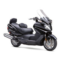
-
Suzuki AN650L 2002
-
Suzuki AN650K3 2002
-
SUZUKI Burgman AN400
-
Suzuki AN400ZA
-
Suzuki AN400A
-
Suzuki AN650/A
Suzuki Categories
Motorcycle
Automobile
Musical Instrument
Offroad Vehicle
Outboard Motor
More Suzuki Manuals
Посмотреть инструкция для Suzuki AN 650 Burgman K3 (2002) бесплатно. Руководство относится к категории Скутеры, 22 человек(а) дали ему среднюю оценку 8.2. Руководство доступно на следующих языках: английский. У вас есть вопрос о Suzuki AN 650 Burgman K3 (2002) или вам нужна помощь? Задайте свой вопрос здесь
- AN650_99500-36110-01E
Главная
| Suzuki | |
| AN 650 Burgman K3 (2002) | |
| Скутер | |
| английский | |
| Руководство пользователя (PDF) |
Не можете найти ответ на свой вопрос в руководстве? Вы можете найти ответ на свой вопрос ниже, в разделе часто задаваемых вопросов о Suzuki AN 650 Burgman K3 (2002).
Как перевести мили в километры?
В чем разница между топливом E10 и E5?
Как удалить ржавчину с устройства Suzuki Скутер?
Инструкция Suzuki AN 650 Burgman K3 (2002) доступно в русский?
Не нашли свой вопрос? Задайте свой вопрос здесь
Руководство на английском языке по ремонту скутеров Suzuki AN400 Burgman.
- Издательство: Suzuki Motor Corporation
- Год издания: 2003
- Страниц: —
- Формат: GIF
- Размер: 26,9 Mb
Руководство на английском языке по ремонту скутеров Suzuki AN650 Burgman.
- Издательство: Suzuki Motor Corporation
- Год издания: 2002
- Страниц: 463
- Формат: PDF
- Размер: 25,6 Mb

Руководство по техническому обслуживанию и ремонту скутеров производства Китая, Тайваня и Кореи с двигателями объемом от 50 до 200 cc и автоматической трансмиссией.
- Издательство: Алфамер
- Год издания: —
- Страниц: 240
- Формат: —
- Размер: —
