 07:04
07:04
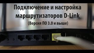
Подключение и настройка маршрутизаторов D-Link
 02:09
02:09
Маршрутизатор D-Link DI-804HV. Ремонт блока питания.
 02:31
02:31
DI-804HV Configuring to the internet
 14:16
14:16
IP sec VPN туннель на роутерах D-link. Пример настройки и работы.
 01:32
01:32
D-link DI-804HV LAN and DHCP.avi
 01:45
01:45
D-link DI-804HV status.avi
 15:20
15:20
D-Link 2100AP ремонт в полевых условиях
 11:30
11:30
Настройка WiFi роутера DLink DIR 300, DIR 615 и подобных
port WIrED Vpn roUtEr Руководство по быстрой установке…
Di-804hv, 4 port wired vpn router
- Изображение
- Текст
4 port WIrED Vpn roUtEr
Руководство по быстрой установке
+
DI-804HV

Di-804hv, Проверьте содержимое комплекта, Прежде чем вы начнете
Страница 2
- Изображение
- Текст
2
Данный продукт можно настраивать
с помощью любого современного
web-браузера, такого как Microsoft
Internet Explorer 6 или Netscape
Navigator 6.2.2 или выше
4-х портовый
широкополосный VPN
маршрутизатор
1. Если вы планируете использовать данное устройство для разделения
широкополосного доступа в Интернет среди компьютеров вашей внутренней сети, то у
вас должен быть кабельный или DSL модем с портом Ethernet, а также существующую
учетную запись пользователя у вашего провайдера Интернет.
2. Для настройки VPN маршрутизатора DI-804HV лучше использовать тот компьютер,
который подключен к вашему модему. DI-804HV может работать в качестве DHCP
сервера и назначать параметры IP автоматически для вашей сети. За подробными
инструкциями по настройке сетевых адаптеров на автоматическое получение
параметров IP обращайтесь к Приложению данного руководства или к Руководству
пользователя на CD-Rom.
Проверьте содержимое комплекта
VPN маршрутизатор DI-804HV
DI-804HV
Прежде чем вы начнете
5 В б л о к п и т а н и я
постоянного тока
C D — R O M ( с о д е р ж и т Р у к о в о д с т в о
пользователя и гарантию)
Кабель Ethernet («прямой»)
И с п о л ь з о в а н и е
электропитания с другими
характеристиками может
привести к поломке и
ликвидации гарантийных
обязательств.
Если что-либо из перечисленного отсутствует, обратитесь к
вашему продавцу.
©2004 D-Link Systems, Inc. Все права защищены. Торговые марки или зарегистрированные торговые марки являются собственностью
их владельцев. Программное обеспечение и спецификации могут изменяться без уведомления.

B. Порт WAN Этот порт служит для подключения к кабельному и…
Страница 3
- Изображение
- Текст
3
B.
Порт WAN
Этот порт служит для
подключения к кабельному
или DSL модему, используя
кабель Ethernet
C.
Порты LAN
Эти порты служат для
подключения компьютеров, оснащенных
адаптерами Ethernet.
D.
COM порт
Используется для
подключения внешнего
модема.
Кнопка Reset
Нажатие на кнопку восстановит
настройки, Принятые на
маршрутизаторе по умолчанию
A.
Гнездо
подключения
блока питания
A.
Сперва, подключите блок питания к гнезду питания, расположеном на тыловой
панели DI-804HV и после этого подключите блок питания к силовой настенной
розетке. Светодиодный индикатор Power загорится, что индицирует включение
устройства.
B.
1. Выключите ваш кабельный или DSL модем, который используется для связи;
обратите внимание, что некоторые устройства не имеют выключателей, и для
выключения необходимо отсоединить блок питания. Сейчас DI-804HV должен
быть включен, а кабельный или DSL модем – выключен.
2. Кабельный / DSL модем (
Выключен
) – DI-804HV (
Включен
)
Подключите Ethernet кабель к гнезду Ethernet, расположенному на кабельном
модеме. После того, как Ethernet кабель зафиксировался в гнезде, включите
кабельный модем или подключите его блок питания к розетке.
3. Кабельный / DSL модем (
Включен
) – DI-804HV (
Включен
)
Вставьте другой разъем Ethernet кабеля в гнездо WAN PORT, расположенное
на тыловой панели DI-804HV. Индикатор WAN загорится, показывая наличие
подключения. Если светодиодный индикатор WAN не горит, пожалуйста вернитесь
на шаг Б1 и повторите шаги инструкции, а также проверьте кабель Ethernet.
C.
Подключите кабель Ethernet к порту LAN port 1 на тыльной стороне DI-804HV и
к свободному порту сетевого адаптера, установленного на компьютере, который
предполагается использовать для настройки DI-804HV. Индикатор LAN Port 1
загорится при правильном подключении. (Примечание: LAN порты на DI-804HV
поддерживают автоматический выбор MDI/MDIX. Это означает, что допускается
использование как «прямого», так и «обратного» кабеля Ethernet.)
D.
COM порт для dial-up соединения с Интернет.
Подключение VPN маршрутизатора
DI-804HV к вашей сети.

постоянное свечение индицирует, что соединение с Интернет у…
Страница 4
- Изображение
- Текст
4
M2 LED – постоянное
свечение индицирует,
что соединение с
Интернет установлено.
Индикатор WAN
– если индикатор
горит постоянно,
значит установлено
соединение через
порт WAN. Во время
передачи данных через
порт индикатор мигает.
COM LED – постоянно
горящий индикатор
указывает на
соединение с внешним
аналоговым модемом.
M LED – будет
постоянно мигать,
индицируя правильную
работу DI-804HV.
Перезагрузите компьютер
Подключение нескольких
компьютеров к маршрутизатору
DI-804HV
Используя дополнительные кабели Ethernet (CAT5 UTP), подключите
компьютеры, оборудованные портом Ethernet к оставшимся Ethernet
портам LAN на задней панели DI-804HV.
Индикатор Power–
если индикатор горит
постоянно, значит
устройство включено.
Индикатор LOCAL
NETWORK – если
индикатор горит
постоянно, значит
установлено
соединение с
компьютерами,
подключенными к
портам 1-4. Во время
передачи данных
через порт индикатор
мигает.

5
Когда вы завершите настройку, описанную в Руководстве по быстрой
установке, ваша сеть будет выглядеть подобным образом:
Использование Мастера установки
Появится экран для регистрации
пользователя для доступа к
устройству.
Запустите ваш web-
браузер и наберите
в адресной строке
“
http://92.68.0.
”. Затем
нажмите клавишу
Enter
Наберите
“admin”
в поле для
ввода имени, поле для ввода
пароля оставьте пустым.
Нажмите
OK

6
Мастер установки (продолжение)
После того, как вы получили
доступ к управлению, перед
вами появится экран
Home.
Нажмите
Run Wizard
Вы увидите следующий экран:
Задайте новый пароль.
Здесь
вы можете задать пароль для
доступа к маршрутизатору.
Нажмите
Next
Нажмите
Next

Мастер установки (продолжение)
Выберите временную зону.
Здесь вы можете выбрать
временную зону для вашего
маршрутизатора.
Нажмите
Next
Выберите тип подключения
к Интернет.
Запрашивается тип
подключения маршрутизатора
к Интернет
Нажмите
Next
Если вы не уверены, какую
настройку выбрать, свяжитесь с
вашим провайдером.

8
Данные настройки должны быть выполнены
на компьютере, который зарегистрирован
в сети Интернет-провайдера, т.е. имеет
подключение к Интернет.
Мастер установки (продолжение)
Если ваш провайдер
Интернет требует назначения
статического IP адреса,
выберите этот пункт:
Static
IP Address
, и появится
следующий экран:
Введите информацию,
которую предоставил
провайдер Интернет в окне
установки IP адреса.Вы
должны заполнить все поля.
Если вы выбрали
Динамический IP-адрес
(Dynamic IP Address)
,
появится следующий экран:
Нажмите кнопку
“Clone MAC
Address”
для автоматического
копирования MAC адреса
сетевого адаптера в ваш
компьютер. Вы также можете
ввести MAC адрес вручную.
Нажмите
Next
Нажмите
Next

9
Этот раздел предназначен
только для тех пользователей,
которые используют аналоговый
dial-up модем для подключения к
провайдеру. В противном случае
нажмите NEXT , чтобы перейти к
следующему разделу.
Мастер установки (продолжение)
Если ваш провайдер
использует
PPPoE
(Point-to-
Point Protocol over Ethernet),
выберите этот пункт и
появится следующий экран:
Пожалуйста, убедитесь,
что вы удалили все
существующее на вашем
компьютере ПО для работы
PPPoE.
Введите имя пользователя
и пароль, предоставленные
провайдером Интернет.
Нажмите
Next
Нажмите
Next

0
Установка завершена!
Нажмите
Restart
Нажмите
Exit
Проверьте соединение с Интернет.
Теперь
перезапустите
WEB браузер на
компьютере (например,
Internet Explorer или
Netscape Navigator)
для подключения
к любимому WEB
сайту для проверки
подключения к Интернет.
Вы будете перенаправлены на страницу
Home.
Чтобы получить
больше информации
или произвести
дополнительные
настройки, обращайтесь
к страницам
Advanced,
Tools или Status Web-
интерфейса управления
или к Руководству
пользователя на CD.

Комментарии
(скачивание инструкции бесплатно)
Формат файла: PDF
Доступность: Бесплатно как и все руководства на сайте. Без регистрации и SMS.
Дополнительно: Чтение инструкции онлайн

4 port WIrED Vpn roUtEr
Руководство по быстрой установке
+
DI-804HV
Страница:
(1 из 13)
навигация

1

2

3

4

5

6

7

8

9

10

11

12

13
Оглавление инструкции
- Страница 1 из 14
4 port WIRED VPn roUter DI-804HV Руководство по быстрой установке+ - Страница 2 из 14
DI-804HV Данный продукт можно настраивать с помощью любого современного web-браузера, такого как Microsoft Internet Explorer 6 или Netscape Navigator 6.2.2 или выше 4-х портовый широкополосный VPN маршрутизатор Прежде чем вы начнете 1. Е с л и в ы п л а н и р у ет е и с п о л ь з о в а т ь д а н н - Страница 3 из 14
Подключение VPN маршрутизатора DI-804HV к вашей сети. A. Сперва, подключите блок питания к гнезду питания, расположеном на тыловой панели DI-804HV и после этого подключите блок питания к силовой настенной розетке. Светодиодный индикатор Power загорится, что индицирует включение устройства. B. 1. - Страница 4 из 14
Перезагрузите компьютер Подключение нескольких компьютеров к маршрутизатору DI-804HV Используя дополнительные кабели Ethernet (CAT5 UTP), подключите компьютеры, оборудованные портом Ethernet к оставшимся Ethernet портам LAN на задней панели DI-804HV. M1 LED – будет постоянно мигать, индицируя - Страница 5 из 14
Когда вы завершите настройку, описанную в Руководстве по быстрой установке, ваша сеть будет выглядеть подобным образом: Использование Мастера установки Запустите ваш webбраузер и наберите в адресной строке “http://192.168.0.1”. Затем нажмите клавишу Enter Появится экран для регистрации пользователя - Страница 6 из 14
Мастер установки (продолжение) После того, как вы получили доступ к управлению, перед вами появится экран Home. Нажмите Run Wizard Вы увидите следующий экран: Нажмите Next Задайте новый пароль.Здесь вы можете задать пароль для доступа к маршрутизатору. 1 Нажмите Next - Страница 7 из 14
Мастер установки (продолжение) Выберите временную зону. Здесь вы можете выбрать временную зону для вашего маршрутизатора. Нажмите Next Выберите тип подключения к Интернет. Запрашивается тип подключения маршрутизатора к Интернет Если вы не уверены, какую настройку выбрать, свяжитесь с вашим - Страница 8 из 14
Мастер установки (продолжение) Если вы выбрали Динамический IP-адрес (Dynamic IP Address), появится следующий экран: Нажмите кнопку “Clone MAC Address” для автоматического копирования MAC адреса сетевого адаптера в ваш компьютер. Вы также можете ввести MAC адрес вручную. Данные настройки должны - Страница 9 из 14
Мастер установки (продолжение) Если ваш провайдер использует PPPoE (Point-toPoint Protocol over Ethernet), выберите этот пункт и появится следующий экран: Пожалуйста, убедитесь, что вы удалили все существующее на вашем компьютере ПО для работы PPPoE. Введите имя пользователя и пароль, - Страница 10 из 14
Установка завершена! Нажмите Restart Проверьте соединение с Интернет. Вы будете перенаправлены на страницу Home. Нажмите Exit Теперь перезапустите WEB браузер на компьютере (например, Internet Explorer или Netscape Navigator) для подключения к любимому WEB сайту для проверки подключения к Интернет. - Страница 11 из 14
ПРИЛОЖЕНИЕ Для подключения к сети,убедитесь,что сетевой адаптер вашего компьютера настроен правильно. Здесь приведены рекомендации по настройке адаптера для автоматического получения IPадреса от маршрутизатора DI-804HV. Для Microsoft Windows XP: Нажмите Пуск>правой кнопкой мыши щелкните на Мое - Страница 12 из 14
Для Apple Macintosh OS X: Перейдите в Apple Menu, щелкните на Network и выберете System Preferences Нажмите на Network Выберете Builtin Ethernet в поле меню Show Выберете Using DHCP в поле меню Configure Нажмите на Apply Now Появятся IP адрес, маска подсети, IP адрес маршрутизатора по умолчанию и - Страница 13 из 14
Техническая поддержка Обновления программного обеспечения и документация доступны на Интернет-сайте D-Link. D-Link предоставляет бесплатную поддержку для клиентов в течение гарантийного срока. Клиенты могут обратиться в группу технической поддержки D-Link по телефону или через Интернет. Техническая - Страница 14 из 14
-
Contents
-
Table of Contents
-
Bookmarks
Quick Links
DI-804HV
D-Link
T M
Broadband Hardware
VPN Router
Manual
Building Networks for People
02212003
Related Manuals for D-Link DI-804HV
Summary of Contents for D-Link DI-804HV
-
Page 1
DI-804HV D-Link Broadband Hardware VPN Router Manual Building Networks for People 02212003… -
Page 2: Table Of Contents
Contents Package Contents …………….3 Introduction………………. 4 Getting Started ………………. 10 Using the Configuration Menu …………. 11 Networking Basics …………….57 Reset to Factory Default Settings …………83 Technical Specifications …………..84 Contacting Technical Support …………. 85 Warranty and Registration …………..86…
-
Page 3: Package Contents
Quick Installation Guide Note: Using a power supply with a different voltage rating than the one included with the DI-804HV will cause damage and void the warranty for this product. If any of the above items are missing, please contact your reseller.
-
Page 4: Introduction
Introduction The D-Link DI-804HV is a 4-port Broadband Router with Virtual Private Network (VPN) functionality. It provides a complete solution for Internet surfing and office resources sharing. It is an ideal way to extend the reach and number of computers connected to your network.
-
Page 5
All unwanted packets from outside intruders are blocked to protect your network DHCP server supported All of the networked computers can retrieve TCP/IP settings automatically from the DI-804HV Web-based configuration Configurable through any networked computer’ s web browser using Netscape or Internet Explorer… -
Page 6: Introduction To Broadband Router Technology
User-Definable Application Sensing Tunnel User can define the attributes to support special applications requiring multiple connections, like Internet gaming, video conferencing, Internet telephony and so on. The DI-804HV can sense the application type and open a multi-port tunnel for it. DMZ Host supported Allows a networked computer to be fully exposed to the Internet;…
-
Page 7: Introduction To Firewalls
Introduction to Firewalls A firewall is a device that sits between your computer and the Internet that prevents unauthorized access to or from your network. A firewall can be a computer using firewall software or a special piece of hardware built specifically to act as a firewall. In most circumstances, a firewall is used to prevent unauthorized Internet users from accessing private networks or corporate LAN’s and Intranets.
-
Page 8: Introduction To Virtual Private Networking
Introduction to Virtual Private Networking Virtual Private Networking (VPN) uses a publicly wired network (the Internet) to se- curely connect two different networks as if they were the same network. For example, an employee can access the corporate network from home using VPN, allowing the employee to access files and printers.
-
Page 9
LEDS stands for Light-Emitting Diode. The DI-804HV has the following LEDs as described below: LED Activity A steady light indicates Power a connection to a power sourcea power source Flashes once per second to indicate an M1 LED active system… -
Page 10: Getting Started
Consult with your Cable or DSL provider for proper installation of the modem Connect the Cable or DSL modem to the DI-804HV wireless broadband router (see the Quick Installation Guide included with the DI-804HV.) If you are connecting a desktop computer to your network, you can install the D-Link DFE-530TX+ ethernet adapter into an available PCI slot.
-
Page 11: Using The Configuration Menu
Type in the IP Address of the DI-804HV (http://192.168.0.1) http://192.168.0.1 Note: If you have changed the default IP Address assigned to the DI-804HV, make sure to enter the correct IP Address. The factory default User name is admin and the default Password is blank (empty).
-
Page 12
Using the Configuration Menu Setup Wizard Once you have logged in, the Home screen will appear. Click Run W izard The welcome screen outlines the ste ps to complete t he se tup wizard. Click Next to continue. Click Next… -
Page 13
Using the Configuration Menu Setup Wizard > Set Password Click Next Old Password- This information is masked. New Password- Type in the new password for the admin account. Type in the new password again to confirm. Click Next to con- Reconfirm- tinue with the Setup Wizard. -
Page 14
Using the Configuration Menu Setup Wizard > Time Zone Select the appropriate time zone for your location- Select the proper time zone. Selections can be made by clicking on the drop down list. Click Next to continue. Click Next Setup Wizard > Connection Type (WAN) Select Your Internet Connection- You will be prompted to se- lect the type of internet con-… -
Page 15
(MAC) address. Note that some computer and peripherals may already include built-in network adapter. Clone MAC By clicking on Clone MAC Address, the DI-804HV will auto- matically copy the MAC address of the network adapter in your Address- computer. You can also manually type in the MAC address. -
Page 16
Enter the IP address infor- mation originally provided to you by your ISP. You will need to complete all the required fields. The subnet for the DI-804HV is preconfigured to 255.255.255.0. WAN Subnet Mask- Configurations can be made in, but not recommended. This feature is for advanced users. -
Page 17
Using the Configuration Menu Setup Wizard > PPPoE Click Next If your ISP uses PPPoE (Point-to-Point Protocol over Ethernet), and this option is selected, then this screen will appear: (Used mainly for DSL Internet service.) PPPoE Account- Enter in the username provided to you by your ISP. PPPoE Password- Enter in the password provided to you by your ISP. -
Page 18
Using the Configuration Menu Setup Wizard Click Next Configure this section only if you have an analog dial-up account. Otherwise click Next to skip. Dial-up Enter the telephone number to connect to your ISP. Telephone- This information is provided by your ISP. The Dial-up Account is Dial-up Account- also known as username. -
Page 19
Using the Configuration Menu Setup Wizard Click Restart Back- Click on Back button to go back to previous page. Restart- Click on Restart button to finalize the settings made. Click on Exit button to end the Setup Wizard without saving Exit- any changes. -
Page 20
Using the Configuration Menu Home > WAN Choose WAN Type WAN stands for Wide Area Network. In this case WAN represents the mode in which you connect to the Internet. If you are uncertain, please ask your ISP which of the following represents your connection mode to the Internet: Dynamic Obtain an IP address from your ISP automatically (mainly for… -
Page 21
Using the Configuration Menu Home > WAN > Dynamic IP Address Most Cable modem users will select this option to obtain an IP Address automatically from their ISP (Internet Service Provider). This is optional, but may be required by some ISPs. The host Host Name- name is the device name of the Router. -
Page 22
Using the Configuration Menu Home > WAN > Static IP Address If you use a Static IP Address, you will input information here that your ISP has provided to you. WAN IP Address- Input the IP Address provided by your ISP Input the Subnet Mask provided by your ISP WAN Subnet Mask- WAN Gateway-… -
Page 23
Using the Configuration Menu Home > WAN > PPPoE Most DSL users will select this option to obtain an IP address automatically from their ISP through the use of PPPoE. PPPoE Account- Your PPPoE username provided by your ISP Your PPPoE password is provided by your ISP PPPoE Password- You will get the DNS IP automatically from your ISP but you Primary DNS-… -
Page 24
Enter a maximum idle time during which Internet connection Maximum Idle Time- is maintained during inactivity. To disable this feature, en- able Auto-reconnect. The communication speed between the DI-804HV and your Baud Rate- modem. If the settings are configured as “0.0.0.0,” they will be auto- Primary DNS- matically assigned upon connection. -
Page 25
Using the Configuration Menu Home > WAN > PPTP Point-to-Point Tunneling Protocol (PPTP) is a WAN connection used in Europe. Enter the IP Address My IP Address- Enter the Subnet Mask My Subnet Mask- Enter the Server IP Address Server IP Address- PPTP Account- Enter the PPTP account name Enter the PPTP password… -
Page 26
Using the Configuration Menu Home > WAN > BigPond Cable Dynamic IP Address for BigPond is a WAN connection used in Australia. Account- Enter in the username for the BigPond account Enter the password for the BigPond account Password- (Optional) enter the Login Server name if required Login Server- Renew IP forever- If enabled, the device will automatically connect to… -
Page 27
Area Network. This is considered your inter- nal network. These are the IP settings of the LAN interface for the DI-804HV. These settings may be re- ferred to as Private set tings. You may change the LAN IP address if needed. -
Page 28
Using the Configuration Menu Home >DHCP DHCP stands for Dynamic Host Control Protocol. The DI-804HV has a built-in DHCP server. The DHCP Server will automatically assign an IP address to the computers on the LAN/private network. Be sure to set your computers to be DHCP clients by setting their TCP/IP settings to “Obtain an IP Address Automatically.”… -
Page 29
Using the Configuration Menu Home >VPN Settings VPN Settings are settings that are used to create virtual private tunnels to remote VPN gateways. The tunnel technology supports data confidentiality, data origin, authentication and data integrity of network information by utilizing encapsulation protocols, encryption algorithms, and hashing algorithms. -
Page 30
Using the Configuration Menu Home >VPN Settings > Tunnel (IKE) VPN Settings — IKE- There are three parts that are necessary to setup the configuration of IKE for the dedicated tunnel: basic setup, IKE proposal setup, and IPSec proposal setup. Basic setup includes the setting of following items: local subnet, local netmask, remote subnet, remote netmask, remote gateway, and pre-shared key. -
Page 31
Using the Configuration Menu Home >VPN Settings > Tunnel Continued… The subnet of the remote VPN gateway’ s local network. It Remote Subnet- can be a host, a partial subnet or a whole subnet. The subnet of the remote VPN gateway’ s local network. It Remote Netmask- can be a host, a partial subnet or a whole subnet. -
Page 32
Using the Configuration Menu Home >VPN Settings > Tunnel (Manual) Tunnel Name- Current tunnel name. Enabling this mode will accelerate establishing tunnel, but Aggressive Mode- the device will have less security. The subnet of the VPN gateway’ s local network. It can be a Local Subnet- host, a partial subnet or a whole subnet. -
Page 33
Using the Configuration Menu Home >VPN Settings > Tunnel (Manual) The value of remote SPI should be set in hex format. Remote SPI- Encapsulation There are two protocols that can be selected: ESP and AH. protocol- There are two algorithms that can be selected: 3DES and Encryption DES. -
Page 34
Using the Configuration Menu Home >VPN Settings > Tunnel > Set IKE Proposal A list of selected proposal indexes from the IKE proposal pool IKE Proposal index- listed below. It indicates which IKE proposal to be focused. First char of Proposal Name- the name with 0x00 value stands for the IKE proposal is not available. -
Page 35
Using the Configuration Menu Home >VPN Settings> Tunnel > Set IKE Proposal Continued… Enter in the life time value. Life Time- Life Time Unit- There are two units that can be selected: second and KB. The identifier of IKE proposal can be chosen for adding Proposal ID- corresponding proposal to the dedicated tunnel. -
Page 36
Using the Configuration Menu Home >VPN Settings > Tunnel > Set IPSEC Proposal A list of selected proposal indexes from the IPSec proposal IPSec Proposal pool listed below. index- It indicates which IPSec proposal to be focused. First char of Proposal Name- the name with 0x00 value stands for the proposal is not available. -
Page 37
Using the Configuration Menu Home >VPN Settings> Tunnel > Set IPSEC Proposal Continued… Enter in a life time value. Life Time- Life Time Unit- There are two units that can be selected: second and KB. The identifier of IPSec proposal can be chosen for adding the Proposal ID- proposal to the dedicated tunnel. -
Page 38
Using the Configuration Menu Advanced > Virtual Server The DI-804HV can be configured as a virtual server so that remote users accessing Web or FTP services via the public IP address can be automatically redirected to local servers in the LAN (Local Area Network). -
Page 39
Internet telephony and others. These applications have difficulties working through NAT (Network Address Translation). Special Applications makes some of these applications work with the DI-804HV. If you need to run applications that require multiple connections, specify the port normally associated with an application in the Trigger field, then enter the public ports associated with the trigger port into the Incoming Ports field. -
Page 40
At the bottom of the screen, there is a list of MAC addresses from the DHCP client computers connected to the DI-804HV. To use them, select one from the drop down list and select an IP number you want to use. Then click the “Copy to” button and the 804HV will fill in the appropriate information to the list. -
Page 41
Using the Configuration Menu Advanced > IP Filter Use IP (Internet Protocol) filters to allow or deny computers access to the Internet based on their IP address. Disabled IP Filter- Select this option if you do not want to use IP filters. Allow all computers to access the Internet except those listed below- Those in the list will be denied access to the Internet;… -
Page 42
Using the Configuration Menu Advanced > Domain Filter Use Domain filters to allow or deny computers access to specific Internet domains whether it is through www, ftp, snmp, etc. Disabled Domain Filter- Select this option if you do not want to use Domain filters. Allow users to access the following domains and block all other domains- Select this option to allow users to access the specified Internet domains listed below. -
Page 43
SNMP (Simple Network Management Protocol) is a widely used network monitoring and control protocol that reports activity on each network device to the administrator of the network. SNMP can be used to monitor traffic and statistics of the DI-804HV. The DI- 804HV supports SNMP v1. -
Page 44
DDNS (Dynamic Domain Name System) keeps dynamic IP addresses (e.g., IP addresses assigned by a DHCP capable router or server) linked to a domain name. Users who have a Dynamic DNS account may use this feature on the DI-804HV. DDNS- When an IP address is automatically assigned by a DHCP server, DDNS automatically updates the DNS server. -
Page 45
Using the Configuration Menu Advanced > Routing Routing Tables allow you to determine which physical interface address to use for outgoing IP data grams. If you have more than one routers and subnets, you will need to enable routing table to allow packets to find proper routing path and allow different subnets to communicate with each other. -
Page 46
Using the Configuration Menu Advanced > DMZ If you have a computer that cannot run Internet applications properly from behind the DI- 804HV, then you can allow that computer to have unrestricted Internet access. Enter the IP address of that computer as a DMZ (Demilitarized Zone) host with unrestricted Internet access. -
Page 47
Internet IP addresses to access the DI-804HV. The port number used to access the DI-804HV. Port- E.g., http://x.x.x.x:8080, where x.x.x.x. is the WAN IP address of the DI-804HV and 8080 is the port used for the Web Manage- ment interface. -
Page 48
Using the Configuration Menu Tools> Time Set the time here by entering it manually or use NTP (Network Time Protocol.) NTP is standard protocol on the Internet that sychronizes the time settings accurately for all the computers on your network. Select to enable NTP and synchronize the time settings on your Enable NTP- network using an NTP server… -
Page 49
The current system settings can be saved as a file onto the local hard drive. The saved file or any other saved setting file created by the DI-804HV can be uploaded into the unit. To reload a system settings file, click on Browse to search the local hard drive for the file to be used. -
Page 50
Using the Configuration Menu Tools > Firmware You can upgrade the firmware by using this tool. First, check the D-Link support site for firmware updates at http://support.dlink.com. Make sure that the firmware you want to use is saved on the local hard drive of your computer. Click on Browse to search the local hard drive for the firmware that you downloaded from the D-Link website to be used for the update. -
Page 51
Restart Device- Click Enable to block the WAN ping. Computers on the Internet Block WAN Ping- will not get a reply back from the DI-804HV when it is being “ping”ed. This may help to increase security. Non-standard If an FTP server you want to access is not using the standard port… -
Page 52
Using the Configuration Menu Status > Device Info 1.20,Thu,Jan 30 2003 This screen displays information about the DI-804HV Click Refresh to update the page. Refresh-… -
Page 53
Using the Configuration Menu Status > Log (1.20) This screen displays activities occurring on the DI-804HV Click for advanced features (see next page.) Log Settings- Back- Click Back to return to the top of the log. Refresh- Click Refresh to update the log. -
Page 54
Syslog Server- Click Enable to activate the policy. The DI-804HV will send all of it’ s logs to the specified syslog server. The DI-804HV can be set up to send the log files to a specific E-Mail Alert- email address. -
Page 55
Using the Configuration Menu Status > Stats In Stats section, traffic statistics are displayed. This will update the page. Refresh- This will reset the packet counter to zero. Reset- Displays Received / Transmitted packets from the WAN port. WAN- Displays Received / Transmitted packets from the LAN port. LAN-… -
Page 56
Using the Configuration Menu Help This screen displays the complete Help menu. For help at anytime, click the Help tab in the Configuration menu. -
Page 57: Networking Basics
Networking Basics Using the Network Setup Wizard in Windows XP In this section you will learn how to establish a network at home or work, using Microsoft Windows XP. Note: Please refer to websites such as http://www.homenethelp.com http://www.microsoft.com/windows2000 for information about networking computers using Windows 2000, ME or 98.
-
Page 58
Networking Basics Please follow all the instructions in this window: Click Next In the following window, select the best description of your computer. If your computer connects to the internet through a gateway/router, select the second option as shown. Click Next… -
Page 59
Networking Basics Enter a Computer description and a Computer name (optional.) Click Next Enter a Workgroup name. All computers on your network should have the same Workgroup name. Click Next… -
Page 60
Networking Basics Please wait while the Network Setup Wizard applies the changes. When the changes are complete, click Next. Please wait while the Network Setup Wizard configures the computer. This may take a few minutes. -
Page 61
Networking Basics In the window below, select the option that fits your needs. In this example, Create a Network Setup Disk has been selected. You will run this disk on each of the computers on your network. Click Next. Insert a disk into the Floppy Disk Drive, in this case drive A. Format the disk if you wish, and click Next. -
Page 62
Networking Basics Please read the information under Here’ s how in the screen below. After you complete the Network Setup Wizard you will use the Network Setup Disk to run the Network Setup Wizard once on each of the computers on your network. To continue click Next. -
Page 63
Networking Basics Please read the information on this screen, then click Finish to complete the Network Setup Wizard. The new settings will take effect when you restart the computer. Click Yes to restart the computer. You have completed configuring this computer. Next, you will need to run the Network Setup Disk on all the other computers on your network. -
Page 64
Networking Basics Naming your Computer To name your computer, please follow these directions:In Windows XP: Click Start (in the lower left corner of the screen) Right-click on My Computer Select Properties and click Select the Computer Name Tab in the System Properties window. -
Page 65: Checking The Ip Address In Windows Xp
Networking Basics Naming your Computer In this window, enter the Computer name Select Workgroup and enter the name of the Workgroup All computers on your network must have the same Workgroup name. Click OK Checking the IP Address in Windows XP The wireless adapter-equipped computers in your network must be in the same IP Ad- dress range (see Getting Started in this manual for a definition of IP Address Range.) To check on the IP Address of the adapter, please do the following:…
-
Page 66
Networking Basics Checking the IP Address in Windows XP This window will appear. Click the Support tab Click Close Assigning a Static IP Address in Windows XP/2000 Note: Residential Gateways/Broadband Routers will automatically assign IP Ad- dresses to the computers on the network, using DHCP (Dynamic Host Configuration Protocol) technology. -
Page 67
Networking Basics Assigning a Static IP Address in Windows XP/2000 Double-click on Network Connections Right-click on Local Area Connections Double-click on Properties… -
Page 68
Networking Basics Assigning a Static IP Address in Windows XP/2000 Enter the LAN IP address of the Wireless Router. (D-Link wireless routers have a LAN IP address of 192.168.0.1) 192 168 Enter the LAN IP address of 192 168 the Wireless Router. (D-Link wireless routers have a LAN IP address of 192.168.0.1) -
Page 69
Networking Basics Assigning a Static IP Address with Macintosh OSX Go to the Apple Menu and se- lect System Preferences cClick on Network Select Built-in Ethernet in the Show pull-down menu Select Manually in the Con- figure pull-down menu Input the Static IP Address, the Subnet Mask and the Router IP Address in the ap- propriate fields… -
Page 70
Networking Basics Selecting a Dynamic IP Address with Macintosh OSX Go to the Apple Menu and select System Preferences Click on Network Select Built-in Ethernet in the Show pull-down menu Select Using DHCP in the Configure pull-down menu Click Apply Now The IP Address, Subnet mask, and the Router’… -
Page 71: Adding A Local Printer
Networking Basics Adding and Sharing Printers in Windows XP After you have run the Network Setup Wizard on all the computers in your network (please see the Network Setup Wizard section at the beginning of Networking Basics,) you can use the Add Printer Wizard to add or share a printer on your network. Whether you want to add a local printer (a printer connected directly to one computer,) share an LPR printer (a printer connected to a print server) or share a network printer (a printer connected to your network through a Gateway/Router,) use the Add Printer…
-
Page 72
Networking Basics Adding a local printer (a printer connected directly to a computer) A printer that is not shared on the network and is connected directly to one computer is called a local printer. If you do not need to share your printer on a network, follow these directions to add the printer to one computer. -
Page 73
Networking Basics Adding a local printer Click Next Select Local printer attached to this computer (Deselect Automati- cally detect and install my Plug and Play printer if it has been selected.) Click Next Select Use the follow- ing port: From the pull-down menu select the correct port for your printer (Most computers use the LPT1: port,… -
Page 74
Networking Basics Adding a local printer Select and highlight the correct driver for your printer. Click Next (If the correct driver is not displayed, insert the CD or floppy disk that came with your printer and click Have Disk.) At this screen, you can change the name of the printer (optional.) Click Next… -
Page 75
Networking Basics Adding a local printer This screen gives you information about your printer. Click Finish When the test page has printed, Click OK… -
Page 76: Sharing A Network Printer
Networking Basics Adding a local printer Go to Start> Printers and Faxes A successful installation will display the printer icon as shown at right. You have successfully added a local printer. Sharing a network printer After you have run the Network Setup Wizard on all the computers on your network, you can run the Add Printer Wizard on all the computers on your network.
-
Page 77
Networking Basics Sharing a network printer Click on Add a printer Click Next Select Network Printer Click Next… -
Page 78
Networking Basics Sharing a network printer Select Browse for a printer Click Next Select the printer you would like to share Click Next Click Finish… -
Page 79
Networking Basics Sharing a network printer To check for proper installation: Go to Start > Printers and Faxes The printer icon will appear at right, indicating proper installation. You have completed adding the printer. To share this printer on your network: Remember the printer name Run the Add Printer… -
Page 80
Networking Basics Sharing an LPR printer To share an LPR printer (using a print server,) you will need a Print Server such as the DP-101P+. Please make sure that you have run the Network Setup Wizard on all the computers on your network. To share an LPR printer, please follow these directions: Go to Start >… -
Page 81
Networking Basics Sharing an LPR printer This screen will show you information about your printer. Click Finish Select the printer you are adding from the list of Printers. Insert the printer driver disk that came with your printer. Click Have Disk If the printer driver is already installed, do the following: Select Keep existing… -
Page 82
Networking Basics Sharing an LPR printer You can rename your printer if you choose. It is optional. Please remember the name of your printer. You will need this information when you use the Add Printer Wizard on the other computers on your network. -
Page 83: Reset To Factory Default Settings
After you have tried other methods for troubleshooting your network, you may choose to Reset the DI-804HV to the factory default settings. To hard-reset the D-Link DI-804HV to the Factory Default Settings, please do the following: Turn off the DI-804HV…
-
Page 84: Technical Specifications
Technical Specifications Standards IEEE 802.3 10BASET-T Ethernet IEEE 802.3u 100BASE-TX Fast Ethernet IEEE 802.3x Flow Control ANSI/IEEE 802.3 NWay auto-negotiation VPN Pass Through Function PPTP L2TP IPSec Device Management Web-Based – Internet Explorer 6x or later; Netscape Navigator 6x or later;…

3
B.
Порт WAN
Этот порт служит для
подключения к кабельному
или DSL модему, используя
кабель Ethernet
C.
Порты LAN
Эти порты служат для
подключения компьютеров, оснащенных
адаптерами Ethernet.
D.
COM порт
Используется для
подключения внешнего
модема.
Кнопка Reset
Нажатие на кнопку восстановит
настройки, Принятые на
маршрутизаторе по умолчанию
A.
Гнездо
подключения
блока питания
A.
Сперва, подключите блок питания к гнезду питания, расположеном на тыловой
панели DI-804HV и после этого подключите блок питания к силовой настенной
розетке. Светодиодный индикатор Power загорится, что индицирует включение
устройства.
B.
1. Выключите ваш кабельный или DSL модем, который используется для связи;
обратите внимание, что некоторые устройства не имеют выключателей, и для
выключения необходимо отсоединить блок питания. Сейчас DI-804HV должен
быть включен, а кабельный или DSL модем – выключен.
2. Кабельный / DSL модем (
Выключен
) – DI-804HV (
Включен
)
Подключите Ethernet кабель к гнезду Ethernet, расположенному на кабельном
модеме. После того, как Ethernet кабель зафиксировался в гнезде, включите
кабельный модем или подключите его блок питания к розетке.
3. Кабельный / DSL модем (
Включен
) – DI-804HV (
Включен
)
Вставьте другой разъем Ethernet кабеля в гнездо WAN PORT, расположенное
на тыловой панели DI-804HV. Индикатор WAN загорится, показывая наличие
подключения. Если светодиодный индикатор WAN не горит, пожалуйста вернитесь
на шаг Б1 и повторите шаги инструкции, а также проверьте кабель Ethernet.
C.
Подключите кабель Ethernet к порту LAN port 1 на тыльной стороне DI-804HV и
к свободному порту сетевого адаптера, установленного на компьютере, который
предполагается использовать для настройки DI-804HV. Индикатор LAN Port 1
загорится при правильном подключении. (Примечание: LAN порты на DI-804HV
поддерживают автоматический выбор MDI/MDIX. Это означает, что допускается
использование как «прямого», так и «обратного» кабеля Ethernet.)
D.
COM порт для dial-up соединения с Интернет.
Подключение VPN маршрутизатора
DI-804HV к вашей сети.