Руководства пользователя
Версия A4323A
3.24 MB
P5KPL-AM SE Asian Quick Start Guide for Multiple Languages
Версия T4810
1.32 MB
P5KPL-AM SE user’s manual (Traditional Chinese)
Версия C4810
1.45 MB
P5KPL-AM SE user’s manual (Simplified Chinese)
Версия E4810
1.06 MB
P5KPL-AM SE user’s manual (English)
Версия T4204
1.97 MB
Motherboard Installation Guide (Traditional Chinese)
Версия C4204
1.83 MB
Motherboard Installation Guide (Simplified Chinese)
Версия U4323
1019.34 KB
P5KPL-AM SE European Quick Start Guide for Multiple Languages
Версия E4323
1.07 MB
P5KPL-AM SE user’s manual(English)
Версия F4236
1.23 MB
P5KPL-AM SE user’s manual(French)
Версия E4236
1.37 MB
P5KPL-AM SE user’s manual(English)
-
Contents
-
Table of Contents
-
Bookmarks
Quick Links
Related Manuals for Asus P5KPL-AM SE
Summary of Contents for Asus P5KPL-AM SE
-
Page 1
P5KPL-AM SE… -
Page 2
Product warranty or service will not be extended if: (1) the product is repaired, modified or altered, unless such repair, modification of alteration is authorized in writing by ASUS; or (2) the serial number of the product is defaced or missing. -
Page 3: Table Of Contents
Contents Notices … v Safety information … vi About this guide … vi P5KPL-AM SE specifications summary … viii Chapter 1: Product information Before you proceed … 1-1 Motherboard overview … 1-2 1.2.1 Motherboard layout … 1-2 1.2.2 Layout contents … 1-2 Central Processing Unit (CPU) …
-
Page 4
Boot menu … 2-13 2.6.1 Boot Device Priority … 2-13 2.6.2 Boot Settings Configuration … 2-13 2.6.3 Security … 2-14 Tools menu … 2-15 2.7.1 ASUS EZ Flash 2 … 2-15 2.7.2 AI NET 2… 2-15 Exit menu … 2-16… -
Page 5: Notices
Notices Federal Communications Commission Statement This device complies with Part 15 of the FCC Rules. Operation is subject to the following two conditions: • This device may not cause harmful interference, and • This device must accept any interference received including interference that may cause undesired operation.
-
Page 6: Safety Information
Safety information Electrical safety • To prevent electric shock hazard, disconnect the power cable from the electric outlet before relocating the system. • When adding or removing devices to or from the system, ensure that the power cables for the devices are unplugged before the signal cables are connected. If possible, disconnect all power cables from the existing system before you add a device.
-
Page 7: Conventions Used In This Guide
Refer to the following sources for additional information and for product and software updates. ASUS websites The ASUS website provides updated information on ASUS hardware and software products. Optional documentation Your product package may include optional documentation, such as warranty flyers, that may have been added by your dealer.
-
Page 8: P5Kpl-Am Se Specifications Summary
Processors Compatible with Intel 05B / 05A / 06 processors ® Intel Hyper-Threading Technology ready ® (Refer to www.asus.com for Intel CPU support list) Northbridge: Intel ® Southbridge: Intel ICH7 ® 1600(O.C.) / 1333 / 1066 / 800 / 533MHz…
-
Page 9
— FSB turning from 133MHz up to 600MHz at 1MHz increment. Overclocking Protection: — ASUS C.P.R. (CPU Parameter Recall) 8 Mb Flash ROM, AMI BIOS, PnP, DMI2.0, WfM2.0, ACPI V2.0a, SM BIOS 2.5 WOL, PXE,RPL, WOR BY Ring, PME Wake Up… -
Page 10: Before You Proceed
Chapter 1 Product introduction Thank you for buying an ASUS P5KPL-AM SE motherboard! ® Before you start installing the motherboard, and hardware devices on it, check the items in your motherboard package. Refer to page ix for the list of accessories.
-
Page 11: Motherboard Overview
KBMS ATX12V LGA775 USB34 LAN1_USB12 Intel ® CHA_FAN AUDIO 8102FL PCIEX16 Lithium Cell CMOS Power Super P5KPL-AM SE PCIEX1_1 SPEAKER PCI1 ALC662 USBPW5-8 F_PANEL SB_PWR USB56 USB78 AAFP Page Connectors/Jumpers/Slots 1-13 USB connectors (10-1 pin USB56, USB 78) 10. USB device wake-up (3-pin USBPW 5-8) 11.
-
Page 12: Central Processing Unit (Cpu)
Contact your retailer immediately if the PnP cap is missing, or if you see any damage to the PnP cap/socket contacts/motherboard components. ASUS will shoulder the cost of repair only if the damage is shipment/ transit-related.
-
Page 13
• You may install varying memory sizes in Channel A and Channel B. The system maps the total size of the lower-sized channel for the dual-channel configuration. Any excess memory from the higher-sized channel is then mapped for single-channel operation. •… -
Page 14
• • • • • • • • • • • • • • • DIMM support • • • • • • • • • • • • • • • • • • • • ASUS P5KPL-AM SE… -
Page 15
AXT760UD00-19DC97X OCZ2N1066SR2DK OCZ2N10662GK 512MB Kingbox EP512D21066PS Visit the ASUS website at (www.asus.com) for the latest QVL. SS — Single-sided / DS — Double — sided DIMM support: • A*: Supports one module inserted into any slot as Single-channel memory configuration. -
Page 16: Expansion Slots
P5KPL-AM SE P5KPL-AM SE USB Device Wake Up • The USB device wake-up feature requires a power supply that can provide 500mA on the +5VSB lead for the USB port. Otherwise, the system would not power up.
-
Page 17: Clear Rtc Ram
• Due to the chipset limitation, AC power off is required before you use the C.P.R. function. You must turn off and on the power supply or unplug and plug the power cord before rebooting the system. P5KPL-AM SE P5KPL-AM SE Clear RTC RAM Chapter 1: Product introduction CLRTC Normal…
-
Page 18: Connectors
USB device. This feature requires an ATX power supply that can supply at least 1A on the +5VSB lead, and a corresponding setting in the BIOS. The USBPW56 jumper is for the rear USB ports. P5KPL-AM SE P5KPL-AM SE Keyboard Power Setting Connectors 1.7.1 Rear panel ports PS/2 mouse port (green).
-
Page 19: Internal Connectors
ICH7 Serial ATA connectors (7-pin SATA1, SATA2) These connectors are for the Serial ATA signal cables for Serial ATA hard disk drives. P5KPL-AM SE P5KPL-AM SE SATA connectors (ICH7) Connect the right-angle side of SATA signal cable to SATA device. You may…
-
Page 20
This prevents incorrect insertion when you connect the IDE cable. • Use the 80-conductor IDE cable for Ultra DMA 133/100/66 IDE devices. P5KPL-AM SE P5KPL-AM SE IDE connector USB connectors (10-1 pin USB56, USB78) These connectors are for USB 2.0 ports. Connect the USB module cable to any of these connectors, then install the module to a slot opening at the back of the system chassis. -
Page 21
This connector is for a chassis-mounted front panel audio I/O module that supports either HD Audio or legacy AC’97 audio standard. P5KPL-AM SE P5KPL-AM SE AAFP connector • We recommend that you connect a high-definition front panel audio module to this connector to avail of the motherboard’s high-definition audio capability. -
Page 22
P5KPL-AM SE P5KPL-AM SE ATX power connectors • For a fully configured system, we recommend that you use a power supply unit (PSU) that complies with EATX 12 V Specification 2.0 (or later version) and provides a minimum power of 400 W. -
Page 23: System Panel Connector
System panel connector (10-1 pin F_PANEL) This connector supports several chassis-mounted functions. P5KPL-AM SE P5KPL-AM SE System panel connector System power LED (2-pin PWRLED) • This 2-pin connector is for the system power LED. Connect the chassis power LED cable to this connector. The system power LED lights up when you turn on the system power, and blinks when the system is in sleep mode.
-
Page 24: Software Support
ASSETUP.EXE from the BIN folder. Double-click the ASSETUP.EXE to run the DVD. 1-15 XP/Vista Operating Systems (OS). Always install the ® XP Service Pack 1 or later versions before installing ® Click an icon to display Support DVD/ motherboard information ASUS P5KPL-AM SE…
-
Page 25: Chapter 2: Bios Information
BIOS in the future. Copy the original motherboard BIOS using the ASUS Update utility.. 2.1.1 ASUS Update utility The ASUS Update is a utility that allows you to manage, save, and update the motherboard BIOS in Windows environment. ®…
-
Page 26: Asus Ez Flash 2 Utility
2.1.2 ASUS EZ Flash 2 utility ASUS EZ Flash 2 allows you to update the BIOS without having to use a bootable floppy disk and a DOS-based utility. Download the latest BIOS file for this motherboard from the ASUS website at www.asus.com.
-
Page 27: Asus Crashfree Bios 3 Utility
2.1.3 ASUS CrashFree BIOS 3 utility The ASUS CrashFree BIOS 3 is an auto recovery tool that allows you to restore the BIOS file when it fails or gets corrupted during the updating process. You can update a corrupted BIOS file using the motherboard Support DVD or a USB flash disk that contains the updated BIOS file.
-
Page 28: Bios Setup Program
• The BIOS setup screens in this section are for reference only. They may not exactly match what you see on your screen. • Visit the ASUS website at www.asus.com to download the latest BIOS file for this motherboard. Main menu When you enter the BIOS Setup program, the Main menu screen appears, giving you an overview of the basic system information.
-
Page 29: Primary Ide/Sata
2.3.3 Primary IDE/SATA While entering Setup, the BIOS automatically detects the presence of IDE/SATA devices. There is a separate sub-menu for each IDE/SATA device. Select a device item then press <Enter> to display the IDE/SATA device information. The BIOS automatically detects the values opposite the dimmed items (Device, Vendor, Size, LBA Mode, Block Mode, PIO Mode, Async DMA, Ultra DMA, and SMART monitoring).
-
Page 30: System Information
Overclock Profile — loads overclocking profiles with optimal parameters for stability when overclocking. Test Mode — loads overclock (overclocking 5%) with spread spectrum. Adjust system frequency/voltage Select Screen Select Item Enter Go to Sub-screen General Help Save and Exit Exit ASUS P5KPL-AM SE…
-
Page 31
The following item appears only when you set the AI Overclocking item to [Manual]. CPU Frequency [xxx] Displays the frequency sent by the clock generator to the system bus and PCI bus. The value of this item is auto-detected by the BIOS. Use the <+> and <-> keys to adjust the CPU frequency. -
Page 32: Usb Configuration
Enable this item to boot legacy operating systems that cannot support CPUs with extended CPUID functions. Configuration options: [Disabled] [Enabled] Vanderpool Technology [Enabled] Enable this item when the processor supports Vanderpool technology. Users need to reset the computer to change the configuration of this item. Configuration options: [Disabled] [Enabled] ASUS P5KPL-AM SE…
-
Page 33: Chipset
CPU TM function [Enabled] Enables or disables Intel® CPU Thermal Monitor (TM2) function, a CPU overheating protection function. When enabled, the CPU core frequency and voltage is reduced when the CPU is overheats. Configuration options: [Enabled] [Disabled] Execute Disable Bit [Enabled] Allows you to Enable/disable Execute Disable Function.
-
Page 34: Onboard Devices Configuration
Palette Snooping [Disabled] When set to [Enabled], the pallete snooping feature informs the PCI devices that an ISA graphics device is installed in the system so that the latter can function correctly. Configuration options: [Disabled] [Enabled] 2-10 ASUS P5KPL-AM SE…
-
Page 35: Power Menu
IRQ-xx assigned to [PCI Device] When set to [PCI Device], the specific IRQ is free for use of PCI/PnP devices. When set to [Reserved], the IRQ is reserved for legacy ISA devices. Configuration options: [PCI Device] [Reserved] Power menu The Power menu items allow you to change the settings for the Advanced Power Management (APM).
-
Page 36: Hardware Monitor
The onboard hardware monitor automatically detects and displays the chassis fan speed in rotations per minute (RPM). If the fan is not connected to the chassis, the specific field shows N/A. Select Ignored if you do not wish to display the detected speed. 2-12 ASUS P5KPL-AM SE…
-
Page 37: Boot Menu
This allows you to enable or disable the full screen logo display feature. Configuration options: [Disabled] [Enabled] Set this item to [Enabled] to use the ASUS MyLogo2 AddOn ROM Display Mode [Force BIOS] Sets the display mode for option ROM. Configuration options: [Force BIOS] [Keep Current] Bootup Num-Lock [On] Allows you to select the power-on state for the NumLock.
-
Page 38: Security
[View Only] — allows access but does not allow change to any field. [Limited] — allows changes only to selected fields, such as Date and Time. [Full Access] — allows viewing and changing all the fields in the Setup utility. 2-14 ASUS P5KPL-AM SE…
-
Page 39: Tools Menu
2.7.1 ASUS EZ Flash 2 Allows you to run ASUS EZ Flash 2. When you press <Enter>, a confirmation message appears. Use the left/right arrow key to select between [Yes] or [No], then press <Enter> to confirm your choice. Please see section 2.1.3 for details.
-
Page 40: Exit Menu
2-16 BIOS SETUP UTILITY Power Boot Tools Exit Exit system setup after saving the changes. F10 key can be used for this operation. Select Screen Select Item Enter Go to Sub-screen General Help Save and Exit Exit ASUS P5KPL-AM SE…
Краткое содержание страницы № 1
P5KPL-AM SE
Motherboard
Краткое содержание страницы № 2
E4323 Second Edition V2 November 2008 Copyright © 2008 ASUSTeK Computer Inc. All Rights Reserved. No part of this manual, including the products and software described in it, may be reproduced, transmitted, transcribed, stored in a retrieval system, or translated into any language in any form or by any means, except documentation kept by the purchaser for backup purposes, without the express written permission of ASUSTeK Computer Inc. (“ASUS”). Product warranty or service will not be extende
Краткое содержание страницы № 3
Contents Notices ……………………………………………………………………………………………. v Safety information ………………………………………………………………………….. vi About this guide …………………………………………………………………………….. vi P5KPL-AM SE specifications summary ………………………………………….. viii Chapter 1: Product information 1.1 Before you proceed ……….
Краткое содержание страницы № 4
Contents 2.3.3 Primary IDE/SATA ………………………………………………….. 2-5 2.3.4 Storage Configuration …………………………………………….. 2-5 2.3.5 System Information ………………………………………………… 2-6 2.4 Advanced menu ………………………………………………………………… 2-6 2.4.1 JumperFree Configuration ………………………………………. 2-6 2.4.2 USB Configuration ………………………
Краткое содержание страницы № 5
Notices Federal Communications Commission Statement This device complies with Part 15 of the FCC Rules. Operation is subject to the following two conditions: • This device may not cause harmful interference, and • This device must accept any interference received including interference that may cause undesired operation. This equipment has been tested and found to comply with the limits for a Class B digital device, pursuant to Part 15 of the FCC Rules. These limits are designed to provide r
Краткое содержание страницы № 6
Safety information Electrical safety • To prevent electric shock hazard, disconnect the power cable from the electric outlet before relocating the system. • When adding or removing devices to or from the system, ensure that the power cables for the devices are unplugged before the signal cables are connected. If possible, disconnect all power cables from the existing system before you add a device. • Before connecting or removing signal cables from the motherboard, ensure that all power cabl
Краткое содержание страницы № 7
Conventions used in this guide To ensure that you perform certain tasks properly, take note of the following symbols used throughout this manual. DANGER/WARNING: Information to prevent injury to yourself when trying to complete a task. CAUTION: Information to prevent damage to the components when trying to complete a task. IMPORTANT: Instructions that you MUST follow to complete a task. NOTE: Tips and additional information to help you complete a task. Where to find more info
Краткое содержание страницы № 8
P5KPL-AM SE specifications summary ® CPU LGA775 socket for Intel Core™2 Quad/ Core™2 ® ® Extreme / Core™2 Duo / Pentium D / Pentium 4 / ® Celeron E1000 Series and Celeron 400 Series Processors ® Compatible with Intel 05B / 05A / 06 processors ® Intel Hyper-Threading Technology ready (Refer to www.asus.com for Intel CPU support list) ® Chipset Northbridge: Intel G31 ® Southbridge: Intel ICH7 Front Side Bus 1600(O.C.) / 1333 / 1066 / 800 / 533MHz Memory Dual channel memory architecture
Краткое содержание страницы № 9
P5KPL-AM SE specifications summary Internal connectors 2 x USB 2.0 connectors supports additional 4 USB ports 1 x internal speaker connector 2 x Serial ATA connectors 1 x CPU fan connector 1 x Chassis fan connector 1 x CD audio in connector 1 x 24-pin EATXPWR 12 V power connector 1 x 4-pin ATX 12 V power connector 1 x Front panel High Definition audio connector 1 x System Panel connector ASUS Exclusive SFS (Stepless Frequency Selection) Overclocking Features — FSB turning from 133MHz
Краткое содержание страницы № 10
Chapter 1 Product introduction ® Thank you for buying an ASUS P5KPL-AM SE motherboard! Before you start installing the motherboard, and hardware devices on it, check the items in your motherboard package. Refer to page ix for the list of accessories. If any of the items is damaged or missing, contact your retailer. 1.1 Before you proceed Take note of the following precautions before you install motherboard components or change any motherboard settings. • Unplug the power cord from the wall s
Краткое содержание страницы № 11
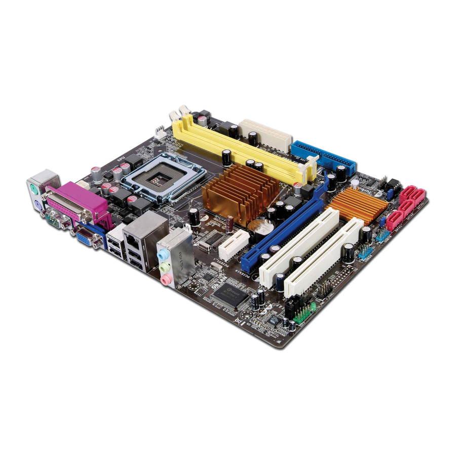
1.2 Motherboard overview 1.2.1 Motherboard layout Ensure that you install the motherboard into the chassis in the correct orientation. The edge with external ports goes to the rear part of the chassis. 18.3cm(7.2in) KBMS ATX12V CPU_FAN LGA775 USB34 Place this side towards LAN1_USB12 the rear of the chassis. ® Intel G31 CHA_FAN AUDIO RTL 8102FL PCIEX16 Lithium Cell CMOS Power ® Super Intel I/O ICH7 PCIEX1_1 P5KPL-AM SE SPEAKER PCI1 CLRTC ALC662 8Mb BIOS USBPW5-8 F_PANEL SB_PWR USB56 PRI_IDE US
Краткое содержание страницы № 12
1.3 Central Processing Unit (CPU) ® The motherboard comes with a surface mount LGA775 socket designed for the Intel Core ® ® ® ™2 Quad / Core™2 Extreme / Core™2 Duo / Pentium D / Pentium 4 and Celeron E1000 Series and Celeron 400 Series processors. • Ensure that all power cables are unplugged before installing the CPU. • Upon purchase of the motherboard, make sure that the PnP cap is on the socket and the socket contacts are not bent. Contact your retailer immediately if the PnP cap is miss
Краткое содержание страницы № 13
• You may install varying memory sizes in Channel A and Channel B. The system maps the total size of the lower-sized channel for the dual-channel configuration. Any excess memory from the higher-sized channel is then mapped for single-channel operation. • Always install DIMMs with the same CAS latency. For optimum compatibility, we recommend that you obtain memory modules from the same vendor. • Due to the memory address limitation on 32-bit Windows OS, when you install 4GB or more memory o
Краткое содержание страницы № 14
DIMM support S S / Size Vendor Model CL Brand Component DS A* B* 1G Apacer 78.01092.420 5 Elpida DS E5108AE-6E-E • • 1G Apacer AU01GE667C5KBGC 5 Apacer DS AM4B5708MIJS7E0627B • • 512MB ADATA M20EL5G3H3160B1C0Z N/A Elpida SS E5108AE-6E-E • • 512MB ADATA M20AD5G3H3166I1C52 N/A ADATA SS AD29608A8A-3EG20648 • • 512MB ADATA M20AD5G3H3166I1C52 N/A ADATA SS AD29608A8A-3EG20718 • • 1G ADATA M2OAD5G3I4176I1C52 N/A ADATA DS AD29608A8A-3EG20645 • • 512MB VDATA M2GVD5G3H31A4I1C52 N/A VDATA SS VD29608
Краткое содержание страницы № 15
DIMM support S S / Size Vendor Model CL Brand Component DS A* B* 1G Samsung KR M378T2953CZ3-CE7 N/A Samsung DS K4T51083QC-ZCE7 • • 256MB Qimonda HYS64T32001HU-2.5-A N/A Qimonda SS HYB18T256800AF25SSS49313 • • 512MB Qimonda HYS64T64020HU-2.5-A N/A Qimonda DS HYB18T256800AF25SSS25063 • • 1G Corsair CM2X1024-6400 5 Corsair DS Heat-Sink Package • • 1G Corsair XMS2-6400 4 Corsair DS Heat-Sink Package • • 1G Corsair XMS2-6400 5 Corsair DS Heat-Sink Package • • 512MB HY HYMP564U64AP8-S6 AA N/A H
Краткое содержание страницы № 16
1.5 Expansion slots In the future, you may need to install expansion cards. Refer to the technical documentation that come with your expansion card for installation details. Ensure to unplug the power cord before adding or removing expansion cards. Failure to do so may cause you physical injury and damage motherboard components. 1.5.1 PCI slot The PCI slot supports cards such as LAN cards, SCSI cards, USB cards, and other cards that comply with the PCI specifications. 1.5.2 PCI Express x1 slo
Краткое содержание страницы № 17
2. Clear RTC RAM (CLRTC) This jumper allows you to clear the Real Time Clock (RTC) RAM in CMOS. You can clear the CMOS memory of date, time, and system setup parameters by erasing the CMOS RTC RAM data. The onboard button cell battery powers the RAM data in CMOS, which include system setup information such as system •words. To erase the RTC RAM: 1. Turn OFF the computer and unplug the power cord. 2. Remove the onboard battery. 3. Move the jumper cap from pins 1-2 (default) to pins 2-3. Keep
Краткое содержание страницы № 18
3. Keyboard/mouse power (3-pin PS2_USBPW1-4) This jumper allows you to enable or disable the keyboard/mouse and USB port 5-6 wake-up feature. When you set this jumper to pins 2-3 (+5VSB), you can wake up the computer by pressing a key on the keyboard (the default is the Space Bar), clicking the mouse, or using a USB device. This feature requires an ATX power supply that can supply at least 1A on the +5VSB lead, and a corresponding setting in the BIOS. The USBPW56 jumper is for the rear USB
Краткое содержание страницы № 19
3. Line In port (light blue). This port connects to the tape, CD, DVD player, or other audio sources. 4. Line Out port (lime). This port connects to a headphone or a speaker. In 4-channel and 6-channel configuration, the function of this port becomes Front Speaker Out. 5. Microphone port (pink). This port connects to a microphone. Refer to the audio configuration table below for the function of the audio ports in 2, 4, or 6-channel configuration. Audio 2, 4, 6-channel configuration Port Head
Краткое содержание страницы № 20
2. IDE connector (40-1 pin PRI_IDE) The onboard IDE connector is for the Ultra DMA 100/66/33 signal cable. There are three connectors on each Ultra DMA 100/66/33 signal cable: blue, black, and gray. Connect the blue connector to the motherboard’s IDE connector, then select one of the following modes to configure your device. Driver Jumper setting Mode of device(s) Cable connector Single device Cable-Selected or Master — Black Two devices Cable-Select Master Black Slave Gray Master Master Blac
Manuals Directory
ManualsDir.com — online owner manuals library
P5kpl-am se, Quick start guide
- Text mode
- Original mode
Advertising

Quick Start Guide
Français
Deutsch
Italiano
Español
Русский
Português
Polski
Česky
Magyar
Български
Română
Srpski
First Edition V1 Published �o�e�ber ����
�o�e�ber ����
����
Copyright © 2008 ASUSTeK COMPUTER INC. All Rights Reserved.
15G�6�1311K1
U43�3
P5KPL-AM SE
Advertising
Popular Brands
- Apple
- Bissell
- Brother
- Canon
- Casio
- Cisco
- Craftsman
- Dell
- FRIGIDAIRE
- Garmin
- GE
- Honeywell
- HP
- John Deere
- Kenmore
- LG
- Maytag
- Motorola
- NETGEAR
- Nikon
- Panasonic
- Pioneer
- Samsung
- Sharp
- SINGER
- Sony
- Whirlpool
- Yamaha
Popular manuals
- Canon — AE-1
- Fitbit — Flex
- Nikon — D5000
- Nikon — D40
- Nikon — D3100
- Nikon — D90
- Nikon — D7000
- Nikon — D80
- Nikon — D3000
- HP — Officejet Pro 8600
- Canon — EOS 60D
- HP — 12C Financial calculator
-
Драйверы
30
-
Инструкции по эксплуатации
7
Языки:

ASUS P5KPL-AM SE инструкция по эксплуатации
(62 страницы)
- Языки:Английский
-
Тип:
PDF -
Размер:
1.84 MB -
Описание:
P5KPL-AM SE user’s manual(English)
Просмотр

ASUS P5KPL-AM SE инструкция по эксплуатации
(40 страниц)
- Языки:Английский
-
Тип:
PDF -
Размер:
1.14 MB -
Описание:
P5KPL-AM SE user’s manual(English)
Просмотр

ASUS P5KPL-AM SE инструкция по эксплуатации
(40 страниц)
- Языки:Английский
-
Тип:
PDF -
Размер:
1.12 MB -
Описание:
P5KPL-AM SE user’s manual (English)
Просмотр

ASUS P5KPL-AM SE инструкция по эксплуатации
(62 страницы)
- Языки:Французский
-
Тип:
PDF -
Размер:
1.7 MB -
Описание:
P5KPL-AM SE user’s manual(French)
Просмотр

ASUS P5KPL-AM SE инструкция по эксплуатации
(44 страницы)
- Языки:Китайский, Молдавский
-
Тип:
PDF -
Размер:
1.88 MB -
Описание:
Motherboard Installation Guide (Simplified Chinese)
Просмотр

ASUS P5KPL-AM SE инструкция по эксплуатации
(44 страницы)
- Языки:Китайский, Молдавский
-
Тип:
PDF -
Размер:
2.02 MB -
Описание:
Motherboard Installation Guide (Traditional Chinese)
Просмотр

ASUS P5KPL-AM SE инструкция по эксплуатации
(38 страниц)
-
Тип:
PDF -
Размер:
1.06 MB -
Описание:
P5KPL-AM SE European Quick Start Guide for Multiple Languages
Просмотр
На NoDevice можно скачать инструкцию по эксплуатации для ASUS P5KPL-AM SE. Руководство пользователя необходимо для ознакомления с правилами установки и эксплуатации ASUS P5KPL-AM SE. Инструкции по использованию помогут правильно настроить ASUS P5KPL-AM SE, исправить ошибки и выявить неполадки.