- Manuals
- Brands
- Gigabyte Manuals
- Motherboard
- B450M H
- User manual
-
Contents
-
Table of Contents
-
Bookmarks
Quick Links
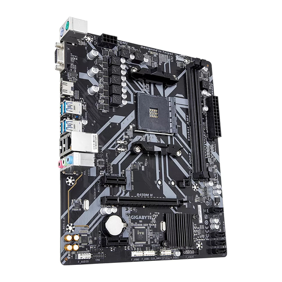
B450M H
User’s Manual
Rev. 1001
For more product details, please visit GIGABYTE’s website.
To reduce the impacts on global warming, the packaging materials of this product
are recyclable and reusable. GIGABYTE works with you to protect the environment.
Related Manuals for Gigabyte B450M H
Summary of Contents for Gigabyte B450M H
-
Page 1
B450M H User’s Manual Rev. 1001 For more product details, please visit GIGABYTE’s website. To reduce the impacts on global warming, the packaging materials of this product are recyclable and reusable. GIGABYTE works with you to protect the environment. -
Page 2
Information in this manual is protected by copyright laws and is the property of GIGABYTE. Changes to the specifications and features in this manual may be made by GIGABYTE without prior notice. No part of this manual may be reproduced, copied, translated, transmitted, or published in any form or by any means without GIGABYTE’s prior written permission. -
Page 3: Table Of Contents
Table of Contents B450M H Motherboard Layout ………………4 Chapter 1 Hardware Installation ………………5 Installation Precautions ………………5 1-2 Product Specifications ………………6 Installing the CPU ……………….. 9 Installing the Memory ………………9 Installing an Expansion Card …………….. 10 Back Panel Connectors ……………… 10 Internal Connectors ………………
-
Page 4: B450M H Motherboard Layout
B450M H Motherboard Layout CPU_FAN KB_MS ATX_12V Socket AM4 R_USB30_1 R_USB30_2 SYS_FAN1 USB_LAN M_BIOS LED_CPU AUDIO PCIEX1_1 M2A_SOCKET B450M H PCIEX16 Realtek ® GbE LAN SATA3 SATA3 CODEC B450 ® Super I/O SPDIF_O PCIEX1_2 SPEAKER CLR_CMOS F_USB2 F_AUDIO F_USB30 F_USB1…
-
Page 5: Chapter 1 Hardware Installation
Chapter 1 Hardware Installation Installation Precautions The motherboard contains numerous delicate electronic circuits and components which can become damaged as a result of electrostatic discharge (ESD). Prior to installation, carefully read the user’s manual and follow these procedures: • Prior to installation, make sure the chassis is suitable for the motherboard. •…
-
Page 6: 1-2 Product Specifications
Š S upport for ECC Un-buffered DIMM 1Rx8/2Rx8 memory modules (operate in Š non-ECC mode) Support for non-ECC Un-buffered DIMM 1Rx8/2Rx8/1Rx16 memory modules Š Support for Extreme Memory Profile (XMP) memory modules Š (Go to GIGABYTE’s website for the latest supported memory speeds and memory modules.) Onboard Integrated Graphics Processor: Š 1 x D-Sub port, supporting a maximum resolution of 1920×1200@60 Hz Graphics 1 x HDMI port, supporting a maximum resolution of 4096×2160@60 Hz (Note 1) * Support for HDMI 2.0 version and HDCP 2.2.
-
Page 7
Internal 1 x 24-pin ATX main power connector Š 1 x 8-pin ATX 12V power connector Connectors Š 1 x CPU fan header Š 1 x system fan header Š 1 x M.2 Socket 3 connector Š 4 x SATA 6Gb/s connectors Š… -
Page 8
Micro ATX Form Factor; 24.4cm x 20.5cm Š * GIGABYTE reserves the right to make any changes to the product specifications and product-related information without prior notice. Please visit the SupportUtility List Please visit GIGABYTE’s website for support lists of CPU, memory page on GIGABYTE’s website to modules, SSDs, and M.2 devices. download the latest version of apps. — 8 -… -
Page 9: Installing The Cpu
Installing the CPU Read the following guidelines before you begin to install the CPU: • Make sure that the motherboard supports the CPU. (Go to GIGABYTE’s website for the latest CPU support list.) • Always turn off the computer and unplug the power cord from the power outlet before installing the CPU to prevent hardware damage.
-
Page 10: Installing An Expansion Card
Installing an Expansion Card Read the following guidelines before you begin to install an expansion card: • Make sure the motherboard supports the expansion card. Carefully read the manual that came with your expansion card. • Always turn off the computer and unplug the power cord from the power outlet before installing an expansion card to prevent hardware damage.
-
Page 11
• When removing the cable, pull it straight out from the connector. Do not rock it side to side to prevent an electrical short inside the cable connector. Please visit GIGABYTE’s website for details on configuring the audio software. — 11 -… -
Page 12: Internal Connectors
Internal Connectors ATX_12V SPEAKER F_USB30 CPU_FAN F_USB1/F_USB2 SYS_FAN1 SATA3 0/1/2/3 M2A_SOCKET CLR_CMOS SPDIF_O LED_CPU F_PANEL F_AUDIO Read the following guidelines before connecting external devices: • First make sure your devices are compliant with the connectors you wish to connect. • Before installing the devices, be sure to turn off the devices and your computer. Unplug the power cord from the power outlet to prevent damage to the devices.
-
Page 13
1/2) ATX_12V/ATX (2×4 12V Power Connector and 2×12 Main Power Connector) With the use of the power connector, the power supply can supply enough stable power to all the components on the motherboard. Before connecting the power connector, first make sure the power supply is turned off and all devices are properly installed. The power connector possesses a foolproof design. Connect the power supply cable to the power connector in the correct orientation. -
Page 14
3/4) CPU_FAN/SYS_FAN1 (Fan Headers) All fan headers on this motherboard are 4-pin. Most fan headers possess a foolproof insertion design. When connecting a fan cable, be sure to connect it in the correct orientation (the black connector wire is the ground wire). The motherboard supports CPU fan speed control, which requires the use of a CPU fan with fan speed control design. -
Page 15
6) M2A_SOCKET (M.2 Socket 3 Connector) The M.2 connector supports M.2 SATA SSDs or M.2 PCIe SSDs and support SATA RAID configuration. Please note that an M.2 PCIe SSD cannot be used to create a RAID array . Refer to Chapter 3, (Note) «Configuring a RAID Set,» for instructions on configuring a RAID array. Follow the steps below to correctly install an M.2 SSD in the M.2 connector. Step 1: Locate the proper mounting hole for the M.2 SSD to be installed and then install the mounting clip first. -
Page 16
 F_PANEL (Front Panel Header) Connect the power switch, reset switch, and system status indicator on the chassis to this header according to the pin assignments below. Note the positive and negative pins before connecting the cables. • PLED (Power LED): Power LED Power Switch Connects to the power status indicator on the…
 -
Page 17
10) SPEAKER (Speaker Header) Connects to the speaker on the chassis front panel. The system reports system startup status by issuing a beep code. One single short beep will be heard if no problem is detected at system startup. Pin No. Definition SPK- 11) F_USB30 (USB 3.1 Gen 1 Header) The header conforms to USB 3.1 Gen 1 and USB 2.0 specification and can provide two USB ports. For… -
Page 18
F_USB3 F 13) TPM (Trusted Platform Module Header) You may connect a TPM (Trusted Platform Module) to this header. Pin No. Definition Pin No. Definition LAD0 LAD3 VCC3 LAD1 LFRAME No Pin LAD2 SERIRQ LCLK LRESET 14) CI (Chassis Intrusion Header) S F_ This motherboard provides a chassis detection feature that detects if the chassis cover has been removed. -
Page 19
16) LED_CPU (CPU Cooler LED Strip/RGB LED Strip Header) The header can be used to connect a CPU cooler LED strip or a standard 5050 RGB LED strip (12V/G/R/B), with maximum power rating of 2A (12V) and maximum length of 2m. Pin No. Definition Connect the CPU cooler LED strip/RGB LED strip to the header. The LED Strip power pin (marked with a triangle on the plug) of the LED strip must be connected to Pin 1 (12V) of this header. -
Page 20: Chapter 2 Bios Setup
To access the BIOS Setup program, press the <Delete> key during the POST when the power is turned on. To upgrade the BIOS, use either the GIGABYTE Q-Flash or @BIOS utility. Q-Flash allows the user to quickly and easily upgrade or back up BIOS without entering the operating system.
-
Page 21: The Main Menu
The Main Menu System Time Setup Menus Hardware Information Configuration Items Current Settings Quick Access Bar allows you to enter Easy Mode, select BIOS default language, configure fan settings, or enter Q-Flash. Classic Setup Function Keys <f><g> Move the selection bar to select a setup menu <h><i> Move the selection bar to select an configuration item on a menu <Enter>/Double Click Execute command or enter a menu <…
-
Page 22
M.I.T. Whether the system will work stably with the overclock/overvoltage settings you made is dependent on your overall system configurations. Incorrectly doing overclock/overvoltage may result in damage to CPU, chipset, or memory and reduce the useful life of these components. This page is for advanced users only and we recommend you not to alter the default settings to prevent system instability or other unexpected results. -
Page 23
` Advanced CPU Settings & CPU Clock Ratio, CPU Frequency The settings above are synchronous to those under the same items on the Advanced Frequency Settings menu. & Core Performance Boost (Note 1) Allows you to determine whether to enable the Core Performance Boost (CPB) technology, a CPU performance-boost technology. -
Page 24
& System Memory Multiplier Allows you to set the system memory multiplier. Auto sets memory multiplier according to memory SPD data. (Default: Auto) & Memory Frequency (MHz) The first memory frequency value is the normal operating frequency of the memory being used; the second is the memory frequency that is automatically adjusted according to the System Memory Multiplier settings. „… -
Page 25
„ Miscellaneous Settings & PCIe Slot Configuration Allows you to set the operation mode of the PCI Express slots to Gen 1, Gen 2, or Gen 3. Actual operation mode is subject to the hardware specification of each slot. Auto lets the BIOS automatically configure this setting. (Default: Auto) & 3DMark01 Enhancement Allows you to determine whether to enhance some legacy benchmark performance. (Default: Disabled) ` Smart Fan 5 &… -
Page 26: System
System This section provides information on your motherboard model and BIOS version. You can also select the default language used by the BIOS and manually set the system time. & System Language Selects the default language used by the BIOS. &…
-
Page 27: Bios
A password is required for booting the system and for entering the BIOS Setup System program. (Default) & Full Screen LOGO Show Allows you to determine whether to display the GIGABYTE Logo at system startup. Disabled skips the GIGABYTE Logo when the system starts up. (Default: Enabled) — 27 -…
-
Page 28
& Fast Boot Enables or disables Fast Boot to shorten the OS boot process. Ultra Fast provides the fastest bootup speed. (Default: Disabled) & SATA Support All Sata Devices All SATA devices are functional in the operating system and during the POST. Last Boot HDD Only Except for the previous boot drive, all SATA devices are disabled before the OS boot process completes. -
Page 29
& Other PCI Device ROM Priority Allows you to select whether to enable the UEFI or Legacy option ROM for the PCI device controller other than the LAN, storage device, and graphics controllers. Disabled Disables option ROM. UEFI Only Enables UEFI option ROM only. (Default) Enables legacy option ROM only. Legacy Only This item is configurable only when CSM Support is set to Enabled. & Administrator Password Allows you to configure an administrator password. Press <Enter> on this item, type the password, and then press <Enter>. You will be requested to confirm the password. Type the password again and press <Enter>. You must enter the administrator password (or user password) at system startup and when entering BIOS Setup. -
Page 30: Peripherals
Peripherals & AMD CPU fTPM Enables or disables the TPM 2.0 function integrated in the AMD CPU. (Default: Disabled) & Initial Display Output Specifies the first initiation of the monitor display from the installed PCI Express graphics card or the onboard graphics. IGD Video Sets the onboard graphics as the first display. (Note) Sets the graphics card on the PCIEX16 slot as the first display. (Default) PCIe 1 Slot & RGB Fusion (LED strip) Allows you to set the display color of the external LED strip. &…
-
Page 31
& XHCI Hand-off Determines whether to enable XHCI Hand-off feature for an operating system without XHCI Hand-off support. (Default: Enabled) & USB Mass Storage Driver Support Enables or disables support for USB storage devices. (Default: Enabled) & Port 60/64 Emulation Enables or disables emulation of I/O ports 64h and 60h. -
Page 32: Chipset
Chipset & IOMMU Enables or disables AMD IOMMU support. (Default: Auto) & Integrated Graphics (Note) Enables or disables the onboard graphics function. The BIOS will automatically enable or disable the onboard graphics depending on the Auto graphics card being installed. (Default) Enables the onboard graphics.
-
Page 33
& SATA Mode Enables or disables RAID for the integrated SATA controllers or configures the SATA controllers to AHCI mode. RAID Enables RAID for the SATA controller. AHCI C onfigures the SATA controllers to AHCI mode. Advanced Host Controller Interface (AHCI) is an interface specification that allows the storage driver to enable advanced Serial ATA features such as Native Command Queuing and hot plug. (Default) & NVMe RAID mode (M2A_SOCKET Connector) Allows you to determine whether to use your M.2 NVMe PCIe SSDs to configure RAID. (Default: Disabled) & APU SATA Port Enable (M2A_SOCKET Connector) Enables or disables the SATA controller integrated in the CPU. (Default: Enabled) &… -
Page 34: Power
Power & AC BACK Determines the state of the system after the return of power from an AC power loss. The system returns to its last known awake state upon the return of the AC power. Memory Always On The system is turned on upon the return of the AC power. Always Off The system stays off upon the return of the AC power.
-
Page 35
& ErP Determines whether to let the system consume least power in S5 (shutdown) state. (Default) Note: When this item is set to Enabled, the following functions will become unavailable: Resume by Alarm, power on by mouse, and power on by keyboard. & Soft-Off by PWR-BTTN Configures the way to turn off the computer in MS-DOS mode using the power button. Press the power button and then the system will be turned off instantly. (Default) Instant-Off Delay 4 Sec. -
Page 36: Save & Exit
Save & Exit & Save & Exit Setup Press <Enter> on this item and select Yes. This saves the changes to the CMOS and exits the BIOS Setup program. Select No or press <Esc> to return to the BIOS Setup Main Menu. &…
-
Page 37: Chapter 3 Appendix
Chapter 3 Appendix 3-1 Configuring a RAID Set RAID Levels RAID 0 RAID 1 RAID 10 Minimum Number of ≥2 Hard Drives Array Capacity Number of hard drives * Size of the smallest drive (Number of hard drives/2) * Size of the smallest drive Size of the smallest drive Fault Tolerance Before you begin, please prepare the following items: •…
-
Page 38
3. Insert the USB thumb drive and then browse to the location of the driver. The location of the drivers is as follows: Hw10RAIDx64 4. Select AMD-RAID Bottom Device first and click Next to load the driver. Then select AMD-RAID Controller and click Next to load the driver. Finally, continue the OS installation. Please visit GIGABYTE’s website for details on configuring a RAID array. — 38 -… -
Page 39: Drivers Installation
Run.exe program.) «Xpress Install» will automatically scan your system and then list all of the drivers that are recommended to install. You can click the Xpress Install button and «Xpress Install» will install all of the selected drivers. Or click the arrow icon to individually install the drivers you need. Please visit GIGABYTE’s website for Please visit GIGABYTE’s website for more troubleshooting information. more software information. — 39 -…
-
Page 40: Regulatory Statements
Contravention will be prosecuted. We believe that the information contained herein was accurate in all respects at the time of printing. GIGABYTE cannot, however, assume any responsibility for errors or omissions in this text. Also note that the information in this document is subject to change without notice and should not be construed as a commitment by GIGABYTE.
-
Page 41
FCC Notice (U.S.A. Only) This equipment has been tested and found to comply with the limits for a Class B digital device, pursuant to Part 15 of the FCC Rules. These limits are designed to provide reasonable protection against harmful interference in a residential installation. This equipment generates, uses, and can radiate radio frequency energy and, if not installed and used in accordance with the instructions, may cause harmful interference to radio communications. -
Page 42: Contact Us
Contact Us GIGA-BYTE TECHNOLOGY CO., LTD. Address: No.6, Baoqiang Rd., Xindian Dist., New Taipei City 231, Taiwan TEL: +886-2-8912-4000, FAX: +886-2-8912-4005 Tech. and Non-Tech. Support (Sales/Marketing) : https://esupport.gigabyte.com WEB address (English): https://www.gigabyte.com WEB address (Chinese): https://www.gigabyte.com/tw GIGABYTE eSupport • To submit a technical or non-technical (Sales/Marketing) question, please link to: https://esupport.gigabyte.com…
 F_PANEL (Front Panel Header) Connect the power switch, reset switch, and system status indicator on the chassis to this header according to the pin assignments below. Note the positive and negative pins before connecting the cables. • PLED (Power LED): Power LED Power Switch Connects to the power status indicator on the…
  Loading…
![]()
B450M H
User’s Manual
Rev. 1001
For more product details, please visit GIGABYTE’s website.
To reduce the impacts on global warming, the packaging materials of this product are recyclable and reusable. GIGABYTE works with you to protect the environment.

Motherboard
B450M H
Motherboard
B450M H
Dec. 13, 2019
Dec. 13, 2019
Copyright
© 2019 GIGA-BYTE TECHNOLOGY CO., LTD. All rights reserved.
The trademarks mentioned in this manual are legally registered to their respective owners.
Disclaimer
Information in this manual is protected by copyright laws and is the property of GIGABYTE.
ChangestothespecificationsandfeaturesinthismanualmaybemadebyGIGABYTEwithoutpriornotice.
No part of this manual may be reproduced, copied, translated, transmitted, or published in any form or by any means without GIGABYTE’s prior written permission.
In order to assist in the use of this product, carefully read the User’s Manual.
For product-related information, check on our website at: https://www.gigabyte.com
Identifying Your Motherboard Revision
The revision number on your motherboard looks like this: «REV: X.X.» For example, «REV: 1.0» means the revision of the motherboard is 1.0. Check your motherboard revision before updating motherboard BIOS, drivers, or when looking for technical information.
Example:

Table of Contents
|
B450M H Motherboard Layout…………………………………………………………………………….. |
4 |
|
|
Chapter 1 Hardware Installation………………………………………………………………………….. |
5 |
|
|
1-1 |
Installation Precautions…………………………………………………………………………. |
5 |
|
1-2 |
Product Specifications………………………………………………………………………….. |
6 |
|
1-3 |
Installing the CPU………………………………………………………………………………… |
9 |
|
1-4 |
Installing the Memory……………………………………………………………………………. |
9 |
|
1-5 Installing an Expansion Card……………………………………………………………….. |
10 |
|
|
1-6 |
Back Panel Connectors………………………………………………………………………. |
10 |
|
1-7 |
Internal Connectors……………………………………………………………………………. |
12 |
|
Chapter 2 BIOS Setup……………………………………………………………………………………… |
20 |
|
|
2-1 |
Startup Screen…………………………………………………………………………………… |
20 |
|
2-2 |
The Main Menu………………………………………………………………………………….. |
21 |
|
2-3 |
M.I.T…………………………………………………………………………………………………. |
22 |
|
2-4 |
System……………………………………………………………………………………………… |
26 |
|
2-5 |
BIOS………………………………………………………………………………………………… |
27 |
|
2-6 |
Peripherals………………………………………………………………………………………… |
30 |
|
2-7 |
Chipset……………………………………………………………………………………………… |
32 |
|
2-8 |
Power……………………………………………………………………………………………….. |
34 |
|
2-9 |
Save & Exit……………………………………………………………………………………….. |
36 |
|
Chapter 3 Appendix…………………………………………………………………………………………. |
37 |
|
|
3-1 Configuring a RAID Set………………………………………………………………………. |
37 |
|
|
3-2 |
Drivers Installation……………………………………………………………………………… |
39 |
|
Regulatory Statements…………………………………………………………………………………. |
40 |
|
|
Contact Us………………………………………………………………………………………………….. |
42 |
— 3 —
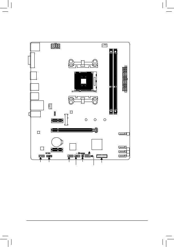
B450M H Motherboard Layout
|
KB_MS |
CPU_FAN |
|||
|
ATX_12V |
||||
|
VGA |
Socket AM4 |
|||
|
HDMI |
||||
|
R_USB30_1 |
||||
|
R_USB30_2 |
||||
|
SYS_FAN1 |
||||
|
USB_LAN |
||||
|
AUDIO |
LED_CPU |
M_BIOS |
||
|
PCIEX1_1 |
M2A_SOCKET 42 |
60 |
||
ATX
|
Realtek® |
PCIEX16 |
B450M H |
|||
|
GbE LAN |
SATA3 |
||||
|
3 |
|||||
|
CODEC |
BAT |
AMD |
SATA3 |
||
|
iTE® |
B450 |
||||
|
Super I/O |
CI |
2 |
|||
|
SPDIF_O |
PCIEX1_2 |
SPEAKER |
1 |
||
|
0 |
|||||
|
F_AUDIO TPM |
F_USB2 |
CLR_CMOS |
F_USB30 |
||
|
F_USB1 |
F_PANEL |
||||
|
Box Contents |
|||||
|
55 B450M H motherboard |
55 Two SATA cables |
||||
|
55 Motherboard driver disc |
55 I/O Shield |
||||
|
55 User’s Manual |
*The box contents above are for reference only and the actual items shall depend on the product package you obtain. The box contents are subject to change without notice.
—4 —

Chapter 1 Hardware Installation
1-1 Installation Precautions
The motherboard contains numerous delicate electronic circuits and components which can become damaged as a result of electrostatic discharge (ESD). Prior to installation, carefully read the user’s manual and follow these procedures:
•• Prior to installation, make sure the chassis is suitable for the motherboard.
•• Prior to installation, do not remove or break motherboard S/N (Serial Number) sticker or warranty sticker provided by your dealer. These stickers are required for warranty validation.
•• Always remove the AC power by unplugging the power cord from the power outlet before installing or removing the motherboard or other hardware components.
•• When connecting hardware components to the internal connectors on the motherboard, make sure they are connected tightly and securely.
•• When handling the motherboard, avoid touching any metal leads or connectors.
•• It is best to wear an electrostatic discharge (ESD) wrist strap when handling electronic components such as a motherboard, CPU or memory. If you do not have an ESD wrist strap, keep your hands dry and first touch a metal object to eliminate static electricity.
•• Prior to installing the motherboard, please have it on top of an antistatic pad or within an electrostatic shielding container.
•• Before connecting or unplugging the power supply cable from the motherboard, make sure the power supply has been turned off.
•• Before turning on the power, make sure the power supply voltage has been set according to the local voltage standard.
•• Before using the product, please verify that all cables and power connectors of your hardware components are connected.
•• To prevent damage to the motherboard, do not allow screws to come in contact with the motherboard circuit or its components.
•• Make sure there are no leftover screws or metal components placed on the motherboard or within the computer casing.
•• Do not place the computer system on an uneven surface.
•• Do not place the computer system in a high-temperature or wet environment.
•• Turning on the computer power during the installation process can lead to damage to system components as well as physical harm to the user.
•• If you are uncertain about any installation steps or have a problem related to the use of the product, please consult a certified computer technician.
•• If you use an adapter, extension power cable, or power strip, ensure to consult with its installation and/or grounding instructions.
— 5 —
1-2 Product Specifications
|
CPU |
AM4 Socket: |
|
— AMD Ryzen™ 2nd Generation processors |
—AMD Ryzen™ with Radeon™ Vega Graphics processors
—AMD Ryzen™ 1st Generation processors
(Go to GIGABYTE’s website for the latest CPU support list.)
|
Chipset |
AMD B450 |
|
|
Memory |
2 x DDR4 DIMM sockets supporting up to 32 GB of system memory |
|
|
Dual channel memory architecture |
||
|
Support for DDR4 2933/2667/2400/2133 MHz memory modules |
||
|
Support for ECC Un-buffered DIMM 1Rx8/2Rx8 memory modules (operate in |
||
|
non-ECC mode) |
||
|
Support for non-ECC Un-buffered DIMM 1Rx8/2Rx8/1Rx16 memory modules |
||
|
Support for Extreme Memory Profile (XMP) memory modules |
||
|
(Go to GIGABYTE’s website for the latest supported memory speeds and memory |
||
|
modules.) |
||
|
Onboard |
Integrated Graphics Processor: |
|
|
Graphics |
— 1 x D-Sub port, supporting a maximum resolution of 1920×1200@60 Hz |
—1 x HDMI port, supporting a maximum resolution of 4096×2160@60 Hz (Note 1)
*Support for HDMI 2.0 version and HDCP 2.2. (Note 1)
Maximum shared memory of 16 GB
|
Audio |
Realtek® ALC887 codec |
||
|
High Definition Audio |
|||
|
2/4/5.1/7.1-channel |
|||
|
* To configure 7.1-channel audio, you have to use an HD front panel audio module |
|||
|
and enable the multi-channel audio feature through the audio driver. |
|||
|
Support for S/PDIF Out |
|||
|
LAN |
Realtek® GbE LAN chip (10/100/1000 Mbit) |
||
|
Expansion Slots |
1 x PCI Express x16 slot, running at x16 |
||
|
(The PCIEX16 slot conforms to PCI Express 3.0 standard.) |
|||
|
2 x PCI Express x1 slots |
|||
|
(The PCI Express x1 slot conforms to PCI Express 2.0 standard.) |
|||
|
Storage Interface |
1 x M.2 connector (Socket 3, M key, type 2242/2260/2280 SATA and PCIe x4/ |
||
|
x2 (Note 2) SSD support) |
|||
|
4 x SATA 6Gb/s connectors |
|||
|
Support for RAID 0, RAID 1, and RAID 10 |
|||
|
USB |
Chipset: |
||
|
— |
2 x USB 3.1 Gen 1 ports available through the internal USB header |
||
|
— |
6 x USB 2.0/1.1 ports (2 ports on the back panel, 4 ports available through |
||
|
the internal USB headers) |
|||
|
CPU: |
|||
|
— |
4 x USB 3.1 Gen 1 ports on the back panel |
(Note 1) Actual support may vary by CPU.
(Note 2) Supports only M.2 SATA SSDs when using an AMD 7th Generation A-series or Athlon™ processor.
— 6 —
1 x 24-pin ATX main power connector1 x 8-pin ATX 12V power connector1 x CPU fan header
1 x system fan header
1 x M.2 Socket 3 connector4 x SATA 6Gb/s connectors1 x front panel header
1 x front panel audio header1 x S/PDIF Out header
1 x CPU cooler LED strip/RGB LED strip header
1 x USB 3.1 Gen 1 header2 x USB 2.0/1.1 headers
1 x Trusted Platform Module (TPM) header (2×6 pin, for the GC-TPM2.0_S module only)
1 x speaker header
1 x Clear CMOS jumper
1 x chassis intrusion header
|
Back Panel |
1 x PS/2 keyboard port |
|
Connectors |
1 x PS/2 mouse port |
|
1 x D-Sub port |
|
|
1 x HDMI port |
|
|
4 x USB 3.1 Gen 1 ports |
|
|
2 x USB 2.0/1.1 ports |
|
|
1 x RJ-45 port |
|
|
3 x audio jacks |
|
|
I/O Controller |
iTE® I/O Controller Chip |
Voltage detection
Temperature detectionFan speed detectionOverheating warningFan fail warning
Fan speed control
*Whether the fan speed control function is supported will depend on the cooler you install.
|
BIOS |
1 x 128 Mbit flash |
|
|
Use of licensed AMI UEFI BIOS |
||
|
PnP 1.0a, DMI 2.7, WfM 2.0, SM BIOS 2.7, ACPI 5.0 |
— 7 —
|
Unique Features |
Support for APP Center |
|||
|
* Available applications in APP Center may vary by motherboard model. Supported |
||||
|
functionsofeachapplicationmayalsovarydependingonmotherboardspecifications. |
||||
|
— |
@BIOS |
|||
|
— |
AutoGreen |
|||
|
— |
Cloud Station |
|||
|
— |
EasyTune |
|||
|
— |
Fast Boot |
|||
|
— |
Game Boost |
|||
|
— |
ON/OFF Charge |
|||
|
— |
RGB Fusion |
|||
|
— |
Smart Backup |
|||
|
— |
Smart Keyboard |
|||
|
— |
Smart Survey |
|||
|
— |
System Information Viewer |
|||
|
— |
USB Blocker |
|||
|
Support for Q-Flash |
||||
|
Support for Xpress Install |
||||
|
Bundled |
Norton® Internet Security (OEM version) |
|||
|
Software |
Realtek® 8118 Gaming LAN Bandwidth Control Utility |
|||
|
Operating |
Support for Windows 10 64-bit |
|||
|
System |
||||
|
Form Factor |
Micro ATX Form Factor; 24.4cm x 20.5cm |
*GIGABYTE reserves the right to make any changes to the product specifications and product-related information without prior notice.
Please visit GIGABYTE’s website for support lists of CPU, memory modules, SSDs, and M.2 devices.
— 8 —
Please visit the SupportUtility List page on GIGABYTE’s website to download the latest version of apps.
1-3 Installing the CPU
Read the following guidelines before you begin to install the CPU:
•• Make sure that the motherboard supports the CPU. (Go to GIGABYTE’s website for the latest CPU support list.)
•• Always turn off the computer and unplug the power cord from the power outlet before installing the CPU to prevent hardware damage.
•• Locate the pin one of the CPU. The CPU cannot be inserted if oriented incorrectly.
•• Apply an even and thin layer of thermal grease on the surface of the CPU.
•• Do not turn on the computer if the CPU cooler is not installed, otherwise overheating and damage of the CPU may occur.
•• Set the CPU host frequency in accordance with the CPU specifications. It is not recommended that the system bus frequency be set beyond hardware specifications since it does not meet the standard requirements for the peripherals. If you wish to set the frequency beyond the standard specifications, please do so according to your hardware specifications including the CPU, graphics card, memory, hard drive, etc.
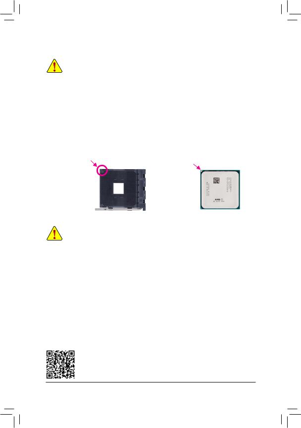
Installing the CPU
Locate the pin one (denoted by a small triangle) of the CPU socket and the CPU.
|
A Small Triangle |
A Small Triangle |
|||
|
Marking Denotes Pin |
AM4 Socket |
AM4 CPU |
||
|
Marking Denotes CPU |
||||
|
One of the Socket |
||||
|
Pin One |
1-4 Installing the Memory
Read the following guidelines before you begin to install the memory:
•• Make sure that the motherboard supports the memory. It is recommended that memory of the same capacity, brand, speed, and chips be used.
(Go to GIGABYTE’s website for the latest supported memory speeds and memory modules.)
•• Always turn off the computer and unplug the power cord from the power outlet before installing the memory to prevent hardware damage.
•• Memory modules have a foolproof design. A memory module can be installed in only one direction. If you are unable to insert the memory, switch the direction.
Dual Channel Memory Configuration
This motherboard provides two memory sockets and supports Dual Channel Technology. After the memory is installed, the BIOS will automatically detect the specifications and capacity of the memory. Enabling Dual
Channel memory mode will double the original memory bandwidth.
The two DDR4 memory sockets are divided into two channels and each channel has one memory socket as following:
Channel A: DDR4_2Channel B: DDR4_1
Due to CPU limitations, read the following guidelines before installing the memory in Dual Channel mode.
1.Dual Channel mode cannot be enabled if only one memory module is installed.
2.When enabling Dual Channel mode with two memory modules, it is recommended that memory of the same capacity, brand, speed, and chips be used.
Please visit GIGABYTE’s website for details on hardware installation.
— 9 —
1-5 Installing an Expansion Card
Read the following guidelines before you begin to install an expansion card:
•• Make sure the motherboard supports the expansion card. Carefully read the manual that came with your expansion card.
•• Always turn off the computer and unplug the power cord from the power outlet before installing an expansion card to prevent hardware damage.
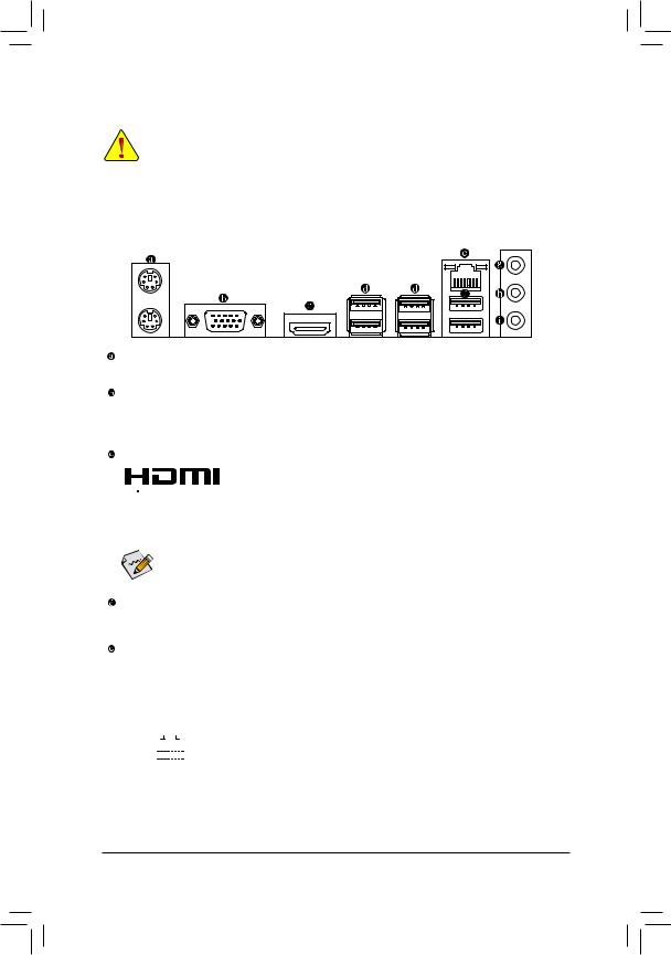
1-6 Back Panel Connectors
PS/2 Keyboard and PS/2 Mouse Port
Use the upper port (green) to connect a PS/2 mouse and the lower port (purple) to connect a PS/2 keyboard.
D-Sub Port
The D-Sub port supports a 15-pin D-Sub connector and supports a maximum resolution of 1920×1200@60 Hz
(the actual resolutions supported depend on the monitor being used). Connect a monitor that supports D-Sub connection to this port.
HDMI Port
 The HDMI port supports HDCP 2.2 (Note) and Dolby TrueHD and DTS HD


 Master Audio formats. It also supports up to 192 KHz/16bit 8-channel LPCM audio output. You can use this port to connect your HDMI-supported monitor. The maximum supported resolution is 4096×2160@60 Hz (Note), but the actual resolutions supported are dependent on the monitor being used.

 After installing the HDMI device, make sure to set the default sound playback device to HDMI. (The
  item name may differ depending on your operating system.)
USB 3.1 Gen 1 Port
The USB 3.1 Gen 1 port supports the USB 3.1 Gen 1 specification and is compatible to the USB 2.0
specification. Use this port for USB devices.
RJ-45 LAN Port
The Gigabit Ethernet LAN port provides Internet connection at up to 1 Gbps data rate. The following describes the states of the LAN port LEDs.
|
Connection/ |
Connection/Speed LED: |
Activity LED: |
|||||||||||||||||
|
Speed LED |
Activity LED |
||||||||||||||||||
|
State |
Description |
State |
Description |
||||||||||||||||
|
Orange |
1 Gbps data rate |
Blinking |
Data transmission or receiving is occurring |
||||||||||||||||
|
Green |
100 Mbps data rate |
Off |
No data transmission or receiving is occurring |
||||||||||||||||
|
LAN Port |
|||||||||||||||||||
|
Off |
10 Mbps data rate |
||||||||||||||||||
(Note) Actual support may vary by CPU.
— 10 —
![]()
USB 2.0/1.1 Port
The USB port supports the USB 2.0/1.1 specification. Use this port for USB devices.
Line In/Rear Speaker Out (Blue)
The line in jack. Use this audio jack for line in devices such as an optical drive, walkman, etc.
Line Out/Front Speaker Out (Green)
The line out jack.
Mic In/Center/Subwoofer Speaker Out (Pink)
The Mic in jack.
Audio Jack Configurations:
|
Jack |
Headphone/ |
4-channel |
5.1-channel |
7.1-channel |
|
|
2-channel |
|||||
|
Line In/Rear Speaker Out |
a |
a |
a |
||
|
Line Out/Front Speaker Out |
a |
a |
a |
a |
|
|
Mic In/Center/Subwoofer Speaker Out |
a |
a |
|||
|
Front Panel Line Out/Side Speaker Out |
a |
To configure 7.1-channel audio, you have to use an HD front panel audio module and enable the multi-channel audio feature through the audio driver.
•• When removing the cable connected to a back panel connector, first remove the cable from your device and then remove it from the motherboard.
•• When removing the cable, pull it straight out from the connector. Do not rock it side to side to prevent an electrical short inside the cable connector.
Please visit GIGABYTE’s website for details on configuring the audio software.
— 11 —
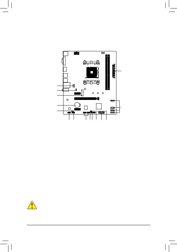
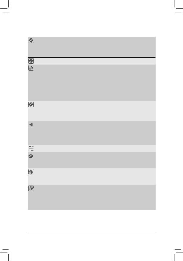
1-7 Internal Connectors
|
1 |
3 |
|||||||||||
|
2 |
|||||
|
4 |
|||||
|
16 |
|||||
|
6 |
|||||
|
17 |
5 |
||||
|
7 |
|||||
|
9 |
13 |
12 14 15 |
8 |
11 |
10 |
|
1) |
ATX_12V |
10) |
SPEAKER |
|
2) |
ATX |
11) |
F_USB30 |
|
3) |
CPU_FAN |
12) |
F_USB1/F_USB2 |
|
4) |
SYS_FAN1 |
13) |
TPM |
|
5) |
SATA3 0/1/2/3 |
14) |
CI |
|
6) |
M2A_SOCKET |
15) |
CLR_CMOS |
|
7) |
SPDIF_O |
16) |
LED_CPU |
|
|
F_PANEL |
17) |
BAT |
|
9) |
F_AUDIO |
Read the following guidelines before connecting external devices:
•• First make sure your devices are compliant with the connectors you wish to connect.
•• Before installing the devices, be sure to turn off the devices and your computer. Unplug the power cord from the power outlet to prevent damage to the devices.
•• After installing the device and before turning on the computer, make sure the device cable has been securely attached to the connector on the motherboard.
— 12 —

1/2) ATX_12V/ATX (2×4 12V Power Connector and 2×12 Main Power Connector)
With the use of the power connector, the power supply can supply enough stable power to all the components on the motherboard. Before connecting the power connector, first make sure the power supply is turned off and all devices are properly installed. The power connector possesses a foolproof design. Connect the power supply cable to the power connector in the correct orientation.
The 12V power connector mainly supplies power to the CPU. If the 12V power connector is not connected, the computer will not start.
To meet expansion requirements, it is recommended that a power supply that can withstand high  power consumption be used (500W or greater). If a power supply is used that does not provide the
required power, the result can lead to an unstable or unbootable system.
|
ATX_12V: |
|||
|
Pin No. |
Definition |
Pin No. |
Definition |
|
1 |
GND (Only for 2×4-pin |
5 |
+12V (Only for 2×4-pin 12V) |
|
12V) |
|||
|
2 |
GND (Only for 2×4-pin |
6 |
+12V (Only for 2×4-pin 12V) |
|
12V) |
|||
|
3 |
GND |
7 |
+12V |
|
4 |
GND |
8 |
+12V |
|
ATX: |
|||
|
Pin No. |
Definition |
Pin No. |
Definition |
|
1 |
3.3V |
13 |
3.3V |
|
2 |
3.3V |
14 |
-12V |
|
3 |
GND |
15 |
GND |
|
4 |
+5V |
16 |
PS_ON (soft On/Off) |
|
5 |
GND |
17 |
GND |
|
6 |
+5V |
18 |
GND |
|
7 |
GND |
19 |
GND |
|
8 |
Power Good |
20 |
NC |
|
9 |
5VSB (stand by +5V) |
21 |
+5V |
|
10 |
+12V |
22 |
+5V |
|
11 |
+12V (Only for 2×12-pin |
23 |
+5V (Only for 2×12-pin ATX) |
|
ATX) |
|||
|
12 |
3.3V (Only for 2×12-pin |
24 |
GND (Only for 2×12-pin |
|
ATX) |
ATX) |
— 13 —
инструкцияGigabyte B450M DS3H

To reduce the impacts on global warming, the packaging materials of this product
are recyclable and reusable. GIGABYTE works with you to protect the environment.
For more product details, please visit GIGABYTE’s website.
B450M DS3H
User’s Manual
Rev. 1001
Посмотреть инструкция для Gigabyte B450M DS3H бесплатно. Руководство относится к категории Материнские платы, 20 человек(а) дали ему среднюю оценку 8.9. Руководство доступно на следующих языках: английский. У вас есть вопрос о Gigabyte B450M DS3H или вам нужна помощь? Задайте свой вопрос здесь
- B450M DS3H Motherboard Layout
- Chapter 1 Hardware Installation
- Chapter 2 BIOS Setup
- Chapter 3 Appendix

Главная
| Gigabyte | |
| B450M DS3H | B450M DS3H | |
| Материнская плата | |
| 4719331803827 | |
| английский | |
| Руководство пользователя (PDF), Инструкция по установке (PDF) |
Память
| Поддерживаемые типы памяти | DDR4-SDRAM |
| Тип слотов памяти | DIMM |
| Количество слотов памяти | 4 |
| Каналы памяти | Dual-channel |
| Поддерживаемые частоты памяти | 2133,2400,2667,2933,3200 MHz |
| Максимальная внутренняя память | 64 GB |
| Небуферизованная память | Да |
| Поддерживаемые объемы модулей памяти | 4GB, 8GB, 16GB |
Прочие свойства
| Буферизованная (Registered) | Нет |
| Размер жесткого диска | 2.5/3.5 « |
Процессор
| Производитель процессора | AMD |
| Совместимые серии процессоров | AMD Athlon, AMD Ryzen 3, AMD Ryzen 3 2nd Gen, AMD Ryzen 3 3rd Gen, AMD Ryzen 5, AMD Ryzen 5 2nd Gen, AMD Ryzen 5 3rd Gen, AMD Ryzen 7, AMD Ryzen 7 2nd Gen, AMD Ryzen 7 3rd Gen, AMD Ryzen 9 3rd Gen |
| Сокет процессора | Разъем AM4 |
Слоты расширения
| PCI Express x16 слоты | 2 |
| PCI Express x1 слоты | 1 |
Контроллеры хранения данных
| Поддерживаемые типы накопителей | HDD & SSD |
BIOS
| Тип BIOS | UEFI AMI |
| Размер памяти BIOS | 256 Mbit |
| Версия ACPI | 5.0 |
| Версия BIOS (SMBIOS) | 2.7 |
| Desktop Management Interface (DMI) версия | 2.7 |
Внутренние порты
| Разъемы USB 2.0 | 2 |
| Разъемы USB 3.2 Gen 1 (3.1 Gen 1) | 0 |
| Разъемы USB 3.2 Gen 2 (3.1 Gen 2) | 1 |
| Количество разъемов SATA III | 4 |
| Количество разъемов SATA II | 0 |
| Количество параллельных разъемов ATA (PATA) | — |
| Разъем вентилятора центрального процессора | Да |
| Разъем для вентилятора | Да |
| Разъем питания ATX (24-конт.) | Да |
| Аудиоразъем передней панели | Да |
| Разъем передней панели | Да |
| TPM коннектор | Да |
| EPS разъем питания (8-конт) | Да |
| Коннекторы последовательного порта | 1 |
| RGB LED контактный разъем | Да |
Порты на задней панели
| Количество портов USB 2.0 | 4 |
| Количество портов USB 3.2 Gen 2 (3.1 Gen 2) Type-A | 0 |
| Количество портов USB 3.2 Gen 1 (3.1 Gen 1) Type-A | 4 |
| Количество портов USB 3.2 Gen 1 (3.1 Gen 1) Type-С | 0 |
| Количество портов USB 3.2 Gen 2 (3.1 Gen 2) Type-С | 0 |
| Количество портов Ethernet LAN ( RJ-45) | 1 |
| Количество портов eSATA | 0 |
| Количество портов PS/2 | 1 |
| Порты FireWire | 0 |
| Количество портов VGA (D-Sub) | 0 |
| Количество HDMI портов | 1 |
| Количество портов DVI-D | 1 |
Сеть
| Подключение Ethernet | Да |
| Тип Ethernet интерфейса | Гигабитный Ethernet |
Свойства
| Комплектующие для | ПК |
| Семейство чипсета материнской платы | AMD |
| Чипсет материнской платы | AMD B450 |
| Формат материнской платы | Микро ATX |
| Выходные звуковые каналы | 7.1 канала |
| Поддерживаемые операционные системы Windows | Windows 10, Windows 7 |
Вес и размеры
| Ширина | 244 mm |
| Глубина | 215 mm |
Содержимое упаковки
| Поставляемое ПО | Norton Internet Security (OEM version)ncFosSpeed |
Логистические данные
| Код гармонизированной системы описания (HS) | 84733020 |
показать больше
Не можете найти ответ на свой вопрос в руководстве? Вы можете найти ответ на свой вопрос ниже, в разделе часто задаваемых вопросов о Gigabyte B450M DS3H.
Какая ширина Gigabyte B450M DS3H?
Какая толщина Gigabyte B450M DS3H?
Инструкция Gigabyte B450M DS3H доступно в русский?
Не нашли свой вопрос? Задайте свой вопрос здесь