- Manuals
- Brands
- Gigabyte Manuals
- Motherboard
- GA-H110M-S2
- User manual
-
Contents
-
Table of Contents
-
Bookmarks
Quick Links
GA-H110M-S2
GA-H110M-S2 DDR3
User’s Manual
Rev. 1003
GA-H110M-S2
GA-H110M-S2 DDR3
To reduce the impacts on global warming, the packaging materials of this product
are recyclable and reusable. GIGABYTE works with you to protect the environment.
For more product details, please visit GIGABYTE’s website.
Related Manuals for Gigabyte GA-H110M-S2
Summary of Contents for Gigabyte GA-H110M-S2
-
Page 1
User’s Manual Rev. 1003 GA-H110M-S2 GA-H110M-S2 DDR3 For more product details, please visit GIGABYTE’s website. To reduce the impacts on global warming, the packaging materials of this product are recyclable and reusable. GIGABYTE works with you to protect the environment. -
Page 2
Motherboard GA-H110M-S2 Motherboard GA-H110M-S2 Nov. 5, 2015 Nov. 5, 2015 Motherboard GA-H110M-S2 DDR3 Motherboard GA-H110M-S2 DDR3 Sept. 15, 2015 Sept. 15, 2015… -
Page 3
Information in this manual is protected by copyright laws and is the property of GIGABYTE. Changes to the specifications and features in this manual may be made by GIGABYTE without prior notice. No part of this manual may be reproduced, copied, translated, transmitted, or published in any form or by any means without GIGABYTE’s prior written permission. -
Page 4: Table Of Contents
Table of Contents GA-H110M-S2/GA-H110M-S2 DDR3 Motherboard Layout ……….5 Chapter 1 Hardware Installation ………………6 Installation Precautions ………………6 1-2 Product Specifications ………………7 Installing the CPU ………………10 Installing the Memory ………………10 Installing an Expansion Card …………….. 11 Back Panel Connectors ……………… 11 Internal Connectors ………………
-
Page 5: Ga-H110M-S2/Ga-H110M-S2 Ddr3 Motherboard Layout
CLR_CMOS F_AUDIO F_USB2 F_USB1 Box Contents 5 GA-H110M-S2 or GA-H110M-S2 DDR3 motherboard 5 Motherboard driver disk 5 Two SATA cables 5 User’s Manual 5 I/O Shield * The box contents above are for reference only and the actual items shall depend on the product package you obtain.
-
Page 6: Chapter 1 Hardware Installation
Chapter 1 Hardware Installation Installation Precautions The motherboard contains numerous delicate electronic circuits and components which can become damaged as a result of electrostatic discharge (ESD). Prior to installation, carefully read the user’s manual and follow these procedures: • Prior to installation, make sure the chassis is suitable for the motherboard. •…
-
Page 7: 1-2 Product Specifications
Support for ECC UDIMM 1Rx8/2Rx8 memory modules (operate in non-ECC mode) Š Support for non-ECC UDIMM 1Rx8/2Rx8/1Rx16 memory modules Š (Go to GIGABYTE’s website for the latest supported memory speeds and memory modules.) Memoryk 2 x DDR3 DIMM sockets supporting up to 32 GB of system memory Š…
-
Page 8
Chipset: Š 4 x USB 3.0/2.0 ports (2 ports on the back panel, 2 ports available through the internal USB header) 6 x USB 2.0/1.1 ports (2 ports on the back panel, 4 ports available through the internal USB headers) Internal 1 x 24-pin ATX main power connector Š… -
Page 9
* G IGABYTE reserves the right to make any changes to the product specifications and product-related information without prior notice. GA-H110M-S2 GA-H110M-S2 DDR3 Please visit GIGABYTE’s website for support lists of CPU, memory modules, and SSDs. Please visit the SupportUtility List page on GIGABYTE’s website to download the latest version of apps. — 9 -… -
Page 10: Installing The Cpu
• Make sure that the motherboard supports the memory. It is recommended that memory of the same capacity, brand, speed, and chips be used. (Go to GIGABYTE’s website for the latest supported memory speeds and memory modules.) • Always turn off the computer and unplug the power cord from the power outlet before installing the memory to prevent hardware damage.
-
Page 11: Installing An Expansion Card
1 Gbps data rate Blinking Data transmission or receiving is occurring Green 100 Mbps data rate No data transmission or receiving is occurring 10 Mbps data rate LAN Port j Only for GA-H110M-S2. k Only for GA-H110M-S2 DDR3. — 11 -…
-
Page 12
Mic In (Pink) The Mic in jack. To configure 7.1-channel audio, you have to use an HD front panel audio module and enable the multi-channel audio feature through the audio driver. Please visit GIGABYTE’s website for more software information. • When removing the cable connected to a back panel connector, first remove the cable from your device and then remove it from the motherboard. • When removing the cable, pull it straight out from the connector. Do not rock it side to side to prevent an electrical short inside the cable connector. -
Page 13: Internal Connectors
Internal Connectors ATX_12V SPDIF_O CLR_CMOS CPU_FAN F_USB30 SYS_FAN F_USB1/F_USB2 SATA3 0/1/2/3 F_PANEL F_AUDIO Read the following guidelines before connecting external devices: • First make sure your devices are compliant with the connectors you wish to connect. • Before installing the devices, be sure to turn off the devices and your computer. Unplug the power cord from the power outlet to prevent damage to the devices.
-
Page 14
1/2) ATX_12V/ATX (2×2 12V Power Connector and 2×12 Main Power Connector) With the use of the power connector, the power supply can supply enough stable power to all the components on the motherboard. Before connecting the power connector, first make sure the power supply is turned off and all devices are properly installed. The power connector possesses a foolproof design. Connect the power supply cable to the power connector in the correct orientation. -
Page 15
5) SATA3 0/1/2/3 (SATA 6Gb/s Connectors) The SATA connectors conform to SATA 6Gb/s standard and are compatible with SATA 3Gb/s and SATA 1.5Gb/s standard. Each SATA connector supports a single SATA device. Pin No. Definition SATA3 To enable hot-plugging for the SATA ports, refer to Chapter 2, «BIOS Setup,» «PeripheralsSATA Configuration,» for more information. -
Page 16
7) F_AUDIO (Front Panel Audio Header) The front panel audio header supports Intel High Definition audio (HD) and AC’97 audio. You may connect your chassis front panel audio module to this header. Make sure the wire assignments of the module connector match the pin assignments of the motherboard header. Incorrect connection between the module connector and the motherboard header will make the device unable to work or even damage it. For HD Front Panel Audio: For AC’97 Front Panel Audio: Pin No. -
Page 17
F_USB30 F_ U 10) F_USB30 (USB 3.0/2.0 Header) The header conforms to USB 3.0/2.0 specification and each header can provide two USB ports. For purchasing the optional 3.5″ front panel that provides two USB 3.0/2.0 ports, please contact the local dealer. Pin No. -
Page 18: Chapter 2 Bios Setup
To access the BIOS Setup program, press the <Delete> key during the POST when the power is turned on. To upgrade the BIOS, use either the GIGABYTE Q-Flash or @BIOS utility. Q-Flash allows the user to quickly and easily upgrade or back up BIOS without entering the operating system.
-
Page 19: Startup Screen
Startup Screen The following startup Logo screen will appear when the computer boots. (Sample BIOS Version: F1a) Function Keys On the main menu of the BIOS Setup program, press arrow keys to move among the items and press <Enter> to accept or enter a sub-menu. Or you can use your mouse to select the item you want. •…
-
Page 20
` M.I.T. Current Status This screen provides information on CPU/memory frequencies/parameters. ` Advanced Frequency Settings & Graphics Slice Ratio Allows you to set the Graphics Slice Ratio. & Graphics UnSlice Ratio Allows you to set the Graphics UnSlice Ratio. & CPU Clock Ratio Allows you to alter the clock ratio for the installed CPU. -
Page 21
& Hyper-Threading Technology (Note) Allows you to determine whether to enable multi-threading technology when using an Intel CPU that ® supports this function. This feature only works for operating systems that support multi-processor mode. Auto lets the BIOS automatically configure this setting. (Default: Auto) & CPU Enhanced Halt (C1E) (Note) Enables or disables Intel CPU Enhanced Halt (C1E) function, a CPU power-saving function in system… -
Page 22
& System Memory Multiplier Allows you to set the system memory multiplier. Auto sets memory multiplier according to memory SPD data. (Default: Auto) & Memory Frequency (MHz) The first memory frequency value is the normal operating frequency of the memory being used; the second is the memory frequency that is automatically adjusted according to the System Memory Multiplier settings. ` Advanced Memory Settings &… -
Page 23
` Advanced Voltage Settings ` Advanced Power Settings & CPU Vcore Loadline Calibration Allows you to configure Load-Line Calibration for the CPU Vcore voltage. Selecting a higher level keeps the CPU Vcore voltage more consistent with what is set in BIOS under heavy load. Auto lets the BIOS automatically configure this setting and sets the voltage following Intel ‘s specifications. (Default: Auto) ® & VAXG Loadline Calibration Allows you to configure Load-Line Calibration for the CPU VAXG voltage. Selecting a higher level keeps the CPU VAXG voltage more consistent with what is set in BIOS under heavy load. -
Page 24
Allows the fan to run at slow speeds. Silent Allows you to control the fan speed under the Fan Speed Percentage item. Manual Full Speed Allows the fan to run at full speeds. & Fan Speed Percentage Allows you to control the fan speed. This item is configurable only when CPU Fan Speed Control is set to Manual. -
Page 25: System Information
System Information This section provides information on your motherboard model and BIOS version. You can also select the default language used by the BIOS and manually set the system time. & System Language Selects the default language used by the BIOS. &…
-
Page 26: Bios Features
System (Default) & Full Screen LOGO Show Allows you to determine whether to display the GIGABYTE Logo at system startup. Disabled skips the GIGABYTE Logo when the system starts up. (Default: Enabled) & Fast Boot Enables or disables Fast Boot to shorten the OS boot process. Ultra Fast provides the fastest bootup speed.
-
Page 27
& SATA Support All Sata Devices All SATA devices are functional in the operating system and during the POST. (Default) Last Boot HDD Only Except for the previous boot drive, all SATA devices are disabled before the OS boot process completes. This item is configurable only when Fast Boot is set to Enabled or Ultra Fast. -
Page 28
& Other PCI Device ROM Priority Allows you to select whether to enable the UEFI or Legacy option ROM for the PCI device controller other than the LAN, storage device, and graphics controllers. Disables option ROM. Disabled UEFI Only Enables UEFI option ROM only. (Default) Legacy Only Enables legacy option ROM only. -
Page 29: Peripherals
Peripherals & Intel Platform Trust Technology (PTT) Enables or disables Intel PTT Technology. (Default: Disabled) ® & Initial Display Output Specifies the first initiation of the monitor display from the installed PCI Express graphics card or the onboard graphics. IGFX Sets the onboard graphics as the first display. Sets the graphics card on the PCIEX16 slot as the first display. (Default) PCIe 1 Slot & OnBoard LAN Controller Enables or disables the onboard LAN function. (Default: Enabled) If you wish to install a 3rd party add-in network card instead of using the onboard LAN, set this item to Disabled.
-
Page 30
& Security Device Support Enables or disables Trusted Platform Module (TPM). (Default: Enable) & Pending operation To clear TPM related settings, set this item to TPM Clear. (Default: None) & TPM 20 InterfaceType Allows you to select the communication interface for the TPM 2.0 device. Set to External TPM2.0 if you install an Infineon TPM 2.0 module (optional). (Default: PTT) &… -
Page 31: Chipset
Chipset & VT-d (Note) Enables or disables Intel Virtualization Technology for Directed I/O. (Default: Disabled) ® & Internal Graphics Enables or disables the onboard graphics function. (Default: Auto) & DVMT Pre-Allocated Allows you to set the onboard graphics memory size. Options are: 32M~512M. (Default: 64M) &…
-
Page 32: Power Management
Power Management & AC BACK Determines the state of the system after the return of power from an AC power loss. Always Off The system stays off upon the return of the AC power. (Default) Always On The system is turned on upon the return of the AC power. The system returns to its last known awake state upon the return of the AC power.
-
Page 33
& Soft-Off by PWR-BTTN Configures the way to turn off the computer in MS-DOS mode using the power button. Press the power button and then the system will be turned off instantly. (Default) Instant-Off Delay 4 Sec. Press and hold the power button for 4 seconds to turn off the system. If the power button is pressed for less than 4 seconds, the system will enter suspend mode. -
Page 34: Save & Exit
Save & Exit & Save & Exit Setup Press <Enter> on this item and select Yes. This saves the changes to the CMOS and exits the BIOS Setup program. Select No or press <Esc> to return to the BIOS Setup Main Menu. &…
-
Page 35: Chapter 3 Appendix
You can click the Xpress Install button and «Xpress Install» will install all of the selected drivers. Or click the arrow icon to individually install the drivers you need. Please visit GIGABYTE’s website for more software information. Please visit GIGABYTE’s website for details on configuring the audio software. — 35 -…
-
Page 36: Regulatory Statements
Contravention will be prosecuted. We believe that the information contained herein was accurate in all respects at the time of printing. GIGABYTE cannot, however, assume any responsibility for errors or omissions in this text. Also note that the information in this document is subject to change without notice and should not be construed as a commitment by GIGABYTE.
-
Page 37
FCC Notice (U.S.A. Only) This equipment has been tested and found to comply with the limits for a Class B digital device, pursuant to Part 15 of the FCC Rules. These limits are designed to provide reasonable protection against harmful interference in a residential installation. -
Page 38: Contact Us
Contact Us GIGA-BYTE TECHNOLOGY CO., LTD. Address: No.6, Baoqiang Rd., Xindian Dist., New Taipei City 231, Taiwan TEL: +886-2-8912-4000, FAX: +886-2-8912-4005 Tech. and Non-Tech. Support (Sales/Marketing) : http://esupport.gigabyte.com WEB address (English): http://www.gigabyte.com WEB address (Chinese): http://www.gigabyte.tw GIGABYTE eSupport • To submit a technical or non-technical (Sales/Marketing) question, please link to: http://esupport.gigabyte.com…
инструкцияGigabyte GA-H110M-S2 DDR3

To reduce the impacts on global warming, the packaging materials of this product
are recyclable and reusable. GIGABYTE works with you to protect the environment.
For more product details, please visit GIGABYTE’s website.
GA-H110M-S2 DDR3GA-H110M-S2
GA-H110M-S2 DDR3
User’s Manual
Rev. 1003
Посмотреть инструкция для Gigabyte GA-H110M-S2 DDR3 бесплатно. Руководство относится к категории Материнские платы, 1 человек(а) дали ему среднюю оценку 7.5. Руководство доступно на следующих языках: английский. У вас есть вопрос о Gigabyte GA-H110M-S2 DDR3 или вам нужна помощь? Задайте свой вопрос здесь
- GA-H110M-S2/GA-H110M-S2 DDR3 Motherboard Layout
- Chapter 1 Hardware Installation
- Chapter 2 BIOS Setup
- Chapter 3 Appendix

Главная
| Gigabyte | |
| GA-H110M-S2 DDR3 | GA-H110M-S2 DDR3 | |
| Материнская плата | |
| 0889523002605, 4719331838409 | |
| английский | |
| Руководство пользователя (PDF) |
Память
| Поддерживаемые типы памяти | DDR3-SDRAM |
| Тип слотов памяти | DIMM |
| Каналы памяти | Dual-channel |
| Error-correcting code (ECC) | Да |
| без функции коррекции ошибок | Да |
| Поддерживаемые частоты памяти | 1333,1600 MHz |
| Максимальная внутренняя память | 32 GB |
Процессор
| Производитель процессора | Intel |
| Совместимые серии процессоров | Intel Celeron, Intel Pentium |
| Сокет процессора | — |
Внутренние порты
| Разъемы USB 2.0 | 2 |
| Разъемы USB 3.2 Gen 1 (3.1 Gen 1) | 1 |
| Разъемы USB 3.2 Gen 2 (3.1 Gen 2) | — |
| Число коннекторов SATA | 4 |
| Разъем выхода S/PDIF | Да |
| Разъем вентилятора центрального процессора | Да |
| Разъем питания ATX (24-конт.) | Да |
| Количество параллельных разъемов ATA (PATA) | — |
| Аудиоразъем передней панели | Да |
| TPM коннектор | Да |
| Количество разъемов SATA II | — |
| Количество разъемов SATA III | — |
Контроллеры хранения данных
| Поддерживаемые интерфейсы носителя | SATA |
Порты на задней панели
| Количество портов USB 2.0 | 2 |
| Количество портов USB 3.2 Gen 1 (3.1 Gen 1) Type-A | 2 |
| Количество портов USB 3.2 Gen 1 (3.1 Gen 1) Type-С | — |
| Количество портов USB 3.2 Gen 2 (3.1 Gen 2) Type-A | — |
| Количество портов USB 3.2 Gen 2 (3.1 Gen 2) Type-С | — |
| Количество портов Ethernet LAN ( RJ-45) | 1 |
| Количество портов eSATA | — |
| Количество портов PS/2 | 2 |
| Порты FireWire | — |
| Линейный вход микрофона | Да |
| Количество портов VGA (D-Sub) | 1 |
| Количество портов DVI-D | — |
| Количество HDMI портов | — |
Сеть
| Подключение Ethernet | Да |
| Тип Ethernet интерфейса | Гигабитный Ethernet |
Свойства
| Комплектующие для | ПК |
| Семейство чипсета материнской платы | Intel |
| Чипсет материнской платы | Intel® H110 |
| Формат материнской платы | Микро ATX |
| Выходные звуковые каналы | 7.1 канала |
| Поддерживаемые операционные системы Windows | Windows 10 Education x64, Windows 10 Enterprise x64, Windows 10 Home x64, Windows 10 Pro x64, Windows 7 Enterprise, Windows 7 Enterprise x64, Windows 7 Home Basic, Windows 7 Home Basic x64, Windows 7 Home Premium, Windows 7 Home Premium x64, Windows 7 Professional, Windows 7 Professional x64, Windows 7 Starter, Windows 7 Starter x64, Windows 7 Ultimate, Windows 7 Ultimate x64, Windows 8.1 Enterprise x64, Windows 8.1 Pro x64, Windows 8.1 x64 |
| Тип источника питания | ATX |
Графический адаптер
| Объём памяти графического адаптера | 512 MB |
| Семейство графического адаптера | Intel |
| Максимальное разрешение | 1920 x 1200 пикселей |
Слоты расширения
| PCI Express x1 слоты | 2 |
| PCI Express x16 слоты | 1 |
BIOS
| Тип BIOS | UEFI AMI |
| Размер памяти BIOS | 64 Mbit |
| Версия ACPI | 5.0 |
| Перемычка Clear CMOS | Да |
Вес и размеры
| Ширина | 226 mm |
| Глубина | 170 mm |
Содержимое упаковки
| Поставляемое ПО | Norton Internet Security (OEM version), cFosSpeed |
Прочие свойства
| Другие особенности | 3D OSD, @BIOS, AutoGreen, Cloud Station, EasyTune, Easy RAID, Fast Boot, Smart TimeLock, Smart Keyboard, Smart Backup, System Information Viewer, USB Blocker, Q-Flash, Smart Switch, Xpress Install |
показать больше
Не можете найти ответ на свой вопрос в руководстве? Вы можете найти ответ на свой вопрос ниже, в разделе часто задаваемых вопросов о Gigabyte GA-H110M-S2 DDR3.
Не нашли свой вопрос? Задайте свой вопрос здесь
Инструкцию для GIGABYTE GA-H110M-S2H на русском языке, в формате pdf можно скачать с нашего сайта. Наш каталог предоставляем Вам инструкцию производителя фирмы GIGABYTE, которая была взята из открытых источников. Ознакомившись с руководством по эксплуатации от GIGABYTE, Вы на все 100% и правильно сможете воспользоваться всеми функциями устройства.
Для сохранения инструкции «Материнская плата GIGABYTE GA-H110M-S2H» на русском языке на вашем компьютере либо телефоне, нажмите кнопку «Скачать инструкцию». Если активна кнопка «Инструкция онлайн», то Вы можете просмотреть документ (manual), в своём браузере онлайн.
Если у Вас нет возможности скачать инструкцию по эксплуатации либо просмотреть её, Вы можете поделиться ссылкой на эту страницу в социальных сетях и при удобном моменте скачать инструкцию. Либо добавьте эту страницу в закладки Вашего браузера, нажав кнопку «Добавить страницу в закладки браузера».
 Loading…
![]()
GA-H110M-S2 GA-H110M-S2 DDR3
User’s Manual
Rev. 1002
GA-H110M-S2 GA-H110M-S2 DDR3
For more product details, please visit GIGABYTE’s website.
To reduce the impacts on global warming, the packaging materials of this product are recyclable and reusable. GIGABYTE works with you to protect the environment.

Motherboard
GA-H110M-S2
Nov. 5, 2015
Motherboard
GA-H110M-S2 DDR3
Sept. 15, 2015
Motherboard
GA-H110M-S2
Nov. 5, 2015
Motherboard
GA-H110M-S2 DDR3
Sept. 15, 2015
Copyright
© 2015 GIGA-BYTE TECHNOLOGY CO., LTD. All rights reserved.
The trademarks mentioned in this manual are legally registered to their respective owners.
Disclaimer
Information in this manual is protected by copyright laws and is the property of GIGABYTE.
ChangestothespecificationsandfeaturesinthismanualmaybemadebyGIGABYTEwithoutpriornotice.
No part of this manual may be reproduced, copied, translated, transmitted, or published in any form or by any means without GIGABYTE’s prior written permission.
In order to assist in the use of this product, carefully read the User’s Manual.
For product-related information, check on our website at: http://www.gigabyte.com
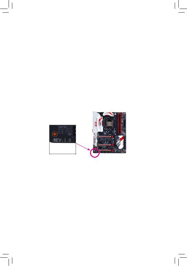
Identifying Your Motherboard Revision
The revision number on your motherboard looks like this: «REV: X.X.» For example, «REV: 1.0» means the revision of the motherboard is 1.0. Check your motherboard revision before updating motherboard BIOS, drivers, or when looking for technical information.
Example:

Table of Contents
|
GA-H110M-S2/GA-H110M-S2 DDR3 Motherboard Layout |
……………………………………….5 |
|
|
Chapter 1 Hardware Installation………………………………………………………………………….. |
6 |
|
|
1-1 |
Installation Precautions…………………………………………………………………………. |
6 |
|
1-2 |
Product Specifications………………………………………………………………………….. |
7 |
|
1-3 |
Installing the CPU………………………………………………………………………………. |
10 |
|
1-4 |
Installing the Memory………………………………………………………………………….. |
10 |
|
1-5 Installing an Expansion Card……………………………………………………………….. |
11 |
|
|
1-6 |
Back Panel Connectors………………………………………………………………………. |
11 |
|
1-7 |
Internal Connectors……………………………………………………………………………. |
13 |
|
Chapter 2 BIOS Setup……………………………………………………………………………………… |
18 |
|
|
2-1 |
Startup Screen…………………………………………………………………………………… |
19 |
|
2-2 |
M.I.T…………………………………………………………………………………………………. |
19 |
|
2-3 |
System Information…………………………………………………………………………….. |
25 |
|
2-4 |
BIOS Features…………………………………………………………………………………… |
26 |
|
2-5 |
Peripherals………………………………………………………………………………………… |
29 |
|
2-6 |
Chipset……………………………………………………………………………………………… |
31 |
|
2-7 |
Power Management……………………………………………………………………………. |
32 |
|
2-8 |
Save & Exit……………………………………………………………………………………….. |
34 |
|
Chapter 3 Appendix…………………………………………………………………………………………. |
35 |
|
|
Drivers Installation……………………………………………………………………………………….. |
35 |
|
|
Regulatory Statements…………………………………………………………………………………. |
36 |
|
|
Contact Us………………………………………………………………………………………………….. |
38 |
— 4 —
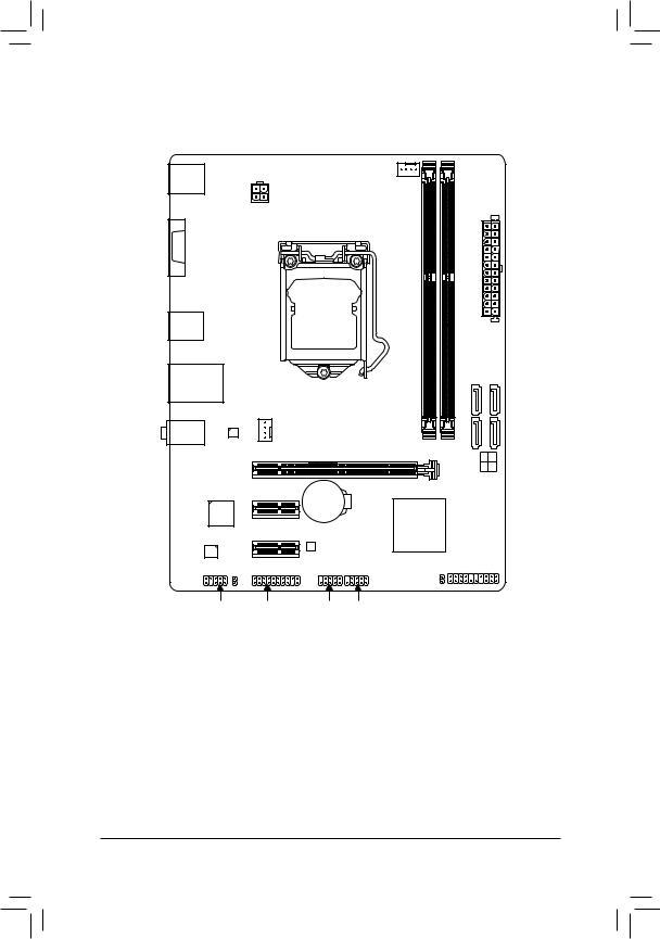
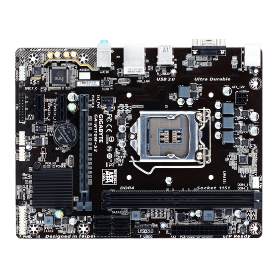
GA-H110M-S2/GA-H110M-S2 DDR3 Motherboard Layout
|
KB_MS |
CPU_FAN |
|||
|
1k |
2k |
|||
|
ATX_12V |
||||
|
1j/DDR3 |
2j/DDR3 |
|||
|
LGA1151 |
||||
|
VGA |
DDR4_ |
DDR4_ |
||
R_USB30
USB_LAN
GA-H110M-S2
GA-H110M-S2 DDR3
ATX
F_USB30
|
AUDIO |
Realtek® |
SYS_FAN |
|||
|
GbE LAN |
PCIEX16 |
SATA3 |
3 2 |
||
|
1 |
0 |
||||
|
iTE® |
PCIEX1_1 |
BAT |
|||
|
Super I/O |
Intel® H110 |
||||
|
PCIEX1_2 |
|||||
|
M_BIOS |
|||||
|
CODEC |
|||||
|
SPDIF_O |
F_PANEL |
||||
|
CLR_CMOS |
|||||
|
F_AUDIO |
TPM |
F_USB2 F_USB1 |
Box Contents
|
55 |
GA-H110M-S2 or GA-H110M-S2 DDR3 motherboard |
||
|
55 |
Motherboard driver disk |
55 |
Two SATA cables |
|
55 |
User’s Manual |
55 |
I/O Shield |
* The box contents above are for reference only and the actual items shall depend on the product package you obtain. The box contents are subject to change without notice.
MMOnly for GA-H110M-S2.
NNOnly for GA-H110M-S2 DDR3.
— 5 —

Chapter 1 Hardware Installation
1-1 Installation Precautions
The motherboard contains numerous delicate electronic circuits and components which can become damaged as a result of electrostatic discharge (ESD). Prior to installation, carefully read the user’s manual and follow these procedures:
•• Prior to installation, make sure the chassis is suitable for the motherboard.
•• Prior to installation, do not remove or break motherboard S/N (Serial Number) sticker or warranty sticker provided by your dealer. These stickers are required for warranty validation.
•• Always remove the AC power by unplugging the power cord from the power outlet before installing or removing the motherboard or other hardware components.
•• When connecting hardware components to the internal connectors on the motherboard, make sure they are connected tightly and securely.
•• When handling the motherboard, avoid touching any metal leads or connectors.
•• It is best to wear an electrostatic discharge (ESD) wrist strap when handling electronic components such as a motherboard, CPU or memory. If you do not have an ESD wrist strap, keep your hands dry and first touch a metal object to eliminate static electricity.
•• Prior to installing the motherboard, please have it on top of an antistatic pad or within an electrostatic shielding container.
•• Before connecting or unplugging the power supply cable from the motherboard, make sure the power supply has been turned off.
•• Before turning on the power, make sure the power supply voltage has been set according to the local voltage standard.
•• Before using the product, please verify that all cables and power connectors of your hardware components are connected.
•• To prevent damage to the motherboard, do not allow screws to come in contact with the motherboard circuit or its components.
•• Make sure there are no leftover screws or metal components placed on the motherboard or within the computer casing.
•• Do not place the computer system on an uneven surface.
•• Do not place the computer system in a high-temperature or wet environment.
•• Turning on the computer power during the installation process can lead to damage to system components as well as physical harm to the user.
•• If you are uncertain about any installation steps or have a problem related to the use of the product, please consult a certified computer technician.
•• If you use an adapter, extension power cable, or power strip, ensure to consult with its installation and/or grounding instructions.
— 6 —
|
1-2 |
Product Specifications |
|
|
CPU |
Support for Intel® Core™ i7 processors/Intel® Core™ i5 processors/ |
|
|
Intel® Core™ i3 processors/Intel® Pentium® processors/ |
||
|
Intel® Celeron® processors in the LGA1151 package |
||
|
(Go to GIGABYTE’s website for the latest CPU support list.) |
||
|
L3 cache varies with CPU |
||
|
Chipset |
Intel® H110 Express Chipset |
|
|
Memoryj |
2 x DDR4 DIMM sockets supporting up to 32 GB of system memory |
*Due to a Windows 32-bit operating system limitation, when more than 4 GB of physical memory is installed, the actual memory size displayed will be less than the size of the physical memory installed.
Dual channel memory architecture
Support for DDR4 2133 MHz memory modules
Support for ECC UDIMM 1Rx8/2Rx8 memory modules (operate in non-ECC mode)Support for non-ECC UDIMM 1Rx8/2Rx8/1Rx16 memory modules
(Go to GIGABYTE’s website for the latest supported memory speeds and memory modules.)
|
Memoryk |
2 x DDR3 DIMM sockets supporting up to 32 GB of system memory |
||
|
* Due to a Windows 32-bit operating system limitation, when more than 4 GB of physical |
|||
|
memory is installed, the actual memory size displayed will be less than the size of |
|||
|
the physical memory installed. |
|||
|
Dual channel memory architecture |
|||
|
Support for DDR3/DDR3L 1600/1333 MHz memory modules |
|||
|
Support for ECC UDIMM 1Rx8/2Rx8 memory modules (operate in non-ECC mode) |
|||
|
Support for non-ECC UDIMM 1Rx8/2Rx8 memory modules |
|||
|
(Go to GIGABYTE’s website for the latest supported memory speeds and |
|||
|
memory modules.) |
|||
|
Onboard |
Integrated Graphics Processor-Intel® HD Graphics support: |
||
|
Graphics |
— |
1 x D-Sub port, supporting a maximum resolution of 1920×1200@60 Hz |
|
|
Maximum shared memory of 512 MB |
|||
|
Audio |
Realtek® ALC887 codec |
||
|
High Definition Audio |
|||
|
2/4/5.1/7.1-channel |
|||
|
* To configure 7.1-channel audio, you have to use an HD front panel audio module |
|||
|
and enable the multi-channel audio feature through the audio driver. |
|||
|
Support for S/PDIF Out |
|||
|
LAN |
Realtek® GbE LAN chip (10/100/1000 Mbit) |
||
|
Expansion Slots |
1 x PCI Express x16 slot, running at x16 (PCIEX16) |
||
|
(The PCI Express x16 slot conforms to PCI Express 3.0 standard.) |
|||
|
2 x PCI Express x1 slots |
|||
|
(The PCI Express x1 slots conform to PCI Express 2.0 standard.) |
|||
|
Storage Interface |
Chipset: |
||
|
— |
4 x SATA 6Gb/s connectors |
MMOnly for GA-H110M-S2.
NNOnly for GA-H110M-S2 DDR3.
— 7 —
|
USB |
Chipset: |
||
|
— |
4 x USB 3.0/2.0 ports (2 ports on the back panel, 2 ports available through |
||
|
the internal USB header) |
|||
|
— |
6 x USB 2.0/1.1 ports (2 ports on the back panel, 4 ports available through |
||
|
the internal USB headers) |
|||
|
Internal |
1 x 24-pin ATX main power connector |
||
|
Connectors |
1 x 4-pin ATX 12V power connector |
||
|
4 x SATA 6Gb/s connectors |
|||
|
1 x CPU fan header |
|||
|
1 x system fan header |
|||
|
1 x front panel header |
|||
|
1 x front panel audio header |
|||
|
1 x S/PDIF Out header |
|||
|
1 x USB 3.0/2.0 header |
|||
|
2 x USB 2.0/1.1 headers |
|||
|
1 x Trusted Platform Module (TPM) header |
|||
|
1 x Clear CMOS jumper |
|||
|
Back Panel |
1 x PS/2 mouse port |
||
|
Connectors |
1 x PS/2 Keyboard port |
||
|
1 x D-Sub port |
|||
|
2 x USB 3.0/2.0 ports |
|||
|
2 x USB 2.0/1.1 ports |
|||
|
1 x RJ-45 port |
|||
|
3 x audio jacks (Line In, Line Out, Mic In) |
|||
|
I/O Controller |
iTE® I/O Controller Chip |
||
|
Hardware |
System voltage detection |
||
|
Monitor |
CPU/System temperature detection |
||
|
CPU/System fan speed detection |
|||
|
CPU/System overheating warning |
|||
|
CPU/System fan fail warning |
|||
|
CPU/System fan speed control |
|||
|
* Whether the fan speed control function is supported will depend on the cooler you install. |
|||
|
BIOS |
1 x 64 Mbit flash |
||
|
Use of licensed AMI UEFI BIOS |
|||
|
PnP 1.0a, DMI 2.7, WfM 2.0, SM BIOS 2.7, ACPI 5.0 |
— 8 —
|
Unique Features |
Support for APP Center |
||
|
* Available applications in APP Center may vary by motherboard model. Supported |
|||
|
functionsofeachapplicationmayalsovarydependingonmotherboardspecifications. |
|||
|
— |
3D OSD |
||
|
— |
@BIOS |
||
|
— |
AutoGreen |
||
|
— |
Cloud Station |
||
|
— |
EasyTune |
||
|
— |
Easy RAID |
||
|
— |
Fast Boot |
||
|
— |
Smart TimeLock |
||
|
— |
Smart Keyboard |
||
|
— |
Smart Backup |
||
|
— |
System Information Viewer |
||
|
— |
USB Blocker |
||
|
Support for Q-Flash |
|||
|
Support for Smart Switch |
|||
|
Support for Xpress Install |
|||
|
Bundled |
Norton® Internet Security (OEM version) |
||
|
Software |
cFosSpeed |
||
|
Operating |
Support for Windows 10/8.1 64-bit |
||
|
System |
Support for Windows 7 32-bit/64-bit |
||
|
* Please download the «Windows USB Installation Tool» from GIGABYTE’s website and |
|||
|
install it before installing Windows 7. |
|||
|
Form Factor |
Micro ATX Form Factor; 22.6cm x 17.4cm |
*GIGABYTE reserves the right to make any changes to the product specifications and product-related information without prior notice.
|
GA-H110M-S2 |
GA-H110M-S2 DDR3 |
Please visit GIGABYTE’s website for support lists of CPU, memory modules, and
SSDs.
Please visit the SupportUtility List page on GIGABYTE’s website to download the latest version of apps.
— 9 —
1-3 Installing the CPU
Read the following guidelines before you begin to install the CPU:
•• Make sure that the motherboard supports the CPU.
(Go to GIGABYTE’s website for the latest CPU support list.)
•• Always turn off the computer and unplug the power cord from the power outlet before installing the CPU to prevent hardware damage.
•• Locate the pin one of the CPU. The CPU cannot be inserted if oriented incorrectly. (Or you may locate the notches on both sides of the CPU and alignment keys on the CPU socket.)
•• Apply an even and thin layer of thermal grease on the surface of the CPU.
•• Do not turn on the computer if the CPU cooler is not installed, otherwise overheating and damage of the CPU may occur.
•• Set the CPU host frequency in accordance with the CPU specifications. It is not recommended that the system bus frequency be set beyond hardware specifications since it does not meet the standard requirements for the peripherals. If you wish to set the frequency beyond the standard specifications, please do so according to your hardware specifications including the CPU, graphics card, memory, hard drive, etc.
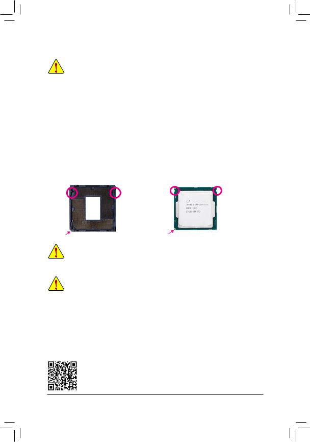
Installing the CPU
Locate the alignment keys on the motherboard CPU socket and the notches on the CPU.
|
LGA1151 CPU Socket |
LGA1151 CPU |
|
|
Alignment |
Notch |
Notch |
|
Alignment |
||
|
Key |
Key |
|
Pin One Corner of the CPU Socket |
Triangle Pin One Marking on the CPU |
Do not remove the CPU socket cover before inserting the CPU. It may pop off from the load plate automatically during the process of re-engaging the lever after you insert the CPU.
1-4 Installing the Memory
Read the following guidelines before you begin to install the memory:
•• Make sure that the motherboard supports the memory. It is recommended that memory of the same capacity, brand, speed, and chips be used.
(Go to GIGABYTE’s website for the latest supported memory speeds and memory modules.)
•• Always turn off the computer and unplug the power cord from the power outlet before installing the memory to prevent hardware damage.
•• Memory modules have a foolproof design. A memory module can be installed in only one direction. If you are unable to insert the memory, switch the direction.
Dual Channel Memory Configuration
This motherboard provides two memory sockets and supports Dual Channel Technology. After the memory is installed, the BIOS will automatically detect the specifications and capacity of the memory. Enabling Dual
Channel memory mode will double the original memory bandwidth.
Please visit GIGABYTE’s website for details on hardware installation.
— 10 —
![]()
The two DDR4 memory sockets are divided into two channels and each channel has one memory socket as followingj:
Channel A: DDR4_1Channel B: DDR4_2
The two DDR3 memory sockets are divided into two channels and each channel has one memory socket as followingk:
Channel A: DDR3_1Channel B: DDR3_2
Due to CPU limitations, read the following guidelines before installing the memory in Dual Channel mode.
1.Dual Channel mode cannot be enabled if only one memory module is installed.
2.When enabling Dual Channel mode with two memory modules, it is recommended that memory of the same capacity, brand, speed, and chips be used for optimum performance.
1-5 Installing an Expansion Card
Read the following guidelines before you begin to install an expansion card:
•• Make sure the motherboard supports the expansion card. Carefully read the manual that came with your expansion card.
•• Always turn off the computer and unplug the power cord from the power outlet before installing an expansion card to prevent hardware damage.
1-6 Back Panel Connectors
PS/2 Keyboard and PS/2 Mouse Port
Use the upper port (green) to connect a PS/2 mouse and the lower port (purple) to connect a PS/2 keyboard.
D-Sub Port
The D-Sub port supports a 15-pin D-Sub connector and supports a maximum resolution of 1920×1200@60 Hz (the actual resolutions supported depend on the monitor being used). Connect a monitor that supports D-Sub connection to this port.
USB 3.0/2.0 Port
The USB 3.0 port supports the USB 3.0 specification and is compatible to the USB 2.0/1.1 specification.
Use this port for USB devices.
RJ-45 LAN Port
The Gigabit Ethernet LAN port provides Internet connection at up to 1 Gbps data rate. The following describes the states of the LAN port LEDs.
|
Connection/ |
Connection/Speed LED: |
Activity LED: |
|||||||||||||||||
|
Speed LED |
Activity LED |
||||||||||||||||||
|
State |
Description |
State |
Description |
||||||||||||||||
|
Orange |
1 Gbps data rate |
Blinking |
Data transmission or receiving is occurring |
||||||||||||||||
|
Green |
100 Mbps data rate |
Off |
No data transmission or receiving is occurring |
||||||||||||||||
|
Off |
10 Mbps data rate |
||||||||||||||||||
|
LAN Port |
|||||||||||||||||||
MMOnly for GA-H110M-S2.
NNOnly for GA-H110M-S2 DDR3.
— 11 —

USB 2.0/1.1 Port
The USB port supports the USB 2.0/1.1 specification. Use this port for USB devices.
Line In (Blue)
The line in jack. Use this audio jack for line in devices such as an optical drive, walkman, etc.
Line Out (Green)
The line out jack. Use this audio jack for a headphone or 2-channel speaker. This jack can be used to connect front speakers in a 4/5.1/7.1-channel audio configuration.
Mic In (Pink)
The Mic in jack.
To configure 7.1-channel audio, you have to use an HD front panel audio module and enable the multi-channel audio feature through the audio driver. Please visit GIGABYTE’s website for more software information.
•• When removing the cable connected to a back panel connector, first remove the cable from your device and then remove it from the motherboard.
•• When removing the cable, pull it straight out from the connector. Do not rock it side to side to prevent an electrical short inside the cable connector.
— 12 —