Материнская плата MSI H510M-A PRO
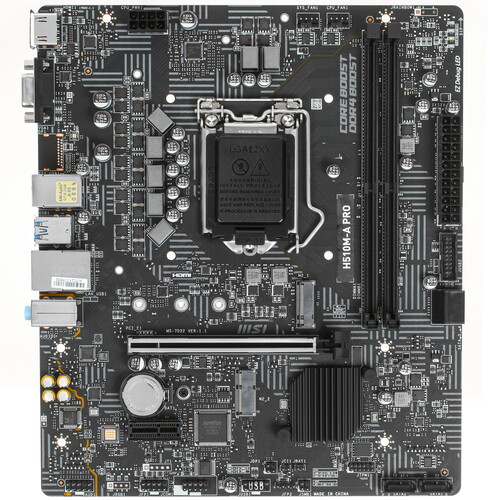
LGA 1200, Intel H510, 2xDDR4-3200 МГц, 1xPCI-Ex16, 1xM.2, Micro-ATX
подробнее

1.2k98,78
Код товара: 4759093
перейти к содержанию
Материнская плата msi H510M PRO ИНСТРУКЦИЯ ПО БЕЗОПАСНОСТИ Пожалуйста, внимательно изучите руководство по эксплуатации и приведенную ниже информацию перед установкой или использованием этого продукта. Пожалуйста, сохраните это руководство пользователя для дальнейшего использования. Светильники могут устанавливаться только авторизованными и квалифицированными специалистами в соответствии с действующими правилами электромонтажа. Техническое обслуживание светильников ограничивается их …
Подробнее «Руководство пользователя материнской платы msi H510M PRO»
Материнская плата MSI Материнская плата MSI Информация о безопасности Компоненты, входящие в этот комплект, подвержены повреждению в результате электростатического разряда (ЭСР). Пожалуйста, придерживайтесь следующих инструкций, чтобы обеспечить успешную сборку компьютера. Убедитесь, что все компоненты надежно подключены. Ненадежные соединения могут привести к тому, что компьютер не распознает компонент или не запустится. Держите …
Подробнее «Руководство пользователя материнской платы MSI»
Смотреть руководство для MSI H510M-A PRO ниже. Все руководства на ManualsCat.com могут просматриваться абсолютно бесплатно. Нажав кнопку «Выбор языка» вы можете изменить язык руководства, которое хотите просмотреть.

MANUALSCAT | RU
Вопросы и ответы
У вас есть вопрос о MSI H510M-A PRO, но вы не можете найти ответ в пользовательском руководстве? Возможно, пользователи ManualsCat.com смогут помочь вам и ответят на ваш вопрос. Заполните форму ниже — и ваш вопрос будет отображаться под руководством для MSI H510M-A PRO. Пожалуйста, убедитесь, что вы опишите свои трудности с MSI H510M-A PRO как можно более детально. Чем более детальным является ваш вопрос, тем более высоки шансы, что другой пользователь быстро ответит на него. Вам будет автоматически отправлено электронное письмо, чтобы проинформировать вас, когда кто-то из пользователей ответит на ваш вопрос.
Задать вопрос о MSI H510M-A PRO
Страница: 1
1
Содержание
Содержание
Безопасное использование продукции………………………………………………..2
Технические характеристики………………………………………………………………3
Задняя панель портов ввода/ вывода………………………………………………….8
Таблица состояний индикатора порта LAN……………………………………………………..8
Компоненты материнской платы…………………………………………………………9
Процессорный сокет……………………………………………………………………………………10
Слоты DIMM………………………………………………………………………………………………..11
M2_1: Разъем M.2 (Ключ M)………………………………………………………………………….11
M2_2: Разъем M.2 (Ключ E)…………………………………………………………………………..12
PCI_E1~2: Слоты расширения PCIe………………………………………………………………12
SATA1~4: Разъемы SATA 6Гб/с……………………………………………………………………..13
JAUD1: Разъем аудио передней панели………………………………………………………..13
JFP1, JFP2: Разъемы передней панели………………………………………………………..14
ATX_PWR1, CPU_PWR1: Разъемы питания……………………………………………………15
JUSB1: Разъем USB 2.0………………………………………………………………………………..16
JUSB2: Разъем USB 3.2 Gen 1 5Гб/с………………………………………………………………16
CPU_FAN1, SYS_FAN1: Разъемы вентиляторов…………………………………………….17
JTPM1: Разъем модуля ТРМ…………………………………………………………………………17
JCI1: Разъем датчика открытия корпуса……………………………………………………….18
JCOM1: Разъем последовательного порта…………………………………………………….18
JBAT1: Джампер очистки данных CMOS (Сброс BIOS)……………………………………19
Индикаторы отладки EZ……………………………………………………………………………….19
Установка ОС, драйверов и MSI Center……………………………………………….20
Установка Windows® 10………………………………………………………………………………..20
Установка драйверов…………………………………………………………………………………..20
MSI Center…………………………………………………………………………………………………..20
UEFI BIOS…………………………………………………………………………………………..21
Настройка BIOS…………………………………………………………………………………………..22
Вход в настройки BIOS…………………………………………………………………………………22
Инструкции по настройке BIOS…………………………………………………………………….22
Сброс BIOS………………………………………………………………………………………………….23
Обновление BIOS…………………………………………………………………………………………23
Благодарим Вас за покупку материнской платы H510M
PRO/ H510M-A PRO/H510M BOMBER/ B560M PRO-E/
B560M PLUS/ B560M-X. Данное руководство пользователя
содержит информацию о схеме платы, компонентах.
материнской платы, настройке BIOS и описании
программного обеспечения.
Страница: 2
2 Безопасное использование продукции
Безопасное использование продукции
∙
∙ Компоненты, входящие в комплект поставки могут быть повреждены
статическим электричеством. Для успешной сборки компьютера, пожалуйста,
следуйте указаниям ниже.
∙
∙ Убедитесь, что все компоненты компьютера подключены должным образом.
Ослабленные соединения компонентов могут привести как к сбоям в работе, так и
полной неработоспособности компьютера.
∙
∙ Чтобы избежать повреждений компонентов платы всегда держите ее за края.
∙
∙ При сборке компьютера рекомендуется пользоваться электростатическим
браслетом. В случае, если это невозможно, перед работой с платой снимите
электростатический заряд со своего тела, прикоснувшись к металлическому
предмету.
∙
∙ В случае, если материнская плата не установлена в корпус, храните ее в
антистатической упаковке или на антистатическом коврике.
∙
∙ Перед включением компьютера убедитесь, что все винты крепления и другие
металлические компоненты на материнской плате и внутри корпуса надежно
зафиксированы.
∙
∙ Не включайте компьютер, если сборка не завершена. Это может привести к
повреждению компонентов, а также травмированию пользователя.
∙
∙ Если вам нужна помощь на любом этапе сборки компьютера, пожалуйста,
обратитесь к сертифицированному компьютерному специалисту.
∙
∙ Всегда выключайте питание и отсоединяйте шнур питания от электрической
розетки перед установкой или удалением любого компонента компьютера.
∙
∙ Сохраните это руководство для справки.
∙
∙ Не допускайте воздействия на материнскую плату высокой влажности.
∙
∙ Перед тем как подключить блок питания компьютера к электрической розетке
убедитесь, что напряжение электросети соответствует напряжению, указанному
на блоке питания.
∙
∙ Располагайте шнур питания так, чтобы на него не могли наступить люди. Не
ставьте на шнур питания никаких предметов.
∙
∙ Необходимо учитывать все предостережения и предупреждения, указанные на
материнской плате.
∙
∙ При возникновении любой из перечисленных ниже ситуаций обратитесь в
сервисный центр для проверки материнской платы:
▪
▪ Попадание жидкости внутрь компьютера.
▪
▪ Материнская плата подверглась воздействию влаги.
▪
▪ Материнская плата не работает должным образом или невозможно
наладить ее работу в соответствии с руководством пользователя.
▪
▪ Материнская плата получила повреждения при падении.
▪
▪ Материнская плата имеет явные признаки повреждения.
∙
∙ Не храните материнскую плату в местах с температурой выше 60°C (140°F), так
как это может привести к ее повреждению.
Страница: 3
3
Технические характеристики
Технические характеристики
Процессор
∙
∙ Поддержка процессоров Intel® Core™ 10-го поколения,
Intel® Core™ 11-го поколения, Pentium® Gold и Celeron®
∙
∙ Процессорный сокет LGA1200
* Пожалуйста, обратитесь intel.com для получения
дополнительной информации о совместимости.
Чипсет Intel®H510/ B560
Память
∙
∙ 2x слота памяти DDR4 с поддержкой до 64ГБ*
∙
∙ Поддержка 1R 2133/ 2666/ 2933 МГц для процессоров
Intel® 10-го поколения (по стандартам JEDEC и POR)
∙
∙ Поддержка 1R 2133/ 2666/ 2933/ 3200 МГц для
процессоров Intel® 11-го поколения (по стандартам JEDEC
и POR)
∙
∙ Максимальная частота разгона (для B560M PRO-E/ B560M
PLUS/ B560M-X):
▪
▪ 1DPC 1R поддерживает максимальную частоту 4800
МГц
▪
▪ 1DPC 2R поддерживает максимальную частоту 4600+
МГц
∙
∙ Двухканальная архитектура памяти
∙
∙ Поддержка non-ECC, небуферизованной памяти
∙
∙ Поддержка Intel® Extreme Memory Profile (XMP)
* Пожалуйста, обратитесь www.msi.com для получения
дополнительной информации о совместимых модулях
памяти.
Слоты
расширения
∙
∙ 1x слот PCIe x16 (от процессора)
▪
▪ Поддержка PCIe 4.0 для процессоров Intel® 11-го
поколения
▪
▪ Поддержка PCIe 3.0 для процессоров Intel® 10-го
поколения
∙
∙ 1x слот PCIe 3.0 x1 (от PCH)
∙
∙ 1x разъем M.2 (Ключ E) (для H510M PRO/ H510M-A PRO/
H510M BOMBER)
▪
▪ Разъем M2_2 только поддерживает модуль PCIe Wi-Fi
Продолжение на следующей странице
Страница: 4
4 Технические характеристики
Продолжение с предыдущей страницы
Встроенная
графика
∙
∙ 1x порт HDMI 2.0b с поддержкой формата HDR, с
поддержкой максимального разрешения 4K 60Гц*/**
∙
∙ 1x порт VGA, с поддержкой максимального разрешения
2048×1536 60Гц, 1920×1200 60Гц (для H510M PRO/ H510M-A
PRO/ H510M BOMBER/ B560M PRO-E/ B560M-X)*
∙
∙ 1x порт DisplayPort 1.4, с поддержкой максимального
разрешения 4K 60Гц (только для H510M PRO)*/**
* Доступно для процессоров с интегрированной графикой.
** Спецификации ведиокарт могут меняться в зависимости
от установленного процессора.
Аудио
Realtek® ALC897 Codec
∙
∙ 7.1-канальный High Definition Audio
LAN 1x Гигабитный сетевой контроллер Intel® I219V
Подключение
накопителей
∙
∙ 4x порта SATA 6Гб/с (от чипсета H510/ B560)
∙
∙ 1x разъем M.2 (Ключ M) (для H510M PRO/ H510M-A PRO/
H510M BOMBER/ B560M PRO-E/ B560M PLUS)
▪
▪ Разъем M2_1 (от чипсета H510/ B560)*
▫
▫ Поддержка PCIe 3.0 x4
▫
▫ Поддержка SATA 6Гб/с
▫
▫ Поддержка накопителей 2242/ 2260 /2280
* Разъем SATA4 будет недоступен при установке M.2 SATA
SSD в разъем M2_1.
USB
∙
∙ Контроллер H510/ B560
▪
▪ 4x порта USB 3.2 Gen 1 5Гбит/с (2 порта Type-A на
задней панели, 2 порта доступны через внутренние
разъемы USB)
▪
▪ 6x портов USB 2.0 (4 порта Type-A на задней панели
(USB-хаб Hub-GL850G), 2 порта доступны через
внутренние разъемы USB 2.0)
Продолжение на следующей странице
Страница: 5
5
Технические характеристики
Продолжение с предыдущей страницы
Разъемы на
плате
∙
∙ 1x 24-контактный разъем питания ATX
∙
∙ 1x 8-контактный разъем питания ATX 12В
∙
∙ 4x разъема SATA 6Гб/с
∙
∙ 1x разъем USB 3.2 Gen 1 5Гб/с (поддержка 2-х
дополнительных портов USB 3.2 Gen 1 5Гб/с)
∙
∙ 1x разъем USB 2.0 (поддержка 2-х дополнительных
портов USB 2.0)
∙
∙ 1x 4-контактный разъем вентилятора процессора
∙
∙ 1x 4-контактный разъем вентилятора системы
∙
∙ 1x разъем аудио передней панели
∙
∙ 2x разъема системной панели
∙
∙ 1x разъем последовательного порта
∙
∙ 1x разъем датчика открытия корпуса
∙
∙ 1x джампер очистки данных CMOS
∙
∙ 1x разъем модуля TPM
Разъемы
задней панели
∙
∙ 1x комбинированный порт PS/2 клавиатуры/ мыши
∙
∙ 1x порт VGA (для H510M PRO/ H510M-A PRO/ H510M
BOMBER/ B560M PRO-E/ B560M-X)
∙
∙ 1x порт DisplayPort (для H510M PRO)
∙
∙ 1x порт HDMI
∙
∙ 4x порта USB 2.0
∙
∙ 2x порта USB 3.2 Gen 1 5Гб/с Type-A
∙
∙ 1x порт LAN (RJ45)
∙
∙ 3x аудиоразъема
Параметры
индикаторов
∙
∙ 4x индикатора отладки EZ
∙
∙ 1x 4-контактный разъем RGB LED (для H510M PRO)
∙
∙ 1x 3-контактный разъем RAINBOW LED (для H510M PRO)
Контроллер
ввода-вывода
NUVOTON NCT6687D-M
Продолжение на следующей странице
Страница: 6
6 Технические характеристики
Продолжение с предыдущей страницы
Аппаратный
мониторинг
∙
∙ Определение температуры процессора/системы
∙
∙ Определение скорости вентиляторов процессора/
системы
∙
∙ Управление скоростью вентиляторов процессора/
системы
Форм-фактор
∙
∙ mATX Форм-фактор
∙
∙ 9.29 x 7.95 дюйма (23.6 cm x 20.2 см)
Параметры
BIOS
∙
∙ 1x 256 Мб флэш
∙
∙ UEFI AMI BIOS
∙
∙ ACPI 6.2, SMBIOS 3.0
∙
∙ Мультиязычный интерфейс
Программное
обеспечение
∙
∙ MSI Center
∙
∙ Intel Extreme Tuning Utility
∙
∙ CPU-Z MSI GAMING
∙
∙ Google Chrome™, Google Toolbar, Google Drive
∙
∙ Norton™ Internet Security Solution
Функции MSI
Center
∙
∙ LAN Manager
∙
∙ Mystic Light (для H510M PRO)
∙
∙ User Scenario
∙
∙ Hardware Monitor
∙
∙ Frozr AI Cooling
∙
∙ True Color
∙
∙ Live Update
∙
∙ Speed Up
∙
∙ Super Charger
Продолжение на следующей странице
Страница: 7
7
Технические характеристики
Продолжение с предыдущей страницы
Эксклюзивные
функции
∙
∙ Аудио
▪
▪ Audio Boost
∙
∙ Сеть
▪
▪ LAN Manager
∙
∙ Охлаждение
▪
▪ Smart Fan Control
∙
∙ Индикатор
▪
▪ Mystic Light Extension(RGB) (для H510M PRO)
▪
▪ Mystic Light Extension (RAINBOW) (для H510M PRO)
▪
▪ Mystic light SYNC (для H510M PRO)
▪
▪ EZ LED Control (для H510M PRO)
▪
▪ EZ DEBUG LED
∙
∙ Производительность
▪
▪ Слот Lightning Gen 4 PCI-E
▪
▪ DDR4 Boost
▪
▪ Core Boost
▪
▪ 2oz Copper thickened PCB
∙
∙ Защита
▪
▪ PCI-E Steel Armor
∙
∙ Опыт использования
▪
▪ MSI Center
▪
▪ Frozr AI Cooling
▪
▪ Click BIOS 5
▪
▪ CPU Cooler Tuning
Страница: 8
8 Задняя панель портов ввода/ вывода
Подключение/ Работа
индикатора
Состояние Описание
Выкл. Не подключен
Желтый Подключен
Мигает Передача данных
Скорость передачи данных
Состояние Описание
Выкл. 10 Мбит/с подключение
Зеленый
100/1000 Мбит/с
подключение
Оранжевый 1 Гбит/с подключение
Таблица состояний индикатора порта LAN
Audio 7.1-конфигурация каналов
Для настройки 7.1 канального аудио необходимо подключить фронтальную
звуковую панель к разъему JAUD1. Далее следуйте указаниям ниже.
1. Нажмите на Realtek HD Audio Manager > Advanced Settings, чтобы открыть
диалоговое окно, как показано ниже.
2. Выберите Mute the rear output device, when a front headphone plugged in.
3. Подключите колонки к аудио разъемам на задней и передней панели. При
подключении устройства к разъему аудио появится диалоговое окно с
просьбой подтвердить подключенное устройство.
Задняя панель портов ввода/ вывода
PS/2 мыши/
клавиатуры
LAN
USB 2.0 Type-A
USB 3.2 Gen 1
5Гб/с Type-A
DisplayPort (для H510M PRO)
Порт VGA (для H510M
PRO/ H510M-A PRO/
H510M BOMBER/ B560M
PRO-E/ B560M-X)
USB 2.0 Type-A
Линейный вход
Линейный
выход
Микрофоный
вход
Страница: 9
9
Компоненты материнской платы
Компоненты материнской платы
* Расстояние от центра процессора до ближайшего слота DIMM.
BAT1
SYS_FAN1
CPU_FAN1
Процессорный сокет
M2_1(опционально)
M2_2(опционально)
PCI_E2
PCI_E1
DIMMA1
DIMMB1
JTPM1
SATA▼3▲4
SATA2
SATA1
JAUD1
JRGB1(опционально)
JRAINBOW1(опционально)
JBAT1
ATX_PWR1
Индикаторы
отладки EZ
CPU_PWR1
JUSB2
JUSB1
JFP2
JFP1
JCI1
JCOM1
53.44мм*
Страница: 10
10 Задняя панель портов ввода/ вывода
Процессорный сокет
Пожалуйста, установите процессор в процессорный сокет, как показано ниже.
⚠
⚠Внимание!
∙
∙ Перед установкой или заменой процессора, необходимо отключить кабель
питания.
∙
∙ Пожалуйста, сохраните защитную крышку процессорного сокета после
установки процессора. Любые возможные гарантийные случаи, связанные с
работой материнской платы, MSI® будет рассматривать только, при наличии
защитной крышки на процессорном сокете.
∙
∙ При установке процессора обязательно установите процессорный кулер.
Кулер, представляющий собой систему охлаждения процессора, предотвращает
перегрев и обеспечивает стабильную работу системы.
∙
∙ Перед включением системы проверьте герметичность соединения между
процессором и радиатором.
∙
∙ Перегрев может привести к серьезному повреждению процессора и
материнской платы. Всегда проверяйте работоспособность вентилятора для
защиты процессора от перегрева. При установке кулера нанесите ровный
слой термопасты (или термоленту) на крышку установленного процессора для
улучшения теплопередачи.
∙
∙ Если процессор не установлен, всегда защищайте контакты процессорного
сокета пластиковой крышкой.
∙
∙ Если вы приобрели отдельно процессор и процессорный кулер, подробное
описание установки см. в документации в данному кулеру.
1
4
6
5
7 8
9
3
2
Страница: 11
11
Задняя панель портов ввода/ вывода
Слоты DIMM
Пожалуйста, установите модуль памяти в слот DIMM, как показано ниже.
1
2
3
2
⚠
⚠Внимание!
∙
∙ Для более стабильной работы системы в двухканальном режимах, модули
памяти должны быть одинакового типа , количества и емкости.
∙
∙ Некоторые модули памяти при разгоне могут работать на частотах ниже
заявленной производителем, поскольку выставляемая для памяти частота
зависит от информации, записанной в SPD (Serial Presence Detect). Зайдите
в BIOS и выберите опцию DRAM Frequency, чтобы установить заявленную или
более высокую частоту.
∙
∙ При установке памяти во все слоты, а также при ее разгоне, рекомендуется
использовать более эффективную систему охлаждения памяти.
∙
∙ Совместимость и стабильность работы установленных модулей памяти при
разгоне зависит от установленного процессора и других устройств.
∙
∙ Пожалуйста, обратитесь www.msi.com для получения дополнительной
информации о совместимых модулях памяти.
M2_1: Разъем M.2 (Ключ M)
Пожалуйста, установите устройства M.2 в разъем M.2_1, как показано ниже.
1
3
Стойка
Прилагаемый
винт для M.2
30º
30º
2
Страница: 12
12 Задняя панель портов ввода/ вывода
PCI_E1~2: Слоты расширения PCIe
⚠
⚠Внимание!
∙
∙ Перед установкой или извлечением плат расширения убедитесь, что кабель
питания отключен от электрической сети. Прочтите документацию на карту
расширения и выполните необходимые дополнительные аппаратные или
программные изменения для данной карты.
∙
∙ При установке массивной видеокарты, необходимо использовать такой
инструмент, как MSI Gaming Series Graphics Card Bolster для поддержки веса
графической карты и во избежание деформации слота.
BAT1
PCI_E1: Слот PCIe 3.0 x16 (CPU)
PCI_E2: Слот PCIe 3.0 x1 (PCH)
M2_2: Разъем M.2 (Ключ E)
Пожалуйста, установите модуль Wi-Fi в разъем M.2_2, как показано ниже.
Прилагаемый
винт для M.2
30º
30º
1
2
3
Страница: 13
13
Задняя панель портов ввода/ вывода
JAUD1: Разъем аудио передней панели
Данный разъем предназначен для подключения аудиоразъемов передней
панели.
1
2 10
9
1 MIC L 2 Ground
3 MIC R 4 NC
5 Head Phone R 6 MIC Detection
7 SENSE SEND 8 No Pin
9 Head Phone L 10 Head Phone Detection
SATA1~4: Разъемы SATA 6Гб/с
Эти разъемы представляют собой интерфейсные порты SATA 6Гб/с. К каждому
порту можно подключить одно устройство SATA.
SATA3
SATA4
SATA1
SATA2
⚠
⚠Внимание!
∙
∙ Избегайте перегибов кабеля SATA под прямым углом. В противном случае,
возможна потеря данных при передаче.
∙
∙ Кабели SATA оснащены одинаковыми коннекторами с обеих сторон. Однако,
для экономии занимаемого пространства к материнской плате рекомендуется
подключать плоский разъем.
∙
∙ Разъем SATA4 будет недоступен при установке M.2 SATA SSD в разъем M2_1.
Страница: 14
14 Задняя панель портов ввода/ вывода
JFP1, JFP2: Разъемы передней панели
Эти разъемы служат для подключения кнопок и светодиодных индикаторов,
расположенных на передней панели.
1
2 10
9
+
+
+
—
—
—
—
+
Power LED
HDD LED Reset Switch
Reserved
Power Switch
1 HDD LED + 2 Power LED +
3 HDD LED — 4 Power LED —
5 Reset Switch 6 Power Switch
7 Reset Switch 8 Power Switch
9 Reserved 10 No Pin
JFP2 1
+
+
—
—
Speaker
Buzzer 1 Speaker — 2 Buzzer +
3 Buzzer — 4 Speaker +
HDD
LED
RESET
SW
HDD LED
HDD LED —
HDD LED +
POWER LED —
POWER LED +
POWER LED
J
F
P
1
Страница: 15
15
Задняя панель портов ввода/ вывода
ATX_PWR1, CPU_PWR1: Разъемы питания
Данные разъемы предназначены для подключения блока питания ATX.
⚠
⚠Внимание!
Для обеспечения стабильной работы системной платы проверьте надежность
подключения всех кабелей питания к блоку питания АТХ.
24
13
1
12
ATX_PWR1
1 +3.3V 13 +3.3V
2 +3.3V 14 -12V
3 Ground 15 Ground
4 +5V 16 PS-ON#
5 Ground 17 Ground
6 +5V 18 Ground
7 Ground 19 Ground
8 PWR OK 20 Res
9 5VSB 21 +5V
10 +12V 22 +5V
11 +12V 23 +5V
12 +3.3V 24 Ground
5
4 1
8
CPU_PWR1
1 Ground 5 +12V
2 Ground 6 +12V
3 Ground 7 +12V
4 Ground 8 +12V
Страница: 16
16 Задняя панель портов ввода/ вывода
JUSB2: Разъем USB 3.2 Gen 1 5Гб/с
Данный разъем предназначен для подключения портов USB 3.2 Gen 1 5Гб/с на
передней панели.
1
10 11
20
1 Power 11 USB2.0+
2 USB3_RX_DN 12 USB2.0-
3 USB3_RX_DP 13 Ground
4 Ground 14 USB3_TX_C_DP
5 USB3_TX_C_DN 15 USB3_TX_C_DN
6 USB3_TX_C_DP 16 Ground
7 Ground 17 USB3_RX_DP
8 USB2.0- 18 USB3_RX_DN
9 USB2.0+ 19 Power
10 Ground 20 No Pin
⚠
⚠Внимание!
Помните, что во избежание повреждений, необходимо правильно подключать
контакты питания и земли.
JUSB1: Разъем USB 2.0
Данный разъем предназначен для подключения портов USB 2.0 на передней
панели.
⚠
⚠Внимание!
∙
∙ Помните, что во избежание повреждений, необходимо правильно подключать
контакты VCC и земли.
∙
∙ Для того, чтобы зарядить ваш iPad, iPhone и iPod через порты USB, пожалуйста,
установите утилиту MSI® Center.
1
2 10
9
1 VCC 2 VCC
3 USB0- 4 USB1-
5 USB0+ 6 USB1+
7 Ground 8 Ground
9 No Pin 10 NC
Страница: 17
17
Задняя панель портов ввода/ вывода
⚠
⚠Внимание!
В меню BIOS > Hardware Monitor вы можете настроить скорость вращения
вентиляторов.
CPU_FAN1, SYS_FAN1: Разъемы вентиляторов
Разъемы вентиляторов с PWM управлением имеют контакт с постоянным
напряжением 12В, а также контакт с сигналом управления скоростью вращения.
Поэтому, при подключении 3-х контактного (Non-PWM) вентилятора к разъему
для вентилятора PWM, скорость вентилятора всегда будет максимальной. Работа
такого вентилятора может оказаться достаточно шумной.
1
Назначение контактов
разъема для режима PWM
1 Ground 2 +12V
3 Sense 4 Speed Control Signal
Разъем Режим по умолчанию Макс. ток
Макс.
мощность
CPU_FAN1 Режим PWM 2А 24Вт
SYS_FAN1 Режим DC 1А 12Вт
1
Назначение контактов
разъема для режима DC
1 Ground 2 Voltage Control
3 Sense 4 NC
1
2 12
11
1 SPI Power 2 SPI Chip Select
3
Master In Slave Out (SPI
Data)
4
Master Out Slave In (SPI
Data)
5 Reserved 6 SPI Clock
7 Ground 8 SPI Reset
9 Reserved 10 No Pin
11 Reserved 12 Interrupt Request
JTPM1: Разъем модуля ТРМ
Данный разъем используется для подключения модуля ТРМ (Trusted Platform
Module). Дополнительные сведения см. в описании модуля ТРМ.
Страница: 18
18 Задняя панель портов ввода/ вывода
JCI1: Разъем датчика открытия корпуса
К этому разъему подключается кабель от датчика открытия корпуса.
Нормально
(По умолчанию)
Разрешить запись по
событию открытия корпуса
Использование датчика открытия корпуса
1. Подключите датчик открытия корпуса к разъему JCI1.
2. Закройте крышку корпуса.
3. Войдите в BIOS > Security > Chassis Intrusion Configuration.
4. Установите Chassis Intrusion в Enabled.
5. Нажмите клавишу F10, чтобы сохранить настройки и выйти, а затем нажмите
клавишу Enter, чтобы выбрать Yes.
6. При открытии корпуса на экране будет появляться предупреждающее
сообщение каждый раз при включении компьютера.
Сброс сообщения об открытии корпуса
1. Войдите в BIOS > Security > Chassis Intrusion Configuration.
2. Выберите Chassis Intrusion, Reset.
3. Нажмите клавишу F10, чтобы сохранить изменения и выйти, а затем нажмите
клавишу Enter, чтобы выбрать Yes.
JCOM1: Разъем последовательного порта
Данный разъем позволяет подключить последовательный порт, размещенный на
внешнем бракете.
1
2 10
9
1 DCD 2 SIN
3 SOUT 4 DTR
5 Ground 6 DSR
7 RTS 8 CTS
9 RI 10 No Pin
Страница: 19
19
Задняя панель портов ввода/ вывода
JBAT1: Джампер очистки данных CMOS (Сброс BIOS)
На плате установлена CMOS память с питанием от батарейки для хранения
данных о конфигурации системы. Для сброса конфигурации системы (очистки
данных CMOS памяти), воспользуйтесь этим джампером.
Сохранение данных
(По умолчанию)
Очистка данных/
Сброс BIOS
Сброс настроек BIOS до значений по умолчанию
1. Выключите компьютер и отключите шнур питания.
2. Используйте джампер, чтобы замкнуть соответствующие контакты JBAT1 в
течение 5-10 секунд.
3. Снимите джампер с контактов JBAT1.
4. Подключите шнур питания и включите компьютер.
Индикаторы отладки EZ
Данные светодиоды показывают состояния материнской платы.
CPU — процессор не обнаружен или поврежден.
DRAM — память DRAM не обнаружена или повреждена.
VGA — видеокарта не обнаружена или повреждена.
BOOT — устройство загрузки не обнаружено или повреждено.
Страница: 20
20 Установка ОС, драйверов и MSI Center
Установка ОС, драйверов и MSI Center
Скачайте и обновите последние утилиты и драйверы с сайта: www.msi.com
Установка Windows® 10
1. Включите компьютер.
2. Вставьте диск Windows® 10 в привод для оптических дисков или вставьте в
разъем USB компьютера USB флэш-диск, содержащий установочный файл
Windows® 10.
3. Нажмите кнопку Restart на корпусе компьютера.
4. Нажмите клавишу F11 во время POST (Power-On Self Test) компьютера, чтобы
войти в меню загрузки.
5. Выберите оптический привод / USB флэш-диск в меню загрузки.
6. Нажмите любую клавишу, когда на экране показывает сообщение Press any
key to boot from CD or DVD…
7. Следуйте инструкциям на экране, чтобы установить Windows® 10.
Установка драйверов
1. Загрузите компьютер в Windows® 10.
2. Вставьте диск с драйверами MSI® Drive Disc в привод для оптических дисков.
3. Нажмите всплывающее окно Select to choose what happens with this disc и
выберите Run DVDSetup.exe, чтобы открыть окно установщика. Если функция
автозапуска в Панели управления Windows выключена, вы также можете
вручную запустить файл DVDSetup.exe из корневой папки диска с драйверами
MSI Drive disc.
4. Окно установщика найдет и перечислит все необходимые драйверы во
вкладке Drivers/Software.
5. Нажмите кнопку Install в правом нижнем углу окна установщика.
6. Начнется установка драйверов. После ее завершения будет предложено
перезапустить систему.
7. Нажмите кнопку OK для завершения.
8. Перезапустите компьютер.
MSI Center
Приложение MSI Center поможет легко оптимизировать настройки игры
и беспрепятственно использовать программы для создания контента. С
помощью MSI Center вы можете контролировать и синхронизировать эффекты
светодиодной подсветки на ПК и других продуктах MSI, настраивать режимы
работы, контролировать производительность системы и регулировать скорость
вращения вентилятора.
Инструкции по использованию MSI Center
Для получения подробной информации о MSI Center,
обратитесь к
http://download.msi.com/manual/mb/MSICENTER.pdf
или отсканируйте QR-код и откройте веб-сайт.
⚠
⚠Внимание!
Функции могут меняться в зависимости от приобретенного вами продукта.
Страница: 21
21
UEFI BIOS
UEFI BIOS
MSI UEFI BIOS совместим с архитектурой UEFI (Unified Extensible Firmware
Interface). Прошивка UEFI имеет множество новых функций и преимуществ,
которые не поддерживаются традиционным BIOS. UEFI полностью заменит
традиционный BIOS в будущем. Чтобы использовать полный функционал нового
чипсета, режимом загрузки по умолчанию для MSI UEFI BIOS является UEFI.
⚠
⚠Внимание!
Термин BIOS в этом руководстве пользователя относится к UEFI BIOS, если не
указано иное.
Преимущества UEFI
∙
∙ Быстрая загрузка — Можно загружать операционную систему напрямую из UEFI
без самопроверки BIOS. Не требуется переключение в режим CSM во время
процедуры POST.
∙
∙ Поддерживает разделы жесткого диска объемом более 2 ТБ.
∙
∙ Поддерживает более 4 основных разделов с таблицей разделов GUID (GPT).
∙
∙ Поддерживает неограниченное количество разделов.
∙
∙ Поддерживает полный функционал новых устройств — Новые устройства могут
не поддерживать обратную совместимость.
∙
∙ Поддерживает запуск ОС в безопасном режиме — UEFI может проверить
работоспособность операционной системы, чтобы убедиться, что вредоносные
программы не влияют на процесс загрузки.
В следующих случаях система несовместима с архитектурой UEFI
∙
∙ 32-битная ОС Windows — Эта материнская плата поддерживает только
64-битную операционную систему Windows 10.
∙
∙ Видеокарта устаревшего поколения — Система определяет модель
установленной видеокарты и отображает предупреждающее сообщение «There is
no GOP (Graphics Output protocol) support detected in this graphics card».
⚠
⚠Внимание!
Для нормальной работы системы рекомендуется заменить установленную
видеокарту на видеокарту, совместимую с GOP/UEFI, или использовать процессор
со встроенной графикой.
Как проверить режим BIOS?
1. Включите компьютер.
2. Нажмите клавишу Delete, когда появляется сообщение на экране Press DEL
key to enter Setup Menu, F11 to enter Boot Menu во время загрузки.
3. Зайдите в BIOS и выберите режим BIOS в верхней части экрана.
Режим BIOS: UEFI
Страница: 22
22 Установка ОС, драйверов и MSI Center
Настройка BIOS
Настройки по умолчанию обеспечивают оптимальную производительность и
стабильность системы при нормальных условиях. Если вы недостаточно хорошо
знакомы с BIOS, всегда устанавливайте настройки по умолчанию. Это позволит
избежать возможных повреждений системы, а также проблем с загрузкой.
⚠
⚠Внимание!
∙
∙ С целью улучшения производительности, меню BIOS постоянно обновляется.
В связи с этим данное описание может немного отличаться от последней версии
BIOS и может использоваться в качестве справки. Для описания какого-либо
пункта меню настроек BIOS, вы можете обратиться к информационной панели
HELP.
∙
∙ Экраны, параметры и настройки BIOS могут меняться в зависимости от вашей
системы.
Вход в настройки BIOS
Нажмите клавишу Delete, когда появляется сообщение на экране Press DEL key
to enter Setup Menu, F11 to enter Boot Menu во время загрузки.
Функциональные клавиши
F1: Общая справка
F2: Добавить / Удалить избранный предмет
F3: Вход в меню Избранное
F4: Вход в меню технических параметров процессора
F5: Вход в меню Memory-Z
F6: Загрузить оптимизированные настройки по умолчанию
F7: Переключить между расширенном режимом и режимом EZ
F8: Загрузить профиль разгона
F9: Сохранить профиль разгона
F10: Сохранить изменения и перезагрузить*
F12: Сделать скриншот и сохранить его на USB флэш-диск (только FAT / FAT32
формат).
Ctrl+F: Вход в страницу поиска
* При нажатии клавиши F10 появится информационное окно. Выберите Yes или
No, чтобы подтвердить выбор.
Инструкции по настройке BIOS
Для получения подробной информации о инсрукцииях по
настройке BIOS, обратитесь к
http://download.msi.com/manual/mb/Intel500BIOSru.pdf
или отсканируйте QR-код и откройте веб-сайт.
Страница: 23
23
Установка ОС, драйверов и MSI Center
Сброс BIOS
В некоторых ситуациях необходимо выполнить восстановление настроек BIOS до
значений по умолчанию. Существует несколько способов сброса настроек:
∙
∙ Войдите в BIOS и нажмите клавишу F6 для загрузки оптимизированных
значений по умолчанию.
∙
∙ Замкните джампер очистки данных CMOS на материнской плате.
⚠
⚠Внимание!
Убедитесь, что компьютер выключен перед очисткой данных CMOS. Для
получения дополнительной информации о сбросе настроек BIOS, обратитесь к
разделу «Джампер/ кнопка очистки данных CMOS».
Обновление BIOS
Обновление BIOS при помощи M-FLASH
Перед обновлением:
Пожалуйста, скачайте последнюю версию файла BIOS с сайта MSI, который
соответствует вашей модели материнской платы. Сохраните файл BIOS на флэш-
диске USB.
Обновление BIOS:
1. Вставьте флэш-диск USB, содержащий файл обновления в порт USB на
компьютере.
2. Для входа в режим обновления следуйте указаниям ниже.
▪
▪ Перезагрузите системы и нажмите клавиши Ctrl+F5 во время процедуры
POST, потом нажмите на кнопку Yes для перезагрузки системы.
▪
▪ Перезагрузите системы и нажмите клавишу Del во время процедуры POST
для входа в настройки BIOS. Выберите вкладку M-FLASH и нажмите на кнопку
Yes для перезагрузки системы.
3. Выберите файл BIOS для выполнения процесса обновления BIOS.
4. При появлении окна с предложением нажмите на кнопку Yes для обновления
BIOS.
5. После завершения процесса обновления, система перезагрузится
автоматически.
Обновление BIOS при помощи MSI Center
Перед обновлением:
∙
∙ Убедитесь, что драйвер локальной сети установлен и есть подключение к сети
Интернет.
∙
∙ Перед обновлением BIOS закройте все остальные приложения.
Обновление BIOS:
1. Установите и запустите MSI Center, и затем перейдите на страницу Support.
2. Выберите Live Update и нажмите кнопку Advance.
3. Выберите файл BIOS и нажмите кнопку Install.
4. Когда на экране появится напоминание об установке, нажмите кнопку Install.
5. Система автоматически перезагрузится для обновления BIOS.
6. По завершению процесса обновления, система перезагрузится
автоматически.
Страница: 24
24 Установка ОС, драйверов и MSI Center
-
Page 1
K9N Platinum Series MS-7250 (V1.X) Mainboard G52-72501X2… -
Page 2: Copyright Notice
If a problem arises with your system and no solution can be obtained from the user’s manual, please contact your place of purchase or local distributor. Alternatively, please try the following help resources for further guidance. Visit the MSI website for FAQ, technical guide, BIOS updates, driver updates, and other information: http://www.msi.com.tw/program/service/faq/ faq/esc_faq_list.php…
-
Page 3: Safety Instructions
Safety Instructions Always read the safety instructions carefully. Keep this User’s Manual for future reference. Keep this equipment away from humidity. Lay this equipment on a reliable flat surface before setting it up. The openings on the enclosure are for air convection hence protects the equip- ment from overheating.
-
Page 4: Fcc-B Radio Frequency Interference Statement
FCC-B Radio Frequency Interference Statement T h is eq uip men t h as been tested and found to c omply with the limits for a Class B digital device, pursuant to Part 15 of the FCC Rules. These limits are designed to provide reasonable protection against harmful interference in a residential installation.
-
Page 5: Weee (Waste Electrical And Electronic Equipment) Statement
WEEE (Waste Electrical and Electronic Equipment) Statement…
-
Page 8: Table Of Contents
CONTENTS Copyright Notice ………………….ii Trademarks ……………………ii Revision History ………………….ii Technical Support ………………….ii Safety Instructions ………………….iii FCC-B Radio Frequency Interference Statement …………iv W EEE (Waste Electrical and Electronic Equipment) Statement ……..v Chapter 1 Getting Started ………………1-1 Mainboard Specifications ……………….
-
Page 9
Button ……………………. 2-20 Clear CMOS Button: SW2 …………….2-20 Slots ……………………2-20 PCI (Peripheral Component Interconnect) Express Slots ……. 2-21 PCI Interrupt Request Routing …………..2-22 Chapter 3 BIOS Setup ……………….. 3-1 Entering Setup ………………… 3-2 Control Keys ………………..3-3 Getting Help ……………….. -
Page 10
Auto Login ………………..A-19 Appendix B Realtek ALC883 Audio …………..B-1 Installing the Realtek HD Audio Driver …………..B-2 Installation for W indows 2000/XP ………….. B-2 Software Configuration ………………B-4 Sound Effect ………………..B-5 Mixer ………………….B-8 Audio I/O ………………… B-12 Microphone ……………….. -
Page 11: Chapter 1 Getting Started
Getting Started Chapter 1 Getting Started Thank you for choosing the K9N Platinum Series (MS- 7250 v1.X) ATX mainboard. The K9N Platinum Series ® mainboards are based on nVIDIA nForce 570 chipsets for optimal system efficiency. Designed to fit the ad- ®…
-
Page 12: Mainboard Specifications
Processor Support ® — AMD Athlon 64 X2, Athlon 64, Athlon FX and Sempronin the socket AM2 package. (For the latest information about CPU, please visit http://www.msi. com.tw/program/products/mainboard/mbd/pro_mbd_cpu_support. php) Supported FSB — HyperTransport supporting speed up to 1GHz (2000MT/s) Chipset ®…
-
Page 13
— 2 PCI Express x 1 slots — 3 PCI slots, support 3.3V/ 5V PCI bus Interface, includes one orange slot which supports 2 master for MSI special PCI function card (ex. wireless LAN and bluetooth combo card.). Form Factor — ATX (24.5 cm X 30.5 cm) -
Page 14: Mainboard Layout
M S-7250 M ainboard Mainboard Layout Top : mouse W inbond Bottom: keyboar d JCI1 JIR 1 Top : Parallel Port Bottom: COM A 1394 Port SPDIF T: LAN jack B: USB ports PW R3 T: LAN jack B: USB ports CP UFAN1 Line-I n PWR2…
-
Page 15: Packing Checklist
Getting Started Packing Checklist SATA RAID Driver MSI Driver/Utility CD Diskette (optional) MSI motherboard Round Cable of SATA Cable IDE Devices Power Cable D-Bracket 2 IEEE1394-Bracket Round Cable of (Optional) (Optional) Floppy Disk Back IO Shield User’s Guide * The pictures are for reference only and may vary from the packing contents of the…
-
Page 16: Chapter 2 Hardware Setup
Hardware Setup Chapter 2 Hardware Setup This chapter provides you with the information about hardware setup procedures. While doing the installation, be careful in holding the components and follow the installation procedures. For some components, if you install in the wrong orientation, the components will not work properly.
-
Page 17: Quick Components Guide
M S-7250 M ainboard Quick Components Guide PWR2, p.2-8 CPU, p.2-3 CPUFAN1, SYSFAN1, DDRII DIMMs, p.2-6 p.2-14 p.2-14 PWR3, p.2-8 JIR1, p.2-15 JCI1, p.2-14 FDD1, p.2-12 Back Panel I/O, p.2-10 PWR1, p.2-8 IDE1, p.2-12 NBFAN1, p.2-14 SATA1~6, p.2-13 PCIE Slots, p.2-21 PCI Slots, SW2, p.2-20…
-
Page 18: Cpu (Central Processing Unit)
If you do not have the heat sink and cooling fan, contact your dealer to purchase and install them before turning on the computer. For the latest information about CPU, please visit http://www.msi.com.tw/program/ products/mainboard/mbd/pro_mbd_cpu_support.php. Important 1.
-
Page 19: Cpu Installation Procedures For Socket Am2
M S-7250 M ainboard CPU Installation Procedures for Socket AM2 1. Please turn off the power and unplug the power cord before Open Lever installing the CPU. Sliding 2. Pull the lever s ideways away 90 degree Plate from the socket. Make sure to raise the lever up to a 90-de- gree angle.
-
Page 20: Installing Amd Socket Am2 Cpu Cooler Set
Hardware Setup Installing AMD Socket AM2 CPU Cooler Set W hen you are installing the CPU, make sure the CPU has a heat sink and a cooling fan attached on the top to prevent overheating. If you do not have the heat sink and cooling fan, contact your dealer to purchase and install them before turning on the computer.
-
Page 21: Memory
M S-7250 M ainboard Memory The mainboard provides four 240-pin non-ECC DDRII DIMMs and supports up to 8GB system memory. For more information on compatible components, please visit http://www.msi.com.tw/ program/products/mainboard/mbd/pro_mbd_trp_list.php DDRII 240-pin, 1.8V 56×2=112 pin 64×2=128 pin Dual-Channel Memory Population Rules…
-
Page 22: Installing Ddrii Modules
Hardware Setup Installing DDRII Modules 1. The memory module has only one notch on the center and will only fit in the right orientation. 2. Insert the DIMM memory module vertically into the DIMM slot. Then push it in until the golden finger on the memory module is deeply inserted in the socket.
-
Page 23: Power Supply
M S-7250 M ainboard Power Supply ATX 24-Pin Power Connector: PWR1 This connector allows you to connect an ATX 24-pin power supply. pin 13 To connect the ATX 24-pin power supply, make sure the plug of the power supply is inserted in the proper orientation and the pins are aligned.
-
Page 24: Important Notification About Power Issue
Hardware Setup Important Notification about Power Issue NForce chipset is very sensitive to ESD (Electrostatic Discharge), therefore this issue mostly happens while the users intensively swap memory modules under S5 (power-off) states, and the power code is plugged while installing modules. Due to several pins are very sensitive to ESD, so this kind of memory-replacement actions might cause system chipset unable to boot.
-
Page 25: Back Panel
M S-7250 M ainboard Back Panel RS-Out L-In Parallel Port M ou se L-Out CS-Out 1394 USB Ports Keyboard S/PDIF- Serial Port Port S/PDIF- M ouse/Keyboard Connector ® ® The standard PS/2 mouse/keyboard DIN connector is for a PS/2 mouse/keyboard. Parallel Port Connector A parallel port is a standard printer port that supports Enhanced Parallel Port (EPP) and Extended Capabilities Parallel Port (ECP) mode.
-
Page 26
Hardware Setup USB Connectors The OHCI (Open Host Controller Interface) Universal Serial Bus root is for attaching USB devices such as keyboard, mouse, or other USB-compatible devices. Audio Port Connectors These audio connectors are used for audio devices. You can differentiate the color of the audio jacks for different audio sound effects. -
Page 27: Connectors
M S-7250 M ainboard Connectors Floppy Disk Drive Connector: FDD1 This standard FDD connector supports 360K, 720K, 1.2M, 1.44M and 2.88M floppy disk types. FDD1 ATA133 Hard Disk Connectors: IDE1 The mainboard has a 32-bit Enhanced PCI IDE and Ultra DMA 66/100/133 controller that provides PIO mode 0~4, Bus Master, and Ultra DMA 66/ 100/133 function.
-
Page 28: Serial Ata Ii Connectors: Sata1~Sata6
Hardware Setup Serial ATA II Connectors: SATA1~SATA6 SATA1~SATA6 are high-speed SATAII interface ports. Each supports data rates of 300 MB/s and is fully compliant with Serial ATA specifications. Each Serial ATA con- nector can connect to 1 hard disk device. SATA6 SATA5 Pin Definition…
-
Page 29: Fan Power Connectors: Cpufan1, Sysfan1 & Nbfan1
M S-7250 M ainboard Fan Power Connectors: CPUFAN1, SYSFAN1 & NBFAN1 The fan power connectors support system cooling fan with +12V. W hen connecting the wire to the connectors, always take note that the red wire is the positive and should be connected to the +12V, the black wire is Ground and should be connected to GND.
-
Page 30: Front Panel Audio Connector: Jaud1
Hardware Setup Front Panel Audio Connector: JAUD1 The JAUD1 front panel audio connector allows you to connect the front panel audio ® and is compliant with Intel Front Panel I/O Connectivity Design Guide. JAUD1 JAUD1 Pin Definition SIGNAL DESCRIPTION PORT 1L Analog Port 1 — Left channel Ground PORT 1R…
-
Page 31: Front Usb Connectors: Jusb1, Jusb2 & Jusb3
M S-7250 M ainboard Front USB Connectors: JUSB1, JUSB2 & JUSB3 The mainboard provides USB 2.0 pinheaders (optional USB 2.0 bracket available) that ® are compliant with Intel I/O Connectivity Design Guide. USB 2.0 technology increases data transfer rate up to a maximum throughput of 480Mbps, which is 40 times faster than USB 1.1, and is ideal for connecting high-speed USB interface peripherals such as USB HDD, digital cameras, M P3 players, printers, modems and the like.
-
Page 32: Ieee 1394 Connectors: J1394_1
Hardware Setup IEEE 1394 Connectors: J1394_1 The mainboard provides IEEE1394 pinheader that allow you to connect IEEE 1394 ports via an external IEEE1394 bracket (optional). Pin Definition SIGNAL SIGNAL TPA+ TPA- J1394_1 Ground Ground TPB+ TPB- Cable power Cable power Key (no pin) Ground Connected to J1394_1…
-
Page 33: Front Panel Connectors: Jfp1/Jfp2
M S-7250 M ainboard Front Panel Connectors: JFP1/JFP2 The mainboard provides two front panel connectors for electrical connection to the ® front panel switches and LEDs. The JFP1 is compliant with Intel Front Panel I/O Connectivity Design Guide. JFP1 Power Reset Switch Switch…
-
Page 34: D-Bracket™ 2 Connector: Jdb1
Hardware Setup D-Bracket™ 2 Connector: JDB1 The mainboard comes with a JDB1 connector for you to connect to D-Bracket™ 2. D- Bracket™ 2 is an external USB Bracket that supports both USB1.1 & 2.0 specs. It integrates four LEDs and allows users to identify system problems through 16 vari- ous combinations of LED signals.
-
Page 35: Button
M S-7250 M ainboard Button The motherboard provides the following button for you to set the computer’s function. This section will explain how to change your motherboard’s function through the use of button. Clear CMOS Button: SW2 There is a CMOS RAM on board that has a power supply from external battery to keep the system configuration data.
-
Page 36: Slots
Hardware Setup Slots PCI (Peripheral Component Interconnect) Express Slots PCI Express architecture provides a high performance I/O infrastructure for Desktop Platforms with transfer rates starting at 2.5 Giga transfers per second over a PCI Express x1 lane for Gigabit Ethernet, TV Tuners, 1394 controllers, and general pur- pose I/O.
-
Page 37: Pci Interrupt Request Routing
M S-7250 M ainboard PCI (Peripheral Component Interconnect) Slots The PCI slots support LAN cards, SCSI cards, USB cards, and other add-on cards that comply with PCI specifications. At 32 bits and 33 MHz, it yields a throughput rate of 133 MBps. 32-bit PCI Slot PCI Interrupt Request Routing The IRQ, acronym of interrupt request line and pronounced I-R-Q, are hardware lines…
-
Page 38: Chapter 3 Bios Setup
BIOS Setup Chapter 3 BIOS Setup This chapter provides information on the BIOS Setup program and allows you to configure the system for optimum use. You may need to run the Setup program when: ² An error message appears on the screen during the system booting up, and requests you to run SETUP.
-
Page 39: Entering Setup
M S-7250 M ainboard Entering Setup Power on the computer and the system will start POST (Power On Self Test) process. W hen the message below appears on the screen, press <DEL> key to enter Setup. Press DEL to enter SETUP If the message disappears before you respond and you still wish to enter Setup, restart the system by turning it OFF and On or pressing the RESET button.
-
Page 40: Control Keys
BIOS Setup Control Keys < ↑> Move to the previous item < ↓> Move to the next item < ←> Move to the item in the left hand < →> Move to the item in the right hand <Enter> Select the item Jumps to the Exit menu or returns to the main menu from a <Esc>…
-
Page 41: The Main Menu
M S-7250 M ainboard The Main Menu Standard CM OS Features Use this menu for basic system configurations, such as time, date etc. Advanced BIOS Features ® Use this menu to setup the items of AMI special enhanced features. Advanced Chipset Features Use this menu to change the values in the chipset registers and optimize your system’s performance.
-
Page 42
BIOS Setup Load Fail-Safe Defaults Use this menu to load the default values set by the BIOS vendor for stable system performance. Load Optimized Defaults Use this menu to load the default values set by the mainboard manufacturer specifi- cally for optimal performance of the mainboard. BIOS Setting Password Use this menu to set the password for BIOS. -
Page 43: Standard Cmos Features
M S-7250 M ainboard Standard CMOS Features The items in Standard CMOS Features Menu includes some basic setup items. Use the arrow keys to highlight the item and then use the <PgUp> or <PgDn> keys to select the value you want in each item. Date (MM:DD:YY) This allows you to set the system to the date that you want (usually the current date).
-
Page 44
BIOS Setup Device/ Vender/ Size/ LBA Mode/ Block M ode/ PIO Mode/ Async DM A/ Ultra DMA/ S.M.A.R.T. It will showing the device information that you connected to the IDE/SATA connector. LBA/Large M ode This allows you to enable or disable the LBA Mode. Setting to Auto enables LBA mode if the device supports it and the devices is not already formatted with LBA mode disabled. -
Page 45
M S-7250 M ainboard Halt On The setting determines whether the system will stop if an error is detected at boot. Available options are: [No Errors] The system doesn’t stop for any detected error. [All, But Keyboard] The system doesn’t stop for a keyboard error. System Information Press <Enter>… -
Page 46: Advanced Bios Features
BIOS Setup Advanced BIOS Features Quick Boot Setting the item to [Enabled] allows the system to boot within 5 seconds since it will skip some check items. Full Screen LOGO Display This item enables you to show the company logo on the bootup screen. Settings are: [Enabled] Shows a still image (logo) on the full screen at boot.
-
Page 47
M S-7250 M ainboard IOAPIC Function This field is used to enable or disable the APIC (Advanced Programmable Interrupt Controller). Due to compliance with PC2001 design guide, the system is able to run in APIC mode. Enabling APIC mode will expand available IRQ resources for the system. MPS Table Version This field allows you to select which MPS (Multi-Processor Specification) version to be used for the operating system. -
Page 48: Advanced Chipset Features
BIOS Setup Advanced Chipset Features Hyper Transport MCP55 Configuration MCP55 (SB) to AM2 (CPU) Freq. Auto [Enabled] Auto Detect HT frequency. [Disabled] Manual to setting HT frequency. M CP55 (SB) to AM 2 (CPU) Frequency W hen the MCP55 (SB) to AM2 (CPU) Freq. Auto set to Disabled, the item will appear.
-
Page 49: Integrated Peripherals
M S-7250 M ainboard Integrated Peripherals USB / 2.0 Controller This setting allows you to enable/disable the onboard USB 1.1/ 2.0 controller. USB Device Legacy Support Select [Enabled] if you need to use a USB-interfaced device in the operating system. Onboard Devices Configuration Press <Enter>…
-
Page 50
BIOS Setup I/O Device Configuration Press <Enter> to enter the sub-menu and the following screen appears: Onboard Floppy Controller Select [Enabled] if your system has a floppy disk controller (FDD) installed on the system board and you wish to use it. If you install add-on FDC or the system has no floppy drive, select [Disabled] in this field. -
Page 51
M S-7250 M ainboard IDE Devices Configuration Press <Enter> to enter the sub-menu and the following screen appears: PCI IDE BusMaster This item allows you to enable/ disable BIOS to used PCI busmastering for reading/ writing to IDE drives. On-Chip IDE Controller This item allows you to enable/ disable IDE Controller. -
Page 52: Power Management Setup
BIOS Setup Power Management Setup Important S3-related functions described in this section are available only when your BIOS supports S3 sleep mode. ACPI Function This item is to activate the ACPI (Advanced Configuration and Power Management Interface) Function. If your operating system is ACPI-aware, such as Windows 98SE/ 2000/ME, select [Enabled].
-
Page 53
M S-7250 M ainboard Power Button Function This feature sets the function of the power button. Settings are: [On/ Off] The power button functions as normal power off button. [Suspend] W hen you press the power button, the computer enters the suspend/sleep mode, but if the button is pressed for more than four seconds, the computer is turned off. -
Page 54
BIOS Setup Resume by PCIE Device W hen set to [Enabled], the feature allows your system to be awakened from the power saving modes through any event on PCIE device. Resume by RTC Alarm The field is used to enable or disable the feature of booting up the system on a scheduled time/date. -
Page 55: Pnp/Pci Configurations
M S-7250 M ainboard PNP/PCI Configurations This section describes configuring the PCI bus system and PnP (Plug & Play) feature. PCI, or Peripheral Component Interconnect, is a system which allows I/O devices to operate at speeds nearing the speed the CPU itself uses when communicating with its special components.
-
Page 56
BIOS Setup IRQ Resource Setup Press <Enter> to enter the sub-menu and the following screen appears. IRQ 3/4/5/7/9/10/11/14/15 These items specify the bus where the specified IRQ line is used. The settings determine if AMIBIOS should remove an IRQ from the pool of avail- able IRQs passed to devices that are configurable by the system BIOS. -
Page 57: H/W Monitor
M S-7250 M ainboard H/W Monitor Chassis Intrusion The field enables or disables the feature of recording the chassis intrusion status and issuing a warning message if the chassis is once opened. To clear the warning message, set the field to [Reset]. The setting of the field will automatically return to [Enabled] later.
-
Page 58
BIOS Setup Each Step Increase Fan Output This item shows the percentage for the CPU fan speed to increase or decrease between two steps. Read only. CPU Fan TargetTemp Value W hen the CPUFAN Mode Setting set to the “Thermal Cruise” this item will appear. -
Page 59: Cell Menu
M S-7250 M ainboard Cell Menu Important Change these settings only if you are familiar with the chipset. Current CPU Clock/ FSB M ulitiplier/ Memory Speed/ Voltage These items show the current clocks of CPU and Memory speed. Read-only. Cool’n’Quiet This feature is especially desiged for AMD processor, which provides a CPU tem- perature detecting function to prevent your CPU’s from overheading due to the heavy working loading.
-
Page 60
CPU Dynamic OverClocking Dynamic Overclocking Technology is the automatic overclocking function, included in ’s newly developed CoreCell the MSI Technology. It is designed to detect the load balance of CPU while running programs, and to adjust the best CPU frequency automatically. -
Page 61
M S-7250 M ainboard FID/VID Change Setting to Manual allows you to set the CPU ratio and voltage manually. Setting options: [Auto], [Manaul]. Processor Frequency M ultiplier This item allows you to set the CPU ratio. Processor Voltage This item allows you to set the CPU voltage. M emclock M ode Select the DRAM frequency programming method. -
Page 62
BIOS Setup MCT Timing M ode This field has the capacity to automatically detect all of the DRAM timing. If you set this field to [Manual], the following fields will be selectable. CAS Latency (TCL) W hen the MCT Timing M ode is set to [Manual], the field is adjustable.This controls the CAS latency, which determines the timing delay (in clock cycles) before SDRAM starts a read command after receiving it. -
Page 63
M S-7250 M ainboard Bank Interleaveing This field selects 2-bank or 4-bank interleave for the installed SDRAM. Disable the function if 16MB SDRAM is installed. SoftWare M emory hole Enable Memory Remapping Around Memory Hole PCIE Frequency (MHz) This item allows you to select the PCI Express frequency (in MHz) and overclock the processor by adjusting the PCI Express frequency to a higher frequency. -
Page 64
BIOS Setup CPU Clock Overclocking The CPU Frequency (M Hz)/ CPU Dynamic OverClocking / Processor Fre- quency M ultiplier are the items for you to overclock the CPU and the Memory. Please refer to the descriptions of these fields for more information. Important 1. -
Page 65: Load Fail-Safe/ Optimized Defaults
M S-7250 M ainboard Load Fail-Safe/ Optimized Defaults The two options on the main menu allow users to restore all of the BIOS settings to the default Fail-Safe or Optimized values. The Optimized Defaults are the default values set by the mainboard manufacturer specifically for optimal performance of the mainboard.
-
Page 66: Bios Setting Password
BIOS Setup BIOS Setting Password W hen you select this function, a message as below will appear on the screen: Type the password, up to six characters in length, and press <Enter>. The password typed now will replace any previously set password from CMOS memory. You will be prompted to confirm the password.
-
Page 67: Appendix A Introduction To Digicell
MP3 files management and communica- tion / 802.11g WLAN settings. Moreover, with this unique utility, you will be able to activate the MSI well-known features, Live Update and Core Center, which makes it easier to update the BIOS/drivers online, and to monitor the system hardware status (CPU/Fan temperature and speed) or to overclock the CPU/memory.
-
Page 68: Activating Digicell
Activating DigiCell Once you have your DigiCell installed (locate the setup source file in the setup CD accompanying with your mainboard, path: Utility —> MSI Utility —> MSI DigiCell), it will have an icon in the system tray, a short cut icon on the desktop, and a short cut path in your “Start-up”…
-
Page 69: Main
Introduction: Click on each icon appearing above to enter the sub-menu to make further configuration. M SI Click on this button to link to MSI website: http://www.msi.com.tw. Quick Guide Click on this button and the quick guide of DigiCell will be displayed for you to review.
-
Page 70
M S-7250 M ainboard Live Update You can take advantage of Live Update to detect and update BIOS and drivers online. Core Center You can take advantage of Core Center to monitor the health status of your system and to overclock under W indows O S if your sys tem s upports overclocking function. -
Page 71: H/W Diagnostic
In the H/W Diagnostic sub-menu, you can see the information, status and note of each DigiCell. You may double check the connection and installation of the item marked as gray. You may also click on the Mail to MSI button to send your questions or suggestions to MSI’s technical support staff.
-
Page 72: Communication
M S-7250 M ainboard Communication In the Communication sub-menu, you can see the status of all the LAN / W LAN / Bluetooth on the screen if the hardware is installed. The first icon indicates the onboard LAN on your system, the second icon indicates the wireless LAN status, and the third one is the information about the bluetooth on your system.
-
Page 73: Software Access Point
Introduction to DigiCell Software Access Point In the Software Access Point sub-menu, you can see the communication status on your system and choose the desired software access point mode by clicking on the desired icon, in which the default settings are configured for your usage. The default software access point mode is set to WLAN Card M ode.
-
Page 74: Access Point Mode
M S-7250 M ainboard Access Point Mode Click on “Setting” button of the Access Point Mode and the following screen will display. IP Sharing Click on this icon to enable/disable the IP sharing. The default of this setting is disabled. Disabled Enabled Enabling/disabling IP sharing depends on the different situation.
-
Page 75: Wlan Card Mode
Introduction to DigiCell enable this feature, only PCs with MAC address located in Association Control List can connect to the wireless LAN. M AC Address MAC stands for Media Access Control. A MAC address is the hardware address of a device connected to a network. Security This option allows you to enable/disable the authentication function.
-
Page 76: Live Update
BIOS/VGA Driver/Utility online so that you don’t need to search for the correct BIOS/driver version throughout the whole W eb site. To use the function, you need to install the “MSI Live Update 3” application. After the installation, the “MSI Live Update 3”…
-
Page 77: Mega Stick
Introduction to DigiCell MEGA STICK In the MEGA STICK sub-menu, you can configure the settings of MSI MEGA STICK and the media files (*.m3u, *.mp3, *.wav, *.cda, *.wma) on your system. Basic Function Here you can edit your own play list with the buttons “load”, “save”, “delete”, “shuttle”, “repeat”…
-
Page 78
M S-7250 M ainboard There is also a toolbar for you to execute some basic function, like play, stop, pause, previous/next song, song info and volume adjust. There is also a scroll bar on the top for you to forward/rewind. pause next previous… -
Page 79: Non-Unicode Programs Supported
Introduction to DigiCell Non-Unicode programs supported If you are using an operating system in European languages, and you’d like to play the media files in MEGA STICK with East-Asian languages (such as Chinese, Japanese… etc.), it is possible that the file names display incorrectly. However, you can ins tall the Supplemental Language Support provided by Microsoft to solve this problem.
-
Page 80
M S-7250 M ainboard 3. Then go to the [Advanced] tab and select the language you want to be supported (the language of the filename in the MegaStick) from the drop- down list in the [Language for non-Unicode programs], then click [Apply]. The system will install the necessary components from your Microsoft Setup CD immediately. -
Page 81: Core Center
Introduction to DigiCell Core Center Click on the Core Center icon in the main menu and the Core Center program will be enabled. Cool’n’Quiet This utility provides a CPU temperature detection function called Cool’n’Quiet. ® Cool’n’Quiet is a special feature designed only for AMD Athlon64 processor, and with Cool’n’Quiet, the system will be capable of detecting the temperature of the CPU according to the CPU’s working loading.
-
Page 82
M S-7250 M ainboard Left-side: Current system status In the left sub-menu, you can configure the settings of FSB, Vcore, Memory Voltage and AGP Voltage by clicking the radio button in front of each item and make it available (the radio button will be lighted as yellow when selected), use the “+” and “-” buttons to adjust, then click “OK”… -
Page 83: Power On Agent
Introduction to DigiCell Power On Agent In the Power on Agent sub-menu, you can configure setting of power-on, power- off and restarting status. In the screen below, you can set the date, time, start-up programs respectively for power-on, power-off and restarting. Power On Here are the available settings for Power On function: Date…
-
Page 84: Power Off / Restart
M S-7250 M ainboard Power Off / Restart You may configure the time (in the format hh:mm:ss) for the next power-off / restart. Start With Use the button “+Add” to add the start-up programs as DigiCell is activated next time. For example, you may like to have Outlook activated or a specified website linked when you get to the office every morning.
-
Page 85: Auto Login
Introduction to DigiCell Auto Login Since the Power On function allows the system to power on automatically, you may have to enable this Auto Login function in the following situations: 1. If you are using a computer belonging to a domain in office, and you need to enter your user name &…
-
Page 86: Appendix B Realtek Alc883 Audio
Realtek ALC883 Audio Appendix B Realtek ALC883 Audio The Realtek ALC883 provides 10-channel DAC that si- multaneously supports 7.1 sound playback and 2 chan- nels of independent s tereo s ound output (multiple streaming) through the Front-Out-Left and Front-Out- Right channels.
-
Page 87: Installing The Realtek Hd Audio Driver
M S-7250 M ainboard Installing the Realtek HD Audio Driver You need to install the driver for Realtek ALC883 codec to function properly before you can get access to 2-, 4-, 6-, 8- channel or 7.1+2 channel audio operations. Follow the procedures described below to install the drivers for different operating systems.
-
Page 88
Realtek ALC883 Audio 3. Click Next to install the Realtek High Definition Audio Driver. Click here 4. Click Finish to restart the system. S el ec t t hi s option Click here… -
Page 89: Software Configuration
M S-7250 M ainboard Software Configuration After installing the audio driver, you are able to use the 2-, 4-, 6- or 8- channel audio feature now. Click the audio icon from the system tray at the lower-right corner of the screen to activate the HD Audio Configuration. It is also available to enable the audio driver by clicking the Realtek HD Audio M anager from the Control Panel.
-
Page 90: Sound Effect
Realtek ALC883 Audio Sound Effect Here you can select a sound effect you like from the Environment list. Environment Simulation You will be able to enjoy different sound experience by pulling down the arrow, totally 23 kinds of sound effect will be shown for selection. Realtek HD Audio Sound Manager also provides five popular settings “Stone Corridor”, “Bathroom”, “Sewer pipe”, “Arena”…
-
Page 91
M S-7250 M ainboard Equalizer Selection Equalizer frees users from default settings; users may create their owned preferred settings by utilizing this tool. 10 bands of equalizer, ranging from 100Hz to 16KHz. Save Reset The settings are saved 10 bands of equalizer permanently for future would go back to the de- fault setting… -
Page 92
Realtek ALC883 Audio Frequently Used Equalizer Setting Realtek recognizes the needs that you might have. By leveraging our long experience at audio field, Realtek HD Audio Sound Manager provides you certain optimized equal- izer settings that are frequently used for your quick enjoyment. [How to Use It] Other than the buttons “Pop”… -
Page 93: Mixer
M S-7250 M ainboard Mixer In the Mixer part, you may adjust the volumes of the rear and front panels individually. 1. Adjust Volume You can adjust the volume of the speakers that you pluged in front or rear panel by select the Realtek HD Audio rear output or Realtek HD Audio front output items.
-
Page 94
Realtek ALC883 Audio W hen you are playing the first audio source (for example: use W indows Media Player to play DVD/VCD), the output will be played from the rear panel, which is the default setting. Then you must to select the Realtek HD Audio front output from the scroll list first, and use a different program to play the second audio source (for example: use Winamp to play MP3 files). -
Page 95
M S-7250 M ainboard 3. Playback control Playback device Tool Mute This function is to let you freely decide which ports to output the sound. And this is essential when multi- streaming playback enabled. — Realtek HD Audio Rear Output — Realtek HD Audio Front Output M u te You may choose to mute single or multiple volume controls or to completely mute… -
Page 96
Realtek ALC883 Audio 4. Recording control Recording device Tool Mute -Back Line in/Mic, Front Lin in -Realtek HD Audio Input M u te You may choose to mute single or multiple volume controls or to completely mute sound input. Tool — Show the following volume controls This is to let you freely decide which volume control items to be displayed. -
Page 97: Audio I/O
M S-7250 M ainboard Audio I/O In this tab, you can easily configure your multi-channel audio function and speakers. You can choose a desired multi-channel operation here. a. Headphone for the common headphone b. 2CH Speaker for Stereo-Speaker Output c. 4CH Speaker for 4-Speaker Output d.
-
Page 98
Realtek ALC883 Audio Connector Settings Click to access connector settings. Disable front panel jack detection (option) Find no function on front panel jacks? Please check if front jacks on your system are so-called AC’97 jacks. If so, please check this item to disable front panel jack detection. M ute rear panel output when front headphone plugged in. -
Page 99
M S-7250 M ainboard S/PDIF Short for Sony/Philips Digital Interface, a standard audio file transfer format. S/PDIF allows the transfer of digital audio signals from one device to another without having to be converted first to an analog format. Maintaining the viability of a digital signal prevents the quality of the signal from degrading when it is converted to analog. -
Page 100
Realtek ALC883 Audio Test Speakers You can select the speaker by clicking it to test its functionality. The one you select will light up and make testing sound. If any speaker fails to make sound, then check whether the cable is inserted firmly to the connector or replace the bad speakers with good ones. -
Page 101: Microphone
M S-7250 M ainboard Microphone In this tab you may set the function of the microphone. Select the Noise Suppres- sion to remove the possible noise during recording, or select Acoustic Echo Cancelltion to cancel the acoustic echo druing recording. Acoustic Echo Cancelltion prevents playback sound from being recorded by mi- crophone together with your sound.
-
Page 102: 3D Audio Demo
Realtek ALC883 Audio 3D Audio Demo In this tab you may adjust your 3D positional audio before playing 3D audio applica- tions like gaming. You may also select different environment to choose the most suitable environment you like. B-17…
-
Page 103: Information
M S-7250 M ainboard Information In this tab it provides some information about this HD Audio Configuration utility, including Audio Driver Version, DirectX Version, Audio Controller & Audio Codec. You may also select the language of this utility by choosing from the Language list. Also there is a selection Show icon in system tray.
-
Page 104: Hardware Setup
Realtek ALC883 Audio Hardware Setup Connecting the Speakers W hen you have set the Multi-Channel Audio Function mode properly in the software utility, connect your speakers to the correct phone jacks in accordance with the setting in software utility. n 2-Channel M ode for Stereo-Speaker Output Refer to the following diagram and caption for the function of each phone jack on the back panel when 2-Channel Mode is selected.
-
Page 105
M S-7250 M ainboard n 4-Channel M ode for 4-Speaker Output Back Panel Description: Connect two speakers to back panel’s Line Out connector and two speakers to the real-chan- nel Line Out connector. 4-Channel Analog Audio Output Line In Line Out (Front channels) Line Out (Rear channels) Line Out (Center and Subwoofer channel, but no functioning in this mode) S/PDIF Out-Optical… -
Page 106
Realtek ALC883 Audio n 6-Channel M ode for 6-Speaker Output Back Panel Description: Connect two speakers to back panel’s Line Out connector, two speakers to the rear-channel Line out connec tor and two s p e a k e r s t o t h e c e n t e r / subwoofer-channel Line Out 6-Channel Analog Audio Output connector. -
Page 107
M S-7250 M ainboard n 8-Channel M ode for 8-Speaker Output Description: Connect two speakers to back panel’s Line Out connector, two speakers to the rear-channel Line out connector, two speak- ers to the center/subwoofer- channel Line Out connector and 8-Channel Analog Audio Output two speakers to the side-chan- nel Line Out connector. -
Page 108: Appendix C Nvidia Raid
nVidia RAID Appendix C nVidia RAID NVIDIA brings Redundant Array of Independent Disks (RAID) technology—which is used by the world’s lead- ing businesses—to the common PC desktop. This tech- nology uses multiple drives to either increase total disk space or to offer data protection. For all levels, RAID techniques optimize storage solutions by using multiple disks grouped together and treating them as a single storage resource.
-
Page 109: Introduct Ion
M S-7250 M ainboard Introduct ion System Requirement Operating System Support NVRAID supports the following operating systems: W indows XP RAID Arrays NVRAID supports the following types of RAID arrays described in this section: RAID 0: RAID 0 defines a disk striping scheme that improves the disk read and write times for many applications.
-
Page 110: Raid Configuration
nVidia RAID RAID Configuration Basic Configuration Instructions The following are the basic steps for configuring NVRAID: Non-Bootable RAID Array 1. Choose the hard disks that are to be RAID enabled in the system BIOS. (To enable the SATA 0/ 1/ 2 Primary/ Secondary Channel in nVidia RAID Setup of Inte- grated Peripherals in BIOS.) 2.
-
Page 111
M S-7250 M ainboard Understanding the “Define a New Array” Window Use the Define a New Array window to • Select the RAID Mode • Set up the Striping Block • Specify which disks to use for the RAID Array Depending on the platform used, the system can have one or more channels. -
Page 112
nVidia RAID Using the Define a New Array Window If necessary, press the tab key to move from field to field until the appropriate field is highlighted. • Selecting the RAID Mode By default, this is set to [Mirroring]. To change to a different RAID mode, press the down arrow key until the mode that you want appears in the RAID Mode box—either [Mirroring], [Striping], [RAID5], [Spanning], or [Stripe Mirroring]. -
Page 113
M S-7250 M ainboard Completing the RAID BIOS Setup 1. After assigning your RAID array disks, press F7. The Clear disk data prompt appears. 2. Press Y if you want to wipe out all the data from the RAID array, otherwise press N. -
Page 114: Installing The Raid Driver (For Bootable Raid Array
Please follow the instruction below to make an nVIDIA Serial ATA RAID driver for yourself. 1. Insert the MSI CD into the CD-ROM drive. 2. Click the “Browse CD” on the Setup screen. 3. Copy all the contents in the :nVidia System M CP55 IDE Win XPsataraid to a formatted floppy disk.
-
Page 115
M S-7250 M ainboard 4. Press Enter to continue with W indows XP Installation. Be sure to leave the floppy disk inserted in the floppy drive until the blue screen portion of W indows XP installation is completed, then take out the floppy. 5. -
Page 116: Nvidia Ide Drive/ Raid Utility Installation
nVidia RAID NVIDIA IDE Drive/ RAID Utility Installation Installing the NVIDIA RAID Software Under Windows (for Non-bootable RAID Array) The existing W indows IDE Parallel ATA driver (as well as the Serial ATA driver if SATA is enabled) must be upgraded to use the NVIDIA IDE Parallel ATA driver (as well as the NV Serial ATA driver if SATA is enabled).
-
Page 117: Initializing And Using The Disk Array
M S-7250 M ainboard Initializing and Using the Disk Array The RAID array is now ready to be initialized under W indows. 1. Launch Computer Management by clicking “Start” —> “Settings” —> “Control Panel” then open the “Administrative Tools” folder and double click on “Computer Management”.
-
Page 118
nVidia RAID 5. Check the disk in the list if you want to make the array a dynamic disk, then click Next. The Completing the Initialize and Convert Disk W izard window appears. 6. Click Finish. The “Computer Management” window appears. The actual disks listed will depend on your system, and the unallocated partition is the total combined storage of two hard disks. -
Page 119: Nvraid Management Utility
M S-7250 M ainboard NVRAID Management Utility There is an application called NVRAIDMAN which helps you perform the following tasks of nVDIA RAID. • Viewing RAID Array Configurations View an array configuration (mirrored, striped, mirror-striped, JBOD, or any sup- ported combination) •…
-
Page 120: Setting Up A Spare Raid Disk
nVidia RAID Setting Up a Spare RAID Disk You can designate a hard drive to be used as a spare drive for a RAID 1, RAID 0+1 or RAID 5 array. The spare drive can take over for a failed disk. NVRAID supports two types of spare drives: •…
-
Page 121
M S-7250 M ainboard Assigning a Dedicated Disk To mark a disk as dedicated, or reserve it for use by a specific array, Step 1: Mark the Disk as a Free Disk 1. Enter the system BIOS setup and make sure that the drive that you want to mark as free is RAID enabled. -
Page 122
nVidia RAID 3. Click Next. The RAID Array Selection page appears. 4. From the Free Disk Selection page, select one of the two free disks available. This would be the disk that will be designated to the mirror array. 5. Click Next. The Completing the NVIDIA Spare Disk Allocation page appears. -
Page 123
M S-7250 M ainboard Removing a Dedicated Disk Once a dedicated disk has been assigned to a particular array, it can be removed at any time. To remove the disk, right click on the dedicated disk and select “Remove Disk…” to remove it. In the previous example, simply right click on the ST380011A drive and select “Remove Disk…”. -
Page 124: Morphing From One Raid Array To Another
nVidia RAID Morphing From One RAID Array to Another In a traditional RAID environment, when a user wants to change the current state of a disk or a current array to a new RAID configuration, the process of reconfiguring the new array involves multiple steps. The user must back up the data, delete the array, re-boot the PC, and then reconfigure the new array.
-
Page 125: Hot Plug Array
M S-7250 M ainboard From New Array Disk Requirements m >= n2 m > n RAID 0 Number of RAID 0 disks must be equal to or greater than half the number of RAID 0+1 disks. RAID 1 ** Not a valid combination ** RAID 0+1 RAID 0+1 ** Not a valid combination **…
-
Page 126: Initializing A Raid Array
nVidia RAID 2 Click Next and the following screen shot will appear: 3 Connect the RAID disk that you want to use with any given RAID array. 4 Click Next and the following screen shot will appear: 5 Click Finish. Initializing a RAID Array Initializing a RAID array erases all the data that is stored on that array, and writes all zeros to the disks.
-
Page 127
M S-7250 M ainboard 1 From the NVRAIDMAN window, right click on any available free disk and select Create Array as show in Figure below. 2 The Create Array W izard opens. Follow the W izard to create a Mirror array. 3 At the Create Array W izard Welcome screen, click Next. -
Page 128
nVidia RAID 8 Click OK. The Clearing System Data screen appears again with the Initialize Array check box checked as shown below. 9 Click Next, then click Finish at the Completing the NVIDIA Create Array W izard screen. The NVRAIDMAN windows shows the created RAID array as shown below. The Initialization Process As you can see from the screen shot above, the initialization process has started and it will be completed in a short period of time. -
Page 129: Rebuilding A Raid Array
M S-7250 M ainboard Rebuilding a RAID Array Rebuilding is the process of restoring data to a hard drive from other drives in the array. This applies only to fault tolerant arrays such as RAID 1, RAID 0+1, as well as a RAID 5.
-
Page 130
nVidia RAID 4. Click Next. The Disk Selection page appears. 5. Select the drive that you want to rebuild by clicking it from the list, then click Next. The Completing the NVIDIA Rebuild Array page appears. 6. Click Finish. The array rebuilding starts after a few seconds, and a small pop-up message appears towards the bottom right corner of the screen as shown in the figure below. -
Page 131
M S-7250 M ainboard During the rebuilding process, the NVRAID Management utility screen shows the status under the System Tasks and Details sections. M ore About Rebuilding Arrays • Rebuilding Occurs in the Background The rebuilding process is very slow (it can take up to a day) and occurs in the background so as not to affect the performance of the system. -
Page 132: Synchronizing A Raid Array
nVidia RAID Synchronizing a RAID Array Synchronizing an array will force a rebuild of redundancy or parity. The operation is applicable to any fault tolerant array such as RAID 1, 0+1 and RAID 5. • For RAID1 and RAID 0+1, “sync” results in copying the data to the redundancy disk, •…
-
Page 133: Appendix D Nvidia System Driver
Installation of nVidia System Driver Appendix D nVidia System Driver MSI provides a setup CD along with your mainboard, which contains the required drivers for your system, and many other useful and powerful utility to bring you the best experience for your office professional work-…
-
Page 134: Nvidia System Driver Installation
M S-7250 M ainboard nVidia System Driver Installation Click on the Driver tab and the screen below will display. NVIDIA System Driver This driver is only available for W indows 2000 and W indows XP operating system. Please follow the following step to install the driver correctly. 1.
-
Page 135
Installation of nVidia System Driver 2. Then the following screen displays the available components to install. All the components shown here will be selected to be installed by default. Then click Next. 3. The system will start installing the selected driver components automatically. 4. -
Page 136
M S-7250 M ainboard 5. Then the following screen displays the installation of NVIDIA IDE SW Driver. Click Yes to continue. 6. The following screen indicates that the installation is complete. Click Yes to restart your computer or click No to restart it later. -
Page 137: Nvidia Utility Installaion
Installation of nVidia System Driver nVidia Utility Installaion 1. Click on the Utility tab and the screen below will display. 2. Then click on the NVIDIA Utility tab and the screen below will display. 3. Click the nTune Utility icon to install it. NVIDIA nTune Utility — provides a safe and easy way to optimize PC performance.
JFP1, JFP2: Разъемы передней панели
Эти разъемы служат для подключения кнопок и светодиодных индикаторов,
расположенных на передней панели.
Power LED
Power Switch
2
1
HDD LED
Reset Switch
JFP2
1
1
3
10
5
9
Reserved
7
9
Buzzer
1
3
Speaker
HDD LED +
HDD LED —
Reset Switch
Reset Switch
Reserved
HDD LED
POWER LED
Speaker —
2
Buzzer —
4
Компоненты материнской платы
2
Power LED +
4
Power LED —
6
Power Switch
8
Power Switch
10
No Pin
HDD LED —
HDD LED +
POWER LED —
POWER LED +
Buzzer +
Speaker +
13