
Руководство по эксплуатации, техническому обслуживанию и ремонту грузовых автомобилей Mercedes-Benz Actros 1996-2007 годов выпуска.
- Автор: —
- Издательство: Диез
- Год издания: —
- Страниц: 704
- Формат: —
- Размер: —
Руководство по эксплуатации, техническому обслуживанию и ремонту грузовых автомобилей Mercedes-Benz Actros третьего поколения 2008-2011 годов выпуска.
- Автор: —
- Издательство: Диез
- Год издания: —
- Страниц: 496
- Формат: —
- Размер: —
Сборник руководств по диагностике, техническому обслуживанию и ремонту автомобиля Mercedes-Benz Actros первого поколения.
- Автор: —
- Издательство: Mercedes-Benz
- Год издания: —
- Страниц: —
- Формат: ISO
- Размер: 653,9 Mb

Руководство по ремонту автомобиля Mercedes-Benz Actros с 2003 года выпуска.
- Автор: —
- Издательство: Терция
- Год издания: —
- Страниц: 218
- Формат: —
- Размер: —
Руководство по эксплуатации, техническому обслуживанию и ремонту автомобиля Mercedes-Benz Actros 1996-2003 годов выпуска в кузовах W950/W952/W953/W954.
- Автор: —
- Издательство: Арго-Авто
- Год издания: —
- Страниц: 800
- Формат: —
- Размер: —
Схемы электрооборудования грузового автомобиля Mercedes-Benz Actros.
- Автор: —
- Издательство: Терция
- Год издания: —
- Страниц: 184
- Формат: —
- Размер: —
Руководство по эксплуатации, техническому обслуживанию и ремонту автомобиля Mercedes-Benz Actros 2003-2011 годов выпуска в кузовах W930/W932/W933/W934.
- Автор: —
- Издательство: Арго-Авто
- Год издания: —
- Страниц: 808
- Формат: —
- Размер: —

Руководство по эксплуатации, техническому обслуживанию и ремонту грузовых автомобилей Mercedes-Benz Actros с 2012 года выпуска.
- Автор: —
- Издательство: Монолит
- Год издания: —
- Страниц: 504
- Формат: —
- Размер: —

Руководство по эксплуатации, техническому обслуживанию и ремонту грузовых автомобилей Mercedes-Benz Actros с 2012 года выпуска.
- Автор: —
- Издательство: Монолит
- Год издания: —
- Страниц: 464
- Формат: —
- Размер: —

- Manuals
- Brands
- Mercedes-Benz Manuals
- Trucks
- Actros 2017
- Operating instructions manual
-
Contents
-
Table of Contents
-
Bookmarks
Quick Links
Actros, Arocs, Antos
Mercedes-Benz
Related Manuals for Mercedes-Benz Actros 2017
Summary of Contents for Mercedes-Benz Actros 2017
-
Page 1
Actros, Arocs, Antos Operating Instructions Mercedes-Benz… -
Page 2
Symbols WARNING Warning notes make you aware of dangers which could pose a threat to your health or life, or to the health and life of others. Environmental note Environmental notes provide you with infor- mation on environmentally aware actions or disposal. -
Page 3
You can also use the smartphone App, Mercedes-Benz Guide: Please note, the Mercedes-Benz Guide App may not yet be available in your country. The technical documentation team at Daimler AG wishes you safe and pleasant motoring. -
Page 4
Operating safety and vehicle registra- Overview of climate control system tion …………29 functions ……….116 Genuine Mercedes-Benz parts ….33 Switching the cooling with air dehu- Data stored in the vehicle …… 33 midification function on/off ….118 Setting climate control to automatic … 119 Setting the temperature …… -
Page 5
Contents FleetBoard Support ……202 Wind deflector ……..331 Winter operation ……..336 DispoPilot.guide …….. 204 Working mode ……..341 Important safety notes ……204 Note on the Brief Instructions ….. 204 Useful information ……. 341 Declaration of conformity ….204 Power take-offs …….. -
Page 6
Index Refuelling ……..318 1, 2, 3 … Service product ……425 9 gear transmission Storage ………. 425 General notes …….. 252 ® AdBlue tank ……..318 9-speed transmission Additional axle Change shift range ……252 Leading axle ……..300 16-speed transmission Leading/trailing axle (steerable) .. -
Page 7
Index Audio system Setting (heating/air condition- ing) ……….121 ® Bluetooth settings ……. 224 Alarm General notes …….. 214 Operating (on-board computer) ..140 Important safety notes ….214 Ambient lighting Operating system (overview) ..216 Switching on/off ……90 Selecting an audio source …. -
Page 8
Index Berths in the M cab see Berths in an M cab BAS (Brake Assist) ……246 Bi-xenon headlamps Battery Notes on replacing bulbs ….91 Charging ……..206 Bleeding the fuel system Inserting ……..206 Bleeding with the hand pump Replacing …….. -
Page 9
Index Bulbs Hill holder ……..249 Independent trailer brake ….247 Spare bulbs ……..370 Buttons Releasing the spring-loaded park- ing brake ……..400 see On-board computer Brakes, axle 1 Maintenance due immediately Yellow display message ….167 Braking Electrohydraulic cab tilting sys- ABS ………. -
Page 10
Index Turn signal lamp (headlamp) …. 96 Cleaning the camera (Lane Keep- Turn signals (rear lamp cluster) ..97 ing Assist and ATTENTION Changing a wheel ASSIST) ………. 352 Fitting a wheel ……. 385 Cleaning the exterior ….. 349 Important safety notes ….380 Cleaning the interior …… -
Page 11
Index Clutch under heavy strain Fuel ……….313 Continuous brake Grey display message ….153 Yellow display message ….164 Activating/deactivating ….250 Clutch/transmission circuit Important safety notes ….250 Control unit Checking the supply pressure ..241 Coarse filter, heating and climate Level control …….. -
Page 12
Index Diesel particle filter full Deactivating ……..278 Driving ……….. 277 Red display message ….. 176 Driving tips ……..277 Yellow display message ….158 Diesel particle filter: fluid level Functions and conditions for acti- increased vation ……….277 Important safety notes ….276 Yellow display message …. -
Page 13
Index Driving mode Important safety notes ….278 Increasing/reducing speed …. 281 Differential locks ……268 Overview ……..279 Idling speed ……..274 Particular driving situations … 287 Notes on axle and wheel loads ..266 Pulling away and stopping the Stability Control Assist …. -
Page 14
Index Drive functions ……256 Checking the oil level (on-board Electrical fuses computer) ……..148 see Fuses Consumption ……… 313 Electromagnetic compatibility Filler neck ……..356 Declaration of conformity ….30 Miscibility ……..420 Emergency braking finished Multi-grade engine oils ….419 Grey display message …. -
Page 15
Foglamp Generator is not charging battery Replacing bulbs (variant 1) ….96 Yellow display message ….173 Replacing bulbs (variant 2) ….97 Genuine Mercedes-Benz parts … 33 Foglamps Green light Switching on/off ……87 see Nightlight Folding ladder ……..318 Grey display message Folding table …….. -
Page 16
Index Hydrodynamic clutch Electrical system and key ….155 Engine and cooling ……157 General notes …….. 264 Semitrailer ……..156 Hydromove ……..265 Service products and mainte- Manoeuvring mode ……265 nance ……….157 Pulling away ……..264 Hydromove Transmission and clutch …. -
Page 17
Index Language Automatic control system (on- board computer) ……149 Setting (on-board computer) ..150 Dimming ………. 89 Laptop holder ……..114 Nightlight (button) ……90 Leading axle ……..300 Nightlight (on-board computer) ..149 Leading/trailing axle (steerable) ..301 Notes on replacing bulbs …. -
Page 18
Stopping ……..259 headlamp cleaning system Transmission mode selection ..256 washer fluid ……..356 Mercedes star Maintenance system (WS) Switching the illumination on/off ..91 Due date (on-board computer) ..355 Mercedes-Benz Service Centre Introduction ……..354 see Qualified specialist workshop… -
Page 19
Index Minimum tyre tread depth ….402 Switching on ……..225 Navigation lights Mirrors Replacing bulbs ……. 94 see Exterior mirrors Nightlight Mobile device Switching on/off (button) ….90 Truck-App ……..112 Mobile devices Switching on/off (on-board com- puter) ……….149 Authorising (registering) …. -
Page 20
Index Adjusting the headlamp range ..149 Operation and maintenance Alarm ……….140 menu ……….143 Areas in the display ……. 134 Overview of warning and indicator Audio and communications menu .. 140 lamps ……….187 Blocking diesel particle filter Setting delayed switch-off, exte- regeneration …….. -
Page 21
Index Declaration of conformity ….30 Preselecting working speed … 342 Notes on operating the vehicle ..29 Transmission-driven ……. 341 Qualified specialist workshops ..31 Transmission-independent ….. 341 Power windows Registering your vehicle ….31 Operating system see Side windows Power-steering assistance over- see On-board computer Operating temperature (coolant… -
Page 22
Index Radio Rear lamp cluster Adjusting the volume ….. 142 Changing a bulb ……. 97 Rear lamps Anti-theft protection …… 215 Changing the audio source or Replacing bulbs ……. 97 Rechargeable battery title/station ……..142 Function overview ……223 Replacing (multifunction key) ..65 Red display message General notes …….. -
Page 23
Index Interior lighting …….. 98 Roller sunblind ……..71 Licence plate lamp ……97 Roof position marker lamps Main-beam headlamps ….. 95 Switching on/off ……91 Navigation lights ……94 Rotating beacon ……..91 Perimeter/side marker lamps ..97 Route Rear foglamps …….. -
Page 24
Index Cleaning the cover ……349 Service brake ……..244 Correct driver’s seat position … 73 Service products Function seat ……..76 ® AdBlue ……… 425 Important safety notes ….73 Coolant ………. 420 Luxury suspension seat ….74 Diesel fuel ……..422 Selecting a menu item Engine oil …….. -
Page 25
Index Smoke detector Starting Function test ……… 106 see Starting (engine) General information ……. 106 Starting (engine) …….. 240 Starting-off aid Replacing the battery ….. 107 Temporarily deactivating ….106 Operation ……..300 Snow chains Starting-off aid active Checking the tyre clearance ..337 Yellow display message …. -
Page 26
Index Driver’s workstation ……43 Wheel nuts ……..428 Tilting system Multifunction lever ……48 Multifunction steering wheel …. 47 Electrohydraulic cab tilting sys- Switch units above the wind- tem ……….374 screen ……….45 Mechanical-hydraulic cab tilting Swivel angle ……..321 system ……….. -
Page 27
Index Transmission/clutch reserve pres- Information on tractor/trailer syn- sure too low chronisation ……..321 Swivel angle ……..321 Yellow display message ….162 Trailer tow hitch Trip computer see Separate operating instructions Calling up/resetting (on-board Trailer/semitrailer computer) ……..137 Notes about trailer/semitrailer Trip data (on-board computer) .. -
Page 28
Index Tyre pressure monitor faulty Loading/unloading when the igni- Yellow display message ….175 tion is switched off (level control) .. 298 Tyre pressure monitor in spare Locking/unlocking the doors … 60 wheel faulty Operating safety ……29 Grey display message ….156 Parking up …….. -
Page 29
Index Wheel brake overloaded Yellow display message ….166 Yellow display message Wheel chock ……..372 ® BlueTec 5 exhaust gas aftertreat- Wheel loads ……..266 ment ……….158 Wheel nuts ® BlueTec 6 exhaust gas aftertreat- For light-alloy disc wheels ….385 ment ………. -
Page 30
Do not attempt to modify the wiring as well as your vehicle’s original purchase agreement. electronic components or their software. Contact a Mercedes-Benz Service Centre if you Always have work on electrical and electronic have any questions about equipment or opera- components carried out at a qualified special- tion. -
Page 31
Introduction WARNING Operating conditions Gases and liquids from substances that con- avoid short trips as these increase fuel con- stitute a health hazard or react aggressively sumption. can escape, even from securely closed con- make sure that the tyre pressures are tainers. -
Page 32
Introduction Jack such as leaves, grass or twigs can gather between the underbody and the underbody pan- Transcript and translation of the original decla- elling. If these materials come in contact with ration of conformity: hot parts of the exhaust system for an extended EC Declaration of conformity 2006/42/EC period, they can catch fire. -
Page 33
Vehicle registration Any tampering with the engine management system in order to increase the engine power Mercedes-Benz may ask its Service Centres to output will lead to the loss of warranty entitle- carry out technical inspections on certain vehi- ments. -
Page 34
Other emissions- Mercedes-Benz in the event of deviations relevant malfunctions, e.g. dosage malfunctions from approved body/equipment mounting or sensor errors, are also detected and logged. -
Page 35
Mercedes-Benz. Electronic control units contain data memories This could lead to malfunctions in safety-rele- that can temporarily or permanently store tech- vant systems, e.g. -
Page 36
Introduction the vehicle’s technical states, is used to help in There is no additional interaction between the finding faults and improving quality and is sent smartphone and the vehicle, particularly active to the manufacturer where necessary. In addi- access to vehicle data. The type of additional tion, the manufacturer is subject to product lia- data processing is determined by the provider of bility. -
Page 37
Introduction For this reason, please ask the service provider for information about the type, extent and pur- pose of the collection and use of personal data when services are provided by third parties. -
Page 38
Cockpit Cockpit Overview, left-hand-drive vehicle Function Page Function Page Switch units Folding table Air vents 24 V socket Light switch Parking brake Instrument cluster Main fuse carrier covering Multifunction steering wheel Trays Multifunction lever Ashtray Climate control panel Cup holder Radio and/or navigation Ignition lock on the dash- device… -
Page 39
Cockpit Overview, right-hand-drive vehicle Function Page Function Page Switch units Instrument cluster Air vents Light switch Folding table Multifunction lever Stowage spaces Horn (air horn) Climbing aids Ignition lock on the dash- board (example) Lane Keeping/ATTENTION ASSIST camera and rain/ Adjusts the multifunction light sensor steering wheel… -
Page 40
Overhead control panel Overhead control panel Overview, left-hand-drive vehicle Function Page Function Page Two-way radio, see the sepa- Stowage compartments rate operating instructions Smoke detector Digital tachograph, see the separate operating instruc- Stowage spaces tions Switch units ® FleetBoard DIN slot for:… -
Page 41
Overhead control panel Overview, right-hand-drive vehicle Function Page Function Page Digital tachograph, see the Smoke detector separate operating instruc- tions Stowage compartments ® FleetBoard DIN slot for: Radio, see the separate oper- Switch units ating instructions Stowage spaces Two-way radio, see the sepa- rate operating instructions… -
Page 42
Instrument cluster Instrument cluster Displays Example: instrument cluster Function Page Function Page Speedometer Total distance and trip dis- tance On-board computer Clock and outside tempera- Rev counter ture display ® AdBlue level (Vehicles with Fuel level ® BlueTec exhaust gas after treatment) Reservoir pressure of brake circuits (vehicles without… -
Page 43
Instrument cluster Indicator lamps Example: instrument cluster Function Page Function Page Warning and indicator À ASR (acceleration skid con- lamps in the speedometer trol system) ; Engine diagnostics ! ABS (Anti-lock Braking Sys- tem) º Cab tilt lock J Brake malfunction ¸… -
Page 44
Instrument cluster Function Page Function Page U Side lamps X Hydrodynamic clutch puter can be found under «On-board com- An overview of the warning and indicator puter and displays» ( page 187). lamps in the status area of the on-board com-… -
Page 45
Switch units Switch units Cockpit Driver’s workstation Function Page Function Page Switch panel n Coolbox Ó FleetBoard with driver card: þ Battery isolator switch Service Call q Anti-lock braking system ã Active Brake Assist â Rotation chains (see the sep- m Lane Keeping Assist arate Operating Instructions) Ø… -
Page 46
Switch units Function Page Function Page i Differential locks D Loading tailgate (see the sep- arate Operating Instructions) â Leading/trailing axle i Working-area lamp (switches å Starting-off aid off automatically after pulling away) Õ Steerable additional axle ¥ Level control: raises the * Reverse warning device chassis frame À… -
Page 47
Switch units Above the windscreen Driver’s door Function Page Function Page Switch panels Switch panel ¤ Opens the left-hand roller | Exterior mirror, left sunblind ~ Exterior mirror, right ¥ Closes the left-hand roller Í Adjusts the exterior mirrors sunblind z Exterior mirror heating ¦… -
Page 48
Switch units Co-driver’s door Berth Function Page Switch panel p Co-driver’s reading lamp c Interior lamps Function Page W Opens/closes co-driver’s side window Reading lamp: bed/berth Ë Locks the doors Switch panel: bed/berth Ì Unlocks the doors ÷ Auxiliary heating Æ… -
Page 49
Multifunction steering wheel Multifunction steering wheel Right-hand button group on the multifunction steering wheel Left group of buttons on the multifunction steering Function Page wheel Operating the driving sys- Function Page tems: Operating the on-board computer: é Selects cruise control Selecting the distance con- u To select the next main trol assistant… -
Page 50
Combination switch and multifunction lever Combination switch and multifunction lever Function Page Function Page Combination switch Automatic gearshift – trans- mission mode selection Main-beam headlamps off (when dipped-beam head- Automatic drive program lamps are switched on) with the economy, power, fleet, offroad, heavy, Main-beam headlamps on municip… -
Page 51
Mercedes-Benz recommends that you use a Mercedes-Benz Service Centre. The components of the restraint system work in conjunction with each other. They can only offer protection if all vehicle occupants always:… -
Page 52
There is an increased Always secure the child in a child restraint system suitable for this Mercedes-Benz vehi- risk of injury, possibly even fatal. cle. The child restraint system must be appro-… -
Page 53
Mercedes-Benz recommends that you use seat Also ensure that no objects are placed belts that have been specifically approved for between a person and the seat. e.g. a cush- the relevant vehicle type by Mercedes-Benz. -
Page 54
Occupant safety The 7 seat belt warning lamp goes out and the warning tone ceases as soon as the driver has fastened the seat belt. Airbag Introduction The driver’s airbag installation location is iden- tified by the label AIRBAG. An airbag supplements a correctly fastened seat belt. -
Page 55
Mercedes-Benz recommends that you have the no accessories are attached to the vehicle vehicle towed to a qualified specialist workshop within the deployment area of an airbag, e.g. -
Page 56
Particular attention must be paid to always secure the child in a child restraint children. system suitable for Mercedes-Benz vehicles. The child restraint system must be appropri- Observe the safety notes on the seat belt ate to the age, weight and size of the child. -
Page 57
Children in the vehicle Child restraint system Immediately replace child restraint systems that have been damaged or subjected to a WARNING load in an accident. Have the child restraint If the child restraint system is incorrectly fit- securing systems checked in a qualified spe- ted on the seat position suitable for this pur- cialist workshop before fitting a child restraint pose, it cannot perform its intended protec-… -
Page 58
Pets in the vehicle You can obtain child restraint systems and infor- mation about the correct child restraint system from any Mercedes-Benz Service Centre. Pets in the vehicle WARNING If you leave animals unsupervised or unse- cured in the vehicle, they may push a button or a switch, for example. -
Page 59
If a vehicle key is lost, obtaining a replace- Useful information ment is a time-consuming process. This can only be done through a Mercedes-Benz Ser- These Operating Instructions describe all the vice Centre. models and standard and optional equipment of… -
Page 60
Locking system Multifunction key You can use the % and & buttons to oper- ate the central locking and the convenience opening and closing functions ( page 62). Operating the multifunction key The remote control works regardless of the direction in which it is pointed. You can lock/ unlock the vehicle from a distance of up to approximately 30 m. -
Page 61
Locking system The display fades out if you do not press any ß Vehicle check buttons on the multifunction key before the set standby time has elapsed. The multifunc- The display shows Ä. The lamp check tion key then deactivates itself if no buttons assists you in making your departure checks are pressed before the set switch-off time has and helps you identify defective bulbs. -
Page 62
Locking system â Operation ä Multifunction key settings The display shows i. The working area The display shows Ç. The brightness of the lamp can be switched on/off. key display can be adjusted. The display shows õ. If the ignition lock is The display shows È. -
Page 63
Locking system External door lock and hold both remote control buttons simul- taneously for approximately 30 seconds. If you have selected the function that only Unlocking and locking using the key unlocks the driver’s door, you can unlock the co-driver’s door by pressing the % button again. -
Page 64
Locking system Convenience closing: insert the integrated Enhanced central locking system key into driver’s door in lock position 2, then turn it to position 3 and hold it there. WARNING When the convenience closing feature is oper- Vehicles without ATA: press and hold the ating, parts of the body could become trapped &… -
Page 65
Locking system ATA monitors: Close the exterior flaps. Detach/remove any loose objects in the cab, on the tractor vehicle: e.g. mascots or coat hangers. the doors the exterior flaps Priming and deactivating ATA the power supply the cab tilt lock Priming ATA with interior motion sensor the vehicle interior (can be deactivated) WARNING… -
Page 66
Locking system Triggering and deactivating the panic alarm Press & on the key with remote control or the multifunction key. WARNING All turn signals flash three times and the indi- cator lamp in the , button flashes. The Limbs could get trapped if they are in the vehicle is locked. -
Page 67
Locking system Replacing the battery Battery and rechargeable battery of the key Important safety notes WARNING Batteries contain toxic and corrosive substan- ces. If batteries are swallowed, it can result in severe health problems. There is a risk of fatal injury. -
Page 68
Remove battery tray :. matically via the ignition lock. A new recharge- Lift battery = at the back and remove it from able battery can be ordered at a Mercedes-Benz battery tray :. Service Centre. Insert new battery = first at the front and Remove integrated key ;… -
Page 69
Side windows WARNING If you close a side window again immediately after it has been blocked or reset, the side window closes with increased or maximum force. The reversing function is then not active. Parts of the body could be trapped in the closing area in the process. -
Page 70
Roof Convenience closing (vehicles with the enhanced central locking system): pull button : or ; past the point of resistance. The corresponding side window closes com- pletely. If the side window is obstructed while closing, the automatic re-opening function halts its movement. If the side window is obstructed and you pull and hold corresponding button : or ;, the window closes without the automatic re-… -
Page 71
Roof Closing the sliding sunroof manually Reset the sliding sunroof after a malfunction or voltage supply interruption ( page 70). Vehicles with ClassicSpace/Compact- Sun screen/insect screen Space cab Vehicles with ClassicSpace cab Example, sliding sunroof: roller blinds The pop-up roof and the sliding sunroof are equipped with an insect screen :. -
Page 72
Roof Pass Allen key = through the opening and If necessary, press the blinds against the roof insert it into the actuator. frame and fit Allen key A through opening ? on the actuator motor. Turn Allen key = clockwise until the sliding sunroof is completely closed. -
Page 73
Roller sunblind Vehicles with BigSpace/StreamSpace/ Roof hatch GigaSpace cab You can open the roof hatch at one end (at the Vehicles with BigSpace/StreamSpace/GigaSpace front or rear) or at both ends (at the front and rear). Remove flat-blade screwdriver (blade width Push the roof hatch up or pull it down by han- 4 mm) from the vehicle tool kit. -
Page 74
Roller sunblind To retract: briefly push the ¤ or ¦ button upwards. The roller sunblinds are retracted to the extreme position. Push the ¤ or ¦ button upwards until the corresponding roller sunblind has reached the desired position. If an error has occurred and you press the button, the roller sunblind carries out a refer- ence run. -
Page 75
Seats Useful information Adjust the seat properly before beginning your journey. Always ensure that the backrest These Operating Instructions describe all the is in an almost vertical position and that the models and standard and optional equipment of shoulder section of your seatbelt is routed your vehicle that were available at the time of across the centre of your shoulder. -
Page 76
Seats Also observe the safety notes on the airbag sys- To prevent damage to the seats and the seat tem ( page 52) and on children in the vehicle heating, observe the following notes: page 54). Do not pour any fluid on the seats. If fluid is If your vehicle is equipped with a suspension poured on the seats, dry it as quickly as seat, always use the EASY-ENTRY/EXIT feature… -
Page 77
Seats Release lever ?. To set the upper portion of the backrest: pull lever K on the rear of the backrest upward and hold it. Tilt the upper portion of the seat backrest to the desired position. Release lever K. To adjust the seat height: pull lever A up or push it down one level. -
Page 78
Seats To use the EASY-ENTRY/EXIT feature: Press button M. press button D. The side contour increases. The seat is lowered completely. Press button O. Press the D button again. The side contour decreases. The seat returns to the previously set height. To set to the rest position: pull lever E Function seat upwards and hold it. -
Page 79
Beds in an L cab Beds in an L cab Only use the bed when the vehicle is station- ary. Overview Make sure that the bed does not hit the The following beds may be fitted in the L cab: seats when you fold it up or down. -
Page 80
Beds in an L cab under the berth and re-clip it at the other end Lower bed of the bed. The air bubble in the spirit level must always be between the lines. Lower bed Release release button ;. Folding the bed up/down Retaining straps : engage automatically and the bed is held in position at that angle. -
Page 81
Beds in an L cab Setting up the safety net backrest can hit the seat and damage both components. WARNING When resetting the seat position, make sure A vehicle occupant cannot be restrained if the that the adjustable backrest of the lower bed vehicle occupant is on the bed while the vehi- is lowered completely. -
Page 82
Beds in an L cab Lower berth WARNING If the seat cushion is not locked in the seat position, it could move. The seat belt cannot perform its intended protective function. There is an increased risk of serious or even fatal injuries. -
Page 83
Beds in an L cab Upper berth Clip belt tongues B into seat belt buckles A on the right and left. Folding the seat backrest up to the fully Folding the seat backrest down to the reclined position upright position Lift up backrest ;… -
Page 84
Beds in an L cab Only use the bed when the vehicle is station- ary. Make sure that the bed does not hit the seats when you fold it up or down. Swing or fold the backrests of the driver’s and co-driv- er’s seats forward or adjust the seats further forward. -
Page 85
Berths in an M cab Standard berth, lower/padded stow- age space WARNING A vehicle occupant on the berth while the vehicle is in motion cannot be restrained. There is a risk of injury, possibly even fatal. Only use the berth when the vehicle is sta- tionary. -
Page 86
Adjusting the multifunction steering wheel Turn hook : 90° and hook it into wall Lower standard berth, split bracket ;. WARNING Push front berth section ? against rear berth section = until locking catch A engages. A vehicle occupant on the berth while the vehicle is in motion cannot be restrained. -
Page 87
Adjusting the exterior mirrors To adjust: step on and hold down yellow but- Adjusting the exterior mirrors ton :. The steering column is unlocked. Adjust the multifunction steering wheel height and angle. Remove your foot from button :. The steering column is locked. Adjusting the exterior mirrors Important safety notes WARNING… -
Page 88
Lighting system swing the exterior mirror into the previously Make sure that the vehicle is safeguarded at set manoeuvring position. the rear in accordance with national legal To swing the exterior mirrors into the requirements, e.g. with a warning triangle. driving position: press the Ï… -
Page 89
Lighting system where vehicles drive on the opposite side of When it is dark or foggy, turn the light switch the road to the country where the vehicle is from c to L in good time. The headlamps registered, there is a danger of oncoming traf- may otherwise be switched off temporarily. -
Page 90
Lighting system Push the combination switch in the direction Cornering lights of arrow ; and engage. Vehicles with foglamps and LED daytime run- The K indicator lamp in the instrument ning lamps: cluster lights up. When the dipped-beam headlamps are switched To use the headlamp flasher: briefly pull the on, the cornering lights improve the illumination combination switch in the direction of… -
Page 91
Lighting system Interior lighting Interior lighting switch Switch panel, bed/berth with reading lamp (exam- ple: lower berth) To switch on/off or to dim the driver’s read- ing lamp Switch panel above the windscreen (variant 1) To switch on/off or to dim the interior light To switch on/off or to dim the ambient light (blue) To switch the automatic control of the inte-… -
Page 92
Lighting system Automatic control of the interior light- Switching the bed/berth reading lamp on/off Depending on the equipment, switch the auto- matic control system of the interior lighting on/ off: Lighting using the menu window in the ä menu settings ( page 149) using button ? as described in the following To switch on/off using the button: press… -
Page 93
Lighting system Observe the legal requirements for the country Illuminated Mercedes star you are currently in when operating the vehicle with the rotating beacon. If the required field of vision is obscured by trailers, special bodies or other attachments, make the vehicle safe by using additional lights. -
Page 94
You must therefore ensure that all bulbs are functioning at all times. Main-beam head- H1 24 V Mercedes-Benz recommends that if a dipped- lamps beam headlamp or main-beam headlamp bulb Daytime driving lights H 21 W 24 V fails, the corresponding bulb in the other head- lamp should be replaced at the same time. -
Page 95
Mercedes-Benz recommends that you have headlamp bulbs replaced at a qualified spe- cialist workshop. Unscrew screws with grey washers =. Do not turn headlamp adjustment screws ?. -
Page 96
Lighting system Do not turn headlamp adjustment screws A. Do not rest on the headlamp when it has The headlamp must otherwise be readjusted. been swung out. Swing the headlamp out in the direction of the Swinging out the headlamps: variant 2 arrow. -
Page 97
Lighting system Main-beam headlamps Daytime driving lights Headlamp, variant 1 Headlamp, variant 1 Headlamp, variant 2 Headlamp, variant 2 Observe the notes on replacing bulbs Observe the notes on replacing bulbs page 91). page 91). Swing out the headlamps – variant 1 Swing out the headlamps –… -
Page 98
Lighting system Turn signal lamps Observe the notes on replacing bulbs page 91). Pull lamp : back d and unclip at the front by turning e. Turn the bulb holder anti-clockwise, applying light pressure, and remove it. Turn the bulb anti-clockwise, applying light pressure, and remove it. -
Page 99
Lighting system Unscrew the bulb from the reflector anti- Roof position marker lamps clockwise. Insert the new bulb and turn it clockwise into the reflector. Foglamp: variant 2 Roof position marker lamps Remove screws :. Remove lamp lens ;. Turn the bulb anti-clockwise, applying light pressure, and remove it. -
Page 100
Lighting system Replacing bulbs Turn the bulb anti-clockwise, applying light pressure, and remove it. Insert the new bulb and turn clockwise, apply- ing light pressure. Interior lighting Interior lighting/reading lamp Six-chamber lamp cluster, rear left (example: plat- form truck) Observe the notes on replacing bulbs page 91). -
Page 101
Lighting system Additional bulbs Side marker lamps Turn bulb ; with cable connector = upwards and remove it. Press the retainers on cable connector = together and hold in this position. Side marker lamps (example: platform truck) Disconnect cable connector =. Observe the notes on replacing bulbs Replace bulb ;. -
Page 102
Halogen headlamps must be masked in accord- ance with the following Mercedes-Benz specifi- cations as close to the border as possible before crossing into one of these countries. Use a com- mercially available opaque adhesive tape. -
Page 103
Good visibility Good visibility Windscreen wipers Vehicles with rain/light sensor: In dry weather conditions, switch the wind- screen wipers off. Otherwise, dirt or optical effects may cause undesired windscreen wiper sweeps. This could then damage the windscreen wiper blades or scratch the wind- screen. -
Page 104
Voltage supply sensitive than in the Ä position, causing the Windscreen heating windscreen wipers to wipe more frequently. If the rain and light sensor fails, the wiper auto- matically switches to the wiping interval corre- sponding to the position of the switch. Windscreen washer system The windscreen heating is operational when the engine is running and deactivates automatically… -
Page 105
Voltage supply event window in the on-board computer. Move may therefore be restricted or unavailable, the ignition lock to position 0 and remove the e.g. power steering, lighting system and ABS. key from the ignition lock. On vehicles with a The compressed-air supply fails. -
Page 106
Voltage supply Sockets Overview Example: 24 V socket Example: power sockets on the dashboard Example: power socket by the bed/berth Cigarette lighter 5 A (max. 120 W) or 24 V socket 15 A (max. 360 W) 24 V socket 15 A (max. 360 W), circuit 1 Example: power socket in the stowage compart- 24 V socket 15 A (max. -
Page 107
600 W (25 A). To use The voltage transformer is supplied perma- 24 V power socket B Mercedes-Benz recom- nently on vehicles without the J button. mends that you have adapter plug C fitted at a qualified specialist workshop. -
Page 108
Practical tips Cigarette lighter Smoke detector General notes WARNING You can burn yourself if you touch the hot heating element or the socket of the cigarette lighter. In addition, flammable materials can ignite if: the hot cigarette lighter falls a child holds the hot cigarette lighter to objects, for example There is a risk of fire and injury. -
Page 109
Practical tips Press and hold button :. WARNING If the smoke detector is working correctly, the If the maximum permissible load of the stow- alarm sounds. The smoke detector is deacti- age compartment is exceeded, the cover can- vated for approximately 20 minutes after the not restrain the objects. -
Page 110
Practical tips Drawer/coolbox under the berth To open: pull handle : and swing the lid upwards. The stowage compartment lighting comes on Drawer automatically. To close: swing the lid downwards and engage it in the lock. The stowage compartment lighting switches off automatically. -
Page 111
Practical tips Installation position of the waste container To switch on: press the upper section of the n switch. Place the waste container in position d or e The indicator lamp in the switch comes on. only. Otherwise, the waste container is not secure and could fall over during the journey. -
Page 112
Practical tips Always comply with the maximum permissible load of the folding table. Do not place more than 15 kg on the folding table. Stowage compartment exterior flap Release lever for the stowage compartment exterior flap Release lever for the tool kit compartment exterior flap Tool kit compartment exterior flap Folding out the folding table… -
Page 113
Practical tips Folding table on the co-driver’s side Folding in the folding table Fold folding table half ? forward. Fold upper cover : upwards and hold it in place. Swing folded folding table = forward as far as it will go into the stowage compartment. Fold upper cover : down. -
Page 114
Communications Truck-App Always hold the compressed-air pistol away from your body. Never aim the compressed- The Truck-App can be purchased in the Google air pistol towards other people. Play Store and in the Apple App Store and allows you to access the vehicle’s network (Wi-Fi). You Do not clean the air filter with the can operate various vehicle functions and call compressed-air pistol. -
Page 115
H button. Operating the audio system (radio) General notes Telephone If you have fitted Mercedes-Benz audio equip- Important safety notes ment, you can operate your audio equipment: WARNING using the buttons on the multifunction steer-… -
Page 116
To charge the Bluetooth Front mobile phone in the vehicle, you need a suitable charger bracket. These are available from retail- ers of Mercedes-Benz accessories. You can operate the mobile phone using the 6 and ~ buttons on the multifunction steering wheel ( page 141). -
Page 117
Communications Using upper clip A, hook the laptop holder onto a grab handle on the upper part of the doors. Using upper clip A and lower clip C, hook the laptop into the sidewall stowage compart- ment of the lower bed or lower berth. -
Page 118
Overview of climate control system functions Useful information Overview of climate control system functions These Operating Instructions describe all the Heating models and standard and optional equipment of your vehicle that were available at the time of going to print. Country-specific differences are possible. -
Page 119
Overview of climate control system functions Air-conditioning system Heating/air-conditioning system with auxiliary heating K Sets the airflow ( page 121) ¿/Á Switches the cooling or cooling K Sets the airflow ( page 121) with air dehumidification function on/off Display page 118), Á switches residual ù… -
Page 120
Switching the cooling with air dehumidification function on/off Only use demisting mode until the misted can also control an auxiliary heating system windscreen is clear again. and/or an auxiliary air-conditioning system. Only use air-recirculation mode briefly, e.g. if Recommendations for optimal climate control: there are unpleasant odours or in dusty con- Switch on automatic mode. -
Page 121
Setting climate control to automatic Dual-stage function Condensation may appear on the underside of the vehicle in cooling mode. To activate: press the Á button . The indicator lamp in the button lights up green and the display appears briefly. The Air-conditioning system «cooling»… -
Page 122
Adjusting the air vents To deactivate: press both of the à but- centre air vent in the driver’s workstation all the way to the top. tons . Set the airflow ( page 121) and the air dis- Centre air vents tribution ( page 121). -
Page 123
Demisting the windscreen and windows Side air vents Heating/air-conditioning system with auxiliary heating Set air-distribution control for heating/air conditioning ? to the corresponding symbol page 116). Automatic climate control Set air-distribution control B to the corre- sponding symbol ( page 116). Press one of the Ã… -
Page 124
Switching the auxiliary ventilation on/off cially at low outside temperatures. Only switch Heating/air-conditioning system air-recirculation mode on for a short time. Only use the following settings until the wind- Switch the flow of fresh air off temporarily and screen and windows are clear again. switch on air-recirculation mode if there are unpleasant odours or in dusty conditions. -
Page 125
Electrical auxiliary air conditioning in the cab before and while using the auxiliary Note that the battery may discharge if the air conditioning. auxiliary ventilation is left running. If you close the curtains and move the backrests forwards, less heat will enter the cab and the Electrical auxiliary air conditioning auxiliary air conditioning will be more effective. -
Page 126
Electrical auxiliary air conditioning Press the ù button . Immediate cooling mode Display shows the selected climate control systems, the Æ auxiliary air conditioning, the y auxiliary heating and the ü engine preheating. Press the s or r button to select the Æ… -
Page 127
Auxiliary heating using fatty acid methyl ester (FAME) fuel Auxiliary heating using conventional diesel fuel with the addi- Important safety notes tion of more than 10 % fatty acid methyl ester (FAME) fuel DANGER The auxiliary heating system operates inde- If the exhaust pipe is blocked or sufficient pendently of the engine and complements the ventilation is not possible, toxic exhaust… -
Page 128
Auxiliary heating Immediate heating mode Setting the switch-on time DANGER If you have preselected a switch-on time, the auxiliary heating system switches on auto- matically. Toxic exhaust fumes may accumulate if there is insufficient ventilation, carbon monoxide in particular. This is the case in enclosed spaces, for example. -
Page 129
Auxiliary heating the operating time does not overlap with the The engine preheating and auxiliary heating sys- operating time of the auxiliary air condition- tems switch off automatically after approx- ing. imately 2 hours. The auxiliary heating runs on for approximately 2 minutes after shutdown. -
Page 130
Instrument cluster stop immediately, paying attention to the road Useful information and traffic conditions. These Operating Instructions describe all the models and standard and optional equipment of Rev counter your vehicle that were available at the time of going to print. Country-specific differences are If you exceed the maximum permissible possible. -
Page 131
Instrument cluster In engine braking mode, use yellow engine ® ® BlueTec 4 vehicles and BlueTec 5 vehicles: speed range ;. The highest engine braking if you do not observe the yellow event window effect will be achieved just before red over- ®… -
Page 132
Instrument cluster Menu menu window within the ä settings menu Clock and outside temperature page 149). Odometer Instrument cluster (example: display in speedom- eter) You should pay special attention to road condi- tions when temperatures are around freezing Instrument cluster (example: display in rev coun- point. -
Page 133
Instrument cluster ® ® BlueTec 4 vehicles and BlueTec 5 vehicles Problem Possible causes/consequences and M Solutions The ; indicator lamp If there are no malfunctions, the indicator lamp lights up briefly during lights up, then goes off the instrument cluster’s display check and then goes out after the again after starting the engine starts. -
Page 134
Instrument cluster Problem Possible causes/consequences and M Solutions The ; indicator lamp An emissions-related malfunction has been detected. lights up. Follow the instructions in the event window. The on-board computer ® Have the BlueTec exhaust gas aftertreatment checked immedi- shows an event window ately at a qualified specialist workshop. -
Page 135
On-board computer ® BlueTec exhaust gas aftertreatment ditions. You could then lose control of the status indicator vehicle. There is a risk of an accident. Only operate these devices if road traffic con- ® Only on BlueTec 6 vehicles, the status of the ditions permit. -
Page 136
On-board computer Whilst you are driving, the on-board computer To save a favourite menu window: call up provides information about: the desired menu window and press the Ú button for approximately 2 seconds. fuel consumption A tone sounds and the menu window is saved. trip time To display the favourite menu window: operating conditions… -
Page 137
On-board computer For the following driving systems, status area = page 137) Trip data ß displays the following corresponding informa- tion: Since reset Displays/resets trip data — all since Reset — all Cruise control: the é symbol and the set 85 km/h speed, e.g. -
Page 138
On-board computer Audio and com- page 140) Monitoring info page 148) munications á ã Reserve pres‐ Displays the reservoir Audio Controls the volume sure pressure in brake circuits Displays the audio and ^ source Changes the audio Coolant Displays the coolant tem- source, title, station or perature frequency… -
Page 139
On-board computer To reset the trip meter: press 9. page 149) Settings ä The input window displays the message Reset trip meter? No/Yes. Service prod‐ Displays/sets service ucts product values Use the r button to select the menu bar and press the u or 9 button to con- Systems Starts or blocks regen- firm. -
Page 140
On-board computer To display performance and level data: Driving mode menu press the 9 button. Consumption menu window shows Speed menu window the average total fuel consumption Use the u or t button to scroll to à the average fuel consumption while driving driving mode. -
Page 141
On-board computer If you often reduce the vehicle speed by If you exceed the air filter maintenance rolling, you receive a positive evaluation. due date, you receive a negative evalua- tion. Stop The on-board computer evaluates the braking phases that lead to the vehicle Press the r or s button to select the category. -
Page 142
The input window shows: Alarm clock menu window for reverse gear for neutral If your vehicle is equipped with Mercedes-Benz for the slow gear, 2nd gear audio equipment, you can set the radio as an for the fast gear, 6th gear alarm in alarm mode. -
Page 143
The input window shows: ® Bluetooth can be obtained: Alarm clock 1/Alarm the alarm clock at your Mercedes-Benz Service Centre clock 2 on the Internet at http://www.mercedes- Audio/Buzzer/Off the alarm mode benz.com/connectivity the hour of the alarm time, e.g. -
Page 144
Audio menu window Audio source, title/station/frequency, MP3 browser Audio menu window is available on vehicles with Mercedes-Benz audio equipment. Switch on the audio equipment ( page 216). Use the u or t button to scroll to á audio and communications. -
Page 145
On-board computer menu. To do this, the Truck-App must be instal- To remove all authorised devices, use the led on the mobile device. All devices r or s button to select and confirm with the 9 button. Further information on the «Remote Online» The input window shows the confirmation function and on the Truck-App can be found Are you sure you want to… -
Page 146
On-board computer Tyres Setting the axle load indicator menu window is available on vehicles with the tyre pressure monitor system. You can adjust the axle load indicator if there is The tyre pressure monitor is a convenience sys- a notable difference between the axle load indi- tem that: cator and the weighbridge results. -
Page 147
On-board computer Trailer tored and displayed in the menu the tyre pressures and temperatures for the tyres on this axle window ( page 147). depending on the equipment If radio transmitting equipment (e.g. cordless the specified pressure for the tyres on headphones, two-way radios) is operated inside the vehicle or in the vicinity of the vehicle, this this axle (at 20 †) -
Page 148
On-board computer vehicle heights for the country you are currently Set the driving level before pulling away. It is necessary to raise/lower the chassis to pick up/set down demountable bodies or semitrail- ers. If you continue a journey after having changed the chassis height, it is necessary to lower/raise the chassis to driving level. -
Page 149
Use the u or t button to scroll to â If the maintenance work is carried out at a operation and maintenance. Mercedes-Benz Service Centre, the fact that the Using the r or s button, scroll to the work has been carried out professionally will be Trailer menu window. -
Page 150
On-board computer Rear axle If you call up the oil level too early or while Not available the engine is running, Transmission appears in the menu window. Brakes, axle 1/2/3/4/5 Use the u or t button to scroll to ã Air filter monitoring info. -
Page 151
You can obtain further information from any set the delayed switch-off of the exterior light- Mercedes-Benz Service Centre. ing (dipped-beam headlamps and foglamp) Use the u or t button to scroll to ã for the surround lighting monitoring info. -
Page 152
On-board computer Change the setting with the u or t Information on installing more languages can be button. obtained from any Mercedes-Benz Service s, the If you set the delayed switch-off to Centre. surround lighting is switched off. Use the u or t button to scroll to ä… -
Page 153
312) Set the oil grade of the engine oil used according Starting manual regeneration ( page 312) to the Sheet Numbers of the Mercedes-Benz You will find information about the drive func- Specifications for Service Products under Engine Oil grade. -
Page 154
On-board computer event window Observe the instructions in the event window. On-board computer event window Immediately stop the vehicle while paying attention to the traffic conditions and contact Notes on events a qualified specialist workshop. If the quali- Messages include operating information, error fied specialist workshop determines it is pos- messages or warnings that the on-board com- sible to continue driving, adapt your driving… -
Page 155
On-board computer event window ® BlueTec exhaust gas aftertreatment Display messages Possible causes/consequences and M Solutions The «HC burn-off» feature reduces deposits of hydrocarbons in the  catalytic converter. This is done by increasing the engine speed. The Engine speed process cannot be cancelled once the message has appeared. -
Page 156
On-board computer event window Driving systems Display messages Possible causes/consequences and M Solutions ABS may be switched off. There may be a fault in Active Brake Assist È or a fault with the vehicle’s brake system. Active Brake Assist WARNING cannot be activated If Active Brake Assist cannot be activated, you will not receive any collision warnings. -
Page 157
On-board computer event window Electrical system and key Display messages Possible causes/consequences and M Solutions The engine is switched off and the battery charge level is low. The following electrical consumers are automatically deactivated: Consumer shutoff audio equipment active 24 V power sockets 12 V socket cigarette lighter seat heating… -
Page 158
On-board computer event window Tyres Display messages Possible causes/consequences and M Solutions ÛCheck and correct tyre pressure Additional text In addition to the event window, the h indicator lamp lights up in Tyre pressure in grey in the status area of the on-board computer. The tyre pressure of spare wheel too low the spare wheel is too low. -
Page 159
On-board computer event window Service products and maintenance Display messages Possible causes/consequences and M Solutions The washer fluid level in the washer fluid reservoir for the windscreen ¥ washer/headlamp cleaning system has fallen to approximately 1 litre. Refill the washer fluid reservoir ( page 357). -
Page 160
On-board computer event window Yellow event window Notes Important safety notes If you ignore warning and indicator lamps and the event window, you will not be able to recognise failures and malfunctions in components or systems. Driving/braking characteristics may be affec- ted and the operating and road safety of your vehicle may be limited. -
Page 161
On-board computer event window ® BlueTec Display messages Possible causes/consequences and M Solutions Please top up AdBlue. Supplementary text Û: Ø ® The AdBlue level has dropped to approximately 10%. AdBlue reserve ® Top up the AdBlue tank immediately ( page 318). -
Page 162
On-board computer event window Display messages Possible causes/consequences and M Solutions Please top up with AdBlue Risk of Supplementary text Û: · limit speed Engine power reduced Additionally, the on-board computer displays the · indicator lamp ® in the status area. The AdBlue level has dropped to approximately 2.5%. -
Page 163
On-board computer event window Diesel particle filter Display messages Possible causes/consequences and M Solutions Please start regeneration Please Supplementary text Û:  observe Operating Instructions Diesel part. fil‐ The  indicator lamp also lights up yellow in the instrument cluster. ter: fluid level The diesel particle filter is in need of regeneration. -
Page 164
On-board computer event window Compressed-air system, engine and cooling system Display messages Possible causes/consequences and M Solutions The compressed-air dryer is malfunctioning. Have the compressed-air dryer checked at a qualified specialist Condensation in workshop. compressed-air res‐ ervoir The reservoir pressure in the transmission/clutch is too low. WARNING Transmission/ clutch reserve pres‐… -
Page 165
On-board computer event window Display messages Possible causes/consequences and M Solutions The coolant temperature is too high. Engine power output is auto- matically reduced. Engine protection: Reduce the speed. engine power reduced Shift to a lower gear. Stop the vehicle, paying attention to road and traffic conditions. Switch off the engine. -
Page 166
On-board computer event window Transmission and clutch Display messages Possible causes/consequences and M Solutions Visit workshop. Supplementary text Û: Ú WARNING Transmission faulty The transmission gearshift system is malfunctioning. The journey can be continued, but with restrictions. Have the transmission checked at a qualified specialist workshop. Visit workshop. -
Page 167
On-board computer event window Display messages Possible causes/consequences and M Solutions Visit workshop Supplementary text Û: Ø WARNING Clutch faulty The clutch is malfunctioning. The journey can be continued, but with restrictions. Have the clutch checked at a qualified specialist workshop. The permissible operating temperature of the clutch has been Ô… -
Page 168
On-board computer event window Trailers/semitrailers Display messages Possible causes/consequences and M Solutions Adapt your driving style Supplementary text Û: The temperature of one of the drum brakes/disc brakes on the tractor Wheel brake overload vehicle is too high. The drum brake/disc brake may overheat. WARNING The vehicle’s driving and braking characteristics may change. -
Page 169
On-board computer event window Display messages Possible causes/consequences and M Solutions The ï indicator lamp lights up yellow in the instrument cluster as ñ well as in the event window. The level control of the trailer/semitrailer Note trailer height is not at driving level. WARNING The vehicle’s driving and braking characteristics may change when driving. -
Page 170
On-board computer event window Display messages Possible causes/consequences and M Solutions Adapt your driving style Supplementary text Û: The temperature of one of the disc brakes on the tractor vehicle is too Braking effect limi‐ high. WARNING The disc brake may overheat. Driving/braking characteristics may change. -
Page 171
On-board computer event window Display messages Possible causes/consequences and M Solutions Please have rectified at Example: supplementary text Û: È next maintenance Active Brake Assist Active Brake Assist is not available. not available WARNING If Active Brake Assist is not available, you will not receive any collision warnings. -
Page 172
On-board computer event window Display messages Possible causes/consequences and M Solutions Visit workshop Lane Keeping Assist Supplementary text Û: Ô and ATTENTION ASSIST not available Lane Keeping Assist Lane Keeping Assist and ATTENTION ASSIST are malfunctioning. faulty WARNING If Lane Keeping Assist and ATTENTION ASSIST are unavailable, you will not receive any warnings from Lane Keeping Assist or ATTENTION ASSIST. -
Page 173
On-board computer event window Display messages Possible causes/consequences and M Solutions Do not steer when the vehicle is Supplementary text Û: at a standstill. Steer carefully when the vehicle is Steering character‐ moving at walking pace Please have rectified at next istics changed maintenance The power-steering function has detected a malfunction. -
Page 174
On-board computer event window Display messages Possible causes/consequences and M Solutions The # indicator lamp lights up yellow supplemented by s in the ¯ status area of the on-board computer. Brakes, axle 1 The service work due has not been performed. Maintenance due The wear limit of the brake pads/linings and/or brake discs has been immediately… -
Page 175
On-board computer event window Lighting system, electrical system and key Display messages Possible causes/consequences and M Solutions Please have rectified at next Supplementary text Û: maintenance Battery charge sta‐ The measured values for the battery charge level are unavailable. You tus not available will not be warned when the battery charge level is critical. -
Page 176
On-board computer event window Display messages Possible causes/consequences and M Solutions The entire exterior lighting of the vehicle is electronically monitored. When the event window is shown, a bulb has failed. The event window contains information about fault location and fault assistance, e.g. Replace light bulb. -
Page 177
On-board computer event window Tyres Display messages Possible causes/consequences and M Solutions The h indicator lamp lights up yellow in the status area of the on- board computer as well as in the event window. The tyre pressure Tyre pressure moni‐ monitor is faulty. -
Page 178
On-board computer event window Display messages Possible causes/consequences and M Solutions ÛCheck and correct tyre pressure Supplementary text The h indicator lamp lights up yellow in the status area of the on- Tyre pressure too board computer as well as in the event window. The tyre pressure in one or more of the tyres is too low. -
Page 179
On-board computer event window Compressed-air system Display messages Possible causes/consequences and M Solutions In addition, the J warning lamp lights up red in the instrument cluster. Brake sup‐ Example: The reservoir pressure in brake circuit 1 or 2 ^ is too low. ply pressure in cir‐… -
Page 180
On-board computer event window Engine and cooling Display messages Possible causes/consequences and M Solutions Stop vehicle. Switch off engine. Supplementary text Û: The 5 indicator lamp lights up red in the status area of the on- Engine oil pressure board computer as well as in the event window. The engine oil pres- too low sure is too low. -
Page 181
On-board computer event window Transmission and clutch Display messages Possible causes/consequences and M Solutions Stop vehicle. Contact service Supplementary text Û: Ø centre. Clutch faulty WARNING The transmission no longer changes gear. The reservoir pressure in the transmission/clutch may be too low. Stop the vehicle at once, paying attention to road traffic conditions. -
Page 182
On-board computer event window Semitrailers Display messages Possible causes/consequences and M Solutions The £ indicator lamp lights up red in the status area of the on- £ board computer as well as in the event window. Open semitrailer If the on-board computer displays a warning and a warning tone coupling sounds: the semitrailer coupling pin was detected during coupling/decou-… -
Page 183
On-board computer event window Display messages Possible causes/consequences and M Solutions The ¤ indicator lamp lights up red in the status area of the on- ¤ board computer as well as in the event window. Check semitrailer If the on-board computer displays a warning and a warning tone coupling sounds, the sensor-monitored semitrailer coupling is engaged and the semitrailer was not correctly detected. -
Page 184
On-board computer event window Braking and driving systems Display messages Possible causes/consequences and M Solutions · WARNING Active Brake Assist warns you of a risk of colliding with the vehicle in front. There is a risk of an accident. When an automatic collision warning is being given, you must brake the vehicle using the service brake if: the on-board computer displays the ·… -
Page 185
On-board computer event window Display messages Possible causes/consequences and M Solutions Vehicles with a programmable special module: the parking brake is not applied. Engage parking brake The parking brake has not been applied before engaging power take- off. WARNING The parked vehicle could roll away. You could endanger yourself and others. -
Page 186
On-board computer event window Display messages Possible causes/consequences and M Solutions Stop vehicle Check hydraulic Supplementary text Û: steering during shunting Consult service centre Power steering: In addition, the D warning lamp lights up red in the instrument function not assured cluster. -
Page 187
On-board computer event window Display messages Possible causes/consequences and M Solutions Stop vehicle. Switch off engine. Supplementary text Û: In addition, the D warning lamp lights up red in the instrument Power-steering cluster. assistance overhea‐ The steering gear has overheated. Stop the vehicle immediately, paying attention to road and traffic conditions. -
Page 188
On-board computer event window Tyres Display messages Possible causes/consequences and M Solutions Change tyre Supplementary text Û: The h indicator lamp lights up red in the status area of the on- Flat tyre board computer as well as in the event window. The tyre pressure has suddenly dropped in one or more tyres. -
Page 189
Indicator lamps in the status area of the display Display messages Possible causes/consequences and M Solutions Stop the vehicle. Pay attention to the traffic conditions. Check wheel position and release blockage if necessary. Indicator lamps in the status area of Warning and indicator lamps the display Driver’s airbag (… -
Page 190
Indicator lamps in the status area of the display Warning and indicator lamps Warning and indicator lamps Sensor-monitored semitrailer cou- ABS equipment ! shown with î pling malfunction ( page 180) s, r or u for tractor vehi- cle and/or trailer/semitrailer Semitrailer coupling, refill grease page 245) reservoir (see separate Operating… -
Page 191
Indicator lamps in the status area of the display Red warning/indicator lamp Problem Possible causes/consequences and M Solutions The Û indicator lamp Risk of accident in the status area of the The trailer’s/semitrailer’s brake system is malfunctioning or the on-board computer trailer/semitrailer is automatically braked. -
Page 192
Board can be operated, e.g. a service contract. For more information, please contact Fleet- Board Support, see contact details in the publi- cation details. You can obtain information on FleetBoard from any Mercedes-Benz Service Centre. FleetBoard vehicle management enables unlimi- ted access to consumption figures and informa-… -
Page 193
LED indicator lamp flashes three times when the message has been successfully sent. The roadside assis- tance data is now available to Mercedes-Benz Service. Switch the ignition lock to position 0. Contact Mercedes-Benz Service (Customer Avoid touching the contact surface points of Assistance Centre or national organisation). -
Page 194
FleetBoard vehicle computer with integrated card reader If a longer warning tone sounds over the loud- The FleetBoard DriverCard is used to identify the speaker and the red LED indicator lamp flashes driver for driver-related evaluation. three times, the message has not been sent: Avoid touching the contact surface points of memory chip with your fingers. -
Page 195
FleetBoard vehicle computer with integrated card reader Driver card read-out error Problem Possible causes/consequences and M Solutions The LED indicator lamp The FleetBoard vehicle computer has not detected a valid driver card. lights up green and you There could be several reasons for this: hear a continuous warn- an invalid driver card has been inserted. -
Page 196
You can obtain information on imately 4 seconds. The roadside assistance FleetBoard from any Mercedes-Benz Service data is now available to Mercedes-Benz Ser- Centre. vice. FleetBoard vehicle management enables unlimi- Switch the ignition lock to position 0. -
Page 197
FleetBoard vehicle computer with driver card transmitted from the FleetBoard vehicle com- Reading out the driver card and send- puter to the FleetBoard Service Centre. Once ing the data the data has been transmitted, the central fleet office can download the data from the Fleet- Board Service Centre via the Internet. -
Page 198
FleetBoard Truck Data Center 6 (DTCO) Safety notes on electromagnetic fields Free and open source software The FleetBoard vehicle computer receives and Information on licences for the free and open transmits radio waves when in operation. The source software used in your device can be FleetBoard vehicle computer was constructed found on this website: and manufactured so that it does not exceed the… -
Page 199
It allows ded in the scope of delivery.) for remote readout of the vehicle fault memory throughout Europe by Mercedes-Benz Service Trailer services links data on the truck and 24h. trailer to one another. -
Page 200
LED indicator lamp lights up green for approx- LED indicator lamp Meaning imately 4 seconds. The roadside assistance data is now available to Mercedes-Benz Ser- Flashes green The FleetBoard vehi- vice. cle computer starts Turn ignition lock to position u. -
Page 201
Protection (ICNIRP) for exposure to radio waves. what is shown in some of the descriptions and Notes on radio malfunctions and interferen- illustrations. Contact a Mercedes-Benz Service Centre if you have any questions about equip- Radio malfunctions can be caused by any device ment or operation. -
Page 202
FleetBoard Truck Data Center 6 (FB Card) Transmitter frequencies Mobile communications 3G UMTS/HSDPA/HSUPA 2G GSM/GPRS/EDGE 5-band support: 4-band support: Band I 2100 MHz GSM 850 MHz Band II 1900 MHz E-GSM 900 MHz Band V 850 MHz DCS 1800 MHz Band VI 800 MHz PCS 1900 MHz Band VII 900 MHz… -
Page 203
FleetBoard Truck Data Center 6 (FB Card) Time recording provides an overview of the current driving and rest periods of drivers. Messaging facilitates communication between the driver and logistics via DispoPi- lot.guide (DispoPilot.guide is not included in the scope of delivery). Trailer services links data on the truck and trailer to one another. -
Page 204
The roadside assis- tance data is now available to Mercedes-Benz Switch the ignition lock to the drive position. Service. When the green LED on the FleetBoard vehi- Turn the ignition to position g. -
Page 205
FleetBoard Support Telephone Germany/ +49 711 17 91 999 International Austria +43 1 36 02 77 30 24 Belgium +32 2 62 00 453 Czech Republic +420 22 53 76 440 Denmark +45 35 15 80 32 (in English) Finland +358 98 17 10 433 (in English) France… -
Page 206
Internet at diverted from the traffic conditions. You could www.mercedes-benz.de/betriebsanleitung-lkw then lose control of the vehicle. There is a risk or in the Operating Instructions on the DispoPi- lot. -
Page 207
Transmitter frequencies mum distance of 15 cm to avoid cardiac pace- makers experiencing any malfunctions. Transmitter frequencies Serial number Mobile communications WCDMA/HSDPA/HSUPA/ Class 3 (23.5 dBm) @ Class 3 (+24 dBm +1/-3 dB) HSPA+ Power Class: 900/2100 MHz for UMTS 2100, WCDMA FDD Class 3 (+24 dBm +1/-3 dB) for UMTS 1900, WCDMA FDD BdII… -
Page 208
First steps Serial number IEEE hrs 802.11n (HT40) 16 dBm ® Bluetooth 2.4 GHz ® 3 dBm 3 dBm Bluetooth Classic 3 dBm 3 dBm ® Bluetooth Low Energy NFC 13.56 MHz -3 dBµA/m @ 3 m 12 dBµA/m @ 3 m Operation restriction Inserting and removing DispoPi- lot.guide… -
Page 209
Overview Overview Operating system To switch DispoPilot.guide on/off Slot for Kensington lock DispoPilot.guide serial number Micro USB port (only for charging the rechargeable battery) Card slot for microSD card Homepage Connection status overview FleetBoard portal homepage Vehicle computer and FleetBoard Server connected Status indicator (GPS status, connection status, time, GSM status, charge status) -
Page 210
Basic functions This allows you to navigate through lists or The connection status in the display shows menus or move the map. whether DispoPilot.guide is connected to the vehicle computer and FleetBoard Server. If there is no connection to the FleetBoard Rapid view change Server, no messages or orders can be trans- mitted. -
Page 211
Navigation Opening the menu Zooming out of the map Place two fingers a larger distance apart on Press and hold the touch-sensitive surface the touch-sensitive surface. with one finger until the menu opens. Slide your fingers together. The map will zoom out. Rapidly zooming in on the map Navigation Important safety notes… -
Page 212
Navigation Calling up the submenu For example, if the routing or the direction of a one-way street has been changed. For this reason, you must always observe road and traffic rules and regulations during your journey. Traffic regulations always take prece- dence over the navigation system’s recommen- dations. -
Page 213
Navigation along the route. To specify a stopover: enter the desired stopover. near the destination. The destination appears on the map. Add to «Current route». Select Example of selecting a destination with Stopovers are added to the route in the order the address: they are entered. -
Page 214
Navigation Display during route guidance (route destinations and traffic messages on the route. Only the next 50 km will be displayed view) for roads longer than 50 km. To display the entire route, the progress bar can be moved. Lane recommendations To switch between 2D and 3D view Next change of direction and distance to change of direction… -
Page 215
+31 20 72 19 232 Dispose of rechargeable batteries in an envi- ronmentally responsible manner at a special- Address Daimler FleetBoard GmbH, ist workshop, a Mercedes-Benz Service HPC: Z400, 70546 Stuttgart, Ger- Centre or a collection point. many Internet http://www.fleetboard.com DispoPilot.guide is only available with a pre-… -
Page 216
General notes Important safety notes WARNING If you handle or operate mobile audio/video WARNING sources while driving, your attention may be diverted from the traffic conditions. You could The CD/DVD drive is a class 1 laser product. then lose control of the vehicle. There is a risk If you open the housing of the CD/DVD drive, of an accident. -
Page 217
Anti-theft protection Please switch on ignition. Disabled, www.mercedes-benz.de/betriebsanleitung-lkw or in the Digital Operating Instructions (radio/ please switch on ignition BLOCKED navigation system only). appears in the audio system display. Switch on the ignition. You can now use the audio system. -
Page 218
Operating system Operating system Radio/navigation system overview Function Page Function Page Display Turn 3 the controller: To select a station Number pad To select a list item To set a station via the sta- To adjust the map scale tion presets To change the adjustment To store stations manually value… -
Page 219
Operating system Function Page Function Page :9 Vertical arrow F Press briefly: buttons: To select stations using the To select a function from the station search function submenu To select the next track To move the map vertically F Press and hold: (in full-screen display) Fast forward To select a DVD menu item… -
Page 220
Operating system Main function navigation ¡ Radio/navigation system display ¢ Basic display with map overview £ Destination entry ¤ Trip entry ¥ Traffic announcements m Navigation settings Main function telephone w x Basic display with keypad Phone book Unanswered calls Accepted calls Dialled numbers Main function video t… -
Page 221
Operating system CD radio overview Function Page Function Page Press V the controller: Display To confirm your selection Number keypad: To display stored stations To set a station via the sta- To display playback options tion presets =; Horizontal arrow To store stations manually buttons: To enter a passkey… -
Page 222
Operating system Function Page Function Page 8/8 Press the mute/ Mini USB socket and AUX eject button briefly: jack To mute Disc slot: To switch off traffic To insert CDs announcements To remove CDs 8/8 Press and hold: o Turn: To eject a CD To adjust the volume F Press briefly:… -
Page 223
Operating system Main function settings ä CD radio menu overview Language Main function radio ´ Display brightness Switching FM stations/traffic announcement ® Bluetooth settings priority on/off System settings Switching automatically stored FM stations/ traffic announcement priority on/off Switching between AM stations/wavebands Radio/navigation system and CD Switching between automatically stored AM radio controller… -
Page 224
Operating system Radio overview Function Page Function Page SRC source button: To select a menu To select an audio source In CD/USB mode: to switch Press and hold: A‑STORE to the track time display To mute the current traffic announcement To select the sound menu 8 Mute button: To end the current traffic… -
Page 225
Audio mode Function Page Function Page üû Arrow buttons q Press the control knob: In radio mode: To switch audio equipment on/off Press briefly: to start station search q Turn: Press and hold: manual sta- To adjust the volume tion search In CD/USB mode: Press briefly: to skip to the next/previous track… -
Page 226
-capable mobile follows (visible by the symbol): phones with the audio system can be obtained: no symbol devices within range from your Mercedes-Benz Service Centre or which have not yet on the Internet at http://www.mercedes- been authorised benz.com/connect Ï greyed out / devices out of range Ï… -
Page 227
Navigation ® If the desired Bluetooth device is not in the list, Navigation you must update the list. Important safety notes Turn 3 the controller to select Update. Press V the controller. WARNING ® The audio system searches for Bluetooth Operating the integrated information systems devices within range. -
Page 228
Navigation Turn 3 the controller to select the desired Showing/hiding the menu country. To hide the menu: press V the controller. To confirm your selection: press V the The map appears in the full-screen display. controller. To show the menu: press the % back The character entry menu for entering the button when the map is shown in full-screen. -
Page 229
Digital Operating Instructions Starting route guidance Change of direction In the address input menu, turn 3 the con- Introduction Start route guidance. troller to select Changes of direction have three phases: To confirm your selection: press V the preparation phase controller. -
Page 230
Digital Operating Instructions Opening the Digital Operating Instruc- tions Press the = or ; button until n (Digital Operating Instructions) is selected in the main function bar. The entry screen appears. Turn V the controller to select More. To confirm your selection: press V the controller. -
Page 231
Digital Operating Instructions Press the 9 or : button to select s Operating the Digital Operating (quick access) in the menu of the Digital Oper- Instructions ating Instructions. The display shows a list of keywords for quick To change the submenu: press the 9 access to the corresponding contents of the or : button. -
Page 232
Important safety notes Important safety notes Only handle a disc when the vehicle is sta- tionary. WARNING Bear in mind that, at a speed of only 50 km/h If you operate information and communica- your vehicle is covering a distance of nearly tion equipment integrated in the vehicle when 14 m per second. -
Page 233
These brief instructions only describe the basic operation of your multimedia system. All further information on the individual func- tions can be found on the Internet at www.mercedes-benz.de/betriebsanleitung- lkw. Press the touch-sensitive surface with one finger until the point of resistance is reached. -
Page 234
Screen operation Overview To switch on and off To select a waveband To call up the radio menu Time To call up the telephone display ® To select/connect Bluetooth equipment To call up the homepage To switch on the voice control system To call up settings To select an App To call up MirrorLink™… -
Page 235
Screen operation To do so, the following conditions must be met: Select :. ® A list of Bluetooth devices that are already mobile phones must support Hands Free Pro- authorised appears. file 1.0 or above device. Select ® the Bluetooth device must be located inside The multimedia system is visible for other the vehicle in the vicinity of the multimedia… -
Page 236
Screen operation Telephone menu Radio menu ® To select a waveband To select an authorised Bluetooth device/ ® to connect a Bluetooth device To call up the previous media display Call lists (dialled, accepted and missed calls) To call up the previous telephone display Status line (connected mobile phone, To call up the previous Apps display charge status) -
Page 237
Screen operation Select the desired waveband ( page 234). To change the frequency in increments: select :. To start automatic station search: select ;. The next available station is played. Storing a station Select the desired waveband ( page 234). Select the desired station ( page 234). -
Page 238
Driving Useful information These Operating Instructions describe all the models and standard and optional equipment of your vehicle that were available at the time of going to print. Country-specific differences are possible. Bear in mind that your vehicle may not be equipped with all the functions described. -
Page 239
Driving Visual and function check in the vehicle trailer/semitrailer with the help of a second person. General notes Check the vehicle lighting using the multi- Please note that all electronic systems in the vehicle only serve to assist you. They do not function key ( page 58). -
Page 240
Driving Switch positions of the electronic igni- When leaving the vehicle, always take the key tion lock with you and lock the vehicle. Never leave children unattended in the vehicle. WARNING If you attach heavy or large objects to the key, the key could be unintentionally turned in the ignition lock. -
Page 241
Driving Engine run-on When key = is inserted and Start/Stop but- ton :: WARNING is pushed in all the way, the ignition lock is switched to position 3 and the engine starts When using the engine run-on function, the vehicle may start to roll if crawler mode is is pushed in to the first switching threshold, the ignition lock is switched to the next posi- activated and the pulling-away gear is… -
Page 242
Driving Observe the information and instructions on this loads against slipping or tipping before the event window in the «On-board computer and journey. displays» section ( page 178). Depress the brake pedal or apply the parking WARNING brake. Objects in the driver’s footwell can impede Switch the ignition lock to the drive position. -
Page 243
Driving If the engine fails to start: rectify the cause of Checking the reservoir pressure in the the poor starting characteristics. transmission/clutch circuit Possible causes of poor starting characteristics WARNING are, for example: If there is a loss of pressure or insufficient a blocked fuel filter reservoir pressure in the transmission/clutch an empty fuel tank (… -
Page 244
Driving Pulling away Do not pull away as soon as the engine starts. Let the engine run in neutral for a short time after starting, until there is sufficient engine oil pressure. Do not drive at high engine speeds when the engine is cold. This will prevent excessive wear and possible engine failure. -
Page 245
Driving idling speed. You can find information on In the control position, check whether the crawler mode in the «Automated manual trans- parking brake alone can hold the entire vehi- mission» section ( page 257). cle. The tractor unit and trailer/semitrailer Vehicles with a hydrodynamic clutch: always should normally be secured using the parking pay attention to the information about pulling… -
Page 246
Brakes Let the engine idle for approximately 2 minutes Hill holder before switching it off, if: BAS (Brake Assist) the vehicle has been driven for a prolonged The electronic control is able to relieve the load period with the hydrodynamic clutch in oper- on the service brake by activating the continu- ation ous brake, depending on the vehicle load and… -
Page 247
Brakes slippery, ABS intervenes even if you only brake Have the compressed-air system repaired at a gently. qualified specialist workshop. Vehicles with engaging four-wheel drive Do not let anyone enter or exit the vehicle during (VG 3000): always deactivate ABS when driv- the test. -
Page 248
Brakes Deactivating/activating ABS As a result, you could lose control of the vehi- cle and cause an accident. WARNING Always adapt your driving style to the prevail- If ABS is deactivated, the wheels may lock ing road and weather conditions and maintain when braked. -
Page 249
Brakes Braking using BAS: semitrailer is achieved. Hold the lever in this position. Keep the brake pedal firmly depressed until To release the independent trailer brake: the emergency braking situation has passed. let go of the independent trailer brake lever. ABS prevents the wheels from locking when The independent trailer brake lever returns to this occurs. -
Page 250
Brakes vehicle, e.g. when carrying out rescue opera- secure the tractor vehicle and trailer/semi- tions using the winch. trailer with chocks. You can find further information about the park- Move parking brake lever ? from control ing brake on the trailer/semitrailer in the man- position 3 back to fully applied position 2 ufacturer’s operating instructions. -
Page 251
Brakes Hill holder vehicle could roll away. There is a risk of an accident. WARNING Always brake the vehicle to a standstill using If you brake in wintry road conditions with the the service brake in order to activate the fre- hill holder activated, the wheels can lock quent-stop brake. -
Page 252
Brakes Vehicles with manual transmission: if you do Do not activate the continuous brake and do not depress the accelerator, clutch or brake not shift to a lower gear in order to increase pedal while the vehicle is stationary and the hill the engine’s braking effect on a slippery road holder is active, a warning tone sounds. -
Page 253
Manual transmission Retarder If the à indicator lamp flashes in the instru- ment cluster, the retarder’s braking power is reduced. Shift down in good time. The engine braking effect and the engine cool- ing effect are increased. Manual transmission Important safety notes Example: multifunction lever ®… -
Page 254
Manual transmission Changing the shift range In order to support a fuel-efficient driving style, the on-board computer displays a gearshift rec- Observe the following maximum permissi- ommendation in the form of an arrow. Shift up Z ble speed when changing shift range from the or down ¬… -
Page 255
Automated transmission Selecting the splitter group The shift ranges of the transmission are divided into: the low shift range «L» with gears 1 to 4 and reverse gear k the high shift range «H» with gears 5 to 8 the splitter groups with the switch on the front side of the gear lever Gearshift options You can shift gears:… -
Page 256
Automated transmission Gear indicator Multifunction lever and gear indicator General notes Mercedes PowerShift is equipped with 8, 12 or 16 forward gears and 2 or 4 reverse gears. When driving, the transmission control controls clutch and gear operation, e.g. when: Pulling away Manoeuvring changing gear… -
Page 257
Automated transmission road can be activated using the í button Drive programs and drive functions page 257). Crawler mode can be deactivated Systems and activated using the menu window Automatic in the ä settings menu ( page 151). The transmission control shifts gears depending In the heavy gearshift program, the transmis- on a number of factors including: sion is not automatically shifted up when you… -
Page 258
Automated transmission Drive program selection gram, the transmission control automatically shifts to the standard gearshift program with lower fuel consumption. EcoRoll mode EcoRoll mode allows an economic driving style. If you do not depress the accelerator pedal when driving, the transmission control shifts to neu- tral, depending on driving conditions. -
Page 259
Automated transmission Crawler mode tuned for road driving can be deactivated and Systems activated using the menu window in the ä settings menu ( page 151). General notes In the offroad gearshift program, the crawler Crawler mode enables the vehicle to crawl for- mode adapted for road driving is always deacti- wards automatically when the service brake is vated. -
Page 260
Automated transmission Activating or deactivating rocking-free If you do not pull away immediately after pressing the button, the indicator lamp in the using the button (all-wheel drive vehicles) í button lights up again. Crawler mode then remains deactivated. To deactivate: press the lower section of the í… -
Page 261
Automated transmission Automatic neutral position can be changed manually, depending on the vehicle load. If the vehicle is stationary for approximately Release the brake pedal or parking brake and 9 minutes with a gear engaged and the engine depress the accelerator pedal. running, a warning tone will sound. -
Page 262
Automated transmission Kickdown gearshifting Pull the multifunction lever up briefly (to shift up) : or push it down briefly (to shift Use kickdown for maximum acceleration of the down) ;. vehicle. The transmission control shifts up or down You can increase performance when pulling 1 gear. -
Page 263
Automated transmission Shifting gears Reverse gear and changing direction quickly Pull the multifunction lever up briefly (to shift up) : or push it down briefly (to shift Multifunction lever down) ;. To pull away, you can only shift from neutral to The transmission control shifts up or down the 1st or 2nd reverse gear. -
Page 264
Automatic transmission or if the driving speed is too high. The selected Touch-key gearshift and gear indica- reverse gear is not engaged. The transmission control only selects permissible reverse gears. If you bring the vehicle to a halt in 2nd, 3rd or 4th reverse gear, the transmission control shifts to 1st reverse gear. -
Page 265
Automatic transmission If the Ü indicator lamp goes out in the Drive position instrument cluster, release the brake pedal. The automatic transmission auto- Depress the accelerator pedal. matically shifts all five or six forward If the automatic transmission is cold (trans- gears. -
Page 266
Operation Depress the accelerator pedal past the pres- If the event window and warning tone persist: sure point to the stop. Brake the vehicle and stop, paying attention The automatic transmission shifts down to a to road and traffic conditions. lower gear depending on the engine speed. -
Page 267
Operation Apply the parking brake or activate the hill To slow down and stop: continue to depress holder. the accelerator. Switch on automatic mode. Driving back up uphill gradients: depress The electronics change the gears quickly and the accelerator further. accurately. -
Page 268
Operation Select a suitable pulling-away gear based on ASR (acceleration skid control) the gross train weight. All pulling-away gears are available. Driving with ASR Release the brake pedal. ASR can neither reduce the risk of an accident The vehicle is, depending on the load and gra- nor override the laws of physics if the driver dient, either held or will roll down the uphill does not pay attention when pulling away or… -
Page 269
Operation laws of physics. Stability Control Assist is only an aid, and you are always responsible for the distance to the vehicle in front, for vehicle speed and for braking in good time. Always adapt your driving style to the prevailing road and weather conditions and maintain a sufficient, safe dis- tance from other road users. -
Page 270
Operation ASR is also deactivated. Activate Stability Con- Disengage the differential locks immediately trol Assist as soon as the situations previously on a firm, high-traction surface. described are no longer present. If you drive with more than two trailers/ WARNING semitrailers, you must switch off Stability If ABS is deactivated, the wheels may lock Control Assist. -
Page 271
Operation dot in the display is flashing, the differential lock has not yet engaged/disengaged. The condi- tions for engaging/disengaging have not been fulfilled, e.g. due to differing wheel rotational speeds. The differential lock is automatically engaged as soon as all gearshift conditions have been fulfilled. -
Page 272
Operation inter-axle lock can lead to a pressure surge and a noticeable jerk in the cab. Even different tyre diameters between the front and rear axle can lead to a pressure surge when disengaging the inter-axle lock. Avoid a difference of more than 3% between the tyre diameters of the front and rear axle. -
Page 273
Operation Press the upper section of the m switch. be engaged/disengaged when all conditions for engaging/disengaging are fulfilled. When all engagement conditions are met, the off-road gear is engaged and the m symbol When you engage the front axle, the transfer is shown in the display. -
Page 274
Operation Activating/deactivating WARNING ® ® If you deactivate ESP , ESP no longer sta- bilises the vehicle. There is an increased risk of skidding and an accident. ® Only deactivate ESP in the situations descri- bed in the following. Depending on the switch and drive program selection, the hydraulic additional drive system drives the front axle up to a maximum speed of 25 km/h as required. -
Page 275
Operation Function display lights up and the F indicator lamp in sta- tus area ; of the on-board computer lights Indica- Indicator Description up white. The hydraulic additional drive sys- tor lamp lamp in tem is in standby mode. in but- status When the front axle is being driven, the F ton :… -
Page 276
Driving systems Pull out the oil dipstick again, check the oil For the OM 470, OM 471 and OM 473 engines, level and correct if necessary. the engine idling speed can be set between approximately 500 and 800 rpm. For the OM Insert the oil dipstick, replace the cap and 936 engine, the engine idling speed can be set tighten it as far as it will go. -
Page 277
Driving systems With the right-hand button group on the multi- The È symbol in the on-board computer function steering wheel, you can switch shows the status of the speed limiter by colour: between the speed limiter, cruise control and Grey symbol: the speed limiter is selected, but distance control assistant driving systems. -
Page 278
Driving systems desired speed is shown in the on-board com- Do not exceed the maximum speed of the puter. individual gears. Keep an eye on the rev coun- ter. To adjust in 5 km/h increments: press and If you fail to adapt your driving style or fail to pay hold the q or Ñ… -
Page 279
Driving systems Setting the speed and speed tolerance The é symbol in the on-board computer shows the status of cruise control in colour: Increasing/reducing the speed grey symbol: cruise control is selected, but not activated You can change the speed setting while driving. white symbol: cruise control is activated and Activate cruise control. -
Page 280
Driving systems The vehicle is braked by the continuous brake Distance control assistant automatically if: Important safety notes cruise control is activated and the vehicle speed exceeds the set speed by WARNING more than the upper speed tolerance Distance control assistant does not respond When the continuous brake is activated and you activate cruise control, the continuous brake regulates the set speed on downhill slopes. -
Page 281
Driving systems Overview In particular, be aware of the following driving situations: cornering, entering and exiting bends your own vehicle driving on a different line or vehicles in front of you driving on a different line other vehicles changing lane vehicles turning off overtaking winding stretches of road… -
Page 282
Driving systems and 90 km/h. If a vehicle is detected in front, it The distance control assistant remains activa- operates in the speed range between 0 and ted if: 90 km/h. you decelerate using the continuous brake If the distance control assistant detects a vehi- it decelerates the vehicle using the continu- cle in front driving at a slower speed, your vehi- ous brake/service brake and you simultane-… -
Page 283
Driving systems Apply the parking brake or the service brake. Stopping Select the distance control assistant. WARNING Briefly press the q button. If you leave the driver’s seat, although the The distance control assistant is activated vehicle is only being braked by the distance and the last stored speed is set. -
Page 284
Driving systems Deactivating Setting a specified distance to the vehicle in front The speed remains stored if you deactivate the distance control assistant. Press the o button. When the distance control assistant acceler- ates the vehicle, depress the brake pedal. The on-board computer shows the É… -
Page 285
Driving systems PPC is active if: Speed tolerance in the driving sys- tems it has been activated in the settings menu cruise control or the distance control assis- Overview tant is active GPS reception is available map data is available PPC is limited if: you set the speed in cruise control or the dis- tance control assistant… -
Page 286
Driving systems ted, the speed limiter brakes the vehicle by Active Brake Assist 4 km/h by applying the continuous brake. Important safety notes Lower speed tolerance The term, Active Brake Assist, used in the fol- lowing sections applies to Active Brake Assist 4. The Å… -
Page 287
Driving systems risk persists, Active Brake Assist automatically Active Brake Assist may unexpectedly issue initiates partial braking of the vehicle. If you do warnings or brake your vehicle: not react to the partial brake application, Active in car washes Brake Assist automatically initiates an emer- to stationary obstacles inside a tunnel gency braking manoeuvre. -
Page 288
Driving systems Activating and deactivating Active Active Brake Assist is deactivated automatically Brake Assist there is a malfunction ABS is deactivated or there is a malfunction in the brake system of the vehicle To deactivate: press the l button. When the l indicator lamp in the instru- ment cluster lights up, Active Brake Assist is deactivated. -
Page 289
Driving systems Particular driving situations Warning (Active Brake Assist) The · symbol appears in the red event win- Cornering, entering and exiting bends dow in the on-board computer. An intermittent warning tone sounds. Partial braking (Active Brake Assist) The · symbol appears in the red event win- dow in the on-board computer. -
Page 290
Driving systems Other vehicles changing lane Vehicles turning off The ability of Active Brake Assist and the dis- The ability of Active Brake Assist and the dis- tance control assistant to detect vehicles pulling tance control assistant to detect vehicles turn- into your lane is limited. -
Page 291
Driving systems On winding stretches of road, Active Brake Stationary objects Assist and the distance control assistant cannot detect which lane the vehicle in front is driving in. Active Brake Assist and the distance control assistant may unexpectedly issue warnings or brake your vehicle. -
Page 292
Driving systems tions into account, nor the prevailing traffic sit- Lane Keeping Assist uation. Lane Keeping Assist is only an aid. You are responsible for the distance to the vehicle in Important safety notes front, for vehicle speed, braking in good time and remaining in lane. -
Page 293
Driving systems road surface, it warns you that you may be leav- ASSIST is not a substitute for a well-rested and ing your lane unintentionally. attentive driver. Lane Keeping Assist is ready to issue warnings: ATTENTION ASSIST may be impaired or inoper- ative: above approximately 60 km/h if there is low visibility, e.g. -
Page 294
Driving systems Functions and activation conditions and changing into the right-hand lane. A warning lamp in the warning element on the right-hand A- ATTENTION ASSIST assesses your level of fati- pillar informs you that an object has been detec- gue or lapses in concentration by taking the fol- ted in the monitored area. -
Page 295
Driving systems Monitoring range of the sensors Assistance menu window of the on-board computer. If you have not coupled up a trailer/ semitrailer, the grey indicator lamp Assistance lights up in the menu window of the on-board computer. If you have switched off the trailer monitoring of Sideguard Assist, the grey Assis‐… -
Page 296
Driving systems the A-pillar lights up. In addition, the Assis‐ indicator lamp lights up yellow in the tance menu window of the on-board computer. When changing lane, a moving object is located in the danger zone. There is a risk of collision. If you indicate or steer to the right, the red warn- ing lamp in the A-pillar flashes for approximately There is a moving object in the monitoring range… -
Page 297
Level control Use the u or t button to scroll to ä When loading/unloading the vehicle with the settings. ignition switched off, observe the information in the section «Loading and unloading the vehicle Use the r or s button to scroll to the when the ignition is switched off»… -
Page 298
Level control Press briefly: to call up memory position û M1 or M2 for chassis height Press and hold: to store memory position M1 or M2 for chassis height You can operate the level control when the vehi- cle is stationary or when the vehicle is in motion up to approximately 30 km/h. -
Page 299
Level control Raising or lowering the chassis with the control panel WARNING People’s limbs may become trapped if they are located underneath the vehicle or between the vehicle body and the tyres when the vehicle is lowering. There is a danger of injury. -
Page 300
Level control Run the engine until the pressure regulator Setting the driving level cuts out. Press and hold the T button on the control panel or the ¤ button on the instrument panel. Switch off the engine. Remove the key from the key slot. Release the T button on the control panel or the ¤… -
Page 301
Level control To activate: press the upper section of the Shunting level ë button. The indicator lamp in the ë button flashes and the function is preselected. Engage power take-off ( page 341). The ë symbol and an event message appear in the display. -
Page 302
Additional axles ment panel or the T button on the control Additional axles panel of the level control ( page 298). Starting-off aid The starting-off aid is only intended for Leading/trailing axle short-term use for spinning wheels on snow and ice-covered roads. If you activate the Environmental note starting-off aid, the rear axle load increases. -
Page 303
Additional axles When loading or unloading the vehicle, lower restarted, the steering function of the additional the leading/trailing axle. axle is re-activated automatically. To raise/lower: press the â button. Start the engine. When the leading/trailing axle is raised, the To centre manually: press the upper section ¡… -
Page 304
Driving tips Driving tips Parts required for vehicle transfer General notes on driving WARNING If you switch off the ignition while the vehicle is in motion, safety-relevant functions are restricted or not available. This can affect the power steering function and the brake boost- ing effect, for example. -
Page 305
Driving tips Collapsible underride guard – tipper Underride guard with steel suspension General notes WARNING If the underride guard is folded up, in a colli- sion with the vehicle in front this vehicle could become trapped underneath the frame. There is a risk of fatal injury for the occupants of the vehicle in front. -
Page 306
Driving tips Collapsible underride guard – tipper Road paver operation with air suspension Preparing for road paver operation Example: mud flap, left-hand side of vehicle Set the underride guard to the road paver operation position. Swing both mud flaps ; up over the licence plate holder. -
Page 307
Driving tips Notes on the road paver – tipper with air Driving off-road suspension Important safety notes WARNING WARNING When the underride guard is pressed against the tyres, persons could become trapped When driving off-road, your body is subject to between the tyres and the underride guard. -
Page 308
WARNING always reach your destination safely. If you drive over obstacles or in ruts, the steer- Mercedes-Benz recommends that you practice ing wheel may jerk out of your grip, causing driving off-road in less demanding terrain. When injury to your hands. -
Page 309
Drive slowly and smoothly. It may often be If in doubt, or in the case of special-purpose necessary to drive at walking pace. vehicles, consult a Mercedes-Benz Service Make sure that the wheels remain in contact Centre before a possible fording. -
Page 310
Driving tips Permissible fording depths for fording with all- Switch off the regeneration block wheel-drive vehicles: page 312). After ending off-road driving, observe the with 13 R 22.5 tyres, up to 700 mm without checklist for after off-road driving fording equipment page 308). -
Page 311
Driving tips Fold down the mud flaps. axles Observe the notes on cleaning after driving brakes off-road or on construction sites. spring elements chassis Cleaning after driving off-road or on licence plate construction sites engine engine radiator Only direct the compressed-air, steam or transmission water jet towards the radiator surface in a oil cooler (transmission) -
Page 312
Driving tips Operating conditions Check the tyre pressure at regular intervals page 405). The following operating conditions affect fuel tyre type, e.g. summer or winter tyres, single consumption: or twin tyres topography, e.g. driving on level routes or in tyre tread and tyre width, e.g. coarse tyre mountainous terrain treads such as those on winter tyres increase outside temperature and weather conditions… -
Page 313
Driving tips Do not warm up the engine while stationary. manual regeneration ( page 158). Manual regeneration lasts approximately 30 minutes up Switch off the engine when waiting in station- to a maximum of 60 minutes ( page 312). ary traffic. Avoid frequent and heavy acceleration. -
Page 314
Driving tips Regeneration block Starting manual regeneration If you need to avoid the increased emission tem- peratures that occur during regeneration, you can disable regeneration, for example, when you are: entering a hazardous area performing work which causes intense build- up of dirt on the vehicle, involving dry or flam- mable materials Automatic and manual regeneration can then no… -
Page 315
Driving tips When regeneration is finished: For these reasons, exact figures about any indi- vidual vehicle’s fuel consumption cannot be pro- the É indicator lamp in the instrument vided. cluster goes out Information and notes on how to keep fuel con- the engine speed is reduced to idling speed sumption to a minimum can be found in the Regeneration is automatically interrupted if you:… -
Page 316
Driving tips are switched on when reverse gear is Reverse warning device engaged. WARNING To set the reverse warning device to quiet/loud: briefly press the * button. Other road users may ignore or fail to hear the If the reverse warning device is set to quiet, warning tone of the reverse warning feature. -
Page 317
Refuelling you do not depress the brake pedal when the Refuelling hill holder is activated and the vehicle is sta- tionary ® Fuel/AdBlue tank the vehicle is stationary for approximately 9 minutes with the engine running and a gear selected you select the reverse gear you shift the ignition lock to the 0 position or remove the key when the frequent-stop brake… -
Page 318
Refuelling heating oils Avoid fire, naked flames, smoking and the FAME fatty acid methyl ester (bio-diesel creation of sparks. Make sure that fuels do fuel) > 7% by volume not come into contact with a hot exhaust sys- tem. Before carrying out work on the fuel sys- ®… -
Page 319
Refuelling Before filling the tank Use truck fuel pump nozzles to refuel. If you use a passenger vehicle fuel pump nozzle, the If you are using drums or canisters to refuel flap in the filler neck could be damaged. the vehicle, you should filter the fuel before If you have to use a passenger vehicle fuel adding it. -
Page 320
Refuelling Folding ladder (Arocs road sweeper) To fold out and lock: press release knob B on detachable locking mechanism A and detach the locking mechanism. Pull locking mechanism ? from the catch and hold it. Fold out the ladder in the direction of the arrow. -
Page 321
Trailers/semitrailers ® ® When opening the AdBlue tank, small amounts You can recognise AdBlue tank ; by blue of ammonia vapours could escape. ® cap :. If AdBlue tank ; still contains suffi- ® Ammonia vapours have a pungent smell and are cient AdBlue , pressure compensation may particularly irritating to:… -
Page 322
Trailers/semitrailers Driving tips for trailers/semitrailers General notes Always observe the following safety instruc- tions for driving with trailers and semitrailers: only attach a trailer/semitrailer at an appropriate trailer/semitrailer coupling. ensure there is adequate clearance between the trailer/semitrailer and the tractor vehicle. if the vehicle is being driven without a load, only a trailer without a load may be coupled do not exceed the permissible axle loads. -
Page 323
Trailers/semitrailers When driving over depressions or elevations, please be aware that the articulation angle at front ; or rear : changes. If the tractor/trailer combination jack- knifes, the clearance between the tractor vehicle and the trailer/semitrailer is reduced. The articulation angles are dependent on the particular tractor vehicle and trailer or semi- trailer. -
Page 324
Trailers/semitrailers Information on semitrailer coupling The sensor-monitored semitrailer coupling has sensors which, during the attaching/detaching process or once the ignition has been switched Important safety notes on, perform the following: WARNING monitor the semitrailer, the semitrailer cou- If the semitrailer coupling is damaged or not pling pin and the clasp correctly engaged, you could lose the semi- display the status of the locking mechanism… -
Page 325
Trailers/semitrailers Release rubber retainers = of mudguard centre parts ? on the left and the right-hand side of the vehicle. Remove mudguard centre parts ?. Coupling up with vehicles with a sensor-moni- tored semitrailer coupling: Drive slowly under the semitrailer plate. Raise the vehicle level or lower the semitrailer until the on-board computer displays the grey Coupling level reached… -
Page 326
Trailers/semitrailers Park the vehicle on a firm and level surface. qualified specialist workshop as soon as pos- Apply the parking brake. sible. Chock the trailer/semitrailer’s wheels to secure it against rolling away. Longitudinal play cannot be checked at the cou- pling jaw. -
Page 327
Trailers/semitrailers WARNING The cover of the silencer can get very hot when driving. You could burn your foot if, for example, you step on this cover in order to connect/disconnect the cables and compressed-air lines. There is a risk of injury. Never step on the cover of the silencer. -
Page 328
Trailers/semitrailers Semitrailer tractor vehicle: connect ABS/BS With dual coupling head: push down and hold (5/7 pin) connecting cable plug = to the the lever at dual coupling head B. trailer. With dual coupling head: remove the Platform truck: attach the connecting cable compressed-air lines. -
Page 329
Trailers/semitrailers Before operating a tipper semi-trailer, be sure WARNING that: If you drive off with the tipper body raised, it the semi-trailer hydraulic system’s operating could get caught on buildings, bridges or pressure does not exceed the maximum per- trees, for example. There is a risk of an acci- mitted operating pressure for the trailer dent. -
Page 330
Trailers/semitrailers Connecting Operating lever Tipper valve Make sure that the trailer hydraulic system’s operating pressure matches that of the semi- trailer hydraulic system. Hydraulic connections Select the high or low pressure setting on the changeover unit for the operating pressure Connecting or disconnecting hydraulic page 327). -
Page 331
The further forward you push the control Only use hydraulic fluid which has been lever, the faster the speed of the lowering checked and approved by the Mercedes-Benz movement. Specification for Service Products for the When the tipper body is fully lowered, the semi-trailer hydraulic system. -
Page 332
Parking up the vehicle Combination tank with fuel tank on the left-hand side of the vehicle In addition to the special measures according to Mercedes-Benz Specifications for Service Prod- ucts Sheet 382.0, a change of hydraulic fluid ? Max. fill level A Distance must be carried out. -
Page 333
Wind deflector Hydraulic fluid reservoir Loading platform approach aid Combination tank with fuel tank on the WARNING left-hand side of the vehicle The loading platform approach aid cannot Maximum tank content 140 l detect persons or moving obstacles. There is therefore a risk of accident even with the Maximum used fluid quantity 128 l… -
Page 334
Using determined adjustment detent A, adjust the adjustment rails on holder ;. Example: wind deflector adjustment Screw in bolts :. Mercedes-Benz recommends that you have the wind deflector adjusted at a qualified specialist workshop. Diagrams Example: semitrailer tractor vehicle/platform truck, ClassicSpace cab… -
Page 335
Wind deflector Example: semitrailer tractor vehicle/platform truck, CompactSpace cab S = 50 — 700 mm: semitrailer tractor vehicle/platform truck with CompactSpace cab and an add-on height of 420, 600 or 765 mm S = 580 — 700 mm: semitrailer tractor vehicle with CompactSpace cab, side air deflector and an add- on height of 420, 600 or 765 mm Example: semitrailer tractor vehicle/platform truck, StreamSpace cab S = 50 — 700 mm: semitrailer tractor vehicle/platform truck with StreamSpace cab and an add-on… -
Page 336
Wind deflector Example: semitrailer tractor vehicle/platform truck, StreamSpace cab S = 50 — 700 mm: semitrailer tractor vehicle/platform truck with Stream or BigSpace cab and an add-on height of 765 mm, total vehicle height up to 4,060 mm S = 580 — 700 mm: semitrailer tractor vehicle with Stream or BigSpace cab, side air deflector and an add-on height of 765 mm, total vehicle height up to 4,060 mm Example: semitrailer tractor vehicle, StreamSpace cab S = 580 — 700 mm: semitrailer tractor vehicle with Stream or BigSpace cab, side air deflector and an… -
Page 337
Wind deflector Example: platform truck, StreamSpace cab S = 50 — 700 mm: semitrailer tractor vehicle with Stream or BigSpace cab and an add-on height of 765 mm Example: semitrailer tractor vehicle/platform truck, GigaSpace cab S = 50 — 700 mm: semitrailer tractor vehicle/platform truck with GigaSpace cab and an add-on height of 765 mm S = 580 — 700 mm: semitrailer tractor vehicle/platform truck with GigaSpace cab, side air deflectors and an add-on height of 765 mm… -
Page 338
Winter operation Pull side panelling : out of the holders on the Winter operation clasp and swing them outwards. Winter driving Remove snow and ice from between side pan- elling : and the chassis frame. Before the journey Swing side panelling : back and press into the holders on the clasp. -
Page 339
Apply the parking brake. Fit snow chains in accordance with the fitting Mercedes-Benz recommends that you fit instructions of the chain manufacturer. snow chains to all drive wheels. If your vehicle has permanent all-wheel drive and you do not Start the engine. -
Page 340
Mercedes-Benz Specifications for Service Products. The use of the hydraulic fluid is not permitted in vehicles with a steered leading/trailing axle. A list of approved service products can be found in the Mercedes-Benz Specifications for Service Products. -
Page 341
Switch the ignition lock to position 0. the engine will start, even with the cold climate Repeat the starting procedure after approx- package. Mercedes-Benz advises against park- imately 1 minute. ing the vehicle outdoors at outside tempera- After three starting attempts, wait approx- tures of below −30 †. -
Page 342
Winter operation Observe the additional instructions and infor- mation on batteries ( page 366). -
Page 343
Power take-offs The display of the on-board computer shows the Useful information activation state of power take-off: / Power take-off disengaged These Operating Instructions describe all the models and standard and optional equipment of 0 Power take-off engaged your vehicle that were available at the time of Vehicles with a power take-off on the going to print. -
Page 344
Power take-offs Preselecting the working speed Engaging power take-off General notes General notes On vehicles with a transmission-driven power take-off it is possible to preselect the working speed. Vehicles with Mercedes PowerShift You can preselect the working speed using the multifunction lever. -
Page 345
Power take-offs Press the upper section of switch I of the Press the lower section of the I switch of power take-off. the power take-off. If power take-off is engaged, the 0 acti- When power take-off is disengaged, / vation status indicator is shown in the display appears in the display of the on-board com- of the on-board computer. -
Page 346
Power take-offs Switch off the ignition. Take the adapter, wrench, screwdriver and hammer out of the vehicle tool kit. Remove covering cap : with a screwdriver and a hammer. Place the adapter and wrench at position 2 on the shaft. Turn the wrench to position 4. -
Page 347
Tipper operation Engine speed setting Constant engine speed You can set the idling speed and the working When the constant engine speed function is speed. activated, the set working speed for power take- off is controlled by the electronic management To operate auxiliary equipment, e.g. -
Page 348
Tipper operation Check and secure the pins on the tipper body; road users to fail to recognise the vehicle in see the manufacturer’s separate operating time. There is a risk of an accident. instructions. Make sure that the vehicle is safeguarded at The tipper body must always be secured with the rear in accordance with national legal pins on a side to which the load is to be tipped. -
Page 349
Tipper operation The following functions are examples and are Unlock claw-type locks displayed on a sticker next to the controls in the Lock claw-type locks driver’s entrance/exit. For the actual function, Control knob observe the tipper or body manufacturer’s oper- ating instructions. -
Page 350
Regular care helps to maintain the value of the Heavy soiling: use a mild washing solution or vehicle. care and cleaning products recommended Mercedes-Benz recommends that you only use and approved by Mercedes-Benz. care products that have been approved for Mercedes-Benz. You can obtain these care… -
Page 351
Vehicles with leather upholstery: use Observe the following notes on cleaning the leather care agents recommended and seat belts: approved by Mercedes-Benz after cleaning. remove any stains or dirt immediately. This will avoid residue or damage. Cleaning the seat covers do not bleach or dye the seat belts. -
Page 352
Wash your vehicle more frequently if it gets This increases the safety of your footing. dirty more often. Steps, front If the vehicle has Mercedes-Benz protective chassis sealing: Ensure that you do not step too low when using the lowest access steps. Otherwise, you do not use high-pressure cleaners or pul- sating circular-jet nozzles. -
Page 353
Cleaning and care access to grab handles :, use recesses ; To fold down: push step ; up a little, pull out when ascending. retainer : and swing step ; down to the stop. Small folding step, front To fold up: pull retainer : and swing step ; If you drive the vehicle with the step folded upwards until it engages. -
Page 354
Clean the plastic covers of the exterior light- TION ASSIST and of rain/light sensor ; ing with a wet sponge and a mild cleaning could be restricted agent, e.g. Mercedes-Benz car shampoo or have the windscreen replaced at a qualified cleaning cloths. specialist workshop… -
Page 355
If your vehicle has Mercedes-Benz protec- Sideguard Assist sensors tive chassis sealing, do not use a high-pres- Regularly clean the sensor cover :. In this way, sure cleaner. You could otherwise damage you will avoid malfunctions. -
Page 356
Only use wax-based protective agents for frequency of maintenance work mainly depend engines that comply with Sheet No. 385.4 on the operating conditions, which can differ of the Mercedes-Benz Specifications for widely. Service Products. You must secure the vehicle on axle stands of… -
Page 357
Maintenance A qualified specialist workshop can program Air filter the first message to appear between 0 to Do not clean the filter elements of the 30 days before the due date. engine air cleaner. Knocking, blowing out or When the maintenance due date has been washing the filter medium could cause struc- reached or exceeded, the on-board computer tural changes and damage. -
Page 358
Maintenance The release levers are under the side panelling Observe the instructions on the respective above the headlamps. original container when using, storing and dis- To unlock and open: press release lever ; posing off service products. Always store ser- on the left and right, one after the other in the vice products in the sealed original container. -
Page 359
The hydraulic fluid for the clutch actuation sys- Switch off the engine. tem must meet the specifications in Sheet No. 345.0 of the Mercedes-Benz Specifications for Vehicles with coolant expansion tank under Service Products. the maintenance flap: open the maintenance flap ( page 355). -
Page 360
Add a washer fluid concentrate according to air filter in dusty conditions. Mercedes-Benz Specifications for Service Prod- Dust particles escape from the inlet port on ucts Sheet No. 371.0 throughout the entire extraction valves : to reduce clogging of the air year. -
Page 361
Maintenance The coarse filter is clearly marked on the WARNING upper side with the letter «B». If the windscreen wipers begin to move while Maintain a distance of at least 20 cm between you are changing the wiper blades, you can be the air jet and the filter when blowing with trapped by the wiper arm. -
Page 362
Maintenance Topping up the engine oil Only use oils which have been approved for the vehicle and with the prescribed SAE clas- sification. Do not add too much oil. If you add too much oil, the engine or the exhaust system could be damaged. -
Page 363
Maintenance Only check the oil level when the automatic Code Meaning transmission is at normal operating tempera- ture. oL HI The oil level in the transmission is too high. Checking the oil level in the display The number subsequently dis- played indicates the transmission Starting oil level measurement oil quantity that must be drained or… -
Page 364
Code Meaning Remedy qualities. oL SH The vehicle is Stop the vehi- All Mercedes-Benz cabs have body cavity pro- rolling. cle. tection. Apply the park- Check the vehicle regularly for corrosion ing brake. damage, particularly the compressed-air… -
Page 365
Operat- ing Instructions when handling the battery. For safety reasons, Mercedes-Benz recom- Example: batteries in the chassis mends that you only use batteries that have been tested and approved for your vehicle by… -
Page 366
Maintenance It is particularly important to observe the described order when connecting and dis- connecting the jump leads. Never connect or disconnect the battery terminals while the engine is running. On vehicles with a battery sensor, the neg- ative terminal clamp forms part of the battery sensor. -
Page 367
Maintenance Removing/fitting batteries Unscrew bolt ; from lower securing frame Important safety notes Remove lower securing frame =. Remove the lower battery and the lower bat- On vehicles with a battery sensor, the neg- tery carrier. ative terminal clamp forms part of the battery sensor. -
Page 368
Long battery service life can be achieved by vehicle overnight, recharging the battery may keeping the batteries adequately charged. be required after several days. Mercedes-Benz recommends the following Example: when replacing the batteries: If the coolbox consumes approximately 1 A in… -
Page 369
Maintenance If you use another type of battery, have the Charge the batteries when the outside temper- battery type set with a diagnostic tester by a ature is above 0 †. The optimal outside tem- qualified specialist workshop. perature is between 10 † and 25 †. use batteries of the same age Remove the batteries. -
Page 370
Only clean the battery housing with commer- cially available cleaning agents. Parking up the vehicle When parking up the vehicle, special measures according to Mercedes-Benz Specifications for Service Products Sheet No. 382.0 need to be taken. You can obtain detailed information from any… -
Page 371
191). the right-hand side until you hear it engage in If you activate telediagnosis and do not the lock. notify Mercedes-Benz Service 24h, the data is The tool kit compartment lighting goes out deleted after 72 hours. automatically. Vehicle tool kit and emergency equip-… -
Page 372
Where will I find…? materials, environmental protection measures, work safety and accident prevention regula- tions. Overview Stowage compartments and tool kit compartment (example: tractor/semitrailer combination with L cab) The vehicle tools and emergency equipment are divided into two packages: Spare bulbs Towing eye Fire extinguisher Spare wheel spacer… -
Page 373
Where will I find…? On vehicles with 2 fire extinguishers, the second fire extinguisher may be in the following storage locations, depending on the vehicle version: in stowage compartment : on the co-driver’s side in tool kit compartment = ( page 369) in a protective box on the exterior of the rear wall on the driver’s side On the L cab as car transporter: with lowered berth or seat/berth combination, the fire extinguisher… -
Page 374
Wheel chock Tilting area of the cab (example: Actros) Before tilting the cab, carry out the following Example: tractor/semitrailer combination, wheel steps: chock For safety reasons, keep the area in front of Depending on the vehicle version and equip- the cab unobstructed. ment, the storage location of the wheel chocks Apply the parking brake. -
Page 375
Tilting the cab back into the driving Make sure the coupling pin of the front cou- pling jaw is secure and that the coupling jaw is position covered ( page 398). WARNING Use chocks to safeguard the vehicle against rolling away. If the cab is not locked, the following danger- ous situations could arise when the vehicle decelerates:… -
Page 376
Swing up the flap on the right-hand side of the Electrohydraulic cab tilting unit door frame. Tilting the cab forwards Check the direction of rotation of the valve lever on the instruction sticker in the door frame. Swing the valve lever on the cab tilting pump to position 2. -
Page 377
In the cab, press the lower section of the C not go out, repeat the process and tip the cab button. back again. The indicator lamp in the C button goes out. Make sure that the º indicator lamp in the instrument cluster goes out after you start the engine. -
Page 378
Engine Shift into neutral. Engine Tilt the cab forwards (electrohydraulic Starting and stopping the engine with page 374) or mechanical hydraulic the cab tilted page 373) cab tilt system). Starting the engine WARNING Press external engine start/engine stop : There are moving components in the engine until the engine starts. -
Page 379
Engine Bleeding the fuel system without fuel prefilter on chassis frame (OM 470/471/473 only) Do not bleed the fuel system with several starting procedures. You could otherwise damage the starter motor. Apply the parking brake. Switch the ignition lock to the drive position. Shift into neutral. -
Page 380
Engine If the engine starts: leave the engine running at an increased engine speed. If the engine does not start: repeat the pro- cedure. Tilt the cab forwards (electrohydraulic page 374) or mechanical hydraulic page 373) cab tilt system). Tighten the fuel tank filler cap. Mount covering :. -
Page 381
Engine Upper air regulation system 20 seconds and, if necessary, repeat after approximately one minute. After three start- ing procedures wait for approximately three minutes. Once the engine starts normally, release the Start/Stop button or the key in the ignition lock and depress the accelerator pedal sev- eral times. -
Page 382
Flat tyre To open and lock: to open slats ; of the The locking screw must be turned a Õ turn lower air regulation system, carefully fold up on both sides of the lower air regulation sys- one of the middle slats. tem. -
Page 383
Flat tyre Only position the jack at the appropriate jack- To prevent risks: ing point of the vehicle. The base of the jack you should therefore adapt your driving must be positioned vertically, directly under style and drive carefully. the jacking point of the vehicle. never fit more than one spare wheel that differs from the wheel to be replaced. -
Page 384
Flat tyre The permissible axle load can be found on the 385/55 R 22.5 vehicle identification plate. 385/65 R 22.5 the jack is designed only to raise the vehicle You could otherwise damage the wheel or the for a short time, e.g. while a wheel is being spare wheel bracket. -
Page 385
Flat tyre Lower the spare wheel using spare wheel Flat tyre on the left-hand side of the vehicle: hoist :, completely unwinding cable ;. turn the steering wheel to the left as far as it will go. Pull the spare wheel out to the side or to the rear. -
Page 386
Flat tyre Air-sprung rear axle Steered trailing axle Example: steered trailing axle Position jack under the jacking point on the air suspension support. Position the jack so that the jack plunger is centrally located under the axle carrier. Air-sprung leading axle Removing a wheel Example: air-sprung leading axle Position the jack under the axle tube,… -
Page 387
Flat tyre Fitting a steel wheel Unscrew the remaining wheel nuts. Remove the wheel. Single tyres: fit the wheel in place and screw Vehicles with 14.00 R 20 twin tyres: remove on 2 to 3 wheel nuts. the wheel nuts for the inner wheel from the Single tyres: screw on the remaining wheel connecting flange and then remove the con- nuts together with the wheel nut cover. -
Page 388
Fuses with the same fuse rating are the same colour. Retightening the wheel nuts You can obtain further information from any Mercedes-Benz Service Centre. WARNING The fuse allocation chart is on the inside of the The wheels could work loose if the wheel nuts main fuse carrier cover. -
Page 389
Electrical fuses Removing the main fuse carrier cover Consumer Illuminated 10 A Mercedes star Torch socket 10 A Non-MB body elec- 15 A trical system Windscreen heating 25 A Windscreen heating 25 A Open fasteners ; and remove cover :. Transfer case oil 10 A cooler… -
Page 390
Electrical fuses Consumer Consumer ADR for England 12 V voltage trans- 25 A former Interior lighting for Distribution 25 A low roof (terminal 30) CB radio Coolbox 20 A Radio/navigation 15 A Auxiliary heating 20 A Electrical auxiliary 12 V voltage trans- 20 A air conditioning former… -
Page 391
Electrical fuses Consumer Consumer LSVA 15 A Body manufacturer 10 A (terminal D+) Steering angle sen- 15 A Fuel prefilter heater 10 A with water separator Level control 25 A ® BlueTec exhaust gas aftertreatment Hydrodynamic 25 A Roller sunblind clutch (turbo retarder clutch) Trailer coupling (low-… -
Page 392
Electrical fuses Consumer Consumer Programmable spe- 10 A Unassigned cial module Electronic air pro- 20 A (terminal 15) cessing unit Engine management 10 A (terminal 30) (terminal 15) Transmission con- 15 A Reversing camera 10 A trol (terminal 30.2) Driver assistance 10 A Fuses in base module (GM) for SSAM: system… -
Page 393
Electrical fuses Consumer Consumer CB radio 15 A Hydrodynamic 25 A clutch (turbo retarder clutch) Heating 10 A Body manufacturer 10 A (terminal 30) Driver assistance 10 A system Transmission con- 15 A trol (terminal 30.1) Reading lamp 10 A (terminal 30) Trailer ABS 10 A… -
Page 394
Electrical fuses Consumer Consumer Unassigned Driver assistance 10 A system Unassigned Reversing camera 10 A Roof stowage com- 10 A partment lamp Engine management 10 A Remote output volt- (terminal 15) age transformer Exchange dropside 10 A 24 V power sockets 25 A body (terminal 15) Transmission con-… -
Page 395
Electrical fuses Consumer Consumer Hydraulic additional drive Bi-stable relay system (HAD) shutoff Bi-stable relay Radio 12 V (terminal 58) Unassigned Radio 12 V (terminal 15R) Relays in base module (GM) for SSAM: Subwoofer Consumer Auxiliary headlamps Unassigned (terminal 58) Amplifier (terminal D+) Interior lighting for low roof Transmission oil cooling Interior lighting for low roof… -
Page 396
Charging the compressed-air system Checking and replacing a safety fuse Charging the compressed-air system Pull the fuse out of the module using the pliers If the supply pressure of the external and carry out a visual inspection. compressed-air source is under 11 bar it can- If the fuse wire has melted, replace the blown not be guaranteed that you will be able to fill fuse with a spare fuse. -
Page 397
Jump-starting, tow-starting and towing away If you fill the compressed-air system via con- WARNING nection 28 ; on the electronic air processing During charging and jump-starting, explosive unit, the pressure circuit of the air suspension is gases can escape from the battery. There is a also filled. -
Page 398
Jump-starting, tow-starting and towing away Vehicles without a jump-starting con- Vehicles with a jump-starting connec- nection point tion point Vehicles without a jump-starting connection point (example: platform truck) Connecting the jump lead Remove the battery compartment cover page 363). First, connect the positive terminal clamp of the jump lead to the positive terminal of the other vehicle’s battery and then to the q positive terminal of the starter battery. -
Page 399
You can obtain further information from any If the rear of the vehicle is raised for towing Mercedes-Benz Service Centre. away, fold back the wind deflectors. Drive carefully and anticipate road and traffic conditions. Observe the maximum clearance Manoeuvring/tow-starting and tow- of underpasses. -
Page 400
Jump-starting, tow-starting and towing away Coupling jaw result of a loss of compressed air, the brakes may overheat and be damaged. Charge the compressed-air system or dis- engage the spring-loaded parking brake manually. For vehicles with air suspension, check the driving level during towing/tow-starting and correct it if necessary. -
Page 401
The person towing away the vehicle should bring one with them or you can purchase one at a Warning Mercedes-Benz Service Centre. The vehicle can thus be raised and towed away. If you lift the vehicle onto towing eyes that… -
Page 402
Jump-starting, tow-starting and towing away Positioning on the rear axle(s) Releasing the spring-loaded parking brake Arrangement of the spring-loaded park- — ing brake cylinders — 6×2 /2 — 6×2 /4 — 8×4 ENA 8×4/4 Spring-loaded parking brake cylinder (exam- 8×6 /4 ple: platform truck) 8×8/4 The positioning of the spring-loaded parking… -
Page 403
Jump-starting, tow-starting and towing away Moving the spring-loaded parking brake cylinder to the driving position Tighten the release bolt up to a torque of 35 Nm. Do not use an impact wrench. You could otherwise damage the spring-loaded parking brake cylinder. Reset all spring-loaded parking brake cylinders to the drive position. -
Page 404
404) carefully. tyre tread tyre condition A tyre dealer, a qualified specialist workshop or a Mercedes-Benz Service Centre will be able to provide further you with information about the: tyre load-bearing capacity (LI, Load Index) tyre speed rating tyre age… -
Page 405
These requirements may stipulate a specific tyre type for your vehicle. In addition, the use of specific tyre types may be advisable for certain regions and areas of operation. A tyre dealer, a qualified specialist workshop or a Mercedes-Benz Service Centre will be able to… -
Page 406
Observe A tyre dealer, a qualified specialist workshop or the mounting instructions and information on a Mercedes-Benz Service Centre will be able to the tyre pressure monitor when changing a tyre provide you with further information. -
Page 407
Tyre pressures altered driving stability Observe the recommended tyre pressure and increased fuel consumption check the tyre pressure of all the tyres includ- Excessive tyre pressure leads to: ing the spare wheel: an increased braking distance at least once a month a deterioration in tyre traction when the load changes increased tyre wear… -
Page 408
Tyre pressure table for single tyres Determine permissible axle load = by check- For specific tasks, e.g. during winter mainte- ing the vehicle identification plate. nance, a maximum vehicle axle load rating for fitting approved attachments may be increased. Select the tyre pressure table which corre- In such cases, the speed of the vehicle is limited. -
Page 409
Tyre pressure table for single tyres Load bearing index 164 Axle load 6,300 kg: 450 kPa (4.50 bar/65 psi) Axle load 6,700 kg: 475 kPa (4.75 bar/69 psi) Axle load 7,100 kg: 525 kPa (5.25 bar/76 psi) Axle load 7,500 kg: 575 kPa (5.75 bar/83 psi) Axle load 8,000 kg: 625 kPa (6.25 bar/91 psi) Axle load 9,000 kg: 700 kPa (7.0 bar/102 psi) Axle load 9,500 kg: 750 kPa (7.5 bar/109 psi) -
Page 410
Tyre pressure table for single tyres Load bearing index 152 Axle load 6,300 kg: 750 kPa (7.5 bar/109 psi) Axle load 6,700 kg: 800 kPa (8.0 bar/116 psi) Axle load 7,100 kg: 850 kPa (8.5 bar/123 psi) Load bearing index 154 Axle load 6,300 kg: 675 kPa (6.75 bar/98 psi) Axle load 6,700 kg: 750 kPa (7.5 bar/109 psi) Axle load 7,100 kg: 800 kPa (8.0 bar/116 psi) -
Page 411
Tyre pressure table for single tyres Axle load 7,100 kg: 775 kPa (7.75 bar/112 psi) Axle load 7,500 kg: 825 kPa (8.25 bar/120 psi) Load bearing index 156 Axle load 6,300 kg: 650 kPa (6.5 bar/94 psi) Axle load 6,700 kg: 700 kPa (7.0 bar/102 psi) Axle load 7,100 kg: 750 kPa (7.5 bar/109 psi) Axle load 7,500 kg: 800 kPa (8.0 bar/116 psi) Axle load 8,000 kg: 850 kPa (8.5 bar/123 psi) -
Page 412
Tyre pressure table for single tyres Load bearing index 160 Axle load 6,300 kg: 600 kPa (6.0 bar/87 psi) Axle load 6,700 kg: 625 kPa (6.25 bar/91 psi) Axle load 7,100 kg: 675 kPa (6.75 bar/98 psi) Axle load 7,500 kg: 725 kPa (7.25 bar/105 psi) Axle load 8,000 kg: 800 kPa (8.0 bar/116 psi) Axle load 9,000 kg: 900 kPa (9.0 bar/131 psi) Tyres 385/65 R 22.5… -
Page 413
Tyre pressure table for twin tyres Load bearing index 169 Axle load 9,500 kg: 725 kPa (7.25 bar/105 psi) Axle load 10,000 kg: 750 kPa (7.5 bar/109 psi) Axle load 10,500 kg: 800 kPa (8.0 bar/116 psi) Axle load 11,500 kg: 900 kPa (9.0 bar/131 psi) Tyres 12 R 24 Load bearing index 160 Axle load 6,300 kg: 550 kPa (5.5 bar/80 psi… -
Page 414
Tyre pressure table for twin tyres Axle load 12,600 kg: 500 kPa (5.0 bar/72 psi) Axle load 13,000 kg: 525 kPa (5.25 bar/76 psi) Axle load 13,400 kg: 550 kPa (5.5 bar/80 psi) Axle load 16,000 kg: 675 kPa (6.75 bar/98 psi) Load bearing index 160 Axle load 9,500 kg: 350 kPa (3.5 bar/51 psi) Axle load 10,000 kg: 375 kPa (3.75 bar/54 psi) -
Page 415
Tyre pressure table for twin tyres Axle load 12,000 kg: 775 kPa (7.75 bar/112 psi) Axle load 12,300 kg: 800 kPa (8.0 bar/116 psi) Axle load 12,600 kg: 825 kPa (8.25 bar/120 psi) Axle load 13,000 kg: 850 kPa (8.5 bar/123 psi) Axle load 13,400 kg: 875 kPa (8.75 bar/127 psi) Load bearing index 151 Axle load 9,500 kg: 550 kPa (5.5 bar, 80 psi) -
Page 416
Tyre pressure table for twin tyres Axle load 10,500 kg: 725 kPa (7.25 bar/105 psi) Axle load 11,500 kg: 800 kPa (8.0 bar/116 psi) Load bearing index 148 Axle load 9,500 kg: 600 kPa (6.0 bar/87 psi) Axle load 10,000 kg: 650 kPa (6.5 bar/94 psi) Axle load 10,500 kg: 700 kPa (7.0 bar/102 psi) Axle load 11,500 kg: 775 kPa (7.75 bar/112 psi) Axle load 12,000 kg: 800 kPa (8.0 bar/116 psi) -
Page 417
Tyre pressure table for twin tyres Load bearing index 148 Axle load 9,500 kg: 650 kPa (6.5 bar/94 psi) Axle load 10,000 kg: 675 kPa (6.75 bar/98 psi) Axle load 10,500 kg: 725 kPa (7.25 bar/105 psi) Axle load 11,500 kg: 825 kPa (8.25 bar/120 psi) Axle load 12,000 kg: 850 kPa (8.5 bar/123 psi) Axle load 12,300 kg: 875 kPa (8.75 bar/127 psi) Axle load 12,600 kg: 900 kPa (9.0 bar/131 psi) -
Page 418
Tyre pressure table for twin tyres Axle load 12,600 kg: 800 kPa (8.0 bar/116 psi) Axle load 13,000 kg: 825 kPa (8.25 bar/120 psi) Axle load 13,400 kg: 850 kPa (8.5 bar/123 psi) Tyres 12 R 24 Load bearing index 156 Axle load 9,500 kg: 450 kPa (4.5 bar/65 psi) Axle load 10,000 kg: 475 kPa (4.75 bar/69 psi) Axle load 10,500 kg: 500 kPa (5.0 bar/72 psi) -
Page 419
You will find this value in your ADR certification. If you require further assistance, consult a Vehicle identification number (VIN) and vehicle Mercedes-Benz Service Centre. identification plate (example: Actros cab with flat floor) Vehicle identification plate : is located in the door frame on the co-driver’s side. -
Page 420
On vehicles with the OM 460 engine, the You can recognise service products approved by engine data plate is located on the crankcase Mercedes-Benz by the following inscription on on the right-hand side when viewed in the the container: direction of travel. -
Page 421
Information on the SAE classes and outside Scope of use temperature ranges can be found in Sheet No. 224.2 in the Mercedes-Benz Specifica- Multi-grade engine oils that comply with Sheet tion for Service Products. No. 228.51 or 228.31 can be used all year… -
Page 422
SAE viscosity class If, in exceptional circumstances, the type of Coolant engine oil currently used is not available, another engine oil approved for Mercedes-Benz WARNING may be used. If antifreeze comes into contact with hot com- Setting the oil grade ponents in the engine compartment, it may ignite. -
Page 423
GWP (global warming potential) of the refrig- Service Products, Sheet No. 310.1. erant used Further information about operational and road Refrigerant type safety can be obtained from any Mercedes-Benz Service Centre. Symbols : advise you about: possible dangers having service work carried out at a qualified… -
Page 424
Service products B20: for diesel fuel with a maximum of twenty WARNING % bio-diesel (fatty acid methyl ester) by vol- If you mix diesel fuel with petrol, the flash point of this fuel mixture is lower than that of B30: for diesel fuel with a maximum of thirty pure diesel fuel. -
Page 425
Information regarding the current country-spe- cific sulphur content can be obtained from any European standard EN 590. This enables the Mercedes-Benz Service Centre or found in the engines to attain the specified performance Mercedes-Benz Specification for Service Prod- as well as legally prescribed emission levels of ucts, Sheet No. -
Page 426
FAME fatty acid methyl ester fuels. The cold start ability is also reduced. Observe the specifications in accordance with Sheet No. 135 of the Mercedes-Benz Specifica- tions for Service Products for operation with FAME fatty acid methyl ester fuel. Alternative diesel fuels in accordance… -
Page 427
Service products Alternative diesel fuels in accordance with The vapours may cause a burning sensation in DIN EN 15940 may be manufactured from: the eyes, nose and throat as well as irritation of the throat and watering eyes. hydrotreated vegetable oils (HVO – Hydro- Avoid inhaling ammonia vapours. -
Page 428
Operating data unalloyed steel Operating data galvanised steel Compressed-air system ® If AdBlue is stored in these types of con- tainer, constituents of these metals may dis- Minimum pressures in bar ® solve and damage the BlueTec exhaust gas aftertreatment beyond repair. Brake circuit 1 Only use containers made of the following mate- Brake circuit 2… -
Page 429
Operating data OM 460 engine with 12816 cm Operating temperature Idling speed Approx- OM 936 imately 560 — 800 rpm Normal operation Approx- imately 80 — Engine brake (operating Approx- 100 † range) imately 1500 — 2500 rpm Maximum permissible cool- Up to 103 †… -
Page 430
Compressed-air reservoir The reservoir is: Wheel nut tightening torques a – only intended for use in compressed-air The tightening torques for the wheel nuts are systems and auxiliary equipment on motor identical for light-alloy and steel wheels. vehicles and their trailers, and is only to be used to hold compressed air. -
Page 431
Compressed-air reservoir Compressed-air reservoir identifica- tion plates Aluminium reservoir Example: identification plate on the aluminium res- ervoir Manufacturer: SAG (Austria) MB part number Maximum operating pressure (bar) Volume (litres) Testing establishment code number Year of construction Steel reservoir Example: identification plate on the steel reservoir Manufacturer: frauenthal automotive Erhard… -
Page 435
Publication details Internet Further information about Mercedes-Benz vehi- cles and about Daimler AG can be found on the following websites: http://www.mercedes-benz.com http://www.daimler.com FleetBoard Support If you have questions concerning your Fleet- Board vehicle computer, contact FleetBoard Support: Telephone +49 711 17 91 999… -
Page 436
É9605849581FËÍ 9605849581 Order no. 6462 9533 02 Part no. 960 584 95 81 Edition 09b-17…
There’re some MERCEDES Benz Actros Truck Service Manuals, Parts Catalog PDF above the page.
The first MERCEDES ACTROS was released in 1996. A few years before the debut of the advanced family, the German trucks manufacturer was thinking about updating the line of
heavy vehicles.
The SK series is outdated in many ways. The indestructible truck began to lose in demand, and the manufacturer needed something fundamentally new. As a result, the
Mercedes Actros family appeared.
The developers went a revolutionary way. From a simple predecessor in the design, there was practically nothing left. The model has noticeably changed, and a lot of electronics have appeared
inside. This had a positive effect on the quality of work and the level of comfort, but reliability decreased slightly.
The car received the standard appearance and design for heavy truck models — a large rectangular cabin and a robust chassis. Mercedes did not forget about the corporate identity.
The front part of the truck cabin was decorated with a powerful radiator grill, characteristic of the brand’s products, and a large company icon.
Mercedes Actros manual PDF: owner’s, operators, service and maintenance manuals, error codes list, DTC, spare parts manuals & catalogues, wiring diagrams, schematics free download PDF
See also:
| Title | File Size | Download Links |
| Mercedes Benz Actros 2031 S Specifications [PDF] | 555.1kb | Download |
| Mercedes Benz Actros 2648LS 6×4 v3 Specifications [PDF] | 776.8kb | Download |
| Mercedes Benz Actros 3939 K 6×4 39 Specifications [PDF] | 314.7kb | Download |
| Mercedes Benz Actros 4043 S 6×4 33 Specifications [PDF] | 283.5kb | Download |
| Mercedes Benz Actros 4046 S 6×4 33 Specifications [PDF] | 380.1kb | Download |
| Mercedes Benz Actros 4054 S Specifications [PDF] | 604.4kb | Download |
| MERCEDES BENZ Actros ABS EBS Wiring Diagrams [PDF] | 547.9kb | Download |
| Mercedes Benz Actros Brochure [PDF] | 2.5Mb | Download |
| Mercedes Benz Actros MP4 Water Retarder [PDF] | 393.9kb | Download |
| Mercedes Benz Actros Spec Engines Brochure [PDF] | 3.4Mb | Download |
| Mercedes Benz Actros Specifications [PDF] | 4.6Mb | Download |
| Mercedes Benz New Actros MP2 Training Manual [PDF] | 6.7Mb | Download |
| Mercedes-Benz 963 / 964 2022 Series Manual [PDF] | 2.3Mb | Download |
| Mercedes-Benz Actros – electronic systems Model 963 [PDF] | 36.2Mb | Download |
| Mercedes-Benz Actros 2017 Operating Instructions Manual [PDF] | 8.1Mb | Download |
| Mercedes-Benz Actros 932314 GS manual PDF [PDF] | 1.9Mb | Download |
| Mercedes-Benz Actros Abs Ebs Schematic Wiring Diagrams [PDF] | 713.2kb | Download |
| Mercedes-Benz Actros GS Service Manual [PDF] | 799kb | Download |
| Mercedes-Benz Actros Manual Oper Cplto [PDF] | 7.5Mb | Download |
| Mercedes-Benz Actros MP II Service Manual [PDF] | 7.9Mb | Download |
| Mercedes-Benz Actros MP4 2020 Driver Familiarisation [PDF] | 1.4Mb | Download |
| Mercedes-Benz Actros Operating Instructions Manual [PDF] | 6Mb | Download |
| Mercedes-Benz Actros, Antos, Arocs Full Service Manual 2014 [PDF] | 18.8Mb | Download |
| Mercedes-Benz Antos 2017 Operating Instructions Manual [PDF] | 8.1Mb | Download |
| Mercedes-Benz Arocs (964) Service Manual [PDF] | 3.9Mb | Download |
| Mercedes-Benz Card Actros Componentes [PDF] | 2.5Mb | Download |
Mercedes Actros User Manual PDF
Manuals for repair, maintenance, and operation of trucks Mercedes Benz Actros (W930 / W932 / W933 / W934) 2003-2011 with diesel engines OM501 V6 12 liters; OM502 V8 16 HP
A heavy truck or tractor driver is driving for a long time. Therefore, the manufacturers of Mercedes-Benz Actros paid special attention to creating a comfortable interior atmosphere. The well-thought-out arrangement of control devices, cozy seats, berths, everything is designed for the convenience of drivers. In addition, German trucks Mercedes Actros are famous for the highest safety, impeccable reliability, and also efficiency. In order for this truck to please you as long as possible with the uninterrupted operation, you need to know and be able to take care of it. To do this, you must have the Mercedes-Benz Actros User Manual. A detailed description of the capabilities, technical characteristics, devices, and rules for the care and operation of the Mercedes-Benz Actros will help you properly care for your truck. It details the control panel, onboard computer, and instrument cluster.
Repair manuals for Mercedes-Benz Actros will acquaint you with methods for diagnosing breakdowns. He will tell you about ways to eliminate them on the way, as well as in garage conditions.
The recommended manuals detail the V6OM 501 12 liters 456 hp diesel engines; V8OM 502, 16 liters, rated at 503 hp. The Mercedes-Benz Actros manuals describe the removal/installation, detailed assembly/dismantling, adjustment, and tuning of these diesel engines. Manual transmission, automatic transmission, transmission, steering, onboard communication systems, heating, air conditioning, control systems, pneumatic lines, axles, driveshaft, exhaust, and brake systems are described in detail.
The system SPA-assistance when driving along a given lane, ABA-distance support, ABS-anti-lock, EBD-distributing brake force, etc., is thoroughly signed. The repair of the cab, its removal and installation, cab suspensions, suspension struts, cab support stabilizers, replacement of floor panels, and much more are signed to the smallest detail.
The electrical equipment of the Mercedes-Benz Actros is presented in detail, accompanied by detailed wiring diagrams, tips, and tricks. Harnesses and, connectors, tightening moments are painted to the smallest detail.
The Mercedes-Benz Actros repair manual describes in detail the operating fluids, lubricants, and necessary spare parts. In addition, preparing the vehicle for driving, starting the engine with an auxiliary battery, towing, etc., are exhaustively described. Mercedes Actros has the most reliable engine capable of winding a million kilometers with proper operation. If the engine of your truck failed earlier than this, then this indicates a ruthless attitude towards your breadwinner.

#image_title
Naturally, the Mercedes-Benz Actros requires regular maintenance. You will find the frequency, schedule, and scope of procedures in the Mercedes Actros manual PDF. The onboard computer of this smart car will tell you, for example, when the oil should be changed. And how to do this, what engine oil to use, you will read in the presented manual. From it you will learn how to change the engine filters or dryer cartridge, how to initialize the control unit or adjust the headlights, and much more. All repair and maintenance procedures are displayed clearly with drawings and photographs. Because of this, you simply cannot have problems with the repair and maintenance of Mercedes-Benz Actros.
The Owner’s User Manual is intended for owners and drivers of Mercedes Actros. In addition, it will help point by point to understand the rather complex electronic control and monitoring system. The need for this manual by representatives of service stations, services and car repair shops is beyond doubt.
1. Техническая информация автомобиля
Заводская табличка автомобиля / нагрузки на мосты
Заводская табличка автомобиля и идентификационный номер автомобиля (VIN)
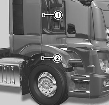
Заводская табличка автомобиля (1) находится на раме двери на стороне переднего пассажира. Идентификационный номер автомобиля (VIN) (2) выштампован на лонжероне рамы в правой колесной арке.
Данные на заводской табличке автомобиля
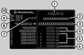
1. Изготовитель автомобиля («Даймлер АГ»). 2. Номер разрешения на эксплуатацию ЕС (только в исполнении для определенных стран). 3. Идентификационный номер автомобиля (VIN). 4. Полная нормативная масса (кг) / Полная нормативная масса автопоезда (кг). 5. Нормативные нагрузки на мосты 1–4 (кг). 6. Нормативная нагрузка на группу мостов T (кг). 7. Коэффициент дымности отработавших газов. 8. Передаточное число заднего моста. 9. Базовая установка угла наклона фар. 10. Тип автомобиля или модификация автомобиля.
Технически допустимую полную нормативную массу автопоезда Вы можете найти на заводской табличке автомобиля или в сертификате соответствия COC. Учитывайте, что при эксплуатации автомобиля для перевозки опасных грузов (ДОПОГ) технически допустимая полная нормативная масса автопоезда определяется действием постоянного тормоза автомобиля. Данное значение Вы найдете в разрешении на перевозку опасных грузов (ДОПОГ).
При возникновении дополнительных вопросов всегда обращайтесь в пункт ТО «Мерседес-Бенц».
Заводская табличка двигателя
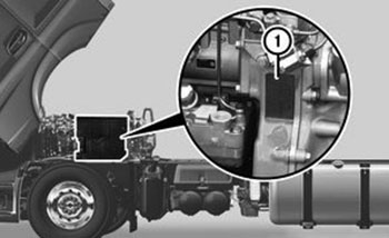
Двигатель OM 471 (пример)
Заводская табличка двигателя (1) находится слева по направлению движения, сзади на блок-картере двигателя.
Заводская табличка двигателя (1) содержит следующую информацию:
— Изготовитель.
— Тип двигателя.
— Модификация двигателя.
— Номер двигателя.
Эксплуатационные материалы
Важные указания по технике безопасности
Внимание:
Эксплуатационные материалы могут быть ядовитыми и вредными для здоровья. Существует опасность травмирования! При применении, хранении и удалении эксплуатационных материалов учитывайте предупреждения на наклейках на соответствующих оригинальных емкостях. Всегда храните эксплуатационные материалы в закрытых оригинальных емкостях. Не подпускайте детей к эксплуатационным материалам.
Примечание:
— Для допущенных эксплуатационных материалов не требуются или не допускаются специальные присадки, за исключением допущенных присадок к топливу. Присадки могут повлечь за собой повреждения агрегатов. Поэтому не примешивайте присадки к эксплуатационным материалам. За применение присадок ответственность всегда несете Вы.
— Удаляйте эксплуатационные материалы в строгом соответствии с требованиями охраны окружающей среды!
Эксплуатационными материалами являются:
— Концентрат стекломоющего средства.
— Топливо, например, дизельное топливо.
— AdBlue®, восстановитель системы нейтрализации отработавших газов BlueTec®.
— Смазочные материалы, например, моторные и трансмиссионные масла, консистентные смазки.
— Гидравлические масла.
— Охлаждающая жидкость.
— Хладагент системы кондиционирования воздуха.
Допущенные эксплуатационные материалы отвечают высшим стандартам качества и указаны в «Предписаниях «Мерседес-Бенц» по эксплуатационным материалам». Поэтому используйте только допущенные для Вашего автомобиля эксплуатационные материалы.
Информацию о допущенных эксплуатационных материалах Вы можете получить в любом пункте ТО «Мерседес-Бенц».
Допущенные «Мерседес-Бенц» эксплуатационные материалы распознаются по следующей надписи на емкости:
— MB-Freigabe (допуск «Мерседес-Бенц», например, Freigabe228.51)
или
— MB-Approval (допуск «Мерседес-Бенц», например, MB-Approval228.51).
Другие обозначения и рекомендации, указывающие на степень качества или спецификацию, не во всех случаях допущены «Мерседес-Бенц».
Дальнейшую информацию Вы получите в любом пункте ТО «Мерседес-Бенц».
Спецификация смазочных материалов и наличие их в продаже могут измениться. Отдельные смазочные материалы, особенно для старых автомобилей, могут не иметься в продаже.
Информацию по этому вопросу можно получить в любом пункте ТО «Мерседес-Бенц».
Моторные масла
Указания по моторным маслам
Примечание:
Использование моторных масел другой степени качества, кроме степени качества, предписанного в данном «Руководстве по эксплуатации», не допускается.

Качество моторных масел имеет решающее значение для работоспособности и срока службы двигателя. На основе сложных и дорогостоящих испытаний «Мерседес-Бенц» постоянно производит выдачу сертификатов допуска для моторных масел в соответствии с новейшим уровнем техники.
Для автомобилей BlueTec®6 используйте только моторные масла, соответствующие «Предписаниям «Мерседес-Бенц» по эксплуатационным материалам» согласно листу №228.51 или 228.31.
Для автомобилей BlueTec®6 с пакетом Fuel Efficiency Package (FE1) используйте моторные масла согласно листу №228.61, 228.51 или 228.31.
Для всех других автомобилей Вы можете использовать моторные масла согласно листу №228.5, 228.51, 228.3 или 228.31. Используйте преимущественно моторные масла согласно листу №228.5 или 228.3.
Моторные масла согласно листу №228.51 отличаются высоким качеством и благоприятно сказываются на:
— длительности интервала замены масла,
— параметрах износа двигателя,
— расходе топлива,
— выбросах отработавших газов.
Примечание:
На емкости для масла Вы найдете степень качества, например лист №228.51, и вязкость, например предписанный по SAE класс 5W-30.
Области применения
Всесезонные моторные масла согласно листам №228.51 или 228.31 можно использовать круглый год.
В зависимости от качества топлива (серосодержание или топливо FAME (метилэфир жирной кислоты)) интервалы замены масла сокращаются.
Замена масла
Примечание:
— При смешивании моторных масел различного качества интервалы замены моторного масла по сравнению с моторными маслами одинакового качества сокращаются. По этой причине смешивайте моторные масла различного качества только в исключительных случаях.
— Если залитое моторное масло предписанного по SAE класса (вязкости) не подходит для продолжительных низких температур наружного воздуха ниже -20 ºС, то это может привести к повреждению двигателя. Указания температуры предписанного по SAE класса относятся к свежим маслам. При эксплуатации автомобиля моторное масло стареет из-за попадания в него сажи и топливных осадков. В результате свойства моторного масла значительно ухудшаются, особенно при низкой температуре наружного воздуха. «Мерседес-Бенц» настоятельно рекомендует Вам при температуре наружного воздуха ниже -20 ºС использовать моторные масла предписанного по SAE класса 5W‑30 или 0W‑30. Пользуйтесь только всесезонными моторными маслами.
— Указание по охране окружающей среды: в случае эксплуатации автомобиля на топливе FAME (метилэфире жирной кислоты) (биодизельном топливе) соблюдайте специальные требования и национальные предписания по утилизации моторных масел. Информацию по этому вопросу Вы можете получить в любом пункте ТО «Мерседес‑Бенц».
Интервалы замены масла зависят от:
— условий эксплуатации автомобиля,
— качества залитого моторного масла,
— вида топлива, например топлива FAME (метилэфира жирной кислоты).
Выбирайте предписанный по SAE класс (вязкость) в соответствии с температурой наружного воздуха. Данные о предписанных по SAE классах и о диапазонах температуры наружного воздуха Вы найдете в листе сортов масла №224.2 в «Предписаниях «Мерседес-Бенц» по эксплуатационным материалам».
Максимальный интервал замены масла достигается только при использовании моторных масел, отвечающих высшему стандарту качества согласно листу №228.51 «Предписаний «Мерседес-Бенц» по эксплуатационным материалам». В бортовом компьютере автоматически индицируется срок очередной замены масла.
Заливка или доливка моторного масла
Примечание:
Превышение максимального уровня масла грозит повреждением катализатора и двигателя. Откачайте излишнее моторное масло.
«Мерседес-Бенц» рекомендует доливать моторные масла того же качества и предписанного по SAE класса, которые были использованы при последней замене масла.
Проверьте уровень масла в бортовом компьютере перед доливкой моторного масла.
Смешиваемость моторных масел
Вследствие смешивания сортов масла преимущества высококачественных моторных масел уменьшаются.
Моторные масла различаются по:
— марке моторного масла,
— степени качества (номер листа),
— предписанному по SAE классу (вязкости).
Если в исключительном случае Вы не располагаете залитым в двигатель моторным маслом, долейте другой сорт допущенного «Мерседес-Бенц» моторного масла.
Установка качества масла
Примечание:
Если на дисплее бортового компьютера появляется символ

, соблюдайте при доливке указанного объема масла следующие требования:
— При заливке или доливке моторного масла более низкого качества установите более низкое качество (номер листа) в бортовом компьютере.
— При заливке или доливке моторного масла более высокого качества не устанавливайте лучшее качество (номер листа) в бортовом компьютере.
Установите номер листа (степень качества) моторного масла на дисплее бортового компьютера.
Трансмиссионные масла
Общие указания
В заводской комплектации в ведущие мосты и коробку передач залито высококачественное синтетическое масло.
В ведущие мосты с планетарными колесными передачами залито минеральное масло.
Используйте для:
— автоматической коробки передач только трансмиссионные масла согласно листу № 236.91.
— автоматизированной механической коробки передач только трансмиссионные масла согласно листу № 235.11.
Примечание:
Замена синтетического масла минеральным трансмиссионным маслом может привести к повреждению агрегата. Перед заменой масла проверьте, допущено ли применение минерального масла. Информацию по этой теме Вы можете получить в любом пункте ТО «Мерседес‑Бенц».
Качество трансмиссионного масла
Степень качества (номер листа) залитого трансмиссионного масла может быть проверена на дисплее бортового компьютера.
Охлаждающая жидкость
Внимание:
— Контакт антифриза с горячими деталями в моторном отсеке может привести к воспламенению. Существует опасность пожара и травмирования! Перед доливкой антифриза дайте двигателю охладиться. Следите за тем, чтобы антифриз не проливался рядом с наливной горловиной.
— Перед запуском двигателя тщательно очищайте загрязненные антифризом детали.
На заводе автомобиль заправляется охлаждающей жидкостью, обеспечивающей защиту от замерзания и коррозии двигателя, а также другие важные защитные функции.
Охлаждающая жидкость представляет собой смесь воды и антифриза с антикоррозионными присадками.
Антифриз с антикоррозионными присадками в охлаждающей жидкости обеспечивает:
— теплопроводность,
— защиту от коррозии,
— защиту от кавитации (защиту от сквозной коррозии),
— защиту от замерзания,
— повышение точки кипения.
Оставляйте охлаждающую жидкость в системе охлаждения двигателя круглогодично— также и в странах с высокой температурой наружного воздуха.
Раз в полгода проверяйте концентрацию антифриза с антикоррозионными присадками в охлаждающей жидкости.
Пользуйтесь при этом только допущенными антифризами с антикоррозионными присадками согласно листу № 325.5. Это позволит Вам избежать повреждений системы охлаждения двигателя.
При замене охлаждающей жидкости следите за тем, чтобы охлаждающая жидкость содержала 50 объемн.% антифриза с антикоррозионными присадками. Это соответствует защите от замерзания до -37 ºС.
Не превышайте долю 55 объемн.% (защита от замерзания примерно до -45 ºС. В противном случае могут ухудшиться теплоотвод и защита от замерзания.
В случае утечки доливайте не только воду, но и в требуемой пропорции допущенный антифриз с антикоррозионными присадками.
Вода в охлаждающей жидкости должна удовлетворять определенным требованиям, которым часто отвечает питьевая вода. Если качество воды не соответствует определенным требованиям, то воду необходимо подготовить.
Смешайте воду и антифриз с антикоррозионными присадками вне контура охлаждающей жидкости. Только после этого влейте смесь в расширительный бачок охлаждающей жидкости.
Избегайте смешивания различных антифризов с антикоррозионными присадками.
Учитывайте «Предписания «Мерседес-Бенц» по эксплуатационным материалам» согласно листу №310.1.
Дальнейшую информацию об эксплуатационной надежности и безопасности движения Вашего автомобиля Вы можете получить в любом пункте ТО «Мерседес-Бенц».
Хладагент
Важные указания по технике безопасности
Система кондиционирования воздуха Вашего автомобиля заправлена хладагентом R-134a и содержит фторированный парниковый газ.
Указательная табличка используемого типа хладагента находится за крышкой для техобслуживания.
Примечание:
Допускается применение только хладагента R‑134a, а также допущенного «Мерседес‑Бенц» масла для кондиционера. Разрешенное масло для кондиционера нельзя смешивать с другими, не допущенными к использованию с хладагентом R‑134a, маслами для кондиционера. В противном случае может быть повреждена система кондиционирования воздуха.
Сервисные работы, например заливка хладагента или замена элементов и деталей, должны производиться только в специализированной мастерской с квалифицированным персоналом. При этом должны быть соблюдены все действительные предписания, касающиеся этого, а также стандарт SAEJ639.
Всегда поручайте выполнение всех работ на системе кондиционирования воздуха специализированной мастерской с квалифицированным персоналом.
Указательная табличка хладагента
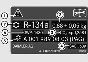
Указательная табличка хладагента (пример):
1. Символы предупреждений об опасности и о необходимости проведения ТО. 2. Заправочный объем хладагента. 3. Эквивалент CO 2 используемого хладагента. 4. Действующие стандарты. 5. Номер изделия для полиалкиленгликолевого масла (PAG). 6. Потенциал глобального потепления (Global Warming Potential) используемого хладагента. 7. Тип хладагента.
Символы (1) указывают на:
— возможные опасности,
— проведение сервисных работ в специализированной мастерской с квалифицированным персоналом.
Указания для качества топлива
Внимание:
При смешивании дизельного топлива с бензином точка воспламенения топливной смеси ниже, чем у чистого дизельного топлива. При работающем двигателе элементы системы выпуска ОГ могут незаметно перегреться. Существует опасность пожара! Никогда не заправляйтесь бензином. Никогда не примешивайте бензин к дизельному топливу.
Уже небольшие количества неправильного топлива могут привести к повреждениям системы питания, двигателя и системы нейтрализации ОГ.
Примечание:
— Заправляйте автомобиль только обычным дизельным топливом, соответствующим требованиям Европейского стандарта EN 590 (или сопоставимым национальным стандартам топлива).
— Автомобили с сажевым фильтром: в странах, в которых отсутствует бессернистое дизельное топливо, заправляйте Ваш автомобиль только малосернистым дизельным топливом с содержанием серы менее 50 мд. В противном случае возможно повреждение системы нейтрализации ОГ.

Знак совместимости для всех автомобилей с дизельным двигателем.
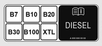
Знак совместимости только для автомобилей с технологией BlueTec® с двигателем OM471 (кодM0W).
Вы найдете знаки совместимости на стяжной ленте топливного бака и на топливораздаточной колонке или на пистолете раздаточной колонки автозаправочной станции:
— B7: для дизельного топлива с максимальным значением 7 объемн. % биодизельного топлива (метилэфир жирной кислоты).
— B10: для дизельного топлива с максимальным значением 10 объемн. % биодизельного топлива (метилэфир жирной кислоты).
— B20: для дизельного топлива с максимальным значением 20 объемн. % биодизельного топлива (метилэфир жирной кислоты).
— B30: для дизельного топлива с максимальным значением 30 объемн. % биодизельного топлива (метилэфир жирной кислоты).
— B100: для дизельного топлива с максимальным значением 100 объемн. % биодизельного топлива (метилэфир жирной кислоты).
— XTL: для парафинового дизельного топлива согласно стандарту EN 15940.
Указания, касающиеся низкой температуры наружного воздуха:
В начале зимнего периода по возможности полностью заправьте Ваш автомобиль зимним сортом дизельного топлива.
Перед переходом на зимний сорт дизельного топлива топливный бак должен быть как можно более пустым. Уровень топлива в топливном баке при первой заправке зимним сортом дизельного топлива должен быть низким, например соответствовать минимальному резерву. При следующей заправке топливом топливный бак снова можно заправлять как обычно.
Дополнительную информацию о топливе Вы найдете:
— на автозаправочной станции,
— в специализированной мастерской с квалифицированным персоналом.
Сорта дизельного топлива согласно европейскому стандарту EN 590
Важные указания по технике безопасности
Внимание:
Топливо – легковоспламеняющийся продукт. При ненадлежащем обращении с топливом существует опасность пожара и взрыва! Обязательно избегайте применения огня, открытого пламени, искрообразования и курения. Следите за тем, чтобы топливо не попадало на горячие элементы системы выпуска ОГ. Перед началом работ на системе питания выключите зажигание и систему дополнительного отопления. Всегда работайте в защитных перчатках.
Примечание:
При заправке автомобиля топливом из бочек или канистр заливайте топливо только через фильтр. Это позволит Вам предотвратить неисправности системы питания, вызываемые загрязнениями топлива.
Автомобили BlueTec®6: заправляйте автомобиль только обычным бессернистым дизельным топливом согласно европейскому стандарту EN 590 по состоянию на 2010 год с серосодержанием не более 0,001 вес. % (10млн-1).
Следующие виды топлива не допускаются:
— Топливо с серосодержанием более 0,001 вес.%.
— Судовое дизельное топливо.
— Авиационное турбинное топливо.
— Котельное топливо.
— Топливо FAME (метилэфир жирной кислоты) (биодизельное топливо).
Эти виды топлива наносят необратимый ущерб двигателю и системе нейтрализации отработавших газов BlueTec®6 и в значительной степени сокращают ожидаемый срок службы.
Автомобили BlueTec®4 и BlueTec®5: дизельное топливо должно соответствовать Европейскому стандарту EN 590. Таким образом двигатели достигают указанные показатели по мощности, а также предписанные законодательством значения ОГ согласно экологическим классам Евро-4 и Евро-5.
Использование топлива с серосодержанием более 0,005 вес. % (50млн-1) сокращает срок службы двигателя и системы выпуска ОГ.
Следующие виды топлива не допускаются:
— Топливо с серосодержанием более 0,05 вес. % (500млн-1).
— Судовое дизельное топливо.
— Авиационное турбинное топливо.
— Котельное топливо.
— Топливо FAME (метилэфир жирной кислоты) (биодизельное топливо) ˃ 7 объемн.%.
Автомобили без системы нейтрализации ОГ BlueTec®: заправляйте автомобиль только обычным бессернистым дизельным топливом согласно европейскому стандарту EN 590 по состоянию на 2010 год или согласно аналогичному национальному стандарту качества топлива.
Таким образом двигатели достигают указанные показатели по мощности, а также предписанные законодательством значения ОГ согласно экологическому классу Евро-3.
Следующие виды топлива не допускаются:
— OM 473: топливо с серосодержанием более 0,1 вес. % (1000млн-1).
— Судовое дизельное топливо.
— Авиационное турбинное топливо.
— Котельное топливо.
— Топливо FAME (метилэфир жирной кислоты) (биодизельное топливо) ˃ 7 объемн.%.
Примечание:
Высокое серосодержание топлива ускоряет процесс старения моторного масла, а также может повредить двигатель и систему выпуска ОГ.
В автомобилях без системы нейтрализации ОГ BlueTec® серосодержание топлива установлено в соответствии с типичными показателями в стране эксплуатации автомобиля. Если Вы заправляете дизельное топливо с другим серосодержанием, установите новое значение серосодержания на бортовом компьютере. Если Вам неизвестно серосодержание используемого дизельного топлива, то установите в бортовом компьютере наиболее высокое значение серосодержания.
Информацию об актуальном специфичном для определенной страны серосодержании топлива Вы можете получить в любом пункте ТО «Мерседес-Бенц» или в «Предписаниях «Мерседес-Бенц» по эксплуатационным материалам» согласно листу № 136.1 или 136.2.
В некоторых странах предлагаются сорта дизельного топлива с различным серосодержанием. Дизельное топливо с низким серосодержанием в некоторых странах предлагается под названием «Евродизель».
Дизельное топливо при низкой температуре
Внимание:
При нагревании элементов системы питания, например при помощи пистолета горячего воздуха или открытого огня, возможно повреждение этих элементов. Это может привести к выходу на поверхность топлива и его воспламенению. В зависимости от вида повреждения выход топлива может произойти только при работающем двигателе. Существует опасность пожара и взрыва! Никогда не нагревайте элементы системы питания. Для устранения неисправности обратитесь в специализированную мастерскую с квалифицированным персоналом.
При низкой температуре наружного воздуха текучесть дизельного топлива может быть недостаточной вследствие кристаллизации парафина.
Поэтому в зимний период во избежание перебоев в работе двигателя предлагаются сорта дизельного топлива с улучшенной текучестью.
В Федеративной Республике Германия и других среднеевропейских странах зимнее дизельное топливо обеспечивает надежную эксплуатацию примерно до -22 ºС. При обычной в этом регионе температуре наружного воздуха текучесть дизельного топлива для бесперебойной эксплуатации в большинстве случаев вполне достаточна.
Автомобиль может быть оснащен устройством предварительного подогрева топлива. Устройство предварительного подогрева топлива подогревает топливо, таким образом улучшая его текучесть.
Присадки к топливу
Примечание:
Не используйте присадок к топливу. Присадки к топливу могут привести к нарушениям функций и повреждениям двигателя. Не примешивайте к дизельному топливу бензина, керосина или средств для улучшения текучести. Такие средства для улучшения текучести ухудшают смазочные свойства дизельного топлива. Это может привести к повреждениям, например, в системе впрыскивания.
Виды биодизельного топлива согласно стандарту DIN EN 14214
UCOME (Used Cooking Oil Methyl Ester)
Запрещается эксплуатировать автомобиль на биодизельном топливе, допущенном к применению согласно стандарту EN14214, произведенном из использованного пищевого растительного масла / пищевого жира = UCOME (Used Cooking Oil Methyl Ester).
Топливо FAME (метилэфир жирной кислоты) (Fatty Acid Methyl Ester)
Эксплуатация на топливе FAME (метилэфир жирной кислоты) допускается только для автомобилей BlueTec® с двигателем OM471 (код M0W). В этих автомобилях двигатель должен быть дополнительно оснащен фильтром предварительной очистки топлива (код M8Y). Информацию на эту тему Вам предоставит любая специализированная мастерская с квалифицированным персоналом.
Обязательно учитывайте указания по технике безопасности, касающиеся эксплуатационных материалов.
При эксплуатации автомобиля используйте чистое топливо FАME (метилэфир жирной кислоты) согласно стандарту DIN EN 14214. Также допускается эксплуатация автомобиля на смеси обычного дизельного топлива согласно европейскому стандарту EN 590 с топливом FAME (метилэфиром жирной кислоты).
Соблюдайте требования, касающиеся эксплуатации на топливе FAME (метилэфире жирной кислоты), согласно листу номер135 «Предписаний «Мерседес-Бенц» по эксплуатационным материалам».
При движении на топливе FAME расход топлива немного возрастает.
При использовании топлива FAME соблюдайте следующие указания:
— Интервалы замены масла, а также топливных и масляных фильтров значительно сокращаются.
— При каждой замене масла производите замену топливного или масляного фильтра. Проводите замену масла, масляных и топливных фильтров в указанных интервалах, не позднее чем каждые шесть месяцев:
• Замена топливного фильтра каждые 30000 км.
• Замена масла и масляного фильтра каждые 60000 км
— Используйте только топливо FAME, отвечающее стандарту DIN EN 14214. Присадки к топливу или топливо, не отвечающее стандарту DIN EN 14214, могут привести к нарушениям работы или к повреждению двигателя.
— Топливо FAME разъедает лакированные поверхности. Поэтому не допускайте воздействия топлива FAME на лакокрасочное покрытие. Немедленно смывайте топливо FAME водой.
— При длительной стоянке топливо FAME может привести к залипанию конструкционных элементов системы питания. Поэтому перед длительным простоем двигателя израсходуйте весь запас топлива FAME. Заполните топливный бак обычным дизельным топливом и дайте двигателю поработать, прежде чем выключить его.
— Топливо FAME подвергается естественному процессу старения. «Мерседес-Бенц» рекомендует не заправлять автомобили с длительными периодами простоя, например пожарные автомобили, топливом FAME.
Низкая температура наружного воздуха
При температуре наружного воздуха ниже 5 ºС «Мерседес-Бенц» рекомендует не использовать топливо FAME (метилэфир жирной кислоты), а использовать обычное дизельное топливо.
В зависимости от сырья и процесса производства топлива FAME (метилэфира жирной кислоты) интервал замены топливного фильтра может значительно сократиться. Помимо этого, также ухудшается способность холодного двигателя к пуску.
Альтернативные виды дизельного топлива согласно стандарту DIN EN 15940
Обязательно учитывайте указания по технике безопасности, касающиеся эксплуатационных материалов.
Альтернативные виды дизельного топлива согласно стандарту DIN EN 15940 могут быть произведены из:
— гидрированного растительного масла (HVO – Hydrotreated Vegetable Oils),
— биомассы (BtL – Biomass-to-Liquid),
— природного газа (GtL – Gas-to-Liquid),
— угля (CtL – Coal-to-Liquid).
Вы можете использовать альтернативные виды дизельного топлива согласно стандарту DIN EN 15940 для следующих двигателей:
— OM470.
— OM471.
— OM473.
— OM936.
Допускается эксплуатация автомобиля с чистыми альтернативными видами дизельного топлива согласно стандарту DIN EN 15940 или на смеси обычного дизельного топлива с альтернативными видами дизельного топлива согласно стандарту DIN EN 15940.
Восстановитель AdBlue®
Указания по восстановителю AdBlue®
Примечание:
Используйте исключительно восстановитель AdBlue® / DEF согласно стандарту DIN 70070/ISO 22241. Не используйте присадки. В случае попадания восстановителя AdBlue® / DEF при заправке на лакированные или алюминиевые поверхности, немедленно обильно промойте поверхность чистой водой.
Если бак восстановителя AdBlue® еще в достаточной степени заполнен восстановителем AdBlue®, то при открывании пробки бака может произойти выравнивание давления. При этом возможен выход восстановителя AdBlue®. Поэтому осторожно вывинтите пробку бака восстановителя AdBlue®. При выходе восстановителя AdBlue® немедленно смойте его большим количеством воды.
Восстановитель AdBlue® представляет собой негорючую, нетоксичную, бесцветную, растворимую в воде жидкость без запаха.
При открывании бака восстановителя AdBlue® в небольших количествах возможен выход паров аммиака.
Аммиачные пары имеют резкий запах и действуют раздражающим образом, прежде всего, на:
— кожу,
— слизистые оболочки,
— глаза.
Вследствие этого может появиться жжение в глазах, носу и горле, а также кашель и слезотечение.
Не вдыхайте выступающие аммиачные пары. Производите заправку бака восстановителя AdBlue® только в хорошо вентилируемых помещениях.
Не допускайте попадания восстановителя AdBlue® на кожу, в глаза, на одежду или в организм. Не подпускайте детей к восстановителю AdBlue.
При контакте с восстановителем AdBlue® учитывайте следующее:
— Немедленно смойте восстановитель AdBlue® с кожи водой и мылом.
— При попадании восстановителя AdBlue®в глаза немедленно промойте их большим количеством чистой воды. Немедленно обратитесь к врачу.
— При проглатывании восстановителя AdBlue® немедленно промойте рот водой и выпейте большое количество воды. Немедленно обратитесь к врачу.
— Немедленно смените загрязненную восстановителем AdBlue® одежду.
Высокая температура наружного воздуха
При длительном нагревании восстановителя AdBlue® до температуры выше 50 ºС, например, под воздействием прямого солнечного излучения, возможно разложение восстановителя AdBlue®. При этом происходит выделение паров аммиака.
Низкая температура наружного воздуха
Восстановитель AdBlue® замерзает при температуре примерно -11 ºС. Система снабжения автомобиля восстановителем AdBlue® оснащена полностью автоматизированной системой подогрева восстановителя. Вследствие этого эксплуатация в зимний период обеспечена также при температуре ниже -11 ºС.
Присадки, водопроводная вода
Не примешивайте какие-либо присадки к восстановителю AdBlue®. Не разбавляйте восстановитель AdBlue® водопроводной водой. Вследствие этого возможно разрушение системы нейтрализации отработавших газов BlueTec®.
Хранение
Примечание:
Емкости из нижеследующих материалов непригодны для хранения восстановителя AdBlue® / DEF:
— алюминий,
— медь,
— медесодержащие сплавы,
— нелегированная сталь,
— оцинкованная сталь.
При хранении в емкостях из таких металлов частицы этих металлов могут отделиться и вызвать разрушение системы нейтрализации отработавших газов BlueTec®.
Используйте для хранения восстановителя AdBlue® только емкости из нижеследующих материалов:
— Хромоникелевая сталь согласно стандарту DIN EN 10 088-1/2/3.
— Хромоникелемолибденовая сталь согласно стандарту DIN EN 10 088-1/2/3.
— Полипропилен.
— Полиэтилен.
Утилизация
Примечание:
Удаляйте восстановитель AdBlue® в соответствии с требованиями охраны окружающей среды!
При утилизации восстановителя AdBlue® соблюдайте законодательные нормы страны, в которой Вы в данный момент находитесь.
Чистота
Примечание:
Загрязнения восстановителя AdBlue®, например, другими эксплуатационными материалами, чистящими средствами, пылью, ведут к:
— повышению значений эмиссии,
— повреждению катализатора,
— повреждению двигателя,
— нарушениям работы системы нейтрализации отработавших газов BlueTec®.
Во избежание нарушений работы системы нейтрализации отработавших газов BlueTec® постоянно следите за обеспечением чистоты восстановителя AdBlue®.
В случае слива восстановителя AdBlue® из бака, например, при ремонте, его повторная заливка в бак запрещена. Иначе чистота продукта при этом больше не обеспечена.
Эксплуатационные параметры
Пневматическое оборудование
| Минимальное давление | в барах |
| 1-й тормозной контур | 6,8 |
| 2-й тормозной контур | 6,8 |
| 3-й тормозной контур | 5,5 |
| Контур коробки передач/ сцепления | 5,5 |
| Давление отпускания в тормозном цилиндре с пружинным энергоаккумулятором | 6,5 |
| Давление воздуха в ресиверах | в барах |
| Рабочий тормоз | 10,5–13,6 |
| Пневмоподвеска | 10,5–15,5 |
| Внешний источник сжатого воздуха (заполнение пневматической системы) | 11,0–12,5 |
| Прочие пневматические контуры | 7,0–8,7 |
Двигатель
Двигатель OM 936 с объемом 7698 cм³:
| Частота вращения холостого хода | примерно 600об/мин |
| Моторный тормоз (диапазон действия) | примерно 1000–3000 об/мин |
| Диапазон частоты вращения максимального крутящего момента двигателя | примерно 1200–1600 об/мин |
| Частота вращения максимальной мощности двигателя | примерно 2200об/мин |
Двигатели OM 470 с объемом 10667cм³ и OM 471 с объемом 12809cм³:
| Частота вращения холостого хода | примерно 500–550 об/мин |
| Моторный тормоз (диапазон действия) | примерно 1000–2300 об/мин |
| Частота вращения максимального крутящего момента двигателя | примерно 1100 об/мин |
| Частота вращения максимальной мощности двигателя | примерно 1600 — 1800 об/мин |
Двигатель OM 473 с объемом 15569 см³:
| Частота вращения холостого хода | примерно 500об/мин |
| Моторный тормоз (диапазон действия) | примерно 1000–2300 об/мин |
| Частота вращения максимального крутящего момента двигателя | примерно 1100 об/мин |
| Частота вращения максимальной мощности двигателя | примерно 1600об/мин |
Рабочая температура
| OM 936 | |
| Нормальные условия эксплуатации | примерно 80–100 ºС |
| Максимально допустимая температура охлаждающей жидкости во время эксплуатации автомобиля | до 103 ºС |
| Автоматически уменьшенная мощность двигателя | от 103 ºС |
| OM 470, OM 471, OM 473 | |
| Нормальные условия эксплуатации | примерно 85– 105 ºС |
| Максимально допустимая температура охлаждающей жидкости во время эксплуатации автомобиля | до 110 ºС |
| Автоматически уменьшенная мощность двигателя | от 110 ºС |
Давление воздуха в шинах
| Допустимая разница давления в шинах одного моста | 20 кПа (0,2 бар, 3 пси) |
| Максимально допустимое давление воздуха для накачивания шин | 1000 кПа (10,0 бар, 145 пси) |
Моменты затяжки гаек крепления колес
Моменты затяжки гаек крепления колес идентичны для легкосплавных и стальных колесных дисков.
| Гайки крепления колес с нажимными дисками (центровка по центральному отверстию) M22x1,5 для колес с диаметром 20″, 22,5″ и 24″. Крепление с десятью отверстиями | 600Н∙м |
| Гайки крепления колес с нажимными дисками (центровка по центральному отверстию) M18x1,5 для колес с диаметром 17,5″. Крепление с шестью отверстиями | 400Н∙м |
| Гайки крепления колес со сферическим пружинным кольцом | 450Н∙м |
| Соединительный фланец при сдвоенных шинах 14.00R20 | 450Н∙м |
| Колпачки гаек крепления колес | 60Н∙м |
Пружинный энергоаккумулятор
| Крутящий момент при отпускании винта отпускания тормозного цилиндра с пружинным энергоаккумулятором | не более70Нм |
| Момент затяжки винта отпускания тормозного цилиндра с пружинным энергоаккумулятором | не более35Нм |
| Давление отпускания (давление внешнего источника сжатого воздуха) | не менее 6,5бар |
Система регулирования дорожного просвета
| Заполнение пневмоподвески воздухом через штуцер28 электронного блока подготовки воздуха | не более 12,5бар |
Ресивер сжатого воздуха
Информация о ресивере для сжатого воздуха
Для первичных покупателей, потребителей и пользователей:
Сопроводительная документация в соответствии с директивой 2009/105/EG Европейского парламента и Совета ЕС и техническим стандартом EN 286-2.
Ресивер…:
1) Предназначен исключительно для использования в тормозных системах с пневматическим приводом и вспомогательных устройствах автомобилей, а также их прицепов и только для приема сжатого воздуха.
2) Для идентификации маркирован заводским номером и наименованием изготовителя ресивера, а также основными эксплуатационными параметрами и знаком ЕС, см. заводскую табличку или обозначения непосредственно на корпусе ресивера.
3) Изготовлен согласно «Сертификату соответствия» в соответствии со статьей 12 директивы ЕС 2009/105/EG.
4) Крепится на автомобиле крепежными лентами (хомутами).
Конструкция контактных поверхностей алюминиевых ресиверов должна исключать появление коррозии и механических повреждений. Стяжные ремни следует закрепить так, чтобы они не соприкасались с соединительными швами оснований, а ресивер не подвергался напряжениям, снижающим эксплуатационную надежность.
Покрытия алюминиевых ресиверов не должны содержать свинца, а лаки должны наноситься только с соответствующей грунтовкой. Стальные резьбовые соединения алюминиевых ресиверов должны иметь антикоррозионное покрытие:
— Обрабатывайте алюминиевые ресиверы только чистящими средствами, не содержащими щелочей.
— Производите внутренний визуальный контроль через резьбовые отверстия.
— Во избежание скопления конденсата регулярно сливайте его (кольцо на спускном вентиле расположено в самой нижней точке ресивера).
5) Не требует техобслуживания при соблюдении пункта «4)».
6) Не допускается проведение на находящихся под давлением стенках ресивера (оболочке, днищах, резьбовых кольцах) сварочных работ, термической обработки или прочих работ, способных повлиять на безопасность.
7) Кратковременные пики давления в ресивере не должны более чем на 10 % превышать максимально допустимое избыточное рабочее давление Ps.
Заводские таблички ресиверов для сжатого воздуха
Алюминиевые ресиверы
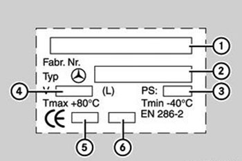
Заводская табличка на алюминиевом ресивере (пример):
1. Изготовитель: фирма SAG (Австрия). 2. Номер изделия «Мерседес-Бенц». 3. Максимальное рабочее давление (бар). 4. Емкость (л). 5. Код испытательной службы. 6. Год выпуска.
Стальные ресиверы
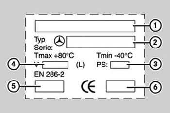
Заводская табличка на стальном ресивере (пример):
1. Изготовитель: Фирма frauenthal automotive / Фирма Erhard. 2. Номер изделия «Мерседес-Бенц». 3. Максимальное рабочее давление (бар). 4. Емкость (л). 5. Год выпуска. 6. Код испытательной службы.
Hello! On this page you can find and download service manuals for heavy truck Mercedes-Benz, which includes three main series of trucks: Mercedes Actros, Mercedes Axor, Mercedes Atego, as
well as Econic and Unimog trucks.

![]()
Mercedes Atego PDF Service Manual
Mercedes Atego PDF Service Manual.pdf
Adobe Acrobat Document
4.6 MB
![]()
Mercedes Sprinter CDI engine PDF Service Manual
Mercedes Sprinter CDI engine PDF Service
compressed file archive
21.5 MB
![]()
Mercedes Sprinter 1995-2007 PDF Service Manual
Mercedes Sprinter 1995-2007 PDF Service
compressed file archive
37.1 MB
![]()
Mercedes-Benz Sprinter 2005 PDF Service Manual
Mercedes-Benz Sprinter 2005 PDF Service
compressed file archive
33.0 MB
![]()
Mercedes-Benz Sprinter 2006 PDF Service Manual
Mercedes-Benz Sprinter 2006 PDF Service
compressed file archive
41.8 MB
![]()
Mercedes-Benz Sprinter 2007 Owners Manual
Mercedes-Benz Sprinter 2007 Owners Manua
Adobe Acrobat Document
9.8 MB
Mercedes Atego PDF Service Manual
Mercedes Sprinter 1995-2007 PDF Service Manual
Mercedes Sprinter CDI engine PDF Service Manual
Mercedes Vario 1996-2003 PDF Service Manual
Mercedes-Benz Arocs (964) Service Manual
Mercedes-Benz Atego 1998 PDF Service Manual
Mercedes-Benz Axor 940-954 PDF Service Manual
Mercedes-Benz MB 100D PDF Service Manual
Mercedes-Benz Series 405 Service Manual
Mercedes-Benz Sprinter 1995-2000 PDF Service Manual
Mercedes-Benz Sprinter 2005 PDF Service Manual
Mercedes-Benz Sprinter 2006 PDF Service Manual
Mercedes-Benz Sprinter 2007 Owners Manual
Mercedes-Benz T1 PDF Service Manual
|
Title |
File Size |
Download Links |
|
Mercedes-Benz Actros Fault Codes List PDF [PDF] |
236.3kb |
Download |
|
Mercedes-Benz Atego Fault Codes List PDF [PDF] |
236.3kb |
Download |
|
Mercedes-Benz Axor Fault Codes List PDF [PDF] |
236.3kb |
Download |
|
Mercedes-Benz Engine Fault Codes List [PDF] |
383.5kb |
Download |
|
Mercedes-Benz Fault code list for brake system (BS) control unit PDF |
29.3kb |
Download |
|
Mercedes-Benz Fault code list for control unit of engine control (MR) |
26.6kb |
Download |
|
Title |
File Size |
Download Links |
|
Mercedes-Benz Series 405 Introduction Into Service Manual |
4.2Mb |
Download |
|
Mercedes-Benz Unimog 416 1976 Instruction Manual [PDF] |
16Mb |
Download |
|
Mercedes-Benz Unimog 435 / 435.111 / 435.110 / 435.117 / 435.160 / |
7.4Mb |
Download |
|
Mercedes-Benz Unimog Series 405 Service Manual [PDF] |
4.2Mb |
Download |
|
Mercedes-Benz Unimog U 20 / U 300 / U 400 / U 500 Manual [PDF] |
3.3Mb |
Download |
|
Mercedes-Benz Unimog U 5023, U 4023 BlueTec 6 Technical Manual |
5.5Mb |
Download |
|
Unimog (model series 405) PDF Service Manuals [PDF] |
4.2Mb |
Download |
|
Unimog 404 PDF CLEANING INSTRUCTIONS [PDF] |
3.8Mb |
Download |
|
Unimog 421-411 PDF Workshop Manual [PDF] |
31.2Mb |
Download |
|
Unimog PDF Service Manuals [PDF] |
8Mb |
Download |
|
Unimog SMALL EMPLACEMENT EXCAVATOR — operator / s manual [PDF] |
1.4Mb |
Download |
|
Unimog tractor, wheeled, 4×4 ded high mobility material handler — |
3.6Mb |
Download |
![]()
Unimog (model series 405) PDF Service Manuals
Unimog (model series 405) PDF Service Ma
Adobe Acrobat Document
4.9 MB
![]()
Unimog 421-411 PDF Workshop Manual
Unimog 421-411 PDF Workshop Manual.pdf
Adobe Acrobat Document
32.8 MB
![]()
Unimog SMALL EMPLACEMENT EXCAVATOR — operator’s manual
Unimog SMALL EMPLACEMENT EXCAVATOR — ope
Adobe Acrobat Document
1.6 MB
![]()
Unimog 404 PDF CLEANING INSTRUCTIONS
Unimog 404 PDF CLEANING INSTRUCTIONS.pd
Adobe Acrobat Document
4.5 MB
![]()
Unimog PDF Service Manuals
Unimog PDF Service Manuals.pdf
Adobe Acrobat Document
11.0 MB
![]()
Unimog tractor, wheeled, 4×4 ded high mobility material handler — operator’s manual
Unimog tractor, wheeled, 4×4 ded high mo
Adobe Acrobat Document
3.8 MB
|
Title |
File Size |
Download Links |
|
Mercedes-benz mbe 4000 service manual [PDF] |
4.9Mb |
Download |
|
Mercedes-benz mbe 4000 valve lash checking [PDF] |
295.1kb |
Download |
|
Mercedes-benz mbe 900 valve lash checking [PDF] |
205.7kb |
Download |
|
Mercedes-Benz Engine MBE4000 workshop manual [PDF] |
12.7Mb |
Download |
|
Mercedes-Benz Engine OM 457 LA PDF manual [PDF] |
15.5Mb |
Download |
|
Mercedes-Benz Engine OM 471 PDF manual [PDF] |
20.2Mb |
Download |
|
Mercedes-Benz Engine OM 501 — OM 502 PDF manual [PDF] |
1.2Mb |
Download |
|
Mercedes-Benz Engine OM 900 PDF manual [PDF] |
15.5Mb |
Download |
|
Mercedes-Benz Engine OM906LA — OM926LA PDF repair manual [PDF] |
25.5Mb |
Download |
|
Mercedes-Benz Transmission AGS and GS7 Shift Systems PDF manual |
7.3Mb |
Download |
![]()
Mercedes-Benz MBE 900 valve lash checking
Mercedes-benz mbe 900 valve lash checki
Adobe Acrobat Document
225.7 KB
![]()
Mercedes-Benz MBE 4000 service manual
Mercedes-benz mbe 4000 service manual.p
Adobe Acrobat Document
5.6 MB
![]()
Mercedes-Benz MBE 4000 valve lash checking
Mercedes-benz mbe 4000 valve lash check
Adobe Acrobat Document
311.1 KB
|
Title |
File Size |
Download Links |
|
Mercedes Benz Actros 2031 S Specifications [PDF] |
555.1kb |
Download |
|
Mercedes Benz Actros 2648LS 6×4 v3 Specifications [PDF] |
776.8kb |
Download |
|
Mercedes Benz Actros 3939 K 6×4 39 Specifications [PDF] |
314.7kb |
Download |
|
Mercedes Benz Actros 4043 S 6×4 33 Specifications [PDF] |
283.5kb |
Download |
|
Mercedes Benz Actros 4046 S 6×4 33 Specifications [PDF] |
380.1kb |
Download |
|
Mercedes Benz Actros 4054 S Specifications [PDF] |
604.4kb |
Download |
|
MERCEDES BENZ Actros ABS EBS Wiring Diagrams [PDF] |
547.9kb |
Download |
|
Mercedes Benz Actros Brochure [PDF] |
2.5Mb |
Download |
|
Mercedes Benz Actros MP4 Water Retarder [PDF] |
393.9kb |
Download |
|
Mercedes Benz Actros Spec Engines Brochure [PDF] |
3.4Mb |
Download |
|
Mercedes Benz Actros Specifications [PDF] |
4.6Mb |
Download |
|
Mercedes Benz New Actros MP2 Training Manual [PDF] |
6.7Mb |
Download |
|
Mercedes-Benz 963 / 964 2022 Series Manual [PDF] |
2.3Mb |
Download |
|
Mercedes-Benz Actros — electronic systems Model 963 [PDF] |
36.2Mb |
Download |
|
Mercedes-Benz Actros 2017 Operating Instructions Manual [PDF] |
8.1Mb |
Download |
|
Mercedes-Benz Actros 932314 GS manual PDF [PDF] |
1.9Mb |
Download |
|
Mercedes-Benz Actros Abs Ebs Schematic Wiring Diagrams [PDF] |
713.2kb |
Download |
|
Mercedes-Benz Actros GS Service Manual [PDF] |
799kb |
Download |
|
Mercedes-Benz Actros Manual Oper Cplto [PDF] |
7.5Mb |
Download |
|
Mercedes-Benz Actros MP II Service Manual [PDF] |
7.9Mb |
Download |
|
Mercedes-Benz Actros MP4 2020 Driver Familiarisation [PDF] |
1.4Mb |
Download |
|
Mercedes-Benz Actros Operating Instructions Manual [PDF] |
6Mb |
Download |
|
Mercedes-Benz Actros, Antos, Arocs Full Service Manual 2014 |
18.8Mb |
Download |
|
Mercedes-Benz Antos 2017 Operating Instructions Manual [PDF] |
8.1Mb |
Download |
Description: The disc is a complete technical documentation for the maintenance and repair of first generation Actros from WIS. All information is in Russian.
There are fault codes with detailed interpretation, description of the parameters of the self-diagnosis menu, electrical and pneumatic circuits.
The disk will be useful to those who deal primarily with the repair of the Actros.
Extras. Information: Attention! The disk works correctly only if the drive is called V. (The virtual drive is easily renamed from the image-reading program.) If you write to
disk, you can change the drive letter in Administration / Computer Management / Storage / Disk Management).
Another inconvenience — when accessing pdf requests a password. The password is the first 4 digits of the file name (in the example on the screenshot — password 0500).
|
Title |
File Size |
Download Links |
|
Mercedes Benz Accelo 2019 Operator’s Manual [PDF] |
2.9Mb |
Download |
|
Mercedes-Benz Accelo 1016 [PDF] |
2.3Mb |
Download |

Mercedes-Benz Actros (lineup 950-954). Catalog of technical documentation [ISO, ENG, RUS, 700 MB] — download
|
Title |
File Size |
Download Links |
|
Mercedes Atego 1016 Spare Parts Catalogue [PDF] |
8.3Mb |
Download |
|
Mercedes Atego Axor Actros Spare Parts Catalogue [PDF] |
9.3Mb |
Download |
|
Mercedes Atego PDF Service Manual [PDF] |
3.3Mb |
Download |
|
Mercedes Atego Service Manual [PDF] |
3.3Mb |
Download |
|
Mercedes-Benz ATEGO –Specifications [PDF] |
1.7Mb |
Download |
|
Mercedes-Benz Atego 1016 EURO V Repair Manual [PDF] |
10Mb |
Download |
|
Mercedes-Benz Atego 1018 Specifications [PDF] |
1.1Mb |
Download |
|
Mercedes-benz Atego 1998-2004 Repair Manual [PDF] |
104.6Mb |
Download |
|
Mercedes-Benz Atego INSTRUÇÕES PDF [PDF] |
3Mb |
Download |
|
Mercedes-Benz Atego Manual de Utilizare [PDF] |
15.4Mb |
Download |
|
Mercedes-Benz Atego Manual [PDF] |
8.7Mb |
Download |
|
Mercedes-Benz Atego PDF Service Manual [PDF] |
3.3Mb |
Download |
|
Mercedes-Benz Atego Rigid 12XXL Specifications [PDF] |
420.5kb |
Download |
|
Mercedes-Benz Atego Specifications [PDF] |
1.7Mb |
Download |
|
Mercedes-Benz Atego Towing — Recovery PDF manual [PDF] |
8.7Mb |
Download |
|
Mercedes-Benz New Atego Introduction into Service Manual [PDF] |
1.2Mb |
Download |
|
Title |
File Size |
Download Links |
|
Mercedes-Benz Arocs 2017 Operating Instructions Manual [PDF] |
8.1Mb |
Download |
|
Mercedes-Benz Arocs Introduction Into Service Manual [PDF] |
3.9Mb |
Download |
|
Mercedes-Benz Arocs Operating Instructions Manual [PDF] |
6Mb |
Download |
|
New Mercedes Arocs Brochure [PDF] |
6.3Mb |
Download |
|
Mercedes-Benz Arocs (964) Service Manual [PDF] |
3.9Mb |
Download |
|
Mercedes-Benz Arocs Full-Service Manual 2014 [PDF] |
18.8Mb |
Download |
|
Title |
File Size |
Download Links |
|
Mercedes-Benz Axor Electrical Wiring Diagram [PDF] |
14.4Mb |
Download |
|
Mercedes-Benz Axor Fuel System repair manual [PDF] |
390kb |
Download |
|
Mercedes-Benz Axor Fuel System Service Manual [PDF] |
60kb |
Download |
|
Mercedes-Benz Axor Owner’s Maintenance Manuals rus [PDF] |
147.9Mb |
Download |
|
Mercedes-Benz Axor PDF manual [PDF] |
5.5Mb |
Download |
|
Mercedes-Benz Axor Spare Parts Catalogue [PDF] |
9.3Mb |
Download |
|
Mercedes-Benz Axor Specifications [PDF] |
1.6Mb |
Download |
|
Mercedes-Benz Axor Wiring Diagrams [PDF] |
823.4kb |
Download |
|
Title |
File Size |
Download Links |
|
Mercedes-Benz Sprinter 2007 Owners Manual [PDF] |
9.4Mb |
Download |
|
Mercedes-Benz Sprinter Service Manual [PDF] |
37.7Mb |
Download |
Multimedia guide in the English language for the operation, maintenance and repair of Mercedes-Benz buses and trucks produced in Brazil.
Mercedes-Benz SELiT
Multimedia information base in the English language for repair of cars and trucks, Mercedes-Benz buses for European and American markets.
Mercedes-Benz WIS ASRA 2016
Mercedes-Benz today is one of the brands of the Truck Group of DaimlerChrysler Corporation and the leading brand of truck sales in the world. The production facilities and car factories on which
the Mercedes trucks are assembled are located in Germany, France, Turkey, Mexico. Annually, under the Mercedes-Benz brand, more than 140,000 trucks are delivered to consumers, half of them to the
countries of Western Europe, where Mercedes-Benz has the largest share in the market among European and world manufacturers — 22%.
However, while Mercedes trucks are only part of the cargo empire DaimlerChrysler. The Truck Group of the German-American concern includes, in addition to Mercedes-Benz, also such trademarks and
manufactures as Freightliner, Sterling, Western Star and Thomas Built Buses in America and Mitsubishi Fuso in Japan. In total
DaimlerChrysler concern annually realizes in the world more than 530 thousand lorries for the sum close to 32 billion Euro.
The Mercedes-Benz heavy-duty lineup includes three main series of trucks: Mercedes Actros, Mercedes Axor, Mercedes Atego, as well as Econic and Unimog trucks offered by the company in some
regions.

top of page
Инструкции по эксплуатации, ремонту и обслуживанию
автомобилей Mercedes-Benz Actros MP4 EURO 6
В данном разделе нашего сайта мы попытаемся собрать основные инструкции по эксплуатации автомобиля Мерседес-Бенц Актрос МР4 Евро 6, необходимые как для водителей, так и для владельцев транспортных средств. Инструкции будем использовать как разработанные заводом изготовителем, так и лично нами, основываясь на личном опыте. В связи с чем информируем Вас, что в приведенной информации могут содержаться ошибки и не точности.


Инструкции по эксплуатации автомобиля
Mercedes-Benz Actros MP4 EURO 6
Инструкции по уходу и обслуживанию за автомобилем
Mercedes-Benz Actros MP4 EURO 6
bottom of page
 Loading…
![]()
Electronic systems, Actros, model 963
Functional description
– This printout will not be recorded by the update service. Status: 09 / 2011 –

Mercedes>Benz Service
Electronic systems, Actros, model 963
Technical status 09.11
Daimler AG . Technical Information and Workshop Equipment(GSP/OI)
D$70546 Stuttgart
– This printout will not be recorded by the update service. Status: 09 / 2011 –

Information and copyright
Product portfolio
You can also find comprehensive information about our complete product portfolio on our Internet portal: Link: http://aftersales.mercedes>benz.com
Questions and suggestions
If you have any questions or suggestions concerning this product, please write to us.
|
E>Mail: |
customer.support@daimler.com |
|
Telefax: |
+49>(0)18 05/0 10>79 78 |
or alternatively
Address: Daimler AG GSP/OIS,
HPC R822, W002
D>70546 Stuttgart (Germany)
©2011 by Daimler AG
This document, including all its parts, is protected by copyright.
Any further processing or use requires the previous written consent of Daimler AG, Department GSP/OIS, HPC R822, W002, D>70546 Stuttgart.
This applies in particular to reproduction, distribution, alteration, translation, microfilming and storage and/or processing in electronic systems, including databases and online services.
|
Image no. of title image: |
W00.01>1016>00 |
|
Order no. of this publication: |
6517 1261 02 > HLI 000 000 02 89 |
|
09/11 |
– This printout will not be recorded by the update service. Status: 09 / 2011 –

Preface
SN00.00>W>0001>01HA Preface
This brochure
Actros electronic systems, model 963
is intended for the technical personnel responsible for service and maintenance of Mercedes>Benz trucks.
The content of this brochure is split up into:
• function descriptions
• component descriptions
• Description of locations of electrical connectors, sockets and ground points
All the data listed in this brochure correspond with the technical status as per September 2011.
Any changes or supplements hereto will be published in the Workshop Information System (WIS) only.
Additional documents for model 963, such as maintenance and repair instructions or wiring diagrams are also available in the Workshop Information System (WIS).
Mercedes>Benz
W‘rth plant, GSP/TTM
September 2011
|
i Electronic systems, Actros, model 963 > 09/2011 > |
1 |
– This printout will not be recorded by the update service. Status: 09 / 2011 –

Contents
|
SN00.00>W>0110H |
Overview of as>built configuration and function descriptions |
2.8.11 |
|
MODEL 963 |
|
Function descriptions |
|||
|
Overall network |
Page 15 |
||
|
Overall network, function |
Page 16 |
||
|
Maintenance system, function |
Page 22 |
||
|
Maintenance system, overall network |
Page 23 |
||
|
Data acquisition function |
Page 24 |
||
|
Data storage function |
Page 29 |
||
|
Normal mode displays function |
Page 30 |
||
|
Reset service item function |
Page 32 |
||
|
Forecast calculation, function |
Page 34 |
||
|
Life cycle consumption calculation, |
Page 35 |
||
|
function |
|||
|
Transmission automation, function |
Page 37 |
||
|
Transmission automation, overall network |
Page 40 |
||
|
Operation, function |
Page 41 |
||
|
Driver information, function |
Page 44 |
||
|
Transmission mode, function |
Page 45 |
||
|
Shifting the transmission, function |
Page 46 |
||
|
Controlling the clutch, function |
Page 52 |
||
|
Countershaft brake, function |
Page 54 |
||
|
Level control, function |
Page 56 |
||
|
Level control, overall network |
Page 59 |
||
|
Axle load measuring system, function |
Page 60 |
||
|
Monitoring/control of specified level, |
Page 62 |
||
|
function |
|||
|
Changeover from level 1 to level 2, |
Page 64 |
||
|
function |
|||
|
Raise/lower vehicle frame manually, |
Page 66 |
||
|
function |
|||
|
Store frame height, function |
Page 68 |
||
|
Constant frame height when |
Page 70 |
||
|
loading/unloading, function |
|||
|
Raise/lower lift axle, function |
Page 73 |
||
2
– This printout will not be recorded by the update service. Status: 09 / 2011 –

|
Contents |
|||
|
Starting>off aid, function |
Page 76 |
||
|
Load/relieve additional axles, function |
Page 78 |
||
|
Roll control, function |
Page 81 |
||
|
Roll control, overall network |
Page 84 |
||
|
Tire pressure monitor, function |
Page 85 |
||
|
Tire pressure monitor, overall network |
Page 86 |
||
|
Tire pressure monitor, driver information |
Page 87 |
||
|
Electronic Brake Control, function |
Page 88 |
||
|
Electronic Brake Control, overall network |
Page 92 |
||
|
Brake application on front axle with |
Page 93 |
||
|
Electronic Brake Control, function |
|||
|
Brake application on front axle without |
Page 95 |
||
|
Electronic Brake Control, function |
|||
|
Brake application on rear axle with |
Page 97 |
||
|
Electronic Brake Control, function |
|||
|
Brake application on rear axle without |
Page 99 |
||
|
Electronic Brake Control, function |
|||
|
Trailer control with Electronic Brake |
Page 101 |
||
|
Control, function |
|||
|
Trailer control without Electronic Brake |
Page 104 |
||
|
Control, function |
|||
|
Auxiliary braking effect, function |
Page 106 |
||
|
Electronic Stability Program, function |
Page 108 |
||
|
Electronic Stability Program, overall |
Page 111 |
||
|
network |
|||
|
Intervention of Electronic Stability Program |
Page 112 |
||
|
in the event of understeer or oversteer, |
|||
|
function |
|||
|
Intervention of Electronic Stability Program |
Page 114 |
||
|
upon risk of tipping, function |
|||
|
Compressed air supply system, function |
Page 116 |
||
|
Compressed air supply system, overall |
Page 122 |
||
|
network |
|||
|
Hydraulic retarder, function |
Page 123 |
||
|
Overall network of hydraulic retarder |
Page 129 |
||
|
Single>circuit power steering, function |
Page 130 |
||
|
i Electronic systems, Actros, model 963 > 09/2011 > |
3 |
– This printout will not be recorded by the update service. Status: 09 / 2011 –

Contents
|
Additional steering axle, function |
Page 133 |
||
|
Additional steering axle, overall network |
Page 137 |
||
|
Additional steering axle, hydraulics |
Page 138 |
||
|
diagram |
|||
|
Driving assistance systems, function |
Page 139 |
||
|
Driving assistance systems, overall network |
Page 144 |
||
|
Proximity Control Assist function |
Page 145 |
||
|
Active Brake Assist function |
Page 149 |
||
|
Lane Keeping Assist function |
Page 154 |
||
|
Battery sensor function |
Page 158 |
||
|
Overall network battery sensor |
Page 159 |
||
|
Modular switch panel function |
Page 160 |
||
|
Overall network modular switch panel |
Page 162 |
||
|
Instrument cluster, function |
Page 163 |
||
|
Instrument cluster, overall network |
Page 166 |
||
|
Instrument cluster operating notes |
Page 167 |
||
|
Display fuel quantity, function |
Page 168 |
||
|
Display outside temperature, function |
Page 169 |
||
|
Display engine speed, function |
Page 170 |
||
|
Display speed and travel distance, function |
Page 171 |
||
|
Display AdBlue level, function |
Page 173 |
||
|
Redundancy operation of Electronic Air> |
Page 174 |
||
|
Processing Unit (EAPU), function |
|||
|
Signaling system, function |
Page 175 |
||
|
Overall network of signaling system |
Page 177 |
||
|
Power windows, function |
Page 178 |
||
|
Power windows, overall network |
Page 181 |
||
|
Electric power sliding roof, function |
Page 182 |
||
|
Electric power sliding rood, overall |
Page 184 |
||
|
network |
|||
|
Central locking, function |
Page 185 |
||
4
– This printout will not be recorded by the update service. Status: 09 / 2011 –

|
Contents |
|||
|
Central locking, overall network |
Page 191 |
||
|
Comfort locking system function |
Page 192 |
||
|
Comfort locking system overall network |
Page 198 |
||
|
Anti>theft alarm system, function |
Page 199 |
||
|
Anti>theft alarm system, overall network |
Page 201 |
||
|
Anti>theft alarm system, status messages |
Page 202 |
||
|
Activate antitheft alarm system, function |
Page 205 |
||
|
Deactivate anti>theft alarm system, |
Page 210 |
||
|
function |
|||
|
Triggering alarm by disconnecting trailer |
Page 214 |
||
|
or semitrailer, function |
|||
|
Alarm actuation by unlocking cab, function |
Page 217 |
||
|
Triggerring alarm with panic switch, |
Page 220 |
||
|
function |
|||
|
Alarm triggering with interior protection, |
Page 223 |
||
|
function |
|||
|
Alarm triggering by steeling fuel, function |
Page 226 |
||
|
Alarm triggering by unlocking/opening a |
Page 229 |
||
|
door/flap, function |
|||
|
Alarm triggering by alarm siren, function |
Page 233 |
||
|
Drive authorization system, function |
Page 236 |
||
|
Drive authorization system overall network |
Page 238 |
||
|
Exterior lighting, function |
Page 239 |
||
|
Exterior lights, overall network |
Page 241 |
||
|
Headlamp control, function |
Page 242 |
||
|
Fog lamp actuation, function |
Page 246 |
||
|
Rear fog lamp actuation, function |
Page 247 |
||
|
Turn signal light actuation, function |
Page 248 |
||
|
Brake lights actuation, function |
Page 250 |
||
|
Backup light actuation, function |
Page 252 |
||
|
Emergency light actuation, function |
Page 253 |
||
|
Floodlight actuation, function |
Page 255 |
||
|
Interior illumination, function |
Page 257 |
||
|
Interior illumination, overall network |
Page 259 |
||
|
Ambient lighting actuation, function |
Page 260 |
||
|
Interior illumination actuation, function |
Page 261 |
||
|
i Electronic systems, Actros, model 963 > 09/2011 > |
5 |
– This printout will not be recorded by the update service. Status: 09 / 2011 –

Contents
|
Reading light actuation, function |
Page 264 |
||
|
Night light actuation, function |
Page 266 |
||
|
Exit lamp actuation, function |
Page 267 |
||
|
Windshield wiper system, function |
With code (F8X) Rain and light sensor |
Page 268 |
|
|
With code (F8X) Rain and light sensor |
Page 270 |
||
|
Windshield wiper system overall network |
Page 272 |
||
|
Multifunction steering wheel, function |
Page 273 |
||
|
Multifunction steering wheel overall |
Page 275 |
||
|
network |
|||
|
Stationary air conditioning, function |
Page 276 |
||
|
Stationary air conditioner, overall network |
Page 279 |
||
|
Load cold reservoir, function |
Page 280 |
||
|
Discharge cold reservoir function |
Page 284 |
||
|
Automatic air conditioning, function |
Page 286 |
||
|
Automatic climate control, overall network |
Page 287 |
||
|
Ventilation function |
Page 288 |
||
|
Air supply in normal operation, function |
Page 290 |
||
|
Air supply in recirculated air mode, |
Page 292 |
||
|
function |
|||
|
Temperature control function |
Page 294 |
||
|
Refrigerant circuit, function |
Page 295 |
||
|
Heater circuit function |
Page 297 |
||
|
Temperature control during heater |
Page 299 |
||
|
operation, function |
|||
|
Temperature control during AC operation, |
Page 302 |
||
|
function |
|||
|
Auxiliary heater, function |
Page 306 |
||
|
Auxiliary heater, overall network |
Page 307 |
||
|
Heater operation, function |
Page 308 |
||
|
Terminate heater operation, function |
Page 309 |
||
|
Trigger heating mode, function |
Page 315 |
||
|
Triggering the permanent heater |
Page 316 |
||
|
operation, function |
|||
|
Triggering the preselection heater |
Page 318 |
||
|
operation, function |
|||
|
Automatic triggering of heat mode, |
Page 320 |
||
|
function |
|||
6
– This printout will not be recorded by the update service. Status: 09 / 2011 –

|
Contents |
|||
|
Starting operation, function |
Page 322 |
||
|
Combustion mode, function |
Page 325 |
||
|
Control pause, function |
Page 327 |
||
|
Residual heat system, function |
Page 329 |
||
|
Residual heat system overall network |
Page 330 |
||
|
Component descriptions |
|||
|
Instrument cluster control unit (ICUC), |
A1 |
Page 331 |
|
|
component description |
|||
|
Central gateway control unit (CGW), |
A2 |
Page 333 |
|
|
component description |
|||
|
Component description drive control (CPC) |
A3 |
Page 334 |
|
|
control unit |
|||
|
Component description for engine |
A4 |
Page 335 |
|
|
management (MCM) control unit |
|||
|
Transmission control (TCM) control unit. |
A5 |
Page 337 |
|
|
component description |
|||
|
Anti>theft alarm system control unit (ATA), |
A6 |
Page 338 |
|
|
component description |
|||
|
Cab signal acquisition and actuation |
A7 |
Page 339 |
|
|
module control unit (SCA), component |
|||
|
description |
|||
|
Signal acquisition and actuation module |
A8 |
Page 340 |
|
|
control unit, frame (SCH), component |
|||
|
description |
|||
|
Electronic Brake Control control unit (EBS), |
A10b, A10c |
Page 341 |
|
|
component description |
|||
|
Retarder control unit (RCM), component |
A11 |
Page 342 |
|
|
description |
|||
|
Component description for automatic air |
A12b |
Page 344 |
|
|
conditioning control unit |
|||
|
Auxiliary heater control unit, component |
A13 |
Page 346 |
|
|
description |
|||
|
Stationary air conditioner control unit, |
A14 |
Page 347 |
|
|
component description |
|||
|
Front radar sensor (RDF) control unit, |
A15 |
Page 348 |
|
|
component description |
|||
|
Driver door control unit (DCMD), |
A16 |
Page 349 |
|
|
component description |
|||
|
Passenger door module control unit |
A17 |
Page 350 |
|
|
(DCMP), component description |
|||
|
Electronic Air>Processing Unit (EAPU), |
A18, 6.16, 6.17, 6.18 |
Page 351 |
|
|
component description |
|||
|
i Electronic systems, Actros, model 963 > 09/2011 > |
7 |
– This printout will not be recorded by the update service. Status: 09 / 2011 –
![]()
Contents
|
Front axle axle modulator, component |
A20, A20a |
Page 509 |
|
|
description |
|||
|
Rear axle axle modulator, component |
A21, A21a |
Page 511 |
|
|
description |
|||
|
Parameterizable special module (PSM) |
A22 |
Page 356 |
|
|
control unit component description |
|||
|
Electronic Stability Program (ESP) control |
A25, A25a |
Page 357 |
|
|
unit, component description |
|||
|
Level control (CLCS) control unit, |
A26 |
Page 358 |
|
|
component description |
|||
|
Driver switch group, component |
A28 |
Page 359 |
|
|
description |
|||
|
Front passenger switch group, component |
A29 |
Page 360 |
|
|
description |
|||
|
FleetBoard control unit, component |
A30 |
Page 361 |
|
|
description |
|||
|
Battery disconnect switch control unit, |
A33 |
Page 362 |
|
|
component description |
|||
|
Additional steering axle (ASA) control unit, |
A34 |
Page 364 |
|
|
component description |
|||
|
Tire pressure monitor (TPM) control unit, |
A35 |
Page 365 |
|
|
component description |
|||
|
Stationary air conditioner cold reservoir, |
A41 |
Page 366 |
|
|
component description |
|||
|
Stationary air conditioner cold reservoir |
A41 b1 |
Page 367 |
|
|
temperature sensor, component |
|||
|
description |
|||
|
Stationary air conditioner cold reservoir |
A41 |
Page 368 |
|
|
coolant pump, component description |
|||
|
Stationary air conditioner cold reservoir |
A41 y1 |
Page 369 |
|
|
solenoid valve, component description |
|||
|
Modular switch panel control unit (MSF), |
A43 |
Page 370 |
|
|
component description |
|||
|
Instrument panel switch modules, |
A44, A45, A46 |
Page 372 |
|
|
component description |
|||
|
Switch module special equipment, |
A47 |
Page 374 |
|
|
component description |
|||
|
Roof switch modules, component |
A48, A49 |
Page 375 |
|
|
description |
|||
|
Bunk switch module, component |
A50, A51 |
Page 376 |
|
|
description |
|||
|
Driver assistance system (VRDU) control |
A53 |
Page 378 |
|
|
unit, component description |
|||
|
EATU output NOx sensor, component |
A57 |
||
|
description |
i The EATU output NOx sensor control |
||
|
unit (A57) forms one unit with the EATU |
|||
|
output NOx sensor (A57 b1). |
|||
8
– This printout will not be recorded by the update service. Status: 09 / 2011 –

|
Contents |
|||
|
Vehicles with code (M5R) Engine version |
Page 379 |
||
|
EEV and vehicles with code (M5Y) Engine |
|||
|
version Euro V |
|||
|
Vehicles with code (M5Z) Engine version |
Page 381 |
||
|
Euro VI |
|||
|
Pump module, component description |
A58 |
Page 384 |
|
|
i The SCR control unit (A58) forms one |
|||
|
unit with the pump module. |
|||
|
Exhaust aftertreatment (ACM) control unit, |
A60 |
||
|
component description |
|||
|
Vehicles with code (M5R) Engine version |
Page 386 |
||
|
EEV and vehicles with code (M5Y) Engine |
|||
|
version Euro V |
|||
|
Vehicles with code (M5Z) Engine version |
Page 388 |
||
|
Euro VI |
|||
|
EATU input NOx sensor, component |
A70 |
||
|
description |
i The EATU input NOx sensor control unit |
||
|
(A70) forms one unit with the EATU input |
|||
|
NOx sensor (A70 b1). |
|||
|
Vehicles with code (M5R) Engine version |
Page 390 |
||
|
EEV and vehicles with code (M5Y) Engine |
|||
|
version Euro V |
|||
|
Vehicles with code (M5Z) Engine version |
Page 392 |
||
|
Euro VI |
|||
|
Lane Assistant camera (SPA), component |
A72 |
Page 395 |
|
|
description |
|||
|
Auxiliary heater heating unit, component |
A901 |
Page 396 |
|
|
description |
|||
|
Exhaust temperature sensor, component |
A901 B1 |
Page 398 |
|
|
description |
|||
|
Component description for coolant |
A901 B2 |
Page 399 |
|
|
temperature sensor |
|||
|
Overheating protection, component |
A901 B3 |
Page 400 |
|
|
description |
|||
|
Glow plug, component description |
A901 E |
Page 401 |
|
|
Combustion air blower, component |
A901 M1 |
Page 402 |
|
|
description |
|||
|
Auxiliary heater coolant circulation pump, |
A901 M2 |
Page 403 |
|
|
component description |
|||
|
Brake wear sensor, component description |
B1, B2 |
Page 404 |
|
|
Component description for the rpm sensor |
B13, B14 |
Page 405 |
|
|
Brake value sensor, component description |
B17, B17a |
Page 406 |
|
|
Travel and speed sensor, component |
B18 |
Page 408 |
|
|
description |
|||
|
Level control pressure sensor, component |
B20, B21 |
Page 409 |
|
|
description |
|||
|
i Electronic systems, Actros, model 963 > 09/2011 > |
9 |
– This printout will not be recorded by the update service. Status: 09 / 2011 –

Contents
|
Travel sensor, component description |
B24, B25 |
Page 410 |
|
|
Condensation sensor, component |
B26 |
Page 412 |
|
|
description |
|||
|
Parking brake pressure switch, component |
B30 |
Page 413 |
|
|
description |
|||
|
Vehicle interior temperature sensor, |
B32 |
Page 414 |
|
|
component description |
|||
|
Air conditioning pressure sensor, |
B33 |
Page 415 |
|
|
component description |
|||
|
Alarm siren, component description |
B42 |
Page 418 |
|
|
Interior protection, component description |
B43 |
Page 419 |
|
|
Component description for accelerator |
B44 |
Page 420 |
|
|
pedal sensor |
|||
|
Outside air sensor, component description |
B49 |
Page 421 |
|
|
Front axle steering angle sensor, |
B64 |
Page 422 |
|
|
component description |
|||
|
Additional steering axle steering angle |
B65 |
Page 423 |
|
|
sensor, component description |
|||
|
Steering wheel angle sensor (SAS), |
B66 |
Page 424 |
|
|
component description |
|||
|
Rain/light sensor, component description |
B81 |
Page 428 |
|
|
Outside temperature sensor, component |
B92 |
Page 430 |
|
|
description |
|||
|
Main shaft rpm sensor, component |
B501 |
Page 431 |
|
|
description |
|||
|
Countershaft rpm sensor, component |
B502 |
Page 432 |
|
|
description |
|||
|
Clutch travel sensor, component |
B503 |
Page 433 |
|
|
description |
|||
|
Range group travel sensor, component |
B504 |
Page 434 |
|
|
description |
|||
|
Transmission oil temperature sensor, |
B505 |
Page 435 |
|
|
component description |
|||
|
Component description for crankshaft |
B600 |
Page 436 |
|
|
position sensor |
|||
|
Component description for camshaft |
B601 |
Page 437 |
|
|
position sensor |
|||
|
Stationary air conditioning air outlet |
B908 |
Page 439 |
|
|
temperature sensor, component |
|||
|
description |
|||
|
Stationary air conditioning air outlet |
B909 |
Page 440 |
|
|
temperature sensor, component |
|||
|
description |
|||
|
Air quality sensor, component description |
B928 |
Page 441 |
|
|
Evaporator temperature sensor, |
B929 |
Page 442 |
|
|
component description |
|||
10
– This printout will not be recorded by the update service. Status: 09 / 2011 –

|
Contents |
|||
|
Air outlet temperature sensor, component |
B930 |
Page 443 |
|
|
description |
|||
|
Dual sun sensor, component description |
B931 |
Page 444 |
|
|
Rear lamp unit, component description |
E3, E4 |
Page 445 |
|
|
Headlamp, component description |
E5, E6 |
Page 446 |
|
|
Component description for battery sensor |
G1a |
Page 447 |
|
|
Fuel metering pump, component |
M2 |
Page 448 |
|
|
description |
|||
|
Power window motor, component |
M3 |
Page 449 |
|
|
description |
|||
|
Door central locking motor, component |
M7 |
Page 450 |
|
|
description |
|||
|
Sliding roof motor, component description |
M12 |
Page 451 |
|
|
Blower motor, component description |
M13 |
Page 452 |
|
|
Residual heat pump, component |
M20 |
Page 453 |
|
|
description |
|||
|
Fresh air/air recirculation flap actuator |
M900 |
Page 454 |
|
|
motor, component description |
|||
|
Temperature control actuator motor, |
M901 |
Page 455 |
|
|
component description |
|||
|
Defroster flap actuator motor, component |
M902 |
Page 456 |
|
|
description |
|||
|
Stationary air conditioner blower motor, |
M904 |
Page 457 |
|
|
component description |
|||
|
Air distribution flap actuator motor, |
M905 |
Page 458 |
|
|
component description |
|||
|
Tachograph (TCO) component description |
P1 |
Page 459 |
|
|
Electronic ignition lock (EIS), component |
S1 |
Page 460 |
|
|
description |
|||
|
Level control operating unit, component |
S22 |
Page 461 |
|
|
description |
|||
|
Right multifunction control lever, |
S23 |
Page 463 |
|
|
component description |
|||
|
EMERGENCY OFF switch, component |
S30 |
Page 464 |
|
|
description |
|||
|
Frame EMERGENCY OFF switch, |
S31 |
Page 465 |
|
|
component description |
|||
|
Cab unlock switch, component description |
S36, S37 |
Page 466 |
|
|
Maintenance flap button, component |
S81 |
Page 467 |
|
|
description |
|||
|
Stowage box switch, component |
S83 |
Page 468 |
|
|
description |
|||
|
Multifunction steering wheel, component |
S110, S111 |
Page 469 |
|
|
description |
|||
|
i Electronic systems, Actros, model 963 > 09/2011 > |
11 |
– This printout will not be recorded by the update service. Status: 09 / 2011 –

Contents
|
Bunk auxiliary heating button, component |
S914, S915 |
Page 470 |
|
|
description |
|||
|
Bunk auxiliary heater and stationary air |
S941, S942 |
Page 471 |
|
|
conditioning button, component |
|||
|
description |
|||
|
Bunk stationary air conditioner button, |
S951, 952 |
Page 472 |
|
|
component description |
|||
|
Transmitter key, component description |
S953 |
Page 473 |
|
|
Antenna, component description |
W3, W6, W7, W8, W9 |
Page 476 |
|
|
Diagnostic socket, component description |
X100.16 |
Page 477 |
|
|
Multifunction antenna, component |
W15 |
Page 478 |
|
|
description |
|||
|
ABS solenoid valve, component description |
Y1, Y2 |
Page 479 |
|
|
Proportional valve component description |
Y12, Y13, Y14, Y15, Y16, Y17, Y18, Y19 |
Page 480 |
|
|
Stationary air conditioner solenoid valve, |
Y27 |
Page 482 |
|
|
component description |
|||
|
Front axle level control valve unit, |
Y20 |
Page 483 |
|
|
component description |
|||
|
Level control valve unit, 2>axle vehicles, |
Y21 |
Page 485 |
|
|
component description |
|||
|
Level control valve unit, 3>axle vehicles, |
Y21a |
Page 487 |
|
|
component description |
|||
|
Refrigerant compressor magnetic clutch, |
Y40 |
Page 489 |
|
|
component description |
|||
|
Heating shutoff valve, component |
Y49 |
Page 490 |
|
|
description |
|||
|
Additional steering axle valve unit, |
Y39 |
Page 491 |
|
|
component description |
|||
|
Transmission positioner, component |
Y900 |
Page 492 |
|
|
description |
|||
|
Overflow valve with return flow, |
7.01 |
Page 494 |
|
|
component description |
|||
|
Parking brake valve, component |
14.01 |
Page 495 |
|
|
description |
|||
|
Pressure limiting valve with ventilation, |
30.03 |
Page 497 |
|
|
component description |
|||
|
Coupling head for compressed air |
35.02, 35.03 |
Page 498 |
|
|
supply/brake, component description |
|||
|
Pneumatic central clutch release bearing, |
Page 499 |
||
|
component description |
|||
|
Range group module, component |
Page 501 |
||
|
description |
|||
|
Wheel sensor, component description |
Page 502 |
||
|
Trailer control valve, component |
Page 503 |
||
|
description |
|||
12
– This printout will not be recorded by the update service. Status: 09 / 2011 –

|
Contents |
|||
|
3/2>way valve for auxiliary braking effect, |
Page 507 |
||
|
component description |
|||
|
Front axle axle modulator, component |
Page 509 |
||
|
description |
|||
|
Rear axle axle modulator, component |
Page 511 |
||
|
description |
|||
|
Retarder, component description |
Page 514 |
||
|
Steering gear, component description |
Page 520 |
||
|
Power steering fluid reservoir, component |
Page 521 |
||
|
description |
|||
|
Power steering pump, component |
Page 522 |
||
|
description |
|||
|
Additional steering axle steering cylinder, |
Page 523 |
||
|
component description |
|||
|
Additional steering axle flow dividing |
Page 524 |
||
|
valve, component description |
|||
|
Additional steering axle high pressure |
Page 525 |
||
|
filter, component description |
|||
|
Heating system heat exchanger, |
Page 526 |
||
|
component description |
|||
|
Stationary air conditioner heat exchanger, |
Page 527 |
||
|
component description |
|||
|
Stationary air conditioner check valve, |
Page 528 |
||
|
component description |
|||
|
Stationary air conditioner expansion valve, |
Page 529 |
||
|
component description |
|||
|
Condenser, component description |
Page 530 |
||
|
Evaporator, component description |
Page 531 |
||
|
Component description for expansion |
Page 532 |
||
|
valve |
|||
|
Fluid reservoir, component description |
Page 533 |
||
|
A/C compressor, component description |
Page 534 |
||
|
Auxiliary heater heat exchanger, |
Page 535 |
||
|
component description |
|||
|
Burner insert with burner tube, component |
Page 536 |
||
|
description |
|||
|
Location of components |
|||
|
Arrangement of cable and plug |
Page 537 |
||
|
connections |
|||
|
Location of line connections and |
Page 541 |
||
|
connectors, interior compartment, left |
|||
|
Location of line connections and |
Page 541 |
||
|
connectors, interior compartment, right |
|||
|
i Electronic systems, Actros, model 963 > 09/2011 > |
13 |
– This printout will not be recorded by the update service. Status: 09 / 2011 –

Contents
|
Location of line connections and |
Page 542 |
||
|
connectors, instrument panel |
|||
|
Location of line connections and |
Page 543 |
||
|
connectors, frame |
|||
|
Location of line connections and |
Page 544 |
||
|
connectors, cab |
|||
|
Location of line connections and |
Page 544 |
||
|
connectors, doors |
|||
|
Location of line connections and |
Page 545 |
||
|
connectors, roof |
|||
|
Location of line connections and |
Page 545 |
||
|
connectors, footwell, left |
|||
|
Location of line connections and |
Page 546 |
||
|
connectors, footwell, right |
|||
|
Location of line connections and |
Page 546 |
||
|
connectors, engine compartment |
|||
|
Location of line connections and |
Page 547 |
||
|
connectors, electronics compartment |
|||
|
Location of line connections and |
Page 548 |
||
|
connectors, driver seat base |
|||
|
Location of line connections and |
Page 548 |
||
|
connectors, front passenger seat base |
|||
|
Location of sockets |
Page 549 |
||
|
Location of electrical sockets |
Page 550 |
||
|
Location of ground points |
Page 551 |
||
|
Location of left engine compartment |
Page 552 |
||
|
ground points |
|||
|
Location of right engine compartment |
Page 552 |
||
|
ground points |
|||
|
Location of left interior compartment |
Page 552 |
||
|
ground points |
|||
|
Location of ground points > frame |
Page 553 |
||
|
Location of ground points > instrument |
Page 553 |
||
|
panel |
|||
14
– This printout will not be recorded by the update service. Status: 09 / 2011 –
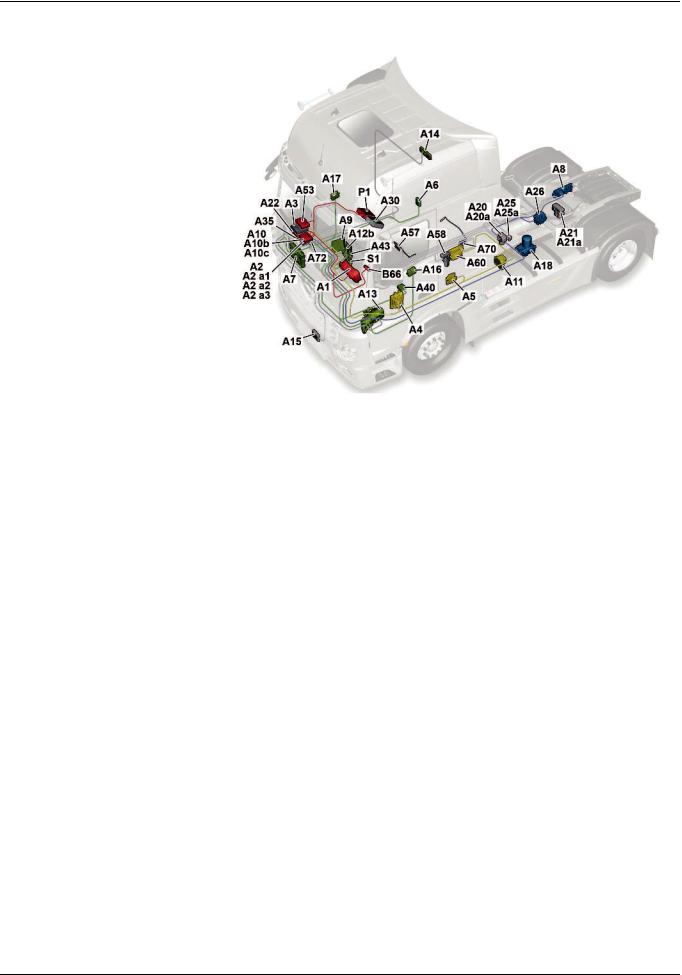
Functions
|
SN00.19>W>0001>02H |
Complete networking |
||||
|
Illustrated on model 963.4 |
|||||
|
A1 |
Instrument cluster (ICUC) control |
||||
|
unit |
|||||
|
A2 |
Central gateway control unit |
||||
|
(CGW) |
|||||
|
A2 a1 |
Central data memory (CDS) |
||||
|
A2 a2 |
Communications interface (COM) |
||||
|
control unit |
|||||
|
A2 a3 |
Maintenance system (MS) control |
||||
|
unit |
|||||
|
A3 |
Drive control (CPC) control unit |
||||
|
A4 |
Engine management control unit |
||||
|
(MCM) |
|||||
|
A5 |
Transmission control (TCM) |
||||
|
control unit |
|||||
|
A6 |
Anti>theft alarm system (ATA) |
||||
|
control unit |
|||||
|
A7 |
Cab signal acquisition and |
||||
|
actuation module control unit |
|||||
|
(SCA) |
|||||
|
W00.19>1065>76 |
|||||
|
A8 |
Frame signal acquisition and |
A17 |
Front passenger door module |
A30 |
FleetBoard“ control unit |
|
actuation module control unit |
(DCMP) control unit |
A35 |
Tire pressure monitor (TPM) |
||
|
(SCH) |
A18 |
Electronic Air Processing Unit |
control unit |
||
|
A9 |
Truck Control Center (TCC) |
(EAPU) control unit |
A40 |
Supplemental restraint system |
|
|
A10 |
Antilock brake system (ABS) |
A20 |
Front axle axle modulator |
(SRS) control unit |
|
|
control unit, 4>channel |
(Wabco) |
A43 |
Modular switch panel (MSF) |
||
|
A10b |
Electronic brake control (EBS) |
A20a |
Front axle axle modulator (Knorr) |
control unit |
|
|
control unit (Wabco) |
A21 |
Rear axle axle modulator |
A53 |
Driver assistance system (VRDU) |
|
|
A10c |
Electronic brake control (EBS) |
(Wabco) |
control unit |
||
|
control unit (Knorr) |
A21a |
Rear axle axle modulator (Knorr) |
A57 |
EATU output NOx sensor control |
|
|
A11 |
Retarder control (RCM) control |
A22 |
Parameterizable special module |
unit |
|
|
unit |
(PSM) control unit |
A58 |
SCR control unit |
||
|
A12b |
Heating, ventilation and air |
A25 |
Electronic Stability Program |
A60 |
Exhaust aftertreatment (ACM) |
|
conditioning control unit (HVAC) |
(ESP“) control unit (Wabco) |
control unit |
|||
|
A13 |
Truck auxiliary heater (ITH) |
A25a |
Electronic Stability Program |
A70 |
EATU input NOx sensor control |
|
control unit |
(ESP“) control unit (Knorr) |
unit |
|||
|
A14 |
Stationary air conditioning (IAC) |
A26 |
Level control (CLCS) control unit |
A72 |
Lane Assistant camera |
|
control unit |
B66 |
Steering wheel angle sensor |
|||
|
A15 |
Front radar sensor (RDF) control |
(SAS) |
|||
|
unit |
P1 |
Tachograph (TCO) |
|||
|
A16 |
Driver door module (DCMD) |
S1 |
Electronic ignition lock (EIS) |
||
|
control unit |
|
i Electronic systems, Actros, model 963 > 09/2011 > |
15 |
– This printout will not be recorded by the update service. Status: 09 / 2011 –

Functions
|
GF00.19>W>0004H |
Overall network, function |
2.8.11 |
MODEL 963
|
W00.19>1079>79 |
|||||
|
A1 |
Instrument cluster (ICUC) control |
A11 |
Retarder control (RCM) control unit |
A33 |
Battery disconnect switch control |
|
unit |
A12b |
Heating, ventilation and air |
unit (BESO) |
||
|
A2 |
Central gateway control unit (CGW) |
conditioning control unit (HVAC) |
A34 |
Additional steering axle (ASA) |
|
|
A2 a1 |
Central data memory (CDS) |
A13 |
Truck auxiliary heater (ITH) control |
control unit |
|
|
A2 a2 |
Communications interface (COM) |
unit |
A35 |
Tire pressure monitor (TPM) control |
|
|
control unit |
A14 |
Stationary air conditioning (IAC) |
unit |
||
|
A2 a3 |
Maintenance system (MS) control |
control unit |
A40 |
Supplemental restraint system (SRS) |
|
|
unit |
A15 |
Front radar sensor (RDF) control |
control unit |
||
|
A3 |
Drive control (CPC) control unit |
unit |
A43 |
Modular switch panel (MSF) control |
|
|
A4 |
Engine management control unit |
A16 |
Driver door module (DCMD) control |
unit |
|
|
(MCM) |
unit |
A53 |
Driver assistance system (VRDU) |
||
|
A5 |
Transmission control (TCM) control |
A17 |
Front passenger door module |
control unit |
|
|
unit |
(DCMP) control unit |
A54 |
Lower radiator shutters controller |
||
|
A6 |
Antitheft alarm system (ATA) |
A18 |
Electronic Air Processing Unit |
unit |
|
|
control unit |
(EAPU) control unit |
A55 |
Upper radiator shutters controller |
||
|
A7 |
Cab signal acquisition and |
A20 |
Front axle axle modulator (Wabco) |
unit |
|
|
actuation module control unit |
A20a |
Front axle axle modulator (Knorr) |
A57 |
EATU output NOx sensor control |
|
|
(SCA) |
A21 |
Rear axle axle modulator (Wabco) |
unit |
||
|
A8 |
Frame signal acquisition and |
A21a |
Rear axle axle modulator (Knorr) |
A58 |
SCR control unit |
|
actuation module control unit |
A22 |
Parameterizable special module |
A60 |
Exhaust aftertreatment (ACM) |
|
|
(SCH) |
(PSM) control unit |
control unit |
|||
|
A9 |
Truck Control Center (TCC) |
A25 |
Electronic Stability Program (ESP“) |
A70 |
EATU input NOx sensor control unit |
|
A10 |
Antilock brake system (ABS) control |
control unit (Wabco) |
A72 |
Lane Assistant camera |
|
|
unit, 4>channel |
A25a |
Electronic Stability Program (ESP“) |
|||
|
A10b |
Electronic Brake Control (EBS) |
control unit (Knorr) |
B42 |
Alarm siren |
|
|
control unit (Wabco) |
A26 |
Level control (CLCS) control unit |
B43 |
Interior protection sensor |
|
|
A10c |
Electronic Brake Control (EBS) |
A28 |
Driver switch group |
B66 |
Steering wheel angle sensor (SAS) |
|
control unit (Knorr) |
A30 |
FleetBoard“ control unit |
B81 |
Rain and light sensor (RLS) |
16
– This printout will not be recorded by the update service. Status: 09 / 2011 –

|
Functions |
|||||
|
CAN 1 |
Exterior>CAN |
LIN 3 |
Right multifunction control lever> |
X100.16 |
Diagnostic socket |
|
CAN 2 |
Interior CAN |
LIN |
X102.15 |
Trailer socket , 15>pin |
|
|
CAN 3 |
Frame CAN |
LIN 4 |
Left multifunction control lever LIN |
X103.7 |
ABS trailer socket 7>pin |
|
CAN 4 |
Drive train CAN |
LIN 5 |
Radiator shutters LIN |
X167.12 |
Fleet management system |
|
CAN 5 |
Climate control CAN |
LIN 6 |
LIN SCA/SCH redundancy |
electrical connector |
|
|
CAN 6a |
Front axle brakes CAN |
LIN 7 |
Button group LIN |
X910 |
Electrical connector for body |
|
CAN 6b |
Rear axle brakes CAN |
LIN 8 |
Level control LIN |
manufacturers |
|
|
CAN 6c |
Redundant brakes CAN |
LIN 9 |
Driver switch panel LIN |
XR>E1H |
CAN>H exterior cable weld point 1 |
|
CAN 6d |
ESP“ brakes CAN |
LIN 10 |
EAPU>LIN |
XR>E1L |
CAN>L exterior cable weld point 1 |
|
CAN 7 |
Trailer CAN (PSM) |
LIN 11 |
ATA>LIN |
XR>E1M |
CAN>ground exterior cable weld |
|
CAN 8 |
Body manufacturer CAN (PSM) |
P1 |
Tachograph (TCO) |
point 1 |
|
|
CAN 9 |
Telematics CAN |
S1 |
Electronic ignition lock (EIS) |
Z1 |
Cab instrument panel CAN bus star |
|
CAN 10 |
Diagnostic CAN |
S20 |
Left multifunction control lever |
point |
|
|
CAN 11 |
Trailer CAN (EBS) |
S22 |
Level control operating unit |
Z3 |
Frame CAN bus star point |
|
CAN 12 |
Radar CAN |
S23 |
Right multifunction control lever |
Z4 |
Drive CAN bus star point |
|
CAN 13 |
NOx>CAN |
S110 |
Left multifunction steering wheel |
||
|
G1a |
Battery sensor (IBS) |
button group |
|||
|
LIN 1 |
Rain/light sensor LIN |
S111 |
Right multifunction steering wheel |
ASIC |
ASIC data bus (Application System |
|
LIN 2 |
Battery sensor LIN |
button group |
Integrated Circuit) |
1General
The increase in electronic systems in the new Actros means that more and more signals now have to be made available across all the systems. This primarily has an impact on the networking, which has also gained in complexity. Alongside the familiar CAN and ASIC data bus systems the LIN data bus is now increasingly being used. The new Actros alone has 11 LIN data buses, which connect the various control units, switches or other electronic components to each other. The number of CAN data buses by contrast has only risen slightly.
2CAN data bus system
The CAN data bus system enables information to be exchanged quickly and reliably between control units over only a few lines. The information is sent or received successively (serial). The exchange is bidirectional, i.e. each control unit operates as both a transmitter and a receiver.
2.1 Transfer rates
In the new Actros up to 13 different CAN data buses are used. The majority of these CAN data buses have a transfer rate of >250 kBaud and this classes them as high>speed CAN data buses. The reasons for the increase in high>speed CAN data buses are:
•Increase in data rate (number of messages that are sent)
•Almost identical manufacturing costs as for low>speed CAN data buses
•Greater use of LIN data bus in non>critical safety areas
>>>>>>>>>>>>>>>>>>>>>>>>>>>>>>>>>>>>>>>>>>>>>>>>>>>>>>>>>>>>>>>>>>>>>>>>>>>>>>>>>>>>>>>>>
•Shortening of flash or parameterization times, in particular through increase in transfer rate for diagnostic CAN (CAN 10)
The following CAN data buses have a transfer rate of 500 kBaud:
•Exterior CAN (CAN 1)
•Interior CAN (CAN 2)
•Frame CAN (CAN 3)
•Climate control CAN (CAN 5)
•Front axle brake CAN (CAN 6a)
•Rear axle brake CAN (CAN 6b)
•Redundancy brake CAN (CAN 6c)
•Brake CAN ESP“ (CAN 6d)
•Diagnostic CAN (CAN 10)
•Radar CAN (CAN 12)
>>>>>>>>>>>>>>>>>>>>>>>>>>>>>>>>>>>>>>>>>>>>>>>>>>>>>>>>>>>>>>>>>>>>>>>>>>>>>>>>>>>>>>>>>
|
i Electronic systems, Actros, model 963 > 09/2011 > |
17 |
– This printout will not be recorded by the update service. Status: 09 / 2011 –
![]()
Functions
The transfer rate of the drive train CAN (CAN 4) was increased to 667 kBaud, because the high number of messages had significantly increased the bus operating rate. If the data rate was not increased, then there is the risk that some messages with low priority could no longer be sent due to the bus operating rate.
To ensure that freight forwarders, for example for fleet management, can continue to call up specific information on vehicle location, current speed, etc. the transfer rate of the telematics CAN (CAN 9) has been retained at 250 kBaud.
The transfer rates have also been retained on the trailer CAN (PSM) (CAN 7), the body manufacturer CAN (PSM) (CAN  and the trailer CAN (EBS) (CAN 11). They are 125 kBaud, whereby they are still classified as low>speed CAN data buses.
The transfer rate for the NOx>CAN (CAN 13) has not been changed either and is > as before > 250 kBaud.
>>>>>>>>>>>>>>>>>>>>>>>>>>>>>>>>>>>>>>>>>>>>>>>>>>>>>>>>>>>>>>>>>>>>>>>>>>>>>>>>>>>>>>>>>
2.3CAN neutral points and bus terminating resistors
Because of the high transfer rates on high>speed CAN data buses, there may be some reflections in the lines. Bus termination resistors are used to avoid reflections that would lead to the falsification of actual information. The characteristic impedance of the electrical line is important for the bus termination resistor. The total bus terminating resistor on a high>speed CAN data bus is 60 ].
In the neutral points for the cab instrument panel CAN bus (Z1) and frame CAN bus (Z3) the bus terminating resistors are integrated into the neutral points. The drive CAN bus neutral point (Z4) only includes those ferrite elements that are also installed in the neutral points for interference suppression of
high>frequency interference pulses.
>>>>>>>>>>>>>>>>>>>>>>>>>>>>>>>>>>>>>>>>>>>>>>>>>>>>>>>>>>>>>>>>>>>>>>>>>>>>>>>>>>>>>>>>>
3LIN data bus
The LIN data bus is an inexpensive serial subbus, which replaces the CAN data bus in the area of uncritical data transfer. The voltage supply for the LIN data bus is 12 V. This is realized internally in the control units through voltage dividers. Signals are transmitted through a single>wire line. The max. data rate is 20 kBaud. Communication refers to ID>based communication. All subscribers connected to the LIN data bus receive the message, but only one subscriber responds to it.
A LIN data bus subscriber never sends information by itself, as is the case, for example with a CAN data bus subscriber. Subscribers of the LIN data bus only ever respond to a query.
2.2Gateways
To compensate for the different transfer speeds, some control units also act as a gateway:
•The central gateway control unit (CGW) (A2) routes the respective messages from the exterior, interior, frame, telematics and diagnostic CAN (CAN 1, 2, 3, 9 and 10).
•The modular switch panel (MSF) control unit (A43) acts as a gateway between the interior CAN (CAN 2), the ASIC data bus (ASIC) and the three LIN data buses to the button groups on the multifunction steering wheel, the left multifunction control lever and the level control operating unit.
•The Electronic Brake Control (EBS) control unit (A10b) or (A10c), depending on the version, sends the messages from the frame CAN (CAN 3) to the front axle brake CAN (CAN 6a), the rear axle brake CAN (CAN 6b), the brake CAN ESP“ (CAN 6d) as well as, where applicable, the trailer CAN (EBS) (CAN 11) and vice versa.
•The drive control (CPC) control unit (A3) acts as an interface between the frame CAN (CAN 3) and the drive train CAN
(CAN 4).
>>>>>>>>>>>>>>>>>>>>>>>>>>>>>>>>>>>>>>>>>>>>>>>>>>>>>>>>>>>>>>>>>>>>>>>>>>>>>>>>>>>>>>>>>
The bus terminator on the exterior CAN (CAN 1) is realized by using bus terminating resistors within the central gateway control unit (CGW) (A2) and the Electronic Air>Processing Unit (EAPU) control unit (A18). Located in both control units is a 120 ] resistor each. The parallel connection then yields a total bus terminating resistance of 60 ].
In the diagnostic CAN (CAN 10) the bus terminator is realized by a 60 ] resistor in the central gateway control unit (CGW) (A2).
>>>>>>>>>>>>>>>>>>>>>>>>>>>>>>>>>>>>>>>>>>>>>>>>>>>>>>>>>>>>>>>>>>>>>>>>>>>>>>>>>>>>>>>>>
18
– This printout will not be recorded by the update service. Status: 09 / 2011 –

Functions
4ASIC data bus system
The previously familiar ASIC data bus system is also used in the new Actros.
The ASIC data bus (ASIC) belongs to the so>called subbuses. In contrast to conventional switches which switch via their own contacts and are connected to their components via separate electrical lines (e.g. motors, solenoid valves, switch inputs, lighting devices), the ASIC data bus performs these tasks.
The electronics installed in the ASIC signal switches notifies the modular switch panel (MSF) control unit (A43) the following via the ASIC data bus (ASIC):
fswitch position (open, closed, operated, not operated)
fFunctionality (normally closed contact, normally open contact, changeover contact)
fSystem affiliation (e.g. headlamp cleaning system button,
power take>off 1 button, etc.)
>>>>>>>>>>>>>>>>>>>>>>>>>>>>>>>>>>>>>>>>>>>>>>>>>>>>>>>>>>>>>>>>>>>>>>>>>>>>>>>>>>>>>>>>>
5Virtual control units
Each ASIC signal switch is connected over three contacts (pins) to the ASIC data bus (ASIC), and it is evaluated by the modular switch panel (MSF) control unit (A43). It is thus possible to install each ASIC signal switch at any arbitrary point on the individual switch modules.
For currents up to a maximum of 20 A there continues to be load switches which as before switch via their own contacts and are connected to their components through electrical lines.
These load switches are only connected to the switch panel via the ASIC contacts for separate background lighting.
>>>>>>>>>>>>>>>>>>>>>>>>>>>>>>>>>>>>>>>>>>>>>>>>>>>>>>>>>>>>>>>>>>>>>>>>>>>>>>>>>>>>>>>>>
6Safety strategy
Virtual control units are not equipped with their own housing. They are integrated into the hardware and software of other control units. In Star Diagnosis and the instrument cluster control unit (ICUC) (A1) they appear as independent control units. Among the virtual control units are the central data memory (CDS) (A2 a1), the communications interface (COM) control unit (A2 a2) and the maintenance system (MS) control unit (A2 a3), which are all integrated into the central gateway control unit (CGW) (A2).
With the aid of the central data memory (CDS) (A2 a1) the parameters for the electronic control units can be reset to manufacturer default settings.
Several control units have a redundant connection over LIN or CAN data buses. The redundant connection serves as an emergency communication, if the actual CAN connection malfunctions. The use of redundant LIN or CAN data buses is dependent on the safety relevance of each system.
The service brake system, for example has a redundant CAN data bus connection between the axle modulators.
LIN data buses serve as redundancies between the sensor and actuator module, cab (SCA) control unit (A7) and the sensor and actuator module, chassis (SCH) control unit (A8) as well as between the instrument cluster control unit (ICUC) (A1) and the Electronic Air>Processing Unit (EAPU) control unit (A18).
|
Instrument cluster control unit (ICUC), |
A1 |
Page 331 |
|
|
component description |
|||
|
Central gateway control unit (CGW), |
A2 |
Page 333 |
|
|
component description |
|||
|
Component description drive control (CPC) |
A3 |
Page 334 |
|
|
control unit |
|||
|
Component description for engine |
A4 |
Page 335 |
|
|
management (MCM) control unit |
|||
|
Transmission control (TCM) control unit. |
A5 |
Page 337 |
|
|
component description |
|||
|
Antitheft alarm system control unit (ATA), |
A6 |
Page 338 |
|
|
component description |
|||
|
Cab signal acquisition and actuation |
A7 |
Page 339 |
|
|
module control unit (SCA), component |
|||
|
description |
|||
|
Signal acquisition and actuation module |
A8 |
Page 340 |
|
|
control unit, frame (SCH), component |
|||
|
description |
|||
|
Electronic Brake Control (EBS) control unit, |
A10b, A10c |
Page 341 |
|
|
component description |
|||
|
Retarder control unit (RCM), component |
A11 |
Page 342 |
|
|
description |
i Only in vehicles with code (B3H) |
||
|
Secondary water retarder. |
|||
|
i Electronic systems, Actros, model 963 > 09/2011 > |
19 |
– This printout will not be recorded by the update service. Status: 09 / 2011 –

Functions
|
Component description for automatic air |
A12b |
Page 344 |
|
|
conditioning control unit |
|||
|
Auxiliary heater control unit, component |
A13 |
Page 346 |
|
|
description |
i Only in vehicles with code (D6M) Cab |
||
|
auxiliary water heater or with code (D6N) |
|||
|
Cab and engine auxiliary water heater. |
|||
|
Stationary air conditioner control unit, |
A14 |
Page 347 |
|
|
component description |
|||
|
Front radar sensor (RDF) control unit, |
A15 |
Page 348 |
|
|
component description |
|||
|
Driver door control unit (DCMD), |
A16 |
Page 349 |
|
|
component description |
|||
|
Passenger door module control unit |
A17 |
Page 350 |
|
|
(DCMP), component description |
|||
|
Electronic Air>Processing Unit (EAPU), |
A18 |
Page 351 |
|
|
component description |
i The Electronic Air>Processing Unit |
||
|
(EAPU) control unit (A18) forms a module |
|||
|
together with the Electronic Air>Processing |
|||
|
Unit (EAPU). |
|||
|
Front axle axle modulator, component |
A20, A20a |
Page 509 |
|
|
description |
|||
|
Rear axle axle modulator, component |
A21, A21a |
Page 511 |
|
|
description |
|||
|
Parameterizable special module (PSM) |
A22 |
Page 356 |
|
|
control unit component description |
|||
|
Electronic Stability Program (ESP) control |
A25, A25a |
Page 357 |
|
|
unit, component description |
|||
|
Level control (CLCS) control unit, |
A26 |
Page 358 |
|
|
component description |
|||
|
FleetBoard control unit, component |
A30 |
Page 361 |
|
|
description |
|||
|
Battery disconnect switch control unit, |
A33 |
Page 362 |
|
|
component description |
i Only in vehicles with one of the |
||
|
following codes: |
|||
|
• Code (E5T) ADR model class EX/II, |
|||
|
including AT |
|||
|
• Code (E5U) ADR model class EX/III, |
|||
|
including EX/II and AT |
|||
|
• Code (E5V) ADR model class FL, |
|||
|
including EX/II, EX/III and AT |
|||
|
• Code (E5X) ADR model class AT |
|||
|
• Code (E5Z) Accessories, ADR |
|||
|
• Code (E9D) Preinstallation, for bipolar |
|||
|
battery circuit breaker |
|||
|
• Code (E9E) ADR preinstallation, without |
|||
|
chassis shielding |
|||
|
Additional steering axle (ASA) control unit, |
A34 |
Page 364 |
|
|
component description |
|||
|
Tire pressure monitor (TPM) control unit, |
A35 |
Page 365 |
|
|
component description |
|||
20
– This printout will not be recorded by the update service. Status: 09 / 2011 –

|
Functions |
|||
|
Modular switch panel control unit (MSF), |
A43 |
Page 370 |
|
|
component description |
|||
|
Driver assistance system control unit |
A53 |
Page 378 |
|
|
(VRDU), component description |
|||
|
EATU output NOx sensor, component |
A57 |
||
|
description |
i The EATU output NOx sensor control |
||
|
unit (A57) together with the EATU output |
|||
|
NOx sensor (A57 b1) forms a unit. |
|||
|
Vehicles with code (M5R) EEV engine |
Page 379 |
||
|
version and vehicles with code (M5Y) Euro |
|||
|
V engine version |
|||
|
Vehicles with code (M5Z) Euro VI engine |
Page 381 |
||
|
version |
|||
|
Pump module, component description |
A58 |
Page 384 |
|
|
i The SCR control unit (A58) together |
|||
|
with the pump module forms a unit. |
|||
|
Exhaust aftertreatment (ACM) control unit, |
A60 |
||
|
component description |
|||
|
Vehicles with code (M5R) EEV engine |
Page 386 |
||
|
version and vehicles with code (M5Y) Euro |
|||
|
V engine version |
|||
|
Vehicles with code (M5Z) Euro VI engine |
Page 388 |
||
|
version |
|||
|
EATU input NOx sensor, component |
A70 |
||
|
description |
i The EATU input NOx sensor control unit |
||
|
(A70) together with the EATU input NOx |
|||
|
sensor (A70 b1) forms a unit. |
|||
|
Vehicles with code (M5R) EEV engine |
Page 390 |
||
|
version and vehicles with code (M5Y) Euro |
|||
|
V engine version |
|||
|
Vehicles with code (M5Z) Euro VI engine |
Page 392 |
||
|
version |
|||
|
Lane Assistant (SPA) camera, component |
A72 |
Page 395 |
|
|
description |
|||
|
Steering wheel angle sensor (SAS), |
B66 |
Page 424 |
|
|
component description |
|||
|
Tachograph (TCO) component description |
P1 |
Page 459 |
|
|
Electronic ignition lock (EIS), component |
S1 |
Page 460 |
|
|
description |
|||
|
i Electronic systems, Actros, model 963 > 09/2011 > |
21 |
– This printout will not be recorded by the update service. Status: 09 / 2011 –
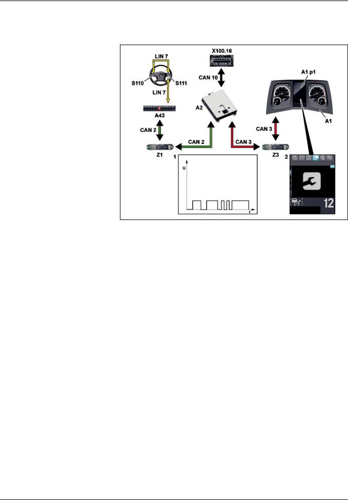
Functions
|
GF00.20>W>0005H |
Maintenance system, function |
2.8.11 |
MODEL 963
1CAN messages
2«Maintenance» menu
|
A1 |
Instrument cluster (ICUC) control |
|
unit |
|
|
A1 p1 |
Multifunction display |
|
A2 |
Central gateway control unit |
|
(CGW) |
|
|
A43 |
Modular switch panel (MSF) |
|
control unit |
|
|
CAN 2 |
Interior CAN |
|
CAN 3 |
Frame CAN |
|
CAN 10 |
Diagnostic CAN |
|
LIN 7 |
Button group LIN |
|
S110 |
Left multifunction steering wheel |
|
button group |
|
W00.20>1076>76 |
|||
|
S111 Right multifunction steering wheel |
Z1 Cab instrument panel CAN bus star |
Z3 |
Frame CAN bus star point |
|
button group |
point |
X100.16 |
Diagnostic socket |
General information
The maintenance system (WS):
fIs a software which is integrated as a virtual control unit into the central gateway control unit (CGW) (A2),
frecords all the required measurement data as CAN messages
(1) using the CAN data bus system and
fcalculates the load>dependent service life and forecast data for each maintenance item in order to determine the service dates.
i Load>dependent forecasting is used to carry out the following:
fIndividual determination of the service dates for each maintenance item and they can be called up in the «Maintenance» (2) menu of the instrument cluster control unit (ICUC) (A1).
fDisplay of pending maintenance items as a message in the multifunction display (A1 p1) when the ignition is switched on.
The menu is operated using the left multifunction steering wheel button group (S110) and the right multifunction steering wheel button group (S111).
Maintenance information is shown in the multifunction display (A1 p1) of the instrument cluster control unit (ICUC) (A1). The instrument cluster control unit (ICUC) (A1) acts as a display unit.
A maintenance item is reset using the left multifunction steering wheel button group (S110) and the right multifunction steering wheel button group (S111) or with the aid of Star Diagnosis through the diagnostic socket (X100.16).
|
Maintenance system overall network |
Page 23 |
||
|
Data acquisition function |
Page 24 |
||
|
Data storage function |
Page 29 |
||
|
Life cycle consumption calculation, |
Page 35 |
||
|
function |
|||
|
Forecast calculation, function |
Page 34 |
||
|
Normal mode displays function |
Page 30 |
||
|
Reset service item function |
Page 32 |
||
22
– This printout will not be recorded by the update service. Status: 09 / 2011 –

Functions
GF00.20>W>0005>02H Maintenance system overall network
|
W00.20>1079>79 |
|||||
|
A1 |
Instrument cluster (ICUC) control |
A11 |
Retarder control (RCM) control |
LIN 6 |
LIN SCA/SCH redundancy |
|
unit |
unit |
LIN 7 |
Button group LIN |
||
|
A2 |
Central gateway control unit (CGW) |
A18 |
Electronic Air Processing Unit |
LIN 10 |
EAPU>LIN |
|
A2a3 |
Maintenance system (MS) control |
(EAPU) control unit |
P1 |
Tachograph (TCO) |
|
|
unit |
A43 |
Modular switch panel (MSF) |
S110 |
Left multifunction |
|
|
A3 |
Drive control (CPC) control unit |
control unit |
steering wheel button group |
||
|
A4 |
Engine management control unit |
A60 |
Exhaust aftertreatment (ACM) |
S111 |
Right multifunction |
|
(MCM) |
control unit |
steering wheel button group |
|||
|
A5 |
Transmission control (TCM) control |
CAN 1 |
Exterior>CAN |
X100.16 |
Diagnostic socket |
|
unit |
CAN 2 |
Interior CAN |
Z1 |
Cab instrument panel CAN bus |
|
|
A7 |
Cab signal acquisition and |
CAN 3 |
Frame CAN |
star point |
|
|
actuation module control unit |
CAN 4 |
Drive train CAN |
Z3 |
Frame CAN bus star point |
|
|
(SCA) |
CAN 10 |
Diagnostic CAN |
Z4 |
Drive CAN bus star point |
|
|
A8 |
Frame signal acquisition and |
||||
|
actuation module control unit |
|||||
|
(SCH) |
|
i Electronic systems, Actros, model 963 > 09/2011 > |
23 |
– This printout will not be recorded by the update service. Status: 09 / 2011 –
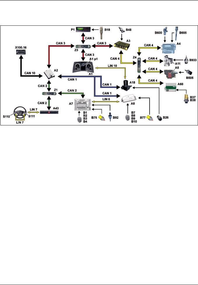
Functions
|
GF00.20>W>3000H |
Data acquisition function |
2.8.11 |
MODEL 963
A1 Instrument cluster (ICUC) control unit
A1p1 Multifunction display
A2 Central gateway control unit (CGW)
A3 Drive control (CPC) control unit
A4 Engine management control unit (MCM)
A5 Transmission control (TCM) control unit
A7 Cab signal acquisition and actuation module control unit (SCA)
A8 Frame signal acquisition and actuation module control unit (SCH)
A11 Retarder control unit (RCM) (in vehicle with code (B3H) Secondary water retarder)
B48 Air filter sensor
B75 1st front axle temperature sensor
B77 1st rear axle temperature sensor
B92 Outside temperature sensor
B505 Transmission oil temperature sensor
B600 Crankshaft position sensor
B605 Engine oil fill level sensor
B933 Coolant temperature sensor (in vehicles with code (B3H) Secondary water retarder)
A18 Electronic Air Processing Unit (EAPU) control unit
A43 Modular switch panel (MSF) control unit
A60 Exhaust aftertreatment (ACM) control unit (in vehicles with code (M5Z) Euro VI engine version)
B1 Left 1st front axle brake wear sensor
B2 Right 1st front axle brake wear sensor
B3 Left 2nd front axle brake wear sensor
B4 Right 2nd front axle brake wear sensor
|
CAN 1 |
Exterior>CAN |
|
CAN 2 |
Interior CAN |
|
CAN 3 |
Frame CAN |
|
CAN 4 |
Drive train CAN |
|
CAN 10 |
Diagnostic CAN |
|
LIN 6 |
LIN SCA/SCH redundancy |
|
LIN 7 |
Button group LIN |
|
LIN 10 |
EAPU>LIN |
|
P1 |
Tachograph (TCO) |
W00.20>1078>79
B7 Left 1st rear axle brake wear sensor
B8 Right 1st rear axle brake wear sensor
B9 Left 2nd rear axle brake wear sensor
B10 Right 2nd rear axle brake wear sensor
B18 Travel and speed sensor
B26 Condensation sensor
B37 Exhaust pressure sensor upstream of diesel oxidation catalytic converter (in vehicles with code (M5Z) Euro VI engine version)
B38 Exhaust pressure sensor downstream of diesel particulate filter (in vehicles with code (M5Z) Euro VI engine version)
|
S110 |
Left multifunction steering wheel |
|
button group |
|
|
S111 |
Right multifunction steering |
|
wheel button group |
|
|
Z1 |
Cab instrument panel CAN bus |
|
star point |
|
|
Z3 |
Frame CAN bus star point |
|
Z4 |
Drive CAN bus star point |
|
X100.16 |
Diagnostic socket |
24
– This printout will not be recorded by the update service. Status: 09 / 2011 –

Functions
General information
The recording of data function enables the maintenance system (WS) to receive two different types of input factors for calculating the load>specific maintenance intervals:
fBasic data, which are determined unchangeable at first in the form of a parameterization and
fmeasured values, which are sensed continuously.
Thus, two functions are differentiated:
fAcquiring the basic data
fAcquiring the measured values
Acquiring the basic data
The maintenance system (WS) requires certain basic data (parameters), which:
fare a prerequisite for the general function and
fwhich are used to adapt the maintenance system (WS) to the vehicle and the operating fluids.
The basic data are acquired in the form of the following parameterizations:
fBasic parameterization
fVehicle>specific parameterization
fSubsequent parameterization
fParameterization of operating fluids
>>>>>>>>>>>>>>>>>>>>>>>>>>>>>>>>>>>>>>>>>>>>>>>>>>>>>>>>>>>>>>>>>>>>>>>>>>>>>>>>>>>>>>>>>
Subsequent parameterization
Subsequent parameterization:
fmakes it possible to change parameters, which are connected to constructional vehicle changes for instance or special customer’s requests, such as the «time>based servicing scheme grid» parameter and
fmay only be carried out in workshops authorized by Mercedes>Benz.
i Querying and operation are conducted using the left multifunction steering wheel button group (S110) and right multifunction steering wheel button group (S111) or using Star Diagnosis through the diagnostic socket (X100.16).
>>>>>>>>>>>>>>>>>>>>>>>>>>>>>>>>>>>>>>>>>>>>>>>>>>>>>>>>>>>>>>>>>>>>>>>>>>>>>>>>>>>>>>>>>
Basic parameterization
The basic parameterization (base parameterization):
fincludes the pre>assignment of certain parameters with values and is a prerequisite for the function of the maintenance system (WS) and
fis made at the manufacturer of the central gateway control unit (CGW) (A2).
Vehicle>specific parameterization
The vehicle>specific parameterization:
fis used to adapt the maintenance system (WS) to the vehicle model and the vehicle equipment, or to the special features of the individual maintenance items, such as
their cut>in or cutout and
fis carried out in the Mercedes>Benz production plant.
>>>>>>>>>>>>>>>>>>>>>>>>>>>>>>>>>>>>>>>>>>>>>>>>>>>>>>>>>>>>>>>>>>>>>>>>>>>>>>>>>>>>>>>>>
Parameterization of operating fluids
Parameterization of operating fluids:
fmakes it possible to change parameters with regard to the properties of fuels and lubricants, which can change during the operation of the vehicle, such as engine oil quality, engine oil viscosity, transmission oil quality, or sulfur content of the fuel and
fmay also be carried out by other workshops.
i The parameters can be checked and changed if necessary through the «Fuels and Lubricants» submenu in the «Adjustments» menu of the menu system. Querying and operation are conducted using the left multifunction steering wheel button group (S110) and right multifunction steering wheel button group (S111) or using Star Diagnosis through the
diagnostic socket (X100.16).
>>>>>>>>>>>>>>>>>>>>>>>>>>>>>>>>>>>>>>>>>>>>>>>>>>>>>>>>>>>>>>>>>>>>>>>>>>>>>>>>>>>>>>>>>
|
i Electronic systems, Actros, model 963 > 09/2011 > |
25 |
– This printout will not be recorded by the update service. Status: 09 / 2011 –

Functions
Acquiring the measured values
The measurement values are recorded using different sensors, which are connected to the system>specific control units or the locally best suited modules, e.g. on the sensor and actuator module, cab (SCA) control unit (A7).
The analog measured values are turned into corresponding CAN messages by the particular control units or modules; these CAN messages are transmitted with the aid of the CAN data bus system to the maintenance system (WS).
The maintenance system (WS):
fprocesses the recorded measured values converting them to input data for the life cycle consumption and forecast calculation, whereby the quality of processed measured values is of major significance in terms of the forecast calculation result and
fmonitors the acquired measured values for errors, exceeding limit values, and plausibility.
>>>>>>>>>>>>>>>>>>>>>>>>>>>>>>>>>>>>>>>>>>>>>>>>>>>>>>>>>>>>>>>>>>>>>>>>>>>>>>>>>>>>>>>>>
Transmission (TCM) control unit (A5)
The transmission control unit (TCM) (A5):
facquires the measured «transmission oil temperature» value from the transmission oil temperature sensor (B505) and
fsends a corresponding CAN message over the drive train CAN (CAN 4) and over the drive train CAN bus neutral point (Z4) to the drive control (CPC) control unit (A3) and from there over the frame CAN (CAN 3) and over the frame CAN bus neutral point (Z3) to the central gateway control unit (CGW) (A2).
>>>>>>>>>>>>>>>>>>>>>>>>>>>>>>>>>>>>>>>>>>>>>>>>>>>>>>>>>>>>>>>>>>>>>>>>>>>>>>>>>>>>>>>>>
Drive control (CPC) control unit (A3)
The drive control (CPC) control unit (A3):
facquires the measured value for air filter contamination by the air filter sensor (B48) and
fsends a corresponding CAN message over the frame CAN (CAN 3) and over the frame CAN bus neutral point (Z3) to the central gateway control unit (CGW) (A2).
Engine management (MCM) control unit (A4)
The engine management (MCM) control unit (A4):
facquires the measured «crankshaft rpm» value from the crankshaft position sensor (B600),
facquires the measured «engine oil temperature» value from the engine oil fill level sensor (B605),
fsends corresponding CAN messages over the drive train CAN (CAN 4) and over the drive train CAN bus neutral point (Z4) to the drive control (CPC) control unit (A3) and from there over the frame CAN (CAN 3) and over the frame CAN bus neutral point (Z3) to the central gateway control unit (CGW)
(A2).
>>>>>>>>>>>>>>>>>>>>>>>>>>>>>>>>>>>>>>>>>>>>>>>>>>>>>>>>>>>>>>>>>>>>>>>>>>>>>>>>>>>>>>>>>
Retarder control (RCM) control unit (A11)
i Only in vehicles with code (B3H) Secondary water retarder.
The retarder control unit (RCM) (A11):
facquires the measured «coolant temperature» value from the coolant temperature sensor (B933) and
fsends a corresponding CAN message over the drive train CAN (CAN 4) and over the drive train CAN bus neutral point (Z4) to the drive control (CPC) control unit (A3) and from there over the frame CAN (CAN 3) and over the frame CAN bus neutral point (Z3) to the central gateway control unit
(CGW) (A2).
>>>>>>>>>>>>>>>>>>>>>>>>>>>>>>>>>>>>>>>>>>>>>>>>>>>>>>>>>>>>>>>>>>>>>>>>>>>>>>>>>>>>>>>>>
26
– This printout will not be recorded by the update service. Status: 09 / 2011 –

Functions
Cab signal acquisition and actuation module (SCA) control unit (A7)
The sensor and actuator module, cab (SCA) control unit (A7):
facquires the measured «brake wear» value at the installed front axles from the following brake wear sensors:
fLeft 1st front axle brake wear sensor (B1)
fRight 1st front axle brake wear sensor (B2)
fLeft 2nd front axle brake wear sensor (B3)
fRight 2nd front axle brake wear sensor (B4)
facquires the measured «front axle oil temperature» value from the front axle temperature sensor
(B75) at the first front axle,
facquires the measured «outside temperature» value from the outside temperature sensor (B92) and
fsends a corresponding CAN message over the interior CAN (CAN 2) and over the cab instrument panel CAN bus neutral point (Z1) to the central gateway control unit (CGW) (A2).
>>>>>>>>>>>>>>>>>>>>>>>>>>>>>>>>>>>>>>>>>>>>>>>>>>>>>>>>>>>>>>>>>>>>>>>>>>>>>>>>>>>>>>>>>
Electronic Air>Processing Unit (EAPU) control unit (A18)
i Only in vehicles with code (B1C, B1D, B1E) Electronic Air> Processing Unit (EAPU).
The Electronic Air>Processing Unit (EAPU) control unit (A18)
frecords the measured «condensation water level» value from the condensation sensor (B26),
fdelivers the «reservoir pressure for brake circuit 1 and 2» measurement value from the integrated reservoir pressure sensors for brake circuit
1 and 2,
fsends corresponding CAN messages over the exterior CAN (CAN 1) to the central gateway control unit (CGW) (A2),
fsends corresponding LIN messages over the redundant EAPU>LIN (LIN 10) to the instrument cluster control unit (ICUC) (A1).
Sensor and actuator module, chassis (SCH) control unit (A8)
The sensor and actuator module, chassis (SCH) control unit (A8):
facquires the measured «brake wear» value at the installed rear axles from the following brake wear sensors:
>Left 1st rear axle brake wear sensor (B7)
>Right 1st rear axle brake wear sensor (B8)
>Left 2nd rear axle brake wear sensor (B9)
>Right 2nd rear axle brake wear sensor (B10)
frecords the «rear axle oil temperature» value at the first rear axle from the 1st rear axle temperature sensor (B77),
fsends corresponding CAN messages over the exterior CAN (CAN 1) to the central gateway control unit (CGW) (A2).
i In the event of any data transfer interference between the central gateway control unit (CGW) (A2) and the sensor and actuator module, cab (SCA) control unit (A7) or the sensor and actuator module, chassis (SCH) control unit (A8) the data can be sent as LIN messages redundantly over the redundancy LIN
SCA/SCH (LIN 6).
>>>>>>>>>>>>>>>>>>>>>>>>>>>>>>>>>>>>>>>>>>>>>>>>>>>>>>>>>>>>>>>>>>>>>>>>>>>>>>>>>>>>>>>>>
Exhaust aftertreatment (ACM) control unit (A60)
i Only for vehicles with code (M5Z) Engine version Euro VI.
The exhaust aftertreatment (ACM) control unit (A60)
facquires the exhaust pressure measurement values on the diesel oxidation catalytic converter/diesel particulate filter from the following pressure sensors:
>exhaust pressure sensor upstream of diesel oxidation catalytic converter (B37)
>exhaust pressure sensor downstream of diesel particulate filter (B38)
fsends a corresponding CAN message over the drive train CAN (CAN 4) and over the drive train CAN bus neutral point (Z4) to the drive control (CPC) control unit (A3) and from there over the frame CAN (CAN 3) and over the frame CAN bus neutral point (Z3) to the central gateway control unit (CGW) (A2).
|
Instrument cluster control unit (ICUC), |
A1 |
Page 331 |
|
|
component description |
|||
|
Central gateway control unit (CGW), |
A2 |
Page 333 |
|
|
component description |
|||
|
Component description drive control (CPC) |
A3 |
Page 334 |
|
|
control unit |
|||
|
Component description for engine |
A4 |
Page 335 |
|
|
management (MCM) control unit |
|||
|
Transmission control (TCM) control unit. |
A5 |
Page 337 |
|
|
component description |
|||
|
Cab signal acquisition and actuation |
A7 |
Page 339 |
|
|
module control unit (SCA), component |
|||
|
description |
|||
|
Signal acquisition and actuation module |
A8 |
Page 340 |
|
|
control unit, frame (SCH), component |
|||
|
description |
|||
|
i Electronic systems, Actros, model 963 > 09/2011 > |
27 |
– This printout will not be recorded by the update service. Status: 09 / 2011 –
![]()
Functions
|
Retarder control unit (RCM), component |
A11 |
Page 342 |
|
|
description |
i Only in vehicles with code (B3H) |
||
|
Secondary water retarder. |
|||
|
Electronic Air>Processing Unit (EAPU), |
A18 |
Page 351 |
|
|
component description |
i Only in vehicles with code (B1C) |
||
|
Electronic Air>Processing Unit (EAPU) low |
|||
|
or with code (B1D) Electronic Air> |
|||
|
Processing Unit (EAPU) mid or with code |
|||
|
(B1E) Electronic Air>Processing Unit (EAPU) |
|||
|
high. |
|||
|
Modular switch panel control unit (MSF), |
A43 |
Page 370 |
|
|
component description |
|||
|
Exhaust aftertreatment (ACM) control unit, |
A60 |
||
|
component description |
|||
|
Vehicles with code (M5R) EEV engine |
Page 386 |
||
|
version and vehicles with code (M5Y) Euro |
|||
|
V engine version |
|||
|
Vehicles with code (M5Z) Euro VI engine |
Page 388 |
||
|
version |
|||
|
Brake wear sensor, component description |
B1, B2, B3, B4, B7, B8, B9, B10 |
Page 404 |
|
|
Travel and speed sensor, component |
B18 |
Page 408 |
|
|
description |
|||
|
Condensation sensor, component |
B26 |
Page 412 |
|
|
description |
|||
|
Exhaust pressure sensor upstream of diesel |
B37 |
Page 416 |
|
|
oxidation catalytic converter, component |
i Only for vehicles with code (M5Z) |
||
|
description |
|||
|
Engine version Euro VI. |
|||
|
Exhaust pressure sensor downstream of |
B38 |
Page 417 |
|
|
diesel particulate filter, component |
i Only for vehicles with code (M5Z) |
||
|
description |
|||
|
Engine version Euro VI. |
|||
|
Outside temperature sensor, component |
B92 |
Page 430 |
|
|
description |
|||
|
Transmission oil temperature sensor, |
B505 |
Page 435 |
|
|
component description |
|||
|
Component description for crankshaft |
B600 |
Page 436 |
|
|
position sensor |
|||
|
Component description for engine oil fill |
B605 |
Page 438 |
|
|
level sensor |
|||
|
Retarder, component description |
B933 |
Page 514 |
|
|
i Only in vehicles with code (B3H) |
|||
|
Secondary water retarder. |
|||
|
The coolant temperature sensor (B933) is |
|||
|
located on the retarder. |
|||
|
Tachograph (TCO) component description |
P1 |
Page 459 |
|
|
Multifunction steering wheel, component |
S110, S111 |
Page 469 |
|
|
description |
|||
|
Diagnostic socket, component description |
X100.16 |
Page 477 |
|
28
– This printout will not be recorded by the update service. Status: 09 / 2011 –

Functions
|
GF00.20>W>3002H |
Data storage function |
2.8.11 |
MODEL 963
The maintenance system (WS) is equipped with different data memories:
fMaintenance memory
fService messages memory
fInternal memory
fMirror memory
fFault memory
Saving maintenance data in the maintenance memory
The maintenance memory:
fis a ring memory, in which the entries are stored in ascending sequence based on the date and time and
fis used to save the basic maintenance data when a maintenance item is reset.
It is possible to save data of consecutive inspections for each
maintenance item, afterwards the oldest entry is overwritten.
>>>>>>>>>>>>>>>>>>>>>>>>>>>>>>>>>>>>>>>>>>>>>>>>>>>>>>>>>>>>>>>>>>>>>>>>>>>>>>>>>>>>>>>>>
Saving service messages in the service messages memory
The service messages memory:
fis a ring memory, in which the data of up to 30 consecutive service messages can be stored,
iHere, the next service message with the highest urgency is then stored. If the data memory capacity has been reached, then the oldest entries are deleted first.
fdocuments the first>time occurrence of a service message and
fsaves the urgency level of the service message, the date, the maintenance interval travel distance, the kilometer reading of the speedometer and the relative life cycle consumption.
fsaves the major assembly designation and
fdocuments whether a service message was confirmed.
>>>>>>>>>>>>>>>>>>>>>>>>>>>>>>>>>>>>>>>>>>>>>>>>>>>>>>>>>>>>>>>>>>>>>>>>>>>>>>>>>>>>>>>>>
Saving service life data, forecast data, maintenance memory data and parameters in internal memory:
In the internal memory:
fthe service life and forecast data are always saved after switching off the ignition or after every operating hour,
fthe data are preserved after the ignition is switched off,
fthe maintenance memory data are stored after a maintenance operation was reset for a maintenance item,
fthe service memory data are saved when a message appears or is confirmed,
fparameters are saved again after a change is made and the Parameterization mode is exited and
fthe new parameters are also stored in the mirror memory of the instrument cluster control unit (ICUC) (A1) to enable parameterization to be conducted when a control unit is replaced.
Saving service life data, forecast data, maintenance memory data and parameters in mirror memory:
The mirror memory is a nonvolatile memory in the instrument cluster (ICUC) (A1), in which all the important service life data and parameters are saved every 5 operating hours.
If the central gateway control unit (CGW) (A2) has to be replaced, then the data from the mirror memory in the instrument cluster control unit (ICUC) (A1) can be copied into the new central gateway control unit (CGW) (A2). The parameterization of the central gateway control unit (CGW) (A2) is restored separately through the central data memory (CDS) in the instrument cluster (ICUC) (A1).
Storing faults and text messages in the diagnostic trouble code memory
The diagnostic trouble code memory stores any fault or text message that appears for the first time.
Consecutive new entries are stored one after the other.
|
Instrument cluster control unit (ICUC), |
A1 |
Page 331 |
|
|
component description |
|||
|
Central gateway control unit (CGW), |
A2 |
Page 333 |
|
|
component description |
|||
|
i Electronic systems, Actros, model 963 > 09/2011 > |
29 |
– This printout will not be recorded by the update service. Status: 09 / 2011 –
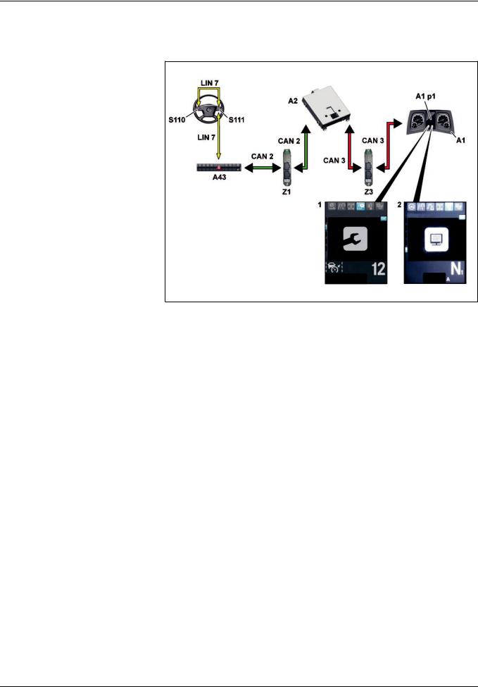
Functions
|
GF00.20>W>3003H |
Normal mode displays function |
2.8.11 |
MODEL 963
1 «Maintenance» menu
2«Diagnosis» menu
A1 Instrument cluster (ICUC) control unit
A1p1 Multifunction display
A2 Central gateway control unit (CGW)
A43 Modular switch panel (MSF) control unit
CAN 2 Interior CAN
CAN 3 Frame CAN
LIN 7 Button group LIN
S110 Left multifunction steering wheel button group
|
W00.20>1077>76 |
||
|
S111 Right multifunction steering wheel |
Z1 Cab instrument panel CAN bus star |
Z3 Frame CAN bus star point |
|
button group |
point |
General information
The central gateway control unit (CGW) (A2) sends the CAN messages with the display information over the frame CAN (CAN 3) and over the frame CAN bus neutral point (Z3) to the instrument cluster control unit (ICUC) (A1).
The maintenance information display is generated in the instrument cluster control unit (ICUC) (A1) and shown on the multifunction display (A1 p1).
The following service information is shown:
fService messages
fService information
>>>>>>>>>>>>>>>>>>>>>>>>>>>>>>>>>>>>>>>>>>>>>>>>>>>>>>>>>>>>>>>>>>>>>>>>>>>>>>>>>>>>>>>>>
Service messages
Service messages are text warnings that indicate upcoming maintenance operations. They contain the «service date» and «remaining driving distance» forecast data for the listed maintenance item or its urgency status (e.g. Service due). They are automatically generated by the maintenance system
(WS) as per their urgency status and shown on the multifunction display (A1 p1).
If there are any service messages pending, they are shown each time the ignition is switched on along with any other pending messages. Service messages can only be canceled by
acknowledging them.
>>>>>>>>>>>>>>>>>>>>>>>>>>>>>>>>>>>>>>>>>>>>>>>>>>>>>>>>>>>>>>>>>>>>>>>>>>>>>>>>>>>>>>>>>
30
– This printout will not be recorded by the update service. Status: 09 / 2011 –

Functions
Five urgency levels of service messages are differentiated:
fNo message
fEarly warning
fService due
fService now (can be acknowledged)
fService now (cannot be acknowledged)
i Any acknowledgeable service messages has to be acknowledged. The associated service dates have to be observed and the maintenance operations have to be carried out.
If service messages are skipped, the operational and road safety of the vehicle can be jeopardized. If a maintenance operation is carried out late or not at all, the wear at the vehicle or at the
major assemblies will increase at any rate.
>>>>>>>>>>>>>>>>>>>>>>>>>>>>>>>>>>>>>>>>>>>>>>>>>>>>>>>>>>>>>>>>>>>>>>>>>>>>>>>>>>>>>>>>>
Service immediately
The life cycle consumption has reached the exceeding limit. The due service date was significantly exceeded.
A highlighted text information is displayed in yellow.
When acknowledging the service message, the next pending service message, where applicable, is then shown.
Service now (cannot be acknowledged)
The life cycle consumption has extended far beyond the overrun limit. The Service due date was exceeded to an extreme extent. A text information highlighted in yellow is shown and the yellow indicator lamp with the wrench symbol. When the maximum brake wear is reached, the indicator lamp also appears with the brake symbol.
When acknowledging the service message, the next pending service message, where applicable, is then shown.
Advance warning
This is information on the maintenance item and the remaining driving distance until the service is due.
The life cycle consumption is still below 100%.
Service will be due within the next days and the life cycle consumption will then be
100%.
When acknowledging the service message, the next pending service message, where applicable, is then shown.
Service due
The life cycle consumption is 100%.
The due service date was reached or exceeded.
If the service message is acknowledged, the next service message
of the «Service due» urgency level is displayed if applicable.
>>>>>>>>>>>>>>>>>>>>>>>>>>>>>>>>>>>>>>>>>>>>>>>>>>>>>>>>>>>>>>>>>>>>>>>>>>>>>>>>>>>>>>>>>
Service information
Service information can be called up at any given time in the «Maintenance» menu in the instrument cluster and shown on the multifunction display (A1 p1). The system is operated using the left multifunction steering wheel button group (S110) and the right multifunction steering wheel button group (S111).
The service information listed in the «Maintenance» menu on a maintenance item contains the same information as the service messages. The interval number is also shown on the multifunction display (A1 p1).
If the «Reset?» prompt is shown in the multifunction display (A1 p1), the maintenance item above the left multifunction steering wheel button group (S110) and the right multifunction steering wheel button group (S111) can be reset.
If the multifunction display (A1 p1) shows a display without any forecast data under the maintenance item text, there are no forecast data available for the maintenance item.
Example: Transmission
> >.> >.> >
|
Instrument cluster control unit (ICUC), |
A1 |
Page 331 |
|
|
component description |
|||
|
Central gateway control unit (CGW), |
A2 |
Page 333 |
|
|
component description |
|||
|
Multifunction steering wheel, component |
S110, S111 |
Page 469 |
|
|
description |
|||
|
i Electronic systems, Actros, model 963 > 09/2011 > |
31 |
– This printout will not be recorded by the update service. Status: 09 / 2011 –

Functions
|
GF00.20>W>3005H |
Reset service item function |
2.8.11 |
||||||||||||
|
MODEL 963 |
||||||||||||||
|
Reset maintenance items |
||||||||||||||
|
Requirements: |
Execution: |
|||||||||||||
|
f Maintenance operation was conducted |
f Confirm the «Reset?» selection internally through the multifunction display (A1 p1) |
|||||||||||||
|
f |
Vehicle at rest |
in the instrument cluster control unit (ICUC) (A1) in the respective maintenance item |
||||||||||||
|
f |
Ignition switched on |
in the Maintenance menu by pressing the left multifunction steering wheel button |
||||||||||||
|
f |
Hand brake applied |
group (S110) and the right multifunction steering wheel button group (S111) |
||||||||||||
|
f Confirm externally through the diagnostic socket (X100.16) using Star Diagnosis |
||||||||||||||
|
Directly measured maintenance items |
Accumulating maintenance items |
Time>based servicing scheme |
||||||||||||
|
(e.g. brake linings) |
(operation oils) |
(e.g. lubrication of steering knuckles) |
||||||||||||
|
f |
Manual reset |
f Manual reset |
f Manual reset |
|||||||||||
f Possible adjustment of the new operating fluid
General information
If a maintenance operation was carried out, the associated maintenance item has to be reset.
For safety reasons the reset of maintenance items is only possible, if the vehicle’s hand brake is tightened and the ignition is switched on. When driving, the instrument cluster control unit (ICUC) (A1) blocks this function.
>>>>>>>>>>>>>>>>>>>>>>>>>>>>>>>>>>>>>>>>>>>>>>>>>>>>>>>>>>>>>>>>>>>>>>>>>>>>>>>>>>>>>>>>>
Reset maintenance items for directly measured maintenance items
Manual reset
The maintenance system (WS):
>recognizes, after the maintenance was carried out, that the currently valid measured wear value lies below the value for the calculation start and
>permits a reset.
After a manual reset:
>the entire service life data (with the exception of the operating time and the total travel distance) is reset to the initialization values,
>the interval number is incremented,
>bars are shown in the forecast data,
>>>>>>>>>>>>>>>>>>>>>>>>>>>>>>>>>>>>>>>>>>>>>>>>>>>>>>>>>>>>>>>>>>>>>>>>>>>>>>>>>>>>>>>>>
A differentiation is made between three functions:
fReset maintenance items for directly measured maintenance items
fReset maintenance items for accumulated maintenance items
fReset maintenance items with a time>based servicing scheme
All maintenance items, including the time>based servicing scheme,
are reset manually.
>>>>>>>>>>>>>>>>>>>>>>>>>>>>>>>>>>>>>>>>>>>>>>>>>>>>>>>>>>>>>>>>>>>>>>>>>>>>>>>>>>>>>>>>>
>bars are shown in the forecast data,
>then the service messages memory is deleted and
>basic maintenance data that have accrued so far are taken over into the maintenance memory.
A reset for the «brake» maintenance item is only possible, if the currently valid measured values for both brakes on one axle are below the brake wear value of 18%.
>>>>>>>>>>>>>>>>>>>>>>>>>>>>>>>>>>>>>>>>>>>>>>>>>>>>>>>>>>>>>>>>>>>>>>>>>>>>>>>>>>>>>>>>>
32
– This printout will not be recorded by the update service. Status: 09 / 2011 –

Functions
Reset maintenance items for accumulated maintenance items
Manual reset
After a manual reset:
>the service life data are reset to their initialization values,
>then the service messages memory is deleted,
>the basic maintenance data that have incurred this far are transferred to the maintenance memory,
>the interval number is incremented,
>bars are shown in the forecast data, and
>where fuels and lubricants are used, that differentiate from the previous fuel and lubricants, then these are to be set in the Fuels and Lubricants menu below the corresponding major assembly.
Reset maintenance items with a time>based servicing scheme
i A reset is only possible after 50 h operating time in the current maintenance interval.
Manual reset
After a reset:
>the entire life cycle data are reset and their initialization values are taken over again,
>then the service messages memory is deleted,
>basic maintenance data that have incurred this far are transferred to the maintenance memory,
>the interval number is incremented, and
>a new forecast date without remaining driving distance is shown.
|
Instrument cluster control unit (ICUC), |
A1 |
Page 331 |
|
|
component description |
|||
|
Central gateway control unit (CGW), |
A2 |
Page 333 |
|
|
component description |
|||
|
Multifunction steering wheel, component |
S110, S111 |
Page 469 |
|
|
description |
|||
|
Diagnostic socket, component description |
X100.16 |
Page 477 |
|
|
i Electronic systems, Actros, model 963 > 09/2011 > |
33 |
– This printout will not be recorded by the update service. Status: 09 / 2011 –

Functions
|
GF00.20>W>3011H |
Forecast calculation, function |
2.8.11 |
MODEL 963
General information
A forecast is used to schedule the vehicle’s visit to the workshop beforehand.
The maintenance system (WS) calculates the individual forecast data for each maintenance item during each calculation cycle:
fRemaining total time
fRemaining driving distance
fMaintenance date
>>>>>>>>>>>>>>>>>>>>>>>>>>>>>>>>>>>>>>>>>>>>>>>>>>>>>>>>>>>>>>>>>>>>>>>>>>>>>>>>>>>>>>>>>
Forecasting start
As long as the life cycle consumption is still below the forecasting start, no forecast data are calculated. There is not yet a sufficient amount of information below the forecasting start to be able to calculate reliable forecast data.
After each reset the forecast data are marked «not predictable» by the base parameterization. After exceeding the forecasting start, the predictions are calculated based on the current life cycle consumption values.
The forecasting start for accumulated, directly measured maintenance items and for time>based servicing schemes lies at 50 h operating time.
Forecasting
The forecast data are calculated individually for each maintenance item. As a result, the service dates of the individual maintenance items do not have a fixed time interval between one
another.
>>>>>>>>>>>>>>>>>>>>>>>>>>>>>>>>>>>>>>>>>>>>>>>>>>>>>>>>>>>>>>>>>>>>>>>>>>>>>>>>>>>>>>>>>
Time>based servicing
The life cycle consumption increases irrespective of the load of the maintenance item in proportion to the elapsed time.
The service date depends exclusively on the calculated remaining total time. The remaining total time is calculated beginning with the start of the total time calculation.
The prognosis calculation is based on the following input parameters:
fTotal time
fOperating time
fDistance
fLife cycle consumption
The service date of the time>based servicing scheme is exclusively specified via the parameterizable time maintenance grid. The forecast data are issued on the multifunction display (A1 p1) in
the instrument cluster (ICUC) (A1).
>>>>>>>>>>>>>>>>>>>>>>>>>>>>>>>>>>>>>>>>>>>>>>>>>>>>>>>>>>>>>>>>>>>>>>>>>>>>>>>>>>>>>>>>>
Thus, the workshop equipment is optimally utilized.
The forecast data for the remaining total time and the remaining driving distance apply exactly to each service date of a maintenance item and represent the remainder values until the due date.
The individual service date for each maintenance item is the point in time at which the next maintenance is due.
i This applies provided the workshop equipment is used with a constant load.
If maintenance items are close to each other, then a decision should be reached in consultation with the customer as to whether they can be conducted together during a maintenance visit to the workshop.
>>>>>>>>>>>>>>>>>>>>>>>>>>>>>>>>>>>>>>>>>>>>>>>>>>>>>>>>>>>>>>>>>>>>>>>>>>>>>>>>>>>>>>>>>
After confirmation of a conducted time>based servicing scheme, the new service date is displayed in the multifunction display (A1 p1).
The remaining distance is shown after 50 operating hours for the first time in the multifunction display (A1 p1).
|
Central gateway control unit (CGW), |
A2 |
Page 333 |
|
|
component description |
|||
34
– This printout will not be recorded by the update service. Status: 09 / 2011 –
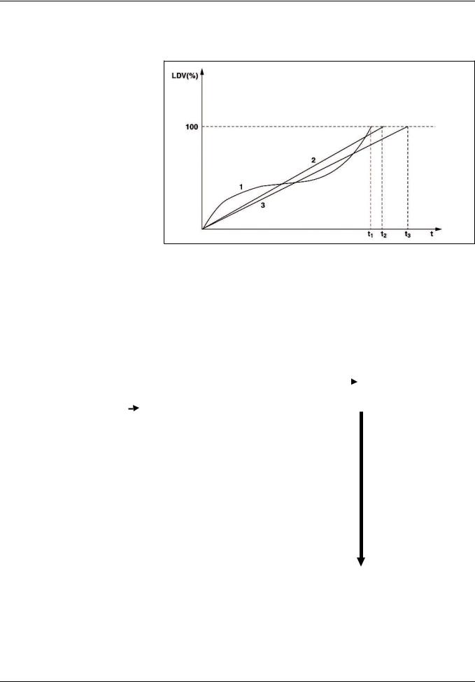
Functions
|
GF00.20>W>3012H |
Life cycle consumption calculation, function |
2.8.11 |
MODEL 963
Life cycle consumption of a maintenance item
1Life cycle consumption after
loading
2Life cycle consumption according to driving time limit
3Life cycle consumption after travel distance limitation
LDV (%) Life cycle consumption
tTime
|
t1 |
Time «100% LDV according to |
|
load» |
|
|
t2 |
Time «100% LDV according to |
|
driving time limit» |
|
|
t3 |
Time «100% LDV according to |
|
distance limit» |
W00.20>1040>05
|
INPUT DATA |
Calculation of life cycle consumption |
OUTPUT DATA |
|||
|
f Operating oil temperatures of |
f Life cycle consumption based on the vehicle load for |
f Life cycle consumption based |
|||
|
major assemblies |
A. directly measured maintenance items (brake linings, air |
on the load |
|||
|
f Brake lining thickness of front and |
filter) |
f Life cycle consumption based |
|||
|
rear axle |
Calculation with linear or nonlinear calculation instruction |
on the time limitation |
|||
|
f Air filter contamination |
as a function of the wear variable. |
f Life cycle consumption based |
|||
|
f Air drier condensation level |
B. Accumulating maintenance items (operation oils) |
on the travel distance |
|||
|
f Brake wear ratio |
Calculation with empirical calculation instructions |
limitation |
|||
|
f Operating time |
dependent on: |
f Life cycle consumption based |
|||
|
f Total time |
> Correction factors for temperature, load, rotational |
on operating |
|||
|
f Distance |
speed, cold start increment |
||||
|
f Number of crankshaft revolutions |
> Quality factors for oil, fuel, mechanical components |
||||
|
f Engine speed |
f Time>based servicing scheme (e.g. lubrication of steering |
||||
|
f Moderate engine speed |
knuckles) |
||||
|
f Average major assemblies |
f Life cycle consumption based on the drive time limit |
||||
|
temperature |
f Life cycle consumption based on the travel distance |
||||
|
f Average outside air temperature |
limitation |
||||
|
f Diesel particulate filter soiling |
f Life cycle consumption based on operating time |
||||
|
f Vehicle speed |
|||||
Æ for forecasting
Forecasting uses the highest value.
|
i Electronic systems, Actros, model 963 > 09/2011 > |
35 |
– This printout will not be recorded by the update service. Status: 09 / 2011 –

Functions
General information
The life cycle consumption calculation provides information on the degree to which the workshop equipment is worn out, and which one should be replaced or repaired during maintenance.
The life cycle consumption calculation determines 4 life cycle consumption values, which are calculated anew during each calculation cycle:
fLife cycle consumption based on vehicle load, based on calculation method for:
>directly measured maintenance items and
>accumulating maintenance items.
fLife cycle consumption based on the drive time limit,
fLife cycle consumption based on the travel distance limitation,
fLife cycle consumption based on operating time,
The workshop equipment is worn out if a life cycle consumption of 100% is reached.
An exception is the time>based servicing scheme, which has fixed maintenance intervals that are independent from loads and driving distance.
The life cycle consumption is the basis for forecasting.
i Very precise, earlier prognoses are possible in the event of regular operations in regard to loads and driving distance over a long period of time. If operations vary greatly, the prognosis variation is higher. The forecasts become increasingly more accurate as total vehicle operating time increases.
Once the four life cycle consumption values have been evaluated, the maintenance system (WS) provides the highest value as a forecasting life cycle parameter.
|
Central gateway control unit (CGW), |
A2 |
Page 333 |
|
|
component description |
|||
36
– This printout will not be recorded by the update service. Status: 09 / 2011 –

Functions
|
GF26.21>W>0002H |
Transmission automation, function |
2.8.11 |
TRANSMISSION 715 in MODEL 963 with CODE (G5G) Mercedes PowerShift 3
TRANSMISSION 715 in MODEL 964 with CODE (G5G) Mercedes PowerShift 3
|
W26.21>1121>79 |
|||||
|
A1 |
Instrument cluster (ICUC) control unit |
B18 |
Travel and speed sensor |
LIN 3 |
Multifunction control lever>LIN on |
|
A2 |
Central gateway control unit (CGW) |
B501 |
Main shaft rpm sensor |
the right |
|
|
A3 |
Drive control (CPC) control unit |
B502 |
Countershaft rpm sensor |
LIN 7 |
Button group LIN |
|
A4 |
Engine management control unit |
B503 |
Clutch travel sensor |
S23 |
Right multifunction control lever |
|
(MCM) |
B504 |
Range group travel sensor |
S110 |
Left multifunction steering wheel |
|
|
A5 |
Transmission control (TCM) control |
B505 |
Transmission oil temperature |
button group |
|
|
unit |
sensor |
S111 |
Right multifunction steering wheel |
||
|
A43 |
Modular switch panel (MSF) control |
CAN 2 |
Interior CAN |
button group |
|
|
unit |
CAN 3 |
Frame CAN |
Y900 |
Transmission positioner |
|
|
CAN 4 |
Drive train CAN |
1General
With transmission automation there a convenience shifting system available over which gear selection as well as declutching and engaging of the clutch take place automatically. It contains a fully automated manual transmission, based on a constant>mesh transmission, with automated clutch operating system. The clutch operation takes place over a pneumatically actuated centrally located clutch operator.
Synchronization does not take place via a blocking synchronization as on a synchromesh transmission but is realized instead by braking or accelerating the countershaft in a controlled manner. As a result can be widened for the same dimensions of the transmission gears and thus higher torques and outputs transmitted. Passive safety is also increased due to reducing the
burden for the driver.
>>>>>>>>>>>>>>>>>>>>>>>>>>>>>>>>>>>>>>>>>>>>>>>>>>>>>>>>>>>>>>>>>>>>>>>>>>>>>>>>>>>>>>>>>
Optimum gear selection supports an economic and fuel>saving driving style. All the shift operations take place in the optimum rpm range, minimizing wear on the transmission and engine.
Faults during shifting are ruled out and it is no longer possible to over rev the engine. After switching on the ignition the automatic mode of transmission automation is always activated irrespective of which mode was last selected (manual or automatic). The option of activating a manual or automatic shift mode with the transmission mode button (M/A) (S23 s3) on the RH multifunction control lever (S23) has been retained. 12 forwards gears, 4 reverse gears and neutral can be engaged.
>>>>>>>>>>>>>>>>>>>>>>>>>>>>>>>>>>>>>>>>>>>>>>>>>>>>>>>>>>>>>>>>>>>>>>>>>>>>>>>>>>>>>>>>>
|
i Electronic systems, Actros, model 963 > 09/2011 > |
37 |
– This printout will not be recorded by the update service. Status: 09 / 2011 –
![]()
Functions
2Changes compared with the previous transmission
generation
fThe transmission positioner (Y900) includes:
>all solenoid valves for controlling the clutch, gear, gate, split, countershaft brake and range group
>travel sensors for gear, gate and split
fa pressed down clutch operation due to the pneumatic central clutch release bearing
>>>>>>>>>>>>>>>>>>>>>>>>>>>>>>>>>>>>>>>>>>>>>>>>>>>>>>>>>>>>>>>>>>>>>>>>>>>>>>>>>>>>>>>>>
3Transmission modes and driving functions
Transmission automation offers the following operating modes:
fAutomatic transmission mode with a driving specific shift program (automatic operation)
fManual transmission mode (manual operation)
fBack>up mode (backup drive mode) includes the additional function «Towing».
Further driving functions include:
fEco>roll mode, in certain driving situations for supporting a fuel>saving driving style through automatic shifting into the transmission neutral position when the accelerator is not actuated
fCrawl function, for automatic starting moving when releasing the service brake and freewheeling without actuating the accelerator pedal
fRocking mode, for rocking the vehicle out of an off>road
recess
>>>>>>>>>>>>>>>>>>>>>>>>>>>>>>>>>>>>>>>>>>>>>>>>>>>>>>>>>>>>>>>>>>>>>>>>>>>>>>>>>>>>>>>>>
4Components of the transmission automation
4.1Transmission (TCM) control unit (A5)
The transmission (TCM) control unit (A5) is the central control unit for the transmission and the clutch. It contains the software modules for controlling the transmission and clutch actors.
The following sensor signals are read in directly amongst others:
fCountershaft rpm sensor (B502)
fTransmission oil temperature sensor (B505)
fMain shaft rpm sensor (B501)
4.2Transmission positioner (Y900)
The transmission positioner (Y900) combines the following components into one unit:
fGear cylinder
fGear cylinder travel sensor (Y900 b2)
>>>>>>>>>>>>>>>>>>>>>>>>>>>>>>>>>>>>>>>>>>>>>>>>>>>>>>>>>>>>>>>>>>>>>>>>>>>>>>>>>>>>>>>>>
4.3Splitter group shift cylinder
The splitter group shift cylinder is integrated into the front part of the transmission housing.
4.4Range group module
The range group module combines the following components into a unit:
fRange group shift cylinder
fRange group travel sensor (B504)
>>>>>>>>>>>>>>>>>>>>>>>>>>>>>>>>>>>>>>>>>>>>>>>>>>>>>>>>>>>>>>>>>>>>>>>>>>>>>>>>>>>>>>>>>
fRetract gear cylinder solenoid valve (Y900 y9)
fExtend gear cylinder solenoid valve (Y900 y8)
fGate cylinder
fGate cylinder travel sensor (Y900 b3)
fRetract gate cylinder solenoid valve (Y900 y11)
fExtend gate cylinder solenoid valve (Y900 y10)
fRetract splitter group solenoid valve (Y900 y7)
fExtend splitter group solenoid valve (Y900 y6)
fSlowly close clutch solenoid valve (Y900 y1)
fSlowly open clutch solenoid valve (Y900 y2)
fQuickly close clutch solenoid valve (Y900 y3)
fQuickly open clutch solenoid valve (Y900 y4)
fRetract range group solenoid valve (Y900 y12)
fExtend range group solenoid valve (Y900 y13)
fCountershaft brake solenoid valve (Y900 y5)
fSplitter group travel sensor (Y900 b1)
>>>>>>>>>>>>>>>>>>>>>>>>>>>>>>>>>>>>>>>>>>>>>>>>>>>>>>>>>>>>>>>>>>>>>>>>>>>>>>>>>>>>>>>>>
4.5Pneumatic central clutch release bearing
The pneumatic central clutch release bearing directly actuates the mechanical clutch components, takes on disengaging the clutch and engaging the clutch and contains the clutch travel sensor (B503).
4.6Right multifunction control lever (S23)
The RH multifunction control lever (S23) transmits the shift
commands to the drive control (CPC) control unit (A3).
>>>>>>>>>>>>>>>>>>>>>>>>>>>>>>>>>>>>>>>>>>>>>>>>>>>>>>>>>>>>>>>>>>>>>>>>>>>>>>>>>>>>>>>>>
38
– This printout will not be recorded by the update service. Status: 09 / 2011 –

Functions
5The following components support during transmission automation
5.1Engine management (MCM) control unit (A4)
The engine management (MCM) control unit (A4) includes the software module for torque and rotational speed actuation of the engine and therefore also implements requests from other control units on the rotational speed and torques for switching, starting off and stopping.
5.2Drive control (CPC) control unit (A3)
The drive control (CPC) control unit (A3) is modular in design and it contains the following software modules:
fSoftware module for drive control; it comes with extended functions (e.g. cruise control etc.)
fSoftware module for automatic gear selection
>>>>>>>>>>>>>>>>>>>>>>>>>>>>>>>>>>>>>>>>>>>>>>>>>>>>>>>>>>>>>>>>>>>>>>>>>>>>>>>>>>>>>>>>>
5.3Modular switch panel (MSF) control unit (A43)
The modular switch panel (MSF) control unit (A43) reads in the operation of the back>up mode via the left multifunction steering wheel button group (S110) or the right multifunction steering wheel button group (S111).
5.4Tachograph (TCO) (P1)
The tachograph (TCO) (P1) reads in the way and speed sensor (B18) and evaluates its signal.
5.5IC control unit (ICUC) (A1)
The IC (ICUC) control unit (A1) shows the driver information over
the multifunction display (A1 p1).
>>>>>>>>>>>>>>>>>>>>>>>>>>>>>>>>>>>>>>>>>>>>>>>>>>>>>>>>>>>>>>>>>>>>>>>>>>>>>>>>>>>>>>>>>
6Transmission cooling (for code N6Z)
A thermostatically regulated transmission cooling with the following components is used as special equipment:
fTransmission cooler with a transmission cooling fan (M19) (located in the direction of travel on the right, next to the cooling module)
fTransmission oil lines
fThermostat element with spring from the shape memory alloy (FGL)
For transmission oil temperatures above 80∞C the spring force of the spring closes the cooler protection valve (bypass). The transmission oil flows through the transmission cooler and is cooled by the airstream.
If the transmission oil temperature increases further, the transmission cooling fan (M19) located on the transmission cooler is switched on from 90∞C over the SCA (SCA) control unit (A7).
For transmission oil temperatures below 80∞C the spring opens the cooler protection valve. The transmission oil flows uncooled over the bypass back into the transmission.
i In the case of an excessively high transmission oil pressure the cooler and the transmission protection valve open and allow the oil to flow uncooled over a bypass back into the transmission.
|
Overall network for transmission |
Page 40 |
||
|
automation |
|||
|
Operation, function |
Page 41 |
||
|
Driver information, function |
Page 44 |
||
|
Transmission mode, function |
Page 45 |
||
|
Shifting the transmission, function |
Page 46 |
||
|
Controlling the clutch, function |
Page 52 |
||
|
Countershaft brake, function |
Page 54 |
||
|
i Electronic systems, Actros, model 963 > 09/2011 > |
39 |
– This printout will not be recorded by the update service. Status: 09 / 2011 –

Functions
GF26.21>W>0002>01H Overall network for transmission automation
|
W26.00>1032>79 |
|||||
|
A1 |
Instrument cluster (ICUC) control |
A10c |
Electronic brake system (EBS) |
S23 |
Right multifunction control lever |
|
unit |
control unit |
S110 |
Left multifunction steering wheel |
||
|
A2 |
Central gateway control unit (CGW) |
A43 |
Modular switch panel (MSF) |
button group |
|
|
A3 |
Drive control (CPC) control unit |
control unit |
S111 |
Right multifunction steering wheel |
|
|
A4 |
Engine management control unit |
CAN 2 |
Interior CAN |
button group |
|
|
(MCM) |
CAN 3 |
Frame CAN |
Z1 |
Cab instrument panel CAN bus star |
|
|
A5 |
Transmission control (TCM) control |
CAN 4 |
Drive train CAN |
point |
|
|
unit |
LIN 3 |
Multifunction control lever>LIN on |
Z3 |
Frame CAN bus star point |
|
|
A10b |
Electronic brake system (EBS) control |
the right |
Z4 |
Drive CAN bus star point |
|
|
unit |
LIN 7 |
Button group LIN |
|||
|
P1 |
Tachograph (TCO) |
40
– This printout will not be recorded by the update service. Status: 09 / 2011 –

Functions
|
GF26.21>W>3003H |
Operation, function |
2.8.11 |
TRANSMISSION 715 in MODEL 963 with CODE (G5G) Mercedes PowerShift 3
TRANSMISSION 715 in MODEL 964 with CODE (G5G) Mercedes PowerShift 3
A3 Drive control (CPC) control unit
A5 Transmission control (TCM) control unit
CAN 4 Drive train CAN
LIN 3 Multifunction control lever>LIN on the right
S23 Right multifunction control lever S23s1 Transmission position switch
(D/N/R)
S23s2 Gearshift paddle (+/>)
S23 s3 Transmission mode (M/A) button
W26.21>1119>06
Normal operation
The shift commands are recorded over in the integral controls in the RH multifunction control lever (S23):
fTransmission position (D/N/R) switch (S23 s1)
fGearshift paddle (+/>) (S23 s2)
fTransmission mode (M/A) button (S23 s3)
The drive control (CPC) control unit (A3) reads in the shift signals from the RH multifunction control lever (S23) via the RH multifunction control lever LIN (LIN 3), evaluates them and sends appropriate CAN messages to the transmission (TCM) control unit (A5) via the drive train CAN (CAN 4).
Twelve forwards gears, 4 reverse gears and neutral can be engaged.
>>>>>>>>>>>>>>>>>>>>>>>>>>>>>>>>>>>>>>>>>>>>>>>>>>>>>>>>>>>>>>>>>>>>>>>>>>>>>>>>>>>>>>>>>
Automatic operation
(the optimal gear (the required gear specification) is determined by the drive control (CPC) control unit (A3))
Gear selection is dependent on the following influencing variables:
fGround speed (only relevant for the start>off gear)
fAccelerator pedal position (specified torque)
fLoad condition of engine
fOperating point of the target gear
fStarting speed of the transmission
fOperation of the permanent brake
fLoad condition of the vehicle
fShift program
fLay of the land for the driving lane
Manual mode
Difference to automatic mode:
fThe shifting operations must be initiated by the driver, that is the driver determines the shift point and shift direction.
fThe kickdown function is not available.
>>>>>>>>>>>>>>>>>>>>>>>>>>>>>>>>>>>>>>>>>>>>>>>>>>>>>>>>>>>>>>>>>>>>>>>>>>>>>>>>>>>>>>>>>
|
i Electronic systems, Actros, model 963 > 09/2011 > |
41 |
– This printout will not be recorded by the update service. Status: 09 / 2011 –

Functions
Operation of the driving functions
The driving functions assist the driver in daily driving to drive with a more fuel economy. They increase the ride comfort and support him in difficult situations.
Selectable driving functions are:
fEcoRoll mode, in certain driving situations for supporting a fuel>saving driving style through automatic shifting into the transmission neutral position «N» when the accelerator is not actuated
fRocking mode, for rocking the vehicle out of an off>road recess
fCrawl mode, for automatic starting moving when releasing the service brake and continued crawling without actuating
the accelerator pedal.
>>>>>>>>>>>>>>>>>>>>>>>>>>>>>>>>>>>>>>>>>>>>>>>>>>>>>>>>>>>>>>>>>>>>>>>>>>>>>>>>>>>>>>>>>
Function sequence
If the pre>conditions are fulfilled then the drive control (CPC) control unit (A3) requests the neutral position from the transmission (TCM) control unit (A5) via the drive train CAN (CAN 4). The transmission (TCM) control unit (A5) actuates the transmission positioner (Y900) to open the clutch. After successful opening of the clutch, read in over the clutch position sensor (B503), the transmission positioner (Y900) is actuated to engage neutral. After ending the switching the transmission (TCM) control unit (A5) transmits the engaged neutral to the drive control (CPC) control unit (A3) via the drive train CAN (CAN 4).
i Based on the reduced engine speed a somewhat lower steering assist can occur and therefore greater steering forces in certain driving situations, for example on slightly curved downslopes. The operation or road safety is not endangered by this.
>>>>>>>>>>>>>>>>>>>>>>>>>>>>>>>>>>>>>>>>>>>>>>>>>>>>>>>>>>>>>>>>>>>>>>>>>>>>>>>>>>>>>>>>>
Function sequence
The crawl function consists of 2 parts:
fIn gears 1 to 6, R1 and R2, self>actuated starting crawling by releasing the service brake (only for an active crawl function)
fIn gears 1 to 6, R1 and R2 further crawling (=freewheeling)
for a non>actuated accelerator pedal
The driving off dosing occurs for first driving off over the accelerator pedal. The system is taught in in the process to the torque prescribed by the driver. After the first «real» driving determination of the crawling torque depends on the determined vehicle mass and incline in the driving lane.
i If driving with a trailer is recognized over the trailer recognition the mass and incline dependent crawling torque is reset in the drive control (CPC) control unit (A3) and teaching in
occurs again during first driving off.
>>>>>>>>>>>>>>>>>>>>>>>>>>>>>>>>>>>>>>>>>>>>>>>>>>>>>>>>>>>>>>>>>>>>>>>>>>>>>>>>>>>>>>>>>
EcoRoll mode
Preconditions
fEcoRoll function activated
fGround speed was > 35 km/h and is > 25 km/h (hysteresis)
fAccelerator not operated
fService brake or permanent brake not actuated
fDriver assistance systems not in control mode
fBrake assistant systems not in control mode
fPower take>off switched off
fVariable speed limiter maximum speed not exceeded
fCC speed tolerance not exceeded
>>>>>>>>>>>>>>>>>>>>>>>>>>>>>>>>>>>>>>>>>>>>>>>>>>>>>>>>>>>>>>>>>>>>>>>>>>>>>>>>>>>>>>>>>
Crawl mode
The crawl function is always switched on after an engine start and is activated after first moving off.
The crawl function is deactivated under the following conditions:
fThe crawl function is switched off over the IC (ICUC) control unit (A1)
fThe transmission in neutral for longer than 2 s
fThe parking brake is tightened
fThe rocking mode is activated
fDriver assistance systems switch into control mode
fIdle speed > 700 rpm
fThreat of clutch overloading
fAn excessively high air drag and rolling resistance
fAn excessively high tire grip
i The crawl function is similar in its behavior to an automatic torque converter. Since the function is realized over the clutch the function is not wear>free and the vehicle in the slip range of the
clutch is not capable of permanently crawling.
>>>>>>>>>>>>>>>>>>>>>>>>>>>>>>>>>>>>>>>>>>>>>>>>>>>>>>>>>>>>>>>>>>>>>>>>>>>>>>>>>>>>>>>>>
Rocking mode Function sequence
Rocking mode is activated over the rocking mode button (S938). If rocking mode has been activated the transmission control changes from automatic into manual mode.
Accelerator pedal requests are implemented more directly and the clutch is opened more rapidly for a non>actuated accelerator pedal. The clutch is closed quickly again as soon as the accelerator pedal is actuated again. Through repeated actuation and release of the accelerator pedal can put the vehicle into a rocking mode condition and in this way can rock the vehicle free out if a hollow.
>>>>>>>>>>>>>>>>>>>>>>>>>>>>>>>>>>>>>>>>>>>>>>>>>>>>>>>>>>>>>>>>>>>>>>>>>>>>>>>>>>>>>>>>>
42
– This printout will not be recorded by the update service. Status: 09 / 2011 –

Functions
Back>up mode
Back>up mode represents a last emergency function for engaging gears for a vehicle standstill. The operating commands for navigation are entered in the menu tree multifunction display (A1 p1) in the IC (ICUC) control unit (A1) over the LH multifunction steering wheel button group (S110) and the RH multifunction steering wheel button group (S111).
The modular switch panel (MSF) control unit (A43) reads in the switching commands from the LH multifunction steering wheel button group (S110) and the RH multifunction steering wheel button group (S111), evaluates them and transmits appropriate CAN messages via the interior CAN (CAN 2), the central gateway (CGW) control unit (A2) and the frame CAN (CAN 3) to the drive control (CPC) control unit (A3).
The drive control (CPC) control unit (A3) evaluates the switching request from the driver, determines the targeted gear to be switched and, for release, transmits appropriate CAN messages via the drive train CAN (CAN 4) to the transmission (TCM) control unit (A5).
The following switching positions can be selected in back>up mode:
fR (for reverse gear)
fN (for neutral)
fD1 (for 2nd gear)
fD2 (for 6th gear)
fTowing (for the towing mode)
The actuation of the clutch is controlled automatically as long as no malfunction is present. A malfunction would result in automatic clutch operation being disabled.
i If gear selection was not enabled, a shift to «neutral» is always enabled.
|
Instrument cluster control unit (ICUC), |
A1 |
Page 331 |
|
|
component description |
|||
|
Component description for central |
A2 |
Page 333 |
|
|
gateway control unit (CGW) |
|||
|
Component description for drive control |
A3 |
Page 334 |
|
|
(CPC) control unit |
|||
|
Component description for transmission |
A5 |
Page 337 |
|
|
control (TCM) control unit |
|||
|
Component description for modular switch |
A43 |
Page 370 |
|
|
panel control unit (MSF) |
|||
|
Component description for right |
S23 |
Page 463 |
|
|
multifunction control lever |
|||
|
Component description for multifunction |
S110, S111 |
Page 469 |
|
|
steering wheel |
|||
|
i Electronic systems, Actros, model 963 > 09/2011 > |
43 |
– This printout will not be recorded by the update service. Status: 09 / 2011 –

Functions
|
GF26.21>W>3005H |
Driver information, function |
2.8.11 |
TRANSMISSION 715 in MODEL 963 with CODE (G5G) Mercedes PowerShift 3
TRANSMISSION 715 in MODEL 964 with CODE (G5G) Mercedes PowerShift 3
A1 Instrument cluster (ICUC) control unit
A1 p1 Multifunction display
A3 Drive control (CPC) control unit
A5 Transmission control (TCM) control unit
B50 Center speaker CAN 3 Frame CAN CAN 4 Drive train CAN
W26.21>1118>76
Displaying shift status
The drive control (CPC) control unit (A3) transmits the information for indication of the switching condition to the IC (ICUC) control unit (A1) via the frame CAN (CAN 3).
To do this the transmission (TCM) control unit (A5) permanently transmits the CAN messages with information about the condition of the transmission (for example the engaged gear, the possible gear) to the drive control (CPC) control unit (A3) via the drive train CAN (CAN 4). Before execution of the shift operation the drive control (CPC) control unit (A3) transmits the targeted gear request (determined from the automatic gear selection or the gear selected by the driver) to the transmission (TCM) control unit (A5). The transmission (TCM) control unit (A5) transmits the confirmed targeted gear and the engaged current gear to the drive control
(CPC) control unit (A3) .
>>>>>>>>>>>>>>>>>>>>>>>>>>>>>>>>>>>>>>>>>>>>>>>>>>>>>>>>>>>>>>>>>>>>>>>>>>>>>>>>>>>>>>>>>
Emit warning tones acoustically
The transmission (TCM) control unit (A5) transmits CAN messages with information concerning the condition of the transmission (for example on the switched gear, the possible gear, temperature of the transmission oil) to the drive control (CPC) control unit (A3) via the drive train CAN (CAN 4).
The IC (ICUC) control unit (A1) receives the CAN messages and generates the following displays in the multifunction display (A1 p1):
fdisplay of the direction of travel and / or the engaged gear
fdisplay of the gearshift recommendation or to engaged gear
fdisplay of the transmission mode
The previous display is retained during the shift operation. The current display only takes place when the shift operation is concluded.
i During the teach>in process appropriate CAN messages are transmitted with information for display of the active teach>in process. Also in back>up mode all CAN messages are transmitted, as in normal mode, via the drive control (CPC) control unit (A3) and the frame CAN (CAN 3) to the IC (ICUC) control unit (A1).
>>>>>>>>>>>>>>>>>>>>>>>>>>>>>>>>>>>>>>>>>>>>>>>>>>>>>>>>>>>>>>>>>>>>>>>>>>>>>>>>>>>>>>>>>
The drive control (CPC) control unit (A3) decides over a warning emission to the driver. If a warning emission is necessary, the drive control (CPC) control unit (A3) transmits an appropriate CAN message with the information for output of warning tones to the IC (ICUC) control unit (A1) via the frame CAN (CAN 3).
The IC (ICUC) control unit (A1) receives the CAN messages from the drive control (CPC) control unit (A3) and generates acoustic messages whose output takes place over the center speaker (B50).
|
Component description for instrument |
A1 |
Page 331 |
|
|
cluster control unit (ICUC) |
|||
|
Component description drive control (CPC) |
A3 |
Page 334 |
|
|
control unit |
|||
|
Component description for transmission |
A5 |
Page 337 |
|
|
control (TCM) control unit |
|||
44
– This printout will not be recorded by the update service. Status: 09 / 2011 –

Functions
|
GF26.21>W>3007H |
Transmission mode, function |
2.8.11 |
TRANSMISSION 715 in MODEL 963 with CODE (G5G) Mercedes PowerShift 3
TRANSMISSION 715 in MODEL 964 with CODE (G5G) Mercedes PowerShift 3
General information
One can select between a manual transmission mode (manual operation) or an automatic transmission mode (automatic operation). In automatic operation there is a standard switching program (A) and either the shift program (A power) or the shift program
(A economy) available depending on the vehicle and transmission design.
Automatic transmission mode
The transmission automation is fitted with a standard shift program:
fA, with kickdown, accelerator pedal curve standard, CC standard, maximum speed of 89.8 km/h, function EcoRoll which can be switched off
The driving specific shift programs have the following significant properties:
fA power, switchings take place at an about 100 rpm higher rotational speed in comparison with a standard shift program and dynamic clutch matching for driving off
fA economy, no kickdown possible, EcoRoll cannot be switched off, maximum speed of 85 km/h, accelerator pedal curve and max. engine torque lowered, CC Softcruise
i Selection of the automatic transmission mode takes place over the transmission mode button (M/A) (S23 s3) on the RH multifunction control lever (S23).
Manual transmission mode
In manual transmission mode the shift operations are initiated by the driver over it. This means that the driver determines the shift point and the switching direction. The kickdown function is not available.
|
Component description for right |
S23 |
Page 463 |
|
|
multifunction control lever |
|||
|
i Electronic systems, Actros, model 963 > 09/2011 > |
45 |
– This printout will not be recorded by the update service. Status: 09 / 2011 –

Functions
|
GF26.20>W>3007H |
Shifting the transmission, function |
2.8.11 |
TRANSMISSION 715 in MODEL 963 with CODE (G5G) Mercedes PowerShift 3
TRANSMISSION 715 in MODEL 964 with CODE (G5G) Mercedes PowerShift 3
|
W26.21>1123>09 |
|||||
|
Schematic representation |
|||||
|
1 |
Gate cylinder |
A3 |
Drive control (CPC) control unit |
B504 |
Range group travel sensor |
|
2 |
Range group shift cylinder |
A4 |
Engine management (MCM) |
CAN 2 |
Interior CAN |
|
3 |
Gear cylinder |
control unit |
CAN 3 |
Frame CAN |
|
|
4 |
Splitter group shift cylinder |
A5 |
Transmission control (TCM) |
CAN 4 |
Drive train CAN |
|
6 |
Countershaft brake |
control unit |
LIN 3 |
Multifunction control lever>LIN on |
|
|
6.1 |
Mechanical vent valve |
A43 |
Modular switch panel (MSF) |
the right |
|
|
7 |
Pneumatic central clutch release |
control unit |
LIN 7 |
Button group LIN |
|
|
bearing |
B18 |
Travel and speed sensor |
S23 |
Right multifunction control lever |
|
|
B501 |
Main shaft rpm sensor |
S110 |
Left multifunction steering wheel |
||
|
A1 |
Instrument cluster (ICUC) control |
B502 |
Countershaft rpm sensor |
button group |
|
|
unit |
B503 |
Clutch travel sensor |
S111 |
Right multifunction steering wheel |
|
|
A2 |
Central gateway control unit (CGW) |
button group |
|
Y900 b1 |
Splitter group travel sensor |
Y900 y4 |
Clutch quick opening solenoid |
Y900 y9 ‘Retract’ gear cylinder solenoid |
|
|
Y900 b2 |
Gear cylinder travel sensor |
valve |
valve |
||
|
Y900 b3 |
Gate cylinder travel sensor |
Y900 y5 |
Countershaft brake solenoid |
Y900 y10 |
‘Extend’ gate cylinder solenoid |
|
Y900 y1 |
Clutch slow closing solenoid valve |
valve |
valve |
||
|
Y900 y2 |
Clutch slow opening solenoid valve |
Y900 y6 |
‘Extend’ splitter group solenoid |
Y900 y11 |
‘Retract’ gate cylinder solenoid |
|
Y900 y3 |
Clutch quick closing solenoid valve |
valve |
valve |
||
|
Y900 y7 |
‘Retract’ splitter group solenoid |
Y900 y12 |
‘Retract’ range group solenoid |
||
|
valve |
valve |
||||
|
Y900 y8 |
‘Extend’ gear cylinder solenoid |
Y900 y13 |
‘Extend’ range group solenoid |
||
|
valve |
valve |
46
– This printout will not be recorded by the update service. Status: 09 / 2011 –

Functions
1General
The transmission control (TCM) control unit (A5) is, as the interface to the transmission, the central control electronics for shift operation of a gear and actuation of the clutch.
It controls the entire shift operation and in the process performs the following tasks:
fSwitching the switching groups of the transmission
fMeasuring and evaluating the shift status and operating condition of the transmission
fMeasuring and evaluating the shift status and operating condition of the clutch
fRegulation and positioning of the clutch
>>>>>>>>>>>>>>>>>>>>>>>>>>>>>>>>>>>>>>>>>>>>>>>>>>>>>>>>>>>>>>>>>>>>>>>>>>>>>>>>>>>>>>>>>
3Shifting the transmission
Actuation of the components cylinder valve gear extend solenoid (Y900 y8), gear cylinder retract solenoid valve (Y900 y9), splitter group extend solenoid valve (Y900 y6), splitter group retract solenoid valve (Y900 y7), range group retract solenoid valve (Y900 y12), range group extend solenoid valve (Y900 y13), gate cylinder extend solenoid valve (Y900 y10), gate cylinder retract solenoid valve (Y900 y11) takes place over electrical shift signals from the transmission control (TCM) control unit (A5).
The sequence of actuation is carried out as per a specified sequence corresponding to the gear to be shifted. The solenoid valves control the admission and release of air into/out of the working spaces of the associated gate shift cylinder (1), range group shift cylinder (2), gear cylinder (3) and splitter group shift cylinder (4). In the process their piston rods assume a defined position and operate the associated shift mechanism for shifting
the splitter, range group, gear and gate.
>>>>>>>>>>>>>>>>>>>>>>>>>>>>>>>>>>>>>>>>>>>>>>>>>>>>>>>>>>>>>>>>>>>>>>>>>>>>>>>>>>>>>>>>>
3.3Shifting the splitter group
The splitter group is switched through actuation of the splitter group extend solenoid valve (Y900 y6) or splitter group retract solenoid valve (Y900 y7).
3.4Shifting the gate
The gate is switched through actuation of the gate cylinder retract solenoid valve (Y900 y11).
i There is a spring in the shift mechanism to reset the transmission shift rod. This ensures that there is the necessary return force present for a non> actuated gate cylinder retract solenoid valve (Y900 y11). The return force of the spring is also supported as required through actuation of the gate cylinder extended solenoid valve (Y900 y10).
>>>>>>>>>>>>>>>>>>>>>>>>>>>>>>>>>>>>>>>>>>>>>>>>>>>>>>>>>>>>>>>>>>>>>>>>>>>>>>>>>>>>>>>>>
2CAN communication
The transmission control (TCM) control unit (A5) which is located above the overall network is in constant data exchange with other control units which provide switching relevant data.
It is in direct connection with the drive control (CPC) control unit (A3) and the engine management (MCM) control unit (A4) via the drive train CAN (CAN 4). Also requests from the transmission control (TCM) control unit (A5) to other control units (e.g. rotational speed requests to the engine) are transmitted via the drive train CAN (CAN 4).
>>>>>>>>>>>>>>>>>>>>>>>>>>>>>>>>>>>>>>>>>>>>>>>>>>>>>>>>>>>>>>>>>>>>>>>>>>>>>>>>>>>>>>>>>
3.1Controlling the clutch
Actuation of the components clutch slow close solenoid valve (Y900 y1), clutch slow open solenoid valve (Y900 y2), clutch rapid close solenoid valve (Y900 y3), clutch rapid open solenoid valve (Y900 y4) occurs over electrical shift signals from the transmission control (TCM) control unit (A5).
The solenoid valves control the aeration and ventilation of the pneumatic central clutch release bearing (7). The pneumatic central clutch release bearing (7) opens or closes the clutch or regulates the clutch at a particular position.
3.2Switch the range group
Condition: the neutral position of gear cylinder (3) was detected. The range group is switched through actuation of the range group retract solenoid valve (Y900 y12) or the range group extend solenoid valve (Y900 y13).
>>>>>>>>>>>>>>>>>>>>>>>>>>>>>>>>>>>>>>>>>>>>>>>>>>>>>>>>>>>>>>>>>>>>>>>>>>>>>>>>>>>>>>>>>
3.5Switch the gear
The gears are switched through actuation of the gate cylinder extend solenoid valve (Y900 y8) or the gate cylinder retract solenoid valve (Y900 y9). The shift operation starts from the neutral position.
i The rotational speed of the countershaft must be aligned with the rotational speed of the main shaft before switching the gear. This occurs for upshifting through actuation of the countershaft brake solenoid valve (Y900 y5) as well as for downshifting through raising the engine speed for a closed clutch.
3.6Shifting gears in towing mode
Towing mode is only possible in back>up mode and if the electrical and pneumatic components are functioning correctly. Towing mode comprises automatic shifting of the high>speed range
group and of the neutral position.
>>>>>>>>>>>>>>>>>>>>>>>>>>>>>>>>>>>>>>>>>>>>>>>>>>>>>>>>>>>>>>>>>>>>>>>>>>>>>>>>>>>>>>>>>
|
i Electronic systems, Actros, model 963 > 09/2011 > |
47 |
– This printout will not be recorded by the update service. Status: 09 / 2011 –