-
Contents
-
Table of Contents
-
Troubleshooting
-
Bookmarks
Quick Links
Configuration and Use Manual
P/N 20000327, Rev. FB
June 2011
Micro Motion
Model 2700 Transmitter
with PROFIBUS-PA
Configuration and Use Manual
®
Related Manuals for Emerson Micro Motion 2700
Summary of Contents for Emerson Micro Motion 2700
-
Page 1
Configuration and Use Manual P/N 20000327, Rev. FB June 2011 ® Micro Motion Model 2700 Transmitter with PROFIBUS-PA Configuration and Use Manual… -
Page 2
© 2011 Micro Motion, Inc. All rights reserved. The Emerson logo is a trademark and service mark of Emerson Electric Co. Micro Motion, ELITE, ProLink, MVD and MVD Direct Connect are marks of one of the Emerson Process Management family of companies. All other trademarks are property of their… -
Page 3: Table Of Contents
Contents Chapter 1 Before You Begin ……..1 Overview .
-
Page 4
Contents Performing meter validation ……… . . 35 Performing zero calibration . -
Page 5
Contents Viewing transmitter status and alarms ……..86 5.7.1 With the display . -
Page 6
Contents Appendix B Using the Display ……..121 Overview . -
Page 7
Contents Appendix G NE53 History ……..189 Overview . -
Page 8
viii Model 2700 Transmitter with PROFIBUS-PA… -
Page 9: Chapter 1 Before You Begin
Chapter 1 Before You Begin Overview This chapter provides an orientation to the use of this manual, and includes a configuration overview flowchart and a pre-configuration worksheet. This manual describes the procedures required to start, ® configure, use, maintain, and troubleshoot Micro Motion Model 2700 transmitters with PROFIBUS-PA.
-
Page 10: Profibus-Pa Functionality
Before You Begin PROFIBUS-PA functionality The transmitter supports the following methods of configuration and operation: • Configuration methods: ® Device description (EDD) for use with a PROFIBUS configuration tool such as Siemens ® Simatic Process Device Manager (PDM). In this manual, the term “EDD” is used to refer to this type of configuration.
-
Page 11: Communication Tools
Before You Begin Table 1-1 Obtaining version information (continued) Component Tool Method Core processor software With ProLink II Not available With EDD Not available With display OFF-LINE MAINT > VER ProLink II With ProLink II Help > About ProLink II GSD version Text editor Open file V3x_057A.gsd or PA139742.GSD and…
-
Page 12: Planning The Configuration
Before You Begin Planning the configuration Refer to the configuration overview flowchart in Figure 1-1 to plan transmitter configuration. In general, perform configuration steps in the order shown here. Note: Depending on your installation and application, some configuration tasks may be optional. Note: This manual provides information on topics that are not included in the configuration overview flowchart, e.g., using the transmitter, troubleshooting, and calibration procedures.
-
Page 13: Pre-Configuration Worksheet
Before You Begin Pre-configuration worksheet The pre-configuration worksheet provides a place to record information about your flowmeter and your application. This information will affect your configuration options as you work through this manual. You may need to consult with transmitter installation or application process personnel to obtain the required information.
-
Page 14: Flowmeter Documentation
• In Europe: In the U.K., phone 0870 240 1978 (toll-free) In other locations, phone +31 (0) 318 495 555 (The Netherlands) Customers outside the U.S.A. can also email Micro Motion customer service at: flow.support@emerson.com. Model 2700 Transmitter with PROFIBUS-PA…
-
Page 15: Chapter 2 Startup
Chapter 2 Startup Overview This chapter describes the procedures you should perform the first time you start the flowmeter. You do not need to use these procedures every time you cycle power to the flowmeter. The procedures in this section will enable you to: •…
-
Page 16: Setting The Node Address
Startup Setting the node address The factory default setting for the node address is 126. To set the node address: • With the display, choose OFF-LINE MAINT > CONFG > ADDRESS PBUS • With ProLink II, choose ProLink > Configuration > Device (Profibus) > Profibus Address •…
-
Page 17
Startup Table 2-2 Process variables by transducer block channel (continued) 12 (0x0C) 51 (0x33) 0x0C33 Concentration measurement – net volume flow 12 (0x0C) 52 (0x34) 0x0C34 Concentration measurement – concentration 12 (0x0C) 53 (0x35) 0x0C35 Concentration measurement – Baume To configure the AI function block channels: •… -
Page 18: Setting The I/O Mode
Startup Setting the I/O mode The transmitter can function in two different I/O modes: Profile-specific and Manufacturer-specific. The factory default is Manufacturer-specific. The two modes control which function blocks are available for use, and whether the format of the status byte is “classic” or “condensed.” (See Appendix D for more information on the format of the status byte.) •…
-
Page 19: Overriding The Status Byte Format
Startup Note: Set the I/O mode in the Physical Block before loading the GSD file. Table 2-4 PROFIBUS GSD file names Identification number GSD file name Profile specific PA139742.GSD Manufacturer specific V3x_057A.gsd 2.5.1 Overriding the status byte format Each I/O mode has a default status byte format – classic or condensed. To override this default: •…
-
Page 20
Startup Figure 2-4 Configuring totalizer function block mode MMI Coriolis Flow > Function Block Totalizer 1 > Totalizer 2 > Totalizer 3 > Totalizer 4 > Parameter Parameter Parameter Parameter Integrator Function Block Selection Bus parameters Block: Totalizer 1 (Slot 4) Index 52 (set to Mode value from table) Block: Totalizer 1 (Slot 4) Index 52 (set to Mode value from table) -
Page 21: Configuring Pressure Compensation
Startup Configuring pressure compensation Due to process pressure change away from calibration pressure, there can be a change in sensor flow and density sensitivity. This change is called pressure effect. Pressure compensation corrects for these changes. Not all sensors and applications require pressure compensation. Contact Micro Motion Customer Service before you configure pressure compensation.
-
Page 22: Enabling Pressure Compensation
Startup 2.7.2 Enabling pressure compensation To enable pressure compensation, see the menu flowcharts in Figure 2-5. You will need the three pressure compensation values from Section 2.7.1. Figure 2-5 Enabling pressure compensation Bus parameters Enable pressure Block: Transducer Block 1 (Slot 11) comp.
-
Page 23: Configuring A Pressure Source
Startup 2.7.3 Configuring a pressure source You will need to choose one of two sources for pressure data: • Analog Output function block – This option allows you to poll for pressure data from an external pressure source. • Fixed pressure data – This option uses a known, constant pressure value. Note: If you configure a fixed pressure value, ensure that it is accurate.
-
Page 24: Configuring Temperature Compensation
Startup Figure 2-7 Configuring an AO function block for pressure compensation – Bus parameters Block: Transducer Block 1 (Slots 11) Configure channel Index 121 (AO Compensation), value = 1 Block: Analog Output Block (Slots 9 and 10) Configure channel Index 37 (IN channel), value = 0x0b72 Index 38 (OUT channel), value = 0x0b72 Configuring temperature compensation External temperature compensation can be used with the petroleum measurement application or the…
-
Page 25: Configuring A Temperature Source
Startup 2.8.2 Configuring a temperature source External temperature data is reported through an analog output (AO) function block. The transmitter has two AO blocks, each of which can be assigned to a compensation variable channel. To configure an AO function block for temperature compensation: •…
-
Page 26
Model 2700 Transmitter with PROFIBUS-PA… -
Page 27: Chapter 3 Calibration
Chapter 3 Calibration Overview This chapter describes the following procedures: • Characterization (Section 3.3) • Smart Meter Verification (Section 3.4) • Meter validation and adjusting meter factors (Section 3.5) • Zero calibration (Section 3.6) • Density calibration (Section 3.7) • Temperature calibration (Section 3.8) Note: All procedures provided in this chapter assume that you have established communication with the transmitter and that you are complying with all applicable safety requirements.
-
Page 28: Characterization
Calibration 3.2.1 Characterization Characterizing the flowmeter adjusts the transmitter to compensate for the unique traits of the sensor it is paired with. Characterization parameters (sometimes called “calibration factors”) describe the sensor’s sensitivity to flow, density, and temperature. If the transmitter and the sensor were ordered together as a Coriolis flowmeter, then the flowmeter has already been characterized.
-
Page 29: Comparison And Recommendations
Calibration Zero calibration requires only that flow through the sensor is stopped. Flowmeters are calibrated at the factory, and normally do not need to be calibrated in the field. Calibrate the flowmeter only if you must do so to meet regulatory requirements. Contact Micro Motion before calibrating your flowmeter.
-
Page 30: Performing A Characterization
Calibration Performing a characterization Characterizing a flowmeter involves entering parameters that are printed on the sensor tag. 3.3.1 Characterization parameters The characterization parameters that must be entered depend on the sensor type: “T-Series” or “Other,” as listed in Table 3-1. The “Other” category includes all Micro Motion sensors except T-Series.
-
Page 31
Calibration Figure 3-1 Sample calibration tags – All sensors except T-Series Newer tag Older tag 19.0005.13 12502142824.44 12502.000 19.0005.13 0.0010 0.9980 14282.000 12500142864.44 4.44000 Figure 3-2 Sample calibration tags – T-Series sensors Newer tag Older tag Density calibration factors If your sensor tag does not show a D1 or D2 value: •… -
Page 32: How To Characterize
Calibration Flow calibration values Two separate values are used to describe flow calibration: a 6-character FCF value (including one decimal point) and a 4-character FT value (including one decimal point). During characterization, these are entered as a single 10-character string that includes two decimal points. In ProLink II, this value is called the Flowcal parameter.
-
Page 33
Calibration Figure 3-3 Characterizing the flowmeter ProLink II ProLink > MMI Coriolis Flow > Configuration Transducer Block Device tab Flow tab Calibration > Device Information Density Sensor Type Enter values from sensor tag Sensor Type Code Enter values from • Curved Tube sensor tag •… -
Page 34: Performing Smart Meter Verification
Calibration Performing Smart Meter Verification Note: To use Smart Meter Verification, the transmitter must be paired with an enhanced core processor, and the Smart Meter Verification option must be purchased for the transmitter. 3.4.1 Preparing for the Smart Meter Verification test The Smart Meter Verification procedure can be performed on any process fluid.
-
Page 35
Calibration Figure 3-4 Smart Meter Verification – EDD Device > Meter Verification Start/Abort Meter Verification Start Meter Verification Abort Meter Verification Select Alarm Manual Abort by Meter verification Last Value End User error Fault Mode Continue measurement Start Meter Verification Meter Verification in Enable MV Progress… -
Page 36
Calibration Figure 3-5 Smart Meter Verification – bus parameters Step 1 Set output state (optional) Step 2 Manual abort (optional) Start/abort procedure Step 3 Check current algorithm state Step 4 Running? Yes (>0) Read percent complete No (=0) Step 8 Step 5 Check abort code Check algorithm abort state… -
Page 37
Calibration Table 3-2 PROFIBUS parameters for Smart Meter Verification Step number Step description Parameters Set output state Block: Transducer block 1 Index: 182 Value: • 0: Last measured value (default) • 1: Fault Start/abort procedure Block: Transducer block 1 Index: 72 (Start/Stop Meter Verification) •… -
Page 38
Calibration Figure 3-6 Smart Meter Verification – ProLink II Tools > Meter Verification > Run Meter Verification Verify configuration View Previous Results parameters Next Enter descriptive data (optional) Next Configuration Changed or Zero Changed? View details (optional) Select output behavior Start Meter Verification ——————— Fail… -
Page 39: Reading And Interpreting Smart Meter Verification Test Results
Calibration 3.4.3 Reading and interpreting Smart Meter Verification test results Pass/Fail/Abort When the Smart Meter Verification test is completed, the result will be reported as Pass, Fail/Caution (depending on the tool you are using), or Abort: • Pass – The test result is within the specification uncertainty limit. In other words, the stiffness of the left and right pickoffs match the factory values plus or minus the specification uncertainty limit.
-
Page 40
Calibration Detailed test data with ProLink II For each test, the following data is stored on the transmitter: • Powered-on seconds at the time of the test • Test result • Stiffness of the left and right pickoffs, shown as percentage variation from the factory value. If the test aborted, 0 is stored for these values. -
Page 41
Calibration Figure 3-7 Test result chart Initiated from ProLink II Initiated from the display or other tool The test result chart shows the results for all tests in the ProLink II database, plotted against the specification uncertainty limit. The inlet stiffness and the outlet stiffness are plotted separately. This helps to distinguish between local and uniform changes to the sensor tubes. -
Page 42: Setting Up Automatic Or Remote Execution Of The Smart Meter Verification Test
Calibration Note the following: • The test result chart may not show all test results, and test counters may not be continuous. ProLink II stores information about all tests initiated from ProLink II and all tests available on the transmitter when the test database is synchronized. However, the transmitter stores only the twenty most recent test results.
-
Page 43: Performing Meter Validation
Calibration Performing meter validation To perform meter validation: 1. Determine the meter factor(s) to use. You may set any combination of the mass flow, volume flow, and density meter factors. Note that all three meter factors are independent: • The mass flow meter factor affects only the value reported for mass flow. •…
-
Page 44
Calibration Example The flowmeter is installed and proved for the first time. The flowmeter mass measurement is 250.27 lb; the reference device measurement is 250 lb. A mass flow meter factor is determined as follows: × —————— — MeterFactor 0.9989 MassFlow 250.27 The first mass flow meter factor is 0.9989. -
Page 45: Performing Zero Calibration
Calibration Performing zero calibration Zeroing the flowmeter establishes the flowmeter’s point of reference when there is no flow. The meter was zeroed at the factory, and should not require a field zero. However, you may wish to perform a field zero to meet local requirements or to confirm the factory zero. When you zero the flowmeter, you may need to adjust the zero time parameter.
-
Page 46
Calibration Figure 3-9 Zeroing procedure – EDD Calibration > Zero Cal Modify zero time if desired Zero in progress Start Zero Cal Zeroing success Troubleshoot Execute Stop flow through sensor Figure 3-10 Zeroing procedure – Bus parameters Modify zero time Block: Transducer Block 1 (Slot 11) (if desired) Index 83 (zero time) -
Page 47: Performing Density Calibration
Calibration Figure 3-11 Zeroing procedure – ProLink II ProLink > Calibration > Zero Calibration Modify zero time if required Perform Auto Zero Calibration in Progress LED turns red Wait until Calibration in Progress LED turns green Calibration Green Failure LED Done Troubleshoot Performing density calibration…
-
Page 48: Preparing For Density Calibration
Calibration Note: Before performing the calibration, record your current calibration parameters. If you are using ProLink II, you can do this by saving the current configuration to a file on the PC. If the calibration fails, restore the known values. 3.7.1 Preparing for density calibration Before beginning density calibration, review the requirements in this section.
-
Page 49
Calibration Figure 3-12 D1 and D2 density calibration – EDD Calibration > Density Cal D1 calibration D2 calibration Fill sensor with D1 Fill sensor with D2 fluid fluid D1 = density of D1 D2 = density of D2 fluid fluid Start Lo Density Cal Start Hi Density Cal Execute… -
Page 50
Calibration Figure 3-14 D1 and D2 density calibration – ProLink II D1 Calibration D2 Calibration Close shutoff valve Fill sensor with D1 fluid Fill sensor with D2 fluid downstream from sensor ProLink Menu > ProLink Menu > Calibration > Calibration > Density cal –… -
Page 51
Calibration Figure 3-15 D3 or D3-and-D4 density calibration – EDD Calibration > T-Series Density Cal D3 calibration D4 calibration Fill sensor with D3 Fill sensor with D4 fluid fluid D3 = density of D3 D4 = density of D4 fluid fluid Start D3 Density Cal Start D4 Density Cal… -
Page 52: Performing Temperature Calibration
Calibration Figure 3-17 D3 or D3-and-D4 density calibration – ProLink II D3 Calibration D4 Calibration Close shutoff valve Fill sensor with D3 fluid Fill sensor with D4 fluid downstream from sensor ProLink Menu > ProLink Menu > Calibration > Calibration > Density cal –…
-
Page 53
Calibration Figure 3-18 Temperature calibration – ProLink II Temperature Offset calibration Temperature Slope calibration Fill sensor with low-temperature fluid Fill sensor with high-temperature fluid Wait until sensor achieves thermal Wait until sensor achieves thermal equilibrium equilibrium ProLink Menu > ProLink Menu > Calibration >… -
Page 54
Model 2700 Transmitter with PROFIBUS-PA… -
Page 55: Configuration
Chapter 4 Configuration Overview This section describes how to change the operating settings of the transmitter. Note: All procedures provided in this chapter assume that you have established communication with the transmitter and that you are complying with all applicable safety requirements. See Appendix C or the documentation for your PROFIBUS host or configuration tool.
-
Page 56: Configuring Standard Volume Flow Measurement For Gas
Configuration Configuring standard volume flow measurement for gas Two types of volume flow measurement are available: • Liquid volume (the default) • Gas standard volume Only one type of volume flow measurement can be performed at a time (i.e., if liquid volume flow measurement is enabled, gas standard volume flow measurement is disabled, and vice versa).
-
Page 57
Configuration Figure 4-1 Enabling and configuring gas standard volume – EDD Enabling GSV Configuring GSV MMI Coriolis Flow > MMI Coriolis Flow > Transducer Block > Transducer Block > Measurement > Measurement > Process Variable > Process Variable > Volume Flow Type Volume Flow Gas Std Density Set Volume Flow Type to… -
Page 58
Configuration Figure 4-3 Enabling and configuring gas standard volume – ProLink II ProLink > Configuration Gas in Enter Other Gas Gas Wizard Choose Gas Flow tab Property list? Select method: Set Vol Flow Type to Std Gas Volume Molecular Weight Specific Gravity Compared to Air Select gas from… -
Page 59: Changing The Measurement Units
Configuration Changing the measurement units The transmitter is able to store measurement units in two different places: in the transducer block and in the AI blocks. These two units locations are independent and can be set to different values. This affects configuration in the following ways: •…
-
Page 60
Configuration Table 4-3 Volume flow measurement units – Liquid Volume flow unit ProLink II Display Unit description ft3/sec CUFT/S Cubic feet per second ft3/min CUF/MN Cubic feet per minute ft3/hr CUFT/H Cubic feet per hour ft3/day CUFT/D Cubic feet per day m3/sec M3/S Cubic meters per second… -
Page 61
Configuration Table 4-4 Volume flow measurement units – Gas (continued) Volume flow unit ProLink II Display Unit description Nm3/day NM3/D Normal cubic meters per day NL/s NLPS NLPS Normal liter per second NL/m NLPM NLPM Normal liter per minute NL/h NLPH NLPH Normal liter per hour… -
Page 62
Configuration Table 4-6 Temperature measurement units Temperature unit PROFIBUS-PA ProLink II Display Unit description ° ° ° Degrees Celsius ° ° ° Degrees Fahrenheit ° ° ° Degrees Rankine ° ° Kelvin Although pressure units are listed in Table 4-7, the transmitter does not measure pressure. These units are for configuring external pressure compensation. -
Page 63: Configuring The Petroleum Measurement Application
Configuration Configuring the petroleum measurement application The petroleum measurement parameters determine the values that will be used in petroleum measurement-related calculations. The petroleum measurement parameters are available only if the petroleum measurement application is enabled on your transmitter. Note: The petroleum measurement application requires liquid volume measurement units. If you plan to use petroleum measurement process variables, ensure that liquid volume flow measurement is specified.
-
Page 64
Configuration Petroleum measurement reference tables Reference tables are organized by reference temperature, CTL derivation method, liquid type, and density unit. The table selected here controls all the remaining options. • Reference temperature: If you specify a 5x, 6x, 23x, or 24x table, the default reference temperature is 60 °F, and cannot be changed. -
Page 65: Configuration Procedure
Configuration Table 4-8 Petroleum measurement reference temperature tables Density unit and range derivation Table method Base temperature Degrees API Base density Relative density Method 1 60 °F, non-configurable 0 to +100 Method 1 60 °F, non-configurable 0 to +85 Method 1 60 °F, non-configurable –10 to +40 Method 1…
-
Page 66
Configuration Figure 4-4 Setting the petroleum measurement table type Bus parameters MMI Coriolis Flow > Block: Transducer Block 2 (Slot 12) Table type Transducer Block > Index 40 (API2540 CTL table type) ProLink II API2540 CTL Table Type ProLink > Configuration Select table type from the API Table Type… -
Page 67: Configuring The Concentration Measurement Application
Configuration Configuring the concentration measurement application Micro Motion sensors provide direct measurements of density, but not of concentration. The concentration measurement application calculates process variables such as concentration or density at reference temperature, using density process data appropriately corrected for temperature. Note: For a detailed description of the concentration measurement application, see the manual entitled Micro Motion Enhanced Density Application: Theory, Configuration, and Use.
-
Page 68
Configuration Table 4-10 Standard curves and associated measurement units (continued) Name Description Density unit Temperature unit HFCS 42 Curve represents a hydrometer scale for HFCS 42 g/cm °C (high fructose corn syrup) solutions that indicates the percent by mass of HFCS in solution. HFCS 55 Curve represents a hydrometer scale for HFCS 55 g/cm… -
Page 69: Configuration Procedure
Configuration Table 4-11 Derived variables and available process variables (continued) Available process variables Density at Standard Specific Concentration Net Derived variable – ProLink II label reference volume gravity mass volume and definition temperature flow rate flow rate flow rate ✓ ✓…
-
Page 70: Changing The Output Scale
Configuration Changing the output scale The AI function blocks can be configured to scale their output. The output scale is established by defining a process variable value at 0% of scale and at 100% of scale. The output of the AI block will be translated to a value between these two limits.
-
Page 71: Changing Process Alarms
Configuration Changing process alarms The transmitter uses process alarms to indicate that a process value has exceeded its user-defined limits. The transmitter maintains four alarm values for each process variable. In addition, the transmitter has an alarm hysteresis function to prevent erratic alarm reports. Note: Process alarms are only posted through the AI function blocks and totalizer blocks and are not shown on the display or in ProLink II.
-
Page 72
Configuration Figure 4-8 Changing alarm values Bus parameters Model 2700 Transmitter with PROFIBUS-PA… -
Page 73: Alarm Hysteresis
Configuration 4.9.2 Alarm hysteresis The alarm hysteresis value is a percentage of the output scale. After a process alarm is created, the transmitter will not create new alarms unless the process first returns to a value within the range of the alarm hysteresis percentage.
-
Page 74: Configuring Status Alarm Severity
Configuration 4.10 Configuring status alarm severity The severity level of some status alarms can be reclassified. For example: • The default severity level for Alarm A020 (calibration factors unentered) is Fault, but you can reconfigure it to either Informational or Ignore. •…
-
Page 75
Configuration Table 4-12 Status alarms and severity levels (continued) Default Alarm code Index severity Configurable Description A103 Data loss possible Informational A104 Calibration in progress Informational A105 Slug flow Informational A107 Power reset occurred Informational A116 API temperature outside standard range Informational A117 API density out of limits… -
Page 76: Changing The Damping Values
Configuration 4.11 Changing the damping values A damping value is a period of time, in seconds, over which the process variable value will change to reflect 63% of the change in the actual process. Damping helps the transmitter smooth out small, rapid measurement fluctuations.
-
Page 77
Configuration Figure 4-12 Changing the damping values Bus parameters Block: Transducer Block 1 (Slot 11) Index 33 (flow damping) Damping Index 34 (temperature damping) Index 35 (density damping) ProLink II ProLink > Configuration Flow tab Density tab Temperature tab Enter a damping value in the Enter a damping value in the Enter a damping value in the Flow Damp box… -
Page 78: Damping And Volume Measurement
Configuration When you specify a new damping value, it is automatically rounded down to the nearest valid damping value. Valid damping values are listed in Table 4-13. Table 4-13 Valid damping values Process variable Valid damping values Flow (mass and volume) 0, 0.04, 0.08, 0.16, …
-
Page 79: Configuring Cutoffs
Configuration Figure 4-13 Configuring slug flow limits and duration ProLink II MMI Coriolis Flow > ProLink > Transducer Block Configuration Calibration Slug Limit Density tab Set the density limits: Slug Duration Slug Low Limit Slug High Limit • Slug Low Limit •…
-
Page 80
Configuration Figure 4-14 Configuring cutoffs MMI Coriolis Flow > Transducer Block > Measurement > Process Variable Mass Flow Volume Flow Density Volume Flow Low Mass Flow Low Cutoff Density Cutoff Cutoff Notes: ProLink II (1) When Gas Standard Volume is configured, this option will be ProLink >… -
Page 81: Changing The Measurement Mode Parameter
Configuration 4.14 Changing the measurement mode parameter The measurement mode parameter defines how the flow is added to or subtracted from the totalizers. • Forward flow moves in the direction of the arrow on the sensor. • Reverse flow moves in the direction opposite from the arrow on the sensor. Table 4-15 shows the possible values for the measurement mode parameter and the transmitter’s behavior when the flow is positive or negative.
-
Page 82: Configuring Sensor Parameters
Configuration 4.15 Configuring sensor parameters The sensor parameters are used to describe the sensor component of your flowmeter. These sensor parameters are not used in transmitter processing, and are not required: • Serial number • Sensor material • Liner material •…
-
Page 83: Configuring The Display
Configuration 4.16 Configuring the display You can restrict the display functionality or change the variables that are shown on the display. 4.16.1 Enabling and disabling display functions Each display function and its associated parameter are listed in Table 4-16. Table 4-16 Display functions and parameters Display Display function…
-
Page 84
Configuration Figure 4-17 Configuring the display – EDD menus Figure 4-18 Configuring the display – bus parameters Block: Transducer Block 1 (Slot 11) Index 220 (Totalizer reset) Index 221 (Totalizer start/stop) Index 222 (Auto scroll enabled/disabled) Index 223 (Offline menu enabled/disabled) Index 224 (Offline password enabled/disabled) Display options Index 225 (Alarm menu enabled/disabled) -
Page 85: Changing The Scroll Rate
Configuration 4.16.2 Changing the scroll rate The scroll rate is used to control the speed of scrolling when auto scroll is enabled. Scroll rate defines how long each display variable will be shown on the display. The time period is defined in seconds (e.g., if scroll rate is set to 10, each display variable will be shown on the display for 10 seconds).
-
Page 86: Changing The Display Variables And Precision
Configuration 4.16.6 Changing the display variables and precision The display can scroll through up to 15 process variables in any order. You can select the process variables you wish to see and the order in which they should appear. Additionally, you can configure display precision for each display variable. Display precision controls the number of digits to the right of the decimal place.
-
Page 87
Configuration Figure 4-20 Changing the display variables and precision ProLink II ProLink > Configuration For each display variable, select a process variable from the list Display tab Enter a precision in the Number of Decimals box Apply Bus parameters Block: Transducer Block 1 (Slot 11) Display variables Indices 232 through 246 Block: Transducer Block 1 (Slot 11) -
Page 88: Enabling Ld Optimization
Configuration 4.17 Enabling LD Optimization LD Optimization is a special compensation is that is specifically for hydrocarbon liquids. LD Optimization should not be used with any other process fluids. LD Optimization is available only with certain large sensor sizes. If your sensor can benefit from LD Optimization, the enable/disable option will appear in ProLink II or on the display.
-
Page 89
Configuration Figure 4-22 LD Optimization – Display Scroll and Select simultaneously for 4 seconds Scroll OFF-LINE MAINT Select Scroll CONFG Select FACTOR LD Scroll Select Select Scroll LD OPT MTR F Configuration and Use Manual… -
Page 90
Model 2700 Transmitter with PROFIBUS-PA… -
Page 91: Chapter 5 Operation
Chapter 5 Operation Overview This chapter describes how to use the transmitter in everyday operation. The following topics and procedures are discussed: • Using the I&M functions (Section 5.2) • Recording process variables (Section 5.3) • Viewing process variables (Section 5.4) •…
-
Page 92: Viewing Process Variables
Operation Record the following process variables: • Flow rate • Density • Temperature • Tube frequency • Pickoff voltage • Drive gain To view these values, refer to Section 5.4. Viewing process variables Process variables include measurements such as mass flow rate, volume flow rate, temperature, and density.
-
Page 93: With Prolink Ii
Operation 5.4.2 With ProLink II The Process Variables window opens automatically when you first connect to the transmitter. This window displays current values for the standard process variables (mass, volume, density, temperature, external pressure, and external temperature). If you have closed the Process Variables window, select ProLink >…
-
Page 94: Accessing Diagnostic Information With A Profibus Host
Operation Figure 5-1 Sensor simulation mode – ProLink II ProLink > Configuration Select a wave form for mass flow, density, and temperature from the Wave Form lists Sensor Simulation tab Triangular or Select Enable Fixed wave sine wave Simulation Mode Enter a value in the Enter period in the Fixed Value box…
-
Page 95: With Prolink Ii
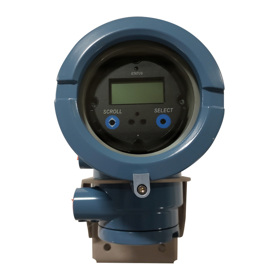
Operation The status LED is located at the top of the display (Figure 5-2). The status LED can be in one of six possible states, as listed in Table 5-1. The procedure for responding to alarms is shown in Figure B-5. Figure 5-2 Status LED Status LED…
-
Page 96: With Edd
Operation Note: The location of alarms in the Status and Alarm Log windows is not affected by the configured alarm severity (see Section 4.10). Alarms in the Status window are predefined as Critical, Informational, or Operational. Alarms in the Alarm Log window are predefined as High Priority or Low Priority.
-
Page 97
Operation Table 5-2 Totalizer and inventory display unit names Totalizer/inventory Unit name on display Mass total Mass unit Mass inventory Mass unit alternating with MASSI Volume total (liquid) Volume unit Volume inventory (liquid) Volume unit alternating with LVOLI Gas standard volume total Volume unit Gas standard volume inventory Volume unit alternating with… -
Page 98: Controlling The Totalizers And Inventories
Operation With EDD To view the current value of the totalizers and inventories: • For standard mass, liquid standard volume, and gas standard volume, select View > Process and then select . (If the transmitter is configured to use Variables > Totalizer Mass Volume gas standard volume, then…
-
Page 99
Operation With Prolink II To control concentration measurement totalizers and inventories, choose ProLink > CM Totalizer Control . To control all other totalizer and inventory functions, choose ProLink > Totalizer Control To reset inventories using ProLink II, you must first enable this capability. To enable inventory reset using ProLink II: 1. -
Page 100
Model 2700 Transmitter with PROFIBUS-PA… -
Page 101: Troubleshooting
Chapter 6 Troubleshooting Overview This section describes guidelines and procedures for troubleshooting the flowmeter. The information in this section will enable you to: • Categorize the problem • Determine whether you are able to correct the problem • Take corrective measures (if possible) Note: All procedures provided in this chapter assume that you have established communication with the transmitter and that you are complying with all applicable safety requirements.
-
Page 102: Transmitter Does Not Communicate
Troubleshooting Transmitter does not communicate If the transmitter does not appear to be communicating on the network, then: • Make sure the PROFIBUS network has proper termination. • Check the PROFIBUS wiring between the transmitter and the DP/PA coupler, and between the DP/PA coupler and the host system.
-
Page 103: Output Problems
Troubleshooting Output problems Micro Motion suggests that you make a record of the process variables listed below, under normal operating conditions. This will help you recognize when the process variables are unusually high or low. • Flow rate • Density •…
-
Page 104
Troubleshooting Table 6-3 Output problems and possible remedies (continued) Symptom Cause Possible remedies Erratic non-zero flow rate under Wiring problem Verify all sensor-to-transmitter wiring and no-flow conditions ensure the wires are making good contact. Refer to the installation manual. Incorrectly grounded 9-wire cable Verify 9-wire cable installation. -
Page 105
Troubleshooting Table 6-3 Output problems and possible remedies (continued) Symptom Cause Possible remedies Inaccurate flow rate Bad flow cal factor Verify characterization. See Section 6.7.4. Inappropriate measurement unit Check measurement units using a PROFIBUS host or configuration tool. Bad sensor zero Rezero the flowmeter. -
Page 106: Damping
Troubleshooting 6.7.1 Damping An incorrectly set damping value may make the transmitter’s output appear too sluggish or too jumpy. Adjust the damping parameters in the transducer block to achieve the damping effect you want. See Section 4.11. Other damping problems If the transmitter appears to be applying damping values incorrectly or the damping effects do not appear to be changed by adjustments to the damping parameters, then the AI PV Filter Time parameter in an AI function block may be improperly set.
-
Page 107: Status Alarms
Troubleshooting Status alarms Status alarms are reported by a PROFIBUS host, the display, and ProLink II software. Remedies for the alarm states appear in Table 6-4. Note: Some status alarms will cause all of the function blocks (AI, AO, and totalizer) to change to Out of Service mode.
-
Page 108
Troubleshooting Table 6-4 Status alarms and remedies (continued) Display code Description Possible remedies A010 Calibration failure If alarm appears during zero, ensure there is no flow through the sensor, then retry. Cycle power to the flowmeter, then retry. A011 Calibration too low Ensure there is no flow through sensor, then retry. -
Page 109
Troubleshooting Table 6-4 Status alarms and remedies (continued) Display code Description Possible remedies A028 Sensor/transmitter write failure Cycle power to the meter. The flowmeter might need service. Contact Micro Motion Customer Service. A030 Hardware/software incompatible The loaded software is not compatible with the programmed board type. -
Page 110: Diagnosing Wiring Problems
Troubleshooting Diagnosing wiring problems Use the procedures in this section to check the transmitter installation for wiring problems. Installation procedures are provided in the manual entitled Model 1700 and Model 2700 Transmitters: Installation Manual. Removing the wiring compartment covers in explosive atmospheres while the power is on can cause an explosion.
-
Page 111: Checking The Grounding
Troubleshooting 6.9.3 Checking the grounding The sensor and the transmitter must be grounded. If the core processor is installed as part of the transmitter or the sensor, it is grounded automatically. If the core processor is installed separately, it must be grounded separately. Refer to the installation manual. 6.9.4 Checking the communication wiring To check the communication wiring, verify that:…
-
Page 112: Checking The Test Points
Troubleshooting 6.12 Checking the test points You can diagnose sensor failure or overrange status alarms by checking the flowmeter test points. The test points include left and right pickoff voltages, drive gain, and tube frequency. 6.12.1 Obtaining the test points You can obtain the test points with the PROFIBUS EDD, PROFIBUS bus parameters, or ProLink II.
-
Page 113: Excessive Drive Gain
Troubleshooting Table 6-6 Sensor pickoff values (continued) Sensor model Pickoff value Model F200 sensors 2.0 mV peak to peak per Hz based on flow tube frequency Model H025, H050, and H100 sensors 3.4 mV peak to peak per Hz based on flow tube frequency Model H200 sensors 2.0 mV peak to peak per Hz based on flow tube frequency Model R025, R050, or R100 sensor…
-
Page 114: Low Pickoff Voltage
Troubleshooting 6.12.5 Low pickoff voltage The causes and possible solutions of low pickoff voltage are listed in Table 6-9. Table 6-9 Low pickoff voltage causes and solutions Cause Solution Faulty wiring runs between the sensor and core Refer to the sensor manual and transmitter installation processor manual.
-
Page 115: Checking The Core Processor
Troubleshooting 6.13 Checking the core processor Two core processor procedures are available: • You can check the core processor LED. The core processor has an LED that indicates different flowmeter conditions. • You can perform the core processor resistance test to check for a damaged core processor. For both tests you will need to expose the core processor.
-
Page 116: Checking The Core Processor Led
Troubleshooting 6.13.2 Checking the core processor LED Do not shut off power to the transmitter when checking the core processor LED. To check the core processor LED: 1. Expose the core processor according to the instructions in Section 6.13.1. 2. Check the core processor LED against the conditions listed in Table 6-10 (standard core processor) or Table 6-11 (enhanced core processor).
-
Page 117: Core Processor Resistance Test
Troubleshooting Table 6-11 Enhanced core processor LED behavior, meter conditions, and remedies (continued) LED behavior Condition Possible remedy Solid red High severity alarm Check alarm status. Flashing red (80% on, Tubes not full If alarm A105 (slug flow) is active, see Section 6.10. 20% off) If alarm A033 (tubes not full) is active, verify process.
-
Page 118: Checking Sensor Coils And Rtd
Troubleshooting 6.14 Checking sensor coils and RTD Problems with sensor coils can cause several alarms, including sensor failure and a variety of out-of-range conditions. Checking the sensor coils involves testing the terminal pairs and testing for shorts to the case. 6.14.1 9-wire remote or remote core processor with remote transmitter installation If you have a 9-wire remote or a remote core processor with remote transmitter installation:…
-
Page 119: 4-Wire Remote Or Integral Installation
Troubleshooting 8. Test the terminal pairs as follows: • Brown against all other terminals except Red • Red against all other terminals except Brown • Green against all other terminals except White • White against all other terminals except Green •…
-
Page 120
Troubleshooting 5. If you have a standard core processor, loosen the captive screw (2,5 mm) at the center of the core processor. Carefully remove the core processor from the sensor by grasping it and lifting it straight up. Do not twist or rotate the core processor. 6. -
Page 121
Troubleshooting Figure 6-2 Sensor pins – Standard core processor Right pickoff ( – ) Right pickoff Lead length compensator ( + ) ( + ) Left pickoff ( – ) Resistance temperature detector return / Lead length compensator (common) Left pickoff ( + ) Resistance temperature detector Drive… -
Page 122
Troubleshooting Reinstalling the core processor If you removed the core processor, replace the core processor according to the instructions below. 1. If you have a standard core processor: a. Align the three guide pins on the bottom of the core processor with the corresponding holes in the base of the core processor housing. -
Page 123: Appendix A Flowmeter Installation Types And Components
Appendix A Flowmeter Installation Types and Components Overview This appendix provides illustrations of different flowmeter installations and components for the Model 2700 transmitter. Installation diagrams Model 2700 transmitters can be installed in four different ways (see Figure A-1): • Integral •…
-
Page 124
Flowmeter Installation Types and Components Figure A-1 Installation types Transmitter Integral Core processor (standard only) Sensor 4-wire remote Transmitter Sensor 4-wire cable Core processor (standard or enhanced) Transmitter 9-wire remote Sensor Core processor (standard only) 9-wire cable Junction box Transmitter Remote core processor with remote transmitter 4-wire cable… -
Page 125
Flowmeter Installation Types and Components Figure A-2 Transmitter and core processor components — Integral installations Transmitter Transition ring Core processor 4 X Cap screws (4 mm) Base Sensor Figure A-3 Transmitter components, junction end-cap removed — 4-wire remote and remote core processor with remote transmitter installations –… -
Page 126
Flowmeter Installation Types and Components Figure A-4 Transmitter/core processor assembly exploded view — 9-wire remote installations Transmitter Core processor 4 X Cap screws (4 mm) Core processor housing Conduit opening for 9-wire cable End-cap Mounting bracket Figure A-5 Remote core processor components Core processor lid 4 X Cap screws (4 mm) Conduit opening… -
Page 127
Flowmeter Installation Types and Components Figure A-6 4-wire cable between Model 2700 transmitter and standard core processor Core processor User-supplied or Mating connector terminals factory-supplied 4-wire cable (transmitter) VDC+ (Red) RS-485/B (Green) RS-485/A (White) VDC– (Black) Figure A-7 4-wire cable between Model 2700 transmitter and enhanced core processor Core processor User-supplied or Mating connector… -
Page 128
Flowmeter Installation Types and Components Figure A-8 9-wire cable between sensor junction box and core processor 9-wire cable 9-wire terminal connections (core processor) Ground screw Black Black to sensor junction box (Drains from all wire sets) Brown Violet Green Green White Yellow White… -
Page 129: Appendix B Using The Display
Appendix B Using the Display Overview This appendix describes the basic use of the display and provides a menu tree for the display. You can use the menu tree to locate and perform display commands quickly. Note that Model 2700 transmitters can be ordered with or without displays. Not all configuration and use functions are available through the display.
-
Page 130: Using The Optical Switches
Using the Display Using the optical switches optical switches are used to navigate the display menus. To activate an optical Scroll Select switch, touch the lens in front of the optical switch or move your finger over the optical switch close to the lens.
-
Page 131: Using Display Menus
Using the Display B.4.3 Using display menus Note: The display menu system provides access to basic transmitter functions and data. It does not provide access to all functions and data. To access all functions and data, use a PROFIBUS host, PROFIBUS configuration tool, or ProLink II To enter the display menu system: 1.
-
Page 132: Entering Floating-Point Values With The Display
Using the Display B.4.5 Entering floating-point values with the display Certain configuration values, such as meter factors or output ranges, are entered as floating-point values. When you first enter the configuration screen, the value is displayed in decimal notation (as shown in Figure B-2) and the active digit is flashing.
-
Page 133
Using the Display Figure B-3 Numeric values in exponential notation SX.XXXEYY Sign Digit (0–9) Digits Enter a four-digit Sign or Digit (0–3) number; three digits must fall to the right of the decimal point. Exponent indicator To change from exponential to decimal notation: until the is flashing. -
Page 134: Abbreviations
Using the Display Abbreviations The display uses a number of abbreviations. Table B-1 lists the abbreviations used by the display. Table B-1 Display codes and abbreviations Abbreviation Definition Abbreviation Definition ACK ALARM Acknowledge alarm LPO_A Left pickoff amplitude ACK ALL Acknowledge all alarms LVOLI Volume inventory…
-
Page 135: Display Menus
Using the Display Display menus Figures B-4 through B-16 show the commands accessible through the display. Figure B-4 Display menu – Main Scroll and Select simultaneously for 4 seconds ENTER SEE ALARM Scroll Scroll OFF-LINE MAINT METER/VERFY Figure B-5 Display menu – Alarms SEE ALARM Select ACK ALL…
-
Page 136
Using the Display Figure B-6 Display menu – Smart Meter Verification: Run verification ENTER METER/VERFY Select RUN VERFY RESULTS READ SCHEDULE VERFY Scroll Scroll Select OUTPUTS Select CONTINUE MEASR Scroll FAULT Scroll LAST VALUE Select Select Select ARE YOU SURE/YES? Select . -
Page 137
Using the Display Figure B-7 Display menu – Smart Meter Verification: Read results ENTER METER/VERFY Select RUN VERFY RESULTS READ SCHEDULE VERFY Scroll Scroll Select RUNCOUNT x Select Scroll Pass Result type Abort Fail xx HOURS xx HOURS xx HOURS Select Select Select… -
Page 138
Using the Display Figure B-8 Display menu – Smart Meter Verification: Scheduling ENTER METER/VERFY Select RUN VERFY RESULTS READ SCHEDULE VERFY Scroll Scroll Select Schedule set? SCHED IS OFF TURN OFF SCHED/YES? Scroll Scroll Select Schedule deleted SET NEXT SET RECUR Scroll HOURS LEFT Select… -
Page 139
Using the Display Figure B-10 Display menu – Off-line Maintenance: Configuration OFF-LINE MAINT Select SWREV Scroll CONFG Scroll ZERO Scroll SENSOR VERFY Select UNITS Scroll MTR F Scroll DISPLAY Scroll ADDRESS PBUS Scroll IDENT SEL Scroll CONFIG AI Scroll CONFIG AO Scroll CONFIG TOT Figure B-11… -
Page 140
Using the Display Figure B-13 Display menu – Off-line Maiintenance: Configuration: Display DISPLAY Select TOTALS RESET Scroll TOTALS STOP Scroll DISPLAY OFFLN Scroll DISPLAY ALARM Scroll DISPLAY ACK Scroll AUTO SCRLL Scroll SCROLL RATE Scroll CODE OFFLN Scroll CODE ALARM Scroll CHANGE CODE Scroll… -
Page 141
Using the Display Figure B-15 Display menu – Off-line Maintenance: Configuration: AO blocks CONFG AO Select AO1 INCH Scroll AO1 PV UNITS Scroll AO1 OUTCH Scroll AO1 OUT UNITS Scroll AO2 INCH Scroll AO2 PV UNITS Scroll AO2 OUTCH Scroll AO2 OUT UNITS Figure B-16 Display menu –… -
Page 142
Using the Display Figure B-17 Display menu – Off-line Maintenance: Zeroing OFF-LINE MAINT Select SWREV Scroll CONFG Scroll ZERO Scroll SENSOR VERFY Select CAL ZERO …………………. Select ZERO/YES? CAL FAIL CAL PASS Select Model 2700 Transmitter with PROFIBUS-PA… -
Page 143: Appendix C Connecting With Prolink Ii
Appendix C Connecting with ProLink II Overview The instructions in this manual assume that users are already familiar with ProLink II software and can perform the following tasks: • Start and navigate in ProLink II software • Establish communication between ProLink II software and compatible devices •…
-
Page 144: Connecting To The Service Port
Connecting with ProLink II C.2.1 Connecting to the service port To temporarily connect to the service port, which is located in the non-intrinsically safe power-supply compartment: 1. Open the cover to the intrinsically safe wiring compartment. Opening the wiring compartment in a hazardous area can cause an explosion. The service port should only be used for temporary connections.
-
Page 145: Appendix Dprofibus-Pa Status Byte
Appendix D PROFIBUS-PA Status Byte Overview This appendix describes the status byte reported by the transmitter to a PROFIBUS host. The output of each AI, AO, and totalizer function block is a 5-byte package: four bytes of process information and one byte indicating measurement quality, also called the status byte. The format of the status byte depends on whether the transmitter is configured for classic mode or condensed mode.
-
Page 146
PROFIBUS-PA Status Byte Table D-3 Sub-status format – Uncertain status Bits Meaning Comment 0000 Non-specific TRUE if the following alarm codes are active: A005, A008, A010, A011, A012, A013, A021, A033, or A102. 0011 Initial value TRUE if the following alarm codes are active: A006 or A120. -
Page 147: Condensed-Mode Status Byte Format
PROFIBUS-PA Status Byte Condensed-mode status byte format Table D-7 describes the format of the status byte when the transmitter is configured for condensed mode. Refer to the PROFIBUS Specification Profile for Process Control Devices Version v3.01 December 2004 and the PROFIBUS Specification June 2005 Amendment 2 to the PROFIBUS Profile for Process Control Devices v3.01, Condensed Status and Diagnostic Messages v1.0 for additional information.
-
Page 148
PROFIBUS-PA Status Byte Table D-7 Condensed-mode status byte format (continued) Expanded status Condensed status Alarms Totalizer Fail Safe: UC_NON_SPECIFIC C_UNCERTAINC_SUBSTITUTE_SET Failsafe – (0x40) (0x4B) MEMORY mode UC_INITIAL_VAL (0x4C) C_UNCERTAIN_INITIAL_VALUE (0x4F) When reset or preset totals. UC_SUBSTITUTE_VAL (0x48) C_UNCERTAIN_SUBSTITUTE_SET (0x4B) AO failsafe active. -
Page 149: Appendix E Slave Diagnostic Response Bytes
Appendix E Slave Diagnostic Response Bytes Overview This appendix describes the diagnostic bytes reported by the transmitter to a PROFIBUS host. There are two sets of diagnostic bytes sent: • Bytes 1–6 conform to the standard PROFIBUS specification. • Byte 7 is the extended diagnostic header byte. •…
-
Page 150
Slave Diagnostic Response Bytes Table E-2 Byte 2 Indication Slave must be parameterized Static diagnostic: master requesting diagnostics until bit is reset This bit is always set to 1 Response monitoring/watchdog (1 = ON; 0 = OFF) Slave is in freeze mode (1 = ON; 0 = OFF) Slave is in sync mode (1 = ON;… -
Page 151
Slave Diagnostic Response Bytes Table E-5 Byte 5 Indication Ident number (MSB) (1) The identification number will be 0x9742 when in profile-specific I/O mode and 0x057A when in manufacturing-specific I/O mode. Refer to Section 2.5 for information about I/O modes. Table E-6 Byte 6 Indication… -
Page 152
Slave Diagnostic Response Bytes Table E-8 Byte 8 Indication Status type = manufacturer-specific (32 decimal, 0x20 hex) Identifier for status—always set to 1 Table E-9 Byte 9 Indication Slot number of physical block (per Profile 3.01 this is 0) Table E-10 Byte 10 Indication Error appears (when any new alarm is activated) -
Page 153
Slave Diagnostic Response Bytes Table E-11 Byte 11 Indication Reserved (always set to 0) Reserved (always set to 0) Reserved (always set to 0)—Not used Reserved (always set to 0) Reserved (always set to 0) Reserved (always set to 0) Reserved (always set to 0) Reserved (always set to 0) Table E-12… -
Page 154
Slave Diagnostic Response Bytes Table E-14 Byte 14 Indication Reserved (always set to 0) Reserved (always set to 0) Reserved (always set to 0) Reserved (always set to 0) Reserved (always set to 0) Reserved (always set to 0) Reserved (always set to 0) Extension available Table E-15 Byte 15… -
Page 155
Slave Diagnostic Response Bytes Table E-17 Byte 17 Indication Line RTD temperature out-of-range (A016) Meter RTD temperature out-of-range (A017) Reserved Reserved Calibration factors unentered (A020) Unrecognized/unentered sensor type (A021) Reserved Reserved Table E-18 Byte 18 Indication Reserved Reserved Sensor/xmtr communication failure (A026) Reserved Sensor/xmtr write failure (A028) Internal communication failure (A029) -
Page 156
Slave Diagnostic Response Bytes Table E-20 Byte 20 Indication Reserved Reserved Drive overrange/partially full tube (A102) Data loss possible (A103) Calibration in progress (A104) Slug flow (A105) Reserved Power reset occurred (A107) Table E-21 Byte 21 Indication Reserved Reserved Reserved Reserved Reserved Reserved… -
Page 157
Slave Diagnostic Response Bytes Table E-23 Byte 23 Indication Reserved Reserved Reserved Reserved Reserved Reserved Reserved Meter verification info alarm (A131) Table E-24 Byte 24 Indication Simulation mode active (A132) Reserved Reserved Reserved Reserved Reserved Reserved Reserved Configuration and Use Manual… -
Page 158
Model 2700 Transmitter with PROFIBUS-PA… -
Page 159: Appendix F Model 2700 Profibus Block Parameters
Appendix F Model 2700 PROFIBUS Block Parameters Overview This appendix describes the block parameters of the Model 2700 transmitter with PROFIBUS-PA. Slot identification Table F-1 shows the slot assignment for blocks. Table F-1 Block slot assignment Slot Assigned block Physical block Analog input block 1 Analog input block 2 Analog input block 3…
-
Page 160
Model 2700 PROFIBUS Block Parameters Table F-2 Physical block parameters (continued) Index Parameter Mnemonic Definition Message Data Type/ Size Store Default Access Enumerated List of Modbus Type Structure /Rate Value Values / Range Register / (HZ) Coil ALERT_KEY This parameter contains the SIMPLE Unsigned8 identification number of the plant… -
Page 161: Physical Block Object
Model 2700 PROFIBUS Block Parameters Table F-2 Physical block parameters (continued) Index Parameter Mnemonic Definition Message Data Type/ Size Store Default Access Enumerated List of Modbus Type Structure /Rate Value Values / Range Register / (HZ) Coil COND_STATUS_DIAG Condensed Status Diagnostics Simple Unsigned-8 0: Status and…
-
Page 162: Physical Block Views
Model 2700 PROFIBUS Block Parameters F.3.2 Physical block views Table F-4 shows the physical block views. Table F-4 Physical block views Parameter Mnemonic View 1 View 2 View 3 View 4 Index Standard Parameters BLOCK_OBJECT ST_REV TAG_DESC STRATEGY ALERT_KEY TARGET_MODE MODE_BLK ALARM_SUM Overall sum of bytes in View Object…
-
Page 163
Model 2700 PROFIBUS Block Parameters Table F-5 Transducer block 1 parameters (continued) Index Parameter Mnemonic Definition Message Data Type/ Size Store Default Access Enumerated List of Modbus Type Structure /Rate Value Values / Range Register / (HZ) Coil CALIBR_FACTOR Gain compensation value for the SIMPLE Float R-0407… -
Page 164
Model 2700 PROFIBUS Block Parameters Table F-5 Transducer block 1 parameters (continued) Index Parameter Mnemonic Definition Message Data Type/ Size Store Default Access Enumerated List of Modbus Type Structure /Rate Value Values / Range Register / (HZ) Coil DENSITY_UNITS Selected unit code for DENSITY, SIMPLE Unsigned16 1103… -
Page 165
Model 2700 PROFIBUS Block Parameters Table F-5 Transducer block 1 parameters (continued) Index Parameter Mnemonic Definition Message Data Type/ Size Store Default Access Enumerated List of Modbus Type Structure /Rate Value Values / Range Register / (HZ) Coil SNS_VolTotalUnits Standard or special volume total ENUM Unsigned16 0000 = None… -
Page 166
Model 2700 PROFIBUS Block Parameters Table F-5 Transducer block 1 parameters (continued) Index Parameter Mnemonic Definition Message Data Type/ Size Store Default Access Enumerated List of Modbus Type Structure /Rate Value Values / Range Register / (HZ) Coil CALIBRATION BLOCK SNS_FlowCalTempCoeff Temperature coefficient for flow VARIABLE… -
Page 167
Model 2700 PROFIBUS Block Parameters Table F-5 Transducer block 1 parameters (continued) Index Parameter Mnemonic Definition Message Data Type/ Size Store Default Access Enumerated List of Modbus Type Structure /Rate Value Values / Range Register / (HZ) Coil SNS_EnablePresComp Enable/Disable Pressure ENUM Unsigned 8 0x00 = disabled… -
Page 168
Model 2700 PROFIBUS Block Parameters Table F-5 Transducer block 1 parameters (continued) Index Parameter Mnemonic Definition Message Data Type/ Size Store Default Access Enumerated List of Modbus Type Structure /Rate Value Values / Range Register / (HZ) Coil EMPTY Alarm Status PA_StatusWords1 Status Word 1 ENUM… -
Page 169
Model 2700 PROFIBUS Block Parameters Table F-5 Transducer block 1 parameters (continued) Index Parameter Mnemonic Definition Message Data Type/ Size Store Default Access Enumerated List of Modbus Type Structure /Rate Value Values / Range Register / (HZ) Coil PA_StatusWords5 Status Word 5 ENUM BIT_ENUM D/20… -
Page 170
Model 2700 PROFIBUS Block Parameters Table F-5 Transducer block 1 parameters (continued) Index Parameter Mnemonic Definition Message Data Type/ Size Store Default Access Enumerated List of Modbus Type Structure /Rate Value Values / Range Register / (HZ) Coil UNI_Alarm_Index Alarm Index ENUM Unsigned8 0 = Reserved… -
Page 171
Model 2700 PROFIBUS Block Parameters Table F-5 Transducer block 1 parameters (continued) Index Parameter Mnemonic Definition Message Data Type/ Size Store Default Access Enumerated List of Modbus Type Structure /Rate Value Values / Range Register / (HZ) Coil Diagnostics SNS_DriveGain Drive Gain RECORD —-… -
Page 172
Model 2700 PROFIBUS Block Parameters Table F-5 Transducer block 1 parameters (continued) Index Parameter Mnemonic Definition Message Data Type/ Size Store Default Access Enumerated List of Modbus Type Structure /Rate Value Values / Range Register / (HZ) Coil FRF_AbortCode Abort Code ENUM 0=No error R-3002… -
Page 173
Model 2700 PROFIBUS Block Parameters Table F-5 Transducer block 1 parameters (continued) Index Parameter Mnemonic Definition Message Data Type/ Size Store Default Access Enumerated List of Modbus Type Structure /Rate Value Values / Range Register / (HZ) Coil EMPTY EMPTY EMPTY EMPTY EMPTY… -
Page 174
Model 2700 PROFIBUS Block Parameters Table F-5 Transducer block 1 parameters (continued) Index Parameter Mnemonic Definition Message Data Type/ Size Store Default Access Enumerated List of Modbus Type Structure /Rate Value Values / Range Register / (HZ) Coil 22= CM: Density (Fixed SG Units) 23= CM: Standard Volume Flow Rate… -
Page 175
Model 2700 PROFIBUS Block Parameters Table F-5 Transducer block 1 parameters (continued) Index Parameter Mnemonic Definition Message Data Type/ Size Store Default Access Enumerated List of Modbus Type Structure /Rate Value Values / Range Register / (HZ) Coil 78= Not used 79= Not used 80= Not used 81= Not used… -
Page 176
Model 2700 PROFIBUS Block Parameters Table F-5 Transducer block 1 parameters (continued) Index Parameter Mnemonic Definition Message Data Type/ Size Store Default Access Enumerated List of Modbus Type Structure /Rate Value Values / Range Register / (HZ) Coil 51 = Board Temperature 52 = Input Voltage 53 = Ext. -
Page 177
Model 2700 PROFIBUS Block Parameters Table F-5 Transducer block 1 parameters (continued) Index Parameter Mnemonic Definition Message Data Type/ Size Store Default Access Enumerated List of Modbus Type Structure /Rate Value Values / Range Register / (HZ) Coil UI_ProcessVariables Display the Variable#2 ENUM Unsigned16 0 = Mass Flow Rate… -
Page 178: Transducer Block 1 Object
Model 2700 PROFIBUS Block Parameters Table F-5 Transducer block 1 parameters (continued) Index Parameter Mnemonic Definition Message Data Type/ Size Store Default Access Enumerated List of Modbus Type Structure /Rate Value Values / Range Register / (HZ) Coil UI_ProcessVariables Display the Variable#7 ENUM Unsigned16 Same as…
-
Page 179: And Diagnosis) Views
Model 2700 PROFIBUS Block Parameters Table F-6 Transducer block 1 object Slot/Index Element name Data type Size in bytes Value Slot 11/Index 0 Reserved Unsigned 8 250 (default) Block_Object Unsigned 8 Parent_Class Unsigned 8 Class Unsigned 8 DD_Refrence Unsigned 32 00 ,00, 00, 00 (reserved) DD_Revision Unsigned 16…
-
Page 180: Transducer Block 2 (Device Information, Api, Cm) Parameters
Model 2700 PROFIBUS Block Parameters F.4.3 Transducer block 2 (device information, API, CM) parameters Table F-8 shows the parameters for transducer block 2. Table F-8 Transducer block 2 parameters Index Parameter Mnemonic Definition Message Type Data Type/ Size Store Default Acce Enumerated List of Modbus…
-
Page 181
Model 2700 PROFIBUS Block Parameters Table F-8 Transducer block 2 parameters (continued) Index Parameter Mnemonic Definition Message Type Data Type/ Size Store Default Acce Enumerated List of Modbus Structure /Rate Value Values / Range Register / Coil (HZ) SNS_FlangeType Flange Type ENUM Unsigned16 0 = ANSI 150… -
Page 182
Model 2700 PROFIBUS Block Parameters Table F-8 Transducer block 2 parameters (continued) Index Parameter Mnemonic Definition Message Type Data Type/ Size Store Default Acce Enumerated List of Modbus Structure /Rate Value Values / Range Register / Coil (HZ) SNS_API2540TableType API 2540 CTLTable Type ENUM Unsigned16 API_… -
Page 183
Model 2700 PROFIBUS Block Parameters Table F-8 Transducer block 2 parameters (continued) Index Parameter Mnemonic Definition Message Type Data Type/ Size Store Default Acce Enumerated List of Modbus Structure /Rate Value Values / Range Register / Coil (HZ) SNS_ED_CurveLock Lock Enhanced Density ENUM Unsigned8 0x00 = not locked… -
Page 184: Transducer Block 2 Object
Model 2700 PROFIBUS Block Parameters Table F-8 Transducer block 2 parameters (continued) Index Parameter Mnemonic Definition Message Type Data Type/ Size Store Default Acce Enumerated List of Modbus Structure /Rate Value Values / Range Register / Coil (HZ) SNS_ED_ConcUnitCode Curven Concentration Units ENUM Unsigned16 —-…
-
Page 185: Transducer Block 2 (Device Information, Api, Cm) Views
Model 2700 PROFIBUS Block Parameters F.4.5 Transducer block 2 (device information, API, CM) views Table F-10 shows the views for transducer block 2. Table F-10 Transducer block 2 views Parameter Mnemonic View 1 View 2 View 3 View 4 Index Standard Parameters BLOCK_OBJECT ST_REV…
-
Page 186
Model 2700 PROFIBUS Block Parameters Table F-11 I & M parameters (continued) Index Sub-Index Parameter Mnemonic Definition Message Type Data Type/ Size Store/ Default Access Modbus Structure Rate Value mera Register / Coil (HZ) List Valu PROFILE_ID –Profile type VARIABLE Unsigned16 0x9700 Hard Coded… -
Page 187: Ai Function Block Parameters
Model 2700 PROFIBUS Block Parameters F.4.7 AI function block parameters Table F-12 shows the parameters for the AI function blocks. Table F-12 AI function block parameters Index Parameter Mnemonic Definition Message Data Type/ Size Store Default Access Enumerated List of Modbus Type Structure…
-
Page 188
Model 2700 PROFIBUS Block Parameters Table F-12 AI function block parameters (continued) Index Parameter Mnemonic Definition Message Data Type/ Size Store Default Access Enumerated List of Modbus Type Structure /Rate Value Values / Range Register / (HZ) Coil ALARM_HYS Hysteresis SIMPLE FLOAT 0.5%… -
Page 189: Analog Input Block Objects
Model 2700 PROFIBUS Block Parameters F.4.8 Analog input block objects Table F-13 shows the analog input block objects. Table F-13 Analog input block objects Slot/Index Element name Data type Size in bytes Value Slot 11/Index 0 Reserved Unsigned 8 250 (default) Block_Object Unsigned 8 02 (function block)
-
Page 190: Ao Function Block Parameters
Model 2700 PROFIBUS Block Parameters F.4.10 AO function block parameters Table F-15 lists the parameters for the AO function blocks. Table F-15 AO function block parameters Index Parameter Mnemonic Definition Message Data Type/ Size Store Default Access Enumerated List of Modbus Type Structure…
-
Page 191
Model 2700 PROFIBUS Block Parameters Table F-15 AO function block parameters (continued) Index Parameter Mnemonic Definition Message Data Type/ Size Store Default Access Enumerated List of Modbus Type Structure /Rate Value Values / Range Register / Coil (HZ) IN_CHANNEL Reference to the active SIMPLE Unsigned16 R-2297… -
Page 192: Analog Output Block Objects
Model 2700 PROFIBUS Block Parameters Table F-15 AO function block parameters (continued) Index Parameter Mnemonic Definition Message Data Type/ Size Store Default Access Enumerated List of Modbus Type Structure /Rate Value Values / Range Register / Coil (HZ) RESERVED RESERVED RESERVED RESERVED AO BLOCK VIEW 1…
-
Page 193: Totalizer Block Parameters
Model 2700 PROFIBUS Block Parameters Table F-17 AO function block views ST_REV TAG_DESC STRATEGY ALERT_KEY TARGET_MODE MODE_BLK ALARM_SUM Overall sum of bytes in View Object Parameter Mnemonic View 1 View 2 View 3 View 4 Index Standard Parameters READBACK POS_D CHECK_BACK Overall sum of bytes in View Object 10+13…
-
Page 194
Model 2700 PROFIBUS Block Parameters Table F-18 Totalizer block parameters (continued) Index Parameter Mnemonic Definition Message Data Type/ Size Store Default Access Enumerated List of Modbus Type Structure /Rate Value Values / Range Register / (HZ) Coil RESERVED Totalizer Function Block Standard Parameters TOTAL The Function Block RECORD… -
Page 195: Totalizer Block Objects
Model 2700 PROFIBUS Block Parameters Table F-18 Totalizer block parameters (continued) Index Parameter Mnemonic Definition Message Data Type/ Size Store Default Access Enumerated List of Modbus Type Structure /Rate Value Values / Range Register / (HZ) Coil RESERVED Totalizer Selection Selection of Totalizer SIMPLE Unsigned8…
-
Page 196
Model 2700 PROFIBUS Block Parameters Table F-20 Totalizer function block views Parameter Mnemonic View 1 View 2 View 3 View 4 Index Standard Parameters BLOCK_OBJECT ST_REV TAG_DESC STRATEGY ALERT_KEY TARGET_MODE MODE_BLK ALARM_SUM Overall sum of bytes in View Object Parameter Mnemonic View 1 View 2 View 3… -
Page 197: Appendix G Ne53 History
Appendix G NE53 History Overview This appendix documents the change history of the Model 2700 transmitter with PROFIBUS-PA software. Software change history Table G-1 describes the change history of the transmitter software. Operating instructions are English versions. Instructions in other languages have different part numbers but matching revision letters. Table G-1 Transmitter software change history Software…
-
Page 198
20000327 Rev. FA Improved EDD more closely matches ProLink II. Added petroleum measurement application. Added enhanced density application. Improved consistency with other Micro Motion 2700 transmitters. Feature additions Added compatibility with enhanced core processor. Added gas standard volume measurement. Added configurable alarm severity. -
Page 199: Index
Index Core processor 116, 117, 118 Address LED 108 node address 8 sensor pins 113 AI function block terminals 119, 120 channels 8, 9 troubleshooting 107 Alarm log 87 Customer service 6 Alarm menu password 123 Cutoffs 71 Alarms 63, 86, 99 display codes 99 high 63 Damping 68…
-
Page 200
Index Meter factors 19, 20, 35 EDD 2, 3 Meter verification Engineering units 51 See Smart Meter Verification Errors Micro Motion customer service 6 see Alarms Exponential notation 125 Node address 8 Fault configuring alarms for 66 Off-line password 77, 123 Flanges 74 Operation 83 Flow calibration values 24… -
Page 201
Index Transducer block Safety 1 channels 8, 9, 12 Scale 62 meter factor parameters 36 Scroll rate 77 Transmitter components 117, 118 Sensor material 74 Transmitter startup 7 Serial number 74 Troubleshooting 93 Service port 135, 136 calibration failure 94 Simulation mode drive gain 105 sensor 85… -
Page 202
Model 2700 Transmitter with PROFIBUS-PA… -
Page 204
+31 (0) 318 495 555 +65 6777-8211 +31 (0) 318 495 556 +65 6770-8003 Micro Motion United Kingdom Micro Motion Japan Emerson Process Management Limited Emerson Process Management Horsfield Way 1-2-5, Higashi Shinagawa Bredbury Industrial Estate Shinagawa-ku Stockport SK6 2SU U.K.
-
Page 1: Emerson MICRO MOTION 2700
Inst allation Manual P/N 20001700, Rev . C November 2007 Micro Motion ® Model 1700 and Model 2700 T ransmitters Installation Manual[…]
-
Page 2: Emerson MICRO MOTION 2700
©2007, Micro Motion, Inc. Al l rights reserved. ELI TE a nd ProLink are registered tradem arks, and MVD and MVD Direct Connect are tradema rks of Micro Mo tion, Inc., Boulder , Colorado . Micro Motion is a registe red trade name of Micro Motion, Inc., Boulder , Colorado. The Micro Motion a nd Emerson logos ar e trademarks and service marks of Emer[…]
-
Page 3: Emerson MICRO MOTION 2700
Installation Manua l iii Contents Chapter 1 Before Y ou Begin . . . . . . . . . . . . . . . . . . . . . . . . . . . . . . . . . . . . . 1 1.1 Overview . . . . . . . . . . . . . . . . . . . . . . . . . . . . . . . . . . . . . . . . . . . . . . . . . . . . . . . . . . . 1 1.2 Safety . . . . . . . . . . . . . . . . . . . . . . . . . . . . . . . . . . […]
-
Page 4: Emerson MICRO MOTION 2700
iv Micro Motion ® Model 1700 and 2700 Tran smitters Contents Chapter 5 Output Wiring – Mo del 1700/2700 Intrinsically Safe T ransmitters . . . 33 5.1 Overview . . . . . . . . . . . . . . . . . . . . . . . . . . . . . . . . . . . . . . . . . . . . . . . . . . . . . . . . . . 33 5.2 Output t er minals and ou tput types . . . . . . . . . . . . . . […]
-
Page 5: Emerson MICRO MOTION 2700
Installation Manua l 1 Installing the T r ansmitter Output Wiring – Analog Sensor Wiring Before Y ou Begin Chapter 1 Before Y ou Begin 1.1 Overvie w This chapter provides an orientat i on to the use of this manual. This manual describes the pro cedures required to install the follo wi ng Model 1700 and 2700 transmitters: • Model 1700 or Model 2[…]
-
Page 6: Emerson MICRO MOTION 2700
2 Micro Motion ® Model 1700 and 2700 Tran smitters Before Y ou Begin 1.3 Flowmeter components The Model 1700 or 2700 transmitter is one compon ent in your Micro Motion flo wmeter . Other major components include: • The sensor, which provides measurement function s • The core processor , which provides memory and processing functions 1.4 T rans[…]
-
Page 7: Emerson MICRO MOTION 2700
Installation Manua l 3 Before Y ou Begin Installing the T r ansmitter Output Wiring – Analog Sensor Wiring Before Y ou Begin 1.5 T ransmitter installation procedures T o install the transmitter , the fo llowing procedures are required: • Install the transmitter – see Chapter 2 • W ire the transmitter to the sensor – see Chapter 3 • W ir[…]
-
Page 8: Emerson MICRO MOTION 2700
4 Micro Motion ® Model 1700 and 2700 Tran smitters Before Y ou Begin 1.7 Micro Motion customer service For technical assistance, phone the Micr o Motion Customer Service depa rtment: • In the U.S.A., phone 800-522-MASS (800-522-6277) (toll free) • In Canada and Latin Amer ica, phone +1 303-527 -5200 (U.S.A.) •I n A s i a : — In Ja pan, phone[…]
-
Page 9: Emerson MICRO MOTION 2700
Installation Manua l 5 Installing th e T ransmitte r Output Wiring – Analog Sensor Wiring Before Y ou Begin Chapter 2 Installing the T ransmitter 2.1 Overvie w This chapter describes ho w to install Micro Motio n Model 1700 and 2700 tr ansmitters. The follo wing general steps a re required: • Determine the location of the transmitter and other […]
-
Page 10: Emerson MICRO MOTION 2700
6 Micro Motion ® Model 1700 and 2700 Tran smitters Installing the T ransmitter Figure 2-1 Installation types T ransmitter Sensor Junction box 9-wire cable 9-wire remote Core processor 4-wire remote T ransmitter Sensor Core processor 4-wire cable T ransmitter Sensor Core processor Integral Remote core processor with remote transmitter 4-wire cable […]
-
Page 11: Emerson MICRO MOTION 2700
Installation Manua l 7 Installing the T ransmitter Installing th e T ransmitte r Output Wiring – Analog Sensor Wiring Before Y ou Begin 2.3 Determining an appropriate location T o determine an appropriate lo cation for the transmitt er , you must consider the en vi ronmental requirements of the transmitter and core processor , hazardous area clas[…]
-
Page 12: Emerson MICRO MOTION 2700
8 Micro Motion ® Model 1700 and 2700 Tran smitters Installing the T ransmitter DC power requirements Note: These r equir ements assume a single transmitte r per cable . Connecting mu ltiple tr ansmitters to a single cable should be avoided. If you are using DC po wer , the fo llowing requirements apply: • 18–100 VDC • 6 watts typical, 11 wa […]
-
Page 13: Emerson MICRO MOTION 2700
Installation Manua l 9 Installing the T ransmitter Installing th e T ransmitte r Output Wiring – Analog Sensor Wiring Before Y ou Begin 2.3.4 Maximum ca ble lengths This requirement does not apply to integral insta llations (see Figure 2-1). For other installation types (see Figure 2-1), maximu m cable length between flo wmeter components de pend[…]
-
Page 14: Emerson MICRO MOTION 2700
10 Micro Motion ® Model 1700 and 2700 Tran smitters Installing the T ransmitter 2.4.1 Integral installations If you chose an integral installation (see Figure 2-1) , there are no special mounting instructions for the transmitter . Y ou can rotate an integrally mounte d transmitter up to 360° in 90° in crements, to one of four possible positions […]
-
Page 15: Emerson MICRO MOTION 2700
Installation Manua l 11 Installing the T ransmitter Installing th e T ransmitte r Output Wiring – Anal og Sensor Wiring Bef ore Y ou Begin 2.4.2 4-wire remote or remote core proc essor with remote transmitter installations If you chose the 4-wire remote or the remote core processor with remote transmitter installation (see Figure 2-1), see Figure[…]
-
Page 16: Emerson MICRO MOTION 2700
12 Micro Motion ® Model 1700 and 2700 Tran smitters Installing the T ransmitter Figure 2-4 T ransmitter components – 4-wire re mote or remote core proce ssor with remote transmitter installations 2.4.3 9-wire remote installations If you chose a 9-wire remote installa tion (see Fi gure 2-1), see Figure 2-5 for a diagram of the mounting bracket su[…]
-
Page 17: Emerson MICRO MOTION 2700
Installation Manua l 13 Installing the T ransmitter Installing th e T ransmitte r Output Wiring – Anal og Sensor Wiring Bef ore Y ou Begin T o mount the transmitter/core processor assembly: 1. Identify the components sho wn in Figu re 2-6. For dimensions, see Ap pendix A. 2. If desired, re-orient the transmitter on the brack et. a. Loosen each of[…]
-
Page 18: Emerson MICRO MOTION 2700
14 Micro Motion ® Model 1700 and 2700 Tran smitters Installing the T ransmitter Figure 2-7 Remo te core processor – W all mount or pipe mount T o mount the core processor: 1. Identify the components sho wn in Figu re 2-8. For dimensions, see Append ix A. 2. If desired, reorient the core processor housing on the bracket. a. Loosen each of the fou[…]
-
Page 19: Emerson MICRO MOTION 2700
Installation Manua l 15 Installing the T ransmitter Installing th e T ransmitte r Output Wiring – Analog Sensor Wiring Before Y ou Begin 2.6 Grounding the flowmeter components Grounding requirements depend on the installation type (see Figure 2-1 ). Grounding meth ods for each flo wmeter component are listed in T able 2-3. If national standards a[…]
-
Page 20: Emerson MICRO MOTION 2700
16 Micro Motion ® Model 1700 and 2700 Tran smitters Installing the T ransmitter 2.7 Supplying pow er In all installations, po wer must be provided to the transmitter . Refe r to Section 2.3.3 for information on the transmitter’ s powe r supply requirements. A user-supp lied switch may be insta lled in the po wer supply line. For compliance with […]
-
Page 21: Emerson MICRO MOTION 2700
Installation Manua l 17 Installing the T ransmitter Installing th e T ransmitte r Output Wiring – Analog Sensor Wiring Before Y ou Begin T o rotate the display , follow the instructions belo w: 1. Po wer down the t ransmitter . 2. Remov e the end-cap clamp by remo ving the cap scre w . See Figure 2-10. 3. T urn the display cove r counterclockwise[…]
-
Page 22: Emerson MICRO MOTION 2700
18 Micro Motion ® Model 1700 and 2700 Tran smitters Installing the T ransmitter Figure 2-10 Display components Display co ver Display scre ws Display module Main enclosure Sub-bezel Pin ter minals Cap screw End-cap clamp[…]
-
Page 23: Emerson MICRO MOTION 2700
Installation Manua l 19 Installing the T r ansmitter Output Wiring – Analog Sensor Wiring Before Y ou Begin Chapter 3 Wiring the T ransmitter to the Sensor 3.1 Overvie w This chapter describes ho w to connect Micro Mo tion Model 1700 and 2700 transmitters to a Micro Motion sensor . Note: If you have an inte gral installation, this step is not r e[…]
-
Page 24: Emerson MICRO MOTION 2700
20 Micro Motion ® Model 1700 and 2700 Tran smitters Wiring the T ransm itter to the Sensor 3.2.1 4-wi re cable Micro Motion offers two types of 4-wire cable: sh ielded and armored. Both types contain shield drain wires. User-sup plied 4-wire cable must meet the follo wing requirements: • T wisted pair construction • The gauge requ irements as […]
-
Page 25: Emerson MICRO MOTION 2700
Installation Manua l 21 Wiring the T ransm itter to the Sensor Installing the T r ansmitter Output Wiring – Analog Sensor Wiring Before Y ou Begin Figure 3-2 4-wire cable between standard core processor and transmitter Figure 3-3 Wiring to the mating connector Core processor terminals 4-wire cable Mating connector (transmitter) Maximum cab le len[…]
-
Page 26: Emerson MICRO MOTION 2700
22 Micro Motion ® Model 1700 and 2700 Tran smitters Wiring the T ransm itter to the Sensor 3.4 Wiring for 9-wire remote installations If you chose a 9-wire re mote installation (see Figure 2- 1), a 9-wire cable must be used to connect the junction box on the sensor to the core processor on the tran smitter/core processor assembly . T o connect the[…]
-
Page 27: Emerson MICRO MOTION 2700
Installation Manua l 23 Wiring the T ransm itter to the Sensor Installing the T r ansmitter Output Wiring – Analog Sensor Wiring Before Y ou Begin If using jack eted cable: a. Ground the shield drai n wires (the black wire) only on the core proce ssor end, by connecting it to the ground scre w inside the lo wer conduit ring. Ne ver ground to the […]
-
Page 28: Emerson MICRO MOTION 2700
24 Micro Motion ® Model 1700 and 2700 Tran smitters Wiring the T ransm itter to the Sensor Figure 3-5 Cable glands 2. Remov e the cov er from the core processor housing. 3. Slide the gland nut and the cl amping insert ov er the cable. Figure 3-6 Micro Motion ca ble gland and heat shrink 4. Fo r connection at the core processor housing, prepare shi[…]
-
Page 29: Emerson MICRO MOTION 2700
Installation Manua l 25 Wiring the T ransm itter to the Sensor Installing the T r ansmitter Output Wiring – Analog Sensor Wiring Before Y ou Begin Figure 3-7 Wrap ping the shield drain wires e. Place the shielded heat shrink over the e x posed shield drain wire(s ). The tubing should completely co ver the drain wires. See Figure 3-8. f. W ithout […]
-
Page 30: Emerson MICRO MOTION 2700
26 Micro Motion ® Model 1700 and 2700 Tran smitters Wiring the T ransm itter to the Sensor Figure 3-10 Gland body and core processor housing 5. Insert the wires throu gh the gland body and assemble the gland b y tightening the gland nut. 6. Identify the wires in the 4-wire cable. The 4-wi re cable supplied by Micro Motion consists of one pair of 1[…]
-
Page 31: Emerson MICRO MOTION 2700
Installation Manua l 27 Wiring the T ransm itter to the Sensor Installing the T r ansmitter Output Wiring – Analog Sensor Wiring Before Y ou Begin 8. At the transmitter , connect the four wires fro m the c ore processor to terminals 1–4 on the mating connector of the transmitter . See Figure 3-2. Nev er ground the shie ld, braid, or shield drai[…]
-
Page 32: Emerson MICRO MOTION 2700
28 Micro Motion ® Model 1700 and 2700 Tran smitters Wiring the T ransm itter to the Sensor If using jack eted cable: a. Ground the shield drain wires (the black wire) only on the core processor end, by connecting it to the ground scre w inside the lo wer conduit ring. Ne ver ground to the core processor’ s mounting scre w . Nev er ground the cab[…]
-
Page 33: Emerson MICRO MOTION 2700
Installation Manua l 29 Installing th e T ransmitte r Output Wiring – Analog Sensor Wiring Before Y ou Begin Chapter 4 Output Wiring – Model 1700/2700 Analog T ransmitters 4.1 Overvie w This chapter explains ho w to wire outputs for Model 1700 or 2700 transmitters with the analog outputs option board (output option code A). Note: If you do not […]
-
Page 34: Emerson MICRO MOTION 2700
30 Micro Motion ® Model 1700 and 2700 Tran smitters Output Wiring – Model 1700/2700 Analog T r ansmitters Note: If you will configur e the transmitter to poll an e xternal temperatur e or pr essur e device, you must wir e the mA output to support HART co mmunications. Y ou may use either HART/analog single-loop wiring or HART multidr op wiring. […]
-
Page 35: Emerson MICRO MOTION 2700
Installation Manua l 31 Output Wiring – Model 1700/2700 Analog T r ansmitters Installing th e T ransmitte r Output Wiring – Analog Sensor Wiring Before Y ou Begin Installing th e T ransmitte r Output Wiring – Analog Sensor Wiring Before Y ou Begin Installing th e T ransmitte r Output Wiring – Analog Sensor Wiring Before Y ou Begin Installin[…]
-
Page 36: Emerson MICRO MOTION 2700
32 Micro Motion ® Model 1700 and 2700 Tran smitters Output Wiring – Model 1700/2700 Analog T r ansmitters Figure 4-4 HAR T multidrop wiring with SMART F AMIL Y ™ transmitters and a configuration tool HAR T -compatib le host or controller HAR T -compatible transmitters SMAR T F AMIL Y ™ transmitters Note: F or optimum HART communication, mak […]
-
Page 37: Emerson MICRO MOTION 2700
Installation Manua l 33 Output Wiring – Configurable I/O Specifications Output Wiring – Fieldb us/PROFIBUS Output Wiring – Intrinsically Safe Chapter 5 Output Wiring – Model 1700/2700 Intrinsically Safe T ransmitters 5.1 Overvie w This chapter explains ho w to wire outputs for Mode l 1700 or 2700 transmitters with the intrinsically safe out[…]
-
Page 38: Emerson MICRO MOTION 2700
34 Micro Motion ® Model 1700 and 2700 Tran smitters Output Wiring – Model 1700/ 2700 Intrinsically Safe T ransm itters 5.3 Safe area o utput wiring The following notes and diagrams are design ed to be used as a guide for wiring the Model 1700 or Model 2700 outputs for sa fe area applications. 5.3.1 Safe area mA output wiring The following 4–20[…]
-
Page 39: Emerson MICRO MOTION 2700
Installation Manua l 35 Output Wiring – Model 1700/ 2700 Intrinsically Safe T ransm itters Output Wiring – Configurable I/O Specifications Output Wiring – Fieldb us/PROFIBUS Output Wiring – Intrinsically Safe Figure 5-2 Safe area mA output load resistance values Figure 5-3 Safe area HART/a nalog single-loop wiring 0 100 200 300 400 500 600 […]
-
Page 40: Emerson MICRO MOTION 2700
36 Micro Motion ® Model 1700 and 2700 Tran smitters Output Wiring – Model 1700/ 2700 Intrinsically Safe T ransm itters Figure 5-4 Safe area HAR T multidrop wiring with SMAR T F AMIL Y ™ transmitters and a configuration tool 5.3.2 Safe area frequency/discrete output wiring The follo wing frequency/discrete output wiring diagra m is an e xample […]
-
Page 41: Emerson MICRO MOTION 2700
Installation Manua l 37 Output Wiring – Model 1700/ 2700 Intrinsically Safe T ransm itters Output Wiring – Configurable I/O Specifications Output Wiring – Fieldb us/PROFIBUS Output Wiring – Intrinsically Safe Figure 5-6 Safe area frequency/discrete outp ut load resistance values 5.4 Hazardous area output wiring The following notes and diagr[…]
-
Page 42: Emerson MICRO MOTION 2700
38 Micro Motion ® Model 1700 and 2700 Tran smitters Output Wiring – Model 1700/ 2700 Intrinsically Safe T ransm itters Hazardous area voltage The Model 1700 or 2700 transmitte r’ s safety parameters require th e selected barrier’ s open-circuit voltage to be limited to less than 30 VDC (Vmax = 30 VDC). This voltage is the combination of the […]
-
Page 43: Emerson MICRO MOTION 2700
Installation Manua l 39 Output Wiring – Model 1700/ 2700 Intrinsically Safe T ransm itters Output Wiring – Configurable I/O Specifications Output Wiring – Fieldb us/PROFIBUS Output Wiring – Intrinsically Safe 5.4.2 Hazardo us area mA output wiring Figure 5-7 provides an e xample of basic hazardous area wiring for the Model 1700 transmitter?[…]
-
Page 44: Emerson MICRO MOTION 2700
40 Micro Motion ® Model 1700 and 2700 Tran smitters Output Wiring – Model 1700/ 2700 Intrinsically Safe T ransm itters Figure 5-8 Hazardo us area frequency/discrete output wiring using galvanic isolator Figure 5-9 Hazardo us area frequency/discrete output wiring using barrier with external loa d resistance External power supply R load V out Galv[…]
-
Page 45: Emerson MICRO MOTION 2700
Installation Manua l 41 Output Wiring – Configurable I/O Specifications Output Wiring – Fieldb us/PROFIBUS Output Wiring – Intrinsically Safe Chapter 6 Output Wiring – Model 2700 Configurable I/O T ransmitters 6.1 Overvie w This chapter explains ho w to wire outputs fo r Model 2700 transmitters with the conf igurable input/outputs board (ou[…]
-
Page 46: Emerson MICRO MOTION 2700
42 Micro Motion ® Model 1700 and 2700 Tran smitters Output Wiring – Model 2700 Confi gurable I/O T ransmi tters Figure 6-1 Configuration of configurabl e I/O terminals 6.3 mA output wiring The follo wing 4–20 mA wiring diagrams are examples of proper basic wiring for the Model 2700 primary and secondary mA outputs. Th e follo wing options are […]
-
Page 47: Emerson MICRO MOTION 2700
Installation Manua l 43 Output Wiring – Model 2700 Confi gurable I/O T ransmi tters Output Wiring – Configurable I/O Specifications Output Wiring – Fieldb us/PROFIBUS Output Wiring – Intrinsically Safe Figure 6-2 Basic mA wiring Figure 6-3 HAR T/analog single-loop wiring + – mA1 mA2 + – 820 Ω maximum loop resistance 420 Ω maximum loop[…]
-
Page 48: Emerson MICRO MOTION 2700
44 Micro Motion ® Model 1700 and 2700 Tran smitters Output Wiring – Model 2700 Confi gurable I/O T ransmi tters Figure 6-4 HAR T multidrop wiring with SMART F AMIL Y ™ transmitters and a configuration tool 6.4 Frequency output wiring Frequency o utput wiring depends on whether you are wirin g terminals 3 and 4 (Channel B) or terminals 5 and 6 […]
-
Page 49: Emerson MICRO MOTION 2700
Installation Manua l 45 Output Wiring – Model 2700 Confi gurable I/O T ransmi tters Output Wiring – Configurable I/O Specifications Output Wiring – Fieldb us/PROFIBUS Output Wiring – Intrinsically Safe Figure 6-5 Freq uency output – T erminals 3 & 4 (Channel B) – Interna l power Figure 6-6 Freq uency output – T erminals 3 & 4 […]
-
Page 50: Emerson MICRO MOTION 2700
46 Micro Motion ® Model 1700 and 2700 Tran smitters Output Wiring – Model 2700 Confi gurable I/O T ransmi tters Figure 6-7 Freq uency output – T erminals 5 & 6 (Channel C) – Interna l power Figure 6-8 Freq uency output – T erminals 5 & 6 (Channel C) – External powe r Output voltage lev el is +15 VDC ± 3% Note: See F igur e 6-14 […]
-
Page 51: Emerson MICRO MOTION 2700
Installation Manua l 47 Output Wiring – Model 2700 Confi gurable I/O T ransmi tters Output Wiring – Configurable I/O Specifications Output Wiring – Fieldb us/PROFIBUS Output Wiring – Intrinsically Safe 6.5 Discrete output wiring Discrete output (DO) wiring depends on whether you are wiring terminals 3 and 4 (Channel B) or terminals 5 and 6 […]
-
Page 52: Emerson MICRO MOTION 2700
48 Micro Motion ® Model 1700 and 2700 Tran smitters Output Wiring – Model 2700 Confi gurable I/O T ransmi tters Figure 6-11 Discrete output 2 – T erminals 5 & 6 (Channel C) – Internal power Figure 6-12 Discrete output 2 – T erminals 5 & 6 (Channel C) – External power Note: See F igur e 6-14 for output voltage ver sus load. T otal[…]
-
Page 53: Emerson MICRO MOTION 2700
Installation Manua l 49 Output Wiring – Model 2700 Confi gurable I/O T ransmi tters Output Wiring – Configurable I/O Specifications Output Wiring – Fieldb us/PROFIBUS Output Wiring – Intrinsically Safe Figure 6-13 Output voltage vs. loa d resistance – T erminals 3 & 4 (Cha nnel B) – Internal po wer Figure 6-14 Output voltage vs. loa[…]
-
Page 54: Emerson MICRO MOTION 2700
50 Micro Motion ® Model 1700 and 2700 Tran smitters Output Wiring – Model 2700 Confi gurable I/O T ransmi tters Figure 6-15 Recommended pull-up resistor versus supply volta ge – External power 6.6 Discrete input wiring Discrete input wiring depends on whether you have conf igure d terminals 5 and 6 (Channel C) for internal or external po wer .[…]
-
Page 55: Emerson MICRO MOTION 2700
Installation Manua l 51 Output Wiring – Model 2700 Confi gurable I/O T ransmi tters Output Wiring – Configurable I/O Specifications Output Wiring – Fieldb us/PROFIBUS Output Wiring – Intrinsically Safe Figure 6-16 Discrete input – T erminals 5 & 6 (Channel C) – Interna l power Figure 6-17 Discrete input – T erminals 5 & 6 (Cha[…]
-
Page 56: Emerson MICRO MOTION 2700
52 Micro Motion ® Model 1700 and 2700 Tran smitters[…]
-
Page 57: Emerson MICRO MOTION 2700
Installation Manua l 53 Output Wiring – Configurable I/O Specifications Output Wiring – Fieldb us/PROFIBUS Output Wiring – Intrinsically Safe Chapter 7 Output Wiring – Model 2700 F OUNDATION fieldbus and PROFIBUS-P A T ransmitters 7.1 Overvie w This chapter explains ho w to wire output s for Model 2700 transmitters with the F OUNDATION fiel[…]
-
Page 58: Emerson MICRO MOTION 2700
54 Micro Motion ® Model 1700 and 2700 Tran smitters Output Wiring – Model 2700 F OUNDATION FIELDBUS and PROFIBUS-P A T ransmitters 7.3 PROFIBUS-P A wiring W ire the transmitter to the PR OFIBUS-P A segment ac cording to the diagram in Figure 7-2. Follow all local safety regulations. The transmitter is FISCO appro ved — see Section A.1.1. Figur[…]
-
Page 59: Emerson MICRO MOTION 2700
Installation Manua l 55 Output Wiring – Configurable I/O Specifications Output Wiring – Fieldb us/PROFIBUS Output Wiring – Intrinsically Safe Appendix A Specifications A.1 Functional specifications The Model 1700 or 2700 transmitter’ s functional specifications include: • Electrical connections • Input/output signals • Digital communi[…]
-
Page 60: Emerson MICRO MOTION 2700
56 Micro Motion ® Model 1700 and 2700 Tran smitters Specifications Core processor connection The transmitter has two pairs of wiring terminals for the 4-wire connection to the core processor: • One pair is used for the RS-485 connection • One pair is used to supply po wer to the core processor Plug connectors accept stranded or solid conductor[…]
-
Page 61: Emerson MICRO MOTION 2700
Installation Manua l 57 Specifications Output Wiring – Configurable I/O Specifications Output Wiring – Fieldb us/PROFIBUS Output Wiring – Intrinsically Safe Output Wiring – Configurable I/O Specifications Output Wiring – Fieldb us/PROFIBUS Output Wiring – Intrinsically Safe Output Wiring – Configurable I/O Specifications Output Wiring[…]
-
Page 62: Emerson MICRO MOTION 2700
58 Micro Motion ® Model 1700 and 2700 Tran smitters Specifications One frequency/pulse output (Model 1700 transmitte rs) or frequency/pulse/discrete output (Model 2700 transmitters): • Intrinsically safe • Externally po wered (passiv e) • Maximum input voltage: 30 VDC, 0.75 watt maximum • Frequency/pulse output (Model 1700/2700): — Can be […]
-
Page 63: Emerson MICRO MOTION 2700
Installation Manua l 59 Specifications Output Wiring – Configurable I/O Specifications Output Wiring – Fieldb us/PROFIBUS Output Wiring – Intrinsically Safe Output Wiring – Configurable I/O Specifications Output Wiring – Fieldb us/PROFIBUS Output Wiring – Intrinsically Safe Output Wiring – Configurable I/O Specifications Output Wiring[…]
-
Page 64: Emerson MICRO MOTION 2700
60 Micro Motion ® Model 1700 and 2700 Tran smitters Specifications One or two frequenc y/pulse outputs: • Channels B and C are configurable as frequenc y /pulse outputs • If both are co nfigure d for frequency/pulse: — The channels function as a dual-pulse ou tp ut which reports a single proces s variable. Channels are electrically isolated bu[…]
-
Page 65: Emerson MICRO MOTION 2700
Installation Manua l 61 Specifications Output Wiring – Configurable I/O Specifications Output Wiring – Fieldb us/PROFIBUS Output Wiring – Intrinsically Safe Output Wiring – Configurable I/O Specifications Output Wiring – Fieldb us/PROFIBUS Output Wiring – Intrinsically Safe Output Wiring – Configurable I/O Specifications Output Wiring[…]
-
Page 66: Emerson MICRO MOTION 2700
62 Micro Motion ® Model 1700 and 2700 Tran smitters Specifications A.1.4 Power supply The Model 1700/2700 tran smitter’ s power supply: • Has a self-switching A C/DC input • Complies with lo w voltage directi ve 2006/95/EC per EN 61010-1 (IEC 610 10-1) with amendment 2 • Meets Installation (Overv oltage) Category II, Pollution De gree 2 re[…]
-
Page 67: Emerson MICRO MOTION 2700
Installation Manua l 63 Specifications Output Wiring – Configurable I/O Specifications Output Wiring – Fieldb us/PROFIBUS Output Wiring – Intrinsically Safe Output Wiring – Configurable I/O Specifications Output Wiring – Fieldb us/PROFIBUS Output Wiring – Intrinsically Safe Output Wiring – Configurable I/O Specifications Output Wiring[…]
-
Page 68: Emerson MICRO MOTION 2700
64 Micro Motion ® Model 1700 and 2700 Tran smitters Specifications A.3 Performance specifications For performance specif ications , refer to the sensor specifications. A.4 Physical specifications The physical specifications of the transmitter include: • Housing • Mounting • Interface/display (optional) •W e i g h t • Dimensions A.4.1 Hou[…]
-
Page 69: Emerson MICRO MOTION 2700
Installation Manua l 65 Specifications Output Wiring – Configurable I/O Specifications Output Wiring – Fieldb us/PROFIBUS Output Wiring – Intrinsically Safe Output Wiring – Configurable I/O Specifications Output Wiring – Fieldb us/PROFIBUS Output Wiring – Intrinsically Safe Output Wiring – Configurable I/O Specifications Output Wiring[…]
-
Page 70: Emerson MICRO MOTION 2700
66 Micro Motion ® Model 1700 and 2700 Tran smitters Specifications Figure A-1 Dimensions – Model 1700/2700 transmit ter with display 6 13/16 (174) 1 (25) 2 1/4 (57) 4 5/16 (110) 8 7/16 (214) 9 5/16 (237) 3 × 1/2 ″ –14 NPT or M20 × 1.5 Note: These dimensions apply to the transmitter in 4-wir e remote installat ions or r emote core pr ocesso[…]
-
Page 71: Emerson MICRO MOTION 2700
Installation Manua l 67 Specifications Output Wiring – Configurable I/O Specifications Output Wiring – Fieldb us/PROFIBUS Output Wiring – Intrinsically Safe Output Wiring – Configurable I/O Specifications Output Wiring – Fieldb us/PROFIBUS Output Wiring – Intrinsically Safe Output Wiring – Configurable I/O Specifications Output Wiring[…]
-
Page 72: Emerson MICRO MOTION 2700
68 Micro Motion ® Model 1700 and 2700 Tran smitters Specifications Figure A-3 Dimensions – Model 1700/2700 transmit ter/core processor assembly with d isplay 2 × 1/2 ″ –14 NPT or M20 × 1.5 2 5/8 (66) 7 3/16 (182) 8 11/16 (220) 3 1/16 (78) 9 5/8 (244) T o center line of 2 ″ pipe (pipe mount) 6 3/16 (158) 2 11/16 (69) 2 7/16 (62) Ø4 11/16[…]
-
Page 73: Emerson MICRO MOTION 2700
Installation Manua l 69 Specifications Output Wiring – Configurable I/O Specifications Output Wiring – Fieldb us/PROFIBUS Output Wiring – Intrinsically Safe Output Wiring – Configurable I/O Specifications Output Wiring – Fieldb us/PROFIBUS Output Wiring – Intrinsically Safe Output Wiring – Configurable I/O Specifications Output Wiring[…]
-
Page 74: Emerson MICRO MOTION 2700
70 Micro Motion ® Model 1700 and 2700 Tran smitters Specifications Figure A-5 Dimensions – Remote core processor 1/2 ″ –14 NPT or M20 × 1.5 2 13/16 (71) 2 1/4 (57) 4 1/2 (114) 3 5/16 (84) 6 3/16 (158) 1 11/16 (43) T o center line of 2 ″ pipe 5 1/2 (140) 2 1/2 (64) 2 × 3 (76) 2 5/8 (67) 4 × Ø3/8 (10) 4 9/16 (116) W all mount 2 13/16 (71[…]
-
Page 75: Emerson MICRO MOTION 2700
Installation Manua l 71 Index Index A Accessibility 9 Ambient temperature effect 62 ATEX installation requirements 7 specifications 63 C Cable maximum cable le ngth 9 types 19 4-wire cable 20 9-wire cable 20 Channel configuration 41 Clearance 9 Core processor 2 components in remote core processor 14 mounting the remote 13 CSA installation requireme[…]
-
Page 76: Emerson MICRO MOTION 2700
72 Micro Motion ® Model 1700 and 2700 Tran smitters Index Interface/display specifications 65 J Junction box 2 L Location, determining appropriate 7 M Mounting maintaining accessibility 9 remote core processor 13 specifications 64 transmitter 9 4-wire remote installations 11 9-wire remote installations 12 integral installations 10 remote core proc[…]
-
Page 77: Emerson MICRO MOTION 2700
Installation Manua l 73 Index Index remote core processor with remote transmitter installations 11 outputs option board type 2 type 2 U UL installation requirements 7 specifications 63 V Vibration limits 7 W Weight 65 Wiring instructions 4-wire remote 20 9-wire remote 22 remote core processor with remote transmitter installations 23 maximum cable l[…]
-
Page 78: Emerson MICRO MOTION 2700
74 Micro Motion ® Model 1700 and 2700 Tran smitters[…]
-
Page 79: Emerson MICRO MOTION 2700
[…]
-
Page 80: Emerson MICRO MOTION 2700
For the latest Micro Motion prod uct specifications, view the PRODUCTS section of our web site at www.micromotion.com Micro Motion Inc. USA Worldwide Headqu arters 7070 Winchester Circle Boulder , Colorado 80301 T +1 303-527-5200 +1 800-522-6277 F +1 303-530-8459 Micro Motion Europe Emerson Process Management Neonstraat 1 6718 WX Ede The Netherland[…]
Бренд: Emerson
Категория для инструкций: Автоматика, регуляторы, модули, термостаты
Алфавит (англ.): E
Описание: Преобразователи Micro Motion® модели 2700с аналоговыми выходами. Руководство по конфигурированию и применению
Размер файла: 5259208 байт
Инструкция на преобразователи Micro Motion® модели 2700
