
- Manuals
- Brands
- Allen-Bradley Manuals
- Controller
- MicroLogix 1400
- User manual
-
Contents
-
Table of Contents
-
Troubleshooting
-
Bookmarks
Quick Links
User Manual
MicroLogix 1400 Programmable Controllers
Bulletin 1766 Controllers and 1762 Expansion I/O
Related Manuals for Allen-Bradley MicroLogix 1400
Summary of Contents for Allen-Bradley MicroLogix 1400
-
Page 1
User Manual MicroLogix 1400 Programmable Controllers Bulletin 1766 Controllers and 1762 Expansion I/O… -
Page 2
Identifies information that is critical for successful application and understanding of the product. Allen-Bradley, Rockwell Automation, MicroLogix, RSLinx, RSLogix 500 and TechConnect are trademarks of Rockwell Automation, Inc. Trademarks not belonging to Rockwell Automation are property of their respective companies. -
Page 3: Summary Of Changes
Summary of Changes To help you find new and updated information in this release of the manual, we have included change bars as shown to the right of this paragraph. The table below lists the sections that document new features and additional or updated information about existing features.
-
Page 4
Chapter Summary of Changes Summary of Changes Notes: Rockwell Automation Publication 1766-UM001I-EN-P — June 2015… -
Page 5: Table Of Contents
Component Descriptions ……… . . 2 MicroLogix 1400 Memory Module and Built-in Real-Time Clock . . 2 1762 Expansion I/O .
-
Page 6
Table of Contents DIN Rail Mounting……… . . 21 Panel Mounting . -
Page 7
Table of Contents Connecting the Communication Cable to the DH-485 Connector. . Grounding and Terminating the DH-485 Network … . . 75 Connecting the AIC+ ……….76 Cable Selection Guide . -
Page 8
Online Editing Directions and Cautions for MicroLogix 1400 Online Editing User ……….. . 151 A Download is Required Before Starting Online Editing . -
Page 9
Replacement Parts MicroLogix 1400 Replacement Kits ……175 Lithium Battery (1747-BA) ……..175 Installation . -
Page 10
Internal Indications ……… . 256 DNP3 Objects and MicroLogix 1400 Data Files ….256 DNP3 Data Files . -
Page 11
MicroLogix 1400 Controllers and Ethernet Communication ..351 MicroLogix 1400 Performance Considerations ….352 Ethernet Interface MicroLogix 1400 and PC Connections to the Ethernet Network. -
Page 12
Table of Contents Index Rockwell Automation Publication 1766-UM001I-EN-P — June 2015… -
Page 13: Preface
If you do not, obtain the proper training before using this product. Purpose of this Manual This manual is a reference guide for MicroLogix 1400 controllers and expansion I/O. It describes the procedures you use to install, wire, and troubleshoot your controller.
-
Page 14: Related Documentation
Information on the MicroLogix 1400 Controllers instruction set. Reference Manual 1766-RM001 MicroLogix 1400 Programmable Controllers Installation Information on mounting and wiring the MicroLogix 1400 Controllers, including a Instructions 1766 -IN001 mounting template for easy installation. Advanced Interface Converter (AIC+) User Manual A description on how to install and connect an AIC+.
-
Page 15: Hardware Overview
Chapter Hardware Overview Hardware Features The Bulletin 1766, MicroLogix 1400 programmable controller contains a power supply, input and output circuits, a processor, an isolated combination RS-232/485 communication port, an Ethernet port, and a non-isolated RS-232 communication port. Each controller supports 32 discrete I/O points(20 digital inputs, 12 discrete outputs) and 6 analog I/O points(4 analog inputs and 2 analog outputs : 1766-L32BWAA, 1766-AWAA and 1766-BXBA only).
-
Page 16: Component Descriptions
The program and data in your MicroLogix 1400 is non-volatile and is stored when the power is lost to the controller. The memory module provides additional backup that can be stored separately.
-
Page 17: 1762 Expansion I/O
Figure 1 — 1766-MM1 Memory Module 44536 1762 Expansion I/O 1762 expansion I/O can be connected to the MicroLogix 1400 controller, as shown below. A maximum of seven I/O modules, in any combination, can be connected to a controller. See Appendix H to determine how much heat a certain combination generates.
-
Page 18: Communication Cables
1762-IT4 4-Channel Thermocouple/mV Input Module Communication Cables Use only the following communication cables with the MicroLogix 1400 controllers. These cables are required for Class I Div. 2 applications. • 1761-CBL-AM00 Series C or later • 1761-CBL-AP00 Series C or later •…
-
Page 19: Communication Options
RS-232/485 communication port (Channel 0), an Ethernet port (Channel 1) and a non-isolated RS-232 communication port (Channel 2). The Channel 0 and Channel 2 ports on the MicroLogix 1400 can be connected to the following: • operator interfaces, personal computers, etc. using DF1 Full Duplex point-to-point •…
-
Page 20
Chapter 1 Hardware Overview information, but also includes the data table memory map and data table monitor screen using a standard web browser. See Chapter 4 for more information on connecting to the available communication options. Rockwell Automation Publication 1766-UM001I-EN-P — June 2015… -
Page 21: Install Your Controller
Chapter Install Your Controller This chapter shows you how to install your controller. The only tools you require are a flat or Phillips head screwdriver and drill. Topics include: • agency certifications • compliance to European Union Directives • installation considerations •…
-
Page 22: Low Voltage Directive
EN 61131-2 Programmable Controllers, Part 2 — Equipment Requirements and Tests. For specific information required by EN 61131-2, see the appropriate sections in this publication, as well as the following Allen-Bradley publications: • Industrial Automation Wiring and Grounding Guidelines for Noise Immunity, publication 1770-4.1 •…
-
Page 23: Safety Considerations
WARNING: Do not place the MicroLogix 1400 Programmable Controller in direct sunlight. Prolonged exposure to direct sunlight could degrade the LCD display and have adverse effects on the controller.
-
Page 24: Disconnecting Main Power
Chapter 2 Install Your Controller Use only the following communication cables in Class I, Division 2 hazardous locations. Environment Classification Communication Cables Class I, Division 2 Hazardous Environment 1761-CBL-AC00 Series C or later 1761-CBL-AM00 Series C or later 1761-CBL-AP00 Series C or later 1761-CBL-PM02 Series C or later 1761-CBL-HM02 Series C or later 2707-NC9 Series C or later…
-
Page 25: Power Distribution
If the power source cannot supply this inrush current, the source voltage may sag momentarily. The only effect of limited inrush current and voltage sag on the MicroLogix 1400 is that the power supply capacitors charge more slowly. However, the effect of a…
-
Page 26: Loss Of Power Source
Chapter 2 Install Your Controller voltage sag on other equipment should be considered. For example, a deep voltage sag may reset a computer connected to the same power source. The following considerations determine whether the power source must be required to supply high inrush current: •…
-
Page 27: Preventing Excessive Heat
Install Your Controller Chapter 2 Preventing Excessive Heat For most applications, normal convective cooling keeps the controller within the specified operating range. Ensure that the specified temperature range is maintained. Proper spacing of components within an enclosure is usually sufficient for heat dissipation. In some applications, a substantial amount of heat is produced by other equipment inside or outside the enclosure.
-
Page 28: Using Emergency-Stop Switches
Chapter 2 Install Your Controller When you use the master control relay to remove power from the external I/O circuits, power continues to be provided to the controller’s power supply so that diagnostic indicators on the processor can still be observed. The master control relay is not a substitute for a disconnect to the controller.
-
Page 29: Schematic (Using Iec Symbols)
Install Your Controller Chapter 2 Schematic (Using IEC Symbols) 230V AC Disconnect Fuse 230V AC Circuits Isolation Operation of either of these contacts will Transformer remove power from the external I/O Master Control Relay (MCR) circuits, stopping machine motion. 115V AC Cat.
-
Page 30: Schematic (Using Ansi/Csa Symbols)
Chapter 2 Install Your Controller Schematic (Using ANSI/CSA Symbols) 230V AC Disconnect Fuse 230V AC Output Circuits Isolation Operation of either of these contacts will Transformer remove power from the external I/O Master Control Relay (MCR) circuits, stopping machine motion. 115V AC or Cat.
-
Page 31: Using The Battery
4. Use a screwdriver as in step 1 to remove the memory module in the future. Using the Battery The MicroLogix 1400 controller is equipped with a replaceable battery (catalog number 1747-BA). The Battery Low indicator on the LCD display of the controller shows the status of the replaceable battery.
-
Page 32: Connecting The Battery Wire Connector
Chapter 2 Install Your Controller WARNING: When you connect or disconnect the battery an electrical arc can occur. This could cause an explosion in hazardous location installations. Be sure that the area is nonhazardous before proceeding. For Safety information on the handling of lithium batteries, including handling and disposal of leaking batteries, see Guidelines for Handling Lithium Batteries, publication AG…
-
Page 33: Controller Mounting Dimensions
Install Your Controller Chapter 2 Controller Mounting Dimensions 44516 1766-L32BWA, 1766-L32AWA, 1766-L32BXB, 1766-L32BWAA, 1766-L32AWAA, 1766-L32BXBA Dimension Measurement 90 mm (3.5 in.) 180 mm (7.087 in.) 87 mm (3.43 in.) Controller and Expansion The controller mounts horizontally, with the expansion I/O extending to the right of the controller.
-
Page 34: Mounting The Controller
Chapter 2 Install Your Controller Mounting the Controller MicroLogix 1400 controllers are suitable for use in an industrial environment when installed in accordance with these instructions. Specifically, this equipment is intended for use in clean, dry environments (Pollution degree 2…
-
Page 35: Din Rail Mounting
Install Your Controller Chapter 2 DIN Rail Mounting The maximum extension of the latch is 14 mm (0.55 in.) in the open position. A flat-blade screwdriver is required for removal of the controller. The controller can be mounted to EN50022-35×7.5 or EN50022-35×15 DIN rails. DIN rail mounting dimensions are shown below.
-
Page 36: Panel Mounting
Mount to panel using #8 or M4 screws. To install your controller using mounting screws: 1. Remove the mounting template from inside the back cover of the MicroLogix 1400 Programmable Controllers Installation Instructions, publication 1766-IN001. 2. Secure the template to the mounting surface. (Make sure your controller is spaced properly.
-
Page 37: 1762 Expansion I/O Dimensions
DIN rail mounting area of the module against the DIN rail. The latch momentarily opens and locks into place. Use DIN rail end anchors (Allen-Bradley part number 1492-EA35 or 1492-EAH35) for vibration or shock environments. The following illustration shows the location of the end anchors.
-
Page 38: Panel Mounting
Chapter 2 Install Your Controller End anchor End anchor 44974 1762 expansion I/O must be mounted horizontally as illustrated. For environments with greater vibration and shock concerns, use the panel mounting method described below, instead of DIN rail mounting. Panel Mounting Use the dimensional template shown below to mount the module.
-
Page 39: Connecting Expansion I/O
Install Your Controller Chapter 2 Connecting Expansion I/O The expansion I/O module is attached to the controller or another I/O module by means of a flat ribbon cable after mounting, as shown below. 44975 Use the pull loop on the connector to disconnect modules. Do not pull on the ribbon cable.
-
Page 40
Chapter 2 Install Your Controller Notes: Rockwell Automation Publication 1766-UM001I-EN-P — June 2015… -
Page 41: Wire Your Controller
Chapter Wire Your Controller This chapter describes how to wire your controller and expansion I/O. Topics include: • wire requirements • using surge suppressors • grounding the controller • wiring diagrams • sinking and sourcing wiring diagrams • controller I/O wiring •…
-
Page 42: Wire Without Spade Lugs
The diameter of the terminal screw head is 5.5 mm (0.220 in.). The input and output terminals of the MicroLogix 1400 controller are designed for a 6.35 mm (0.25 in.) wide spade (standard for #6 screw for up to 14 AWG) or a 4 mm (metric #4) fork terminal.
-
Page 43: Using Surge Suppressors
Wire Your Controller Chapter 3 When using spade lugs, use a small, flat-blade screwdriver to pry the finger-safe cover from the terminal blocks as shown below. Then loosen the terminal screw. Finger-safe cover 44528 Using Surge Suppressors Because of the potentially high current surges that occur when switching inductive load devices, such as motor starters and solenoids, the use of some type of surge suppression to protect and extend the operating life of the controllers output contacts is required.
-
Page 44: Recommended Surge Suppressors
Output Device Output Device Surge Suppressor RC Network Varistor Recommended Surge Suppressors Use the Allen-Bradley surge suppressors shown in the following table for use with relays, contactors, and starters. Recommended Surge Suppressors Device Coil Voltage Suppressor Catalog Number Type Bulletin 100/104K 700K 24…48V AC…
-
Page 45: Grounding The Controller
Wire Your Controller Chapter 3 Recommended Surge Suppressors Device Coil Voltage Suppressor Catalog Number Type Bulletin 100C, (C09 — C97) 24…48V AC 100-FSC48 110…280V AC 100-FSC280 380…480V AC 100-FSC480 12…55V AC, 12…77V DC 100-FSV55 56…136V AC, 78…180V DC 100-FSV136 137…277V AC, 181…250V DC 100-FSV277 278…575V AC 100-FSV575…
-
Page 46: Wiring Diagrams
Wiring Diagrams The following illustrations show the wiring diagrams for the MicroLogix 1400 controllers. Controllers with DC inputs can be wired as either sinking or sourcing inputs. (Sinking and sourcing does not apply to AC inputs.) Refer to Sinking and Sourcing Wiring Diagrams on page 36.
-
Page 47: Terminal Block Layouts
Wire Your Controller Chapter 3 This symbol denotes a protective earth ground terminal which provides a low impedance path between electrical circuits and earth for safety purposes and provides noise immunity improvement. This connection must be made for safety purposes on AC-powered controllers.
-
Page 48
Chapter 3 Wire Your Controller ATTENTION: The 24V DC sensor supply of the 1766-L32BWA and 1766-L32BWAA controllers should not be used to power output circuits. It should only be used to power input devices, for example, sensors and switches. See Master Control Relay on page 13 for information on MCR wiring in output circuits. -
Page 49
Wire Your Controller Chapter 3 Wire Types and Sizes Solid wire Cu-90⋅C (194⋅F) 14…22 AWG Stranded wire Cu-90⋅C (194⋅F) 16…22 AWG Wiring torque = 0.791Nm (7 in-lb) rated. Output Terminal Grouping Outputs Output Terminal Controllers Output Group Description Voltage Terminal 1766-L32BWA Group 0 Isolated relay output… -
Page 50: Sinking And Sourcing Wiring Diagrams
Chapter 3 Wire Your Controller Sinking and Sourcing Any of the MicroLogix 1400 DC embedded input groups can be configured as sinking or sourcing depending on how the DC COM is wired on the group. Wiring Diagrams Type Definition Sinking Input The input energizes when high-level voltage is applied to the input terminal (active high).
-
Page 51
Wire Your Controller Chapter 3 Figure 7 — 1766-L32BWA/L32BWAA Sinking Input Wiring Diagram +DCa +DCb +DCc 24V DC Sensor Power -DCa -DCb -DCc DC OUT — 24V + COM 0 COM 1 COM 2 IN10 IN11 1766-L32BWAA only +DCd -DCd COM 3 IN12 IN13… -
Page 52: Controller I/O Wiring
To help reduce the effects of environmental noise, install the MicroLogix 1400 system in a properly rated (for example, NEMA) enclosure. Make sure that the MicroLogix 1400 system is properly grounded.
-
Page 53: Wiring Your Analog Channels
Wire Your Controller Chapter 3 Wiring Your Analog Analog input circuits can monitor voltage signals and convert them to serial digital data. Channels Sensor 2 (V) Voltage Sensor 0 (V) Voltage Input Terminal Block I/10 COM 3 I/13 I/15 I/17 I/19 IV0(+) IV2(+)
-
Page 54: Analog Channel Wiring Guidelines
Chapter 3 Wire Your Controller Figure 13 — Analog Output Voltage Load O/10 O/11 Output Terminal Block Voltage Load 44680 Analog Channel Wiring Guidelines Consider the following when wiring your analog channels: • The analog common (COM) is connected to earth ground inside the module.
-
Page 55: Minimizing Electrical Noise On Analog Channels
Several specific steps can be taken to help reduce the effects of environmental noise on analog signals: • install the MicroLogix 1400 system in a properly rated enclosure, for example, NEMA. Make sure that the MicroLogix 1400 system is properly grounded.
-
Page 56: Grounding Your Analog Cable
Chapter 3 Wire Your Controller Grounding Your Analog Cable Use shielded communication cable (Belden #8761). The Belden cable has two signal wires (black and clear), one drain wire, and a foil shield. The drain wire and foil shield must be grounded at one end of the cable. Foil Shield Black Wire Insulation…
-
Page 57
Wire Your Controller Chapter 3 Figure 16 — 1762-IQ8 Wiring Diagram +DC (sinking) -DC (sourcing) IN 0 IN 1 IN 2 IN 3 24V DC IN 4 IN 5 IN 6 IN 7 Common connected internally. -DC (sinking) +DC (sourcing) 44571 Figure 17 — 1762-IQ16 Wiring Diagram +DC (Sinking) -
Page 58
Chapter 3 Wire Your Controller Figure 18 — 1762-IQ32T Wiring Diagram 44920 Figure 19 — 1762-OA8 Wiring Diagram OUT 0 OUT 1 OUT 2 OUT 3 OUT 4 OUT 5 OUT 6 OUT 7 44573 Rockwell Automation Publication 1766-UM001I-EN-P — June 2015… -
Page 59
Wire Your Controller Chapter 3 Figure 20 — 1762-OB8 Wiring Diagram +VDC OUT 0 OUT 1 OUT 2 OUT 3 OUT 4 OUT 5 24V DC (source) OUT 6 OUT 7 DC COM 44574 Figure 21 — 1762-OB16 Wiring Diagram VDC+ OUT 0 OUT 1… -
Page 60
Chapter 3 Wire Your Controller Figure 22 — 1762-OB32T Wiring Diagram 44925 Rockwell Automation Publication 1766-UM001I-EN-P — June 2015… -
Page 61
Wire Your Controller Chapter 3 Figure 23 — 1762-OV32T Wiring Diagram 44915 Figure 24 — 1762-OW8 Wiring Diagram L1 VAC1 + VAC-VDC 1 OUT 0 L2 DC1 COM OUT 1 OUT 2 OUT3 L1 VAC2 + VAC-VDC2 OUT 4 OUT 5 L2 DC2 COM OUT 6 OUT 7… -
Page 62
Chapter 3 Wire Your Controller Figure 25 — 1762-OW16 Wiring Diagram VAC-VDC OUT 0 OUT 1 OUT 2 OUT 3 OUT 4 OUT 5 OUT 6 OUT 7 VAC-VDC OUT 8 OUT 9 OUT 10 OUT 11 OUT 12 OUT 13 OUT 14 OUT 15 44577… -
Page 63
Wire Your Controller Chapter 3 Figure 26 — 1762-OX6I Wiring Diagram L1-0 L1 OR +DC OUT0 N.C. L2 OR -DC OUT0 N.O. L1 OR +DC L1-1 OUT1 N.C. OUT1 N.O. L2 OR -DC L1-2 L1 OR +DC OUT2 N.C. L2 OR -DC OUT2 N.O. -
Page 64: Analog Wiring
Select the input type, current or voltage, using the switches located on the module’s circuit board and the input type/range selection bits in the Configuration Data File. Refer to MicroLogix 1400 Programmable Controllers Instruction Set Reference Manual, publication 1766-RM001. You can access the switches through the ventilation slots on the top of the module.
-
Page 65
Wire Your Controller Chapter 3 channel 0; switch 2 controls channel 1. The factory default setting for both switch 1 and switch 2 is Current. Switch positions are shown below. Ch0 Ch1 Switch Location Voltage (OFF) Current (ON) Default Rockwell Automation Publication 1766-UM001I-EN-P — June 2015… -
Page 66
The output type selection, current or voltage, is made by wiring to the appropriate terminals, Iout or Vout, and by the type/range selection bits in the Configuration Data File. Refer to MicroLogix 1400 Programmable Controllers Instruction Set Reference Manual, publication 1766-RM001. -
Page 67
Wire Your Controller Chapter 3 Figure 28 — 1762-IF2OF2 Terminal Block Layout IN 0 (+) IN 0 (-) IN 1 (+) IN 1 (-) V Out 0 I Out 0 V Out 1 I Out 1 Common connected internally. Figure 29 — Differential Sensor Transmitter Types IN 0 (+) Analog Sensor IN 0 (-) -
Page 68
Select the input type, current or voltage, using the switches located on the module’s circuit board and the input type/range selection bits in the Configuration Data File. Refer to MicroLogix 1400 Programmable Controllers Instruction Set Reference Manual, publication 1766-RM001. You can access the switches through the ventilation slots on the top of the module. -
Page 69
Wire Your Controller Chapter 3 Figure 31 — 1762-IF4 Terminal Block Layout IN 0 (+) IN 0 (-) IN 1 (+) IN 1 (-) IN 2 (+) IN 2 (-) IN 3 (+) IN 3 (-) Commons internally connected. Figure 32 — Differential Sensor Transmitter Types IN 0 (+) Analog Sensor IN 0 (-) -
Page 70
Chapter 3 Wire Your Controller Figure 33 — Sensor/Transmitter Types 2-Wire Transmitter Transmitter Module Power IN + Supply IN — Transmitter 3-Wire Transmitter Signal Supply Module Power IN + Supply IN — Transmitter 4-Wire Transmitter Module Signal Supply Power IN + Supply IN — All power supplies rated N.E.C. -
Page 71
Wire Your Controller Chapter 3 1762-OF4 Wiring I out 0 Current Load I out 1 I out 2 I out 3 V out 0 Voltage Load V out 1 V out 2 V out 3 Rockwell Automation Publication 1766-UM001I-EN-P — June 2015… -
Page 72
Chapter 3 Wire Your Controller Notes: Rockwell Automation Publication 1766-UM001I-EN-P — June 2015… -
Page 73: Communication Connections
The Ethernet communication channel, Channel 1, allows your controller to be connected to a local area network for various devices providing 10 Mbps/100 Mbps transfer rate. MicroLogix 1400 controllers support Ethernet/IP with CIP explicit messaging (message exchange), BOOTP/DHCP Client, HTTP Server, SMTP Client, DNS Client, SNMP Server, Socket Interface with CIP Generic messaging, Modbus TCP Client/Server and DNP3 over IP.
-
Page 74: Default Communication Configuration
Chapter 4 Communication Connections For more information on MicroLogix 1400 communications, refer to the MicroLogix 1400 Programmable Controllers Instruction Set Reference Manual, publication 1766-RM001. Default Communication The MicroLogix 1400 communication Channel 0 has the following default communication configuration. Configuration For Channel 0, the default configuration is present when: •…
-
Page 75: Changing Communication Configuration
Communication Connections Chapter 4 mode. Hold down the OK key more than 5 seconds to toggle the communication mode on the Main Menu screen. The Communication Toggle Functionality only affects the communication configuration of Channel 0. Changing Communication Configuration Follow the procedure below to change from the user-defined communication configuration to the default communications mode and back.
-
Page 76
Chapter 4 Communication Connections 2. Press the OK key on the LCD keypad. The Advanced Settings Menu screen is displayed. 3. Select DCOMM Cfg using the Up and Down keys, and then press the OK key. 4. The DCOMM Configuration screen is displayed. In this example, the current status is Disable. -
Page 77: Connecting To The Rs-232 Port
6. Press the ESC key to return to the Advanced Set Menu screen, as shown in step 3. Connecting to the RS-232 There are two ways to connect the MicroLogix 1400 programmable controller to your personal computer using the DF1 protocol: using a point-to-point Port connection, or using a modem.
-
Page 78: Making A Df1 Point-To-Point Connection
MicroLogix controllers and the 1747-DPS1 network port . Making a DF1 Point-to-Point Connection You can connect the MicroLogix 1400 programmable controller to your personal computer using a serial cable (1761-CBL-PM02) from your personal computer’s serial port to the controller’s Channel 0. The recommended protocol for this configuration is DF1 Full-Duplex.
-
Page 79: Using A Modem
(1) Series C or later cables are required for Class I Div 2 applications. Using a Modem You can use modems to connect a personal computer to one MicroLogix 1400 controller (using DF1 Full-Duplex protocol), to multiple controllers (using DF1 Half-Duplex protocol), or Modbus RTU Slave protocol via Channel 0, as shown in the following illustration.
-
Page 80
Chapter 4 Communication Connections MicroLogix 1400 Channel 0 to Modem Cable Pinout When connecting MicroLogix 1400 Channel 0 to a modem using an RS-232 cable, the maximum that the cable length may be extended is 15.24 m (50 ft). DTE Device… -
Page 81
Communication Connections Chapter 4 Constructing Your Own Null Modem Cable If you construct your own null modem cable, the maximum cable length is 15.24m (50 ft) with a 25-pin or 9-pin connector. Refer to the following typical pinout: Optical Isolator Modem 9-Pin 25-Pin… -
Page 82: Connecting To A Df1 Half-Duplex Network
Chapter 4 Communication Connections Connecting to a DF1 Half-Duplex Network When a communication port is configured for DF1 Half-Duplex Slave, available parameters include the following: DF1 Half-Duplex Configuration Parameters Parameter Options Baud Rate 300, 600, 1200, 2400, 4800, 9600, 19.2 KBps, 38.4 KBps Parity none, even Node Address…
-
Page 83
Communication Connections Chapter 4 DF1 Half-Duplex Master-Slave Network Use the following diagram for DF1 Half-Duplex Master-Slave protocol without hardware handshaking. SLC 5/03 MicroLogix 1400 processor Master 1761-CBL-AM00 or 1761-CBL-HM02 1761-CBL-AP00 or 1761-CBL-PM02 DF1 Slave radio modem or lease line AIC+… -
Page 84: Connecting To A Rs-485 Network
MicroLogix 1400 controllers to the RS-485 network. Network You can connect a MicroLogix 1400 controller to your RS-485 network directly without using an external optical isolator, such as Advanced Interface Converter (AIC+), catalog number 1761-NET-AIC, as shown in the illustrations below, because Channel 0 is isolated within the controller.
-
Page 85: Dh-485 Configuration Parameters
Communication Connections Chapter 4 DH-485 Configuration Parameters When MicroLogix communications are configured for DH-485, the following parameters can be changed: DH-485 Configuration Parameters Parameter Options Baud Rate 9600, 19.2 KBps Node Address 1…31 decimal Token Hold Factor 1…4 See Software Considerations on page 215 for tips on setting the parameters listed above.
-
Page 86
Chapter 4 Communication Connections DH-485 Network with a MicroLogix 1400 Controller AIC+ AIC+ TERM TERM PanelView SHLD SHLD CHS GND CHS GND DC SOURCE DC SOURCE CABLE CABLE EXTERNAL EXTERNAL SLC 5/04 PanelView 550 DH-485 Network AIC+ AIC+ AIC+ AIC+… -
Page 87: Recommended Tools
Communication Connections Chapter 4 Typical 3-Node Network (Channel 0 Connection) PanelView 550 PanelView MicroLogix 1400 RJ45 port 1761-CBL-AS09 or 1761-CBL-AS03 TERM 1747-CP3 or SHLD CHS GND 1761-CBL-AM00 1761-CBL-AC00 or 1761-CBL-HM02 DC SOURCE CABLE EXTERNAL 44599 Recommended Tools To connect a DH-485 network to additional devices, you need tools to strip the shielded cable and to attach the cable to the AIC+ Advanced Interface Converter.
-
Page 88: Connecting The Communication Cable To The Dh-485 Connector
Use these instructions for wiring the Belden #3106A or #9842 cable. (See Cable Selection Guide on page 77 if you are using standard Allen-Bradley cables.) Connecting the Communication Cable to the DH-485 Connector A daisy-chained network is recommended.
-
Page 89: Grounding And Terminating The Dh-485 Network
Communication Connections Chapter 4 Multiple Cable Connection When connecting multiple cables to the DH-485 connector, use the following diagram. to Previous Device to Next Device Connections using Belden #3106A Cable For this Wire/Pair Connect this Wire To this Terminal Shield/Drain Non-jacketed Terminal 2 — Shield Blue…
-
Page 90: Connecting The Aic
Shield ChassisGround Connecting the AIC+ You can connect a MicroLogix 1400 controller to a DH-485 network via Channel 0 directly without using an optical isolator, such as AIC+, catalog number 1761-NET-AIC, because Channel 0 is isolated. However, you need to use an AIC+ to connect your PC or other MicroLogix Family products, such as MicroLogix 1200, to a DH-485 network.
-
Page 91: Cable Selection Guide
SLC 5/03 or SLC 5/04 processors, ch 0 port 2 external 1761-CBL-PM02 2 m (6.5 ft) MicroLogix 1000, 1200, or 1500 ch 0 port 1 external MicroLogix 1400 ch 2 port 2 external PanelView 550 through NULL modem port 2 external adapter DTAM Plus / DTAM Micro…
-
Page 92
Port 1 on another AIC+ port 1 external MicroLogix 1400 ch 2 port 2 external External power supply required unless the AIC+ is powered by the device connected to port 2, then the selection switch should be set to cable. -
Page 93
Communication Connections Chapter 4 External power supply required unless the AIC+ is powered by the device connected to port 2, then the selection switch should be set to cable. 1761-CBL-PM02 Series C (or equivalent) Cable Wiring Diagram 6 8 7 44605 Programming Controller… -
Page 94: Recommended User-Supplied Components
If you are making a cable to connect to port 2, you must configure your cable to connect to the Allen-Bradley cable shown above. In the 1761-CBL-PM02 cable, pins 4 and 6 are jumpered together within the DB-9 connector.
-
Page 95: Safety Considerations
Communication Connections Chapter 4 Safety Considerations This equipment is suitable for use in Class I, Division 2, Groups A, B, C, D or non-hazardous locations only. WARNING: EXPLOSION HAZARD AIC+ must be operated from an external power source. This product must be installed in an enclosure. All cables connected to the product must remain in the enclosure or be protected by conduit or other means.
-
Page 96: Powering The Aic
1761-NET-AIC, 1761-NET-ENI, and the 1761-NET-ENIW, these controllers provide the power for the interface converter modules. The MicroLogix 1400 does not provide 24V DC communication power through communication ports. Instead these pins are used to provide RS-485 communications directly. Any AIC+, ENI, or ENIW not connected to a MicroLogix 1000, 1200, or 1500 controller requires a 24V DC power supply.
-
Page 97: Connecting To Ethernet
Connecting to Ethernet You can connect directly a MicroLogix 1400 to an Ethernet network via the Ethernet port (Channel 1). You do not need to use an Ethernet interface card, such as the Ethernet Interface (ENI) and (ENIW), catalog number 1761-NET-ENI and 1761-NET-ENIW, to connect your MicroLogix 1400 controller to an Ethernet network.
-
Page 98: Ethernet Connections
End view of RJ 45 Plug Looking into a RJ45 Jack 1 2 3 4 5 6 7 8 8 7 6 5 4 3 2 1 For more information on using ethernet cables with MicroLogix 1400, see. Rockwell Automation Publication 1766-UM001I-EN-P — June 2015…
-
Page 99: Using The Lcd
Chapter Using the LCD This chapter describes how to use the LCD and keypad on the MicroLogix 1400 controller. Topics include: • operating principles • I/O status display • monitoring user defined target files • using the mode switch • using a user defined LCD screen •…
-
Page 100: Operating Principles
Chapter 5 Using the LCD LCD and Keypad Feature Description LCD Screen Keypad (ESC, OK, Up, Down, Left, and Right Buttons) Operating Principles MicroLogix 1400 LCD Menu Structure Tree Startup Screen User defined? Main Menu I/O Status Monitoring Integer Long Integer…
-
Page 101
Using the LCD Chapter 5 LCD Default Startup Screen You can customize this Startup screen in your application program by defining a ASCII data file that contains the bitmap format image to display on the Startup screen and specifying the CBL element of the LCD Function File to the address of this ASCII file. -
Page 102
LCD display. For more information on how to create and use a customized Startup screen, refer to the LCD Function File described in the MicroLogix 1400 Programmable Controllers Instruction Set Reference Manual, publication 1766-RM001. After the default Startup screen or your customized Startup screen is displayed… -
Page 103: Main Menu And Default Screen
Using the LCD Chapter 5 Main Menu and Default Screen The Main menu consists of five menu items: I/O Status, Monitoring, Mode Switch, User Display, and Advanced Set. LCD Main Menu Rockwell Automation Publication 1766-UM001I-EN-P — June 2015…
-
Page 104
Chapter 5 Using the LCD Main Menu Items Menu Item Description For details, refer to I/O Status Displays the I/O Status screen, which shows the I/O status of the I/O Status on page 93 embedded digital I/O. Monitoring Allows you to view and change the data value of a bit and an Monitor User Defined Target Files on page 95 integer file. -
Page 105: Operating Buttons
Using the LCD Chapter 5 Operating Buttons Button Function Cursor Buttons Move cursor Select menu item Choose file numbers, values, etc. Next menu level, store your entry, apply the changes Previous menu level, cancel your entry 44612 Using Menus to Choose Values Press •…
-
Page 106: Cursor Display
Chapter 5 Using the LCD Cursor Display There are two different cursor types: Selection cursor (the symbol “ ”) is displayed left to the selected item. • Move cursor with the up/down arrows Full block navigation is shown as a flashing block: •…
-
Page 107: Setting Values
Down arrow = decrement I/O Status The MicroLogix 1400 provides I/O status indicators on the LCD screen. You can view the status of inputs and outputs on the I/O Status screen on the LCD, as shown below. The I/O status indicators on this screen are updated every 100 ms to reflect the current I/O status in real time, regardless of controller scan time.
-
Page 108: Viewing I/O Status
TO element in the LCD Function File. For more information, refer to the LCD Function File described in the MicroLogix 1400 Programmable Controllers Instruction Set Reference Manual, publication 1766-RM001.
-
Page 109: Monitor User Defined Target Files
IMPORTANT in the TUF element, as well as the appropriate number of elements, exist in the MicroLogix 1400 user program. The data protection for a file depends on the LCD edit disable setting. When LCD Edit Disable is set (1: Checked) in file properties, the corresponding data file is considered read-only by and the “Protected!”…
-
Page 110: Monitoring A Bit File
Chapter 5 Using the LCD LCD Edit Disable is clear (0: Unchecked), the “UnProtected!” message is displayed and the corresponding data file is editable from the LCD keypad. Although you cannot change protected data from the LCD keypad, the IMPORTANT control program or other communication devices do have access to this data.
-
Page 111
Using the LCD Chapter 5 • LCD Edit Disable is set to unchecked(disable) • The TUF element of the LCD Function File is set to 3 to specify the bit file B3 as the target bit file to monitor on the LCD, as shown in the screen capture below. -
Page 112
Chapter 5 Using the LCD Follow these steps to view and change the data values of the bit file B3. 1. On the Main Menu screen, select Monitoring by using the Up and Down keys on the LCD keypad. 2. Press the OK key on the LCD keypad. The File Number prompt is displayed. -
Page 113
Using the LCD Chapter 5 7. Press OK to apply the changes. Then, the new value OFF (0) is applied. Note that the target bit, “0/0” in this example, is flashing. The cursor is moved automatically to the target bit position. You can identify this change of data value is reflected to your RSLogix 500/RSLogix Micro programming software. -
Page 114: Monitoring Integer Files
Chapter 5 Using the LCD 8. Now, we will view an example of the data value of a protected property. If LCD Edit Disable is set to checked (enable), the “Protected!” message will be displayed and this data file cannot be edited from the LCD. 9.
-
Page 115
Use your programming software to ensure that the integer file you IMPORTANT specify in the TUF element, as well as the appropriate number of elements, exists in the MicroLogix 1400 user program. The example table below shows how the LCD uses the configuration information with integer file number 7 (LCD:0.TUF=7). -
Page 116
Chapter 5 Using the LCD • The TUF element of the LCD Function File is set to 7 to specify the integer file N7 as the target integer file to monitor on the LCD, as shown in the screen capture below. •… -
Page 117
Using the LCD Chapter 5 4. The current data value (ON) of the N7:0 word is displayed. Note that the target word “0”, which is right next to “N7:”, is flashing, which means the cursor is at the target word position. 5. -
Page 118
Chapter 5 Using the LCD 8. Press the Left key once. Then, press the Down key once. The sign digit will change to “-”, as shown below. Note that “-” is still flashing, which means the cursor is still at the data value position. 9. -
Page 119: Monitoring Double Integer Files
Using the LCD Chapter 5 10. Now, we will view an example of the data value of a protected property. If LCD Edit Disable is set to checked (enable), the “Protected!” message will be displayed and this data file cannot be edited by the LCD. 11.
-
Page 120
Chapter 5 Using the LCD File and download your application program to the controller. The TUF element can only be changed by a program download. The value stored in the TUF element identifies the double integer file with which the LCD will interface. Valid double integer files are L9, and L10 through L255. When the LCD reads a valid double integer file number, it can access up to 256 words (0 to 255) on the LCD screen. -
Page 121
Using the LCD Chapter 5 • LCD Edit Disable is set to unchecked(disable) • The TUF element of the LCD Function File is set to 9 to specify the integer file L9 as the target file to monitor on the LCD, as shown in the screen capture below. -
Page 122
Chapter 5 Using the LCD 1. On the Main Menu screen, select Monitoring by using the Up and Down keys on the LCD keypad. 2. Then, press the OK key on the LCD keypad. The File Number prompt is displayed. 3. -
Page 123
Using the LCD Chapter 5 6. Press the Left key twice. Then, the cursor will position at the third digit. Press the Up key three times to change the third digit to 3. 7. Press the Left key once. Then, press the Up key once. The second digit will change to «1». -
Page 124
Chapter 5 Using the LCD 10. You can identify this change of data value is reflected to your RSLogix 500/RSLogix Micro programming software. After changing the data value of a target double word, press the OK key to apply the changes or press the ESC key to discard the changes. 11. -
Page 125: Monitor Floating Point Files
105. However, you will not be able to edit floating point files from the LCD. The Protected! message is displayed on the LCD for floating point files. MicroLogix 1400 Series A controllers display an «Unprotected!» message but you will not be able to edit the corresponding data file.
-
Page 126: Using The Mode Switch
Instruction Set Reference Manual, publication 1766-RM001. Using the Mode Switch The MicroLogix 1400 provides the controller mode switch on the LCD. The possible positions of the mode switch are PROGRAM, REMOTE, and RUN. You can change mode switch position using the Mode Switch screen on the LCD, as shown below.
-
Page 127: Controller Modes
Using the LCD Chapter 5 Controller Modes The table below shows the possible controller modes when the mode switch positions at PROGRAM, REMOTE, or RUN. For example, if the Mode Switch is at RUN and you want to test a control program with running it for a single scan, you have to first change mode switch position to REMOTE before you run the control program in the remote test single scan mode with your RSLogix 500/RSLogix Micro programming software.
-
Page 128
Chapter 5 Using the LCD • How to forcibly set Mode Switch to PROG when the controller is powered up: Press ESC key for 5 seconds when the controller is powered up. The following LCD screen appears if it’s successfully done. Note that I/O output status may be changed for some programs. -
Page 129: Using A User Defined Lcd Screen
Main Menu screen, as shown in step Using a User Defined LCD The MicroLogix 1400 controller allows you to use user defined LCD screens instead of the default built-in screens. Screen To use a user defined screen, you need to create a group of appropriate instructions using the LCD instruction in your application program.
-
Page 130: User Defined Lcd Screen
Chapter 5 Using the LCD User Defined LCD Screen Follow these steps to display the user defined screen implemented in your application program. 1. On the Main Menu screen, select User Display by using the Up and Down keys on the LCD keypad, as shown below. If the menu items shown in the figure below are not displayed on the Main Menu screen, you need to scroll down the screen by pressing the Down key.
-
Page 131: Configuring Advanced Settings
Using the LCD Chapter 5 If a user defined screen is used in your application program, the LCD screen is displayed, as shown below, according to the specific instructions used in your program. 3. Hold down the ESC key more than 3 seconds to return to the Main Menu screen, as shown below.
-
Page 132: Changing Key In Mode
Chapter 5 Using the LCD Changing Key In Mode Key In Modes There are two Key In modes, Continuous and Discrete. The Key In mode has an effect only when you change the data value of a trim pot on a trim pot screen, either Trim Pot 0 or Trim Pot 1 screen.
-
Page 133
Using the LCD Chapter 5 1. On the Main Menu screen, select Advance Set by using the Up and Down keys on the LCD keypad. If the menu items shown in the figure below are not displayed on the Main Menu screen, you need to scroll down the screen by pressing the Down key. -
Page 134: Using Communications Toggle Functionality
7. Press the ESC key to return to the Advanced Set Menu screen, as shown in step Using Communications The MicroLogix 1400 provides the Communications Toggle Functionality, which allows you to change from the user-defined communication configuration Toggle Functionality to the default communications mode and back to the user defined communication configuration on Channel 0.
-
Page 135
Using the LCD Chapter 5 1. On the Main Menu screen, select Advanced Set by using the Up and Down keys on the LCD keypad, as shown below. If the menu items shown in the figure below are not displayed on the Main Menu screen, you need to scroll down the screen by pressing the Down key. -
Page 136: Configuring The Ip Address
Chapter 5 Using the LCD 5. When an IP address is not yet assigned to your controller, only the MAC address that is assigned to your controller, represented as XXXXXXXXXXXX below, is displayed. A MAC address is a 12-digit hexadecimal number. Your controller ships with a unique MAC address assigned in the factory.
-
Page 137
Using the LCD Chapter 5 1. On the Main Menu screen, select Advanced Set by using the Up and Down keys on the LCD keypad, as shown below. If the menu items shown in the figure below are not displayed on the Main Menu screen, you need to scroll down the screen by pressing the Down key. -
Page 138
Chapter 5 Using the LCD 4. The password screen is displayed. Press Up, Down, Left and Right keys to enter the Master password up to a maximum of 10 digits. In this example, the current Master password is allocated as «1234». 5. -
Page 139
Using the LCD Chapter 5 7. If the password is correct, the Ethernet network type screen is displayed as below. Press Up or Down key to select the appropriate Ethernet mode. If you press the OK key at the static mode, the IP address flashes. 8. -
Page 140: Configuring The Ethernet Port
Chapter 5 Using the LCD 10. After configuring the Gateway address, press the OK key. The Primary DNS is displayed. 11. After configuring the Primary DNS, press the OK key. The Secondary DNS is displayed. To exit the Network configuration Menu, press the ESC key on the LCD keypad at any time.
-
Page 141
Using the LCD Chapter 5 2. Press the OK key on the LCD keypad. The Advanced Settings Menu screen is displayed. 3. If ENET Cfg is selected, press the OK key. If not, select ENET Cfg using the Up and Down keys, and then press the OK key. 4. -
Page 142: Configuring Ethernet Protocol Setup
Chapter 5 Using the LCD 6. If the Master password is correct, the last configuration is displayed. In this example, the auto negotiation function is enabled and the 10/100Mbps link configuration is shown. 7. Press Up and Down key to select auto disable menu, then press the OK key. The fourth line on the LCD flashes.
-
Page 143
Using the LCD Chapter 5 1. On the Main Menu screen, select Advanced Set by using the Up and Down keys on the LCD keypad, as shown below. If the menu items shown in the figure below are not displayed on the Main Menu screen, you need to scroll down the screen by pressing the Down key. -
Page 144
Chapter 5 Using the LCD 5. The password screen is displayed. Press Up, Down, Left and Right keys to enter a Master password up to a maximum of 10 digits. In this example, the current Master password is allocated as «1234». After entering the Master password, press the OK key on the LCD keypad. -
Page 145: Using Trim Pots
Using Trim Pots Trim Pot Operation The MicroLogix 1400 controller provides two trimming potentiometers (trim pots, POT0 and POT1) which allow modification of integer data within the controller. The data value of each trim pot can be used throughout the control program for timers, counters, analog presets, depending upon the requirements of the application.
-
Page 146: Changing Data Value Of A Trim Pot
Chapter 5 Using the LCD Changing Data Value of a Trim Pot Follow these steps to change the data value of a trim pot, either POT0 or POT1. 1. On the Main Menu screen, select trim pot Set by using the Up and Down keys on the LCD keypad.
-
Page 147: Trim Pot Configuration In Lcd Function File
Trim Pot Configuration in LCD Function File The configuration for Trim Pots in the LCD Function File, including trim pot low and high values for data value range, is described in the MicroLogix 1400 Programmable Controllers Instruction Set Reference Manual, publication 1766-RM001.
-
Page 148: Viewing System Information
Chapter 5 Using the LCD Viewing System The System Information screen of the LCD allows you to identify the system information for your controller. Information Follow these steps to view the system information for your controller. 1. On the Main Menu screen, select Advanced Set by using the Up and Down keys on the LCD keypad, as shown below.
-
Page 149: Viewing Fault Code
Using the LCD Chapter 5 Viewing Fault Code The Fault Code screen of the LCD displays the fault code when a fault occurs. When a fault occurs, the Fault Code screen is not displayed automatically. Only the FAULT LED on the controller flashes in red light. Therefore, you need to navigate into the Fault Code screen to identify the fault code on the LCD.
-
Page 150: Saving/Loading Communication Eeprom
Chapter 5 Using the LCD If a fault is occurred, its fault code is displayed, as shown below. For more information on a specific fault code, refer to the Online Help of your RSLogix 500/RSLogix Micro programming software. 5. Press the ESC key to return to the Advanced Set Menu screen, as shown in step Saving/Loading At the communication EEPROM screen, you can load/save user programs and…
-
Page 151
Using the LCD Chapter 5 3. Select Comms EEPROM using the Down key, and then press the OK key. 4. Select Store to MM to save user program and data, and then press the OK key. 5. If your controller is in a non-executing mode, skip to the next step. Otherwise switch your controller to a non-executing mode. -
Page 152
Chapter 5 Using the LCD 6. The usual method for using a memory module is to reuse the device. Select Reuse Device or Write Only by pressing the Up or Down keys. Once set to Write Only mode, write protection cannot be removed. If a IMPORTANT change is required, use a different memory module. -
Page 153: Loading Communication Eeprom
Using the LCD Chapter 5 Loading communication EEPROM Follow these steps to load user programs and data from the memory module to the controller’s memory. 1. Select Load from MM to load user programs and data. 2. If your controller is in a non-executing mode, skip to the next step. Otherwise switch your controller to a non-executing mode.
-
Page 154: Configuring Contrast Value
Chapter 5 Using the LCD Configuring contrast value 1. On the Main Menu screen, select Advanced Set by using the Up and Down keys on the LCD keypad. If the menu items shown are not displayed on the Main Menu screen, scroll down by pressing the Down key.
-
Page 155: Configuring The Backlight
Using the LCD Chapter 5 Configuring the backlight 1. On the Main Menu screen, select Advanced Set by using the Up and Down keys on the LCD keypad. If the menu items shown are not displayed on the Main Menu screen, scroll down by pressing the Down key.
-
Page 156: Protocol Configuration
Chapter 5 Using the LCD Protocol Configuration The following section provides a step-by-step guide on how to change the Modbus Node address. Modbus RTU Slave Node Address The user can set the Modbus RTU Slave Node address for Channel 0 or 2. The node address change will only be applicable after a power cycle.
-
Page 157
Using the LCD Chapter 5 3. Select the Protocol Cfg using the Up and Down arrow keys, and then press the OK key. 4. Select the Modbus RTU Sl and then press the OK key. 5. The Modbus RTU Slave screen is displayed. Channel 0 is selected below. 6. -
Page 158
Chapter 5 Using the LCD 7. If the channel selected is not configured with the Modbus RTU Slave driver, then Modbus Not Configured is displayed, as shown below. 8. If channel 0 is configured with the Modbus RTU Slave driver with node address 100, the following screen will appear as shown. -
Page 159
Using the LCD Chapter 5 Rockwell Automation Publication 1766-UM001I-EN-P — June 2015… -
Page 160
Chapter 5 Using the LCD Rockwell Automation Publication 1766-UM001I-EN-P — June 2015… -
Page 161: Real-Time Clock Operation
For more information on “Real-Time Clock Function File” and “Memory Module Information File”, refer to the MicroLogix 1400 Programmable Controllers Instruction Set Reference Manual, publication 1766-RM001. One type of memory module is available for use with the MicroLogix 1400 controller. Catalog Number Function…
-
Page 162: Rtc Battery Operation
Chapter 6 Using Real-Time Clock and Memory Modules RTC Battery Operation The real-time clock uses the same replaceable battery that the controller uses. The RTC Function File features a battery low indicator bit (RTC:0/BL), which shows the status of the replacement battery. When the battery is low, the indicator bit is set (1).
-
Page 163: User Program , User Data, Datalog And Recipe Back-Up
(run or test) mode. To enable this feature, set the S:2/9 bit in the system status file. See “Status System File” in the MicroLogix 1400 Programmable Controllers Instruction Set Reference Manual, Publication 1766-RM001 for more information.
-
Page 164: Removal/Insertion Under Power
If a memory module is installed while the MicroLogix 1400 is executing, the memory module is not recognized until either a power cycle occurs, or until the controller is placed in a non-executing mode (program mode, suspend mode or fault condition).
-
Page 165: Editing User
At least one download is required before you can start online editing. Editing User If you are using a MicroLogix 1400 from out-of-box state or after clearing processor memory or a firmware upgrade, at least one download is required before starting online edits. If not, an error occurs and programming software will go offline due to a default image mismatch between programming software (RSLogix500) and the MicroLogix 1400.
-
Page 166: Types Of Online Editing
LCD screen in the RUN mode. This prevents the use of the online editing feature. Types of Online Editing The type of online editing is dependent on the MicroLogix 1400 processor’s mode switch position in LCD display and the processor’s mode. There are two types of online editing: •…
-
Page 167: Edit Functions In Runtime Online Editing
Online Editing Chapter 7 ATTENTION: Use the online editing function while in the RUN mode to make minor changes to the ladder program. We recommend developing your program offline since ladder rung logic changes take effect immediately after testing your edits. Improper machine operation may occur, causing personnel injury or equipment damage.
-
Page 168
Chapter 7 Online Editing Notes: Rockwell Automation Publication 1766-UM001I-EN-P — June 2015… -
Page 169: Specifications For Inputs
Appendix Specifications General Specifications Description 1766-L32AWA/A 1766-L32BWA/A 1766-L32BXB/A Dimensions 90 x 180 x 87 mm HxWxD 3.5 x 7.08 x 3.43 in. Shipping weight 0.9 kg (2.0 lbs) Number of I/O 24 inputs (20 digital and 4 analog) and 14 outputs (12 digital and 2 analog) Power supply voltage 100…240V AC (-15%, +10%) at 47…63 Hz 24V DC (-15%, +10%) Class 2 SELV…
-
Page 170
Appendix A Specifications Description 1766-L32AWA/A 1766-L32BWA/A, 1766-L32BXB/A Inputs 0 through 11 Inputs 12 and higher (12 high-speed DC inputs) (8 standard DC inputs) Off-State Leakage Current 2.5 mA max. 0.1 mA max 1.5 mA max. Nominal Impedance 12 kΩ at 50 Hz 2.0 kΩ… -
Page 171
Specifications Appendix A Relay and FET Outputs Description 1766-L32AWA/A, 1766-L32BXB/A 1766-L32BWA/A Maximum controlled load 1440 VA 1080 VA Maximum Continuous Current: Current per channel and group 2.5 A per channel 2.5 A per channel common 8A max channel 8…11 common Current per at 150V max 28 A or total of per-point… -
Page 172
Appendix A Specifications Figure 1 — MicroLogix 1400 DC Input Power Requirements for 1766-L32BXB/A Unit 1766-L32BXB/A Typical Power Requirements Calculated Expansion I/O Power Load (Watts) Figure 2 — 1766-L32BXB, 1766-L32BXBA FET Output Maximum output current (temperature dependent): FET Current per Point FET Total Current 1.75… -
Page 173
Specifications Appendix A AC Input Filter Settings Nominal Filter Setting (ms) ON Delay (ms) OFF Delay (ms) Minimum Maximum Minimum Maximum High-Speed DC Input Filter Settings (Inputs 0 to 11) Nominal Filter Setting (ms) ON Delay (ms) OFF Delay (ms) Maximum Counter Frequency (Hz) 50% Duty Cycle Minimum… -
Page 174: Working Voltage
Appendix A Specifications Working Voltage Working Voltage for 1766-L32AWA/A Description Recommendation Power Supply Input to Backplane Verified by one of the following dielectric tests: 1836V AC for 1 second or 2596V DC for 1 second Isolation 265V AC Working Voltage (IEC Class 2 reinforced insulation) Input Group to Backplane Isolation Verified by one of the following dielectric tests:1517V AC for 1 second or 2145V DC for 1 second 132V AC Working Voltage (IEC Class 2 reinforced insulation)
-
Page 175: Expansion I/O Specifications
Specifications Appendix A Expansion I/O Digital I/O Modules Specifications General Specifications Specification Value Dimensions 90 mm (height) x 87 mm (depth) x 40.4 mm (width) height including mounting tabs is 110 mm 3.54 in. (height) x 3.43 in. (depth) x 1.59 in. (width) height including mounting tabs is 4.33 in.
-
Page 176
Appendix A Specifications (2) Conducted Immunity frequency range may be 150 kHz to 30 MHz if the Radiated Immunity frequency range is 30…1000 MHz. Input Specifications Specification 1762-IA8 1762-IQ8 1762-IQ16 1762-IQ32T 1762-IQ8OW6 Shipping weight, approx. 209 g (0.46 lbs.) 200 g (0.44 lbs.) 230 g (0.51 lbs.) 200g (0.44 lbs.) 280g (0.62 lbs.) -
Page 177
Specifications Appendix A Input Specifications Specification 1762-IA8 1762-IQ8 1762-IQ16 1762-IQ32T 1762-IQ8OW6 Vendor I.D. code Product type code Product code (1) Sinking/Sourcing Inputs — Sourcing/sinking describes the current flow between the I/O module and the field device. Sourcing I/O circuits supply (source) current to sinking field devices. -
Page 178
Appendix A Specifications Output Specifications Specification 1762-OA8 1762-OB8 1762-OB16 1762-OB32T 1762-OV32T Output group to Verified by one of the Verified by one of the following dielectric tests: Verified by one of the following dielectric tests: backplane isolation following dielectric 1200V AC for 1 s or 1697V DC for 1 s. 1200V AC for 2 s or 1697V DC for 2 s. -
Page 179
Specifications Appendix A Output Specifications Specification 1762-OW8 1762-OW16 1762-OX6I 1762-IQ8OW6 Continuous current per 7 A (Also see “Relay common, max. Contact Ratings” on page 157.) Continuous current per 16 A 16 A 30A (Also see Module module, max. Load Ratings 1762-OX6I on page 166.) Surge current, max. -
Page 180
Appendix A Specifications (1) The continuous current per module must be limited so the module power does not exceed 1440VA. (2) 6 A in ambient temperatures above 40 °C (104.°F) (3) Surge Suppression – Connecting surge suppressors across your external inductive load will extend the life of the relay contacts. -
Page 181: Analog Modules
Specifications Appendix A Analog Modules Common Specifications Specification 1762-IF2OF2, 1762-IF4, 1762-IR4, 1762-IT4 and 1762-OF4 Dimensions 90 mm (height) x 87 mm (depth) x 40 mm (width) height including mounting tabs is 110 mm 3.54 in. (height) x 3.43 in. (depth) x 1.58 in. (width) height including mounting tabs is 4.33 in.
-
Page 182: Rockwell Automation Publication 1766-Um001I-En-P — June
Appendix A Specifications General Specifications Specification 1762-IF2OF2 1762-IF4 1762-OF4 1762-IR4 1762-IT4 Shipping weight, 240 g (0.53 lbs.) 235 g (0.517 lbs.) 260 g (0.57 lbs.) 220 g (0.53 lbs.) approx. (with carton) Bus current draw, max. 40 mA at 5V DC 40 mA at 5V DC 40 mA at 5V DC 40 mA at 5V DC…
-
Page 183
Specifications Appendix A Input Specifications Specification 1762-IF2OF2 1762-IF4 1762-IR4 1762-IT4 Number of inputs 2 differential (unipolar) 4 differential (bipolar) 4 input channels plus 1 CJC sensor Update time (typical) 2.5 ms 130, 250, 290, 450, 530 ms Input filter and cofiguration (selectable) dependent A/D converter type… -
Page 184
Appendix A Specifications Input Specifications 1762-IR4 Specification 1762-IR4 ·100 Ω Platinum 385 Input types ·200 Ω Platinum 385 ·500 Ω Platinum 385 ·1,000 Ω Platinum 385 ·100 Ω Platinum 3916 ·200 Ω Platinum 3916 ·500 Ω Platinum 3916 ·1,000 Ω Platinum 3916 ·10 Ω… -
Page 185
Specifications Appendix A Input Specifications 1762-IR4 Specification 1762-IR4 Maximum overload at input terminals ±35V DC continuous 25 Ω (Operating with >25 Ω will reduce accuracy.) Cable impedance, max. Channel to channel isolation ±10V DC (1) Accuracy is dependent upon the Analog/Digital converter filter rate selection, excitation current selection, data format, and input noise. (2) Open-circuit detection time is equal to channel update time. -
Page 186
Appendix A Specifications (1) (2) 1762-IT4 Repeatability at 25 °C (77 °F) Input Type Repeatability for 10 Hz Filter Thermocouple J ±0.1 °C [±0.18 °F] Thermocouple N (-110…1300 °C [-166…2372 °F]) ±0.1 °C [±0.18 °F] Thermocouple N (-210…-110 °C [-346…-166 °F]) ±0.25 °C [±0.45 °F] Thermocouple T (-170…400 °C [-274…752 °F]) ±0 .1 °C [±0.18 °F]… -
Page 187
Specifications Appendix A 1762-IT4 Accuracy Input Type With Autocalibration Enabled Without Autocalibration (2) (3) Accuracy for 10 Hz, 50 Hz and 60 Hz Maximum Temperature Drift Filters (max.) at 25 °C [77 °F] at 0…60 °C at 0…60 °C [32…140 °F] Ambient [32…140 °F] Ambient… -
Page 188
Appendix A Specifications Valid Input/Output Data Word Formats/Ranges for 1762-IF2OF2 Normal Operating Range Full Scale Range RAW/Proportional Data Scaled-for-PID 0…10V DC 10.5V DC 32760 16380 0.0V DC 4…20 mA 21.0 mA 32760 16380 20.0 mA 31200 15600 4.0 mA 6240 3120 0.0 mA Rockwell Automation Publication 1766-UM001I-EN-P — June 2015… -
Page 189: Micrologix 1400 Replacement Kits
Appendix Replacement Parts This chapter contains the following information: • a table of MicroLogix 1400 replacement parts • procedure for replacing the lithium battery MicroLogix 1400 The table below provides a list of replacement parts and their catalog number. Replacement Kits…
-
Page 190
Appendix B Replacement Parts Battery compartment Battery 1762 I/O expansion bus connector Battery wire connector Battery connector Battery wires 44522 Rockwell Automation Publication 1766-UM001I-EN-P — June 2015… -
Page 191: Battery Handling
Replacement Parts Appendix B Battery Handling Follow the procedure below to ensure proper battery operation and reduce personnel hazards. • Use only for the intended operation. • Do not ship or dispose of cells except according to recommended procedures. • Do not ship on passenger aircraft. ATTENTION: •…
-
Page 192
Appendix B Replacement Parts cargo-only aircraft, providing certain conditions are met. Transport by passenger aircraft is not permitted. A special provision of DOT-E7052 (11th Rev., October 21, 1982, par. 8-a) provides that: “Persons that receive cell and batteries covered by this exemption may reship them pursuant to the provisions of 49 CFR 173.22a in any of these packages authorized in this exemption including those in which they were received.”… -
Page 193: Disposal
Replacement Parts Appendix B Disposal ATTENTION: Do not incinerate or dispose of lithium batteries in general trash collection. Explosion or violent rupture is possible. Batteries should be collected for disposal in a manner to prevent against short-circuiting, compacting, or destruction of case integrity and hermetic seal.
-
Page 194
Appendix B Replacement Parts Notes: Rockwell Automation Publication 1766-UM001I-EN-P — June 2015… -
Page 195: Understanding The Controller Status Indicators
• analog expansion I/O diagnostics and troubleshooting • calling Rockwell Automation for assistance Understanding the The MicroLogix 1400 provides three groups of status indicators: • the status LEDs on the top of the controller, Controller Status Indicators • the status indicators on the LCD •…
-
Page 196: Status Indicators On The Lcd
Appendix C Troubleshooting Your System Controller LED Indicators Color Indicates FAULT No fault detected red flashing Application fault detected Controller hardware faulted FORCE No forces installed amber Forces installed amber flashing Forces installed in force files but forcing is disabled. Status Indicators on the LCD Figure 4 — Status Indicators on the LCD Status Indicators on the LCD…
-
Page 197: I/O Status Indicators On The Lcd
Troubleshooting Your System Appendix C When using a MicroLogix 1400 controller, the DCOMM LED applies only to Channel 0. I/O Status Indicators on the LCD Figure 5 — I/O Status Indicators on the LCD I/O LED screen on the LCD…
-
Page 198: Controller Error Recovery Model
Cycle power. Contact your local Allen-Bradley representative if the error LEDs on solid Error persists. Loose Wiring Verify connections to the controller. For error codes and Status File information, see MicroLogix 1400 Power LED on and Application fault Hardware/Software Programmable Controllers Instruction Set Reference Manual, Publication FAULT LED flashing Major Fault Detected 1766-RM001.
-
Page 199
Troubleshooting Your System Appendix C Identify the error code and Is the error Start description. hardware related? Refer to page 206 for Are the wire Tighten wire connections. probable cause and connections tight? recommended action. Does the Is the Power Clear Fault. -
Page 200: Analog Expansion I/O Diagnostics And Troubleshooting
Channel over-range or under-range conditions are reported in the module’s input data table. Module hardware errors are reported in the controller’s I/O status file. Refer to the MicroLogix 1400 Programmable Controllers Instruction Set Reference Manual, publication 1766-RM001 for more information.
-
Page 201: Critical And Non-Critical Errors
Troubleshooting Your System Appendix C Critical and Non-Critical Errors Non-critical module errors are recoverable. Channel errors (over-range or under-range errors) are non-critical. Non-critical error conditions are indicated in the module input data table. Non-critical configuration errors are indicated by the extended error code. See Extended Error Codes for 1762-IF2OF2 on page 188.
-
Page 202: Error Codes
The type of error determines what kind of information exists in the extended error information field. These types of module errors are typically reported in the controller’s I/O status file. Refer to the MicroLogix 1400 Programmable Controllers Instruction Set Reference Manual, publication 1766-RM001 for more information.
-
Page 203: Calling Rockwell Automation For Assistance
Troubleshooting Your System Appendix C Extended Error Codes for 1762-IF2OF2 Error Type Hex Equivalent Module Error Extended Error Error Description Code Information Code Binary Binary Hardware-Specific X210 0 0001 0000 Reserved Error Configuration Error X400 0 0000 0000 General configuration error; no additional information X401 0 0000 0001 Invalid input data format selected (channel 0)
-
Page 204
Appendix C Troubleshooting Your System • controller error codes (Refer to MicroLogix 1400 Programmable Controllers Instruction Set Reference Manual, Publication 1766-RM001 for error code information.) Rockwell Automation Publication 1766-UM001I-EN-P — June 2015… -
Page 205: Preparing For Firmware Upgrade
Appendix Using ControlFLASH to Upgrade Your Operating System The operating system (OS) can be upgraded through the Ethernet port of the controller. In order to download a new operating system, you must have the following: • ControlFLASH Upgrade Kit containing the new OS Go to http://www.ab.com/programmablecontrol/plc/micrologix/downloads.ht to download the upgrade kit.
-
Page 206: Prepare The Controller For Firmware Upgrade
Appendix D Using ControlFLASH to Upgrade Your Operating System Prepare the Controller for Firmware Upgrade 1. It is important that the SNMP server is enabled before the firmware upgrade begins. You can check if the SNMP server is enabled by looking at the Channel Configuration page for Channel 1 in RSLogix 500/RSLogix Micro.
-
Page 207: Using Controlflash For Firmware Upgrade
Using ControlFLASH to Upgrade Your Operating System Appendix D 2. Ensure that you complete the IP configuration for the OS firmware upgrade. Note the assigned IP address of the controller. If the IP address is not configured you can still perform the IP configuration using Static, BOOTP or DHCP settings.
-
Page 208
Appendix D Using ControlFLASH to Upgrade Your Operating System The Welcome to ControlFLASH dialog box is displayed. 2. Click the Next button. 3. Select the appropriate catalog number from the Catalog Number dialog box and click the Next button. Rockwell Automation Publication 1766-UM001I-EN-P — June 2015… -
Page 209
Using ControlFLASH to Upgrade Your Operating System Appendix D The AB_SNMP.DLL — Enter IP Address dialog box is displayed. 4. Type in the IP address for the processor. Use the IP address that was configured earlier, or use an available IP IMPORTANT address assigned to by your network administrator. -
Page 210
Appendix D Using ControlFLASH to Upgrade Your Operating System For the IP address to be configured using the ControlFLASH BOOTP server, the BOOTP settings should be enabled in the controller, see step 2 of Prepare the Controller for Firmware Upgrade on page 192. 8. -
Page 211
Using ControlFLASH to Upgrade Your Operating System Appendix D 9. Click the OK button. 10. Select the appropriate revision from the Firmware Revision dialog box and click the Next button. Rockwell Automation Publication 1766-UM001I-EN-P — June 2015… -
Page 212
Appendix D Using ControlFLASH to Upgrade Your Operating System The Summary dialog box is displayed. 11. Click the Finish button. The ControlFLASH dialog box is displayed. 12. Click the Yes button. If your computer has more than one Ethernet interface installed, the following dialog box displays the assigned IP addresses of each of the listed Ethernet interfaces. -
Page 213
Using ControlFLASH to Upgrade Your Operating System Appendix D 14. You may need to wait several seconds before the Progress dialog box is displayed. (A typical sequence is shown below). While the download is in progress, the RUN LED, FAULT LED and FORCE LED display a Walking Pattern (First RUN LED ON, then FAULT LED ON and then FORCE LED ON in sequence). -
Page 214
Appendix D Using ControlFLASH to Upgrade Your Operating System The LCD displays this screen: The Run, Fault and Force LEDs display a walking Pattern. Stage 3 The LCD displays this screen: At this stage the Power and Force LEDs are solid ON. After flashing of the controller, the LCD shows this screen: Rockwell Automation Publication 1766-UM001I-EN-P — June 2015… -
Page 215
Using ControlFLASH to Upgrade Your Operating System Appendix D 15. After the flashing is complete, the following dialog box prompts you to wait for the controller to reset, verify that the POWER LED is solid GREEN and verify the FAULT LED is turned OFF. 16. -
Page 216
Appendix D Using ControlFLASH to Upgrade Your Operating System The Update Status dialog box is displayed. If the update was successful, the status text box is green and has an appropriate message. If the update was not successful, the status text box is red and has an appropriate message. -
Page 217: Controlflash Error Messages
Using ControlFLASH to Upgrade Your Operating System Appendix D 18. Click the OK button. You are returned to the Welcome to ControlFLASH dialog box. 19. You can continue to upgrade additional controllers by clicking the Next button, or exit the program by clicking the Cancel button. If you click cancel, you are asked to verify that you want to end the update session.
-
Page 218
Appendix D Using ControlFLASH to Upgrade Your Operating System This error message is displayed if the ControlFLASH tool is unable to match the processor to the catalog number that was selected in the Catalog Number dialog box. To clear this error: 1. -
Page 219: Missing Or Corrupt Os State
Using ControlFLASH to Upgrade Your Operating System Appendix D To clear this error: 1. Connect the controller’s Ethernet port directly to the computer’s Ethernet port using a crossover cable, or disable or uninstall any firewall VPN or virus protection software running on the computer. 2.
-
Page 220: Recovering From Missing Or Corrupt Os State
Appendix D Using ControlFLASH to Upgrade Your Operating System • The POWER LED is solid ON and the RUN, FAULT and FORCE LEDs are blinking simultaneously. The LCD shows this information: • The POWER and FAULT LED are solid ON and the LCD shows this information: When the LCD displays the Fpga Corrupt information, the LEDs do not show the Walking pattern during the firmware upgrade process.
-
Page 221: Communication Interface
• Modbus RTU Master/Slave • ASCII • DNP3 Slave RS-232 Communication The communications port on Channel 0 of the MicroLogix 1400 controller utilizes a combined, isolated RS-232/485 interface. RS-232 and RS-485 are Interface Electronics Industries Association (EIA) standards that specify the electrical and mechanical characteristics for serial binary communication.
-
Page 222: Df1 Half-Duplex Protocol
RS-232 point-to-point communication is required. DF1 protocol controls message flow, detects and signals errors, and retries if errors are detected. Example DF1 Full-Duplex Connections For information about required network connecting equipment, see Chapter Communication Connections. MicroLogix 1400 Personal Computer Personal Computer Modem cable 1761-CBL-PM02 MicroLogix 1400…
-
Page 223
(including the master) on the DF1 Half-Duplex link. MicroLogix 1400 can act as the master or as a slave on a Half-Duplex network. When the MicroLogix 1400 is a slave device, a master device is required to “run”… -
Page 224: Considerations When Communicating As A Df1 Slave
Radio modems may be implemented in a point-to-point topology supporting either Half-Duplex or Full-Duplex communications, or in a multi-drop topology supporting Half-Duplex communications between three or more modems. MicroLogix 1400 also supports DF1 Radio Modem protocol. Rockwell Automation Publication 1766-UM001I-EN-P — June 2015…
-
Page 225: Communication Protocol
“Half-Duplex Modem”. MicroLogix 1400 controllers also support DCD (Data Carrier Detect) line for DF1 Radio Modem protocol. For other protocols, you can only access the DCD signal from your ladder logic. No other modem handshaking lines (such as Data Set Ready and Data Terminal Ready) are supported by MicroLogix 1400 controller.
-
Page 226: Dh-485 Configuration Parameters
Appendix E Connecting to Networks via RS-232/RS-485 Interface • maximum network segment of 1,219 m (4,000 ft.) The DH-485 protocol supports two classes of devices: initiators and responders. All initiators on the network get a chance to initiate message transfers. To determine which initiator has the right to transmit, a token passing algorithm is used.
-
Page 227: Important Dh-485 Network Planning Considerations
Connecting to Networks via RS-232/RS-485 Interface Appendix E Devices that Support DH-45 Network Catalog Description Installation Function Publication Number 1746-BAS BASIC Module SLC Chassis Provides an interface for SLC 500 devices to foreign devices. Program in 1746-UM004 BASIC to interface the 3 channels (2 RS232 and 1 DH-485) to printers, 1746-PM001 modems, or the DH-485 network for data collection.
-
Page 228
Appendix E Connecting to Networks via RS-232/RS-485 Interface (8000 ft.). For additional information on connections using the AIC+, refer to the Advanced Interface Converter (AIC+) User Manual, publication 1761-6.4. Planning Cable Routes Follow these guidelines to help protect the communication cable from electrical interference: •… -
Page 229
Connecting to Networks via RS-232/RS-485 Interface Appendix E Software Considerations Software considerations include the configuration of the network and the parameters that can be set to the specific requirements of the network. The following are major configuration factors that have a significant effect on network performance: •… -
Page 230
Appendix E Connecting to Networks via RS-232/RS-485 Interface Setting Node Addresses The best network performance occurs when node addresses are assigned in sequential order. Initiators, such as personal computers, should be assigned the lowest numbered addresses to minimize the time required to initialize the network. -
Page 231: Example Dh-485 Connections
Use a 1763-NC01 Series A or later cable to connect a MicroLogix 1400 controller to a DH-485 network. You can connect a MicroLogix 1400 controller to your DH-485 network directly without using a RS-232 to RS-485 converter and optical isolator, such as the AIC+, catalog number 1761-NET-AIC, as shown in the illustration below, because Channel 0 has isolation and RS-485 built-in.
-
Page 232
DC SOURCE DC SOURCE DC SOURCE CABLE CABLE CABLE CABLE EXTERNAL EXTERNAL EXTERNAL EXTERNAL MicroLogix Personal MicroLogix MicroLogix 1400 MicroLogix 1000 Computer 1200 1500 DH-485 Network Belden, shielded, twisted-pair cable Belden, shielded, twisted-pair cable AIC+ TERM 1763-NC01 SHLD CHS GND… -
Page 233: Modbus Communication Protocol
You can use ASCII by configuring the RS-232/485 port, channel 0 and the RS-232 port, Channel 2 for the ASCII driver. Refer to the MicroLogix 1400 Programmable Controllers Instruction Set Reference Manual, publication 1766-RM001 for detailed configuration information.
-
Page 234
Appendix E Connecting to Networks via RS-232/RS-485 Interface Notes: Rockwell Automation Publication 1766-UM001I-EN-P — June 2015… -
Page 235: Micrologix 1400 Distributed
The default communication protocol for the Ethernet Channel 1 in the MicroLogix 1400 is Ethernet/IP. To communicate with DNP3 over IP protocol in the MicroLogix 1400 Series B controller, the channel must be configured to use the DNP3 protocol. The MicroLogix 1400 Series A controller supports DNP3 protocol via Channel 0 and/or Channel 2 Serial ports.
-
Page 236
Appendix F MicroLogix 1400 Distributed Network Protocol (DNP3) In RSLogix 500/RSLogix Micro, open Channel Configuration in the MicroLogix 1400 project tree. There are 4 configurations related to DNP3 protocol in RSLogix 500/RSLogix Micro software: • Channel 0 configuration • Channel 2 configuration •… -
Page 237: Channel 0 And Channel 2 Link Layer Configuration
MicroLogix 1400 Distributed Network Protocol (DNP3) Appendix F Channel 0 and Channel 2 Link Layer Configuration Link Layer related configuration can be done in the Channel 0 and/or Channel 2 tab. Rockwell Automation Publication 1766-UM001I-EN-P — June 2015…
-
Page 238: Channel 1 Link Layer Configuration
Appendix F MicroLogix 1400 Distributed Network Protocol (DNP3) Channel 1 Link Layer Configuration In RSLogix 500/RSLogix Micro, open Channel Configuration in the MicroLogix 1400 Series B project tree. To enable DNP3 over IP protocol, check DNP3 over IP Enable in the Channel 1 configuration.
-
Page 239
MicroLogix 1400 Distributed Network Protocol (DNP3) Appendix F Unlike serial port configuration, cycle power to the controller after downloading the Ethernet port configuration to enable the DNP3 over IP feature. Rockwell Automation Publication 1766-UM001I-EN-P — June 2015… -
Page 240: Dnp3 Slave Application Layer Configuration
Appendix F MicroLogix 1400 Distributed Network Protocol (DNP3) Link Layer related configuration can also be done in the Chan. 1 — DNP3 tab. DNP3 Slave Application Layer Configuration Application Layer related configuration can be done in the DNP3 Slave tab.
-
Page 241
MicroLogix 1400 Distributed Network Protocol (DNP3) Appendix F For the MicroLogix 1400 Series A controllers, you can see the following tabs. If you want to communicate with DNP3 protocol using Channel 0 port, both Channel 0 and DNP3 Slave configurations should be set. If you want to communicate with DNP3 protocol using Channel 2 port, Channel 2 and DNP3 Slave configurations should be set. -
Page 242: Channel 0 And Channel 2 Link Layer Configuration Parameters
Appendix F MicroLogix 1400 Distributed Network Protocol (DNP3) For the MicroLogix 1400 Series B controllers, you can see the following tabs. DNP3 Slave configuration is shared by Channel 0, Channel 1 and Channel 2 ports if Channels 0, 1 and 2 are configured for DNP3 protocol. Any changes in the DNP3 Slave configuration tab will affect all channels.
-
Page 243
Enable Master Address Validation Valid selections are Enabled(Checked) and Disabled(Unchecked). Default value is Disabled (Unchecked). When the selection is Disabled(Unchecked), the MicroLogix 1400 accepts the requests from any DNP3 Master. When the selection is Enabled(Checked), the MicroLogix 1400 accepts the requests only from the DNP3 Master which is configured in the Master Node0 to Master Node4. -
Page 244
No Handshaking. If you want to use the Modem line in a half duplex network, you must select Half Duplex Modem(CTS/RTS handshaking). If the MicroLogix 1400 is connected to an RS-485 network and a 1763-NC01 cable is used, you must select No Handshaking (485 Network). -
Page 245
When the selection is Enabled (Checked), Primary Frames from the MicroLogix 1400 are sent out with the function code FC_CONFIRMED_USER_DATA (3). In this case, the MicroLogix 1400 waits for the confirmation and may retry the Frame if it did not receive the confirmation from DNP3 Master within the time Confirmation Timeout (x1 ms). -
Page 246: Channel 1(Ethernet) Link Layer Configuration Parameters
Channel 1(Ethernet) Link Layer Configuration Parameters This section is only applicable to MicroLogix 1400 Series B controllers. The DNP3 over IP subsystem in the MicroLogix 1400 supports Listening End Point, TCP Dual End Point and Datagram End Point type. Listening End Point type supports a single TCP connection as a Server and UDP datagram.
-
Page 247
The unsolicited responses are transmitted via this connection when this connection is available. The MicroLogix 1400 does not request TCP client connection to DNP3 Master until an unsolicited response is generated. UDP Datagram Accepts only broadcast packets when DNP3 destination node is one of 0xFFFD, 0xFFFE and 0xFFFF in the request. -
Page 248
Appendix F MicroLogix 1400 Distributed Network Protocol (DNP3) When the selection is Enabled(Checked), the MicroLogix 1400 accepts the requests only from the DNP3 Master Node Address which is configured in the parameters Master Node0 on page 234, and Master Node1, Master Node2, Master Node3, Master Node4 on page 235. -
Page 249
MicroLogix 1400 Distributed Network Protocol (DNP3) Appendix F Master Node1, Master Node2, Master Node3, Master Node4 This value is used for validation of the Master node address when the Enable Master Address Validation is Enabled (Checked). This value is only valid when the Enable Master Address Validation is Enabled (Checked). -
Page 250
Keep Alive Interval (x1 s) This parameter specifies a time interval for TCP Keep Alive mechanism. If the timer times out, the MicroLogix 1400 transmits a keep-alive message. The keep-alive message is a DNP Data Link Layer status request (FC_REQUEST_LINK_STATUS). If a response is not received to the keep-alive message, the MicroLogix 1400 deems the TCP connection broken and closes the TCP connection. -
Page 251: Dnp3 Slave Application Layer Configuration Parameters
Valid selections are Enabled (Checked) and Disabled (Unchecked). Default value is Disabled (Unchecked). When the selection is Disabled (Unchecked), the MicroLogix 1400 will not send any enabled Unsolicited Responses after a restart until it has received a FC_ENABLE_UNSOLICITED (20) command from the DNP3 Master..
-
Page 252
Valid selections are Enabled (Checked) and Disabled (Unchecked). Default value is Disabled (Unchecked). When the selection is Disabled (Unchecked), the MicroLogix 1400 does not send Unsolicited NULL Response with RESTART IIN bit on startup. When the selection is Enabled (Checked), the MicroLogix 1400 sends Unsolicited NULL Response with RESTART IIN bit on startup. -
Page 253
0, IIN1.4 bit is never turned on. Max Response Size The MicroLogix 1400 sends Application Layer frame to fit in Max Response Size. If the Response packet size is larger than this value, the MicroLogix 1400 fragments the Response packet. -
Page 254
The valid range is 0…65535. Default value is 0. Number of Class1 Events If the MicroLogix 1400 is configured not to initiate Unsolicited Response, this parameter used to limit the maximum number of events which is generated and logged into the event buffer for Class 1 events. In this case, value 0 will disable to generate the event. -
Page 255
DNP3 Object Data File Number The DNP3 Object Data File Numbers define the mapping of the listed DNP3 objects to MicroLogix 1400 data table files. The number of elements defined for each of those data table files also defines the number of corresponding DNP3 objects. -
Page 256
Appendix F MicroLogix 1400 Distributed Network Protocol (DNP3) See DNP3 Objects and MicroLogix 1400 Data Files on page 256 for more details. DNP3 Object Config File Number The DNP3 Object Config File Numbers define the mapping of the listed DNP3 object properties (class number, online/offline status, object quality flags, deadbands and/or thresholds) to MicroLogix 1400 data table files. -
Page 257
When the selection is Disabled (Unchecked), the MicroLogix 1400 disables DNP3 Aggressive Mode in Secure Authentication subsystem. When the selection is Enabled (Checked), the MicroLogix 1400 enables DNP3 Aggressive Mode in Secure Authentication subsystem. Critical FCs File Number in Secure Authentication This parameter is supported only in MicroLogix 1400 Series B controllers. -
Page 258
The valid range is 0…7200 (2 hrs). Default value is 1800 (30 mins). When DNP3 Master does not change the Session Key within this time configured, the MicroLogix 1400 invalidate the Session Key and its state for each user. Expected Session Key Change Count in Secure Authentication This parameter is supported only in MicroLogix 1400 Series B controllers. -
Page 259
Appendix F Reply Timeout (x100 ms) in Secure Authentication This parameter is supported only in MicroLogix 1400 Series B controllers. This parameter is used for configuring the reply timeout in 100 msec. The valid range is 0…1200 (120 s). Default value is 20 (2 s). -
Page 260
Appendix F MicroLogix 1400 Distributed Network Protocol (DNP3) In RSLogix 500/RSLogix Micro software, when this parameter is configured properly, you can see a DNP3 Auth User Info Config File tree in Channel Configuration. The following table shows the structure of the DNP3 Secure Authentication User Info Configuration File. -
Page 261
Update Key (7) 0 to 65535 Diagnostic File Number in Secure Authentication This parameter is supported only in MicroLogix 1400 Series B controllers. The diagnostic file number is used to store the diagnostics for the troubleshooting of DNP3 Secure Authentication subsystem. -
Page 262
Appendix F MicroLogix 1400 Distributed Network Protocol (DNP3) This file number is used to define default variations in a response to a Class 0 poll request. The value of this parameter is N file only. Valid range is 0, 7, 9 to 255. Default value is 0. -
Page 263
MicroLogix 1400 Distributed Network Protocol (DNP3) Appendix F Table 2.1 Word Offset Default Variation for the following Objects Group and Standard Alternate Default Default Variation Variations Binary Input Static Object g1v1 Binary Input Change Object g2v3 v1, v2 Binary Output Static Object… -
Page 264: Dnp3 Slave Application Layer
Connections. When this parameter is checked (disabled) in the Channel 1 Ethernet configuration, the MicroLogix 1400 does not allow any incoming Ethernet/IP connections. In doing so, you cannot use RSLogix 500/RSLogix Micro over Ethernet port to monitor or change the configuration/user program.
-
Page 265: Function Codes
02 — Write The WRITE function code is used to write the contents of DNP3 objects from the DNP3 master to the MicroLogix 1400. This function code is used for clearing bit IIN1.7 [DEVICE_RESTART], setting time in the MicroLogix 1400 and downloading user programs to the MicroLogix 1400 controller.
-
Page 266
FC_IMMED_FREEZE (FC Byte = 0x07) 07 — Immediate Freeze Upon receiving a request with this function, the MicroLogix 1400 copies the current value of a counter point to a separate memory location associated with the same point. The copied value remains constant until the next freeze operation to the same point. -
Page 267
Appendix F FC_WARM_RESTART (FC Byte = 0x0E) 14 — Warm Restart This function code forces the MicroLogix 1400 to perform a partial reset. This applies only to the MicroLogix 1400 Series B controller. FC_INITIALIZE_APPL (FC Byte = 0x10) 16 — Initialize Application This function code is used to initialize the user program which was downloaded by RSLogix 500/RSLogix Micro software. -
Page 268
24 — Record Current Time, used for LAN Procedure This function code is used in the procedure for time synchronizing MicroLogix 1400 controllers that communicate over a LAN. This applies only to MicroLogix 1400 Series B controllers. FC_OPEN_FILE (FC Byte = 0x19) 25 — Open File This function code is used to make a file available for reading or writing. -
Page 269
MicroLogix 1400 Distributed Network Protocol (DNP3) Appendix F This applies only to MicroLogix 1400 Series B controllers. FC_ACTIVATE_CONFIG (FC Byte = 0x1F) 31 — Activate Config This function code is used to begin using the configuration or executable code specified by the objects included in the request. -
Page 270: Internal Indications
Communication Status file, CS0:58 or CS2:58. For more details, see Diagnostics. DNP3 Objects and All of the DNP3 Objects which are supported in the MicroLogix 1400 are summarized in Implementation Table on page 337. MicroLogix 1400 Data Files…
-
Page 271
MicroLogix controller, but are similar. Mapping is required between DNP3 data files and MicroLogix 1400 data files. Overview DNP3 Data objects that are implemented in the MicroLogix 1400 controller are listed below: • DNP3 Binary Input Object • DNP3 Double Bit Binary Input Object •… -
Page 272
Appendix F MicroLogix 1400 Distributed Network Protocol (DNP3) For the MicroLogix 1400 Series A controllers: Rockwell Automation Publication 1766-UM001I-EN-P — June 2015… -
Page 273
MicroLogix 1400 Distributed Network Protocol (DNP3) Appendix F For the MicroLogix 1400 Series B controllers: Each of the data files for a DNP3 Object will have a file number in the user memory as shown below. You can configure the Data file number for each DNP3 Object in the DNP3 Slave tab of the DNP3 Slave Application Layer Configuration. -
Page 274: Dnp3 Data Files
Appendix F MicroLogix 1400 Distributed Network Protocol (DNP3) DNP3 Data Files Relationship between DNP3 object database and MicroLogix data files DNP Objects Micrologix Data Files Object Name Related Maximum File name for Data File Type File Maximum Groups Configurable Number…
-
Page 275: Dnp3 Configuration Files
MicroLogix 1400 Distributed Network Protocol (DNP3) Appendix F DNP3 Configuration Files You can set configuration files for each object. These configuration files allow you to configure parameters such as Class level and Object Flag bit information for each element. Only a Binary Data file type can be used for configuration file.
-
Page 276
The upper byte of the configuration file of these objects is used to configure the object flag. Other bits are reserved. Two new bits are defined in MicroLogix 1400 Series B controllers. The bit TE is used to generate an event by setting it regardless of the change of state. -
Page 277
MicroLogix 1400 Distributed Network Protocol (DNP3) Appendix F ladder logic or communications, the MicroLogix 1400 clears it automatically after generating an event at the end of scan. The bit DCE is used to suppress the events by the change of state. -
Page 278
Appendix F MicroLogix 1400 Distributed Network Protocol (DNP3) • 32-bit Counter Threshold Config File Number (In Series B) Word Offet Description Element 0 Threshold for point 0 Element 1 Threshold for point 1 Element 2 Threshold for point 2 Element 3… -
Page 279: Dnp3 Binary Input Object
DNP3 Binary Input Object The supported object group and variations are listed in this section. The MicroLogix 1400 responds with the default group and variation when the DNP3 Master requests to read the object with all variations. Binary Input Static Objects: •…
-
Page 280
Appendix F MicroLogix 1400 Distributed Network Protocol (DNP3) • g1v1 — Binary Input — Packed format (default) • g1v2 — Binary Input — With flags Binary Input Event Objects: • g2v0 — Binary Input Event — All Variations • g2v1 — Binary Input Event — Without time •… -
Page 281: Dnp3 Binary Output Object
DNP3 Binary Output Object The supported object group and variations are listed in this section. The MicroLogix 1400 responds with the default group and variation when the DNP3 Master requests to read the object with Any Variation. Binary Output Static Objects: •…
-
Page 282
Appendix F MicroLogix 1400 Distributed Network Protocol (DNP3) Related Configuration File Number: • Binary Output Config File Number To generate a Binary Output Object from the DNP3 Subsystem in the controller, you should configure Binary Output Object File Number in the DNP3 Slave Application Layer Configuration file. -
Page 283
If this bit is set, the Online bit in the status flag of each Binary Output points is set when you read Binary Output Status objects. Binary Command — Control relay output block (CROB) The MicroLogix 1400 has three control models for Binary Output Control. They are Activation model, Complementary latch model and Complementary two-output model. -
Page 284: Dnp3 Double Bit Binary Input Object
Appendix F MicroLogix 1400 Distributed Network Protocol (DNP3) These control codes and point models are implemented in the MicroLogix 1400 controller: • 0x00 (NUL/NUL): Clear field Off • 0x20 (NUL/NUL): Clear field On • 0x01 (Pulse On/NUL): Clear field Off, Activation Model •…
-
Page 285
MicroLogix 1400 Distributed Network Protocol (DNP3) Appendix F • Double Bit Binary Input Object File Number Related Configuration File Number: • Double Bit Binary Input Config File Number To generate a Double Bit Binary Input Object from the DNP3 Subsystem in the controller, you should configure Double Bit Binary Input Object File Number in the DNP3 Slave Application Layer Configuration file. -
Page 286: Dnp3 Counter Object
Index 16 to 23 is 3(B39:2/0 and B39:2/1), and Class Level of other Indexes are 0. DNP3 Counter Object The supported object group and variations are listed in this section. The MicroLogix 1400 responds with the default group and variation when the DNP3 Master requests to read an object with Any variation. Counter Static Objects: •…
-
Page 287
MicroLogix 1400 Distributed Network Protocol (DNP3) Appendix F • 32-bit Counter Config File Number To generate a Counter Object from the DNP3 Subsystem in the controller, you should configure Counter Object File Numbers in the DNP3 Slave Application Layer Configuration file. -
Page 288
Appendix F MicroLogix 1400 Distributed Network Protocol (DNP3) or 3 for DNP3 Index 0 of the 16 bits Counter Object File. B32:1/0 and B32:1/1 can be configured for Class Level for DNP3 Index 1 of the Counter Object File. Default Class Level is 0. Any other bits are reserved. So, in the example below, for… -
Page 289: Dnp3 Frozen Counter Object
DNP3 Frozen Counter Object The supported object group and variations are listed in this section. The MicroLogix 1400 responds with the default group and variation when the DNP3 Master requests to read the object with all variations. Frozen Counter Static Objects: •…
-
Page 290
Appendix F MicroLogix 1400 Distributed Network Protocol (DNP3) If both 16-bit Counter Object File Number and 32-bit Counter Object File Number were configured in the DNP3 Slave Application Layer Configuration file, the 16-bit Frozen Counter Object starting index number is 0 and the 32-bit Frozen Counter Object starting index number of starts after the last index number for 16-bit Frozen Counter Object. -
Page 291: Dnp3 Analog Input Object
DNP3 Analog Input Object The supported object group and variations are listed in this section. The MicroLogix 1400 responds with the default group and variation when the DNP3 Master requests to read the object with Any variation. Analog Input Static Objects: •…
-
Page 292
Appendix F MicroLogix 1400 Distributed Network Protocol (DNP3) Related Object File Number: • 16-bit Analog Input Object File Number • 32-bit Analog Input Object File Number • Short Floating Point Analog Input Object File Number Related Configuration File Number: • 16-bit Analog Input Config File Number •… -
Page 293
MicroLogix 1400 Distributed Network Protocol (DNP3) Appendix F indexes are configured. Index 0 of the Analog Input Object is N14:0, Index 10 is L15:0, Index 20 is F16:0 and Index 29 is F16:9. As an example, an Analog Input Config File is shown below. These files have 10 elements each. -
Page 294
Appendix F MicroLogix 1400 Distributed Network Protocol (DNP3) Class Level of Index 2 is 3(B36:2/0 and B36:2/1), and Class Level of other Indexes are 0. For a 32-bit Analog Input Config File, Class Level of Index 10 is 1(B37:0/0 and B37:0/1), Class Level of Index 11 is 2(B37:1/0 and B37:1/1), Class Level of Index 12 is 3(B37:2/0 and B37:2/1), and Class Level of other Indexes are 0. -
Page 295: Dnp3 Analog Output Object
DNP3 Analog Output Object The supported object group and variations are listed in this section. The MicroLogix 1400 responds with the default group and variation when the DNP3 Master requests to read an object with Any variation. Analog Output Status Objects: •…
-
Page 296
Appendix F MicroLogix 1400 Distributed Network Protocol (DNP3) To generate Analog Output Object from the DNP3 Subsystem in the controller, you should configure the Analog Output Object File Number in the DNP3 Slave Application Layer Configuration file. When only one of the Analog Output Object File is configured, Index number starts from 0 for the configured object. -
Page 297: Dnp3 Bcd Object
Appendix F Analog Output Command — Control analog output block (AOB) When the controller is in Non-Executing mode, the MicroLogix 1400 will not accept an Analog Output Command. The MicroLogix 1400 returns a Control Status Code 7 in the response. To access the objects 41(AOB), the controller mode should be in Executing mode.
-
Page 298
Appendix F MicroLogix 1400 Distributed Network Protocol (DNP3) To generate a Small BCD Object from the DNP3 Subsystem in the controller, you should configure the Small BCD Object File Number in the DNP3 Slave Application Layer Configuration file. When a Small BCD Object File is configured, the Index number starts from 0. 1 word is used for 1 Index of Small BCD Object. -
Page 299: Dnp3 Data Set Object
MicroLogix 1400 Distributed Network Protocol (DNP3) Appendix F DNP3 Data Set Object This feature is supported only in MicroLogix 1400 Series B controllers. These object groups and variations are supported. Data Set Objects: • g85v0 — Data Set Prototype — Any Variation •…
-
Page 300
Appendix F MicroLogix 1400 Distributed Network Protocol (DNP3) Prototypes Files» to 9, N Data files 50 to 58 are reserved to store the structure of the Data Set Prototypes configuration. Data Set Prototypes file N50 Data Set Prototypes file N51… -
Page 301
Channel Configuration of RSLogix 500/RSLogix Micro software, where «X» is the element numbers of each Prototype or Descriptor. For DNP3 DS Prototype X, you can configure the MicroLogix 1400 to construct the Data Set Prototype objects. Rockwell Automation Publication 1766-UM001I-EN-P — June 2015… -
Page 302
Appendix F MicroLogix 1400 Distributed Network Protocol (DNP3) For DNP3 DS Descriptor X, you can configure the MicroLogix 1400 to construct the Data Set Descriptor objects. Data Set Prototypes Configuration Parameters These parameters are used to construct Data Set Prototypes object. -
Page 303
MicroLogix 1400 Distributed Network Protocol (DNP3) Appendix F Prototype Element Configuration: Each Prototypes element is configured in this configuration. Double-click an element to edit it. Descriptor Code: UUID for element 1. NSPC/NAME/DAEL for element 2 or higher. Data Type Code: NONE for element 1. -
Page 304
Once this parameter is set by the ladder logic or communications, the MicroLogix 1400 clears it automatically after generating an event at the end of scan. This parameter is… -
Page 305
0/1/2/3 in the DNP3 Data Set Descriptors Object File. When one of the values that are pointing to the Event Occurrence Condition 0/1/2/3 are changed or the criteria are met, the MicroLogix 1400 generates a Data Set Event, retrievable using the object g88v1. -
Page 306
Appendix F MicroLogix 1400 Distributed Network Protocol (DNP3) Descriptor Element Configuration: Each Descriptors element is configured in this here. Double-click each element to edit it. Descriptor Code: NONE, NAME, DAEL, PTYP Data Type Code: NONE, VSTR, UINT, INT, FLT, OSTR, BSTR, TIME Max Data Length (bytes): 0…255… -
Page 307
• File Sub Element. When these values are configured properly according to the supported data files, the MicroLogix 1400 responds with a g87v1 object filled with the value in the data file. The following table shows the supported data files for the Point Addressing. -
Page 308
Appendix F MicroLogix 1400 Distributed Network Protocol (DNP3) When the Descriptor Code is selected as PTYP, the Point Addressing parameters for the Descriptor element are replaced by 10 Point Addressing parameters. These should be configured in the same order of the DAEL elements in the relevant Prototypes. -
Page 309: Object Quality Flags
MicroLogix 1400 Distributed Network Protocol (DNP3) Appendix F this, Point Address 4 in the PTYP element configuration of the Descriptor should be configured properly. Object Quality Flags The object flag is composed of an 8 bit string for some DNP3 objects. The tables below show Flag Descriptions for each object.
-
Page 310
Appendix F MicroLogix 1400 Distributed Network Protocol (DNP3) There are some rules for the Object flag set or clear for each bit by the controller. The rules below are also applied to Event data. • When the controller is in Non-Executing mode, the object flag is always all •… -
Page 311
MicroLogix 1400 Distributed Network Protocol (DNP3) Appendix F Object Flags for Binary Output Bit Offset Name Description ONLINE 0 when the controller is or was in Non-Executing mode. 1 when the controller is or was in Executing mode and the configuration file does not exist. -
Page 312: Dnp3 Device Attribute Object
DNP3 Device Attribute The Device Attribute object can be used to identify DNP3 Slave devices. With the MicroLogix 1400, some of the variations are written so that you can Object read or write your own strings in your application.
-
Page 313
MicroLogix 1400 Distributed Network Protocol (DNP3) Appendix F The object group of the Device Attribute object is 0. The supported range of the variation is 211…255. The R/W property shows if the object is Read Only, Read, or Write. If the R/W property is writable, the value which was written by DNP3 master device is stored to non-volatile memory. -
Page 314
Appendix F MicroLogix 1400 Distributed Network Protocol (DNP3) Object Group 0, Variations for Attribute Set 0 Variation Read Attribute Length in Max Length Description Value (Series A) Value (Series B) /Write Data Type Bytes in Bytes (Series A) (Series B) -
Page 315: Event Reporting
This section covers how to generate DNP3 events from DNP3 Data Objects and how to report the generated events by polled response or unsolicited response. Generating Events The MicroLogix 1400 has a separate buffer area that you can use to log DNP3 events internally. Rockwell Automation Publication 1766-UM001I-EN-P — June 2015…
-
Page 316
Event data type. With Series B controllers, a Data Set event can consume multiple numbers of the event buffers. If the number of the generated events reaches this value, the MicroLogix 1400 sets IIN2.3 [EVENT_BUFFER_OVERFLOW]. Further events are not logged until the logged events are reported to DNP3 Master and the buffer is available. -
Page 317
MicroLogix 1400 Distributed Network Protocol (DNP3) Appendix F 4 files will be automatically generated in the tree list of the Data Files. You need to adjust the number of the elements for each file according to your application. In this example, the number of the elements is 10 for Binary Input Object File and 10 for 16-bit Analog Input Object File. -
Page 318
Appendix F MicroLogix 1400 Distributed Network Protocol (DNP3) there are any changes for the points(B10:0, B10:1 or B10:2). For any other Binary Input points, the events will not be generated. In the same manner, this 16-bit Analog Input Object File has bit 1/bit 0 of B36:0, B36:1 and B36:2 configured to 0/1, 1/0 and 1/1 respectively. -
Page 319
MicroLogix 1400 Distributed Network Protocol (DNP3) Appendix F event, if there are any changes for the points(N14:0, N14:1 or N14:2). For any other 16-bit Analog Input points, the events will not be generated. Rockwell Automation Publication 1766-UM001I-EN-P — June 2015… -
Page 320: Control Generating Event
MicroLogix 1400 Distributed Network Protocol (DNP3) Control Generating Event The MicroLogix 1400 checks all elements in the Object Data file for changes at the end of a scan and generates events where needed. The key method to turn on and off event generating by ladder logic is to assign or un-assign the Class information bits in the Object Config Files.
-
Page 321: Reporting Event By Polled Response
MicroLogix 1400 Distributed Network Protocol (DNP3) Appendix F In the MicroLogix 1400 Series B controllers, new configuration files are defined for the Deadband for Analog Input Objects and the Threshold for Counter Objects. The feature of the configuration files replaces the ladder program in this section.
-
Page 322: Reporting Event By Unsolicited Response
• DNP3 Object Config File Number • content of the Config File In some cases, MicroLogix 1400 may not send an Unsolicited Response even though the parameters are configured properly. • Normally, when the parameter Enable Unsolicited On Start Up is checked,…
-
Page 323
MicroLogix 1400 Distributed Network Protocol (DNP3) Appendix F The example below shows how to initiate and send the Unsolicited Response. Master Node0 in Channel 0 Configuration tab indicates that the Unsolicited Response is reported to the Master with the node address 3. -
Page 324: Collision Avoidance
When the MicroLogix 1400 is connected to RS485 network, it monitors all data on the link. If the MicroLogix 1400 is preparing to transmit a packet and finds the link busy, it waits for an interval defined by the Backoff_Time until it is no longer busy.
-
Page 325: Time Synchronization
Time Synchronization The time value in the embedded RTC module of the MicroLogix 1400 controller is updated by an RTC Function file every 2 seconds. This resolution is insufficient to log DNP3 events in a DNP3 subsystem. Another timer, incremented by 1 millisecond in the DNP3 Slave subsystem, serves to provide appropriate resolution.
-
Page 326: Download A User Program Via Dnp3 Network
DNP3 Network Channel 0 Status File, Ethernet Channel 1 Status File, and Serial Channel 2 Status File can be uploaded from the MicroLogix 1400. All File-Control/Status of Requested Operation objects and supported File-Control/Status of Requested Operation objects are listed in this section.
-
Page 327: Default Directories And Files
• Directory level can only contain directories. • File level can only contain files. Note that the directory marker is different in the MicroLogix 1400 Series A and Series B controllers. The directory marker is «/» for Series A and «» for Series B controllers.
-
Page 328
After saving the file, you can see the file «ML1400A_DNP3S.IMG». This is the file to be used for download. RSLogix 500/RSLogix Micro v8.10.00 and the MicroLogix 1400 Series IMPORTANT A controller do not support the opening of *.IMG files. Be sure to store your ladder program in the RSLogix Files (*.RSS) format before… -
Page 329: Rules For File Authentication
MicroLogix 1400 Distributed Network Protocol (DNP3) Appendix F RSLogix 500/RSLogix Micro v8.30.00 and the MicroLogix 1400 Series IMPORTANT B controller support the opening of *.IMG files. However, some information is not stored into the IMG file, for example, rung comments. Be sure to store your ladder program in the RSLogix Files (*.RSS) format before generating RSLogix IMG Files (*.IMG).
-
Page 330: Rules For Downloading A User Program
MicroLogix 1400 Distributed Network Protocol (DNP3) Once the DNP3 Master receives a proper Authentication Key (Non-zero value) from the MicroLogix 1400, the Authentication Key must be used for sending the request with the function code OPEN_FILE(25) or DELETE_FILE(27). Rules for Downloading a User Program A DNP3 master should send the function code OPEN_FILE(25), WRITE(2), and CLOSE_FILE(26) for downloading user programs.
-
Page 331: Rules For Uploading A User Program
Activate Configuration (0x1F) after downloading the user program. Maximum file size is 384 Kbytes. The MicroLogix 1400 supports downloading up to 256Kbyte size of user program when Recipe is not configured. When Recipe is configured, Maximum file size is 384 Kbytes.
-
Page 332: Rules For Initializing A User Program
Appendix F MicroLogix 1400 Distributed Network Protocol (DNP3) The maximum file size is 384 Kbytes. The MicroLogix 1400 supports uploading of user programs up to 256Kbyte in size when Recipe is not configured. When Recipe is configured, Maximum file size is 384 Kbytes.
-
Page 333: Initialize User Program
If MicroLogix 1400 receives the function code FC_INITIALIZE_APPL (16) with the object Application Identifier (g90v1), it changes mode to Remote Program. If the controller is in a fault mode, the MicroLogix 1400 clears the fault before changing the mode to Remote Program.
-
Page 334: Diagnostics
Appendix F MicroLogix 1400 Distributed Network Protocol (DNP3) the controller is in a fault mode, it sends the command with the function code FC_INITIALIZE_APPL (16) before sending the command with the function code FC_STOP_APPL (18). Diagnostics Errors in a DNP3 Slave subsystem are logged in the Communication Status File.
-
Page 335
MicroLogix 1400 Distributed Network Protocol (DNP3) Appendix F Communication Status File Words Words Offset File/Element File/Element Description Description for Description for Channel 0 Channel 2 CS0:17 CS2:17 Link Layer Error Codes 0: ERR_NO_ERROR 1: ERR_NO_RX_BUFFER 2: ERR_TOO_SHORT 3: ERR_TOO_LONG 4: ERR_UART_ERROR… -
Page 336
Appendix F MicroLogix 1400 Distributed Network Protocol (DNP3) Communication Status File Words Words Offset File/Element File/Element Description Description for Description for Channel 0 Channel 2 CS0:49 CS2:49 RTS Send Delay CS0:50 CS2:50 RTS Off Delay CS0:51 CS2:51 bits 0-7: Baud Rate… -
Page 337
MicroLogix 1400 Distributed Network Protocol (DNP3) Appendix F Communication Status File Words Words Offset File/Element File/Element Description Description for Description for Channel 0 Channel 2 CS0:68 CS2:68 Transport Function Layer Error Codes 0: NO_ERROR — No error found in the Transport Layer. -
Page 338
Appendix F MicroLogix 1400 Distributed Network Protocol (DNP3) The elements can be seen in the Function Files for each Channel. Rockwell Automation Publication 1766-UM001I-EN-P — June 2015… -
Page 339
MicroLogix 1400 Distributed Network Protocol (DNP3) Appendix F For the elements of the DNP3 Slave Link Layer diagnostic counter CS0:9 to CS0:17 and CS2:9 to CS2:17, the counter values are available with the structured display in RSLogix 500/RSLogix Micro as below. -
Page 340: Diagnostics For Ethernet Channel (Channel 1)
RSLogix 500/RSLogix Micro software as below. Diagnostics for Ethernet Channel (Channel 1) This feature is supported only in MicroLogix 1400 Series B controllers. Diagnostic Counters and Errors in DNP3 Slave subsystem for the Ethernet channel are logged in the Data File. The data file is configured in the parameter…
-
Page 341
MicroLogix 1400 Distributed Network Protocol (DNP3) Appendix F Diagnostic File Number. This table shows the 80 words of the data file for the troubleshooting. Data File for Troubleshooting Word Offset Description Category Counter for Commands Received TCP Server — Link Layer Diagnostics for DNP3 TCP Server. -
Page 342
Appendix F MicroLogix 1400 Distributed Network Protocol (DNP3) Data File for Troubleshooting Word Offset Description Category Counter for Commands Received UDP Datagram — Link Layer Diagnostics for DNP3 UDP. Counter for Commands Received with Error Counter for Replies Sent Reserved… -
Page 343
MicroLogix 1400 Distributed Network Protocol (DNP3) Appendix F Data File for Troubleshooting Word Offset Description Category Counter for Commands Sent TCP Client — Link Layer Diagnostics for DNP3 TCP Client. Reserved Counter for Replies Received Counter for Replies Received with Error… -
Page 344
Appendix F MicroLogix 1400 Distributed Network Protocol (DNP3) Data File for Troubleshooting Word Offset Description Category Application Layer Error Codes: DNP3 Slave — Application Layer Diagnostics for DNP3 Slave. 0: NO_ERROR — No error found in the Application Layer. 1: FC_CANNOT_BROADCAST — Reserved 2: FC_NOT_SUPPORTED — The received packet has unsupported Function Code. -
Page 345
MicroLogix 1400 Distributed Network Protocol (DNP3) Appendix F Data File for Troubleshooting Word Offset Description Category Transport Function Layer Error Codes: 0: NO_ERROR — No error found in the Transport Layer. 1: DISCARD_NOT_FIRST_SEG — The received packet was discarded since it was not a first segment. -
Page 346
Appendix F MicroLogix 1400 Distributed Network Protocol (DNP3) Error Codes Value (DEC) Mnemonic Description ERR_PACKET_RELEASE Firmware use only 19-29 Reserved ERR_CONN_REJECTED Incoming Connection is rejected by the IP address validation. ERR_INVALID_HEADER_CRC Received packet header has invalid CRC. ERR_INVALID_HEADER Received packet header has invalid packet format. -
Page 347: Diagnostics For Secure Authentication
Diagnostics for Secure Authentication This feature is supported only in MicroLogix 1400 Series B controllers. Counters in DNP3 Slave Secure Authentication subsystem are logged in the Data File. The data file is configured in the parameter Diagnostic File Number in Secure Authentication.
-
Page 348
Appendix F MicroLogix 1400 Distributed Network Protocol (DNP3) Word Offset Current State Description Security Idle Event Counter for Rx Critical ASDU Security Idle Event Counter for Rx Valid Reply Security Idle Event Counter for Rx Invalid Reply Security Idle Event Counter for Reply Timeout… -
Page 349: Function Codes
11 (0x0B) FC_FREEZE_AT_TIME Request 12 (0x0C) FC_FREEZE_AT_TIME_NR Request 13 (0x0D) FC_COLD_RESTART MicroLogix 1400 parses. MicroLogix 1400 should not be in the executing mode and any program and files should not be in open state. Request 14 (0x0E) FC_WARM_RESTART Request 15 (0x0F)
-
Page 350
11 (0x0B) FC_FREEZE_AT_TIME Request 12 (0x0C) FC_FREEZE_AT_TIME_NR Request 13 (0x0D) FC_COLD_RESTART MicroLogix 1400 parses. MicroLogix 1400 should not be in the executing mode and any program and files should not be in open state. Rockwell Automation Publication 1766-UM001I-EN-P — June 2015… -
Page 351: Implementation Table
MicroLogix 1400 Distributed Network Protocol (DNP3) Appendix F Function Codes for MicroLogix 1400 Series B Controllers Message Function Name MicroLogix Description Type Code 1400 Support Request 14 (0x0E) FC_WARM_RESTART MicroLogix 1400 parses Request 15 (0x0F) FC_INITIALIZE_DATA Obsolete Request 16 (0x10) FC_INITIALIZE_APPL MicroLogix 1400 parses.
-
Page 352
DNP3 Master, or must be parsed/sent by the MicroLogix 1400. The implementation table lists all functionality required by either DNP3 Master or MicroLogix 1400 as defined within the DNP3 IED Conformance Test Procedures. Any functionality beyond the highest subset level supported is indicated by grayed table cells. -
Page 353
MicroLogix 1400 Distributed Network Protocol (DNP3) Appendix F Implementation Table for Series A controllers DNP Object Group & Variation Request Response DNP3 Master may issue DNP3 Master must parse MicroLogix 1400 must parse MicroLogix 1400 may issue Group Var Num Description… -
Page 354
Appendix F MicroLogix 1400 Distributed Network Protocol (DNP3) Implementation Table for Series A controllers DNP Object Group & Variation Request Response DNP3 Master may issue DNP3 Master must parse MicroLogix 1400 must parse MicroLogix 1400 may issue Group Var Num Description… -
Page 355
MicroLogix 1400 Distributed Network Protocol (DNP3) Appendix F Implementation Table for Series A controllers DNP Object Group & Variation Request Response DNP3 Master may issue DNP3 Master must parse MicroLogix 1400 must parse MicroLogix 1400 may issue Group Var Num Description… -
Page 356
Appendix F MicroLogix 1400 Distributed Network Protocol (DNP3) Implementation Table for Series A controllers DNP Object Group & Variation Request Response DNP3 Master may issue DNP3 Master must parse MicroLogix 1400 must parse MicroLogix 1400 may issue Group Var Num Description… -
Page 357
MicroLogix 1400 Distributed Network Protocol (DNP3) Appendix F Implementation Table for Series B controllers DNP Object Group & Variation Request Response DNP3 Master may issue DNP3 Master must parse MicroLogix 1400 must parse MicroLogix 1400 may issue Group Var Num Description… -
Page 358
Appendix F MicroLogix 1400 Distributed Network Protocol (DNP3) Implementation Table for Series B controllers DNP Object Group & Variation Request Response DNP3 Master may issue DNP3 Master must parse MicroLogix 1400 must parse MicroLogix 1400 may issue Group Var Num Description… -
Page 359
MicroLogix 1400 Distributed Network Protocol (DNP3) Appendix F Implementation Table for Series B controllers DNP Object Group & Variation Request Response DNP3 Master may issue DNP3 Master must parse MicroLogix 1400 must parse MicroLogix 1400 may issue Group Var Num Description… -
Page 360
Appendix F MicroLogix 1400 Distributed Network Protocol (DNP3) Implementation Table for Series B controllers DNP Object Group & Variation Request Response DNP3 Master may issue DNP3 Master must parse MicroLogix 1400 must parse MicroLogix 1400 may issue Group Var Num Description… -
Page 361
MicroLogix 1400 Distributed Network Protocol (DNP3) Appendix F Implementation Table for Series B controllers DNP Object Group & Variation Request Response DNP3 Master may issue DNP3 Master must parse MicroLogix 1400 must parse MicroLogix 1400 may issue Group Var Num Description… -
Page 362
Appendix F MicroLogix 1400 Distributed Network Protocol (DNP3) Implementation Table for Series B controllers DNP Object Group & Variation Request Response DNP3 Master may issue DNP3 Master must parse MicroLogix 1400 must parse MicroLogix 1400 may issue Group Var Num Description… -
Page 363
MicroLogix 1400 Distributed Network Protocol (DNP3) Appendix F Notes: Rockwell Automation Publication 1766-UM001I-EN-P — June 2015… -
Page 364
Appendix F MicroLogix 1400 Distributed Network Protocol (DNP3) Rockwell Automation Publication 1766-UM001I-EN-P — June 2015… -
Page 365: Micrologix 1400 Controllers And Ethernet Communication
• describes MicroLogix 1400 controllers and Ethernet communication. • describes MicroLogix 1400 performance considerations. • describes Ethernet network connections and media. • explains how the MicroLogix 1400 establishes node connections. • lists Ethernet configuration parameters and procedures. • describes configuration for subnet masks and gateways.
-
Page 366: Micrologix 1400 Performance Considerations
Channel 1 RS-232/485 Ethernet (DH485, DF1, or ASCII) (10/100Base-T) MicroLogix 1400 Actual performance of an MicroLogix 1400 controller varies according to: • size of Ethernet messages. Performance • frequency of Ethernet messages. Considerations • network loading. • the implementation of and performance of your processor application program.
-
Page 367: Micrologix 1400 And Pc Connections To The Ethernet Network
The MicroLogix 1400 Ethernet connector conforms to ISO/IEC 8802-3 STD 802.3 and utilizes 10/100Base-T media. Connections are made directly from the Connections to the MicroLogix 1400 to an Ethernet hub or switch. The network setup is simple and Ethernet Network cost effective. Typical network topology is pictured below.
-
Page 368: Cables
• Use the auto negotiation function for both the switch port and the MicroLogix 1400 Ethernet port • If you want to force to a specific speed/duplex mode, you must force both the MicroLogix 1400 Ethernet port and the switch port to the same setting. Cables Shielded and non-shielded twisted-pair 10/100Base-T cables with RJ45 connectors are supported.
-
Page 369
Connecting to Networks via Ethernet Interface Appendix G green/green, white brown/brown, they are also numbered one to four in the order shown. Rockwell Automation Publication 1766-UM001I-EN-P — June 2015… -
Page 370: Ethernet Connections
MicroLogix 1400 to enable the MicroLogix 1400 to receive solicited messages from a client program or another processor. In order to send an outgoing message, the MicroLogix 1400 must first establish a connection with the destination node at a specified IP address on the Ethernet network.
-
Page 371: Duplicate Ip Address Detection
IP address assigned to this device does not match the address of any other network device. The MicroLogix 1400 will check every 2 minutes for a duplicate IP address on the network. If the MicroLogix 1400 determines that there is a conflict (another device on the network with a matching IP address), the following message gets posted on the LCD display.
-
Page 372: Configuring The Ethernet Channel On The Micrologix 1400
Appendix G Connecting to Networks via Ethernet Interface The MicroLogix 1400 will check every 2 minutes for a duplicate IP address on the network. Configuring the Ethernet There are three ways to configure the MicroLogix 1400 Ethernet channel 1. • via a BOOTP or DHCP request at controller powerup Channel on the •…
-
Page 373
The MSG Connection Timeout has 250 ms resolution and a range from 250 to 65,500. MSG Reply The amount of time (in ms) that the MicroLogix 1400 will wait for a reply to a command that it has 3,000 ms read/write Timeout initiated via a MSG instruction. -
Page 374: Configuration Using Rslogix 500/Rslogix Micro Programming
The Location string which is specified by the SNMP client. The maximum length is 63 characters. read only Network Link ID The Link ID assigned to the MicroLogix 1400 by either an RSLinx OPC topic or by the routing table in read/write a 1756-DHRIO or 1756-DH485 module. The range is 0…199.
-
Page 375: Using The Rockwell Automation Bootp/Dhcp Utility
The BOOTP request can be disabled by clearing the BOOTP Enable parameter in the channel configuration file. When both BOOTP Enable and DHCP are cleared (disabled), the MicroLogix 1400 uses the existing channel configuration data. If BOOTP is disabled, or no BOOTP server exists on the network, you…
-
Page 376
Appendix G Connecting to Networks via Ethernet Interface The newest version of the utility can be downloaded from http://www.ab.com/networks/ethernet/bootp.html . The device must have BOOTP enabled (factory default) or DHCP enabled to use the utility. To configure your device using the BOOTP utility, perform the following steps. 1. -
Page 377: Using A Dhcp Server To Configure Your Processor
Connecting to Networks via Ethernet Interface Appendix G 3. Double-click on the hardware address of the device you want to configure. You will see the New Entry pop-up window with the device’s Ethernet Address (MAC). 4. Enter the IP Address and Description you want to assign to the device, and click OK.
-
Page 378: Using Subnet Masks And Gateways
Appendix G Connecting to Networks via Ethernet Interface Using Subnet Masks and Configure subnet masks and gateways using the Ethernet channel 1 configuration screen. Gateways If BOOTP is enabled, you can’t change any of the advanced Ethernet IMPORTANT communications characteristics. If your network is divided into subnetworks that use gateways or routers, you must indicate the following information when configuring channel 1: •…
-
Page 379: Manually Configuring Channel 1 For Controllers On
Manually Configuring Channel 1 for Controllers on Subnets If you are manually configuring channel 1 for a MicroLogix 1400 controller located on a subnet, deselect both of the “BOOTP Enable” and “DHCP Enable” options by clicking on the checked box, as shown in the figure below.
-
Page 380
Appendix G Connecting to Networks via Ethernet Interface For more information on MicroLogix 1400 embedded web server capability, refer to the MicroLogix 1400 Embedded Web Server User Manual, publication 1766-UM002. Rockwell Automation Publication 1766-UM001I-EN-P — June 2015… -
Page 381: System Loading Calculations
System Loading The MicroLogix 1400 controller is designed to support up to any seven 1762 expansion I/O modules. Calculations When you connect MicroLogix accessories and expansion I/O, an electrical load is placed on the controller power supply.
-
Page 382: System Loading Example Calculations
Appendix H System Loading and Heat Dissipation System Loading Example Calculations Current Loading Calculating the Current for Expansion I/O Catalog Number n x A n x B Number of Device Current Requirements (max) Calculated Current Modules at 5V DC (mA) at 24V DC (mA) at 5V DC (mA) at 24V DC (mA)
-
Page 383: System Loading Worksheet
System Loading and Heat Dissipation Appendix H Validating the System The example systems shown in the tables below are verified to be acceptable configurations. The systems are valid because: • Calculated Current Values < Maximum Allowable Current Values • Calculated System Loading < Maximum Allowable System Loading Validating Systems using 1766-L32AWA, or 1766-L32BXB Maximum Allowable Values Calculated Values…
-
Page 384
Appendix H System Loading and Heat Dissipation Calculating the Current for Expansion I/O 1762-IQ8 1762-IQ16 1762-IQ32T 1762-IR4 1762-IT4 1762-OA8 1762-OB8 1762-OB16 1762-OB32T 1762-OF4 1762-OV32T 1762-OW8 1762-OW16 1762-OX6I 1762-IQ8OW6 Total Modules (7 maximum): Subtotal: (1) Refer to your expansion I/O Installation Instructions for Current Requirements not listed in this table. (2) Only applicable to Series B I/O modules. -
Page 385: Calculating Heat Dissipation
System Loading and Heat Dissipation Appendix H Validating Systems using 1766-L32AWA or 1766-L32BXB Maximum Allowable Values Calculated Values Current: Current (Subtotal from Table .): 1225 mA at 5V DC 1155 mA at 24V DC mA @ 5V DC mA @ 24V DC System Loading: System Loading: = (________ mA x 5V) + (________ mA x 24V)
-
Page 386
Appendix H System Loading and Heat Dissipation Heat Dissipation 1762-OB8 1.6 W x number of modules 1.6 W x _________ 1762-OB16 2.9 W x number of modules 2.9 W x _________ 1762-OB32T 3.4 W x number of modules 3.4 W x _________ 1762-OF4 3.8 W x number of modules 3.8 W x _________… -
Page 387
Glossary The following terms are used throughout this manual. Refer to the Allen-Bradley Industrial Automation Glossary, publication AG-7.1, for a complete guide to Allen-Bradley technical terms. address A character string that uniquely identifies a memory location. For example, I:1/0 is the memory address for the data located in the Input file location word1, bit 0. -
Page 388
Glossary controller A device, such as a programmable controller, used to monitor input devices and control output devices. controller overhead An internal portion of the operating cycle used for housekeeping and set-up purposes. control profile The means by which a controller determines which outputs turn on under what conditions. -
Page 389
I/O Expansion I/O is I/O that is connected to the controller via a bus or cable. MicroLogix 1400 controllers use Bulletin 1762 expansion I/O. false The status of an instruction that does not provide a continuous logical path on a ladder rung. -
Page 390
Glossary high byte Bits 8 to 15 of a word. input device A device, such as a push button or a switch, that supplies signals to the input circuits of the controller. inrush current The temporary surge current produced when a device or circuit is initially energized. -
Page 391
Glossary LIFO (Last-In-First-Out) The order that data is entered into and retrieved from a file. low byte Bits 0 to 7 of a word. logic A process of solving complex problems through the repeated use of simple functions that can be either true or false. General term for digital circuits and programmed instructions to perform required decision making and computational functions. -
Page 392
Glossary normally closed Contacts on a relay or switch that are closed when the relay is de-energized or the switch is deactivated; they are open when the relay is energized or the switch is activated. In ladder programming, a symbol that allows logic continuity (flow) if the referenced input is logic “0”… -
Page 393
Glossary online Describes devices under direct communication. For example, when RSLogix 500/RSLogix Micro is monitoring the program file in a controller. operating voltage For inputs, the voltage range needed for the input to be in the On state. For outputs, the allowable range of user-supplied voltage. output device A device, such as a pilot light or a motor starter coil, that is controlled by the controller. -
Page 394
Glossary read To acquire data from a storage place. For example, the processor READs information from the input data file to solve the ladder program. relay An electrically operated device that mechanically switches electrical circuits. relay logic A representation of the program or other logic in a form normally used for relays. restore To download (transfer) a program from a personal computer to a controller. -
Page 395
Glossary scan time The time required for the controller to execute the instructions in the program. The scan time may vary depending on the instructions and each instruction’s status during the scan. sinking A term used to describe current flow between an I/O device and controller I/O circuit —… -
Page 396
Glossary workspace The main storage available for programs and data and allocated for working storage. write To copy data to a storage device. For example, the processor WRITEs the information from the output data file to the output modules. Rockwell Automation Publication 1766-UM001I-EN-P — June 2015… -
Page 397
Index application 373 Numerics 1747-BA battery 17 1762 expansion I/O dimensions 23 1762-24AWA wiring diagram 36 battery 148 1762-IA8 wiring diagram 42 processor battery life expectancy 175 1762-IF2OF2 processor replacement battery 175 input type selection 50 baud rate 373 output type selection 52 before calling for assistance 189 terminal block layout 53 bit 373… -
Page 398
Index component descriptions 2 1762 expansion I/O 3 data table 374 communication cables 4 default communication configuration 60 memory module 2 DeviceNet Communications 83 real-time clock 2 DeviceNet network configuration errors 188 connecting 83 configure processor with DHCP server 363 DF1 Full-Duplex protocol configuring connecting 63… -
Page 399
Index full-duplex 64 errors configuration 188 critical 187 extended error information field 188 general considerations 8 hardware 188 generating DNP3 events 301 module error field 188 non-critical 187 grounding the controller 31 Ethernet advanced functions 364 messaging 352 half-duplex 69 processor performance 352 hard disk 375 using the SLC 5/05 processors 351… -
Page 400
Index minimizing electrical noise 38 configuring advanced settings 117 minimizing electrical noise on analog channels 41 I/O status indicators 93 mnemonic 377 loading communication EEPROM 136 Modbus communication protocol 219 main menu 89 mode switch 112 menu structure tree 86 modem 377 saving communication EEPROM 136 modem cable… -
Page 401
Index reporting event by polled response 307 reporting event by unsolicited response 308 performance reserved bit 380 Ethernet processor 352 restore 380 planning considerations for a network 213 retentive data 380 power considerations RS-232 380 input states on power down 12 RS-232 communication interface 207 isolation transformers 11 RS-485 communication interface 207… -
Page 402
Index system loading example calculations 368 wiring analog channels 39 limitations 367 wiring diagram worksheet 369 1762-IA8 42 system loading and heat dissipation 367 1762-IF2OF2 differential sensor 53 1762-IF2OF2 single-ended sensor 54 1762-IQ16 43 1762-IQ32T 44 target user defined file number 95 1762-IQ8 43 terminal 381 1762-IQ8OW6 50… -
Page 403
Rockwell Automation Publication 1766-UM001I-EN-P — June 2015… -
Page 404
Rockwell Automation Support Rockwell Automation provides technical information on the Web to assist you in using its products. At http://www.rockwellautomation.com/support/, you can find technical manuals, a knowledge base of FAQs, technical and application notes, sample code and links to software service packs, and a MySupport feature that you can customize to make the best use of these tools.
![]()

В основу систем с программируемым логическим контроллером Rockwell Automation MicroLogix 1400 заложены важные опции MicroLogix 1100: EtherNet/IP, возможность редактирования в режиме «онлайн» и встроенная ЖК-панель. Эти контроллеры имеют следующие характеристики: бóльшее количество вводов-выводов, более быстрый счетчик, высокоскоростные выходы, усовершенствованные сетевые возможности и наличие подсветки на ЖК-панели. Контроллеры без встроенных аналоговых каналов ввода-вывода оснащены 32 цифровыми каналами ввода-вывода, а аналоговые версии оснащаются 32 цифровыми каналами ввода-вывода и 6 аналоговыми. Количество расширительных модулей ввода-вывода 1762 может быть увеличено во всех версиях до семи.
Решения

Отрасль:
Нефтяная и газовая промышленность
Где реализовано:
Technip (Финляндия) — нефтегазодобывающая платформа

Отрасль:
Водоснабжение и водоотведение
Где реализовано:
Порнайнен (Финляндия) — муниципальное водоснабжение для 5000…
Пользовательская документация
Запросить ценовое предложение
|
Документ |
Катaложный номер |
Тип документа |
|
|
Визуализация. Брошюра |
2706, 2711P, 2711,2711E, 6182H, 6181P, 6181H, 6155R, 6180W, 6186 |
Брошюра |
IAVISU-BR001B-RU-P |
|
Руководство по выбору платформы визуализации. Руководство по выбору |
2706, 2711P, 2711,2711E, 6182H, 6181P, 6181H, 6155R, 6180W, 6186 |
Руководство по выбору |
VIEW-SG001A-RU-P |
|
Получение результатов с помощью PanelBuilder32. Программное обеспечение разработки приложений для стандартных терминалов PanelView |
Программное обеспечение разработки приложений для стандартных терминалов PanelView |
2711-6.19-RU |
|
|
Быстрый запуск PanelBuilder32. Программное обеспечение разработки приложений для стандартных терминалов PanelView |
Программное обеспечение разработки приложений для стандартных терминалов PanelView |
2711-6.20-RU |
|
|
Начало работы с PanelBuilder Software. Руководство пользователя |
Руководство пользователя |
2711-6.2-RU |
|
|
Эффективность, гибкость, долговечность |
PanelView 550, 600, 900, 1000, 1400 |
2711-1.11-RU |
|
|
Терминалы оператора. Информация об изделии |
PanelView 1400 CRT |
Информация об изделии |
2711-1.12-RU |
|
Плоскопанельные терминалы оператора. Информация об изделии |
PanelView 550, PanelView 600 |
Информация об изделии |
2711-1.13-RU |
|
Плоскопанельные терминалы оператора. Информация об изделии |
PanelView 1000 |
Информация об изделии |
2711-1.14-RU |
|
Плоскопанельные терминалы оператора. Информация об изделии |
PanelView 900 |
Информация об изделии |
2711-1.6-RU |
|
Стандартные терминалы оператора PanelView. Руководство пользователя |
PV300, PV550, PV600, PV900, PV1000, PV1400 |
Руководство пользователя |
2711-6.1-RU |
|
Панели оператора и модули дисплеев PanelView Plus с 700 по 1500 и PanelView Plus Compact 1000. Инструкция по установке |
2711 P-Kxxxx, 2711 P-Txxxx, 2711 P-Bxxxx, 2711 PWxxxx, 2711PC-T10C4D1 |
Инструкция по установке |
2711P-IN0001I-RU-P |
|
Панели оператора PanelView Plus и PanelView Plus Compact 400 и 600. Инструкция по установке |
2711 P-Kxxxx, 2711 P-Txxxx, 2711 P-Bxxxx, 2711 PWxxxx, 2711PC-T10C4D1 |
Инструкция по установке |
2711P-IN0002G-RU-P |
|
Панели оператора PanelView Plus Compact. Описание продукта |
2711PС |
Описание продукта |
2711PC-PP001A-RU-P |
|
Терминалы PanelView Plus 6. Руководство пользователя |
2711P |
Руководство пользователя |
2711P-UM006B-RU-P |
PanelView 5500 Graphic Terminals
PanelView Plus 7 Graphic Terminals
|
Bulletin 2711P PanelView Plus 7 Operator Interfaces Product Profile |
2711P-PP013 |
|
Visualization Solutions Selection Guide |
VIEW-SG001 |
|
Bulletin 2711P PanelView Plus 7 Standard Terminals Environmental Specifications Technical Data |
2711P-TD008 |
|
Bulletin 2711P PanelView Plus 7 Performance Terminals Technical Data |
2711P-TD009 |
|
Bulletin 2711P PanelView Plus 7 Standard Terminals Mounting Levers Installation Instructions |
2711P-IN032 |
|
Bulletin 2711P PanelView Plus 7 Standard Terminals User Manual |
2711P-UM007 |
|
Bulletin 2711P PanelView Plus 7 Performance Terminals User Manual |
2711P-UM008 |
|
Bulletin 2711P PanelView Plus 7 Standard Terminals Cutout Templates |
2711P-DS010 |
|
Bulletin 2711P PanelView Plus 7 Standard Procurement Specifications for 4…15 inch Displays |
2711P-SR003 |
|
Bulletin 2711P PanelView Plus 7 Performance Procurement Specifications for 7…19 inch Displays |
2711P-SR002 |
PanelView Plus 6 Graphic Terminals
PanelView Plus 6 Compact Graphic Terminals
PanelView 800 Graphic Terminals
|
Bulletin 2711R PanelView 800 Graphic Terminals Brochure |
2711R-BR001 |
|
Bulletin 2711R PanelView 800 Product Profile |
2711R-PP001 |
|
Visualization Solutions Selection Guide |
VIEW-SG001 |
|
Bulletin 2711R PanelView 800 Graphic Terminals Technical Data |
2711R-TD001 |
|
Bulletin 2711R PanelView 800 HMI Graphic Terminals Installation Instructions |
2711R-IN001 |
|
Bulletin 2711R PanelView 800 Graphic Terminals Adapter Plate Kit Installation Instructions |
2711R-IN002 |
|
Bulletin 2711R PanelView 800 Graphic Terminals User Manual |
2711R-UM001 |
PanelView Component Graphic Terminals
- Обязательно представиться на русском языке кириллицей (заполнить поле «Имя»).
- Фиктивные имена мы не приветствуем. Ивановых и Пупкиных здесь уже достаточно.
- Не писать свой вопрос в первую попавшуюся тему — вместо этого создать новую тему.
- За поиск, предложение и обсуждение пиратского ПО и средств взлома — бан без предупреждения.
- Рекламу и частные объявления «куплю/продам/есть халтура» мы не размещаем ни на каких условиях.
- Перед тем как что-то написать — читать здесь и здесь.
-
User1981
- здесь недавно

- Сообщения: 9
- Зарегистрирован: 02 май 2019, 14:53
- Имя: Евгений
- Страна: Туркменистан
- город/регион: Дашогуз
- Благодарил (а): 3 раза

MicroLogix1400 и Monitouch S806 слетела программа
Сообщение
User1981 » 28 июл 2021, 04:08
Доброго времени суток, уважаемые!
ПЛК MicroLogix 1400 1766-L32bxba подключен к панели Monitouch S806CD. На plc мигал fault, в меню fault code было Major error 0001h. Plc был в Remote, перевел в Program, потом в Run, ошибка исчезла, загорелся Run.Battery Low — не горит. Панель тоже была с ошибкой error 161: SRAM not formatted. В мануале нашел как отформатировать и поменял батарейку (сдохла). Панель ожила, но в связке с плк пишет: plc1 error code received
Received code No: 10 00
Rslinx classic 2.54.00.11 смог подключить по rs-232 и Ethernet. Но RSLogix 500 Pro 7.10.00 и RSLogix Micro Starter Lite 8.30.00 при попытке подключить плк выдают ошибку: The target node is not an SLC-500 or MicroLogix Controller.
Как убедиться что в плк слетела или не слетела программа? Может ли плк не отвечать панели из-за отсутствия модулей расширения?
Есть ещё один такой же станок, но на его панели такая же ошибка, а что с плк пока не знаю. Но до него добираться проблематично. Фото панели, плк и ошибок во вложении. Форумчане выручайте, вторые сутки урывками сплю!
- [+]
У вас нет необходимых прав для просмотра вложений в этом сообщении.
-
Andreyit
- освоился
- Сообщения: 271
- Зарегистрирован: 06 фев 2020, 16:09
- Имя: Андрей
- город/регион: Екатеринбург
- Поблагодарили: 49 раз

MicroLogix1400 и Monitouch S806 слетела программа
Сообщение
Andreyit » 28 июл 2021, 16:33
Обновляйте rslogix 500 до 11 версии (или выше). Это раз. В документации требуют 8.1 Pro или выше.
«RSLogix Micro Starter Lite 8.30.00» — это вообще две разные версии, еще и «Lite» намекает что урезана она. + у вас в rs linx в названии ПЛК даже приписка есть «11.00», что скорее всего указывает версию rslogix которую надо.
Из официальной документации «Замена батареи при выключенном питании приведет к потере всех данных в памяти. Производите замену батареи при включенном контроллере». Это два.
Вас может спасти если была карточка памяти вставлена. Около COM-порта такой прямоугольник. Но без rslogix точно не сказать и не восстановить если она есть.
Error code received — «The error code denotes a controller error (NAK).
1) When the error code appears only on a certain screen, a memory address that does not exist on the controller may be set on the S8-series screen.
2) When the error code appears at power-on, the memory address set for buffering area or initial macro or in the [Read/Write Area] tab window ([System Setting] → [Device Connection Setting]) may not exist in the controller».
Т.е. панель запрашивает данные из адреса в ПЛК, а этого адреса не существует.
-
User1981
- здесь недавно
- Сообщения: 9
- Зарегистрирован: 02 май 2019, 14:53
- Имя: Евгений
- Страна: Туркменистан
- город/регион: Дашогуз
- Благодарил (а): 3 раза
MicroLogix1400 и Monitouch S806 слетела программа
Сообщение
User1981 » 28 июл 2021, 22:46
Спасибо за ответ. Если бы в нашей деревне можно было бы обновить/купить/найти Rslogix 11.00 было бы счастье. Насчёт
Andreyit писал(а): ↑28 июл 2021, 16:33
«RSLogix Micro Starter Lite 8.30.00» — это вообще две разные версии,
позже сделаю скрин. Приписка в Rslinx «11.00» это frn, т.е версия прошивки plc. Батарея была заменена на панели оператора. Карточки памяти не было.
-
Andreyit
- освоился
- Сообщения: 271
- Зарегистрирован: 06 фев 2020, 16:09
- Имя: Андрей
- город/регион: Екатеринбург
- Поблагодарили: 49 раз
MicroLogix1400 и Monitouch S806 слетела программа
Сообщение
Andreyit » 29 июл 2021, 07:14
Если лицензия была 8 версии, то обновить не должно быть сложно. А найти… Ну, можно найти 12 версию.
У 5000 серии пошла та же хрень как и у сименса, что какой версией ПО делалась заливка в ПЛК, то только той и сможете выгрузить. А их там куча разных. У 500 точно не скажу, но вот это 11.00 прям намекает…
Но ведь у вас «Battery Low — не горит», если это упомянули значит раньше горел.
И по ошибке «0001h» это NVRAM error — if a power down occurred during program download or transfer from the memory module.
• RAM integrity test failed», но не так подробно как для SCL т.к. у SCL еще есть причина «Loss of battery or capacitor backup» (хотя RAM integrity test failed тоже намекает на это). Т.е. батарейка у ПЛК с большой вероятностью села и программа в ПЛК потеряна. Посмотрите насчет карточки памяти или вам только производитель помочь может.
-

Looker
- эксперт
- Сообщения: 1031
- Зарегистрирован: 09 фев 2011, 11:32
- Имя: Дитрих Евгений Линусович
- город/регион: Донецк
- Благодарил (а): 214 раз
- Поблагодарили: 161 раз


MicroLogix1400 и Monitouch S806 слетела программа
Сообщение
Looker » 29 июл 2021, 15:51
Andreyit писал(а): ↑29 июл 2021, 07:14Посмотрите насчет карточки памяти или вам только производитель помочь может.
Когда он сможет подключиться: потеряна программа в ОЗУ и при наличии карточки, ему об этом будет сказано открытым текстом, но по английски.
Биты поведения контроллера при старте по умолчанию не взведены. Обслуживая чужие разработки — 100%, никто на это не обращал внимание. Наверно по этому мне и прилетало обслуживание.
Программа в ПЗУ (карточка) может отличаться от рабочей в ОЗУ (сделали изменения OnLine, а в ПЗУ не вписали, т.к. это требует остановки процесса).
Отправлено спустя 12 минут 14 секунд:
User1981 писал(а): ↑28 июл 2021, 04:08Может ли плк не отвечать панели из-за отсутствия модулей расширения?
Нет. Контролер всегда отвечает панели, но если в контроллере слетела программа и сеть в контроллере была не по умолчанию. Отсутствующие модули можно можно отключить в статусе процессора, но это влияет только на ошибки самого процессора, панель об этом даже не знает.
Отправлено спустя 6 минут 8 секунд:
Про панели AB совет: Тренды не писать на внутреннюю память — убивают ее за 2-3 года.
_______________________________________________
Узкая специализация в широком смысле этого слова ведет к широкой идиотизации в узком смысле этого слова . (С) Бернард Шоу
-
User1981
- здесь недавно
- Сообщения: 9
- Зарегистрирован: 02 май 2019, 14:53
- Имя: Евгений
- Страна: Туркменистан
- город/регион: Дашогуз
- Благодарил (а): 3 раза
MicroLogix1400 и Monitouch S806 слетела программа
Сообщение
User1981 » 31 июл 2021, 02:32
И снова здравствуйте! Нашел RSLogix 500 v8.20, но как и ожидал, она для MicroLogix 1400 ser A, а у меня ser B. Программы в плк не обнаружил. Естественно вопрос: программы не было или Rslogix не тот? В панели проект сидит. На следующей неделе посмотрю второй станок, если и в нем проекта не будет, то неделя бессонных ночей и танцев с бубном коту под хвост!
Что интересно, батарея на ПЛК живая, напряжение 3,073 V. Правда на самом станке сгорел диодный мост kbpc5010, но он питает обмотки реле 24 V. Питание ПЛК от отдельного БП.
Спасибо большое!
P.S. Ищется программа от турецкого настилочного станка Ozbilim P4ADD (Astron).
-
Looker
- эксперт
- Сообщения: 1031
- Зарегистрирован: 09 фев 2011, 11:32
- Имя: Дитрих Евгений Линусович
- город/регион: Донецк
- Благодарил (а): 214 раз
- Поблагодарили: 161 раз
MicroLogix1400 и Monitouch S806 слетела программа
Сообщение
Looker » 31 июл 2021, 10:14
User1981 писал(а): ↑31 июл 2021, 02:32Нашел RSLogix 500 v8.20, но как и ожидал, она для MicroLogix 1400 ser A, а у меня ser B.
В версии 8.30 series B уже поддерживается.
User1981 писал(а): ↑31 июл 2021, 02:32Программы в плк не обнаружил.
RSLinx Classic в окне RSWho увидишь свой контроллер и название загруженной программы.
Если RSLinx Classic Gateway, тогда можешь увидеть еще и внутренние данные. Анализ файла S2 может многое рассказать, но рядом нужно иметь букварь для расшифровки.
Последний раз редактировалось Looker 31 июл 2021, 10:23, всего редактировалось 1 раз.
_______________________________________________
Узкая специализация в широком смысле этого слова ведет к широкой идиотизации в узком смысле этого слова . (С) Бернард Шоу
-
Andreyit
- освоился
- Сообщения: 271
- Зарегистрирован: 06 фев 2020, 16:09
- Имя: Андрей
- город/регион: Екатеринбург
- Поблагодарили: 49 раз
MicroLogix1400 и Monitouch S806 слетела программа
Сообщение
Andreyit » 31 июл 2021, 18:32
Если у вас села батарейка в панели (которая держит часы реально времени), значит что оборудование где-то долго стояло. А потом кто-то «умный» решил поменять на обесточеном плк батарейку (заметив или нет ошибку на панеле, и что она связана с батарейкой), тип все целое, менялось, программа на месте (вероятно можно увидеть т. к. у оригинальной батарейки название 1747-BA). Результат видим. Повторюсь чаще всего на такое ставилась карточка памяти…
С изготовителем этого оборудывания связи нет?
-
Looker
- эксперт
- Сообщения: 1031
- Зарегистрирован: 09 фев 2011, 11:32
- Имя: Дитрих Евгений Линусович
- город/регион: Донецк
- Благодарил (а): 214 раз
- Поблагодарили: 161 раз
MicroLogix1400 и Monitouch S806 слетела программа
Сообщение
Looker » 31 июл 2021, 19:04
Вот так выглядят биты поведения контроллера по умолчанию, так что, даже если есть программа в энергонезависимой памяти в ОЗУ для работы она не попадет.

PS. Что доводилось чужое обслуживать — везде так было.
Отправлено спустя 4 минуты 5 секунд:
User1981 писал(а): ↑31 июл 2021, 10:19В data table monitor все как в новом проекте. Названия не было.
Имя программы нужно смотреть в окне RSWho RSLinx Classic.
_______________________________________________
Узкая специализация в широком смысле этого слова ведет к широкой идиотизации в узком смысле этого слова . (С) Бернард Шоу
-
User1981
- здесь недавно
- Сообщения: 9
- Зарегистрирован: 02 май 2019, 14:53
- Имя: Евгений
- Страна: Туркменистан
- город/регион: Дашогуз
- Благодарил (а): 3 раза
MicroLogix1400 и Monitouch S806 слетела программа
Сообщение
User1981 » 01 авг 2021, 14:35
Извините, опять ночью не спал, поэтому плохо догоняю. Батарейка вот такая
- [+]
т.е. без наклейки 1747-BA, либо поменяли батарейку, либо наклейку оторвали. Станок стоит с сентября — октября 2020 года. Название программы «ML1400»
- [+]
Но когда я делаю upload программа должна отображаться или ещё какие то дополнительные манипуляции должны быть?
И ещё, если батарейку отключали, то программа должна остаться или нет?
Отправлено спустя 4 минуты 22 секунды:
А какие биты мне надо изменить, чтобы программа не пропадала? Вот мой статус файл
- [+]
Отправлено спустя 6 минут 31 секунду:
И ещё что означает User Program Type S:63 = 9001h ?
У вас нет необходимых прав для просмотра вложений в этом сообщении.
-
Andreyit
- освоился
- Сообщения: 271
- Зарегистрирован: 06 фев 2020, 16:09
- Имя: Андрей
- город/регион: Екатеринбург
- Поблагодарили: 49 раз
MicroLogix1400 и Monitouch S806 слетела программа
Сообщение
Andreyit » 01 авг 2021, 15:23
User1981 писал(а): ↑01 авг 2021, 14:46
И ещё, если батарейку отключали, то программа должна остаться или нет?
Программа слетает. Батарейка держит память энергозависимую. Точнее как, при включении питания заряжается ионистор (не моментально) и если что-то с батареей случилось, он держит память пару-тройку дней (иногда неделю) на своем заряде, чтобы обслуживающий персонал увидел загоревшийся светодиод и быстренько заменил батарейку. Если ионистор не был заряжен и батарейку отключили, то сразу слетает программа.
User1981 писал(а): ↑01 авг 2021, 14:46
Станок стоит с сентября — октября 2020 года.
И никто не следил как там у него дела? Еще и ровненько зимой.
Дырка под карту памяти:
ттттт.JPG
У вас нет необходимых прав для просмотра вложений в этом сообщении.
-
User1981
- здесь недавно
- Сообщения: 9
- Зарегистрирован: 02 май 2019, 14:53
- Имя: Евгений
- Страна: Туркменистан
- город/регион: Дашогуз
- Благодарил (а): 3 раза
MicroLogix1400 и Monitouch S806 слетела программа
Сообщение
User1981 » 01 авг 2021, 15:47
Кажется разобрался, в качестве эксперимента изменил пустую программу, залил, отключил батарейку, подождал, затем подключил батарейку, включил питание, online, и вуаля — никакой программы нет, ошибка s:6: 1h, т.е. в том виде, в котором я снял плк со станка! По крайней мере не я стёр программу, получается если на обесточенном плк села батарейка, и отсутствует модуль памяти, то программа — пропадает. А что эту программу нельзя было энергонезависимой сделать?
-
Looker
- эксперт
- Сообщения: 1031
- Зарегистрирован: 09 фев 2011, 11:32
- Имя: Дитрих Евгений Линусович
- город/регион: Донецк
- Благодарил (а): 214 раз
- Поблагодарили: 161 раз
MicroLogix1400 и Monitouch S806 слетела программа
Сообщение
Looker » 01 авг 2021, 15:54
User1981 писал(а): ↑01 авг 2021, 14:46А какие биты мне надо изменить, чтобы программа не пропадала? Вот мой статус файл
Как и ожидалось — все по умолчанию.
Установить в 1:
S:1/10 — загружать из энергонезависимой в ОЗУ, при ошибке в ОЗУ.
S:1/12 — переход в режим RUN по включению питания.
S:1/8 (на вкладке Errors) — стирать ошибку при включении питания.
Записать в энергонезависимую память с этими установленными битами.
_______________________________________________
Узкая специализация в широком смысле этого слова ведет к широкой идиотизации в узком смысле этого слова . (С) Бернард Шоу
-
User1981
- здесь недавно
- Сообщения: 9
- Зарегистрирован: 02 май 2019, 14:53
- Имя: Евгений
- Страна: Туркменистан
- город/регион: Дашогуз
- Благодарил (а): 3 раза
MicroLogix1400 и Monitouch S806 слетела программа
Сообщение
User1981 » 01 авг 2021, 15:54
Видите ли в нашей деревне очень туго со специалистами, поэтому обслуживания можно сказать нет. А потом спрашивают: Вообще ничего нельзя сделать? Вернее специалисты не хотят работать за копейки, а владельцы оборудования хотят как говорится и рыбку съесть и на … не сесть.
Извините за оффтоп, накипело!
-
Looker
- эксперт
- Сообщения: 1031
- Зарегистрирован: 09 фев 2011, 11:32
- Имя: Дитрих Евгений Линусович
- город/регион: Донецк
- Благодарил (а): 214 раз
- Поблагодарили: 161 раз
MicroLogix1400 и Monitouch S806 слетела программа
Сообщение
Looker » 01 авг 2021, 15:56
User1981 писал(а): ↑01 авг 2021, 15:47А что эту программу нельзя было энергонезависимой сделать?
В Micrologix 1000 и 1200 нет батарейки, но помнит все — успевает записать на флеш.
_______________________________________________
Узкая специализация в широком смысле этого слова ведет к широкой идиотизации в узком смысле этого слова . (С) Бернард Шоу
-
User1981
- здесь недавно
- Сообщения: 9
- Зарегистрирован: 02 май 2019, 14:53
- Имя: Евгений
- Страна: Туркменистан
- город/регион: Дашогуз
- Благодарил (а): 3 раза
MicroLogix1400 и Monitouch S806 слетела программа
Сообщение
User1981 » 01 авг 2021, 16:08
Да с MicroLogix 1200 я работал, на кислородной станции плк встал по major error, у них зимой подогрева помещения не было. Пришел, подключился, стёр ошибку и запустил.
-
User1981
- здесь недавно
- Сообщения: 9
- Зарегистрирован: 02 май 2019, 14:53
- Имя: Евгений
- Страна: Туркменистан
- город/регион: Дашогуз
- Благодарил (а): 3 раза
MicroLogix1400 и Monitouch S806 слетела программа
Сообщение
User1981 » 08 авг 2021, 15:47
Всем привет! На втором станке плк в рабочем состоянии, программу слил, залил на первый, первый в работе! На втором на оперпанели поменял батарейку, второй в работе!
Всем спасибо за участие!
P.S. Теперь есть программа от станка
Looker писал(а): ↑01 авг 2021, 15:54
P.S. Ищется программа от турецкого настилочного станка Ozbilim P4ADD (Astron).
если кому то нужно, поделюсь.
Тему можно закрывать. Ещё раз спасибо.
-
Looker
- эксперт
- Сообщения: 1031
- Зарегистрирован: 09 фев 2011, 11:32
- Имя: Дитрих Евгений Линусович
- город/регион: Донецк
- Благодарил (а): 214 раз
- Поблагодарили: 161 раз
MicroLogix1400 и Monitouch S806 слетела программа
Сообщение
Looker » 19 июн 2022, 20:24
Looker писал(а): ↑01 авг 2021, 15:54P.S. Ищется программа от турецкого настилочного станка Ozbilim P4ADD (Astron).
Опять не моя цитата!!! Сегодня получил благодарность от User1981, иначе бы не увидел.
Оригинал:
User1981 писал(а): ↑31 июл 2021, 02:32P.S. Ищется программа от турецкого настилочного станка Ozbilim P4ADD (Astron).
_______________________________________________
Узкая специализация в широком смысле этого слова ведет к широкой идиотизации в узком смысле этого слова . (С) Бернард Шоу
Вернуться в «ПЛК»
Перейти
- Работа форума
- База знаний (Knowledge Exchange)
- ↳ Eplan Electric P8
- ↳ Общий F.A.Q.
- ↳ Общие вопросы
- ↳ Новости
- ↳ Ошибки
- ↳ Проект
- ↳ Изделия
- ↳ Устройства
- ↳ Соединения
- ↳ Кабели
- ↳ Клеммы
- ↳ ПЛК
- ↳ Компоновка 2D
- ↳ Макросы
- ↳ Eplan API
- ↳ Сценарии (Только готовые решения)
- ↳ Внешняя обработка
- ↳ ProPanel
- ↳ Инструкции ProPanel (Только готовые решения)
- ↳ Прочие направления Eplan
- ↳ FieldSys (Топология)
- ↳ Preplanning
- ↳ Harness proD
- ↳ EEC One
- ↳ Advantech
- ↳ F.A.Q., Инструкции
- ↳ Allen Bradley
- ↳ Общие вопросы
- ↳ ПЛК
- ↳ Операторские панели
- ↳ B&R Automation
- ↳ F.A.Q.
- ↳ Danfoss
- ↳ DEIF A/S
- ↳ Общие вопросы
- ↳ UNI-LINE
- ↳ MULTI-LINE
- ↳ MULTI-LINE 300
- ↳ Emerson
- ↳ Общие вопросы
- ↳ КИП и регуляторы
- ↳ DeltaV
- ↳ ОВЕН
- ↳ Прософт-Системы
- ↳ Общие вопросы
- ↳ ПЛК REGUL
- ↳ Schneider Electric
- ↳ Общие вопросы
- ↳ ПЛК
- ↳ Панели оператора
- ↳ SCADA
- ↳ Электротехника
- ↳ Приводная техника
- ↳ SIEMENS
- ↳ Общие вопросы
- ↳ LOGO!
- ↳ ПЛК SIMATIC (S7-200, S7-1200, S7-300, S7-400, S7-1500, ET200)
- ↳ Simatic Step7
- ↳ Simatic TIA Portal
- ↳ Simatic PCS 7
- ↳ Операторские панели
- ↳ WinCC
- ↳ Приводная техника (Sinamics, Micromaster, Masterdrive, Simoreg, Simotics)
- ↳ SmartGen
- ↳ Общие вопросы
- ↳ Промышленные (береговые) контроллеры
- ↳ Морские контроллеры и устройства
- ↳ WEINTEK (операторские панели)
- ↳ F.A.Q., Инструкции
- ↳ Архив
- ↳ Микроконтроллеры и электроника
- ↳ Arduino
- ↳ Raspberry
- ↳ Другие микроконтроллеры
- ↳ Электроника
- Общие вопросы АСУТП
- ↳ Общие вопросы
- ↳ Вопросы от студентов
- ↳ Литература
- ↳ Новости и отчётность
- ↳ Нормативы, ГОСТы, стандарты
- ↳ Информационная безопасность
- ↳ Проектирование и САПР
- ↳ Системная интеграция
- ↳ Разбор полетов
- ↳ Работа
- ↳ Заготовки для базы знаний
- ↳ Производство и технология
- ↳ MES — Системы автоматизации управления производством
- ↳ Метрология, КИП и датчики
- ↳ Исполнительные устройства, регуляторы
- ↳ Средний уровень автоматизации (управляющий)
- ↳ Алгоритмы
- ↳ Операторские панели
- ↳ Верхний уровень автоматизации (отображение)
- ↳ GE iFix
- ↳ Wonderware Intouch
- ↳ MasterScada
- ↳ SCADA+
- ↳ Альфа платформа
- ↳ Интерфейсы, протоколы, связь
- ↳ Радиосвязь
- ↳ Полезное ПО
- ↳ Электротехника, энергетика и электропривод
- ↳ Генераторы, электростанции и силовые агрегаты
- ↳ Теплотехника
- ↳ Подбор аналогов
- F.A.Q. (краткая выжимка из некоторых сообщений форума)
- ↳ Документация (вариант 1)
- ↳ Документация (вариант 2)
- ↳ Электротехника и электроэнергетика
- ↳ F.A.Q. по программируемым логическим контроллерам (PLC)
- ↳ Обсуждение F.A.Q. по PLC
- ↳ F.A.Q. по выбору PLC
- ↳ F.A.Q. по аппаратной части PLC
- ↳ F.A.Q. по языкам программирования
- ↳ F.A.Q. по структуре программ
- ↳ F.A.Q. по взаимодействию PLC с HMI
- О жизни
- ↳ Для дома, для семьи
- ↳ Комната смеха
- ↳ Электродвижение
Промышленные контроллеры Rockwell Automation (Allen-Bradley)
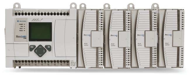
Рассмотрим современные контроллеры Allen-Bradley. Этим брендом, которому более 100 лет, владеет фирма Rockwell Automation.
Данную продукцию в России используют в основном американские компании (Mars и Pepsico например).
Перспективная линейка среди контроллеров Allen-Bradley — контроллеры серии Micrologix. В состав линейки PLC Micrologix входят
следующие модели, каждая из которых соответствует своему бюллетеню (серии):
- MicroLogix 1000 (серия 1761)
- MicroLogix 1100 (серия 1763, с ЖК дисплеем)
- MicroLogix 1200 (серия 1762)
- MicroLogix 1400 (серия 1766, с ЖК дисплеем)
- MicroLogix 1500 (серия 1764)
Выше перечисленные серии разработаны на основе популярного, но морально устаревшего контроллера SLC500, от которого производитель взял лучшие решения.
Рассмотрим по порядку данные модели, обратив внимание на их достоинства и недостатки, сходства и различия.
MicroLogix 1000 (бюллетень 1761)
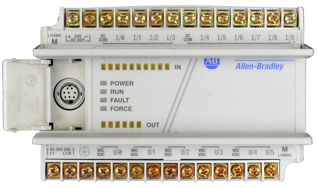
Контроллер 1200 серии
Это экономичный компактный контроллер, который имеет 16 или 32 канала ввода/вывода дискретных данных. Соотношение количества
входов и выходов может быть разное, но входов всегда больше.
Входы могут быть рассчитаны на промышленный стандарт 120 VAC, либо на напряжение 24 VDC. Выходы могут быть универсальными (релейными),
либо транзисторными. Конфигурация модулей зависит от модели, и выбирается в зависимости от поставленной задачи.
Входы DC могут быть с общим плюсом, или с общим минусом. Это позволяет подключать различные устройства, например, датчики с транзисторным выходом.
Хранение программы ПЛК производится в энергонезависимой памяти (EEPROM), благодаря чему не нужно применение элементов питания, как в устаревших моделях.
С помощью конвертера интерфейсов AIC+ возможно объединить в одной сети до 32 контроллеров. Для управления и контроля за технологическим процессом может
служить компьютер или интерфейсы оператора DTAM Micro или Micro View.
Для программирования MicroLogix 1000 применяется программная среда (пакет программирования ) RSLogix 500, которая также совместима с другими
сериями контроллеров Allen-Bradley. Для программирования необходимо подключить контроллер к компьютеру через порт RS-232 непосредственно, либо через
соответствующий преобразователь. Например, USB-RS-232. Также возможно применение специализированного ручного программатора.
Существенный минус данной модели PLC – отсутствие возможности анализа и обработки аналоговых сигналов. Кроме того, нет возможности наращивать
периферийные модули. Наращивание возможно только выбором модели на 32 входа, либо объединением в одну сеть нескольких контроллеров.
Контроллер Allen-Bradley MicroLogix 1000 является устаревшим и в настоящее время не выпускается.
MicroLogix 1100 (бюллетень 1763)
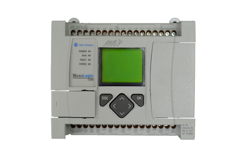
Данный промышленный контроллер является более гибким по нескольким параметрам:
- Наличие собственного ЖК-дисплея (4 строки по 12 символов) с кнопками управления;
- Съемный модуль памяти;
- Возможность подключения модулей расширения, в том числе аналоговых;
- Наличие двух коммуникационных портов – RS-232/485 и Ethernet.
Минусом можно назвать необходимость применения батареи питания. Хотя, в большинстве современных контроллеров
батарея применяется для хранения важных данных, на период длительного отключения питания.
ПЛК MicroLogix 1100 выпускается в четырех конфигурациях входов/выходов. В зависимости от модели, может быть 10 DI на рабочее напряжение промышленного
стандарта 120 VAC, либо 10 DI на напряжение 24 VDC, из них 4 высокоскоростных. Во всех моделях присутствует 2 AI для напряжения до 10 VDC,
что существенно расширяет круг задач, выполняемых базовым модулем.Все модели имеют по 6 DI, которые могут быть релейными или транзисторными.
Количество входов/выходов можно увеличить до 80, применив до 4 периферийных модулей 1762. Данные модули также совместимы с контроллером MicroLogix 1200 и MicroLogix 1400.
Важная функция MicroLogix 1100 – встроенный веб-сервер. Это дает возможность в режиме реального времени дистанционно отображать на заданной веб-странице данные
с контроллера, позволяя оперативно контролировать технологический процесс.
Для программирования применяется пакет программирования RSLogix 500.
MicroLogix 1200 (бюллетень 1762)
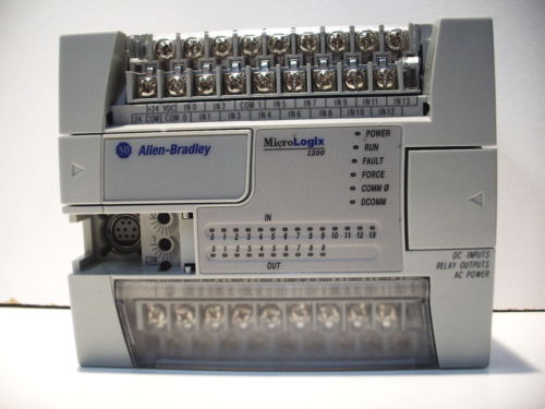
Данный контроллер является усовершенствованной моделью контроллера MicroLogix 1000, являясь гораздо более гибким и расширяемым.
Базовый модуль может иметь 24 или 40 дискретных входов/выходов. Возможно подключение дополнительных периферийных модулей 1762,
что увеличивает максимальное количество входов/выходов до 136.
Конфигурации входов/выходов могут быть следующими:
Количество входов – 14 или 24. Когда в контроллере 14 входов, возможны 14 входов на 120 VAC, или 14 на 24 VDC (из них – 4 скоростных).
В модели на 24 входа может быть либо 24 входа на 120 VAC, либо 24 входа на 24 VDC, из них – 4 скоростных.
Что касается выходов, то их может быть 10 или 16. Они могут быть релейными или транзисторными.
Для программирования применяется пакет программирования RSLogix 500.
MicroLogix 1400 (бюллетень 1766)
Этот контроллер – усовершенствованная модель PLC MicroLogix 1100. Включая в себя все его функции, MicroLogix 1400
более гибок в расширении (увеличении количества входов и выходов), скорости и возможностях связи.
MicroLogix 1100 и 1400 имеют общее сходство — ЖК дисплей, который значительно облегчает диагностику работы по сравнению с другими моделями.
Выпускается 6 моделей данного контроллера, которые отличаются в основном напряжением питания и входов. У всех моделей MicroLogix 1400 имеется
32 входа/выхода. Из них — 20 входов (включая 4 аналоговых в некоторых моделях) и 12 выходов (из них в некоторых моделях – 2 аналоговых).
Напряжение питания в зависимости от модели – 100…240 VAC, или 24 VDC.
Для расширения возможностей используются периферийные модули серии 1762, которые также используются для расширения контроллеров
MicroLogix 1100 и MicroLogix 1200. Допустимо подключать через специальную шину до 7 модулей расширения. При этом количество входов/выходов увеличится до 256.
Для сохранения некоторых типов данных, таких, как текущее время, используется встроенная батарея питания.
MicroLogix 1400 – самая широко используемая модель промышленного контроллера в линейке MicroLogix. Данная модель представляет серьезную конкуренцию для Siemens LOGO!
Для программирования контроллеров 1400 серии применяется пакет программирования RSLogix 500 или RSLogix 5000.
MicroLogix 1500 (бюллетень 1764)
Контроллеры MicroLogix 1500 имеют принципиально новую систему построения аппаратной части, по сравнению с 1200 серией.
Для установки контроллера используется базовое устройство (базовый модуль), которое монтируется на стандартную ДИН-рейку (монтажный профиль DIN).
Базовые устройства могут быть на 24 или 28 порта ввода/вывода. Они также отличаются напряжением питания входов (24 VDC или 120 VAC). Питание входов и выходов разнесено.
В базовое устройство после его монтажа вставляется процессор, и фиксируется там защелкой. Затем уже в процессор можно установить другие вспомогательные устройства, такие,
как устройство доступа к данным (терминал данных), модуль памяти, часы реального времени.
Для расширения сигналов управления, если это необходимо, можно применить модули Compact I/O для дискретного ввода, дискретного вывода и аналогового ввода/вывода.
Модули расширения подключаются с левой стороны базового модуля через специальный разъем, который исходно закрыт заглушкой.
При расширении нужно использовать конечный терминатор, который вставляется в последний модуль.
Производитель рекомендует использовать схему подключения, при которой в целях безопасности в аварийной ситуации выключатся главное
управляющее реле и обесточивает входы и выходы контроллера. Таким образом, будут обесточены контакторы, через которые питаются приводы механизмов.
При этом питание базового модуля и процессора сохраняется, позволяя выдавать оператору нужные сообщения.
Максимально можно использовать 8 модулей расширения в нужной конфигурации. Установленные модули нужно запрограммировать соответствующим образом в программном пакете.
Для программирования PLC MicroLogix 1500 используется среда программирования RSLogix 500 либо RSLogix 5000.
MicroLogix 1500 подключается к персональному компьютеру через протокол DF1. Он также может быть подключен к другим контроллерам через сеть DH485 и через сеть DeviceNet.
Наша компания предлагает услуги по программированию ПЛК Allen-Bradley в Ростове-на-Дону и области. Возможна реализация как небольших, так
и крупных проектов с использованием оборудования Rockwell Automation (включая частотные преобразователи и устройства плавного пуска).