-
Contents
-
Table of Contents
-
Troubleshooting
-
Bookmarks
Quick Links
MITSUBISHI ELECTRIC
Servo Amplifier
Instruction Manual
(General-Purpose Interface)
MR-J3- A
01072007
INDUSTRIAL AUTOMATION
MITSUBISHI ELECTRIC
SH(NA)030038
Version ES
Related Manuals for Mitsubishi Electric Melservo MR-J3-A
Summary of Contents for Mitsubishi Electric Melservo MR-J3-A
-
Page 1: Servo Amplifier
MITSUBISHI ELECTRIC Servo Amplifier Instruction Manual (General-Purpose Interface) MR-J3- A 01072007 INDUSTRIAL AUTOMATION MITSUBISHI ELECTRIC SH(NA)030038 Version ES…
-
Page 2: Safety Instructions
Safety Instructions (Always read these instructions before using the equipment.) Do not attempt to install, operate, maintain or inspect the servo amplifier and servo motor until you have read through this Instruction Manual, Installation guide, Servo motor Instruction Manual and appended documents carefully and can use the equipment correctly.
-
Page 3
1. To prevent electric shock, note the following: WARNING Before wiring or inspection, switch power off and wait for more than 15 minutes. Then, confirm the voltage is safe with voltage tester. Otherwise, you may get an electric shock. Connect the servo amplifier and servo motor to ground. Any person who is involved in wiring and inspection should be fully competent to do the work. -
Page 4
4. Additional instructions The following instructions should also be fully noted. Incorrect handling may cause a fault, injury, electric shock, etc. (1) Transportation and installation CAUTION Transport the products correctly according to their weights. Stacking in excess of the specified number of products is not allowed. Do not carry the servo motor by the cables, shaft or encoder. -
Page 5
(2) Wiring CAUTION Wire the equipment correctly and securely. Otherwise, the servo motor may misoperate. Do not install a power capacitor, surge absorber or radio noise filter (FR-BIF option) between the servo motor and servo amplifier. Connect the output terminals (U, V, W) correctly. Otherwise, the servo motor will operate improperly. Connect the servo motor power terminal (U, V, W) to the servo motor power input terminal (U, V, W) directly. -
Page 6
(4) Usage CAUTION Provide an external emergency stop circuit to ensure that operation can be stopped and power switched off immediately. Any person who is involved in disassembly and repair should be fully competent to do the work. Before resetting an alarm, make sure that the run signal of the servo amplifier is off to prevent an accident. -
Page 7
(6) Maintenance, inspection and parts replacement CAUTION With age, the electrolytic capacitor of the servo amplifier will deteriorate. To prevent a secondary accident due to a fault, it is recommended to replace the electrolytic capacitor every 10 years when used in general environment. -
Page 8
About processing of waste When you discard servo amplifier, a battery (primary battery), and other option articles, please follow the law of each country (area). FOR MAXIMUM SAFETY These products have been manufactured as a general-purpose part for general industries, and have not been designed or manufactured to be incorporated in a device or system used in purposes related to human life. -
Page 9
COMPLIANCE WITH EC DIRECTIVES 1. WHAT ARE EC DIRECTIVES? The EC directives were issued to standardize the regulations of the EU countries and ensure smooth distribution of safety-guaranteed products. In the EU countries, the machinery directive (effective in January, 1995), EMC directive (effective in January, 1996) and low voltage directive (effective in January, 1997) of the EC directives require that products to be sold should meet their fundamental safety requirements and carry the CE marks (CE marking). -
Page 10
(3) Environment Operate the servo amplifier at or above the contamination level 2 set forth in IEC60664-1. For this purpose, install the servo amplifier in a control box which is protected against water, oil, carbon, dust, dirt, etc. (IP54). (4) Power supply (a) This servo amplifier can be supplied from star-connected supply with earthed neutral point of overvoltage category III set forth in IEC60664-1. -
Page 11
(7) Auxiliary equipment and options (a) The no-fuse breaker and magnetic contactor used should be the EN or IEC standard-compliant products of the models described in section 12.12. Use a type B (Note) breaker. When it is not used, provide insulation between the servo amplifier and other device by double insulation or reinforced insulation, or install a transformer between the main power supply and servo amplifier. -
Page 12: Mr-J3-200A
CONFORMANCE WITH UL/C-UL STANDARD (1) Servo amplifiers and servo motors used Use the servo amplifiers and servo motors which comply with the standard model. Servo amplifier :MR-J3-10A to MR-J3-22KA MR-J3-10A1 to MR-J3-40A1 MR-J3-11KA4 to MR-J3-22KA4 Servo motor :HF-MP HF-KP HF-SP HC-RP HC-UP HC-LP…
-
Page 13: Table Of Contents
(5) Options and auxiliary equipment Use UL/C-UL standard-compliant products. This servo amplifier is UL/C-UL-listed when using the fuses indicated in the following table. When the servo amplifier must comply with the UL/C-UL Standard, be sure to use these fuses. Fuse Fuse Servo amplifier Servo amplifier…
-
Page 14
<<About the manuals>> This Instruction Manual and the MELSERVO Servo Motor Instruction Manual are required if you use the General-Purpose AC servo MR-J3-A for the first time. Always purchase them and use the MR-J3-A safely. Relevant manuals Manual name Manual No. MELSERVO-J3 Series To Use the AC Servo Safely IB(NA)0300077 MELSERVO Servo Motor Instruction Manual Vol.2… -
Page 15
MEMO A — 14… -
Page 16
CONTENTS 1. FUNCTIONS AND CONFIGURATION 1 — 1 to 1 -28 1.1 Introduction…………………………. 1 — 1 1.2 Function block diagram……………………..1 — 2 1.3 Servo amplifier standard specifications………………..1 — 5 1.4 Function list ………………………… 1 — 7 1.5 Model code definition ……………………..1 — 8 1.6 Combination with servo motor …………………… -
Page 17
3.10 Connection of servo amplifier and servo motor ………………. 3 -58 3.10.1 Connection instructions……………………3 -58 3.10.2 Power supply cable wiring diagrams ………………… 3 -59 3.11 Servo motor with electromagnetic brake………………..3 -69 3.11.1 Safety precautions ……………………. 3 -69 3.11.2 Setting……………………….. 3 -69 3.11.3 Timing charts …………………….. -
Page 18
5.1.9 Auto tuning ……………………….5 -10 5.1.10 In-position range ……………………..5 -11 5.1.11 Torque limit……………………….. 5 -12 5.1.12 Selection of command pulse input form ………………5 -13 5.1.13 Selection of servo motor rotation direction………………5 -14 5.1.14 Encoder output pulse ……………………5 -14 5.2 Gain/filter parameters (No. -
Page 19
7.2.2 Auto tuning mode operation………………….7 — 4 7.2.3 Adjustment procedure by auto tuning………………..7 — 5 7.2.4 Response level setting in auto tuning mode ………………7 — 6 7.3 Manual mode 1 (simple manual adjustment) ………………7 — 7 7.4 Interpolation mode …………………….. -
Page 20
12.4 Power regeneration converter ………………….12-36 12.5 Power regeneration common converter………………..12-39 12.6 External dynamic brake ……………………12-47 12.7 Junction terminal block MR-TB50 ………………….. 12-52 12.8 MR Configurator……………………… 12-54 12.9 Battery unit MR-J3BAT ……………………12-57 12.10 Heat sink outside mounting attachment (MR-J3ACN)…………..12-58 12.11 Recommended wires ……………………. -
Page 21
14. ABSOLUTE POSITION DETECTION SYSTEM 14- 1 to 14-62 14.1 Outline …………………………14- 1 14.1.1 Features……………………….14- 1 14.1.2 Restrictions……………………….. 14- 1 14.2 Specifications ……………………….14- 2 14.3 Battery installation procedure ………………….. 14- 3 14.4 Standard connection diagram………………….. 14- 4 14.5 Signal explanation…………………….. -
Page 22: Functions And Configuration
1. FUNCTIONS AND CONFIGURATION 1. FUNCTIONS AND CONFIGURATION 1.1 Introduction The Mitsubishi MELSERVO-J3 series general-purpose AC servo is based on the MELSERVO-J2-Super series and has further higher performance and higher functions. It has position control, speed control and torque control modes. Further, it can perform operation with the control modes changed, e.g.
-
Page 23: Function Block Diagram
1. FUNCTIONS AND CONFIGURATION 1.2 Function block diagram The function block diagram of this servo is shown below. (1) MR-J3-350A or less Power factor Regenerative improving DC reactor option Servo amplifier Servo motor Diode (Note1) stack Relay (Note 2) Current Power detector supply…
-
Page 24: Mr-J3-700A
1. FUNCTIONS AND CONFIGURATION (2) MR-J3-350A4 MR-J3-500A(4) MR-J3-700A(4) Power factor Regenerative improving DC reactor option Servo amplifier Servo motor Diode stack Relay (Note) Current Power supply detector Regene- rative CHARGE lamp Dynamic Cooling f an brake Electro- Control magnetic circuit power brake supply…
-
Page 25: Mr-J3-11Ka
1. FUNCTIONS AND CONFIGURATION (3) MR-J3-11KA(4) to 22KA(4) Power factor Regenerative improving DC option reactor Servo amplifier Servo motor Diode Thyristor stack (Note) Current Power detector supply CHARGE Regene- lamp rative Cooling fan Control Electro- circuit magnetic power brake supply Base Voltage Current…
-
Page 26: Servo Amplifier Standard Specifications
1. FUNCTIONS AND CONFIGURATION 1.3 Servo amplifier standard specifications (1) 200VAC class, 100VAC class Servo Amplifier 10A 20A 40A 70A 100A 200A 350A 500 A 700 A 11KA 15KA 22KA 10A1 20A1 40A1 MR-J3- Item 3-phase or 1-phase 200 1-phase 100V to Voltage/frequency 3-phase 200 to 230VAC, 50/60Hz to 230VAC, 50/60Hz…
-
Page 27
1. FUNCTIONS AND CONFIGURATION (2) 400VAC class Servo Amplifier MR-J3- 60A4 100A4 200A4 350A4 500A4 700A4 11KA4 15KA4 22KA4 Item Voltage/frequency 3-phase 380 to 480VAC, 50/60Hz Permissible voltage fluctuation 3-phase 323 to 528VAC Permissible frequency fluctuation Within 5% Power supply capacity Refer to section 11.2 Inrush current Refer to section 11.5… -
Page 28: Function List
1. FUNCTIONS AND CONFIGURATION 1.4 Function list The following table lists the functions of this servo. For details of the functions, refer to the reference field. (Note) Function Description Reference Control mode Section 3.2.1 Position control mode This servo is used as position control servo. Section 3.6.1 Section 4.2 Section 3.2.2…
-
Page 29: Model Code Definition
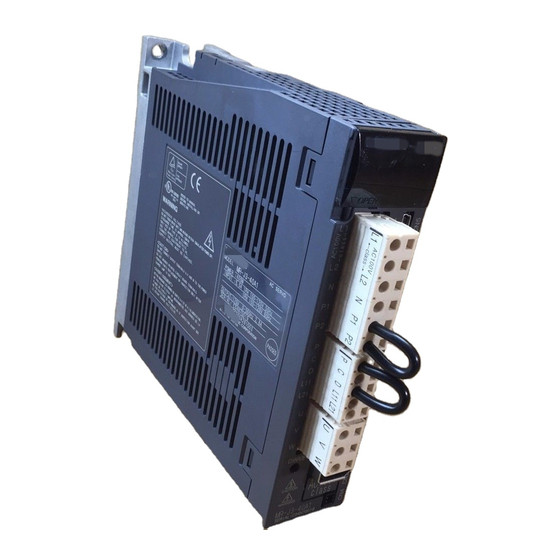
Capacity POWER : 100W 0.9A 3PH+1PH200-230V 50Hz Applicable power supply INPUT 3PH+1PH200-230V 60Hz 1.3A 1PH 230V 50/60Hz Rated output current 170V 0-360Hz 1.1A OUTPUT : SERIAL : A34230001 Serial number PASSED MITSUBISHI ELECTRIC CORPORATION MADE IN JAPAN 1 — 8…
-
Page 30
1. FUNCTIONS AND CONFIGURATION (2) Model MR-J3-100A or less MR-J3-60A4 100A4 With no regenerative resistor Series Symbol Description Indicates a servo amplifier of 11 to 22kW that does not use a regenerative resistor as standard accessory. Power supply Symbol Power supply 3-phase or 1-phase 200 None (Note 1) -
Page 31: Combination With Servo Motor
1. FUNCTIONS AND CONFIGURATION 1.6 Combination with servo motor The following table lists combinations of servo amplifiers and servo motors. The same combinations apply to the models with electromagnetic brakes. Servo motors Servo amplifier HF-SP HF-MP HF-KP HC-RP HC-UP HC-LP 1000r/min 2000r/min MR-J3-10A (1)
-
Page 32: Structure
1. FUNCTIONS AND CONFIGURATION 1.7 Structure 1.7.1 Parts identification (1) MR-J3-100A or less Detailed Name/Application Explanation Display The 5-digit, seven-segment LED shows the servo Chapter 6 status and alarm number. Operation section Used to perform status display, diagnostic, alarm and parameter setting operations.
-
Page 33
1. FUNCTIONS AND CONFIGURATION (2) MR-J3-60A4 MR-J3-100A4 Detailed Name/Application Explanation Display The 5-digit, seven-segment LED shows the servo Chapter 6 status and alarm number. Operation section Used to perform status display, diagnostic, alarm and parameter setting operations. DOWN MODE Chapter 6 Used to set data. -
Page 34
1. FUNCTIONS AND CONFIGURATION (3) MR-J3-200A MR-J3-350A Detailed Name/Application Explanation Display The 5-digit, seven-segment LED shows the servo Chapter 6 status and alarm number. Operation section Used to perform status display, diagnostic, alarm and parameter setting operations. MODE DOWN SET Chapter 6 Used to set data. -
Page 35
1. FUNCTIONS AND CONFIGURATION (4) MR-J3-200A4 Detailed Name/Application Explanation Display The 5-digit, seven-segment LED shows the servo Chapter 6 status and alarm number. Operation section Used to perform status display, diagnostic, alarm and parameter setting operations. MODE DOWN Chapter 6 Used to set data. -
Page 36
1. FUNCTIONS AND CONFIGURATION (5) MR-J3-350A4 MR-J3-500A(4) POINT The servo amplifier is shown without the front cover. For removal of the front cover, refer to section 1.7.2. Detailed Name/Application Explanation Display The 5-digit, seven-segment LED shows the servo Chapter 6 status and alarm number. -
Page 37
1. FUNCTIONS AND CONFIGURATION (6) MR-J3-700A(4) POINT The servo amplifier is shown without the front cover. For removal of the front cover, refer to section 1.7.2. Detailed Name/Application Explanation Display The 5-digit, seven-segment LED shows the servo Chapter 6 status and alarm number. Operation section Used to perform status display, diagnostic, alarm and parameter setting operations. -
Page 38: Mr-J3-22Ka
1. FUNCTIONS AND CONFIGURATION (7) MR-J3-11KA(4) to MR-J3-22KA(4) POINT The servo amplifier is shown without the front cover. For removal of the front cover, refer to section 1.7.2. Detailed Name/Application Explanation Display The 5-digit, seven-segment LED shows the servo Chapter 6 status and alarm number.
-
Page 39: Removal And Reinstallation Of The
1. FUNCTIONS AND CONFIGURATION 1.7.2 Removal and reinstallation of the front cover Before removing or reinstalling the front cover, make sure that the charge lamp is WARNING off more than 15 minutes after power off. Otherwise, you may get an electric shock. (1) For MR-J3-350A4 MR-J3-500A(4) MR-J3-700A(4) Removal of the front cover Hold the ends of lower side of the front cover with…
-
Page 40
1. FUNCTIONS AND CONFIGURATION Reinstallation of the front cover Front cover setting tab Insert the front cover setting tabs into the sockets of Pull up the cover, supporting at point A) . servo amplifier (2 places). Setting tab Push the setting tabs until they click. 1 — 19… -
Page 41
1. FUNCTIONS AND CONFIGURATION (2) For MR-J3-11KA(4) to MR-J3-22KA(4) Removal of the front cover 1) Press the removing knob on the lower side of the 3) Pull it to remove the front cover. front cover ( A) and B) ) and release the installation hook. -
Page 42: Configuration Including Auxiliary Equipment
1. FUNCTIONS AND CONFIGURATION 1.8 Configuration including auxiliary equipment POINT Equipment other than the servo amplifier and servo motor are optional or recommended products. (1) MR-J3-100A or less (a) For 3-phase or 1-phase 200V to 230VAC R S T (Note3) power supply No-fuse breaker (NFB) or fuse…
-
Page 43
1. FUNCTIONS AND CONFIGURATION (b) For 1-phase 100V to 120VAC (Note3) power supply No-fuse breaker (NFB) or fuse Analog monitor Magnetic Servo amplifier contactor (MC) Personal Power factor computer improving MR Configurator reactor (FR-BAL) Line noise filter (FR-BLF) (Note 2) Junction terminal block (Note 1) Battery unit… -
Page 44: Mr-J3-60A4
1. FUNCTIONS AND CONFIGURATION (2) MR-J3-60A4 MR-J3-100A4 R S T (Note 3) Power supply No-fuse breaker (NFB) or fuse Analog monitor Magnetic Servo amplifier contactor (MC) Personal computer MR Configurator (Note 2) Line noise filter (FR-BSF01) (Note 2) Power factor Junction terminal block improving DC reactor…
-
Page 45
1. FUNCTIONS AND CONFIGURATION (3) MR-J3-200A MR-J3-350A R S T (Note4) power supply No-fuse breaker (NFB) or fuse Magnetic contactor (MC) (Note2) (Note3) Analog monitor Line noise filter (FR-BSF01) Servo amplifier Personal computer MR Configurator (Note2) Power factor improving DC reactor Junction terminal block Regenerative… -
Page 46
1. FUNCTIONS AND CONFIGURATION (4) MR-J3-200A4 (Note 3) R S T Power supply No-fuse breaker (NFB) or fuse Magnetic contactor (MC) (Note 2) Analog monitor Line noise filter (FR-BSF01) Servo amplifier Personal (Note 2) computer MR Configurator Power factor improving DC reactor (FR-BEL-H) Regenerative… -
Page 47
1. FUNCTIONS AND CONFIGURATION (5) MR-J3-350A4 MR-J3-500A(4) R S T (Note3) power supply No-fuse breaker (NFB) or fuse Analog monitor Servo amplifier Personal computer MR Configurator Magnetic contactor (MC) (Note1) Battery unit Line noise filter (Note2) MR-J3BAT (FR-BLF) Junction terminal block (Note2) Power factor improving DC… -
Page 48
1. FUNCTIONS AND CONFIGURATION (6) MR-J3-700A(4) R S T (Note3) power supply No-fuse breaker (NFB) or fuse Analog monitor Servo amplifier Personal computer MR Configurator Magnetic contactor (MC) (Note1) Battery unit Line noise filter MR-J3BAT (FR-BLF) (Note2) Junction terminal block (Note2) Power factor improving DC… -
Page 49
1. FUNCTIONS AND CONFIGURATION (7) MR-J3-11KA(4) to MR-J3-22KA(4) R S T (Note3) power supply No-fuse breaker (NFB) or fuse Analog monitor Servo amplifier Personal Magnetic computer contactor MR Configurator (MC) Line noise filter (Note2) (FR-BLF) (Note1) Battery unit MR-J3BAT Junction terminal block Power factor (Note2) improving DC… -
Page 50: Installation
2. INSTALLATION 2. INSTALLATION Stacking in excess of the limited number of products is not allowed. Install the equipment to incombustibles. Installing them directly or close to combustibles will led to a fire. Install the equipment in a load-bearing place in accordance with this Instruction Manual.
-
Page 51
2. INSTALLATION (b) Installation of two or more servo amplifiers POINT Mounting closely is available for a combination of servo amplifiers of 3.5kW or less in 200V or 100V class. Leave a large clearance between the top of the servo amplifier and the internal surface of the control box, and install a fan to prevent the internal temperature of the control box from exceeding the environmental conditions. -
Page 52: Keep Out Foreign Materials
2. INSTALLATION (b) Installation of two or more servo amplifiers Leave a large clearance between the top of the servo amplifier and the internal surface of the control box, and install a fan to prevent the internal temperature of the control box from exceeding the environmental conditions.
-
Page 53: Inspection Items
2. INSTALLATION 2.4 Inspection items Before starting maintenance and/or inspection, make sure that the charge lamp is off more than 15 minutes after power-off. Then, confirm that the voltage is safe in the tester or the like. Otherwise, you may get an electric shock. WARNING Any person who is involved in inspection should be fully competent to do the work.
-
Page 54: Signals And Wiring
3. SIGNALS AND WIRING 3. SIGNALS AND WIRING Any person who is involved in wiring should be fully competent to do the work. Before starting wiring, switch power off, then wait for more than 15 minutes, and after the charge lamp has gone off, make sure that the voltage is safe in the tester or like.
-
Page 55: Input Power Supply Circuit
3. SIGNALS AND WIRING 3.1 Input power supply circuit When the servo amplifier has become faulty, switch power off on the servo amplifier power side. Continuous flow of a large current may cause a fire. Use the trouble signal to switch power off. Otherwise, a regenerative transistor CAUTION fault or the like may overheat the regenerative resistor, causing a fire.
-
Page 56
3. SIGNALS AND WIRING (2) For 1-phase 200 to 230VAC power supply to MR-J3-10A to MR-J3-70A Emergency stop Servo amplifier Servo motor CNP1 1-phase CNP3 200 to (Note 5) 230VAC Motor (Note 1) CNP2 (Note 2) (Note 3) Encoder Encoder cable 24VDC Emergency stop DOCOM… -
Page 57
3. SIGNALS AND WIRING (3) For 1-phase 100 to 120VAC power supply to MR-J3-10A1 to MR-J3-40A1 Emergency stop Servo amplifier Servo motor CNP1 1-phase CNP3 100 to (Note 5) Blank 120VAC Motor (Note 1) CNP2 (Note 2) (Note 3) Encoder Encoder cable 24VDC Emergency stop… -
Page 58
3. SIGNALS AND WIRING (4) MR-J3-60A4 to MR-J3-200A4 Emergency stop (Note 6) Stepdown transformer Servo amplifier Servo motor CNP1 3-phase CNP3 (Note 5) 380 to Motor 480VAC (Note 1) CNP2 (Note 2) (Note 3) Encoder Encoder cable 24VDC Emergency stop DOCOM Servo-on (Note 4) -
Page 59
3. SIGNALS AND WIRING (5) MR-J3-500A MR-J3-700A Emergency stop Servo amplifier Servo motor 3-phase (Note 5) Built-in 200 to regenerative Motor 230VAC resistor (Note 2) (Note 3) Encoder Encoder cable (Note 1) 24VDC DOCOM Emergency stop (Note 4) DICOM Servo-on (Note 4) Trouble DOCOM… -
Page 60
3. SIGNALS AND WIRING (6) MR-J3-350A4 to MR-J3-700A4 Emergency stop (Note 7) Power supply of Cooling fan (Note 6) Stepdown transformer Servo amplifier Servo motor 3-phase (Note 5) Built-in 380 to regenerative Motor 480VAC resistor (Note 2) (Note 3) Encoder Encoder cable (Note 1) Cooling fan… -
Page 61: Servo Amplifier
3. SIGNALS AND WIRING (7) MR-J3-11KA to MR-J3-22KA Servo motor Emergency thermal relay stop Trouble Servo amplifier Servo motor Dynamic break 3-phase 200 to 230VAC (Note 5) (Note 2) (Note 1) Regenerative resistor (Note 3) Encoder Encoder cable (Note 6) Cooling fan OHS1 OHS2…
-
Page 62
3. SIGNALS AND WIRING (8) MR-J3-11KA4 to MR-J3-22KA4 Servo motor Emergency thermal relay stop Trouble (Note 7) Cooling fan power supply (Note Stepdown transformer Servo motor Servo amplifier Dynamic break 3-phase 380 to 480VAC (Note 5) (Note 2) (Note 1) Regenerative resistor (Note 3)
 -
Page 63: I/O Signal Connection Example
3. SIGNALS AND WIRING 3.2 I/O Signal connection example 3.2.1 Position control mode Servo amplifier (Note 4) (Note 7) 24VDC Positioning module power (Note 7) QD75D supply DICOM (Note 2) DICOM Trouble (Note 6) CLEARCOM DOCOM Zero speed CLEAR (Note12) RDYCOM Limiting torque REDY…
-
Page 64
3. SIGNALS AND WIRING Note 1. To prevent an electric shock, always connect the protective earth (PE) terminal (terminal marked ) of the servo amplifier to the protective earth (PE) of the control box. 2. Connect the diode in the correct direction. If it is connected reversely, the servo amplifier will be faulty and will not output signals, disabling the emergency stop (EMG) and other protective circuits. -
Page 65: Speed Control Mode
3. SIGNALS AND WIRING 3.2.2 Speed control mode Servo amplifier (Note 4) (Note 7) 24VDC power (Note 7) supply DICOM (Note 2) Trouble (Note 6) DICOM DOCOM Zero speed (Note 3, 5) Emergency stop Limiting torque (Note 12) Servo-on Reset Speed reached Speed selection 1 Ready…
-
Page 66: Torque Control Mode
3. SIGNALS AND WIRING 3.2.3 Torque control mode Servo amplifier (Note 4) (Note 6) 24VDC power (Note 6) supply DICOM (Note 2) Trouble (Note 5) DICOM Zero speed DOCOM (Note 10) (Note 3) Emergency stop Limiting speed Servo-on Reset Ready Speed selection 1 (Note 10) Speed selection 2…
-
Page 67: Explanation Of Power Supply System
3. SIGNALS AND WIRING 3.3 Explanation of power supply system 3.3.1 Signal explanations POINT For the layout of connector and terminal block, refer to outline drawings in chapter 10. Connection Target Abbreviation Description (Application) Supply the following power to L .
-
Page 68: Power-On Sequence
3. SIGNALS AND WIRING 3.3.2 Power-on sequence (1) Power-on procedure 1) Always wire the power supply as shown in above section 3.1 using the magnetic contactor with the main circuit power supply (three-phase: L , single-phase: L ). Configure up an external sequence to switch off the magnetic contactor as soon as an alarm occurs.
-
Page 69
3. SIGNALS AND WIRING (3) Emergency stop Provide an external emergency stop circuit to ensure that operation can be CAUTION stopped and power switched off immediately. Make up a circuit that shuts off main circuit power as soon as EMG is turned off at an emergency stop. When EMG is turned off, the dynamic brake is operated to bring the servo motor to a sudden stop. -
Page 70: Cnp1, Cnp2, Cnp3 Wiring Method
3. SIGNALS AND WIRING 3.3.3 CNP1, CNP2, CNP3 wiring method POINT Refer to Table 12.1 in section 12.11 for the wire sizes used for wiring. MR-J3-500A or more does not have these connectors. Use the supplied servo amplifier power supply connectors for wiring of CNP1, CNP2 and CNP3. (1) MR-J3-100A or less (a) Servo amplifier power supply connectors (Note)
-
Page 71: Mr-J3-200A4
3. SIGNALS AND WIRING (2) MR-J3-200A MR-J3-350A (a) Servo amplifier power supply connectors Servo amplifier power supply connectors Connector for CNP1 PC4/6-STF-7.62-CRWH (phoenix contact) Servo amplifier <Applicable cable example> Cable finish OD: to CNP1 Connector for CNP3 PC4/3-STF-7.62-CRWH (phoenix contact) CNP3 CNP2 Connector for CNP2…
-
Page 72: Mr-J3-350A4
3. SIGNALS AND WIRING (3) MR-J3-200A4 MR-J3-350A4 (a) Servo amplifier power supply connectors Servo amplifier power supply connectors Connector for CNP1 721-207/026-000(Plug) (WAGO JAPAN) Servo amplifier <Applicable cable example> Cable finish OD: 4.1mm or less CNP1 Connector for CNP2 721-205/026-000(Plug) (WAGO JAPAN) CNP2 CNP3…
-
Page 73
3. SIGNALS AND WIRING (4) Insertion of cable into Molex and WAGO JAPAN connectors Insertion of cable into 54928-0610, 54927-0510, 54928 (Molex) connectors and 721-207/026-000, 721-205/ 026-000 and 721-203/026-000 (WAGO JAPAN) connectors are as follows. The following explains for Molex, however use the same procedures for inserting WAGO JAPAN connectors as well. -
Page 74
3. SIGNALS AND WIRING 2) Cable connection procedure Cable connection lever 1) Attach the cable connection lever to the housing. (Detachable) 2) Push the cable connection lever in the direction of arrow. 3) Hold down the cable connection lever and insert the cable in the direction of arrow. -
Page 75
3. SIGNALS AND WIRING (b) Inserting the cable into the connector 1) Applicable flat-blade screwdriver dimensions Always use the screwdriver shown here to do the work. [Unit: mm] Approx.R0.3 Approx.22 Approx.R0.3 2) When using the flat-blade screwdriver — part 1 1) Insert the screwdriver into the square hole. -
Page 76
3. SIGNALS AND WIRING 3) When using the flat-blade screwdriver — part 2 1) Insert the screwdriver into the 2) Push the screwdriver in the 3) With the screwdriver pushed, insert the cable in the square window at top of the direction of arrow. -
Page 77: Connectors And Signal Arrangements
3. SIGNALS AND WIRING 3.4 Connectors and signal arrangements POINT The pin configurations of the connectors are as viewed from the cable connector wiring section. Refer to (2) of this section for CN1 signal assignment. (1) Signal arrangement The servo amplifier front view shown is that of the MR-J3-20A or less. Refer to chapter 10 Outline Drawings for the appearances and connector layouts of the other servo amplifiers.
-
Page 78
3. SIGNALS AND WIRING (2) CN1 signal assignment The signal assignment of connector changes with the control mode as indicated below; For the pins which are given parameter No.s in the related parameter column, their signals can be changed using those parameters. (Note 1) (Note 2) I/O Signals in Control Modes Related… -
Page 79
3. SIGNALS AND WIRING (Note 1) (Note 2) I/O Signals in Control Modes Related Pin No. Parameter No. DOCOM DOCOM DOCOM DOCOM DOCOM DOCOM DOCOM DOCOM DOCOM DOCOM DOCOM DOCOM PD18 Note 1. I: Input signal, O: Output signal 2. P: Position control mode, S: Speed control mode, T: Torque control mode, P/S: Position/speed control changeover mode, S/T: Speed/torque control changeover mode, T/P: Torque/position control changeover mode 3. -
Page 80: Signal Explanations
3. SIGNALS AND WIRING 3.5 Signal explanations For the I/O interfaces (symbols in I/O division column in the table), refer to section 3.8.2. In the control mode field of the table P : Position control mode, S: Speed control mode, T: Torque control mode : Denotes that the signal may be used in the initial setting status.
-
Page 81
3. SIGNALS AND WIRING Control Connec- mode Device Symbol tor pin Functions/Applications division External torque CN1-18 Turn TL off to make Forward torque limit (parameter No. PA11) and DI-1 limit selection Reverse torque limit (parameter No. PA12) valid, or turn it on to make Analog torque limit (TLA) valid. -
Page 82
3. SIGNALS AND WIRING Connec- Control Device Symbol tor pin Functions/Applications mode division Speed selection 1 CN1-41 <Speed control mode> DI-1 Used to select the command speed for operation. When using SP3, make it usable by making the setting of parameter No. -
Page 83
3. SIGNALS AND WIRING Connec- Control Device Symbol Functions/Applications tor pin mode division Proportion control CN1-17 Turn PC on to switch the speed amplifier from the proportional DI-1 integral type to the proportional type. If the servo motor at a stop is rotated even one pulse due to any external factor, it generates torque to compensate for a position shift. -
Page 84
3. SIGNALS AND WIRING Connec- Control Device Symbol Functions/Applications tor pin mode division Control change CN1-45 <Position/speed control change mode> DI-1 Refer to Used to select the control mode in the position/speed control change Functions/ mode. Appli- cations. (Note) LOP Control mode Position Speed… -
Page 85
3. SIGNALS AND WIRING (b) Output devices Control Connec- mode Device Symbol tor pin Functions/Applications division Trouble CN1-48 ALM turns off when power is switched off or the protective circuit is DO-1 activated to shut off the base circuit. Without alarm occurring, ALM turns on within 1.5s after power-on. -
Page 86
3. SIGNALS AND WIRING Control Connec- mode Device Symbol tor pin Functions/Applications division Zero speed CN1-23 ZSP turns on when the servo motor speed is zero speed (50r/min) or DO-1 less. Zero speed can be changed using parameter No. PC17. Example Zero speed is 50r/min OFF level… -
Page 87
3. SIGNALS AND WIRING Connec- Control Signal Symbol Functions/Applications tor pin mode division Alarm code ACD 0 CN1-24 To use this signal, set » 1 » in parameter No. PD24. DO-1 This signal is output when an alarm occurs. When there is no alarm, ACD 1 CN1-23 respective ordinary signals (RD, INP, SA, ZSP) are output. -
Page 88
3. SIGNALS AND WIRING (2) Input signals Connec- Control Signal Symbol tor pin Functions/Applications mode division Analog torque CN1-27 To use this signal in the speed control mode, set any of parameters Analog limit No. PD13 to PD16, PD18 to make TL available. input When the analog torque limit (TLA) is valid, torque is limited in the full servo motor output torque range. -
Page 89
3. SIGNALS AND WIRING (4) Communication POINT Refer to chapter 13 for the communication function. Connec- Control Signal Symbol Functions/Applications tor pin mode division RS-422 I/F CN3-5 Terminals for RS-422 communication. (Refer to chapter 13.) CN3-4 CN3-3 CN3-6 (5) Power supply Connec- Control Signal… -
Page 90: Detailed Description Of The Signals
3. SIGNALS AND WIRING 3.6 Detailed description of the signals 3.6.1 Position control mode (1) Pulse train input (a) Input pulse waveform selection Command pulses may be input in any of three different forms, for which positive or negative logic can be chosen.
-
Page 91
3. SIGNALS AND WIRING 2) Differential line driver system Connect as shown below: Servo amplifier Approx. (Note) Approx. Note. Pulse train input interface is comprised of a photo coupler. Therefore, it may be any malfunctions since the current is reduced when connect a resistance to a pulse train signal line. -
Page 92
3. SIGNALS AND WIRING (3) Ready (RD) Servo-on (SON) Alarm 100ms or less 10ms or less 10ms or less Ready (RD) (4) Electronic gear switching The combination of CM1 and CM2 gives you a choice of four different electronic gear numerators set in the parameters. -
Page 93
3. SIGNALS AND WIRING (b) Torque limit value selection As shown below, the forward torque limit (parameter No. PA11), or reverse torque limit (parameter No. PA12) and the analog torque limit (TLA) can be chosen using the external torque limit selection (TL). When internal torque limit selection (TL1) is made usable by parameter No. -
Page 94: Speed Control Mode
3. SIGNALS AND WIRING 3.6.2 Speed control mode (1) Speed setting (a) Speed command and speed The servo motor is run at the speeds set in the parameters or at the speed set in the applied voltage of the analog speed command (VC). A relationship between the analog speed command (VC) applied voltage and the servo motor speed is shown below: The maximum speed is achieved at 10V.
-
Page 95
3. SIGNALS AND WIRING (b) Speed selection 1 (SP1), speed selection 2 (SP2) and speed command value Choose any of the speed settings made by the internal speed commands 1 to 3 using speed selection 1 (SP1) and speed selection 2 (SP2) or the speed setting made by the analog speed command (VC). (Note) External input signals Speed command value Analog speed command (VC) -
Page 96: Torque Control Mode
3. SIGNALS AND WIRING 3.6.3 Torque control mode (1) Torque control (a) Torque command and torque A relationship between the applied voltage of the analog torque command (TC) and the torque by the servo motor is shown below. The maximum torque is generated at 8V. Note that the torque at 8V input can be changed with parameter No.
-
Page 97
3. SIGNALS AND WIRING (b) Analog torque command offset Using parameter No. PC38, the offset voltage of 999 to 999mV can be added to the TC applied voltage as shown below. Max. torque Parameter No. PC38 offset range 999 to 999mV 8( TC applied voltage [V] (2) Torque limit… -
Page 98
3. SIGNALS AND WIRING (b) Speed selection 1(SP1)/speed selection 2(SP2)/speed selection 3(SP3) and speed limit values Choose any of the speed settings made by the internal speed limits 1 to 7 using speed selection 1(SP1), speed selection 2(SP2) and speed selection 3(SP3) or the speed setting made by the speed limit command (VLA), as indicated below. -
Page 99: Position/Speed Control Change Mode
3. SIGNALS AND WIRING 3.6.4 Position/speed control change mode Set » 1 » in parameter No. PA01 to switch to the position/speed control change mode. This function is not available in the absolute position detection system. (1) Control change (LOP) Use control change (LOP) to switch between the position control mode and the speed control mode from an external contact.
-
Page 100
3. SIGNALS AND WIRING (3) Speed setting in speed control mode (a) Speed command and speed The servo motor is run at the speed set in parameter No. 8 (internal speed command 1) or at the speed set in the applied voltage of the analog speed command (VC). A relationship between analog speed command (VC) applied voltage and servo motor speed and the rotation directions determined by the forward rotation start (ST1) and reverse rotation start (ST2) are as in (a), (1) in section 3.6.2. -
Page 101: Speed/Torque Control Change Mode
3. SIGNALS AND WIRING 3.6.5 Speed/torque control change mode Set » 3 » in parameter No. PA01 to switch to the speed/torque control change mode. (1) Control change (LOP) Use control change (LOP) to switch between the speed control mode and the torque control mode from an external contact.
-
Page 102
3. SIGNALS AND WIRING (4) Speed limit in torque control mode (a) Speed limit value and speed The speed is limited to the limit value set in parameter No. 8 (internal speed limit 1) or the value set in the applied voltage of the analog speed limit (VLA). A relationship between the analog speed limit (VLA) applied voltage and the servo motor speed is as in section 3.6.3 (3) (a). -
Page 103: Torque/Position Control Change Mode
3. SIGNALS AND WIRING 3.6.6 Torque/position control change mode Set » 5 » in parameter No. PA01 to switch to the torque/position control change mode. (1) Control change (LOP) Use control change (LOP) to switch between the torque control mode and the position control mode from an external contact.
-
Page 104: Alarm Occurrence Timing Chart
3. SIGNALS AND WIRING 3.7 Alarm occurrence timing chart When an alarm has occurred, remove its cause, make sure that the operation signal is not being input, ensure safety, and reset the alarm before restarting CAUTION operation. As soon as an alarm occurs, turn off Servo-on (SON) and power off. When an alarm occurs in the servo amplifier, the base circuit is shut off and the servo motor is coated to a stop.
-
Page 105: Interfaces
3. SIGNALS AND WIRING 3.8 Interfaces 3.8.1 Internal connection diagram Servo amplifier (Note 1) (Note 1) Approx. 5.6k SON SON SON DICOM SP2 SP2 16 INP SA PC ST1 RS2 17 TL ST2 RS1 18 (Note 3) RES RES (Note 3) CR SP1 Approx.
-
Page 106: Detailed Description Of Interfaces
3. SIGNALS AND WIRING Note 1. P: Position control mode S: Speed control mode T: Torque control mode 2. For the differential line driver pulse train input. For the open collector pulse train input, make the following connection. DOCO 24VDC DICOM DOCOM 3.
-
Page 107
3. SIGNALS AND WIRING (3) Pulse train input interface DI-2 Give a pulse train signal in the differential line driver system or open collector system. (a) Differential line driver system 1) Interface Servo amplifier Max. input pulse frequency 1Mpps 10m or less PP(NP) (Note) Approx. -
Page 108
3. SIGNALS AND WIRING (4) Encoder pulse output DO-2 (a) Open collector system Interface Max. output current : 35mA Servo amplifier Servo amplifier 5 to 24VDC Photocoupler (b) Differential line driver system 1) Interface Max. output current: 35mA Servo amplifier Servo amplifier Am26LS32 or equivalent High-speed photocoupler… -
Page 109: Source I/O Interfaces
3. SIGNALS AND WIRING (6) Analog output Servo amplifier (MO2) Output voltage 10V Max. 1mA Max. Output current Resolution: 10 bit 3.8.3 Source I/O interfaces In this servo amplifier, source type I/O interfaces can be used. In this case, all DI-1 input signals and DO-1 output signals are of source type.
-
Page 110: Treatment Of Cable Shield External Conductor
3. SIGNALS AND WIRING 3.9 Treatment of cable shield external conductor In the case of the CN1 and CN2 connectors, securely connect the shielded external conductor of the cable to the ground plate as shown in this section and fix it to the connector shell. External conductor Sheath Core…
-
Page 111: Connection Of Servo Amplifier And Servo Motor
3. SIGNALS AND WIRING 3.10 Connection of servo amplifier and servo motor During power-on, do not open or close the motor power line. Otherwise, a WARNING malfunction or faulty may occur. 3.10.1 Connection instructions Insulate the connections of the power supply terminals to prevent an electric WARNING shock.
-
Page 112: Power Supply Cable Wiring Diagrams
3. SIGNALS AND WIRING 3.10.2 Power supply cable wiring diagrams (1) HF-MP series HF-KP series servo motor (a) When cable length is 10m or less 10m or less MR-PWS1CBL M-A1-L MR-PWS1CBL M-A2-L MR-PWS1CBL M-A1-H Servo amplifier Servo motor MR-PWS1CBL M-A2-H CNP3 AWG 19(red) AWG 19(white)
-
Page 113
3. SIGNALS AND WIRING (2) HF-SP series HC-RP series HC-UP series HC-LP series servo motor POINT Insert a contact in the direction shown in the figure. If inserted in the wrong direction, the contact is damaged and falls off. Soldered part or Soldered part Pin No.1 Pin No.1… -
Page 114
3. SIGNALS AND WIRING (b) Connector and signal allotment The connector fitting the servomotor is prepared as optional equipment. Refer to section 12.1. For types other than those prepared as optional equipment, refer to chapter 3 in Servomotor Instruction Manual, Vol. -
Page 115
3. SIGNALS AND WIRING Power supply connector signal allotment Encoder connector signal allotment MS3102A18-10P Power supply connector signal allotment CM10-R10P MS3102A22-22P CE05-2A22-23PD-B CE05-2A32-17PD-B Terminal Terminal Terminal Signal Signal Signal View a View b View b (earth) (earth) (Note) (Note) Note. For the motor with electromagnetic brake, supply… -
Page 116
3. SIGNALS AND WIRING (3) HA-LP series servo motor (a) Wiring diagrams Refer to section 12.11 for the cables used for wiring. 1) 200VAC class Servo amplifier Servo motor Cooling fan Emergency (Note 2) Electromagnetic stop Trouble brake (MBR) (EMG) (ALM) (Note 1) 24VDC power… -
Page 117
3. SIGNALS AND WIRING 2) 400VAC class (Note 4) Cooling fan power supply Servo amplifier Servo motor Cooling fan Emergency (Note 2) Electromagnetic Trouble stop brake (MBR) (ALM) (EMG) (Note 1) 24VDC power supply for electromagnetic brake Servo motor OHS1 OHS2 24VDC thermal relay… -
Page 118
3. SIGNALS AND WIRING (b) Servo motor terminals Encoder connector CM10-R10P Brake connector Terminal box MS3102A10SL-4P Encoder connector signal Terminal Brake connector signal Terminal Signal Signal allotment allotment CM10-R10P MS3102A10SL-4P (Note) (Note) Note. For the motor with electromagnetic brake, supply electromagnetic brake power (24VDC). -
Page 119
3. SIGNALS AND WIRING Terminal box inside (HA-LP801(4), 12K1(4), 11K1M(4), 15K1M(4), 15K2(4), 22K2(4) BU BV OHS1 OHS2 Thermal sensor terminal block Cooling fan terminal block (OHS1,OHS2) M4 screw (BU,BV,BW) M4 screw Terminal block Motor power supply terminal block signal arrangement (U,V,W) M8 screw Encoder connector OHS1OHS2… -
Page 120
3. SIGNALS AND WIRING Terminal box inside (HA-LP25K1) Motor power supply terminal block Encoder connector (U,V,W) M8 screw CM10-R10P OHS1 OHS2 Thermal sensor terminal block (OHS1,OHS2) M4 screw Cooling fan Terminal block signal arrangement terminal block (BU,BV,BW) M4 screw BW OHS1 OHS2 Earth terminal M6 screw 3 — 67… -
Page 121
3. SIGNALS AND WIRING Signal Name Abbreviation Description Connect to the motor output terminals (U, V, W) of the servo amplifier. During power-on, do Power supply U V W not open or close the motor power line. Otherwise, a malfunction or faulty may occur. Supply power which satisfies the following specifications. -
Page 122: Servo Motor With Electromagnetic Brake
3. SIGNALS AND WIRING 3.11 Servo motor with electromagnetic brake 3.11.1 Safety precautions Configure the electromagnetic brake operation circuit so that it is activated not only by the servo amplifier signals but also by an external emergency stop signal. Contacts must be open when Circuit must be servo-off, when an trouble (ALM) opened during…
-
Page 123: Timing Charts
3. SIGNALS AND WIRING 3.11.3 Timing charts (1) Servo-on (SON) command (from controller) ON/OFF Tb [ms] after the servo-on (SON) signal is switched off, the servo lock is released and the servo motor coasts. If the electromagnetic brake is made valid in the servo lock status, the brake life may be shorter. Therefore, when using the electromagnetic brake in a vertical lift application or the like, set Tb to about the same as the electromagnetic brake operation delay time to prevent a drop.
-
Page 124
3. SIGNALS AND WIRING (3) Alarm occurrence Dynamic brake Dynamic brake Electromagnetic brake Servo motor speed Electromagnetic brake (10ms) Base circuit Invalid(ON) Electromagnetic brake Electromagnetic operation delay time brake interlock (MBR) Valid(OFF) No(ON) Trouble (ALM) Yes(OFF) (4) Both main and control circuit power supplies off Dynamic brake Dynamic brake (10ms) -
Page 125: Wiring Diagrams (Hf-Mp Series Hf-Kp Series Servo Motor)
3. SIGNALS AND WIRING 3.11.4 Wiring diagrams (HF-MP series HF-KP series servo motor) POINT For HF-SP series HC-RP series HC-UP series HC-LP series servo motors, refer to section 3.10.2 (2). (1) When cable length is 10m or less 10m or less 24VDC power MR-BKS1CBL M-A1-L supply for…
-
Page 126
3. SIGNALS AND WIRING (2) When cable length exceeds 10m When the cable length exceeds 10m, fabricate an extension cable as shown below on the customer side. In this case, the motor power supply cable pulled from the servo motor should be within 2m long. Refer to section 12.11 for the wire used for the extension cable. -
Page 127: Grounding
3. SIGNALS AND WIRING 3.12 Grounding Ground the servo amplifier and servo motor securely. WARNING To prevent an electric shock, always connect the protective earth (PE) terminal of the servo amplifier with the protective earth (PE) of the control box. The servo amplifier switches the power transistor on-off to supply power to the servo motor.
-
Page 128: Startup
4. STARTUP 4. STARTUP WARNING Do not operate the switches with wet hands. You may get an electric shock. Before starting operation, check the parameters. Some machines may perform unexpected operation. Take safety measures, e.g. provide covers, to prevent accidental contact of hands and parts (cables, etc.) with the servo amplifier heat sink, regenerative resistor, servo motor, etc.
-
Page 129: Wiring Check
4. STARTUP 4.1.2 Wiring check (1) Power supply system wiring Before switching on the main circuit and control circuit power supplies, check the following items. (a) Power supply system wiring The power supplied to the power input terminals (L ) of the servo amplifier should satisfy the defined specifications.
-
Page 130: Surrounding Environment
4. STARTUP 2) When regenerative option is used over 5kW The lead of built-in regenerative resistor connected to P terminal and D terminal of TE1 terminal block should not be connected. The generative brake option should be connected to P terminal and C terminal. A twisted cable should be used when wiring is over 5m and under 10m.
-
Page 131: Startup In Position Control Mode
4. STARTUP 4.2 Startup in position control mode Make a startup in accordance with section 4.1. This section provides the methods specific to the position control mode. 4.2.1 Power on and off procedures (1) Power-on Switch power on in the following procedure. Always follow this procedure at power-on. 1) Switch off the servo-on (SON).
-
Page 132: Test Operation
4. STARTUP 4.2.3 Test operation Before starting actual operation, perform test operation to make sure that the machine operates normally. Refer to section 4.2.1 for the power on and off methods of the servo amplifier. Test operation of servo motor In this step, confirm that the servo amplifier and servo motor alone in JOG operation of test operate normally.
-
Page 133: Parameter Setting
4. STARTUP 4.2.4 Parameter setting POINT The encoder cable MR-EKCBL M-L/H for the HF-MP series HF-KP series servo motor requires the parameter No. PC22 setting to be changed depending on its length. Check whether the parameter is set correctly. If it is not set correctly, the encoder error 1 (AL.
-
Page 134: Trouble At Start-Up
4. STARTUP 4.2.6 Trouble at start-up Excessive adjustment or change of parameter setting must not be made as it will CAUTION make operation instable. POINT Using the optional MR Configurator, you can refer to unrotated servo motor reasons, etc. The following faults may occur at start-up. If any of such faults occurs, take the corresponding action. (1) Troubleshooting Start-up sequence Fault…
-
Page 135
4. STARTUP (2) How to find the cause of position shift Positioning unit Servo amplifier Electronic gear (a) Output pulse Machine (parameters No. PA06, PA07) counter Servo motor (d) Machine stop position M (b) Cumulative command pulses (C) Servo-on (SON), stroke end (LSP/LSN) input Encoder… -
Page 136: Startup In Speed Control Mode
4. STARTUP 4.3 Startup in speed control mode Make a startup in accordance with section 4.1. This section provides the methods specific to the speed control mode. 4.3.1 Power on and off procedures (1) Power-on Switch power on in the following procedure. Always follow this procedure at power-on. 1) Switch off the servo-on (SON).
-
Page 137: Test Operation
4. STARTUP 4.3.3 Test operation Before starting actual operation, perform test operation to make sure that the machine operates normally. Refer to section 4.3.1 for the power on and off methods of the servo amplifier. Test operation of servo motor In this step, confirm that the servo amplifier and servo motor alone in JOG operation of test operate normally.
-
Page 138: Parameter Setting
4. STARTUP 4.3.4 Parameter setting POINT The encoder cable MR-EKCBL M-L/H for the HF-MP series HF-KP series servo motor requires the parameter No. PC22 setting to be changed depending on its length. Check whether the parameter is set correctly. If it is not set correctly, the encoder error 1 (AL.
-
Page 139: Trouble At Start-Up
4. STARTUP 4.3.6 Trouble at start-up Excessive adjustment or change of parameter setting must not be made as it will CAUTION make operation instable. POINT Using the optional servo configuration software, you can refer to unrotated servo motor reasons, etc. The following faults may occur at start-up.
-
Page 140: Startup In Torque Control Mode
4. STARTUP 4.4 Startup in torque control mode Make a startup in accordance with section 4.1. This section provides the methods specific to the torque control mode. 4.4.1 Power on and off procedures (1) Power-on Switch power on in the following procedure. Always follow this procedure at power-on. 1) Switch off the servo-on (SON).
-
Page 141: Test Operation
4. STARTUP 4.4.3 Test operation Before starting actual operation, perform test operation to make sure that the machine operates normally. Refer to section 4.4.1 for the power on and off methods of the servo amplifier. Test operation of servo motor In this step, confirm that the servo amplifier and servo motor alone in JOG operation of test operate normally.
-
Page 142: Parameter Setting
4. STARTUP 4.4.4 Parameter setting POINT The encoder cable MR-EKCBL M-L/H for the HF-MP series HF-KP series servo motor requires the parameter No. PC22 setting to be changed depending on its length. Check whether the parameter is set correctly. If it is not set correctly, the encoder error 1 (AL.
-
Page 143: Trouble At Start-Up
4. STARTUP 4.4.6 Trouble at start-up Excessive adjustment or change of parameter setting must not be made as it will CAUTION make operation instable. POINT Using the optional servo configuration software, you can refer to unrotated servo motor reasons, etc. The following faults may occur at start-up.
-
Page 144: Parameters
5. PARAMETERS 5. PARAMETERS Never adjust or change the parameter values extremely as it will make operation CAUTION instable. In the MR-J3-A servo amplifier, the parameters are classified into the following groups on a function basis. Parameter Group Main Description Basic setting parameters When using this servo amplifier in the position control mode, make basic setting with these (No.
-
Page 145: Parameter Write Inhibit
5. PARAMETERS 5.1.2 Parameter write inhibit Parameter Initial Setting Control Mode Unit Value Range Position Speed Torque Symbol Name Refer to PA19 *BLK Parameter write inhibit 000Bh the text. POINT This parameter is made valid when power is switched off, then on after setting. In the factory setting, this servo amplifier allows changes to the basic setting parameter, gain/filter parameter and extension setting parameter settings.
-
Page 146: Selection Of Regenerative Option
5. PARAMETERS 5.1.4 Selection of regenerative option Parameter Initial Setting Control Mode Unit Value Range Position Speed Torque Symbol Name Refer to PA02 *REG Regenerative option 0000h the text. POINT This parameter is made valid when power is switched off, then on after setting. Wrong setting may cause the regenerative option to burn.
-
Page 147: Using Absolute Position Detection System
5. PARAMETERS 5.1.5 Using absolute position detection system Parameter Initial Setting Control Mode Unit Value Range Position Speed Torque Symbol Name Refer to PA03 *ABS Absolute position detection system 0000h the text. POINT This parameter is made valid when power is switched off, then on after setting. Set this parameter when using the absolute position detection system in the position control mode.
-
Page 148: Number Of Command Input Pulses Per Servo Motor Revolution
5. PARAMETERS 5.1.7 Number of command input pulses per servo motor revolution Parameter Initial Setting Control Mode Unit Value Range Position Speed Torque Symbol Name 0 1000 PA05 *FBP Number of command input pulses per revolution to 50000 POINT This parameter is made valid when power is switched off, then on after setting. When «0»…
-
Page 149: Electronic Gear
5. PARAMETERS 5.1.8 Electronic gear Parameter Initial Setting Control Mode Unit Value Range Position Speed Torque Symbol Name Electronic gear numerator 1 to PA06 (command pulse multiplying factor numerator) 1048576 Electronic gear denominator 1 to PA07 (command pulse multiplying factor denominator) 1048576 CAUTION Wrong setting can lead to unexpected fast rotation, causing injury.
-
Page 150
5. PARAMETERS (a) For motion in increments of 10 m per pulse n NL/NM Machine specifications Pb 10[mm] Ballscrew lead Pb 10 [mm] Reduction ratio: n Servo motor Servo motor resolution: Pt 262144 [pulse/rev] 262144 [pulse/rev] 262144 524288 65536 10 10 n Pb 1/2 10 1000… -
Page 151
5. PARAMETERS (2) Instructions for reduction The calculated value before reduction must be as near as possible to the calculated value after reduction. In the case of (1), (b) in this section, an error will be smaller if reduction is made to provide no fraction for CDV. -
Page 152
5. PARAMETERS To rotate the servo motor at 3000r/min in the open collector system (200kpulse/s), set the electronic gear as follows Input pulses [pulse/s] Servo motor speed [r/min] Servo motor resolution [pulse/rev] 3000 262144 3000 262144 3000 262144 8192 60 200000 The following table indicates the electronic gear setting example (ballscrew lead 10mm) when the QD75 is used in this way. -
Page 153: Auto Tuning
5. PARAMETERS 5.1.9 Auto tuning Parameter Initial Setting Control Mode Unit Value Range Position Speed Torque Symbol Name Refer to PA08 Auto tuning mode 0001h the text. PA09 Auto tuning response 1 to 32 Make gain adjustment using auto tuning. Refer to section 7.2 for details. (1) Auto tuning mode (parameter No.
-
Page 154: In-Position Range
5. PARAMETERS (2) Auto tuning response (parameter No. PA09) If the machine hunts or generates large gear sound, decrease the set value. To improve performance, e.g. shorten the settling time, increase the set value. Guideline for Machine Guideline for Machine Setting Response Setting…
-
Page 155: Torque Limit
5. PARAMETERS 5.1.11 Torque limit Parameter Initial Setting Control Mode Unit Value Range Symbol Name Position Speed Torque PA11 Forward rotation torque limit 100.0 0 to 100.0 PA12 Reverse rotation torque limit 100.0 0 to 100.0 The torque generated by the servo motor can be limited. Refer to section 3.6.1 (5) and use these parameters. When torque is output with the analog monitor output, the larger torque of the values in this parameter and parameter No.
-
Page 156: Selection Of Command Pulse Input Form
5. PARAMETERS 5.1.12 Selection of command pulse input form Parameter Initial Setting Control Mode Unit Value Range Position Speed Torque Symbol Name Refer to PA13 *PLSS Command pulse input form 0000h the text. POINT This parameter is made valid when power is switched off, then on after setting. Select the input form of the pulse train input signal.
-
Page 157: Selection Of Servo Motor Rotation Direction
5. PARAMETERS 5.1.13 Selection of servo motor rotation direction Parameter Initial Setting Control Mode Unit Value Range Position Speed Torque Symbol Name PA14 *POL Rotation direction selection POINT This parameter is made valid when power is switched off, then on after setting. Select servo motor rotation direction relative to the input pulse train.
-
Page 158
5. PARAMETERS (1) For output pulse designation Set » » (initial value) in parameter No. PC19. Set the number of pulses per servo motor revolution. Output pulse set value [pulses/rev] For instance, set «5600» to parameter No. PA15, the actually output A/B-phase pulses are as indicated below: 5600 A B-phase output pulses… -
Page 159: Gain/Filter Parameters (No. Pb )
5. PARAMETERS 5.2 Gain/filter parameters (No. PB POINT For any parameter whose symbol is preceded by *, set the parameter value and switch power off once, then switch it on again to make that parameter setting valid. 5.2.1 Parameter list Control Mode Symbol Name…
-
Page 160: Detail List
5. PARAMETERS Control Mode Symbol Name Initial Value Unit Position Speed Torque PB42 For manufacturer setting 1125 PB43 0004h PB44 PB45 0000h 5.2.2 Detail list Initial Setting Control Mode Symbol Name and Function Unit Value Range Position Speed Torque PB01 FILT Adaptive tuning mode (adaptive filter ) 0000h…
-
Page 161: (Advanced Vibration Suppression Control)
5. PARAMETERS Initial Setting Control Mode Symbol Name and Function Unit Value Range Position Speed Torque PB02 VRFT Vibration suppression control tuning mode (advanced vibration 0000h suppression control) The vibration suppression is valid when the parameter No. PA08 (auto tuning) setting is » 2″…
-
Page 162: Pb04 Ffc Feed Forward Gain
5. PARAMETERS Initial Setting Control Mode Symbol Name and Function Unit Value Range Position Speed Torque PB03 Position command acceleration/deceleration time constant (position smoothing) Used to set the time constant of a low-pass filter in response to the 20000 position command. You can use parameter No.
-
Page 163: Pb07 Pg1 Model Loop Gain 24 Rad/S
5. PARAMETERS Initial Setting Control Mode Symbol Name and Function Unit Value Range Position Speed Torque PB07 Model loop gain rad/s Set the response gain up to the target position. Increase the gain to improve track ability in response to the 2000 command.
-
Page 164: Pb17 Automatic Setting Parameter
5. PARAMETERS Initial Setting Control Mode Symbol Name and Function Unit Value Range Position Speed Torque PB14 NHQ1 Notch shape selection 1 0000h Refer to Used to selection the machine resonance suppression filter 1. Name function column. Notch depth selection Setting value Depth Gain…
-
Page 165: Pb19 Vrf1 Vibration Suppression Control Vibration Frequency Setting Hz
5. PARAMETERS Initial Setting Control Mode Symbol Name and Function Unit Value Range Position Speed Torque PB18 Low-pass filter setting 3141 rad/s Set the low-pass filter. Setting parameter No. PB23 (low-pass filter selection) to » » 18000 automatically changes this parameter. When parameter No.
-
Page 166: Pb25 *Bop1 Function Selection
5. PARAMETERS Initial Setting Control Mode Symbol Name and Function Unit Value Range Position Speed Torque PB25 *BOP1 Function selection B-1 0000h Refer to Select the control systems for position command Name acceleration/deceleration time constant (parameter No. PB03). function column. Control of position command acceleration/ deceleration time constant 0: Primary delay…
-
Page 167
5. PARAMETERS Initial Setting Control Mode Symbol Name and Function Unit Value Range Position Speed Torque PB31 VG2B Gain changing — speed loop gain rad/s Set the speed loop gain when the gain changing is valid. This parameter is made valid when the auto tuning is invalid 20000 (parameter No. -
Page 168: Position Smoothing
5. PARAMETERS 5.2.3 Position smoothing By setting the position command acceleration/deceleration time constant (parameter No. PB03), you can run the servo motor smoothly in response to a sudden position command. The following diagrams show the operation patterns of the servo motor in response to a position command when you have set the position command acceleration/deceleration time constant.
-
Page 169: Extension Setting Parameters (No. Pc )
5. PARAMETERS 5.3 Extension setting parameters (No. PC POINT For any parameter whose symbol is preceded by *, set the parameter value and switch power off once, then switch it on again to make that parameter setting valid. 5.3.1 Parameter list Control Mode Symbol Name…
-
Page 170
5. PARAMETERS Control Mode Symbol Name Initial Value Unit Position Speed Torque PC34 CMX4 Command pulse multiplying factor numerator 4 Internal torque limit 2 PC35 100.0 PC36 *DMD Status display selection 0000h PC37 Analog speed command offset Analog speed limit offset PC38 Analog torque command offset Analog torque limit offset… -
Page 171: List Of Details
5. PARAMETERS 5.3.2 List of details Initial Setting Control Mode Symbol Name and Function Unit Value Range Position Speed Torque PC01 Acceleration time constant Used to set the acceleration time required to reach the rated speed from 0r/min in response to the analog speed command and 50000 internal speed commands 1 to 7.
-
Page 172
5. PARAMETERS Initial Setting Control Mode Symbol Name and Function Unit Value Range Position Speed Torque PC04 Torque command time constant Used to set the constant of a low-pass filter in response to the torque command. 20000 Torque command Torque After filtered Time… -
Page 173
5. PARAMETERS Initial Setting Control Mode Symbol Name and Function Unit Value Range Position Speed Torque PC11 Internal speed command 7 r/min 0 to Used to set speed 7 of internal speed commands. instan- taneous Internal speed limit 7 permi- Used to set speed 7 of internal speed limits. -
Page 174
5. PARAMETERS Initial Setting Symbol Name and Function Unit Control Mode Value Range PC14 MOD1 Analog monitor 1 output 0000h Refer to Used to selection the signal provided to the analog monitor 1 (MO1) output. (Refer to section 5.3.3) Name 0 0 0 Function field. -
Page 175
5. PARAMETERS Initial Setting Control Mode Symbol Name and Function Unit Value Range Position Speed Torque PC19 *ENRS Encoder output pulse selection 0000h Refer to Use to select the, encoder output pulse direction and encoder pulse output setting. Name Function field. -
Page 176
5. PARAMETERS Initial Setting Control Mode Symbol Name and Function Unit Value Range Position Speed Torque PC22 *COP1 Function selection C-1 0000h Refer to Select the execution of automatic restart after instantaneous power failure selection, and encoder cable communication system Name selection. -
Page 177
5. PARAMETERS Initial Setting Control Mode Symbol Name and Function Unit Value Range Position Speed Torque PC23 *COP2 Function selection C-2 0000h Refer to Select the servo lock at speed control mode stop, the VC-VLA voltage averaging, and the speed limit in torque control mode. Name Function field. -
Page 178
5. PARAMETERS Initial Setting Control Mode Symbol Name and Function Unit Value Range Position Speed Torque PC26 *COP5 Function selection C-5 0000h Refer to Select the stroke limit warning (AL. 99). Name 0 0 0 Function Stroke limit warning (AL. 99) selection 0: Valid field. -
Page 179
5. PARAMETERS Initial Setting Control Mode Symbol Name and Function Unit Value Range Position Speed Torque PC36 *DMD Status display selection 0000h Refer to Select the status display to be provided at power-on. Name Function Selection of status display at power-on field. -
Page 180
5. PARAMETERS Initial Setting Control Mode Symbol Name and Function Unit Value Range Position Speed Torque PC38 Analog torque command offset Used to set the offset voltage of the analog torque command (TC). Analog torque limit offset Used to set the offset voltage of the analog torque limit (TLA). PC39 Analog monitor 1 offset Used to set the offset voltage of the analog monitor (MO1). -
Page 181: Analog Monitor
5. PARAMETERS 5.3.3 Analog monitor The servo status can be output to two channels in terms of voltage. The servo status can be monitored using un ammeter. (1) Setting Change the following digits of parameter No. PC14, PC15: Parameter No. PC14 0 0 0 Analog monitor (MO1) output selection (Signal output to across MO1-LG)
-
Page 182
5. PARAMETERS Setting Output item Description Setting Output item Description Droop pulses (Note) CCW direction Droop pulses (Note) CCW direction 10[V] 10[V] ( 10V/100 pulses) ( 10V/1000 pulses) 100[pulse] 1M[pulse] 100[pulse] 1M[pulse] -10[V] -10[V] CW direction CW direction Droop pulses CCW direction Droop pulses CCW direction… -
Page 183: Alarm History Clear
5. PARAMETERS (3) Analog monitor block diagram Command Current Droop pulse pulse frequency command Bus voltage Speed command Current encoder Position Current Speed Command Servo Motor control control control pulse Encoder Current feedback Differ- ential Position feedback Feedback position Servo Motor Torque speed Home position (CR input position)
-
Page 184: I/O Setting Parameters (No. Pd )
5. PARAMETERS 5.4 I/O Setting parameters (No. PD POINT For any parameter whose symbol is preceded by *, set the parameter value and switch power off once, then switch it on again to make that parameter setting valid. 5.4.1 Parameter list Control Mode Symbol Name…
-
Page 185: List Of Details
5. PARAMETERS 5.4.2 List of details Initial Setting Control Mode Symbol Name and Function Unit Value Range Position Speed Torque PD01 *DIA1 Input signal automatic ON selection 1 0000h Refer to Select the input devices to be automatically turned ON. Name Initial value Function…
-
Page 186: Input Signal Device Selection 1 (Cn1-15) 00020202H
5. PARAMETERS Initial Setting Control Mode Symbol Name and Function Unit Value Range Position Speed Torque PD03 *DI1 Input signal device selection 1 (CN1-15) 0002 Refer to Any input signal can be assigned to the CN1-15 pin. 0202h Note that the setting digits and the signal that can be assigned Name change depending on the control mode.
-
Page 187
5. PARAMETERS Initial Setting Control Mode Symbol Name and Function Unit Value Range Position Speed Torque PD05 *DI3 Input signal device selection 3 (CN1-17) 0007 Refer to Any input signal can be assigned to the CN1-17 pin. 0704h The devices that can be assigned and the setting method are the Name same as in parameter No. -
Page 188
5. PARAMETERS Initial Setting Control Mode Symbol Name and Function Unit Value Range Position Speed Torque PD10 *DI8 Input signal device selection 8 (CN1-43) 0000 Refer to Any input signal can be assigned to the CN1-43 pin. 0A0Ah The devices that can be assigned and the setting method are the Name same as in parameter No. -
Page 189: Output Signal Device Selection 1 (Cn1-22) 0004H
5. PARAMETERS Initial Setting Control Mode Symbol Name and Function Unit Value Range Position Speed Torque PD13 *DO1 Output signal device selection 1 (CN1-22) 0004h Refer to Any output signal can be assigned to the CN1-22 pin. Note that the device that can be assigned changes depending on Name the control mode.
-
Page 190: Pd17 For Manufacturer Setting Pd18 *Do6
5. PARAMETERS Initial Setting Control Mode Symbol Name and Function Unit Value Range Position Speed Torque PD15 *DO3 Output signal device selection 3 (CN1-24) 0004h Refer to Any output signal can be assigned to the CN1-24 pin. The devices that can be assigned and the setting method are the Name same as in parameter No.
-
Page 191: Pd20 *Dop1 Function Selection
5. PARAMETERS Initial Setting Control Mode Symbol Name and Function Unit Value Range Position Speed Torque PD20 *DOP1 Function selection D-1 0000h Refer to Select the stop processing at forward rotation stroke end (LSP)/reverse rotation stroke end (LSN) OFF and the base circuit Name status at reset (RES) ON.
-
Page 192
5. PARAMETERS Initial Setting Control Mode Symbol Name and Function Unit Value Range Position Speed Torque PD24 *DOP5 Function selection D-5 0000h Select the alarm code and warning (WNG) outputs. Setting of alarm code output Connector pins of CN1 Set value Alarm code is not output. -
Page 193: Using Forward/Reverse Rotation Stroke End To Change The Stopping Pattern
5. PARAMETERS Initial Setting Control Mode Symbol Name and Function Unit Value Range Position Speed Torque PD25 For manufacturer setting Do not change this value by any means. PD26 PD27 PD28 PD29 PD30 5.4.3 Using forward/reverse rotation stroke end to change the stopping pattern The stopping pattern is factory-set to make a sudden stop when the forward/reverse rotation stroke end is made valid.
-
Page 194: Display And Operation Sections
6. DISPLAY AND OPERATION SECTIONS 6. DISPLAY AND OPERATION SECTIONS 6.1 Overview The MR-J3-A servo amplifier has the display section (5-digit, 7-segment LED) and operation section (4 pushbuttons) for servo amplifier status display, alarm display, parameter setting, etc. The operation section and display data are described below. 5-digit LED Displays data.
-
Page 195: Display Sequence
6. DISPLAY AND OPERATION SECTIONS 6.2 Display sequence Press the «MODE» button once to shift to the next display mode. Refer to section 6.3 and later for the description of the corresponding display mode. To refer to or set the gain filter parameters, extension setting parameters and I/O setting parameters, make them valid with parameter No.
-
Page 196: Status Display
6. DISPLAY AND OPERATION SECTIONS 6.3 Status display The servo status during operation is shown on the 5-digit, 7-segment LED display. Press the «UP» or «DOWN» button to change display data as desired. When the required data is selected, the corresponding symbol appears.
-
Page 197: Display Examples
6. DISPLAY AND OPERATION SECTIONS 6.3.2 Display examples The following table lists display examples: Displayed data Item Status Servo amplifier display Forward rotation at 2500r/min Servo motor speed Reverse rotation at 3000r/min Reverse rotation is indicated by » «. Load inertia 15.5 times moment 11252rev…
-
Page 198: Status Display List
6. DISPLAY AND OPERATION SECTIONS 6.3.3 Status display list The following table lists the servo statuses that may be shown: Refer to Appendix 2 for the measurement point. Display Name Symbol Unit Description range Feedback pulses from the servo motor encoder are counted and Cumulative feedback pulse 99999…
-
Page 199: Changing The Status Display Screen
6. DISPLAY AND OPERATION SECTIONS Display Name Symbol Unit Description range Within one-revolution The within one-revolution position is displayed in 100 pulse increments of position high pulse the encoder. The value returns to 0 when it exceeds the maximum number of pulses. 2621 The value is incremented in the CCW direction of rotation.
-
Page 200: Diagnostic Mode
6. DISPLAY AND OPERATION SECTIONS 6.4 Diagnostic mode Name Display Description Not ready. Indicates that the servo amplifier is being initialized or an alarm has occurred. Sequence Ready. Indicates that the servo was switched on after completion of initialization and the servo amplifier is ready to operate. Indicates the ON-OFF states of the external I/O signals.
-
Page 201
6. DISPLAY AND OPERATION SECTIONS Name Display Description Press the «SET» button to show the motor series ID of the servo motor currently connected. Motor series For indication details, refer to the optional MELSERVO Servo Motor Instruction Manual. Press the «SET» button to show the motor type ID of the servo motor currently connected. -
Page 202: Alarm Mode
6. DISPLAY AND OPERATION SECTIONS 6.5 Alarm mode The current alarm, past alarm history and parameter error are displayed. The lower 2 digits on the display indicate the alarm number that has occurred or the parameter number in error. Display examples are shown below.
-
Page 203: Parameter Mode
6. DISPLAY AND OPERATION SECTIONS 6.6 Parameter mode POINT To use the I/O setting parameters, change the parameter No. PA19 (parameter write inhibit value. (Refer to section 5.1.1) The I/O signal settings can be changed using the I/O setting parameter No. PD03 to PD08, PD10 to PD18.
-
Page 204: Operation Example
6. DISPLAY AND OPERATION SECTIONS 6.6.2 Operation example (1) Parameter of 5 or less digits The following example shows the operation procedure performed after power-on to change the control mode (Parameter No. PA01) into the speed control mode. Press «MODE» to switch to the basic setting parameter screen.
-
Page 205
6. DISPLAY AND OPERATION SECTIONS (2) Signed 6-digit or more parameter The following example gives the operation procedure to change the electronic gear numerator (parameter No. PA06) to «123456». (Note) Press MODE three times. Press UP or DOWN to choose parameter No. PA06. Press SET once. -
Page 206: External I/O Signal Display
6. DISPLAY AND OPERATION SECTIONS 6.7 External I/O signal display The ON/OFF states of the digital I/O signals connected to the servo amplifier can be confirmed. (1) Operation Call the display screen shown after power-on. Using the «MODE» button, show the diagnostic screen. Press UP once.
-
Page 207
6. DISPLAY AND OPERATION SECTIONS (a) Control modes and I/O signals Signal (Note 2) Symbols of I/O signals in control modes Related Connector Pin No. input/output parameter (Note 1) I/O No. PD03 /SP2 SP2/SP2 SP2/ No. PD04 PC/ST1 ST1/RS2 RS2/PC No. -
Page 208
6. DISPLAY AND OPERATION SECTIONS (3) Display data at initial values (a) Position control mode CR(CN1-41) PC(CN1-17) RES(CN1-19) TL(CN1-18) SON(CN1-15) LOP(CN1-45) LSN(CN1-44) EMG(CN1-42) LSP(CN1-43) Input Lit: ON Extinguished: OFF Output OP(CN1-33) RD(CN1-49) ALM(CN1-48) INP(CN1-24) ZSP(CN1-23) TLC(CN1-25) INP(CN1-22) (b) Speed control mode SP2(CN1-16) SP1(CN1-41) ST1(CN1-17) -
Page 209: Output Signal (Do) Forced Output
6. DISPLAY AND OPERATION SECTIONS 6.8 Output signal (DO) forced output POINT When the servo system is used in a vertical lift application, turning on the electromagnetic brake interlock (MBR) after assigning it to connector CN1 will release the electromagnetic brake, causing a drop. Take drop preventive measures on the machine side.
-
Page 210: Test Operation Mode
6. DISPLAY AND OPERATION SECTIONS 6.9 Test operation mode The test operation mode is designed to confirm servo operation. Do not use it for actual operation. CAUTION If any operational fault has occurred, stop operation using the emergency stop (EMG) signal. POINT The test operation mode cannot be used in the absolute position detection system.
-
Page 211: Jog Operation
6. DISPLAY AND OPERATION SECTIONS 6.9.2 Jog operation POINT When performing jog operation, turn ON EMG, LSP and LSN. LSP and LSN can be set to automatic ON by setting parameter No. PD01 to » C «. Jog operation can be performed when there is no command from the external command device. (1) Operation Hold down the «UP»…
-
Page 212: Positioning Operation
6. DISPLAY AND OPERATION SECTIONS 6.9.3 Positioning operation POINT MR Configurator is required to perform positioning operation. Turn ON EMG when performing positioning operation. With no command given from the external command device, positioning operation can be executed once. (1) Operation a) Motor speed [r/min] Enter the servo motor speed into the «Motor speed»…
-
Page 213: Motor-Less Operation
6. DISPLAY AND OPERATION SECTIONS g) Forward/Reverse Click the «Forward» button to rotate the servo motor in the forward rotation direction. Click the «Reverse» button to rotate the servo motor in the reverse rotation direction. h) Pause Click the «Pause» button during servo motor rotation to temporarily stop the servo motor. This button is valid during servo motor rotation.
-
Page 214: General Gain Adjustment
7. GENERAL GAIN ADJUSTMENT 7. GENERAL GAIN ADJUSTMENT POINT For use in the torque control mode, you need not make gain adjustment. 7.1 Different adjustment methods 7.1.1 Adjustment on a single servo amplifier The gain adjustment in this section can be made on a single servo amplifier. For gain adjustment, first execute auto tuning mode 1.
-
Page 215: Adjustment Using Mr Configurator
7. GENERAL GAIN ADJUSTMENT (2) Adjustment sequence and mode usage START Usage Used when you want to match Interpolation made for 2 or more the position gain (PG1) axes? between 2 or more axes. Interpolation mode Normally not used for other purposes.
-
Page 216
7. GENERAL GAIN ADJUSTMENT 7.2 Auto tuning 7.2.1 Auto tuning mode The servo amplifier has a real-time auto tuning function which estimates the machine characteristic (load inertia moment ratio) in real time and automatically sets the optimum gains according to that value. This function permits ease of gain adjustment of the servo amplifier. -
Page 217: Auto Tuning Mode Operation
7. GENERAL GAIN ADJUSTMENT 7.2.2 Auto tuning mode operation The block diagram of real-time auto tuning is shown below. Load inertia Automatic setting moment Encoder Loop gains Command Current Servo PG1,VG1 control motor PG2,VG2,VIC Current feedback Real-time auto Position/speed Set 0 or 1 to turn on. tuning section feedback Load inertia…
-
Page 218: Adjustment Procedure By Auto Tuning
7. GENERAL GAIN ADJUSTMENT 7.2.3 Adjustment procedure by auto tuning Since auto tuning is made valid before shipment from the factory, simply running the servo motor automatically sets the optimum gains that match the machine. Merely changing the response level setting value as required completes the adjustment.
-
Page 219: Response Level Setting In Auto Tuning Mode
7. GENERAL GAIN ADJUSTMENT 7.2.4 Response level setting in auto tuning mode Set the response (The first digit of parameter No. PA09) of the whole servo system. As the response level setting is increased, the track ability and settling time for a command decreases, but a too high response level will generate vibration.
-
Page 220: Manual Mode 1 (Simple Manual Adjustment)
7. GENERAL GAIN ADJUSTMENT 7.3 Manual mode 1 (simple manual adjustment) If you are not satisfied with the adjustment of auto tuning, you can make simple manual adjustment with three parameters. POINT If machine resonance occurs, filter tuning mode (parameter No. PB01) or machine resonance suppression filter (parameter No.
-
Page 221
7. GENERAL GAIN ADJUSTMENT (c) Adjustment description 1) Speed loop gain (parameter No. PB09) This parameter determines the response level of the speed control loop. Increasing this value enhances response but a too high value will make the mechanical system liable to vibrate. The actual response frequency of the speed loop is as indicated in the following expression: Speed loop gain setting Speed loop response… -
Page 222
7. GENERAL GAIN ADJUSTMENT (c) Adjustment description 1) Model loop gain (parameter No. PB07) This parameter determines the response level of the model loop. Increasing position loop gain 1 improves track ability to a position command but a too high value will make overshooting liable to occur at the time of settling. -
Page 223: Interpolation Mode
7. GENERAL GAIN ADJUSTMENT 7.4 Interpolation mode The interpolation mode is used to match the position loop gains of the axes when performing the interpolation operation of servo motors of two or more axes for an X-Y table or the like. In this mode, the model loop gain and speed loop gain which determine command track ability are set manually and the other parameter for gain adjustment are set automatically.
-
Page 224: Differences Between Melservo-J2-Super And Melservo-J3 In Auto Tuning
7. GENERAL GAIN ADJUSTMENT 7.5 Differences between MELSERVO-J2-Super and MELSERVO-J3 in auto tuning To meet higher response demands, the MELSERVO-J3 series has been changed in response level setting range from the MELSERVO-J2S-Super series. The following table lists comparison of the response level setting.
-
Page 225
7. GENERAL GAIN ADJUSTMENT MEMO 7 — 12… -
Page 226: Special Adjustment Functions
8. SPECIAL ADJUSTMENT FUNCTIONS 8. SPECIAL ADJUSTMENT FUNCTIONS POINT The functions given in this chapter need not be used generally. Use them if you are not satisfied with the machine status after making adjustment in the methods in chapter 7. If a mechanical system has a natural resonance point, increasing the servo system response level may cause the mechanical system to produce resonance (vibration or unusual noise) at that resonance frequency.
-
Page 227
8. SPECIAL ADJUSTMENT FUNCTIONS (2) Parameters The operation of adaptive tuning mode (parameter No. PB01). Parameter No. PB01 0 0 0 Filter tuning mode selection Setting Filter adjustment mode Automatically set parameter Filter OFF (Note) Parameter No. PB13 Filter tuning mode Parameter No. -
Page 228
8. SPECIAL ADJUSTMENT FUNCTIONS (3) Adaptive tuning mode procedure Adaptive tuning adjustment Operation Is the target response reached? Increase the response setting. Has vibration or unusual noise occurred? Execute or re-execute adaptive tuning. (Set parameter No. PB01 to «0001».) Tuning ends automatically after the If assumption fails after tuning is executed at predetermined period of time. -
Page 229: Machine Resonance Suppression Filter
8. SPECIAL ADJUSTMENT FUNCTIONS POINT «Filter OFF» enables a return to the factory-set initial value. When adaptive tuning is executed, vibration sound increases as an excitation signal is forcibly applied for several seconds. When adaptive tuning is executed, machine resonance is detected for a maximum of 10 seconds and a filter is generated.
-
Page 230
8. SPECIAL ADJUSTMENT FUNCTIONS (2) Parameters (a) Machine resonance suppression filter 1 (parameter No. PB13, PB14) Set the notch frequency, notch depth and notch width of the machine resonance suppression filter 1 (parameter No. PB13, PB14) When you have made adaptive filter tuning mode (parameter No. PB01) «manual mode», set up the machine resonance suppression filter 1 becomes effective. -
Page 231: Advanced Vibration Suppression Control
8. SPECIAL ADJUSTMENT FUNCTIONS 8.4 Advanced vibration suppression control (1) Operation Vibration suppression control is used to further suppress machine end vibration, such as workpiece end vibration and base shake. The motor side operation is adjusted for positioning so that the machine does not shake.
-
Page 232
8. SPECIAL ADJUSTMENT FUNCTIONS (3) Vibration suppression control tuning mode procedure Vibration suppression control tuning adjustment Operation Is the target response reached? Increase the response setting. Has vibration of workpiece end/device increased? Stop operation. Execute or re-execute vibration suppression control tuning. (Set parameter No. -
Page 233
8. SPECIAL ADJUSTMENT FUNCTIONS (4) Vibration suppression control manual mode Measure work end vibration and device shake with the machine analyzer or external measuring instrument, and set the vibration suppression control vibration frequency (parameter No. PB19) and vibration suppression control resonance frequency (parameter No. PB20) to set vibration suppression control manually. -
Page 234
8. SPECIAL ADJUSTMENT FUNCTIONS POINT When machine end vibration does not show up in motor end vibration, the setting of the motor end vibration frequency does not produce an effect. When the anti-resonance frequency and resonance frequency can be confirmed using the machine analyzer or external FFT device, do not set the same value but set different values to improve the vibration suppression performance. -
Page 235: Low-Pass Filter
8. SPECIAL ADJUSTMENT FUNCTIONS 8.5 Low-pass filter (1) Function When a ballscrew or the like is used, resonance of high frequency may occur as the response level of the servo system is increased. To prevent this, the low-pass filter is factory-set to be valid for a torque command.
-
Page 236: Function Block Diagram
8. SPECIAL ADJUSTMENT FUNCTIONS 8.6.2 Function block diagram The valid loop gains PG2, VG2, VIC and GD2 of the actual loop are changed according to the conditions selected by gain changing selection CDP (parameter No. PB26) and gain changing condition CDS (parameter No.
-
Page 237: Parameters
8. SPECIAL ADJUSTMENT FUNCTIONS 8.6.3 Parameters When using the gain changing function, always set » 3″ in parameter No. PA08 (auto tuning) to choose the manual mode of the gain adjustment modes. The gain changing function cannot be used in the auto tuning mode.
-
Page 238
8. SPECIAL ADJUSTMENT FUNCTIONS (1) Parameters No. PB06 to PB10 These parameters are the same as in ordinary manual adjustment. Gain changing allows the values of ratio of load inertia moment to servo motor inertia moment, position loop gain, speed loop gain and speed integral compensation to be changed. -
Page 239: Gain Changing Operation
8. SPECIAL ADJUSTMENT FUNCTIONS 8.6.4 Gain changing operation This operation will be described by way of setting examples. (1) When you choose changing by external input (a) Setting Parameter No. Abbreviation Name Setting Unit Ratio of load inertia moment to servo motor PB06 times inertia moment…
-
Page 240
8. SPECIAL ADJUSTMENT FUNCTIONS (2) When you choose changing by droop pulses (a) Setting Parameter No. Abbreviation Name Setting Unit Ratio of load inertia moment to servo motor PB06 times inertia moment PB07 Model loop gain rad/s PB08 Position loop gain rad/s PB09 Speed loop gain 2… -
Page 241
8. SPECIAL ADJUSTMENT FUNCTIONS MEMO 8 — 16… -
Page 242: Troubleshooting
9. TROUBLESHOOTING 9. TROUBLESHOOTING POINT As soon as an alarm occurs, turn off Servo-on (SON) and power off. If an alarm/warning has occurred, refer to this chapter and remove its cause. 9.1 Alarms and warning list When a fault occurs during operation, the corresponding alarm or warning is displayed. If any alarm or warning has occurred, refer to section 9.2 or 9.3 and take the appropriate action.
-
Page 243: Remedies For Alarms
9. TROUBLESHOOTING 9.2 Remedies for alarms When any alarm has occurred, eliminate its cause, ensure safety, then reset the alarm, and restart operation. Otherwise, injury may occur. CAUTION If an absolute position erase (AL.25) occurred, always make home position setting again.
-
Page 244
9. TROUBLESHOOTING Display Name Definition Cause Action AL.15 Memory error 2 EEP-ROM fault 1. Faulty parts in the servo amplifier Change the servo amplifier. (EEP-ROM) Checking method Alarm (AL.15) occurs if power is switched on after disconnection of all cables but the control circuit power supply cables. -
Page 245
9. TROUBLESHOOTING Display Name Definition Cause Action AL.30 Regenerative Permissible 1. Wrong setting of parameter No. Set correctly. alarm regenerative power PA02 of the built-in 2. Built-in regenerative resistor or Connect correctly regenerative regenerative option is not resistor or connected. regenerative option 3. -
Page 246
9. TROUBLESHOOTING Display Name Definition Cause Action AL.32 Overcurrent Current that flew is 1. Short occurred in servo motor Correct the wiring. higher than the power (U, V, W). permissible current 2. Transistor (IPM IGBT) of the Change the servo amplifier. of the servo servo amplifier faulty. -
Page 247
9. TROUBLESHOOTING Display Name Definition Cause Action AL.45 Main circuit Main circuit device 1. Servo amplifier faulty. Change the servo amplifier. device overheat 2. The power supply was turned on The drive method is reviewed. overheat and off continuously by overloaded status. -
Page 248
9. TROUBLESHOOTING Display Name Definition Cause Action AL.51 Overload 2 Machine collision or 1. Machine struck something. 1. Review operation pattern. the like caused 2. Install limit switches. max. output current 2. Wrong connection of servo motor. Connect correctly. to flow successively Servo amplifier’s output terminals for several seconds. -
Page 249: Remedies For Warnings
9. TROUBLESHOOTING Display Name Definition Cause Action (Note) Watchdog CPU, parts faulty Fault of parts in servo amplifier Change servo amplifier. 88888 Checking method Alarm (88888) occurs if power is switched on after disconnection of all cables but the control circuit power supply cable.
-
Page 250
9. TROUBLESHOOTING Display Name Definition Cause Action AL.E3 Absolute position Absolute position encoder 1. Noise entered the encoder. Take noise suppression counter warning pulses faulty. measures. 2. Encoder faulty. Change servo motor. The multi-revolution 3. The movement amount from the home Make home position setting counter value of the position exceeded a 32767 rotation or… -
Page 251
9. TROUBLESHOOTING MEMO 9 — 10… -
Page 252: Outline Drawings
10. OUTLINE DRAWINGS 10. OUTLINE DRAWINGS 10.1 Servo amplifier (1) MR-J3-10A MR-J3-20A MR-J3-10A1 MR-J3-20A1 [Unit: mm] mounting hole Approx.80 (Note) CNP1 (Note) CNP2 CNP3 CHARGE Approx.68 Approx. 25.5 With MR-J3BAT Note. This data applies to the 3-phase or 1-phase 200 to 230VAC power supply models. For a single-phase, 100 to 120VAC power supply, refer to the terminal signal layout.
-
Page 253
10. OUTLINE DRAWINGS (2) MR-J3-40A MR-J3-60A MR-J3-40A1 [Unit: mm] mounting hole Approx.80 (Note) CNP1 (Note) CNP2 CNP3 CHARGE Approx. Approx.68 25.5 With MR-J3BAT Note. This data applies to the 3-phase or 1-phase 200 to 230VAC and 1-phase 230VAC power supply models. For a single-phase, 100 to 120VAC power supply, refer to the terminal signal layout. -
Page 254
10. OUTLINE DRAWINGS (3) MR-J3-70A MR-J3-100A [Unit: mm] mounting hole Approx.80 CNP1 CNP2 CNP3 CHARGE FAN WIND DIRECTION 12 42 Approx. Approx.68 25.5 With MR-J3BAT Mass: 1.4 [kg] (3.086 [lb]) Terminal signal layout Approx.60 PE terminal CNP1 Screw size: M4 Tightening torque: 1.2 [N m] (10.6 [lb in]) 3-M5 screw CNP2… -
Page 255
10. OUTLINE DRAWINGS (4) MR-J3-60A4 MR-J3-100A4 [Unit: mm] Approx.80 6 mounting hole CNP1 CNP2 CNP3 Approx.68 Approx. 25.5 With MR-J3BAT Mass: 1.7 [kg] (3.75 [lb]) Terminal signal layout Approx.60 PE terminal CNP1 Screw size: M4 Tightening torque: 1.2 [N m] (10.6 [lb in]) 3-M5 screw CNP2 Approx.6… -
Page 256
10. OUTLINE DRAWINGS (5) MR-J3-200A MR-J3-350A [Unit: mm] mounting hole Approx.80 21.4 CHARGE FAN WIND DIRECTION Approx.25.5 Approx.68 With MR-J3BAT Mass: 2.3 [kg] (5.071 [lb]) Terminal signal layout Approx.90 PE terminal CNP1 Screw size: M4 Tightening torque: 1.2 [N m] (10.6 [lb in]) 3-M5 screw CNP3 Approx.6… -
Page 257
10. OUTLINE DRAWINGS (6) MR-J3-200A4 [Unit: mm] 6 mounting hole Approx.80 CNP1 CNP2 CNP3 Cooling fan Approx. wind direction Approx.68 25.5 With MR-J3BAT Mass: 2.1 [kg] (4.63 [lb]) Terminal signal layout Approx.90 PE terminal CNP1 Screw size: M4 Tightening torque: 1.2 [N m] (10.6 [lb in]) 3-M5 screw CNP2… -
Page 258
10. OUTLINE DRAWINGS (7) MR-J3-350A4 MR-J3-500A (4) [Unit: mm] 2- 6 Approx.80 mounting hole 131.5 68.5 Fan air Terminal layout orientation (Terminal cover open) CAUTION CAUTION WARNING WARNING With MR-J3BAT CHARGE 20.5 3 places for ground (M4) Regenerative resistor lead terminal fixing screw Mass: 4.6 [kg] (10.141 [lb]) Terminal signal layout Approx.130… -
Page 259
10. OUTLINE DRAWINGS (8) MR-J3-700A (4) [Unit: mm] 2- 6 Approx.80 mounting hole Fan air Terminal layout orientation (Terminal cover open) CAUTION CAUTION WARNING WARNING With MR-J3BAT CHARGE 20.5 3 places for ground (M4) Regenerative resistor lead terminal fixing screw Mass: 6.2 [kg] (13.669[lb]) Terminal signal layout Approx.172… -
Page 260: Mr-J3-11Ka4
10. OUTLINE DRAWINGS (9) MR-J3-11KA(4) to MR-J3-22KA(4) [Unit: mm] Approx.80 Fan air 2- 12 mounting hole orientation With MR-J3BAT Rating plate 6 x 26 = 156 Servo amplifier Mass[kg] ([lb]) MR-J3-11KA(4) 18.0 (39.7) MR-J3-15KA(4) 18.0 (39.7) MR-J3-22KA(4) 19.0 (41.9) Approx.260 Terminal signal layout Approx.12 Approx.12…
-
Page 261: Connector For Cn1
10. OUTLINE DRAWINGS 10.2 Connector for CN1 (1) Miniature delta ribbon (MDR) system (3M) (a) One-touch lock type [Unit: mm] Logo etc, are indicated here. 12.7 Each type of dimension Connector Shell kit 10150-3000PE 10350-52F0-008 41.1 52.4 18.0 14.0 17.0 (b) Jack screw M2.6 type This is not available as option.
-
Page 262
10. OUTLINE DRAWINGS (2) SCR connector system (3M) Receptacle : 36210-0100PL Shell kit : 36310-3200-008 39.5 34.8 10 — 11… -
Page 263
10. OUTLINE DRAWINGS MEMO 10 — 12… -
Page 264: Characteristics
11. CHARACTERISTICS 11. CHARACTERISTICS 11.1 Overload protection characteristics An electronic thermal relay is built in the servo amplifier to protect the servo motor and servo amplifier from overloads. Overload 1 alarm (AL.50) occurs if overload operation performed is above the electronic thermal relay protection curve shown in any of Figs 11.1.
-
Page 265
11. CHARACTERISTICS 10000 1000 During operation During servo lock (Note) Load ratio [%] MR-J3-11KA(4) to MR-J3-22KA (4) Note. If operation that generates torque more than 100% of the rating is performed with an abnormally high frequency in a servo motor stop status (servo lock status) or in a 30r/min or less low-speed operation status, the servo amplifier may fail even when the electronic thermal relay protection is not activated. -
Page 266: Power Supply Equipment Capacity And Generated Loss
11. CHARACTERISTICS 11.2 Power supply equipment capacity and generated loss (1) Amount of heat generated by the servo amplifier Table 11.1 indicates servo amplifiers’ power supply capacities and losses generated under rated load. For thermal design of an enclosure, use the values in Table 11.1 in consideration for the worst operating conditions.
-
Page 267: Mr-J3-15Ka4
11. CHARACTERISTICS (Note 1) (Note 2) Area required for Servo amplifier Servo motor Power supply Servo amplifier-generated heat[W] heat dissipation capacity[kVA] At rated torque With servo off HF-SP702 (4) 10.0 HA-LP702 10.6 MR-J3-700A (4) HA-LP601 (4) 10.0 HA-LP701M (4) 11.0 HC-LP11K2 (4) 16.0 11.0…
-
Page 268
11. CHARACTERISTICS (2) Heat dissipation area for enclosed servo amplifier The enclosed control box (hereafter called the control box) which will contain the servo amplifier should be designed to ensure that its temperature rise is within 10 at the ambient temperature of 40 . (With a 5 (41 ) safety margin, the system should operate within a maximum 55 (131 ) limit.) The necessary enclosure heat dissipation area can be calculated by Equation 11.1:… -
Page 269: Dynamic Brake Characteristics
11. CHARACTERISTICS 11.3 Dynamic brake characteristics 11.3.1 Dynamic brake operation Fig. 11.3 shows the pattern in which the servo motor comes to a stop when the dynamic brake is operated. Use Equation 11.2 to calculate an approximate coasting distance to a stop. The dynamic brake time constant varies with the servo motor and machine operation speeds.
-
Page 270
11. CHARACTERISTICS 500 1000 1500 2000 2500 3000 1000 1500 2000 Speed [r/min] Speed [r/min] HF-SP1000r/min series HF-SP2000r/min series 22K1M 20K1 11K1M 12K1 15K1 15K1M 701M 25K1 800 1000 1200 1000 1500 2000 Speed[r/min] Speed[r/min] HA-LP1000r/min series HA-LP1500r/min series 15K2 11K2 22K2 1000… -
Page 271: The Dynamic Brake At The Load Inertia Moment
11. CHARACTERISTICS (b) 400V class servo motor 0.035 0.025 5024 0.030 20K14 12K14 0.020 0.025 7024 0.020 0.015 0.015 0.010 15K14 0.010 8014 6014 0.005 0.005 1200 1000 2000 3000 Speed[r/min] Speed[r/min] HA-SP2000r/min series HA-LP1000r/min series 0.020 0.04 0.035 0.016 0.03 0.025 0.012…
-
Page 272: Encoder Cable Flexing Life
11. CHARACTERISTICS Servo motor Servo amplifier HF-SP 4 HA-LP 14 HA-LP 24 LP 1M4 MR-J3-60A4 5 (Note 1) MR-J3-100A4 5 (Note 1) MR-J3-200A4 MR-J3-350A4 5 (Note 1) MR-J3-500A4 5 (Note 1) MR-J3-700A4 5 (Note 1) MR-J3-11KA4 (Note 2) MR-J3-15KA4 (Note 2) MR-J3-22KA4 (Note 2) Note 1.
-
Page 273: Inrush Currents At Power-On Of Main Circuit And Control Circuit
11. CHARACTERISTICS 11.5 Inrush currents at power-on of main circuit and control circuit The following table indicates the inrush currents (reference data) that will flow when the maximum permissible voltage (200VAC class: 253VAC, 400VAC class: 528VAC) is applied at the power supply capacity of 2500kVA and the wiring length of 1m.
-
Page 274: Options And Auxiliary Equipment
12. OPTIONS AND AUXILIARY EQUIPMENT 12. OPTIONS AND AUXILIARY EQUIPMENT Before connecting any option or auxiliary equipment, make sure that the charge WARNING lamp is off more than 15 minutes after power-off, then confirm the voltage with a tester or the like. Otherwise, you may get an electric shock. Use the specified auxiliary equipment and options.
-
Page 275: Combinations Of Cable/Connector Sets
12. OPTIONS AND AUXILIARY EQUIPMENT 12.1.1 Combinations of cable/connector sets To CN6 Operation panel To CN1 Servo amplifier To CN2 Personal computer Controller 1) 2) (note) CNP1 CNP2 CNP3 Direct connection type (cable length 10m or less, IP65) 20) 21) 22) 23) Junction type (cable length more than 10m, IP20) 26) 27) 24) 25)
-
Page 276
12. OPTIONS AND AUXILIARY EQUIPMENT From previous page a) From previous page b) 29)30) Servo motor 35)39)40) HC-RP HC-UP HC-LP Power supply Encoder Brake connector connector connector 29)30) Servo motor HA-LP Terminal box 12 — 3… -
Page 277
12. OPTIONS AND AUXILIARY EQUIPMENT Product Model Description Application 1) Servo Supplied with amplifier servo power supply amplifiers of connector 1kW or less in 100V class CNP1 CNP2 CNP3 and 200V connector: 54928-0670 connector: 54927-0520 connector: 54928-0370 class (Molex) (Molex) (Molex) <Applicable cable example>… -
Page 278
12. OPTIONS AND AUXILIARY EQUIPMENT Product Model Description Application 6) USB cable MR-J3USBCBL3M For CN5 connector For personal computer connector For connection Cable length: 3m minB connector (5 pins) A connector with PC-AT compatible personal computer 7) Monitoring MR-J3CN6CBL1M CN6 connector 3 (Red) cable Cable length: 1m… -
Page 279
12. OPTIONS AND AUXILIARY EQUIPMENT Product Model Description Application 18) Motor brake MR-BKS2CBL03M-A1-L IP55 Brake connector cable Cable length: 0.3m Load side lead HF-MP series HF-KP series Refer to section 12.1.4 for details. 19) Motor brake MR-BKS2CBL03M-A2-L IP55 Brake connector cable Cable length: 0.3m Opposite-to-… -
Page 280
12. OPTIONS AND AUXILIARY EQUIPMENT Product Model Description Application 29) Encoder MR-J3ENSCBL IP67 cable Cable length: Standard flex 2 5 10 20 30m life For HF-SP HA-LP HC-UP HC-LP HC-RP series 30) Encoder MR-J3ENSCBL IP67 Refer to section 12.1.2 (4) for details. cable Cable length: Long flex life… -
Page 281
12. OPTIONS AND AUXILIARY EQUIPMENT Product Model Description Application 38) Break MR-BKCN Plug: D/MS3106A10SL-4S(D190) (DDK) EN standard connector set For cable connector : YS010-5-8(Daiwa Dengyo) compliant Example of applicable cable IP65 For HC-UP Applicable wire size: 0.3mm (AWG22) to IP67 For HC-LP 1.25mm (AWG16) -
Page 282: Encoder Cable/Connector Sets
12. OPTIONS AND AUXILIARY EQUIPMENT 12.1.2 Encoder cable/connector sets (1) MR-J3ENCBL M-A1-L/H MR-J3ENCBL M-A2-L/H These cables are encoder cables for the HF-MP HF-KP series servo motors. The numerals in the Cable Length field of the table are the symbols entered in the part of the cable model.
-
Page 283
12. OPTIONS AND AUXILIARY EQUIPMENT (b) Cable internal wiring diagram MR-J3ENCBL2M-L/-H MR-J3ENCBL5M-L/-H MR-J3ENCBL10M-L/-H Encoder side Servo amplifier connector side connector Plate (2) MR-EKCBL M-L/H POINT The following encoder cables are of four-wire type. When using any of these encoder cables, set parameter No. PC22 to «1 «… -
Page 284
12. OPTIONS AND AUXILIARY EQUIPMENT (a) Connection of servo amplifier and servo motor Servo amplifier MR-EKCBL M-L MR-J3JCBL03M-L MR-EKCBL M-H Cable length: 0.3m Servo motor HF-MP HF-KP Cable Model 1) CN2 Connector 2) Junction Connector MR-EKCBL Receptacle: 36210-0100PL Connector set: 54599-1019 Housing: 1-172161-9 Shell kit: 536310-3200-008 (Molex) -
Page 285
12. OPTIONS AND AUXILIARY EQUIPMENT (b) Internal wiring diagram MR-EKCBL20M-L MR-EKCBL30M-L Servo amplifier side Encoder side Servo amplifier side Encoder side Plate (Note) CONT Plate (Note) MR-EKCBL20M-H MR-EKCBL30M-H MR-EKCBL40M-H Servo amplifier side Encoder side MR-EKCBL50M-H Servo amplifier side Encoder side Plate (Note) CONT… -
Page 286
12. OPTIONS AND AUXILIARY EQUIPMENT (c) When fabricating the encoder cable When fabricating the cable, prepare the following parts and tool, and fabricate it according to the wiring diagram in (b). Refer to section 12.11 for the specifications of the used cable. Parts/Tool Description Connector set… -
Page 287
12. OPTIONS AND AUXILIARY EQUIPMENT (a) Connection of servo amplifier and servo motor MR-J3JCBL03M-A1-L Servo amplifier Servo motor HF-MP HF-KP MR-EKCBL M-L/-H MR-J3JCBL03M-A2-L Servo motor HF-MP HF-KP Cable Model 1) Junction Connector 2) For Encoder Connector MR-J3JCBL03M-A1-L Housing: 1-172169-9 Connector: 1674320-1 Contact: 1473226-1 Crimping tool for ground clip: 1596970-1 Cable clamp: 316454-1… -
Page 288
12. OPTIONS AND AUXILIARY EQUIPMENT (4) MR-J3ENSCBL M-L MR-J3ENSCBL These cables are detector cables for HF-SP Series servomotors. The number in the cable length column of the table indicates the symbol filling the square in the cable model. Cable lengths corresponding to the specified symbols are prepared. -
Page 289
12. OPTIONS AND AUXILIARY EQUIPMENT (b) Internal wiring diagram MR-J3ENSCBL2M-L/H MR-J3ENSCBL20M-L MR-J3ENSCBL20M-H MR-J3ENSCBL30M-L MR-J3ENSCBL5M-L/H MR-J3ENSCBL30M-H MR-J3ENSCBL10M-L/H MR-J3ENSCBL40M-H Encoder side Servo amplifier MR-J3ENSCBL50M-H connector side connector Encoder side Servo amplifier Encoder side Servo amplifier connector side connector connector side connector Plate Plate Plate (c) When fabricating the encoder cable… -
Page 290
12. OPTIONS AND AUXILIARY EQUIPMENT (5) MR-J3BTCBL03M This cable is a battery connection cable. Use this cable to retain the current position even if the detector cable is disconnected from the servo amplifier. Cable Cable Model Application Length MR-J3BTCBL03M 0.3m For HF-MP HF-KP HF-SP servo motor (a) Connection of servo amplifier and servo motor Servo amplifier… -
Page 291: Motor Power Supply Cables
12. OPTIONS AND AUXILIARY EQUIPMENT 12.1.3 Motor power supply cables These cables are motor power supply cables for the HF-MP HF-KP series servo motors. The numerals in the Cable Length field of the table are the symbols entered in the part of the cable model.
-
Page 292
12. OPTIONS AND AUXILIARY EQUIPMENT (2) Internal wiring diagram MR-PWS1CBL M-A1-H MR-PWS1CBL M-A2-H MR-PWS2CBL03M-A1-L MR-PWS1CBL03M-A2-L AWG 19 (Red) AWG 19 (White) AWG 19 (Black) AWG 19 (Green/yellow) 12 — 19… -
Page 293: Motor Brake Cables
12. OPTIONS AND AUXILIARY EQUIPMENT 12.1.4 Motor brake cables These cables are motor brake cables for the HF-MP HF-KP series servo motors. The numerals in the Cable Length field of the table are the symbols entered in the part of the cable model. The cables of the lengths with the symbols are available.
-
Page 294
12. OPTIONS AND AUXILIARY EQUIPMENT (2) Internal wiring diagram MR-BKS1CBL M-A1-H MR-BKS1CBL M-A2-H MR-BKS2CBL03M-A1-L MR-BKS1CBL03M-A2-L AWG 20 AWG 20 12 — 21… -
Page 295
12. OPTIONS AND AUXILIARY EQUIPMENT 12.2 Regenerative options The specified combinations of regenerative options and servo amplifiers may only CAUTION be used. Otherwise, a fire may occur. (1) Combination and regenerative power The power values in the table are resistor-generated powers and not rated powers. Regenerative power[W] Built-in (Note 1) -
Page 296
12. OPTIONS AND AUXILIARY EQUIPMENT (2) Selection of the regenerative option Use the following method when regeneration occurs continuously in vertical motion applications or when it is desired to make an in-depth selection of the regenerative option: (a) Regenerative energy calculation Use the following table to calculate the regenerative energy. -
Page 297
12. OPTIONS AND AUXILIARY EQUIPMENT (b) Losses of servo motor and servo amplifier in regenerative mode The following table lists the efficiencies and other data of the servo motor and servo amplifier in the regenerative mode. Servo amplifier Inverse efficiency[%] Capacitor charging[J] Servo amplifier Inverse efficiency[%] Capacitor charging[J] MR-J3-10A… -
Page 298
12. OPTIONS AND AUXILIARY EQUIPMENT (4) Connection of the regenerative option POINT When the MR-RB50 MR-RB51 MR-RB3M-4 MR-RB3G-4 MR-RB5G-4 MR-RB34-4 MR-RB54-4 is used, a cooling fan is required to cool it. The cooling fan should be prepared by the customer. For the sizes of wires used for wiring, refer to section 12.11. -
Page 299
12. OPTIONS AND AUXILIARY EQUIPMENT (b) MR-J3-350A4 MR-J3-500A(4) MR-J3-700A(4) Always remove the wiring (across P-C) of the servo amplifier built-in regenerative resistor and fit the regenerative option across P-C. The G3 and G4 terminals act as a thermal sensor. G3-G4 is opened when the regenerative option overheats abnormally. -
Page 300
12. OPTIONS AND AUXILIARY EQUIPMENT The drawing below shows the MR-J3-350A4 and MR-J3-500A. Refer to section 10.1 (6) Outline Drawings for the position of the fixing screw for MR-J3-700A. Built-in regenerative resistor lead terminal fixing screw For the MR-RB51, MR-RB3G-4, MR-RB5G-4, MR-RB34-4 or MR-RB54-4 install the cooling fan as shown. -
Page 301
The detection level of the thermal sensor varies according to the settings of the resistor. Set the thermal sensor in the most appropriate position on your design basis or use the thermal sensor built-in regenerative option (MR- RB5E, 9P, 9F, 6B-4, 60-4 and 6K-4) provided by Mitsubishi Electric Corporation. Regenerative… -
Page 302: Regenerative Options
12. OPTIONS AND AUXILIARY EQUIPMENT (d) MR-J3-11KA(4)-PX to MR-J3-22KA(4)-PX (when using the regenerative option) The MR-J3-11KA(4)-PX to MR-J3-22KA(4)-PX servo amplifiers are not supplied with regenerative resistors. When using any of these servo amplifiers, always use the MR-RB5E, 9P, 9F, 6B-4, 60-4 and 6K-4 regenerative option.
-
Page 303
12. OPTIONS AND AUXILIARY EQUIPMENT (5) Outline dimension drawings (a) MR-RB032 MR-RB12 [Unit: mm] TE1 terminal block 6 mounting hole MR-RB Terminal screw: M3 Tightening torque: 0.5 to 0.6 [N m] (4 to 5 [lb in]) Mounting screw Screw: M5 Tightening torque: 3.2 [N m] (28.3 [lb in]) Regenerative Variable dimensions… -
Page 304
12. OPTIONS AND AUXILIARY EQUIPMENT (c) MR-RB50 MR-RB51 MR-RB54-4 MR-RB5G-4 [Unit: mm] Terminal block Cooling fan mounting screw (2-M3 screw) On opposite side 82.5 Terminal screw: M4 Tightening torque: 1.2 [N m] (10.62 [lb in]) 7 14 Mounting screw slot Screw size: M6 Tightening torque: 5.4 [N m] (47.79 [lb in]) Wind blows… -
Page 305
12. OPTIONS AND AUXILIARY EQUIPMENT (e) GRZG400-1.5 GRZG400-0.9 GRZG400-0.6 GRZG400-5.0 GRZG400-2.5 GRZG400- 2.0 (standard accessories) Approx. Approx. Approx. Variable Tightening Regenerative Mounting Mass [kg] dimensions torque resistor screw size ([lb]) [N m] Approx.330 ([lb in]) Approx. GRZG400-1.5 GRZG400-0.9 GRZG400-0.6 13.2 (116.83) (1.76) GRZG400-5.0… -
Page 306: Brake Unit
12. OPTIONS AND AUXILIARY EQUIPMENT 12.3 Brake unit POINT The brake unit and resistor unit of other than 200V class are not applicable to the servo amplifier. The brake unit and resistor unit of other than 400V class are not applicable to the servo amplifier.
-
Page 307
12. OPTIONS AND AUXILIARY EQUIPMENT (2) Connection example Servo amplifier No-fuse breaker (Note 2) 3-phase 200 to 230VAC (Note 1) (Note 1) 3-phase 380 to Alarm 480VAC output (Note 3) FR-BU brake unit FR-BR resistor unit Note 1. Make up the external sequence to switch the power off when an alarm occurs or when the thermal relay is actuated. 2. -
Page 308
12. OPTIONS AND AUXILIARY EQUIPMENT (3) Outside dimensions (a) Brake unit (FR-BU) [Unit : mm(in)] (Note) Operation Control circuit display terminals Main circuit terminals Note: Ventilation ports are provided in both side faces and top face. The bottom face is open. Approx. -
Page 309: Power Regeneration Converter
12. OPTIONS AND AUXILIARY EQUIPMENT (b) Resistor unit (FR-BR) [Unit : mm(in)] 2- D (Note 2) (Note 2) Hanger (M8) (Note 2) Control circuit (Note 1) terminals Main circuit terminals Approx. E Approx. E AA 5 Note 1. Ventilation ports are provided in both side faces and top face. The bottom face is open. 2.
-
Page 310
12. OPTIONS AND AUXILIARY EQUIPMENT (2) Connection example Servo amplifier Power factor improving reactor FR-BAL (Note 6) Power supply 24VDC Emergency DOCOM stop (Note 3) Servo-on DICOM (Note 3) Trouble DOCOM (Note 2) 5m or less (Note 4) (Note 5) Ready output Alarm… -
Page 311
12. OPTIONS AND AUXILIARY EQUIPMENT (3) Outside dimensions of the power regeneration converters [Unit : mm(in)] Mounting foot (removable) 2- D hole Mounting foot movable Rating plate Display panel Front cover window Cooling fan Heat generation area outside mounting dimension Power Approx. -
Page 312: Power Regeneration Common Converter
12. OPTIONS AND AUXILIARY EQUIPMENT 12.5 Power regeneration common converter POINT Use the FR-CV for the servo amplifier of 200VAC class and the FR-CV-H for that of 400 VAC class. For details of the power regeneration common converter FR-CV(-H), refer to the FR-CV(-H) Installation Guide (IB(NA)0600075).
-
Page 313
12. OPTIONS AND AUXILIARY EQUIPMENT FR-CV-H Item Maximum number of connected servo amplifiers Total of connectable servo amplifier capacities [kW] 18.5 27.5 Total of connectable servo motor rated currents [A] Maximum servo amplifier capacity [kW] When using the FR-CV (-H), always install the dedicated stand-alone reactor (FR-CVL (-H)). Power regeneration common converter Dedicated stand-alone reactor FR-CV-7.5K (-AT) -
Page 314
12. OPTIONS AND AUXILIARY EQUIPMENT (3) Connection diagram (a) 200VAC class Servo amplifier Servo motor FR-CVL FR-CV R2/L R2/L 3-phase S2/L 200 to S2/L Thermal (Note 5) 230VAC T2/L relay T2/L 0HS2 (Note 4) (Note 2) 0HS1 T/MC1 (Note 3) RESET RDYB (Note 3) -
Page 315
12. OPTIONS AND AUXILIARY EQUIPMENT (b) 400VAC class Servo motor Servo amplifier FR-CVL-H FR-CV-H R2/L R2/L 3-phase S2/L 380 to S2/L Thermal (Note 4) 480VAC T2/L relay T2/L 0HS2 (Note 2) 0HS1 Stepdown T/MC1 transformer (Note 3) RESET RDYB (Note 3) (Note 1) RDYA DOCOM… -
Page 316
12. OPTIONS AND AUXILIARY EQUIPMENT (4) Wires used for wiring (a) Wire sizes 1) Across P-P, N-N The following table indicates the connection wire sizes of the DC power supply (P, N terminals) between the FR-CV and servo amplifier. The used wires are based on the 600V vinyl wires. Total of servo amplifier capacities [kW] Wires [mm 1 or less… -
Page 317
12. OPTIONS AND AUXILIARY EQUIPMENT (b) Example of selecting the wire sizes When connecting multiple servo amplifiers, always use junction terminals for wiring the servo amplifier terminals P, N. Also, connect the servo amplifiers in the order of larger to smaller capacities. 1) 200VAC class Wire as short as possible. -
Page 318
12. OPTIONS AND AUXILIARY EQUIPMENT (5) Other precautions (a) Always use the FR-CVL(-H) as the power factor improving reactor. Do not use the FR-BAL or FR-BEL. (b) The inputs/outputs (main circuits) of the FR-CV(-H) and servo amplifiers include high-frequency components and may provide electromagnetic wave interference to communication equipment (such as AM radios) used near them. -
Page 319
12. OPTIONS AND AUXILIARY EQUIPMENT (6) Specifications Power regeneration common converter FR-CV- 7.5K Item Total of connectable servo amplifier capacities [kW] 3.75 18.5 27.5 Maximum servo amplifier capacity [kW] Total of connectable servo motor rated currents Short-time Output Total capacity of applicable servo motors, 300% torque, 60s (Note1) Regenerative rating braking torque… -
Page 320: External Dynamic Brake
12. OPTIONS AND AUXILIARY EQUIPMENT 12.6 External dynamic brake POINT Configure up a sequence which switches off the contact of the brake unit after (or as soon as) it has turned off the servo on signal at a power failure or failure. For the braking time taken when the dynamic brake is operated, refer to section 11.3.
-
Page 321
12. OPTIONS AND AUXILIARY EQUIPMENT (2) Connection example Servo amplifier Operation-ready Servo motor (Note 2) (Note 4) Power supply DOCOM 24VDC DICOM (Note 1) (Note 3) DOCOM Plate 13 U (Note 5) External dynamic brake Note 1. For the servo amplifiers from 11k to 22kW, be sure to connect P — P . -
Page 322
12. OPTIONS AND AUXILIARY EQUIPMENT Coasting Coasting Servo motor rotation Dynamic brake Dynamic brake Present Trouble (ALM) Absent Base Invalid Dynamic brake Valid Short Emergency stop (EMG) Open a. Timing chart at alarm occurrence b. Timing chart at Emergency stop (EMG) validity Coasting Dynamic brake Electro magnetic… -
Page 323
12. OPTIONS AND AUXILIARY EQUIPMENT (3) Outline dimension drawing (a) DBU-11K DBU-15K DBU-22K [Unit: mm] Terminal block 13 14 (GND) Screw : M4 Screw : M3.5 Tightening torque: 1.2 [N m](10.6 [lb in]) Tightening torque: 0.8 [N m](7 [lb in]) Mass Connection Dynamic brake… -
Page 324
12. OPTIONS AND AUXILIARY EQUIPMENT (b) DBU-11K-4 DBU-22K-4 2- 7Mounting hole 73.75 Mass: 6.7[kg] Terminal block Screw: M3.5 Screw: M4 Tightening torque: 0.8[N m](7[lb in]) Tightening torque: 1.2[N m](10.6[lb in]) Wire [mm Dynamic brake U V W DBU-11K DBU-15K, 22K 12 — 51… -
Page 325: Junction Terminal Block Mr-Tb50
12. OPTIONS AND AUXILIARY EQUIPMENT 12.7 Junction terminal block MR-TB50 (1) How to use the junction terminal block Always use the junction terminal block (MR-TB50) with the junction terminal block cable (MR-J2M- CN1TBL M) as a set. A connection example is shown below: Servo amplifier Junction terminal block MR-TB50…
-
Page 326
12. OPTIONS AND AUXILIARY EQUIPMENT (4) Junction terminal block cable MR-J2M-CN1TBL M (a) Model explanation Model: MR-J2M-CN1TBL Symbol Cable length[m] (b) Connection diagram PCR-S50FS(Servo amplifier side) JE1S-501(Junction terminal side) Signal Symbols Pin No. Pin No. Speed Torque Position P15R P15R P15R DICOM DICOM… -
Page 327: Mr Configurator
RS-422/232C DSV-CABV (Diatrend) is recommended. conversion cable RS-422/232C FA-T-RS40VS (Mitsubishi Electric Engineering) is recommended. Required for use of the multidrop converter communication function. Note 1. Windows is the registered trademarks of Microsoft Corporation in the United State and other countries.
-
Page 328
RS-422/232C converter FA-T-RS40VS (Mitsubishi Electric Engineering) Note 1. Refer to section 13.1 for cable wiring. 2. The BMJ-8 (Hakko Electric Machine Works) is recommended as the branch connector. 3. The final axis must be terminated between RDP (pin No. 3) and RDN (pin No.6) on the receiving side (servo amplifier) with a 150 resistor. -
Page 329
12. OPTIONS AND AUXILIARY EQUIPMENT (c) To diagnose the trouble using diagnosis cable (MR-J3ACHECK) POINT The amplifier diagnosis function can be used with the following software versions of the servo amplifier. Servo amplifier: A1 or later Do not turn the power on with all connectors connected. Do not connect or disconnect connectors after the power is turned on. -
Page 330: Battery Unit Mr-J3Bat
The year and month of manufacture are indicated by the last one digit of the year and 1 to 9, X(10), Y(11), Z(12). For October 2004, the Serial No. is like, «SERIAL «. MELSERVO MR-J3BA 3.6V,2000mAh SERIAL MITSUBISHI ELECTRIC CORPORATION MADE IN JAPAN The year and month of manufacture 12 — 57…
-
Page 331: Heat Sink Outside Mounting Attachment (Mr-J3Acn)
12. OPTIONS AND AUXILIARY EQUIPMENT 12.10 Heat sink outside mounting attachment (MR-J3ACN) Use the heat sink outside mounting attachment to mount the heat generation area of the servo amplifier in the outside of the control box to dissipate servo amplifier-generated heat to the outside of the box and reduce the amount of heat generated in the box, thereby allowing a compact control box to be designed.
-
Page 332
12. OPTIONS AND AUXILIARY EQUIPMENT (3) Fitting method Attachment Punched hole Servo amplifier Fit using the Servo assembiling Control box amplifier screws. Attachment a. Assembling the heat sink outside mounting attachment b. Installation to the control box (4) Outline dimension drawing Panel Servo amplifier… -
Page 333: Recommended Wires
12. OPTIONS AND AUXILIARY EQUIPMENT 12.11 Recommended wires (1) Wires for power supply wiring The following diagram shows the wires used for wiring. Use the wires given in this section or equivalent. 1) Main circuit power supply lead 3) Motor power supply lead Servo motor Servo amplifier Power supply…
-
Page 334
12. OPTIONS AND AUXILIARY EQUIPMENT Table 12.1 Recommended wires Wires [mm Servo amplifer 2) L 4) P C 5) B1 B2 U V W BU BV BW OHS1 OHS2 MR-J3-10A(1) MR-J3-20A(1) MR-J3-40A(1) 1.25(AWG16) MR-J3-60A 2(AWG14) 1.25(AWG16) 2(AWG14) MR-J3-70A MR-J3-100A 2(AWG14) MR-J3-200A MR-J3-350A 3.5(AWG12) -
Page 335
12. OPTIONS AND AUXILIARY EQUIPMENT Table 12.2 Recommended crimping terminals Servo amplifier side crimping terminals (Note 2) Applicable tool Symbol Crimping Manufacturer Body Head Dice terminal FVD5.5-4 YNT-1210S (Note 1)b 8-4NS YHT-8S FVD14-6 DH-112 DH122 YF-1 E-4 YNE-38 FVD22-6 DH-113 DH123 YPT-60-21 (Note 1)e 38-6 TD-112 TD-124… -
Page 336
12. OPTIONS AND AUXILIARY EQUIPMENT (2) Wires for cables When fabricating a cable, use the wire models given in the following table or equivalent: Table 12.3 Wires for option cables Characteristics of one core Core Number (Note 3) Insulation Length Conductor Type Model… -
Page 337: No-Fuse Breakers, Fuses, Magnetic Contactors
12. OPTIONS AND AUXILIARY EQUIPMENT 12.12 No-fuse breakers, fuses, magnetic contactors Always use one no-fuse breaker and one magnetic contactor with one servo amplifier. When using a fuse instead of the no-fuse breaker, use the one having the specifications given in this section. No-fuse breaker Fuse Magnetic…
-
Page 338: Power Factor Improving Dc Reactor
12. OPTIONS AND AUXILIARY EQUIPMENT 12.13 Power factor improving DC reactor POINT For the 100VAC power supply type (MR-J3- A1), the power factor improving DC reactor cannot be used. The power factor improving DC reactor increases the form factor of the servo amplifier’s input current to improve the power factor.
-
Page 339: Power Factor Improving Reactors
12. OPTIONS AND AUXILIARY EQUIPMENT 12.14 Power factor improving reactors The power factor improving reactors improve the phase factor by increasing the form factor of servo amplifier’s input current. It can reduce the power capacity. The input power factor is improved to be about 90%. For use with a 1-phase power supply, it may be slightly lower than 90%.
-
Page 340: Relays (Recommended)
12. OPTIONS AND AUXILIARY EQUIPMENT Dimensions [mm] Mounting Terminal Mass Servo amplifier Model screw size screw size [kg (lb)] 10A1 FR-BAL-0.4K MR-J3-10A M3.5 2.0 (4.41) -2.5 FR-BAL-0.75K MR-J3-40A 20A1 M3.5 2.8 (6.17) -2.5 40A1 FR-BAL-1.5K MR-J3-60A M3.5 3.7 (8.16) -2.5 FR-BAL-2.2K MR-J3-100A M3.5…
-
Page 341: Surge Absorbers (Recommended)
12. OPTIONS AND AUXILIARY EQUIPMENT 12.16 Surge absorbers (recommended) A surge absorber is required for the electromagnetic brake. Use the following surge absorber or equivalent. When using the surge absorber, perform insulation beforehand to prevent short-circuit. Maximum rating Static Maximum Varistor voltage capacity Permissible circuit…
-
Page 342
12. OPTIONS AND AUXILIARY EQUIPMENT (c) Techniques for noises radiated by the servo amplifier that cause peripheral devices to malfunction Noises produced by the servo amplifier are classified into those radiated from the cables connected to the servo amplifier and its main circuits (input and output circuits), those induced electromagnetically or statically by the signal cables of the peripheral devices located near the main circuit cables, and those transmitted through the power supply cables. -
Page 343
12. OPTIONS AND AUXILIARY EQUIPMENT Noise transmission route Suppression techniques When measuring instruments, receivers, sensors, etc. which handle weak signals and may malfunction due to noise and/or their signal cables are contained in a control box together with the servo amplifier or run near the servo amplifier, such devices may malfunction due to noises transmitted through the air. -
Page 344
12. OPTIONS AND AUXILIARY EQUIPMENT (b) Surge suppressor The recommended surge suppressor for installation to an AC relay, AC valve, AC electromagnetic brake or the like near the servo amplifier is shown below. Use this product or equivalent. Relay Surge suppressor Surge suppressor This distance should be short Surge suppressor… -
Page 345
12. OPTIONS AND AUXILIARY EQUIPMENT Outline drawing [Unit: mm] Earth plate Clamp section diagram 2- 5 hole 17.5 installation hole L or less (Note)M4 screw Note. Screw hole for grounding. Connect it to the earth plate of the control box. Type Accessory fittings Clamp fitting… -
Page 346
12. OPTIONS AND AUXILIARY EQUIPMENT (d) Line noise filter (FR-BSF01, FR-BLF) This filter is effective in suppressing noises radiated from the power supply side and output side of the servo amplifier and also in suppressing high-frequency leakage current (zero-phase current) especially within 0.5MHz to 5MHz band. -
Page 347: Leakage Current Breaker
12. OPTIONS AND AUXILIARY EQUIPMENT 12.18 Leakage current breaker (1) Selection method High-frequency chopper currents controlled by pulse width modulation flow in the AC servo circuits. Leakage currents containing harmonic contents are larger than those of the motor which is run with a commercial power supply.
-
Page 348
12. OPTIONS AND AUXILIARY EQUIPMENT Table 12.4 Servo motor’s leakage current example (Igm) Table 12.5 Servo amplifier’s leakage current example (Iga) Servo motor power Leakage current Servo amplifier capacity Leakage current [kW] [mA] [kW] [mA] 0.05 to 1 0.1 to 0.6 0.75 to 3.5 (Note) 0.15 11 15… -
Page 349: Emc Filter (Recommended)
12. OPTIONS AND AUXILIARY EQUIPMENT 12.19 EMC filter (recommended) For compliance with the EMC directive of the EN Standard, it is recommended to use the following filter: Some EMC filters are large in leakage current. (1) Combination with the servo amplifier Recommended filter (Soshin Electric) Servo amplifier Mass [kg]([lb])
-
Page 350
12. OPTIONS AND AUXILIARY EQUIPMENT (3) Outline drawing (a) EMC filter HF3010A-UN [Unit: mm] 3-M4 4-5.5 7 3-M4 Approx.41 HF3030A-UN HF-3040A-UN Dimensions [mm] Model HF3030A-UN R3.25, length HF3040A-UN 12 — 77… -
Page 351
12. OPTIONS AND AUXILIARY EQUIPMENT HF3100A-UN 2-6.5 2- 6.5 380 1 400 5 TF3005C-TX TX3020C-TX TF3030C-TX [Unit: mm] 3-M4 6-R3.25 length8 3 M4 Approx.67.5 100 1 100 1 290 2 150 2 308 5 Approx.160 332 5 170 5 12 — 78… -
Page 352
12. OPTIONS AND AUXILIARY EQUIPMENT TF3040C-TX TF3060C-TX [Unit: mm] 3-M6 3-M6 Dimensions [mm] Model R3.25 TF3040C-TX Approx.190 Approx.91.5 length 8 TF3060C-TX (M6) 12 — 79… -
Page 353
12. OPTIONS AND AUXILIARY EQUIPMENT (b) Surge protector RAV-781BYZ-2 [Unit: mm] Black Black Black UL-1015AWG16 41 1.0 RAV-781BXZ-4 [Unit: mm] UL-1015AWG16 41 1.0 12 — 80… -
Page 354: Communication Function
Interface cable DSV-CABV(Diatrend) To RS-232C connector RS-422/232C communication converter FA-T-RS40VS (Mitsubishi Electric Engineering) (2) Multidrop connection (a) Diagrammatic sketch Up to 32 axes of servo amplifiers from stations 0 to 31 can be operated on the same bus. Servo amplifier…
-
Page 355
13. COMMUNICATION FUNCTION (b) Cable connection diagram Wire the cables as shown below. (Note 3) 30m or less (Note 1) (Note 1) (Note 1, 7) Axis 1 servo amplifier Axis 2 servo amplifier Axis n servo amplifier CN3 connector CN3 connector CN3 connector (RJ45 connector) (RJ45 connector) -
Page 356: Communication Specifications
13. COMMUNICATION FUNCTION 13.2 Communication specifications 13.2.1 Communication overview This servo amplifier is designed to send a reply on receipt of an instruction. The device which gives this instruction (e.g. personal computer) is called a master station and the device which sends a reply in response to the instruction (servo amplifier) is called a slave station.
-
Page 357: Parameter Setting
13. COMMUNICATION FUNCTION 13.2.2 Parameter setting When the USB/RS-422 communication function is used to operate the servo, set the communication specifications of the servo amplifier in the corresponding parameters. After setting the values of these parameters, they are made valid by switching power off once, then on again. (1) Serial communication baud rate Choose the communication speed.
-
Page 358: Protocol
13. COMMUNICATION FUNCTION 13.3 Protocol 13.3.1 Transmission data configuration Since up to 32 axes may be connected to the bus, add a station number to the command, data No., etc. to determine the destination servo amplifier of data communication. Set the station number to each servo amplifier using the parameter.
-
Page 359: Character Codes
13. COMMUNICATION FUNCTION 13.3.2 Character codes (1) Control codes Hexadecimal Personal computer terminal key operation Code name Description (ASCII code) (General) start of head ctrl start of text ctrl end of text ctrl end of transmission ctrl (2) Codes for data ASCII unit codes are used.
-
Page 360: Error Codes
13. COMMUNICATION FUNCTION 13.3.3 Error codes Error codes are used in the following cases and an error code of single-code length is transmitted. On receipt of data from the master station, the slave station sends the error code corresponding to that data to the master station.
-
Page 361: Time-Out Operation
13. COMMUNICATION FUNCTION 13.3.5 Time-out operation The master station transmits EOT when the slave station does not start reply operation (STX is not received) 300[ms] after the master station has ended communication operation. 100[ms] after that, the master station retransmits the message. Time-out occurs if the slave station does not answer after the master station has performed the above operation three times.
-
Page 362: Initialization
13. COMMUNICATION FUNCTION 13.3.7 Initialization After the slave station is switched on, it cannot reply to communication until the internal initialization processing terminates. Hence, at power-on, ordinary communication should be started after: (1) 1s or more time has elapsed after the slave station is switched on; and (2) Making sure that normal communication can be made by reading the parameter or other data which does not pose any safety problems.
-
Page 363: Command And Data No. List
13. COMMUNICATION FUNCTION 13.4 Command and data No. list POINT If the command and data No. are the same, the description may be different from that of the servo amplifier. 13.4.1 Read commands (1) Status display (Command [0][1]) Command Data No. Description Display Item Frame Length…
-
Page 364
13. COMMUNICATION FUNCTION (2) Parameters (Command [0][4] [0][5] [0][6] [0][7] [0][8] [0][9]) Command Data No. Description Frame Length [0] [4] [0] [1] Parameter group read 0000: Basic setting parameter (No.PA 0001: Gain filter parameter (No.PB 0002: Extension setting parameter (No.PC 0003: I/O setting parameter (No.PD [0] [5] [0] [1] to [F] [F] Current values of parameters… -
Page 365
13. COMMUNICATION FUNCTION (4) Alarm history (Command [3][3]) Command Data No. Description Alarm Occurrence Sequence Frame Length [3] [3] [1] [0] most recent alarm [1] [1] first alarm in past [1] [2] second alarm in past Alarm number in alarm history [1] [3] third alarm in past [1] [4]… -
Page 366
13. COMMUNICATION FUNCTION Command Data No. Description Display Item Frame Length [3][5] [0][0] Status display name and unit at Cumulative feedback pulse alarm occurrence [0][1] Servo motor speed [0][2] Droop pulse [0][3] Cumulative command pulse [0][4] Command pulse frequency [0][5] Analog speed command voltage Analog speed limit voltage [0][6]… -
Page 367: Write Commands
13. COMMUNICATION FUNCTION 13.4.2 Write commands (1) Status display (Command [8][1]) Command Data No. Description Setting Range Frame Length [8] [1] [0] [0] Status display data erasure 1EA5 (2) Parameters (Command [8][4] [8][5]) Command Data No. Description Setting Range Frame Length [8] [4] [0] [1] to [F] [F] Write of parameters Depending on the parameter…
-
Page 368
13. COMMUNICATION FUNCTION (7) Operation mode selection (Command [8][B]) Command Data No. Description Setting Range Frame Length [8] [B] [0] [0] Operation mode switching 0000 to 0004 0000: Test operation mode cancel 0001: JOG operation 0002: Positioning operation 0003: Motorless operation 0004: Output signal (DO) forced output (8) Test operation mode data (Command [9][2] [A][0]) Command… -
Page 369: Detailed Explanations Of Commands
13. COMMUNICATION FUNCTION 13.5 Detailed explanations of commands 13.5.1 Data processing When the master station transmits a command data No. or a command data No. data to a slave station, the servo amplifier returns a reply or data according to the purpose. When numerical values are represented in these send data and receive data, they are represented in decimal, hexadecimal, etc.
-
Page 370
13. COMMUNICATION FUNCTION (2) Writing the processed data When the data to be written is handled as decimal, the decimal point position must be specified. If it is not specified, the data cannot be written. When the data is handled as hexadecimal, specify «0» as the decimal point position. -
Page 371: Status Display
13. COMMUNICATION FUNCTION 13.5.2 Status display (1) Reading the status display name and unit Read the status display name and unit. (a) Transmission Transmit command [0][1] and the data No. corresponding to the status display item to be read, [0][0] to [0][E].
-
Page 372: Parameters
13. COMMUNICATION FUNCTION 13.5.3 Parameters (1) Specify the parameter group The group of the parameters to be operated must be specified in advance to read or write the parameter settings, etc. Write data to the servo amplifier as described below to specify the parameter group to be operated.
-
Page 373
13. COMMUNICATION FUNCTION (4) Reading the setting Read the parameter setting. Specify the parameter group in advance (refer to (1) of this section). (a) Transmission Transmit command [0][5] and the data No. corresponding to the parameter No., [0][0] to [F][F]. (Refer to section 13.4.1.) The data No. -
Page 374
13. COMMUNICATION FUNCTION (6) Parameter write POINT If setting values need to be changed with a high frequency (i.e. one time or more per one hour), write the setting values to the RAM, not the EEP-ROM. The EEP-ROM has a limitation in the number of write times and exceeding this limitation causes the servo amplifier to malfunction. -
Page 375: External I/O Signal Statuses (Di0 Diagnosis)
13. COMMUNICATION FUNCTION 13.5.4 External I/O signal statuses (DI0 diagnosis) (1) Reading of input device statuses Read the statuses of the input devices. (a) Transmission Transmit command [1][2] and data No. [0][0]. Command Data No. [1][2] [0][0] (b) Reply The slave station sends back the statuses of the input pins. 1:ON 0:OFF Command of each bit is transmitted to the master…
-
Page 376
13. COMMUNICATION FUNCTION (3) Read of the statuses of input devices switched on through communication Read the ON/OFF statuses of the input devices switched on through communication. (a) Transmission Transmit command [1][2] and data No. [6][0]. Command Data No. [1][2] [6][0] (b) Reply The slave station sends back the statuses of the input pins. -
Page 377: Input Device On/Off
13. COMMUNICATION FUNCTION (5) Read of the statuses of output devices Read the ON/OFF statuses of the output devices. (a) Transmission Transmit command [1][2] and data No. [8][0]. Command Data No. [1][2] [8][0] (b) Reply The slave station sends back the statuses of the output devices. 1:ON 0:OFF Command of each bit is transmitted to the master…
-
Page 378: Disable/Enable Of I/O Devices (Dio)
13. COMMUNICATION FUNCTION 13.5.6 Disable/enable of I/O devices (DIO) Inputs can be disabled independently of the I/O devices ON/OFF. When inputs are disabled, the input signals (devices) are recognized as follows. Among the input devices, EMG, LSP and LSN cannot be disabled. Signal Status Input devices (DI)
-
Page 379: Test Operation Mode
13. COMMUNICATION FUNCTION 13.5.8 Test operation mode POINT The test operation mode is used to confirm operation. Do not use it for actual operation. If communication stops for longer than 0.5s during test operation, the servo amplifier decelerates to a stop, resulting in servo lock. To prevent this, continue communication all the time, e.g.
-
Page 380
13. COMMUNICATION FUNCTION (2) JOG operation Send the command, data No. and data as indicated below to execute JOG operation. Start Select the JOG operation in the test Command : [8][B] operation mode. Data No. : [0][0] Data : 0001(JOG operation) Servo motor speed setting Command : [A][0] Data No. -
Page 381
13. COMMUNICATION FUNCTION (3) Positioning operation (a) Operation procedure Send the command, data No. and data as indicated below to execute positioning operation. Start Select the positioning operation in Command : [8][B] the test operation mode. Data No. : [0][0] Data : 0002 (positioning operation) Servo motor speed setting… -
Page 382: Output Signal Pin On/Off Output Signal (Do) Forced Output
13. COMMUNICATION FUNCTION (b) Temporary stop/restart/remaining distance clear Send the following command, data No. and data during positioning operation to make deceleration to a stop. Command Data No. Data [A][0] [4][1] STOP Send the following command, data No. and data during a temporary stop to make a restart. Command Data No.
-
Page 383: Alarm History
13. COMMUNICATION FUNCTION 13.5.10 Alarm history (1) Alarm No. read Read the alarm No. which occurred in the past. The alarm numbers and occurrence times of No. 0 (last alarm) to No. 5 (sixth alarm in the past) are read. (a) Transmission Send command [3][3] and data No.
-
Page 384: Current Alarm
13. COMMUNICATION FUNCTION 13.5.11 Current alarm (1) Current alarm read Read the alarm No. which is occurring currently. (a) Transmission Send command [0][2] and data No. [0][0]. Command Data No. [0][2] [0][0] (b) Reply The slave station sends back the alarm currently occurring. Alarm No.
-
Page 385: Other Commands
13. COMMUNICATION FUNCTION 13.5.12 Other commands (1) Servo motor end pulse unit absolute position Read the absolute position in the servo motor end pulse unit. Note that overflow will occur in the position of 8192 or more revolutions from the home position. (a) Transmission Send command [0][2] and data No.
-
Page 386: Absolute Position Detection System
14. ABSOLUTE POSITION DETECTION SYSTEM 14. ABSOLUTE POSITION DETECTION SYSTEM If an absolute position erase alarm (AL.25) or absolute position counter warning CAUTION (AL.E3) has occurred, always perform home position setting again. Not doing so can cause runaway. POINT When configuring an absolute position detection system using the QD75P/D PLC, refer to the Type QD75P/QD75D Positioning Module User’s Manual QD75P1/QD75P2/QD75P4, QD75D1/QD75D2/QD75D4 (SH (NA) 080058).
-
Page 387: Specifications
14. ABSOLUTE POSITION DETECTION SYSTEM 14.2 Specifications POINT Replace the battery with only the control circuit power ON. Removal of the battery with the control circuit power OFF will erase the absolute position data. (1) Specification list Item Description System Electronic battery backup system 1 piece of lithium battery ( primary battery, nominal 3.6V)
-
Page 388: Battery Installation Procedure
14. ABSOLUTE POSITION DETECTION SYSTEM 14.3 Battery installation procedure Before starting battery installation procedure, make sure that the charge lamp is off more than 15 minutes after main circuit power is switched OFF. Then, confirm that WARNING the voltage between P-N terminals is safe in the tester or the like with control circuit power ON.
-
Page 389: Standard Connection Diagram
14. ABSOLUTE POSITION DETECTION SYSTEM 14.4 Standard connection diagram Servo amplifier 24VDC Power supply DICOM DOCOM (Note 2) Stroke end in forward rotation Stroke end in reverse rotation External torque control Reset DOCOM EMG (Note 1) Emergency stop Output Electromagnetic Servo-on brake output ABS transmission…
-
Page 390: Signal Explanation
14. ABSOLUTE POSITION DETECTION SYSTEM 14.5 Signal explanation When the absolute position data is transferred, the signals of connector CN1 change as described in this section. They return to the previous status on completion of data transfer. The other signals are as described in section 3.5.
-
Page 391: Startup Procedure
14. ABSOLUTE POSITION DETECTION SYSTEM 14.6 Startup procedure (1) Battery installation. Refer to section 14.3 installation of absolute position backup battery. (2) Parameter setting Set » 1″in parameter No.PA03 of the servo amplifier and switch power off, then on. (3) Resetting of absolute position erase (AL.25) After connecting the encoder cable, the absolute position erase (AL.25) occurs at first power-on.
-
Page 392: Absolute Position Data Transfer Protocol
14. ABSOLUTE POSITION DETECTION SYSTEM 14.7 Absolute position data transfer protocol POINT After switching on the ABS transfer mode (ABSM), turn on the servo-on signal (SON). When the ABS transfer mode is off, turning on the servo-on signal (SON) does not switch on the base circuit. 14.7.1 Data transfer procedure Each time the servo-on (SON) is turned ON (when the power is switched ON for example), the programmable controller reads the position data (present position) of the servo amplifier.
-
Page 393: Transfer Method
14. ABSOLUTE POSITION DETECTION SYSTEM 14.7.2 Transfer method The sequence in which the base circuit is turned ON (servo-on) when it is in the OFF state due to the servo-on (SON) going OFF, an emergency stop (EMG), or alarm (ALM), is explained below. In the absolute position detection system, every time the servo-on (SON) is turned on, the ABS transfer mode (ABSM) should always be turned on to read the current position in the servo amplifier to the controller.
-
Page 394
14. ABSOLUTE POSITION DETECTION SYSTEM 1) The ready (RD) is turned ON when the ABS transfer mode (ABSM) is turned OFF after transmission of the ABS data. While the ready (RD) is ON, the ABS transfer mode (ABSM) input is not accepted. 2) Even if the servo-on (SON) is turned ON before the ABS transfer mode (ABSM) is turned ON, the base circuit is not turned ON until the ABS transfer mode (ABSM) is turned ON. -
Page 395
14. ABSOLUTE POSITION DETECTION SYSTEM (b) Detailed description of absolute position data transfer Servo-on (programmable controller) Servo-on (SON) (Note) ABS transfer mode During transfer of ABS (ABSM) ABS request (ABSR) ABS transmission data ready (ABST) Lower Check sum Transmission (ABS) data 2 bits Upper 2 bits Note. -
Page 396
14. ABSOLUTE POSITION DETECTION SYSTEM (c) Checksum The check sum is the code which is used by the programmable controller to check for errors in the received ABS data. The 6-bit check sum is transmitted following the 32-bit ABS data. At the programmable controller, calculate the sum of the received ABS data using the ladder program and compare it with the check sum code sent from the servo. -
Page 397
14. ABSOLUTE POSITION DETECTION SYSTEM (2) Transmission error (a) Time-out warning(AL.E5) In the ABS transfer mode, the time-out processing shown below is executed at the servo. If a time-out error occurs, an ABS time-out warning (AL.E5) is output. The ABS time-out warning (AL.E5) is cleared when the ABS transfer mode (ABSM) changes from OFF to ON. -
Page 398
14. ABSOLUTE POSITION DETECTION SYSTEM 3) ABS transfer mode finish-time time-out check If the ABS transfer mode (ABSR) is not turned OFF within 5s after the last ready to send signal (19th signal for ABS data transmission) is turned ON, it is regarded as the transmission error and the ABS time-out warning (AL.E5) is output. -
Page 399
14. ABSOLUTE POSITION DETECTION SYSTEM (3) At the time of alarm reset If an alarm occurs, turn OFF the servo-on (SON) by detecting the alarm output (ALM). If an alarm has occurred, the ABS transfer mode (ABSM) cannot be accepted. In the reset state, the ABS transfer mode (ABSM) can be input. -
Page 400
14. ABSOLUTE POSITION DETECTION SYSTEM (4) At the time of emergency stop reset (a) If the power is switched ON in the emergency stop state The emergency stop state can be reset while the ABS data is being transferred. If the emergency stop state is reset while the ABS data is transmitted, the base circuit is turned ON 95[ms] after resetting. -
Page 401
14. ABSOLUTE POSITION DETECTION SYSTEM (b) If emergency stop is activated during servo-on The ABS transfer mode (ABSM) is permissible while in the emergency stop state. In this case, the base circuit and the ready (RD) are turned ON after the emergency stop state is reset. Servo-on (SON) Emergency stop… -
Page 402: Home Position Setting
14. ABSOLUTE POSITION DETECTION SYSTEM 14.7.3 Home position setting (1) Dog type home position return Preset a home position return creep speed at which the machine will not be given impact. On detection of a zero pulse, the home position setting (CR) is turned from off to on. At the same time, the servo amplifier clears the droop pulses, comes to a sudden stop, and stores the stop position into the non-volatile memory as the home position ABS data.
-
Page 403
14. ABSOLUTE POSITION DETECTION SYSTEM (2) Data set type home position return POINT Never make home position setting during command operation or servo motor rotation. It may cause home position sift. It is possible to execute data set type home position return when the servo off. Move the machine to the position where the home position is to be set by performing manual operation such as jog operation. -
Page 404: Use Of Servo Motor With Electromagnetic Brake
14. ABSOLUTE POSITION DETECTION SYSTEM 14.7.4 Use of servo motor with electromagnetic brake The timing charts at power on/off and servo-on (SON) on/off are given below. Preset parameter No. PA04/PD13 to PD16/PD18 of the servo amplifier to make the electromagnetic brake interlock (MBR) valid.
-
Page 405: How To Process The Absolute Position Data At Detection Of Stroke End
14. ABSOLUTE POSITION DETECTION SYSTEM 14.7.5 How to process the absolute position data at detection of stroke end The servo amplifier stops the acceptance of the command pulse when stroke end (LSP LSN) is detected, clears the droop pulses to 0 at the same time, and stops the servo motor rapidly. At this time, the programmable controller keeps outputting the command pulse.
-
Page 406: Examples Of Use
14. ABSOLUTE POSITION DETECTION SYSTEM 14.8 Examples of use 14.8.1 MELSEC FX -32MT (FX -1PG) (2N) (2N) (1) Connection diagram (a) FX-32MT (FX-1PG) Servo amplifier FX-32MT Power supply DOCOM ABS transmission data bit PC-RUN 0/Completion of positioning 3.3k ABSB0 22 ABS transmission data bit 1/Zero speed ABSB1 23 ABS transmission data ready/Torque limit control…
-
Page 407
14. ABSOLUTE POSITION DETECTION SYSTEM (b) FX -32MT (FX -1PG) Servo amplifier -32MT Power supply DOCOM ABS transmission data bit 0/Completion of positioning ABSB0 22 ABS transmission data bit 1/Zero speed 3.3k ABSB1 23 ABS transmission data ready/Torque limit control ABST 25 Alarm Alarm reset… -
Page 408
14. ABSOLUTE POSITION DETECTION SYSTEM (2) Sequence program example (a) Conditions 1) Operation pattern ABS data transfer is made as soon as the servo-on pushbutton is turned on. After that, positioning operation is performed as shown below: Home position 300000 300000 address After the completion of ABS data transmission, JOG operation is possible using the JOG or JOG… -
Page 409
14. ABSOLUTE POSITION DETECTION SYSTEM (b) Device list X input contact Y output contact Transmission data bit 0 / completion of Servo-on positioning Transmission data bit 1 / zero speed ABS transfer mode Send ABS transmission data ready/ torque limit ABS request control Servo alarm… -
Page 410
14. ABSOLUTE POSITION DETECTION SYSTEM (c) ABS data transfer program for X-axis M8002 Setting home position address DMOV to 0 Initial pulse Setting 1PG pulse command unit 1PG max. speed: 100 kpps K100000 1PG Jog speed: 10 kpps K10000 1PG home position return K50000 speed: 50 kpps 1PG creep speed: 1 kpps… -
Page 411
14. ABSOLUTE POSITION DETECTION SYSTEM (Continued from preceding page) Servo-on request Servo-on Retry Servo-on output Servo-on ABS check Error request error flag communication error ABS data transmission start Clearing retry counter Retry transmission start Resetting ready to send ABS data Servo-on PB Servo-on and Resetting servo-on request… -
Page 412
14. ABSOLUTE POSITION DETECTION SYSTEM (Continued from preceding page) Alarm reset output Alarm Error flag reset PB Clearing retry counter Alarm reset Clearing ABS data receiving ZRST area Clearing ABS receive data ZRST buffer Resetting ABS data reception counter Resetting all data reception counter Servo alarm Error flag output… -
Page 413
14. ABSOLUTE POSITION DETECTION SYSTEM (Continued from preceding page) Resetting ABS data Send data ready transfer mode ABS data 32 bits ABS request ON (2 bits 16 times) ABS data read Check sum 6 bits ABS data waiting timer 10ms T204 (2 bits 3 times) Send data… -
Page 414
14. ABSOLUTE POSITION DETECTION SYSTEM (Continued from preceding page) ABS data D0, D1 DMOVP K8M20 Check match Adding 1PG home position DADDP address ABS data DTOP Writing absolute position data to Setting ABS data ready Clearing check sum judging ZRST area Resetting retry flag Detecting ABS… -
Page 415
14. ABSOLUTE POSITION DETECTION SYSTEM (Continued from preceding page) M8000 M109 Normally M110 M111 1PG control command (not used) M112 M102 M103 Start command pulse M120 Servo Position ABS data ready start PB ready 1PG JOG command M104 Operation command control 1PG JOG command M105… -
Page 416
14. ABSOLUTE POSITION DETECTION SYSTEM (Continued from preceding page) M8000 K4M100 Normally Transmission of control signals FROM K3M200 Transmission of status DFROM D106 Transmission of present position D106, D107 M200 M108 Resetting start command (d) Data set type home position return After jogging the machine to the position where the home position (e.g.500) is to be set, choose the home position return mode set the home position with the home position return start (PBON). -
Page 417
14. ABSOLUTE POSITION DETECTION SYSTEM (e) Electromagnetic brake output During ABS data transfer (for several seconds after the servo-on (SON) is turned on), the servo motor must be at a stop. Set » 1″ in parameter No. PA04 of the servo amplifier to make the electromagnetic brake interlock (MBR) valid. -
Page 418: Melsec A1Sd75
14. ABSOLUTE POSITION DETECTION SYSTEM 14.8.2 MELSEC A1SD75 (1) Connection diagram Servo amplifier A1S62P DICOM 600mA DOCOM Power INPUT supply AC100/200 A1SCPU A1SX40 ABS transmission data bit 0/Positioning completion ABSB0 ABS transmission data bit 1/zero speed ABSB1 ABS transmission data ready/Torque limiting ABST Trouble Alarm reset…
-
Page 419
14. ABSOLUTE POSITION DETECTION SYSTEM Note 1. For the dog type home position return. Need not be connected for the data set type home position return. 2. If the servo motor provided with the zero point signal is started, the A1SD75 will output the deviation counter clear (CR). Therefore, do not connect the clear (CR) of the MR-J3-A to the A1SD75 but connect it to the output module of the programmable controller. -
Page 420
14. ABSOLUTE POSITION DETECTION SYSTEM (2) Sequence program example (a) Conditions 1) When the servo-on signal and power supply GND are shorted, the ABS data is transmitted at power- on of the servo amplifier or on the leading edge of the RUN signal after a PC reset operation (PC- RESET). -
Page 421
14. ABSOLUTE POSITION DETECTION SYSTEM (c) ABS data transfer program for X axis This sequence program example assumes the following conditions: Parameters of the A1SD75-P1 positioning module 1) Unit setting pulse (PLS) 2) Travel per pulse :1 1 pulse To select the unit other than the pulse, conversion into the unit of the feed value per pulse is required. Hence, add the following program to the area marked (Note) in the sequence program: <Additional program>… -
Page 422
14. ABSOLUTE POSITION DETECTION SYSTEM (Continued from preceding page) Servo-on request Servo-on Reading A1SD75 1-axis RDY FROM H0000 K816 signal Masking RDY signal WAND H0001 Current position change processing instruction Current position change flag D11 K1 Processing instruction RDY signal ON judgment Servo-on Resetting ready control… -
Page 423
14. ABSOLUTE POSITION DETECTION SYSTEM (Continued from preceding page) Initializing ABS data transmission counter ABS data transfer start Initializing checksum transmission counter Initializing checksum register Initializing ABS data register ABS transfer mode initial setting Initializing ABS data register DMOV Initializing ABS data register DMOV Resetting ABS transmission counter… -
Page 424
14. ABSOLUTE POSITION DETECTION SYSTEM (Continued from preceding page) Reading 4 bits K1X20 Read ABS data enabled counter Masking 2 bits WAND H0003 Adding 2 bits Reading checksum 6bits (2 bits 3 times) Right rotation of A0 2 bits Counting the number of checksum data Completion of reading checksum 2 bits… -
Page 425
14. ABSOLUTE POSITION DETECTION SYSTEM (Continued from preceding page) ABS request reset ABS 2 bits completion Checksum 2 bits completion ABS 2 bits request ABS transfer Ready to send ABS request mode ABS data control ABS request set ABS 2 bits request 10ms delay timer T200 ABS request Ready to send ABS data… -
Page 426
14. ABSOLUTE POSITION DETECTION SYSTEM (Continued from preceding page) Resetting ABS transfer mode ABS communi- Servo-on PB cation error ABS transfer mode 5s timer ABS transfer mode ABS request response 1s timer ABS transfer ABS request mode Detecting ABS ABS data send ready communication response 1s timer ABS transfer… -
Page 427
14. ABSOLUTE POSITION DETECTION SYSTEM (d) X-axis program Do not execute the X-axis program while the ABS ready (M8) is off. (Note) Positioning X-axis start When «M10» (ready to send ABS data) switches on, mode command X-axis start program the X-axis start program is executed by the X-axis Ready to start command. -
Page 428
14. ABSOLUTE POSITION DETECTION SYSTEM (f) Data set type home position return After jogging the machine to the position where the home position (e.g. 500) is to be set, choose the home position return mode and set the home position with the home position return start (PBON). After switching power on, rotate the servo motor more than 1 revolution before starting home position return. -
Page 429
14. ABSOLUTE POSITION DETECTION SYSTEM (g) Electromagnetic brake output During ABS data transfer (for several seconds after the servo-on (SON) is turned on), the servo motor must be at a stop. Set » 1″ in parameter No. PA04 of the servo amplifier to make the electromagnetic brake interlock (MBR) valid. -
Page 430
14. ABSOLUTE POSITION DETECTION SYSTEM (3) Sequence program — 2-axis control The following program is a reference example for creation of an ABS sequence program for the second axis (Y axis) using a single A1SD75 module. Create a program for the third axis in a similar manner. (a) Y-axis program Refer to the X-axis ABS sequence program and create the Y-axis program. -
Page 431: Melsec Qd75
14. ABSOLUTE POSITION DETECTION SYSTEM 14.8.3 MELSEC QD75 (1) Connection diagram Servo amplifier Q62P DICOM 600mA DOCOM Power INPUT supply AC100/200 Q02HCPU QX40 ABS transmission data bit 0/Positioning completion ABSB0 ABS transmission data bit 1/zero speed ABSB1 ABS transmission data ready/Torque limiting ABST Trouble Alarm reset…
-
Page 432
14. ABSOLUTE POSITION DETECTION SYSTEM Note 1. For the dog type home position return. Need not be connected for the data set type home position return. 2. For the dog type home position return, connect a QD75 deviation counter clearing signal cable. For the data set type home position return, connect a cable to the output module of the programmable logic controller. -
Page 433
14. ABSOLUTE POSITION DETECTION SYSTEM (2) Sequence program example (a) Conditions 1) When the servo-on signal and power supply GND are shorted, the ABS data is transmitted at power- on of the servo amplifier or on the leading edge of the RUN signal after a PC reset operation (PC- RESET). -
Page 434
14. ABSOLUTE POSITION DETECTION SYSTEM (c) ABS data transfer program for X axis Programmable controller ready QD75 error reset Initial setting Retry frequency set (Set 3 times.) Error reset completion flag Servo-on request Preparation completion reset Servo-on control Servo-on request reset Absolute value restoration start… -
Page 435
14. ABSOLUTE POSITION DETECTION SYSTEM Absolute value restoration start flag Absolute value restoration status reset Absolute value restoration output Error code storage Absolute value restoration start flag Absolute value Preparation completion restoration Absolute value restoration data reception Absolute value restoration data reception Absolute value restoration data… -
Page 436
14. ABSOLUTE POSITION DETECTION SYSTEM (d) X-axis program Do not execute the X-axis program while the ABS ready (M10) is off. (Note) Positioning X-axis start When «M10» (ready to send ABS data) switches on, mode command X-axis start program the X-axis start program is executed by the X-axis Ready to start command. -
Page 437
14. ABSOLUTE POSITION DETECTION SYSTEM (f) Data set type home position return After jogging the machine to the position where the home position (e.g. 500) is to be set, choose the home position return mode and set the home position with the home position return start (PBON). After switching power on, rotate the servo motor more than 1 revolution before starting home position return. -
Page 438
14. ABSOLUTE POSITION DETECTION SYSTEM (g) Electromagnetic brake output During ABS data transfer (for several seconds after the servo-on (SON) is turned on), the servo motor must be at a stop. Set » 1″ in parameter No. PA04 of the servo amplifier to make the electromagnetic brake interlock (MBR) valid. -
Page 439
14. ABSOLUTE POSITION DETECTION SYSTEM (3) Sequence program — 2-axis control The following program is a reference example for creation of an ABS sequence program for the second axis (Y axis) using a single QD75 module. Create a program for the third axis in a similar manner. (a) Y-axis program Refer to the X-axis ABS sequence program and create the Y-axis program. -
Page 440: Absolute Position Data Transfer Errors
14. ABSOLUTE POSITION DETECTION SYSTEM 14.9 Absolute position data transfer errors 14.9.1 Corrective actions (1) Error list The number within parentheses in the table indicates the output coil or input contact number of the A1SD75. Output coil Name Description Cause Action AD75 1PG (Note)
-
Page 441
14. ABSOLUTE POSITION DETECTION SYSTEM (2) ABS communication error (a) The OFF period of the ABS transmission data ready signal output from the servo amplifier is checked. If the OFF period is 1s or longer, this is regarded as a transfer fault and the ABS communication error is generated. -
Page 442: Error Resetting Conditions
14. ABSOLUTE POSITION DETECTION SYSTEM (c) To detect the ABS time-out warning (AL.E5) at the servo amplifier, the time required for the ABS request signal to go OFF after it has been turned ON (ABS request time) is checked. If the ABS request remains ON for longer than 1s, it is regarded that an fault relating to the ABS request signal or the ABS transmission data ready (ABST) has occurred, and the ABS communication error is generated.
-
Page 443: Communication-Based Abs Transfer System
14. ABSOLUTE POSITION DETECTION SYSTEM 14.10 Communication-based ABS transfer system 14.10.1 Serial communication command The following commands are available for reading absolute position data using the serial communication function. When reading data, take care to specify the correct station number of the drive unit from where the data will be read.
-
Page 444
14. ABSOLUTE POSITION DETECTION SYSTEM (2) Transfer method The sequence in which the base circuit is turned ON (servo-on) when it is in the OFF state due to the servo-on (SON) going OFF, an emergency stop, or alarm, is explained below. In the absolute position detection system, always give the serial communication command to read the current position in the servo amplifier to the controller every time the ready (RD) turns on. -
Page 445
14. ABSOLUTE POSITION DETECTION SYSTEM (c) At the time of alarm reset If an alarm has occurred, detect the trouble (ALM) and turn off the servo-on (SON). After removing the alarm occurrence factor and deactivating the alarm, get the absolute position data again from the servo amplifier in accordance with the procedure in (a) of this section. -
Page 446
14. ABSOLUTE POSITION DETECTION SYSTEM (d) At the time of forced stop reset 210ms after the forced stop is deactivated, the base circuit turns on, and further 5ms after that, the ready (RD) turns on. Always get the current position data from when the ready (RD) is triggered until before the position command is issued. -
Page 447: Confirmation Of Absolute Position Detection Data
14. ABSOLUTE POSITION DETECTION SYSTEM 14.11 Confirmation of absolute position detection data You can confirm the absolute position data with MR Configurator (servo configuration software). Choose «Diagnostics» and «Absolute Encoder Data» to open the absolute position data display screen. (1) Choosing «Diagnostics» in the menu opens the sub-menu as shown below: (2) By choosing «Absolute Encoder Data»…
-
Page 448: Appendix
APPENDIX App 1. Parameter list POINT For any parameter whose symbol is preceded by *, set the parameter value and switch power off once, then switch it on again to make that parameter setting valid. Basic setting parameters (PA Gain/filter parameters (PB Control Control Symbol…
-
Page 449
APPENDIX Extension setting parameters (PC Extension setting parameters (PC Control Control Symbol Name Symbol Name mode mode PC01 Acceleration time constant PC39 Analog monitor 1 offset P S T PC02 Deceleration time constant PC40 Analog monitor 2 offset P S T PC03 S-pattern acceleration/ PC41… -
Page 450: App 2. Signal Layout Recording Paper
APPENDIX App 2. Signal layout recording paper App — 3…
-
Page 451: App 3. Status Display Block Diagram
APPENDIX App 3. Status display block diagram App — 4…
-
Page 452: App 4. Change Of Connector Sets To The Rohs Compatible Products
APPENDIX App 4. Change of connector sets to the RoHS compatible products Connector sets (options) in the following table are changed to the RoHS compatible products after September, 2006 shipment. Please accept that the current products might be mixed with RoHS compatible products based on availability. Model Current Product RoHS Compatible Product…
-
Page 453
REVISIONS *The manual number is given on the bottom left of the back cover. Print Data *Manual Number Revision Oct., 2003 SH(NA)030038-A First edition May, 2003 SH(NA)030038-B Safety Instructions: 4. (1) HF-SP Series servomotor is added to the environment conditions. Compliance with EC directives in EU: 2.(1) Servo amplifiers MR-J3- 60A/100A/200A/350A are added. -
Page 454
Print Data *Manual Number Revision May, 2003 SH(NA)030038-B Section 5.4.2: List of details is added. PD24 AL. 47 is added. Section 6.4: Amplifier diagnosis is added. Section 6.7 (3) (a) (b): SP2 (CN1-16) is added. Section 8.2 (3): Paragraph is added. Part of the paragraph in «POINT»… -
Page 455
Print Data *Manual Number Revision Apr., 2005 SH(NA)030038-C Section 3.1 (1) (2) (3) Titles are examined. Note 4. is added. Section 3.1 (4): Added. Section 3.2.1: Note 12. is added. Section 3.2.2: Note 12. is added. Section 3.2.3: Note 10. is added. Section 3.3.1: «POINT»… -
Page 456
Print Data *Manual Number Revision Apr., 2005 SH(NA)030038-C Section 5.3.3 (1): Parameters are separated into each case. Section 5.3.3 (2): Note 2. is added. Setting A Horizontal axis is changed to 1Mpulse. Setting B Horizontal axis is changed to 10Mpulse. Setting C Horizontal axis is changed to 100Mpulse. -
Page 457
Print Data *Manual Number Revision Apr., 2005 SH(NA)030038-C Section 17.8.2 (2) (c): Note 2. is added. Section 17.8.2 (2) (f): Note 3. is added. App 6.: Table is examined. Oct., 2006 SH(NA)030038-D Servo amplifiers MR-J3-11KA to 22KA 11KA4 to 22KA4 are added. Servo motors HC-RU HC-UP HC-LP HA-LP HA-LP4 are added. -
Page 458
Print Data *Manual Number Revision Section 5.3.3: (Note 3) is added to setting value 1 and 3. Oct., 2006 SH(NA)030038-D (Note 4) is added to setting value D. Section 5.4.2: PD01 Explanation is modified. PD13 Setting value 06 is modified. PD13 Setting value 09 is modified. -
Page 459
Print Data *Manual Number Revision Oct., 2006 SH(NA)030038-D Section 12.11 (1): Cooling fan thermal are added. Section 12.13 (2): 400V class is added. Section 12.14 (2) (e): Radio noise filter FR-BIF-H is added. Section 12.15 (1): 400V class graph is added. Section 12.16: Sentence is modified. -
Page 460
Phone: +370 (0)5 / 232 3101 Fax: +370 (0)5 / 232 2980 Mitsubishi Electric Europe B.V. /// FA — European Business Group /// Gothaer Straße 8 /// D-40880 Ratingen /// Germany Tel.: +49(0)2102-4860 /// Fax: +49(0)2102-4861120 /// info@mitsubishi-automation.com /// www.mitsubishi-automation.com…
 Stepdown transformer Servo motor Servo amplifier Dynamic break 3-phase 380 to 480VAC (Note 5) (Note 2) (Note 1) Regenerative resistor (Note 3)
  Loading…
![]()
General-Purpose AC Servo

 J3 Series
Built-in Positioning Function
MODEL
MR-J3-
 T
T
SERVO AMPLIFIER INSTRUCTION MANUAL (CC-Link)
E

Safety Instructions
 Safety Instructions
(Always read these instructions before using the equipment.)
Do not attempt to install, operate, maintain or inspect the servo amplifier and servo motor until you have read through this Instruction Manual, Installation guide, Servo motor Instruction Manual (Vol.2) and appended documents carefully and can use the equipment correctly. Do not use the servo amplifier and servo motor until you have a full knowledge of the equipment, safety information and instructions.
In this Instruction Manual, the safety instruction levels are classified into «WARNING» and «CAUTION».
Indicates that incorrect handling may cause hazardous conditions, resulting in death or severe injury.
Indicates that incorrect handling may cause hazardous conditions, resulting in medium or slight injury to personnel or may cause physical
damage.
Note that the CAUTION level may lead to a serious consequence according to conditions. Please follow the instructions of both levels because they are important to personnel safety.
What must not be done and what must be done are indicated by the following diagrammatic symbols.
 : Indicates what must not be done. For example, «No Fire» is indicated by
  .
.  : Indicates what must be done. For example, grounding is indicated by
  .
.
In this Instruction Manual, instructions at a lower level than the above, instructions for other functions, and so on are classified into «POINT».
After reading this installation guide, always keep it accessible to the operator.
A — 1

1. To prevent electric shock, note the following
 WARNING
Before wiring or inspection, turn off the power and wait for 15 minutes or more until the charge lamp turns off. Then, confirm that the voltage between P(  ) and N( ) is safe with a voltage tester and others. Otherwise, an electric shock may occur. In addition, always confirm from the front of the servo amplifier, whether the charge lamp is off or not.
Connect the servo amplifier and servo motor to ground.
Any person who is involved in wiring and inspection should be fully competent to do the work.
Do not attempt to wire the servo amplifier and servo motor until they have been installed. Otherwise, you may get an electric shock.
Operate the switches with dry hand to prevent an electric shock.
The cables should not be damaged, stressed, loaded, or pinched. Otherwise, you may get an electric shock.
During power-on or operation, do not open the front cover of the servo amplifier. You may get an electric shock.
Do not operate the servo amplifier with the front cover removed. High-voltage terminals and charging area are exposed and you may get an electric shock.
Except for wiring or periodic inspection, do not remove the front cover even of the servo amplifier if the power is off. The servo amplifier is charged and you may get an electric shock.
2. To prevent fire, note the following
 CAUTION
Install the servo amplifier, servo motor and regenerative resistor on incombustible material. Installing them directly or close to combustibles will lead to a fire.
Always connect a magnetic contactor (MC) between the main circuit power supply and L1, L2, and L3 of the servo amplifier, and configure the wiring to be able to shut down the power supply on the side of the servo amplifier’s power supply. If a magnetic contactor (MC) is not connected, continuous flow of a large current may cause a fire when the servo amplifier malfunctions.
When a regenerative resistor is used, use an alarm signal to switch main power off. Otherwise, a regenerative transistor fault or the like may overheat the regenerative resistor, causing a fire.
3. To prevent injury, note the follow
 CAUTION
Only the voltage specified in the Instruction Manual should be applied to each terminal, Otherwise, a burst, damage, etc. may occur.
Connect the terminals correctly to prevent a burst, damage, etc.
Ensure that polarity (  , ) is correct. Otherwise, a burst, damage, etc. may occur.
Take safety measures, e.g. provide covers, to prevent accidental contact of hands and parts (cables, etc.) with the servo amplifier heat sink, regenerative resistor, servo motor, etc. since they may be hot while power is on or for some time after power-off. Their temperatures may be high and you may get burnt or a parts may damaged.
During operation, never touch the rotating parts of the servo motor. Doing so can cause injury.
A — 2
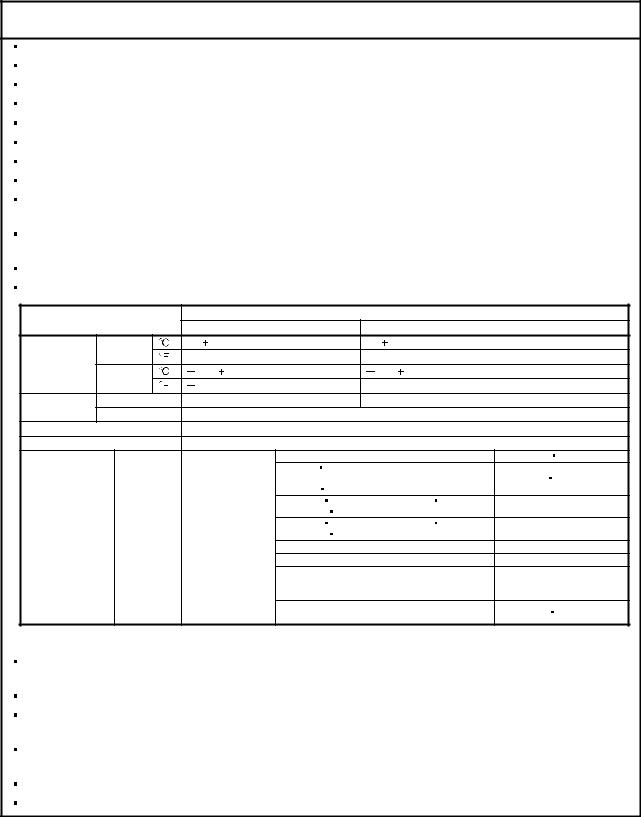
4. Additional instructions
The following instructions should also be fully noted. Incorrect handling may cause a fault, injury, electric shock, etc.
(1) Transportation and installation
 CAUTION
Transport the products correctly according to their weights.
Stacking in excess of the specified number of products is not allowed. Do not carry the servo motor by the cables, shaft or encoder.
Do not hold the front cover to transport the servo amplifier. The servo amplifier may drop. Install the servo amplifier in a load-bearing place in accordance with the Instruction Manual. Do not climb or stand on servo equipment. Do not put heavy objects on equipment.
The servo amplifier and servo motor must be installed in the specified direction.
Leave specified clearances between the servo amplifier and control enclosure walls or other equipment.
Do not install or operate the servo amplifier and servo motor which has been damaged or has any parts missing.
Provide adequate protection to prevent screws and other conductive matter, oil and other combustible matter from entering the servo amplifier and servo motor.
Do not drop or strike servo amplifier or servo motor. Isolate from all impact loads. When you keep or use it, please fulfill the following environmental conditions.
|
Environment |
Conditions |
||||||||||
|
Servo amplifier |
Servo motor |
||||||||||
|
Ambient |
In operation |
[ |
] |
0 to 55 (non-freezing) |
0 to |
40 (non-freezing) |
|||||
|
[ |
] |
32 to 131 (non-freezing) |
32 to 104 (non-freezing) |
||||||||
|
temperature |
In storage |
[ |
] |
20 to 65 (non-freezing) |
15 to 70 (non-freezing) |
||||||
|
[ |
] |
4 to 149 (non-freezing) |
5 to 158 (non-freezing) |
||||||||
|
Ambient |
In operation |
90%RH or less (non-condensing) |
80%RH or less (non-condensing) |
||||||||
|
humidity |
In storage |
90%RH or less (non-condensing) |
|||||||||
|
Ambience |
Indoors (no direct sunlight) Free from corrosive gas, flammable gas, oil mist, dust and dirt |
||||||||||
|
Altitude |
Max. 1000m (3280 ft) above sea level |
||||||||||
|
HF-MP series |
HF-KP series |
X |
Y: 49 |
||||||||
|
HF-SP51 |
81 |
HF-SP52 to 152 |
X |
Y: 24.5 |
|||||||
|
HF-SP524 to 1524 |
HC-RP Series |
||||||||||
|
HC-UP72 |
152 |
||||||||||
|
HF-SP121 |
201 |
HF-SP202 352 |
X: 24.5 Y: 49 |
||||||||
|
HF-SP2024 |
3524 |
HC-UP202 to 502 |
|||||||||
|
(Note) |
HF-SP301 |
421 |
HF-SP502 702 |
X: 24.5 Y: 29.4 |
|||||||
|
[m/s2] |
5.9 or less |
HF-SP5024 |
7024 |
||||||||
|
Vibration |
HC-LP52 to 152 |
X: 9.8 Y: 24.5 |
|||||||||
|
HC-LP202 to 302 |
X: 19.6 Y: 49 |
||||||||||
|
HA-LP601 to 12K1 |
HA-LP701M to 15K1M |
||||||||||
|
HA-LP502 to 22K2 |
HA-LP6014 to 12K14 |
X: 11.7 Y: 29.4 |
|||||||||
|
HA-LP701M4 to 15K1M4 |
HA-LP11K24 to 22K24 |
||||||||||
|
HA-LP15K1 to 25K1 |
HA-LP37K1M |
X |
Y: 9.8 |
||||||||
|
HA-LP15K14 to 20K14 |
HA-LP22K1M4 |
||||||||||
Note. Except the servo motor with a reduction gear.
Securely attach the servo motor to the machine. If attach insecurely, the servo motor may come off during operation.
The servo motor with a reduction gear must be installed in the specified direction to prevent oil leakage.
Take safety measures, e.g. provide covers, to prevent accidental access to the rotating parts of the servo motor during operation.
Never hit the servo motor or shaft, especially when coupling the servo motor to the machine. The encoder may become faulty.
Do not subject the servo motor shaft to more than the permissible load. Otherwise, the shaft may break. When the equipment has been stored for an extended period of time, consult Mitsubishi.
A — 3
(2) Wiring
 CAUTION
Wire the equipment correctly and securely. Otherwise, the servo motor may operate unexpectedly.
Do not install a power capacitor, surge absorber or radio noise filter (FR-BIF-(H) option) between the servo motor and servo amplifier.
Connect the wires to the correct phase terminals (U, V, W) of the servo amplifier and servo motor. Not doing so may cause unexpected operation.
Connect the servo motor power terminal (U, V, W) to the servo motor power input terminal (U, V, W) directly. Do not let a magnetic contactor, etc. intervene.
|
Servo amplifier |
U |
Servo motor |
Servo amplifier |
U |
Servo motor |
||
|
U |
U |
||||||
|
V |
V |
||||||
|
V |
M |
V |
M |
||||
|
W |
W |
||||||
|
W |
W |
||||||
Do not connect AC power directly to the servo motor. Otherwise, a fault may occur.
The surge absorbing diode installed on the DC output signal relay of the servo amplifier must be wired in the specified direction. Otherwise, the forced stop (EMG) and other protective circuits may not operate.
|
Servo amplifier |
Servo amplifier |
|
24VDC |
24VDC |
|
DOCOM |
DOCOM |
|
DICOM |
DICOM |
|
RA |
RA |
When the cable is not tightened enough to the terminal block (connector), the cable or terminal block (connector) may generate heat because of the poor contact. Be sure to tighten the cable with specified torque.
(3) Test run adjustment
 CAUTION
Before operation, check the parameter settings. Improper settings may cause some machines to perform unexpected operation.
The parameter settings must not be changed excessively. Operation will be insatiable.
A — 4
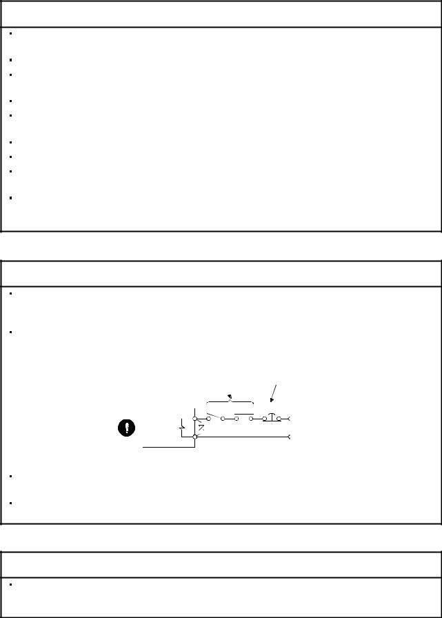
(4) Usage
 CAUTION
Provide an external emergency stop circuit to ensure that operation can be stopped and power switched off immediately.
Any person who is involved in disassembly and repair should be fully competent to do the work.
Before resetting an alarm, make sure that the run signal of the servo amplifier is off to prevent an accident. A sudden restart is made if an alarm is reset with the run signal on.
Do not modify the equipment.
Use a noise filter, etc. to minimize the influence of electromagnetic interference, which may be caused by electronic equipment used near the servo amplifier.
Burning or breaking a servo amplifier may cause a toxic gas. Do not burn or break a servo amplifier. Use the servo amplifier with the specified servo motor.
The electromagnetic brake on the servo motor is designed to hold the motor shaft and should not be used for ordinary braking.
For such reasons as service life and mechanical structure (e.g. where a ball screw and the servo motor are coupled via a timing belt), the electromagnetic brake may not hold the motor shaft. To ensure safety, install a stopper on the machine side.
(5) Corrective actions
 CAUTION
When it is assumed that a hazardous condition may take place at the occur due to a power failure or a product fault, use a servo motor with an electromagnetic brake or an external brake mechanism for the purpose of prevention.
Configure the electromagnetic brake circuit so that it is activated not only by the servo amplifier signals but also by an external forced stop (EMG).
Contacts must be open when servo-off, when an trouble (ALM) and when an electromagnetic brake interlock (MBR). 
Circuit must be opened during forced stop (EMG).
SON RA EMG
24VDC
Electromagnetic brake
When any alarm has occurred, eliminate its cause, ensure safety, and deactivate the alarm before restarting operation.
When power is restored after an instantaneous power failure, keep away from the machine because the machine may be restarted suddenly (design the machine so that it is secured against hazard if restarted).
(6) Maintenance, inspection and parts replacement
 CAUTION
With age, the electrolytic capacitor of the servo amplifier will deteriorate. To prevent a secondary accident due to a fault, it is recommended to replace the electrolytic capacitor every 10 years when used in general environment. Please consult our sales representative.
A — 5

(7) General instruction
To illustrate details, the equipment in the diagrams of this Specifications and Instruction Manual may have been drawn without covers and safety guards. When the equipment is operated, the covers and safety guards must be installed as specified. Operation must be performed in accordance with this Specifications and Instruction Manual.
About processing of waste
 About processing of waste
When you discard servo amplifier, a battery (primary battery), and other option articles, please follow the law of each country (area).
 FOR MAXIMUM SAFETY
These products have been manufactured as a general-purpose part for general industries, and have not been designed or manufactured to be incorporated in a device or system used in purposes related to human life.
Before using the products for special purposes such as nuclear power, electric power, aerospace, medicine, passenger movement vehicles or under water relays, contact Mitsubishi.
These products have been manufactured under strict quality control. However, when installing the product where major accidents or losses could occur if the product fails, install appropriate backup or failsafe functions in the system.
 EEP-ROM life
The number of write times to the EEP-ROM, which stores parameter settings, etc., is limited to 100,000. If the total number of the following operations exceeds 100,000, the servo amplifier and/or converter unit may fail when the EEP-ROM reaches the end of its useful life.
Write to the EEP-ROM due to parameter setting changes Home position setting in the absolute position detection system Write to the EEP-ROM due to device changes
Write to the EEP-ROM due to point table changes
Precautions for Choosing the Products
Mitsubishi will not be held liable for damage caused by factors found not to be the cause of Mitsubishi; machine damage or lost profits caused by faults in the Mitsubishi products; damage, secondary damage, accident compensation caused by special factors unpredictable by Mitsubishi; damages to products other than Mitsubishi products; and to other duties.
A — 6

COMPLIANCE WITH EC DIRECTIVES
1. WHAT ARE EC DIRECTIVES?
The EC directives were issued to standardize the regulations of the EU countries and ensure smooth distribution of safety-guaranteed products. In the EU countries, the machinery directive (effective in January, 1995), EMC directive (effective in January, 1996) and low voltage directive (effective in January, 1997) of the EC directives require that products to be sold should meet their fundamental safety requirements and carry the CE marks (CE marking). CE marking applies to machines and equipment into which servo amplifiers have been installed.
(1)EMC directive
The EMC directive applies not to the servo units alone but to servo-incorporated machines and equipment. This requires the EMC filters to be used with the servo-incorporated machines and equipment to comply with the EMC directive. For specific EMC directive conforming methods, refer to the EMC Installation Guidelines (IB(NA)67310).
(2)Low voltage directive
The low voltage directive applies also to servo units alone. Hence, they are designed to comply with the low voltage directive.
This servo is certified by TUV, third-party assessment organization, to comply with the low voltage directive.
(3)Machine directive
Not being machines, the servo amplifiers need not comply with this directive.
2. PRECAUTIONS FOR COMPLIANCE
(1)Servo amplifiers and servo motors used
Use the servo amplifiers and servo motors which comply with the standard model.
|
Servo amplifier |
:MR-J3-10T to MR-J3-22KT |
|
|
MR-J3-10T1 to MR-J3-40T1 |
||
|
MR-J3-60T4 to MR-J3-22KT4 |
||
|
Servo motor |
:HF-MP |
|
|
HF-KP |
||
|
HF-SP |
(Note) |
|
|
HF-SP |
4 (Note) |
|
|
HC-RP |
||
|
HC-UP |
||
|
HC-LP |
||
|
HA-LP |
(Note) |
|
|
HA-LP |
4 (Note) |
Note. For the latest information of compliance, contact Mitsubishi.
A — 7
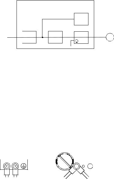
(2)Configuration
The control circuit provide safe separation to the main circuit in the servo amplifier.
|
Control box |
||||||||||||||
|
Reinforced |
||||||||||||||
|
insulating type |
||||||||||||||
|
24VDC |
||||||||||||||
|
No-fuse |
Magnetic |
power |
||||||||||||
|
supply |
Servo |
|||||||||||||
|
breaker |
contactor |
|||||||||||||
|
motor |
||||||||||||||
|
Servo |
M |
|||||||||||||
|
NFB |
MC |
amplifier |
||||||||||||
(3)Environment
Operate the servo amplifier at or above the contamination level 2 set forth in IEC60664-1. For this purpose, install the servo amplifier in a control box which is protected against water, oil, carbon, dust, dirt, etc. (IP54).
(4)Power supply
(a)This servo amplifier can be supplied from star-connected supply with earthed neutral point of overvoltage category III set forth in IEC60664-1. However, when using the neutral point of 400V class for single-phase supply, a reinforced insulating transformer is required in the power input section.
(b)When supplying interface power from external, use a 24VDC power supply which has been insulationreinforced in I/O.
(5)Grounding
(a)To prevent an electric shock, always connect the protective earth (PE) terminals (marked  ) of the servo amplifier to the protective earth (PE) of the control box.
(b)Do not connect two ground cables to the same protective earth (PE) terminal (marked  ). Always connect the cables to the terminals one-to-one.
|
PE terminals |
||||||||||||||||||||||||||||||||||||
|
PE terminals |
(c)If a leakage current breaker is used to prevent an electric shock, the protective earth (PE) terminals (marked  ) of the servo amplifier must be connected to the corresponding earth terminals.
A — 8
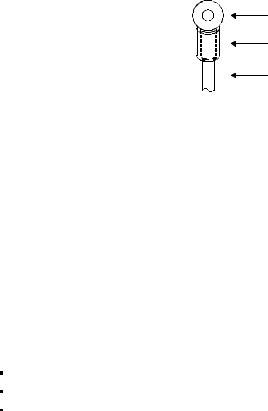
(6)Wiring
(a)The cables to be connected to the terminal block of the servo amplifier must have crimping terminals provided with insulating tubes to prevent contact with adjacent terminals.
Crimping terminal
Insulating tube
Cable
(b)Use the servo motor side power connector which complies with the EN Standard. The EN Standard compliant power connector sets are available from us as options. (Refer to section 14.1)
(7)Auxiliary equipment and options
(a)The no-fuse breaker and magnetic contactor used should be the EN or IEC standard-compliant products of the models described in section 14.10.
Use a type B (Note) breaker. When it is not used, provide insulation between the servo amplifier and other device by double insulation or reinforced insulation, or install a transformer between the main power supply and servo amplifier.
Note. Type A: AC and pulse detectable Type B: Both AC and DC detectable
(b)The sizes of the cables described in section 14.9 meet the following requirements. To meet the other requirements, follow Table 5 and Appendix C in EN60204-1.
Ambient temperature: 40 (104) [°C (°F)] Sheath: PVC (polyvinyl chloride)
Installed on wall surface or open table tray
(c)Use the EMC filter for noise reduction.
(8)Performing EMC tests
When EMC tests are run on a machine/device into which the servo amplifier has been installed, it must conform to the electromagnetic compatibility (immunity/emission) standards after it has satisfied the operating environment/electrical equipment specifications.
For the other EMC directive guidelines on the servo amplifier, refer to the EMC Installation Guidelines (IB(NA)67310).
A — 9
![]()
CONFORMANCE WITH UL/C-UL STANDARD
(1)Servo amplifiers and servo motors used
Use the servo amplifiers and servo motors which comply with the standard model.
|
Servo amplifier |
:MR-J3-10T to MR-J3-22KT |
|
|
MR-J3-10T1 to MR-J3-40T1 |
||
|
MR-J3-60T4 to MR-J3-22KT4 |
||
|
Servo motor |
:HF-MP |
|
|
HF-KP |
||
|
HF-SP |
(Note) |
|
|
HF-SP |
4 (Note) |
|
|
HC-RP |
||
|
HC-UP |
||
|
HC-LP |
||
|
HA-LP |
(Note) |
|
|
HA-LP |
4 (Note) |
Note. For the latest information of compliance, contact Mitsubishi.
(2)Installation
Install a fan of 100CFM (2.8m3/min) air flow 4[in] (10.16[cm]) above the servo amplifier or provide cooling of at least equivalent capability to ensure that the ambient temperature conforms to the environment conditions (55 or less).
(3)Short circuit rating (SCCR: Short Circuit Current Rating)
Suitable For Use In A Circuit Capable Of Delivering Not More Than 100 kA rms Symmetrical Amperes, 500 Volts Maximum.
(4)Capacitor discharge time
The capacitor discharge time is as listed below. To ensure safety, do not touch the charging section for 15 minutes after power-off.
|
Servo amplifier |
Discharge time |
|
|
[min] |
||
|
MR-J3-10T 20T |
1 |
|
|
MR-J3-40T 60T(4) 10T1 20T1 |
2 |
|
|
MR-J3-70T |
3 |
|
|
MR-J3-40T1 |
4 |
|
|
MR-J3-100T(4) |
5 |
|
|
MR-J3-200T(4) 350T |
9 |
|
|
MR-J3-350T4 500T(4) 700T(4) |
10 |
|
|
MR-J3-11KT(4) |
4 |
|
|
MR-J3-15KT(4) |
6 |
|
|
MR-J3-22KT(4) |
8 |
A — 10

(5)Options and auxiliary equipment
Use UL/C-UL standard-compliant products.
(6)Attachment of a servo motor
For the flange size of the machine side where the servo motor is installed, refer to “CONFORMANCE WITH UL/C-UL STANDARD” in the Servo Motor Instruction Manual (Vol.2).
(7)About wiring protection
For installation in United States, branch circuit protection must be provided, in accordance with the National Electrical Code and any applicable local codes.
For installation in Canada, branch circuit protection must be provided, in accordance with the Canada Electrical Code and any applicable provincial codes.
<<About the manuals>>
This Instruction Manual and the MELSERVO Servo Motor Instruction Manual (Vol.2) are required if you use the General-Purpose AC servo MR-J3-T for the first time. Always purchase them and use the MR-J3-T safely.
Relevant manuals
|
Manual name |
Manual No. |
|
MELSERVO-J3 Series Instructions and Cautions for Safe Use of AC Servos |
IB(NA)0300077 |
|
MELSERVO Servo Motor Instruction Manual (Vol.2) |
SH(NA)030041 |
|
EMC Installation Guidelines |
IB(NA)67310 |
<<About the wires used for wiring>>
Wiring wires mentioned in this instruction manual are selected based on the ambient temperature of 40°C (104 ).
).
A — 11

MEMO
A — 12

CONTENTS
|
1. FUNCTIONS AND CONFIGURATION |
1 — 1 to 1 -36 |
|
1.1 Introduction…………………………………………………………………………………………………………………………….. |
1 — 1 |
|
1.1.1 Features of CC-Link communication functions …………………………………………………………………….. |
1 — 1 |
|
1.1.2 Function block diagram……………………………………………………………………………………………………… |
1 — 2 |
|
1.1.3 System configuration…………………………………………………………………………………………………………. |
1 — 5 |
|
1.2 Servo amplifier standard specifications……………………………………………………………………………………… |
1 — 7 |
|
1.3 |
Function list …………………………………………………………………………………………………………………………… |
1 |
-13 |
|
1.4 |
Model code definition ……………………………………………………………………………………………………………… |
1 |
-15 |
|
1.5 |
Combination with servo motor …………………………………………………………………………………………………. |
1 |
-16 |
|
1.6 |
Structure ……………………………………………………………………………………………………………………………….. |
1 |
-17 |
|
1.6.1 Parts identification ……………………………………………………………………………………………………………. |
1 |
-17 |
|
|
1.6.2 Removal and reinstallation of the front cover………………………………………………………………………. |
1 |
-23 |
|
|
1.7 |
Configuration including auxiliary equipment ……………………………………………………………………………… |
1 |
-26 |
|
1.8 |
Selection of operation method…………………………………………………………………………………………………. |
1 |
-34 |
|
2. INSTALLATION |
2 — 1 to 2 — 4 |
||
|
2.1 |
Installation direction and clearances …………………………………………………………………………………………. |
2 — 1 |
|
|
2.2 |
Keep out foreign materials……………………………………………………………………………………………………….. |
2 — 3 |
|
|
2.3 |
Cable stress …………………………………………………………………………………………………………………………… |
2 — 3 |
|
|
2.4 |
Inspection items ……………………………………………………………………………………………………………………… |
2 — 4 |
|
|
2.5 |
Parts having service lives ………………………………………………………………………………………………………… |
2 — 4 |
|
|
3. CC-LINK COMMUNICATION FUNCTIONS |
3 — 1 to 3 -60 |
||
|
3.1 |
Communication specifications ………………………………………………………………………………………………….. |
3 — 1 |
|
|
3.2 |
System configuration ………………………………………………………………………………………………………………. |
3 — 2 |
|
|
3.2.1 Configuration example ………………………………………………………………………………………………………. |
3 — 2 |
||
|
3.2.2 Wiring method ………………………………………………………………………………………………………………….. |
3 — 3 |
||
|
3.2.3 Station number setting ………………………………………………………………………………………………………. |
3 — 5 |
||
|
3.2.4 Communication baud rate setting……………………………………………………………………………………….. |
3 — 6 |
||
|
3.2.5 Occupied station count setting……………………………………………………………………………………………. |
3 — 6 |
||
|
3.3 |
Functions ……………………………………………………………………………………………………………………………….. |
3 — 7 |
|
|
3.3.1 Function block diagram……………………………………………………………………………………………………… |
3 — 7 |
||
|
3.3.2 Functions …………………………………………………………………………………………………………………………. |
3 — 7 |
||
|
3.4 |
Servo amplifier setting …………………………………………………………………………………………………………….. |
3 — 8 |
|
|
3.5 |
I/O signals (I/O devices) transferred to/from the programmable controller CPU…………………………….. |
3 — 9 |
|
|
3.5.1 I/O signals (I/O devices)…………………………………………………………………………………………………….. |
3 — 9 |
||
|
3.5.2 Detailed explanation of I/O signals …………………………………………………………………………………….. |
3 -12 |
||
|
3.5.3 Monitor codes………………………………………………………………………………………………………………….. |
3 -22 |
||
|
3.5.4 Instruction codes (RWwn+2 RWwn+3) …………………………………………………………………………….. |
3 -23 |
||
|
3.5.5 Respond codes (RWrn+2) ………………………………………………………………………………………………… |
3 -31 |
||
|
3.5.6 Setting the CN6 external input signals ……………………………………………………………………………….. |
3 -32 |
||
|
3.6 |
Data communication timing charts …………………………………………………………………………………………… |
3 -34 |
|
|
3.6.1 Monitor codes………………………………………………………………………………………………………………….. |
3 -34 |
||
|
3.6.2 Instruction codes ……………………………………………………………………………………………………………… |
3 -36 |
||
|
1 |

|
3.6.3 Remote register-based position/speed setting…………………………………………………………………….. |
3 |
-38 |
|
|
3.7 |
Function-by-function programming examples……………………………………………………………………………. |
3 |
-41 |
|
3.7.1 System configuration example…………………………………………………………………………………………… |
3 |
-41 |
|
|
3.7.2 Reading the servo amplifier status …………………………………………………………………………………….. |
3 |
-44 |
|
|
3.7.3 Writing the operation commands……………………………………………………………………………………….. |
3 |
-45 |
|
|
3.7.4 Reading the data……………………………………………………………………………………………………………… |
3 |
-46 |
|
|
3.7.5 Writing the data ……………………………………………………………………………………………………………….. |
3 |
-49 |
|
|
3.7.6 Operation………………………………………………………………………………………………………………………… |
3 |
-52 |
|
|
3.8 |
Continuous operation program example…………………………………………………………………………………… |
3 |
-55 |
|
3.8.1 System configuration example when 1 station is occupied …………………………………………………… |
3 |
-55 |
|
|
3.8.2 Program example when 1 station is occupied …………………………………………………………………….. |
3 |
-56 |
|
|
3.8.3 System configuration example when 2 stations are occupied……………………………………………….. |
3 |
-58 |
|
|
3.8.4 Program example when 2 stations are occupied…………………………………………………………………. |
3 |
-59 |
|
|
4. SIGNALS AND WIRING |
4 — 1 to 4 -54 |
||
|
4.1 |
Input power supply circuit ………………………………………………………………………………………………………… |
4 — 2 |
|
|
4.2 |
I/O signal connection diagram …………………………………………………………………………………………………. |
4 -10 |
|
|
4.3 |
Explanation of power supply system………………………………………………………………………………………… |
4 -11 |
|
|
4.3.1 Signal explanations ………………………………………………………………………………………………………….. |
4 -11 |
||
|
4.3.2 Power-on sequence …………………………………………………………………………………………………………. |
4 -12 |
||
|
4.3.3 CNP1, CNP2, CNP3 wiring method …………………………………………………………………………………… |
4 -14 |
||
|
4.4 |
Connectors and signal arrangements ………………………………………………………………………………………. |
4 -22 |
|
|
4.5 |
Signal (device) explanation……………………………………………………………………………………………………… |
4 -23 |
|
|
4.5.1 I/O devices………………………………………………………………………………………………………………………. |
4 -23 |
||
|
4.5.2 Input signals ……………………………………………………………………………………………………………………. |
4 -26 |
||
|
4.5.3 Output signals………………………………………………………………………………………………………………….. |
4 -26 |
||
|
4.5.4 Power supply…………………………………………………………………………………………………………………… |
4 -27 |
||
|
4.6 |
Detailed description of signals (devices)…………………………………………………………………………………… |
4 -27 |
|
|
4.6.1 Forward rotation start |
reverse rotation start temporary stop/restart……………………………………. |
4 -27 |
|
|
4.6.2 Movement completion |
rough match in position ……………………………………………………………….. |
4 -28 |
|
|
4.6.3 Torque limit……………………………………………………………………………………………………………………… |
4 -30 |
||
|
4.7 |
Alarm occurrence timing chart…………………………………………………………………………………………………. |
4 -31 |
|
|
4.8 |
Interface………………………………………………………………………………………………………………………………… |
4 -32 |
|
|
4.8.1 Internal connection diagram ……………………………………………………………………………………………… |
4 -32 |
||
|
4.8.2 Detailed description of interfaces……………………………………………………………………………………….. |
4 -33 |
||
|
4.8.3 Source I/O interfaces ……………………………………………………………………………………………………….. |
4 -35 |
||
|
4.9 |
Treatment of cable shield external conductor ……………………………………………………………………………. |
4 -36 |
|
|
4.10 Connection of servo amplifier and servo motor ……………………………………………………………………….. |
4 -37 |
||
|
4.10.1 Connection instructions…………………………………………………………………………………………………… |
4 -37 |
||
|
4.10.2 Power supply cable wiring diagrams………………………………………………………………………………… |
4 -38 |
||
|
4.11 Servo motor with an electromagnetic brake…………………………………………………………………………….. |
4 -48 |
||
|
4.11.1 Safety precautions …………………………………………………………………………………………………………. |
4 -48 |
||
|
4.11.2 Timing charts…………………………………………………………………………………………………………………. |
4 -49 |
||
|
4.11.3 Wiring diagrams (HF-MP series HF-KP series servo motor) …………………………………………….. |
4 -52 |
||
|
4.12 Grounding……………………………………………………………………………………………………………………………. |
4 -53 |
2

|
5. OPERATION |
5 — 1 to 5 -60 |
||
|
5.1 Switching power on for the first time …………………………………………………………………………………………. |
5 — 1 |
||
|
5.1.1 Startup procedure……………………………………………………………………………………………………………… |
5 — 1 |
||
|
5.1.2 Wiring check …………………………………………………………………………………………………………………….. |
5 — 2 |
||
|
5.1.3 Surrounding environment…………………………………………………………………………………………………… |
5 — 3 |
||
|
5.2 Startup …………………………………………………………………………………………………………………………………… |
5 — 4 |
||
|
5.2.1 Power on and off procedures……………………………………………………………………………………………… |
5 — 4 |
||
|
5.2.2 Stop…………………………………………………………………………………………………………………………………. |
5 — 4 |
||
|
5.2.3 Test operation…………………………………………………………………………………………………………………… |
5 — 5 |
||
|
5.2.4 Parameter setting……………………………………………………………………………………………………………… |
5 — 6 |
||
|
5.2.5 Point table setting……………………………………………………………………………………………………………… |
5 — 7 |
||
|
5.2.6 Actual operation ……………………………………………………………………………………………………………….. |
5 — 7 |
||
|
5.3 Servo amplifier display…………………………………………………………………………………………………………….. |
5 — 8 |
||
|
5.4 Automatic operation mode………………………………………………………………………………………………………. |
5 |
-10 |
|
|
5.4.1 What is automatic operation mode?…………………………………………………………………………………… |
5 |
-10 |
|
|
5.4.2 Automatic operation using point table ………………………………………………………………………………… |
5 |
-12 |
|
|
5.4.3 Remote register-based position/speed setting…………………………………………………………………….. |
5 |
-22 |
|
|
5.5 Manual operation mode ………………………………………………………………………………………………………….. |
5 |
-28 |
|
|
5.5.1 JOG operation …………………………………………………………………………………………………………………. |
5 |
-28 |
|
|
5.5.2 Manual pulse generator ……………………………………………………………………………………………………. |
5 |
-29 |
|
|
5.6 Manual home position return mode………………………………………………………………………………………….. |
5 |
-31 |
|
|
5.6.1 Outline of home position return………………………………………………………………………………………….. |
5 |
-31 |
|
|
5.6.2 Dog type home position return…………………………………………………………………………………………… |
5 |
-34 |
|
|
5.6.3 Count type home position return ……………………………………………………………………………………….. |
5 |
-36 |
|
|
5.6.4 Data setting type home position return……………………………………………………………………………….. |
5 |
-38 |
|
|
5.6.5 Stopper type home position return …………………………………………………………………………………….. |
5 |
-39 |
|
|
5.6.6 Home position ignorance (servo-on position defined as home position) ………………………………… |
5 |
-41 |
|
|
5.6.7 Dog type rear end reference home position return ………………………………………………………………. |
5 |
-42 |
|
|
5.6.8 Count type front end reference home position return …………………………………………………………… |
5 |
-44 |
|
|
5.6.9 Dog cradle type home position return ………………………………………………………………………………… |
5 |
-46 |
|
|
5.6.10 Dog type first Z-phase reference home position return ………………………………………………………. |
5 |
-48 |
|
|
5.6.11 Dog type front end reference home position return method………………………………………………… |
5 |
-50 |
|
|
5.6.12 Dogless Z-phase reference home position return method ………………………………………………….. |
5 |
-52 |
|
|
5.6.13 Home position return automatic return function…………………………………………………………………. |
5 |
-54 |
|
|
5.6.14 Automatic positioning function to the home position…………………………………………………………… |
5 |
-55 |
|
|
5.7 Roll feed display function in roll feed mode……………………………………………………………………………….. |
5 |
-56 |
|
|
5.8 Absolute position detection system ………………………………………………………………………………………….. |
5 |
-57 |
|
|
6. PARAMETERS |
6 — 1 to 6 -40 |
||
|
6.1 Basic setting parameters (No.PA |
)……………………………………………………………………………………… |
6 — 1 |
|
|
6.1.1 Parameter list …………………………………………………………………………………………………………………… |
6 — 1 |
||
|
6.1.2 Parameter write inhibit ………………………………………………………………………………………………………. |
6 — 2 |
||
|
6.1.3 Selection of command system……………………………………………………………………………………………. |
6 — 3 |
||
|
6.1.4 Selection of regenerative option …………………………………………………………………………………………. |
6 — 3 |
||
|
6.1.5 Using absolute position detection system ……………………………………………………………………………. |
6 — 4 |
||
|
6.1.6 Follow-up for absolute value command system in incremental system…………………………………… |
6 — 4 |
||
|
6.1.7 Feeding function selection …………………………………………………………………………………………………. |
6 — 5 |
3

|
6.1.8 Electronic gear………………………………………………………………………………………………………………….. |
6 — 6 |
|||||
|
6.1.9 Auto tuning ………………………………………………………………………………………………………………………. |
6 — 7 |
|||||
|
6.1.10 In-position range……………………………………………………………………………………………………………… |
6 — 8 |
|||||
|
6.1.11 Torque limit…………………………………………………………………………………………………………………….. |
6 — 9 |
|||||
|
6.1.12 Selection of servo motor rotation direction………………………………………………………………………… |
6 |
-10 |
||||
|
6.1.13 Encoder output pulse ……………………………………………………………………………………………………… |
6 |
-10 |
||||
|
6.2 |
Gain/filter parameters (No. PB |
)………………………………………………………………………………………… |
6 |
-12 |
||
|
6.2.1 Parameter list ………………………………………………………………………………………………………………….. |
6 |
-12 |
||||
|
6.2.2 Detail list …………………………………………………………………………………………………………………………. |
6 |
-13 |
||||
|
6.3 |
Extension setting parameters (No. PC |
) …………………………………………………………………………….. |
6 |
-20 |
||
|
6.3.1 Parameter list ………………………………………………………………………………………………………………….. |
6 |
-20 |
||||
|
6.3.2 Detail list …………………………………………………………………………………………………………………………. |
6 |
-21 |
||||
|
6.3.3 S-pattern acceleration/deceleration……………………………………………………………………………………. |
6 |
-27 |
||||
|
6.3.4 Alarm history clear……………………………………………………………………………………………………………. |
6 |
-27 |
||||
|
6.3.5 Rough match output…………………………………………………………………………………………………………. |
6 |
-27 |
||||
|
6.3.6 Software limit …………………………………………………………………………………………………………………… |
6 |
-28 |
||||
|
6.4 |
I/O setting parameters (No. PD |
)……………………………………………………………………………………….. |
6 |
-29 |
||
|
6.4.1 Parameter list ………………………………………………………………………………………………………………….. |
6 |
-29 |
||||
|
6.4.2 Detail list …………………………………………………………………………………………………………………………. |
6 |
-30 |
||||
|
6.4.3 Stopping method when the forward stroke end (LSP) or reverse stroke end (LSN) is valid……… |
6 |
-38 |
||||
|
6.4.4 Stopping method when a software limit is detected……………………………………………………………… |
6 |
-39 |
||||
|
7. MR Configurator |
7 — 1 to 7 -26 |
|||||
|
7.1 |
Specifications …………………………………………………………………………………………………………………………. |
7 — 1 |
||||
|
7.2 |
System configuration ………………………………………………………………………………………………………………. |
7 — 2 |
||||
|
7.3 |
Station selection……………………………………………………………………………………………………………………… |
7 — 4 |
||||
|
7.4 |
Parameters…………………………………………………………………………………………………………………………….. |
7 — 5 |
||||
|
7.5 |
Point table………………………………………………………………………………………………………………………………. |
7 — 7 |
||||
|
7.6 |
Device assignment method ……………………………………………………………………………………………………… |
7 — 9 |
||||
|
7.7 |
Test operation ……………………………………………………………………………………………………………………….. |
7 |
-13 |
|||
|
7.7.1 Jog operation…………………………………………………………………………………………………………………… |
7 |
-13 |
||||
|
7.7.2 Positioning operation………………………………………………………………………………………………………… |
7 |
-15 |
||||
|
7.7.3 Motor-less operation ………………………………………………………………………………………………………… |
7 |
-18 |
||||
|
7.7.4 Output signal (DO) forced output……………………………………………………………………………………….. |
7 |
-19 |
||||
|
7.7.5 Single-step feed ………………………………………………………………………………………………………………. |
7 |
-20 |
||||
|
7.8 |
Alarm ……………………………………………………………………………………………………………………………………. |
7 |
-23 |
|||
|
7.8.1 Alarm display…………………………………………………………………………………………………………………… |
7 |
-23 |
||||
|
7.8.2 Batch display of data at alarm occurrence ………………………………………………………………………….. |
7 |
-24 |
||||
|
7.8.3 Alarm history……………………………………………………………………………………………………………………. |
7 |
-26 |
||||
|
8. PARAMETER UNIT (MR-PRU03) |
8 — 1 to 8 -20 |
|||||
|
8.1 |
External appearance and key explanations ……………………………………………………………………………….. |
8 — 2 |
||||
|
8.2 |
Specifications …………………………………………………………………………………………………………………………. |
8 — 3 |
||||
|
8.3 |
Outline dimension drawings……………………………………………………………………………………………………… |
8 — 3 |
||||
|
8.4 |
Connection with servo amplifier………………………………………………………………………………………………… |
8 — 4 |
||||
|
8.4.1 Single axis ……………………………………………………………………………………………………………………….. |
8 — 4 |
|||||
|
8.4.2 Multidrop connection …………………………………………………………………………………………………………. |
8 — 5 |
4

|
8.5 Display…………………………………………………………………………………………………………………………………… |
8 — 7 |
|
|
8.5.1 Outline of screen transition ………………………………………………………………………………………………… |
8 — 7 |
|
|
8.5.2 MR-PRU03 parameter unit setting ……………………………………………………………………………………… |
8 — 8 |
|
|
8.5.3 Monitor mode (status display)…………………………………………………………………………………………….. |
8 — 9 |
|
|
8.5.4 Alarm/diagnostic mode …………………………………………………………………………………………………….. |
8 -11 |
|
|
8.5.5 Parameter mode………………………………………………………………………………………………………………. |
8 -13 |
|
|
8.5.6 Point table mode ……………………………………………………………………………………………………………… |
8 -14 |
|
|
8.5.7 Test operation mode ………………………………………………………………………………………………………… |
8 -15 |
|
|
8.6 Error message list ………………………………………………………………………………………………………………….. |
8 -19 |
|
|
9. GENERAL GAIN ADJUSTMENT |
9 — 1 to 9 -12 |
|
|
9.1 Different adjustment methods…………………………………………………………………………………………………… |
9 — 1 |
|
|
9.1.1 Adjustment on a single servo amplifier………………………………………………………………………………… |
9 — 1 |
|
|
9.1.2 Adjustment using MR Configurator……………………………………………………………………………………… |
9 — 2 |
|
|
9.2 Auto tuning …………………………………………………………………………………………………………………………….. |
9 — 3 |
|
|
9.2.1 Auto tuning mode ……………………………………………………………………………………………………………… |
9 — 3 |
|
|
9.2.2 Auto tuning mode operation……………………………………………………………………………………………….. |
9 — 4 |
|
|
9.2.3 Adjustment procedure by auto tuning………………………………………………………………………………….. |
9 — 5 |
|
|
9.2.4 Response level setting in auto tuning mode ………………………………………………………………………… |
9 — 6 |
|
|
9.3 Manual mode 1 (simple manual adjustment)……………………………………………………………………………… |
9 — 7 |
|
|
9.4 Interpolation mode …………………………………………………………………………………………………………………. |
9 -11 |
|
|
9.5 Differences between MELSERVO-J2-Super and MELSERVO-J3 in auto tuning………………………….. |
9 -12 |
|
|
10. SPECIAL ADJUSTMENT FUNCTIONS |
10- 1 to 10-16 |
|
|
10.1 |
Function block diagram…………………………………………………………………………………………………………. |
10- 1 |
|
10.2 |
Adaptive filter …………………………………………………………………………………………………………………….. |
10- 1 |
|
10.3 |
Machine resonance suppression filter…………………………………………………………………………………….. |
10- 4 |
|
10.4 |
Advanced vibration suppression control …………………………………………………………………………………. |
10- 6 |
|
10.5 |
Low-pass filter …………………………………………………………………………………………………………………….. |
10-10 |
|
10.6 |
Gain changing function ………………………………………………………………………………………………………… |
10-10 |
|
10.6.1 Applications ………………………………………………………………………………………………………………….. |
10-10 |
|
|
10.6.2 Function block diagram………………………………………………………………………………………………….. |
10-11 |
|
|
10.6.3 Parameters…………………………………………………………………………………………………………………… |
10-12 |
|
|
10.6.4 Gain changing operation………………………………………………………………………………………………… |
10-14 |
|
|
11. TROUBLESHOOTING |
11- 1 to 11-14 |
|
|
11.1 |
Trouble at start-up………………………………………………………………………………………………………………… |
11- 1 |
|
11.2 |
Operation at error occurrence ……………………………………………………………………………………………….. |
11- 2 |
|
11.3 |
CC-Link communication error………………………………………………………………………………………………… |
11- 2 |
|
11.4 When alarm or warning has occurred …………………………………………………………………………………….. |
11- 3 |
|
|
11.4.1 Alarms and warning list…………………………………………………………………………………………………… |
11- 3 |
|
|
11.4.2 Remedies for alarms………………………………………………………………………………………………………. |
11- 4 |
|
|
11.4.3 Remedies for warnings ………………………………………………………………………………………………….. |
11-11 |
|
|
11.5 |
Point table error…………………………………………………………………………………………………………………… |
11-13 |
5
|
12. OUTLINE DRAWINGS |
12- 1 to 12-12 |
||
|
12.1 |
Servo amplifier …………………………………………………………………………………………………………………….. |
12- 1 |
|
|
12.2 |
Connector…………………………………………………………………………………………………………………………… |
12-10 |
|
|
13. CHARACTERISTICS |
13- 1 to 13-10 |
||
|
13.1 |
Overload protection characteristics ………………………………………………………………………………………… |
13- 1 |
|
|
13.2 |
Power supply equipment capacity and generated loss …………………………………………………………….. |
13- 3 |
|
|
13.3 |
Dynamic brake characteristics……………………………………………………………………………………………….. |
13- 6 |
|
|
13.3.1 Dynamic brake operation………………………………………………………………………………………………… |
13- 6 |
||
|
13.3.2 The dynamic brake at the load inertia moment………………………………………………………………….. |
13- 9 |
||
|
13.4 |
Cable flexing life………………………………………………………………………………………………………………….. |
13-10 |
|
|
13.5 |
Inrush currents at power-on of main circuit and control circuit………………………………………………….. |
13-10 |
|
|
14. OPTIONS AND AUXILIARY EQUIPMENT |
14- 1 to 14-90 |
||
|
14.1 |
Cable/connector sets ……………………………………………………………………………………………………………. |
14- 1 |
|
|
14.1.1 Combinations of cable/connector sets ……………………………………………………………………………… |
14- 2 |
||
|
14.1.2 Encoder cable/connector sets …………………………………………………………………………………………. |
14- 8 |
||
|
14.1.3 Motor power supply cables …………………………………………………………………………………………….. |
14-17 |
||
|
14.1.4 Motor brake cables………………………………………………………………………………………………………… |
14-18 |
||
|
14.2 |
Regenerative options …………………………………………………………………………………………………………… |
14-19 |
|
|
14.3 |
FR-BU2-(H) brake unit…………………………………………………………………………………………………………. |
14-32 |
|
|
14.3.1 Selection………………………………………………………………………………………………………………………. |
14-33 |
||
|
14.3.2 Brake unit parameter setting…………………………………………………………………………………………… |
14-33 |
||
|
14.3.3 Connection example ……………………………………………………………………………………………………… |
14-34 |
||
|
14.3.4 Outline dimension drawings……………………………………………………………………………………………. |
14-41 |
||
|
14.4 |
Power regeneration converter ………………………………………………………………………………………………. |
14-43 |
|
|
14.5 |
Power regeneration common converter…………………………………………………………………………………. |
14-46 |
|
|
14.6 |
External dynamic brake ……………………………………………………………………………………………………….. |
14-54 |
|
|
14.7 |
Battery MR-J3BAT ………………………………………………………………………………………………………………. |
14-59 |
|
|
14.8 |
Heat sink outside mounting attachment (MR-J3ACN)……………………………………………………………… |
14-60 |
|
|
14.9 |
Selection example of wires…………………………………………………………………………………………………… |
14-62 |
|
|
14.10 |
No-fuse breakers, fuses, magnetic contactors ……………………………………………………………………… |
14-68 |
|
|
14.11 |
Power factor improving DC reactor ……………………………………………………………………………………… |
14-69 |
|
|
14.12 |
Power factor improving reactors………………………………………………………………………………………….. |
14-71 |
|
|
14.13 |
Relays (recommended) ……………………………………………………………………………………………………… |
14-73 |
|
|
14.14 |
Surge absorbers (recommended) ……………………………………………………………………………………….. |
14-73 |
|
|
14.15 |
Noise reduction techniques ………………………………………………………………………………………………… |
14-74 |
|
|
14.16 |
Leakage current breaker…………………………………………………………………………………………………….. |
14-81 |
|
|
14.17 |
EMC filter (recommended) …………………………………………………………………………………………………. |
14-83 |
|
|
14.18 |
MR-HDP01 manual pulse generator……………………………………………………………………………………. |
14-88 |
|
|
15. COMMUNICATION FUNCTION |
15- 1 to 15-46 |
||
|
15.1 |
Configuration……………………………………………………………………………………………………………………….. |
15- 1 |
|
|
15.2 |
Communication specifications ……………………………………………………………………………………………….. |
15- 3 |
|
|
15.2.1 Communication overview………………………………………………………………………………………………… |
15- 3 |
||
|
15.2.2 Parameter setting…………………………………………………………………………………………………………… |
15- 4 |
6

|
15.3 Protocol ………………………………………………………………………………………………………………………………. |
15- 5 |
|
|
15.3.1 Transmission data configuration………………………………………………………………………………………. |
15- 5 |
|
|
15.3.2 Character codes…………………………………………………………………………………………………………….. |
15- 6 |
|
|
15.3.3 Error codes ……………………………………………………………………………………………………………………. |
15- 7 |
|
|
15.3.4 Checksum……………………………………………………………………………………………………………………… |
15- 7 |
|
|
15.3.5 Time-out operation …………………………………………………………………………………………………………. |
15- 8 |
|
|
15.3.6 Retry operation………………………………………………………………………………………………………………. |
15- 8 |
|
|
15.3.7 Initialization……………………………………………………………………………………………………………………. |
15- 9 |
|
|
15.3.8 Communication procedure example…………………………………………………………………………………. |
15- 9 |
|
|
15.4 Command and data No. list ………………………………………………………………………………………………….. |
15-10 |
|
|
15.4.1 Read commands …………………………………………………………………………………………………………… |
15-10 |
|
|
15.4.2 Write commands …………………………………………………………………………………………………………… |
15-14 |
|
|
15.5 Detailed explanations of commands ……………………………………………………………………………………… |
15-17 |
|
|
15.5.1 Data processing ……………………………………………………………………………………………………………. |
15-17 |
|
|
15.5.2 Status display ……………………………………………………………………………………………………………….. |
15-19 |
|
|
15.5.3 Parameters…………………………………………………………………………………………………………………… |
15-20 |
|
|
15.5.4 External I/O signal statuses (DIO diagnosis) ……………………………………………………………………. |
15-23 |
|
|
15.5.5 Device ON/OFF…………………………………………………………………………………………………………….. |
15-28 |
|
|
15.5.6 Disable/enable of I/O devices (DIO)………………………………………………………………………………… |
15-29 |
|
|
15.5.7 Input devices ON/OFF (test operation) ……………………………………………………………………………. |
15-30 |
|
|
15.5.8 Test operation mode ……………………………………………………………………………………………………… |
15-31 |
|
|
15.5.9 Alarm history…………………………………………………………………………………………………………………. |
15-37 |
|
|
15.5.10 Current alarm ……………………………………………………………………………………………………………… |
15-38 |
|
|
15.5.11 Point table…………………………………………………………………………………………………………………… |
15-39 |
|
|
15.5.12 Servo amplifier group designation…………………………………………………………………………………. |
15-45 |
|
|
15.5.13 Other commands…………………………………………………………………………………………………………. |
15-46 |
|
|
16. INDEXER POSITIONING OPERATION |
16- 1 to 16-112 |
|
|
16.1 Function………………………………………………………………………………………………………………………………. |
16- 1 |
|
|
16.1.1 Overview……………………………………………………………………………………………………………………….. |
16- 1 |
|
|
16.1.2 Servo amplifier standard specifications (functions only)……………………………………………………… |
16- 1 |
|
|
16.1.3 Function list …………………………………………………………………………………………………………………… |
16- 2 |
|
|
16.2 I/O signals (I/O devices) transferred to/from the programmable controller CPU………………………….. |
16- 3 |
|
|
16.2.1 I/O signals (I/O devices)………………………………………………………………………………………………….. |
16- 3 |
|
|
16.2.2 Detailed explanation of I/O signals …………………………………………………………………………………… |
16- 5 |
|
|
16.2.3 Monitor codes……………………………………………………………………………………………………………….. |
16-14 |
|
|
16.2.4 Instruction codes (RWwn |
2 RWwn 3)……………………………………………………………………….. |
16-15 |
|
16.2.5 Respond codes (RWrn |
2) ……………………………………………………………………………………………. |
16-22 |
|
16.3 Signal…………………………………………………………………………………………………………………………………. |
16-23 |
|
|
16.3.1 Signal (device) explanation…………………………………………………………………………………………….. |
16-23 |
|
|
16.3.2 Detailed description of signals (devices)………………………………………………………………………….. |
16-26 |
|
|
16.4 Switching power on for the first time ……………………………………………………………………………………… |
16-29 |
|
|
16.4.1 Startup procedure …………………………………………………………………………………………………………. |
16-29 |
|
|
16.4.2 Wiring check…………………………………………………………………………………………………………………. |
16-30 |
|
|
16.4.3 Surrounding environment ………………………………………………………………………………………………. |
16-31 |
|
|
16.5 Startup ……………………………………………………………………………………………………………………………….. |
16-32 |
|
|
16.5.1 Power on and off procedures………………………………………………………………………………………….. |
16-32 |
|
|
16.5.2 Stop……………………………………………………………………………………………………………………………… |
16-32 |
7
![]()
|
16.5.3 Test operation ………………………………………………………………………………………………………………. |
16-33 |
||
|
16.5.4 Parameter setting………………………………………………………………………………………………………….. |
16-34 |
||
|
16.5.5 Point table setting………………………………………………………………………………………………………….. |
16-35 |
||
|
16.5.6 Actual operation ……………………………………………………………………………………………………………. |
16-35 |
||
|
16.6 Servo amplifier display…………………………………………………………………………………………………………. |
16-36 |
||
|
16.7 Automatic operation mode……………………………………………………………………………………………………. |
16-38 |
||
|
16.7.1 What is automatic operation mode?………………………………………………………………………………… |
16-38 |
||
|
16.7.2 Automatic operation mode 1 (Rotation direction specifying indexer)…………………………………… |
16-39 |
||
|
16.7.3 Automatic operation mode 2 (Shortest rotating indexer) ……………………………………………………. |
16-49 |
||
|
16.8 Manual operation mode……………………………………………………………………………………………………….. |
16-58 |
||
|
16.8.1 Indexer JOG operation…………………………………………………………………………………………………… |
16-58 |
||
|
16.8.2 JOG operation ………………………………………………………………………………………………………………. |
16-60 |
||
|
16.9 Home position return mode ………………………………………………………………………………………………….. |
16-61 |
||
|
16.9.1 Outline of home position return……………………………………………………………………………………….. |
16-61 |
||
|
16.9.2 Torque limit changing dog type home position return………………………………………………………… |
16-63 |
||
|
16.9.3 Torque limit changing data setting type home position return…………………………………………….. |
16-65 |
||
|
16.9.4 Home position return automatic return function………………………………………………………………… |
16-66 |
||
|
16.10 Absolute position detection system……………………………………………………………………………………… |
16-67 |
||
|
16.11 Parameters……………………………………………………………………………………………………………………….. |
16-70 |
||
|
16.11.1 Basic setting parameters (No.PA |
)…………………………………………………………………………… |
16-70 |
|
|
16.11.2 Gain/filter parameters (No.PB |
)……………………………………………………………………………….. |
16-79 |
|
|
16.11.3 Extension setting parameters (No.PC |
) ……………………………………………………………………. |
16-87 |
|
|
16.11.4 I/O setting parameters (No.PD |
)…………………………………………………………………………… |
16-93 |
|
|
16.12 TROUBLESHOOTING ………………………………………………………………………………………………………. |
16-98 |
||
|
16.12.1 Trouble at start-up……………………………………………………………………………………………………….. |
16-98 |
||
|
16.12.2 Operation at error occurrence……………………………………………………………………………………….. |
16-99 |
||
|
16.12.3 CC-Link communication error……………………………………………………………………………………….. |
16-99 |
||
|
16.12.4 When alarm or warning has occurred ………………………………………………………………………….. |
16-100 |
||
|
16.12.5 Point table error…………………………………………………………………………………………………………. |
16-112 |
||
|
APPENDIX |
App.- 1 to App.-30 |
||
|
App. 1 Parameter list…………………………………………………………………………………………………………………. |
App.- 1 |
||
|
App. 2 Signal layout recording paper ………………………………………………………………………………………….. |
App.- 3 |
||
|
App. 3 Twin type connector: outline drawing for 721-2105/026-000(WAGO) ………………………………….. |
App.- 4 |
||
|
App. 4 Change of connector sets to the RoHS compatible products………………………………………………. |
App.- 5 |
||
|
App. 5 MR-J3-200T-RT servo amplifier……………………………………………………………………………………….. |
App.- 6 |
||
|
App. 6 Selection example of servo motor power cable ………………………………………………………………… |
App.-10 |
||
|
App. 7 Parameter list………………………………………………………………………………………………………………… |
App.-11 |
||
|
App. 8 Program example with MELSEC-A series programmable controllers |
|||
|
(point table positioning operation) |
……………..App.-13 |
8

1.FUNCTIONS AND CONFIGURATION
1.FUNCTIONS AND CONFIGURATION
1.1 Introduction
The MR-J3- T CC-Link compatible servo amplifier can support the CC-Link communication functions. Up to 42 axes of servo amplifiers can be controlled/monitored from the programmable controller side.
As the servo, it has the function to perform positioning operation by merely setting the position data (target positions), servo motor speeds, acceleration and deceleration time constants, etc. to point tables as if setting them in parameters. The servo amplifier is the most appropriate to configure a program-free, simple positioning system or to simplify a system, for example.
There are 31 points of point tables to be used when 1 station is occupied and 255 points when 2 stations are occupied.
All servo motors are equipped with an absolute position encoder as standard. An absolute position detection system can be configured by merely adding a battery to the servo amplifier. Once the home position has been set, home position return is not required at power on, alarm occurrence, etc.
The MR-J3-T is made easier to use and higher in function by using it with the MR Configurator.
1.1.1 Features of CC-Link communication functions
(1)Fast communication
Fast communication can be made by cyclic transmission of not only bit data but also word data.
(a)The highest communication speed is 10Mbps.
(b)The broadcast polling system ensures as high as 3.9ms to 6.7ms even at the maximum link scan (10Mbps).
(2)Variable communication speed/distance system
Selection of speed/distance allows use in a wide range of areas from a system requiring high speed to a system requiring long distance.
(3)System fault prevention (station separating function)
Because of connection in the bus system, any remote or local station that has become faulty due to poweroff or the like does not affect communications with normal remote and local stations.
In addition, use of the two-piece terminal block allows the unit to be changed during data link.
(4)Factory Automation compatible
As the remote device stations of CC-Link, the servo amplifiers share a link system and can be controlled/monitored with programmable controller user programs.
From the programmable controller side, the running speed, acceleration/deceleration time constant and other settings of servo motors can be changed/checked and the servo motors started and stopped.
1 — 1
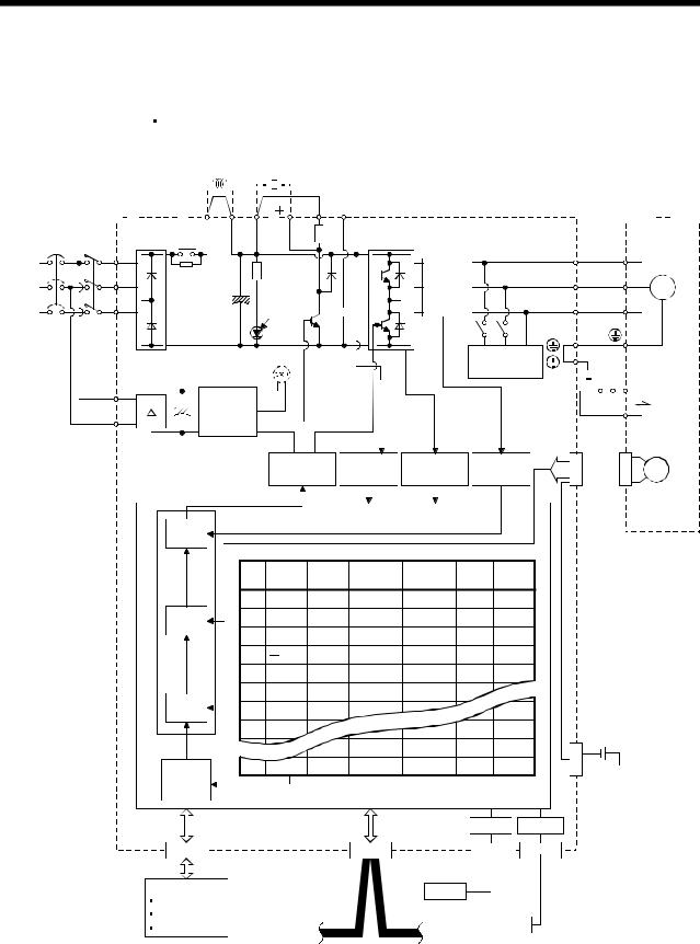
1. FUNCTIONS AND CONFIGURATION
1.1.2 Function block diagram
The function block diagram of this servo is shown below.
(1) MR-J3-350T or less MR-J3-200T4 or less
|
Power factor |
Regenerative |
|||||
|
improving DC |
||||||
|
reactor |
option |
|||||
|
Servo amplifier P1 |
P2 |
P( ) C D N( |
) |
Servo motor |
||
|
Diode |
Relay |
(Note 1) |
|||||
|
NFB |
MC |
stack |
U |
U |
|||
|
L1 |
|||||||
|
(Note 2) |
L2 |
Current |
V |
V |
|||
|
Power |
M |
||||||
|
detector |
|||||||
|
supply |
L3 |
CHARGE |
W |
W |
|||
|
Regene- |
|||||||
|
lamp |
rative |
||||||
|
TR |
|
(Note 4) Cooling fan |
Dynamic |
|||||||||||||||||
|
L11 |
Control |
brake |
RA |
Electro- |
||||||||||||||
|
circuit |
24VDC B1 |
magnetic |
||||||||||||||||
|
L21 |
power |
B2 |
brake |
|||||||||||||||
|
supply |
||||||||||||||||||
Model adaptive control
|
Base |
Voltage |
Overcurrent |
Current |
CN2 |
||||||
|
amplifier |
detection |
protection |
detection |
|||||||
|
Encoder |
||||||||||
|
Current |
|||||||||
|
control |
Point table |
||||||||
|
No. |
Position |
Speed |
Acceleration |
Deceleration |
Dwell |
Auxiliary |
|||
|
data |
time |
time |
|||||||
|
constant |
constant |
||||||||
|
1 |
1000 |
1000 |
80 |
80 |
0 |
0 |
|||
|
Speed |
2 |
2000 |
2000 |
100 |
100 |
0 |
0 |
||
|
control |
3 |
4000 |
2000 |
70 |
60 |
500 |
1 |
||
|
4 |
500 |
2000 |
60 |
70 |
1000 |
1 |
|||
|
5 |
1000 |
2000 |
80 |
80 |
0 |
0 |
|||
|
Position |
6 |
2000 |
1000 |
80 |
80 |
0 |
0 |
||
|
7 |
1000 |
1000 |
80 |
80 |
0 |
0 |
|||
|
control |
|||||||||
|
8 |
1000 |
1000 |
100 |
100 |
0 |
0 |
MR-J3BAT |
||
|
(Note 3) |
1000 |
1000 |
100 |
100 |
0 |
0 |
|||
|
CN4 |
|||||||||
|
Position |
255 |
2000 |
2000 |
80 |
80 |
0 |
0 |
||
|
command |
Optional battery |
||||||||
|
creation |
(for absolute position |
||||||||
|
detection system) |
|||||||||
|
USB |
RS-422 |
|
CN6 |
CN1 |
Personal |
CN5 |
CN3 |
|||||
|
computer |
|||||||||
|
DI/O Control |
USB |
||||||||
|
Servo on |
Controller |
||||||||
|
Start |
CC-Link |
||||||||
|
RS-422 |
|||||||||
|
Failure, etc |
|||||||||
Note 1. The built-in regenerative resistor is not provided for the MR-J3-10T (1).
2.For 1-phase 200 to 230VAC, connect the power supply to L1, L2 and leave L3 open.
There is no L3 for 1-phase 100 to 120VAC power supply. Refer to section 1.2 for the power supply specification.
3.For the case when 2 stations are occupied. When 1 station is occupied, the point table ends at No.31.
4.Servo amplifiers MR-J3-70T or greater have a cooling fan.
1 — 2
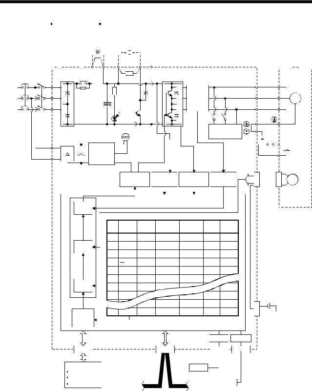
1. FUNCTIONS AND CONFIGURATION
|
(2) MR-J3-350T4 MR-J3-500T(4) |
MR-J3-700T(4) |
||
|
Power factor |
|||
|
improving DC Regenerative |
|||
|
reactor |
option |
||
|
C N |
|||
|
Servo amplifier P1 |
P2 P |
Servo motor |
|
Diode |
Relay |
||||||
|
NFB |
MC |
stack |
U |
U |
|||
|
L1 |
|||||||
|
(Note 1) |
L2 |
Current |
V |
V |
|||
|
Power |
M |
||||||
|
detector |
|||||||
|
supply |
L3 |
CHARGE |
W |
W |
|||
|
Regene- |
|||||||
|
lamp |
rative |
||||||
|
TR |
|
Cooling fan |
Dynamic |
|||||||||||||||||||
|
L11 |
Control |
brake |
RA |
Electro- |
||||||||||||||||
|
circuit |
24VDC B1 |
magnetic |
||||||||||||||||||
|
L21 |
power |
B2 |
brake |
|||||||||||||||||
|
supply |
||||||||||||||||||||
Model adaptive control
|
Base |
Voltage |
Overcurrent |
Current |
CN2 |
||||||
|
amplifier |
detection |
protection |
detection |
|||||||
|
Encoder |
||||||||||
|
Current |
|||||||||
|
control |
Point table |
||||||||
|
No. |
Position |
Speed |
Acceleration |
Deceleration |
Dwell |
Auxiliary |
|||
|
data |
time |
time |
|||||||
|
constant |
constant |
||||||||
|
1 |
1000 |
1000 |
80 |
80 |
0 |
0 |
|||
|
Speed |
2 |
2000 |
2000 |
100 |
100 |
0 |
0 |
||
|
control |
3 |
4000 |
2000 |
70 |
60 |
500 |
1 |
||
|
4 |
500 |
2000 |
60 |
70 |
1000 |
1 |
|||
|
5 |
1000 |
2000 |
80 |
80 |
0 |
0 |
|||
|
Position |
6 |
2000 |
1000 |
80 |
80 |
0 |
0 |
||
|
7 |
1000 |
1000 |
80 |
80 |
0 |
0 |
|||
|
control |
|||||||||
|
8 |
1000 |
1000 |
100 |
100 |
0 |
0 |
MR-J3BAT |
||
|
(Note 2) |
1000 |
1000 |
100 |
100 |
0 |
0 |
|||
|
CN4 |
|||||||||
|
Position |
255 |
2000 |
2000 |
80 |
80 |
0 |
0 |
||
|
command |
Optional battery |
||||||||
|
creation |
(for absolute position |
||||||||
|
detection system) |
|||||||||
|
USB |
RS-422 |
CN6
DI/O Control
Servo on
Start
Failure, etc
Note 1. Refer to section 1.2 for the power supply specification.
|
CN1 |
Personal |
CN5 |
CN3 |
|
|
computer |
||||
|
USB |
Controller
CC-Link
RS-422
2. For the case when 2 stations are occupied. When 1 station is occupied, the point table ends at No.31.
1 — 3
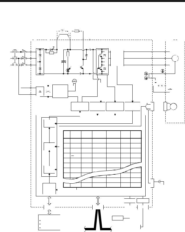
1. FUNCTIONS AND CONFIGURATION
(3) MR-J3-11KT(4) to 22KT(4)
Power factor
improving DC Regenerative reactor option
|
Servo amplifier |
P1 |
P |
C |
N |
Servo motor |
||||
|
Diode Thyristor |
|||||||||
|
NFB |
MC |
stack |
U |
U |
|||||
|
L1 |
|||||||||
|
(Note 1) |
L2 |
Current |
V |
V |
|||||
|
Power |
M |
||||||||
|
detector |
|||||||||
|
supply |
L3 |
CHARGE |
W |
W |
|||||
|
Regene- |
|||||||||
|
lamp |
rative |
||||||||
|
TR |
|||||||||
|
Cooling fan |
|
L11 |
Control |
RA |
Electro- |
|||||||||||||
|
circuit |
24VDC B1 |
magnetic |
||||||||||||||
|
L21 |
power |
B2 |
brake |
|||||||||||||
|
supply |
||||||||||||||||
Model adaptive control
|
Base |
Voltage |
Overcurrent |
Current |
CN2 |
||||||
|
amplifier |
detection |
protection |
detection |
|||||||
|
Encoder |
||||||||||
|
Current |
|||||||||
|
control |
Point table |
||||||||
|
No. |
Position |
Speed |
Acceleration |
Deceleration |
Dwell |
Auxiliary |
|||
|
data |
time |
time |
|||||||
|
constant |
constant |
||||||||
|
1 |
1000 |
1000 |
80 |
80 |
0 |
0 |
|||
|
Speed |
2 |
2000 |
2000 |
100 |
100 |
0 |
0 |
||
|
control |
3 |
4000 |
2000 |
70 |
60 |
500 |
1 |
||
|
4 |
500 |
2000 |
60 |
70 |
1000 |
1 |
|||
|
5 |
1000 |
2000 |
80 |
80 |
0 |
0 |
|||
|
Position |
6 |
2000 |
1000 |
80 |
80 |
0 |
0 |
||
|
7 |
1000 |
1000 |
80 |
80 |
0 |
0 |
|||
|
control |
|||||||||
|
8 |
1000 |
1000 |
100 |
100 |
0 |
0 |
MR-J3BAT |
||
|
(Note 2) |
1000 |
1000 |
100 |
100 |
0 |
0 |
|||
|
CN4 |
|||||||||
|
Position |
255 |
2000 |
2000 |
80 |
80 |
0 |
0 |
||
|
command |
Optional battery |
||||||||
|
creation |
(for absolute position |
||||||||
|
detection system) |
|||||||||
|
USB |
RS-422 |
CN6
DI/O Control
Servo on
Start
Failure, etc
Note 1. Refer to section 1.2 for the power supply specification.
|
CN1 |
Personal |
CN5 |
CN3 |
|
|
computer |
||||
|
USB |
Controller
CC-Link
RS-422
2. For the case when 2 stations are occupied. When 1 station is occupied, the point table ends at No.31.
1 — 4
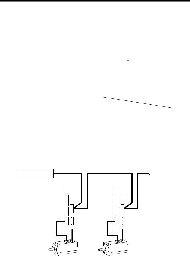
1. FUNCTIONS AND CONFIGURATION
1.1.3 System configuration
This section provides operations using this servo.
Use of CC-Link enables you to freely configure any system from a single-axis system to an up to 42-axis system.
Set the following values to the point table.
|
Name |
Setting range |
Unit |
||
|
0.001[mm] |
||||
|
Position data |
999999 to 999999 |
0.01[mm] |
||
|
0.1[mm] |
||||
|
1[mm] |
||||
|
Servo motor speed |
0 to max. speed |
[r/min] |
||
|
Acceleration time constant |
0 to 20000 |
[ms] |
||
|
Deceleration time constant |
0 to 20000 |
[ms] |
||
|
Dwell |
0 to 20000 |
[ms] |
||
|
Auxiliary function |
0 to 3 |
|||
|
(Refer to section 4.2) |
||||
There are 31 points of point tables to be used when 1 station is occupied and 255 points when 2 stations are occupied.
(1)Operation using CC-Link communication functions
(a)Operation
All devices can be controlled by CC-Link communication. Also, each point table setting, point table selection, parameter value change, setting, monitor, servo motor operation and others can be performed.
(b)Configuration
|
Programmable controller |
To the next axis |
|
|
CC-Link master unit |
||
|
Servo amplifier |
Servo amplifier |
|
|
(Axis 1) |
(Axis 2) |
|
CN1 |
CN1 |
||
|
CN6 |
CN6 |
||
|
CNP3 |
CNP3 |
||
|
CN2 |
CN2 |
1 — 5
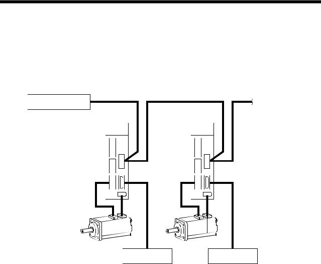
1. FUNCTIONS AND CONFIGURATION
(2)Operation using CC-Link communication functions and external input signals
(a)Operation
Using parameter No.PD06 to PD08 and parameter No.PD12, PD14, input devices can be assigned to the external input devices of CN1A and CN1B. The signals assigned to the external input signals cannot be used with the CC-Link communication functions. Output devices can be used with the CN6 connectors and CC-Link communication functions simultaneously.
(b)Configuration
|
Programmable controller |
To the next axis |
||||
|
CC-Link master unit |
|||||
|
Servo amplifier |
Servo amplifier |
||||
|
(Axis 1) |
(Axis 2) |
||||
|
CN1 |
CN1 |
|
CN6 |
CN6 |
|
CNP3 |
CNP3 |
|
CN2 |
CN2 |
|
External I/O |
External I/O |
|
signal |
signal |
1 — 6

1. FUNCTIONS AND CONFIGURATION
1.2 Servo amplifier standard specifications
(1) 200V class, 100V class
|
Servo amplifier |
|||||||||||||||||||||||
|
MR-J3- |
10T |
20T |
40T |
60T |
70T |
100T |
200T |
350T |
500T |
700T |
11KT |
15KT |
22KT |
10T1 |
20T1 |
40T1 |
|||||||
|
Item |
|||||||||||||||||||||||
|
Voltage/frequency |
3-phase or 1-phase 200 to |
3-phase 200 to 230VAC, 50/60Hz |
1-phase 100V to |
||||||||||||||||||||
|
230VAC, 50/60Hz |
120VAC, 50/60Hz |
||||||||||||||||||||||
|
supply |
|||||||||||||||||||||||
|
230VAC: 170 to 253VAC |
132VAC |
||||||||||||||||||||||
|
Permissible voltage fluctuation |
3-phase or 1-phase 200 to |
3-phase 170 to 253VAC |
1-phase 85 to |
||||||||||||||||||||
|
Power |
Permissible frequency |
Within |
5% |
||||||||||||||||||||
|
fluctuation |
|||||||||||||||||||||||
|
Power supply capacity |
Refer to section 13.2 |
||||||||||||||||||||||
|
Inrush current |
Refer to section 13.5 |
||||||||||||||||||||||
|
Voltage, |
1-phase 200 to 230VAC, 50/60Hz |
1-phase 100 to |
|||||||||||||||||||||
|
frequency |
120VAC, 50/60Hz |
||||||||||||||||||||||
|
Permissible |
1-phase 170 to 253VAC |
1-phase 85 to |
|||||||||||||||||||||
|
voltage fluctuation |
132VAC |
||||||||||||||||||||||
|
Control circuit |
|||||||||||||||||||||||
|
Permissible |
|||||||||||||||||||||||
|
power supply |
|||||||||||||||||||||||
|
frequency |
Within |
5% |
|||||||||||||||||||||
|
fluctuation |
|||||||||||||||||||||||
|
Input |
30W |
45W |
30W |
||||||||||||||||||||
|
Inrush current |
Refer to section 13.5 |
||||||||||||||||||||||
|
Interface power |
Voltage |
24VDC 10% |
|||||||||||||||||||||
|
Power supply |
|||||||||||||||||||||||
|
supply |
(Note 1) 150mA |
||||||||||||||||||||||
|
capacity |
|||||||||||||||||||||||
|
Control System |
Sine-wave PWM control, current control system |
||||||||||||||||||||||
|
Dynamic brake |
Built-in |
External option |
Built-in |
||||||||||||||||||||
|
Overcurrent shut-off, regenerative overvoltage shut-off, overload shut-off (electronic thermal relay), |
|||||||||||||||||||||||
|
Protective functions |
servo motor overheat protection, encoder error protection, regenerative brake error protection, |
||||||||||||||||||||||
|
undervoltage, instantaneous power failure protection, overspeed protection, excessive error |
|||||||||||||||||||||||
|
protection |
|||||||||||||||||||||||
|
Operational |
Positioning by specifying the point table No. (255 points) |
||||||||||||||||||||||
|
specifications |
|||||||||||||||||||||||
|
Point table |
Position command |
Set in point table. 1-point feed length setting range: |
1[ m] to 999.999[mm] |
||||||||||||||||||||
|
input |
|||||||||||||||||||||||
|
number |
|||||||||||||||||||||||
|
Speed command |
Set in point table. Acceleration/deceleration time is set in point table. |
||||||||||||||||||||||
|
input |
|||||||||||||||||||||||
|
input |
S-pattern acceleration/deceleration time constant is set in parameter No.PC13. |
||||||||||||||||||||||
|
system |
|||||||||||||||||||||||
|
System |
Signed absolute value command system, incremental value command system, signed absolute |
||||||||||||||||||||||
|
value command/incremental value command specifying system |
|||||||||||||||||||||||
|
Command |
Operational |
Remote register setting is used for positioning. |
|||||||||||||||||||||
|
Position |
specifications |
||||||||||||||||||||||
|
Position command |
Remote register is used to set position command data. |
||||||||||||||||||||||
|
command |
|||||||||||||||||||||||
|
input |
Feed length input setting range: |
1 m to 999.999m |
|||||||||||||||||||||
|
data input |
|||||||||||||||||||||||
|
Remote register is used to make selection from point table. |
|||||||||||||||||||||||
|
(when 2 |
Speed command |
||||||||||||||||||||||
|
Remote register is used to set speed command data (speed). |
|||||||||||||||||||||||
|
stations are |
input |
||||||||||||||||||||||
|
S-pattern acceleration/deceleration time constant is set in parameter No.PC13. |
|||||||||||||||||||||||
|
occupied) |
|||||||||||||||||||||||
|
System |
Signed absolute value command system, incremental value command system, signed absolute |
||||||||||||||||||||||
|
value command/incremental value command specifying system |
|||||||||||||||||||||||
|
Point table |
Point table number input, position data input system |
||||||||||||||||||||||
|
Automatic |
Positioning operation is performed once in accordance with the position and speed commands. |
||||||||||||||||||||||
|
mode |
|||||||||||||||||||||||
|
operation |
Automatic |
Varied speed operation (2 to 255 speeds), automatic continuous positioning operation (2 to 255 |
|||||||||||||||||||||
|
mode |
continuous |
points) |
|||||||||||||||||||||
|
Operation |
operation |
or through CC-Link communication function. |
|||||||||||||||||||||
|
Manual |
Jog |
Jog operation is performed in accordance with the parameter-set speed command by contact input |
|||||||||||||||||||||
|
operation |
|||||||||||||||||||||||
|
Manual pulse |
Manual feed is made by manual pulse generator. |
||||||||||||||||||||||
|
mode |
|||||||||||||||||||||||
|
generator |
Command pulse multiplication: |
1, 10 or 100 is selected using parameter. |
|||||||||||||||||||||
1 — 7

1. FUNCTIONS AND CONFIGURATION
|
Servo amplifier |
|||||||||||||||||||
|
MR-J3- |
10T |
20T |
40T |
60T |
70T |
100T |
200T |
350T |
500T |
700T |
11KT |
15KT |
22KT |
10T1 |
20T1 |
40T1 |
|||
|
Item |
|||||||||||||||||||
|
Home position return is made starting with Z-phase pulse after passage of proximity dog. |
|||||||||||||||||||
|
Dog type |
Home position address may be set. Home position shift distance may be set. Home position return |
||||||||||||||||||
|
direction may be selected. |
|||||||||||||||||||
|
Automatic at-dog home position return return/automatic stroke return function. |
|||||||||||||||||||
|
Home position return is made by counting encoder pulses after contact with proximity dog. |
|||||||||||||||||||
|
Count type |
Home position address may be set. Home position shift value may be set. Home position return |
||||||||||||||||||
|
direction may be set. |
|||||||||||||||||||
|
Automatic at-dog home position return return/automatic stroke return function. |
|||||||||||||||||||
|
Home position return is made without dog. |
|||||||||||||||||||
|
Data setting type |
Home position may be set at any position by manual operation, etc. Home position address may be |
||||||||||||||||||
|
set. |
|||||||||||||||||||
|
Stopper type |
Home position return is made by pressing machine part against stroke end. |
||||||||||||||||||
|
Home position address may be set. Home position return direction may be set. |
|||||||||||||||||||
|
Home position |
Position where servo-on (RYn0) is switched on is defined as home position. |
||||||||||||||||||
|
ignorance |
Home position address may be set. |
||||||||||||||||||
|
(Servo-on position |
|||||||||||||||||||
|
as home position) |
|||||||||||||||||||
|
Home position return is made with respect to the rear end of a proximity dog. |
|||||||||||||||||||
|
Dog type rear end |
Home position address may be set. Home position shift value may be set. Home position return |
||||||||||||||||||
|
mode |
Home |
reference |
direction may be set. |
||||||||||||||||
|
position |
Automatic at-dog home position return return/automatic stroke return function. |
||||||||||||||||||
|
Operation |
return |
Home position return is made with respect to the front end of a proximity dog. |
|||||||||||||||||
|
mode |
Count type front |
Home position address may be set. Home position shift value may be set. Home position return |
|||||||||||||||||
|
end reference |
direction may be set. |
||||||||||||||||||
|
Automatic at-dog home position return return/automatic stroke return function. |
|||||||||||||||||||
|
Home position return is made with respect to the front end of a proximity dog by the first Z-phase |
|||||||||||||||||||
|
pulse. |
|||||||||||||||||||
|
Dog cradle type |
Home position address may be set. Home position shift value may be set. Home position return |
||||||||||||||||||
|
direction may be set. |
|||||||||||||||||||
|
Automatic at-dog home position return return/automatic stroke return function. |
|||||||||||||||||||
|
Home position return is made with respect to the front end of a proximity dog by the last Z-phase |
|||||||||||||||||||
|
Dog type last |
pulse. |
||||||||||||||||||
|
Home position address may be set. Home position shift value may be set. Home position return |
|||||||||||||||||||
|
Z-phase reference |
|||||||||||||||||||
|
direction may be set. |
|||||||||||||||||||
|
Automatic at-dog home position return return/automatic stroke return function. |
|||||||||||||||||||
|
Home position return is made to the dog front end with respect to the front end of a proximity dog. |
|||||||||||||||||||
|
Dog type front end |
Home position address may be set. Home position shift value may be set. Home position return |
||||||||||||||||||
|
reference |
direction may be set. |
||||||||||||||||||
|
Automatic at-dog home position return return/automatic stroke return function. |
|||||||||||||||||||
|
Dogless |
Home position return is made with respect to the first Z-phase to the Z-phase. |
||||||||||||||||||
|
Home position address may be set. Home position shift value may be set. Home position return |
|||||||||||||||||||
|
Z-phase reference |
|||||||||||||||||||
|
direction may be set. |
|||||||||||||||||||
|
Automatic positioning to home |
High-speed automatic return to a defined home position. |
||||||||||||||||||
|
position |
|||||||||||||||||||
|
Absolute position detection, backlash function |
|||||||||||||||||||
|
Other functions |
Overtravel prevention using external limit switch |
||||||||||||||||||
|
Software stroke limit |
|||||||||||||||||||
|
Structure |
Self-cooled, open |
Force-cooling, open (IP00) |
Self-cooled, open |
||||||||||||||||
|
(IP00) |
(IP00) |
||||||||||||||||||
1 — 8

1. FUNCTIONS AND CONFIGURATION
|
Servo amplifier |
|||||||||||||||||||||||
|
MR-J3- |
10T |
20T |
40T |
60T |
70T |
100T |
200T |
350T |
500T |
700T |
11KT |
15KT |
22KT |
10T1 |
20T1 |
40T1 |
|||||||
|
Item |
|||||||||||||||||||||||
|
In operation |
[ |
] |
(Note 2) 0 to |
55 (non-freezing) |
|||||||||||||||||||
|
Ambient |
[ |
] |
(Note 2) 32 to |
131 (non-freezing) |
|||||||||||||||||||
|
Environment |
temperature |
In storage |
[ |
] |
20 to 65 (non-freezing) |
||||||||||||||||||
|
[ |
] |
4 to |
149 (non-freezing) |
||||||||||||||||||||
|
Ambient |
In operation |
90%RH or less (non-condensing) |
|||||||||||||||||||||
|
humidity |
In storage |
||||||||||||||||||||||
|
Ambient |
Indoors (no direct sunlight) |
||||||||||||||||||||||
|
Free from corrosive gas, flammable gas, oil mist, dust and dirt |
|||||||||||||||||||||||
|
Altitude |
Max. 1000m above sea level |
||||||||||||||||||||||
|
Vibration |
5.9 [m/s2] or less |
||||||||||||||||||||||
|
Mass |
[kg] |
0.8 |
0.8 |
1.0 |
1.0 |
1.4 |
1.4 |
2.1 |
2.3 |
4.6 |
6.2 |
18 |
18 |
19 |
0.8 |
0.8 |
1.0 |
||||||
|
[lb] |
1.76 |
1.76 |
2.21 |
2.21 |
3.09 |
3.09 |
4.63 |
5.07 |
10.1 |
13.7 |
39.7 |
39.7 |
41.9 |
1.76 |
1.76 |
2.21 |
|||||||
Note 1. 150mA is the value applicable when all I/O signals are used. The current capacity can be decreased by reducing the number of I/O points.
2. When closely mounting the servo amplifier of 3.5kW or less, operate them at the ambient temperatures of 0 to 45 (32 to 113
 ) or at 75% or smaller effective load ratio.
1 — 9
![]()
1. FUNCTIONS AND CONFIGURATION
(2) 400V class
|
Servo amplifier |
|||
|
MR-J3- |
|||
|
Item |
|||
|
supply |
Voltage/frequency |
||
|
Permissible voltage fluctuation |
|||
|
Permissible frequency |
|||
|
Power |
fluctuation |
||
|
Power supply capacity |
|||
|
Inrush current |
|||
|
Voltage, |
|||
|
frequency |
|||
|
Permissible |
|||
|
Control circuit |
voltage fluctuation |
||
|
Permissible |
|||
|
power supply |
|||
|
frequency |
|||
|
fluctuation |
|||
|
Input |
|||
|
Inrush current |
|||
|
Interface power |
Voltage |
||
|
supply |
Power supply |
||
|
capacity |
|||
|
Control System |
|||
|
Dynamic brake |
|||
|
Protective functions |
|||
|
Operational |
|||
|
specifications |
|||
|
Point table |
Position command |
||
|
input |
|||
|
number |
|||
|
Speed command |
|||
|
input |
|||
|
input |
|||
|
system |
|||
|
System |
|||
|
Command |
|||
|
Operational |
|||
|
Position |
specifications |
||
|
Position command |
|||
|
command |
|||
|
input |
|||
|
data input |
|||
|
(when 2 |
Speed command |
||
|
stations are |
input |
||
|
occupied) |
|||
|
System |
|||
|
Automatic |
Point table |
||
|
mode |
|||
|
operation |
Automatic |
||
|
mode |
continuous |
||
|
Operation |
operation |
||
|
Manual |
Jog |
||
|
operation |
Manual pulse |
||
|
mode |
|||
|
generator |
|||
|
60T4 |
100T4 |
200T4 |
350T4 |
500T4 |
700T4 |
11KT4 |
15KT4 |
22KT4 |
3-phase 380 to 480VAC, 50/60Hz
3-phase 323 to 528VAC
Within  5%
5%
Refer to section 13.2
Refer to section 13.5
1-phase 380 to 480VAC, 50/60Hz
1-phase 323 to 528VAC
|
Within |
5% |
|
|
30W |
45W |
|
|
Refer to section 13.5 |
||
|
24VDC |
10% |
(Note) 150mA
Sine-wave PWM control, current control system
Built-in External option
Overcurrent shut-off, regenerative overvoltage shut-off, overload shut-off (electronic thermal relay), servo motor overheat protection, encoder error protection, regenerative brake error protection, undervoltage, instantaneous power failure protection, overspeed protection, excessive error protection
Positioning by specifying the point table No. (255 points)
Set in point table. 1-point feed length setting range:  1[
1[ m] to
m] to  999.999[mm]
Set in point table. Acceleration/deceleration time is set in point table. S-pattern acceleration/deceleration time constant is set in parameter No.PC13.
Signed absolute value command system, incremental value command system, signed absolute value command/incremental value command specifying system
Remote register setting is used for positioning.
Remote register is used to set position command data.
Feed length input setting range:  1
1 m to
m to  999.999m
Remote register is used to make selection from point table. Remote register is used to set speed command data (speed).
S-pattern acceleration/deceleration time constant is set in parameter No.PC13.
Signed absolute value command system, incremental value command system, signed absolute value command/incremental value command specifying system
Point table number input, position data input system
Positioning operation is performed once in accordance with the position and speed commands.
Varied speed operation (2 to 255 speeds), automatic continuous positioning operation (2 to 255 points)
Jog operation is performed in accordance with the parameter-set speed command by contact input or through CC-Link communication function.
Manual feed is made by manual pulse generator.
Command pulse multiplication:  1,
1,  10 or
10 or  100 is selected using parameter.
1 — 10

1. FUNCTIONS AND CONFIGURATION
|
Servo amplifier |
||||||||||||||||||
|
MR-J3- |
60T4 |
100T4 |
200T4 |
350T4 |
500T4 |
700T4 |
11KT4 |
15KT4 |
22KT4 |
|||||||||
|
Item |
||||||||||||||||||
|
Home position return is made starting with Z-phase pulse after passage of proximity dog. |
||||||||||||||||||
|
Dog type |
Home position address may be set. Home position shift distance may be set. Home position return |
|||||||||||||||||
|
direction may be selected. |
||||||||||||||||||
|
Automatic at-dog home position return return/automatic stroke return function. |
||||||||||||||||||
|
Home position return is made by counting encoder pulses after contact with proximity dog. |
||||||||||||||||||
|
Count type |
Home position address may be set. Home position shift value may be set. Home position return |
|||||||||||||||||
|
direction may be set. |
||||||||||||||||||
|
Automatic at-dog home position return return/automatic stroke return function. |
||||||||||||||||||
|
Home position return is made without dog. |
||||||||||||||||||
|
Data setting type |
Home position may be set at any position by manual operation, etc. Home position address may be |
|||||||||||||||||
|
set. |
||||||||||||||||||
|
Stopper type |
Home position return is made by pressing machine part against stroke end. |
|||||||||||||||||
|
Home position address may be set. Home position return direction may be set. |
||||||||||||||||||
|
Home position |
Position where servo-on (RYn0) is switched on is defined as home position. |
|||||||||||||||||
|
ignorance |
Home position address may be set. |
|||||||||||||||||
|
(Servo-on position |
||||||||||||||||||
|
as home position) |
||||||||||||||||||
|
Home position return is made with respect to the rear end of a proximity dog. |
||||||||||||||||||
|
Home |
Dog type rear end |
Home position address may be set. Home position shift value may be set. Home position return |
||||||||||||||||
|
mode |
reference |
direction may be set. |
||||||||||||||||
|
position |
Automatic at-dog home position return return/automatic stroke return function. |
|||||||||||||||||
|
Operation |
return |
Home position return is made with respect to the front end of a proximity dog. |
||||||||||||||||
|
mode |
Count type front |
Home position address may be set. Home position shift value may be set. Home position return |
||||||||||||||||
|
end reference |
direction may be set. |
|||||||||||||||||
|
Automatic at-dog home position return return/automatic stroke return function. |
||||||||||||||||||
|
Home position return is made with respect to the front end of a proximity dog by the first Z-phase |
||||||||||||||||||
|
pulse. |
||||||||||||||||||
|
Dog cradle type |
Home position address may be set. Home position shift value may be set. Home position return |
|||||||||||||||||
|
direction may be set. |
||||||||||||||||||
|
Automatic at-dog home position return return/automatic stroke return function. |
||||||||||||||||||
|
Home position return is made with respect to the front end of a proximity dog by the last Z-phase |
||||||||||||||||||
|
Dog type last |
pulse. |
|||||||||||||||||
|
Home position address may be set. Home position shift value may be set. Home position return |
||||||||||||||||||
|
Z-phase reference |
||||||||||||||||||
|
direction may be set. |
||||||||||||||||||
|
Automatic at-dog home position return return/automatic stroke return function. |
||||||||||||||||||
|
Home position return is made to the dog front end with respect to the front end of a proximity dog. |
||||||||||||||||||
|
Dog type front end |
Home position address may be set. Home position shift value may be set. Home position return |
|||||||||||||||||
|
reference |
direction may be set. |
|||||||||||||||||
|
Automatic at-dog home position return return/automatic stroke return function. |
||||||||||||||||||
|
Dogless |
Home position return is made with respect to the first Z-phase to the Z-phase. |
|||||||||||||||||
|
Home position address may be set. Home position shift value may be set. Home position return |
||||||||||||||||||
|
Z-phase reference |
||||||||||||||||||
|
direction may be set. |
||||||||||||||||||
|
Automatic positioning to home |
High-speed automatic return to a defined home position. |
|||||||||||||||||
|
position |
||||||||||||||||||
|
Absolute position detection, backlash function |
||||||||||||||||||
|
Other functions |
Overtravel prevention using external limit switch |
|||||||||||||||||
|
Software stroke limit |
||||||||||||||||||
|
Structure |
Self-cooled, open |
Force-cooling, open (IP00) |
||||||||||||||||
|
(IP00) |
||||||||||||||||||
1 — 11

1. FUNCTIONS AND CONFIGURATION
|
Servo amplifier |
|||||||||||||||||
|
MR-J3- |
60T4 |
100T4 |
200T4 |
350T4 |
500T4 |
700T4 |
11KT4 |
15KT4 |
22KT4 |
||||||||
|
Item |
|||||||||||||||||
|
In operation |
[ |
] |
0 to |
55 (non-freezing) |
|||||||||||||
|
Ambient |
[ |
] |
32 to |
131 (non-freezing) |
|||||||||||||
|
Environment |
temperature |
In storage |
[ |
] |
20 to |
65 (non-freezing) |
|||||||||||
|
[ |
] |
||||||||||||||||
|
Indoors (no direct sunlight) |
|||||||||||||||||
|
4 to |
149 (non-freezing) |
||||||||||||||||
|
Ambient |
In operation |
90%RH or less (non-condensing) |
|||||||||||||||
|
humidity |
In storage |
||||||||||||||||
|
Ambient |
Free from corrosive gas, flammable gas, oil mist, dust and dirt |
||||||||||||||||
|
Altitude |
Max. 1000m above sea level |
||||||||||||||||
|
Vibration |
5.9 [m/s2] or less |
||||||||||||||||
|
Mass |
[kg] |
1.7 |
1.7 |
2.1 |
4.6 |
4.6 |
6.2 |
18 |
18 |
19 |
|||||||
|
[lb] |
3.75 |
3.75 |
4.63 |
10.1 |
10.1 |
13.7 |
39.7 |
39.7 |
41.9 |
||||||||
|
Note. 150mA is the value applicable |
when all I/O signals are used. The current capacity can be decreased by reducing the number of |
||||||||||||||||
|
I/O points. |
1 — 12

1. FUNCTIONS AND CONFIGURATION
1.3 Function list
The following table lists the functions of this servo. For details of the functions, refer to the reference field.
|
Function |
Description |
Reference |
|
|
Select the required ones from among 31 preset point tables and perform |
|||
|
Positioning by automatic |
operation in accordance with the set values. |
Section 5.4 |
|
|
operation |
Use the external input signal or communication function to choose the point |
||
|
tables. |
|||
|
Varied speed operation |
Servo motor speed can be varied continuously until the preset moving |
Section 5.4.2 |
|
|
distance is reached. (Max. set speeds: 255 speeds) |
(4)(b) |
||
|
Automatic continuous positioning |
By merely choosing one point table and starting operation, positioning can |
Section 5.4.2 (4) |
|
|
operation |
be executed continuously in accordance with several point tables. |
||
|
Dog type, count type, data setting type, stopper type, home position |
|||
|
Home position return |
ignorance, dog type rear end reference, count type front end reference, dog |
Section 5.6 |
|
|
cradle type |
|||
|
High-resolution encoder |
High-resolution encoder of 262144 pulses/rev is used as a servo motor |
||
|
encoder. |
|||
|
Absolute position detection |
By merely setting the home position once, home position return need not be |
Section 5.7 |
|
|
system |
done at each power on. |
||
|
Gain changing function |
You can switch between gains during rotation and gains during stop or use |
Section 10.6 |
|
|
an input device to change gains during operation. |
|||
|
Advanced vibration suppression |
This function suppresses vibration at the arm end or residual vibration. |
Section 10.4 |
|
|
control |
|||
|
Adaptive filter |
Servo amplifier detects mechanical resonance and sets filter characteristics |
Section 10.2 |
|
|
automatically to suppress mechanical vibration. |
|||
|
Low-pass filter |
Suppresses high-frequency resonance which occurs as servo system |
Section 10.5 |
|
|
response is increased. |
|||
|
Analyzes the frequency characteristic of the mechanical system by simply |
|||
|
Machine analyzer function |
connecting a MR Configurator installed personal computer and servo |
||
|
amplifier. |
|||
|
MR Configurator is necessary for this function. |
|||
|
Can simulate machine motions on a personal computer screen on the basis |
|||
|
Machine simulation |
of the machine analyzer results. |
||
|
MR Configurator is necessary for this function. |
|||
|
Personal computer changes gains automatically and searches for |
|||
|
Gain search function |
overshoot-free gains in a short time. |
||
|
MR Configurator is necessary for this function. |
|||
|
Slight vibration suppression |
Suppresses vibration of 1 pulse produced at a servo motor stop. |
Parameters No. |
|
|
control |
PB24 |
||
|
The electronic gear is used to make adjustment so that the servo amplifier |
|||
|
Electronic gear |
setting matches the machine moving distance. Also, changing the electronic |
Parameter No. |
|
|
gear value allows the machine to be moved at any multiplication ratio to the |
PA06, PA07 |
||
|
moving distance using the servo amplifier. |
|||
|
Auto tuning |
Automatically adjusts the gain to optimum value if load applied to the servo |
Section 9.2 |
|
|
motor shaft varies. |
|||
|
S-pattern |
Acceleration/deceleration can be made smoothly. |
Parameters No. |
|
|
acceleration/deceleration time |
|||
|
PC13 |
|||
|
constant |
|||
|
Regenerative option |
Used when the built-in regenerative resistor of the servo amplifier does not |
Section 14.2 |
|
|
have sufficient regenerative capability for the regenerative power generated. |
|||
|
Used when the regenerative option cannot provide enough regenerative |
|||
|
Brake unit |
power. |
Section 14.3 |
|
|
Can be used with the servo amplifier of 5kW or more. |
|||
|
Used when the regenerative option cannot provide enough regenerative |
|||
|
Regeneration converter |
power. |
Section 14.4 |
|
|
Can be used with the servo amplifier of 5kW or more. |
|||
|
Alarm history clear |
Alarm history is cleared. |
Parameter No. |
|
|
PC18 |
|||
1 — 13

1. FUNCTIONS AND CONFIGURATION
|
Function |
Description |
Reference |
||
|
I/O signal selection (Device |
Any input device such as servo-on (SON) can be assigned to any pin of CN6 |
Parameter No. |
||
|
connector. |
PD06 to PD08 |
|||
|
setting) |
||||
|
PD12 |
PD14 |
|||
|
Torque limit |
Servo motor-torque is limited. |
Section 4.6.3 |
||
|
Section 6.1.11 |
||||
|
Output signal (DO) forced output |
Output signal can be forced on/off independently of the servo status. |
Section 7.7.4 |
||
|
Use this function for output signal wiring check, etc. |
Section 8.5.7(4) |
|||
|
JOG operation positioning operation DO forced output single — step |
Section 7.7 |
|||
|
Test operation mode |
feed. |
|||
|
Section 8.5.7 |
||||
|
MR Configurator is necessary for this function. |
||||
|
Limit switch |
The servo motor travel region can be limited using the forward rotation |
|||
|
stroke end (LSP)/reverse rotation stroke end (LSN). |
||||
|
Software limit |
The travel region is limited using parameters in terms of address. |
Section 6.3.6 |
||
|
The function similar to that of a limit switch is limited by parameter. |
||||
1 — 14

1. FUNCTIONS AND CONFIGURATION
1.4 Model code definition
(1) Rating plate
|
MITSUBISHI |
AC SERVO |
Model |
||||||||||
|
MODEL |
MR-J3-10T |
Capacity |
||||||||||
|
POWER : 100W |
Applicable power supply |
|||||||||||
|
INPUT |
: 0.9A 3PH+1PH200-230V 50Hz |
|||||||||||
|
3PH+1PH200-230V 60Hz |
||||||||||||
|
1.3A 1PH 200-230V 50/60Hz |
Rated output current |
|||||||||||
|
OUTPUT : 170V 0-360Hz 1.1A |
||||||||||||
|
SERIAL |
: A34230001 |
Serial number |
||||||||||
|
PASSED |
||||||||||||
MITSUBISHI ELECTRIC CORPORATION
MADE IN JAPAN
MR-J3-100T(4) or less
 With no regenerative resistor Symbol Description
Indicates a servo amplifier of 11k to 22kW
-PX that does not use a regenerative resistor as standard accessory.
|
Power supply |
||||||||||||||||||||
|
Symbol |
Description |
|||||||||||||||||||
|
(Note 1) |
3-phase or 1-phase 200 |
Rating plate |
||||||||||||||||||
|
None |
to 230VAC |
|||||||||||||||||||
|
(Note 2) |
1-phase 100 to 120VAC |
|||||||||||||||||||
|
1 |
MR-J3-350T |
|||||||||||||||||||
|
4 |
3-phase 380 to 480VAC |
|||||||||||||||||||
|
Note 1. 1-phase 200V to 230V is |
||||||||||||||||||||
|
supported by 750W or less. |
||||||||||||||||||||
|
2. 1-phase 100V to 120V is |
||||||||||||||||||||
|
supported by 400W or less. |
||||||||||||||||||||
|
Built-in positioning function |
||||||||||||||||||||
|
Rated output |
||||||||||||||||||||
|
Symbol |
Rated |
|||||||||||||||||||
|
output [kW] |
||||||||||||||||||||
|
10 |
0.1 |
|||||||||||||||||||
|
20 |
0.2 |
|||||||||||||||||||
|
Rating plate |
||||||||||||||||||||
|
40 |
0.4 |
|||||||||||||||||||
|
60 |
0.6 |
|||||||||||||||||||
|
70 |
0.75 |
MR-J3-700T(4) |
||||||||||||||||||
|
100 |
1 |
|||||||||||||||||||
200 2
350 3.5
500 5
700 7
11K 11
15K 15
22K 22
MR-J3-200T(4)
Rating plate
MR-J3-350T4 500T(4)
Rating plate 
MR-J3-11KT(4) to 22KT(4)
Rating plate
Rating plate
1 — 15

1. FUNCTIONS AND CONFIGURATION
1.5 Combination with servo motor
The following table lists combinations of servo amplifiers and servo motors. The same combinations apply to the servo motors with an electromagnetic brakes and the servo motors with a reduction gear.
Servo motors
|
Servo amplifier |
HF-MP |
HF-KP |
HF-SP |
HC-RP |
HC-UP |
HC-LP |
|||
|
2000r/min |
|||||||||
|
1000r/min |
|||||||||
|
MR-J3-10T (1) |
053 |
13 |
053 |
13 |
|||||
|
MR-J3-20T (1) |
23 |
23 |
|||||||
|
MR-J3-40T (1) |
43 |
43 |
|||||||
|
MR-J3-60T |
51 |
52 |
52 |
||||||
|
MR-J3-70T |
73 |
73 |
72 |
||||||
|
MR-J3-100T |
81 |
102 |
102 |
||||||
|
MR-J3-200T |
121 |
201 |
152 202 |
103 153 |
152 |
152 |
|||
|
MR-J3-350T |
301 |
352 |
203 |
202 |
202 |
||||
|
MR-J3-500T |
421 |
502 |
353 503 |
352 502 |
302 |
||||
|
MR-J3-700T |
702 |
||||||||
|
MR-J3-11KT |
|||||||||
|
MR-J3-15KT |
|||||||||
|
MR-J3-22KT |
|
Servo motors |
||||
|
Servo amplifier |
HA-LP |
|||
|
1000r/min |
1500r/min |
2000r/min |
||
|
MR-J3-500T |
502 |
|||
|
MR-J3-700T |
601 |
701M |
702 |
|
|
MR-J3-11KT |
801 |
12K1 |
11K1M |
11K2 |
|
MR-J3-15KT |
15K1 |
15K1M |
15K2 |
|
|
MR-J3-22KT |
20K1 |
25K1 |
22K1M |
22K2 |
Servo motors
|
Servo amplifier |
HF-SP |
HA-LP |
||||
|
1000r/min |
1500r/min |
2000r/min |
||||
|
MR-J3-60T4 |
524 |
|||||
|
MR-J3-100T4 |
1024 |
|||||
|
MR-J3-200T4 |
1524 |
2024 |
||||
|
MR-J3-350T4 |
3524 |
|||||
|
MR-J3-500T4 |
5024 |
|||||
|
MR-J3-700T4 |
7024 |
6014 |
701M4 |
|||
|
MR-J3-11KT4 |
8014 |
12K14 |
11K1M4 |
11K24 |
||
|
MR-J3-15KT4 |
15K14 |
15K1M4 |
15K24 |
|||
|
MR-J3-22KT4 |
20K14 |
22K1M4 |
22K24 |
1 — 16

1. FUNCTIONS AND CONFIGURATION
1.6 Structure
1.6.1 Parts identification
(1) MR-J3-100T or less
|
4 |
5 |
6 |
||||||||||||||
|
3 |
7 |
|||||||||||||||
|
2 |
8 |
|||||||||||||||
|
1 |
0 |
9 |
||||||||||||||
|
4 |
5 |
6 |
4 |
5 |
6 |
|||||||||||
|
3 |
7 |
3 |
7 |
|||||||||||||
|
2 |
8 |
2 |
8 |
|||||||||||||
|
1 |
0 |
9 |
1 |
0 |
9 |
|||||||||||
Fixed part (2 places)
Name/Application
Display
The 3-digit, seven-segment LED shows the servo status and alarm number.
Baud rate switch (MODE)
MODE
|
4 |
5 |
6 |
Select the CC-Link communication baud rate. |
|
2 |
|||
|
3 |
7 |
||
|
8 |
|||
|
1 |
0 |
9 |
|
Station number switches (STATION NO.) Set the station number of the servo amplifier.
X10 STATION NO. X1
|
4 |
5 |
6 |
4 |
5 |
6 |
|
3 |
7 |
3 |
7 |
||
|
2 |
8 |
2 |
8 |
||
|
1 |
0 |
9 |
1 |
0 |
9 |
|
Set the one place. |
|||||
Set the ten place.
Occupied station count switch (SW1)
SW1
Set the number of occupied stations.
Main circuit power supply connector (CNP1) Used to connect the input power supply.
Communication alarm display section Indicates alarms in CC-Link communication.
USB communication connector (CN5)
Used to connect the personal computer.
CC-Link connector (CN1)
Wire the CC-Link cable.
Control circuit connector (CNP2)
Used to connect the control circuit power supply/ regenerative option.
I/O signal connector (CN6)
Used to connect digital I/O signals.
Servo motor power connector (CNP3)
Used to connect the servo motor.
Encoder connector (CN2)
Used to connect the servo motor encoder.
Battery connector (CN4)
Used to connect the battery for absolute position data backup.
Charge lamp
Lit to indicate that the main circuit is charged. While this lamp is lit, do not reconnect the cables.
Battery holder
Contains the battery for absolute position data backup.
Rating plate
Protective earth (PE) terminal ( )
)
Ground terminal.
1 — 17
Detailed explanation
Section 5.3
Chapter 11
Section 3.2.4
Section 3.2.3
Section 3.2.5
Section 11.3
Chapter 7
Chapter 7
Chapter 8
Chapter 15
Section 3.2.2
Section 4.1
Section 4.3
Section 12.1
Section 14.2
Section 4.2
Section 4.4
Section 4.1
Section 4.3
Section 12.1
Section 4.10
Section 14.1
Section 5.8
Section 14.7
Section 5.8
Section 1.4
Section 4.1
Section 4.3
Section 12.1

1. FUNCTIONS AND CONFIGURATION
(2) MR-J3-200T(4) or less
7 8
Name/Application
Display
The 3-digit, seven-segment LED shows the servo status and alarm number.
Baud rate switch (MODE)
MODE
|
4 |
5 |
6 |
Select the CC-Link communication baud rate. |
|
2 |
|||
|
3 |
7 |
||
|
8 |
|||
|
1 |
0 |
9 |
|
Station number switches (STATION NO.) Set the station number of the servo amplifier.
X10 STATION NO. X1
|
4 |
5 |
6 |
4 |
5 |
6 |
|
3 |
7 |
3 |
7 |
||
|
2 |
8 |
2 |
8 |
||
|
1 |
0 |
9 |
1 |
0 |
9 |
|
Set the one place. |
|||||
Set the ten place.
Occupied station count switch (SW1)
SW1
Set the number of occupied stations.
Cooling fan
Fixed part (3 places)
Main circuit power supply connector (CNP1)
Used to connect the input power supply.
Communication alarm display section
Indicates alarms in CC-Link communication.
|
USB communication connector (CN5) |
|
|
(Note) |
Used to connect the personal computer. |
CC-Link connector (CN1)
Wire the CC-Link cable.
I/O signal connector (CN6)
Used to connect digital I/O signals.
Encoder connector (CN2)
Used to connect the servo motor encoder.
Battery connector (CN4)
Used to connect the battery for absolute position data backup.
Control circuit connector (CNP2)
Used to connect the control circuit power supply/ regenerative option.
Servo motor power connector (CNP3)
Used to connect the servo motor.
Battery holder
Contains the battery for absolute position data backup.
Charge lamp
Lit to indicate that the main circuit is charged. While this lamp is lit, do not reconnect the cables.
Protective earth (PE) terminal ( )
)
Ground terminal.
Rating plate
Detailed explanation
Section 5.3
Chapter 11
Section 3.2.4
Section 3.2.3
Section 3.2.5
Section 11.3
Chapter 7
Chapter 7
Chapter 8
Chapter 15
Section 3.2.2
Section 4.2
Section 4.4
Section 4.10
Section 14.1
Section 5.8
Section 14.7
Section 4.1
Section 4.3
Section 12.1
Section 14.2
Section 4.1
Section 4.3
Section 12.1
Section 5.8
Section 4.1
Section 4.3
Section 12.1
Section 1.4
Note. Connectors (CNP1, CNP2, and CNP3) and appearance of MR-J3-200T servo amplifier have been changed from January 2008 production. Model name of the existing servo amplifier is changed to MR-J3-200T-RT. For MR-J3-200T-RT, refer to appendix 5.
1 — 18

1. FUNCTIONS AND CONFIGURATION
(3) MR-J3-350T
|
4 |
5 |
6 |
|||
|
3 |
7 |
||||
|
2 |
8 |
||||
|
1 |
0 |
9 |
|||
|
4 |
5 |
6 |
4 |
5 |
6 |
|
3 |
7 |
3 |
7 |
||
|
2 |
8 |
2 |
8 |
||
|
1 |
0 |
9 |
1 |
0 |
9 |
Cooling fan
Fixed part (3 places)
|
Name/Application |
Detailed |
|||||||||||||||
|
explanation |
||||||||||||||||
|
Display |
Section 5.3 |
|||||||||||||||
|
The 3-digit, seven-segment LED shows the servo |
||||||||||||||||
|
Chapter 11 |
||||||||||||||||
|
status and alarm number. |
||||||||||||||||
|
Baud rate switch (MODE) |
||||||||||||||||
|
3 |
MODE |
Section 3.2.4 |
||||||||||||||
|
5 |
7 |
|||||||||||||||
|
4 |
6 |
Select the CC-Link communication baud rate. |
||||||||||||||
|
2 |
8 |
|||||||||||||||
|
1 |
0 |
9 |
||||||||||||||
|
Station number switches (STATION NO.) |
||||||||||||||||
|
Set the station number of the servo amplifier. |
||||||||||||||||
|
X10 STATION NO. X1 |
||||||||||||||||
|
4 |
5 |
6 |
4 |
5 |
6 |
Section 3.2.3 |
||||||||||
|
2 |
2 |
|||||||||||||||
|
3 |
7 |
3 |
7 |
|||||||||||||
|
8 |
8 |
|||||||||||||||
|
1 |
0 |
9 |
1 |
0 |
9 |
Set the one place. |
||||||||||
|
Set the ten place. |
||||||||||||||||
|
Occupied station count switch (SW1) |
||||||||||||||||
|
SW1 |
Section 3.2.5 |
|||||||||||||||
|
Set the number of occupied stations. |
||||||||||||||||
|
Main circuit power supply connector (CNP1) |
||||||||||||||||
|
Used to connect the input power supply. |
||||||||||||||||
|
Communication alarm display section |
||||||||||||||||
|
Indicates alarms in CC-Link communication. |
||||||||||||||||
|
Section 11.3 |
||||||||||||||||
|
USB communication connector (CN5) |
Chapter 7 |
|||||||||||||||
|
Used to connect the personal computer. |
||||||||||||||||
|
Chapter 7 |
||||||||||||||||
|
Chapter 8 |
||||||||||||||||
|
Chapter 15 |
||||||||||||||||
|
CC-Link connector (CN1) |
Section 3.2.2 |
|||||||||||||||
|
Wire the CC-Link cable. |
||||||||||||||||
|
Servo motor power connector (CNP3) |
Section 4.1 |
|||||||||||||||
|
Used to connect the servo motor. |
Section 4.3 |
|||||||||||||||
|
Section 12.1 |
||||||||||||||||
|
I/O signal connector (CN6) |
Section 4.2 |
|||||||||||||||
|
Used to connect digital I/O signals. |
Section 4.4 |
|||||||||||||||
|
Encoder connector (CN2) |
Section 4.10 |
|||||||||||||||
|
Used to connect the servo motor encoder. |
Section 14.1 |
|||||||||||||||
|
Battery connector (CN4) |
Section 5.8 |
|||||||||||||||
|
Used to connect the battery for absolute position data |
||||||||||||||||
|
Section 14.7 |
||||||||||||||||
|
backup. |
||||||||||||||||
|
Control circuit connector (CNP2) |
Section 4.1 |
|||||||||||||||
|
Used to connect the control circuit power supply/ |
Section 4.3 |
|||||||||||||||
|
regenerative option. |
Section 12.1 |
|||||||||||||||
|
Section 14.2 |
||||||||||||||||
|
Battery holder |
Section 5.8 |
|||||||||||||||
|
Contains the battery for absolute position data backup. |
||||||||||||||||
|
Charge lamp |
||||||||||||||||
|
Lit to indicate that the main circuit is charged. While |
||||||||||||||||
|
this lamp is lit, do not reconnect the cables. |
||||||||||||||||
|
Protective earth (PE) terminal ( |
) |
Section 4.1 |
||||||||||||||
|
Ground terminal. |
Section 4.3 |
|||||||||||||||
|
Section 12.1 |
||||||||||||||||
|
Rating plate |
Section 1.4 |
|||||||||||||||
1 — 19
![]()
1. FUNCTIONS AND CONFIGURATION
(4) MR-J3-350T4 MR-J3-500T(4)
POINT
The servo amplifier is shown without the front cover. For removal of the front cover, refer to section 1.6.2.
|
4 |
5 |
6 |
|||
|
3 |
7 |
||||
|
2 |
8 |
||||
|
1 |
0 |
9 |
|||
|
4 |
5 |
6 |
4 |
5 |
6 |
|
3 |
7 |
3 |
7 |
||
|
2 |
8 |
2 |
8 |
||
|
1 |
0 |
9 |
1 |
0 |
9 |
Cooling fan
Fixed part (4 places)
Name/Application
Display
The 3-digit, seven-segment LED shows the servo status and alarm number.
Baud rate switch (MODE)
MODE
|
4 |
5 |
6 |
Select the CC-Link communication baud rate. |
|
3 |
7 |
||
|
2 |
8 |
||
|
1 |
0 |
9 |
|
Station number switches (STATION NO.) Set the station number of the servo amplifier.
X10 STATION NO. X1
|
4 |
5 |
6 |
4 |
5 |
6 |
|
3 |
7 |
3 |
7 |
||
|
2 |
8 |
2 |
8 |
||
|
1 |
0 |
9 |
1 |
0 |
9 |
|
Set the one place. |
|||||
Set the ten place.
Occupied station count switch (SW1)
SW1
Set the number of occupied stations.
Communication alarm display section Indicates alarms in CC-Link communication.
USB communication connector (CN5)
Used to connect the personal computer.
CC-Link connector (CN1)
Wire the CC-Link cable.
I/O signal connector (CN6)
Used to connect digital I/O signals.
Battery holder
Contains the battery for absolute position data backup.
Encoder connector (CN2)
Used to connect the servo motor encoder.
Battery connector (CN4)
Used to connect the battery for absolute position data backup.
DC reactor terminal block (TE3)
Used to connect the DC reactor.
Charge lamp
Lit to indicate that the main circuit is charged. While this lamp is lit, do not reconnect the cables.
Main circuit terminal block (TE1)
Used to connect the input power supply and servo motor.
Control circuit terminal block (TE2)
Used to connect the control circuit power supply.
Protective earth (PE) terminal ( )
)
Ground terminal.
Rating plate
Detailed explanation
Section 5.3
Chapter 11
Section 3.2.4
Section 3.2.3
Section 3.2.5
Section 11.3
Chapter 7
Chapter 7
Chapter 8
Chapter 15
Section 3.2.2
Section 4.2
Section 4.4
Section 5.8
Section 4.10
Section 14.1
Section 5.8
Section 14.7
Section 4.1
Section 4.3
Section 12.1
Section 14.11
Section 4.1
Section 4.3
Section 12.1
Section 1.4
1 — 20

1. FUNCTIONS AND CONFIGURATION
(5) MR-J3-700T(4)
POINT
The servo amplifier is shown without the front cover. For removal of the front cover, refer to section 1.6.2.
|
4 |
5 |
6 |
|||
|
3 |
7 |
||||
|
2 |
8 |
||||
|
1 |
0 |
9 |
|||
|
4 |
5 |
6 |
4 |
5 |
6 |
|
3 |
7 |
3 |
7 |
||
|
2 |
8 |
2 |
8 |
||
|
1 |
0 |
9 |
1 |
0 |
9 |
Cooling fan
|
Name/Application |
Detailed |
||||||||||||||||||||||||
|
explanation |
|||||||||||||||||||||||||
|
Display |
Section 5.3 |
||||||||||||||||||||||||
|
The 3-digit, seven-segment LED shows the servo |
|||||||||||||||||||||||||
|
Chapter 11 |
|||||||||||||||||||||||||
|
status and alarm number. |
|||||||||||||||||||||||||
|
Baud rate switch (MODE) |
|||||||||||||||||||||||||
|
3 |
MODE |
Section 3.2.4 |
|||||||||||||||||||||||
|
5 |
7 |
||||||||||||||||||||||||
|
4 |
6 |
Select the CC-Link communication baud rate. |
|||||||||||||||||||||||
|
2 |
8 |
||||||||||||||||||||||||
|
1 |
0 |
9 |
|||||||||||||||||||||||
|
Station number switches (STATION NO.) |
|||||||||||||||||||||||||
|
Set the station number of the servo amplifier. |
|||||||||||||||||||||||||
|
X10 STATION NO. X1 |
|||||||||||||||||||||||||
|
4 |
5 |
6 |
4 |
5 |
6 |
Section 3.2.3 |
|||||||||||||||||||
|
2 |
2 |
||||||||||||||||||||||||
|
3 |
7 |
3 |
7 |
||||||||||||||||||||||
|
8 |
8 |
||||||||||||||||||||||||
|
1 |
0 |
9 |
1 |
0 |
9 |
Set the one place. |
|||||||||||||||||||
|
Set the ten place. |
|||||||||||||||||||||||||
|
Occupied station count switch (SW1) |
|||||||||||||||||||||||||
|
SW1 |
Section 3.2.5 |
||||||||||||||||||||||||
|
Set the number of occupied stations. |
|||||||||||||||||||||||||
|
Communication alarm display section |
|||||||||||||||||||||||||
|
Indicates alarms in CC-Link communication. |
Section 11.3 |
||||||||||||||||||||||||
|
USB communication connector (CN5) |
Chapter 7 |
||||||||||||||||||||||||
|
Used to connect the personal computer. |
|||||||||||||||||||||||||
|
Chapter 7 |
|||||||||||||||||||||||||
|
Chapter 8 |
|||||||||||||||||||||||||
|
Chapter 15 |
|||||||||||||||||||||||||
|
CC-Link connector (CN1) |
Section 3.2.2 |
||||||||||||||||||||||||
|
Wire the CC-Link cable. |
|||||||||||||||||||||||||
|
I/O signal connector (CN6) |
Section 4.2 |
||||||||||||||||||||||||
|
Used to connect digital I/O signals. |
Section 4.4 |
||||||||||||||||||||||||
|
Battery holder |
Section 5.8 |
||||||||||||||||||||||||
|
Contains the battery for absolute position data backup. |
|||||||||||||||||||||||||
|
Encoder connector (CN2) |
Section 4.10 |
||||||||||||||||||||||||
|
Used to connect the servo motor encoder. |
Section 14.1 |
||||||||||||||||||||||||
|
Battery connector (CN4) |
Section 5.8 |
||||||||||||||||||||||||
|
Used to connect the battery for absolute position data |
|||||||||||||||||||||||||
|
Section 14.7 |
|||||||||||||||||||||||||
|
backup. |
|||||||||||||||||||||||||
|
DC reactor terminal block (TE3) |
Section 4.1 |
||||||||||||||||||||||||
|
Used to connect the DC reactor. |
Section 4.3 |
||||||||||||||||||||||||
|
Section 12.1 |
|||||||||||||||||||||||||
|
Section 14.11 |
|||||||||||||||||||||||||
|
Charge lamp |
|||||||||||||||||||||||||
|
Lit to indicate that the main circuit is charged. While |
|||||||||||||||||||||||||
|
this lamp is lit, do not reconnect the cables. |
|||||||||||||||||||||||||
|
Fixed part |
Control circuit terminal block (TE2) |
||||||||||||||||||||||||
|
Used to connect the control circuit power supply. |
|||||||||||||||||||||||||
|
(4 places) |
Section 4.1 |
||||||||||||||||||||||||
|
Main circuit terminal block (TE1) |
|||||||||||||||||||||||||
|
Section 4.3 |
|||||||||||||||||||||||||
|
Used to connect the input power supply and servo motor. |
|||||||||||||||||||||||||
|
Section 12.1 |
|||||||||||||||||||||||||
|
Protective earth (PE) terminal ( |
) |
||||||||||||||||||||||||
|
Ground terminal. |
|||||||||||||||||||||||||
|
Rating plate |
Section 1.4 |
||||||||||||||||||||||||
1 — 21

1. FUNCTIONS AND CONFIGURATION
(6) MR-J3-11KT(4) to MR-J3-22KT(4)
POINT
The servo amplifier is shown without the front cover. For removal of the front cover, refer to section 1.6.2.
|
4 |
5 |
6 |
|||
|
3 |
7 |
||||
|
2 |
8 |
||||
|
1 |
0 |
9 |
|||
|
4 |
5 |
6 |
4 |
5 |
6 |
|
3 |
7 |
3 |
7 |
||
|
2 |
8 |
2 |
8 |
||
|
1 |
0 |
9 |
1 |
0 |
9 |
|
Fixed part |
Cooling fan |
|||||||||||||||||||||||||||||||||||||||||||||||||||||||||||||||||||
|
(4 places) |
||||||||||||||||||||||||||||||||||||||||||||||||||||||||||||||||||||
Name/Application
Display
The 3-digit, seven-segment LED shows the servo status and alarm number.
Baud rate switch (MODE)
MODE
|
4 |
5 |
6 |
Select the CC-Link communication baud rate. |
|
3 |
7 |
||
|
2 |
8 |
||
|
1 |
0 |
9 |
|
Station number switches (STATION NO.) Set the station number of the servo amplifier.
X10 STATION NO. X1
|
4 |
5 |
6 |
4 |
5 |
6 |
|
3 |
7 |
3 |
7 |
||
|
2 |
8 |
2 |
8 |
||
|
1 |
0 |
9 |
1 |
0 |
9 |
|
Set the one place. |
|||||
Set the ten place.
Occupied station count switch (SW1)
SW1
Set the number of occupied stations.
Communication alarm display section Indicates alarms in CC-Link communication.
USB communication connector (CN5)
Used to connect the personal computer.
CC-Link connector (CN1)
Wire the CC-Link cable.
I/O signal connector (CN6)
Used to connect digital I/O signals.
Encoder connector (CN2)
Used to connect the servo motor encoder.
Battery connector (CN4)
Used to connect the battery for absolute position data backup.
Battery holder
Contains the battery for absolute position data backup.
Rating plate
Protective earth (PE) terminal ( )
)
Ground terminal.
Detailed explanation
Section 5.3
Chapter 11
Section 3.2.4
Section 3.2.3
Section 3.2.5
Section 11.3
Chapter 7
Chapter 7
Chapter 8
Chapter 15
Section 3.2.2
Section 4.2
Section 4.4
Section 4.10
Section 14.1
Section 5.8
Section 14.7
Section 5.8
Section 1.4
Section 4.1
Section 4.3
Section 12.1
Section 14.11
1 — 22

1. FUNCTIONS AND CONFIGURATION
1.6.2 Removal and reinstallation of the front cover
Before removing or installing the front cover, turn off the power and wait for 15 minutes or more until the charge lamp turns off. Then, confirm that the voltage
WARNING between P( ) and N( ) is safe with a voltage tester and others. Otherwise, an electric shock may occur. In addition, always confirm from the front of the servo
amplifier whether the charge lamp is off or not.
(1) For MR-J3-350T4 MR-J3-500T(4) MR-J3-700T(4)
Removal of the front cover
a)
a)
|
Hold the ends of lower side of the front cover with |
Pull up the cover, supporting at point a). |
|
both hands. |
Pull out the front cover to remove.
1 — 23

1. FUNCTIONS AND CONFIGURATION
Reinstallation of the front cover
Front cover setting tab
a)
a)
|
Insert the front cover setting tabs into the sockets of |
Pull up the cover, supporting at point a). |
|
servo amplifier (2 places). |
 Setting tab
Push the setting tabs until they click.
1 — 24

1)Fit the front cover installation hooks on the sockets of body cover ( a) to d) ) to reinstall it.
2)Push the front cover until you hear the clicking noise of the installation hook.
Note 1. The cooling fan cover can be locked with enclosed screws (M4  40).
40).
2.By drilling approximately  4 of a hole on the front cover, the front cover can be locked on the body with an enclosed screw (M4
 14).
14).
1 — 25

1. FUNCTIONS AND CONFIGURATION
1.7 Configuration including auxiliary equipment
POINT
Equipment other than the servo amplifier and servo motor are optional or recommended products.
(1)MR-J3-100T or less
(a) For 3-phase or 1-phase 200V to 230VAC
R S T
(Note 3) Power supply
No-fuse breaker (NFB) or fuse
Magnetic  contactor


 (MC)
(MC) 
|
(Note 2) |
|
|
Line noise |
|
|
filter |
|
|
(FR-BSF01) |
|
|
L1 |
|
|
L2 |
|
|
L3 |
|
|
(Note 2) |
|
|
Power factor |
|
|
improving DC |
P1 |
|
reactor |
|
|
(FR-BEL) |
P2 |
P C
Regenerative option
|
MR Configurator |
Personal |
|
computer |
Servo amplifier
|
CN5 |
CC-Link |
|||||||||||||||||
|
CN3 |
||||||||||||||||||
|
CN1 |
||||||||||||||||||
|
U |
CN6 |
I/O signal |
||||||||||||||||
|
V |
||||||||||||||||||
|
W |
||||||||||||||||||
CN2
CN4
(Note 1) Battery MR-J3BAT
Servo motor
Note 1. The battery (option) is used for the absolute position detection system in the position control mode.
2.The AC reactor can also be used. In this case, the DC reactor cannot be used. When not using DC reactor, short P1 and P2.
3.A 1-phase 200V to 230VAC power supply may be used with the servo amplifier of MR-J3-70T or less.
For 1-phase 200V to 230VAC, connect the power supply to L1 L2 and leave L3 open. Refer to section 1.2 for the power supply specification.
1 — 26

1. FUNCTIONS AND CONFIGURATION
(b) For 1-phase 100V to 120VAC
R S
(Note 3) Power supply
No-fuse breaker (NFB) or fuse
Magnetic contactor (MC)
Power factor improving DC  reactor
 (FR-BEL)


Line noise filter (FR-BSF01) 
L1
L2
P C
Regenerative option
|
MR Configurator |
Personal |
|
|
computer |
||
Servo amplifier
|
(Note 2) |
CN5 |
|
|
CN3 |
||
|
CN1 |
||
|
U |
CN6 |
|
|
V |
||
|
W |
||
|
CN2 |
||
|
CN4 |
||
|
(Note 1) |
||
|
Battery |
||
|
MR-J3BAT |
CC-Link
I/O signal
Servo motor
Note 1. The battery (option) is used for the absolute position detection system in the position control mode.
2.The power factor improving DC reactor cannot be used.
3.Refer to section 1.2 for the power supply specification.
1 — 27

1. FUNCTIONS AND CONFIGURATION
(2) MR-J3-60T4 MR-J3-100T4
R S T
(Note 3) Power supply
No-fuse breaker (NFB) or fuse
Magnetic contactor (MC)
(Note 2)
Line noise filter
(FR-BSF01) 

|
Power factor |
L3 |
|
|
improving DC |
||
|
reactor |
||
|
(FR-BEL-H) |
||
|
P1 |
||
|
P2 |
P C
C
Regenerative option
L11
L21
|
MR Configurator |
Personal |
|
|
computer |
||
Servo amplifier


 CN1
CN1
CN6
I/O signal
CN2
CN4
(Note 1) Battery MR-J3BAT
Servo motor
U V W
Note 1. The battery (option) is used for the absolute position detection system in the position control mode.
2.The AC reactor can also be used. In this case, the DC reactor cannot be used. When not using DC reactor, short P1 and P2.
3.Refer to section 1.2 for the power supply specification.
1 — 28

1. FUNCTIONS AND CONFIGURATION
(3) MR-J3-200T(4)
R S T
(Note 3) Power supply
No-fuse breaker (NFB) or fuse
|
MR Configurator |
Personal |
|||||||||||||||||||||||||||||||||||
|
computer |
||||||||||||||||||||||||||||||||||||
|
Magnetic |
||||||||||||||||||||||||||||||||||||
|
contactor |
||||||||||||||||||||||||||||||||||||
|
(MC) |
||||||||||||||||||||||||||||||||||||
|
Line noise filter |
(Note 2) |
|||||||||||||||||||||||||||||||||||
|
(FR-BSF01) |
Servo amplifier |
|||||||||||||||||||||||||||||||||||
|
(Note 2) |
||||||||||||||||||||||||||||||||||||
|
Power factor |
||||||||||||||||||||||||||||||||||||
|
improving |
L1 |
|||||||||||||||||||||||||||||||||||
|
DC reactor |
||||||||||||||||||||||||||||||||||||
|
L2 |
||||||||||||||||||||||||||||||||||||
|
(FR-BEL/ |
||||||||||||||||||||||||||||||||||||
|
L3 |
||||||||||||||||||||||||||||||||||||
|
FR-BEL-H) |
CN5 |
CC-Link |
||||||||||||||||||||||||||||||||||
|
P1 |
||||||||||||||||||||||||||||||||||||
|
CN3 |
||||||||||||||||||||||||||||||||||||
|
P2 |
Regenerative P |
(Note 4) |
||||||||||||||||||||||||||||||||||
|
L11 |
option |
C |
CN1 |
|||||||||||||||||||||||||||||||||
|
L22 |
CN6 |
I/O signal |
||||||||||||||||||||||||||||||||||
|
CN2 |
||||||||||||||||||||||||||||||||||||
|
CN4 |
||||||||||||||||||||||||||||||||||||
|
(Note 1) |
||||||||||||||||||||||||||||||||||||
|
Battery |
||||||||||||||||||||||||||||||||||||
|
U V W |
MR-J3BAT |
|||||||||||||||||||||||||||||||||||
Servo motor
Note 1. The battery (option) is used for the absolute position detection system in the position control mode.
2.The AC reactor can also be used. In this case, the DC reactor cannot be used. When not using DC reactor, short P1 and P2.
3.Refer to section 1.2 for the power supply specification.
4.Connectors (CNP1, CNP2, and CNP3) and appearance of MR-J3-200T servo amplifier have been changed from January 2008 production. Model name of the existing servo amplifier is changed to MR-J3-200T-RT. For MR-J3-200T-RT, refer to appendix 5.
1 — 29