- Manuals
- Brands
- Mitsubishi MOTORS Manuals
- Automobile
- Outlander 2007
- Owner’s manual
-
Contents
-
Table of Contents
-
Bookmarks
Related Manuals for Mitsubishi MOTORS Outlander 2007
Summary of Contents for Mitsubishi MOTORS Outlander 2007
-
Page 1
OWNER’S MANUAL English… -
Page 2
Foreword Throughout this owner’s manual, the words WARNING and CAUTION appear. E09300101597 E09200102098 Thank you for selecting a MITSUBISHI MOTORS product as These serve as reminders to be especially careful. Failure to fol- 2WD models 63 litres your new vehicle. -
Page 3
Table of contents Overview General information Locking and unlocking Seat and seat belts Instruments and controls Starting and driving For pleasant driving For emergencies Vehicle care Maintenance Specifications… -
Page 4
Overview Instruments and Controls E00100102818 LHD (Left-hand drive) Headlamp levelling switch* P. 3-65 Sonar switch* P. 4-78 Combination headlamps and dipper switch P. 3-60 Turn-signal lever P. 3-68 Front fog lamp switch* P. 3-69 Instruments P. 3-2 Active stability control (ASC) OFF switch* P. -
Page 5
Overview RHD (Right-hand drive) Headlamp levelling switch P. 3-65 Sonar switch* P. 4-78 Windscreen wiper and washer switch P. 3-71 Rear window wiper and washer switch P. 3-77 Instruments P. 3-2 Active stability control (ASC) OFF switch* P. 4-65 Shift paddles* P. -
Page 6
Overview LHD (Left-hand drive) Centre ventilators P. 5-2 Digital clock* P. 5-76 Supplemental restraint system Audio system* P. 5-16, 5-40 (SRS)-airbag (for front passen- HDD navigation & Mitsubishi Multi-Communication System* ger’s seat) P. 2-55, 2-62 Hazard warning flasher switch P. 3-69 Upper glove box P. -
Page 7
Overview RHD (Right-hand drive) Digital clock* P. 5-76 Centre ventilators Audio system* P. 5-16, 5-40 P. 5-2 Supplemental restraint system HDD navigation & Mitsubishi Multi-Communication System* (SRS)-airbag (for front passen- ger’s seat) P. 2-55, 2-62 Hazard warning flasher switch P. 3-69 Upper glove box P. -
Page 8
Overview Interior E00100202082 Outside rear-view mirror switch P. 4-10 Adjustable seat belt anchor P. 2-38 Lock switch Seat belts P. 2-34 P. 1-56 Room lamp (rear) P. 5-121 Central door lock switch P. 1-43 Assist grip P. 5-139 Electric window control switch P. 1-56 Coat hook P. -
Page 9
Overview LHD (Left-hand drive) Head restraints P. 2-23 Sunglasses holder P. 5-132 SRS curtain airbag* P. 2-55, 2-67 Sunroof switch* P. 1-61 Map lamp & room Cargo area cover P. 5-137 lamp (front) P. 5-121 Quarter trim box P. 5-132 Bottle holder P. -
Page 10
Overview RHD (Right-hand drive) Outside rear-view mirror switch P. 4-10 Central door lock Adjustable seat belt anchor P. 2-38 switch P. 1-43 Seat belts P. 2-34 Lock switch P. 1-56 Room lamp (rear) P. 5-121 Assist grip P. 5-139 Electric window control switch P. 1-56 Coat hook P. -
Page 11
Overview RHD (Right-hand drive) Head restraints P. 2-23 Sunglasses holder P. 5-132 SRS curtain airbag* P. 2-55, 2-67 Sunroof switch* P. 1-61 Map lamp & room lamp (front) P. 5-121 Cargo area cover P. 5-137 Bottle holder P. 5-135 Luggage floor box (with 5 seat Armrest P. -
Page 12
Overview Luggage area E00100400699 Accessory socket P. 5-119 Luggage hook P. 5-140 Luggage hook P. 5-140 Jack P. 6-14 Tools P. 6-14 Luggage hook P. 5-140 Luggage hook P. 5-140… -
Page 13
Overview Exterior E00100502274 Windscreen wipers P. 3-71 Sunroof* P. 1-61 Electric window control P. 1-56 Bonnet P. 8-3 Fuel tank filler P. 3 Outside rear-view mirror P. 4-10 Headlamps P. 3-60, 8-41, 8-43 Position lamps P. 3-60, 8-41, 8-46 Turn-signal lamps/Hazard warning lamps Turn-signal lamps P. -
Page 14
Overview Split tailgate P. 1-49 Keyless entry system P. 1-6 Antenna P. 5-75 Keyless operation system* P. 1-10 Locking and unlocking the doors P. 1-41 Rear spoiler Rear window wiper P. 3-77 Rear view camera P. 4-82 Rear fog lamp Size of tyres and wheels P. -
Page 15: Table Of Contents
General information Fuel selection ……Filling the fuel tank ……Installation of accessories .
-
Page 16: Fuel Selection
General information Fuel selection ● Repeatedly driving short distances at very low speeds can cause deposits in the fuel system and engine, which can E00200101375 lead to poor starting ability or acceleration. If these prob- Petrol-powered vehicles lems occur, add a detergent additive to the petrol when Unleaded petrol, octane number (EN228) refuelling.
-
Page 17: Filling The Fuel Tank
If you move away and do something else (for example, cleaning your wind- screen) partway through the refuelling process, you could pick up a fresh charge of static electricity. ● If the tank cap must be replaced, use only a MITSUBISHI MOTORS original part.
-
Page 18
General information 3. Remove the fuel cap. Open the fuel tank filler neck by slowly turning the cap anticlockwise. Except for 2200 models 1- Remove 2- Close… -
Page 19
General information CAUTION For 2200 models ● The fuel cap does not turn more than 90 degrees. Turning it further by force could damage the fuel cap. ● Since the fuel system may be under pressure, remove the fuel cap slowly. This relieves any pres- sure or vacuum that might have built up in the fuel tank. -
Page 20: Installation Of Accessories
We recommend you to consult your MITSUBISHI MOTORS ferent manufactures available in the market, it is not possible, Authorised Service Point. not only for MITSUBISHI MOTORS, but also a MITSUBISHI ● The installation of accessories, optional components, etc., MOTORS Authorised Service Point, to check whether the…
-
Page 21: Modification/Alterations To The Electrical Or Fuel Systems
General information Modification/alterations to the electrical or Genuine Parts fuel systems E00200500499 MITSUBISHI MOTORS has gone to great lengths to bring you E00200400368 a superbly crafted automobile offering the highest quality and MITSUBISHI MOTORS CORPORATION has always manu- dependability. factured safe, high quality vehicles. In order to maintain this…
-
Page 22: Safety And Disposal Information For Used Engine Oil
General information Safety and disposal information for used engine oil E00200600155 WARNING ● Prolonged and repeated contact may cause serious skin disorders, including dermatitis and cancer. ● Avoid contact with the skin as far as possible and wash thoroughly after any contact. ●…
-
Page 23
Locking and unlocking Keys ……..1- Electronic immobiliser (Anti-theft starting system). -
Page 24: Keys
Locking and unlocking Keys Type 2 E00300101217 Type 1, Type 2, Type 3 The keys fit all locks. Type 1 1- Keyless entry key (with electronic immobiliser) 2- Key number tag 1- Electronic immobiliser key 2- Key number tag…
-
Page 25
Locking and unlocking Type 4 Type 3 The emergency key fits all locks. Type 4 1- Keyless entry key (with electronic immobiliser) 2- Key number tag 1- Keyless operation key (with electronic immobiliser and lock remote control but- tons) 2- Emergency key 3- Key number tag… -
Page 26: Electronic Immobiliser (Anti-Theft Starting System)
Locking and unlocking Electronic immobiliser NOTE ● The key number is stamped on the tag as indicated in the (Anti-theft starting system) illustration. E00300201146 Make a record of the key number and store the key and [For vehicles equipped with keyless operation key] key number tag in separate places so that you can order a For information on operations for vehicles equipped with key- key in case the original keys are lost.
-
Page 27
(including keys of other vehicles) (Type C) In these cases remove the object or additional key from the vehicle key. Then try to restart the engine. If the engine does not start, contact a MITSUBISHI MOTORS Authorised Service Point. -
Page 28: Keyless Entry System
To obtain a key, take your vehicle and any remaining all doors as well as the tailgate will lock or unlock respectively. key to a MITSUBISHI MOTORS Authorised Service These switches can also operate the door mirrors and electric Point.
-
Page 29
Locking and unlocking To lock To unlock Press the LOCK switch (1) and all doors and the tailgate will Press the UNLOCK switch (2) and all doors and the tailgate be locked. The turn-signal lamps will blink once when the will be unlocked. -
Page 30
Locking and unlocking ● It is possible to modify functions as follows: Operation of the Dead Lock System For further information, please contact your MITSUBI- On a vehicle equipped with a Dead Lock System, it is possible SHI MOTORS Authorised Service Point. On vehicles to set the Dead Lock System using the remote controller. -
Page 31
To fold out ● In case of loss or damage of your key with remote control Press the Release button (4). switches please contact your MITSUBISHI MOTORS Authorised Service Point for a replacement. NOTE ● The function of the remote control switches can be modi- ●… -
Page 32: Keyless Operation System (Kos)
Locking and unlocking Keyless operation system (KOS) E00305600106 On vehicles with keyless operation system or KOS you can lock and unlock the doors as well as the tailgate and start the engine simply by carrying the KOS key or electronic key with you.
-
Page 33
• You can limit operations to the locking and unlocking of ing on usage conditions. When the battery wears out, doors and the tailgate. have it replaced at your MITSUBISHI MOTORS • You can limit operations to starting the engine. Authorised Service Point. -
Page 34
Locking and unlocking Operating range of the KOS system Operating range for locking and unlocking of doors and tailgate (keyless operation system) E00306200095 E00305700093 The operating range extends about 70 cm from the driver’s When carrying the KOS key you need to enter the operating door handle, front passenger’s door handle, and tailgate handle. -
Page 35
Locking and unlocking Operating range for starting the engine NOTE ● Locking and unlocking are only possible when the door or E00306300012 The operating range is the interior of the vehicle. tailgate is operated while the KOS key is being detected. ●… -
Page 36
Locking and unlocking Operation with keyless operation function Driver’s door and front passenger’s door switches E00305800094 Locking the doors and tailgate When you are carrying the KOS key and press the “LOCK” switch (A) on the driver’s door, front passenger’s door, or tail- gate within the system’s operating range, the doors and the tail- gate will lock. -
Page 37
The time allowed for checking whether the vehicle is locked can be adjusted. For further information, please contact your MITSUBISHI MOTORS Authorised Service Point. On vehicles with the Mitsubishi Multi-Communi- cation System (MMCS), this function can be customised via the display. -
Page 38
● The time allowed for checking whether the vehicle is electromagnetic waves, or an electronic device. locked can be adjusted. For further information, please contact your MITSUBISHI MOTORS Authorised Service Point. On vehicles with the Mitsubishi Multi-Communi- cation System (MMCS), this function can be customised via the display. -
Page 39
If this happens, the vehi- ● This function can be modified as stated below. For further cle is automatically locked again after about 30 seconds. information, please contact your MITSUBISHI MOTORS On vehicles with the Mitsubishi Multi-Communication Authorised Service Point. -
Page 40
To obtain a key, take your vehicle and any remaining key • Link the outside rear-view mirror retraction to door to a MITSUBISHI MOTORS Authorised Service Point. locking. All the keys have to be re-registered in the immobiliser • Disable all operations. -
Page 41
Locking and unlocking Ignition switch The engine is stopped, but the audio system and other electric E00306500102 In order to prevent theft, the engine will not start unless a pre- devices can be operated. registered keyless operation key is used. (Engine immobiliser function) The engine is running and all of the vehicle’s electrical devices Provided you are carrying the KOS key, you can start the… -
Page 42
Locking and unlocking When turning from “LOCK” (PUSH OFF) to “ACC” When turning from “ACC” to “LOCK” E00306600015 E00306700032 Push the ignition switch and then turn it slowly. [Vehicles with M/T] Put the gearshift lever into the “N” (Neutral) position, and slowly turn the ignition switch to the “LOCK”… -
Page 43
Locking and unlocking Warning activation CAUTION E00305900109 In order to prevent vehicle theft or an accidental operation of ● Do not turn the ignition switch to “LOCK” position the keyless operation system, a buzzer and messages on the while driving. The steering wheel will lock, causing multi-information display are used to alert the driver. -
Page 44
Locking and unlocking If any of the following warnings are activated, please contact a KOS key location monitoring system MITSUBISHI MOTORS Authorised Service Point. E00308000042 If you open any of the doors and take the KOS key out of the vehicle while the ignition switch is in an other position than There is a fault in the keyless operation system. -
Page 45
3 seconds. Under these cir- opening a door. For further information, please contact cumstances locking of doors and tailgate will be impossible. your MITSUBISHI MOTORS Authorised Service Point. ● Even though the KOS key is within the engine start oper-… -
Page 46
Locking and unlocking Door ajar prevention system Ignition switch reminder system E00308200031 E00308300032 If you try to lock the doors and tailgate by pressing one of the If you close all doors and the tailgate with the ignition switch “LOCK” switches while one of the doors or the tailgate is not in any position other than “LOCK”… -
Page 47
Locking and unlocking Steering wheel lock Starting E00306800017 E00306900089 To lock Tips for starting ● Do not operate the starter motor continuously for longer Turn the steering wheel until it is locked. than 10 seconds to avoid discharging the battery. If the To unlock engine does not start, turn the ignition switch back to the Turn the ignition switch to the “ACC”… -
Page 48
Locking and unlocking Starting the engine (petrol-powered vehicles) 5. On vehicles with M/T, place the gearshift lever in the “N” (Neutral) position. E00307000117 This vehicle is equipped with an electronically controlled fuel On vehicles with A/T or CVT, make sure the selector injection system. -
Page 49
Locking and unlocking At extreme low ambient temperatures Starting the engine (diesel-powered vehicles) If the engine will not start, depress the accelerator pedal about E00307000120 1. Fasten the seat belt. halfway while cranking the engine. Once the engine starts, 2. Make sure the parking brake is applied. release the accelerator pedal. -
Page 50
This is not an abnormal condition. The noise will disap- pear after the engine has run for a short time. If the ticking noise continues after the engine is warmed up, please contact your MITSUBISHI MOTORS Author- ised Service Point. 1-28… -
Page 51
Locking and unlocking Locking and unlocking the door NOTE ● Only use the emergency key for emergencies. If the KOS Turning the emergency key to the vehicle front locks the door, and turning it to rear unlocks the door. Also refer to “Locking key battery wears out, replace it as quickly as possible so and unlocking: Doors”… -
Page 52
To obtain a key, take your vehicle and any remaining key to a MITSUBISHI MOTORS Authorised Service Point. All the keys have to be re-registered in the immobiliser computer unit. The immobiliser can register up to 4 differ- ent keys. -
Page 53
Locking and unlocking When turning from “LOCK” to “ACC” NOTE ● The KOS key is combined with an electronic immobiliser. 1. Take the emergency key out of the KOS key. Refer to “Emergency keys” on page1-28. To start the engine, the ID code which the transponder 2. -
Page 54
Locking and unlocking 3. Insert the emergency key into the ignition switch, and turn When turning from “ACC” to “LOCK” it while pushing. 1. [Vehicles with M/T] While pushing the ignition switch, turn it to the “LOCK” position and pull out the key. [Vehicles with A/T or CVT] First, set the selector lever to the “P”… -
Page 55
Locking and unlocking Steering wheel lock CAUTION E00307500095 ● Do not leave the emergency key in the “ON” posi- To lock tion for a long time when the engine is not running Turn the emergency key to the “LOCK” position. as this will cause discharge of the battery. -
Page 56
Locking and unlocking Starting Starting the engine (petrol-powered vehicles) This vehicle is equipped with an electronically controlled fuel E00307600100 injection system. When starting the engine, do not depress the Tips for starting accelerator pedal. ● Do not operate the starter motor continuously for longer than 10 seconds to avoid discharging the battery. -
Page 57
Locking and unlocking 3. Insert the emergency key of the KOS key. 5. Make sure the parking brake is applied. 6. Depress and hold the brake pedal. 7. On vehicles with M/T, depress the clutch pedal all the way and place the gearshift lever in the “N” (Neutral) position. On vehicles with A/T or CVT, make sure the selector lever is in the “P”… -
Page 58
Locking and unlocking At extreme low ambient temperatures Starting the engine (diesel-powered vehicles) If the engine will not start, depress the accelerator pedal about 1. Fasten the seat belt. halfway while cranking the engine. Once the engine starts, 2. Remove the cover of the ignition switch. release the accelerator pedal. -
Page 59
Locking and unlocking 4. Set the emergency key onto the KOS key. 7. Depress the clutch pedal all the way and place the gear- shift lever in the “N” (Neutral) position. 5. Make sure the parking brake is applied. 6. Depress and hold the brake pedal. 8. -
Page 60
) switch If the ticking noise continues after the engine is warmed 2- UNLOCK ( ) switch up, please contact your MITSUBISHI MOTORS Author- 3- Indicator lamp ised Service Point. 1-38… -
Page 61
MITSUBISHI MOTORS Authorised Service Point. On To unlock vehicles with the Mitsubishi Multi-Communication Sys- Press the UNLOCK switch (2). All the doors and the tailgate tem (MMCS), this function can be customised via the dis- will be unlocked. -
Page 62
• The indicator lamp (3) is dim or does not come on. ● In case of loss or damage of your key with remote control To fold out switches please contact your MITSUBISHI MOTORS You can fold out the outside rear-view mirrors within 30 sec- Authorised Service Point for a replacement. -
Page 63: Doors
Locking and unlocking Doors To lock or unlock with the key E00300401496 CAUTION ● Make sure the doors are closed: driving with doors not completely closed is dangerous. ● Never leave children in the vehicle unattended. ● Be careful not to lock the doors while the key is inside the vehicle.
-
Page 64
Locking and unlocking To lock or unlock from inside the vehicle To lock without using the key Front passenger’s door, Rear door 1- Lock 2- Unlock Set the inside lock knob (1) to the locked position and close the Pull the inside door handle to open the door. door (2). -
Page 65: Central Door Locking System
Locking and unlocking Ignition switch reminder system Central door locking system E00310100040 E00300801025 When the engine was started using the keyless operation NOTE function ● Each door can be locked or unlocked independently using If the driver’s door is opened with the ignition switch in a posi- the inside lock knob.
-
Page 66
Locking and unlocking Central locking function with key in driver’s Central locking function with door lock switch on door driver’s door Pushing the central door lock switch on the driver’s door will Vehicles without keyless entry system or keyless operation lock or unlock all doors and the tailgate. -
Page 67: Dead Lock System
Locking and unlocking Dead Lock System* RHD (Right-hand drive) E00305100068 The Dead Lock System helps prevent theft. When the remote control switch on the key (keyless entry system) has been used to lock all of the doors and the tailgate, the Dead Lock System makes it impossible to unlock the doors using the inside lock knobs.
-
Page 68
Locking and unlocking Vehicles with keyless entry system Vehicles with keyless operation system (KOS) NOTE Vehicles with keyless operation system (KOS) ● Pressing the LOCK switch (A) once after the Dead Lock System has been set, causes the turn-signal lamps to flash three times, which confirms that the Dead Lock System has been set. -
Page 69
● It is possible to adjust the time span until automatic relocking after the UNLOCK switch (B) has been pressed. For details, please contact a MITSUBISHI MOTORS Authorised Service Point. On vehicles with the Mitsubishi Multi-Communication System (MMCS), this function can be customised via the display. -
Page 70: Child-Protection» Rear Doors
NOTE ● If you need advice on how to set the Dead Lock System, please contact a MITSUBISHI MOTORS Authorised Service Point. 1- Lock 2- Unlock Child protection helps prevent the rear doors from being opened accidentally from the inside.
-
Page 71: Split Tailgate
Locking and unlocking Split tailgate To lock or unlock from outside the vehicle E00301400760 Vehicle with key cylinder WARNING ● It is dangerous to drive with upper, lower or both tailgates open since carbon monoxide (CO) gas can enter the cabin. Carbon monoxide is a colourless and odourless gas.
-
Page 72
Locking and unlocking To lock or unlock from inside the vehicle RHD (Right-hand drive) The tailgate can be locked or unlocked by pushing the central door lock switch (driver’s door). LHD (Left-hand drive) 1- Lock 2- Unlock NOTE ● Repeated switching between locking and unlocking could trigger the central locking system’s built-in protection cir- cuit and temporarily prevent the system from operating. -
Page 73
Locking and unlocking To open 2. Move the lever (A) in the direction of the arrow and slowly fold down the lower gate. 1. After unlocking the tailgate, pull the handle and lift the upper gate. CAUTION ● If a trailer hitch is mounted, do not open the lower gate! Otherwise, the trailer hitch could scratch and dam- age the lower gate. -
Page 74
Locking and unlocking To close NOTE ● Do not jump on the lower gate or subject it to a strong 1. Raise the lower gate until it locks properly in position impact. This could damage the lower gate. with a click. ●… -
Page 75
Locking and unlocking 2. Pull the upper gate grip (B) downward as illustrated. Gen- CAUTION tly slam the upper tailgate from the outside so that it is completely closed. Always make sure that the upper gate ● Before closing the upper gate, always make sure that is securely closed. -
Page 76: Tailgate Emergency Release Lever
Locking and unlocking ● Gas struts (D) and wires (E) are installed to support the Tailgate emergency release lever tailgate. E00303400168 To prevent damage or faulty operation: The tailgate emergency release lever allows opening of the tail- • Do not hold the gas struts when closing the tailgate. gate in case of a discharged battery.
-
Page 77
Locking and unlocking To open 2. Move the lever (B) up to open the tailgate. 1. Open the lid (A) on the inside of the tailgate. 3. Push out the upper gate to open it. 4. Slowly lower the lower gate. CAUTION ●… -
Page 78: Electric Window Control
Locking and unlocking Electric window control Electric window control switch E00302300997 E00302200446 Each door window opens or closes while the corresponding The electric windows can only be operated with the ignition switch is operated. switch in the “ON” position. Driver’s switch (LHD) WARNING ●…
-
Page 79
Locking and unlocking Driver’s / Passenger’s switches Driver’s switch (RHD) The driver’s switches can be used to operate all door windows. A window can be opened or closed by operating the corre- sponding switch. Press the switch down to open the door window, and pull it up to close the window. -
Page 80
Locking and unlocking Lock switch NOTE ● Repeated operation of the RHT when the engine is turned E00303100673 When this switch is pressed in, the passenger’s switches cannot off will run down the battery. Operate the window control be used to open or close the door windows. switches only while the engine is running. -
Page 81
If the driver’s door switches when the lock switch is depressed. is opened during this period, the door window can be opened or Please consult your MITSUBISHI MOTORS Authorised closed for another 30 seconds. Service Point. On vehicles with the Mitsubishi Multi- However, once the driver’s door is closed, the windows cannot… -
Page 82
Locking and unlocking Safety mechanism ● If the safety mechanism is activated three or more times in a row, the safety mechanism will be cancelled and the E00302500292 If a hand or head is trapped in the closing window, it will lower door window will not close correctly. -
Page 83: Sunroof
Locking and unlocking Sunroof* To close, press the switch (3) To stop the moving sunroof, press the switch (1) or (2). E00302800237 Sunroof To tilt up, press the switch (2) The sunroof can only be operated when the ignition switch is in The rear sunroof will rise to ventilate the car interior.
-
Page 84
Locking and unlocking Sunshade NOTE ● The safety mechanism can be triggered if driving condi- Slide the sunshade manually to open and close it. tions or other circumstances cause the door windows to be subjected to a physical shock similar to that caused by a trapped hand or head. -
Page 85
Locking and unlocking ● Depending on the ski carrier or roof carrier models, the WARNING sunroof may touch the carrier when it is tilted up. Be care- ● Do not stick your head, hands or anything else out of ful when tilting up the sunroof if such a ski carrier or a roof carrier is installed on the vehicle. -
Page 87
Seat and seat belts Seats ……..2- Arrangement of seats . -
Page 88: Seats
Seat and seat belts Seats E00400101061 1-Front seat 2- Second seat ● To adjust forward or backward → P. 2-6 ● To adjust forward or backward (vehicles with second seat ● To recline the seatback → P. 2-7 slide function) → P. 2-11 ●…
-
Page 89: Arrangement Of Seats
Seat and seat belts Arrangement of seats E00400200342 The seats can be arranged as desired to the patterns shown below. 5 persons 7 persons Normal usage 7 persons → P. 2-13 Flat seat → P. 2-31 Folding the seatbacks for- Making a luggage ward room…
-
Page 90
Seat and seat belts 5 persons 7 persons To collapse the second seat → P. 2-25… -
Page 91: Seat Adjustment
Seat and seat belts Seat adjustment CAUTION E00400300271 ● Make sure the seat is adjusted by an adult or with Adjust the driver’s seat so that you are comfortable and that adult supervision for correct and safe operation. you can reach the pedals, steering wheel, switches etc. while ●…
-
Page 92: Front Seat
Seat and seat belts Front seat Power type Adjust the seat by operating the switch as indicated by the E00400400142 arrows. To adjust forward or backward E00400500462 Manual type Pull the seat adjusting lever and adjust the seat forward or backward to the desired position, and release the adjusting lever.
-
Page 93
Seat and seat belts To recline the seatback Power type Adjust the seatback angle by operating the switch as indicated E00400600580 by the arrows. Manual type In order to recline the seatback, lean forward slightly, pull the seatback lock lever up, and then lean backward to the desired position and release the lever. -
Page 94
Seat and seat belts To adjust seat height (driver’s seat only) Power type To adjust the seat height, operate the switch as indicated by E00400700549 arrows. Manual type To adjust the seat height, operate the lever repeatedly to adjust. NOTE ●… -
Page 95
Seat and seat belts Armrest E00400900206 The lid of the floor console box can be moved forward and backward, and used as an armrest. 2- To move the rear of the seat up and down 3- To move the whole seat up and down… -
Page 96
Seat and seat belts Seat heaters CAUTION E00401100380 The seat heaters can only be operated with the ignition switch ● Switch off the seat heaters when not in use. in the “ON” position. The indicator lamp (A) will illuminate ● Operate in the high position for quick heating. Once while the heater is on. -
Page 97: Second Seat
Seat and seat belts Second seat WARNING E00402000256 ● To make sure that the seat is securely locked in place When the second seat is used raise the head restraints to a after adjustment, try to move it forward and back- height at which they lock in position.
-
Page 98
Seat and seat belts Armrest WARNING E00402400247 To use the armrest, fold it down. ● To reduce the risk of serious or life-threatening inju- To return it to the original position, push it backward until it is ries in case of accident or sudden stops, make sure flush with the seat. -
Page 99: Third Seat (7 Persons)
Seat and seat belts Accessing the underfloor-stowable third seat Third seat (7 persons) (7 persons) E00402700211 To fold out the underfloor-stowable third seat E00412600011 The passenger gets on or off the third seat after collapsing the The third seat is stowed under the floor. Use the seat when second seat.
-
Page 100
Seat and seat belts To fold out WARNING 1. Open the tailgate. Refer to “Split tailgate” on page 1-49 ● For safety reasons, whenever a passenger sits in the 2. Pull up the cover from the rear. third seat, ensure that all head restraints of the sec- Fasten the pulled up cover to the seatback with the band ond seats are raised. -
Page 101
Seat and seat belts 3. Pull the belt (B) located in the centre of the seatback and 4. Pull the belt (C- black) to release the lock. raise the seatback. 2-15… -
Page 102
Seat and seat belts 5. Tilt the whole of the third seat to the rear. 6. Raise the head restraints. NOTE ● If the third seat is locked to the floor after tilting it to the rear, pull the belt (C-black) again to release the lock. 2-16… -
Page 103
Seat and seat belts 7. Lift up the whole of the third seat from the floor and push NOTE it forward to lock it in place. ● Push the third seat once more to the front to make sure it is securely locked in place. -
Page 104
Seat and seat belts 8. Return the cover to its position. WARNING Lightly push the seat and seatback to make sure they are ● When lifting the third seat, keep your hands away firmly fixed in place. from the areas indicated by the red labels (D). Oth- erwise, you could trap your fingers in the seat hinge and be injured. -
Page 105
Seat and seat belts To retract 3. Slide the knob (C) while folding the head restraint to the rear, then fold it down the seat front. Fold them one side at 1. Open the tailgate. Refer to “Split tailgate” on page 1-49 a time. -
Page 106
Seat and seat belts 4. Pull the belt (D — grey) and stow the whole of the third seat CAUTION under the floor. ● Do not put your hands on the end trim (E) when stowing the third sea. Doing so you could trap and injure your hand. -
Page 107
Seat and seat belts 5. Tilt the whole of the seat to the front. NOTE ● Push down on the rear of the third seat until it is securely locked to the floor. ● If the third seat is difficult to lock, return it to its original position. -
Page 108
Seat and seat belts 6. Fold the seatback while pulling the belt (F) located in the NOTE ● Before folding the seatback, make sure that the front of centre of the seatback. the third seat is securely locked to the floor. ●… -
Page 109: Head Restraints
Seat and seat belts Head restraints E00403300937 WARNING ● Driving without the head restraints in place can cause you and your passengers serious injury or death in an accident. To reduce the risk of injury in an accident, always make sure the head restraints are installed and properly positioned when the seat is occupied.
-
Page 110
Seat and seat belts To remove CAUTION To remove the head restraints, lift them with the height adjust- ● Confirm that the height adjusting knob (A) is cor- ing knob (A) pushed in. rectly adjusted as shown in the illustration, and also lift the head restraints to ensure they do not come out of the seatback. -
Page 111: Making A Luggage Room
Seat and seat belts Making a luggage room CAUTION E00403400156 ● The head restraints for the front and rear seats dif- WARNING fer in size. When installing head restraints, make sure the head restraints are fitted in their respective ● When making a luggage area, never arrange the seats.
-
Page 112
Seat and seat belts To collapse Luggage area switch operation (if so equipped) While the tailgate or a rear door is open, pull the switch 1. Lower the head restraints of the second seat to the lowest (B) for about 1 second or more. position. -
Page 113
Seat and seat belts Second seat lock release belt operation 3. On vehicles with second seat slide function, the seatbacks first fold forward, and then the entire seat unit rises up while moving forward. 2-27… -
Page 114
Seat and seat belts On vehicles without second seat slide function, the seat- CAUTION backs fold forward. Lift the entire seat unit until you hear a click. ● The exhaust pipe is still hot for a while after stop- ping the engine, so be sure not to touch it. ●… -
Page 115
Seat and seat belts To replace CAUTION 1. Pull the lock release belt (A) on the rear of the seat cush- ● When returning the second seat on vehicles with a ion while supporting the seat with the other hand and third seat, be careful not to trap the feet of any third lower it. -
Page 116
Seat and seat belts 2. Push down the seats until they click to firmly lock them in NOTE ● On vehicles with a third seat, the rear of the seat cushion place. of the second seat is equipped with a foot lamp (B). When the lock release belt is pulled, the lamp illuminates for about 10 seconds to light the foot area of the third seat occupants. -
Page 117: Making A Flat Seat
Seat and seat belts Making a flat seat 3. Pull the lock release belt on the rear of the seatback to fold up the seatback. E00404300471 You can transform the rear seats into a large flat laying area by removing the head restraints and fully reclining the seatbacks of the seats.
-
Page 118
Seat and seat belts 1. Remove the head restraints from the front seats, raise the 2. Move the second seat fully to the rear (vehicles with sec- armrest and remove the cargo area cover (if so equipped). ond seat slide function). (Refer to “Head restraints”… -
Page 119
Seat and seat belts 3. Slide the front seats fully forward, then recline their seat- 4. Recline the seatbacks of the second seat backwards. backs backwards to form a flat surface. (Refer to “To recline the seatback” on page 2-7) (Refer to “To adjust forward or backward”… -
Page 120: Seat Belts
Seat and seat belts Seat belts 5. Flattening the seat is now complete. To return the seats to their normal position, reverse the above procedure. E00404800636 In order to protect you and your passengers in the event of an accident, it is extremely important that seat belts are worn cor- rectly while the vehicle is in motion.
-
Page 121
Seat and seat belts WARNING WARNING ● Always place the shoulder belt over your shoulder ● Never hold a child in your arms or on your lap when and across your chest. Never put it behind you or riding in this vehicle, even if you are wearing your under your arm. -
Page 122
Seat and seat belts 3-point-type seat belt WARNING (with emergency locking mechanism) ● Never wear the lap portion of the belt across your E00404900897 abdomen. The risk of injury in an accident is This type of belt requires no length adjustment. Once fastened, increased due to sharp pressure on the abdomen the belt adjusts itself to the movement of the wearer. -
Page 123
Seat and seat belts Driver’s seat belt warning lamp and display the seat belt whenever the vehicle is stopped and started off again. The warning will operate in the same way if the seat belt E00409800426 A warning tone and warning lamp are used to remind the driver is unbuckled while driving the vehicle. -
Page 124
Seat and seat belts Front passenger seat belt warning lamp Adjustable seat belt anchor (front seats) E00411600027 E00405000329 The front passenger seat belt warning lamp is located in the The seat belt anchor height can be adjusted. instrument panel. Raise or lower the seat belt anchor (A) while pressing the lock knob (B). -
Page 125
Seat and seat belts Second and third seat belt storage Seat belt plate storage After passing the belt through the rear notch (C), insert the E00405300205 Store the second seat belts (excluding the centre seat belt) and plate into the front notch (D). third seat belts as shown in the illustration. -
Page 126: Pregnant Women Restraint
Seat and seat belts To store the second seat belt buckles Pregnant women restraint E00412100016 E00405600077 When the second seat belts are not in use, insert the buckles WARNING into the seat cushion slits. ● Seat belts work for everyone, including pregnant women.
-
Page 127: Seat Belt Pre-Tensioner System And Force Limiter System
● If you need to scrap the vehicle, please consult a MITSUBISHI MOTORS Authorised Service Point. It is important to do so because unexpected activa- tion of the pre-tensioner seat belts could cause inju- ries.
-
Page 128: Child Restraint
Seat and seat belts SRS warning Child restraint E00405900243 E00406401196 The same warning lamp/display is shared by the SRS airbags When transporting children in your vehicle, some type of child and the pre-tensioner seat belts. restraint system should always be used according to the size of Refer to “SRS warning lamp/display”…
-
Page 129
Seat and seat belts Caution for installing a child restraint on vehicles Use rearward facing child restraints only in the rear seat or turn off the front passenger’s airbag ON-OFF switch. (Refer to “To with front passenger airbag turn an airbag off” on page 2-61) The label shown here is affixed to vehicles with a front passen- ger airbag. -
Page 130
Seat and seat belts Infants and small children WARNING E00406600609 When transporting infants and small children in your vehicle, ● A FORWARD-FACING CHILD RESTRAINT follow the instructions provided below. should be used in the rear seat whenever possible; if used in the front seat, adjust the seat to the most rearward position. -
Page 131
Seat and seat belts Depending on the seating position in the vehicle and the NOTE ● Before purchasing a child restraint system, try installing it child restraint system that you have, the child restraint can be attached using one of the following two locations: in the rear seat to make sure it fits properly. -
Page 132
Seat and seat belts Older children E00406700105 Children who have outgrown the child restraint system should be seated in the rear seat and wear combination lap shoulder belt. The lap portion of the belt should be snug and positioned low on the abdomen so that it is below the top of the hip-bone. -
Page 133
Seat and seat belts Suitability for various ISOFIX positions E00411400113 Vehicle ISOFIX positions Mass Group Size class Fixture Front Passenger Second Outboard carrying cot ISO/L1 ISO/L2 -Up to 10 kg ISO/R1 -Up to 13 kg ISO/R1 IL, IL* ISO/R2 ISO/R3 -9 to 18 kg ISO/R2 ISO/R3… -
Page 134
IL (Genuine part information) Genuine part No. ECE no. MZ313589 E1-04301146 MZ313045 E1-04301133 NOTE ● MITSUBISHI MOTORS Europe B.V. reserves the right to make changes without any prior announcement. For detailed information, please consult your MITSUBISHI MOTORS Authorised Service Point. 2-48… -
Page 135
● U — Suitable for “universal” category restraints approved for use in this mass group. ● UF — Suitable for forward-facing “universal” category restraints approved for use in this mass group. ● L- Suitable for particular child restraints (MITSUBISHI MOTORS genuine parts.) ● B — Built-in restraint approved for this mass group. -
Page 136
E1-04301148 NOTE ● There are no applicable MITSUBISHI MOTORS Genuine Parts for the Mass Group “0 — Up to 10 kg (0 — 9 months)”. MITSUBISHI MOTORS Europe B.V. reserves the right to make changes without any prior announcement. For detailed information, please consult your MITSUBISHI MOTORS Authorised Service Point. -
Page 137
Seat and seat belts Installing a child restraint system on the lower Tether anchorage locations anchorage (ISOFIX child restraint mountings) There are 3 child restraint anchorage points located on the back of the seatbacks of the 2nd seat. These are for fastening the and tether anchorage child restraint tether straps to the 3 seating positions of the sec- E00406900471… -
Page 138
Seat and seat belts Child restraint system with ISOFIX mountings To install The child restraint system is only designed for seats that incor- 1. Remove any foreign material in or around the connectors porate lower anchorages. Retain the child restraint system and ensure the vehicle seat belt is in its normal storage using the lower anchorages. -
Page 139
Seat and seat belts Installing a child restraint system to a 3-point 3. Remove the head restraint from the seat on which you wish to install a child restraint. type seat belt (with emergency locking 4. Latch the tether strap hook (F) of the child restraint sys- mechanism) tem to the tether anchor (G) and tighten the strap so that it E00408700196… -
Page 140: Seat Belt Inspection
● Do not attempt to repair or replace any part of the seat belt assemblies; we recommend you have this work done by a MITSUBISHI MOTORS Author- ised Service Point. Incorrect repair or replacement could reduce the effectiveness of the belts and could result in serious injury in the event of a collision.
-
Page 141: Supplemental Restraint System (Srs)-Airbag
Seat and seat belts Supplemental restraint system (SRS)-airbag How the supplemental restraint system works E00407300948 E00407201410 The SRS includes the following components: This information about SRS airbags includes important infor- mation concerning the driver’s and front passenger’s airbags, the side airbags and the curtain airbags. The SRS are designed to supplement the primary protection of the driver and front passenger seat belt systems by providing those occupants with protection against head and chest injuries…
-
Page 142
Seat and seat belts The deployment of the airbags produces a sudden, loud noise and releases some smoke and powder, but these conditions are not injurious and do not indicate a fire in the vehicle. People with respiratory problems may feel some temporary irritation from chemicals used to produce the deployment;… -
Page 143
Seat and seat belts WARNING WARNING ● IT IS VERY IMPORTANT TO BE PROPERLY ● Do not sit on the edge of the seat or lean your head SEATED. or chest close to the steering wheel or instrument A driver or front passenger seated too close to the panel. -
Page 144
Seat and seat belts Use rearward facing child restraints only in the rear seat or turn WARNING off the front passenger’s airbag ON-OFF switch. (Refer to “To ● Infants and small children should never be unre- turn an airbag off” on page 2-61) strained, allowed to stand up against the instrument panel or held in your arms or on your lap. -
Page 145
Seat and seat belts Caution for installing the child restraint on WARNING vehicle with front passenger airbag ● A FORWARD FACING CHILD RESTRAINT E00408800038 should be used in the rear seat whenever possible; if The label shown here is attached on vehicles with front passen- it must be used in the front passenger seat, adjust ger airbag. -
Page 146
Seat and seat belts Front passenger’s airbag ON-OFF switch Front passenger’s airbag off indicator lamp E00410100083 E00410200130 The front passenger’s airbag ON-OFF switch can be used to The front passenger’s airbag off indicator is located on the disable the front passenger’s airbag. If you have a rearward instrument panel. -
Page 147
Seat and seat belts To turn the front passenger airbag off WARNING E00412300034 ● Do not fit any accessory that makes the indicator WARNING impossible to see, and do not cover the indicator with a sticker. You would not be able to verify the ●… -
Page 148
Seat and seat belts Driver’s and passenger’s front airbag system To turn the front passenger airbag off, follow these steps: 1. Insert the key into the airbag ON-OFF switch, and turn it E00407400486 The driver’s airbag is located under the padded cover in the to the “OFF”… -
Page 149
Seat and seat belts Deployment of front airbags The front airbags will deploy if the severity of the impact exceeds the designed threshold level, comparable to a collision E00407501149 at approximately 25 km/h when impacting straight into a solid The front airbags ARE DESIGNED TO DEPLOY wall that does not move or deform. -
Page 150
Seat and seat belts The front airbags MAY NOT DEPLOY when… The front airbags ARE NOT DESIGNED TO DEPLOY when… With certain types of frontal collisions, the vehicle’s body structure is designed to absorb the shock to help protect the The front airbags are not designed to deploy in conditions occupants from harm. -
Page 151
Seat and seat belts The front airbags MAY DEPLOY when… WARNING The front airbags may deploy if the bottom of the vehicle suf- ● Do not attach anything to the steering wheel’s pad- fers a moderate-to-severe impact (undercarriage damage). ded cover, such as badges or accessories. They might Examples of some typical conditions are shown in the illustra- strike and injure occupants when the airbag inflates. -
Page 152
● The airbag system is designed to work only once. Once the airbags have deployed, they will not work again. They must be replaced immediately. We rec- ommend you have the entire airbag system inspected by a MITSUBISHI MOTORS Authorised Service Point. 2-66… -
Page 153
Seat and seat belts Curtain airbag system* The label shown here is attached to the seatbacks equipped with a side airbag. E00409100113 The curtain airbags are contained in the front pillars and roof side rail. The curtain airbag is designed to inflate only on the side of the vehicle that is impacted, even with no passenger in the front seat or second seat. -
Page 154
Seat and seat belts Deployment of side airbags and curtain airbags The side airbags and curtain airbags MAY NOT DEPLOY when… E00407700593 With certain types of side collisions, the vehicle’s body struc- The side airbags and curtain airbags ARE DESIGNED ture is designed to absorb the shock to help protect the occu- TO DEPLOY when… -
Page 155
Seat and seat belts The side airbags and curtain airbags ARE NOT DESIGNED TO DEPLOY when… The side airbags and curtain airbags are not designed to deploy in conditions where they cannot usually provide protection to the occupant. Typical conditions are shown in the illustration. 4- Oblique side impacts 5- Vehicle rolls onto its side or roof Because the side airbags and curtain airbags do not protect the… -
Page 156
Seat and seat belts Because the side airbags and curtain airbags do not protect the occupant in all types of collisions, be sure to always properly wear your seat belts. WARNING ● The side airbags and curtain airbags are designed to supplement the driver and passenger seat belts in certain side impacts. -
Page 157
Failure to follow all of these instructions could lead to serious or fatal injury to a child. ● We recommend work around and on the side airbag system to be done by a MITSUBISHI MOTORS Authorised Service Point. 2-71… -
Page 158
Therefore, have them inspected by an go out. authorised MITSUBISHI MOTORS dealer as soon After deployment of an SRS airbag or operation of the pre-ten- as possible. sioner system, the warning lamp will illuminate and stay on. -
Page 159
● If your vehicle has to be scrapped do this in line with local near the components of the SRS to be performed by legislation and contact a MITSUBISHI MOTORS a MITSUBISHI MOTORS Authorized Service Authorised Service Point to safely dismantle the airbag Point. -
Page 161
Instruments and controls Instruments…….3- Multi-information display ….3- Indicator lamp, warning lamp, and information screen display list . -
Page 162: Instruments
Instruments and controls Instruments Tachometer E00500300445 E00500100573 The tachometer indicates the engine speed (r/min). The tachometer can help you obtain more economical driving and also warns you of excessive engine speeds (Red zone). 1- Speedometer (km or mph + km/h) 2- Multi-information display →…
-
Page 163
Instruments and controls Daytime dipper button (meter illumination control) E00519800055 Each time you press this button, there is a confirmation sound and the brightness of the instruments changes. NOTE ● If you press and hold the button for longer than about 1 second, the brightness automatically scrolls through its different levels, and stops scrolling when you release the button. -
Page 164: Multi-Information Display
Instruments and controls Multi-information display E00519900186 The multi-information display gives following information: warnings, odometer/tripmeter, service reminder, engine coolant tem- perature, fuel level, outside temperature, selector lever position, 4WD operation status, average and momentary fuel consumption, driving range, average speed and meter illumination. It is also possible to change the language and units used on the multi-information display etc.
-
Page 165
Instruments and controls NOTE ● The fuel units, temperature units, display language, and Information screen (when the ignition switch is “OFF”) other settings can be changed. P. 3-6 Refer to “Changing the function settings (when the igni- tion switch is “ON”)” on page 3-28. ●… -
Page 166
Instruments and controls “!” mark display screen (when the ignition switch is “OFF”) E00520100016 If you press the multi-information meter switch and return from the warning display screen to the previous screen, the “!” mark is displayed. Refer to “To return to the screen displayed before the warning display”… -
Page 167
Instruments and controls 1- Odometer/Tripmeter 2- Odometer/Tripmeter 3- Service reminder 4- Redisplay of a warning display screen Odometer / Tripmeter E00521200434 Each time you lightly press the multi-information meter switch, the display screen switches. → Odometer / Tripmeter → Odometer / Tripmeter Service reminder →… -
Page 168
Instruments and controls ● When disconnecting the battery terminal, the memories of Interrupt display screen (when the ignition switch is “OFF”) tripmeter display and display are erased, and their displays return to 0.0 km (0.0 miles). E00520500010 When there is information to be announced, such as lamp Service reminder reminders, the buzzer sounds and the multi-information display E00521300451… -
Page 169
Instruments and controls To return to the screen displayed before the warning NOTE display ● Warning display screens with a “ ” or “ ” mark dis- Even if the cause of the warning display is not eliminated, you played in the upper right of the screen can be switched. If can return to the screen that was displayed before the warning you want to switch the display, press the multi-informa- display. -
Page 170
Instruments and controls Door ajar warning display screen Information screen (when the ignition switch is “OFF”) (when the ignition switch is turned from “OFF” to “ON”) E00520600011 If any of the doors or the tailgate is not completely closed, this E00520700184 displays the open door or tailgate. -
Page 171
Instruments and controls System check screen Service reminder When the ignition switch is turned to the “ON” position, the When the time for periodic inspection arrives, “PERIODIC system check screen is displayed for about 4 seconds. If there INSPECTION” is displayed for a few seconds after the igni- is no fault, the information screen (for ignition “ON”) is dis- tion switch “ON”… -
Page 172
Instruments and controls Drive mode display screen* Active Stability Control (ASC) OFF display screen* E00520800198 This displays the 4WD system status. E00521000012 If you select “4WD LOCK” mode with the drive This is displayed when the active stability con- mode selector, “4WD LOCK” is displayed; if trol (ASC) is turned off with the ASC OFF you select “4WD AUTO”… -
Page 173
Instruments and controls Information screen (when the ignition switch is “ON”) E00521100198 Each time you lightly press the multi-information meter switch, the display screen switches in the following order. When there is no warning display When there is a warning display 3-13… -
Page 174
Instruments and controls Service reminder 1- Odometer / Tripmeter E00521300448 This displays the distance and number of months 2- Odometer / Tripmeter until the next periodic inspection. 3- Service reminder Refer to “Service reminder” on page 3-24. 4- Engine coolant temperature display 5- Driving range display Engine coolant temperature display 6- Average speed display, average fuel consumption display,… -
Page 175
Instruments and controls Driving range display ● The display setting can be changed to the preferred units (km or miles). E00521500017 This displays the approximate driving range Refer to “Changing the function settings (how many more kilometres or miles you can (when the ignition switch is “ON”)”… -
Page 176
Instruments and controls Average speed display Auto reset mode ● When the average speed is being displayed, E00521600210 This displays the average speed from the last if you hold down the multi-information reset to the present time. meter switch, the average speed displayed There are the following 2 mode settings. -
Page 177
Instruments and controls Average fuel consumption display ● If the ignition switch is at “ACC” or “LOCK” for about 4 hours or longer, the E00521700208 This displays the average fuel consumption from average fuel consumption display is auto- the last reset to the present time. matically reset. -
Page 178
Instruments and controls Momentary fuel consumption display Function setting screen E00521800010 E00521900011 While driving, this displays the momentary fuel The “Display language”, “Temperature unit”, consumption, using a bar graph. “Fuel consumption unit”, and “Average fuel con- sumption and speed reset method” settings can NOTE be modified as desired. -
Page 179
Instruments and controls Interrupt display screen (when the ignition switch is “ON”) E00522000080 Warning display When there is information to be announced, such as a system fault, a sound is emitted and the information screen is switched to the warning display screen. Refer to the warning list and take the necessary measures. -
Page 180
Instruments and controls Selector lever position display screen* Redisplay of a warning display screen When the “!” mark is displayed, if you lightly press the multi- E00532500118 Shows the position of the selector lever. information meter switch a few times, the warning display Refer to “Selector lever operation”… -
Page 181
Instruments and controls Outside temperature display screen E00522100140 This displays the temperature outside the vehi- cle. NOTE ● The display setting can be changed to the preferred units (°C or °F). Refer to “Changing the function settings (when the ignition switch is “ON”)” on page 3-28. -
Page 182
Instruments and controls Fuel remaining display screen NOTE ● It may take several seconds to stabilise the display after E00522200011 This displays the amount of fuel remaining. refilling the tank. ● If fuel is added with the ignition switch in the “ON” posi- tion, the fuel gauge may incorrectly indicate the fuel level. -
Page 183
Instruments and controls Fuel remaining warning display E00522400071 When the fuel is reduced to about 10 litres, the information screen switches to the interrupt display of the fuel remaining warning display, and the “ ” mark (B) on the fuel remaining display flashes slowly (about once per second). -
Page 184
Displays the approximate time until the next periodic inspec- ● The distance is shown in units of 100 km (100 miles). The tion recommended by MITSUBISHI MOTORS. When the time is shown in units of months. inspection time has arrived “—” is displayed. -
Page 185
Instruments and controls 3. After your vehicle has been inspected by a MITSUBISHI 1. When you lightly press the multi-information meter MOTORS Authorised Service Point, the display will switch a few times, the information screen switches to the show the time until the next periodic inspection. service reminder display screen. -
Page 186
● When “—” is displayed, after a certain distance and a cer- tain period of time, the display is reset and the time until the next periodic inspection is displayed. ● If you accidentally reset the display, we recommend you to consult a MITSUBISHI MOTORS Authorised Service Point. 3-26… -
Page 187
Instruments and controls Door ajar warning display screen CAUTION (when the ignition switch is “ON”) ● Before moving your vehicle, check that the warning E00522600073 lamp is OFF. If any of the doors or the tailgate is not completely closed, this displays the open door or tailgate. -
Page 188
Instruments and controls Changing the function settings (when the ignition switch is “ON”) E00522700016 The multi-information display average fuel consumption and speed reset mode, fuel consumption unit, temperature unit, dis- play language, language cooperative control, buzzer sound, and the time until the “REST REMINDER” display appears can be modified as desired. -
Page 189
Instruments and controls NOTE CAUTION ● To return the menu screen to the function setting screen, ● For safety, stop the vehicle before operating. press and hold the multi-information meter switch for While driving, even if you operate the multi-infor- about 2 seconds or more. -
Page 190
Instruments and controls Changing the reset mode for average fuel consumption and average speed E00522900180 The mode conditions for the average fuel consumption and average speed display can be switched between “Auto reset” and “Manual reset”. 1. Press and hold the multi-information meter switch for about 2 seconds or more to switch from the setting mode screen to the menu screen. -
Page 191
Instruments and controls Manual reset mode Changing the fuel consumption display unit • When the average fuel consumption and average speed E00523000159 The display unit for fuel consumption can be switched. The are being displayed, if you hold down the multi-infor- distance, speed, and amount units are also switched to match mation meter switch, the average fuel consumption and the selected fuel consumption unit. -
Page 192
Instruments and controls 3. Press and hold the multi-information meter switch for NOTE about 2 seconds or more to display “AVG UNIT” (fuel ● The display units for the driving range, the average fuel consumption display unit setting). consumption, the average speed and the momentary fuel 4. -
Page 193
Instruments and controls Changing the temperature unit 3. Press and hold the multi-information meter switch for about 2 seconds or more to switch in sequence from °C → E00523100147 The display unit for temperature can be switched. °F → °C. 1. -
Page 194
Instruments and controls 2. Lightly press the multi-information meter switch to select 4. Lightly press the multi-information meter switch to switch in sequence from JAPANESE → ENGLISH → GER- “LANGUAGE” (language setting). MAN → FRENCH → SPANISH → ITALIAN → “—” (do not display warning message) →… -
Page 195
Instruments and controls 5. If you hold down the multi-information meter switch for 2. Lightly press the multi-information meter switch to select about 2 seconds or more, the setting is changed to the “ ” (language cooperative control). (Located on MENU selected language. -
Page 196
Instruments and controls 3. Press and hold the multi-information meter switch to Operation sound setting switch in sequence from A (language cooperation ena- E00523400010 You can turn off the operation sounds of the multi-information bled) → M (language cooperation disabled) → A (lan- meter switch. -
Page 197
Instruments and controls NOTE ● The memory of the operation sound setting is erased if the battery is disconnected, and it returns automatically to ON (operation sound on). ● The operation sound setting only deactivates the operation sound of the multi-information meter switch. The warning display and other sounds cannot be deactivated. -
Page 198
Instruments and controls Changing the time until “REST REMINDER” is 3. Press and hold the multi-information meter switch for about 2 seconds or more to display “ALARM” (rest time displayed setting). E00523500011 The time until the display appears can be changed. 1. -
Page 199
Instruments and controls 5. Press and hold the multi-information meter switch for Returning to the factory settings about 2 seconds or more, the setting is changed to the E00523600012 All of the function settings can be returned to their factory set- selected time. -
Page 200
Instruments and controls 3. When you press and hold the multi-information meter switch for about 5 seconds or more, the buzzer sounds and all of the function settings are returned to the factory set- tings. NOTE ● The factory settings are as follows. •… -
Page 201: Indicator Lamp, Warning Lamp, And Information Screen Display List
Instruments and controls Indicator lamp, warning lamp, and information screen display list E00523700013 Indicator and warning lamps E00523800131 11- Cruise control indicator lamp* → P. 4-70 1- Turn-signal indicator lamps/Hazard warning indicator lamps → P. 3-53 12- Supplemental restraint system (SRS) warning lamp →…
-
Page 202
• Abnormal voltage or a static electricity discharge is generated by the operation of installed electrical equipment (including after-market parts). If the warning display appears many times, we recommend you to consult a MITSUBISHI MOTORS Authorised Service Point. 3-42… -
Page 203
Instruments and controls Warning display list (when the ignition switch is “OFF”) E00524000130 Screen Cause Solution (Reference) ● You have forgotten to turn off the Refer to “Lamp auto-cutout function (head- lamps. lamps, fog lamp, etc.) ” on page 3-60. ●… -
Page 204
Instruments and controls Screen Cause Solution (Reference) ● There is a fault in the keyless operation Refer to “Keyless operation system” on system. page 1-10. 3-44… -
Page 205
Instruments and controls Warning display list (when the ignition switch is “ON”) E00524100131 Screen Cause Solution (Reference) ● There is a fault in the keyless operation Refer to “Keyless operation system” on system. page 1-10. 3-45… -
Page 206
Instruments and controls Screen Cause Solution (Reference) ● The brake fluid level in the reservoir ● Stop the vehicle in a safe place and has fallen to a low level. inspect it. ● There is a fault in the brake system. ●… -
Page 207
Instruments and controls Screen Cause Solution (Reference) ● The automatic transmission (A/T or Refer to “Automatic transmission INVECS- CVT) fluid temperature is too high. II Sports Mode 6A/T (Intelligent & Innova- tive Vehicle Electronic Control System II)” on page 4-27. Refer to “Automatic transmission INVECS- III Sports Mode 6CVT (Intelligent &… -
Page 208
Solution (Reference) ● There is a fault in the charging system. ● Immediately stop the vehicle in a safe place. We recommend you to consult a MITSUBISHI MOTORS Authorised Service point. Refer to “Charge warning display” on page 3-58. ● There is a fault in the SRS airbag or the ●… -
Page 209
Instruments and controls Screen Cause Solution (Reference) ● There is a fault in the A/T or CVT. ● We recommend you have it checked. Refer to “Automatic transmission INVECS-II Sports Mode 6A/T (Intelli- gent & Innovative Vehicle Electronic Control System II)” on page 4-27. Refer to “Automatic transmission INVECS-III Sports Mode 6CVT (Intel- ligent &… -
Page 210
Cause Solution (Reference) ● More than the specified amount of par- ● We recommend you to consult a ticulate matter (PM) has accumulated MITSUBISHI MOTORS Authorised inside the diesel particulate filter Service point. (DPF). Refer to “Diesel particulate filter (DPF)” on page 4-23. -
Page 211
Instruments and controls Other interrupt displays (when the ignition switch is “ON”) E00524200057 The operation status of each system is displayed on the information screen. For further details, please refer to the appropriate page about the system. Screen System operation status Reference ●… -
Page 212
Instruments and controls Alerts the driver in time for periodic inspections. Screen Solution We recommend you have it checked. Refer to “Service reminder” for further details on page 3-24. The setting for rest intervals can be changed. Screen Solution Stop the vehicle in a safe place, turn off the engine, and take a rest. Use this display as rough guide for taking rests during a long drive. -
Page 213: Indicator Lamps
Instruments and controls Indicator lamps Rear fog lamp indicator lamp E00502000185 E00501600100 This lamp illuminates while the rear fog lamp is Turn-signal indicator lamps/Hazard warning indicator lamps E00501700172 These indicator lamps blink on and off when a Position lamp indicator lamp turn-signal lamp is operating.
-
Page 214: Warning Lamps
Instruments and controls Warning lamps CAUTION E00502400147 ● If the brake warning lamp comes on at Brake warning lamp the same time as the ABS warning lamp, the brake force distribution E00502501073 This lamp will illuminate for a few seconds function is not working so hard brak- when the ignition switch is turned to the “ON”…
-
Page 215
Instruments and controls Check engine warning lamp CAUTION E00502600703 ● If the lamp illuminates while the This lamp is a part of an onboard diagnostic sys- engine is running, avoid driving at tem which monitors the emissions, engine and high speeds and we recommend you to automatic transmission control systems. -
Page 216: Information Screen Display
Instruments and controls Charge warning lamp Information screen display E00502700456 E00502400150 This lamp illuminates when the ignition switch Fuel filter warning display is turned “ON”, and goes off after the engine has started. E00503500028 If the water accumulated in the fuel filter exceeds the limit A warning is also displayed on the multi-infor- when the ignition switch is turned to “ON”, the message mation display.
-
Page 217
● If “REMOVE WATER IN SEPARATOR” does not go out ● If a vehicle is driven without releasing the parking or appears frequently after removing the water, we recom- mend you to consult a MITSUBISHI MOTORS Author- brake, the brake will be overheated, resulting in ised Service Points. -
Page 218
Instruments and controls Charge warning display CAUTION E00502700502 If there is a fault with the charging system, the “SERVICE ● If this warning stays illuminated and does not go out REQUIRED” warning is displayed on the information screen while driving, there is a danger of ineffective brak- in the multi-information display. -
Page 219
Instruments and controls Oil pressure warning display Engine oil level warning display E00524300090 E00502900113 If the engine oil pressure drops while the engine is running, the If the engine oil level falls the specified limit with the ignition “CHECK” warning is displayed on the information screen of switch turned to “ON”, the “CHECK ENGINE OIL LEVEL”… -
Page 220: Combination Headlamps And Dipper Switch
Instruments and controls Combination headlamps and dipper switch Rotate the switch to turn on the lamps. E00506001236 Headlamps NOTE ● Do not leave the lights on for a long time while the engine is stopped. Otherwise, the battery will discharge. ●…
-
Page 221
Type 1 ● The sensitivity of the automatic light control can be adjusted. For further information, please contact your MITSUBISHI MOTORS Authorised Service Point. On vehicles with the Mitsubishi Multi-Communication System (MMCS), this function can be customised via the display. -
Page 222
Instruments and controls ● If the lamps do not turn on or off with the switch in the Lamp automatic cut-out function “AUTO” position, operate the switch manually. We rec- (headlamps, fog lamp, etc.) ommend you have your vehicle checked. ●… -
Page 223
The buzzer stops when the driver’s door is closed. (A For further information, we recommend you to consult a warning will also appear on the multi-information dis- MITSUBISHI MOTORS Authorised Service Point. play.) On vehicles with the Mitsubishi Multi-Communication The buzzer can be stopped in the following manner: System (MMCS), this function can be customised via the •… -
Page 224
Instruments and controls Lamp reminder buzzer Dipper (High/Low beam change) E00506100344 E00506200329 [When the engine was started using the key] When the lamp switch is in the “ ” position, the beam If the lights are on when the driver’s door is opened while the changes from high to low (or low to high) each time the lever is ignition key is in the “LOCK”… -
Page 225: Headlamp Levelling
Instruments and controls Headlamp flasher Headlamp levelling E00506300199 E00517400031 The high beams flash when the lever is pulled slightly (2), and Headlamp levelling switch will go off when it is released. (except for vehicles with discharge headlamps) When the high beam is on, the high beam indicator lamp in the instrument cluster will illuminate.
-
Page 226
Instruments and controls 5 seat configuration 7 seat configuration Vehicle Vehicle condition condition Switch Switch “0” “0” “2” “3” “4” position position “0” “0” “2” “3” “3” “4” ● :1 person ● :1 person :Full luggage loading :Full luggage loading Switch position 0 — Driver only/Driver + 1 front passenger Switch position 0 — Driver only/Driver + 1 front passenger Switch position 2 — 5 passengers (including driver) -
Page 227
Instruments and controls Automatic headlamp levelling CAUTION (vehicles with discharge headlamps) ● If this warning is displayed, the system may be mal- E00517600118 functioning and we recommend you to have your This system automatically adjusts the direction of the head- vehicle inspected. -
Page 228: Turn-Signal Lever
● It is possible to change the following functions: For fur- ther information, we recommend you to consult a MITSUBISHI MOTORS Authorised Service Point. On vehicles with the Mitsubishi Multi-Communication System (MMCS), this function can be customised via the display.
-
Page 229: Hazard Warning Flasher Switch
Instruments and controls Hazard warning flasher switch Fog lamp switch E00506600408 E00506700034 Use the hazard warning flasher switch when the vehicle has to Front fog lamp switch* be parked on the road for any emergency. E00508300294 The hazard warning flashers can always be operated, regard- The front fog lamps can be operated while the headlamps or less of the position of the ignition switch.
-
Page 230
Instruments and controls ● In the case of vehicles with a Daytime Running Lamp, the front fog lamps can be operated even if the lamp switch is set to the “OFF” position. Rear fog lamp switch E00508400107 The rear fog lamp can be operated when the headlamps or front fog lamps (if so equipped) turn on. -
Page 231: Wiper And Washer Switch
Instruments and controls Wiper and washer switch Windscreen wipers E00516900055 E00507101218 Except for vehicles with rain sensor CAUTION The windscreen wipers can be operated with the ignition switch in the “ON” or “ACC” position. ● If the washer is used in cold weather, washer fluid If the blades are frozen to the windscreen or rear window, do sprayed against the glass may freeze, resulting in not operate the wipers until the ice has melted and the blades…
-
Page 232
● The speed-sensitive-operation function of the windscreen wipers can be deactivated. For further information, we recommend you to consult a MITSUBISHI MOTORS Authorised Service Point. On vehicles with the Mitsubishi Multi-Communication System (MMCS), this function can be customised via the display. -
Page 233
Instruments and controls Vehicles with rain sensor Rain sensor E00517000024 E00517100025 The windscreen wipers can be operated with the ignition Only functional when the ignition switch is “ON” position. switch in the “ON” or “ACC” position. If the lever is put in the “AUTO” position, the rain sensor (A) If the blades are frozen to the windscreen or rear window, do will detect the extent of rain (or snow, other moisture, dust, not operate the wipers until the ice has melted and the blades… -
Page 234
To make the wipers start operating again, place the lever in the “LO” or “HI” position after the objects stuck to the windscreen have been removed. ● Contact an authorised MITSUBISHI MOTORS dealer for replacing the windscreen or reinforcing the glass around the sensor. -
Page 235
With the lever in the “AUTO” (rain sensor) position, it is possi- ther information, we recommend you to consult a ble to adjust the sensitivity of the rain sensor by turning the MITSUBISHI MOTORS Authorised Service Point. knob (B). On vehicles with the Mitsubishi Multi-Communication System (MMCS), this function can be customised via the display. -
Page 236
Instruments and controls Mist removal function E00517300027 If you pull the lever in direction of the arrow and release it, the wipers will operate once. Use this function when you are driving in mist or drizzle. The wipers will operate once if the lever is in the “AUTO” position and the knob (C) is turned in the “+”… -
Page 237
Instruments and controls Windscreen washer Rear window wiper and washer E00507200371 E00507300776 The washer fluid will be sprayed onto the windscreen by pull- The rear window wiper and washer switch can be operated ing the lever toward you. The wipers operate automatically with the ignition switch in the “ON”… -
Page 238
Instruments and controls Headlamp washer switch* NOTE ● To ensure a clear rear view, the wiper performs several E00507800188 continuous operations when the reverse gear is engaged The headlamp washer can be operated with the ignition switch while the switch is in the “INT” position. in the “ON”… -
Page 239: Wiper Deicer Switch
Instruments and controls Precautions to observe when using wipers and Wiper deicer switch washers E00507700057 The rear window demister switch can be operated when the E00510000025 ● If the moving wipers become blocked by ice or other engine is running. deposits on the glass, the motor may burn out even if the When the front wipers have frozen to the windscreen at the wiper switch is turned to OFF.
-
Page 240: Rear Window Demister Switch
Instruments and controls Rear window demister switch ● When cleaning the inside of the rear window, use a soft cloth and wipe lightly along the heater wires, being care- E00507900697 ful not to damage the wires. The rear window demister switch can be operated when the ●…
-
Page 241: Horn Switch
Instruments and controls Horn switch E00508000318 Press the steering wheel on or around the “ ” mark. 3-81…
-
Page 243
Starting and driving Economical driving ……4- Inspection and maintenance following Driving, alcohol and drugs….4- rough road operation . -
Page 244: Economical Driving
Starting and driving Economical driving Idling The vehicle consumes fuel even during idling. Avoid extended E00600100789 For economical driving, there are some technical requirements idling whenever possible. that have to be met. The prerequisite for low fuel consumption Speed is a properly adjusted engine. In order to achieve longer life of At higher the vehicle speed, more fuel is consumed.
-
Page 245: Driving, Alcohol And Drugs
Starting and driving Driving, alcohol and drugs Safe driving techniques E00600200070 E00600300446 Drunk driving is one of the most frequent causes of accidents. Driving safety and protection against injury cannot be fully Your driving ability can be seriously impaired even with blood ensured.
-
Page 246
Starting and driving Floor mats Carrying children in the vehicle ● Never leave your vehicle unattended with the key and WARNING children inside the vehicle. Children may play with the driving controls and this could lead to an accident. ● Keep floor mats clear of the pedals by correctly lay- ●… -
Page 247: Running-In Recommendations
Starting and driving Running-in recommendations Vehicles with A/T E00600401196 During the running-in period for the first 1,000 km, it is advis- Shift point Speed limit able to drive your new vehicle using the following precautions 1st gear 15 km/h as a guideline to aid long life as well as future economy and performance.
-
Page 248: Parking Brake
Starting and driving Parking brake To release E00600500653 To park the vehicle, first bring in to a complete stop, fully engage the parking brake. To apply 1- Pull the lever up slightly. 2- Push the button at the end of hand grip. 3- Push the lever downward.
-
Page 249
Starting and driving CAUTION CAUTION ● Before driving, be sure that the parking brake is ● When you intend to apply the parking brake, firmly fully released and brake warning lamp is off. press the brake pedal to bring the vehicle to a com- If you drive without the parking brake fully plete stop before pulling the parking brake lever. -
Page 250: Parking
Starting and driving Parking NOTE ● If your vehicle is equipped with A/T or CVT, be sure to E00600600856 apply the parking brake before moving the selector lever To park the vehicle, fully engage the parking brake, and then to the “P” (PARK) position. If you move the selector lever move the gearshift lever to 1st or “R”…
-
Page 251: Steering Wheel Height Adjustment
Starting and driving Steering wheel height adjustment Inside rear-view mirror E00600700352 E00600800366 1. Release the tilt lock lever while holding the steering wheel Adjust the rear-view mirror only after making any seat adjust- ments so you have a clear view to the rear of the vehicle. 2.
-
Page 252: Outside Rear-View Mirrors
Starting and driving To reduce the glare Outside rear-view mirrors The lever (A) at the bottom of the mirror can be used to adjust E00600900338 the mirror to reduce the glare from the headlamps of vehicles To adjust the mirror position behind you during night driving.
-
Page 253
Starting and driving 1. Place the lever (A) to the same side as the mirror whose 2. Press the switch (B) to the left, right, up or down to adjust adjustment is desired. the mirror position. 1- Up Except for vehicles equipped with the mirror 2- Down retractor switch 3- Right… -
Page 254
Starting and driving Retracting and extending the outside mirrors [For vehicles equipped with the mirror retractor switch] E00601100438 Retracting and extending the mirrors using the mirror The outside mirror can be folded in towards the side window to retractor switch prevent damage when parking in narrow areas. -
Page 255
Starting and driving NOTE CAUTION ● Be careful not to get your hands trapped while a mirror is ● It is possible to retract and extend the mirrors by moving. ● If the vehicle is equipped with the keyless entry system or hand. -
Page 256
Use the mirror switch to extend the mirrors. ● Functions can be modified as stated below. Please consult a MITSUBISHI MOTORS Authorised Service Point. On vehicles equipped with Mitsubishi Multi-Communica- tion System (MMCS), screen operations can be used to make the adjustment. -
Page 257: Ignition Switch
Starting and driving Ignition switch LOCK The engine is stopped and the steering wheel locked. The key E00601401148 can only be inserted and removed in this position. [For vehicles equipped with the keyless operation system] For information on operations for vehicles equipped with the keyless operation system, refer to “Keyless operation system: The engine is stopped, but the audio system and other electric Ignition switch”…
-
Page 258
The factory setting is “No Auto Cut”. If you wish to modify the setting to “Auto Cut”, please consult a MITSUBISHI MOTORS Authorised Service Point. NOTE ● The time until the power cuts out can be set either “Auto Cut after 30 minutes”… -
Page 259
Starting and driving For vehicles with an A/T or CVT, when removing the key, first CAUTION set the selector lever to the “P” (PARK) position, and then turn the key to the “LOCK” position and remove it. ● Do not remove the ignition key from the ignition switch while driving. -
Page 260: Steering Wheel Lock
Starting and driving Steering wheel lock CAUTION E00601500429 ● Remove the key when leaving the vehicle. [For vehicles equipped with the keyless operation system] In some countries, it is prohibited to leave the key on For information on operations for vehicles equipped with the the vehicle when parked.
-
Page 261: Starting The Engine
Starting and driving Starting the engine CAUTION E00601600723 ● Release the ignition key as soon as the engine starts [For vehicles equipped with the keyless operation system] to avoid damaging the starter motor. For information on operations for vehicles equipped with the ●…
-
Page 262
Starting and driving Starting the engine (petrol-powered vehicles) 6. After turning the ignition key to the “ON” position, make certain that all warning lamps are functioning properly E00601701415 before starting the engine. Normal conditions 7. Turn the ignition key to the “START” position without The starting procedure is as follows: depressing the accelerator pedal, and release it when the 1. -
Page 263
Starting and driving Starting the engine (diesel-powered vehicles) Flooded engine If the engine was flooded during starting, first operate the E00601800103 1. Insert the ignition key and fasten the seat belt. starter for 5 to 6 seconds while fully depressing the accelerator 2. -
Page 264
Starting and driving Fuel injection amount learning process 6. Turn the ignition key to the “ON” position. The diesel preheat indicator lamp will first illuminate, and (diesel-powered vehicles) then after a short time go out, indicating that preheating is E00616000086 completed. -
Page 265: Diesel Particulate Filter (Dpf)
Starting and driving Diesel particulate filter (DPF) DPF warning lamp There could be a system malfunction if “CHECK” is displayed E00619800085 The diesel particulate filter (DPF) is a device that captures on the information screen in the multi-information display. most of the particulate matter (PM) in the exhaust emissions of the diesel engine.
-
Page 266
DPF system. Have the system inspected by a MITSUBI- in the DPF system. Have the system inspected immediately by SHI MOTORS Authorized Service Point as soon as possible. a MITSUBISHI MOTORS Authorized Service Point. CAUTION ● Continuing to drive with “… -
Page 267: Manual Transmission
Starting and driving Manual transmission NOTE ● If it is hard to shift into 1st, depress the clutch pedal again; E00602000317 the shift will then be easier to make. The shift pattern is shown on the gearshift lever knob. Be sure to always fully depress the clutch pedal before attempting to Moving the gearshift lever to the “R”…
-
Page 268
Starting and driving Vehicles equipped with 6M/T CAUTION Pull up the pull-ring (A), then move the gearshift lever to the ● If the pull-ring will not return from the pulled-up “R” (Reverse) position with the pull-ring still pulled. position, we recommend you to have the vehicle inspected. -
Page 269: Automatic Transmission Invecs-Ii Sports Mode 6A/T (Intelligent & Innovative Vehicle Electronic Control System Ii)
Starting and driving Possible driving speed Automatic transmission INVECS-II Sports Mode 6A/T (Intelligent & Innovative E00610800750 Avoid shifting down at high speed, as this may cause excessive Vehicle Electronic Control System II) engine speed (the tachometer needle into the red zone) and damage the engine.
-
Page 270
Starting and driving Selector lever operation NOTE ● During running-in period or immediately after reconnec- E00603300636 The transmission has 6 forward gears and 1 reverse gear. tion of the battery cable, there may be a case where gear The individual gears are selected automatically, depending on shifts are not made smoothly. -
Page 271
Starting and driving While depressing the brake pedal, move the selector lever through the gate. Move the selector lever through the gate. 4-29… -
Page 272
Starting and driving Selector lever position display WARNING E00603500667 When the ignition switch is turned to the “ON” position, the ● Always depress the brake pedal when shifting the position of the selector lever is indicated in the multi-informa- selector lever into a gear from the “P” (PARK) or tion display. -
Page 273
Starting and driving Selector lever positions (Main gate) WARNING E00603800439 ● Always keep your right foot on the brake pedal “P” PARK when shifting into or out of “N” (NEUTRAL), to This position locks the transmission to prevent the vehicle minimize the risk of loss of control. -
Page 274
Starting and driving Sports mode SHIFT E00603900788 Whether the vehicle is stationary or in motion, sports mode is selected by gently pushing the selector lever from the “D” (DRIVE) position into the manual gate (A). To return to “D” SHIFT range operation, gently push the selector lever back into the DOWN main gate (B). -
Page 275
Starting and driving NOTE CAUTION ● In sports mode, only the 6 forward gears can be selected. ● Upward shifts do not take place automatically in To reverse or park the vehicle, move the selector lever to sports mode. The driver must execute upward shifts the “R”… -
Page 276
Starting and driving When a malfunction occurs in the A/T Sports mode display E00612300270 E00615100110 In sports mode, the currently selected position is displayed on When the warning display appears the multi-information display. There could be a system malfunction if the warning display and “SLOW DOWN”, or the warning display and “SERV-… -
Page 277
Starting and driving Operation of the A/T CAUTION E00604200355 ● If malfunction occurs in the A/T while driving, the CAUTION warning display and “SLOW DOWN” or the warning display and “SERVICE REQUIRED” will ● Before selecting a gear with the engine running and appear on the information screen in the multi-infor- the vehicle stationary, fully depress the brake pedal mation display. -
Page 278
Starting and driving Passing acceleration Waiting E00604500185 E00604600258 To gain extra acceleration in “D” (DRIVE) position push the For short waiting periods, such as at traffic signals the vehicle accelerator to the floor. The A/T will automatically downshift. can be left in gear and held stationary with the service brake. For longer waiting periods with the engine running, place the NOTE selector lever in the gNh (NEUTRAL) position and apply the… -
Page 279: Automatic Transmission Invecs-Iii Sports Mode 6Cvt (Intelligent & Innovative Vehicle Electronic Control System Iii)
Starting and driving Automatic transmission INVECS-III Sports When the A/T makes no speed change E00604800654 Mode 6CVT (Intelligent & Innovative If the transmission does not change speeds while driving, or Vehicle Electronic Control System III)* your vehicle does not pick up enough speed when starting on an uphill slope, it may be that there is something unusual hap- E00602100031 pening in the transmission, causing a safety device to activate.
-
Page 280
Starting and driving Selector lever operation E00602200117 The CVT selects an optimum gear ratio automatically, depend- ing on the speed of the vehicle and the position of the accelera- tor pedal. The selector lever (A) has 2 gates; the main gate (B) and the manual gate (C). -
Page 281
Starting and driving WARNING ● Always depress the brake pedal when shifting the selector lever into the other position from the “P” (PARK) or “N” (NEUTRAL) position. Never put your foot on the accelerator pedal while shifting the selector lever from the “P” (PARK) or “N”… -
Page 282
Starting and driving Selector lever position display Selector lever positions (Main gate) E00602300147 E00602400089 When the ignition switch is turned to the “ON” position, the “P” PARK position of the selector lever is indicated in the multi-informa- This position locks the transmission to prevent the vehicle tion display. -
Page 283
Starting and driving “N” NEUTRAL “D” DRIVE At this position the transmission is disengaged. It is the same as This position is for normal driving. The transmission automati- the neutral position on a manual transmission, and should only cally selects a suitable gear ratio for your speed and accelera- be used when the vehicle is stationary for an extended length of tion. -
Page 284
Starting and driving Sports mode E00602500064 Whether the vehicle is stationary or in motion, sports mode is selected by gently pushing the selector lever from the “D” SHIFT SHIFT (DRIVE) position into the manual gate (A). To return to “D” DOWN SHIFT DOWN… -
Page 285
Starting and driving NOTE CAUTION ● In sports mode, only the 6 forward gear ratios can be ● Upward shifts do not take place automatically in selected. To reverse or park the vehicle, move the selector sports mode. The driver must execute upward shifts lever to the “R”… -
Page 286
Starting and driving When a malfunction occurs in the CVT Sports mode display E00612200022 E00602300163 In sports mode, the currently selected position is displayed on When the warning display appears the multi-information display. There could be a system malfunction if the warning display and “SLOW DOWN”, or the warning display and “SERV-… -
Page 287
Starting and driving Operation of the CVT CAUTION E00602600094 ● If malfunction occurs in the CVT while driving, the CAUTION warning display and “SLOW DOWN” or the warning display and “SERVICE REQUIRED” will ● Before selecting a position with the engine running appear on the information screen in the multi-infor- and the vehicle stationary, fully depress the brake mation display. -
Page 288
Starting and driving Passing acceleration Waiting E00602700037 E00602800067 To gain extra acceleration in “D” (DRIVE) position push the For short waiting periods, such as at traffic signals the vehicle accelerator to the floor. The CVT will automatically downshift. can be left in seleter lever position and held stationary with the service brake. -
Page 289: Electronically Controlled 4Wd System
Starting and driving Electronically controlled 4WD system When the CVT makes no speed change E00603100139 E00604900176 If the transmission does not change speeds while driving, or The electronically controlled 4WD system is a 4-wheel drive your vehicle does not pick up enough speed when starting on system that allows one of three drive modes to be selected with an uphill slope, it may be that there is something unusual hap- a dial, in accordance with the driving conditions.
-
Page 290
Starting and driving Drive mode-selector Drive mode Display The drive mode can be switched by turning the dial while the ignition switch is in the “ON” position. 4WD AUTO 4WD LOCK CAUTION ● Do not operate the drive mode-selector with the front wheels spinning on a snowy road or in similar conditions. -
Page 291
Starting and driving Drive mode indicator CAUTION Normally the indicator illuminates when the ignition switch is ● If the selected drive mode indicator is blinking, the turned to the “ON” position, and then the drive mode is dis- vehicle switches automatically to front-wheel drive played a few seconds after the engine is started. -
Page 292
Starting and driving CAUTION CAUTION ● If the “4WD” and “LOCK” indicators blink alter- ● Always use tyres of the same size, type, and brand nately and “SERVICE REQUIRED” appears on the that have no wear differences. Using tyres that differ information screen in the multi-information display, in size, type, brand, or wear amount may activate a problem has occurred with the electronically con-… -
Page 293: 4-Wheel Drive Operation
Starting and driving 4-wheel drive operation WARNING E00606600643 ● Do not over-rely on the 4-wheel drive vehicles. Even Your vehicle has been designed primarily for use on pavement. 4-wheel drive vehicles have limits to the system and But its unique 4-wheel drive system allows you to occasionally ability to maintain control and traction.
-
Page 294
The phenomenon is typical ● MITSUBISHI MOTORS is not responsible to the opera- of 4-wheel drive vehicles. If this occurs, either straighten out tor for any damage or injury caused or liability incurred the steering wheel, or change to “2WD”… -
Page 295
Starting and driving On snowy or icy roads Driving on sandy or muddy roads Set the drive mode-selector to “4WD AUTO” or “4WD Set the drive mode-selector to “4WD LOCK” and then gradu- LOCK” in accordance with the road conditions, and then grad- ally depress the accelerator pedal for a smooth start. -
Page 296
Starting and driving Driving through water NOTE ● Avoid sudden braking, sudden acceleration and sharp E00618900034 If the electrical circuits become wet, further operation of the turning; such operations could result in the vehicle vehicle will be impossible; therefore, avoid driving through becoming stuck. -
Page 297: Inspection And Maintenance Following Rough Road Operation
Starting and driving Inspection and maintenance following Cautions on the handling of 4-wheel drive rough road operation vehicles E00606700338 E00606800397 After operating the vehicle in rough road conditions, be sure to Tyres and wheels perform the following inspection and maintenance procedures: Since the driving torque can be applied to the 4 wheels, the ●…
-
Page 298
Starting and driving Towing CAUTION ● Even in “2WD” drive mode, the vehicle cannot be towed with the front or the rear wheels on the ground. Jacking up a 4-wheel drive vehicle WARNING ● Do not crank the engine while jacking up the vehi- cle. -
Page 299: Braking
Starting and driving Braking Warning display The brake warning lamp illuminates to indicate a fault in the E00607001029 All the parts of the brake system are critical to safety. We rec- braking system. A warning is also displayed on the multi-infor- ommend you to have the vehicle checked at regular intervals mation display.
-
Page 300: Anti-Lock Brake System (Abs)
Starting and driving When driving downhill Anti-lock brake system (ABS) It is important to take advantage of the engine braking by shift- E00607100834 Environmental conditions can have an effect on braking. Dur- ing to a lower shift position while driving on steep downhill ing sudden braking when there is snow, ice, oil, water etc.
-
Page 301
Starting and driving ● When the ABS is activated, you may feel the brake pedal CAUTION pulsation and the vibrations of the vehicle body and steer- ing wheel. You may also hear a characteristic noise. At ● Even the ABS cannot prevent the natural laws of this time, you may feel as if the pedal attempts to resist physics from acting on the vehicle. -
Page 302
Starting and driving If the waning lamp / display illuminate while driving E00607300878 If only the ABS warning lamp/display illuminate Avoid hard braking and high-speed driving. Stop the vehicle in a safe place. Restart the engine and check to see whether the lamp goes out after a few minutes driving;… -
Page 303
Starting and driving If the ABS warning lamp / display and brake warning NOTE ● The ABS warning lamp and brake warning lamp illumi- lamp / display illuminate at the same time nate at the same time and the warning displays appear The ABS and brake force distribution function may not work, alternately on the information screen in the multi-informa- so hard braking could make the vehicle unstable. -
Page 304
Starting and driving After driving on icy roads Rear E00618800020 After driving on snowy roads, remove any snow and ice which may have become adhered to the wheel areas. When doing this, be careful not to damage the wheel speed sensors (A) and cables located at each wheel on vehicles equipped with an ABS. -
Page 305: Power Steering System
Starting and driving Power steering system Active stability control (ASC) E00607400156 E00616700155 When the engine is stopped, the power steering system will not The active stability control (ASC) takes overall control of the function and it will require greater manual effort to operate the anti-lock brake system, traction control function and stability steering wheel.
-
Page 306
Starting and driving Traction control function NOTE ● An operation noise may be emitted from the engine com- E00619000087 On slippery surfaces, the traction control function prevents the partment in the following situations. The sound is associ- drive wheels from spinning excessive, thus helping the vehicle ated with checking the operations of the ASC. -
Page 307
Starting and driving “ASC OFF” switch NOTE ● When moving out of mud, sand or fresh snow, pressing E00619200106 the accelerator pedal may not allow the engine speed to The ASC is automatically activated when the ignition switch is increase. In such situations, temporarily turning off the turned to the “ON”… -
Page 308
Starting and driving ASC operation display, ASC OFF display CAUTION E00619300093 ● When display blinks, ASC is operating, which ASC operation display means that the road is slippery or that your vehicle’s When the ASC is operating, the information screen in the wheels are beginning to slip. -
Page 309
Starting and driving ASC warning display CAUTION E00619400108 If an abnormal condition occurs in the system while driving, ● The system may be malfunctioning. Park your vehicle in a safe place and stop the engine. display will blink or the warning display, “SERVICE Restart the engine and check whether the warn-… -
Page 310: Cruise Control
Starting and driving Cruise control CAUTION E00609100623 ● If the 2WD vehicle is towed with the ignition switch Cruise control is an automatic speed control system that keeps in the “ON” position and only the front wheels or a set speed. It can be activated at about 40 km/h (25 mph) or only the rear wheels raised off the ground, the ASC more.
-
Page 311
Starting and driving Cruise control switches NOTE ● When operating the cruise control switches, press the cruise control switches correctly. The set speed driving may be deactivated automatically if two or more switches of the cruise control are pressed at the same time. A- “ON OFF”… -
Page 312
Starting and driving To activate NOTE ● If the cruise control is on when the ignition switch is E00609300582 1. With the ignition switch in the “ON” position, press the turned to “LOCK” or “ACC” position, cruise control will “ON OFF” switch (A) to turn on the cruise control. The be on automatically the next time you start the engine. -
Page 313
Starting and driving To increase the set speed 2. Accelerate or decelerate to your desired speed, then press and release the “COAST SET” switch (B) when the E00609400479 There are 2 ways to increase the set speed. “CRUISE” indicator lamp is illuminated. The vehicle will then maintain the desired speed. -
Page 314
Starting and driving To decrease the set speed Accelerator pedal While driving at the set speed, use the accelerator pedal to E00609500409 There are 2 ways to decrease the set speed. reach your desired speed and then press the “COAST SET” switch (B) and release the switch momentarily to set a new “COAST SET”… -
Page 315
Starting and driving To temporarily increase or decrease the speed Brake pedal While driving at the set speed, use the brake pedal, which dis- E00609600136 engages the cruise control, then press the “COAST SET” To temporarily increase the speed switch (B) and release the switch momentarily to set a new Depress the accelerator pedal as you would normally. -
Page 316
Starting and driving To deactivate To temporarily decrease the speed Depress the brake pedal to decrease the speed. To return to the E00609700658 The set speed driving can be deactivated as follows: previously set speed, press the “ACC RES” switch (C). ●… -
Page 317
Press the “ON OFF” switch to turn off the cruise control and have your vehicle inspected by a MITSUBISHI MOTORS Authorised Service Point. Under either of the following conditions, however, using the switch does not allow you to resume the previously set speed. -
Page 318: Reversing Sensor System
Starting and driving Reversing sensor system* Obstacle detection areas E00615600102 E00615500068 The detection areas of the corner and back sensors are limited This system operates when you are backing the vehicle. It uses to those shown in the illustration. Moreover, the sensors are corner and back sensors to detect an obstacle and sounds a unable to detect low or thin objects or objects near the rear buzzer to inform you of the approximate distance to the obsta-…
-
Page 319
Have the vehicle inspected at a MITSUBISHI MOTORS Authorised Service Point. ● The sensors do not detect objects located in the area directly below or near the bumper. If the height of an… -
Page 320
Starting and driving For information on how to change the detection areas, please NOTE refer to “Changing the detection areas” on page4-81. ● The buzzer may sound lower than the normal warning sound when the reversing sensor system is receiving ultra- CAUTION sonic noise from other sources, but this is not a malfunc- tion. -
Page 321
Starting and driving The reversing sensor system operation indicator lamp (A) will NOTE ● Only when the gearshift lever is in the “R” (Reverse) posi- turn off when the system has stopped operating. It will flash in case there is a malfunction in the system. For tion (with M/T) or the selector lever is in the “R”… -
Page 322
Starting and driving The warning buzzer sounds when the system detects an obsta- Warning for obstacles cle during operation. If there is an obstacle behind the vehicle, a warning buzzer sounds to indicate the distance between the vehicle and the NOTE obstacle. -
Page 323
Starting and driving Reversing sensor system operation indicator Back sensor (vehicles with a towbar) lamp Vehicle to obstacle distance Warning sound cycle E00615900088 In case there is a malfunction in the reversing sensor system, Approx. 150 to 100 cm Intermittent the reversing sensor system operation indicator lamp will blink and the warning buzzer will sound for approximately 5 sec- Approx. -
Page 324: Rear-View Camera
Starting and driving Rear-view camera Location of rear-view camera The rear-view camera (A) is integrated into the part near the E00618400042 The rear-view camera is a system that shows the view behind tailgate handle. the vehicle on a screen in the centre panel. CAUTION ●…
-
Page 325
Starting and driving How to use the rear-view camera Range of view of rear-view camera When you place the gearshift lever in the “R” (Reverse) posi- tion (with M/T) or the selector lever in the “R” (REVERSE) position (with A/T or CVT) with the ignition switch in the “ON”… -
Page 326
Starting and driving Example of rear-view camera screen indication A: Upper part of the rear bumper The lines (E and F) in the view from the rear-view camera have B: Approx. 20 cm the meanings shown below. Please use them as guides. C: Approx. -
Page 327
Starting and driving ● It is not possible to fully see obstacles when the lens is NOTE ● It is possible to set the display language of the screen to dirty. If the lens becomes contaminated by water droplets, snow, mud, or oil, wipe off the contamination, taking care English, Spanish, French, German, Italian, Swedish, not to scratch the lens. -
Page 328: Cargo Loads
● Load heavy cargo or luggage in the front of the vehi- MITSUBISHI MOTORS Authorised Service Point. cle. If the load in the back of the vehicle is too heavy, steering may become unstable. 4-86…
-
Page 329
Starting and driving Roof carrier mounting brackets* Attaching the roof carrier Slide each cover (B) toward the front of the vehicle to remove When installing the roof carrier, use the brackets (A). The brackets (A) are located under each cover (B). 4-87… -
Page 330
Starting and driving Roof carrier precaution Refitting the covers 1. With each cover, put the tabs (C) on the cover in the holes CAUTION (D) in the roof. 2. Slide the cover (B) toward the rear of the vehicle to install ●… -
Page 331: Trailer Towing
● Remove the roof carrier before using an automatic car towing device mounted that meets all relevant regulations in wash. your area, consult a MITSUBISHI MOTORS Authorised Serv- ● Be sure that adequate clearance is maintained for raising ice Point.
-
Page 332
Starting and driving Towing bar mounting specifications See the following table for fixing points (A) for the towing bar. 4-90… -
Page 333
Starting and driving Operating hints 553 mm ● To prevent the clutch from slipping (Vehicle with a M/T 171 mm only), do not rev the engine more than is required when starting off. 353 mm ● Be sure that the driving speed does not exceed the 100 540 mm km/h for trailer operation. -
Page 335
For pleasant driving Ventilators …….5- Cup holder ……. 5-133 Automatic air conditioning . -
Page 336: Ventilators
For pleasant driving Ventilators Air flow and direction adjustments E00700200534 E00700100357 Centre ventilators Move the knob (A) to adjust the air flow direction. To close the ventilator, move the knob (A) toward the inside completely. 1- Centre ventilators 2- Side ventilators 1- Close 2- Open…
-
Page 337
For pleasant driving Side ventilators Mode selection dial Move the knob (A) to adjust the air flow direction. E00726500014 To change the amount of air flowing from the ventilators, turn To close the ventilator, move the knob (A) toward the outside the mode selection dial. -
Page 338
For pleasant driving Changing the mode selection Face position Air flows only to the upper section of the passenger compart- E00700300942 To change the position and amount of air flowing from the air ment. vents, turn the mode selection dial. (Refer to “Mode selection dial”… -
Page 339
For pleasant driving Foot/face position Foot position Air flows to the upper section of the passenger compartment Air flows mainly to the leg area. and to the leg area. NOTE ● With the mode selection dial between the “ ” and “ ”… -
Page 340
For pleasant driving Foot/demister position Demister position Air flows to the leg area, the windscreen and the door win- Air flows mainly to the windscreen and the door windows. dows. NOTE ● With the mode selection dial between the “ ”… -
Page 341: Automatic Air Conditioning
For pleasant driving Automatic air conditioning NOTE ● There is an interior air temperature sensor (A) in the E00702400211 shown position. The air conditioning can only be used while the engine is run- Never place anything on top of the sensor, since doing so ning.
-
Page 342
For pleasant driving Blower speed selection dial Temperature control dial E00702800172 E00703000227 Select the blower speed by turning the blower speed selection Turn the temperature control dial clockwise or anticlockwise. dial clockwise or anticlockwise. Turn the dial clockwise to increase the air flow and anticlock- wise to decrease the air flow. -
Page 343
For further information, we recommend you to consult a MITSUBISHI MOTORS Authorised Service Point. Refer to “Customising the air conditioning switch (Changing function settings)” on page 5-12. -
Page 344
For pleasant driving Customising the air selection CAUTION (Changing function settings) ● Normally, use the outside position to keep the wind- E00725800010 Functions can be changed as desired, as stated below. screen and side windows clear and quickly remove fog or frost from the windscreen. ●… -
Page 345
For pleasant driving Air conditioning switch NOTE ● If a fault is detected in the air conditioning system, the air E00703500903 Push the switch to turn the air conditioning on. At the same conditioning operation indicator lamp (A) blinks. Press time the indicator lamp (A) will come on. -
Page 346
For pleasant driving Operating the system in automatic mode Customising the air conditioning switch (Changing function settings) E00704100586 E00725900011 Functions can be changed as desired, as stated below. ● Enable automatic air conditioning control: If the mode selection dial or blower speed selection dial is turned to the “AUTO”… -
Page 347
For pleasant driving Operating the system in manual air mode The outlet port (except “ ”), recirculation/outside air selec- tion and blower speed, as well as ON/OFF of air conditioning E00704200167 Blower speed and ventilator mode may be controlled manually will be controlled automatically. -
Page 348
For pleasant driving For ordinary demisting For quick demisting Perform the following settings to prevent the misting of the windscreen and door windows, and heat the leg area. 1. Set the mode selection dial to the “ ” position. 2. Set your blower to the maximum speed. 1. -
Page 349: Important Operation Tips For The Air Conditioning System
For pleasant driving Important operation tips for the air Air conditioning system refrigerant and lubricant recommendations conditioning system If the air conditioning seems less effective than usual, the cause E00708300762 might be a refrigerant leak. We recommend you have the sys- ●…
-
Page 350: Air Purifier
For pleasant driving Air purifier LW/MW/FM digital tuning radio with CD player E00708400415 An air filter has been incorporated into this air conditioning so E00708501093 that pollen and dust are cleaned from the air. The audio system can only be used when the ignition switch is Replace the air filter periodically as its ability to clean the air in the “ON”…
-
Page 351
For pleasant driving Volume and tone control panel To adjust the tone E00708600693 E00708800738 Press the SOUND switch (4) to select: TYPE → FIELD → BASS → MID → TREBLE → FADER → BALANCE → audio control mode OFF. QUICK ACCESS MODE To access the sound customisation features directly, push and hold the SOUND switch (4), then turn the switch clockwise or anticlockwise to access your desired sound customisation set-… -
Page 352
For pleasant driving TYPE (Acoustic characteristics selection) FIELD (Sound field selection) 1. Turn the SOUND switch (4) to select the desired music 1. Turn the SOUND switch (4) to select the desired music type. type. 2. Press the SOUND switch (4) to set the audio system to the 2. -
Page 353
For pleasant driving BALANCE (Left /Right balance control) Turn the SOUND switch (4) to balance the volume of the front and rear speakers. NOTE ● When set to 0, a beep sounds. ● When TYPE or FIELD is changed, the sound will cut out briefly, but this does not indicate a malfunction. -
Page 354
For pleasant driving Radio control panel and display E00708900771 1- PWR (On-Off) switch 2- AM/FM (FM/MW/LW selection) button 3- Memory select buttons 4- TUNE switch 5- SEEK (Up-seek) button 6- SEEK (Down-seek) button 7- FM (FM1/FM2/FM3) indicator 8- ST (Stereo) indicator 5-20… -
Page 355
For pleasant driving To listen to the radio E00709000522 1. Press the PWR switch (1) or the AM/FM button (2) to turn ON the radio. Press the PWR switch again to turn OFF the radio. 2. Press the AM/FM button (2) to select the desired band. 3. -
Page 356
For pleasant driving Automatic setting Via this method, all manually set stations in the band currently selected for reception are replaced with stations in the same band that are automatically selected in order of signal strength. The radio automatically selects 6 stations in the FM band (FM3 stations only) and 6 stations each in the MW and LW band. -
Page 357
For pleasant driving Radio data system (RDS) E00709200276 1- PWR (On-Off) switch 8- SEEK (Down-seek) button 2- AM/FM (FM/MW/LW selection) button 9- CT (Clock time) indicator 3- Memory select buttons 10- RDS (Radio data system) indicator 4- TP (Traffic programme) button 11- TP (Traffic programme identification) indicator 5- PTY (Programme type) button 12- PTY (Programme type) indicator… -
Page 358
For pleasant driving RDS uses PI (programme identification) signals and AF (alter- REG (Regional) function native frequency) lists transmitted in addition to the normal E00721100060 REG function limits to receive the stations broadcasting FM broadcasting programmes. It picks up the FM stations that regional programmes. -
Page 359
For pleasant driving PTY (Programme type) To search for a broadcast of the desired programme type: 1. Press the PTY button (5). E00721300206 RDS broadcasts are classified according to programme type 2. Turn the TUNE switch (6) or press a memory select but- (PTY) as follows. -
Page 360
For pleasant driving To change the language of PTY display NOTE ● If you press the SEEK button (7 or 8), the radio will try to E00721500123 You can select your favourite language among English, French, find another broadcast of the same programme type that is German, Swedish, Spanish and Italian. -
Page 361
For pleasant driving Traffic information E00721600182 The radio will automatically tune into traffic information broadcasts while receiving FM broadcasts or playing compact discs. To select this function, follow the instructions below. 1. Press the TP button (4). The display will show “TP” (11). If RDS data can be read, the display will show “RDS”… -
Page 362
For pleasant driving TP (Traffic information Programme) search function E00721800083 The traffic information programme standby function is turned on (with the TP indicator (11) shown on the display) and after about 45 seconds since the RDS indicator (10) turns off due to weak signal or the tuning station is changed over from a TP station to a station which does not broadcast traffic informa- tion, the sound will beep 5 times and seeks out a TP station in… -
Page 363
For pleasant driving Emergency broadcasts Function setup mode E00721700112 E00722500117 It is possible to change the following functions: ● AF ● CT ● REG ● TP-S ● PI-S* ● Language of PTY display ● SCV If an emergency broadcast is caught while receiving a FM broadcast or playing back a compact disc with the ignition switch in “ACC”… -
Page 364
For pleasant driving 1. Enter the function setup mode by pressing the TUNE switch (6) for 2 seconds or longer. 2. Press the TUNE switch (6) repeatedly to select the mode you wish to change. The order is: AF → CT → REG → TP-S → PI-S* → Lan- guage of PTY display →… -
Page 365
For pleasant driving 3. Select the desired setting for each mode by turning them ON or OFF as shown below. The setting will be shown on the display. NOTE ● After selecting a mode, you can leave the function setup mode by taking either of the following steps: •… -
Page 366
For pleasant driving CD control panel and display E00709500774 1- AM/FM button 13- FOLDER switch 2- CD (CD mode changeover) button (Track up) button 3- PWR (On-Off) switch (Track down) button 4- PAGE (Title scroll) button 16- CD indicator 5- DISP (Display) button 17- FOLDER indicator 6- RPT (Repeat) button 18- TRACK (Track number) indicator… -
Page 367
For pleasant driving To listen to a CD To listen to a music CD E00709601147 1. Insert the disc with the label facing up. When a disc is inserted, the CD indicator (16) will come on and the CD player will begin playing even if the radio is being used. -
Page 368
For pleasant driving To listen to an MP3 CD NOTE ● While listening to a disc featuring both CD-DA (CD-Dig- This CD player allows you to play MP3 (MPEG Audio Layer- ital Audio) and MP3 files, you can switch between read- 3) files recorded on CD-ROMs, CD-Rs (recordable CDs), and ing of CD-DA files, MP3 files, and external input by CD-RWs (rewritable CDs) in ISO9660 Level 1/Level 2, Joliet,… -
Page 369
For pleasant driving Folder selection order/MP3 file playback order (Example) CAUTION ● Attempting to play a file which is not in the MP3 Root folder (root directory) format, but which has an “.mp3” file extension nev- ertheless may produce noise from the speakers and damage the speakers. -
Page 370
For pleasant driving To fast-forward/reverse the disc To select a desired folder (MP3 CDs only) You can select your desired folder by turning the FOLDER Fast-forward switch (13). The disc is fast-forwarded when the button (9) is held down. Playback will begin once the button is released. Fast-reverse The disc is fast-reversed when the button (8) is held down. -
Page 371
For pleasant driving To select a desired track To repeat tracks You can cue tracks on a disc by using the button (15 To repeat a track or 14). Press the RPT button (6) to repeat the same track. If the RPT button is pressed, the RPT indicator (20) will come Track up The disc will skip as many songs as the number of times the To exit this mode, press the button again. -
Page 372
For pleasant driving To change track playback order To find the start of each track on a disc for playback Press the SCAN button (10). “SCAN” will appear on the dis- Random playback for a disc (music CDs only) play (22) and the CD player will play back the first 10 seconds If the RDM button (7) is pressed, the RDM indicator (21) will of each track on the disc. -
Page 373
For pleasant driving CD text and MP3 title display MP3 titles The CD player can display folder and track titles for discs with E00725000328 This CD player can display CD text and MP3 titles including encoded folder and track information. Press the DISP button ID3 tag information. -
Page 374
For pleasant driving LW/MW/FM digital tuning radio with CD ID3 tag information The CD player can display ID3 tag information for files that changer have been recorded with ID3 tag information. E00708501107 1. Press the DISP button (5) for 2 seconds or longer to The audio system can only be used when the ignition switch is switch to the ID3 tag information. -
Page 375
For pleasant driving Volume and tone control panel To adjust the volume E00708600707 E00708700261 VOL (Volume control) Turn the VOL knob (2) clockwise to increase the volume; anti- clockwise to decrease the volume. To adjust the tone E00708800741 Press the SOUND switch (4) to select: SUB PUNCH → TYPE →… -
Page 376
For pleasant driving TYPE (Acoustic characteristics selection) FIELD (Sound field selection) 1. Turn the SOUND switch (4) to select the desired music 1. Turn the SOUND switch (4) to select the desired music type. type. 2. Press the SOUND switch (4) to set the audio system to the 2. -
Page 377
For pleasant driving BALANCE (Left /Right balance control) Turn the SOUND switch (4) to balance the volume of the front and rear speakers. NOTE ● When set to 0, a beep sounds. ● When SUB PUNCH, TYPE or FIELD is changed, the sound will cut out briefly, but this does not indicate a mal- function. -
Page 378
For pleasant driving Radio control panel and display E00708900784 1- PWR (On-Off) switch 2- AM/FM (FM/MW/LW selection) button 3- Memory select buttons 4- TUNE switch 5- SEEK (Up-seek) button 6- SEEK (Down-seek) button 7- FM (FM1/FM2/FM3) indicator 8- ST (Stereo) indicator 5-44… -
Page 379
For pleasant driving To listen to the radio E00709000548 1. Press the PWR switch (1) or the AM/FM button (2) to turn ON the radio. Press the PWR switch again to turn OFF the radio. 2. Press the AM/FM button (2) to select the desired band. 3. -
Page 380
For pleasant driving Automatic setting Via this method, all manually set stations in the band currently selected for reception are replaced with stations in the same band that are automatically selected in order of signal strength. The radio automatically selects 6 stations in the FM band (FM3 stations only) and 6 stations each in the MW and LW band. -
Page 381
For pleasant driving Radio data system (RDS) E00709200289 1- PWR (On-Off) switch 8- SEEK (Down-seek) button 2- AM/FM (FM/MW/LW selection) button 9- CT (Clock time) indicator 3- Memory select buttons 10- RDS (Radio data system) indicator 4- TP (Traffic programme) button 11- TP (Traffic programme identification) indicator 5- PTY (Programme type) button 12- PTY (Programme type) indicator… -
Page 382
For pleasant driving RDS uses PI (programme identification) signals and AF (alter- REG (Regional) function native frequency) lists transmitted in addition to the normal E00721100073 REG function limits to receive the stations broadcasting FM broadcasting programmes. It picks up the FM stations that regional programmes. -
Page 383
For pleasant driving PTY (Programme type) To search for a broadcast of the desired programme type: 1. Press the PTY button (5). E00721300219 RDS broadcasts are classified according to programme type 2. Turn the TUNE switch (6) or press a memory select but- (PTY) as follows. -
Page 384
For pleasant driving To change the language of PTY display NOTE ● If you press the SEEK button (7 or 8), the radio will try to E00721500136 You can select your favourite language among English, French, find another broadcast of the same programme type that is German, Swedish, Spanish and Italian. -
Page 385
For pleasant driving Traffic information E00721600124 The radio will automatically tune in to traffic information broadcasts while receiving FM broadcasts or playing compact discs. To select this function, follow the instructions below. 1. Press the TP button (4). The display will show “TP” (11). If the RDS data can be read, the display will show “RDS”… -
Page 386
For pleasant driving TP (Traffic information Programme) search function E00721800096 The traffic information programme standby function is turned on (with the TP indicator (11) shown on the display) and after about 45 seconds since the RDS indicator (10) turns off due to weak signal or the tuning station is changed over from a TP station to a station which does not broadcast traffic informa- tion, the sound will beep 5 times and seeks out a TP station in… -
Page 387
For pleasant driving Emergency broadcasts Function setup mode E00721700125 E00722500120 It is possible to change the following functions: ● AF ● CT ● REG ● TP-S ● PI-S* ● Language of PTY display ● SCV If an emergency broadcast is caught while receiving a FM broadcast or playing back a compact disc with the ignition switch in “ACC”… -
Page 388
For pleasant driving 1. Enter the function setup mode by pressing the TUNE switch (6) for 2 seconds or longer. 2. Press the TUNE switch (6) repeatedly to select the mode you wish to change. The order is: AF → CT → REG → TP-S → PI-S* → Lan- guage of PTY display →… -
Page 389
For pleasant driving 3. Select the desired setting for each mode by turning them ON or OFF as shown below. The setting will be shown on the display. NOTE ● After selecting a mode, you can leave the function setup mode by taking either of the following steps: •… -
Page 390
For pleasant driving CD control panel and display E00709500787 16- CD insertion slot 1- AM/FM button 17- FOLDER switch 2- CD (CD mode changeover) button (Track up) button 3- PWR (On-Off) switch (Track down) button 4- LOAD indicator 20- CD indicator 5- LOAD button 21- FOLDER indicator 6- PAGE (Title scroll) button… -
Page 391
For pleasant driving To listen to a CD To load discs E00709601150 The CD can be loaded or ejected by pressing the LOAD button (5) or the eject button (15) even while the audio system is switched off. 1. Press the PWR switch (3) to turn the audio system ON and OFF. -
Page 392
For pleasant driving To load all discs To eject discs 1. Press the LOAD button (5) for 2 seconds or longer (until you hear a beep). 2. The autochanger will select the lowest-numbered empty slot and switch to loading standby mode. 3. -
Page 393
For pleasant driving To eject all discs To listen to a music CD 1. Press the eject button (15) for 2 seconds or longer (until you hear a beep). 2. The currently selected disc will be ejected. When you remove the ejected disc, the next disc will automatically be ejected. -
Page 394
For pleasant driving To listen to an MP3 CD NOTE ● While listening to a disc featuring both CD-DA (CD-Dig- This autochanger allows you to play MP3 (MPEG Audio ital Audio) and MP3 files, you can switch between read- Layer-3) files recorded on CD-ROMs, CD-Rs (recordable ing of CD-DA files, MP3 files, and external input by CDs), and CD-RWs (rewritable CDs) in ISO9660 Level pressing the CD button for 2 seconds or longer (until you… -
Page 395
For pleasant driving To fast-forward/reverse the disc Folder selection order/MP3 file playback order (Example) Fast-forward The disc is fast-forwarded when the button (11) is held Root folder (root directory) down. Playback will begin once the button is released. Fast-reverse The disc is fast-reversed when the button (10) is held down. -
Page 396
For pleasant driving To select a desired folder (MP3 CDs only) To select a desired track You can select your desired folder by turning the FOLDER You can cue tracks on a disc by using the button (19 switch (17). or 18). -
Page 397
For pleasant driving To repeat tracks To change track playback order To repeat a track Random playback for a disc (music CDs only) Press the RPT button (8) to repeat the same track. If the RDM button (9) is pressed, the RDM indicator (26) will If the RPT button is pressed, the RPT indicator (25) will come come on and the tracks for playback will be selected at random. -
Page 398
For pleasant driving Random playback for all folders on a disc (MP3 CDs only) CD text and MP3 title display Press the RDM button (9) for 2 seconds or longer (until you E00725000331 This autochanger can display CD text and MP3 titles, including hear a beep). -
Page 399
For pleasant driving MP3 titles ID3 tag information The autochanger can display folder and track titles for discs The autochanger can display ID3 tag information for files that with recorded folder and track information. Press the DISP but- have been recorded with ID3 tag information. ton (7) repeatedly to make selections in the following 1. -
Page 400: To Use The External Audio Input Function (Vehicles With A Rear-Seat Display)
For pleasant driving To use the external audio input function To activate the external audio input mode (vehicles with a rear-seat display)* E00732200133 Auxiliary Video connector (RCA) 1. Use a commercially available audio cable to connect the audio equipment to the internal audio input connector (A or B).
-
Page 401
For pleasant driving To listen to a disc in the rear-seat display CAUTION (vehicle with rear-seat display) ● Do not operate the connected audio equipment while E00755100025 driving. It is possible to listen to the audio from the rear-seat display This could distract you and cause an accident. -
Page 402: Steering Wheel Audio Remote Control Switches
For pleasant driving Steering wheel audio remote control Turning on the power Press the power switch (3) to turn on the power. When you turn switches the power on, the mode that was selected when the power was E00710000056 last turned off appears. To turn off the power, press and hold The remote control switch is located on the left side of the down the power switch (3) for about 2 seconds until you hear a steering wheel.
-
Page 403
For pleasant driving To listen to a CD Press the mode selector button (3) and select CD mode. To fast-forward/reverse the disc To fast-forward/reverse the disc, press the fast-forward button (4) or the fast-reverse button (5). Fast-forward You can fast-forward the disc by holding down the fast-for- ward button (4). -
Page 404: Error Codes
For pleasant driving Error codes E00710100800 If an error code (1) appears on the display, take action in accordance with the table below. Error display Problem Item Remedy NO DISC No disc inserted There are no discs in the CD player. Insert disc.
-
Page 405
For pleasant driving Error display Problem Item Remedy Communication error between external Communication or Please consult your MITSUBISHI MOTORS ERROR device and audio equipment. power supply error Authorised Service Point. Power supply of external device faulty. 5-71… -
Page 406: Handling Of Compact Discs
For pleasant driving Handling of compact discs E00723000151 ● Use only the type of compact discs that have the mark shown in the illustration below. (Playback of CD-R or CD-RW discs may cause problems.) ● The use of special shaped, damaged compact discs (like cracked discs) or low-quality compact discs (like warped discs or burrs on the discs) such as those shown will dam- age the CD player.
-
Page 407
For pleasant driving ● Under the following circumstances, moisture can form on ● To clean a disc, use a soft, clean, dry cloth. Wipe directly discs and inside the audio system, preventing normal from the centre hole toward the outer edge. Do not wipe in operation. -
Page 408
For pleasant driving ● Do not put additional labels (A) or stickers (B) on com- Notes on CD-Rs/RWs pact discs. Also, do not use any compact disc on which a E00725100055 ● You may have trouble playing back some CD-R/RW discs label or sticker has started to peel off or any compact disc recorded on CD recorders (CD-R/RW drives), either due that has stickiness or other contamination left by a peeled-… -
Page 409: Antenna
For pleasant driving Antenna To remove Turn the pole (A) anticlockwise. E00710500237 Roof antenna Before listening to the radio, raise the antenna until you feel a click. To install Screw the pole (A) clockwise into the base (B) until it is securely retained.
-
Page 410: Digital Clock
For pleasant driving Digital clock* Select the automatic mode or the manual mode by performing the following operations: E00711800178 1. Press the PWR switch (A) to turn ON the audio system. 2. Enter the function setup mode by pressing the TUNE switch (B) for 2 seconds or longer.
-
Page 411
For pleasant driving 3. Press the TUNE switch (B) repeatedly to select the CT NOTE (Clock Time) mode. ● Although “PHONE” appears on the display, the PHONE The order is: AF → CT → REG →TP-S → Language of function is inoperative. PTY display →… -
Page 412
For pleasant driving Automatic mode 4. Turn the TUNE switch (B) left and right and select either ON or OFF. The automatic mode can set the local time automatically by using the signal from local RDS stations. In this mode, CT (A) is shown on the display. -
Page 413
For pleasant driving Manual mode 3. Once the time is set, press the “DISP” button, and the time display will stop flashing. The manual mode is also available in case the “Automatic After the time adjustment has been made, the flashing mode”… -
Page 414: Hands-Free Bluetooth® Cellular Phone Interface System With Voice Recognition
For pleasant driving ® Hands-free Bluetooth cellular phone WARNING interface system with voice recognition ® ● Although the Hands-free Bluetooth cellular phone E00726000077 interface system with voice recognition allows you to ® The Hands-free Bluetooth cellular phone interface system make hands-free calls, if you choose to use the cell with voice recognition uses a wireless communication technol- phone while driving, you must not allow that usage ®…
-
Page 415
For pleasant driving Steering control switch Volume up button Press this button to increase the volume. E00727200018 Volume down button Press this button to decrease the volume. SPEECH button ● Press this button to change to voice recognition mode. While the system is in voice recognition mode, “Listen- ing”… -
Page 416
For pleasant driving Voice recognition function HANG-UP button ● Press this button when an incoming call is received to E00727300048 ® refuse the call. The Hands-free Bluetooth cellular phone interface system ● Press this button during a call to end the current call. features a voice recognition function. -
Page 417
For pleasant driving Selecting the Language The system recognises your spoken command and changes the language There are two ways to change the language. From the main menu, say ‘English’ (Spanish, French, German NOTE ® or Italian) and the Hands-free Bluetooth cellular phone inter- ●… -
Page 418
For pleasant driving Speaker enrolment function Speaker enrolment It takes about 10 to 15 minutes to complete the speaker enrol- E00727400094 ® ment process. The Hands-free Bluetooth cellular phone interface system To ensure optimum results, run through the process while in with voice recognition offers a speaker enrolment function to the driver’s seat, in an environment that is as quiet as possible create a voice model for one person per language. -
Page 419
For pleasant driving 6. When all enrolment commands have been read out, the NOTE ● If you do not start the speaker enrolment process within 3 voice guide will say “Speaker Enrolment is complete”. The system will then end the speaker enrolment process minutes after pressing the SPEECH button, the speaker and return to the main menu. -
Page 420
For pleasant driving Help function Enabling and disabling the voice model and retraining You can turn a voice model registered with the speaker enrol- E00727700013 ® ment function on and off according to your needs. The Hands-free Bluetooth cellular phone interface system You can also retrain the system. -
Page 421
For pleasant driving Confirmation function setting Security function E00728000013 E00728100014 ® It is possible to use a password as a security function by setting The Hands-free Bluetooth cellular phone interface system ® with voice recognition is equipped with a confirmation func- a password of your choice for the Hands-free Bluetooth cellu- tion. -
Page 422
For pleasant driving Entering the password Disabling the password E00728300016 E00728400017 If a password has been set and the security function is enabled, Use the following procedure to turn off the security function by the voice guide will say “Hands-free System is locked. State disabling the password. -
Page 423
For pleasant driving Pairing a cellular phone ® Use the following procedure to pair a Bluetooth compatible ® E00728500063 cell phone to the vehicle’s Bluetooth cellular phone interface. ® To use the Hands-free Bluetooth cellular phone interface sys- 1. Stop your vehicle in a safe area, put the gearshift lever in ®… -
Page 424
For pleasant driving 6. After the voice guide says “Please say a 4-digit pairing ® 8. When the system finds a Bluetooth compatible cell code,” say a 4 digit number. The 4 digit number will be phone, the voice guide will say “Please say the name of registered as the pairing code for the phone. -
Page 425
For pleasant driving 10. After the voice guide says “<phone tag> set to priority 4. After the voice guide says “Please say,” it will read out <priority>,” the system will start the pairing process. Wait each priority number and phone name pair in order, start- a moment for the pairing process to complete. -
Page 426
For pleasant driving Calling out a list of the registered cellular phones Deleting a phone E00728700052 E00728800037 You can use the following procedure to hear a list of the cellu- ® Use the following procedure to delete a paired Bluetooth cell lar phones that are currently registered. -
Page 427
For pleasant driving 7. When the phone deletion process is completed, the voice NOTE guide will say “Deleted.” The system will then beep and ● For English, the system will recognise both “zero” and the voice recognition mode will be deactivated. “oh (Letter “o”) for the number “0.”… -
Page 428
For pleasant driving 4. If multiple telephone numbers are registered for the per- Redialling son, the voice guide will ask “Would you like to call E00729200012 You can redial the last number called, based on the history of <voice tag> at {home}, {work}, {mobile} or {pager}?” dialed calls in the paired cellular phone. -
Page 429
For pleasant driving Switching between hands-free mode and private Emergency calls mode E00729300039 You can make quick calls to “112” in the event of an emer- E00730900019 gency. The simple process to call “112” is described below. ® The Hands-free Bluetooth cellular phone interface system 1. -
Page 430
For pleasant driving Phonebook function New entry E00729800021 E00729700017 You can add a new entry to the phone book by saying “New ® The Hands-free Bluetooth cellular phone interface system entry” while in the Phone Book Main menu. You can register with voice recognition has its own phonebook separate from up to 32 entries. -
Page 431
For pleasant driving 3. Say the telephone number to register it. Edit E00729900019 NOTE You can edit information in the phonebook by saying “Edit” on ● In the case of English, the system will recognise both the Phonebook Main menu. “zero”… -
Page 432
For pleasant driving 3. After the voice guide says “Number Please,” say the tele- Having the system tell you a list of the phonebook phone number to register it. entries If a telephone number has been registered for the selected E00730000023 You can hear a list of the names registered in the phonebook by location, the voice guide will say “The current number is… -
Page 433
For pleasant driving Deleting a registered number 4. When the deletion of the telephone number is completed, the voice guide will say “<voice tag> <location> deleted” E00730100011 You can delete a telephone number in the phonebook by saying and then the system will return to the main menu. “Delete”… -
Page 434
For pleasant driving Voice Command Tree E00730400027 5-100… -
Page 435
For pleasant driving Voice Command Tree — Phonebook E00730500028 5-101… -
Page 436
For pleasant driving Voice Command Tree — Setup E00730600029 5-102… -
Page 437
For pleasant driving Commands and Alternatives Alternative Command Language Primary Command E00730700059 Commands Alternative English Call Command Language Primary Command Commands French Appeler English Setup CALL Spanish Llamar French Configurer Italian Chiama SETUP Spanish Configuración German Anrufen Italian Configura English Redial German Einrichtung… -
Page 438
For pleasant driving Alternative Alternative Command Language Primary Command Command Language Primary Command Commands Commands English Pairing Options English Delete A Phone Options De Supprimer Un French French Jumelage Téléphone Opciones De Eliminar Un PHONE Spanish DELETE Spanish Emparejamiento Teléfono OPTIONS A PHONE Opzioni Di… -
Page 439
For pleasant driving Alternative Alternative Command Language Primary Command Command Language Primary Command Commands Commands English Select Phone English Add Location Sélectionner Un Ajouter {Un} French French Téléphone Emplacement SELECT Seleccionar Telé- Agregar {Una} PHONE Spanish LOCA- Spanish fono Ubicación TION Italian Seleziona telefono… -
Page 440
For pleasant driving Alternative Alternative Command Language Primary Command Command Language Primary Command Commands Commands English New Entry English Call This Number Nouvelle Inscrip- French Appeler Ce Numéro — French tion Llamar A Este CALL Spanish ENTRY Spanish Nueva Entrada Número THIS Italian… -
Page 441
For pleasant driving Alternative Alternative Command Language Primary Command Command Language Primary Command Commands Commands English Erase All English Work French Effacer Tout French Travail, au Travail ERASE Spanish Borrar Todo Trabajo, en Su Tra- Spanish WORK bajo Italian Cancella Tutte Italian Lavoro, al Lavoro German… -
Page 442
For pleasant driving Alternative Alternative Command Language Primary Command Command Language Primary Command Commands Commands English Help English Mute French Aide French Sourdine HELP Spanish Ayuda Spanish Silencio MUTE Italian Aiuto Italian Disattiva Audio German Hilfe Stummschaltung German English Continue English Mute Off French… -
Page 443
For pleasant driving Alternative Alternative Command Language Primary Command Command Language Primary Command Commands Commands English English Three French French Trois Spanish Three Spanish Tres Italian Italian German Nein German Drei English Zero English Four French Zéro French Quatre Zero Spanish Cero Four… -
Page 444
For pleasant driving Alternative Alternative Command Language Primary Command Command Language Primary Command Commands Commands English Seven English Hash ( # ) French Sept French Dièse (#) Seven Spanish Siete Pound Spanish Almohadilla ( # ) Italian Sette Italian Cancelletto (#) German Sieben German… -
Page 445
For pleasant driving Alternative Alternative Command Language Primary Command Command Language Primary Command Commands Commands English Italian English Phone book Edit French Italien French Répertoire Modifier — Spoken Language Spanish Italiano PHONE Spanish Agenda — Editar (Italian) BOOK Italian Italiano Modifica Nella Italian EDIT… -
Page 446
For pleasant driving Alternative Alternative Command Language Primary Command Command Language Primary Command Commands Commands Phone book Erase Setup Confirmation English English Prompts Répertoire Effacer Configurer Les French Tout French Invites De PHONE Confirmation Agenda — Borrar BOOK Spanish Todo Configurar ERASE SETUP… -
Page 447
For pleasant driving Alternative Alternative Command Language Primary Command Command Language Primary Command Commands Commands Setup Pairing English Setup Language English Options Configurer La French SETUP Configurer Les Langue LAN- French Options De Spanish Configurar Idioma GUAGE Jumelage Italian Configura Lingua SETUP Configurar PHONE… -
Page 448
For pleasant driving Alternative Alternative Command Language Primary Command Command Language Primary Command Commands Commands English Password English Join Calls French French Intégrer L’appel PASS- Spanish Contraseña JOIN Spanish Unir Llamadas WORD CALLS Italian Codice Di Accesso Italian Unisci Chiamate German Passwort Konferenzgespräch… -
Page 449
For pleasant driving Enrolment Commands E00732400050 # = “Hash” # = “Diése” # = “Cancelletto” # = “Raute” # = “Almohadilla” * = “Star” * = “Étoile” * = “Asterisco” * = “Stern” * = “Asterisco” Phrase # English French Italian German Spanish… -
Page 450
For pleasant driving Phrase # English French Italian German Spanish 19 Call * 350 Appeler * 350 Chiama * 350 Anrufen * 350 Llamar * 350 Call 1 Appeler 1 Chiama 1 Anrufen 1 Llamar 1 (234) 567 — 8901 (234) 567 — 8901 (234) 567 — 8901 (234) 567 — 8901… -
Page 451
For pleasant driving Phrase # English French Italian German Spanish Répertoire: Cancella tutte dalla Alle Telefon- 37 Phone book: Erase All Agenda — borrar todo Effacer tout rubrica bucheinträge löschen 38 Redial Recomposer Ricomponi Wahlwiederholung Volver a marcar Ripetere l’addestra- 39 Retrain Refaire I’entraînement Erneut trainieren… -
Page 452: Sun Visors
For pleasant driving Sun visors Card holder Cards can be slipped into the front (A) of the vanity mirror lid. E00711200765 1- To eliminate front glare 2- To eliminate side glare 5-118…
-
Page 453: Vanity Mirror
For pleasant driving Vanity mirror Accessory socket E00711300548 E00711600730 The vanity mirrors are located on the back of the sun visor. CAUTION ● Ensure you use a “plug-in” type accessory that oper- ates at 12 V and at 120 W or less. When using more than one socket at the same time, make sure that the electrical accessories are 12 V accessories and that their total power consumption…
-
Page 454
For pleasant driving The accessory socket are operational with the ignition switch Floor console box in either the “ON” or “ACC” position. Floor console Luggage area 5-120… -
Page 455: Interior Lamps
For pleasant driving Interior lamps NOTE ● If you leave the lamps on without running the engine, you E00712000526 will run down the battery. Before you leave the vehicle, ensure that all lamps are switched off. Room lamps E00712100875 Front 1- (DOOR) The lamp illuminates when a door or the tailgate is opened.
-
Page 456
15 seconds. ● The time until the lamp goes out can be customised. For details, please contact a MITSUBISHI MOTORS Author- ised Service Point. For vehicles equipped with the HDD 1- (ON) -
Page 457
● The time until the lamp goes out can be customised. For details, please contact a MITSUBISHI MOTORS Author- ised Service Point. For vehicles equipped with the HDD… -
Page 458
● The interior lamp auto-cut function can be deactivated. details support, consult your nearest MITSUBISHI MOTORS Authorised Service Point. For vehicles equipped with the HDD navigation Mitsubi- shi Multi-Communication System (MMCS), adjustments can be made using screen operations. For details, refer to 1- (ON) the separate owner’s manual. -
Page 459: Storage Spaces
For pleasant driving Storage spaces E00713100973 CAUTION ● Never leave lighters, cans of carbonated drink and glasses in the cabin when parking the vehicle in direct sunlight. The cabin will become extremely hot, lighters or other flammable items may ignite and unopened drink cans (including beer cans) may rupture.
-
Page 460
For pleasant driving Upper glove box To use the warming and cooling function* The upper glove box can be used to keep its contents (e.g. E00726100065 Press the button (A) and lift the lid to open. drink bottles) warm or cool with hot or cold air from the air To close, pull down the lid. -
Page 461
For pleasant driving 2. Turn the air conditioning temperature control dial (A) to CAUTION the desired temperature. 3. Turn the air conditioning blower speed selection dial (B) ● When the vehicle is subjected to strong direct sun- to the desired air flow. light, the temperature inside the vehicle becomes very high. -
Page 462
For pleasant driving Lower glove box Pen holder There is a pen holder inside the lower glove box. E00726200066 If the vehicle is equipped with key cylinders, the lower glove box can be locked and unlocked using the key. NOTE ●… -
Page 463
For pleasant driving Floor console box Card holder There is a card holder inside the lower glove box. E00723300330 Upper and lower boxes are located inside the floor console box. The floor console box can also be used as an arm rest. NOTE ●… -
Page 464
For pleasant driving Upper box Lower box To open the upper box, lift the right release lever (A) and raise To open the lower box, lift the left release lever (B) and raise the lid. the lid. 5-130… -
Page 465
For pleasant driving Upper instrument panel box Personal box E00726300012 E00718000313 Press the centre front of the lid until it clicks, and then open. Pull the lid to open. To close, push until the lid clicks into place. 5-131… -
Page 466
For pleasant driving Sunglasses holder* Quarter trim box* E00718600159 E00730800018 Push the lid to open. The box for storing articles is located inside the luggage com- To close, push until it locks. partment. 1- To close CAUTION 2- To open ●… -
Page 467: Cup Holder
For pleasant driving Luggage floor box* Cup holder E00718700293 E00714500381 The box for storing articles is located inside the luggage com- CAUTION partment. To use the box, raise the luggage floor board. ● Do not drink beverages while driving. This is dis- tracting and could cause an accident.
-
Page 468
For pleasant driving For the front seat For the second seat The cup holder is located in front of the floor console box. E00716900305 1. Allow the armrest to drop down. 5-134… -
Page 469: Bottle Holder
For pleasant driving Bottle holder 2. Open the lid (A) while holding the side face of the lid with your hand. E00718200083 CAUTION ● Do not drink beverages while driving. This is dis- tracting and could cause an accident. ● Drinks could be spilled by the vibration and jolts while driving.
-
Page 470
For pleasant driving For the front seat For the second seat There are bottle holders located on both sides. There are bottle holders located on both sides. 5-136… -
Page 471: Cargo Area Cover
For pleasant driving Cargo area cover To change There are 2 installation holes (B) for the cargo area cover. E00715500333 To use 1. Draw out the spring-loaded cover and insert it in the mounting grooves (A). 2. Remove the cover from the mounting grooves. The cover will automatically wind up.
-
Page 472
For pleasant driving To remove 1. Move one of the sliders (C) toward the inside of the vehi- cle, and fit the tab (D) into the installation hole that is to 1. Wind up the cargo area cover. be used. Move the opposite slider in the same fashion. 2. -
Page 473: Coat Hook
For pleasant driving Assist grips Coat hook E00732800038 E00725600119 The assist grips (located above the doors on the headliner) are There is a coat hook on the rear seat assist grip of the driver’s not designed to support full body weight. They are intended for side.
-
Page 474: Luggage Hooks
For pleasant driving Luggage hooks E00715700292 There are 4 hooks located on the floor and side walls of the luggage area. Use the hooks on the floor for securing the luggage. CAUTION ● Do not pile up the luggage beyond the seatback height.
-
Page 475
For emergencies If the vehicle breaks down ….6- Emergency starting ……6- Engine overheating . -
Page 476: If The Vehicle Breaks Down
For emergencies If the vehicle breaks down Emergency starting E00800100563 E00800501304 If the vehicle breaks down on the road, move it to the shoulder If the engine cannot be started because the battery is weak or and use the hazard warning flashers. dead, the battery from another vehicle can be used with jumper Refer to “Hazard warning flasher switch”…
-
Page 477
For emergencies 1. Position the vehicles close enough so the jumper cables 4. Ensure the battery electrolyte is at the proper level. can reach, but make sure the vehicles do not touch. Refer to “Battery” on page 8-14. CAUTION WARNING ●… -
Page 478
For emergencies 5. On diesel-powered vehicles, remove the engine cover. [2200 models] [2000 models] Lift up the front of the engine cover to release the 4 grom- Lift up the front of the engine cover to release the 3 grom- mets (A) and remove the cover. -
Page 479
For emergencies Diesel-powered vehicles Petrol-powered vehicles 2000 models 2400 models 2200 models 3000 models… -
Page 480
For emergencies 7. Connect one end of the other jumper cable to the negative 8. Start the engine of the vehicle with the booster battery, let (-) terminal of the booster battery, and the other end to the the engine idle a few minutes and then start the engine of engine block of the vehicle with the discharged battery at the vehicle with the discharged battery. -
Page 481: Engine Overheating
For emergencies Engine overheating NOTE ● If the vehicle is driven off without fully charging the bat- E00800601392 tery, the engine might not run smoothly and the anti-lock When the engine is overheating, the multi-information display brake warning lamp might illuminate. will interrupt the information screen and switch to the engine Refer to “Anti-lock brake system (ABS)”…
-
Page 482
For emergencies 3. Confirm that the cooling fan is turning. If the fan is not WARNING turning, stop the engine immediately and have it checked. ● Do not open the bonnet while steam is coming from Petrol-powered vehicles the engine compartment. Doing so could cause steam or hot water to spurt out, resulting in burns. -
Page 483
For emergencies 5. Check the coolant level in the reserve tank (A). A — Radiator fan B — Radiator cap Petrol-powered vehicles C — Reserve tank cap * : Front of the vehicle WARNING FULL ● Be careful not to get your hands or clothes caught in the cooling fan. -
Page 484: Bleeding The Fuel System (2200 Models)
For emergencies Bleeding the fuel system (2200 models) WARNING E00800700208 ● If there is none, ensure the engine has cooled down If the vehicle has run out of fuel while driving, the fuel system before removing the radiator cap (B) (petrol-pow- requires bleeding to remove air as described below ered vehicles) or reserve tank cap (C) (diesel-pow- 1.
-
Page 485: Draining Water From The Fuel Filter (2200 Models)
For emergencies Draining water from the fuel filter 3. Shift the duct (C) to the front of the vehicle. (2200 models) E00800800225 If the fuel filter indicator symbol in the instrument panel illu- minates during driving, a large amount of water has accumu- lated in the fuel filter.
-
Page 486
For emergencies 4. Take out the duct (C) after removing the air cleaner filter 5. Locate the fuel filter (E). (D). 6-12… -
Page 487
For emergencies 6. Loosen the plug (G) at the fuel filter (E) with a hexagonal 8. Install the air cleaner filter and put the cover back on in its wrench (5 mm). original position. Loosening the plug forces the water out through the drain NOTE pipe (F). -
Page 488: Tools And Jack
For emergencies Tools and jack 11. Check to be sure that the fuel filter indicator display lights when the ignition switch is turned to “ON”, and that it E00800900633 goes off as soon as the engine has started. If in doubt, we Storage recommend you to consult a specialist for necessary infor- The tools and jack are stowed on the right side of the luggage…
-
Page 489
For emergencies Tools Jack To remove 1. Turn the knob (A) anticlockwise and remove the lid (B). 1- Tool case 2- Wheel nut wrench 3- Jack bar 4- Towing hook 6-15… -
Page 490
For emergencies 2. Remove the fastening band (C) and remove the tools. 3. Retract the jack and remove it from its installation fitting (D). To retract 6-16… -
Page 491: How To Change A Tyre
For emergencies How to change a tyre To store 1. Retract the jack, then return it to its original position. E00801201630 2. Extend the jack and firmly secure it. Before changing a tyre, first stop your vehicle in a safe, flat location.
-
Page 492
For emergencies 5. To prevent the vehicle from rolling when it is raised on the 6. Get the jack bar and wheel nut wrench ready. jack, place chocks or blocks (A) in front and behind the Refer to “Tools and jack” on page 6-14. tyre diagonally opposite the tyre (B) you are changing. -
Page 493
For emergencies Spare wheel information Compact spare wheel* The compact spare wheel is stored beneath the floor of the lug- E00803600136 Check the air pressure of the spare tyre frequently and ensure it gage area. It is designed to save space in the luggage area and is ready for emergency use at any time. -
Page 494
For emergencies CAUTION CAUTION ● Do not use a tyre chain on your compact spare ● Installation of the compact spare wheel slightly low- wheel. Due to the smaller tyre size, a tyre chain will ers the overall vehicle height since the tyre is smaller not fit properly. -
Page 495
For emergencies To remove the spare wheel 2. Loosen the tyre hanger installation bolt by turning it anti- clockwise with the wheel nut wrench. E00803500047 On vehicles with a compact spare wheel 1. Open the tailgate and remove the tyre hanger installation bolt covers (A) with the jack bar. -
Page 496
For emergencies 4. Lift up the tyre hanger (B) at the section indicated by the NOTE arrow in the diagram, remove it from the hook (C), lower ● Put the spare wheel under the vehicle body near the jack. it, and then take the tyre off the tyre hanger. This makes it safer if the jack slips out of position. -
Page 497
For emergencies On vehicles with a standard spare wheel 2. Insert the wheel nut wrench in the hole and lower the standard spare wheel by turning anticlockwise. 1. Open the tailgate and remove the cover (A) with the jack bar. Refer to “Tailgate: To open”… -
Page 498
For emergencies 4. Remove the chain from the spare tyre hanger. 5. Separate the standard spare wheel from the spare tyre hanger. 6-24… -
Page 499
For emergencies To change a tyre 2. Place the jack under one of the jacking points (A) shown in the illustration. Use the jacking point closest to the tyre E00803200145 1. If a wheel cover is installed, first remove the cover. (Refer you wish to change. -
Page 500
For emergencies 3. Rotate the jack by hand until the flange portion (B) fits in 4. Insert the jack bar (D) into the wheel nut wrench (E). the groove (C) at the top of the jack. Then set the end of the bar to the shaft’s jack end, as shown in the illustration. -
Page 501
For emergencies 6. Wipe off any mud, etc. on the hub surface (F), hub bolts WARNING (G) or in the installation holes (G) in the wheel, and then ● No one should be in your vehicle when the jack is in mount the spare tyre. -
Page 502
For emergencies 7. Turn the wheel nuts clockwise by hand to initially tighten WARNING them. ● Be sure align the tyres correctly mounting them on [On vehicles with steel wheels] the vehicle. The valves should be on the outer side of •… -
Page 503
For emergencies [On vehicles with aluminium wheels] • Steel wheel and compact spare wheel • Normal wheel For compact spare wheels, initially tighten the wheel For normal tyres, initially tighten the wheel nuts until nuts until the tapered area (A) of the nuts lightly touches the wheel nut flange area (C) touches the wheel enough the wheel hole seat area (B) enough to keep the tyre to keep the tyre from wobbling. -
Page 504
For emergencies 8. Lower the vehicle slowly by rotating the wheel nut 9. Then tighten the nuts in the order shown in the illustration wrench anticlockwise until the tyre touches the ground. until each nut has been tightened to the torque listed here. Tightening torque 88 ˜… -
Page 505
For emergencies 10. If the vehicle has a wheel cover, install it. CAUTION Refer to “Wheel covers” on page 6-35. ● After changing the tyre and driving the vehicle 11. Retract and remove the jack, and then store the jack, flat about 1000 km (600 miles), retighten the wheel nuts tyre and chock. -
Page 506
● Storing the tyre with the wheel surface facing down may damage the wheel or tyre hanger. If you find any damage on a spare tyre, do not use the tyre and contact a MITSUBISHI MOTORS Authorised Serv- ice Point. CAUTION ●… -
Page 507
For emergencies 3. Open the lower gate. On vehicles with a standard spare wheel Refer to “Tailgate: To open” on page 1-49. 1. Put the tyre on the spare tyre hanger with the wheel sur- 4. Tighten the tyre hanger installation bolt securely by turn- face facing downwards. -
Page 508
For emergencies 2. Install the chain on the spare tyre hanger. 4. Turn the wheel nut wrench until the tyre is secure and the chain is tight. Do not over tighten. 3. Open the lower gate. Refer to “Tailgate: To open” on page 1-49. CAUTION ●… -
Page 509
For emergencies Wheel covers* 5. Install the cover (A). E00801300315 To remove Wrap the tip of the jack bar with a cloth, insert it deeply into the notch provided in the wheel cover, and pry the cover away from the wheel. Using the same procedure at the other wheel cover notches, work the wheel cover away from the wheel to remove it completely. -
Page 510
(B). If in doubt, do not install the wheel cover and consult your MITSUBISHI MOTORS Authorised Servise Point. NOTE ● There is a symbol (E) on the back of the wheel cover indi- cating the cut out area. -
Page 511: Towing
5. Gently push around the top (H) of the wheel cover. If you need to tow your vehicle, we recommend that you con- tact a MITSUBISHI MOTORS Authorised Service Point or tow truck company. In the following cases, transport the vehicle using a tow truck.
-
Page 512
For emergencies Towing the vehicle with a tow truck CAUTION ● This vehicle must not be towed by a tow truck using sling-lift equipment (Type A) as illustrated. Using a sling lift will damage the bumper and front end. ● Do not tow 4WD vehicles with the front or rear wheels on the ground (Type B or Type C) as illus- trated. -
Page 513
For emergencies Towing with rear wheels off the ground (Type B) If your vehicle is to be towed by another vehicle Place the gearshift lever in the “N” (Neutral) position. 1. The front towing hook (A) is located as shown in the illus- Turn the ignition switch to the “ACC”… -
Page 514
For emergencies ● Using a wire rope or metal chain can result in damage to 2. Keep the engine running. the vehicle body. It is best to use a non-metallic rope. If If the engine is not running, turn the ignition switch to the you use a wire rope or metal chain, wrap it with cloth at “ACC”… -
Page 515
For emergencies If your vehicle tows another vehicle WARNING 1. Take out the towing hook, wheel nut wrench and jack bar. ● Avoid sudden braking, acceleration and steering Refer to “Tools and jack” on page 6-14. wheel movements; since such actions could cause 2. -
Page 516
For emergencies 3. Use the wheel nut wrench (D) to securely attach the tow- NOTE ing hook. ● Do not tow a vehicle heavier than your own vehicle. 4. Always attach the towing rope to the towing hook. Other- wise, the instructions are the same as for “When being towed by another vehicle”. -
Page 517: Operation Under Adverse Driving Conditions
For emergencies Operation under adverse driving conditions On a snow-covered or frozen road ● The use of snow tyres or tyre chains is recommended for E00801701420 driving on snow and ice. On a flooded road Refer to the “Snow tyres” and “Tyre chains” sections. ●…
-
Page 519
Vehicle care Vehicle care precautions ….7- Cleaning the interior of your vehicle …7- Cleaning the exterior of your vehicle. -
Page 520
Vehicle care Vehicle care precautions Cleaning the interior of your vehicle E00900100362 E00900200116 In order to maintain the value of your vehicle, it is necessary to After cleaning the interior of your vehicle with water, cleaner perform regular maintenance using the proper procedures. or similar, wipe and dry in a shady, well-ventilated area. -
Page 521
Vehicle care Upholstery ● Dirty genuine leather seat may mildew. Be very careful about oil stains and remove them quickly. E00900500076 1. To maintain the value of your new vehicle, handle the ● The genuine leather surface may harden and shrink if it is upholstery carefully and keep the interior clean. -
Page 522
Vehicle care Cleaning the exterior of your vehicle CAUTION E00900700108 ● If your vehicle has a an automatic wiper system with If the following is left on your vehicle, it may cause corrosion, rain sensor, place the wiper switch lever in the “” discolouration and stains, wash the vehicle as soon as possible. -
Page 523
Vehicle care Waxing CAUTION E00901000469 ● When using an automatic car wash, pay attention to Waxing the vehicle will help prevent the adherence of dust and the following points and refer to the operation man- road chemicals to the paintwork. Apply a wax solution after ual or consult the car wash operator. -
Page 524
Vehicle care Polishing Cleaning plastic parts E00901100066 E00901300358 The vehicle should only be polished if the paintwork has Use a sponge or chamois leather. become stained or lost its lustre. Do not polish parts with a mat If a car wax adheres on a grey or black rough surface of the coating and the plastic bumpers. -
Page 525
Vehicle care Aluminium wheels* Window glass E00901500347 E00901600117 1. Remove dirt using a sponge while sprinkling water on the The window glass can normally be cleaned using only a vehicle. sponge and water. 2. Use neutral detergent on any dirt that cannot be removed Glass cleaner can be used to remove oil, grease, insect car- easily with water. -
Page 526
Vehicle care Engine compartment E00902100308 Clean the engine compartment at the beginning and end of winter. Pay particular attention to flanges, crevices and periph- eral parts where dust containing road chemicals and other cor- rosive materials might collect. If salt and other chemicals are used on the roads in your area, clean the engine compartment at least every three months. -
Page 527
Maintenance Service precautions ……8- Catalytic converter ……8- Bonnet . -
Page 528: Service Precautions
Always use automotive jack We recommend you to have the periodic inspection and main- stands. tenance performed by a MITSUBISHI MOTORS Authorised ● Improper handling of components and materials Service Point or another specialist. used in the vehicle can endanger your personal In the event a malfunction or a problem is discovered, we rec- safety.
-
Page 529: Catalytic Converter
Maintenance Catalytic converter Bonnet E01000200765 E01000301226 The exhaust gas scavenging devices used with the catalytic To open converter are extremely efficient for the reduction of noxious 1. Pull the release lever towards you to unlock the bonnet. gases. The catalytic converter is installed in the exhaust sys- tem.
-
Page 530
Maintenance 2. Raise the bonnet while pressing the safety catch. RHD (Right-hand drive) NOTE ● Only open the bonnet when the wipers are in the parked position. In any other position, the wipers could damage the paint or bonnet. -
Page 531
Maintenance To close 3. Support the bonnet by inserting the support bar in its slot. 1. Unlatch the support bar and clip it in its holder. 2. Slowly lower the bonnet to a position 30 cm above the closed position, then let it drop. 3. -
Page 532: Engine Oil
Maintenance Engine oil 3000 models E01000401256 MIN. MAX. To check and refill engine oil Petrol-powered vehicles 2400 models MIN. MAX. Diesel-powered vehicles 2000 models Max. Min.
-
Page 533
Maintenance 7. If the oil level is below the specified limit, remove the cap 2200 models located on the cylinder head cover and add enough oil to raise the level to within the specified range. Do not over- fill to avoid engine damage. Ensure you use the specified engine oil and do not mix various types of oil. -
Page 534
Maintenance Recommended engine oil viscosity NOTE ● The use of additives is not recommended since they may Petrol-powered vehicles reduce the effectiveness of additives already included in the engine oil. Doing so may cause mechanical assembly failure. Diesel-powered vehicles Use engine oil in accordance with the following classifi- cation: •… -
Page 535: Engine Coolant
Maintenance Engine coolant Diesel-powered vehicles E01000500986 To check the coolant level A transparent coolant reserve tank (A) is located in the engine FULL compartment. The coolant level in this tank should be kept between the “LOW” and “FULL” marks when measured while the engine is cold.
-
Page 536
Maintenance To add coolant (Petrol-powered vehicles) Because of the necessity of this anti-corrosion agent, the cool- ant must not be replaced with plain water even in summer. The The cooling system is a closed system and normally the loss of required concentration of anti-freeze differs depending on the coolant should be very slight. -
Page 537
Maintenance During cold weather To add coolant (diesel-powered vehicles) If the temperatures in your area drop below freezing, there is The cooling system is a closed system and normally the loss of the danger that the coolant in the engine or radiator could coolant should be very slight. -
Page 538: Washer Fluid
Maintenance Washer fluid Brake fluid/Clutch fluid* E01000700539 E01000800543 Open the washer fluid reservoir cap and check the level of Brake fluid and clutch fluid share a reservoir tank. washer fluid with the dipstick. To check the fluid level If the level is low, replenish the container with washer fluid. EMPTY FULL The fluid level must be between the “MAX”…
-
Page 539: Power Steering Fluid
Maintenance Power steering fluid If the fluid level falls markedly in a short length of time, it may indicate a leak in the brake system. E01001100439 If this occurs, we recommend you have the vehicle checked. Fluid type Use brake fluid conforming to DOT3 or DOT4 from a sealed container.
-
Page 540: Battery
Maintenance Battery Checking the battery electrolyte level E01001201381 The condition of the battery is very important for quick starting of the engine and proper functioning of the vehicle’s electrical system. Regular inspection and care are especially important in cold weather. NOTE ●…
-
Page 541
Maintenance During cold weather Type A The capacity of the battery is reduced at low temperatures. This is an inevitable result of its chemical and physical properties. This is why a very cold battery, particularly one that is not fully charged will only deliver a fraction of the starter current which is normally available. -
Page 542
Maintenance WARNING CAUTION ● Keep sparks, cigarettes, and flames away from the ● Keep it out of the reach of children. ● Never disconnect the battery when the ignition battery as it could explode. ● The battery electrolyte is extremely caustic. Do not switch is in the “ON”… -
Page 543
Maintenance ● When the vehicle is left unused for a long period of time, remove the battery and store it in a place where the battery fluid will not freeze. The battery should be stored in a fully charged condition only. 8-17… -
Page 544: Tyres
Maintenance Tyres E01001300255 WARNING ● Driving with tyres that are worn, damaged or improperly inflated can lead to loss of control, tyre blow-out etc. and cause a collision involving serious or fatal injuries. Tyre inflation pressures E01001401468 Up to 5 passengers Up to Max.
-
Page 545
Maintenance Wheel condition When replacement of any of the tyres is necessary, replace all of them. E01001800465 CAUTION ● Always use tyres of the same size, same type, and same brand, and which have no wear differences. Using tyres of defferent size, type, brands or degree of wear, will increase the differential oil tempera- ture, resulting in possible damage to the driving sys- tem. -
Page 546
Maintenance Tyre rotation Spare tyre used E01001900974 Tyre wear varies with vehicle conditions, road surface condi- tions and individual driver’s driving habits. To equalize the wear and help extend tyre life, it is recommended that you Front rotate the tyres immediately after discovery of abnormal wear, or whenever the wear difference between the front and rear tyres is recognisable. -
Page 547
Maintenance CAUTION CAUTION ● A compact spare tyre can be fitted temporarily in ● If the tyres have arrows (A) indicating the correct place of a tyre that has been removed during the direction of rotation, swap the front and rear wheels tyre rotation. -
Page 548
Contact a MITSUBISHI MOTORS Authorised Service Point A snow tyre that is worn down more than 50% is no longer before putting on tyre chains. The maximum chain height is as appropriate to use. -
Page 549
Maintenance NOTE CAUTION ● Laws and regulations concerning the use of tyre chains ● Choose a clear, straight stretch of road where you vary. Always follow local laws and regulations. can pull off and still be seen while you are fitting the The law in most countries prohibits the use of tyre chains chains. -
Page 550: Parking Brake Break-In
(B). Pull the wiper blade further to remove it. This procedure is described in the vehicle service manual and can be carried out by a MITSUBISHI MOTORS Authorised Service Point. NOTE ● Do not let the wiper arm drop onto the windscreen. This could damage the glass.
-
Page 551
Maintenance 3. Attach the retainers (C) to a new wiper blade. 5. Push the wiper blade until the hook (B) engages securely Refer to the illustration to ensure that the retainers are cor- with the stopper (A). rectly aligned as you attach them. 4. -
Page 552
Maintenance Rear window wiper blades 4. Firmly insert the retainer (C) into the groove (D) in the wiper blade. 1. Lift the wiper arm off the window glass. Refer to the illustration to ensure that the retainers are cor- 2. Pull the wiper blade downward to disengage it from the rectly aligned as you insert them into the groove. -
Page 553: General Maintenance
Maintenance General maintenance Meter, gauge and indicator/warning lamps operation E01002700344 Start the engine and check the operation of all instruments, Fuel, engine coolant, oil and exhaust gas leakage gauges and indicator and warning lamps. Look under the body of your vehicle to check for fuel, engine If there is anything wrong, we recommend you to have your coolant, oil and exhaust gas leaks.
-
Page 554: For Cold And Snowy Weather
Maintenance For cold and snowy weather Fusible links E01002800361 E01002900476 The fusible links will melt to prevent a fire if a large current Ventilation slots attempts to flow through certain electrical systems. The ventilation slots in front of the windscreen should be In case of a melted fusible link, we recommend you to have brushed clear after a heavy snowfall to avoid impairing opera- your vehicle inspected.
-
Page 555: Fuses
Maintenance Fuses 1. Open the personal box and pull to remove it. E01003001745 Fuse block location Each individual circuit is equipped with a fuse to prevent dam- age to the electrical system caused by short-circuiting or over- loading. There are fuse blocks in the passenger compartment and in the engine compartment.
-
Page 556
Maintenance 2. To put back the personal box, line up the personal box Passenger compartment (RHD vehicles) hook (C) with the clamp (D) on the instrument panel and The fuse block in the passenger compartment is located behind push the box back in. the lower glove box at the position shown in the illustration. -
Page 557
Maintenance Main fuse block 2. Move the rod (A) on the left side of the lower glove box to 1. Open the lower glove box. the left side of the box. 8-31… -
Page 558
Maintenance 3. While pressing the side of the lower glove box, unhook 4. Remove the lower glove box fastener, and then remove the left and right hooks (B) and lower the lower glove the lower glove box. box. 8-32… -
Page 559
Maintenance Sub fuse block Engine compartment 1. Remove the cover from the bottom of the glove box. In the engine compartment, the fuse block is located as shown in the illustration. 1- Push the knob. 2- Remove the cover. 8-33… -
Page 560
Maintenance Fuse load capacity Passenger compartment fuse location (LHD) E01007700091 The fuse capacity and the names of electrical systems protected by the fuses are indicated on the inside of the personal box (LHD vehicles), the inside of the lower glove box (RHD vehi- cles) and the inside of the fuse block cover (inside of the engine compartment). -
Page 561
Maintenance Symbol Electrical system Capacities Passenger compartment fuse location (RHD) Heater 30 A* Stop lamps Main fuse block 15 A (Brake lamps) Rear fog lamp 10 A Windscreen wipers 30 A Option 10 A Door locks 20 A Radio 15 A Control unit relay 7.5 A Interior lamps… -
Page 562
Maintenance Engine compartment fuse location table Symbol Electrical system Capacities Reversing lamps Engine compartment fuse location 7.5 A (Backup lamps) Accessory socket 15 A Electric window control 30 A* Rear window demister 30 A* Heated door mirror 7.5 A AC power supply 15 A Power seats 25 (20) A… -
Page 563
Maintenance Symbol Electrical system Capacities Symbol Electrical system Capacities Headlamp low Front fog lamps 15 A Halogen 10 A beam (right) Engine 7.5 A ENG/POWER 10 A Automatic transmission 20 A Ignition coil 10 A Horn 10 A ENG/POWER 20 A Alternator 7.5 A Fuel pump… -
Page 564
Maintenance ● Depending on the vehicle model or specifications, some Identification of fuse fuses may not be installed on your vehicle. ● The table above shows the main equipment corresponding 7.5 A Brown to each fuse. 10 A The fuse box does not contain spare fuses of 7.5 A, 25 A and 15 A Blue 30 A. -
Page 565
Maintenance 2. Remove the fuse puller (A) from the inside of the fuse box 3. Referring to the fuse load capacity table, check the fuse in the engine compartment. pertaining to the problem. B — Fuse is OK C — Blown fuse NOTE ●… -
Page 566: Replacement Of Lamp Bulbs
Maintenance Replacement of lamp bulbs 4. Use the fuse puller to insert a new fuse of the same capac- ity. Make sure you insert the fuse into the same location in E01003100488 the fuse block. Before replacing a bulb, ensure the lamp is off. Do not touch the glass part of the new bulb with your bare fingers;…
-
Page 567
Maintenance Bulb capacity E01003200157 When replacing a bulb, use a new bulb with the same wattage and colour. Outside E01003301546 7- High mounted stop lamp 8- Rear turn-signal lamps: 21 W (WY21W) 9- Rear fog lamp (driver’s side): 21 W (W21W) 10- Tail lamps / Stop lamps 11- Reversing lamps: 21 W (W21W) 12- License plate lamps: 5 W (W5W) -
Page 568
● For the side turn-signal lamp, it is not possible to repair or replace just the bulb. Contact a MITSUBISHI MOTORS Authorised Service Point when there is a need for repair or replacement. 1- Luggage room lamp: 8 W 2- Room lamp (rear): 8 W 3- Map &… -
Page 569
Maintenance Headlamps 2. Turn the bulb (B) anticlockwise and remove it. E01003500945 Replacement of low beam (halogen lamp type) 1. When replacing the bulb on the left side of the vehicle in the case of 2000 models, 2200 models and 3000 models, remove the bolt (A) holding down the relay box and move the relay box toward the rear of the vehicle. -
Page 570
Maintenance 4. To install a bulb, perform the removal steps in reverse. Replacement of low beam lamp (high intensity discharge lamp type) CAUTION WARNING ● Handle halogen lamp bulbs with care. The gas inside a halogen lamp bulb is highly pressurised, so drop- ●… -
Page 571
Maintenance 2. While holding down the tab (B), pull out the socket (C). CAUTION ● Handle halogen lamp bulbs with care. The gas inside a halogen lamp bulb is highly pressurised, so drop- ping, knocking, or scratching a halogen lamp bulb can cause it to shatter. -
Page 572
Maintenance Position lamps 2. To ensure that you have enough space to work, pull out the socket (B) while pushing down on the tab (C) of the E01003700468 1. When replacing the bulb on the right side of the vehicle, headlamp (high beam) (D). -
Page 573
Maintenance 3. Turn the position lamp socket (E) anticlockwise and 4. Remove the bulb from the socket. remove it. 5. To install a bulb, perform the removal steps in reverse. NOTE ● Securely install the headlamp (high beam) socket after replacing the bulb. -
Page 574
Maintenance Front turn-signal lamps 2. Remove the bulb from the socket. E01003800401 1. Turn the socket (A) anticlockwise and remove it. 3. To install a bulb, perform the removal steps in reverse. 8-48… -
Page 575
For the side turn-signal lamp, it is not possible to repair or body, then remove the front bumper under cover. replace just the bulb. Contact a MITSUBISHI MOTORS Authorised Service Point when there is a need for repair or replacement. Front fog lamps* E01004000761 1. -
Page 576
Maintenance 3. Remove the cover below the fog lamp that you intend to 4. When replacing the bulb on the left side of the vehicle, replace. take off the duct (if so equipped) by removing the 2 bolts Insert a minus screwdriver into the clip groove on the (D). -
Page 577
Maintenance 5. While holding down the tab (F), pull out the socket (G). CAUTION ● On vehicles equipped with an oil cooler (E), make sure you do not put pressure on the oil cooler when replacing the fog lamp bulb. Otherwise you might injure yourself or damage the oil cooler. -
Page 578
Maintenance Rear fog lamp (driver’s side) 7. To install a bulb, perform the removal steps in reverse. E01004100254 CAUTION 1. Open the lower gate and pull back the cover between the passenger compartment and the lower gate. ● Handle halogen lamp bulbs with care. The gas inside 2. -
Page 579
Maintenance 3. Remove the lamp mounting screws (B) and remove the 4. Remove the socket and bulb assembly (C) together by lamp unit. turning it anticlockwise, and then remove the bulb by pulling it out. 8-53… -
Page 580
Maintenance Rear combination lamps 5. To install a bulb, perform the removal steps in reverse. E01004200620 NOTE 1. Remove the screws (A) and then remove the lamp unit. ● For mounting the lamp unit align the pins (G) on the unit with the holes in the body. -
Page 581
B — Stop lamps/tail lamps (LED) — Cannot be replaced. C — Rear turn-signal lamps NOTE ● An LED, not a bulb, is used in the stop lamp/tail lamp. Contact a MITSUBISHI MOTORS Authorised Service Point when there is a need for repair or replacement. 8-55… -
Page 582
Maintenance Reversing lamps 4. To install a bulb, perform the removal steps in reverse. E01004400101 NOTE 1. Open the tailgate. ● For mounting the lamp unit align the holes in the unit with 2. Use a minus screwdriver with its blade covered in a cloth the pins (G) on the vehicle body. -
Page 583
E01004500261 NOTE ● An LED, not a bulb, is used in the high mounted stop lamp. Contact a MITSUBISHI MOTORS Authorised Service Point when there is a need for repair or replacement. License plate lamps E01004600464 1. Press the lamp unit (A) to the left side of the vehicle and remove it. -
Page 584
Maintenance 2. Use a minus screwdriver with its blade covered in a cloth 3. Remove the bulb from the socket. or another suitable tool to press the hook (B) aside and remove the lens. 8-58… -
Page 585
Maintenance Map & room lamps (front) 4. To install a bulb, perform the removal steps in reverse. E01005000045 NOTE ● When installing the lamp unit, first insert the end of tab 1. Use a minus screwdriver with its blade covered in a cloth (C) and then tab (D). -
Page 586
Maintenance 2. While holding down the tab (A), pull out the bulb. 3. To install a bulb, perform the removal steps in reverse. NOTE ● When installing the lens, align the hooks (B) with the holes in the vehicle body. 8-60… -
Page 587
Maintenance Room lamp (rear) / luggage room lamp 2. While holding down the tab (A), pull out the bulb. E01005300208 1. Use a minus screwdriver with its blade covered in a cloth or another suitable tool and insert it into the cut out area of the lens and wedge it off. -
Page 588
Maintenance Foot lamps* 3. To install a bulb, perform the removal steps in reverse. E01008600055 NOTE 1. Use a minus screwdriver with its blade covered in a cloth ● When installing the lens, align the hooks (B) with the or another suitable tool and insert it into the cut out area of holes in the vehicle body. -
Page 589
Maintenance Glove box lamp 2. Remove the bulb. E01006100203 1. Turn the socket (A) anticlockwise and remove it. 3. To install a bulb, perform the removal steps in reverse. 8-63… -
Page 590
E01008700072 NOTE ● An LED, not a bulb, is used in the centre console footwell lamp. Contact a MITSUBISHI MOTORS Authorised Service Point when there is a need for repair or replace- ment. 3. To install a bulb, perform the removal steps in reverse. -
Page 591
Specifications Vehicle labeling ……9- Vehicle dimensions ……9- Vehicle performance . -
Page 592: Vehicle Labeling
Specifications Vehicle labeling 2-Vehicle information code plate The vehicle information code plate is riveted in the location E01100101687 shown in the illustration. The plate shows the model code, engine model, transmission model and body colour code, etc. Please use this number when ordering replacement parts. 1-Vehicle identification number The vehicle identification number is stamped on the bulkhead as shown in the illustration.
-
Page 593
Specifications Vehicle identification number plate Engine number (RHD vehicles only) The engine number is stamped on the engine cylinder block as shown in the illustration. This is stamped on the number plate riveted to the front left corner of the instrument panel pad. It is visible from the outside 2000 models of the vehicle through the windscreen. -
Page 594
Specifications 2400 models 3000 models *: Front of the vehicle… -
Page 595: Vehicle Dimensions
Specifications Vehicle dimensions E01100201343 Front track 1,540 mm Overall width 1,800 mm Front overhang 965 mm Wheel base 2,670 mm Rear overhang 1,005 mm Overall length 4,640 mm 2000 models 205 mm, 178 mm* Ground clearance 2200 models 176 mm* (unladen) 2400 models, 215 mm…
-
Page 596
Specifications With roof rails 1,680 mm Overall height (unladen) With roof rails 1,720 mm Rear track 1,540 mm Body 5.65 m Minimum turning radius Wheel 5.3 m… -
Page 597: Vehicle Performance
Specifications Vehicle performance E01100301142 2000 models 187 km/h (116 mph) 2200 models 200 km/h (124 mph) Maximum speed 2400 models 190 km/h (118 mph) 3000 models 200 km/h (124 mph)
-
Page 598: Vehicle Weight
Specifications Vehicle weight E01100402371 2000 models 2200 models 5 persons 7 persons Item 5 persons 7 persons Without Without With DPF With DPF Without optional parts 1,660 kg 1,655 kg 1,700 kg 1,695 kg 1,695 kg 1,735 kg Kerb weight With full optional parts 1,742 kg 1,737 kg…
-
Page 599
Specifications 2400 models Item 3000 models 5 persons 7 persons 5 persons 7 persons Without optional parts 1,490 kg 1,555 kg 1,595 kg 1,585 kg 1,625 kg 1,645 kg Kerb weight With full optional parts 1,572 kg 1,637 kg 1,662 kg 1,667 kg 1,692 kg 1,722 kg… -
Page 600: Engine Specifications
Specifications Engine specifications E01100601350 Item 2000 models 2200 models 2400 models 3000 models Engine model 4B12 6B31 No. of cylinders 4 in line 4 in line 4 in line 6-V (60°) Total displacement 1,968 cc 2,179 cc 2,360 cc 2,998 cc Bore 81.0 mm 85.0 mm…
-
Page 601: Electrical System
Specifications Electrical system E01100801235 Item 2000 models, 2200 models 2400 models 3000 models Voltage 12 V Type (JIS) 95D31L (622CCA/159RC) 75D23L (520CCA/118RC) 80D26L (582CCA/133RC) Battery Capacity (5HR) 64Ah 52Ah 55Ah Alternator capacity 140A 120A FR5EI ILKR7B8 Spark plug type DENSO K16PSR-B8 SXU22HDR8 9-11…
-
Page 602: Tyres And Wheels
Specifications Tyres and wheels E01100901382 Item 2000 models, 2200 models, 2400 models 3000 models Tyre 215/70R16 100H 225/55R18 98V 215/70R16 100H P225/55R18 97H* 16×6 1/2 JJ (Steel) 18×7 JJ (Aluminium) 18×7 JJ (Aluminium)* Size 16×6 1/2 JJ (Aluminium) 16×6 1/2 JJ (Aluminium) 18×7 J (Aluminium) 18×7 J (Aluminium)* Wheel…
-
Page 603: Fuel Consumption
Specifications Fuel consumption E01101100342 Extra urban Combined Urban conditions conditions Item Fuel consumption Fuel consumption Fuel consumption (g/km) (L/100 km) (L/100 km) (L/100 km) With DPF 2000 models Without DPF 2200 models 12.4 2400 models 12.6 12.6 3000 models 10.6 15.1 NOTE ●…
-
Page 604: Notes Regarding Diesel Fuel
Specifications Notes regarding diesel fuel E01101400055 Due to the separation of paraffin, the fluidity of the fuel decreases considerably as the temperature falls. Because of this fact there are two kinds of fuel: “summer” and “winter”. This must be considered in winter use. When travelling abroad, find out in advance about the fuels served in local service stations.
-
Page 605: Refill Capacities
Specifications Refill capacities E01101301790 2000 models LHD (Left-hand drive) RHD (Right-hand drive) 2200 models LHD (Left-hand drive) RHD (Right-hand drive) 9-15…
-
Page 606
Specifications 2400 models LHD (Left-hand drive) RHD (Right-hand drive) 3000 models LHD (Left-hand drive) RHD (Right-hand drive) 9-16… -
Page 607
Specifications Item Quantity Lubricants Oil pan 3.7 litres 2000 models Oil filter 0.3 litres Oil pan 5.0 litres 2200 models Oil filter 0.3 litres Engine oil Refer to page 8-6 Oil pan 4.3 litres 2400 models Oil filter 0.3 litres Oil pan 4.0 litres 3000… -
Page 608
Specifications Item Quantity Lubricants Automatic transmission 8.2 litres DIA QUEEN ATF-J2 (3000 models) CVT fluid (2400 models) 7.8 litres DIA QUEEN CVTF-J1 5 M/T 2.5 litres 2000 Manual 2.0 litres DIA QUEEN NEW MULTI GEAR OIL API classification models transmission oil GL-3 SAE 75W-80 6 M/T 2200… -
Page 609
Alphabetical index Fluid 8-12, 9-17 Parking brake 4-6 Bulb capacity 8-41 Accessory socket 5-119, 8-36 Accessory (Installation) 6 Active stability control (ASC) 4-63 Additional equipment 8-28 Capacities 9-17 Air conditioning Card holder 5-118, 5-129 Automatic air conditioning 5-7 Cargo loads 4-86 Important operation tips for the air conditioning 5-15 Catalytic converter 8-3 Air purifier 5-16… -
Page 610
Alphabetical index Exterior and interior lamp operation 8-27 Demister (rear window) 3-80 Dimensions 9-5 Fluid Dipper (High/Low beam change) 3-64 Automatic transmission fluid 9-17 Doors Brake fluid 8-12, 9-17 Central door locking system 1-43 Clutch fluid 8-12 Child-protection 1-48 Engine coolant 9-17 Locking and unlocking 1-41 Power steering fluid 8-13, 9-17 Driving, alcohol and drugs 4-3… -
Page 611
Alphabetical index Fuses 8-29 Interior lamps 5-121, 8-35 General maintenance 8-27 Jack 6-15 General vehicle data 9-5 Storage 6-14 Genuine parts 7 Jump starting (Emergency starting) 6-2 Hazard warning flasher switch 3-69 Keyless entry system 1-6 Hazard warning indicator lamps 3-53 Keys 1-2 Head restraints 2-23 Headlamp levelling switch 3-65… -
Page 612
Alphabetical index MIVEC engine 4-21 Modification/alterations to the electrical or fuel systems 7 Rear combination lamps Bulb capacity 8-41 Notes regarding diesel fuel 9-14 Replacement 8-54 Rear differential oil 9-17 Rear fog lamp Bulb capacity 8-41 Replacement 8-52 Engine oil 8-6 Switch 3-70 Rear differential oil 9-17 Rear room lamp 5-121… -
Page 613
Alphabetical index Seat Bulb capacity 8-41 Adjustment 2-5 Replacement 8-54 Front seat 2-6 Sun visors 5-118 Head restraints 2-23 Supplemental restraint system 2-55 Making a flat seat 2-31 Servicing 2-73 Seat belt 2-34 Adjustable seat belt anchor 2-38 Child restraint 2-42 Tail lamps Inspection 2-54 Bulb capacity 8-41… -
Page 614
Alphabetical index Tread wear indicators 8-19 Wiper Tyre chains 8-22 Rear window 3-77 Wiper blades 8-24 Used engine oils safety instructions and disposal information 8 Vanity mirror 5-119 Vehicle care precautions 7-2 Vehicle dimensions 9-5 Vehicle identification number plate 9-3 Vehicle information code plate 9-2 Vehicle labeling 9-2 Vehicle performance 9-7…
SUV Mitsubishi Outlander Mark I (Airtrek, CU2W/CU4W/CU5W) 2WD/4WD с бензиновыми двигателями: 4G63 2.0 л (1997 см³) 126-136-139 л.с./93-100-102 кВт, 4G64 2.4 л (2351 см³) 133-139 л.с./98-102 кВт и 4G69 2.4 л (2378 см³) 160-163 л.с./118-120 кВт; Инструкция по эксплуатации, каталог запасных частей, характерные неисправности, 57 электросхемы 39 систем, характерные неисправности, проверка и замена, моменты затяжки, техобслуживание, периодичность, объемы и жидкости, диагностика — 236 кодов dtc/8 систем Pin Data, технические характеристики, устройство, особенности конструкции. Производственно-практическое издание легковой автомобиль повышенной проходимости J-класса Мицубиси Аутлендер компактный кроссовер с цельнометаллическими несущими кузовами пятидверный универсал повышенной вместимости передне- и полноприводные модели первого поколения выпуска (Аиртрек 2001-2008) с 2002 по 2006 год
ЕСЛИ ВЫ ВИДИТЕ ОШИБКУ 406 Not Acceptable и не видите документ, то скорей всего у Вас IP РФ и его надо сменить, на любой другой страны, с помощью VPN ( Scribd и SlideShare блокируют посетителей с Российским IP).
Видео Mitsubishi Outlander замена ремня ГРМ и роликов (4G63), передних стоек амортизаторов (Мицубиси Аутлендер 01-07)
Mitsubishi Outlander Mark I общая информация (Мицубиси Аутлендер 2001-2007)
Замена ремня привода ГРМ и ремня привода балансирного механизма
Снятие
• Перед началом снятия деталей выполните следующие операции:
а) Снимите передний защитный кожух (правый).
б) Снимите боковой защитный кожух (правый).
в) Снимите шкив коленчатого вала.
г) Приподнимите силовой агрегат до освобождения опоры двигателя от нагрузки силового агрегата и снимите опору двигателя.
• Снятие деталей производится в порядке номеров, указанном на рисунке «Замена ремней привода ГРМ и балансирного механизма».
• Снятие деталей производится в порядке номеров, указанном на рисунках «Снятие шкива коленчатого вала» и «Замена ремня привода ГРМ».
• При снятии деталей обратите внимание на следующие операции:
1. (Двигатель 4G64) Отсоединение разъема датчика положения коленчатого вала. Во избежание возможного повреждения жгута проводов системы управления двигателем о шкив насоса гидроусилителя рулевого управления, при отсоединении разъема датчика положения коленчатого вала не снимайте ленту крепления проводки, расположенную на разъеме.
2. Снятие ремня привода ГРМ.
а) Проверните коленчатый вал по часовой стрелке до совмещения установочных меток на шкиве распределительного вала и зубчатом шкиве «А» коленчатого вала с соответствующими установочными метками, чтобы установить поршень цилиндра №1 в ВМТ такта сжатия. Внимание: всегда проворачивайте коленчатый вал только по часовой стрелке.
б) Если автоматический натяжитель ремня привода ГРМ необходимо не снимать или снять с зафиксированным штоком, то:
— Извлеките заглушку и вверните специальный стержень (каталожный номер MD998738) в отверстие кронштейна крепления навесного оборудования так, чтобы он упирался в канавку на рычаге натяжителя.
— Медленно вворачивайте специальный стержень, чтобы совместить отверстие «В» на корпусе автоматического натяжителя с отверстием «А» на штоке натяжителя. Внимание: постепенно, в несколько приемов, вворачивайте специальный стержень с шагом не более 30° в секунду. Если стержень заворачивается с трудом или завернут сразу на полный ход, то возможна деформация специального стержня из-за затрудненного перемещения штока натяжителя.
— Вставьте жесткую «L»-образную проволоку диаметром 2 мм в отверстие корпуса автоматического натяжителя.
в) Ослабьте регулировочный болт ролика натяжителя и снимите ремень привода ГРМ.
Внимание: в случае повторного использования ремня привода ГРМ необходимо нанести мелом на обратной (нерабочей) поверхности ремня стрелку, указывающую направление вращения (по часовой стрелке).
3. (Двигатели 4G63 и 4G64) Снятие насоса гидроусилителя рулевого управления. Снимите насос гидроусилителя рулевого управления с двигателя вместе с подсоединенными к нему шлангами.
Примечание: после снятия, закрепите насос гидроусилителя рулевого управления вместе со шлангами с помощью проволоки в таком месте, где он не будет помехой, и не будет поврежден, при снятии и установке ремня привода ГРМ.
4. Снятие зубчатого шкива «А» коленчатого вала. С помощью вильчатого держателя и спецболтов (каталожные номера МВ991367 и МВ991385 соответственно) зафиксируйте коленчатый вал от проворота и отверните болт крепления зубчатого шкива.
Внимание: надежно закрепите специальный инструмент (зубчатый держатель со спецболтами), чтобы он не перемещался.
Примечание: если зубчатый шкив «А» сложно снять с коленчатого вала, то воспользуйтесь специальным приспособлением (MD998778).
5. Снятие ремня привода балансирного механизма.
Отверните болт ролика-натяжителя ремня привода балансирного механизма для ослабления натяжения ремня, затем снимите ремень.
Внимание: если ремень привода балансирного механизма будет использоваться повторно, то нанесите мелом на обратной (нерабочей) стороне ремня стрелку, указывающую направление вращения по часовой стрелке.
6. Снятие зубчатого шкива уравновешивающего вала (при необходимости последующего снятия других деталей, например, масляного насоса).
При отворачивании болта крепления зубчатого шкива удерживайте зубчатый шкив от проворота с помощью специального приспособления (каталожный номер MD998785).
7. Снятие зубчатого шкива масляного насоса (при необходимости последующего снятия других деталей, например, масляного насоса).
а) Снимите пробку технологического отверстия на левой стороне блока цилиндров.
б) Вставьте крестовую отвертку (диаметром стержня 8 мм, длиной более 60 мм) в технологическое отверстие, чтобы зафиксировать левый уравновешивающий вал в данном положении. Если отвертка вставляется на глубину 60 мм или больше, то установочные метки совмещены правильно.
в) Отверните гайку и снимите зубчатый шкив масляного насоса.
Проверка натяжителя ремня привода ГРМ
1. Проверьте натяжитель ремня привода ГРМ на отсутствие утечек масла.
При наличии утечек замените натяжитель.
2. Проверьте шток натяжителя на отсутствие износа и повреждения, при необходимости замените натяжитель.
3. Измерьте величину выступания штока. Если эта величина не соответствует номинальному значению, то замените натяжитель.
Номинальное значение «А» …….. 11 мм
4. Возьмите натяжитель ремня привода ГРМ в руки. Надавите на шток натяжителя, например, уперев его в блок цилиндров, приложив усилие 98-196 Нм, и затем измерьте ход штока «В». Если ход штока выходит за пределы номинального значения, то замените натяжитель.
Номинальное значение «В» ……….. 1 мм или меньше
Примечание: данную проверку можно выполнить с помощью тисков. При установке корпуса натяжителя в тиски убедитесь, что корпус не перекошен по отношению к губкам тисков. Если шток легко утапливается, то замените натяжитель. Если натяжитель исправен, то утапливание штока требует значительных усилий.
Установка
Внимание:
— Поскольку вода или масло могут серьезно уменьшить срок службы ремня привода ГРМ, то при снятии деталей обеспечьте, чтобы ремень привода ГРМ, зубчатый шкив и кронштейн механизма натяжения были чистыми и сухими, никогда не мойте их. Загрязненные детали должны быть заменены.
— Если какая-нибудь из деталей замаслена, то проверьте отсутствие утечки масла через сальники (в том числе передний сальник распределительного вала).
— Проверьте состояние и плавность вращения ролика натяжителя.
— Если устанавливается ремень привода ГРМ, бывший в эксплуатации, то проверьте его состояние.
• Установка производится в порядке, обратном снятию. • При установке деталей обратите внимание на следующие операции:
1. Установка зубчатого шкива масляного насоса (если был снят),
а) Вставьте крестовую отвертку (диаметром стержня 8 мм, длиной более 60 мм) в технологическое отверстие, чтобы зафиксировать левый уравновешивающий вал в данном положении, Если отвертка вставляется на глубину 60 мм или больше, что установочные метки совмещены правильно. б) Установите зубчатый шкив масляного насоса на вал.
в) Нанесите немного чистого моторного масла на поверхность сопряжения гайки крепления и шкива, затем затяните гайку номинальным моментом.
Момент затяжки ……….. 54±4 Нм
2. Установка распорной втулки (если была снята).
а) Нанесите небольшое количество моторного масла на поверхность сопряжения распорной втулки с сальником уравновешивающего вала.
б) Установите распорную втулку так, чтобы фаска на втулке была направлена к уравновешивающему валу.
3. Установка зубчатого шкива уравновешивающего вала (если был снят).
а) Установите зубчатый шкив на уравновешивающий вал и предварительно затяните болт.
б) Зафиксируйте зубчатый шкив от проворота с помощью специального приспособления (использовавшимся при снятии) и затяните болт его крепления номинальным моментом.
Момент затяжки …….. 45+3 Нм
4. Установка ремня привода балансирного механизма.
а) Проверьте, что метка на зубчатом шкиве «В» коленчатого вала и метка на зубчатом шкиве уравновешивающего вала совмещены с соответствующими установочными метками.
б) Установите ремень привода балансирного механизма на зубчатый шкив «В» коленчатого вала и зубчатый шкив уравновешивающего вала. Обеспечьте отсутствие провисания ремня.
Внимание: устанавливайте бывший в эксплуатации ремень так, чтобы стрелка с обратной (нерабочей) его стороны совпадала с направлением вращения ремня (по часовой стрелке).
в) Установите ролик натяжителя ремня привода балансирного механизма так, чтобы его фланец был направлен к передней части двигателя. Временно зафиксируйте болтом ролик натяжителя, чтобы центр оси ролика натяжителя сместился влево и вверх от центра болта крепления ролика.
5. Регулировка натяжения ремня привода балансирного механизма,
а) Рукой удерживая натяжитель ремня привода балансирного механизма в направлении, указанном стрелкой на рисунке, приложите усилие 3±0,5 Нм к ремню привода так, чтобы натянуть рабочую ветвь ремня. Затем зафиксируйте натяжитель ремня привода балансирного механизма в этом положении, затянув болт крепления.
Внимание: при затягивании болта следите за тем, чтобы ролик натяжителя не проворачивался вместе с болтом крепления. Если ролик натяжителя провернулся вместе с болтом крепления ролика, то натяжение ремня привода балансирного механизма будет чрезмерным.
Момент затяжки ………. 19+3 Нм
б) Проверните коленчатый вал на 2 оборота по часовой стрелке и установите поршень цилиндра №1 в ВМТ такта сжатия. Проверьте совмещение установочных меток.
в) Проверьте соответствие прогиба рабочей ветви ремня привода балансирного механизма номинальному значению, нажимая с усилием 100 Нм в центре пролета ремня между зубчатыми шкивами (удерживайте ролик от проворота), как показано на рисунке.
Номинальное значение ………. 5-7 мм
г) Отрегулируйте прогиб ремня, если он не соответствует номинальному значению.
6. Установка ротора датчика положения коленчатого вала и зубчатого шкива «А» коленчатого вала.
а) Очистите, затем обезжирьте поверхность торца коленчатого вала и зубчатого шкива «А» коленчатого вала, контактирующих с ротором датчика положения коленчатого вала.
Примечание: обезжиривание необходимо для улучшения сопряжения деталей.
б) Очистите резьбовое отверстие в торце коленчатого вала, торец вала, шайбу болта крепления зубчатого шкива и поверхности, с ней контактирующие.
в) Установите ротор датчика положения коленчатого вала и зубчатый шкив «А» коленчатого вала, расположив их, как показано на рисунке.
г) Нанесите небольшое количество моторного масла на резьбу болта и фланец болта, контактирующего с шайбой.
д) Перед установкой болта крепления зубчатого шкива «А» коленчатого вала необходимо установить шайбу болта стороной с фаской к болту.
е) С помощью специального инструмента зафиксируйте зубчатый шкив «А» коленчатого вала от поворота или зафиксируйте маховик от поворота, установите и затяните болт крепления зубчатого шкива.
Внимание: надежно закрепите специальный инструмент, чтобы он не проворачивался.
Момент затяжки ……….. 167 Нм
7. Установка натяжителя ремня привода ГРМ (если шток натяжителя находится в своем полностью выдвинутом положении).
а) Установите натяжитель ремня привода ГРМ в тиски с накладками из мягкого материала.
б) Постепенно сжимая тиски, утапливайте шток натяжителя так медленно, насколько это возможно до совмещения отверстия «А» в штоке с отверстием «В» в корпусе натяжителя!
Внимание:
— Натяжитель ремня привода ГРМ должен быть установлен под прямым углом к поверхности губок тисков, без перекоса.
— Если утапливать шток слишком быстро, то он может быть поврежден или погнут, поэтому выполняйте эту операцию медленно.
в) Вставьте проволоку или штифт необходимого диаметра в отверстие для фиксации штока в корпусе натяжителя.
Примечание: проволока должна быть достаточно жесткой (типа рояльной струны и т.д.), и должна быть согнута под прямым углом («L»).
г) Установите натяжитель ремня привода ГРМ на двигателе и затяните болты его крепления номинальным моментом.
Момент затяжки ………. 23±3 Нм
Примечание: не извлекайте проволоку из натяжителя ремня привода ГРМ.
8. Установка ролика натяжителя ремня привода ГРМ.
Установите и временно закрепите ролик натяжителя так, чтобы прямая, проходящая через центры маленьких отверстий ролика, была расположена, как показано на рисунке.
9. (Двигатели 4G64 и 4G69) Установка ремня привода ГРМ.
а) Проверьте, что ролик натяжителя и натяжитель ремня привода ГРМ находятся в соответствующем положении.
б) Проверьте, что метки шкива распределительного вала, зубчатого шкива «А» коленчатого вала и зубчатого шкива масляного насоса совмещены с соответствующими установочными метками (при этом поршень цилиндра №1 будет находиться в ВМТ такта сжатия).
Внимание: если установочные метки не совмещены, то клапаны могут «встретиться» с поршнем при повороте шкива распределительного вала, когда поршень находится в ВМТ.
в) Снимите пробку технологического отверстия на блоке цилиндров и вставьте крестовую отвертку (диаметром стержня 8 мм) в технологическое отверстие. Если отвертка вставляется на глубину 60 мм или больше, то установочные метки совмещены правильно. Если отвертка вставляется только на глубину 20-25 мм, то проверните зубчатый шкив масляного насоса на один оборот и снова совместите установочные метки. Затем проверьте, что отвертка может быть вставлена на глубину 60 мм или больше. Оставьте отвертку вставленной в отверстие до завершения операции установки ремня привода ГРМ.
Примечание: для фиксации уравновешивающего вала допускается использование болта (М6, длина резьбовой части 10 мм и общей длиной 45 мм).
г) Установите ремень привода ГРМ на шкивы (не допуская провисания в следующем порядке:
— Зубчатый шкив «А»коленчатого вала и ролик натяжителя ремня привода ГРМ (придерживайте ремень левой рукой, чтобы он не соскочил со шкива и ролика).
— Зубчатый шкив масляного насоса.
— Направляющий ролик ремня привода ГРМ.
— Шкив распределительного вала.
Внимание: устанавливайте бывший в эксплуатации ремень так, чтобы стрелка с обратной его стороны совпадала с направлением вращения ремня (по часовой стрелке).
Примечание: перед установкой ремня привода ГРМ на шкив распределительного вала убедитесь, что все метки шкивов совпадают с соответствующими установочными метками.
д) Переместите ролик натяжителя так, чтобы его маленькие отверстия были расположены горизонтально. Затем слегка прижмите ролик натяжителя к ремню привода ГРМ и временно затяните болт ролика перед регулировкой натяжения ремня.
Примечание: рекомендуется выполнять данную процедуру с использованием специального инструмента (каталожный номер MD998767, адаптер).
е) Убедитесь, что метки шкивов совпадают с соответствующими установочными метками.
ж) Извлеките отвертку из технологического отверстия на блоке цилиндров, затем установите и затяните пробку номинальным моментом.
Момент затяжки ……….. 30±3 Нм
з) Отрегулируйте натяжение ремня привода ГРМ (см. пункт «11»).
10. (Двигатель 4G63) Установка ремня привода ГРМ.
а) Проверьте, а) Проверьте, что ролик натяжителя и натяжитель ремня привода ГРМ находятся в соответствующем положении.
б) Проверьте, что метки каждого шкива распределительного вала, зубчатого шкива «А» коленчатого вала и зубчатого шкива масляного насоса совмещены с соответствующими установочными метками (при этом поршень цилиндра №1 будет находиться в ВМТ такта сжатия).
Внимание: если установочные метки не совмещены, то клапаны могут «встретиться» с поршнем при повороте шкива распределительного вала, когда поршень находится в ВМТ.
в) Снимите пробку технологического отверстия на блоке цилиндров и вставьте крестовую отвертку (диаметром стержня 8 мм) в технологическое отверстие. Если отвертка вставляется на глубину 60 мм или больше, то установочные метки совмещены правильно. Если отвертка вставляется только на глубину 20-25 мм, то проверните зубчатый шкив масляного насоса на один оборот и снова совместите установочные метки. Затем проверьте, что отвертка может быть вставлена на глубину 60 мм или больше. Оставьте отвертку вставленной в отверстие до завершения операции установки ремня привода ГРМ.
Примечание: для фиксации уравновешивающего вала допускается использование болта (М6, длина резьбовой части 10 мм и общей длиной 45 мм).
г) Установите ремень привода ГРМ на шкивы (не допуская провисания ремня между шкивами или роликами) в следующем порядке: сначала на зубчатый шкив «А» коленчатого вала, затем на зубчатый шкив масляного насоса и на направляющий ролик.
Внимание: устанавливайте бывший в эксплуатации ремень так, чтобы стрелка с обратной его стороны совпадала с направлением вращения ремня (по часовой стрелке).
д) Установите ремень привода ГРМ на шкив распределительного вала выпускных клапанов и зафиксируйте ремень зажимом в позиции, показанной на рисунке.
е) Убедитесь, что метки шкивов совмещены с установочными метками и, зафиксировав относительное положение шкивов распределительных валов с помощью двух ключей, установите ремень привода ГРМ на шкив распределительного вала впускных клапанов.
ж) С помощью другого зажима зафиксируйте ремень привода ГРМ на шкиве распределительного вала впускных клапанов в позиции, показанной на рисунке.
Примечание: длина пролета ремня между метками шкивов распределительных валов должна быть равна 17 зубьям.
з) Установите ремень привода ГРМ на ролик натяжителя ремня.
и) Переместите ролик натяжителя так, чтобы его маленькие отверстия были расположены горизонтально. Затем слегка прижмите ролик натяжителя к ремню привода ГРМ и временно затяните болт ролика перед
регулировкой натяжения ремня.
Примечание: рекомендуется выполнять данную процедуру с использованием специального инструмента (каталожный номер MD998767, адаптер).
к) Снимите два зажима, которые фиксировали ремень на шкивах.
Примечание: после установки ремня приложите усилие к зубчатому шкиву «А» коленчатого вала в направлении против часовой стрелки и убедитесь, что ремень полностью натянут и все метки шкивов совмещены с соответствующими установочными метками.
л) Извлеките отвертку из технологического отверстия на блоке цилиндров, затем установите и затяните пробку номинальным моментом.
Момент затяжки ……….. 30±3 Нм
м) Отрегулируйте натяжение ремня привода ГРМ (см, пункт «11»).
11. Регулировка натяжения ремня привода ГРМ.
а) Вверните специальный стержень (каталожный номер MD998738) в отверстие кронштейна крепления навесного оборудования.
Внимание: вворачивайте специальный стержень от руки, поскольку при использовании специального’ инструмента возможно повреждение проволоки, вставленной в натяжитель ремня привода ГРМ.
б) Медленно вворачивайте специальный стержень до положения, при котором вставленная в автоматический натяжитель проволока будет легко перемещаться.
в) Поверните коленчатый вал на 1/4 оборота против часовой стрелки, затем, проворачивая коленчатый вал по часовой стрелке, совместите установочные метки.
г) Ослабьте болт крепления ролика натяжителя и с помощью специального инструмента (адаптера) и динамометрического ключа приложите момент к ролику натяжителя (натяните ремень).
Номинальное значение (момент, приложенный к ролику натяжителя) ……… 3,5 Нм
д) Затем, удерживая ролик натяжителя от проворота, затяните болт крепления номинальным моментом затяжки.
Момент затяжки …………. 48±5 Нм
Внимание: при затяжке болта крепления убедитесь в том, что ролик натяжителя (или его вал) не поворачивается вместе с болтом.
е) Извлеките проволоку или штифт из натяжителя ремня привода ГРМ.
ж) Извлеките специальный стержень из отверстия кронштейна крепления навесного оборудования и установите заглушку.
з) Проверните коленчатый вал по часовой стрелке на два оборота и совместите установочные метки,
и) Подождите, по крайней мере, 15 минут, и затем проверьте, что проволока может быть легко установлена в натяжитель ремня привода ГРМ и легко извлечена из него. Если проволока не может быть легко вставлена в отверстие натяжителя ремня привода ГРМ, то проверьте, что величина выступания штока натяжителя находится в диапазоне номинальных значений.
Номинальное значение «А» … 3,8-4,5 мм
к) Если величина выступания штока не соответствует диапазону номинальных значений, то повторите операции по подпунктам с «а» по «и».
л) Снова проверьте, что метки всех шкивов совмещены с установочными метками.
• После завершения установки деталей выполните следующие операции:
а) Установите опору двигателя.
б) Установите шкив коленчатого вала.
в) Установите боковой защитный кожух (правый).
г) Установите передний защитный кожух (правый).
д) Проверьте натяжение ремня привода навесных агрегатов.
Примечание редакции: если при работе двигателя на холостом ходу после замены ремня привода ГРМ и ремня привода балансирного механизма появилась заметная вибрация от двигателя, то, возможно, это является следствием рассинхронизации уравновешивающих валов (один из валов провернулся на один оборот).
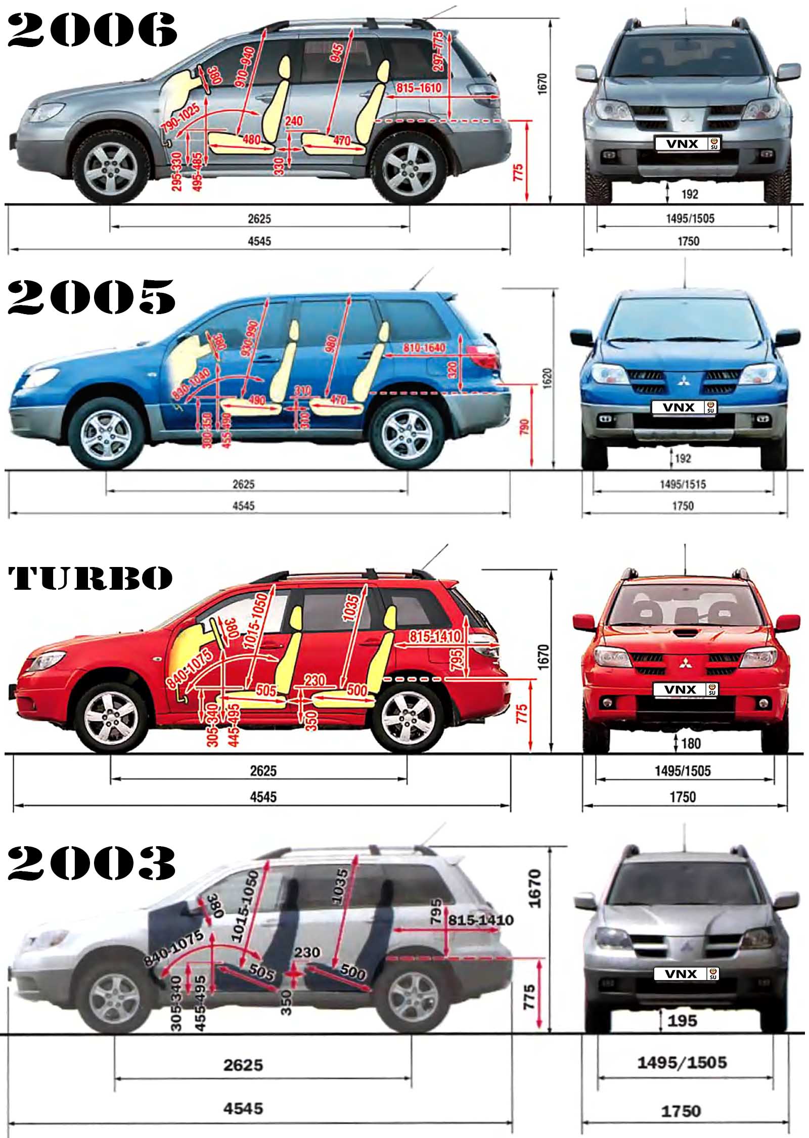
| № | Спецификация / Specs | Данные |
| Габариты (мм/mm) и масса (кг/kg) / Dimensions and Weight | ||
| 1 | Длина / Length | 4545 |
| 2 | Ширина (без/с зеркалами) / Width | 1750-1780 |
| 3 | Высота (загружен/пустой) / Height | 1620/1670 с багажником на крыше |
| 4 | Колёсная база / Wheelbase | 2625 |
| 5 | Дорожный просвет (клиренс) / Ground clearance | 195⇒192 |
| 6 | Снаряжённая масса / Total (curb) weight | 1580 |
| Полная масса / Gross (max.) weight | 2070 | |
|
Двигатель / Engine |
||
| 7 | Тип / Engine Type, Code | Бензиновый, жидкостного охлаждения, четырехтактный, 4G69 MIVEC (Sirius) |
| 8 | Количество цилиндров / Cylinder arrangement: Total number of cylinders, of valves | 4-цилиндровый, рядный, 16V, SOHC с верхним расположением одного распределительного вала |
| 9 | Диаметр цилиндра / Bore | 87.0 мм |
| 10 | Ход поршня / Stroke | 100.0 мм |
| 11 | Объём / Engine displacement | 2378 см³ |
| 12 | Система питания / Fuel supply, Aspiration | Распределенный впрыск топлива MPI (ECI-MULTI) |
| Атмосферный | ||
| 13 | Степень сжатия / Compression ratio | 9.5:1 |
| 14 | Максимальная мощность / Max. output power kW (HP) at rpm | 118 кВт (160 л.с.) при 5750 об/мин |
| 15 | Максимальный крутящий момент / Max. torque N·m at rpm | 216 Нм при 4000 об/мин |
|
Трансмиссия / Transmission |
||
| 16 | Сцепление / Clutch type | Гидротрансформатор с блокировкой/ Torque Converter |
| 17 | КПП / Transmission type | W4A4B INVECS-II АКПП 4 Автоматическая, четырёхступенчатая, гидромеханическая, адаптивная |
О Книге
- Название: Mitsubishi Outlander 2002-2007 Руководство по ремонту и техническому обслуживанию
- Бензиновые двигатели: 4G63 2.0 л (1997 см³) 126-136-139 л.с./93-100-102 кВт, 4G64 2.4 л (2351 см³) 133-139 л.с./98-102 кВт и 4G69 2.4 л (2378 см³) 160-163 л.с./118-120 кВт
- Выпуск с 2001 года
- Серия: «Профессионал»
- Год издания: 2013
- Автор: Коллектив авторов
- Издательство: «Ассоциация независимых издателей»
- Формат: PDF
- Страниц в книге: 525
- Размер: 307.80 МБ
- Язык: Русский
- Количество электросхем: 57
Руководство по эксплуатации и техническому обслуживанию автомобиля Mitsubishi Outlander XL 2007 года выпуска.
Рекомендуем перед началом ремонта или обслуживания изучить руководство, это позволит избежать проблем при эксплуатации и узнать о всех функциях и особенностях автомобиля.
◀Скачать Workshop Manual Mitsubishi Lancer Evolution IV/V
Скачать Technical Information Manual Mitsubishi Pajero 1991 г▶
Сборник руководств на английском языке по кузовному ремонту автомобиля Mitsubishi Outlander 2004-2006 годов выпуска.
- Автор: —
- Издательство: Mitsubishi Motors Corp.
- Год издания: 2003-2005
- Страниц: —
- Формат: PDF
- Размер: 23,7 Mb
Руководство на английском языке по техническому обслуживание и ремонту автомобиля Mitsubishi Outlander 2011 года выпуска.
- Автор: —
- Издательство: Mitsubishi Motors Corp.
- Год издания: 2010
- Страниц: 7200
- Формат: PDF
- Размер: 191,0 Mb
Сборник мультимедийных руководств на английском языке по техническому обслуживанию и ремонту автомобиля Mitsubishi Outlander 2007-2012 годов выпуска.
- Автор: —
- Издательство: Mitsubishi Motors Corp.
- Год издания: —
- Страниц: —
- Формат: ISO
- Размер: 2,2 Gb
Сборник мультимедийных руководств на английском языке по техническому обслуживанию и ремонту автомобиля Mitsubishi Outlander 2013-2016 годов выпуска.
- Автор: —
- Издательство: Mitsubishi Motors Corp.
- Год издания: —
- Страниц: —
- Формат: ISO
- Размер: 1,9 Gb
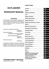
Руководство на английском языке по техническому обслуживанию и ремонту + схемы электрооборудования автомобиля Mitsubishi Outlander первого поколения.
- Автор: —
- Издательство: Mitsubishi Motors Corp.
- Год издания: 2003
- Страниц: —
- Формат: PDF
- Размер: 147,9 Mb
Сборник руководств на английском языке по техническому обслуживание и ремонту автомобиля Mitsubishi Outlander 2007 года выпуска.
- Автор: —
- Издательство: Mitsubishi Motors Corp.
- Год издания: 2006
- Страниц: —
- Формат: PDF
- Размер: 167,3 Mb
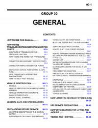
Сборник руководство на английском языке по техническому обслуживание и ремонту автомобиля Mitsubishi Outlander 2013 года выпуска.
- Автор: —
- Издательство: Mitsubishi Motors Corp.
- Год издания: 2011
- Страниц: —
- Формат: PDF
- Размер: 133,0 Mb
Сборник руководство на английском и немецком языках по техническому обслуживанию и ремонту автомобиля Mitsubishi Outlander первого поколения.
- Автор: —
- Издательство: Mitsubishi Motors Corp.
- Год издания: 2006
- Страниц: —
- Формат: PDF
- Размер: 428,8 Mb

Руководство по техническому обслуживанию и ремонту автомобиля Mitsubishi Outlander третьего поколения
- Автор: —
- Издательство: Mitsubishi Motors Corp.
- Год издания: —
- Страниц: —
- Формат: PDF
- Размер: 107,4 Mb
Руководство по эксплуатации, техническому обслуживанию и ремонту + каталог расходных запчастей автомобиля Mitsubishi Outlander 2002-2007 годов выпуска с бензиновыми двигателями объемом 2,0/2,4 л.
- Автор: —
- Издательство: Легион-Автодата
- Год издания: —
- Страниц: 526
- Формат: —
- Размер: —
Руководство по эксплуатации, техническому обслуживанию и ремонту + каталог расходных запчастей автомобиля Mitsubishi Outlander III с 2012 года выпуска с бензиновыми двигателями объемом 2,0/2,4/3.0 л.
- Автор: —
- Издательство: Легион-Автодата
- Год издания: —
- Страниц: 590
- Формат: —
- Размер: —
Руководство по эксплуатации, техническому обслуживанию и ремонту + каталог расходных запчастей автомобиля Mitsubishi Outlander 2006-2012 годов выпуска с бензиновыми двигателями объемом 2,0/2,4/3.0 л.
- Автор: —
- Издательство: Легион-Автодата
- Год издания: —
- Страниц: 738
- Формат: —
- Размер: —
Руководство по эксплуатации и ремонту автомобилей Mitsubishi Airtrek и Mitsubishi Outlander XL с 2005 года выпуска с бензиновыми и дизельными двигателями.
- Автор: —
- Издательство: Монолит
- Год издания: —
- Страниц: 458
- Формат: —
- Размер: —
Руководство по эксплуатации и ремонту автомобиля Mitsubishi Outlander с 2009 года выпуска с бензиновыми двигателями объемом 2,0/2,4/3,0 л.
- Автор: —
- Издательство: Монолит
- Год издания: —
- Страниц: 360
- Формат: —
- Размер: —
Руководство по эксплуатации и ремонту автомобиля Mitsubishi Outlander с 2013 года выпуска с бензиновыми и дизельными двигателями.
- Автор: —
- Издательство: Монолит
- Год издания: —
- Страниц: 456
- Формат: —
- Размер: —

Руководство по эксплуатации и техническому обслуживанию автомобиля Mitsubishi Outlander XL с 2006 года выпуска.
- Автор: —
- Издательство: MoToR
- Год издания: —
- Страниц: 510
- Формат: —
- Размер: —
Сборник руководств по эксплуатации и техническому обслуживанию автомобиля Mitsubishi Outlander третьего поколения.
- Автор: —
- Издательство: Mitsubishi Motors Corp.
- Год издания: 2013
- Страниц: —
- Формат: PDF
- Размер: 161,4 Mb

Руководство по эксплуатации и техническому обслуживанию автомобиля Mitsubishi Outlander XL 2007 года выпуска.
- Автор: —
- Издательство: Mitsubishi Motors Corp.
- Год издания: —
- Страниц: 522
- Формат: PDF
- Размер: 27,7 Mb
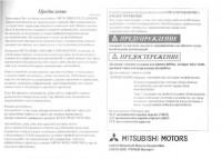
Руководство по эксплуатации и техническому обслуживанию автомобиля Mitsubishi Outlander XL после рестайлинга.
- Автор: —
- Издательство: Mitsubishi Motors Corp.
- Год издания: 2010
- Страниц: —
- Формат: PDF
- Размер: 85,1 Mb
Руководство по эксплуатации и техническому обслуживанию автомобиля Mitsubishi Outlander первого поколения.
- Автор: —
- Издательство: Mitsubishi Motors
- Год издания: 2005
- Страниц: 350
- Формат: PDF
- Размер: 15,0 Mb

Мультимедийное руководство по эксплуатации, техническому обслуживанию и ремонту автомобиля Mitsubishi Outlander с 2003 года выпуска с двигателями объемом 2,0/2,4 л.
- Автор: —
- Издательство: Новая версия
- Год издания: —
- Страниц: —
- Формат: —
- Размер: 255,4 Mb


- Manuals
- Brands
- Mitsubishi Manuals
- Automobile
- Outlander 2007
- Owner’s manual
-
Contents
-
Table of Contents
-
Bookmarks
Related Manuals for Mitsubishi Outlander 2007
Summary of Contents for Mitsubishi Outlander 2007
-
Page 1
Специально для Руководство пользователя Mitsubishi Outlander‘007 a.k.a XL *на английском языке* от dr. -
Page 2: Table Of Contents
Table of contents Overview General information Locking and unlocking Seat and seat belts Instruments and controls Starting and driving For pleasant driving For emergencies Vehicle care Maintenance Specifications…
-
Page 3
Overview Instruments and controls E00100102300 Headlamp levelling switch* P. 3-60 Sonar switch* P. 4-50 Combination headlamps and dipper switch P. 3-56 Turn-signal lever P. 3-63 Front fog lamp switch* P. 3-64 Instruments P. 3-2 Active stability control (ASC) OFF Windscreen wiper and switch* P. -
Page 4
Overview Headlamp levelling switch P. 3-60 Sonar switch P. 4-50 Windscreen wiper and washer switch P. 3-66 Rear window wiper and washer switch P. 3-68 Instruments P. 3-2 Active stability control (ASC) OFF switch P. 4-37 Combination headlamps and dipper switch P. 3-56 Turn-signal lever P. -
Page 5
Digital clock* P. 5-74 Supplemental restraint system Audio system* P. 5-16, 5-40 (SRS) — airbag (for the front HDD navigation & Mitsubishi Multi-Communication System* passenger’s seat) P. 2-53, 2-60 Hazard warning flasher switch P. 3-64 Upper glove box P. 5-120 Air conditioning P. -
Page 6
Digital clock* P. 5-74 Centre ventilators Audio system* P. 5-16, 5-40 P. 5-2 Supplemental restraint system HDD navigation & Mitsubishi Multi-Communication System* (SRS) — airbag (for the front pas- senger’s seat) P. 2-53, 2-60 Hazard warning flasher switch P. 3-64 Upper glove box P. -
Page 7
Overview Interior E00100201737 Electric remote-controlled outside rear-view mirrors switch P. 4-9 Adjustable seat belt anchor P. 2-37 Lock switch P. 1-51 Seat belts P. 2-33 Room lamp (rear) P. 5-115 Central door lock switch P. 1-38 Electric window control switch P. 1-51 Sun visors P. -
Page 8
Overview Head restraints P. 2-22 Sunglasses holder P. 5-126 SRS curtain airbag* P. 2-53, 2-65 Sunroof switch* P. 1-55 Map lamp & room Cargo area cover P. 5-131 lamp (front) P. 5-115 Quarter trim box P. 5-126 Bottle holder P. 5-129 Luggage floor box (5 persons) P. -
Page 9
Overview Electric remote-controlled outside rear-view mirrors switch P. 4-9 Central door lock Adjustable seat belt anchor P. 2-37 switch P. 1-38 Seat belts P. 2-33 Lock switch P. 1-51 Room lamp (rear) P. 5-115 Electric window control switch P. 1-51 Sun visor P. -
Page 10
Overview Head restraints P. 2-22 Sunglasses holder P. 5-126 SRS curtain airbag* P. 2-53, 2-65 Sunroof switch* P. 1-55 Map lamp & room lamp (front) P. 5-115 Cargo area cover P. 5-131 Bottle holder P. 5-129 Luggage floor box (5 persons) P. 5-127 Armrest P. -
Page 11
Overview Luggage area E00100400699 Accessory socket P. 5-113 Luggage hook P. 5-133 Luggage hook P. 5-133 Jack P. 6-9 Tools P. 6-9 Luggage hook P. 5-133 Luggage hook P. 5-133… -
Page 12
Overview Exterior E00100501929 Windscreen wipers P. 3-66 Sunroof* P. 1-55 Electric window control P. 1-50 Bonnet P. 8-3 Fuel tank filler P. 2 Outside rear-view mirror P. 4-9 Headlamps P. 3-56, 8-35, 8-37 Position lamps P. 3-56, 8-35, 8-40 Turn-signal lamps/Hazard warning lamps Turn-signal lamps P. -
Page 13: Locking And Unlocking
Overview Split tailgate P. 1-43 Keyless entry system P. 1-6 Antenna P. 5-73 Keyless operation system* P. 1-9 Locking and unlocking the doors P. 1-35 Rear spoiler Rear window wiper P. 3-68 Rear fog lamp P. 3-65, 8-35, 8-47 Size of tyres and wheels P. 9-9 Tyre inflation pressures P.
-
Page 14
General information Fuel selection ……Filling the fuel tank ……Installation of accessories . -
Page 15: Fuel Selection
If you moved away and did something else (for example, cleaning your windscreen) part-way through the refuelling process, you could pick up a fresh charge of static electricity. ● If the tank cap must be replaced, use only a MITSUBISHI MOTORS original part.
-
Page 16
General information Fuel tank capacity 60 litres Refuelling 1. Before filling with fuel, stop the engine. 2. The fuel tank filler is located on the rear left side of your vehicle. Open the fuel tank filler door with the release lever located the side of the driver’s seat. -
Page 17
General information 3. Open the fuel tank filler tube by slowly turning the cap 4. Insert the gun in the tank port as far as it goes. anticlockwise. CAUTION ● Do not tilt the gun. 5. When the gun stops automatically, remove the gun half the way in the tank port. -
Page 18: Installation Of Accessories
We recommend you to consult your MITSUBISHI MOTORS ferent manufactures available in the market, it is not possible, Authorised Service Point. not only for MITSUBISHI MOTORS, but also a MITSUBISHI ● The installation of accessories, optional components, etc., MOTORS Authorised Service Point, to check whether the…
-
Page 19: Modification/Alterations To The Electrical Or Fuel Systems
General information Modification/alterations to the electrical or Genuine Parts fuel systems E00200500499 MITSUBISHI MOTORS has gone to great lengths to bring you E00200400368 a superbly crafted automobile offering the highest quality and MITSUBISHI MOTORS CORPORATION has always manu- dependability. factured safe, high quality vehicles. In order to maintain this…
-
Page 20: Safety And Disposal Information For Used
General information Safety and disposal information for used engine oil E00200600155 WARNING ● Prolonged and repeated contact may cause serious skin disorders, including dermatitis and cancer. ● Avoid contact with the skin as far as possible and wash thoroughly after any contact. ●…
-
Page 22
Locking and unlocking Keys ……..1- Electronic immobiliser (Anti-theft starting system). -
Page 23: Keys
Locking and unlocking Keys Type 2 E00300100858 Type 1, Type 2 Two keys are provided. The keys fit all locks. Keep one in a safe place as a spare key. Type 1 1- Key for the electronic immobiliser and keyless entry system 2- Key number tag 1- Key for the electronic immobiliser 2- Key number tag…
-
Page 24
Locking and unlocking Type 3 NOTE Two keyless operation key and two emergency keys are pro- ● You can remove the emergency key from the keyless vided. Keep one keyless operation key and one emergency key operation key to lock or unlock the glove box. Refer to in a safe place together as a set of spare keys. -
Page 25: Electronic Immobiliser (Anti-Theft Starting System)
Locking and unlocking ● The engine is designed so that it will not start if the Electronic immobiliser IDcode registered in the immobiliser computer and the (Anti-theft starting system) key’s ID code do not match. Refer to the section entitled E00300200703 “Electronic immobiliser”…
-
Page 26
Locking and unlocking NOTE ● In the following cases, the vehicle may not be able to receive the registered ID code from the registered key and the engine may not start. • When the key contacts a key ring or other metallic or magnetic object. -
Page 27: Keyless Entry System
To obtain a replacement or extra spare key, take your will be locked or unlocked as desired. It is also possible to vehicle and all remaining key to your MITSUBISHI operate the door mirrors, electric window. MOTORS Authorized Service Point. All the keys have to be re-registered in the immobiliser computer unit.
-
Page 28
● It is possible to modify functions as follows: For further information, please contact your authorized MITSUBISHI MOTORS dealer. • The time for automatic relocking can be changed. • The confirmation function (blinking of the turn-signal… -
Page 29
● If you wish to add a remote control switch, we recom- To extend mend you to contact your MITSUBISHI MOTORS Within 30 seconds of unlocking the doors and tailgate using the Authorised Service Point. UNLOCK switch (2), press the UNLOCK switch twice rapidly A maximum of 4 remote control switches are available for to return the door mirrors to their extended positions. -
Page 30: Keyless Operation System
Locking and unlocking Keyless operation system E00305600018 The keyless operation system allows you to lock and unlock the doors and tailgate and start the engine simply by carrying the keyless operation key with you. The keyless operation key can also be used as the keyless entry system remote control switch.
-
Page 31
Please con- with strong radio waves or noise. sult an authorised MITSUBISHI MOTORS dealer. In such cases, use the emergency key. • You can limit operations to locking and unlocking the Refer to “To operate without using the keyless operation… -
Page 32
Locking and unlocking Operating range of the keyless operation system Operating range for locking and unlocking the doors and tailgate E00305700019 If you are carrying the keyless operation key, enter the operat- E00306200011 ing range of the keyless operation system, and operate a door The operating range is about 70 cm from the driver’s door, or tailgate switch or handle, the ID code for your key is veri- front passenger’s door, and tailgate handle. -
Page 33
Locking and unlocking Operating range for starting the engine NOTE ● Locking and unlocking are only possible when the door or E00306300012 The operating range is the interior of the vehicle. tailgate is operated while the keyless operation key is being detected. -
Page 34
If you wait longer than 3 seconds and pull on one of the handles, the doors and tailgate will be unlocked. The time allowed for checking that the vehicle is locked can be adjusted. For further information, please contact your authorised MITSUBISHI MOTORS dealer. 1-13… -
Page 35
For further information, please contact When you are carrying the keyless operation key, if you grip your authorised MITSUBISHI MOTORS dealer. the handle on the driver’s door or front passenger’s door or pull ● To unlock, securely grip the sensor (B) on the rear of a… -
Page 36
30 seconds. NOTE ● Functions can be modified as stated below. For further information, please contact your authorised MITSUBISHI MOTORS dealer. • Set the confirmation function (flashing of the turn-signal lamps) to operate only when the vehicle is locked or only when the vehicle is unlocked. -
Page 37
● The switch operations for the door and tailgate can be tion system : Ignition switch” on page 1-17, 1-27. changed as follows. For further information, please con- tact your authorised MITSUBISHI MOTORS dealer. • Disable the “Close” operation of the sunroof and electric window control. -
Page 38: Ignition Switch
Locking and unlocking Ignition switch The engine is stopped, but the audio system and other electric E00306500014 In order to prevent theft, the engine will not start unless a pre- devices can be operated. registered keyless operation key is used. (Engine immobiliser function) The engine is running, and all the vehicle’s electrical devices If you are carrying the keyless operation key, you can start the…
-
Page 39
Locking and unlocking When turning from “LOCK” (PUSH OFF) to “ACC” When turning from “ACC” to “LOCK” E00306600015 E00306700016 Push the ignition switch and then turn it slowly. Put the gearshift lever into the “N” (Neutral) position, and slowly turn the ignition switch while pushing until it is in the “LOCK”… -
Page 40
Locking and unlocking Warning activation CAUTION E00305900011 In order to prevent vehicle theft or the accidental operation of ● Do not remove the ignition key from the ignition the keyless operation system, the buzzer and the display on the switch while driving. The steering wheel will be information screen in the multi-information display are used to locked, causing loss of control. -
Page 41
If any of the following warnings are activated, please contact Keyless operation key take-out monitoring system an authorised MITSUBISHI MOTORS dealer. When the ignition switch is in any position other than “LOCK” (PUSH OFF) and you open any of the doors and take the key- less operation key out from the vehicle and the keyless opera- There is a fault in the keyless operation system. -
Page 42
For further information, please contact your authorised MITSUBISHI MOTORS dealer. ● Even if you have the keyless operation key within the… -
Page 43
Locking and unlocking Door ajar prevention system Ignition switch turn-off reminder system When the ignition switch is in the “LOCK” (PUSH OFF) posi- When the ignition switch is in any position other than the tion, if you try to lock the doors and tailgate by pressing one of “LOCK”… -
Page 44
Locking and unlocking Steering wheel lock Starting E00306800017 E00306900018 To lock Tips for starting ● Do not operate the starter motor continuously longer than Turn the steering wheel until it is locked. 10 seconds; doing so could run down the battery. If the To unlock engine does not start, turn the ignition switch back to Turn the ignition switch to the “ACC”… -
Page 45
Locking and unlocking Starting the engine CAUTION E00307000016 1. Fasten the seat belt. ● Never attempt to start the engine by pushing or pull- 2. Apply the parking brake. ing the vehicle. 3. Depress and hold the brake pedal. ● Do not run the engine at high rpm or drive the vehi- 4. -
Page 46
● A ticking noise may be heard after starting the engine. This is not an abnormal condition. The noise will disap- pear after a short time of engine running. If the ticking noise continues after the engine is warmed up, please contact your authorized MITSUBISHI MOTORS dealer. 1-25… -
Page 47
Locking and unlocking Locking and unlocking the doors NOTE ● Only use the emergency key for emergencies. If the key- Turning the emergency key in the forward direction locks the doors, and turning it in the rear direction unlocks the doors. less operation key battery wears out, replace it as quickly Also refer to “Locking and unlocking: Doors”… -
Page 48
Locking and unlocking Electronic immobiriser (Anti-theft startingsystem) Ignition switch E00307300019 E00307400010 The electronic immobiriser is designed to significantly reduce In order to prevent theft, the engine will not start unless a pre- the possibility of vehicle theft. The purpose of the system is to registered emergency key is used (engine immobiliser func- immobilise the vehicle if an invalid start is attempted. -
Page 49
Locking and unlocking When turning from “LOCK” to “ACC” NOTE ● Your vehicle equipped with an electronic immobiliser, to 1. Take the emergency key out of the keyless operation key. Refer to “Emergency keys” on page 1-25. start the engine, the ID code which the transponder inside 2. -
Page 50
Locking and unlocking 3. Insert the emergency key into the ignition switch, and turn When turning from “ACC” to “LOCK” slowly while pushing. 1. While pushing the ignition switch, turn to the “LOCK” position and pull out the key. 2. Install the ignition switch cover. 3. -
Page 51
Locking and unlocking Steering wheel lock Starting E00307500011 E00307600012 To lock Tips for starting ● Do not operate the starter motor continuously longer than Turn the emergency key to the “LOCK” position. Turn the steering wheel until it is locked. 10 seconds;… -
Page 52
Locking and unlocking Starting the engine CAUTION 1. Fasten the seat belt. ● Never attempt to start the engine by pushing or pull- 2. Apply the parking brake. 3. Depress and hold the brake pedal. ing the vehicle. ● Do not run the engine at high rpm or drive the vehi- 4. -
Page 53
The noise will disappear after a short time of engine running. 1- LOCK ( If the ticking noise continues after the engine is warmed ) switch up, please contact your authorized MITSUBISHI 2- UNLOCK ( ) switch MOTORS dealer. 3- Indicator lamp… -
Page 54
For further information, please contact your authorised Lock switch (1) two times in succession causes the Dead MITSUBISHI MOTORS dealer. Lock System to be set (refer to “Setting the system” on • The time from pressing of the UNLOCK switch (2) to page 1-40). -
Page 55
● The remote control switch can be modified as stated With a vehicle that has a Dead Lock System, it is possible to below. Please consult your authorised MITSUBISHI set the Dead Lock System using the remote controller (refer to MOTORS dealer. -
Page 56: Doors
Locking and unlocking Doors CAUTION E00300401034 ● Do not leave the remote control switch in direct sun- CAUTION light to prevent damage by overheating. ● The remote control switch is a precision electronic ● Make sure the doors are closed: driving with doors device.
-
Page 57
Locking and unlocking To lock or unlock with the key To lock or unlock from inside the vehicle 1- Lock 1- Lock 2- Unlock 2- Unlock Pull the inside door handle toward you to open the door. NOTE ● If the vehicle is equipped with the keyless operation sys- NOTE tem, the doors can be locked or unlocked with the emer- ●… -
Page 58
Locking and unlocking ● In a vehicle that has a Dead Lock System, it is not possi- Ignition switch on reminder system ble to unlock the door by pushing the lock knob to the When the engine was started using the keyless operation unlock side while the Dead Lock System is set (refer to function “Dead Lock System”… -
Page 59: Central Door Locks
Locking and unlocking Central door locks Driver’s doors with key E00300800712 Vehicles without the keyless entry system and vehicles NOTE without the keyless operation system ● Each of the doors can be locked or unlocked independ- Using the key on driver’s door locks or unlocks driver’s doors ently by using the inside lock knob.
-
Page 60
Locking and unlocking Driver’s door with central door lock switch Using the central door lock switch on the driver’s door locks or unlocks all doors and the tailgate. 1- LOCK 2- UNLCOK 1-39… -
Page 61: Dead Lock System
Locking and unlocking Dead Lock System* Vehicles with keyless entry system E00305100039 The Dead Lock System helps to prevent theft. When the key- less entry system has been used to lock all of the doors and the tailgate, the Dead Lock System makes it impossible to unlock the doors using the inside lock knobs.
-
Page 62
(flashing of the hazard warning lamps). • It is possible to change the number of times the opera- tion confirmation function causes the hazard warning lamps to flash for confirmation of system operation. For details, please contact a MITSUBISHI MOTORS Authorised Service Point. 1-41… -
Page 63
“ON” or “ACC” position. ● It is possible to adjust the duration after which automatic relocking takes place when the UNLOCK switch (B) has been pressed. For details, please contact a MITSUBISHI MOTORS Authorised Service point. 1-42… -
Page 64: Child-Protection» Rear Doors
Locking and unlocking “Child-protection” rear doors Split tailgate E00300900250 E00301400539 WARNING ● It is dangerous to drive with the tailgate (upper gate and lower gate) open, since carbon monoxide (CO) gas can enter the cabin. You cannot see or smell CO. It can cause uncon- sciousness and even death.
-
Page 65
Locking and unlocking To lock or unlock from outside the vehicle To lock or unlock from inside the vehicle The tailgate can be locked or unlocked by using the central door lock switch (driver side). Vehicles without the keyless entry system and vehicles without the keyless operation system 1- Insert (or remove) the key 2- Lock… -
Page 66
Locking and unlocking To open 1. After unlocking the tailgate, pull the handle and lift the upper gate. 1- Lock 2- Unlock NOTE ● Repeated continuous operating between lock and unlock could cause the central door locks’ built-in protection cir- cuit to prevent the system from operating. -
Page 67
Locking and unlocking 2. Move the lever in the direction of the arrow and slowly NOTE fold down the lower gate. ● Do not jump on to the lower gate or subject it to a strong impact. This could damage the lower gate. ●… -
Page 68
Locking and unlocking To close 2. Pull the upper gate grip (B) downward as illustrated. Gen- tly slam the upper gate from the outside so that it is com- 1. Raise the lower gate until it locks properly in position pletely closed. -
Page 69
Locking and unlocking ● Gas struts (D) and wires (E) are installed to support the CAUTION tailgate. ● When closing the upper gate, always ensure your or To prevent damage or faulty operation. • Do not hold the gas struts and wires when closing the other person’s fingers cannot be caught by the tailgate. -
Page 70: Inside Tailgate Release
Locking and unlocking Inside tailgate release To open 1. Open the lid (A) inside of the tailgate. E00303400096 The inside tailgate release is designed to provide a way to open the tailgate in the case of a discharged battery. The tailgate release lever (see illustration) is mounted on the tailgate.
-
Page 71: Electric Window Control
Locking and unlocking Electric window control 2. Move the lever (B) up to open the tailgate. E00302200358 The electric windows can only be operated with the ignition switch in the “ON” position. WARNING ● Before operating the electric window control, make sure that nothing is capable of being trapped (head, hand, finger, etc.).
-
Page 72
Locking and unlocking Electric window control switch E00302300711 Each door window opens or closes while the corresponding switch is operated. 1- Driver’s door window 2- Front passenger’s door window 3- Rear left door window 4- Rear right door window 5- Lock switch 1-51… -
Page 73
Locking and unlocking The switches can be used to operate all door windows. A door NOTE window can be opened or closed by operating the correspond- ● Repeated operation with the engine stopped will run down ing switch. the battery. Operate the electric window switches only Press the switch down to open the door window, and pull up while the engine is running. -
Page 74
● The settings can be changed so that when the lock switch is “ON” the front passenger and rear door windows cannot be opened or closed even with the driver’s switch. Please consult an authorised MITSUBISHI MOTORS dealer. 1- Lock… -
Page 75
WARNING ● Functions can be modified as stated below. ● If the safety mechanism is activated three or more Please consult an authorized MITSUBISHI MOTORS dealer. times successively, the safety mechanism will be tem- ● The timer period can be adjusted. -
Page 76: Sunroof
Locking and unlocking ● If the safety mechanism is activated three or more times in Sunroof* a row, the safety mechanism will be cancelled and the E00302800178 door window will not close correctly. Sunroof In such a case, the following procedure should be imple- The sunroof can only be operated with the ignition switch in mented to rectify this situation.
-
Page 77
Locking and unlocking To close, press the switch (3) NOTE ● The safety mechanism can be activated if the driving con- To stop the moving sunroof, press the switch (1) or (2). ditions or other circumstances cause the sunroof to be sub- To tilt up, press the switch (2) jected to a physical shock similar to that caused by a The rear sunroof will rise to ventilate the car interior. -
Page 78
Locking and unlocking Sunshade WARNING Slide the sunshade manually to open and close it. ● Do not put head, hands or anything else out of the sunroof opening while driving the vehicle. ● Never leave a child (or other person who might not be capable of safe operation of the sunroof switch) in the vehicle alone. -
Page 79
Locking and unlocking ● Be careful, not to put any wax on the weatherstrip (black rubber) around the sunroof opening. If stained with wax, the weatherstrip cannot maintain a weatherproof seal with the sunroof. ● After washing the vehicle or after it has rained, wipe off any water that is on the sunroof before operating it. -
Page 80: Seat And Seat Belts
Seat and seat belts Seat……..2- Arrangement of seats .
-
Page 81: Seat
Seat and seat belts Seat E00400100761 1-Front seat 2- Second seat ● To adjust forward or backward → P. 2-6 ● To adjust forward or backward → P. 2-11 ● To recline the seatback → P. 2-7 ● To recline the seatback → P. 2-11 ●…
-
Page 82: Arrangement Of Seats
Seat and seat belts Arrangement of seats E00400200342 The seats can be arranged as desired to the patterns shown below. 5 persons 7 persons Normal usage 7 persons → P. 2-14 Flat seat → P. 2-30…
-
Page 83
Seat and seat belts 5 persons 7 persons Folding the seatbacks for- ward (Second seat) → P. 2-25 Making a luggage room To collapse the second seat → P. 2-25… -
Page 84: Seat Adjustment
Seat and seat belts Seat adjustment CAUTION E00400300271 ● Make sure the seat is adjusted by an adult or with Adjust the driver’s seat so that you are comfortable and that adult supervision for correct and safe operation. you can reach the pedals, steering wheel, switches etc. while ●…
-
Page 85: Front Seat
Seat and seat belts Front seat Power type Adjust the seat by operating the switch as indicated by the E00400400142 arrows. To adjust forward or backward E00400500316 Manual type Pull the seat adjusting lever and adjust the seat forward or backward to the desired position, and release the adjusting lever.
-
Page 86
Seat and seat belts To recline the seatback CAUTION E00400600418 ● The reclining mechanism of the seatback is spring Manual type loaded, causing it to return to the vertical position In order to recline the seatback, lean forward slightly, pull the when the lock lever is operated. -
Page 87
Seat and seat belts To adjust seat height (driver’s seat only) Power type Adjust the seatback angle by operating the switch as indicated E00400700419 by the arrows. Manual type To adjust the seat height, operate the lever repeatedly to adjust. 1- To move to forward direction 2- To recline rearward 1- Raise… -
Page 88
Seat and seat belts Power type To adjust the seat height, operate the switch as indicated by arrows. NOTE ● To prevent the battery from discharging, use the power seat while the engine is on. 2- To move the rear of the seat up and down 1- To move the front of the seat up and down 3- To move the whole seat up and down… -
Page 89: Heated Seats
Seat and seat belts Armrest Heated seats E00400900206 E00401100263 The lid of the floor console box can be moved forward and The heated seats can be operated with the ignition switch in the backward, and used as an armrest. “ON” position. The indication lamp (A) will illuminate while the heater is on.
-
Page 90: Second Seat
Seat and seat belts Second seat CAUTION E00401300151 ● Operate in the high position for quick heating. Once When a person is sitting in the second seat, raise the head the seat is warm, set the heater to low to keep it restraints to height at which it lock in position.
-
Page 91
Seat and seat belts WARNING WARNING ● To make sure that the seat is securely locked in place ● To reduce the risk of serious or life-threatening inju- after adjustment, try to move it forward and back- ries in an accident or sudden stop, make sure that ward without using the adjustment lever. -
Page 92
Seat and seat belts Armrest Accessing the underfloor-stowable third seat (7 persons) E00401700403 To use the armrest, fold it down. E00412200017 To return to the original position, push it backward flush with The passenger gets on or off the third seat after collapsing the the seat. -
Page 93: Third Seat (7 Persons)
Seat and seat belts Third seat (7 persons) WARNING E00402700165 ● For reasons of safety, whenever passenger sit in the To fold out the underfloor-stowable third seat third seat, be sure to raise all the head restraints of The third seat is stowed under the floor. Use the seat when the second seats.
-
Page 94
Seat and seat belts To fold out 3. Pull the belt (B) located in the centre of the seatback and raise the seatback. 1. Open the tailgate. Refer to “Tailgate” on page 1-43. 2. Pull up the cover from the rear direction. Fasten the pulled up cover to the seatback with the band (A). -
Page 95
Seat and seat belts 4. Pull the belt (C- black) to release the lock. 6. Raise the head restraints. 5. Tilt the whole of the third seat to the rear. 2-16… -
Page 96
Seat and seat belts 7. Lift up the whole of the third seat from the floor and fas- NOTE ten it to the front. ● Push up the third seat to the front to make sure that is securely locked in place. 2-17… -
Page 97
Seat and seat belts To retract WARNING 1. Open the tailgate. Refer to “Tailgate” on page 1-43. ● When lifting up the third seat, do not put your 2. Pull up the cover (A) from the rear direction. Fasten the hands in the areas indicated by the red labels (D). -
Page 98
Seat and seat belts 3. Slide the knob while folding the head restraints (C) to the 4. Stow the whole of the third seat under the floor while pull- rear, and stow to the front one side at a time. ing the belt (D- grey). -
Page 99
Seat and seat belts NOTE CAUTION ● Push down on the rear of the third seat until it is securely ● Do not put your hands on the end trim (E) when locked to the floor. ● If the third seat is difficult to lock, return it to its original stowing the third seat under the floor. -
Page 100
Seat and seat belts 5. Tilt the whole of the seat to the front. NOTE ● Before folding the seatback, make sure that the front of the third seat is securely locked to the floor. ● If the third seat is difficult to lock, make sure that the rear of the third seat is securely locked to the floor, and then strongly tilt the whole of the seat to the front to lock in place. -
Page 101: Head Restraints
Seat and seat belts Head restraints 6. Fold the seatback while pulling the belt (F) located in the centre of the seatback. E00403300793 WARNING ● Driving without the head restraints in place can cause you and your passengers serious injury or death in an accident.
-
Page 102
Seat and seat belts To remove To remove the head restraints, lift the head restraint with the height adjusting knob (A) pushed in. Installation To install the head restraints, first confirm that they are facing the correct direction, and then insert them into the seatback while pressing the height adjusting knob (A) in the direction indicated by the arrows. -
Page 103
Seat and seat belts CAUTION CAUTION ● Confirm that the height adjusting knob (A) is cor- ● The head restraints for the seats differ in shape and rectly adjusted as shown in the illustration, and also size. When installing head restraints, make sure the lift the head restraints to ensure that they do not head restraints are fitted in their respective seats. -
Page 104: Making A Luggage Room
Seat and seat belts Making a luggage room To collapse 1. Lower the head restraints of the second seat to the lowest E00403400156 position. Refer to “Head restraints: To adjust height” on WARNING page 2-22. 2. Use the second seat lever (A), the luggage area switch (B) ●…
-
Page 105
Seat and seat belts Luggage area switch operation Second seat lock release belt operation While the tailgate or a rear door is open, pull the switch (B) for about 1 second or more. 2-26… -
Page 106
Seat and seat belts 3. The seatbacks fold forward, and then the entire seat unit CAUTION rises up while moving forward. ● The exhaust pipe is still hot for a while after stop- ping the engine, so be sure not to touch it. ●… -
Page 107
Seat and seat belts To replace CAUTION 1. While supporting the seat with your hand, lower the seat ● On vehicles with a third seat, when returning the while pulling the lock release belt (A) on the rear of the second seat while there are occupants in the third seat cushion. -
Page 108
Seat and seat belts 2. Push down the seats until they click to firmly lock in NOTE ● On vehicles with a third seat, the rear of the seat cushion place. of the second seat is equipped with a foot lamp (B). When the lock release belt is pulled, the lamp illuminates for about 10 seconds to light the foot area of the third seat occupants. -
Page 109: Making A Flat Seat
Seat and seat belts Making a flat seat 3. Fold up the seatback while pulling the lock release belt on the rear of the seatback. E00404300279 By removing the head restraints and fully reclining the seat- backs of the seats, one large flat seat is achieved. WARNING ●…
-
Page 110
Seat and seat belts 1. Remove the head restraints from the front seats, raise the 2. Move the second seat fully to the rear (refer to “To adjust armrest and remove the cargo area cover (if so equipped) forward or backward” on page 2-6). (refer to “Head restraints”… -
Page 111
Seat and seat belts 3. Slide the front seats fully forward, then recline the seat- 4. Recline the seatbacks of the second seat backwards (refer backs backwards to achieve a flat surface (refer to “To to “To recline the seatback” on page 2-7). adjust forward or backward”… -
Page 112: Seat Belts
Seat and seat belts Seat belts 5. The flat seat configuration is now complete. To return the seats to the normal position, reverse the above procedure. E00404800388 To protect you and your passengers in the event of an accident, it is most important that the seat belts be worn correctly While drive.
-
Page 113
Seat and seat belts WARNING WARNING ● Always place the shoulder belt over your shoulder ● Never hold a child in your arms or on your lap when and across your chest. Never put it behind you or riding in this vehicle, even if you are wearing your under your arm. -
Page 114
Seat and seat belts 3-point type seat belt (with emergency locking WARNING mechanism) ● Never wear the lap portion of the belt across your E00404900480 abdomen. During accidents it can press sharply This type of belt requires no length adjustment. Once worn, the against abdomen and increase the risk of injury. -
Page 115
Seat and seat belts Driver’s seat belt warning lamp and display Subsequently, if the seat belt is still not fastened, the warning lamp and tone will be activated to remind the driver to fasten E00409800354 A tone and warning lamp are used to remind the driver to fas- the seat belt whenever the vehicle is stopped and started off ten the seat belt. -
Page 116
Seat and seat belts Front passenger seat belt warning lamp Adjustable seat belt anchor (front seats) E00411600027 E00405000329 The front passenger seat belt warning lamp is located in the The seat belt anchor height can be adjusted. instrument panel. Raise or lower the seat belt anchor (A) while pressing the lock knob (B). -
Page 117
Seat and seat belts Second and third seat belt storage Seat belt plate storage After passing the belt through the rear notch (C), insert the E00405300205 Store the second seat belts (excluding the centre seat belt) and plate into the front notch (D). third seat belts as shown in the illustration. -
Page 118: Pregnant Women Restraint
Seat and seat belts To store the second seat belt buckles Pregnant women restraint E00412100016 E00405600077 When the second seat belts are not in use, insert the buckles WARNING into the seat cushion slits. ● Seat belts work for everyone, including pregnant women.
-
Page 119: Seat Belt Pre-Tensioner System And Force Limiter System
MITSUBISHI and/or front passenger and the ignition switch is in the “ON” or MOTORS guidelines.
-
Page 120: Srs Warning
Seat and seat belts SRS warning Child restraint E00405900243 E00406400942 The same warning lamp/display is shared by the SRS airbags When transporting children in your vehicle, some type of child and the pre-tensioner seat belts. Refer to “SRS warning restraint system should always be used according to the size of lamp/display”…
-
Page 121
Seat and seat belts Caution for installing the child restraint on Use rearward facing child restraints in the rear seat or turn off the front passenger’s airbag ON-OFF switch (refer to “To turn vehicle with front passenger airbag an airbag off” on page 2-59). The label shown here is attached on vehicles with front passen- ger airbag. -
Page 122
Seat and seat belts Infants and small children WARNING E00406600407 When transporting infants and small children in your vehicle, ● A REARWARD FACING CHILD RESTRAINT follow the instruction given below. should be used in the rear seat whenever possible; if used in the front seat, adjust the seat to the most rearward position. -
Page 123: Older Children
Seat and seat belts Depending on the seating position in the vehicle and the NOTE ● Before purchasing a child restraint system, try installing it child restraint system that you have, the child restraint can be attached using one of the following two locations: in the rear seat to make sure there is a good fit.
-
Page 124
Seat and seat belts Suitability for various ISOFIX positions E00406800412 Vehicle ISOFIX positions Mass Group Size class Fixture Front Passenger Second Outboard carrycot ISO/L1 ISO/L2 -Up to 10 kg ISO/R1 -Up to 13 kg ISO/R1 IL, IL* ISO/R2 ISO/R3 -9 to 18 kg ISO/R2 ISO/R3 ISO/F2… -
Page 125
● X- ISOFIX position not suitable for ISOFIX child restraint systems in this mass group and/or this size class. IL (Genuine part information) Genuine part No. ECE No. MZ313589 E1-04301146 MZ313045 E1-04301133 NOTE ● MITSUBISHI MOTORS Europe B.V. reserves the right to changes without any prior announcement. For detail information, consult your MITSUBISHI MOTORS Authorised Service Point. 2-46… -
Page 126
● U- Suitable for “universal” category restraints approved for use in this mass group. ● UF- Suitable for forward-facing “universal” category restraints approved for use in this mass group. ● L- Suitable for particular child restraints (MITSUBISHI MOTORS genuine parts). ● B- Built-in restraint approved for this mass group. -
Page 127
ECE No. MZ312807 E1-04301146 MZ313589 E1-04301146 MZ312745 E1-04301136 MZ313045 E1-04301133 MZ312808 E1-04301148 NOTE ● There is no applicable MITSUBISHI MOTORS Genuine Parts to the Mass Group “0-Up to 10 kg”. For detail information, consult your MITSUBISHI MOTORS Authorised service point. 2-48… -
Page 128
Seat and seat belts Installing a child restraint system to the lower Tether anchorage locations anchorage (ISOFIX child restraint mountings) There are 3 child restraint anchorage points located on the back of the rear seatbacks. These are for fastening the child restraint and tether anchorage tether straps to the 3 second seat seating positions. -
Page 129
Seat and seat belts Child restraint system with ISOFIX mountings To install The child restraint system is designed only for seats that incor- 1. Remove any foreign material in or around the connectors porate lower anchorages. Retain the child restraint system and ensure the vehicle seat belt is in its normal storage using the lower anchorages. -
Page 130
Seat and seat belts Installing a child restraint system to a 3-point 3. Remove the head restraint from the location in which you wish to install a child restraint. type seat belt (with emergency locking 4. Latch the tether strap hook (F) of the child seat to the mechanism) tether anchor bar (G) and tighten the top tether strap hook E00408700196… -
Page 131: Seat Belt Inspection
● Do not attempt to repair or replace any part of the sat belt assemblies; we recommend you to have this work done by a MITSUBISHI MOTORS Author- ised Service Point. Incorrect repair or replacement result in serious injury in the event of a collision.
-
Page 132: Supplemental Restraint System (Srs)-Airbag
Seat and seat belts Supplemental restraint system (SRS)-airbag How the supplemental restraint system works E00407300616 E00407201117 The SRS includes the following components: The information for SRS airbags includes important informa- tion concerning the driver’s and front passenger’s airbags, the side airbags and the curtain airbags. The SRS airbags are designed to supplement the primary pro- tection of the driver and front passenger side seat belt systems by providing those occupants with protection against head and…
-
Page 133
Seat and seat belts The airbags deployment produces a sudden, loud noise, and releases some smoke and powder, but these conditions are not injurious, and do not indicate a fire in the vehicle. People with respiratory problems may feel some temporary irritation from chemicals used to produce the deployment;… -
Page 134
Seat and seat belts WARNING WARNING ● IT IS VERY IMPORTANT TO BE PROPERLY ● Do not sit on the edge of the seat, or lean head or SEATED. chest close to the steering wheel or instrument panel. A driver or front passenger too close to the steering Do not put feet or legs on or against the instrument wheel or instrument panel during airbag deploy- panel. -
Page 135
Seat and seat belts Use rearward facing child restraints in the rear seat or turn off WARNING the front passenger’s airbag ON-OFF switch (refer to “To turn ● Infants and small children should never be unre- an airbag off” on page 2-59). strained, stand up against the instrument panel or held in your arms or on your lap. -
Page 136
Seat and seat belts Caution for installing the child restraint on WARNING vehicle with front passenger airbag ● A FRONTWARD FACING CHILD RESTRAINT E00408800038 should be used in the rear seat whenever possible; if The label shown here is attached on vehicles with front passen- they must be used in the front passenger seat, adjust ger airbag. -
Page 137
Seat and seat belts Front passenger’s airbag ON-OFF switch Front passenger’s airbag off indicator lamp E00410100083 E00410200097 The front passenger’s airbag ON-OFF switch can be used to The front passenger’s airbag off indicator is located in the disable the front passenger’s airbag. If you have a rearward instrument panel. -
Page 138
We recommend you to switched on again. have the system inspected by a MITSUBISHI MOTORS Authorised Service Point. • If the indicator remains on when the front passen- ger’s airbag ON-OFF switch is turned ON, do not… -
Page 139
Seat and seat belts Driver’s and passenger’s front airbag system E00407400369 The driver’s airbag is located under the padded cover in the middle of the steering wheel. The front passenger’s airbag is contained in the instrument panel above the upper glove box. The driver airbag and the front passenger airbag are designed to inflate at the same time even if the passenger seat is not occupied. -
Page 140
Seat and seat belts Deployment of front airbags The front airbags will deploy if the severity of impact is above the designed threshold level, comparable to an approximately E00407500807 25 km/h (16 mph) collision when impacting straight into a solid The front airbags ARE DESIGNED TO DEPLOY wall that does not move or deform. -
Page 141
Seat and seat belts The front airbags MAY NOT DEPLOY when… The front airbags ARE NOT DESIGNED TO DEPLOY when… With certain types of frontal collisions, the vehicle’s body structure is designed to absorb the shock to help protect the The front airbags are not designed to deploy in conditions occupants from harm (the vehicle body’s front area may where they cannot typically provide protection to the occupant. -
Page 142
Seat and seat belts The front airbags MAY DEPLOY when… WARNING The front airbags may deploy if the bottom of the vehicle suf- ● Do not attach anything to the steering wheel’s pad- fers a moderate to severe impact (undercarriage damage). ded cover, such as badges or accessories. -
Page 143
There is a danger of being burnt. ● The airbag system is designed to work only once. Once the airbags have deployed, they will not work again. They must promptly be replaced, and the entire airbag system inspected, by an authorised MITSUBISHI dealer. 2-64… -
Page 144
Seat and seat belts Curtain airbag system* The label shown here is attached to the seatbacks with a side airbag. E00409100113 The curtain airbags are contained in the front pillars and roof side rail. The curtain airbag is designed to inflate only on the side of the vehicle that is impacted, even with no passenger in the front seat or second seat. -
Page 145
Seat and seat belts Deployment of side airbags and curtain airbags The side airbags and curtain airbags MAY NOT DEPLOY when… E00407700463 With certain types of side collisions, the vehicle’s body struc- The side airbags and curtain airbags ARE DESIGNED ture is designed to absorb the shock to help protect the occu- TO DEPLOY when… -
Page 146
Seat and seat belts The side airbags and curtain airbags ARE NOT DESIGNED TO DEPLOY when… The side airbags and curtain airbags are not designed to deploy in conditions where they cannot usually provide protection to the occupant. Typical conditions are shown in the illustration. 4- Oblique side impacts 5- Vehicle rolls onto its side or roof Because the side airbags and curtain airbags do not protect the… -
Page 147
Seat and seat belts Because the side airbags and curtain airbags do not protect the WARNING occupant in all types of collisions, be sure to always properly wear your seat belts. ● The side airbags and curtain airbags inflates with great force. -
Page 148
Seat and seat belts WARNING WARNING ● Do not allow any second seat occupant to hold onto ● Do not attach a microphone (A) or any other device the seatback of either front seat, in order to reduce or object around the part where the curtain airbags risk of injury from the deploying side airbags. -
Page 149
Failure to follow all of these instructions could lead to serious or fatal injury to the child. ● Work around and on the side airbags and curtain airbags system components should only be done by an authorised MITSUBISHI MOTORS dealer. 2-70… -
Page 150
If you found any tear scratch, crack or damage to the seat fabric near the side airbag, the portion of the front and rear pillars and roof side rail, you should have the SRS inspected by a MITSUBISHI MOTORS Authorised Service Point. 2-71… -
Page 151
SRS and refer that owner to the applica- ble section in this owner’s manual. ● If your vehicle has to be scrapped do this in line with local legislation and contact a MITSUBISHI MOTORS Authorised Service Point to safely dismantle the airbag system. -
Page 152: Instruments And Controls
Instruments and controls Instruments…….3- Multi-information display ….3- Indicator lamp, warning lamp, and information screen display list.
-
Page 153: Instruments
Instruments and controls Instruments Tachometer E00500300445 E00500100401 The tachometer indicates the engine speed (r/min). The tachometer can help you obtain more economical driving and also warns you of excessive engine speeds (Red zone). 1- Speedometer (km or mph + km/h) 2- Multi-information display →…
-
Page 154
Instruments and controls Daytime dipper button (meter illumination control) E00519800013 Each time you press this button, there is a sound and the bright- ness of the instruments changes. NOTE ● If you press and hold the button for longer than about 1 second, the brightness automatically scrolls through its different levels, and stops scrolling when you release the button. -
Page 155: Multi-Information Display
Instruments and controls Multi-information display E00519900014 The following information is included on the multi-information display: warnings, odometer/tripmeter, service reminders, engine coolant temperature, fuel remaining, outside temperature, 4WD operation status, average and momentary fuel consumption, driving range, average speed and meter illumination. It is also possible to change elements such as the language and units used on the multi-information display.
-
Page 156
Instruments and controls NOTE ● The fuel units, temperature units, display language, and Information screen (when the ignition switch is “OFF”) other settings can be changed. P. 3-6 Refer to “Changing the function settings (when the igni- tion switch is “ON”)” on page 3-27. ●… -
Page 157
Instruments and controls “!” mark display screen (when the ignition switch is “OFF”) E00520100016 If you press the multi-information meter switch and return from the warning display screen to the previous screen, the “!” mark is displayed. Refer to “To return to the screen displayed before the warning display”… -
Page 158
Instruments and controls 1- Odometer/Tripmeter 2- Odometer/Tripmeter 3- Service reminder 4- Redisplay of a warning display screen Odometer / Tripmeter E00521200027 Each time you lightly press the multi-information meter switch, the display screen switches. → Odometer / Tripmeter → Odometer / Tripmeter Service reminder →… -
Page 159: Service Reminder
Instruments and controls ● When disconnecting the battery terminal, the memories of Interrupt display screen (when the ignition switch is “OFF”) tripmeter display and display are erased, and their displays return to 0.0 km (0.0 miles). E00520500010 When there is information to be announced, such as lamp Service reminder reminders, the buzzer sounds and the multi-information display E00521200014…
-
Page 160
Instruments and controls To return to the screen displayed before the warning NOTE display ● Warning display screens with a “ ” or “ ” mark dis- Even if the cause of the warning display is not eliminated, you played in the upper right of the screen can be switched. If can return to the screen that was displayed before the warning you want to switch the display, press the multi-informa- display. -
Page 161
Instruments and controls Door ajar warning display screen (when the Information screen (when the ignition switch is ignition switch is “OFF”) turned from “OFF” to “ON”) E00520600011 E00520700012 If any of the doors or the tailgate is not completely closed, this When the ignition switch is turned to the “ON”… -
Page 162
Instruments and controls System check screen Service reminder When the ignition switch is turned to the “ON” position, the When the time for periodic inspection arrives, “PERIODIC system check screen is displayed for about 4 seconds. If there INSPECTION” is displayed for a few seconds after the igni- is no fault in the “Oil pressure warning display”, “Headlamp tion switch “ON”… -
Page 163
Instruments and controls Drive mode indicator display screen Active Stability Control (ASC) OFF display screen* E00520800013 This displays the 4WD status. E00521000012 If you select “4WD LOCK” mode with the drive This is displayed when the active stability con- mode selector, “4WD LOCK” is displayed; if trol (ASC) is turned off with the ASC OFF you select “4WD AUTO”… -
Page 164
Instruments and controls Information screen (when the ignition switch is “ON”) E00521100013 Each time you lightly press the multi-information meter switch, the display screen switches in the following order. When there is no warning display When there is a warning display 3-13… -
Page 165
Instruments and controls Service reminder 1- Odometer / Tripmeter E00521300028 This displays the distance and number of months 2- Odometer / Tripmeter until the next periodic inspection. 3- Service reminder Refer to “Service reminder” on page 3-14. 4- Engine coolant temperature display 5- Driving range display Engine coolant temperature display 6- Average speed display, average fuel consumption display,… -
Page 166
Instruments and controls Driving range display ● The display setting can be changed to the preferred units (km or miles). E00521500017 This displays the approximate driving range Refer to “Changing the function settings (how many more kilometres or miles you can (when the ignition switch is “ON”)”… -
Page 167
Instruments and controls Average speed display NOTE ● “—” is displayed when the average speed E00521600018 This displays the average speed from the last cannot be measured. reset to the present time. ● The initial (default) setting is “Auto reset There are the following 2 mode settings. -
Page 168
Instruments and controls Average fuel consumption display NOTE ● “—” is displayed when the average fuel E00521700019 This displays the average fuel consumption from consumption cannot be measured. the last reset to the present time. ● The initial (default) setting is “Auto reset There are the following 2 mode settings. -
Page 169
Instruments and controls Momentary fuel consumption display Function setting screen E00521800010 E00521900011 While driving, this displays the momentary fuel The “Display language”, “Temperature unit”, consumption, using a bar graph. “Fuel consumption unit”, and “Average fuel con- sumption and speed reset method” settings can NOTE be modified as desired. -
Page 170
Instruments and controls Interrupt display screen (when the ignition switch is “ON”) E00522000019 Warning display When there is information to be announced, such as a system fault, a sound is emitted and the information screen is switched to the warning display screen. Refer to the warning list and take the necessary measures. -
Page 171
Instruments and controls Outside temperature display screen Redisplay of a warning display screen When the “!” mark is displayed, if you lightly press the multi- E00522100010 This displays the temperature outside the vehi- information meter switch a few times, the warning display cle. -
Page 172
Instruments and controls Fuel remaining display screen NOTE ● It may take several seconds to stabilise the display after E00522200011 This displays the amount of fuel remaining. refilling the tank. ● If fuel is added with the ignition switch in the “ON” posi- tion, the fuel gauge may incorrectly indicate the fuel level. -
Page 173
Instruments and controls Fuel remaining warning display E00522400013 When the fuel is reduced to about 10 litres, the information screen switches to the interrupt display of the fuel remaining warning display, and the “ ” mark (B) on the fuel remaining display flashes slowly (about once per second). -
Page 174
Instruments and controls Service reminder 2. Alerts the driver when the inspection time has arrived. We recommend you to consult a MITSUBISHI MOTORS E00522500014 Shows the time until the periodic inspection every 12 months Authorised Service Point. (15,000 km or 9,000 miles ). -
Page 175
Instruments and controls 3. After your vehicle is inspected at an authorised MIT- 1. When you lightly press the multi-information meter SUBISHI MOTORS dealer, it displays the time until the switch a few times, the information screen switches to the next periodic inspection. -
Page 176
● When “—” is displayed, after a certain distance and a cer- tain period of time, the display is reset and the time until the next periodic inspection is displayed. ● If you accidentally reset the display, we recommend you to consult a MITSUBISHI MOTORS Authorised Service Point. 3-25… -
Page 177
Instruments and controls Door ajar warning display screen (when the CAUTION ignition switch is “ON”) ● Before moving your vehicle, check that the warning E00522600015 lamp is OFF. If any of the doors or the tailgate is not completely closed, this displays the open door or tailgate. -
Page 178
Instruments and controls Changing the function settings (when the ignition switch is “ON”) E00522700016 The multi-information display average fuel consumption and speed reset mode, fuel consumption unit, temperature unit, dis- play language, language cooperative control, buzzer sound, and the time until the “REST REMINDER” display appears can be modified as desired. -
Page 179
Instruments and controls NOTE CAUTION ● To return the menu screen to the function setting screen, ● For safety, stop the vehicle before operating. press and hold the multi-information meter switch for While driving, even if you operate the multi-infor- about 2 seconds or more. -
Page 180
Instruments and controls Changing the reset mode for average fuel consumption and average speed E00522900018 The mode conditions for the average fuel consumption and average speed display can be switched between “Auto reset” and “Manual reset”. 1. Press and hold the multi-information meter switch for about 2 seconds or more to switch from the setting mode screen to the menu screen. -
Page 181
Instruments and controls Manual reset mode Changing the fuel consumption display unit • When the average fuel consumption and average speed E00523000016 The display unit for fuel consumption can be switched. The are being displayed, if you hold down the multi-infor- distance, speed, and amount units are also switched to match mation meter switch, the average fuel consumption and the selected fuel consumption unit. -
Page 182
Instruments and controls 3. Press and hold the multi-information meter switch for NOTE about 2 seconds or more to display “AVG UNIT” (fuel ● The display units for the driving range, the average fuel consumption display unit setting). consumption, the average speed and the momentary fuel 4. -
Page 183
Instruments and controls Changing the temperature unit 3. Press and hold the multi-information meter switch for about 2 seconds or more to switch in sequence from °C → E00523100017 The display unit for temperature can be switched. °F → °C. 1. -
Page 184
Instruments and controls 2. Lightly press the multi-information meter switch to select 4. Lightly press the multi-information meter switch to switch in sequence from JAPANESE → ENGLISH → GERMAN “LANGUAGE” (language setting). → FRENCH → SPANISH → ITALIAN → “—” (do not display warning message) →… -
Page 185
Changing the language cooperative control E00523300019 The language used in Mitsubishi Multi-Communication Sys- ® tem (MMCS) (if so equipped) or the Hands-free Bluetooth so equipped) cellular phone interface system with voice recog- nition* can be changed automatically to the same language as that shown in the multi-information display. -
Page 186
• When A (language cooperation enabled) has been selected with the language cooperative control, the lan- guage for Mitsubishi Multi-Communication System ® (MMCS) (if so equipped) or the Hands-free Bluetooth (if so equipped) cellular phone interface system with voice recognition* is automatically changed to the lan- guage selected for the multi-information display. -
Page 187
Instruments and controls NOTE ● The memory of the operation sound setting is erased if the battery is disconnected, and it returns automatically to ON (operation sound on). ● The operation sound setting only deactivates the operation sound of the multi-information meter switch. The warning display and other sounds cannot be deactivated. -
Page 188
Instruments and controls Changing the time until “REST REMINDER” is 3. Press and hold the multi-information meter switch for about 2 seconds or more to display “ALARM” (rest time displayed setting). E00523500011 The time until the display appears can be changed. 1. -
Page 189
Instruments and controls 5. Press and hold the multi-information meter switch for Returning to the factory settings about 2 seconds or more, the setting is changed to the E00523600012 All of the function settings can be returned to their factory set- selected time. -
Page 190
Instruments and controls 3. When you press and hold the multi-information meter switch for about 5 seconds or more, the buzzer sounds and all of the function settings are returned to the factory set- tings. NOTE ● The factory settings are as follows. •… -
Page 191: Indicator Lamp, Warning Lamp, And Information Screen Display List
Instruments and controls Indicator lamp, warning lamp, and information screen display list E00523700013 Indicator and warning lamp list E00523800014 12- Supplemental restraint System (SRS) warning lamp 1- Turn-signal indicator lamps/Hazard warning indicator lamps → P. 2-70 → P. 3-50 13- Check engine warning lamp → P. 3-55 2- High-beam indicator lamp →…
-
Page 192
• Abnormal voltage or a static electricity discharge is generated by the operation of installed electrical equipment (including after-market parts). If the warning display appears many times, we recommend you to consult a MITSUBISHI MOTORS Authorised Service Point. 3-41… -
Page 193
Instruments and controls Warning display list (when the ignition switch is “OFF”) E00524000013 Screen Cause Solution (Reference) ● You have forgotten to turn off the Refer to “Lamps auto-cutout (headlamps lamps. and other lamps)” on page 3-56. ● When the ignition switch was in a posi- ●… -
Page 194
Instruments and controls Screen Cause Solution (Reference) ● There is a fault in the keyless operation Refer to “Keyless operation system” on system. page 1-9. 3-43… -
Page 195
Instruments and controls Warning display list (when the ignition switch is “ON”) E00524100014 Screen Cause Solution (Reference) ● There is a fault in the keyless operation Refer to “Keyless operation system” on system. page 1-9. 3-44… -
Page 196
● There is a fault in the brake system. ● If the warning remains on after you inspect the vehicle, we recommend you to consult a MITSUBISHI MOTORS Authorised Service Point. Refer to “Brake warning display” on page 3-53. -
Page 197
3-55. ● There is a fault in the charging system. ● Immediately stop the vehicle in a safe place. We recommend you to consult a MITSUBISHI MOTORS Authorised Service Point. Refer to “Charge warning display” on page 3-55. -
Page 198
Instruments and controls Screen Cause Solution (Reference) ● There is an automatic headlamp level- ● We recommend you to have it checked. ling fault. Refet to “Automatic headlamp level- ling” on pgae 3-62. ● There is a fault in the active stability ●… -
Page 199
Instruments and controls Other interrupt displays (when the ignition switch is “ON”) E00524200015 The operation status of each system is displayed on the information screen. Refer to the appropriate page for the system for further details. Screen System operation status Reference ●… -
Page 200
Alerts the driver of the time for periodic inspection. Screen Solution Have your vehicle checked by an authorised MITSUBISHI MOTORS dealer. Refer to “Service reminder” for further details on page 3-8. The setting for rest interval can be changed. Screen Solution Stop the vehicle in a safe place, turn off the engine, and take a rest. -
Page 201: Indicator Lamps
Instruments and controls Indicator lamps Rear fog lamp indicator lamp E00502000127 E00501600100 This lamp illuminates while the rear fog lamps Turn-signal indicator lamps/Hazard are on. warning indicator lamps E00501700172 These indicator lamps blink on and off when a Position lamp indicator lamp turn-signal lamp is operating.
-
Page 202: Warning Lamps
Instruments and controls Warning lamps CAUTION E00502400147 ● If the brake warning lamp comes on at Brake warning lamp the same time as the ABS warning E00502500728 lamp, the brake force distribution This lamp will illuminate for a few seconds function is not working so hard brak- when the ignition switch is turned to the “ON”…
-
Page 203: Check Engine Warning Lamp
Instruments and controls Check engine warning lamp CAUTION E00502400147 ● If the lamp illuminates while the This lamp is a part of an onboard diagnostic sys- engine is running, avoid driving at tem which monitors the emissions, engine and high speeds and we recommend you to automatic transmission control systems.
-
Page 204: Information Screen Display
Instruments and controls Charge warning lamp Information screen display E00502700456 E00502400150 This lamp illuminates when the ignition switch Brake warning display is turned “ON”, and goes off after the engine has started. E00502500786 When “RELEASE PARKING BRAKE” is displayed A warning is also displayed on the multi-infor- mation display.
-
Page 205
Instruments and controls When “CHECK” is displayed CAUTION When the ignition switch is turned to the “ON” position, if the ● If the brake warning display is displayed and the brake fluid is low, this warning is displayed. brake warning lamp and the ABS warning lamp are The warning lamp in the instrument cluster also illuminates. -
Page 206
Instruments and controls Charge warning display Oil pressure warning display E00502700502 E00524300016 If there is a fault with the charging system, the “SERVICE If the engine oil pressure drops while the engine is running, the REQUIRED” warning is displayed on the information screen “CHECK”… -
Page 207: Combination Headlamps And Dipper Switch
Instruments and controls Combination headlamps and dipper switch NOTE ● The oil pressure warning display should not be treated as E00506000978 an indication of the engine oil level. The oil level must be Headlamps checked using the dipstick. NOTE ● Do not leave the lights on for a long time while the engine is stationary (not running).
-
Page 208
Instruments and controls Rotate the switch to turn on the lamps. NOTE ● If the front fog lamps (if so equipped) turn on when they are supposed to with the switch in the “AUTO” position, the lamps turn off automatically with the engine switch off. -
Page 209
MITSUBISHI MOTORS Authorised Service Point. the lamps automatically go out when the driver’s door is On vehicles equipped with Mitsubishi Multi-Communica- opened. tion System (MMCS), screen operations can be used to make the adjustment. -
Page 210: Lamp Monitor Buzzer
Instruments and controls Lamp monitor buzzer Dipper (High/Low beam change) E00506100243 E00506200329 [When the engine was started using the key] When the lamp switch is in the “ ” position, the beam If the driver’s door is opened when the key is in the “LOCK” or changes from high to low (or low to high) each time the lever is “ACC”…
-
Page 211: Headlamp Flasher
Instruments and controls Headlamp flasher Headlamp levelling E00506300199 E00517400031 The high beams flash when the lever is pulled slightly (2), and Headlamp levelling switch* will go off when it is released. When the high beam is on, the high beam indicator lamp in the E00517500032 Except for vehicles with discharge headlamps instrument cluster will illuminate.
-
Page 212
Instruments and controls 5 — person seat 7 — person seat Vehicle con- Vehicle dition condition Switch posi- Switch “0” “0” “2” “3” “4” “0” “0” “2” “3” “3” “4” tion position •: 1 person •:1 person :Full luggage loading : Full luggage loading Switch position 0- Driver only / Driver + 1 front passenger Switch position 0- Driver only/Driver + 1 front passenger… -
Page 213: Automatic Headlamp Levelling
Instruments and controls Automatic headlamp levelling* CAUTION E00517600020 ● If the warning is displayed, the system may be mal- Vehicles with discharge headlamps functioning, so we recommend you to have your This mechanism automatically adjusts the direction of the vehicle inspected. headlamps (beam position) depending on changes in the condi- tion of the vehicle, such as the number of occupants or luggage weight.
-
Page 214: Turn-Signal Lever
● It is possible to activate the following functions. For fur- ther information, we recommend you to consult a MIT- SUBISHI MOTORS Authorised Service Point. On vehicles equipped with Mitsubishi Multi-Communica- tion System (MMCS), screen operations can be used to make the adjustment. Refer to the separate owner’s man- ual for details.
-
Page 215: Hazard Warning Flasher Switch
Instruments and controls Hazard warning flasher switch Fog lamp switch E00506600408 E00506700034 Use the hazard warning flasher switch when the vehicle has to Front fog lamp switch* be parked on the road for any emergency. E00508300119 The hazard warning flashers can always be operated, regard- The front fog lamps can be operated while the headlamps and less of the position of the ignition switch.
-
Page 216
Instruments and controls ● In case of vehicles with Daytime Running Lamp, the front fog lamps can be operated even if the lamp switch is set to the “OFF” position. Rear fog lamp switch E00508400107 The rear fog lamp can be operated when the headlamps or front fog lamps (if so equipped) turn on. -
Page 217: Wiper And Washer Switch
For furher information, we recommend you to consult a MIST- Misting function MITSUBISHI MOTORS Authorised Service Point. The wipers will operate once. On vehicles equipped with Mitsubishi Multi-Communica- OFF- tion System (MMCS), screen operations can be used to make the adjustment. Refer to the separate owner’s man-…
-
Page 218: Windscreen Washer
Instruments and controls Windscreen washer Misting function Move the lever in the direction of the arrow and release, to E00507200371 The washer fluid will be sprayed onto the windscreen by pull- operate the wipers once. ing the lever toward you. The wipers operate automatically Use this function when you are driving in mist or drizzle.
-
Page 219
● It is possible to activate the following functions. For fur- ther information, we recommend you to consult a MIT- SUBISHI MOTORS Authorised Service Point. On vehicles equipped with Mitsubishi Multi-Communica- tion System (MMCS), screen operations can be used to make the adjustment. Refer to the separate owner’s man- ual for details. -
Page 220
Instruments and controls Headlamp washer switch* Precautions to observe when using wipers and washers E00507800146 The headlamp washer can be operated with the ignition switch E00510000025 ● If the moving wipers become blocked by ice or other in the “ON” or “ACC” position and the lamp switch at the deposits on the glass, the motor may burn out even if the “… -
Page 221: Wiper Deicer Switch
Instruments and controls Wiper deicer switch* Rear window demister switch E00507700057 E00507900697 The rear window demister switch can be operated when the The rear window demister switch can be operated when the engine is running. engine is running. When the front wipers have frozen to the windscreen at the Push the switch to turn on the rear window demister.
-
Page 222: Horn Switch
Instruments and controls ● When cleaning the inside of the rear window, use a soft Horn switch cloth and wipe lightly along the heater wires, being care- E00508000318 ful not to damage the wires. Press the steering wheel on or around the “ ”…
-
Page 224: Starting And Driving
Starting and driving Economical driving ……4- Reversing sensor system* ….4- 47 Driving, alcohol and drugs.
-
Page 225: Economical Driving
Starting and driving Economical driving Idling The vehicle consumes fuel even during idling. Avoid extended E00600100545 For economical driving, there are some technical requirements idling whenever possible. that have to be met. The prerequisite for low fuel consumption Speed is a properly adjusted engine. In order to achieve longer life of At higher the vehicle speed, more fuel is consumed.
-
Page 226: Driving, Alcohol And Drugs
Starting and driving Driving, alcohol and drugs Safe driving techniques E00600200070 E00600300156 Drunk driving is one of the most frequent causes of accidents. Driving safety and protection against injury cannot be fully Your driving ability can be seriously impaired even with blood ensured.
-
Page 227: Floor Mats
Starting and driving Floor mats Carrying children in the vehicle ● Never leave your vehicle unattended with the key and WARNING children inside the vehicle. Children may play with the driving controls and this could lead to an accident. ● Keep floor mats clear of the pedals by correctly lay- ●…
-
Page 228: Running-In Recommendations
Starting and driving Running-in recommendations Parking brake E00600400841 E00600500392 During the running-in period for the first 1,000 km (600 miles), To park the vehicle, first bring in to a complete stop, fully it is advisable to drive your new vehicle using the following engage the parking brake.
-
Page 229
Starting and driving To release CAUTION ● Before driving, be sure that the parking brake is fully released and brake warning lamp is off. If you drive without the parking brake fully released, “RELEASE PARKING BRAKE” will appear on the information screen in the multi-infor- mation display. -
Page 230: Parking
Starting and driving Parking Parking with the engine running Never leave the engine running while you take a short E00600600553 To park the vehicle, fully engage the parking brake, and then sleep/rest. Also, never leave the engine running in a closed or move the gearshift lever to 1st or “R”…
-
Page 231: Steering Wheel Height Adjustment
Starting and driving Steering wheel height adjustment Inside rear-view mirror E00600700248 E00600800366 1. Release the tilt lock lever while holding the steering wheel Adjust the rear-view mirror only after making any seat adjust- ments so you have a clear view to the rear of the vehicle. 2.
-
Page 232: Outside Rear-View Mirrors
Starting and driving To reduce the glare Outside rear-view mirrors The lever (A) at the bottom of the mirror can be used to adjust E00600900338 the mirror to reduce the glare from the headlamps of vehicles To adjust the mirror position behind you during night driving.
-
Page 233
Starting and driving Retracting and extending the outside mirrors 1. Place the lever (A) to the same side as the mirror whose adjustment is desired. E00601100353 The outside mirror can be folded in towards the side window to prevent damage when parking in narrow areas. CAUTION ●… -
Page 234
Starting and driving NOTE ● Be careful not to get your hands trapped while a mirror is moving. ● If the vehicle is equipped with the keyless entry system or keyless operation system, the mirrors can also be retracted or extended with the remote control switch. Refer to “Keyless entry system”… -
Page 235: Heated Mirror
Use the mirror switch to extend the mirrors. ● Functions can be modified as stated below. Please consult a MITSUBISHI MOTORS Authorised Service Point. • Automatically extend when the ignition switch is turned to the “ON” position, and automatically retract when the driver’s door is opened after the ignition switch is turned…
-
Page 236: Ignition Switch
Starting and driving Ignition switch LOCK The engine is stopped and the steering wheel locked. The key E00601400792 can only be inserted and removed in this position. [For vehicles equipped with the keyless operation system] For information on operations for vehicles equipped with the keyless operation system, refer to “Keyless operation system: The engine is stopped, but the audio system and other electric Ignition switch”…
-
Page 237
Starting and driving To remove the key NOTE ● This vehicle is equipped with ignition switch illumination. Press the key in the “ACC” position. While pressing the key • The ignition switch illumination comes on while the turn it to the “LOCK” position and then remove. driver’s door is opened and remains on for about 30 sec- onds after the driver’s door is closed. -
Page 238: Steering Wheel Lock
Starting and driving Steering wheel lock CAUTION E00601500256 ● Do not remove the ignition key from the ignition [For vehicles equipped with the keyless operation system] switch while driving. The steering wheel will be For information on operations for vehicles equipped with the locked, causing loss of control.
-
Page 239: Starting The Engine
Starting and driving Starting the engine CAUTION E00601600475 ● Remove the key when leaving the vehicle. [For vehicles equipped with the keyless operation system] In some countries, it is prohibited to leave the key on For information on operations for vehicles equipped with the the vehicle when parked.
-
Page 240
Starting and driving Starting the engine CAUTION E00601700900 ● Release the ignition key as soon as the engine starts 1. Insert the ignition key and fasten the seat belt. to avoid damaging the starter motor. 2. Apply the parking brake. ●… -
Page 241
Starting and driving Fuel injection amount learning process 5. Turn the ignition key to the “ON” position. The diesel preheat indicator lamp will first illuminate, and E00616000057 To keep exhaust emissions and engine noise low, the engine then after a short time go out, indicating that preheating is very occasionally performs a learning process for the fuel completed. -
Page 242: Manual Transmission
Starting and driving Manual transmission NOTE ● If it is hard to shift into 1st, depress the clutch pedal again; E00602000258 the shift will then be easier to make. The shift pattern is shown on the gearshift lever knob. Be sure ●…
-
Page 243
Starting and driving Possible driving speed CAUTION E00610800561 Avoid shifting down at high speed, as this may cause excessive ● Do not pull up the pull-ring (A) when moving the engine speed (the tachometer needle into the red zone) and gearshift lever to any position other than the “R”… -
Page 244: Electronically Controlled 4Wd System
Starting and driving Electronically controlled 4WD system Drive mode-selector The drive mode can be switched by turning the dial while the E00604900105 The electronically controlled 4WD system is an 4-wheel drive ignition switch is in the “ON” position. system that allows one of three drive modes to be selected with a switch, in accordance with the driving conditions.
-
Page 245
Starting and driving Drive mode indicator Drive mode Display Normally the indicator illuminates when the ignition switch is turned to the “ON” position, and then the drive mode is dis- played a few seconds after the engine is started. 4WD AUTO 4WD LOCK CAUTION ●… -
Page 246
4WD system and the safety device has acti- “SLOW DOWN” is also displayed in the informa- vated. Have an inspection made by a MITSUBISHI tion screen in the multi-information display. MOTORS Authorised Service Point. Reduce speed, and if the indicator goes out after driving a while, resume driving as before. -
Page 247: 4-Wheel Drive Operation
Starting and driving 4-wheel drive operation CAUTION E00606600483 ● Always use tyres of the same size, type, and brand Your vehicle has been designed primarily for use on pavement. that have no wear differences. Using tyres that differ But its unique 4-wheel drive system allows you to occasionally in size, type, brand, or wear amount may activate travel on unpaved roads, to campgrounds, picnic sites, and sim- the protection of the drive-system components, caus-…
-
Page 248
Always drive care- tion of the tyres, and check the tyre pressures. ● MITSUBISHI MOTORS is not responsible to the opera- fully, taking account of the road conditions. ● Improperly operating this vehicle on or off-pave-… -
Page 249
Starting and driving Turning sharp corners On snowy or icy roads When turning a sharp corner in “4WD LOCK” position at low Set the drive mode-selector to “4WD AUTO” or “4WD speed, a slight difference in steering may be experienced simi- LOCK”… -
Page 250: Driving Through Water
Starting and driving Driving on sandy or muddy roads NOTE ● Avoid sudden braking, sudden acceleration and sharp Set the drive mode-selector to “4WD LOCK” and then gradu- turning; such operations could result in the vehicle ally depress the accelerator pedal for a smooth start. Keep the becoming stuck.
-
Page 251: Inspection And Maintenance Following Rough Road Operation
Starting and driving Inspection and maintenance following CAUTION rough road operation ● Never drive through water that is deep enough to E00606700224 cover wheel hubs, axles or exhaust pipe. Do not After operating the vehicle in rough road conditions, be sure to change gears while driving through water.
-
Page 252: Cautions On The Handling Of 4-Wheel Drive Vehicles
Starting and driving Cautions on the handling of 4-wheel drive Towing vehicles E00606800397 Tyres and wheels Since the driving torque can be applied to the 4 wheels, the driving performance of the vehicle when operating in 4-wheel drive is greatly affected by the condition of the tyres. Pay close attention to the tyres.
-
Page 253: Braking
Starting and driving Braking CAUTION E00607000716 ● Even in “2WD” drive mode, the vehicle cannot be All the parts of the brake system are critical to safety. We rec- towed with the front or the rear wheels on the ommend you to have the vehicle checked at regular intervals ground.
-
Page 254: Warning Display
Starting and driving Warning display When driving downhill The brake warning lamp illuminates to indicate a fault in the It is important to take advantage of the engine braking by shift- braking system. A warning is also displayed on the multi-infor- ing to a lower shift position while driving on steep downhill mation display.
-
Page 255: Anti-Lock Brake System (Abs)
Starting and driving Anti-lock brake system (ABS) ● When the ABS is activated, you may feel the brake pedal pulsation and the vibrations of the vehicle body and steer- E00607100834 ing wheel. You may also hear a characteristic noise. At Environmental conditions can have an effect on braking.
-
Page 256
If tyre types or sizes are mixed, ABS may not func- tion normally. ● Never install a limited slip differential, which is not MITSUBISHI Genuine parts, as the ABS may not function normally. CAUTION We recommend you to consult a MITSUBISHI ●… -
Page 257
Starting and driving If the waning lamp / display illuminate while driving E00607300722 If only the ABS warning lamp/display illuminate Avoid hard braking and high-speed driving. Stop the vehicle in a safe place. Restart the engine and check to see whether the lamp goes out after a few minutes driving;… -
Page 258
Starting and driving After driving on icy roads Rear E00618800020 After driving on snowy roads, remove any snow and ice which may have become adhered to the wheel areas. When doing this, be careful not to damage the wheel speed sensors (A) and cables located at each wheel on vehicles equipped with an ABS. -
Page 259: Power Steering System
Starting and driving Power steering system Active stability control (ASC)* E00607400156 E00616700038 When the engine is stopped, the power steering system will not The active stability control (ASC) takes overall control of the function and it will require greater manual effort to operate the anti-lock brake system, traction control function and stability steering wheel.
-
Page 260
Starting and driving Stability control function NOTE ● A whining sound may be emitted from the engine com- E00619100017 The stability control function is designed to help the driver partment in the following situations. The sound is associ- maintain control of the vehicle on slippery roads or during ated with checking the operations of the ASC. -
Page 261
Starting and driving ● If you continue to press the “ASC OFF” switch after the ASC is turned off, the “mistaken operation protection function” will activate and the ASC will turn back on. After the “mistaken operation protection function” is acti- vated, it will not be possible to turn the ASC off. -
Page 262
Starting and driving ASC warning display CAUTION E00619400010 If an abnormal condition occurs in the system while driving, ● When display blinks, ASC is operating, which display will blink or the warning display, “SERVICE means that the road is slippery or that your vehicle’s REQUIRED”… -
Page 263: Cruise Control
Starting and driving Cruise control* CAUTION E00609100522 Cruise control is an automatic speed control system that lets ● [If warning display, “SERVICE you keep the same driving speed. It can be activated at 40 km/h REQUIRED” and the display are shown at the (25 mph) or more.
-
Page 264
Starting and driving Cruise control switches NOTE ● When operating the cruise control switches, correctly press each cruise control switch. The cruise control may be turned off automatically if two or more of the cruise control switches are pressed at the same time. -
Page 265
Starting and driving “CRUISE” control indicator To activate E00609200233 E00609300478 This indicator will come on when the cruise control “ON OFF” 1. Lightly press the “ON OFF” switch (A). switch (A) is pressed to turn on the cruise control system. NOTE ●… -
Page 266
Starting and driving To increase the set speed 2. Press the “COAST SET” switch (B) while driving at the desired speed. E00609400411 There are 2 ways to increase the set speed. “ACC RES” switch If you press and hold down the “ACC RES” switch (C), the speed will gradually increase. -
Page 267
Starting and driving To decrease the set speed Accelerator pedal Use the accelerator pedal to reach your desired speed and then E00609500340 There are 2 ways to reduce the set speed. push the “COAST SET” switch (B) and release the switch momentarily to set a new desired cruising speed. -
Page 268
Starting and driving To temporarily increase or decrease the speed Brake pedal Use the brake pedal, which disengages the cruise control, then E00617300028 push the “COAST SET” switch (B) and release the switch To temporarily increase the speed momentarily to set a new desired cruising speed. Press the accelerator pedal as you would normally. -
Page 269
Starting and driving To deactivate To temporarily decrease the speed Apply the brakes to decrease the speed. To return to the previ- E00609700456 The cruise control can be turned off as follows: ously set speed, press the “ACC RES” switch. Refer to “To ●… -
Page 270: Reversing Sensor System
Starting and driving To resume the set speed Reversing sensor system* E00609800369 E00615500068 If the cruise control is deactivated by the condition described in This system operates when you are backing the vehicle. It uses “To deactivate” on page 4-46, you can resume the previously corner and back sensors to detect an obstacle and sounds a set speed by pressing the “ACC RES”…
-
Page 271
Starting and driving Obstacle detection areas Reversing sensor system detection areas Depending on whether the vehicle is equipped with a towbar, E00615600102 The detection areas of the corner and back sensors are limited you can change the reversing sensor system between the stand- to those shown in the illustration. -
Page 272
Have the vehicle inspected at a • Objects that are thin, such as wire nets or ropes. MITSUBISHI MOTORS Authorised Service Point. • Objects that absorb sound waves, such as snow. ● The sensors do not detect objects located in the area •… -
Page 273
Starting and driving The reversing sensor system operation indicator lamp (A) will NOTE ● The buzzer may sound lower than the normal warning turn off that the system has stopped operating. It will flash in case there is a malfunction in the system. For sound when the reversing sensor system is receiving ultra- details, refer to “Reversing sensor system operation indicator sonic noise from other sources, but this is not a malfunc-… -
Page 274
Starting and driving The warning buzzer sounds when the system detects an obsta- Warning for obstacles cle during operation. If there is an obstacle behind the vehicle, a warning buzzer sounds to indicate the distance between the vehicle and the NOTE obstacle. -
Page 275
Within approx. 60 cm Continuous lamp will continue blinking until the system reverts to the nor- mal state. Have the vehicle inspected at a MITSUBISHI CAUTION MOTORS Authorised Service Point. ● The distances given are to be used for reference only, as errors may be caused by various factors, such as temperature, humidity, or the shape of the obstacles. -
Page 276: Cargo Loads
NOTE the rear view blocked, and your cargo being thrown ● We recommend you to use a genuine MITSUBISHI roof inside the cabin if you suddenly have to brake can carrier, since the brackets to be used have a special shape.
-
Page 277: Roof Carrier Precaution
Starting and driving Roof carrier mounting brackets Roof carrier precaution CAUTION ● Make sure that the weight of the luggage does not exceed the allowable roof load. If the allowable roof load is exceeded, this may cause damage to the vehicle. The roof load is the total allowable load on the roof (the weight of the roof carrier plus the weight of lug- gage placed on the roof carrier).
-
Page 278: Trailer Towing
● Remove the roof carrier before using an automatic car device that meets all relevant regulations in your area, mounted wash. at an authorised MITSUBISHI dealer. ● Be sure that adequate clearance is maintained for raising The regulations concerning the towing of a trailer may differ the sunroof (if so equipped) and/or the tailgate when from country to country.
-
Page 279
Starting and driving Towing bar mounting specifications See the following table for fixing points (A) for the towing bar. 4-56… -
Page 280
Starting and driving Operating hints 553 mm ● To prevent the clutch from slipping, do not rev the engine 171 mm more than is required when starting off. ● Be sure that the driving speed does not exceed the 100 353 mm km/h (62 mph) for trailer operation. -
Page 282: For Pleasant Driving
For pleasant driving Ventilators …….5- Cup holder ……. 5-127 Automatic air conditioning .
-
Page 283: Ventilators
For pleasant driving Ventilators Air flow and direction adjustments E00700200420 E00700100357 Centre ventilators Move the knob (A) to adjust the air flow direction. To close the ventilator, fully move the knob (A) to the inner side. 1- Centre ventilators 2- Side ventilators 1- Close 2- Open…
-
Page 284
For pleasant driving Side ventilators Mode selection dial Move the knob (A) to adjust the air flow direction. E00726500014 To change the amount of air flowing from the ventilators, turn To close the ventilator, fully move the knob (A) to the outer the mode selection dial. -
Page 285
For pleasant driving Changing the mode selection Face position Air flows only to the upper part of the passenger compartment. E00700300737 To change the position and amount of air flowing from the ven- tilators, turn the mode selection dial. These symbols are used in the next several illustrations to dem- onstrate the quantity of air coming from the ventilators. -
Page 286
For pleasant driving Foot/face position Foot position Air flows to the upper part of the passenger compartment, and Air flows mainly to the leg area. flows to the leg area. NOTE ● With the mode selection dial between the “ ”… -
Page 287
For pleasant driving Foot/demister position Demister position Air flows to the leg area, the windscreen and the door win- Air flows mainly to the windscreen and the door windows. dows. NOTE ● With the mode selection dial between the “ ”… -
Page 288: Automatic Air Conditioning
For pleasant driving Automatic air conditioning NOTE ● There is a photo sensor (A) and interior air temperature E00702400211 sensor (B) inside the vehicle. The air conditioning can only be used while the engine is run- Do not place anything on these sensors. The sensors will ning.
-
Page 289
For pleasant driving Blower speed selection dial Temperature control dial E00702800172 E00703000227 Select the blower speed by turning the blower speed selection Turn the temperature control dial clockwise or anticlockwise. dial clockwise or anticlockwise. Turn the dial clockwise to increase the air flow and anticlock- wise to decrease the air flow. -
Page 290
For pleasant driving Air selection switch NOTE ● While the engine coolant temperature is low, the tempera- E00703400348 ture of the air from the heater will be cool/cold until the To change the air selection, simply press the air selection engine warms up even if you have selected warm air with switch. -
Page 291
For pleasant driving Customising the air selection (Changing function CAUTION settings) ● Normally, use the outside position to keep the wind- E00725800010 Functions can be changed as desired, as stated below. screen and side windows clear and quickly remove fog or frost from the windscreen. ●… -
Page 292
For pleasant driving Air conditioning switch NOTE ● If a problem is detected in the air conditioning system, the E00703500509 Push the switch to turn the air condition on, indicator lamp (A) air conditioning operation indicator lamp (A) blinks. Press will come on. -
Page 293
For pleasant driving Operating the system in automatic mode Customising the air conditioning switch (Changing function settings) E00704100355 E00725900011 Functions can be changed as desired, as stated below. ● Enable automatic air conditioning control: If the mode selection dial or blower speed selection dial is turned to the “AUTO”… -
Page 294
For pleasant driving Operating the system in manual air mode The outlet port (except “ ”), recirculation/outside air select and blower speed, and ON/OFF of air conditioning will be con- E00704200167 Blower speed and ventilator mode may be controlled manually trolled automatically. -
Page 295
For pleasant driving For ordinary demisting For quick demisting Perform the following settings to prevent the misting of the windscreen and door windows, and heat the leg area. 1. Set the mode selection dial to the “ ” position. 2. Set your blower to the maximum speed. 1. -
Page 296: Important Operation Tips For The Air Conditioning
For pleasant driving Important operation tips for the air Air conditioning system refrigerant and lubricant recommendations conditioning If the air conditioning seems less effective than usual, the cause E00708300485 might be a refrigerant leak. We recommend you to have the ●…
-
Page 297: Air Purifier
For pleasant driving Air purifier LW/MW/FM digital tuning radio with CD player* E00708400415 An air filter has been incorporated into this air conditioning so E00708500780 that pollen and dust are cleaned from the air. The audio system can only be used when the ignition switch is Replace the air filter periodically as its ability to clean the air in the “ON”…
-
Page 298
For pleasant driving Volume and tone control panel To adjust the tone E00708600390 E00708800406 Press the SOUND switch (4) to select: TYPE → FIELD → BASS → MID → TREBLE → FADER → BALANCE → audio control mode OFF. QUICK ACCESS MODE To access the sound customisation features quickly, push and hold the SOUND switch (4), then turn the switch clockwise or anticlockwise to access your desired sound customisation set-… -
Page 299
For pleasant driving TYPE (Acoustic characteristic selection) FIELD (Sound field selection) 1. Turn the SOUND switch (4) to select the desired music 1. Turn the SOUND switch (4) to select the desired sound type. field. 2. Press the SOUND switch (4) to set the audio system to the 2. -
Page 300
For pleasant driving BALANCE (Left /Right balance control) Turn the SOUND switch (4) to balance volume from the left and right speakers. NOTE ● When set to 0, it will beep. ● When TYPE or FIELD is changed, the sound will cut out briefly, but this does not indicate a malfunction. -
Page 301
For pleasant driving Radio control panel and display E00708900481 1- PWR (Power ON/OFF) switch 2- AM/FM (FM/MW/LW selection) button 3- Memory select buttons 4- TUNE switch 5- SEEK (Up-seek) button 6- SEEK (Down-seek) button 7- FM (FM1/FM2/FM3) indicator 8- ST (Stereo) indicator 5-20… -
Page 302
For pleasant driving To listen to the radio E00709000522 1. Press the PWR switch (1) or the AM/FM button (2) to turn ON the radio. Press the PWR switch again to turn OFF the radio. 2. Press the AM/FM button (2) to select the desired band. 3. -
Page 303
For pleasant driving Automatic setting With the method, all manually set stations in the band currently selected for reception are replaced with stations in the same band that are automatically selected in order of signal strength. The radio automatically selects 6 stations in the FM band (FM3 station only) and 6 stations each in the MW and LW band. -
Page 304
For pleasant driving Radio data system (RDS) E00709200146 1- PWR (Power ON/OFF) switch 8- SEEK (Down-seek) button 2- AM/FM (FM/MW/LW selection ) button 9- CT (Clock time) indicator 3- Memory select buttons 10- RDS (Radio data system) indicator 4- TP (Traffic programme) button 11- TP (Traffic programme identification) indicator 5- PTY (Programme type) button 12- PTY (Programme type) indicator… -
Page 305
For pleasant driving RDS uses PI (programme identification) signal and AF (alter- REG (Regional) function native frequency) list transmitted in addition to the normal FM E00721100060 REG function limits to receive the stations broadcasting broadcasting programmes, and picks up the FM stations that regional programmes. -
Page 306
For pleasant driving 1. NEWS To search for a broadcast of the desired programme type: 2. AFFAIRS (Current affairs) 1. Press the PTY button (5). 3. INFO (Information) 2. Turn the TUNE switch (6) or press a memory select but- 4. -
Page 307
For pleasant driving To change the language of PTY display NOTE ● If the SEEK button (7 to is pressed, the radio will try to E00721500123 You can select your favourite language among English, French, find out another broadcast of the same programme type as German, Swedish, Spanish and Italian.
 -
Page 308
For pleasant driving Traffic information E00721600111 The radio will automatically tune in to traffic information broadcasts while receiving FM broadcasts or playing compact discs. To select this function. follow the instructions below. 1. Press the TP button (4). The display will show “TP” (11). If the RDS data can be read, the display will show “RDS”… -
Page 309
For pleasant driving TP (Traffic information Programme) search function E00721800083 The traffic information programme standby function is turned on (with the TP indicator (11) shown on the display) and after about 45 seconds since the RDS indicator (10) turns off due to weak signal or the tuning station is changed over from a TP station to a station which does not broadcast traffic informa- tion, the sound will beep 5 times and seeks out a TP station in… -
Page 310
For pleasant driving Emergency broadcasts Function setup mode E00721700112 E00722500117 It is possible to change the following functions: ● AF ● CT ● REG ● TP-S ● Language of PTY display ● SCV If an emergency broadcast is caught while receiving a FM broadcast or playing back a compact disc with the ignition switch in “ACC”… -
Page 311
For pleasant driving 1. Press the TUNE switch (6) for 2 seconds or longer to select the function setup mode. 2. Press the TUNE switch (6) repeatedly to select the mode you wish to change. The order is: AF → CT → REG → TP-S → Language of PTY display →… -
Page 312
For pleasant driving 3. Select the desired setting for each mode to be turned ON and OFF as shown below. The setting will be shown on the display. NOTE ● After selecting a mode, you can leave the function setup mode by taking either of the following steps: •… -
Page 313
For pleasant driving CD control panel and display E00709500442 1- AM/FM button 13- FOLDER switch 2- CD (CD mode changeover) button (Track up) button 3- PWR (Power ON/OFF) switch (Track down) button 4- PAGE (Title scroll) button 16- CD indicator 5- DISP (Display) button 17- FOLDER indicator 6- RPT (Repeat mode) button… -
Page 314
For pleasant driving To listen to a CD To listen to a music CD E00709600720 1. Insert the disc with the label facing up. When a disc is inserted, the CD indicator (16) will come on and the CD player will begin playing even if the radio is being used. -
Page 315
For pleasant driving To listen to an MP3 CD NOTE ● While listening to a disc on which CD-DA (CD-Digital This CD player allows you to play MP3 (MPEG Audio Layer- Audio) and MP3 files have both been recorded, you can 3) files recorded on CD-ROMs, CD-Rs (recordable CDs), and switch between reading of the CD-DA and reading of the CD-RWs (rewritable CDs) in ISO9660 Level 1/Level 2, Joliet,… -
Page 316
For pleasant driving Folder selection order/MP3 file playback order (Example) To fast-forward/reverse the disc Fast-forward Root folder (Root directory) The disc is fast-forwarded while the button (9) is held down. Playback will begin once the button is released. Fast-reverse The disc is fast-reversed while the button (8) is held down. -
Page 317
For pleasant driving To select a desired folder (MP3 CDs only) To select a desired track You can select your desired folder by turning the FOLDER You can cue tracks on a disc by using the button (15 switch (13). or 14). -
Page 318
For pleasant driving To repeat tracks To change track playback order To repeat a track Random playback for a disc (music CDs only) Press the RPT button (6) to repeat the same track. If the RDM button (7) is pressed, the RDM indicator (21) will If the RPT button is pressed, the RPT indicator (20) will come come on and the tracks that are played will be selected at ran- dom. -
Page 319
For pleasant driving To find the start of each track on a disc for playback CD text and MP3 title display Press the SCAN button (10). “SCAN” will appear on the dis- E00725000139 This CD player can display CD text and MP3 titles, including play (22) and the CD player will play back the first 10 seconds ID3 tag information (version 1). -
Page 320
For pleasant driving MP3 titles ID3 tag information The CD player can display folder and track titles for discs with The CD player can display ID3 tag information (version 1) for converted folder and track information. Press the DISP button files that have been recorded with ID3 tag information. -
Page 321: Lw/Mw/Fm Digital Tuning Radio With Cd Changer
For pleasant driving LW/MW/FM digital tuning radio with CD Volume and tone control panel changer* E00708600404 E00708500777 The audio system can only be used when the ignition switch is in the “ON” or “ACC” position. NOTE ● When listening to the audio system with the engine stopped, be sure to turn the ignition switch to the “ACC”…
-
Page 322
For pleasant driving To adjust the tone TYPE (Acoustic characteristic selection) 1. Turn the SOUND switch (4) to select the desired music E00708800419 Press the SOUND switch (4) to select: SUB PUNCH → TYPE type. → FIELD → BASS → MID → TREBLE → FADER → BAL- 2. -
Page 323
For pleasant driving FIELD (Sound field selection) BALANCE (Left/Right balance control) 1. Turn the SOUND switch (4) to select the desired sound Turn the SOUND switch (4) to balance volume from the left field. and right speakers. 2. Press the SOUND switch (4) to set the audio system to the NOTE selected sound field. -
Page 324
For pleasant driving Radio control panel and display E00708900494 1- PWR (Power ON/OFF) switch 2- AM/FM (FM/MW/LW selection) button 3- Memory select buttons 4- TUNE switch 5- SEEK (Up-seek) button 6- SEEK (Down-seek) button 7- FM (FM1/FM2/FM3) indicator 8- ST (Stereo) indicator 5-43… -
Page 325
For pleasant driving To listen to the radio E00709000548 1. Press the PWR switch (1) or the AM/FM button (2) to turn ON the radio. Press the PWR switch again to turn OFF the radio. 2. Press the AM/FM button (2) to select the desired band. 3. -
Page 326
For pleasant driving Automatic setting With the method, all manually set stations in the band currently selected for reception are replaced with stations in the same band that are automatically selected in order of signal strength. The radio automatically selects 6 stations in the FM band (FM3 station only) and 6 stations each in the MW and LW band. -
Page 327
For pleasant driving Radio data system (RDS) E00709200159 1- PWR (Power ON/OFF) switch 8- SEEK (Down-seek) button 2- AM/FM (FM/MW/LW selection ) button 9- CT (Clock time) indicator 3- Memory select buttons 10- RDS (Radio data system) indicator 4- TP (Traffic programme) button 11- TP (Traffic programme identification) indicator 5- PTY (Programme type) button 12- PTY (Programme type) indicator… -
Page 328
For pleasant driving RDS uses PI (programme identification) signal and AF (alter- REG (Regional) function native frequency) list transmitted in addition to the normal FM E00721100073 REG function limits to receive the stations broadcasting broadcasting programmes, and picks up the FM stations that regional programmes. -
Page 329
For pleasant driving 1. NEWS To search for a broadcast of the desired programme type: 2. AFFAIRS (Current affairs) 1. Press the PTY button (5) 3. INFO (Information) 2. Turn the TUNE switch (6) or press a memory select but- 4. -
Page 330
For pleasant driving To change the language of PTY display NOTE ● If the SEEK button (7 to is pressed, the radio will try to E00721500136 You can select your favourite language among English, French, find out another broadcast of the same programme type as German, Swedish, Spanish and Italian. -
Page 331
For pleasant driving Traffic information E00721600124 The radio will automatically tune in to traffic information broadcasts while receiving FM broadcasts or playing compact discs. To select this function, follow the instructions below. 1. Press the TP button (4). The display will show “TP” (11). If the RDS data can be read, the display will show “RDS”… -
Page 332
For pleasant driving TP (Traffic information Programme) search function E00721800096 The traffic information programme standby function is turned on (with the TP indicator (11) shown on the display) and after about 45 seconds since the RDS indicator (10) turns off due to weak signal or the tuning station is changed over from a TP station to a station which does not broadcast traffic informa- tion, the sound will beep 5 times and seeks out a TP station in… -
Page 333
For pleasant driving Emergency broadcasts Function setup mode E00721700125 E00722500120 It is possible to change the following functions: ● AF ● CT ● REG ● TP-S ● Language of PTY display ● SCV If an emergency broadcast is caught while receiving a FM broadcast or playing back a compact disc with the ignition switch in “ACC”… -
Page 334
For pleasant driving 1. Press the TUNE switch (6) for 2 seconds or longer to select the function setup mode. 2. Press the TUNE switch (6) repeatedly to select the mode you wish to change. The order is: AF → CT → REG → TP-S → Language of PTY display →… -
Page 335
For pleasant driving 3. Select the desired setting for each mode to be turned ON and OFF as shown below. The setting will be shown on the display. NOTE ● After selecting a mode, you can leave the function setup mode by taking either of the following steps: •… -
Page 336
For pleasant driving CD control panel and display E00709500455 15- Eject button 1- AM/FM button 16- CD insertion slot 2- CD (CD mode changeover) button 17- FOLDER switch 3- PWR (Power ON/OFF) switch 4- LOAD indicator (Track up) button 5- LOAD button (Track down) button 6- PAGE (Title scroll) button 20- CD indicator… -
Page 337
For pleasant driving To listen to a CD To set discs E00709600805 The CD can be loaded or ejected by pressing the LOAD button (5) or the eject button (15) even if the audio system power is off. 1. Press the PWR switch (3) to turn the audio system ON and OFF. -
Page 338
For pleasant driving To eject discs NOTE ● If there are multiple empty slots, you can select your desired slot by pressing the DISC buttons (12 or 13). ● If you do not insert a disc for about 15 seconds after the autochanger starts standing by for loading, the loading standby mode will be cancelled. -
Page 339
For pleasant driving To eject all the discs To listen to a music CD 1. Press the eject button (15) for 2 seconds or longer (until you hear a beep). 2. The currently selected disc will be ejected. When you remove the ejected disc, the next disc will automatically be ejected. -
Page 340
For pleasant driving To listen to an MP3 CD NOTE ● While listening to a disc on which CD-DA (CD-Digital This autochanger allows you to play MP3 (MPEG Audio Audio) and MP3 files have both been recorded, you can Layer-3) files recorded on CD-ROMs, CD-Rs (recordable switch between reading of the CD-DA and reading of the CDs), and CD-RWs (rewritable CDs) in ISO9660 Level MP3 files by pressing the CD button for 2 seconds or… -
Page 341
For pleasant driving Folder selection order/MP3 file playback order (Example) To fast-forward/reverse the disc Fast-forward Root folder (Root directory) The disc is fast-forwarded while the button (11) is held down. Playback will begin once the button is released. Fast-reverse The disc is fast-reversed while the button (10) is held down. -
Page 342
For pleasant driving To select a desired folder (MP3 CDs only) To select a desired track You can select your desired folder by turning the FOLDER You can cue tracks on a disc by using the button (19 switch (17). or 18). -
Page 343
For pleasant driving To repeat tracks To change track playback order To repeat a track Random playback for a disc (music CDs only) Press the RPT button (8) to repeat the same track. If the RDM button (9) is pressed, the RDM indicator (26) will If the RPT button is pressed, the RPT indicator (25) will come come on and the tracks that are played will be selected at ran- dom. -
Page 344
For pleasant driving Random playback for all folders on a disc (MP3 CDs only) CD text and MP3 title display Press the RDM button (9) for 2 seconds or longer (until you E00725000142 This autochanger can display CD text and MP3 titles, including hear a beep). -
Page 345
For pleasant driving MP3 titles ID3 tag information The autochanger can display folder and track titles for discs The autochanger can display ID3 tag information (version 1) with converted folder and track information. Press the DISP for files that have been recorded with ID3 tag information. button (7) repeatedly to make selections in the following 1. -
Page 346: To Use The External Audio Input Function (Vehicles With A Rear-Seat Display)
For pleasant driving To use the external audio input function To activate the external audio input mode (vehicles with a rear-seat display) E00732200016 Auxiliary Video connecter (RCA) 1. Use a commercially available audio cable to connect the audio equipment to the internal audio input connecter (A or B).
-
Page 347: Steering Wheel Audio Remote Control Switches
For pleasant driving Steering wheel audio remote control CAUTION switches* ● Do not operate the connected audio equipment while E00710000056 driving. The remote control switch is located on the left side of the This could distract you and an accident might occur. steering wheel.
-
Page 348: Volume Adjustment
For pleasant driving Turning on the power To listen to a CD Press the power switch (3) to turn on the power. When you turn Press the mode selector button (3) and select CD mode. the power on, the mode that was selected when the power was To fast-forward/reverse the disc last turned off appears.
-
Page 349: Error Codes
For pleasant driving Error codes E00710100510 If an error code (1) appears in the display, take action in accordance with the table below. Error display Problem Item Repair NO DISC No disc inserted Disc is not CD player. Insert disc. Disc is not loaded correctly, or conden- Insert disc with label facing up.
-
Page 350
For pleasant driving Error display Problem Item Repair Communication error between external Communication or Consult a MITSUBISHI MOTORS Authorised ERROR device and audio equipment. power supply error Service Point. Power supply error of external device. 5-69… -
Page 351: Handling Of Compact Discs
For pleasant driving Handling of compact discs E00723000119 ● Use only the type of compact discs that have the mark shown in the illustration below (playback of CD-R or CD- RW discs may cause problems). ● The use of special shaped, damaged compact discs (like cracked discs) or low-quality compact discs (like warped discs or burrs on the discs) such as those shown will dam- age the CD player.
-
Page 352
For pleasant driving ● In the following circumstances, moisture can form on ● To clean a disc, use a soft, clean, dry cloth. Wipe directly discs and inside the audio system, preventing normal from the centre hole toward the outer edge. Do not wipe in operation. -
Page 353
For pleasant driving ● Do not put additional labels (A) or stickers (B) on com- Notes on CD-Rs/RWs pact discs. Also, do not use any compact disc on which a E00725100055 ● You may have trouble playing back some CD-R/RW discs label or sticker has started to peel off or any compact disc recorded on CD recorders (CD-R/RW drives), either due that has stickiness or other contamination left by a peeled-… -
Page 354: Antenna
For pleasant driving Antenna E00710500208 Roof antenna To remove Turn the pole (A) anticlockwise. To install Screw the pole (A) clockwise into the base (B) until it is securely retained. NOTE ● Be sure to remove the roof antenna in the following cases: •…
-
Page 355: Digital Clock
For pleasant driving Digital clock* Select the automatic mode or the manual mode by performing the following operations: E00711800077 1. Press the PWR switch (A) to turn ON the audio system. 2. Enter the function setup mode by pressing the TUNE switch (B) for 2 seconds or longer.
-
Page 356
For pleasant driving 3. Press the TUNE switch (B) repeatedly to select the CT NOTE (Clock Time) mode. ● Although “PHONE” appear on the display, the PHONE The order is: AF → CT → REG → TP-S → Language of function is inoperative. -
Page 357: Automatic Mode
For pleasant driving Automatic mode 4. Turn the TUNE switch (B) left and right and select either ON or OFF. The automatic mode can set the local time automatically by using the signal from the local RDS stations. In this mode, CT (A) is shown in the display.
-
Page 358: Manual Mode
For pleasant driving Manual mode 3. Once the time is set, press the “DISP” button, and the time display will stop flashing. The manual mode is also available in case the “Automatic When a time adjustment has been made, the flashing stops mode”…
-
Page 359
For pleasant driving ® Hands-free Bluetooth cellular phone WARNING interface system with voice recognition* ® ● Although the Hands-free Bluetooth cellular phone E00726000022 interface system with voice recognition allows you to ® The Hands-free Bluetooth cellular phone interface system make hands-free calls, you should do so only after with voice recognition uses a wireless communication technol- parking your vehicle in a safe area. -
Page 360
For pleasant driving Steering control switch Volume up button Press this button to increase the volume. E00727200018 Volume down button Press this button to decrease the volume. SPEECH button ● Press this button to change to voice recognition mode. While the system is in voice recognition mode, “Listen- ing”… -
Page 361: Hands-Free Bluetooth® Cellular Phone Interface System With Voice Recognition
For pleasant driving Voice recognition function HANG-UP button ● Press this button when an incoming call is received to E00727300019 ® refuse the call. The Hands-free Bluetooth cellular phone interface system ● Press this button during a call to end the current call. with voice recognition is equipped with a voice recognition When another call is on hold or there is an incoming call, function.
-
Page 362
For pleasant driving Selecting the Language System recognises the command that you said and changes the language There are two ways to change the language. ® When the Hands-free Bluetooth cellular phone interface sys- NOTE tem with voice recognition recognises a valid language com- ●… -
Page 363
For pleasant driving Speaker enrollment function Speaker enrollment It takes about 10 to 15 minutes to complete the speaker enrol- E00727400010 ® ment process. The Hands-free Bluetooth cellular phone interface system To ensure the best results, run through the process while in the with voice recognition can use the speaker enrollment function driver’s seat, in an environment that is as quiet as possible to create a voice model for one person per language. -
Page 364
For pleasant driving Enabling and disabling the voice model and retraining NOTE ● If you do not start the speaker enrollment process within 3 You can turn a voice model registered with the speaker enroll- minutes of pressing the SPEECH button, the speaker ment function on and off whenever you want. -
Page 365: Help Function
For pleasant driving Help function Confirmation function setting E00727700013 E00728000013 ® ® The Hands-free Bluetooth cellular phone interface system The Hands-free Bluetooth cellular phone interface system with voice recognition is equipped with a Help function. with voice recognition is equipped with a confirmation func- If you say “Help”…
-
Page 366
● If you have forgotten your password, say “Cancel” to quit Answer “No” to cancel the setting of the password and the voice input mode and then check with a MITSUBISHI return to the main menu. MOTORS Authorised Service Point. -
Page 367
For pleasant driving Pairing a cellular phone Disabling the password E00728400017 E00728500018 ® Use the following procedure to turn off the security function by To use the Hands-free Bluetooth cellular phone interface sys- ® disabling the password. tem with voice recognition, you need to pair a Bluetooth ®… -
Page 368
For pleasant driving ® Use the following procedure to pair a Bluetooth compatible 6. After the voice guide says “Please say a 4-digit pairing ® cellular phone to the Hands-free Bluetooth cellular phone code,” say a 4 digit number. The 4 digit number will be interface system with voice recognition. -
Page 369
For pleasant driving ® 8. When the system finds a Bluetooth compatible cellular 10. After the voice guide says “<phone tag> set to priority phone, the voice guide will say “Please say the name of <priority>,” the system will start the pairing process. Wait the phone after the beep.”… -
Page 370: Cellular Phones
For pleasant driving Having the system tell you a list of the registered 4. After the voice guide says “Please say,” it will read out each priority number and phone name pair in order, start- cellular phones ing with the phone that has the highest priority level (from E00728700010 1 to 7).
-
Page 371
For pleasant driving Deleting a phone 7. When the phone deletion process is completed, the voice guide will say “Deleted.” The system will then beep and E00728800011 ® the voice recognition mode will be deactivated. Use the following procedure to delete a paired Bluetooth If the phone deletion process fails for some reason, the ®… -
Page 372
For pleasant driving 3. After the voice guide says “Number Please,” say the tele- 4. If multiple telephone numbers are registered for the per- phone number. son, the voice guide will ask “Would you like to call <voice tag> at {home}, {work}, {mobile} or {pager}?” ®… -
Page 373
For pleasant driving SEND function Redialling E00729200012 E00729400014 You can redial the last number called, based on the history of During a call, press the SPEECH button to enter voice recogni- dialed calls in the paired cellular phone. tion mode, then say “<numbers> SEND” to generate DTMF Use the following procedure to redial. -
Page 374
For pleasant driving Switching between hands-free mode and private Phonebook function mode E00729700017 ® The Hands-free Bluetooth cellular phone interface system E00730900019 ® with voice recognition has its own phonebook separate from The Hands-free Bluetooth cellular phone interface system the phonebook on the cellular phone. with voice recognition can switch between Hands-free mode This phonebook is used when making calls with the voice rec- (Hands-free calls) and private mode (calls using cellular… -
Page 375
For pleasant driving New entry 3. Say the telephone number to register it. E00729800018 NOTE You can register a new entry in the phonebook by saying “New ● In the case of English, the system will recognise both entry” on the Phonebook Main menu. You can register up to a “zero”… -
Page 376
For pleasant driving Edit 3. After the voice guide says “Number Please,” say the tele- phone number to register it. E00729900019 You can edit information in the phonebook by saying “Edit” on If a telephone number has been registered for the selected the Phonebook Main menu. -
Page 377
For pleasant driving Having the system tell you a list of the phonebook Deleting a registered number entries E00730100011 You can delete a telephone number in the phonebook by saying E00730000010 “Delete” on the Phonebook Main menu. You can hear a list of the names registered in the phonebook by 1. -
Page 378
For pleasant driving Commands and Alternatives 4. When the deletion of the telephone number is completed, the voice guide will say “<voice tag> <location> deleted” E00730700017 and then the system will return to the main menu. Alternative Command Language Primary Command NOTE Commands ●… -
Page 379
For pleasant driving Alternative Alternative Command Language Primary Command Command Language Primary Command Commands Commands English Call English Pairing Options French Appeler Options De Jume- French lage CALL Spanish Llamar Opciones De Italian Chiama PHONE Spanish Emparejamiento OPTIONS German Anrufen Opzioni Di Asseg- Italian English… -
Page 380
For pleasant driving Alternative Alternative Command Language Primary Command Command Language Primary Command Commands Commands English Delete A Phone English Select Phone Supprimer Un Télé- Sélectionner Un French French phone Téléphone SELECT Eliminar Un Telé- Seleccionar Telé- DELETE Spanish PHONE Spanish fono fono… -
Page 381
For pleasant driving Alternative Alternative Command Language Primary Command Command Language Primary Command Commands Commands English Add Location English Language Ajouter {Un} French Langue French LAN- Emplacement Spanish Idioma GUAGE Agregar {Una} Italian Lingua Spanish LOCA- Ubicación German Sprache TION Aggiungere {Una} Italian English… -
Page 382
For pleasant driving Alternative Alternative Command Language Primary Command Command Language Primary Command Commands Commands English Call This Number English Erase All French Appeler Ce Numéro — French Effacer Tout ERASE Llamar A Este Spanish Borrar Todo CALL Spanish Número Italian Cancella Tutte THIS… -
Page 383
For pleasant driving Alternative Alternative Command Language Primary Command Command Language Primary Command Commands Commands English Work English Help French Travail, au Travail French Aide Trabajo, en Su Tra- HELP Spanish Ayuda Spanish WORK bajo Italian Aiuto Italian Lavoro, al Lavoro German Hilfe Arbeit, auf Der… -
Page 384
For pleasant driving Alternative Alternative Command Language Primary Command Command Language Primary Command Commands Commands English Mute English French Sourdine French Spanish Silencio Spanish MUTE Italian Disattiva Audio Italian Stummschaltung German Nein German English Zero English Mute Off French Zéro Désactiver La Sour- Zero Spanish… -
Page 385
For pleasant driving Alternative Alternative Command Language Primary Command Command Language Primary Command Commands Commands English Three English Seven French Trois French Sept Three Spanish Tres Seven Spanish Siete Italian Italian Sette German Drei German Sieben English Four English Eight French Quatre French… -
Page 386
For pleasant driving Alternative Alternative Command Language Primary Command Command Language Primary Command Commands Commands English Hash ( # ) English Phonebook Edit French Dièse (#) French Répertoire Modifier — Pound Spanish Almohadilla ( # ) PHONE- Spanish Agenda — Editar BOOK Italian Cancelletto (#) -
Page 387
For pleasant driving Alternative Alternative Command Language Primary Command Command Language Primary Command Commands Commands Phonebook Erase Setup Confirmation English English Prompts Répertoire Effacer Configurer Les French Tout French Invites De Confir- PHONE- mation Agenda — Borrar BOOK Spanish Todo Configurar Men- ERASE SETUP… -
Page 388
For pleasant driving Alternative Alternative Command Language Primary Command Command Language Primary Command Commands Commands Setup Pairing English Setup Language English Options Configurer La French SETUP Configurer Les Langue LAN- French Options De Jume- Spanish Configurar Idioma GUAGE lage Italian Configura Lingua SETUP Configurar… -
Page 389
For pleasant driving Alternative Alternative Command Language Primary Command Command Language Primary Command Commands Commands English Password English Join Calls French French Intégrer L’appel PASS- Spanish Contraseña JOIN Spanish Unir Llamadas WORD CALLS Italian Codice Di Accesso Italian Unisci Chiamate German Passwort Konferenzgespräch… -
Page 390
For pleasant driving Enrollment Commands E00732400018 Phrase # English French Italian German Spanish 1 # 790 # 790 # 790 # 790 # 790 2 * 671 * 671 * 671 * 671 * 671 3 212 — 4903 212 — 4903 212 — 4903 212 — 4903 212 — 4903… -
Page 391
For pleasant driving Phrase # English French Italian German Spanish Call 1 Appeler 1 Chiama 1 Anrufen 1 Llamar 1 (234) 567 — 8901 (234) 567 — 8901 (234) 567 — 8901 (234) 567 — 8901 (234) 567 — 8901 21 Dial 639 — 1542 Composer 639 — 1542 Componi 639 — 1542… -
Page 392
For pleasant driving Phrase # English French Italian German Spanish 38 Redial Recomposer Ricomponi Wahlwiederholung Volver a marcar Ripetere l’addestra- 39 Retrain Refaire I’entraînement Erneut trainieren Volver a educar mento Einrichtung der Setup Confirmation Configurer les invites Configura richieste di Configurar mensajes de Eingabeaufforderun- Prompts… -
Page 393: Sun Visors
For pleasant driving Sun visors Card holder Cards can be slipped into the front (A) of the vanity mirror lid. E00711200765 1- To eliminate front glare 2- To eliminate side glare 5-112…
-
Page 394: Vanity Mirror
For pleasant driving Vanity mirror Accessory socket E00711300548 E00711600482 The vanity mirrors are located on the back of the sun visor. CAUTION ● Be sure to use a “plug-in” type accessory operating at 12 V and at 120 W or less. When using more than one socket at the same time, make sure that the electrical accessories are 12 V accessories and that the total power consumption…
-
Page 395
For pleasant driving The accessory socket can be used while the ignition switch is Floor console box in either the “ON” or “ACC” position. Floor console Luggage compartment 5-114… -
Page 396: Interior Lamps
For pleasant driving Interior lamps NOTE ● If you leave the lamps on without running the engine, you E00712000308 will run down the battery. Before you leave the vehicle, make sure the lamps are turned off. Room lamps E00712100686 Front 1- (DOOR) The lamp illuminates when a door or the tailgate is opened, and 1- Luggage room lamp…
-
Page 397
● The time until the lamp goes out can be adjusted. For 1- (ON) details, please consult a MITSUBISHI MOTORS Author- The lamp illuminates regardless of whether the doors and tailgate ised Service Point. For vehicles equipped with the HDD are open or closed. -
Page 398
● The time until the lamp goes out can be adjusted. For details, please consult a MITSUBISHI MOTORS Author- ised Service Point. For vehicles equipped with the HDD navigation… -
Page 399: Map Lamps
For pleasant driving Map lamps Lamps (room lamps, etc.) auto-cutout function E00712500198 E00712900424 Push the lens (A) to turn on the lamp. Push it again to turn it If any of the interior lamps are left switched on with the igni- off.
-
Page 400: Storage Spaces
For pleasant driving Storage spaces E00713100726 CAUTION ● Never leave lighters, canned carbonated beverage, and spectacles in the cabin when parking the vehicle in hot sunshine. The cabin will become extremely hot, so lighters and other flammable items may catch fire and unopened drink cans (including soft drink or beer cans) may rupture.
-
Page 401
For pleasant driving Upper glove box (with warming and cooling To use the warming and cooling function function) 1. Turn the dial in the upper glove box to the “ ” position. Turn the dial to the “ ” position when not using the E00726100010 Press the button (A) and lift the lid to open. -
Page 402
For pleasant driving 2. Turn the air conditioning temperature control dial (A) to CAUTION the desired temperature. 3. Turn the air conditioning blower speed selection dial (B) ● When the vehicle is subjected to strong direct sun- to the desired air flow. light, the temperature inside the vehicle becomes very high, so do not leave canned carbonated bever- age or drink bottles in the vehicle. -
Page 403
For pleasant driving Lower glove box Pen holder There is a pen holder inside the lower glove box. E00726200011 The lower glove box can be locked and unlocked using the key. NOTE ● There is a limit to the size of pens that can be stored in the 1. -
Page 404: Floor Console Box
For pleasant driving Floor console box Card holder There is a card holder inside the lower glove box. E00723300330 Upper and lower boxes are located inside the floor console box. The floor console box can also be used as an arm rest. NOTE ●…
-
Page 405
For pleasant driving Upper box Lower box To open the upper box, lift the right release lever (A) and raise To open the lower box, lift the left release lever (B) and raise the lid. the lid. 5-124… -
Page 406
For pleasant driving Upper instrument panel box Personal box E00726300012 E00718000313 Press the centre front of the lid until it clicks, and then open. Pull the lid to open. To close, push until the lid clicks into place. 5-125… -
Page 407
For pleasant driving Sunglasses holder* Quarter trim box* E00718600159 E00730800018 Push the lid to open. The box for storing articles is located inside the luggage com- To close, push until it locks. partment. 1- To close CAUTION 2- To open ●… -
Page 408: Cup Holder
For pleasant driving Luggage floor box* Cup holder E00718700293 E00714500381 The box for storing articles is located inside the luggage com- CAUTION partment. To use the box, raise the luggage floor board. ● Do not drink beverages while driving. This is dis- tracting and could cause an accident.
-
Page 409
For pleasant driving For the front seat For the second seat The cup holder is located in front of the floor console box. E00716900305 1. Allow the armrest to drop down. 5-128… -
Page 410: Bottle Holder
For pleasant driving Bottle holder 2. Open the lid (A) while holding the side face of the lid with your hand. E00718200083 CAUTION ● Do not drink beverages while driving. This is dis- tracting and could cause an accident. ● Drinks could be spilled by the vibration and jolts while driving.
-
Page 411
For pleasant driving For the front seat For the second seat There are bottle holders located on both sides. There are bottle holders located on both sides. 5-130… -
Page 412: Cargo Area Cover
For pleasant driving Cargo area cover To change There are 2 installation holes (B) for the cargo area cover. E00715500261 To use 1. Draw out the cover retracted by spring and insert it in the mounting grooves (A). 2. Remove the cover from the mounting grooves, and the cover will be rolled back into the retracted position.
-
Page 413
For pleasant driving To remove 1. Move one of the sliders (C) toward the inside of the vehi- cle, and fit the tab (D) into the installation hole that is to 1. Wind up the cargo area cover. be used. Move the opposite slider in the same fashion. 2. -
Page 414: Luggage Hooks
For pleasant driving Luggage hooks E00715700292 There are 4 hooks located on the floor and side walls of the luggage area. Use the hooks on the floor for securing the luggage. CAUTION ● Do not pile up the luggage beyond the seatback height.
-
Page 416: For Emergencies
For emergencies If the vehicle breaks down ….6- Emergency starting ……6- Engine overheating .
-
Page 417: If The Vehicle Breaks Down
For emergencies If the vehicle breaks down Emergency starting E00800100563 E00800500932 If the vehicle breaks down on the road, move it to the shoulder If the engine cannot be started because the battery is weak or and use the hazard warning flashers. dead, the battery from another vehicle can be used with jumper Refer to “Hazard warning flasher switch”…
-
Page 418
For emergencies 1. Get the vehicles close enough so the jumper cables can 4. Make sure battery electrolyte is at the proper level. reach, but be sure the vehicles aren’t touching each other. Refer to “Battery” on page 8-10. CAUTION WARNING ●… -
Page 419
For emergencies 6. Connect one end of one jumper cable to the positive (+) WARNING terminal of the discharged battery (C), and the other end to ● When connecting the jumper cables, do not allow the positive (+) terminal of the booster battery (D). the positive (+) cable and negative (-) terminal to make contact. -
Page 420
For emergencies 8. Start the engine in the vehicle which has the booster bat- NOTE tery, let the engine idle a few minutes, then start the ● If the vehicle is put in motion without fully charging the engine in the vehicle with the discharged battery. battery, it might cause the loss of the smooth engine oper- ation and the anti-lock brake warning lamp to illuminate. -
Page 421: Engine Overheating
For emergencies Engine overheating WARNING E00800601161 ● Do not open the bonnet while steam is coming from When the engine has overheated, the information screen in the the engine compartment. It could cause steam or hot multi-information display will be interrupted and the engine water to spurt out, causing burns.
-
Page 422
For emergencies 3. Confirm that the cooling fan is turning. If the fan is not 4. When the bar graph in the engine coolant temperature turning, stop the engine immediately and have it checked. warning display in the multi-information display drops, stop the engine. -
Page 423
For emergencies 5. Check the coolant level in the reserve tank (A). 6. Fill the reserve tank with coolant as needed (refer to the “Maintenance”). CAUTION ● Add the coolant a little at a time while running the engine, to prevent engine damage. FULL 7. -
Page 424: Tools And Jack
For emergencies Tools and jack Tools E00800900633 Storage The tools and jack are stowed on the right side of the luggage area. The storage location of the tools and jack should be remem- bered in case of an emergency. 1- Tool case 2- Wheel nut wrench 3- Jack bar 4- Towing hook…
-
Page 425
For emergencies Jack 2. Remove the fastening band (C) and remove the tools. To remove 1. Turn the knob (A) anticlockwise and remove the lid (B). 6-10… -
Page 426
For emergencies 3. Retract the jack and remove it from its installation fitting To store (D). 1. Retract the jack, then return it to its original position. 2. Extend the jack and firmly secure it. To retract To retract To extend 3. -
Page 427: How To Change A Tyre
For emergencies How to change a tyre 5. To prevent the vehicle from rolling when it is raised on the jack, place chocks or blocks (A) in front of and behind the E00801201409 tyre that is diagonally opposite from the tyre (B) you are Before changing a tyre, first stop your vehicle in a safe, flat changing.
-
Page 428
For emergencies Spare wheel information WARNING E00803600019 Check the air pressure of the spare tyre frequently and make ● Be sure to apply chocks to the correct tyre when sure it is ready for emergency use at any time. jacking up the vehicle. If the vehicle moves while jacked up, the jack could slip out of position, leading Maintaining the spare wheel at the highest specified air pres- to an accident. -
Page 429
For emergencies Compact spare wheel* CAUTION The compact spare wheel is stored under the floor of the lug- ● Do not use tyre chain with your compact spare gage area. It is designed to save space in the luggage area and wheel. -
Page 430
For emergencies To remove the spare wheel CAUTION E00803500018 ● Upon installation of the compact spare wheel, the On vehicles with a compact spare wheel ground clearance is reduced as the tyre is smaller in 1. Open the tailgate and remove the tyre hanger installation diameter than the standard tyre. -
Page 431
For emergencies 2. Loosen the tyre hanger installation bolt by turning it anti- 4. Lift up the tyre hanger (B) at the section indicated by the clockwise with the wheel nut wrench. arrow in the diagram, remove it from the hook (C), lower it, and then take the tyre off the tyre hanger. -
Page 432
For emergencies On vehicles with a standard spare wheel NOTE ● Put the spare wheel under the vehicle body near the jack. 1. Open the tailgate and remove the cover (A) with the jack This makes it safer if the jack slips out of position. bar. -
Page 433
For emergencies 2. Insert the wheel nut wrench in the hole and lower the 4. Remove the chain from the spare wheel cover. standard spare wheel by turning it anticlockwise. 3. Raise the lower gate until it locks properly in position with a click. -
Page 434
● Storing the tyre with the wheel surface facing down may damage the wheel or tyre hanger. If you find any damage on a spare tyre, do not use the tyre and contact a MITSUBISHI MOTORS Authorised Serv- ice Point. 6-19… -
Page 435
For emergencies 2. Lift up the tyre hanger (A) and hang it on the hook (B). 3. Open the lower gate. Refer to “Tailgate: To open” on page 1-43. 4. Tighten the tyre hanger installation bolt securely by turn- ing it clockwise with the wheel nut wrench. CAUTION ●… -
Page 436
For emergencies On vehicles with a standard spare wheel 2. Install the chain on the spare wheel cover. 1. Put the tyre on the spare wheel cover with the wheel sur- face facing downwards. 3. Open the lower gate. Refer to “Tailgate: To open” on page 1-43. 6-21… -
Page 437
For emergencies 4. Turn the wheel nut wrench until the tyre is secure and the 5. Install the cover (A). chain is tight. Do not over tighten. To store the tools and jack CAUTION E00803800011 Reverse the removing procedure when storing the jack, bar and wheel nut wrench. -
Page 438: Wheel Covers
Wrap the tip of the jack bar with a cloth, insert it deeply into MITSUBISHI MOTORS Authorised Servise Point. the notch provided in the wheel cover, and pry the cover away from the wheel.
-
Page 439
For emergencies 2. Align the tyre valve stem (C) with the cut out area (D) in 3. Push the underside (F) of the wheel cover into the wheel. the wheel cover. 4. Gently push both sides (G) of the wheel cover and hold it in place with both knees. -
Page 440
For emergencies To change a tyre 2. Place the jack under one of the jacking points (A) shown in the illustration. Use the jacking point closest to the tyre E00803200028 1. If a wheel cover is installed, first remove the cover (refer you wish to change. -
Page 441
For emergencies 3. Rotate the jack by hand until the flange portion (B) fits in 4. Insert the jack bar (D) into the wheel nut wrench (E). the groove (C) at the top of the jack. Then put the end of the jack bar into the shaft’s jack end, as shown in the illustration. -
Page 442
For emergencies 6. Clean out any mud, etc. on the hub surface (F), hub bolts WARNING (G) or in the installation holes (H) in the wheel, and then ● No one should be in your vehicle when using the mount the spare tyre. jack. -
Page 443
For emergencies 7. Turn the wheel nuts clockwise by hand to initially tighten WARNING them. ● Be sure to position the tyres the correct way when [On vehicles with steel wheels] putting them on the vehicle. The valves should be on •… -
Page 444
For emergencies [On vehicles with aluminium wheels] • Compact spare wheel • Normal wheel For compact spare wheels, initially tighten the wheel For the normal tyres, initially tighten the wheel nuts nuts until the tapered area (A) of the nuts lightly touches until the wheel nut flange area (C) touches the wheel the wheel hole seat area (B) enough to keep the tyre enough to keep the tyre from wobbling. -
Page 445
For emergencies 8. Lower the vehicle slowly by rotating the wheel nut 9. Tighten the nuts in the order shown in the illustration until wrench anticlockwise until the tyre touches the ground. each nut has been tightened to the torque listed here. Tightening torque 88 ~ 108 N•m (Achieved by applying force of 350 to 420N at end of wheel nut wrench supplied with vehicle) -
Page 446
For emergencies 10. If the vehicle has a wheel cover, install it. CAUTION Refer to “Wheel covers” on page 6-23. ● If the steering wheel vibrates when driving after 11. Lower and remove the jack, then store the jack, flat tyre, changing the tyre, we recommend you to have the and chocks. -
Page 447: Towing
If your vehicle needs to be towed If you need to tow your vehicle, we recommend that you con- tact a MITSUBISHI MOTORS Authorised Service Point or tow truck company. In the following cases, transport the vehicle using a tow truck.
-
Page 448: Emergency Towing
For emergencies Towing the vehicle by a tow truck If your vehicle is to be towed by another vehicle 1. The front towing hook (A) is located as shown in illustra- CAUTION tion. Secure the tow rope to the front towing hook. ●…
-
Page 449
For emergencies ● Using a wire rope or metal chain can result in damage to 2. Keep the engine running. the vehicle body. It is best to use a non-metallic rope. If If the engine is not running, turn the ignition key to the you use a wire rope or metal chain, wrap it with cloth at “ACC”… -
Page 450
For emergencies If your vehicle tows another vehicle WARNING 1. Take out the towing hook, wheel nut wrench and jack bar. ● Avoid sudden braking, acceleration and steering Refer to “Tools and jack” on page 6-9. wheel movements; such driving operation could 2. -
Page 451
For emergencies 3. Use the wheel nut wrench (D) to firmly attach the towing NOTE hook. ● Do not tow a vehicle heavier than your own vehicle. 4. Always attach the towing rope to the towing hook. Other- wise, the instructions are the same as for “When being towed by another vehicle”. -
Page 452: Operation Under Adverse Driving Conditions
For emergencies Operation under adverse driving conditions On a snow-covered or frozen road ● The use of snow tyres or tyre chains is recommended for E00801701172 driving on snow and ice. On a flooded road Refer to “Snow tyres” and “Tyre chains”. ●…
-
Page 454: Vehicle Care
Vehicle care Vehicle care precautions ….7- Cleaning the interior of your vehicle …7- Cleaning the exterior of your vehicle.
-
Page 455: Maintenance
Vehicle care Vehicle care precautions Cleaning the interior of your vehicle E00900100362 E00900200116 In order to maintain the value of your vehicle, it is necessary to After cleaning the interior of your vehicle with water, cleaner perform regular maintenance using the proper procedures. or similar, wipe and dry in a shady, well-ventilated area.
-
Page 456
Vehicle care Upholstery ● Dirty genuine leather seat may mildew. Be very careful about oil stains and remove them quickly. E00900500076 1. To maintain the value of your new vehicle, handle the ● The genuine leather surface may harden and shrink if it is upholstery carefully and keep the interior clean. -
Page 457: Cleaning The Exterior Of Your Vehicle
Vehicle care Cleaning the exterior of your vehicle CAUTION E00900700108 ● Refrain from excessively using a car wash as its If the following is left on your vehicle, it may cause corrosion, brushes may scratch the paint surface, causing it to discolouration and stains, wash the vehicle as soon as possible.
-
Page 458
Vehicle care Waxing CAUTION E00901000469 ● Using an automatic car wash, pay attention to the Waxing the vehicle will help prevent the adherence of dust and following items, refering to the operation manual or road chemicals to the paintwork. Apply a wax solution after consulting a car wash operator. -
Page 459: Chrome Parts
CAUTION E00901200054 Small cracks and scratches in the paint coat should be touched up as soon as possible with MITSUBISHI touch-up paint to ● Do not use a scrubbing brush or other hard tools as prevent corrosion. they may damage the plastic part surface.
-
Page 460: Wiper Blades
Vehicle care Aluminium wheels* Window glass E00901500347 E00901600117 1. Remove dirt using a sponge while sprinkling water on the The window glass can normally be cleaned using only a vehicle. sponge and water. 2. Use neutral detergent on any dirt that cannot be removed Glass cleaner can be used to remove oil, grease, insect car- easily with water.
-
Page 461: Engine Compartment
Vehicle care Chassis and underbody protection Engine compartment E00902000509 E00902100308 Your vehicle’s underbody has been treated at the factory in Clean the engine compartment at the beginning and end of order to protect it from rust and corrosion. Some areas have winter.
-
Page 462
Maintenance Service precautions ……8- Bonnet ……..8- Engine oil . -
Page 463: Service Precautions
Always use automotive jack We recommend you to have the periodic inspection and main- stands. tenance performed by a MITSUBISHI MOTORS Authorised ● Improper handling of components and materials Service Point or another specialist. used in the vehicle can endanger your personal In the event a malfunction or a problem is discovered, we rec- safety.
-
Page 464: Bonnet
Maintenance Bonnet E01000300652 To open 1. Pull the release lever toward you to unlock the bonnet.
-
Page 465
Maintenance 2. Raise the bonnet while pressing the safety lock. 3. Support the bonnet by inserting the support bar in its slot. NOTE ● Only open the bonnet when the wipers are in the parked position. In any other position, the wipers could damage the paint or bonnet. -
Page 466: Engine Oil
Maintenance To close Engine oil 1. Unlatch the support bar and clip it in its holder. E01000400738 2. Slowly lower the bonnet to a position 30 cm above the To check and refill engine oil closed position, then let it drop. 3.
-
Page 467
Maintenance Recommended engine oil viscosity 6. Remove the dipstick and read the oil level, which should always be within the range indicated Use engine oil conforming to the following classification: 7. If the oil level is below the specified limit, remove the cap •… -
Page 468: Engine Coolant
Maintenance Engine coolant To add coolant The cooling system is a closed system and normally the loss of E01000500638 coolant should be very slight. A noticeable drop in the coolant To check the coolant level level could indicate leakage. If this occurs, we recommend you A transparent coolant reserve tank (A) is located in the engine to have the system checked as soon as possible.
-
Page 469: Washer Fluid
Maintenance Washer fluid Brake fluid/Clutch fluid E01000700395 E01000800338 Open the washer fluid reservoir cap and check the level of The brake fluid and the clutch fluid share reservoir tank. washer fluid with the dipstick. To check the fluid level If the level is low, replenish the container with washer fluid. EMPTY FULL The fluid level must be between the “MAX”…
-
Page 470: Power Steering Fluid
Maintenance Power steering fluid If the fluid level falls markedly in a short length of time, it indi- cates leaks from the brake system. E01001100237 If this occurs, we recommend you to have the vehicle checked. Recommended fluid Use brake fluid conforming to DOT3 or DOT4. The brake fluid is hygroscopic.
-
Page 471: Battery
Maintenance Battery Checking battery electrolyte level E01001200892 The condition of the battery is very important for quick starting and to keep the vehicle’s electrical system working properly. Regular inspection and care are especially important in cold weather. NOTE ● Memory data for settings made by the user may be erased when the battery is replaced.
-
Page 472: During Cold Weather
Maintenance During cold weather The capacity of the battery is reduced at low temperatures. This is an inevitable result of its chemical and physical properties. This is why a very cold battery, particularly one that is not fully charged will only deliver a fraction of the starter current which is normally available.
-
Page 473
Maintenance ● When the vehicle is to be left unused for a long period of CAUTION time, remove the battery and store it in a place where the ● Keep it out of reach of children. battery fluid will not freeze. The battery should be stored ●… -
Page 474: Tyres
Maintenance Tyres E01001300138 WARNING ● Driving with tyres that are worn or improperly inflated can result in a collision and serious or fatal injury. Tyre inflation pressures E01001400966 Up to 5 passengers Up to max. load At trailer towing Item Tyre size Front Rear…
-
Page 475
Maintenance Wheel condition When replacement of any of the tyres is necessary, replace all of them. E01001800465 CAUTION ● Always use tyres of the same size, same type, and same brand, and which have no wear differences. Using tyres of defferent size, type, brands or degree of wear, will increase the differential oil tempera- ture, resulting in possible damage to the driving sys- tem. -
Page 476: Tyre Rotation
Maintenance Tyre rotation Spare tyre used E01001900639 Tyre wear varies with vehicle conditions, road surface condi- tions and individual driver’s driving habits. To equalise the wear and help extend tyre life, it is recommended to rotate the Front tyres immediately after discovery of abnormal wear, or when- ever the wear difference between the front and rear tyres is rec- ognisable.
-
Page 477
Maintenance CAUTION CAUTION ● A compact spare tyre can be fitted temporarily in ● If the tyres have arrows (A) indicating the correct place of a tyre that has been removed during the direction of rotation, swap the front and rear tyres tyre rotation. -
Page 478: Specifications
Snow tyres which do not meet specifications must not be used. chain could result in damage to the vehicle body. Contact a MITSUBISHI MOTORS Authorised Service Point CAUTION before putting on tyre chains. The max chain height is as fol- lows.
-
Page 479: Parking Brake Break-In
This procedure is described in the vehicle service manual and ● Do not install a tyre chain on an emergency wheel can be carried out by a MITSUBISHI MOTORS Authorised which is compact in size. If one of the front wheels Service Point.
-
Page 480: Wiper Blade Rubber Replacement
Maintenance Wiper blade rubber replacement 3. Attach the retainers (C) to a new wiper blade. Refer to the illustration to ensure that the retainers are cor- E01002600327 rectly aligned as you attach them. Windscreen wiper blades 1. Lift the wiper arm off the windscreen. 2.
-
Page 481
Maintenance Rear window wiper blades 5. Push the wiper blade until the hook (B) engages securely with the stopper (A). 1. Lift the wiper arm off the window glass. 2. Pull the wiper blade downward to disengage it from the stopper (A) at the end of the wiper arm. -
Page 482: General Maintenance
WARNING ● If you see a suspicious fuel leak or if you smell fuel, do not operate the vehicle; call your MITSUBISHI MOTORS Authorised Service Point for assistance. Exterior and interior lamp operation Operate the combination lamp switch to check that all lamps are functioning properly.
-
Page 483: For Cold And Snow Weather
Maintenance Meter, gauge and indicator/warning lamps For cold and snow weather operation E01002800084 Start the engine and check the operation of all instruments, Ventilation slots gauges and indicator and warning lamps. The ventilation slots in front of the windscreen should be If there is anything wrong, we recommend you to have your brushed clear after heavy snowfall so that the operation of the vehicle inspected.
-
Page 484
Maintenance Fusible links Fuses E01002900287 E01003001556 The fusible links will melt to prevent a fire if a large current Fuse block location attempts to flow through certain electrical systems. To prevent damage to the electrical system due to short- In case of a melted fuse link, we recommend you to have your circuiting or overloading, each individual circuit is provided vehicle inspected. -
Page 485
Maintenance 1. Open the personal box and pull to remove it. 2. To put back the personal box, line up the personal box hook (C) with the clamp (D) on the instrument panel and push the box back in. 8-24… -
Page 486
Maintenance Passenger compartment (RHD vehicles) Main fuse block 1. Open the lower glove box. The fuse block in the passenger compartment is located behind the lower glove box at the position shown in the illustration. A- Main fuse block B- Sub fuse block 8-25… -
Page 487
Maintenance 2. Move the rod (A) on the left side of the lower glove box to 3. While pressing the side of the lower glove box, unhook the left side of the box. the left and right hooks (B) and lower the lower glove box. -
Page 488
Maintenance 4. Remove the lower glove box fastener, and then remove Sub fuse block the lower glove box. 1. Remove the cover from the bottom of the glove box. 8-27… -
Page 489
Maintenance Fuse load capacity Engine compartment In the engine compartment, the fuse block is located as shown The fuse capacity and the names of electrical systems protected in the illustration. by the fuses are indicated on the inside of the personal box (LHD vehicles), the inside of the lower glove box (RHD vehi- cles) and inside of the fuse block cover (inside of the engine compartment). -
Page 490
Maintenance Passenger compartment fuse location (LHD) Passenger compartment fuse location (RHD) Main fuse block Main fuse block Sub fuse block Sub fuse block 8-29… -
Page 491: Fusible Links
Maintenance Symbol Electrical system Capacities Symbol Electrical system Capacities Reversing lamps Heater 30 A* 7.5 A (Backup lamps) Stop lamps 15 A Accessory socket 15 A (Brake lamps) Electric window control 30 A* Rear fog lamp 10 A Rear window demister 30 A* Windscreen wipers 30 A…
-
Page 492
Maintenance Engine compartment fuse location table Symbol Electrical system Capacities Engine compartment fuse location Front fog lamps 15 A Engine 7.5 A Automatic transmission 20 A Horn 10 A Alternator 7.5 A Headlamp washer 20 A Air conditioning 10 A 15 A Security horn 20 A… -
Page 493: Fuses
Maintenance ● Some fuses may not be installed on your vehicle, depend- Symbol Electrical system Capacities ing on the vehicle model or specifications. Headlamp low ● The table above shows the main equipment corresponding Halogen 10 A beam (right) to each fuse. ENG/POWER 10 A The fuse box does not contain spare 7.5 A, 25 A or 30 A fuses.
-
Page 494
Maintenance Fuse replacement Identification of fuse 1. Before replacing a fuse, always turn off the electrical cir- 7.5 A Brown cuit concerned and place the ignition switch in the “LOCK” position. 10 A 2. Remove the fuse puller (A) from the inside of the fuse box 15 A Blue in the engine compartment. -
Page 495
Maintenance 3. Referring to the fuse load capacity table, check the fuse 4. Use the fuse puller to insert a new fuse with the same pertaining to the problem. capacity. Make sure you insert the fuse into the same loca- tion in the fuse block. -
Page 496: Replacement Of Lamp Bulbs
Maintenance Replacement of lamp bulbs Bulb capacity E01003200157 E01003100488 When replacing a bulb, use a new bulb with the same wattage Before replacing a bulb, ensure the lamp is off. Do not touch and colour. the glass part of the new bulb with your bare fingers; the skin oil left on the glass will evaporate when the bulb gets hot and Outside the vapour will condense on the reflector and dim the surface.
-
Page 497
Maintenance NOTE ● An LED, not a bulb, is used in the stop lamp/tail lamp and high mounted stop lamp. Contact a MITSUBISHI MOTORS Authorised Service Point when there is a need for repair or replacement. ● For the side turn-signal lamp, it is not possible to repair or replace just the bulb. -
Page 498
6- Lower glove box lamp: 1.4 W NOTE ● An LED, not a bulb, is used in the centre console down light. Contact a MITSUBISHI MOTORS Authorised Service Point when there is a need for repair or replace- ment. 8-37… -
Page 499
Maintenance 2. Turn the bulb (B) anticlockwise and remove it. CAUTION ● Handle halogen lamp bulb with care. The gas inside halogen lamp bulb is highly pressurized, so drop- ping, knocking, or scratching a halogen lamp bulb can cause it to shatter. ●… -
Page 500
Maintenance Replacement of low beam (discharge lamp type) 2. While holding down the tab (B), pull out the socket (C). WARNING ● Always consult a specialist when replacing the bulbs of discharge headlamps. This is because the power circuit, bulbs and elec- trodes generate a high voltage that could cause an electric shock. -
Page 501: Position Lamps
Maintenance Position lamps CAUTION E01003700338 1. When replacing the bulb on the right side of the vehicle, ● Handle halogen lamp bulb with care. The gas inside remove the bolt (A) fastening the washer fluid reservoir halogen lamp bulb is highly pressurized, so drop- spout and move the spout in the rear direction.
-
Page 502
Maintenance 2. To ensure that you have enough space to work, pull out 3. Turn the position lamp socket (E) anticlockwise and the socket (B) while pushing down on the tab (C) on the remove it. headlamp (high beam) (D). 8-41… -
Page 503: Front Turn-Signal Lamps
Maintenance Front turn-signal lamps 4. Remove the bulb from the socket. E01003800296 1. Turn the socket (A) anticlockwise and remove it. NOTE ● Securely install the headlamp (high beam) socket after replacing the bulb. 8-42…
-
Page 504: Front Fog Lamps
2. Remove the bulb from the socket. E01003900213 For the side turn-signal lamp, it is not possible to repair or replace just the bulb. Contact a MITSUBISHI MOTORS Authorised Service Point when there is a need for repair or replacement. Front fog lamps* E01004000615 1.
-
Page 505
Maintenance 2. Remove the five bolts (B) for the front bumper under 3. Insert a minus screwdriver or other object into the clip cover. groove to wedge out the six clips (C) toward the vehicle body, then remove the front bumper under cover. 8-44… -
Page 506
Maintenance 4. Remove the cover below the fog lamp that you will 5. In order to secure space to work, remove the bolt (E) and replace. tilt the front fog lamp unit in the direction of the arrow. Insert a minus screwdriver into the clip groove on the cover to wedge out the clips (D) toward the vehicle body, then remove the cover. -
Page 507
Maintenance 6. While holding down the tab (F), pull out the socket (G). CAUTION ● Handle halogen lamp bulb with care. The gas inside halogen lamp bulb is highly pressurized, so drop- ping, knocking, or scratching a halogen lamp bulb can cause it to shatter. -
Page 508
Maintenance Rear fog lamp (driver’s side) 3. Remove the lamp mounting screws (B) and remove the lamp unit. E01004100111 1. Open the lower gate and pull back the cover between the passenger compartment and the lower gate. 2. Remove the cover after you remove each of the 4 clips (A) by inserting a screw driver into the clip groove and lever- ing it toward the vehicle body. -
Page 509
Maintenance 4. Remove the socket and bulb assembly (C) together by NOTE turning it anticlockwise, and then remove the bulb by ● When mounting the lamp unit, align the pins (D) on the pulling it out. lamp unit with the hole in the body. 8-48… -
Page 510: Rear Combination Lamps
Maintenance Rear combination lamps 2. Turn the socket anticlockwise and remove it. E01004200431 1. Remove the screws (A), and then remove the lamp unit. B- Stop lamps/tail lamps (LED) — Cannot be replaced. C- Rear turn-signal lamps 8-49…
-
Page 511
NOTE ● An LED, not a bulb, is used in the stop lamp/tail lamp. Contact a MITSUBISHI MOTORS Authorised Service Point when there is a need for repair or replacement. ● When installing the lamp unit, align the lamp unit pins (D) with the holes on the vehicle body and install. -
Page 512: Reversing Lamps
Maintenance Reversing lamps 3. Turn the socket (A) anticlockwise and remove it. E01004400039 1. Open the tailgate. 2. Insert a minus screwdriver with the end covered with a cloth or other object into the cut out area of the cover to wedge out the cover.
-
Page 513: Licence Plate Lamps
NOTE ● An LED, not a bulb, is used in the high mounted stop lamp. Contact a MITSUBISHI MOTORS Authorised Service Point when there is a need for repair or replacement. Licence plate lamps E01004600321 1. Remove while pressing the lamp unit (A) to the left side of the vehicle.
-
Page 514
Maintenance 3. Remove the bulb from the socket. NOTE ● When installing the lamp unit, first insert the end of tab (C) and then align tab (D). 8-53… -
Page 515
Maintenance Map & room lamps (front) 2. While holding down the tab (A), pull out the bulb. E01005000029 1. Insert a minus screwdriver with the end covered with a cloth or other object to prise out the lens. NOTE ● When replacing the bulb, put the map room lamp (front) switch in the OFF position. -
Page 516
Maintenance ● When installing the lens, align the hooks (B) to the holes Room lamp (rear) / luggage room lamp in the vehicle body. E01005300136 1. Insert a minus screwdriver with the end covered with a cloth or other object into the cut out area of the lens to wedge out the lens. -
Page 517
Maintenance 2. While holding down the tab (A), pull out the bulb. NOTE ● When replacing the bulb, put the room lamp (rear) / lug- gage area lamp switch in the “OFF” position. ● When installing the lens, align the hooks (B) to the holes in the vehicle body. -
Page 518: Glove Box Lamp
Maintenance Glove box lamp 2. Remove the bulb. E01006100072 1. Turn the socket (A) anticlockwise and remove it. 8-57…
-
Page 519
Centre console down light E01008700014 NOTE ● An LED, not a bulb, is used in the centre console down light. Contact a MITSUBISHI MOTORS Authorised Service Point when there is a need for repair or replace- ment. 8-58… -
Page 520
Specifications Vehicle labeling ……9- Vehicle dimensions ……9- Vehicle performance . -
Page 521: Vehicle Labeling
Specifications Vehicle labeling 2-Vehicle information code plate The vehicle information code plate is riveted as shown in the E01100100996 illustration. The plate shows model code, engine model, transmission model and body colour code, etc. Please use this number when ordering replacement parts. 1-Vehicle identification number The vehicle identification number is stamped on the bulkhead as shown in the illustration.
-
Page 522: Engine Number
Specifications Vehicle identification number plate (RHD Engine number vehicles only) The engine number is stamped on the engine cylinder block as shown in the illustration. This is stamped on the number plate riveted to the left front corner of the instrument panel pad. It is visible from outside of the vehicle through the windscreen.
-
Page 523: Vehicle Dimensions
Specifications Vehicle dimensions E01100200900 Front track 1,540 mm Overall width 1,800 mm Front overhang 965 mm Wheel base 2,670 mm Rear overhang 1,005 mm Overall length 4,640 mm Ground clearance (unladen) 178 mm Without roof rails 1,680 mm Overall height (unladen) With roof rails 1,720 mm…
-
Page 524: Vehicle Performance
Specifications Vehicle performance E01100300783 Maximum speed 187 km/h (115 mph) Body 5.65 m Maximum turning radius Wheel 5.3 m…
-
Page 525: Vehicle Weight
Specifications Vehicle weight E01100402007 5 persons 7 persons 5 persons 7 persons Item INTENSE+ INVITE INVITE INTENSE INSTYLE Without optional parts 1,655 kg 1,690 kg 1,655 kg 1,690 kg Kerb weight With full optional parts 1,739 kg 1,764 kg 1,745 kg 1,770 kg Maximum gross vehicle weight 2,360 kg, 2,460 kg*…
-
Page 526: Engine Specifications
Specifications Engine specifications E01100600890 Engine model No. of cylinders 4 in line Total displacement 1,968 cc Bore 81.0 mm Stroke 95.5 mm Camshaft Double overhead Mixture preparation Direct injection Maximum output (EEC net) 103 kW/4,000 rpm • m/1,750 rpm Maximum torque (EEC net) 310 N…
-
Page 527: Electrical System
Specifications Electrical system E01100800876 Voltage 12 V Type (JIS) 95D31L (622CCA/159RC) Battery Capacity (5HR) 64 Ah Alternator capacity 140 A…
-
Page 528: Tyres And Wheels
Specifications Tyres and wheels E01100900965 Item INVITE INTENSE, INTENSE+, INSTYLE Tyre 215/70R16 100H 225/55R18 98V* 215/70R16 100H 225/55R18 98V* 16×6 1/2 JJ (Steel) Size 18×7 JJ (Aluminium)* 16×6 1/2 JJ (Aluminium) 18×7 JJ (Aluminium)* 16×6 1/2 JJ (Aluminium)* Wheel Offset 38 mm *Optional equipment…
-
Page 529: Fuel Consumption
Specifications Fuel consumption E01101100254 Combined Urban conditions Extra-urban conditions Item Fuel consumption Fuel consumption Fuel consumption (g/km) (L/100km) (L/100km) (L/100km) Standard INVITE 5 persons INTENSE Full option INTENSE+ 7 persons INSTYLE NOTE ● The results given do not express or imply any guarantee of the fuel consumption of the particular vehicle. The vehicle itself has not been tested and there are inevitably differences between individual vehicles of the same model.
-
Page 530: Refill Capacities
As required Brake fluid DOT 3 or DOT 4 Clutch fluid Washer fluid 4.5 litres — Genuine MITSUBISHI Power Steering Fluid or ATF DEXRON Power steering fluid As required III /DEXRON II 8 litres Engine coolant [Includes 0.7 litre in the…
-
Page 531
Specifications Item Quantity Recommended lubricants DIA QUEEN NEW MULTI GEAR OIL API classification GL-3 Manual transmission oil 2.0 litres SAE 75W-80 Transfer oil 0.54 litre Hypoid gear oil API classification GL-5 SAE 90 Rear differential oil 0.5 litre Hypoid gear oil API classification GL-5 SAE 80W Refrigerant (air conditioning) 480 — 520 g HFC-134a… -
Page 532
Alphabetical index Accessory socket 5-113, 8-30 Capacities 9-11 Accessory (Installation) 5 Card holder 5-112, 5-123 Additional equipment 8-22 Cargo loads 4-53 Air bag 2-53 Cautions on the handling of 4-wheel drive vehicles 4-29 Air conditioning Central door locks 1-38 Automatic air conditioning 5-7 Charge warning lamp 3-53 Important operation tips for the air conditioning 5-15 Chassis number 9-2… -
Page 533
Alphabetical index Central door locks 1-38 Engine coolant 8-7, 9-11 Child-protection 1-43 Power steering fluid 8-9, 9-11 Lock and unlock 1-35 Washer fluid 8-8, 9-11 Driving, alcohol and drugs 4-3 Fluid capacities and lubricants 9-11 For cold and snow weather 8-22 Front fog lamps Bulb capacity 8-35 Economical driving 4-2… -
Page 534
Alphabetical index Hazard warning flasher switch 3-64 Keyless entry system 1-6 Hazard warning indicator lamps 3-50 Keys 1-2 Head restraints 2-22 Headlamp levelling switch 3-60 Headlamps Labeling 9-2 Bulb capacity 8-35 Lamp monitor buzzer 3-59 Headlamp flasher 3-60 Leakage (Fuel, engine coolant, oil and exhaust gas) 8-21 Replacement 8-39 Licence plate lamps Switch 3-56… -
Page 535
Alphabetical index Overheating 6-6 Bulb capacity 8-35 Replacement 8-49 Rear window demister switch 3-70 Rear-view mirror Parking 4-7 Inside 4-8 Parking brake 4-5 Replacement of lamp bulbs 8-35 Personal lamps 5-118 Reversing lamps Bulb capacity 8-37 Bulb capacity 8-35 Position lamps Replacement 8-49 Bulb capacity 8-35 Roof carrier precaution 4-54… -
Page 536
Alphabetical index Heated seats 2-10 Tools 6-9 Service precaution 8-2 Storage 6-9 Side turn-signal lamps Towing 6-32 Bulb capacity 8-35 Trailer towing 4-55 Replacement 8-43 Transfer oil 9-11 Snow tyres 8-17 Transmission Spare wheel 6-13 Manual transmission 4-19 Spark plug 9-8 Turn-signal indicator lamps 3-50 Specifications 9-2 Turn/Lane-change signals 3-63… -
Page 537
Alphabetical index Vehicle weight 9-6 Ventilators 5-2 Warning lamps 3-51 Washer Fluid 8-8, 9-11 Switch 3-68 Washing 7-4 Waxing 7-5 Weatherstripping 8-22 Weight 9-6 Wheel Covers 6-23 Specification 9-9 Wiper Rear window 3-68 Wiper blades 8-19 Numerics 4-wheel drive operation 4-24…
 is pressed, the radio will try to E00721500123 You can select your favourite language among English, French, find out another broadcast of the same programme type as German, Swedish, Spanish and Italian.