-
Contents
-
Table of Contents
-
Troubleshooting
-
Bookmarks
Quick Links
MLT 3000
Headlight Tester
Original Operating Instructions
BA380701-en
Related Manuals for MAHA MLT 3000
Summary of Contents for MAHA MLT 3000
-
Page 1
MLT 3000 Headlight Tester Original Operating Instructions BA380701-en… -
Page 2
BA380701-en 2018-11-20 © MAHA Maschinenbau Haldenwang GmbH & Co. KG The reproduction, distribution and utilization of this document as well as the communication of its con- tents to others without explicit authorization is prohibited. Offenders will be held liable for the payment of damages. -
Page 3: Table Of Contents
Requirements for the Place of Installation …………….7 Technical Data ……………………7 Design……………………….. 8 Electronic Levelling …………………… 9 2.4.1 Compensation Coordinate Axes of MLT 3000 …………… 9 2.4.2 Angle Symbols ……………………10 Definition of Technical Terms ………………..11 2.5.1 Pitch Angle ……………………… 11 2.5.2…
-
Page 4
3.4.1 Test Phase Indication via Light Buttons …………….22 3.4.2 Measuring ……………………..22 3.4.3 Light Selection Buttons Disabled ………………23 3.4.4 Adjusting: Setting the Headlights in Real Time…………..24 3.4.5 Saving the Measurement Values to PDF …………….25 Settings ……………………..27 3.5.1 Variables …………………….. -
Page 5: Safety
Safety Introduction Thoroughly read this manual before operating the equipment and comply with the instructions. Always display the manual in a conspicuous location. Personal injury and property damage incurred due to non-compliance with these safety instructions are not covered by the product liability regulations. Symbols and Signal Words 1.2.1 Personal Injury…
-
Page 6: Intended Use
Intended Use This device only serves to check and adjust the alignment of vehicle headlights. This device cannot be modified without the express, written consent of the manufacturer. Any infringement renders the conformity declaration invalid. Requirements on Operating and Service Personnel WARNING All persons employed in the operation, maintenance, installation, removal and disposal of the device must…
-
Page 7: Description
Description Requirements for the Place of Installation Please observe your national guidelines and specifications. Technical Data Measuring range above hotspot 0…800 mm / 10 m (0…8 %) above pitch angle 0…300 mm / 10 m (0…3 %) below 0…700 mm / 10 m (0…7 %) left 0…1000 mm / 10 m (0…10 %) right…
-
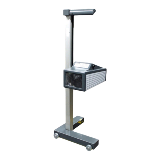
Page 8: Design
Design Mirror, with optional Charging socket laser alignment unit Column Casing, with adjusting handle Display Carriage, with spirit level USB port Battery compartment BA380701-en…
-
Page 9: Electronic Levelling
See section “Operation > Settings > Calibrating the Camera according to Directive”. NOTICE This function must be enabled exclusively by authorised service technicians and is ap- plicable for the respective test surface only. 2.4.1 Compensation Coordinate Axes of MLT 3000 BA380701-en…
-
Page 10: Angle Symbols
2.4.2 Angle Symbols Once the adjustment of the inclination sensor has been completed, an angle symbol appears in the info bar to indicate the adjusted/active inclination axes. Overview of symbols: Both axes adjusted/active, Z-axis active, headlight tester headlight tester ready for op- ready for operation eration Both axes active, inclination of…
-
Page 11: Definition Of Technical Terms
Definition of Technical Terms 2.5.1 Pitch Angle Angle of inclination of light-dark limit against the test surface. The inclination of headlight lighting bundle against the test surface is expressed as a percentage, using 10 m as a reference parameter: H X 100 1000 2.5.2…
-
Page 12: High Beam
Light-dark limit Boundary for light distribution between ‘top dark’ and ‘bottom light’ for low- beam lights. Inflection point Synonymous with the light-dark limit for asymmetric low-beam lighting. The deviation of the inflection point is expressed in %. 10 meters is used as the ref- erence dimension.
-
Page 13: Operation
Operation Switching On / Off The headlight tester is operated via touchscreen buttons. The resistive touchscreen reacts to pressure and can also be operated while wearing work gloves. The On/Off button is on the right-hand side underneath the touchscreen. Press to confirm Switch Off.
-
Page 14: Aligning
Aligning When using guide rails, position the device centrally in front of the vehicle. Without guide rails, the device must be adjusted in front of each headlight. Please ob- serve your national guidelines and specifications. The device is correctly aligned when two symmetrical reference points on the front of the vehicle are located on the black line of the alignment mirror.
-
Page 15: Led Adjustment Aid (Option)
3.2.2 LED Adjustment Aid (Option) This optional unit is integrated into the window housing (A) above the Fresnel lens. The colour LEDs (B) pointing toward the vehicle indicate the direction of adjustment. Green LED = Optimum setting (corresponds to green rating in the display centre) Yellow LED = Minor deviation within tolerance range (corresponds to yellow direction arrows on the display)
-
Page 16: Light Selection Buttons
Light Selection Buttons 3.3.1 Headlight Test according to § 29 StVZO (Germany) Headlight test according to § 29 StVZO (Germany). Use the OEM button for manufacturer-specific test instructions. BA380701-en…
-
Page 17: Showing The Button Labels
3.3.2 Showing the Button Labels When the Info button is activated, the button labels are shown instead of the symbols. 3.3.3 Adjusting the Pitch Angle The pitch angle can be increased or reduced using the Arrow buttons. BA380701-en…
-
Page 18: Choosing The Vehicle Class
3.3.4 Choosing the Vehicle Class The Truck/Car button activates the appropriate settings for the respective vehicle class. 3.3.5 Browsing back through the Test Screens Use the Back Arrow button to browse back through the test screens one by one. BA380701-en…
-
Page 19: Choosing Between Left-Hand Or Right Hand Traffic
3.3.6 Choosing between Left-Hand or Right Hand Traffic Left-hand/Right-hand traffic can be changed under “User Settings”. Right-hand traffic is preset by default. 3.3.7 Manufacturer-Specific Test Instructions (OEM) OEM area! Perform the test according to manufacturer’s instructions. BA380701-en…
-
Page 20
Button “ALL“ makes several test levels available. Example: testing Volkswagen matrix headlights OEM area! Perform the test according to manufacturer’s instructions. BA380701-en… -
Page 21: Navigating Through The Test Levels
3.3.8 Navigating through the Test Levels Use the Play button to open the activated test levels one by one. BA380701-en…
-
Page 22: Testing The Headlights
Testing the Headlights 3.4.1 Test Phase Indication via Light Buttons Green dot = Headlight tested, measurement OK Red dot = Headlight tested, not OK Grey dot = Headlight without evaluation Adjusting direction: Yellow arrow = Minor deviation within tolerance range Red arrow = Outside tolerance 3.4.2 Measuring…
-
Page 23: Light Selection Buttons Disabled
PA = Pitch Angle; IP = Inflection Point; I = Intensity Yaw and Rolling angles can be additionally activated under “User Settings”. Use the Camera button (bottom centre) to change from the Measuring menu to the Adjusting menu. 3.4.3 Light Selection Buttons Disabled During measurement the light selection buttons are disabled.
-
Page 24: Adjusting: Setting The Headlights In Real Time
3.4.4 Adjusting: Setting the Headlights in Real Time Green light button = Current measurement Use the “New vehicle” button to change back to the Main menu. BA380701-en…
-
Page 25: Saving The Measurement Values To Pdf
3.4.5 Saving the Measurement Values to PDF Using the USB stick button, all available test values can be saved as PDF to a USB stick. The button appears only in the Measuring and Adjusting menus and if a USB stick has been detected by the headlight tester.
-
Page 26
Overview of test results as PDF file (example) BA380701-en… -
Page 27: Settings
Settings 3.5.1 Variables Limit values as well as user and customer variables can be set directly at the headlight tester. BA380701-en…
-
Page 28
Limit values, user and customer variables can be adjusted directly on the equipment. BA380701-en… -
Page 29: User Settings
3.5.2 User Settings Quick access to all important settings. BA380701-en…
-
Page 30: Language
3.5.3 Language Use the flag button to open the language selection. Choose the desired language. BA380701-en…
-
Page 31: Calibrating The Camera According To Directive
3.5.4 Calibrating the Camera according to Directive Compensation values can be checked using button “Calibrate camera according to di- rective”. No password required. Choose between Cross hair / Spot laser. BA380701-en…
-
Page 32
BA380701-en… -
Page 33: Country Specifications
3.5.5 Country Specifications Statutory requirements, limit values and country-specific settings. Switching back from some of the country-specific test procedures requires a password. BA380701-en…
-
Page 34: Settings With Password
The disabled (greyed out) menu items can be accessed only by entering a service technician password. Adjustment of the headlight tester is permitted exclusively with the following calibration equipment approved by MAHA and must be performed by an authorised service technician. VP 990175…
-
Page 35: List Of Variables (Extract)
3.5.7 List of Variables (Extract) User variables Default Percentage 0 / Degrees 1 Lux 0 / Candela 1 Target value Pitch angle Car Target value Pitch angle HGV Switch-off time of display in minutes 1200 10.1 RHT/LHT button enabled 1 / disabled 0 11.0 OEM in main menu enabled 12.0.1…
-
Page 36: Interfaces And Software Updates
Interfaces and Software Updates Software updates are normally performed using a USB stick (FAT32). Procedure: 1 Download the current software version from the MAHA homepage. www.maha.de/downloads.htm 2 Open the ZIP file by double-clicking. 3 Select the MAHA folder with preset folder structure and copy it to a USB stick.
-
Page 37
BA380701-en… -
Page 38: Eurosystem V7.50
Troubleshooting > Charging the Battery”) Wireless connection via Bluetooth, order number: VZ 990312 These interfaces can be used for establishing a connection to MAHA’s EUROSYSTEM software, which is included with the cable or Bluetooth module. Alternatively, the headlight tester can also be integrated into a EUROSYSTEM test lane.
-
Page 39
Test devices are connected automatically. After the measurement has been started, all measured values are transferred to EUROSYSTEM. The connection to the MLT 3000 is re- tained until EUROSYSTEM is quit. Select menu item <Display measurement values>. Select menu item <Light tester>. -
Page 40
The selected measurement data is dis- played in detail. Graphic representation of headlight ad- justment in EUROSYSTEM: Use the camera button on the MLT 3000 display to switch over to headlight ad- justment. EUROSYSTEM shows the coordi- nates, the measured values and the head- light image in real time. -
Page 41: Energy Management And Troubleshooting
Energy Management and Troubleshooting Charging the Battery The plug of the charger is inserted into the round (Neutrik) connector on the underside of the housing (see Fig.). The charging process normally takes 11 hours. Full battery capacity is achieved when the battery voltage has exceeded 14.00 V during charging.
-
Page 42: Battery Status
Battery Status 4.2.1 Battery Life The battery has a rated capacity of 9500mAh and can provide up to 20 hours of continuous workshop operation at an optimum environmental temperature of 20°C. 4.2.2 Energy Saving Function After 10 minutes of no activity, the display switches off. By tapping the touchscreen, the device is immediately ready for operation.
-
Page 43: Data Recording For Error Analysis
4.2.5 Data Recording for Error Analysis The data records of the battery status allow for an optimum analysis in problem cases. A USB stick is needed for data recording. Records with a duration of more than 2 h can be saved by setting variable 9.0 accordingly. BA380701-en…
-
Page 44: Troubleshooting
Troubleshooting This message may appear after updating older software versions. Acknowledge with “Wait”. Maintenance Care Instructions NOTICE The equipment must be periodically cleaned. Do not use high pressure and steam jet cleaners nor caustic cleaning agents. Regular care and maintenance is the key condition for functionality and long life expec- tancy of the equipment! Spare Parts To ensure safe and reliable operation, only use original spare parts supplied by the…
-
Page 45: Disposal
Disposal If you want to dispose of the equipment, please contact your MAHA dealer or the following address, indicating equipment type, date of purchase and serial number: MAHA Maschinenbau Haldenwang GmbH & Co. KG Hoyen 20 | 87490 Haldenwang | Germany…
Specifications:
|
Accompanying Data:
MAHA MLT 3000 Diagnostic Equipment, Test Equipment PDF Original Operating Instructions (Updated: Monday 5th of September 2022 05:23:36 PM)
Rating: 4.8 (rated by 8 users)
Compatible devices: MTL 15, TPS I, TPS II, MLT Series, MBT Series, MFP 3000, MBT 2200 LON, MET Series.
Recommended Documentation:
MAHA MLT 3000: Text of Manual, Original Operating Instructions
(Ocr-Read Version Summary of Contents, UPD: 05 September 2022)
-
23, 23 BA380701-en PA = Pitch Angle; IP = Inflection Point; I = Intensity Yaw and Rolling angles can be additionally activated under “User Settings”. Use the Camera button (bottom centre) to change from the Measuring menu to the Adjusting menu. 3.4.3 Light Selection Buttons Disabled During measurement the light selection buttons are disabled.
… -
24, 24 BA380701-en 3.4.4 Adjusting: Setting the Headlights in Real Time Green light button = Current measurement Use the “New vehicle” button to change back to the Main menu.
… -
28, 28 BA380701-en Limit values, user and customer variables can be adjusted directly on the equipment.
… -
13, 13 BA380701-en 3 Operation 3.1 Switching On / Off The headlight tester is operated via touchscreen buttons. The resistive touchscreen reacts to pressure and can also be operated while wearing work gloves. The On/Off button is on the right-hand side underneath the touchscreen. Press to confirm Switch Off.
… -
30, 30 BA380701-en 3.5.3 Language Use the flag button to open the language selection. Choose the desired language.
… -
10, 10 BA380701-en 2.4.2 Angle Symbols Once the adjustment of the inclination sensor has been completed, an angle symbol appears in the info bar to indicate the adjusted/active inclination axes. Overview of symbols: Both axes adjusted/active, headlight tester ready for op- eration Z-axis active, headlight tester ready for operation Both ax…
-
35, 35 BA380701-en 3.5.7 List of Variables (Extract) No. User variables Default Min Max 3.0 Percentage 0 / Degrees 1 0 0 1 4.0 Lux 0 / Candela 1 0 0 1 6.0 Target value Pitch angle Car 11 0 50 6.1 Target value Pitch angle HGV 30 0 50 8.0 Switch-off time of display in minutes 10 2 1200 10.1 RHT/LHT button enabled 1 /…
-
43, 43 BA380701-en 4.2.5 Data Recording for Error Analysis The data records of the battery status allow for an optimum analysis in problem cases. A USB stick is needed for data recording. Records with a duration of more than 2 h can be saved by setting variable 9.0 accordingly. USB
… -
29, 29 BA380701-en 3.5.2 User Settings Quick access to all important settings.
… -
38, 38 BA380701-en Please wait until the software has been installed and restarted. Interfaces for connecting a computer: RS232 as cable connection (round connector, see section “Energy Management and Troubleshooting > Charging the Battery”) Wireless connection via Bluetooth, order number: VZ 990312 These interfaces can be used for establishing a con…
-
21, 21 BA380701-en 3.3.8 Navigating through the Test Levels Use the Play button to open the activated test levels one by one.
…
MAHA MLT 3000: Recommended Instructions
OptiPlex FX160, Wireless Desktop 130, FR328S, L 87680 FLCS


-
Quick Tips &Care GuideVacuum Gauge PlacementVacuum Gauge OrientationConnect the Vacuum Gauge to the system as far from the pumpas possible — For a system to be adequately dehydrated a deepvacuum must be achieved throughout the entire system, not justthe point where the vacuum pump is connected. Unlike pressure,vacuum will not quickly equalize across all points of the system. …
AV760 2
-
1 THE QUALITY GOALS OF AIR CONDITIONING COME TRUE WITH THE RECOVERY SYSTEM Air ventilation system TALTERI is designed to remove stale air from the interior and supply it with fresh and clean air. Humidity and impurities are exhausted through the thermal recovery unit that cost-effectively heats the filtered ambient air. Fresh warm air is channeled draught-proof and noise-free int …
FAIR-80 EC 21
-
User’s Guide RIGOL Publication number UGA07107-1110 July 2008 DS1000E, DS1000D Series Digital Oscilloscopes DS1102E, DS1052E, DS1102D, DS1052D © 2008 RIGOL Technologies, Inc. All Rights Reserved …
DS1000D series 172
-
1AC II VoltAlertInstruction SheetRead First: Safety InformationWX WarningTo avoid possible electric shock or personal injury:If the Tester is used in a manner not specied by the manufacturer, protection ●provided by the Tester may be affected.Do not use if VoltBeat is not ashing. ●Test on a known live source within the rated ac voltage range of the pro …
1AC-II 12
-
56TESTER KABELU LAN 44LAN-KAAPELIN TESTAAJA 32PROBADOR DE CABLE LAN 20LAN-KABELTESTER 8LAN-KABELPRÜFER 62TESTER CABLU LAN 50LAN-KABELTESTARE 38LAN KÁBELTESZTER 26TESTER CAVI LAN 14TESTEUR DE CÂBLE RÉSEAULAN CABLE TESTERCMP-RCT31 …
CMP-RCT31 68
-
HD-TVI, CVI, AHD, Analogue & IP CCTV Test MonitorThe LCD400K professional CCTV test monitor is capable of testing, configuring and controlling HD-TVI, CVI, AHD, analogue and IP cameras.It features a full Qwerty keyboard, ONVIF 16 compatibility, a 1080p HD 4 inch screen and up the coax control. LCD400K Instruction ManualxLCD400K v1InstructionManual …
LCD400K 40
-
WARNING! Always use caution when working around fuel systems. The fuel in the fuel rail may be pressurised even if the engine is not running. WARNING! Ensure Health and Safety, local authority and general workshop practice regulations are adhered to when using tools. IMPORTANT: These instructions are provided as a guide only. Always refer to the vehicle …
VS2058.V3 2
-
TR700 SeriesRefrigerant Recovery MachinesOWNER’S MANUAL (English) Français, Español, Deutsch and latest updates: www.cpsproducts.comSeries: TR700, TR700E, TR710, TR700C, TR710C, TR700JUK, TR700J, TR700S, TR710STO BE OPERATED BY QUALIFIED PERSONNEL ONLYTHIS EQUIPMENT HAS BEEN VERIFIED BY UNDERWRITERS LABORATORIES INC. TO MEET EPA’S MINIMUM REQUIREMENTS FOR RECOVERY EQUIPMENT INTENDED FOR …
BLACKMAX TR700 Series 16
-
Please read the user’s manual carefully before use.AF-50AF-50Breath Alcohol TesterProfessional Fuel cell sensorPersonal & professional use alcohol testerInstructionManual50 sets of data memory Professional Fuel Cell SensorLaw enforcement grade accuracy4-digit LCD display with a backlitFast analyzing and resultAutomatic power offUser adjustable settings (Blow time, Unit, …
AF-50 6
Popular Right Now:
Operating Impressions, Questions and Answers:
Назначение
Описание
Программное обеспечение
Технические характеристики
Знак утверждения типа
Комплектность
Поверка
Сведения о методах измерений
Рекомендации к применению
Назначение
Приборы для измерений параметров света фар автотранспортных средств MLT 3000 предназначены для:
— измерений углов наклона светотеневой границы светового пучка фар ближнего света к плоскости рабочей площадки, на которой устанавливается автотранспортное средство (в соответствии с требованиями ГОСТ Р 51709 — 2001);
— измерений углового отклонения от нулевого положения в горизонтальном направлении точки пересечения левого горизонтального и правого наклонного участков светотеневой границы светового пучка фар ближнего света (в соответствии с требованиями ГОСТ Р 51709 — 2001);
— измерений углового отклонения от нулевого положения в горизонтальном и вертикальном направлении центра светового пучка фар дальнего света (в соответствии с требованиями ГОСТ Р 51709-2001);
— измерений силы света и проверки технического состояния фар автотранспортных средств, соответствующих требованиями: ГОСТ Р 41.1-99, ГОСТ Р 41.5-99, ГОСТ Р 41.8-99, ГОСТ Р 41.20-99, ГОСТ Р 41.31-99.
Описание
В приборах для измерений параметров света фар автотранспортных средств MLT 3000 измерение углов наклона светотеневой границы светового пучка фар ближнего света к плоскости рабочей площадки, на которой устанавливается автотранспортное средство, а также углового отклонения от нулевого положения в горизонтальном направлении точки пересечения левого горизонтального и правого наклонного участков светотеневой границы светового пучка фар ближнего света и измерения углового отклонения от нулевого положения в горизонтальном и вертикальном направлении центра светового пучка фар дальнего света осуществляется с помощью оптоэлектронной видеокамеры, объектив которой направлен на экран, расположенный за линзой в оптической камере приборов. На экране с помощью линзы происходит фокусировка изображения светотеневой границы пучка ближнего света фар или противотуманной фары, а также наиболее яркой точки дальнего света фар.
Одновременно с угловыми пространственными характеристиками светового пучка фар с помощью оптоэлектронного датчика измеряется сила света.
Обработка данных, получаемых с видеокамеры и получение численных значений результатов измерений, проводится с помощью программного обеспечения планшетного компьютера, интегрированного в корпус приборов для измерений параметров света фар автотранспортных средств MLT 3000.
Приборы для измерений параметров света фар автотранспортных средств MLT 3000 конструктивно состоят из:
1. Оптической камеры, в которой размещены: линза, экран, оптоэлектронная видеокамера, электронные узлы и блоки обработки измерительной информации, планшетный компьютер;
2. Нижней платформы на колесах, в которую вмонтирован жидкостный цилиндрический уровень для выравнивания приборов для измерений параметров света фар автотранспортных средств MLT 3000 в вертикальной плоскости;
3. Вертикальной направляющей стойки, вращающейся вокруг своей оси, с расположенным внутри противовесом, предназначенным для фиксации оптической камеры на требуемой высоте относительно автотранспортного средства;
4. Ориентирующего устройства, состоящего из подвижного элемента крепления на вертикальной направляющей стойке, с помощью которого на стойке размещается приспособление, ориентирующее приборы для измерений параметров света фар автотранспортных средств MLT 3000 по отношению к фарам автомобиля — зеркало с реперной линией или лазерный визир.
Для предотвращения несанкционированного доступа к внутренним частям приборов для измерений параметров света фар автотранспортных средств MLT 3000 производится пломбирование винтов соединяющих панели корпуса оптической камеры.
Программное обеспечение
Приборы для измерений параметров света фар автотранспортных средств MLT 3000 имеют встроенное программное обеспечение «MLT 3000 Firmware», которое служит для управления их функциональными возможностями, а также для обработки и отображения результатов измерений и передачи их на персональный компьютер.
Идентификационные данные программного обеспечения:
|
Наименование ПО |
Идентификационное наименование ПО |
Номер версии ПО, не ниже |
Цифровой идентификатор (контрольная сумма кодов) |
Алгоритм вычисления цифрового идентификатора |
|
MLT 3000 Firmware |
MLT3000_V0.07.0 15EN.mot |
0.07.015 |
— |
— |
Программное обеспечение защищено от несанкционированного доступа электронными ключами и паролями различных уровней доступа и соответствует уровню защиты «А» в соответствии с МИ 3286-2010.
Технические характеристики
|
Характеристика |
Значение характеристики |
|
Диапазон измерений углов наклона светового пучка фары в вертикальной плоскости |
от плюс 4° 35′ (800 мм/10 м) до минус 4° 01′ (700 мм/10 м) (от плюс 8 % до минус 7 %) |
|
Диапазон измерений углов отклонения светового пучка фары в горизонтальной плоскости |
от плюс 5° 45′ (1000 мм/10 м) до минус 5° 45′ (1000 мм/10 м) (от плюс 10% до минус 10%) |
|
Пределы допускаемой абсолютной погрешности измерений углов отклонения светового пучка фары в вертикальной и горизонтальной плоскости |
± 5′ (± 15 мм/10 м) ± 0,15% |
|
Максимальная высота измерений, мм |
1500 |
|
Минимальная высота измерений, мм |
200 |
|
Диапазон измерений силы света, кд |
0-125000 |
|
Предел допускаемой относительной погрешности измерений силы света, % |
±15 |
|
Напряжение питания, В |
220+10% 220-15% |
|
Частота, Гц |
50±1 |
|
Габаритные размеры в сборе (Д х Ш х В), мм, не более |
720 x 655 x 1770 |
|
Масса в сборе, кг, не более |
65 |
|
Рабочий диапазон температур, °С |
от плюс 5 до плюс 40 |
Знак утверждения типа
наносится на корпус приборов для измерений параметров света фар автотранспортных средств MLT 3000 методом наклеивания и на титульный лист руководства по эксплуатации методом печати.
Комплектность
— прибор для измерений параметров света фар автотранспортных средств;
— комплект принадлежностей и приспособлений;
— руководство по эксплуатации;
— методика поверки МП АПМ 04-14.
Поверка
осуществляется в соответствии с МП АПМ 04-14 «Приборы для измерений параметров света фар автотранспортных средств MLT 3000. Методика поверки», утверждённому ГЦИ СИ ООО «Автопрогресс-М» в апреле 2014 г.
Перечень основных средств поверки (эталонов), применяемых для поверки:
|
№ п/п |
Наименование и тип средства поверки |
Основные технические характеристики |
|
1. |
Тахеометр электронный |
Та20, ГОСТ Р 51774-2001 |
|
2. |
Рулетка измерительная металлическая |
(0- 3000) мм, КТ3, ГОСТ 7502-98 |
|
3. |
Секундомер |
СДСпр-1-2-000, КТ2, ТУ 25-1894.003-90 |
|
4. |
Набор гирь |
ГОСТ OIML 111-1 2009, (10мг-5 кг) M1 |
|
5. |
Люксметр |
«ТКА-Люкс/Эталон» (1 -50000) лк, предел основной относительной погрешности измерения освещённости ±2% |
|
6. |
Источник света |
Фара категории R2, HS1, или SB по ГОСТ Р 41.1-99, ГОСТ Р 41.5-99, ГОСТ Р 41.8-99, ГОСТ Р 41.20-99, ГОСТ Р 41.31-99 |
Сведения о методах измерений
Методика измерений приведена в документе «Приборы для измерений параметров света фар автотранспортных средств MLT 3000. Руководство по эксплуатации»
Нормативные и технические документы, устанавливающие требования к приборам для измерений параметров света фар автотранспортных средств MLT 3000
1. ГОСТ Р 51709-2001 «Автотранспортные средства. Требования безопасности к техническому состоянию и методы проверки».
Лист № 4 Всего листов 4
2. Техническая документация «MAHA Maschinenbau Haldenwang GmbH & Co. KG», Г ермания.
Рекомендации к применению
— выполнение работ по обеспечению безопасных условий и охраны труда в соответствии с приказом МВД России от 08.11.2012 № 1014 (п.п. 1; 2);
— осуществление мероприятий государственного контроля (надзора) в соответствии с приказом МВД России от 08.11.2012 № 1014 (п. 107);
— выполнение измерений, предусмотренных законодательством Российской Федерации о техническом регулировании в соответствии с Приложением N 2 к «Техническому регламенту о безопасности колесных транспортных средств», утвержденному Постановлением Правительства Российской Федерации от 10 сентября 2009 г. N 720;
— выполнение работ по оценке соответствия промышленной продукции и продукции других видов, а также иных объектов установленным законодательством Российской Федерации обязательным требованиям в соответствии с Приложением N 2 к «Техническому регламенту о безопасности колесных транспортных средств», утвержденному Постановлением Правительства Российской Федерации от 10 сентября 2009 г. N 720.
34
3.5.6
Settings with Password
The disabled (greyed out) menu items can be accessed only by entering a service
technician password.
Adjustment of the headlight tester is permitted exclusively with the following
calibration equipment approved by MAHA and must be performed by an authorised
service technician.
VP 990175
VP 990471
BA380701-en
Laser calibration device with spot laser, model LK1
(no longer available)
Laser calibration device with cross hair laser, model LK2
Прибор проверки и регулировки света фар МАХА MLT 3000. Прибор проверки света фар для легкового, грузового, коммерческого транспорта и мотоциклов. Для проверки существующих и будущих систем освещения. Может использоваться в составе диагностической линии. Зеркальный или лазерный прицел. Вертикально перемещающаяся измерительная камера. Большая линза Френеля. Удобное меню с цветным 7” сенсорным дисплеем. Электронное нивелирование на неровностях пола. Высокопроизводительная CMOS-камера. Встроенный электронный контроль для цифровой фиксации и оценки (обработки) результатов измерений. Возможность подключения к компьютеру. Результаты измерений могут быть переданы через Bluetooth, WLAN или кабель на компьютер и транслироваться на мониторе в режиме реального времени. Емкость батареи обеспечивает до 10 часов бесперебойной работы.
Характеристики:
| Отклонения оптической оси | +/- 5′ |
| Сила света | 0-125000 кандел |
| Освещенность | 0-200 люкс |
| Вес прибора | 65 кг |
| Вес в упаковке | 80 кг |
| Длина *Ширина *Высота прибора | 720*655*1770 мм |
| Питание | 100-240В, 50/60 Гц, АС/12 В пост. ток |
| Диапазон рабочих температур | + 5˚С до + 40˚ С, Влажность 20-80% |
| Высота центра фары | 240–1500 мм |
| Расстояние до центра фары | 100-500 мм |
| Область измерения вверх | hotspot 0-800 мм /10 м (0-8%). угол наклона 0-300 мм /10 м (0-3%) |
| Область измерения вниз | 0-700 мм/ 10 м (0-7%) |
| Область измерения влево | 0-1000 мм / 10м (0-10%) |
| Область измерения вправо | 0-1000 мм / 10м (0-10%) |
| Сила света | +/- 5 % |
Прибор проверки и регулировки света фар MAHA MLT 3000 в наличии и под заказ в Москве с возможностью купить в кредит и лизинг. Каталог, технические характеристики, фото, видео, инструкция по эксплуатации и отзывы клиентов помогут выбрать оборудование под ваши задачи. Чтобы оформить заказ на сайте нажмите в карточке товар на кнопку «В корзину» или позвоните нам по бесплатному телефону 8-804-333-33-48.
Компания «Трейдимпорт» специализируется на поставках профессионального оборудования и инструмента. Наши специалисты помогут подобрать качественное и надежное оборудование и инструмент в соответствии с вашими требованиями. Компания «Трейдимпорт», является официальным дилером ведущих компаний производителей, поэтому на все товары действует гарантия до 36 месяцев.
На некоторое оборудование и инструмент действует система скидок, поэтому вы можете приобрести товар по выгодной цене.
Закажите обратный звонок и наш менеджер позвонит и проконсультирует по любым вопросам. Купите Прибор проверки и регулировки света фар MAHA MLT 3000 — хороший товар, выгодная цена. Товар имеет все необходимые сертификаты и инструкции. Доставку в г. Москва мы осуществляем транспортными компаниями ПЭК, Деловые линии, Ратэк, СДЭК и другими.
Время работы:
- с 9-00 до 18-00 по Москве с понедельника по пятницу
- Сб — Вс с 10-00 до 17-00
- Приём заявок круглосуточно в любой день.
Компания Трейдимпорт предлагает взять Прибор проверки и регулировки света фар MAHA MLT 3000 в кредит или лизинг на выгодных для вас условиях. Цена может быть ниже указанной на сайте для торгующих организаций и при покупке оптом.