Руководство по эксплуатации коммутатора EtherDevice серии MOXA EDS-405A
Обзор
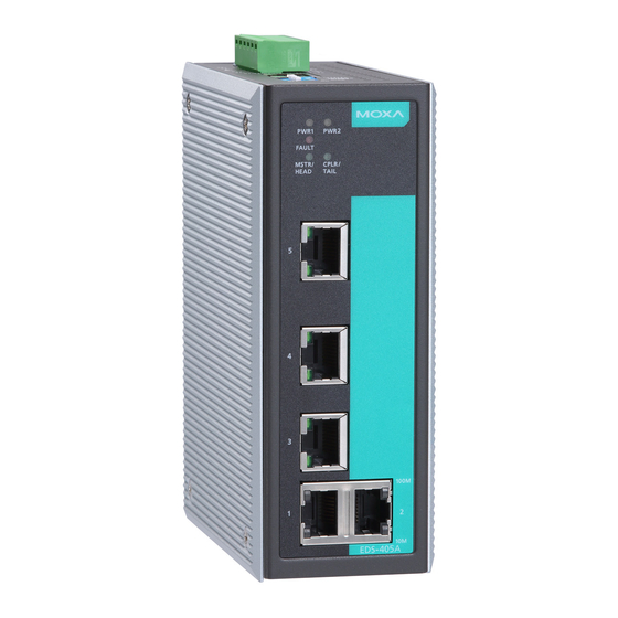
Серия Moxa EtherDevice™ EDS-405A/408A, включающая 5- и 8-портовые интеллектуальные Ethernet-коммутаторы, представляет собой экономичное решение для ваших Ethernet-соединений. Кроме того, встроенная функция интеллектуального оповещения помогает специалистам по обслуживанию системы контролировать состояние вашей сети Ethernet.
Контрольный список пакетов
Коммутаторы Moxa EDS-405A/408A поставляются со следующими элементами. Если какой-либо из этих элементов отсутствует или поврежден, обратитесь за помощью к представителю отдела обслуживания клиентов.
- Ethernet-коммутатор EDS-405A или EDS-408A
- Кабель консольного порта RJ45-DB9
- Защитные колпачки для неиспользуемых портов
- Комплект для монтажа на панели (дополнительно — необходимо заказывать отдельно)
- Руководство по быстрой установке (печатное)
- Гарантийный талон
Настройки по умолчанию
- IP-адрес по умолчанию: 192.168.127.253
- Маска подсети по умолчанию: 255.255.255.0
- Имена пользователей по умолчанию: admin, user
- Пароль по умолчанию: moxa
ЗАМЕТКА Для пользователей, которые только что обновили прошивку до версии 3.10 и выше:
Если пользователи ранее не вводили пароль, им придется ввести новый пароль, содержащий не менее четырех символов. Текущий пароль по умолчанию — «moxa». Если пользователи ввели пароль длиной не более трех символов, им потребуется ввести новый пароль длиной не менее четырех символов. Если пользователи уже добавили пароль, состоящий из четырех или более символов, никаких действий не требуется.
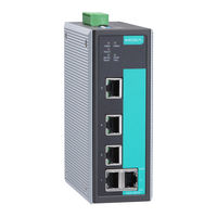
Схема панели EDS-405A/408A (стандартная)


- Винт заземления
- Клеммная колодка для входа питания PWR1/PWR2 и релейного выхода
- Вентиляционные отверстия для отвода тепла
- Консольный порт
- DIP-переключатели
- Потребляемая мощность Светодиод PWR1
- Потребляемая мощность Светодиод PWR2
- Светодиод неисправности
- MSTR/HEAD: светодиодный индикатор
- CPLR/TAIL: светодиодный индикатор
- Индикатор порта TP 100 Мбит/с
- Индикатор порта TP 10 Мбит/с
- Название модели
- Порты 10/100BaseT(X)
- Отверстие для крепления к стене
- Комплект DIN-рейки
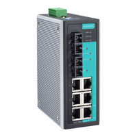
Схема панели EDS-405A/408A-MM (типа SC)


ПРИМЕЧАНИЕ:
Внешний вид EDS-405A-SS-SC идентичен внешнему виду EDS-405A-MM-SC.
Внешний вид EDS-408A-SS-SC идентичен внешнему виду EDS-408A-MM-SC.
- Винт заземления
- Клеммная колодка для входа питания PWR1/PWR2 и релейного выхода
- Вентиляционные отверстия для отвода тепла
- Консольный порт
- DIP-переключатели
- Потребляемая мощность Светодиод PWR1
- Потребляемая мощность Светодиод PWR2
- Светодиод неисправности
- MSTR/HEAD: светодиодный индикатор
- CPLR/TAIL: светодиодный индикатор
- Индикатор порта TP 100 Мбит/с
- Индикатор порта TP 10 Мбит/с
- Название модели
- Порты 10/100BaseT(X)
- порты 100BaseFX
- Индикаторы порта FX 100 Мбит/с
- Отверстие для крепления к стене
- Комплект DIN-рейки
Схема панели EDS-405A/408A-MM (тип ST)


- Винт заземления
- Клеммная колодка для входа питания PWR1/PWR2 и релейного выхода
- Вентиляционные отверстия для отвода тепла
- Консольный порт
- DIP-переключатели
- Потребляемая мощность Светодиод PWR1
- Потребляемая мощность Светодиод PWR2
- Светодиод неисправности
- MSTR/HEAD: светодиодный индикатор
- CPLR/TAIL: светодиодный индикатор
- Индикатор порта TP 100 Мбит/с
- Индикатор порта TP 10 Мбит/с
- Название модели
- Порты 10/100BaseT(X)
- порты 100BaseFX
- Индикаторы порта FX 100 Мбит/с
- Отверстие для крепления к стене
- Комплект DIN-рейки
Схема панели EDS-408A-3M (тип SC/ST)


ПРИМЕЧАНИЕ:
Внешний вид EDS-408A-3S-SC, EDS-408A-1M2S-SC и EDS-408A-2M1S-SC идентичен внешнему виду EDS-408A-3M-SC.
- Винт заземления
- Клеммная колодка для входа питания PWR1/PWR2 и релейного выхода
- Консольный порт
- DIP-переключатели
- Вентиляционные отверстия для отвода тепла
- Потребляемая мощность Светодиод PWR1
- Потребляемая мощность Светодиод PWR2
- Светодиод неисправности
- MSTR/HEAD: светодиодный индикатор
- CPLR/TAIL: светодиодный индикатор
- Порты 10/100BaseT(X)
- Индикатор порта TP 100 Мбит/с
- Индикатор порта TP 10 Мбит/с
- порты 100BaseFX
- 1 светодиодный индикатор 100 Мбит/с порта FX 100M-M: многорежимный порт FX 100M-S: одномодовый порт FX
- Название модели
- Отверстие для крепления к стене
- Комплект DIN-рейки
Монтажные размеры

Монтаж на DIN-рейку
Алюминиевая пластина для крепления на DIN-рейку уже должна быть прикреплена к задней панели EDS-405A/408A, когда вы достаете его из коробки. Если вам нужно снова прикрепить пластину для крепления на DIN-рейку, убедитесь, что жесткая металлическая пружина направлена вверх, как показано на следующих рисунках.
ШАГ 1: Вставьте верхнюю часть DIN-рейки в паз чуть ниже жесткой металлической пружины.
ШАГ 2: Блок крепления на DIN-рейку встанет на место, как показано на рисунке.
Чтобы снять переключатель Moxa EtherDevice с DIN-рейки, просто переверните
Шаги 1 и 2.
ЗАМЕТКА
Для обеспечения надежной работы, пожалуйста, убедитесь, что рабочая температура. окружающей среды не превышает норматива. При монтаже коммутатора EDS-400A с другими блоками управления в шкафу без принудительной вентиляции рекомендуется минимальное расстояние 5 см с обеих сторон и над/под коммутатором.
Настенный монтаж (опция)
В некоторых случаях удобно закрепить EDS-405A/408A на стене, как показано на следующих рисунках.
ШАГ 1:
Снимите алюминиевую пластину для крепления на DIN-рейку с задней панели EDS-405A/408A, а затем прикрепите пластины для настенного монтажа с помощью винтов M3, как показано на схеме справа.
ШАГ 2:
Для крепления EDS-405A/408A на стене требуется 4 винта. Используйте переключатель с прикрепленными пластинами для настенного крепления в качестве ориентира, чтобы отметить правильное расположение 4 винтов. Головки винтов должны быть менее 6.0 мм в диаметре, а стержни должны быть менее 3.5 мм в диаметре, как показано на рисунке справа.
ЗАМЕТКА
Прежде чем закручивать шурупы в стену, убедитесь, что головка шурупа и размер хвостовика подходят, вставив шуруп в одно из отверстий в форме замочной скважины на пластинах для настенного монтажа.
Не вворачивайте винты полностью — оставьте около 2 мм, чтобы можно было сдвинуть панель настенного крепления между стеной и винтами.
ШАГ 3:
Как только винты будут закреплены в стене, вставьте четыре головки винтов в большие части отверстий в форме замочной скважины, а затем сдвиньте EDS-405A/408A вниз, как показано. Затяните четыре винта для
добавлена стабильность.
Информация ATEX/IECEx

- Номер сертификата: ATEX: DEMKO 18 ATEX 1978X
IECEx: IECEx UL 18.0089X (только для модели EDS-408A с медным проводом и 2 оптоволоконными кабелями) - Окружающий диапазон:
-40°C ≤ Tamb ≤ 75°C только для модели с индексом –T
-10°C ≤ Tamb ≤ 60°C только для модели без суффикса –T - Строка сертификации:
АТЕКС:
Серия EDS-405A: Ex nA nC IIC T4 Gc
Серия EDS-408A (медная модель EDS-408A(-T)):
Ex nA nC IIC T4 Gc
Серия EDS-408A (2 модели оптоволокна EDS-408A-MM/SS(-T)):
Ex nA nC op is IIC T4 Gc IECEx:
EDS-408A(-T), EDS-408A-MM/SS(-T): Ex nA nC IIC T4 Gc - Охватываемые стандарты:
EN 60079-0:2012+A11:2013, IEC 60079-0 ред.6,
EN 60079-15:2010, IEC 60079-15 ред.4,
EN 60079-28:2015, IEC 60079-28 2-я версия - Условия безопасного использования для IECEx/ATEX (Zone2):
- Должны быть предусмотрены меры защиты от переходных процессов, которые должны быть установлены на уровне, не превышающем 140 % пикового номинального объема.tage.
- Эти устройства должны быть установлены в подходящем корпусе, сертифицированном по стандарту ATEX/IECEx и имеющем доступ к инструментам, со степенью защиты не ниже IP54, как определено в EN/IEC 60529, и со степенью загрязнения 2, как определено в EN/IEC 60664-1, и использоваться в пределах своих номинальных электрических и экологических характеристик. рейтинги.
- Условия безопасного использования для других сред
- Эти продукты должны быть установлены в корпусе IP54.
- Устанавливайте в зоне со степенью загрязнения 2 или ниже.
- Используйте проводник сечением 0.2 мм² или больше.
- Входной клеммный блок (JP3, JP4) — номинал 300 В/12 А, пайка на плате, сопряжение со штекерным разъемом, подходящим для размера провода 28–12 AWG (Sol, Str), значение крутящего момента 4.5–5.0 фунт-дюйм. Вставное половинное соединение имеет защелкивающийся механизм.
- Рассматриваемые устройства должны использовать проводники, пригодные для ≥95°C, и должны использоваться для клеммы источника питания.
Требования к проводке
![]() ПРЕДУПРЕЖДЕНИЕ
ПРЕДУПРЕЖДЕНИЕ
Безопасность прежде всего!
Обязательно отсоедините шнур питания перед установкой и/или подключением коммутатора Moxa EtherDevice Switch.
Рассчитайте максимально возможный ток в каждом проводе питания и общем проводе. Соблюдайте все электрические нормы и правила, определяющие максимально допустимый ток для каждого размера провода.
Если ток превысит максимальные значения, проводка может перегреться, что приведет к серьезному повреждению вашего оборудования.
Обязательно прочтите и следуйте этим важным рекомендациям:
- Используйте отдельные пути для прокладки проводки для питания и устройств. Если пути силовой проводки и электропроводки устройства должны пересекаться, убедитесь, что провода перпендикулярны в точке пересечения.
ПРИМЕЧАНИЕ: Не прокладывайте сигнальную или коммуникационную проводку и силовую проводку через один и тот же кабелепровод. Чтобы избежать помех, провода с разными характеристиками сигнала следует прокладывать отдельно. - Используйте тип сигнала, передаваемого по проводу, чтобы определить, какие провода следует держать отдельно. Эмпирическое правило состоит в том, что проводку с одинаковыми электрическими характеристиками можно связать вместе.
- Держите входную и выходную проводку отдельно.
- При необходимости следует пометить проводку ко всем устройствам в системе.
Заземление коммутатора EtherDevice
Заземление и прокладка проводов помогают ограничить влияние шума из-за электромагнитных помех (EMI). Перед подключением устройств проведите заземление от винта заземления к поверхности заземления.
![]() ВНИМАНИЕ
ВНИМАНИЕ
Этот продукт предназначен для установки на хорошо заземленную монтажную поверхность, например, на металлическую панель. При подключении к внешнему заземляющему винту необходимо использовать провод сечением 4 мм2.
Подключение контакта реле
Контакт реле состоит из двух средних контактов клеммной колодки на верхней панели EDS-405A/408A. Обратитесь к следующему разделу за подробными инструкциями о том, как подсоединить провода к разъему клеммной колодки и как прикрепить разъем клеммной колодки к приемнику клеммной колодки.
В этом разделе мы объясним значение двух контактов, используемых для подключения контакта сигнализации.
ВИНА: Два средних контакта 6-контактного разъема клеммной колодки используются для обнаружения как сбоев питания, так и сбоев портов. Два провода, подключенные к контактам неисправности, образуют разомкнутую цепь, когда:
Запускается событие предупреждения реле.
OR
EDS-405A/408A является Мастером этого Турбо-Кольца, и Турбо-Кольцо сломано.
OR
Есть сбой при запуске. Если ни одно из этих трех условий не выполняется, цепь неисправности останется замкнутой.

Подключение резервных входов питания
Два верхних контакта и два нижних контакта 6-контактного разъема клеммной колодки на верхней панели EDS-405A/408A используются для двух входов постоянного тока EDS-405A/408A. Сверху и спереди views одного из разъемов клеммной колодки показаны на следующих рисунках:
ШАГ 1: Вставьте отрицательный/положительный провод постоянного тока в клеммы V-/V+ соответственно.
ШАГ 2: Чтобы провода постоянного тока не выдернулись, используйте небольшую отвертку с плоским лезвием, чтобы затянуть провода.amp винты на передней части разъема клеммной колодки.
ШАГ 3: Вставьте пластиковые штыри разъема клеммной колодки в гнездо клеммной колодки, расположенное на верхней панели EDS-405A/408A.

![]() ВНИМАНИЕ
ВНИМАНИЕ
Перед подключением EDS-405A/408A к входам питания постоянного тока убедитесь, что мощность источника питания постоянного токаtagе стабильно.
Коммуникационные соединения
Модели EDS-408A имеют 5, 6 или 8 портов 10/100BaseT(X) Ethernet и 3, 2 или 0 (ноль) оптоволоконных портов 100BaseFX (разъем типа SC/ST). Модели EDS-405A имеют 3 или 5 портов 10/100BaseT(X) Ethernet и 2 или 0 (ноль) оптоволоконных портов 100 BaseFX (разъем типа SC/ST).
Подключение порта Ethernet 10/100BaseT(X)
Порты 10/100BaseT(X), расположенные на передней панели EDS, используются для подключения к устройствам с поддержкой Ethernet.
Далее мы показываем выводы для портов MDI (типа NIC) и портов MDI-X (типа HUB/Switch), а также показываем схемы разводки кабелей для прямых и перекрестных кабелей Ethernet.
Выводы 10/100Base T(x) RJ45
| шпилька | сигнал |
| 1 | Tx + |
| 2 | Тх- |
| 3 | Rx + |
| 6 | Rx- |
Распиновка порта MDI
| шпилька | сигнал |
| 1 | Rx + |
| 2 | Rx- |
| 3 | Tx + |
| 6 | Тх- |
8-контактный RJ45

Прямой кабель RJ45 (8-контактный) — RJ45 (8-контактный)

RJ45 (8-контактный) — RJ45 (8-контактный) Перекрестный кабель

Подключение порта Ethernet 100BaseFX
Концепция порта и кабеля SC/ST довольно проста. Предположим, вы подключаете устройства I и II; в отличие от электрических сигналов оптические сигналы не требуют цепи для передачи данных. Следовательно, одна из оптических линий используется для передачи данных от устройства I к устройству II, а другая оптическая линия используется для передачи данных от устройства II к устройству I для полнодуплексной передачи.
Не забудьте подключить порт Tx (передача) устройства I к порту Rx (прием) устройства II, а порт Rx (прием) устройства I к порту Tx (передача) устройства II. Если вы делаете свой собственный кабель, мы рекомендуем маркировать две стороны одной и той же линии одной и той же буквой (A-to-A и B-to-B, как показано ниже, или A1-to-A2 и B1-to-B2). ).
Распиновка порта SC
Подключение кабеля SC-Port к SC-Port
Распиновка ST-порта
Проводка кабеля ST-Port-ST-Port

![]() ВНИМАНИЕ
ВНИМАНИЕ
Это лазерный/светодиодный продукт класса 1. Во избежание серьезного повреждения глаз не смотрите прямо на лазерный луч.
Резервные входы питания
Оба входа питания могут быть подключены одновременно к источникам постоянного тока под напряжением. Если один источник питания выходит из строя, другой активный источник действует как резервный и автоматически подает питание на EDS-405A/408A.
Контакт реле
Переключатель Moxa EtherDevice имеет один релейный контакт, расположенный на верхней панели. Подробные инструкции по подключению проводов питания контактов реле к двум средним контактам 6-контактного разъема клеммной колодки см. в разделе «Подключение контактов реле». Типичным сценарием было бы подключение цепи неисправности к сигнальной лампе, расположенной в диспетчерской. Свет можно настроить на включение при обнаружении неисправности.
Контакт реле имеет две клеммы, образующие цепь неисправности для подключения к системе сигнализации. Два провода, подключенные к контактам неисправности, образуют разомкнутую цепь, когда (1) срабатывает событие предупреждения реле, (2) EDS-405A/408A является ведущим устройством этого кольца Turbo Ring, и кольцо Turbo Ring разорвано, или (3) ) происходит сбой при запуске. Если ни одно из этих трех условий не возникает, цепь неисправности замыкается.
Настройки DIP-переключателя Turbo Ring
Коммутаторы серии EDS-405A/408A представляют собой управляемые по принципу plug-and-play резервные Ethernet-коммутаторы. Запатентованный протокол Turbo Ring был разработан Moxa для обеспечения большей надежности сети и более быстрого времени восстановления. Время восстановления Moxa Turbo Ring составляет менее 300 мс (Turbo Ring) или 20 мс (Turbo Ring V2) — по сравнению с 3–5-минутным временем восстановления для коммерческих коммутаторов — что снижает возможные потери, вызванные сбоями сети в промышленных условиях.
На верхней панели EDS-4A/405A есть 408 аппаратных DIP-переключателя для Turbo Ring, которые можно использовать для простой настройки Turbo Ring за считанные секунды. Если вы не хотите использовать аппаратный DIP-переключатель для настройки Turbo Ring, вы можете использовать web браузер, Telnet или консоль, чтобы отключить эту функцию.
ЗАМЕТКА
Подробную информацию о настройках и использовании Turbo Ring и Turbo Ring V2 см. в разделах «DIP-переключатель Turbo Ring» и «Использование резервирования связи» в руководстве пользователя.
DIP-переключатели серии EDS-405A/408A

По умолчанию для каждого DIP-переключателя установлено значение OFF. В следующей таблице поясняется действие установки DIP-переключателя в положение ON.
Настройки DIP-переключателя «Turbo Ring»
| DIP-1 | DIP-2 | DIP-3 | DIP-4 |
| Зарезервировано для использования в будущем. | ON: Включает этот EDS как Ring Master. | ON: Включает порты «Ring Coupling» по умолчанию. | ON: Активирует
DIP-переключатели 1, 2, 3 для настройки параметров «Turbo Ring». |
| OFF: Этот EDS не будет Ring Master. | OFF: Не используйте этот EDS в качестве кольцевого соединителя. | OFF: DIP-переключатели 1, 2, 3 будут отключены. |
Настройки DIP-переключателя «Turbo Ring V2»
| DIP-1 | DIP-2 | DIP-3 | DIP-4 |
| ON: включает порт по умолчанию «Ring Coupling (резервный)». | ON: Включает этот EDS как Ring Master. | ON: Включает порт «Ring Coupling» по умолчанию. | ON: активирует DIP-переключатели 1,
2, 3 для настройки «Turbo Ring V2» настройки. |
| OFF: включает порт по умолчанию «Ring Coupling (основной)». | OFF: Это ЭЦП не будет Мастером ринга. |
OFF: Не используйте этот EDS в качестве кольцевого соединителя. | OFF: ОКУНАТЬ переключатели 1, 2, 3 будут отключены. |
ЗАМЕТКА
Если вы не назначите какой-либо из коммутаторов EDS-405A/408A в качестве Ring Master, протокол Turbo Ring автоматически выберет EDS-405A/408A с наименьшим диапазоном MAC-адресов в качестве Ring Master. Если вы случайно активируете несколько EDS-405A/408A в качестве Ring Master, эти коммутаторы EDS-405A/408A автоматически согласуют, какой из коммутаторов будет Ring Master.
ЗАМЕТКА
Чтобы включить функции ведущего устройства или соединителя с помощью DIP-переключателя, вам необходимо сначала включить полюс Turbo Ring.
Светодиодные индикаторы
На передней панели EDS имеется несколько светодиодов. Функция каждого светодиода описана в следующей таблице.
| LED | Цвет | Область | Описание |
| PWR1 | ЖЕЛТЫМ | On | Питание подается на вход питания PWR1. |
| от | Мощность не подается на вход питания PWR1. | ||
| PWR2 | ЖЕЛТЫМ | On | Питание подается на вход питания PWR2. |
| от | Мощность не подается на вход питания PWR2. | ||
| FAULT | RED | On | 1. Сигнальный контакт разомкнут. 2. Порт был отключен, так как количество пакетов превышает предел скорости входящего трафика. 3. Неправильное подключение шлейфа в одиночном коммутаторе. 4. Неверное подключение к кольцевому порту. 5. Сбой при запуске. |
| от | Когда событие предупреждения реле не срабатывает. | ||
| MSTR/ ГОЛОВА | GREEN | On | 1. Переключатель устанавливается как Master of Turbo Ring или как Head of Turbo Chain. 2. Ошибка инициализации оборудования (мигает +Stat и Fault) 3. Переключатель установлен как корень RSTP. |
| моргание | EDS-405A/408A стал Мастером Турбо-Кольца или Главой Турбо-Цепи после выхода из строя Турбо-Кольца или Турбо-Цепи. | ||
| от | Когда EDS-405A/408A не является Мастером этого кольца Turbo или установлен в качестве члена цепочки Turbo. | ||
| CPLR/ ХВОСТ | GREEN | On | Когда функция сопряжения EDS-405A/408A включена для формирования резервного пути или когда она установлена как хвостовая часть цепочки Turbo. |
| моргание | Когда Turbo Chain не работает. | ||
| от | Когда EDS-405A/408A отключает функцию сопряжения или
Член сети Turbo. |
||
| 10М (ТП) | GREEN | On | Соединение порта TP 10 Мбит/с активно. |
| моргание | Данные передаются со скоростью 10 Мбит/с. | ||
| от | Канал TP Port 10 Мбит/с неактивен. | ||
| 100M (ТР) | GREEN | On | Соединение порта TP 100 Мбит/с активно. |
| моргание | Данные передаются со скоростью 100 Мбит/с. | ||
| от | Канал TP Port 100 Мбит/с неактивен. | ||
| 100M (FX) | GREEN | On | Порт FX 100 Мбит/с активен. |
| моргание | Данные передаются со скоростью 100 Мбит/с. | ||
| от | Порт FX 100 Мбит/с неактивен. |
Автоматическое подключение MDI/MDI-X
Функция Auto MDI/MDI-X позволяет пользователям подключать порты 405/408BaseTX EDS-10A/100A к любому устройству Ethernet, не обращая внимания на тип кабеля Ethernet, используемого для подключения. Это означает, что вы можете использовать прямой или перекрестный кабель для подключения EDS-405A/408A к устройствам Ethernet.
Характеристики
| Технологии | |||
| Стандартный | IEEE802.3, 802.3u, 802.3x, 802.1D, 802.1Q, 802.1w, 802.1p | ||
| протоколы | Устройство IGMP V1/V2, GMRP, GVRP, SNMPv1/v2c/v3, DHCP-сервер/клиент, TFTP, SNTP, SMTP, RARP, RMON, HTTP, Telnet, системный журнал, опция DHCP 66/67/82, BootP, LLDP, Modbus TCP, IPv6 | ||
| MIB | MIB-II, Ethernet-подобная MIB, P-BRIDGE MIB, RMON Группа MIB 1, 2, 3, 9, MIB моста, MIB RSTP |
||
| Скорость пересылки и фильтрации | 148810 пакетов в секунду | ||
| Тип обработки | Запомнить и продолжить | ||
| Управление потоком | Управление потоком IEEE802.3x, управление потоком обратного давления | ||
| Интерфейс | |||
| Порты RJ45 | 10/100BaseT(X) автоматическое согласование скорости, дуплекс F/H
режим и автоматическое подключение MDI/MDI-X |
||
| Оптоволоконные порты | Порты 100BaseFX (разъем SC/ST) | ||
| Консоли | RS-232 (RJ45) | ||
| Светодиодные индикаторы | PWR1, PWR2, FAULT, 10/100M (порт TP),
100M (оптоволоконный порт), CPLR/TAIL и MSTR/HEAD |
||
| Контакт реле | Один релейный выход с допустимой нагрузкой по току 1А
@ 24 VDC |
||
| DIP-переключатели | Мастер, муфта, турбокольцо, резерв | ||
| Оптоволокно | |||
| 100BaseFX | |||
| Multi-Mode | Одиночный режим | ||
| Тип оптоволоконного кабеля | OM1 | 50/125 мкм | G.652 |
| 800 МГц*км | |||
| Типичное расстояние | 4 км | 5 км | 40 км |
| Длина волны | Типичный (нм) | 1300 | 1310 |
| Диапазон TX (нм) | 1260 — 1360 | 1280 — 1340 | |
| Диапазон RX (нм) | 1100 — 1600 | 1100 — 1600 | |
| Оптическая сила | Диапазон передачи (дБм) | От -10 до -20 | От 0 до -5 |
| Диапазон приема (дБм) | От -3 до -32 | От -3 до -34 | |
| Бюджет канала (дБ) | 12 | 29 | |
| Штраф за рассеивание (дБ) | 3 | 1 | |
| Внимание: При подключении одномодового оптоволоконного приемопередатчика рекомендуется использовать аттенюатор, чтобы предотвратить повреждение, вызванное чрезмерной оптической мощностью. Рассчитайте «типичное расстояние» для конкретного оптоволоконного приемопередатчика следующим образом: бюджет канала (дБ) > штраф за дисперсию (дБ) + общие потери в канале (дБ). |
| Питания | |
| Vol входtage | • Серия EDS-405A/408A: 12/24/48 В постоянного тока, резервные входы • EDS-408A-3S-SC-48: ±24/±48 В пост. тока (от -60 до -19 В пост. тока или от 19 до 60 В пост. тока), резервные входы (Смешение полярности питания запрещено.) |
| входной ток | • Серия EDS-405A: 0.594 А/0.286 А/0.154 А при 12/24/48 В • Серия EDS-408A (модели с медным и 2 оптоволоконными кабелями): 0.61 А/0.3 А/0.16 А при 12/24/48 В • Серия EDS-408A (3 модели с оптоволоконным кабелем): 0.73 А/0.35 А/0.18 А при 12/24/48 В |
| Пусковой ток | • Серия EDS-405A: макс. 2.08 А при 24 В постоянного тока (0.1–1 мс)
• Модель EDS-408A с 3 волокнами: макс. 15.96 А при 24 В постоянного тока (0.1–1 мс) |
| Подключения | Одна съемная 6-контактная клеммная колодка |
| Ток перегрузки Protection |
Представить |
| Обратная полярность Protection |
Представить |
| Физические характеристики | |
| Дома | Металл, защита IP30 |
| Размеры | 53.6 х 135 х 105 мм |
| Вес | 0.65 кг (ЭДС-405А), 0.89 кг (ЭДС-408А) |
| Установка | DIN-рейка, настенный монтаж (дополнительный комплект) |
| Пределы окружающей среды | |
| Рабочая Температура | от -10 до 60°C (от 14 до 140°F);
от -40 до 75°C (от -40 до 167°F) для моделей -T |
| Хранилище
Температура |
От -40 до 85 ° C (от -40 до 185 ° F) |
| Окружающий относительный
Влажность |
От 5% до 95% (без конденсации) |
| Соответствие нормативным требованиям | |
| Сохранность | • EDS-405A/408A: UL 60950-1, UL 508, EN 60950-1 • EDS-408A-3S-SC-48: UL508 |
| в опасных зонах | UL/cUL, класс I, раздел 2, группы A, B, C и D, ATEX, зона 2, IECEx Серия EDS-405A/EDS-408A (медные и 2 оптоволоконные модели): ANSI/ISA-12.12.01-2015 CSA C22.2 №. 213-15 EN 60079-0:2012+A11:2013 EN 60079-15:2010 EN 60079-28:2015 (только для EDS-408A-MM/SS) EDS-408A(-T), EDS-408A-MM/SS(-T): МЭК 60079-0, 6-е издание МЭК 60079-15, 4-е издание МЭК 60079-28, 2-е издание |
| EMI | FCC часть 15, CISPR 32 класс A |
| EMS | EN 61000-4-2 (ESD), уровень 3 EN 61000-4-3 (RS), уровень 3 EN 61000-4-4 (EFT), уровень 3 EN 61000-4-5 (броски напряжения), уровень 3 EN 61000-4-6 (CS), уровень 3 |
| Шок | IEC 60068-2-27 |
| Свободное падение | IEC 60068-2-31 |
| вибрация | IEC 60068-2-6 |
| ГАРАНТИИ | 5 лет |
| Адрес производителя | № 1111, Heping Rd., Bade Dist., Taoyuan City 334004, Тайвань |
![]() ПРЕДУПРЕЖДЕНИЕ
ПРЕДУПРЕЖДЕНИЕ
Данное оборудование предназначено для использования в местах с ограниченным доступом.
ПРЕДУПРЕЖДЕНИЕ: Горячая поверхность! Прежде чем прикасаться к нему, требуется особое внимание или защита.
Документы / Ресурсы
Рекомендации

Мокса — Поддержка
- Manuals
- Brands
- Moxa Technologies Manuals
- Switch
- EtherDevice EDS-405A-SS-SC
Manuals and User Guides for Moxa Technologies EtherDevice EDS-405A-SS-SC. We have 2 Moxa Technologies EtherDevice EDS-405A-SS-SC manuals available for free PDF download: User Manual, Hardware Installation Manual
Moxa Technologies EtherDevice EDS-405A-SS-SC User Manual (78 pages)
EDS-408A/EDS-405A Series
Brand: Moxa Technologies
|
Category: Switch
|
Size: 2.23 MB
Table of Contents
-
Copyright Notice
2
-
Table of Contents
3
-
Chapter 1 Introduction
5
-
Inside the Future of Industrial Ethernet Technology
6
-
The Trend in Industrial Communications and Automation Applications
6
-
Industrial Vs. Commercial
6
-
Informative Vs. Passive
6
-
-
MOXA Etherdevice™ Switch
6
-
Package Checklist
6
-
Optional Accessories
7
-
Features
7
-
Advanced Industrial Networking Capability
7
-
Designed for Industrial Applications
7
-
Useful Utility and Remote Configuration
7
-
-
-
Chapter 2 Getting Started
8
-
Configuration Using RS-232 Serial Console (115200, None, 8, 1, VT100)
9
-
Configuration Using Telnet Console
12
-
Configuration Using Web Browser
14
-
Disabling Telnet and Browser Access
15
-
-
Chapter 3 Featured Functions
16
-
Configuring Basic Settings
17
-
System Identification
17
-
Password
18
-
Accessible IP
19
-
Port
20
-
Network
21
-
Time
23
-
Turbo Ring DIP Switch
24
-
System File Update-By Remote TFTP
26
-
System File Update-By Local Import/Export
27
-
Factory Default
27
-
-
Configuring SNMP
28
-
SNMP Read/Write Settings
29
-
Trap Settings
30
-
Private MIB Information
31
-
-
Using Communication Redundancy
31
-
The Turbo Ring Concept
31
-
Configuring Turbo Ring
34
-
The STP/RSTP Concept
36
-
How Stp Works
38
-
Stp Example
39
-
Using Stp on a Network with Multiple Vlans
40
-
-
Configuring STP/RSTP
41
-
-
Using Traffic Prioritization
44
-
The Traffic Prioritization Concept
44
-
Configuring Traffic Prioritization
46
-
-
Using Virtual LAN
49
-
The Concept of Virtual LAN (VLAN)
49
-
Using Virtual LAN
50
-
-
Using Rate Limiting
51
-
Configuring Rate Limiting
51
-
-
Using Auto Warning
53
-
Configuring Email Warning
53
-
Email Warning Events Settings
53
-
Email Settings
55
-
Configuring Relay Warning
56
-
Relay Warning Events Settings
56
-
Relay Warning List
58
-
-
Using Line-Swap-Fast-Recovery
58
-
Configuring Line-Swap Fast Recovery
58
-
-
Using Set Device IP
58
-
Configuring Set Device IP
59
-
-
Using Diagnosis
60
-
Mirror Port
60
-
Ping
61
-
-
Using the Monitor
61
-
Monitor by Switch
61
-
Monitor by Port
62
-
-
Using the MAC Address Table
62
-
Using Event Log
63
-
-
Chapter 4 EDS Configurator GUI
64
-
Starting EDS Configurator
65
-
Broadcast Search
65
-
Search by IP Address
66
-
Upgrade Firmware
66
-
Modify IP Address
67
-
Export Configuration
68
-
Import Configuration
69
-
Unlock Server
70
-
-
Mib Groups
72
-
Appendix A MIB Groups
74
-
Appendix B Specifications
74
-
Appendix C Service Information
75
-
MOXA Internet Services
76
-
Problem Report Form
77
-
Product Return Procedure
78
-
Advertisement
Moxa Technologies EtherDevice EDS-405A-SS-SC Hardware Installation Manual (17 pages)
EDS-405A/408A Series
Brand: Moxa Technologies
|
Category: Switch
|
Size: 0.91 MB
Table of Contents
-
Package Checklist
2
-
EDS-408A-3M Panel Layout (SC/ST-Type)
6
-
Mounting Dimensions (Unit = MM)
7
-
DIN-Rail Mounting
7
-
Wall Mounting (Optional)
8
-
ATEX Information
8
-
Wiring Requirements
9
-
Grounding the Etherdevice Switch
9
-
Wiring the Relay Contact
9
-
Wiring the Redundant Power Inputs
10
-
Communication Connections
10
-
10/100Baset(X) Ethernet Port Connection
10
-
RJ45 (8-Pin) to RJ45 (8-Pin) Cross-Over Cable Wiring
11
-
100Basefx Ethernet Port Connection
11
-
Redundant Power Inputs
12
-
Relay Contact
12
-
Turbo Ring DIP Switch Settings
12
-
Led Indicators
13
-
Auto MDI/MDI-X Connection
14
-
Specifications
15
Advertisement
Related Products
-
Moxa Technologies EtherDevice EDS-405A/408A Series
-
Moxa Technologies EtherDevice EDS-405A-SS-SC-T
-
Moxa Technologies EtherDevice EDS-405A-T
-
Moxa Technologies EtherDevice EDS-405A-MM-ST
-
Moxa Technologies EtherDevice EDS-405A-MM-SC
-
Moxa Technologies EtherDevice EDS-405A-PTP Series
-
Moxa Technologies EtherDevice EDS-405A-PN
-
Moxa Technologies EtherDevice EDS-405A-MM-ST-T
-
Moxa Technologies EDS-405A-MM
-
Moxa Technologies EDS-4008-2MST
Moxa Technologies Categories
![]()
Switch
Server
![]()
Desktop
Gateway
Media Converter
More Moxa Technologies Manuals

Навигация
Спецификация
Сетевые порты |
|
| Количество Ethernet-разъемов | 5 |
| Количество 10/100 Mb Ethernet | 5 |
| Тип коннектора 10/100 Mb Ethernet | 2xSC, 3xRJ-45, Одномодовый |
| Реализация Ethernet | 10BASE-T, 100BASE-FX, 100BASE-TX |
Поддерживаемые протоколы |
|
| Управляемый | Да, Layer 2 |
| Стандартные протоколы | IGMPv1/v2, DHCP Server/Client, DHCP Option 66/67/82, EtherNet/IP, NTP Server/Client, SNTP, SMTP, SNMP Inform, SNMPv1/v2c/v3, BootP, GMRP, GVRP, HTTP, LLDP, RARP, RMON, Syslog, Telnet, TFTP, VLAN, STP/RSTP, Modbus TCP, Turbo Ring, Turbo Chain |
| Поддержка стандартов IEEE 802.x | IEEE 802.1D-2004 для STP, IEEE 802.1P для CoS, IEEE 802.1Q для VLAN, IEEE 802.1W для RSTP, IEEE 802.3 для 10BaseT, IEEE 802.3u для 100BaseT(X), 100BaseFX, IEEE 802.3x для Flow Control |
| Версия IP-протокола | IPv4, IPv6 |
Производительность коммутатора |
|
| Размер буфера пакетов | 1 МБит |
| Размер таблицы MAC адресов | 2000 |
Технологии и функции |
|
| Поддерживаемые функции | Port Mirror, Rate Limit, Loop Protection, Защита от широковещательного шторма, Port-Based VLAN, Автоматическое оповещение об обрыве электропитания, Автоматическое оповещение об обрыве связи по порту, Flow Control, Back pressure flow control, Line-Swap Fast Recovery, Подключение к системе управления и мониторинга |
Полевые протоколы |
|
| Протокол EtherNet/IP | Да |
| Протокол Modbus TCP | Да |
Цифровой вывод |
|
| Количество каналов DO | 1 |
| Тип DO | Сигнальное реле |
| Максимальный коммутируемый ток для реле с контактами (А) | 1А при 24В DC |
Отвод тепла |
|
| Тип | Пассивный |
Способы оповещения и настройки |
|
| Индикация | Индикатор сбоя, Индикатор «Мастер/Головной», Индикатор «Участник цепи/Хвост», Индикатор скорости 10/100 Мбит, Индикатор питания 1, Индикатор питания 2 |
| Метод настройки | Telnet, Консольный порт, DIP-переключатели, WEB-консоль, Интерфейс командной строки (CLI), Через утилиту MXconfig |
Порты и кабели в комплекте |
|
| Тип коннектора | Консольный порт RS-232 (RJ-45) |
Электропитание |
|
| Требования по напряжению DC | 9.6~60 В |
| Мощность потребления | 6.2 Вт |
| Потребляемый ток | 0.26 А |
| Требования по напряжению DC резервного входа | 9.6~60 В |
| Мощность потребления резервного входа | 6.2 Вт |
| Потребляемый ток | 0.26 А |
| Входная защита питания | Предохранитель, От смены полярности |
Требования к условиям использования |
|
| Требования к температуре при работе | -10~60 °С |
| Требования к влажности | 5~95 % |
| Время наработки на отказ | 1547941 |
Требования к условиям хранения |
|
| Требования к температуре хранения | -40~85 °С |
Реализация корпуса |
|
| Внешний вид и материал | Металл |
| Монтаж | На стену, На DIN-рейку |
| IP-защита изделия | IP30 |
Размеры |
|
| Ширина | 53.6 мм |
| Высота | 135 мм |
| Глубина | 105 мм |
Сертификация и поддерживаемые стандарты |
|
| Стандарты по вибрации и ударам | МЭК 60068-2-6, МЭК 60068-2-27 |
| Стандарт по свободному падению | МЭК 60068-2-32 |
| Стандарты безопасности | UL 60950-1, UL 508, EN 60950-1 |
| Стандарты ЭМС | МЭК 61000-4-2, МЭК 61000-4-3, МЭК 61000-4-4, МЭК 61000-4-5, МЭК 61000-4-6, МЭК 61000-4-8, EN 55024, EN 55032 |
| Стандарты по электромагнитным помехам | FCC Part 15 Subpart B Class A, CISPR 32 |
| Стандарты по суровым условиям | UL/cUL Class I Division 2 Groups A/B/C/D, ATEX Zone 2 Ex nA nC IIC T4 Gc |
| Стандарты по ЖД | EN 50121-4 |
| Стандарты для автомагистралей | NEMA TS2 |
Модификации
Часто задаваемые вопросы / FAQ
Управляемые коммутаторы серии EDS-400A являются базовой серией коммутаторов.
Серии EDS-500A дополнительно поддерживает функции LACP Port Trunking, 802.1X, IEEE 1588 PTP V1, имеет второй релейный выход и 2 цифровых входа.
Подробнее
В данной статье показан процесс обновления прошивки через консольный порт коммутатора EDS при помощи программы PComm Terminal Emulator.
Подробнее
Все управляемые коммутаторы Moxa поддерживают протоколы DHCP/BootP и RARP для автоматической настройки IP-адресов подключенных устройств.
Есть два режима работы: Автоматическое назначение IP-адреса и DHCP Relay Agent.
Подробнее
-
Contents
-
Table of Contents
-
Bookmarks
Quick Links
Moxa EtherDevice™ Switch
EDS-408A/405A Series User’s Manual
www.moxa.com/product
Fourth Edition, June 2008
© 2008 Moxa Inc., all rights reserved.
Reproduction without permission is prohibited.
Related Manuals for Moxa Technologies EDS-405A Series
Summary of Contents for Moxa Technologies EDS-405A Series
-
Page 1
Moxa EtherDevice™ Switch EDS-408A/405A Series User’s Manual www.moxa.com/product Fourth Edition, June 2008 © 2008 Moxa Inc., all rights reserved. Reproduction without permission is prohibited. -
Page 2: Copyright Notice
Moxa EtherDevice™ Switch EDS-408A/405A Series User’s Manual The software described in this manual is furnished under a license agreement and may be used only in accordance with the terms of that agreement. Copyright Notice Copyright © 2008 Moxa Inc. All rights reserved. Reproduction without permission is prohibited.
-
Page 3: Table Of Contents
Table of Contents Chapter 1 Introduction ………………..1-1 Inside the Future of Industrial Ethernet Technology …………1-2 The trend in industrial communications and automation applications …… 1-2 Industrial vs. Commercial ………………1-2 Informative vs. Passive ………………… 1-2 Moxa EtherDevice™ Switch………………..1-2 Package Checklist…………………….
-
Page 4
Using Virtual LANs ………………..3-41 Using Rate Limiting ………………….3-43 Configuring Rate Limiting ………………3-43 Using Auto Warning ………………….3-44 Configuring Email Warning………………3-44 Email Warning Events Settings…………….3-45 Email Settings ………………….3-46 Configuring Relay Warning ………………3-47 Relay Warning Events Settings…………….3-48 Relay Warning List ……………….. -
Page 5: Chapter 1 Introduction
Introduction Chapter 1 Welcome to the Moxa EtherDevice Switch EDS-408A/405A Series, the world’s first intelligent Ethernet Device Switch designed especially for connecting Ethernet-enabled devices in industrial field applications. The following topics are covered in this chapter: Inside the Future of Industrial Ethernet Technology Moxa EtherDevice™…
-
Page 6: Inside The Future Of Industrial Ethernet Technology
EDS-408A/405A Series User’s Manual Introduction Inside the Future of Industrial Ethernet Technology The trend in industrial communications and automation applications As the world’s network and information technology becomes more mature, the trend is to use Ethernet as the major communications interface in many industrial communications, and automation applications.
-
Page 7: Optional Accessories
EDS-408A/405A Series User’s Manual Introduction Optional Accessories DR-4524—45W/2A DIN-Rail 24 VDC Power Supply with 85 to 264 VAC input DR-75-24—75W/3.2A DIN-Rail 24 VDC Power Supply with 85 to 264 VAC input DR-120-24—120W/5A DIN-Rail 24 VDC Power Supply with 88 to 132 VAC/176 to 264 VAC input by switch EDS-SNMP OPC Server Pro—CD with EDS-SNMP OPC Server Software and manual ADP-SCm-STf-M—Multi-mode SC male to ST female duplex adapter, gray color…
-
Page 8: Chapter 2 Getting Started
Getting Started Chapter 2 This chapter explains how to access your Moxa EtherDevice Switch for the first time. There are three ways to access the switch: serial console, Telnet console, and web browser. The serial console connection method, which requires using a short serial cable to connect the switch to a PC’s COM port, can be used if you do not know the switch’s IP address.
-
Page 9: Rs-232 Console Configuration (115200, None, 8, 1, Vt100)
EDS-408A/405A Series User’s Manual Getting Started RS-232 Console Configuration (115200, None, 8, 1, VT100) NOTE Connection Caution! 1. You cannot connect to the EDS using serial console and Telnet simultaneously. 2. You can connect to the EDS using a web browser and serial console simultaneously, or using a web browser and Telnet simultaneously.
-
Page 10
EDS-408A/405A Series User’s Manual Getting Started 3. The Communication Parameter page of the Property window opens. Select the appropriate COM port for Console Connection, 115200 for Baud Rate, 8 for Data Bits, None for Parity, and 1 for Stop Bits. 4. -
Page 11
EDS-408A/405A Series User’s Manual Getting Started 6. The Console login screen will be displayed. Press Enter to open the Account pop-up selector and then select either admin or user. Use the keyboard’s down arrow to move the cursor to the Password field, enter the Console Password (this is the same as the Web Browser password;… -
Page 12: Configuration Using A Telnet Console
EDS-408A/405A Series User’s Manual Getting Started Configuration Using a Telnet Console You may use Telnet to access the EDS’s console utility over a network. To be able to access the EDS’s functions over the network (using Telnet or a Web Browser) from a PC host that is connected to the same LAN as the EDS, you need to make sure that the PC host and the EDS are on the same logical sub network.
-
Page 13: Configuration Using A Web Browser
EDS-408A/405A Series User’s Manual Getting Started 3. The Console login screen will be displayed. Press Enter to open the Account pop-up selector and then select either admin or user. Use the keyboard’s down arrow to move the cursor to the Password field, enter the Console Password (this is the same as the Web Browser password;…
-
Page 14
EDS-408A/405A Series User’s Manual Getting Started NOTE Before accessing the EDS’s web browser interface, first connect one of the EDS’s RJ45 Ethernet ports to your Ethernet LAN, or directly to your PC’s Ethernet NIC. You can establish a connection with either a straight-through or cross-over Ethernet cable. If you have difficulty connecting, refer to the Auto MDI/MDI-X Connection section from the Hardware installation Guide for more information about the different types of Ethernet cables and ports. -
Page 15: Disabling Telnet And Browser Access
EDS-408A/405A Series User’s Manual Getting Started Disabling Telnet and Browser Access If you are connecting the EDS to a public network, but do not intend to use its management functions over the network, then we suggest disabling both Telnet Console and Web Configuration from the RS-232 Console’s Basic Settings System Identification page, as shown in the following figure.
-
Page 16: Chapter 3 Featured Functions
Featured Functions Chapter 3 This chapter explains how to access a Moxa EtherDevice Switch’s various configuration, monitoring, and administration functions. There are three ways to access these functions: serial console, Telnet console, and web browser. The serial console connection method, which requires using a short serial cable to connect the EDS to a PC’s COM port, can be used if you do not know the EDS’s IP address.
-
Page 17: Configuring Basic Settings
EDS-408A/405A Series User’s Manual Featured Functions Configuring Basic Settings The Basic Settings group includes the most commonly used settings required by administrators to maintain and control the EDS. System Identification The system identification items are displayed at the top of the web page, and will be included in alarm emails.
-
Page 18: Password
EDS-408A/405A Series User’s Manual Featured Functions Password The EDS-408A/405A switch provides two levels of access privileges: admin privilege gives read/write access to all EDS configuration parameters; user privilege provides read access only— you will be able to view the configuration, but will not be able to make modifications. ATTENTION The EDS’s default Password is not set (i.e., is blank).
-
Page 19: Accessible Ip
EDS-408A/405A Series User’s Manual Featured Functions Accessible IP An IP address-based filtering method to control access to EDS switches. Accessible IP Settings allows you to add or remove Legal remote host IP addresses to prevent unauthorized access. Access to the EDS is controlled by IP addresses. That is, if a host’s IP address is in the accessible IP table, then the host will be allowed access to the EDS.
-
Page 20: Port
EDS-408A/405A Series User’s Manual Featured Functions Port Port settings are included to give the user control over Port Access, Port Transmission Speed, Flow Control, and Port Type (MDI or MDIX). An explanation of each configuration item is given below. (NOTE: The user interface for the EDS-408A will show 8 ports.) Enable Setting Description…
-
Page 21: Network
EDS-408A/405A Series User’s Manual Featured Functions Port Transmission Speed Setting Description Factory Default Allows the port to use the IEEE 802.3u protocol to negotiate with connected devices. Auto The port and connected devices will determine the best speed for that connection. Auto-nego 100M-Full Choose one of these fixed speed options if the…
-
Page 22
EDS-408A/405A Series User’s Manual Featured Functions Auto IP Configuration Setting Descriptions Factory Default Disable Set up the EDS’s IP address manually. The EDS’s IP address will be assigned By DHCP automatically by the network’s DHCP Disable server. The EDS’s IP address will be assigned By BootP automatically by the network’s BootP server. -
Page 23: Time
EDS-408A/405A Series User’s Manual Featured Functions Time The Time configuration page lets users set the time, date, and other settings. An explanation of each setting is given below the figure. The EDS has a time calibration function based on information from an NTP server or user specified Time and Date information.
-
Page 24: Turbo Ring Dip Switch
EDS-408A/405A Series User’s Manual Featured Functions End Date Setting Description Factory Default TheEnd Date parameter allows users to User adjustable enter the date that daylight saving time None date. ends. Offset Setting Description Factory Default The offset parameter indicates how User adjustable many hours forward the clock should None…
-
Page 25
EDS-408A/405A Series User’s Manual Featured Functions NOTE The proprietary “Turbo Ring” protocol (recovery time < 300 ms) was developed by Moxa in 2003 to provide better network reliability and faster recovery time for redundant ring topologies. The “Turbo Ring V2” protocol (recovery time < 20 ms), which was released in 2007, supports additional redundant ring architectures. -
Page 26
EDS-408A/405A Series User’s Manual Featured Functions NOTE If you upgrade the firmware of your EDS from Turbo Ring to Turbo Ring V2, but do not reset the switch to factory defaults, the DIP switches will be set to configure the EDS for a “Turbo Ring” ring. -
Page 27: System File Update-By Remote Tftp
Ring Coupling port will NOT be enabled, even if DIP 1 is ON. Protocol Default Turbo Ring Ports Default Ring Coupling Port(s) EDS-405A: ports 4 and 5 EDS-405A: ports 2 and 3 Turbo Ring EDS-408A: ports 7 and 8…
-
Page 28: System File Update-By Local Import/Export
EDS-408A/405A Series User’s Manual Featured Functions TFTP Server IP/Name Setting Description Factory Default The IP or name of the remote TFTP server. IP Address of the Must be set up before downloading or None TFTP Server uploading files. Configuration Files Path and Name Setting Description Factory Default…
-
Page 29: System File Update-By Backup Media
EDS-408A/405A Series User’s Manual Featured Functions Upload Configuration Data To import the configuration file of the EDS, click Browse to select the configuration file already saved on your computer. The upgrade procedure will proceed automatically after you click Import. System File Update—By Backup Media Auto load system configurations when system boots up Setting Description…
-
Page 30: Configuring Snmp
EDS-408A/405A Series User’s Manual Featured Functions The Factory Default function is included to give users a quick way of restoring the EDS’s configuration settings to their factory default values. This function can be accessed from either the telnet/RS-232 Console, or Web Browser interface. NOTE After activating the Factory Default function, you must use the default network settings to re-establish a web-browser or Telnet connection with your Moxa EtherDevice Switch.
-
Page 31: Snmp Read/Write Settings
EDS-408A/405A Series User’s Manual Featured Functions SNMP Read/Write Settings SNMP Versions Setting Description Factory Default Select SNMP protocol versions V1, V2c, V1, V2c, V3 V3 to manage the switch Select SNMP protocol versions V1, V2c to V1, V2c V1, V2c manage the switch Select only SNMP protocol version V3 to V3 only…
-
Page 32: Trap Settings
EDS-408A/405A Series User’s Manual Featured Functions Admin Auth. Type (for SNMP V1, V2c, V3, and V3 only) Setting Description Factory Default Use admin account to access objects. No-Auth No authentication Provide authentication based on the MD5- HMAC-MD5 algorithms. 8-character Auth passwords are the minimum requirement for authentication.
-
Page 33: Private Mib Information
EDS-408A/405A Series User’s Manual Featured Functions Trap Community Setting Description Factory Default Use a community string match for character string public authentication; Maximum of 30 characters. Private MIB information Switch Object ID Setting Description Factory Default 8691.7.1 The EDS’s enterprise value Fixed This value cannot be changed.
-
Page 34
EDS-408A/405A Series User’s Manual Featured Functions In the event that one branch of the ring gets disconnected from the rest of the network, the protocol automatically readjusts the ring so that the part of the network that was disconnected can reestablish contact with the rest of the network. -
Page 35
EDS-408A/405A Series User’s Manual Featured Functions “Turbo Ring” rings with an odd number of EDS units If there are 2N+1 EDS units (an odd number) in Master the “Turbo Ring” ring, with EDS units and segments labeled counterclockwise, then segment N+1 will serve as the backup path. For the example shown here, N=1, so that N+1=2. -
Page 36
EDS-408A/405A Series User’s Manual Featured Functions Ring Coupling for a “Turbo Ring” Ring Switch D Switch B Coupling Port Main Path Coupling Control Port Backup Path Coupling Port Switch A: «Coupler» Switch C To configure the Ring Coupling function for a “Turbo Ring” ring, select two EDS units (e.g., Switch A and B in the above figure) in the ring, and another two EDS units in the adjacent ring (e.g., Switch C and D). -
Page 37
EDS-408A/405A Series User’s Manual Featured Functions ATTENTION Ring Coupling only needs to be enabled on one of the switches serving as the Ring Coupler. The Coupler must designate different ports as the two Turbo Ring ports and the coupling port. NOTE You do not need to use the same EDS unit for both Ring Coupling and Ring Master. -
Page 38: Configuring «Turbo Ring» And «Turbo Ring V2
EDS-408A/405A Series User’s Manual Featured Functions Configuring “Turbo Ring” and “Turbo Ring V2” Use the Communication Redundancy page to configure select “Turbo Ring” or “Turbo Ring V2.” Note that configuration pages for these two protocols are different. Configuring “Turbo Ring” Explanation of “Current Status”…
-
Page 39
Do not select this EDS as Master Redundant Ports Setting Description Factory Default Select any port of the EDS to be EDS-405A: port 4 1st Port one of the redundant ports. EDS-408A: port 7 Select any port of the EDS to be EDS-405A: port 5 2nd Port one of the redundant ports. -
Page 40
EDS-408A/405A Series User’s Manual Featured Functions Configuring “Turbo Ring V2” NOTE When using the Dual-Ring architecture, users must configure settings for both Ring 1 and Ring 2. In this case, the status of both rings will appear under “Current Status.” Explanation of “Current Status”… -
Page 41
Do not select this EDS as Master Redundant Ports Setting Description Factory Default Select any port of the EDS to be EDS-405A: port 4 1st Port one of the redundant ports. EDS-408A: port 7 Select any port of the EDS to be EDS-405A: port 5 2nd Port one of the redundant ports. -
Page 42: The Stp/Rstp Concept
Backup Port: port 3 Select this item to change to the Ring Coupling EDS-408A: Port 5 Ring Coupling (backup) (backup) EDS-405A: Port 2 configuration page Ring Coupling Select this item to change to the EDS-408A: Port 5 (primary) Ring Coupling (primary)
-
Page 43
EDS-408A/405A Series User’s Manual Featured Functions The topology of a bridged network will be determined much more quickly compared to STP. RSTP is backward compatible with STP, making it relatively easy to deploy. For example: Defaults to sending 802.1D style BPDUs if packets with this format are received. STP (802.1D) and RSTP (802.1w) can operate on different ports of the same EDS. -
Page 44
EDS-408A/405A Series User’s Manual Featured Functions LAN 1 Bridge B LAN 2 Bridge A Bridge C LAN 3 What happens if a link failure is detected? As shown in next figure, the STP process reconfigures the network so that traffic from LAN segment 2 flows through Bridge B. LAN 1 Bridge B LAN 2… -
Page 45
EDS-408A/405A Series User’s Manual Featured Functions Each port has a cost that specifies the efficiency of each link. The efficieny cost is usually determined by the bandwidth of the link, with less efficient links assigned a higher cost. The following table shows the default port costs for a switch: Port Speed Path Cost 802.1D, Path Cost… -
Page 46
EDS-408A/405A Series User’s Manual Featured Functions STP Example The LAN shown below has three segments, with adjacent segments connected using two possible links. The various STP factors, such as Cost, Root Port, Designated Bridge Port, and Blocked Port are shown in the figure. LAN Segment 1 Port 1 Port 1… -
Page 47: Configuring Stp/Rstp
EDS-408A/405A Series User’s Manual Featured Functions has a port cost of 100 and is automatically blocked because the other Switch-to-Switch connections have a port cost of 36 (18+18). This means that both VLANs are now subdivided—VLAN 1 on Switch units A and B cannot communicate with VLAN 1 on Switch C, and VLAN 2 on Switch units A and C cannot communicate with VLAN 2 on Switch B.
-
Page 48
EDS-408A/405A Series User’s Manual Featured Functions Now Active: This shows the communication protocol being used—Turbo Ring, RSTP, or none. Root/Not Root This is displayed only when RSTP is selected as the mode of operation. It indicates whether or not this EDS is the Root of the Spanning Tree (the root is determined automatically). At the lower portion of this page, the user can configure the Settings of this function. -
Page 49
EDS-408A/405A Series User’s Manual Featured Functions Max. Age (sec.) Setting Description Factory Default If this device is not the root, and it has not received a hello message from the root in an amount of time equal to Max. Age, then this Numerical value device will reconfigure itself as a input by user… -
Page 50: Using Traffic Prioritization
EDS-408A/405A Series User’s Manual Featured Functions [Eq. 4]: 2 * (Hello Time + 1 sec) ≦ Max. Age ≦ 2 * (Forwarding Delay – 1 sec) The EDS’s firmware will alert you immediately if any of these restrictions are violated. For example, setting Hello Time = 5 sec, Max.
-
Page 51
EDS-408A/405A Series User’s Manual Featured Functions IEEE 802.1D—a layer 2 marking scheme. Differentiated Services (DiffServ)—a layer 3 marking scheme. IEEE 802.1D Traffic Marking The IEEE Std 802.1D, 1998 Edition marking scheme, which is an enhancement to IEEE Std 802.1D, enables Quality of Service on the LAN. Traffic service levels are defined in the IEEE 802.1Q 4-byte tag, which is used to carry VLAN identification as well as IEEE 802.1p priority information. -
Page 52
EDS-408A/405A Series User’s Manual Featured Functions traffic is classified based upon the IEEE 802.1D frame and is assigned to the appropriate priority queue based on the IEEE 802.1p service level value defined in that packet. Service level markings (values) are defined in the IEEE 802.1Q 4-byte tag, and consequently traffic will only contain 802.1p priority markings if the network is configured with VLANs and VLAN tagging. -
Page 53: Configuring Traffic Prioritization
EDS-408A/405A Series User’s Manual Featured Functions Configuring Traffic Prioritization QoS Classification The EDS supports inspection of layer 3 TOS and/or layer 2 QoS tag information to determine how to classify traffic packets. (NOTE: The user interface for the EDS-408A shows 8 ports.) Queuing Mechanism Setting Description…
-
Page 54
EDS-408A/405A Series User’s Manual Featured Functions Inspect COS Setting Description Factory Default Select this setting to enable the EDS-408A/405A to Enable/Disable inspect the 802.1p COS tag in the MAC frame to Enable determine the priority of each frame. Default Port Priority Setting Description Factory Default… -
Page 55: Using Virtual Lans
EDS-408A/405A Series User’s Manual Featured Functions TOS/DiffServ Mapping Setting Description Factory Default 1 to 16: Low Low/Normal/ Set the mapping table of different TOS values to 4 17 to 32: Normal Medium/High different egress queues. 33 to 48: Medium 49 to 64: High Using Virtual LANs Setting up Virtual LANs (VLANs) on your EDS increases the efficiency of your network by dividing the LAN into logical segments, as opposed to physical segments.
-
Page 56: Using Virtual Lans
EDS-408A/405A Series User’s Manual Featured Functions Switch A Backbone connects multiple switches Switch B Department 3 VLAN 3 Department 1 Department 2 VLAN 1 VLAN 2 Benefits of VLANs The main benefit of VLANs is that they provide a network segmentation system that is far more flexible than traditional networks.
-
Page 57
EDS-408A/405A Series User’s Manual Featured Functions NOTE Port-based VLAN settings only affect one switch. The EDS-405A can have a maximum of 5 VLAN settings and the EDS-408A can have a maximum of 8 VLAN settings. NOTE The Turbo Ring Ports and Coupler Ports will be added to all VLANs if you enable the “Turbo Ring DIP Switch”… -
Page 58: Using Rate Limiting
EDS-408A/405A Series User’s Manual Featured Functions Using Rate Limiting A single device should not be allowed to occupy unlimited bandwidth, especially when the device malfunctions. For example, broadcast storms could be caused by an incorrect topology or malfunctioning device. The EDS-408A/405A series not only prevents broadcast storms, but can also configure the ingress rate of unicast/multicast/broadcast packets, giving administrators full control of the limited bandwidth, and preventing unpredictable faults before they occur.
-
Page 59: Using Auto Warning
EDS-408A/405A Series User’s Manual Featured Functions Rate of Low Priority Queue Setting Description Factory Default 128K, 256K, Set the threshold of traffic of limited packets in the 512K, 1M, 2M, EDS’s low priority queue. 4M, 8M Rate of Normal Priority Queue Setting Description Factory Default…
-
Page 60: Email Warning Events Settings
EDS-408A/405A Series User’s Manual Featured Functions Configuring Email Settings To configure the EDS’s email setup from the Console interface or browser interface, enter your Mail Server IP/Name (IP address or name), Account Name, Account Password, Retype New Password, and the email address(es) to which warning messages will be sent. Activate your settings and test email if necessary After configuring and activating your EDS’s Event Types and Email Setup, you can use the Test Email function to see if your e-mail addresses and mail server address have been…
-
Page 61: Email Settings
EDS-408A/405A Series User’s Manual Featured Functions Port Event Warning e-mail is sent when… Link-on The port is connected to another device. The port is disconnected (e.g., the cable is pulled Link-off out, or the opposing device shuts down). The port’s traffic surpasses the Traffic-Threshold for Traffic-Overload that port (provided this setting is Enabled).
-
Page 62: Configuring Relay Warning
EDS-408A/405A Series User’s Manual Featured Functions Mail Server IP/Name Setting Description Factory Default IP address The IP Address of your email server. None Account Name Setting Description Factory Default Max. 45 Charters Your email account. None Password Setting Setting Description Factory Default Disable/Enable to To reset the Password from the Web…
-
Page 63: Relay Warning Events Settings
EDS-408A/405A Series User’s Manual Featured Functions 2. Activate your settings After configuring, you will need to activate your EDS’s Relay Event Types. Relay Warning Events Settings NOTE: The user interface for the EDS-408A shows 8 ports. Event Types Event Types can be divided into two basic groups: System Events and Port Events. System Events are related to the overall function of the switch, whereas Port Events are related to the activity of a specific port.
-
Page 64: Relay Warning List
EDS-408A/405A Series User’s Manual Featured Functions Port Event Warning e-mail is sent when… Link-on The port is connected to another device. The port is disconnected (e.g., the cable is pulled Link-off out, or the opposing device shuts down). The port’s traffic surpasses the Traffic-Threshold for Traffic-Overload that port (provided this setting is Enabled).
-
Page 65: Configuring Line-Swap Fast Recovery
EDS-408A/405A Series User’s Manual Featured Functions Configuring Line-Swap Fast Recovery Enable Line-Swap-Fast-Recovery Setting Description Factory Default Enable/Disable Select this setting to enable the Enable Line-Swap-Fast-Recovery function Using Set Device IP To reduce the effort required to set up IP addresses, the EDS-408A/405A series comes equipped with DHCP/BootP server and RARP protocol to set up IP addresses of Ethernet-enabled devices automatically.
-
Page 66: Configuring Set Device Ip
EDS-408A/405A Series User’s Manual Featured Functions STEP 3 Be sure to activate your settings before exiting. • When using the Web Browser interface, activate by clicking the Activate button. • When using the Console utility, activate by first highlighting the Activate menu option, and then press Enter.
-
Page 67: Ping
EDS-408A/405A Series User’s Manual Featured Functions Do the following to set up the Mirror Port function: STEP 1 Configure the EDS’s Mirror Port function from either the Console utility or Web Browser interface. You will need to configure three settings: Select the port number of the port whose network activity will be Monitored Port monitored.
-
Page 68: Using The Monitor
EDS-408A/405A Series User’s Manual Featured Functions Using the Monitor You can monitor statistics in real time from the EDS’s web console and serial console. Monitor by Switch Access the Monitor by selecting System from the left selection bar. Monitor by System allows the user to view a graph that shows the combined data transmission activity of all of the EDS’s ports.
-
Page 69: Using The Mac Address Table
EDS-408A/405A Series User’s Manual Featured Functions Using the MAC Address Table This section explains the information provided by the EDS’s MAC address table. The MAC Address table can be configured to display the following EDS MAC address groups. Select this item to show all EDS MAC addresses ALL Learned Select this item to show all EDS Learned MAC addresses ALL Static Lock…
-
Page 70: Using Event Log
EDS-408A/405A Series User’s Manual Featured Functions Using Event Log This field shows how many times the EDS has been rebooted or cold Bootup started. The date is updated based on how the current date is set in the “Basic Date Setting”…
-
Page 71
EDS-408A/405A Series User’s Manual Featured Functions Syslog Server 1 Setting Description Factory Default IP Address Enter the IP address of 1st Syslog Server used by your None network. Port Destination Enter the UDP port of 1st Syslog Server. (1 to 65535) Syslog Server 2 Setting Description… -
Page 72: Eds Configurator Gui
EDS Configurator GUI Chapter 4 EDS Configurator is a comprehensive Windows-based GUI that is used to configure and maintain multiple Moxa EtherDevice Switches. A suite of useful utilities is available to help you locate EDS switches attached to the same LAN as the PC host (regardless of whether or not you know the IP addresses of the switches), connect to an EDs whose IP address is known, modify the network configurations of one or multiple EDS switches, and update the firmware of one or more EDS switches.
-
Page 73: Starting Eds Configurator
EDS-408A/405A Series User’s Manual EDS Configurator GUI Starting EDS Configurator To start EDS Configurator, locate and then run the executable file edscfgui.exe. NOTE You may download the EDS Configurator software from Moxa’s website at www.moxa.com. For example, if the file was placed on the Windows desktop, it should appear as follows. Double click the icon to run the program.
-
Page 74: Search By Ip Address
EDS-408A/405A Series User’s Manual EDS Configurator GUI Once the search is complete, the Configurator window will display a list of all switches that were located. Search by IP address This utility is used to search for EDSs one at a time. Note that the search is conducted by IP address, so you should be able to locate any EDS that is properly connected to your LAN, WAN, or even the Internet.
-
Page 75: Modify Ip Address
EDS-408A/405A Series User’s Manual EDS Configurator GUI 4. Click Open to navigate to the folder that contains the firmware upgrade file, and then click the correct “*.rom” file (eds.rom in the example shown below) to select the file. Click Open to activate the upgrade process.
-
Page 76: Export Configuration
EDS-408A/405A Series User’s Manual EDS Configurator GUI Export Configuration The Export Configuration utility is used to save the entire configuration of a particular EDS to a text file. Do the following to export a configuration: 1. Highlight the switch (from the Server list in the Configurator window’s left pane), and then click the Export toolbar icon or select Export Configuration from the Configuration menu.
-
Page 77: Import Configuration
EDS-408A/405A Series User’s Manual EDS Configurator GUI Import Configuration The Import Configuration function is used to import an entire configuration from a text file to the EDS. This utility can be used to transfer the configuration from one EDS to another, by first using the Export Configuration function (described in the previous section) to save a switch configuration to a file, and then using the Import Configuration function.
-
Page 78: Unlock Server
EDS-408A/405A Series User’s Manual EDS Configurator GUI 4. Click Yes in response to the following warning message to accept the new settings. Unlock Server The Unlock Server function is used to open a password protected switch so that the user can modify its configuration, import/export a configuration, etc.
-
Page 79
EDS-408A/405A Series User’s Manual EDS Configurator GUI 2. When the Unlock status window reports Progress as OK, click the Close button on the upper right corner of the window. 3. The status of the switch will now read either Unlocked or Unlocked Fixed. -
Page 80
MIB Groups Appendix A Moxa EtherDevice Switches come with built-in SNMP (Simple Network Management Protocol) agent software that supports cold/warm start trap, line up/down trap, and RFC 1213 MIB-II. The standard MIB groups that the EDS-408A/405A support are: MIB II.1 – System Group MIB II.2 –… -
Page 81: Appendix B Specifications
(1 dB/km, 800 MHz*km) Power Input Voltage 12 to 45 VDC, redundant inputs Input Current (@24V) Max. 0.24A: (EDS-405A) Max. 0.26A: (EDS-408A) Max. 0.32A: (EDS-405A-MM, EDS-405A-SS) Max. 0.35A: (EDS-408A-MM, EDS-408A-SS) Connection One removable 6-pin terminal block Overload Current Protection Present Reverse Polarity Protection…
-
Page 82
EDS-408A/405A Series User’s Manual Specifications Mechanical Dimensions 53.6 × 135 × 105 mm (W × H × D) Weight 0.65 kg Installation DIN-Rail, Wall Mounting (optional kit) Casing IP30 protection, metal case Environment Operating Temperature 0 to 60°C (32 to 140°F) -40 to 75°C (-40 to 167°F) for -T models Storage Temperature -40 to 85°C (-40 to 185°F)