-
Contents
-
Table of Contents
-
Bookmarks
Quick Links
Related Manuals for Sonel MRU-200
Summary of Contents for Sonel MRU-200
-
Page 3: Operating Manual
OPERATING MANUAL EARTH RESISTANCE METER MRU-200 SONEL S. A. ul. Wokulskiego 11 58-100 Świdnica Version 5.0 February 22, 2017…
-
Page 4
The MRU-200 meter is a modern, easy and safe measuring device. Please acquaint yourself with the present manual in order to avoid measuring errors and prevent possible problems related to opera- tion of the meter. MRU-200 OPERATING MANUAL Version 5.0… -
Page 5: Table Of Contents
AVING OF THE MEASUREMENT RESULTS IN THE MEMORY ………………..41 EMORY ERASING ………………… 42 EMORY BROWSING DATA TRANSMISSION ………………43 …………..43 OMPUTER CONNECTION ACCESSORIES …………43 ONNECTION OF THE METER TO A COMPUTER OR-1 ……….43 ATA TRANSMISSION WITH RADIO MODULE MRU-200 OPERATING MANUAL Version 5.0…
-
Page 6
Additional uncertainties in accordance with IEC 61557-5 (3P, 4P, 3P + clamp) ………………..56 ACCESSORIES ………………… 56 11.1 ………………. 56 ASIC ACCESSORIES 11.2 …………….. 57 DDITIONAL ACCESSORIES POSITIONS OF THE METER’S COVER …………58 MANUFACTURER ………………..59 MRU-200 OPERATING MANUAL Version 5.0… -
Page 7: Safety
The MRU-200 meter has been designed for the purpose of measurements of earth connection and equipotential bonding, ground resistivity, as well as clamps current measurements. Any ap- plication that differs from those specified in the present manual may result in a damage to the de- vice and constitute a source of danger for the user.
-
Page 8: Menu
The menu is available at any position of the knob. Press MENU. Using buttons highlight the required position. Press ENTER to select the option. Wireless transmission See chapter 5.3. Measurement settings Using buttons highlight the required position. Press ENTER to select the option. MRU-200 OPERATING MANUAL Version 5.0…
-
Page 9: Mains Frequency
It may be periodically calibrated in order to avoid the influence of the ageing elements upon the resolution of measurements. The procedure of calibration must be realized also after clamp has been replaced. Calibration of hard clamps Having read the preliminary infor- mation ENTER. Follow the displayed instructions. MRU-200 OPERATING MANUAL Version 5.0…
-
Page 10
Calibration of flexible clamps (using ERP-1 adapter) After reading the intro- ductory information press ENTER. Follow on-screen prompts displayed by the meter and short H and E sockets with a wire. MRU-200 OPERATING MANUAL Version 5.0… -
Page 11
Wrap the clamps around the wire referred to in sec. (up to 4 times). Use FLEX and TURNS buttons on ERP-1 adapter to select the clamps and number of wraps, according to the actual situation around the wire referred to in sec. MRU-200 OPERATING MANUAL Version 5.0… -
Page 12
ERROR: CLAMP NOT CONNECTED whether it is placed OR NOT PUT ON WIRE upon the test lead CONNECTED TO H AND E SOCKET! used by the meter to force the pas- sage of current. MRU-200 OPERATING MANUAL Version 5.0… -
Page 13: Earth Resistivity Settings
ENTER 2.2.3 Earth resistivity settings Using buttons select the result and the distance unit and press ENTER to confirm. Meter settings 2.3.1 LCD contrast Using the buttons set the contrast value and press ENTER. MRU-200 OPERATING MANUAL Version 5.0…
-
Page 14: Lcd Backlight
AUTO-OFF disable, press ENTER. 2.3.4 Display settings The setting permits to turn on/off the setting bar display. Use buttons to set the dis- play of the setting bar (measurement parameters), press ENTER. Visible bar Hidden bar MRU-200 OPERATING MANUAL Version 5.0…
-
Page 15: Date And Time
Before you proceed to updating the programme, download from the manufacturer’s web page (www.sonel.pl) the meter programming software, install it in the computer and connect the meter to the computer. Having chosen the Program update in the MENU, proceed in accordance with the instructions displayed by the programme.
-
Page 16: Measurements
Connect the object being measured to the terminals S and E of the meter. The meter is ready for measurement. The auxiliary display shows the value of the interference voltage and its fre- quency. The setting bat shows the mains frequency set in the MENU. MRU-200 OPERATING MANUAL Version 5.0…
-
Page 17: Calibration Of The Test Leads
(auto-zeroing). In order to do so the measurement function 2P includes the AUTOZERO subfunction. 3.2.1 Auto-zeroing on Turn the meter on. Set the rotational function selector at 2P. Press F1. Follow the displayed instructions. MRU-200 OPERATING MANUAL Version 5.0…
-
Page 18: Auto-Zeroing Off
Auto-zeroing is signalled by the legend AUTOZERO on the right-hand side of the display. 3.2.2 Auto-zeroing off Turn the meter on. Set the rotational function selector at 2P. Press F1. Separate the test leads. Press START. MRU-200 OPERATING MANUAL Version 5.0…
-
Page 19: Measurement 3P
Connect the voltage electrode driver into ground to the S socket of the meter. Connect the tested earth electrode to the E socket of the meter. The tested earth electrode as well as the current electrode and voltage electrode should be aligned. MRU-200 OPERATING MANUAL Version 5.0…
-
Page 20
ENTER. Press START In order for the test to commence measurement. Read out the result. Current electrode resistance Voltage electrode resistance Additional uncertainty caused by the resistance of the electrodes Displayed, when δ>30% MRU-200 OPERATING MANUAL Version 5.0… -
Page 21
The uncertainty of the electrode resistance > 30%. (Un- LIMIT! certainties calculated on the basis of the measured val- ues) The value of the interfering signal is too high, NOISE! the result may be distorted by additional uncertainty. MRU-200 OPERATING MANUAL Version 5.0… -
Page 22: Measurement 4P
Connect the tested earth electrode to the E socket of the meter. Connect the ES socket to the earth electrode In question below the E cable. The tested earth electrode as well as the current electrode and voltage electrode should be aligned. MRU-200 OPERATING MANUAL Version 5.0…
-
Page 23
ENTER. Press START In order for the test to commence measurement. Read out the result. Current electrode resistance Voltage electrode resistance Additional uncertainty caused by the resistance of the electrodes MRU-200 OPERATING MANUAL Version 5.0… -
Page 24
The uncertainty of the electrode resistance > 30%. (Un- LIMIT! certainties calculated on the basis of the measured val- ues) The value of the interfering signal is too high, NOISE! the result may be distorted by additional uncertainty. MRU-200 OPERATING MANUAL Version 5.0… -
Page 25: Measurement 3P + Clamp
The auxiliary display shows the value of the interference voltage and its frequen- cy. The setting bar shows the mains fre- quency set in the MENU. Press button F2 to select measurement with C-3 clamp. MRU-200 OPERATING MANUAL Version 5.0…
-
Page 26
Read out the result. Current electrode resistance Voltage electrode resistance Additional uncertainty caused by the resistance of the electrodes. The result is displayer for 20s. It may be displayed again ENTER is pressed. MRU-200 OPERATING MANUAL Version 5.0… -
Page 27
«R_H and R_S electrodes resistance are higher than 19.9 kΩ! Measurement impossi- ble!». — Manufacturer’s calibration doesn’t include the resistance of test leads. Displayed result is sum of measured object and test leads resistance. MRU-200 OPERATING MANUAL Version 5.0… -
Page 28: Measurement 3P + Erp-1 Adapter
The tested leg of the pole, the current electrode and the voltage electrode should be arranged in one line. Clamps should be attached to the tested leg of the pole below the connection point of E lead. Select voltage measurement as described in par. 3.5. MRU-200 OPERATING MANUAL Version 5.0…
-
Page 29
Press F2 button to select the measurement in ERP-1. buttons to select the meas- urement with ERP-1, press ENTER. Press F3 button to select the number of pole legs. MRU-200 OPERATING MANUAL Version 5.0… -
Page 30
ENTER. Press START. Follow the command on the screen and fix the clamps to the first leg (if not already done). To start the measurement, press START push-button again. MRU-200 OPERATING MANUAL Version 5.0… -
Page 31: Two-Clamp Measurement
Two-clamp measurement Two-clamp measurements are applied where there is no possibility of using ground-driven elec- trodes. NOTE! The two-clamp method may be used solely in the case of multiple earthing measurements. MRU-200 OPERATING MANUAL Version 5.0…
-
Page 32
Press START In order for the test to com- mence measurement. Read out the result. The result is displayer for 20s. It may be displayed again ENTER is pressed. MRU-200 OPERATING MANUAL Version 5.0… -
Page 33: Measurement 4P
The impulse method is used to determine the resultant earth impedance. Therefore the control measurement points must not be undone. It is recommended to place the test leads in such a manner that the angle between them is at least 60°. MRU-200 OPERATING MANUAL Version 5.0…
-
Page 34
Connect the ES socket to the earth electrode in question below the E cable. The tested earth electrode and the current electrode and voltage electrode should be placed in such a manner than the angle between the gauging aligned amount to 60°. MRU-200 OPERATING MANUAL Version 5.0… -
Page 35
Read out the result. Current electrode resistance Voltage electrode resistance Additional uncertainty caused by the resistance of the electrodes. The result is displayer for 20s. It may be displayed again when ENTER is pressed. MRU-200 OPERATING MANUAL Version 5.0… -
Page 36: Current Measurement
It may be used for example for the purpose of measurements of the leakage current in the in- stallation in question. It is possible to choose between several types of clamps, which differ in regard to diameter and measured current range (see Technical Data). MRU-200 OPERATING MANUAL Version 5.0…
-
Page 37
ENTER. Notes: — Measurements are continuous and there is no possibility of their being saved. — Flexible clamp F series may be used solely for the purpose of measurements of currents > 1A. MRU-200 OPERATING MANUAL Version 5.0… -
Page 38: Earth Resistivity Measurements
The auxiliary display shows the value of the interference voltage and its fre- quency. The setting bar shows the measurement voltage, mains frequency set in the MENU and the distance be- tween the electrodes. Press F1 to change the measurement voltage. MRU-200 OPERATING MANUAL Version 5.0…
-
Page 39
Press START to commerce measure- ment. The meter will activate the mode of selection of the distance between probes. Use buttons to set the dis- tance between probes and press ENTER In order to commerce meas- urement. MRU-200 OPERATING MANUAL Version 5.0… -
Page 40
— If the resistance of H and S probes or one of them exceeds 19,9kΩ, an appropriate message is dis- played: «R_H and R_S electrodes resistance are higher than 19.9 kΩ! Measurement impossi- ble!». MRU-200 OPERATING MANUAL Version 5.0… -
Page 41
The uncertainty of the electrode resistance > 30%. (Un- LIMIT! certainties calculated on the basis of the measured val- ues) The value of the interfering signal is too high, NOISE! the result may be distorted by additional uncertainty. MRU-200 OPERATING MANUAL Version 5.0… -
Page 42: Memory
Memory The MRU-200 meters are equipped with a memory whose capacity is 990 results of resistance measurements. Individual measurements are saved in memory cells. The whole memory is divided into 10 banks with 99 cells each. Each result may be saved in a cell of a defined number and in the…
-
Page 43: Memory Erasing
Memory erasing Note: — During the process of memory erasing the progress bar is being displayed. Turn the meter on. Set the rotational function selector at MEM. Using the buttons highlight “Memory erasing”. Press ENTER. MRU-200 OPERATING MANUAL Version 5.0…
-
Page 44: Memory Browsing
20; cells 21…99 are empty and unavailable. The same principle refers to banks. If the memory is not filled in a continuous manner, then empty measurements and banks are skipped during browsing. MRU-200 OPERATING MANUAL Version 5.0…
-
Page 45: Data Transmission
USB cable and appropriate software. If the required accessories such have not been purchased along with the meter, then they are available from the manufacturer or an authorized distributor. The accessories may be used in case of many devices manufactured by SONEL S.A. which are equipped with the USB interface.
-
Page 46
The following messages will be displayed: Establishing RF connection and then Active wire- less connection. If it is impossible to establish connection the message Wireless connection lost will appear. Once the connection is established, follow the SONEL READER programme manual for data filing. -
Page 47: Power Supply
Replacement of accumulators The MRU-200 meter is equipped with a package of NiMH accumulators and charger. The package of accumulators is placed in a compartment. The charger is installed inside the meter casing and it may be used solely to charge the original accumulators.
-
Page 48: Fuse Replacement
The end of the process of charging is signalled by: Charging concluded. In order to turn the device off, remove the power supply plug of the charger. MRU-200 OPERATING MANUAL Version 5.0…
-
Page 49
The message is displayd for a deeply discharged while and then the precharge accumulator pack- process begins again. If after Precharge error several attempts the message: Battery temperature too high! is displayed, replace the pack- age. MRU-200 OPERATING MANUAL Version 5.0… -
Page 50: Discharging Of Accumulators
Keeping accumulators at high temperatures may accelerate this process even 100%. In order to prevent excessive discharge of accumulators, after which it would be necessary to format them, it is recommended to charge the accumulators from time to time (even if not in use). MRU-200 OPERATING MANUAL Version 5.0…
-
Page 51: Cleaning And Maintenance
Worn-out electronic equipment should be sent to a collection point in accordance with the law of worn-out electric and electronic equipment. Before the equipment is sent to a collection point, do not dismantle any elements. Observe the local regulations concerning disposal of packages, worn-out batteries and accumula- tors. MRU-200 OPERATING MANUAL Version 5.0…
-
Page 52: Technical Data
0,000…3,999Ω * 0,001Ω ±(2% m.v. + 4 digits) 4,00…39,99Ω 0,01Ω 40,0…399,9Ω 0,1Ω ±(2% m.v. + 2 digits) 400…3999Ω 1Ω 4,00…19,99kΩ 0,01kΩ ±(5% m.v. + 2 digits) * For 3-cable method in 0,000…0,045Ω range uncertainty is unspecified. MRU-200 OPERATING MANUAL Version 5.0…
-
Page 53
0,1Ωm 0,0..199,9Ωm 1Ωm 200..1999Ωm Depends on the basic un- certainty of the R 4P me- 0,01kΩm 2,00..19,99kΩm asurement but not less than ±1 digit. 0,1kΩm 20,0..99,9kΩm 100..999kΩm 1kΩm distance between measurement probes (L): 1…50m MRU-200 OPERATING MANUAL Version 5.0… -
Page 54
Signalling of insufficient clamp current for …………….. ≤0,5 mA m) Power supply of the meter ……accumulator package type SONEL NiMH 4,8V 4,2 Ah n) parameters of AC adapter for the battery charge ……100 V…240 V, 50 Hz…60 Hz o) Number of measurements for R 2P …….. -
Page 55: Additional Data
>1kΩ or >3,999Ω >1kΩ or >1kΩ and R [Ω], R [Ω] and R [Ω] are values which are displayed by the device. MRU-200 OPERATING MANUAL Version 5.0…
-
Page 56: Influence Of The Auxiliary Electrodes Upon Earth Resistance Measurements For Function Ρ
>1 50 Ω 0,0…4,9Ω 5,0…199Ω [Ω] and R [Ω] are values which are displayed by the device. MRU-200 OPERATING MANUAL Version 5.0…
-
Page 57: Influence Of The Interference Current I
3P+clamp The MRU-200 meter may perform a measurement, if the value of the interference current does not exceed 3A rms and the frequency complies with the value set in the MENU. Uncertainty [] …
-
Page 58: Additional Uncertainties In Accordance With Iec 61557-5 (3P, 4P, 3P + Clamp)
Harness to carry the device, two pieces (short and long) – WAPOZSZEKPL, USB cable – WAPRZUSB, Cable to charge the accumulators from the car lighter socket – WAPRZLAD12SAM, Accumulator charger (to be used in different countries) – WAZASZ7, Operating manual. MRU-200 OPERATING MANUAL Version 5.0…
-
Page 59: Additional Accessories
Transmission clamp N-1 into the ground WACEGC3OKR WACEGF1AOKR Flexible clamp F-1A Reception clamp C-3 WACEGF3AOKR WACEGF2AOKR Flexible clamp F-2A Flexible clamp F-3A WACEGF4AOKR WACEGFS2OKR Flexible clamp F-4A Flexible clamp FS-2 MRU-200 OPERATING MANUAL Version 5.0…
-
Page 60: Positions Of The Meter’s Cover
1 – Cover as the bottom of the meter 2 – Cover used as a support 3 – Cover in the position that enables convenient use of the meter suspended on the neck by means of hanging straps MRU-200 OPERATING MANUAL Version 5.0…
-
Page 61: Manufacturer
SONEL S.A. ul. Wokulskiego 11 58-100 Świdnica Poland tel. +48 74 858 38 60 fax +48 74 858 38 09 E-mail: export@sonel.pl Web page: www.sonel.pl Attention: Service repairs must be realized solely by the manufacturer. MRU-200 OPERATING MANUAL Version 5.0…
-
Page 62
NOTES MRU-200 OPERATING MANUAL Version 5.0…
MRU-200 — это многофункциональный измерительный прибор, предназначенный для измерения параметров заземляющих устройств, удельного сопротивления грунта и молниезащит. Прибор позволяет измерять параметры как классическими методами (3-х, 4-х полюсная схема), так и бесконтактным методом двух клещей, что помогает в городских условиях, где отсутствует возможность использования вспомогательных электродов. Измеритель MRU 200 от компании Sonel характеризуется широкими измерительными функциями b хорошими эргономичными показателями (в том числе прибор анализирует условия, отрицательно влияющие на точность полученных результатов).
Для определения характеристик молниезащит в MRU-200 используется импульсный метод измерения сопротивления, с возможностью выбора формы сигнала (4/10мкс, 8/20 мкс, 10/350 мкс). А также добавлена функция измерения заземляющих устройств опор ВЛ с помощью адаптера ERP-1. Все результаты измерений можно сохранять в память прибора и в дальнейшем передавать данные на компьютер.
Функциональные возможности измерителя MRU-200
- Измерение сопротивления заземляющих устройств по трёхполюсной и четырехполюсной схемам (3p и 4p);
- Измерение сопротивления многоэлементных заземляющих устройств без разрыва цепи заземлителей (с применением токоизмерительных клещей С-3);
- Измерение сопротивления заземляющих устройств бесконтактным методом двух клещей (С-3 и N-1);
- Измерение сопротивления молниезащит по четырехполюсной схеме импульсным методом (форма сигнала 4/10 мкс, 8/20 мкс, 10/350 мкс);
- Измерение сопротивления заземляющих устройств опор ВЛ с помощью адаптера ERP-1;
- Прибор MRU-200 позволяет измерять удельное сопротивление грунта методом Веннера;
- Измерение сопротивления контактных соединений заземляющих, защитных проводников и проводников системы уравнивания потенциалов Rcont током ±200 мА разрешением 0,001 Ом;
- Измерение напряжения помех;
- Измерение сопротивления измерительных зондов;
- Измеритель параметров заземляющих устройств MRU-200 производит автоматический расчет дополнительной погрешности, вызванной сопротивлением измерительных зондов;
- Сохранение результатов измерений в память;
- Передача данных на ПК по USB или с использованием беспроводного интерфейса OR-1;
- MRU 200 совместим с ПО Sonel Reader и СОНЭЛ Протоколы 2.0.
Работа с измерителем параметров заземляющих устройств MRU-200
Четырёхпроводный метод (4p) рекомендуется применять при измерении сопротивления заземления очень малых значений. Он позволяет избежать влияния сопротивления измерительных проводов на результат измерения.

Измерение сопротивления заземляющих устройств 4-х проводным методом в MRU 200
Большая погрешность измерения при работе с прибором MRU 200 возникает, если измеряется малая величина заземляющего устройства зондами, которые имеют слабый контакт с грунтом (такая ситуация возникает, если заземлитель является хорошим проводником, в то время как верхний уровень грунта сухой и имеет плохую проводимость). Контакт измерительных щупов с грунтом может быть улучшен, например, увлажнением водой места, где установлен щуп в грунт или перестановкой щупа в другое место поверхности грунта.
216 810 ₽ Выгода — 4 337 ₽
212 473 ₽
Купить в 1 клик
- Наличие
- на складе
- Гарантия
- 12
- Самовывоз
-
Тюмень
- Возможна доставка до адреса
-
Способы оплаты
Описание
Характеристики
Комплектация
Стандартная комплектация:
| Количество | Индекс | |
|---|---|---|
| Адаптер автомобильный (12В) | 1 | WAPRZLAD12SAM |
| Аккумуляторная батарея NiMH SONEL-07 4,8V | 1 | WAAKU07 |
| Зажим «Крокодил» изолированный красный K02 | 1 | WAKRORE20K02 |
| Зажим «Крокодил» изолированный черный K01 | 1 | WAKROBL20K01 |
| Зажим специальный типа «струбцина» с разъемом «банан» | 1 | WAZACIMA1 |
| Зарядное устройство для аккумуляторов Z7, модель SYS1319-3012 | 1 | WAZASZ7 |
| Зонд измерительный для забивки в грунт 30 см | 4 | WASONG30 |
| Кабель последовательного интерфейса USB | 1 | WAPRZUSB |
| Клещи измерительные C-3 | 1 | WACEGC3OKR |
| Комплект ремней «Свободные руки» | 1 | WAPOZSZEKRU |
| Провод измерительный 1,2 м с разъемами «банан» красный | 1 | WAPRZ1X2REBB |
| Провод измерительный 2,2 м с разъемами «банан» черный | 1 | WAPRZ2X2BLBB |
| Провод измерительный 25 м на катушке с разъёмами «банан» голубой | 1 | WAPRZ025BUBBSZ |
| Провод измерительный 25 м на катушке с разъемами «банан» красный | 1 | WAPRZ025REBBSZ |
| Провод измерительный 50 м на катушке экранированный с разъемами «банан» желтый | 1 | WAPRZ050YEBBSZE |
| Футляр L2 | 1 | WAFUTL2 |
Дополнительная комплектация:
| Индекс | |
|---|---|
| Адаптер ERP-1 | WAADAERP1V2 |
| Аккумуляторная батарея NiMH SONEL-07 4,8V | WAAKU07 |
| Беспроводной интерфейс OR-1 (USB) v2 | # |
| Зонд измерительный для забивки в грунт 80 см | WASONG80 |
| Зонд острый с разъёмом «банан» красный | WASONREOGB1 |
| Катушка для намотки измерительного провода | WAPOZSZP1 |
| Клещи гибкие F-1 | WACEGF1OKR |
| Клещи гибкие F-2 | WACEGF2OKR |
| Клещи гибкие F-3 | WACEGF3OKR |
| Клещи передающие N-1 | WACEGN1BB |
| Комплект измерительных проводов 2 м с разъемами «банан» | WAPRZ002DZBB |
| Отсек для батареек LR14 | WAPOJ1 |
| Провод измерительный 100 м на катушке с разъёмами «банан» желтый | WAPRZ100YEBBSZ |
| Провод измерительный 200 м на катушке с разъёмами «банан» желтый | WAPRZ200YEBBSZ |
| Провод измерительный 75 м на катушке с разъёмами «банан» желтый | WAPRZ075YEBBSZ |
| Программа автоматического формирования протоколов испытаний электроустановок «СОНЭЛ Протоколы 2.0» | # |
| Соединитель электрический — адаптер AC-16 | WAADAAC16 |
| Футляр для двух зондов 80 см | WAFUTL3 |
Файлы

Оформить заказ
Экспертные мнения
Экспертные мнения
Купить MRU-200 Измеритель параметров заземляющих устройств в Тюмени легко — просто позвоните по телефону:: 8-800-551-11-01
Описание измерителя параметров заземляющих устройств MRU-200:
MRU-200 — многофункциональный измеритель, позволяющий всесторонне охарактеризовать электрическое состояние заземляющих устройств (ЗУ) и молниезащит.
В данном приборе реализованы все существующие методы контроля параметров ЗУ. Впервые для определения характеристик молниезащит (громоотводов) используется импульсный метод измерения динамического сопротивления. Также MRU-200 дает ряд возможностей по проведению измерений бесконтактным методом, что особенно актуально в городских условиях, где отсутствует возможность для использования вспомогательных электродов.
Отличительные особенности:
В обновлённой версии MRU-200 появилась функция измерения сопротивление опор воздушных линий передачи. Для повышения достоверности устройство учитывает ряд условий работы, влияющих на результат.
Прибор измеряет сопротивление:
- Заземляющих контуров по 3-х / 4-полюсной схемах.
- Заземления без разрыва цепи.
- Молниезащиты импульсным методом.
- Устройств заземления опор воздушных линий электропередачи (нужен адаптер ERP-1).
- Почвы (удельное) методом Веннера.
- Контактов защитных и заземляющих проводников.
Устройство дополнительно измеряет ток утечки, напряжение помех до 100 В, автоматически учитывает сопротивление измерительных зондов для повышения точности результатов.
Сфера применения:
Измеритель MRU-200 применяется для тщательной проверки работы заземления промышленных электрических установок, бытовых устройств. Он определит основные характеристики контура, несоответствие которых требованиям несёт угрозу здоровью или жизни людей.
Технические характеристики измерителя MRU-200:
| Диапазон | Разрешение | Погрешность |
|---|---|---|
| Измерение напряжения помех UN (RMS) | ||
| 0…100 В | 1 В | ± (2% и. в. + 3 е. м. р.) |
| частота fN 15…450 Гц частота измерения – минимум два измерения/с |
||
| Измерение частоты помех fN | ||
| 15…450 Гц | 1 Гц | ± (1% и. в. + 2 е. м. р.) |
| измерения для напряжения помех >1В (при напряжении помех <1В на дисплее высветится: f=»—) | ||
| Измерение сопротивления проводников и выравнивания потенциалов (2p) | ||
| 0,000…3,999 Ом | 0,001 Ом | ± (2% и. в. + 4 е. м. р.) |
| 4,00…39,99 Ом | 0,01 Ом | ± (2% и. в. + 2 е. м. р.) |
| 40…399,9 Ом | 0,1 Ом | |
| 400…3999 Ом | 1 Ом | |
| 4,00…19,99 кОм | 0,01 кОм | ± (5% и. в. + 2 е. м. р.) |
| Измерение сопротивления проводников и выравнивания потенциалов (3p, 4p) | ||
| 0,000…3,999 Ом | 0,001 Ом | ± (2% и. в. + 4 е. м. р.) |
| 4,0…39,99 Ом | 0,01 Ом | ± (2% и. в. + 2 е. м. р.) |
| 40…399,9 Ом | 0,1 Ом | |
| 400…3999 Ом | 1 Ом | |
| 4,0…19,99 кОм | 0,01 кОм | ± (5% и. в. + 2 е. м. р.) |
| Измерение сопротивления сложных заземляющих устройств с использованием клещей (3P+клещи) | ||
| 0,000…3,999 Ом | 0,001 Ом | ± (8% и. в. + 4 е. м. р.) |
| 4,00…39,99 Ом | 0,01 Ом | ± (8% и. в. + 3 е. м. р.) |
| 40,0…399,9 Ом | 0,1 Ом | |
| 400…1999 Ом | 1 Ом | |
| Измерение сопротивления заземляющих устройств методом двух клещей | ||
| 0,00…19,99 Ом | 0,01 Ом | ± (10% и. в. + 3 е. м. р.) |
| 20,0…149,9 Ом | 1 Ом | ± (20% и. в. + 3 е. м. р.) |
| Измерение удельного сопротивления грунта | ||
| 0,00…9,99 Ом м | 0,01 Ом м | Зависит от основной погрешности RE при измерении методом 4p но не менее ±1 е.м.р. |
| 100…999 Ом м | 1 Ом м | |
| 1,00…9,99 кОм м | 0,01 кОм м | |
| 10,0…99,9 кОм м | 0,1 кОм м | |
| 100…999 кОм м | 1 кОм м | |
| расстояние между измерительными зондами (L): 1…50м | ||
| Измерение сопротивления заземляющих устройств и молниезащит импульсным методом | ||
| 0,0…99,9 Ом | 0,1 Ом | ±(2,5% и. в. + 3 е. м. р.) |
| 100…199 Ом | 1 Ом | |
| форма сигнала: 8/10 с или 10/350 с амплитуда тока измерительного импульса приблизительно 1A пиковые значения напряжения приблизительно 1500В |
||
| Измерение сопротивления измерительных зондов | ||
| 0…999 Ом | 1 Ом | ±5%(RE+RH+RS)+8 е.м.р. |
| 1,00…9,99 кОм | 1 кОм | |
| 10,0…19,9 кОм | 0,1 кОм | |
| Измерение тока утечки (RMS) | ||
| 0…99,9 мA1 | 0,1 мА | ±(8% и.в. + 5 е.м.р.) |
| 100…999 мA1 | 1 мA | ±(8% и.в. + 3 е.м.р.) |
| 1,00…4,99 A1,2 | 0,01 A | ±(5% и.в. + 5 е.м.р.)1 Не используется2 |
| 5,00…9,99 A1,2 | 0,01 A | ±(5% и.в. + 5 е.м.р.) |
| 10,0…99,9 A1,2 | 0,1 A | |
| 100…300 A1,2 | 1 A | |
| 1 — клещи (диаметр 52 мм) – C-«3 2 — гибкие клещи – F-1 частотный диапазон: 45…400 Гц |
||
| Дополнительные технические характеристики измерителя MRU-200 | ||
| Класс изоляции | двойная, согласно EN 61010-1 и IEC 61557 | |
| Категория безопасности | III 600 В согласно EN 61010-1 | |
| Степень защиты корпуса PN-EN 60529 | IP54 | |
| Максимальное напряжение шума (сумма переменного и постоянного тока), при котором ещё могут проводиться измерения | 24 В | |
| Максимальное значение тока шума, при котором измерение может быть произведено (с использованием клещей) | 3 A RMS | |
| Частота измерительного тока | 50 Гц, 60 Гц,125 Гц, 150 Гц и 400 Гц | |
| Измерительное напряжение и ток для 2p | U < 24 В RMS, I 200 мA для R 2 Ом | |
| Измерительное напряжение для 3p, 4p | 25 или 50 В | |
| Измерительный ток 3p, 4p | > 200 мA | |
| Максимальное сопротивление измерительных зондов | 20 кОм | |
| Индикация тока помех (клещи) | 0,5 мA | |
| Питание измерителя | пакет аккумуляторов SONEL NiMH 4,8 В 4,2 Aч | |
| Количество измерений сопротивления R 2p | > 1500 (1 Ом, 2 измерения/мин.) | |
|
Количество измерений RE |
> 1200 (RE=»10 Ом, RH=RS=100 Ом, 2 измерения/мин.) | |
| Длительность измерения сопротивления для метода 2p | < 6 секунд | |
| Длительность измерения для остальных методов | < 8 секунд | |
| Габаритные размеры | 288 x 223 x 75 мм | |
| Масса измерителя | приблизительно 2 кг | |
| Рабочая температура | -10 … +50 °C | |
| Температура зарядки аккумуляторов | +10 … +35 °C |
Индикация и управление:
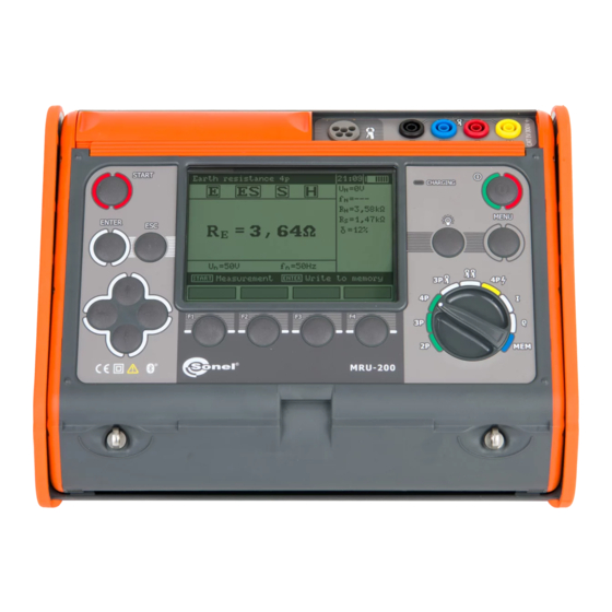
Прибор оснащён жидкокристаллическим сегментным дисплеем с подсветкой, которая облегчит эксплуатацию устройства при плохой освещённости. Она автоматически отключается после 30 либо 60 секунд бездействия. Настраиваемая контрастность сделает показания читаемыми при взгляде под углами даже при ярком свете.
На дисплее отображается индикатор состояния батареи, текущее время, рабочий режим и исследуемые характеристики. Часть параметров можно убрать. Русскоязычное меню упрощает настройку измерителя, обращение с ним.
Результаты исследований сохраняются во встроенную память на 990 результатов: 10 банков по 99 ячеек. Их содержимое можно свободно перемещать для группировки информации и выводить на дисплей. Благодаря USB-разъёму и модулю Bluetooth результаты измерений можно передать на компьютер.
Комплект поставки MRU-200:
- Аккумуляторная батарея NiMH SONEL-07 4,8V
- Адаптер автомобильный (12В)
- Зажим «Крокодил» изолированный красный K02
- Зажим «Крокодил» изолированный черный K01
- Зажим специальный типа «струбцина» с разъемом «банан»
- Зарядное устройство для аккумуляторов Z7, модель SYS1319-3012
- Зонд измерительный для забивки в грунт 30 см
- Кабель последовательного интерфейса USB
- Кабель сетевой
- Клещи измерительные C-3
- Комплект ремней «Свободные руки»
- Провод измерительный 1,2 м с разъемами «банан» красный
- Провод измерительный 2,2 м с разъемами «банан» черный
- Провод измерительный 25 м на катушке с разъёмами «банан» голубой
- Провод измерительный 25 м на катушке с разъемами «банан» красный
- Провод измерительный 50 м на катушке экранированный с разъемами «банан» желтый
- Футляр L2.
Дополнительная комплектация измерителя MRU-200:
- Отсек для батареек LR14 — для MRU-120/200, MPI-52X/530;
- Комплект измерительных проводов 2 м с разъемами «банан» — совместно с клещей N-1 для MRU120/200/GPS, ТЕ-30;
- Клещи гибкие F-3 — для MRU-200, PQM-7XX, MPI-530 и MPU-1;
- Клещи гибкие F-2 — для MRU-200, PQM-7XX, MPI-530 и MPU-1;
- Клещи гибкие F-1 — для MRU-200, PQM-7XX, MPI-530 и MPU-1;
- Адаптер для измерения сопротивления заземления опор линий электропередачи ERP-1 — для MRU-120/200/200-GPS;
- Аккумуляторная батарея NiMH SONEL-07 4,8V — для MRU-120/200, MPI-520/525;
- Клещи передающие N-1 — для LKZ-720, MRU-120, MRU-200;
- Футляр для двух зондов 80 см — для ТЕ-30, LKZ-700/720, MRU-XXX, MPI-52X и MPI-530;
- Зонд измерительный для забивки в грунт 80 см — для ТЕ-30, MRU-XXX, MPI-52X/530, LKZ-700/720;
- Программа автоматического формирования протоколов испытаний электроустановок «СОНЭЛ Протоколы 2.0» — программа ЭВМ.