-
Драйверы
17
-
Инструкции по эксплуатации
2
Языки:

MSI 770-C45 инструкция по эксплуатации
(168 страниц)
- Языки:Русский
-
Тип:
PDF -
Размер:
9.33 MB -
Описание:
Материнская плата AMD
Просмотр

MSI 770-C45 инструкция по эксплуатации
(74 страницы)
- Языки:Английский
-
Тип:
PDF -
Размер:
6.56 MB -
Описание:
Материнская плата Intel
Просмотр
На NoDevice можно скачать инструкцию по эксплуатации для MSI 770-C45. Руководство пользователя необходимо для ознакомления с правилами установки и эксплуатации MSI 770-C45. Инструкции по использованию помогут правильно настроить MSI 770-C45, исправить ошибки и выявить неполадки.

MS-7599
FCC-B Radio FRequenCy inteRFeRenCe StateMent
this equipment has been tested and found to comply with the limits for a class
B digital device, pursuant to part 5 of the FCC rules. these limits are designed
to provide reasonable pro-
tection against harmful in-
terference in a residential
installation. this equipment
generates, uses and can
radiate radio frequency energy and, if not installed and used in accordance with
the instruction manual, may cause harmful interference to radio communications.
However, there is no guarantee that interference will occur in a particular instal-
lation. if this equipment does cause harmful interference to radio or television
reception, which can be determined by turning the equipment off and on, the user
is encouraged to try to correct the interference by one or more of the measures
listed below.
Reorient or relocate the receiving antenna.
increase the separation between the equipment and receiver.
Connect the equipment into an outlet on a circuit different from that to which the
receiver is connected.
Consult the dealer or an experienced radio/ television technician for help.
notice
the changes or modifications not expressly approved by the party responsible for
compliance could void the user’s authority to operate the equipment.
notice 2
Shielded interface cables and a.C. power cord, if any, must be used in order to
comply with the emission limits.
VoiR La notiCe d’nStaLLation aVant de RaCCoRdeR au ReSeau.
Micro-Star international
MS-7599
this device complies with Part 5 of the FCC Rules. operation is subject to the
following two conditions:
() this device may not cause harmful interference, and
(2) this device must accept any interference received, including interference that
may cause undesired operation.
PaRt nuMBeR
G52-7599X2
-
Contents
-
Table of Contents
-
Bookmarks
Quick Links
K8N Neo4 Series
MS-7125 (v1.X) ATX Mainboard
G52-M7125X4
i
Related Manuals for MSI 770 C45 — AM3 AMD 770 HDMI Motherboard
Summary of Contents for MSI 770 C45 — AM3 AMD 770 HDMI Motherboard
-
Page 1
K8N Neo4 Series MS-7125 (v1.X) ATX Mainboard G52-M7125X4… -
Page 2
Manual Rev: 1.1 Release Date: January 2005 FCC-B Radio Frequency Interference Statement This equipment has been tested and found to comply with the limits for a class B digital device, pursuant to part 15 of the FCC rules. These limits are designed to provide reasonable protection against harmful interference when the equipment is operated in a commercial environment. -
Page 3: Copyright Notice
Copyright Notice T he material in this document is the intellec tual property of M ICRO-STAR INTERNATIONAL. W e take every care in the preparation of this document, but no guarantee is given as to the correctness of its contents. Our products are under continual improvement and we reserve the right to make changes without notice.
-
Page 4: Technical Support
Alternatively, please try the following help resources for further guidance. † Visit the MSI homepage & FAQ site for technical guide, BIOS updates, driver updates, and other information: http://www.msi.com.tw & http://www.msi.
-
Page 5: Table Of Contents
CONTENTS Chapter 1. Getting Started ………………1-1 Mainboard Specifications ………………. 1-2 Mainboard Layout ………………..1-5 Packing Contents ………………..1-6 Chapter 2. Hardware Setup ……………… 2-1 Quick Components Guide ………………. 2-2 Central Processing Unit: CPU …………….2-3 CPU Installation Procedures for Socket 939 ……….2-4 Installing AMD Athlon64 CPU Cooler Set …………
-
Page 6
IrDA Infrared Module Header: JIR1 …………2-20 IEEE 1394 Connectors: J1394_1 (Optional) ……….2-21 D-Bracket 2 Connector: JDB1 …………… 2-22 Buuton …………………… 2-24 Clear CMOS Button: SW1 …………….2-25 Slots ……………………2-26 PCI Express Slots ………………2-26 PCI (Peripheral Component Interconnect) Slots ……..2-26 PCI Interrupt Request Routing ………….. -
Page 7
Audio Speaker Setting ………………4-16 Power on Agent ………………..4-18 Power On ………………..4-18 Power Off / Restart ………………. 4-19 Start W ith ………………..4-19 Auto Login ………………..4-20 Chapter 5. nVIDIA RAID Introduction …………..5-1 Introduction ………………….5-2 System Requirement ………………. 5-2 RAID Arrays ……………….. -
Page 8
viii… -
Page 9: Chapter 1. Getting Started
Getting Started Chap t er 1 . Ge tting Started Getting Started Thank you for choosing the K8N Neo4 series (MS-7125) v1. X ATX mainboard. The K8N Neo4 series mainboard is based on ® nVIDIA nForce™4 Ultra/Standard chipset for optimal system ®…
-
Page 10: Mainboard Specifications
Mainboard Specifications † Supports Socket-939 for AMD K8 Athlon 64 FX / Athlon 64 (Socket939) processor † Supports up to Athlon64 3500+, 3800+, or higher CPU (For the latest information about CPU, please visit http://www.msi.com.tw/program/ products/mainboard/mbd/pro_mbd_cpu_support.php) Chipset † nVIDIA nForce4 Ultra/Standard…
-
Page 11
Getting Started USB Interface † 10 USB ports — Controlled by nForce4 Ultra chipset — 4 ports in the rear I/O, 6 ports via the external bracket NV RAID (Software) † Supports up to 4 SATA and 4 ATA133 Hard drives — RAID 0 or 1, 0+1, JBOD is supported — RAID function available for PATA+SATA H/D drives Gigabit LAN… -
Page 12
† ATX Form Factor (30.4 cm X 24.4 cm) M ounting † 9 mounting holes MSI Reminds You… 1. Now the nVidia nForce4 system driver is only available for Windows 2000 and Windows XP. 2. To create a bootable RAID volume for a Windows 2000 environment, Microsoft’s Windows 2000 Service Pack 4 (SP4) is required. -
Page 13: Mainboard Layout
Getting Started Mainboard Layout J C I 1 To p : mo u s e B o tto m: k e y bo a r d S FA N 1 J IR 1 J IR 1 To p : Pa ra lle l Po r t B ot to m: C O M P o r t 1 3 9 4 Po r t ( O p tio n a l)
-
Page 14: Packing Contents
M S-7125 ATX M ainboard Packing Contents MSI Driver/Utility CD SATA RAID Driver SATA Cable (Optional) MSI motherboard Diskette Round Cable of Power Cable D-Bracket 2 (Optional) IDE Devices (Optional) Round Cable of 1394 Cable (Optional) Back IO Shield Floppy Disk (Optional)
-
Page 15: Chapter 2. Hardware Setup
Hardware Setup Chapter 2. Hardware Setup Hardware Setup This chapter tells you how to install the CPU, memory modules, and expansion cards, as well as how to setup the jumpers on the mainboard. Also, it provides the instructions on connecting the periph- eral devices, such as the mouse, keyboard, etc.
-
Page 16: Quick Components Guide
M S-7125 ATX M ainboard Quick Components Guide CPU, p.2-3 DDR DIMMs, p.2-7 JPW1, p.2-10 SFAN1, p.2-16 CPUFAN1, p.2-16 JCI1, p.2-7 ATX1, p.2-10 JIR1, p.2-20 FDD1, p.2-16 Back Panel I/ O,(Optional) p.2-12 PCI_E3, p.2-26 IDE1/2, p.2-17 PCI_E2, p.2-26 PCI_E1, p.2-26 NBFAN1, p.2-16 SATA1~4,…
-
Page 17: Central Processing Unit: Cpu
CPU has a heat sink and a cooling fan attached on the top to prevent overheating. If you do not have the heat sink and cooling fan, contact your dealer to purchase and install them before turning on the computer. For the latest information about CPU, please visit http://www.msi.com.tw/program/ products/mainboard/mbd/pro_mbd_cpu_support.php. MSI Reminds You…
-
Page 18: Cpu Installation Procedures For Socket 939
M S-7125 ATX M ainboard CPU Installation Procedures for Socket 939 Please turn off the power and Open Lever unplug the power cord before installing the CPU. Sliding 90 degree Plate Pull the lever s ideways away from the socket. Make sure to raise the lever up to a 90-de- gree angle.
-
Page 19: Installing Amd Athlon64 Cpu Cooler Set
Hardware Setup Installing AMD Athlon64 CPU Cooler Set W hen you are installing the CPU, make sure the CPU has a heat sink and a cooling fan attached on the top to prevent overheating. If you do not have the heat sink and cooling fan, contact your dealer to purchase and install them before turning on the computer.
-
Page 20
Safety Hook Fixed Lever Fixed Bolt MSI Reminds You… While disconnecting the Safety Hook from the fixed bolt, it is neces- sary to keep an eye on your fingers, because once the Safety Hook is disconnected from the fixed bolt, the fixed lever will spring back instantly. -
Page 21: Memory
The mainboard provides 4 slots for 184-pin DDR SDRAM DIMM (Double In-Line Memory Module) modules and supports the memory size up to 4GB. You can install DDR266/ 333/400 modules on the DDR DIMM slots (DDR 1~4). For the updated supporting memory modules, please visit http://www.msi.com.tw/ program/products/mainboard/mbd/pro_mbd_trp_list.php. DIMM1~4…
-
Page 22: Recommended Memory Combination List
128MB~1GB 128MB~1GB 128MB~1GB 512MB~4GB MSI Reminds You… — Dual-channel DDR works ONLY in the 3 combinations listed in the table as below. — Please select the identical memory modules to install on the dual channel, and DO NOT install three memory modules on three DIMMs, or it may cause some failure.
-
Page 23: Installing Ddr Modules
Hardware Setup MSI Reminds You… 1. The maximum memory speed decreases when the following two Memory Combination is selected (you can also refer to the Rec- ommended Memory Combination list shown in the previous page: — Each channel is installed with two double-sided memory mod-…
-
Page 24: Power Supply
JPW1 Pin Definition SIGNAL JPW1 MSI Reminds You… 1. These two connectors connect to the ATX power supply and have to work together to ensure stable operation of the mainboard. 2. Power supply of 350 watts (and above) is highly recommended for system stability.
-
Page 25: Important Notification About Power Issue
Hardware Setup Important Notification about Power Issue NForce chipset is very sensitive to ESD (Electrostatic Discharge), therefore this issue mostly happens while the users intensively swap memory modules under S5 (power-off) states, and the power code is plugged while installing modules. Due to several pins are very sensitive to ESD, so this kind of memory-replacement actions might cause system chipset unable to boot.
-
Page 26: Back Panel
M S-7125 ATX M ainboard Back Panel The back panel provides the following connectors: L-In RS-Out Parallel M ou se 1394 Port USB Ports SPDIF L-Out CS-Out Keyboard COM Port (Optional) SPDIF Out (Coaxial) (Optical) Mouse Connector (Green) / Keyboard Connector (Purple) ®…
-
Page 27: Ieee1394 Port (Optional)
Hardware Setup IEEE1394 Port (Optional) The back panel provides one standard IEEE 1394 port. The standard IEEE1394 port connects to IEEE1394 devices without external power. The IEEE1394 high-speed serial bus complements USB by providing enhanced PC connectivity for a wide range of devices, including consumer electronics audio/video (A/V) appliances, storage peripherals, other PCs, and portable devices.
-
Page 28: Lan (Rj-45) Jack
M S-7125 ATX M ainboard LAN (RJ-45) Jack The mainboard provides one standard RJ-45 jacks for connection to single Local Area Network (LAN). This Giga-bit LAN enables data to be transferred at 1000, 100 or 10Mbps. You can connect a network cable to either LAN jack. Giga-bit LAN Pin Definition SIGNAL DESCRIPTION…
-
Page 29: Parallel Port Connector: Lpt1
Hardware Setup Parallel Port Connector: LPT1 The mainboard provides a 25-pin female centronic connector as LPT. A parallel port is a standard printer port that supports Enhanced Parallel Port (EPP) and Extended Capabilities Parallel Port (ECP) mode. Pin Definition SIGNAL DESCRIPTION STROBE Strobe…
-
Page 30: Connectors
CPUFAN1 SFAN1 SFAN2 NBF AN1 MSI Reminds You… 1. Always consult the vendors for proper CPU cooling fan. 2. CPUFAN1 supports fan control. You can install Core Center util- ity that will automatically control the CPU fan speed according to the actual CPU temperature.
-
Page 31: Hard Disk Connectors: Ide1/Ide2
IDE2 (Secondary IDE Connector) IDE2 can also connect a Master and a Slave drive. MSI Reminds You… If you install two hard disks on cable, you must configure the second drive to Slave mode by setting its jumper. Refer to the hard disk documentation supplied by hard disk vendors for jumper setting instructions.
-
Page 32: Serial Ata/Serial Ata Raid Connectors Controlled By
Connect to serial ATA ports MSI Reminds You… Please do not fold the serial ATA cable in a 90-degree angle, which will cause the loss of data during the transmission. CD-In Connector: JCD1 The connector is for CD-ROM audio connector.
-
Page 33: Front Panel Connectors: Jfp1 / Jfp2
Key (no pin) USBOC Connected to JUSB1, JUSB2, or USB 2.0 Bracket JUSB3 (the USB pinheader in (Optional) YELLOW color) MSI Reminds You… Note that the pins of VCC and GND must be connected correctly, or it may cause some damage. 2-19…
-
Page 34: Front Panel Audio Connector: Jaud1
Left channel audio signal to front panel AUD_RET_L Left channel audio signal return from front panel MSI Reminds You… If you don’t want to connect to the front audio header, pins 5 & 6, 9 & 10 have to be jumpered in order to have signal output directed to the rear audio ports.
-
Page 35: Ieee 1394 Connectors: J1394_1 (Optional)
Hardware Setup IEEE 1394 Connectors: J1394_1 (Optional) The mainboard provides another 1394 pin header that allows you to connect IEEE 1394 ports via an external IEEE1394 bracket (optional). Pin Definition SIGNAL SIGNAL TPA+ TPA- Ground Ground J1394_1 TPB+ TPB- Cable power Cable power Key (no pin) Ground…
-
Page 36: D-Bracket 2 Connector: Jdb1
M S-7125 ATX M ainboard D-Bracket™ 2 Connector: JDB1 The mainboard comes with a JDB1 connector for you to connect to D-Bracket™ 2. D- Bracket™ 2 is a USB Bracket that supports both USB1.1 & 2.0 spec. It integrates four LEDs and allows users to identify system problem through 16 various combinations of LED signals.
-
Page 37
Hardware Setup D-Bracket™ 2 is an external USB bracket integrating four Diagnostic LEDs, which use graphic signal display to help users understand their system. The LEDs provide up to 16 combinations of signals to debug the system. The 4 LEDs can debug all problems that fail the system, such as VGA, RAM or other failures. -
Page 38
M S-7125 ATX M ainboard Description D-Bracket™ 2 Processor Initialization This will show information regarding the processor (like brand name, system bus, etc…) Testing RTC (Real Time Clock) Initializing Video Interface This will start detecting CPU clock, checking type of video onboard. -
Page 39: Clear Cmos Button: Sw1
Hardware Setup Button The motherboard provides the following button for you to set the computer’s function. This section will explain how to change your motherboard’s function through the use of button. Clear CMOS Button: SW1 There is a CMOS RAM on board that has a power supply from external battery to keep the system configuration data.
-
Page 40: Slots
M S-7125 ATX M ainboard Slots The mainboard provides one PCI Express x16 slot, one PCI Express x1 slots, one PCI Express x4 slots and four 32-bit PCI bus slots. PCI Express Slots The PCI Express slots, as a high-bandwidth, low pin count, serial, intercon- nect technology.
-
Page 41: Pci Interrupt Request Routing
Hardware Setup PCI Interrupt Request Routing The IRQ, acronym of interrupt request line and pronounced I-R-Q, are hard- ware lines over which devices can send interrupt signals to the microprocessor. The PCI IRQ pins are typically connected to the PCI bus INT A# ~ INT D# pins as follows: Order 1 Order 2 Order 3…
-
Page 42: Chapter 3. Bios Setup
SETUP. You want to change the default settings for customized features. MSI Reminds You… 1. The items under each BIOS category described in this chapter are under continuous update for better system performance.
-
Page 43: Entering Setup
MSI Reminds You… The items under each BIOS category described in this chapter are under continuous update for better system performance. Therefore, the description may be slightly different from the latest BIOS and should be held for reference only.
-
Page 44: Control Keys
BIOS Setup Control Keys < > Move to the previous item < > Move to the next item < > Move to the item in the left hand < > Move to the item in the right hand <Enter> Select the item <Esc>…
-
Page 45: The Main Menu
MS-7125 ATX Mainboard The Main Menu ® Once you enter Phoenix-Award BIOS CMOS Setup Utility, the Main Menu will appear on the screen. The Main Menu allows you to select from twelve setup func- tions and two exit choices. Use arrow keys to select among the items and press <Enter>…
-
Page 46
BIOS Setup Load Optimized Defaults Use this menu to load the BIOS values for the best system performance, but the system stability may be affected. BIOS Setting Password Use this menu to set the password for BIOS. Save & Exit Setup Save changes to CMOS and exit setup. -
Page 47: Standard Cmos Features
MS-7125 ATX Mainboard Standard CMOS Features The items in Standard CMOS Features Menu includes some basic setup items. Use the arrow keys to highlight the item and then use the <PgUp> or <PgDn> keys to select the value you want in each item. Date This allows you to set the system to the date that you want (usually the current date).
-
Page 48
BIOS Setup Head Number of heads. Precomp Write precompensation. Landing Zone Cylinder location of the landing zone. Sector Number of sectors. Drive A This item allows you to set the type of floppy drive installed. Available options: [None], [360K, 5.25 in.], [1.2M, 5.25 in.], [720K, 3.5 in.], [1.44M, 3.5 in.], [2.88M, 3.5 in.]. Halt On The setting determines whether the system will stop if an error is detected at boot. -
Page 49: Advanced Bios Features
MS-7125 ATX Mainboard Advanced BIOS Features Quick Boot Setting the item to [Enabled] allows the system to boot within 5 seconds since it will skip some check items. Available options: [Enabled], [Disabled]. Boot To OS/2 This allows you to run the OS/2 ®…
-
Page 50
BIOS Setup Boot Sequence Press <Enter> to enter the sub-menu and the following screen appears: 1st/2nd/3rd Boot Device The items allow you to set the sequence of boot devices where BIOS attempts to load the disk operating system. Boot Other Device Setting the option to [Enabled] allows the system to try to boot from other device if the system fails to boot from the 1st/2nd/3rd boot device. -
Page 51: Advanced Chipset Features
MS-7125 ATX Mainboard Advanced Chipset Features DRAM Configuration Press <Enter> to enter the sub-menu and the following screen appears: Timing Mode This field has the capacity to automatically detect all of the DRAM timing. If you set this field to [Manual], the following fields will be selectable. The settings are: [Auto], [Manual].
-
Page 52
BIOS Setup CAS# Latency (Tcl) When the Timing Mode is set to [Manual], the field is adjustable.This controls the CAS latency, which determines the timing delay (in clock cycles) before SDRAM starts a read command after receiving it. Settings: [Auto], [CL=2.0], [CL=2.5], [CL=3.0]. -
Page 53
MS-7125 ATX Mainboard Row to Row delay (Trrd) When the Timing Mode is set to [Manual], the field is adjustable. Specifies the active-to-active delay of different banks. Available settings: [Auto], [2T], [3T], [4T]. Write recovery time (Twr) When the Timing Mode is set to [Manual], the field is adjustable. It specifies the amount of delay (in clock cycles) that must elapse after the completion of a valid write operation, before an active bank can be precharged. -
Page 54
BIOS Setup Read Preamble value When the User Config mode is set to [Manual], the field is adjustable. The time prior to the max-read DQS-return when the DQS receiver should be turned on. This is specified in units of 0.5ns. The controller needs to know when to enbale its DQS receiver in anticipation of the DRAM DQS driver truning on for a read. -
Page 55: Integrated Peripherals
MS-7125 ATX Mainboard Integrated Peripherals USB Controller This setting allows you to enable/disable the onboard USB controller. Selecting [V1.1+V2.0] enables the system to support both USB 1.1 and 2.0 spec. Setting options: [Disabled], [V1.1], [V1.1+V2.0]. USB KB/Storage Support Select [Enabled] if you need to use a USB-interfaced keyboard or storage device in the operating system.
-
Page 56
BIOS Setup Onboard GigaBit LAN Setting to [Enabled] allows the BIOS to detect the Marvell LAN controller and enable it. Setting options: [Enabled] and [Disabled]. Onboard GigaBit LAN ROM This setting controls the onboard Marvell LAN Boot ROM. Setting options: [Enabled], [Disabled]. -
Page 57
MS-7125 ATX Mainboard RxD, TxD Active This setting controls the receiving and transmitting speed of the IR peripheral in use. Setting options: [Hi,Hi], [Hi,Lo], [Lo,Hi], [Lo,Lo]. IR Transmission Delay This setting determines whether the IR transmission rate will be delayed while converting to receiving mode. -
Page 58
BIOS Setup EPP Mode Select The onboard parallel port is EPP Spec. compliant, so after the user chooses the onboard parallel port with the EPP function, the following message will be displayed on the screen: “EPP Mode Select.” At this time either [EPP 1.7] spec or [EPP 1.9] spec can be chosen. -
Page 59
MS-7125 ATX Mainboard IR Function Select This setting allows you to specify the operation mode for serial port 2. Setting options: [IrDA], [ASKIR], [Disable]. [Disable] RS-232C Serial Port [IrDA] IrDA-compliant Serial Infrared Port [ASKIR] Amplitude Shift Keyed Infrared Port SATA Devices Configuration Press <Enter>… -
Page 60: Power Management Setup
BIOS Setup Power Management Setup MSI Reminds You… S3-related functions described in this section are available only when your BIOS supports S3 sleep mode. ACPI Standby State This item specifies the power saving modes for ACPI function. If your operating…
-
Page 61
MS-7125 ATX Mainboard Power Button Function This feature sets the function of the power button. Settings are: [Power Off] The power button functions as normal power off button. [Suspend] When you press the power button, the computer enters the suspend/sleep mode, but if the button is pressed for more than four seconds, the computer is turned off. -
Page 62: Pnp/Pci Configurations
BIOS Setup PNP/PCI Configurations This section describes configuring the PCI bus system and PnP (Plug & Play) feature. PCI, or Peripheral Component Interconnect, is a system which allows I/O devices to operate at speeds nearing the speed the CPU itself uses when communi- cating with its special components.
-
Page 63
This item allows you to set the PCI Express Maximum payload size per time . Settings: [4096], [128], [256], [512], [1024], [2048]. MSI Reminds You… IRQ (Interrupt Request) lines are system resources allocated to I/O devices. When an I/O device needs to gain attention of the operating system, it signals this by causing an IRQ to occur. -
Page 64: H/W Monitor
BIOS Setup H/W Monitor This section shows the status of your CPU, fan, overall system status, etc. Monitor function is available only if there is hardware monitoring mechanism onboard. Chassis Intrusion Detect The field enables or disables the feature of recording the chassis intrusion status and issuing a warning message if the chassis is once opened.
-
Page 65: Cell Menu
Cell Menu The items in Cell Menu includes some important settings of CPU, AGP, DRAM and overclocking functions. MSI Reminds You… Change these settings only if you are familiar with the chipset. Current CPU / DDR Clock These two items show the current clocks of CPU & DDR. Read-only.
-
Page 66
5th level of overclocking, increasing the CPU frequency by 9%. [Commander] 6th level of overclocking, increasing the CPU frequency by 11%. MSI Reminds You… Even though the Dynamic Overclocking Technology is more stable than manual overclocking, basically, it is still risky. We suggest user to make sure that your CPU can afford to overclocking regularly first. -
Page 67
MS-7125 ATX Mainboard SATA Spread Spectrum This setting is used to enable or disable the SATA Spread Spectrum feature. Setting options: [Disabled], [Down Spread]. PCIE Spread Spectrum This setting is used to enable or disable the CPU Spread Spectrum feature. When overclocking the CPU, always set it to [Disabled]. -
Page 68
NF4 Voltage NV4 voltage is adjustable in the field. Setting options are: [1.50V]~[1.85V]. MSI Reminds You… The settings shown in different color in CPU Voltage, Memory Volt- age and NF4 Voltage help to verify if your setting is proper for your system. -
Page 69: Load Fail-Safe/Optimized Defaults
MS-7125 ATX Mainboard Optimized Defaults The two options on the main menu allow users to restore all of the BIOS settings to the default Optimized values. The Optimized Defaults are the default values set by the mainboard manufacturer specifically for optimal performance of the mainboard.
-
Page 70: Bios Setting Password
BIOS Setup BIOS Setting Password When you select this function, a message as below will appear on the screen: Type the password, up to eight characters in length, and press <Enter>. The password typed now will replace any previously set password from CMOS memory. You will be prompted to confirm the password.
-
Page 71: Chapter 4. Introduction To Digicell
Chapter 2. Hardware Setup Introduction to DigiCell DigiCell, the most useful and powerful utility that MSI has spent much research and efforts to develop, helps users to monitor and configure all the integrated peripherals of the system, such as audio program, power management, MP3 files management and communication / 802.11g WLAN…
-
Page 72: Main
Introduction: Click on each icon appearing above to enter the sub-menu to make further configuration. Click on this button to link to MSI website: http://www.msi.com.tw. Quick Guide Click on this button and the quick guide of DigiCell will be displayed for you to review.
-
Page 73
Power on Agent In this sub-menu, you can configure date, time and auto-executed programs of the power-on, power-off and restarting features. MSI Reminds You… Click on back button in every sub-menu and it will bring you back to the main menu. -
Page 74: H/W Diagnostic
In the H/W Diagnostic sub-menu, you can see the information, status and note of each DigiCell. You may double check the connection and installation of the item marked as gray. You may also click on the Mail to MSI button to send your questions or suggestions to MSI’s technical support staff.
-
Page 75: Communication
Introduction to DigiCell Communication In the Communication sub-menu, you can see the status of all the LAN / WLAN / Bluetooth on the screen if the hardware is installed. The first icon indicates the onboard LAN on your system, the second icon indicates the wireless LAN status, and the third one is the information about the bluetooth on your system.
-
Page 76: Software Access Point
MS-7125 ATX Mainboard MSI Feature Software Access Point In the Software Access Point sub-menu, you can see the communication status on your system and choose the desired software access point mode by clicking on the desired icon, in which the default settings are configured for your usage. The default software access point mode is set to WLAN Card Mode.
-
Page 77: Access Point Mode
Introduction to DigiCell Access Point Mode Click on “Setting” button of the Access Point Mode and the following screen will display. IP Sharing Click on this icon to enable/disable the IP sharing. The default of this setting is disabled. Disabled. Enabled.
-
Page 78: Wlan Card Mode
MS-7125 ATX Mainboard MSI Feature enable this feature, only PCs with MAC address located in Association Control List can connect to the wireless LAN. MAC Address MAC stands for Media Access Control. A MAC address is the hardware address of a device connected to a network.
-
Page 79: Live Update
BIOS/VGA Driver/OSD/Utility online so that you don’t need to search for the correct BIOS/driver version throughout the whole Web site. To use the function, you need to install the “MSI Live Update 3” application. After the installation, the “MSI Live Update 3”…
-
Page 80: Mega Stick
MS-7125 ATX Mainboard MSI Feature MEGA STICK In the MEGA STICK sub-menu, you can configure the settings of MSI MEGA STICK and the media files (*.m3u, *.mp3, *.wav, *.cda, *.wma) on your system. Basic Function Here you can edit your own play list with the buttons “load”, “save”, “delete”, “shuttle”, “repeat”…
-
Page 81
Introduction to DigiCell There is also a toolbar for you to execute some basic function, like play, stop, pause, previous/next song, song info and volume adjust. There is also a scroll bar on the top for you to forward/rewind. pause previous next forward/rewind… -
Page 82: Non-Unicode Programs Supported
MS-7125 ATX Mainboard MSI Feature Non-Unicode programs supported If you are using an operating system in European languages, and you’d like to play the media files in MEGA STICK with East-Asian languages (such as Chinese, Japanese… etc.), it is possible that the file names display incorrectly.
-
Page 83
Introduction to DigiCell 3. Then go to the [Advanced] tab and select the language you want to be supported (the language of the filename in the MegaStick) from the drop- down list in the [Language for non-Unicode programs], then click [Apply]. The system will install the necessary components from your Microsoft Setup CD immediately. -
Page 84: Core Center (For Amd K8 Processor)
MS-7125 ATX Mainboard MSI Feature Core Center (for AMD K8 Processor) Click on the Core Center icon in the main menu and the Core Center program will be enabled. Cool’n’Quiet This utility provides a CPU temperature detection function called Cool’n’Quiet .
-
Page 85
CPU fan speed in 8 different modes, from High Speed to Low speed. If you choose Cool’n’Quiet , the system will automatically configure an optimal setting for you. MSI Reminds You… To ensure that Cool’n’Quiet function is activated and will… -
Page 86: Audio Speaker Setting
MS-7125 ATX Mainboard MSI Feature Audio Speaker Setting In the Audio Speaker Setting sub-menu, you can configure the multi-channel audio operation, perform speaker test, and choose the environment you prefer while en- joying the music. You can scroll the bar of each equalizer to regulate the current playing digital sound source.
-
Page 87
Introduction to DigiCell Click on the “Speaker test” button and the following dialogue box will appear: In this Speaker Configuration dialogue box, select the audio configuration which is identical to the audio jack on your mainboard. Once the correct audio configuration is selected, click “Apply”… -
Page 88: Power On Agent
Click “OK” to restart the computer right away or click “Later” to restart your computer later. MSI Reminds You… Please note that the new setting will not take effect until you restart your computer.
-
Page 89: Power Off / Restart
Delete. delete the added program MSI Reminds You… You can also enable the Every turn on function, which will enable the specified program(s) and file(s) every time the Digi Cell utility runs.
-
Page 90: Auto Login
MS-7125 ATX Mainboard MSI Feature Auto Login Since the Power On function allows the system to power on automatically, you may have to enable this Auto Login function in the following situations: 1. If you are using a computer belonging to a domain in office, and you need to enter your user name &…
-
Page 91: Chapter 5. Nvidia Raid Introduction
nVIDIA RAID Introduction Chapter 5. nVidia RAID In- troduction nVidia RAID Introduction NVIDIA brings Redundant Array of Independent Disks (RAID) technology—which is used by the world’s leading businesses—to the common PC desktop. This technology uses multiple drives to either increase total disk space or to offer data protection. For all levels, RAID techniques optimize storage solutions by using multiple disks grouped together and treating them as a single storage resource.
-
Page 92: Introduction
MSI Reminds You… Please note that users cannot install OS, either WinME or Win98, in their SATA hard drive. Under these two OSs, SATA can not support.
-
Page 93: Raid Configuration
nVIDIA RAID Introduction RAID Configuration Basic Configuration Instructions The following are the basic steps for configuring NVRAID: Non-Bootable RAID Array 1. Choose the hard disks that are to be RAID enabled in the system BIOS. 2. Specify the RAID level, either Mirroring (RAID 1), Striping (RAID 0), Striping and Mirroring (RAID 0+1), or Spanning (JBOD) and create the desired RAID array.
-
Page 94
Channel 2, controller 0, Master 2.1.M Channel 2, controller 1, Master MSI Reminds You… There is no such thing as Slave drive in Serial ATA. All drives are considered to be Master since there is a one to one connection… -
Page 95
nVIDIA RAID Introduction Using the Define a New Array Window If necessary, press the tab key to move from field to field until the appropriate field is highlighted. • Selecting the RAID Mode By default, this is set to [Mirroring]. To change to a different RAID mode, press the down arrow key until the mode that you want appears in the RAID Mode box—either [Mirroring], [Striping], [Spanning], or [Stripe Mirroring]. -
Page 96
MS-7125 ATX Mainboard Completing the RAID BIOS Setup 1. After assigning your RAID array disks, press F7. The Clear disk data prompt appears. 2. Press Y if you want to wipe out all the data from the RAID array, otherwise press N. -
Page 97: Nvidia Raid Untility Installation
Please follow the instruction below to make an nVIDIA RAID driver for yourself. 1. Insert the MSI CD into the CD-ROM drive. 2. Ignore the Setup screen and use “Explorer” to browse the CD. 3. Copy all the contents (not including the sub-folders) in the \nVidiaSystemCK804IDEWinXP or \nVidiaSystemCK804IDEWin2k to a formatted floppy disk.
-
Page 98
This will not be an issue with a signed driver. MSI Reminds You… Each time you add a new hard drive to a RAID array, the RAID driver will have to be installed under Windows once for that hard drive. After… -
Page 99: Installing The Nvidia Raid Software Under Windows (For Non-Bootable Raid Array)
nVIDIA RAID Introduction Installing the NVIDIA RAID Software Under Windows (for Non-bootable RAID Array) The existing Windows IDE Parallel ATA driver (as well as the Serial ATA driver if SATA is enabled) must be upgraded to use the NVIDIA IDE Parallel ATA driver (as well as the NV Serial ATA driver if SATA is enabled).
-
Page 100: Initializing And Using The Disk Array
MS-7125 ATX Mainboard Initializing and Using the Disk Array The RAID array is now ready to be initialized under Windows. 1. Launch Computer Management by clicking “Start” —> “Settings” —> “Control Panel” —> “Switch to Classic View” then open the “Administrative Tools” folder and double click on “Computer Management”.
-
Page 101
nVIDIA RAID Introduction 5. Check the disk in the list if you want to make the array a dynamic disk, then click Next. The Completing the Initialize and Convert Disk Wizard window appears. 6. Click Finish. The “Computer Management” window appears. The actual disks listed will depend on your system, and the unallocated partition is the total combined storage of two hard disks. -
Page 102: Raid Drives Management
CD accompanied with your mainboard). The RAID configuration information appears in the right-side pane, as shown below. MSI Reminds You… The information in the figures in this part may very from what it is shown in your system.
-
Page 103
nVIDIA RAID Introduction NVRAID Striped Array The figure below shows an example of a two hard drive striped array using identical 55.90 GB IDE hard drives (ST360015A), where one drive is configured as Master and the other drive is configured as Slave. The total disk space used is 111.80 GB. NVRAID Striped Mirror Array The figure below shows an example of a four hard drive stripe-mirrored array. -
Page 104: Setting Up A Spare Raid Disk
MS-7125 ATX Mainboard Setting Up a Spare RAID Disk You can designate a hard drive to be used as a spare drive for a RAID 1 or RAID 0+1 array2. The spare drive can take over for a failed disk. NVRAID supports two types of spare drives: •…
-
Page 105
nVIDIA RAID Introduction Assigning a Dedicated Disk To mark a disk as dedicated, or reserve it for use by a specific array, Step 1: Mark the Disk as a Free Disk 1. Enter the system BIOS setup and make sure that the drive that you want to mark as free is RAID enabled. -
Page 106
MS-7125 ATX Mainboard 3. Click Next. The RAID Array Selection page appears. 4. From the RAID Array Selection page, select one of the arrays from the list. This is the array to which you want to allocate the dedicated free disk. 5. -
Page 107
nVIDIA RAID Introduction Method 2: Select an array and then assign a free disk to it. 1. Right click on the array to which you want to assign a dedicated free disk. The pop- up menu appears. 2. Select Designate Spare from the menu to launch the Spare Disk Allocation Wizard. 3. -
Page 108
MS-7125 ATX Mainboard 5. Click Next. The Completing the NVIDIA Spare Disk Allocation page appears. 6. Click Finish. You have now assigned a dedicated free disk to a mirrored array. Once a dedicated disk has been assigned to a particular array, it can be removed at any time. -
Page 109
nVIDIA RAID Introduction Example of Dedicating a Free Disk in a RAID 1 or RAID 0+1 Array You can also assign a dedicated free disk to a RAID 1 or a RAID 0+1 array, using the same process. 1. Right-click either the free disk that you want to dedicate to an array, the array type, or the array drives as shown in the figure below. -
Page 110: Rebuilding A Raid Mirrored Array
MS-7125 ATX Mainboard Rebuilding a RAID Mirrored Array Rebuilding is the process of recovering data from one hard drive to another. All data is copied from one hard drive to another and then the data is synchronized between the two hard drives. This only applies to RAID 1 array as well as a RAID 0+1 array. Rebuilding Instructions After creating a mirrored array, you can rebuild the array using the following steps: 1.
-
Page 111
nVIDIA RAID Introduction 4. Click Next. The Disk Selection page appears. 5. Select the drive that you want to rebuild by clicking it from the list, then click Next. The Completing the NVIDIA Rebuild Array page appears. 6. Click Finish. The array rebuilding starts after a few seconds, and a small pop-up message appears towards the bottom right corner of the screen as shown in the figure below. -
Page 112
MS-7125 ATX Mainboard More About Rebuilding Arrays • Rebuilding Occurs in the Background The rebuilding process is very slow (it can take up to a day) and occurs in the background so as not to affect the performance of the system. •… -
Page 113
SATARAID5, both of these problems are solved. SATARAID5 software provides a Graphical User Interface (GUI) for easy-to-use configurations of the RAID Groups. MSI Reminds You… All the information/volumes listed in your system might differ from the illustrations in this appendix. -
Page 114
MS-7125 ATX Mainboard Introduction RAID — Redundant Array of Independent Disks RAID technology manages multiple disk drives to enhance I/O performance and provide redundancy in order to withstand the failure of any individual member, without loss of data. SATA RAID provides two RAID Set types, Striping (RAID 0) and Mirroring (RAID 1). -
Page 115
Silicon Image SATARAID5 Introduction The data is written to RAID Group A, which is striped (RAID 0). This allows maximum speed. The data is then mirrored to another RAID 0 striped set, which is Set B in the figure above. This provides data redundancy (RAID 1), and thus increased data security. -
Page 116
MS-7125 ATX Mainboard SATARAID5 Features RAID 0, RAID 1, RAID 5, RAID 10, and JBOD Groups are supported. Supported OS: Win2000/XP/Server 2003. RAID Groups can be created and deleted without exiting Windows. Hot Spare and On-line Rebuilding. The spare policy supports testing periodically for a health check of the spare disk. -
Page 117: Creating And Deleting Legacy Raid Groups With Bios Utility
Silicon Image SATARAID5 Introduction Creating and Deleting Legacy RAID Groups with BIOS Utility Legacy RAID sets and JBOD can be created and managed by either the BIOS utility or the SATARAID5 GUI. New RAID groups must be created and managed by the SATARAID5 GUI.
-
Page 118
MS-7125 ATX Mainboard Create RAID Group is used to create a new legacy RAID Set or for allocating legacy spare drives. Delete RAID Group is used to delete a legacy RAID Set or to deallocate a legacy spare drive. Rebuild RAID 1 Set is used to initiate the rebuild of a RAID 1 set after, for example, a drive in the Group has been replaced. -
Page 119: Creating Raid Groups
Silicon Image SATARAID5 Introduction Creating RAID Groups As previously discussed, the Silicon Image SATA host adapter supports RAID 0, 1, 5, 10, and JBOD configurations. The selection of the RAID level to be used should be based upon factors including performance, data security, and number of drives available.
-
Page 120: Creating Spare Drive
MS-7125 ATX Mainboard 4. If manual configuration is selected, the chunk size of Striped Sets can be selected. 5. If auto configuration is selected, BIOS will select RAID member drives automatically. 6. Select RAID set size with keys. 7. After the RAID set size is set, the message “Are You Sure?” will display before completing the configuration.
-
Page 121: Creating Jbod
Silicon Image SATARAID5 Introduction 5. After the spare drive size is set, the message “Are You Sure?” will display before completing the configuration. Answer “N” to abort the creation of the spare drive, or “Y” to proceed with the spare drive creation. Creating JBOD Since BIOS no longer reports non-RAID drives to the system BIOS, if a non-RAID boot drive or data drive is desired, a JBOD…
-
Page 122: Rebuild Raid 1 Set
MS-7125 ATX Mainboard Rebuild RAID 1 Set This menu selection is used to initiate the copying of data from an existing drive to a replacement drive that has been installed in a RAID 1 set after the failure of one of the members.
-
Page 123
Silicon Image SATARAID5 Introduction 2. Select the “Conflict” entry in the Logical Drive Status window and press Enter. 6-11… -
Page 124
MS-7125 ATX Mainboard 3. Note that some conflict resolutions may result in the drive letter assignment changing; for example the RAID set may have been drive D: but after the conflict resolution, it may become drive E. Be aware of this when performing a conflict resolution. -
Page 125: Low Level Formatting
Silicon Image SATARAID5 Introduction Low Level Formatting The Low Level Format menu selection allows the complete erasure of data on a hard drive. This is not an action, which typically needs to be performed as formatting the drive under Windows is usually sufficient to prepare the drive for use.
-
Page 126
MS-7125 ATX Mainboard Reserved Drive and Setting Size for RAID Set, Spare Drive, or JBOD Once a physical drive has been used to create a RAID set, spare drive, or JBOD by BIOS utility, BIOS saves user selected set or drive size in the reserved area of the physical drive. -
Page 127
You may make the Serial ATA RAID driver by yourself by following the instruction below. 1. Insert the MSI CD into the CD-ROM drive. 2. Ignore the Setup screen and use “Explorer” to browse the CD. -
Page 128: Installing Drivers And Gui
Installing Drivers and GUI Before installing the SATARAID5 software, Silicon Image Serial ATA host adapter driver must be installed. Insert MSI driver CD into the computer’s CDROM drive and select Silicon Image SATA RAID Drivers. The Java 2 Runtime Environment is required for the SATARAID5 GUI. The Java 2 Runtime Installer and executable package must be downloaded from the Sun Microsystems website at http://java.sun.com/j2se/downloads.html.
-
Page 129
Silicon Image SATARAID5 Introduction When a window appears asking for acceptance the license agreement, select I accept the terms of this license agreement and click Next. Choose the Typical setup type and click Next. When the installation completes, click Finish. Restart the computer when prompted. 6-17… -
Page 130: Chapter 6. Installation Of Driver & Utility
Driver & Utility Installation of Drivers & Utility MSI provides a setup CD along with your mainboard, which contains the required drivers for your system, and many other use- ful and powerful utility to bring you the best experience for your…
-
Page 131: Driver Installation
MS-7125 ATX Mainboard Driver Installation Click on the Driver tab and the screen below will display. Click on the driver you like to install, and follow the proceeding instructions. NVIDIA nForce4 System Driver This driver is only available for Windows 2000 and Windows XP operating system. Please follow the following step to install the driver correctly.
-
Page 132
Installation of Drivers and Utility 2. Then the following screen displays the available components to install. All the components shown here will be selected to be installed by default. Then click Next. 3. The system will start installing the selected driver components automatically. 4. -
Page 133
However, it is strongly suggested that you do not install this component. Please follow the instruction below to make a software firewall CD for yourself. 1. Insert the MSI CD into the CD-ROM drive. 2. Ignore the Setup screen and use “Explorer” to browse the CD. 3. In the \nVidiaSystemCK804EthernetFirewall double-… -
Page 134: Realtek Ac97 Audio Driver
Installation of Drivers and Utility Realtek AC97 Audio Driver 1. Click on this button to install the Realtek AC97 Audio Driver. Then the welcome dialogue will display. Click Next to continue. The installation process will launch automatically. 2. The following screen indicates the installation is complete. Click Yes to restart your computer or click No to restart it later.
-
Page 135: Utility Installation
MS-7125 ATX Mainboard Utility Installation Click on the Utility tab and the screen below will display. Click on the utility you like to install, and follow the proceeding instructions.
 Loading…
![]()
MS-7599
FCC
 -B Radio Frequency
 Interference
 Statement


This equipment has been tested and found to comply with the limits for a class B digital device, pursuant to part 15 of the FCC rules. These limits are designed to provide reasonable pro-
tection against harmful in-
terference in a residential installation. This equipment
generates, uses and can
radiate radio frequency energy and, if not installed and used in accordance with the instruction manual, may cause harmful interference to radio communications. However, there is no guarantee that interference will occur in a particular installation. If this equipment does cause harmful interference to radio or television reception, which can be determined by turning the equipment off and on, the user is encouraged to try to correct the interference by one or more of the measures listed below.
Reorient or relocate the receiving antenna.
Increase the separation between the equipment and receiver.
Connect the equipment into an outlet on a circuit different from that to which the receiver is connected.
Consult the dealer or an experienced radio/ television technician for help.
Notice 1
The changes or modifications not expressly approved by the party responsible for compliance could void the user’s authority to operate the equipment.
Notice 2
Shielded interface cables and A.C. power cord, if any, must be used in order to comply with the emission limits.
VOIR LA NOTICE D’NSTALLATION AVANT DE RACCORDER AU RESEAU.
Micro-Star International
MS-7599
This device complies with Part 15 of the FCC Rules. Operation is subject to the following two conditions:
(1)this device may not cause harmful interference, and
(2)this device must accept any interference received, including interference that may cause undesired operation.
Part
 Number
G52-75991X2
Copyright
 Notice
The material in this document is the intellectual property of MICRO-STAR INTERNATIONAL. We take every care in the preparation of this document, but no guarantee is given as to the correctness of its contents. Our products are under continual improvement and we reserve the right to make changes without notice.
Trademarks
All trademarks are the properties of their respective owners.
■MSI® is registered trademark of Micro-Star Int’l Co.,Ltd.
■NVIDIA® is registered trademark of NVIDIA Corporation.
■ATI® is registered trademark of ATI Technologies, Inc.
■AMD® is registered trademarks of AMD Corporation.
■Intel® is registered trademarks of Intel Corporation.
■Windows® is registered trademarks of Microsoft Corporation.
■AMI® is registered trademark of Advanced Micro Devices, Inc.
■Award® is a registered trademark of Phoenix Technologies Ltd.
■Sound Blaster® is registered trademark of Creative Technology Ltd.
■Realtek® is registered trademark of Realtek Semiconductor Corporation.
■JMicron® is registered trademark of JMicron Technology Corporation.
■Netware® is a registered trademark of Novell, Inc.
Revision History
|
Revision |
Revision History |
Date |
||
|
V1.1 |
Add 770-C45 & APS LEDs |
April 2009 |
||
MS-7599
Safety Instructions
■Always read the safety instructions carefully.
■Keep this User Manual for future reference.
■Keep this equipment away from humidity.
■Lay this equipment on a reliable flat surface before setting it up.
■The openings on the enclosure are for air convection hence protects the equipment from overheating. Do not cover the openings.
■Make sure the voltage of the power source and adjust properly 110/220V before connecting the equipment to the power inlet.
■Place the power cord such a way that people can not step on it. Do not place anything over the power cord.
■Always Unplug the Power Cord before inserting any add-on card or module.
■All cautions and warnings on the equipment should be noted.
■Never pour any liquid into the opening that could damage or cause electrical shock.
■If any of the following situations arises, get the equipment checked by a service personnel:
○The power cord or plug is damaged.
○Liquid has penetrated into the equipment.
○The equipment has been exposed to moisture.
○The equipment does not work well or you can not get it work according to User Manual.
○The equipment has dropped and damaged.
○The equipment has obvious sign of breakage.
■Do not leave this equipment in an environment unconditioned, storage temperature above 60°C (140°F), it may damage the equipment.
CAUTION
Danger of explosion if battery is incorrectly replaced. Replace only with the same or equivalent type recommended by the manufacturer.
For better environmental protection, waste batteries should be collected separately for recycling or special disposal.

WEEE Statement
ENGLISH


To protect the global environment and as an environmentalist, MSI
must remind you that… Under the European Union (“EU”) Directive on Waste Electrical and Electronic Equipment, Directive 2002/96/EC, which takes effect on August 13, 2005, products of “electrical and electronic equipment”
cannot be discarded as municipal waste anymore and manufacturers of covered electronic equipment will be obligated to take back
such products at the end of their useful life. MSI will comply with the product take back requirements at the end of life of MSI-branded products that are sold into the
EU. You can return these products to local collection points.
DEUTSCH
Hinweis von MSI zur Erhaltung und Schutz unserer Umwelt
Gemäß der Richtlinie 2002/96/EG über Elektround Elektronik-Altgeräte dürfen Elektround Elektronik-Altgeräte nicht mehr als kommunale Abfälle entsorgt werden. MSI hat europaweit verschiedene Sammelund Recyclingunternehmen beauftragt, die in die Europäische Union in Verkehr gebrachten Produkte, am Ende seines Lebenszyklus zurückzunehmen. Bitte entsorgen Sie dieses Produkt zum gegebenen Zeitpunkt ausschliesslich an einer lokalen Altgerätesammelstelle in Ihrer Nähe.
FRANÇAIS
En tant qu’écologiste et afin de protéger l’environnement, MSI tient à rappeler ceci…
Au sujet de la directive européenne (EU) relative aux déchets des équipement électriques et électroniques, directive 2002/96/EC, prenant effet le 13 août 2005, que les produits électriques et électroniques ne peuvent être déposés dans les décharges ou tout simplement mis à la poubelle. Les fabricants de ces équipements seront obligés de récupérer certains produits en fin de vie. MSI prendra en compte cette exigence relative au retour des produits en fin de vie au sein de la communauté européenne. Par conséquent vous pouvez retourner localement ces matériels dans les points de collecte.
РУССКИЙ
Компания MSI предпринимает активные действия по защите окружающей среды, поэтому напоминаем вам, что….
В соответствии с директивой Европейского Союза (ЕС) по предотвращению загрязнения окружающей среды использованным электрическим и электронным оборудованием (директива WEEE 2002/96/EC), вступающей в силу 13 августа 2005 года, изделия, относящиеся к электрическому и электронному оборудованию, не могут рассматриваться как бытовой мусор, поэтому производители вышеперечисленного электронного оборудования обязаны принимать его для переработки по окончании срока службы. MSI обязуется соблюдать требования по приему продукции, проданной под маркой MSI на территории EC, в переработку по окончании срока службы. Вы можете вернуть эти изделия в специализированные пункты приема.

MS-7599
ESPAÑOL


MSI como empresa comprometida con la protección del medio ambiente, recomienda:
Bajo la directiva 2002/96/EC de la Unión Europea en materia de desechos y/ o equipos electrónicos, con fecha de rigor desde el 13 de agosto de 2005, los productos clasificados como “eléctricos y equipos electrónicos” no pueden ser depositados en los contenedores habituales de su municipio, los fabricantes de equipos electrónicos, están obligados a hacerse cargo de dichos productos al termino de su período de vida. MSI estará comprometido con los términos de recogida de sus productos vendidos en la Unión Europea al final de su periodo de vida. Usted debe depositar estos productos en el punto limpio establecido por el ayuntamiento de su localidad o entregar a una empresa autorizada para la recogida de estos residuos.
NEDERLANDS
Om het milieu te beschermen, wil MSI u eraan herinneren dat….
De richtlijn van de Europese Unie (EU) met betrekking tot Vervuiling van Electrische en Electronische producten (2002/96/EC), die op 13 Augustus 2005 in zal gaan kunnen niet meer beschouwd worden als vervuiling. Fabrikanten van dit soort producten worden verplicht om producten retour te nemen aan het eind van hun levenscyclus. MSI zal overeenkomstig de richtlijn handelen voor de producten die de merknaam MSI dragen en verkocht zijn in de EU. Deze goederen kunnen geretourneerd worden op lokale inzamelingspunten.
SRPSKI
Da bi zaštitili prirodnu sredinu, i kao preduzeće koje vodi računa o okolini i prirodnoj sredini, MSI mora da vas podesti da…
Po Direktivi Evropske unije (“EU”) o odbačenoj ekektronskoj i električnoj opremi, Direktiva 2002/96/EC, koja stupa na snagu od 13. Avgusta 2005, proizvodi koji spadaju pod “elektronsku i električnu opremu” ne mogu više biti odbačeni kao običan otpad i proizvođači ove opreme biće prinuđeni da uzmu natrag ove proizvode na kraju njihovog uobičajenog veka trajanja. MSI će poštovati zahtev o preuzimanju ovakvih proizvoda kojima je istekao vek trajanja, koji imaju MSI oznaku i koji su prodati u EU. Ove proizvode možete vratiti na lokalnim mestima za prikupljanje.
POLSKI
Aby chronić nasze środowisko naturalne oraz jako firma dbająca o ekologię, MSI przypomina, że…
ZgodniezDyrektywąUniiEuropejskiej(“UE”)dotyczącąodpadówproduktówelektrycznych i elektronicznych (Dyrektywa 2002/96/EC), która wchodzi w życie 13 sierpnia 2005, tzw. “produkty oraz wyposażenie elektryczne i elektroniczne “ nie mogą być traktowane jako śmieci komunalne, tak więc producenci tych produktów będą zobowiązani do odbierania ich w momencie gdy produkt jest wycofywany z użycia. MSI wypełni wymagania UE, przyjmując produkty (sprzedawane na terenie Unii Europejskiej) wycofywane z użycia. Produkty MSI będzie można zwracać w wyznaczonych punktach zbiorczych.

TÜRKÇE

Çevreci özelliğiyle bilinen MSI dünyada çevreyi korumak için hatırlatır:
Avrupa Birliği (AB) Kararnamesi Elektrik ve Elektronik Malzeme Atığı, 2002/96/ EC Kararnamesi altında 13 Ağustos 2005 tarihinden itibaren geçerli olmak üzere, elektrikli ve elektronik malzemeler diğer atıklar gibi çöpe atılamayacak ve bu elektonik cihazların üreticileri, cihazların kullanım süreleri bittikten sonra ürünleri geri toplamakla yükümlü olacaktır. Avrupa Birliği’ne satılan MSI markalı ürünlerin kullanım süreleri bittiğinde MSI ürünlerin geri alınması isteği ile işbirliği içerisinde olacaktır. Ürünlerinizi yerel toplama noktalarına bırakabilirsiniz.
ČESKY
Záleží nám na ochraně životního prostředí — společnost MSI upozorňuje…
Podle směrnice Evropské unie (“EU”) o likvidaci elektrických a elektronických výrobků 2002/96/EC platné od 13. srpna 2005 je zakázáno likvidovat “elektrické a elektronické výrobky” v běžném komunálním odpadu a výrobci elektronických výrobků, na které se tato směrnice vztahuje, budou povinni odebírat takové výrobky zpět po skončení jejich životnosti. Společnost MSI splní požadavky na odebírání výrobků značky MSI, prodávaných v zemích EU, po skončení jejich životnosti. Tyto výrobky můžete odevzdat v místních sběrnách.
MAGYAR
Annak érdekében, hogy környezetünket megvédjük, illetve környezetvédőként fellépve az MSI emlékezteti Önt, hogy …
Az Európai Unió („EU”) 2005. augusztus 13-án hatályba lépő, az elektromos és elektronikus berendezések hulladékairól szóló 2002/96/EK irányelve szerint az elektromos és elektronikus berendezések többé nem kezelhetőek lakossági hulladékként, és az ilyen elektronikus berendezések gyártói kötelessé válnak az ilyen termékek visszavételére azok hasznos élettartama végén. Az MSI betartja a termékvisszavétellel kapcsolatos követelményeket az MSI márkanév alatt az EU-n belül értékesített termékek esetében, azok élettartamának végén. Az ilyen termékeket a legközelebbi gyűjtőhelyre viheti.
ITALIANO

Per proteggere l’ambiente, MSI, da sempre amica della natura, ti ricorda che…. In base alla Direttiva dell’Unione Europea (EU) sullo Smaltimento dei Materiali Elettrici ed Elettronici, Direttiva 2002/96/EC in vigore dal 13 Agosto 2005, prodotti appartenenti alla categoria dei Materiali Elettrici ed Elettronici non possono più essere eliminati come rifiuti municipali: i produttori di detti materiali saranno obbligati a ritirare ogni prodotto alla fine del suo ciclo di vita. MSI si adeguerà a tale Direttiva ritirando tutti i prodotti marchiati MSI che sono stati venduti all’interno dell’Unione Europea alla fine del loro ciclo di vita. È possibile portare i prodotti nel più vicino punto di raccolta

|
MS-7599 |
|
Table of Content |
|
English.…………………………………………………………………..9 |
|
Getting start…………………………………………………………………………………..9 |
|
SPECIFICATIONS………………………………………………………………………………..10 |
|
REAR PANEL………………………………………………………………………………………12 |
|
HARDWARE SETUP…………………………………………………………………………….12 |
|
BIOS Setup……………………………………………………………………………………….22 |
|
.……………………………………………………………………..29 |
|
.…………………………………………………………………………………………….29 |
|
.…………………………………………………………………………………………………..30 |
|
.…………………………………………………………………………………………………..32 |
|
………………………………………………………………………………………32 |
|
BIOS ……………………………………………………………………………………………42 |
|
Français………………………………………………………………..49 |
|
Pour commencer.………………………………………………………………………….49 |
|
SPéCIFICATIONS………………………………………………………………………………..50 |
|
Panneau arrière……………………………………………………………………………52 |
|
Installation du matériel……………………………………………………………..52 |
|
Réglage bios…………………………………………………………………………………..62 |
|
DEUTSCH…………………………………………………………………69 |
|
eINLEITUNG……………………………………………………………………………………….69 |
|
SPEZIFIKATIONEN………………………………………………………………………………70 |
|
Hinteres Anschlusspanel……………………………………………………………72 |
|
HARDWARE SETUP…………………………………………………………………………….72 |
|
BIOS Setup……………………………………………………………………………………….82 |
|
Русский…………………………………………………………………89 |
|
Начало Работы………………………………………………………………………………89 |
|
Характеристики…………………………………………………………………………….90 |
|
ЗаДНяя ПаНель……………………………………………………………………………….92 |
|
устаНоВка обоРуДоВаНия.………………………………………………………….92 |
|
Настройка BIOS…………………………………………………………………………….102 |
|
………………………………………………………………….109 |
|
.…………………………………………………………………………………………………109 |
|
.…………………………………………………………………………………………………110 |
|
.…………………………………………………………………………………………..112 |
|
.…………………………………………………………………………………………..112 |
|
BIOS ………………………………………………………………………………………….122 |

|
…………………………………………………………………. |
129 |
|
.………………………………………………………………………………………………… |
129 |
|
.………………………………………………………………………………………………… |
130 |
|
.………………………………………………………………………………………………… |
132 |
|
.………………………………………………………………………………………….. |
132 |
|
BIOS …………………………………………………………………………………………. |
142 |
|
.…………………………………………………………………… |
149 |
|
.………………………………………………………………………………………….. |
149 |
|
.………………………………………………………………………….. |
150 |
|
…………………………………………………………………………………….. |
152 |
|
.………………………………………………………………… |
152 |
|
BIOS ………………………………………………………………………………………. |
162 |
MS-7599
English


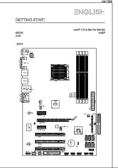
Getting start

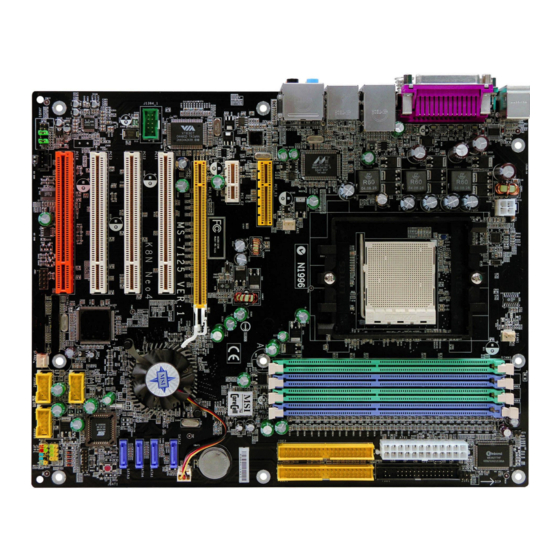
Thank you for choosing the 770-C35/ 770-C45 series (MS-7599 v1.x) ATX mainboard. The 770-C35/ 770-C45 series are based on AMD® 770 & SB710/ SB750/ SB700 chipset for optimal system efficiency. Designed to fit the advanced AMD® AM3 processor, the 770-C35/ 770-C45 series deliver a high performance and professional desktop platform solution.
Layout
SPECIFICATIONS
Processor Support
■AMD® Athlon™ X2/ X3/ X4 & Phenom™II X3/ X4 processors in AM3 package
(For the latest information about CPU, please visit http://www.msi.com/index.php?func=cpuform2)
HyperTransport
■ HyperTransport™ 3.0 up to 5.2 GT/s Chipset
■North Bridge: AMD® 770 chipset
■South Bridge: AMD® SB710/ SB750 (optional)/ SB700 (optional) chipset
Memory Support
■DDR3 800/ 1066/ 1333/ 1600*(OC) SDRAM (total 16GB Max)
■4 DDR3 DIMMs (240pin / 1.5V)
(* OC = overclocking, for more information on compatible components, please visit http://www.msi.com/index.php?func=testreport)
LAN
■ Supports PCIe LAN 10/ 100/ 1000 by Realtek® RTL 8111DL Audio
■Chip integrated by Realtek® ALC888S/ ALC885
■Supports 7.1 channels audio out
■Compliant with Azalia 1.0 Spec
IDE

■1 IDE port by AMD® SB710/ SB750 (optional)/ SB700 (optional)
■Supports Ultra DMA 66/100/133, PIO & Bus Master operation mode
SATA
■6 SATAII ports by AMD® SB710/ SB750 (optional)/ SB700 (optional)
■Supports storage and data transfers at up to 3.0 Gb/s
RAID
■SATA1~6 support RAID 0/ 1/ 10 or JBOD mode by AMD® SB710/ SB750 (optional)/ SB700 (optional)
Floppy

■1 floppy port
■Supports 1 FDD with 360 KB, 720 KB, 1.2 MB, 1.44 MB and 2.88 MB
10
![]()
MS-7599
Connectors
■Back panel
1 PS/2 mouse port
1 PS/2 keyboard port
1 Serial port
6 USB 2.0 Ports
1 LAN jack
6 flexible audio jacks
■On-Board
3 USB 2.0 connectors
1 SPDIF-Out connector
1 Front Panel Audio connector
1 Chassis Intrusion connector
1 CD-In connector
1 TPM connector
Slots
■1 PCI Express x16 slot, supports PCIE Gen2.0
■2 PCI Express x1 slots, supports PCIE Gen2.0
■3 PCI slots, support 3.3V/ 5V PCI bus Interface
Form Factor
■ ATX (21.0cm X 30.5 cm)
Mounting
■ 6 mounting holes
If you need to purchase accessories and request the part numbers, you could search the product web page and find details on our web address below http://www.msi.com/index.php
11
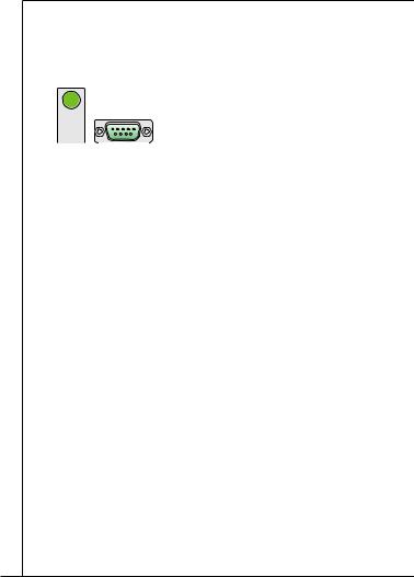
REAR PANEL
The rear panel provides the following connectors:
|
PS/2 mouse |
LAN |
|||||
|
Line-In RS-Out |
||||||
|
Line-Out CS-Out |
||||||
|
PS/2 keyboard |
Serial port |
USB ports |
USB ports |
USB ports |
MIC |
SS-Out |
HARDWARE
 SETUP
SETUP
This chapter tells you how to install the CPU, memory modules, and expansion cards, as well as how to setup the jumpers on the mainboard. It also provides the instructions on connecting the peripheral devices, such as the mouse, keyboard, etc. While doing the installation, be careful in holding the components and follow the installation procedures.
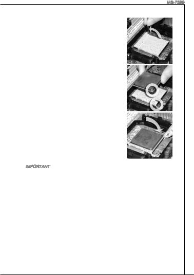
CPU & Cooler Installation for AM3
When you are installing the CPU, make sure the CPU has a cooler attached on the top to prevent overheating. Meanwhile, do not forget to apply some thermal paste on CPU before installing the heat sink/cooler fan for better heat dispersion.
Follow the steps below to install the CPU & cooler correctly. Wrong installation will cause the damage of your CPU & mainboard.
12
MS-7599
. Pull the lever sideways away from the socket. Make sure to raise the lever up to a 90-degree angle.
2.Look for the gold arrow of the CPU. The gold arrow should point as shown in the picture. The CPU can only fit in the correct orientation.
. If the CPU is correctly installed, the pins should be completely embedded into the socket and can not be seen. Please note that any violation of the correct installation procedures may cause permanent damages to your mainboard.
4.Press the CPU down firmly into the socket and close the lever. As the CPU is likely to move while the lever is being closed, always close the lever with your fingers pressing tightly on top of the CPU to make sure the CPU is properly and completely embedded into the socket.
5.Position the cooling set onto the retention mechanism. Hook one end of the clip to hook first.
6.Then press down the other end of the clip to fasten the cooling set on the top of the retention mechanism. Locate the Fix Lever and lift up it.
7.Fasten down the lever.
8.Attach the CPU Fan cable to the CPU fan connector on the mainboard.
Important
*Mainboard photos shown in this section are for demonstration of the cooler installation for Socket AM3 CPU only. The appearance of your mainboard may vary depending on the model you purchase.
*While disconnecting the Safety Hook from the fixed bolt, it is necessary to keep an eye on your fingers, because once the Safety Hook is disconnected from the fixed bolt, the fixed lever will spring back instantly.
13

Installing Memory Modules
. The memory module has only one notch on the center and will only fit in the right orientation.
2.Insert the memory module vertically into the DIMM slot. Then push it in until the golden finger on the memory module is deeply inserted in the DIMM slot. The plastic clip at each side of the DIMM slot will automatically close when the
memory module is properly seated. You can barely see the golden finger if the memory module is
 properly inserted
 in
in the DIMM slot.
. Manually check if the memory module has been locked in place by the DIMM slot clips at the sides.
 Notch
Notch
Volt
Important
*DDR3 memory modules are not interchangeable with DDR2 and the DDR3 standard is not backwards compatible. You should always install DDR3 memory modules in the DDR3 DIMM slots.
*In Dual-Channel mode, make sure that you install memory modules of the same type and density in different channel DIMM slots.
*To enable successful system boot-up, always insert the memory modules into the DIMM1 first.
14

MS-7599
ATX 24-Pin Power Connector: ATX1
ATX1
This connector allows you to connect an ATX 24-pin power supply. To connect the ATX 24-pin power supply, make sure the plug of the power supply is inserted in the proper orientation and the pins are aligned. Then push down the power supply firmly into the connector.
|
12. |
|||||||||||||||
|
11 |
. +3 |
. |
|||||||||||||
|
910. |
|||||||||||||||
|
8 |
. |
+12V |
3 |
||||||||||||
|
V |
|||||||||||||||
|
7 |
|||||||||||||||
|
6 . |
|||||||||||||||
|
5 . |
|||||||||||||||
|
4 |
. +5 |
||||||||||||||
|
2 |
3 . |
||||||||||||||
|
. +5 |
V |
||||||||||||||
|
1 |
. |
||||||||||||||
|
Ground |
|||||||||||||||
|
. +3. |
24 |
||||||||||||||
|
3 |
|||||||||||||||
|
+3.Ground |
. |
||||||||||||||
|
3 |
V |
||||||||||||||
|
V |
23. |
||||||||||||||
|
. +5 |
V |
||||||||||||||
|
+5 |
|||||||||||||||
|
Ground |
|||||||||||||||
|
+5 |
V |
V |
|||||||||||||
|
. |
— |
||||||||||||||
|
13. |
— |
ON |
# |
||||||||||||
|
12V |
|||||||||||||||
|
+3.Ground |
|||||||||||||||
|
3 |
|||||||||||||||
|
V |
ATX 4-Pin Power Connector: JPW1
JPW1
This 4-Pin power connector is used to provide power to the CPU.
|
1 |
||
|
. |
||
|
2 |
Ground |
|
|
. |
||
|
Ground |
||
|
3 |
||
|
. |
||
|
4 |
+12V |
|
|
. |
||
|
+12V |
Important
*Make sure that all the power connectors are connected to proper ATX power supplies to ensure stable operation of the mainboard.
*Power supply of 350 watts (and above) is highly recommended for system stability.
Floppy Disk Drive Connector:
 FDD1
FDD1
This connector supports 360 KB, 720 KB, 1.2 MB, 1.44 MB or 2.88 MB floppy disk drive.
15

IDE
 Connector:
 IDE1
IDE1
This connector supports IDE hard disk drives, optical disk drives and other IDE devices.
Important
If you install two IDE devices on the same cable, you must configure the drives to cable select mode or separately to master / slave mode by setting jumpers. Refer to IDE device documentation supplied by the vendors for jumper setting instructions.
Serial ATA Connector:
 SATA1 ~ 6
This connector is a high-speed Serial ATA interface port. Each connector can connect to one Serial ATA device.
Important
Please do not fold the Serial ATA cable into 90-degree angle. Otherwise, data loss may occur during transmission.
Fan Power Connectors:
 CPUFAN1, SYSFAN1, SYSFAN2
The fan power connectors support system cooling fan with +12V. When connecting the wire to the connectors, always note that the red wire is the positive and should be connected to the +12V; the black wire is Ground and should be connected to GND. If the mainboard has a System Hardware Monitor chipset onboard, you must use a specially designed fan with speed sensor to take advantage of the CPU fan control.
|
CPUFAN1 |
SYSFAN1/ SYSFAN2 |
||||||||||||
|
1 |
1 |
||||||||||||
|
2 |
. |
2 |
|||||||||||
|
3 |
. Gr |
3 |
+ r |
||||||||||
|
. + |
o |
. |
1 o |
||||||||||
|
4 S |
1 |
u |
N |
2 u |
|||||||||
|
. |
e 2 |
n |
o |
V |
n |
||||||||
|
C |
n V |
d |
U |
d |
|||||||||
|
o |
s |
||||||||||||
|
n |
s |
||||||||||||
|
t o |
e |
||||||||||||
|
r r |
|||||||||||||
|
o |
|||||||||||||
|
l |
16

MS-7599
S/PDIF
 -Out Connector:
 JSPD1
JSPD1
This connector is used to connect S/PDIF (Sony & Philips Digital Interconnect Format) interface for digital audio transmission.
|
3 |
||||||
|
2 . |
||||||
|
1 |
. Gr |
|||||
|
S |
o |
|||||
|
. |
P |
u |
||||
|
V |
D |
n |
||||
|
C |
I |
d |
||||
|
C |
F |
CD-In Connector:
 CD_IN1
This connector is provided for external audio input.
|
1 |
||||||||
|
2 |
. |
|||||||
|
L |
||||||||
|
3 |
. |
|||||||
|
G |
||||||||
|
4 |
. |
r |
||||||
|
o |
||||||||
|
. Gr |
u |
|||||||
|
R |
o |
n |
||||||
|
u |
d |
|||||||
|
n |
||||||||
|
d |
Front Panel
Panel Connectors:
 JFP1, JFP2
These connectors are for electrical connection to the front panel switches and LEDs. The JFP1 is compliant with Intel® Front Panel I/O Connectivity Design Guide.
|
P |
||||||||
|
P |
ower |
S |
10. |
|||||
|
ower |
LE |
witch |
No |
|||||
|
D |
8Pin |
|||||||
|
6 |
— |
|||||||
|
4 |
. |
. |
||||||
|
+ |
||||||||
|
2 |
. |
|||||||
|
— |
||||||||
|
. |
||||||||
|
+ |
JFP1
|
9 |
||||||||||
|
1 — |
. |
|||||||||
|
7 |
Reserve |
|||||||||
|
5 |
. |
|||||||||
|
+ |
||||||||||
|
3 |
. |
|||||||||
|
— |
||||||||||
|
. |
d |
|||||||||
|
+ |
||||||||||
|
. |
Reset |
|||||||||
|
S |
||||||||||
|
HDD |
LE |
|||||||||
|
D |
witch |
|
Speaker |
6 |
+ |
|||
|
Buzzer |
|||||
|
8 |
|||||
|
. |
|||||
|
4 |
. |
||||
|
— |
|||||
|
2 |
. |
||||
|
+ |
|||||
|
. |
|||||
|
— |
JFP2
|
7 |
||||||
|
3 |
5 . |
|||||
|
. No |
||||||
|
1 |
Power |
|||||
|
. |
Pi |
|||||
|
. |
Suspend |
D |
||||
|
n |
||||||
|
Ground |
LE |
|||||
|
LE |
||||||
|
D |
Front
 Panel
Panel Audio Connector:
 JAUD1
JAUD1
This connector allows you to connect the front panel audio and is compliant with Intel® Front Panel I/O Connectivity Design Guide.
|
1 |
|||||||||||||||||||
|
0 |
|||||||||||||||||||
|
8 . |
|||||||||||||||||||
|
6 |
. |
H |
|||||||||||||||||
|
N |
e |
||||||||||||||||||
|
. |
o |
a |
|||||||||||||||||
|
4 |
M |
P |
P |
||||||||||||||||
|
2 |
. |
I |
i |
||||||||||||||||
|
P |
C |
n |
h |
||||||||||||||||
|
. |
R |
D |
o |
||||||||||||||||
|
G |
E |
e |
n |
||||||||||||||||
|
r |
S |
t |
e |
||||||||||||||||
|
o |
e |
D |
|||||||||||||||||
|
u |
E |
c |
t |
||||||||||||||||
|
n |
N |
i |
|||||||||||||||||
|
d |
C |
o |
e |
||||||||||||||||
|
E |
n |
c |
|||||||||||||||||
|
t |
|||||||||||||||||||
|
# |
i |
||||||||||||||||||
|
o |
|||||||||||||||||||
|
n |
|
9 |
||||||||||||||||
|
7 |
. |
|||||||||||||||
|
H |
||||||||||||||||
|
5 |
. |
e |
||||||||||||||
|
S |
a |
|||||||||||||||
|
3 |
. |
E |
||||||||||||||
|
H |
d |
|||||||||||||||
|
1 |
. |
e |
N |
P |
||||||||||||
|
M |
a |
S |
h |
|||||||||||||
|
. |
I |
d |
E |
o |
||||||||||||
|
M |
C |
P |
_ |
n |
||||||||||||
|
I |
R |
S |
e |
|||||||||||||
|
C |
h |
L |
||||||||||||||
|
L |
o |
E |
||||||||||||||
|
n |
N |
|||||||||||||||
|
e |
D |
|||||||||||||||
|
R |
17
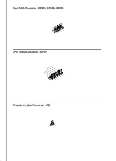
Front USB Connector:
 JUSB1/ JUSB2/ JUSB3
This connector, compliant with Intel® I/O Connectivity Design Guide, is ideal for connecting high-speed USB interface peripherals such as USB HDD, digital cameras, MP3 players, printers, modems and the like.
|
10 |
|||||||
|
2 |
. |
8 . |
|||||
|
. |
USBOC |
||||||
|
. |
USBDGround |
||||||
|
6 |
|||||||
|
4 |
. |
||||||
|
VCUSBD |
+ |
||||||
|
C |
— |
|
9 |
||||||||||
|
5 |
. |
|||||||||
|
. No |
||||||||||
|
7 |
||||||||||
|
USBDGround |
||||||||||
|
3 . |
Pi |
|||||||||
|
. |
+ |
n |
||||||||
|
VCUSBD |
||||||||||
|
1 |
||||||||||
|
. |
C |
|||||||||
|
— |
TPM Module connector: JTPM1
JTPM1
This connector connects to a TPM (Trusted Platform Module) module. Please refer to the TPM security platform manual for more details and usages.
|
1 |
||||||||||||||||||||||||||||||||||||||||||||||||
|
4 |
||||||||||||||||||||||||||||||||||||||||||||||||
|
1 . |
||||||||||||||||||||||||||||||||||||||||||||||||
|
1 |
2 |
|||||||||||||||||||||||||||||||||||||||||||||||
|
. Gr |
||||||||||||||||||||||||||||||||||||||||||||||||
|
. G |
o |
|||||||||||||||||||||||||||||||||||||||||||||||
|
8 |
0 |
r |
||||||||||||||||||||||||||||||||||||||||||||||
|
N |
u |
|||||||||||||||||||||||||||||||||||||||||||||||
|
6 |
. |
o |
n |
|||||||||||||||||||||||||||||||||||||||||||||
|
5 |
o |
u |
d |
|||||||||||||||||||||||||||||||||||||||||||||
|
4 |
. |
V |
P |
n |
||||||||||||||||||||||||||||||||||||||||||||
|
S |
P |
i |
d |
|||||||||||||||||||||||||||||||||||||||||||||
|
. |
e |
n |
||||||||||||||||||||||||||||||||||||||||||||||
|
3 |
i o |
|||||||||||||||||||||||||||||||||||||||||||||||
|
2 . |
r |
w |
||||||||||||||||||||||||||||||||||||||||||||||
|
a |
||||||||||||||||||||||||||||||||||||||||||||||||
|
. |
3 |
l |
e |
|||||||||||||||||||||||||||||||||||||||||||||
|
3 |
V |
I |
r |
|||||||||||||||||||||||||||||||||||||||||||||
|
V |
t |
P |
R |
|||||||||||||||||||||||||||||||||||||||||||||
|
o |
Q |
|||||||||||||||||||||||||||||||||||||||||||||||
|
S |
a |
w |
||||||||||||||||||||||||||||||||||||||||||||||
|
n |
e |
|||||||||||||||||||||||||||||||||||||||||||||||
|
d |
r |
|||||||||||||||||||||||||||||||||||||||||||||||
|
b |
||||||||||||||||||||||||||||||||||||||||||||||||
|
y |
||||||||||||||||||||||||||||||||||||||||||||||||
|
p |
||||||||||||||||||||||||||||||||||||||||||||||||
|
o |
||||||||||||||||||||||||||||||||||||||||||||||||
|
w |
1 |
|||||||||||||||||||||||||||||||||||||||||||||||
|
e |
||||||||||||||||||||||||||||||||||||||||||||||||
|
r |
3 |
|||||||||||||||||||||||||||||||||||||||||||||||
|
1 . |
||||||||||||||||||||||||||||||||||||||||||||||||
|
9 |
1 |
L |
||||||||||||||||||||||||||||||||||||||||||||||
|
. |
P |
|||||||||||||||||||||||||||||||||||||||||||||||
|
7 |
. |
L |
C |
|||||||||||||||||||||||||||||||||||||||||||||
|
L |
P |
F |
||||||||||||||||||||||||||||||||||||||||||||||
|
5 |
. |
P |
C |
|||||||||||||||||||||||||||||||||||||||||||||
|
L |
C |
a |
r |
|||||||||||||||||||||||||||||||||||||||||||||
|
3 |
. |
P |
a |
a |
||||||||||||||||||||||||||||||||||||||||||||
|
L |
C |
d |
m |
|||||||||||||||||||||||||||||||||||||||||||||
|
1 |
. |
P |
d |
d |
e |
|||||||||||||||||||||||||||||||||||||||||||
|
L |
a |
d |
r |
|||||||||||||||||||||||||||||||||||||||||||||
|
. |
P C |
d |
r |
e |
||||||||||||||||||||||||||||||||||||||||||||
|
L |
C |
a |
d |
e |
s |
|||||||||||||||||||||||||||||||||||||||||||
|
P |
d |
r |
s |
s |
||||||||||||||||||||||||||||||||||||||||||||
|
C |
R |
d |
e |
s |
& |
|||||||||||||||||||||||||||||||||||||||||||
|
C |
e |
r |
s |
& |
d |
|||||||||||||||||||||||||||||||||||||||||||
|
s |
e |
s |
d |
a |
||||||||||||||||||||||||||||||||||||||||||||
|
l |
e |
s |
& |
t |
||||||||||||||||||||||||||||||||||||||||||||
|
o |
t |
s |
a |
a |
||||||||||||||||||||||||||||||||||||||||||||
|
c |
& |
d |
t |
|||||||||||||||||||||||||||||||||||||||||||||
|
k |
a |
p |
||||||||||||||||||||||||||||||||||||||||||||||
|
d |
a |
p |
i |
|||||||||||||||||||||||||||||||||||||||||||||
|
t |
n |
|||||||||||||||||||||||||||||||||||||||||||||||
|
a |
a |
i |
||||||||||||||||||||||||||||||||||||||||||||||
|
t |
p |
n |
3 |
|||||||||||||||||||||||||||||||||||||||||||||
|
a |
i |
2 |
||||||||||||||||||||||||||||||||||||||||||||||
|
p |
n |
|||||||||||||||||||||||||||||||||||||||||||||||
|
n |
1 |
|||||||||||||||||||||||||||||||||||||||||||||||
|
i |
||||||||||||||||||||||||||||||||||||||||||||||||
|
0 |
Chassis Intrusion Connector:
 JCI1
JCI1
This connector connects to the chassis intrusion switch cable. If the chassis is opened, the chassis intrusion mechanism will be activated. The system will record this status and show a warning message on the screen. To clear the warning, you must enter the BIOS utility and clear the record.
|
2 |
|||||||
|
1 |
. |
||||||
|
G |
|||||||
|
. |
r |
||||||
|
CI |
u |
||||||
|
N |
o |
n |
|||||
|
T |
d |
||||||
|
R |
|||||||
|
U |
18
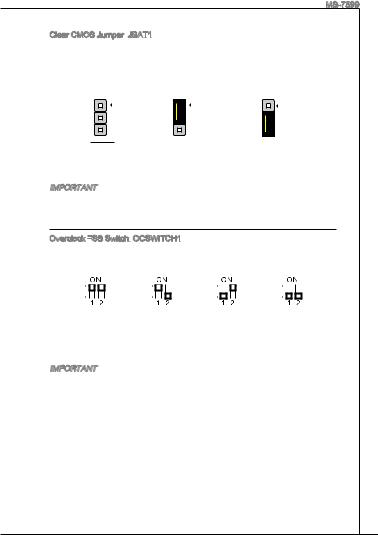
MS-7599
Clear CMOS Jumper: JBAT1
JBAT1
There is a CMOS RAM onboard that has a power supply from an external battery to keep the data of system configuration. With the CMOS RAM, the system can automatically boot OS every time it is turned on. If you want to clear the system configuration, set the jumper to clear data.
JBAT1 Keep Data Clear Data
Important
You can clear CMOS by shorting 2-3 pin while the system is off. Then return to 1-2 pin position. Avoid clearing the CMOS while the system is on; it will damage the mainboard.
Overclock FSB Switch:
 OCSWITCH1
You can overclock the FSB to increase the processor frequency by changing the switch. Follow the instructions below to set the FSB.
|
Default |
Increase 10% |
Increase 15% |
Increase 20% |
|||||||||||||||||||||||
|
speed of FSB |
speed of FSB |
speed of FSB |
Important
*Make sure that you power off the system before setting the switch.
*When overclocking cause system instability or crash during boot. Please set the switch to default setting.
19
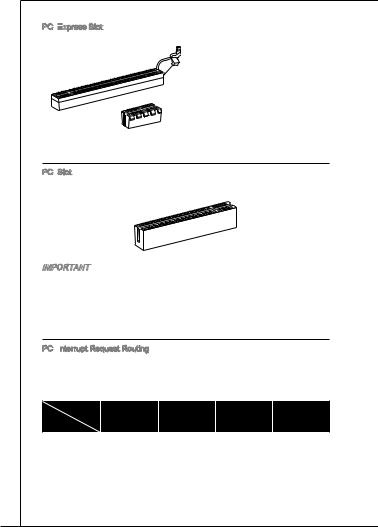
PCI Express
 Slot
Slot
The PCI Express slot supports the PCI Express interface expansion card.
The PCI Express 2.0 x16 slot supports up to 8.0 GB/s transfer rate.
The PCI Express 2.0 x1 slot supports up to 500 MB/s transfer rate.
PCI Slot
Slot
The PCI slot supports LAN card, SCSI card, USB card, and other add-on cards that comply with PCI specifications.
Important
Make sure that you unplug the power supply first. Meanwhile, read the documentation for the expansion card to configure any necessary hardware or software settings for the expansion card, such as jumpers, switches or BIOS configuration.
PCI Interrupt
 Request Routing
When adding or removing expansion cards, make the IRQ, acronym of interrupt request line and pronounced I-R-Q, are hardware lines over which devices can send interrupt signals to the microprocessor. The PCI IRQ pins are typically connected to the PCI bus pins as follows:
|
Order |
1 |
2 |
3 |
4 |
|||||
|
Slot |
|||||||||
|
PCI 1 |
INT E# |
INT F# |
INT G# |
INT H# |
|||||
|
PCI 2 |
INT F# |
INT G# |
INT H# |
INT E# |
|||||
|
PCI 3 |
INT G# |
INT H# |
INT E# |
INT F# |
|||||
20
![]()
MS-7599
LED Status Indicators
 (optional)
LED1 LED2 LED3 LED4 Mode
CPU is in 1 phase power mode.
CPU is in 4 phase power mode.
21
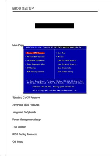
BIOS Setup
Power on the computer and the system will start POST (Power On Self Test) process. When the message below appears on the screen, press <DEL> key to enter Setup.
Press DEL to enter SETUP
If the message disappears before you respond and you still wish to enter Setup, restart the system by turning it OFF and On or pressing the RESET button. You may also restart the system by simultaneously pressing <Ctrl>, <Alt>, and <Delete> keys.
Main Page
Standard CMOS Features
Use this menu for basic system configurations, such as time, date etc.
Advanced BIOS Features
Use this menu to setup the items of special enhanced features.
Integrated Peripherals
Use this menu to specify your settings for integrated peripherals.
Power Management Setup
Use this menu to specify your settings for power management.
H/W Monitor
This entry shows the status of your CPU, fan, warning for overall system status.
BIOS Setting Password
Use this menu to set BIOS setting Password.
Cell
 Menu
Menu
Use this menu to specify your settings for frequency/ voltage control.
22
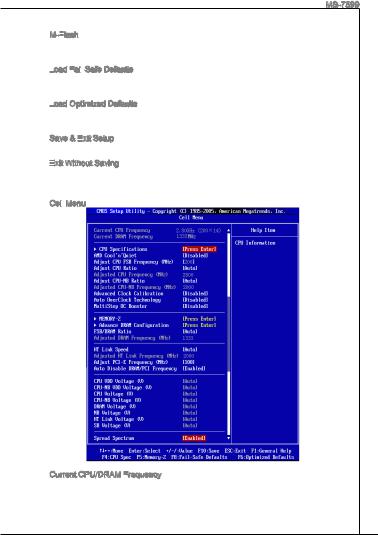
MS-7599
M-Flash
Use this menu to read/ flash the BIOS from storage drive (FAT/ FAT32 format only).
Load
 Fail
Fail


 -Safe Defaults
Use this menu to load the BIOS default values that are factory settings for system operations.
Load
 Optimized Defaults
Use this menu to load factory default settings into the BIOS for stable system performance operations.
Save & Exit
 Setup
Setup
Save changes to CMOS and exit setup.
Exit
 Without Saving
Abandon all changes and exit setup.
Cell
 Menu
Menu
Current CPU/DRAM Frequency
It shows the current frequency of CPU/Memory. Read-only.
23
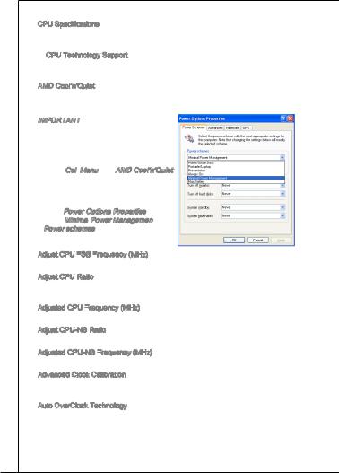
CPU Specifications
Press <Enter> to enter the sub-menu. This submenu shows the information of installed CPU.
CPU Technology Support
Press <Enter> to enter the sub-menu. This sub-menu shows the technologies that the installed CPU supported.
AMD Cool’n’Quiet
The Cool’n’Quiet technology can effectively and dynamically lower CPU speed and power consumption.
Important
To ensure that Cool’n’Quiet function is activated and will be working properly, it is required to double confirm that:
*Run BIOS Setup, and select Cell Menu.
Under Cell Menu, find AMD Cool’n’Quiet, and set this item to “Enabled”.
*Enter Windows, and select [Start]->[Set- tings]->[Control Panel]->[Power Options]. Enter Power Options Properties tag, and
select Minimal Power Management
 under Power schemes.
Adjust CPU FSB Frequency
 (MHz)
(MHz)
This item allows you to adjust the CPU FSB frequency.
Adjust CPU Ratio
This item is used to adjust CPU clock multiplier (ratio). It is available only when the processor supports this function.
Adjusted CPU Frequency (MHz)
(MHz)
It shows the adjusted CPU frequency. Read-only.
Adjust CPU-NB Ratio
This item is used to adjust CPU-NB ratio.
Adjusted CPU-NB Frequency (MHz)
(MHz)
It shows the adjusted CPU-NB frequency. Read-only.
Advanced Clock Calibration
This item is for overclock. Setting to [Enabled] allows you to set the CPU Ratio higher. It is available only when the processor supports this function.
Auto OverClock Technology
Setting this item to [Max FSB] allows the system to detect the maximum FSB clock and to overclock automatically. If overclocking fails to run, you can try the lower FSB clock for overclocking successfully.
24
MS-7599
MultiStep OC Booster
This item is used to avoid the BIOS might crash with overclocking. Disabled Disable this item, apply OC settings during POST.
Mode 1 Slight OC during POST and then apply full OC when loading the OS
Mode 2 Load the OS then apply the OC settings.
Memory-Z
Press <Enter> to enter the sub-menu.
DIMM1~4 Memory SPD Information
Press <Enter> to enter the sub-menu. This sub-menu displays the informations of installed memory.
Advance DRAM Configuration Press <Enter> to enter the sub-menu.
DRAM Timing Mode
This field has the capacity to automatically detect the DRAM timing. If you set this field to [DCT 0], [DCT 1] or [Both], some fields will appear and selectable. DCT 0 controls channel A and DCT1 controls channel B.
DRAM Drive Strength
This feature allows you to control the memory data bus’ signal strength. Increasing the drive strength of the memory bus can increase stability during overclocking.
DRAM Advance Control
This field has the capacity to automatically detect the advanced DRAM timing. If you set this field to [DCT 0], [DCT 1] or [Both], some fields will appear and selectable.
1T/2T
 Memory Timing
This field controls the SDRAM command rate. Selecting [1T] makes SDRAM signal controller to run at 1T (T=clock cycles) rate. Selecting [2T] makes SDRAM signal controller run at 2T rate.
DCT
 Unganged Mode
This feature is used to Integrate two 64-bit DCTs into a 128-bit interface.
Bank Interleaving
Bank Interleaving is an important parameter for improving overclocking capability of memory. It allows system to access multiple banks simultaneously.
Power Down Enable

This is a memory power-saving technology. When the system does not access memory over a period of time, it will automatically reduce the memory power supply.
MemClk Tristate C3/ATLVID
This setting allows you to enable/disable the MemClk Tristating during C3 and ATLVID.
25

FSB/DRAM
 Ratio
Ratio
This item will allow you to adjust the ratio of FSB to memory.
Adjusted DRAM Frequency
 (MHz)
(MHz)
It shows the adjusted memory frequency. Read-only.
HT

 Link
Link Speed
Speed
This item allows you to set the Hyper-Transport Link speed. Setting to [Auto], the system will detect the HT link speed automatically.
Adjusted HT

 Link
Link Frequency
 (MHz)
(MHz)
It shows the adjusted HT link frequency. Read-only.
Adjust PCI
 -E
-E

 Frequency
 (MHz)
(MHz)
This item allows you to adjust the PCI-E frequency.
Auto Disable DRAM/PCI Frequency

When set to [Enabled], the system will remove (turn off) clocks from empty DIMM and PCI slots to minimize the electromagnetic interference (EMI).
CPU VDD Voltage (V)/ CPU-NB VDD Voltage (V)/ CPU Voltage (V)/ CPU-NB Voltage (V)/ DRAM Voltage (V)/ NB Voltage (V)/ HT

 Link
Link Voltage (V)/ SB Voltage
(V)
These items are used to adjust the voltage of CPU, Memory and chipset.
Spread Spectrum
When the motherboard’s clock generator pulses, the extreme values (spikes) of the pulses create EMI (Electromagnetic Interference). The Spread Spectrum function reduces the EMI generated by modulating the pulses so that the spikes of the pulses are reduced to flatter curves. If you do not have any EMI problem, leave the setting at Disabled for optimal system stability and performance. But if you are plagued by EMI, set to Enabled for EMI reduction. Remember to disable Spread Spectrum if you are overclocking because even a slight jitter can introduce a temporary boost in clock speed which may just cause your overclocked processor to lock up.
Important
*If you do not have any EMI problem, leave the setting at [Disabled] for optimal system stability and performance. But if you are plagued by EMI, select the value of Spread Spectrum for EMI reduction.
*The greater the Spread Spectrum value is, the greater the EMI is reduced, and the system will become less stable. For the most suitable Spread Spectrum value, please consult your local EMI regulation.
*Remember to disable Spread Spectrum if you are overclocking because even a slight jitter can introduce a temporary boost in clock speed which may just cause your overclocked processor to lock up.
26
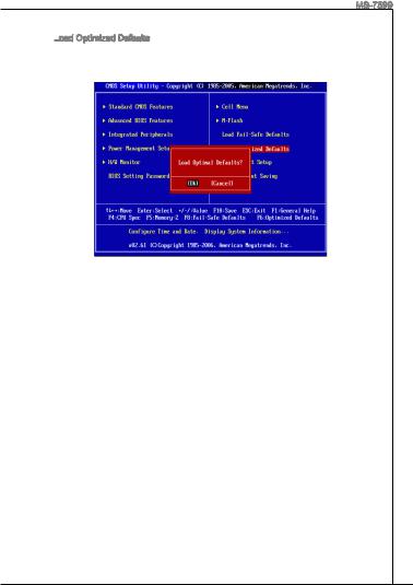
MS-7599
Load
 Optimized Defaults
You can load the default values provided by the mainboard manufacturer for the stable performance.
27

28
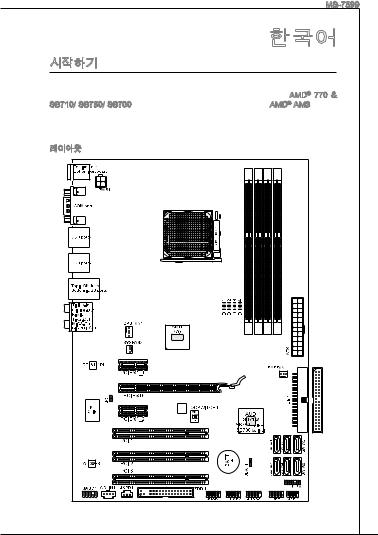
|
MS-7599 |
|
770-C35/ 770-C45 (MS-7599 v1.x) ATX |
|
. 770-C35/ 770-C45 AMD® 770 & |
|
SB710/ SB750/ SB700 . AMD® AM3 |
|
770-C35/ 770-C45 |
|
. |
|
29 |
■AM3 AMD® Athlon™ X2/ X3/ X4 & Phenom™II X3/ X4
(CPU http://www.msi.com/index.php?func=cpuform2 )
HyperTransport
■ HyperTransport™ 3.0 5.2 GT/s
■: AMD® 770
■: AMD® SB710/ SB750 ( )/ SB700 ( )

■DDR3 800/ 1066/ 1333/ 1600*(OC) SDRAM ( 16GB)
■4 DDR3 DIMMs (240 / 1.5V)
(* OC = overclocking, http://www.msi.com/index.php?func=testreport .)
LAN
■ PCIe LAN 10/ 100/ 1000 by Realtek® RTL 8111DL
■Realtek® ALC888S/ ALC885
■7.1
■1.0 Spec
IDE

■AMD® SB710/ SB750 ( )/ SB700 ( ) IDE 1
■Ultra DMA 66/100/133, PIO
SATA
■AMD® SB710/ SB750 ( )/ SB700 ( ) SATAII 6
■3.0 Gb/s
RAID
■AMD® SB710/ SB750 ( )/ SB700 ( ) RAID 0/ 1/ 10 JBODSATA1~6
■1
■1 FDD with 360 KB, 720 KB, 1.2 MB, 1.44 MB and 2.88 MB
30
![]()
MS-7599
PS/2 1
PS/2 1
1
USB 2.0 6
LAN 1
6
USB 2.0 3
SPDIF 1
1
1
CD 1
TPM 1
■PCI Express x16 1 , PCIE Gen2.0
■PCI Express x1 2 , PCIE Gen2.0
■PCI 3 , 3.3V/ 5V PCI
■ ATX (21.0cm X 30.5 cm)
■ 6
, “http://www.msi.com/index.php” .
31

|
. |
||
|
PS/2 |
LAN |
|
|
RS |
||
|
CS |
||
|
PS/2 |
USB |
USB USB MIC SS |
|
CPU, , |
||
|
. , |
||
|
. , . |
||
|
AM3 CPU |
||
|
CPU . |
||
|
/ CPU |
||
|
. |
||
|
CPU . CPU |
||
|
. |
||
|
32 |

MS-7599
. . 90.
2.CPU . . CPU.
. CPU , ..
4.CPU. CPU, CPUCPU .
5...
6...
7..
8.CPU CPU.
*AM3 CPU. .
*,.
33


 . , .
. , .
2.DIMM .DIMM .DIMM. 
 DIMM
DIMM 

 .
.
. DIMM.

*DDR3 DDR2 , DDR3. DDR3DIMM DDR3 .
*, DIMM.
*, DIMM1 .
34

MS-7599
ATX 24 : ATX1
ATX1
ATX 24 . ATX 24,, ..
|
12. |
|||||||||||||||
|
11 |
. +3 |
. |
|||||||||||||
|
910. |
|||||||||||||||
|
8 |
. |
+12V |
3 |
||||||||||||
|
V |
|||||||||||||||
|
7 |
|||||||||||||||
|
6 . |
|||||||||||||||
|
5 . |
|||||||||||||||
|
4 |
. +5 |
||||||||||||||
|
2 |
3 . |
||||||||||||||
|
. +5 |
V |
||||||||||||||
|
1 |
. |
||||||||||||||
|
Ground |
|||||||||||||||
|
. +3. |
24 |
||||||||||||||
|
3 |
|||||||||||||||
|
+3.Ground |
. |
||||||||||||||
|
3 |
V |
||||||||||||||
|
V |
23. |
||||||||||||||
|
. +5 |
V |
||||||||||||||
|
+5 |
|||||||||||||||
|
Ground |
|||||||||||||||
|
+5 |
V |
V |
|||||||||||||
|
. |
— |
||||||||||||||
|
13. |
— |
ON |
# |
||||||||||||
|
12V |
|||||||||||||||
|
+3.Ground |
|||||||||||||||
|
3 |
|||||||||||||||
|
V |
ATX 4 : PWR1
PWR1
4 CPU .
|
1 |
||
|
. |
||
|
2 |
Ground |
|
|
. |
||
|
Ground |
||
|
3 |
||
|
. |
||
|
4 |
+12V |
|
|
. |
||
|
+12V |
*ATX.
*350 .
:
 FDD1
FDD1
360 KB, 720 KB, 1.2 MB, 1.44 MB 2.88 MB.
35

IDE
 :
: IDE1
IDE1
IDE , IDE.
2 IDE ,, / .IDE .
ATA :
 SATA1 ~ 6
ATA .ATA .
ATA 90 . ,.
: CPUFAN1, SYSFAN1, SYSFAN2
+12V ., +12V ,GND ., CPU .
|
CPUFAN1 |
SYSFAN1/ SYSFAN2 |
||||||||||||
|
1 |
1 |
||||||||||||
|
2 |
. |
2 |
|||||||||||
|
3 |
. Gr |
3 |
+ r |
||||||||||
|
. + |
o |
. |
1 o |
||||||||||
|
4 S |
1 |
u |
N |
2 u |
|||||||||
|
. |
e 2 |
n |
o |
V |
n |
||||||||
|
C |
n V |
d |
U |
d |
|||||||||
|
o |
s |
||||||||||||
|
n |
s |
||||||||||||
|
t o |
e |
||||||||||||
|
r r |
|||||||||||||
|
o |
|||||||||||||
|
l |
36

|
MS-7599 |
|||||||||||||||||||||||||||||||||||||||||||||||||||||||||||||
|
S/PDIF : JSPD1 |
|||||||||||||||||||||||||||||||||||||||||||||||||||||||||||||
|
S/PDIF(Sony & Philips Digital Intercon- |
|||||||||||||||||||||||||||||||||||||||||||||||||||||||||||||
|
nect Format) . |
|||||||||||||||||||||||||||||||||||||||||||||||||||||||||||||
|
3 |
|||||||||||||||||||||||||||||||||||||||||||||||||||||||||||||
|
2 . |
|||||||||||||||||||||||||||||||||||||||||||||||||||||||||||||
|
1 |
. Gr |
||||||||||||||||||||||||||||||||||||||||||||||||||||||||||||
|
S |
o |
||||||||||||||||||||||||||||||||||||||||||||||||||||||||||||
|
. |
P |
u |
|||||||||||||||||||||||||||||||||||||||||||||||||||||||||||
|
V |
D |
n |
|||||||||||||||||||||||||||||||||||||||||||||||||||||||||||
|
C |
I |
d |
|||||||||||||||||||||||||||||||||||||||||||||||||||||||||||
|
C |
F |
||||||||||||||||||||||||||||||||||||||||||||||||||||||||||||
|
CD : CD_IN1 |
|||||||||||||||||||||||||||||||||||||||||||||||||||||||||||||
|
. |
|||||||||||||||||||||||||||||||||||||||||||||||||||||||||||||
|
1 |
|||||||||||||||||||||||||||||||||||||||||||||||||||||||||||||
|
2 |
. |
||||||||||||||||||||||||||||||||||||||||||||||||||||||||||||
|
L |
|||||||||||||||||||||||||||||||||||||||||||||||||||||||||||||
|
3 |
. |
||||||||||||||||||||||||||||||||||||||||||||||||||||||||||||
|
G |
|||||||||||||||||||||||||||||||||||||||||||||||||||||||||||||
|
4 |
. |
r |
|||||||||||||||||||||||||||||||||||||||||||||||||||||||||||
|
o |
|||||||||||||||||||||||||||||||||||||||||||||||||||||||||||||
|
. Gr |
u |
||||||||||||||||||||||||||||||||||||||||||||||||||||||||||||
|
R |
o |
n |
|||||||||||||||||||||||||||||||||||||||||||||||||||||||||||
|
u |
d |
||||||||||||||||||||||||||||||||||||||||||||||||||||||||||||
|
n |
|||||||||||||||||||||||||||||||||||||||||||||||||||||||||||||
|
d |
|||||||||||||||||||||||||||||||||||||||||||||||||||||||||||||
|
: JFP1, JFP2 |
|||||||||||||||||||||||||||||||||||||||||||||||||||||||||||||
|
LED . JFP1 |
|||||||||||||||||||||||||||||||||||||||||||||||||||||||||||||
|
Intel® Front Panel I/O Connectivity Design Guide . |
|||||||||||||||||||||||||||||||||||||||||||||||||||||||||||||
|
P |
|||||||||||||||||||||||||||||||||||||||||||||||||||||||||||||
|
P |
ower |
S |
10. |
Speaker |
|||||||||||||||||||||||||||||||||||||||||||||||||||||||||
|
8 |
|||||||||||||||||||||||||||||||||||||||||||||||||||||||||||||
|
ower |
witch |
Buzzer |
|||||||||||||||||||||||||||||||||||||||||||||||||||||||||||
|
No |
6 |
. |
|||||||||||||||||||||||||||||||||||||||||||||||||||||||||||
|
+ |
|||||||||||||||||||||||||||||||||||||||||||||||||||||||||||||
|
LE |
8Pi |
4 |
. |
||||||||||||||||||||||||||||||||||||||||||||||||||||||||||
|
— |
|||||||||||||||||||||||||||||||||||||||||||||||||||||||||||||
|
D |
. n |
2 |
. |
||||||||||||||||||||||||||||||||||||||||||||||||||||||||||
|
6 |
— |
+ |
|||||||||||||||||||||||||||||||||||||||||||||||||||||||||||
|
. |
|||||||||||||||||||||||||||||||||||||||||||||||||||||||||||||
|
4 |
. |
— |
|||||||||||||||||||||||||||||||||||||||||||||||||||||||||||
|
+ |
|||||||||||||||||||||||||||||||||||||||||||||||||||||||||||||
|
2 |
. |
||||||||||||||||||||||||||||||||||||||||||||||||||||||||||||
|
— |
7 |
||||||||||||||||||||||||||||||||||||||||||||||||||||||||||||
|
. |
|||||||||||||||||||||||||||||||||||||||||||||||||||||||||||||
|
+ |
9 |
3 |
5 . |
||||||||||||||||||||||||||||||||||||||||||||||||||||||||||
|
. No |
|||||||||||||||||||||||||||||||||||||||||||||||||||||||||||||
|
7 |
. |
1 |
. |
Pi |
|||||||||||||||||||||||||||||||||||||||||||||||||||||||||
|
5 |
. |
Reserve |
JFP2 |
. |
Power |
n |
|||||||||||||||||||||||||||||||||||||||||||||||||||||||
|
+ |
|||||||||||||||||||||||||||||||||||||||||||||||||||||||||||||
|
3 |
. |
||||||||||||||||||||||||||||||||||||||||||||||||||||||||||||
|
JFP1 |
1 |
. |
GroundSuspend |
LE |
|||||||||||||||||||||||||||||||||||||||||||||||||||||||||
|
— |
d |
D |
|||||||||||||||||||||||||||||||||||||||||||||||||||||||||||
|
. |
Reset |
||||||||||||||||||||||||||||||||||||||||||||||||||||||||||||
|
+ |
|||||||||||||||||||||||||||||||||||||||||||||||||||||||||||||
|
S |
LED |
||||||||||||||||||||||||||||||||||||||||||||||||||||||||||||
|
HDD |
LE |
||||||||||||||||||||||||||||||||||||||||||||||||||||||||||||
|
D |
witch |
||||||||||||||||||||||||||||||||||||||||||||||||||||||||||||
|
: JAUD1 |
|||||||||||||||||||||||||||||||||||||||||||||||||||||||||||||
|
, Intel® |
|||||||||||||||||||||||||||||||||||||||||||||||||||||||||||||
|
Front Panel I/O Connectivity Design Guide . |
|||||||||||||||||||||||||||||||||||||||||||||||||||||||||||||
|
1 |
|||||||||||||||||||||||||||||||||||||||||||||||||||||||||||||
|
0 |
|||||||||||||||||||||||||||||||||||||||||||||||||||||||||||||
|
8 . |
|||||||||||||||||||||||||||||||||||||||||||||||||||||||||||||
|
6 |
. |
H |
|||||||||||||||||||||||||||||||||||||||||||||||||||||||||||
|
N |
e |
||||||||||||||||||||||||||||||||||||||||||||||||||||||||||||
|
. |
o |
a |
|||||||||||||||||||||||||||||||||||||||||||||||||||||||||||
|
4 |
M |
P |
P |
||||||||||||||||||||||||||||||||||||||||||||||||||||||||||
|
2 |
. |
I |
i |
||||||||||||||||||||||||||||||||||||||||||||||||||||||||||
|
P |
C |
n |
h |
||||||||||||||||||||||||||||||||||||||||||||||||||||||||||
|
. |
R |
D |
o |
||||||||||||||||||||||||||||||||||||||||||||||||||||||||||
|
G |
E |
e |
n |
||||||||||||||||||||||||||||||||||||||||||||||||||||||||||
|
r |
S |
t |
e |
||||||||||||||||||||||||||||||||||||||||||||||||||||||||||
|
o |
e |
D |
|||||||||||||||||||||||||||||||||||||||||||||||||||||||||||
|
u |
E |
c |
|||||||||||||||||||||||||||||||||||||||||||||||||||||||||||
|
n |
N |
t |
e |
||||||||||||||||||||||||||||||||||||||||||||||||||||||||||
|
d |
C |
o |
e |
||||||||||||||||||||||||||||||||||||||||||||||||||||||||||
|
E |
n |
c |
|||||||||||||||||||||||||||||||||||||||||||||||||||||||||||
|
t |
|||||||||||||||||||||||||||||||||||||||||||||||||||||||||||||
|
# |
i |
||||||||||||||||||||||||||||||||||||||||||||||||||||||||||||
|
o |
|||||||||||||||||||||||||||||||||||||||||||||||||||||||||||||
|
n |
|||||||||||||||||||||||||||||||||||||||||||||||||||||||||||||
|
9 |
|||||||||||||||||||||||||||||||||||||||||||||||||||||||||||||
|
7 |
. |
||||||||||||||||||||||||||||||||||||||||||||||||||||||||||||
|
H |
|||||||||||||||||||||||||||||||||||||||||||||||||||||||||||||
|
5 |
. |
e |
|||||||||||||||||||||||||||||||||||||||||||||||||||||||||||
|
S |
a |
||||||||||||||||||||||||||||||||||||||||||||||||||||||||||||
|
3 |
. |
E |
|||||||||||||||||||||||||||||||||||||||||||||||||||||||||||
|
H |
d |
||||||||||||||||||||||||||||||||||||||||||||||||||||||||||||
|
1 |
. |
e |
N |
P |
|||||||||||||||||||||||||||||||||||||||||||||||||||||||||
|
M |
a |
S |
h |
||||||||||||||||||||||||||||||||||||||||||||||||||||||||||
|
. |
I |
d |
E |
o |
|||||||||||||||||||||||||||||||||||||||||||||||||||||||||
|
M |
C |
P |
_ |
n |
|||||||||||||||||||||||||||||||||||||||||||||||||||||||||
|
I |
R |
S |
e |
||||||||||||||||||||||||||||||||||||||||||||||||||||||||||
|
C |
h |
L |
|||||||||||||||||||||||||||||||||||||||||||||||||||||||||||
|
L |
o |
E |
|||||||||||||||||||||||||||||||||||||||||||||||||||||||||||
|
n |
N |
||||||||||||||||||||||||||||||||||||||||||||||||||||||||||||
|
e |
D |
||||||||||||||||||||||||||||||||||||||||||||||||||||||||||||
|
R |
|||||||||||||||||||||||||||||||||||||||||||||||||||||||||||||
|
37 |

|
USB : JUSB1/ JUSB2/ JUSB3 |
|||||||||||||||||||||||||||||||||||||||||||||||||||||||
|
Intel® I/O Connectivity Design Guide USB HDD, |
|||||||||||||||||||||||||||||||||||||||||||||||||||||||
|
, MP3 , , USB |
|||||||||||||||||||||||||||||||||||||||||||||||||||||||
|
. |
|||||||||||||||||||||||||||||||||||||||||||||||||||||||
|
10 |
|||||||||||||||||||||||||||||||||||||||||||||||||||||||
|
8 . |
|||||||||||||||||||||||||||||||||||||||||||||||||||||||
|
6 |
. |
USBOC |
|||||||||||||||||||||||||||||||||||||||||||||||||||||
|
4 |
. |
||||||||||||||||||||||||||||||||||||||||||||||||||||||
|
2 |
. |
||||||||||||||||||||||||||||||||||||||||||||||||||||||
|
. |
USBDGround |
||||||||||||||||||||||||||||||||||||||||||||||||||||||
|
VCUSBD |
— |
+ |
|||||||||||||||||||||||||||||||||||||||||||||||||||||
|
C |
|||||||||||||||||||||||||||||||||||||||||||||||||||||||
|
9 |
|||||||||||||||||||||||||||||||||||||||||||||||||||||||
|
5 |
7 |
. |
|||||||||||||||||||||||||||||||||||||||||||||||||||||
|
. No |
Pi |
||||||||||||||||||||||||||||||||||||||||||||||||||||||
|
3 . |
|||||||||||||||||||||||||||||||||||||||||||||||||||||||
|
1 |
. |
USBDGround |
n |
||||||||||||||||||||||||||||||||||||||||||||||||||||
|
. |
|||||||||||||||||||||||||||||||||||||||||||||||||||||||
|
VCUSBD |
— |
+ |
|||||||||||||||||||||||||||||||||||||||||||||||||||||
|
C |
|||||||||||||||||||||||||||||||||||||||||||||||||||||||
|
TPM : JTPM1 |
|||||||||||||||||||||||||||||||||||||||||||||||||||||||
|
TPM(Trusted Platform Module) . |
|||||||||||||||||||||||||||||||||||||||||||||||||||||||
|
TPM . |
|||||||||||||||||||||||||||||||||||||||||||||||||||||||
|
1 |
|||||||||||||||||||||||||||||||||||||||||||||||||||||||
|
4 |
|||||||||||||||||||||||||||||||||||||||||||||||||||||||
|
1 . |
|||||||||||||||||||||||||||||||||||||||||||||||||||||||
|
1 |
2 |
||||||||||||||||||||||||||||||||||||||||||||||||||||||
|
. Gr |
|||||||||||||||||||||||||||||||||||||||||||||||||||||||
|
0 |
o |
||||||||||||||||||||||||||||||||||||||||||||||||||||||
|
8 |
. G |
u |
|||||||||||||||||||||||||||||||||||||||||||||||||||||
|
6 |
. |
N |
o |
n |
|||||||||||||||||||||||||||||||||||||||||||||||||||
|
5 |
o |
u |
d |
||||||||||||||||||||||||||||||||||||||||||||||||||||
|
4 |
. |
V |
P |
n |
|||||||||||||||||||||||||||||||||||||||||||||||||||
|
S |
P |
i |
d |
||||||||||||||||||||||||||||||||||||||||||||||||||||
|
. |
e |
n |
|||||||||||||||||||||||||||||||||||||||||||||||||||||
|
3 |
r |
||||||||||||||||||||||||||||||||||||||||||||||||||||||
|
i o |
|||||||||||||||||||||||||||||||||||||||||||||||||||||||
|
2 . |
a |
w |
|||||||||||||||||||||||||||||||||||||||||||||||||||||
|
. |
3 |
l |
e |
||||||||||||||||||||||||||||||||||||||||||||||||||||
|
3 |
V |
I |
r |
||||||||||||||||||||||||||||||||||||||||||||||||||||
|
V |
P |
R |
|||||||||||||||||||||||||||||||||||||||||||||||||||||
|
S |
o |
Q |
|||||||||||||||||||||||||||||||||||||||||||||||||||||
|
t |
|||||||||||||||||||||||||||||||||||||||||||||||||||||||
|
a |
w |
||||||||||||||||||||||||||||||||||||||||||||||||||||||
|
n |
e |
||||||||||||||||||||||||||||||||||||||||||||||||||||||
|
d |
r |
||||||||||||||||||||||||||||||||||||||||||||||||||||||
|
b |
|||||||||||||||||||||||||||||||||||||||||||||||||||||||
|
y |
|||||||||||||||||||||||||||||||||||||||||||||||||||||||
|
p |
|||||||||||||||||||||||||||||||||||||||||||||||||||||||
|
o |
|||||||||||||||||||||||||||||||||||||||||||||||||||||||
|
w |
1 |
||||||||||||||||||||||||||||||||||||||||||||||||||||||
|
e |
|||||||||||||||||||||||||||||||||||||||||||||||||||||||
|
r |
3 |
||||||||||||||||||||||||||||||||||||||||||||||||||||||
|
1 . |
|||||||||||||||||||||||||||||||||||||||||||||||||||||||
|
9 |
1 |
L |
|||||||||||||||||||||||||||||||||||||||||||||||||||||
|
. |
P |
||||||||||||||||||||||||||||||||||||||||||||||||||||||
|
7 |
. |
L |
C |
||||||||||||||||||||||||||||||||||||||||||||||||||||
|
L |
P |
F |
|||||||||||||||||||||||||||||||||||||||||||||||||||||
|
5 |
. |
P |
C |
||||||||||||||||||||||||||||||||||||||||||||||||||||
|
L |
C |
a |
r |
||||||||||||||||||||||||||||||||||||||||||||||||||||
|
3 |
. |
P |
a |
||||||||||||||||||||||||||||||||||||||||||||||||||||
|
L |
a |
d |
m |
||||||||||||||||||||||||||||||||||||||||||||||||||||
|
1 |
. |
P C |
a |
d |
d |
e |
|||||||||||||||||||||||||||||||||||||||||||||||||
|
L |
C |
d |
r |
||||||||||||||||||||||||||||||||||||||||||||||||||||
|
. |
P |
d |
r |
e |
|||||||||||||||||||||||||||||||||||||||||||||||||||
|
L |
C |
a |
d |
e |
s |
||||||||||||||||||||||||||||||||||||||||||||||||||
|
P |
d |
r |
s |
s |
|||||||||||||||||||||||||||||||||||||||||||||||||||
|
C |
R |
d |
e |
s |
& |
||||||||||||||||||||||||||||||||||||||||||||||||||
|
C |
e |
r |
s |
& |
d |
||||||||||||||||||||||||||||||||||||||||||||||||||
|
s |
e |
s |
d |
a |
|||||||||||||||||||||||||||||||||||||||||||||||||||
|
l |
e |
s |
& |
t |
|||||||||||||||||||||||||||||||||||||||||||||||||||
|
o |
t |
s |
a |
a |
|||||||||||||||||||||||||||||||||||||||||||||||||||
|
c |
& |
d |
t |
||||||||||||||||||||||||||||||||||||||||||||||||||||
|
k |
a |
p |
|||||||||||||||||||||||||||||||||||||||||||||||||||||
|
d |
a |
p |
i |
||||||||||||||||||||||||||||||||||||||||||||||||||||
|
t |
n |
||||||||||||||||||||||||||||||||||||||||||||||||||||||
|
a |
a |
i |
|||||||||||||||||||||||||||||||||||||||||||||||||||||
|
t |
p |
n |
3 |
||||||||||||||||||||||||||||||||||||||||||||||||||||
|
a |
i |
2 |
|||||||||||||||||||||||||||||||||||||||||||||||||||||
|
p |
n |
||||||||||||||||||||||||||||||||||||||||||||||||||||||
|
i |
1 |
||||||||||||||||||||||||||||||||||||||||||||||||||||||
|
n |
|||||||||||||||||||||||||||||||||||||||||||||||||||||||
|
0 |
|||||||||||||||||||||||||||||||||||||||||||||||||||||||
|
: JCI1 |
|||||||||||||||||||||||||||||||||||||||||||||||||||||||
|
. , |
|||||||||||||||||||||||||||||||||||||||||||||||||||||||
|
. |
|||||||||||||||||||||||||||||||||||||||||||||||||||||||
|
. , BIOS . |
|||||||||||||||||||||||||||||||||||||||||||||||||||||||
|
2 |
|||||||||||||||||||||||||||||||||||||||||||||||||||||||
|
1 |
. |
||||||||||||||||||||||||||||||||||||||||||||||||||||||
|
G |
|||||||||||||||||||||||||||||||||||||||||||||||||||||||
|
. |
r |
||||||||||||||||||||||||||||||||||||||||||||||||||||||
|
CI |
o |
||||||||||||||||||||||||||||||||||||||||||||||||||||||
|
u |
|||||||||||||||||||||||||||||||||||||||||||||||||||||||
|
N |
n |
||||||||||||||||||||||||||||||||||||||||||||||||||||||
|
T |
d |
||||||||||||||||||||||||||||||||||||||||||||||||||||||
|
R |
|||||||||||||||||||||||||||||||||||||||||||||||||||||||
|
U |
|||||||||||||||||||||||||||||||||||||||||||||||||||||||
|
38 |

MS-7599
CMOS : JBAT1
JBAT1
은CMOS RAM . CMOS RAM , OS . ,.
JBAT1
2-3 CMOS .1-2 . CMOS. .
 FSB
FSB :
:
 OCSWITCH1
FSB .FSB .
39

|
PCI Express |
|||||
|
PCI Express PCI Express . |
|||||
|
PCI Express 2.0 x16 |
|||||
|
8.0 GB/s . |
|||||
|
PCI Express 2.0 x1 |
|||||
|
500 MB/s . |
|||||
|
PCI |
|||||
|
PCI LAN , SCSI , USB PCI |
|||||
|
. |
|||||
|
. , BIOS |
|||||
|
. |
|||||
|
PCI |
|||||
|
Interrupt request line IRQ I-R-Q |
|||||
|
, |
|||||
|
. PCI IRQ PCI . |
|||||
|
Order |
1 |
2 |
3 |
4 |
|
|
Slot |
|||||
|
PCI 1 |
INT E# |
INT F# |
INT G# |
INT H# |
|
|
PCI 2 |
INT F# |
INT G# |
INT H# |
INT E# |
|
|
PCI 3 |
INT G# |
INT H# |
INT E# |
INT F# |
|
|
40 |
![]()
|
MS-7599 |
||||
|
LED ( ) |
||||
|
LED1 |
LED2 LED3 |
LED4 |
||
|
CPU 1 . |
||||
|
CPU 4 . |
||||
|
41 |

|
BIOS |
|
POST(Power On Self Test) . |
|
, <DEL> . |
|
Press DEL to enter SETUP |
|
, |
|
(RESET) . <Ctrl>, <Alt> |
|
<Delete> . |
|
Main Page ( ) |
|
Standard CMOS Features |
|
, . |
|
Advanced BIOS Features |
|
. |
|
Integrated Peripherals |
|
. |
|
Power Management Setup |
|
. |
|
H/W Monitor |
|
CPU , . |
|
BIOS Setting Password |
|
BIOS . |
|
Cell Menu |
|
/ . |
|
42 |

MS-7599
M-Flash
BIOS (FAT/ FAT32 ).
Load
 Fail
Fail


 -Safe Defaults
BIOS.
Load
 Optimized Defaults
BIOS.
Save & Exit
 Setup
Setup
CMOS .
Exit
 Without Saving
.
Cell
 Menu (
  )
)
Current CPU/DRAM Frequency
CPU . .
43

CPU Specifications
<Enter> . CPU
.
CPU Technology Support
<Enter> . CPU.
AMD Cool’n’Quiet
CPU.
,.
*BIOS Cell Menu(
) . Cell Menu( )AMD Cool’n’Quiet( )
“Enabled( )”.
*Windows [ ]-> [ ]->[]->[ ] . Power Options Properties( ) Power schemes(
) Minimal Power Management(
) .
Adjust CPU FSB Frequency
 (MHz)
(MHz)
CPU FSB .
Adjust CPU Ratio
CPU ( ) ..
Adjusted CPU Frequency (MHz)
(MHz)
CPU . .
Adjust CPU-NB Ratio
CPU-NB .
Adjusted CPU-NB Frequency (MHz)
(MHz)
CPU-NB . .
Advanced Clock Calibration
. [Enabled( )] CPU..
44

MS-7599
Auto OverClock Technology
[Max FSB] FSB.FSB .
MultiStep OC Booster
BIOS .POST OC .
1 POST OC OS OC.
2 OS OC .
Memory-Z
<Enter> .
DIMM1~4 Memory SPD Information
<Enter> ..
Advance DRAM Configuration
<Enter> .
DRAM Timing Mode
DRAM timing (DRAM ) .[DCT 0], [DCT 1] [Both]. DCT 0 A DCT1 B .
DRAM Drive Strength
. .
DRAM Advance Control
DRAM timing (DRAM ) .
[DCT 0], [DCT 1] [Both].
1T/2T
 Memory Timing
SDRAM . [1T] SDRAM1T (T= ) . [2T] SDRAM2T .
DCT
 Unganged Mode
64 DCTs 128.
Bank Interleaving
니다. .
Power Down Enable

. .
45

MemClk Tristate C3/ATLVID
C3 ATLVID MemClk Tristating.
FSB/DRAM
 Ratio
Ratio
FSB .
Adjusted DRAM Frequency
 (MHz)
(MHz)
. .
HT

 Link
Link Speed
Speed
. [ (Auto)]HT .
Adjusted HT

 Link
Link Frequency
 (MHz)
(MHz)
HT . ..
Adjust PCI
 -E
-E

 Frequency
 (MHz)
(MHz)
PCI-E .
Auto Disable DRAM/PCI Frequency

[Enabled( )] DIMM PCI () (EMI) .
CPU VDD Voltage (V)/ CPU-NB VDD Voltage (V)/ CPU Voltage (V)/ CPU-NB Voltage (V)/ DRAM Voltage (V)/ NB Voltage (V)/ HT

 Link
Link Voltage (V)/ SB Voltage
(V)
CPU, , .
Spread Spectrum ( )
( ). EMI. EMI . EMIEMI ..
*EMI [] . EMI EMI.
*EMI .EMI .
*.
46

MS-7599
Load
 Optimized Defaults
있습니다.
47

48

|
MS-7599 |
|
Français |
|
Pour commencer |
|
Félicitations, vous venez d’aquérir une carte mère des séries ATX 770-C35/ 770- |
|
C45 (MS-7599 v1.x). Les séries 770-C35/ 770-C45 sont basées sur les chipsets |
|
AMD® 770 & SB710/ SB750/ SB700 offrant un système très performant. La carte |
|
fonctionne avec les processeurs AMD® AM3 avancés. Les séries 770-C35/ 770- |
|
C45 sont très performanantes et offrant une solution adaptée tant aux profession- |
|
nels qu’aux particuliers. |
|
Schéma |
|
49 |

SPéCIFICATIONS
Processeurs Supportés
■AMD® Athlon™ X2/ X3/ X4 & Phenom™II X3/ X4 processeurs dans le paquet AM3
(Pour plus d’informations sur le CPU, veuillez visiter http://www.msi.com/index.php?func=cpuform2)
HyperTransport
■ HyperTransport™ 3.0 jusqu’à 5.2 GT/s Chipset
■North Bridge : chipset AMD® 770
■South Bridge : chipset AMD® SB710/ SB750 (optionnel)/ SB700 (optionnel)
Mémoire supportée
■DDR3 800/ 1066/ 1333/ 1600*(OC) SDRAM (total 16GB Max)
■4 DDR3 DIMMs (240pin / 1.5V)
(* OC = overclocking, pour plus d’informations sur les composants compatibles, veuillez visiter http://www.msi.com/index.php?func=testreport)
LAN
■ Supporte PCIe LAN 10/ 100/ 1000 par Realtek® RTL 8111DL Audio
■Puce intégrée par Realtek® ALC888S/ ALC885
■Supporte 7.1 canaux audio out
■Compatible avec les spécifications d’Azalia 1.0
IDE

■1 port IDE par AMD® SB710/ SB750 (optionnel)/ SB700 (optionnel)
■Supporte les modes d’opération Ultra DMA 66/100/133, PIO et Bus Master
SATA
■6 ports SATAII par AMD® SB710/ SB750 (optionnel)/ SB700 (optionnel)
■Supporte le stockage et un taux de transfert jusqu’à 3.0 Gb/s
RAID
■SATA1~6 supportent le mode RAID 0/ 1/ 10 ou JBOD par AMD® SB710/ SB750 (optionnel)/ SB700 (optionnel)
Disquette
■1 port disquette
■Supporte 1 FDD avec 360 KB, 720 KB, 1.2 MB, 1.44 MB et 2.88 MB.
50