-
Инструкции по эксплуатации
1

MSI 770T-C45 инструкция по эксплуатации
(169 страниц)
- Языки:Русский
-
Тип:
PDF -
Размер:
8.09 MB -
Описание:
Материнская плата AMD
Просмотр
На NoDevice можно скачать инструкцию по эксплуатации для MSI 770T-C45. Руководство пользователя необходимо для ознакомления с правилами установки и эксплуатации MSI 770T-C45. Инструкции по использованию помогут правильно настроить MSI 770T-C45, исправить ошибки и выявить неполадки.
MS-7388
FCC-B Radio FRequenCy inteRFeRenCe StateMent
this equipment has been tested and found to comply with the limits for a class
B digital device, pursuant to part 5 of the FCC rules. these limits are designed
to provide reasonable pro-
tection against harmful in-
terference in a residential
installation. this equipment
generates, uses and can
radiate radio frequency energy and, if not installed and used in accordance with
the instruction manual, may cause harmful interference to radio communications.
However, there is no guarantee that interference will occur in a particular instal-
lation. if this equipment does cause harmful interference to radio or television
reception, which can be determined by turning the equipment off and on, the user
is encouraged to try to correct the interference by one or more of the measures
listed below.
Reorient or relocate the receiving antenna.
increase the separation between the equipment and receiver.
Connect the equipment into an outlet on a circuit different from that to which the
receiver is connected.
Consult the dealer or an experienced radio/ television technician for help.
notice
the changes or modifications not expressly approved by the party responsible for
compliance could void the user’s authority to operate the equipment.
notice 2
Shielded interface cables and a.C. power cord, if any, must be used in order to
comply with the emission limits.
VoiR La notiCe d’nStaLLation aVant de RaCCoRdeR au ReSeau.
Micro-Star international
MS-7388
this device complies with Part 5 of the FCC Rules. operation is subject to the
following two conditions:
() this device may not cause harmful interference, and
(2) this device must accept any interference received, including interference that
may cause undesired operation.
PaRt nuMBeR
G52-7388XC
 Loading…
![]()
MS-7388
FCC
 -B Radio Frequency
 Interference
 Statement


This equipment has been tested and found to comply with the limits for a class B digital device, pursuant to part 15 of the FCC rules. These limits are designed to provide reasonable pro-
tection against harmful in-
terference in a residential installation. This equipment
generates, uses and can
radiate radio frequency energy and, if not installed and used in accordance with the instruction manual, may cause harmful interference to radio communications. However, there is no guarantee that interference will occur in a particular installation. If this equipment does cause harmful interference to radio or television reception, which can be determined by turning the equipment off and on, the user is encouraged to try to correct the interference by one or more of the measures listed below.
Reorient or relocate the receiving antenna.
Increase the separation between the equipment and receiver.
Connect the equipment into an outlet on a circuit different from that to which the receiver is connected.
Consult the dealer or an experienced radio/ television technician for help.
Notice 1
The changes or modifications not expressly approved by the party responsible for compliance could void the user’s authority to operate the equipment.
Notice 2
Shielded interface cables and A.C. power cord, if any, must be used in order to comply with the emission limits.
VOIR LA NOTICE D’NSTALLATION AVANT DE RACCORDER AU RESEAU.
Micro-Star International
MS-7388
This device complies with Part 15 of the FCC Rules. Operation is subject to the following two conditions:
(1)this device may not cause harmful interference, and
(2)this device must accept any interference received, including interference that may cause undesired operation.
Part
 Number
G52-73881XC
Copyright
 Notice
The material in this document is the intellectual property of MICRO-STAR INTERNATIONAL. We take every care in the preparation of this document, but no guarantee is given as to the correctness of its contents. Our products are under continual improvement and we reserve the right to make changes without notice.
Trademarks
All trademarks are the properties of their respective owners.
■MSI® is registered trademark of Micro-Star Int’l Co.,Ltd.
■NVIDIA® is registered trademark of NVIDIA Corporation.
■ATI® is registered trademark of ATI Technologies, Inc.
■AMD® is registered trademarks of AMD Corporation.
■Intel® is registered trademarks of Intel Corporation.
■Windows® is registered trademarks of Microsoft Corporation.
■AMI® is registered trademark of Advanced Micro Devices, Inc.
■Award® is a registered trademark of Phoenix Technologies Ltd.
■Sound Blaster® is registered trademark of Creative Technology Ltd.
■Realtek® is registered trademark of Realtek Semiconductor Corporation.
■JMicron® is registered trademark of JMicron Technology Corporation.
■Netware® is a registered trademark of Novell, Inc.
Revision History
|
Revision |
Revision History |
Date |
||
|
V3.0 |
First release for K9A2 Neo2 |
August 2008 |
||
|
V3.1 |
For 770T-C45/ 770T-C35 |
June 2009 |
||
MS-7388
Safety Instructions
■Always read the safety instructions carefully.
■Keep this User Manual for future reference.
■Keep this equipment away from humidity.
■Lay this equipment on a reliable flat surface before setting it up.
■The openings on the enclosure are for air convection hence protects the equipment from overheating. Do not cover the openings.
■Make sure the voltage of the power source and adjust properly 110/220V before connecting the equipment to the power inlet.
■Place the power cord such a way that people can not step on it. Do not place anything over the power cord.
■Always Unplug the Power Cord before inserting any add-on card or module.
■All cautions and warnings on the equipment should be noted.
■Never pour any liquid into the opening that could damage or cause electrical shock.
■If any of the following situations arises, get the equipment checked by a service personnel:
○The power cord or plug is damaged.
○Liquid has penetrated into the equipment.
○The equipment has been exposed to moisture.
○The equipment does not work well or you can not get it work according to User Manual.
○The equipment has dropped and damaged.
○The equipment has obvious sign of breakage.
■Do not leave this equipment in an environment unconditioned, storage temperature above 60°C (140°F), it may damage the equipment.
CAUTION
Danger of explosion if battery is incorrectly replaced. Replace only with the same or equivalent type recommended by the manufacturer.
For better environmental protection, waste batteries should be collected separately for recycling or special disposal.

WEEE Statement
ENGLISH


To protect the global environment and as an environmentalist, MSI
must remind you that… Under the European Union (“EU”) Directive on Waste Electrical and Electronic Equipment, Directive 2002/96/EC, which takes effect on August 13, 2005, products of “electrical and electronic equipment”
cannot be discarded as municipal waste anymore and manufacturers of covered electronic equipment will be obligated to take back
such products at the end of their useful life. MSI will comply with the product take back requirements at the end of life of MSI-branded products that are sold into the
EU. You can return these products to local collection points.
DEUTSCH
Hinweis von MSI zur Erhaltung und Schutz unserer Umwelt
Gemäß der Richtlinie 2002/96/EG über Elektround Elektronik-Altgeräte dürfen Elektround Elektronik-Altgeräte nicht mehr als kommunale Abfälle entsorgt werden. MSI hat europaweit verschiedene Sammelund Recyclingunternehmen beauftragt, die in die Europäische Union in Verkehr gebrachten Produkte, am Ende seines Lebenszyklus zurückzunehmen. Bitte entsorgen Sie dieses Produkt zum gegebenen Zeitpunkt ausschliesslich an einer lokalen Altgerätesammelstelle in Ihrer Nähe.
FRANÇAIS
En tant qu’écologiste et afin de protéger l’environnement, MSI tient à rappeler ceci…
Au sujet de la directive européenne (EU) relative aux déchets des équipement électriques et électroniques, directive 2002/96/EC, prenant effet le 13 août 2005, que les produits électriques et électroniques ne peuvent être déposés dans les décharges ou tout simplement mis à la poubelle. Les fabricants de ces équipements seront obligés de récupérer certains produits en fin de vie. MSI prendra en compte cette exigence relative au retour des produits en fin de vie au sein de la communauté européenne. Par conséquent vous pouvez retourner localement ces matériels dans les points de collecte.
РУССКИЙ
Компания MSI предпринимает активные действия по защите окружающей среды, поэтому напоминаем вам, что….
В соответствии с директивой Европейского Союза (ЕС) по предотвращению загрязнения окружающей среды использованным электрическим и электронным оборудованием (директива WEEE 2002/96/EC), вступающей в силу 13 августа 2005 года, изделия, относящиеся к электрическому и электронному оборудованию, не могут рассматриваться как бытовой мусор, поэтому производители вышеперечисленного электронного оборудования обязаны принимать его для переработки по окончании срока службы. MSI обязуется соблюдать требования по приему продукции, проданной под маркой MSI на территории EC, в переработку по окончании срока службы. Вы можете вернуть эти изделия в специализированные пункты приема.
MS-7388
ESPAÑOL


MSI como empresa comprometida con la protección del medio ambiente, recomienda:
Bajo la directiva 2002/96/EC de la Unión Europea en materia de desechos y/ o equipos electrónicos, con fecha de rigor desde el 13 de agosto de 2005, los productos clasificados como “eléctricos y equipos electrónicos” no pueden ser depositados en los contenedores habituales de su municipio, los fabricantes de equipos electrónicos, están obligados a hacerse cargo de dichos productos al termino de su período de vida. MSI estará comprometido con los términos de recogida de sus productos vendidos en la Unión Europea al final de su periodo de vida. Usted debe depositar estos productos en el punto limpio establecido por el ayuntamiento de su localidad o entregar a una empresa autorizada para la recogida de estos residuos.
NEDERLANDS
Om het milieu te beschermen, wil MSI u eraan herinneren dat….
De richtlijn van de Europese Unie (EU) met betrekking tot Vervuiling van Electrische en Electronische producten (2002/96/EC), die op 13 Augustus 2005 in zal gaan kunnen niet meer beschouwd worden als vervuiling. Fabrikanten van dit soort producten worden verplicht om producten retour te nemen aan het eind van hun levenscyclus. MSI zal overeenkomstig de richtlijn handelen voor de producten die de merknaam MSI dragen en verkocht zijn in de EU. Deze goederen kunnen geretourneerd worden op lokale inzamelingspunten.
SRPSKI
Da bi zaštitili prirodnu sredinu, i kao preduzeće koje vodi računa o okolini i prirodnoj sredini, MSI mora da vas podesti da…
Po Direktivi Evropske unije (“EU”) o odbačenoj ekektronskoj i električnoj opremi, Direktiva 2002/96/EC, koja stupa na snagu od 13. Avgusta 2005, proizvodi koji spadaju pod “elektronsku i električnu opremu” ne mogu više biti odbačeni kao običan otpad i proizvođači ove opreme biće prinuđeni da uzmu natrag ove proizvode na kraju njihovog uobičajenog veka trajanja. MSI će poštovati zahtev o preuzimanju ovakvih proizvoda kojima je istekao vek trajanja, koji imaju MSI oznaku i koji su prodati u EU. Ove proizvode možete vratiti na lokalnim mestima za prikupljanje.
POLSKI
Aby chronić nasze środowisko naturalne oraz jako firma dbająca o ekologię, MSI przypomina, że…
ZgodniezDyrektywąUniiEuropejskiej(“UE”)dotyczącąodpadówproduktówelektrycznych i elektronicznych (Dyrektywa 2002/96/EC), która wchodzi w życie 13 sierpnia 2005, tzw. “produkty oraz wyposażenie elektryczne i elektroniczne “ nie mogą być traktowane jako śmieci komunalne, tak więc producenci tych produktów będą zobowiązani do odbierania ich w momencie gdy produkt jest wycofywany z użycia. MSI wypełni wymagania UE, przyjmując produkty (sprzedawane na terenie Unii Europejskiej) wycofywane z użycia. Produkty MSI będzie można zwracać w wyznaczonych punktach zbiorczych.

TÜRKÇE

Çevreci özelliğiyle bilinen MSI dünyada çevreyi korumak için hatırlatır:
Avrupa Birliği (AB) Kararnamesi Elektrik ve Elektronik Malzeme Atığı, 2002/96/ EC Kararnamesi altında 13 Ağustos 2005 tarihinden itibaren geçerli olmak üzere, elektrikli ve elektronik malzemeler diğer atıklar gibi çöpe atılamayacak ve bu elektonik cihazların üreticileri, cihazların kullanım süreleri bittikten sonra ürünleri geri toplamakla yükümlü olacaktır. Avrupa Birliği’ne satılan MSI markalı ürünlerin kullanım süreleri bittiğinde MSI ürünlerin geri alınması isteği ile işbirliği içerisinde olacaktır. Ürünlerinizi yerel toplama noktalarına bırakabilirsiniz.
ČESKY
Záleží nám na ochraně životního prostředí — společnost MSI upozorňuje…
Podle směrnice Evropské unie (“EU”) o likvidaci elektrických a elektronických výrobků 2002/96/EC platné od 13. srpna 2005 je zakázáno likvidovat “elektrické a elektronické výrobky” v běžném komunálním odpadu a výrobci elektronických výrobků, na které se tato směrnice vztahuje, budou povinni odebírat takové výrobky zpět po skončení jejich životnosti. Společnost MSI splní požadavky na odebírání výrobků značky MSI, prodávaných v zemích EU, po skončení jejich životnosti. Tyto výrobky můžete odevzdat v místních sběrnách.
MAGYAR
Annak érdekében, hogy környezetünket megvédjük, illetve környezetvédőként fellépve az MSI emlékezteti Önt, hogy …
Az Európai Unió („EU”) 2005. augusztus 13-án hatályba lépő, az elektromos és elektronikus berendezések hulladékairól szóló 2002/96/EK irányelve szerint az elektromos és elektronikus berendezések többé nem kezelhetőek lakossági hulladékként, és az ilyen elektronikus berendezések gyártói kötelessé válnak az ilyen termékek visszavételére azok hasznos élettartama végén. Az MSI betartja a termékvisszavétellel kapcsolatos követelményeket az MSI márkanév alatt az EU-n belül értékesített termékek esetében, azok élettartamának végén. Az ilyen termékeket a legközelebbi gyűjtőhelyre viheti.
ITALIANO

Per proteggere l’ambiente, MSI, da sempre amica della natura, ti ricorda che…. In base alla Direttiva dell’Unione Europea (EU) sullo Smaltimento dei Materiali Elettrici ed Elettronici, Direttiva 2002/96/EC in vigore dal 13 Agosto 2005, prodotti appartenenti alla categoria dei Materiali Elettrici ed Elettronici non possono più essere eliminati come rifiuti municipali: i produttori di detti materiali saranno obbligati a ritirare ogni prodotto alla fine del suo ciclo di vita. MSI si adeguerà a tale Direttiva ritirando tutti i prodotti marchiati MSI che sono stati venduti all’interno dell’Unione Europea alla fine del loro ciclo di vita. È possibile portare i prodotti nel più vicino punto di raccolta

|
MS-7388 |
|
Table of Content |
|
English.…………………………………………………………………..9 |
|
Getting start…………………………………………………………………………………..9 |
|
SPECIFICATIONS………………………………………………………………………………..10 |
|
REAR PANEL………………………………………………………………………………………12 |
|
HARDWARE SETUP…………………………………………………………………………….12 |
|
BIOS Setup……………………………………………………………………………………….22 |
|
.……………………………………………………………………..29 |
|
.…………………………………………………………………………………………….29 |
|
.…………………………………………………………………………………………………..30 |
|
.…………………………………………………………………………………………………..32 |
|
………………………………………………………………………………………32 |
|
BIOS ……………………………………………………………………………………………42 |
|
Français………………………………………………………………..49 |
|
Pour commencer.………………………………………………………………………….49 |
|
SPéCIFICATIONS………………………………………………………………………………..50 |
|
Panneau arrière……………………………………………………………………………52 |
|
Installation du matériel……………………………………………………………..52 |
|
Réglage bios…………………………………………………………………………………..62 |
|
DEUTSCH…………………………………………………………………69 |
|
eINLEITUNG……………………………………………………………………………………….69 |
|
SPEZIFIKATIONEN………………………………………………………………………………70 |
|
Hinteres Anschlusspanel……………………………………………………………72 |
|
HARDWARE SETUP…………………………………………………………………………….72 |
|
BIOS Setup……………………………………………………………………………………….82 |
|
Русский…………………………………………………………………89 |
|
Начало работы………………………………………………………………………………89 |
|
Характеристики…………………………………………………………………………….90 |
|
Задняя панель……………………………………………………………………………….92 |
|
установка оборудования.………………………………………………………….92 |
|
настройка BIOS…………………………………………………………………………….102 |
|
………………………………………………………………….109 |
|
.…………………………………………………………………………………………………109 |
|
.…………………………………………………………………………………………………110 |
|
.…………………………………………………………………………………………..112 |
|
.…………………………………………………………………………………………..112 |
|
BIOS ………………………………………………………………………………………….122 |

|
…………………………………………………………………. |
129 |
|
.………………………………………………………………………………………………… |
129 |
|
.………………………………………………………………………………………………… |
130 |
|
.………………………………………………………………………………………………… |
132 |
|
.………………………………………………………………………………………….. |
132 |
|
BIOS …………………………………………………………………………………………. |
142 |
|
.…………………………………………………………………… |
149 |
|
.………………………………………………………………………………………….. |
149 |
|
.………………………………………………………………………….. |
150 |
|
………………………………………………………………………………………… |
152 |
|
…………………………………………………………………….. |
152 |
|
BIOS ………………………………………………………………………………………. |
162 |
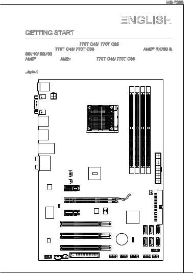
Top : mouse
Bottom: keyboard
PWR1
COM port
USB ports
USB ports
Top: LAN Jack
Bottom: USB ports
T:Line-In
M:Line-Out
B:Mic
T:RS-Out
M:CS-Out
B:SS-Out

 CPUFAN

 NB_FAN
PCIEX1_1

PCIEX16
JCI1
PCIEX1_2

|
PCI1 |
|
|
Audio Codec |
PCI2 |
|
PCI3 |
JAUD1 CD_IN1JSPD1
AM2 SOCKET
ATX1
AMD
RX780
SYS_FAN
|
ON |
|||
|
1 |
2 |
AMD |
|
|
OCSWITCH1 |
|||
|
SB710/ |
|||
|
Sb700 |
|||
|
BATT |
|||
|
+ |
|||
|
JBAT1 |
|
IDE1 |
||
|
SATA1 |
SATA3 |
SATA5 |
|
SATA2 |
SATA4 |
SATA6 |
|
JUSB1 JUSB2 JUSB3 |
JTPM |
|
FDD1 |
JFP1 JFP2 |
SPECIFICATIONS
Processor Support
■AMD® Phenom FX/X4/X2, Althon 64 FX/X2 and Sempron processors in AM2+ package
(For the latest information about CPU, please visit http://www.msi.com/index.php?func=cpuform2)
HyperTransport
■ Supports Hyper Transport(HT) 3.0 Technology
Chipset
■North Bridge: AMD® RX780 chipset
■South Bridge: AMD® SB710/ SB700 chipset
Memory Support
■DDR2 533/ 667/ 800/ 1066 SDRAM (8GB Max)
■4 DDR2 DIMMs (240pin / 1.8V)
(For more information on compatible components, please visit http://www.msi.com/index.php?func=testreport)
LAN
■ Supports LAN 10/100/1000 Fast Ethernet by Realtek® RTL 8111DL Audio
■Chip integrated by Realtek® ALC889/ ALC888S/ ALC885
■Flexible 8-channel audio with jack sensing
■Compliant with Azalia 1.0 Spec
IDE

■1 IDE port by AMD® SB710/ SB700
■Supports Ultra DMA 33/66/100/133, PIO & Bus Master operation mode
SATA
■6 SATAII ports by AMD® SB710/ SB700
■Supports storage and data transfers at up to 3.0 Gb/s
RAID
■ Supports RAID 0/ 1/ 0+1 mode by AMD® SB710/ SB700 Floppy

■1 floppy port
■Supports 1 FDD with 360KB, 720KB, 1.2MB, 1.44MB and 2.88MB
Connectors
■Back panel
1 PS/2 mouse port
1 PS/2 keyboard port
1 Serial port
6 USB 2.0 Ports
1 LAN jack
6 flexible audio jacks
■On-Board Connectors
3 USB 2.0 connectors
1 Chassis Intrusion connector
10
![]()
MS-7388
1 CD-In connector
1 Front Panel Audio connector
1 SPDIF-Out connector
1 TPM connector (optional)
1 OC switch
Slots
■1 PCI Express x16 slot
■2 PCI Express x1 slot
■3 PCI slots, support 3.3V/ 5V PCI bus Interface
Form
 Factor

■ ATX (30.5cm X 21.0 cm) Mounting
■6 mounting holes
(If you need to purchase accessories and request the part numbers, you could search the product web page and find details on our web address below http://www.msi.com/index.php)
11
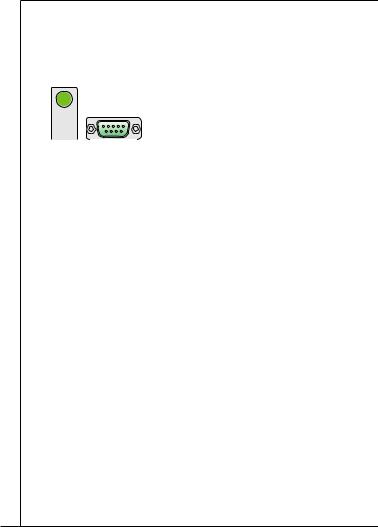
REAR PANEL
The 770T
 -C45/770T
 -C35 rear panel provides the following connectors:
|
PS/2 mouse |
LAN |
Line-In |
RS-Out |
|
Serial port |
Line-Out CS-Out |
||
|
PS/2 keyboard |
USB ports |
MIC |
SS-Out |
HARDWARE SETUP
SETUP

 SETUP
SETUPThis chapter tells you how to install the CPU, memory modules, and expansion cards, as well as how to setup the jumpers on the mainboard. It also provides the instructions on connecting the peripheral devices, such as the mouse, keyboard, etc. While doing the installation, be careful in holding the components and follow the installation procedures.
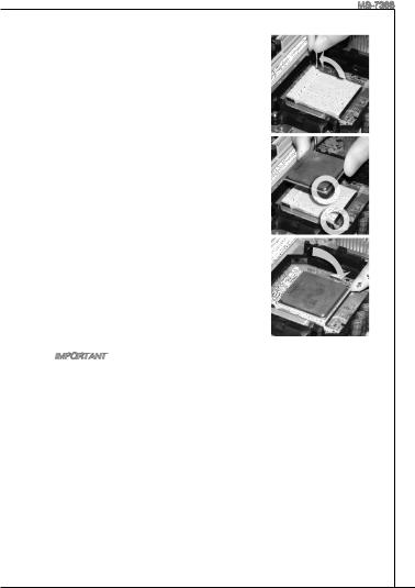
CPU & Cooler Installation for AM2+
When you are installing the CPU, make sure the CPU has a cooler attached on the top to prevent overheating. Meanwhile, do not forget to apply some thermal paste on CPU before installing the heat sink/cooler fan for better heat dispersion.
Follow the steps below to install the CPU & cooler correctly. Wrong installation will cause the damage of your CPU & mainboard.
The surface of AM2+ CPU.
Remember to apply some thermal paste on it
 for better heat dispersion.
Gold arrow
12
MS-7388
. Pull the lever sideways away from the socket. Make sure to raise the lever up to a 90-degree angle.
2.Look for the gold arrow of the CPU. The gold arrow should point as shown in the picture. The CPU can only fit in the correct orientation.
3.If the CPU is correctly installed, the pins should be completely embedded into the socket and can not be seen. Please note that any violation of the correct installation procedures may cause permanent damages to your mainboard.
4.Press the CPU down firmly into the socket and close the lever. As the CPU is likely to move while the lever is being closed, always close the lever with your fingers pressing tightly on top of the CPU to make sure the CPU is properly and completely embedded into the socket.
5.Position the cooling set onto the retention mechanism. Hook one end of the clip to hook first.
6.Then press down the other end of the clip to fasten the cooling set on the top of the retention mechanism. Locate the Fix Lever and lift up it.
7.Fasten down the lever.
8.Attach the CPU Fan cable to the CPU fan connector on the mainboard.
Important
*Mainboard photos shown in this section are for demonstration of the cooler installation for Socket AM2+ CPU only. The appearance of your mainboard may vary depending on the model you purchase.
*While disconnecting the hook from the fixed bolt, it is necessary to keep an eye on your fingers, because once the hook is disconnected from the fixed bolt, the fixed lever will spring back instantly.
13
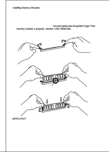
Installing Memory Modules
. The memory module has only one notch on the center and will only fit in the right orientation.
2.Insert the memory module vertically into the DIMM slot. Then push it in until the golden finger on the memory module is deeply inserted in the DIMM slot. The plastic clip at each side of the DIMM slot will automatically close when the
memory module is properly seated. You can barely see the golden finger if the memory module is
 properly inserted
 in
in the DIMM slot.
3.Manually check if the memory module has been locked in place by the DIMM slot clips at the sides.
 Notch
Notch
Volt
Important
*DDR2 memory modules are not interchangeable with DDR and the DDR2 standard is not backwards compatible. You should always install DDR2 memory modules in the DDR2 DIMM slots.
*In Dual-Channel mode, make sure that you install memory modules of the same type and density in different channel DIMM slots.
*To enable successful system boot-up, always insert the memory modules into the DIMM1 first.
14
MS-7388
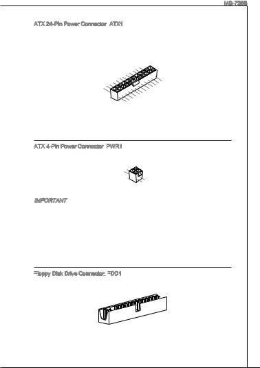
ATX 24-Pin Power Connector: ATX1
ATX1
This connector allows you to connect an ATX 24-pin power supply. To connect the ATX 24-pin power supply, make sure the plug of the power supply is inserted in the proper orientation and the pins are aligned. Then push down the power supply firmly into the connector.
|
12. |
|||||||||||||||
|
11 |
. +3 |
. |
|||||||||||||
|
910. |
|||||||||||||||
|
8 |
. |
+12V |
3 |
||||||||||||
|
V |
|||||||||||||||
|
7 |
|||||||||||||||
|
6 . |
|||||||||||||||
|
5 . |
|||||||||||||||
|
4 |
. +5 |
||||||||||||||
|
2 |
3 . |
||||||||||||||
|
. +5 |
V |
||||||||||||||
|
1 |
. |
||||||||||||||
|
Ground |
|||||||||||||||
|
. +3. |
24 |
||||||||||||||
|
3 |
|||||||||||||||
|
+3.Ground |
. |
||||||||||||||
|
3 |
V |
||||||||||||||
|
V |
23. |
||||||||||||||
|
. +5 |
V |
||||||||||||||
|
+5 |
|||||||||||||||
|
Ground |
|||||||||||||||
|
+5 |
V |
V |
|||||||||||||
|
. |
— |
||||||||||||||
|
13. |
— |
ON |
# |
||||||||||||
|
12V |
|||||||||||||||
|
+3.Ground |
|||||||||||||||
|
3 |
|||||||||||||||
|
V |
ATX 4-Pin Power Connector: PWR1
PWR1
This 4-Pin power connector is used to provide power to the CPU.
|
1 |
||
|
. |
||
|
2 |
Ground |
|
|
. |
||
|
Ground |
||
|
3 |
||
|
. |
||
|
4 |
+12V |
|
|
. |
||
|
+12V |
Important
*Make sure that all the connectors are connected to proper ATX power supplies to ensure stable operation of the mainboard.
*Power supply of 350 watts (and above) is highly recommended for system stability.
Floppy Disk Drive Connector:
 FDD1
FDD1
This connector supports 360KB, 720KB, 1.2MB, 1.44MB or 2.88MB floppy disk drive.
15
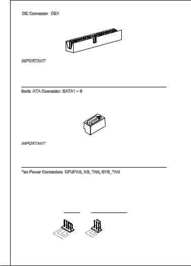
IDE
 Connector:
 IDE1
IDE1
This connector supports IDE hard disk drives, optical disk drives and other IDE devices.
Important
If you install two IDE devices on the same cable, you must configure the drives to cable select mode or separately to master / slave mode by setting jumpers. Refer to IDE device documentation supplied by the vendors for jumper setting instructions.
Serial ATA Connector:
 SATA1 ~ 6
This connector is a high-speed Serial ATA interface port. Each connector can connect to one Serial ATA device.
Important
Please do not fold the Serial ATA cable into 90-degree angle. Otherwise, data loss may occur during transmission.
Fan
 Power Connectors:
 CPUFAN, NB_FAN,
 SYS_FAN

The fan power connectors support system cooling fan with +12V. When connecting the wire to the connectors, always note that the red wire is the positive and should be connected to the +12V; the black wire is Ground and should be connected to GND. If the mainboard has a System Hardware Monitor chipset onboard, you must use a specially designed fan with speed sensor to take advantage of the CPU fan control.
|
CPUFAN |
NB_FAN, SYS_FAN |
||||||||||||
|
1 |
1 |
||||||||||||
|
2 |
. |
2 |
|||||||||||
|
3 |
. G |
||||||||||||
|
3 |
. Gr |
+ r |
|||||||||||
|
. + |
o |
. |
1 o |
||||||||||
|
4 S |
1 |
u |
N |
2 u |
|||||||||
|
. |
e 2 |
n |
o |
V |
n |
||||||||
|
C |
n V |
d |
U |
d |
|||||||||
|
o |
s |
||||||||||||
|
n |
s |
||||||||||||
|
t o |
e |
||||||||||||
|
r r |
|||||||||||||
|
o |
|||||||||||||
|
l |
16
MS-7388
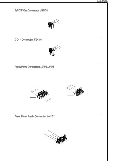
S/PDIF
 -Out Connector:
 JSPD1
JSPD1
This connector is used to connect S/PDIF (Sony & Philips Digital Interconnect Format) interface for digital audio transmission.
|
3 |
||||||
|
2 . |
||||||
|
1 |
. Gr |
|||||
|
S |
o |
|||||
|
. |
P |
u |
||||
|
V |
D |
n |
||||
|
C |
I |
d |
||||
|
C |
F |
CD-In Connector:
 CD_IN1
This connector is provided for external audio input.
|
1 |
||||||||
|
2 |
. |
|||||||
|
L |
||||||||
|
3 |
. |
|||||||
|
G |
||||||||
|
4 |
. |
r |
||||||
|
o |
||||||||
|
. Gr |
u |
|||||||
|
R |
o |
n |
||||||
|
u |
d |
|||||||
|
n |
||||||||
|
d |
Front Panel
Panel Connectors:
 JFP1, JFP2
These connectors are for electrical connection to the front panel switches and LEDs. The JFP1 is compliant with Intel® Front Panel I/O Connectivity Design Guide.
|
P |
||||||||
|
P |
ower |
S |
10. |
|||||
|
ower |
LE |
witch |
No |
|||||
|
D |
8Pin |
|||||||
|
6 |
— |
|||||||
|
4 |
. |
. |
||||||
|
+ |
||||||||
|
2 |
. |
|||||||
|
— |
||||||||
|
. |
||||||||
|
+ |
JFP1
|
9 |
||||||||||
|
1 — |
. |
|||||||||
|
7 |
Reserve |
|||||||||
|
5 |
. |
|||||||||
|
+ |
||||||||||
|
3 |
. |
|||||||||
|
— |
||||||||||
|
. |
d |
|||||||||
|
+ |
||||||||||
|
. |
Reset |
|||||||||
|
S |
||||||||||
|
HDD |
LE |
|||||||||
|
D |
witch |
|
Speaker |
6 |
+ |
|||
|
Buzzer |
|||||
|
8 |
|||||
|
. |
|||||
|
4 |
. |
||||
|
— |
|||||
|
2 |
. |
||||
|
+ |
|||||
|
. |
|||||
|
— |
JFP2
|
7 |
||||||
|
3 |
5 . |
|||||
|
. No |
||||||
|
1 |
Power |
|||||
|
. |
Pi |
|||||
|
. |
Suspend |
D |
||||
|
n |
||||||
|
Ground |
LE |
|||||
|
LE |
||||||
|
D |
Front
 Panel
Panel Audio Connector:
 JAUD1
JAUD1
This connector allows you to connect the front panel audio and is compliant with Intel® Front Panel I/O Connectivity Design Guide.
|
1 |
|||||||||||||||||||
|
0 |
|||||||||||||||||||
|
8 . |
|||||||||||||||||||
|
6 |
. |
H |
|||||||||||||||||
|
N |
e |
||||||||||||||||||
|
. |
o |
a |
|||||||||||||||||
|
4 |
M |
P |
P |
||||||||||||||||
|
2 |
. |
I |
i |
||||||||||||||||
|
P |
C |
n |
h |
||||||||||||||||
|
. |
R |
D |
o |
||||||||||||||||
|
G |
E |
e |
n |
||||||||||||||||
|
r |
S |
t |
e |
||||||||||||||||
|
o |
e |
D |
|||||||||||||||||
|
u |
E |
c |
t |
||||||||||||||||
|
n |
N |
i |
|||||||||||||||||
|
d |
C |
o |
e |
||||||||||||||||
|
E |
n |
c |
|||||||||||||||||
|
t |
|||||||||||||||||||
|
# |
i |
||||||||||||||||||
|
o |
|||||||||||||||||||
|
n |
|
9 |
||||||||||||||||
|
7 |
. |
|||||||||||||||
|
H |
||||||||||||||||
|
5 |
. |
e |
||||||||||||||
|
S |
a |
|||||||||||||||
|
3 |
. |
E |
||||||||||||||
|
H |
d |
|||||||||||||||
|
1 |
. |
e |
N |
P |
||||||||||||
|
M |
a |
S |
h |
|||||||||||||
|
. |
I |
d |
E |
o |
||||||||||||
|
M |
C |
P |
_ |
n |
||||||||||||
|
I |
R |
S |
e |
|||||||||||||
|
C |
h |
L |
||||||||||||||
|
L |
o |
E |
||||||||||||||
|
n |
N |
|||||||||||||||
|
e |
D |
|||||||||||||||
|
R |
17
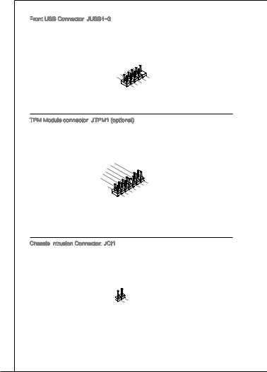
Front USB Connector:
 JUSB1~3
This connector, compliant with Intel® I/O Connectivity Design Guide, is ideal for connecting high-speed USB interface peripherals such as USB HDD, digital cameras, MP3 players, printers, modems and the like.
|
1 |
||||||||||||
|
0 |
||||||||||||
|
8 . |
||||||||||||
|
6 |
. U |
|||||||||||
|
G |
S |
|||||||||||
|
4 |
. |
r |
B |
|||||||||
|
U |
o |
O |
||||||||||
|
2 |
. |
S |
u |
|||||||||
|
U |
B |
n |
C |
|||||||||
|
. |
S |
1 |
d |
|||||||||
|
V |
B |
+ |
||||||||||
|
C |
1 |
|||||||||||
|
C |
— |
|
9 |
|||||||||
|
7 |
. |
||||||||
|
N |
|||||||||
|
5 . |
o |
||||||||
|
3 |
. Gr |
P |
|||||||
|
U |
o |
i |
|||||||
|
1 |
. |
S |
u n |
||||||
|
U |
n |
||||||||
|
. |
S |
B |
d |
||||||
|
V |
B |
0 |
|||||||
|
C |
0 |
+ |
|||||||
|
C |
— |
TPM Module connector: JTPM1 (optional)
This connector connects to a TPM (Trusted Platform Module) module. Please refer to the TPM security platform manual for more details and usages.
|
1 |
||||||||||||||||||||||||||||||||||||||||||||||||
|
4 |
||||||||||||||||||||||||||||||||||||||||||||||||
|
1 . |
||||||||||||||||||||||||||||||||||||||||||||||||
|
1 |
2 |
|||||||||||||||||||||||||||||||||||||||||||||||
|
. Gr |
||||||||||||||||||||||||||||||||||||||||||||||||
|
. G |
o |
|||||||||||||||||||||||||||||||||||||||||||||||
|
8 |
0 |
r |
||||||||||||||||||||||||||||||||||||||||||||||
|
6 |
. |
N |
o |
n |
||||||||||||||||||||||||||||||||||||||||||||
|
5 |
o |
u |
d |
|||||||||||||||||||||||||||||||||||||||||||||
|
4 |
. |
V |
P |
n |
||||||||||||||||||||||||||||||||||||||||||||
|
S |
P |
i |
d |
|||||||||||||||||||||||||||||||||||||||||||||
|
. |
e |
n |
||||||||||||||||||||||||||||||||||||||||||||||
|
3 |
i o |
|||||||||||||||||||||||||||||||||||||||||||||||
|
2 . |
r |
w |
||||||||||||||||||||||||||||||||||||||||||||||
|
a |
||||||||||||||||||||||||||||||||||||||||||||||||
|
. |
3 |
l |
e |
|||||||||||||||||||||||||||||||||||||||||||||
|
3 |
V |
I |
r |
|||||||||||||||||||||||||||||||||||||||||||||
|
V |
t |
P |
R |
|||||||||||||||||||||||||||||||||||||||||||||
|
o |
Q |
|||||||||||||||||||||||||||||||||||||||||||||||
|
S |
a |
w |
||||||||||||||||||||||||||||||||||||||||||||||
|
n |
e |
|||||||||||||||||||||||||||||||||||||||||||||||
|
d |
r |
|||||||||||||||||||||||||||||||||||||||||||||||
|
b |
||||||||||||||||||||||||||||||||||||||||||||||||
|
y |
||||||||||||||||||||||||||||||||||||||||||||||||
|
p |
||||||||||||||||||||||||||||||||||||||||||||||||
|
o |
||||||||||||||||||||||||||||||||||||||||||||||||
|
w |
1 |
|||||||||||||||||||||||||||||||||||||||||||||||
|
e |
||||||||||||||||||||||||||||||||||||||||||||||||
|
r |
3 |
|||||||||||||||||||||||||||||||||||||||||||||||
|
1 . |
||||||||||||||||||||||||||||||||||||||||||||||||
|
9 |
1 |
L |
||||||||||||||||||||||||||||||||||||||||||||||
|
. |
P |
|||||||||||||||||||||||||||||||||||||||||||||||
|
7 |
. |
L |
C |
|||||||||||||||||||||||||||||||||||||||||||||
|
L |
P |
F |
||||||||||||||||||||||||||||||||||||||||||||||
|
5 |
. |
P |
C |
|||||||||||||||||||||||||||||||||||||||||||||
|
L |
C |
a |
r |
|||||||||||||||||||||||||||||||||||||||||||||
|
3 |
. |
P |
a |
a |
||||||||||||||||||||||||||||||||||||||||||||
|
L |
C |
d |
m |
|||||||||||||||||||||||||||||||||||||||||||||
|
1 |
. |
P |
d |
d |
e |
|||||||||||||||||||||||||||||||||||||||||||
|
L |
a |
d |
r |
|||||||||||||||||||||||||||||||||||||||||||||
|
. |
P C |
d |
r |
e |
||||||||||||||||||||||||||||||||||||||||||||
|
L |
C |
a |
d |
e |
s |
|||||||||||||||||||||||||||||||||||||||||||
|
P |
d |
r |
s |
s |
||||||||||||||||||||||||||||||||||||||||||||
|
C |
R |
d |
e |
s |
& |
|||||||||||||||||||||||||||||||||||||||||||
|
C |
e |
r |
s |
& |
d |
|||||||||||||||||||||||||||||||||||||||||||
|
s |
e |
s |
d |
a |
||||||||||||||||||||||||||||||||||||||||||||
|
l |
e |
s |
& |
t |
||||||||||||||||||||||||||||||||||||||||||||
|
o |
t |
s |
a |
a |
||||||||||||||||||||||||||||||||||||||||||||
|
c |
& |
d |
t |
|||||||||||||||||||||||||||||||||||||||||||||
|
k |
a |
p |
||||||||||||||||||||||||||||||||||||||||||||||
|
d |
a |
p |
i |
|||||||||||||||||||||||||||||||||||||||||||||
|
t |
n |
|||||||||||||||||||||||||||||||||||||||||||||||
|
a |
a |
i |
||||||||||||||||||||||||||||||||||||||||||||||
|
t |
p |
n |
3 |
|||||||||||||||||||||||||||||||||||||||||||||
|
a |
i |
2 |
||||||||||||||||||||||||||||||||||||||||||||||
|
p |
n |
|||||||||||||||||||||||||||||||||||||||||||||||
|
n |
1 |
|||||||||||||||||||||||||||||||||||||||||||||||
|
i |
||||||||||||||||||||||||||||||||||||||||||||||||
|
0 |
Chassis Intrusion Connector:
 JCI1
JCI1
This connector connects to the chassis intrusion switch cable. If the chassis is opened, the chassis intrusion mechanism will be activated. The system will record this status and show a warning message on the screen. To clear the warning, you must enter the BIOS utility and clear the record.
|
2 |
|||||||
|
1 |
. |
||||||
|
G |
|||||||
|
. |
r |
||||||
|
CI |
u |
||||||
|
N |
o |
n |
|||||
|
T |
d |
||||||
|
R |
|||||||
|
U |
18
MS-7388
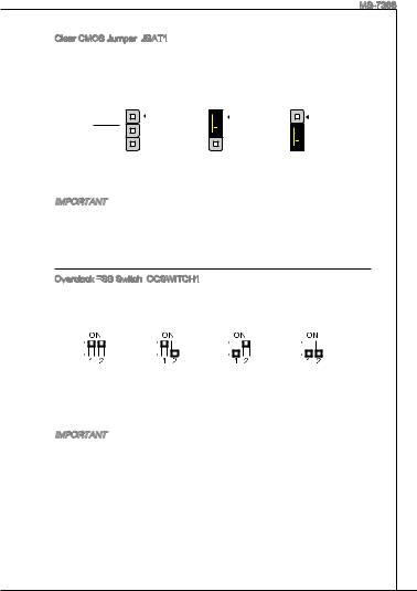
Clear CMOS Jumper: JBAT1
JBAT1
There is a CMOS RAM onboard that has a power supply from an external battery to keep the data of system configuration. With the CMOS RAM, the system can automatically boot OS every time it is turned on. If you want to clear the system configuration, set the jumper to clear data.
|
1 |
1 |
1 |
|
JBAT1 |
||
|
Keep Data |
Clear Data |
Important
You can clear CMOS by shorting 2-3 pin while the system is off. Then return to 1-2 pin position. Avoid clearing the CMOS while the system is on; it will damage the mainboard.
Overclock FSB Switch:
 OCSWITCH1
You can overclock the FSB to increase the processor frequency by changing the switch. Follow the instructions below to set the FSB.
|
Default |
Increase 10% |
Increase 15% |
Increase 20% |
|||||||||||||||||||||||
|
speed of FSB |
speed of FSB |
speed of FSB |
Important
*Make sure that you power off the system before setting the switch.
*When overclocking cause system instability or crash during boot, please set the switch to default setting.
19
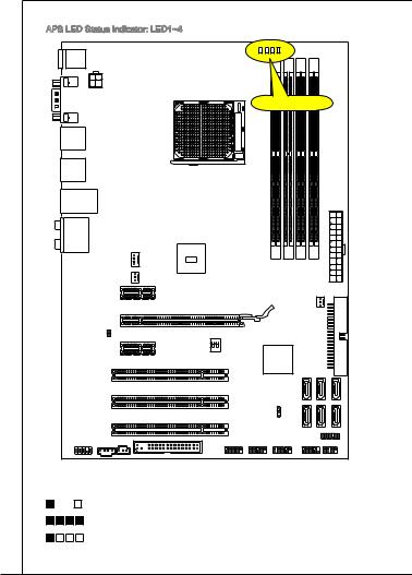
|
APS LED Status Indicator: LED1~4 |
||
|
APS LEDs |
||
|
ON |
||
|
1 |
2 |
|
|
These APS (Active Phase Switching) LED indicates the current CPU power phase |
||
|
mode. Follow the instructions below to read. |
||
|
:ON, |
:OFF |
|
|
4 of the LEDs will light blue when CPU is in 4 phase power mode. |
||
|
1 of the LEDs will light blue when CPU is in 1 phase power mode. |
||
|
20 |
![]()
MS-7388
PCI Express
 Slot
Slot
The PCI Express slot supports the PCI Express interface expansion card.
PCI Express x16 slot.


 PCI Express x1 slot.
PCI Slot
Slot
The PCI slot supports LAN card, SCSI card, USB card, and other add-on cards that comply with PCI specifications.
Important
Make sure that you unplug the power supply first. Meanwhile, read the documentation for the expansion card to configure any necessary hardware or software settings for the expansion card, such as jumpers, switches or BIOS configuration.
PCI Interrupt
 Request Routing
When adding or removing expansion cards, make the IRQ, acronym of interrupt request line and pronounced I-R-Q, are hardware lines over which devices can send interrupt signals to the microprocessor. The PCI IRQ pins are typically connected to the PCI bus pins as follows:
|
Order |
1 |
2 |
3 |
4 |
|||||
|
Slot |
|||||||||
|
PCI 1 |
INT E# |
INT F# |
INT G# |
INT H# |
|||||
|
PCI 2 |
INT F# |
INT G# |
INT H# |
INT E# |
|||||
|
PCI 3 |
INT G# |
INT H# |
INT E# |
INT F# |
|||||
21
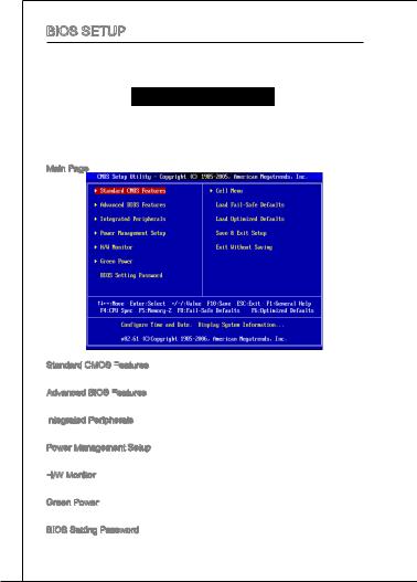
BIOS Setup
Power on the computer and the system will start POST (Power On Self Test) process. When the message below appears on the screen, press <DEL> key to enter Setup.
Press DEL to enter SETUP
If the message disappears before you respond and you still wish to enter Setup, restart the system by turning it OFF and On or pressing the RESET button. You may also restart the system by simultaneously pressing <Ctrl>, <Alt>, and <Delete> keys.
Main Page
Standard CMOS Features
Use this menu for basic system configurations, such as time, date etc.
Advanced BIOS Features
Use this menu to setup the items of special enhanced features.
Integrated Peripherals
Use this menu to specify your settings for integrated peripherals.
Power Management Setup
Use this menu to specify your settings for power management.
H/W Monitor
This entry shows the status of your CPU, fan, warning for overall system status.
Green Power
Use this menu to specify the power phase.
BIOS Setting Password
Use this menu to set BIOS setting Password.
22
MS-7388
Cell
 Menu
Menu
Use this menu to specify your settings for frequency/voltage control.
Load
 Fail
Fail


 -Safe Defaults
Use this menu to load the BIOS default values that are factory settings for system operations.
Load
 Optimized Defaults
Use this menu to load factory default settings into the BIOS for stable system performance operations.
Save & Exit
 Setup
Setup
Save changes to CMOS and exit setup.
Exit
 Without Saving
Abandon all changes and exit setup.
23
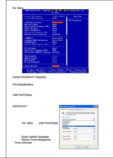
Cell
 Menu
Menu
Current CPU/DRAM Frequency
It shows the current frequency of CPU/Memory. Read-only.
CPU Specifications
Press <Enter> to enter the sub-menu and it displays the informations of installed CPU.
AMD Cool’n’Quiet
The Cool’n’Quiet technology can effectively and dynamically lower CPU speed and power consumption.
Important
To ensure that Cool’n’Quiet function is activated and will be working properly, it is required to double confirm that:
*Run BIOS Setup, and select Cell Menu.
Under Cell Menu, find AMD Cool’n’Quiet, and set this item to “Enabled”.
*Enter Windows, and select [Start]->[Set- tings]->[Control Panel]->[Power Options]. Enter Power Options Properties tag, and
select Minimal Power Management
 under Power schemes.
24
MS-7388
Adjust CPU FSB
 Frequency
 (MHz)
(MHz)
This item allows you to adjust the CPU FSB frequency.
Adjust CPU Ratio
This item is used to adjust CPU clock multiplier (ratio). It is available only when the processor supports this function.
Adjust CPU-NB Ratio
This item is used to adjust CPU-NB ratio.
Adjusted CPU Frequency
 (MHz)
(MHz)
It shows the adjusted CPU frequency. Read-only.
Advanced Clock Calibration
This item is for overclock. Setting to [Enabled] allows you to set the CPU Ratio higher. It is available only when the processor supports this function.
MEMORY-Z
Press <Enter> to enter the sub-menu, select a item form DIMM list and enter to read the memory SPD informations.
Advance DRAM Configuration Press <Enter> to enter the sub-menu.
DRAM Timing Mode
This field has the capacity to automatically detect all of the DRAM timing. If you set this field to [DCT 0], [DCT 1] or [Both], some fields will appear and selectable. DCT 0 controls channel A and DCT1 controls channel B.
CAS Latency
 (CL)
(CL)
When the DRAM Timing Mode sets to [DCT 0], [DCT1] or [Both], the field is adjustable. This controls the CAS latency, which determines the timing delay (in clock cycles) before SDRAM starts a read command after receiving it.
tRCD
When the DRAM Timing Mode sets to [DCT 0], [DCT1] or [Both], the field is adjustable. When DRAM is refreshed, both rows and columns are addressed separately. This setup item allows you to determine the timing of the transition from RAS (row address strobe) to CAS (column address strobe). The less the clock cycles, the faster the DRAM performance.
tRP
When the DRAM Timing Mode sets to [DCT 0], [DCT1] or [Both], the field is adjustable. This setting controls the number of cycles for Row Address Strobe (RAS) to be allowed to precharge. If insufficient time is allowed for the RAS to accumulate its charge before DRAM refresh may be incomplete and DRAM may fail to retain data. This item applies only when synchronous DRAM is installed in the system.
tRAS
When the DRAM Timing Mode sets to [DCT 0], [DCT1] or [Both], the field is adjustable. This setting determines the time RAS takes to read from and write to a memory cell.
25
tRTP
When the DRAM Timing Mode sets to [DCT 0], [DCT1] or [Both], the field is adjustable. This setting controls the time interval between a read and a precharge command.
tRC
When the DRAM Timing Mode sets to [DCT 0], [DCT1] or [Both], the field is adjustable. The row cycle time determines the minimum number of clock cycles a memory row takes to complete a full cycle, from row activation up to the precharging of the active row.
tWR
When the DRAM Timing Mode sets to [DCT 0], [DCT1] or [Both], the field is adjustable. It specifies the amount of delay (in clock cycles) that must elapse after the completion of a valid write operation, before an active bank can be precharged. This delay is required to guarantee that data in the write buffers can be written to the memory cells before precharge occurs.
tRRD
When the DRAM Timing Mode sets to [DCT 0], [DCT1] or [Both], the field is adjustable. Specifies the active-to-active delay of different banks.
tWTR
When the DRAM Timing Mode sets to [DCT 0], [DCT1] or [Both], the field is adjustable. This item controls the Write Data In to Read Command Delay memory timing. This constitutes the minimum number of clock cycles that must occur between the last valid write operation and the next read command to the same internal bank of the DDR device.
tRFC0~3
When the DRAM Timing Mode sets to [DCT 0], [DCT1] or [Both], these fields are adjustable. These settings determine the time RFC take to read from and write to memory cells.
1T/2T
 Memory Timing
When the DRAM Timing Mode sets to [DCT 0], [DCT1] or [Both], the field is adjustable. This field controls the SDRAM command rate. Selecting [1T] makes SDRAM signal controller to run at 1T (T=clock cycles) rate. Selecting [2T] makes SDRAM signal controller run at 2T rate.
DCT
 Unganged Mode
This feature is used to Integrate two 64-bit DCTs into a 128-bit interface.
FSB/DRAM Ratio
Ratio
This item allows you to set the FSB/DRAM ratio.
Adjusted DRAM Frequency (MHz)
(MHz)
It shows the adjusted DDR memory frequency. Read-only.
HT

 Link
Link
 Speed
Speed
This item allows you to set the Hyper-Transport Link speed. Setting to [Auto], the system will detect the HT link speed automatically.
Adjust PCI
 -E
-E

 Frequency
 (MHz)
(MHz)
This item allows you to set the PCI-E frequency (in MHz).
26
MS-7388
Auto Disable DRAM/PCI Frequency
When set to [Enabled], the system will remove (turn off) clocks from empty DIMM and PCI slots to minimize the electromagnetic interference (EMI).
CPU Voltage (V)
This item will allow you to adjust the CPU voltage.
DRAM Voltage (V)
This item will allow you to adjust the Memory voltage.
NB Voltage (V)
This item will allow you to adjust the North Bridge voltage.
HT

 Link
Link
 Voltage (V)
This item will allow you to adjust the Hyper-Transport Link voltage.
Spread Spectrum
When the motherboard’s clock generator pulses, the extreme values (spikes) of the pulses create EMI (Electromagnetic Interference). The Spread Spectrum function reduces the EMI generated by modulating the pulses so that the spikes of the pulses are reduced to flatter curves. If you do not have any EMI problem, leave the setting at Disabled for optimal system stability and performance. But if you are plagued by EMI, set to Enabled for EMI reduction. Remember to disable Spread Spectrum if you are overclocking because even a slight jitter can introduce a temporary boost in clock speed which may just cause your overclocked processor to lock up.
Important
*If you do not have any EMI problem, leave the setting at [Disabled] for optimal system stability and performance. But if you are plagued by EMI, select the value of Spread Spectrum for EMI reduction.
*The greater the Spread Spectrum value is, the greater the EMI is reduced, and the system will become less stable. For the most suitable Spread Spectrum value, please consult your local EMI regulation.
*Remember to disable Spread Spectrum if you are overclocking because even a slight jitter can introduce a temporary boost in clock speed which may just cause your overclocked processor to lock up.
27
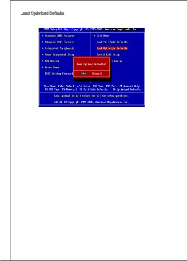
Load
 Optimized Defaults
You can load the default values provided by the mainboard manufacturer for the stable performance.
28
Top : mouse
Bottom: keyboard
PWR1
COM port
USB ports
USB ports
Top: LAN Jack
Bottom: USB ports
T:Line-In
M:Line-Out
B:Mic
T:RS-Out
M:CS-Out
B:SS-Out

 CPUFAN

 NB_FAN
PCIEX1_1

PCIEX16
JCI1
PCIEX1_2

|
PCI1 |
|
|
Audio Codec |
PCI2 |
|
PCI3 |
JAUD1 CD_IN1JSPD1
AM2 SOCKET
ATX1
AMD
RX780
SYS_FAN
|
ON |
|||
|
1 |
2 |
AMD |
|
|
OCSWITCH1 |
|||
|
SB710/ |
|||
|
Sb700 |
|||
|
BATT |
|||
|
+ |
|||
|
JBAT1 |
|
IDE1 |
||
|
SATA1 |
SATA3 |
SATA5 |
|
SATA2 |
SATA4 |
SATA6 |
|
JUSB1 JUSB2 JUSB3 |
JTPM |
|
FDD1 |
JFP1 JFP2 |
29
■AM2+ AMD® Phenom FX/X4/X2, Althon 64 FX/X2 Sempron
(CPU http://www.msi.com/index.php?func=cpuform2 )
HyperTransport
■ Hyper Transport(HT) 3.0
■: AMD® RX780
■: AMD® SB710/ SB700

■DDR2 533/ 667/ 800/ 1066 SDRAM ( 8GB)
■DDR2 DIMM 4 (240 / 1.8V)
( http://www.msi.com/index.php?func=testreport .)
LAN
■ Realtek® RTL 8111DL LAN 10/100/1000
■Realtek® ALC889/ ALC888S/ ALC885
■8
■Azalia 1.0 Spec
IDE

■AMD® SB710/ SB700 IDE 1
■Ultra DMA 33/66/100/133, PIO
SATA
■AMD® SB710/ SB700 SATAII 6
■3.0 Gb/s
RAID
■ AMD® SB710/ SB700 RAID 0/ 1/ 0+1
■1
■360KB, 720KB, 1.2MB, 1.44MB 2.88MB FDD 1
PS/2 1
PS/2 1
1
USB 2.0 6
LAN 1
6
USB 2.0 3
1
30
![]()
MS-7388
CD 1
1
SPDIF 1
TPM 1 ( )
OC 1
■PCI Express x16 1
■PCI Express x1 2
■PCI 3 , 3.3V/ 5V PCI
■ ATX (30.5cm X 21.0 cm)
■6 ( ,
http://www.msi.com/index.php .)
31

|
770T-C45/770T-C35 . |
||
|
PS/2 |
LAN |
RS |
|
CS |
||
|
PS/2 |
USB |
SS |
|
CPU, , |
||
|
. , |
||
|
. , . |
||
|
AM2+ CPU |
||
|
CPU . |
||
|
/ CPU |
||
|
. |
||
|
CPU . CPU |
||
|
. |
||
|
AM2+ CPU . |
||
|
. |
||
|
32 |

MS-7388
. . 90.
2.CPU . . CPU.
3.CPU , ..
4.CPU. CPU, CPUCPU .
5...
6...
7..
8.CPU CPU.
*AM2+ CPU. .
*,.
33


 . , .
. , .
2.DIMM .DIMM .DIMM. 
 DIMM
DIMM 

 .
.
3.DIMM.

*DDR2 DDR , DDR2. DDR2 DIMM DDR2 .
*, DIMM.
*, DIMM1 .
34

MS-7388
ATX 24 : ATX1
ATX1
ATX 24 . ATX 24,, ..
|
12. |
|||||||||||||||
|
11 |
. +3 |
. |
|||||||||||||
|
910. |
|||||||||||||||
|
8 |
. |
+12V |
3 |
||||||||||||
|
V |
|||||||||||||||
|
7 |
|||||||||||||||
|
6 . |
|||||||||||||||
|
5 . |
|||||||||||||||
|
4 |
. +5 |
||||||||||||||
|
2 |
3 . |
||||||||||||||
|
. +5 |
V |
||||||||||||||
|
1 |
. |
||||||||||||||
|
Ground |
|||||||||||||||
|
. +3. |
24 |
||||||||||||||
|
3 |
|||||||||||||||
|
+3.Ground |
. |
||||||||||||||
|
3 |
V |
||||||||||||||
|
V |
23. |
||||||||||||||
|
. +5 |
V |
||||||||||||||
|
+5 |
|||||||||||||||
|
Ground |
|||||||||||||||
|
+5 |
V |
V |
|||||||||||||
|
. |
— |
||||||||||||||
|
13. |
— |
ON |
# |
||||||||||||
|
12V |
|||||||||||||||
|
+3.Ground |
|||||||||||||||
|
3 |
|||||||||||||||
|
V |
ATX 4 : PWR1
PWR1
4 CPU .
|
1 |
||
|
. |
||
|
2 |
Ground |
|
|
. |
||
|
Ground |
||
|
3 |
||
|
. |
||
|
4 |
+12V |
|
|
. |
||
|
+12V |
*ATX.
*350 .
 :
:
 FDD1
FDD1
360 KB, 720 KB, 1.2 MB, 1.44 MB 2.88 MB.
35

IDE
 :
: IDE1
IDE1
IDE , IDE.
2 IDE ,, / .IDE .
ATA :
 SATA1 ~ 6
ATA .ATA .
ATA 90 . ,.
: CPUFAN, NB_FAN,
 SYS_FAN
+12V ., +12V ,GND ., CPU .
|
CPUFAN |
NB_FAN, SYS_FAN |
||||||||||||
|
1 |
1 |
||||||||||||
|
2 |
. |
2 |
|||||||||||
|
3 |
. Gr |
3 |
+ r |
||||||||||
|
. + |
o |
. |
1 o |
||||||||||
|
4 S |
1 |
u |
N |
2 u |
|||||||||
|
. |
e 2 |
n |
o |
V |
n |
||||||||
|
C |
n V |
d |
U |
d |
|||||||||
|
o |
s |
||||||||||||
|
n |
s |
||||||||||||
|
t o |
e |
||||||||||||
|
r r |
|||||||||||||
|
o |
|||||||||||||
|
l |
36

|
MS-7388 |
||||||||||||||||||||||||||||||||||||||||||||||||||||||||||||||
|
S/PDIF : JSPD1 |
||||||||||||||||||||||||||||||||||||||||||||||||||||||||||||||
|
S/PDIF(Sony & Philips Digital Intercon- |
||||||||||||||||||||||||||||||||||||||||||||||||||||||||||||||
|
nect Format) . |
||||||||||||||||||||||||||||||||||||||||||||||||||||||||||||||
|
3 |
||||||||||||||||||||||||||||||||||||||||||||||||||||||||||||||
|
2 . |
||||||||||||||||||||||||||||||||||||||||||||||||||||||||||||||
|
1 |
. Gr |
|||||||||||||||||||||||||||||||||||||||||||||||||||||||||||||
|
S |
o |
|||||||||||||||||||||||||||||||||||||||||||||||||||||||||||||
|
. |
P |
u |
||||||||||||||||||||||||||||||||||||||||||||||||||||||||||||
|
V |
D |
n |
||||||||||||||||||||||||||||||||||||||||||||||||||||||||||||
|
C |
I |
d |
||||||||||||||||||||||||||||||||||||||||||||||||||||||||||||
|
C |
F |
|||||||||||||||||||||||||||||||||||||||||||||||||||||||||||||
|
CD : CD_IN1 |
||||||||||||||||||||||||||||||||||||||||||||||||||||||||||||||
|
. |
||||||||||||||||||||||||||||||||||||||||||||||||||||||||||||||
|
1 |
||||||||||||||||||||||||||||||||||||||||||||||||||||||||||||||
|
2 |
. |
|||||||||||||||||||||||||||||||||||||||||||||||||||||||||||||
|
L |
||||||||||||||||||||||||||||||||||||||||||||||||||||||||||||||
|
3 |
. |
|||||||||||||||||||||||||||||||||||||||||||||||||||||||||||||
|
G |
||||||||||||||||||||||||||||||||||||||||||||||||||||||||||||||
|
4 |
. |
r |
||||||||||||||||||||||||||||||||||||||||||||||||||||||||||||
|
o |
||||||||||||||||||||||||||||||||||||||||||||||||||||||||||||||
|
. Gr |
u |
|||||||||||||||||||||||||||||||||||||||||||||||||||||||||||||
|
R |
o |
n |
||||||||||||||||||||||||||||||||||||||||||||||||||||||||||||
|
u |
d |
|||||||||||||||||||||||||||||||||||||||||||||||||||||||||||||
|
n |
||||||||||||||||||||||||||||||||||||||||||||||||||||||||||||||
|
d |
||||||||||||||||||||||||||||||||||||||||||||||||||||||||||||||
|
: JFP1, JFP2 |
||||||||||||||||||||||||||||||||||||||||||||||||||||||||||||||
|
LED . JFP1 |
||||||||||||||||||||||||||||||||||||||||||||||||||||||||||||||
|
Intel® Front Panel I/O Connectivity Design Guide . |
||||||||||||||||||||||||||||||||||||||||||||||||||||||||||||||
|
P |
||||||||||||||||||||||||||||||||||||||||||||||||||||||||||||||
|
P |
ower |
S |
10. |
Speaker |
||||||||||||||||||||||||||||||||||||||||||||||||||||||||||
|
8 |
||||||||||||||||||||||||||||||||||||||||||||||||||||||||||||||
|
ower |
witch |
Buzzer |
||||||||||||||||||||||||||||||||||||||||||||||||||||||||||||
|
No |
6 |
. |
||||||||||||||||||||||||||||||||||||||||||||||||||||||||||||
|
+ |
||||||||||||||||||||||||||||||||||||||||||||||||||||||||||||||
|
LE |
8Pi |
4 |
. |
|||||||||||||||||||||||||||||||||||||||||||||||||||||||||||
|
— |
||||||||||||||||||||||||||||||||||||||||||||||||||||||||||||||
|
D |
. n |
2 |
. |
|||||||||||||||||||||||||||||||||||||||||||||||||||||||||||
|
6 |
— |
+ |
||||||||||||||||||||||||||||||||||||||||||||||||||||||||||||
|
. |
||||||||||||||||||||||||||||||||||||||||||||||||||||||||||||||
|
4 |
. |
— |
||||||||||||||||||||||||||||||||||||||||||||||||||||||||||||
|
+ |
||||||||||||||||||||||||||||||||||||||||||||||||||||||||||||||
|
2 |
. |
|||||||||||||||||||||||||||||||||||||||||||||||||||||||||||||
|
— |
7 |
|||||||||||||||||||||||||||||||||||||||||||||||||||||||||||||
|
. |
||||||||||||||||||||||||||||||||||||||||||||||||||||||||||||||
|
+ |
9 |
3 |
5 . |
|||||||||||||||||||||||||||||||||||||||||||||||||||||||||||
|
. No |
||||||||||||||||||||||||||||||||||||||||||||||||||||||||||||||
|
7 |
. |
1 |
. |
Pi |
||||||||||||||||||||||||||||||||||||||||||||||||||||||||||
|
5 |
. |
Reserve |
JFP2 |
. |
Power |
n |
||||||||||||||||||||||||||||||||||||||||||||||||||||||||
|
+ |
||||||||||||||||||||||||||||||||||||||||||||||||||||||||||||||
|
3 |
. |
|||||||||||||||||||||||||||||||||||||||||||||||||||||||||||||
|
JFP1 |
1 |
. |
GroundSuspend |
LE |
||||||||||||||||||||||||||||||||||||||||||||||||||||||||||
|
— |
d |
D |
||||||||||||||||||||||||||||||||||||||||||||||||||||||||||||
|
. |
Reset |
|||||||||||||||||||||||||||||||||||||||||||||||||||||||||||||
|
+ |
||||||||||||||||||||||||||||||||||||||||||||||||||||||||||||||
|
S |
LED |
|||||||||||||||||||||||||||||||||||||||||||||||||||||||||||||
|
HDD |
LE |
|||||||||||||||||||||||||||||||||||||||||||||||||||||||||||||
|
D |
witch |
|||||||||||||||||||||||||||||||||||||||||||||||||||||||||||||
|
: JAUD1 |
||||||||||||||||||||||||||||||||||||||||||||||||||||||||||||||
|
, Intel® |
||||||||||||||||||||||||||||||||||||||||||||||||||||||||||||||
|
Front Panel I/O Connectivity Design Guide . |
||||||||||||||||||||||||||||||||||||||||||||||||||||||||||||||
|
1 |
||||||||||||||||||||||||||||||||||||||||||||||||||||||||||||||
|
0 |
||||||||||||||||||||||||||||||||||||||||||||||||||||||||||||||
|
8 . |
||||||||||||||||||||||||||||||||||||||||||||||||||||||||||||||
|
6 |
. |
H |
||||||||||||||||||||||||||||||||||||||||||||||||||||||||||||
|
N |
e |
|||||||||||||||||||||||||||||||||||||||||||||||||||||||||||||
|
. |
o |
a |
||||||||||||||||||||||||||||||||||||||||||||||||||||||||||||
|
4 |
M |
P |
P |
|||||||||||||||||||||||||||||||||||||||||||||||||||||||||||
|
2 |
. |
I |
i |
|||||||||||||||||||||||||||||||||||||||||||||||||||||||||||
|
P |
C |
n |
h |
|||||||||||||||||||||||||||||||||||||||||||||||||||||||||||
|
. |
R |
D |
o |
|||||||||||||||||||||||||||||||||||||||||||||||||||||||||||
|
G |
E |
e |
n |
|||||||||||||||||||||||||||||||||||||||||||||||||||||||||||
|
r |
S |
t |
e |
|||||||||||||||||||||||||||||||||||||||||||||||||||||||||||
|
o |
e |
D |
||||||||||||||||||||||||||||||||||||||||||||||||||||||||||||
|
u |
E |
c |
||||||||||||||||||||||||||||||||||||||||||||||||||||||||||||
|
n |
N |
t |
e |
|||||||||||||||||||||||||||||||||||||||||||||||||||||||||||
|
d |
C |
o |
e |
|||||||||||||||||||||||||||||||||||||||||||||||||||||||||||
|
E |
n |
c |
||||||||||||||||||||||||||||||||||||||||||||||||||||||||||||
|
t |
||||||||||||||||||||||||||||||||||||||||||||||||||||||||||||||
|
# |
i |
|||||||||||||||||||||||||||||||||||||||||||||||||||||||||||||
|
o |
||||||||||||||||||||||||||||||||||||||||||||||||||||||||||||||
|
n |
||||||||||||||||||||||||||||||||||||||||||||||||||||||||||||||
|
9 |
||||||||||||||||||||||||||||||||||||||||||||||||||||||||||||||
|
7 |
. |
|||||||||||||||||||||||||||||||||||||||||||||||||||||||||||||
|
H |
||||||||||||||||||||||||||||||||||||||||||||||||||||||||||||||
|
5 |
. |
e |
||||||||||||||||||||||||||||||||||||||||||||||||||||||||||||
|
S |
a |
|||||||||||||||||||||||||||||||||||||||||||||||||||||||||||||
|
3 |
. |
E |
||||||||||||||||||||||||||||||||||||||||||||||||||||||||||||
|
H |
d |
|||||||||||||||||||||||||||||||||||||||||||||||||||||||||||||
|
1 |
. |
e |
N |
P |
||||||||||||||||||||||||||||||||||||||||||||||||||||||||||
|
M |
a |
S |
h |
|||||||||||||||||||||||||||||||||||||||||||||||||||||||||||
|
. |
I |
d |
E |
o |
||||||||||||||||||||||||||||||||||||||||||||||||||||||||||
|
M |
C |
P |
_ |
n |
||||||||||||||||||||||||||||||||||||||||||||||||||||||||||
|
I |
R |
S |
e |
|||||||||||||||||||||||||||||||||||||||||||||||||||||||||||
|
C |
h |
L |
||||||||||||||||||||||||||||||||||||||||||||||||||||||||||||
|
L |
o |
E |
||||||||||||||||||||||||||||||||||||||||||||||||||||||||||||
|
n |
N |
|||||||||||||||||||||||||||||||||||||||||||||||||||||||||||||
|
e |
D |
|||||||||||||||||||||||||||||||||||||||||||||||||||||||||||||
|
R |
||||||||||||||||||||||||||||||||||||||||||||||||||||||||||||||
|
37 |

|
USB : JUSB1~3 |
|||||||||||||||||||||||||||||||||||||||||||||||||||||||
|
Intel® I/O Connectivity Design Guide USB HDD, |
|||||||||||||||||||||||||||||||||||||||||||||||||||||||
|
, MP3 , , USB |
|||||||||||||||||||||||||||||||||||||||||||||||||||||||
|
. |
|||||||||||||||||||||||||||||||||||||||||||||||||||||||
|
1 |
|||||||||||||||||||||||||||||||||||||||||||||||||||||||
|
0 |
|||||||||||||||||||||||||||||||||||||||||||||||||||||||
|
8 . |
|||||||||||||||||||||||||||||||||||||||||||||||||||||||
|
6 |
. U |
||||||||||||||||||||||||||||||||||||||||||||||||||||||
|
G |
S |
||||||||||||||||||||||||||||||||||||||||||||||||||||||
|
4 |
. |
r |
B |
||||||||||||||||||||||||||||||||||||||||||||||||||||
|
U |
o |
||||||||||||||||||||||||||||||||||||||||||||||||||||||
|
2 |
. |
S |
u O |
||||||||||||||||||||||||||||||||||||||||||||||||||||
|
U |
B |
n C |
|||||||||||||||||||||||||||||||||||||||||||||||||||||
|
. |
S |
1 |
d |
||||||||||||||||||||||||||||||||||||||||||||||||||||
|
V |
B |
+ |
|||||||||||||||||||||||||||||||||||||||||||||||||||||
|
C |
1 |
||||||||||||||||||||||||||||||||||||||||||||||||||||||
|
C |
— |
||||||||||||||||||||||||||||||||||||||||||||||||||||||
|
9 |
|||||||||||||||||||||||||||||||||||||||||||||||||||||||
|
7 |
. |
||||||||||||||||||||||||||||||||||||||||||||||||||||||
|
5 |
N |
||||||||||||||||||||||||||||||||||||||||||||||||||||||
|
. |
o |
||||||||||||||||||||||||||||||||||||||||||||||||||||||
|
3 |
. Gr |
P |
|||||||||||||||||||||||||||||||||||||||||||||||||||||
|
U |
o |
i |
|||||||||||||||||||||||||||||||||||||||||||||||||||||
|
1 |
. |
S |
u n |
||||||||||||||||||||||||||||||||||||||||||||||||||||
|
U |
n |
||||||||||||||||||||||||||||||||||||||||||||||||||||||
|
. |
S |
B |
d |
||||||||||||||||||||||||||||||||||||||||||||||||||||
|
V |
B |
0 |
|||||||||||||||||||||||||||||||||||||||||||||||||||||
|
C |
0 |
+ |
|||||||||||||||||||||||||||||||||||||||||||||||||||||
|
C |
— |
||||||||||||||||||||||||||||||||||||||||||||||||||||||
|
TPM : JTPM1 ( ) |
|||||||||||||||||||||||||||||||||||||||||||||||||||||||
|
TPM(Trusted Platform Module) . |
|||||||||||||||||||||||||||||||||||||||||||||||||||||||
|
TPM . |
|||||||||||||||||||||||||||||||||||||||||||||||||||||||
|
1 |
|||||||||||||||||||||||||||||||||||||||||||||||||||||||
|
4 |
|||||||||||||||||||||||||||||||||||||||||||||||||||||||
|
1 . |
|||||||||||||||||||||||||||||||||||||||||||||||||||||||
|
1 |
2 |
||||||||||||||||||||||||||||||||||||||||||||||||||||||
|
. Gr |
|||||||||||||||||||||||||||||||||||||||||||||||||||||||
|
0 |
o |
||||||||||||||||||||||||||||||||||||||||||||||||||||||
|
8 |
. G |
u |
|||||||||||||||||||||||||||||||||||||||||||||||||||||
|
6 |
. |
N |
o |
n |
|||||||||||||||||||||||||||||||||||||||||||||||||||
|
5 |
o |
u |
d |
||||||||||||||||||||||||||||||||||||||||||||||||||||
|
4 |
. |
V |
P |
n |
|||||||||||||||||||||||||||||||||||||||||||||||||||
|
S |
P |
i |
d |
||||||||||||||||||||||||||||||||||||||||||||||||||||
|
. |
e |
n |
|||||||||||||||||||||||||||||||||||||||||||||||||||||
|
3 |
r |
||||||||||||||||||||||||||||||||||||||||||||||||||||||
|
i o |
|||||||||||||||||||||||||||||||||||||||||||||||||||||||
|
2 . |
a |
w |
|||||||||||||||||||||||||||||||||||||||||||||||||||||
|
. |
3 |
l |
e |
||||||||||||||||||||||||||||||||||||||||||||||||||||
|
3 |
V |
I |
r |
||||||||||||||||||||||||||||||||||||||||||||||||||||
|
V |
P |
R |
|||||||||||||||||||||||||||||||||||||||||||||||||||||
|
S |
o |
Q |
|||||||||||||||||||||||||||||||||||||||||||||||||||||
|
t |
|||||||||||||||||||||||||||||||||||||||||||||||||||||||
|
a |
w |
||||||||||||||||||||||||||||||||||||||||||||||||||||||
|
n |
e |
||||||||||||||||||||||||||||||||||||||||||||||||||||||
|
d |
r |
||||||||||||||||||||||||||||||||||||||||||||||||||||||
|
b |
|||||||||||||||||||||||||||||||||||||||||||||||||||||||
|
y |
|||||||||||||||||||||||||||||||||||||||||||||||||||||||
|
p |
|||||||||||||||||||||||||||||||||||||||||||||||||||||||
|
o |
|||||||||||||||||||||||||||||||||||||||||||||||||||||||
|
w |
1 |
||||||||||||||||||||||||||||||||||||||||||||||||||||||
|
e |
|||||||||||||||||||||||||||||||||||||||||||||||||||||||
|
r |
3 |
||||||||||||||||||||||||||||||||||||||||||||||||||||||
|
1 . |
|||||||||||||||||||||||||||||||||||||||||||||||||||||||
|
9 |
1 |
L |
|||||||||||||||||||||||||||||||||||||||||||||||||||||
|
. |
P |
||||||||||||||||||||||||||||||||||||||||||||||||||||||
|
7 |
. |
L |
C |
||||||||||||||||||||||||||||||||||||||||||||||||||||
|
L |
P |
F |
|||||||||||||||||||||||||||||||||||||||||||||||||||||
|
5 |
. |
P |
C |
||||||||||||||||||||||||||||||||||||||||||||||||||||
|
L |
C |
a |
r |
||||||||||||||||||||||||||||||||||||||||||||||||||||
|
3 |
. |
P |
a |
||||||||||||||||||||||||||||||||||||||||||||||||||||
|
L |
C |
a |
d |
m |
|||||||||||||||||||||||||||||||||||||||||||||||||||
|
1 |
. |
P |
d |
d |
e |
||||||||||||||||||||||||||||||||||||||||||||||||||
|
L |
C |
a |
d |
r |
|||||||||||||||||||||||||||||||||||||||||||||||||||
|
. |
P |
d |
r |
e |
|||||||||||||||||||||||||||||||||||||||||||||||||||
|
L |
a |
d |
e |
s |
|||||||||||||||||||||||||||||||||||||||||||||||||||
|
P C |
d |
r |
s |
s |
|||||||||||||||||||||||||||||||||||||||||||||||||||
|
C |
R |
d |
e |
s |
& |
||||||||||||||||||||||||||||||||||||||||||||||||||
|
C |
e |
r |
s |
& |
d |
||||||||||||||||||||||||||||||||||||||||||||||||||
|
s |
e |
s |
d |
a |
|||||||||||||||||||||||||||||||||||||||||||||||||||
|
l |
e |
s |
& |
t |
|||||||||||||||||||||||||||||||||||||||||||||||||||
|
o |
t |
s |
a |
a |
|||||||||||||||||||||||||||||||||||||||||||||||||||
|
c |
& |
d |
t |
||||||||||||||||||||||||||||||||||||||||||||||||||||
|
k |
a |
p |
|||||||||||||||||||||||||||||||||||||||||||||||||||||
|
d |
a |
p |
i |
||||||||||||||||||||||||||||||||||||||||||||||||||||
|
t |
n |
||||||||||||||||||||||||||||||||||||||||||||||||||||||
|
a |
a |
i |
|||||||||||||||||||||||||||||||||||||||||||||||||||||
|
t |
p |
n |
3 |
||||||||||||||||||||||||||||||||||||||||||||||||||||
|
a |
i |
2 |
|||||||||||||||||||||||||||||||||||||||||||||||||||||
|
p |
n |
||||||||||||||||||||||||||||||||||||||||||||||||||||||
|
i |
1 |
||||||||||||||||||||||||||||||||||||||||||||||||||||||
|
n |
|||||||||||||||||||||||||||||||||||||||||||||||||||||||
|
0 |
|||||||||||||||||||||||||||||||||||||||||||||||||||||||
|
: JCI1 |
|||||||||||||||||||||||||||||||||||||||||||||||||||||||
|
. , |
|||||||||||||||||||||||||||||||||||||||||||||||||||||||
|
. |
|||||||||||||||||||||||||||||||||||||||||||||||||||||||
|
. , BIOS . |
|||||||||||||||||||||||||||||||||||||||||||||||||||||||
|
2 |
|||||||||||||||||||||||||||||||||||||||||||||||||||||||
|
1 |
. |
||||||||||||||||||||||||||||||||||||||||||||||||||||||
|
G |
|||||||||||||||||||||||||||||||||||||||||||||||||||||||
|
. |
r |
||||||||||||||||||||||||||||||||||||||||||||||||||||||
|
CI |
o |
||||||||||||||||||||||||||||||||||||||||||||||||||||||
|
u |
|||||||||||||||||||||||||||||||||||||||||||||||||||||||
|
N |
n |
||||||||||||||||||||||||||||||||||||||||||||||||||||||
|
T |
d |
||||||||||||||||||||||||||||||||||||||||||||||||||||||
|
R |
|||||||||||||||||||||||||||||||||||||||||||||||||||||||
|
U |
|||||||||||||||||||||||||||||||||||||||||||||||||||||||
|
38 |

MS-7388
CMOS : JBAT1
JBAT1
은CMOS RAM . CMOS RAM , OS . ,.
2-3 CMOS .1-2 . CMOS. .
 FSB
FSB :
: OCSWITCH1
FSB .FSB .
|
FSB |
FSB |
FSB |
||||||||||||||||||||||||
|
10% |
15% |
20% |
*.
*.
39

|
APS LED : LED1~4 |
||
|
APS LEDs |
||
|
ON |
||
|
1 |
2 |
|
|
APS (Active Phase Switching) LED CPU . |
||
|
. |
||
|
: , |
: |
|
|
CPU 4 4 LED . |
||
|
CPU 1 1 LED . |
||
|
40 |
![]()
|
MS-7388 |
|||||
|
PCI Express |
|||||
|
PCI Express PCI Express . |
|||||
|
PCI Express x16 . |
|||||
|
PCI Express x1 . |
|||||
|
PCI |
|||||
|
PCI LAN , SCSI , USB PCI |
|||||
|
. |
|||||
|
. , BIOS |
|||||
|
. |
|||||
|
PCI |
|||||
|
Interrupt request line IRQ I-R-Q |
|||||
|
, |
|||||
|
. PCI IRQ PCI . |
|||||
|
1 |
2 |
3 |
4 |
||
|
PCI 1 |
INT E# |
INT F# |
INT G# |
INT H# |
|
|
PCI 2 |
INT F# |
INT G# |
INT H# |
INT E# |
|
|
PCI 3 |
INT G# |
INT H# |
INT E# |
INT F# |
|
|
41 |

|
BIOS |
|
POST(Power On Self Test) . |
|
, <DEL> . |
|
Press DEL to enter SETUP |
|
(DEL .) |
|
, |
|
(RESET) . <Ctrl>, <Alt> |
|
<Delete> . |
|
Main Page ( ) |
|
Standard CMOS Features ( CMOS ) |
|
, . |
|
Advanced BIOS Features ( BIOS ) |
|
. |
|
Integrated Peripherals ( ) |
|
. |
|
Power Management Setup ( ) |
|
. |
|
H/W Monitor (H/W ) |
|
CPU , . |
|
Green Power ( ) |
|
. |
|
BIOS Setting Password (BIOS ) |
|
BIOS . |
|
42 |

MS-7388
Cell
 Menu (
  )
)
/ .
Load
 Fail
Fail

 -Safe Defaults (
  )
)
BIOS.
Load
 Optimized Defaults (
  )
)
BIOS.
Save & Exit
 Setup (
  )
)
CMOS .
Exit
 Without Saving (
  )
)
.
43

Cell
 Menu (
  )
)
Current CPU/DRAM Frequency
 ( CPU/DRAM ) CPU . .
CPU Specifications (CPU )
<Enter> CPU .
AMD Cool’n’Quiet (AMD )
CPU.
,.
*BIOS Cell Menu(
) . Cell Menu( )AMD Cool’n’Quiet( )“Enabled( )”.
*Windows [ ]-> [ ]->[]->[ ] . Power Options Properties( ) Power schemes(
) Minimal Power Management(
) .
44

MS-7388
Adjust CPU FSB
 Frequency
 (CPU FSB
 ) (MHz)
CPU FSB .
Adjust CPU Ratio (CPU  )
)
CPU ( ) ..
Adjust CPU-NB Ratio (CPU-NB  )
)
CPU-NB .
Adjusted CPU Frequency
 ( CPU ) (MHz)
CPU . .
Advanced Clock Calibration (  )
)
. [Enabled( )] CPU..
MEMORY-Z (
 -Z)
-Z)
<Enter> . DIMMSPD .
Advance DRAM Configuration ( DRAM ) <Enter> .
DRAM Timing Mode (DRAM  )
)
DRAM . [DCT 0], [DCT 1 ] [Both( )]. DCT 0 A , DCT1 B .
CAS Latency
 (CAS ) (CL)
DRAM [DCT 0], [DCT1] [Both( )] ,
. SDRAM( ) CAS.
tRCD
DRAM [DCT 0], [DCT1] [Both( )] ,
. DRAM .RAS( ) CAS( ). DRAM .
tRP
DRAM [DCT 0], [DCT1] [Both( )] ,
. RAS. DRAM RAS ,DRAM .DRAM .
tRAS
DRAM [DCT 0], [DCT1] [Both( )] ,
. RAS.
45

tRTP
DRAM [DCT 0], [DCT1] [Both( )] ,
..
tRC
DRAM [DCT 0], [DCT1] [Both( )] ,
..
tWR
DRAM [DCT 0], [DCT1] [Both( )] ,
. ( ) ..
tRRD
DRAM [DCT 0], [DCT1] [Both( )] ,
. active-to-active .
tWTR
DRAM [DCT 0], [DCT1] [Both( )] ,
. (Write Data In to Read Command Delay) . DDR.
tRFC0~3
DRAM [DCT 0], [DCT1] [Both( )] ,
. RFC.
1T/2T
 Memory Timing (1T/2T

 )
)
DRAM [DCT 0], [DCT1] [Both( )] ,
. SDRAM . [1T] SDRAM 1T(T= ). [2T] SDRAM 2T .
DCT
 Unganged Mode (DCT

 )
)
2 64DCT 128-.
FSB/DRAM Ratio (FSB/DRAM
  )
)
FSB/DRAM .
Adjusted DRAM Frequency ( DRAM ) (MHz)
DDR . .
HT

 Link
Link
 Speed (HT
 )
)
. [ (Auto)]HT .
46

MS-7388
Adjust PCI
 -E
-E

 Frequency
 (MHz) (PCI
 -E
-E

 )
)
PCI-E (in MHz) .
Auto Disable DRAM/PCI Frequency
 (DRAM/PCI
 ) [Enabled( )] DRAM/PCI () (EMI) .
CPU Voltage (CPU ) (V)
CPU .
DRAM Voltage (DRAM ) (V)
.
NB Voltage (NB ) (V)
.
HT

 Link
Link
 Voltage (HT
 ) (V)
) (V)
.
Spread Spectrum ( )
( ). EMI. EMI . EMIEMI ..
*EMI [] . EMI EMI.
*EMI .EMI .
*.
47

Load
 Optimized Defaults (
  )
)
있습니다.
48

Top : mouse
Bottom: keyboard
PWR1
COM port
USB ports
USB ports
Top: LAN Jack
Bottom: USB ports
T:Line-In
M:Line-Out
B:Mic
T:RS-Out
M:CS-Out
B:SS-Out

 CPUFAN

 NB_FAN
PCIEX1_1

PCIEX16
JCI1
PCIEX1_2

|
PCI1 |
|
|
Audio Codec |
PCI2 |
|
PCI3 |
JAUD1 CD_IN1JSPD1
AM2 SOCKET
ATX1
AMD
RX780
SYS_FAN
|
ON |
|||
|
1 |
2 |
AMD |
|
|
OCSWITCH1 |
|||
|
SB710/ |
|||
|
Sb700 |
|||
|
BATT |
|||
|
+ |
|||
|
JBAT1 |
|
IDE1 |
||
|
SATA1 |
SATA3 |
SATA5 |
|
SATA2 |
SATA4 |
SATA6 |
|
JUSB1 JUSB2 JUSB3 |
JTPM |
|
FDD1 |
JFP1 JFP2 |
49

SPéCIFICATIONS
Processeurs Supportés
■AMD® Phenom FX/X4/X2, Althon 64 FX/X2 et Sempron processeurs dans le paquet AM2+
(Pour plus d’informations sur le CPU, veuillez visiter http://www.msi.com/index.php?func=cpuform2)
HyperTransport
■ Supporte la Technologie Hyper Transport(HT) 3.0 Chipset
■North Bridge : Chipset AMD® RX780
■South Bridge : Chipset AMD® SB710/ SB700
Mémoire supportée
■DDR2 533/ 667/ 800/ 1066 SDRAM (8GB Max)
■4 DDR2 DIMMs (240pin / 1.8V)
(Pour plus d’informations sur les composants compatibles, veuillez visiter http://www.msi.com/index.php?func=testreport)
LAN
■ Supporte LAN 10/100/1000 Fast Ethernet par Realtek® RTL 8111DL Audio
■Puce intégrée par Realtek® ALC889/ ALC888S/ ALC885
■8-canaux audio flexbiles avec détection de jack
■Compatible avec les spécifications d’Azalia 1.0
IDE

■1 port IDE par AMD® SB710/ SB700
■Supporte les modes d’opération Ultra DMA 33/66/100/133, PIO et Bus Master
SATA
■6 ports SATAII par AMD® SB710/ SB700
■Supporte le stockage et un taux de transfert jusqu’à 3.0 Gb/s
RAID
■ Supporte le mode RAID 0/ 1/ 0+1 par AMD® SB710/ SB700 Disquette
■1 port de disquette
■Supporte 1 FDD avec 360KB, 720KB, 1.2MB, 1.44MB et 2.88MB
Connecteurs
■Panneau arrière
1 port de souris PS/2
1 port de clavier PS/2
1 port Sérial
6 USB 2.0 Ports
1 jack LAN
6 jacks audio flexibles
■Connecteurs intégrés
3 connecteurs USB 2.0
1 connecteur Châssis Intrusion
50
Материнская плата модели MSI 770-C45 являлась универсальным решением и позволяла создавать вычислительные системы любого уровня сложности. Но все же с учетом функциональности и стоимости в первую очередь наиболее оптимально ее использовать в составе наиболее бюджетных ПК. Именно об этом компьютерном компоненте и пойдет речь в рамках этого обзора.
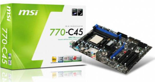
Ниша
Как было отмечено уже ранее, системная плата MSI 770-C45 MS-7599, по существу, была универсальной платформой, которая в рамках сокета АМ3 позволяла создавать электронно-вычислительные системы любого уровня сложности. Но вот ее стоимость, а также использованный при ее создании чипсет и степень функциональности указывают на то, что наиболее оптимально этот компьютерный аксессуар использовать при создании ПК эконом-класса. Опять-таки, поддержкой одного процессорного разъема АМ3 в этом случае производитель не ограничился и добавил также возможность установки процессоров семейства АМ2+ и АМ3+. В последнем случае необходимо предварительно обновить БИОС. Если этого не сделать, то центральный микропроцессор не определится, и компьютер не сможет запуститься.
Комплектация
Типичная, как для ультрабюджетного компьютерного продукта, комплектация в MSI 770-C45. Инструкция, набор рекламных брошюр по компьютерной продукции данного производителя и гарантийный талон — это полный набор комплектной документации. Кроме самой платы, в перечень поставки был включен набор коммуникационных шлейфов. В него входили 4 SATA-провода и провод-переходник для подключения дополнительного питания внешнего графического ускорителя. Этот перечень дополнен металлической заглушкой для монтажа платы в корпус ПК. Также производитель в него включил диск с драйверами и документацией. Все это позволяет без особых проблем собрать ПК на основе этой системной платы.
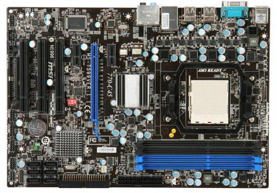
Дизайн
Данная системная плата изготавливалась в полноформатном размере АТХ. Ее размеры составляют 210 мм в ширину и 305 мм в длину. Текстолит, который лежит в основе данного продукта, имеет красный цвет. Сама же плата имеет четырехслойную компоновку. В центре верхней части находится сокет для установки кремниевого чипа. Справа от него находятся слоты для установки модулей памяти. Их четыре. Два из них имеют синий окрас, а два — черный. Слева же, как положено, находятся все коммуникационные порты системной платы. В центре платы находится северный мост из набора системной логики. Он закрыт алюминиевым радиатором. В нижней части сгруппированы слоты расширения. Также в этой части системной платы находятся порты для подключения различных накопителей и батарейка, которая обеспечивает питание системы БИОС. MSI 770-C45 коммутируется к лицевой панели системного блока с помощью разъемов, которые сгруппированы в ее правом нижнем углу.
Сокет
Основной процессорный разъем для MSI 770-C45 — AM3. Но ключевой особенностью последних поколений чипов от компании «АМД» является то, что они совместимы между собой. Как результат, в сокет этой системной платы можно установить ЦПУ АМ2+. Причем каких-либо дополнительных манипуляций с таким компьютерным компонентом выполнять нет нужды. Также в процессорный разъем этой материнской платы можно установить чипы серии АМ3+. Но они появились в продаже после ее анонса. Поэтому в этом случае понадобится “перепрошивка” БИОСа. Также необходимо отметить то, что в ее процессорный разъем можно установить ЦПУ с тепловым пакетом не более 140 Вт. Поэтому наиболее производительным микропроцессором для нее является FX-8370.
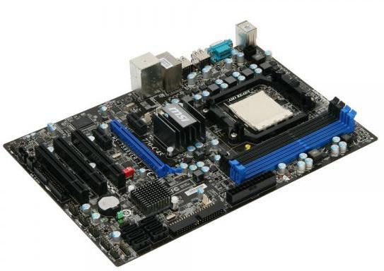
ЦПУ
Очень большим списком поддерживаемых моделей ЦПУ может похвастаться MSI 770-C45. Процессоры семейств Septron, Athlon II или же Phenom II для АМ3 полноценно поддерживались данным компьютерным решением. Также этот список дополнялся более ранними процессорами этих же самых моделей без индекса II, но только для АМ2+. Позднее этот список был дополнен ЦПУ серии АМ3+, который включал чипы серии FX. Последние и обеспечивали наибольший уровень производительности для вычислительных компьютеров на базе данной модели системной платы.
Слоты расширения
Безупречным даже по нынешним меркам набором слотов расширения может похвастаться MSI 770-C45. Характеристики ее указывают на то, что она поддерживает и устаревшие модификации контроллеров расширения, и более новые. Для начала необходимо отметить тот момент, что в такую материнскую плату можно установить лишь только один дискретный адаптер в слот PCI — E-модели 16Х. А вот интегрированной видеокарты в данном случае нет по той причине, что ее нет в составе набора системной логики. Как результат, графический адаптер должен иметь в этом случае достаточный уровень производительности по той причине, что режим SLI от NVidia или же CrossFire от «АМД» в этом случае попросту невозможны. В случае установки двухслотовой видеокарты один из слотов PCI — E-ревизии 1Х будет недоступен, но их два и при необходимости один новый контроллер расширения можно в таком ПК использовать без особых проблем. А вот для установки устаревших модификаций внешних контроллеров предусмотрено сразу 3 слота расширения PCI.
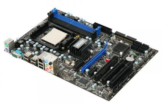
Коммуникационные порты
Еще одно важное преимущество MSI 770-C45 — это большой набор коммуникационных портов. За счет этой важной особенности к вычислительной машине на базе рассматриваемого решения можно подключить любое актуальное периферийное решение. Для осуществления коммутации с манипулятором или же клавиатурой в этом случае предусмотрены 2 разъема PS/2. Также в данном решении реализовано 6 портов USB ревизии 2.0. Причем они универсальные и к ним могут быть подключены устройства не только версии 2.0, а и 1.Х или даже 3.Х. С учетом того что их 6, то переживать о нехватке таких разъемов владельцу такого ПК не приходится. В дополнение к этому в рассматриваемую плату встроен сетевой разъем RJ-45. Скорость передачи информации по нему может достигать 100 Мбит/сек. Кроме всего прочего, рассматриваемое решение оснащено шестью портами 3,5 мм для подключения внешней акустической системы. Причем звук в этом случае 6-канальный. Конечно, последовательный порт COM на текущий момент устарел, но и его можно на ней найти. А вот встроенных MIDI или LPT разъемов в этой ситуации не предусмотрено. Для их реализации владельцу ПК придется установить дополнительный контроллер в слот расширения.
Подсистема оперативной памяти
Действительно безупречно по меркам компьютерной платформы АМ3 была организована подсистема памяти в MSI 770-C45. Сам контроллер входил в состав северного моста чипсета и обеспечивал работу оперативной памяти в двухканальном режиме. Как было отмечено ранее, 2 слота для установки ОЗУ были синего цвета, и это был первый канал, а два других чёрного, и это уже был второй канал контроллера. Тип микросхем памяти для данного памяти — DDR3. Их рекомендованная частота в 1333 МГц. Объем же энергозависимой памяти ограничен 16 Гб. Как результат, в рамках подобной вычислительной системы может быть установлено всего лишь 4 планки по 4 Гб. Установка модулей с большим объемом в этом случае не допускается. Более скоростные планки в эту системную плату установить можно, но в номинальном режиме их частота автоматически снизится до максимально возможных 1333 МГц. Поэтому увеличить быстродействие ПК за счет использования более быстрой памяти в этом случае не получится. Отдельно необходимо отметить работу контроллера подсистемы ОЗУ. Как было уже отмечено ранее, он двухканальный. Поэтому предпочтительней в таком компьютере устанавливать 2 планки по 2 Гб, чем 1 модуль на 4 Гб.
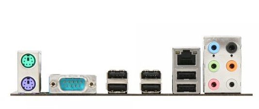
Стоимость
Изначально MSI 770-C45 MS-7599 была оценена производителем в 70-80 долларов. Это дополнительный аргумент относительно того, что это бюджетный компьютерный аксессуар. Но вот полноформатное расширение в формате АТХ указывает все же на то, что это более универсальное решение. Именно по этой причине ее можно использовать не только в составе бюджетных персональных компьютеров, а и более производительных вычислительных систем. С учетом того что эта плата в рамках АМ3 была представлена в 2009 году, она уже достаточно давно снята с производства, а ее складские запасы распроданы. В подержанном же состоянии подобный компонент можно приобрести по цене 2000 рублей. При сборке компьютера бюджетного уровня ее приобретать нет особого смысла. Покупка такого компонента оправдана лишь только в случае ремонта ПК на базе сокетов серии АМ2+/АМ3/АМ3+. Причем при поломке системной платы. Во всех остальных случаях ее приобретение целиком и полностью не оправдано.
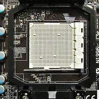
Отзывы
Материнская плата MSI 770-C45, несмотря на то что является изначально бюджетным и наиболее доступным решением, позволяла создавать любые по уровню производительности и быстродействию стационарные вычислительные системы. Тем более что тепловой пакет в 140 ВТ позволяет устанавливать в нее чипы вплоть до Phenom II модели 1100Т или же FX-8370. Единственное ограничение в этом случае — это невозможность установки процессоров серии FX-9ХХХ, потребляемая мощность которых составляет 220 Вт. Поэтому в большинстве отзывов владельцы указывают на то, что это отменная плата, способная работать практически с любым совместимым процессором компании «АМД». У нее отменная функциональность и доступная цена — это тоже ее плюсы. Также к их числу можно отнести комплектацию, лишенную каких-либо существенных недостатков. Минус же у этой платы лишь только один — это то, что она поддерживает устаревшие модели центральных процессорных устройств. Сейчас компания «АМД» активно продвигает новый сокет АМ4 и ЦПУ серии Ryzen. Именно эта продукция является наиболее актуальной в модельном ряду данного производителя. Поэтому новый компьютер даже на базе АМ3+ сейчас уже не актуален. Единственный недостаток такого продукта — это то, что он устарел. Причем как морально, так и физически.

Заключение
Рассматриваемая в рамках этой статьи плата модели MSI 770-C45 расткрывает секрет успеха данного производителя компьютерной техники. Он заключается в том, что компания изготавливает доступные и надежные функциональные изделия. И такой подход в глазах конечного потребителя более чем оправдан. При минимальных вложениях можно создать компьютер, который соответствует наиболее высоким требованиям. Именно эта концепция и привела в конечном итоге к тому, что компания MSI заняла ведущие позиции на рынке компьютерных комплектующих и изделий. Если же говорить конкретно о рассматриваемой системной плате, то можно отметить то, что она до недавних пор была лишена каких-либо минусов и недостатков. Сейчас же она устарела по той причине, что была представлена обновленная компьютерная платформа от компании «АМД» — это АМ4. Именно этот фактор и поспособствовал тому, что у нее появился минус. До этого владельцы каких-либо недостатков у нее не выделяли.