
I
Quick Start
Quick Start
Thank you for purchasing the MSI
®
B450M MORTAR MAX
motherboard. This Quick Start section provides demonstration
diagrams about how to install your computer. Some of the
installations also provide video demonstrations. Please link to the
URL to watch it with the web browser on your phone or tablet. You
may have even link to the URL by scanning the QR code.
Kurzanleitung
Danke, dass Sie das MSI
®
B450M MORTAR MAX Motherboard
gewählt haben. Dieser Abschnitt der Kurzanleitung bietet eine Demo
zur Installation Ihres Computers. Manche Installationen bieten
auch die Videodemonstrationen. Klicken Sie auf die URL, um diese
Videoanleitung mit Ihrem Browser auf Ihrem Handy oder Table
anzusehen. Oder scannen Sie auch den QR Code mit Ihrem Handy,
um die URL zu öffnen.
Présentation rapide
Merci d’avoir choisi la carte mère MSI
®
B450M MORTAR MAX.
Ce manuel fournit une rapide présentation avec des illustrations
explicatives qui vous aideront à assembler votre ordinateur. Des
tutoriels vidéo sont disponibles pour certaines étapes. Cliquez sur
le lien fourni pour regarder la vidéo sur votre téléphone ou votre
tablette. Vous pouvez également accéder au lien en scannant le QR
code qui lui est associé.
Быстрый старт
Благодарим вас за покупку материнской платы MSI
®
B450M
MORTAR MAX. В этом разделе представлена информация,
которая поможет вам при сборке комьютера. Для некоторых
этапов сборки имеются видеоинструкции. Для просмотра
видео, необходимо открыть соответствующую ссылку в
веб—браузере на вашем телефоне или планшете. Вы также
можете выполнить переход по ссылке, путем сканирования
QR-кода.
II
Quick Start
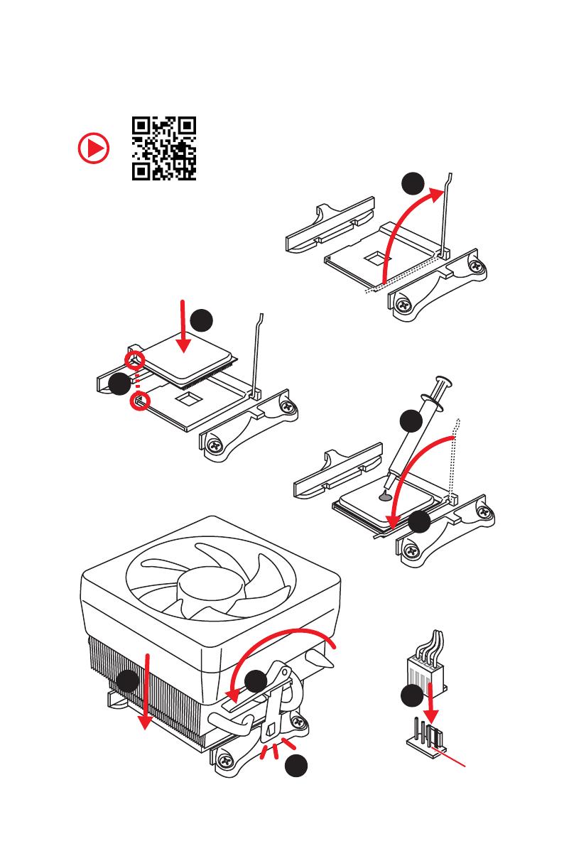
Installing a Processor/ Installation des Prozessors/ Installer un
processeur/ Установка процессора
1
2
3
6
4
5
7
8
9
CPU_FAN1
III
Quick Start
1
2
3
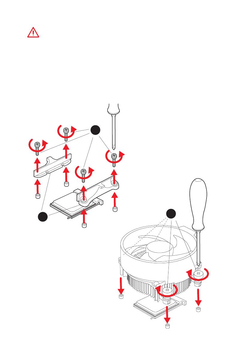
If you are installing the screw-type CPU heatsink, please follow the figure below
to remove the retention module first and then install the heatsink.
Wenn Sie einen CPU-Kühler mit Schraubenbefestigung einsetzen, folgen Sie bitte
den Anweisungen unten um das Retention-Modul zu entfernen und den Kühler zu
installieren.
Si vous voulez installer un ventirad pour processeur à vis, veuillez suivre les
instructions ci-dessous pour d’abord retirer le module de rétention puis installer le
ventirad.
В случае установки процессорного кулера с системой крепления на винтах,
следуйте указаниям на рисунке ниже для снятия пластикового модуля
крепления. Затем установите кулер.
V
Quick Start
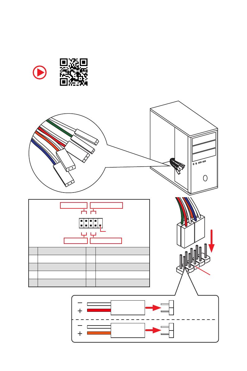
RESET SW
POWER SW
POWER LED+
POWER LED-
HDD LED
HDD LED
RESET SW
JFP1
HDD LED
HDD LED —
HDD LED +
POWER LED —
POWER LED +
POWER LED
Connecting the Front Panel Header/ Anschließen der
Frontpanel-Stiftleiste/ Connecter un connecteur du panneau
avant/ Подключение разъемов передней панели
1
2 10
9
+
+
+—
——
—
+
Power LED
HDD LED Reset Switch
Reserved
Power Switch
JFP1
1 HDD LED + 2 Power LED +
3 HDD LED — 4 Power LED —
5 Reset Switch 6 Power Switch
7 Reset Switch 8 Power Switch
9 Reserved 10 No Pin
VII
Quick Start
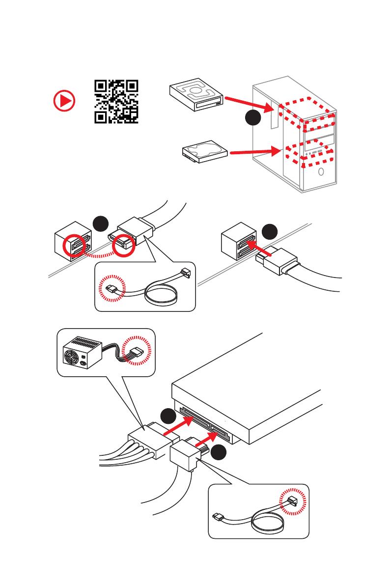
1
2
3
4
5
Installing SATA Drives/ Installation der SATA-Laufwerke/
Installer le disque dur SATA/ Установка дисков SATA
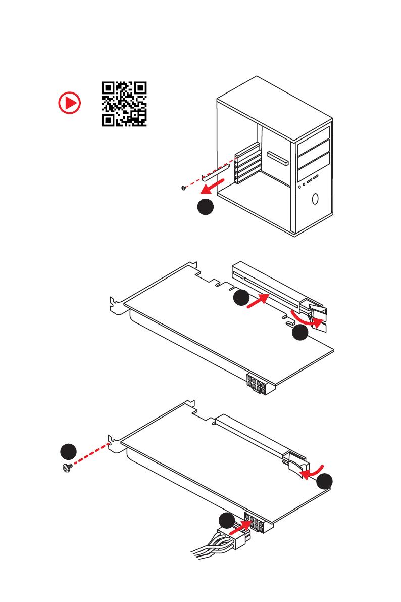
VIII
Quick Start
1
2
3
4
5
6
Installing a Graphics Card/ Einbau der Grafikkarte/ Installer
une carte graphique/ Установка дискретной видеокарты
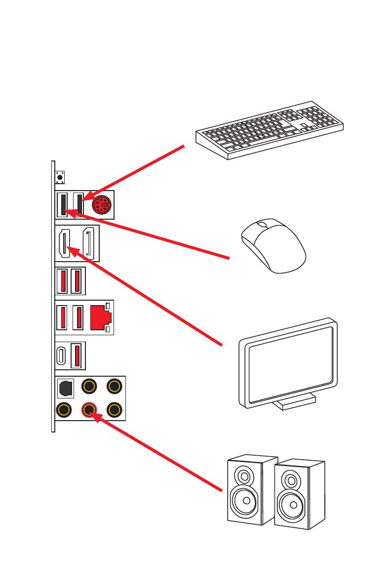
IX
Quick Start
Connecting Peripheral Devices/ Peripheriegeräte/
Connecter un périphérique anschliessen/ Подключение
периферийных устройств
Integrated Graphics Processing Unit
(iGPU)
X
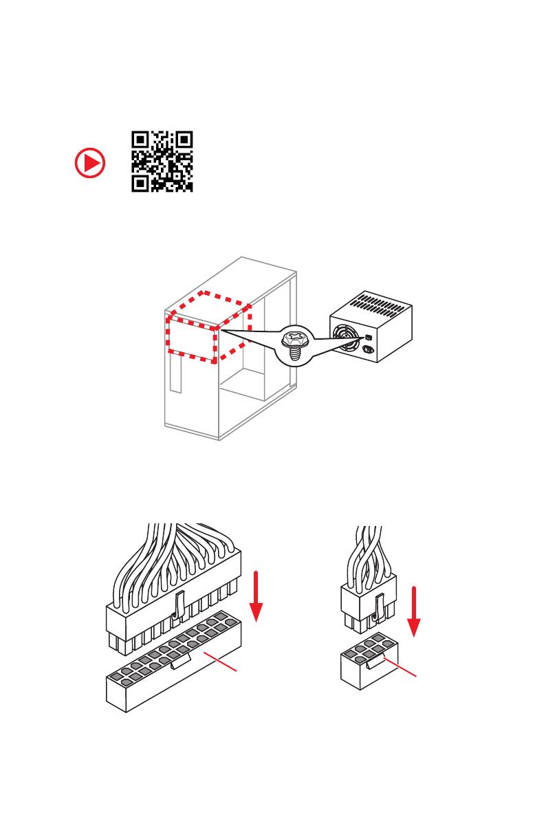
Quick Start
Connecting the Power Connectors/ Stromanschlüsse
anschliessen/ Connecter les câbles du module d’alimentation/
Подключение разъемов питания
ATX_PWR1
CPU_PWR1
4
Specifications
Continued from previous page
Storage
AMD
®
B450 Chipset
y 4x SATA 6Gb/s ports*
y 1x M.2 slot (M2_2, Key M)*
Supports PCIe 2.0 x4 2242/ 2260 /2280 storage devices
AMD
®
CPU
y 1x M.2 slot (M2_1, Key M)*
Supports PCIe 3.0 x4 (1st
,
2nd and 3rd Gen AMD
Ryzen™/ Ryzen™ with Radeon™ Vega Graphics and 2nd
Gen AMD Ryzen™ with Radeon™ Graphics) or PCIe 3.0 x2
(AMD
®
Athlon™ with Radeon™ Vega Graphics)and SATA
6Gb/s 2242/ 2260 /2280 storage devices
* PCI_E4 slot will be unavailable when an M.2 SSD is installed in the M2_2 slot.
RAID
AMD
®
B450 Chipset
y Supports RAID 0, RAID 1 and RAID 10 for SATA storage
devices
y Supports RAID 0 and RAID 1 for M.2 NVMe RAID
USB
AMD
®
B450 Chipset
y 1x USB 3.2 Gen2 (SuperSpeed USB 10Gbps) Type-C port on
the back panel
y 1x USB 3.2 Gen2 (SuperSpeed USB 10Gbps) Type-A port on
the back panel
y 2x USB 3.2 Gen1 (SuperSpeed USB) ports available through
the internal USB 3.2 Gen1 connector
y 6x USB 2.0 (High-speed USB) ports (2 Type-A ports on the
back panel, 4 ports available through the internal USB 2.0
connectors)
AMD
®
CPU
y 4x USB 3.2 Gen1 (SuperSpeed USB) Type-A ports on the
back panel
LAN 1x Realtek
®
RTL8111H-CG Gigabit LAN controller
Audio
y Realtek
®
ALC892 Codec
y 7.1-Channel High Definition Audio
y Supports S/PDIF output
Continued on next page

5
Specifications
Continued from previous page
Back Panel
Connectors
y 1x Flash BIOS Button
y 1x PS/2 keyboard/ mouse combo port
y 2x USB 2.0 Type-A ports
y 1x DisplayPort
y 1x HDMI
™
port
y 4x USB 3.2 Gen1 Type-A ports
y 1x LAN (RJ45) port
y 1x USB 3.2 Gen2 Type-A port
y 1x USB 3.2 Gen2 Type-C port
y 5x OFC audio jacks
y 1x Optical S/PDIF OUT connector
Internal Connectors
y 1x 24-pin ATX 12V power connector
y 1x 8-pin ATX 12V power connector
y 4x SATA 6Gb/s connectors
y 2x USB 2.0 connectors (support additional 4 USB 2.0 ports)
y 1x USB 3.2 Gen1 connector (support additional 2 USB 3.2
Gen1 ports)
y 1x 4-pin CPU fan connector
y 3x 4-pin system fan connectors
y 2x 5050 RGB LED strip 12V connectors
y 1x TPM module connector
y 1x Front panel audio connector
y 2x System panel connectors
y 1x Chassis Intrusion connector
y 1x Clear CMOS jumper
y 1x Serial Port connector
y 1x Parallel Port connector
I/O Controller NUVOTON NCT6797D Controller Chip
Hardware Monitor
y CPU/System temperature detection
y CPU/System fan speed detection
y CPU/System fan speed control
Continued on next page

6
Specifications
Continued from previous page
Form Factor
y m-ATX Form Factor
y 9.6 in. x 9.6 in. (24.4 cm x 24.4 cm)
BIOS Features
y 1x 256 Mb flash
y UEFI AMI BIOS
y ACPI 6.1, SM BIOS 2.8
y Multi-language
Software
y Drivers
y APP MANAGER
y COMMAND CENTER
y LIVE UPDATE 6
y MYSTIC LIGHT
y SUPER CHARGER
y GAMING APP
y RAMDISK
y X-BOOST
y SMART TOOL
y Open Broadcaster Software (OBS)
y Norton™ Internet Security Solution
y Google Chrome™, Google Toolbar, Google Drive
y CPU-Z MSI GAMING
Continued on next page
11
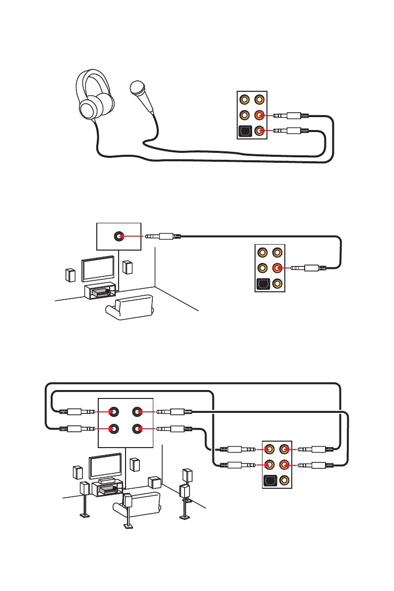
Rear I/O Panel
AUDIO INPUT
Rear Front
Side Center/
Subwoofer
Audio jacks to headphone and microphone diagram
Audio jacks to stereo speakers diagram
Audio jacks to 7.1-channel speakers diagram
AUDIO INPUT
12
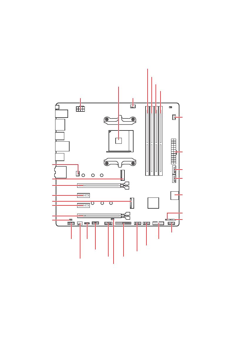
Overview of Components
Overview of Components
SATA▼1▲2
SATA4
SATA3
CPU_FAN1
JRGB2
JRGB1
PCI_E1
PCI_E2
PCI_E3
PCI_E4
JTPM1
JCOM1
CPU Socket
CPU_PWR1
JBAT1
M2_2
M2_1
DIMMA1
SYS_FAN1
DIMMA2
DIMMB1
DIMMB2
JUSB2
JUSB1
JLPT1
JUSB3
JFP2
JFP1
JAUD1
ATX_PWR1
SYS_FAN2
SYS_FAN3
JCI1
14
Overview of Components
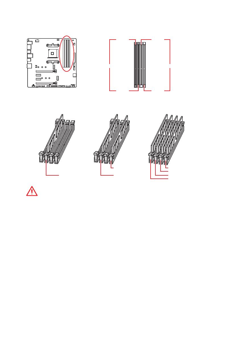
DIMM Slots
Important
y
Always insert memory modules in the DIMMA2 slot first.
y
Due to chipset resource usage, the available capacity of memory will be a little less
than the amount of installed.
y
Based on the processor specification, the Memory DIMM voltage below 1.35V is
suggested to protect the processor.
y
Some memory modules may operate at a lower frequency than the marked value
when overclocking due to the memory frequency operates dependent on its Serial
Presence Detect (SPD). Go to BIOS and find the DRAM Frequency to set the memory
frequency if you want to operate the memory at the marked or at a higher frequency.
y
It is recommended to use a more efficient memory cooling system for full DIMMs
installation or overclocking.
y
The stability and compatibility of installed memory module depend on installed CPU
and devices when overclocking.
y
Due to AM4 CPU/memory controller official specification limitation, the frequency of
memory modules may operate lower than the marked value under the default state.
Please refer www.msi.com for more information on compatible memory.
DIMMA1 DIMMB1
Channel A Channel B
DIMMA2 DIMMB2
Memory module installation recommendation
DIMMB2 DIMMB2
DIMMB1
DIMMA2 DIMMA2 DIMMA2
DIMMA1

17
Overview of Components
24
131
12
ATX_PWR1
1 +3.3V 13 +3.3V
2 +3.3V 14 -12V
3 Ground 15 Ground
4 +5V 16 PS-ON#
5 Ground 17 Ground
6 +5V 18 Ground
7 Ground 19 Ground
8 PWR OK 20 Res
9 5VSB 21 +5V
10 +12V 22 +5V
11 +12V 23 +5V
12 +3.3V 24 Ground
5
4 1
8
CPU_PWR1
1 Ground 5 +12V
2 Ground 6 +12V
3 Ground 7 +12V
4 Ground 8 +12V
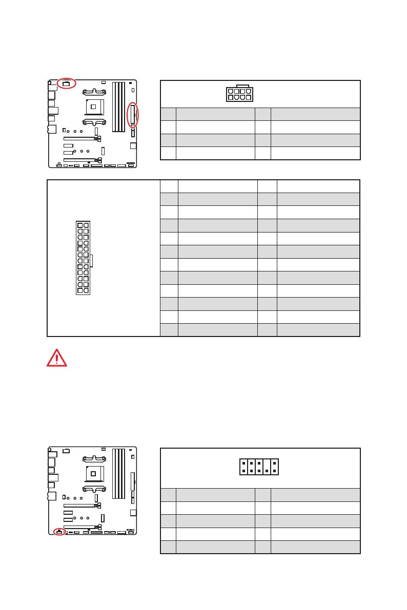
Important
Make sure that all the power cables are securely connected to a proper ATX power
supply to ensure stable operation of the motherboard.
CPU_PWR1, ATX_PWR1: Power Connectors
These connectors allow you to connect an ATX power supply.
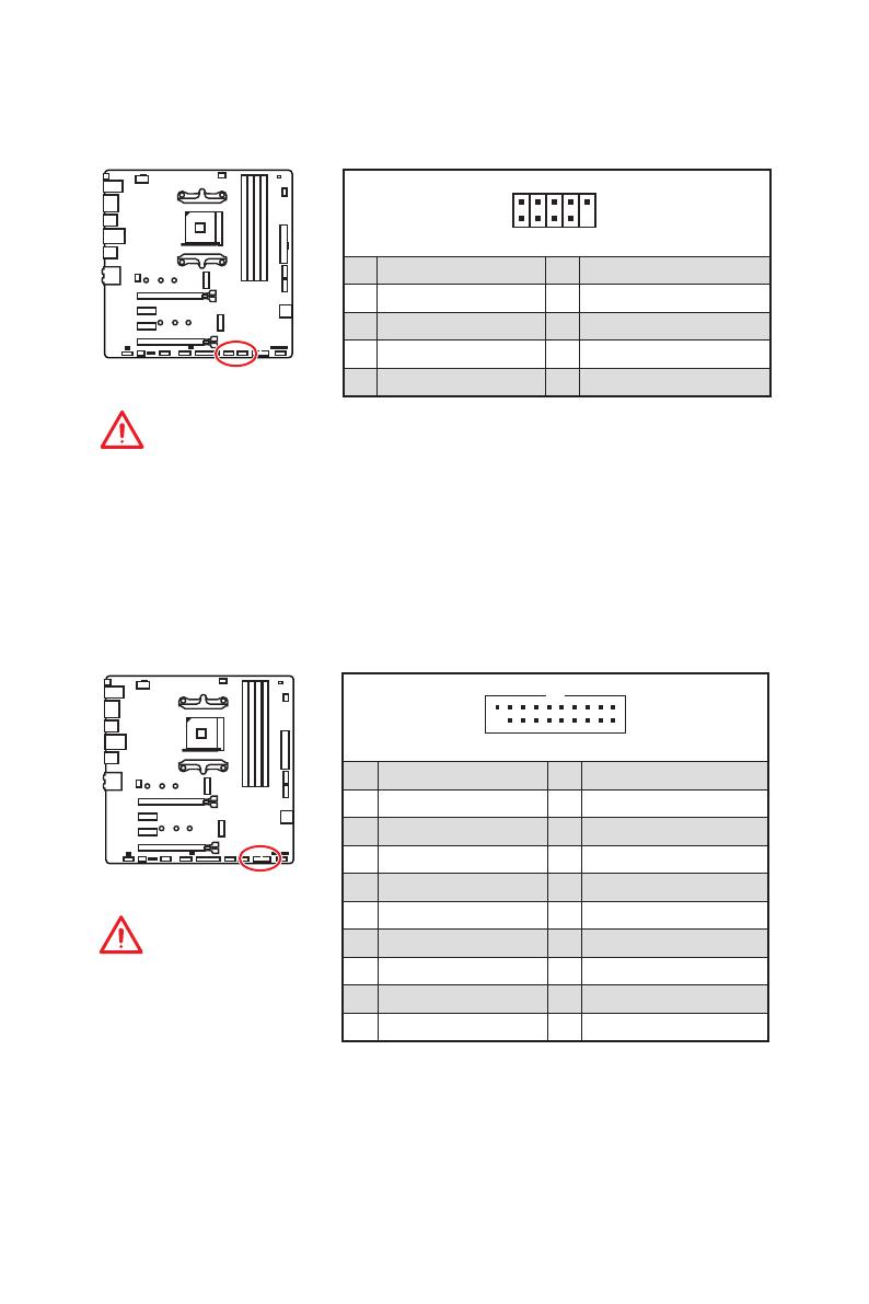
JAUD1: Front Audio Connector
This connector allows you to connect audio jacks on the front panel.
1
2 10
9
1 MIC L 2 Ground
3 MIC R 4 NC
5 Head Phone R 6 MIC Detection
7 SENSE_SEND 8 No Pin
9 Head Phone L 10 Head Phone Detection
18
Overview of Components
JUSB1~2: USB 2.0 Connectors
These connectors allow you to connect USB 2.0 ports on the front panel.
1
2 10
9
1 VCC 2 VCC
3 USB0- 4 USB1-
5 USB0+ 6 USB1+
7 Ground 8 Ground
9 No Pin 10 NC
Important
y
Note that the VCC and Ground pins must be connected correctly to avoid possible
damage.
y
In order to recharge your iPad,iPhone and iPod through USB ports, please install
MSI
®
SUPER CHARGER utility.
JUSB3: USB 3.2 Gen1 Connector
This connector allows you to connect USB 3.2 Gen1 ports on the front panel.
Important
Note that the Power and
Ground pins must be
connected correctly to avoid
possible damage.
1 10
1120
1 Power 11 USB2.0+
2 USB3_RX_DN 12 USB2.0-
3 USB3_RX_DP 13 Ground
4 Ground 14 USB3_TX_C_DP
5 USB3_TX_C_DN 15 USB3_TX_C_DN
6 USB3_TX_C_DP 16 Ground
7 Ground 17 USB3_RX_DP
8 USB2.0- 18 USB3_RX_DN
9 USB2.0+ 19 Power
10 NC 20 No Pin
20
Overview of Components
1
2 26
25
1 RSTB# 2 AFD# 3 PRND0
4 ERR# 5 PRND1 6 PINIT#
7 PRND2 8 LPT_SLIN# 9 PRND3
10 Ground 11 PRND4 12 Ground
13 PRND5 14 Ground 15 PRND6
16 Ground 17 PRND7 18 Ground
19 ACK# 20 Ground 21 BUSY
22 Ground 23 PE 24 Ground
25 SLCT 26 No Pin
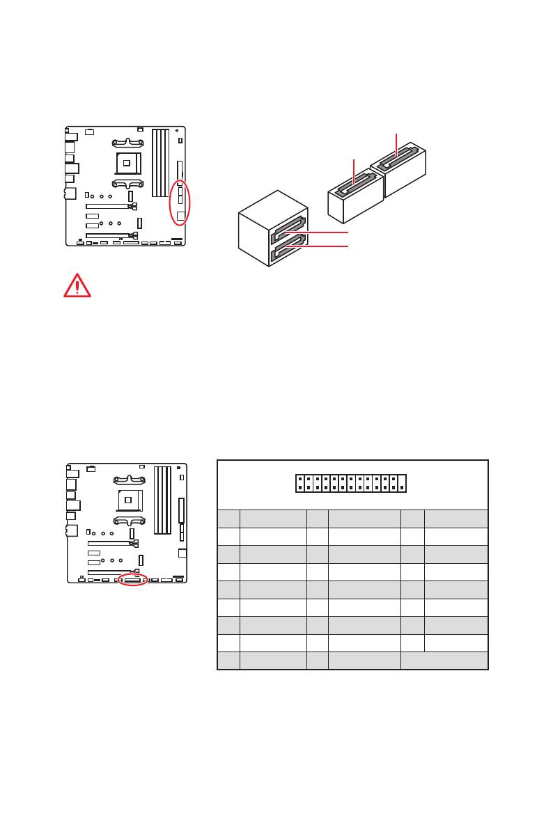
JLPT1: Parallel Port Connector
This connector allows you to connect the optional parallel port with bracket.
SATA1~4: SATA 6Gb/s Connectors
These connectors are SATA 6Gb/s interface ports. Each connector can connect to one
SATA device.
SATA1
SATA3
SATA2
SATA4
Important
y
Please do not fold the SATA cable at a 90-degree angle. Data loss may result during
transmission otherwise.
y
SATA cables have identical plugs on either sides of the cable. However, it is
recommended that the flat connector be connected to the motherboard for space
saving purposes.

6
Spécifications
Suite du tableau de la page précédente
Moniteur système
y Détection de la température du CPU et du système
y Détection de la vitesse du ventilateur du CPU et du
système
y Contrôle de la vitesse du ventilateur du CPU et du système
Dimensions
y Format m-ATX
y 24,4 cm x 24,4 cm (9,6” x 9,6”)
Fonctions BIOS
y 1 x flash 256 Mb
y UEFI AMI BIOS
y ACPI 6.1, SM BIOS 2.8
y Multilingue
Logiciel
y Pilotes
y APP MANAGER
y COMMAND CENTER
y LIVE UPDATE 6
y MYSTIC LIGHT
y SUPER CHARGER
y GAMING APP
y RAMDISK
y X-BOOST
y SMART TOOL
y Open Broadcaster Software (OBS)
y Norton™ Internet Security Solution
y Google Chrome™, Google Toolbar, Google Drive
y CPU-Z MSI GAMING
Suite du tableau sur la page suivante

12
Vue d’ensemble des composants
Vue d’ensemble des composants
SATA▼1▲2
SATA4
SATA3
CPU_FAN1
JRGB2
JRGB1
PCI_E1
PCI_E2
PCI_E3
PCI_E4
JTPM1
JCOM1
Socket
processeur
CPU_PWR1
JBAT1
M2_2
M2_1
DIMMA1
SYS_FAN1
DIMMA2
DIMMB1
DIMMB2
JUSB2
JUSB1
JLPT1
JUSB3
JFP2
JFP1
JAUD1
ATX_PWR1
SYS_FAN2
SYS_FAN3
JCI1
17
Vue d’ensemble des composants
24
131
12
ATX_PWR1
1 +3.3V 13 +3.3V
2 +3.3V 14 -12V
3 Ground 15 Ground
4 +5V 16 PS-ON#
5 Ground 17 Ground
6 +5V 18 Ground
7 Ground 19 Ground
8 PWR OK 20 Res
9 5VSB 21 +5V
10 +12V 22 +5V
11 +12V 23 +5V
12 +3.3V 24 Ground
5
4 1
8
CPU_PWR1
1 Ground 5 +12V
2 Ground 6 +12V
3 Ground 7 +12V
4 Ground 8 +12V
Important
Veuillez vous assurer que tous les câbles d’alimentation sont branchés aux
connecteurs adéquats afin de garantir une opération stable de la carte mère.
CPU_PWR1, ATX_PWR1 : Connecteurs d’alimentation
Ces connecteurs vous permettent de relier une alimentation ATX.
JAUD1 : Connecteur audio avant
Ce connecteur se lie aux jacks audio du panneau avant.
1
2 10
9
1 MIC L 2 Ground
3 MIC R 4 NC
5 Head Phone R 6 MIC Detection
7 SENSE_SEND 8 No Pin
9 Head Phone L 10 Head Phone Detection
/
на других языках
Похожие инструкции
Другие инструкции

I
Quick Start
Quick Start
Thank you for purchasing the MSI
®
B450M MORTAR motherboard.
This Quick Start section provides demonstration diagrams about
how to install your computer. Some of the installations also provide
video demonstrations. Please link to the URL to watch it with the web
browser on your phone or tablet. You may have even link to the URL
by scanning the QR code.
Kurzanleitung
Danke, dass Sie das MSI
®
B450M MORTAR Motherboard gewählt
haben. Dieser Abschnitt der Kurzanleitung bietet eine Demo zur
Installation Ihres Computers. Manche Installationen bieten auch
die Videodemonstrationen. Klicken Sie auf die URL, um diese
Videoanleitung mit Ihrem Browser auf Ihrem Handy oder Table
anzusehen. Oder scannen Sie auch den QR Code mit Ihrem Handy,
um die URL zu öffnen.
Présentation rapide
Merci d’avoir choisi la carte mère MSI
®
B450M MORTAR. Ce manuel
fournit une rapide présentation avec des illustrations explicatives
qui vous aideront à assembler votre ordinateur. Des tutoriels vidéo
sont disponibles pour certaines étapes. Cliquez sur le lien fourni
pour regarder la vidéo sur votre téléphone ou votre tablette. Vous
pouvez également accéder au lien en scannant le QR code qui lui est
associé.
Быстрый старт
Благодарим вас за покупку материнской платы MSI
®
B450M
MORTAR. В этом разделе представлена информация,
которая поможет вам при сборке комьютера. Для некоторых
этапов сборки имеются видеоинструкции. Для просмотра
видео, необходимо открыть соответствующую ссылку в
веб—браузере на вашем телефоне или планшете. Вы также
можете выполнить переход по ссылке, путем сканирования
QR-кода.
Задняя панель портов ввода/ вывода
PS/2
Кнопка
USB 2.0
Flash BIOS
USB 2.0/
Порт Flash BIOS
y Кнопка/Порт Flash BIOS — Обратитесь к странице 26 для получения
информации об обновлении BIOS при помощи кнопки Flash BIOS.
Таблица состояний индикатора порта LAN
Подключение/ Работа
индикатора
Состояние
Описание
Выкл.
Не подключен
Желтый
Подключен
Мигает
Передача данных
Конфигурация портов Аудио
DisplayPort
USB 3.2 Gen1
USB 3.2 Gen1
LAN
USB 3.2 Gen2
Оптический S/PDIF-Out
USB 3.2 Gen2 Type-C
Скорость передачи данных
Состояние
Описание
Выкл.
10 Мбит/с подключение
Зеленый
100 Мбит/с подключение
Оранжевый
1 Гбит/с подключение
Порты Аудио
Выход центральной
колонки/ сабвуфера
Тыловые колонки
Линейный вход/ Выход
боковых колонок
Линейный выход/ Выход
фронтальных колонок
Микрофонный вход
(●: подключен, Пусто: не подключен)
Задняя панель портов ввода/ вывода
Порты Аудио
Канал
2
4
6
8
●
●
●
●
●
●
●
●
●
●
9