- Manuals
- Brands
- MSI Manuals
- Motherboard
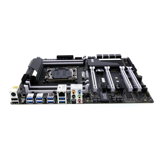
- X99A SLI KRAIT EDITION
- User manual
-
Contents
-
Table of Contents
-
Bookmarks
Quick Links
Preface
X99A SLI Krait Edition
Motherboard
G52-78851XH
Related Manuals for MSI MSI X99A SLI KRAIT EDITION
Summary of Contents for MSI MSI X99A SLI KRAIT EDITION
-
Page 1
Preface X99A SLI Krait Edition Motherboard G52-78851XH… -
Page 2: Preface
Copyright Notice The material in this document is the intellectual property of MICRO-STAR INTERNATIONAL. We take every care in the preparation of this document, but no guarantee is given as to the correctness of its contents. Our products are under continual improvement and we reserve the right to make changes without notice.
-
Page 3: Smartphone Application
If a problem arises with your system and no solution can be obtained from the user’s manual, please contact your place of purchase or local distributor. Alternatively, please try the following help resources for further guidance. Visit the MSI website for technical guide, BIOS updates, driver updates, and other information: http://www.msi.com/service/download/ Contact our technical staff at: http://register.msi.com/…
-
Page 4: Safety Instructions
Safety Instructions ■ Always read the safety instructions carefully. ■ Keep this User’s Manual for future reference. ■ Keep this equipment away from humidity. ■ Lay this equipment on a reliable flat surface before setting it up. ■ The openings on the enclosure are for air convection hence protects the equipment from overheating.
-
Page 5: Fcc-B Radio Frequency Interference Statement
FCC-B Radio Frequency Interference Statement This equipment has been tested and found to comply with the limits for a Class B digital device, pursuant to Part 15 of the FCC Rules. These limits are designed to provide reasonable protection against harmful interference in a residential installation. This equipment generates, uses and can radiate radio frequency energy and, if not installed and used in accordance with the instructions, may cause harmful interference to radio communications.
-
Page 6: Radiation Exposure Statement
Radiation Exposure Statement This equipment complies with FCC radiation exposure limits set forth for an uncontrolled environment. This equipment and its antenna should be installed and operated with minimum distance 20 cm between the radiator and your body. This equipment and its antenna must not be co-located or operating in conjunction with any other antenna or transmitter.
-
Page 7: Battery Information
Replace only with the same or equivalent type recommended by the manufacturer. Chemical Substances Information In compliance with chemical substances regulations, such as the EU REACH Regulation (Regulation EC No. 1907/2006 of the European Parliament and the Council), MSI provides the information of chemical substances in products at: http://www.msi.com/html/popup/csr/evmtprtt_pcm.html Preface…
-
Page 8: Weee (Waste Electrical And Electronic Equipment) Statement
MSI will comply with the product take back requirements at the end of life of MSI-branded products that are sold into the EU. You can return these products to local collection points.
-
Page 9
MSI će poštovati zahtev o preuzimanju ovakvih proizvoda kojima je istekao vek trajanja, koji imaju MSI oznaku i koji su prodati u EU. Ove proizvode možete vratiti na lokalnim mestima za prikupljanje. -
Page 10
MSI si adeguerà a tale Direttiva ritirando tutti i prodotti marchiati MSI che sono stati venduti all’interno dell’Unione Europea alla fine del loro ciclo di vita. -
Page 11: 日本Jis C 0950材質宣言
2008 № 1057. Việt Nam RoHS Kể từ ngày 01/12/2012, tất cả các sản phẩm do công ty MSI sản xuất tuân thủ Thông tư số 30/2011/TT-BCT quy định tạm thời về giới hạn hàm lượng cho phép của một số…
-
Page 12: Table Of Contents
CONTENTS ▍ Preface ………………….i Copyright Notice …………………..ii Trademarks ………………….ii Revision History …………………..ii Smartphone Application ………………iii Technical Support ………………..iii Safety Instructions ………………..iv FCC-B Radio Frequency Interference Statement ……….. v CE Conformity ………………….v Radiation Exposure Statement …………….vi European Community Compliance Statement …………vi Taiwan Wireless Statements ……………….vi Japan VCCI Class B Statement …………….vi Korea Warning Statements ………………vi…
-
Page 13
Quad-Channel mode ………………. 1-18 Mounting Screw Holes ………………1-19 Power Supply ………………… 1-20 JPWR1~3: ATX Power Connectors …………. 1-20 Expansion Slots ………………..1-21 PCI_E1~6: PCIe Expansion Slots …………..1-21 PCIe Bandwidth Table …………….1-21 Video/ Graphics Cards ………………1-22 Single Video Card Installation …………..1-22 Internal Connectors ……………….. -
Page 14
Power Connectors Installation …………….2-7 SATA HDD Installation ………………2-9 M.2 module Installation ………………2-10 Front Panel Connector Installation …………..2-11 JFP1 Connector Installation …………….. 2-11 Front Panel Audio Connector Installation ………… 2-11 Peripheral Connector Installation …………… 2-12 USB2.0 Connector Installation …………..2-12 USB3.0 Connector Installation ………….. -
Page 15: Chapter 1 Getting Started
Chapter 1 Getting Started Thank you for choosing the X99A SLI Krait Edition Series (MS-7885 v4.X) ATX motherboard. The X99A SLI Krait Edition Series motherboards are based on Intel X99 chipset for optimal system efficiency. Designed to fit the ® advanced Intel LGA2011-3 processor, the X99A SLI Krait Edition Series ®…
-
Page 16: Packing Contents
Packing Contents Drivers & Utilities Motherboard I/O Shield Motherboard Disc User Guide SATA Cable SLI Cable M-Connector * These pictures are for reference only and may vary without notice. * The packing contents may vary according to the model you purchased. Getting Started…
-
Page 17: Assembly Precautions
Assembly Precautions ■ The components included in this package are prone to damage from electrostatic discharge (ESD). Please adhere to the following instructions to ensure successful computer assembly. ■ Always turn off the power supply and unplug the power cord from the power outlet before installing or removing any computer component.
-
Page 18: Motherboard Specifications
USB 2.0 connectors) ■ AsMedia ASM1142 — 2x USB 3.1 ports on the back panel ■ VIA VL805 — 4x USB 3.0 ports on the back panel * Internal JUSB1 connector supports MSI Super Charger. Audio ■ Realtek ALC1150 Codec ®…
-
Page 19
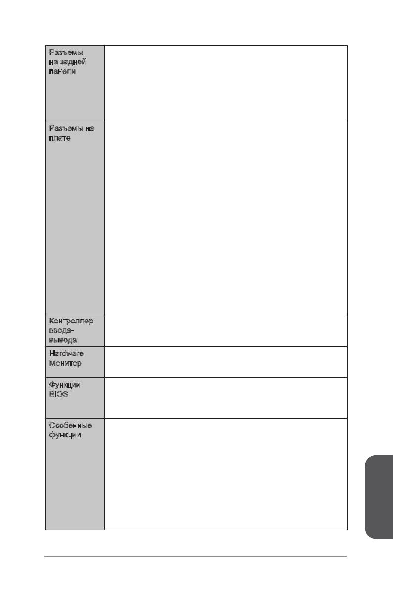
Back Panel ■ 1x PS/2 port ■ 2x USB 2.0 ports Connectors ■ 1x Clear CMOS button ■ 6x USB 3.0 ports ■ 2x USB 3.1 ports ■ 1x Optical S/PDIF OUT connector ■ 1x LAN (RJ45) port ■ 5x OFC audio jacks Internal ■… -
Page 20
■ Total Fan Control ■ Super Charger ■ Smart Utilities ■ Command Center ■ ECO Center Software ■ Drivers ■ MSI — Command Center — Live Update 6 — Smart Utilities — Super Charger — Fast Boot — ECO Center ■… -
Page 21: Block Diagram
Block Diagram 4 Channel DDR4 Memory Haswell-E Processor LGA2011-3 CPU Switch PCIe x1 slot PCI Express Bus Switch PCI Express Bus Intel I210 DMI 2.0 1 x M.2 PCIe x1 slot Switch 1 x SATA Express 10 x SATA 6Gb/s (2 ports reserved for SATA Express) X99 PCH 4 x USB 3.0…
-
Page 22: Connectors Quick Guide
Connectors Quick Guide CPU Socket DIMM8 CPUFAN1 DIMM1 JPWR2 DIMM7 SYSFAN1 DIMM2 CPUFAN2 DIMM6 DIMM3 JPWR3 DIMM5 DIMM4 Back Panel JPWR1 JUSB1 SYSFAN3 M2_1 PCI_E1 JUSB2 PCI_E2 SATA1_2 PCI_E3 SATA3_4 PCI_E4 SATA7_8 PCI_E5 SATA9_10 JSLOW1 JTPM1 SLOW_1 PCI_E6 JCI1 JBAT1 BIOS1 JAUD1 SYSFAN2…
-
Page 23
Connectors Reference Guide Port Name Port Type Page Back Panel 1-10 BIOS1 Multi-BIOS Switch 1-33 CPUFAN1~2,SYSFAN1~3 Fan Power Connectors 1-28 FASTB1 GO2BIOS Button 1-31 JAUD1 Front Panel Audio Connector 1-29 JBAT1 Clear CMOS Jumper 1-32 JCI1 Chassis Intrusion Connector 1-27 JFP1, JFP2 System Panel Connectors 1-25… -
Page 24: Back Panel Quick Guide
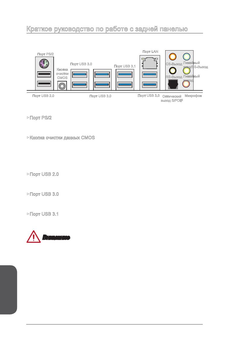
Back Panel Quick Guide Clear CMOS Button PS/2 Port LAN Port CS-Out Line-In/ SS-Out RS-Out Line-Out Optical USB 2.0 Port USB 3.0 Port USB 3.0 Port USB 3.1 Port USB 3.0 Port S/PDIF-Out ▶ PS/2 Port A PS/2 DIN connector is for a PS/2 mouse/keyboard.
-
Page 25
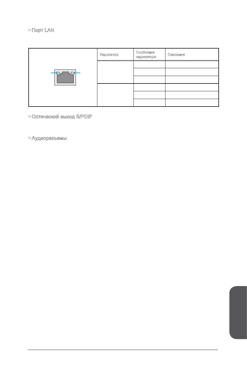
▶ Optical S/PDIF-Out This S/PDIF (Sony & Philips Digital Interconnect Format) connector is provided for digital audio transmission to external speakers through an optical fiber cable. ▶ Audio Ports These connectors are used for audio devices. ■ Line-In/ SS-Out: Line-In is used for connecting external audio outputting devices. -
Page 26: Cpu (Central Processing Unit)
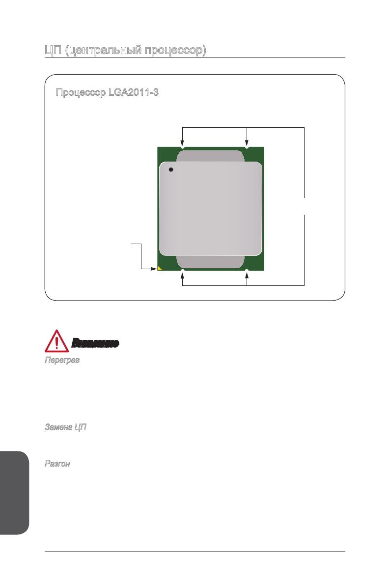
This motherboard is designed to support overclocking. Before attempting to overclock, please make sure that all other system components can tolerate overclocking. Any attempt to operate beyond product specifications is not recommend. MSI does not guarantee the damages or risks caused by inadequate operation beyond product specifications.
-
Page 27: Cpu & Heatsink Installation
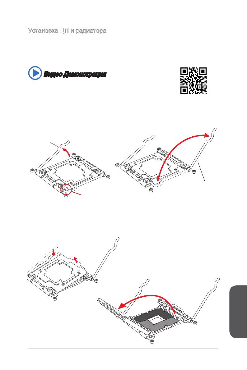
CPU & Heatsink Installation When installing a CPU, always remember to install a CPU heatsink. A CPU heatsink is necessary to prevent overheating and maintain system stability. Follow the steps below to ensure correct CPU and heatsink installation. Wrong installation can damage both the CPU and the motherboard.
-
Page 28
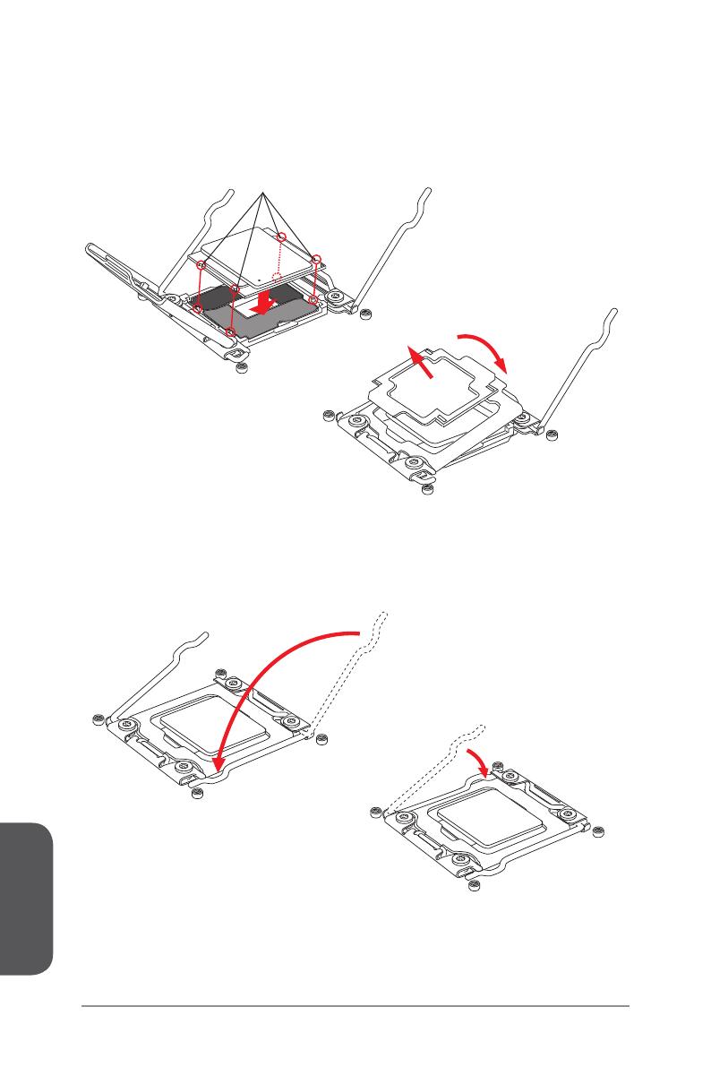
5. Line up the CPU to fit the CPU socket. Be sure to hold the CPU by the base with the metal contacts facing downward. The alignment keys on the CPU will line up with the edges of the CPU socket to ensure a correct fit. 6. -
Page 29
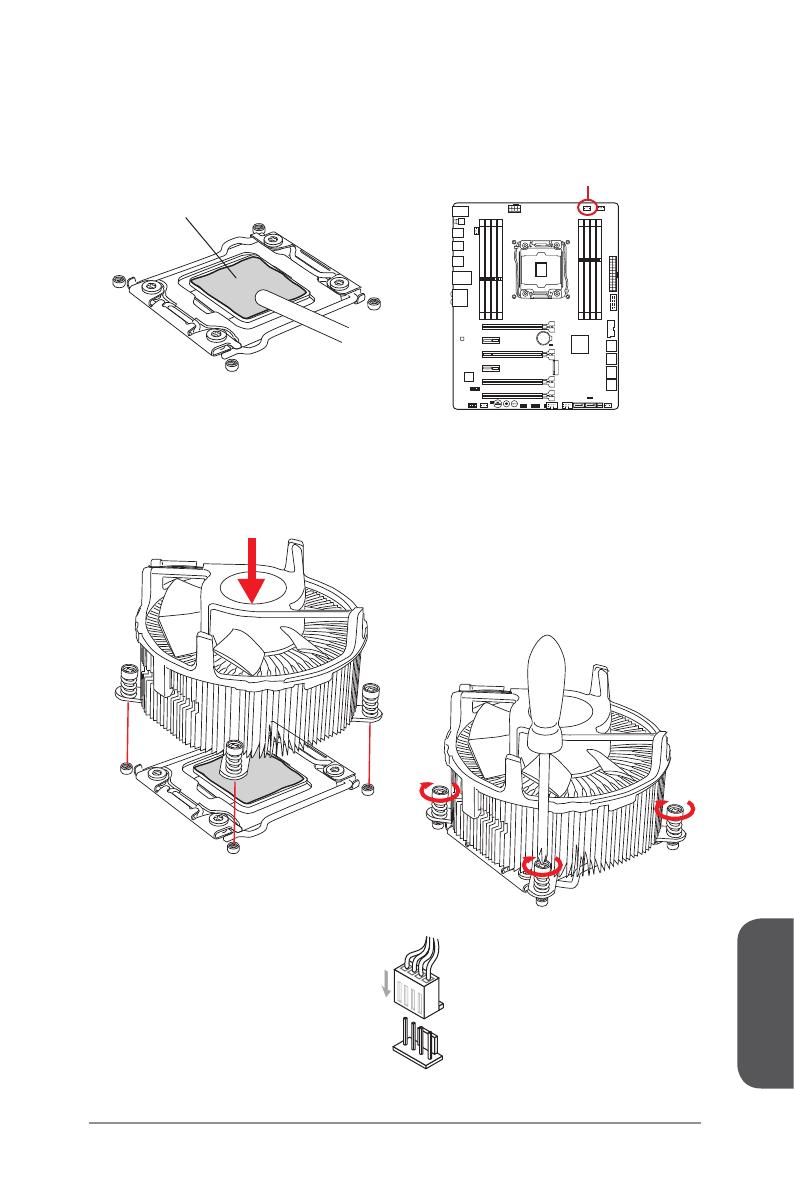
9. Evenly spread a thin layer of thermal paste (or thermal tape) on the top of the CPU. This will help in heat dissipation and prevent CPU overheating. 10. Locate the CPU fan connector on the mainboard. CPUFAN1 Thermal paste 11. -
Page 30: Memory
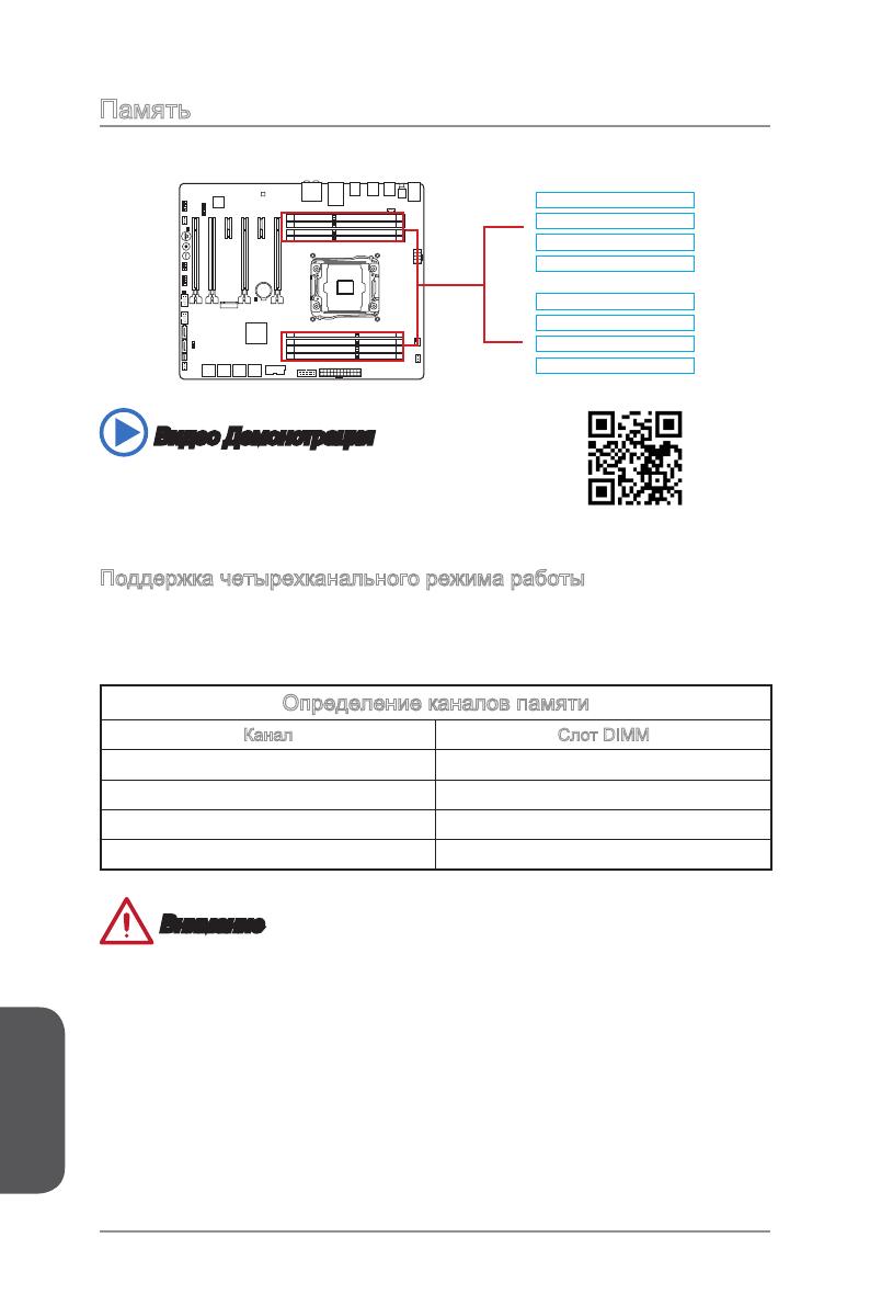
Memory These DIMM slots are used for installing memory modules. DIMM1 DIMM2 DIMM3 DIMM4 DIMM8 DIMM7 DIMM6 DIMM5 Video Demonstration Watch the video to learn how to install memory. http://youtu.be/T03aDrJPyQs Up to Quad-Channel mode This mainboard supports up to four memory channels. Two DIMM slots provide a single channel.
-
Page 31: Suggestions For Multi-Channel Mode Population Rule
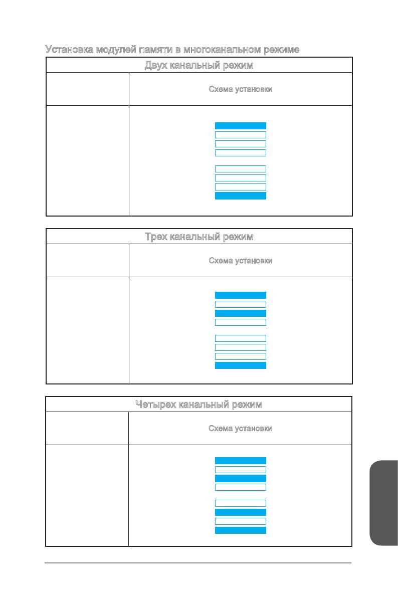
Suggestions for Multi-Channel mode population rule Dual-Channel mode Installed DIMMs Diagram (2 memory modules) DIMM1 DIMM2 DIMM3 DIMM4 DIMM1, DIMM5 DIMM8 DIMM7 DIMM6 DIMM5 Triple-Channel mode Installed DIMMs Diagram (3 memory modules) DIMM1 DIMM2 DIMM3 DIMM4 DIMM1, DIMM3, DIMM5 DIMM8 DIMM7 DIMM6 DIMM5…
-
Page 32: Quad-Channel Mode
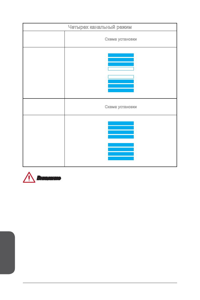
Quad-Channel mode Installed DIMMs Diagram (6 memory modules) DIMM1 DIMM2 DIMM3 DIMM4 DIMM1, DIMM2, DIMM3, DIMM5, DIMM6, DIMM7 DIMM8 DIMM7 DIMM6 DIMM5 Installed DIMMs Diagram (8 memory modules) DIMM1 DIMM2 DIMM3 DIMM1, DIMM2, DIMM4 DIMM3, DIMM4, DIMM5, DIMM6, DIMM8 DIMM7, DIMM8 DIMM7 DIMM6 DIMM5…
-
Page 33: Mounting Screw Holes
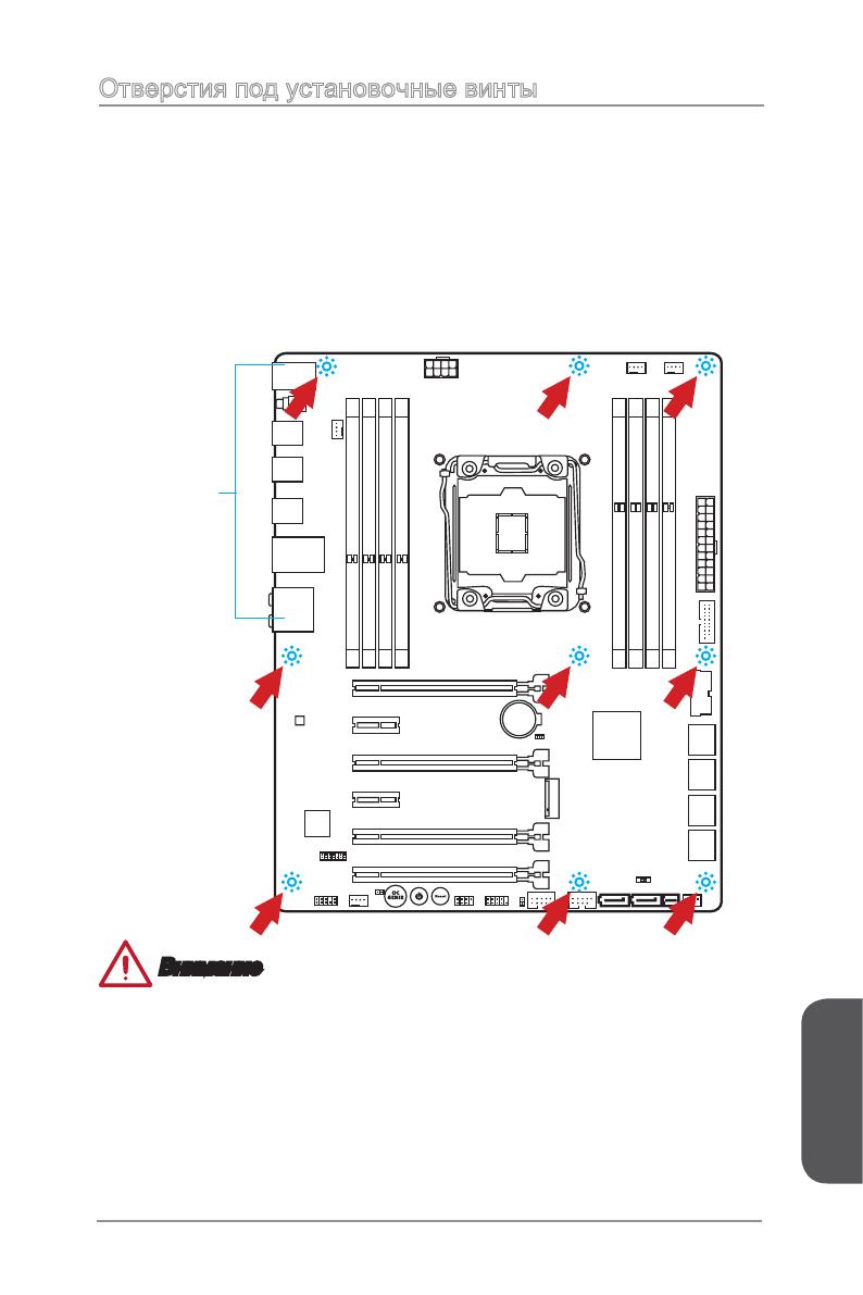
Mounting Screw Holes When installing the motherboard, first install the necessary mounting stands required for an motherboard on the mounting plate in your computer case. If there is an I/O back plate that came with the computer case, please replace it with the I/O backplate that came with the motherboard package.
-
Page 34: Power Supply
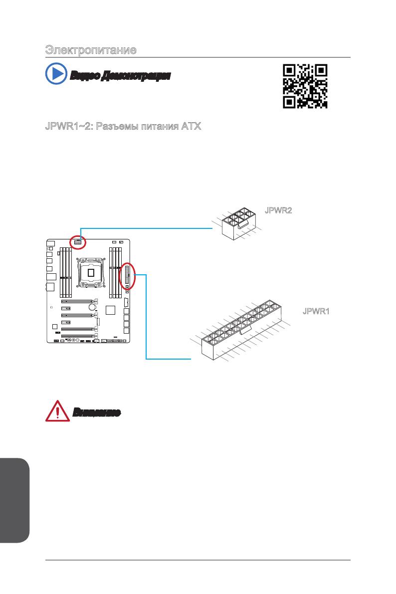
Power Supply Video Demonstration Watch the video to learn how to install power supply connectors. http://youtu.be/gkDYyR_83I4 JPWR1~3: ATX Power Connectors These connectors allow you to connect an ATX power supply. To connect the ATX power supply, align the power supply cable with the connector and firmly press the cable into the connector.
-
Page 35: Expansion Slots
Expansion Slots This motherboard contains numerous slots for expansion cards, such as discrete graphics or audio cards. PCI_E1~6: PCIe Expansion Slots The PCIe slot supports the PCIe interface expansion card. PCIe 3.0 x16 Slot PCIe 2.0 x1 Slot PCIe Bandwidth Table ■…
-
Page 36: Video/ Graphics Cards
Adding on one or more discrete video cards will significantly boost the system’s graphics performance. For best compatibility, MSI graphics cards are recommended. Video Demonstration Watch the video to learn how to install a graphics card on PCIe x16 slot with butterfly lock.
-
Page 37: Internal Connectors
Internal Connectors SATA1~10: SATA Connectors This connector is a high-speed SATA interface port. Each connector can connect to one SATA device. SATA devices include disk drives (HDD), solid state drives (SSD), and optical drives (CD/ DVD/ Blu-Ray). Video Demonstration Watch the video to learn how to Install SATA HDD. http://youtu.be/RZsMpqxythc SATA2 SATA1…
-
Page 38: Sata_Ex1: Sata Express Connector
SATA_EX1: SATA Express Connector The SATA Express, a new high performance storage interface, supports to connect 1 SATA Express device with up to 10 Gb/s transfer rate. Connects the SATA Express device to this 3-in-1 connector by a SATA Express cable. M2_1: M.2 Port The M.2 port supports either M.2 SATA 6Gb/s module or M.2 PCIe module.
-
Page 39: Jfp1, Jfp2: System Panel Connectors
JFP1, JFP2: System Panel Connectors These connectors connect to the front panel switches and LEDs. The JFP1 connector is compliant with the Intel Front Panel I/O Connectivity Design Guide. When ® installing the front panel connectors, please use the optional M-Connector to simplify installation.
-
Page 40: Jusb1~2: Usb 3.0 Expansion Connector
• Please only connect one device per USB port to ensure stable charging. • Super-Charger Technology is only available on select MSI motherboard models. Please refer to the MSI website to check if your motherboard has Super-Charger technology. • For iPad, JUSB1 (red mark) can still charge iPad in S3, S4, S5 state.
-
Page 41: Jusb3~4: Usb 2.0 Expansion Connectors
JUSB3~4: USB 2.0 Expansion Connectors This connector is designed for connecting high-speed USB peripherals such as USB HDDs, digital cameras, MP3 players, printers, modems, and many others. Important Note that the VCC and GND pins must be connected correctly to avoid possible damage.
-
Page 42: Cpufan1~2,Sysfan1~3: Fan Power Connectors
CPUFAN1~2,SYSFAN1~3: Fan Power Connectors The fan power connectors support system cooling fans with +12V. If the motherboard has a System Hardware Monitor chipset on-board, you must use a specially designed fan with a speed sensor to take advantage of the CPU fan control. Remember to connect all system fans.
-
Page 43: Jaud1: Front Panel Audio Connector
JAUD1: Front Panel Audio Connector This connector allows you to connect the front audio panel located on your computer case. This connector is compliant with the Intel Front Panel I/O Connectivity Design ® Guide. JTPM1: TPM Module Connector This connector connects to a TPM (Trusted Platform Module). Please refer to the TPM security platform manual for more details and usages.
-
Page 44: Buttons
BIOS section of the manual for instructions on how to turn off OC Genie from the BIOS. • The usage of OC Genie is at the user’s own risk. Overclocking is never guaranteed by MSI. • To ensure successfully OC Genie usage, MSI components are recommended. Getting Started 1-30…
-
Page 45: Power1: Power Button
This reset button is used to reset the system. Press the button to reset the system. FASTB1: GO2BIOS Button If you enable the «MSI Fast Boot» feature in BIOS, the keyboard will be unavaiable and entering BIOS Setup by pressing DEL will not function. Therefore, you can press this button to enter BIOS Setup after reboot.
-
Page 46: Jumpers
Jumpers JBAT1: Clear CMOS Jumper There is CMOS RAM onboard that is external powered from a battery located on the motherboard to save system configuration data. With the CMOS RAM, the system can automatically boot into the operating system (OS) every time it is turned on. If you want to clear the system configuration, set the jumpers to clear the CMOS RAM.
-
Page 47: Switch
Preparation: 1. Prepare a bootable USB flash drive. 2. Download the latest BIOS file from the MSI official website at www.msi.com, and then decompress the file. 3. Copy the AFUDE238.exe and the BIOS file to the bootable USB flash drive BIOS recovery steps: 1.
-
Page 48: Oc_Sw1: Oc Genie Mode Switch
OC_SW1: OC Genie Mode Switch This swtich provides two overclocking modes (Gear 1 and Gear 2) for OC Genie operation. When you press the OC Genie button, the overclocking procedure will be performed according to the setting of this switch. The Gear 1 Mode is the default setting.
-
Page 49: Led Status Indicators
LED Status Indicators Thermal Warning LED BIOS A LED OC Switch Gear 1 LED MSI LED OC Switch Gear 2 LED BIOS B LED LED Status Table The following table describes the status of LED indicators. LED Status Description OC Switch Gear 1…
-
Page 50: Drivers And Utilities
After you install the operating system you will need to install drivers to maximize the performance of the new computer you just built. MSI motherboard comes with a Driver Disc. Drivers allow the computer to utilize your motherboard more efficiently and take advantage of any special features we provide.
-
Page 51
Chapter 2 Quick Installation This chapter provides demonstration diagrams about how to install your computer. Some of the installations also provide video demonstrations. Please link to the URL to watch it with the web browser on your phone or tablet. You may have even link to the URL by scanning the QR code. Important The diagrams in this chapter are for reference only and may vary from the product you purchased. -
Page 52
CPU Installation http://youtu.be/WPhyn2C5mgs Quick Installation… -
Page 53: Chapter 2 Quick Installation
Quick Installation…
-
Page 54: Memory Installation
Memory Installation http://youtu.be/T03aDrJPyQs Quick Installation…
-
Page 55: Motherboard Installation
Motherboard Installation Quick Installation…
-
Page 56
Quick Installation… -
Page 57: Power Connectors Installation
Power Connectors Installation http://youtu.be/gkDYyR_83I4 Quick Installation…
-
Page 58
Quick Installation… -
Page 59: Sata Hdd Installation
SATA HDD Installation http://youtu.be/RZsMpqxythc Quick Installation…
-
Page 60: M.2 Module Installation
M.2 module Installation http://youtu.be/JCTFABytrYA 30° Quick Installation 2-10…
-
Page 61: Front Panel Connector Installation
Front Panel Connector Installation JFP1 Connector Installation http://youtu.be/DPELIdVNZUI Front Panel Audio Connector Installation 2-11 Quick Installation…
-
Page 62: Peripheral Connector Installation
Peripheral Connector Installation USB2.0 Connector Installation USB3.0 Connector Installation Quick Installation 2-12…
-
Page 63: Graphics Card Installation
Graphics Card Installation http://youtu.be/mG0GZpr9w_A 2-13 Quick Installation…
-
Page 64
Quick Installation 2-14… -
Page 65: Chapter 3 Bios Setup
Chapter 3 BIOS Setup CLICK BIOS is a revolutionary UEFI interface that allows you to setup and configure your system for optimum use. Using your mouse and keyboard, users can change BIOS settings, monitor CPU temperature, select the boot device priority and view system information such as the CPU name, DRAM capacity, the OS version and the BIOS version.
-
Page 66: Entering Setup
(optional) on the motherboard to enable the system going to BIOS setup directly at next boot. Click «GO2BIOS» tab on «MSI Fast Boot» utility screen. Important Please be sure to install the “MSI Fast Boot” utility before using it to enter the BIOS setup. BIOS Setup…
-
Page 67: Overview
Overview After entering BIOS, the following screen is displayed. Temperature monitor My Favorites Language System information Boot device priority bar Virtual OC Genie Button BIOS menu BIOS menu selection selection Menu display ▶ BIOS menu selection The following options are available: ■…
-
Page 68
Enables or disables the OC Genie function by clicking on this button. When enabled, this button will be light. Enabling OC Genie function can automatically overclock with MSI optimized overclocking profile. Important We recommend that you do not to make any modification in OC menu mode and do not to load defaults after enabling the OC Genie function. -
Page 69
Adding BIOS item to Favorite 1~5 1. Move the mouse cursor to highlight a BIOS setting item. 2. Right-click (or press «F2» key) and then choose a favorite menu (Favorite 1~5) to add the BIOS item. Choose a favorite menu to add the BIOS item Deleting BIOS item from Favorite 1~5 1. -
Page 70: Operation
Operation You can control BIOS settings with the mouse and the keyboard. The following table lists and describes the hot keys and the mouse operations. Hot key Mouse Description <↑↓→← > Select Item Move the cursor <Enter> Select Icon/ Field Click/ Double-click the left button <Esc>…
-
Page 71: Updating Bios
Updating BIOS Updating the BIOS with M-FLASH ▶ Before updating Please download the latest BIOS file that matches your motherboard model from MSI website. And then save the BIOS file into the USB flash disk. Important Only the FAT32/ NTFS format USB flash disk supports updating BIOS by M-FLASH.
-
Page 72: Settings
SETTINGS System Status ▶ System Date Sets the system date. Use tab key to switch between date elements. The format is <day> <month> <date> <year>. <day> Day of the week, from Sun to Sat, determined by BIOS. Read-only. <month> The month from Jan. through Dec. <date>…
-
Page 73
▶ PEGX — PCI_EX_Gen X [Auto] Sets PCI Express protocol for matching different installed devices. [Auto] Enables all PCIe Gen1, Gen2 and Gen3. supports. [Gen1] Enables PCIe Gen1 support only. [Gen2] Enables PCIe Gen2 support only. [Gen3] Enables PCIe Gen3 support only. ▶… -
Page 74
▶ SATA Mode [AHCI Mode] (For SATA1~6) Sets the operation mode of the onboard 1st SATA controller. [IDE Mode] Specify the IDE mode for SATA storage devices. [AHCI Mode] Specify the AHCI mode for SATA storage devices. AHCI (Advanced Host Controller Interface) offers some advanced features to enhance the speed and performance of SATA storage device, such as Native Command Queuing (NCQ) and hot-plugging. -
Page 75
Disables this function. ▶ MSI Fast Boot [Disabled] MSI Fast Boot is the fastest way to boot the system. It will disable more devices to speed up system boot time which is faster than the boot time of “Fast Boot”. -
Page 76
▶ Secure Boot Sets the Windows secure boot to prevent the unauthorized accessing. Press <Enter> to enter the sub-menu. This sub-menu will appear when “Windows 8/ 8.1 Feature” is enabled. ▶ Secure Boot Support [Disabled] Enables or disables secure boot support. [Enabled] Enables the secure boot function and allow you to set the secure boot settings. -
Page 77: Boot
▶ Resume By Onboard LAN [Disabled] Disables or enables the system wake up by Onboard LAN. [Enabled] Enables the system to be awakened from the power saving modes when activity or input signal of LAN device is detected. [Disabled] Disables this function. ▶…
-
Page 78: Security
▶ FIXED BOOT ORDER Priorities Sets device priority for system boot. ▶ Boot Option #1~N These items are used to prioritize the installed boot devices. Security ▶ Administrator Password Sets administrator password for system security. Enters the administrator password if set;…
-
Page 79: Save & Exit
Save & Exit ▶ Discard Changes and Exit Exit BIOS setup without saving any change. This it is used to abandon all changes and exit BIOS setup. ▶ Save Changes and Reboot This item is used to save all changes and reboot the system. ▶…
-
Page 80
Important • Overclocking your PC manually is only recommended for advanced users. • Overclocking is not guaranteed, and if done improperly, can void your warranty or severely damage your hardware. • If you are unfamiliar with overclocking, we advise you to use OC Genie for easy overclocking. -
Page 81
Enables the OC Genie function by virtual button in BIOS or physical button on motherboard. Enabling OC Genie function can automatically overclock the system with MSI optimized overclocking profile. [By BIOS Options] OC Genie function is enabled by clicking the virtual OC Genie button at the top left corner of BIOS setup screen. -
Page 82
Important • We recommend that you do not to make any modification in OC menu mode and do not to load defaults after enabling the OC Genie function. • Updating BIOS or clearing CMOS is not allowed in OC Genie mode, and it may cause OC Genie function fail or other effect. -
Page 83
Important Manual tweaking or fine-tuning the memory parameters is preferred due to different memory module type and quality. ▶ Memory Try It ! [Disabled] It can improve memory compatibility or performance by choosing optimized memory preset. ▶ DRAM Timing Mode [Auto] Selects the memory timing mode. -
Page 84
▶ CPU Phase Control [Auto] Controls PWM phase proportionally to the CPU loading. If set to «Auto», BIOS will optimize the CPU PWM phase automatically. [Auto] This setting will be configured automatically by BIOS. [Normal] Sets the normal power phase profile for CPU, it could provide a stable system proformance and effective power-saving capability. -
Page 85
▶ DRAM CH_A/B, CH_C/D Under Voltage Protection [Auto] Sets the voltage limit for DRAM under-voltage protection. If set to «Auto», BIOS will configure this setting automatically. Higher voltage provides less protection and may damage the system. ▶ DRAM CH_A/B, CH_C/D Over Current Protection [Auto] Sets the current limit for DRAM over-current protection. -
Page 86
▶ CPU Core/Ring Voltage Mode [Auto]* Selects the control mode of CPU Core/ Ring voltages. [Auto] This setting will be configured automatically by BIOS. [Adaptive Mode] Sets the adaptive voltage automatically for optimizing the system performance. [Override Mode] Allows you to set the voltage manually. [Offset Mode] Allows you to set the offset voltage and select the voltage offset mode. -
Page 87
▶ XXX Voltage [Auto]* (optional) Sets the voltages related to memory/ PCH. If set to «Auto», BIOS will set the voltage automatically or you can set it manually. < Other Setting > ▶ CPU Memory Changed Detect [Enabled]* Enables or disables the system to issue a warning message during boot when the CPU or memory has been replaced. -
Page 88
▶ Execute Disable Bit [Enabled] Intel’s Execute Disable Bit functionality can prevent certain classes of malicious “buffer overflow” attacks where worms attempt to execute code to damage the system. It is recommended that keeps this item enabled always. [Enabled] Enables NO-Execution protection to prevent the malicious attacks and worms. -
Page 89
▶ Intel C-State [Enabled] C-state is a processor power management technology defined by ACPI. [Auto] This setting will be configured automatically by BIOS. [Enabled] Detects the idle state of system and reduce CPU power consumption accordingly. [Disabled] Disable this function. ▶… -
Page 90
▶ Internal VR OVP OCP Protection [Auto] Enables or disables the over-voltage protection and over-current protection for CPU internal VR (Voltage Regulator). [Auto] This setting will be configured automatically by BIOS. [Enabled] Enables the limitation of internal VR for over-voltage protection and over-current protection. -
Page 91: M-Flash
M-FLASH Important M-Flash funcion allows you to update BIOS from USB flash disk (FAT32/ NTFS format only). ▶ Select one file to update BIOS and ME Selects a BIOS file, includes the ME management settings, in the USB flash disk (NTFS/ FAT 32 format) to update the BIOS and ME.
-
Page 92: Oc Profile
OC PROFILE ▶ Overclocking Profile 1/ 2/ 3/ 4/ 5/ 6 Overclocking Profile 1/ 2/ 3/ 4/ 5/ 6 management. Press <Enter> to enter the sub- menu. ▶ Set Name for Overclocking Profile 1/ 2/ 3/ 4/ 5/ 6 Names the current overclocking profile. ▶…
-
Page 93: Hardware Monitor
HARDWARE MONITOR Current Temperature & Speed information control field Setting Buttons Voltage display ▶ Current Temperature & Speed information Shows the current CPU temperature, system temperature and fans’ speeds. ▶ Fan control field This motherboard provides a fan speed control feature call “Smart Fan Mode”. Please check the “Smart Fan Mode”…
-
Page 95: Appendix A Realtek Audio
Appendix A Realtek Audio The Realtek audio provides 10-channel DAC that simultaneously supports 7.1 sound playback and 2 channels of independent stereo sound output (multiple streaming) through the Front-Out-Left and Front-Out-Right channels.
-
Page 96: Software Configuration
Software Configuration After installing the audio driver (see Chapter 1 — Driver and Utilities), the “Realtek HD Audio Manager” icon will appear at the notification area (lower right of the screen). You may double click the icon and the GUI will pop up accordingly. double click the icon It is also available to enable the audio driver by clicking the Realtek HD Audio Manager from the Control Panel.
-
Page 97: Auto Popup Dialog
▶ Device Selection Here you can select a audio output source to change the related options. The “check” sign indicates the devices as default. ▶ Volume Adjustment You can control the volume or balance the right/left side of the speakers that you plugged in front or rear panel by adjust the bar.
-
Page 99: Appendix B Intel Raid
Appendix B Intel RAID This appendix will assist users in configuring and enabling RAID functionality and accelerating system on platforms…
-
Page 100: Introduction
Introduction The motherboard comes with the Intel RAID controller that allows you to configure SATA hard drives as RAID sets. SATA hard drives deliver blistering transfer speeds up to 6 Gb/s. Serial ATA uses long, thin cables, making it easier to connect your drive and improving the airflow inside your PC.
-
Page 101: Using Intel Rapid Storage Technology Option Rom
Using Intel Rapid Storage Technology Option ROM The Intel Rapid Storage Technology Option ROM should be integrated with the system BIOS on all motherboards with a supported Intel chipset. The Intel Rapid Storage Technology Option ROM is the Intel RAID implementation and provides BIOS and DOS disk services.
-
Page 102
After pressing the <Ctrl> and <I> keys simultaneously, the following window will appear: MAIN MENU MAIN MENU Create RAID Volume Recovery Volume Options Acceleration Options Delete RAID Volume Exit Reset Disks to Non-RAID DISK / VOLUME INFORMATION RAID Volumes : None defined. -
Page 103
3. In the Disk field, press <Enter> key and use <Space> key to select the disks you want to create for the RAID volume, then click <Enter> key to finish selection. This field will become available according to the selected RAID level. 4. -
Page 104
6. Go to the Create Volume field and press <Enter>, the following screen appears for you to confirm if you are sure to create the RAID volume. Press <Y> to continue. CREATE VOLUME MENU Name : Volume0 RAID Level : RAID1(Mirror) Disks : Select Disks… -
Page 105
■ Delete RAID Volume Here you can delete the RAID volume, but please be noted that all data on RAID drives will be lost. Important If your system currently boots to RAID and you delete the RAID volume in the Intel RAID Option ROM, your system will become un-bootable. -
Page 106
■ Reset Disks to Non-RAID Select option 3 Reset Disks to Non-RAID and press <Enter> to delete the RAID volume and remove any RAID structures from the drives. The following screen appears: MAIN MENU Recovery Volume Options Create RAID Volume RESET RAID DATA Recovery Volume Options Delete RAID Volume… -
Page 107
■ Recovery Volume Options Select option 4 Recovery Volume Options and press <Enter> to change recovery volume mode. The following screen appears: RECOVERY VOLUME OPTIONS Enable Only Recovery Disk Enable Only Master Disk HELP Enable Only Recovery Disk — enables recovery disk if available and disables master disk. -
Page 108: Degraded Raid Array
Degraded RAID Array A RAID 1, RAID 5 or RAID 10 volume is reported as degraded when one of its hard drive members fails or is temporarily disconnected, and data mirroring is lost. As a result, the system can only utilize the remaining functional hard drive member. To re-establish data mirroring and restore data redundancy, refer to the procedure below that corresponds to the current situation.
-
Page 109
5. Exit Intel RAID Option ROM, and then reboot to Windows system. 6. When prompted to rebuild the RAID volume, click ‘Yes’. 7. The Intel Rapid Storage Technology application will be launched. Right-click the new hard drive and select ‘Rebuild to this Disk’. The ‘Rebuild Wizard’ will be launched which will guide you through the process of rebuilding to the new hard drive. -
Page 110: System Acceleration (Optional
1. Reboot and enter the BIOS steup. 2. Set the SATA Mode to RAID in BIOS. 3. Install Windows operating system. 4. Insert the MSI Driver DVD into the DVD-ROM drive. 5. Install Intel RAID driver 6. Powered off. 7. Connect the SSD.
-
Page 111
9. Run Intel Rapid Storage Technology application. 10. Click «Enable acceleration» under Performance tab. Click here 11. Select the acceleration mode options. 12. Click OK and reboot the system. The page refreshes and reports the new acceleration configuration in the Acceleration View. -
Page 112: Rst Synchronization (Optional
RST Synchronization (optional) If you are using Maximized mode as the Acceleration mode, the data on the hard disk is not always synchronized with the data in the SSD cache. In some situations, you may want to manually sync the disks for avoiding data loss. Follow these steps to sync manually.
Page 1 — X99A SLI Krait Edition
X99A SLI Krait EditionMotherboardG52-78851XHPreface
Page 2
xPrefacePrefaceTÜRKÇE
Page 3
Appendix BB-2Intel RAIDIntroductionSATA hard drives as RAID sets.SATA
Page 4
Appendix BIntel RAIDUsing Intel Rapid Storage Technology Option ROMThe Intel Rapid Storage Technology Option ROM should be integrated with the syst
Page 5
Appendix BB-4Intel RAIDAfter pressing the <Ctrl> and <I> keys simultaneously, the following window will appear: Create RAID Volume 1. S
Page 6
Appendix BB-5Intel RAID
Page 7
Appendix BB-6Intel RAID7. 6.
Page 8
Appendix BB-7Intel RAID Delete RAID Volume Here you can delete the RAID volume, but please be noted that all data on RAID drives will be lost. Impo
Page 9
Appendix BB-8Intel RAID Reset Disks to Non-RAID volume and remove any R
Page 10 — ITALIANO
Appendix BB-9Intel RAID Recovery Volume Options Select option 4 Recovery Volume Options and press <Enter> to change recovery volume mode. The
Page 11 —
Appendix BB-10Intel RAIDDegraded RAID ArrayA RAID 1, RAID 5 or RAID 10 volume is reported as degraded when one of its hard drive members fails or is t
Page 12
Appendix BB-11Intel RAID5. Exit Intel RAID Option ROM, and then reboot to Windows system.6. When prompted to rebuild the RAID volume, click ‘Yes’.7.
Page 13
PrefacexiPrefacehttp://www.msi.com/html/popup/csr/cemm_
Page 14
Appendix BB-12Intel RAIDSystem Acceleration (optional)Intel® Rapid Storage Technology use a SSD as a cache. Which can store frequently used data witho
Page 15
Appendix BIntel RAID9. Run Intel Rapid Storage Technology application.10. Click «Enable acceleration» under Performance tab.Click here1
Page 16
Appendix BB-14Intel RAID
Page 17
xiiPrefacePreface CONTENTSPreface … iCopyr
Page 18
PrefacexiiiPrefaceQuad-Channel mode …1-18Mounting Screw Holes …
Page 19
Power Connectors Installation …2-7SATA HDD Installation …
Page 20
Chapter 1Getting StartedThank you for choosing the X99A SLI Krait Edition Series (MS-7885 v4.X) ATX motherboard. The X99A SLI Krait Edition Series mot
Page 21
Chapter 11-2Getting StartedPacking Contents* These pictures are for reference only and may vary without notice.* The packing contents may vary accordi
Page 22
Chapter 1Getting StartedAssembly Precautions The components included in this package are prone to damage from electrostatic discharge (ESD). Plea
Page 23
Chapter 11-4Getting StartedCPU Support Supports New Intel® Core™ i7 Processors Extreme Edition for LGA Chipset
Page 24
Chapter 11-5Getting StartedBack Panel Connectors 1x PS/2 port 2x USB 2.0 ports 1x Clear CMOS button 1x O
Page 25
iiPrefacePrefaceCopyright NoticeThe material in this document is the intellectual property of MICRO-STAR INTERNATIONAL. We take every care in the prep
Page 26
Chapter 11-6Getting StartedSpecial Features Audio Boost Military Class 4 OC Genie 4 Click BIOS 4 NVIDIA SLI AMD CrossFire GO2BIOS Easy
Page 27
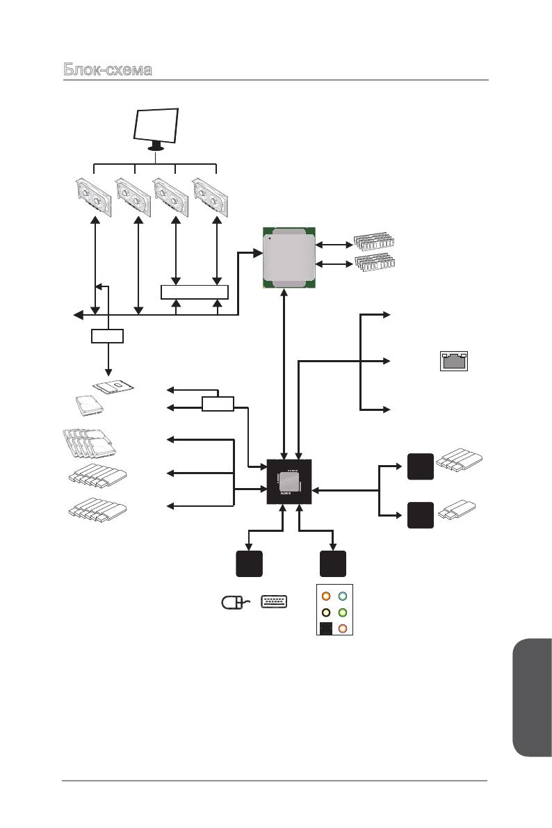
Chapter 11-7Getting StartedBlock DiagramLPC Bus2 x USB 3.1 4 Channel DDR4 Memory6 x USB 3.01 x SATA Express 1 x M.2 10 x SATA 6Gb/s6 x USB 2.0PCI Expr
Page 28
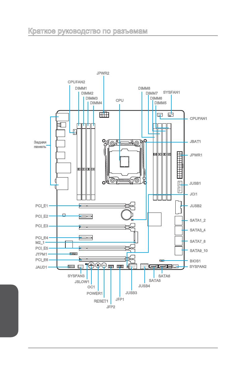
Chapter 11-8Getting StartedConnectors Quick GuideCPUFAN1CPUFAN2PCI_E1PCI_E2PCI_E4PCI_E5PCI_E6SATA1_2SATA7_8SATA9_10JBAT1JCI1BackPane
Page 29
Chapter 11-9Getting StartedConnectors Reference GuidePort Name Port Type PageBack Panel 1-10
Page 30
Chapter 11-10Getting StartedBack Panel Quick Guide PS/2 PortA PS/2® DIN connector is for a PS/2® mouse/keyboard. Clear CMOS ButtonThere is CMOS RAM
Page 31
Chapter 11-11Getting Started Optical S/PDIF-Out
Page 32
Chapter 11-12Getting StartedCPU (Central Processing Unit) ImportantOverheatingOverheating can seriously damage the CPU and motherboard. Always make su
Page 33
Chapter 1Getting StartedWhen installing a CPU, always remember to install a CPU heatsink. A CPU heatsink is necessary t
Page 34
Chapter 11-14Getting Started7. Close the active lever with a smooth uniform motion and latch to the socket.8. Close the hinge lever with a smooth un
Page 35
Chapter 11-15Getting Started9. Evenly spread a thin layer of thermal paste (or thermal tape) on the top of the CPU. This will help in heat dissipatio
Page 36
PrefaceiiiPrefaceSmartphone ApplicationMSI+ is a smart web gadget that works as a shopping navigator and provides specs comparison for IT buyers. With
Page 37
Chapter 11-16Getting StartedMemoryThese DIMM slots are used for installing memory modules.DIMM1DIMM2DIMM4DIMM8DIMM7DIMM6DIMM5 Video Demonstration
Page 38
Chapter 11-17Getting StartedSuggestions for Multi-Channel mode population ruleDual-Channel modeInstalled DIMMs (2 memory modules)DiagramDIMM1, DIMM5DI
Page 39
Chapter 11-18Getting StartedQuad-Channel modeInstalled DIMMs (6 memory modules)DiagramDIMM5, DIMM6, DIMM7DIMM1DIMM2DIMM4DIMM
Page 40
Chapter 11-19Getting StartedMounting Screw Holesfor an motherboar
Page 41
Chapter 11-20Getting StartedPower Supply Video DemonstrationWatch the video to learn how to install power supply connectors.
Page 42
Chapter 11-21Getting StartedExpansion SlotsThis motherboard contains numerous slots for expansion cards, such as discrete graphics or audio cards.PCI_
Page 43
Chapter 11-22Getting StartedVideo/ Graphics Cards If available, this motherboard takes advantage of the CPU’s integrate graphics processor, but discre
Page 44
Chapter 1Getting StartedInternal ConnectorsSATA1~10: SATA ConnectorsThis connector is a high-speed SATA interface port. Each connector can connect
Page 45
Chapter 11-24Getting StartedSATA_EX1: SATA Express Connector The SATA Express, a new high performance storage interface, supports to connect 1 SATA Ex
Page 46
Chapter 11-25Getting StartedJFP1, JFP2: System Panel ConnectorsThese connectors connect to the front panel switches and LEDs. The JFP1 connector is co
Page 47
ivPrefacePrefaceSafety Instructions Always read the safety instructions carefully. Keep this User’s Manual for future reference. Keep this equip
Page 48
Chapter 11-26Getting Startedtransf
Page 49
Chapter 11-27Getting StartedThis connector is designed for connecting high-speed USB peripherals such as USB
Page 50
Chapter 11-28Getting StartedThe fan power connectors support system cooling fans with +12V. If the motherboar
Page 51
Chapter 11-29Getting StartedJAUD1: Front Panel Audio ConnectorThis connector allows you to connect the front audio panel located on your computer case
Page 52
Chapter 1Getting StartedButtonsThe motherboard has numerous on-board buttons to control various functions. This section will explain how to change
Page 53
Chapter 1Getting StartedPOWER1: Power Button
Page 54
Chapter 1Getting StartedJumpersJBAT1: Clear CMOS JumperThere is CMOS RAM onboard that is external powered from a battery located on the
Page 55
Chapter 1Getting StartedSwitchBIOS1: Multi-BIOS SwitchThis motherboard has two built-in BIOS ROMs (Labeled A and B, default BIOS ROM is A). If one
Page 56
Chapter 1Getting StartedOC_SW1: OC Genie Mode SwitchThis swtich provides two overclocking modes (Gear 1 and Gear 2) for OC Genie operation. When y
Page 57
Chapter 1Getting StartedLED Status IndicatorsBIOS A LEDOC Switch Gear 1 LEDBIOS B LEDMSI LEDThermal Warning LEDOC Switch Gear 2 LEDLED Status Tabl
Page 58
PrefacevPrefaceCE ConformityHereby, Micro-Star International CO., LTD declares that this device is in compliance with the essential safety requirement
Page 59
Chapter 1Getting StartedDrivers and Utilitiesperformance o
Page 60
Chapter 2Quick InstallationThis chapter provides demonstration diagrams about how to install your computer. Some of the installations also provide vid
Page 61
Chapter 22-2Quick InstallationCPU Installation12456 http://youtu.be/WPhyn2C5mgs
Page 62
Chapter 2Quick Installation7 89 101112
Page 63
Chapter 22-4Quick Installation12Memory Installation
Page 64
Chapter 22-5Quick InstallationMotherboard Installation12
Page 65
Chapter 22-6Quick Installation
Page 66
Chapter 22-7Quick InstallationPower Connectors InstallationE68 8MSIMC4E68 8MSIMC4E68 8MSIMC41
Page 67
Chapter 22-8Quick InstallationE68 8MSIMC4E68 8MSIMC4E68 8MSIMC4E68 8MSIMC4E68 8MSIMC4E68 8MSIMC4or2
Page 68
Chapter 22-9Quick InstallationSATA HDD Installation12http://youtu.be/RZsMpqxythcE688MSIMC4E688MSIMC4E688MSIMC4E688MSIMC4E688MSIMC4E688MSIMC4E688MSIMC4
Page 69
viPrefacePrefaceRadiation Exposure StatementThis equipment complies with FCC radiation exposure limits set forth for an uncontrolled environment. This
Page 70
Chapter 22-10Quick InstallationM.2 module Installation12http://youtu.be/JCTFABytrYA
Page 71
Chapter 22-11Quick InstallationE68 8MSIMC4E688MSIMC4E688MSIMC4E688MSIMC4E688MSIMC4E68 8MSIMC4E68 8MSIMC4E68 8MSIMC4E688MSIMC4E688MSIMC4E688MSIMC4E688M
Page 72
Chapter 22-12Quick InstallationE68 8MSIMC4E688MSIMC4E688MSIMC4E688MSIMC4E688MSIMC4E688MSIMC4E688MSIMC4E688MSIMC4E688MSIMC4E68 8MSIMC4USBE68 8MSIMC4E68
Page 73
Chapter 2Quick InstallationGraphics Card Installationhttp://youtu.be/mG0GZpr9w_A12
Page 74
Chapter 22-14Quick Installation45
Page 75
ImportantThe items under each BIOS category described in this chapter are under continuous update for better system performance. Therefore, the
Page 76
Chapter 3BIOS Setup BIOS SetupEntering Setupconditions. You ma
Page 77
Chapter 3BIOS Setup BIOS SetupOverviewAfter entering BIOS, the following screen is displayed.BIOS menu selectionTemperature monitorSysteminform
Page 78
Chapter 3BIOS Setup BIOS Setup Virtual OC Genie ButtonEnables or disables the OC Genie function by clicking on this button. When enabled, this
Page 79
Chapter 3BIOS Setup BIOS SetupAdding BIOS item to Favorite 1~51. Move the mouse cursor to highlight a BIOS setting item.2. Right-click (or pr
Page 80
PrefaceviiPrefaceCalifornia, USA: The button cell battery may contain perchlorate material and requires special handling when recycled or disposed of
Page 81
Chapter 3BIOS Setup BIOS SetupOperationYou can control BIOS settings with the mouse and the keyboard. The following table lists and describes t
Page 82
Chapter 3BIOS Setup BIOS SetupUpdating BIOSUpdating the BIOS with M-FLASH Before updating
Page 83
Chapter 3BIOS Setup BIOS SetupSETTINGSSystem Status System DateSets the system date. Use tab key to switch between date elements.The format is
Page 84
Chapter 3BIOS Setup BIOS Setup PEGX — PCI_EX_Gen X [Auto]
Page 85
Chapter 3BIOS Setup BIOS Setup SATA Mode [AHCI Mode] (For SATA1~6)Sets the operation mode of the onboard 1st SATA controller. [IDE Mode] Sp
Page 86
Chapter 3BIOS Setup BIOS Setup regulation.
Page 87
Chapter 3BIOS Setup BIOS Setup Secure Boot<Enter> to enter
Page 88
Chapter 3BIOS Setup BIOS Setup Resume By Onboard LAN [Disabled]Disables or enables the system wake up by Onboard LAN.[Enabled] Enables the
Page 89
Chapter 3BIOS Setup BIOS Setup FIXED BOOT ORDER PrioritiesSets device priority for system boot. Boot Option #1~N
Page 90
Chapter 3BIOS Setup BIOS Setup Discard Changes and ExitExit BIOS setup without saving any change. This it is used to abandon all
Page 91
viiiPrefacePrefaceWEEE (Waste Electrical and Electronic Equipment) StatementENGLISHTo protect the global environment and as an environmentalist, MSI m
Page 92
Chapter 3BIOS Setup BIOS SetupOC ImportantOverclocking your PC manually is only recommended for advanced users.Overclocking is not guaran
Page 93
Chapter 3BIOS Setup BIOS Setup X-Core Ratio Limit [Auto]These items only appear when a CPU that support this function is installed. These
Page 94
Chapter 3BIOS Setup BIOS Setup Importantnot to load defaults af
Page 95
Chapter 3BIOS Setup BIOS Setup Importantmemory module type a
Page 96
Chapter 3BIOS Setup BIOS Setup CPU Phase Control [Auto]Controls PWM phase proportionally to the CPU loading. If set to «Auto», BI
Page 97
Chapter 3BIOS Setup BIOS Setup DRAM CH_A/B, CH_C/D Under Voltage Protection [Auto]Sets the voltage limit for DRAM under-voltage protection.
Page 98
Chapter 3BIOS Setup BIOS Setup CPU Core/Ring Voltage Mode [Auto]*Selects the control mode of CPU Core/ Ring voltages.
Page 99
Chapter 3BIOS Setup BIOS Setup XXX Voltage [Auto]* (optional)Sets the voltages related to memory/ PCH. If set to «Auto», BIOS wil
Page 100 — Introduction
Chapter 3BIOS Setup BIOS Setup Execute Disable Bit [Enabled]Intel’s Execute Disable Bit functionality can prevent certain classes of malicio
Page 101
Chapter 3BIOS Setup BIOS Setup Intel C-State [Enabled]
Page 102
PrefaceixPrefaceESPAÑOLMSI como empresa comprometida con la protección del medio ambiente, recomienda:Bajo la directiva 2002/96/EC de la Unión Europea
Page 103
Chapter 3BIOS Setup BIOS Setup Internal VR OVP OCP Protection [Auto]Enables or disables the over-voltage protection and over-current protect
Page 104
Chapter 3BIOS Setup BIOS SetupM-FLASH Importantonly).
Page 105
Chapter 3BIOS Setup BIOS SetupOC PROFILE
Page 106
Chapter 3BIOS Setup BIOS SetupHARDWARE MONITORinformationFanVoltagedisplaySetting Buttons
Page 108 — Degraded RAID Array
Appendix ARealtek AudioThe Realtek audio provides 10-channel DAC that simultaneously supports 7.1 sound playback and 2 channels of independent stereo
Page 109
Appendix AA-2Realtek AudioAfter installing the audio driver (see Chapter 1 — Driver and Utilities), the “Realtek HD
Page 110
Appendix ARealtek Audio Device SelectionHere you can select a audio output source to change the related options. The “check” sign indicates the de
Page 112
Appendix BIntel RAIDand accelerating system on platforms
viii
Preface
Preface
WEEE (Waste Electrical and Electronic Equipment) Statement
ENGLISH
To protect the global environment and as an environmentalist, MSI must
remind you that…
Under the European Union (“EU”) Directive on Waste Electrical and
discarded as municipal wastes anymore, and manufacturers of covered
electronic equipment will be obligated to take back such products at the end of their
useful life. MSI will comply with the product take back requirements at the end of life
of MSI-branded products that are sold into the EU. You can return these products to
local collection points.
DEUTSCH
Gemäß der Richtlinie 2002/96/EG über Elektro- und Elektronik-Altgeräte dürfen
Elektro- und Elektronik-Altgeräte nicht mehr als kommunale Abfälle entsorgt werden.
MSI hat europaweit verschiedene Sammel- und Recyclingunternehmen beauftragt,
die in die Europäische Union in Verkehr gebrachten Produkte, am Ende seines
Zeitpunkt ausschliesslich an einer lokalen Altgerätesammelstelle in Ihrer Nähe.
FRANÇAIS
Au sujet de la directive européenne (EU) relative aux déchets des équipement
que les produits électriques et électroniques ne peuvent être déposés dans les
les points de collecte.
Preface
xiii
Preface
……………………………………………………………………………………….. Fr-1
…………………………………………………………………………………………Fr-2
Block Diagram ………………………………………………………………………………………..Fr-5
Guide Rapide Des Connecteurs ……………………………………………………………….Fr-6
Guide rapide du panneau arrière ………………………………………………………………Fr-8
Processeur : CPU …………………………………………………………………………………Fr-10
Mémoire ………………………………………………………………………………………………Fr-14
Trous Taraudés de Montage …………………………………………………………………..Fr-17
Connecteurs d’alimentation …………………………………………………………………….Fr-18
Emplacements d’extension …………………………………………………………………….Fr-19
Connecteurs internes …………………………………………………………………………….Fr-20
Boutons ……………………………………………………………………………………………….Fr-27
Cavaliers ……………………………………………………………………………………………..Fr-29
Interrupteur …………………………………………………………………………………………..
Pilotes et Utilitaires ………………………………………………………………………………..
……………………………………………………………………………….
………………………………………………………………………………………. Ru-1
…………………………………………………….. Ru-2
…………………………………………………………………………………………. Ru-5
………………………………………………………. Ru-6
……………………………….. Ru-8
…………………………………………………………….. Ru-10
……………………………………………………………………………………………… Ru-14
…………………………………………………… Ru-17
………………………………………………………………………………… Ru-18
……………………………………………………………………………. Ru-19
………………………………………………………………………… Ru-20
………………………………………………………………………………………………. Ru-27
…………………………………………………………………………………………… Ru-29
………………………………………………………………………………….
………………………………………………………………………….
…………………………………………………………………………………

Intel
®
Intel
®
Русский
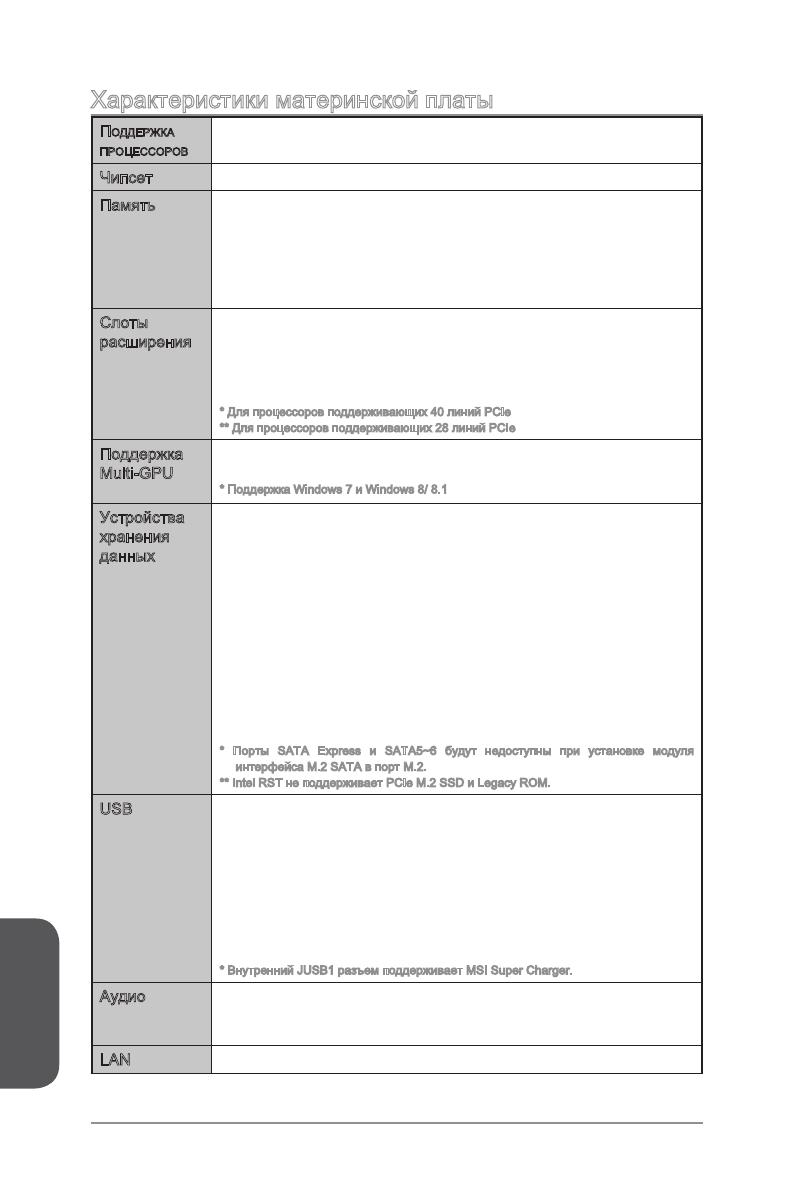
Ru-2
Поддержка
Процессоров
®
Core™ i7
Intel
®
®
—
—
—
Multi-GPU
®
CrossFireTM*
®
SLI
TM
®
X99 Express
—
—
—
®
Smart Response (Windows 7/
8/ 8.1)
—
—
** Intel RST
USB
®
X99 Express
—
—
ASMedia ASM1142
—
VIA VL805
—
Realtek
®
ALC892 Codec
—
—
LAN
Русский
USB 2.0)
Hardware
BIOS
ACPI 5.0, PnP 1.0a, SM BIOS 2.7, DMI 2.0
Military Class 4
OC Genie 4
CLICK BIOS 4
NVIDIA SLI
AMD CrossFire
Easy Button
Clear CMOS Button
Total Fan Control
Super Charger
Smart Utilities
Command Center
ECO Center
Русский
Ru-4
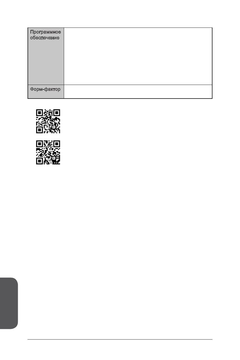
MSI
— Command Center
— Live Update 6
— Smart Utilities
— Super Charger
— Fast Boot
— ECO Center
Norton Internet Security Solution
Intel Extreme Tuning Utility
cpu-support/
http://www.msi.com/test-report/
Русский
Ru-5
LPC Bus
2 x USB 3.1
4 Channel DDR4 Memory
4 x USB 3.0
6 x USB 3.0
1 x SATA Express
1 x M.2
10 x SATA 6Gb/s
6 x USB 2.0
PCI Express Bus
PCI Express Bus
PCI Express Bus
PS/2 Mouse / Keyboard
Intel I218
Gigabit LAN
DMI 2.0
PCI Express 3.0
PCI Express 3.0
PCI Express 3.0
PCI Express 3.0
PCI Express Bus
Switch
X99 PCH
Haswell-E
Processor
LGA2011-3 CPU
NV6792
Super I/O
Realtek
ALC892
VIA
VL805
ASMEDIA
ASM1142
x1
x1
x2
x1
x4
x2
x1
Switch
Switch
(2 ports reserved for SATA Express)
OR
S/PDIF-Out
Line-In/ SS-Out
Line-OutRS-Out
CS-Out
MIC
PCIe x1 slot
PCIe x1 slot
Русский
Ru-6
SATA3 _4SATA9 _1 0
SATA1 _2SATA7 _8
CPUFAN1
PCI_E1
PCI_E2
PCI_E4
PCI_E5
JPWR1
JUSB4
SATA1_2
SATA7_8
JPWR2
CPU
JUSB1
M2_1
JTPM1
DIMM1
DIMM2
DIMM4
CPUFAN2
JSLOW1
OC1
POWER1
RESET1
SATA9_10
JCI1
JFP1
JFP2
JBAT1
JUSB2
SYSFAN2
SYSFAN1
JAUD1
SATA6
BIOS1
DIMM8
DIMM7
DIMM6
DIMM5
SATA5
PCI_E6

Русский
Ru-7
Русский
Ru-8
®
®
.
CMOS
Русский
Ru-9
(LAN).
LINK/ACT
LED
SPEED
LED
Link/ Activity LED
Speed LED
4/ 5.1/ 7.1.
Русский
Ru-10
1
Русский
Ru-11
http://youtu.be/WPhyn2C5mgs
Русский
Ru-12
Русский
pounds).
SATA3_4SATA 9_10
SATA1_2SATA7_8
CPUFAN1
Русский
Ru-14
SATA3_4SATA9_1 0
SATA1_2SATA7_8
DIMM1
DIMM2
DIMM4
DIMM8
DIMM7
DIMM6
DIMM5
DIMM1, DIMM2
DIMM5, DIMM6
DIMM7, DIMM8
Русский
Ru-15
DIMM1, DIMM5
DIMM1
DIMM2
DIMM4
DIMM8
DIMM7
DIMM6
DIMM5
DIMM1
DIMM2
DIMM4
DIMM8
DIMM7
DIMM6
DIMM5
DIMM5, DIMM7
DIMM1
DIMM2
DIMM4
DIMM8
DIMM7
DIMM6
DIMM5
Русский
Ru-16
DIMM5, DIMM6, DIMM7
DIMM1
DIMM2
DIMM4
DIMM8
DIMM7
DIMM6
DIMM5
DIMM1, DIMM2,
DIMM5, DIMM6,
DIMM7, DIMM8
DIMM1
DIMM2
DIMM4
DIMM8
DIMM7
DIMM6
DIMM5
Русский
Ru-17
SATA3 _4SATA9 _1 0
SATA1 _2SATA7 _8
Русский
Ru-18
SATA3_4SATA9_ 10
SATA1_2SATA7_8
13.+3.3
V
14.—12V
2.+3.3V
15.Ground
3.Ground
16.PS—ON#
4.+5V
17.Ground
5.Ground
18.Ground
6.+5V
19.Ground
7.Ground
22.+5V
10.+12V
20.Res
8.PWR OK
23.+5V
11. +12 V
21.+5V
9.5VSB
24.Ground
12.+3.3V
7.+12V
3.
Ground
5.+12V
Ground
8.+12V
.Ground
6.+12V
2.Ground
JPWR1
JPWR2
/
- Home
- Brands
- MSI
- Motherboard
- X99A SLI KRAIT EDITION
- Quick Start Manual
Manual for MSI X99A SLI KRAIT EDITION Motherboard (220 pages)
Specifications:
|
MSI X99A SLI KRAIT EDITION: Read PDF Manual Online
Accompanying Data:
MSI X99A SLI KRAIT EDITION Motherboard PDF Quick Start Manual (Updated: Saturday 8th of October 2022 02:24:35 AM)
Rating: 4.1 (rated by 59 users)
Compatible devices: 865PE NEO2-LS — Motherboard — ATX, B450-A PRO, MAG B660M MORTAR WIFI DDR4, MS-7360, MS-6380, MS-7071, KT4A-V, 945GM3-F — Motherboard — Micro ATX.
Recommended Documentation:
MSI X99A SLI KRAIT EDITION: Text of Quick Start Manual
(Ocr-Read Version Summary of Contents, UPD: 08 October 2022)
-
206, 42 Настройка BIOS функцию. Данные опции позволяют настроить множители процессора для различных ядер в режиме турбо-разгона. f Adjusted CPU Frequency Показывает текущую частоту процессора. Это значение нельзя �…
-
4, IV Quick Start 1 2 10 9 JFP1 1 HDD LED + 2 Power LED + 3 HDD LED — 4 Power LED — 5 Reset Switch 6 Power Switch 7 Reset Switch 8 Power Switch 9 Reserved 10 No Pin RESET SW POWER SW POWER LED+ POWER LED- HDD LED HDD LED RESET SW JFP1 HDD LED HDD LED — HDD LED + POWER LED — POWER LED + POWER LED Connecting the Front Panel Header/ Anschließen der Frontpanel-Stiftleiste/ C…
-
197, 33 Светодиодные индикаторы Индикатор отладочных кодов Индикатор отладочных кодов отображает фазы процесса самотестирования POST, а также коды ошибок. Для получения дополнительной информации см. таблицу отладочных �…
-
100, 40 BIOS-Setup Erweiterter Modus Drücken Sie den Setup Modus Schalter oder die Funkionstaste F7, um zwischen dem EZ-Modus und Erweiterten-Modus im BIOS-Setup zu wechseln. OC GENIE 4 Schalter XMP Schalter System- information Bootgeräte- Prioritätsleiste BIOS-Menü -Auswahl Sprache FavoritenScreenshotSetup Modus Schalter Menüanzeige BIOS-Menü -Auswahl y …
-
171, 7 Технические характеристики Продолжение с предыдущей страницы MSI Эксклюзивные функции y CLICK BIOS 5 Режим EZ и расширенный режим Board Explorer Аппаратный мониторинг y MILITARY CLASS 5 Компоненты Military Cla…
-
145, 33 Indicateurs d’état LED Debug Code LED La Debug Code LED affiche les codes de progression et d’erreur pendant et après le processus de POST. Référez-vous au tableau de Debug Code LED pour plus de détails. Tableau des caractères hexadécimaux Hexadécimaux 0 1 2 3 4 5 6 7 8 9 A B C D E F Affichage de Debug Code LED 0 1 2 3 4 5 6 7 8 9 A B C D E …
-
122, 10 Panneau arrière Entrée/ Sortie Ilustration de l’utilisation des ports audio dédiés au casque et au microphone Ilustration de l’utilisation du port audio dédié aux haut-parleurs Ilustration de l’utilisation des ports audio dédiés aux haut-parleurs 7.1 AUDIO INPUT AUDIO INPUT Rear Front Side Center/ Subwoofer
… -
192, 28 Компоненты материнской платы JAUD1: Разъем аудио передней панели Данный разъем предназначен для подключения аудиоразъемов передней панели. 1 2 10 9 1 MIC L 2 Ground 3 MIC R 4 NC 5 Head Phone R 6 MIC Detection 7 SENSE_SEND 8 No Pin 9 Head Phone L 10 Head Phon…
-
36, 26 Overview of Components JUSB3~4: USB 2.0 Connectors These connectors allow you to connect USB 2.0 ports on the front panel. 1 2 10 9 1 VCC 2 VCC 3 USB0- 4 USB1- 5 USB0+ 6 USB1+ 7 Ground 8 Ground 9 No Pin 10 NC Important y Note that the VCC and Ground pins must be connected correctly to avoid possible damage. y In order to recharge your iPad,iPhone and iPod th…
-
182, 18 Компоненты материнской платы SATA1~10: Разъемы SATA 6 Гб/с Эти разъемы представляют собой интерфейсные порты SATA 6 Гб/с. К каждому порту можно подключить одно устройство SATA. SATA2 SATA3 SATA7 SATA4 SATA8 SATA1 SATA10 SATA9 SATA5 SATA6 SE1…
-
18, 8 Rear I/O Panel Rear I/O Panel Link/ Activity LED Status Description Off No link Yellow Linked Blinking Data activity Speed LED Status Description Off 10 Mbps connection Green 100 Mbps connection Orange 1 Gbps connection LAN Port LED Status Table Audio Ports Configuration Audio Ports Channel 2 4 6 8 Center/ Subwoofer Out ● ● Rear Speaker Out ● ● ● …
-
142, 30 Vue d’ensemble des composants POWER1, RESET1: Boutons d’alimentation et de réinitialisation Les boutons d’alimentation et de réinitialisation vous permettent d’allumer ou de redémarrer l’ordinateur. Bouton d’alimentation Bouton de réinitialisation JBAT1: Cavalier clear CMOS (Réinitialisation BIOS) Une mémoire CMOS est intégrée et est alimentée en externe par une ba…
-
167, 3 Технические характеристики Технические характеристики Процессор y Поддержка новых процессоров Intel ® Core ™ i7 Extreme Edition для сокета LGA2011-3 y Поддержка Технологии Intel ® Turbo Boost Max 3.0* * Поддержка данной функции зав…
-
61, 1 Inhalt Inhalt Sicherheitshinweis …………………………………………………………………………………… 2 Spezifikationen ………………………………………………………………………………………… 3 Rückseite E/A ………………………………………………………………………………………..…
-
191, 27 Компоненты материнской платы CPUFAN1,SYSFAN1~3,PUMPFAN1: Разъемы вентиляторов Разъемы вентиляторов можно разделить на два типа: с PWM (PulseWidth Modulation) управлением и управлением постоянным током. Разъемы вентиляторов с PWM упра�…
DOC-13dc5c5c:
MSI X99A SLI KRAIT EDITION: Recommended Instructions
SmartWare R.3.20, AQ5150/04S, GFH600BH, CDR-018


-
FCC Compliance Statement: This equipment has been tested and found to comply with limits for a Class B digital device, pursuant to Part 15 of the FCC rules. These limits are designed to provide reasonable protection against harmful interference in residential installations. This equipment generates, uses, and can radiate radio frequency energy, and if not ins …
GA-7ZX-H 88
-
S3115 Version 1.00 Copyright Copyright © MiTAC Computer Corporation, 2009. All rights reserved. No part of this manual may be reproduced or translated without prior written consent from MiTAC Computer Corp. Trademark All registered and unregistered trademarks and company names contained in this manual are property of their respective owners including, but not limited …
S3115 74
-
June 2017 DocID030511 Rev 1 1/691UM2198User manualEvaluation board with STM32H743XI MCUIntroductionThe STM32H743I-EVAL Evaluation board is a high-end development platform for the ARM® Cortex®-M7-based STM32H743XI microcontroller. The STM32H743I-EVAL Evaluation board provides access to all the STM32 peripherals for user applications and includes an embedded ST-LINK debugger/progr …
STM32H743I-EVAL 69
-
Detail Specification CPUMemoryExpansion SlotAudioGraphicsLANRear Panel I/OConnectorBIOS FeatureSupport CDAccessoriesHardware MonitorOSCertificationsThe specification is subject to change without notice. The brand and product names are trademarks of their respective companies. Any configuration other than original product specification is not guaranteed.ChipsetP …
G31M-VS2 5
-
1SLUUBC8A–August 2015–Revised May 2016Submit Documentation FeedbackCopyright © 2015–2016, Texas Instruments Incorporatedbq2512x Evaluation ModuleUser’s GuideSLUUBC8A–August 2015–Revised May 2016bq2512x Evaluation ModuleThe bq2512x evaluation module (EVM) is a high-performance, easy-to-use development kit for the designof a compact, flexible, high-efficiency, low …
bq25120EVM 23
-
1SLAU806–October 2019Submit Documentation FeedbackCopyright © 2019, Texas Instruments IncorporatedBP-DAC11001EVMUser’s GuideSLAU806–October 2019BP-DAC11001EVMThis user’s guide describes the characteristics, operation, and use of the BP-DAC11001 evaluationmodule (EVM) BoosterPack™ plug-in module. This EVM is designed to evaluate the performance of theD …
BP-DAC11001EVM 31
-
1AMD RAID Installation Guide 1. AMD BIOS RAID Installation Guide …………………………………………………………………….. 2 1.1 Introduction to RAID ……………………………………………………………………………….. 2 1.2 RAID Configurations Precautions ……………………………………………………………� …
Fatal1ty 990FX Killer 27
-
User’s GuideTPS40100 Buck Controller Evaluation Module User’s GuideTable of Contents1 Introduction………………………………………………………………………………………………………………………………………………………..22 Description……………………………………………………………………………. …
TPS40100 32
-
To reduce the impacts on global warming, the packaging materials of this product are recyclable and reusable. GIGABYTE works with you to protect the environment.For more product details, please visit GIGABYTE’s website.GA-Q170M-D3HUser’s ManualRev. 100112ME-Q170M3H-1001R …
GA-Q170M-D3H 40
-
CONTENT I — I Challtcr I 1 N IHODliCTION Chapter 2 GENERAL FEATURES 2-1 Specification Processor Ma t h Coprocessor Mcmory Systcm I/O Subsystem System functions Chapter 3 INSTALLING :2 — I 2-3 2-6 2-8 2-11 2-12 COMPONENTS 3-1 Installing 80387SX Math Coprocessor 3-1 System Mcmory Configuration 3-3 Control or Systcm Spccd 3-8 Systcm Board Jumpcr Setting 3-10 S y s t c III I …
Panther-II 386SX 77