
-
Contents
-
Table of Contents
-
Troubleshooting
-
Bookmarks
Quick Links
T-BERD/MTS 5800
Timing Expansion Module
User Manual
Related Manuals for Viavi MTS-5800
Summary of Contents for Viavi MTS-5800
-
Page 1
T-BERD/MTS 5800 Timing Expansion Module User Manual… -
Page 3
T-BERD/MTS 5800 Timing Expansion Module User Manual Viavi Solutions 1-844-GO-VIAVI www.viavisolutions.com… -
Page 4
Copyright/Trademarks © Copyright 2017 Viavi Solutions Inc. All rights reserved. No part of this guide may be reproduced or transmitted, electronically or otherwise, without written permission of the publisher. Viavi Solutions and the Viavi logo are trademarks of Viavi Solutions Inc. -
Page 5
• Consult the dealer or an experienced radio/TV technician for help. In order to maintain compliance with the limits of a Class A digital device Viavi requires that quality interface cables be used when connecting to this equipment. Any changes or modifications not expressly approved by Viavi could void the user’s authority to operate the equipment. -
Page 6
It is the responsibility of the equipment owner to return equipment and batteries to Viavi for appropriate disposal. If the equipment or battery was imported by a reseller whose name or logo is marked on the equipment or battery, then the owner should return the equipment or battery directly to the reseller. -
Page 7: Table Of Contents
Contents About this Guide Purpose and scope …………… ii Assumptions .
-
Page 8
Contents Action Buttons …………… 17 Result Buttons . -
Page 9
Contents Measuring TIE and calculating MTIE/TDEV ……….42 Analyzing 1PPS wander . -
Page 10
…………75 Returning equipment to Viavi . -
Page 11
About this Guide This preface explains how to use this User Manual. Topics discussed in this chapter include the following: • “Purpose and scope” on page ii • “Assumptions” on page ii • “Terminology” on page ii • “Related Information” on page iii •… -
Page 12: Purpose And Scope
Terminology The T-BERD 5800 is branded as the MTS-5800 in Europe, and it is interchangeably referred to as the T-BERD 5800, MTS 5800, MTS-5800, MTS5800 and Media Test Set 5800 throughout supporting documentation.
-
Page 13: Related Information
Satellite System (GNSS) based clock or other precise sources. • Viavi Ethernet test set — A test set marketed by Viavi and designed to transmit an Acterna Test Packet (ATP) payload. These packets carry a time stamp used to calculate a variety of test results. The FST-2802 TestPad, the SmartClass Ethernet tester, the HST with an Ethernet SIM, the T-BERD/MTS 8000 Transport Module, the T-BERD/MTS 6000A MSAM, and the T-BERD ⁄…
-
Page 14
About this Guide Conventions Table 1 Text formatting and other typographical conventions Item(s) Example(s) Buttons, keys, or switches that Press the On button. you press or flip on a physical – Press the Enter key. device. – Flip the Power switch to the on position. Buttons, links, menus, menu Click Start options, tabs, or fields on a PC-… -
Page 15
About this Guide Conventions Table 2 Symbol conventions This symbol indicates a note that includes important supplemental infor- mation or tips related to the main text. This symbol represents a general hazard. It may be associated with either a DANGER, WARNING, CAUTION, or ALERT message. See Table 3 more information. -
Page 16: Safety And Compliance Information
Safety and compliance information for the 5800v2 test instrument and the TEM Module are provided in the printed T-BERD ⁄ MTS 5800 Safety Information document that shipped with the instrument or module. Technical assistance If you require technical assistance, call 1-844-GO-VIAVI. For the latest TAC informa- tion, go to http://www.viavisolutions.com/en/services-and-support/support/technical- assistance.
-
Page 17: Overview
Overview Chapter 1 This chapter provides a general description of each of the TEM Module. Topics discussed in this chapter include the following: • “About the TEM Module” on page 2 • “Features and capabilities” on page 2 • “What ships with the TEM Module?” on page 3 •…
-
Page 18: About The Tem Module
Chapter 1 Overview About the TEM Module About the TEM Module The TEM Module provides a stable, highly accurate timing reference for the T-BERD / MTS 5800v2, and the ability to conduct synchronized timing tests across multiple instruments with the support of a Global Navigation Satellite System (GNSS) and an internal rubidium oscillator.
-
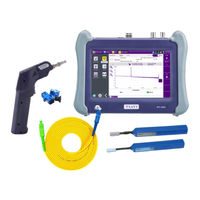
Page 19: What Ships With The Tem Module
Chapter 1 Overview What ships with the TEM Module? • Satellite Based Augmentation Systems (SBAS). SBAS can be used in combina- tion with GPS, GLONASS, or BeiDou GNSS systems to improve the availability of satellites during surveys of areas with poor satellite visibility. In the future, QZSS augmentation will also be supported for satellite constellations in Japan and Australia.
-
Page 20: Unpacking The Components
When transporting the TEM Module and 5800v2 in a powered on state, Viavi strongly recommends only using the optional glove bag to transport the assembled test instrument. The standard bag should not be used.
-
Page 21: Exploring The Tem Module Connector Panel
Chapter 1 Overview Exploring the TEM Module connector panel Exploring the TEM Module connector panel The connector panel of the TEM Module provides the connectors used to obtain timing information from an external timing source (for example, a 1 PPS or 10MHz reference clock), and to provide an external reference clock to another device during testing.
-
Page 22
Chapter 1 Overview Exploring the TEM Module connector panel SMB connectors — 10 MHz input and output Two additional SMB connectors are provided on the connector panel for 10 MHz input and output (labeled 10 MHz OUT and 10 MHz REF IN). The connector labeled 10 MHz OUT can be used to provide an external, disciplined 10MHz timing reference to other instruments, and emulate an accurate master 10MHz clock. -
Page 23: Getting Started
Getting Started Chapter 2 This chapter explains how to connect the TEM Module to your instrument, how to connect a GNSS antenna (if you are using GNSS timing as your synchronization source), and how to navigate the user interface. Topics discussed in this chapter include the following: •…
-
Page 24: Connecting The Tem Module To Your Test Instrument
Chapter 2 Getting Started Connecting the TEM Module to your test instrument Connecting the TEM Module to your test instrument Before connecting your new TEM Module to a T-BERD ⁄ MTS 5800: • Verify that the instrument is a 5800v2 by checking the label on the back panel of the instrument, which will indicate whether or not it is a 5800v2.
-
Page 25
Chapter 2 Getting Started Connecting the TEM Module to your test instrument Locate the hinges on the TEM Module. Insert the hinges into the 5800v2 at about a 45 to 60 degree angle. Pivot the module down towards the connector. T-BERD/MTS 5800 Timing Expansion Module User Manual July 2017 22112315, Rev. -
Page 26: Connecting A Gnss Antenna
LEDs, results, and action buttons that are associated with the TEM module. Connecting a GNSS antenna A Viavi qualified GNSS antenna ships with each TEM Module. The cable is 3 meters long, and the antenna is equipped a magnetic base and a male SMA connector.
-
Page 27: Powering The Tem Module
• When transporting the TEM Module to a test location after the oscillator has warmed up and tuned, Viavi recommends using an optional power inverter for the duration of the trip. To discuss the various power adapters and inverters available for the 5800v2, contact Viavi Customer Care, or contact Viavi via the company web site,www.viavisolu-…
-
Page 28: Verifying That You Have The Correct Adapter
Chapter 2 Getting Started Powering the TEM Module Verifying that you have the correct adapter Figure 2 shows the label on the adapter that ships with T-BERD / MTS 5800v2 test instruments. This adapter must be used to provide power to the 5800v2 instrument and connected TEM Module.
-
Page 29: Turning On The Instrument
Chapter 2 Getting Started Verifying the local time zone For power specifications, see the Getting Started Guide that shipped with your instru- ment. Turning on the instrument To power the instrument • Press the ON/OFF key. The On LED, located on the front panel, illuminates green when the unit is powered, and the instrument beeps.
-
Page 30: Turning On The Rubidium Oscillator
Chapter 2 Getting Started Turning on the Rubidium Oscillator To verify the time zone Select the SYSTEM/HOME icon. The System screen appears. Select Date and Time. Review, and, if necessary, specify the Region, Country, and Area. The time zone has been verified. Turning on the Rubidium Oscillator By default, the TEM Module’s Rubidium Oscillator is off when you turn on your test instrument.
-
Page 31: Navigating The Tem Module User Interface
Chapter 2 Getting Started Navigating the TEM Module user interface Table 4 Oscillator Modes (Continued) Mode Description Wait for 1PPS The TEM Module is waiting for a valid 1PPS signal from the specified synchronization source. Coarse Tune The oscillator is beginning to tune to the frequency for the synchronization source that you specified when you configured the oscillator.
-
Page 32: Timing Module Tab
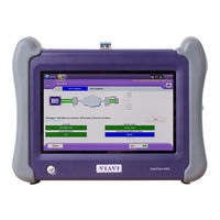
Chapter 2 Getting Started Navigating the TEM Module user interface provided to and by the module. Figure 4 shows the Timing Module tab when the module is configured to use a GNSS synchronization source. Figure 4 Main screen (Timing Module, GNSS Synchronization Source) For a detailed description of the UI elements on the 5800v2 user interface, refer to the Getting Started Guide that shipped with your instrument.
-
Page 33: Setup/Results Soft Key
Chapter 2 Getting Started Navigating the TEM Module user interface Setup/Results soft key The Setup soft key located on the right side of the UI provides quick access to the screen and the setup tabs that you use to configure the TEM Module. After configuring the module, use the Results soft key to return to the Timing Module tab on the Main screen.
-
Page 34: Result Buttons
Chapter 2 Getting Started Navigating the TEM Module user interface Figure 5 illustrates the buttons with the oscillator turned on and warming up. NOTE: The color of a button reflects its current state. Action buttons are highlighted in yellow when they are turned on; they are grey when they are off. Result Buttons Group and Category buttons are provided at the top of each result window.
-
Page 35: Turning Off The Rubidium Oscillator
Chapter 2 Getting Started Turning off the Rubidium Oscillator Turning off the Rubidium Oscillator To turn off the oscillator • Press the yellow Rubidium Osc. On action button. The action button turns grey, and the text on the button changes to Rubidium Osc. Off. Turning off the instrument To turn off the instrument •…
-
Page 36: Disconnecting The Tem Module
Chapter 2 Getting Started Disconnecting the TEM Module Disconnecting the TEM Module To disconnect the TEM Module from your instrument Verify that power is OFF on your instrument and that the AC power adapter is unplugged. Turn the instrument over so the display is facing downwards, and the back panel of the module is facing upwards.
-
Page 37: High Accuracy Timing
igh Accuracy Timing Chapter 3 This chapter explains how to setup and configure the TEM Module for use as a high accuracy timing reference during testing. Topics discussed in this chapter include the following: • “Basic timing principles” on page 22 •…
-
Page 38: Basic Timing Principles
Chapter 3 High Accuracy Timing Basic timing principles Basic timing principles The TEM Module is designed to provide a stable, highly accurate timing reference when performing tests that require: • The precise synchronization of multiple test instruments; • High accuracy wander analysis, •…
-
Page 39: Available Survey Modes
The TEM Module ships with a default Antenna Bias value of 28, which is the optimal value for the Viavi supplied antenna. If you are using a different antenna, you should calculate the cumulative delay introduced by 1) the antenna, 2) the antenna’s cable, and if applicable, 3) any in-line splitter or amplifier, then change the Antenna Bias value on the GNSS setup tab.
-
Page 40: Fixed Position Mode
Chapter 3 High Accuracy Timing Basic timing principles Fixed position mode If the values that the TEM Module’s GNSS receiver currently has in memory for position and altitude are correct and your instrument will remain in the same location, you do not need to conduct a survey.
-
Page 41: External 1 Pps And 10 Mhz Timing
Chapter 3 High Accuracy Timing Basic timing principles page 30) and perform a short survey to generate accurate coordinates (see “Surveying GNSS constellations” on page 34). NOTE: The TEM Module provides the highest degree of accuracy and stability when it is operated with a connected GNSS antenna and with an accurate Antenna Time Bias setting and in fixed timing mode;…
-
Page 42: Common Test Applications
PTP Delay To accurately measure PTP delay, you must either use two precisely synchronized Viavi Ethernet test instruments that are optioned and configured for PTP testing, or one test instrument synchronized to a PTP Master (for example, a Grandmaster or Boundary Clock).
-
Page 43: Ptp Delay Symmetry
To accurately measure one way delay, you must use two precisely synchronized Viavi Ethernet test instruments that are optioned and configured for one way delay testing.
-
Page 44: Warming Up The Oscillator
Chapter 3 High Accuracy Timing Warming up the oscillator The TEM Module’s oscillator, when tuned to a highly accurate synchronization source, can be used as a precise reference clock when analyzing wander or jitter on the 5800v2 test instrument. Specific applications include: •…
-
Page 45: Configuring The Module
Chapter 3 High Accuracy Timing Configuring the module TEM Module to leave the oscillator off by default, you must manually turn the oscillator on to allow it to warm up. To turn the oscillator on • Press the grey Rubidium Osc. Off action button on the Timing Module tab. The button turns yellow, and states Rubidium Osc.
-
Page 46: Specifying Gnss Settings
Chapter 3 High Accuracy Timing Configuring the module In Sync Source, select the synchronization source to be used to tune the TEM Module’s rubidium oscillator. – If you want the module to use GNSS timing, verify that you have connected a GNSS antenna (see “Connecting a GNSS antenna”…
-
Page 47: Specifying Location Settings
(another device is providing power to the antenna), or you are using a special low-power antenna, select 0. The default Antenna Time Bias value is 28 (the optimal value for the Viavi qualified antenna). If you are using a different antenna, determine the optimal bias value by referring to the vendor specifications for the antenna (and, if applicable, splitter or amplifier), then specify the bias value in nanoseconds.
-
Page 48: Fixed Position Settings
Each selectable survey mode is auto- matically associated with a specific duration and survey position accuracy. For optimal timing performance, Viavi recommends conducting surveys for at least 12 to 24 hours. Satellites complete two orbits per day; therefore, a survey of at least 12 hours will provide data from an entire constellation.
-
Page 49: Saving Location Coordinates
Chapter 3 High Accuracy Timing Configuring the module on the Location tab to indicate that a survey does not need to be conducted. In this mode, precise timing can be maintained from the signal received from a single satellite. NOTE: The specified Fixed Position Accuracy value must be reasonably accurate or performance may be degraded.
-
Page 50: Surveying Gnss Constellations
Chapter 3 High Accuracy Timing Surveying GNSS constellations Surveying GNSS constellations After specifying survey settings (as described in “Survey settings” on page 31), you are ready to start the survey. To start the survey Press the grey Start Survey action button on the Timing Module tab of the Main screen.
-
Page 51: Tuning To An External Reference Clock Or Signal
Chapter 3 High Accuracy Timing Forcing the oscillator into holdover mode Tuning to an external reference clock or signal If you are using an external 1 PPS or 10 MHz reference signal as the synchronization source, you must provide the signal to the TEM Module via the appropriate input connector on the module’s connector panel (see “Exploring the TEM Module connector panel”…
-
Page 52: Qualifying Gnss Antennas
Chapter 3 High Accuracy Timing Qualifying GNSS antennas mode, or fine tune, which provides the best accuracy when testing for a prolonged period of time. NOTE: The oscillator should be placed into holdover mode before removing the reference signal for a synchronization source. If you do not place the oscillator into holdover mode before removing the signal, tuning may be adversely impacted.
-
Page 53
Chapter 3 High Accuracy Timing Qualifying GNSS antennas If the signal strength for the satellites used is “40 or higher,” you can conclude that the antenna is in the optimal location. For details concerning the supporting results, see “Signal Strength” on page 54 of this manual. -
Page 54
Chapter 3 High Accuracy Timing Qualifying GNSS antennas T-BERD/MTS/SC Timing Expansion Module User Manual Page 38 22112315, Rev. 004 July 2017… -
Page 55: 1Pps Wander Analysis
1PPS Wander Analysis Chapter 4 This chapter provides step-by-step instructions for analyzing 1PPS wander using the TEM Module. Topics discussed in this chapter include the following: • “About 1PPS wander analysis” on page 40 • “Impact on oscillator tuning” on page 41 •…
-
Page 56: About 1Pps Wander Analysis
Chapter 4 1PPS Wander Analysis About 1PPS wander analysis About 1PPS wander analysis If your TEM Module optioned to do so, you can place it into 1PPS Analysis mode, then use it to perform highly accurate wander analysis of a 1PPS signal by measuring the Time Interval Error (TIE) and calculating the Maximum Time Interval Error/Time Devia- tion (MTIE/TDEV) on the TEM itself.
-
Page 57: Impact On Oscillator Tuning
Chapter 4 1PPS Wander Analysis Impact on oscillator tuning cates that the module is in 1PPS Analysis mode, and that the oscillator has been placed into Holdover mode. Figure 7 1 PPS Analysis LEDs Impact on oscillator tuning If the TEM oscillator has reached Fine Tune mode, after you put the TEM into 1 PPS Analysis mode the oscillator is automatically placed into Holdover mode.
-
Page 58: Measuring Tie And Calculating Mtie/Tdev
Chapter 4 1PPS Wander Analysis Measuring TIE and calculating MTIE/TDEV be lost too. If you want use a GNSS tuned oscillator to perform measurements at a loca- tion without a GNSS synchronization source, you must use the 1 PPS OUT connector on the TEM to provide the GNSS derived reference signal to the 1 PPS IN 1 connector.
-
Page 59
Chapter 4 1PPS Wander Analysis Measuring TIE and calculating MTIE/TDEV Under Mode, select 1PPS Analysis, then specify the source of the reference timing signal: – If you want to use an external 1PPS reference clock: Select 1 PPS IN 1. In Differential Time Bias, specify the time difference between the refer- ence 1 PPS IN 1 and the analyzed 1 PPS IN 2 input in nanoseconds. -
Page 60: Analyzing 1Pps Wander
Chapter 4 1PPS Wander Analysis Analyzing 1PPS wander TIE is measured, and MTIE/TDEV is calculated. To view the supporting results, display the 1 PPS Analysis category. Analyzing 1PPS wander After you accumulate TIE data, you can analyze the data for wanter using the On-board Wander Analysis tool.
-
Page 61
Chapter 4 1PPS Wander Analysis Analyzing 1PPS wander If you want to observe the frequency offset curve, clear the Remove Offset checkbox. To select the data curve to observe, under Curve Selection, do one of the following: – To observe both TIE and frequency offset data curves, select Both Curves. –… -
Page 62: Saving And Exporting Tie Measurement Data
The TIE data is saved. NOTE: The Viavi offline analysis tool can only analyze .hrd files. To export the TIE data to a USB memory key Insert a USB memory key into one of the two slots provided on the top panel of the base unit.
-
Page 63
Chapter 4 1PPS Wander Analysis Saving and exporting TIE measurement data Supported ToD formats for the DUT include NMEA GPZDA and ITU-T Draft G.8271. T-BERD/MTS 5800 Timing Expansion Module User Manual July 2017 22112315, Rev. 004 Page 47… -
Page 64
Chapter 4 1PPS Wander Analysis Saving and exporting TIE measurement data T-BERD/MTS 5800 Timing Expansion Module User Manual Page 48 22112315, Rev. 004 July 2017… -
Page 65: Timing And 1 Pps Analysis Results
Timing and 1 PPS Analysis Results Chapter 5 This chapter describes the groups, categories and results that are available when tuning the TEM Module oscillator for use as a high accuracy timing reference or performing 1 PPS wander analysis. Topics discussed in this chapter include the following: •…
-
Page 66: About Tem Module Timing And 1 Pps Analysis Results
Chapter 5 Timing and 1 PPS Analysis Results About TEM Module timing and 1 PPS analysis results About TEM Module timing and 1 PPS analysis results If an optional TEM Module is connected to your instrument, LEDs and results associ- ated with timing are provided when the Timing Module tab is selected.
-
Page 67: Gnss Leds
Chapter 5 Timing and 1 PPS Analysis Results Event Log Table 6 Oscillator LEDs TEM Mode Indicates 1 PPS Analysis Ref CLK Valid Green – A valid reference clock is present. Grey – A valid reference clock is not present. Input CLK Valid Green –…
-
Page 68: Satellite Results
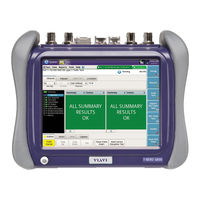
Chapter 5 Timing and 1 PPS Analysis Results Satellite Results and duration. Table 8 provides a sample Event Log for the TEM Module as the oscillator tunes to the Internal GNSS receiver. Figure 8 Sample Event Log, GNSS Synchronization Source If the TEM is in 1PPS analysis mode, the event log reports an event each time the analyzed 1PPS signal exceeds a value specified for an enabled threshold.
-
Page 69: Sky Plot
Chapter 5 Timing and 1 PPS Analysis Results Satellite Results Sky Plot The Sky Plot (shown in Figure 9) illustrates the satellites that were identified using the GNSS receiver attached to the TEM Module. The ID is provided for each satellite, and colors are used to indicate the satellite’s status (No Signal, Signal, Ready, or Used).
-
Page 70: Signal Strength
Chapter 5 Timing and 1 PPS Analysis Results Satellite Results Table 8 Satellite Status (Continued) Color Status Indicates Green Used The signal from the satellite is being used to provide GNSS timing. Signal Strength The signal strength for each received channel for used satellites is illustrated graphi- cally in the signal strength category, and represents the Carrier to Noise Ratio (C/No or CNO) on a scale of 0 to 50, with 50 representing the optimal signal strength.
-
Page 71: Gnss Results
Chapter 5 Timing and 1 PPS Analysis Results GNSS Results as well. The CNO Sky Plot test is an easy way to determine what the GNSS receiver will be able to see given the antenna location. The test will take 6-8 hours but the data it produces will enable planners to determine if GNSS antennas are in a good location or if they need to be moved to roll out advanced services.
-
Page 72: Status
Chapter 5 Timing and 1 PPS Analysis Results GNSS Results Status The Status category provides general information concerning the GNSS satellites reported in the almanac and the TEM Module’s GNSS receiver. Table 9 describes the Status results. Table 9 Status results Result Definition Fix Type…
-
Page 73: Time
Chapter 5 Timing and 1 PPS Analysis Results GNSS Results Table 10 Location results (Continued) Result Definition Latitude (deg) Longitude determined using either the GNSS receiver’s triangulation algorithm (in degrees), or entered manually when configuring the module. Depending on the location, this may be a positive or negative value.
-
Page 74: Oscillator Results
Chapter 5 Timing and 1 PPS Analysis Results Oscillator Results Table 11 Time results (Continued) Result Definition GPS Time Valid Indicates whether the GPS time is valid per the timing information received by the GPS receiver. Leap Seconds Displays the leap seconds. Local Time Displays the local time which is derived from the time zone with respect to GNSS time.
-
Page 75: Pps Analysis Results
Chapter 5 Timing and 1 PPS Analysis Results 1 PPS Analysis Results Table 12 Oscillator Status results (Continued) Result Definition Oscillator Mode The current mode of the oscillator (Warm Up, Coarse Tune, Fine Tune, or Holdover). 1 PPS Analysis Results The 1PPS Analysis category provides results describing the offset analyzed signal as compared to the reference signal.
-
Page 76
Chapter 5 Timing and 1 PPS Analysis Results ToD Results T-BERD/MTS 5800 Timing Expansion Module User Manual Page 60 22112315, Rev. 004 July 2017… -
Page 77: Chapter 6 Troubleshooting
Troubleshooting Chapter 6 This chapter describes how to identify and correct issues related to the operation of the TEM Module. Topics discussed in this chapter include the following: • “About troubleshooting” on page 62 • “Assembly and setup” on page 62 •…
-
Page 78: Troubleshooting About Troubleshooting
Chapter 6 Troubleshooting About troubleshooting About troubleshooting If you experience problems using your instrument, you may be able to solve these prob- lems on your own after referring to this section. If you experience significant problems with the module, call the Technical Assistance Center (see “Technical assistance”…
-
Page 79: No Gnss Time Is Detected
Chapter 6 Troubleshooting Performing tests No GNSS Time is detected There are several reasons why GNSS time may not be detected: • Verify that the GNSS antenna is properly connected (see “Connecting a GNSS antenna” on page 10), and that the antenna power level specified is correct for the antenna that you are using (see “Specifying GNSS settings”…
-
Page 80: Application Does Not Appear On The Test Menu
Chapter 6 Troubleshooting Maintaining your TEM Module Application does not appear on the Test menu Verify that all required test options are installed on your 5800v2 test instrument. For example, if you are using the TEM Module to provide high accuracy timing during PTP or One Way Delay testing, verify that the associated test option has been installed.
-
Page 81: Does The Module Need To Be Calibrated
Chapter 6 Troubleshooting Maintaining your TEM Module Does the module need to be calibrated? The TEM Module does not need to be calibrated; every time rubidium oscillator is tuned to a high accuracy synchronization source, the oscillator is disciplined. T-BERD/MTS 5800 Timing Expansion Module User Manual July 2017 22112315, Rev.
-
Page 82
Chapter 6 Troubleshooting Maintaining your TEM Module T-BERD/MTS 5800 Timing Expansion Module User Manual Page 66 22112315, Rev. 004 July 2017… -
Page 83: Appendix A Specifications
Specifications Appendix A This appendix contains specifications for the TEM Module. Topics discussed in this appendix include the following: • “About the TEM Module specifications” on page 68 • “Physical specifications” on page 68 • “Environmental specifications” on page 68 •…
-
Page 84: About The Tem Module Specifications
Appendix A Specifications About the TEM Module specifications About the TEM Module specifications Refer to the following sections for specifications for the TEM Module and rubidium oscil- lator: • “Physical specifications” on page 68 • “Environmental specifications” on page 68 •…
-
Page 85: Power Specifications
Appendix A Specifications Power specifications Power specifications Power is provided to the TEM Module by the connected 5800v2 test instrument. Battery life varies depending on the type and duration of the tests that you conduct; the 5800v2 may also be powered using the AC Adapter that shipped with the test instrument. Connector specifications The TEM Module connector panel provides an SMA connector for a GNSS Antenna, and five SMB connectors for 1 PPS and 10 MHz input and output signals.
-
Page 86: Performance Specifications
Appendix A Specifications Performance specifications Performance specifications Table 18 Table 19 provide GNSS and time performance specifications. GNSS specifications Table 18 lists GNSS performance specifications. Table 18 Performance (GNSS) specifications Specification Description Receiver Type 72-channel – GPS L1C/A – GLONASS L1OF –…
-
Page 87: Oscillator Specifications
Appendix A Specifications Oscillator specifications Oscillator specifications Table 20 lists phase noise specifications for the TEM Module’s Rubidium Oscillator. Table 20 Rubidium Oscillator specifications Specification Description Phase Noise — 1 Hz <-70 dBc — 10 Hz <-87 dBc — 100 Hz <-114 dBc — 1 kHz <-130 dBc…
-
Page 88
Appendix A Specifications 1 PPS Analysis specifications T-BERD/MTS 5800 Timing Expansion Module User Manual Page 72 22112315, Rev. 004 July 2017… -
Page 89: Appendix B Storage And Shipment
“Storing the instrument and module” on page 74 • “Transporting your TEM Module” on page 74 • “Shipping your TEM Module” on page 75 • “Returning equipment to Viavi” on page 75 T-BERD/MTS 5800 Timing Expansion Module User Manual July 2017 22112315, Rev. 004 Page 73…
-
Page 90: Storing The Instrument And Module
Store the battery in a cool, dry, clean environment. Do not leave the battery in a car or truck, particularly during extremely warm weather. While out of the instrument, the battery will discharge at a slow rate. Viavi recommends checking the battery periodically while it is in storage, and keeping it charged to at least 40%.
-
Page 91: Shipping Your Tem Module
NOTE: Viavi is not liable for any damage that may occur during shipping. Returning equipment to Viavi Before you return any equipment to Viavi, contact Viavi Customer Care at 1-844-GO- VIAVI or www.viavisolutions.com for the correct shipping address and for a Return or Reference Authorization.
-
Page 92
Returning equipment to Viavi Clearly mark the outside of the package with the Viavi-issued Return or Reference Authorization number and ship it prepaid and insured to Viavi. For information on pack- aging equipment for shipment, see “Packing the components” on page… -
Page 93: Glossary
Glossary Symbols/Numerics 10 MHz — 10 Megahertz timing reference. The TEM Module provides one 10 MHz input connectors and one 10 MHz output connector. 1 PPS — 1 Pulse Per Second timing reference. The TEM Module provides two 1 PPS input connectors and one 1 PPS output connector.
-
Page 94
Glossary BERT — Bit error rate test. A known pattern of bits is transmitted, and errors received are counted to figure the BER. The Bit Error Rate test is used to measure transmission quality. BITS — Building Integrated Timing Supply. C/No —… -
Page 95
Glossary Frequency stabilization — The process of tuning an oscillator to a specific frequency for a period of time sufficient to ensure that the oscillator provides a stable timing refer- ence. The frequency of the TEM Module’s oscillator must be stabilized before it is used for high accuracy timing applications. -
Page 96
Glossary reached coarse tune, intermediate tune, or fine tune mode (as indicated by the corre- sponding action key); however, for optimal timing performance, the oscillator should first reach fine tune mode. ISO — International Organization for Standardization. IP — Internet Protocol. Protocol specifying the format and address scheme of packets transmitted over the Internet. -
Page 97
Glossary Rx — Receive or receiver or input. SBAS — Satellite-based augmentation system. A GNSS augmentation system that improves satellite availability when performing surveys in areas with poor satellite visibility. See GNSS Augmentation. SETS — Synchronous Equipment Timing Source. Slave clock — PTP clock that obtains precisely synchronized time generated and distributed by a Grandmaster clock over packet networks (per the IEEE1588 v2 stan- dard). -
Page 98
Glossary USB — Universal Serial Bus. A bus designed to handle a broad range of devices, such as keyboards, mouses, printers, modems, and hubs. VNC — Virtual Network Computing. A thin client system that enables you to run appli- cations on a VNC server from any other computer connected to the Internet. Using VNC, you can run the T-BERD ⁄… -
Page 100
22112315 Rev. 004, July 2017 English Viavi Solutions North America: 1.844.GO VIAVI / 1.844.468.4284 Latin America +52 55 5543 6644 EMEA +49 7121 862273 APAC +1 512 201 6534 All Other Regions: viavisolutions.com/contacts email TAC@viavisolutions.com…
- Manuals
- Brands
- Viavi Manuals
- Control Unit
- T-BERD MTS 5800
Manuals and User Guides for Viavi T-BERD MTS 5800. We have 21 Viavi T-BERD MTS 5800 manuals available for free PDF download: Getting Started Manual, User Manual, Quick Card, Quick Manual
Viavi T-BERD MTS 5800 Getting Started Manual (296 pages)
T-BERD/MTS/SC Getting Started Guide
Brand: Viavi
|
Category: Test Equipment
|
Size: 3.77 MB
Table of Contents
-
Table of Contents
7
-
About this Guide
18
-
Purpose and Scope
18
-
Assumptions
18
-
Terminology
18
-
Components
18
-
Transceivers
20
-
Line Rates and Signals
21
-
-
Related Information
21
-
Conventions
22
-
Safety and Compliance Information
24
-
Technical Assistance
24
-
-
Chapter 1 Overview
25
-
About the Instruments
26
-
Features and Capabilities
26
-
Configuring Your Instrument
28
-
What Ships with Your Instrument
28
-
Unpacking the Components
29
-
Inspecting the Components for Damage
30
-
-
Accessories
30
-
Optional Expansion Modules
31
-
-
About the T-BERD / MTS 5800 and SC 4800
32
-
Configuring the T-BERD / MTS 5800 and SC 4800
33
-
Exploring the SC 4800 and T-BERD / MTS 5800
35
-
Smart Class 4800
35
-
T-Berd / Mts 5800
37
-
-
-
About the CSAM Assembly
38
-
Exploring the CSAM Connector Panel
39
-
External Clock Reference and Clock Out/1Pps Connectors
40
-
CFP2 40/100G Connectors
40
-
QSFP+ 40G Connectors
40
-
MPO Connectivity
40
-
SFP+ Connectors
41
-
-
About the MSAM Assembly
41
-
MSAM Chassis
43
-
USB Connector
44
-
SMA Connector
44
-
-
Msam Pims
44
-
Restrictions
48
-
-
-
About the DMC Assembly
48
-
Base Unit Requirements
48
-
Restrictions
49
-
-
Viavi Recommended Optical Adapters and Transceivers
49
-
Chapter 2 Assembling Your Instrument
51
-
Preparing for Assembly
52
-
Connecting a DMC to a Base Unit
52
-
Key Principles
52
-
Verifying the Base Unit Requirements
52
-
Required Tools
53
-
Connecting the Components
54
-
Connecting Two Dmcs to a Base Unit
57
-
Disconnecting the DMC
57
-
Required Tools
57
-
Disassembling the Instrument
57
-
-
-
-
Inserting Msams or Csams into the 6000A Base Unit or DMC
59
-
MSAM Requirements
59
-
CSAM Requirements
59
-
Required Tools
59
-
Inserting the MSAM or CSAM
59
-
-
Inserting, Removing, and Swapping Pims in the MSAM
61
-
Inserting a PIM
61
-
Removing a PIM
63
-
Swapping Pims
64
-
-
Attaching an Expansion Module to the 5800V2/100G and 5882
64
-
Handling CFP Adapters and Transceivers
67
-
Inserting a CFP Adapter
67
-
Inserting a CFP, CFP2, or CFP4 Transceiver
69
-
Removing a CFP, CFP2, or CFP4 Transceiver
71
-
-
Handling SFP/SFP+, XFP, and QSFP+ Transceivers
72
-
Inserting an SFP/SFP+, XFP, or QSFP+ Transceiver
72
-
Removing an SFP/SFP+, XFP, or QSFP+ Transceiver
74
-
-
Attaching an External Optical Connector
75
-
Disconnecting the DMC
76
-
Required Tools
76
-
Disassembling the Instrument
76
-
-
Chapter 3 Getting Started
79
-
Powering the Instrument
80
-
Verifying that You Have the Correct Adapter
80
-
Using the AC Power Adapter
83
-
Turning on the Instrument
83
-
Turning off the Instrument
83
-
Charging the Battery
83
-
6000A Charge LED
84
-
Launching the MSAM or CSAM
84
-
Multiple BERT Icons
84
-
About the Jitter Icon
85
-
Turning the BERT Icon on
85
-
-
Navigating the User Interface
86
-
Menu Bar
87
-
Soft Keys
87
-
Setup/Results
88
-
-
Menu Keys
88
-
Test Bar
88
-
Message Box
89
-
Quick Config Settings
89
-
Signal Structure
90
-
LED Panel
90
-
Current and History Leds
91
-
LED Colors
91
-
Leds for Muxed Payloads
92
-
10 Gigabit Ethernet WAN Leds
92
-
-
Actions Panel
92
-
Result Buttons
93
-
Result Windows
93
-
-
Setting up the Instrument
94
-
Specifying International Settings
94
-
Setting the Date and Time
95
-
MSAM and CSAM
95
-
T-BERD / MTS 5800 and SC 4800
95
-
-
Changing the Remote Access Password
96
-
Checking the Battery
96
-
Setting up the Display
97
-
Adjusting Screen Brightness
97
-
Setting up the Screen Saver
97
-
-
Customizing the User Interface Look and Feel
98
-
Testpad Mode
98
-
ANT Mode
98
-
Specifying the LED Results Mode
98
-
-
Viewing or Installing Options
99
-
Loading Upgrades
100
-
Synchronizing to the Stratasync Server
101
-
Specifying a Printer for the Instrument
103
-
-
Connecting Your Instrument to the Circuit
103
-
Configuring Expert Optical Settings
104
-
Browsing the Web
107
-
Connecting to Wifi
107
-
Playing Videos
108
-
Setting up the Job Manager
109
-
To Specify Report Information
109
-
Job Manager Test Plan86
110
-
-
-
-
Chapter 4 Basic Testing
113
-
Preparing to Test
114
-
Understanding Synchronization Requirements
114
-
ATP-GPS Test Packets
114
-
About CDMA Receivers
115
-
About GPS Receivers
116
-
Connecting the GPS Receiver to Your Instrument
117
-
-
Configuring GPS as the Time Source
122
-
Understanding External High Accuracy Timing References
122
-
Preparing for Optical Testing
123
-
Considerations
123
-
Verifying Supported Line Rates
124
-
Tuning SFP+ and XFP Transceivers
124
-
-
Testing Optics and Cables
126
-
5800-100G and 5800V2
127
-
Running the Optics Self-Test and Cable Test
127
-
Generating Reports
131
-
-
-
Step 1: Selecting a Test Application
133
-
About the Quick Launch Screen
133
-
Pinned Tests
134
-
Recently Selected Tests
134
-
Launching a Test from the Quick Launch Screen
135
-
Customizing the Quick Launch Screen
135
-
-
Launching a Test Using the Test Menu
136
-
-
Step 2: Configuring a Test
137
-
Displaying the Setup Screens
137
-
Entering Data in the Setup Fields
138
-
Saving Setups
138
-
Understanding Write-Protected Configurations
139
-
-
-
Step 3: Connecting the Instrument to the Circuit
139
-
Step 4: Starting the Test
139
-
Using the Action Buttons
140
-
Controlling Laser Transmission
140
-
Restarting a Test
141
-
-
Step 5: Viewing Test Results
142
-
Setting the Result Group and Category
142
-
Expanding and Collapsing Result Measurements
143
-
Changing the Result Layout
143
-
Using the Entire Screen for Results
144
-
Setting the Blink Option on Errors
144
-
About Histogram Results
145
-
Viewing a Histogram
145
-
-
About the Event Log
146
-
Viewing an Event Log
146
-
-
About Result Graphs
147
-
Viewing Graphs
147
-
-
Clearing History Results
148
-
Creating and Maintaining Custom Result Groups
148
-
-
Running Multiple Tests
149
-
Restrictions
150
-
Running Multiple Tests
151
-
Viewing both Tests
153
-
-
Scheduling Timed Tests
155
-
Creating and Printing Reports
155
-
Including a Logo in Your Reports
156
-
Specifying Report Details
156
-
Creating a Report
157
-
Printing Reports
158
-
Generating Reports Automatically
159
-
Viewing a Report
160
-
Accessing Test Reports Remotely
161
-
Exporting Reports
161
-
-
Restoring Test Defaults
162
-
VT-100 Emulation
162
-
Establishing a Serial Connection
162
-
Running a VT-100 Session
163
-
Saving Terminal Screen Data
164
-
-
HTML Viewer
165
-
Launching the Viewer
165
-
Navigating Using the Viewer
165
-
Scrolling
165
-
Finding Text on a Page
165
-
Selecting Links
166
-
Going Back or Forward One Pages
166
-
Going Home
166
-
-
Exiting the Viewer
166
-
-
-
Chapter 5 Smart Access Anywhere
167
-
About Smart Access Anywhere
168
-
Licensing
168
-
Downloading and Extracting the Utility
168
-
Establishing a Connection
169
-
Wired Ethernet Connection
169
-
Wifi Connection
170
-
Smartphone with Data Tethering
170
-
-
Launching the Utility
171
-
Launching the Utility on the Instrument
171
-
Testing Your Connection
171
-
Launching the Utility on Your Workstation
172
-
-
Displaying the Instrument’s User Interface
172
-
Transferring Files
173
-
Displaying and Modifying Connection Settings
173
-
-
Chapter 6 Using Bluetooth Connections
175
-
Setting up a Bluetooth Connection
176
-
Transferring Files Via Bluetooth
177
-
Using a Bluetooth Audio Device
178
-
Disconnecting and Unpairing Bluetooth Devices
179
-
Deactivating Bluetooth
180
-
-
Chapter 7 Optical Tools
181
-
About the Optical Tools
182
-
Inspecting Fiber
182
-
Measuring Optical Power
184
-
-
Appendix A Specifications
185
-
T-BERD / MTS 5800 and Smart Class 4800 Specifications
186
-
Physical Specifications
186
-
Power Specifications
187
-
Electrical Ethernet Specifications
187
-
Clock Source (Timing) Specifications
187
-
DS1 Specifications
188
-
Receiver
189
-
Transmitter
189
-
Physical Measurements
190
-
-
E1 Specifications
190
-
E1 (RJ-48) Specifications
191
-
Receiver (RJ-48)
191
-
Transmitter (RJ-48)
191
-
-
E3/DS3/STS-1 Specifications (5800 Family of Instruments Only)
192
-
Receiver (E3 Circuits)
192
-
Transmitter (E3 Circuits)
193
-
Level Measurements (E3 Circuits)
193
-
Receiver (DS3 Circuits)
193
-
Transmitter (DS3 Circuits)
194
-
Physical Measurements (DS3 Circuits)
195
-
Receiver (STS-1 Circuits)
195
-
Transmitter (STS-1 Circuits)
195
-
Physical Measurements (STS-1 Circuits)
196
-
-
E4/STM-1E Specifications (5800 Family of Instruments Only)
196
-
Receiver (E4 Circuits)
197
-
Transmitter (E4 Circuits)
197
-
Physical Measurements (E4 Circuits)
197
-
Receiver (STM-1E Circuits)
198
-
Transmitter (STM-1E Circuits)
198
-
Physical Measurements (STM-1E Circuits)
199
-
-
SFP/SFP+/SFP28 Specifications
199
-
Supported Optical Rates
199
-
CFP4 and QSFP+/QSFP28 Specifications for 5800-100G
200
-
CFP4 Interface
200
-
QSFP+/QSFP28 Interface
200
-
Optical Specifications
200
-
-
-
Optional Expansion Module Specifications
201
-
OTDR Modules
201
-
TEM Module
201
-
Internal GNSS Application for T-BERD / MTS 5800-100G and 5882
201
-
MSAM Specifications
201
-
Physical Specifications
202
-
Power Supply Specifications
202
-
Battery Specifications
202
-
HS Datacom PIM Specifications
202
-
Clock Input Interface Specifications
202
-
Clock Output Interface Specifications
203
-
Internal Synthesizer Specifications
204
-
X.21 Interface Specifications
204
-
RS-232/V.24 Interface Specifications
206
-
EIA-530/EIA-530A Balanced Interface Specifications
208
-
EIA-530/EIA-530A Unbalanced Interface Specifications
211
-
MIL-188C Interface Specifications
213
-
V.35 Interface Specifications
215
-
MIL-188-114 Interface Specifications
220
-
-
Diphase PIM Specifications
222
-
DS1 PIM Specifications
223
-
Receiver
223
-
Transmitter
224
-
Physical Measurements
224
-
-
E1 (BNC) PIM Specifications
225
-
Receiver (BNC)
225
-
Transmitter (BNC)
226
-
-
E1 (RJ-48) PIM Specifications
226
-
Receiver (RJ-48)
226
-
Transmitter (RJ-48)
227
-
-
E3/DS3/STS-1 PIM Specifications
228
-
Receiver (E3 Circuits)
228
-
Transmitter (E3 Circuits)
228
-
Level Measurements (E3 Circuits)
229
-
Receiver (DS3 Circuits)
229
-
Transmitter (DS3 Circuits)
229
-
Physical Measurements (DS3 Circuits)
230
-
Receiver (STS-1 Circuits)
230
-
Transmitter (STS-1 Circuits)
231
-
Physical Measurements (STS-1 Circuits)
231
-
-
E4/STM-1E PIM Specifications
231
-
Receiver (E4 Circuits)
232
-
Transmitter (E4 Circuits)
232
-
Physical Measurements (E4 Circuits)
233
-
Receiver (STM-1E Circuits)
233
-
Transmitter (STM-1E Circuits)
233
-
Physical Measurements (STM-1E Circuits)
234
-
-
Interface Specifications- Jitter and Wander Applications
234
-
SFP PIM Specifications
234
-
Supported Electrical Rates
234
-
Electrical Interface Specifications
235
-
Supported Optical Rates
235
-
-
XFP PIM Specifications
235
-
Optical Specifications
236
-
Clock Source (Timing) Specifications
236
-
-
DS1 Electrical Specifications
236
-
Receivers
236
-
Transmitter
237
-
Physical Measurements
237
-
-
E1 (2M) Electrical Specifications
238
-
Receivers
238
-
Transmitters
239
-
-
E3 Electrical Specifications
240
-
Receiver
240
-
Transmitter
240
-
Level Measurements
241
-
-
DS3 Electrical Specifications
241
-
Receivers
241
-
Transmitter
241
-
Physical Measurements
242
-
-
STS-1 Electrical Specifications
242
-
Receivers
243
-
Transmitter
243
-
Physical Measurements
244
-
-
E4 Electrical Specifications
244
-
Receiver
244
-
Transmitter
244
-
Physical Measurements
245
-
-
STM-1 Electrical Specifications
245
-
Receiver
245
-
Transmitter
246
-
Physical Measurements
246
-
-
10/100/1000Base T Electrical Specifications
246
-
Optical Interface Specifications
246
-
Jitter and Wander Specifications
248
-
Electrical Jitter and Wander Specifications
248
-
Standards
249
-
Jitter Generator
249
-
Jitter Analyzer
249
-
Automatic Jitter Measurements
251
-
Wander Generator
252
-
Wander Measurement
253
-
Memory Requirements
254
-
-
Interface Specifications (Jitter and Wander Applications)
254
-
Optical Jitter and Wander Specifications
255
-
Standards
256
-
Jitter Generator
256
-
Jitter Analyzer
256
-
Automatic Jitter Measurements
260
-
Wander Generator
260
-
Wander Measurement
261
-
Memory Requirements
263
-
-
-
CSAM Specifications
263
-
Physical Specifications
263
-
Power Supply Specifications
263
-
Battery Specifications
264
-
Optical Specifications
264
-
CFP2 Interface
264
-
QSFP+ Interface
264
-
SFP+ Interface
265
-
-
-
DMC Specifications
265
-
Physical Specifications
265
-
Power Supply Specifications
265
-
Battery Specifications
266
-
-
Transceiver and Adapter Specifications
266
-
Environmental Specifications
266
-
T-BERD / MTS 5800 and SC 4800 Environmental Specifications
266
-
MSAM Environmental Specifications
267
-
-
-
-
-
Maintaining the T-BERD/MTS 5800 and SC 4800 Batteries
269
-
Appendix B Maintenance and Troubleshooting245
269
-
Guidelines
269
-
-
Appendix B Maintenance and Troubleshooting Maintaining the T-BERD/MTS 5800 and SC 4800 Batteries
270
-
Recharging the Battery
270
-
Replacing the T-BERD / MTS 5800 and SC 4800 Batteries
271
-
Calibrating the T-BERD / MTS 5800 and SC 4800 Touchscreen
271
-
Viewing the System Info
272
-
Enabling Software Options
272
-
Locating the Option Challenge ID
272
-
Enabling the Software Option
273
-
-
Updating the Software
273
-
Downloading Software to a USB
273
-
Extracting the Software to a USB Stick
274
-
Installing the Software Using a USB Stick
275
-
Reimage Software Using a USB Stick
275
-
Updating over a Network Connection
276
-
Retrograding the Software
277
-
-
About Troubleshooting
277
-
Assembly and Setup
278
-
Which Transceivers Are Compatible with the Instrument
278
-
Can I Hot-Swap Msams and Csams
278
-
Can I Hot-Swap Pims
278
-
Can I Hot-Swap Transceivers
278
-
Can I Do Dual Port Testing from a Single SFP PIM
278
-
No Signal Is Detected When Running 10 Gige Application
278
-
-
Operating the Instrument
279
-
How Much Space Is Available for My Data
279
-
Instrument will Not Power up
280
-
Can Not Print Test Results
280
-
Instrument Shows an Unused Slot
280
-
Instrument Does Not Recognize USB Stick
280
-
-
Performing Tests
281
-
Test Menu Does Not Appear
281
-
Application Does Not Appear on the Test Menu
281
-
Optical Overload Protection Is Activated
281
-
MSAM or CSAM User Interface Is Not Launching
281
-
Test Results Are Inconsistent
282
-
Result Values Are Blank
283
-
No RFC 2544 or FC Test Buttons Appear
283
-
-
Maintaining Your Instrument
283
-
How Often Does the Instrument Need to be Calibrated
283
-
What Are the Insertion Rates for All Components
283
-
-
Battery Communication
284
-
-
Appendix C Storage and Shipment
285
-
Storing the Instrument
286
-
Environmental Specifications
286
-
-
Shipping the Your Instrument
286
-
Removing the Component
286
-
Packing the Components
287
-
-
Returning Equipment to Viavi
287
-
-
Glossary
289
Advertisement
Viavi T-BERD MTS 5800 User Manual (100 pages)
Timing Expansion Module (TEM)
Brand: Viavi
|
Category: Control Unit
|
Size: 1.37 MB
Table of Contents
-
Table of Contents
7
-
Assumptions
12
-
Purpose and Scope
12
-
Terminology
12
-
Conventions
13
-
Related Information
13
-
Safety and Compliance Information
16
-
Technical Assistance
16
-
Overview
17
-
-
Chapter 1 Overview
17
-
About the TEM Module
18
-
Features and Capabilities
18
-
What Ships with the TEM Module
19
-
Unpacking the Components
20
-
Inspecting the Components for Damage
20
-
Exploring the TEM Module Connector Panel
21
-
Getting Started
23
-
-
Chapter 2 Getting Started
23
-
Connecting the TEM Module to Your Test Instrument
24
-
Connecting a GNSS Antenna
26
-
Powering the TEM Module
27
-
Verifying that You Have the Correct Adapter
28
-
Using the AC Power Adapter
28
-
Turning on the Instrument
29
-
Checking the Battery
29
-
-
Verifying the Local Time Zone
29
-
Turning on the Rubidium Oscillator
30
-
Navigating the TEM Module User Interface
31
-
Timing Module Tab
32
-
Setup/Results Soft Key
33
-
Message Bar
33
-
LED Panel
33
-
Current and History Leds
33
-
LED Colors
33
-
-
Action Buttons
33
-
Result Buttons
34
-
Turning off the Rubidium Oscillator
35
-
-
Turning off the Instrument
35
-
Disconnecting a GNSS Antenna
35
-
Disconnecting the TEM Module
36
-
High Accuracy Timing
37
-
-
Chapter 3 High Accuracy Timing
37
-
Basic Timing Principles
38
-
GNSS Timing
38
-
Satellite Based Augmentation Systems
38
-
GNSS Antennas
38
-
Available Survey Modes
39
-
Fixed Position Mode
40
-
Receiver Modes
40
-
Resynchronizing GNSS Time
40
-
-
External 1 PPS and 10 Mhz Timing
41
-
External BITS/SETS Timing
41
-
Holdover Mode
41
-
-
Common Test Applications
42
-
Precision Time Protocol (PTP) Measurements
42
-
PTP Delay
42
-
PTP Delay Symmetry
43
-
PTP Time Errors
43
-
-
One Way Delay Measurements
43
-
Wander and Jitter Analysis
43
-
-
Warming up the Oscillator
44
-
Configuring the Module
45
-
Specifying Oscillator and Timing Settings
45
-
Specifying GNSS Settings
46
-
Specifying Location Settings
47
-
Survey Settings
47
-
Fixed Position Settings
48
-
-
Saving Location Coordinates
49
-
-
Surveying GNSS Constellations
50
-
Resetting the Start Location
50
-
-
Tuning the Oscillator
50
-
Tuning to an External Reference Clock or Signal
51
-
Tuning to the Internal GNSS Receiver
51
-
-
Forcing the Oscillator into Holdover Mode
51
-
Qualifying GNSS Antennas
52
-
-
Chapter 4 1PPS Wander Analysis
55
-
About 1PPS Wander Analysis
56
-
Signal Input
56
-
Leds and Test Results
56
-
-
Impact on Oscillator Tuning
57
-
Monitoring Oscillator Drift
57
-
Using a GNSS Tuned Oscillator
57
-
-
Measuring TIE and Calculating MTIE/TDEV
58
-
Analyzing 1PPS Wander
60
-
Saving and Exporting TIE Measurement Data
62
-
Chapter 5 Timing and 1 PPS Analysis Results
65
-
About TEM Module Timing and 1 PPS Analysis Results
66
-
Leds
66
-
Oscillator Leds
66
-
GNSS Leds
67
-
-
Event Log
67
-
Satellite Results
68
-
Sky Plot
69
-
Signal Strength
70
-
CNO Map Spectrogram and CNO Map Table
70
-
-
GNSS Results
71
-
Status
72
-
Location
72
-
Time
73
-
-
Oscillator Results
74
-
PPS Analysis Results
75
-
Tod Results
75
-
-
Chapter 6 Troubleshooting
77
-
Troubleshooting about Troubleshooting
78
-
-
About Troubleshooting
78
-
No GNSS Time Is Detected
79
-
No GNSS Satellites Are Located
79
-
-
Assembly and Setup
78
-
Can I Hot-Swap the TEM Module
78
-
Can I Hot-Swap GNSS Antennas
78
-
-
Operating the TEM Module
78
-
TEM Module Is Not Recognized
78
-
Oscillator Leds Are Not Illuminated
78
-
-
Performing Tests
79
-
Application Does Not Appear on the Test Menu
80
-
Test Results Are Inconsistent
80
-
Result Values Are Unavailable
80
-
Can I Use the TEM Module to Support Dual Port Testing
80
-
-
Maintaining Your TEM Module
80
-
Does the Module Need to be Calibrated
81
-
-
Appendix A Specifications
83
-
About the TEM Module Specifications
84
-
Physical Specifications
84
-
Environmental Specifications
84
-
Power Specifications
85
-
Connector Specifications
85
-
SMA Connector
85
-
SMB Connectors
85
-
-
Performance Specifications
86
-
GNSS Specifications
86
-
Time Specifications
86
-
-
Oscillator Specifications
87
-
PPS Analysis Specifications
87
-
Appendix B Storage and Shipment
89
-
Storing the Instrument and Module
90
-
Using the Instrument and Module after Prolonged Storage
90
-
-
Transporting Your TEM Module
90
-
Shipping Your TEM Module
91
-
Disconnecting the Components
91
-
Packing the Components
91
-
-
Returning Equipment to Viavi
91
-
-
Glossary
93
Viavi T-BERD MTS 5800 Quick Card (6 pages)
Handheld Network Tester
Brand: Viavi
|
Category: Test Equipment
|
Size: 1.5 MB
Advertisement

Viavi T-BERD MTS 5800 Quick Manual (5 pages)
Network Tester CPRI Check, RRU Testing with ALU BBU Emulation and RF over CPRI Spectrum Analysis
Brand: Viavi
|
Category: Test Equipment
|
Size: 0.93 MB

Viavi T-BERD MTS 5800 Quick Card (5 pages)
Network Tester, Ethernet RFC 2544 Layer 3 Traffic
Brand: Viavi
|
Category: Test Equipment
|
Size: 1.08 MB

Viavi T-BERD MTS 5800 Quick Card (5 pages)
Modular Test Set, E4100 Module EXPERT OTDR Quick Setup
Brand: Viavi
|
Category: Test Equipment
|
Size: 1.04 MB

Viavi T-BERD MTS 5800 Quick Card (4 pages)
Network Tester One Way Delay (OWD) Measurement
Brand: Viavi
|
Category: Network Cable
|
Size: 1.47 MB
Viavi T-BERD MTS 5800 Quick Card (4 pages)
Modular Test Set FTTA OTDR, Cell Tower Maintenance
Brand: Viavi
|
Category: Network Cable
|
Size: 0.62 MB

Viavi T-BERD MTS 5800 Quick Card (4 pages)
Network Tester: CPRI Check, Dark Fiber and WDM Loopback Testing
Brand: Viavi
|
Category: Test Equipment
|
Size: 0.75 MB
Viavi T-BERD MTS 5800 Quick Card (4 pages)
Network Tester
Brand: Viavi
|
Category: Test Equipment
|
Size: 1.2 MB
Viavi T-BERD MTS 5800 Quick Card (4 pages)
Modular Test Set
Brand: Viavi
|
Category: Test Equipment
|
Size: 1.21 MB
Viavi T-BERD MTS 5800 Quick Card (4 pages)
Network Tester, Ethernet Layer 3 Multicast Traffic Analysis
Brand: Viavi
|
Category: Test Equipment
|
Size: 1.04 MB
Viavi T-BERD MTS 5800 Quick Card (4 pages)
Network Tester, Ethernet Layer 3 IPv4 Traffic Loopback
Brand: Viavi
|
Category: Test Equipment
|
Size: 1.06 MB
Viavi T-BERD MTS 5800 Quick Card (3 pages)
Modular Test Set, DWDM Optical Channel Checker
Brand: Viavi
|
Category: Test Equipment
|
Size: 0.79 MB
Viavi T-BERD MTS 5800 Quick Card (3 pages)
Network Tester, CPRI Check SFP/SFP+ Loopback Testing
Brand: Viavi
|
Category: Test Equipment
|
Size: 0.65 MB

Viavi T-BERD MTS 5800 Quick Card (3 pages)
Modular Test Set, E4100 OTDR Module Optical Light Source Option
Brand: Viavi
|
Category: Test Equipment
|
Size: 0.55 MB

Viavi T-BERD MTS 5800 Quick Card (3 pages)
Network Tester
Brand: Viavi
|
Category: Test Equipment
|
Size: 0.9 MB
Viavi T-BERD MTS 5800 Quick Card (3 pages)
Network Tester CPRI Check, RRU Connectivity Testing
Brand: Viavi
|
Category: Network Cable
|
Size: 0.59 MB
Viavi T-BERD MTS 5800 Quick Card (3 pages)
Network Tester GNSS Reception Test
Brand: Viavi
|
Category: Network Cable
|
Size: 0.78 MB

Viavi T-BERD MTS 5800 Quick Card (3 pages)
Network Tester Ethernet Packet Capture/Decode in Copper RJ-45 10/100/1000 Dual Through Mode
Brand: Viavi
|
Category: Network Cable
|
Size: 1.01 MB
Viavi T-BERD MTS 5800 Quick Card (2 pages)
Measuring Light Levels with the MP-60 and MP-80 Optical Power Meters
Brand: Viavi
|
Category: Measuring Instruments
|
Size: 0.36 MB
Advertisement
Related Products
-
Viavi mA-3011
-
Viavi mA-3A01
-
Viavi MSAM
-
Viavi T-BERD 5800
-
Viavi MTS 4000 Base Unit
-
Viavi MTS 2000
-
Viavi T-BERD MTS 5800-100G
-
Viavi MTS 8000
-
Viavi MTS 6000A V2
-
Viavi SmartClass MPOLS-84
Viavi Categories
Test Equipment
Measuring Instruments
Server
Control Unit
Network Cable
More Viavi Manuals
Viavi T-BERD MTS 5800: Available Instructions
Note for Owners:
Guidesimo.com webproject is not a service center of Viavi trademark and does not carries out works for diagnosis and repair of faulty Viavi T-BERD MTS 5800 equipment. For quality services, please contact an official service center of Viavi company. On our website you can read and download documentation for your Viavi T-BERD MTS 5800 device for free and familiarize yourself with the technical specifications of device.
-
Milwaukee MW14
WARRANTY:This instrument is warranted from all defects in materials and manufacturing fora period of two years from the date of purchase.If during this period, the repair or replacement of parts is required, where thedamage is not due to negligence or erroneous operation by the user, please returnthe parts to either dealer or our ofce and the repair will be effected free …
MW14 Measuring Instruments, 2
-
Tektronix TBS1000 Series
xxContacting TektronixTektronix, Inc., 14150 SW Karl Braun Drive, P.O. Box 500,Beaverton, OR 97077, USAFor product information, sales, service, and technical support:In North America, call 1-800-833-9200.Worldwide, visit www.tek.com to find contacts in your area.Important safety informationThis manual contains information and warnings that must befollowed by the user for safe operation and to kee …
TBS1000 Series Test Equipment, 4
-
sauter HMM
Sauter GmbH Ziegelei 1 D-72336 Balingen e-mail: [email protected] Phone : +49-[0]7433- 9933-0 Fax: +49-[0]7433-9933-149 Internet: www.sauter.eu Instruction manual mobile Leeb hardness tester SAUTER HMM Version 2.0 04/2020 GB HMM-BA-e-2020 PROFESSIONAL MEASURING …
HMM Test Equipment, 13
-
Agilent Technologies ENA Series
Caution Do not exceed the operating input power, voltage, and currentlevel and signal type appropriate for the instrument being used, refer toyour instrument’s Function Reference. Electrostatic discharge(ESD) can damage the highly sensitivemicrocircuits in your instrument. ESD damage is most likely to occur asthe test fixtures are being connected or disconnected. Protect them fromESD damage …
ENA Series Measuring Instruments, 769
-
WHALETEQ CMRR 3.0E
CMRR 3.0E | User Manual WHALETEQ Common Mode Rejection Ratio Tester For IEC80601-2-26:2019 CMRR 3.0E User Manual (Revision 2020-09-03) PC Software Version V1.0.6.9 …
CMRR 3.0E Test Equipment, 22
-
Campbell CS650
CS650 & CS655 Soil Water Content Reflectometers Issued: 24.6.15 Copyright © 2011-2015 Campbell Scientific, Inc. Printed under licence by Campbell Scientific Ltd. CSL 912 USER MANUAL …
CS650 Measuring Instruments, 56
-
Kemot NAR0238
Tester napięcia pozwala na szybkie, łatwe i bezpieczne sprawdzenie obecności napięcia.KWESTIE BEZPIECZEŃSTWA:1. Nie należy używać testera do wyższych napięć niż pozwala na to instrukcja.2. Optymalna temperatura pracy urządzenia to -10°C do 50°C, częstotliwość prądu 50-500 Hz.3. Nie należy wystawiać urządzenia na działanie promieni słonecznych, oraz na wysokościach bez u …
NAR0238 Test Equipment, 4
-
Feltest Caliper Profiler
Compare the compaction curves With every nip pass, a felt’s ability to recover from the nip impact decreases. Depending on felt design and press load, the felt becomes increasingly compacted. Establish a typical compaction curve for every felt position; this is your refe-rence. Compare the compaction curve of any (trial) felt with this reference and you know precisely what is going on. Wear o …
Caliper Profiler Test Equipment, 2
-
HyQuest Solutions TB340A
HyQuest Solutions Pty Ltd TBRG Calibrator TB340A © Copyright Page — 1 Issue 7 : 28 Apr, 2017 QUALITY SYSTEM ISO: 9001 CERTIFIED INSTRUCTION MANUAL TB340A TBRG Calibrator (TBRG AUTOMATED LABORATORY CALIBRATOR) HYQUEST SOLUTIONS PTY LTD 48-50 Scrivener St, Warwick Farm, NSW 2170, AUSTRALIA Phone: +61 2 9601 2022 Fax: +61 2 9602 6971 Email: [email protected] …
TB340A Test Equipment, 50
-
Fluke 5502A
September 2012 © 2012 Fluke Corporation. All rights reserved. Specifications are subject to change without notice. All product names are trademarks of their respective companies. 5502A Multi-Product Calibrator Operators Manual …
5502A Test Equipment, 378
-
Status Instruments SEM1700
To fit or release moduleInsert screw driver intoslot and lever latchaway from bodyMECHANICAL INSTALLATIONEnclosureStyle DIN Rail MountMaterial Blend PC/ABS self extinguishingTerminals Screw terminalCable 2.5 mm MaxColour GrayØ 3 mmMOUNTINGScrew driverEN60715 DIN RAIL12Ambient Range+ 70 °C Max- 20 °C MinØ 3mmScrew DriverShielded CableTwisted Pair Cable TC Compensation CableScreened TURN …
SEM1700 Controller, 2
-
IET Labs HARS-X
♦ PRECISION INSTRUMENTS FOR TEST AND MEASUREMENT ♦Email: [email protected]: (516) 334-5959 • FAX: (516) 334-5988www.ietlabs.comIET LABS, INC.HARS-X and X2High Accuracy Resistance SubstituterUser and Service ManualCopyright © 2018 IET Labs, Inc.Visit www.ietlabs.com for manual revision updatesHARS-X im/October 2018 …
HARS-X Test Equipment, 15
-
Honeywell TB7600
REFERENCE MANUALPut Bar Code Here63-4523-01BACnet Integration Manual for TB7600 Series Thermostats ContentsProduct Overview ……………………………………………………. 1Compatibility …………………………………………………………… 2Tips and Things You Need to Know ……………………………. 2Wiring guidelines ………………………………… …
TB7600 Thermostat, 24
-
Dräger X-plore 3000 Series
iDräger X-plore 3000WARNINGStrictly follow the Instructions for Use. The user must fully understand and strictly observe the instructions. Use the product only for the purposes specified in the Intended use section of this document.!deGebrauchsanweisung 4nlGebruiksaanwijzing 86enInstructions for Use 17ruРуководство по эксплуатации 100frNotice d� …
X-plore 3000 Series Respiratory Product, 172
-
Rohde & Schwarz R&S RTM 1052
R&S RTM Digital OscilloscopeRelease Notes 1305.1004.00 — 11 1Release NotesRevision: 11R&SRTMDigital OscilloscopeFirmware Release 4.600These Release Notes describe the following models and options of the R&S®DigitalOscilloscope: R&S®RTM 1052 Digital Oscilloscope, order no. 1305.0008.52 R&S®RTM 1054 Digital Oscilloscope, order no. 1305.0008.54New Features of V4.600:� …
R&S RTM 1052 Test Equipment, 8
-
VOLTCRAFT DSO-1084E
SicherheitshinweiseLesen Sie bitte vor Inbetriebnahme die Kurzanleitung durch, sie enthält wichtige Hinweise zum korrekten Betrieb.Bei Schäden, die Nichtbeachten dieser Bedienungsanleitung verursacht werden, erlischt die Gewährleistung/Garantie! Für Folgeschäden übernehmen wir keine Haftung!Bei Sach- oder Personenschäden, die durch unsachgemäße Handhabung oder Nichtbeachten der Sicherheit …
DSO-1084E Test Equipment, 8
-
Redtech TRAILERteck T05
1 T05 Wireless Trailer Tester User manual By REDTECH inc. DézielDrummond 2775 rue St-Pierre, Drummondville, www.redtech.ca 3880 rue St-Pierre, Drummondville Québec, Can, J2C 7Y1 Québec, Can, J2B 6V2 T : (819) 474-3832 E-mail : [email protected] T : (819) 395-4232 F : (819) 472-6487 1-877-773-3832 F : (819)395-4234 …
TRAILERteck T05 Test Equipment, 9
-
MAHA MBT Series
Fehler! Verwenden Sie die Registerkarte ‘Start’, um Name dem Text zuzuweisen, der hier angezeigt werden soll.Fehler! Verwenden Sie die Registerkarte ‘Start’, um Name dem Text zuzuweisen, der hier angezeigt werden soll.Fehler! Verwenden Sie die Registerkarte ‘Start’, um Name dem Text zuzuweisen, der hier angezeigt werden soll. MBT 1000 EUROSYSTEM Roller Brake Tes …
MBT Series Test Equipment, 21
-
Maico WRG 35
D GB F Dezentrales Wärmerückgewinnungsgerät Decentralised heat recovery unit Récupérateur de chaleur décentralisé WRG 35 Montage- und Betriebsanleitung Mounting and Operating instructions Instructions de montage et Mode d’emploi www.maico-ventilatoren.com …
WRG 35 Heating System, 56
-
GW Instek GDS-820 Programming
GDS-806/810/820/840 Programming Manual 0 Digital Storage Oscilloscope GDS-806/810/820/840 Programming Manual © 2004 GOOD WILL Instrument Co., Ltd. All rights reserved GW Part No: 82DS-82000I0 …
GDS-820 Programming Test Equipment, 89