-
Contents
-
Table of Contents
-
Troubleshooting
-
Bookmarks
Quick Links
Operating Manual
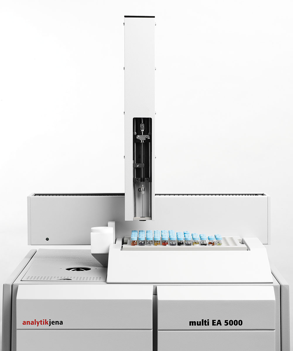
multi EA 5000
C/N/S/X Analyzer
Related Manuals for Endress+Hauser Analytik Jena multi EA 5000
Summary of Contents for Endress+Hauser Analytik Jena multi EA 5000
-
Page 1
Operating Manual multi EA 5000 C/N/S/X Analyzer… -
Page 2
Manufacturer Analytik Jena AG Konrad-Zuse-Straße 1 07745 Jena / Germany Telephone: +49 3641 77 70 Fax: +49 3641 77 9279 E-mail: info@analytik-jena.de Technical Service Analytik Jena AG Konrad-Zuse-Straße 1 07745 Jena / Germany Phone: +49 3641 77 7407 Fax: +49 3641 77 9279 Email: service@analytik-jena.com For a proper and safe use of this product follow the instructions. -
Page 3: Table Of Contents
multi EA 5000 Table of contents Table of contents 1 About this user manual …………………………2 Intended use…………………………….3 Security ……………………………… 10 Safety labeling on the device ……………………… 10 Requirements for the operating personnel………………… 11 Safety instructions, transport and commissioning ………………11 Safety instructions: during operation ………………….
-
Page 4
Table of contents multi EA 5000 Operation …………………………..48 8 Chlorine analysis with the Cl module……………………..49 Function and design ……………………….49 8.1.1 Function and measuring principle ……………………49 8.1.2 Design…………………………..49 8.1.3 Connection ………………………….. 57 Installation ………………………….. 60 Operation …………………………..64 8.3.1 Preparing the measuring cell ……………………… -
Page 5
multi EA 5000 Table of contents 13.3 Initializing the basic module and the system components …………….107 13.4 Displays in the window Status analyzer ………………….108 13.4.1 Overview …………………………..108 13.4.2 Method…………………………..109 13.4.3 Sampling modules ……………………….109 13.4.4 Detectors …………………………..110 13.5 Device faults on the basic module ……………………112 13.6 Analytical problems in the basic module………………….114 13.7… -
Page 6
Table of contents multi EA 5000 14.11 Maintenance of the Cl module chlorine detector ………………151 14.11.1 Replacing the sulfuric acid and cleaning the sulfuric acid container………….151 14.11.2 Maintenance of the measuring cell …………………….152 14.11.3 Maintenance and storage of the electrodes ………………..153 14.12 Maintenance of the UVFD 5000 and MPO 5000 sulfur detector …………..156 14.12.1 Replacing the UV lamp ………………………..156… -
Page 7: About This User Manual
multi EA 5000 About this user manual About this user manual The multi EA 5000 analyzer is intended for operation by qualified personnel with the aid of this user manual. The user manual contains descriptions of the design and operation of the multi EA 5000 and provides personnel experienced in analysis with the necessary information for the safe handling of the basic module and its components.
-
Page 8: Intended Use
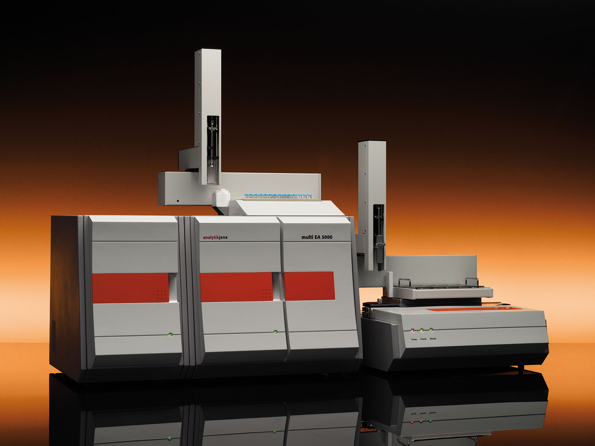
Intended use multi EA 5000 Intended use The multi EA 5000 is a modular analyzer for determining the sulfur, nitrogen, chlorine and carbon content in solid, liquid, paste-like, viscous and gaseous samples. Sample di- gestion is achieved via pyrolysis and subsequent thermal oxidation of the achieved result of the pyrolysis.
-
Page 9
multi EA 5000 Intended use Parameter Description Total sulfur Organically bound sulfur is detected. Inorganic sulfur compounds are only digested partially or not at all. Total nitrogen Organically bound nitrogen is detected. Inorganic nitrogen compounds and molecular nitrogen (N ) are only digested partially or not at all. Total carbon The total organic carbon and elementary carbon and contained CO detected. -
Page 10: Security
Security multi EA 5000 Security For your own safety and to ensure error-free and safe operation of the device, please read this chapter carefully before commissioning. Observe all safety instructions listed in this user manual and all messages and infor- mation displayed on the monitor by the control and analysis software.
-
Page 11: Requirements For The Operating Personnel
multi EA 5000 Security Warning sym- Meaning Comment Caution (GHS07) On the absorber and the chemical ozone decomposer of the CLD 5000 On the chemical ozone decomposer of the MPO 5000 The cartridges contain hazardous sub- stances. Do not open the cartridges. Only replace the entire cartridge.
-
Page 12: Safety Instructions: During Operation
Security multi EA 5000 To prevent health damage, the following must be observed when moving the device in the laboratory (lifting and carrying): ¡ For safety reasons, two persons are required to transport the device who must hold the unit by either side of the equipment. The device does not have any carrying handles.
-
Page 13: Safety Instructions: Electrical Equipment
multi EA 5000 Security 3.4.3 Safety instructions: electrical equipment Lethal voltages may occur in the device! Contact with live components may cause death, serious injury or painful electrical shock. ¡ The power plug must be connected to a proper power outlet to ensure that the device meets protection class I (ground connector).
-
Page 14: Decontamination After Soiling
Security multi EA 5000 3.4.5 Decontamination after soiling Observe the following: The operator is responsible for carrying out suitable decontamination should the ¡ device become contaminated externally or internally with dangerous substances. ¡ Splashes, drops or larger liquid spillages should be removed using an absorbent material such as cotton wool, laboratory wipes or cellulose.
-
Page 15: Safety Instructions — Maintenance And Repair
multi EA 5000 Security When closing the argon gas supply, a return of the acid used can occur in the ¡ Cl module. For this reason, the measuring gas lines to this module must be dis- connected before closing the argon gas supply. ¡…
-
Page 16: Function And Design
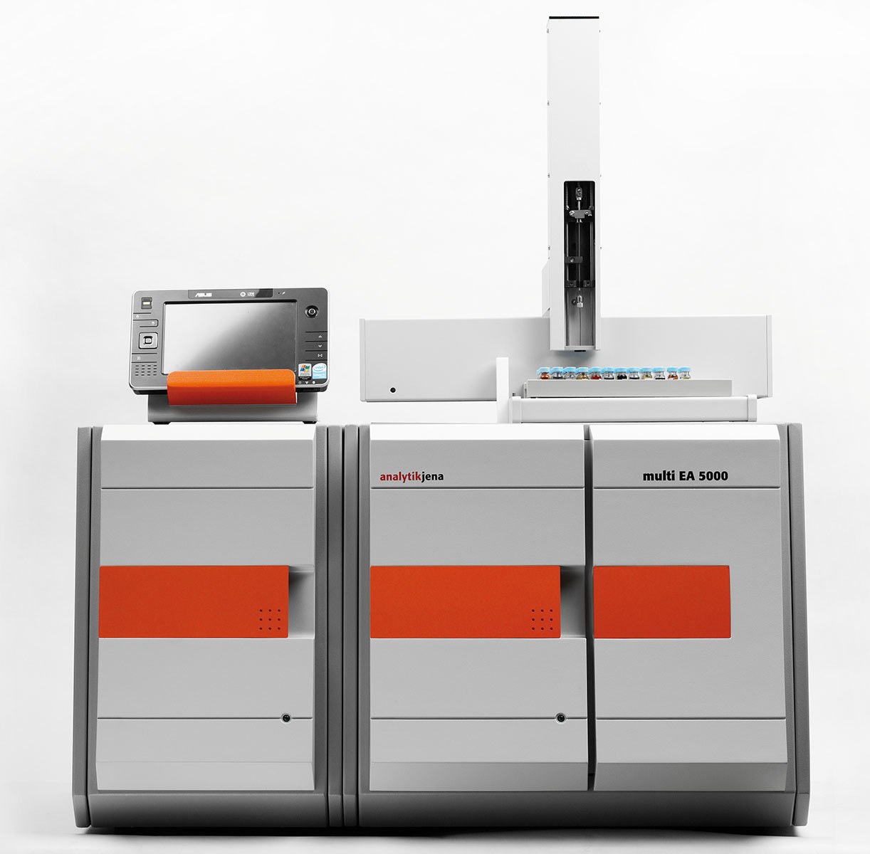
Function and design multi EA 5000 Function and design multi EA 5000 basic module The multi EA 5000 analysis system is modular and can be adapted to each measuring tasks by combining it with different detectors and sampling modules. The analysis sys- tem is used to determine the sulfur, nitrogen, chlorine and carbon content in solid, liq- uid, paste-like, viscous and gaseous samples.
-
Page 17: Figure 1 Operating Modes Of The Multi Ea 5000
multi EA 5000 Function and design Sample feed Liquid/LPG/gaseous Sample feed Solid/liquid/LPG/gaseous C/N/S analysis Dryer Flame sensor Quartz glass boat Cooled sample port Cl analysis — (EOX/TOX/AOX) Coulometer Figure 1 Operating modes of the multi EA 5000 4.1.1.2 Sample Digestion TS, TN, TC, TX and EOX Sample digestion to determine TS, TN, TC, TX and EOX can be performed in vertical and horizontal operation mode.
-
Page 18: Design Of The Basic Module
Function and design multi EA 5000 EC/OC Digestion for EC/OC determination is performed in horizontal operation mode. Digestion is performed in two phases. In the first process phase, the OC content adsorbed on the filter samples is thermally desorbed in a pure argon flow. The gaseous products are then re-incinerated in oxygen.
-
Page 19: Figure 2 Front View In Vertical Operation Mode
multi EA 5000 Function and design Figure 2 Front view in vertical operation mode 1 Ventilator 2 Control electronics 3 Membrane dryer unit 4 Tilt device 5 Pump connection for N/S/C mode 6 Combustion furnace 7 Knob for tilting the furnace Horizontal device Furnace in horizontal installation position ¡…
-
Page 20: Figure 4 Basic Module With A Sampling Module And A Detection Module
Function and design multi EA 5000 4.1.2.2 Electrical components, display elements and connections Internal device control The control electronics are found on the rear of the basic module behind the panel when viewed from the front. The control electronics provides the power supply and control of the individual components and the communication with the control PC and other con- nected system modules.
-
Page 21: Figure 5 Interfaces On The Rear Of The Device
multi EA 5000 Function and design Figure 5 Interfaces on the rear of the device 1 Gas connectors 3 USB port for PC 2 Power connection, power switch 4 Interfaces for detector modules and sampling modules Figure 6 Power connection, power switch 1 Power switch 2 Equipment fuse 3 Power connection…
-
Page 22: Figure 7 Interfaces For Detector Modules And Sampling Modules
Function and design multi EA 5000 Figure 7 Interfaces for detector modules and sampling modules 1 «External» connection 2 Autoinjector connection 3 «Flame» flame sensor connection 4 S-coulometer connection 5 S-UVF connection 6 CI-coulometer connection 7 N-CLD connection 8 C-NDIR connection 9 Sampler connection (RS-232 bus) 10 Service connection 11 Control PC connection…
-
Page 23: Figure 9 Connections For The Auto-Protection Valve Assembly And Transfer Line
multi EA 5000 Function and design Figure 9 Connections for the auto-protection valve assembly and transfer line 1 Toggle switch for opening and clos- 2 Transfer line heating connection ing the pneumatic seal in the auto- protection valve assembly 3 Valve assembly connection 4.1.2.3 Gas supply/hose diagrams Hose diagrams The connection between the individual components is made with labeled hoses.
-
Page 24: Figure 10 Hose Diagram For Horizontal Operation
Function and design multi EA 5000 main inlet seal dryer bypass Coupling Figure 10Hose diagram for horizontal operation…
-
Page 25: Figure 11 Hose Diagram For Vertical Operation
multi EA 5000 Function and design Membrane dryer Rotary bearing Combustion furnace Rotary bearing Gas box Figure 11 Hose diagram for vertical operation…
-
Page 26: Figure 12 Gas Connections At The Rear Of The Device
Function and design multi EA 5000 Gas connections at the rear of The gas connections are located on the rear of the device. The gas supplies for oxygen the device and argon must be connected to the «IN O » or «IN Ar» connection via the included con- nection hoses (AD 6 mm, ID 4 mm.
-
Page 27: Figure 13 Gas Connections On The Gas Box
multi EA 5000 Function and design Figure 13Gas connections on the gas box «main» – oxygen supply to the com- «inlet» – argon supply to the combus- bustion tube (hose 3) tion tube (hose 4) «seal» – argon connection for the seal «dryer»…
-
Page 28: Figure 15 Combustion Furnace In The Vertical And Horizontal Operating Mode
Function and design multi EA 5000 Gas supply control The composition of the gas mixture for optimum gas digestion is controlled via the flow management system (FMS). 4.1.2.4 Combustion system A resistance-heated combustion furnace for digestion temperatures of 700 to 1100 °C is used in the basic module.
-
Page 29: Sampling Modules
multi EA 5000 Function and design 4.1.2.5 Measuring gas dryer Measuring gas is dried in accordance with the measuring method: To determine TS, TN, TC, EC/OC via membrane dryer: ¡ The membrane dryer is mounted on the furnace. To increase drying effectiveness, purge gas (O ) is drawn through the membrane dryer with a pump.
-
Page 30: Manual Boat Drive (Mbd)
Function and design multi EA 5000 4.2.2 Manual Boat Drive (MBD) The MBD is used for the manual transfer is samples on the sample boat to the combus- tion tube. The user determines the transfer speed and thus the introduction of the sam- ple into the combustion zone.
-
Page 31: Installation And Commissioning
multi EA 5000 Installation and commissioning Installation and commissioning Installation conditions Installation location requirements Ambient conditions The climate conditions for the installation location are listed in the technical data (→ «Technical data for the multi EA 5000 » 176). If required, ensure that the room is temperature-controlled.
-
Page 32: Gas Supply
Installation and commissioning multi EA 5000 Gas supply The operator is responsible for the gas supply and the corresponding connections and pressure reducers. The connection hoses with outer diameter (AD) 6 mm and inner diameter (ID) 4 mm are provided with the device. Their lengths are 2 m. If other lengths are preferred, please contact the Analytik Jena AG customer service department.
-
Page 33: Figure 18 Space Required For The Basic Device And Modules (Vertical Operation)
multi EA 5000 Installation and commissioning Component Width x Height x Depth Mass [kg] Arrangement [mm] Autoinjector 30 x 80 mm 0.5 kg Installed on the basic (without syringe, module, or on the ⌀ x L) right of the basic 80 x 110 mm module Auto injector cou- pling (⌀ x L)
-
Page 34: Figure 19 Space Required For The Basic Device And Modules (Horizontal Operation)
Installation and commissioning multi EA 5000 Figure 19Space required for the basic device and modules (horizontal operation)
-
Page 35: Installing And Commissioning The Analysis System
multi EA 5000 Installation and commissioning Installing and commissioning the analysis system WARNING Danger due to incorrect commissioning ¡ The analysis system may only be set up, mounted and installed by the Analytik Jena AG customer service department. ¡ Any unauthorized access of the device can endanger the user and the operational safety of the equipment and limits or completely voids any warranty claims.
-
Page 36: Figure 20 Media Connections Of The Rear Of The Device
Installation and commissioning multi EA 5000 NOTICE Settled condensation and temperature differences can damage individual com- ponents of the basic module during commissioning. ¡ If there is any temperature difference between the storage location and the operat- ing location, allow the analyzer system to acclimatize for at least one hour in the room it will operate in.
-
Page 37: Operation
multi EA 5000 Operation Operation General notes for measuring operations Only use the correct sampling modules for the corresponding matrix and installation po- sition of the furnace for sampling. Furnace installation Sample type Sampling position Vertical: Liquids ¡ Autoinjector Multi Matrix Sampler ¡…
-
Page 38: Selecting The Measurement Method
Operation multi EA 5000 Begin the analysis with a standard solution and determine the daily factor. If the ¡ value measured for the standard solution differs by more than 20 % from the target value, repeat the measurement. If required, look for the source of the fault. If re- quired, re-calibrate the analysis system.
-
Page 39: Switching On The Basic Module And The Modules
multi EA 5000 Operation Sample Furnace installation po- Comment sition and sampling Horizontal for Column method: Activated carbon in a quartz container in a ABD with MMS quartz glass boat Batch method: Activated carbon with no quartz container in a quartz glass boat with holding-down clamp EC/OC…
-
Page 40: Switching Off The Basic Module And The Modules
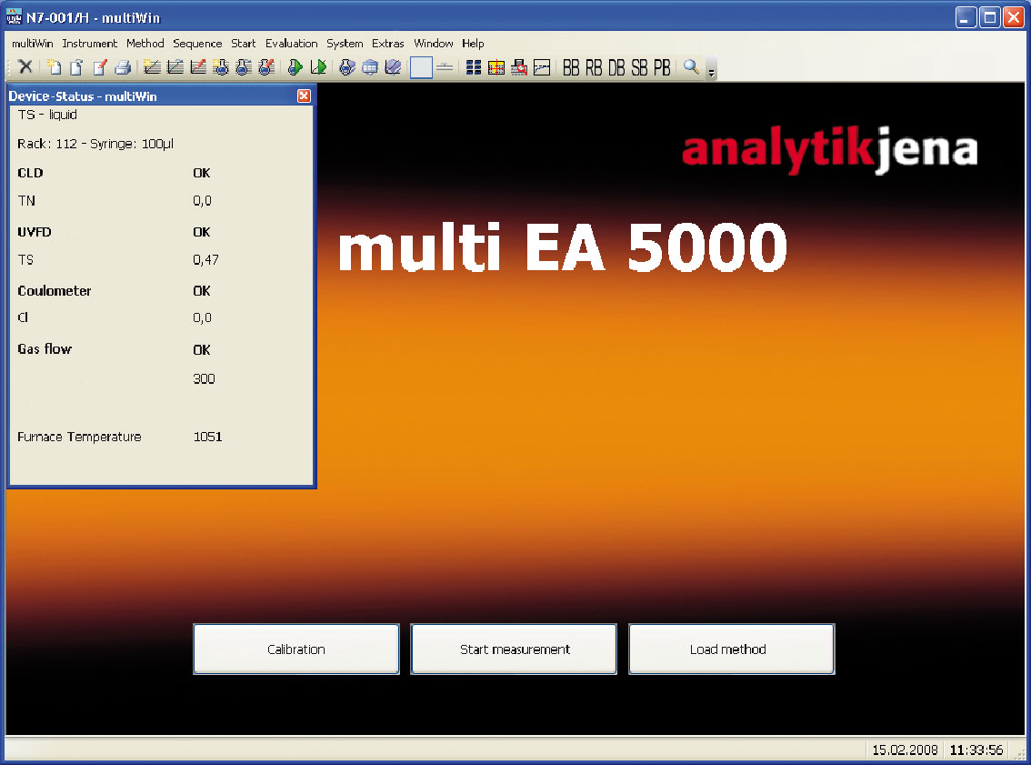
Operation multi EA 5000 } The basic module boots up. The LED on the front lights up in green after approx 30 s. } Start the multiWin program. Log in with user name and password. } Click the [Initialize analyzer] button. ü…
-
Page 41: Recommissioning After Emergency Shutdown (Cl Module)
multi EA 5000 Operation Recommissioning after emergency shutdown (Cl module) WARNING Chemical burns due to concentrated sulfuric acid If a Cl module is connected to the basic module, sulfuric acid can still be in the gas trans- fer line and the auto-protection valve assembly after an emergency shutdown. ¡…
-
Page 42
Operation multi EA 5000 – Connect the gas transfer line with the auto-protection valve assembly. Plug the heating cable plug into its socket. – Route the gas transfer line through the wall of the basic module top the detection module. Connect the gas transfer line to the sulfuric acid container. ü… -
Page 43: Nitrogen Analysis With The Cld 5000
multi EA 5000 Nitrogen analysis with the CLD 5000 Nitrogen analysis with the CLD 5000 Function and design 7.1.1 Function and measuring principle Expansion of the basic module with the detection module allows the determination of the nitrogen content in solids, liquids, and gases via chemiluminescence. Organic nitrogen compounds can be determined as a TN sum parameter with the analy- sis system.
-
Page 44: Connection
Nitrogen analysis with the CLD 5000 multi EA 5000 Figure 21Basic module with detection module and sampling module The detection module consists of the following components: Component Function Micro-plasma chamber Preparation of ozone (O ) from oxygen Converter Transformation of nitrogen dioxide ) into nitrogen monoxide (NO) Reactor with sensor Reaction of nitrogen monoxide (NO)
-
Page 45: Figure 22 Rear Of The Nitrogen Detector
multi EA 5000 Nitrogen analysis with the CLD 5000 Interface for connection to a basic module ¡ ¡ Service interface with programming button. A diagram at the center on the rear of the device explains the different connections. Figure 22Rear of the nitrogen detector gas inlet 2 Measuring gas inlet 3 Measuring gas outlet…
-
Page 46: Installation
Nitrogen analysis with the CLD 5000 multi EA 5000 Installation NOTICE Connecting or disconnecting electrical contacts may damage the sensitive electronic components of the basic module and of the detection module. ¡ Always connect the modules to power when they are switched off. NOTICE The detection module is equipped with a pump that can disrupt the function of other optical detection modules or lead to serious errors.
-
Page 47: Figure 24 Connecting Detection Modules To The Basic Module
multi EA 5000 Nitrogen analysis with the CLD 5000 } Connect the supplied power cable to the power cable connection on the rear of the module and to an earthed socket. Observe the permissible maximum voltage! } Insert the oxygen hose in the «O «…
-
Page 48: Operation
Nitrogen analysis with the CLD 5000 multi EA 5000 Operation CAUTION Risk of respiratory problems due to leaking ozone If the gas hoses have not been properly connected to the ozone generator, ozone may leak out of the detection module. ¡…
-
Page 49: Chlorine Analysis With The Cl Module
multi EA 5000 Chlorine analysis with the Cl module Chlorine analysis with the Cl module Function and design 8.1.1 Function and measuring principle Expansion of the basic module with the detection module allows determination of the chlorine content in solid, liquid, paste-like, viscous and gaseous samples. When doing so, the device will determine the bromine and iodine content as proportions of the total chlorine of the sample as well.
-
Page 50: Figure 25 Design Of The Chlorine Detector (Without Measuring Cell)
Chlorine analysis with the Cl module multi EA 5000 Figure 25Design of the chlorine detector (without measuring cell) 1 Safety attachment 2 Sulfuric acid container 3 Stirrer/cooling block 4 Connections for electrodes, measur- ing cells The wide-range coulometer has 3 application ranges. A special measuring cell is used for each application range: «high sensitive»…
-
Page 51: Figure 26 Measuring Cell «Sensitive» With Lid
multi EA 5000 Chlorine analysis with the Cl module Figure 26Measuring cell «sensitive» with lid 1 Opening for combined electrode 2 Opening for direct injection and ex- haust connection Figure 27Equipped measuring cell 1 Combined electrode 2 Olive for connecting to the exhaust The combined electrode is used for the «sensitive»…
-
Page 52: Figure 28 Combined Electrode
Chlorine analysis with the Cl module multi EA 5000 Figure 28Combined electrode 1 Connector plug 2 Generator cathode (Pt) 3 Indicator electrodes (Ag) 4 Gas inlet to measuring cell 5 Measuring gas connection (hose 20) The «high concentration» mea- The measuring cell has the same function as the «sensitive» measuring cell, but has a suring cell higher electrolyte volume.
-
Page 53: Figure 30 Measuring Cell «High Sensitive» With Lid
multi EA 5000 Chlorine analysis with the Cl module The «high sensitive» measuring This measuring cell is used for very low chlorine content (0.01 to 10 µg). In particular, it cell is recommended for use in EOX determination or for gaseous sample. The measuring cell consists of the base element with magnetic stirring rod and lid.
-
Page 54: Figure 31 Equipped Measuring Cell
Chlorine analysis with the Cl module multi EA 5000 Figure 31Equipped measuring cell 1 Gas inlet tube with screw connec- 2 Adapter for exhaust connection tion (for measuring gas) 3 Sensor electrode with pre-amplifier 4 Opening for direct injection, with plug 5 Silver electrode 6 Platinum electrode (with salt bridge)
-
Page 55: Figure 32 Sensor Electrode
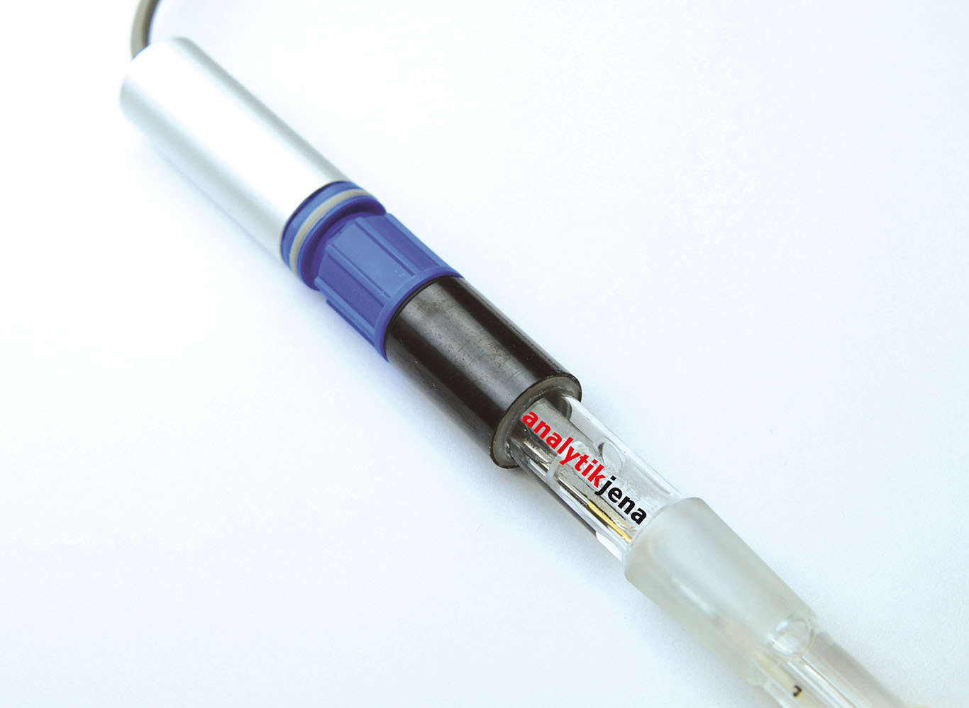
multi EA 5000 Chlorine analysis with the Cl module Figure 32Sensor electrode 1 Reference electrode 2 Filling port for internal electrolyte with rubber plug 3 Diaphragm 4 Silver ring (sensor) A short hose with a T piece can be found in the accessories of the measuring cell. The hose and the T piece are applied to the adapter and connected to the exhaust hose.
-
Page 56: Figure 34 Platinum Electrode With Salt Bridge
Chlorine analysis with the Cl module multi EA 5000 Figure 34Platinum electrode with salt bridge 1 Platinum electrode with salt bridge, 2 Salt bridge complete 3 Platinum electrode with screw-on cap and sealing ring Figure 35Silver electrode The storage container for the sensor electrode can be fitted to the front door of the chlorine module.
-
Page 57: Connection
multi EA 5000 Chlorine analysis with the Cl module 8.1.3 Connection An LED is installed on the front of the detection module. The LED lights up when the module is switched on. The power switch, the device fuse and the power connection are located on the rear of the module.
-
Page 58: Figure 37 Measuring Cell Connections
Chlorine analysis with the Cl module multi EA 5000 Figure 37Measuring cell connections 1 Combined electrode connection 2 Measuring cells «sensitive» and «high concentration» connection 3 Platinum electrode connection 4 Silver electrode connection 5 Sensor electrode connection Measuring gas transfer A heated gas transfer line is used to transfer the measuring gas. It connects the combus- tion system of the basic module with the sulfuric acid container in the detection module.
-
Page 59: Figure 39 Gas Infeed Tube With Ptfe Connector
multi EA 5000 Chlorine analysis with the Cl module Figure 39Gas infeed tube with PTFE connector In both cases, the measuring gas hose is fastened with the aid of a PTFE connector. En- sure the proper fit of the sealing rings! Figure 40Gas infeed to the «sensitive»…
-
Page 60: Installation
Chlorine analysis with the Cl module multi EA 5000 Installation CAUTION Risk of injury A risk of injury due to broken glass is present when handling glass parts. ¡ Handle glass parts with extreme caution. NOTICE Connecting or disconnecting electrical contacts may damage the sensitive electronic components of the basic module and of the detection module.
-
Page 61: Figure 41 Connection Of The Heated Gas Transfer Lines To The Sulfuric Acid Container
multi EA 5000 Chlorine analysis with the Cl module Installing the detection module Figure 41Connection of the heated gas transfer lines to the sulfuric acid container 1 Safety attachment 2 Sulfuric acid container 3 Hose for measuring gas infeed 4 Connector 5 Banjo bolt 6 Heated gas transfer line 7 Measuring gas transfer to the mea-…
-
Page 62: Figure 42 Connection Of The Gas Transfer Line In The Basic Module
Chlorine analysis with the Cl module multi EA 5000 Figure 42Connection of the gas transfer line in the basic module Left Connection to the auto-pro- Right Heating cable connection tection valve assembly ü Connection of the detection module is complete. Inserting measuring cells The «sensitive»…
-
Page 63
multi EA 5000 Chlorine analysis with the Cl module The «high sensitive» measuring cell is inserted into the detection module as follows: NOTICE Risk of damage to the sensor electrode The sensor pin and the gold contact of the sensor electrodes are sensitive to touch. ¡… -
Page 64: Operation
Chlorine analysis with the Cl module multi EA 5000 Operation 8.3.1 Preparing the measuring cell Preparing the measuring cell includes the following steps: ¡ Preparing the electrolyte solution Performing the end point routine ¡ 8.3.1.1 The «sensitive» and «high concentration» measuring cells The measuring cells are similar in function.
-
Page 65
multi EA 5000 Chlorine analysis with the Cl module The finished electrolyte solution (solution C) can be kept for approx. 30 days if kept ¡ in a well-sealed glass container at 20 to 25 °C. Performing the end point rou- An end point routine is necessary after every electrolyte change. The end point routine is tine used to adjust the electrolyte to the optimal operating range of the measuring cell. -
Page 66: Operating The Analysis System
Chlorine analysis with the Cl module multi EA 5000 Preparing internal electrolyte ð Reagents required: 8.52 g of sodium sulfate p.a., anhydrous, max. chlorine content 0.001 } Dilute 8.52 g of sodium sulfate (Na ) in approx. 50 ml of ultrapure water in a 100 ml volumetric flask.
-
Page 67: Notes For Measuring Operations
multi EA 5000 Chlorine analysis with the Cl module } Initialize the analysis system by clicking on [Initialize analyzer]. ü The initialization and automatic detection of all connected components will be carried out. } Ready the samples. } Activate a pre-existing method via the Method |Method — activate menu item. } Alternatively: Create a new method in the Method |Method — new menu.
-
Page 68
Chlorine analysis with the Cl module multi EA 5000 The «sensitive» and «high con- Fill the measuring cells with fresh electrolyte solution daily: centration» measuring cells ¡ «sensitive» measuring cell: 15 to 20 ml ¡ «high concentration» measuring cell: 120 ml The «high sensitive»… -
Page 69: Sulfur Analysis With The Uvfd 5000, Mpo 5000
multi EA 5000 Sulfur analysis with the UVFD 5000, MPO 5000 Sulfur analysis with the UVFD 5000, MPO 5000 Function and design 9.1.1 Function and measuring principle Expansion of the basic module with the detection module allows determination of the sulfur content in solid, liquid, paste-like, viscous and gaseous samples via UV floures- cence.
-
Page 70: Connection
Sulfur analysis with the UVFD 5000, MPO 5000 multi EA 5000 To determine the sulfur content without interference from simultaneous increased ni- trogen content the patented MPO (microplasma optimization) technology has been de- veloped. The MPO technology removes the interfering nitrogen monoxide from the measuring gas.
-
Page 71: Installation
multi EA 5000 Sulfur analysis with the UVFD 5000, MPO 5000 S-UVF Figure 44Rear of the sulfur detector 1 Chemical ozone decomposer (MPO) 2 Measuring gas inlet 3 Measuring gas outlet 4 Service interface and programming button. 5 Interface to the basic module 6 Power connection 7 Fuse holder 8 Equipment switch…
-
Page 72: Figure 45 Chemical Ozone Decomposer
Sulfur analysis with the UVFD 5000, MPO 5000 multi EA 5000 } Leave the «sample out» outlet unconnected or connect it to the measuring gas inlet of the next detection module. } For detection modules with MPO technology: Install the chemical ozone decomposer on the rear of the module: –…
-
Page 73: Operation
multi EA 5000 Sulfur analysis with the UVFD 5000, MPO 5000 Operation CAUTION Risk of respiratory problems due to leaking ozone If the gas hoses have not been properly connected to the ozone generator, ozone may leak out of the detection module. ¡…
-
Page 74: Sulfur Analysis With The Coulometric Sulfur Module
Sulfur analysis with the Coulometric Sulfur Module multi EA 5000 Sulfur analysis with the Coulometric Sulfur Module 10.1 Function and design 10.1.1 Function and measuring principle Expansion of the basic module with the detection module allows the determination of the sulfur content in solids, liquids, and gases via microcoulometric titration. The organic sulfur compounds are incinerated into a mixture of sulfur dioxide (SO ) and sulfur trioxide (SO…
-
Page 75: Figure 46 Coulometric Sulfur Detector With Measuring Cell (Without Door)
multi EA 5000 Sulfur analysis with the Coulometric Sulfur Module Figure 46Coulometric sulfur detector with measuring cell (without door) 1 Indicator electrodes connection 2 Indicator electrode (black) 3 Gas inlet 4 Measuring cell 5 Port for manual dosing 6 Anode (yellow) 7 Cathode (red) 8 Generator electrodes connection…
-
Page 76: Figure 47 Coulometric Sulfur Detectors Without Measuring Cell
Sulfur analysis with the Coulometric Sulfur Module multi EA 5000 Figure 47Coulometric sulfur detectors without measuring cell 1 Measuring gas hose from the basic 2 Measuring gas hose to the measur- module (hose 71) ing cell (hose 72) 3 HX absorber 4 Hose 73 5 Magnetic mixer with controls 6 Magnetic mixer connection 7 NOx absorber…
-
Page 77: Figure 48 Coulometric Measuring Cell
multi EA 5000 Sulfur analysis with the Coulometric Sulfur Module Figure 48Coulometric measuring cell 1 Indicator electrodes (black) 2 Gas inlet tube 3 Port for manual dosing 4 Electrolyte solution filling height 5 Cathode (red) 6 Anode (yellow) 7 Gas outlet Electrodes A diaphragm is located between the electrodes for generation (anode and cathode).
-
Page 78: Figure 49 Generator And Indicator Electrodes, Gas Inlet Tube
Sulfur analysis with the Coulometric Sulfur Module multi EA 5000 Figure 49Generator and indicator electrodes, gas inlet tube 1 Generator electrodes (with union 2 Cathode (inside) nut) 3 Diaphragm 4 Anode (outside) 5 Platinum electrodes 6 Gas inlet tube 7 Indicator electrodes Absorber To clean the measuring gas, two absorbers are installed in the detection module.
-
Page 79: Figure 50 Nox Absorber And Hx Absorber
multi EA 5000 Sulfur analysis with the Coulometric Sulfur Module Figure 50NOx absorber and HX absorber 1 NOx absorber 2 HX absorber Hose diagram Labeled hoses connect the measuring cell with the other components in the detection module. The numbers in the hose diagram correspond to the labels on the hoses. Measuring cell Mixer Figure 51Hose diagram…
-
Page 80: Connection
Sulfur analysis with the Coulometric Sulfur Module multi EA 5000 10.1.3 Connection The electrical connection and the interface to the basic module can be found on the rear of the detection module. The device switch for switching the detection module on and off is located on the top right of the rear of the device (when viewed from the front).
-
Page 81: Installation
multi EA 5000 Sulfur analysis with the Coulometric Sulfur Module 10.2 Installation CAUTION Risk of injury A risk of injury due to broken glass is present when handling glass parts. ¡ Handle glass parts with extreme caution. NOTICE Connecting or disconnecting electrical contacts may damage the sensitive electronic components of the basic module and of the detection module.
-
Page 82: Figure 53 Coulometric Sulfur Detector With Measuring Cell (Without Door)
Sulfur analysis with the Coulometric Sulfur Module multi EA 5000 Figure 53Coulometric sulfur detector with measuring cell (without door) 1 Indicator electrodes connection 2 Indicator electrode (black) 3 Gas inlet 4 Measuring cell 5 Port for manual dosing 6 Anode (yellow) 7 Cathode (red) 8 Generator electrodes connection…
-
Page 83: Operation
multi EA 5000 Sulfur analysis with the Coulometric Sulfur Module 10.3 Operation 10.3.1 Preparing the measuring cell Preparing the measuring cell includes the following steps: ¡ Preparing the electrolyte solution Performing the end point routine ¡ Two further solutions are required for the end point routine and for the check of the measuring cell.
-
Page 84: Operating The Analysis System
Sulfur analysis with the Coulometric Sulfur Module multi EA 5000 As soon as the cell potential goes outside of the operating range, the software will auto- matically start an end point routine. Cell potential is lower than the operating range: Automatic generation start (iodine generation) ¡…
-
Page 85
multi EA 5000 Sulfur analysis with the Coulometric Sulfur Module } Select Start |Start — Analysis in the menu. } Select an analysis group or create a new one and confirm via [OK]. } Create an analysis sequence. } Enter the sample ID for all sample in the Name field. } Release all sequence lines } Confirm the entries with [OK]. -
Page 86: Carbon Analysis With The Tc Module
Carbon analysis with the TC module multi EA 5000 Carbon analysis with the TC module 11.1 Function and design 11.1.1 Function and measuring principle Expansion of the basic module with the detection module allows determination of the carbon content in solid, liquid, paste-like, viscous and gaseous samples. The detection module contains a wide-range NDIR detector.
-
Page 87: Connection
multi EA 5000 Carbon analysis with the TC module The detection module can be used to determine TC and EC/OC. ¡ TC determination can be performed in both the multi-purpose combustion tube (standard tube) and the special EC/OC combustion tube. ¡…
-
Page 88: Installation
Carbon analysis with the TC module multi EA 5000 11.2 Installation NOTICE Connecting or disconnecting electrical contacts may damage the sensitive electronic components of the basic module and of the detection module. ¡ Always connect the modules to power when they are switched off. } Place the detection module to the left of the basic module.
-
Page 89
multi EA 5000 Carbon analysis with the TC module } Click the [Start Measurement] button. ü The prepared analysis sequence is processed. For manual sampling, follow the instructions in the software. -
Page 90: Carbon Analysis With The Toc Module
Carbon analysis with the TOC module multi EA 5000 Carbon analysis with the TOC module 12.1 Function and design 12.1.1 Function and measuring principle The detection module contains a wide-range NDIR detector. Expansion of the basic module with the detection module allow determination of the following sum parame- ters: Sum parameters Samples…
-
Page 91: Figure 56 Toc Detector, Door Opened
multi EA 5000 Carbon analysis with the TOC module Figure 56TOC detector, door opened 1 Water traps 2 Measuring gas hose from the basic module (hose 80) 3 Condensate pump 4 TIC reactor 5 Cooling block (measuring gas dryer) 6 Halogen trap 7 Hose 81 The basic module must be equipped with the following components to analyze aqueous samples:…
-
Page 92: Figure 57 Components In The Basic Module
Carbon analysis with the TOC module multi EA 5000 Figure 57Components in the basic module 1 TOC combustion tube injection port 2 Spherical joint (fasten with forked clamp) 3 Condensation coil TOC combustion tube The TOC combustion tube (reactor) is used to determine the TC, TOC and NPOC param- eters in water samples.
-
Page 93: Figure 59 Tube Holder For The Toc Combustion Tube
multi EA 5000 Carbon analysis with the TOC module Screw the screw cap with the septum on the top opening of the combustion tube. Con- nect the condensation coil with the aid of a fork type clamp to the spherical joint on the lateral outlet.
-
Page 94: Figure 60 Condensation Coil
Carbon analysis with the TOC module multi EA 5000 Figure 60Condensation coil 1 FAST connector 2 Spherical joint The detection module is equipped with the TIC condensation unit. The TIC condensation unit consists of the following components: Component Task TIC reactor TIC determination Gas-liquid separator Separation of the liquid phase (conden-…
-
Page 95: Connection
multi EA 5000 Carbon analysis with the TOC module NDIR outlet Measuring gas inlet Waste (from condensation coil, basic device) NDIR measuring gas inlet Figure 61Hose diagram of the TOC detector Straight and angled FAST connectors are used to fasten hose connections. 12.1.3 Connection The device switch for switching the detection module on and off is located on the top right of the rear of the device (when viewed from the front).
-
Page 96: Figure 62 Rear Of The Toc Detector
Carbon analysis with the TOC module multi EA 5000 Figure 62Rear of the TOC detector 1 «External (out)» connection socket 2 «C-NDIR» interface cable connection (25-pin) (9-pin) 3 «External (in)» interface cable con- 4 «Sample in» measuring gas inlet nection (25-pin) 5 «Sample out»…
-
Page 97: Installation
multi EA 5000 Carbon analysis with the TOC module EC/OC determination requires the use of the EC/OC combustion tube. For the connection to the basic module, hose 82 is removed from the «sample in» mea- suring gas inlet on the rear of the detection module. The «sample in» measuring gas inlet is connected to the «Sample OUT N/S/C»…
-
Page 98: Figure 63 Toc Detector, Door Opened
Carbon analysis with the TOC module multi EA 5000 Figure 63TOC detector, door opened 1 Water traps 2 Measuring gas hose from the basic module (hose 80) 3 Condensate pump 4 TIC reactor 5 Cooling block (measuring gas dryer) 6 Halogen trap 7 Hose 81 Preparing the basic module } Fill the TOC combustion tube as shown in the illustration.
-
Page 99: Operation
multi EA 5000 Carbon analysis with the TOC module Figure 64TOC combustion tube 1 HT mat 2 Quartz glass fragments 3 Quartz wool 4 Catalyst 5 Quartz wool For NPOC determination } Prepare the detection module and the basic module as previously described. } Connect the NPOC purge hose (hose 16) to the «out ABD»…
-
Page 100: Notes For Measuring Operations
Carbon analysis with the TOC module multi EA 5000 } Start the control and analysis software and login with your username and password. } Initialize the analysis system by clicking on [Initialize analyzer]. ü The initialization and automatic detection of all connected components will be carried out.
-
Page 101: Troubleshooting
multi EA 5000 Troubleshooting Troubleshooting 13.1 General notes For fault analysis, log files can be recorded. Log file recording should be activated after consultation with Analytik Jena AG customer service for specific faults. The save location of the log files can be defined via the Extras |Configuration menu item in the Configuration |Error analysis window.
-
Page 102
Troubleshooting multi EA 5000 Error Error message/cause Remedy code Serial port not available! Serial port not reachable! communication problems Disconnect the USB connection between the basic module and the PC and reconnect after approx. 10 s. Initialize Operating system faults: Unauthorized access Undefined multiWin end Exit the software and switch off the device Detach the USB cable and re-connect after ap-… -
Page 103
multi EA 5000 Troubleshooting Error Error message/cause Remedy code C sensor: No connection C sensor: CRC error Communication interrupted after sensor detection Acknowledge message during initialization Initialize C sensor: Analog values outside range The analog values of the detector are outside the Check the quality of the carrier gas operating range Initialize… -
Page 104
Troubleshooting multi EA 5000 Error Error message/cause Remedy code Gas box: Fault when setting the target flow Communication to gas box interrupted Acknowledge message Initialize Gas box: Conversion fault 1 Gas box: Conversion fault 2 Gas box: Conversion fault 3 Gas box: Conversion fault 4 Communication faulty (readout of flows from gas Acknowledge message… -
Page 105
multi EA 5000 Troubleshooting Error Error message/cause Remedy code ABD: No connection Communication error after ABD was detected dur- Acknowledge message ing initialization Initialize ABD: Runtime exceeded Completion message for the ABD movement Check that the flame sensor is properly applied takes too long and connected Record log files… -
Page 106
Troubleshooting multi EA 5000 Error Error message/cause Remedy code Syringe not drawn back all the way Draw syringe back all the way Insert syringe Autoinjector: No connection Auto-injector coupling not found Check connection Acknowledge message Initialize No Autoinjector AI-EA was found Autoinjector AI-EA not connected or faulty Check connection Acknowledge message… -
Page 107: Initializing The Basic Module And The System Components
multi EA 5000 Troubleshooting Error Error message/cause Remedy code Syringe pump: Pump step not permitted Syringe pump: Command error Syringe pump: incorrect type Communication error Acknowledge message Initialize 13.3 Initializing the basic module and the system components Initialization of a measuring system establishes communication between the measuring system and the computer.
-
Page 108: Displays In The Window Status Analyzer
Troubleshooting multi EA 5000 13.4 Displays in the window Status analyzer 13.4.1 Overview In the Status analyzer window, information on the device status or information on indi- vidual modules is displayed. Status analyzer multi EA 5000 TN liquid vertical (1) — liquid Rack : 112 — Syringe…
-
Page 109: Method
multi EA 5000 Troubleshooting 13.4.2 Method The following can be displayed in the top line of the Status analyzer window: Display Description TN(1) — liquid Example of a method: Name(version) – state Possible states: ¡ Liquid ¡ Solid ¡ ¡ AOX, AOX solid ¡…
-
Page 110: Detectors
Troubleshooting multi EA 5000 The following status displays are possible: Device not ready for measurement Display Description No sampling module dis- Device not ready for measurement, no sampling mod- played (display empty) ule identified: Connect and activate at least one sampling mod- ¡…
-
Page 111
multi EA 5000 Troubleshooting The following status displays are possible: Device ready for measurement Display Description OK (green, black) Detector is ready for measurement Device not ready for measurement — general Display Description No detector displayed (dis- No detector detected play empty) ¡… -
Page 112: Device Faults On The Basic Module
Troubleshooting multi EA 5000 End point routine Automatic end point routine running: ¡ Wait for the end point routine to finish Drift determination Drift determination immediately after titration or end point routine: Wait until drift determination is complete (ap- ¡ prox.
-
Page 113
multi EA 5000 Troubleshooting Error Possible cause Remedy Check the connection be- tween the basic module and the PC Malfunction in the inter- Inform customer service nal electronics department Furnace temperature is Temperature control Inform customer service outside tolerance limits or faulty department target temperature is not… -
Page 114: Analytical Problems In The Basic Module
Troubleshooting multi EA 5000 Error Possible cause Remedy Heating faulty Inform customer service department Temperature control faulty Auto-injector not de- Auto-injector and au- Switch off the autosam- tected tosampler switched on at pler the same time 13.6 Analytical problems in the basic module Error Possible cause Remedy…
-
Page 115: Device Faults On The Cld 5000
multi EA 5000 Troubleshooting Error Possible cause Remedy Scattering measurements Dosing faulty Check dosing Combustion tube contam- Clean or replace combus- inated or severely crystal- tion tube lized 13.7 Device faults on the CLD 5000 Error Possible cause Remedy LED in front panel flash- ¡…
-
Page 116: Analytical Problems During Tc Determination
Troubleshooting multi EA 5000 Error Possible cause Remedy Smell of ozone ¡ Chemical ozone de- ¡ Replace chemical composer old/inef- ozone decomposer fective (→ «Replacing the chemical ozone de- composer» 149) Gas hoses on the Check hoses ¡ ¡ ozone generator Search for leak as ¡…
-
Page 117: Device Faults On The Chlorine Detector
multi EA 5000 Troubleshooting Error Possible cause Remedy ¡ Converter worn out/ ¡ Inform customer ser- vice department ¡ Ozone generator ¡ Replace ozone gener- faulty ator, see (→ «Replac- ing the ozone gener- ator» 146) Device leaking or de- Inform customer ser- ¡…
-
Page 118: Analytical Problems During Aox, Eox And Tx Determination
Troubleshooting multi EA 5000 13.10 Analytical problems during AOX, EOX and TX determination Error Possible cause Remedy Low results Incomplete HX for- Reduce sample size/ ¡ ¡ mation due too ex- amount cessive halogen con- Dilute sample ¡ tents, due to exces- sive inorganically bound halogen com- pounds or due to…
-
Page 119: Device Faults On The Uvfd 5000 And Mpo 5000
multi EA 5000 Troubleshooting 13.11 Device faults on the UVFD 5000 and MPO 5000 Error Possible cause Remedy LED in front panel flash- Run-in period not yet Wait for the comple- ¡ ¡ completed tion time for the run- in period of approx 30 min to elapse.
-
Page 120: Device Faults On The Coulometric Sulfur Detector
Troubleshooting multi EA 5000 Error Possible cause Remedy ¡ Sample too viscous ¡ Use the horizontal too be drawn in with- operation mode and out air pockets dilute the sample, or dose directly as a solid. Inhomogeneous sam- Homogenize sample ¡…
-
Page 121
multi EA 5000 Troubleshooting Error Possible cause Remedy ¡ In vertical operation ¡ Check the position of mode: Quartz wool the quartz wool, ad- not present or at the just as necessary wrong position in the combustion tube Sample evaporates Use a cooled sampler. -
Page 122: Device Faults On The Carbon Detector
Troubleshooting multi EA 5000 13.15 Device faults on the carbon detector Error Possible cause Remedy Analog values exceeding Analog values outside Check the gas con- ¡ ¡ values range (display in of operating range nection to the basic the Status analyzer win- module dow) ¡…
-
Page 123: Device Faults On The Toc Detector
multi EA 5000 Troubleshooting Error Possible cause Remedy ¡ Inlet gas flow set too ¡ Adjust method pa- low in the method rameters (EC/OC methods only) Results too high Inlet gas flow set too Adjust method pa- ¡ ¡ low in the method rameters (EC/OC methods only)
-
Page 124: Analytical Problems During Tc, Ec/Oc, Toc, Npoc And Tic Determination
Troubleshooting multi EA 5000 Error Possible cause Remedy ¡ Rinse the syringe thoroughly with ul- trapure water after each cleaning step Water traps clogged Service life expired Replace the water ¡ ¡ (> 6 months) traps Do not analyze any ¡ Water trap capacity ¡…
-
Page 125
multi EA 5000 Troubleshooting Error Possible cause Remedy ¡ Inlet gas flow set too ¡ Adjust method pa- low in the method rameters (EC/OC methods only) Results too high Inlet gas flow set too Adjust method pa- ¡ ¡ low in the method rameters (EC/OC methods only) -
Page 126
Troubleshooting multi EA 5000 Error Possible cause Remedy Low results ¡ Catalyst depleted ¡ Exchange the catalyst ¡ System is leaking ¡ Check the sluice for leaks ¡ Replace septum ¡ Incorrect injection vol- ¡ For manual sampling: introduce the sample volume set in the method Phosphoric acid in the… -
Page 127: Maintenance And Care
multi EA 5000 Maintenance and care Maintenance and care 14.1 Overview of maintenance work Basic module Maintenance inter- Measure Daily and after Check gas flow maintenance Check system tightness Weekly Clean and care of the analyzer Check all hose connection for proper fit; replace loose connec- tions Monthly Check fastening screws for proper fit;…
-
Page 128
Maintenance and care multi EA 5000 UVFD 5000, MPO 5000 Maintenance inter- Maintenance task Weekly Clean the module from the outside Check all screw connections for tight fit Annually Replace the absorber (MPO 5000 only) As necessary Replace the UV lamp Cl module Maintenance inter- Maintenance task… -
Page 129: Maintenance Of The Multi-Purpose Combustion Tube
multi EA 5000 Maintenance and care TC module Maintenance inter- Maintenance task Weekly Clean the module from the outside Check hoses for cracks, replace as necessary Check hose connections for tight fit TOC module Maintenance inter- Maintenance task Daily Check gas flow Check copper wool in the halogen trap for discoloration Regenerate the TIC reactor Weekly…
-
Page 130: Removing The Combustion Tube
Maintenance and care multi EA 5000 14.2.1 Removing the combustion tube CAUTION There is a risk of burns at the combustion furnace and combustion tube! ¡ Only perform removal when cold. Allow the device to cool sufficiently. ¡ Wear the heat-proof gloves included in the delivery when handling hot components. These gloves are suitable for temperatures of up to 200 °C.
-
Page 131: Cleaning The Combustion Tube
multi EA 5000 Maintenance and care 14.2.2 Cleaning the combustion tube ð Remove the combustion tube from the combustion furnace (→ «Removing the com- bustion tube» 130). } Remove the screw cap and septum, if present. Remove the 2 angled FAST connectors from the combustion tube.
-
Page 132: Installing The Combustion Tube
Maintenance and care multi EA 5000 } Remove the combustion tube from the combustion furnace as described. } Roll a small amount of quartz wool into a loose plug approx. 1.5 to 2 cm long. } Insert the quartz wool plug into the inner tube of the combustion tube with a clean glass rod.
-
Page 133
multi EA 5000 Maintenance and care } Place the combustion system in the vertical position. } For nitrogen and sulfur determination in vertical operation mode: Ensure that the quartz wool plug has been inserted at the proper place in the combustion tube. -
Page 134: Maintenance Of The Auto-Protection Valve Assembly
Maintenance and care multi EA 5000 14.3 Maintenance of the auto-protection valve assembly CAUTION Risk of injury from falling components The user can be injured if the assembly falls down during maintenance. ¡ Exercise extreme caution during maintenance of the auto-protection valve assem- bly.
-
Page 135: Check And Replace The Filter
multi EA 5000 Maintenance and care } Pull the electrical connection of the auto-protection valve assembly and, where applicable, the transfer line out of the connection. } Hold the auto-protection valve assembly with the left hand and pull at the knob of the clamping mount with the right hand to open the lock. Re- move the auto-protection valve assembly from the combustion furnace.
-
Page 136: Replacing The Pneumatic Seal
Maintenance and care multi EA 5000 } Remove the intermediate ring. } Remove the worn filter and insert a new filter. } Reassemble the auto-protection valve assembly again in reverse order. ü The auto-protection valve assembly is ready for operation again. 14.3.3 Replacing the pneumatic seal } Remove the auto-protection valve assembly.
-
Page 137: Replacing The Membrane Dryer
multi EA 5000 Maintenance and care } Carefully separate the special seal from the ring. } Insert a new special seal into the ring. } Place the PTFE disk (2) in the housing (3). } Place the seal (1) in the housing. The hole in the ring must align with the hole in the housing.
-
Page 138
Maintenance and care multi EA 5000 For better clarity, some work steps are displayed with the side panels removed. How- ever, for the installation and removal of the membrane dryer it is not necessary to re- move the side panels. } Move the combustion furnace into the horizontal position. -
Page 139: Replacing The Hose Connections
multi EA 5000 Maintenance and care 14.5 Replacing the hose connections Check the hose connections regularly for leaks. Remove and replace faulty hoses and hose connections. Check the system for leaks after maintenance (→ «Checking the sys- tem for leaks» 142). When replacing Fingertight screw connections, observe the following: Only use straight cut, round and unpinched hose ends for the connection.
-
Page 140: Replacing The Check Valves And Particle Filters
Maintenance and care multi EA 5000 } Insert the septum and screw the screw cap back onto the combustion tube. ü Replacing the septum on the combustion tube is now complete. 14.7 Replacing the check valves and particle filters 14.7.1 Replacing the check valves on the gas box The check valves must be replaced if the gas flow can no longer be set to the target value (observe the message in the software) and possible leaks in the system have been excluded.
-
Page 141: Replacing The Particle Filters In The Gas Inlets
multi EA 5000 Maintenance and care } Replace the sealing rings of the check valves in the upper and lower part of the valve block. } Insert new check valves. } Assemble the valve block and screw on the top part. } Connect hose 3 to the «main»…
-
Page 142: Checking The System For Leaks
Maintenance and care multi EA 5000 14.8 Checking the system for leaks } Switch on the basic module and the system components. } Open the gas supply. } Start the multiWin program. } Activate a method. ü The current gas flows are displayed in the Status analyzer window. Faulty gas inlet flows are marked in red in the Status analyzer window.
-
Page 143
multi EA 5000 Maintenance and care } Assemble the flow monitoring set in the following order: – Thread the screw cap, the seal and the sealing cone (1) onto the thin hose (2). – Connect the hose (2) with the other hose (3). –… -
Page 144: System Tightness For Toc Methods
Maintenance and care multi EA 5000 14.8.3 System tightness for TOC methods System tightness for the gas path from the inlet of the basic module to the outlet of the TOC module is not regulated automatically. Use the hose set included in the scope of de- livery and proceed as follows: ð…
-
Page 145
multi EA 5000 Maintenance and care CAUTION Risk of injury from falling components The user can be injured if the combustion furnace falls down during installation/re- moval. ¡ Exercise extreme caution when installing/removing the combustion furnace. The combustion furnace must be removed for transport. } Remove the combustion tube (→… -
Page 146: Maintenance Of The Cld 5000 Nitrogen Detector
Maintenance and care multi EA 5000 } Move the combustion furnace into the horizontal position. } Remove the auto-protection valve assembly from the combustion fur- nace (→ «Maintenance of the auto-protection valve assembly» 134). } Detach hose 14 (see arrow). Press the ring at the plug connector into the connector and pull off the hose.
-
Page 147
multi EA 5000 Maintenance and care CAUTION Risk of respiratory problems due to leaking ozone If the gas hoses are not properly connected to the ozone generator, ozone can leak out of the detection module. ¡ Ensure proper hose connection. ¡… -
Page 148: Replacing The Absorber
Maintenance and care multi EA 5000 Figure 68Replacing the ozone generator 1 Oxygen connection (O 2 Ozone outlet (O out) 3 Communication cable (to the PCB) Checking the function of the Check the function of the detection module after maintenance via a control measure- detection module ment.
-
Page 149: Replacing The Chemical Ozone Decomposer
multi EA 5000 Maintenance and care Figure 69Absorber 1 Hose 6 connection 2 Holding clamp 3 Absorber 14.10.3 Replacing the chemical ozone decomposer WARNING Risk of electric shock High voltages are present in the interior of the device, which can lead to electric shock if contacted.
-
Page 150: Figure 70 Replacing The Chemical Ozone Decomposer
Maintenance and care multi EA 5000 } Switch off the detection module via the power switch. } Remove the left side panel. Remove the 4 screws to do this. Remove the protective grounding cable and remove the side panel. } Disconnect the following hose connections: Disconnect hose 25 from the T piece.
-
Page 151: Maintenance Of The Cl Module Chlorine Detector
multi EA 5000 Maintenance and care 14.11 Maintenance of the Cl module chlorine detector 14.11.1 Replacing the sulfuric acid and cleaning the sulfuric acid container. WARNING Risk of chemical burns Concentrated sulfuric acid can cause severe chemical burns! ¡ Before replacing the sulfuric acid: Switch off the gas supply via the software. Risk of splashing if the gas supply is running.
-
Page 152: Maintenance Of The Measuring Cell
Maintenance and care multi EA 5000 ð Replace the sulfuric acid daily. High sample throughput may require more frequent replacement. } Exit the multiWin software and switch off the analysis system. Switch of the detec- tion module via the switch on the rear of the device. } Allow the heated gas transfer line to cool or wear heat-proof gloves when replacing the sulfuric acid.
-
Page 153: Maintenance And Storage Of The Electrodes
multi EA 5000 Maintenance and care ð For the «sensitive» and «high concentration» measuring cells: Replace the electrolyte solution daily. ð For the «high sensitive» measuring cell: Refill the electrolyte solution daily. Only replace the electrolyte solution in the event of analytical problem and if crys- talline deposits form.
-
Page 154: Figure 72 Correct Handling Of The Combined Electrode
Maintenance and care multi EA 5000 Figure 72Correct handling of the combined electrode Drying of electrolyte on the combined electrode can cause an irreversible reduction of its sensitivity or damage the electrode. Therefore, make sure that the electrolyte never dries on the combined electrode. For brief operational interruptions (one full day): Store the combined electrode in ¡…
-
Page 155
multi EA 5000 Maintenance and care NOTICE Risk of destruction of the sensor electrode due to cleaning agents or abrasives The sensor electrode is particularly mechanically sensitive around the area of the silver ring and the diaphragm. ¡ Do not touch the silver ring. ¡… -
Page 156: Maintenance Of The Uvfd 5000 And Mpo 5000 Sulfur Detector
Maintenance and care multi EA 5000 During this time: Start an end point routine from time to time to remove excess ¡ chloride ions. Platinum electrode The salt bridge of the platinum electrode has a diaphragm. The electrolyte solution must not be allowed to crystallize inside the diaphragm, otherwise it can clog.
-
Page 157
multi EA 5000 Maintenance and care NOTICE Contamination reduces the effectiveness of the UV lamp. ¡ Do not touch the glass of the new lamp. In particular, protect the radiation emission point made of quartz glass. ¡ If the glass is touched, wipe it with a lint-free cloth and pure alcohol. The following states indicate a defective UV lamp: The run-in period of the detection module takes is not complete after 30 min. -
Page 158: Replacing The Chemical Ozone Decomposer
Maintenance and care multi EA 5000 } Place the lamp in the proper position when inserting: The pin on the holder must fit into the groove of the lamp body. } Fasten the new lamp with the 2 screws. } Plug the connection plug back into the socket all the way. } Fasten the side panel again.
-
Page 159: Maintenance Of The Coulometric Sulfur Detector
multi EA 5000 Maintenance and care 14.13 Maintenance of the coulometric sulfur detector CAUTION Risk of injury A risk of injury due to broken glass is present when handling glass parts. ¡ Handle glass parts with extreme caution. 14.13.1 Replacing the absorber CAUTION Skin and respiratory system irritation due to quartz wool Quartz wool tends to form dust.
-
Page 160: Figure 74 Nox Absorber And Hx Absorber
Maintenance and care multi EA 5000 Figure 74NOx absorber and HX absorber 1 NOx absorber 2 HX absorber…
-
Page 161: Replacing The Electrolyte Solution
multi EA 5000 Maintenance and care 14.13.2 Replacing the electrolyte solution Figure 75Coulometric sulfur detector with measuring cell (without door) 1 Indicator electrodes connection 2 Indicator electrode (black) 3 Gas inlet 4 Measuring cell 5 Port for manual dosing 6 Anode (yellow) 7 Cathode (red) 8 Generator electrodes connection ð…
-
Page 162: Maintenance Of The Toc Detector
Maintenance and care multi EA 5000 } Fill the measuring cell with approx. 100 ml of fresh electrolyte solution (approx up to the manual dosing port). For creation of the electrolyte solution, see (→ «Preparing the measuring cell» 83). } Carefully place the stirring rod back in the measuring cell. } Reinsert the electrodes in the measuring cell.
-
Page 163: Replacing The Water Traps
multi EA 5000 Maintenance and care 14.14.1 Replacing the water traps Figure 76Replace the water traps 1 FAST connector (angled) 2 Screw connection 3 Disposable retention filter (water 4 Clamp trap) 5 Aerosol trap (large water trap) 6 Hose connector (to the cooling block) ð…
-
Page 164: Figure 77 Replacing The Halogen Trap
Maintenance and care multi EA 5000 NOTICE Risk of device damage due to aggressive combustion products When the copper wool is used up, aggressive combustion products can damage the opti- cal and electronic components of the detection module. ¡ Replace the complete filling of the halogen trap as soon as half of the copper wool has turned black.
-
Page 165: Regenerating The Tic Reactor
multi EA 5000 Maintenance and care } Cover the copper and brass wool with quartz wool. } Carefully press the filled U-tube into the clamps. } Connect the fast connector with hose 81 to the gas inlet limb with copper wool and hose 82 to the gas outlet limb with brass wool.
-
Page 166: Figure 78 Toc Detector, Door Opened
Maintenance and care multi EA 5000 ð Check the TIC reactor for deposits and cracks quarterly. Cleaning is only required if TIC samples are no longer properly purged. } Undo the connection between the TIC reactor and the water traps. } Remove the 2 knurled screws on the cover of the cooling block.
-
Page 167: Replacing The Pump Hose Of The Condensate Pump
multi EA 5000 Maintenance and care 14.14.5 Replacing the pump hose of the condensate pump WARNING Risk of chemical burns Residue of 40 % phosphoric acid can still be found in the pump hose. Phosphoric acid can irritate eyes, skin and mucous membranes. ¡…
-
Page 168: Cleaning The Condensation Coil
Maintenance and care multi EA 5000 14.14.6 Cleaning the condensation coil CAUTION Risk of burns at the hot furnace ¡ Switch off the device and allow it to cool before performing maintenance. ð Clean the condensation coil annually. } Switch off the basic modules via the power switch and allow the device to cool. } Switch off the gas supply and disconnect the power plug from the power outlet.
-
Page 169: Replacing The Catalyst In The Toc Combustion Tube
multi EA 5000 Maintenance and care 14.14.7 Replacing the catalyst in the TOC combustion tube CAUTION Risk of burns at the hot furnace ¡ Switch off the device and allow it to cool before performing maintenance. CAUTION Skin and respiratory system irritation due to quartz wool Quartz wool tends to form dust.
-
Page 170: Figure 81 Toc Combustion Tube
Maintenance and care multi EA 5000 } Insert approx. 500 mg of quartz glass wool in the combustion tube. Carefully press the glass wool down to a height of approx. 1 cm with a glass rod. Do not press it down too tightly. } Carefully pour 16 g of platinum catalyst onto the quartz wool (fill height approx 4 cm).
-
Page 171: Transport And Storage
multi EA 5000 Transport and storage Transport and storage 15.1 Transport When transporting the device, observe the safety instructions in the «Safety instructions» section. Avoid the following during transport: Impact and vibration ¡ Risk of damage due to shock, impact or vibration! ¡…
-
Page 172: Preparing The Basic Module For Transport And Storage
Transport and storage multi EA 5000 If the device is not installed immediately after delivery or not required for longer periods, it should be stored in its original packaging. A suitable desiccant should be added to the equipment to prevent damage from moisture. The requirements for the climatic conditions of the storage location can be found in the specifications.
-
Page 173: Notes For The Transport Of The Cl Module
multi EA 5000 Transport and storage WARNING Risk of chemical burns due to acid and electrolyte solution return Concentrated sulfuric acid is used in the Cl module, phosphoric acid in the TOC module and a slightly acidic electrolyte solution in the Coulometric Sulfur Module. A vacuum can be created in the analysis system when the combustion furnace is cooling.
-
Page 174: Notes On Transport Of The Coulometric Sulfur Module
Transport and storage multi EA 5000 } Disconnect the measuring cell from the exhaust hose and remove the measuring cell. Empty the measuring cell. } Disconnect the gas transfer line from the sulfuric acid container. } Remove the sulfuric acid container from the detection module. Empty and rinse the container Replacing the sulfuric acid and cleaning the sulfuric acid container..
-
Page 175: Disposal
multi EA 5000 Disposal Disposal When the respective service life has expired, the multi EA 5000 basic module, the detec- tors and sampling modules must be disposed of as electronic waste in accordance with the applicable regulations. Waste water containing acids and sample material is generated during device operation. Dispose of the neutralized waste in accordance with the legal requirements.
-
Page 176: Specifications
Specifications multi EA 5000 Specifications 17.1 Technical data for the multi EA 5000 General characteristics Name on the basic module multi EA 5000 Dimensions (W x H x D) 510 x 470 x 550 mm Mass 25 kg Procedural data Digestion principle ¡…
-
Page 177
multi EA 5000 Specifications Transfer of the loaded, filtered active carbon without a quartz container (vibration method, with polycarbonate filters) in the quartz boat with holding-down clamp into the multi-purpose combustion tube Injection of an extract via injection port with septum (ABD) into quartz glass boats and transfer into the multi purpose combustion tube EC/OC… -
Page 178
Specifications multi EA 5000 Dosing speed (horizontal) Liquids, EOX 1 to 10 µl/s Recommended: 3 µl/s (with ABD + MMS or manual dosing) ABD transfer speed to furnace controlled automatically via flame sensor or soft- ware settings 0,2 to 2 µl/s Recommended: 0,5 µl/s (with Autoinjector) Solids… -
Page 179
multi EA 5000 Specifications Pressurized gases GSS/LPG combi module, GSS module + GSS adapterbox LPG module 2.0, GSS/LPG combi module Process control Control and analysis software multiWin Software function scope (extract) Control of the analysis system, data log- ging and analysis, recalculation, data ex- port/import, maintenance wizard, on- line help, real-time chart, service mod- ule, report generator, automatic leak… -
Page 180: Technical Data Of The Cld 5000
Specifications multi EA 5000 Computer specifications Graphics resolution 1280×1024 (1024×768 possible with restrictions) CD/DVD drive Required for software installation Interface 1 USB 2.0 Operating system Windows 8.1, Windows 10 (32, 64 bit ) Other Activation of DoNetFrameWork 3.5 17.2 Technical data of the CLD 5000 Procedural data Analytical parameters Total nitrogen TN…
-
Page 181: Technical Data For The Uvfd 5000, Mpo 5000
multi EA 5000 Specifications Operating range of the wide-range coulometer measuring cells ¡ «high sensitive» «sensitive» ¡ «high concentration» ¡ The «high sensitive» measuring Measurement mode Potentiometry cell Measuring range (Cl absolute) 0.01 to 10 µg Generator current 100 µA Electrolyte volume 65 ml The «sensitive»…
-
Page 182: Technical Data For The Coulometric Sulfur Module
Specifications multi EA 5000 Electrical variables Power supply 110 to 240 V +10/-5 % Overvoltage category Frequency 50/60 Hz Module fuse protection T 4.0 A H Number of device fuses Typical average power consumption 200 VA Interface to the basic module RS 232 Only use original fuses from Analytik Jena! General characteristics…
-
Page 183: Technical Data For The Toc Module
multi EA 5000 Specifications Electrical variables Power supply 110 to 240 V +10/-5 % Overvoltage category Frequency 50/60 Hz Module fuse protection T 4.0 A H Number of device fuses Typical average power consumption 50 VA Interface to the basic module RS 232 Only use original fuses from Analytik Jena! General characteristics…
-
Page 184: Standards And Directives
Specifications multi EA 5000 17.8 Standards and directives Protection class and protection The device is protection class I. The housing is protection type IP 20. type Device safety The device complies with the following safety standards EN 61010-1 ¡ EN 61010-2-081 ¡…
-
Page 185
multi EA 5000 Table of figures Table of figures Figure 1 Operating modes of the multi EA 5000 ………………….17 Figure 2 Front view in vertical operation mode …………………… 19 Figure 3 Basic module in horizontal operation mode………………….. 19 Figure 4 Basic module with a sampling module and a detection module…………… 20 Figure 5 Interfaces on the rear of the device …………………… -
Page 186
Table of figures multi EA 5000 Figure 41 Connection of the heated gas transfer lines to the sulfuric acid container …………61 Figure 42 Connection of the gas transfer line in the basic module ………………. 62 Figure 43 Basic module with detection module and sampling module…………….69 Figure 44 Rear of the sulfur detector………………………
multi EA models – Support documents
Device Manuals
multi EA 5100
multi EA 5000 (Device no longer on sale.)
| Title | Info |
|---|---|
| Manual multi EA 5000 (Edition 02.20, English) | PDF, 4 MB |
| Manual multi EA 5000 (Edition 02.20, German) | PDF, 4 MB |
| Manual multi EA 5000 (Edition 02.20, French) | PDF, 4 MB |
| Manual multi EA 5000 (Edition 02.20, Spanish) | PDF, 4 MB |
| Manual multi EA 5000 (Edition 09, Russia) | PDF, 10 MB |
multi EA 4000
Accessories Manuals
| Title | Info |
|---|---|
| Manual GSS Module – for multi EA 5000/compEAct (V11, Edition 0.19, English) | PDF, 4 MB |
| Manual GSS Module – for multi EA 5000/compEAct (V11, Edition 0.19, German) | PDF, 4 MB |
| Manual combi module GSS/LPG – for multi EA 5000/compEAct (V11, Edition 2.19, English) | PDF, 5 MB |
| Manual combi module GSS/LPG – for multi EA 5000/compEAct (V11, Edition 2.19, German) | PDF, 5 MB |
Software Manuals
Overview Technical Data
| Title | Info |
|---|---|
| Technical Data multi EA 5100 (Edition 02.20, English) | PDF, 260 KB |
| Technical Data multi EA 5000 (Edition 10.18, English) | PDF, 202 KB |
| Technical Data multi EA 5000 (Edition 10.18, German) | PDF, 215 KB |
| Technical Data multi EA 4000 (Edition 02/2021, English) | PDF, 459 KB |
| Technical Data multi EA 4000 (Edition 2/2021, German) | PDF, 466 KB |
Service hotline and contact How can we help you?
+49 3641 77 7407
service@analytik-jena.com
Contact us
The newsletter of Analytik Jena frequently keeps you posted about:
- News
- Trends and developments
- Events
Sign up here
Specifications:
|
Accompanying Data:
Endress+Hauser Analytik Jena multi EA 5000 Measuring Instruments PDF Operating Manual (Updated: Saturday 7th of January 2023 07:24:38 AM)
Rating: 4.4 (rated by 3 users)
Compatible devices: Promag 300, Memosens Wave CAS80E, Cerabar S PMC71, Proline Promag 300, Proline t-mass 65, Liquiphant M/S, LPGmass, Micropilot FMR54.
Recommended Documentation:
Endress+Hauser Analytik Jena multi EA 5000: Text of Operating Manual
(Ocr-Read Version Summary of Contents, UPD: 07 January 2023)
-
56, Chlorine analysis with the Cl module multi EA 5000 56 1 2 3 Figure34Platinum electrode with salt bridge 1 Platinum electrode with salt bridge, complete 2 Salt bridge 3 Platinum electrode with screw-on cap and sealing ring Figure35Silver electrode The storage container for the sensor electrode can be fitted to the front door of the chlorine module. It …
-
133, multi EA 5000 Maintenance and care 133 } Place the combustion system in the vertical position. } For nitrogen and sulfur determination in vertical operation mode: Ensure that the quartz wool plug has been inserted at the proper place in the combustion tube. } Apply FAST connectors to the gas connections of the combustion tube. NOTICE!For angled FAST connectors: Do not push …
-
51, multi EA 5000 Chlorine analysis with the Cl module 51 1 2 Figure26Measuring cell «sensitive» with lid 1 Opening for combined electrode 2 Opening for direct injection and ex- haust connection 1 2 Figure27Equipped measuring cell 1 Combined electrode 2 Olive for connecting to the exhaust The combined electrode is used for the «sensitive» and «high concent…
-
35, multi EA 5000 Installation and commissioning 35 5.6 Installing and commissioning the analysis system WARNING Danger due to incorrect commissioning ¡ The analysis system may only be set up, mounted and installed by the Analytik Jena AG customer service department. ¡ Any unauthorized access of the device can endanger the user and the operational safety of the equipment and li…
-
178, Specifications multi EA 5000 178 Dosing speed (horizontal) Liquids, EOX 1 to 10 µl/s Recommended: 3 µl/s (with ABD + MMS or manual dosing) ABD transfer speed to furnace controlled automatically via flame sensor or soft- ware settings 0,2 to 2 µl/s Recommended: 0,5 µl/s (with Autoinjector ) Solids Fixed/transfer speed to furnace con- trolled automatically via flame s…
-
176, Specifications multi EA 5000 176 17 Specifications 17.1 Technical data for the multi EA 5000 General characteristics Name on the basic module multi EA 5000 Dimensions (W x H x D) 510 x 470 x 550 mm Mass 25 kg Procedural data Digestion principle ¡ Catalyst-free high-temperature in- cineration 2-phase process for C/N/S/Cl, EOX, EC/OC 1-phase process for AOX ¡ Catalyst-assisted inciner…
-
20, Function and design multi EA 5000 20 4.1.2.2 Electrical components, display elements and connections Internal device control The control electronics are found on the rear of the basic module behind the panel when viewed from the front. The control electronics provides the power supply and control of the individual components and the communication with the control PC and other con…
-
11, multi EA 5000 Security 11 Warning sym- bol Meaning Comment Caution (GHS07) On the absorber and the chemical ozone decomposer of the CLD 5000 On the chemical ozone decomposer of the MPO 5000 The cartridges contain hazardous sub- stances. Do not open the cartridges. Only replace the entire cartridge. Mandatory ac- tion labels Meaning Comment Disconnect the power supp…
-
117, multi EA 5000 Troubleshooting 117 Error Possible cause Remedy ¡ Converter worn out/ old ¡ Inform customer ser- vice department ¡ Ozone generator faulty ¡ Replace ozone gener- ator, see (→ «Replac- ing the ozone gener- ator» 146) ¡ Device leaking or de- fective ¡ Inform customer ser- vice department Results too high ¡ High halogen con- tents disrupting TN determ…
-
98, Carbon analysis with the TOC module multi EA 5000 98 1 2 3 4 5 6 7 Figure63TOC detector, door opened 1 Water traps 2 Measuring gas hose from the basic module (hose 80) 3 Condensate pump 4 TIC reactor 5 Cooling block (measuring gas dryer) 6 Halogen trap 7 Hose 81 Preparing the basic module } Fill the TOC combustion tube as shown in the illustration. } Inser…
-
151, multi EA 5000 Maintenance and care 151 14.11 Maintenance of the Cl module chlorine detector 14.11.1Replacing the sulfuric acid and cleaning the sulfuric acid container. WARNING Risk of chemical burns Concentrated sulfuric acid can cause severe chemical burns! ¡ Before replacing the sulfuric acid: Switch off the gas supply via the software. Risk of splashing if the gas supp…
-
48, Nitrogen analysis with the CLD 5000 multi EA 5000 48 7.3 Operation CAUTION Risk of respiratory problems due to leaking ozone If the gas hoses have not been properly connected to the ozone generator, ozone may leak out of the detection module. ¡ If you can smell ozone, switch off the device and check the connection of the gas hoses on the ozone generator. } Switch on the …
-
46, Nitrogen analysis with the CLD 5000 multi EA 5000 46 7.2 Installation NOTICE Connecting or disconnecting electrical contacts may damage the sensitive electronic components of the basic module and of the detection module. ¡ Always connect the modules to power when they are switched off. NOTICE The detection module is equipped with a pump that can disrupt the functi…
Endress+Hauser Analytik Jena multi EA 5000: Recommended Instructions
EdgeMarc 4500 SOHO, SRFU15AP, FRS6HR4H, CNGE28FX4TX24MSPOE+, Hi221AP
-
Growatt ShineWiFiQuick Installation GuidelineSearch “Shine Phone” in google play or app store, or scan the picture below, download and install the app. Register and Add deviceFor more info, please download from http://server.growatt.comNOTE: 1.Please install the latest version; 2.For more details, please refer to the content on server. …
ShineWiFi 2
-
B00002014 / IM07022002(1.3) 10-5*2 13X(MS)3.5HHT-3200� …
HT-3200 2
-
1MIERNIK PARAMETRÓW SIECINETWORK PARAMETER METERN14INSTRUKCJA OBSŁUGI SZYBKI STARTPełna wersja instrukcji dostępna naFull version of user’s manual available at www.lumel.com.plUSER’S MANUAL QUICK STARTPLENZeskanuj mnieZeskanuj kod Scan the code …
N14 24
-
Color of WaterPreliminary examination:Please examine this product carefully. Make sure that the instrument is not damaged. Ifany damage occurred during shipment, please notify your Dealer.Each HI 727 meter is supplied complete with:• Two Sample Cuvettes and Caps• 1 x 1.5V AAA Battery• Instruction ManualHI 727Technical specifications:Range 0 to 500 PCUResolution 5 PCUAcc …
Color of Water HI 727 2
-
BETRIEBSANLEITUNGOPERATING INSTRUCTIONSDEITDKNLSKBGRUNOESTRROSEPLHUFRGBCZUltraschall-Wärmezähler radio 3 (MID)Ultraschall-Kältezähler radio 3 (PTB)Ultrasonic heat meter radio 3 (MID)Ultrasonic cold meter radio 3 (PTB)BETRIEBSANLEITUNGOPERATING INSTRUCTIONSDEN• Batterien dürfen nicht geöffnet, nicht mit Wasser in Berührung kommen oder Temperaturen größer 80 °C aus …
Kamstrup MULTICAL 402 114
-
Thank you for purchasing NIDEC COPAL ELECTRONICS CORP. product.In order to use the product correctly and most appropriately, please completely read this manual before use and keep it for future reference.1This caution mark indicates a chance of physical damages to the user and/or the product if it is used improperly and/or incorrectly. The damage can be substantial. HANDY MANOMETERPG-10 …
PG-100N Series 5
-
1 Tl-4015 Smart Station Caregiver Pocket PagerTL-4016PSMART CAREGIVER CORPORATION1229 North McDowell Blvd., Petaluma, CA 94954 | Tel: [email protected] | www.smartcaregiver.comWireless Central Monitoring UnitEmergency Call Alert4017-ECAReset Button4017-RBCall Buttonwith Emergency Pull Cord4017-CBQuiet Wireless Monitor TL-4016RD …
Tl-4015 Smart Station 12
-
Installation, Operation,and Maintenance ManualAUTO-purge IIIPanelInstallation, Operation & MaintenanceAir Monitor Corporation provides completetechnical support between the hours of7 a.m. and 5 p.m. PST, M-FContact our Service DepartmentToll Free: 1-800-AIRFLOWor fax us at 1-707-526-2825Air Monitor Corporation116-038-40.P65 (08/24/10)AUTO-purge III — I …
AUTO-purge III 16
Additional Information:
Popular Right Now:
Operating Impressions, Questions and Answers:
multi EA® 5000 представляет собой новое поколение элементных анализаторов. Приборы, которые устанавливают более высокие стандарты качественной и удобной работы! Совершенный, универсальный и удобный в использовании элементный анализатор с неограниченными возможностям. Данный прибор служит для определения углерода, азота, серы и хлора в твёрдых, жидких, пастообразных и газообразных образцах.
multi EA® 5000 может успешно применяться для определения суммарных параметров: общего органического углерода TOC, экстрагируемых органических галогенидов EOX, адсорбируемых органических галогенидов AOX/TOX. Новые возможности позволяют использовать прибор в различных областях: нефтехимия, экологический мониторинг, фармацевтика, химическая промышленность и исследование свойств материалов
Уникальный модульный принцип предполагает, что система комплектуется под конкретную аналитическую задачу. Конфигурация прибора может быть подобрана согласно конкретным производственным требованиям, то есть пользователь получает персональную аналитическую систему. Если круг задач изменился, возможности прибора могут быть расширены дополнительными модулями.
Уникальная технология сдвоенной печи позволяет быстро и легко трансформировать печь из горизонтального положения в вертикальное и обратно в одном приборе, что даёт возможность подобрать наиболее подходящие параметры сжигания в зависимости от природы и матрицы анализируемого образца.
Технология сенсора пламени обеспечивает оптимальное количественное сжигание образца. Даже образцы с неисследованными матрицами разлагаются количественно без образования сажи, что позволяет получать всегда точные и надёжные результаты.
Система самоконтроля (SCS – Self Check System), понятное программное обеспечение multiWin®, уникальная технология FAST соединения (Fast, Safe and Tight = Быстро. Безопасно. Герметично) обеспечивает простоту эксплуатации и надёжность получаемых результатов.
Стандарты, без которых Вы не сможете обойтись:
- Мультиэлементный » определение C, S, N в одном приборе за один аналитический цикл и Cl последовательно
- Широкий диапазон измерений в сочетании с минимальными эксплутационными расходами » ультра современные детекторы, позволяющие работать в широком диапазоне концентраций, от ppb до %
- Сдвоенная печь » вертикальный и горизонтальный режимы работы в одном инструменте
- Сенсор пламени » оптимизация процессов разложения проб любого матричного состава
- Мультиматричный автосэмплер » полностью автоматический ввод твердых и жидких проб в горизонтальную печь и жидких проб с низкой вязкостью в вертикальную печь
- Модульный дизайн » аналитическая система, свободно конфигурируемая в соответствии с аналити-ческой задачей
- Мультиприменение » один анализатор для анализа жидких, пастообразных, твердых, газообразных проб и образцов сжиженного газа
- Система самоконтроля SCS » гарантия безопасности работы
- Простота и удобство использования » предварительно установленные стандартные методы упрощают работу и сокращают время анализа
- Соответствие » соответствует многим международным и национальным стандартам, ASTM, EPA, DIN, ISO, EN и т.д.
Дополнительные функции, на которые также необходимо обратить внимание:
- Технология сенсора пламени с функцией изучения характера горения пробы » сжигание проб любой природы и матричного состава без образования сажи
- Универсальная трубка сжигания применяется
- для работы как в горизонтальном, так и вертикальном режимах » простота процесса переконфигурации печи
- Интеллектуальный встроенный блок управления » автоматическое распознавание и связывание всех модулей системы
- Система FAST соединения » инновационная техника соединения трубок с помощью специальных гибких переходников
- Автозащита » обеспечение безопасности управления прибором и снижение текущих эксплуатационных затрат
- Универсальная система автоматической подачи проб » автоматическое распознавание насадок, шприцев, типов лотков, управление и контроль процесса подачи проб
- Непрерывная система управления FMS (Flow Management System) » стабильность газовых потоков для обеспечения количественного разложения пробы и получения точных результатов измерений
Возможности прибора multi EA® 5000 позволяют анализировать разные образцы на содержание различных элементов без перенастройки прибора, например, определение серы в дизельном топливе первой пробой, затем сразу же второй пробой — хлора в пропилене.
Сдвоенная печь позволяет работать как в горизонтальном, так и в вертикальном режиме. Причём при переходе от одного режима к другому не требуется никаких переконфигураций и перенастроек прибора. Достаточно лишь с помощью ручки быстро и легко перевести печь из горизонтального положения в вертикальное и обратно. Это удобно, поскольку для быстрого и точного анализа жидкостей и газов, а особенно определения в них следовых количеств элементов, используется вертикальный режим. При анализе веществ сложного матричного состава, высоковязких, либо содержащих легколетучие компоненты, надёжнее использовать горизонтальный режим. Это особенно актуально для лабораторий с широким кругом аналитических задач. Например, необходимо определять серу в различных продуктах переработки (минеральные масла, газы, топлива, тяжёлые масла, битумы, кокс и т.д.). Для корректного решения всех этих задач наличие сдвоенной печи является желательным условием.
Универсальный реактор для сжигания проб
В процессе анализа образец помещается во внутреннюю трубку реактора для сжигания проб, который изготовлен из особо чистого кварца. Реактор универсален: его помещают внутрь трубчатой печи, которая может быть ориентирована как вертикально, так и горизонтально. Кроме того, одна трубка подходит для решения всех задач, что существенно упрощает переход от одного анализа к другому.
Преимущества горизонтального режима подачи вещества:
- Подходит для анализа твёрдых, жидких образцов вне зависимости от их плотности, газов и сжиженных газов
- Анализ образцов с использованием сенсора пламени и функции изучения
- Рекомендован для анализа проб сложного химического состава, легколетучих жидкостей, AOX|EOX проб
Преимущества вертикального режима подачи вещества:
- Подходит для анализа газов, сжиженных газов и жидкостей с нормальной вязкостью (< 10 мм2/с)
- Рекомендован для определения N, S, Cl в следовых и ультра следовых количествах
- Необходим для определения параметра TOC
- Высокая скорость анализа
- Экономия рабочего пространства
Техника FAST соединения (FAst, Safe and Tight – Быстро, Безопасно, Герметично) — инновационная техника соединения трубок с помощью специальных гибких переходников, изготовленных из термостойких и коррозионностойких полимерных материалов. Данный вид соединения позволяет избежать разгерметизации системы, утечек газов, а также возможных поломок, которые могут возникнуть при монтаже трубки сжигания в корпусе печи, подсоединении газоподводящих трубок к системе и т.д.
Автозащита
Первый встроенный фильтр для очистки газов от твёрдых частиц защищает всю аналитическую систему и минимизирует текущие эксплуатационные расходы. Все компоненты аналитической системы надёжно защищены от разрушения и загрязнения.
Библиотека встроенных методик
Наличие встроенной в программное обеспечение библиотеки методик анализа позволяет быстро и точно задавать параметры рутинных измерений. При необходимости пользователь может дополнить уже существующую, либо создать свою собственную методику и сохранить её в памяти компьютера для дальнейшей работы.
Мультиматричный автосэмплер
Один универсальный дозатор для ввода жидких и твёрдых проб в вертикально и горизонтально расположенный реактор сжигания. Использование данного устройства экономит драгоценное время пользователя за счёт отсутствия необходимости смены автосэмплеров, переключения и перенастроек системы.
Интегрированная система самопроверки SCS обеспечивает ровное протекание аналитического процесса без сбоев и помех, что исключает получение ошибочных результатов, предотвращает загрязнение системы, позволяет снизить расход образца и реагентов, и экономит рабочее время.
Очевидные преимущества:
- Библиотека готовых методик рутинного анализа
- Эффективное количественное разложение образца
- Повышение точности анализа и сокращение времени анализа благодаря использованию универсального автосэмплера, управляемого с помощью программного обеспечения
- Максимально короткое время анализа благодаря выбору оптимального режима работы
Система самопроверки SCS
Уникальная система тесно взаимосвязанных между собой узлов и функций аппаратного и программного обеспечения; необходима для качественного и точного выполнения прибором всех операций и получения надёжных результатов. Более двадцати сенсорных датчиков распределены по всему прибору. Они постоянно контролируют самые важные параметры, такие как поток газа, температура, давление, герметичность системы, состояние действующих модулей и детекторов, стабильность базовой линии, дрейф сигнала, период охлаждения, величина сигнала сенсора пламени, и передают данные на компьютер. На основании полученной информации система сама оптимизирует определённые параметры или выводит на экран сообщение о случившихся неполадках и возможностях их устранения.
В случае возникновения реальной опасности во избежание поломки прибора работа всех действующих модулей автоматически приостанавливается, процесс анализа завершается, данные анализа сохраняются.
Очевидные преимущества:
- Максимальная безопасность эксперимента с минимальными усилиями на его проведение
- Подходит для 24-часовой работы на приборе
- Делает прибор доступным в использовании для специалистов с малым опытом работы
- Автоматическое определение и приведение в рабочее состояние активных модулей
- Автоматическое определение периодичности технического обслуживания
- Контроль флуктуации потока газа, а также падения давления рабочих газов, как следствие, минимизация возможности образования сажи
- Автоматическое отключение системы в случае опасности
Сенсор пламени
Это один из двадцати двух сенсоров, позволяет полностью контролировать процесс сжигания. Свет от пламени передаётся по специальному световоду к датчику, расположенному вне реактора. Сигнал датчика поступает в модуль контроля, обрабатывается, и на основе полученных результатов система с помощью программного обеспечения регулирует параметры сжигания, а именно температуру печи, скорость подачи кислорода и т.д. Всё это позволяет избежать сажеобразования, что особенно характерно для сжигания органических проб, и обеспечивает эффективное разложение как рутинных, так и новых образцов с ещё неисследованными матрицами).
Очевидные преимущества:
- Автоматическая корректировка параметров процесса сжигания в зависимости от матрицы исследуемого образца
- Не требуется предварительное изучение характера сжигания пробы
- Не требуется тратить время на разработку методик
- Уникальная возможность введения больших объемов пробы при необходимости
- Гарантированное количественное разложение; исключено образование сажи
- Высокая точность благодаря полному окислению всех компонентов пробы
- Минимальное влияние матрицы образца на процесс анализа
- Уменьшение эксплутационных затрат
Функция изучения (self-learning function)
Для того, чтобы максимально сократить время анализа образцов с определённым типом матриц на стадии разложения в приборах multi EA® 5000 доступна функция предварительного изучения характера горения пробы.
Суть её состоит в том, что на протяжении всего этапа окисления образца система постоянно регистрирует интенсивность образующегося пламени, а также все изменения параметров процесса. Полученные данные обрабатываются программой, и на основании расчетов выстраивается алгоритм наиболее оптимального разложения, который сохраняется в памяти компьютера и используется для дальнейшей работы.
Непрерывная система управления (FMS)
FMS гарантирует абсолютную безопасность процесса и высокую точность получаемых результатов благодаря обеспечению стабильности газовых потоков и отсутствию утечек газов. Высокопроизводительный газовый модуль с помощью электроники проверяет и регулирует газовые потоки в системе несколько раз в секунду. Если необходимо, система даёт возможность оператору регулировать величину потока газа самостоятельно.
Проверка герметичности происходит автоматически в течение всего времени работы прибора с помощью системы самоконтроля SCS. Если полученные вновь результаты отличаются от величин, сохранённых ранее, система автоматически выдаёт оператору сообщение об ошибке. В это же время все активные процессы блокируются во избежание поломки прибора.
Очевидные преимущества:
- Максимальная безопасность процесса
- Гарантированное количественное разложение образца
- Надежность результатов
- Возможность корректировать параметры газового потока конкретно под задачу
- Минимальное техническое обслуживание
«Включай и работай»
Функция Plug-and-Start (Включай и работай) в первую очередь определяет активную конфигурацию системы, какие модули подключены. Затем проверяется исправность всех модулей и их готовность к работе. При описании аналитической задачи, пользователю предлагается загрузить уже существующую методику, либо создать и сохранить свою собственную. При этом все заданные параметры автоматически вносятся в настройки программного обеспечения multiWin®. Затем система проверяет конфигурацию автодозатора, правильность всех необходимых для анализа параметров, корректирует их при необходимости. Всё, что нужно сделать пользователю – нажать кнопку СТАРТ!
Очевидные преимущества:
- Автоматическое распознавание и связь всех модулей системы
- Технология «Включай и работай» позволяет экономить время при инсталляции новых модулей
- Автоматическое определение конфигурации системы
- и автодозатора устраняет источники возможных ошибок
В зависимости от желания заказчика прибор multi EA® 5000 может комплектоваться ручной, полуавтоматической или автоматической системой ввода проб.
Универсальный автодозатор для ввода жидких и твёрдых проб в горизонтальную и вертикальную печь
Подача вещества с помощью кварцевых лодочек в горизонтальном режиме и ввод пробы с помощью шприца в вертикальном режиме – две функции в одном устройстве. Разнообразные насадки, типы и ёмкости лотков, объём шприцов определяются автоматически. В случае анализа твёрдых проб, автосэмплер комплектуется сенсором лодочки для ввода образца, что позволяет корректировать её положение.
Автоматизация процесса подачи пробы в систему позволяет сократить продолжительность аналитического цикла вцелом.
Вместимость автосэмплера: твёрдые пробы – 35 штук, жидкие пробы – 112 штук, AOX образцы – 35 штук, EOX образцы – 112 штук.
Очевидные преимущества:
- Простота инсталляции с минимумом усилий на корректировку
- Автоматическое определение конфигурации
- Мультиматричный: подходит для анализа твёрдых, жидких, AOX/EOX проб
- Автоматический контроль правильности выполнения операции подачи проб в систему
Полуавтоматический ввод образца
По желанию заказчика прибор может быть оборудован автоинжектором для ввода жидких проб. Подходит для работы как при горизонтальном, так и при вертикальном положении печи. Для повышения точности дозирования в автоинжекторе используются шприцы различных объёмов. При этом количество вводимой пробы определяется максимальным объёмом соответствующего шприца, что предупреждает возникновение субъективных систематических погрешностей, обусловленных недостаточной квалификацией аналитика. Скорость введения пробы контролируется с помощью программного обеспечения multiWin®. Таким образом, дозирование образца имеет точность автосэмплера.
Встроенная магнитная пара позволяет быстро идентифицировать используемое устройство, разпознать его параметры, а также избежать ошибок при установке.
Очевидные преимущества:
- Магнитная пара, одновременно сенсор правильности установки, позволяет быстро, легко и точно установить автоинжектор в приборе
- Автоматическое определение объёмов дозирования
- с помощью SCS
- Высокая точность благодаря строго нормированному заполнению
- Постоянная скорость дозирования под контролем программного обеспечения multiWin®
Детекторы
Одно из основных преимуществ системы multi EA® — модульность конструкции. Каждый детектор представляет собой отдельный модуль. Под каждую конкретную задачу прибор комплектуется индивидуально. При изменении характера аналитических задач возможности системы можно расширить дополнительными модулями.
Определение серы, азота, углерода и хлора без перестановки модулей и перенастройки прибора
После окисления соответствующие оксиды элементов C, S, N осушаются, проходя через специальную мембрану, и далее вместе с газом-носителем доставляются на соответствующие детекторы.
Для определения серы предлагаются на выбор два вида детекторов — высокоэффективный УФ-флуоресцентный детектор (10 мкг/л – 10 000 мг/л) либо кулонометрический детектор (0,6 мг/л – 40 000 мг/л). Содержание азота измеряется хемилюминисцентным детектором (30 мкг/л – 10 000 мг/л). Для углерода используется многоканальный недисперсионный ИК-детектор (100 мкг/л – 100% по массе при анализе органических проб и 100 мкг/л – 10 000 мг/л при анализе водных проб).
C, S, N определяются одновременно, за один аналитический цикл. Далее последовательно происходит определение хлора.
После сжигания пробы, образовавшийся галогеноводород освобождается от влаги. Трубки, по которым проходит газ из реактора сжигания в сосуд с серной кислотой, подогреваются для предотвращения образования конденсата. Это повышает качество определение хлора и уменьшает эксплуатационные расходы. Интенсивность подогрева контролируется системой самоконтроля SCS.
Для определения концентрации хлора используется микрокулонометрическая ячейка с запатентованным комбинированным электродом. Диапазон измерения концентраций TOX / AOX и EOX от 100 мкг/л до 100 000 мг/л.
Определение хлора с высокой точностью благодаря хорошо продуманной конструкции соответствующего детекционного модуля
Измерение концентрации хлора зависит от стабильности работы кулонометра. Для того чтобы исключить возможные ошибки анализа, в приборе multi EA® 5000 предусмотрена электронная стабилизация и охлаждение микрокулонометрических ячеек. Функции программного обеспечения, такие как автоматический подбор условий, мониторинг дрейфа и функция автоматической калибровки нулевой точки перед каждым измерением , гарантируют абсолютную стабильность и высокую чувствительность. Таким образом, хлор может быть определён в концентрации на уровне ppb обычным стандартным методом.
Анализ параметров окружающей среды
multi EA® 5000 позволяет контролировать такие параметры окружающей среды как AOX/TOX, EOX, EC/OC и TOC. С помощью универсального автодозатора можно вводить в систему пробы EOX и AOX/TOX, заранее подготовленные колоночным методом или методом встряхивания. Пробы воды для определения параметра TOC подаются в печь напрямую также с помощью автодозатора или с помощью автоинжектора.
multi EA® 5000 позволяет получать точные результаты как при анализе газов под обычным давлением, так и сжиженных газов
Автоматический анализ газообразных продуктов, таких как природный газ или смеси калибровочных газов, а также сжиженные под высоким давлением газы (LPG) выполняется с использованием революционной высокоточной техники дозирования.
Возможность выбирать объём дозирования позволяет не только сократить время анализа, но также работать в широком диапазоне концентраций с использованием только одного стандарта газа.
Высокочувствительный анализ газов
В приборе multi EA® 5000 предусмотрены опционно два дополнительных модуля:
Модуль GSS – для анализа газов, находящихся под обычным давлением, в том числе воздуха. Ввод пробы осуществляется с помощью помпы-шприца, который позволяет варьировать объёмы дозирования, от 1 до 100 мл, что даёт возможность определять C, N, S, Cl в широком диапазоне концентраций, в том числе в следовых количествах.
Накопители газов – подушки Тедлара, сделанные из специального прочного полимерного материала.
Специальный адаптер для модуля GSS позволяет работать с газами под давлением до 200 бар.
Очевидные преимущества:
- Простое и безопасное подсоединение сосудов с образцами
- Цикл автоматической промывки системы дозирования, устранение «эффектов памяти»
- Уникально высокий, изменяющийся объём дозирования – до 100 мл
- Непревзойденная чувствительность анализа следовых количеств элементов
Анализ сжиженных газов
Модуль LPG – для анализа сжиженных газов. Позволяет работать с образцами под давлением до 20 бар. Данный модуль уникален по множеству характеристик. Во-первых, система абсолютно герметична. Во-вторых, система охлаждения Пельтье позволяет исключить чрезмерное неконтролируемое расширение газов и образование пузырьков. В-третьих, модуль анализа сжиженных газов LPG оборудован камерой подогрева, что позволяет работать с газами под низким давлением (например, 5 бар) без дополнительного нагнетания с помощью вспомогательных газов, а также переводить в газовое состояние труднолетучие компоненты и исключить засорение переходников и самого цилиндра продуктами полимеризации, которые образуются, например, при анализе природного и сопутствующего газов. Также несомненным преимуществом является большой объём дозирования (до 50 мкл с шагом 1 мкл), что даёт возможность определять C, S, N, Cl на уровне следовых количеств.
Очевидные преимущества:
- Система анализа сжиженных газов отвечает самым высоким стандартам безопасности и качества работы
- Не требуется использование вспомогательных газов при работе с образцами под низким давлением, что позволяет снизить текущие эксплуатационные расходы
- Система охлаждения Пельтье для более точного дозирования и предотвращения образования пузырьков
- Высокий объём дозирования — до 50 мл
- Нагреваемая испарительная камера для количественного испарения пробы
- Технология непрерывной продувки аргоном устраняет эффекты памяти
- Высокая чувствительность определения следовых количеств элементов
Комбинированный модуль анализа газов и сжиженных газов
Для анализа газообразных образцов различной природы возможно использовать комбинированный LPG + GSS модуль. Два модуля объединены в один, но при этом каналы подачи газа и сжиженного газа разделены, что исключает эффекты памяти и загрязнение системы. Комбинированный LPG + GSS модуль экономит средства при приборетении и рабочее пространство. В то же время объединяет все преимущества двух вышеописанных самостоятельных модулей.
Прибор multi EA® 5000 прост и удобен в использовании, позволяет быстро и качественно анализировать объекты любой природы. Понятное руководство пользователя и различные подсказки программы существенно облегчают работу и помогают поддерживать систему в исправном состоянии. Никаких специальных знаний для эффективного использования прибора не требуется. Пользователи multi EA® 5000, вне зависимости от квалификации, всегда получают точные и надёжные результаты.
Понятное руководство пользователя – редкость в элементном анализе
multi EA® 5000 управляется от внешнего компьютера или автономно от встроенного компьютера с сенсорным экраном высокого разрешения. Современное программное обеспечение multiWin® контролирует работу пользователя с самого первого нажатия кнопки СТАРТ и до выключения прибора как постоянный ассистент и консультант.
Мониторинг всех необходимых параметров процесса, а также многочисленные подсказки, помогают быстро и легко справиться с любой задачей даже начинающему пользователю. Полученные системой данные проверки отображаются в специальном окне.
Любые ошибки в конфигурации, в настройках идентифицируются и корректируются для исключения заведомо ложных результатов.
Сразу после старта система Plug-and-Start (Включай и работай) автоматически определяет все активные модули системы, проверяет их работоспособность. Затем автоматически загружается пакет применимых к данной конфигурации методов.
Программное обеспечение multiWin® позволяет проводить мультиточечную калибровку в широком диапазоне концентраций. Возможно использование линейной, либо регрессионной модели при построении градуировочной зависимости. Процесс калибровки проводится с помощью стандартных растворов различных концентраций, либо одного стандартного раствора путём варьирования его объёма.
Автономная версия без внешнего компьютера
При использовании встроенного компьютера также возможно контролировать параметры системы, обрабатывать и выводить данные. Программа шаг за шагом руководит действиями пользователя и делает процесс анализа простым и логичным. Посредством подробных инструкций система информирует пользователя, куда войти и что поменять в настройках, если это необходимо.
Очевидные преимущества:
- Интуитивное ведение пользователя
- Автоматическая регулировка и мониторинг всех параметров системы
- Четкое представление результатов
- Встроенная библиотека методов для решения стандартных задач
- Расширенные пакеты методов для решения специальных задач (опционно)
- Экономия рабочего места
- Простота использования
multi EA® 5000 – самый надёжный, быстрый и безопасный способ анализа
С помощью multi EA® 5000 можно анализировать любые жидкие образцы вне зависимости от химического и элементного состава пробы, точки кипения, окислительных и прочих свойств вещества.
Сжигание твёрдых образцов таких, как воск, полимеры, дерево, и даже уголь, происходит количественно благодаря использованию уникальной технологии сенсора пламени с полностью автоматической оптимизацией параметров процесса разложения в соответствии с матрицей пробы. Теперь не требуется предварительно изучать характер окисления пробы, каждый раз вручную подбирать и вводить в программу такие параметры, как поток газа, температура, скорость подачи и т. д. Это всё в прошлом…
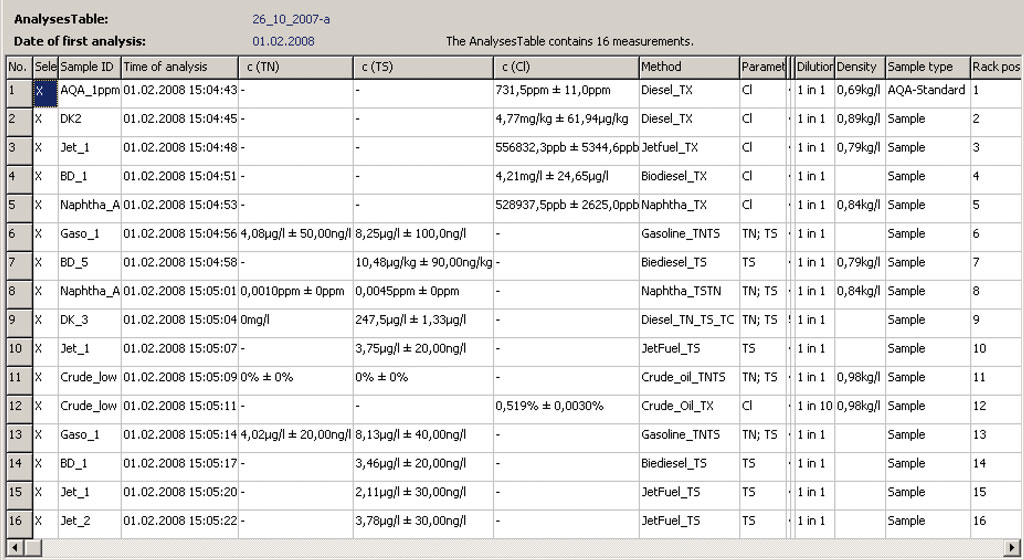
Нефтехимическая промышленность
Анализ ароматических и алифатических углеводородов, смазок, трансмиссионных масел, трансформаторных масел, тормозных и гидравлических жидкостей и многое другое
Добыча нефти и природного газа, нефтепереработка
Анализ нефти, природного газа, фракций переработки нефти, кубовых остатков, биодизелей, биоэтанола и многое другое.
Химическая промышленность
Анализ восков, жирных кислот, красителей, растворителей, таких как углеводороды, спирты, альдегиды, кетоны и т.д.
Полимерная промышленность
Анализ сырья, бутана, пропана, различных присадок, производных, таких как PP, PE, PC
Фармацевтическая промышленность
Анализ воды, вазелиновое масло, вазелин, воски, парафины, активированный уголь, спирты и другие органические соединения.
Пищевая промышленность
Анализ спиртов, воды, жиров, масел, восков и многое другое.
Анализ экологических параметров
Определение параметров TOC, TOX/AOX/EOX в поверхностных, питьевых, охлаждающих, производственных и сточных водах. TOX/AOX/EOX в почвах, осадках сточных вод, отложениях. EC, OC, TC в твёрдых частицах выбросов дизельных двигателей для определения качества воздуха
Электростанции
Анализ топлива, угля, горючего, природного газа, вторичного топлива – дерева, соломы, биогаза и т.д. TOC и TOX/AOX в охлаждающих водах.
Анализ материалов/контроль качества
Сертификационный контроль сырья и продуктов на азот, серу, хлор в нефтехимической промышленности.Тестовый контроль чистоты растворителей и т.д.
Элементный анализатор серы, хлора, азота и углерода Multi EA 5100, Analytik Jena

Данный элементный анализатор серы, хлора и углерода является универсальным решением и обладает исключительными параметрами надежности, точности и функциональности, как и все аналитическое оборудование, выпускаемое известным немецким производителем Analytik Jena AG.
Multi EA® 5100 применятся в нефтехимии, экологическом мониторинге, фармацевтике, химической промышленности и исследовании свойств материалов.
!! Поставка оборудования и комплектующих Analytik Jena продолжается !!
Multi EA® 5100
|
|
Особенности Multi EA® 5100
|
Принцип анализа:
Высокотемпературное окисление компонентов пробы (Тмах = 1050оС) без использования катализатора в токе кислорода до соответствующих оксидов CO2, SO2, NOx, H2O и галогенидов HX с последующим определением на соответствующих детекторах.
Функциональная схема элементного анализатора Multi EA® 5100 — техника сдвоенной печи
Характеристика детекторов Multi EA® 5100
|
Элемент |
Хлор |
Сера |
Азот |
Углерод |
|
Детектор |
Кулонометрический |
УФ-флуоресцентный |
Хемилюминесцентный |
NDIR (ИК-детектор) |
|
Минимальная концентрация |
100 ppb |
10 ppb |
30 ppb |
200 ppb |
|
Максимальная концентрация |
10 % |
1% |
1 % |
100 % |
|
Образец |
Твердые, жидкие, газообразные пробы и сжиженные газы |
|||
|
Макс.температура разложения пробы |
+ 1050 оС |
Технические особенности Multi EA® 5100
|
Параметры сжигания |
|
|
Используемые газы |
|
|
Модули |
|
|
Примечание: система комплектуется необходимыми модулями непосредственно под задачу клиента. Элементный анализатор Multi EA® 5000 (сера, хлор, азот, углерод) |
|
|
«Внутренний интеллект» |
|
|
Ввод пробы |
|
Аксессуары для элементного анализатора серы, хлора, азота и углерода Multi EA® 5100
- Автоматическое устройство подачи лодочек с функцией охлаждения.
- Мультиматричный автодозатор ММS 5000.
- Система для анализа газа GSS.
- Модуль анализа сжиженных газов LPG.
- Комбинированный модуль анализа газов / сжиженных газов GSS / LPG.
- Автоинжектор.
Аксессуары подробнее…
Методическое обеспечение для элементного анализатора Multi EA® 5100 (сера, хлор, азот, углерод)
Сера в нефтепродуктах
ГОСТ Р ЕН ИСО 20846-2006 (ЕN ISO 20846:2004)
Нефтепродукты. Определение содержания серы методом ультрафиолетовой флуоресценции.
ASTM D 5453, 3120, 3961, 6667, 3246
Органические хлориды в нефтепродуктах
ГОСТ Р 52247-2004, метод Б (ASTM D 4929).
Нефть. Методы определения хлорорганических соединений.
ASTM D 5808, 14077
Азот в нефтепродуктах
ASTM D 4629, 6069, 7184, 51444, 5762
Элементный анализатор Multi EA® 5100 (сера, хлор, азот, углерод) внесен в Госреестр средств измерений
Другое аналитическое оборудование Analytik Jena
-
Создано:
Forum LINCO Platform
| 10 марта 2023 в 14:43 |
Ответить
Добрый день! Не подскажите, кто работает на приборе Анализатор элементный универсальный Multi EA 5000 производства «Analytik Jena AG», Германия. Может кто составлял краткую инструкцию по эксплуатации?
Материалы
Материалы LINCO
Возможно Вас
заинтересует
Возможно Вас заинтересует

Открытая разработка документов для лаборатории
Информация

Подготовка лаборатории к ПК, расширение ОА
Повышение квалификации: ПК, расширение, выездная проверка и ВКС. Анкета самообследования. 13-14 июня

Правовое и методическое сопровождение лабораторий
ООО «ЦПК «ПРОФИЛЬ» оказывает всестороннюю поддержку деятельности и представляет интересы лаборатории

Практическая реализация требований Критериев аккредитации и стандарта ГОСТ ISO/IEC 17025-2019. Создание, внедрение и поддержание функционирования сис
Для участия в работе курса необходимо подать заявку по электронной почте: orgkomitet@list.ru.
Назначение
Описание
Программное обеспечение
Технические характеристики
Знак утверждения типа
Комплектность
Поверка
Рекомендации к применению
Назначение
Анализаторы элементные универсальные multi EA 5000 предназначены для измерения содержания общего хлора, общего азота, общей серы и общего углерода в жидких, вязких, твердых и газообразных пробах в соответствии с аттестованными и стандартизованными методиками (методами).
Описание
Принцип действия анализатора основан на высокотемпературном разложении и окислении компонентов пробы, содержащих хлор, азот, серу и/или углерод, с образованием, соответственно, HCl, NOx, SO2, CO2, которые потоком газа-носителя переносятся, соответственно, в кулонометрическую ячейку (при анализе общего хлора (TX)), хемилюминесцентный детектор CLD (при анализе общего азота (TN)), ультрафиолетовый флуоресцентный детектор UVFD (при анализе общей серы (TS)) и/или ИК-детектор NDIR (при анализе общего углерода (TC)). На основе полученного значения программное обеспечение прибора рассчитывает исходное содержание TX, TN, TS и/или TC в пробе. В анализаторе multi EA 5000 ввод пробы возможен в печь, установленную как в вертикальном положении (только для жидких и газообразных проб), так и в горизонтальном положении (все виды проб). Конструктивно анализаторы представляют собой стационарные настольные лабораторные приборы, состоящие из системы подачи проб, узла преобразования и разделения компонентов пробы и электронных узлов, установленных в общем корпусе. Внешний вид анализатора показан на рис. 1.
Программное обеспечение
Анализаторы оснащены автономным программным обеспечением (ПО) multiWin, которое управляет работой приборов, отображает, обрабатывает и хранит полученные данные.
|
Наименование программного обеспечения |
Идентификационное наименование программного обеспечения |
Номер версии (идентификационный номер) программного обеспечения |
Цифровой идентификатор программного обеспечения (контрольная сумма метрологической значимой части ПО для версии 5.3.3.0) |
Алгоритм вычисления цифрового идентификатора программного обеспечения |
|
multiWin |
multiWin |
5. и выше |
4933CE5671A74816F6D CDFB6CD74C1A0 |
MD5 |
К метрологически значимой части ПО относится файл multiWin.exe, который выполняет следующие функции:
— управление прибором;
— установка режимов работы прибора;
— построение калибровочных зависимостей;
— расчет содержания определяемого компонента;
— обработка и хранение результатов измерений;
— проведение диагностических тестов прибора.
Уровень защиты ПО от непреднамеренных и преднамеренных изменений соответствует уровню «С» по МИ 3286-2010. Влияние ПО на метрологические характеристики учтено при их нормировании.
Технические характеристики
|
Определяемый элемент |
Общий хлор (TX) |
Общий азот (TN) |
Общая сера (TS) |
Общий углерод (ГС) |
||
|
Тип детектора |
Кулонометрическая ячейка «высокочувствительная (high sensitive, hs)» |
Кулонометрическая ячейка «чувствительная (sensitive, s)» |
Кулонометрическая ячейка «для высоких концентраций (high concentration, hc)» |
CLD |
UVFD |
NDIR |
|
Чув ствительность, у.е./мкг, не менее |
350 1) |
2) in 0, |
3) 0, |
120 000 4) |
60 000 5) |
430 6) |
|
Относительное СКО выходного сигна- ла1)’2),3),4),5)’6),%, не более |
5 |
5 |
5 |
5 |
||
|
Объем вводимой пробы: |
||||||
|
-жидкие пробы, мкл |
от 1 до 100 |
|||||
|
-твердые пробы, мг |
от 1 до 100 |
|||||
|
-несжатые газы, мл |
от 1 до 100 |
|||||
|
-сжатые газы, мл |
от 1 до 20 |
|||||
|
-сжиженные газы, мкл |
от 1 до 50 |
|||||
|
Потребляемая мощность, В-А, не более |
1000 |
|||||
|
Напряжение питания переменного тока частотой 50±1 Гц, В |
220±22 |
|
Габаритные размеры основного модуля, мм, не более: |
|
|
-длина |
530 |
|
-ширина |
560 |
|
-высота |
470 |
|
Масса основного модуля, кг, не более |
25 |
|
Средний срок службы, лет |
10 |
|
Наработка на отказ, ч, не менее |
5000 |
|
Условия эксплуатации: |
|
|
— диапазон температур окружающего о/~’ воздуха, С |
от 19 до 29 |
|
— диапазон относительной влажности окружающего воздуха (при 25 °С), % |
от 20 до 80 |
|
— диапазон атмосферного давления, кПа |
от 84 до 106 |
1) 3 При дозировании 100 мкл стандартного раствора с концентрацией TX 5 мг/дм
2) 3
При дозировании 100 мкл стандартного раствора с концентрацией TX 354,5 мг/дм
3) При дозировании 100 мкл стандартного раствора с концентрацией TX 3,545 г/дм3
4) При дозировании 40 мкл стандартного раствора с концентрацией TN 5 мг/дм3
5) 3 При дозировании 40 мкл стандартного раствора с концентрацией TS 5 мг/дм
6) При дозировании 40 мкл стандартного вещества с концентрацией ТС 580,36 г/дм3
Знак утверждения типа
наносится на лицевую панель прибора в виде наклейки и на титульный лист руководства по эксплуатации методом компьютерной графики.
Комплектность
— анализатор;
— руководство по эксплуатации;
— методика поверки МП-242-1608-2013.
Поверка
осуществляется по документу МП-242-1608-2013 «Анализаторы элементные универсальные multi EA 5000 фирмы «Analytik Jena AG», Германия», утвержденному ГЦИ СИ ФГУП «ВНИИМ им.Д.И.Менделеева» 30.06.2013 г.
Основные средства поверки:
— изооктан эталонный по ГОСТ 12433-83;
— стандартный образец состава хлорбензола ГСО 7142-95;
— пиридин, кв. «ЧДА» по ГОСТ 13647-78;
— стандартный образец массовой доли серы в декане (массовая доля серы 0,5%) ГСО 79972002.
приведены в следующих документах:
— Анализаторы элементные универсальные multi EA 5000 фирмы «Analytik Jena AG», Германия. Руководство по эксплуатации.
— ГОСТ Р EN ISO 20846-2006. Нефтепродукты. Определение содержания серы методом ультрафиолетовой флуоресценции.
— ГОСТ Р 52247-2004. Нефть. Методы определения хлорорганических соединений.
Нормативные и технические документы, устанавливающие требования к анализаторам элементным универсальным multi EA 5000
Техническая документация фирмы-изготовителя.
Рекомендации к применению
При выполнении работ по оценке соответствия промышленной продукции и продукции других видов, а также иных объектов установленным законодательством Российской Федерации обязательным требованиям.


