- Manuals
- Brands
- Braun Manuals
- Medical Equipment
- Perfusor Space
- Instructions for use manual
-
Contents
-
Table of Contents
-
Bookmarks
Quick Links
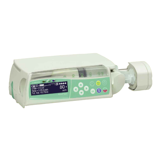
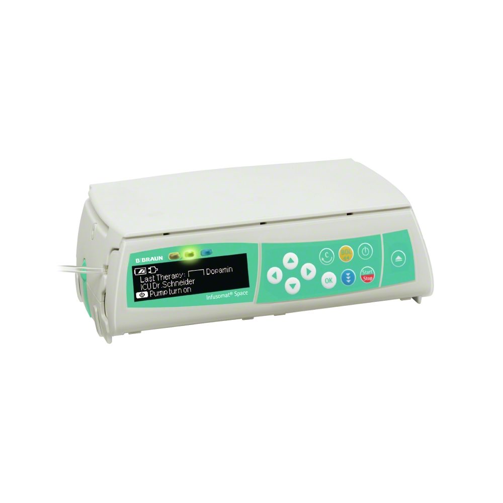
Perfusor® Space
and Accessories
Please make sure all pumps on your
ward are equipped with the same
software version.
Instructions for Use
Rx only
Valid for Software 688F
951092 Rev C (03/08)
Related Manuals for Braun Perfusor Space
Summary of Contents for Braun Perfusor Space
-
Page 1
Perfusor® Space and Accessories Instructions for Use Rx only Please make sure all pumps on your Valid for Software 688F ward are equipped with the same software version. 951092 Rev C (03/08) -
Page 2: Table Of Contents
CONTENTS C O N T E N T S Contents ……………………2 Perfusor® Space Overview…………………..3 Patient Safety ……………………5 The Perfusor® Space Menu Structure / Overview ………………..8 Infusion Syringe Pump System in- Menu Structure / Navigation………………..9 cludes an external Chapter 1 Operation ………………….11 transportable elec- tronic infusion sy- 1.1 Start of Infusion …………………….11…
-
Page 3: Perfusor® Space Overview
PERFUSOR SPACE® OVERVIEW P E R F U S O R ® S PA C E O V E R V I E W Up and Down Arrows Press to reset single values Drive head with Scroll through menus, change setting of numbers…
-
Page 4
PERFUSOR® SPACE OVERVIEW Syringe Fixation Pull and turn the syringe holder to the right to open the green axial fixation mechanism (see red arrow). Syringe must be fixed with wings upright in the slot to the left side of the green axial fixation mechanism before closing syringe holder. -
Page 5: Patient Safety
PATIENT SAFETY PAT I E N T S A F E T Y Operation • The initial training of the Perfusor® Space is to be performed by B. Braun sales personnel or other authorized persons. After each software update, the Caution:…
-
Page 6
PATIENT SAFETY • A supplemental patient monitoring must be carried out if critical medication is performed. • Avoid applying external force on the drive mechanism during administration. • In case high potent drugs are given be sure to have a second infusion pump for that drug at hand. -
Page 7
PATIENT SAFETY (e.g. HF surgical equipment, nuclear spin tomography units, mobile telephones etc.) maintain the recommended protective distances from these devices. As there is no international standard for enteral nutrition pumps the safety fea- tures of the Infusomat Space are also for this therapy designed according to IEC 601-2-24 Symbols Electrical Shock Protection Rating… -
Page 8: Infusion Syringe Menu Structure / Overview
MENU STRUCTURE / OVERVIEW MENU STRUCTURE / OVERVIEW Symbols On/Off button Start/Stop button Bolus button Clear button OK button Keypad with arrow up, -down, -left, -right button Connection button Menu Structure Start Up Main Status Special Options Menu Menu Menu Functions Menu Syringe…
-
Page 9: Menu Structure / Navigation
MENU STRUCTURE / NAVIGATION MENU STRUCTURE / NAVIGATION Display Settings Explanation At the top of the screen the last therapy is indicated. Yes/No question can be answered by pressing for yes or for no. Parameters which can be changed (e.g. rate in ml/hr) are accessed with k.
-
Page 10
MENU STRUCTURE / NAVIGATION Display Settings Explanation Set pressure level with confirm by pressing k. Cancel to edit pressure by using c. Optionally the pressure values can be displayed in mmHg. Pre-alarms are indicated by an alarm tone with a message on the display (e.g. “Syringe nearly empty”), and a flashing yellow LED. -
Page 11: Operation
OPERATION Chapter 1 OPERATION 1.1 Start of Infusion • Ensure the pump is properly secured. Check if all pump components are present and that there are no damages. If the pump is connected to A/C, the display states information such as the battery status, the A/C connection symbol and last therapy.
-
Page 12: Setting Different Combinations Of Rate, Vtbi (Vtbi= Volume To Be Infused)
OPERATION Chapter 1 • Press to start infusion. Running arrows on display and green LED above display indicate that infusion was started. Note: Stop the infusion at any time by pressing . The pump can be turned off at any time by pressing for 3 sec (Exception: Data lock level 2).
-
Page 13: Bolus Application
OPERATION Chapter 1 • Change of time => Adjustment of rate. Previous and new target: VTBI b) Target symbol is placed in front of time: • Change of time => Adjustment of VTBI. Previous and new: Time • Change of VTBI => Adjustment of time. New target: VTBI 1.3 Bolus Application There are three ways to administer a bolus: 1.) Manual Bolus: Press…
-
Page 14: Syringe Change And New Therapy Start
OPERATION Chapter 1 At low bolus volumes, under dosages due to the start up characteristic of the pump and the tolerances in the infusion system cannot be excluded. Disconnect patient while purging. 1.4 Syringe Change and New Therapy Start Note: Always disconnect patient line before syringe change to avoid inadvertent administrations.
-
Page 15: End Of Infusion
OPERATION Chapter 1 1.5 End of Infusion • Press to stop infusion. The green LED will go off. Disconnect from the patient. • Open the syringe holder. The drive mechanism will move backwards into the starting position. • Open pump door. Remove syringe, turn the syringe holder into an upright position and close the front door.
-
Page 16: Advanced Operations
ADVANCED OPERATIONS Chapter 2 ADVANCED OPERATIONS 2.1 Request Status of Infusion while Pump is Running Press to switch between run display and Main Menu while the pump is running. Navigate through the menu using to check parameters. In order to check parameters in the Status/Options Menu, select «Status»…
-
Page 17: Chapter 3 Special Functions
SPECIAL FUNCTIONS Chapter 3 SPECIAL FUNCTIONS 3.1 Dose Rate Calculation (Overview) The dose rate calculation enables a calculation of the rate in ml/hr from the entered dose parameters. Dose Infusion rate [ml/hr] = x Patient weight (optional) Concentration Setting parameters: 1.
-
Page 18: Drug Library
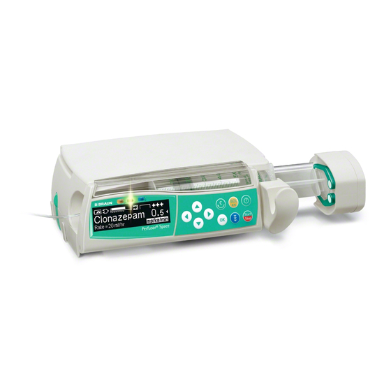
SPECIAL FUNCTIONS Chapter 3 To get out of dose rate calculation is only possible when the pump is stopped. from Main Menu and then press d. Press Caution: A change of the patient weight will alter the flow rate. 3.3 Drug Library Up to 720 drug names including therapy data and information can be stored in 15 categories.
-
Page 19: Chapter 4 Options
OPTIONS Chapter 3 that describe the status with regard to the soft limits are being displayed: The infusion is within the range of the minimum and maximum soft limit The infusion is within the range of the maximum soft limit The infusion is within the range of the minimum soft limit Violation of the upper soft limit Violation of the lower soft limit…
-
Page 20: Occlusion Pressure
OPTIONS Chapter 4 O P T I O N S The options functions may be selected and changed while the pump is running or stopped. To edit a menu item, select “Options” in the Main Menu and press l. Then select desired function with and follow the Instructions for Use as described.
-
Page 21: Bolus Rate
OPTIONS Chapter 4 audible alarm, a nurse call will go off and the yellow LED blinks. If a target value is reached while data lock is active a new start of the pump is only possible after entering the code. In order to deactivate the function, select “Off”…
-
Page 22: Date / Time
OPTIONS Chapter 4 4.7 Date / Time • Access date/time in Options Menu with l. • Change date/time with and confirm with k. 4.8 Macro Mode The infusion rate appears larger on the display when the macro mode is activated and the pump is infusing. •…
-
Page 23: Chapter 5 Alarms
ALARMS Chapter 5 ALARMS The Perfusor® Space is equipped with an audible and optical alarm signal. Alarm- Audible Optical signal Staff call User confirmation type signal Red LED Yellow LED Text Device flashes device alarm Press and follow Alarm and alarm the instruction on the code display.
-
Page 24
ALARMS Chapter 5 Display message Pre-alarm reason “Syringe nearly empty“ Very little fluid is left in syringe. “VTBI near end“ The preselected volume is nearly infused. “Time near end“ The preselected time is almost over. “Battery nearly empty“ The battery is almost discharged. “KVO active“… -
Page 25
ALARMS Chapter 5 “KVO finished” KVO is reached. Continue with old or set new therapy. “Pressure high“ Occlusion occured in the system. The set pressure level was exceeded. A bolus reduction is automatically initiated by the pump. Check if syringe is empty, kinks are in tubing and tubing isn’t damaged, IV patency and filter patency. -
Page 26: Reminder Alarms
ALARMS Chapter 5 “Data Lock» An attempt was made to stop or switch the pump off without entering the code. Enter the correct code in order to continue the therapy or in order to turn the pump off. The red LED doesn’t go off until the administration is started again or the pump is turned off.
-
Page 27: Battery Operation And Maintenance
BATTERY OPERATION AND MAINTENANCE Chapter 6 BATTERY OPERATION AND MAINTENANCE The Perfusor® Space is equipped with a NiMH-battery. It has an operating lifetime of 8 hours at 25 ml/hr when new. For optimal treatment of the battery, the device is equipped with protection against overcharge and deep depletion.
-
Page 28
BATTERY OPERATION AND MAINTENANCE Chapter 6 Caution: Batteries may explode or leak if they are opened or incinerated. Dispose properly! Battery maintenance: To accurately balance the battery capacity cyclical battery maintenance is necessary. The pump asks the user to perform battery maintenance every 30 days. The battery maintenance mode detects a possible capacity loss (e.g. -
Page 29: Compatible Syringes
COMPATIBLE SYRINGES Chapter 7 COMPATIBLE SYRINGES The syringe types listed in the following tables can be used with the Perfusor® Space. Please refer to the listed material number (Mat. No.1)) to ensure specific syringe brand compatibility. The alarm Time to Occlusion was measured at 5ml/hr.
-
Page 30: Chapter 8 Start Up Graphs And Trumpet Curves
START UP GRAPHS AND TRUMPET CURVES Chapter 8 START UP GRAPHS AND TRUMPET CURVES Start Up Curves Trumpet Curves The graphs show the accuracy/uniformity of flow in relation to time. They allow for the following: The delivery behaviour or delivery precision is essentially influenced by the type of (disposable syringe) used.
-
Page 31: Chapter 9 Technical Data
Moisture protection IP 22 (drip protected for horizontal usage) External power supply: • Rated voltage Via B. Braun SpaceStation or optional A/C adaptor (rated voltage 100 … 240 V AC~, 50/60 Hz) for stand alone operation • External low voltage 11 ……
-
Page 32
< 10 ml/hr: KVO-rate 1 ml/hr Delivery rate < 1 ml/hr: KVO-rate = set rate (default setting 0.1 ml/hr) Computer connection USB connection in combination with B. Braun interface lead CAN SP (8713230) including electrical insulation. Please pay attention to safety notices. History protocol 1000 last history entries. -
Page 33: Chapter 10 Tsc* / Service / Training / Cleaning / Disposal
Medical Devices Training 93/42/EEC” dated 14th June 1993. B. Braun offers training and inservicing. Please ask your local representative for B. Braun further details. Melsungen AG Check regularly Check for cleanliness, completeness and damage. Only use devices according to Instructions for Use.
-
Page 34
TSC* / SERVICE / TRAINING / CLEANING / DISPOSAL Chapter 10 Disposal The pumps as well as battery packs can be returned to B. Braun for further disposal. When taking care of disposing of disposables as well as infusion solutions, please consider the applicable hygiene and disposal regulations. -
Page 35: Chapter 11 Instructions For Use Accessory
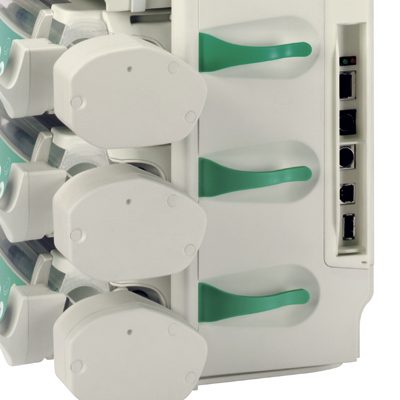
Comfort additionaly includes a central alarm management and alarm LEDs. PoleClamp SP (8713130) A maximum of three B. Braun Space pump either Infusomat™or Perfusor® can be stacked together when used with the PoleClamp SP. For detailed instructions on secure fixation of the PoleClamp SP please refer to «Overview Perfusor® Space»…
-
Page 36
INSTRUCTIONS FOR USE ACCESSORY Chapter 11 2.) Connect plug of Connection Lead SP with Combi Lead SP. 3.) Push plug of Connection Lead SP into 12 V connector. A maximum of three plugs can be plugged into each other in socket P2. Note: Battery-Pack SP (8713180) For further information on the Battery-Pack SP (NiMH) see “Battery Operation”. -
Page 37
INSTRUCTIONS FOR USE ACCESSORY Chapter 11 Connection Lead for Staff Call SP (8713232) To connect the Perfusor® Space to staff call, use the Connection Lead for staff Call SP. The staff call needs to comply with the requirements of VDE 0834 (consider country specific regulations). -
Page 38: Ordering
ORDERING Art. No. B. Braun Perfusor® Space (100 – 240 V) ……..871 3030U/US Recommended accessories for the B. Braun Perfusor® Space: SpaceStation …………………871 3140U SpaceCover Standard …………….871 3147U SpaceCover Comfort …………….871 3145U PoleClamp SP………………..871 3130 Power Supply SP (US Plug)…………..871 3112A Combi Lead SP 12 V ……………..871 3133…
-
Page 39: Technical Support
B. Braun Customer Service at (800) 627-PUMP. A Returned Materials Authorization number will be provided. Carefully pack the pump (preferably in the original packing), and ship it prepaid to the address below. B. Braun cannot assume any responsibility for loss or damage to returned instruments while they are in transit.
-
Page 40
Manufactured by: B. Braun Melsungen AG P.O.Box 1120 D-34209 Melsungen, GERMANY Tel +49-(0) 56 61 — 71 — 0 Fax +49-(0) 56 61 71 — 204 Distributed by: B.Braun Medical, Inc. 824 12th Avenue Clinical and Technical Support for USA and Canada:…
B.Braun Space – насос инфузионный шприцевый (Перфузор)
Многофункциональный инфузионный шприцевый насос B.Braun Space (Перфузор) используется для внутривенного введения лекарственных препаратов пациентам, которые нуждаються в постоянной инфузионной терапии, а также для обеспечения энтерального питания. Аппарат незаменим в анестезиологии, реаниматологии, хирургии.
Насос подходит как для постоянной, так и для периодической, для энтеральной либо парентеральной подачи жидкости, когда лекарство не попадает в желудочно-кишечный тракт. Компактный и легкий, прибор легко подключается к коммуникационным сетям.
Одной из отличительных характеристик данной модели является безопасность инфузии. Во избежание ошибок в определении количества подаваемых препаратов расчет дозы происходит автоматически. При этом устройство учитывает время терапии, объем лекарства, его концентрацию.
В случае возникновения безопасности срабатывает световой индикатор. А при внезапном повышении давления звучит сигнал тревоги и скорость болюса уменьшается автоматически. Инфузия прекращается, если системой обнрауживается неточность дозировки от 0,1 мл.
Преимущества инфузионного насоса
Модульная система B.Braun Space отличается простотой управления и эргономичностью. Доступный каждому интерфейс, удобное меню и интуитивно понятная навигация позволяют без специального обучения задавать показатели и менять параметры, контролируя состояние пациента.
Стоит выделить другие преимущества насоса:
-
Библиотека препаратов на 30 категорий, которые включают до 1 500 позиций. Для каждого лекарства предусмотрены ключевые данные и рекомендованные настройки инфузии.
-
Есть готовые заданные параметры и возможность установить ограничения исходя из целей и специфики инфузии.
-
Свободный поток питательной смеси или лекарства обеспечивается наличием интегрированного фиксатора шприцевого штока.
-
Менять шприц удобно и безопасно за счет автоматического привода, который также улучшает пусковые свойства.
Возможность работы от перезаряжаемого аккумулятора NiMH составляет восемь часов (при 25 мл/ч). С учетом малого веса (1,4 кг) и небольших габаритов, насос является удобным устройством для автономного проведения инфузии.
Шаг установки скорости:
-
0.01* — 99.99 мл/ч, шаг 0.01 мл/ч;
-
100.0 — 999.9 мл/ч, шаг 0.1 мл/ч;
-
точность болюсной инфузии: тип ±2%;
-
макс. болюс, после снижения скорости: ≤ 0.2 мл.
Скорость инфузии в режиме KVO:
-
Скорость ≥ 10 мл/ч: KVO 3 мл/ч;
-
Скорость < 10 мл/ч: KVO 1 мл/ч;
-
Скорость < 1 мл/ч: KVO = заданной скорости.
Установка объема инфузии:
-
0,1 — 99,99 мл, шаг 0,01 мл;
-
100,0 — 999,9 мл, шаг 0,1 мл;
-
1000 — 9999 мл, шаг 1 мл.
Протокол событий:
-
1000 последних вводов данных;
-
100 событий диагностики системы;
-
Источник питания: 100-240В АВ, 50/60 Гц, 11-16В DC (от Станции Спэйс или опционального блока питания);
-
Вызов персонала макс. 24В / 0,5А / 24 ВА (VDE 0834).
Условия эксплуатации:
-
Относительная влажность: 30% … 90% (без конденсата);
-
Температура: +5… +40° С;
-
Атмосферное давление: 500… 1060 мбар.
|
Скорость длительной инфузии / скорость болюса зависит от типа шприца |
||
|
Размер шприца, мл
|
Скорость болюса, мл/ч |
|
|
50/60
|
Скорость инфузии, мл/ч 0.01 — 200, опционально 0.01 — 999.9 |
1 — 1800 |
|
30/35
|
0.01 — 100 |
1 — 1200 |
|
20 |
0.01 — 100 |
1 — 800 |
|
10/12 |
0.01 — 50 |
1 — 500 |
|
5/6 |
0.01 — 50 |
1 — 300 |
|
2/3 |
0.01 — 25 |
1 — 150 |
Свяжитесь со специалистами магазина «Бравокислород» по телефону 8 (343) 357-90-06 или 8 (800) 775-16-38. Вы получите бесплатную консультацию и помощь с подбором инфузионного оборудования для дома или для медицинского учреждения. Работаем с государственными и частными клиниками по договору согласно ФЗ 44 и 223.
Гарантия: 1 год
- Manuals
- Brands
- B. Braun Manuals
- Medical Equipment
- Perfusor Space
- Service manual
-
Contents
-
Table of Contents
-
Troubleshooting
-
Bookmarks
Quick Links
1.0
1.3
Perfusor® Space
Service Manual
Version 1.3 English
Related Manuals for B. Braun Perfusor Space
Summary of Contents for B. Braun Perfusor Space
-
Page 1
Perfusor® Space Service Manual Version 1.3 English… -
Page 2
This Service Manual is valid for: Designation Part No. Infusion syringe pump Perfusor® Space … . 0871 3030 This Service Manual is available under Designation Part No. the following part number: Service Manual Perfusor®… -
Page 3
Table of Contents Important Preliminary Remarks Service Work Page 0 — 5 Technical Safety Checks Page 0 — 5 Current Versions Page 0 — 5 Revision Service Page 0 — 5 Quality Management Page 0 — 6 Checks and Repair Page 0 — 6 Notes on ESD… -
Page 4
Table of Contents Servicing the Unit Cleaning Page 4 — 1 Servicing the Battery Page 4 — 1 Technical Safety Check (TSC) Perfusor® Space 1 Technical Safety Check (TSC) Power Supply SP 1 Procedural Instructions on the TSC Visual Inspection Page 7 — 1 Electrical Safety… -
Page 5
You will be included in the revision service after: technical training by B. Braun Melsungen or a written order placed with the sales department of B. Braun (fee required). Perfusor® Space, 1.1 gb 0 — 5… -
Page 6
B. Braun unit. Quality Management B. Braun is certified in accordance with DIN EN ISO 9001 and ISO 13485. This certification also includes maintenance and service. The unit has the CE label. The CE label confirms that the device corresponds to the “Directive of the Council for Medical Products… -
Page 7
Service personnel are responsible for the calibration of their test equipment. Original test equipment can be calibrated at the works of B. Braun. Further information is available upon request. Setting Off Additional notes and warnings are set off as follows:… -
Page 8
Important Preliminary Remarks References to chapters are shown as follows (see “Setting Off“ pg. 0 — 7) References to figures and tables are shown as follows Fig.: 2 — 3 Table 2 — 1 References to item numbers in figures are shown as follows (Fig.: 1 — 1 / Item In this case “Fig.: 1 — 1“… -
Page 9
Important Preliminary Remarks List of Abbreviations Abbreviations which are not generally known, but are used in this manual, are listed below. Controller Area Network Communauté Européenne (European Communities) Calibration Step Deutsche Industrie Norm (German Industrial Standard) European Standard Electrostatic Discharge Function Microprocessor International Electrotechnical Commission… -
Page 10
Important Preliminary Remarks Unit Test Step Verband der Elektrotechnik, Elektronik und Informationstechnik e.V. (German electrical engineering association) 0 — 10 Perfusor® Space, 1.2 gb… -
Page 11
Entry for Technical Training Application for a technical training course must be made via the responsible representative. Ordering of Spare Parts and Test Equipment Please contact your local B. Braun subsidary. International Technicians (Intercompany) Nadja Machal Fax: +49 5661 / 75 — 47 89 e-mail: nadja.machal@bbraun.com… -
Page 12
Contact Persons For your notes: 0 — 12 Perfusor® Space, 1.0 gb… -
Page 13
System Overview Description The Perfusor® Space (PSP) is according to IEC/EN 60601 resp. IEC/ EN 60601-2-24 a transportable infusion syringe pump for administrating fluids in the nutritional therapy and infusion technique as well as for home care applications. The medical specialist must decide on suitability for application on the basis of the warranted properties and the technical data. -
Page 14
System Overview Physical Construction Fig.: 1 — 2 Perfusor® Space Legend of fig. 1 — 2: ItemDesignation Perfusor® Space Connector “P2“ for SpaceStation module, external 12 V DC and accessories Drive head Connector “P3“, connection to SpaceControl module Syringe holder with piston brake Battery compartment cover Operating Unit Syringe area… -
Page 15
System Overview The Perfusor® Space housing mainly consists of the bottom part and the upper part. The battery module is inserted in the rear of the housing upper part. The opening is covered by the battery compartment cover. The operating unit is attached to the front of the bottom part with two hinges. -
Page 16
System Overview The pressure in the infusion system is measured through a strain gauge measuring in the drive head and monitored in the device electronics. The data from the strain gauge is continuously compared with the limit values which are calculated dependent on the selected syringe type and the pressure settings. -
Page 17
System Overview Fig.: 1 — 3 Block diagram Perfusor® Space Perfusor® Space, 1.0 gb 1 — 5… -
Page 18
System Overview Unit Software Approved Software Versions 688A030032 Basic software Position 1 2 3 4 5 6 7 8 9 10 688A030035 Digit 6 8 8 C 0 3 0 0 0 1 Improved functions 688A030040 Revision level Improved functions Hardware Languages French and Swedish added Software group… -
Page 19
PC is switched off, a component of the software may be seriously damaged so that repairs are no longer possible. In such a case the software cannot be updated via the PC and the device must be returned to B. Braun. Service Program Approved Version… -
Page 20
System Overview 1. Start the “HiBaSeD.exe” program (History, Barcode, Service, Drug list) on the PC. The Service Program is loaded and started and the initial window of the Service Program is displayed. 2. Read the notes carefully. 3. Mark the field “I accept all conditions” and then the field “Yes”… -
Page 21
System Overview The work window of the Service Program appears on the screen. All devices recognized are listed in the left column. Fig.: 1 — 8 5. Activate the desired device from the list on the left in the work window with a double-click. The device data is then displayed below the device name. -
Page 22
System Overview If the unit software version is not compatible with the Service Program version, a window opens prompting the operator to change the Service Program version. This window displays a compatibility list of the Service Program- and unit software versions. -
Page 23
System Overview Service Program Version Help Info … 1. Open the “HiBaSeD“ window via . The current version of the Service Program is shown in this window. 2. Close the window by clicking “OK”. Fig.: 1 — 11 Compatibility List Help 1. -
Page 24
System Overview Technical Data All technical data is indicated in the instructions for use. Options The functions of the individual options are detailed in the instructions for use. Perfusor® Space Designation Part No.: Power supply Euro ……0871 3110A Power supply UK. -
Page 25
Unit Diagnosis / Calibration General WARNING WHILE TESTING THE UNIT AND TROUBLE SHOOTING THE OPERATOR/SERVICE TECHNICIAN MUST WORK WITH VOLTAGES UP TO 115 / 230 V AC. THESE VOLTAGES MAY CAUSE INJURIES WHICH ARE DANGEROUS TO LIFE AND LIMB. THE NATIONAL AND INTERNATIONAL SAFETY REGULATIONS ARE TO BE ADHERED TO. -
Page 26
Unit Diagnosis / Calibration The unit check, calibration and trouble shooting are subdivided into numbered working steps (Unit Test Step UTS, Calibration Step CS, Trouble Shooting TS) and are based on each other. Beginning with UTS 1 the operation described here has to be executed. -
Page 27
Unit Diagnosis / Calibration Alarms and Error Codes The alarms of the Perfusor® Space are classified in 5 categories. These categories are listed hereafter according to their importance. Alarm advice In case of unacceptable inputs corresponding messages are displayed (e.g. “Caution! Rate out of range“, “The parameter cannot be changed“) and a beep sounds. -
Page 28
Unit Diagnosis / Calibration Alarms Alarm Possible Cause Fault Clearance Battery nearly discharged (type: pre- The device was not connected to the Operate the device with battery until the alarm) mains long enough message “Battery discharged“ is displayed and the unit is switched off. Then connect the unit to the mains for at least 6 hours. -
Page 29
Unit Diagnosis / Calibration Device Alarms of the Function Processor Error Code Definition Possible Cause Fault Clearance 1001 … 1013 Internal Error 1014 Loudspeaker not off Loudspeaker connector Check the loudspeaker connector Loudspeaker Check the loudspeaker 1015 Loudspeaker lost Loudspeaker connector Check the loudspeaker connector Loudspeaker Check the loudspeaker… -
Page 30
Unit Diagnosis / Calibration Device Alarms of the Control Microprocessor Error Code Definition Possible Cause Fault Clearance 1100 Timebase too fast Quartz of the processor PCB Exchange processor PCB 1101 Timebase too slow Quartz of the processor PCB Exchange processor PCB 1102 Timebase fail Quartz of the processor PCB… -
Page 31
Unit Diagnosis / Calibration Error Code Definition Possible Cause Fault Clearance 1201 different version FuP to KuP Software Update unit software Software 1202 E_ERROR_STEPMOTOR_1 Phase Drive motor, lead screw Exchange processor PCB not ok 1203 E_ERROR_STEPMOTOR_2 Current Motor drive Carry out calibration value not 0x55 Recognition of direction of rotation… -
Page 32
Unit Diagnosis / Calibration The Most Important Error Modes The following list specifies the most important error modes and their clearance. Note The device must be checked after every repair or service (see “Device Check“ pg. 2 — Error Possible Cause Fault Clearance The battery module discharges too fast The device was not used for a longer time. -
Page 33
Unit Diagnosis / Calibration Device Check Activity Function If yes If no The device is inserted in a SpaceStation or UTS 2 UTS 3 connected to a SpaceControl. Remove the device. UTS 4 Loosen all connections from the device. UTS 4 Remove syringe and close syringe holder. -
Page 34
Unit Diagnosis / Calibration Activity Function If yes If no Insert 2 ml / 3 ml syringe. On the LC display “Brake: stopped by holder” UTS 22 TS 21 appears in the line. Open syringe holder and remove syringe. On the LC display “Brake: stopped by light barrier” UTS 23 TS 21 appears in the line. -
Page 35
Unit Diagnosis / Calibration Activity Function If yes If no Insert syringe gauge for the strain gauge UTS 41 measurement, close syringe holder and select syringe type „#Lehre OPS50“. The syringe gauge must not be tipped. Therefore fix the syringe gauge so far into the syringe recess by hand that the piston brake moves back and the claws surrounds the pressure element. -
Page 36
Unit Diagnosis / Calibration Activity Function If yes If no Confirm syringe change, release syringe gauge and UTS 48 remove gauge. WARNING WHILE CHECKING THE MOTOR POWER LIMITATION WITH THE SYRINGE GAUGE THE SYRINGE HOLDER MUST NOT BE OPENED. THE SYRINGE GAUGE IS UNDER VERY HIGH PRESSURE AND MAY CAUSE INJURIES IF THE PRESSURE IS RELIEVED SUDDENLY. -
Page 37
Unit Diagnosis / Calibration Activity Function If yes If no Select pressure stage 6 and start infusion. When the maximum pressure of this pressure stage UTS 56 CS 1 is reached, the delivery is stopped, the red LED on the operating unit flashes and the message “Alarm / Drive blocked”… -
Page 38
Unit Diagnosis / Calibration Calibration Activity Function If yes If no Connect unit to PC with interface cable. CS 2 Start Service Program on the PC (see “Starting the The desired device is found by the Service Program CS 3 Service Program“… -
Page 39
Unit Diagnosis / Calibration 1. Start the Service Program (see “Starting the Service Program“ pg. 1 — 2. Select the unit to be calibrated in the left column of the window with a double mouse-click. The blue and the yellow LED blinks in opposite with the red LED. -
Page 40
Unit Diagnosis / Calibration 5. Input your user number in the window “Worker ID” as well as the six-digit serial number of the device, if necessary. 6. Confirm the input with “OK”. Fig.: 2 — 3 Note If HiBaSeD could not clearly read the device serial number, the number must be entered according to the rating plate. -
Page 41
Unit Diagnosis / Calibration Fig.: 2 — 6 Perfusor® Space, 1.2 gb 2 — 17… -
Page 42
Unit Diagnosis / Calibration 8. The frame “Data selection” is now activated. Fig.: 2 — 7 If the “Modify” button was pressed in the “Calibration procedure” frame, the desired data for editing and transmission can now be selected in the “Data selection” frame. -
Page 43
Unit Diagnosis / Calibration 9. Mark at least the “Calibration data“ field in this frame if you have not selected “New device” and confirm by clicking “OK”. The device switches on and the drive head moves to the extended end position. You are prompted to press the blue connection key on the device. -
Page 44
Unit Diagnosis / Calibration Fig.: 2 — 9 11. In the frame “Type of calibration” you can choose between a complete or a partial calibration. Select the desired calibration mode with the mouse pointer. Note The following description is applicable to a complete and a partial calibration. -
Page 45
Unit Diagnosis / Calibration 12. Press the “OK“ button after you have selected the calibration elements. The necessary device data is read out and stored in the PC. Fig.: 2 — 10 Fig.: 2 — 11 Fig.: 2 — 12 Fig.: 2 — 13 Perfusor®… -
Page 46
Unit Diagnosis / Calibration Fig.: 2 — 14 13. The frame “Element selection” is now activated. If you have selected a complete calibration in the “Type of calibration” frame, the individual calibration elements are already selected and cannot be changed. Actuate the “OK” button. -
Page 47
Unit Diagnosis / Calibration Claw Calibration 1. The frame “Claw calibration” is activated and calibration is started. 2. The claws in the drive head are closed and the query “Claw closed? Please confirm” is displayed in the frame “Claw calibration”. 3. -
Page 48
Unit Diagnosis / Calibration 4. Insert diameter gauge 23.4 mm and close the syringe holder. 5. Press the “OK” button. Fig.: 2 — 18 6. Insert diameter gauge 15.7 mm and close the syringe holder. 7. Press the “OK” button. Fig.: 2 — 19 2 — 24 Perfusor®… -
Page 49
Unit Diagnosis / Calibration 8. Insert diameter gauge 9.0 mm and close the syringe holder. 9. Press the “OK” button. Fig.: 2 — 20 10. Open the syringe holder and remove the diameter gauge. Press the “OK” button. Note The syringe holder must always be completely turned and the axial fastening completely opened. -
Page 50
Unit Diagnosis / Calibration 11. Close the syringe holder and actuate the “OK” button. If calibration was not terminated successfully, an error message is displayed on the PC screen. Fig.: 2 — 22 Pressure Calibration Note The term “Power gauge” in the windows of the Service Program corresponds to the syringe gauge. -
Page 51
Unit Diagnosis / Calibration 4. If “Insert power gauge and confirm with OK” is displayed in the frame “Pressure calibration/length/PWM”, open the syringe holder and remove the length gauge. WARNING DURING PRESSURE CALIBRATION WITH THE SYRINGE GAUGE THE SYRINGE HOLDER MUST NOT BE OPENED. THE SYRINGE GAUGE IS UNDER VERY HIGH PRESSURE AND MAY CAUSE INJURIES IF THE PRESSURE IS RELIEVED SUDDENLY. -
Page 52
Unit Diagnosis / Calibration This report can be printed out by pressing the “Print” button. Fig.: 2 — 27 2. Actuate the “OK” button to finish the calibration process and to store the data in the device. 2 — 28 Perfusor®… -
Page 53
Unit Diagnosis / Calibration Trouble Shooting Note The following trouble shooting cannot be carried out independently. It is based on the precise observance of the steps for the device check (see “Device Check“ pg. 2 — 9). From there reference is made to the corresponding trouble shooting steps. Activity Function If yes… -
Page 54
Unit Diagnosis / Calibration Activity Function If yes If no Switch on unit and insert syringe. The syringe piston is fastened with the syringe UTS 19 TS 23 holder blade and the default message is displayed on the LC display. Exchange processor PCB. -
Page 55
Disassembly / Assembly Perfusor® Space 3.1 General Remarks on Disassembly / Assembly Before disassembling the unit, the system must be checked (see “Device Check“ pg. 2 — 9) to isolate the part to be exchanged. The necessary steps to disassemble the complete unit, all its subsystems and spare parts are detailed in the following description. -
Page 56
Disassembly / Assembly Preparations for Exchanging the Processor PCB If the processor PCB is to be replaced a back-up of the pump settings is to be carried out, if this is still possible. 1. Start the Service Program (see “Starting the Service Program“ pg. -
Page 57
Disassembly / Assembly 4. Select the tab “IO”. 5. Press the “To file” button. In the window which opens now you are asked for the storage position of the file on the PC hard disk and the file name. Fig.: 3 — 2 6. -
Page 58
Disassembly / Assembly 7. Actuate the “Display” button to display the device data on screen. With “Close” the window is closed again. Fig.: 3 — 3 8. Select the storage position in the “Save as” window and input a unique file name. 9. -
Page 59
Disassembly / Assembly 10. Select the tab “Disposable articles”. Fig.: 3 — 5 11. Actuate the “From device” button. The data is read from the pump. The data of the disposable articles read out is displayed on screen. Perfusor® Space, 1.2 gb 3 — 5… -
Page 60
Disassembly / Assembly Fig.: 3 — 6 12. Press the “Save as” button. In the window which opens now you are asked for the storage position of the file on the PC hard disk and the file name. 3 — 6 Perfusor®… -
Page 61
Disassembly / Assembly 13. Select the storage position in the “Save as” window and input a unique file name. 14. Press the “Save” button. The data of the pump is saved on the PC hard disk. 15. Exit the Service Program (see “Quit the Service Program“… -
Page 62
Disassembly / Assembly Service Parts and Screw Kit All small parts, such as cover caps, are contained in a Perfusor® Space service part kit. Designation Ord. No. Service part kit Perfusor® Space ….3477 4270 with: housing cover cap (40 pieces) cover caps for operating unit (10 pieces) -
Page 63
Disassembly / Assembly 3.2 Battery Module Designation Ord. No. Battery compartment cover PSP , cpl….3452 0872 Battery pack SP (NIMH)……0871 3180 Disassembly Note Move the drive head to the extended end position before starting… -
Page 64
Disassembly / Assembly 2. Lift the lock (Fig.: 3 — 9 / Item 3) on the battery pack (Fig.: 3 — 9 / Item 1) and remove the battery pack out of the device. Fig.: 3 — 9 Legend of fig. 3 — 9: ItemDesignation Battery pack Battery compartment cover… -
Page 65
Disassembly / Assembly 3.3 Unit Foot Designation Ord. No. Unit foot (see “Service Parts and Screw Kit“ pg. 3 — Disassembly 1. Pull the unit foot (Fig.: 3 — 10 / Item 1) out of the housing. Fig.: 3 — 10 Legend of fig.
 -
Page 66
Disassembly / Assembly 3.4 Operating Unit Designation Ord. No. Operating unit PSP, cpl……3452 0970 Hinge plate PSP, left ……3452 1011 Hinge plate PSP, right . -
Page 67
Disassembly / Assembly 4. Push the right and left connector locks (Fig.: 3 — 12 / Item carefully forward. 5. Disconnect the operating unit connection cable (Fig.: 3 — 12 / Item 1) from the connector. Fig.: 3 — 12 Legend of fig. -
Page 68
Disassembly / Assembly 6. Pull the operating unit from the left hinge plate (Fig.: 3 — 13 / Item 7. Pierce two cover caps (Fig.: 3 — 13 / Item 1) with a small screwdriver and remove cover caps. 8. Unscrew two screws and remove the left hinge plate. Fig.: 3 — 13 Legend of fig. -
Page 69
Disassembly / Assembly Disassembly 1. Pierce six cover caps (Fig.: 3 — 14 / Item 1) with a small screwdriver and remove cover caps. 2. Unscrew six screws and remove the rear panel (Fig.: 3 — 14 / Item Note The three screws of the keyboard must not be loosened. -
Page 70
Disassembly / Assembly 3. Push the right and left connector locks of the PCB keyboard carefully to the left. 4. Pull the LC display ribbon cable (Fig.: 3 — 16 / Item 1) out of the connector. Fig.: 3 — 15 Legend of fig. -
Page 71
Disassembly / Assembly 3.5 Upper Part of Housing Designation Ord. No. Upper part of housing PSP ….. . 3452 0910 Screws and cover caps (see “Service Parts and Screw Kit“… -
Page 72
Disassembly / Assembly 4. Unscrew two screws and remove the contact strip (Fig.: 3 — 18 / Item (Fig.: 3 — 18 / Item Note If necessary, the spring-mounted contact pins must be carefully inserted when the contact strip is dismounted. Fig.: 3 — 18 Legend of fig. -
Page 73
Disassembly / Assembly 3.6 Release Button Designation Ord. No. Release button PSP with leaf spring (see “Service Parts and Screw Kit“ pg. 3 — Disassembly 1. Pull the release button (Fig.: 3 — 19 / Item 1) out of the housing bottom part. -
Page 74
Disassembly / Assembly 3.8 Drive Designation Ord. No. Drive PSP, cpl. Silver claws ……. 3452 1046 Green claws (as from unit software “F”) . -
Page 75
Disassembly / Assembly Fig.: 3 — 23 Legend of fig. 3 — 23: ItemDesignation Screw EJOT 22×8 WN 5451 TORX 6IP A2 Washer Fastening angle Carrier Screw EJOT 22×8 WN 5451 TORX 6IP A2 Drive head Perfusor® Space, 1.1 gb 3 — 21… -
Page 76
Disassembly / Assembly 6. Pull the drive motor connector (Fig.: 3 — 24 / Item 2) off the processor PCB. 7. Unscrew one screw (first temporary screw) and remove the processor PCB ground cable (Fig.: 3 — 24 / Item Fig.: 3 — 24 Legend of fig. -
Page 77
Disassembly / Assembly 8. Unscrew one screw (second temporary screw) and take the drive assembly (Fig.: 3 — 25 / Item 1) out of the housing. Note Please pay attention to the corresponding notes during assembly and installation (see “Assembly / Installation“ pg. -
Page 78
Disassembly / Assembly Disassembly of the Drive Head 1. Pierce two cover caps (Fig.: 3 — 27 / Item 4) with a small screwdriver and remove cover caps. 2. Unscrew two screws (Fig.: 3 — 27 / Item 3. Remove claws (Fig.: 3 — 27 / Item 2) carefully out of the drive head. -
Page 79
Disassembly / Assembly 7. Pull the claw mechanism (Fig.: 3 — 29 / Item 3) off the drive head cover (Fig.: 3 — 29 / Item 2) until the connection cable connector (Fig.: 3 — 30 / Item (Fig.: 3 — 29 / Item 1) can be easily accessed. -
Page 80
Disassembly / Assembly 10. Unscrew one screw (Fig.: 3 — 31 / Item 2) and remove the ground wire (Fig.: 3 — 31 / Item 1) of the drive PCB (Fig.: 3 — 31 / Item 3) from the driving tube. CAUTION Pay attention to the strain gauge (Fig.: 3 — 31 / Item… -
Page 81
Disassembly / Assembly 3.9 Syringe Holder with Piston Brake Designation Ord. No. Piston brake PSP ribbon cable….3452 0864 Syringe holder with piston brake PSP, cpl… 3452 0945 Syringe holder PSP spring . -
Page 82
Disassembly / Assembly 3. Unscrew one screw and remove the locking clip (Fig.: 3 — 33 / Item 2) from the piston brake PCB. Fig.: 3 — 33 Legend of fig. 3 — 33: ItemDesignation Screw EJOT 20×14 WN 5452 TORX 6IP Locking clip 3 — 28 Perfusor®… -
Page 83
Disassembly / Assembly 4. Open the right and left connector lock (Fig.: 3 — 34 / Item on the piston brake PCB carefully. Fig.: 3 — 34 Legend of fig. 3 — 34: ItemDesignation Piston brake connector lock 5. Pull the ribbon cable (Fig.: 3 — 35 / Item 1) out of the connector and remove the cable from the housing. -
Page 84
Disassembly / Assembly 6. Remove the syringe holder spring (Fig.: 3 — 36 / Item 1) from the post in the bottom part of the housing. Note The syringe holder spring can only be removed together with the piston brake drive. Fig.: 3 — 36 Legend of fig. -
Page 85
Disassembly / Assembly 11. Drive the piston brake motor with maximum 3 V DC. The blade is moved out of the syringe holder housing. Note If the blade moves into the syringe holder housing, then the polarity on the piston brake motor must be changed. 12. -
Page 86
Disassembly / Assembly 14. Unscrew one screw and remove the bearing cover (Fig.: 3 — 40 / Item 15. Take the lock (Fig.: 3 — 40 / Item 3) out of the bearing housing. Fig.: 3 — 40 Legend of fig. 3 — 40: ItemDesignation Screw EJOT 20×12 WN 5452 TORX 6IP Bearing cover… -
Page 87
Disassembly / Assembly 18. Unscrew two screws and remove guide rail (Fig.: 3 — 42 / Item 2) out of the bottom part of the housing. 19. Take piston brake motor assembly (Fig.: 3 — 42 / Item 4) out of the housing bottom part. -
Page 88
Disassembly / Assembly 3.10 Processor PCB Designation Ord. No. Processor PCB PSP ……3452 0880 (incl. -
Page 89
Disassembly / Assembly 3.11 Assembly / Installation Assembly or installation of the modules and subsystems is done in reverse order of disassembly. Special steps to be observed are described hereafter in detail. Only new cover caps are to be used. Special Screws Special screws for plastic housings are used in this unit. -
Page 90
Disassembly / Assembly Processor PCB When the processor PCB is replaced all data of the pump except for the calibration data was probably saved on a PC (see “Preparations for Exchanging the Processor PCB“ pg. 3 — Carry out the following steps to transmit the data back to the device. -
Page 91
Disassembly / Assembly Fig.: 3 — 44 4. Select the desired file with the mouse pointer and press the “Open” button. Fig.: 3 — 45 Perfusor® Space, 1.2 gb 3 — 37… -
Page 92
Disassembly / Assembly 5. Change to the tab “IO” and actuate the “To device” button. Fig.: 3 — 46 6. Press the “OK” button when the window “Confirmation” is displayed. Fig.: 3 — 47 3 — 38 Perfusor® Space, 1.2 gb… -
Page 93
Disassembly / Assembly 7. Enter your worker id in the window “Worker ID”. Press the “OK” button to transmit the data to the device. Fig.: 3 — 48 A message is displayed that a change of the device data may affect the patients. -
Page 94
Disassembly / Assembly 8. Select the tab “Disposable articles”. Fig.: 3 — 50 9. Press the “Load from“ button. The window “Open” is displayed on screen. 3 — 40 Perfusor® Space, 1.2 gb… -
Page 95
Disassembly / Assembly 10. Select the desired file with the mouse pointer and press the “Open” button. The data loaded is displayed on screen. 11. Actuate the “To device” button. Fig.: 3 — 51 Fig.: 3 — 52 Perfusor® Space, 1.2 gb 3 — 41… -
Page 96
Disassembly / Assembly 12. Press the “OK” button when the window “Confirmation” is displayed. Fig.: 3 — 53 13. Enter your worker id in the window “Worker ID”. Press the “OK” button to transmit the data to the device. Fig.: 3 — 54 A message is displayed that a change of the device data may affect the patients. -
Page 97
Disassembly / Assembly Loudspeaker 1. Route the loudspeaker connection cable between the drive motor and its connection wires, see Fig.: 3 — Fig.: 3 — 56 Piston Brake WARNING PAY ATTENTION TO THE PISTON BRAKE BLADE WHEN WORKING ON THE PISTON BRAKE. THE BLADE IS SHARP AND MAY CAUSE INJURIES. -
Page 98
Disassembly / Assembly Drive Head 1. Insert the drive head PCB with the strain gauge vertically in the drive head cover. Please note that the strain gauge must not get jammed in the guide. Note The three strain gauge tongues are level with the PCB upper side. 2. -
Page 99
Disassembly / Assembly Note Check the position of the emergency release tappet before mounting the drive head housing. Fig.: 3 — 60 5. Push the drive head housing on to the driving tube until the switch flag of the membrane tappet is positioned just before the claw mechanism. -
Page 100
Disassembly / Assembly Note Pay attention to the syringe wing sensor when inserting the side part of the housing and make sure that the sensor can be operated correctly. 1. Route the ribbon cable through the slide nut before pushing in the driving tube and then through the slide in front of the spindle nut when looking from the rear of the housing. -
Page 101
Disassembly / Assembly Operating Unit Note Before fitting the rear panel check the screw lengths. The screws may only be 4.5 mm long (without head). Longer screws must be exchanged. Note Before mounting the operating unit check the plastic foam gaskets in the housing opening for the connection cable to the operating unit. -
Page 102
Disassembly / Assembly Check List for Checks after Repair Visual Inspection Electrical Safety Functional Inspection according to IEC/EN 60601-1 or VDE 0750 and VDE 0751 Cleanliness The patient and housing leakage current of Locking with second unit Completeness the Perfusor® Space is caused exclusively by Operating unit magnets the operating voltage supply (Power Supply Battery compartment cover… -
Page 103
Disassembly / Assembly Visual Inspection Electrical Safety Functional Inspection according to IEC/EN 60601-1 or VDE 0750 and VDE 0751 Pressure cut off according to TSC Syringe type: «#Lehre OPS50“ Delivery rate: 200 ml/h WARNING REMOVE SYRINGE GAUGE ONLY WHEN RELEASED. DANGER OF INJURY! Strain gauge pressure measurement Pressure stage 1 _______ N… -
Page 104
Disassembly / Assembly For your notes: 3 — 50 Perfusor® Space, 1.0 gb… -
Page 105
For disinfection by wiping, you should use for example Meliseptol® from B. Braun. Allow the unit to dry for at least one minute. When you disinfect the device by spraying, make sure not to spray in the system openings (such as interface sockets and connectors, loudspeaker opening). -
Page 106
Servicing the Unit For your notes: 4 — 2 Perfusor® Space, 1.0 gb… -
Page 107
Checklist for Technical Safety Check – Every 24 Months Unit: Perfusor® Space User Manufacturer: B. Braun Melsungen AG Observe the Service Manual and the instructions for use. All measured values are to be documented. Accessories used should be included in testing. Make exclusive use of calibrated measuring equipment. -
Page 108
Technical Safety Check (TSC) Index d (Master — to be added to the documentation) Visual Inspection Electrical Safety Functional Inspection according to IEC/EN 60601-1 or VDE 0750 and VDE 0751 Pressure cut-off Syringe type: «#Lehre OPS50“ Delivery rate: 200 ml/h — Strain gauge pressure measurement Pressure stage 1 (9 … -
Page 109
Checklist for Technical Safety Check – Every 24 Months Unit: Power Supply SP User Manufacturer: B. Braun Melsungen AG Observe the Service Manual and the instructions for use of the respective device. All measured values are to be documented. Make exclusive use of calibrated measuring equipment. -
Page 110
Technical Safety Check (TSC) Index d (Master — to be added to the documentation) For your notes: M001 32 10 05 F04 / 3891 6142 (GB) 6 — 2 Perfusor® Space, 1.0 gb Sheet 2 of 2… -
Page 111
Procedural Instructions on the TSC Visual Inspection Perfusor® Space 1. Check the Perfusor® Space and accessories for cleanliness. 2. Check the Perfusor® Space and accessories for completeness and check configuration. 3. Check the Perfusor® Space and its accessories for damage and the labels for readability. -
Page 112
Procedural Instructions on the TSC Electrical Safety Perfusor® Space according to IEC/EN 60601-1 The patient and housing leakage current of the Perfusor® Space is caused exclusively by the operating voltage supply (Power Supply or VDE 0750 and VDE 0751 SP or SpaceStation). The Technical Safety Checks of the power supply SP (drawing No. -
Page 113
Procedural Instructions on the TSC Functional Inspection Perfusor® Space Mechanical Inspection 1. Fit the unit to be tested on top of another Space device and check the proper functioning of the lock. 2. Fit the unit to be tested under another Space device and check the proper functioning of the lock. -
Page 114
Procedural Instructions on the TSC 3. Check syringe recognition. a) Insert approved 2 ml / 3 ml syringe. The syringe size is recognized. b) Insert approved 50 ml / 3 ml syringe. The syringe size is recognized. 4. Carry out infusion and bolus with any syringe and press all buttons at least once. -
Page 115
Procedural Instructions on the TSC Pressure Cut-Off (Strain Gauge Pressure Measurement) WARNING DURING THE STRAIN GAUGE MEASUREMENT WITH SYRINGE GAUGE THE SYRINGE HOLDER MUST NOT BE OPENED. THE SYRINGE GAUGE IS UNDER VERY HIGH PRESSURE AND MAY CAUSE INJURIES IF THE PRESSURE IS RELIEVED SUDDENLY. 1. -
Page 116
Procedural Instructions on the TSC 3. Disassemble push-button plate for Perfusor® Space from syringe gauge, insert syringe gauge and select syringe type “#Lehre OPS50”. Note The threaded end of the syringe gauge must be introduced in the opening of the motor power test adapter. Hold on to syringe gauge –… -
Page 117
Test Equipment and Special Tools Test equipment Designation Ord. No. For Device Check Syringe 2 ml / 3 ml Syringe 10 ml Syringe 30 ml Service connector SP ……3452 1062 HiBaSeD Service-CD . -
Page 118
Test Equipment and Special Tools Syringe gauge PSP ……0770 5204 “#Lehre OPS 50” with push-button plate and motor power test adapter for Perfusor®… -
Page 119
Test Equipment and Special Tools Special Tools Designation Ord. No. For Repairs TORX screwdriver kit 5 — 10, 25 TORX plus screwdriver kit 5 — 10, 25 Screwdriver 6IPx60 TORX plus ….4002 4806 Screwdriver 8IPx60 TORX plus . -
Page 120
Test Equipment and Special Tools For your notes: 8 — 4 Perfusor® Space, 1.0 gb… -
Page 121
Spare Parts List Item Designation Ord. No. Perfusor® Space Service part kit Perfusor® Space … . . 3477 4270 with: housing cover cap (40 pieces) cover caps for operating unit (10 pieces) cover cap for syringe holder (10 pieces) cover cap for drive head and claw (20 pieces) housing foot (20 pieces) -
Page 122
Spare Parts List Fig.: 9 — 1 Exploded drawing Perfusor® Space 9 — 2 Perfusor® Space, 1.3 gb… -
Page 123
Spare Parts List Battery compartment cover PSP , cpl..3452 0872 Battery pack SP (NIMH) ….0871 3180 Operating unit PSP, cpl. -
Page 124
Spare Parts List 9 — 4 Perfusor® Space, 1.0 gb… -
Page 125
Revision Documentation 10 — Description of Version Version 1.0 (Base Version) First edition of this Service Manual Release date: 07.01.05. Version 1.1 Description for disassembly of the drive head added. Claw mechanism and drive head PCB added as new spare parts. -
Page 126
Revision Documentation 10 — 2 Perfusor® Space, 1.0 gb… -
Page 127
Revision Documentation Title page and pages preceding main body Page 2 — 9 ……..Version 1.1 Page 0 — 1 . -
Page 128
Revision Documentation Page 3 — 13 ……..Version 1.0 Page 3 — 49 . -
Page 129
Revision Documentation Page 10 — 3 ……..Version 1.0 Page 10 — 4 . -
Page 130
Revision Documentation 10 — 6 Perfusor® Space, 1.0 gb… -
Page 131
Index 11 — Accessories ……..1 — 12 Housing Alarms .
 Disassembly 1. Pull the unit foot (Fig.: 3 — 10 / Item 1) out of the housing. Fig.: 3 — 10 Legend of fig.
Перфузор® Спэйс
Быстрый поиск по продуктам
Удобная и безопасная смена шприца
Б. Браун Спэйс самая компактная, легкая и удобная в применении из современных модульных инфузионных систем. Устремляясь в будущее, эта система отвечает высоким требованиям безопасности.
Система Б. Браун Спэйс интегрируется в современные коммуникационные сети.
Технические характеристики
- Автоматический расчет дозы через объем и время
- Расчет дозы:
- Автоматический расчет скорости введения в мл/ч на основе заданной концентрации препарата вместе с требуемой дозировкой (например, мл/кг/мин)
- Список лекарств
- До 1500 лекарств с параметрами инфузии и общими данными с распределением по 30 категориям
- Установка жестких и мягких ограничений вместе с заданными по умолчанию значениями
- Пользовательский интерфейс
- Насосы Б. Браун Спэйс имеют унифицированный понятный интерфейс
- Меню управления и кнопки навигации концентрируют внимание пользователя на экране при настройке / вводе данных
- Концепция безопасности
- Встроенный фиксатор штока шприца предупреждает свободный ток жидкости
- Автоматический привод обеспечивает прекрасные характеристики пуска и удобство при смене шприца
- Автоматическое снижение скорости болюса при срабатывании сигнала тревоги по давлению
- Три уровня блокировки данных (параметры и принадлежности)
- Светодиодный индикатор тревоги с выводом на экран сообщения о тревоге
Сопутствующие продукты
Коммуникационный модуль СпэйсКом
Больше

Перфузор Спэйс – очень легок, компактен и удобен в эксплуатации. Современная модульная инфузионная система. Система Б. Браун Спэйс может быть интегрирована в современные коммуникационные сети. Инфузионный насос предназначается для проведения, различного рода, инфузионной терапии у взрослых, детей и новорожденных.
Особенности:
Перфузор B.Braun Space предназначается для проведения, различного рода, инфузионной терапии у взрослых, детей и новорожденных. Его также можно использовать для проведения периодического или непрерывного парентерального или энтерального введения питательных смесей или лекарственных препаратов.
Основные преимущества:
- Автоматический расчет дозы через объем и время.
- Автоматический расчет скорости введения в мл/ч на основе заданной концентрации препарата вместе с требуемой дозировкой (мл/кг/мин).
- Список лекарств: до 1500 наименований с параметрами инфузий и общими данными с распределением по 30 категориям.
- Установка жестких и мягких ограничений вместе с заданными по умолчанию значениями.
Интерфейс пользователя
Насосы Б. Браун Спэйс имеют унифицированный понятный интерфейс.
Меню управления и кнопки навигации концентрируют внимание пользователя на экране при настройке / вводе данных.
Максимальное обеспечение безопасности пациента:
- Встроенный фиксатор штока шприца предупреждает свободный ток жидкости.
- Автоматический привод обеспечивает прекрасные характеристики пуска и удобство при смене шприца.
- Автоматическое снижение скорости болюса при срабатывании сигнала тревоги по давлению.
- Три уровня блокировки данных (параметры и принадлежности).
- Светодиодный индикатор тревоги с выводом на экран сообщения о тревоге.
Технические характеристики:
Шаг установки скорости:
- 0.01* — 99.99 мл/ч, шаг 0.01 мл/ч;
- 100.0 — 999.9 мл/ч, шаг 0.1 мл/ч;
- точность болюсной инфузии: тип ±2%;
- макс. болюс, после снижения скорости: ? 0.2 мл.
Скорость инфузии в режиме KVO:
- Скорость ? 10 мл/ч: KVO 3 мл/ч;
- Скорость < 10 мл/ч: KVO 1 мл/ч;
- Скорость < 1 мл/ч: KVO = заданной скорости.
Установка объема инфузии:
- 0,1 — 99,99 мл, шаг 0,01 мл;
- 100,0 — 999,9 мл, шаг 0,1 мл;
- 1000 — 9999 мл, шаг 1 мл.
Задание времени инфузии: 00:01 — 99:59 ч.
Точность инфузии: ± 2% в соответствии с IEC/EN 60601-2-24.
Регулировка уровня окклюзионного давления: 9 уровней от 0.1 до 1.2 бар.
Сигнал тревоги при неточном дозировании: при неправильном введении от 0,1 мл из-за неисправности насоса прибор автоматически останавливается.
Протокол событий:
- 1000 последних вводов данных;
- 100 событий диагностики системы;
- Источник питания: 100-240В АВ, 50/60 Гц, 11-16В DC (от Станции Спэйс или опционального блока питания);
- Вызов персонала макс. 24В / 0,5А / 24 ВА (VDE 0834).
Условия эксплуатации:
- Относительная влажность: 30% … 90% (без конденсата);
- Температура: +5… +40° С;
- Атмосферное давление: 500… 1060 мбар;
- Тип аккумулятора (перезаряжаемый): NiMH;
- Время работы от аккумулятора: прибл. 8 часов при скорости 25 мл/ч;
- Время зарядки аккумулятора: прибл. 6 часов;
- Размеры: 249?68?152 мм;
- Вес: 1,4 кг.