Попало недавно такое заданьице — на Regul 500 прописать некий клапан, и визуализацию сделать на Альфа платформе.
ПО для Regul — Epsilon LD. Суть — Codesys. И хотя с кодесис впервые, ну как то разобрался.
Прикольно, что симулятор ПЛК -виртульная машину под, к примеру — VirtualBox )))
Ребята не стали париться, ПЛК? Ну это же тот же ПК, поэтому Intel Atom, SSD на 4Гб, ну и интерфейсы наружу. Не знаю чего там с материнкой. Пока что о импортозамещении, заметим, речи нет. Что за ОС не знаю, или линь какой то, но скорее своя какая то версия линя, гордо именуемая собственной разработкой )
А вот Альфа платформа — прелюбопытнейший зверек. Очень долго вникал в замысел. Благо справка — на уровне. Судя по подходу, вещь интересная. Не буду расписывать — https://www.automiq.ru/ru/products/alpha-platform
На мой не опытный взгляд — подходы интересные. Но пока все убогонько. Про графику молчу. Нам, в принципе, хорошо когда ее совсем нет ))) А вот процесс формирования переменных из того же ОРС… Рукопашка сплошная. И да, под внешними интерфейсами подразумеваются пока протоколы: Modbus, OPC, МЭК 104 и т.д. Не вникал особо. Прямых драйверов для ПЛК нет, или я их не увидел. Тот же Regul — вроде и есть возможность выбрать его, но исследуя проект-пример, понимаешь, что снова ОРС/МЭК. А в руководстве ничего нет.
Такой вот обзорчик ) Из того, что я изучал, а это и сайт и видео и документы — самое позднее — 2019г. Трудно видимо развиваться… Но точно знаю, что платформа нашла свое место в Транснефти. Оттуда, кстати, задание и прилетело.
Изменения относительно предыдущего релиза
Новый функционал
Добавлена поддержка модулей и субмодулей:
- R100 AI 01 011
- R100 AI 01 041
- R100 DI 02 031
- R100 DO 02 041
- R100 DO 02 061
- R200 DA 01 012
- R500 AI 08 022
- R500 AI 08 042
- R500 AI 08 142
- R500 AI 08 342
- R500 DI 16 032
- R500 DS 32 012
- R500 PO 08 041
Новый функционал в СПО контроллера:
- Добавлена возможность установки дополнительных IP-адресов сетевым интерфейсами модуля ЦП
- Добавлен журнал действий авторизированных пользователей (Audit.log)
- Добавлена возможность захвата и журналирования сетевых пакетов
- Добавлена возможность отправки сообщений журналов контроллера на syslog сервер
- Добавлена возможность получения IP-адресов сетевыми интерфейсами модуля ЦП по протоколу DHCP
- Добавлена нативная реализация драйвера шины контроллера (RegulBus OS)
- Добавлена нативная реализация функции резервирования (Redundancy OS)
- Добавлена нативная реализация драйвера протокола IEC 60870-5 104 (IEC 104 OS)
Изменения
- Epsilon LD переименован в Astra.IDE
Изменения в Astra.IDE:
- В редактор драйвера протокола IEC 60870-5 101 добавлен параметр задержки ответа на запрос
- В редактор протокола IEC 60870-5 101 Master добавлена настройка количества повторов PDU
- В редакторе протокола IEC 60870-5 104 Slavе расширена настройка основных и резервных адресов
- Добавлена библиотека PsSqlQuery
- Добавлена проверка привязанных типов переменных протокола IEC 60870-5 при компиляции
- Добавлена нормализация калибровочного коэффициента для модулей DA
Изменения в СПО контроллера:
- Нативная версия OPC UA OS используется по умолчанию при обмене данным по протоколу OPC UA
- Версия среды исполнения обновлена до 3.5.17.30
- Добавлена возможность задавать диапазон портов, используемый FTP сервером в пассивном режиме
- Добавлена возможность изменения фонового изображения экрана контроллера
- Добавлена возможность настраивать права доступа пользователей FTP
- Добавлена возможность сохранения сетевых настроек контроллера при обновлении СПО
- Добавлена возможность считывания из прикладной программы уникального идентификационного номера модулей ЦП II типа
- Добавлено журналирование операций FTP сервера
- Добавлено журналирование счетчика SMI прерываний в системе
- Исправлены права доступа к базам данных, созданным функцией create_database библиотеки PsMySql
- Реализован новый алгоритм определения загрузки CPU (штатный, реализованный в операционной системе, некорректно отображал нагрузку от циклов со временем фактического исполнения менее 1 мс.)
- Сервер СУБД обновлен до MariaDB версии 10.2.44
Изменения в драйвере IEC 60870-5:
- Добавлено журналирование события переполнения очередей спорадических данных
- Добавлено имя устройства при журналировании событий драйвера
- Добавлено сообщение об ошибке в случае недостаточного размера поля адреса PDU
- Исправлена ошибка, приводившая к отказу ПЛК в случае переполнения очередей спорадических данных
- 104 Slave: Добавлена возможность очистки очереди сообщений
- 104 Slave: Добавлена возможность отключения накопления сообщений при останове драйвера
- 101 Slave: Добавлены конфигурационные параметры обработки команды time sync
- 101 Master: Добавлена возможность задавать минимальный интервал между PDU
Изменение в драйвере ModBus_OS:
- Расширен набор диагностической информации
Изменения в драйвере шины контроллера:
- Добавлена поддержка карты PDO/SDO v2 для модуля R500 AI 08 242
- Добавлена поддержка расширенного диапазона рабочего напряжения частотного канала модуля R500 DA 03 011
- Увеличено адресное пространство крейта, что позволяет полностью его заполнять модулями с большим объемом передаваемых данных
Изменения в подсистеме резервирования:
- Рекомендованный алгоритм расчета таймаутов модуля применен в настройках по умолчанию
- Максимальный размер резервируемых данных увеличен до 500 КБ
Исправления
Исправления в Astra.IDE:
- Исправлена привязка переменных к командам HART в проектах с несколькими ПЛК
- Исправлены ошибки компиляции проекта в режиме эмуляции
Исправления в СПО контроллера:
- Добавлена посылка события started new application по протоколу OPC UA при online change
- Исправлена ошибка в OpcUaServer, в крайне редких случаях приводившая к исключениям при работе контроллера
- Исправлена ошибка в OpcUaServer, связанная с идентификацией комплексных типов
- Исправлена ошибка генерация событий OPC UA при старте приложения
- Исправлена ошибка при загрузке некоторых проектов с использованием OpcUaServer
- Исправлена ошибка, при которой контроллер самостоятельно выходил из сервисного режима спустя 10 сек после его активации
- Исправлена ошибка, при которой не функционировала настройка отключение тачскрина при запуске контроллера R400
- Исправлена ошибка при работе со статическими переменными по протоколу OPC UA
- Исправлена ошибка, приводившая к искажению значения переменных с типом WSTRING при изменении их клиентом OPC UA
- Исправлена ошибка, из-за которой отключение авторизации действовало только до перезагрузки контроллера
- Исправлена ошибка, приводившая к сбросу калибровки тачcкрина на контроллере R400
- Исправлена утечка памяти в OpcUaServer при работе со структурами, содержащими строки
- Исправлено значение качества для комплексных типов WSTRING в OPC UA
- Устранена ошибка, которая, с низкой долей вероятности, может привести к ошибкам планирования задач при использовании протокола OPC UA
Исправление в драйвере HART:
- Исправлена ошибка работы ActivateStopBehavior
Исправления в драйвере IEC 60870-5:
- Исправлена ошибка отправки PDU с причиной передачи ACT_TERM в ответ на select
- Исправлена ошибка, приводившая к нарушению последовательности спонтанных передач
- Исправлена ошибка, приводившая к потере части спонтанных данных при восстановлении соединения
- 104 Slave: Исправлена ошибка, при которой первая спонтанная передача не отправлялась, пока не поступала следующая
- 104 Slave: Откорректирован алгоритм работы буфера
- 104 Slave: Исправлена ошибка, приводившая к повторной отправке ранее отправленных данных после восстановления соединения
- 101 Slave: При наличии в конфигурации только команд без данных не производилась инициализации команд
- Slave: Устранена утечка ресурсов при установлении нового соединения
Исправление в драйвере ModBus_OS:
- Исправлена ошибка, из-за которой переменные не сбрасывались к значению по умолчанию при старте проекта
Исправление в драйвере OPC UA OS:
- Исправлено некорректное отображение массивов WSTRING
- Исправлена ошибка идентификации комплексных типов, объявленных в библиотеках
- Устранена ошибка, иногда приводившая к утечке памяти
Исправления в драйвере шины контроллера:
- Исправлена ошибка в диагностике состояния модулей питания и оконечных модулей
- Исправлена ошибка обработки некоторых событий модулей DA
Исправления в СПО контроллера:
- Исправлена ошибка, приводившая к прекращению обмена по сети при получении большого количества пакетов на модулях ЦП II типа
- Снятие ограничений, наложенных Уведомлением 01/2020-1 (при условии использования соответствующих модулей шасси)
- Устранена критическая уязвимость BDU:2021-04268 в функции calloc()
| Название или текст документа |
| Размер |
| Дата изменения |
..
Regul R600 System Manual (DPA-309 v2 17)_ rus.pdf
0
23.09.2019
Regul R500 System Manual (DPA-311 v2 26)_rus_.pdf
0
06.10.2022
Regul R400 System Manual (DPA-321 v2.0)_rus.pdf
0
23.09.2019
Regul R200 System Manual (DPA-319 v2 16)_ rus.pdf
0
23.09.2019
Redundancy Manual v2.0 (ПО 1.6.0.0).pdf
0
18.04.2019
OPC DA User Guide.pdf
0
18.04.2019
HART User Guide.pdf
0
18.04.2019
Epsilon LD.Modbus User Guide.pdf
0
18.04.2019
Epsilon LD.IEC-104 User Guide.pdf
0
18.04.2019
Epsilon LD User Guide _DPA_302_v2.4.pdf
0
18.04.2019
Epsilon LD User Guide _DPA_302_v2_5.pdf
0
24.10.2019
| : 11 |
Страницы: |
Configuration of HART Protocol in Redul PLC
This tutorial contains information on setting up data transfer using the HART protocol on the Redul BX00 series industrial logic controllers. Setup will be done using the Sigma LD software.
Getting Started
Install the Sigma LD software on the computer. A description of the program installation process, as well as instructions for working with the program are given in the document “Sigma LD Software. User’s manual”. The installation program and documentation are available at https://www.gp-systems.com/ .
Launch the Sigma LD program. Open the project in which you want to configure the controller for HART communication. If there is no such project, create it using the Redul Configuration Wizard (for instructions, see the Sigma LD Software. User Guide document).
HART Configuration Steps
HART configuration starts by adding a HART Master to the project, to which, in turn, Hart Outer Slave end devices that directly exchange data via the HART protocol must be added. When using HART-enabled I/O modules in the project (see the corresponding module description in the System Guide), a HART master is added directly to the I/O module (see the section “Adding HART Devices to the Analog I/O Module” )
In cases when data exchange with HART devices via an external HART modem having a serial interface or with devices using only the digital part of the HART protocol via a serial channel is required, the following HART master connections are possible:
- A communication module with the required number of serial ports (Extended Redul Serial Port) is added to the project, to each of which a HART master can be connected (see the section “Adding HART Devices to Communication Modules”).
- The HART master is added directly to the serial port (Redul Serial Port) of the CPU module (see the section “Adding HART devices directly to the CPU module”).
Next, you need to create objects of type HartDevice in the project. These are containers containing HART commands for the slave device. The next step is to add commands to the container (see the “Adding Custom HART Commands” section).
In an IEC application, a command variable of the appropriate type should be declared. Next, you need to bind the container with the commands to the slave device and bind the declared variable to the command parameters (see the section “Declaring Variables and Linking Variables to Commands”).
To execute the HART command in the IEC application, a processing cycle is organized with an analysis of the status of the command. And, when the command moves from the execution phase to the Ok status, the received data is processed. The value Ok is set upon successful receipt of a response from the device and its processing without errors (see the section “Processing the execution of a command”).
HART Master Algorithm
Point-to-point mode. If one HART device is connected to one input/output of an analog module with HART support, then both the current value from the sensor (its Primary Value, PV) and data exchange with the device via the HART protocol are available. At the same time, according to the HART specification, it is recommended to set the address 0 in the device and enable the use of the current signal mode (factory default settings).
Multi-drop mode. If several* HART devices are connected to one input/output, they are assigned unique addresses on the bus and the current signal is converted to the minimum value necessary for the device to function (4 mA). In this case, only the digital part of the HART protocol works – the exchange of commands. Additionally, at the Hart_Outer_Slave level, access to one channel of the module is synchronized – after the capture and execution of one request attempt (successful or with an error), the Hart_Outer_Slave object is guaranteed to free the channel for a specified period of time (100 ms).
According to the HART specification, bus arbitration is supported in the amount of collaboration with the second master.
* Redul BX00 Series HART-enabled I/O Modules allow up to 10 HART devices to be connected per channel.
Adding and Configuring HART Devices
The principle of adding devices and objects to the controller configuration
To add a device to the controller configuration:
- In the device tree window, place the cursor on the name of the device to which the new device will be added. Press the right mouse button;
- In the context menu that appears, select Add device … (Figure 1).

The Add device window opens, where by default the list of devices that is currently available to the user for insertion is displayed, for example, when adding a rack – a list of racks, when placing modules in a rack – a list of modules (Figure 2).

Figure 2. Add Device window
Select the desired device, click the Add device button or double-click the left mouse button. The selected device appears in the project in the device tree.
To add an object to the controller configuration, the context menu called by the right mouse button is also used. In the menu select the Add object … item (Figure 3).

Figure 3. Adding an object to the controller configuration
Adding HART Devices to Analog I/O Modules
In the device tree window add a HART-enabled analog I/O module to the crate (Figure 4).

Figure 4. AI 16 081 module added to controller configuration
You can add one or more HART masters to each analog I/O module, each of which is a container for several Hart Outer Slave devices. The maximum number of HART masters is determined by the number of channels in the module.
Next, you need to connect one or several external slaves to the Hart Master device, which will be interrogated by the controller (Redul => Hart => Hart Master => Hart Outer Slave) (Figure 5). The maximum number of devices is 10.

Figure 5. Adding Hart Outer Slave Devices
Double-click on the Hart Master device name to open the options tab (Figure 6).

Figure 6. Hart Master Device Parameters
If the HART master is connected to a multi-channel I/O module with HART support, the Channel number field in the module is displayed in the HART master editor. Using the arrows or manually set the value – the channel number in the module to which the Hart Outer Slave device is connected and through which it will be interrogated.
Note: when connecting the HART master via the serial port, the channel selection in the module is not required, the field is not displayed in the HART master editor
Checking the box in the Debug mode field enables the mode of adding the HART wizard’s debug messages to the controller log.
In the Secondary Wizard field, the box is unchecked by default and the device acts as a Primary HART Master. To set the type of master as Secondary HART Master, check the box.
Double-click on the name of the Hart Outer Slave device to open the options tab. By default, the first internal tab Hart Outer Slave Settings opens. (Figure 7).

Figure 7. Hart Outer Slave Settings
Setting the checkbox in the Debug mode field enables debug mode with tracing in the controller log.
The user can configure the following parameters:
- Slave address – address of the end device (0-15), which is used in the universal identification command (Universal Command 0) during the initial polling of devices on the bus;
- Slave timeout – maximum timeout for waiting for a response from a HART device, ms;
- STOP mode behavior – STOP mode behavior. Indicates what to do if the RUN / STOP switch of the CPU module is set to the STOP position: the No activity option means the polling is stopped, the Normal operation option means that normal operation continues;
- Preamble length – sending a group of bytes 0xFF before each command, necessary to synchronize the receivers on the bus. For Universal Command 0, 20 preamble characters are always used;
- Number of attempts – the number of attempts to complete each command.
Adding HART Devices to Communication Modules
Add a communication module to the crate. Add the Extended Redul Serial Port virtual serial port object to it (Figure 8). You can add multiple expansion ports.
Each Hart Master should be added to each expansion port. Next, you need to connect one or several external slaves to the Hart Master device, which will be interrogated by the controller (Redul => Hart => Hart Master => Hart Outer Slave) (Figure 8). The maximum number of devices is 10.

Figure 8. Adding the Extended Redul Serial Port and HART devices to the CP module
In the device tree window, double-click on the port name to open the main tab for the port settings. Go to the internal tab Serial Port Settings (Figure 9).
The port number is set automatically (incremented when a new Extended Redul Serial Port device is added).
For HART, set the following parameters:
- Speed – 1200;
- Number of data bits – 8;
- Parity – check for oddness;
- Number of stop bits – default is 1.
The settings for the Hart Master and Hart Outer Slave devices are similar to those described for the analog I/O modules.

Figure 9. Serial port settings
Adding HART Devices Directly to the CPU Module
Add the Redul Serial Port to the head unit (Figure 10).

Figure 10. Adding a Serial Port
You can add up to two serial ports.
Add one Hart Master to the serial port. Next, you need to connect one or more external slaves to the Hart Master device, which will be interrogated by the controller (Redul => Hart => Hart Master => Hart Outer Slave). The maximum number of devices is 10.
The serial port settings as well as the settings for the Hart Master and Hart Outer Slave devices are described in the previous sections.
Adding HART User Commands
Adding HartDevice Containers
All user commands used when exchanging data via the HART protocol are stored in special HartDevice objects, which are containers for commands. This allows you to group commands for specific sensors and other devices polled. Each container can contain many different commands. But only one HartDevice container can be bound to each slave device.
To add a container:
- in the window of the device tree, place the cursor on the Application object, right-click on the context menu, select Add object … => HartDevice …;
- the Add HartDevice window opens. In the Name field, specify the name of the container. For example, it may be the name of the sensor (the interrogated device) (Figure 11). Click the Add button.

Figure 11. Adding a container
Note: later, if necessary, the container can be renamed (in the device tree).
An object of type HartDevice is added to the device tree. The hart device editor opens automatically (Figure 12).

Figure 12. HART device editor
Click the Find all hart devices button. In the Select hart device field: a list of all containers of the HartDevice type available in the current project and in all connected libraries will be displayed (Figure 13).

Figure 13. HART device editor
An object named DefaultHartDeviceRev6 is a container with a set of universal and general commands used in the HART Revision 6.0 specification. The prefix uni_ means that this is a command from the HART (Universal Command Specification) specification, Cmn_ is a command from the Common Practice Command Specification. The container is part of the PsIoDrvHartMaster library, which, in turn, is automatically installed along with a package containing settings for HART communication. Thus, the user can access the container by default from which the necessary commands can be imported, and not to create them manually.
Using a Preset Command Set
To use the predefined set of commands in the hart device editor, in the Select hart device: field, select DefaultHartDeviceRev6. In the right part of the window, in the Select commands section: a list of all the commands available in this container is displayed. Select the checkboxes for the required commands and click the Import selected commands button. Commands will be copied to the user container (Figure 14).

Figure 14. Import of commands
To view the parameters of a command, double-click the name of the command. The hart command editor will open (Figure 15).

Figure 15. HART command editor
Design Your Own Commands
The user may need to create a container with new commands that are not in the connected libraries (work with HART versions other than revision 6.0; a set of commands for a specific device is required; there are special customer requirements; etc.). The program provides the ability to edit existing commands and create your own new commands. Also, the developer, at the request of the customer, can develop and provide a new library with a container containing the required commands. Figure 16).
To make changes to an existing command (imported or manually created), double-click the name of the command. The hart command editor will open, where you can change the code and description of the command, as well as add / change fields in the formats of data transmission / reception structures (Figure 16).
When changing the format of structures for a certain range of command codes (these are the commands of the DefaultHartDeviceRev6 integrated into the library of the HART device) automatic verification of the format of command structures by code is provided. If the format of the structures does not comply with the HART specification for this command code, an error message appears in the Result: field (Figure 16). When the project starts, such a command will not be executed.

Figure 16. HART command editor
To create a new command, place the cursor on the name of the container. Right-click the context menu and select Add Object => HartCommand … The Add Hart Command window opens, where in the Name: field specify the name of the command (Figure 17).

Figure 17. Adding a HART command
Click the Add button. The hart command editor window with empty fields will open (Figure 18).

Figure 18. HART command editor when creating a new command
In the Code: field, use the arrows or to manually enter the command code — the command number according to the HART specification, corresponding to its functionality. The command will be automatically verified by code. If a command with such a code is in the library, then information on the required formats for receiving / transmitting structures appears in the Check structure format section. An error message is present at this stage because formats not yet defined.
If the command is not described in the connected libraries, then in the Result: field a message appears: “Structure check is disabled”. For such a command, there are no recommendations on the formats of data transmission / reception structures. Such a command will be added for execution.
Click the Add New Field button. The structure declaration editor opens (Figure 19).

Figure 19. Structure Declaration Editor
Enter a command name. Select a field type according to the HART specification or your requirements.
The optional Description field is optional and has a descriptive function.
Click OK. The created field appears in the hart editor of the command. In the future, these fields can be edited, deleted, and copied using the right-click context menu.

Figure 20. Formation of data reception / transmission structures
After all fields have been added / edited, close the hart command editor. A new command with the specified parameters will be added to the container and will be displayed in the device tree.
In the PsIoDrvHartMaster library for each command specified in the list of user commands, structures are defined where the fields correspond to the data block in both the request and the response. Additionally, each command contains four fields (Figure 21):
- CmdRespCode
- CmdDevStatus
- CmdStatus
- CmdTrigger

Figure 21. Additional command properties
CmdRespCode and CmdDevStatus – after receiving a response from a HART device, two bytes of Response Code and Field Device Status are copied to these fields, which, according to the specification, are contained in the response to any HART command; the user can independently analyze their contents in terms of obtaining extended information about the status of the interrogated device.
CmdStatus is an enumeration of the current state of a command, which is used in an IEC application to track the processing cycle of a command:
- after adding a command to the queue, it receives the Idle status (it is waiting for the start of execution by timer or by trigger);
- upon transition to the execution phase, the status changes to InProcess;
- upon successful receipt of a response from the device and its processing without errors, the status is set to Ok; at the same time, the data field of the rdata command contains a block of response data from the device and access to its individual fields is possible according to the structure of a specific command;
- in case of a command execution error, the status can take the following values:
- Timeout – a complete response to the command was not received from an external HART device during the Slave Timeout period specified for the current Hart_Outer_Slave;
- ErrorInResponse – error processing the received response (incorrect length or incorrect response structure, invalid address, command not implemented in the device, the device is busy, there is an error in the Response Code byte);
- UserReqArg – parameter error of a separate dynamically generated command implemented in the function block of the HartUserRequest library;
- InternalError – an error related to processing a command inside the library;
- after executing a command and receiving a response, its status is not reset in Idle, but retains its value until the next start of the processing cycle and transition to the InProcess state;
CmdTrigger – control flag for on-demand commands (Trigger); the library records all trigger transitions from the False (0) state to the True (1) state and the command will be added to the execution queue a specified number of times.
Declaring Variables and Linking Variables to Commands
Declaring Variables
In order for HART commands to be executed, it is necessary to add variables to the program code, which are structures of certain types described in the PsIoDrvHartMaster library and corresponding to the commands added in the paragraph above for the Hart Outer Slave device. For all added HART commands, new types of structures are automatically generated with names consisting in series of the container name (HartDevice), then the underscore and the variable name (HartCommand). For example, for a container named Metran_P_Sensor and the Read_Primary_Variable command, a structure type named Metran_P_Sensor_ Read_Primary_Variable will be generated.
To create variables, open the PLC program editor (IEC application). For example, in the ST editor for the MAIN program, creating a variable is as follows: cmd: container name_name of the command. (Figure 22).

Figure 22. Variable Declaration Example
Linking Program Variables to Commands
The first step is to bind the container to the slave device, then bind the program variables to the commands. It is permissible to bind only one container with commands to one slave device.
Double-click on the name of the Hart Outer Slave device to open the device editor. Click the Hart Commands tab Figure 23).

Figure 23. Hart Commands Tab
Click the device search button. In the Select a new hart device field: find the name of the container in the drop-down list, select it. Click the button . In the Bound/Linking device: field, the name of the container will appear, and in the Commands field: – a list of commands that this container contains (Figure 24).

Figure 24. The container is linked to a slave device
In the line of the desired command, select the Select box. The following command parameters will be available for editing:
- Type of command call – the command can be added to the execution queue automatically with a specified period (Timer) or on demand (Trigger). In the first case, the Cycle Time (ms) field will be available for editing – the period of execution of the command in ms. In the second case, to add a command to the execution queue, the Trigger Boolean field is used – during the execution of the IEC application, every time the value of this field for the variable corresponding to the added command goes from False to True, the command is added to the queue.
Left-click in the Var for mapping field. A cursor will appear (you can manually enter the variable name) and a button that opens the Input Assistant window. Expanding the hierarchical list, find the desired variable (Figure 25).

Figure 25. Input assistant
Double-click the left mouse button to select the variable to bind. The Input Assistant window closes, and the variable name for the linking appears in the command line in the Var for mapping field (Figure 26). To save, place the cursor anywhere in the window.

Figure 26. Linking variable
Only a variable of the corresponding type can be assigned to each command. In case of type mismatch, an error message appears (Figure 27).

Figure 27. Error message when variable types do not match
Processing Commands
Processing the execution of a command by timer consists of the following steps:
- check the command execution status field. If the status is Ok, then the command was executed successfully, and you can work with the received data;
- an error in the command status means a failure while executing the command or an error in the response from the device itself and additional analysis of the CmdStatus code or analysis of the fields of the CmdRespCode and CmdDevStatus commands is required.
Processing the execution of a command by a trigger consists of the following steps:
- to add a command to the execution queue by a trigger, set the program code for the CmdTrigger field of the command to True (this field must first be set to False):
IF Run_Condition_to_ execute = TRUE THEN
    P_Sensor_cmd01.CmdTrigger := TRUE;
END_IF
- monitor the successful completion of the command on the status field:
- if the status is equal to Ok, then the command in the last cycle was completed successfully and you can work with the received data;
- an error in the status of the command means a failure in the execution of the command or an error in the response from the device and additional analysis of the CmdStatus code or analysis of the fields of the CmdRespCode and CmdDevStatus commands is required.
IF P_Sensor_cmd01.Status = CmdStatus.Ok THEN
…
END_IF
Processing the received data in the command data field:
P_Sensor_cmd01.data.PrimUnit
P_Sensor_cmd01.data.PrimValue
…
Note: When executing user commands, a “long” (5 bytes) unique device address is used, which is formed in the library when a response is received to an identification command request (Universal Command # 0). Therefore, if a unique address has not yet been generated, then before executing a user command, the library automatically adds an identification command and tries to execute it. Also, this command will be automatically executed in case of an exchange error with the device before the next user command in the queue.
Function Block HartUserRequest and Dynamic Generation of Commands
Overview
The library can work in an IEC application with a dynamically generated HART command, implemented in the function block (hereinafter referred to as the FB) HartUserRequest. Work with the command – only on the trigger.

Figure 28. HartUserRequest Function Block
For the correct processing of an arbitrary HART command, specific parameters are transferred to the function block variable when it is called in the IEC application, including the formats of the data field structures for writing (in the request) and reading (in the response). This allows the library to correctly format the output / input block of the request / response data and to match the heterogeneous parameters contained in this block to the corresponding fields of the command variable declared in the IEC application.
The following is an example of executing a universal device information request command (command with code 15). In this case, two options for setting the data structure are available.
Declaring Command Data Structure Directly in the Code
To declare the command data structure directly in the code, it is necessary to inherit the structure of the 15th command from the basic CmdBase structure declared in the library (Figure 29).
//UNI 15 - Read Device Information;
TYPE cmd15 EXTENDS PsIoDrvHartMaster.CmdBase :
STRUCT
		data	: cmd15_rdata;	//UNI 15 - Read Device Information;
END_STRUCT
END_TYPE

Figure 28. The basic structure of CmdBase
With a data field of structure type cmd15_rdata conforming to the HART specification.
{attribute 'pack_mode' := '1'}
TYPE cmd15_rdata :			//UNI 15 - Read Device Information;
STRUCT
	PV_AlarmSelCode	: BYTE;	//PV Alarm Selection Code;
	PV_TransFuncCode	: BYTE;	//PV Transfer Function Code;
	PV_UL_UnitCode	: BYTE;	//PV Upper and Lower Range Values Units Code;
	PV_UpperRangeValue: REAL;	//PV Upper Range Value;
	PV_LowerRangeValue: REAL;	//PV Lower Range Value;
	PV_DampingValue	: REAL;	//PV Damping Value;
	WriteProtectCode	: BYTE;	//Write Protect Code;
	PrivLblDistrCode	: BYTE;	//Private Label Distributor Code;
	PV_AnalogChFlags	: BYTE;	//PV Analog Channel Flags;
END_STRUCT
END_TYPE
Next, in the area of declarations of the program unit (POU) for processing the HART command, a set of working variables should be declared.
// FB instance of user request;
	UserRequest	: PsIoDrvHartMaster.HartUserRequest;
	//command code;
	bUR_Command	: BYTE := 0;
	// number of attempts to execute a command;
	bUR_RepeatNum	: BYTE := 4;
	// FB output parameter - flag of successful command execution;
	xUR_Done		: BOOL := FALSE;
	// output parameter FB - flag of the command execution error
	xUR_Error		: BOOL := FALSE;
	// size of response data structure;
	bUR_CommandRxDataLen: BYTE;
	// request data structure size;
	bUR_CommandTxDataLen: BYTE;

	// command start / stop control flag;
	xUR_Execute_Uni_15 : BOOL := FALSE;
	//command structure;
	cmdUR_Command_15 : cmd15;
	// device response data block format containing the size of data fields in bytes;
	arrbUR_CommandRxFrm_15: ARRAY[0..10] OF BYTE := [1, 1, 1, 4, 4, 4, 1, 1, 1, 0];
	// the number of fields in the response data block, including the terminating '0';
	bUR_CommandRxFrmtLen_15: BYTE := 10;
	// device request data block format containing the size of data fields in bytes;
	arrbUR_CommandTxFrmt_15: POINTER TO BYTE;	// not used for this command;
	// the number of fields in the request data block, including the terminating '0';
	bUR_CommandRTxFrmtLen_15: BYTE;				// not used for this command;
the body of the block, command processing is reduced to the following lines:
// Custom request execution
IF xUR_Execute_Uni_15 = TRUE THEN
	bUR_Command := 15;
	bUR_CommandRxDataLen := UINT_TO_BYTE(SIZEOF(cmdUR_Command_15.data));
	bUR_CommandTxDataLen := 0;
	UserRequest(	xExecute := xUR_Execute_Uni_15,
			refHartOuterSlave := Hart_Outer_Slave,
			byCommand := bUR_Command,
			byRepeatNum := bUR_RepeatNum,
			sSpecificName := 'Test',
			pbyRData := ADR(cmdUR_Command_15.data),
			byRDataLen := bUR_CommandRxDataLen,
			pbyRDataFormat := ADR(arrbUR_CommandRxFrm_15),
			byRDataFormatLen := bUR_CommandRxFrmtLen_15,
			bRespCode => cmdUR_Command_15.RespCode,
			bDevStatus => cmdUR_Command_15.DevStatus,
			eStatus => cmdUR_Command_15.Status,
			xDone => xUR_Done,
			xError => xUR_Error
	);
	IF xUR_Done OR xUR_Error THEN
		xUR_Execute_Uni_15 := FALSE;
		UserRequest(	xExecute := xUR_Execute_Uni_15);
	END_IF
END_IF
In this case, Hart_Outer_Slave is the name of the function block instance corresponding to the Hart Outer Slave device in the device tree.
Using a Command from the HART Device Command Container
To use a command from the HART device command container, you need to create a dummy container in the device tree and add / import the 15th command into it, for which the HartUserRequest_Uni_15 structure type is automatically created (Figure 30).

Figure 30. Structure of HartUserRequest_Uni_15
Next, in the area of declarations of the program unit (POU) for processing the HART command, a set of working variables should be declared.
	// FB instance of user request;
	UserRequest			: PsIoDrvHartMaster.HartUserRequest;
	//command code;
	bUR_Command		: BYTE := 0;
	// number of attempts to execute a command;
	bUR_RepeatNum		: BYTE := 4;
	//FB output parameter - flag of successful command execution;
	xUR_Done			: BOOL := FALSE;
	// FB output parameter - command execution error flag;
	xUR_Error			: BOOL := FALSE;
	// size of response data structure;
	bUR_CommandRxDataLen: BYTE;
	// request data structure size;
	bUR_CommandTxDataLen: BYTE;

	//command structure;
	cmd_15	: HartUserRequest_Uni_15;
	// device response data block format containing the size of data fields in bytes;
	arrbUR_CommandRxFrm_15:	 ARRAY[0..10] OF BYTE := [1, 1, 1, 4, 4, 4, 1, 1, 1, 0];
	// the number of fields in the response data block, including the terminating '0';
	bUR_CommandRxFrmtLen_15: 	BYTE := 10;
	// device request data block format containing the size of data fields in bytes;
	arrbUR_CommandTxFrmt_15: POINTER TO BYTE;	// not used for this command;
	// he number of fields of the request data block, including the terminating '0';
	bUR_CommandRTxFrmtLen_15: BYTE;		// not used for this command;
In the body of the block, command processing is reduced to the following lines:
// Custom request execution
IF cmd_15.CmdTrigger = TRUE THEN
	bUR_Command := 15;
	bUR_CommandRxDataLen := UINT_TO_BYTE(SIZEOF(cmd_15.rx_data));
	bUR_CommandTxDataLen := 0;
	UserRequest(	xExecute := cmd_15.CmdTrigger,
			refHartOuterSlave := Hart_Outer_Slave,
			byCommand := bUR_Command,
			byRepeatNum := bUR_RepeatNum,
			sSpecificName := 'Test',
			pbyRData := ADR(cmd_15.rx_data),
			byRDataLen := bUR_CommandRxDataLen,
			pbyRDataFormat := ADR(arrbUR_CommandRxFrm_15),
			byRDataFormatLen := bUR_CommandRxFrmtLen_15,
			bRespCode => cmd_15.CmdRespCode,
			bDevStatus => cmd_15.CmdDevStatus,
			eStatus => cmd_15.CmdStatus,
			xDone => xUR_Done,
			xError => xUR_Error
	);
	IF xUR_Done OR xUR_Error THEN
		cmd_15.CmdTrigger  := FALSE;
		UserRequest(	xExecute := cmd_15.CmdTrigger);
	END_IF
END_IF
Command Execution Example 34 – Write Primary Variable Damping Value
To declare the command data structure directly in the code, it is necessary to inherit the structure of the 34th command from the base CmdBase structure declared in the library.
//COMMON PRACTICE 34 - Write Primary Variable Damping Value;
TYPE cmd34 EXTENDS PsIoDrvHartMaster.CmdBase:
STRUCT
	xdata	: cmd34_data;	//COMMON PRACTICE 34 - OUT - Write Primary Variable Damping Value;
	rdata	: cmd34_data;	//COMMON PRACTICE 34 - IN - Write Primary Variable Damping Value;
END_STRUCT
END_TYPE
{attribute 'pack_mode' := '1'}
TYPE cmd34_data :	//COMMON PRACTICE 34 - Write Primary Variable Damping Value;
STRUCT
	PV_DampungValue	: REAL;//Primary Variable Damping Value (units of seconds);
END_STRUCT
END_TYPE
Next, in the area of declarations of the program unit (POU) for processing the HART command, a set of working variables should be declared.
// FB instance of user request;
UserRequest				: PsIoDrvHartMaster.HartUserRequest;
//command code;
bUR_Command				: BYTE := 0;
// number of attempts to execute a command;
bUR_RepeatNum			: BYTE := 4;
// FB output parameter - flag of successful command execution;
xUR_Done				: BOOL := FALSE;
// FB output parameter - command execution error flag;
xUR_Error				: BOOL := FALSE;
// size of response data structure;
bUR_CommandRxDataLen: BYTE;
// request data structure size;
bUR_CommandTxDataLen: BYTE;

// start / stop command control flag;
xUR_Execute_Cmn_34 : BOOL := FALSE;
//command structure;
cmdUR_Command_34 : cmd34;
// device response data block format
//containing the size of data fields in bytes;
arrbUR_CommandRxFrmt_34: ARRAY[0..1] OF BYTE := [4, 0];
// the number of fields in the response data block, including the //terminating '0';
bUR_CommandRxFrmtLen_34: BYTE := 2;
// device request data block format containing the size of data fields // in bytes;
arrbUR_CommandTxFrmt_34: ARRAY[0..1] OF BYTE := [4, 0];
// the number of fields in the request data block, including the //terminating '0';
bUR_CommandTxFrmtLen_34: BYTE := 2;
Command processing in the body of the block is reduced to the following lines:
IF xUR_Execute_Cmn_34 = TRUE THEN
	bUR_Command := 34;
	bUR_CommandRxDataLen := UINT_TO_BYTE(SIZEOF(cmdUR_Command_34.rdata));
	bUR_CommandTxDataLen := UINT_TO_BYTE(SIZEOF(cmdUR_Command_34.xdata));
	cmdUR_Command_34.xdata.PV_DampungValue := 4.0;
	UserRequest(	xExecute := xUR_Execute_Cmn_34,
			refHartOuterSlave := Hart_Outer_Slave,
			byCommand := bUR_Command,
			byRepeatNum := bUR_RepeatNum,
			sSpecificName := 'Test',
			pbyRData := ADR(cmdUR_Command_34.rdata),
			byRDataLen := bUR_CommandRxDataLen,
			pbyRDataFormat := ADR(arrbUR_CommandRxFrmt_34),
			byRDataFormatLen := bUR_CommandRxFrmtLen_34,
			byXDataLen := bUR_CommandTxDataLen,
			pbyXData := ADR(cmdUR_Command_34.xdata),
			pbyXDataFormat := ADR(arrbUR_CommandTxFrmt_34),
			byXDataFormatLen := bUR_CommandTxFrmtLen_34,
			bRespCode => cmdUR_Command_34.RespCode,
			bDevStatus => cmdUR_Command_34.DevStatus,
			eStatus => cmdUR_Command_34.Status,
			xDone => xUR_Done,
			xError => xUR_Error
	);
	IF xUR_Done OR xUR_Error THEN
		xUR_Execute_Cmn_34 := FALSE;
		UserRequest(	xExecute := xUR_Execute_Cmn_34);
	END_IF
END_IF
Table of Contents
В статье рассматривается разработанный инженерами компании «Прософт-Системы» и серийно выпускаемый программируемый логический контроллер Regul R500 – уникальный по своим характеристикам отечественный продукт, отвечающий самым высоким требованиям, предъявляемым к оборудованию систем промышленной автоматизации. Приведены технические характеристики контроллера и его описание, также рассматриваются возможности резервирования.
Введение
В настоящее время в рамках программы импортозамещения наблюдается растущий спрос на оборудование автоматизации отечественного производства. Наиболее востребованный продукт – это, определённо, программируемые логические контроллеры (ПЛК). Сейчас уже никого не удивишь ПЛК, разработанным и произведённым в России, однако далеко не все из них поддерживают полное резервирование и обладают высокоскоростной внутренней шиной для мониторинга и управления быстро меняющимися процессами. Одним из редких представителей подобных ПЛК является Regul R500 производства компании «Прософт-Cистемы». Данные контроллеры предназначены для создания ответственных распределённых систем управления.
Линейка контроллеров Regul на сегодняшний день представлена контроллерами четырёх серий (R600, R500, R400 и R200), каждая из которых имеет свой набор модулей. Все контроллеры работают под управлением операционной системы реального времени, программируются с помощью единого программного обеспечения Epsilon LD и реализованы по большей части на одинаковых схемотехнических решениях. В данной статье мы более подробно рассмотрим серию R500.
Контроллер Regul R500
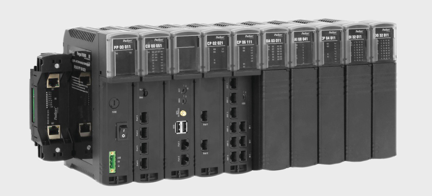
Regul R500 (рис. 1) является вторым контроллером в линейке и представляет собой «реинкарнацию» Regul R600, с которым читатели могли познакомиться в статьях, ранее опубликованных в журнале «СТА».
При этом Regul R500 предоставляет пользователю более широкие возможности при создании систем.
Функциональные возможности R500 можно разделить на две части.
- Характеристики, совпадающие с R600:
• поддержка «горячего» резервирования всех модулей, включая процессорные;
• поддержка «горячей» замены модулей;
• наличие двух независимых внутренних шин передачи данных на основе технологии EtherCAT;
• различные схемы резервирования;
• подключение станций удалённого ввода/вывода к центральному процессору по топологии «двойное резервируемое кольцо», «звезда» и смешанной схеме;
• фиксация событий внутри контроллера с метками времени;
• минимальное время цикла программы 1 мс;
• возможность расширения системы до 255 крейтов;
• первичная обработка сигналов внутри модулей ввода/вывода;
• глубокая диагностика системы с фиксацией нарушений структуры контроллера и неисправностей, в том числе конкретного модуля и канала ввода/вывода. - Особенности R500:
• подключение крейтов расширения через оконечные модули по медному и оптическому кабелю с защитой от «перекрещивания» внутренних шин;
• размещение модуля любого типа в любой позиции крейта и системы;
• более гибкое построение структуры сети контроллера за счёт возможности создания дополнительных структур типа «кольцо» и «звезда» через специализированные 6-канальные модули расширения шины.
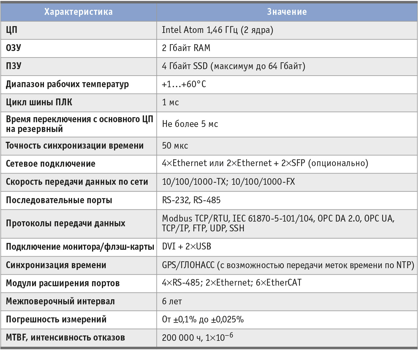
С техническими характеристиками модулей центрального процессора Regul R500 можно ознакомиться в табл. 1.
Также хотелось бы отметить тот факт, что Regul R500 поддерживает Web-визуализацию и онлайн-обновление по сети без остановки прикладной программы, выполняемой на контроллере.
Конструктивные особенности
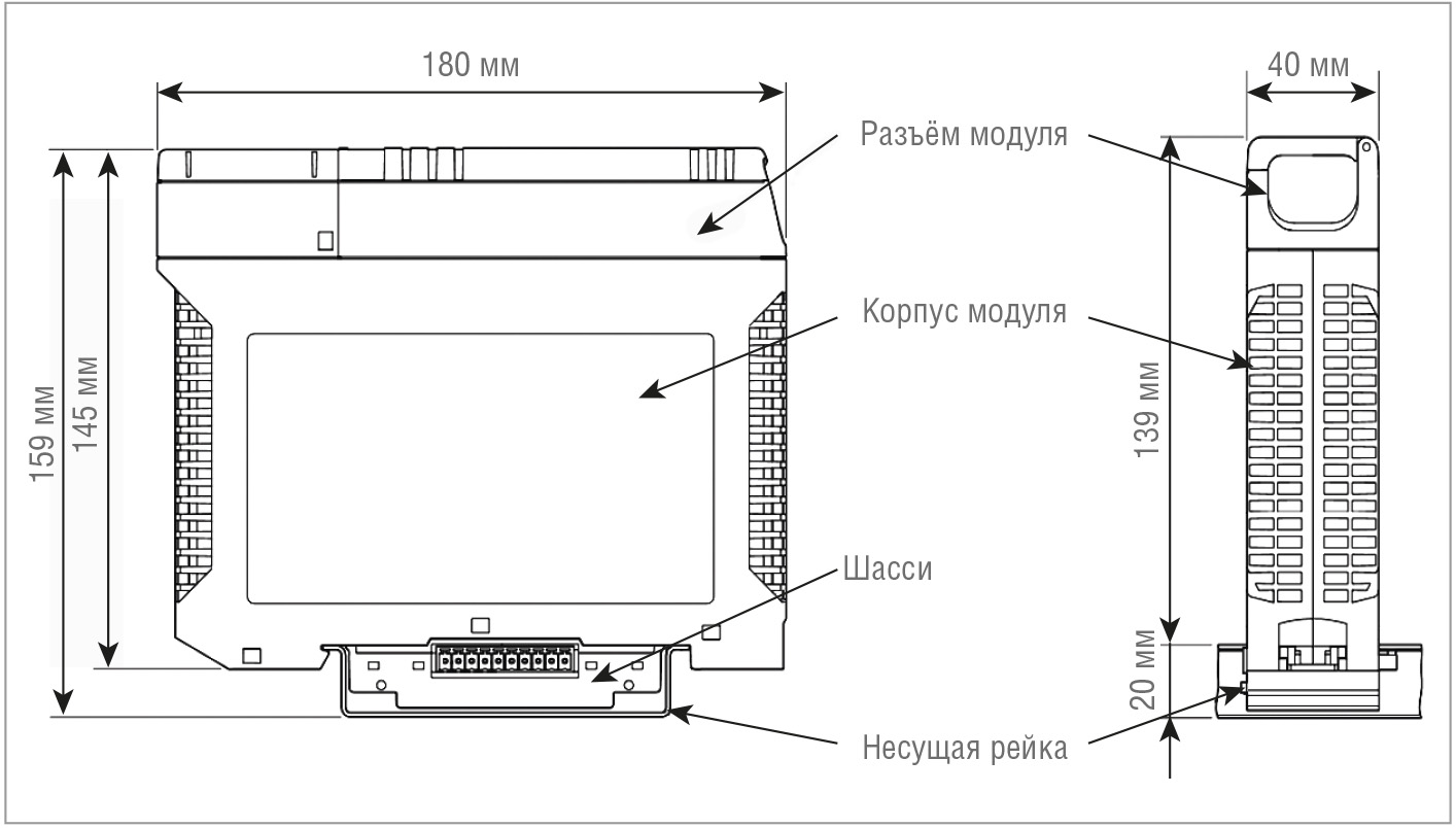
Конструктив Regul R500 (рис. 2) представляет собой пластмассовый корпус с удобным съёмным разъёмом с пружинными клеммами для подключения датчиков и исполнительных механизмов.
Данное исполнение позволяет при необходимости быстро заменить любой модуль контроллера без необходимости долгого переподключения периферии. Крепление каждого модуля осуществляется на отдельное шасси, установленное на
105-миллиметровой DIN-рейке, которое выполняет роль дублированной шины передачи данных на основе технологии EtherCAT. Шасси на рейке соединяются между собой, образуя крейт. Наборный крейт (линейка модулей) даёт возможность наращивания его с дискретностью в один модуль (до 40 модулей в крейте).
Типы модулей контроллера Regul R500
Все модули контроллера Regul R500 можно разделить на следующие подгруппы:
- модули шасси;
- модули источника питания;
- модули центрального процессора;
- модули коммуникационного процессора;
- модули ввода/вывода;
- оконечные модули.
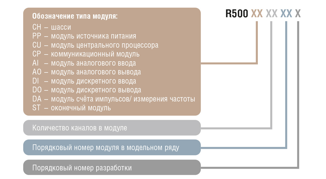
Модули ввода/вывода, в свою очередь, представлены модулями аналогового и дискретного ввода/вывода, а также модулями счёта импульсов. Принцип кодирования модулей в модельном ряду Regul R500 представлен на рис. 3.
Добавление индекса -02 в конце говорит о том, что модуль идёт в комплекте с шасси с поддержкой резервирования.
Схемы подключения крейтов и варианты резервирования
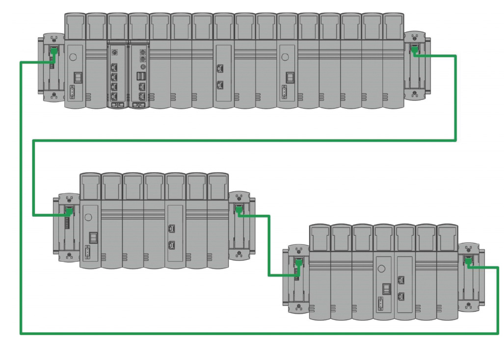
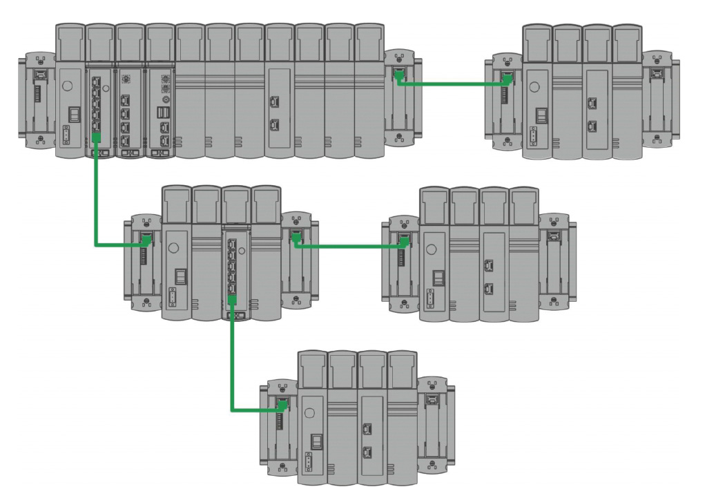
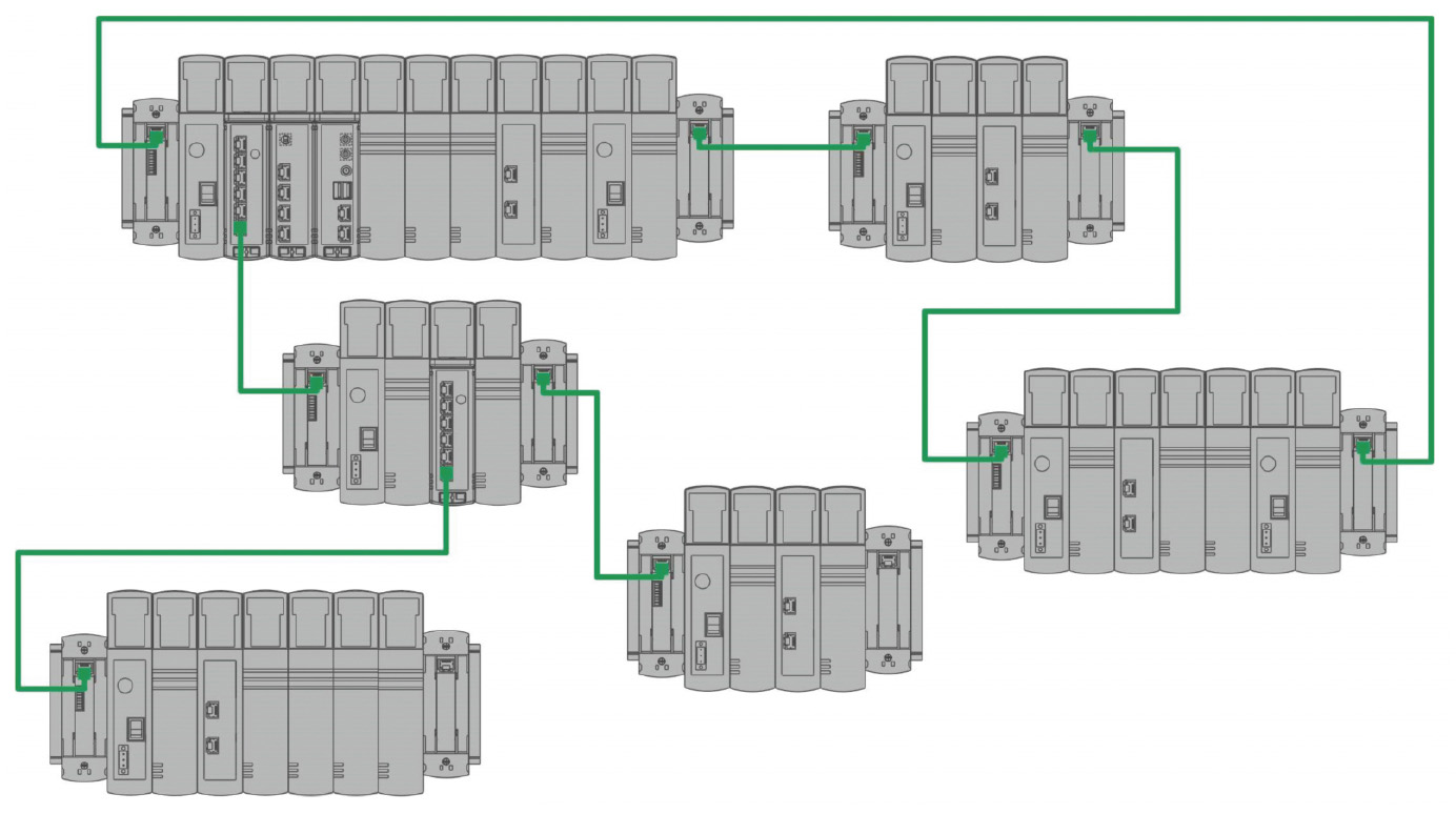
Как уже упоминалось, ПЛК Regul R500 позволяет подключать дополнительные крейты не только по топологии «звезда» и «кольцо», но и по смешанной схеме. Такая гибкость обеспечивается благодаря специализированному 6-канальному модулю расширения шины, который позволяет создавать дополнительные структуры типа «кольцо» и «звезда».
На рис. 4 представлена схема подключения крейтов «кольцо».
На рис. 5 представлена схема подключения крейтов «звезда».
На рис. 6 представлена смешанная схема подключения крейтов.
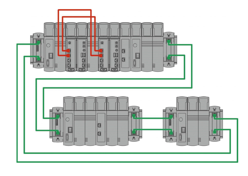
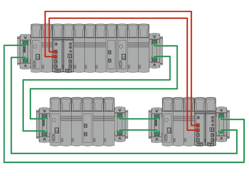
Все описанные схемы подключения крейтов могут применяться и в резервированных системах. Самой полной и надёжной является смешанная схема подключения крейтов с полным резервированием (рис. 7).
При стопроцентном резервировании каждый модуль ЦП имеет свой собственный набор модулей ввода-вывода, представляя собой «зеркало» другого.
Чуть менее надёжной является схема, при которой резервируются только модули центральных процессоров и блоков питания (рис. 8).
Резервирование модулей центрального процессора и блоков питания возможно также и при размещении процессорных модулей в разных крейтах (рис. 9).
Учитывая, что крейты могут находиться на расстоянии до 10 км друг от друга при подключении по оптической линии связи, отказоустойчивость системы будет значительно выше.
Наименее надёжной является схема, при которой резервируются только модули источников питания в каждом крейте. При данной схеме система останется работоспособной только лишь при выходе из строя одного из источников питания. Любой другой отказ приведёт к нарушению работоспособности системы. Именно поэтому наиболее распространены схемы с полным резервированием или с резервированием модулей центрального процессора и источников питания.
Заключение
В заключение хотелось бы обозначить наиболее вероятные сферы применения Regul R500, исходя из его широких возможностей резервирования и невероятного быстродействия внутренней шины передачи данных на основе технологии EtherCAT:
- ответственные решения, требующие повышенной надёжности оборудования (поддержка различных схем резервирования контроллеров и станций удалённого ввода/вывода);
- высокоточные измерительные системы ответственного применения (специальные измерительные модули повышенной точности, контроллер как система в составе с модулями ввода/вывода имеет сертификат средства измерения);
- отказоустойчивые системы управления технологическими объектами с быстро меняющимися физическими процессами (резервированные системы управления с минимальным циклом исполнения программы, специализированные модули высокоскоростного измерения физических параметров);
- распределённые системы АСУ ТП. ●
Автор – сотрудник фирмы ПРОСОФТ
Телефон: (495) 234-0636
E-mail: info@prosoft.ru

