Думаю одной из главных тем в любом сообществе которое ведётся по узкой специальности, а в нашем случае Almera N15, нужно иметь максимальную информацию по ремонту и обслуживанию. Так вот, небольшая подборочка полезного чтива:
1) Nissan Almera N15 Service Manual
Руководство по ремонту и техобслуживанию Nissan Almera N15 содержит подробное и полное описание ремонта и диагностики всех агрегатов автомобиля Ниссан Алмера, включая кузовные размеры для вытяжки кузова, подробный ремонт АКПП и МКПП, подробные электрические схемы, моменты затяжек, процесс сборки и разборки двигателя и других агрегатов и узлов, ремонт сцепления, рулевого управление, кондиционера, всех электрических устройств и блоков управления, необходимый специальный инструмент, а так же другая информация.
Ссылка на ЯндексДиск (архив .zip) Размер 152мб. Файлы в формате .pdf
Пример из одного PDF файла
2) Инструкция по эксплуатации Almera N15.
Это стандартная книженция которая выдавалась счастливому обладателю при покупке нового автомобиля в те далёкие годы, обычно шло в комплекте с сервисной книжкой и прочими «фантиками» =)
Ссылка на ЯндексДиск (формат .pdf) Размер 7,6мб.

3) Родная инструкция по ремонту и обслуживанию.
Стандартная инструкция которая шла вместе с автомобилем при покупке. Здесь собраны основные данные по машине, сколько чего заливать, как менять и когда))
Качество копирования не очень, но всё равно читается =)
Ссылка на ЯндексДиск (формат .pdf) Размер 90мб.

4) Мультимедийное руководство по ремонту Almera N15
• Секреты эксплуатации
• Детальное описание операций
• Более 500 иллюстраций
• Цветные электросхемы
В новой серии представлены руководства по ремонту, техническому обслуживанию и эксплуатации самых популярных в России на сегодняшний день зарубежных легковых автомобилей.В этих руководствах на основе обширного иллюстрированного материала автовладельцы, автомеханики средних и небольших автомастерских найдут всю необходимую для ремонта информацию по различным узлам и системам, познакомятся с особенностями эксплуатации и технического обслуживания. Издания снабжены цветными электросхемами.
Ссылка на ЯндексДиск (формат .rar) В разархивированном варианте образ диска .ISO) Размер 260мб.

з.ы. возможно будет продолжение =)
Руководство по эксплуатации, техническому и ремонту автомобиля Ниссан Альмера первого поколения (код N15) с четырехцилиндровыми бензиновыми двигателями объемом 1.4 литра (GA14DE), 1.5 литра (GA15DE), 1.6 литра (GA16DE) и 2.0 литра (SR20DE), а также с дизельными моторами объемом 2.0 литра (CD20, CD20E). Коробки передач описываются механические RS5F30A, RS5F31A и RS5F32A, а также автоматические.
Смотрите этот мануал на: болгарском, белорусском, украинском, сербском, хорватском
Руководство по эксплуатации
Приборы управления
Введение в руководство по эксплуатации
Описание панели управления
Сигнальные и контрольные лампочки и зуммеры
Сигнальная лампа противоугонной системы NATS
Полный список статей этой категории »
Подготовка к движению
Ключ зажигания
Дверные замки
Отпирание капота
Замок вещевого ящика
Полный список статей этой категории »
Отопитель, кондиционер и аудио
Центральные и боковые сопла вентилятора
Ручки управления кондиционером и отопителем
Работа обогревателя
Работа кондиционера
Полный список статей этой категории »
Запуск двигателя и вождение
Обкатка нового автомобиля
Перед запуском двигателя
Меры предосторожности при запуске двигателя и движении
Меры безопасности при движении
Полный список статей этой категории »
Техническое обслуживание
Общий уход за автомобилем
Защита кузова от коррозии
Меры предосторожности при выполнении технического ухода
Схема расположения точек обслуживания
Полный список статей этой категории »
Техническая информация
Рекомендуемое топливо, смазочные жидкости и заправочные объемы
Рекомендуемые типы смазочных жидкостей
Смазочная жидкость и хладагент воздушного кондиционера
Основные характеристики двигателей
Полный список статей этой категории »
Силовой агрегат
Ремонт двигателя
Общие указания по ремонту двигателя
Стандартные и специальные инструменты и приспособления
Измерение компрессии в цилиндрах
Масляный поддон — снятие и установка
Полный список статей этой категории »
Система смазки
Нанесение герметика в качестве «жидкой прокладки»
Специальные инструменты и приспособления
Схема смазочной системы
Проверка давления масла
Полный список статей этой категории »
Система охлаждения
Схема системы охлаждения
Водяной насос — снятие, проверка и установка
Термостат — снятие, установка и проверка
Выходной патрубок — проверка и установка
Полный список статей этой категории »
Система управления (бензин)
Общие меры предосторожности
Специальные инструменты и приспособления
Электрическая принципиальная схема
Структурная схема системы управления двигателем
Полный список статей этой категории »
Система управления (дизель)
Общие меры предосторожности
Специальные инструменты и приспособления
Электрическая принципиальная схема
Структурная схема системы управления двигателем
Полный список статей этой категории »
Система питания и выхлопа
Привод дроссельной заслонки — устройство
Регулировка троса привода дроссельной заслонки
Управление подачей топлива в двигателе CD20E
Топливный бак и топливный насос — устройство
Полный список статей этой категории »
Трансмиссия
Сцепление
Общие меры предосторожности
Специальные инструменты и приспособления
Регулировка педали сцепления
Удаление воздуха из гидравлического привода сцепления
Полный список статей этой категории »
Механическая коробка передач
Специальные и стандартные инструменты и приспособления
Замена сальников МКПП
Проверка выключателей
Снятие и установка коробки передач
Полный список статей этой категории »
Автоматическая коробка передач
Специальные инструменты и приспособления
Механизм переключения передач
Конструкция автоматической коробки передач
Проверка рабочей жидкости
Полный список статей этой категории »
Шасси
Передняя подвеска
Общие замечания
Специальные и стандартные инструменты и приспособления
Проверка деталей подвески на автомобиле
Устройство передней подвески
Полный список статей этой категории »
Задняя подвеска
Общие замечания о ремонте задней подвески
Специальные и стандартные инструменты и приспособления
Устройство задней подвески
Устройство ступицы заднего колеса
Полный список статей этой категории »
Рулевое управление
Общие указания по ремонту рулевого управления
Специальные и стандартные инструменты и приспособления
Рулевое колесо и рулевая колонка — устройство
Проверка рулевого управления на автомобиле
Полный список статей этой категории »
Тормозная система
Общие указания по ремонту тормозной системы
Стандартные инструменты и приспособления
Обслуживание тормозной системы
Удаление воздуха из гидравлического привода
Полный список статей этой категории »
Кузов
Отопление и кондиционирование
Общие меры предосторожности
Правила работы с компрессором кондиционера
Правила работы с соединениями
Специальные инструменты и приспособления
Полный список статей этой категории »
Система безопасности
Указания по работе с подушками безопасности
Расположение компонентов в системе с двумя подушками безопасности
Блок управления — снятие и установка
Механические натяжители ремней безопасности — снятие к установка
Полный список статей этой категории »
Элементы кузова
Зажимы и фиксаторы
Снятие и установка бамперов
Регулировка петель и замков
Наружное зеркало заднего вида — снятие
Полный список статей этой категории »
Электрооборудование
Оборудование и приборы
Электрические разъемы
Стандартные реле
Список сокращений, используемых на схемах
Принципиальная схема подачи питания к потребителям
Полный список статей этой категории »
Силовые устройства
Защита электрических цепей
Аккумуляторная батарея
Устройство стартера
Стартер — снятие, проверка и сборка
Полный список статей этой категории »
Отправить эту информацию вашим друзьям:
программа для ремонта автомобилей . Купить отзывы авито: накрутка отзывов авито.
Ссылка в разных форматах на этот раздел
TEXTHTMLBB Code

Руководство на английском языке по техническому обслуживанию и ремонту автомобиля Nissan Almera Classic серии B10.
- Автор: —
- Издательство: Nissan Motor Co., Ltd.
- Год издания: 2006
- Страниц: —
- Формат: PDF
- Размер: 74,1 Mb

Руководство на английском языке по техническому обслуживанию и ремонту автомобиля Nissan Almera серии N16.
- Автор: —
- Издательство: Nissan Motor Co., Ltd.
- Год издания: 2001
- Страниц: —
- Формат: PDF
- Размер: 101,2 Mb

Руководство на английском языке по техническому обслуживанию и ремонту автомобиля Nissan Almera серии N16.
- Автор: —
- Издательство: Nissan Motor Co., Ltd.
- Год издания: 2003
- Страниц: —
- Формат: PDF
- Размер: 118,0 Mb

Сборник руководств на английском языке по техническому обслуживанию и ремонту автомобиля Nissan Almera серии N15 1995-2000 годов выпуска.
- Автор: —
- Издательство: Nissan Motor Co., Ltd.
- Год издания: —
- Страниц: —
- Формат: PDF
- Размер: 211,9 Mb

Руководство на английском языке по техническому обслуживанию и ремонту автомобилей Nissan Almera/Latio/Sunny/Versa 2011-2012 годов выпуска.
- Автор: —
- Издательство: Motorist
- Год издания: —
- Страниц: 2747
- Формат: —
- Размер: —

Руководство по техническому обслуживанию и ремонту автомобиля Nissan Almera 1996 года выпуска.
- Автор: —
- Издательство: Nissan Europe
- Год издания: 1995
- Страниц: 318
- Формат: PDF
- Размер: 67,0 Mb
Руководство по эксплуатации и техническому обслуживанию автомобиля Nissan Almera 2013 года выпуска.
- Автор: —
- Издательство: Nissan International SA
- Год издания: 2012
- Страниц: 172
- Формат: PDF
- Размер: 3,1 Mb

Руководство по эксплуатации и техническому обслуживанию автомобиля Nissan Almera 1996 года выпуска.
- Автор: —
- Издательство: Nissan Europe
- Год издания: 1995
- Страниц: 149
- Формат: PDF
- Размер: 7,7 Mb

Руководство по эксплуатации, техническому обслуживанию и ремонту автомобиля Nissan Almera Classic с 2005 года выпуска с бензиновым двигателем объемом 1,6 л.
- Автор: —
- Издательство: Третий Рим
- Год издания: —
- Страниц: 344
- Формат: —
- Размер: —

Руководство по эксплуатации, техническому обслуживанию и ремонту автомобиля Nissan Almera серии N16 2000-2006 годов выпуска с бензиновыми двигателями объемом 1,5/1,8 л.
- Автор: —
- Издательство: АртСтиль
- Год издания: 2007
- Страниц: 424
- Формат: PDF
- Размер: 114,8 Mb

Руководство по техническому обслуживанию и ремонту автомобиля Nissan Almera 1995-1999 годов выпуска с бензиновыми и дизельными двигателями.
- Автор: —
- Издательство: Атласы автомобилей
- Год издания: —
- Страниц: 190
- Формат: —
- Размер: —

Руководство по эксплуатации и ремонту автомобиля Nissan Almera Classic серии с 2006 года выпуска с бензиновым двигателем объемом 1,6 л.
- Автор: —
- Издательство: Монолит
- Год издания: —
- Страниц: 302
- Формат: —
- Размер: —

Руководство по эксплуатации и техническому обслуживанию автомобиля Nissan Almera Classic.
- Автор: —
- Издательство: MoToR
- Год издания: —
- Страниц: 270
- Формат: —
- Размер: —

Руководство по эксплуатации, техническому обслуживанию и ремонту автомобиля Nissan Almera с 2000 года выпуска с бензиновыми двигателями объемом 1,5/1,8 л.
- Автор: —
- Издательство: Арго-Авто
- Год издания: —
- Страниц: 264
- Формат: —
- Размер: —

Руководство по техническому обслуживанию и ремонту автомобиля Nissan Almera Classic серии B10 2006-2012 годов выпуска с бензиновым двигателем объемом 1,6 л.
- Автор: —
- Издательство: Автонавигатор
- Год издания: —
- Страниц: 374
- Формат: —
- Размер: —

Руководство по эксплуатации, техническому обслуживанию и ремонту автомобиля Nissan Almera серии G15 с 2013 года выпуска с бензиновым двигателем объемом 1,6 л.
- Автор: —
- Издательство: Автонавигатор
- Год издания: —
- Страниц: 296
- Формат: —
- Размер: —

Руководство по техническому обслуживанию и ремонту автомобиля Nissan Almera с 2013 года выпуска.
- Автор: —
- Издательство: За рулем
- Год издания: —
- Страниц: 255
- Формат: —
- Размер: —

Руководство по техническому обслуживанию и ремонту автомобилей Nissan Almera и Nissan Sunny с 2000 года выпуска с бензиновыми двигателями объемом 1,5/1,8 л.
- Автор: —
- Издательство: Автонавигатор
- Год издания: —
- Страниц: 376
- Формат: —
- Размер: —
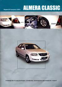
Руководство по эксплуатации, техническому обслуживанию и ремонту автомобиля Nissan Almera Classic серии B10 с 2006 года выпуска.
- Автор: —
- Издательство: Автонавигатор
- Год издания: 2007
- Страниц: 344
- Формат: DjVu
- Размер: 28,7 Mb

Инструкция на русском языке для Nissan Almera N15 1995, содержит справочные данные и описание основных моментов эксплуатации автомобиля.
Рекомендуем перед началом использования изучить руководство, это позволит избежать проблем при эксплуатации и узнать о всех функциях и особенностях автомобиля.
Информация о файле: 90.12 Мб
manual-nissan-almera-n15-1995
◀Скачать руководство для Nissan Pathfinder 2010
Скачать руководство для Nissan Almera 2013▶
This manual contains maintenance and repair procedures for NISSAN model N15 series. In order to assure your safety and the efficient functioning of the vehicle, this manual should be read thoroughly. It is especially important that the PRECAUTIONS in the Gl section be completely understood before starting any repair task. All information in this manual is based on the latest product information at the time of publication. The right is reserved to make changes in specifications and methods at any time without notice.
The proper performance of service is essential for both the safety of the technician and the efficient functioning of the vehicle. The service methods in this Service Manual are described in such a manner that the service may be performed safely and accurately. Service varies with the procedures used, the skills of the technician and the tools and parts available. Accordingly, anyone using service procedures, tools or parts which are not specifically recommended by NISSAN must first be completely satisfied that neither personal safety nor the vehicle’s safety will be jeopardized by the service method selected.
CONTENTS
- GENERAL INFORMATION
- MAINTENANCE
- ENGINE MECHANICAL
- ENGINE LUBRICATION & COOLING SYSTEMS
- ENGINE CONTROL SYSTEM
- ACCELERATOR CONTROL, FUEL & EXHAUST SYSTEMS
- CLUTCH
- MANUAL TRANSAXLE
- AUTOMATIC TRANSAXLE
- FRONT AXLE & FRONT SUSPENSION
- REAR AXLE & REAR SUSPENSION
- BRAKE SYSTEM
- STEERING SYSTEM
- RESTRAINT SYSTEM
- BODY & TRIM
- HEATER & AIR CONDITIONER
- ELECTRICAL SYSTEM
- ALPHABETICAL INDEX
Language: English
Format: PDF
Pages: 1712
Nissan Almera N15 series Service Manual
- Главная
- Nissan
- Almera
- Книга по эксплуатации и ремонту Nissan Almera N15 1995-1999 гг.
Год выпуска:
1995 — 1999 гг.
Найдено 5 книг стоимостью от 444 руб.
Быстро купить книгу в оригинальной качественной версии PDF от издательства
Купить бумажную версию книги с доставкой по вашему адресу
Скачать руководство с предоставленного файлообменника
Команда нашего сайта предоставляет вам возможность скачать руководство по ремонту, диагностике и техническому обслуживанию автомобилей Nissan Almera N15, которые выпускались с 1995 по 1999 года.
Мануал содержит в себе всю информацию по автомобилям Nissan Almera N15 с бензиновыми и двигательными двигателями. Бензиновые двигатели представлены в следующих вариациях объёма: 1.6, 2.0 и малолитражный мотор – 1.4 литра. Дизельные двигатели автомобилей Nissan Almera N15 представлены лишь одним мотором, объёмом 2.0 литра.
Пособие включило в свой состав не только голый текст, но и набор иллюстраций, которые присутствуют в каждом разделе руководства. Каждой детали автомобиля отведена отдельная глава. В этой главе, вы найдете правила и порядок проведения диагностики и ремонта детали в случае поломки, для этого в пособии и присутствуют иллюстрации, которые графически объясняют, как правильно диагностировать и ремонтировать деталь.
Эксплуатация Nissan Almera
Похожие руководства на сайте
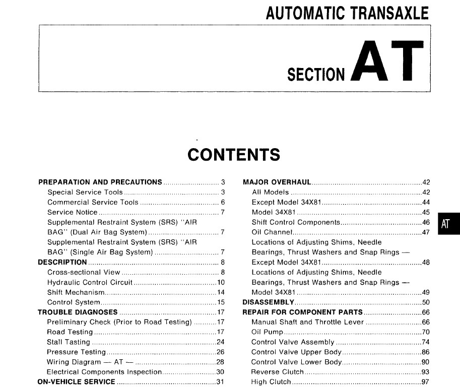
AUTOMATIC TRANSAXLE
AT
SECTION
CONTENTS
PREPARATION AND PRECAUTIONS
Special
Service
Commercial
Service
Tools
Service
Notice
Restraint
System
Supplemental
Restraint
BAG»
Air Bag System)
(Single
All Models
Except
Model
Model
34X81
System
(SRS) «AIR
Cross-sectional
View
Control
Circuit
42
42
34X81
.44
45
Shift Control
7
DESCRIPTION
Hydraulic
3
(SRS) «AIR
(Dual Air Bag System)
MAJOR OVERHAUL..
6
7
Supplemental
BAG»
Tools
3
Components
46
Oil Channel
47
Locations
of Adjusting
7
Bearings,
Thrust
8
Except
8
Locations
of Adjusting
10
Bearings,
Thrust
Model
Shims,
Washers
Needle
and Snap Rings —
34X81
.48
Shims,
Washers
Needle
and Snap Rings —
Shift Mechanism
14
Control
15
DiSASSEMBLy
17
REPAIR FOR COMPONENT PARTS
System
TROUBLE DIAGNOSES
Preliminary
(Prior
to Road Testing)
34X81
.49
50
66
17
Manual
Road Testing
17
Oil Pump
Stall Tasting
24
Control
Valve
Assembly
74
Pressure
26
Control
Valve
Upper
Body
86
28
Control
Valve
Lower
Body
30
Reverse
31
High Clutch
31
Forward
33
Low & Reverse
35
Rear Internal
36
Overrun
37
Output
Wiring
Check
Model
Testing
Diagram
Electrical
—
AT —
Components
Inspection
ON-VEHICLE SERVICE
Control
Valve
Assembly
Throttle
Wire Adjustment..
Control
Cable
Governor
Inhibitor
Differential
and Accumulator
Installation
and Adjustment
Valve
Switch
Adjustment
Side Oil Seal Replacement..
REMOVAL AND INSTALLATION
Removal
Installation
Shaft and Throttle
Lever
66
70
90
Clutch
93
97
Clutch
and Overrun
108
Forward
Clutch
112
Gear,
Idler
Gear,
Reduction
Pinion
Gear and Bearing
39
—
Model
34X81
39
Output
.40
Shaft,
Idler Gear,
Gear and Bearing
Band Servo
Hub and
Hub
Output
37
Except
102
Brake
Gear,
Clutch
Shaft,
Clutch
Piston
Retainer
116
Reduction
Retainer
—
Model
Assembly
Final Drive —
Except
Model
Final Drive —
Model
34X81
Pinion
34X81
121
126
34X81
131
135
•
i
CONTENTS
ASSEMBLy
Assembly 1
Adjustment 1
Assembly 2
Adjustment 2
Assembly 3
138
138
139
147
151
(Cont’d.)
Adjustment 3
Assembly 4
SERVICE DATA AND SPECIFICATIONS (SOS)
General Specifications
Specifications and Adjustments
155
When you read wiring diagrams:
• Read GI section, «HOW TO READ WIRING DIAGRAMS» .
• See EL section, «POWER SUPPLY ROUTING» for power distribution circuit.
157
158
165
165
165
PREPARATION AND PRECAUTIONS
Special Service Tools
Tool number
Tool name
Description
8T25058001
Oil pressure gauge set
G) 8T25051001
Oil pressure gauge
@ 8T25052000
Hose
@ 8T25053000
Joint pipe
@ 8T25054000
Adapter
@ 8T25055000
Adapter
Measuring line pressure and governor
pressure
NT097
KV31103000
Drift
Installing differential side oil seal
(Use with 8T35325000)
a: 59 mm (2.32 in) dia.
b: 49 mm (1.93 in) dia.
NT105
8T35325000
Drift
Installing differential side oil seal
(Use with KV31103000)
a: 215 mm (8.46 in)
b: 25 mm (0.98 in) dia.
c: M12 x 1.5P
NT417
Removing and installing clutch return
spring
KV31103200
Clutch spring compressor
a: 179 mm (7.05 in)
b: 76 mm (2.99 in) dia.
c: 174 mm (6.85 in)
NT425
Removing and installing parking rod plate
and manual plate
8T23540000
Pin punch
a: 2.3 mm (0.091 in) dia.
b: 4 mm (0.16 in) dia.
NT442
Installing throttle lever and manual shaft
retaining pins
Removing and installing differential pinion
mate shaft lock pin.
KV32101000
Pin punch
a: 4 mm (0.16 in) dia.
NT410
AT-3
•
PREPARATION AND PRECAUTIONS
Special Service Tools (Cont’d)
Tool number
Tool name
Description
ST3306S001
Removing differential side bearing inner
Differential side bearing
puller set
race
CD
ST33051001
Puller
@ ST33061000
Adapter
,~
a
NT413
KV381054S0
(ST33290001)
Puller
a:
b:
c:
d:
e:
38 mm (1.50 in) dia.
28.5 mm (1.122 in) dia.
130 mm (5.12 in)
135 mm (5.31 in)
100 mm (3.94 In)
• Removing differential side oil seal
• Removing idler gear bearing outer race
— EXCEPT MODEL 34X81 • Removing output shaft bearing outer
race from bearing retainer
• Removing output gear bearing outer
race from bearing retainer
— MODEL 34X81 • Removing differential side bearing outer
race
• Removing needle bearing from bearing
retainer
a: 250 mm (9.84 in)
b: 160 mm (6.30 in)
NT414
ST27180001
Puller
• Removing idler gear
• Removing output gear (Except model
34X81)
a: 100 mm (3.94 In)
b: 110 mm (4.33 in)
c: M8 x 1.25P
NT424
ST30031000
Puller
Removing reduction pinion gear bearing
inner race (Except model 34X81)
a: 90 mm (3.54 In) dia.
b: 50 mm (1.97 in) dia.
NT411
ST30021000
Puller
Removing differential side bearing
(Except model 34X81)
a: 110 mm (4.33 in) dia.
b: 68 mm (2.68 in) dia.
NT411
ST35272000
Drift
• Installing reduction pinion gear bearing
inner race
• Installing idler gear bearing inner race
• Installing output gear bearing inner race
(Except model 34X81)
~
a: 72 mm (2.83 in) dia.
b: 35.5 mm (1.398 in) dia.
NT426
AT-4
PREPARATION AND PRECAUTIONS
Special Service Tools (Cont’d)
Tool number
Tool name
Description
8T37830000
Drift
Installing idler gear bearing outer race
a: 62 mm (2.44 in) dia.
b: 39 mm (1.54 in) dia.
NT427
8T33200000
Drift
Installing differential side bearing (Except
model 34X81)
a: 60 mm (2.36 in) dia.
b: 44.5 mm (1.752 in) dia.
NT091
8T35271000
Drift
• Installing idler gear
• Installing output gear (Except model
34X81)
a: 72 mm (2.83 in) dia.
b: 44 mm (1.73 in) dia.
NT115
8T33400001
Drift
• Installing oil pump housing oil seal
• Installing output gear bearing outer race
onto bearing retainer (Except model
34X81)
a: 60 mm (2.36 in) dia.
b: 47 mm (1.85 in) dia.
NT086
KV40104840
Drift
Installing output shaft bearing outer race
onto bearing retainer (Except model
34X81)
a: 49 mm (1.93 in) dia.
NT108
b: 42 mm (1.65 in) dia.
— MODEL 34X81 • Measuring turning torque of final drive
KV38105710
Preload adapter
assembly
• Measuring clearance between side gear
and differential case with washer
• Selecting differential side bearing
adjusting shim
NT087
8T35321000
Drift
Installing output shaft bearing
(Model 34X81)
a: 49 mm (1.93 in) dia.
b: 41 mm (1.61 in) dia.
NT073
ST30633000
Drift
Installing differential side bearing outer
race (Model 34X81)
a: 67 mm (2.64 in) dia.
b: 49 mm (1.93 in) dia.
NT073
AT-5
•
PREPARATION AND PRECAUTIONS
Commercial Service Tools
Tool name
Description
Puller
=m
o
NT077
0
Drift
• Removing idler gear bearing inner race
• Removing and installing band servo piston snap ring
— EXCEPT MODEL 34X81 • Removing output gear bearing inner
race
• Removing differential side bearing
Removing idler gear bearing inner race
(Except model 34X81)
NT109
~
a: 34 mm (1.34 in) dia.
Installing needle bearing onto bearing
retainer (Model 34X81)
Drift
NT109
~
a: 36 mm (1.42 in) dia.
Removing output gear bearing inner race
(Except model 34X81)
Drift
NT109
~
a: 33 mm (1.30 in) dia.
Removing differential side bearing (Except
model 34X81)
Drift
NT109
~
a: 38 mm (1.50 in) dia.
Removing output shaft bearing inner race
(Except model 34X81)
Drift
NT110
a: 70 mm (2.76 in) dia.
b: 30 mm (1.18 in) dia.
~
Installing output shaft bearing inner race
(Except model 34X81)
Drift
a:
b:
c:
d:
~d
NT111
AT-6
70 mm (2.76 in) dia.
34 mm (1.34 in) dia.
30 mm (1.18 in) dia.
2 mm (0.08 in)
PREPARATION AND PRECAUTIONS
Service Notice
•
•
•
•
•
•
•
Before proceeding
with disassembly,
thoroughly clean the outside of the transaxle. It is
important to prevent the internal parts from
becoming contaminated by dirt or other foreign matter.
Disassembly should be done in a clean work
area.
Use lint-free cloth or towels for wiping parts
clean. Common shop rags can leave fibers
that could interfere with the operation of the
transaxle.
Place disassembled parts in order, on a parts
rack, for easier and proper assembly.
All parts should be carefully cleaned- with a
general
purpose,
non-flammable
solvent
before inspection or reassembly.
Gaskets,
seals
and O-rings
should
be
replaced any time the transaxle is disassembled.
It is very important to perform functional tests
whenever they are indicated.
•
•
•
•
•
The valve body contains precision parts and
requires
extreme
care when
parts are
removed and serviced. Place disassembled
valve body parts in order, on a parts rack, for
easier and proper assembly. Care will also
prevent springs and small parts from becoming scattered or lost.
Properly installed vales, sleeves, plugs, etc.
will slide along their bores in the valve body
under their own weight.
Before assembly,
apply a coat of recommended ATF to all parts. Apply petroleum
jelly to protect O-ring and seals, or hold bearings and washers in place during assembly.
Do not use grease.
Extremely care should be taken to avoid damage to O-rings, seals and gaskets when
assembling.
After overhaul, refill the transaxle with new
ATF.
Supplemental Restraint System (SRS) «AIR
BAG» (Dual Air Bag System)
The Supplemental Restraint System «Air Bag» used along with a seat belt, helps to reduce the risk or
severity of injury to the driver and front passenger in a frontal collision. The Supplemental Restraint
System consists of air bag modules (located in the center of the steering wheel and on the instrument
panel on the passenger side), a diagnosis sensor unit, warning lamp, wiring harness and spiral cable.
Information necessary to service the system safely is included in the RS section of this Service Manual.
WARNING:
•
To avoid rendering the SRS inoperative, which could increase the risk of personal injury or death
in the event of a collision which would result in air bag inflation, all maintenance must be performed
by an authorized NISSAN dealer.
•
Improper maintenance, including incorrect removal and installation of the SRS, can lead to personal
injury caused by unintentional activation of the system.
Ii
Do not use electrical test equipment on any circuit related to the SRS unless instructed to in this
Service Manual. SRS wiring harnesses are covered with yellow insulation either just before the
harness connectors or for the complete harness, for easy identification.
Supplemental Restraint System (SRS) «AIR
BAG» (Single Air Bag System)
The Supplemental Restraint System «Air Bag» and used along with a seat belt, helps to reduce the risk
or severity of injury to the driver in a frontal collision. The Supplemental Restraint System consists of
an air bag module (located in the center of the steering wheel), a diagnosis sensor unit, warning lamp,
wiring harness and spiral cable. Information necessary to service the system safely is included in the
RS section of this Service Manual.
WARNING:
•
To avoid rendering the SRS inoperative, which could increase the
in the event of a collision which would result in air bag inflation, all
by an authorized NISSAN dealer.
•
Improper maintenance, including incorrect removal and installation
injury caused by unintentional activation of the system.
•
Do not use electrical test equipment on any circuit related to the
Service Manual.
AT-7
risk of personal injury or death
maintenance must be performed
of the SRS, can lead to personal
SRS unless instructed
to in this
•
DESCRIPTION
Cross-sectional View
EXCEPT MODEL 34X81
Band servo piston
Reverse clutch drum
Converter housing
High clutch
Brake band
Torque converter
SAT502HB
AT-8
DESCRIPTION
Cross-sectional View (Cant’ d)
MODEL 34X81
Reverse clutch drum
Band servo piston
High clutch
Front planetary gear
Reverse clutch
Low one-way clutch
Oil pump assembly
Brake band
Rear planetary gear
Converter housing
Forward clutch
Overrun clutch
Low & reverse brake
Torque converter
Input shaft
c
Idler gear
…
-;-
I
,»‘I
L_
Forward one-way clutch
Reduction pinion gear
Final gear
Differential case
SAT101EA
AT-9
•
DESCRIPTION
Hydraulic Control Circuit
MODEL 34X68
Low & reverse
brake
High clutch
Forward
clutch
4th
speed cut
valve
Overrun
clutch
control
valve
Lock-up
control
valve
1-2
shift
valve
Torque
‘~ ..•.•
converter
relief
..••…..
valve
..
>..•.••••
Governor
valve
X
: Drain port
Detent valve
: Orifice
SAT1961
AT-10
DESCRIPTION
Hydraulic Control Circuit (Cont’d)
MODEL 34X69 AND 34X70
Torque
converter
High clutch
Forward
clutch
Oil
pump
4th
speed
cut
valve
i
accumulator
valve
Lock-up
control
valve
Overrun
clutch
control
valve
II
•
1-2
shift valve
00 cancel
solenoid
X
: Drain
=:= :
port
Orifice
SAT509H
AT-11
DESCRIPTION
Hydraulic Control Circuit (Cont’d)
MODEL 34X80
Low & reverse
Torque
converter
Oil
brake
Overrun
,clutch
tJ
I g~
pump
I
~J
speed cut
valve
C-1
(~
Forward
clutch
—;::;-;r.]O
~~ l]
~
J~
~
UL «-‘ IU4~1~~
~%~
1
~frEJ!
-!
6 ~,
Lock-up_
control
valve
tf1
(T,
N
~iJ —
Reverse
clutch
Band servo
(Jp::-
1 ~
4th
Overrun
clutch
controlvalve
High clutch
-~
1-2
accumulator
valve
cooler-
L-
_
—
m
0
~,—J
—
,-O…J
ILJ
ar
r
I ‘—,~
r::r=<
,’-
=-
II
.
,,’
~tL
‘
(
I
‘
IJ
—
—
(
I
,
~1
i i
xU
~H
::l.
-= ~ I
rr=-
LL:
L~
Torque x'»
converter
relief
valve
~
x
—
r
~
i i
‘
2 ~ ‘-
3-4 shift valv~-HiliJI
Governor../l
valve
Pressure
regulator
valve
~M~ ·
F= f=’l
.,.11
L 2-3
~
=—=-.J
!lJF
—
II
:;;; ~ I
=-.—‘
00 cancel
solenoid
»
1-
~
L…—…l
I
nn
I
1-2
shift
valve
~reducing_
~
«~’L—.J
lJl.
U
p RNb’21
11
r’
.
4-2
I ~valve=
~
seq!!.enc~
,-=-valve—j
h
1J;;;.Q»t….
Ma~alve
II
~
II
‘i-VD
-,
.»
c: I
I
modifier
Throttle
valve
II
•
‘:fj’~1
I
:=~-‘
Pressure
modifier valve
: Drain port
~I»
shift
valve
..-
D ~Y&
X
I~
J~
Detent valve
1″
Throttle valve
.
If.’
.
«;’Jnn!
~
~
l…
,
Klckdown
modifier
valve
:::::: : Orifice
SAT1971
AT-12
DESCRIPTION
Hydraulic Control Circuit (Cont’d)
MODEL 34X81
Oil
pump
Torque
converter
High clutch
4th speed
cut valve
Lock-up
control valve
Overrun
clutch
control valve
•
1-2
shift valve
3-4 shift valve
X
Drain port
:::::= : Orifice
SAT1981
AT-13
DESCRIPTION
Shift Mechanism
CONSTRUCTION
,:-1
18
SAT214H
ill
@
@
@
@
Brake band
Reverse clutch
High clutch
@
Front sun gear
Front pinion gear
@
o
@
@l
@
@
Torque converter
Oil pump
Input shaft
FUNCTION
@
@
@
@
Front internal gear
Front planetary carrier
Rear sun gear
Rear pinion gear
Rear internal gear
Rear planetary carrier
Forward clutch
Forward one-way clutch
@
@
@
@
@
@
@
@
Overrun clutch
Low one-way clutch
Low & reverse brake
Parking pawl
Parking gear
Output shaft
Idle gear
Output gear
OF CLUTCH AND BRAKE
Glutch and brake components
Abbr.
Function
Reverse clutch
RIG
To transmit input power to front sun gear
High clutch
HIG
To transmit input power to front planetary carrier
Forward clutch
FIG
To connect front planetary carrier with forward one-way clutch
Overrun clutch
OIG
To connect front planetary carrier with rear internal gear
Brake band
BIB
To lock front sun gear
Forward one-way clutch
F/O.G
Low one-way clutch
LlO.G
Low & reverse brake
L & RIB
When forward clutch is engaged, to stop rear internai gear from rotating in opposite direction against engine speed
To stop front planetary carrier from rotating in opposite direction
against engine speed
To lock front planetary carrier
AT-14
DESCRIPTION
Shift Mechanism (Cont’d)
OPERATION
OF CLUTCH AND BRAKE
Band servo
Shift posi- Reverse
tion
clutch
High
clutch
Forward
clutch
Overrun
clutch
2nd
apply
3rd
release
Forward
Low
one-way one-way
clutch
clutch
4th
apply
Low &
reverse
brake
Lock-up
PARK POSITION
P
R
REVERSEPOSITION
0
0
NEUTRAL POSITION
N
D
‘4
1st
0
’10
2nd
0
’10
0
’10
‘2@
@
‘3@
@
3rd
0
0
4th
0
@
1st
0
0
2nd
0
0
1st
0
0
2nd
0
0
• •
••
• •
•• •
•
0
2
0
1
‘1
‘2
‘3
‘4
o
Remarks
0
Automatic shift
1<—>2<—>3<—>4
0
Automatic shift
1<—>2
0
Locks (held stationary) in 1st
speed 1 <— 2
Operates when overdrive switch is sel to «OFF».
Oil pressure is applied to both 2nd «apply» side and 3rd «release» side of band servo piston. However, brake band does not contract
because oil pressure area on the «release» side is greater than that on the «apply» side.
Oil pressure is applied to 4th «apply» side in condition ‘2 above, and brake band contracts.
AIT will not shift to 4th when overdrive switch is set to «OFF» position.
Operates.
•
Operates. During «progressive»
@
Operates but does not affect power transmission.
acceleration.
Control System
CONTROL SYSTEM
Engine
AIT
:
Governor valve
1
1
I
1
Lock-up cancel
solenoid’1
‘1:
1
1
Equipped on model
34X69, 34X70 and 34X80
I
: Electrical signal
1
1
Overdrive
control switch
OD cancel solenoid :
;
….
: Hydraulic pressure
I
J
L
AT-15
SAT985HA
•
DESCRIPTION
NOTE
AT-16
TROUBLE DIAGNOSES
Preliminary Check (Prior to Road Testing)
Fluid leakage
AIT FLUID CHECK
Fluid leakage check
1.
2.
3.
4.
Clean area suspected of leaking, — for example, mating
surface of converter housing and transmission case.
Start engine, apply foot brake, place selector lever in «0»
position and wait a few minutes.
Stop engine.
Check for fresh leakage.
SAT288G
Fluid condition check
Fluid color
Suspected problem
Oark or black with burned odor
Wear of frictional material
Milky pink
Water contamination
— Road water entering through
filler tube or breather
Varnished fluid, light to dark brown
and tacky
Oxidation
— Over or under filling
— Overheating
Fluid level check — Refer to MA section (CHASSIS AND
BODY MAINTENANCE).
Road Testing
Perform
AT-20.
road
tests
using
«Symptom»
chart.
Refer to page
«P» POSITION
1.
2.
Place selector lever in «P» position and start engine. Stop
engine and repeat the procedure in all positions, including
neutral position.
Stop vehicle on a slight upgrade and place selector lever in
«P» position. Release parking brake to make sure vehicle
remains locked.
«R» POSITION
1.
2.
Manually move selector lever from «P» to «R», and note
shift quality.
Drive vehicle in reverse long enough to detect slippage or
other abnormalities.
«N» POSITION
1.
2.
Manually move selector lever from «R» and «0» to «N» and
note shift quality.
Release parking brake with selector lever in «N» position.
Lightly depress accelerator
pedal to make sure vehicle
does not move. (When vehicle is new or soon after clutches
have been replaced, vehicle may move slightly. This is not
a problem.)
AT-17
•
TROUBLE DIAGNOSES
Road Testing (Cont’d)
«0» POSITION
SAT612GA
1. Manually move selector lever from «N» to «D» position, and
note shift quality.
2. Using the shift schedule as a reference, drive vehicle in «D»
position. Record, on symptom chart, respective vehicle
speeds at which up-shifting and down-shifting occur. These
speeds are to be read at three different throttle positions
(light, half and full), respectively. Also determine the timing
at which shocks are encountered during shifting and which
clutches are engaged.
3. Determine whether lock-up properly occurs while driving
vehicle in proper gear position and at proper vehicle speed.
4. Check to determine if shifting to overdrive gear cannot be
made while OD control switch is «OFF».
5. Drive vehicle in «D3» position at half to light throttle position. Keep driving at 60 to 70 km/h (34 to 43 MPH). FUlly
depress accelerator pedal to make sure transaxle downshifts from 3rd to 2nd gear.
6. Drive vehicle in «D2» position at half to light throttle position. Keep driving at 25 to 35 km/h (16 to 22 MPH). Fully
depress accelerator pedal to make sure transaxle downshifts from 2nd to 1st gear.
SAT497G
«2» POSITION
1. Shift to «2» position and make sure vehicle starts in 1st
gear.
2. Increase vehicle speed to make sure transaxle upshifts from
1st to 2nd gear.
3. Further increase vehicle speed. Make sure transaxle does
not upshift to 3rd gear.
4. Drive vehicle in «22» position at half to light throttle position.
Keep driving at 25 to 35 km/h (16 to 22 MPH). Fully depress
accelerator pedal to make sure transaxle downshifts from
2nd to 1st gear.
5. Allow vehicle to run idle while in «2» position to make sure
that transaxle downshifts to 1st gear.
6. Move selector lever to «D» position and allow vehicle to
operate at 30 to 40 km/h (19 to 25 MPH). Then, shift to «2»
position to make sure transaxle downshifts to 2nd gear.
«1» POSITION
1. Place selector lever in «1» position and accelerate vehicle.
Make sure transaxle does not shift from 1st to 2nd gear
although vehicle speed increases.
2. Drive vehicle in «1» position. Release accelerator pedal to
make sure that engine compression acts as a brake.
3. Place selector lever in «D» or «2» position and allow vehicle to run at 15 to 25 km/h (9 to 16 MPH). Then move selector lever to «1» position to make sure transaxle downshifts
to 1st gear.
AT-18
TROUBLE DIAGNOSES
Road Testing (Cont’d)
SHIFT SCHEDULE
Drive the vehicle for approx. 10 minutes. Measure the oil temperature. When the oil temperature
becomes between 50 and
80°C (122 and 176°F), carry out this check.
VEHICLE SPEED WHEN SHIFTING
GEARS
Model 34X68
Throttle position
Full throttle
Half throttle
Vehicle speed km/h (MPH)
0, ~ O2
O2
->
03
48 — 56
88 — 96
(30 — 35)
(55 — 60)
03
->
04
04
—
~
03
03
->
O2
O2
->
0,
12
~
1,
133 — 141
80 — 88
37 — 45
45 — 53
(83 — 88)
(50 — 55)
(23 — 28)
(28 — 33)
31 — 39
54 — 62
102 — 110
75 — 83
44 — 52
7 — 15
45 — 53
(19 — 24)
(34 — 39)
(63 — 68)
(47 — 52)
(27 — 32)
(4 — 9)
(28 — 33)
O2
03
Model 34X69 and 34X70
Throttle pasition
Full throttle
Half throttle
Vehicle speed km/h (MPH)
0, ~ O2
~
03
51 — 60
94 — 102
(32 — 37)
(58 — 63)
->
04
04
—
~
03
03
->
O2
O2
~
0,
12
~
1,
136 — 144
85 — 93
40 — 48
48 — 56
(85 — 89)
(53 — 58)
(25 — 30)
(30 — 35)
30 — 38
52 — 60
97 — 105
67 — 75
42 — 50
8 — 16
48 — 56
(19 — 24)
(32 — 37)
(60 — 65)
(42 — 47)
(26 — 31)
(5 — 10)
(30 — 35)
0, ~ O2
O2
03
Model 34X80
Throttle position
Full throttle
Half throttle
Vehicle speed km/h (MPH)
->
03
52 — 60
100 — 108
(32 — 37)
(62 — 67)
~
04
04
—
->
03
03
~
O2
O2
->
0,
1″ -> 1,
145 — 153
90 — 98
40 — 48
49 — 57
(90 — 95)
(56 — 61)
(25 — 30)
(30 — 35)
30 — 38
53 — 61
103 — 111
69 — 77
42 — 50
8 — 16
49 — 57
(19 — 24)
(33 — 38)
(64 — 69)
(43 — 48)
(26 — 31)
(5 — 10)
(30 — 35)
Model 34X81
Throttle position
Full throttle
Half throttle
Vehicle speed km/h (MPH)
0, ~ O2
O2
->
03
58 — 66
107 — 115
(36 — 41)
(66 — 71)
03
~
04
04
—
->
03
03
->
O2
O2
~
0,
12
~
1,
160 — 168
96 — 104
39 — 47
48 — 56
(99 — 104)
(60 — 65)
(24 — 29)
(30 — 35)
33 — 41
57 — 65
105 — 113
69 — 77
45 — 53
8 — 16
48 — 56
(21 — 25)
(35 — 40)
(65 — 70)
(43 — 48)
(28 — 33)
(5 — 10)
(30 — 35)
AT-19
•
TROUBLE DIAGNOSES
Road Testing (Cont’d)
ROAD TEST SYMPTOM CHART
Numbers are arranged in order of probability.
Perform inspections starting with number one
and work up.
Circled numbers indicate that the transaxle
must be removed from the vehicle.
ON VEHICLE
~
Q)
c:
.;:
~
‘;:
::l
0″
«lJ
Iii
~
«lJ
c:
ro
;:
(/)
(/)
~
;:
Ol
c:
~
~
::l
(/)
(/)
Q)
>
Iii
>
ec s:0
E
0
c:
0
.E
I-
c:
W
ec
:::i
0
2
5
3
4
7
When shifting from 1st to 2nd or
2nd to 3rd
2
4
3
6
When shifting from 3rd to 4th
2
4
3
5
When shifting from D to 2 and 1
position.
When OD switch is set from
«ON» to «OFF»
2
4
3
5
When shifting from 2nd to 1st in
«1» position
2
4
3
5
When shifting from 1st to 2nd
2
4
3
5
When shifting from 2nd to 3rd
2
4
3
6
When shifting from 3rd to 4th
2
4
3
5
Sharp shocks in shifting from «N» to «D» position
Shift slippage with accelerator
pedal depressed
:0
ro
.l:l
od
<.l
0
~
Q)
~e
Q)
c:
‘0,
~
0Q)
0
When shifting from 4th to 2nd
2
5
3
6
When shifting from 4th to 3rd
2
4
3
6
When shifting from 4th to 1st
and shifting from 3rd to 1st
2
5
3
6
When vehicle starts
2
4
3
6
When upshifting
2
4
3
7
When shifting from «D» to «2»
and» 1″ position
2
4
3
5
When OD switch is set from
«ON» to «OFF»
2
4
3
7
When shifting from 2nd to 1st in
«1» position
2
4
3
5
Too Iowa gear change point
from 2nd to 3rd and from 3rd to
2nd.
3
2
6
Too high a gear change point
from 2nd to 3rd and from 3rd to
2nd.
3
2
6
Too Iowa gear change point
from 2nd to 1st in «1» position.
3
2
6
Too high a gear change point
from 2nd to 1st in «1» position.
3
2
6
Poor power/acceleration
No engine braking
Shift quality
AT-20
Q)
>
Iii
>
Q)
E
~e
l-
Q)
>
co>
Q)
~
eC
>
Iii
>
ro
«3
~
<.l
~
B
«lJ
0-
>
2
Q)
Shift slippage when upshifting
Q)
>
Iii
>
Q)
Q)
Q)
ro
>
Iii
>
Q)
C
2
«lJ
c:
‘0
Q)
>
Iii
>
Ol
: Valve expected to be malfunctioning
Shift shocks
~
Ol
~
~
::l
(/)
(/)
~
0
Q)
>
Iii
>
Q)
Q)
>
Iii
>
>
Iii
>
~
.c
;:
;;:
(/)
(/)
M
C)’
N
.l:l
.2
u
c:
eQ;
>
0
«lJ
0
E
~
::l
(/)
(/)
Q)
0:
TROUBLE DIAGNOSES
Road Testing (Cont’d)
…
..
ON VEHICLE
…
~
OFF VEHICLE
Q)
>
Iii
>
~
~0
~0
Q)
>
Iii
Q)
>
Q)
>
Iii
Qi
Q)
>
>
~
Iii
Q)
>
Q)
;;::
(;
‘6
c;;
0
~
~
E
E
c:::
~
0
(J
(J
«0
nl
-‘»
(J
‘}’
~
~
>
Q)
>
Iii
Iii
>
>
OJ
OJ
U
c:::
«E
:;:;
‘}’
C»)
c:::
~
«0
~
ii)
~
>
Iii
0
>
~
CT
(;
l-
Q)
>
Oi
Q)
Q)
Q)
~
«0
>
:;
>
Iii
>
0
1:
E
«0
u
Q)
Q)
~
.r:
I-
Q)
0-
‘»
.r:
::
Q)
u
c:::
0
~
~
0
..J
~
Q)
0(J
>
Oi
«2
u
Q)
.r:
>
.B
CT
Q)
‘»
N
.}
«0
0
~
~
‘»‘»
Ci
Q)
~
0
c:::
(j;
>
0
~
c:::
Q)
>
Oi
>
(;
c:::
(j;
>
0
~
‘»
>
Iii
Q)
~
~
~>
c:::
u
B
c:::
Q)
(5
‘»
Qj
(J
c:::
nl
(J
D
0
~
U
~
Q)
t
Q)
>
c:::
0
u
~
Q)
CT
0
E
~
Q)
‘»
nl
Q)
~
0
~
Q)
«~
~
«0
.r:
u
nl
U
.r:
.r:
>-
.B
~
~
U
‘»
c:::
nl
‘»(;
Z
.r:
(;
.B
~~
E
~
~~
E
~
(;
(J
(J
I-
<{
(J
(J
<{
c:::
ill
«0
D
OJ
«;:
«~
‘»c:::0
E
c:::
E’
:;
c:::
.B
«~
«2′»
1:
0
(J
D
0
(j;
t
>
c:::
0
u
~
Q)
CT
(;
l-
5
.r:
u
.B
Q)
6
I
.r:
~
0-
E
~
0-
u
Q)
~
Q)
>
Q)
(5
e::
9
8
.r:
.B
~
u
.r:
OJ
I
:;
u
nl
Q)
c:::
«0
0
«0
tii
tii
(;
(;
~
LL
~
LL
.B
~
U
c:::
;:
(j;
>
0
>nl
~
Q)
c:::
Q)
>
~
o1S
~
0
~
0
..J
A
8
5
4
7
5
5
5
If
I[
5
4
5
4
5
4
5
AT-21
c:::
lD
0..
~
6
6
6
8
7
7
6
10
11
7
8
11
8
9
7
13
14
15
10
16
17
12
11
9
9
10
8
8
8
6
4
OJ
~
8
9
0
-‘»
Q)
7
6
6
u
.Q
9
9
6
E
nl
c:::
6
7
7
«0
7
7
4
0
0-
tii
7
8
5
c:::
Q)
c:::
Q)
~
0
..J
tl
:;
U
8
8
•
.r:
.r:
u
7
•
TROUBLE DIAGNOSES
Road Testing (Cont’d)
~
Numbers are arranged in order of probability.
Perform inspections starting with number one
and work up.
Circled numbers indicate that the transaxle
must be removed from the vehicle.
(J)
. Valve expected to be malfunctioning
~
«0
::J
c:
III
‘0
c:
III
a;
Lock-up quality
(J)
:0
III
<.>
£
.~
rtl
~
eC
.8
:0
6
u
EO
0
J::.
Q)
rtl
~
.~
(J)
E
e
J::.
~
01
c:
~
(J)
.!::
01
c:
UJ
oil
~
::J
rtl
rtl
~
0.
(J)
c:
(J)
>
0;
>
ec
0
::i
u
Failure to change gear from 4th
to 2nd with accelerator pedal
depressed.
3
2
6
Failure to change gear from 3rd
to 2nd with accelerator pedal
depressed.
3
2
6
Failure to change gear from 1st
to 2nd in «0» and «2» position.
3
2
6
Vehicle does not start from
«1st» in «0» and «2» position.
3
2
6
Failure to change gear to 3rd
and 4th in «0» position.
3
2
6
Changes gear to 1st directly
when selector lever is set from
«D» to «1» position.
3
2
6
Changes gear to 2nd in «1»
position.
3
2
6
Lock-up point is extremely high
or low.
3
2
6
Torque converter does not lockup.
3
2
7
Lock-up is not released when
accelerator pedal is released.
Engine does not start in «P» and «N» positions or engine starts
in positions other than «P» and «N» positions.
2
2
Vehicle moves with selector lever in «P» position.
AT-22
3
.8III
«0
0.
J::.
~
>
>
0;
>
(J)
«0
(J)
(J)
(J)
>
0;
>
(J)
E
0
.c~
>
0;
>
(J)
c
.~
rr
«0
(J)
>
0;
>
01
c:
.;::
0;
Shift quality
..
ON VEHICLE
(J)
:;
01
>
0;
>
0;
~
~
::J
::J
rtl
rtl
(J)
c:
III
::E
a:
>
0;
>
J::.
ii
0
<.>
(J)
(J)
(J)
>
0;
>
>
0;
>
>
0;
>
;:
‘E
;t:
J::.
rtl
J::.
rtl
«‘f
C’)
C’)
N
:c
rtl
C)’
(J)
eC
£
::J
(3
c:
~
0
E
~
2
::J
>
a:
li;
0
rtl
rtl
(J)
TROUBLE DIAGNOSES
Road Testing (Conl’d)
…
~ …
ON VEHICLE
~
OFF VEHICLE
QJ
>
OJ
>
…
«0
.0
c:
QJ
QJ
>
(5
OJ
>
OJ
QJ
…
OJ
>
>
QJ
>
0
.8
~
«0
E
c:
:;:
0
«0
-»
()
~
QJ
>
QJ
~
::l
E
::l
()
()
OJ
>
Ol
.~
E
:;:;
‘}’
C’)
>
OJ
>
Ol
c:
.0
::l
«0
~
u;
~
~
~
…
2
Qi
>
c:
0
()
QJ
::l
2»
0
f-
rr
0
(5
QJ
>
OJ
>
QJ
>
OJ
~
«0
0
E
QJ
E
2
.s::
f-
>
«5
()
«0
QJ
QJ
0.
en
.s::
::;
>
OJ
>
e1:
0
()
0.
l’
-»
()
0
..J
QJ
>
~
>
en
en
OJ
QJ
()
c:
QJ
::l
0QJ
en
N
..,;.
QJ
0.
0c:
Qi
>
QJ
>
OJ
>
ac:
Qi
>
0
0
Cl
Cl
4
5
4
5
4
5
4
5
4
5
4
5
4
5
4
5
4
5
…
en
>
.s::
.B
::l
t3
~
‘»
~
~en
0
2
>
«0
Qi
en
Z
.s::
>
c:
0
0
.~
«0
::l
E
QJ
>
OJ
QJ
en
.0
c:
~0
en
Qi
Q)
0
()
()
c:
‘»
()
Cl
0
QJ
::l
2″
0
f-
QJ
Cl
1ii
1ii
::l
::l
E
E
()
()
()
()
<{
<{
::l
::l
Ol
c:
..:;
.~
‘»
.s::
‘»
.B
en
c:
0
E
c:
~
7
.B
::l
t3
c:
c:
.B
.s::
«0
Qi
.~
t
.s::
.s::
en
>
c:
.B
::l
.B
::l
t3
e1:
0
()
Cl
0
QJ
0
()
QJ
::l
0-
0
f-
.s::
>-
0.
E
::l
0.
<5
u
QJ
en
Qi
>
QJ
a:
.s::
.B
::l
t3
.s::
Ol
I
«0
:a
~
0
u..
‘»d>
:;:
c:
0
«0
:a:;:
0
u..
.s::
.B
::l
t3
c:
.B
::l
t3
>-
‘»
:;:
d>
.s::
.B
.!!l
t3
QJ
~
QJ
>
~
t
>
:;:
:;:
0
..J
0
..J
QJ
0
0
QJ
c:
0
c:
c:
::l
o(l
0.
«0
c:
~ID
Start engine, apply foot brake, and place selector lever in
«0» position.
•
SAT7678
6. Accelerate to wide-open throttle gradually while applying
foot brake.
7. Quickly note the engine stall revolution and immediately
release throttle.
• During test, never hold throttle wide-open for more than 5
seconds.
Stall revolution .standard:
Refer to SDS, AT-166.
SAT514G
8. Move selector lever to «N» position.
9. Cool off ATF.
• Run engine at idle for at least one minute.
10. Repeat steps 5 through 9 with selector lever in «2», «1» and
«R positions.
n
SAT7718
AT-24
TROUBLE DIAGNOSES
Stall Tasting (Cont’d)
JUDGEMENT
OF STALL TEST
Selector
Damaged
Judgement
lever position
o
L
L
H
o
o
L
o
H
L
D
H
2
H
R
o : Stall
H
L
revolution
: Stall revolution
than specified.
is normal.
is higher
: Stall revolution
than specified.
is lower
components
Forward
cluth
one-way
Engine
•
Torque converter
one-way clutch
Hydraulic
circuit
line pressure
clutch
Low one-way
clutch
for
control
(Line pressure
Reverse
is low.)
D
H
2
H
R
Selector
lever position
o
o
H
o
H
o
Clutches and brakes except
high clutch, brake band and
overrun clutch are OK.
(Condition of high clutch,
brake band and overrun
clutch cannot
stall test.)
be confirmed
by
Judgement
SAT871H
AT-25
TROUBLE DIAGNOSES
Pressure Testing
•
•
Test port for
line pressure
Location of pressure test port.
Always replace pressure plugs
bolts.
as they are self-sealing
governor pressure
SAT565D
LINE PRESSURE TEST PROCEDURE
1.
2.
Check AfT and engine fluid levels. If necessary, add fluid.
Drive vehicle for about 10 minutes until engine oil and ATF
reach operating temperature.
ATF operating temperature:
50 — 80°C (122 — 176°F)
3.
Install pressure
SAT647B
gauge to line pressure
port.
4. Set parking brake and block wheels.
Continue to depress brake pedal fully while
pressure test at stall speed.
performing
line
SAT513G
5.
Start engine and measure
speed.
Line pressure:
Refer to SOS, AT-166.
JUDGEMENT
•
SAT494G
line pressure
at idle and stall
OF LINE PRESSURE TEST
If line pressure does not rise, first check to make sure that
throttle wire is connected properly.
1) When line pressure while idling is low at all positions («D»,
«2», «1», «R» and «P»), the problem may be due to:
•
Wear on interior of oil pump
AT-26
TROUBLE DIAGNOSES
Pressure Testing (Cont’d)
•
Oil leakage at or around oil pump, control valve body, transmission case or governor
•
Sticking pressure regulator valve
•
Sticking pressure modifier valve
2) When line pressure while idling is low at a particular
position, check the following.
•
If oil leaks at or around low & reverse brake circuit, line
pressure becomes low in «R» position. But line pressure is
normal in «P», «D», «2» or «1» position.
3) When line pressure is high while idling, pressure regulator
valve may have stuck.
GOVERNOR
PRESSURE TESTING
1. Check AIT and engine fluid levels. If necessary, add fluid.
2.. Drive vehicle for about 10 minutes until engine oil and ATF
reach operating temperature.
ATF operating temperature:
50 — 80°C (122 — 176°F)
‘-)
~)o
(
3.
Install pressure
gauge to governor
pressure
port.
4.
5.
6.
Be
Set parking brake and block rear wheels.
Jack up front wheels.
Set selector lever in D position and drive vehicle.
careful of rotating wheels.
Front
SAT498G
Governor pressure:
•
Governor
pressure
is not generated
when vehicle
is
stopped. (front wheels are not rotating.)
•
Governor pressure rises gradually in response to vehicle
speed. (front wheel rotating speed.)
If not, check governor valve assembly. Refer to AT-36.
AT-27
•
TROUBLE DIAGNOSES
Wiring Diagram —
AT —
AT-A/T-01
(b):
:
@:
FUSE
BLOCK
(J!B)
@:
@:
@:
Refer to EL-POWER.
([@
(El06)
LHD models
RHO models
For Europe and Israel
Except@
GA engine
SR engine
l—t~’~
Y ~Next
I
y
III
Y
~ .~
~
y
(E202)
METER (00
C~INATION
OFF
INDICATOR)
OR!B
I .-
O~
OR!B ~1-
DRIB
(BID (Elan
CBID
rm
3 00 CANCEL
SOLENOID
VALVE
(E224) : @
OR!B
I
L
(El0n
OVERDRIVE
CONTROL
SWITCH
~
~
.-1
OR!B ~O
OR!B ~
/I; II
P!B@l)
E20l
I P!B ~
@ (E20n
SR
i
P!B ~
II II E203
P!B ~
<0>
~
0—1
-cz::n.
OR!B
OR!B ~
(E?6)(E203)
SR
OFF
~
~
OR!B P!B
4 ~~
TA
~o ~
•
DRIB -ea-O~
OR!B ~
ORI!B
ON
t~)
I!::iJl
@
O~
A!T CONTROL
VALVE (E223) : @
TORQUE
CONVERTER
CLUTCH
SOLENOID
VALVE
Y
~
I .-
112•61
page
L
PIB -@>Next
page
JOINT
CONNECTOR-1
B
L ~==~
~
B
B
r———————————,
Refer to last page
(Foldout page) .
~
(E224)
~GY
L
~
~~
~@D
~W
~
~
B
rn:rn:rz::rnJ
(E202),~
B
GY
CHID ,(EtOn
([@ ,(El06)
~
@J)
W@
B
ITIII:illIillIi ~
~
BR
HAT001
AT-28
TROUBLE DIAGNOSES
Wiring Diagram — AT —
(Coni’ d)
AT-A/T-02
ECM
(ECCS
CONTROL
MODULE)
LKUP
@
NEUT
I1¥Jl
3 5
11 • 1
P/B
t
LHD models
: RHO models
@: Except for Europe
and Israel
~:
GA engine for Australia
@: Except@
*1 … @ 30 , @ 115
(b):
em
G/OR
~CIID~
~-
I
G/OR
. {~P/8~
~
G/OR
lltlJr — $100 — ~
Precedlng ~
page
G/OR
CHID
c:
C
Q)
0-
o
,/
,-
r-/
~
I
2
I
I
I
Normal
:
.J
,/
/
£
I-
If throttle wire stroke is improperly adjusted the following problems may arise.
• «P1» is the throttle drum fully-open position. When «P1» is
too far in direction «T», the shift schedule will be @ in the
figure. And the kickdown range will greatly increase.
• When «P1» is too far in direction «U», the shift schedule will
be CD in the figure. And the kickdown will not occur.
,,~/~
o
Vehicle speed
SAT669H
AT-34
ON-VEHICLE SERVICE
Control Cable Installation and Adjustment
•
•
•
Move selector lever from the «P» range to the «1» range.
You should be able to feel the detents in each range.
The control cable needs adjustment in the following cases:
1) When the detents cannot be felt;
2) When the pointer indicating the range is improperly
aligned.
Always adjust control cable when it is removed from selector lever or manual shaft.
SEC. 349
Front
~
<;:::J
Selector lever assembly
4.4 — 5.9 (0.45 — 0.60, 39.1 — 52.1) Transax1,e
~
•
Cable bracket
~4.4
~
— 5.9
(0.45 • 0.60.
39.1 — 52.1)
4.4 • 5.9 (0.45 — 0.60, 39.1 — 52.1)
•
‘I
Floor panel
17.5 — 23.7 (1.8 • 2.4, 13 • 17)
Sub frame
.~
4.4 — 5.9 (0.45 • 0.60. 39.1 — 52.1)
AIT control cable assembly
~
: N.m (kg-m, in-Ib)
~
: N.m (kg-m, ft-Ib)
SAT499HA
INSTALLATION
-{‘
.~
did
Selector lever
I’y- Clamp
,I .
‘4’i»» .,)
‘OJ}
»
I
,i
Selector lever bracket Vu
7/ /
( (
. tll@:::(-c/»,/.I
»’J)!I’r.
cY’?1I /’
;
j \-.. ) ~j ‘.-It
‘.~/;,J~
‘j (,k;;. l~.: eee:::
Control cable
t;- ‘II/.f Lock nut ~i’.— l~}I’
p
u
/,<,:.~ 4.4 • 5.9 N.m
.. »
— (0.45 — 0.6 kg-m,
‘~-39.1 — 52.1 in-Ib)
A(
i t:J- .,’-‘
1. Place selector lever and manual shaft at «P» position.
2. Connect control cable to selector lever and tighten control
cable lock nut. Clamp control cable to selector lever
bracket.
,
D
I
SAT230EA
AT-35
ON-VEHICLE SERVICE
Control Cable Installation and Adjustment
(Cont’d)
3.
4.
5.
6.
7,
8.
Connect control cable to manual shaft and clamp control
cable to bracket at transaxle.
Pull control cable in the direction of the arrow shown in the
illustration by specified force.
Specified force: 6.9 N (0.7 kg, 1.5 Ib)
Return control cable in the opposite direction of the arrow
for 1.0 mm (0.039 in).
Tighten control cable lock nut.
Move selector lever from «P» position to «1» position. Make
sure that selector lever can be moved smoothly without any
sliding noise.
Apply grease to contacting areas of selector lever and control cable. Install any part removed.
SAT576E
ADJUSTMENT
1.
2.
3.
4.
5.
6.
7.
Loosen control cable lock nut at transaxle side.
Place selector lever and manual shaft at «P» position.
Pull control cable in the direction of the arrow shown in the
illustration by specified force.
Specified force: 6.9 N (0.7 kg, 1.5 Ib)
Return control cable in the opposite direction of the arrow
for 1.0 mm (0.039 in).
Tighten control cable lock nut.
Move selector lever from «P» position to «1» position. Make
sure that selector lever can be moved smoothly without any
sliding noise.
Apply grease to contacting areas of selector lever and control cable.
SAT577E
Governor Valve
1.
2.
3,
Remove air duct.
Remove governor
Remove governor
AT-36
cap snap ring.
cap,
ON-VEHICLE SERVICE
Governor Valve (Cont’d)
4.
5.
Remove governor valve assembly from transaxle.
Check governor valve assembly if necessary «DISASSEMBLY»,
AT-65.
Refer to
Inhibitor Switch Adjustment
1. Remove control cable end from manual shaft.
2. Set manual shaft in «N» position.
3.» Loosen inhibitor switch fixing bolts.
4.
Use a 4 mm (0.16 in) pin for this adjustment.
a. Insert the pin straight into the manual shaft adjustment hole.
b.
5.
6.
7.
8.
SAT580E
9.
Rotate inhibitor switch until the pin can also be inserted
straight into hole in inhibitor switch.
Tighten inhibitor switch fixing bolts.
Remove pin from adjustment hole after adjusting inhibitor
switch.
Reinstall any part removed.
Adjust control cable — Refer to «Control Cable Installation
and Adjustment», AT-35.
Check continuity of inhibitor switch — Refer to «Electrical
Components Inspection», AT-30.
Differential Side Oil Seal Replacement
1.
2.
Remove drive shaft assemblies. Refer to FA section
(«Removal»,
«FRONT AXLE — Drive Shaft»).
Remove oil seals.
AT-37
•
ON-VEHICLE SERVICE
Differential Side Oil Seal Replacement
(Cont’d)
3. Install oil seals.
• Apply ATF to oil seal surface before installing.
Converter housing side (RHS)
Transmission
case side (LHS)
SAT259EA
Transmission
case side
B
Oil
seal
Converter housing
side
•
Install oil seals so that dimensions «A» and «8» are within
specifications.
Unit: mm (in)
Oil seal
A
B
5.5 — 6.5 (0.217 — 0.256)
0.5 (0.020) or less
4. Reinstall any part removed.
A
SAT639D
AT-38
REMOVAL AND INSTALLATION
Removal
•
•
•
•
•
•
•
•
•
•
•
Remove battery and bracket.
Remove air duct.
Disconnect AIT solenoid harness connector, inhibitor switch
harness connector and speedometer
pinion harness connector.
Disconnect throttle wire at engine side.
Drain ATF.
Remove undercover and side cover.
Disconnect control cable from transaxle.
Disconnect oil cooler hoses.
Remove
«FRONT
Remove
Remove
drive shafts Refer to FA section
AXLE — Drive Shaft»).
exhaust front tube.
starter motor from transaxle.
(«Removal»,
•
Remove front and rear gussets and engine rear plate.
•
Remove bolts securing torque converter to drive plate.
Rotate crankshaft for access to securing bolts.
•
Support engine by placing a jack under oil pan.
Do not place jack under oil pan drain plug.
•
•
•
•
Support transaxle with a jack.
Remove LH and rear mountings from transaxle.
Remove bolts fixing AIT to engine.
Lower transaxle while supporting it with a jack.
AT-39
•
REMOVAL AND INSTALLATION
Installation
•
Drive plate runout
Maximum allowable runout:
Refer to EM section («Inspection»,
«CYLINDER
BLOCK»).
If this runout is out of allowance, replace drive plate with
ring gear.
•
When connecting torque converter to transaxle, measure
distance «A» to be certain that they are correctly assembled.
Distance «A»:
Except model 34X81
21.1 mm (0.831 in) or more
Model 34X81
15.9 mm (0.626 in) or more
•
•
Install converter to drive plate.
With converter installed, rotate crankshaft several turns to
check that transaxle rotates freely without binding.
SAT037C
SAT573D
o AIT to engine
o Engine (gusset)
•
Tighten bolts fixing transaxle
GA engine models
to AIT
Tightening torque
N.m (kg-m, ft-Ib)
G)
30 — 40 (3.1 — 4.1,22 — 30)
50 (1.97)
@
.30 — 40 (3.1 — 4.1, 22 — 30)
30 (1.18)
@
16 — 21 (1.6 — 2.1,12 — 15)
25 (0.98)
Front gusset to
engine
30 — 40 (3.1 — 4.1,22 — 30)
20 (0.79)
Rear gusset to
engine
16 — 21 (1.6 — 2.1,12 — 15)
16 (0.63)
AT-40
Bolt length
mm (in)
«e»
Bolt No.
REMOVAL AND INSTAllATION
Installation (Cont’d)
SR engine models
:0
E
Ql
en
gj
0.
E
::>
0.
~
E
:cen
Cl
c
en::>
‘0
‘»
Cl
c
.~
Ql
.0
Ql
«0
«in
Ql
.0
.a
Cl
c
«in
::>
o
.c
~
ill
>
c
o
()
~
ill
>
c
0
()
e;;-
Ql
.».
~
C»l
C»l
::>
0-
0
cD
It)
:!.
01
It)
.».
.».
(;j
Ql
Cl
Ql
«0
CI.i
o
SAT1991
AT-42
SEC. 315
«Q)
‘»‘»
~c
Qi.x
«-()
E£
::J ~
Q) Q)
» (5
LL::.O
c.
~ ~ c.
>->-u
o.o.~
c.c.Q)
««en
•
SAT932HA
AT-43
MAJOR OVERHAUL
Except Model 34X81
~
:0-
.~
.:::
~ E6>
~ ~
Ol
E
E
z z
~~
…ai
….
co
o10
g
COO
ai.
o
e
SAT2001
AT-44
•
II)
(‘)
:;
c
0
….
13 (‘)
3~
SAT2011
AT-45
MAJOR OVERHAUL
Shift Control Components
~
SEC. 349
I
»»’-y.
Control cable clamp~
«.
NT
«01co,
p
4.4 • 5.9 (0.45 • 0.6, 39.1 • 52.1)
‘
Return
«‘.,,’,,»
Selector lever
spring
m
rror.;
«II»
•
S»»», ,,,»
k,o’
‘
-~~
Position indicator
Control lever assemblY~
~11.8
• 14.7
(1.20 — 1.50, 8.76 • 10.84)
~
4.4 — 5.9
(0.45 • 0.6, 39.1 — 52.1)
Dust cover
AT-46
~
: N’m (kg-m. in-Ib)
~
: N’m (kg-m, tt-Ib)
SATOBOI
MAJOR OVERHAUL
Oil Channel
High clutch pressure
Torque converter pressure
(Lock-up released)
Reverse clutch
pressure
Reverse clutch
pressure
Oil pump suction hole
Differential lubricant hole
Torque converter pressure
(Lock-up released)
SIR accumulator shoulder pressure
SIR accumulator back pressure
(Reverse clutch pressure)
Oil cooler tube (IN)
Torque converter pressure
(Lock-up applied)
» Servo 4th apply chamber pressure
Servo 2nd apply chamber pressure
• Servo 3rd release
chamber pressure
Oil pump suction hole
Torque converter
pressure
(Lock-up applied)
Oil pump discharge hole
High clutch pressure
Low & reverse brake pressure
Overrun clutch pressure
Forward clutch pressure
Forward clutch pressure
•
Oil cooler tube (OUT) hole
Overrun clutch pressure
Low & reverse brake
pressure
Torque converter
pressure
(Lock-up applied)
Torque converter
pressure
(Lock-up released)
High clutch pressure
Oil pump discharge hole
Reverse clutch
pressure
Oil pump suction hole
Governor pressure
Oil cooler tube (IN) hole
Line pressure
SAT586DC
AT-47
MAJOR OVERHAUL
Locations of Adjusting Shims, Needle Bearings,
Thrust Washers and Snap Rings — Except
Model 34X81
Outer diameter and color of thrust washers
Item number
Outer diameter
@
mm (inl
Outer and inner diameter of needle bearings
Color
Item number
Outer diameter
mm(in)
Inner diameter
47.0 (1.8501
32.0 (1.2601
35011.3781
20.1 10.7911
72.012.8351
black
@
78.5 13.091)
mm(in)
60.012.3621
42.00.6541
60.0 (2.362)
45.011.7721
47.011.850)
30011.1811
42.6 0.677)
26.1 0.0281
48.0 (1890)
33.511.319)
54.0 121261
40.1 11.5791
Outer & inner diameter of bearing races, adjusting shims and
adjusting spacer
Outer diameter of snap rings
Outer diameter
Inner diameter
mm linl
mm (in)
@
48.00.8901
33.0 (1.299)
Q.
142.0 (5.591
@
29.0 11.1421
25.0 (0.9841
CV
113.0 (4.451
@
34.5 (358)
26.1 11.0281
@
162.4 (6391
@
79.5 13.1301
72.012.835)
@
135.4 15.331
~
55.012.165)
42.0 (1.654)
Item number
*: Select
Item number
proper thickness.
AT-48
Outer diameter
mm lin)
CID
126.0 (4.961
@
161.5 16.361
SAT510H
MAJOR OVERHAUL
Locations of Adjusting Shims, Needle Bearings,
Thrust Washers and Snap Rings — Model 34X81
Outer & inner diameter of needle bearings
Outer diameter and color of thrust washers
Item number
Outer diameter
mm (in)
@
72.0 (2.835)
@
78.5 (3.091)
Outer diameter
Item number
Color
mm (in)
Black
Inner diameter
mm (in)
47.0 (1.850)
32.0 (1.260)
35.0 (1.378)
20.0 (0.787)
60.0 (2.362)
42.0 (1.654)
60.0 (2.362)
45.0 (1.772)
47.0 (1.850)
30.0 (1.181)
42.6 (1.677)
26.1 (1.028)
48.0 (1.890)
33.5 (1.319)
55.0 (2.165)
40.5 (1.594)
60.0 (2.362)
40.1 (1.579)
•
Outer diameter of snap rings
* : Select proper thickness.
Item number
Outer diameter mm (in)
Item number
Outer diameter
mm (in)
Inner diameter
mm (in)
CD
ClJ
0
@
48.0 (1.890)
33.0 (1.299)
0
135.4 (5.33)
@
72.0 (2.835)
61.0 (2.402)
~
161.5 (6.36)
@
34.5 (1358)
26.1 (1.028)
@
126.0 (4.96)
@
68.0 (2.677)
60.0 (2.362)
(j)
40.5 (1.594)
Outer & inner diameter of bearing race and adjusting shims
142.0 (5.59)
113.0 (4.45)
162.4 (6.39)
SAT106EC
AT-49
DISASSEMBL Y
1. Drain ATF through drain plug.
J!in
plug
SAT007D
2. Remove torque converter.
/
~:e2
I
;,cr~~ar~
— ~
g
….
..
/
/
3. Check torque converter one-way clutch using check tool as
shown at left.
a. Insert check tool into the groove of bearing support built into
one-way clutch outer race.
b. While fixing bearing support with check tool, rotate one-way
clutch spline using flat-bladed screwdriver.
c. Check inner race rotates clockwise only. If not, replace
torque converter assembly.
/
Bend a wire and use
it as a check tool .
.—-:Approx. 3.0 (0.118)
[Bend a 1.5 (0.059) die ..
wire In hall.]
Outer race
2
:
Approx.
15 (0.59)
Unit: mm (in)
One-way clutch
SAT009D
4. Remove oil charging pipe and oil cooler tube.
SAT586H
AT-50
DISASSEMBL Y
5.
6.
Set manual shaft to «P» position.
Remove inhibitor switch.
7.
•
Remove oil pan and oil pan gasket.
Do not reuse oil pan bolts.
8.
Check foreign materials in oil pan to help determine cause
of malfunction.
If the fluid is very dark, smells burned, or
contains foreign particles, the frictional material (clutches,
band) may need replacement. A tacky film that will not wipe
clean indicates varnish build up. Varnish can cause valves,
servo and clutches to stick and can inhibit pump pressure.
If frictional material is detected, replace radiator after repair
of AlT. Refer to LC section («Radiator», «ENGINE COOLING
SYSTEM»).
SAT620E
Waste
material
•
Oil pan
SAT013D
9.
a.
Remove control valve assembly according to the following
procedures.
Remove control valve assembly mounting bolts @, CID, @
and @.
SAT711D
AT-51
•
DISASSEMBL Y
Model
b.
Remove stopper ring from terminal
body.
c.
Push terminal body into transmission
solenoid harness.
34X68
case and draw out
SAT496HB
10. Remove manual valve from control valve assembly.
SAT0170
11. Remove return spring from SIR accumulator
piston.
12. Remove SIR accumulator piston with compressed
13. Remove O-rings from SIR accumulator piston.
AT-52
air.
DISASSEMBL Y
14. Remove N-D accumulator
piston and return
compressed air.
15. Remove O-rings from N-D accumulator piston.
(‘l:,~~
o
o
Contact
0
~A~~l
u~!~~:
&k .~
9
‘»~~~~~)(?~~
SIR
accumulator piston
~.
spring
with
16. Check accumulator pistons and contact surface of transmission case for damage.
17. Check accumulator
return springs for damage and free
. length.
Unit: mm (in)
Spring
Free length
Outer diameter
SIR accumulator
spring
56.4 (2.220)
21.0 (0.827)
N-D accumulator
spring
43.5 (1.713)
28.0 (1.102)
/
SAT023DB
18. Remove lip seals from band servo oil port.
SAT129E
19. Remove oil filter for governor.
20. Check oil filter for governor
SAT024D
AT-53
for damage or clogging.
•
DISASSEMBL V
21. Remove throttle wire from throttle lever.
22. Remove throttle wire mounting bolt.
23. Draw out throttle wire from transmission case.
—
All models —
24. Remove converter housing according to the following procedures.
a. Remove converter housing mounting bolts @ and CID.
b. Remove converter housing.
c. Remove O-ring from differential oil port.
AT-54
DISASSEMBL V
25. Remove final drive assembly from transmission case.
•
If it is difficult to lift up by hand, tap final drive slightly with
a soft hammer (Except model 34X81).
SAT030D
26. Remove differential side bearing outer race from transmission case (Model 34X81).
27. Remove differential
mission case.
side bearing adjusting
shim from trans-
SAT132E
28. Remove differential side bearing outer race from converter
housing (Model 34X81).
KV381054S0
SAT840DB
29. Remove oil seal from converter
driver.
•
Be careful not to damage case.
SAT133E
AT-55
housing
using
a screw-
•
DISASSEMBL
Y
30. Remove side oil seal from transmission case using a screwdriver.
31. Remove oil tube from converter housing.
SAT134E
32. Remove oil pump according to the following procedures.
a. Remove O-ring from input shaft.
b. Remove oil pump assembly from transmission case.
c. Remove thrust washer and bearing race from oil pump
assembly.
AT-56
DISASSEMBLY
33. Remove brake band according to the following procedures.
a. Loosen lock nut, then back off anchor end pin.
•
Do not reuse anchor end pin.
l~~
.
b.
Remove brake band from transmission
case.
•
To prevent brake linings from cracking or peeling, do not
stretch the flexible band unnecessarily. When removing the
brake band, always secure it with a clip as shown in the
figure at left.
Leave the clip in position after removing the brake band .
_~
Unit: mm (in)
SAT039D
c.
Check brake band facing for damage, cracks, wear or burns.
34. Remove input shaft assembly (high clutch) and reverse
clutch according to the following procedures.
a. Remove input shaft assembly (high clutch) with reverse
clutch.
AT-57
•
i
DISASSEMBl Y
b.
Remove
clutch.
input shaft assembly
(high clutch)
from
reverse
c.
d.
Remove needle bearing from high clutch drum.
Check input shaft assembly and needle bearing for damage
or wear.
SAT042D
Needle bearing ~
…
High clutch
SAT043D
35. Remove high clutch hub and needle bearing from transmission case.
36. Check high clutch hub and needle bearing for damage or
wear.
Front
sun gear
37. Remove front sun gear and needle bearings from transmission case.
38. Check front sun gear and needle bearings for damage or
wear.
39. Remove front planetary carrier assembly and low one-way
clutch according to the following procedures.
a. Remove snap ring using a screwdriver.
AT-58
DISASSEMBLY
b.
Remove front planetary
c.
Check that low one-way clutch rotates in the direction of the
arrow and locks in the opposite direction.
Remove low one-way clutch from front planetary carrier by
rotating it in the direction of unlock.
d.
carrier
with low one-way clutch.
e.
Remove needle bearing from front planetary
carrier.
f.
Check front planetary carrier, low one-way clutch and needle bearing for damage or wear.
Check clearance between pinion washer and planetary carrier using feeler gauge.
Standard clearance:
0.15 — 0.70 mm (0.0059 — 0.0276 in)
Replace if the clearance exceeds 0.80 mm (0.0315 in).
Front planetary carrier
SAT049D
g.
40. Remove rear planetary carrier assembly and rear sun gear
according to the following procedures.
a. Remove rear planetary carrier assembly from transmission
case.
AT-59
•
DISASSEMBL Y
~
b.
Remove rear sun gear from rear planetary
c.
Remove needle
assembly.
d.
Check rear planetary carrier, rear sun gear and needle
bearings for damage or wear.
Check clearance between pinion washer and rear planetary
carrier using feeler gauge.
Standard clearance:
0.15 .0.70 mm (0.0059 . 0.0276 in)
Replace if the clearance exceeds 0.80 mm (0.0315 in).
bearings
from
rear
carrier.
planetary
carrier
Needle bearing
SAT053D
Clearance
tarn:
e.
SAT054D
41. Remove rear internal gear from transmission
case.
Rear internal
gear
~
42. Remove needle bearing from rear internal gear.
43. Check needle bearing for damage or wear.
N.»»,..»I»,
I
Rear internal gear
SAT056D
AT-50
DISASSEMBL V
44. Remove forward
clutch assembly
from transmission
case.
45. Remove thrust washer and bearing race from transmission
case.
—
All models —
46. Remove
driver.
return
•
spring
from
parking
shaft using a screw-
Parking shaft
SAT064D
—
Except model 34X81 —
47. Remove output shaft, output gear and reduction
according to the following procedures.
a. Remove side cover.
•
Do not reuse side cover bolts.
pinion gear
SAT702D
b.
c.
Set manual lever to «p» position to fix idler gear and output gear.
Unlock both idler gear and output gear lock nuts using a pin
punch.
AT-61
i
DISASSEMBL V
d. Remove idler gear and output gear lock nuts.
• Do not reuse idler gear and output gear lock nuts.
SAT704D
e. Remove idler gear and output gear using a puller.
f. Remove reduction pinion gear and output shaft.
g. Remove adjusting shim from reduction pinion gear.
h. Remove adjusting spacer from output shaft.
Reduction
pinion gear
SAT706DA
—
Model 34X81 —
47. Remove output shaft assembly according to the following
procedures.
a. Remove side cover bolts.
b. Remove side cover by lightly tapping it with a soft hammer.
• Be careful output shaft assembly does not drop out when
removing cover.
AT-62
DISASSEMBL Y
c.
Remove adjusting shim.
d.
Remove output shaft assembly.
•
If output shaft assembly is still attached to side cover, separate the two by tapping cover with a soft hammer.
e.
Remove needle bearing.
SAT439D
SAT435D
48. Disassemble reduction pinion gear according to the following procedures.
a. Set manual shaft to position «P» to fix idler gear.
b. Unlock idler gear lock nut using a pin punch.
AT-53
•
DISASSEMBL V
c.
Remove idler gear lock nut.
•
Do not reuse idler gear lock nut.
SAT061D
d. Remove idler gear with puller.
ST27180001
—«»
SAT841DA
e. Remove reduction pinion gear.
f. Remove adjusting shim from reduction pinion gear.
SAT310G
— All models 49. Draw out parking shaft and remove parking pole from transmission case.
50. Check parking pole and shaft for damage or wear.
SAT065D
«(
~~~
~,O
0
Eh~
~
-vf~SDO
II ~ ~~—‘-:c
,L.J,,=-….
o
0
~_
Parking actuator~
support
0)
CH
0
51. Remove parking actuator support from transmission case.
52. Check parking actuator support for damage or wear.
_
0
C’:l
C’:l
I-i
~~
SAT066D
AT-64
DISASSEMBL Y
53. Remove governor valve assembly according
ing procedures.
a. Remove snap ring using a screwdriver.
to the follow-
b.
c.
Remove governor cap using water pump pliers.
Remove a-ring from governor cap.
d.
Remove governor
e.
With low primary weight closed, place top of governor valve
assembly down to make sure governor valve properly lowers under its own weight.
Place top of governor assembly down. Operate both low and
high secondary weights to make sure governor valve functions properly.
•
valve assembly.
SAT070D
LOW secondary weight
Low primary weight
f.
Governor valve
High primary weight
High secondary weight
SAT071D
54. Remove side oil seal from transmission
driver.
•
Be careful not to damage case.
AT-55
case using a screw-
REPAIR FOR COMPONENT PARTS
Manual Shaft and Throttle Lever
SEC. 319
~
6.4 • 7.5 N.m
(0.65 — 0.76 kg-m. «-
Retaining pm ~~
Throttle shaft
~
56.4 — 66.0 In-Ib)
~
0.»»
Th»»‘. ,,~,/
f
»»0»’11)
V
,
~
Return spnng
~
Retaining pin ~
)
c&D:
Apply ATF.
SAT109EB
REMOVAL
1.
Remove detent spring from transmission
2.
Pullout throttle shaft retaining
shaft from transmission case.
3.
Drive out manual plate retaining
AT-66
case.
pin, then draw out throttle
pin.
REPAIR FOR COMPONENT PARTS
Manual Shaft and Throttle Lever (ConI’ d)
4.
Drive and then pull out parking
rod plate retaining
pin.
5.
6.
Remove parking rod plate from manual shaft.
Draw out parking rod from transmission case.
7.
8.
Pull out manual shaft retaining pin.
Remove manual shaft and manual plate from transmission
case.
9.
Remove manual shaft oil seal.
•
i
SATOBOD
INSPECTION
•
Check component
necessary.
AT-67
parts for wear
or damage.
Replace
if
REPAIR FOR COMPONENT PARTS
Manual Shaft and Throttle Lever (Cont’d)
INSlALLA liON
1. Install manual shaft oil seal.
•
Apply ATF to outer surface of oil seal.
2.
3.
Install throttle lever and return spring on throttle shaft.
Install throttle lever assembly on transmission case.
4.
5.
Align groove of throttle shaft and hole of transmission
Install throttle shaft retaining pin.
6.
7.
Move throttle lever in the direction of the arrow.
Install manual shaft and manual plate.
8.
9.
Align groove of manual shaft and hole of transmission
Install manual shaft retaining pin.
AT-68
case.
case.
REPAIR FOR COMPONENT PARTS
Manual Shaft and Throttle Lever (Co nt’ d)
10. Install parking rod to parking rod plate.
11. Install parking rod assembly to manual shaft.
Parking rod plate
View A
12. Install manual
retaining pin.
Retaining Pin~
Manual plate
and parking
(rod plate
plate retaining
pin and parking
rod plate
» ~5 .6 mm
— (0.20 • 0.24 In)
tt
~ /1
ST2354~
~~
SAT087D
13. Install detent spring.
AT-69
•
REPAIR FOR COMPONENT PARTS
Oil Pump
SEC. 313
a-ring
~
~@D
7 -11 N.m
(0.7 — 1.1 kg-m,
61 — 95 in-Ibj
‘,- Ouler gear
o
Seal ring ~
Inner gear
m C!’
@V:
Apply ATF.
petroleum jelly.
m C~) : Apply
SAT698HA
DISASSEMBL Y
1. Remove seal rings.
SAT699H
2. Loosen bolts in numerical
cover.
order and remove oil pump
3. Remove inner and outer gear from oil pump housing.
AT-70
REPAIR FOR COMPONENT PARTS
Oil Pump (Cont’d)
4.
Remove O-ring from oil pump housing.
5.
Remove oil pump housing oil seal.
(
(
~)
SAT093D
SAT094D
INSPECTION
Oil pump housing, oil pump cover, inner gear and outer
gear
•
Check for wear or damage.
Side clearance
•
Dial gauge
/
Span (180 mm
(7.09 In)]
•
Oil pump
housing
•
Inner gear
*: Measuring
Measure side clearance of inner and outer gears in at least
four places around each outside edge. Maximum measured
values should be within specified ranges.
Standard clearance:
0.02 — 0.04 mm (0.0008 — 0.0016 in)
If clearance is below standard, select inner and outer gears
as a set to assure clearance within specifications.
Inner and outer gear:
Refer to SOS, AT-169.
If clearance is more than standard, replace whole oil pump
assembly except oil pump cover.
points
SAT095D
AT-71
•
REPAIR FOR COMPONENT PARTS
Oil Pump (Cont’d)
•
•
Measure clearance between outer gear and oil pump housing.
Standard clearance:
0.08 — 0.15 mm (0.0031 — 0.0059 in)
If not within standard clearance, replace whole oil pump
assembly except oil pump cover.
SAT0960
Seal ring clearance
• Install new seal rings onto oil pump cover.
• Measure clearance between seal ring and ring groove.
Standard clearance:
0.10 — 0.25 mm (0.0039 — 0.0098 in)
Allowable limit:
0.25 mm (0.0098 in)
• If not within wear limit, replace oil pump cover assembly.
ASSEMBLY
1. Install oil seal on oil pump housing.
2. Install O-ring on oil pump housing.
• Apply ATF to O-ring.
3. Install inner and outer gears on oil pump housing.
• Take care with the direction of the inner gear.
AT-72
REPAIR FOR COMPONENT PARTS
Oil Pump (Conl’d)
4.
a.
b.
Install oil pump cover on oil pump housing.
Wrap masking tape around splines of oil pump cover
assembly to protect seal. Position oil pump cover assembly
on oil pump housing assembly, then remove masking tape.
Tighten bolts in numerical order.
SAT101D
5.
Install new seal rings carefully after packing ring groove
with petroleum jelly.
•
Do not spread gap of seal ring excessively while installing .
. It may deform the ring.
SAT699H
•
AT-73
REPAIR FOR COMPONENT PARTS
Control Valve Assembly
SEC. 317
Model 34X69, 34X70,
34X80, 34X81
Clip
~ 6-T1ng~
~
: N.m (kg-m, in-Ib)
‘I : Model 34X68
‘2 : Model 34X69, 34X70.
34X80, 34X81
SATOB11
DISASSEMBL Y
Model
34X68
1.
Remove
body.
tube connector
SAT603DB
Model
34X69,
34X70.
34X80,
34X81
SAT104DB
AT-74
and tube from control valve
lower
REPAIR FOR COMPONENT PARTS
Control Valve Assembly (Cont’d)
2.
Disassemble upper, inter and lower bodies using the following procedures.
Bolt length, number and location:
Without torque converter clutch solenoid valve
Model 34X68
@
Bolt symbol
Bolt length ‘T’
@
~Qmm(in)
Number of bolts
@
@
@
cD
CID
13.5
58.0
40.0
66.0
33.0
78.0
(0.531)
(2.283)
(1.575)
(2.598)
(1.299)
(3.071)
4
3
6
11
2
2
@
Section Y —
Y
CD
@Bolt~
Support plate
Plain
washer
f
Nut
SAT245EB
With torque converter
Bolt symbol
Bolt length» (»
~>-,-1
Q mm (in)
Number of bolts
Section Z Section y —
y
(E)BOIt~
Support
clutch solenoid valve
@
@
@
@
CID
CD
13.5
58.0
40.0
66.0
33.0
78.0
(0.531)
(2.283)
(1.575)
(2.598)
(1.299)
(3.071)
5
3
6
11
2
2
Z
Reamer bolt
(f)
Plain
washer
plate ~
Nut
Model 34X68
SAT515HB
a.
b.
Remove bolts @, @ and CB shown in the illustration.
Remove oil strainer from control valve assembly.
AT-75
•
REPAIR FOR COMPONENT PARTS
Control Valve Assembly (Cont’d)
Model 34X69. 34X70. 34X80, 34X81
Model 34X68
Model 34X69. 34X70, 34X80. 34X81
c.
Remove aD cancel solenoid
(Model 34X68)
d.
Remove aD cancel solenoid and torque converter clutch
solenoid valve from control valve assembly. (Model 34X69,
34X70, 34X80, 34X81)
e.
Remove a-rings from aD cancel solenoid,
minal body. (Model 34X68)
f.
Remove a-rings from aD cancel solenoid, torque converter
clutch solenoid valve and harness terminal body. (Model
34X69, 34X70, 34X80, 34X81)
Torque
converter
clutch
solenoid
valve
~)
from control
valve assembly.
SAT519HB
Model 34X68
and harness ter-
Ori~
SAT240EB
ModeJ
34X69.
34X70.
34X80.
34X81
Overdrive cancel solenoid
Torque
converter
clutch
‘0
solenoid valv~
»
o_rin~
Terminal
body
O-ring~
0
l
SAT521HB
AT-76
REPAIR FOR COMPONENT PARTS
Control Valve Assembly (Cont’d)
g.
Place upper
body facedown,
and remove
bolts.
h.
Remove
i.
Turn over
plate.
j.
•
Remove
separating
plate and separating
gaskets
from
lower body.
Remove steel balls and relief valve springs
from lower
body.
Be careful not to lose steel balls and relief valve springs.
I.
Remove
SAT107DA
Accumulator
support plate
lower
body from
lower
body,
inter body and upper
and
remove
body.
accumulator
support
SAT109D
Line pressure
relief valve
spring
k.
Section A-A
SAT110D
inter body from upper
AT-77
body.
•
REPAIR FOR COMPONEN
Control Val
T PARTS
ve Asse b
m. Check to see that
m Iy (Cont’d)
•
body and th
steel balls ar
Be careful n~~ ;:m ove them. e properly positioned in .
ose steel b
Inter
l
ails.
SAT111D
Model 34X69 and 34X70
n.
Remo ve separatin
•
upper bodye:n~ht steel balls are
els from
Be careful nollo ~en remove them properly positioned.
upper body
o. Check
to s.
9 plate
and separating gask
ose steel balls.
Model 34X68
SAT523H
Model
Model
34X80
34X81
SAT0831
AT-78
.
In
REPAIR FOR COMPONENT PARTS
Control Valve Assembly (Cont’d)
INSPECTION
Lower and upper bodies
•
Check to see that retainer
lower body.
plates are in proper position
in
•
Check to see that retainer
upper body.
plates are in proper position
in
•
Be careful not to lose these parts.
SAT113D
•
Oil strainer
•
Oil strainer
Model 34X68
Check wire netting of oil strainer for damage.
SAT115D
Overdrive cancel solenoid
00 cancel solenoid and torque converter clutch solenoid
valve
•
Measure resistance
Inspection», AT-3D.
SAT608DB
Model 34X69, 34X70, 34X80, 34X81
Overdrive cancel solenoid
Torque converter
clutch
solenoid valve
SAT522HB
AT-79
—
Refer to «Electrical
Components
REPAIR FOR COM PONE
Control Val
NT PARTS
0″1
ve
Asse
I cooler reli f
m b Iy (Cont’d)
•
•
Check f
e valve spring
Measureorfree
damag
Ie e or deformation
Inspection
ngth and outer d’Iameter
.
Re f er tostandard»
of valve spring
50S AT.
,
-167.
.
Q (Length)
ASSEMBLY
Model 34X69 and 34X70
1. PI
Install upper, inter and
a
. tha~e oil circuit of u
lower body
I Ions.
elr pro per posT
pper b0dY face. up. Install ste e lb’ ails
Model 34X68
Model
34X80
SATOB21
SATOB31
AT-SO
In
REPAIR FOR COMPONENT PARTS
Control Valve Assembly (Cont’d)
b.
Install new upper separating gasket, new upper inter separating gasket and upper separating plate in order shown in
illustration.
c.
Install reamer bolts (!) from bottom of upper body and
install separating gaskets and separating plate as a set on
upper body using reamer bolts as guides.
d.
Place lower body side of inter body face up. Install
balls in their proper positions.
e.
Install inter body on upper body using reamer bolts (!) as
guides.
Be careful not to dislocate or drop steel balls.
Upper
separating
gasket
SAT243E
Separating
plate &
gaskets
SAT119DA
Inter body
•
steel
SAT121DA
f.
Line pressure
relief valve
spring
Install steel balls and relief valve springs
positions in lower body.
Section A-A
SAT110D
AT-81
in their
proper
•
REPAIR FOR COMPONENT PARTS
Control Valve Assembly (Cont’d)
g.
Install new lower separating gasket, new lower inter separating gasket and lower separating plate in order shown in
illustration.
h.
Install support plate fixing bolts CID from bottom of lower
body and install separating gaskets and separating plate as
a set on lower body using bolts CID as guides.
i.
Temporarily
j.
Install lower body on inter body using reamer bolts (f) as
guides and tighten reamer bolts (f) slightly.
2.
Install a-rings to aD cancel solenoid, torque
clutch solenoid valve and harness connector.
Apply ATF to O-rings.
Lower separating
plate
Lower separating
gasket
SAT244E
Separating
plate & gaskets
Lower body
>
(~)
Boit
SAT124DA
install support plates on lower body.
SAT125DA
Lower body
Inter and
upper bodies
SAT126D
Model 34X68
Overdrive cancel solenoid 7
.’
•
AT-82
converter
REPAIR FOR COMPONENT PARTS
Control Valve Assembly (Cont’d)
Model
34X69,
34X70,
34X80,
34X81
Overdrive cancel solenoid
Torque~
converter
clutch
‘0
solenoid valv~
‘»
o_rin~
Terminal
body
0
l
O-ring~
SAT521HB
3. Install and tighten bolts.
Bolt length, number and location:
Without torque converter clutch solenoid valve
Model 34X68
@
Bolt symbol
Bolt length «C»
Q mm(in)
~
Number of bolts
@
@
@
(!)
ffi
13.5
58.0
40.0
66.0
33.0
78.0
(0.531)
(2.283)
(1.575)
(2.598)
(1.299)
(3.071)
4
3
6
11
2
2
3.4 —
Tightening torque
N’m (kg-m, in-Ib)
Section Z —
7 — 9 (0.7 — 0.9, 61 — 78)
30.4 —
(:E)
Support plate
0.9,61
— 78)
39.1)
y
@Bolt~
7 — 9
(0.7 —
0.45,
Z
Reamer bolt
Section y —
4.4
(0.35 —
/
Plain
washer
r
Nut
SAT245EB
With torque converter
@
Bolt symbol
Bolt length «C»
~
clutch solenoid valve
Q mm (in)
Number of bolts
@
@
@
(!)
ffi
13.5
58.0
40.0
66.0
33.0
78.0
(0.531)
(2.283)
(1.575)
(2.598)
(1.299)
(3.071)
5
3
6
11
2
2
3.4 4.4
Tightening torque
N’m (kg-m, in-Ib)
7 — 9 (0.7 — 0.9, 61 — 78)
(0.35 0.45,
30.4 39.1)
Section y (ElBolt —
y
Section Z Reamer bolt
Z
en Plain
washer
. S»PP~
AT-83
7-9
(0.7 0.9,61
— 78)
•
REPAIR FOR COMPONENT PARTS
Control Valve Assembly (Cont’d)
a.
Install and tighten bolts @ slightly.
b.
c.
Install OD cancel solenoid to lower body. (Model 34X68)
Install OD cancel solenoid and torque converter clutch solenoid valve to lower body. (Except model 34X68)
Install and tighten bolts @ and @ slightly.
Remove both reamer bolts (f) previously
installed
as
guides. Install one reamer bolt (f) (marked in illustration)
from lower body side.
Tighten bolts @, @, @ and (f) to specified torque.
~: 7 — 9 N’m (0.7 — 0.9 kg-m, 61 — 78 in-Ib)
SAT609D
Model 34X68
d.
e.
f.
SAT525HA
00 cancel
solenoid
SAT526HB
g.
Install oil strainer
and the other bolt CB (marked in
illustration), then tighten bolts @, @ and CB to specified
torque.
~: 7 — 9 N’m (0.7 — 0.9 kg-m, 61 — 78 in-Ib)
Oil
strainer
SAT516HA
AT-84
REPAIR FOR COMPONENT PARTS
Control Valve Assembly (Cant’ d)
Model 34X69, 34X70, 34X80, 34X81
h,
Model 34X68
Install support plates and tighten bolts CID to specified
torque.
[j]: 3.4 — 4.4 N’m (0.35 — 0.45 kg-m, 30.4 — 39.1 in-Ib)
SAT529HA
•
Model
34X69,
34X70,
34X80,
34X81
i.
Model
34X68
•
Install tube connector and tubes to lower body,
Install oil circuit side of tube connector face up.
SAT603DB
Model
34X69,
34X70,
34X80,
34X81
SAT104DB
AT-8S
REPAIR FOR COMPONENT PARTS
Control Valve Upper Body
SEC. 317
Ql
OJ
c:
.~
(J)
c:
Cil
c.
iii
c:
Z ~
u c: >
0 0
-J u
Ql
c:
5
~
a:
@
~
Ql
U
c:
Ql
::J
0Ql
(J)
CI
.;.
iii
0.
0.
::>
OJ
c:
‘;:
iit
E
::J
~
a:
e
(I)
Cil
c.
iii
c:
’19
Ql
a:
2
co
c.
iii
c:
yg
Ql
a:
Apply ATF to all components before their installation.
Numbers preceding valve springs correspond with those shown in Spring Chart of SDS on page AT-167,
AT-86
SAT2021
REPAIR FOR COMPONENT PARTS
Control Valve Upper Body (Cont’d)
DISASSEMBL Y
1.
•
Remove valves at retainer plates.
Do not use a magnetic «hand».
a.
Use a screwdriver
b.
Remove retainer plates while holding spring, plugs and
sleeves.
Remove plug slowly to prevent internal parts from jumping
out.
SAT114D
to remove retainer
plates.
SAT135D
•
c.
•
•
Place mating surface of valve face down, and remove internal parts.
If a valve is hard to remove, place valve body face down and
lightly tap it with a soft hammer.
Be careful not to drop or damage valves and sleeves.
SAT137D
INSPECTION
Valve
spring
•
Measure free length and outer diameter of each
spring. Also check for damage or deformation.
Inspection standard:
Refer to 50S, AT-167.
•
Replace valve springs if deformed or fatigued.
Control valves
Q (Length)
•
Check sliding
SAT138D
AT-87
surfaces of valves, sleeves
and plugs.
valve
•
REPAIR FOR COMPONENT PARTS
Control Valve Upper Body (Cont’d)
ASSEMBLY
•
•
Lay the control valve body down when installing valves.
Do not stand the control valve body on edge.
SAT139D
1. Lubricate the control valve body and all valves with ATF.
Install control valves by sliding them carefully into their
bores.
• Be careful not to scratch or damage valve body.
•
Wrap a small screwdriver with vinyl tape and use it to insert
the valves into their proper positions.
Screwdriver
SAT141D
1-2 accumulator valve
• Install 1-2 accumulator valve. Align 1-2accumulator retainer
plate from opposite side of control valve body.
• Install return spring and 1-2 accumulator piston.
SAT142D
Retainer plate
Screwdriver
2. Install retainer plates.
• While pushing plug or return spring, install retainer plate.
J
SAT143D
AT-SS
REPAIR FOR COMPONENT PARTS
Control Valve Upper Body (Cont’d)
Retainer plate:
A
A
Unit: mm (in)
E{1}
B
Name of control valves
Length A
Length B
6.0 (0.236)
28.0 (1.102)
Type
Pressure modifier valve
Lock-up control valve
Type B
4-2 sequence valve
Kickdown modulator valve
A
3-2 timing valve
Type A
SAT611D
6.0 (0.236)
21.5 (0.846)
1-2 accumulator valve
6.0 (0.236)
38.5 (1516)
Torque converter relief valve
13.0 (0.512) 17.0 (0.669)
1st reducing valve
Throttle modulator valve
4th speed cut valve
•
B
Install proper retainer plates.
•
AT-89
REPAIR FOR COMPONENT
PARTS
Control Valve Lower Body
SEC. 317
~o
.0
Ol
::>
i5.
oo
a.
W
~Ol
::>
a:
~
Cll
m
i5.
Q;
c
‘OJ
a;
a:
Apply ATF to all components before their installation.
Numbers preceding valve springs correspond with those shown in Spring Chart of SOS on page AT-167.
SAT532H
AT-gO
REPAIR FOR COMPONENT PARTS
Control Valve Lower Body (Cont’d)
DISASSEMBL Y
1.
Remove valves at retainer plate.
For removal procedures, refer to «DISASSEMBLY»
trol Valve Upper Body», AT-B?
in «Con-
SAT1130
Throttle valve
o
f2-
•
Remove throttle valve at E-ring.
SAT147D
INSPECTION
Valve springs
•
•
Q (Length)
Check each valve spring for damage or deformation.
measure free length and outer diameter.
Inspection standard:
Refer to 50S, AT-167.
Replace valve springs if deformed or fatigued.
Also
Control valves
•
SAT13BO
Check sliding surfaces of control valves, sleeves and plugs
for damage.
ASSEMBLY
Throttle valve
•
Insert throttle valve to control
E-ring to throttle valve.
valve body and then install
SAT1490
Pressure regulator valve
•
Install pressure regulator
plug, plug A and plug B.
SAT1500
AT-91
valve
after
assembling
sleeve
•
REPAIR FOR COMPONENT PARTS
Control Valve Lower Body (Cont’d)
3-4 shift valve and 2-3 shift valve
•
Install 3-4 shift valve and 2-3 shift valve after fixing plugs to
retainer plates on the opposite side.
•
Install control valves.
For installation procedures, refer to «ASSEMBLY
trol Valve Upper Body», AT-8?
SAT151D
in «Con-
SAT113D
Retainer plate:
«A»
Unit: mm (in)
«A»
«B»
U
Eli
Name of control valve
Length A
Length 8
Type
Throttle valve & detent valve
6.0 (0.236)
7.2 (0.283)
1/
6.0 (0.236)
28.0 (1.102)
I
Pressure regulator valve
3-4 shift valve
Type II
2-3 shift valve
1-2 shift valve
Type I
SAT153D
Overrun clutch control valve
•
Install proper retainer plates.
AT-92
REPAIR FOR COMPONENT PARTS
Reverse Clutch
SEC. 315
Snap ring
I
*
Retaining plate
Driven plate
Snap ring~
Piston
Oil seal~@D
D-ring~
@:>
* : Select proper thickness.
Dish plate
Snap ring~
Drive plate
~.
Apply ATF.
SAT940HA
DISASSEMBLY
1.
a.
b.
c.
•
•
•
Check operation of reverse clutch.
Install seal ring onto drum support of oil pump cover and
install reverse clutch assembly. Apply compressed air to oil
hole.
Check to see that retaining plate moves to snap ring.
If retaining plate does not contact snap ring,
D-ring might be damaged.
Oil seal might be damaged.
Fluid might be leaking past piston check ball.
2.
3.
Remove snap ring.
Remove drive plates, driven plates, retaining plate, and dish
plates.
4.
Set Tool on spring retainer and remove snap ring from
reverse clutch drum while compressing return springs.
Set Tool directly above springs.
Do not expand snap ring excessively.
Remove spring retainer and return springs.
Do not remove return springs from spring retainer.
SAT156D
KV31103200
•
•
5.
•
SAT157D
AT-93
•
REPAIR FOR COMPONENT PARTS
Reverse Clutch (Cont’d)
6. Remove piston from reverse clutch drum by turning it.
SAT159D
7. Remove O-ring and oil seal from piston.
SAT13BE
INSPECTION
Reverse clutch snap ring, spring retainer and return
springs
•
•
•
Check for deformation, fatigue or damage.
Replace if necessary.
When replacing spring retainer and return springs, replace
them as a set.
Reverse clutch drive plates
• Check facing for burns, cracks or damage.
• Measure thickness of facing.
Thickness of drive plate:
Standard value 2.0 mm (0.079 in)
Wear limit 1.8 mm (0.071 in)
• If not within weC1rlimit, replace.
Facing
SAT162D
Reverse clutch dish plates
•
•
•
Check for deformation or damage.
Measure thickness of dish plate.
Thickness of dish plate:
2.89 — 3.19 mm (0.1138 — 0.1256 in)
If deformed or fatigued, replace.
SAT163D
AT-94
REPAIR FOR COMPONENT PARTS
Reverse Clutch (Cont’d)
Reverse clutch piston
•
•
•
Check air does not flow
through ball hole.
Make
Apply
return
Apply
make
sure check balls are not fixed.
compressed air to check ball oil hole opposite the
spring. Make sure there is no air leakage.
compressed air to oil hole on return spring side to
sure air leaks past ball.
SAT164D
ASSEMBLY
1. Install O-ring and oil seal on piston.
•
Take care with the direction of the oil seal.
•
Apply ATF to both parts.
Oil seal
SAT138E
2.
Install piston assembly
by turning it slowly.
3.
Install return springs and spring retainer on piston.
4.
Set Tool on spring retainer and install snap ring while compressing return springs.
Set Tool directly above return springs.
SAT159D
Spring
retainer
Piston
SAT168D
KV31103200
•
SAT157D
AT-95
•
REPAIR FOR COMPONENT PARTS
Reverse Clutch (Cont’d)
5. Install drive plates, driven plates, retaining plate and dish
plates.
CD
evCD
.~
~
?
•
Do not align the projections
of any two dish plates.
jjfu
SAT170D
6. Install snap ring.
SAT156D
7. Measure clearance between retaining plate and snap ring.
If not within allowable limit, select proper retaining plate.
Specified clearance:
Standard 0.5 — 0.8 mm (0.020 — 0.031 in)
Allowable limit 1.2 mm (0.047 in)
Retaining plate:
Refer to SOS, AT -168.
Retaining plate
SAT174D
8. Check operation of reverse clutch.
Refer to «DISASSEMBLY» in «Reverse Clutch», AT-93.
AT-96
REPAIR FOR COMPONENT PARTS
High Clutch
SEC. 315
Fa
O2
O2
—>
03
Full throttle
48 — 56
(30 — 35)
88 — 96
(55 — 60)
Half throttle
31 — 39
(19 — 24)
54 — 62
(34 — 39)
03
—>
O.
102 — 110
(63 — 68)
O.
—>
03
03
—>
O2
O2
—>
D,
12
—>
1,
133 — 141
(83 — 88)
80 — 88
(50 — 55)
37 — 45
(23 — 28)
45 — 53
(28 — 33)
75 — 83
(47 — 52)
44 — 52
(27 — 32)
7 — 15
(4 — 9)
45 — 53
(28 — 33)
Model 34X69 and 34X70
Throttle position
Vehicle speed km/h (MPH)
0,
—>
O2
O2
—>
03
Full throttle
51 — 60
(32 — 37)
94 — 102
(58 — 63)
Half throttle
30 — 38
(19 — 24)
52 — 60
(32 — 37)
0,
O2
03
—>
O.
O.
—>
03
03
—>
O2
O2
—>
0,
12
—>
1,
—
136 — 144
(85 — 89)
85 — 93
(53 — 58)
40 — 48
(25 — 30)
48 — 56
(30 — 35)
97 — 105
(60 — 65)
67 — 75
(42 — 47)
42 — 50
(26 — 31)
8 — 16
(5 — 10)
48 — 56
(30 — 35)
Model 34X80
Throttle position
Vehicle speed km/h (MPH)
—>
O2
—>
03
Full throttle
52.60
(32 — 37)
100 — 108
(62 — 67)
Half throttle
30 — 38
(19 — 24)
53 — 61
(33 — 38)
0,
O2
03
—>
O.
—
103 — 111
(64 — 69)
O.
—>
03
03
—>
O2
O2
—>
0,
12
—>
1,
145 — 153
(90 — 95)
90.98
(56 — 61)
40 — 48
(25 — 30)
49 — 57
(30 — 35)
69 — 77
(43 — 48)
42 — 50
(26 — 31)
8 — 16
(5 — 10)
49 — 57
(30 — 35)
Model 34X81
Throttle position
Vehicle speed km/h (MPH)
—>
O2
—>
03
Full throttle
58.66
(36 — 41)
107.115
(66 — 71)
Half throttle
33 — 41
(21 — 25)
57 — 65
(35 — 40)
03
—>
O.
O.
—>
03
03
—>
O2
O2
—>
0,
12
—>
1,
—
160. 168
(99 — 104)
96 — 104
(60 — 65)
39 — 47
(24 — 29)
48 — 56
(30 — 35)
105.113
(65.70)
69 — 77
(43 — 48)
45 — 53
(28 — 33)
8. 16
(5 — 10)
48 — 56
(30 — 35)
AT-165
•
SERVICE OATA AND SPECIFICATIONS (SOS)
Specifications and Adjustments (Cont’d)
VEHICLE SPEED WHEN PERFORMING
LOCK-UP
Model 34X81
Model 34X68
Throttle position
Vehicle speed
km/h (MPH)
Gear position
Lock-up «ON»
Throttle position
Vehicle speed
km/h (MPH)
Gear position
105 — 113
Half throttle
(65 — 70)
Lock-up «ON»
102 — 110
Half throttle
(63 — 68)
STALL REVOLUTION
Stall revolution
rpm
Engine
Model 34X69 and 34X70
GA15DE
Throttle position
Gear position
Half throttle
D4
Vehicle speed
km/h (MPH)
Model 34X69
2,400 — 2,700
Model 34X70, 34X80
2,550 — 2,850
Model 34X68, 34X80
2,450 — 2,750
Model 34X81
1,850-2,150
GA16DE
Lock-up «ON»
Lock-up «OFF»
112 — 120
(70 — 75)
97 — 105
(60 — 65)
SR20DE
THROTTLE WIRE ADJUSTMENT
Model 34X80
Throttle position
Unit: mm (in)
Gear position
Half throttle
D4
Throttle wire stroke
Vehicle speed
km/h (MPH)
Lock-up «ON»
Lock-up «OFF»
116 — 124
(72 — 77)
97 — 105
(60 — 65)
40 — 42 (1.57 — 1.65)
LINE PRESSURE
Model 34X68, 34X69 and 34X70
Engine speed
rpm
Line pressure kPa (bar, kg/em’, psi)
R position
D position
2 position
1 position
Idle
883 (8.83, 9.0, 128)
637 (6.37, 6.5, 92)
1,147 (11.47,11.7,166)
1,147 (11.47,11.7,166)
Stall
1,765 (17.65, 18.0,256)
1,275 (12.75,13.0,185)
1,275 (12.75, 13.0, 185)
1,275 (12.75,13.0,185)
Model 34X80
Line pressure kPa (bar, kg/em?, psi)
Engine speed
rpm
R position
D position
2 position
1 position
Idle
883 (8.83, 9.0, 128)
637 (6.37, 6.5, 92)
1,147 (11.47,11.7,166)
1,147 (11.47,11.7,166)
Stall
1,765 (17.65, 18.0, 256)
1,275 (12.75, 13.0, 185)
1,275 (12.75, 13.0, 185)
1,275 (12.75, 13.0, 185)
Model 34X81
Engine speed
rpm
Line pressure kPa (bar, kg/em’, psi)
R position
D position
2 position
1 position
1,147 (11.47,11.7,166)
1,147 (11.47,11.7,166)
1,275 (12.75, 13.0, 185)
1,275 (12.75, 13.0, 185)
Idle
883 (8.83, 9.0, 128)
637 (6.37, 6.5, 92)
Stall
1,765 (17.65, 18.0,256)
1,275 (12.75, 13.0, 185)
AT-166
SERVICE DATA AND SPECIFICATIONS (SOS)
Specifications and Adjustments (Cont’d)
CONTROL VALVES
Control valve return springs
Unit: mm (in)
Part No.
Free length
Outer diameter
31742-31X64
2502 (0.9850)
79 (0.311)
31742-31 X03
40.5 (1.594)
9.0 (0.354)
34X80
31742-31X04
51.14 (2.0134)
17.0 (0.669)
34X69, 34X70, 34X68,
34X81
31742-31X63
50.8 (2000)
17.0 (0.669)
3-2 timing valve spring
31736-21 XOO
26.3 (1.035)
7.2 (0.283)
Parts
Model
Pressure
modi-
34X69, 34X70, 34X68,
34X80, 34X81
d) lier valve
spring
@)
Kickdown
@
1-2 accumulator valve spring
@
Upper
body
modulator
~
1st reducing valve spring
31835-21X08
22.6 (0.890)
7.3 (0.287)
@
Torque converter
31742-31X06
23.5 (0.925)
7.4 (0.291)
Throttle modulator valve
spring
34X68, 34X81
31742-31X07
29.5 (1.161)
5.5 (0.217)
(J)
34X69, 34X70, 34X80
31742-31X18
29.5 (1161)
5.5 (0.217)
34X69, 34X70, 34X80
31736-01X02
21.7 (0.854)
6.65 (0.2618)
34X68
31756-21X02
22.6 (0.890)
7.3 (0.287)
34X81
31835-21X02
23.2 (0913)
6.2 (0.244)
@
4th speed cut
valve spring
relief valve spring
@
Lock-up control valve spring
31742-31X08
39.5 (1.555)
50 (0.197)
@
4-2 sequence valve spring
31742-31X09
39.5 (1.555)
51 (0.201)
—
Oil cooler relief valve spring
31872-31XOO
17.02 (0.6701)
8.0 (0.315)
34X81
31802-31 X06
32.0 (1.260)
10.0 (0.394)
34X69, 34X70, 34X68,
34X80
31802-31X07
33.0 (1.299)
10.0 (0.394)
31742-31XOO
5224 (2.0567)
15.0 (0.591)
34X68
31762-31XOO
52.0 (2.047)
8.0 (0.315)
34X69, 34X70, 34X80
31762-31 X 13
52.0 (2.047)
7.45 (0.2933)
Throttle valve
d) and detent
valve spring
Lower
body
valve spring
(2)
Pressure
@
3-4 shift valve
spring
31762-31X11
52.0 (2.047)
80 (0.315)
@
2-3 shift valve spring
31762-31X01
52.7 (2.075)
7.0 (0.276)
cID
1-2 shift valve spring
31762-31X02
45.9 (1.807)
5.3 (0.209)
@
Overrun clutch control valve spring
31742-31X60
48.9 (1.925)
7.0 (0.276)
regulator
valve spring
34X81
AT-167
•
SERVICE DATA AND SPECIFICATIONS (SOS)
Specifications and Adjustments (Cont’d)
CLUTCH AND BRAKES
34X68,
Model
34X68,
Model
34X69,
34X81
34X70, 34X80
I Forward
IReverse clutch I
Number of
drive plates
2
Number of
driven plates
2
5
Number of driven plates
5
1.8 (0.071)
Wear limit
1.6 (0.063)
2.0 (0.079)
Wear limit
Clearance
1.8 (0.071)
mm (in)
Standard
0.45 — 0.85 (0.0177 — 0.0335)
1.85 (0.0728)
Allowable limit
Standard
0.5 — 0.8 (0.020 — 0.031)
Allowable
limit
1.2 (0.047)
Thickness mm (in)
Part number
4.4 (0.173)
31537-31XOO
4.6 (0.181)
31537-31X01
4.8 (0.189)
31537-31X02
5.0 (0.197)
31537-31X03
5.2 (0.205)
31537-31X04
IHigh clutch I
Thickness of retaining plate
IOverrun clutch
Number 01
drive plates
3
4
Number 01
driven plates
5
6+1
Thickness
mm (in)
Part number
3.6 (0.142)
31537-31X60
3.8 (0.150)
31537-31X61
4.0 (0.157)
31537-31X62
4.2 (0.165)
31537-31X63
4.4 (0.173)
31537-31X64
4.6 (0.181)
31537-31X65
I
Number of drive plates
3
Number of driven plates
4
Drive plate thickness
Drive plate
thickness
mm (in)
mm (in)
Standard
2.0 (0.079)
1.6 (0.063)
Wear limit
1.8 (0.071)
1.4 (0.055)
1.6 (0.063)
Standard
1.4 (0.055)
Wear limit
Clearance
Clearance
mm (in)
mm (in)
Standard
1.0 — 1.4 (0.039 — 0.055)
1.4 — 1.8 (0.055 — 0.071)
Standard
Allowable limit
2.4 (0.094)
2.6 (0.102)
Thickness mm (in)
Part number
3.8 (0.150)
4.0 (0.157)
4.2 (0.165)
Thickness 01
retaining
plates
I
Standard
Clearance
mm (in)
Allowable
limit
cl utch
Number of drive plates
mm (in)
Standard
—
34X81
Drive plate thickness
Drive plate
thickness
mm (in)
Thickness 01
retaining
plates
34X69,
34X70, 34X80
4.4 (0.173)
46 (0.181)
4.8 (0.189)
3153731X11
3153731X12
3153731X13
3153731X14
3153731X15
3153731X16
3.8 (0.150)
4.0 (0.157)
4.2 (0.165)
4.4 (0.173)
4.6 (0.181)
4.8 (0.189)
5.0 (0.197)
31537-
2.0 (0.079)
Thickness
mm (in)
Part number
3.6 (0.142)
31567-31X72
31X11
Thickness 01 retaining plate
3153731X12
.
3153731X13
3153731X14
3153731X15
3153731X16
3153731X17
AT-168
3.8 (0.150)
31567-31X73
4.0 (0.157)
31567-31X74
4.2 (0.165)
31567-31X75
4.4 (0.173)
31567-31X76
SERVICE OATA AND SPECIFICATIONS (50S)
Specifications and Adjustments (Cont’d)
OIL PUMP
34X68,
34X69,
34X70, 34X80
Model
ILow & reverse
of drive
Number
of driven
Oil pump side clearance
I
brake
Number
34X81
Inner gear
5
plates
Thickness
Drive plate thickness
mm (in)
Standard
2.0 (0.079)
Wear limit
1.8 (0.071)
mm (in)
Allowable
Thickness
1.4 — 1.8 (0.055 — 0.071)
Standard
2.8 (0.110)
limit
plate
I
Brake
Anchor
9.98 — 9.99
(0.3929 — 0.3933)
31346-31 X01
9.97 — 998
(0.3925 — 0.3929)
31346-31X02
and outer gears
Outer gear
.
Thickness
36 (0.142)
31667-31X10
38(0150)
31667-31X11
4.0 (0 157)
31667-31X12
4.2 (0.165)
31667-31X13
4.4 (0.173)
31667-31X14
Clearance
4.6 (0.181)
31667-31X15
pump housing
Part number
between
9.99 — 10.00
(0.3933 — 0.3937)
31347-31XOO
9.98 — 9.99
(0.3929 — 0.3933)
31347-31X01
9.97 — 9,98
(0.3925 — 0.3929)
31347-31X02
oil
and
outer gear
I
band
31346-31 XOO
Part number
mm (in)
of retaining
gears
of inner
9.99 — 10.00
(0.3933 — 0.3937)
mm (in)
Thickness
Thickness
Part number
mm (in)
5
plates
Clearance
0.02 — 0.04 (0.0008 — 0.0016)
mm (in)
mm (in)
end bolt tighten-
008 — 0 15 (0.0031 — 0.0059)
Standard
39 — 5.9 (0.4 — 06, 35 — 52)
ing torque
N’m (kg-m,
Number
of returning
olutions
for anchor
Allowable
in-Ib)
Oil pump cover
revend
015 (0.0059)
limit
seal
ring clearance
2.5:1e0125
mm (in)
bolt
0.10 — 0.25 (0.0039 — 0.0098)
Standard
Lock nut tightening
torque
N’m (kg-m,
ft-Ib)
31 — 36 (3.2 — 3.7, 23 — 27)
Allowable
Clutch and brake return springs
0.25 (0.0098)
limit
INPUT SHAFT
Unit: mm (in)
Input shaft seal ring
Return
Forward
(Overrun
spring
clutch
Free length
Inner
263 (1.035)
Outer
diameter
clearance
mm (in)
77 (0.303)
clutch)
0.08 — 0.23 (0.0031 — 0.0091)
Standard
Outer
(16 pes)
266 (1.047)
10.6 (0.417)
18.6 (0.732)
80 (0.315)
197 (0.776)
11.1 (0.437)
Allowable
Reverse
clutch
High clutch
(16 pes)
(12 pes)
0.23 (0.0091)
limit
PLANETARY CARRIER
Clearance
carrier
between
and pinion
planetary
washer
mm (in)
0.15 — 0.70 (0.0059 — 0.0276)
Standard
Allowable
AT-169
limit
080 (0.0315)
•
SERVICE DATA AND SPECIFICATIONS (SOS)
Specifications and Adjustments (Cont’d)
FINAL DRIVE
Differential
side gear clearance
Clearance between side gear
and differential ease with
washer
mm (in)
Differential
34X69)
Differential side bearing adjusting shims
(Except model 34X81)
Thickness mm (in)
0.1 — 0.2 (0.004 — 0.008)
side gear thrust washers (Model
Thickness mm (in)
Part number
0.75 — 0.80 (0.0295 — 0.0315)
38424-31 XOO
0.80 — 0.85 (0.0315 — 0.0335)
38424-31X01
0.85 — 0.90 (0.0335 — 0.0354)
38424-31 X02
0.90 — 0.95 (0.0354 — 0.0374)
38424-31 X03
0.95 — 1.00 (0.0374 — 0.0394)
38424-31X04
Part number
0.75 — 0.80 (0.0295 — 0.0315)
38424-02111
0.80 — 0.85 (0.0315 — 0.0335)
38424-02112
0.85 — 090 (0.0335 — 0.0354)
38424-02113
090 — 0.95 (0.0354 — 0.0374)
38424-02114
0.95 — 1.00 (0.0374 — 0.0394)
38424-02115
Differential
34X81)
0-015
(0 — 0.0059)
Bearing preload (Model 34X81)
Oifferential side bearing preload ‘T’
mm (in)
004 — 009 (00016 — 0.0035)
Turning torque (Model 34X81)
Turning torque of final drive
assembly
Nm (kg-em, in-Ib)’
049 _ 1 08 (
_ 11 4
.
5.0
.0,.3
38454-M8001
0.56 (0.0220)
38454-M8003
0.64 (0.0252)
38454-M8005
0.72 (0.0283)
38454-M8007
0.80 (0.0315)
38454-M8009
0.88 (0.0346)
38454-M8011
0.96 (0.0378)
38454-M8013
1.04 (0.0409)
38454-M8015
Thickness mm (in)
case end play (Except model
Differential case end play
mm (in)
0.48 (0.0189)
Differential side bearing adjusting shims
(Model 34X81)
Differential side gear thrust washers
(Except model 34X69)
Thickness mm (in)
Part number
_
5)
9.
AT-170
Part number
0.40 (0.0157)
31499-21X07
0.44 (0.0173)
31499-21X08
0.48 (00189)
31499-21X09
0.52 (0.0205)
31499-21X10
0.56 (0.0220)
31499-21X11
0.60 (00236)
31499-21X12
0.64 (0.0252)
31499-21X13
068 (00268)
31499-21 X14
0.72 (00283)
31499-21X15
076 (0.0299)
31499-21X16
0.80 (0.0315)
31499-21X17
0.84 (0.0331)
31499-21X18
0.88 (0.0346)
31499-21X19
0.92 (0.0362)
31499-21X20
1.44 (00567)
31499-21X21
SERVICE DATA AND SPECIFICATIONS (SOS)
Specifications and Adjustments (Cont’d)
Table for selecting differential
adjusting shim(s)
side bearing
Bearing preload (Model 34X81)
Reduction pinion gear bearing
preload
mm (in)
Unit: mm (in)
Dial indicator deflection
Suitable shim(s)
0.31 — 0.35 (0.0122 — 0.0138)
040 (0.0157)
035 — 0.39 (0.0138 — 0.0154)
0.44 (0.0173)
0.39 — 043 (0.0154 — 0.0169)
048 (0.0189)
043 — 047 (0.0169 — 0.0185)
0.52 (0.0205)
047 — 0.51 (0.0185 — 0.0201)
0.56 (0.0220)
0.51 — 0.55 (0.0201 — 0.0217)
0.05 (0.0020)
Reduction pinion gear bearing adjusting
shims
Thickness mm (in)
Part number
1.74 (0.0685)
31438-31X16
060 (0.0236)
1.78 (00701)
31438-31X17
055 — 059 (0.0217 — 0.0232)
0.64 (0.0252)
1.82 (0.0717)
31438-31X18
0.59 — 0.63 (0.0232 — 0.0248)
0.68 (0.0268)
1.86 (0.0732)
31438-31X19
0.63 — 0.67 (0.0248 — 00264)
0.72 (0.0283)
1.90 (0.0748)
31438-31 X20
1.92 (0.0756)
31439-31 X60
1.94 (0.0764)
31438-31X21
0.67 — 0.71 (0.0264 — 0.0280)
076 (0.0299)
071 — 075 (0.0280 — 0.0295)
0.80 (0.0315)
1.96 (0.0772)
31439-31X61
075 — 079 (0.0295 — 0.0311)
084 (0.0331)
1.98 (0.0780)
31438-31 X22
0.79 — 083 (0.0311 — 0.0327)
0.88 (0.0346)
2.00 (0.0787)
31439-31 X62
0.83 — 0.87 (0.0327 — 0.0343)
0.92 (00362)
202 (0.0795)
31438-31 X23
087 — 0.91 (0.0343 — 0.0358)
048 (0.0189) + 048 (0.0189)
+
2.04 (0.0803)
31439-31X63
206 (0.0811)
31438-31X24
2.08 (0.0819)
31439-31X64
0.91 — 095 (0.0358 — 0.0374)
048 (0.0189)
095 — 099 (0.0374 — 0.0390)
0.52 (0.0205) + 052 (0.0205)
2.10 (00827)
31438-31X60
0.99 — 1.03 (0.0390 — 0.0406)
052 (0.0205) + 056 (0.0220)
2.12 (0.0835)
31439-31X65
103 — 1.07 (0.0406 — 0.0421)
056 (00220)
+ 0.56 (0.0220)
2.14 (0.0843)
31438-31X61
056 (0.0220) + 060 (0.0236)
2.16 (00850)
31439-31 X66
2.18 (0.0858)
31438-31X62
2.20 (0.0866)
31439-31 X67
1.07 — 1.11 (0.0421 — 0.0437)
1.11 — 1.15 (0.0437 — 00453)
052 (0.0205)
0.60 (0.0236) + 0.60 (0.0236)
+
1.15 — 1.19 (0.0453 — 0.0469)
060 (00236)
2.22 (0.0874)
31438-31X63
119 — 1.23 (0.0469 — 0.0484)
064 (0.0252) + 0.64 (0.0252)
2.24 (0.0882)
31439-31 X68
1.23 — 1.27 (0.0484 — 0.0500)
0.64 (0.0252) + 0.68 (0.0268)
226 (0.0890)
31438-31X64
1.27 — 1.31 (0.0500 — 0.0516)
068 (0.0268) + 0.68 (0.0268)
2.28 (0.0898)
31439-31 X69
1.31 — 1.35 (0.0516 — 0.0531)
0.68 (0.0268)
+
2.30 (0.0906)
31438-31 X65
234 (0.0921)
31438-31X66
238 (0.0937)
31438-31 X67
31438-31 X68
064 (0.0252)
0.72 (0.0283)
135 — 139 (00531 — 0.0547)
144 (0.0567)
139 — 143 (0.0547 — 0.0563)
0.72 (0.0283) + 0.76 (0.0299)
242 (0.0953)
143 — 147 (0.0563 — 0.0579)
076 (0.0299) + 0.76 (0.0299)
246 (0.0969)
31438-31X69
147 — 151 (0.0579 — 0.0594)
0.76 (0.0299) + 0.80 (0.0315)
250 (0.0984)
31438-31 X70
151 — 155 (00594 — 0.0610)
0.80 (0.0315) + 080 (0.0315)
2.54 (0.1000)
31438-31X71
2.58 (0 1016)
31438-31 X72
1.55 — 159 (0.0610 — 00626)
0.80 (0.0315) + 0.84 (0.0331)
1.59 — 163 (0.0626 — 0.0642)
084 (0.0331)
163 — 1.67 (0.0642 — 0.0657)
0.84 (0.0331) + 088 (0.0346)
1.67 — 1.71 (0.0657 — 0.0673)
088 (0.0346) + 0.88 (0.0346)
1.71 — 1.75 (0.0673 — 0.0689)
088 (0.0346)
i
1.75 — 1.79 (0.0689 — 0.0705)
092 (00362)
+ 0.92 (0.0362)
1.79 — 183 (0.0705 — 0.0720)
044 (0.0173) + 144 (0.0567)
1.83 — 187 (0.0720 — 00736)
048 (0.0189) + 144 (0.0567)
1.87 — 191 (0.0736 — 0.0752)
052 (0.0205) + 144 (0.0567)
1.91 — 195 (0.0752 — 0.0768)
0.56 (0.0220) + 144 (0.0567)
REDUCTION
j-
084 (0.0331)
092 (0.0362)
GEAR
Bearing preload (Model 34X68, 34X69,
34X70, 34X80)
Reduction pinion gear bearing
011 — 069 (11 — 70, 095 — 6.08)
preload
Nm (kg-em, in-Ib)
AT-171
262 (0.1031)
31438-31 X73
266 (0.1047)
31438-31 X74
•
SERVICE OATA AND SPECIFICATIONS (SOS)
Specifications and Adjustments (Cont’d)
Table for selecting reduction pinion gear
bearing adjusting shim
Bearing preload (Except model 34X81)
Unit: mm (in)
Dimension’T’
Output shaft bearing preload
Nm (kg-em, in-Ib)
0.25 — 0.88 (2.5 — 9.0, 2.2 — 7.8)
Suitable shim(s)
1.77 — 1.81 (0.0697 — 00713)
1.74 (0.0685)
1.81 — 1.85 (0.0713 — 0.0728)
1.78 (0.0701)
1.85 — 1.89 (0.0728 — 0.0744)
1.82 (0.0717)
1.89 — 1.93 (00744 — 0.0760)
1.86 (0.0732)
1.93 — 1.96 (0.0760 — 0.0772)
1.90 (0.0748)
1.96 — 1.98 (0.0772 — 0.0780)
1.92 (0.0756)
1.98 — 2.00 (0.0780 — 0.0787)
1.94 (0.0764)
2.00 — 2.02 (0.0787 — 0.0795)
1.96 (00772)
2.02 — 2.04 (0.0795 — 0.0803)
1.98 (0.0780)
2.04 — 2.06 (0.0803 — 0.0811)
2.00 (0.0787)
2.06 — 2.08 (0.0811 — 0.0819)
Output shaft bearing adjusting spacers
(Except model 34X81)
Thickness mm (in)
Part number
6.26 (0.2465)
31437-31X16
6.30 (0.2480)
31437-31X17
6.34 (0.2496)
31437-31X18
6.38 (0.2512)
31437-31X19
6.42 (0.2528)
31437-31X20
6.46 (0.2543)
31437-31X21
2.02 (0.0795)
6.50 (0.2559)
31437-31X22
2.04 (0.0803)
6.54 (0.2575)
31437-31X23
2.10 — 2.12 (0.0827 — 0.0835)
206 (0.0811)
658 (0.2591)
31437 -31X24
2.12 — 2.14 (0.0835 — 0.0843)
2.08 (0.0819)
2.08 — 2.10 (0.0819 — 0.0827)
6.62 (0.2606)
31437-31X60
6.64 (0.2614)
31437-31X78
666 (0.2622)
31437-31X61
2.14 — 216 (0.0843 — 0.0850)
2.10 (0.0827)
2.16 — 2.18 (0.0850 — 0.0858)
2.12 (0.0835)
2.18 — 2.20 (0.0858 — 00866)
2.14 (0.0843)
2.20 — 2.22 (0.0866 — 0.0874)
2.16 (0.0850)
6.72 (0.2646)
31437-31X80
2.22 — 2.24 (0.0874 — 0.0882)
218 (0.0858)
6.74 (02654)
31437-31X63
2.24 — 2.26 (0.0882 — 00890)
2.20 (0.0866)
6.76 (0.2661)
31437-31X81
2.26 — 2.28 (0.0890 — 0.0898)
2.22 (0.0874)
6.78 (0.2669)
31437-31X64
2.28 — 2.30 (0.0898 — 0.0906)
2.24 (0.0882)
6.80 (0.2677)
31437-31X82
2.30 — 2.32 (0.0906 — 0.0913)
226 (00890)
6.82 (0.2685)
31437-31X65
2.32 — 234 (0.0913 — 0.0921)
2.28 (0.0898)
6.84 (0.2693)
31437-31X83
234 — 237 (0.0921 — 00933)
2.30 (0.0906)
6.86 (02701)
31437-31X66
2.37 — 2.41 (0.0933 — 0.0949)
2.34 (0.0921)
6.88 (0.2709)
31437-31X84
2.41 — 2.45 (0.0949 — 0.0965)
238 (0.0937)
690 (0.2717)
31437-31X67
6.92 (0.2724)
31437-31X46
2.45 — 2.49 (0.0965 — 0.0980)
2.42 (0.0953)
2.49 — 2.53 (0.0980 — 0.0996)
2.46 (0.0969)
253 — 2.57 (0.0996 — 0.1012)
2.50 (0.0984)
2.57 — 2.61 (0.1012 — 0.1028)
254 (0.1000)
261 — 2.65 (0.1028 — 0.1043)
6.68 (0.2630)
31437-31X79
6.70 (0.2638)
31437-31X62
694 (0.2732)
31437-31X68
696 (0.2740)
31437-31X47
6.98 (0.2748)
31437-31X69
7.00 (0.2756)
31437-31X48
258 (0.1016)
702 (0.2764)
31437-31X70
265 — 269 (0.1043 — 0.1059)
2.62 (0.1031)
706 (0.2780)
31437-31X71
2.69 — 273 (0 1059 — 0.1075)
266 (0.1047)
7.10 (0.2795)
31437-31X72
7.14 (0.2811)
31437-31X73
OUTPUT SHAFT
Seal ring clearance
Output shaft seal ring clearance
mm (in)
0.10 — 0.25 (0.0039 — 0.0098)
Standard
Allowable limit
025 (00098)
End play (Model 34X81)
Output shaft end play
mm (in)
o — 0.5 (0 — 0.020)
AT-172
7.18 (0.2827)
31437-31X74
7.22 (0.2843)
31437-31X75
SERVICE DATA AND SPECIFICATIONS (SOS)
Specifications and Adjustments (Cont’d)
Table for selecting output shaft bearing
adjusting spacer
BEARING RETAINER
Unit: mm (in)
Dimension «T»
Suitable spacer
6.29 — 6.33 (0.2476 — 0.2492)
6.26 (0.2465)
6.33 — 6.37 (0.2492 — 0.2508)
6.30 (0.2480)
6.37 — 6.41 (0.2508 — 0.2524)
634 (0.2496)
6.41 — 6.45 (0.2524 — 0.2539)
6.38 (0.2512)
6.45 — 6.49 (0.2539 — 0.2555)
6.42 (0.2528)
6.49 — 6.53 (0.2555 — 0.2571)
6.46 (0.2543)
6.53 — 657 (0.2571 — 0.2587)
6.50 (0.2559)
6.57 — 6.61 (0.2587 — 0.2602)
654 (0.2575)
6.61 — 6.65 (0.2602 — 0.2618)
6.58 (0.2591)
6.65 — 668 (0.2618 — 0.2630)
6.62 (0.2606)
6.68 — 670 (0.2630 — 0.2638)
6.64 (0.2614)
Seal ring clearance
Bearing retainer seal ring
clearance
mm (in)
Standard
0.10 — 0.25 (0.0039 — 0.0098)
Allowable limit
0.25 (0.0098)
TOTAL END PLAY
Total end play
mm (in)
0.25 — 0.55 (0.0098 — 0.0217)
Bearing races for adjusting total end play
Thickness mm (in)
Part number
0.6 (0024)
31435-31X01
6.70 — 6.72 (0.2638 — 0.2646)
6.66 (0.2622)
0.8 (0.031)
31435-31X02
6.72 — 674 (0.2646 — 0.2654)
6.68 (0.2630)
1.0 (0.039)
31435-31X03
6.74 — 6.76 (0.2654 — 0.2661)
6.70 (0.2638)
1.2 (0.047)
31435-31X04
6.76 — 6.78 (0.2661 — 0.2669)
6.72 (0.2646)
1.4 (0.055)
31435-31 X05
6.78 — 6.80 (0.2669 — 0.2677)
6.74 (0.2654)
1.6 (0.063)
31435-31X06
1.8 (0.071)
31435-31X07
2.0 (0.079)
31435-31X08
6.80 — 6.82 (0.2677 — 0.2685)
676 (0.2661)
6.82 — 684 (0.2685 — 0.2693)
6.78 (0.2669)
6.84 — 6.86 (0.2693 — 0.2701)
6.80 (0.2677)
6.86 — 6.88 (0.2701 — 0.2709)
6.82 (0.2685)
6.88 — 6.90 (0.2709 — 0.2717)
6.84 (0.2693)
6.90 — 6.92 (0.2717 — 0.2724)
6.86 (0.2701)
6.92 — 6.94 (0.2724 — 0.2732)
6.88 (0.2709)
6.94 — 696 (0.2732 — 0.2740)
690 (0.2717)
6.96 — 698 (0.2740 — 0.2748)
6.92 (0.2724)
6.98 — 7.00 (0.2748 — 0.2756)
6.94 (0.2732)
7.00 — 702 (0.2756 — 02764)
696 (0.2740)
7.02 — 7.04 (0.2764 — 0.2772)
6.98 (0.2748)
7.04 — 7.06 (0.2772 — 0.2780)
7.00 (0.2756)
7.06 — 7.09 (0.2780 — 0.2791)
7.09 — 7.13 (0.2791 — 0.2807)
7.13 — 7.17 (0.2807 — 0.2823)
7.17 — 7.21 (0.2823 — 0.2839)
REVERSE CLUTCH END PLAY
Reverse clutch end play
mm (in)
0.65 — 1.00 (0.0256 — 0.0394)
Thrust washers for adjusting reverse clutch
end play
Thickness mm (in)
Part number
0.65 (0.0256)
31508-31XOO
0.80 (00315)
31508-31X01
7.02 (0.2764)
0.95 (0.0374)
31508-31 X02
7.06 (0.2780)
1.10 (0.0433)
31508-31X03
1.25 (0.0492)
31508-31X04
1.40 (0.0551)
31508-31X05
7.10 (0.2795)
7.14 (0.2811)
7.21 — 7.25 (0.2839 — 0.2854)
7.18 (0.2827)
7.25 — 7.29 (0.2854 — 0.2870)
7.22 (0.2843)
ACCUMULATOR
O-ring
Unit: mm (in)
Inner diameter
(Small)
Inner diameter
(Large)
SIR accumulator
26.9 (1.059)
44.2 (1.740)
N-D accumulator
34.6 (1.362)
39.4 (1.551)
Accumulator
AT-173
•
.SERVICE OAT A AND SPECIFICATIONS (SOS)
Specifications and Adjustments (Cont’d)
Return spring
Unit: mm (in)
Accumulator
Free length
Outer diameter
spring
56.4 (2.220)
21.0 (0.827)
N-D accumulator spring
43.5 (1.713)
28.0 (1.102)
SIR accumulator
BAND SERVO
Return spring
Unit: mm (in)
Return spring
Free length
Outer diameter
2nd servo return spring
32.5 (1.280)
25.9 (1.020)
00 servo return spring
31.0 (1.220)
21.7 (0.854)
REMOVAL AND INSTALLATION
Distance between end of converter housing and torque converter
Except model 34X81
21.1 mm (0.831 in) or more
Model 34X81
15.9 mm (0.626 in) or more
AT-174
BRAKE SYSTEM
SECTION
BR
CONTENTS
PRECAUTIONS
AND PREPARATION
Precautions
Special
Service
Commercial
Tools
Service
Tools
CHECK AND ADJUSTMENT
3
Inspection
—
Caliper
22
3
Inspection
—
Rotor
23
4
Assembly
4
Installation
5
‘» .23
24
REAR DRUM BRAKE
25
Removal
25
Checking
Brake
Fluid Level
5
Checking
Brake
Line
5
Inspection
Changing
Brake
Fluid
5
Wheel Cylinder
6
Inspection
—
Drum
27
6
Inspection
—
Lining
27
AIR
BLEEDING
Bleeding
Procedure
BRAKE HYDRAULIC
LINE
7
—
Wheel Cylinder
26
Overhaul
27
Installation
27
Removal
8
REAR DISC BRAKE
29
Inspection
8
Pad Replacement
29
Installation
8
CONTROL VALVE
9
~~s:~::~’~I~’:::::::::::’:::
::.::::::::.::
::::.:::::::
:::.:::::
:.::::::::~~•••
Proportioning
9
Inspection
—
Caliper
32
11
Inspection
—
Rotor
33
11
Assembly
33
Installation
35
Valve
BRAKE PEDAL AND BRACKET
Removal
and Installation
Inspection
11
Adjustment
11
MASTER
CYLINDER
12
PARKING
BRAKE CONTROL
36
and Installation
36
Removal
12
Inspection
Disassembly
12
Adjustment
Removal
36
.»
Inspection
13
ANTI-LOCK
Assembly
13
Purpose
Installation
14
Operation
15
ABS Hydraulic
BRAKE BOOSTER
37
38
38
Circuit
15
System
Components
Removal
15
System
Description
Inspection
16
Removal
Installation
16
Wiring
On-vehicle
VACUUM
Service
HOSE
Removal
and Installation
Inspection
FRONT DISC BRAKE
17
Diagram
TROUBLE
38
39
39
and Installation
—
.40
ABS —
.45
52
DIAGNOSES
17
Contents
17
Component
19
Location
Pad Replacement..
19
Removal
22
General
Disassembly
22
Inspection
SERVICE
38
BRAKE SYSTEM
52
Parts and Harness
Connector
64
DATA AND SPECIFICATIONS
Specifications
and Adjustment
(SDS)
86
86
88
CONTENTS
(Cont’d.)
When you read wiring diagrams:
• Read GI section, «HOW TO READ WIRING DIAGRAMS» .
• See El section, «POWER SUPPLY ROUTING» for power distribution circuit.
When you perform trouble diagnoses, read GI section, «HOW TO FOllOW FLOW CHART
IN TROUBLE DIAGNOSES» and «HOW TO PERFORM EFFICIENT DIAGNOSIS FOR AN
ELECTRICAL INCIDENT».
PRECAUTIONS AND PREPARATION
Precautions
SUPPLEMENTAL RESTRAINT SYSTEM (SRS) «AIR BAG»
(DUAL AIR BAG SYSTEM)
The Supplemental Restraint System «Air Bag» used along with
a seat belt, helps to reduce the risk or severity of injury to the
driver and front passenger in a frontal collision. The Supplemental Restraint System consists of air bag modules (located
in the center of the steering wheel and on the instrument panel
on the passenger side), a diagnosis sensor unit, warning lamp,
wiring harness and spiral cable. Information necessary to service the system safely is included in the RS section of this Service Manual.
WARNING:
•
To avoid rendering the SRS inoperatiYe, which could increase the risk of personal injury or death
in the event of a collision which would result in air bag inflation, all maintenance must be performed
by an authorized NISSAN dealer.
•
Improper maintenance, including incorrect removal and installation of the SRS, can lead to personal
injury caused by unintentional activation of the system.
•
Do not use electrical test equipment on any circuit related to the SRS unless instructed to in this
Service Manual. SRS wiring harnesses are covered with yellow insulation either just before the
harness connectors or for the complete harness, for easy identification.
SUPPLEMENTAL RESTRAINT SYSTEM (SRS) «AIR BAG»
(SINGLE AIR BAG SYSTEM)
The Supplemental Restraint System «Air Bag» and used along with a seat belt, helps to reduce the risk
or severity of injury to the driver in a frontal collision. The Supplemental Restraint System consists of
an air bag module (located in the center of the steering wheel), a diagnosis sensor unit, warning lamp,
wiring harness and spiral cable. Information necessary to service the system safely is included in the
RS section of this Service Manual.
WARNING:
•
To avoid rendering the SRS inoperative, which could increase the
in the event of a collision which would result in air bag inflation, all
by an authorized NISSAN dealer.
•
Improper maintenance, including incorrect removal and installation
injury caused by unintentional activation of the system.
•
Do not use electrical test equipment on any circuit related to the
Service Manual.
BR-3
risk of personal injury or death
maintenance must be performed
of the SRS, can lead to personal
SRS unless instructed
to in this
•
PRECAUTIONS AND PREPARATION
Precautions (Conl’d)
BRAKE SYSTEM
For tightening flare nut
•
•
•
•
GG94310000 or
commercial equivalent
SBR820BA
Recommended fluid is brake fluid «DOT 3» or «DOT 4».
Never reuse drained brake fluid.
Do not mix different types of brake fluids (DOT 3, DOT 4).
Be careful not to splash brake fluid on painted areas; it may
cause paint damage. If brake fluid is splashed on painted
areas, wash it away with water immediately.
•
To clean master cylinder parts, disc brake caliper parts or
wheel cylinder parts, use clean brake fluid.
•
Never use mineral oils such as gasoline or kerosene. They
will ruin rubber parts of hydraulic system.
•
Use flare nut wrench when removing and installing brake
tubes.
•
Always torque brake lines when installing.
WARNING:
•
Clean brakes with a vacuum dust collector to minimize risk
of health hazard from powder caused by friction.
Special Service Tools
Tool number
Tool name
Description
GG9431 0000
Flare nut torque wrench
Removing and installing each brake piping
a: 10 mm (0.39 in)
~:
NT406
Commercial
Tool name
CD
16.2 N’m (1.65 kg-m, 11.9 f1-lb)
Service Tools
Description
Removing and installing each brake piping
Flare nut crows foot
@ Torque wrench
a: 10 mm (0.39 in)
NT360
Brake fluid pressure
Measuring brake fluid pressure
gauge
NT151
BR-4
CHECK AND ADJUSTMENT
Checking Brake Fluid Level
Max. line
Min. line
OK
•
•
•
Check fluid level in reservoir tank. It should be between
Max. and Min. lines on reservoir tank.
If fluid level is extremely low, check brake system for leaks.
If brake warning lamp comes on, check brake fluid level
switch and parking brake switch.
MIN
SBR418C
Checking Brake Line
CAUTION:
If leakage occurs around joints, retighten or, if necessary,
replace damaged parts.
1. Check brake lines (tubes and hoses) for cracks, deterioration or other damage. Replace any damaged parts.
2. Check for oil leakage by fully depressing brake pedal while
engine is running.
ABR159
Changing Brake Fluid
SBR419C
CAUTION:
•
Refill with new brake fluid «DOT 3» or «DOT 4».
•
Always keep fluid level higher than minimum line on reservoir tank.
•
Never reuse drained brake fluid.
•
Do not mix different types of brake fluids (DOT 3, DOT 4).
•
Be careful not to splash brake fluid on painted areas; it may
cause paint damage. If brake fluid is splashed on painted
areas, wash it away with water immediately.
1. Clean inside of reservoir tank, and refill with new brake
fluid.
2. Connect a vinyl tube to each air bleeder valve.
3. Drain brake fluid from each air bleeder valve by depressing
brake pedal.
4. Refill until new brake fluid comes out of each air bleeder
valve.
Use same procedure as in bleeding hydraulic system to
refill brake fluid.
Refer to «Bleeding Procedure», BR-6.
BR-5
•
: •
AIR BLEEDING
Bleeding Procedure
SBR995
CAUTION:
•
Carefully monitor brake fluid level at master cylinder during
bleeding operation.
•
If master cylinder is suspected to have air inside, bleed air
from master cylinder first. Refer to «Installation»,
«MASTER
CYLINDER», BR-12.
•
Fill reservoir with new brake fluid «DOT 3» or «DOT 4».
Make sure it is full at all times while bleeding air out of
system.
•
Do not mix different types of brake fluids (DOT 3, DOT 4).
•
Place a container under master cylinder to avoid spillage of
brake fluid.
•
For models with ABS, turn ignition switch OFF and disconnect ABS actuator connector or battery cable.
•
Bleed air in the following order:
I
RHO models
I
Left rear brake-+Right
front brake
LAD models
I
SBR419C
front brake-+Right
rear brake-+Left
I
Right rear brake-+Left front brake-+Left rear brake-+Right
front brake.
1. Connect a transparent vinyl tube to air bleeder valve.
2. Fully depress brake pedal several times.
3. With brake pedal depressed, open air bleeder valve to
release air.
4. Close air bleeder valve.
5. Release brake pedal slowly.
6. Repeat steps 2. through 5. until clear brake fluid comes out
of air bleeder valve.
7. Tighten air bleeder valve.
~: 7 — 9 N.m (0.7 — 0.9 kg-m, 61 — 78 in-Ib)
BR-6
BRAKE HYDRAULIC LINE
Without anti-lock brake system
(Models with dual proportioning valve built into master cylinder)
(built-in type)
Proportioning valve
(Do not disassemble.)
With anti-lock brake system
•
ASS actuator
= .Primary
L Master cylinder
~
line
. Secondary line
0 : Flare nut
15 — 18 (1.5 — 1.8, 11 — 13)
• : Connecting bolt
17 — 20 (1.7 — 2.0, 12 — 14)
~ : N.m (kg-m. ft-Ib)
SBR086D
BR-7
BRAKE HYDRAULIC
LINE
Removal
SBR419C
CAUTION:
•
Be careful not to splash brake fluid on painted areas; it may
cause paint damage. If brake fluid is splashed on painted
areas, wash it away with water immediately.
•
All hoses must be free from excessive bending, tWisting and
pulling.
1~ Connect a vinyl tube to air bleeder valve~
2. Drain brake fluid from each air bleeder valve by depressing
brake pedal.
3. Remove flare nut securing brake tube to hose, then withdraw lock spring.
4. Cover openings to prevent entrance of dirt whenever
disconnecting hydraulic line.
Inspection
Check brake lines (tubes and hoses) for cracks, deterioration
other damage. Replace any damaged parts.
or
Installation
For tightening flare nut
~GG94310000
or
commercial equivalent
SBR820BA
CAUTION:
•
Refill with new brake fluid «DOT 3» or «DOT 4».
•
Never reuse drained brake fluid.
•
Do not mix different types of brake fluids (DOT 3, DOT 4).
1. Tighten all flare nuts and connecting bolts.
Flare nut:
.
~: 15 — 18 N’m (1.5 — 1.8 kg-m, 11 — 13 ft-Ib)
Connecting bolt:
~: 17 — 20 N’m (1.7 — 2.0 kg-m, 12 — 14 ft-Ib)
2. Refill until new brake fluid comes out of each air bleeder
valve.
3. Bleed air. Refer to «Bleeding Procedure», BR-6.
BR-8
CONTROL VALVE
Proportioning Valve
INSPECTION
CAUTION:
•
Carefully monitor brake fluid level at master cylinder.
•
Use new brake fluid «DOT 3» or «DOT 4».
•
Do not mix different types of brake fluids (DOT 3, DOT 4).
•
Be careful not to splash brake fluid on painted areas; it may
cause paint damage. If brake fluid is splashed on paint
areas, wash it away with water immediately.
•
Depress pedal slowly when raising front brake pressure.
•
Check rear brake pressure 2 seconds after front brake pressure reaches specified value.
•
For models with ABS disconnect harness connectors from
ABS actuator relay before checking.
1. Connect Tool to air bleeders of front and rear brakes on
either LH or RH side.
2. Bleed air from the Tool.
3. Check rear brake pressure by depressing
brake pedal
(increasing front brake pressure).
Unit: kPa (bar, kg/cm2,
psi)
I
With ABS
GA14DE, GA16DE, CD20
GA16DE’
SR20DE
Applied pressure
(Front brake)
7.355
(73.6, 75, 1,067)
6.375
(63.7, 65, 924)
5,394
(53.9, 55, 782)
Output pressure
(Rear brake)
5,100 — 5,492
(51.0 — 54.9, 52 — 56, 739 — 796)
3,432 — 3,825
(34.3 — 38.2,
35 — 39,
498 — 555)
Without ABS
Applied models
2,452
(245
25
356
— 2,844
— 28.4,
— 29,
— 412)
* Models for Australia
4.
If output pressure is out of specifications, replace dual proportioning valve (separated type) or master cylinder assembly (built-in type).
Bleed air after disconnecting the Tool. Refer to «Bleeding
Procedure», BR-5.
BR-9
•••
CONTROL VALVE
Proportioning
Valve (Co nt’ d)
REMOVAL (Separated type)
CAUTION:
• Be careful not to splash brake fluid on painted areas; it may
cause paint damage. If brake fluid is splashed on painted
areas, wash it away with water immediately.
• All hoses must be free from excessive bending, twisting and
pulling.
1. Connect a vinyl tube to air bleeder valve.
2. Drain brake fluid from each air bleeder valve by depressing
brake pedal.
3. Loosen flare nut.
4. Remove proportioning valve mounting bolt, then remove
flare nut.
INSTAllATION (Separated type)
CAUTION:
• Refill with new brake fluid «DOT 3» or «DOT 4».
• Never reuse drained brake fluid.
• Do not mix different types of brake fluids (DOT 3, DOT 4).
1. Temporarily fit flare nut to proportioning valve.
2. Tighten proportioning valve mounting bolt, then tighten flare
nut with wooden block placed between proportioning valve
and dash panel.
Flare nut:
15 — 18 N’m (1.5 — 1.8 kg-m, 11 — 13 ft-Ib)
Mounting bolt:
11]: 5.1 — 8.8 N’m (0.52 — 0.9 kg-m, 45.1 — 78.1 in-Ib)
3. Refill until new brake fluid comes out of each air bleeder
valve.
4. Bleed air. Refer to «Bleeding Procedure», BR-6.
tDJ:
REMOVAL AND INSTAllATION (Built-in type)
Always replace together with master cylinder as an assembly.
• Refer to «MASTER CYLINDER», BR-12.
BR-10
BRAKE PEDAL AND BRACKET
Removal and Installation
SEC. 465
Slop lamp sWitch
iii : N’m
~
(kg-m, in-Ib)
: N’m (kg-m, ft-Ib)
SBR205D
Inspection
Check brake pedal for following items:
•
Brake pedal bend
•
Clevis pin deformation
•
Crack of any welded portion
•
Crack or deformation of clevis pin stopper
o
SBR997
Adjustment
Check brake pedal free height from dash reinforcement panel
(RHD) and dash lower panel (LHD). Adjust if necessary.
H:
Free height
Refer to 50S (BR-SS).
0:
Depressed height
Refer to 50S (BR-SS).
Under force of 490 N (50 kg, 110 Ib)
with engine running
1. Loosen lock nut and adjust pedal free height by turning
brake booster input rod. Then tighten lock nut.
2. Check pedal free play.
Make sure that stop lamps go off when pedal is released.
3. Check brake pedal’s depressed height while engine is running.
If lower than specification, check for leaks, air in system or
damage to components (master cylinder, wheel cylinder,
etc.). Then make necessary repairs.
SBR034D
BR-11
•
MASTER CYLINDER
Removal
CAUTION:
•
Be careful not to splash brake fluid on painted areas; it may
cause paint damage. If brake fluid is splashed on painted
areas, wash it away with water immediately.
•
In the case of brake fluid leakage from the master cylinder,
disassemble the cylinder. Then check piston cups for deformation or scratches and replace necessary parts.
1. Connect a vinyl tube to air bleeder valve.
2. Drain brake fluid from each air bleeder valve, depressing
brake pedal to empty fluid from master cylinder.
3. Remove brake pipe flare nuts.
4. Remove master cylinder mounting nuts.
SEC. 460
Reservoir cap
—-g
___Reservoir tank
Seal~
Oil strainer —-.
~
L——- Cylinder body
Models with ASS
o
jJ’JD~—-
C’9 —~
Stopper cap ~
Secondary piston
assembly ~f]
‘~
T@»
. .-:’J
N.m (kg-m, in-Ib)
N.m (kg-m. ft-Ib)
Brake fluid point
l-~
‘V/O-ring~(Models with ABS only)
~
11.7 — 14.7
(1.2 — 1.5, 8.7 — 10.8)
Disassembly
1. Bend claws of stopper cap outward.
BR-12
/’
~
Valve stopper
1.5.2.9
(0.15.0.3,
13.0 • 26.0)
SBR019DB
MASTER CYLINDER
Disassembly (Cont’d)
2.
Remove valve stopper while piston is pushed into cylinder
(Models with ASS only).
SBR435B
3. Remove piston assemblies.
If it is difficult to remove secondary piston assembly,
apply compressed air through fluid outlet.
4. Draw out reservoir tank.
gradually
SBR939A
Inspection
Check master cylinder
Replace if damaged.
inner wall for pin holes or scratches.
Assembly
Secondary piston
1.
•
Primary piston
•
Insert secondary piston assembly. Then insert primary piston assembly.
Pay attention to direction of piston cups in figure at left.
Also, insert pistons squarely to avoid scratches on cylinder
bore.
Pay attention to alignment of secondary piston slit with
valve stopper mounting hole of cylinder body (For models
with ABS only).
SBR012A
Models with ABS
Secondary piston
Primary piston
_-rnIJ
SBR221BA
BR-13
•
MASTER CYLINDER
Assembly (Cont’d)
2. Install stopper cap.
Before installing
stopper cap, ensure that claws
inward.
3. Push reservoir tank seals into cylinder body.
4. Push reservoir tank into cylinder body.
5.
Install valve stopper while
(Models with ABS only).
piston
is pushed
are
bent
into cylinder
SBR435B
Installation
CAUTION:
•
Refill with new brake fluid «DOT 3» or «DOT 4».
•
Never reuse drained brake fluid.
•
Do not mix different types of brake fluids (DOT 3, DOT 4).
1. Place master cylinder
onto brake booster and secure
mounting nuts lightly.
2. Torque mounting nuts.
~: 11.7 — 14.7 N’m (1.2 — 1.5 kg-m, 8.7 -10.8 ft-Ib)
3. Fill up reservoir tank with new brake fluid.
4. Plug all ports on master cylinder with fingers to prevent air
suction while releasing brake pedal.
5. Have driver depress brake pedal slowly several times until
no air comes out of master cylinder.
6. Fit brake lines to master cylinder.
7. Tighten flare nuts.
~: 15 — 18 N’m (1.5 — 1.8 kg-m, 11 — 13 ft-Ib)
8. Bleed
air from
brake
system.
Refer
to «Bleeding
Procedure», BR-6.»
BR-14
BRAKE BOOSTER
On-vehicle Service
OPERATING
•
•
CHECK
Depress brake pedal several times with engine off. After
exhausting vacuum, make sure there is no change in pedal
stroke.
Depress brake pedal, then start engine. If pedal goes down
slightly, operation is normal.
AIRTIGHT CHECK
•
SBR002A
OK
•
NG
Start engine, and stop it after one or two minutes. Depress
brake pedal several times slowly. Booster is airtight if pedal
stroke is less each time.
Depress brake pedal while engine is running, and stop
engine with pedal depressed. The pedal stroke should not
change after holding pedal down for 30 seconds.
SBR365AA
Removal
CAUTION:
•
Be careful not to splash brake fluid on painted areas; it may
cause paint damage. If brake fluid is splashed on painted
areas, wash it away with water immediately.
•
Be careful not to deform or bend brake pipes, during
removal of booster.
•
SEC. 465.470
Gasket
~
: N.m (kg-m. ft-Ib)
SBR223BB
BR-15
BRAKE BOOSTER
Inspection
OUTPUT ROD LENGTH CHECK
1. Supply brake booster with vacuum of -66.7 kPa (-667 mbar,
-500 mmHg, -19.69 inHg) using a hand vacuum pump.
2. Check output rod length.
Specified length:
M195, S205 or C205
10.275 — 10.525 mm (0.4045 — 0.4144 in)
Installation
Approx.
125 mm (4.92 In)
CAUTION:
•
Be careful not to deform or bend brake pipes during installation of booster.
•
Replace clevis pin if damaged.
•
Refill with new brake fluid «DOT 3» or «DOT 4».
•
Never reuse drained brake fluid.
•
Do nol mix different types of brake fluids (DOT 3, DOT 4).
•
Due to the angle of installation, thread can be damaged by
the dash panel.
1. Before fitting booster, temporarily adjust clevis to dimension shown. (Does not apply to vehicles fitted with ABS.)
2. Fit booster, then secure mounting nuts (brake pedal bracket
to booster) lightly.
3. Connect brake pedal and booster input rod with clevis pin.
4. Secure mounting nuts.
Specification:
~: 13 — 16 N’m (1.3 — 1.6 kg-m, 9 — 12 ft-Ib)
5. Install master cylinder. Refer to BR-12.
6. Bleed air. Refer to «Bleeding Procedure», BR-6.
BR-16
VACUUM HOSE
—-a
Removal and Installation
More Ih ..
(0.94 In)
24 mm
———-r:~
———~~~———-
CAUTION:
When installing vacuum hoses, pay attention to the following
points.
•
Do not apply any oil or lubricants to vacuum hose and check
valve.
•
Insert vacuum tube into vacuum hose as shown.
Connect hose until it contacts
protrusion on vacuum tube.
SBR225B
•
Intake manifold
Install check valve, paying attention to its direction.
TYPE 1
Brake booster
; C::::::::’::::~:d
q
SBR498A
CAUTION
TYPE 2
~
…
ENG.
Inspection
HOSES AND CONNECTORS
Check vacuum
lines,
connections
and check valve for
airtightness, improper attachment, chafing and deterioration.
BR-17
•
VACUUM HOSE
Inspection (Cont’d)
CHECK VALVE
Check vacuum with a vacuum pump.
~
Booster side
Connect to
booster side
Vacuum should exist.
Connect to
engine side
Vacuum should not exist.
SBR943A
Booster side
Engine side
Arrow indicates
engine side
SBR826B
VACUUM WARNING SWITCH (Diesel engine models)
Test continuity through vacuum warning switch with an ohmmeter and vacuum pump.
Vacuum condition
Continuity
Less than 26.7 kPa
(267 mbar, 200 mmHg, 7.87 inHg)
Yes
33.3 kPa
(333 mbar, 250 mmHg, 9.84 inHg) or
SBR007A
No
more
VACUUM PUMP
1. Install vacuum gauge.
2. Run engine at 1,000 rpm or more.
3. Check vacuum.
Specified vacuum:
86.6 kPa (8~6 mbar, 650 mmHg, 25.59 inHg) or more
BR-18
FRONT DISC BRAKE
Pad Replacement
WARNING:
Clean brake pads with a vacuum dust collector to minimize the
hazard of airborne particles or other materials.
CAUTION:
•
When cylinder body is open, do not depress brake pedal or
piston will pop out.
•
Be careful not to damage piston boot or get oil on rotor.
Always replace shims when replacing pads.
•
If shims are rusted or show peeling of the rubber coat,
replace them with new shims.
•
It is not necessary to remove connecting bolt except for
disassembly
or replacement of caliper assembly. In this
case, suspend cylinder body with wire so as not to stretch
. brake hose.
1.
2.
Remove master cylinder
Remove lower pin bolt.
3.
reservoir
cap.
Open cylinder body upward. Then remove pad retainers,
return spring (Except AD22VF brake model) and inner/ol,lter
shims.
Standard pad thickness:
CL22VD and CL22VE
11 mm (0.43 in)
CL22VF
10 mm (0.39 in)
Pad wear limit:
2.0 mm (0.079 in)
Carefully monitor brake fluid level because brake fluid will
return to reservoir when pushing back piston.
~
0
tJ
L:{SR020D
BR-19
•
FRONT DISC BRAKE
SEC. 440
CL22VD AND CL22VE
~
~
~
(0.33 • 0.44, 28.6 — 38.2)
Bracket
m
iii ~ci~3;~’~.44,
II] 3.2
28.6 _ 38.2)
/ 3.2 .4.3 (0.33 • 0.44, 28.6 — 38.2)
• 4.3 (0.33 • 0.44′,28.6 — 38.2)
Ill: N.m
(kg-m, In-Ib)
~:
(kg-m, ft-Ib)
N.m
SBR028DA
Removal and Installation
1.
2.
3.
4.
To remove parking brake cable, first remove center
sole.
Disconnect warning lamp connector.
Remove bolts, slacken off and remove adjusting nut.
con-
Remove lock plate and disconnect cable (disc brake only).
For drum brake models, refer to BR-25.
Inspection
1.
2.
3.
4.
Check control lever for wear or other damage. Replace if
necessary.
Check wires for discontinuity
or deterioration.
Replace if
necessary.
Check warning lamp and switch. Replace if necessary.
Check parts at each connecting portion and, if deformed or
damaged, replace.
BR-36
PARKING BRAKE CONTROL
Adjustment
Toggle lever
Stopper
Before or after adjustment, pay attention to the following points.
a. For rear disc brake be sure that toggle lever returns to
stopper when parking brake lever is released.
b. There is no drag when parking brake lever is released.
Front
V
SBR029D
1. Adjust clearance between shoe and drum/pad and rotor as
follows:
a. Release parking brake lever and loosen adjusting nut.
b.- Depress brake pedal fully at least 10 times with engine running.
2. Pull control lever 4 — 5 notches. Then adjust control lever by
turning adjusting nut.
SBR042D
3.
Pull control lever with specified amount of force.
lever stroke and ensure smooth operation.
Number of notches:
Drum brake: 7 — 8
Disc brake: 8 — 9
4.
Bend warning lamp switchplate to ensure following. Warning lamp comes on when lever is pulled «A» notches and
goes out when fully released.
Number of «A» notches: 1 or less
196 N (20 kg, 44 Ib)
/
Check
SBR073D
BR-37
•
ANTI-LOCK BRAKE SYSTEM
Purpose
The Anti-Lock Brake
trol of braking force
The ABS:
1) Improves proper
2) Eases obstacles
3) Improves vehicle
System (ABS) consists of electronic and hydraulic
so that locking of the wheels can be avoided.
components.
It allows for con-
tracking performance through steering wheel operation.
to be avoided through steering wheel operation.
stability by preventing flat spins.
Operation
•
•
•
When the vehicle speed is less than 10 km/h (6 MPH) this system does not work.
The Anti-Lock Brake System (ABS) has self-test capabilities. The system turns on the ABS warning
light for 1 second after turning the ignition switch ON. The system performs another test the first time
the vehicle reaches 6 km/h (4 MPH). A mechanical noise may be heard as the ABS performs a selftest. This is a normal part of the self-test feature. If a malfunction is found during this check, the ABS
warning light will come on.
During ABS operation, a mechanical noise may be heard. This is a normal condition.
ABS Hydraulic Circuit
)(
@
SBR918C
G)
@
Inlet solenoid valve
Outlet solenoid valve
@
Reservoir
Pump
@)
@
@
(J)
@
Motor
Inlet valve
Outlet valve
Bypass check valve
BR-38
@
Check valve
@)
Damper
Gradient switch
@
ANTI-LOCK BRAKE SYSTEM
System Components
Dual proportioning
valve
Rear wheel sensors
For LHD models, control unit
is located on the opposite side.
SBR048DB
System Description
Control unit
s::’;o~’~W.
Magnetic flux ~
I
Tooth~
/
r
Ll-l
—-
1
1
I
I
I….
,.
CONNECTOR
GNO
12.81 12.91 13•91
B
B
B
R
JOINT
GNO 1
SPEED
SENSOR
FRONT RH
(E 11)
em), @ill)
<..!J.g) GY
GY
Refer to last page
(Foldoutpage).
~(Eli[9)
IIlIITl.IIillJ
GY
HBR004
BR-47
•
ANTI-LOCK BRAKE SYSTEM
Wiring Diagram — ABS —
(Cont’d)
BR-ABS-04
ASS
CONTROL
UNIT
~
SENSOR
FR-LH
H
~
t
•
L
‘EEL
SENSOR SPEED
FRONT LH
rv
1
I
I
)
——
M
R
L
(eUO)
~~(@
56 iBl91
(lli)
I
I:
?
I@ ~@
UQ)
~~
GY
~B
m•
G/R
rrf1iJ
@
~
)
@>
@)
~
MOTOR
RELAY
I@
ABS
RELAY
BOX
UQ)
~)
Refer to last page
(Foldout page) .
I
(411’3)
t
Y
n=f3n
@
~———————-~
I
I
m
Y
——<
SOLENOID
VALVE
RELAY
:
t Lt
~———————-~
HBRDDa
BR-51
• :.
TROUBLE DIAGNOSES
Contents
How to Perform Trouble Diagnoses for Quick and Accurate
Self-diagnosis
CONSULT
CONSULT Inspection Procedure
Component Parts and Harness Connector Location
Preliminary Check
Ground Circuit Check
Circuit Diagram for Quick Pinpoint Check
Diagnostic Procedure 1 Warning lamp does not come on
Diagnostic Procedure 2 Warning lamp stays on
Diagnostic Procedure 3 ABS actuator solenoid valve
Diagnostic Procedure 4 Wheel sensor or rotor
Diagnostic Procedure 5 Motor relay or motor
Diagnostic Procedure 6 Solenoid valve relay
Diagnostic Procedure 7 Power supply
Diagnostic Procedure 8 Control unit
Diagnostic Procedure 9 Pedal vibration and noise
Diagnostic Procedure 10 Long stopping distance
Diagnostic Procedure 11 Unexpected pedal action
Diagnostic Procedure 12 ABS does not work
Diagnostic Procedure 13 ABS works frequently
Electrical Component Inspection
Repair
SR-52
SR-53
BR-58
BR-59
BR-64
BR-65
BR-66
BR-67
BR-68
BR-69
BR-72
BR-74
BR-76
BR-79
BR-81
BR-82
BR-82
BR-83
BR-83
BR-84
B R-84
BR-85
How to Perform Trouble Diagnoses for Quick
and Accurate Repair
INTRODUCTION
SEF233G
SEF234G
The ABS system has an electronic control unit to control major
functions. The control unit accepts input signals from sensors
and instantly drives the actuators. It is essential that both kinds
of signals are proper and stable. It is also important to check
for conventional problems: such as air leaks in booster lines,
lack of brake fluid, or other problems with the brake system.
It is much more difficult to diagnose a problem that occurs
intermittently rather than continuously. Most intermittent problems are caused by poor electric connections or faulty wiring.
In this case, careful checking of suspicious circuits may help
prevent the replacement of good parts.
A visual check only may not find the cause of the problems, so
a road test should be performed.
Before undertaking actual checks, take just a few minutes to
talk with a customer who approaches with a ABS complaint. The
customer is a very good source of information on such problems; especially intermittent ones. Through the talks with the
customer, find out what symptoms are present and under what
conditions they occur.
Start your diagnosis by looking for «conventional»
problems
first. This is one of the best ways to troubleshoot brake problems on an ABS controlled vehicle.
BR-52
TROUBLE DIAGNOSES
Self-diagnosis (For Europe)
FUNCTION
•
When a problem occurs in the ABS, the warning lamp on the
instrument panel comes on.
•
A maximum of three malfunctions are stored in the memory
of the ABS control unit.
Erase the self-diagnosis results stored in the control unit after
malfunctions are repaired (See next page).
•
The self-diagnosis
results are identified by CONSULT or
warning lamp.
SELF-DIAGNOSIS
PROCEDURE
Start engine.
Dr.ive vehicle over 15 km/h (9 MPH) for at least one minute .
.=J
MPH
-~s:: ~
Stop vehicle with engine running.
~~
___ — warnin:1
Make sure thai the ASS warning
lamp activates.
SBR875CA
Verify the location of the malfunction with the malfunction code chart.
Then make necessary repairs following the diagnostic procedures.
After the malfunctions are repaired, erase the self-diagnostic results
stored in the control unit.
Disconnect
connectors
for ASS control unit or the battery negative
termi-
nal for at least one minute.
Check warning lamp for deactivation after driving vehicle over 15 km/h (9
MPH) for at least one minute.
Test the ASS in a safe area to verify that it functions properly.
BR-53
•
TROUBLE DIAGNOSES
Self-diagnosis (For Europe) (ConI’ d)
HOW TO READ SELF-DIAGNOSTIC
•
•
RESULTS (Malfunction
codes)
Determine the code No. by counting the number of times the warning
The malfunction code chart is given on the next page.
lamp flashes on and off.
Example
Malfunction code No. 12 and 23
Warning lamp ON
a
b
c
Warning lamp OFF
3 seconds (Clearance between code No.)
0.6 second (Ten digits)
0.3 second (One digit)
c
SBR877CA
HOW TO ERASE SELF-DIAGNOSTIC
•
•
RESULTS (Malfunction
codes)
Disconnect ASS control unit connectors or battery negative terminal for at least one minute.
When using CONSULT, touch «ERASE» on the CONSULT screen with self-diagnostic
results mode.
BR-54
TROUBLE DIAGNOSES
Self-diagnosis (For Europe) (Cont’d)
MALFUNCTION
Code No.
(No. of warning lamp flashes)
CODE/SYMPTOM
Malfunctioning part
CHART
Diagnostic procedure
45
Actuator front left outlet solenoid valve
3
46
Actuator front left inlet solenoid valve
3
41
Actuator front right outlet solenoid valve
3
42
Actuator front right inlet solenoid valve
3
51
Actuator rear right outlet solenoid valve
3
52
Actuator rear right inlet solenoid valve
3
55
Actuator rear left outlet solenoid valve
3
56
Actuator rear left inlet solenoid valve
3
25
Front left sensor (open-circuit)
4
26
Front left sensor (short-circuit)
4
21
Front right sensor (open-circuit)
4
22
Front right sensor (short-circuit)
4
35
Rear left sensor (open-circuit)
4
36
Rear left sensor (short-circuit)
4
31
Rear right sensor (open-circuit)
4
32
Rear right sensor (short-circuit)
4
18
Sensor rotor
4
61
Actuator motor or motor relay
5
63
Solenoid valve relay
6
57
Power supply (Low voltage)
7
71
Control unit
8
Control unit power supply circuit
Warning lamp bulb circuit
Warning lamp stays on when igniControl unit or control unit connector
tion switch is turned on
Solenoid valve relay stuck
Power supply for solenoid valve relay coil
Warning lamp stays on, during
self-diagnosis
Control unit
Warning lamp does not come on
when ignition switch is turned on
Fuse, warning lamp bulb or warning lamp circuit
Control unit
Warning lamp does not come on
during self-diagnosis
Control unit
2
—
1
—
Unexpected pedal action
—
11
ABS does not work
—
12
ABS works frequently
—
13
Pedal vibration and noise
Long stopping distance
BR-55
9
10
•
TROUBLE DIAGNOSES
Self-diagnosis
(Except Europe)
FUNCTION
•
When a problem occurs in the ASS, the warning lamp on the
instrument
panel comes on. To start the self-diagnostic
results mode, ground the self-diagnostic
(check) terminal
located on «Data Link Connector for CONSULT». The location of the malfunction
is indicated by the warning lamp
flashing.
SELF-DIAGNOSIS
PROCEDURE
Drive vehicle over 30 km/h (20 MPH)
for at least one minute.
~
Turn ignition switch «OFF».
m
L
Ground terminal «L» of «DATA LINK
CONNECTORfor CONSULT» with a
suitable harness.
L
Turn ignition switch «ON» while
grounding terminal «L».
Do not depress brake pedal.
m
~
After 3.6 seconds, the warning lamp
starts flashing to indicate the malfunction code No (See NOTE.)
~
[i
s~’~»
Verify the location of the malfunction
with the malfunction code chart. Refer
to BR-57. Then make the necessary
repairs following the diagnostic procedures.
~/»’:~~
~/\l—u~
L
After the malfunctions are repaired,
erase the malfunction codes stored in
the control unit. Refer to BR-57.
DATA LINK CONNECTOR (D’.
ct the harness)
!/717) ‘)
SBR054D
for CONSULT
~
/
~Isconne
~
Rerun the self-diagnostic results mode
to verify that the malfunction codes
have been erased.
1
~
Disconnect the check terminal from
the ground. The self-diagnostic results
mode is now complete.
,
BR-56
NOTE: The indication terminates
after five minutes.
However, when the ignition
switch is turned from
«OFF» to «ON», the indication starts flashing again.
TROUBLE DIAGNOSES
Self-diagnosis (Except Europe) (Cont’d)
@
Check warning lamp for deactivation
after driving vehicle over 30 km/h (20
MPH) for at least one minute.
After making certain that warning
lamp does not come on, test the ASS
in a safe area to verify that it functions
properly.
HOW TO READ SELF-DIAGNOSTIC
•
•
RESULTS (Malfunction
codes)
Determine the code No. by counting the number of times the warning lamp flashes on and off.
When several malfunctions occur at one time, up to three code numbers can be stored; the latest
malfunction will be indicated first.
The indication begins with the start code 12. After that a maximum of three code numbers appear in
the order of the latest one first. The indication then returns to the start code 12 to repeat (the indication will stay on for five minutes at the most).
The malfunction code chart is given on the next page.
•
•
Example: Code No. 32 REAR SENSOR SHORT-CIRCUIT
CODE NO. 32
Start code: 12
Tens digits
Units digits
Warning
lamp
Tens digits
Units digits
ON
OFF
3.6
0.4
1.6
0.4 0.4
0.4
3.6
Unit: Second
ON
IGN
OFF
SBR441C
Self-diagnosis
completed
«I
~~
i
::J1IU
1
i
!
p;eck~IJi
Open -._.Idlsconnect)
10—+1
Ground
I
__. __… _—.J.. ~9rt’_ !~~_1.~:’:.
;
L
12.5
see
…
…
LJ
j
Malfunction code
memory erased
HOW TO ERASE SELF-DIAGNOSTIC
(Malfunction codes)
RESULTS
1.
Disconnect the check terminal from ground (ASS warning
lamp will stay lit).
2. Within 12.5 seconds, ground the check terminal 3 times.
Each terminal ground must last more than 1 second. The
ASS warning lamp goes out after the erase operation has
been completed.
3. Perform self-diagnosis again. Refer to SR-56. Only the start
code should appear, no malfunction codes.
ABR256
MALFUNCTION
Refer to SR-55.
BR-57
CODE/SYMPTOM
CHART
•
TROUBLE DIAGNOSES
CONSULT
CONSULT APPLICATION
TO ASS
SELF-DIAGNOSTIC
RESULTS
DATA MONITOR
ACTIVE TEST
Front right wheel sensor
X
X
Front left wheel sensor
X
X
Rear right wheel sensor
X
X
—
Rear left wheel sensor
X
X
—
Stop lamp switch
—
X
—
Front right inlet solenoid valve
X
X
X
Front right outlet solenoid valve
X
X
X
Front left inlet solenoid valve
X
X
X
Front left outlet solenoid valve
X
X
X
Rear right inlet solenoid valve
X
X
X
Rear left inlet solenoid valve
X
X
X
Rear right outlet solenoid valve
X
X
X
Rear left outlet solenoid valve
X
X
.X
Actuator solenoid valve relay
X
X
—
Actuator motor relay
(ABS MOTOR is shown on the Data Monitor
screen.)
X
X
X
—
X
—
X
—
ITEM
ABS warning lamp
Battery voltage
X
X: Applicable
-; Not applicable
ECU part number mode
Ignore the ECU part number displayed
the ECU.
in the ECU PART NUMBER MODE. Refer to parts catalog to order
BR-58
TROUBLE DIAGNOSES
CONSULT Inspection Procedure
SELF-DIAGNOSIS
m
PROCEDURE
1) Turn ignition switch OFF.
2) Connect CONSULT to Data Link Connector for CONSULT.
1) Start engine.
2) Drive vehicle over 30 km/h (20 MPH)
for at least one minute.
Ii)
NISSAN
CONSULT
.
EE940.
(;)
~
START
I
I
I,
SUB MODE
SEF253Q
@]
•
(!]
r
1) Stop vehicle with engine running
and touch «START» on CONSULT screen.
Program card
AE950: For Australia
EE940: Except Australia
2) Touch «ASS».
lP]
~
0
SELECTSYSTEM
ENGINE
3) Touch «SELF-DIAG RESULTS».
• The screen shows the detected malfunction and the times of ignition
switch ON and OFF after it occurred.
AfT
AIRBAG
Make the necessary repairs following
the diagnostic procedures.
ABS
IVMS
SBR104D
@]
I ~ SELECTDIAG MODE 01
,
I SELF-DIAGRESULTS
I DATA MONITOR
I
I ACTIVETEST
I ECU PARTNUMBER
I
I
II
After the malfunctions are repaired,
erase the self-diagnostic results stored
in the control unit by touching
«ERASE».
Check warning lamp for deactivation
after driving vehicle over 30 km/h (20
MPH) for at least one minute.
SST412B
II
• SELF-DiAGRESULTS.
FAILURE DETECTED
FR RH SENSOR
[OPEN)
ERASE
II
0
Test the ASS in a safe area to verify
that it functions properly.
TIME
0
Note: «SELF.DlAG RESULTS» screen shows the detected malfunction and
the times of ignition switch ON and OFF after it occurred.
PRINT
SBR950C
BR-59
•
TROUBLE DIAGNOSES
CONSULT Inspection Procedure (Conl’d)
SELF-DIAGNOSTIC
RESULTS MODE
Diagnostic item
FR RH SENSOR
[OPEN]
FR LH SENSOR
[OPEN]
Diagnostic item is detected when …
RR RH SENSOR
[OPEN]
RR LH SENSOR
[OPEN]
• Circuit for front
(An abnormally
• Circuit for front
(An abnormally
• Circuit for rear
(An abnormally
• Circuit for rear
(An abnormally
right wheel sensor is open.
high input voltage is entered.)
left wheel sensor is open.
high input voltage is entered.)
right sensor is open.
high input voltage is entered.)
left sensor is open.
high input voltage is entered.)
FR RH SENSOR
[SHORT]
FR LH SENSOR
[SHORT]
• Circuit for front
(An abnormally
• Circuit for front
(An abnormally
right wheel sensor is shorted.
low input voltage is entered.)
left wheel sensor is shorted.
low input voltage is entered.)
RR RH SENSOR
[SHORT]
RR LH SENSOR
[SHORT]
FR LH IN ABS SOL
[SHORT]
• Circuit for rear right sensor is shorted.
(An abnormally low input voltage is entered.)
• Circuit for rear left sensor is shorted.
(An abnormally low input voltage is entered.)
• Teeth damage on sensor rotor or improper installation of wheel sensor.
(Abnormal wheel sensor signal is entered.)
• Circuit for front right inlet solenoid valve is open.
(An abnormally low output voltage is entered.)
• Circuit for front left inlet solenoid valve is open.
(An abnormally low output voltage is entered.)
• Circuit for rear right inlet solenoid valve is open.
(An abnormally low output voltage is entered.)
• Circuit for rear left inlet solenoid valve is open.
(An abnormally low output voltage is entered.)
• Circuit for front right inlet solenoid valve is shorted.
(An abnormally high output voltage is entered.)
• Circuit for front left inlet solenoid valve is shorted.
(An abnormally high output voltage is entered.)
RR RH IN ABS SOL
[SHORT]
• Circuit for rear right inlet solenoid valve is shorted.
(An abnormally high output voltage is entered.)
RR LH IN ASS SOL
[SHORT]
FR RH OUT ABS SOL
[OPEN]
FR LH OUT ASS SOL
[OPEN]
RR RH OUT ASS SOL
[OPEN]
• Circuit for rear
(An abnormally
• Circuit for front
(An abnormally
• Circuit for front
(An abnormally
• Circuit for rear
(An abnormally
• Circuit for rear
(An abnormally
• Circuit for front
(An abnormally
• Circuit for front
(An abnormally
• Circuit for rear
(An abnormally
• Circuit for rear
(An abnormally
ABS SENSOR
[ABNORMAL SIGNAL]
FR RH IN ABS SOL
[OPEN]
FR LH IN ABS SOL
[OPEN]
RR RH IN ABS SOL
[OPEN]
RR LH IN ABS SOL
[OPEN]
FR RH IN ABS SOL
[SHORT]
RR LH OUT ABS SOL
[OPEN]
FR RH OUT ASS SOL
[SHORT]
FR LH OUT ABS SOL
[SHORT]
RR RH OUT ABS SOL
[SHORT]
RR LH OUT ASS SOL
[SHORT]
ABS ACTUATOR RELAY
[FAILURE]
ABS MOTOR
[FAILURE]
BATTERY VOLT
[VB-LOW]
CONTROL UNIT
left inlet solenoid valve is shorted.
high output voltage is entered.)
right outlet solenoid valve is open.
low output voltage is entered.)
left outlet solenoid valve is open.
low output voltage is entered.)
right outlet solenoid valve is open.
low output voltage is entered.)
left outlet solenoid valve is .open.
low output voltage is entered.)
right outlet solenoid valve is shorted.
high output voltage is entered.)
left outlet solenoid valve is shorted.
high output voltage is entered.)
right outlet solenoid valve is shorted.
high output voltage is entered.)
left outlet solenoid valve is shorted.
high output voltage is entered.)
Diagnostic
procedure
4
4
4
4
4
4
4
4
4
3
3
3
3
3
3
3
3
3
3
3
3
3
3
3
3
• Actuator solenoid valve relay is ON, even control unit sends off signal.
• Actuator solenoid valve relay is OFF, even control unit sends on signal.
6
• Circuit for actuator motor is open or shorted.
• Actuator motor relay is stuck.
5
• Power source voltage supplied to ABS control unit is abnormally low.
7
• Function of calculation in ASS control unit has failed.
8
BR-50
TROUBLE DIAGNOSES
CONSULT Inspection Procedure (Cont’d)
m
DATA MONITOR
PROCEDURE
NISSAN
CONSULT
EE940
1) Turn ignition switch OFF.
+
2) Connect CONSULT to Data Link Connector for CONSULT.
3) Turn ignition switch ON.
fDU
II
START
I
I
SUB MODE
SEF253Q
Iil
~
01
SELECT SYSTEM
ENGINE
m 1) Touch
«START» on CONSULT screen.
«A8S».
3) Touch «DATA MONITOR».
Iil 2) Touch
t!J
~
I!l
(I
AfT
1
I!l
1) Touch «SETTING» on «SELECT MONITOR ITEM» screen.
2) Touch «LONG TIME» on «SET RECORDING COND» screen.
3) Touch «START» on «SELECT MONITOR ITEM».
AIRBAG
ABS
IVMS
SBR104D
t!J
I ~ SELECTDIAG MODE
I SELF-DIAG RESULTS
I
I
I
01
DATA MONITOR
ACTIVE TEST
ECU PART NUMBER
I
I
I
I
I
I
•
I
I
SST412B
I!l
I~
SELECT MONITOR ITEM
ALL SIGNALS
SELECTION FROM MENU
SETTING
II
START
SBR936C
AUTO TRIG
LONG TIME
SBR937C
BR-61
TROUBLE DIAGNOSES
CONSULT Inspection Procedure (Coni’ d)
ACTIVE TEST PROCEDURE
Fa
NISSAN
•
•
CONSULT
EE940
+
rBU
1) Turn
START
I
I
When conducting Active test, vehicle must be stationary.
When ASS warning lamp stays on, never conduct Active
test.
I
ignition
2) Connect
3) Start
switch
CONSULT
OFF.
to Data Link Connector
I
SUB MODE
l
SEF253Q
Fa
m
D
SELECT SYSTEM
~
ENGINE
m
1) Touch
«START»
2) Touch
«ASS».
[!)
3) Touch
«ACTIVE
£!1
1) Select
active
on CONSULT
~
AIRBAG
II 2) Touch
ASS
test item
by touching
~
I
Carry
out the active
SBR104D
OJ
~ SELECT DIAG MODE
SELF.DIAG
RESULTS
DATA MONITOR
ACTIVE TEST
ECU PART NUMBER
SST412B
0
SELECT TEST ITEM
FR RH SOLENOID
FR LH SOLENOID
RR RH SOLENOID
RR LH SOLENOID
I
I
ASS MOTOR
SBR976C
II
•
~
FR RH SOL TEST
SELECT
MONITOR
•
ITEM
MAIN SIGNALS
SELECTION
screen.
«START».
IVMS
~
screen.
TEST».
AlT
£!1
for CONSULT.
engine.
FROM
MENU
START
SBR934C
BR-62
test by touching
screen
key.
TROUBLE DIAGNOSES
CONSULT Inspection Procedure (Cont’d)
DATA MONITOR MODE
MONITOR ITEM
CONDITION
SPECIFICATION
FR RH SENSOR
FR LH SENSOR
REAR RH SENSOR
Drive vehicle.
(Each wheel is rotating.)
Almost the same speed as speedometer.
Brake is depressed.
Depress the pedal: ON
Release the pedal: OFF
Engine is running.
Operating conditions for each solenoid valve are indicated.
ABS is not operating: OFF
REAR LH SENSOR
STOP LAMP SW
FR RH IN SOL
FR RH OUT SOL
FR LH IN SOL
FR LH OUT SOL
RR RH IN SOL
RR RH OUT SOL
RR LH IN SOL
RR LH OUT SOL
.
Ignition switch ON (Engine stops): OFF
Engine running: ON
ACTUATOR RLY
MOTOR RELAY
ABS is not operating: OFF
ABS is operating: ON
Ignition switch is ON or
engine is running.
WARNING LAMP
Warning lamp is turned on: ON
Warning lamp is turned off: OFF
BATTERY VOLT
Power supply voltage for control unit
ACTIVE TEST MODE
TEST ITEM
CONDITION
JUDGEMENT
Brake fluid pressure control operation
FR RH SOLENOID
FR LH SOLENOID
RR RH SOLENOID
RR LH SOLENOID
ABS MOTOR
Engine is running.
UP (Increase):
KEEP (Hold):
DOWN (Decrease):
IN SOL
OUT SOL
OFF
ON
ON
OFF
OFF
ON
ABS actuator motor
ON: Motor runs
OFF: Motor stops
Note: Active test will automatically stop ten seconds after the
test starts. (LIMIT SIGNAL monitor shows ON.)
BR-63
•
TROUBLE DIAGNOSES
Component Parts and Harness Connector
Location
RHO models
Dual proportioning
valve
DABS
warning lamp
1.1 ABS relay box
X
~
Rear wheel sensors
Ii Rear right
wheel
sensor connector
[i1 Rear
left wheel
sensor connector
Brake master cylinder
•
For LHD models, control unit
is located on the opposite side.
SBR047DA
BR-64
TROUBLE DIAGNOSES
Preliminary Check
Max line
m
Check brake fluid level in reservoir tank.
Min line
Low fluid level may indicate brake pad
OK
wear or leakage from brake line.
SBR418CB
Check brake line for leakage.
NG
Repair.
NG
Replace.
NG
Replace.
NG
Fill up brake fluid.
NG
Check fuse, warning
lamp bulb and warning
OK
t
Check brake booster for operation and
air tightness. Refer to BR-15.
OK
Check brake pads and rotor. Refer to
SBR389C
BR-19,29.
OK
Check brake fluid level in reservoir tank.
OK
-,/»
‘
iii,A’,.!.,
SBR058C
Check warning lamp activation.
When ignition switch is turned on,
warning lamp turns on.
OK
-~—
ASS ,:»arnlng
/~
/
/
/’
(‘)
/>Jf,
»
,J
lamp
,/~
I
i
/
) 003
-..,J
C
Check warning lamp for deactivation.
When ignition switch is turned on,
warning lamp turns on, then deacti.
(-ji=o
—
~»
‘-,—_
..
NG
Go to Self-diagnosis,
BR-56.
vates after 1 second.
OK
~—
~»
lamp circuit.
[—,-SBR051DA
Drive vehicle at 30 km/h (20 MPH) for at
least one minute.
Ensure warning lamp remains off while
NG
Go to Self-diagnosis,
BR-56.
driving.
OK
END
BR-65
•
TROUBLE DIAGNOSES
Ground Circuit Check
ACTUATOR MOTOR GROUND
• Check resistance between actuator motor ground terminal
and body ground.
Resistance:
on
SBR055D
[(
CONTROL UNIT GROUND
• Check resistance between the terminals and ground.
p~
C/UNIT CONNECTOR
28 . 29 . 39
15
Resistance:
on
SBR237D
~ABS
relay box 6-pin connector (body side)
EtiD r:tt °i5
T
ABS RELAY BOX GROUND
• Check resistance between ASS relay box harness 6-pin connector (body side) terminal @ and ground.
Resistance:
[ill
SBR931CB
BR-66
on
TROUBLE DIAGNOSES
Circuit Diagram for Quick Pinpoint Check
C!l
Z
H
zo.
W
Ul
(fJITL:
CDW>a:
@
II
0
I-
II
W
lI-
W
Ul
~
LL
::II:J
ZOUl
HI-Z
-lUO
WU
securi-ng bumper lower side to bumper fascia.
@) Remove clips ~
securing rear panel upper to bumper fascia.
@ Extract bumper fascia assembly.
rn
~\\\\\\\\\\\
I
1f;
omm~
(0 in)
,
«-
Opener cable
‘ ‘—
adju~~m~nl
•
l
[O.J :
~
N.m (kg-m, Il-Ib)
: N’m (kg-m, in-Ib)
SBT041
B1-9
BODY END
Body Rear End and Opener (Cont’d)
SEC. 850-900-905
Back door hinge adjustment
(!J
Opener handle
Back door stay installation
Fuel filler lid control
m
Gl
fi!I
I
I
I
I
@!@~
*
I
‘
*
! <@Y
*
Bumper fascia assembly@
*:
Bumper assembly
mounting clips and bolls.
SBT042
B1-10
DOOR
Front Door
•
•
For removal of door trim, refer to «Door Trim» in «INTERIOR TRIM» for details, 8T-22.
After adjusting door or door lock, check door lock operation.
SEC. 800-803-805
Bell crank adjustment
Striker
adjustment
..
~
=:-/~
g3-
c1 ..
@~
.1~.6,
9 — 12)
Outside
handle
escutcheon
•
—: __
/~
‘. ‘
~~
~
,
—
~
Outside handle adjustment
(Turn holder as the clearance between
holder & rod is specified value.)
~
: N’m (kg-m, ft-Ib)
Ii] : N’m
(kg-m, in-Ib)
SBT044
BT-11
DOOR
Rear Door
SEC. 820-823-825
Outside
handle adjustment
m
Inside handle installation
Door-hinge
adjustment
r.:.1
-‘;;;;Tau@
()Q
~
,===W
.
m
~J'»,*
~’-
~
L!il4.3 — 5.9
(0.44 • 0.60, 38.1 • 52.2)
Amll.e
m
!ilS.2
r.:.1 Door-hinge
1[0.]21
_ 28 (2.1 — 2.9, 15 — 21)
— 7.0 (0.53 • 0.71, 46.0 • 62.0)
m
adjustment
Outside handle ~6)
escutcheon
/ ~:~ _
,
_t
6) ~
r
/
.»..,..-
0.5 — 2.4 mm ~
(0.020 • 0.094 in)
I
Release
I
ever
Holder
~
Outside handle adjustment
(Turn holder as the clearance between
holder & rod is specified value.)
Striker
adjustment
~
cI
=-/~13
ill
~
~’~3
— 16
1~;'»
: N’m (kg-m, ft-lb)
iii :N’m
(kg-m, in-Ib)
88T045
BT-12
INSTRUMENT PANEL
CAUTION:
•
Disconnect both battery cables in advance.
•
Disconnect air bag system line in advance.
•
Never tamper with or force air bag lid open, as this may adversely
•
Be careful not to scratch pad and other parts.
REMOVAL —
affect air bag performance.
Instrument panel assembly
Instrument panel assembly
Audio & AIC control
Console box
Remove air bag module (driver’s) and steering wheel.
Refer to «SUPPLEMENTAL RESTRAINT SYSTEM» in RS section for details.
CD
Steering column cover and combination switch
• Remove screws.
l6l
Instrument lower panel on driver side
• Remove screws.
@ Cluster lid C
• Remove screws and disconnect harness connectors.
@ Cluster lid A
• Remove screws.
@ Combination meter
• Remove screws and disconnect harness connectors.
cID
Audio and AIC control unit
• Remove screws from the instrument panel.
(J) Glove box assembly
• Remove glove box pin .
• Then disconnect passenger air bag module
connector.
@ Passenger air bag module
• Refer to «SUPPLEMENTAL RESTRAINT
SYSTEM» in RS section for details.
@ AIT finisher or MIT shift lever boot
•
@ Rear console box
• Remove console mask and screws.
@ Front console box
• Remove screws and bolts.
@ Instrument mask
• Disconnect harness connector.
@ Front pillar garnish
• Refer to «Side and Floor Trim» in «INTERIOR TRIM» for details, 8T-16.
@ Instrument panel and pads
• Remove bolts and nuts.
• Remove door mirror switch and disconnect
the connector.
II
8T-13
INSTRUMENT PANEL
SEC. 248-251-272-487-680-685-969
8
Metal clip
rn
* : Instrument
bolts & nuts.
panel assembly mounting
.
SBT046
8T-14
INSTRUME NT PANEL
SBT047
•
8T-15
INTERIOR TRIM
Side and Floor Trim
CAUTION:
Wrap the tip of flat-bladed
REMOVAL —
screwdriver
with a cloth when removing
metal clips from garnishes.
Body side trim
4-door sedan
CD
Remove
@ Remove
@) Remove
@ Remove
@) Remove
@ Remove
tD Remove
@ Remove
@ Remove
@) Remove
@ Remove
@ Remove
front and rear seats. Refer to «SEAT» for details, BT-35.
front and rear seat belts. Refer to «SEAT BELTS» in RS section for details.
front and rear kicking plates.
dash side lower finishers.
front and rear body side welts.
front pillar garnishes.
center pillar lower garnishes.
center pillar upper garnishes.
rear pillar garnishes.
rear parcel shelf finisher.
welt.
seatback finisher.
SEC. 678-749-769-799
(!] Metal
clip
(ilHook
Metal clip~
X : Metal clips
SBT048
8T-16
INTERIOR TRIM
Side and Floor Trim (Cont’d)
m
To instrument
panel
8BT049
•
8T-17
INTERIOR TRIM
Side and Floor Trim (ConI’ d)
REMOVAL —
Body side trim
5-door hatchback
• Remove tonneau board before removing body side trim.
CD Remove front and rear seats. Refer to «SEAT» for details, BT-35.
@ Remove front and rear seat belts. Refer to «SEAT BELTS» in RS section for details.
@) Remove front and rear kicking plates.
@ Remove dash side lower finishers.
CID Remove front and rear body side welts.
@) Remove front pillar garnishes.
(f) Remove center pillar lower garnishes.
@ Remove center pillar upper garnishes.
@ Remove rear parcel shelf side finishers.
@) Remove rear pillar finishers.
@ Remove rear wheelhouse finishers.
@ Remove luggage room rear plate.
@ Remove luggage room rear finisher.
@ Remove luggage room side lower finishers.
SEC. 678-749-769-799
Metal cliPGl
~:
Velcro
X : Metal clip
88T050
8T-18
INTERIOR TRIM
Side and Floor Trim (Cont’d)
To instrument
panel
SBT051
•
8T-19
INTERIOR TRIM
Side and Floor Trim (Conl’d)
REMOVAL —
Body side trim
3-door hatchback
• Remove tonneau board before removing body side trim.
CD Remove front and rear seats. Refer to «SEAT» for details, BT-35.
@ Remove front and rear seat belts. Refer to «SEAT BELTS» in RS section for details.
@) Remove kicking plate.
@ Remove dash side lower finishers.
@ Remove body side welts.
@ Remove front pillar garnishes.
(j) Remove rear parcel shelf side finishers.
@ Remove rear side finishers.
@ Remove rear pillar garnishes.
@) Remove luggage room rear plate.
@ Remove luggage room rear finisher.
@ Remove luggage room rear side lower finishers.
SEC. 678-749-769-799
~:
Velcro
X : Metal clips
SBT052
8T-20
___________
s~rcN~T~E~R*IO~R~~T~RI~M~~CO’:;j;;j),Side an
d Floor Trim (Cont d)
1
Metal clip
To instrument
panel
SBT053
•
8T-21
INTERIOR TRIM
Door Trim
REMOVAL —
Door trim
3-door hatchback
(j) Remove inside handle escutcheon.
@ Remove arm rest finisher from power window switch assembly and disconnect the connector.
@ Remove bolts, screws and clips @ securing door finisher.
@ Lift out door finisher.
SEC. 809
«»J
@
r
@
a
~’
SBT054
8T-22
INTERIOR TRIM
Door Trim (Coni’ d)
REMOVAL —
Door trim
4-door sedan and 5-door hatchback
G) Remove inside handle escutcheon.
CID Remove arm rest finisher from power window switch assembly and disconnect the connector.
@
@
@
@
Remove screw securing pull handle and remove pull handle.
Remove window regulator handle (Manual window models).
Remove bolts, screws and clips ~
securing door finisher.
Lift out door finisher.
SEC. 251-267-809-828
:
Hook
~ Manual
Removal
(j)
window
regulator
~?
~
{}
@~l
handle
.P»h
Flat-bladed
screwdriver
Squeeze the regulator handle clip in place with a
screwdriver and remove the regulator handle from
the regulator shaft.
Set the regulator handle clip as shown in figure CD
•
.
Installation
Push the regulator handle to install it onto the regulator
shaft.
Install the regulator handle in place as shown in the figure
with the window completely closed.
88T055
8T-23
INTERIOR TRIM
Roof Trim
REMOVAL —
Headlining
4-door sedan
CD
@
@)
@
@
@
([)
@
@
@)
@
Remove
Remove
Remove
Remove
Remove
Remove
Remove
Remove
Remove
Remove
Remove
front and rear seats. Refer to «SEAT» for details, BT-35.
front and rear seat belts. Refer to «SEAT BELTS» in RS section for details.
body side trim. Refer to «Side and Floor Trim» for details, BT-16.
sunroof switch. (Models equipped with sunroof)
sunroof welt. (Models equipped with sunroof)
inside mirror assembly.
sun visors.
interior lamp assembly.
assist grips.
clips @ securing headlining.
headlining.
SEC. 264-738-963-964
9
Pawl’
Pawl
SBT056
BT-24
INTERIOR TRIM
Roof Trim (Cont’d)
REMOVAL —
Headlining
3-door and 5-door hatchback
CD
Remove front and rear seats. Refer to «SEAT»
for details,
BT-35.
@ Remove front and rear seat belts. Refer to «SEAT BELTS» in RS section for details.
@) Remove body side trim. Refer to «Side and Floor Trim» for details, BT-16.
@ Remove sunroof switch. (Models equipped with sunroof)
cID
Remove sunroof welt. (Models equipped with sunroof)
@ Remove inside mirror assembly.
(f) Remove sun visors.
@ Remove
Remove
Remove
Remove
Remove
@
@)
(j]
@
interior lamp assembly.
assist grips.
clips @ securing headlining.
roof rear garnish.
headlining.
SEC. 264-738-963-964
Pawlm
Metal clip
l!1
m
Pawl
•
SBT05?
8T-25
_
__________
-:~N~T~E~R~IO~R~T~R~IM~——Trun k Room Trim
SEC. 849
Front
Trunk room rear plate
Trunk roo m floor trim
SBT05B
BT-26
INTERIOR TRIM
Back Door Trim
REMOVAL —
CD
Remove
CID Remove
@) Remove
@ Remove
Back door trim
back door side finisher.
handle escutcheon.
back door finisher.
high-mounted stop lamp.
SEC. 909
x
x
><
Me'» ‘UP~
•
G’,»‘~
SBTOS9
BT-27
EXTERIOR
SBT060
8T-28
EXTERIOR
CD ~
CID Windshield upper molding
Hood front sealing rubber
SEC. 720
SEC. 650
Hood front sealing rubber
1
2.
3.
Cut off sealant at glass end.
Clean the side on which panel was mounted.
Set molding fastener and apply primer to body
panel, and apply sealant to body.
58T061
(ID @ Cowl top seal and cowl top grille
SEC. 660
4.
Install molding by aligning the molding mark
located on center with vehicle center.
Be sure to install tightly so that there is no gap
around the corner.
@lJ
SBF342H
Cowl top seal
(f) Drip weatherstrip
58T062
CID Windshield side molding
Mounted with screws,
Door panel
•
SEC. 720
SBT063
8T-29
EXTERIOR
@ Door outside molding
@ Body side welt
III
Front door
SEC. 769
SEC. 800
Screw’
~»
g.@~
~/CIiP
Door outer molding
d;!)de
~
__
~»..-/f’yoor
Rear door
~
c:?
~J
s,,~,~)
SEC. 820
: Front door only
SBT043
CID Door weatherstrip
.~
outer panel
~’
«‘,,
mold'»
SEC. 800.820
CIIP~~
Door panel ~
—~
0
SBT067
@ Sunroof lid weath erstnp.
SEC.736
Sun roof lid
weatherstrip
Roof panel
SBF455EA
r
@ Front doo r parting
.
seal
Sun roof rail
assembly
l
Front
(
@
\@
SBF349H
\
~~
@
::€t)£j
I.
II
.~) I
……… \
@
\
@
II
@
u
SBT065
8T-30
EXTERIOR
@J
@ Trunk lid weatherstrip
Side guard molding
SEC. 766
4-door and 5-door
SEC. 843
3-door
Bonding portion
SBT069
@ Back door side sealing rubber
SEC. 909
•
; Double-faced adhesive tape
——~
~~~~
~.:
..
..
.
~-o
«—-‘
~.
-.-/
‘Heat gun
SBT06B
•
With a vehicle coated with Hard Clear Coat,
use double-faced 3M adhesive tape Product
No. 4210 or equivalent, after priming with 3M
primer Product No. N-200 or C-100 or equivalent.
SBT070
@
Back door window molding
SEC. 900
Back door window molding
@ Rear window upper molding and side
molding
•
Basically the same as windshield upper molding.
Refer to @ Windshield upper molding.
@
Rear window lower molding
Mounted with screws.
Removal: Remove molding by cutting around its perimeter.
Installation: Refer to «Back door window.»
MBF13BAA
8T-31
@l
Back door weatherstrip
SEC. 900
Vehicle center
Bonding portion
SBT072
@ Rear combination
•
lamp.
d ith nuts and butyl sealant.
Rear com b’Ination lamps are Installe w
SEC. 265
BT-32
EXTERIOR
@
Front air spoiler
SEC. 960
8BT074
@
Front strut tower bar assembly
SEC. 401
[OJ :
N.m (kg-m, ft-lb)
8BT099
CAUTION:
Do not remove front strut tower bar assembly while vehicle is jacked up with wheels on.
8T-33
•
EXTERIOR
@
•
•
Rear air spoiler
When installing,
Before installing
make sure that there are not gaps or waves at ends of air spoiler.
spoiler, clean and remove oil from surface where spoiler will be mounted.
4-door sedan
SEC. 960
Sealing rubber
SBT075
3-door and 5-door hatchback
Double-laced
SEC. 960
adhesive lape
SBT076
8T-34
SEAT
•
*
When removing
or installing
For Wiring Diagram,
the seat trim, carefully
handle it to keep dirt out and avoid damage.
refer to «POWER SEAT» in EL section.
Front Seat
SEC. 870
l»l 43 • 55 (4.4 • 5.6, 32 . ~
~4.4
t»J :’ — -555.6,
~~@~.
~
iTiln>__
~
32 • 41)
L
—
m
I:
tOJ
~
/
m
~
‘
43 — 55
~’}
(4.4 — 5.6, 32 • 41)
21 — 26 (2.1 — 2.7, 15 . 20)
~,
•
~
: N.m (kg-m, ft-Ib)
SBT077
8T-35
SEAT
Heated Seat
•
•
•
When handling seat, be extremely careful not to scratch heating unit.
To replace heating unit, seat trim and pad should be separated.
Do not use any organic solvent, such as thinner, benzene, alcohol, gasoline,
etc. to clean trims.
Seatback heating unit removal & installation
Seat back trim
Heating
unit
Trim temperature
0C (OF)
Thermostat
operation
Increasing to
Decreasing to
35 — 45
(95 — 113)
15 — 25
(59 — 77)
OFF
ON
SBF424H
*
For Wiring Diagram, refer to «HEATED SEAT» in EL section.
8T-36
SEAT
Rear Seat
4-door sedan
SEC. 880
Rear seat hinge
[!J
~
: N.m (kg-m, ft-Ib)
if
I
Bushing
~
13 — 16
l ~’;’
«tD-1
~
(1.3 — 1.6,
9 — 12)
..
Ol
-=—-,
/ t
‘
SBT078
•
8T-37
SEAT
Rear Seat (Cont’d)
Hatchback
Type-l
SEC. 880
Rear seat hinge
~
m
; N. m (kg-m, ft-Ib)
SBT079
Type-2
SEC. 880
Rear seat back striker
r.i.1
Rear armrest h’mge~r-‘I
Bushing
,
N7I
l
~~-~
~13
-I’ ‘)
.—!
)
-16~
(1.3 — 1.6,
9 • 12)
~
~
BT-38
~
~
; N’m (kg-m, fHb)
SBT080
SUNROOF
ADJUSTMENT
Install motor & limit SW assembly and sunroof rail assembly in the following sequence:
1.
2.
3.
4.
5.
6.
7.
8.
9.
Arrange equal lengths of link and wire assemblies on both sides of sunroof opening.
Connect sunroof connector to sunroof switch and positive (+) power supply.
Set lid assembly to fully closed position
by operating OPEN switch and TILT switch.
Fit outer side of lid assembly to the surface of roof on body outer panel.
Remove motor, and keep OPEN switch pressed until motor pinion gear reaches the end of its rotating range.
Install motor.
Check that motor drive gear fits properly in wires.
Press TILT-UP switch to check lid assembly for normal tilting.
Check sunroof lid assembly for normal operations (tilt-up, tilt-down, open, and close).
m
9 Rear
ri1
FrontQ
—
/
Tilting
up & down range
;::
u
Outer body panel
~
Closing & opening
~
Closing & opening
range
range
SBF920F
•
81-39
SUNROOF
REMOVAL
•
•
•
After any adjustment, check sunroof operation and lid alignment.
Handle finisher plate and glass lid with care so not to cause damage.
It is desirable for easy installation to mark each point before removal.
CAUTION:
Always work with a helper.
Link and wire
assembly
Sunroof frame
assembly
Shade assembly
~
~
8T-40
Lid assembly
Motor assembly
SUNROOF
*
For Wiring Diagram,
refer to «ELECTRIC
SUNROOF»
in EL section.
SEC. 736
@Rear
drain assembly
•
@Motor
assembly
7 Sunroof switch bracket
SBT081
81-41
SUNROOF
m
Using flat-bladed screwdriver, pry shade assembly holder
off rail. Then pull shade assembly forward to remove it from
rail.
I]IIDisengage
holder.
pawls from rail, then remove window deflector
mUsing
flat-bladed screwdriver, pry stopper spring off rail
groove. Then slide rear guide backward to remove it from
rail.
Link assembly
mRemove
wire and link assembly from rail while pushing
link back with flat-bladed screwdriver.,
MBF493B
81-42
WINDSHIELD AND WINDOWS
REMOVAL
Cutting sealant
After removing moldings, remove glass,
CAUTION:
Be careful not to scratch glass when removing.
INSTALLATION
•
Use genuine Nissan Sealant kit or equivalent.
Follow
instructions furnished with it.
•
After installing the glass, the vehicle should remain stationary until the sealant hardens.
WARNING:
Keep heat and open flames away as primers are flammable.
CAUTION:
Advise user not to drive the vehicle on rough roads until sealant has properly vulcanized.
•. Do not use sealant which is past its usable term.
•
Do not leave cartridge unattended with its cap open.
•
Keep primers and sealant in a cool, dry place. Ideally, they
should be stored in a refrigerator.
•
Molding must be installed securely so that it is in position
and leaves no gap.
SBF034B
Windshield and Rear Window
Body side
Glass side
Install spacer to panel.
Windshield
Rear window
Install dam
rubber.
Windshield
8 (0.31)
•
Vehicle center
8 (0.31)
‘@8(0.31)1:@
447.2 (17.61)
fj
8 (0.31)
Joint portion
:~’
h¥ •
Joint
portion
G,,,,
O,m ,»bb»~
Double-laced
adhesive tape
markmg po»II»
8 (0.31)
»
Rear window
t==
(J
8 (0.31)
•
Apply sealant evenly.
Windshield and rear window
400 (15.75)
7 • 8 (0.28 • 0.31)
Install molding fastener.
When installing it, heat body panel and
fastener to approx. 30 to 40°C
(86 to 104°F).
0;-.
Upper & side molding lasteners
V
Fastener
12 — 15
(0.47 — 0.59)
P'»»~
Unit: mm (in)
Double-laced adhesive
tape
S8T083
REPAIRING WATER LEAKS FOR WINDSHIELD
Leaks can be repaired
without removing
and reinstalling
glass.
If water is leaking between caulking material and body or glass, determine
can be determined by applying water while pushing glass outward.
To stop the leak, apply primer and then sealant to the leak point.
81-43
the extent of leakage. This
WINDSHIELD AND WINDOWS
Back Door Window
SEC. 900
.:
•
Locating pin
: Spacer
Primer portion (Body side)
Spacer portion
Ii
Spacer in;ltallation
marking
pacer
S
pacer
:t
Spacer installation
marking
Back door molding
Back door molding
joint portion
Apply sealant evenly.
More than
7 (0.28)
Locating pin
8 mm
(0.31 in)
primer~
607.6 (23.92)
611.3 (24.07)
Unit: mm (in)
Back door mOld~
Back door window molding
Unit: mm (in)
SBT098
BT-44
WINDSHIELD AND WINDOWS
Rear Side Window
Sealant quantity
1
12 — 15
(0.47 — 0.59)
17 -8
Unit: mm (in)
locating
(0.28 — 0.31)
pin
58T084
Sealant quantity
12 — 15
(0.47 — 0.59)
•
7 -8
(0.28 — 0.31)
Unit: mm (in)
88T085
8T-45
MIRROR
CAUTION:
Be careful not to scratch door rearview
*
For Wiring Diagram,
REMOVAL —
Door Mirror
mirror body.
refer to «POWER
DOOR MIRROR»
in EL section.
Door mirror
CD
Remove door trim. Refer to «Door Trim» for details, BT-22.
~ Remove inner cover from front corner of door.
~ Disconnect door mirror harness connector.
@ Remove bolts securing door mirror, then remove door mirror assembly.
SEC. 963
Removal:
• Wrap flat-bladed of screwdriver with a cloth to prevent
scratching rear of door mirror. Do not insert screwdriver
too far.
Pawl
Cloth
Flat-bladed
screwdriver
58T086
8T-46
BODY ALIGNMENT
•
•
•
•
•
•
All dimensions indicated in figures are actual ones.
When using a tracking gauge, adjust both pointers to equal length. Then check the pointers and
gauge itself to make sure there is no free play.
When a measuring tape is used, check to be sure there is no elongation, twisting or bending.
Measurements should be taken at the center of the mounting holes.
An asterisk (*) following the value at the measuring point indicates that the measuring point on the
other side is symmetrically the same value.
The coordinates of the measurement points are the distances measured from the standard line of
«X», «Y» and HZ».
2
~r
(+)
I
y
/H
v
L»oo»
~
b.~
Ii»‘
«2»: Imaginary base line
[200 mm below datum line
(«02» at design plan)]
Front axle center
(0)
SBF874GB
Engine Compartment
MEASUREMENT
•
SBT087
8T-47
BODY ALIGNMENT
Engine Compartment (Cont’d)
MEASUREMENT
POINTS
Unit: mm
SBT088
Front side
Radiato~ COrf~ —.!upport lo~er
-~-
l’l
J
«c
::::>
1,017
@@
@@
0
Itl
CD
(J)
(II
CD
Itl
CD
.,.
..,.
..,.
(J)
(J)
Itl
O.
…
.,.»,
@@
CXlItl
CXlC!-
…
(II
(J)
CXl
(j
£
~
(J)
0:
-l
0
Itl
Itl
@)@
@»I
@@
500
~{>
~{>
88T096
BT-49
•
BODY ALIGNMENT
Underbody (Cont’d)
MEASUREMENT
POINTS
Rear
{t
Front
coordinates:
Rear
coordinates:
@.@
@.@
@
X : 393.5
Y : 1,460
Z : 126.9
X : 475
Y : 3,082
Z : 336.8
X : 250
Y : -632
Z : 224.8
@.@
X : 492
Y : -450
Z : 355
@.@
X : 406
Y : 64
Z : 172
@.@
••
Q
Q
II
CD
X : 600
Y : 2,035
Z : 235.2
Q)
@
X : 432
Y : 338
Z : 128
X : 300
Y : 2,480
Z : 381.8
CD
X : -542
Y : 3,082
Z : 336.8
@
X : -300
Y : 2,480
Z : 405.8
@. @)
RH side
If
Q).
(g),@
@
LH side
Bottom
view of
vehicle
@
X : 150
Y : 2,442.9
Z : 241
X : 395
Y : 515
Z : 129.2
dia.@.
@
X : 572
Y : 1,940
Z : 200
X : 352.7
Y : 69
Z : 240
CEJ,
12
@,
X : 393
Y : 2,560
Z : 365
@
X : 470
Y : 2,911
Z : 339.6
@
X : -539
Y : 2,911
Z : 339.6
Unit: mm
Front and rear strut tower centers
I
~-t~
Coordinates:
@.0
X : 522.2
Y : 18.1
Z : 571.7
Front
@,
076 dia.
Rear
@,
@62
dia.
@,@
X : 465
Y : 2,456.4
Z : 522
Front
SBT097
BT-50
CLUTCH
SECTION
CL
CONTENTS
PRECAUTIONS AND PREPARATION
2
Operating
Precautions
2
Clutch
Preparation
2
CLUTCH SYSTEM — Hydraulic Type
CLUTCH SYSTEM — Mechanical Type
INSPECTION AND ADJUSTMENT
Adjusting
Clutch
Bleeding
Procedure
Pedal
—
Master
Cylinder
Clutch
Disc
5
Clutch
Cover
type
9
11
11
and Flywheel
12
SERVICE DATA AND SPECIFICATIONS (SDS)
13
5
General
6
Inspection
6
7
8
CLUTCH RELEASE MECHANiSM
CLUTCH DISC AND CLUTCH COVER
4
5
Hydraulic
HYDRAULIC CLUTCH CONTROL..
Clutch
3
Cylinder
Damper
Specifications
and Adjustment
13
14
•
PRECAUTIONS AND PREPARATION
Precautions
•
•
•
•
•
•
Recommended fluid is brake fluid «DOT 3″.
Do not reuse drained brake fluid.
Be careful not to splash brake fluid on painted areas.
When removing and installing clutch piping, use Tool.
Use new brake fluid to clean or wash all parts of master
cylinder, operating cylinder and clutch damper.
Never use mineral oils such as gasoline or kerosene. It will
ruin the rubber parts of the hydraulic system.
SBR820B
WARNING:
After cleaning clutch disc, wipe it with a dust collector.
use compressed air.
Do not
Preparation
SPECIAL SERVICE TOOLS
Tool number
Tool name
Description
GG94310000
Flare nut torque wrench
Removing and installing clutch piping
a: 10 mm (0.39 in)
NT406
New
KV30101600 (New)
Installing clutch cover and clutch disc:
KV30101000 (Former)
Clutch aligning bar
a: 15.9 mm (0.626 In) dia.
b: 17.9 mm (0.705 in) dia.
c: 40 mm (1.57 in)
NT645
ST20050240
Diaphragm spring
adjusting wrench
Adjusting unevenness of diaphragm spring
of clutch cover
a: 150 mm (5.91 in)
b: 25 mm (0.98 in)
NT404
COMMERCIAL
Tool name
SERVICE TOOLS
Description
Equivalent to
GG94310000
CD Flare nut crows foot
@ Torque wrench
Removing and installing clutch piping
a: 10 mm (0.39 in)
NT360
CL-2
CLUTCH SYSTEM —
Hydraulic Type
•
m (bl : Apply
lithium-based grease including
molybdenum disulphide.
G)
Clutch pedal bracket
@
Withdrawal lever
@
Clutch master cylinder
Assist spring
Bushing
Pin
Stopper rubber
Operating cylinder
Air bleeder screw
@J
@
Release bearing
Clutch hose
Operating cylinder support
bracket
Clutch lever
Spring pin
@
Operating cylinder bracket
@
@
@
@
(J)
@
@
@
@
CL-3
~
: N.m (kg-m. ft-Ib)
~
: N.m (kg-m. in-Ib)
@
@
@
@
@
@
Clutch cover
Clutch disc
Clutch pedal
Clevis pin
Pedal stopper
Fulcrum pin
SCL667
CLUTCH SYSTEM —
Mechanical Type
SEC. 300’307.465
~
r»»
@m
~~~
~
,/
/
<
@
~
~JO
~,
to.J 16 — 22
12 — 16)~
model)
,-0
{l
I
~;,
~
a ,
be
i,:
c
I
‘,@/
c
‘~d’
_1 L~—-
@
~
.~
J
• 22 (1.6 — 2.2, 12 • 16)
@
~m
..—…….
to.J13-16
(1.3 • 1.6, 9 — 12)
~
C1J.~,
.Jl
@m
(
.~.
,
I
~
@
I
d ~~
v,~
1
@
to.J 16 — 22 (1.6 — 2.2, 12 — 16)
@ to.J 16
I’
a!’,~~
,
~
to.J 13 — 16 (1.3 • 1.6, 9 • 12)
~~
—
‘:,
/~
~’
be .~’:~
:’ ~’
‘m
@
r ‘;,
~
1r
~
01Q’?0’J:l’e..——
~
(1.6 — 2.2, 12 — 16)
Of ~
@m
~
M
~
0~~
‘»l(0.8-1.1,69-95)
<:.~
‘I
¥:11)
/l~~
m (Q
~
~I!C!
—
•••••••••••••••••••••••••••••••••••••••••••••••••••••
Radiator Core Support (Partial Replacement)
Hoodledge (Partial Replacement)
Front Side Member (Partial Replacement)
Front Pillar ..~
33
34
35
36
Center Pillar (Sedan -5-door Hatchback)
Outer Sill (Sedan -5-door Hatchback)
Outer Sill (3-door Hatchback)
Rear Fender (Sedan)
Rear Fender (5-door Hatchback)
Rear Fender (3-door Hatchback)
Rear Floor Rear
37
38
39
40
41
42
43
Rear Side Member Extension (Sedan)
44
Rear Side Member Extension (3-door and 5-door Hatchback)
45
_
~~~~~~~~_GENERALJNFORM~ION~~~~~~~~_
REPLACEMENT
Rear Side Member Extension
Identification Number
Vehicle identification
Emission
control information
number
Vehicle identification
OPERATIONS
Service
plate
Joint
label
SGI908
VEHICLE
IDENTIFICATION
NUMBER
/
/
ARRANGEMENT
JN1
B
A
A
N15
U
T
T
xxxxxx.
0
—c::
0: Stopgap
/~
——-
—
~ ~>~
‘——-
For Europe
•
Sedan
,,
I
serial number
(no meaning)
Destination
U: Europe
Model
A: 2-wheel
drive
Engine type
A: GA 14DE engine
C: GA 16DE engine
E: SR20DE engine
F: CD20 engine
111
Body type
B: 4-door Sedan
F: 5-door Hatchback
E: 3-door Hatchback
Manufacturer
114
J N 1: Nissan, Passenger vehicle
2-spot welds
3-spot
welds
M. I. G plug weld
For
d
-1-
r;==
GTJ
(
3 panels plug weld method
dA~
dB~
-44-
~
)
M. I. G seam weld/
Point weld
/
c-
________
REPLACEM ENT OPERATIONS
GENERAL INFORMATION
Rear Floor Rear
(Work
_
Identification Number (Cont’ d)
after rear panel have been removed.)
Except for Europe
Service Joint
IN 1
. B
CAN
15
0
A
XXXXXX
T
—c:::
T
111
0: Stopgap
serial number
(no meaning)
Destination
A: Australia and New Zealand
Z: Except for Europe, Australia,
~
and New Zealand
Model
A: 2-wheel
drive
Engine type
B: GA 15DE engine
C: GA 16DE engine
E: SR20DE engine-For
Australia
and New Zealand only
Body type
B: 4-door Sedan
F: 5-door Hatchback
Manufacturer
IN 1: Nissan, Passenger vehicle
VEHICLE IDENTIFICATION
PLATE
Europe
Expect Europe
NISSAN MOTOR CO., LTD. APAN
NISSAN MOTOR CO., LTD. JAPAN
I
~
I
~
CNHOA»SIS
~
o
&
1-
kgO
&
&
2TYPE
TTP
~(:l &
~ tt
~~~sg~
~~~~~o
COlOR. TRIM
FARBE. POlST
&
kg
kg
~
~
&
o ~0:ggtg~ ~~~RNICION ~ &.
~~~~~~~
& £
;
; ~)~
/
~~~~~’.
AE~~
PLANT
PlANTA
&
El ii: 13 IJJ
if[
** it ~ *1
FR
3D
5D
HI
HI
_2
B : 3door hatchback
B : 5door hatchback
2-spot welds
3-spot welds
M. I. G plug weld
.
For
• GTJrr=-
(
3 panels plug weld method
• A ===-=
—
-43-
.’S ~
~
)
A1 L11
F
M I G seam weld/
weld
P:
.L.LLL
-2-
MADE IN JAPAN
o
cc
1 Type approval number
2 Vehicle identification
number(Chassis number)
3 Gross vehicle weight
4 Gross combination weight
Gross vehicle weight
+ Gross trailing capacity
(Weight)
5 Gross axle weight(Front)
6 Gross axle weight(Rear)
7 Type approval number
8 Body color code
9 Trim color code
10 Model Specification No.
11 Engine model
12 Engine displacement
13 Transaxle model
14 Axle model
REPLACEMENT’
Rear Fender
Underbody Component Parts
~
—
:i
J:
..J
et:
~
>-
:i
..J
:i ~
:c
a: .
Q)
-~
c:
0
0)(3
c:
Q)
~Q)
+-‘
c:
Q)
J:
..J
Q)
+-‘
x
Q)
’00 +-‘c: +-‘c: ~
co
0 0
~Q)
~
J:
E
Q)
u
~
c:
+-‘
Q)
’00
«t-
Q)
+-‘
~
c:
‘0)
c:
Q)
~ Q)
~ .0 cC Q)x
U
~Q) ~Q) Q)~ Q)~ E
Q)
~Q) ~Q)
Q)
.0 .0 .0 .0 E .0
.0
.0
en
+-‘
Q)
:i (5~
~
~ cou
c:
«t-
Jo,;.
E E E E en E E E
0
~
E E E E u
E E E
m ~
m
..J
+-‘
~
0
‘+-
112
~
u E .0
~
:i, c: Q) 0
Q)
.0
0
«t-
c:
‘0)
~
~
.0 Q)
0).0
c:
+-‘
c:
Q)
‘,p
:J
0
..c:
u
co
Cl)
c:
+-‘
c:
,~-
co
— — — -«»
~ 0
~ Q5
0 E m E Q) «t- .0
a:
c:
+-‘
Q)
’00
Q)
Q)
Q)
m Q) co ~co l0- +-‘
+-‘
Q)
Q)
O
en
co
«‘0 «‘0 «‘0 «‘0 co
m Q) ~ 0 Q)
«‘0 «‘0 0
~ 0
’00 ’00 ’00 ’00 Q) ’00
~0 0) en .0 i:i=0 m
’00 u i:i= ’00 ‘E u
en
Cl)
+-‘
~
+-‘
+-‘
+-‘
+-‘
(0
~
~ ~ ~ ~ +-‘c: Q) c:
looc: «‘0
c: c: c: c: co
c: co co
«‘0 .0
co co co
0 0
~ co Q) Q)
~ Q) Q) Q) Q) ~0 c: co~ c: ~ 0
~ 0
~ ~ 0
u.. :t: CC CC
u.. u.. u.. u.. cc CC CC CC «t- ..= l- N
,…… CO m
q- LO co ,…… CO 0’) 0
CV)
N CV) q- LO CO
Q)
Q)
Q)
Q)
Q)
Q)
Q)
—
0
+-‘
Cl)
«
N N N N N N
+-‘
Q)
~
u
~
t::
0
a.
a.
:J
en
~
u
co
.0
+-‘
co
Q)
~
Q)
cc
‘,p
co
«‘0
~
c:
E
Q)
«‘0
co
~ ’00 ~:J (3
~ ~ E
0 0
~
‘,p
Q)
Q)
0
+-‘
0
~ co~
:J
co
Cl)
Q)
co
..c:
x
CV)
CV)
CV)
CV)
:i
e8
~
‘,p
a:
:J
or-
c:
0
+-‘
c:
Q)
:c :a
E E
u
co
J
LO
Q)
Q)
Cl)
Cl)
Cl)
Cl)
co
co
Q)
Q)
~ ~
.0 .0
+-‘
Q)
~
u
E ~
N
>- >-
E
~ ~
co
or
116
J:
c:
qq- q- q- q- q- qN
0
CV)
..J
Q)
a.
cc cc w c.n
Q)
CV)
~
:J
co
CV)
CV)
«\
Q)
+-‘
Q)
~ +-‘Q)
u ~
:i 0 .0co~ uco
a: E~ 0..0~
0)
Q)
~
en ‘+= ‘+=
co
c:
CV)
CV)
e
co
-:- .0
J: 0)
..J
N
CV)
Q)
c:
Q)
~
0
0)
0
‘,p
c:
c: c
‘0) ::::J
~ 0
Q)
U
Q)
«t-
E
«t-
u
..0
~
+-‘
~ ~ E
Q)
Q)
c: .0 .0
‘0) E E
c:
0
EQ) ~ Q) Q) ’00
E
Q)
>E E co E E Cl)c:
@3
or
112
e5
or
114
+-‘
Q)
Q)
m Q) Q) a.
«‘0
«‘0 «‘0
’00 ’00 ~Q) ’00 ’00 :J
a.+-, +-‘ +-‘
+-‘
+-‘
Cl)
«‘0
Cl)
ui
c
ui
c:
‘f
‘f
0
0
0
0
Q.
E
c:
c:
0
~
0
~
u.. u.. CO
C C
0
‘u.. LJ-
,……
CO
0
:J
0’)
e
C
0
~
u..
N
N N N
Q.
Q)
tJ)
tJ)
…,CD
tJ)
ui J:
c: «C
c
m ‘f ca
«C
CD
…,
0
CJ
CD
cs.
CD
:>
‘;;
e
0
0
Q.
en
tJ)
;.
tJ)
:>
‘;;
6
E
~
C)
m
…,!
CD
«C
c:
tJ)
.J::.
‘;;
6
C)
tJ)
tJ)
tJ)
m
m
m
CJ
CJ
~ ~ ~
.5 .5 .5
0I
~
114
113
..J
t:: t::
0
t:: 0
0 a. a.
a.
a. a.
:J
:J
t:: a.
0 :J Q) Q)
a.
~ ~
a. Q)
~ 0 0
…,~ :.c …,~
…,CD …,CD …,CD
CJ
J:
:c
tJ)
CD
«C
>-
e
Q)
Unit:mm
CD
0 …,CD 0
~
~
‘+:i
‘+:i .J::.
c …, c:
m
114
CD
…,CD
‘;;
2-spot welds
3-spot welds
M, I. G plug weld
Q)
m
m
co
Cl)
a:
:c
Cl)
:J
0
Cl)
u
Q)
~
0
u
~
0
+-‘
co
:.cco
CC
«~
0
co
+-‘
U
U
0
+-‘
co
0
+-‘
co
~
~
>-
co
~ ~
Q)
~
Q)
1’1’
«‘0
0
0
J:
U5
…J
a.
a.
::::>
N
CV)
q- LO
Q)
«‘0
Q)
Cl)
Cl)
.Q
~
0
Q)
0)
«‘0
=0
(
3 panels plug weld method
.A~
• B~
0
0
~~..c:
:.cco :.cco ~u «’05>
:.cco ~ ~
Q)
E
+-‘
• G@rr=
Q)
.g
>-
«‘0
0
0
Q)..c:»t-
+-‘
C
e
=0 CD CD
o a. ~
~gs
co,……
00
-42-
-3-
F:~~m
M I G
For
J:
Cl)
1 or 11 1
E
Q)
~u
E
Cl)
c:
~ ‘0)
U
~
co
~ .:t:
0
0
@
Q)
+-‘
0
1 or 11 1
112
111
Q)
u
~
@
c:
+-‘
en +-‘
c: cc
en co 0
co -a. ._
c:
en
Q)
0) c: 0
+-‘
Q)
’00
co c: +-‘
a. ’00 x c:
(3
3-door hatchback
Service Joint
J:
..J
E
Q)
OPERATIONS
~
)
P:
..u..u.
Id/
we
___________
________
REPLACEMENT OPERATIONS
Rear Fender
BODY COMPONENT
5-door hatch back
Body Component
PARTS
Parts
_
Sedan
5-door Hatchback
Service Joint
~
o
o
@ 1 or 111
113
‘»C
1 or 11 1
112
111
iD
@
111
_ 7 orll5
112
~
c
[IJ
…….
co
:I:
«0
«en
1IIl.
(]J
[J
ID
~~f~
@90r1l7
_50r1l4
_ 5 orll4
c
«»
co
_ 4 orll3
«0
(]J
~
en
_ 3 orll2
c
co
@ 1 or 111
«0
[IJ
…….
111
_ 12 orll 9
(]J
en
:I:
0
LO
@ 5 orll 4
1IIl.
(length: 10mm)
@ 4
or 11 3
Rear pillar inner
reinforcement
_ 200r 11 15
Unit:mm
116
@ 1 or 111
c
co
«0
(]J
2-spot welds
3-spot
welds
M.1. G plug wel(d
·r
For 3 panels plug weld method
)
M.I. G seam weld/
Point weld
en
.A===-= .B~
-41-
-4-
REPLACEMENT OPERATIONS
~~~~~~~_BODYCOMPONENTPAR~~~~~~~~_
Rear Fender
Sedan
Body Component Parts
Sedan
5-door Hatchback
Service Joint
..an
(length
: 10mm)
Unit:mm
Cut off
@
1 orll 1
113A
o~
(
e3
@
FR
orll2
13 orll10
116
I I
..J ..J
t
0
I
..J
…..,
~
(])
cc:
Cl)
—
~
~
..J
I
I
~
er: er:
— -er: a;
E
c
(])
Cl)
o.:i
0.
»
:::J
..an
:i
(])
Co)
«-
I
(])
Cl)
C
:::J
>- co
0.
.c .c
a; a; E «:::J
0
0
:c
0
.c ‘+(])
0
«- Ci5
Co)
~Co) ~.c
…..,
c (]) .c(])
0
$
0
co «m .c
«‘C
0 0 0 0 0 -c
co
co
S «- …..,
-c -c -c -c -c
-c 0.- (]) 0. «- S «»»‘+- ‘+- ‘+- ‘+- ‘+- ‘+- …..,
«»0 c
Co)
co
co
0 0 0 0 0 0 co co «- ~
0 0
(])
~ (]) «»(])
(])
co
0 0 0
0 0
‘+»‘C
«»»»- …..,
«»0. «0.. «0.. «- «- …..,
«»Q)
(])
CV) q- LO
«»»»(])
(])
….., c …..,
co co (])
co N c
0 :::J
0 co
C
C «‘C
(])
(])
(])
:::J
ci ci ci (]) ci «»cc: c US cc: cc: E 0 u. 0
z z z cc: Z u.
s s
s s s
e
to I'»
ex)
en
‘+-
Cl)
Cl)
:-::
e4
orll3
e3
orll 2
Cl)
@
e
Cl)
1 orll 1
12 orll 9
N CV) q- LO to I'» ex) en 0
N N N N N N N N N N CV)
0
e 20
I
..J
~
:i
..J
~
I
..J
~
I
er:
:i
er:
…..,
(])
~Co)
co
«-
-C
0
0
I
..J
I
..J
~
~
er:
>-
I
I
E
c I
E
(])
Co)
«-
—
‘+-
>- «~
(])
er:
E
«-
«co»- co
«-
-C
(])
Cl)
Cl)
0
«-
~
—
‘+-
«(])
Q)
«‘C
«‘C
C
(])
(])
‘+-
‘+-
0
0
«-
~
«0..
….., …..,
c c c
…..,
«-
«-
0
0
«‘+»(])
S
0
(])
Co)
-C
«-
«co»-
(])
‘+-
«‘C
«00
Q)
C
C
-er:»co
«-
‘+-
0
0
«(])
0 «‘C
0 «00
«-
:c
(])
Cl)
Cl)
co
«-
«-
C
(])
Co)
C
ex)
«-
«-
«-
q- LO to I'»
«-
«0..
:::J
N CV)
~
(])
Co)
«-
0
~
«0.. «0..
C
(])
…..,
(])
2-spot welds
(])
(])
c c
C
(])
3-spot welds
M. I. G plug weld
«-
(])
Co)
0
u. u.
«-
C
(])
c …..,
«U.
..J
~
(])
…..,
~
@
114
:i
(])
…..,
«-
…..,
«U.
…J
~
116
I
(])
«0.. 0
co ….., 0
c c
«‘C
…..,
orll15
«~
(])
S
0.
0. 0
.E: ::::> …J
en 0 ~
er:
«-
c
(])
Co)
• G@rr=
I
..J
co ~
«0..
Q)
…..,
M I G seam weld/
.A=-= .B~
For
I
:i
er:
~- «co
—
~
-C
E
(])
«00
(
3 panels plug weld method
Cl)
Cl)
«‘+-
0
0
«co …..,
«(])
….., ‘+…..,
0 c
s…
(])
:::J
:::J
0
0
«-
0 0 cc: u.
N CV) q- LO
-5-
-40-
)
P..an.~i~t
(Fweld
1 orll 1
REPLACEMENT OPERATIONS
Outer Sill
Body Component Parts
3-door hatch back
3-door Hatchback
Service Joint
—
112
—:-~
_ I
:i~
0
0
~ ~
~ I
:r: cC
cC
—
:r: :r: -:r:
~ ~ :i~ ~:i:i~
~ ~ c2S ~ ~
:r: :r: ~ :r:o:r: :r: :r:
cC cC :r: 0::
~
0:: cC
-cC
—c2S
CD
+-‘
CD
0
en
CD
::J
en
0
0
::J
..c ..c
Q5 Q5
->-
Q5 >- c
c
:0 0 I
:0 co
0.. E 00 cC
c
E
CD
CD
CD
0 en +-‘
en 0 en >< CD
en
co CD .:::£
co «‘C
°C+-‘
+-‘
CD
CD
C
O
«‘C «‘C en
0
—
lo-
CD
$ co .:::£C,) ..c
CD
co $ ..c
0
.0. .0
;g
$
..0
a;
‘+- ‘+O c
0 C C
co
0 0 co CD co
0
0 co
CD
CD «‘C ‘+~
CD
0 0 CD -0
CD
CD
«‘C 0.00
‘+- ‘+C «i=
+-‘
+-‘
~C,) co
CD
°co
N
c Q; co +-‘CD CD C +-‘
Q5
co
co
+-‘
0 0 c CD ::J c 0 ::J CD CD CD ::J co CD
C
C
u. 0 0:: 0:: 0:: u. 0) CC
0:: 0
Z u.
r/
$
lo-
0
..0
=
l0-
lo-
l0-
lo-
lo-
lo-
lo-
lo-
lo-
lo-
11 11
lo-
lo-
c.o
lo-
I.-
lo-
lo-
I»‘- 00
~
lo-
lo-
lo-
111
l0-
l0-
lo-
lo-
lo-
~
(j)
~
0
N
N
N
N
CV)
N
~
N
LO
N
c.o
N
I»‘N
00
N
(j)
N
:r:
cC—:-:r:
.co ~
112A
I.-
~o
114
‘+-
0
0
lo-
o
l-
t:
@-~~~»:::.~
o
,-
.~
~
~.~.~..
~:
.an.
2-spot
welds
3-spot
welds
(CNerlap cutting)
Mol. G plug weld
• G@r;=::::.
(
p:;m
M I G
For
•
3 panels plug weld method
A
:=::A:=:
•
8~
~
).
Id/
we
.u.u.
-6-39-
lo-
«‘C
~
Unit:mm
~-
:r: ..0 .co
cC CDE ‘+-0
CD
en
en
.00 .00 co
::J
en
111
c2S
~~
lo-
l0-
CD
+-‘
::J
CD
+-‘
::J
0 0
00
~-<0h ~
(j)
‘+-
o
0
0
l0-
+-‘
C
0
lo-
$ $ $ $
0
..0
0
..0
.c
0
0
..0
‘+-
‘+-
‘+-
‘+-
0
0
lo-
CV)
0
0
0
lo-
~
0
0
0
lo-
LO
0
0:: u. Z Z Z
0
N
CV)
~
0
o
lo-
lo-
co
CD
cc
LO
REPLACEMENT OPERATIONS
Outer Sill
Description
To provide improved corrosion prevention, the following
anti-corrosive
measures have been implemented in
Sedan
5-door hatchback
Service Joint
_4A
our production plants. When repairing or replacing body panels, it is necessary to use these same anti-corrosive
measures.
FR
ANTI-CORROSIVE
PRECOATED STEEL
(DURASTEEL)
To improve repairability and corrosion
Zn-Ni alloy
resistance, a
new type of anti-corrosive precoated steel sheets have
been adopted taking the place of conventional zinccoated steel sheets.
This durasteel is electroplated, zinc-nickel alloy under
Steel sheet
organic film, which provides excellent corrosion resisOne-side precoated
tance.
119
Durasteel is classified as either one-side precoated
steel or two-side
precoated
precoated
steel provides
steel. The two
excellent corrosion
side
resis-
tance.
~
Outside
117
_4
Two-side precoated
Nissan Genuine Service Parts are fabricated from durasteel sheets. Therefore, it is recommended that
(OIerlap
112A
GENUINE NISSAN PARTS be used for panel replacement to maintain the anti-corrosive performance
built into the vehicle at the factory.
.cm
11 12
111A
111
114
112A
114
113
PHOSPHATE COATING TREATMENT AND
CATIONIC ELECTRODEPOSITION
PRIMER
A phosphate coating treatment
and a cationic electrodeposition
primer, which provide an excellent anti-
corrosion effect, are employed on all body components.
Caution:
Confine paint removal in the welding operation to the absolute minimum.
Cationic electrodeposition
_4
primer
Unit:mm
111
2-spot welds
3-spot welds
M. I. G plug weld
(
Nissan Genuine Service Parts also are treated in the same manner. Therefore, it is recommended tbat
3 panels plug weld method
=6=___
GENUINE NISSAN PARTS be used for panel replacement to maintain anti-corrosive performance built
into the vehicle at the factory.
-38-
-7-
;=::
M I G seam weld/
·r .A
For
.8=:=
)
P.an.0int
V
cutting)
REPLACEMENT OPERATIONS
________
Center Pillar
Sedan
5-door hatch back
CORROSION PROTECTION
_
Anti-corrosive Wax
To improve corrosion resistance, anti-corrosive wax is applied inside the body sill and inside other closed
Service Joint
sections. Accordingly, when replacing these parts, be sure to apply anti-corrosive wax to the appropriate areas
of the new parts. Select an excellent anti-corrosive wax which will penetrate after application and has a long
shelf life.
111
117
112
117
FR
A
FR
E
.cm.
Hatchback
111A
111A
( Overl ap cutt ing)
Upper center pillar hinge brace
Seat belt ancher
reinforcement
114
113
113
:
Indicates anti-corrosive wax coated portions.
112
FR
Lower center pillar
114
Section C-C:
Section A-A:
Section 8-8:
Section 0-0: SEDAN
Section E-E: Hatchback
For Australia model
For Australia model
hinge brace
116
o
Unit:mm
2-spot welds
3-spot welds
M. I. G plug weld
For
• G1Jrr=
(
3 panels plug weld method
==-= •
• A —
-37-
B~
~
)
F
M I G seam weld/
weld
P:
..LLLL
-8-
REPLACEMENT OPERATIONS
Front Pillar
Undercoating
(Work
The undersides of the floor and wheelhouse are undercoated to prevent rust, vibration, noise and stone
after hoodledge
reinforcement
has been removed.)
Service Joint
chipping.
Therefore, when such a panel is replaced or repaired, apply undercoating to that part. Use an undercoating with
the following properties: rust preventive, soundproof, vibration-proof,
<:=i
shock-resistant, adhesive, and durable.
FR
Precautions in undercoating
1.
Do not apply undercoating to any place unless specified (such as the areas above the muffler and catalytic
1lIl.. ( Dri p channel)
converter which are subjected to heat).
2.
Do not undercoat the exhaust pipe, other parts which become hot, and rotary parts.
3.
Apply bitumen wax after applying undercoating.
~I!!!!!!!!iiii!!!!!i!II
:
an
(Outer)
112
Indicates undercoated portions
1lIl..
( Inner)
112
~
113
:::::——
116
112
112
FR
Unit:mm
2-spot
welds
3-spot
welds
M. I. G plug wel(d
For 3 panels plug weld method
• rr= • A ==-=.
GTJ
-9-
116
c;;;;?
—
-36-
B~ ~
)
.. ~:
G(F:~dm weld/
.LLLL
REPLACEMENT OPERATIONS
________
CORROSION
Front Side Member (Partial Replacement)
(Work
after radiator
core support
PROTECTION
_
Stone Guard Coat
has been removed.)
To prevent damage caused by stones, the lower outer body panels (fender, door, etc.) have an additional layer
Service Joint
(This figure show right front
side member)
of Stone Guard Coat over the ED primer coating. Thus, when replacing or repairing these panels, apply
undercoat to the same portions as before. Use a coat which is rust preventive, durable, shockresistant and has
—
a long shelf life.
~mm1111i : Indicates stone guard coated portions
114
111
8
115
«» » »
Patch
(Thickness:
1mm)
117
118
111
hoodledge panel
Section A-A
—r’:»:’
Section B-B
114
Patch
Unit:mm
2-spot welds
3-spot
welds
M.1. G plug weld
.A=-= .B~
For
• G1Jrr=
(
3 panels plug weld method
—
)
F
M I G seam weld/
weld
P1ID.~irit
Section C-C
~
-35-10-
————
BODY CONSTRUCTION
_
————
REPLACEMENT OPERATIONS
Hoodledge (Partial
Body Consb»uction.
(Work
after radiator
core support
_
Replacement)
has been removed.)
Service Joint
(This figure show right side hoodledge)
Sedan
Before installing
hoodledge reinforcement.
117
3-d oar Hatchback
114A
Unit:mm
2-spot
5-door Hatchback
welds
3-spot
welds
M.1. G plug weld
·r
)
For
(
3 panels plug weld method.
.A~
.B~
-34-11-
M.I. G seam weld/
Point weld
.an.F
————Radiator
REPLACEMENT OPERATIONS
Core Support (Partial
_
————
Replacement)
BODY CONSTRUCTION
_
Body Construction
* indicates
Service Joint
that there is an equivalent wel~ing. portion
with the same dimensions on the opposite Side.
(
Section A-A:
Section 8-8:
Section C-C:
Section D-D:
Section E-E:
Section F-F:
Section G-G:
Section H-H:
Section I-I:
Section J-J:
Section K-K:
Section L-L:
Section M-M:
. Section N-N:
Section 0-0:
Section P-P:
_1
o
*e
3 or 11 2
FR
e4
orll3
FR
Section 0-0:
2-spot
welds
3-spot
welds
M.1. G plug weld
Point For 3 panels plug weld m.ethod
·r ·==’*=
(
A
• B ===:=
)
Section R-R:
M.I. G seam weld/
weld
.an
F
-33-12-
_________
BODY ALIGNMENT
_
________
REPLACEMENT OPERATIONS
Body Center Marks
Description
The indentification of the cutting and the welding/brazing
A mark has been placed on each part of the body to indicate the vehicle center. When repairing parts damaged
following
_
SYMBOLS FOR CUITING AND
WELDING/BRAZING OPERATIONS
symbols used throughout
this guide is given in the
pages
by an accident which might affect the vehicle frame (members, pillars, etc.) more accurate, effective repair will
be possible by using these marks together with body alignment data.
Portion G
Saw cut or
air chisel cut
Portion D-Sedan
Portion C
Portion E
-Sedan
Portion B
..J
••••
Portion A
2-spot
welds
Spot
weld
Porton H
3-Door Hatchback
and 5-Door Hatchback
Portion F
0000
3-spot
welds
2-SDOt welds
(2-panel overlapping portions)
3-spot welds
(3-panel overlapping portions)
•• •
M.LG. plug weld
Unit: mm
Portion A
Portion C
Portion 8
(ItIlI)
M.LG. seam weld/
Point weld
Hole(4 dial
Brazing
• Cowl top
• Upper radiator core support
• Front roof
Portion F
Portion E
Portion D
Soldering
~
Slot(7X 11)
/~/
• Rear waist panel slot
• Rear roof
Portion G
• Second cross member
Portion H
3-door and 5-door Hatchback
3-door and 5-door Hatchback
Sealing
Lozenge
mark
• Rear roof
• Rear panel
-13-
-32-
__________
PRECAUTIONS
_
_
BODY ALIGNMENT
Precautions For Handling High Strength Steel
•
Follow
established
specifications
for
_
Panel Parts Matching Marks
A mark has been placed on each part of the body to indicate the panel parts matching positions. When repairing
the
Welding
Pressure
parts damaged by an accident which might affect the vehicle frame (members, pillars, etc.) more accurate,
current
appropriate pressure level, current level and
effective repair will be possible by using these marks together wi~h body alignment data.
weld time.
•
Follow
the
specifications
for
the
proper
welding pitch.
~
Unit: mrr
Thickness
(t) Minimum
0.6 (0.024)
0.8 (0.031)
~71)
•
After
welding,
welding
strength
must
be
tested.
J
I
(C
pitch ( Q
3-Door Hatchback
and 5-Door Hatchback
•
)
10 (0.39) or over
12 (0.47) or over
1.0 (0.039)
18 (0.71) or over
1.2 (0.047)
20 (0.79) or over
1.6 (0.063)
27 (1.06) or over
31
11.221 or over
Type W:
@——
Type V:
~—— ~
~
Et
View A
ViewS
ViewC
View D-1
View D-2
ViewE
Sedan and 5-door Hatchback
3-door Hatchback and 5-door Hatchback
3-door Hatchback
/w-..IE
+-W
II
(-
‘-r
-31-
ViewE
)
-14-
o
__________
BODY ALIGNMENT
_
_
PRECAUTIONS
Description
•
•
•
•
•
•
_
Precautions For Handling High Strength Steel
•
All dimensions indicated in figures are actual ones.
When using a tracking gauge, adjust both pointers to equal length. Then check the pointers and gauge
itself to make sure there is no free play.
When a measuring tape is used, check to be sure there is no elongation, twisting or bending.
Measurements should be taken at the center of the mounting holes.
An asterisk (*) following the value at the measuring point indicates that the measuring point on the other
side is symmetrically the same value.
The coordinates of the measurement points are the distances measured from the standard line of «X», «V»
and «Z».
The spot ungget on HSS panel is harder than
that of an ordinary steel panel.
Therefore, for spot cutting HSS panel, a high
torque drill of a low speed (1,000 to 1,200
rpm) may be used to maintain its durability
and facilitate the operation.
•
HSS panels with a tensile strength of 785 to 981 N/mm2 (80 to 100 kg/mm2,
114 to 142 klb/sq in),
used as reinforcement in the door guard bar and in the bumper, is too high in tensile strength to use
for general repairs. When these panels are damaged, the outer panels also sustain consequential
damage; therefore, these panels are never remedied without replacing the door assembly or bumper
assembly.
2.
Precautions in spot welding
This work should be performed under standard work conditions. However, work control must be exercised
as folloows:
«Z»: Imaginary base line
[200 mm below datum line
(«OZ» at design plan)]
/
y (_)
• The electrode tip diameter must be reformed
Front axle center
(0)
properly according to the panels thickness.
SBF8?4GB
Engine Compartment
____
MEASURMENT
D=2T+3
D=2T+O.12
_
D==Tip+diameter
(mm)
(in)
T
,::=T====p=la::t_e=-=-_t_h=i_C=k=_n=_e_s=s=
__,-~
•
The panel surfaces must be fitted to each
other, leaving no gaps.
Correct
SBT08?
-15-
-30-
Incorrect
Incorrect
__________
PRECAUTIONS
_
__________
BODY ALIGNMENT
_
Engine Compartment
Precautions For Handling High Stregth Steel
__
MEASURMENT
POINTS __
Unit: mm
Special consideration for HSS must be given to the following points:
1. Additional points to consider
•
The repair of reinforcements
(such as side
Not recommended
members) by heating is not recommended
since it involves the risk of lowering strength.
When heating is unavoidable, do not heat
such parts at temperatures above 550°C (1,
022°F)
Heating temperature should be verified with
a thermometer.
(A crayon-type
and other
SBT088
thermometer are available.)
Front side
•
When straightening body panels, use caution
Traction direction: …
in pulling any HSS panel. Because it is very
strong, this may cause deformation in adjacent portions
of the body. In this case,
increase the number of measuring points,
and carefully pull the HSS panel.
•
In cutting
HSS panel, avoid gas cutting
Radiator core support lower
if
possible. Instead, use an air saw or a hand
cutter to avoid decreasing the strength of
surrounding portions due to the influence of
heat. In case gas cutting
minimum
is inevitable, a
allowance of 50 mm (1.97 in)
must be given.
•
(b) 11
SBT090
•
In welding
HSS panel, use spot welding
whenever possible in order to minimize any
decrease in strength of surrounding portions
GOOD
-================
N.G.
Never use acetylene .gas
Radiator core support upper center
welding.
due to the influence of heat.
If spot welding
is impossible, use M.LG.
welding. Donot use acetylene gas welding
because it is inferior in welding strength.
SBT091
-29-
-16-
dia.
SBT094
__________
BODY ALIGNMENT
_
__________
PRECAUTIONS
Precautions For Handling High Strength Steel
Underbody
____
MEASURMENT
_
_
High strength steel has been used for body panels in order to reduce vehicle weight.
(ij
Accordingly, precautions in repairing automotive bodies made of high strength steel are described below:
Q)
er:
E
E
iJ
HIGH STRENGTH STEEL (HSS) USED IN NISSAN VEHICLES
———
Tensile strength
Major applicable parts
Nissan designation
• Side member
N
CD
• Hoodledge
o
en
It)
373N/mm2
CD
It)
CD
IIIlI:t’
(38 kg/mm2,
en
54 klb/sq in)
• Pillar
NP130
• Hood
It)
C!. N
~ en
.Trunk
co
CD
It)
It)
235
~200
CD
It)
C!.
~
..
~
It)
785-981
N/mm2
(80-100
kg/mm2
114-142
• Bumper reinforcement
NP150
• Door guard beam
klb/sq in)
ee
@@
N
..
CD
00
N ~
•
In Nissan vehicles, HSS plates of 373 N/mm2 (38kg/mm2,
54 klb/sq in) (NP130) are most commonly
utilized, and those with a tensile strength of 785 to 981 N/mm2 (80 to 100 kg/mm2,
CD
in) (NP150) are used only on parts requiring much more strength.
..
CD
en~
0)
..o
..
0)
o
127
@>@)
129
@8
..0
CD
~
@@
.,
@)@)
It)
It)
I’
225
SBT096
-17-
lid outer
-28-
114 to 142 klb/sq
______
HANDLING PRECAUTIONS FOR PLASTICS
_
_
BODY ALIGNMENT
Location Of Plastic Parts
Underbody
__
Roof spoilar(FRP)
Side wind molding(PVC)
_
MEASURMENT
POINTS __
Side wind molding(PVC)
Rear
High mounted stop lamp
Lens: PMMA )
( Housing: ABS
(f
Front
coordinates:
Rear
coordinates:
@,@
@,@
@
X : 393.5
V : 1,460
Z : 126.9
X : 475
V : 3,082
Z : 336.8
(8), @
@
X : 572
V : 1,940
Z : 200
X : -542
V : 3,082
Z : 336.8
X : 250
V : -632
Z : 224.8
@,@
X : 492
V : -450
Z : 355
@,@
X : 406
V : 64
Z : 172
@,@
Back door finisher(ABS)
3-door Hatchback
5-door Hatchback
Cluster lid A(PPC)
Front pillar garnish(PPC)
Center pillar upper garnish(PPC)
@, @
@
X : 432
V : 338
Z : 128
X : 300
V : 2,480
Z : 381.8
CD
Instrument
panel(PPC)
RH side
Q
Q
X : -300
V : 2,480
Z: 405.8
X : 393
Y : 2,560
Z : 365
@
X : 470
Y : 2,911
Z : 339.6
,1
Rear pillar garnish(PPC)
@
@, @)
@
LH side
Bottom
view of
vehicle
Q)
X : 150
V : 2,442.9
Z : 241
X : 395
V : 515
Z : 129.2
Center pillar lower garnish(PP)
X : 600
V : 2,035
Z : 235.2
X : 352.7
V : 69
Z : 240
(f),
••
CD, CD
@
X : -539
Y : 2,911
Z : 339.6
Cluster lid C(PPC)
Unit: mm
Front and rear strut tower centers
I
~t-~
Glove box(PPC)
Coordinates:
Console box(PPC)
@,0
X : 522.2
V : 18.1
Z : 571.7
~—-_/
Kicking plate(PP)
Front
@,
Rear
@, @ 62
076 dia.
dia.
@,@
X : 465
V : 2,456.4
Z : 522
Front
SBT097
-27-
-18-
__________
BODY ALIGNMENT
_
…
._ MEASURMENT
HANDLING PRECAUTIONS FOR PLASTICS
Sedan
5-door Hatchback
Passenger Compartment
,
_
Location Of Plastic Parts
_
Point
@-@
Side turn signal lamp lens
Lens:
AS )
( Housing: ASS
Dimension
1228
1374
@-@
1366
(8)-{6)
1159
1387
CD—cD
Q)-{J)
1367
1156
@—@
(b)—{[) 1385
1370
~-4iV
1364
@~
1364
@~
C’e)—@
1598
@—@
989*
@-{E)
918*
1156*
@~
@—{[)
917*
@~@
975*
@~(b)
757*
1004*
@~
723*
@—@
CB- : Front roof flange end at center
Positioning
mark
~~
~ } Outer front pillar joggle
Rear spoiler(PPO)
-for Sedan
Door outside
handle
Handle: POM
)
( Escutcheon: POM
Rear Windowmolding
(PVC)
-for Sedan
High mounted stop lamp
(In Rear SpoilerType)
(Lens: PMMA ) -for Sedan
Housing: ASS
(Fixed Trunk Lid Tipe)
Side guard
molding
Lens:
PC ) -for Sedan
( Housing: PP
@@ : Dash upper flange
end corner
CBCD:
}
~@:
Outer front pillar indention
(f3),Cfi),Q),CD,@,@,CD,CD,~,@
:
Trunk
Outer center pillar indention
CDCD :
Outer center pillar standard
center
lid finisher(pp)
-for Sedan
hole
License
lamp
Lens: PC
)
( Housing: PP
Rear bumper
fascia
(PP)
Mud guard
-19-
(TPR)
-26-
Rear combination
lamp
Lens: PMMA)
( Housing: PP
(PVC)
______
HANDLING PRECAUTIONS FOR PLASTICS
_
_________
BODY ALIGNMENT
Handling Precautions For Plastics
Heat resisting
Abbreviation
Material
name
temperature
Resistance to gasoline
PE
PET
80 (176)
Polyethylene
Polyethylene
180 (356)
terephthalate
Passenger Compartment
____
and
Gasoline and most solvents
are harmless.
MEASURMENT
Unit: mm
~@
: Rear fender standard hole center
Flammable
(Q)@ : Rear fender indention
(B@ : Door switch
Gasoline and most solvents
installing
80 (176)
chloride
are harmless
if applied for a
very short time (wide up
when
burned.
~
quickly).
pp
ABS
AES
styrene
butadiene
resin
Acrylonitrile
ethylene
styrene
Polymethyl
PUR
Polyurethane
methacrylate
Acrylonitrile
acrylic
acid.
80 (176)
Avoid
gasoline
and solvents.
80 (176)
Avoid
gasoline
and solvents.
85 (185)
Avoid
gasoline
and solvents.
90 (194)
ru bber styrene
Same as above.
Also avoid battery
Gasoline and most solvents
are harmless.
85 (185)
Avoid
gasoline
and solvents.
85 (185)
Avoid
gasoline
and solvents.
110 (230)
Avoid
gasoline .and solvents.
AS
Styre ne-a c rylo n itri Ie
PPO
Polyphenylene
POM
Polyacetal
120 (248)
PC
Polycarbonate
120 (248)
PA
Polyamide
140 (284)
FRP
Fiber reinforced
PPC
Polypropylene
PBT
Polybutylene
TPR
Thermoplastic
rubber
80 (176)
Avoid
gasoline
and solvents.
TPE
Thermoplastic
elastomer
80 (176)
Avoid
gasoline
and solvents.
80 (176)
Avoid
gasoline
and solvents.
TPUR
1.
Acrylonitrile
PMMA
AAS
90 (194)
Polypropylene
(Nylon)
Thermoplastic
polyurethane
oxide
plastics
170 (338)
composite
115 (239)
terephthalate
140 (284)
Gasoline and solvents
are harmless.
Avoid
@([):
gasoline
Flammable
Avoid
battery
acid.
Avoid
battery
acid.
Avoid
immersing
Avoid
battery
Rear floor harness installing
(D<
~
~~ ‘—-
~
(7diajj \1
~;.
~
~
J
O»~Wiaol
D
Gasoline and most solvents
Gasoline and most solvents
are harmless.
Gasoline and most solvents
are harmless.
k@(fdiaol»,
-Z
~
in water.
acid.
Flammable
Gasoline and most solvents
are harmless.
When repairing and painting a portion of the body adjacent to plastic parts, consider their characteristics
(influence of heat and solvent) and remove them if necessary or take suitable measures to protect them. _
2.
Plastic parts should be repaired and painted using methods suiting the materials.
-25-
)
. · C’)U—
and solvents.
are harmless.
hole
center (8 dia.)
~~
Poison gas is emitted
hole
mark
(8 dia.)
hole cen-
ter
are harmless.
standard
center at center positioning
(20 dia.)
Polyvinyl
@ : 2nd crossmember
(7dia)
Gasoline and most solvents
PVC
_
Other cautions
solvents
QC rF)
_
-20-
Sedan
5-door Hatchback
__________
BODY ALIGNMENT
_
Rear Body
____
MEASUREMENT
(Q : Roof flonge
_
Point Dimension
@~(E)
189*
@~CD
1213*
@~(8)
608*
(E)~@
1110*
Unit: mm
~
mark
MEASUREMENT
_
positioning
at
end at center
(Q@:
Unit: mm
Rear fender corner joggle
(6)@ : Rear fender extension
CD :
Rear panel trunk lid lock installing
hole flange end at center position-
Q):
Rear
suspension
center (9 dia.)
installing
hole
~@
: Rear suspention
joggle
installing
hole
center (9 dia.)
ing mark
-21-
@ : Rear
door
mark
~
CE)@ : Rear fender joggle
(8(f) : Front roof flange end at center
Positioning
mark
~~
~ } Outer front pillar joggle
Rear spoiler(PPO)
-for Sedan
Door outside
handle
Handle: POM
)
( Escutcheon: POM
Rear Windowmolding
(PVC)
-for Sedan
High mounted stop lamp
(In Rear SpoilerType)
(Lens: PMMA ) -for Sedan
Housing: ASS
(Fixed Trunk Lid Tipe)
Side guard
molding
Lens:
PC ) -for Sedan
( Housing: PP
@@ : Dash upper flange
end corner
CBCD:
}
~@:
Outer front pillar indention
(f3),Cfi),Q),CD,@,@,CD,CD,~,@
:
Trunk
Outer center pillar indention
CDCD :
Outer center pillar standard
center
lid finisher(pp)
-for Sedan
hole
License
lamp
Lens: PC
)
( Housing: PP
Rear bumper
fascia
(PP)
Mud guard
-19-
(TPR)
-26-
Rear combination
lamp
Lens: PMMA)
( Housing: PP
(PVC)
______
HANDLING PRECAUTIONS FOR PLASTICS
_
_
BODY ALIGNMENT
Location Of Plastic Parts
Underbody
__
Roof spoilar(FRP)
Side wind molding(PVC)
_
MEASURMENT
POINTS __
Side wind molding(PVC)
Rear
High mounted stop lamp
Lens: PMMA )
( Housing: ABS
(f
Front
coordinates:
Rear
coordinates:
@,@
@,@
@
X : 393.5
V : 1,460
Z : 126.9
X : 475
V : 3,082
Z : 336.8
(8), @
@
X : 572
V : 1,940
Z : 200
X : -542
V : 3,082
Z : 336.8
X : 250
V : -632
Z : 224.8
@,@
X : 492
V : -450
Z : 355
@,@
X : 406
V : 64
Z : 172
@,@
Back door finisher(ABS)
3-door Hatchback
5-door Hatchback
Cluster lid A(PPC)
Front pillar garnish(PPC)
Center pillar upper garnish(PPC)
@, @
@
X : 432
V : 338
Z : 128
X : 300
V : 2,480
Z : 381.8
CD
Instrument
panel(PPC)
RH side
Q
Q
X : -300
V : 2,480
Z: 405.8
X : 393
Y : 2,560
Z : 365
@
X : 470
Y : 2,911
Z : 339.6
,1
Rear pillar garnish(PPC)
@
@, @)
@
LH side
Bottom
view of
vehicle
Q)
X : 150
V : 2,442.9
Z : 241
X : 395
V : 515
Z : 129.2
Center pillar lower garnish(PP)
X : 600
V : 2,035
Z : 235.2
X : 352.7
V : 69
Z : 240
(f),
••
CD, CD
@
X : -539
Y : 2,911
Z : 339.6
Cluster lid C(PPC)
Unit: mm
Front and rear strut tower centers
I
~t-~
Glove box(PPC)
Coordinates:
Console box(PPC)
@,0
X : 522.2
V : 18.1
Z : 571.7
~—-_/
Kicking plate(PP)
Front
@,
Rear
@, @ 62
076 dia.
dia.
@,@
X : 465
V : 2,456.4
Z : 522
Front
SBT097
-27-
-18-
__________
BODY ALIGNMENT
_
__________
PRECAUTIONS
Precautions For Handling High Strength Steel
Underbody
____
MEASURMENT
_
_
High strength steel has been used for body panels in order to reduce vehicle weight.
(ij
Accordingly, precautions in repairing automotive bodies made of high strength steel are described below:
Q)
er:
E
E
iJ
HIGH STRENGTH STEEL (HSS) USED IN NISSAN VEHICLES
———
Tensile strength
Major applicable parts
Nissan designation
• Side member
N
CD
• Hoodledge
o
en
It)
373N/mm2
CD
It)
CD
IIIlI:t’
(38 kg/mm2,
en
54 klb/sq in)
• Pillar
NP130
• Hood
It)
C!. N
~ en
.Trunk
co
CD
It)
It)
235
~200
CD
It)
C!.
~
..
~
It)
785-981
N/mm2
(80-100
kg/mm2
114-142
• Bumper reinforcement
NP150
• Door guard beam
klb/sq in)
ee
@@
N
..
CD
00
N ~
•
In Nissan vehicles, HSS plates of 373 N/mm2 (38kg/mm2,
54 klb/sq in) (NP130) are most commonly
utilized, and those with a tensile strength of 785 to 981 N/mm2 (80 to 100 kg/mm2,
CD
in) (NP150) are used only on parts requiring much more strength.
..
CD
en~
0)
..o
..
0)
o
127
@>@)
129
@8
..0
CD
~
@@
.,
@)@)
It)
It)
I’
225
SBT096
-17-
lid outer
-28-
114 to 142 klb/sq
__________
PRECAUTIONS
_
__________
BODY ALIGNMENT
_
Engine Compartment
Precautions For Handling High Stregth Steel
__
MEASURMENT
POINTS __
Unit: mm
Special consideration for HSS must be given to the following points:
1. Additional points to consider
•
The repair of reinforcements
(such as side
Not recommended
members) by heating is not recommended
since it involves the risk of lowering strength.
When heating is unavoidable, do not heat
such parts at temperatures above 550°C (1,
022°F)
Heating temperature should be verified with
a thermometer.
(A crayon-type
and other
SBT088
thermometer are available.)
Front side
•
When straightening body panels, use caution
Traction direction: …
in pulling any HSS panel. Because it is very
strong, this may cause deformation in adjacent portions
of the body. In this case,
increase the number of measuring points,
and carefully pull the HSS panel.
•
In cutting
HSS panel, avoid gas cutting
Radiator core support lower
if
possible. Instead, use an air saw or a hand
cutter to avoid decreasing the strength of
surrounding portions due to the influence of
heat. In case gas cutting
minimum
is inevitable, a
allowance of 50 mm (1.97 in)
must be given.
•
(b) 11
SBT090
•
In welding
HSS panel, use spot welding
whenever possible in order to minimize any
decrease in strength of surrounding portions
GOOD
-================
N.G.
Never use acetylene .gas
Radiator core support upper center
welding.
due to the influence of heat.
If spot welding
is impossible, use M.LG.
welding. Donot use acetylene gas welding
because it is inferior in welding strength.
SBT091
-29-
-16-
dia.
SBT094
__________
BODY ALIGNMENT
_
_
PRECAUTIONS
Description
•
•
•
•
•
•
_
Precautions For Handling High Strength Steel
•
All dimensions indicated in figures are actual ones.
When using a tracking gauge, adjust both pointers to equal length. Then check the pointers and gauge
itself to make sure there is no free play.
When a measuring tape is used, check to be sure there is no elongation, twisting or bending.
Measurements should be taken at the center of the mounting holes.
An asterisk (*) following the value at the measuring point indicates that the measuring point on the other
side is symmetrically the same value.
The coordinates of the measurement points are the distances measured from the standard line of «X», «V»
and «Z».
The spot ungget on HSS panel is harder than
that of an ordinary steel panel.
Therefore, for spot cutting HSS panel, a high
torque drill of a low speed (1,000 to 1,200
rpm) may be used to maintain its durability
and facilitate the operation.
•
HSS panels with a tensile strength of 785 to 981 N/mm2 (80 to 100 kg/mm2,
114 to 142 klb/sq in),
used as reinforcement in the door guard bar and in the bumper, is too high in tensile strength to use
for general repairs. When these panels are damaged, the outer panels also sustain consequential
damage; therefore, these panels are never remedied without replacing the door assembly or bumper
assembly.
2.
Precautions in spot welding
This work should be performed under standard work conditions. However, work control must be exercised
as folloows:
«Z»: Imaginary base line
[200 mm below datum line
(«OZ» at design plan)]
/
y (_)
• The electrode tip diameter must be reformed
Front axle center
(0)
properly according to the panels thickness.
SBF8?4GB
Engine Compartment
____
MEASURMENT
D=2T+3
D=2T+O.12
_
D==Tip+diameter
(mm)
(in)
T
,::=T====p=la::t_e=-=-_t_h=i_C=k=_n=_e_s=s=
__,-~
•
The panel surfaces must be fitted to each
other, leaving no gaps.
Correct
SBT08?
-15-
-30-
Incorrect
Incorrect
__________
PRECAUTIONS
_
_
BODY ALIGNMENT
Precautions For Handling High Strength Steel
•
Follow
established
specifications
for
_
Panel Parts Matching Marks
A mark has been placed on each part of the body to indicate the panel parts matching positions. When repairing
the
Welding
Pressure
parts damaged by an accident which might affect the vehicle frame (members, pillars, etc.) more accurate,
current
appropriate pressure level, current level and
effective repair will be possible by using these marks together wi~h body alignment data.
weld time.
•
Follow
the
specifications
for
the
proper
welding pitch.
~
Unit: mrr
Thickness
(t) Minimum
0.6 (0.024)
0.8 (0.031)
~71)
•
After
welding,
welding
strength
must
be
tested.
J
I
(C
pitch ( Q
3-Door Hatchback
and 5-Door Hatchback
•
)
10 (0.39) or over
12 (0.47) or over
1.0 (0.039)
18 (0.71) or over
1.2 (0.047)
20 (0.79) or over
1.6 (0.063)
27 (1.06) or over
31
11.221 or over
Type W:
@——
Type V:
~—— ~
~
Et
View A
ViewS
ViewC
View D-1
View D-2
ViewE
Sedan and 5-door Hatchback
3-door Hatchback and 5-door Hatchback
3-door Hatchback
/w-..IE
+-W
II
(-
‘-r
-31-
ViewE
)
-14-
o
_________
BODY ALIGNMENT
_
________
REPLACEMENT OPERATIONS
Body Center Marks
Description
The indentification of the cutting and the welding/brazing
A mark has been placed on each part of the body to indicate the vehicle center. When repairing parts damaged
following
_
SYMBOLS FOR CUITING AND
WELDING/BRAZING OPERATIONS
symbols used throughout
this guide is given in the
pages
by an accident which might affect the vehicle frame (members, pillars, etc.) more accurate, effective repair will
be possible by using these marks together with body alignment data.
Portion G
Saw cut or
air chisel cut
Portion D-Sedan
Portion C
Portion E
-Sedan
Portion B
..J
••••
Portion A
2-spot
welds
Spot
weld
Porton H
3-Door Hatchback
and 5-Door Hatchback
Portion F
0000
3-spot
welds
2-SDOt welds
(2-panel overlapping portions)
3-spot welds
(3-panel overlapping portions)
•• •
M.LG. plug weld
Unit: mm
Portion A
Portion C
Portion 8
(ItIlI)
M.LG. seam weld/
Point weld
Hole(4 dial
Brazing
• Cowl top
• Upper radiator core support
• Front roof
Portion F
Portion E
Portion D
Soldering
~
Slot(7X 11)
/~/
• Rear waist panel slot
• Rear roof
Portion G
• Second cross member
Portion H
3-door and 5-door Hatchback
3-door and 5-door Hatchback
Sealing
Lozenge
mark
• Rear roof
• Rear panel
-13-
-32-
————Radiator
REPLACEMENT OPERATIONS
Core Support (Partial
_
————
Replacement)
BODY CONSTRUCTION
_
Body Construction
* indicates
Service Joint
that there is an equivalent wel~ing. portion
with the same dimensions on the opposite Side.
(
Section A-A:
Section 8-8:
Section C-C:
Section D-D:
Section E-E:
Section F-F:
Section G-G:
Section H-H:
Section I-I:
Section J-J:
Section K-K:
Section L-L:
Section M-M:
. Section N-N:
Section 0-0:
Section P-P:
_1
o
*e
3 or 11 2
FR
e4
orll3
FR
Section 0-0:
2-spot
welds
3-spot
welds
M.1. G plug weld
Point For 3 panels plug weld m.ethod
·r ·==’*=
(
A
• B ===:=
)
Section R-R:
M.I. G seam weld/
weld
.an
F
-33-12-
————
BODY CONSTRUCTION
_
————
REPLACEMENT OPERATIONS
Hoodledge (Partial
Body Consb»uction.
(Work
after radiator
core support
_
Replacement)
has been removed.)
Service Joint
(This figure show right side hoodledge)
Sedan
Before installing
hoodledge reinforcement.
117
3-d oar Hatchback
114A
Unit:mm
2-spot
5-door Hatchback
welds
3-spot
welds
M.1. G plug weld
·r
)
For
(
3 panels plug weld method.
.A~
.B~
-34-11-
M.I. G seam weld/
Point weld
.an.F
REPLACEMENT OPERATIONS
________
CORROSION
Front Side Member (Partial Replacement)
(Work
after radiator
core support
PROTECTION
_
Stone Guard Coat
has been removed.)
To prevent damage caused by stones, the lower outer body panels (fender, door, etc.) have an additional layer
Service Joint
(This figure show right front
side member)
of Stone Guard Coat over the ED primer coating. Thus, when replacing or repairing these panels, apply
undercoat to the same portions as before. Use a coat which is rust preventive, durable, shockresistant and has
—
a long shelf life.
~mm1111i : Indicates stone guard coated portions
114
111
8
115
«» » »
Patch
(Thickness:
1mm)
117
118
111
hoodledge panel
Section A-A
—r’:»:’
Section B-B
114
Patch
Unit:mm
2-spot welds
3-spot
welds
M.1. G plug weld
.A=-= .B~
For
• G1Jrr=
(
3 panels plug weld method
—
)
F
M I G seam weld/
weld
P1ID.~irit
Section C-C
~
-35-10-
REPLACEMENT OPERATIONS
Front Pillar
Undercoating
(Work
The undersides of the floor and wheelhouse are undercoated to prevent rust, vibration, noise and stone
after hoodledge
reinforcement
has been removed.)
Service Joint
chipping.
Therefore, when such a panel is replaced or repaired, apply undercoating to that part. Use an undercoating with
the following properties: rust preventive, soundproof, vibration-proof,
<:=i
shock-resistant, adhesive, and durable.
FR
Precautions in undercoating
1.
Do not apply undercoating to any place unless specified (such as the areas above the muffler and catalytic
1lIl.. ( Dri p channel)
converter which are subjected to heat).
2.
Do not undercoat the exhaust pipe, other parts which become hot, and rotary parts.
3.
Apply bitumen wax after applying undercoating.
~I!!!!!!!!iiii!!!!!i!II
:
an
(Outer)
112
Indicates undercoated portions
1lIl..
( Inner)
112
~
113
:::::——
116
112
112
FR
Unit:mm
2-spot
welds
3-spot
welds
M. I. G plug wel(d
For 3 panels plug weld method
• rr= • A ==-=.
GTJ
-9-
116
c;;;;?
—
-36-
B~ ~
)
.. ~:
G(F:~dm weld/
.LLLL
REPLACEMENT OPERATIONS
________
Center Pillar
Sedan
5-door hatch back
CORROSION PROTECTION
_
Anti-corrosive Wax
To improve corrosion resistance, anti-corrosive wax is applied inside the body sill and inside other closed
Service Joint
sections. Accordingly, when replacing these parts, be sure to apply anti-corrosive wax to the appropriate areas
of the new parts. Select an excellent anti-corrosive wax which will penetrate after application and has a long
shelf life.
111
117
112
117
FR
A
FR
E
.cm.
Hatchback
111A
111A
( Overl ap cutt ing)
Upper center pillar hinge brace
Seat belt ancher
reinforcement
114
113
113
:
Indicates anti-corrosive wax coated portions.
112
FR
Lower center pillar
114
Section C-C:
Section A-A:
Section 8-8:
Section 0-0: SEDAN
Section E-E: Hatchback
For Australia model
For Australia model
hinge brace
116
o
Unit:mm
2-spot welds
3-spot welds
M. I. G plug weld
For
• G1Jrr=
(
3 panels plug weld method
==-= •
• A —
-37-
B~
~
)
F
M I G seam weld/
weld
P:
..LLLL
-8-
REPLACEMENT OPERATIONS
Outer Sill
Description
To provide improved corrosion prevention, the following
anti-corrosive
measures have been implemented in
Sedan
5-door hatchback
Service Joint
_4A
our production plants. When repairing or replacing body panels, it is necessary to use these same anti-corrosive
measures.
FR
ANTI-CORROSIVE
PRECOATED STEEL
(DURASTEEL)
To improve repairability and corrosion
Zn-Ni alloy
resistance, a
new type of anti-corrosive precoated steel sheets have
been adopted taking the place of conventional zinccoated steel sheets.
This durasteel is electroplated, zinc-nickel alloy under
Steel sheet
organic film, which provides excellent corrosion resisOne-side precoated
tance.
119
Durasteel is classified as either one-side precoated
steel or two-side
precoated
precoated
steel provides
steel. The two
excellent corrosion
side
resis-
tance.
~
Outside
117
_4
Two-side precoated
Nissan Genuine Service Parts are fabricated from durasteel sheets. Therefore, it is recommended that
(OIerlap
112A
GENUINE NISSAN PARTS be used for panel replacement to maintain the anti-corrosive performance
built into the vehicle at the factory.
.cm
11 12
111A
111
114
112A
114
113
PHOSPHATE COATING TREATMENT AND
CATIONIC ELECTRODEPOSITION
PRIMER
A phosphate coating treatment
and a cationic electrodeposition
primer, which provide an excellent anti-
corrosion effect, are employed on all body components.
Caution:
Confine paint removal in the welding operation to the absolute minimum.
Cationic electrodeposition
_4
primer
Unit:mm
111
2-spot welds
3-spot welds
M. I. G plug weld
(
Nissan Genuine Service Parts also are treated in the same manner. Therefore, it is recommended tbat
3 panels plug weld method
=6=___
GENUINE NISSAN PARTS be used for panel replacement to maintain anti-corrosive performance built
into the vehicle at the factory.
-38-
-7-
;=::
M I G seam weld/
·r .A
For
.8=:=
)
P.an.0int
V
cutting)
REPLACEMENT OPERATIONS
Outer Sill
Body Component Parts
3-door hatch back
3-door Hatchback
Service Joint
—
112
—:-~
_ I
:i~
0
0
~ ~
~ I
:r: cC
cC
—
:r: :r: -:r:
~ ~ :i~ ~:i:i~
~ ~ c2S ~ ~
:r: :r: ~ :r:o:r: :r: :r:
cC cC :r: 0::
~
0:: cC
-cC
—c2S
CD
+-‘
CD
0
en
CD
::J
en
0
0
::J
..c ..c
Q5 Q5
->-
Q5 >- c
c
:0 0 I
:0 co
0.. E 00 cC
c
E
CD
CD
CD
0 en +-‘
en 0 en >< CD
en
co CD .:::£
co «‘C
°C+-‘
+-‘
CD
CD
C
O
«‘C «‘C en
0
—
lo-
CD
$ co .:::£C,) ..c
CD
co $ ..c
0
.0. .0
;g
$
..0
a;
‘+- ‘+O c
0 C C
co
0 0 co CD co
0
0 co
CD
CD «‘C ‘+~
CD
0 0 CD -0
CD
CD
«‘C 0.00
‘+- ‘+C «i=
+-‘
+-‘
~C,) co
CD
°co
N
c Q; co +-‘CD CD C +-‘
Q5
co
co
+-‘
0 0 c CD ::J c 0 ::J CD CD CD ::J co CD
C
C
u. 0 0:: 0:: 0:: u. 0) CC
0:: 0
Z u.
r/
$
lo-
0
..0
=
l0-
lo-
l0-
lo-
lo-
lo-
lo-
lo-
lo-
lo-
11 11
lo-
lo-
c.o
lo-
I.-
lo-
lo-
I»‘- 00
~
lo-
lo-
lo-
111
l0-
l0-
lo-
lo-
lo-
~
(j)
~
0
N
N
N
N
CV)
N
~
N
LO
N
c.o
N
I»‘N
00
N
(j)
N
:r:
cC—:-:r:
.co ~
112A
I.-
~o
114
‘+-
0
0
lo-
o
l-
t:
@-~~~»:::.~
o
,-
.~
~
~.~.~..
~:
.an.
2-spot
welds
3-spot
welds
(CNerlap cutting)
Mol. G plug weld
• G@r;=::::.
(
p:;m
M I G
For
•
3 panels plug weld method
A
:=::A:=:
•
8~
~
).
Id/
we
.u.u.
-6-39-
lo-
«‘C
~
Unit:mm
~-
:r: ..0 .co
cC CDE ‘+-0
CD
en
en
.00 .00 co
::J
en
111
c2S
~~
lo-
l0-
CD
+-‘
::J
CD
+-‘
::J
0 0
00
~-<0h ~
(j)
‘+-
o
0
0
l0-
+-‘
C
0
lo-
$ $ $ $
0
..0
0
..0
.c
0
0
..0
‘+-
‘+-
‘+-
‘+-
0
0
lo-
CV)
0
0
0
lo-
~
0
0
0
lo-
LO
0
0:: u. Z Z Z
0
N
CV)
~
0
o
lo-
lo-
co
CD
cc
LO
REPLACEMENT OPERATIONS
~~~~~~~_BODYCOMPONENTPAR~~~~~~~~_
Rear Fender
Sedan
Body Component Parts
Sedan
5-door Hatchback
Service Joint
..an
(length
: 10mm)
Unit:mm
Cut off
@
1 orll 1
113A
o~
(
e3
@
FR
orll2
13 orll10
116
I I
..J ..J
t
0
I
..J
…..,
~
(])
cc:
Cl)
—
~
~
..J
I
I
~
er: er:
— -er: a;
E
c
(])
Cl)
o.:i
0.
»
:::J
..an
:i
(])
Co)
«-
I
(])
Cl)
C
:::J
>- co
0.
.c .c
a; a; E «:::J
0
0
:c
0
.c ‘+(])
0
«- Ci5
Co)
~Co) ~.c
…..,
c (]) .c(])
0
$
0
co «m .c
«‘C
0 0 0 0 0 -c
co
co
S «- …..,
-c -c -c -c -c
-c 0.- (]) 0. «- S «»»‘+- ‘+- ‘+- ‘+- ‘+- ‘+- …..,
«»0 c
Co)
co
co
0 0 0 0 0 0 co co «- ~
0 0
(])
~ (]) «»(])
(])
co
0 0 0
0 0
‘+»‘C
«»»»- …..,
«»0. «0.. «0.. «- «- …..,
«»Q)
(])
CV) q- LO
«»»»(])
(])
….., c …..,
co co (])
co N c
0 :::J
0 co
C
C «‘C
(])
(])
(])
:::J
ci ci ci (]) ci «»cc: c US cc: cc: E 0 u. 0
z z z cc: Z u.
s s
s s s
e
to I'»
ex)
en
‘+-
Cl)
Cl)
:-::
e4
orll3
e3
orll 2
Cl)
@
e
Cl)
1 orll 1
12 orll 9
N CV) q- LO to I'» ex) en 0
N N N N N N N N N N CV)
0
e 20
I
..J
~
:i
..J
~
I
..J
~
I
er:
:i
er:
…..,
(])
~Co)
co
«-
-C
0
0
I
..J
I
..J
~
~
er:
>-
I
I
E
c I
E
(])
Co)
«-
—
‘+-
>- «~
(])
er:
E
«-
«co»- co
«-
-C
(])
Cl)
Cl)
0
«-
~
—
‘+-
«(])
Q)
«‘C
«‘C
C
(])
(])
‘+-
‘+-
0
0
«-
~
«0..
….., …..,
c c c
…..,
«-
«-
0
0
«‘+»(])
S
0
(])
Co)
-C
«-
«co»-
(])
‘+-
«‘C
«00
Q)
C
C
-er:»co
«-
‘+-
0
0
«(])
0 «‘C
0 «00
«-
:c
(])
Cl)
Cl)
co
«-
«-
C
(])
Co)
C
ex)
«-
«-
«-
q- LO to I'»
«-
«0..
:::J
N CV)
~
(])
Co)
«-
0
~
«0.. «0..
C
(])
…..,
(])
2-spot welds
(])
(])
c c
C
(])
3-spot welds
M. I. G plug weld
«-
(])
Co)
0
u. u.
«-
C
(])
c …..,
«U.
..J
~
(])
…..,
~
@
114
:i
(])
…..,
«-
…..,
«U.
…J
~
116
I
(])
«0.. 0
co ….., 0
c c
«‘C
…..,
orll15
«~
(])
S
0.
0. 0
.E: ::::> …J
en 0 ~
er:
«-
c
(])
Co)
• G@rr=
I
..J
co ~
«0..
Q)
…..,
M I G seam weld/
.A=-= .B~
For
I
:i
er:
~- «co
—
~
-C
E
(])
«00
(
3 panels plug weld method
Cl)
Cl)
«‘+-
0
0
«co …..,
«(])
….., ‘+…..,
0 c
s…
(])
:::J
:::J
0
0
«-
0 0 cc: u.
N CV) q- LO
-5-
-40-
)
P..an.~i~t
(Fweld
1 orll 1
___________
________
REPLACEMENT OPERATIONS
Rear Fender
BODY COMPONENT
5-door hatch back
Body Component
PARTS
Parts
_
Sedan
5-door Hatchback
Service Joint
~
o
o
@ 1 or 111
113
‘»C
1 or 11 1
112
111
iD
@
111
_ 7 orll5
112
~
c
[IJ
…….
co
:I:
«0
«en
1IIl.
(]J
[J
ID
~~f~
@90r1l7
_50r1l4
_ 5 orll4
c
«»
co
_ 4 orll3
«0
(]J
~
en
_ 3 orll2
c
co
@ 1 or 111
«0
[IJ
…….
111
_ 12 orll 9
(]J
en
:I:
0
LO
@ 5 orll 4
1IIl.
(length: 10mm)
@ 4
or 11 3
Rear pillar inner
reinforcement
_ 200r 11 15
Unit:mm
116
@ 1 or 111
c
co
«0
(]J
2-spot welds
3-spot
welds
M.1. G plug wel(d
·r
For 3 panels plug weld method
)
M.I. G seam weld/
Point weld
en
.A===-= .B~
-41-
-4-
REPLACEMENT’
Rear Fender
Underbody Component Parts
~
—
:i
J:
..J
et:
~
>-
:i
..J
:i ~
:c
a: .
Q)
-~
c:
0
0)(3
c:
Q)
~Q)
+-‘
c:
Q)
J:
..J
Q)
+-‘
x
Q)
’00 +-‘c: +-‘c: ~
co
0 0
~Q)
~
J:
E
Q)
u
~
c:
+-‘
Q)
’00
«t-
Q)
+-‘
~
c:
‘0)
c:
Q)
~ Q)
~ .0 cC Q)x
U
~Q) ~Q) Q)~ Q)~ E
Q)
~Q) ~Q)
Q)
.0 .0 .0 .0 E .0
.0
.0
en
+-‘
Q)
:i (5~
~
~ cou
c:
«t-
Jo,;.
E E E E en E E E
0
~
E E E E u
E E E
m ~
m
..J
+-‘
~
0
‘+-
112
~
u E .0
~
:i, c: Q) 0
Q)
.0
0
«t-
c:
‘0)
~
~
.0 Q)
0).0
c:
+-‘
c:
Q)
‘,p
:J
0
..c:
u
co
Cl)
c:
+-‘
c:
,~-
co
— — — -«»
~ 0
~ Q5
0 E m E Q) «t- .0
a:
c:
+-‘
Q)
’00
Q)
Q)
Q)
m Q) co ~co l0- +-‘
+-‘
Q)
Q)
O
en
co
«‘0 «‘0 «‘0 «‘0 co
m Q) ~ 0 Q)
«‘0 «‘0 0
~ 0
’00 ’00 ’00 ’00 Q) ’00
~0 0) en .0 i:i=0 m
’00 u i:i= ’00 ‘E u
en
Cl)
+-‘
~
+-‘
+-‘
+-‘
+-‘
(0
~
~ ~ ~ ~ +-‘c: Q) c:
looc: «‘0
c: c: c: c: co
c: co co
«‘0 .0
co co co
0 0
~ co Q) Q)
~ Q) Q) Q) Q) ~0 c: co~ c: ~ 0
~ 0
~ ~ 0
u.. :t: CC CC
u.. u.. u.. u.. cc CC CC CC «t- ..= l- N
,…… CO m
q- LO co ,…… CO 0’) 0
CV)
N CV) q- LO CO
Q)
Q)
Q)
Q)
Q)
Q)
Q)
—
0
+-‘
Cl)
«
N N N N N N
+-‘
Q)
~
u
~
t::
0
a.
a.
:J
en
~
u
co
.0
+-‘
co
Q)
~
Q)
cc
‘,p
co
«‘0
~
c:
E
Q)
«‘0
co
~ ’00 ~:J (3
~ ~ E
0 0
~
‘,p
Q)
Q)
0
+-‘
0
~ co~
:J
co
Cl)
Q)
co
..c:
x
CV)
CV)
CV)
CV)
:i
e8
~
‘,p
a:
:J
or-
c:
0
+-‘
c:
Q)
:c :a
E E
u
co
J
LO
Q)
Q)
Cl)
Cl)
Cl)
Cl)
co
co
Q)
Q)
~ ~
.0 .0
+-‘
Q)
~
u
E ~
N
>- >-
E
~ ~
co
or
116
J:
c:
qq- q- q- q- q- qN
0
CV)
..J
Q)
a.
cc cc w c.n
Q)
CV)
~
:J
co
CV)
CV)
«\
Q)
+-‘
Q)
~ +-‘Q)
u ~
:i 0 .0co~ uco
a: E~ 0..0~
0)
Q)
~
en ‘+= ‘+=
co
c:
CV)
CV)
e
co
-:- .0
J: 0)
..J
N
CV)
Q)
c:
Q)
~
0
0)
0
‘,p
c:
c: c
‘0) ::::J
~ 0
Q)
U
Q)
«t-
E
«t-
u
..0
~
+-‘
~ ~ E
Q)
Q)
c: .0 .0
‘0) E E
c:
0
EQ) ~ Q) Q) ’00
E
Q)
>E E co E E Cl)c:
@3
or
112
e5
or
114
+-‘
Q)
Q)
m Q) Q) a.
«‘0
«‘0 «‘0
’00 ’00 ~Q) ’00 ’00 :J
a.+-, +-‘ +-‘
+-‘
+-‘
Cl)
«‘0
Cl)
ui
c
ui
c:
‘f
‘f
0
0
0
0
Q.
E
c:
c:
0
~
0
~
u.. u.. CO
C C
0
‘u.. LJ-
,……
CO
0
:J
0’)
e
C
0
~
u..
N
N N N
Q.
Q)
tJ)
tJ)
…,CD
tJ)
ui J:
c: «C
c
m ‘f ca
«C
CD
…,
0
CJ
CD
cs.
CD
:>
‘;;
e
0
0
Q.
en
tJ)
;.
tJ)
:>
‘;;
6
E
~
C)
m
…,!
CD
«C
c:
tJ)
.J::.
‘;;
6
C)
tJ)
tJ)
tJ)
m
m
m
CJ
CJ
~ ~ ~
.5 .5 .5
0I
~
114
113
..J
t:: t::
0
t:: 0
0 a. a.
a.
a. a.
:J
:J
t:: a.
0 :J Q) Q)
a.
~ ~
a. Q)
~ 0 0
…,~ :.c …,~
…,CD …,CD …,CD
CJ
J:
:c
tJ)
CD
«C
>-
e
Q)
Unit:mm
CD
0 …,CD 0
~
~
‘+:i
‘+:i .J::.
c …, c:
m
114
CD
…,CD
‘;;
2-spot welds
3-spot welds
M, I. G plug weld
Q)
m
m
co
Cl)
a:
:c
Cl)
:J
0
Cl)
u
Q)
~
0
u
~
0
+-‘
co
:.cco
CC
«~
0
co
+-‘
U
U
0
+-‘
co
0
+-‘
co
~
~
>-
co
~ ~
Q)
~
Q)
1’1’
«‘0
0
0
J:
U5
…J
a.
a.
::::>
N
CV)
q- LO
Q)
«‘0
Q)
Cl)
Cl)
.Q
~
0
Q)
0)
«‘0
=0
(
3 panels plug weld method
.A~
• B~
0
0
~~..c:
:.cco :.cco ~u «’05>
:.cco ~ ~
Q)
E
+-‘
• G@rr=
Q)
.g
>-
«‘0
0
0
Q)..c:»t-
+-‘
C
e
=0 CD CD
o a. ~
~gs
co,……
00
-42-
-3-
F:~~m
M I G
For
J:
Cl)
1 or 11 1
E
Q)
~u
E
Cl)
c:
~ ‘0)
U
~
co
~ .:t:
0
0
@
Q)
+-‘
0
1 or 11 1
112
111
Q)
u
~
@
c:
+-‘
en +-‘
c: cc
en co 0
co -a. ._
c:
en
Q)
0) c: 0
+-‘
Q)
’00
co c: +-‘
a. ’00 x c:
(3
3-door hatchback
Service Joint
J:
..J
E
Q)
OPERATIONS
~
)
P:
..u..u.
Id/
we
________
REPLACEM ENT OPERATIONS
GENERAL INFORMATION
Rear Floor Rear
(Work
_
Identification Number (Cont’ d)
after rear panel have been removed.)
Except for Europe
Service Joint
IN 1
. B
CAN
15
0
A
XXXXXX
T
—c:::
T
111
0: Stopgap
serial number
(no meaning)
Destination
A: Australia and New Zealand
Z: Except for Europe, Australia,
~
and New Zealand
Model
A: 2-wheel
drive
Engine type
B: GA 15DE engine
C: GA 16DE engine
E: SR20DE engine-For
Australia
and New Zealand only
Body type
B: 4-door Sedan
F: 5-door Hatchback
Manufacturer
IN 1: Nissan, Passenger vehicle
VEHICLE IDENTIFICATION
PLATE
Europe
Expect Europe
NISSAN MOTOR CO., LTD. APAN
NISSAN MOTOR CO., LTD. JAPAN
I
~
I
~
CNHOA»SIS
~
o
&
1-
kgO
&
&
2TYPE
TTP
~(:l &
~ tt
~~~sg~
~~~~~o
COlOR. TRIM
FARBE. POlST
&
kg
kg
~
~
&
o ~0:ggtg~ ~~~RNICION ~ &.
~~~~~~~
& £
;
; ~)~
/
~~~~~’.
AE~~
PLANT
PlANTA
&
El ii: 13 IJJ
if[
** it ~ *1
FR
3D
5D
HI
HI
_2
B : 3door hatchback
B : 5door hatchback
2-spot welds
3-spot welds
M. I. G plug weld
.
For
• GTJrr=-
(
3 panels plug weld method
• A ===-=
—
-43-
.’S ~
~
)
A1 L11
F
M I G seam weld/
weld
P:
.L.LLL
-2-
MADE IN JAPAN
o
cc
1 Type approval number
2 Vehicle identification
number(Chassis number)
3 Gross vehicle weight
4 Gross combination weight
Gross vehicle weight
+ Gross trailing capacity
(Weight)
5 Gross axle weight(Front)
6 Gross axle weight(Rear)
7 Type approval number
8 Body color code
9 Trim color code
10 Model Specification No.
11 Engine model
12 Engine displacement
13 Transaxle model
14 Axle model
_
~~~~~~~~_GENERALJNFORM~ION~~~~~~~~_
REPLACEMENT
Rear Side Member Extension
Identification Number
Vehicle identification
Emission
control information
number
Vehicle identification
OPERATIONS
Service
plate
Joint
label
SGI908
VEHICLE
IDENTIFICATION
NUMBER
/
/
ARRANGEMENT
JN1
B
A
A
N15
U
T
T
xxxxxx.
0
—c::
0: Stopgap
/~
——-
—
~ ~>~
‘——-
For Europe
•
Sedan
,,
I
serial number
(no meaning)
Destination
U: Europe
Model
A: 2-wheel
drive
Engine type
A: GA 14DE engine
C: GA 16DE engine
E: SR20DE engine
F: CD20 engine
111
Body type
B: 4-door Sedan
F: 5-door Hatchback
E: 3-door Hatchback
Manufacturer
114
J N 1: Nissan, Passenger vehicle
2-spot welds
3-spot
welds
M. I. G plug weld
For
d
-1-
r;==
GTJ
(
3 panels plug weld method
dA~
dB~
-44-
~
)
M. I. G seam weld/
Point weld
/
c-
___________
REPLACEMENT OPERATIONS
_
Rear Side Member Extension
3-door hatch back
5-door hatch back
Service Joint
(This figure show left side member extension)
LH : Left side
RH : Right side
—_ 4 (LH)
_ 6 (RH)
FR
11 1 (LH)
FR
11 2 (RH)
~
~
/
111 (LH)
2-spot
welds
3-spot
welds
M. I. G plug weld(
For 3 panels plug weld method
·r ·===-=
A
-45-
• B:::::C=
)
M. I. G seam weld/
Point weld
ENGINE CONTROL SYSTEM
EC
SECTION
•
CONTENTS
PRECAUTIONS AND PREPARATION
Special
Service
Supplemental
BAG»
4
Tools
4
Restraint
System
Supplemental
Restraint
BAG»
Air Bag System)
(Single
System
(SRS) «AIR
(Dual Air Bag System)
7
System
(SRS) «AIR
7
Diagnosis
8
8
of
Engine
9
Precautions
9
c=
~
GA
ENGINE AND EMISSION CONTROL OVERALL
SYSTEM
Circuit
Diagram
—
Circuit
Diagram
—
System
Diagram
Europe
and Israel
System
Diagram
System
Diagram
Europe,
Israel
System
ECCS Component
ECCS Component
except
for Europe,
ECCS Component
ECCS Component
(at no load & high engine
28
GA15DE
—
GA 16DE except
Inspection
29
Parts Location
—
31
Inspection
32
BASIC SERVICE PROCEDURE
Fuel Pressure
Release
Fuel Pressure
Check
Fuel Pressure
Regulator
Parts Location
Parts Location
—
GA15DE
—
Malfunction
CONSULT
33
Check
33
and Installation
34
Timing/ldle
Mixture
Ratio
,
35
Indicator
Lamp
(MIL)
.44
44
.48
TROUBLE DIAGNOSIS —
General Description
58
15
Introduction
58
16
Work Flow
59
17
Diagnostic
Description
18
Diagnostic
Fail-Safe
19
Basic
for Work Flow
60
Worksheet
61
Trouble
62
Code (DTC) Chart
Chart
64
Inspection
65
Fast Idle Cam (FIC) Inspection
GA 16DE
20
Parts Location
33
33
Adjustment
14
GA 16DE
and Australia
Parts Location
Removal
13
GA 14DE,
and Israel
31
Description
ON-BOARD DIAGNOSTIC SYSTEM DESCRIPTION
for
GA 16DE for Australia
29
POSITIVE CRANKCASE VENTILATION
12
Hose Drawing
28
EVAPORATIVE EMISSION SYSTEM
For Australia
for Austral ia
Vacuum
27
Cut Control
Idle Speed/lgnition
Israel
24
(01) System
Fuel Cut Control
Injector
—
ECCS Component
(MFI) System
Air Conditioning
11
GA 14DE, GA 16DE for
GA 16DE for Europe
Ignition
11
—
—
23
Fuel Injection
Except for Australia
and Australia
Diagram
Multiport
speed)
PRECAUTIONS AND PREPARATION
Engine Fuel & Emission Control System
for ECCS Trouble
23
Chart..
Distributor
GA,SR
Precautions
ENGINE AND EMISSION BASIC CONTROL
SYSTEM DESCRiPTION
Adjustment
—
For Europe
and Israel
21
Fast Idle Cam (FIC) Inspection
22
Adjustment
Symptom
Matrix
Except
Chart
and
68
and
for Europe
and Israel.
68
71
CONTENTS
CONSULT Reference Value in Data Monitor
Mode
74
Major Sensor Reference Graph in Data
Monitor Mode
76
ECM Terminals and Reference Value
78
TROUBLE DIAGNOSIS FOR POWER SUPPLY
88
Main Power Supply and Ground Circuit..
88
TROUBLE DIAGNOSIS FOR DTC 11
94
Camshaft Position Sensor (CMPS)
94
TROUBLE DIAGNOSIS FOR DTC 12
101
Mass Air Flow Sensor (MAFS)
101
TROUBLE DIAGNOSIS FOR DTC 13
108
Engine Coolant Temperature Sensor (ECTS)
108
TROUBLE DIAGNOSIS FOR DTC 21
113
Ignition Signal
113
TROUBLE DIAGNOSIS FOR DTC 34
119
Knock Sensor (KS)
119
TROUBLE DIAGNOSIS FOR DTC 41
124
Intake Air Temperature Sensor (IATS)
124
TROUBLE DIAGNOSIS FOR NON-DETECTABLE
ITEMS
,
‘» .128
Throttle Position Sensor
128
Vehicle Speed Sensor (VSS)
133
Start Signal
138
Injector
141
Fuel Pump
145
Idle Air Control Valve (IACV) — Auxiliary Air
Control (AAC) Valve
150
Cooling Fan Control
156
Power Steering Oil Pressure Switch
169
Park/Neutral Position Switch
173
EVAP Canister Purge Control Solenoid Valve
179
EGR Valve and EVAP Canister Purge Control
Solenoid Valve
183
Heated Oxygen Sensor (H02S)
189
Oxygen Sensor (02S)
194
Valve Timing Control (VTC)
198
IACV-FICD Solenoid Valve
204
Electrical Load Signal
211
Torque Converter Clutch Solenoid Valve
219
MIL & Data Link Connectors
223
SR
ENGINE AND EMISSION CONTROL OVERALL
SYSTE M
Circuit Diagram
System Diagram
ECCS Component Parts Location
Vacuum Hose Drawing
System Chart…
226
226
227
228
231
232
(Cont’d.)
ENGINE AND EMISSION BASIC CONTROL
SYSTEM DESCRiPTION
Multipart Fuel Injection (MFI) System
Distributor Ignition (01) System
Air Conditioning Cut Control
Fuel Cut Control (at no load & high engine
speed)
EVAPORATIVE EMISSION SYSTEM
Description
Inspection
POSITIVE CRANKCASE VENTILATION
Description
Inspection
BASIC SERVICE PROCEDURE
Fuel Pressure Release
Fuel Pressure Check
Fuel Pressure Regulator Check
Injector Removal and Installation
Idle Speed/Ignition Timing/Idle Mixture Ratio
Adjustment
ON-BOARD DIAGNOSTIC SYSTEM DESCRIPTION
Malfunction Indicator Lamp (MIL)
CONSULT
TROUBLE DIAGNOSIS — General Description
Introduction
Work Flow
Description for Work Flow
Diagnostic Worksheet
Diagnostic Trouble Code (DTC) Chart
Fail-Safe Chart
Basic Inspection
Symptom Matrix Chart.
CONSULT Reference Value in Data Monitor
Mode
Major Sensor Reference Graph in Data
Monitor Mode
ECM»Terminals and Reference Value
TROUBLE DIAGNOSIS FOR POWER SUPPLY
Main Power Supply and Ground Circuit..
TROUBLE DIAGNOSIS FOR DTC 11
Camshaft Position Sensor (CMPS)
TROUBLE DIAGNOSIS FOR DTC 12
Mass Air Flow Sensor (MAFS)
TROUBLE DIAGNOSIS FOR DTC 13
Engine Coolant Temperature Sensor (ECTS)
TROUBLE DIAGNOSIS FOR DTC 21
Ignition Signal
TROUBLE DIAGNOSIS FOR DTC 34
Knock Sensor (KS)
233
233
235
236
237
238
238
238
240
240
240
241
241
241
242
242
243
..250
250
254
264
264
265
266
267
268
270
271
274
277
279
281
286
286
289
289
293
293
297
297
301
301
306
306
CONTENTS
TROUBLE
DIAGNOSIS
FOR DTC 43
Throttle Position Sensor
TROUBLE
DIAGNOSIS
309
309
FUEL SYSTEM
314
314
317
CRANKCASE
FOR NON-DETECTABLE
ITEMS
Vehicle Speed Sensor (VSS)
Start Signal
Exhaust Gas Recirculation (EGR) Valve and
EVAP Canister Purge Control
Injector
Fuel Pump
Idle Air Control Valve (IACV)-Air Regulator
Idle Air Control Valve (IACV) — Auxiliary Air
Control (AAC) Valve
:
Idle Air Control Valve (IACV)-FICD Solenoid
Valve
‘»
Cooling Fan Control
Power Steering Oil Pressure Switch
Park/Neutral Position Switch
Heated Oxygen Sensor (H02S)
Torque Converter Clutch Solenoid Valve
Malfunction Indicator Lamp (MIL) & Data Link
Connector (DLC) for CONSULT
(Cont’d.)
381
381
381
382
382
CHECK
Priming Pump Check
Fuel Cut Solenoid Valve
VENTILATION
SYSTEM
Ventilation Hose
ENGINE
AND EMISSION
CONTROL
OVERALL
SYSTEM
319
324
327
332
Component Parts Location
System Diagram
Circuit Diagram
System Chart.
TROUBLE
335
339
343
354
357
362
367
370
,
DIAGNOSES
ECM Terminals and Reference Values
Quick-glow System
Partial Load Advance (PLA) Control
Cooling Fan Control
Air Conditioner Cut Control
Fuel Cut Control
383
383
384
385
386
387
387
390
399
404
413
416
GA
SERVICE
DATA AND SPECIFICATIONS
(505)
.417
417
417
(505)
.418
418
.418
(505)
.419
419
419
General Specifications
Inspection and Adjustment..
CD
INJECTION
VE.TYPE
SYSTEM
INJECTION
PUMP
Removal
Installation
Adjustment
INJECTION
NOZZLE
Removal and Installation
Disassembly
Inspection
Cleaning
Assembly
Test and Adjustment
371
372
372
373
374
376
376
376
377
377
378
379
SR
SERVICE
DATA AND SPECIFICATIONS
General Specifications
Inspection and Adjustment..
CD
SERVICE
DATA AND SPECIFICATIONS
VE-type Injection Pump
Injection Nozzle
When you read wiring diagrams:
• Read GI section, «HOW TO READ WIRING DIAGRAMS» .
• See El section, «POWER SUPPLY ROUTING» for power distribution circuit.
When you perform trouble diagnoses, read GI section, «HOW TO FOllOW FLOW CHART IN TROUBLE DIAGNOSES» and «HOW TO PERFORM EFFICIENT DIAGNOSIS FOR AN ELECTRICAL INCIDENT».
•
PRECAUTIONS AND PREPARATION
Special Service Tools
Engine
Tool number
Tool name
application
Description
EG11140000
Ignition coil adapter
harness
SR
GA
x
x
Measuring engine speed
NT338
KV10117100
Heated oxygen sensor
wrench
Loosening or tightening
heated oxygen sensor
x
NT630
KV10114400
Oxygen sensor wrench
Loosening or lightening
heated oxygen sensor
x
a: 22 mm (0.87 in)
NT636
FOR CD ENGINE VE- TYPE INJECTION
Adjusting
PUMP
device on vehicle
Tool number
Tool name
Description
KV11229352
Measuring device
CD KV11229350
Holder
@ KV11229360
Nut
@ KV11229370
Pin
@ KV11254410
Dial gauge
Measuring set length of plunger spring
NT570
KV11102900
Pulley puller
Removing injection pump sprocket
NT647
EC-4
PRECAUTIONS AND PREPARATION
Special Service Tools (Cont’d)
FOR CD ENGINE INJECTION NOZZLE
Tool number
Tool name
Description
KV11289004
Nozzle cleaning kit
CD
KV11290012
Box
@
KV11290110
Brush
@ KV11290122
•
Nozzle oil sump
scraper
@ KV11290140
Nozzle needle tip
cleaner
@
KV11290150
Nozzle seat scraper
@ KV11290210
Nozzle holder
!J) KV11290220
Nozzle hole cleaning
needle
NT296
KV11292010
Nozzle centering device
NT293
KV11100300
Nozzle holder socket
NT563
EC-5
PRECAUTIONS AND PREPARATION
NOTE
EC-6
PRECAUTIONS AND PREPARATION
Supplemental Restraint System (SRS) «AIR
BAG» (Dual Air Bag System)
The Supplemental Restraint System «Air Bag», used along with a seat belt, helps to reduce the risk or
severity of injury to the driver and front passenger in a frontal collision. The Supplemental Restraint
System consists of air bag modules (located in the center of the steering wheel and on the instrument
panel on the passenger side), a diagnosis sensor unit, warning lamp, wiring harness and spiral cable.
Information necessary to service the system safely is included in the RS section of this Service Manual.
WARNING:
•
To avoid rendering the SRS inoperative, which could increase the risk of personal injury or death
in the event of a collision which would result in air bag inflation, all maintenance must be performed
by an authorized NISSAN dealer.
•
•
Improper maintenance, including incorrect removal and installation of the SRS, can lead to personal
injury caused by unintentional activation of the system.
•
Do not use electrical test equipment ~n any circuit related to the SRS unless instructed to in this
Service Manual. SRS wiring harnesses are covered with yellow insulation either just before the
harness connectors or for the complete harness, for easy identification.
Supplemental Restraint System (SRS) «AIR
BAG» (Single Air Bag System)
The Supplemental Restraint System «Air Bag», used along with a seat belt, helps to reduce the risk or
severity of injury to the driver in a frontal collision. The Supplemental Restraint System consists of an
air bag module (located in the center of the steering wheel), a diagnosis sensor unit, warning lamp,
wiring harness and spiral cable. Information necessary to service the system safely is included in the
RS section of this Service Manual.
WARNING:
•
To avoid rendering the SRS inoperative, which could increase the
in the event of a collision which would result in air bag inflation, all
by an authorized NISSAN dealer.
•
Improper maintenance, including incorrect removal and installation
injury caused by unintentional activation of the system.
•
Do not use electrical test equipment on any circuit related to the
Service Manual.
EC-7
risk of personal injury or death
maintenance must be performed
of the SRS, can lead to personal
SRS unless instructed
to in this
PRECAUTIONS AND PREPARATION
I GA,
SR
Engine Fuel & Emission Control System
ECM
• Do not disassembly
module).
EGM (EGGS control
• Do not turn diagnosis
forcibly.
BATTERY
• Always use a 12 volt battery as power
source.
mode selector
• If a battery terminal is disconnected,
the memory will return to the ECM
value.
The ECM will now start to self-control
at its initial value. Engine operation can
vary slightly when the terminal is
disconnected. However, this is not an
indication of a problem. Do not replace
parts because of a slight variation.
• Do not attempt to disconnect battery
cables while engine is running.
WIRELESS EQUIPMENT
• When installing C.B. ham radio or a
mobile phone, be sure to observe the
following as it may adversely affect
electronic control systems depending
on its installation location .
1) Keep the antenna as far as possible
away from the EGM.
2) Keep the antenna feeder line more than
20 em (7.9 in) away from the harness
of electronic controls.
Do not let them run parallel for a long
distance.
3) Adjust the antenna and feeder line so
that the standing-wave ratio can be
kept smaller.
4) Be sure to ground the radio to vehicle
body.
INJECTOR
• Do not disconnect injector harness
connectors with engine running .
• Do not apply battery
injectors.
power directly to
ECCS PARTS HANDLING
• Handle mass air flow sensor carefully
avoid damage.
• Do not disassemble mass air flow
sensor.
to
• Do not clean mass air flow sensor with
any type of detergent.
• Do not disassemble
• Even a
system
• Do not
position
IACV-AAC valve.
slight leak in the air intake
can cause serious problems.
shock or jar the camshaft
sensor.
WHEN STARTING
• Do not depress accelerator
starting.
pedal when
• Immediately after starting, do not rev up
engine unnecessarily .
• Do not rev up engine just prior to
shutdown.
FUEL PUMP
• Do not operate fuel pump when there
is no fuel in lines.
• Tighten fuel hose clamps to the
specified torque.
ECCS HARNESS HANDLING
• Securely connect EGGS harness
connectors.
A poor connection can cause an
extremely high (surge) voltage to
develop in coil and condenser, thus
resulting in damage to ICs .
• Keep ECGS harness at least 10 em (3.9
in) away from adjacent harnesses, to
prevent an EGGS system malfunction
due to receiving external noise,
degraded operation of IGs, etc .
• Keep EGCS parts and harnesses dry .
• Before removing parts, turn off ignition
switch and then disconnect battery
ground cable.
SEF320R
EC-8
I
PRECAUTIONS AND PREPARATION
I GA, SR I
Precautions for ECCS Trouble Diagnosis of
Engine
CAUTION:
•
Be sure to turn the ignition switch «OFF» and disconnect the negative battery terminal before any
repair or inspection work. The open/short circuit of related switches, sensors, solenoid valves, etc.
will cause malfunction.
•
Be sure to connect and lock the connectors securely after work. A loose (unlocked) connector will
cause malfunction due to the open circuit. (Be sure the connector is free from water, grease, dirt,
bent terminals, etc.)
•
Be sure to route and clamp the harnesses properly after work. The interference of the harness with
a bracket, etc. may cause malfunction due to the short circuit.
•
Be sure to connect rubber tubes properly after work. A misconnected or disconnected rubber tube •
may cause malfunction.
•
Be sure to erase the unnecessary malfunction information (repairs completed) in the ECM before
returning the vehicle to the customer.
Precautions
•
Before connecting
or disconnecting
the ECM harness
connector, turn ignition switch OFF and disconnect negative
battery terminal. Failure to do so may damage the ECM
because battery voltage is applied to ECM even if ignition
switch is turned off.
•
When connecting ECM harness connector, tighten securing
bolt until red projection is in line with connector face.
•
When connecting or disconnecting pin connectors into or
from ECM, take care not to damage pin terminals (bend or
break).
Make sure that there are not any bends or breaks on ECM
pin terminal, when connecting pin connectors.
SEF289H
SEF725H
Bend
Break
SEF291H
EC-9
PRECAUTIONS AND PREPARATION
Precautions (Cont’d)
»
/
—
‘~/»
/
•
Before replacing ECM, perform Terminals and Reference
Value inspection and make sure ECM functions properly.
Refer to EC-281 for SR engine model and EC-78 for GA
engine model.
•
After performing each TROUBLE DIAGNOSIS, perform
«OVERALL FUNCTIONCHECK» or «DTC (Diagnostic Trouble Code) CONFIRMATIONPROCEDURE».
The DTC should not be displayed in the «DTC CONFIRMATION PROCEDURE»if the repair is completed. The «OVERALL FUNCTION CHECK» should be a good result if the
repair is completed.
•
When measuring ECM signals with a circuit tester, never
allow the two tester probes to contact.
Accidental contact of probes will cause a short circuit and
damage the ECM power transistor.
MEF040D
I /
CHECK-
/
,
I GA, SR I
…….
SEF051P
NG
@~
~K
Circuit tester
)
.1
SEF34BN
EC-10
ENGINE AND EMISSION CONTROL OVERALL SYSTEM
Circuit Diagram —
Except for Australia
H
OJ
—
L
:J….
WI:.
Ol
L’~
OH
.~::
«L
LOJ
OJOJ
DDD
ooc
EE- OJ OJ
‘-co
:::E:.rlO
OlL
OJC:J
~ OJ
-D
~.~
OJ….
D>0- ….
r—.
~
.-I~(I)W
….
-11
.. ..
:s
~L-
@@
H
~
a:
w
IO~
L.:-:.:.-J
~
….u«
>4
CD—‘
ZW
REAR WINDOW DEFOGGER
Ha:
RELAY@)
—‘
OZ
•
j):Ji
06
:>:([
lIt-.
LUZo..
~ LtBf- .
~m
u.
OJ
~DU
4Cx
CD.
G)
…
I
U
IH
X
Ul
Z
4
LL
.~Q)W
UJ4
‘-..::lE+J
4: 0 QJ 0. OCDo
I:. …. OJ LlJ
—
I
U
IUH
‘-X
ffJH
WOX
ZIl-ffJ
04~
,»0
~
~
I
2
a::
=0:00
ow
~
~
~([
~~
[!J ffi@~ 0
o..-.J
~8itJJ I
UJO —HI
_
U
I-
t-Z
(J)WO
H> U
:3
0-
:>:
4
Z—‘
o
Ha:
>-0
~’::(0)
::>U
~—‘0-4
LLH
:>:H
~r;
«,a:::>
ZOffJ
HI-Z
W
::>
LL
I’
l
I
«H
GJ~ ffi~
~c5 tn~
~Ul
20
wo
-.J….J
<£0
5~
I
>
U
4
H
:3
0
Z
W
U…J
>-0
>ffJ
([
O-I
IU
—‘>4H
::>X
OUl
—
@
co
~ ~ ~
~
~
CJ
0
Z
0
Z
°
CD
Z
H
@)
L-jl’
>-@—
CJI
([
…J 0
OZI040
ULL:>:
—ll’
~
»
L
CD
~
Z
H
I
([
…J 0
OZI-
~
040
ULL:>:
@
~~~~
:;;
LlJ-
~en
«»»
@ @@
~
!,;l
‘»0 0′»
Z
II
([
~0[~
»
L
la=
:J
uo
HH
LLO
IZ
>w
U—‘
40
HffJ
,..J
@
[ft(‘»~
04
ULL
@w
Z
a:
@@
ECM (ECCS CONTROL MODULE)
‘»;’!;
~
UO
ll!
U
…J
ffJ
ffJ
w
I
I0
—‘
oz
~
~s:
@e
co
r—
II OJ
0
lHI
alU
HIIH
ZX
HffJ
W
I
>4
CD—‘
ZW
H([
illS Gj@
UJU
4Z
«H
~~ ~~
~~
—‘UO
>-Za:
400
OULL
Q.
b:~
~
u8
mil
w
>
—‘
4
>
([
a:
CJ
w
U>~@
O-O::>~
lD'»
«»»
«- co ‘»
~
—‘
2:
UJ:>:—‘
::>::>w
LLIl-([
—‘0
4Z
~: w
::J
0-
=
Ii!>
([
::J
HW(J)
IWZ
I’
>-
0
>U
W
-,
3
L
I
I
I
I
Z
II I
!
@
@
@
@
hi
r;:;;s
«‘en
~~
_
{;) @R)
CD
‘»‘»
«‘-
o-J
I’
.:—1
itJ
,
I
I
I
I
iY
II
I
@
I
~
EI
bJ ~~
I’
CD
Z
HUJ
([([
»
I’
I’
([
H
4
a:
0
ffJXffJ
ffJOZ
4—‘UJ
:>:LLffJ
~g@)
UffJ UJ
OZ
ZUJ
«‘Ul
0([
0::>
UI4
wa:a:
ZUJO
HIl-ffJ
«‘:>:z
ZUJw
Wl-Ul
WZ
—‘0
I-Ha:
1-1-0
OHffJ
a:UlZ
IOUJ
I-Il-Ul
oza:
wUJO
….
CDffJ
4>-Z
WXW
IOffJ
UJ::>
WffJ
I-ffJ
ffJUJ
([I
([Il-U
w IX..JH
OHX
O-OUl
H
‘»-
ffJ- >i
H
LL
Z LL
CD 0
H
~
—<..r
~
—<..r
Cl
0
1’
1
‘»
::>
…J
I’ Il-
‘»4
([
I’
ll-
ffJ
~
—u
W
~~
E~
W
ll>
(I)
H
ll>
D
D
0
0
E
l-
E
I-
(I)
H
ll>
D
0
E
0
I
»4 :>: ([
ll>
0
co
L
C
:J W;:)
UJ
ro
L OlL,;;;-,W!H
0
~
0
«tJ
C
~.~
~
~
Ul
u
H
5
L
U
….
>-
uULuU+J
L U …….
0 x
00l
U
I ….. X
…J..-t lLJ
I’
BATTERY
HEC060
EC-11
ENGINE AND EMISSION CONTROL OVERAll
Circuit Diagram ~
~
~
3:
H
I-L
H
HO
Z
H
g:
«-.3:
—II’
3:a:
f-
ZZ
00
Zfou:>
I
U
f-
UH
W
H
:nu:>a:
«
For Australia
a:
U
f-
H
SYSTEM
U ‘»
f-
‘»
Z »
«
IL ~
‘—
~
I
>«
tnU1
u:>0
I
—jl’
—
>-
@
«
«
_J[l-
W:>:…J
::J:OW
ILa-a:
J(
-jl’~
I’
«‘
4′-
…JaW:>:
::J::J
ILa-
I
lcil’
«,a::o
:J
»
lD
;s
lD
ru
Z
H
…J
OZf-
I
a:
0
0«0
HI
COU
HfIH
Z3:
1
H(/)
:
II
tn~I
a:a-u
W f3:…JH
OH3:
a-O(/)
@
I’
Ha:
…J 0
OZf0«0
UIL:>:
lD
tn
ZOu:>
Hf-Z
…JUO
lD
~~~
ECM (ECCS CONTROL MOOULE)
«00
DUlL
o~
tnLD
I
1″‘1
aZ
ru
0
Z
(T)
~
Q
0
Z
J
z
DJDJDJDJ
(<<
ffi
I
Z
W
o
Z
o
fU
!!j
~
KfB-g
f-Z
ILO
«Ha:
If-O
(/)H(/)
:>:(/)Z
~ntJ];
>-
(/)«
U…J
uw
~~
is
er
«ow
ua-(/)
Z
I ~
I I
I I
I I
I I
I I
II
II
II
II
II
II
(/)
a:
o
I
U
IH tii
3:
u:>
,,.J
a:
«‘0
g~
ZUJ
«‘CfJ
H
:IL(/)
L
QJ
H
a:(/)
C
WZ
3:«
oa:
a-I-
~ :.i
U
0
.~
…,
.~
«c
I-
H
Z
u-
~
8 i5
QJ
~~~~~
‘»
~
…J
L
QJ
…,
QJ
UJ
E
…J
H
u:>
::J
IL
CD
~~
~
o
~
u
~~
…,'»
~ffi
o
f-
l-
::J
u:>
H
(/)
W
CD
H
a:
er
~
f-
o
OJ)
rl
QJ
0
U
L
.~
» » ‘»
~
…,
0
0
E
E
f- f»-. «-. .~
« :>: 3:
.. ..
.,
@@@
o
BATTERY
f-
HEC061
EC-12
ENGINE AND EMISSION CONTROL OVERALL SYSTEM
System Diagram Europe and Israel
.c
.B
.~
GA14DE, GA 16DE for
II
If)
Q;
n.
c:
0
:;:;
:0
c:
0
()
~
•
c
o
+:
~
u 0
c-
o2 ~ a.
o;i’iE
:! -!; .!!!
ClI
>
0;
>
«0
-0
C
ClI
0
III
0
0
u ~
ClI
£’
~>
~
«0
6
c
>.!!’
Q)
—
~
0
III
UO
«0
ClI
>
~
‘(5
…
0;
III 0
III III
.:x
‘» c
>
U
ClI
:! ~
«u:
>-‘=
o .’=’
~~
III
a;
«0
o
E
f-
:t
-‘=
U
a;
:;]
lJ..
Q;
a..,
« —
>
c
w rl
SEF450QA
EC-15
ENGINE AND EMISSION CONTROL OVERALL SYSTEM
System Diagram —
GA 16DE for Australia
(;
oo
C
Q)
oo
-0
«-
Q)
Q)
0.
rJl
Q)
u
:c
Q)
>
c:
.r::
:2 .g
~
0 oo
0.
~
.8
~ :0
‘5 :c
’00
Q)
z
Ol
Q;
C
C
.~
~
Q)
Q)
:;
‘5
t5
0
~ 0..,8j;
0
c:
.r::
u .B
(5
(ij oo
>
UO
(ij
>
UJ
Q;
‘0
0
>.r::
U ,-:::
0
~~
~u
oo
C
Q)
oo
Q)
.r::
Q)
u
2
Q;
~
:J
U.
Q)
0.
E
2]
~E
!!2fQ)~
‘O.
Q)
oo x
0
C-o
Q)
‘co
oo
Q)
Ol_
>.ro
x Q)
OI
•
SEF121R
EC-16
ENGINE AND EMISSION CONTROL OVERALL SYSTEM
ECCS Component Parts Location GA 16DE for Europe and Israel
Fast idle cam
EGR valve & EVAP canister
GA 14DE,
purge control solenoid valve
Mass air flow sensor
Throttle
position sensor
Power steering oil
pressure switch
•
Engine coolant temperature
sensor
IACV-FICD solenoid valve
IACV-AAC
Distributor with built-in camshaft position
sensor, power transistor and ignition coil
valve
Throttle
position sensor
SEF122R
EC-17
ENGINE AND EMISSION CONTROL OVERALL SYSTEM
ECCS Component Parts Location EGR valve & EVAP canister
(Only M/T models)
Mass air flow sensor
Throttle
position
f
sensor
Engine coolant temperature
sensor
IACV-AAC valve
(with FICD
solenoid valve)
GA 15DE
purge control solenoid
valve
EGR valve (Only M/T models)
Oxygen sensor
Fuel filter
EVAP canister
Distributor with built-in camshaft position
sensor, power transistor and ignition coil
Mass air flow sensor
Throttle position
sensor
SEF123R
EC-18
ENGINE AND EMISSION CONTROL OVERALL SYSTEM
ECCS Component Parts Location — GA 16DE
except for Europe, Israel and Australia
Throttle position sensor
Engine coolant
temperature sensor
Power steering oil
,,,,,»to
‘WI»h~~>- __
EVAP canister purge
control solenoid valve
(Only M/T models)
«7-_
•
VTC solenoid valve
Oxygen sensor
Engine coolant temperature sensor
VTC solenoid valve
Throttle position sensor
SEF451QA
EC-19
ENGINE AND EMISSION CONTROL OVERALL SYSTEM
ECCS Component Parts Location Australia
Engine coolant temperature
sensor
VTC solenoid
EGR valve & EVAP
canister purge
control solenoid valve
Throttle position
GA 16DE for
sensor
IACV-AAC valve (with FICO solenoid
valve)
valve
Heated oxygen sensor
(AfT models)
Oxygen sensor
(MfT models)
Distributor with built-in camshaft position
sensor, power transistor and ignition coil
Engine coolant temperature sensor
VTC solenoid valve
Throttle
position sensor
SEF124R
EC-20
ENGINE AND EMISSION CONTROL OVERALL SYSTEM
[]K]
ECCS Component Parts Location
Behind the center console
•
SEF452Q
EC-21
ENGINE AND EMISSION CONTROL OVERALL SYSTEM
Vacuum Hose Drawing
GA 14DE, GA 16DE for Europe
~.
Throttle body
10
1—«~
EGR valve
z:
~L/
1
5
0
~
I t~:::L
4
~
8
To EVAP canister ¥
EGR valve & EVAP canister purge
control solenoid
GA15DE
»
BPT valve
W
EGR valve & EVAP
canister purge
control solenoid
valve
3-way connector
valve
MIT models
AIT models
AIT models
Pressure
regulator
SEF125R
(1)
@
@
@
@
@
Pressure regulator to intake
manifold
EGR valve to 3-way connector
3-way connector to 3-way connector
BPT valve to 3-way connector
3-way connector to EVAP canister
EGR valve & EVAP canister
purge control solenoid valve to
3-way connector
(j)
@
@
@l
EGR valve & EVAP canister
purge control solenoid valve to
air cleaner
EGR valve & EVAP canister
purge control solenoid valve to
throttle body
Pressure regulator to throttle
body
EGR valve & EVAP canister
purge control solenoid valve to
air duct
EC-22
@
@
@
@
@
Throttle body to EVAP canister
EVAP canister purge control
valve to throttle body
EVAP canister purge control
valve to EVAP canister
EVAP canister purge control
valve to resonator
Throttle body to EVAP canister
ENGINE AND EMISSION BASIC CONTROL SYSTEM DESCRIPTION
System Chart
I Camshaft position sensor
Fuel injection & mixture
‘1
Injectors
ratio control
Knock sensor
Distributor ignition system
Power transistor
Mass air flow sensor
*4
Engine coolant temperature
Idle air control system
sensor
Ignition switch
IACV-AAC valve (With FICD
solenoid valve)
Fuel pump control
Fuel pump relay
2
Throttle position sensor
Oxygen sensor monitor
& On-board diagnostic system
Malfunction indicator lamp
(On the instrument panel)
Neutral positionllnhibitor
switch
Air conditioner switch
5
ECM
Torque converter clutch can(ECCS
cel solenoid valve control
control
module) (A/T models)
‘5
Torque converter clutch solenoid valve
Battery voltage
Power steering oil pressure
switch
I
Cooling fan control
Cooling fan relay
Air conditioner cut control
during acceleration
Air conditioner relays
Vehicle speed sensor
*6
6
*2
I Oxygen sensor
Valve timing control
7
EVAP canister purge control
*3
Intake air temperature sensor
EVAP canister purge control
solenoid valve
‘8
8
Electrical load
• Rear defogger switch
• Lighting switch
VTC solenoid valve
EGR & EVAP canister purge
control
*1: Except for Europe and Israel
*2: Heated oxygen sensor (For Europe and Israel, and Australia A/T models)
Oxygen sensor (Except for Europe and Israel, and Australia A/T models)
*3: For Australia
*4: IACV-AAC valve and IACV-FICD solenoid valve (For Europe and Israel)
IACV-AAC valve (with FICD solenoid valve) (Except for Europe and Israel)
‘5: Except for Europe
*6: GA16DE except for Europe and Israel
*7: GA 16DE MIT models except for Europe, Israel and Australia
*8: For Europe and Israel and Australia, and GA15DE MIT models
EC-23
EGR valve & EVAP canister
purge control solenoid valve
•
ENGINE AND EMISSION BASIC CONTROL SYSTEM DESCRIPTION
Multipart Fuel Injection (MFI) System
INPUT/OUTPUT
SIGNAL LINE
Camshaft position sensor
Engine speed and piston position
Mass air flow sensor
Amount of intake air
Engine coolant temperature sensor
Engine coolant temperature
*1
Density of oxygen in exhaust gas
Oxygen sensor
Throttle position
Throttle position sensor
Throttle valve idle position
Neutral position/Inhibitor
switch
Vehicle speed sensor
~gnition
switch
Gear position
ECM
(ECCS
control
module)
Injector
Vehicle speed
Start signal
Air conditioner switch
Air conditioner operation
Power steering oil pressure switch
Power steering load signal
Battery
Battery voltage
*1: Heated oxygen sensor (For Europe and Israel, and Australia A/T models)
Oxygen sensor (Except for Europe and Israel, and Australia A/T models)
BASIC MUL TIPORT FUEL INJECTION
SYSTEM
VARIOUS FUEL INJECTION
INCREASE/DECREASE
COMPENSATION
The amount of fuel injected from the fuel injector
is determined by the ECM. The ECM controls the
length of time the valve remains open (injection
pulse duration). The amount of fuel injected is a
program value in the ECM memory. The program
value is preset by engine operating conditions.
These conditions are determined by input signals
(for engine speed and intake air) from both the
camshaft position sensor and the mass air flow
sensor.
In addition, the amount of fuel injected is compensated to improve engine performance under
various operating conditions as listed below.
< Fuel increase>
•
During warm-up
•
When starting the engine
•
During acceleration
•
Hot-engine operation
•
When selector lever is changed from «N» to
«D» (AfT models only)
•
High-load, high-speed operation
< Fuel decrease>
•
During deceleration
EC-24
ENGINE AND EMISSION BASIC CONTROL SYSTEM DESCRIPTION
[ill
Multipart Fuel Injection (MFI) System (Cant’ d)
MIXTURE RATIO FEEDBACK CONTROL (CLOSED LOOP
CONTROL)
CLOSED LOOP
CONTROL
Feedback signal
MEF025DC
The mixture ratio feedback system provides the best air-fuel
mixture ratio for driveability
and emission control. The three
way catalyst can then better reduce CO, HC and NOx emissions.
This system uses an oxygen sensor*1 in the exhaust manifold
to monitor if the engine operation is rich or lean. The ECM
adjusts the injection pulse width according to the sensor voltage signal. This maintains the mixture ratio within the range of
stoichiometric
(ideal air-fuel mixture).
This stage is referred to as the closed loop control condition .
OPEN LOOP CONTROL
The open loop system condition refers to when the ECM detects
any of the following conditions. Feedback control stops in order
to maintain stabilized fuel combustion.
•
Deceleration and acceleration
•
High-load, high-speed operation
•
Engine idling
•
Malfunction of oxygen sensor*1 or its circuit
•
Insufficient activation of oxygen sensor*1 at low engine
coolant temperature
•
High-engine coolant temperature
•
After shifting from «N» to «D»
•
During warm-up
•
When starting the engine
MIXTURE RATIO SELF-LEARNING
CONTROL
The mixture ratio feedback control system monitors the mixture
ratio signal transmitted from the oxygen sensor*1. This feedback signal is then sent to the ECM. The ECM controls the basic
mixture ratio as close to the theoretical mixture ratio as possible. However, the basic mixture ratio is not necessarily controlled as originally designed. Both manufacturing
differences
(i.e., mass air flow sensor hot film) and characteristic changes
during operation (i.e., injector clogging) directly affect mixture
ratio.
Accordingly, the difference between the basic and theoretical
mixture ratios is monitored in this system. This is then computed in terms of «injection
pulse duration»
to automatically
compensate for the difference between the two ratios.
* 1: Heated oxygen sensor (For Europe and Israel, and Australia AIT models)
Oxygen sensor (Except for Europe and Israel, and Australia
AIT models)
EC-25
•
ENGINE AND EMISSION BASIC CONTROL SYSTEM DESCRIPTION
@K]
Multipart Fuel Injection (MFI) System (Cont’d)
No.1 cylinder
—r:T
/
Injection pUlse
_
No.2 cylinder
rL
No.3 cylinder
n…. _
n….
__
No.4 cylinder
~
1 engine cycle
Sequential multiport fuel injection system
No. 1 cylinder jl
No.2 cylinder jl
FUEL INJECTION TIMING
Two types of systems are used.
Sequential
multiport fuel injection system
Fuel is injected into each cylinder during each engine cycle
according to the firing order. This system is used when the
engine is running.
—-j
MEF522D
n
n
nn-
No. 3 cylinder
.n
n
rL-
No.4 cylinder
j1~
n….
rL-
f—
1 engine cycle
-l
Simultaneous
multiport fuel injection system
Fuel is injected simultaneously into all four cylinders twice each
engine cycle. In other words, pulse signals of the same width
are simultaneously transmitted from the ECM.
The four injectors will then receive the signals two times for
each engine cycle.
This system is used when the engine is being started and/or if
the fail-safe system (CPU) is operating.
Simultaneous multiport fuel injection system
FUEL SHUT-OFF
MEF523D
Fuel to each cylinder is cut off during deceleration or operation
of the engine and the vehicle at excessively high speeds.
EC-26
ENGINE AND EMISSION BASIC CONTROL SYSTEM DESCRIPTION
Distributor Ignition (DI) System
INPUT/OUTPUT
SIGNAL LINE
Engine speed and piston position
Camshaft position sensor
Amount of intake air
Mass air flow sensor
Engine coolant temperature
Engine coolant temperature sensor
Throttle position
Throttle position sensor
Throttle valve idle position
Vehicle speed
Vehicle speed sensor
Start signal
Ignition switch
*1
ECM
(ECCS
control
module)
Power
transistor
Engine knocking
Knock sensor
Gear position
Neutral position/Inhibitor switch
Battery voltage
Battery
*1: Except for Europe and Israel
SYSTEM DESCRIPTION
Tp
(msec)
1.75
A
~ 1.50
.~
~ 1.25
«S
0.
1.00
o
.~ 0.75
C
E
600
1,000
Engine
1,400 1,800 2,200
speed
(rpm)
N
SEF742M
The ignition timing is controlled by the ECM to maintain the best
air-fuel ratio for every running condition of the engine.
The ignition timing data is stored in the ECM. This data forms
the map shown.
The ECM receives information such as the injection pulse width
and camshaft position sensor signal. Computing this information, ignition signals are transmitted to the power transistor .
e.g.,
N: 1,800 rpm, Tp: 1.50 msec
AOBTDC
During the following conditions, the ignition timing is revised by
the ECM according to the other data stored in the ECM.
•
At starting
•
During warm-up
•
At idle
•
Hot engine operation
•
During acceleration
•
During high-load operation (VTC on) — GA 16DE except for
Europe and Israel
Except for Europe and Israel
The knock sensor retard system is designed only for emergencies. The basic ignition timing is programmed within the antiknocking zone, if recommended fuel is used under dry conditions. The retard system does not operate under normal driving conditions.
If engine knocking occurs, the knock sensor monitors the condition. The signal is transmitted to the ECM (ECCS control module). The ECM retards the ignition timing to eliminate the knocking condition.
EC-27
•
ENGINE AND EMISSION BASIC CONTROL SYSTEM DESCRIPTION
~
Air Conditioning Cut Control
INPUT/OUTPUT
SIGNAL LINE
Air conditioner «ON» signal
Air conditioner switch
Neutral position/Inhibitor switch
Neutral position
Throttle valve opening angle
Throttle position sensor
Engine speed
Camshaft position sensor
Engine coolant temperature sensor
Engine coolant temperature
ECM
(ECCS
control
module)
Air conditioner
relay
Start signal
Ignition switch
Vehicle speed
Vehicle speed sensor
Power steering oil pressure switch
Power steering load signal
SYSTEM DESCRIPTION
This system improves acceler8.tion when the air conditioner is used.
When the accelerator pedal is fully depressed, the air conditioner is turned off for a few seconds.
Fuel Cut Control (at no load & high engine
speed)
INPUT/OUTPUT
SIGNAL LINE
Vehicle speed
Vehicle speed sensor
Neutral position/Inhibitor
switch
Throttle position sensor
Engine coolant temperature sensor
Camshaft position sensor
Neutral position
Throttle position
ECM
(ECCS
control
module)
Injectors
Engine coolant temperature
Engine speed
If the engine speed is above 2,500 rpm with no load (for
example, in neutral and engine speed over 2,500 rpm) fuel will
be cut off after some time. The exact time when the fuel is cut
off varies based on engine speed.
Fuel cut will operate until the engine speed reaches 2,000 rpm,
then fuel cut is cancelled.
NOTE:
This function is different than deceleration control listed under
«Multiport Fuel Injection (MFI) System» on EC-24.
EC-28
EVAPORATIVE EMISSION SYSTEM
r— — — —- — — —— ———,
To EGR I
Throttle valve
‘1 EVAP canister
purge control
solenoid valve
or
‘2 EGR valve &
EVAP canister
purge control
solenoid
valve
~
I
————,
I
I
I
I
Intake manifold
I
I
,
valve
I
1
1
I
I
I
Vacuum
signal line
:
I
I
I
I
I
I
I
I
I
I
I
Fuel check valve
‘-
I
I
—
—
—
—
—
—
——
__
….J
‘1 : GA 16DE M/T models except for Europe,
Israel and Australia
‘2 : For Europe, Israel and Australia,
and GA 15DE M/T models
~
: GA 15, 16DE AlT models except for
Europe, Israel and Australia
..
Fuel filler cap
with vacuum
relief valve
: Air
Q : Fuel
vapor
EVAP canister
SEF126R
The evaporative emission system is used to reduce hydrocarbons emitted into the atmosphere from the fuel system. This
reduction of hydrocarbons is accomplished by activated charcoals in the EVAP canister.
The fuel vapor from sealed fuel tank is led into the EVAP canister when the engine is off. The fuel vapor is then stored in the
EVAP canister. The EVAP canister retains the fuel vapor until
the EVAP canister is purged by air.
When the engine is running, the air is drawn through the bottom of the EVAP canister. The fuel vapor will then be led to the
intake manifold.
When the engine runs at idle, the EVAP canister purge control
valve is closed. Only a small amount of vapor flows into the
intake manifold through the constant purge orifice.
As the engine speed increases and the throttle vacuum rises,
the purge control valve opens. The vapor is sucked through
both main purge and constant purge orifices.
Inspection
EVAP CANISTER
Check EVAP canister as follows:
1. Blow air in port @ and ensure that there is no leakage.
2. Apply vacuum to port @. [Approximately -13.3 to -20.0 kPa
(-133 to -200 mbar, -100 to -150 mmHg, -3.94 to -5.91 inHg)]
3. Cover port CID with hand.
4. Blow air in port @ and ensure free flow out of port CID .
@Q
@
AEC664
EC-29
•
EVAPORATIVE EMISSION SYSTEM
Inspection (Cont’d)
..
FUEL CHECK VALVE
Check valve operation
«?
Fuel tank side
1.
QAir
…
Fuel vapor
..
2.
EVAP canister side
3.
LEAN -> RICH
2 limes: RICH -> LEAN -> RICH ->LEAN ->
RICH
SEF909P
OR
Set «Oxygen sensor monitor» in diagnostic
test mode II.
(See page EC-47.)
2. Run engine at about 2,000 rpm for about 2
minutes under no-load.
3. Maintaining engine at 2,000 rpm under
no-load, check that the malfunction indicator
lamp on the instrument panel goes ON and
OFF more than 5 times during 10 seconds.
MALFUNCTION INDICATOR LAMP
OK
SEF217M
END
EC-40
BASIC SERVICE PROCEDURE
Idle Speed/Ignition Timing/Idle
Adjustment (Cont’d)
II For Australia
II
ECM
~
CONNECTORII
CD
~
DISCONNECT
46
18
II
Check oxygen sensor*1 harness:
1) Turn off engine and disconnect battery
~
ground cable.
2) Disconnect ECM harness connector from
ECM.
3) Disconnect oxygen sensor*1 harness connector. Then connect harness side terminal for
SEF056PA
II
Except for Australia
II
19’
ECM
CONNECTOR
oxygen sensor*1 to ground with a jumper
wire.
4) .Check for continuity between terminal No. 46
or No. 19 of ECM harness connector and
body ground.
II
19
Continuity exists ………………………………………… OK
Continuity does not exist ……………………………. NG
OK
ACTIVE TEST.
COOLANTTEMP
0
lNG
I
SEF194R
•
Repair or replace harness .
Connect ECM harness connector to control unit.
20°C
===MONITOR===
CMPS.RPM (REF)
INJ PULSE
IGN TIMING
~
Orpm
O.7msec
5BTDC
III
00
AEC681
DISCONNECT
10
!;j:~:~~’~»;»‘»
Engine coolant
temperature
@
2.5 k n resistor
1) Connect battery ground cable.
2) Select «ENG COOLANT TEMP» in
«ACTIVE TEST» mode.
3) Set «COOLANT TEMP» to 20°C (68°F)
by touching «au»
«UP», «DWN».
~
00
~
Mixture Ratio
and «ad»
and
OR
1) Disconnect engine coolant temperature sensor harness connector.
2) Connect a resistor (2.5 kQ) between
terminals of engine coolant temperature sensor harness connector.
[+]
SEC242BA
Start engine and warm it up until water temperature indicator points to middle of gauge.
~
@
SEF455Q
EC-41
*1: Heated oxygen sensor (For Europe and
Israel, a nd Australia
AIT mod els)
Oxygen sensor
(Except for Europe
and Isra el, and Australia AI T models)
•
BASIC SERVICE PROCEDURE
Idle Speed/Ignition Timinglldle
Adjustment (Cont’d)
~\~\\»»1″‘1///1.
#’
7
~
{2{
6~
7-=1
84
?1
:;::.
~o
@
5 ~
~
1
Ii
Race engine two or three times under no-load, then run engine at idle
speed.
.;f
xl000 rlmin
~
Mixture Ratio
1
Check «CO»%.
SEF248F
Idle CO: Less than 10%
[!J
After checking COOJo,
1) Touch «BACK».
00
@
1) Disconnect the resistor from terminals of engine coolant temperature sensor h.arness connector.
2) Connect engine coolant temperature sensor harness connector
to engine coolant temperature sensor.
SEF913J
OK
NG
1;:( MONITOR
1;:( NO FAIL
0
Replace oxygen sensor’1.
CMPS.RPM(REF)
MIR FIC MNT
2000rpm
RICH
m
00
__
R_E_C_O_R_D __
I
SEF515Q
1. See «M/R FIC MNT» in «Data monitor» mode.
2. Maintaining engine at 2,000 rpm under no-load
(engine is warmed up sufficiently.), check that
the monitor fluctuates between «LEAN» and
«RICH» more than 5 times during 10 seconds.
1 time : RICH -> LEAN -> RICH
2 times: RICH -> LEAN -+ RICH -> LEAN ->
RICH
OR
Ii)
@
1. Set «Oxygen sensor monitor» in diagnostic test
.mode II.
(See page EC-47.)
2. Maintaining engine at 2,000 rpm under no-load,
check that the malfunction indicator lamp on the
instrument panel goes ON and OFF more than 5
SEF987K
times during 10 seconds.
I NG
OK
~~~~N
l~~i~V-=~
(gJ~
@
-~
Data link connector for CONSULT
(Connect CHK and IGN terminals
with a suitable harness.)
@
‘1: Heated oxygen
and Israel, and
els)
Oxygen sensor
and Israel, and
els)
SEF909P
EC-42
sensor (For Europe
Australia AIT mod(Except for Europe
Australia AIT mod-
BASIC SERVICE PROCEDURE
Idle Speed/Ignition Timing/Idle
Adjustment (Cont’d)
[]KJ
Mixture Ratio
@
Connect oxygen sensor harness connector to oxygen
sensor.
Check fuel pressure regulator.
(See page EC-33.)
.
Check mass air flow sensor and its circuit.
(See page EC-107.)
Check injector and its circuit.
(See page EC-141.)
Clean or replace if necessary.
Check engine coolant temperature sensor and its circuit.
(See page EC-112.)
Check ECM function* by substituting another known
good ECM.
*. ECM may be the caus e of a problem,
but this is rarely the c ase.
EC-43
•
ON-BOARD DIAGNOSTIC SYSTEM DESCRIPTION
Malfunction Indicator lamp (Mil)
‘e/’
—
1. The malfunction indicator lamp will light up when the ignition switch is turned ON without the engine running. This is
a bulb check.
•
If the malfunction indicator lamp does not light up, refer to
EL section («WARNING LAMPS AND CHIME») or see
I /
CHECK-
/
…….
/
EC-223.
I
2. When the engine is started, the malfunction indicator lamp
should go off.
Malfunction indicator
lamp
SEF051PA
Condition
Diagnostic
Test Mode I
Diagnostic
Test Mode II
BULB CHECK
SELF-DIAGNOSTIC
RESULTS
Engine
stopped
Ignition
switch in
«ON» position
~
Engine
running
ID
~
MALFUNCTION
WARNING
*1
OXYGEN SENSOR
MONITOR
*1: Heated oxygen sensor (For Europe and Israel, and Australia AIT models)
Oxygen sensor (Except for Europe and Israel, and Australia AIT models)
EC-44
ON-BOARD DIAGNOSTIC SYSTEM DESCRIPTION
Malfunction Indicator lamp (Mil) (Cont’d)
Turn ignition switch «ON».
(Do not start engine.)
Diagnostic Test Mode I —
HOW TO SWITCH DIAGNOSTIC TEST MODES
BULB CHECK
Diagnostic Test Mode I
— MALFUNCTION WARNING
o,~yr;;~N
•
~-~
Data link connector for CONSULT
(Connect CHK and IGN terminals
with a suitable harness.)
(Turn diagnostic test mode
selector on ECM fully clockwise.)
Wait at least 2 seconds.
O,~/~N
~-~
Data link connector for CONSULT
(Disconnect CHK and IGN terminals
with a suitable harness.)
(Turn diagnostic test mode
selector fully counterclockwise.)
DIAGNOSTIC TEST MODE II
— SELF-DIAGNOSTIC RESULTS
Q~
~
ON
~
Diagnostic Test Mode II
— OXYGEN SENSOR MONITOR*1
S art engine.
0′
~~~~~
~~r
~!~~:V
[gJ~
-~
Data link connector for CONSULT
(Connect CHK and IGN terminals
with a suitable harness.)
Wait at least 2 seconds.
1
Ol
or
g2g~E;V
~~~;::
~~
W:jr
-~
Data link connector for CONSULT
(Disconnect CHK and IGN terminals
with a suitable harness.)
EC-45
• Switching the modes is not possible when the engine is running.
• When ignition switch is turned off
during diagnosis, power to ECM
will drop after approx. 5 second.
The diagnosis will automatically
return to Diagnostic Test Mode I.
• Turn back diagnostic test mode
selector to the fully counterclockwise position whenever vehicle is
in use.
*1: Heated oxygen sensor (For Europe and Israel,
and Australia AfT models)
Oxygen sensor (Except for Europe and tsrael,
and Australia AfT models)
ON-BOARD DIAGNOSTIC SYSTEM DESCRIPTION
Malfunction Indicator lamp (Mil) (Cont’d)
@KJ
DIAGNOSTIC TEST MODE I-BULB
CHECK
In this mode, the MALFUNCTIONINDICATOR LAMP on the instrument panel should stay ON. If it remains
OFF, check the bulb. Refer to EL section («WARNING LAMPS AND CHIME») or see EC-223.
DIAGNOSTIC
TEST MODE I-MALFUNCTION
WARNING
MALFUNCTION INDICATOR LAMP
Condition
Engine coolant temperature
ON
OFF
•
sensor circuit malfunction
or overheating
is detected, or
the ECM’s CPU is malfunctioning.
No malfunction.
These Diagnostic Trouble Code Numbers are clarified in Diagnostic Test Mode II (SELF-DIAGNOSTIC RESULTS).
DIAGNOSTIC
TEST MODE II-SELF-DIAGNOSTIC
RESULTS
In this mode, a diagnostic trouble code is indicated by the number of blinks of the MALFUNCTION INDICATOR LAMP as shown below.
Example: Diagnostic trouble code No. 12 and No. 43
0.6
03
111-‘1
ON
0.3
0.6
II
OFF
~
j
~~
Q9
O~
-I.
—.1
-4—1-21
OB
‘———v——~
‘———v—-‘
Diagnostic trouble code No. 12
Q9
2.1
Diagnostic trouble code No. 43
Unit: second
AEC490
Long (0.6 second) blinking indicates the number of ten digits, and short (0.3 second) blinking indicates
the number of single digits. For example, the malfunction indicator lamp blinks 4 times for about 2.5
seconds (0.6 sec x 4 times) and then it blinks three times for about 1 second (0.3 sec x 3 times). This
indicates the DTC «43» and refers to the malfunction of the throttle position sensor.
In this way, all the detected malfunctions are classified by their diagnostic trouble code numbers. The
DTC «55» refers to no malfunction. (See DIAGNOSTIC TROUBLE CODE CHART, refer to EC-62.)
HOW TO ERASE DIAGNOSTIC TEST MODE II (Self-diagnostic results)
The diagnostic trouble code can be erased from the backup memory in the ECM when the diagnostic
test mode is changed from Diagnostic Test Mode II to Diagnostic Test Mode I. (Refer to «HOW TO
SWITCH DIAGNOSTIC TEST MODES» on previous page.)
•
If the battery terminal is disconnected,
memory within 24 hours.
•
Be careful not to erase the stored memory
• SELF-DIAG RESULTS.
FAILURE DETECTED
NATS MALFUNCTION
•
0
TIME
0
•
•
I
ERASE
II
I
SEF288Q
the diagnostic
trouble
code will be lost from the backup
before startin~ trouble diagnoses.
If the MIL blinks or «NATS MALFUNCTION»
is displayed on
«SELF-OIAG
RESULTS»
screen, perform self-diagnostic
results mode with CONSULT using NATS program card
(NATS-E940). Refer to EL section.
Confirm no self-diagnostic
results of NATS is displayed
before touching «ERASE» in «SELF-DIAG RESULTS» mode
with CONSULT.
When replacing ECM, initialisation of NATS V2.0 system and
registration of all NATS V2.0 ignition key 10s must be carried out with CONSULT using NATS program card (NATSE940).
Therefore, be sure to receive all keys from vehicle owner.
Regarding the procedures of NATS initialisation and NATS
ignition key 10 registration,
refer to CONSULT operation
manual, NA TS V2.0.
EC-46
ON-BOARD DIAGNOSTIC SYSTEM DESCRIPTION
Malfunction Indicator lamp (Mil) (Cont’d)
DIAGNOSTIC TEST MODE II-OXYGEN
[QKJ
SENSOR*1 MONITOR
In this mode, the MALFUNCTION INDICATOR LAMP displays
rich) which is monitored by the oxygen sensor*1.
the condition
MALFUNCTION INDICATOR LAMP
Fuel mixture condition in the exhaust gas
ON
Lean
OFF
Rich
*2 Remains ON or OFF
Any condition
of the fuel mixture
(lean or
Air fuel ratio feedback control condition
Closed loop system
Open loop system
*2: Maintains conditions just before switching to open loop.
To check the oxygen sensor*1 function, start engine in Diagnostic Test Mode II. Then warm it up until
engine coolant temperature indicator points to middle of gauge.
Next run engine at about 2,000 rpm for about 2 minutes under no-load conditions. Make sure that the
MALFUNCTION INDICATOR LAMP comes ON more than 5 times within 10 seconds with engine running
at 2,000 rpm under no-load.
.
*1: Heated oxygen sensor (For Europe and Israel, and Australia AfT models)
Oxygen sensor (Except for Europe and Israel, and Australia AfT models)
EC-47
•
ON-BOARD DIAGNOSTIC SYSTEM DESCRIPTION
CONSULT
CONSULT INSPECTION
PROCEDURE
1. Turn off ignition switch.
2. Connect «CONSULT» to data link connector for CONSULT.
(Data link connector for CONSULT is located behind the fuse
box cover.)
for CONSULT
E3==/
3. Turn on ignition switch.
4. Touch «START».
NISSAN
CONSULT
EE940
+: Program
card
AE930: For Australia
EE940: Except for Australia
+
!DiI
II
START
SUB MODE
I
I
SEF253Q
~
I
SELECT~S_Y_S_T_EM
5. Touch «ENGINE».
ENGINE—-~
SEFS95K
~
SELECT
DIAG MODE
WORK SUPPORT
SELF-DIAG
RESULTS
lill
I
6. Perform each diagnostic test mode according to each service procedure.
For further information,
I
DATA MONITOR
I
I
I
ACTIVE TEST
ECM PART NUMBER
FUNCTION
TEST
SEF136P
EC-48
see the CONSULT Operation
Manual.
ON-BOARD DIAGNOSTIC SYSTEM DESCRIPTION
CONSULT (Cont’d)
ECCS COMPONENT
PARTS/CONTROL
SYSTEMS APPLICATION
DIAGNOSTIC
Item
WORK
SUPPORT
SELF-DIAGNOSTIC
RESULTS
lll:
<
~
IZ
UJ
ACTIVE
MONITOR
TEST
FUNCTION
TEST
X
X
Mass air flow sensor
X
X
Engine coolant temperature sensor
X
X
Oxygen sensor’1
X
X
X
X
X
X
X
X
Intake air temperature sensor.’2
X
X
Knock sensor’3
X
Throttle position sensor
I/)
DATA
Camshaft position sensor
Vehicle speed sensor
INPUT
TEST MODE
X
X
Ignition switch (start signal)
X
X
Closed throttle position
X
X
Air conditioner switch
X
Park/Neutral position switch
X
X
X
z
~
Power steering oil pressure switch
X
Electrical load signal
X
0
Battery voltage
X
I/)
Injectors
X
X
X
X
X
X
X
X
X
Valve timing control solenoid valve
X
X
X
Air conditioner relay
X
X
X
X
X
X
X
X
X
X
X
X
X
0
:E
u
u
u
UJ
OUTPUT
Power transistor (Ignition timing)
X
IACV-AAC valve
X
X
Fuel pump relay
Cooling fan
EVAP canister purge control solenoid
valve’4
EGR valve & EVAP canister purge control
solenoid valve’5
X: Applicable
‘1: Heated oxygen sensor (For Europe and Israel, and Australia AIT models)
Oxygen sensor (Except for Europe and Israel, and Australia AIT models)
‘2: For Australia
‘3: Except for Australia
‘4: GA16DE MIT models except for Europe and Israel, and Australia
‘5: For Europe and Israel and Australia, and GA15DE MIT models
EC-49
X (Ignition
signal)
•
ON-BOARD DIAGNOSTIC SYSTEM DESCRIPTION
CONSULT (Cont’d)
FUNCTION
Diagnostic test mode
Function
A technician can adjust some devices
faster and more accurately by following
Work support
indications
Self-diagnostic
Self-diagnostic results can be read and
erased quickly.
results
Data monitor
Active
on CONSULT.
Input/Output data in the ECM can be read.
CONSUL T drives some actuators apart
from the ECM’s and also shifts some
parameters in a specified range.
test
ECM part numbers
ECM part numbers can be read.
Function test
Conducted by CONSULT instead of a technician to determine whether each system
is «OK» or «NG».
WORK SUPPORT MODE
WORK ITEM
THRTL POS SEN ADJ
CONDITION
CHECK THE THROTTLE POSITION SENSOR SIGNAL.
ADJUST iT TO THE SPECIFIED VALUE BY ROTATING
THE SENSOR BODY UNDER THE FOLLOWiNG CONDITIONS .
• IGN SW «ON»
• ENG NOT RUNNING
USAGE
When adjusting throttle position
sensor initial position
• ACC PEDAL NOT PRESSED
IGNITION TIMING ADJ
IACV-AAC VALVE ADJ
• IGNITION TIMING FEEDBACK CONTROL WILL BE
HELD BY TOUCHING «START». AFTER DOING SO,
ADJUST IGNITION TIMING WITH A TIMING LIGHT BY
TURNING THE CAMSHAFT POSITION SENSOR.
When adjusting
initial ignition
timing
—
SET ENGINE SPEED AT THE SPECIFIED VALUE UNDER
THE FOllOWING CONDITIONS .
• ENGINE WARMED UP
• NO-LOAD
FUEL PRESSURE RELEASE
• FUEL PUMP Will
DURING IDLING.
STOP BY TOUCHING «START»
CRANK A FEW TIMES AFTER ENGINE STALLS.
EC-50
When releasing
from fuel line
fuel pressure
ON-BOARD DIAGNOSTIC SYSTEM DESCRIPTION
CONSULT (ConI’ d)
SELF-DIAGNOSTIC
MODE
Regarding items detected
Chart» (Refer to EC-62.)
DATA MONITOR
Monitored item
[Unit]
MAS AIR/FL SE [V]
COOLAN TEMP/S
[‘C] or [‘F]
02 SENSOR [V]
Main
signals
THRTL POS SEN [V]
INT/A TEMP SE [‘C]
or [‘F]*2
START SIGNAL
[ON/OFF]
CLSD THLIPOSI
[ON/OFF]
AIR COND SIG
[ON/OFF]
PIN POSI SW
[ON/OFF]
PW/ST SIGNAL
[ON/OFF]
NOTE:
Any monitored
matically.
Trouble
Code (DTC)
Description
Remarks
• Indicates the engine speed computed
from the REF signal (180′ signal) of
the camshaft position sensor.
• Accuracy becomes poor if engine
speed drops below the idle rpm.
• If the signal is interrupted while the
engine is running, an abnormal value
may be indicated .
0
0
0
• The signal voltage of the mass air
flow sensor is displayed .
• When the engine is stopped, a certain
value is indicated.
0
0
• The engine coolant temperature
(determined by the signal voltage of
the engine coolant temperature sensor) is displayed.
• When the engine coolant temperature
sensor is open or short-circuited,
ECM enters fail-safe mode. The
engine coolant temperature determined by the ECM is displayed .
0
0
• The signal voltage of the oxygen sensor*1 is displayed .
0
• Display of oxygen sensor signal during air-fuel ratio feedback control:
RICH … means the mixture became
«rich», and control is being affected
toward a leaner mixture.
LEAN … means the mixture became
«lean», and control is being affected
toward a rich mixture .
0
BATTERY VOLT [V]
mode, refer to «Diagnostic
0
M/R F/C MNT
[RICH/LEAN]
VHCL SPEED SE
[km/h] or [mph]
RESULTS»
MODE
ECM
input
signals
CMPS.RPM
(REF) [rpm]
in «SELF-DIAG
0
0
0
0
0
0
0
0
0
0
0
0
0
0
• The vehicle speed computed from the
vehicle speed sensor signal is displayed .
• The power supply voltage of ECM is
displayed .
• The throttle position sensor signal
voltage is displayed.
• The intake air temperature determined by the signal voltage of the
intake air temperature sensor is indicated.
0
0
• After turning ON the ignition switch,
«RICH» is displayed until air-fuel mixture ratio feedback control begins.
• When the air-fuel ratio feedback is
clamped, the value just before the
clamping is displayed continuously.
0
• Indicates [ON/OFF] condition from the
starter signal.
• After starting the engine, [OFF] is displayed regardless of the starter signal.
• Indicates the closed throttle position
[ON/OFF] determined by the throttle
position sensor signal.
ON: Closed throttle position
OFF:Other than closed throttle position
• Indicates [ON/OFF] condition of the
air conditioner switch as determined
by the air conditioning signal.
• Indicates [ON/OFF] condition from the
park/neutral position switch signal.
• Indicates [ON/OFF] condition of the
power steering oil pressure switch
determined by the power steering oil
pressure signal.
item that does not match the vehicle being diagnosed
*1: Heated oxygen sensor (For Europe and Israel, and Australia A/T models)
Oxygen sensor (Except for Europe and Israel, and Australia A/T models)
*2: For Australia
EC-51
is deleted from the display auto-
•
ON-BOARD DIAGNOSTIC SYSTEM DESCRIPTION
CONSULT (Coni’ d)
Monitored item
[Unit]
ECM
input
signals
Main
signals
Description
0
• Indicates [ON/OFF] condition from the
rear defogger signal and/or lighting
switch.
ON: Rear defogger is operating
and/or lighting switch is on.
OFF: Rear defogger is not operating
and lighting switch is not on.
0
• Indicates the actual fuel injection
pulse width compensated by ECM
according to the input signals.
0
• Indicates the ignition timing computed
by ECM according to the input signals.
0
• Indicates the idle air control valve
(AAC valve) control value computed
by ECM according to the input signals.
LOAD SIGNAL
[ON/OFF]
0
INJ PULSE [msec]
IGN TIMING [BTDC]
IACV-AACIV [%]
A/F ALPHA [%]
AIR COND RLY
[ON/OFF]
COOLING FAN*2
[ON/OFF] or [LOW/
HI/OFF]
FUEL PUMP RLY
[ON/OFF]
0
• Indicates the mean value of the airfuel ratio feedback correction factor
per cycle.
0
• Indicates the air conditioner relay
control condition (determined by ECM
according to the input signal).
0
• Indicates the control condition of the
cooling fans (determined by ECM
according to the input signal).
ON … Operating
LOW … Operates at low speed
HI … Operates at high speed
OFF … Stopped
0
• Indicates the fuel pump relay control
condition determined by ECM according to the input signals.
VALVE TIM SOL*1
[ON/OFF]
• The control condition of the valve timing solenoid valve (determined by
ECM according to the input signal) is
indicated.
ON … VTC operating
OFF … VTC not operating
EGRC SOLIV (EVAP
canister purge control solenoid valve
or EGR & EVAP canister purge control
solenoid valve)
[ON/OFF]
• Indicates the control condition of the
EVAP canister purge control solenoid
valve or EGR valve & EVAP canister
purge control solenoid valve (determined by ECM according to the input
signal).
ON ‘» EVAP canister purge operation
cut-off
OFF … EVAP canister purge operation
not cut-off
0
VOLTAGE
[V]
• Voltage measured by the voltage
probe.
PULSE
[msec] or [Hz] or
[%]
• Pulse width, frequency or duty cycle
measured by the pulse probe.
Remarks
• When the engine is stopped, a certain
computed value is indicated.
• When the engine is stopped, a certain
value is indicated.
• This data also includes the data for
the air-fuel ratio learning control.
• Only «#» is displayed if item is
unable to be measured .
• Figures with «#»s are temporary
ones. They are the same figures as
an actual piece of data which was just
previously measured.
*1: GA16DE except for Europe and Israel
*2: GA16DE engine A/T models for Europe without heavy duty kit have a 2- step control [ON/OFF] system. «LOW» and «HI»
are shown on CONSULT screen to represent «ON» condition.
EC-52
ON-BOARD DIAGNOSTIC SYSTEM DESCRIPTION
CONSULT (Cont’d)
ACTIVE TEST MODE
TEST ITEM
CONDITION
• Engine: Return to the original
trouble condition
FUEL INJECTION
• Change the amount of fuel
injection using CONSULT.
JUDGEMENT
CHECK ITEM (REMEDY)
If trouble symptom disappears,
see CHECK ITEM.
• Harness and connector
• Fuel injectors
• Oxygen sensor*1
IACV-AACIV
OPENING
• Engine: After warming up, idle
the engine.
• Change the IACV-AAC valve
opening percent using CONSULT.
Engine speed changes according
to the opening percent.
• Harness and connector
• IACV-AAC valve
ENG COOLANT
TEMP
• Engine: Return to the original
trouble condition
• Change the engine coolant .
temperature indication using
CONSULT.
If trouble symptom disappears,
see CHECK ITEM.
• Harness and connector
• Engine coolant temperature
sensor
• Fuel injectors
• Engine: Return to the original
trouble condition
If trouble symptom disappears,
IGNITION TIMING • Timing light: Set
see CHECK ITEM.
• Retard the ignition timing using
CONSULT.
• Adjust initial ignition timing
POWER
BALANCE
• Engine: After warming up, idle
the engine.
• A/C switch «OFF»
Engine runs rough or dies .
• Shift lever «N»
• Cut off each injector signal one
at a time using CONSULT.
•
•
•
•
•
•
Harness and connector
Compression
Injectors
Power transistor
Spark plugs
Ignition coils
COOLING FAN*3
• Ignition switch: ON
• Turn the cooling fan «ON» and
«OFF», or «LOW» and «HI»
and «OFF» using CONSULT.
Cooling fan moves and stops.
• Harness and connector
• Cooling fan motor
FUEL PUMP
RELAY
• Ignition switch: ON (Engine
stopped)
• Turn the fuel pump relay «ON»
and «OFF» using CONSULT
and listen to operating sound.
Fuel pump relay makes the operating sound.
• Harness and connector
• Fuel pump relay
EGRC SOLENOID
VALVE
(EVAP canister
• Ignition switch: ON
purge control
• Turn solenoid valve «ON» and
solenoid valve or
«OFF» with the CONSULT and
EGR valve &
listen to operating sound.
EVAP canister
purge control
solenoid valve)
Solenoid valve makes an operating sound.
• Harness and connector
• Solenoid valve
VALVE TIMING
SOL*2
• Ignition switch: ON
• Turn solenoid valve «ON» and
«OFF» using CONSULT and
listen to operating sound.
Solenoid valve makes an operating sound.
• Harness and connector
• Solenoid valve
SELF-LEARNING
CONT
• In this test, the coefficient of self-learning control mixture ratio returns to the original coefficient by
touching «CLEAR» on the screen.
*1: Heated oxygen sensor (For Europe and Israel, and Australia A/T models)
Oxygen sensor (Except for Europe and Israel, and Australia A/T models)
*2: GA16DE except for Europe and Israel
*3: GA16DE engine A/T models for Europe without heavy duty kit have a 2- step control [ON/OFF] system. «LOW» and «HI»
are shown on CONSULT screen to represent «ON» condition.
EC-53
•
ON-BOARD DIAGNOSTIC SYSTEM DESCRIPTION
CONSULT (Cont’d)
FUNCTION TEST MODE
FUNCTION TEST
ITEM
SELF-DIAG
RESULTS
CONDITION
• Ignition switch: ON
(Engine stopped)
• Closed throllle position is
tested when throttle is
opened and closed fully.
PARK/NEUT POSI
SW CKT
Throttle valve: opened
Objective system
OFF
• Harness and connector
• Throllle position sensor
• Throllie position sensor
adjustment
ON
• Throttle linkage
• Verify operation in DATA
MONITOR mode.
Range (Throllle valve fully
opened — Throllle valve
fully closed)
More than
3.DV
• Harness and connector
• Throttle position sensor
• Throllle position sensor
adjustment
• Throllie linkage
• Verify operation in DATA
MONITOR mode .
• Ignition switch: ON
(Engine stopoed)
Out of NIP positions
OFF
• Inhibitor/NelJlral position
switch circuit is tested
when shift lever is manip-
In NIP positions
ON
(Closed throllie position is
selected by throttle position sensor.)
THROTTLE POSI
SEN CKT
CHECK ITEM (REMEDY)
—
• Displays the results of onboard diagnostic system .
• Ignition switch: ON
(Engine stopped)
CLOSED THROTTLE
POSI
JUDGEMENT
• Ignition switch: ON
(Engine stopped)
• Throllle position sensor
circuit is tested when
throllie is opened and
closed fully.
Throttle valve: closed
• Harness and connector
• Neutral position switch or
inhibitor switch
• Linkage or inhibitor switch
adjustment
ulated .
FUEL PUMP
CIRCUIT
• Ignition switch: ON
(Engine stopped)
• Fuel pump circuit is tested
by checking the pulsation
in fuel pressure when fuel
There is pressure pulsation on the fuel
feed hose.
tube is pinched .
EGRC SOllV
CIRCUIT (EVAP canister purge control
solenoid valve or
• Ignition switch: ON
(Engine stopped)
• EVAP canister purge control solenoid valve or EGR
EGR valve & EVAP
canister purge control solenoid valve)
valve & EVAP canister
purge control solenoid
valve circuit is tested by
checking solenoid valve
operating noise .
VALVE TIMING SIV
CKT*1
• Ignition switch: ON
(Engine stopped)
• Valve timing SIV circuit is
tested by checking solenoid valve operating
sound
•
•
•
•
•
Harness and connector
Fuel pump
Fuel pump relay
Fuel filter clogging
Fuel level
• Harness and connector
The solenoid valve makes an operating
sound every 3 seconds.
The solenoid valve makes an operating
sound periodically.
‘1: GA16DE except for Europe and Israel
EC-54
• EVAP canister purge control solenoid valve or EGR
valve & EVAP canister
purge control solenoid
valve
• Harness and connector
• Valve timing solenoid
valve
ON-BOARD DIAGNOSTIC SYSTEM DESCRIPTION
CONSULT (Conl’d)
FUNCTION TEST
ITEM
CONDITION
JUDGEMENT
CHECK ITEM (REMEDY)
COOLING FAN
CIRCUIT
• Ignition switch: ON
(Engine stopped)
• Cooling fan circuit is
tested when cooling fan is
rotated .
The cooling fan rotates and stops every
3 seconds.
• Harness and connector
• Cooling fan motor
• Cooling fan relay
START SIGNAL
CIRCUIT
• Ignition switch: ON -.
START
• Start signal circuit is
tested when engine is
started by operating the
starter. Before cranking,
battery voltage and engine
coolant temperature are
displayed. During
cranking, average battery
voltage, mass air flow
sensor output voltage and
cranking speed are displayed .
Start signal: OFF -. ON
• Harness and connector
• Ignition switch
PW/ST SIGNAL
CIRCUIT
• Ignition switch: ON
(Engine running)
• Power steering circuit is
tested when steering
wheel is rotated fully and
then set to a straight line
running position .
Locked position
ON
Neutral position
OFF
• Harness and connector
• Power steering oil pressure switch
• Power steering pump
VEHICLE SPEED
SEN CKT
• Vehicle speed sensor circuit is tested when vehicle Vehicle speed sensor input signal is
is running at a speed of 10 greater than 4 km/h (2 MPH)
km/h (6 MPH) or higher .
• Harness and connector
• Vehicle speed sensor
• Electric speedometer
IGN TIMING ADJ
• After warming up, idle the
engine.
• Ignition timing adjustment
is checked by reading
ignition timing with a timing light and checking
whether it agrees with
specifications.
• Adjust ignition timing (by
moving camshaft position
sensor or distributor)
• Camshaft position sensor
drive mechanism
MIXTURE RATIO
TEST
The timing light indicates the same
value on the screen.
• Air-fuel ratio feedback circuit (injection system, ignition system, vacuum
Oxygen sensor’1 COUNT: More than 5
system, etc.) is tested by
times during 10 seconds
examining the oxygen
sensor’1 output at 2,000
rpm under non-loaded
state.
‘1: Heated oxygen sensor (For Europe and Israel, and Australia AIT models)
Oxygen sensor (Except for Europe and Israel, and Australia A/T models)
EC-55
• INJECTION SYS (Injector,
fuel pressure regulator,
harness or connector)
• IGNITION SYS (Spark
plug, power transistor,
ignition coil, harness or
connector)
• VACUUM SYS (Intake air
leaks)
• Oxygen sensor’1 circuit
• Oxygen sensor’1 operation
• Fuel pressure high or low
• Mass air flow sensor
•
ON-BOARD DIAGNOSTIC SYSTEM DESCRIPTION
CONSULT (Cont’d)
FUNCTION TEST
ITEM
POWER BALANCE
CONDITION
• After warming up, idle the
engine .
• Injector operation of each
cylinder is stopped one
after another, and resultant change in engine rotalion is examined to evaluate combustion of each
cylinder. (This is only dis-
JUDGEMENT
CHECK ITEM (REMEDY)
• Injector circuit (Injector,
harness or connector)
Difference in engine speed is greater
than 25 rpm before and after cutting off
the injector of each cylinder.
played for models where a
sequential multi port fuel
• Ignition circuit (Spark
plug, power transistor,
ignition coil, harness or
connector)
• Compression
• Valve timing
injection system is used.)
IACV-AACIV
SYSTEM
• After warming up, idle the
engine.
• IACV-AAC valve system is
Difference in engine speed is greater
tested by detecting change
than 150 rpm between when valve openin engine speed when
ing is at 80% and at 20%.
IACV-AAC valve opening
is changed to 0%, 20%
and 80%.
EC-56
• Harness and connector
• IACV-AAC valve
• Air passage restriction
between air inlet and
IACV-AAC valve
• IAS (Idle adjusting screw)
adjustment
[]K]
ON-BOARD DIAGNOSTIC SYSTEM DESCRIPTION
CONSULT (Cont’d)
REAL TIME DIAGNOSIS IN DATA MONITOR MODE
CONSULT has two kinds of triggers and they can be selected by touching «SETTING»
in «DATA
MONITOR» mode.
1. «AUTO TRIG» (Automatic trigger):
•
The malfunction will be identified on the CONSULT screen in real time.
In other words, DTC and malfunction item will be displayed at the moment the malfunction is
detected by ECM.
DATA MONITOR can be performed continuously until a malfunction is detected. However, DATA
MONITOR cannot continue any longer after the malfunction detection.
2. «MANU TRIG» (Manual trigger):
•
DTC and malfunction item will not be displayed automatically on CONSULT screen even though
a malfunction is detected by ECM.
•
DATA MONITOR can be performed continuously even though a malfunction is detected.
Use these triggers as follows:
1. «AUTO TRIG»
•
While trying to detect the DTC by performing the «DTC CONFIRMATION PROCEDURE», be sure
to select to «DATA MONITOR (AUTO TRIG)» mode. You can confirm the malfunction at the
moment it is detected.
•
While narrowing down the possible causes, CONSULT should be set in «DATA MONITOR (AUTO
TRIG)» mode, especially in case the incident is intermittent.
Inspect the circuit by gently shaking (or twisting) suspicious connectors, components and harness
in the «DTC CONFIRMATION PROCEDURE». The moment a malfunction is found the DTC will be
displayed. (Refer to GI section, «Incident Simulation Tests» in «HOW TO PERFORM EFFICIENT
DIAGNOSIS FOR AN ELECTRICAL INCIDENT».)
2. «MANU TRIG»
•
If the malfunction is displayed as soon as «DATA MONITOR» is selected, reset CONSULT to
«MANU TRIG». By selecting «MANU TRIG» you can monitor and store the data. The data can be
utilized for further diagnosis, such as a comparison with the value for the normal operating condition.
I~
SELECT
MONITOR
ITEM
ECM INPUT SIGNALS
SETTING
II
FROM
SET RECORDING
AUTO TRIG
HI SPEED
MAIN SIGNALS
SELECTION
I~
I
I
COND
MANU TRIG
MANU TRIG
LONG TIME
HI SPEED
MENU
START
___
«SETTIN-G»
1__
«AUTO TRIG»
1
«MANU
TRIG»
A malfunction can be
A malfunction
displayed on «DATA
displayed on «DATA
MONITOR» screen
MONITOR»
automatically
automatically
if detected.
can not be
screen
even if
detected.
SEF674Q
EC-57
TROUBLE DIAGNOSIS —
General Description
Introduction
Sensors
~
ECM
Actuators
~~.~
MEF036D
The engine has an ECM to control major systems such as fuel
control, ignition control, idle air control system, etc. The ECM
accepts input signals from sensors and instantly drives actuators. It is essential that both input and output signals are proper
and stable. At the same time, it is important that there are no
problems such as vacuum leaks, fouled spark plugs, or other
problems with the engine.
It is much more difficult to diagnose a problem that occurs
intermittently rather than continuously. Most intermittent problems are caused by poor electric connections or improper wiring. In this case, careful checking of suspected circuits may
help prevent the replacement of good parts.
A visual check only may not find the cause of the problems. A
road test with CONSULTor a circuit tester connected should be
performed. Follow the «Work Flow» on the next page.
Before undertaking actual checks, take just a few minutes to
talk with a customer who approaches with a driveability complaint. The customer can supply good information about such
problems, especially intermittent ones. Find out what symptoms
are present and under what conditions they occur. A «Diagnostic Worksheet» like the example on EC-61 should be used.
Start your diagnosis by looking for «conventional» problems
first. This will help troubleshoot driveability problems on an
electronically controlled engine vehicle.
SEF234G
EC-58
TROUBLE DIAGNOSIS —
General Description
Work Flow
CHECK IN
Listen to customer complaints.
(Get symptoms.)
…………………………………………
Check, print out or write down, and erase Diagnostic Trouble Code (DTC).
Symptoms
collected.
STEP I
..
STEP II
No symptoms, but
Malfunction Code
exists at STEP II.
Verify the symptom by driving in the conditiOn the
customer described.
Normal Code
(at STEP II)
……………………………………………………………………………..
*1
STEP III
Malfunction Code
(at STEP II)
Verify the DTC by performing
Choose the appropriate
the «DTC CONFIRMATION PROCEDURE».
..
.
action.
*1 STEP IV
STEP V
*2
Malfunction
Code (at STEP II or IV)
Normal Code (at both STEP II and IV)
BASIC INSPECTION
SYMPTOM BASIS (at STEP I or III)
Perform inspections
according to Symptom
Matrix Chart.
STEP VI
TROUBLE DIAGNOSIS FOR DTC XX.
REPAIR/REPLACE
NG
FINAL CHECK
Confirm that the incident is completely fixed by performing BASIC INSPECTION
and DTC CONFIRMATION PROCEDURE (or OVERALL FUNCTION CHECK).
……………………………………
STEP VII
CHECK OUT
*1: If the incident cannot be duplicated, refer to GI section («Incident Simulation Tests», «HOW TO PERFORM EFFICIENT DIAGNOSIS FOR AN ELECTRICAL INCIDENT»).
*2: If the on-board diagnostic system cannot be performed, check main power supply and ground circuit. Refer to «TROUBLE
DIAGNOSIS FOR POWER SUPPLY», EC-88.
EC-59
•
TROUBLE DIAGNOSIS —
General oescrip_ti_on
I_G_A_’
Description for Work Flow
STEP
STEP I
DESCRIPTION
Get detailed information about the conditions and the environment when the incident/symptom occurred
using the «DIAGNOSTIC WORKSHEET» as shown on the next page.
STEP II
Before confirming the concern, check and write down (print out using CONSULT) the Diagnostic Trouble
Code (DTC), then erase the code. The DTC can be used when duplicating the incident at STEP III & IV.
Study the relationship between the cause, specified by DTC, and the symptom described by the customer.
(The «Symptom Matrix Chart» will be useful. Refer to EC-72.)
STEP III
Try to confirm the symptom and under what conditions the incident occurs.
The «DIAGNOSTIC WORK SHEET» is useful to verify the incident. Connect CONSULT to the vehicle in DATA
MONITOR (AUTO TRIG) mode and check real time diagnosis results.
If the incident cannot be verified, perform INCIDENT SIMULATION TESTS. Refer to GI section.
If the malfunction code is detected, skip STEP IV and perform STEP V.
STEP IV
Try to detect the Diagnostic Trouble Code (DTC) by driving in (or performing) the «DTC CONFIRMATION
PROCEDURE». Check and read the DTC by using CONSULT.
During the DTC verification, be sure to connect CONSULT to the vehicle in DATA MONITOR (AUTO TRIG)
mode and check real time diagnosis results.
If the incident cannot be verified, perform INCIDENT SIMULATION TESTS. Refer to GI section.
In case the «DTC CONFIRMATION PROCEDURE» is not available, perform the «OVERALL FUNCTION
CHECK» instead. The DTC cannot be displayed by this check, however, this simplified «check» is an effective alternative.
The «NG» result of the «OVERALL FUNCTION CHECK» is the same as the DTC detection.
STEP V
Take the appropriate action based on the results of STEP I through IV.
If the malfunction code is indicated, proceed to TROUBLE DIAGNOSIS FOR DTC XX.
If the normal code is indicated, proceed to the BASIC INSPECTION. Refer to EC-65. Then perform inspections according to the Symptom Matrix Chart. Refer to EC-72.
Identify where to begin diagnosis based on the relationship study between symptom and possible causes.
Inspect the system for mechanical binding, loose connectors or wiring damage using (tracing) «Harness
STEP VI
STEP VII
Layouts».
Gently shake the related connectors, components or wiring harness with CONSULT set in «DATA MONITOR
(AUTO TRIG)» mode.
Check the voltage of the related ECM terminals or monitor the output data from the related sensors with
CONSULT. Refer to EC-74.
The «DIAGNOSTIC PROCEDURE» in EC section contains a description based on open circuit inspection. A
short circuit inspection is also required for the circuit check in the DIAGNOSTIC PROCEDURE. For details,
refer to GI section («HOW TO PERFORM EFFICIENT DIAGNOSIS FOR AN ELECTRICAL INCIDENT», «Circuit
Inspection’ ‘).
Repair or replace the malfunction parts.
Once you have repaired the circuit or replaced a component, you need to run the engine in the same conditions and circumstances which resulted in the customer’s initial complaint.
Perform the «DTC CONFIRMATION PROCEDURE» and confirm the normal code (Diagnostic trouble code No.
55) is detected. If the incident is still detected in the final check, perform STEP VI by using a different
method from the previous one.
Before returning the vehicle to the customer, be sure to erase the unnecessary (already fixed) DTC in ECM.
Refer to EC-46.
EC-60
TROUBLE DIAGNOSIS —
General Description
Diagnostic Worksheet
KEY POINTS
WHAT …..
WHEN
WHERE
HOW
Vehicle & engine model
Date, Frequencies
Road conditions
Operating conditions,
Weather conditions,
Symptoms
There are many operating conditions that lead to the malfunction of engine components. A good grasp of such conditions can
make troubleshooting faster and more accurate.
In general, each customer feels differently about a problem. It
is important to fully understand the symptoms or conditions for
a customer complaint.
Utilize a diagnostic worksheet like the one shown below in
order to organize all the information for troubleshooting.
SEF907L
WORKSHEET
Customer name
Engine
•
SAMPLE
MR/MS
#
Incident Date
Model & Year
Mileage
Manu!. Date
In Service Date
o
Startability
Idling
Symptoms
o
Driveability
[.J Engine stall
Incident occurrence
Frequency
Weather conditions
Weather
Temperature
Engine conditions
VIN
Trans.
o
o
.
o
o
o
o
o No combustion
Impossible to start
o Partial combustion
o Partial combustion affected by throttle position
LJ Partial combustion NOT affected by throttle position
Possible but hard to start
o Others [
o
No fast idle
Others [
o
o
o
o
o
o
o
o
o
o
Driving conditions
Lack of power
1
o While idling
o While decelerating
o While loading
Just after delivery
o Recently
In the morning
o At night
o In the daytime
o Under certain conditions
All the time
o Sometimes
Not affected
o
Fine
DRaining
Hot
o Warm
o During
Cold
I
o
In town
o
o
Snowing
warm-up
I
I
I
o
OF
I
I
4,000
2,000
In suburbs
1
Others [
o Cold
o Humid
o After warm-up
Cool
I
I
6,000
o
Highway
Off road (up/down)
Not affected
At starting
o While idling
o At racing
While accelerating
o While cruising
o While turning (RH/LH)
While decelerating
,
I
0
o
o
At the lime of start
While accelerating
Just after stopping
Vehicle speed
Malfunction indicator lamp
1
Low idle
1
Engine speed
o
o
o
o
o
o
High idle
Stumble
o Surge
o Knock
i.J Intake backfire
o Exhaust backfire
o Others [
0
Road conditions
o
Unstable
Turned on
I
10
o
I
I
20
Not turned on
EC-61
I
I
30
I
I
40
I
I
50
I
I
60 MPH
I
8,000 rpm
TROUBLE DIAGNOSIS —
General Description
Diagnostic Trouble Code (DTC) Chart
ENGINE RELATED ITEMS
Detected items
Diagnostic
trouble code
No.
Malfunction is detected when …
(Screen terms for CONSULT,
«SELF-DIAG RESULTS» mode)
11
Camshaft position sensor circuit
(CAMSHAFT POSI SEN)
• Either l’ or 180′ signal is not detected by the ECM for the first few
seconds during engine cranking .
• Either l’ or 180′ signal is not detected by the ECM often enough
while the engine speed is higher than the specified rpm .
• The relation between l’ and 180′ signals is not in the normal range
during the specified rpm .
12
Mass air flow sensor circuit
(MASS AIR FLOW SEN)
• An excessively high or low voltage is entered to ECM.
• Voltage sent to ECM is not practical when compared with the camshaft position sensor signal and throttle position sensor signal.
13
Engine coolant temperature sensor circuit
(COOLANT TEMP SEN)
• An excessively high or low voltage from the sensor is detected by
the ECM.
21
Ignition signal circuit
(IGN SIGNAL-PRIMARY)
• The ignition signal in the primary circuit is not detected by the ECM
during engine cranking or running .
28*1
OVER HEAT
• The engine coolant temperature sensor output voltage is below
0.35V.
34″2
Knock sensor circuit
(KNOCK SENSOR)
• An excessively low or high voltage from the sensor is detected by
the ECM.
41*3
Intake air temperature sensor circuit
(INT AIR TEMP SEN)
• An excessively high or low voltage from the sensor is detected by
the ECM.
• Voltage sent to ECM is not practical when compared with the engine
coolant temperature sensor signal.
55
No failure
• No malfunction is detected by the ECM.
(NO SELF DIAGNOSTIC FAILURE
INDICATED…)
«1: Except for Australia
*2: Except for Europe and Israel
«3: For Australia
*4: This is Quick Reference of «DTC CONFIRMATION PROCEDURE».
Details are described in each TROUBLE DIAGNOSIS FOR DTC XX
Abbreviations are as follows:
IGN: ON : Turning the ignition switch ON is required for the ECM to detect a malfunction (if one exists).
RUNNING: Running engine is required for the ECM to detect a malfunction (if one exists).
*5: • The «OVERALL FUNCTION CHECK» is a simplified and effective way to inspect a component or circuit.
In some cases, the «OVERALL FUNCTION CHECK» is used rather than a «DIAGNOSTIC TROUBLE CODE CONFIRMATION PROCEDURE».
When no DTC CONFIRMATION PROCEDURE is available, the «NG» result of the OVERALL FUNCTION CHECK can be
considered to mean the same as a DTC detection .
• During an «NG» OVERALL FUNCTION CHECK, the DTC might not be confirmed.
EC-62
TROUBLE DIAGNOSIS — General Description
mJ
Diagnostic Trouble Code (DTC) Chart (Cont’d)
X: Applicable
-:
*4
«DTC
*5
Check Items
CONFIRMATION
«OVERALL FUNC-
Fail
(Possible Cause)
PROCEDURE»
TION CHECK»
Safe
Quick Ref.
Quick Ref.
System
• Harness or connectors
(The sensor circuit is open or shorted.)
• Camshaft position sensor
RUNNING
• Starter motor
• Starting system circuit (EL section)
Not applicable
—
Reference Page
—
EC-94
X
EC-101
• Dead (Weak) battery
• Harness or connectors
(The sensor circuit is open or shorted.)
• Mass air flow sensor
• Harness or connectors
(The sensor circuit is open or shorted.)
• Engine coolant temperature sensor
• Harness or connectors
(The ignition primary circuit is open or shorted.)
• Power transistor unit
• Camshaft position sensor
• Camshaft position sensor circuit
• Harness or connector
• Engine coolant temperature sensor
• Harness or connectors
(The sensor circuit is open or shorted.)
• Knock sensor
• Harness or connectors
(The sensor circuit is open or shorted.)
• Intake air temperature sensor
.
RUNNING
RUNNING
IGN: ON
—
X
EC-108
RUNNING
—
—
EC-113
—
EC-108
—
IGN: ON
(after warming up)
RUNNING
—
—
EC-119
IGN: ON
—
—
EC-124
—
—
• No failure
—
EC-63
—
•
TROUBLE DIAGNOSIS —
General Description
Fail-Safe Chart
The ECM enters fail-safe
Detected
DTC No.
12
Mass
mode, if any of the following
items
air flow
sensor
Engine
Engine
speed
will
DTCs is recorded due to the open or short circuit.
operating
not rise more
than
condition
in fail-safe
3,000 rpm*1
mode
due to the fuel cut.
circuit
13
Engine
perature
coolant
sensor
cuit
temcir-
Engine
coolant
temperature
switch
«ON»
Except
for Europe
will
be determined
based
on the time
Engine coolant temperature
Just as ignition switch is turned ON or Start
BO’G (176’F)
and Israel
Condition
Engine coolant temperature
More than 4.5 minutes after ignition ON or
Start
BO’G (176’F)
35 — BO’C (95 — 176’F)
(Depends on the time)
Except as shown above
the fail-safe
fan operates
sensor
position
circuit
Throttle
system
for engine
engine
is running.
while
position
will
be determined
coolant
based
temperature
sensor
on the injected
fuel amount
acceleration
will
the cooling
and the engine
be poor.
Driving condition
Condition
Normal
When engine is idling
Poor acceleration
When accelerating
ECM
is activated,
speed.
Therefore,
—
decided
35’C (95’F)
Just as ignition switch is turned ON or Start
Throttle
decided
30 — BO’C (B6 — 176’F)
(Depends on the time)
Except as shown above
43
ignition
30’C (B6’F)
More than 5 minutes after ignition ON or Start
When
turning
and Israel
Condition
For Europe
after
or «START».
Fail-safe system activating condition when ECM is malfunctioning
The computing
When
function
the fail-safe
the CPU of ECM),
warn
of the ECM was judged
system
activates
(i.e.,
the MALFUNCTION
to be malfunctioning.
if the ECM detects
INDICATOR
LAMP
a malfunction
condition
on the instrument
panel
in
lights
to
the driver.
Engine control, with fail-safe system, operates when ECM is malfunctioning
When
the fail-safe
operation,
tain
system
IACV-AAC
valve
is operating,
operation
fuel injection,
and cooling
ignition
fan operation
timing,
fuel pump
are controlled
under
cer-
limitations.
Operation
Engine speed will not rise more than 3,000 rpm
Engine speed
Simultaneous
Fuel injection
system
Fuel pump’ relay is «ON» when engine is running and «OFF» when engine
stalls
Full open
IACV-AAG valve
Cooling fans
fuel injection
Ignition timing is fixed at the preset valve
Ignition timing
Fuel pump
multipart
Cooling fan relay «ON» when engine is running, and «OFF» when engine
stalls
EC-64
TROUBLE DIAGNOSIS —
General Description
Basic Inspection
Precaution:
Perform Basic Inspection without electrical or mechanical loads
applied;
•
Headlamp switch is OFF,
•
Air conditioner switch is OFF,
•
Rear defogger switch is OFF,
•
Steering wheel is in the straight-ahead position, etc.
\
~
m
~
SEF1421
~use
box
~-~
vll-JIData link connector~’
BEFORE STARTING
1. Check service records for any recent
repairs that may indicate a related
problem, or the current need for
scheduled maintenance.
2. 9pen engine hood and check the fol.
lowing:
• Harness connectors for improper connections
• Vacuum hoses for splits, kinks, or
improper connections
• Wiring for improper connections,
pinches, or cuts
•
CONNECT CONSULT TO THE VEHICLE.
Connect «CONSULT» to the data link
connector for CONSULT and select
«ENGINE» from the menu. Refer to
EC-36
DOES ENGINE START?
CHECK IGNITION TIMING.
1. Warm up engine sufficiently.
2. Stop engine and disconnect throttle
position sensor harness connector.
3. Start engine.
4. Check ignition timing at idle using
timing light.
Ignition liming:
Refer to EC-36.
OK
(Go to @ on next page.)
EC-65
No
NG
Go to
(J.
Adjust ignition timing by
turning distributor.
TROUBLE DIAGNOSIS — General Description
Basic Inspection (Coni’ d)
@
1
(;]
CHECK IDLE ADJ. SCREW INITIAL SET
RPM.
Base idle speed: Refer to EC-36.
t
NG
~
Adjust engine speed by
turning idle adjusting
screw.
K
II
CHECK THROTTLE POSITION SENSOR
IDLE POSITION.
1. Perform »THRTl POS SEN
ADJ» in «WORK SUPPORT»
mode.
2. Check that output voltage of
throttle position sensor is
approx. 0.35 to 0.65V (Throttle
valve fully closes.) and «ClSD
THlIP SW» stays «ON».
OR
Measure output voltage of throttle position sensor using
voltmeter, and check that it is
approx. 0.35 to 0.65V. (Throttle
valve fully closed.)
00
NG
~
Adjust output voltage to
0.50 :l: 0.1V by rotating
throttle position sensor
body.
00
OK
• THRTl POSSEN ADJ.
***
ADJ MONITOR
THRTLPOSSEN
==========
RESET IDLE POSITION
MEMORY.
1. Warm up engine sufficiently.
2. Turn ignition switch
«OFF» and wait at
least 5 seconds.
3. Disconnect throttle
position sensor harness connector.
4. Start engine and wait
at least 5 seconds in
«N» position .
5. Reconnect throttle
position sensor harness connector while
running engine.
0
***
0.52V
==========
@
MONITOR
CMPS.RPM (REF) Orpm
CLSD THLIPOSI
ON
(Go to next page)
SEF516Q
SEF12BR
EC-66
TROUBLE DIAGNOSIS — General Description
Basic Inspection (Cont’d)
CID
CHECK IDLE SPEED
Check idle speed. Refer to EC-36.
NG
Adjust idle speed. Refer
EC-35.
OK
After this inspection, unnecessary diagnostic trouble code No. might be displayed.
Erase the stored memory in ECM.
OK
INSPECTION END
EC-67
•
TROUBLE DIAGNOSIS —
*
MONITOR
*
NO FAIL
ENG TEMP SEN
General Description
Fast Idle Cam (FIC) Inspection and Adjustment
— For Europe and Israel
o
1. Start engine and warm it up.
2. See «ENG TEMP SEN» or «COOLAN TEMP/S» in
~
«DATA MONITOR» mode with CONSULT.
3. When engine coolant temperature is 80:l: 5°C
(176:l:9°F), make sure that mark @ is aligned with
mark ~ as shown in the figure.
80°C
(ij
RECORD
SEF214N
Cam follower
lever
SEF147N
•
2. Disconnect engine coolant temperature sensor harness connector and check resistance as shown in
the figure.
3. When the resistance of engine coolant temperature
sensor is 0.26 to 0.39 kQ, make sure that mark @ is
aligned with mark @ as shown in the figure.
If NG, adjust by turning adjusting screw .
Adjusting serew tightening torque:
0.98 — 1.96 N.m (10 — 20 kg-em, 8.7 — 17.4 in-Ib)
SEF536H
Fast idle earn
Cam follower
lever
4. Stop engine.
5. Turn ignition switch «ON» and see «ENG TEMP
~
SEN» or «COOLAN TEMP/S» in «DATA MONITOR»
mode with CONSULT.
6. When engine coolant temperature is 25:l: 5°C
(77:l: 9°F), make sure that mark CID is aligned with
mark @ as shown in the figure.
~
5. When the resistance of engine coolant temperature
~
sensor is 1.65to 2.40 kQ, make sure that mark CID is
aligned with mark @ as shown in the figure.
• If NG, replace thermo-element and perform the above
inspection and adjustment again.
rF.i
Thermoelement
SEF148N
Fast Idle Cam (FIC) Inspection and Adjustment
— Except for Europe and Israel
1. Remove throttle body from engine.
2. Wait for at least 3 hours.
(This step is necessary to bring the temperature of the
thermo-element to the room temperature
EC-68
TROUBLE DIAGNOSIS — General Description
~
Fast Idle Cam (FIC) Inspection and Adjustment
— Except for Europe and Israel (Cont’d)
3.
4.
Thermo-element
Measure thermo-element
stroke (L) and room temperature.
Check thermo-element
stroke (L) as shown in the figure.
L: Thermo-element
stroke
Go to step
17
(0.669)
16
C (0630)
1645
1(0.6476)
«» 15
~ (0591)
15.35
: (06043)
::J 14
-; (0.551)
‘14.24
: (05610)
t5
fJi
I
13
(0.512)
2**
5*
*: Thermo-element
is normal. Adjust first idle cam only.
**: Thermo-element
is malfunctioning.
inspection beginning with step 2.
Replace thermo-element,
and perform
•
I
12
11.05
(0472) (0435)
11
(0433)
10
(0.394) 9.95
(0.392)
: 1290 :
I (0.508) I
I
I
I
I
I
I
:
I
I
r
I
r
r
I
I
I
-20
0
20 25
40
HI
(32)
(68) (77)
(104)
Thermo-element temperature °C (OF)
SEF0810
Adjust clearance
@ between
adjusting screw to specification
(8).
5.
GA15DE
Adjusting
screw (s)
Lock nut
Engine models
Fast idle
carn
GA15DE
throttle stopper and throttle
by turning adjusting screw
Clearance
@ mm (in)
M/T
0.40 — 0.75 (0.0157 — 0.0295)
A/T
0.61 — 0.95 (0.0240 — 0.0374)
M/T
0.72 — 1.18 (0.0283 — 0.0465)
A/T
0.95 — 1.43 (0.0374 — 0.0563)
GA16DE
SEF0820
GA16DE
6.
Z
*.
Clearance
@
SEF0830
Rotate adjusting
screw (8) clockwise
or counterclockwise
by Z turns according to the following equation, then tighten
the adjusting screw lock nut.
L (mm) —
= ——-~
Value of
element
Y = 0.5
0.8
•
Direction
(1) Positive
(2) Negative
L8* (mm)
Y (mm)
L (in) —
/ Z = ———
Y (in)
the specified line (Ls) at the temperature
actually measured.
(GA 15DE)
(GA 16DE)
of adjusting screw (8) rotation
(+) Z: Counterclockwise
( — ) Z: Clockwise
EC-69
L8* (IN)
of thermo-
TROUBLE DIAGNOSIS — General Description
[]A]
Fast Idle Cam (FIC) Inspection and Adjustment
— Except for Europe and Israel (Cont’d)
For example:
Thermo-element
.C l»F)
temperature
Case I
Case II
25 (77)
40 (104)
14.0 (0.551)
15.35 (0.6043)
14.5 (0.571)
14.60 (0.5748)
Thermo-element
specified stroke (Ls)
mm (in)
Thermo-element
stroke (L)
mm (in)
Revolutions of
adjusting screw (Z)
mm/in
Direction of revolution
EC-70
14.5. 14.0
=0.63 I
0.80
0.571 — 0.551
= 0.63
0.0315
Z =
Counterclockwise
14.60 — 15.35
= -0.94 I
0.80
0.5748.0.6043
= -0.94
0.0315
Z =
Clockwise
TROUBLE DIAGNOSES —
General Description
Symptom Matrix Chart
SYMPTOM
~
Cl.
en
~
~
~
0::
<{
0
Z
2i
0::
I
Fuel pump circuit
Fuel pressure regulator system
Injector circuit
Evaporative emission system
Air
Positive crankcase ventilation system
Incorrect idle speed adjustment
IACV-AAC valve circuit
IACV-FICD solenoid valve circuit
Ignition
Incorrect ignition timing adjustment
Ignition circuit
EGR
(EGR valve &) EVAP canister purge
control soienoid valve circuit
EGR system
Main power supply and ground circuit
Cooling
I Cooling
tan circuit
Air conditioner circuit
u..
<{
~
>
U5
en
W
0
>
U5
en
W
>0::
w
~
~
0
:c
0::
en
0
w
W
III
AE
AF
AG
AH
AJ
AK
AL
AM
HA
•
•
•
0
• •
• •
0
()
0
0
()
(~)
C)
C)
(~,
()
r)
()
0
0
()
:.’-1
U
()
(,)
‘,)
C)
()
Co
u
()
CJ
U
U
t)
,
0
EC-145
EC-33
EC-141
EC-29
U
()
EC-31
0
0
EC-35
Ci
»
<{
0
•
U
C:
0
EC-150
0
EC-204
•
EC-35
•
•
(,)
()
X
0
0
()
<.)
X
•
•
•
0
(,
~)
()
<.)
•
<{
w
:J
-I
Reterence
page
0
Q
0
0
• ; High Possibility Item
(), Low Possibility Item
0
=’
CJ
• •
0
0
• •
• • • • 0•
0
• •
• •
• •
• •
•
•
• • 0
0
w
Cl.
W
z
EC-113
EC-179,183
EC-179. 183
0
~
EC-88
()
0
(
n
(J
0
EC-156
~,
()
HA section
u
(continued on next page)
EC-71
TROUBLE DIAGNOSES — General Description
Symptom Matrix Chart (Cont’d)
SYMPTOM
:I:
C)
Z
~
:I:
c.:
I-
0
u
ll.
X
(f)
~
I-
I-
a:
SYSTEM
— ECCS system
«
I-
UJ
a:
«
I(f)
(f)
aa::
z
az
0
UJ
c;
«
z
c;
lUJ
Cl
:J
a:
0
0
ll.
ii:
0
«
::.::
::.::
u.
0
«
ll.
u
I-
in
a::
UJ
—l
«
0
z
a:
u
l2
0
i=
I-
«
U
Z
U
:J
UJ
—l
UJ
UJ
(f)
UJ
a:
~
ll.
::.::
9
w
—l
9
C)
i=
z
~
:J
:I:
—l
UJ
—l
0
W
—l
9
:I:
C)
0
Z
I-
z
0
i=
«
9
a::
[])
;;
:I:
C)
C)
z
:J
:J
z
a:
:J
IUJ
a::
0
z
~
0
Z
0
i=
UJ
ll.
ll.
:2
:J
:2
[ij’
z
0
i=
ll.
:2
UJ
I-
(f)
a:
0
z
I-
—l
UJ
—l
w
«
~
en
I-
«
UJ
:I:
a::
UJ
Z
u
:J
u.
w
>
in
(f)
:J
(f)
0
U
(5
W
>
in
(f)
C)
a:
«
:I:
U
a:
UJ
Cl
z
2Cl
«
>a::
U
X
U
X
UJ
UJ
II-
UJ
«
z
UJ
:I:
(f)
«
—l
i
0
a::
9
(f)
0
UJ
UJ
[])
AA
AS
AC
AD
AE
AF
AG
AH
AJ
AK
AL
AM
HA
•
•
•
•
0
()
0
0
•
•
• •
• •
•
• •
Incorrect throttle position sensor
adjustment
•
•
•
•
•
•
0
0
0
•
•
•
•
Vehicle speed sensor circuit
0
C)
()
0
0
Camshaft position sensor circuit
Mass air flow sensor circuit
(Heated) oxygen sensor circuit
Engine coolant temperature sensor
circuit
Throttle position sensor circuit
w
Knock sensor circuit
ECM
Start signal circuit
0
0
•
•
0
()
()
>
• •
• • •
• • •
0
0
•
()
0
0
0
()
0
()
()
0
0
(J
0
()
0
EC-94
EC-101
EC-189,194
EC-108
EC-128
()
EC-65
0
0
0
EC-133
EC-119
EC-64
EC-138
0
Park/Neutral position switch circuit
Power steering oil pressure switch circuit
•
•
—l
Reference
page
UJ
Cl
«
:I:
ECCS
—l
—l
«
l-
0
Z
0
i=
a:
i==:
a::
z
«
—l
u.
(f)
I
0
i=
«
a:
0
• ; High Possibility Item
0; Low Possibility Item
0
0
EC-173
EC-169
(continued on next page)
EC-72
TROUBLE DIAGNOSES — General Description
Symptom Matrix Chart (Cont’d)
SYMPTOM
J:
CJ
Z
~
i=
«
a:
J:
cL
I-
><
D..
0
~
Z
LU
I-
«
5:
D..
:2
Z
0
LU
«
>
(ij
~
0
0
LU
LU
CD
AK
AL
AM
HA
a:
9
C/J
AF
AG
AH
AJ
0
0
0
0
><
0
0
0
0
0
0
C)
0
0
()
0
0
0
Air duct
0
0
0
0
0
0
0
0
Air cleaner
0
0
0
(J
()
0
0
Air leakage from air duct
(Mass air flow sensor — throttle body)
()
Throttle body, Throttle wire
• • •
0
()
0
><
•
LU
II-
«
(»
)
C’
•
FE section
C;
U
—
0
•
(~)
Battery
0
U
()
(J
Alternator circuit
()
0
0
0
0
0
—
• • • • •
Air leakage from intake manifold/
Collector/Gasket
tJ
U
0
0
(J
0
0
0
0
‘:J
(J
•
•
Clutch interlock switch
0
Inhibitor switch
()
—
AT section
0
0
• •
U
0
()
()
()
0
(J
()
(J
()
()
0
()
U
0
0
0
U
()
U
U
()
0
0
Piston ring
Connecting rod
(‘
0
0
0
0
)
Bearing
(i
0
()
0
()
U
0
C
Crankshaft
Cl
(~)
0
0
()
()
0
0
n
()
C’
0
0
()
HydraUlic lash adjuster
• • • CJ0 0•
• • •
• 0 00 • 0
• 0 0 0 0
()
()
0
Exhaust manifoldlTube/Muffler/Gasket
C)
c:
()
()
0
U
()
U
Three way catalyst
• •
0
U
0
0
()
0
•
Ci
0
0
0
• •
()
0
()
0
()
()
()
(J
0
U
()
()
0
0
()
()
C)
U
()
0
()
Ci
Timing chain
Camshaft
Intake valve
C)
Exhaust valve
pump/Oil filter/
Oil level (Low)/Filthy oil
filler cap
U
0
0
0
0
C)
u
0
U
0
0
Water gallery
U
()
0
()
0
Cooling fan
0
()
CJ
U
0
U
0
0
0
0
cool-
• ‘:J•
()
Thermostat
• ; High Possibility Item
U; Low Possibility Item
EC-73
(‘
0
()
()
Water pump
Coolant level (low)/Contaminated
ant
EL section
CL section
• • • • •
• • 0
•
0
•
• •
•
•
Cylinder head
Radiator/Hose/Radiator
LU
0
>a:
0
0
a:
LU
>
Reference
page
20
«
C/J
C/J
LU
J:
0
Oil pan/Oil strainer/Oil
Oil gallery
LU
C/J
LU
CJ
Z
0
0
(5
J:
CJ
::J
«
0
Z
::J
LU
9
0
-‘
a:
C/J
LU
LU
«
:2
LL
J:
CJ
J:
:J
D..
en
I-
0
~
J:
0
a:
0
Piston
Cooling
0
0
i=
LU
D..
:2
0
Cylinder head gasket
Lubrication
0:
CJ
LU
-‘
UJ
a:
z
0
i=
Poor fuel (Heavy weight gasoline, Low
octane)
Cylinder block
Exhaust
«
0
Valve deposit
Flywheel
Valve
mechanism
0
0
0
0
Z
U
Starter circuit
Engine
Z
~
«
I-
LU
Z
Vapor lock
Air
«
C/J
0
-‘
(3
«
Fuel tank
-‘
-‘
«
0
::J
z
0
Fuel
a:
0
LU
a:
LU
IC/J
LU
0
I
0
0
U
0
l~’
u
()
0
0
U
I)
U
0
0
0
()
U
()
0
C)
U
Cl
0
U
CJ
(i
()
)
—
TROUBLE DIAGNOSES —
General Description
CONSULT Reference Value in Data Monitor
Mode
Remarks:
• Specification data are reference values .
• Specification data are output/input values which are detected or supplied by the ECM at the connector.
* Specification data may not be directly related to their components signals/values/operations.
(Le., Adjust ignition timing with a timing light before monitoring IGN TIMING. Specification data might
be displayed even when ignition timing is not adjusted to specification. This IGN TIMING monitors the data calculated by the ECM according to the input signals from the camshaft position
sensor and other ignition timing related sensors.)
• If the real-time diagnosis results are NG, and the on-board diagnostic system results are OK, when
diagnosing the mass air flow sensor, first check to see if the fuel pump control circuit is normal.
MONITOR ITEM
SPECIFICATION
CONDITION
CMPS.RPM (REF)
• Tachometer: Connect
• Run engine and compare tachometer indication with the CONSULT value .
MAS AIRIFL SE
•
•
•
•
COOLAN TEMPIS
Engine: After warming up
Air conditioner switch: OFF
Shift lever: «N»
No-load
Idle
1.0 — 1.7V
2,000 rpm
1.5 — 2.1V
More than 70°C (158°F)
• Engine: After warming up
0- 0.3V
02 SEN
Maintaining
rpm
• Engine: After wflrming up
MIR FIC MNT
VHCL SPEED SE
• Turn drive wheels and compare speedometer
value
SA TTERY VOLT
• Ignition switch: ON (Engine stopped)
THRTL POS SEN
• Ignition switch: ON
(Engine stopped)
START SIGNAL
• Ignition switch: ON
CLSD THLIPOS
• Ignition switch: ON
(Engine stopped)
AIR COND SIG
PIN POSI SW
Almost the same speed as the CONSULT value .
—>
START
—>
0.6 — 1.0V
LEAN <-+ RICH
Changes more than 5 times
during 10 seconds .
indication with the CONSULT
Almost the same speed as
the CONSULT value
11 — 14V
Throttle valve fully closed
0.35 — 0.65V
Throttle valve fully opened
Approx. 4.0V
OFF
ON
• Engine: After warming up, idle the
engine
<-+
engine speed at 2,000
Throttle valve:
Idle position
ON
Throttle valve:
Slightly open
OFF
AIC switch «OFF»
OFF
AIC switch «ON»
(Compressor operate&)
ON
Shift lever «P» or «N»
ON
Except above
OFF
• Ignition switch: ON
EC-74
—>
ON
—>
OFF
TROUBLE DIAGNOSES — General Description
@KJ
CONSULT Reference Value in Data Monitor
Mode (Cont’d)
CONDITION
MONITOR ITEM
PW/ST SIGNAL
• Engine: After warming up. idle the
engine
IGNITION SW
• Ignition switch: ON
LOAD SIGNAL
INJ PULSE
—>
SPECIFICATION
Steering wheel in neutral position
(forward direction)
OFF
The steering wheel is turned
ON
OFF
ON
—>
Rear window defogger is operating
and/or lighting switch is on
ON
Rear window defogger is not operating and lighting switch is not on
OFF
Idle
2.4 — 3.2 msec.
2.000 rpm
1.9 — 3.2 msec.
Idle
6 _10′ BTDC
• Ignition switch: ON
•
•
•
•
Engine: After warming up
Air conditioner switch: OFF
Shift lever: «N»
No-load
.
ditto
IGN TIMING
2.000 rpm
More than 25′ BTDC
Idle
20 — 40%
2.000 rpm
—
Maintaining engine speed at 2.000
rpm
75 — 125%
ditto
IACV-AACIV
A/F ALPHA
• Engine: After warming up
AIR COND RLY
• Air conditioner switch:
ON
FUEL PUMP RLY
• Ignition switch is turned to ON (Operates for 5 seconds)
• Engine running and cranking
• When engine is stopped (stops in 1.0 seconds)
• Except as shown above
OFF
• When cooling fan is stopped
OFF
• When cooling fan operates at low speed
LOW
• When cooling fan o!Jerates at high speed
HI
COOLING FAN
VALVE TIM SOL’1
EGRC SOLIV
(EVAP canister
purge control solenoid valve or EGR
valve & EVAP canister purge control
solenoid valve)
OFF
OFF
• Engine: After warming up
•
•
•
•
Engine: After warming up
Air conditioner switch: OFF
Shift lever: N
No-load
—>
OFF
ON
Idle
OFF
Racing engine quickly from idle to
4.000 rpm
ON
Idle
ON
Racing engine from idle to
3.000 rpm in 1st position
OFF
*1: GA16DE except for Europe and Israel
EC-75
—>
ON
•
TROUBLE DIAGNOSES —
I_G_A_’
General Descrip_ti_o_n
Major Sensor Reference Graph in Data Monitor
Mode
The following are the major sensor reference graphs in «DATA MONITOR» mode.
(Select «HI SPEED» in «DATA MONITOR» with CONSULT.)
THRTL POS SEN, CLSD THLIPOSI
Below is the data for «THRTL pas SEN» and «CLSD THLIPOSI» when depressing the accelerator pedal
with the ignition switch «ON».
The signal of «THRTL pas SEN» should rise gradually without any intermittent drop or rise after «CLSD
THLIPOSI» is changed from «ON» to «OFF».
CLSD THUPOSI
10:22
OFF
Full
Release
THRTL POS SEN
10:22
XO.1V
o
13
26
-00″09
+02″69
ON
~
I
{ ~
‘
-00’09
+02’69
38
51,
..
Full
Depress {
SEF673Q
CMPS,RPM (REF), MAS AIR/FL SE, THRTL POS SEN, 02 SENSOR, INJ PULSE
Below is the data for «CMPS.RPM (REF)», «MAS AIR/FL SE», «THRTL pas SEN», «02 SENSOR» and
«‘NJ PULSE» when revving quickly up to 4,800 rpm under no load after warming up engine sufficiently.
Each value is for reference, the exact value may vary.
:
./
E
0-
..
.•.•…..•.,
C5 CJ LL~C?
wX
a:
~ co_
a..
a:
ci>
………..
o «CMPSoRPM(REF)» should increase gradually
while depressing the accelerator pedal and
should decrease gradually after releasing
the pedal without any intermittent drop or rise.
………
……………………………… _ ……. __ ._….
…
1l)
.,_,.
a..CJ
;:a»
L.-r… ——————
(.)~o
CO»
…
OCOIt)
gg
, +
CDC’)
…/ ….
>
… co
.’:
~CJ
W
C/)
-J
~
,.. …. —
~-
… _ ••,. •••• •••• ,.. _ ……
~
.. _
… _-
…… «¥’.,. … «»»»»‘… _ …. _ .. _ …
_ .. —
…. ‘
…. _.
o «MAS AIRIFL SE» should increase when
depressing the accelerator pedal and should
decrease at the moment «THRTL POS SENu is
closed (accelerator pedal is released).
z ~
• «THRTL
re
pas SEN»
depressing
w
should increase while
the accelerator
pedel and should
decrease while releasing it.
en
en
•
M
0
0..
-‘
b:
:r:
-‘
ll)
Cl
t-
o
a;
0
cD
0
….
cD
ll)
b ~
9 0+
A
cD
Cl
Cl
C1l
>
<3
ci
><
IX)
Cl
—
v
cD
z
w
en
Cl
0
cD
0
ll)
Cl
a;
0
….
cD
b ~
9 0+
—._——
.~.
0
A
• »02 SEN» may increase immediately
depressing
the accelerator
after
pedel and may
decrease after releasing the pedal.
…….
0
Cl
ll)
u
w
en
:!
w
en
-‘
::>
a.
..,
z
:~.
0
• «INJ PULSE» should increase when depressing
ll)
j
‘.
ll)
Cl
a;
0
0
I
.»»»
~—
the accelerator
pedal and should decrease
when the pedal is released.
A
SEF259QA
EC-77
TROUBLE DIAGNOSES —
General Description
ECM Terminals and Reference Value
PREPARATION
1.
ECM is located behind the center console panel. For this
inspection, remove the center console under cover.
2.
Remove ECM harness protector.
3.
Perform all voltage measurements with the connectors connected. Extend tester probe as shown to perform tests easily.
MEF140D
~~
Tester probe
MEC4868
ECM HARNESS CONNECTOR
TERMINAL
LAYOUT
For Australia
~
101 102 03
104 105 106
107 lOB 09
110 111 112
113 114 115
116 117 lIB
1~~~~.41i i5~
@]8
~9
.
~1
3
1
4950
51
70
SEF130R
Except for Australia
SEF131R
EC-78
TROUBLE DIAGNOSES — General Description
@K]
ECM Terminals and Reference Value (Conl’d)
ECM INSPECTION
Specification
TERMINAL
NO.
TABLE —
GA16DE for Australia
data are reference
values and are measured
WIRE
COLOR
ITEM
between each terminal
and @ (ECCS ground).
CONDITION
[Efl9ine is running.
DATA
I
0.3 — 0.6V
1
WIB
Ignition signal
L
Idle speed
IEngine is running. I
L
IEngine is running.
2
GYIR
Ignition check
Idle speed
[Engine is running.
LIB
I
Approximately 12V
L
3
Approximately 0.9V
Engine speed is 2,000 rpm.
I
Tachometer
Approximately 0.9V
L
Idle speed
IEngine is running.
I
Ilgnition switch «OFF’.’
4
WIG
ECCS relay (Self-shutoff)
L
For a few seconds after turning ignition
switch «OFF»
Ilgnition switch «OFF»
L
8
BIP
Fuel pump relay
Engine ground
Idle speed
IEngine is running.
LG
Cooling fan relay
(High speed: For AIT
models)
~
Cooling fan is not operating.
Cooling fan is operating at low speed.
Cooling fan relay
(Low speed)
L
Cooling fan is not operating.
L
Y
Air conditioner relay
Approximately OV
BATTERY VOLTAGE
(11-14V)
0.07 — 0.30V
Cooling fan is operating.
I Engine
15
I
IEngine is running. I
L_
BATTERY VOLTAGE
(11-14V) .
Cooling fan is operating at high speed.
IEngine is running.
LGIR
I
I Engine is running. I
L
14
BATTERY VOLTAGE
(11-14V)
I
ECCS ground
L
13
I
More than 5 seconds after turning ignition
switch «ON»
IEngine is running.
BIW
0.07 — 0.20V
I
Ilgnition switch «ON»
10
BATTERY VOLTAGE
(11 — 14V)
I
For 5 seconds after turning ignition switch
«ON»
IEngine is running.
L
I
A few seconds passed after turning ignition
switch «OFF»
Ilgnition switch «ON»
L
0- 1V
is running.
I
Both AIC switch and blower switch are
«ON».
IEngine is running.
LAIC
I
switch is «OFF».
EC-79
0.08 — 0.2V
BATTERY VOLTAGE
(11 — 14V)
•
TROUBLE DIAGNOSES — General Description
~
ECM Terminals and Reference Value (Cont’d)
TERMINAl
NO.
WIRE
COLOR
18
OR/l
Malfunction indicator
lamp
19
BIW
ECCS ground
/’gnition switch «ON'»
Approximately 50mV
IEngine is running. I
L Idle speed
BATTERY VOLTAGE
(11.14V)
IEngine is running. I
L
BIY
Engine ground
Idle speed
I’gnition switch «ON»
20
I
Start signal
I’gnition switch «5T ART»
Approximately OV
I
IEngine is running. I
L Both air conditioner
21
G
DATA
CONDITION
ITEM
switch and blower
switch are «ON» (Compressor operates)
Air conditioner switch
IEngine is running.
L
t
I
Air conditioner switch is «OFF»
BATTERY VOLTAGE
(11-14V)
Approximately OV
BATTERY VOLTAGE
(11 — 14V)
I’gnition switch «ON'»
22
G/OR
Neutral position switch
(M/T models)
Inhibitor switch (A/T
models)
Ge., po,»‘on » «Ne»».1 po,ltlon» (MIT
models)
Gear position is «N» or «P» (A/T models)
Except the above gear position
Ilgnition switch «ON»
23
Y
Throttle position sensor
AIT models:
BATTERY VOLTAGE
(11 — 14V)
llgnition switch «ON'»
L
L
M/T models:
Approximately 5V
I
0.35 — 0.65V
Accelerator pedal released
!’gnition switch «ON»
L
Approximately OV
I
Approximately 4V
Accelerator pedal fully depressed
/Engine is running.1
25
Pu/W
Power steering oil pressure switch
L
IEngine is running.1
L
26
PUIR
Vehicle speed sensor
Approximately OV
Steering wheel is being turned
Approximately 5V
Steering wheel is not being turned
IEngine is running. I
L Front of vehicle
raised and front wheels are
Approximately
1.8 — 2.4V (AC voltage)
rotating
30
PIB
Torque converter clutch
solenoid valve
(A/T models only)
IEngine is running. I
L Idle speed
IEngine is running. I (Warm-up condition)
L
Vehicle speed is 64 km/h (40 MPH) or more
in «D» position
Approximately OV
BATTERY VOLTAGE
(11-14V)
I,gnition switch «ON» ,
35
lG/B
Blower fan switch
L
Approximately OV
Blower fan switch is «ON»
EC-80
TROUBLE DIAGNOSES — General Description
~
ECM Terminals and Reference Value (Cont’d)
TERMINAL
NO.
38
WIRE
COLOR
BIR
ITEM
CONDITION
DATA
Ilgnition switch «OFF»1
OV
llgnition switch «ON»!
BATTERY VOLTAGE
(11 — 14V)
Ignition switch
IEngine is running. I
39
B
ECCS ground
40
l
Camshaft position sen-
44
l
sor (Reference signal)
L
Engine ground
Idle speed
IEngine is running. I
L
(AC voltage)
Idle speed
i’gnition switch «ON'»
42
PUlW
IACV-AAC valve (Close)
I
IEngine is running. (Warm-up condition)
L
Engine speed is 2,000 rpm.
IEngine is running. I
43
B
ECCS ground
41
45
B/W
B/W
Camshaft position sensor (Position signal)
46
W
Oxygen sensor
L
BATTERY VOLTAGE
(11 — 14V)
Engine ground
(Probe this terminal with
e
Idle speed
IEngine is running. I
L
Approximately OV
tester probe when
measuring.)
Idle speed
IEngine is running.1
L
Approximately 2.7V
After warming up sufficiently and engine
speed is 2,000 rpm.
Approximately 2.7V
(AC voltage)
o — Approximately
1.0V
(periodically change)
IEngine is running. I (Warm-up condition)
47
OR
Mass air flow sensor
L
I Engine
L
48
W
Mass air flow sensor
ground
49
P/l
Throttle position sensor
power supply
50
B
Sensors’ ground
1.0 — 1.7V
Idle speed
1.5 — 2.1V
Engine speed is 2,000 rpm.
I Engine
L
is running.! (Warm-up condition)
is running. I (Warm-up condition)
0.005 — 0.02V
Idle speed
j!gnition switch «ON»I
IEngine is running. I (Warm-up condition)
51
BRIY
Engine coolant temperature sensor
L
Approximately 5V
0.001 — 0.02V
Idle speed
1Engine is running.
I
0- 4.84V
Output voltage varies
with engine coolant temperature.
I Engine
54
W
Knock sensor
L
is running.!
2.0 — 3.0V
Idle speed
Ilgnition switch «ON'»
55
LlR
Rear defogger relay
L
Ilgnition switch «ON»I
L
56
61
W/R
W/R
Power supply for ECM
Approximately OV
Rear defogger is «OFF».
Rear defogger is «ON».
Ilgnition switch «ON»I
EC-81
BATTERY VOLTAGE
(11 — 14V)
BATTERY VOLTAGE
(11 — 14V)
•
TROUBLE DIAGNOSES — General Description
~
ECM Terminals and Reference Value (Conl’d)
TERMINAL
NO.
60
WIRE
COLOR
RIG
63
RIY
64
GIR
65
GY/L
68
GIW
70
W/L
ITEM
CONDITION
ILighting switch «ON»I
BATTERY VOLTAGE
(11 — 14V)
ILighting switch «OFF»I
Approximately OV
IEngine is running. I
0- 5.0V
Output voltage varies
with intake air temperature.
IEngine is running. I
Approximately OV
Headlamp switch
Intake air temperature
sensor
Data link connector for
CONSULT
Power supply (Back-up)
L
Idle speed (CONSULT is connected and
turned on)
I,gnition switch «OFF»
I
SS
IACV-AAC valve
(Open)
RIB
Injector No.1
104
GIS
Injector No.3
107
YIB
Injector No.2
109
LIB
Injector No.4
BATTERY VOLTAGE
(11 — 14V)
0- 4V
Engine speed is 2,000 rpm.
103
106
P
BIY
ECCS ground
~
L
BIY
ECCS ground
models: Jack up front wheels and drive
wheels at 16 kmlh (10 mph)
Engine speed is 2,000 rpm.
IEngine is running.
L
Idle speed
L
Idle speed
YIR
VTC solenoid valve
L
L
is running.
OR
L
I
I
SlY
ECCS ground
Engine ground
.
is running.
BATTERY VOLTAGE
(11 — 14V)
I
Approximately OV
Engine speed is 2,000 rpm.
I
Engine speed is above 3,200 rpm.
IEngine is running.
I
L
Engine speed is below 3,200 rpm.
L
Idle speed
IEngine is running. I
118
Approximately OV
Engine ground
Idle speed
IEngine is running.
115
BATTERY VOLTAGE
(11 — 14V)
Idle speed
IEngine
L
Heated oxygen sensor
heater ground
(A/T models)
I (Warm-up condition)
IEngine is running. I
IEngine is running.
114
I (Warm-up condition)
MIT
IEngine
112
BATTERY VOLTAGE
(11 — 14V)
Engine is running
IEngine is running.
EGR valve & EVAP can.ister purge control solenoid valve
Approximately 3.5V
IEngine is running. I (Warm-up condition)
L
102
Approximately 4 — 9V
BATTERY VOLTAGE
(11 — 14V)
Ilgnition switch «ON»I
101
DATA
EC-82
BATTERY VOLTAGE
(11 — 14V)
Approximately OV
Engine ground
TROUBLE DIAGNOSES — General Description
@K]
ECM Terminals and Reference Value (Conl’d)
ECM INSPECTION
TABLE —
Except GA 16DE for Australia
Specification data are reference values and are measured between each terminal and @ (ECCS ground).
TERMINAL
NO.
WIRE
COLOR
ITEM
CONDITION
DATA
IEngine is running.1
1
WIB
Ignition signal
L
0.2 — 0.3V
Idle speed
IEngine is ru~
L
Tachometer
2
LIB
(Models with tachometer)
Approximately 0.7V
Engine speed is 2,000 rpm.
IEngine is running.1
L
0.7 — 0.9V
Idle speed
jEngine is running.1
3
GYIR
Ignition check
Approximately 13V
L
Idle speed
Engine is running.’
I
Ignition switch «OFF»I
4
WIG
ECCS relay (Self-shutoff)
L
0- 1V
For a few seconds after turning ignition
switch «OFF»
llgnition switch «OFF»I
L
A few seconds after turning ignition
BATTERY VOLTAGE
(11-14V)
switch «OFF» and thereafter
IEngine is running.1
9
LGIR
Cooling fan relay (Low
speed)
L
Cooling fan is not operating.
BATTERY VOLTAGE
(11-14V)
IEngine is running.1
L
Approximately OV
Cooling fan is operating.
IEngine is running.1
10
LG
Cooling fan relay (High
speed)
t
BATTERY VOLTAGE
Cooling fan is not operating.
Cooling fan is operating at low speed.
(11 — 14V)
IEngine is running.1
L
Approximately OV
Cooling fan is operating at high speed.
IEngine is running.1
L
11
Yor G
Both AIC switch and blower fan switch
are «ON».
Air conditioner relay
IEngine is running.1
LAIC
switch is «OFF».
IEngine is running.1
12
YIR
VTC solenoid valve
(GA16DE engine models except for Europe
and Israel)
Approximately OV
L
Idle speed
BATTERY VOLTAGE
(11 — 14V)
BATTERY VOLTAGE
(11 — 14V)
IEngine is running.1
L
Engine is racing quickly from idle to 4,000
rpm at 1st position.
EC-83
Approximately OV
•
TROUBLE DIAGNOSES — General Description
rnJ
ECM Terminals and Reference Value (Cont’d)
TERMINAL
NO.
WIRE
COLOR
ITEM
CONDITION
DATA
IEngine is running./ (Warm-up condition)
16
OR or G Mass air flow sensor
L
1.2 — 1.8V
Idle speed
IEngine is running.1 (Warm-up condition)
L
18
BR/Yor
Engine coolant temper-
GY
ature sensor
1.7-2.3V
Engine speed is 2,000 rpm.
0- 5.0V
Output voltage varies
with engine coolant
IEngine is running.’
temperature.
19
W
Oxygen sensor (Except
for Europe and Israel)
IEngine is running.1
L
o — Approximately
1.0V
After warming up sufficiently
Ilgnition switch «ON»I (Warm-up condition)
20
Y
Throttle position sensor
L
0.40 — 0.60V
Accelerator
pedal released
jlgnition switch «ON»I
L
Approximately
Accelerator
4V
pedal fully depressed
For Israel
22
30
L
Camshaft position sensor (Reference signal:
Except for Europe)
1.5 — 3.0V
IEngine is running.1
Except for Israel
0.1 — 0.4V
Ilgnition switch «ON'»
24
ORIL
Malfunction
lamp
Approximately
1.5V
indicator
BATIERY VOLTAGE
IEngine is running.1
(11 — 14V)
27
W
L
Knock sensor (Except
for Europe and Israel)
IEngine is running.1
L
Approximately
2.5V
Idle speed
Camshaft position sensor (Reference signal:
1.5 — 3.0V
For Europe)
31
40
B/W
Camshaft position sensor (Position signal:
Except for Europe and
Israel)
IEngine is running.1
2.0 — 3.0V
t
Ilgnition switch «ON»I
32
PUIR
Vehicle speed sensor
‘S «Neu-
Eog’oe stopped aod gea, posit;oo
tral position».
While rotating drive wheel by hand
Varies from 0 to 5V
IEngine is running.1
t
33
R
BA TIERY VOLTAGE
Rear window defogger switch is «ON».
Lighting switch is «ON».
(11 — 14V)
Electric load switch
IEngine is running.1
t
Rear window defogger switch is «OFF».
Lighting switch is «ON».
EC-84
OV
TROUBLE DIAGNOSES — General Description
@K]
ECM Terminals and Reference Value (Conl’d)
TERMINAL
NO.
WIRE
COLOR
CONDITION
ITEM
Ilgnition switch «ON»I
34
BIY
DATA
Approximately OV
Start signal
BATTERY VOLTAGE
(11 — 14V)
pgnition switch «ST ART»I
pgnition switch «ON»I
t
35
G/OR
Neutral position switchl
Inhibitor switch
«N» or «P» position (A/T)
Neutral position (M/T)
OV
For Europe and Israel
Approximately 5V
llgnition switch «ON»1
.L Except the above gear position
Except for Europe and
Israel
BATTERY VOLTAGE
(11 — 14V)
Ilgnition switch «OFF»!
36
B/R
Ignition switch (Except
for Europe)
OV
BATTERY VOLTAGE
(11 • 14V)
!Ignition switch «ON»I
37
P/L
Throttle position sensor
power supply
Ilgnition switch «ON»I
38
47
W/R
Power supply for ECM
Ilgnition switch «ON»I
Approximately 5V
BATTERY VOLTAGE
(11 — 14V)
IEngine is running.1
L
41
Both air conditioner switch and blower
Approximately OV
fan switch are «ON».
G or GY Air conditioner switch
!Engine is running.1
L Air conditioner
switch is «OFF».
BATTERY VOLTAGE
(11 — 14V)
IEngine is running.!
43
PU/W
OV
L
Steering wheel is being turned.
Power steering oil pressure switch
IEngine is running.1
L Steering
44
B/R
Ignition switch
(For Europe)
Approximately 5V
wheel is not being turned.
jlgnition switch «OFF»I
OV
pgnition switch «ON»I
BATTERY VOLTAGE
(11-14V)
IEngine is running.1
44
R/L
Thermo control amp.
(Except for Europe and
Israel)
L Both air conditioner
switch and blower fan Approximately OV
switch are «ON».
IEngine is running.1
L Air conditioner
switch is «OFF».
BATTERY VOLTAGE
(11 — 14V)
IEngine is running.1
45
LG/B or
G/Y
Blower fan switch
L
Approximately OV
Blower fan switch is «ON».
IEngine is running.!
L
Approximately 5V
Blower fan switch is «OFF».
EC-85
•
TROUBLE DIAGNOSES — General Description
mJ
ECM Terminals and Reference Value (Cont’d)
TERMINAL
NO.
WIRE
COLOR
ITEM
46
WIL
Power supply (Back-up)
101
RIB
Injector No. 1
103
GIB
Injector No.3
110
Y/B
Injector NO.2
112
LIB
Injector NO.4
CONDITION
Ilgnition switch «OFF'»
BATTERY VOLTAGE
(11 — 14V)
IEngine is running./
BATTERY VOLTAGE
(11-14V)
IEngine is running.1
Heated oxygen sensor
102
OR
heater ground
(For Europe and Israel)
DATA
L
BATTERY VOLTAGE
Engine speed is above 3,200 rpm.
(11 — 14V)
IEngine is running.1
L
Approximately OV
Engine speed is below 3,200 rpm.
jlgnition switch «ON»I
L
104
B/P
Fuel pump relay
(Except for Europe)
For 5 seconds after turning ignition switch
«ON»
Approximately OV
/Engine is running.1
Ilgnition switch «ON»I
L
EVAP canister purge
control solenoid valve
(GA16DE MIT models
105
P
5 seconds after turning ignition switch
«ON» and thereafter
BATTERY VOLTAGE
(11 — 14V)
IEngine is running.1 (Warm-up condition)
L
Approximately OV
Idle speed
except for Europe &
Israel)
EGR valve & EVAP canIEngine is running.1 (Warm-up condition)
ister purge control solenoid valve (For Europe
Engine is racing from idle to 3,000 rpm in
and Israel, and GA15DE
1st position.
MIT models)
L
BATTERY VOLTAGE
(11-14V)
jlgnition switch «ON»I
L
106
SIP
Fuel pump relay
For 5 seconds after turning ignition switch
«ON»
IEngine is running.1
(For Europe)
0.7 — 0.9V
—
Ilgnition switch «ON»I
L
5 seconds after turning ignition switch
«ON» and thereafter
BATTERY VOLTAGE
(11 — 14V)
IEngine is running.1
L
IACV-AAC valve (Open111
5B
ing signal: Except for
Europe and Israel)
10 — 13V
Idle speed
l
IEngine is running.1
51..»»
wheel t, be'» I,med
Air conditioner is operating.
Rear window defogger switch is «ON».
Lighting switch is «ON».
EC-86
Approximately 5.0V
TROUBLE DIAGNOSES — General Description
[ill
ECM Terminals and Reference Value (Cont’d)
TERMINAL
NO.
WIRE
COLOR
CONDITION
ITEM
DATA
IEngine is running.1
L
PU/W
IACV-AAC valve (Closing signal: Except for
Europe and Israel)
t
~gine
7 — 13V
Idle speed
is running.1
Stee,'», wheel’, be'», t,med
Air conditioner is operating.
Rear window defogger switch is «ON».
Lighting switch is «ON».
11 — 14V
113
IEngine is running.1
L
5B
IACV-AAC valve
(For Europe and Israel)
11 — 14V
Idle speed
I~ngine is running.1
~
Steee'», wheel » be'», t,med
Air conditioner is operating.
Rear window defogger switch is «ON».
Lighting switch is «ON».
1 — 10V
IEngine is running.1
115
P/B
Torque converter clutch
solenoid valve
(A/T models except for
Europe and Israel)
L
Approximately OV
Idle speed
IEngine is running
L
I (Warm-up
condition)
Vehicle speed is 60 km/h (37 MPH) or
more in «0» position.
EC-87
BATTERY VOLTAGE
(11-14V)
•
TROUBLE DIAGNOSIS FOR POWER SUPPLY
Main Power Supply and Ground Circuit
7.5A
‘iIi’
Refer to EL-POWER.
30A
OJ
[ill
W~L
<:MID
~
0-<0- W!L ~
G
W/L —
m
…..
Refer to EL-POWER.
ST IGNITION
~
W!L
SWITCH
IE7n7
OF
d::,~
I~I
~
EC-MAIN-01
/
I
I
W/L
B/R
B/R
-:
i
LHD mode1s
RHO models
For Europe and Israe 1
Except@
@:
L
_.
Detectable
line
for DTC
Non-detectable
line
for DTC
-:
W!L
d= (EI0l)
I~I CHID
/
~RL
JUNCTION BOX NO.2
(JOINT CONNECTORS)
‘T’
0-<:0-
I
q—~
~
W/L
W!L
W/R
@)@
O-
4D-
W/L ~
W/L ~
W/L ~
W/L
~cm
I
MASS AIR
FLOW SENSOR
—
I
T-,
t
W!L W!L
lbiJ~
OR
W
»
….1
(
n
IT~I
ECCS
RELAY
U (IT)
~~
WIG W!R
.I—_.
I’
1
1
1
1
1
1
1
I
1
1
1
1
»
WIG W!R W!R
~!
t
I
I
I
I
1
1
I
I
I
I
I
JOINT
CONNECTOR
em
…..—u1
~….
,
1—-
I
OR
~
W
1rf6il~
IFh~Wfl
SSOFF V8
•
I
W!R
W!L
V8
QA+
QA-
ECM
(ECCS
CONTROL
MODULE)
em
8
I
l!jj CEID
W
+
2
1
8
t…J 1
ffi
~I
45678
II
8
ill
Refer to last page
(Foldout page) .
(IT)
L
~em
~rn>
ill]]]D
8R
5
UI.ill.I.ITIIII
GY
HEC031
EC-103
TROUBLE DIAGNOSIS FOR OTC 12
Mass Air Flow Sensor (MAFS) (Conl’d)
GA16DE for Australia
EC-MAFS-01
Refer to EL-POWER.
-:
-:
W/L
Detectable line
for DTC
Non-detectable
line for DTC
I
W /L
tETt’i7
r=b~
I~I@)
W/R
W/L
11iJ,@
W
3MASS
AIR
=r@
W/L
I
OR
W/L
t
ECCS
~ RELAY
I
I
I
I
I
I
1
»
JOINT
I
I
I
CONNECTOR-6
@
—.~=-
I
I …
r,
I
-=~I—«»
OR
W/R
mlf5’sil~
SSOFF VB
I.
I
W/R
W/R
,
(
.I—_ …
WIG
W
I’
I
I
I~~I
~U:jJJ@
WIG
SENSOR
4=!Ilbj:Jlrn>
T.
W/L
FLOW
W
II}; 1 14-81
QA+
VB
QA-
ECM
(ECCS
CONTROL
MODULE)
em
B
11
B
8
t…l 1
~
~
Refer to last page
11[iJ
3456
~I
@
W
(Foldout
~@
~~
IIIIlII.IIIITJ
~BR
page) .
GY
101 102 103 104 105 106
107 108 109 110 111 112
113 114 115 116 117 118
HEC064
EC-104
TROUBLE DIAGNOSIS FOR DTC 12
Mass Air Flow Sensor (MAFS) (Conl’d)
DIAGNOSTIC
For Europe ~ GA15DE engine
and Israel
I~
«,,~~)rl
~»
/JJ~
‘ Mass air flow sensor
PROCEDURE
INSPECTION START
connector
1 _ harness
==—,
I-
1
I
I
~ Mass air flow sensor
d.-
I
;~
~(~lr~~
SEF138R
CHECK POWER SUPPLY.
1. Turn ignition switch «OFF».
2. Disconnect mass air flow sensor harness connector.
3. Turn ignition switch «ON».
4. Check voltage between terminal @
and ground with CONSULT or tester.
Voltage: Battery positive voltage
NG
Repair harness or connectors.
OK
CHECK GROUND CIRCUIT.
1. Turn ignition switch «OFF».
2. Disconnect ECM harness connector.
3. Loosen and retighten engine ground
screws.
4. Check harness continuity between
terminal @ and ECM terminal @ or
@ or engine ground.
Continuity should exist.
If OK, check harness for short.
CHECK INPUT SIGNAL CIRCUIT.
Check harness continuity between terminal CD and ECM terminal @ or @.
Continuity should exist.
If OK, check harness for short.
NG
NG
Repair harness or connectors.
Repair harness or connectors.
*1
For Europe and Israel, and GA15DE engine
*2 : GA16DE engine models except for
Europe and Israel
SEF139R
CHECK COMPONENT
(Mass air flow sensor).
Refer to «COMPONENT INSPECTION»
on page EC-107.
Disconnect and reconnect harness connectors in the circuits. Then retest.
Trouble is not fixed.
Check ECM pin terminals for damage
or the connection of ECM harness connector. Reconnect ECM harness connector and retest.
,~
INSPECTION END
C/
Power steering’
tluic! reservxr ..—
W~
/,
‘»
Meo,»»»
EC-105
NG
Replace mass air flow
sensor.
•
TROUBLE DIAGNOSIS FOR DTC 12
Mass Air Flow Sensor (MAFS) (Cont’d)
Ii)
For Europe and Israel, and
GA15DE engine
~i5
cill1D
GA16DE engine models except for
Europe and Israel
~15
1=’
=E=CM==:!iH
CONNECTOR
17
@ :
@ :
[!J
II
48
Except for Australia
For Australia
For Europe and Israel, and
GA15DE engine models
~i5
II
SEF140R
ECM
Ef
CONNECTOR
~i5
II
c:illli:>
16
@a
GA16DE engine models except for
Europe and Israel
II
~io
ECM
El’CONNECTORII
16
@:
~i5
ULffhD
47
Except for Australia
47 : For Australia
SEF141R
EC-106
TROUBLE DIAGNOSIS FOR DTC 12
Mass Air Flow Sensor (MAFS) (Cont’d)
COMPONENT
INSPECTION
Mass air flow sensor
1. Turn ignition switch «ON».
2. Start engine and warm it up sufficiently.
3. Check voltage between terminal CD and ground.
Conditions
*
—
—
1 : For Europe and Israe( and GA 15DE engine
models
*2 : GA 16DE engine models except for
Euro e and I rael
SEF142R
4.
Voltage V
Ignition switch «ON» (Engine stopped.)
Less than 1.0
Idle (Engine is warmed-up sufficiently.)
1.2 — 1.8
If NG, remove mass air flow sensor from air duct. Check hot
wire for damage or dust.
SEF154N
EC-107
•
TROUBLE DIAGNOSIS FOR DTC 13
Engine Coolant Temperature
Sensor (ECTS)
The engine coolant temperature sensor is used to detect the
engine coolant temperature. The sensor modifies a voltage signal from the ECM. The modified signal returns to the ECM as
the engine coolant temperature input. The sensor uses a thermistor which is sensitive to the change in temperature. The
electrical resistance of the thermistor decreases as temperature increases.
SEF594K
< Reference data>
20
18
Engine coolant temperature
‘C (‘F)
Voltage
(V)
Resistance
(kQ)
-10 (14)
4.4
7.0 — 11.4
0.4
20 (68)
3.5
2.1 — 2.9
0.2
50 (122)
2.2
0.6 — 1.0
90 (194)
0.9
0.23 — 0.26
6
9
4
B
Iii
2
10
1ii 0.8
‘0
£
0.1
-20 0
20 40 60 80 100
(-4) (32) (68)(104)(140)(176)(212)
Temperature ‘C (OF)
Diagnostic
Trouble Code
No.
13
SEF012P
Check Items
(Possible Cause)
Malfunction is detected when …
• An excessively high or low voltage from the sensor • Harness or connectors
is entered to ECM.
(The sensor circuit is open or shorted.)
• Engine coolant temperature sensor
DIAGNOSTIC TROUBLE CODE CONFIRMATION
PROCEDURE
(F.i 1) Turn ignition switch «ON».
~
2) Select «DATA MONITOR» mode with CONSULT.
3) Wait for at least 5 seconds.
————OR————fU 1) Turn ignition switch «ON» and wait for at least 5 sec~
2)
3)
onds.
Turn ignition switch «OFF», wait for at least 5 seconds
and then turn «ON».
Perform «Diagnostic Test Mode II» (Self-diagnostic
reSUlts) with ECM.
EC-108
TROUBLE DIAGNOSIS FOR DTC 13
Engine Coolant Temperature
(Cont’d)
~
Sensor (ECTS)
EC-ECTS-01
ENGINE COOLANT
TEMPERATURE
SENSOR
m
@:
For Europe and
Israel
@: Except@
*1″,@
-:
-:
t
B
GY, @BR!Y
Detectable line
for DTC
Non-detectable
line for DTC
B
~
~
GND
GND
-A
-A
ECM
(ECCS
CONTROL
MODULE)
em
lZlfll)
:
LHD models
(8): RHO models
@: For Europe and Israel
@: Except @
Detectable line
-:
for DTC
Non-detectable
-:
line for DTC
Refer to EL-POWER.
30A
OJ
G
m
OFF
ST
‘e-
ACC
IGNITION
SWITCH
@
4J
B/R
~
t
•
4>1>
m~
B/R
B/R
CONDENSER
DISTRIBUTOR
IGNITION
COIL
POWER
TRANSISTOR
B/R
~@
B/R
B/R
1>J
4-‘
~
~~
W/B B/W
G
I
B/R
II
t
II
.-
G
B/R
IctJ,
IrtJl
@
=r CEID
(H) 9F
B/R
B/R
W
RESISTOR
SPARK PLUG
ECM
(ECCS
CONTROL
MODULE)
~———————~
GY/R
nB
W/B
rn
IGN
m
IGN
B/Y B
f.J
1
m
CK
I
,
I
L
I
I
j
W
fIll I II~
(H)
W
4567BI
~I
ffi)
r———————,
I
W
To ECM
(ECCS
control
module)
~
(IT)
:~@R@
@g)
BR
~oo
LL.@y B
~cw
I1IIIITITDII
GY
HEC034
EC-120
TROUBLE DIAGNOSIS FOR DTC 34
Knock Sensor (KS) (Cont’d)
GA 16DE for Australia
EC-KS-01
-:
-:
ECM
(ECCS
CONTROL
MODULE)
Detectable line
for DTC
Non-detectable
line for DTC
em
KNK
•
5 4
1 • 1
w
f .——
I
I
I
I
I
I
I
I
I
I
I
I
1’:- •
w
…..
rshort.
OK
@:
@:
Disconnect and reconnect harness connectors in the circuit. Then retest.
For Australia
Except for Australia
SEF232R
Trouble is not fixed.
Check ECM pin terminals for damage
or the connection of ECM harness connector. Reconnect ECM harness connector and retest.
INSPECTION END
EC-140
NG
Check the following.
• Harness connectors
(ID,@
• Harness for open or
short between ECM
and fuse block
If NG, repair harness or
connectors.
TROUBLE DIAGNOSIS FOR NON-DETECTABLE
ITEMS
Injector
EC-INJECT-01
Refer to EL-POWER.
(b):
@:
@:
@:
G
rh
OFF
ST
‘e-
IGNITION
SWITCH
-:
~
ACC
-:
4J
SIR
LHO models
RHO models
For Europe and Israel
Except for Europe and
Israle
Detectable line
for DTC
Non-detectable
line for DTC
•
I
~$
SIR
m r=b
<:BID
SIR
t=
I~I
~
SIR
SiR
(EiOt)
<:BID
1;>-1>
.——‘.——.—-I
I
I
~.
I
SIR
~m
ernl4=Jl
SIR
SIR
t
SIR IG7’A
rn~
l!::i=Jl@
SIR
BIR
BIR
2
INJECTOR
INJECTOR
INJECTOR
NO.1
NO.2
NO.3
2(EJ])
~2rn rn
fi1=i1 ~
rn
rn4=B
4=B
Y/B
RIS
U
BIR
I
4JJ
GIB
I
I
4=B
LIB
(F21)
I
RIB
Y/B
G/B
LIB
rmru
In10iJ
11~31
11~21
INJ
#2
INJ
#3
INJ
#4
INJ
#1
INJECTOR
NO.4
ECM
(ECCS
CONTROL
MODULE)
ill)
~——————~
,
,
‘FITm
~
:rnrnID@~@@:
:
L
W
rn’3456I ‘fil ernW
W
I
Refer to last page
(Foldout page;J .
1&1 (EJ]),rn,@,~
@B
B
B
B
<:BID ~
:
~
I
~I
,1f.I)@
87654
W
HEC039
EC-141
TROUBLE DIAGNOSIS FOR NON-DETECTABLE
Injector (Cont’d)
ITEMS
GA16DE for Australia
EC-IN0ECT-01
-:
Detectable line
for OTC
Non-detectable
line for DTC
-:
Refer to EL-POWER.
IGNITION
SWITCH
‘e-
tEi7A
AGG
ON
~
~
BIR
1r$1~
BIR <:BID
4J@
B/R@
I
e—-e—-e—-I
I
I
I
BIR
BIR
( ~ :1 No.1
INJECTOR
OCI NO.2
INJECTOR
~
@
L4J
RIB
I
4J
Y/B
I
m
BIR
I4=!J
m
BIR
INJECTOR
No.3
@
GIB
I
L4J
LIB
Y/B
GIB
LIB
~
11~71
11~41
h1~1
INJ
INJ
INJ
INJ
#2
#3
m
I
RIB
#1
INJECTOR
NO.4
#4
ECM
(EGGS
CONTROL
MODULE)
(ED
~~
rmrn
W
101 102 103
104 105 106
107 108 109
110 111 112
113 114 115
116 117 118
(![~lifilCIT>
~
3456
W
~
~,m,@,m
B
B
B
B
Refer to last page
(Foldout page) .
HEC071
EC-142
TROUBLE DIAGNOSIS FOR NON-DETECTABLE
Injector (Cont’d)
COMPONENT
ITEMS
DESCRIPTION
The fuel injector is a small, precise solenoid valve. When the
ECM supplies a ground to the injector circuit, the coil in the
injector is energized. The energized coil pulls the needle valve
back and allows fuel to flow through the injector into the intake
manifold. The amount of fuel injected depends upon the injection pulse duration. Pulse duration is the length of time the
injector remains open. The ECM controls the injection pulse
duration based on engine fuel needs.
SEF596K
•
ACTIVE TEST.
DIAGNOSTIC
D
==
•
INSPECTION START
••• POWER BALANCE •••
===
PROCEDURE
=
MONITOR
CMPS.RPM(REF)
737rpm
MAS AIR/FL SEN
098V
IACV-AAC/V
41%
CHECK OVERALL FUNCTION.
1. Start engine.
~
2. Perform «POWER BALANCE»
in «ACTIVE TEST» mode with
CONSULT.
3. Make sure that each circuit
produces a momentary engine
speed drop.
OK
INSPECTION END
(F.I
110Q]Q]~
DDDDc:J
MEF354F
OR
~7~
~
fff
)drJ
At idle
/~~
~
Click
Ct.
‘~.+
—
/I
SEF730L
Fuel injector harness
connector
II
1. Start engine.
2. Listen to each injector operating sound.
Clicking noise should be
heard.
CHECK POWER SUPPLY.
1. Stop engine.
2. Disconnect injector harness connector.
3. Turn ignition switch «ON».
4. Check voltage between terminal @
and ground with CONSULT or tester.
Voltage: Battery voltage
AEC872
AEC755
EC-143
NG
Check the following.
• Harness connectors
@,@or@,
@
• Harness connectors
@,CillD
• Harness for open or
short between injector
and ignition switch
If NG, repair harness or
connectors.
TROUBLE DIAGNOSIS FOR NON-DETECTABLE
Injector (Cont’d)
For Australia
r.ii3I
@
~ ~15
1=’
=E=CM=Ef
.102 • 107.
CONNECTOR
104.
1
II
CHECK
109,
Except for Australia
~io
‘g
ECM
.101.110.
CONNECTOR
OUTPUT
SIGNAL
CIRCUIT.
NG
1. Turn ignition switch «OFF».
2. Disconnect ECM harness connector.
3. Check harness continuity between
injector harness connector terminal
QLand ECM terminals GID, @,
@, CTID or 00, CIID, Gill, @).
Continuity should exist.
If OK, check harness for short.
(@:No.1 cylinder @:No.3cylinder
@: No.2cylinder @: No.4cylinder
II
ITEMS
Check the following.
• Harness for open or
short between ECM and
injector
If NG, repair harness or
connectors.
OK
CHECK COMPONENT
(Injector).
Refer to «COMPONENT INSPECTION»
below.
II
103.112 ,
NG
Replace injector.
OK
Disconnect and reconnect harness connectors in the circuit. Then retest.
@ :NO.1cylinder @: No.3cylinder
@:No.2cylinder
@:No.4cylinder
Trouble is not fixed.
SEF148R
Check ECM pin terminals for damage or
the connection of ECM harness connector. Reconnect ECM harness connector
and retest.
INSPECTION END
COMPONENT
INSPECTION
Injector
1.
2.
Disconnect injector harness connector.
Check resistance between terminals as shown in the figure.
Resistance: 10 — 140 [at 25°C (77°F)]
If NG, replace injector.
AEC559
EC-144
TROUBLE DIAGNOSIS FOR NON-DETECTABLE
ITEMS
Fuel Pump
SYSTEM DESCRIPTION
Engine speed
Camshaft position sensor
ECM
(ECCS
control
module)
Start signal
Ignition switch
The ECM activates the fuel pump for several seconds after the ignition switch is turned on to
improve engine startability. If the ECM receives
a 180 signal from the camshaft position sensor,
it knows that the engine is rotating, and causes
the pump to perform. If the 180 signal is not
received when the ignition switch is on, the
engine stalls. The ECM stops pump operation
and
prevents
battery
discharging,
thereby
improving
safety. The ECM does not directly
drive the fuel pump. It controls the ON/OFF fuel
pump relay, which in turn controls the fuel pump.
0
Condition
Ignition switch is turned to ON.
Engine running and cranking
Fuel
pump
relay
Fuel pump operation
Operates for
5 seconds
Operates
0
When engine is stopped
Stops in 1 second
Except as shown above
Stops
COMPONENT
DESCRIPTION
A turbine type design fuel pump is used in the fuel tank.
AEC801
EC-145
•
TROUBLE DIAGNOSIS FOR NON-DETECTABLE
Fuel Pump (Co nt’ d)
ITEMS
EC-F/PUMP-01
IGNITION SWITCH
ON or START
FUSE
BLOCK
15A
ITZJ
Refer to EL-POWER.
(JIB)
@: For Europe
@: Except for Europe
~
B/P
ACMD
T
FUEL
PUMP
~@
rnrn
~~
~~
W
B
~
w.g;
rQ,~
L!J.gj
GY
Refer to last page
(Foldout
page) .
HEC040
EC-146
TROUBLE DIAGNOSIS FOR NON-DETECTABLE
Fuel Pump (Conl’d)
ITEMS
GA 16DE for Australia
EC-F/PUMP-01
IGNITION SWITCH
ON or START
-:
Detectable line
for oTC
Non-detectable
line for oTC
-:
FUSE
BLOCK
Refer to EL-POWER.
(J/B)
~
•
UN•51 I ~51
slL
B/W
II!’I~In (UEL
PUMP
U RELAY
~1bi=Jl@)
s/P s/Y
1
s/Y
-if] r
s/Y
——1
(@ ([D
s/Y
ITil
~~
S
1
M
s/P~
r=:b~
~
I
FUEL
TANK
GAUGE
UNIT
~
~
s
ITil~
S/P
~
m
,.
B
FPR
I
ECM
(ECCS
CONTROL
MODULE)
(ill
L
PUMP
~
‘Ill’
CEID
B/P
AQID
T
FUEL
~(@
tmJ
W
@
~
GY
~~
J.l.SI
rQ,~
W£.J
B
S
-:!:
..L..
(J311)
@
Refer to last page
(Foldout page) .
101 102 103 104 105 106
107 108 109 110 111 112
113 114 115 116 117 118
HEC072
EC-147
TROUBLE DIAGNOSIS FOR NON-DETECTABLE
Fuel Pump (Cont’d)
DIAGNOSTIC
ITEMS
PROCEDURE
INSPECTION START
m
CHECK OVERALL FUNCTION.
1. Turn ignition switch «ON».
AEC884
~
INSPECTION END
2. Pinch fuel feed hose with fingers.
Fuel pressure pulsation should be felt
on the fuel feed hose for 5 seconds
after ignition switch is turned «ON».
Driver’s dash lower
NG
Ii)
MEC266B
~
NG Check the following.
CHECK POWER SUPPLY.
—+
1. Turn ignition switch «OFF».
• 15A fuse
• Harness for open or
2. Disconnect fuel pump relay from relay
short between fuse and
box.
fuel pump relay
3. Turn ignition switch «ON».
4. Check voltage between terminals G),
If NG, repair harness or
connectors.
@ and ground with CONSULTor
tester.
Voltage: Battery voltage
DISCONNECT
~ E~D
OK
[!]
CHECK POWER GROUND CIRCUIT.
1. Turn ignition switch «OFF».
SEF479P
NG
—..
Check the following.
• Harness connectors
@,CID
2. Disconnect fuel pump harness connector.
3. Check harness continuity between
terminal @ and body ground, terminal G) and fuel pump relay connector
• Harness connectors
@,@)
• Harness for open or
short between fuel
pump and body ground
• Harness for open or
short between fuel
terminal CID.
Continuity should exist.
If OK, check harness for short.
pump and fuel pump
relay
If NG, repair harness or
connectors .
OK
.
IE
CHECK OUTPUT SIGNAL CIRCUIT.
1. Disconnect ECM harness connector.
Fuel pump harnessconnector
0111
~
MEC267BA
2. Check harness continuity between
ECM terminal @, @ or @ and
fuel pump relay connector terminal
@.
Continuity should exist.
If OK, check harness for short.
OK
SEF4B7Q
EC-148
NG
Check the following.
• Harness connectors
CID,@
• Harness for open or
short between ECM and
fuel pump relay
If NG, repair harness or
connectors.
TROUBLE DIAGNOSIS FOR NON-DETECTABLE
Fuel Pump (Cont’d)
~i5
II
8
@
Ej’coNNECTORII
ECM
ITEMS
CHECK
104 108
COMPONENT
1
NG
Replace fuel pump relay.
NG
Replace fuel pump.
(Fuel pump relay).
Refer to «Component Inspection» below.
OK
104
:
Except for Europe and Australia
106
:
For Europe
SEF149R
8 : For Australia
Ii
• ACTIVE
D
TEST.
FUEL PUMP RELAY
ON
= = = MONITOR
—Orpm
CMPS.RPM(REFj
I ON
I_I
CHECK COMPONENT
(Fuel pump).
Refer to «COMPONENT INSPECTION»
below.
OFF
•
OK
Di!?connect and reconnect harness connectors in the circuit. Then retest.
Trouble is not fixed.
I
Check ECM pin terminals for damage or
the connection of ECM harness connector. Reconnect ECM harness connector
and retest.
MEF309F
INSPECTION END
COMPONENT
=
INSPECTION
Fuel pump relay
Check continuity between terminals CID and CID.
Conditions
12V direct current supply
between terminals CD and @
No current supply
Continuity
Yes
No
If NG, replace relay.
SEF511P
-Fuel pump
1. Disconnect fuel pump harness connector.
2. Check resistance between terminals CD and @.
Resistance: 0.2 — 5.0n [at 25°C (77°F)]
If NG, replace fuel pump.
EC-149
TROUBLE DIAGNOSIS FOR NON-DETECTABLE
ITEMS
Idle Air Control Valve (IACV) Control (AAC) Valve
SYSTEM DESCRIPTION
Auxiliary Air
Engine speed
Camshaft position sensor
Amount of intake air
I Mass air flow sensor
I
Engine coolant temperature
Engine coolant temperature sensor
~
I
Start signal
Ignition switch
I
Throttle position
Throttle position sensor
~
I
Inhibitor switch (A/T models)/
Neutral position switch (M/T models)
Air conditioner operation
Air conditioner switch
Vehicle speed sensor
Cooling fan relay
Load switch’
Blower fan switch
ECM
(ECCS
control
module)
!
IACV-AAC valve
I
Power steering load signal
Power steering oil pressure switch
I Battery
Park/Neutral position
~
Battery voltage
Vehicle speed
Cooling fan operation
Electrical load
Blower fan operation
‘: Rear window defogger switch and headlamp switch.
This system automatically
controls engine idle speed to a specified level. Idle speed is controlled
through fine adjustment of the amount of air which bypasses the throttle valve via IACV-AAC valve. The
IACV-AAC valve opens and closes (except for Europe and Israel), or repeats ON/OFF operation (for
Europe and Israel), according to the signal sent from the ECM. The camshaft position sensor detects
the actual engine speed and sends a signal to the ECM. The ECM then controls the IACV-AAC valve so
that engine speed coincides with the target value memorized in ECM. The target engine speed is the
lowest speed at which the engine can operate steadily. The optimum value stored in the ECM is determined by taking into consideration various engine conditions, such as during warm up, deceleration, and
engine load (air conditioner,
power steering and cooling fan operation).
COMPONENT
DESCRIPTION
IACV-AAC valve —
Except for Europe and Israel
The IACV-AAC valve is moved by open and close signals from
the ECM. When the open signal is sent to the valve, the amount
of air that will flow through the valve increases. The more air
that flows through the valve, the higher the idle speed. When
the close signal is sent to the valve. the amount of air
decreases.
EC-150
TROUBLE DIAGNOSIS FOR NON-DETECTABLE ITEMS
~
Idle Air Control Valve (IACV) — Auxiliary Air
Control (AAC) Valve (Cont’d)
IACV-AAC valve —
For Europe and Israel
The IACV-AAC valve is moved by ON/OFF pulses from the ECM.
The longer the ON pulse, the greater the amount of air that will
flow through the valve. The more air that flows through the
valve, the higher the idle speed.
•
EC-151
TROUBLE DIAGNOSIS FOR NON-DETECTABLE ITEMS
[EJ
Idle Air Control Valve (IACV) — Auxiliary Air
Control (AAC) Valve (Cont’d)
EC-AAC/V-01
10A
1251
IIN~91
FUSE
Refer
to EL-POWER.
BLOCK
(JIB)
~
@: For Europe and Israel
@: Except for @
BR
I
~——-~
BR
-:
Detectable
line
for DTC
Non-detectable
line
for DTC
-:
BR
~T
T@
@~
~@
BR
BR
m
IACVAAC
VALVE
~
flQ): @
BR
BR
3
IACVAAC
VALVE
QID:@
~1!4J
~
SB
SB
Ii1t3n
I5C
PU/W
5B
PU/W
5B
Ii1t3nffiru
ISC
ISC
-C
-0
ECM
(ECCS
CONTROL
MODULE)
(IT)
Refer to last page
(Foldout page) .
rn’ 11fi] @
3456
W
(ill II~
4567B
@
W
~rn
@ BR
~@
~BR
HEC043
EC-152
TROUBLE DIAGNOSIS FOR NO~-DETECTABLE ITEMS
[]K]
Idle Air Control Valve (IACV) — Auxiliary Air
Control (AAC) Valve (Cont’d)
GA 16DE for Australia
EC-AAC/V-01
FUSE
BLOCK
(JIB)
lOA
1251
Refer
to EL-POWER.
•
~
IIN;91
BR
.I
_.
Detectable
line
for DTC
-:
BR
Non-detectable
line for DTC
IrfJl@
em
BR
I
BR
3
IACVAAC
VALVE
CEID
4=Uli4=ll
~
PU/W
58
PU/W
58
~~
ISC
ISC
-c
-0
ECM
(ECCS
CONTROL
MODULE)
em
fIjl I I~ (IT)
3456
W
Refer to last page
(Foldout page) .
~CEID
~8R
101 102 103 104 105 106
107 lOB 109 110 111 112
113 114 115 116 117 l1B
HEC075
EC-153
TROUBLE DIAGNOSIS FOR NON-DETECTABLE ITEMS
ffiJ
Idle Air Control Valve (IACV) — Auxiliary Air
Control (AAC) Valve (Cont’d)
DIAGNOSTIC
PROCEDURE
INSPECTION START
CHECK OVERALL FUNCTION.
1. Start engine and warm it up sufficiently.
2. Check idle speed.
If NG, adjust idle speed.
~
3.• Perform «AAC VALVE
~
ADJ» or «IACV-AACIV
ADJ» in «WORK
SUPPORT» mode with
CONSULT.
• Disconnect throttle position sensor harness connector.
4. Make sure that idle speed drops.
~
SEF142NC
Ii)
~i5~i5
dfu
CillffuID
CHECK POWER SUPPLY.
1. Stop engine.
2. Disconnect IACV-AAC valve harness
connector.
3. Turn ignition switch «ON».
4. Check voltage between terminal @
or G) and ground.
Voltage: Battery voltage
OK
NG
CD :
For Europe and Israel
for Europe and Israel
SEF233R
• IACV-AACNSYSTEM.
LET ENGINEIDLE
THEN
TOUCHSTART
(AiC SW-UGHT SW OFF)
OR
~
I
I
MEF176E
o
M
~
3. Perform «IACV-AACIV
OPENING» in «ACTIVE TEST»
mode with CONSULT.
OR
2. Disconnect ECM harness connectar.
3. Check harness continuity
between ECM terminal (ill)
or @ and terminal @, ECM
terminal
or @ and
terminal @.
Continuity should exist.
If OK, check harness for short.
GID
IACV-AACN
34%
OPENING
MONITOR
CMPS-RPM(REF)
712rpm
MASAIRIFLSE
1.13V
COOLANTEMPtS
92°C
==========
(ij
(F.I
!:::=====mul===
NEXT»
START
• ACTIVETEST.
CHECK OUTPUT SIGNAL CIRCUIT.
1. Turn ignition switch «OFF».
2. Reconnect IACV-AAC valve
~
harness connector and then
start engine.
3. Perform «IACV-AACIV
SYSTEM» in «FUNCTION
TEST» mode with CONSULT.
==========
OK
@
illU—illU
~[]fl[OOWN][Qill
SEF484Q
EC-154
Check the following.
• Harness connectors
QD,@orQD,
@
• 10A fuse
• Harness for open or
short between IACV-AAC
valve and fuse
If NG, repair harness or
connectors.
OK
@ : Except
INSPECTION END
NG
Repair harness or connectors.
TROUBLE DIAGNOSIS FOR NON-DETECTABLE ITEMS
[ill
Idle Air Control Valve (IACV) — Auxiliary Air
Control (AAC) Valve (Cont’d)
[!J For Europe and Israel
~io
1=1
=E=CM=19’CONNECTORII
~io
cffu
@
CHECK COMPONENT
(IACV-AAC valve).
Refer to «COMPONENT INSPECTION»
below.
113
NG
Replace IACV-AAC valve.
OK
Except for Europe and Israel
~io
•
Disconnect and reconnect harness connectors in the circuit. Then retest.
II
Trouble is not fixed.
Check ECM pin terminals for damage
or the connection of ECM harness connector. Reconnect ECM harness connector and retest.
SEF150R
COMPONENT
INSPECTION
IACV-AAC valve —
Except for Europe and Israel
Disconnect IACV-AAC valve harness connector.
• Check resistance between terminals @ and
@.
Resistance:
50 — 1000 [at 25°C (7rF)]
AEC845
IACV-AAC VALVE —
For Europe and Israel
•
Check IACV-AAC valve resistance.
Resistance:
Approximately 100 [at 25°C (77°F))
•
Check plunger for seizing or sticking.
EC-155
CID, CID and
TROUBLE DIAGNOSIS FOR NON-DETECTABLE
ITEMS
Cooling Fan Control
SYSTEM DESCRIPTION
Vehicle speed
Vehicle speed sensor
EGM
Engine coolant temperature
Air conditioner
(EGGS
control
module)
Engine coolant temperature
sensor
Air conditioner
switch
Gooling
fan
relay(s)
«ON» signal
MIT MODELS
The ECM controls the cooling fan corresponding to the vehicle speed, engine coolant temperature,
air conditioner ON signal. The control system has 2-step control [ON/OFF].
and
Operation
For Europe with daytime light system
E~
::J
Air conditioner switch Is «OFF».
0
~Z;
2io
E
~
~
~ iL
/,
:v ()
0.0
E
~
95 (203)
95 (203)
o
Gl
c
w
/’/»
!~~ 11’l1/1~~~
100 (212)
‘0
o
c
‘0>
Air conditioner switch Is «ON».
r
r
20
80
.~
(12) (50)
Vehicle speed km/h (MPH)
D :Cooling fans do not operate.
20
80
(12) (50)
Vehicle speed km/h (MPH)
ill
EZ2l : Cooling
fans operate.
SEF902P
For Europe without daytime light system and Australia
Gl_
2~
., :v0.0()
E
~
~
‘0
o
o
Air conditioner switch Is «OFF»,
Air conditioner switch Is «ON»,
105 (221)
95 (203)
100 (212)
91 (196)
Gl
c
‘0>
c
w
20
(12)
80
(50)
Vehicle speed km/h (MPH)
D :Cooling
20
80
(12)
(50)
Vehicle speed km/h (MPH)
fans do not operate.
EC-156
~
: Cooling fans operate.
SEF649MB
TROUBLE DIAGNOSIS FOR NON-DETECTABLE ITEMS
Cooling Fan Control (Cont’d)
AIT MODELS
The ECM controls the cooling fan corresponding to thevehicle speed, engine coolant temperature,
air conditioner ON signal. The control system has 3-step control [HIGH/LOW/OFF],
and
Operation
For Europe with daytime light system
Air conditioner switch Is «OFF».
~ iL
::J
e;-
105 (221)
Air conditioner switch Is «ON».
0
105 (221)
~o
100 (212)
C
95 (203)
E
~
100 (212)
C
95 (203)
c
i
~
~
00
00
(12)
(50)
tD
(12)
(50)
UJ
Vehicle speed km/h (MPH)
Vehicle speed km/h (MPH)
Cooling fans do not operate. ~:
Cooling fans operate at «Low» speed. ~:
Cooling fans operate at «High» speed.
o:
SEF904P
For Europe without daytime
light system and Australia
Air conditioner switch Is «OFF».
~~
::J
~
‘0
o
()
Q)
c
Air conditioner switch is «ON»,
0
105 (221)
(;j….
0 105 (221)
~o
100 (212)
E
2
100 (212)
95 (203)
C
95 (203)
91 (196)
‘0
o
()
c
o:
SEF905P
EC-157
TROUBLE DIAGNOSIS FOR NON-DETECTABLE ITEMS
Cooling Fan Control (Cont’d)
EC-COOL/F-01
IGNITION SWITCH
ON or START
BATTERY (Via
fusible
link)
FUSE
BLOCK
(JIB)
(E106)
10A
1251
(1):
(8):
Refer
to
EL-POWER.
30A
@:
IT]
IQ~OI
@:
LHD models
RHO models
LHD AIT models
for Europe without
daytime
light
system
Except @
GY
t:}
9-I—@————I!’ ‘$1
I ——0—<])———-
BR
GY
BR
SR
Next
page
~
GY
nU
FAN
COOLING
RELAY-1
lki=U~rn>
LG/R
I
00 L~
G/B
‘ ———0—<1»——..
1I1¥J1
-I9>}
-~@———-_
•..
LG
RFRL
RFRH
ldoll
B
LG
-:
ECM
(ECCS
CONTROL
MODULE)
-:
Ne x t page
E
Detectable
line
for DTC
Non-detectable
line
for DTC
Refer to last page
(Foldout page) .
+
1
@:@
B
I
————CED
2
COOLING
FAN
MOTOR-2
ll4JI
B
LG/R
m
m
COOLING
FAN
MOTOR-1
m:@
I
LG/R~g
r:::!::, ‘l:!::!3’
page
G!B
rFh
I~I
LG/R
-i9> Next
T—
1$
~
G/B
@
L
@)
W
5
@
@~
GY ,
GY
I ~
—-0——0-‘.
B
-!~
B
-!(E51)
Refer to last page
(Foldout page) .
lmf
2
57
3 6
rn
BR
~
mJ
@
GY ,
@Z)
GY ,
(E303)
GY ,
(E304)
:
::t}
Next page
GY
n
u
FAN
COOLING
RELAY-1
~~~
I ..’———0—<:£)——-
LG/R G/B
2rL CHID
(~II (il
G/B
LG1/R
G/B
FAN
COOLING
MOTOR-1
~:
5
110 111 112
116 117 118
:
G/OR
I¥J’@
<:A>:
G/OR
@:
@:
@:
:
~
I
G/OR
1$1 ~~~1) 1$1~~~1)
-:
G/OR
*_.I _T
O—: <:A>
2
l4=Jl
B
NEUTRAL
POSITION
SWITCH
OTHER — ~
@:
4J
B
A
(E20f) ~
I———(H)-O-
B
~
B
,.
B
~
B
~
@rn
Refer to last page
(Foldout page) .
~
~
(E20t)
B
~
(E222)
~
GY
—O—‘-,
B
~
~
B
~
@D
Refer to last page
(Foldout page) .
~
(222)
~
GY
fTIffiI
EVAP canister
purge control
DESCRIPTION
The EVAP canister purge control solenoid valve responds to
signals from the ECM. When the ECM sends an ON (ground)
signal, the coil in the solenoid valve is energized. A plunger will
then move to cut the vacuum signal (from the intake manifc,ld
to the EVAP canister purge control solenoid valve).
When the ECM sends an OFF signal, the vacuum signal passes
through the solenoid valve. The signal then reaches the EVAP
canister purge control solenoid valve.
SEF240PG
EC-179
•
TROUBLE DIAGNOSIS FOR NON-DETECTABLE ITEMS
~
EVAP Canister Purge Control Solenoid Valve
(Cont’d)
MIl models except for Europe and Israel
EC-PGC/V-01
IGNITION SWITCH
ON or START
10A
1251
FUSE
BLOCK
Refer to EL-POWER.
(JIB)
~
_.
-:
Detectable line
for DTC
Non-detectable
line for DTC
BR
IlIDl
W
F -;
tl
I
I
I
I
W.~-~In
I
I
:
OR
~
02H
mn
02S
JOINT
CONNECTOR-6
@
ECM
B
8
I
(Eg~iROL
MODULE)
(IT)
Bjl
Illjj @
3456
W
~
~GY
~cw
[I[I]1]I[ill]
..J
…1..
__
1
8
(ffi)(ffi)
Refer to last page
(Foldout page) .
GY
HEC048
EC-189
•
TROUBLE DIAGNOSIS FOR NON-DETECTABLE ITEMS
Heated Oxygen Sensor (H02S) (Co nt’ d)
GA16DE for Australia
(A/T models)
EC-H02S-01
IGNITION SWITCH
ON or START
10A
rnJ
FUSE
BLOCK
(J/B)
Refer to EL-POWER.
~
IN~OI
BR/Y
-:
Detectable
I
-:
Non-detectable
BR/Y
for DTC
line
line for DTC
I$I~
@
BR/Y
I
BR/Y
rn
—
~
OR
HEATEO
OXYGEN
SENSOR
<0
Ibi=ll
W
~
;
tl
I
I
I
I
I
I
W.~~~
:
OR
uil5il
rr16il
02H
02S
JOINT
CONNECTOR-6
CW
ECM
In
B B B
,_I.J
(~g~¥ROL
MODULE)
1_
-L
~
(IT)
Refer to last page
~III’ti}
3456
@
W
~cw
IIITIIII[ll!]
(Foldout
page) .
GY
101 102 103 104 105 106
107 108 109 110 111 112
113 114 115 116 117 118
HEeDBD
EC-190
TROUBLE DIAGNOSIS FOR NON-DETECTABLE ITEMS
Heated Oxygen Sensor (H02S) (Cont’d)
The heated oxygen sensor is placed into the exhaust manifold.
It detects the amount of oxygen in the exhaust gas compared
to the outside air. The heated oxygen sensor has a closed-end
tube made of ceramic zirconia. The zirconia generates voltage
from approximately 1V in richer conditions to
in leaner conditions. The heated oxygen sensor signal is sent to the ECM.
The ECM adjusts the injection pulse duration to achieve the
ideal air-fuel ratio. The ideal air-fuel ratio occurs near the radical change from 1V to
av
L
av.
Healer pad
Zirconia
tube
Isolalion
bearing
SEF406H
2:
:>
•
1
Q)
Ol
~
0
>
::;
c.
::;
0
,,»-0
Rich-
Ideal ratio
_
Lean
Mixlure ratio
SEF288D
m
DIAGNOSTIC
•
INSPECTION START
ACCELERATE TO 2000
RPM AND HOLD THEN
TOUCH START
I£J
1800
2200
2000
II
NEXT
START
~J
SEF815L
m *
PROCEDURE
MIXTURE RATIO TEST.
CHECK OXYGEN SENSOR CIRCUIT.
1) Start engine and warm it up sufficiently.
(F.i 2) Perform «MIXTURE RATIO
~
TEST» in «FUNCTION TEST»
mode with CONSULT.
OR
MONITOR
*
NO FAIL
CMPS.RPM (REF)
MIR FIC MNT
(F.i
D
~
2000rpm
RICH
fti>
~
I
RECORD
SEF522Q
……..
e»,/
—
I /
CHECK-
«,/
2) Make sure that «M/R FIC
MNT» in «DATA MONITOR»
mode indicates «RICH» and
«LEAN» periodically more
than 5 times during 10 seconds at 2,000 rpm.
OR
2) Stop engine and set ECM
Diagnostic Test Mode /I
(Heated oxygen sensor monitor).
3) Restart engine and run it at
about 2,000 rpm for about 2
minutes under no-load.
4) Keep engine speed at 2,000
rpm and make sure that the
malfunction indicator lamp on
the instrument panel goes on
and off more than 5 times during 10 seconds.
NG
……..
/
I
@
Malfunction indicator
lamp
SEF051PA
EC-191
OK
INSPECTION END
TROUBLE DIAGNOSIS FOR NON-DETECTABLE ITEMS
Heated Oxygen Sensor (H02S) (Cont’d)
@
1
I;)
CHECK INPUT SIGNAL CIRCUIT.
1. Stop engine.
2. Disconnect ECM harness connector
and heated oxygen sensor harness
connector.
3. Check harness continuity between
ECM terminal @ or @ and terminal
~
~
~i5
Il
46
@:
@:
Continuity should exist.
If OK, check harness for short.
~i5
cilltD
‘QcoNNECTORII
ECM
19
For Australia NT models
SEF181R
For Europe and Israel
Repair harness or connectors.
@.
SEF180R
I;)
NG
—.
1
0K
CHECK HEATED OXYGEN SENSOR
HEATER CIRCUIT.
1. Reconnect harness connectors.
2. Start engine.
3. Check voltage between ECM terminal
@ (For Europe and Israel) or @
(For Australia AfT models) and
ground with CONSULTor tester
under the following conditions.
Voltage:
Engine speed is below 3,200 rpm
Approximately OV
Engine speed is above 3,200 rpm
Battery voltage
OK
—.
Go to «CHECK
COMPONENT».
NG
[!J
SEF646P
For Europe and Israel, and GA15DE.L.J
engine models
Engine ground @, @
~
~
CHECK POWER SUPPLY.
1. Stop engine.
2. Disconnect heated oxygen sensor
harness connector.
3. Turn ignition switch «ON».
4. Check voltage between terminal @
and ground.
Voltage: Battery voltage
——
Check the following.
• Harness connectors
aD,@
• 10A fuse
• Harness for open or
short between heated
oxygen sensor and
fuse
If NG, repair harness or
connectors.
OK
‘1
.~
CHECK OUTPUT SIGNAL CIRCUIT.
1. Turn ignition switch «OFF».
2. Disconnect ECM harness connector.
3, Check harness continuity between
terminal G) and ECM terminal @
(For Europe and Israel) or Gill (For
Australia AfT models) .
Continuity should exist.
If OK, check harness for short.
t
OK
,~
NG
~
C/
Power steering»,
fluid reservoir __
W~
~
:’C»»,,
EC-192
NG
——…
Repair harness or connectors.
TROUBLE DIAGNOSIS FOR NON-DETECTABLE ITEMS
Heated Oxygen Sensor (H02S) (Cont’d)
@
Loosen and retighten engine ground
screws.
OK
CHECK COMPONENT
(Heated oxygen sensor heater).
Refer to «COMPONENT INSPECTION»
below.
NG
Replace heated oxygen
sensor.
OK
Disconnect and reconnect harness conne~tors in the circuit. Then retest.
Trouble is not fixed.
Check ECM pin terminals for damage
or the connection of ECM harness connector. Reconnect ECM harness connector and retest.
Trouble is not fixed.
Replace heated oxygen sensor.
COMPONENT
INSPECTION
Heated oxygen sensor heater
DISCONNECT
I~J
00
SEF586Q
Check resistance between terminals
@ and CD.
Resistance: 2.3 — 4.3Q at 25°C (77°F)
Check continuity between terminals
@ and CD, @ and @.
Continuity should not exist.
If NG, replace the heated oxygen sensor.
CAUTION:
•
Discard any oxygen sensor which has been dropped from
a height of more than 0.5 m (19.7 in) onto a hard surface
such as a concrete floor; use a new one.
EC-193
•
TROUBLE DIAGNOSIS FOR NON-DETECTABLE
ITEMS
Oxygen Sensor (02S)
Except for Europe and Israel
EC-02S-01
_.
ECM
(ECCS
CONTROL
MODULE)
line
for DTC
-:
Non-detectable
line for DTC
em
02S
~
Detectable
w
~,——….
(-
1
1
I
I
I
1
1
I
I
I
1
1
I
1
I
I
1
I
I
I
I
I
I
I
rn
JOINT
CONNECTOR-6
@
1
I
I
1
I
I
—
_I
-)
w
rn
8
OXYGEN
SENSOR
@
n
8
8
i.J
1
m m
~@
rn:II.ITIIillJ
GY
HEC049
EC-194
TROUBLE DIAGNOSIS FOR NON-DETECTABLE ITEMS
Oxygen Sensor (02S) (Coni’ d)
GA16DE for Australia
(M/T
models)
EC-02S-01
Detectable line
for OTC
Non-detectable
line for OTC
-:
ECM
(ECCS
CONTROL
MODULE)
-:
•
Q)
OJ
.!!1
~
‘5
0-
‘5
o
,’—
o
Rich
—
_
Ideal ratio
Mixture
Lean
ratio
SEF288D
m
DIAGNOSTIC
INSPECTION START
ACCELERATETO 2CXXJ
RPM AND HOLD THEN
TOUCH START
~
2CXXJ 2200
1800
II
NEXT
START
~J
SEF815L
m
PROCEDURE
• MIXTURE RATIOTEST.
1;{
MONITOR
1;{
NO FAIL
CMPS.RPM (REF)
MIR FICMNT
..!!J
D
2000rpm
RICH
I
RECORD
SEF522Q
—
‘~/’
/
CHECK OXYGEN SENSOR CIRCUIT.
1. Start engine and warm it up sufficiently.
(F.i 2. Perform «MIXTURE RATIO
~
TEST» in «FUNCTION TEST»
mode with CONSULT.
OR
(F.i 2. Make sure that «M/R FIC
MNT» in «DATA MONITOR»
mode indicates «RICH» and
«LEAN» periodically more
than 5 times during 10 seconds at 2,000 rpm.
OR
~
2. Stop engine and’set ECM
~
Diagnostic Test Mode II (Oxygen sensor monitor).
3. Restart engine and run it at
about 2,000 rpm for about 2
minutes under no-load.
4. Keep engine speed at 2,000
rpm and make sure that the
malfunction indicator lamp on
the instrument panel goes on
and off more than 5 times during 10 seconds.
I /
CHECK-
I I
Malfunction
lamp
NG
«-
@
indicator
SEF051PA
EC-196
OK
INSPECTION END
TROUBLE DIAGNOSIS FOR NON-DETECTABLE ITEMS
Oxygen Sensor (02S) (Conl’d)
@
CHECK INPUT SIGNAL CIRCUIT.
1. Stop engine.
2. Disconnect ECM harness connector
and oxygen sensor harness connector.
3. Check harness continuity between
ECM terminal @ or @ and terminal
NG
Repair harness or connectors.
CD.
II
~Io
19′
ECM
46
CONNECTOR
Continuity should exist.
If OK, check harness for short.
II
~iV
@
19
OK
Loosen and retighten engine ground
screws.
OK
Disconnect and reconnect harness connectors in the circuit. Then retest.
@:
For Australia M/T models
@:
Except for Europe and Israel
Trouble is not fixed.
SEF182R
Check ECM pin terminals for damage
or the connection of ECM harness connector. Reconnect ECM harness connector and retest.
Trouble is not fixed.
Replace oxygen sensor.
CAUTION:
•
Discard any oxygen sensor which has been dropped from
a height of more than 0.5 m (19.7 in) onto a hard surface
such as a concrete floor; use a new one.
EC-197
•
TROUBLE DIAGNOSIS FOR NON-DETECTABLE
ITEMS
Valve Timing Control (VTC)
SYSTEM DESCRIPTION
Mass air flow sensor
Amount of intake air
Camshaft position sensor
Engine speed
Engine coolant temperature sensor
Engine coolant temperature
Throttle position sensor
Throttle position
ECM
(ECCS
control
module)
Valve timing
control solenoid
valve
The valve timing control system is utilized to increase engine performance. Intake valve opening and
closing time is controlled, according to the engine operating conditions, by the ECM.
Engine coolant temperature signals, engine speed, amount of intake air, throttle position, vehicle speed
and gear position are used to determine intake valve timing.
The intake camshaft pulley position is regulated by oil pressure, which is controlled by the valve timing
control solenoid valve.
Valve timing control ~
‘o'»»oid ,,’,»
»
Ii
Intake air signal (From mass air flow sensor)
EGM (EGGS
control
module)
Engine speed signal (From camshaft position sensor)
Engine coolant temperature (From engine coolant temperature sensor)
Throttle valve idle position (From throttle position sensor)
Vehicle speed (From vehicle speed sensor)
Drain ..
Piston
«‘- Camshaft (Intake side)
/
Return spring
/
Camshaft sprocket
MEF572DA
EC-198
TROUBLE DIAGNOSIS FOR NON-DETECTABLE ITEMS
Valve Timing Control (VTC) (Co nt’ d)
OPERATION
•
Engine
operating
Engine
coolant
Valve
condition
timing
solenoid
control
Intake
valve
valve
opening
and closing
time
Valve
overlap
Engine
torque
curve
temperature
is 70″C (158″F) or more .
•
Engine
load
•
Engine
speed
is high .
is between
ON
Advance
Increased
@
OFF
Normal
Normal
CD
1,500 rpm and 5,100 rpm .
•
Engine
speed
is 6,800 rpm or
more.
Those
other
than
above
CD Valve
(VTC) solenoid valve is OFF.
@
Valve timing control
(VTC) solenoid valve is ON.
f __~
t
Effr
Torque
timing control
~
L__
_
Engine speed
—+-
Except for Australia
Overlap
(18°)
Intake valve
open lime
Exhaust valve
open time
Intake closes
BOC
@
CD
For Australia
I~
TOC
Overlap (-12°)
, Intake opens
Intake valve
open time
Exhaust valve
open time
intake cioses
BOC
CD
@
EC-199
SEF183R
•
TROUBLE DIAGNOSIS FOR NON-DETECTABLE ITEMS
Valve Timing Control (VTC) (Cont’d)
GA16DE engine models except for Europe and Israel
EC-VTC-01
IGNITION SWITCH
ON or START
10A
1251
FUSE
BLOCK
Refer to EL-POWER.
(JIB)
Next
L/A
+ (Aefer
to
HA-A/C.)
page
L/Y
1_~_1
I~_!_~I~~~TIONER
dJ
~~
Y
L/R
•1
I
I
O—
o~
..
~L
k
l
():100
(MID ~
I~I
Y
Y
tElOO
CMID
~
To compressor
(HOt)
CHID
—
L
5
page) .
CHID , (~fo})
,
:
*1 …
-:
THERMISTOR
—
L
~
G
~
(El0l)
G
~
G
CHID
G
~
~@
~
—
Ir———
L
L
THERMO
CONTROL
AMPLIFIER
<8[D
L/R
•
I
m
THERMISTOR
~
… …….
LOW
HIGH
~
NORMAL
DUALPRESSURE
SWITCH
m
~
G.Y
L/R
r=!:::,@
IqJlcm
I
,
—
To A/C
I
switch
_
HA-A/C.)
r.:::b,@
….
G
….
d=~
~
•
RIL
GY
14.41
Ii4TI
THAMP
ARCON
—-
T
2
5
1
L
B
•
tt—-
I
cgw
W
~3
B/Y +
r-1
B/Y B
1~C~~M
control
module)
B
t…l
1
m
ECM
(ECCS
CONTROL
MODULE)
2
IACVFICO
SOLENOID
VALVE
~CfID
@)
I~I
ill)
U])
m
L/R
GY
Ir~’Rll(Elan
~
I
L/R
It I
Y
r=b~
Il4Jl <£[)
Y
~CHID
d:,~
ICiJI <£[)
G
Y
IDilt
Irfffil
ARCON
ACRLY
FICO
lACVSOLENOID
VALVE
~@
I
G
B
•1-
B/Y
I n
ECM
(ECCS
CONTROL
MODULE)
(IT)
—————— I
L
i-
IqJ’cru
L/R
•
1r!R1I CE101)
T
~12~~~VIONER
~…….
I@
L/R
•1 —1
L!R
OUALPRESSURE
SWITCH
lk¥J
G
A,@
•
AIR
——-I
To A/e
SWitch
+ (Refer to
HA-A/C .J
I
L!Y
~G/R
~
THERMO
CONTROL
AMPLIFIER
~
LOW
Refer to EL-POWER.
(J/B)
B/Y
B
t-J
ill
+~~CE~M
control
module)
B
1
—l
*3
I Q(E106)
3
1
FUSE
l4dJ
B
*2 .. ‘@RIL
BLOCK
(JIB)
RIG
RIG
‘@W/R
*3 …
R
DIODE-2 ~
R
{#Jjf{I}
RIG
RIG
..J
LG/B
6
I
R
rn~ rn~
O~
LG/BIGA»?i
r=b~
I
It
LG/B
rI
1@5J1
H/FAN
LOAD
ECM
(ECCS
CONTROL
MODULE)
(IT)
——————- I
~———————~
~@
~w
F1Tffi~
L
l4=!J
B
LG/B
I
IT3n
W
~
IU/JI@
R
rn:rn:rn
FAN
SWITCH
~
ON
OFF—
~R em I!4=lJ
@
R
~
for DTC
Non-detectable
line for DTC
-:
B B
I
B B
L~ L~
-!-
(M68)
-!-
I
B
1
(M60) CM28)
Refer to last page
(Foldout page’) .
~
, (E106)
~
HEC056
EC-213
•
TROUBLE DIAGNOSIS FOR NON-DETECTABLE ITEMS
Electrical Load Signal (Cont’d)
GA 16DE for Australia
EC-LOAD-01
lOA
FUSE
1361
m
20A
BIR
I
BLOCK
(JIB)
Refer to EL-POWER.
~
~
LIB
I
BIR
LIB
rrffil
l
2ND LIGHTING
SWITCH
~
OFF …._1ST
l1JJ
ON
:
AIT models for Australia
@: AlT models except for Europe
and Israel, and Australia
SEF189R
Voltage:
Accelerator pedal is depressed
[Vehicle speed is above
58 km/h (36 MPH).]
Battery voltage
Accelerator pedal is fully
released
ApprOXimately OV
NG
MEC279BA
EC-221
OK
CHECK COMPONENT
(Torque converter clutch
solenoid valve).
Refer to «Electrical Components Inspection» in
AT section.
If NG, replace torque
converter clutch solenoid
valve.
OK
INSPECTION END
TROUBLE DIAGNOSIS FOR NON-DETECTABLE ITEMS
@]
Torque Converter Clutch Solenoid Valve (Cont’d)
@
~i5
~
SEF513Q
II
115
CHECK OUTPUT SIGNAL CIRCUIT.
1. Turn ignition switch «OFF».
2. Disconnect ECM harness connector.
3. Check harness continuity between
ECM terminal (ill) or @ and terminal (D.
Continuity should exist.
» OK, check harness for short.
30
@ : AIT
@:
NG
—.—..
Check the fol/owing.
• Harness connectors
@),-
0.
A
-@—11′
OD~~O
::E
-Z
WXW
IO(f)
W-‘
0
«‘0:
fWZ
>0
-‘U
UW
>WW
cll->
«‘>
0::::>—1 0:0:-‘
O—l
wo.>
wo
f-H
0:0
WZ
>w
Z-‘
00
U(f]
ILH
-‘0
‘»…
N
r
I
:::
;;
~
II)
‘»
Q)
wu
ECM (ECCS CONTROL MODULE)
(f]
—I
Z
H
U
::>
u.o.
r—:l
l::’:.J
~
~~
f-
(f]
«(!)
-u-
I’~
-u
I
W:;,:
II
(1
0:
«‘0
g~
~ij!
zw
«,(f]
0::>
Uf
om
‘»c
~
-u
~
~
-u
~
O:(f]
~I’
II
II
L
~I~~g
f-
H
H
-‘
m
) -J
>:::J
U(!)
-‘0
I-Ha:
I-f-O
OH(f)
a:(/)Z
IOW
f-o.(/)
f-Z
u.o
—
N
II
a:
o
ru
I
II
II
II
I
I
I
I
I
I
I
I-
i
II. I ~D
-,
0
c.-U U J
j
L
0
fU
W
I
U
I-
:;:;
(T)(T)
11 I
I
I
o~
~tO~Ri
……
~8:::
>
U
u.
«‘
U
«(/)o-<
W03:
Zo.(/)
:::>
(f]
-‘
o
U
IU
(!) ru
Z
I
H
0:
-‘ 0
I
o
ij!
o
H
.c
-@—11’
HO:
—I
OZ
o
W(f]
f-(f]
(f]W
o:I
o:o.u
fW
3-‘H
OH3:
0.0(f]
!~
II)
‘!l
ru
r—
L
‘»‘»‘»
>u
H
::E
II
O:Z-‘
HOW
‘»
» a:
—
—
Ctl
~
CD
Ql
.c
f-
Qi
::J
LL
SEF306R
EC-227
ENGINE AND EMISSION CONTROL OVERALL SYSTEM
ECCS Component Parts Location
IACV.air regulator
EGR valve
EGRC-BPT
valve
Injector
IACV.AAC valve
IACV.FICD
Pressure
regulator
solenoid valve
Engine coolant temperature
sensor
Knock sensor
Heated oxygen
sensor
Camshaft position sensor,
ignition coil and power
transistor built into distributor
SEF307R
EC-228
ENGINE AND EMISSION CONTROL OVERALL SYSTEM
ECCS Component Parts Location (Cont’d)
Engine coolant temperature
~
sensor
IACV.FICD
•
solenoid valve
IACV.air regulator
Knock sensor
SEF308R
EC-229
ENGINE AND EMISSION CONTROL OVERALL SYSTEM
ECCS Component Parts Location (Cont’d)
L
Camshaft
position
sensor
Metal tip of ignition coil tower
(Terminal of secondary coil circuit)
Terminal for ignition coil
NOTE: Power transistor, camshaft position sensor,
and ignition coil have to be replaced as a
distributor assembly.
SEF853NA
EC-230
ENGINE AND EMISSION CONTROL OVERALL SYSTEM
Vacuum Hose Drawing
EGR valve
Pressure
•
regulator
VIEW A
VIEW B
/-
Vacuum gallery
A
Throttle body ~
EGR valve
5
EGR valve & EVAP canister
purge control solenoid valve
SEF309R
(1)
@
@
@
Pressure
gallery
regulator
Air duct to vacuum
to vacuum
Throttle body to EGR valve &
EVAP canister
purge control
solenoid
valve
@
EGR valve & EVAP canister
purge control solenoid
valve
vacuum gallery
to
EGR valve & EVAP canister
purge control solenoid
valve
vacuum gallery
to
gallery
EVAP canister
(vacuum
vacuum gallery
EVAP canister
intake manifold
@
line) to
(purge line) to
collector
(J)
EC-231
@
@
@
@
Intake manifold
vacuum gallery
collector
to
EGRC-BPT
valve
to EGR tube
EGRC-BPT
gallery
valve
to vacuum
EGR valve
to EGRC-BPT
valve
ENGINE AND EMISSION CONTROL OVERALL SYSTEM
System Chart
Camshaft position sensor
Mass air flow sensor
Fuel injection
control
I
Idle air control system
Throttle position sensor
Air conditioner switch
Power steering oil pressure
switch
Vehicle speed sensor
IACV-AAC valve and
IACV-FICD solenoid valve
~—..j
IACV-air regulator
Fuel pump relay
Fuel pump control
~-+
.
ECM
(ECCS
control
module)
Heated oxygen sensor
monitor & on-board diagnostic system
~-+
Malfunction indicator lamp
(On the instrument panel)
EGR valve & EVAP canister
purge control
1—+
EGR valve & EVAP canister
purge control solenoid valve
t~
…..
Knock sensor
Battery voltage
I
I
Neutral position/Inhibitor
switch
I
~1Power transistor
I
IACV-air regulator control
I
r
.
Engine coolant temperature
sensor
Ignition switch
Injectors
I
Distributor ignition system
Heated oxygen sensor
• I
& mixture ratio
I
.
~
.
Cooling fan control
…..
Front heated oxygen sensor
heater
Front heated oxygen sensor
heater control
Air conditioning cut control
EC-232
—
Cooling fan relay
Air conditioner relay
I
ENGINE AND EMISSION BASIC CONTROL SYSTEM DESCRIPTION
Multiport Fuel Injection (MFI) System
INPUT/OUTPUT
SIGNAL LINE
Engine speed and piston position
Camshaft position sensor
Amount of intake air
Mass air flow sensor
Engine coolant temperature sensor
Front heated oxygen sensor
Throttle position sensor
Neutral position/lnhibitor
I Vehicle speed sensor
Ignition switch
Air conditioner switch
Battery
BASIC MULTIPORT
SYSTEM
switch
Engine coolant temperature
•
Density of oxygen in exhaust gas
Throttle position
ECM
Throttle valve idle position
(ECCS
control
module)
Gear position
Injector
I Vehicle speed
Start signal
Air conditioner operation
Battery voltage
VARIOUS FUEL INJECTION
INCREASE/DECREASE
COMPENSATION
FUEL INJECTION
The amount of fuel injected from the fuel injector
is determined by the ECM. The ECM controls the
length of time the valve remains open (injection
pulse duration). The amount of fuel injected is a
program value in the ECM memory. The program
value is preset by engine operating conditions.
These conditions are determined by input signals
(for engine speed and intake air) from both the
camshaft position sensor and the mass air flow
sensor.
In addition, the amount of fuel injected is compensated to improve engine performance under
various operating conditions as listed below.
< Fuel increase>
•
During warm-up
•
When starting the engine
•
During acceleration
•
Hot-engine operation
•
When selector lever is changed from «N» to
«0» (AfT models only)
•
High-load operation
< Fuel decrease>
•
During deceleration
EC-233
ENGINE AND EMISSION BASIC CONTROL SYSTEM DESCRIPTION
[][]
Multiport Fuel Injection (MFI) System (Cont’d)
MIXTURE RATIO FEEDBACK CONTROL (CLOSED LOOP
CONTROL)
CLOSED LOOP
CONTROL
Feedback signal
MEF025DD
The mixture ratio feedback system provides the best air-fuel
mixture ratio for driveability and emission control. The three
way catalyst can then better reduce CO, HC and NOx emissions.
This system uses a heated oxygen sensor in the exhaust manifold to monitor if the engine operation is rich or lean. The ECM
adjusts the injection pulse width according to the sensor voltage signal. For more information about the heated oxygen
sensor, refer to EC-362. This maintains the mixture ratio within
the range of stoichiometric (ideal air-fuel mixture).
This stage is referred to as the closed loop control condition.
OPEN LOOP CONTROL
The open loop system condition refers to when the ECM detects
any of the following conditions. Feedback control stops in order
to maintain stabilized fuel combustion.
• Deceleration and acceleration
• High-load, high-speed operation
• Engine idling
• Malfunction of heated oxygen sensor or its circuit
• Insufficient activation of heated oxygen sensor at low
engine coolant temperature
• High-engine coolant temperature
• After shifting from «N» to «0»
• During warm-up
• When starting the engine
MIXTURE RATIO SELF-LEARNING CONTROL
The mixture ratio feedback control system monitors the mixture
ratio signal transmitted from the heated oxygen sensor. This
feedback signal is then sent to the ECM. The ECM controls the
basic mixture ratio as close to the theoretical mixture ratio as
possible. However, the basic mixture ratio is not necessarily controlled as originally designed. Both manufacturing differences
(Le., mass air flow sensor hot wire) and characteristic changes
during operation (Le., injector clogging) directly affect mixture
ratio.
Accordingly, the difference between the basic and theoretical
mixture ratios is monitored in this system. This is then computed in terms of «injection pulse duration» to automatically
compensate for the difference between the two ratios.
EC-234
ENGINE AND EMISSION BASIC CONTROL SYSTEM DESCRIPTION
~
Multiport Fuel Injection (MFI) System (Cont’d)
..—./
NO.1 cylinder
FUEL INJECTION TIMING
Injection pulse
—1 0/1
_
Two types of systems are used.
Sequential
rL
No.2 cylinder
~n~
_
~n~ _
NO.3 cylinder
NO.4 cylinder
~
multiport fuel injection system
Fuel is injected into each cylinder during each engine cycle
according to the firing order. This system is used when the
engine is running.
—-j
1 engine cycle
Sequential multiport fuel injection system
MEF522D
Simultaneous
rL-
No. 2 cylinder jl
n
n
No. 3 cylinder ]l
n
rL-
n
fL-.
No. 1 cylinder jl
NO.4 cylinder
D
~-
1 engine cycle
multipart fuel injection system
Fuel is injected simultaneously into all four cylinders twice each
engine cycle. In other words, pulse signals of the same width
are simultaneously transmitted from the ECM.
The four injectors will then receive the signals two times for
each engine cycle.
This system is used when the engine is being started and/or if
the fail-safe system (CPU) is operating.
rL-
—1
Simultaneous multi port fuel injection system
FUEL SHUT-OFF
MEF523D
Fuel to each cylinder is cut off during deceleration
of the engine at excessively high speeds.
or operation
Distributor Ignition (DI) System
INPUT/OUTPUT
SIGNAL LINE
Engine speed and piston position
Camshaft position sensor
Amount of intake air
Mass air flow sensor
Engine coolant temperature
Engine coolant temperature sensor
Throttle position
Throttle position sensor
I Vehicle speed sensor
Ignition switch
Knock sensor
Neutral position/Inhibitor switch
Battery
I
Throttle valve idle position
Vehicle speed
Start signal
Engine knocking
Gear position
Battery voltage
EC-235
ECM
(ECCS
control
module)
Power
transistor
•
ENGINE AND EMISSION BASIC CONTROL SYSTEM DESCRIPTION
Distributor Ignition (01) System (Cont’d)
SYSTEM DESCRIPTION
Tp
(msec)
1.75
~
A
1.50
.~
3l
:;
a.
1.25
c: 1.00
.Q
~ 0.75
E
600
N
1,000 1,400 1,800 2,200
Engine speed (rpm)
SEF742M
The ignition timing is controlled by the ECM to maintain the best
air-fuel ratio for every running condition of the engine.
The ignition timing data is stored in the ECM. This data forms
the map shown.
The ECM receives information such as the injection pulse width
and camshaft position sensor signal. Computing this
information, ignition signals are transmitted to the power transistor.
e.g.,
N: 1,800 rpm, Tp: 1.50 msec
AOBTDC
During the following conditions, the ignition timing is revised by
the ECM according to the other data stored in the ECM.
• At starting
• During warm-up
• At idle
• Hot engine operation
• During acceleration
The knock sensor retard system is designed only for emergencies. The basic ignition timing is programmed within the antiknocking zone, if recommended fuel is used under dry conditions. The retard system does not operate under normal driving conditions.
If engine knocking occurs, the knock sensor monitors the condition. The signal is transmitted to the ECM (ECCScontrol module). The ECM retards the ignition timing to eliminate the k.nocking condition.
Air Conditioning Cut Control
INPUT/OUTPUT SIGNAL LINE
Air conditioner switch
Throttle position sensor
Camshaft position sensor
Engine coolant temperature sensor
Ignition switch
Air conditioner «ON» signal
Throttle valve opening angle
Engine speed
ECM
(ECCS
control
module)
Air
conditioner
relay
Engine coolant temperature
Start signal
SYSTEM DESCRIPTION
This system improves acceleration when the air conditioner is used.
When the accelerator pedal is fully depressed, the air conditioner is turned off for a few seconds.
When engine coolant temperature becomes excessively high, the air conditioner is turned off. This continues until the coolant temperature returns to normal.
EC-236
ENGINE AND EMISSION BASIC CONTROL SYSTEM DESCRIPTION
Fuel Cut Control (at no load & high engine
speed)
INPUT/OUTPUT
SIGNAL LINE
Vehicle speed
Vehicle speed sensor
Neutral position/lnhibitor
switch
Throllle position sensor
Engine coolant temperature sensor
Neutral position
Throllle position
ECM
(ECCS
control
module)
Injectors
Engine coolant temperature
.
Camshaft position sensor
Engine speed
If the engine speed is above 3,950 rpm with no load (for
example, in neutral and engine speed over 3,950 rpm) fuel will
be cut off after some time. The exact time when the fuel is cut
off varies based on engine speed.
Fuel cut will operate until the engine speed reaches 1,150 rpm,
then fuel cut is cancelled.
NOTE:
This function is different than deceleration control listed under
«Multipart Fuel Injection (MFI) System» on EC-233.
EC-237
•
EVAPORATIVE EMISSION SYSTEM
Description
EGR valve & EVAP canister purge control
solenoid valve
—
Vapor vent line
t
—
Fuel filler cap
with vacuum
relief valve
Fuel tank
EVAP canister
yAir
..
Fuel vapor
MEF609DC
The evaporative emission system is used to reduce hydrocarbons emitted into the atmosphere from the fuel system. This
reduction of hydrocarbons is accomplished by activated charcoals in the EVAP canister.
The fuel vapor from sealed fuel tank is led into the EVAP canister when the engine is off. The fuel vapor is then stored in the
EVAP canister. The EVAP canister retains the fuel vapor until
the EVAP canister is purged by air.
When the engine is running, the air is drawn through the bottom of the EVAP canister. The fuel vapor will then be led to the
intake manifold.
When the engine runs at idle, the purge control valve is closed.
Only a small amount of vapor flows into the intake manifold
through the constant purge orifice.
As the engine speed increases and the throttle vacuum rises,
the purge control valve opens. The vapor is sucked through
both main purge and .constant purge orifices.
Inspection
EVAP CANISTER
Check EVAP canister as follows:
1. Blow air in port @ and ensure that there is no leakage.
2.
•
Apply vacuum to port @. [Approximately -13.3 to -20.0 kPa
(-133 to -200 mbar, -100 to -150 mmHg, -3.94 to -5.91 inHg)]
•
Cover port CID with hand.
•
Blow air in port @ and ensure free flow out of port @.
SEF312N
EC-238
EVAPORATIVE EMISSION SYSTEM
Inspection (Conl’d)
FUEL CHECK VALVE
+
Check valve operation
0:>
Fuel lank side
1.
QAir
..
Fuel vapor
..
2.
EVAP canister side
3.
Engine not running
or backfiring
Idling or
decelerating
Fresh air
Blow-by gas
-~—
Blow-by gas during
high-load operation
Cruising
.0
.~
Acceleration or
high load
AEC923
Inspection
PCV (Positive Crankcase
Ventilation)
With engine running at idle, remove PCV valve from rocker
cover. A properly working valve makes a hissing noise as air
passes through it. A strong vacuum should be felt immediately
when a finger is placed over the valve inlet.
AEC911
VENTILATION
HOSE
1. Check hoses and hose connections for leaks.
2. Disconnect all hoses and clean with compressed
hose cannot be freed of obstructions, replace.
ET277
EC-240
air. If any
BASIC SERVICE PROCEDURE
~U5e
Fuel Pressure Release
box
Before disconnecting fuel line, release fuel pressure from fuel
line to eliminate danger.
~
1. Turn ignition switch «ON».
J!I} 2. Perform «FUEL PRESSURE RELEASE» in «WORK
SUPPORT» mode with CONSULT.
3. Start engine.
4. After engine stalls, crank it two or three times to
release all fuel pressure.
5. Turn ignition switch «OFF».
~~~
~11~1-
Data link connector ~»
for CONSULT
t=====/
• FUEL PRES RELEASE.
•
D
FUEL PUMP Will STOP BY
TOUCHING START DURING
IDLE.
CRANK A FEW TIMES AFTER
ENGINE STALL
—S-T~-RT-SEF823K
Remove fuse for fuel
@ ~: Start
engine.
3.
4.
pump.
After engine stalls, crank it two or three times to
release all fuel pressure.
Turn ignition switch off and reconnect fuel pump
fuse.
SEF921P
Fuel Pressure Check
•
•
•
•
•
1.
2.
3.
4.
5.
When reconnecting fuel line, always use new clamps.
Make sure that clamp screw does not contact adjacent
parts.
Use a torque driver to tighten clamps.
Use Pressure Gauge to check fuel pressure.
Do not perform fuel pressure check with system operating.
Fuel pressure gauge may indicate false readings.
Release fuel pressure to zero.
Disconnect fuel hose between fuel filter and fuel tube
(engine side).
Install pressure gauge between fuel filter and fuel tube.
Start engine and check for fuel leakage.
Read the indication of fuel pressure gauge.
At idling:
With vacuum hose connected
Approximately 235 kPa (2.35 bar, 2.4 kg/cm2, 34 psi)
With vacuum hose disconnected
Approximately 294 kPa (2.94 bar, 3.0 kg/cm2, 43 psi)
If results are unsatisfactory, perform Fuel Pressure Regulator Check.
SEF034K
EC-241
BASIC SERVICE PROCEDURE
Fuel Pressure Regulator Check
Vacuum
Fuel pressure
….
LTo
pressure regulator
1. Stop engine and disconnect fuel pressure regulator vacuum
hose from intake manifold.
2. Plug intake manifold with a rubber cap.
3. Connect variable vacuum source to fuel pressure regulator.
4. Start engine and read indication of fuel pressure gauge as
vacuum is changed.
Fuel pressure should decrease as vacuum increases.
are unsatisfactory, replace fuel pressure regulator.
If results
SEF718B
Injector Removal and Installation
1.
2.
3.
4.
5.
Release fuel pressure to zero.
Disconnect vacuum hose from pressure regulator.
Disconnect fuel hoses from fuel tube assembly.
Disconnect injector harness connectors.
Remove injectors with fuel tube assembly.
•
•
Push injector tail piece.
Do not pull on the connector.
‘nsu’a,or~7
a-ring~1~OJ’
~>
~
InsUlalor~7
Om~riJ$
_.
~lnjeCIOr
SEF310R
Insulator
6. Install injectors.
• Clean exterior of injector tail piece.
• Use new O-rings.
kJ
11+-
1
‘I»
•.
a-ring
.
~
FuellUbe~i
assembly
,
‘.
I
Locale plate
on this side.
.
~’nsulator
I
SEF616N
7. Install injectors with fuel tube assembly to intake manifold.
8. Install fuel hoses to fuel tube assembly.
9. Reinstall any parts removed in reverse order of removal.
CAUTION:
After properly connecting fuel hose to injector
assembly, check connection for fuel leakage.
MEC710B
EC-242
and fuel tube
BASIC SERVICE PROCEDURE
Idle Speedllgnition
Adjustment
•
PREPARATION
•
Make sure that the following parts are in
good order.
(1) Battery
(2) Ignition system
(3) Engine oil and coolant levels
(4) Fuses
(5) ECM harness connector
(6) Vacuum hoses
(7) Air intake system
(Oil filler cap, oil level gauge, etc.)
(8) Fuel pressure
(9) Engine compression
(10) Throttle valve
•
•
•
•
•
Timinglldle
Mixture Ratio
On models equipped with air conditioner,
checks should be carried out while the air
conditioner is «OFF».
On
models
equipped
with
automatic
transaxle, when checking idle speed, ignition
timing and mixture ratio, checks should be
carried out while shift lever is in «N» position.
When measuring «CO» percentage, insert
probe more than 40 cm (15.7 in) into tail pipe.
Turn off headlamps, heater blower, rear
defogger.
Keep front wheels pointed straight ahead.
Make the check after the cooling fan has
stopped.
Overall inspection sequence
INSPECTION
Perform diagnostic test mode II
(Self-diagnostic results).
NG
Repair or replace.
NG
Check heated oxygen sensor
harness.
OK
Check & adjust ignition timing.
Check & adjust idle speed.
Check heated oxygen sensor
function.
OK
NG
Repair or replace harness.
OK
Replace heated oxygen sensor.
NG
Check heated oxygen sensor
OK
Check CO%.
NG
Check emission control parts
and repair or replace if necessary.
INSPECTION END
EC-243
function.
OK
•
BASIC SERVICE PROCEDURE
Idle Speedllgnition Timinglldle
Adjustment (Cont’d)
Em
Mixture Ratio
START
Visually check the following:
• Air cleaner clogging
• Hoses and duct for leaks
• Electrical connectors
• Gasket (intake manifold, cylinder head, exhaust system)
• Throttle valve and throttle position sensor operation
SEF455Q
—
‘~,,/
m
I /
Start engine and warm it up until engine coolant temperature indicator
points to the middle of gauge.
Ensure engine speed stays below 1,000 rpm.
CHECK-
,,/
1
……..
/
I
Open engine hood and run engine at about 2,000 rpm for about 2 minutes
under no-load.
Malfunction indicator
lamp
SEF051PA
Ii]
Perform the Diagnostic Test Mode 1 (Self-diagnostic results).
OK
~NG
Repair or replace components as necessary.
[!J
SEF248F
Ii]
•
IGN TIMING ADJ.
D
IGNITION TIMING FEEDBACK
CONTROL WILL BE HELD BY
TOUCHING START.
AFTER DOING SO, ADJUST
IGNITION TIMING WITH A
TIMING LIGHT BY TURNING
THE CAMSHAFT POSITION
SENSOR.
I
START
Run engine at about 2,000 rpm for about 2 minutes under no-load.
Rev engine two or three times under no-load, then run engine at idle
speed for about 1 minute .
li]1!I
I
00
00
1. Select «IGNITION TIMING ADJ» in WORK SUPPORT mode.
2. Touch «START» . .
OR
1. Turn off engine and disconnect throttle position sensor harness
connector.
2. Start engine.
SEF546N
Rev engine (2,000 — 3,000 rpm) 2 or 3 times under no-load, then run engine
at idle speed.
t
@
Throttle position sensor
harness connector
SEF785KA
EC-244
[]K]
BASIC SERVICE PROCEDURE
Idle Speed/Ignition Timing/Idle
Adjustment (Cont’d)
Ii
Mixture Ratio
@
Ii
L
Check ignition timing with a timing light.
M/T: 15°::l:2° BTDC
A/T: 15°::l:2° BTDC (in UN» position)
NG
Adjust ignition timing to the specified value by turning
distributor after loosening bolts which secure distributor.
AEC804
•
0
IGN TIMING ADJ.
IGNITION TIMING FEEDBACK
CONTROL WILL BE HELD BY
TOUCHING START
AFTER DOING SO, ADJUST
IGNITION TIMING WITH A
TIMING LIGHT BY TURNING
THE CAMSHAFT POSITION
SENSOR
M/T: 15°::l:2° BTDC
A/T: 15°::l:2° BTDC (in UN» position)
.
@
~IIJ
00
START
@
SEF546N
~
1. Select «IGN TIMING ADJ» in «WORK
SUPPORT» mode.
2. Touch «START».
OR
1. Stop engine and disconnect throttle position
sensor harness connector.
2. Start engine.
0
Check idle speed.
@
Read idle speed in «IGN TIMING ADJ» in
«WORK SUPPORT» mode.
OR
Check idle speed.
@
M/T: 750::l:50 rprn
A/T: 750::l:50 rprn (in UN» position)
OK
o
•
I- —
IGN TIMING ADJ.
0
CONDITION SETIING —
—
IGN/T FEEDBACK
NG
Rev engine (2,000 — 3,000 rpm) 2 or 3 times under
no-load, then run engine at idle speed.
1.1
HOLD
Adjust idle speed by turning idle speed adjusting
screw.
===
===
MONITOR
CMPS.RPM (REF)
762rpm
IGN TIMING
15BTDC
CLOSED TH/POS
ON
M/T: 750::l:50 rpm
A/T: 750::l:50 rprn (in UN» position)
SEF548N
II
00
@
Touch «BACK».
OR
1. Turn off engine and connect throttle position
sensor harness connector.
2. Start engine.
L
/
/
Rev engine (2,000 — 3,000 rpm) 2 or 3 times under
no-load, then run engine at idle speed.
I
-.
Throttle position sensorharness connector / I
SEF788LA
EC-245
•
BASIC SERVICE PROCEDURE
Idle Speed/Ignition Timing/Idle
Adjustment (Cont’d)
mJ
Mixture Ratio
@
1
II
Check idle speed.
00
SEF913J
II
~MONITOR
CAS-RPM
~NO
0
FAIL
(REF)
@
Read idle speed in «DATA
MONITOR» mode with CONSULT.
OR
Check idle speed.
M/T: 800:l: 50 rpm
A/T: 800:l: 50 rpm (in uN» position)
825rpm
~NG
OK
Check IACV-AAC valve and replace if necessary.
~
Check IACV-AAC valve harness and repair
if necessary.
RECORD
SEF135K
1<
MONITOR
1<
NO FAIL
~
Check ECM function- by substituting
another known good ECM.
D
CMPS.RPM (REF)
2000rpm
MIR FIC MNT
RICH
— ECM may be the
cau se of a
pro blem, but this
is r arely the case
1II111[!]
(j)
I
RECORD
MEC7118
~
~~r
~~V
@~
-~
—
Data link connector for CONSULT
(Connect CHK and IGN terminals
with a suitable harness)
SEF909P
—
I /
(j)
1. See «M/R FIC MNT» in «DATA
MONITOR» mode.
2. Run engine at about 2,000 rpm
for about 2 minutes under
no-load.
3. Maintain engine at 2,000 rpm
under no-load (engine is warmed
up sufficiently). Check that the
monitor fluctuates between
«LEAN» and «RICH» more than 5
times during 10 seconds.
1 cycle: RICH -> LEAN -> RICH
2 cycles: RICH -> LEAN -> RICH
->LEAN -> RICH
OR
1. Set «Heated oxygen sensor
monitor» in the Diagnostic Test
Mode II.
(See page EC-252.)
2. Run engine at about 2,000 rpm
for about 2 minutes under
no-load.
3. Maintain engine at 2,000 rpm
under no-load. Check that the
malfunction indicator lamp goes
on and off more than 5 times during 10 seconds.
……… ~/»
CHECK-
/
~OK
END
……
/
I
SEF051P
EC-246
NG
~@
BASIC SERVICE PROCEDURE
Idle Speed/Ignition Timing/Idle
Adjustment (Cont’d)
Heated oxygen sensor
harness connector
[][]
Mixture Ratio
@
Check heated oxygen sensor harness:
1. Turn off engine and disconnect battery ground
cable.
MEF031DB
4. Check for continuity between terminal @ of ECM
harness connector and body ground.
~io
II
ECM
2. Disconnect ECM harness connector from ECM.
3. Disconnect heated oxygen sensor harness connector. Then connect harness side terminal for
heated oxygen sensor to ground with a jumper
wire.
Continuity exists
Continuity does not exist
TIcoNNECTORl1
19
LEn
OK
Repair or replace harness.
MEC712B
•
Connect ECM harness connector to ECM.
0
ACTIVE TEST.
COOLANT TEMP
20°C
1. Connect battery ground cable.
2. Select «ENG COOLANT TEMP» in
«ACTIVE TEST» mode.
3. Set «COOLANT TEMP» to 20″C (68″F) by
touching «Qu» and «Qd» and «UP»,
«DWN».
===MONITOR===
CMPS.RPM (REF)
INJ PULSE
IGN TIMING
OK
NG
Orpm
O.7msec
5BTDC
OR
Disconnect engine coolant temperature
sensor harness connector.
2. Connect a resistor (2.5 kQ) between termi-
AEC681
DISCONNFCT
10
nals of engine coolant temperature sensor
harness connector.
3. Connect battery ground cable.
Engine coolant
temperature sensor
harness connector
~
00
‘—
Ii
~
2.5 k 0 resistor
A_E_C6_8-l2
Start engine and warm it up until engine coolant
temperature indicator points to middle of gauge.
(Be sure to start engine after setting «COOLANT
TEMP» or installing a 2.5 kQ resistor.)
Ii
SEF455Q
EC-247
•
BASIC SERVICE PROCEDURE
Idle Speed/Ignition Timing/ldle
Adjustment (Cont’d)
mJ
Mixture Ratio
CID
1
m
Rev engine two or three times under no-load, then run
engine at idle speed.
m
SEF248F
Check «CO»%.
Idle CO: Less than 10% and engine runs smoothly.
After checking CO%.
1. Touch «BACK».
00
(j)
SEF913J
*
MONITOR
*
NO FAIL
D
CMPS.RPM (REF)
2000rpm
MIR F/C MNT
RICH
OR
1. Disconnect the resistor from terminals of engine
coolant temperature sensor harness connector.
2. Connect engine coolant temperature sensor harness connector to engine coolant temperature
sensor.
1
NG
0K
Replace heated oxygen sensor.
fa
an
00
I
RECORD
MEC7118
~~:?_-~
.
w=jr
~~~~»v
~~ -~
(j)
Data link connector for CONSULT
(Connect CHK and IGN terminals
with a suitable harness)
SEF909P
1. See «MIR FIC MNT» in «Data
monitor» mode.
2. Maintain engine at 2,000 rpm under
no-load (engine is warmed up sufficiently.). Check that the monitor fluctuates between «LEAN» and «RICH»
more than 5 times during 10 seconds.
1 cycle: RICH —> LEAN -. RICH
2 cycles: RICH —> LEAN —> RICH
—>LEAN —> RICH
OR
1. Set «Heated oxygen sensor monitor»
in the Diagnostic Test Mode II.
(Refef’to EC-253)
2. Maintain engine at 2,000 rpm under
no-load. Check that the malfunction
indicator lamp goes ON and OFF
more than 5 times during 10 seconds.
I NG
—
……… ~/’
I /
CHECK-
/
…….
/
I
SEF051P
EC-248
OK
,$
BASIC SERVICE PROCEDURE
Idle Speedllgnition Timinglldle
Adjustment (Cont’d)
[]K]
Mixture Ratio
CD
1
Connect heated oxygen sensor harness connector to heated oxygen sensor.
Check fuel pressure regulator.
(Refer to EC-242.)
Check mass air flow sensor and its circuit.
Refer to TROUBLE DIAGNOSIS FOR DTC 12.
(Refer to EC-293.)
Check injector and its circuit.
Refer to TROUBLE DIAGNOSIS FOR NON
DETECTABLE ITEMS.
(Refer to EC-324.)
Clean or replace if necessary.
Check engine coolant temperature sensor and
its circuit. Refer to TROUBLE DIAGNOSIS FOR
DTC 13.
(Refer to EC-297.)
Check ECM function’
known good ECM
by substituting
another
•. ECM may be the c ause of a problem, but
It1IS
EC-249
IS
rarely the case.
•
ON-BOARD DIAGNOSTIC SYSTEM DESCRIPTION
Malfunction Indicator lamp (Mil)
—
‘~/’
1. The malfunction indicator lamp will light up when the ignition switch is turned ON without the engine running. This is
a bulb check.
• If the malfunction indicator lamp does not light up, refer to
EL section («WARNING LAMPS AND CHIME») or see
I /
CHECK-
/
EC-370.
…….
/
I
2. When the engine is started, the malfunction indicator lamp
should go off.
SEF051P
Diagnostic
Test Mode I
Condition
Engine
stopped
Ignition
switch in
«ON» position
0
Engine
running
ID
~
EC-250
BULB CHECK
MALFUNCTION
WARNING
Diagnostic
Test Mode II
SELF-DIAGNOSTIC
RESULTS
HEATED OXYGEN
SENSOR MONITOR
ON-BOARD DIAGNOSTIC SYSTEM DESCRIPTION
Malfunction Indicator Lamp (MIL) (Cont’d)
HOW TO SWITCH DIAGNOSTIC
~
Turn
ignition
~
start
engine.)
switch
«ON».
TEST MODES
(Do not
~
Diagnostic
Test Mode
I-
BULB
CHECK
Diagnostic
I
1
Start
engine.
Test
MALFUNCTION
Mode
I —
WARNING
•
~yW~r
~-~
Data link connector for CONSULT
(Connect CHK and IGN terminals
with a suitable harness.)
Wait at least
2 seconds.
CHK
IGN
~J/~l
~-~
Data link connector for CONSULT
(Disconnect CHK and IGN terminals
with a suitable harness.)
DIAGNOSTIC
—
TEST MODE
SELF-DIAGNOSTIC
II
Diagnostic
RESULTS
—
:~~-~
l~mv
f!i~
Start
~
engine.
Test
Mode
HEATED
OXYGEN
SENSOR
MONITOR
II
w;ir
-~
Data link connector for CONSULT
(Connect CHK and IGN terminals
with a suitable harness.)
Wait at least
2 seconds.
~
• SWitching the diagnostic test mode is not possible when
the engine is running.
• When ignition switch is turned off during diagnosis, power
to ECM will drop after approx. 1 second.
The diagnosis will automatically return to Diagnostic Test
Mode I.
~/~~N
~-~
Data link connector for CONSULT
(Disconnect CHK and IGN terminals
with a suitable harness.)
EC-251
ON-BOARD DIAGNOSTIC SYSTEM DESCRIPTION
Malfunction Indicator Lamp (MIL) (Cont’d)
DIAGNOSTIC TEST MODE I-BULB
~
CHECK
In this mode, the MALFUNCTION INDICATOR LAMP on the instrument panel should stay ON. If it remains
OFF, check the bulb. Refer to EL section («WARNING LAMPS AND CHIME») or see EC-370.
DIAGNOSTIC TEST MODE I-MALFUNCTION
WARNING
MALFUNCTION INDICATOR LAMP
•
Condition
ON
Engine coolant temperature
is malfunctioning.
OFF
No malfunction.
sensor circuit malfunction
is detected, or the ECM’s CPU
These Diagnostic Trouble Code Numbers are clarified in Diagnostic Test Mode II (SELF-DIAGNOSTIC RESULTS).
DIAGNOSTIC TEST MODE II-SELF-DIAGNOSTIC
RESULTS
In this mode, a diagnostic trouble code is indicated by the number of blinks of the MALFUNCTION INDICATOR LAMP as shown below.
Example: Diagnostic trouble code No. 12 and No. 43
0.6
0.3
0.3
0.6
1111
ON
OFF
~
0.9
0.3
—I~
2.1
Unit: second
0.9
0.6
Diagnostic trouble code No. 43
Diagnostic trouble code No. 12
AEC490
Long (0.6 second) blinking indicates the number of ten digits, and short (0.3 second) blinking indicates
the number of single digits. For example, the malfunction indicator lamp blinks 4 times for about 2.5
seconds (0.6 sec x 4 times) and then it blinks three times for about 1 second (0.3 sec x 3 times). This
indicates the DTC «43» and refers to the malfunction of the throttle position sensor.
In this way, all the detected malfunctions are classified by their diagnostic trouble code numbers. The
DTC «55» refers to no malfunction. (See DIAGNOSTIC TROUBLE CODE CHART, refer to EC-268.)
HOW TO ERASE DIAGNOSTIC TEST MODE II (Self-diagnostic
results)
The diagnostic trouble code can be erased from the backup memory in the ECM when the diagnostic
test mode is changed from Diagnostic Test Mode II to Diagnostic Test Mode I. (Refer to «HOW TO
SWITCH DIAGNOSTIC TEST MODES» on previous page.)
• If the battery terminal is disconnected, the diagnostic trouble code will be lost from the backup
memory within 24 hours.
• Be careful not to erase the stored memory before starting- trouble diagnoses.
• If the MIL blinks or «NATS MALFUNCTION» is displayed on
• SELF-DIAG RESULTS. 0
«SELF-OIAG RESULTS» screen, perform self-diagnostic
FAILURE DETECTED
TIME
results mode with CONSULT using NATS program card
NATS MALFUNCTION
0
(NATS-E940). Refer to EL section.
• Confirm no self-diagnostic results of NATS is displayed
before touching «ERASE» in «SELF-DiAG RESULTS» mode
with CONSULT.
• When replacing ECM, inltialisation of NATS V2.0 system and
registration of all NATS V2.0 Ignition key IDs must be carried out with CONSULT using NATS program card (NATSPRINT
ERASE
E940).
SEF288Q
Therefore, be sure to receive all keys from vehicle owner.
Regarding the procedures of NATS initialisation and NATS
ignition key 10 registration, refer to CONSULT operation
manual, NATS V2.0.
I
II
I
EC-252
ON-BOARD DIAGNOSTIC SYSTEM DESCRIPTION
Malfunction Indicator lamp (Mil) (Cont’d)
DIAGNOSTIC TEST MODE II-HEATED
[]K]
OXYGEN SENSOR MONITOR
In this mode, the MALFUNCTION INDICATOR LAMP displays the condition of the fuel mixture (lean or
rich) which is monitored by the heated oxygen sensor.
MALFUNCTION INDICATOR LAMP
Fuel mixture condition in the exhaust gas
ON
Lean
OFF
Rich
Remains ON or OFF
Any condition
Air fuel ratio feedback control condition
Closed loop system
Open loop system
To check the heated oxygen sensor function, start engine in Diagnostic Test Mode II. Then warm it up
until engine coolant temperature indicator points to middle of gauge.
Next run engine at about 2,000 rpm for about 2 minutes under no-load conditions. Make sure that the •
MALFUNCTION INDICATOR LAMP comes ON more than 5 times within 10 seconds with engine running
at 2,000 rpm under no-load.
EC-253
ON-BOARD DIAGNOSTIC SYSTEM DESCRIPTION
CONSULT
CONSULT INSPECTION
PROCEDURE
1.
2.
Turn off ignition switch.
Connect «CONSULT» to Data link connector for CONSULT.
(Data link connector for CONSULT is located behind the fuse
box cover.)
3.
4.
Turn on ignition switch.
Touch «START».
Program card
AE930: For Australia
5.
Touch «ENGINE»,
for CONSULT
t======/
NISSAN
+:
CONSULT
EE940
+
~
START
I
I
SUB MODE
I
I
SEF253Q
~
SELECT~S=Y=S=TE=M====
ENGINE
SEF895K
~
SELECT
DIAG
MODE
[i]
WORK SUPPORT
SELF-DIAG
6.
Perform each diagnostic test mode according to each service procedure.
For further information, see the CONSULT Operation Manual.
RESULTS
DATA MONITOR
ACTIVE TEST
ECM PART NUMBER
FUNCTION
TEST
SEF136P
EC-254
ON-BOARD DIAGNOSTIC SYSTEM DESCRIPTION
CONSULT (Coni’ d)
ECCS COMPONENT
PARTS/CONTROL
SYSTEMS APPLICATION
DIAGNOSTIC TEST MODE
Item
WORK
SUPPORT
SELF.
DlAG.
NOSTIC
RESULTS
DATA
MONITOR
Camshaft position sensor
X
X
Mass air flow sensor
X
X
X
X
Engine coolant temperature
sensor
ACTIVE
TEST
FUNCTION
TEST
X
Heated oxygen sensor
X
X
Vehicle speed sensor
X
X
X
X
Ignition switch (start signal)
X
X
Air conditioner
X
Throttle position sensor
X
X
INPUT
X
Knock sensor
lJ)
~
a:
<
0~
z
w
z
switch
X
X
Power steering oil pressure switch
X
X
0
0
Battery voltage
X
lJ)
Injectors
X
X
X
X
X
X
X
X
X
X
X
X
Cooling fan
X
X
X
EGR valve & EVAP canister purge
control solenoid valve
X
X
X
Park/Neutral
0
0-
:!
0
0
w
position switch
Power transistor
(Iynition timing)
X
IACV-AAC valve
OUTPUT
Air conditioner
X
X
relay
Fuel pump relay
X (Ignition
signal)
X
X: Applicable
EC-255
•
ON-BOARD DIAGNOSTIC SYSTEM DESCRIPTION
CONSULT (Cont’d)
FUNCTION
Diagnostic test mode
A technician can adjust some devices
faster and more accurately by following
indications on CONSULT.
Work support
Self-diagnostic
Function
results
Self-diagnostic results can be read and
erased quickly.
Data monitor
Input/Output data in the ECM can be read.
Active test
CONSULT drives some actuators apart
from the ECM’s and also shifts some
parameters in a specified range.
ECM part numbers
ECM part numbers can be read.
Function test
Conducted by CONSULT instead of a technician to determine whether each system
is «OK» or «NG».
WORK SUPPORT MODE
WORK ITEM
CONDITION
USAGE
THRTL POS SEN ADJ
CHECK THE THROTTLE POSITION SENSOR SIGNAL.
ADJUST IT TO THE SPECIFIED VALUE BY ROTATING
THE SENSOR BODY UNDER THE FOLLOWING CONDITIONS .
• IGN SW «ON»
• ENG NOT RUNNING
• ACC PEDAL NOT PRESSED
When adjusting throttle position
sensor initial position
IGNITION TIMING ADJ
• IGNITION TIMING FEEDBACK CONTROL WILL BE
When adjusting
timing
initial ignition
HELD BY TOUCHING «START». AFTER DOING SO,
ADJUST IGNITION TIMING WITH A TIMING LIGHT BY
TURNING THE CAMSHAFT POSITION SENSOR.
IACV-AAC VALVE ADJ
SET ENGINE SPEED AT THE SPECIFIED VALUE UNDER
THE FOLLOWING CONDITIONS .
• ENGINE WARMED UP
• NO-LOAD
When adjusting
idle speed
FUEL PRESSURE RELEASE
• FUEL PUMP WILL STOP BY TOUCHING «START»
DURING IDLING.
When releasing
from fuel line
fuel pressure
CRANK A FEW TIMES AFTER ENGINE STALLS
EC-256
ON-BOARD DIAGNOSTIC SYSTEM DESCRIPTION
CONSULT (Cont’d)
SELF-DIAGNOSTIC
MODE
Regarding items detected in «SELF-DiAG
Chart». (See page EC-268.)
DATA MONITOR
Monitored item
[Unit]
Main
signals
CMPS.RPM
(REF) [rpm]
0
0
0
0
COOLAN TEMP/S
rOC]or rF]
02 SEN [V]
0
0
0
0
0
VHCL SPEED SE
[km/h] or [mph]
SATTERY VOLT [V]
THRTL POS SEN [V]
0
0
0
0
0
0
0
Code (DTC)
Remarks
• Indicates the engine speed computed
from the REF signal (180′ signal) of
• Accuracy becomes poor if engine
speed drops below the idle rpm.
• If the signal is interrupted while the
engine is running, an abnormal value
may be indicated .
the camshaft position sensor.
• The sig~al voltage of the mass air
flow sensor is displayed.
• When the engine is stopped, a certain
value is indicated .
• The engine coolant temperature
(determined by the signal voltage of
the engine coolant temperature sensor) is displayed.
• When the engine coolant temperature
sensor is open or short-circuited,
0
0
ECM enters fail-safe mode. The
engine coolant temperature determined by the ECM is displayed .
• The signal voltage of the heated oxygen sensor is displayed.
«rich», and control is being affected
toward a leaner mixture.
LEAN … means the mixture became
«lean», and control is being affected
toward a rich mixture .
• After turning ON the ignition switch,
«RICH» is displayed until air-fuel mixture ratio feedback control begins.
• When the air-fuel ratio feedback is
clamped, the value just before the
clamping is displayed continuously.
• The vehicle speed computed from the
vehicle speed sensor signal is displayed .
• The power supply voltage of ECM is
displayed .
• The throttle position sensor signal
voltage is displayed.
• Indicates [ON/OFF] condition from the
• After starting the engine, [OFF] is displayed regardless of the starter signal.
starter signal.
• Indicates the closed throttle position
CLSD THLIPOSI
[ON/OFF]
0
NOTE:
Any monitored
matically.
Trouble
Description
• Display of heated oxygen sensor signal during air-fuel ratio feedback control:
RICH … means the mixture became
M/R F/C MNT
[RICH/LEAN]
START SIGNAL
[ON/OFF]
mode, refer to «Diagnostic
MODE
ECM
input
signals
MAS AIR/FL SE [V]
RESULTS»
0
[ON/OFF] determined by the throttle
position sensor signal.
ON: Closed throttle position
OFF: Other than closed throttle
position
item that does not match the vehicle
being diagnosed
EC-257
is deleted from the display auto-
•
ON-BOARD DIAGNOSTIC SYSTEM DESCRIPTION
CONSULT (Conl’d)
Monitored item
[Unit]
AIR COND SIG
[ON/OFF]
PIN POSI SW
[ON/OFF]
PW/ST SIGNAL
[ON/OFF]
INJ PULSE [msec]
IGN TIMING [BTDC]
ECM
input
signals
Main
signals
0
0
• Indicates [ON/OFF] condition of the
air conditioner switch as determined
by the air conditioning signal.
0
0
• Indicates [ON/OFF] condition from the
park/neutral position switch signal.
0
• Indicates [ON/OFF] condition of the
power steering oil pressure switch
determined by the power steering oil
pressure signal.
0
• Indicates the actual fuel injection
pulse width compensated by ECM
according to the input signals.
0
• Indicates the ignition timing computed
by ECM according to the input signals.
0
• Indicates the idle air control valve
(AAC valve) control value computed
by ECM according to the input signals.
0
IACV-AACIV [%]
A/F ALPHA [%J
0
AIR COND RLY
[ON/OFF]
FUEL PUMP RLY
[ON/OFFJ
Description
• Indicates the mean value of the airfuel ratio feedback correction factor
per cycle.
0
• Indicates the air conditioner relay
control condition (determined by ECM
according to the input signal).
0
• Indicates the fuel pump relay control
condition determined by ECM according to the input signals.
0
• Indicates the control condition of the
cooling fans (determined by ECM
according to the input signal).
HI … High speed operation
LOW … Low speed operation
OFF … Stopped
0
• Indicates the control condition of the
EGR valve & EVAP canister Purge
control solenoid valve (determined by
ECM according to the input signal).
ON … EGR and EVAP canister purge
operation cut-off
OFF … EGR and EVAP canister purge
operation not cut-off
COOLING FAN
[HI/LOW/OFFJ
EGRC SOLIV
[ON/OFFJ
VOLTAGE
[V]
• Voltage measured by the voltage
probe.
PULSE
[msec] or [Hz] or
[%]
• Pulse width, frequency or duty cycle
measured by the pulse probe.
EC-258
Remarks
• When the engine is stopped, a certain
computed value is indicated.
• When the engine is stopped, a certain
value is indicated.
• This data also includes the data for
the air-fuel ratio learning control.
• Only «#» is displayed if item is
unable to be measured.
• Figures with «#»s are temporary
ones. They are the same figures as
an actual piece of data which was just
previously measured.
ON-BOARD DIAGNOSTIC SYSTEM DESCRIPTION
CONSULT (Conl’d)
ACTIVE TEST MODE
TEST ITEM
CONDITION
• Engine: Return to the original
trouble condition
FUEL INJECTION
• Change the amount of fuel
JUDGEMENT
CHECK ITEM (REMEDY)
If trouble symptom disappears,
see CHECK ITEM.
• Harness and connector
• Fuel injectors
• Heated oxygen sensor
Engine speed changes according
to the opening percent.
• Harness and connector
• IACV-AAC valve
If trouble symptom disappears,
see CHECK ITEM.
• Harness and connector
• Engine coolant temperature
sensor
• Fuel injectors
• Engine: Return to the original
trouble condition
If trouble symptom disappears,
IGNITION TIMING • Timing light: Set
see CHECK ITEM.
• Retard the ignition timing using
CONSULT.
• Adjust initial ignition timing
injection using CONSULT.
IACV-AACIV
OPENING
• Engine: After warming up, idle
the engine.
• Change the IACV-AAC valve
opening percent using CONSULT.
ENG COOLANT
TEMP
POWER
BALANCE
COOLING FAN
FUEL PUMP
RELAY
• Engine: Return to the original
trouble condition
• Change the engine coolant .
temperature indication using
CONSULT.
• Engine: After warming up, idle
the engine.
• AIC switch «OFF»
• Shift lever «N»
• Cut off each injector signal one
at a time using CONSULT.
• Ignition switch: ON
• Turn the cooling fan «ON» and
«OFF» using CONSULT.
• Ignition switch: ON (Engine
stopped)
• Turn the fuel pump relay «ON»
and «OFF» using CONSULT
Engine runs rough or dies.
•
•
•
•
•
•
Cooling fan moves and stops.
• Harness and connector
• Cooling fan motor
Fuel pump relay makes the operating sound.
Harness and connector
Compression
Injectors
Power transistor
Spark plugs
Ignition coils
• Harness and connector
• Fuel pump relay
and listen to operating sound .
EGRC
SOLENOID
VALVE
SELF-LEARNING
CONT
• Ignition switch: ON
• Turn solenoid valve «ON» and
«OFF» with the CONSULT and
Solenoid valve makes an operating sound.
• Harness and connector
• Solenoid valve
listen to operating sound .
• In this test, the coefficient of self-learning control mixture ratio returns to the original coefficient by
touching «CLEAR» on the screen.
EC-259
•
ON-BOARD DIAGNOSTIC SYSTEM DESCRIPTION
CONSULT (Conl’d)
FUNCTION
TEST MODE
FUNCTION TEST
ITEM
SELF-DIAG
RESULTS
CONDITION
JUDGEMENT
• Ignition switch: ON
(Engine stopped)
• Displays the results of on-
CHECK ITEM (REMEDY)
—
Objective system
board diagnostic system .
• Ignition switch: ON
(Engine stopped)
• Closed throttle position is
CLOSED THROTTLE
POSI
Throttle valve: opened
OFF
Throttle valve: closed
ON
tested when throttle is
opened and closed fully.
(Closed throttle position is
selected by throttle position sensor.)
THROTTLE POSI
SEN CKT
• Ignition switch: ON
(Engine stopped)
• Throttle position sensor
circuit is tested when
throttle is opened and
closed fully.
PARK/NEUT POSI
• Ignition switch: ON
(Engine stopped)
• Inhibitor/Neutral position
switch circuit is tested
when shift lever is manip-
SW CKT
FUEL PUMP
CIRCUIT
by checking the pulsation
in fuel pressure when fuel
tube is pinched .
Range (Throttle valve fully
opened — Throttle valve
fully closed)
More than
3.QV
Out of N/P positions
OFF
• Harness and connector
• Neutral position switch or
In N/P positions
ON
There is pressure pulsation on the fuel
feed hose.
• EGR valve & EVAP canister purge control solenoid
valve circuit is tested by
The solenoid valve makes an operating
sound every 3 seconds.
.
checking solenoid valve
operating noise .
COOLING FAN
CIRCUIT
• Ignition switch: ON
(Engine stopped)
• Cooling fan circuit is
tested when coaling fan is
rotated.
inhibitor switch
• Linkage or inhibitor switch
adjustment
• Harness and connector
• Fuel pump
• Fuel pump relay
• Fuel filter clogging
• Fuel level
• Ignition switch: ON
(Engine stopped)
EGRC SOLIV
CIRCUIT
• Verify operation in DATA
MONITOR mode.
• Harness and connector
• Throttle position sensor
• Throttle position sensor
adjustment
• Throttle linkage
• Verify operation in DATA
MONITOR mode .
ulated .
• Ignition. switch: ON
(Engine stopped)
• Fuel pump circuit is tested
• Harness and connector
• Throttle position sensor
• Throttle position sensor
adjustment
• Throttle linkage
The cooling fan rotates and stops every
3 seconds.
EC-260
• Harness and connector
• EGR valve & EVAP canister purge control solenoid
valve
• Harness and connector
• Cooling fan motor
• Cooling fan relay
ON-BOARD DIAGNOSTIC SYSTEM DESCRIPTION
CONSULT (Cont’d)
FUNCTION TEST
ITEM
CONDITION
• Ignition switch: ON
START
START SIGNAL
CIRCUIT
JUDGEMENT
CHECK ITEM (REMEDY)
->
• Start signal circuit is
tested when engine is
started by operating the
starter. Before cranking,
battery voltage and engine
coolant temperature are
displayed. During
cranking, average battery
voltage, mass air flow
Start signal: OFF
->
• Harness and connector
• Ignition switch
ON
•
sensor output voltage and
.
cranking speed are displayed .
PW/ST SIGNAL
CIRCUIT
VEHICLE SPEED
SEN CKT
• Ignition switch: ON
(Engine running)
• Power steering circuit is
tested when steering
wheel is rotated fully and
then set to a straight line
running position .
Locked position
ON
Neutral position
OFF
• Vehicle speed sensor circuit is tested when vehicle Vehicle speed sensor input signal is
is running at a speed of 10 greater than 4 km/h (2 MPH)
km/h (6 MPH) or higher .
• After warming up, idle the
engine.
IGN TIMING ADJ
• Ignition timing adjustment
is checked by reading
ignition timing with a tim-
• Harness and connector
• Power steering oil pressure switch
• Power steering oil pump
• Harness and connector
• Vehicle speed sensor
• Electric speedometer
• Adjust ignition timing (by
The timing light indicates the same
value on the screen.
ing light and checking
whether it agrees with
moving crankshaft position
sensor or distributor)
• Camshaft position sensor
drive mechanism
specifications.
MIXTURE RATIO
TEST
• Air-fuel ratio feedback circuit (injection system, ignition system, vacuum
system, etc.) is tested by
Heated oxygen sensor COUNT: More
examining the heated oxy- than 5 times during 10 seconds
gen sensor output at 2,000
rpm under non-loaded
state.
• INJECTION SYS (Injector,
fuel pressure regulator,
harness or connector)
• IGNITION SYS (Spark
plug, power transistor,
ignition coil, harness or
connector)
• VACUUM SYS (Intake air
leaks)
• Heated oxygen sensor circuit
• Heated oxygen sensor
operation
• Fuel pressure high or low
• Mass air flow sensor
EC-261
ON-BOARD DIAGNOSTIC SYSTEM DESCRIPTION
CONSULT (Cont’d)
FUNCTION TEST
ITEM
CONDITION
JUDGEMENT
• After warming up, idle the
engine.
• Injector operation of each
cylinder is stopped one
POWER BALANCE
after another, and resultant change in engine rotation is examined to evaluate combustion of each
cylinder. (This is only displayed for models where a
sequential multi port fuel
injection system is used.)
• Injector circuit (Injector,
harness or connector)
Difference in engine speed is greater
than 25 rpm before and after cutting off
the injector of each cylinder.
• Ignition circuit (Spark
plug, power transistor,
ignition coil, harness or
connector)
• Compression
• Valve timing
• After warming up, idle the
engine.
• IACV-AAC valve system is
IACV-AACIV
SYSTEM
CHECK ITEM (REMEDY)
Difference in engine speed is greater
tested by detecting change
than 150 rpm between when valve openin engine speed when
ing is at 80% and at 20%.
IACV-AAC valve opening
is changed to 0%,20%
and 80%.
EC-262
• Harness and connector
• IACV-AAC valve
• Air passage restriction
between air inlet and
IACV-AAC valve
• IAS (Idle adjusting screw)
adjustment
ON-BOARD DIAGNOSTIC SYSTEM DESCRIPTION
CONSULT (Cont’d)
REAL TIME DIAGNOSIS IN DATA MONITOR MODE
CONSULT has two kinds of triggers and they can be selected by touching «SETTING»
in «DATA
MONITOR» mode.
1. «AUTO TRIG» (Automatic trigger):
• The malfunction will be identified on the CONSULT screen in real time.
In other words, DTC and malfunction item will be displayed at the moment the malfunction is
detected by ECM.
DATA MONITOR can be performed continuously until a malfunction is detected. However, DATA
MONITOR cannot continue any longer after the malfunction detection.
2. «MANU TRIG» (Manual trigger):
• DTC and malfunction item will not be displayed automatically on CONSULT screen even though a
malfunction is detected by ECM.
•
DATA MONITOR can be performed continuously even though a malfunction is detected.
Use these triggers as follows:
1. «AUTO TRIG»
• While trying to detect the DTC by performing the «DTC CONFIRMATION PROCEDURE», be sure to
select to «DATA MONITOR (AUTO TRIG)» mode. You can confirm the malfunction at the moment
it is detected .
• While narrowing down the possible causes, CONSULT should be set in «DATA MONITOR (AUTO
TRIG)» mode, especially in case the incident is intermittent.
Inspect the circuit by gently shaking (or twisting) suspicious connectors, components and harness
in the «DTC CONFIRMATION PROCEDURE». The moment a malfunction is found the DTC will be
displayed. (Refer to GI section, «Incident Simulation Tests» in «HOW TO PERFORM EFFICIENT
DIAGNOSIS FOR AN ELECTRICAL INCIDENT».)
2. «MANU TRIG»
• If the malfunction
is displayed as soon as «DATA MONITOR» is selected, reset CONSULT to
«MANU TRIG». By selecting MANU TRIG you can monitor and store the data. The data can be
utilized for further diagnosis, such as a comparison with the value for the normal operating condition.
I~
SELECT
MONITOR
ECM INPUT
I
I
ITEM
1
FROM
SET RECORDING
AUTO TRIG
SIGNALS
HI SPEED
MAIN SIGNALS
SELECTION
I~
I
I
COND
MANU
MANU TRIG
TRIG
LONG TIME
HI SPEED
MENU
_
1========
__
l-SE-TI-IN-G
ll—S-T.-AR-T—
«SETIING»
1__
«AUTO TRIG»
J
«MANU
TRIG»
A malfunction can be
A malfunction
displayed on «DATA
displayed on «DATA
MONITOR» screen
MONITOR»
automatically
automatically
if detected.
can not be
screen
even if
detected.
SEF6740
EC-263
TROUBLE DIAGNOSIS —
General Description
Introduction
Sensors
~
ECM
Actuators
~~.~
MEF036D
The engine has an ECM to control major systems such as fuel
control, ignition control, idle air control system, etc. The ECM
accepts input signals from sensors and instantly drives actuators. It is essential that both input and output signals are proper
and stable. At the same time, it is important that there are no
problems such as vacuum leaks, fouled spark plugs, or other
problems with the engine.
It is much more difficult to diagnose a problem that occurs
intermittently rather than continuously. Most intermittent problems are caused by poor electric connections or improper wiring. In this case, careful checking of suspected circuits may
help prevent the replacement of good parts.
A visual check only may not find the cause of the problems. A
road test with CONSULTor a circuit tester connected should be
performed. Follow the «Work Flow» on the next page.
Before undertaking actual checks, take just a few minutes to
talk with a customer who approaches with a driveability complaint. The customer can supply good information about such
problems, especially intermittent ones. Find out what symptoms
are present and under what conditions they occur. A «Diagnostic Worksheet» like the example on EC-267 should be used.
Start your diagnosis by looking for «conventional» problems
first. This will help troubleshoot driveability problems on an
electronically controlled engine vehicle.
SEF234G
EC-264
TROUBLE DIAGNOSIS —
General Description
Work Flow
CHECK IN
Listen to customer complaints.
(Get symptoms.)
………………………………………..
Check, print out or write down, and erase Diagnostic Trouble Code (DTC).
Symptoms
collected.
STEP I
..
STEP II
No symptoms but
Malfunction Code
exists at STEP II.
Verify the symptom by driving in the condition the
customer described.
Normal Code
(at STEP II)
‘1
……………………………….
STEP III
Malfunction Code
(at STEP II)
Verify the DTC by performing
Choose the appropriate
‘1
…… STEP IV
the «DTC CONFIRMATION PROCEDURE»
.
‘2
action.
Malfunction Code
(at STEP II or IV)
STEP V
Normal Code (at both STEP II and IV)
BASIC INSPECTION
SYMPTOM BASIS (at STEP I or III)
Perform inspections
according to Symptom
Matrix Chart.
STEP VI
TROUBLE DIAGNOSIS FOR DTC XXX.
REPAIR/REPLACE
NG
FINAL CHECK
Confirm that the incident is completely fixed by performing BASIC INSPECTION
and DTC CONFIRMATION PROCEDURE (or OVERALL FUNCTION CHECK).
………………………………..
STEP VII
OK
CHECK OUT
*1: If the incident cannot be duplicated, refer 10 GI section («Incident Simulation Tesls», «HOW TO PERFORM EFFICIENT DIAGNOSIS FOR AN ELECTRICAL
*2: If the on-board
DIAGNOSIS
diagnostic
INCIDENT»).
system cannot be performed,
FOR POWER SUPPLY»,
check main power supply and ground circuit. Refer 10 «TROUBLE
EC-286.
EC-265
•
TROUBLE DIAGNOSIS —
General Description
Description for Work Flow
DESCRIPTION
STEP
STEP I
STEP II
STEP III
Get detailed information about the conditions and the environment when the incident/symptom
using the «DIAGNOSTIC WORKSHEET» as shown on the next page.
occurred
Before confirming the concern, check and write down (print out using CONSULT) the Diagnostic Trouble
Code (DTC), then erase the code. The DTC can be used when duplicating the incident at STEP 1/1 & IV.
Study the relationship between the cause, specified by DTC, and the symptom described by the customer.
(The «Symptom Matrix Chart» will be useful. Refer to EC-274.)
Try to confirm the symptom and under what conditions the incident occurs.
The «DIAGNOSTIC WORK SHEET» is useful to verify the incident. Connect CONSULT to the vehicle in DATA
MONITOR (AUTO TRIG) mode and check real time diagnosis results.
If the incident cannot be verified, perform INCIDENT SIMULATION TESTS. Refer to GI section.
If the malfunction code is detected, skip STEP IV and perform STEP V.
Try to detect the Diagnostic Trouble Code (DTC) by driving in (or performing) the «DTC CONFIRMATION
PROCEDURE». Check and read the DTC by using CONSULT.
During the DTC verification, be sure to connect CONSULT to the vehicle in DATA MONITOR (AUTO TRIG)
mode and check real time diagnosis results.
STEP IV
If the incident cannot be verified, perform INCIDENT SIMULATION TESTS. Refer to GI section.
In case the «DTC CONFIRMATION PROCEDURE» is not available, perform the «OVERALL FUNCTION
CHECK» instead. The DTC cannot be displayed by this check, however, this simplified «check» is an effective alternative.
The «NG» result of the «OVERALL FUNCTION CHECK» is the same as the DTC detection.
STEP V
Take the appropriate action based on the results of STEP I through IV.
If the malfunction code is indicated, proceed to TROUBLE DIAGNOSIS FOR DTC XX.
If the normal code is indicated, proceed to the BASIC INSPECTION. Refer to EC-271. Then perform inspections according to the Symptom Matrix Chart. Refer to EC-274.
STEP VI
Identify where to begin diagnosis based on the relationship study between symptom and possible causes.
Inspect the system for mechanical binding, loose connectors or wiring damage using (tracing) «Harness
Layouts».
Gently shake the related connectors, components or wiring harness with CONSULT set in «DATA MONITOR
(AUTO TRIG)» mode.
Check the voltage of the related ECM terminals or monitor the output data from the related sensors with
CONSULT. Refer to EC-277.
The «DIAGNOSTIC PROCEDURE» in EC section contains a description based on open circuit inspection. A
short circuit inspection is also required for the circuit check in the DIAGNOSTIC PROCEDURE. For details,
refer to GI section («HOW TO PERFORM EFFICIENT DIAGNOSIS FOR AN ELECTRICAL INCIDENT», «Circuit
Inspection»).
Repair or replace the malfunction parts.
.
Once you have repaired the circuit or replaced a component, you need to run the engine in the same conditions and circumstances which resulted in the customer’s initial complaint.
Perform the «DTC CONFIRMATION PROCEDURE» and confirm the normal code (Diagnostic trouble code No.
STEP VII
55) is detected. If the incident is still detected in the final check, perform STEP VI by using a different
method from the previous one.
Before returning the vehicle to the customer, be sure to erase the unnecessary (already fixed) DTC in ECM.
(Refer to EC-252.)
EC-266
TROUBLE DIAGNOSIS —
General Description
Diagnostic Worksheet
There are many operating conditions that lead to the malfunction of engine components. A good grasp of such conditions can
make troubleshooting faster and more accurate.
In general, each customer feels differently about a problem. It
is important to fully understand the symptoms or conditions for
a customer complaint.
Utilize a diagnostic worksheet like the one shown below in
order to organize all the information for troubleshooting.
KEY POINTS
WHAT
WHEN
….. Vehicle
& engine model
Date, Frequencies
Road conditions
Operating conditions,
Weather conditions,
Symptoms
WHERE
HOW
SEF907L
WORKSHEET
Customer name
Engine
•
SAMPLE
MR/MS
#
Incident Date
Model & Year
VIN
Trans.
Mileage
Manuf. Date
In Service Date
o
o
Startability
[J Idling
Symptoms
o
Driveability
o
Engine stall
Incident occurrence
Frequency
Weather conditions
Weather
Temperature
Engine conditions
o
o
o
Impossible to start
o No combustion
o Partial combustion
o Partial combustion affected by throttle position
o Partial combustion NOT affected by throttle position
Possible but hard to start
o Others [
o
No fast idle
Others [
Driving conditions
Engine speed
o
o
o
o
o
In town
Low idle
I
I
I
o
I
4,000
o
In suburbs
I
0
o
I
I
2,000
o
Highway
I
6,000
Turned on
o
I
I
10
I
I
20
Not turned on
EC-267
I
I
30
I
I
40
I
]
of
I
Off road (up/down)
Not affected
At starting
o While idling
o At racing
While accelerating
o While cruising
While decelerating
o While turning (RH/LH)
Vehicle speed
Malfunction indicator lamp
o
High idle
]
[J Stumble
o Surge
o Knock
o Lack of power
o Intake backfire
o Exhaust backfire
o Others [
]
o At the time of start
o While idling
o While accelerating
o While decelerating
o Just after stopping
o While loading
o Just after delivery
o Recently
o In the morning
o At night
o In the daytime
o All the time
o Under certain conditions
o Sometimes
o Not affected
o Fine
DRaining
o Snowing
o Others [
o Hot
o Warm
o Cool
o Cold
o Humid
o During warm-up
o Cold
o After warm-up
0
Road conditions
o
Unstable
]
I
50
I
I
60 MPH
I
8,000 rpm
TROUBLE DIAGNOSIS —
General Description
Diagnostic Trouble Code (DTC) Chart
ENGINE RELATED ITEMS
Diagnostic
trouble code
No.
MIL
11
Detected items
Malfunction is detected when …
(Screen terms for CONSULT,
«SELF-DIAG RESULTS» mode)
Camshaft position sensor circuit
(CAMSHAFT POSI SEN)
0
• Either 1 or 180 signal is not detected by the ECM for the first few
seconds during engine cranking .
• Either 1 or 180 signal is not detected by the ECM often enough
while the engine speed is higher than the specified rpm .
• The relation between 1″ and 180″ signals is not in the normal range
during the specified rpm .
0
0
12
Mass air flow sensor circuit
(MASS AIR FLOW SEN)
0
• An excessively high or low voltage is entered to ECM.
• Voltage sent to ECM is not practical when compared with the camshaft position sensor signal and throttle position sensor signal.
13
Engine coolant temperature sensor circuit
(COOLANT TEMP SEN)
• An excessively high or low voltage from the sensor is detected by
the ECM.
21
Ignition signal circuit
(IGN SIGNAL-PRIMARY)
• The ignition signal in the primary circuit is not detected by the ECM
during engine cranking or running.
34
Knock sensor circuit
(KNOCK SENSOR)
• An excessively low or high voltage from the sensor is detected by
the ECM.
43
Throttle position sensor circuit
(THROTTLE POSI SEN)
• An excessively low or high voltage from the sensor is detected by
No failure
(NO SELF DIAGNOSTIC FAILURE
INDICATED…)
• No malfunction related to OBD system is detected by either ECM or
AIT control unit.
55
the ECM.
• Voltage sent to ECM is not practical when compared with the mass
air flow sensor and camshaft position sensor signals .
*1: This is Quick Reference of «DTC CONFIRMATION PROCEDURE».
Details are described in each TROUBLE DIAGNOSIS FOR DTC XX.
Abbreviations are as follows:
IGN: ON : Turning the ignition switch ON is required for the ECM to detect a malfunction (if one exists).
RUNNING: Running engine is required for the ECM to detect a malfunctiQn (if one eXists).
EC-268
TROUBLE DIAGNOSIS — General Description
ill]
Diagnostic Trouble Code (DTC) Chart (Cont’d)
x:
-:
*1
«DTC
Applicable
Not applicable
*2
Check Items
CONFIRMATION
«OVERALL FUNC-
Fail
(Possible Cause)
PROCEDURE»
TION CHECK»
Safe
Quick Ref.
Quick Ref.
System
Reference Page
• Harness or connectors
(The sensor circuit is open or shorted.)
• Camshaft position sensor
• Starter motor
• Starting system circuit (EL section)
• Dead (Weak) battery
• Harness or connectors
(The sensor circuit is open or shorted.)
• Mass air flow sensor
• Harness or connectors
(The sensor circuit is open or shorted.)
• Engine coolant temperature sensor
• Harness or connectors
(The ignition primary circuit is open or shorted.)
• Power transistor unit
• Camshaft position sensor
• Camshaft position sensor circuit
RUNNING
—
—
EC-289
RUNNING
RUNNING
X
EC-293
—
IGN: ON
—
X
EC-297
RUNNING
—
—
EC-301
RUNNING
—
—
EC-306
—
IGN: ON
X
EC-309
• Harness or connectors
(The sensor circuit is open or shorted.)
• Knock sensor
• Harness or connectors
(The sensor circuit is open or shorted.)
• Throttle position sensor
• No failure
—
—
—
—
*2: • The «OVERALL FUNCTION CHECK» is a simplified and effective way to inspect a component or circuit.
In some cases, the «OVERALL FUNCTION CHECK» is used rather than a «DIAGNOSTIC TROUBLE CODE CONFIRMATION PROCEDURE».
When no DTC CONFIRMATION PROCEDURE is available, the «NG» result of the OVERALL FUNCTION CHECK can be
considered to mean the same as a DTC detection .
• During an «NG» OVERALL FUNCTION CHECK, the DTC might not be confirmed.
EC-269
•
TROUBLE DIAGNOSIS —
General Description
Fail-Safe Chart
The ECM enters fail-safe
mode, if any of the following
DTCs is recorded due to the open or short circuit.
DTC No.
MIL
Detected items
Engine operating condition
in fail-safe mode
12
Mass air flow sensor
circuit
Engine speed will not rise more than 2,400 rpm due to the fuel cut.
13
Engine coolant temperature sensor circuit
Engine coolant temperature
switch «ON» or «START».
will be determined
Condition
based on the time after turning ignition
Engine coolant temperature decided
Just as ignition switch is turned ON or Start
30’C (86’F)
More than 4 minutes after ignition ON or Start
Except as shown above
43
Throttle position
sensor circuit
80’C (176’F)
30 — 80’C (86 — 176’F)
(Depends on the time)
Throttle position will be determined based on the injected fuel amount and the engine
speed.
Therefore, acceleration will be poor.
Condition
Driving condition
When engine i$ idling
Normal
When accelerating
—
Start signal circuit
Poor acceleration
If the ECM always receives a start signal, the ECM will judge the start signal «OFF»
when engine speed is above 1,000 rpm.
This prevents extra enrichment.
After the engine speed is below 200 rpm, start-up enrichment
engine speed reaches 1,000 rpm.
—
ECM
will be allowed until the
Fail-safe system activating condition when ECM is malfunctioning
The computing function of the ECM was judged to be malfunctioning.
When the fail-safe system activates (i.e., if the ECM detects a malfunction condition in
the CPU of ECM), the MALFUNCTION INDICATOR LAMP on the instrument panel lights to
warn the driver.
Engine control, with fail-safe system, operates when ECM is malfunctioning
When the fail-safe system is operating, fuel injection, ignition timing, fuel pump
operation, IACV-AAC valve operation
tain limitations.
and cooling fan operation
are controlled
under cer-
Operation
Engine speed
Engine speed will not rise more than 3,000 rpm
Fuel injection
Simultaneous multi port fuel injection system
Ignition timing
Ignition timing is fixed at the preset valve
Fuel pump
Fuel pump relay is «ON» when engine is running and «OFF» when
engine stalls
IACV-AAC valve
Cooling fans
Full open
Cooling fan relay «ON» (High speed condition) when engine is
running, and «OFF» when engine stalls
EC-270
TROUBLE DIAGNOSIS —
General
Descrip_ti_on
1
S_R_’
Basic Inspection
Precaution:
Perform Basic Inspection without electrical or mechanical loads
applied;
•
Headlamp switch is OFF,
•
Air conditioner switch is OFF,
•
Rear defogger switch is OFF,
•
Steering wheel is in the straight-ahead position, etc.
\
~
m
~
SEF1421
BEFORE
STARTING
1. Check service records for any recent
repairs that may indicate a related
problem, or the current need for
scheduled maintenance.
2. Open engine hood and check the following:
• Harness connectors for improper connections
• Vacuum hoses for splits, kinks, or
improper connections
• Wiring for improper connections,
pinches, or cuts
•
IGN TIMING ADJ.
•
0
CONNECT
IGNITION TIMING FEEDBACK
CONTROL WILL BE HELD BY
TOUCHING START
AFTER DOING SO, ADJUST
IGNITION TIMING WITH A
TIMING LIGHT BY TURNING
THE CAMSHAFT POSITION
SENSOR.
CONSULT
TO THE VEHICLE.
Connect «CONSULT» to the data link
connector for CONSULT and select
«ENGINE» from the menu. Refer to
EC-254.
DOES ENGINE
START
START?
No
Go to
(I.
Yes
SEF555N
CHECK
(ij
~
IGNITION
TIMING.
1. Warm up engine sufficiently.
2. Select «IGN TIMING ADJ» in
«WORK SUPPORT» mode.
3. Touch «START».
4. Check ignition timing at idle
using timing light.
Ignition timing:
15°::f:2° BTDC
~
~
1 Warm up engine sufficiently.
Stop engine and disconnect
throttle position sensor harness connector.
3. Start engine.
4. Check ignition timing at idle
using timing light.
2:
Ignition timing:
15°::f:2° BTDC
OK
(Go to @ on next page.)
EC-271
Adjust ignition timing by
turning distributor.
TROUBLE DIAGNOSIS — General Description
Basic Inspection (Cont’d)
I!]
•
IGN TIMING ADJ.
IGNITION TIMING FEEDBACK
CONTROL WILL BE HELD BY
TOUCHING START
AFTER DOING SO, ADJUST
IGNITION TIMING WITH A
TIMING LIGHT BY TURNING
THE CAMSHAFT POSITION
SENSOR
I
Ii
@
0
I!]
CHECK IDLE ADJ. SCREW INITIAL SET
RPM.
1. Select «IGN TIMING ADJ» in
00
I
START
• THRTL POS SEN ADJ .0
00
ADJ MONITOR •••
THRTL POS SEN
========
MONITOR
CMPS.RPM(REF)
CLSDTHUP
NG
Adjust engine speed by
turning idle adjusting
screw.
NG
—..
Adjust output voltage to
0.50V by rotating throttle
position sensor body.
«WORK SUPPORT» mode.
2. When touching «START»,
does engine speed fall to
750:!: 50 rpm (AfT in «N» position)?
SEF546N
•••
—..
OR
Does engine run at 750:!: 50 rpm
(AfT In «N» position)?
O,52V
OK
========
Reconnect throttle position sensor har-
Orpm
ON
ness connector.
SEF165P
Ii
CHECK THROTTLE POSITION SENSOR
IDLE POSITION.
1. Perform »THRTL POS SEN
ADJ» in «WORK SUPPORT»
00
mode.
2. Check that output voltage of
00
throttle position sensor is
approx. 0.35 to 0.65V (Throttle
valve fully closes.) and «CLSD
THLIPOSI» stays «ON».
OR
Measure output voltage of throttie position sensor using
voltmeter, and check that it is
approx. 0.35 to O.65V.(Throttle
valve fully closed.)
OK •
~
,
CID
(Go to next page)
EC-272
1
RESET IDLE POSITION
MEMORY.
1. Warm up engine sufficiently.
2. Turn ignition switch
«OFF» and wait at
least 5 seconds.
3. Disconnect throttle
position sensor harness connector.
4. Start engine and wait
at least 5 seconds in
«N» position.
5. Reconnect throttle
position sensor harness connector while
running engine.
1
TROUBLE DIAGNOSIS — General Description
Basic Inspection (Conl’d)
@
CHECK
(ij
~
fiY
~
IDLE SPEED
Read the engine idle speed in
«DATA MONITOR» mode with
CONSULT.
MfT = 800:1: 50 rpm
AfT = 800:1: 50 rpm
(in uN» position)
OR
Check idle speed.
MfT = 800:1:50 rpm
AfT = 800:1: 50 rpm
(in uN» posillon)
OK
After this inspection,
unnecessary
diagnostic trouble code No. might be displayed.
Erase the stored memory in ECM.
OK
INSPECTION
EC-273
END
NG
Adjust idle speed.
to EC-243.
Refer
•
TROUBLE DIAGNOSIS —
General Description
Symptom Matrix Chart
SYMPTOM
z
0
i=
i=’
SYSTEM
— Basic engine control system
l/)
6′ 0
;S
….J
0
S?III:
0
II:
….J
….J
:::
0
w l/)
l/)
w z
0
Q
:r:
Q
:r:
(9
-l
Z
Q
0
:>:::
iJJ
IZ
II:
::>
I-
w
II:
0
z
ill
Z
w
z
a
~
II:
z
0
0
Z
:>:::
:>:::
9W
W
II:
z
::>
….J
w
(!)
Z
0::
w
l/)
0
z
0
0
(!)
z
-l
U.
(5
W
W
l/)
l/)
l/)
I-
l/)
….J
B
II:
> :::
O’
~ B 0 0 w w w
u.. Z >< >< > > >
II:
w
r:
en
i=’
is’
;:::
0
~
0 ….
~ 0::
Z
0::
Z
::.:::
0::
w en
en z
w 0
5
z
e;
W
Z
..J
:r:
s: ….0
0
Q.
z
I
CJ
W
9-
Z
0
W
0::
w
0::
z
::::>
0::
()
..J
W
::::>
Camshaft position sensor circuit
Mass air flow sensor circuit
Heated oxygen sensor circuit
Engine coolant temperature sensor
circuit
Throttle position sensor circuit
Incorrect fhrottle position sensor
adjustment
•
•
• • • •
• •
• • • •
• •
0
•
0
0
0
Vehicle speed sensor circuit
Knock sensor circuit
ECM
Start signal circuit
Park/Neutral
position switch circuit
Power steering oil pressure switch circuit
0
0
0
0
0
•
•
•
•
•
0
0
•
•
• •
0
()
:2
0::
::::>
w
en
0
Z
z
0
U
CJ
..J
….
(/)
u: u:
w en
0:: z
0:: 0:: 0::
w
W
w e;
u u w w w 1=
….
> > >
11 18 1C 1F 1H 1R 1S 1M 1J 1L 1K 1T
ECCS
W
Z
W
..J
0
0 0
1V 1N 1P 1X 1Y
0
EC-289
•
•
•
•
0
EC-293
EC-362
EC-297
EC-309
0
0
EC-272
EC-306
0
0
0
0
0
0
EC-314
0
EC-270
EC-317
0
0
0
0
• ; High Possibility Item
0; Low Possibility Item
0
0
EC-357
EC-354
(continued on next page)
EC-275
•
TROUBLE DIAGNOSIS — General Descrip_tio_n
Symptom Matrix Chart (Cont’d)
1
s_R_1
SYMPTOM
z
0
i=
«
i=’
w
a:
::J
en
~
f:::.
0
CJ
Q 0
….J
SYSTEM
— Engine mechanical & other
0
S:?I-
a:
«
a:
«
I-
~
en
a:
0
0
Z
Z
Ci Ci
a: a:
« «
:I:
:I:
w
….J
….J
….J
«
I-
9 en
:I:
CJ
:J
0
a:
W
Z
u.
Z
0
i=
«
I-
a wen
z
w
w
«
:I:
(.)
(.)
a:
9
CJ
8
z
8
:I:
0
0..
u..
0
0
e-
(.)
0
w
:J
u..
Z
0
:J
l-
:.:::
«
0
….J
a:
w
z
w
a:
(.)
:2
z
Z
:.:::
:.:::
a:
W
a:
ii:
:.:::
«
(.)
en
(l)
0..
«
a:
ii:
a:
w
Iu..
«
:J
a:
w
z
a
Z
w
en
0
….J
W
>
Fuel tank
Fuel piping
Vapor lock
Valve deposit
Air
Poor fuel (Heavy weight gasoline. Low
octane)
Air duct
0
0
0
0
0
Cranking
0
0 0
0
Throttle body. Throttle wire
•
• • • • •
0 0
0
•
0 0
0 0
0 0
0
0
0
0
0 0
0 0
Air leakage from intake manifoldl
Coliector/Gasket
Battery
Alternator circuit
0
0
Inhibitor switch
Cylinder head
Cylinder head gasket
Connecting rod
Bearing
Crankshaft
Timing chain
0
0
Exhaust
Exhaust manifoldlTube/Mulfler/Gasket
Three way catalyst
0 0 0
0 0 0
0 0
0
0 0 0
0 0 0
0 0
0 0 0 0
0 0
Lubrication
Oil pan/Oil strainer/Oil pump/Oil filterl
Oil gallery
Oil level (Low)/Filthy oil
•
•
•
•
Camshaft
Intake valve
Exhaust valve
Hydraulic lash adjuster
Radiator/Hose/Radiator
Thermostat
filler cap
Water pump
Water gallery
Cooling fan
Coolant level (low)/Contaminated coolant
•
0
0
0
0
•
0
0
0
0
0
0
0
0
0
0
0
0
0
0
0
0
0
0
0
0
0 0
• ; High Possibility Item
0; Low Possibility Item
EC-276
0
0
0
0
0
0
~
—
0
0
0
0
0
0
0
0
0
0
0
0
0
0
0
0
0 0
0 0
0 0
0 0
0 0
0 0
0
«
> > > (l)
FE section
0
0
0
0
0
0
0
0
>-
a:
w
0
0
0
0
0
0
0
0
0 0
0
0 0
•
a:
w
•
•
•
0
0
0
0
0
•
:I:
a:
w
(.)
«
Cl
—
0
0
0
0
0
0
0
0
0
0
0
0
0 0
0 0
0
0
0
0
«
(.)
Cl
w
1V 1N 1P 1X 1Y
0
0
0
0
0 0
0
0
0
0
‘0 0
0 0 0
0 0 0
• • 0•
0
0
a
a:
Reference
page
0
0 EL section
AT section
• • 0•
•
x
….J
0
0
()
Piston
Piston ring
Cooling
0
()
Cylinder block
Valve
mechanism
0
• •
•0 00
• 00 • • 0• •
• 0 0• 0 0•
•
• 00 00 0• 00 00
•
0 0 0 0 0 0
Flywheel
w
en
z
2-
0
0
Air leakage from air duct
(Mass air flow sensor — throttle body)
Starter circuit
Engine
0 0
0 0
«
0
0
0 0
0 0
I-
w
0
Air cleaner
W
en
(.)
0
0 0
CJ
Z
….J
0
(.)
x
0 0
0
(.)
w
0
0
Cl
z
w
:I:
a:
w
0 0
0
0 0 0 0 0 0
0
0
0 0 0 0 0 0
0
:J
en enen>
en
w
1A 1B 1C 1F 1H 1R 1S 1M 1J 1L 1K 1T
Fuel
«
:I:
en
0
z
0
i=
z
:.:::
a:
:2
:J
I-
W
0..
(.)
w
en
w
(.)
i=
CJ
Z
0..
:J
0
0
~
W
a:
z
0
….J
:E z
az
en 0.. W
….J
l9
ii.
~
« w
….J
0..
I-
a:
w
….J
w
0
0
0
0
0
0
0
—
0
0 0
0
0
0 0
0
TROUBLE DIAGNOSIS —
General Description
CONSULT Reference Value in Data Monitor
Mode
Remarks:
• Specification data are reference values .
• Specification data are output/input values which are detected or supplied by the ECM at the connector.
* Specification data may not be directly related to their components signals/values/operations.
(Le., Adjust ignition timing with a timing light before monitoring IGN TIMING. Specification data might
be displayed even when ignition timing is not adjusted to specification. This IGN TIMING monitors the data calculated by the ECM according to the input signals from the camshaft position
sensor and other ignition timing related sensors.)
• If the real-time diagnosis results are NG, and the on-board diagnostic system results are OK, when
diagnosing the mass air flow sensor, first check to see if the fuel pump control circuit is normal.
CONDITION
MONITOR ITEM
CMPS.RPM (REF)
• Tachometer: Connect
• Run engine and compare tachometer indication with the CONSULT value.
MAS AIR/FL SE
•
•
•
•
COOLAN TEMPIS
Engine: After warming up
Air conditioner switch: OFF
Shift lever: «N»
No-load
SPECIFICATION
Almost the same speed as the CONSULT value .
Idle
1.3 — 1.7V
2,000 rpm
1.7 — 2.1V
More than 70°C (15S0F)
• Engine: After warming up
0- 0.3V …..0.6 — 1.0V
02 SEN
Maintaining engine speed at 2,000
rpm
• Engine: After warming up
MIR FIC MNT
LEAN +—> RICH
Changes more than 5 times
during 10 seconds.
VHCL SPEED SE
• Turn drive wheels and compare speedometer indication with the CONSULT
value
Almost the same speed as
the CONSULT value
BATTERY VOLT
• Ignition switch: ON (Engine stopped)
11 — 14V
THRTL
pas
SEN
• Ignition switch: ON
(Engine stopped)
START SIGNAL
• Ignition switch: ON
CLSD THLIPOSI
• Ignition switch: ON
(Engine stopped)
AIR COND SIG
PIN POSI SW
->
START
->
Throttle valve fully closed
0.35 — 0.65V
Throttle valve fully opened
Approx. 4.0V
OFF
ON
• Engine: After warming up, idle the
engine
Throttle valve:
Idle position
ON
Throttle valve:
Slightly open
OFF
Air conditioner switch: OFF
OFF
Air conditioner switch: ON
(Compressor operates)
ON
Shift lever «P» or «N»
ON
Except above
OFF
• Ignition switch: ON
EC-277
->
ON
->
OFF
•
TROUBLE DIAGNOSIS — General Description
CONSULT Reference Value in Data Monitor
Mode (Cont’d)
MONITOR ITEM
PW/ST SIGNAL
INJ PULSE
CONDITION
• Engine: After warming up, idle the engine
•
•
•
•
Engine: After warming up
Air conditioner switch: OFF
Shift lever: «N»
No-load
IGN TIMING
SPECIFICATION
Steering wheel in neutral
position
(forward direction)
OFF
The steering wheel is
turned
ON
Idle
2.5 — 3.7 msec .
2,000 rpm
1.9 — 2.8 msec .
Idle
13 — 15° BTDC
2,000 rpm
More than 25° BTDC
Idle
20 — 40%
2,000 rpm
—
Maintaining engine speed
at 2.000 rpm
53 — 155%
ditto
IACV-AACIV
ditto
A/F ALPHA
• Engine: After warming up
AIR COND RLY
• Air conditioner switch:
ON
FUEL PUMP RLY
• Ignition switch is ~urned to ON (Operates for 5 seconds)
• Engine running and cranking
• When engine is stopped (stops in 1.0 seconds)
• Except as shown above
OFF
COOLING FAN
EGRC SOLIV
OFF
-+
ON
OFF
• After warming up engine. idle the engine.
• Air conditioner switch: OFF
• Vehicle stopped
•
•
•
•
Engine: After warming up
Air conditioner switch: OFF
Shift lever: «N»
No-load
EC-278
[]K]
-+
Engine coolant temperature
is 94°C (201°F) or less for
AfT models. and 99°C
(210°F) or less for M/T models
OFF
Engine coolant temperature
is between 95°C (203°F) and
104°C (219°F) for A/T models only
LOW
Engine coolant temperature
is 105°C (221°F) or more for
A/T models. and 100°C
(212°F) or more for M/T
models
HIGH
Idle
ON
2.000 rpm
OFF
ON
TROUBLE DIAGNOSIS —
General Description
Major Sensor Reference Graph in Data Monitor
Mode
The following are the major sensor reference graphs in «DATA MONITOR» mode.
(Select «HI SPEED» in «DATA MONITOR» with CONSULT.)
THRTL POS SEN, CLSD THLIPOSI
Below is the data for «THRTL pas SEN» and «CLSD THLIPOSI» when depressing the accelerator pedal
with the ignition switch «ON».
The signal of «THRTL pas SEN» should rise gradually without any intermittent drop or rise after «CLSD
THLIPOSI» is changed from «ON» to «OFF».
-00″09
+02″69
CLSD THUPOSI
10:22
ON
OfF
Full
{
Release
I
~
THRTL
10:22
.
o
~
POS SEN
xO.1V
13
•
-00″09
+02″69
38
2,6
51,
Full
Depress {
SEF673Q
CMPS.RPM
(REF), MAS AIR/FL SE, THRTL POS SEN, 02 SEN, INJ PULSE
Below is the data for «CMPS.RPM (REF)», «MAS AIR/FL SE», «THRTL pas SEN», «02 SEN» and «INJ
PULSE» when revving quickly up to 4,800 rpm under no load after warming up engine sufficiently.
Each value is for reference, the exact value may vary .
….
,
.
…..
E
c.
‘»
-8~
u..~
• «CMPS’RPM{REF)»
,… …»» ..
,
w><
should increase gradually
the accelerator
the pedal without any intermittent
co_
o:
<‘,••»»», ..,..’
~
lO
pedal and
should decrease gradually after releasing
…………
0:
~
Q.
en
while depressing
,
,
d
_
drop or rise,
.
….. ,..
Q.Cj
:EOio
()o
•
/
>
w
:;re><
(J)
-»
!o!::
0:
….
.0″
.’:
• «MAS AIRIFL SE» should increase when
depressing
….•
«‘-
«, ••’o,
«»
,
.».
~
_ ••••_
_
.
the accelerator
pedal and should
decrease at the moment «THRTL POS SEN» is
C’)_
~
closed (accelerator
pedal is released),
C{LO
(J)Cj
0
«,,0
It.
SEF059P
EC-279
m:J
TROUBLE DIAGNOSIS — General Description
Major Sensor Reference Graph in Data Monitor
Mode (Cont’d)
<0
0
,…
<0
0 ~
9 0
+
..lO
..z
w
0
x
pedel and should
l’)
~
…J
0
SEN» should increase while
the accelerator
…
a..
<0
pas
depressing
decrease while releasing it.
en
en
0
I0:
:I:
I-
• «THRTL
<0
Cl
lO
Cl
Oi
0
,…
m.
0
<0
~ ~+
A
Cl
Cl
0>
>
0
ci
X
to
Cl
.—-v-.
<0
«»»
z
w
en
Cl
_…:——.
lO
Cl
0
Oi
<0
,…
0
0
<0
9
0
b ~
0
—….
I-A
• »02 SEN» may increase immediately
depressing
the accelerator
after
pedel and may
decrease after releasing the pedal .
—
0
Cl
+
II)
c..>
w
en ;!~
:~.
• «INJ PULSE» should increase when depressing
w
II)
en
…J
::>
a..
~
z
j
‘.
lO
Cl
Oi
0
0
.
.-‘
~-
the accelerator
pedal and should decrease
when the pedal is released .
A
SEF259QA
EC-280
TROUBLE DIAGNOSIS —
General Description
ECM Terminals and Reference Value
PREPARATION
1. ECM is located behind the center console.
For this
inspection,
remove the front passenger center console
panel.
•
2.
Remove ECM harness protector.
3.
Perform all voltage measurements with the connectors connected. Extend tester probe as shown to perform tests eas-
MEF505D
ily.
!~
Thin wire
Tester probeJ
SEF3671
ECM HARNESS CONNECTOR
TERMINAL
LAYOUT
SEF877K
EC-281
TROUBLE DIAGNOSIS — General Description
[![]
ECM Terminals and Reference Value (Cont’d)
ECM inspection table
*Data are reference values.
TERMINAL
NO.
WIRE
COLOR
ITEM
CONDITION
‘DATA
[Engine is runninQ]
0.2 — 0.3V
L
1
W/B
Idle speed
Ignition signal
IEngine is running.1
Approximately 0.7V
L
Engine speed is 2,000 rpm.
IEngine is running]
2
LlOR
Tachometer
Approximately 0.9V
L
Idle speed
!Engine is running.1
3
GY/R
Ignition check
Approximately 13V
L
Idle speed
IEngine is running.1
I
Ilgnition switch «OFF»I
4
WIG
ECCS relay (Self-shutoff)
L
0- 1V
For a few seconds after turning ignition
switch «OFF»
Ilgnition switch «OFF»I
L
A few seconds after turning ignition switch
«OFF» and thereafter
BATTERY VOLTAGE
(11 — 14V)
IEngine is running.1
6
B/W
ECCS ground
Engine ground
L
7
G/B
14
G/W
15
GY/L
23
G/R
Idle speed
Approximately 13.5V
Data link connector for
CONSULT
IEngine is running.1
L
Idle speed
LG/R
Approximately 2.5V
Approximately OV
IEngine is running.1
9
Approximately OV
Cooling fan relay (Low
speed)
L
Cooling fan is not operating.
BATTERY VOLTAGE
(11 — 14V)
IEngine is running.1
Approximately OV
L
Cooling fan is operating.
IEngine is running.1
10
LG
Cooling fan relay
(High speed)
t
Cooling fan is not operating.
Cooling fan is operating at low speed.
BATTERY VOLTAGE
(11 — 14V)
IEngine is running.1
Approximately OV
L
Cooling fan is operating at high speed.
IEngine is running.1
L
11
Y
Air conditioner relay
Both A/C switch and blower fan switch are
«ON».
IEngine is running.1
LAIC
switch is «OFF».
Approximately OV
BATTERY VOLTAGE
(11 — 14V)
IEngine is running.1
13
B/W
Engine ground
ECCS ground
L
Idle speed
EC-282
TROUBLE DIAGNOSIS — General Description
[ill
ECM Terminals and Reference Value (Conl’d)
*Data are reference values.
TERMINAL
NO.
WIRE
ITEM
COLOR
*DATA
CONDITION
IEngine is running.1 (Warm-up condition)
16
OR
Mass air flow sensor
L
1.3 — 1.7V
Idle speed
IEngine is running.1 (Warm-up condition)
L
17
W
Mass air flow sensor
ground
1.7-2.1V
Engine speed is 2,000 rpm.
IEngine is running.!
L
Approximately OV
Idle speed
0- 5.0V
18
BRIY
Engine coolant temperature sensor
19
W
Heated oxygen sensor
IEngine is running.!
Output voltage varies
with engine coolant
temperature.
IEngine is running.1
L
0- Approximately
1.OV
After warming up sufficiently
Ilgnition switch «ON»I (Warm-up condition)
20
Y
Throttle position sensor
L
0.35 — 0.65V
Accelerator pedal released
Ilgnition switch «ON»I
L
Approximately 4V
Accelerator pedal fully depressed
IEngine is running.1
21
22
30
B
Sensor’s ground
L
Approximately OV
Idle speed
Camshaft position
L
sensor (Reference
signal)
IEngine is running.1
jlgnition switch «ON»!
24
ORIL
0.1 — O.4V
Approximately 1.5V
Malfunction indicator
lamp
IEngine is running.1
BATTERY VOLTAGE
(11 — 14V)
IEngine is running.1
27
W
Knock sensor
L
Approximately 2.5V
Idle speed
IEngine is running.1
29
31
40
B
S/W
Sensor’s ground
Camshaft position
sensor (Position sig-
L
Approximately OV
Idle speed
IEngine is running.!
2.0 — 3.0V
nal)
t
Ilgnition switch «ON»I
32
PUIR
Vehicle speed sensor
Eng;ne «opped and ge., po,;!;on ;, «Neotral position».
While rotating drive wheel by hand
Ilgnition switch «ON»!
34
BIY
Varies from 0 to 5V
Approximately OV
Start signal
Ilgnition switch «START»I
EC-283
SATTERY VOLTAGE
(11 — 14V)
•
TROUBLE DIAGNOSIS — General Description
[]:KJ
ECM Terminals and Reference Value (Cont’d)
*Data are reference values.
TERMINAL
NO.
WIRE
COLOR
ITEM
*DATA
CONDITION
/Ignition switch «ON'»
35
G/OR
t
Neutral position
switch/lnhibitor
«N» or «P» position (A/T)
Neutral position (M/T)
switch
I’gnition switch «ON»I
L
Except the above gear position
I’gnition switch «OFF»I
36
B/R
OV
BATTERY VOLTAGE
(11 — 14V)
OV
Ignition switch
BATTERY VOLTAGE
Ilgnition switch «ON»I
(11 — 14V)
37
P/L
Throttle position sensor power supply
pgnition switch «ON»I
38
47
W/R
Power supply for ECM
Ilgnition switch «ON»I
39
B
ECCS ground
Approximately
5V
BATTERY VOL TAGE
(11 — 14V)
IEngine is running.1
L
Engine ground
Idle speed
IEngine is running.!
L
41
G
Air conditioner
switch
Both air conditioner
switch are «ON».
switch and blower fan
IEngine is running.1
L
Air conditioner
switch is «OFF».
Approximately
OV
BATTERY VOLTAGE
(11 — 14V)
IEngine is running.1
43
PUlW
Power steering oil
pressure switch
L
IEngine is running.1
L
46
W/L
Power supply
(Back-up)
48
B
ECCS ground
OV
Steering wheel is being turned.
7 — 9V
Steering wheel is not being turned.
I’gnition switch
«0FFj
BATTERY VOLTAGE
(11 — 14V)
IEngine is running.1
109
W/L
Current return
101
RIB
Injector No. 1
103
G/B
Injector No.3
110
Y/B
Injector NO.2
112
LIB
Injector NO.4
L
Engine ground
Idle speed
Ilgnition switch «OFF»I
BATTERY VOLTAGE
(11 — 14V)
IEngine is running.1
BATTERY VOLTAGE
(11 — 14V)
EC-284
TROUBLE DIAGNOSIS — General Description
[]K]
ECM Terminals and Reference Value (Cont’d)
‘Data are reference values.
TERMINAL
NO.
WIRE
COLOR
CONDITION
ITEM
‘DATA
Ilgnition switch «ON»I
L
For 5 seconds after turning ignition switch
«ON»
Approximately OV
!Engine is running.1
104
B/P
Fuel pump relay
Ilgnition switch «ON»I
L 5 seconds
after turning ignition switch
BATTERY VOLTAGE
(11 — 14V)
«ON» and thereafter
IEngine is running.1
105
P
EGR valve & EVAP
canister purge control
solenoid valve
. L Engine speed
0.6 — 0.8V
is 4,000 rpm.
IEngine is running.1
L
BATTERY VOLTAGE
(11 — 14V)
Idle speed
IEngine is running.j
107
B/Y
ECCS ground
108
L
Engine ground
Idle speed
!Engine is running.1
111
OR
Heated oxygen sensor
heater
L
Approximately 0.2V
Engine speed is below 3,200 rpm.
IEngine is running.1
L Engine speed
is above 3,200 rpm.
BATTERY VOLTAGE
(11 — 14V)
IEngine is running.
L
11 — 14V
Idle speed
lEngine is running.1
113
SB
IACV-AAC valve
~
Sle«;ng wheel ;, be;ng I»med
Air conditioner is operating.
Rear window defogger switch is «ON».
Lighting switch is «ON».
2 — 11V
!Engine is running.1
115
P/B
Torque converter
clutch solenoid valve
(A/T models)
L
Approximately OV
Idle speed
IEngine is running.1 (Warm-up condition)
L Vehicle
speed is 60 km/h (37 MPH) or
more in «D» position
BATTERY VOLTAGE
(11 — 14V)
IEngine is running.1
116
BIY
ECCS ground
L
Engine ground
Idle speed
EC-285
•
TROUBLE DIAGNOSIS FOR POWER SUPPL V
Main Power Supply and Ground Circuit
EC-MAIN-01
7.5A
Refer to EL-POWER.
30A
OJ
[ill
W!L
d:::. (E10n
I~I (MS)
Refer to EL-POWER.
W!L
*@
ST IGNITION
SWITCH
~@
W!L
~
I
e—-‘—,
~
W/L
B/R
W/L
I
IT ]1
B/R
ECCS
~ RELAY
Ibi=Jl
Ibi=Jl
WIG
W/R
I
‘—I
W/L
W/L
WIG
14’61
h1~1
BATT
CRTN
m
SSOFF
d:::.(llii)
I~I(]ID
B/R
@
+—~
ICDI@
=r@
B/R
I
W/R
W/R
B/R
‘;sl
171
~
VB
VB
IGN
SW
ECM
(ECCS
CONTROL
GNO
GNO
GND
GND
GND
GND
GND
-C
-C
-E
-E
-E
-I
-I
13.91 I~SI
B
B
11~71 1I1~1
11~61
~
B/Y
B/Y
B/W
B/Y
MODULE)
em
~
B/W
L , I—i ‘-e-e-=e—-lI
I
I
I
.~
L,
+
*
B
B
ill
CF13)
Acrn
~IIIllij @ T
3456
W
L
B B/Y
I
I
-:
-:
Detectable line
for DTC
Non-detectable
line for DTC
Refer to last page
(Foldout page) .
~
[mJID
(E114)
W
em
L
HEC002
EC-286
TROUBLE DIAGNOSIS FOR POWER SUPPLY
[]K]
Main Power Supply and Ground Circuit (Co nt’ d)
~i)
Il
ECM
Er
CONNECTOR
INSPECTION START
II
36
No
Start engine.
Is engine running?
—+
CHECK
PL V-I.
POWER
SUP-
1. Turn ignition switch
«ON».
Yes
2. Check voltage between
ECM terminal @ and
ground with CONSULT
or tester.
Voltage: Battery voltage
If NG, check the following .
• Harness connectors
MEC746B
~i)
II
ECM
@,@
EfCONNECTORI!
• Harness connectors
~$
Lwt
OO,@l)
• Harness for open or
short between ECM
and ignition switch
If NG, repair harness or
connectors.
MEC714B
~OK
III
Go to
«CHECK
GROUND CIRCUIT» on
next page.
Il
ECM
~
CONNECTOR
II
38′ 47
CHECK
«—.—‘
POWER
SUPPL V.II.
1. Stop engine.
2. Check voltage between ECM terminals
@l , (ill) and ground with CONSULT
or tester.
Voltage: Battery voltage
MEC747BI
MEC748B
• Harness connectors
@,@
• Harness connectors
OO,@l)
• 7.5A fuse
• Harness for open or
short between ECM
and battery
If NG, repair harness or
connectors.
OK
CHECK
@
NG
—+ Check the following.
POWER
SUPPL V-III.
1. Turn ignition switch «ON» and then
«OFF».
2. Check voltage between ECM terminals
@, @ and ground with CONSULT
or tester.
Voltage:
After turning ignition switch «OFF»,
battery voltage will exist for a few
seconds, then drop to approximately
QV.
OK
—+ Go to
III
«CHECK
GROUND CIRCUIT» on
next page.
Case-1: Battery voltage
does not exist.
Case-2: Battery voltage
exists for more than
a few seconds.
NG
Case-2
Case-1
EC-287
Go to [it «CHECK ECCS
RELA Y» on next page.
•
TROUBLE DIAGNOSIS FOR POWER SUPPLY
[gJ
Main Power Supply and Ground Circuit (Cont’d)
@
Ie
~IV
ECM
~i5
E!’CONNECTORI!
+3
38.47
1
5
~
SEF460Q
I!]
CHECK HARNESS CONTINUITY
BETWEEN ECCS RELAY AND ECM
1. Disconnect ECM harness connector.
2. Disconnect ECCS relay harness connector.
3. Check harness continuity between
ECM terminals @, @ and terminal
@.
Continuity should exist.
If OK, check harness for short.
NG
Check the following.
• Harness connectors
@,@
OK
ts
2
CHECK VOLTAGE BETWEEN ECCS
RELAY AND GROUND.
Check voltage between terminals (!),
@ and ground with CONSULT or
tester.
Voltage: Battery voltage
1
5
3
Ii
~i5
ECM
JO[CONNECTOR
•
II
4
AEC492
CHECK OUTPUT SIGNAL CIRCUIT.
Check harness continuity between ECM
terminal @ and terminal @.
Continuity should exist.
If OK, check harness for short.
CHECK ECCS RELAY.
1. Apply 12V direct current between
relay terminals (!) and @.
2. Check continuity between relay terminals @ and @.
12V «(!) . @) applied:
Continuity exists.
No voltage applied:
No continuity
COO, GID
SEF090M
II
ECM
.
~
OK
Check ECM pin terminals for damage
and check the connection of ECM harness connector.
II
CONNECTOR
6’13’39048’107’108’116
INSPECTION END
.
LEn
@,
B
…»‘J.
CEID
WIG W!R
.I—_.
I
»
WIG W!R
@
l'» — ….
rT
L
W!R
rhU3’sn~
SSOFF VB
JOINT
CONNECTOR-6
VB
L
»
B!W
~==~—•
B!W
12~1 13.01
Ii3’n1 1:0 I
REF REF
POS POS
ECM
(ECCS
CONTROL
MODULE)
em
(Ill I I~
3456
@
W
T
~5
1
CF
3)
L
~
(112134156)
rn>
~@
GY
ITIIIIIIIillI
B
…
B
B
1..1
J
m m
Refer to last page
(Foldout page) .
GY
em
L
HEC003
EC-290
TROUBLE DIAGNOSIS FOR OTC 11
Camshaft Position Sensor (CMPS) (Cont’d)
DIAGNOSTIC
PROCEDURE
(DETECTABLE
[][]
CIRCUIT)
INSPECTIONSTART
CHECK POWER SUPPLY.
1. Turn ignition switch «OFF».
NG
2. Disconnect camshaft position sensor
harness connector.
3. Turn ignition switch «ON».
If NG, repair harness or
connectors.
4. Check voltage between terminal @
and ground with CONSULT or tester.
Voltage: Battery voltage
SEF524Q
~i5
CHECK GROUND CIRCUIT.
1. Turn ignition switch «OFF».
2. Loosen and retighten engine ground
screws.
3. Check harness continuity between
terminal @ and engine ground.
Continuity should exist.
If OK, check harness for short.
NG
Repair harness or connector.
CHECK INPUT SIGNAL CIRCUIT.
1. Disconnect ECM harness connector.
NG
Repair harness or con-
@a
( 1121’ij151~
SEF463Q
nectors.
2. Check harness continuity between
terminal @ and ECM terminals @,
@l, terminal @ and ECM terminals
@,@.
Continuity should exist.
If OK, check harness for short.
[!J
~15
II
Check the following.
• Harness for open or
short between camshaft
position sensor and
ECCS relay
ECM
31.40
‘-.,-J
ECONNECTORII
f
~15
mmJili)
~Q~
OK
CHECK COMPONENT
(Camshaft position sensor).
Refer to «COMPONENT INSPECTION»
on next page.
~
OK
.—
[fiJ
.. —
SEF462Q
Disconnect and reconnect harness connectors in the circuit. Then retest.
Trouble is not fixed.
Check ECM pin terminals for damage
and check the connection of ECM harness connector. Reconnect ECM harness connector and retest.
INSPECTIONEND
EC-291
NG
Replace camshaft position
sensor.
•
TROUBLE DIAGNOSIS FOR DTC 11
Camshaft Position Sensor (CMPS) (Cont’d)
COMPONENT
~i)ID
[][]
INSPECTION
Camshaft position sensor
1. Start engine.
2. Check voltage between camshaft position sensor terminals
CID, @ and ground with AC range.
dID
AEC689
Condition
Terminal
Voltage (AC range)
Engine running at idle
@and ground
@and ground
Approximately
2.7V’
*: Average voltage for pulse signal (Actual pulse signal can be confirmed
by oscilloscope.)
3. If NG, replace distributor assembly with camshaft position
sensor.
4. Remove distributor cap. Visually check signal plate for damage or dust.
After this inspection, diagnostic trouble code No. 11 might be
displayed with camshaft position sensor functioning properly.
Erase the stored memory.
SEF887K
EC.292
TROUBLE DIAGNOSIS FOR OTe 12
Mass Air Flow Sensor (MAFS)
SEF781K
Diagnostic
Trouble
Code No.
12
The mass air flow sensor is placed in the stream of intake air.
It measures the intake flow rate by measuring a part of the
entire intake flow. It consists of a hot wire that is supplied with
electric current from the ECM. The temperature of the hot wire
is controlled by the ECM a certain amount. The heat generated
by the hot wire is reduced as the intake air flows around it. The
more air, the greater the heat loss.
Therefore, the ECM must supply more electric current to maintain the temperature of the hot wire as air flow increases. The
ECM detects the air flow by means of this current change .
Check Items
Malfunction is detected when …
(Possible Cause)
• An excessively high or low voltage from the sensor • Harness or connectors
is sent to ECM.
(The sensor circuit is open or shorted.)
• Mass air flow sensor
DIAGNOSTIC
PROCEDURE
fiii
1)
~
2)
3)
Turn ignition switch «ON», and wait at least 6 seconds.
Select «DATA MONITOR» mode with CONSULT.
Start engine and wait at least 3 seconds.
———-
rR
TROUBLE CODE CONFIRMATION
OR ———-
1)
~
2)
3)
4)
Turn ignition switch «ON», and wait at least 6 seconds.
Start engine and wait at least 3 seconds.
Turn ignition switch «OFF», wait at least 7 seconds
and then turn «ON».
Perform «Diagnostic
Test Mode II» (Self-diagnostic
results) with ECM.
EC-293
•
TROUBLE DIAGNOSIS FOR DTC 12
Mass Air Flow Sensor (MAFS) (Coni’ d)
[][]
EC-MAFS-01
Refer to EL-POWER.
-:
Oetectable line
for DTG
Non-detectable
line for DTC
-:
W!L
I
W!L
iETtITI
1Fst11~
~@
W!R
W/L
,ctJ,@
W
3MASS
AIR
FLOW
SENSOR
=r(ffi
W!L
I
T-,
lbjdJlbj:Jlm
OR
W!L W!L
W
t
EGGS
~ RELAY
»
…1
I!~I
1ki=JI1’=i=!’@
WIG W!R
.I—_….
I
»
JOINT
CONNEGTOR-6
( ….-m=_ ~=P:1
@
WIG W!R W!R
OR
wtilli1Bnd7n
SSOFF VB
W
w=IT5il~
VB
QA+
QA-
ECM
(EGCS
CONTROL
MODULE)
em
B
t…J 1
~III’fil em
3456
W
~
cn.g:oo
CDODDDJDJJJD
(ffi)
Refer to last page
(Foldout page) .
~@
BR
11
B
B
GY
em
L
HEC004
EC-294
TROUBLE DIAGNOSIS FOR OTC 12
Mass Air Flow Sensor (MAFS) (Cont’d)
DIAGNOSTIC
PROCEDURE
INSPECTION START
CHECK POWER SUPPLY.
1. Turn ignition switch «OFF».
2. Disconnect mass air flow sensor harness connector.
3. Turn ignition switch «ON».
4. Check voltage between terminal @
and ground with CONSULT or tester.
Voltage: Battery positive voltage
~i5~0
NG
Repair harness or connectors.
•
c:u:ffiD
MEC749B
CHECK GROUND CIRCUIT.
1. Turn ignition switch «OFF»
2. Disconnect ECM harness connector.
3. Loosen and retighten engine ground
screws.
4. Check harness continuity between
terminal @ and ECM terminal @.
Continuity should exist.
If OK. check harness for short.
CHECK INPUT SIGNAL CIRCUIT.
Check harness continuity between terminal CD and ECM terminal @.
Continuity should exist.
if OK, check harness for short.
~I() ~Io
1=’
II
=E=CM=B
CONNECTOR
CIIfJ1D
CHECK COMPONENT
(Mass air flow sensor).
Refer to «COMPONENT iNSPECTION»
on next page.
17
OK
Disconnect and reconnect harness connectors in the circuits. Then retest.
Trouble is not fixed.
MEC751B
~i()
II
ECM
‘ECONNECTORII
~io
(TIffiJ::J
Check ECM pin terminals for damage
and check the connection of ECM harness connector. Reconnect ECM harness connector and retest.
16
INSPECTION END
MEC752B
EC-295
NG
NG
NG
Repair harness or connectors.
Repair harness or connectors.
Replace mass air flow
sensor.
TROUBLE DIAGNOSIS FOR DTC 12
Mass Air Flow Sensor (MAFS) (Cont’d)
,
COMPONENT
INSPECTION
Mass air flow sensor
1, Turn ignition switch «ON»,
2, Start engine and warm it up sufficiently,
3, Check voltage between terminal CD and ground,
Conditions
MEC753B
Voltage V
Ignition switch «ON» (Engine stopped.)
Less than 1.0
Idle (Engine is warmed-up sufficiently.)
1.3 — 1.7
4, If NG, remove mass air flow sensor from air duct. Check hot
wire for damage or dust.
SEF881K
EC-296
TROUBLE DIAGNOSIS FOR OTC 13
Engine Coolant Temperature
Sensor (ECTS)
The engine coolant temperature sensor is used to detect the
engine coolant temperature. The sensor modifies a voltage signal from the ECM. The modified signal returns to the ECM as
the engine coolant temperature input. The sensor uses a thermistor which is sensitive to the change in temperature. The
electrical resistance of the thermistor decreases as temperature increases.
SEF594K
< Reference data>
20
19
9
6
4
~
2
~
1.0
0.8
1ij
‘w
8!
Engine coolant temper-
Voltage
(V)
Resistance
(kQ)
-10 (14)
4.4
7.0-11.4
20 (68)
3.5
2.1 — 2.9
ature
‘C («F)
.
04
0.2
0.1
.20 0
20 40 60 80 100
(-4) (32) (68) (104)(140)(176)(212)
Temperature ‘C (OF)
Diagnostic
Trouble Code
Malfunction
50 (122)
2.2
0.68 — 1.00
90 (194)
0.9
0.236 — 0.260
SEF012P
Check Items
(Possible Cause)
is detected when …
No.
13
• An excessively high or low voltage from the sensor
is sent to ECM.
DIAGNOSTIC
PROCEDURE
rF.i
1)
2)
3)
———1)
~
2)
~
rm
3)
• Harness or connectors
(The sensor circuit is open or shorted.)
• Engine coolant temperature sensor
TROUBLE CODE CONFIRMATION
Turn ignition switch «ON».
Select «DATA MONITOR» mode with
Wait at least 5 seconds.
OR ———Turn ignition switch «ON» and wait at
Turn ignition switch «OFF», wait at
and then turn «ON».
Perform «Diagnostic Test Mode II»
results) with ECM.
EC-297
CONSULT.
least 5 seconds.
least 7 seconds
(Self-diagnostic
•
TROUBLE DIAGNOSIS FOR DTC 13
Engine Coolant Temperature
(Cont’d)
~
Sensor (ECTS)
EC-ECTS-01
~ENGlNE
COOLANT
TEMPERATURE
SENSOR
@lID
4=U
Il:j.JJ
BR/Y
B
I I
BR/Y ~
_.
Detectable line
for DTC
Non-detectable
line for DTC
-:
B
$—1—$
B
BR/Y U])
•
t
BR/Y
Ii1’sH
TW
B
B
~
12-91
GND
-A
GND
-A
ECM
(ECCS
CONTROL
MODULE)
em
~
~~
@
L
~
GY
em
L
HEC005
EC-298
TROUBLE DIAGNOSIS FOR DTC 13
Engine Coolant Temperature
(Cont’d)
DIAGNOSTIC
mJ
Sensor (ECTS)
PROCEDURE
INSPECTIONSTART
m
MEC7188A
CHECK POWER SUPPLY.
1. Turn ignition switch «OFF».
2. Disconnect engine coolant temperature sensor harness connector.
3. Turn ignition switch «ON».
NG
4. Check voltage between terminal @
and ground with CONSULT or tester.
Voltage:
. Approximately 5V
~io
~
SEF518Q
CHECK GROUND CIRCUIT.
1. Turn ignition switch «OFF».
2. Check harness continuity between
terminal CD and engine ground.
Continuity should exist.
If OK, check harness for short.
~i5
OK
~
Check the following.
• Harness for open or
short between ECM
and engine coolant
temperature sensor
• Harness connectors
@D,@)
If NG, repair harness or
connectors.
NG
Check the following.
• Harness for open or
short between ECM
and engine coolant
temperature sensor
• Harness connectors
@D.@)
If NG. repair harness or
connectors.
CHECK COMPONENT
Replace engine coolant
(Engine coolant temperature sensor).
Refer to «COMPONENT INSPECTION»
on next page.
temperature sensor.
SEF519Q
OK
Disconnect and reconnect harness connectors in the circuits. Then retest.
Trouble is not fixed.
Check ECM pin terminals for damage
and check the connection of ECM harness connector. Reconnect ECM harness connector and retest.
INSPECTIONEND
EC-299
•
TROUBLE DIAGNOSIS FOR DTC 13
Engine Coolant Temperature
(Cont’d)
COMPONENT
~
Sensor (ECTS)
INSPECTION
Engine coolant temperature sensor
Check resistance as shown in the figure.
SEF152P
Temperature °C (OF)
Resistance kQ
20 (68)
2.1 — 2.9
50 (122)
0.68 — 1.00
90 (194)
0.236 — 0.260
If NG, replace engine coolant temperature sensor.
EC-300
TROUBLE DIAGNOSIS FOR DTC 21
Ignition Signal
COMPONENT
DESCRIPTION
Ignition coil & power transistor (Built into distributor)
The ignition coil is a small molded type. The ignition signal from
the ECM is sent to the power transistor. The power transistor
switches on and off the ignition coil primary circuit. As the primary circuit is turned on and off, the proper high voltage is
induced in the coil secondary circuit.
Diagnostic
Trouble
Code No.
21
Malfunction is detected when …
Check Items
(Possible Cause)
• The ignition signal in the primary circuit is not sent • Harness or connectors
to ECM during engine cranking or running.
(The ignition primary circuit is open or shorted.)
• Power transistor unit.
• Resistor
• Camshaft position sensor
• Camshaft position sensor circuit
DIAGNOSTIC
PROCEDURE
TROUBLE CODE CONFIRMATION
Note: If both DTC 11 and 21 are displayed, perform TROUBLE
DIAGNOSIS FOR DTC 11 first. Refer to EC-289.
(F.I 1) Turn ignition switch «ON».
~
2) Select «DATA MONITOR» mode with CONSULT.
3) Start engine. (If engine does not run, turn ignition
switch to «START» for at least 5 seconds.)
———OR ———~
1) Turn ignition switch «ON».
~
2) Start engine. (If engine does not run, turn ignition
switch to «START» for at least 5 seconds.)
3) Turn ignition switch «OFF», wait at least 7 seconds
and then turn «ON».
4) Perform «Diagnostic Test Mode II» (Self-diagnostic
results) with ECM.
EC-301
•
TROUBLE DIAGNOSIS FOR DTC 21
Ignition Signal (Co nt’ d)
EC-IGN/SG-01
Refer to EL-POWER.
30A
-:
OJ
Detectable line
for OTC
Non-detectable
line for DTC
-:
G
OFF
m
‘ ….
ST
IGNITION
SWITCH
~GY
~@
I.IIIIIIII1lII
GY
em
L
HEC007
EC-307
TROUBLE DIAGNOSIS FOR DTC 34
Knock Sensor (KS) (Cont’d)
rr~ // AY
,,~n~(
..(«‘~Inlake
DIAGNOSTIC
manifold
PROCEDURE
INSPECTION START
~
~
Loosen and retighten engine ground
screws.
fa
CHECK
INPUT SIGNAL
Repair harness or connectors.
CIRCUIT.
1. Turn ignition switch «OFF».
2. Disconnect ECM harness connector
and knock sensor harness connector.
3. Disconnect sub-harness connectors
@,@D.
4. Check harness continuity between
terminal CD and ECM terminal @ .
Continuity should exist.
If OK, check harness for shorl.
OK
m
CHECK
MEC7568
fa
II
~15 ~15
..
ECM
BCONNECTORII
27
~
SUB.HARNESS
Repair harness or connectors.
CIRCUIT.
1. Disconnect knock sensor harness
connector.
2. Check harness continuity between
knock sensor harness connector terminal @ and knock sensor sub-harness connector terminal CD.
Continuity should exist.
If OK, check harness for shorl.
ili:tV
OK
CHECK COMPONENT
(Knock sensor).
Refer to «COMPONENT INSPECTION»
below.
NG
Replace knock sensor.
OK
MEC757B
Disconnect and reconnect harness connectors in the circuit. Then retest.
Trouble is not fixed.
~~
Check ECM pin terminals for damage
and check the connection of ECM harness connector. Reconnect ECM harness connector and retest,
tiiliJ
INSPECTION END
COMPONENT
INSPECTION
Knock sensor
• Use an ohmmeter which can measure more than 10 MO.
1. Disconnect knock sensor harness connector.
2. Check resistance between terminal @ and ground.
Resistance: 500 — 620 kO [at 25°C (77°F))
CAUTION:
Do not use any knock sensors that have been dropped or physically damaged. Use only new ones.
AEC719
EC-308
TROUBLE DIAGNOSIS FOR DTC 43
Throttle Position Sensor
The throttle position sensor responds to the accelerator pedal
movement. This sensor is a kind of potentiometer which transforms the throttle position into output voltage, and emits the
voltage signal to the ECM. In addition, the sensor detects the
opening and closing speed of the throttle valve and feeds the
voltage signal to the ECM.
Idle position of the throttle valve is determined by the ECM
receiving the signal from the throttle position sensor. This one
controls engine operation such as fuel cut.
SEF089K
VI
~
.~
•
Supply voltage:
4.55V (Applied be~VoIee~_terminalsNO.1 and 3)
2
~L
[f~..
L
1
~
Throttle position sensor
&c
~M
g -g
:; ~ 0.5
8~
0.
00
-~—_.
90
Throttle valve opening angle (deg.)
Diagnostic
Trouble
Code No.
43
Malfunction is detected when …
SEF520Q
Check Items
(Possible Cause)
• An excessively low or high voltage from the sensor • Harness or connectors
is sent to ECM.
(The sensor circuit is open or shorted.)
• Throttle position sensor
EC-309
TROUBLE DIAGNOSIS FOR DTC 43
Throttle Position Sensor (Cont’d)
«*
*
MONITOR
THRTL pas SEN
I-
0
NO FAIL
0.48V
I~——..l
~-R-E-CO-R-D-~I
SEF477Q
THFm.
NG data
pos SEN
‘~U.’3
•
00″00
~v
~:’
OK data
pos SEN
~~~’3. 1
•…•..•..• 1
THRTl
~~~
THRTL
15:38
~~~
(V)
(V)
00″36
00″37
00″38
00″39
00″41
00″42
00″43
OO~
‘g;v :»:’
…………….. 1
«)
15:38
THRTL
214
2.20
2.26
2.32
2.26
2.20
2.58
00″46
00″47
00″48
00″49
00″50
00″51
00″52
2.88
3.00
3.12
3.24
3.34
3.46
3.56
SEF267Q
~i)
II
LelJ
ECM
El’coNNEcTORII
OVERALL FUNCTION CHECK
Use this procedure to check the overall function of the throttle
position sensor. During this check, a DTC might not be confirmed.
rij 1) Turn ignition switch «ON».
~
2) Select «MANU TRIG» and «HI SPEED» in «DATA
MONITOR» mode with CONSULT.
3) Select «THRTL POS SEN» in «DATA MONITOR» mode
with CONSULT.
4) Press RECORD on CONSULT SCREEN at the same
time accelerator pedal is depressed.
5) Print out the recorded data and check the following:
• The voltage when accelerator pedal fully released
is approximately 0.35 — 0.65V .
• The voltage rise is linear in response to accelerator pedal depression .
• The voltage when accelerator pedal fully depressed
is approximately 4V.
———OR ———1) Turn ignition switch «ON»,
2) Check the voltage between ECM terminals @J and
@, @ (ground) and check the follOWing:
• The voltage when accelerator pedal fully released
is approximately 0.35 — 0.65V.
• The voltage rise is linear in response to accelerator pedal depression.
• The voltage when accelerator pedal fully depressed
is approximately 4V,
(9″oodl
MEC7228
EC-310
TROUBLE DIAGNOSIS FOR DTC 43
Throttle Position Sensor (Cont’d)
EC-TPS-01
—
THROTTLE
POSITION
SENSOR
@
-:
Detectable line
for DTC
Non-detectable
line for DTC
•
1I
(
I
t
I~
I
~
I
I
I
I
I
I
I
I
I
I
I
I
I
I
I
I
I
I
I
I
I
I
I
I
I
‘::::
t
P/L
.i~.
JOINT
CONNECTOR-6
@
~
~
~
Y
B
B
13-71 12.01
~
12-91
AVCC
GND
-A
GND
-A
TVO
B
ECM
(ECCS
CONTROL
MODULE)
CED
tJ m1
0:13)
~@
~@
SR
1[~]1 @
=r=
BR
-:
Detectable
-:
Non-detectable
line for DTC
for DTC
em
line
I
1!1~~~p
v~k~iS~EA
BR
PURGE CONTROL
SOLENOID
II 111VALVE
=r=
• Harness for open or
short between injector
and ignition switch
If NG, repair harness or
connectors.
TROUBLE DIAGNOSIS FOR NON-DETECTABLE
Injector (Cont’d)
ITEMS
@
~i5
II
ECM
-g
CONNECTOR
II
~i5
illb
101’110:103’112,
@: NO.1 cylinder @ :No.3cylinder
<::DQ): No.2cylinder @): No.4cylinder
1
CHECK OUTPUT SIGNAL CIRCUIT.
1. Turn ignition switch «OFF».
2. Disconnect ECM harness connector.
3. Check harness continuity between
injector harness connector terminal
G) and ECM terminals @. Gill,
Repair harness or connectors.
GID. Gill.
SEF485Q
Continuity should exist.
If OK, check harness for short.
OK
NG
CHECK COMPONENT
(Injector).
Refer to «COMPONENT INSPECTION»
below.
Replace injector.
OK
Disconnect and reconnect harness connectors in the circuit. Then retest.
~ Trouble is not fixed.
Check ECM pin terminals for damage
and check the connection of ECM harness connector. Reconnect ECM harness connector and retest.
INSPECTION END
COMPONENT
INSPECTION
Injector
1. Disconnect injector harness connector.
2. Check resistance between terminals as shown in the figure.
Resistance: 10 — 140 [at 25 (77°F)]
If NG, replace injector.
0
AEC559
EC-326
TROUBLE DIAGNOSIS FOR NON-DETECTABLE
ITEMS
Fuel Pump
SYSTEM DESCRIPTION
I Camshaft position sensor
I Engine speed
~
ECM
(ECCS
control
module)
Start signal
!,gnition
switch
I
The ECM activates the fuel pump for several seconds after the ignition switch is turned on to
improve engine startability.
If the ECM receives
a 180 signal from the camshaft position sensor,
it knows that the engine is rotating, and causes
the pump to perform. If the 180 signal is not
received when the ignition switch is on, the
engine stalls. The ECM stops pump operation
and
prevents
battery
discharging,
thereby
improving
safety. The ECM does not directly
drive the fuel pump. It controls the ON/OFF fuel
pump relay, which in turn controls the fuel pump.
0
Fuel
pump
relay
Condition
Fuel pump operation
Ignition switch is turned to «ON»
Operates for
5 seconds
Engine running and cranking
Operates
0
When engine is stopped
Stops in 1 second
Except as shown above
Stops
COMPONENT
DESCRIPTION
The fuel pump with a fuel damper is an in-tank type (the pump
and damper are located in the fuel tank).
AECB01
EC-327
•
TROUBLE DIAGNOSIS FOR NON-DETECTABLE
Fuel Pump (Cont’d)
[]K]
ITEMS
EC-F/PUMP-01
IGNITION
SWITCH
ON 01″‘ START
-:
Detectable
line
tal»‘ DTC
Non-detectable
line
tal»‘ DTC
-:
15A
FUSE
BLOCK
IJI)
ReteI»‘
to
EL-POWER.
(JIB)
(M15)
UN•61 I N.61
II!]I(UEL
B/L
B/W
n
U
PUMP
RELAY
Ibi=JlIbiJCHD
B/P
B/Y
1
B/Y
~
~ B/Y
—-_1
(@ (]I)
B/Y
m
~@
B
1
M
B/P
r=b~
~
~
B/P
m@
B
I
B/P
~
,-,
B
~
FPR
I
ECM
(ECCS
CONTROL
MODULE)
(ffi
L
TANK
GAUGE
UNIT
(B17)
~
I~I@
A
=CMPS.RPM(REFj
= = MONITOR —
~
Orpm
Refer to «COMPONENT
INSPECTION» on next page.
OK
_o_N_I_’
OFF
I
MEF309F
CHECK COMPONENT
(Fuel pump).
Refer to «COMPONENT INSPECTION»
on next page.
OK
Disconnect and reconnect harness connectors in the circuit. Then retest.
Trouble is not fixed.
Check ECM pin terminals for damage
and check the connection of ECM harness connector. Reconnect ECM harness connector and retest.
INSPECTION END
EC-330
TROUBLE DIAGNOSIS FOR NON-DETECTABLE
Fuel Pump (Conl’d)
COMPONENT
=
ITEMS
INSPECTION
Fuel pump relay
Check continuity
between terminals
Conditions
CID and @.).
Continuity
12V direct current supply
between terminals G) and @
Yes
No current supply
No
If NG, replace
relay.
SEF511P
Fuel pump
1. Disconnect fuel pump harness connector.
2. Check resistance between terminals CD and @.
. Resistance: 0.2 — 5.0n [at 25°C (77°F)]
If NG, replace fuel pump.
EC-331
•
TROUBLE DIAGNOSIS FOR NON-DETECTABLE
ITEMS
Idle Air Control Valve (IACV)-Air Regulator
SYSTEM
DESCRIPTION
Engine speed
Camshaft
position sensor
ECM
(ECCS
control
module)
Start signal
Ignition switch
The IACV-air regulator is controlled by the ECM
at the same time as fuel pump ON-OFF control.
Condition
IACV-air regulator
operation
Ignition switch is turned to «ON»
Operates for 5
seconds
Engine running and cranking
COMPONENT
Bimetal
…
Air flow
IACV-air regulator
Operates
When engine is stopped
OFF in 1 second
Except as shown above
OFF
DESCRIPTION
IACV-air regulator provides an air bypass when the engine ;s
cold for a fast idle during warm-up.
A bimetal, heater and rotary shutter are built into the IACV-air
regulator. When the bimetal temperature is low, the air bypass
port opens. As the engine starts and electric current flows
through a heater, the bimetal begins to turn the shutter to close
the bypass port. The air passage remains closed until the
engine stops and the bimetal temperature drops.
SEF095K
EC-332
TROUBLE DIAGNOSIS FOR NON-DETECTABLE ITEMS
Idle Air Control Valve (IACV)-Air Regulator
(Cont’d)
[]:[]
EC-AIRREG-01
IGNITION SWITCH
ON or START
15A
[ill
<:E>:
:
FUSE
BLOCK
AIT models
MIT models
… : Detectable line
for DTC
—: Non-detectable
line for DTC
Refer to EL-POWER.
(JIB)
~
B/W
B/W
n PUMP
I~IIFCEL
U RELAY
B/Y
r=b@})
B/Y
r-!-,
I~ICHID
~(E203)
~(E20t)
B/Y
B/Y
B/Y
IbJdlIbiJlCBD
B/P B/Y
t
B/Y
@
,..-!-,
@
t_f
I
B/Y
BIP
rn
B
I
IllJl C£[)
B
1$1(ffi)
B/P
(E227)
I
B
B/P
~
FPR
ECM
(ECCS
CONTROL
MODULE)
(ill
ffiill@W
~(E203)
L
rnrn:tzlID
Clli:4)
1
~
tG»Ai’\
d:::,~
ACBD
T
IACV-AIR
REGULATOR
GY
~B
In
fJ
1
mm
B B B
Refer to last page
(Foldout page) .
.r.’T;:;,.. (Eli 4)
LJ…1J£p GY
CHID , (EJon
~
~@
~GY
em
L
HEC013
EC-333
TROUBLE DIAGNOSIS FOR NON-DETECTABLE ITEMS
Idle Air Control Valve (IACV)-Air Regulator
(Cont’d)
DIAGNOSTIC
~
PROCEDURE
INSPECTION START
I
CHECK CONTROL FUNCTION.
1. Turn ignition switch «ON».
2. Pinch fuel feed hose with fingers.
Fuel pressure pulsation should be felt
on the fuel feed hose for 5 seconds
after ignition switch is turned «ON».
1
NG
~
Check fuel pump control
circuit.
(See page EC-327.)
0K
I;)
CHECK POWER SUPPLY.
1. Turn ignition switch «OFF».
2. Disconnect IACV-air regulator harness connector.
3. Turn ignition switch «ON».
4. Check voltage between terminal G)
and ground.
Battery voltage should exist for 5 sec.
onds after ignition switch is turned
«ON».
I
NG
~
@,@})
• Harness connectors
@D,
(M/T models)
• Harness connectors
@, @ (A/T models)
• Harness for open or
short between IACV-air
regulator and fuel pump
relay
If NG, repair harness or
connectors.
(E201)
@:
AlT models
MIT models
… : Detectable line
for DTC
—:
Non-detectable
line for DTC
:
*_1
BR
SR
I
~I
BR
IACV-AAC
VALVE
(E213)
~
SB
I
SB
14J1
(E227)
(F12)
SB
I
SB
~
ISC
~
—
~ u:
switch is «OFF».
C
o'»o
I
o
20
80
(12)
(50)
Vehicle speed km/h (MPH)
0: COOling fans
95 (203)
OJ
c
0,
c
ill
m:
do not operate.
EC-343
20
80
(12)
(50)
Vehicle speed km/h (MPH)
Cooling fans operate at «High» speed.
MEC773B
•
TROUBLE DIAGNOSIS FOR NON-DETECTABLE ITEMS
Cooling Fan Control (Cont’d)
M/T models
~
EC-COOL/F-01
BATTERY (Via
fusible link)
Refer to EL-POWER.
FUSE
BLOCK
30A
o
(JIB)
(El06)
IIQ~OI
BR
I
GY
1—
II!]1
BR
I
GY
n
@: Models with air conditioner
… : Detectable line
for DIC
-:
Non-detectable
line for Ole
COOLING
FAN
u 1 RELAY-1
1biJ1bi=Jl@
LG/R G/B
I
1—-0-1
LG/R
r=::!=
@D
B
em
Refer to last page
(Foldout page) .
+
2
1
L
@ , (El0t)
~@~
lJ.l.g)
GY , GY
(El06)
5
em
L
HEC016
EC-344
TROUBLE DIAGNOSIS FOR NON-DETECTABLE ITEMS
Cooling Fan Control (Cont’d)
AIT models
[][]
EC-COOL/F-02
IGNITION
SWITCH
ON or STAAT
i0A
~.jffil
FUSE
~~9~f
I 25 I
(El06)
30A
30A
IT]
IT]
GY
@:
Models with air
conditioner
… : Detectable line
for DTC
-:
Non-detectable
line for DTC
Refer to
EL-POWEA.
G/W
•
•—1
-~-,-I-FO~=-_I I
SR
COOLINGII:!:I
~~~AY-i
(ffi)
GY
:!i’
~
~
~
~
LG/R
G/8
G/A
LG ~LG/R
r:::::k,{jQj;r:::::k,
SR
‘I :}:’
:]JII COOLING
~
I~ 114.J I~-
G/W
rn
LG/S
~
~
~ lbiJ U+!J
-tr=- !-.JI
LG
G/Y
8
_I
— — -l13.J II
SA
~~~AY-3
~
~iC8)
lbiJ ~
~
@
LG
RFRL
S
I—~t
_
~~~LING
MOTOR-1
~
~)
t
COOLING
FAN
MOTOR-2
rn
t t
@
LG/R
AFAH
G/OR
wT1
I I
1t!J~CEID
-F6- ~cPl
I~ 1 ~
rrToi1
rm
LG/R
~
G/R
LG (M49) LG/R
LG
G/W LG/R
‘:f]1 I:[]II COOLING/I:!:I 1:f]1 ‘:[]II
~~~AY-2
LG ~LG/R
LG
GY
____r~-,
ECM
(ECCS
CONTROL
MODULE)
(IT)
S
S
-!-
-!-
~
Refer to last page
(Foldout page) .
~
~
(Ei2),
SR
(Ei7),
SR
(Ei8)
SR
~
t::mJ
(E40),
GY
(E46)
GY
~
, (El0!)
(El06)
em
L
HEC017
EC-345
TROUBLE DIAGNOSIS FOR NON-DETECTABLE ITEMS
Cooling Fan Control (Cont’d)
• COOLING FAN CIRCUIT.
M/T models
DOES
INSPECTION START
COOLING FAN
ROTATE AND STOP
EVERY3 SECONDS
NEXT
II
II
NO
===
I
YES
MEF311F
0
• ACTIVE TEST.
COOLING FAN
7
OK
INSPECTION END
(ij
rij
J!V
OFF
MONITOR
CHECK OVERALL FUNCTION.
1. Turn ignition switch «ON».
~
2. Perform «COOLING FAN
CIRCUIT» in «FUNCTION
TEST» mode with CONSULT.
OR
1. Turn ignition switch «ON».
2. Select «COOLING FAN» in
«ACTIVE TEST» mode with
CONSULT.
OR
===
COOLAN TEMP/S
I With air
HI
k
With air conditioner
C
00lin9fan
I
conditioner
1. Start engine.
2. Set temperature lever at full cold
position.
3. Turn air conditioner switch «ON».
4. Turn blower fan switch «ON».
5. Run engine at idle for a few minutes
with air conditioner operating.
6. Make sure that cooling fan operates.
Without air conditioner
1. Start engine.
2. Keep engine speed at about 2,000
rpm until engine is warmed up sufficiently.
3. Make sure that cooling fan begins to
operate during warm-up.
I
Q
~ID~
I
NG
MEF277G
CHECK POWER SUPPLY.
1. Turn air conditioner switch «OFF».
2. Turn blower fan switch «OFF»
(Step 1 and 2 are only performed for
models with air conditi.oner.)
3. Stop engine.
4. Disconnect cooling fan relay.
5. Turn ignition switch «ON».
6. Check voltage between terminals G),
@ and ground.
Voltage: Battery voltage
OK
@
EC-346
NG
Check the following.
• 30A fusible link
• 10A fuse
• Harness for open or
short between fuse and
cooling fan relay
• Harness for open or
short between battery
and cooling fan relay
If NG, repair harness or
connectors.
TROUBLE DIAGNOSIS FOR NON-DETECTABLE ITEMS
Cooling Fan Control (Cont’d)
@
SEF777P
CHECK GROUND CIRCUIT.
1. Turn ignition switch «OFF».
2. Disconnect cooling fan motor-1 harness connector and cooling fan
motor-2 harness connector.
3. Check harness continuity between
terminal G) and terminal @, terminal @ and body ground.
Continuity should exist.
NG
Repair harness or connectors.
(!]
CHECK OUTPUT SIGNAL CIRCUIT.
1. Disconnect ECM harness connector.
2. Check harness continuity between
ECM terminal @ and terminal @.
Continuity should exist.
If OK, check harness for short.
NG
(]D,@
• Harness connectors
@,@D
• Harness for open or
short between ECM
and cooling fan relay
If NG, repair harness or
connectors.
OK
MEC775B
~io
1=1
=EC=M=W CONNECTOR
~i5
II
~
CHECK COMPONENT
(Cooling fan relay).
Refer to «COMPONENT INSPECTION»,
EC-353.
Check the following.
• Harness connectors
NG
Replace cooling fan
relay.
OK
SEF332Q
CHECK COMPONENTS
(Cooling fan motors).
Refer to «COMPONENT INSPECTION»,
EC-353.
Disconnect and reconnect harness connectors in the circuit. Then retest.
Trouble is not fixed.
Check ECM pin terminals for damage
and check the connection of ECM harness connector. Reconnect ECM harness connector and retest.
INSPECTION END
EC-347
NG
Replace cooling fan
motors.
•
TROUBLE DIAGNOSIS FOR NON-DETECTABLE ITEMS
Cooling Fan Control (Cont’d)
AlT models
INSPECTION START
CHECK COOLING FAN LOW SPEED
OPERATION.
1. Disconnect cooling fan re/ays-2 and
-3.
2. Turn ignition switch «ON».
3. Perform «COOLING FAN
CIRCUIT» in «FUNCTION
00
• COOLING FAN CIRCUIT.
DOES
TEST» mode with CONSULT.
OR
COOLING FAN
2. Turn ignition switch «ON».
3. Perform «COOLING FAN» in
«ACTIVE TEST» mode with
CONSULT.
ROTATE AND STOP
EVERY 3 SECONDS
I
OR
NEXT
II
II
NO
YES
0
• ACTIVE TEST.
COOLING FAN
===
OFF
===
MONITOR
COOLAN TEMPjS
88°C
==H=I=11 L~W
I
With air conditioner
lCOOtingfan
@l
JF311F
(j)
I With
air conditioner
2. Start engine.
I
3. Set temperature lever at full cold
position.
4. Turn air conditioner switch «ON».
5. Turn blower fan switch «ON».
6. Run engine at idle for a few minutes
with air conditioner operating.
7. Make sure that cooling fan operates
at low speed.
Without air conditioner 1
2. Start engine.
3. Keep engine speed at about 2,000
rpm until engine is warmed up sufficiently.
4. Make sure that cooling fan begins to
I
operate at low speed during warmup.
OK
~ID~
EC-348
NG
Check cooling fan low
speed control circuit.
(Go to
I
PROCEDURE A
EC-350.)
I,
TROUBLE DIAGNOSIS FOR NON-DETECTABLE ITEMS
Cooling Fan Control (Cont’d)
• COOLING FAN CIRCUIT.
DOES
Ii
COOLING FAN
ROTATE AND STOP
EVERY 3 SECONDS
II
NEXT
Ii
•
II
NO
ACTIVE TEST.
COOLING FAN
===
«I
I
YES
MEF311F
D
CHECK COOLING FAN HIGH SPEED
OPERATION.
1. Turn ignition switch «OFF».
2. Reconnect cooling fan relays-2 and
-3.
3. Disconnect cooling fan relay-1.
4. Turn ignition switch «ON».
~
5. Perform «COOLING FAN
(ij
CIRCUIT» in «FUNCTION
TEST» mode with CONSULT.
OFF
MONITOR
fiii
—
~
COOLAN TEMP/S
clTJI
Ii
LOW
1.1-
MEF314F
Cooling fan
OR
4. Turn ignition switch «ON».
5. Perform «COOLING FAN» in
«ACTIVE TEST» mode with
CONSULT.
OR
4. Turn air conditioner switch
and blower fan switch «OFF»
(Models with air conditioner).
5. Disconnect engine coolant
temperature sensor harness
connector.
6. Connect 150Q resistor to
engine coolant temperature
sensor harness connector.
150(1 resistor
7. Restart engine and make sure
that cooling fan operates at
higher speed than low speed.
OK
MEC475B
INSPECTION END
EC-349
NG
Check cooling fan high
speed control circuit.
(Go to
I
PROCEDURE B
EC-351.)
I.
•
TROUBLE DIAGNOSIS FOR NON-DETECTABLE ITEMS
Cooling Fan Control (Cont’d)
PROCEDURE A
INSPECTION START
IJ;
3
~
7 5
2
I CHECK
POWER SUPPLY.
1. Turn ignition switch «OFF».
1
Cooling fan
relay-1
SEF725QB
NG
2. Disconnect cooling fan relay-1.
3. Turn ignition switch «ON».
4. Check voltage between terminals CD,
@, @ and ground with CONSULT or
tester.
Voltage: Battery voltage
OK
Check the following.
• 10A fuse
• 30A fusible link
• Harness for open or
short between cooling
fan relay-1 and fuse
• Harness for open or
short between cooling
fan relay-1 and battery
If NG, repair harness or
connectors.
Repair harness or connectors.
CHECK GROUND CIRCUIT.
1. Turn ignition switch «OFF».
2. Disconnect cooling fan motor-1 harness connector and cooling fan
rnotor-2 harness connector.
3. Check harness continuity between
cooling fan relay-1 terminal @ and
cooling fan motor-1 terminal CD, cooling fan relay-1 terminal (J) and cooling fan motor-2 terminal CD.
Continuity should exist.
If OK, check harness for short.
4. Check harness continuity between
terminal @ and body ground.
Continuity should exist.
If OK, check harness for short.
/ 0
~io~io~io.-fT1
3
.~
7 5
~21.
.
C00 ,Ing
f an re Iay- 1
~
~
Cooling
Cooling
fan motor-1 fan motor-2
~
SEF723QA
CHECK OUTPUT SIGNAL CIRCUIT.
1. Disconnect ECM harness connector.
2. Check harness continuity between
ECM terminal @ and terminal @.
Continuity should exist.
If OK, check harness for short.
CHECK COMPONENT
(Cooling fan relay-1).
Refer to «COMPONENT INSPECTION»,
EC-353.
@
S S
lliJ
Cooling fan
~motor-2
SEF727QA
EC-350
Check the following.
• Harness connectors
@D,@
• Harness connectors
@,QD
• Harness for open or
short between cooling
fan relay-1 and ECM
If NG, repair harness or
connectors.
OK
OK
Cooling.fan
motor-1
NG
NG
Replace cooling fan relay.
TROUBLE DIAGNOSIS FOR NON-DETECTABLE ITEMS
Cooling Fan Control (Cont’d)
o
~15
II
ECM
~CONNECTORII
9
~
INNEer
@
~
Cooling
CHECK COMPONENT
(Cooling fan motors-1 and -2).
Refer to «COMPONENT INSPECTION»,
EC-353.
fan
relay-1
illi
3
7 5
2
1
Replace cooling fan
motors.
OK
Disconnect and reconnect harness connectors in the circuit. Then retest.
•
Trouble is not fixed.
Check ECM pin terminals for damage
and check the connection of ECM harne&s connector. Reconnect ECM harness connector and retest.
[
INSPECTION END
PROCEDURE B
INSPECTION START
CHECK POWER SUPPLY.
1. Turn ignition switch «OFF»
2. Disconnect cooling fan relays-2 and
-3.
3. Turn ignition switch «ON».
4. Check voltage between cooling fan
relay-2 terminals CD, @ and ground,
and between cooling fan relay-3 terminals CD, @ and ground with CONSULT or tester.
Voltage: Battery voltage
~i5
~-
clf:tb
Coolingfan
relay-2
OK
~-
@
ffi:b
Coolingfan
relay-3
SEF781P
EC-351
NG
Check the following.
• 10A fuse
• 30A fusible link
• Harness for open or
short between cooling
fan relays-2, -3 and fuse
• Harness for open or
short between cooling
fan relays-2, -3 and battery
If NG, repair harness or
connectors.
TROUBLE DIAGNOSIS FOR NON’;DETECTABLE ITEMS
Cooling Fan Control (Cont’d)
@
1
~
iiO
Cooling
fan
relay-2
6 3
7 5
2
1
1f,
2
CHECK GROUND CIRCUIT.
1. Turn ignition switch «OFF».
2. Disconnect cooling fan motor-1 harness connector and cooling fan
motor-2 harness connector.
3. Check harness continuity between
terminal @ and terminal @, terminal @ and terminal @, terminal CV and body ground.
Continuity should exist.
If OK, check harness for short.
4. Check harness continuity between
terminal @ and terminal @, terminal @ and terminal @, terminal CV and body ground.
Continuity should exist.
If OK, check harness for short.
NG
Repair harness or connectors.
NG
Check the following.
• Harness connectors
Ia
3 4
Cooling fan
motor-1
harness
connector
II
111
SEF782PA
II
~ iifO
6 3
7 5
2
CHECK OUTPUT SIGNAL CIRCUIT.
1. Disconnect ECM harness connector.
2. Check harness continuity between
ECM terminal @J and terminal @.
Continuity should exist.
If OK, check harness for short.
Cooling
fan
relay-3
CID.@
• Harness connectors
@,@
• Harness for open or
short between cooling
fan relays-2. 3 and ECM
If NG. repair harness or
connectors.
OK
1
tllii
It
Cooling fan
motor-2
harness
connector
CHECK COMPONENT
(Cooling fan relays-2, 3).
Refer to «COMPONENT INSPECTION»
on next page.
NG
Replace cooling fan
relays.
OK
CHECK COMPONENTS
(Cooling fan motors).
Refer to «COMPONENT INSPECTION»
on next page.
OK
SEF783PA
II
~15 I ~Io
f,:j!
ECM
ElCONNECTORI
10
Cooling
fan
relay-2, -3
Disconnect and reconnect harness connectars in the circuit. Then retest.
Trouble is not fixed.
Check ECM pin terminals for damage
and check the connection of ECM harness connector. Reconnect ECM harness connector and retest.
~
[?Ffu
INSPECTION END
MEC7788
EC-352
Replace cooling fan
motors.
TROUBLE DIAGNOSIS FOR NON-DETECTABLE ITEMS
Cooling Fan Control (Cont’d)
COMPONENT
MIT models
INSPECTION
Cooling fan relay (M/T models)
=
Check continuity
between
terminals
@ and
Continuity
Conditions
12V direct
current
supply
terminals
CD
@
No current
and
CID.
between
Yes
No
supply
SEF511PA
If NG, replace
•
relay.
Cooling fan relays-1, -2 and -3 (A/T models)
Check continuity between terminals
@ and CID, @ and (j).
AlT models
Continuity
Conditions
12V direct
current
terminals
CD
No current
supply
between
Yes
and @
No
supply
If NG, replace
relay.
SEC202BA
Cooling fan motors-1 and -2
For AIT Models
1.
2.
Cooling fan motor
harness connector
Disconnect cooling fan motor harness connectors.
Supply cooling fan motor terminals with battery voltage
check operation.
Terminals
Speed
Low
(A/T
AEC715
Cooling
fan
High
(A/T
motor
For MIT models
models)
models)
High
(M/T models)
Cooling fan motor should operate.
If NG, replace cooling fan motor.
AEC,81
EC-353
(Ee)
(8)
CD
@
CD,@
@,@
CD
@
and
TROUBLE DIAGNOSIS FOR NON-DETECTABLE
ITEMS
~
Power Steering Oil Pressure Switch
EC-PST/SW-01
ECM
(ECCS
CONTROL
MODULE)
em
PWST
-:
Detectable
-:
Non-detectable
line for DTC
for DTC
1~31
line
PU/W
IIrnl
PU/W
CfID
=r@
PU/W
I
PU/W
I$J’C~MID
pu/w
I
POWER STEERING
OIL PRESSURE
SWITCH
ON
OFF…..—
(g)
~
B
I
,-,
B
B
-L
-L
@
<1;51)
Refer to last page
(Foldout page) .
~@
U@ GY
CHID ,m
em
L
HEC018
EC-354
TROUBLE DIAGNOSIS FOR NON-DETECTABLE ITEMS
[][]
Power Steering Oil Pressure Switch (Cont’d)
COMPONENT
DESCRIPTION
The power steering oil pressure switch is attached to the power
steering high-pressure tube and detects a power steering load.
When a power steering load is detected, it signals the ECM. The
ECM adjusts the IACV-AAC valve to increase the idle speed and
adjust for the increased load.
Hoodledge RH ~
MEC730B
DIAGNOSTIC
•
PROCEDURE
• PW/ST SIGNAL CIRCUIT.
INSPECTION START
HOLD STEERING WHEEL
IN A FULL
LOCKED
POSITION
THEN
CHECK OVERALL FUNCTION.
1. Start engine and warm it up sufficiently.
TOUCH START
II
NEXT
START
MEF023E
-crMONITOR
0
-crNO FAIL
PW/ST SIGNAL
00
@
OFF
2. Perform «PW/ST SIGNAL
CIRCUIT» in «FUNCTION
TEST» mode with CONSULT.
OR
2. Check «PW/ST SIGNAL» in
«DATA MONITOR» mode with
CONSULT.
Steering is in neutral
position:
OFF
Steering is turned:
ON
RECORD
SEF5911
m
1=’
=EC=M
=.,~
CONNECTORII ~
43
is
00
When steering wheel is
turned quickly.
Approximately OV
Except above
Approximately 8 — 10V
[Y]
+
@
OR
2. Check voltage between ECM
terminal @ and ground.
Voltage:
—
~NG
.». MEF315F
EC-355
~
INSPECTION END
I
TROUBLE DIAGNOSIS FOR NON-DETECTABLE ITEMS
Power Steering Oil Pressure Switch (Co nt’ d)
mJ
@
1
CHECK GROUND CIRCUIT.
1. Turn ignition switch «OFF».
2. Disconnect power steering oil pressure switch harness connector.
—..
NG
Repair harness or connectors.
NG
Check the following.
• Harness connectors
3. Check harness continuity between
terminal @ and engine ground.
Continuity should exist.
AEC760
If OK, check harness for short.
OK
~i5
II
ECM
~CONNECTORII
~i5
dIb
43
[!J
CHECK INPUT SIGNAL CIRCUIT.
1. Disconnect ECM harness connector.
2. Check harness continuity between
ECM terminal @ and terminal CD.
Continuity should exist.
If OK, check harness for short.
—..
CID,@
• Harness connectors
@,@D
• Harness for open or
short between ECM and
power steering oil pressure switch
If NG, repair harness or
connectors.
OK
SEF501Q
NG
CHECK COMPONENT
(Power steering oil pressure switch).
Replace power steering
oil pressure switch.
Refer to «COMPONENT INSPECTION»
below.
OK
Disconnect and reconnect harness connectors in the circuit. Then retest.
Trouble is not fixed.
Check ECM pin terminals for damage
and check the connection of ECM harness connector. Reconnect ECM harness connector and retest.
INSPECTION END
COMPONENT
~ to ID
INSPECTION
Power steering oil pressure switch
1. Disconnect power steering oil pressure switch harness connector then start engine.
2. Check continuity between terminals CD and @.
Conditions
~
AEC762
Continuity
Steering wheel is being turned
Yes
Steering wheel is not being turned
No
If NG, replace power steering oil pressure switch.
EC-356
TROUBLE DIAGNOSIS FOR NON-DETECTABLE
Park/Neutral
ITEMS
~
Position Switch
EC-PNP/SW-01
ECM
(ECCS
CONTROL
MODULE)
ill)
NEUT
(A): A/T models
@: MlT models
Detectable line
-:
for DTC
-:
Non-detectable
line for DTC
13•51
G/OR
I
G/OR
I$I@
@
G/OR
1$1 CMID
~
G/OR
I
O—a>—
t
~~Qr
G/OR.j
G/OR —
G/OR
•
IdJl~
=r (£201)
P …..
R
G/OR
..
N-D
INHIBITOR
1 SWITCH
2
(W):(A)
I
G/OR
m
OTHER —
NEUTRAL
POSITION
SWITCH
@ID: @
tIDIDZIID
~
tgJ
(E220)
~
«222)
B
~
GY
Refer to last page
(Foldout page) .
fITilll~
~~
GY
~
(][)
B
,(E10t)
(IT)
L
HEC019
EC-357
•
TROUBLE DIAGNOSIS FOR NON-DETECTABLE ITEMS
Park/Neutral Position Switch (Cont’d)
[ill
When the gear position is in «P» (A/T models only) or «N»,
park/neutral
position is «ON».
ECM detects the position
because the continuity of the line (the «ON» signal) exists.
m
DIAGNOSTIC
PROCEDURE
• PARKINEUTPOSI SW CKT •
Neutral position switch (M/T models)
SHIFT
NIP -POSITION
OUT OF
INSPECTION 8T ART
THEN
TOUCH START
I NEXT II
I
START
MEC731B
m * MONITOR * NO FAIL 0
CHECK OVERALL FUNCTION.
1 Turn ignition switch «ON».
(Iii'»
~
ON
PIN POSI SW
(F.i
J!J
RECORD
2. Perform «PARK/NEUT POSI
SW CKT» in «FUNCTION
TEST» mode with CONSULT.
OR
2. Select «PIN POSI SW» in
«DATA MONITOR» mode with
CONSULT.
3. Check «PIN POSI SW» signal
under the following conditions.
Neutral position: ON
Except neulral posllion: OFF
OR
SEF963N
m ~
CONNECT
~
~
~
~
lAID£)~~
II
ECM
EcoNNECTORl1
35
2. Check vo~ge between ECM
terminal ~ and ground under
the following conditions.
Voltage:
Neutral position
Approximately OV
Excepl neutral position
Ballery voltage
NG
MEC779B
EC-3S8
OK
INSPECTION END
TROUBLE DIAGNOSIS FOR NON-DETECTABLE ITEMS
Park/Neutral Position Switch (Cont’d)
@
1
CHECK GROUND CIRCUIT.
1. Turn ignition switch «OFF».
2. Disconnect neutral position switch
harness connector.
3. Check harness continuity between
terminal @ and body ground.
AEC750
NG
—..
(ill1), (ill)
• Harness for open or
short between neutral
position switch and
body ground
If NG, repair harness or
Continuity should exist.
If OK, check harness for short.
connectors.
OK
II
~Io
ECM
Ef
CONNECTOR
II
~Io
illDJ
35
Check the following.
• Harness connectors
[!] .
CHECK INPUT SIGNAL CIRCUIT.
1. Disconnect ECM harness connector.
2. Check harness continuity between
ECM terminal @ and terminal CD.
Continuity should exist.
If OK, check harness for short.
NG
f——
• Harness connectors
@,@
• Harness connectors
@,@D
• Harness connectors
@),@
OK
SEF503Q
Check the following.
• Harness for open or
short between ECM and
neutral position switch
If NG, repair harness or
connectors.
NG
CHECK COMPONENT
(Neutral position switch).
Refer to MT section.
OK
Disconnect and reconnect harness connectors in the circuit. Then retest.
Trouble is not fixed.
Check ECM pin terminals for damage
and check the connection of ECM harness connector. Reconnect ECM harness connector and retest.
INSPECTION END
EC-359
~
Replace neutral position
switch.
•
TROUBLE DIAGNOSIS FOR NON-DETECTABLE ITEMS
Park/Neutral Position Switch (Cont’d)
m
•
I Inhibitor switch
PARKINEUTPOSI SW CKT •
SHIFT
(AIr
models)
J
INSPECTION START
OUT OF NIP-POSITION
THEN
TOUCH START
CHECK OVERALL FUNCTION.
fiii
I
NEXT
II
I
START
~
SW CKT» in «FUNCTION
TEST» mode with CONSULT.
MEC7318
m * MONITOR * NO FAIL
PIN POSI SW
0
ON
1. Turn ignition switch «ON».
2. Perform «PARK/NEUT POSI
rif1
~
OR
1. Turn ignition switch «ON».
2. Select «PIN POSI SW» in
«DATA MONITOR» mode with
CONSULT.
3. Check «PIN POSI SW» signal
under the following conditions.
«N» or «P» position: ON
Except above position: OFF
RECORD
OR
SEF963N
m~i)~0
II
ECM
~CONNECTORII
1. Make sure that inhibitor switch
circuit functions properly.
(Refer to AT section.)
2. Turn ignition switch «ON».
3. Check voltage between ECM
terminal @ and ground under
the following conditions.
Voltage:
UN» or uP» position
30
Approximately OV
Except above position
Battery voltage
MEC7798
NG
EC-360
OK
INSPECTION END
TROUBLE DIAGNOSIS FOR NON-DETECTABLE ITEMS
Park/Neutral Position Switch (Cont’d)
@
1
CHECK GROUND CIRCUIT.
1. Disconnect inhibitor switch harness
connector.
2. Check harness continuity between
terminals CD and body ground.
Continuity should exist.
If OK, check harness for short.
NG
f—-+
@ill,@
• Harness for open or
short between inhibitor
switch and body ground
If NG, repair harness or
connectors.
OK
MEF791EA
Check the following.
• Harness connectors
[i
~i5
CHECK INPUT SIGNAL CIRCUIT.
1. Disconnect ECM harness connector.
2. Gheck harness continuity between
ECM terminal @ and terminal @.
Continuity should exist.
If OK, check harness for short.
@B
NG
—-.
QD,@
• Harness connectors
@,@[!)
• Harness connectors
@,@
OK
• Harness for open or
short between ECM and
inhibitor switch
If NG, repair harness or
connectors.
MEC780B
ECM
~CONNECTORI
35
NG
CHECK COMPONENT
(Inhibitor switch).
Refer to AT section.
~.
:lliJ
OK
Disconnect and reconnect harness connectors in the circuit. Then retest.
Trouble is not fixed.
MEC781B
Check ECM pin terminals for damage
and check the connection of ECM harness connector. Reconnect ECM harness connector and retest.
INSPECTION END
EC-361
Check the following.
• Harness connectors
Replace inhibitor switch.
•
TROUBLE DIAGNOSIS FOR NON-DETECTABLE
ITEMS
[]K]
Heated Oxygen Sensor (H02S)
EC-H02S-01
IGNITION SWITCH
ON or START
10A
[l[J
FUSE
Refer to EL-POWER.
BLOCK
(JIB)
~
IN:OI
BR!Y
-:
I
-:
BR/Y
Detectable line
for DTC
Non-detectable
line for DTC
,cID,@
=r@
BR/Y
I
BR/Y
m
I4=!J
—
OR
HEATED
OXYGEN
SENSOR
~
W
F 4
tl
I
I
I
I
I
I
I
JOINT
CONNECTOR-6
em
W .~…..—~
OR
urtru
u=f9l1
02H
025
ECM
(~g~~ROL
MODULE)
cw.
!Il’ I’I~
3456
@
W
~
U@..@)
GY
In
8
B
,_I
-I
-L
m~
~em
CDODJDJDJDJD
1
8
Refe~ to last page
(Foldout page) .
GY
CED
L
HEC020
EC-362
TROUBLE DIAGNOSIS FOR NON-DETECTABLE ITEMS
Heated Oxygen Sensor (H02S) (Cont’d)
SYSTEM DESCRIPTION
Heated oxygen sensor heater control
ECM
(ECCS
~
control
module)
I Engine speed
I Crankshaft position sensor
The ECM performs ON/OFF control of the heated
oxygen
sensor
heater
corresponding
to the
engine speed.
Heated
~ oxygen
sensor
heater
OPERATION
—~-
COMPONENT
•
Engine speed rpm
Heated oxygen sensor
heater
Above 3,200
OFF
Below 3,200
ON
DESCRIPTION
The heated oxygen sensor is placed into the front tube. It
detects the amount of oxygen in the exhaust gas compared
to
the outside air. The heated oxygen sensor has a closed-end
tube made of ceramic zirconia. The zirconia generates voltage
from approximately
1V in richer conditions to
in leaner conditions. The heated oxygen sensor signal is sent to the ECM.
The ECM adjusts the injection
pulse duration to achieve the
ideal air-fuel ratio. The ideal air-fuel ratio occurs near the radical change from 1V to
av
i
Heater pad
Zirconia
tube
Isolation
bearing
i
av.
SEF406H
2
::>
1
«5
c.
«5
0
0
Rich —
:’-Ideal ratio
_
Lean
Mixture ratio
SEF288D
EC-363
TROUBLE DIAGNOSIS FOR NON-DETECTABLE ITEMS
Heated Oxygen Sensor (H02S) (Cont’d)
DIAGNOSTIC
•
INSPECTION START
ACCELERATE TO 2000
RPM AND HOLD THEN
TOUCH START.
II=]
1800
2000
II
NEXT
ij
J
2200
START
MONITOR
*
NO FAIL
CMPSoRPM(REF)
M/RFIC MNT
CHECK HEATED OXYGEN SENSOR
CIRCUIT.
1. Start engine and warm it up sufficiently.
2. Perform «MIXTURE RATIO
TEST» in «FUNCTION TEST»
mode with CONSULT.
OK
INSPECTION END
rF.i
SEF815L
*.
PROCEDURE
MIXTURE RATIO TEST.
0
J!J
OR
rF.i
J!J
2. Make sure that «M/R FIC
MNT» in «DATA MONITOR»
mode indicates «RICH» and
«LEAN» periodically more
than 5 times during 10 seconds at 2,000 rpm.
~
~
2. Stop engine and set ECM
Diagnostic Test Mode II
(Heated oxygen sensor monitor).
3. Restart engine and run it at
about 2,000 rpm for about 2
minutes under no-load.
4. Keep engine speed at 2,000
rpm and make sure that the
malfunction indicator lamp on
the instrument panel goes on
and off more than 5 times during 10 seconds.
2000rpm
RICH
OR
I
RECORD
MEC782B
—
‘~/’
I /
CHECK-
/
……
/
NG
I
Malfunction indicator
lamp
SEF051PA
‘——————-‘
~
Heated oxygen ‘ ~~
sensor harness connector
ij ~I
1-»—
CHECK INPUT SIGNAL CIRCUIT.
1. Turn ignition switch «OFF».
2. Disconnect heated oxygen sensor
harness connector and ECM harness
connector.
3. Check harness continuity between
ECM terminal @ and terminal @.
Continuity should exist.
4. Check harness continuity between
ECM terminal @ (or terminal @)
and ground.
Continuity should not exist.
if OK, check harness for short.
OK
SEF089PA
~i5
II
ECM
-er
CONNECTOR
@
~i5
II
~
19
MEC735B
EC-364
NG
Repair harness or connectors.
TROUBLE DIAGNOSIS FOR NON-DETECTABLE ITEMS
Heated Oxygen Sensor (H02S) (Cont’d)
@J
~i)~ID
II
J9″
ECM
CONNECTOR
@
II
111
MEC783B
SEF646P
~i5
ECM
J9″ CONNECTOR II
CHECK HEATED OXYGEN SENSOR
HEATER CIRCUIT.
1. Reconnect harness connectors.
2. Start engine.
3. Check voltage between ECM terminal
Gill and ground with CONSULT or
tester under the following conditions.
Voltage:
Engine speed is below 3,200 rpm
Approximately OV
Engine speed is above 3,200 rpm
Battery voltage
CHECK POWER SUPPLY.
1. Stop engine.
2. Disconnect heated oxygen sensor
harness connector.
3. Turn ignition switch «ON».
4. Check voltage between terminal @
and ground.
Voltage: Battery voltage
~i5
OK
Go to «CHECK
COMPONENT».
•
NG
Check the following.
• Harness connectors
aD,@
• 10A fuse
• Harness for open or
short between heated
oxygen sensor and
fuse
If NG, repair harness or
connectors.
OK
cillID
111
CHECK OUTPUT SIGNAL CIRCUIT.
1. Turn ignition switch «OFF».
2. Disconnect ECM harness connector.
3. Check harness continuity between
terminal G) and ECM terminal Gill.
Continuity should exist.
If OK, check harness for short.
NG
Repair harness or connectors.
MEC784B
OK
Loosen and retighten engine ground
screws.
CHECK COMPONENT
(Heated oxygen sensor heater).
Refer to «COMPONENT INSPECTION»
on next page.
OK
Disconnect and reconnect harness connectors in the circuit. Then retest.
Trouble is not fixed
Check ECM pin terminals for damage
and check the connection of ECM harness connector. Reconnect ECM harness connector and retest.
INSPECTION END
EC-365
NG
Replace heated oxygen
sensor.
TROUBLE DIAGNOSIS FOR NON-DETECTABLE ITEMS
Heated Oxygen Sensor (H02S) (Cont’d)
COMPONENT
INSPECTION
Heated oxygen sensor heater
Check resistance between terminals CD and
Resistance: 3.3 • 6.30 [at 25°C (77°F)]
If NG, replace the heated oxygen sensor.
AEC745
EC-366
CID.
[][]
TROUBLE DIAGNOSIS FOR NON-DETECTABLE
ITEMS
~
Torque Converter Clutch Solenoid Valve
EC-LKUP-01
IGNITION SWITCH
ON or START
10A
[]]
FUSE
SLOCK
Refer to EL-POWER.
-:
Detectable
for DTC
-:
Non-detectable
line for DTC
(J/S)
line
•
…..
U
IH
3:
UJ
soL
-0
I
U
IH
3:
Ul
~
U
«‘4
>-ill
IT …..
WD
I—rl
I-Ul
4::J
Z
4
LL
‘»
L
0
Ul
Ul
(T)
-.J
00
:LIT
ITIWZOIO:L
I-U4
ill
N
L
~
D.
E
0
LL
LL
0
~)~
~~
I-
U
0
I-
I
CO-.-
—-y-
L
‘—11’
0 0
Ql
C
0
-rl
….,
>-
-rl
D
C
0
4
U-.J
«‘-W
4IT
u
=
L
GLI,
I~Ivvv
-rl
ro
L::::::::::J
.c
….,
0
uo
0-
:L
4
-.J
lIT
OW
WI-
IT
0
I-
8Q 0
—
0
Z
H
—11’
81t5 ==0
;:
‘—
LO
r-0’1
~
LO
0-
:L
::J
WW
0-
Z
0
H
IU
W
J
Z
H
W
-.J IT
UOO
HWUl
IWZ
WO-W
>Ulul
3:
0
-.J
CD
~
IZ
4
-.JW
OIT
O::J
UI4
WITIT
ZWO
HO-Ul
CD:LZ
ZWW
WI-Ul
.-1-0
=>H
UO
ZW
-.JW>
W-.J-.J
::J04
LLUl>
0
H
0
ZIT
W
-.J:L
OH
Ull-
HWUJ
CDWZ
ZO-W
WUlUl
zoo
ww
,-11′
IT
I’
~
~
….
~
s:
ECM(ENGINE
Ul
…..
.c
Ql
TI
….,
:L
u
ro
0
,-
0
IU
4
V
r—
OJ
~
Ql
0
I
….
(D
rl
Ql
….,
E
W
IT
::JI
lUlU
-.JUlI4 WI-<
=>IT3:
OO-ul
U
~
(
L
HH
LLO
IZW
>W>
U-.J-.J
404
HUl>
0’1
(D
0’1
(j
….
OJ
0’1
r-(j
….I
T
LO
S S
H
CONTROL MODULE)
(j
(D
OJ
0
0’1
(j
….
0
OJ
0’1
010
(D
(j
I
….
01
0’1
j
CD
I
Z
H
>-.J -1-<
U
-.J —
3:4
O-.J
-.JW
CD IT
~
6
6
6
~
=
~
W
-.J
ill
H
Ul
::J
LL
~~
~
~~
>-
~
~
«-‘
L..:..’J
IT:
W
I’lI4
I’
CD
::J
-.J
I’
0-
I’
3:
0
-.J
19
I’
2:
~~
-f-o
= 0- ~I’
— f-o
~=
(Y]
CD
I
Z
H
>-.J
Leaving key in
ON position
Repeating key IN
and OUT
T’o ~ 80% of To
when T. 5′: 3 sec.
< T,
Glow plugs
Glow relay
I
11
I !
I
ONe
ECM
(Engine
control
module)
1iI
~
I HTL
I-l T’L
~
~
1r;,1
,
I
Repeating key ON
and OFF
T’,
T’,
=.
=.
T,
T,
;a; To
SEC550B
When the ignition key is inserted into the key
cylinder, the engine control module turns on the
relay and the «high-level»
electric current flows
through the glow plugs and heats them up
quickly. When the ignition switch is turned on, the
control module turns on the indicator. After T1
seconds have passed from key in, the control
module turns off the indicator.
While cranking, the relay remains on. The relay
automatically
turns off after T4 seconds have
passed from the engine start.
Engine coolant temperature sensor
Second
To
3.1 — 3.9
5.0 — 7.0
T,
1.8 — 3.2
Engine coolant tempera-‘
ture ‘C (‘F)
-25(-13)
Remarks
Resistance (kQ)
19.7
20 (68)
2.5
0.8 — 2.2
60 (140)
0.6
17.0 — 23.0
Lower than 60 (140)
More than 0.6
Higher than 60 (140)
Less than 0.6
255 — 345
Lower than 60 (140)
More than 0.6
Less than 10
Higher than 60 (140)
Less than 0.6
15 — 25
Lower than 60 (140)
More than 0.6
3 — 7
Higher than 60 (140)
Less than 0.6
0.1 — 0.9
—
—
T3
40
— 6.0
T4
(T4)
T5
EC-390
When alternator
working
When alternator
working
is
is not
TROUBLE DIAGNOSES
Quick-glow System (Cont’d)
DESCRIPTION
Engine coolant temperature
sensor (ECTS)
The engine coolant temperature sensor detects engine coolant
temperature and transmits a signal to the ECM.
Electrical resistance of the thermistor decreases in response to
the temperature rise.
Key-in switch
The key-in switch is built into the key cylinder. The ECM detects
the key position and controls the key-in glow system.
SEF938P
EC-391
•
TROUBLE DIAGNOSES
Quick-glow System (Co nt’ d)
EC-GLOW-01
IGNITION SWITCH
START
IGNITION SWITCH
ON or START
7.5A
10A
10A
1261
1251
IT]
IN.41
B/Y
1Ni91
1Ni91
1I~11
BR
BR
Y
FUSE
BLOCK
Refer to EL-POWER.
(JIB)
@:ID
:
<£D:
LHD models
RHO models
I
I!i
(GLOW LAMP)
113•31
@
Y
METER
COMBINATION
OR
I
B/Y
BR
BR
~
START
~
IGN
~
IGN
GNO-A
11~11
B
GNO-A
11~51
B
GNO-C
12.6I
B
GNO-C
113•9 I
B
I—-.-_-.-I
I
OR
m
GIL
ECM
(ENGINE
CONTROL
MODULE)
@
TW
~
G/B
I
__ 1.I
.-o-ee-°l
I
——-..
I
<;
B
-!-!
A
To engine coolant
temperature
sensor
(Refer to EC-COOL/F.)
;>
1—.1
.
B
-!-
Refer to last page
(Foldout page) .
HEC088
EC-392
TROUBLE DIAGNOSES
Quick-glow System (Cont’d)
I
EC-GLDW-02
.——.
BATTERY
•
I
Refer
FUSE
BLOCK
7.5A
1241
(JIB)
(106)
~ffij
10.91
W!L
KEY-IN
~
SWITCH
@
OUT—
~
W/R
+f ~1
BR/Y
~
(EiOf)
I~I
R
I
~~
BR/Y
B/R
~
I
CHID I~I
m W/L
CHID
CHID I~I
I~I
W/L
BR/Y
W/R
W/L
~(E10f)
rA,
~~~~:
I
~
[IIg]
(E115)
W
LHD models
RHO models
1!:i=Jll!:i=!J~
BR/Y
BR/Y
(E10f) . ~
(b):
:
11!11~II~e~y
~m>
1
IN
•
B/R
1—~ I
I
P
EL-POWER.
IT]
W/L
P
to
75A
:rnJ
,
G
@J
W
l.9J
——————
W
I
R
ctJ@
~~
R
I
R
Q
GLOW
PLUG
(E213)
Refer to last page
(Foldout page) .
:
,
HEC089
EC-393
TROUBLE DIAGNOSES
Quick-glow System (Cont’d)
-«-…..
‘y;——…
Connectingplate nut:J
~1.0
• 1.5 N.mr»(0.1 • 0.15 kg-m,8.7 — 13.0 in-Ib)
«»
~
.
INSPECTION START
«»‘-
‘——~
Check fuel level, fuel supplying
starter motor, etc.
system,
~
Correct.
~
Install properly.
OK
m
Check that all glow plug connecting
plate nuts are installed properly.
OK
CHECK OVERALL FUNCTION.
Check entire quick-glow system. (Refer
to «System Operation Check» on next
OK
—..
CHECK COMPONENT
(Glow plug).
See page EC-397.
NG
—..
Repair harness or connector.
NG
—..
Check the following.
page.)
NG
SEF939P
(!]
~io
CHECK POWER SUPPLY AND GROUND
CIRCUIT.
(Refer to «Power Supply and ground
circuit for ECM», EC-396).
OK
(!]
CHECK VOLTAGE BETWEEN GLOW
RELA Y AND GROUND.
1) Check voltage between terminals
G), @ and ground with tester.
• Harness continuity
between glow relay
Voltage: Battery voltage
~
II
ECM
and fuse
If NG, repair harness or
connectors.
OK
SEF940P
• 7.5A fuse
• 75A fusible link
[!1
E1
CONNECTOR
II
CHECK OUTPUT SIGNAL CIRCUIT.
1) Check harness continuity between
ECM terminal @ and terminal @.
106
NG
—+
Repair harness or connectors.
Continuity should exist.
ill]
OK
Ii]
~
SEF941P
Ii]
~i5
Eill~
@]Q]
2
CHECK HARNESS CONTINUITY
BETWEEN GLOW RELAY AND GLOW
PLUG.
1) Disconnect ECM harness connector.
2) Disconnect glow relay.
3) Check harness continuity between
glow relay terminal @ and glow
Glow
plug
0
plug.
Continuity should exist.
[ill
~OK
~
SEF942P
EC-394
NG
—+
Repair harness or connectors.
TROUBLE DIAGNOSES
Quick-glow System (Cont’d)
@
CHECK COMPONENTS
NG
(Glow relay, Glow plug, Engine coolant
temperature sensor, Key-in switch, Ignition switch).
Refer to «Component Inspection» (EC-
Replace malfunctioning
component(s).
397).
OK
•
Disconnect and reconnect harness connectors in the circuit. Then retest.
Trouble is not fixed.
Check ECM pin terminals for damage or
the connection of ECM harness connector. Reconnect ECM harness connector
and retest.
SYSTEM OPERATION
Set voltmeter
ON
key
IN [
OUT
BATIERY [
Voltage
OV
between glow plug and engine body.
1. Key-in glow system
•
Read voltage when ignition key is inserted
switch.
Voltage:
Battery voltage for about 3 seconds
START [
Ignition
CHECK
,,
,
I
,
into ignition
JL
SEC5558
2. Quick-glow (Pre-glow) system
1) Turn ignition switch «ON» 3 or more seconds after key-in.
2) Read voltage.
Voltage:
Battery voltage for about 20* seconds
* Coolant temperature is lower than 60°C (140°F).
* Repeating ignition key «ON» and «OFF» may
change the time.
Ignition
key
BATIERY [
Voltage
OV
SEC5568
EC-395
TROUBLE DIAGNOSES
Quick-glow System (Cont’d)
J
F:
vo,,:TIERYlJlfr
START[
Ignition
ON
key
IN r-
j
L
:
OUT
I
I
I
oV
SEC557B
r:JL
STA:~[
Ignition
key
3. Quick-glow (Cranking) system
1) Disconnect «S» terminal for starter motor to prevent engine
from cranking.
2) Read voltage when ignition key is turned to «8T ART».
Voltage:
Battery voltage *
* For about 20 seconds after returning ignition switch
to «ON».
IN
:
Engine running
!
OUT [
I
I
4. After-glow system
1) Connect «8» terminal to starter motor.
2) Start engine and read voltage.
Voltage:
Battery voltage for 5* minutes
* Coolant temperature is lower than 60°C (140°F).
Jlfi=
,
,
I
votta;ATIERY
[
oV
II
SEC558B
POWER SUPPLY AND GROUND CIRCUIT FOR ECM
~i5
ECM
1.
E
CONNECTOR
II
2.
3.
26-39101-105
•
Disconnect «S» terminal for starter motor to prevent engine
from cranking.
Disconnect ECM harness connector.
Check terminals @, @. Gill. @ for ground continuity.
Continuity should exist (On).
If NG, check ground harness.
SEF943P
~i5
(D
II
ECM
B
CONNECTOR
•5-25-28-30-37-38-106,
4.
II
Check voltage
chart.
Terminal
at each terminal
No .
Ignition switch position
@
GID
according
to the following
Voltage
OFF (Not inserted)
.
Battery voltage
OFF (Not inserted)
OFF (Not inserted)
OV
OFF (Inserted)
Battery voltage
OFF
OV
@
@,@
ON
START
OFF
Battery voltage
OV
@
ON
START
Battery voltage
OFF
ON
OV
@
START
EC-396
Battery voltage
TROUBLE DIAGNOSES
Quick-glow System (Cont’d)
~
If NG. check component parts and their
according to the following chart.
•
related
harness
Parts which should be checked
Terminal
No.
Battery
Fuse
IFusible
link
@
X
X
Glow
relay
Key-in
switch
Ignition
switch
Harness
X
@
X
X
@
X
X
@,@
X
X
X
@
X
X
X
@
X
X
X
COMPONENT
Glow indicator
bulb
X
X
X
X
X
X
X
INSPECTION
Glow relay
1.
2.
Check relay for coil continuity.
Continuity should exist.
Check relay for proper operation.
Coil voltage
Continuity
Contact point
OV
No
OFF
12V
Yes
ON
Ohmmeter
SEC5648
Glow plug
1.
2.
•
Remove glow plug connecting plate.
Check each glow plug for continuity.
Continuity should exist:
Approximately 0.650
If NG, replace glow plug.
SEF630K
EC-397
X
•
TROUBLE DIAGNOSES
Quick-glow System (Cont’d)
3.
~GIOwnut
Install glow plug connecting
plate securely.
Glow harness
Connecting
plate
Spring washer
SEC5658
Engine coolant temperature
sensor
Check engine coolant temperature
Coolant temp. °C (‘F)
-15
sensor resistance.
Resistance kfl
11.5
(5)
0(32)
5.6
10 (50)
3.7
40 (104)
1.2
Key-in switch
Check continuity
between terminals
of key-in switch connector.
Ignition key
Continuity
Not inserted
No continuity
Inserted
Continuity should exist.
Alternator
Refer to «CHARGING
EC-398
SYSTEM» in EL section.
TROUBLE DIAGNOSES
Partial Load Advance (PLA) Control
SYSTEM DESCRIPTION
Engine coolant temperature sensor
Engine speed sensor
Engine coolant temperature
Engine speed
ECM
(Engine
control
module)
Solenoid timer
This system switches the solenoid timer on and off corresponding to the engine coolant temperature and
engine speed. The solenoid timer operation advances and retards the fuel injection timing as follows:
•
The injection timing advances when the timer is ON, while it retards when the timer is OFF.
•
When the engine stalls or the ignition switch is in the START position, the solenoid timer is set to
OFF.
•
When the engine coolant temperature is lower than 10°C (50°F), the timer is set to ON.
DESCRIPTION
Solenoid timer
The solenoid timer switches on and off in accordance with a
signal from the ECM. This timer operation changes the pressure in the injection pump, thereby controlling the fuel injection
timing.
Engine speed sensor
The engine speed sensor detects engine speed by monitoring
the rotation of drive shaft gear in the injection pump. The sensor sends a signal of 37 pulses per drive shaft rotation to the
ECM.
EC-399
•
TROUBLE DIAGNOSES
~
Partial Load Advance (PLA) Control (Cont’d)
LHD models
EC-PLA-01
~~~~K
Refer to EL-POWER.
(JIB)
…LL
:J
Air conditioner switch Is «OFF».
~LL
:J
0
~~
eZ;
100 (212)
E
2
95 (203)
c
90 (194)
E
95 (203)
C
90 (194)
2
‘»
‘»
‘0
o
‘0
o
U
U
Q>
Q>
o:
100 (212)
~o
~o
c
‘5>
c:
w
Air conditioner switch Is «ON».
0
c
‘5>
c
w
20
80
(12) (50)
Vehicle speed kmfh (MPH)
Cooling fans do not operate.
1222l:
Cooling fans operate at «Low»
speed.
20
80
(12) (50)
Vehicle speed kmfh (MPH)
~
: Cooling fans operate at «High»
speed.
SEF953P
EC-404
TROUBLE DIAGNOSES
Cooling Fan Control (Cont’d)
EC-COOL/F-01
IGNITION
SWITCH
ON or START
FUSE
BLOCK
10A
1251
Refer
(JIB)
to
:
EL-POWER.
-O-_ ….
_.
LG
-@>:
Refer to last page
(Foldout page) .
~~
~~
~B
~B
~~
tW
GY
HEC092
EC-405
•
TROUBLE DIAGNOSES
Cooling Fan Control (Cont’d)
EC-COOL/F-02
iJ
_
ENGINE COOLANT
TEMPERATURE
SENSOR
~
(6): LHD models
(B): RHO models
lLj:U
GIS
S/W
It
S/W ~
IciJl
S/W
d!b:. ~
d!b:.
Icpt (ES-) — -1~1
S/W
I
I
<:BID
L
GIS ~
t’ETr’i
db ~
I
I
S/W
I~I@QD
S/W
,.,.b
;,:@
1~~-M8—~
GIS @
S/W
I~I
GIS
t
L
o
o
I
iTlJ
t
S/W
GIS
I@I
S/W
100′
1l@1
GND-S
TW
GND-S
I
(ENGINE
EeM
CONTROL
MODULE)
@
Refer to last page
(Foldout page) .
~~
@GY
~(E203)
rnmz:mI
~~
GY
~GY
HEC093
EC-406
TROUBLE DIAGNOSES
Cooling Fan Control (Cont’d)
EC-COOL/F-03
rt~30A
LVffi ~[]]
GY
G/W
I
~g,COOL/F ~
8R
GY
I
,1=
e
=,-I-F
BA
Refer to EL-POWER.
G/W
GY LG/8
COOLING
I I:!:’ I:!r
FAN
n 1:1]1n ~OOLINGI:~:I
FAN
RELAY-1
U
U RELAY-2
IJjI n 1:1]1n
COOLING
lbi=Jl ~
U
1
IbjJJ lbj.JJ ~
(ill)
LG/R G/8
To
EC-COOL/F
-01
I
8R
{~LG/R:J
* _—I~~
….
LG
:
BR
LHO mode Is
RHD models
SR
liJ~
1!:iJl@
~@)
~m»
BR
BR
t
o
I
BR
m
INJECTION
PUMP
FUEL CUT
SOLENOID
VALVE
~
Refer to last page
(Foldout page) .
~~
~S
~~
m:zm
~~
GY
IDZJ
EC-416
GY
HEe09?
SERVICE DATA AND SPECIFICATIONS
(SOS)
General Specifications
PRESSURE REGULATOR
Regulated pressure
kPa (bar, kg/cm2, psi)
299 (2.99, 3.05, 43.4)
Inspection and Adjustment
Idle speed’1
rpm
No-load’2
GA14DE, GA16DE for Europe and
Israel
AIT: 800:1:50
Models with daytime light system
MIT: 800:1:50
Models without daytime light system
M/T: 700:1:50
GA15DE
M/T: 630:1:50
A/T: 750:1:50
GA16DE for Australia
M/T: 675:1:50
A/T: 800:1:50
GA16DE except for Europe and Israel,
and Australia
M/T: 650:1:50
A/T: 800:1:50
Ignition timing
GA 14DE, GA 16DE for Europe and
Israel and GA16DE except for Australia
10′:1:2′ BTDC
GA15DE
6′:1:2′ BTDC
GA16DE for Australia
8′:1:2′ BTDC
Throttle position sensor
idle position’3
V
Temperature
‘c
(‘F)
Resistance kn
20 (68)
2.1 — 2.9
90 (194)
0.24 — 0.26
110 (230)
0.14-0.15
•
FUEL PUMP
Resistance [at 25’C (77’F)]
n
Approximately
0.2 — 5
IACV-AAC VALVE
900 or more
Air conditioner: ON
ENGINE COOLANT TEMPERATURE
SENSOR
Resistance [at 25’C (77’F))
n
Approximately 10 (For Europe
and Israel)
50 — 100 (Except for Europe and
Israel)
INJECTOR
0.40. 0.60
‘1: Feedback controlled and needs no adjustments
‘2: Under the following conditions:
• Air conditioner switch: OFF
• Electric load: OFF (Lights, heater, fan & rear defogger)
• A/T models: in «N» position
‘3: Engine is warmed up SUfficiently.
Resistance [at 25’C (77’F))
n
Approximately
10. 14
RESISTOR
Resistance [at 25’C (77’F)]
kn
Approximately
2.2
IGNITION COIL
Primary voltage
Primary resistance
[at 20’C (68’F)]
Secondary resistance
[at 20’C (68’F)]
V
12
n
Approximately 0.5 — 1.0
kn
Approximately
THROTTLE POSITION SENSOR
12
Accelerator pedal conditions
Completely released
Partially released
Completely depressed
‘: Engine is warmed up sufficiently.
MASS AIR FLOW SENSOR
Supply voltage
V
Battery voltage
Output voltage
V
1.2 — 1.8’
‘: Engine is warmed up SUfficiently and idling under no-load.
EC-417
Resistance kn [at 25’C (77’F))
Approximately
0.5′
0.5 — 4
Approximately
4
SERVICE DATA AND SPECIFICATIONS
(SOS)
General Specifications
PRESSURE REGULATOR
Fuel pressure at idling
kPa (bar, kg/cm2, psi)
Vacuum hose is connected
Approximately
235 (2.35. 2.4. 34)
Vacuum hose is disconnected
Approxi mately
294 (2.94, 3.0, 43)
Inspection and Adjustment
Idle speed’1
FUEL PUMP
rpm
Resistance [at 25’C (77’F)]
No-load’2
Air conditioner: ON
(in «N» position)
Approximately
0.2 — 5.0
850 or more
IACV-AAC VALVE
Ignition timing
15′:1:2’ BTDC
Resistance [at 25’C (77’F)]
Throttle position sensor idle
position
V
COIL
Approximately
10.0
INJECTOR
Resistance [at 25’C (77’F))
n ‘
1_0_-_1_4
_
RESISTOR
Primary voltage
V
12
Resistance [at 25’C (77’F))
Primary resistance
[at 25’C (77’F))
kn
ApproXimately 2.2
0.5 — 1.0
Secondary resistance
[at 25’C (77’F))
Approximately 25
kn
THROTTLE
POSITION SENSOR
Throttle valve conditions
MASS AIR FLOW SENSOR
Completely closed
Supply voltage
V
Battery voltage (11 — 14)
Output voltage
V
1.3 — 1.7’
Partially open
Completely open
‘: Engine is warmed up sufficiently and idling under no-load.
ENGINE COOLANT TEMPERATURE
SENSOR
Temperature
n
0.35 — 0.65
‘1: Feedback controlled and needs no adjustments
‘2: Under the following conditions:
• Air conditioner switch: OFF
• Electric load: OFF (Lights, heater fan & rear defogger)
IGNITION
n
800:1:50
(in «N» position)
‘c
(‘F)
Resistance kn
20 (68)
2.1-2.9
50 (122)
0.68 — 1.00
90 (194)
0.236 — 0.260
HEATED OXYGEN SENSOR HEATER
Resistance [at 25’C (77’F)]
n
I
3.3 — 6.3
EC-418
Resistance kn
[at 25’C (77’F)]
Approximately
1
1 — 10
Approximately
10
SERVICE OATA AND SPECIFICATIONS
(SOS)
VE-type Injection Pump
Pump numbers
GENERAL SPECIFICATIONS
Unit:
Engine
rpm
CD20
Idle speed
FICO: OFF
700~~O
FICO: ON
800
Dash pot touch speed
1,300
Maximum
5,400
engine speed
INSPECTION
Engine
Part number
Pump assembly
number
CD20
16700-75J01
104740-2610
Pump data is not yet available.
(Pump data will be given by Technical Bulletin, or
refer to CALIBRATION STANDARD published by
ZEXEL.)
•
AND ADJUSTMENT
Installation of injection pump
Engine
Plunger lift
(Injection timing)
CD20
mm (in)
0.79 — 0.85
(0.0311 — 0.0335)
(equivalent to 8′ BTDC)
Injection Nozzle
INSPECTION
AND ADJUSTMENT
Adjusting shims
Injection nozzle assembly
Thickness
Unit: kPa (bar, kg/em’, psi)
Initial injection pressure
New
Used
12,749 — 13,534 (127.5 — 135.3,
130 — 138,1,849 — 1,962)
12,259 — 13,239 (122.6 — 132.4,
125 — 135, 1,778 — 1,920)
EC-419
mm (in)
Parts No.
0.50 (0.0197)
16613-V0700
0.54 (0.0213)
16613-V0702
0.58 (0.0228)
16613-V0704
062 (0.0244)
16613-V0706
0.66 (0.0260)
16613-V0708
0.70 (0.0276)
16613-V0710
0.74 (0.0291)
16613-V0712
0.78 (0.0307)
16613-V0714
0.82 (0.0323)
16613-V0716
0.86 (0.0339)
16613-V0718
0.90 (0.0354)
16613-V0720
0.94 (0.0370)
16613-V0722
0.98 (0.0386)
16613-V0724
1.00 (0.0394)
16613-V0760
ELECTRICAL SYSTEM
SECTION
EL
When you read wiring diagrams:
• Read GI section, «HOW TO READ WIRING DIAGRAMS».
When you perform trouble diagnos.es, read GI section, «HOW TO FOllOW
FLOW CHART
IN TROUBLE DIAGNOSES»
and «HOW TO PERFORM EFFICIENT DIAGNOSIS FOR AN
ELECTRICAL INCIDENT».
CONTENTS
PRECAUTIONS
Supplemental Restraint System (SRS) «AIR
BAG» (Dual Air Bag System)
Supplemental Restraint System (SRS) «AIR
BAG» (Single Air Bag System)
HARNESS CONNECTOR
Description
STANDARDIZED RELAy
Description
POWER SUPPLY ROUTING
Schematic
Wiring Diagram — POWER Fuse
Fusible Link
Circuit Breaker
GROUND DISTRIBUTION
BATTERy
How to Handle Battery
Battery Test and Charging Chart..
Service Data and Specifications (SOS)
STARTING SySTEM
Wiring Diagram — START Trouble Diagnoses
Construction
Removal and Installation
Magnetic Switch Check
Pinion/Clutch Check
Brush Check
Yoke Check
Armature Check
Assembly
Service Data and Specifications (SDS)
CHARGING SYSTEM
Wiring Diagram — CHARGE Trouble Diagnoses
4
4
4
5
5
6
6
8
8
10
19
19
19
20
25
25
28
32
33
33
35
36
.45
.46
46
46
47
48
.49
50
52
52
54
Construction
Removal and Installation
Disassembly
Rotor Check
Brush Check
Stator Check
Diode Check
Assembly
Service Data and Specifications (SDS)
COMBINATION SWITCH
Combination Switch/Check
Replacement
HEADLAMP — Without Daytime light System Wiring Diagram — H/LAMP Trouble Diagnoses
HEADLAMP — Daytime light System Operation (Daytime light system)
System Description
Schematic
Wiring Diagram — DTRL Trouble Diagnoses (Daytime Light)
HEADLAMP
Bulb Replacement…
Aiming Adjustment.
HEADLAMP — Headlamp Aiming ControlWiring Diagram — AIM Description
EXTERIOR LAMP
Clearance, License and Tail Lamps/Schematic
Clearance, License and Tail Lamps/Wiring
Diagram — TAILIL Stop Lamp/Wiring Diagram — STOP/L Back-up Lamp/Wiring Diagram — BACK/L Front Fog Lamp/Wiring Diagram — F/FOG Front Fog Lamp Bulb Replacement
55
57
57
57
58
58
59
60
61
62
62
64
65
65
67
68
68
69
70
71
74
75
75 •
75
77
77
81
82
82
83
92
94
96
101
CONTENTS
Front
Fog Lamp
Aiming
Adjustment..
Rear Fog Lamp/Wiring
Turn Signal
Diagram
and Hazard
—
R/FOG —
Warning
Rear Wiper
102
—
and Hazard
Lamps/Wiring
Diagram
Turn Signal
and Hazard
Lamps/Trouble
Warning
—
TURN —
107
Warning
Flasher
Bulb Specifications
INTERIOR LAMP
Illumination/Schematic
Illumination/Wiring
Diagram
Spot, Trunk
—
Room
Rear Wiper
ILL —
114
Headlamp
Wiper
Motor
115
Headlamp
Wiper
Installation
115
Headlamp
Washer
116
Check Valve
Schematic
Wiring
Meter
127
Tachometer,
Gauges/Wiring
Diagram
Inspection/Fuel
Gauge
Temperature
Temp.
—
129
Gauge
Inspection/Tachometer
and Vehicle
Unit Check
Transmitter
Vehicle
Speed
Signal
Warning
Lamps/Schematic
Warning
Lamps/Wiring
Check
Switch
Check
Fuel Warning
Lamp
Sensor
137
138
—
WARN —
Check
151
151
Buzzer
Warning
Buzzer/System
Warning
Buzzer/Wiring
BUZZER
Components
Unit…
151
Description
152
—
154
Inspection
—
Warning
Buzzer
Front Wiper
—
and Washer/Wiring
Description
Amplifier
Front Wiper
Installation
Front Wiper
Check
and Adjustment..
Linkage
Nozzle
Front Washer
Tube Layout
Adjustment…
and Washer/System
179
washer)
179
180
183
—
WINDOW —
185
Diagnoses
197
198
Description
198
200
Diagram
—
Diagnoses
—
202
—
Type 1 (For Europe
—
Type 2 (Except
and
212
Diagnoses
Europe
and Australia)
216
POWER DOOR MIRROR
220
Wiring
Diagram
—
MIRROR
for
—
220
ELECTRIC SUN ROOF
Wiring
Diagram
—
224
SROOF —
224
HORN, CIGARETTE LIGHTER AND CLOCK
Wiring
Diagram
—
HORN —
226
REAR WINDOW DEFOGGER AND DOOR
MIRROR DEFOGGER
System
Description
(For models
light system)
Filament
Check
Fi lament
Repai
Diagram
230
with daytime
230
—
DEF —
231
235
r
236
AUDIO AND ANTENNA
Audio/System
226
237
Description
—
237
AUDIO —
238
162
Radio
166
Location
of Antenna
243
166
Antenna
Rod Replacement..
243
168
168
Description
D/LOCK
Trouble
Wiring
167
Front Washer
Rear Wiper
160
Diagram
WIPER —
Front Wiper
157
160
and Washer/System
179
Tube Layout..
180
Wirin.g Diagram
Diagram
WIPER AND WASHER
Front Wiper
139
151
Check
Warning
179
Austral ia)
138
Diagram
Oil Pressure
—
Trouble
137
WARNING LAMPS AND BUZZER
Diode
Wiring
137
Check
Sensor
Check
(For headlamp
Diagram
System
133
135
Fuel Tank Gauge
177
Description
Trouble
134
Speed
Sensor
Thermal
Diagram
Schematic
and Water
Inspection/Speedometer
and Washer/Wiring
POWER DOOR LOCK
and Fuel
METER —
Wiper
POWER WINDOW
127
Combination
176
176
HLC —
126
Speedometer,
Layout..
Headlamp
Bulb Specifications
INT/L —
175
(for rear washer)
—
METER AND GAUGES
—
Tube
175
Adjustment
113
and Luggage
Diagram
Nozzle
175
and Adjustment..
113
System
Lamps/Wiring
Check
Installation
Rear Washer
122
Room
171
Check Valve
Unit Check
Diagram
WIP/R —
Rear Washer
Diagnoses
Combination
and Washer/Wiring
Rear Wiper Amplifier
106
Turn Signal
Interior,
101
Lamps/
Schematic
(Conl’d.)
169
Fuse Check
243
HEATED SEAT
Wiring
Diagram
245
—
245
NATS (Nissan Anti-Theft System)
—
H/SEAT
247
System
Description
247
System
Composition
247
CONTENTS
Component Parts Location
Wiring Diagram — NATS Trouble Diagnoses
LOCATION OF ELECTRICAL UNITS
Engine Compartment
Passenger Compartment
HARNESS LAyOUT
How to Read Harness Layout…
Outline
Engine Control Harness
Engine Room Harness
Main Harness ‘»
Body Harness
Body No.2 Harness
Engine Harness
:
248
249
251
266
266
267
269
269
270
271
274
280
284
292
294
(Cont’d.)
Air Bag Harness
Room Lamp Harness
Back Door Harness
Front Door Harness (LH side)
Front Door Harness (RH side)
Rear Door Harness
SUPER MULTIPLE JUNCTION (SMJ)
Terminal Arrangement
FUSE BLOCK — Junction Box (JIB)
Terminal Arrangement
ELECTRICAL UNITS
Terminal Arrangement
JOINT CONNECTOR (J/C)
Terminal Arrangement
297
298
299
300
302
304
Foldout
Foldout
Foldout
Foldout
Foldout
Foldout
Foldout
Foldout
WIRING DIAGRAM REFERENCE CHART
COOLING SYSTEM
ECCS (Ignition syslem)
AUTOMATIC TRANSAXLE CONTROL SYSTEM
ANTI-LOCK BRAKE SYSTEM
SRS «AIR BAG»
HEATER AND AIR CONDITIONER
LC SECTION
EC SECTION
AT SECTION
BR SECTION
RS SECTION
HA SECTION
•
PRECAUTIONS
Supplemental Restraint System (SRS) «AIR
BAG» (Dual Air Bag System)
The Supplemental Restraint System «Air Bag», used along with a seat belt, helps to reduce the risk or
severity of injury to the driver and front passenger in a frontal collision. The Supplemental Restraint
System consists of air bag modules (located in the center of the steering wheel and on the instrument
panel on the passenger side), a diagnosis sensor unit, warning lamp, wiring harness and spiral cable.
Information necessary to service the system safely is included in the RS section of this Service Manual.
WARNING:
•
To avoid rendering the SRS inoperative, which could increase the risk of personal injury or death
in the event of a collision which would result in air bag inflation, all maintenance must be performed
by an authorized NISSAN dealer.
•
Improper maintenance, including incorrect removal and installation of the SRS, can lead to personal
injury caused by unintentional activation of the system.
•
Do not use electrical test equipment on any circuit related to the SRS unless instructed to in this
Service Manual. SRS wiring harnesses are covered with yellow insulation either just before the
harness connectors or for the complete harness, for easy identification.
Supplemental Restraint System (SRS) «AIR
BAG» (Single Air Bag System)
The Supplemental Restraint System «Air Bag», used along with a seat belt, helps to reduce the risk or
severity of injury to the driver in a frontal collision. The Supplemental Restraint System consists of an
air bag module (located in the center of the steering wheel), a diagnosis sensor unit, warning lamp and
spiral cable. Information necessary to service the system safely is included in the RS section of this
Service Manual.
WARNING:
•
To avoid rendering the SRS inoperative, which could increase the risk of personal injury or death
in the event of a collision which would result in air bag inflation, all maintenance must be performed
by an authorized NISSAN dealer.
•
Improper maintenance, including incorrect removal and installation of the SRS, can lead to personal
injury caused by unintentional activation of the system.
•
Do not use electrical test equipment on any circuit related to the SRS.
EL-4
HARNESS CONNECTOR
Description
HARNESS CONNECTOR
•
•
All harness connectors have been modified to prevent accidental looseness or disconnection.
The connector can be disconnected by pushing or lifting the locking section.
CAUTION:
Do not pull the harness when disconnecting
the connector.
[Example]
Packing
(Water-proof
LIFT
type)
PUSH
PUSH
PUSH
•
PUSH
(For combination
(For relay)
meted
SEL769D
EL-5
STANDARDIZED
RELAY
Description
NORMAL OPEN, NORMAL CLOSED AND MIXED TYPE RELAYS
Relays can mainly be divided into three types: normal open, normal closed and mixed type relays.
NORMAL OPEN RELAY
NORMAL CLOSED RELAY
MIXED TYPE RELAY
Flows.
U.
Flows .
Does not
flow.
u.
e:> =
•
Does note:>
flow.
9
~
(J)
=0
I
BATIERY
Flows .
•
BATIERY
Does not
flow. Q
=
0
:s:
I
0
SW 1
BATIERY
Does not
flow. Q
Z
(J)
=
I
SW 1
Flows.
L
t
SW 1
SW 1
BATIERY
L
I
BATIERY
BATIERY
SEL881H
TYPE OF STANDARDIZED
r~~-~.~_._-
-~—_.-_..»..__ ._-~-
RELAYS
1M
1 Make
2M
2 Make
1T
1 Transfer
1M.1B ………………
1 Make 1 Break
_.. ————
——-~.-
-.—-.——~—-
2M
1M
(ftj
r—~—.————-~~-~.
—-.—….
r
1M
,
..
;
,
»
iM.1B
1T
1T
(/
2M
-‘,
~.. — -__~- ~—-
I
1B
I
j
SEL882H
EL-6
51 ANDARDIZED RELAY
Description (Cont’d)
Type
Outer view
Circuit
Connector symbol
and connection
1T
Case color
BLACK
=
2M
BROWN
1M.1B
GRAY
=
1M
BLUE
•
The arrangement of terminal numbers on the actual relays may differ from those shown above.
SEL661TA
EL-7
POWER SUPPLY ROUTING
Schematic
CHARGE
75A
[ill
>-
a:
w
25A
I-I—
m
CIRCUIT
BREAKER
ILL, WINDOW, D/LOCK, SROOF
«
CD
30A
30A
0
I COOl/F,
A/C
I
lliJ
COOl/F, A/C
7.5A@Q]
FICO, A/CCUT, A/C
7.5A@I]
CHARGE
UJ
..J
30A
ITJ
IGNITION
OFF ACC
SWITCH
ON
ST
MAIN, IGN/SG, INJECT
START
7.5A~
7.5A~
S/SIG, GLOW, PlA, DTRl
AAC/V
15A
@ill
H/lAMP, DTRl, R/FOG
15A
@Q]
H/LAMP,DTRl
7.5A0J
MAIN, CMPS, MAFS, GLOW, NATS
LIGHTING
SWITCH
OFF
2ND
1ST
ABC ABC ABC
10A ~
HORN
7.5A@]
R/FOG
10A
FRONT FOG
lAMP SWITCH
00
DR
10A
LE
mI
CD
DAYTIME
LIGHT
UNIT
DL
HEL001
EL-8
POWER SUPPLY ROUTING
Schematic (Cont’d)
l5A ~
F/FOG
@J
20A
LOAD, DEF
lOA
[8J
lOA
[ill
ABS, SToP/L
TURN
7.5A@Q]
FICO, A!CCUT,
HEATER, A!e
INT/L
GLOW, AIM, BUZZER,
HORN, AUDIO, NATS
ILL, AUDIO
lOA
@]
HEATER, A!e
WIP/R
l5A
[ill
20A
[ill
HORN
WIPER
lOA
ACCESSORY
RELAY
~
MIRROR, DEF
l5A ~
HLC
20A []]
@
@
@
@
@
@
@
@
@
@
@
@)
RHO models
eo engine
SR engine
SR engine A/T models
and CO engine
For Europe and Israel
Except @
LHD models without
daytime light system
Except @
LHo models with
daytime light system
Without daytime light system
With single air bag system
With dual air bag system
LOAD, DEF
n IGNITION
U RELAY
LOAD, MIL, BUZZER, WINDOW,
SROOF, DEF, NATS
LKUP, AIT, BACK/L,
METER, WARN
TURN
7. 5A [ill
ABS
lOA
[ill
H/SEAT
lOA
[ill
l5A
@]
•
H02S
F/PUMP, AIRREG
TAIL. F/FoG
3A
IE]
LOAD, AIM, TAIL, F/FO~
ILL, BUZZER
SRS
lOA ~
SRS
PGC/V, EGRC/V, AAC/V, VTC,
COOL/F, LOAD, GLOW, PLA,
FCUT, A/C, START, DTRL, DEF
HEL096
EL-9
POWER SUPPLY ROUTING
Wiring Diagram ~
EL-POWER-01
BATTERY
FUSIBLE LINK AND
RELAY BOX
~
W/R
~
POWER —
~
t
W/R~
@:
30A
I
W
@:
B/R
Jt
BR
t
rn
—
_-I:::::::
—
A
Wt
!
1
ABS
GLOW
Next page
75A
W
BYR :}
B/R +
FUSIBLE LINK
AND FUSE BOX
~
~
~
[]]
Il:jdI
daytime light system
SR engine AT models
and CD engine
Y
1_-_-_-_-
o
W/R
CD engine
@: LHD models without
GY
CIRCUIT
BREAKER
(102)
G/W
L!Y
RIB
I
1
———
RIB +
CHARGE
L/Y +
FICO, A/CCUT,
G/W
~
~
GY
W!L
I
.————-1——0———1._.- __ —
W/L
~
W
W
+}
COOL/F,A/C
+
+ 57tb~R~~2~bF
+CHARGE
JB—- To EL -POWER
~:—. -f9>
W
A/C
~
-04
Next page
~————————————,
CE57>
FRONT»
~
FRONT
t
————————————~
HEL002
El-10
POWER SUPPLY ROUTING
Wiring Diagram — POWER —
Preceding
page
—19~
(Cont’d)
EL-POWER-02
W
@: AHO models
:
LIGHTING
SWITCH
00):
LHO models
without
daytime
light
system
Except
1451
@
A/Y
BIA
BA
+
~
•
I
0
~
R
1l12J1
~R/l
BIA ~
~
—
—
~:
~Ol
~
LE
~H/lAMP.
BA ..
LIGHTING
SWITCH
OFF….
R
01—
LE
AAC/V
TAIL. F/FOG. ILL
TAIl/l
FUSE
DAYTIME
LIGHT
TAIL/l
UNIT
SW
(E119):
@
TAIL/L
OUTPUT
* 1 .JE-.
~
0-0-
DTRl. AIFOG
AIL ..
To El -POWER
-09
TAIL, F/FOG
r———————————,
~g6EL-POWER
+
B/R
MAIN.IGN/SG.INJECT
W/L ~
~g5EL-POWER
r——————-~
1
JOINT
CONNECTOR-1
@
~
B
I
I
R
B
B
•
..
B
..
B
If-II
~~
… ——
—-
__
LIB +}
LG/R +
FICO. A/CCUT•
A/C
LG/R +
HEATER, A/C
LG/R +
A/CCUT. A/C
LG/R+}
L/W
@
HEATER.A/C
+
r————————————————————,
•
+
2
5
1
CIGN2)
(ACC2)
r————————-UITIIIIIIIIIill
@
~BR
———————————~
HEL009
EL-17
POWER SUPPLY ROUTING
Wiring Diagram — POWER —
.
e0
Q)
a;
<;;
>,
1.22
1.20
1.18
=5
‘»0,
1.16
.g
U
Q)
1.14
000
1.12
1.10
-30
(-22)
-20
(-4)
-10
(14)
0
(32)
10
(50)
20
(68)
Electrolyte temperature °C (OF)
30
(86)
40
(104)
50
(122)
SELOO7Z
•
EL-27
BATTERY
Battery Test and Charging Chart
Chart I
VISUAL INSPECTION
• Check battery case for cracks or bends .
• Check battery terminals for damage .
• If the difference between the max. and min. electrolyte level in cells is within 10 mm (0.39 in), it is OK.
t
OK
NG
Replace
battery.
CHECKING SPECIFIC GRAVITY
Refer to «Specific Gravity Check».
I
Below 1.100
SLOW CHARGE
Refer to «A: Slow
Charge».
1.100 — 1.220
.
STANDARD CHARGE
Refer to «B: Standard
Charge».
CAPACITY TEST
Refer to «Chart
II».
Ready for
use
CAPACITY TEST
Refer to «Chart II».
QUICK CHARGE
Refer to «C: Quick Charge».
r
Ready for use
• Mount battery again
and check loose terminals. Also check other
related circuits.
NG
OK
G
Replace
battery.
NG
K
CAPACITY TEST
Refer to «Chart II».
t t
K
Above 1.220
Ready for
use
CHECKING SPECIFIC
GRAVITY
Refer to «Specific Gravity
Check».
QUICK CHARGE
Refer to «C: Quick Charge».
• Time required: 45 min.
1
RECHARGE
Refer to «C: Quick Charge» .
• If battery temperature rises above 60°C (140°F),
stop charging. Always charge battery when its
temperature is below 60°C (140°F).
OK
Ready
for use
OK
Ready for use
CAPACITY TEST
Refer to «Chart II»
t
CAPACITY TEST
Refer to «Chart II».
t
NG
Replace
battery.
* «STANDARD CHARGE» is recommended if the vehicle is in storage alter charging.
EL-28
NG
Replace
battery.
BATTERY
Battery Test and Charging Chart (Cont’d)
• Check battery type and determine the specified current
using the following table.
Fig. 1 DISCHARGING CURRENT
Chart II
(Load Tester)
CAPACITY TEST
Test using load tester.
Follow manufacturer’s
instructions to check and
determine if battery is serviceable,
OK
Ready for use
Read load tester voltage
when specified discharging
current (Refer to Fig~ 1.)
flows through battery for 15
seconds.
NG
Go to next
step.
Above 9.6
volts
OK
Ready for use
Type
Current (A)
28B19R(L)
90
34B19R(L)
99
46B24R(L)
135
55B24R(L)
135
50D23R(L)
150
55D23R(L)
180
65D26R(L)
195
80D26R(L)
195
75D31R(L)
210
95D31R(L)
240
115D31R(L)
240
95E41R(L)
300
130E41R(L)
330
~m
Below 9.6
volts
NG
o~
Go to next
step.
SEL008Z
•
EL-29
BATTERY
Battery Test and Charging Chart (Cont’d)
I
A: SLOW CHARGE
Determine initial charging current Irom specilic gravity
relerring to Fig. 2.
Fig. 2 INITIAL CHARGING CURRENT SETTING (Slow charge)
• Charge battery.
• Check charging voltage 30 minutes after starting the
battery charge.
BATTERY TYPE
CONVERTED
SPECIFIC
GRAVITY
2
r:r:
en
~
CD
<0
N
Below
1.100
::J
if
en
CD
‘
er:0>
(‘)
L!)
L!)
L!)
er:-
::J
er:to
a
L!)
(‘)
L!)
:J
er:;:;:;
D
~
~
L!)
:J
a:
:;
UJ
L!)
OJ
~
a:
:;
UJ
a
~
1.100 — 1.130
4.0 (A)
5.0 (A)
60 (A)
7.0 (A)
8.0
(A)
90 (A)
130
(A)
1.130 — 1160
30 (Al
4.0 (Al
5.0 (A)
6.0 (A)
7.0
(A)
8.0 (A)
11.0
(A)
1.160 — 1.190
2.0 (A)
3.0 (Al
4.0 (A)
5.0 (Al
6.0
(A)
7.0 (A)
9.0
(A)
1.190 — 1.220
2.0 (A)
2.0 (A)
3.0 (A)
4.0 (A)
5.0
(A)
5.0 (A)
7.0
(A)
• Check battery type and determine the specified current using the table shown
above .
• After starting charging, adjustment of charging current is not necessary.
Fig. 5 ADDITIONAL CHARGE (Standard charge)
Conduct additional charge as per Fig.
5, if necessary.
Go to «CAPACITY TEST».
Below 1.150
1.150 — 1.200
1.200 — 1.240
Charge for 3.5
hours at initial
Charge for 2.5
hours at initial
charging current setting.
Charge for 1.5
hours at initial
charging current setting.
charging current setting.
Above 1240
I
Go to «CAPACITY TEST».
CAUTION:
•
Do not use standard charge method on a battery whose specific gravity is less than 1.100.
•
Set charging current to value specified in Fig. 4. If charger is not capable of producing specified
current value, set its charging current as close to that value as possible.
•
Keep battery away from open flame while it is being charged.
•
When connecting charger, connect leads first, then turn on charger. Do not turn on charger first, as
this may cause a spark.
•
If battery temperature rises above 60°C (140°F), stop charging. Always charge battery when its temperature is below 60°C (140°F).
EL-31
•
I
BATTERY
Battery Test and Charging Chart (Cont’d)
C: QUICK CHARGE
Fig. 6 INITIAL CHARGING CURRENT SETTING AND CHARGING TIME (Quick
charge)
:::J
Determine initial charging current setting and
charging time from specific gravity, referring to
Fig. 6.
SATTERY TYPE
I
Charge battery.
:::J
«» «»
CD
C’)
10 (A)
:::J
:::J
:::J
C’)
C’)
CI
N
CD
CI
Cl
0
Cl
Cl
L()
L()
L()
~ ~ ~ ~
CI
CURRENT [A]
>I-
:::J
co co «»D:l «»
D:l
to
N
:>
:::J
~
~
0>
0>
N
L()
L()
L()
15 (A)
~
CD
:::J
d d d ~ :::J
a: a: a: ;;:; ~
;;:; ;;:; Cl ~
W
Cl
Cl
Cl
CD
N
L()
0
to
L()
L()
t-
O>
20 (A)
;:
L()
0>
2.5 hours
1.130 — 1.160
2.0 hours
1.160 — 1.190
1.5 hours
1.190 — 1.220
1.0 hours
Above 1.220
0.75 hours (45 min.)
0
~
40
(A)
30 (A)
1.100 — 1.130
:::J
~
~
W
z
0
0
• Check battery type and determine the specified current using the table
shown above .
• After starting charging, adjustment of charging current is not necessary.
CAUTION:
•
Do not use quick charge method on a battery whose specific gravity is less than 1.100.
•
Set initial charging current to value specified in Fig. 6. If charger is not capable of producing specified current value, set its charging current as close to that value as possible.
•
Keep battery away from open flame while it is being charged.
•
When connecting charger, connect leads first, then turn on charger. Do not turn on charger first, as
this may cause a spark.
•
Be careful of a rise in battery temperature because a large current flow is required during quickcharge operation.
If battery temperature rises above 60°C (140°F), stop charging. Always charge battery when its temperature is below 60°C (140°F).
•
Do not exceed the charging time specified in Fig. 6, because charging battery over the charging time
can cause deterioration of the battery.
Service Data and Specifications (SOS)
GA engines
Applied model
Type
Capacity
V-AH
EL-32
CD20
SR20DE
26S19L
55D23L
65D26L
95D31L
34S19L
12 — 30
12 — 60
12 — 65
12 — 80
12 — 33
STARTING SYSTEM
Wiring Diagram —
START —
MIl MODELS
EL-START-01
:J Refer to EL-POWEA.
(1):
@:
@:
@:
@:
@:
~:
LHOmode1s
RHOmodels
GAeng ine and SR eng ine
CD engine
For Europe and Israe 1
Except@
Gasoline engine models for
Europe, Israel and Australia
@: Except~
*1″‘(1)1
, @4
ST IGNITION
SWITCH
ON
OFF
‘e- …..
~
ACC
U:i=ll
B/W
~~
O~
B/W ~
B/W ~Ol
—
B/W
-(Q
LB/W~B/W.J
SA
~H»‘@3
@4
*2 …
AW
GY
HEL195
EL-34
STARTING SYSTEM
Trouble Diagnoses
If any abnormality
is found, immediately
disconnect battery negative terminal.
Replace magnetic switch.
Starter does not stop.
Engine does not start.
Does engine turn by cranking?
Check ignition/fuel system.
Does engine turn normally?
No (Turns slowly.)
No
OK
Check battery as follows:
• Charging condition
• Terminal connections
• Terminal corrosion
Repair starter motor.
NG
@
Does starter motor turn?
Yes
Does gear shaft turn?
No
Check pinion clutch.
No
Check reduction gear, armature
and gear shaft.
Check fuse and fusible link.
Replace.
OK
Check battery as follows:
• Charging condition
• Terminal connections
• Terminal corrosion
@
NG
OK
Check starting system wiring.
• Charge battery .
• Repair connections and corrosian of battery terminals.
Repair.
OK
Does magnetic switch operation
sound occur?
No
Replace magnetic switch
Yes
Check condition of pinion and
ring gear mesh.
OK
Does starter turn under no load
by connecting wires as follows?
Yes
Replace magnetic switch.
NG
• Adjust pinion movement.
• Check pinion moving mechanism .
• Check ring gear.
Repair starter motor .
SELOO9Z
EL-35
•
STARTING SYSTEM
Construction
SEC. 233
S114-766A
r.ii1
III 7.4 — 9.8 (0.75 — 1.00, 65.1 • 86.8) ~
~6.4.
8.3
(0.65 — 0.85, 56.4 • 73.8)
~:
@
@
@
@
iii(0.17
1.7 • 2.4
_ 0.24,
14.8 • 20.8)
(0.50 — 0.65, 43.4 • 56.4)
N.m (kg-m, in-Ib)
a @: High-temperature
G)
4.9 _ 6.4
grease point
MEL779DA
@
Gear case
Pinion assembly
Shift lever
Adjusting plate
Magnetic switch assembly
SEC. 233
@
@
Pinion shaft
Planetary gear
Internal gear
@
@
Yoke
@
@
Armature
(J)
@
-Magnetic
Adjusting plate ~
Plate thickness:
0.25 (0.0098)
0.50 (0.0197)
MIT72087A
Brush spring
Brush H
Brush holder
Rear cover
switch assembly
~10
• 12 (1.0 — 1.2, 87 — 104)
-Planetary
Packing
Plate
0
gear
m
@
paCking
KJo
~4.4
o
— 7.1
(0.45 — 0.72, 39.1 — 62.5)
~
~
Brush holder
~m@
L
Internal g~ar
0
m@
Pinion stopper
Ii!2.5
— 4.4
(0.25 — 0.45,
21.7 — 39.1)
Yoke
Unit : mm (in)
m
Ii! : N’m
(kg-m, in-Ib)
@ : High-temperature
grease point
MEL234F
EL-36
STARTING SYSTEM
Construction (Cont’d)
SEC. 233
M1T77281
:;
,o42 •
0:
[Magnetic
SWitrChas:~::~ry
365 • 66.’}
gear
paCking
m@
~4.4
-7.1
(0.45 — 0.72,
39.1 • 62.5)
~
/’
~;:/
~o
~
C)~G
~
Gear case metal
Brush holder
m@
Brush spring
~2.5
— 4.4
(0.25
~:
m@:
. 0.45,
21.7 . 39.1)
Unit: mm (in)
N.m (kg-m, in-Ib)
lligh-temperature grease point
SEL151SA
SEC. 233
Adjusting plate
S114-769A
T::~~nc::~~g~p,a~~£~~~~~fr:
Shift lever
),
Gear case assembly
0″
o
~
02,
m@
‘:
Magnetic switch assembly
;P
I!E!l~
~
p;o;o~,,~
(J
, (
Qo
~
~~~
I!E!@I.’
~
l]J
Center bracket (A)
«‘;0′.5’..
m
I!E!(flJ
P,»,oo ,.,.
~»»»
Planetary gear (x3)
/_
_
Ollll!
Through bolt (x2)
~
1i’iI14.9 • 6.4 (0.50 • 0.65, 43.4 . 56.4)
3J
~m@R»i’7m,::
~.
‘0.17 .0.24,14.’.
~oo
Yoke assembly
~
7~0 I]
Pinion stopper clip
Pinion stopper
~cp
p
Connector stay
0
Center br
~
~., Jtlj)~
I~~~
IOI!Ei!@
EIl@
6
87.104)
.
<,
,
\:~’
.
,,,’
U;it: mm (in)
[iJ:
B(8J:
Q)
@
@
@
@
@
(j)
Sleeve bea ring
.
Gear case
Stopper cr
P’
Ip
p~n!on stopper
mlon assembl
Internal
g ear Y
,
ShIft lever
N.m (k
Hi h- g.m, in-Ib)
9 temperature grease pOint
.
@
@
@)
@
@
@
@
Plate
Packing
PI~netary gear
Adjusting plate
Magnetic swit h
Packing
c assembly
Armature
Bush (+)
Brush spring
Brush holder
Bearing
Rear cover
Yoke
SEC. 233
S114-806
m iji:
tj:f» N.m (kg-m, in-Ib)
!:y’
Hlgh-temp,erature
greas
e POint
MEL675EA
EL-42
STARTING SYSTEM
Construction (Cont’d)
SEC. 233
S114-800A
Magnetic switch assembly
Brush
spring
‘.
t
Brush H
Ij] 1.7
— 2.4
(0.17 — 0.24, 14.8 — 20.8)
Brush (+)
Armature
Ij]:
@:
m
Ij] 6.4 — 8.3 (0.65 — 0.85, 56.4 — 73.8)
N.m (kg-m, in-Ibl
High-temperature grease point
SEL027UA
SEC. 233
o:l
l
Planetary
gearm@
Magnetic switch assembly
MOT80281
MOT80281ZC
.G::f
5hifll’.’,
~4.1-7..
~~
~4.4
— 7.1
(0.45 — 0.72, 39.1 — 62.S)
~~
~19
(0.42 • 0.77, 36.5 • 66.8)
l..-
44
(0.25 — 0.45,
21.7 — 39.1)
Brush holder
Armature
m@
m
~:
@:
N.m (kg-m, in-Ib)
High-temperature grease point
Yoke
SEL026UA
EL-43
•
STARTING SYSTEM
Construction (Cont’d)
SEC. 233
M2T49282
@Plate thickness:
0.25 (0.0098)
0.50 (0.0197)
SEL526QB
CD
@
@
@
@
Gear case metal
Gear case
@
Stopper clip
Pinion stopper
Pinion assembly
@
@
(J)
@)
SEC. 233
S114-570B
~
onnector
stay set
Torsion sprrng
Dust cover
~
0Jl
0
)
Dust cover (Adjusting Plate
Plate thickness:
0.5 (0.020)
0.8 (0.031)
6.4 — 7.8
(0.65 — 0.80, 56.4 . 69.4)
@
@
@
@
Shift lever
Holder
Armature
Adjusting plate
Magnetic switch assembly
1
@
Yoke
Brush (+)
Brush spring
Brush (-)
Rear cover
Magnetic switch assembly
r~7.4
— 9.8 (0.75 — 1.00,65.1
.86.8)
0 0
0
~4.9
— 6.4
(0.50 — 0.65, 43.4 — 56.4)
E-ring
Gear case metal
m@
Rear cover metal
m@
Unit : mm (in)
~:
Brush
N.m (kg-m, in-Ib)
m (8J: High.temperature
H
Brush (+)
grease point
MEL674E
EL-44
STARTING SYSTEM
Construction (Cont’d)
SEC. 233
Adjusting plate
Plate thickness:
0.25 (0.0098)
0.50 (0.0197)
M2T48681
Magnetic switch assembly
~
~
4.4 .7.1
4.1 • 7.6 (0.42 — 0.77, 36.5 — 66.8)
(0.45 — 0.72. 39.1 — 62.5)
~2.5
— 4.4
(0.25 — 0.45. 21.7-
39.1)
J
Rear cover
Brush
~
H
Brush spring
Brush (+)
Unit : mm (in)
~:
m@:
N.m (kg-m, in-Ib)
High-temperature grease point
MEL673E
~
~
. N.m (kg-m, ft-Ib)
31 — 42 (3.2 — 4.3, 23 — 31)
Removal and Installation
SEL909T
•
EL-45
STARTING SYSTEM
Magnetic Switch Check
Type 1
•
Before starting to check,
•
Disconnect «M» terminal
1. Continuity test (between
•
No continuity … Replace.
2. Continuity test (between
•
No continuity … Replace.
disconnect battery ground cable.
of starter motor.
«S» terminal and switch body).
«S» terminal
and «M»
terminal).
Type 2
Type 3
W4
Pinion/Clutch Check
1.
•
2.
•
3.
•
Type 3
Type 2
Type 1
Inspect pinion teeth.
Replace pinion if teeth are worn or damaged. (Also check
condition of ring gear teeth.)
Inspect reduction gear teeth.
Replace reduction gear if teeth are worn or damaged. (Also
check condition of armature shaft gear teeth.)
Check to see if pinion locks in one direction and rotates
smoothly in the opposite direction.
If it locks or rotates in both directions, or unusual resistance
is evident. … Replace.
Type 4
Type 5
SEL011Z
Brush Check
BRUSH
— Vernier
Check wear of brush.
Wear limit length:
Refer to 50S (El-SO).
•
Excessive wear … Replace.
caliper
SEL014Z
EL-46
STARTING SYSTEM
Brush Check (Conl’d)
BRUSH SPRING PRESSURE
/
Brush spring
Check brush spring pressure with brush spring
brush.
Spring pressure (with new brush):
Refer to SOS (EL-50).
e Not within the specified values … Replace.
detached from
Brush
SEL015Z
BRUSH HOLDER
Type 1
1.
Perform insulation test between brush holder (positive side)
and its base (negative side).
e. Continuity exists …. Replace.
2. Check brush to see if it moves smoothly.
e If brush holder is bent, replace it; if sliding surface is dirty,
clean.
Type 2
Type 3
SEL016Z
Yoke Check
Type 1
Magnet is secured to yoke by bonding agent. Check magnet to
see that it is secured to yoke and for any cracks. Replace malfunctioning parts as an assembly.
Holder may move slightly as it is only inserted and not bonded.
CAUTION:
Do not clamp yoke in a vice or strike it with a hammer .
•
Type 2
SEL018Z
EL-47
STARTING SYSTEM
Armature Check
1.
•
2.
•
Continuity test (b
No continuit
etween two segm
.
Insulation t Y … Replace.
ents sIde by side)
C
. . est (between
.
eplace. commutato r bar and shaft).
ontlnulty exists …. Reach
SEL019Z
•3. Check
Rough comm
S ut a~or surface.
… and lightly with N0.500 — 600 emery paper.
4. Check diameter of
Commutator ml» «commutator.
•
mmum dia
meter:
R e f er to SOS (EL
Less than spe CI’f’led value
-50) . … Replace.
Vernier caliper
SEL021Z
5. Check depth of .
• Less than 0 2 Insulating mold from
(0.020 to 003’1
~m)
commutator
.
In (0.008 in) … Undercut
to 0.5 tosurface
0.8 m’m
Round
0.5 — 0.8 ,;,;;
~»»I
Correct
~File
~
Commutator
SEL022Z
EL-48
STARTING SYSTEM
Assembly
Apply high-temperature
grease to lubricate the bearing, gears
and frictional surface when assembling the starter.
Carefully observe the following instructions.
PINION PROTRUSION
LENGTH ADJUSTMENT
With pinion driven out by magnetic switch, push pinion back to
remove slack and measure clearance»£»
between the front
edge of the pinion and the pinion stopper.
Clearance «-E»:
Refer to 50S (EL-SO).
[
,,
«T»
I
-L.
Clearance »
!2 »
SEL026Z
,.
Type 1
•
~»‘ti»g
Type 2
Not in the specified
value .., Adjust by adjusting
plate.
pl.»
~
~o’IJ
III III
~ A:iusting
Type 3
plate
,.~
~.Adjusting
plate
•
SEL029Z
EL-49
STARTING SYSTEM
Service Data and Specifications (SDS)
STARTER
S114-766A
Type
M1T72087A
HITACHI
M1T77281
S114-769A
MITSUBISHI
S114-630
M3T37783
HITACHI
M2T62071A
S13-305
HITACHI
MITSUBISHI
Non-reduction
Reduction
S13-331
M2T61871A
MITSUBISHI
Reduction
Europe
Applied model
GA engines
CD20
A/T
System voltage
MIT
12
V
No-load
Terminal
voltage
11.0
V
11.0
115
Less than
105
Less than 140
Less than
110
More than
4,030
More than 3,900
More than
4,100
A
Less than
85
50 — 75
Less than
85
rpm
More than
2,950
3,000 — 4,000
More than
2,950
More
than
7,000
Minimum diameter of
commutator
mm (in)
28.0
(1,102)
28.8 (1.134)
28.0
(1,102)
39.0
(1.535)
31.4 (1.236)
35.5 (1.398)
31.4
(1236)
Minimum
of brush
10.5
(0.413)
12.0 (0.472)
10.5
(0.413)
11.0
(0.433)
11.5 (0.453)
11.0 (0.433)
11.5
(0.453)
Brush spring tension
N (kg, Ib)
16.2
(1.65,
3.64)
13.7 — 25.5
(1.4 — 2.6, 3.1 — 5.7)
14.7 — 17.7
(1.5 — 1.8,
3.3 — 4.0)
17.7 21.6
(1.8 — 2.2,
4.0 — 4.9)
13.7 — 25.5
(1.4 — 2.6, 3.1 — 5.7)
28.4 — 34.3 (2.90 3.50, 6.38 — 7.71)
13.7 — 25.5
(1.4 — 2.6,
3.1 — 5.7)
Clearance between
bearing metal and
armature shaft mm (in)
Less than
0.2 (0.008)
—
Less
than 0.2
(0.008)
Clearance ‘T’
between pinion front
edge and pinion
mm (in)
stopper
0.3 — 2.5
(0.012 0.098)
Current
Revolution
length
mm (in)
Movement ‘T’ in
height of pinion
assembly
mm (in)
—
Less
than 0.2
(0.008)
0.5 — 2.0
(0.020 — 0.079)
Less than 60
0.3 — 2.5
(0.012 — 0.098)
More than
6,500
—
0.5 — 2.0
(0.020 0.079)
—
0.5 — 2.0
(0.020 0.079)
—
EL-50
0.3 — 2.0 0.3 — 0.8
(0.012 — (0.012 0.079)
0.031)
—
—
—
0.3 — 1.5
(0.012 0.059)
STARTING SYSTEM
Service Data and Specifications (SOS) (Co nt’ d)
M1T72985A
S114-806
MITSUBISH I
Type
S114-800A
MOT80281ZC
HITACHI
I MOT80281
M2T49282
S114-568A
MITSUBISHI
I S114-570B
M2T48681
MITSUBISHI
HITACHI
Non-reduction
Reduction
RHD Except Europe and Australia
Australia
GA engines
Applied model
SR20DE
A/T
System voltage
I
M/T
AIT
12
V
No-load
Terminal
voltage
Current
11.5
11.0
V
Less than
53
Less than 90
Less than 60
Less than
53
A
50 — 75
rpm
3,000 4,000
Minimum diameter of
commutator
mm (in)
28.8
(1.134)
280 (1.102)
28.8 (1.134)
314
(1.236)
28.0 (1.102)
314
(1236)
Minimum
of brush
12.0
(0472)
10.5 (0413)
7.0 (0.276)
11.5
(0453)
90 (0.354)
11.5
(0453)
13.7 — 25.5
(14 — 2.6,
3.1-5.7)
12.7 — 17.7
(1.3 — 1.8, 2.9 — 4.0)
11.77 — 23.53
(1.2 — 24, 2.6 — 5.3)
13.7 — 25.5
(14 — 2.6,
3.1 — 5.7)
9.8 — 13.7
(1.0 — 14, 2.2 — 31)
137 — 25.5
(1.4 — 2.6,
3.1 .5.7)
0.3 — 2.5 (0.012 — 0.098)
0.5 — 2.0
(0.020 0.079)
Revolution
length
mm (in)
Brush spring tension
N (kg, Ib)
More
than
2,700
.
Clearance between
bearing metal and armature shaft
mm (in)
Clearance» C»
between pinion front
edge and pinion
mm (in)
stopper
More than 2,750
Less than 0.2 (0.008)
0.5 — 2.0
(0.020 0.079)
0.3 — 25
(0.012 — 0.098)
05 — 2.0 (0.020 — 0.079)
Movement ‘T’ in
heigh. at pinion
assembly
More than 6,000
mm (in)
•
EL-51
CHARGING SYSTEM
Wiring Diagram
GASOLINE
—
CHARGE —
ENGINE MODELS
EL-CHARGE-01
IGNITION SWITCH
ON or START
FUSIBLE
Refer to
LINK AND EL-POWER.
FUSE BOX
7.5A
mJ
lOA
FUSE
BLOCK
[]]
(JIB)
~
1~11
~
~
I~
Y
METER
COMBINATION
(CHARGE
WARNING
LAMP)
RIB
(M30)
~
1*.31
Y/R
2
~
Y/R
-ee-~
JOINT
CONNECTOR-l~
()~
~
(0:
@:
@:
@:
@:
@:
()-ID-I
Y/R
In-‘
Irku@
RIB
~
~
~ @D
IJ¥!I
RIB
R/B@@
LHD models
RHO models
AIT models
MIT models
For Europe
Except@
~
~
~
Y/R
~
{(100
I
J~
Y/R
~—~
Y/R
1
Y/R
,c:r
eMB)
l /
Fix ring into groove in rear bearing so that it is as close to
the adjacent area as possible.
CAUTION:
Do not reuse rear bearing
groovy
after removal.
Rear bearing
SEL044Z
REAR COVER INSTALLATION
(1) Fit brush assembly, diode assembly, regulator assembly
and stator.
(2) Push brushes up with fingers and install them to rotor.
Take care not to damage
SEL048Z
SEl049Z
EL-60
slip ring sliding surface.
CHARGING SYSTEM
Service Data and Specifications (SOS)
ALTERNATOR
A5T06891
LR170-746E
LR170-504B
A2T82491A
Type
MITSUBISHI
HITACHI
GA engines
Applied model
V-A
Nominal rating
12-70
SR20DE
12-80
Negative
Ground polarity
Minimum revolutions
under no-load
(when 13.5V is applied)
rpm
Hot output current
(When 13.5V is applied)
.
Less than
1,300
21/1,300
50/2,500
A/rpm
Regulated output
voltage
Less than 1,000
More than
More than
More than
Minimum
brush
MITSUBISHI
CD20
27/1,300
More than
More than
56/2,500
More than
67/5,000
More than
More than
22/1,300
More than
65/2,500
66/5,000
14.1 — 14.7
V
length of
mm (in)
More than
22/1,300
50/2,500
Less than
1,300
6.0 (0.236)
50(0.197)
5.0 (0.197)
Brush spring pressure
N (g, oz)
4.609 — 5.786
(470 — 590,
16.58 — 20.81)
1.0 — 343
(102 — 350,
3.60 — 12.34)
0.92 — 328
(94 — 334,
332 — 11.78)
4.609 — 5.786
(470 — 590,
16.58 — 20.81)
Slip ring minimum
diameter
mm (in)
221 (0.870)
26.0 (1.024)
31.6 (1.244)
221 (0.870)
2.5 — 2.9
258
48
24 — 29
Rotor coil resistance
20’C (68’F)
at
n
•
EL-61
COMBINATION
SWITCH
Combination Switch/Check
FOR EUROPE AND ISRAEL
REAR WIPER
AND WASHER
ON
WIPER
WASH~INT
….
6
,»»
OFF INT
13 0
14 6
15
16
17
18
LO
HI
REAR WIPER AND
WASHER SWITCH
WASH
WASH OFF INT ON WASH
21
22
23
0
6
24
0
6
INTERMITTENT
WIPER VOLUME
•
TURN SIGNAL
SWITCH
II
HORN SWITCH
(Without air bag)
HEL012
EL-63
COMBINATION
SWITCH
Replacement
For removing/installing air bag module and spiral cable, refer
to RS section.
Wiper and washer switch
•
Each switch can be replaced without removing
switch base.
•
To remove combination
screw.
~I!!.t:~
~~
.~
combination
Switch base
MEL612D
MEL613D
EL-64
switch base. remove base attaching
HEADLAMP -, Without Daytime Light System Wiring Diagram —
H/LAMP —
EL-H/LAMP-01
I
BATTERY
•
I
Refer
~
4-11391
R
m
to
EL-POWER.
15A
~
15′
R/W
rrtil
—2NO—-
2ND
OFF’-.- ….
1ST
HIGH
PASS
PASS
— -PASS — PASS
,LOW ..
,LOW»
, LOW
, LOW
…. HIGH …. HIGH -.-….
HIGH -.- ….
HEADLAMP RH
~~
~
HIGH
R/G P!L
a- R/G.:JJ
~B
LOW
~P/L
LOW
HEADLAMP LH
~
lbi=IJ~
R/B R/Y
.-
~~ R/y-I
B-. ,..-.,
i]- R/B-
HIGH
LIGHTING
SWITCH
(EtO])
B
B
~
(ffil
~
@!)
—
•
R/B ~
Next
page
@: For Europe and Israe 1
@: Except @
•
r———————,
J3L:
I
LHD models
@: RHO models
e-o-ee-o—,
@: With tachometer
I <:
@:
Without tachometer
JU.»@
14 , @ 38
*2.»@
15 , @ 37
8
R
:>
8
I
B
1 t-~
1
@@
r———————————~
ITITIilllIIIIIl
8
I
~
Refer to last page
(Foldout page) .
@
~BR
HEL014
EL-66
HEADLAMP -. Without Daytime Light System Trouble Diagnoses
Symptom
LH headlamps do not operate.
1. Bulb
2. LH headlamp ground
3. 15A fuse
4. Lighting switch
RH headlamps do not operate.
1. Bulb
2. RH headlamp ground
3
15A fuse
4. Lighting switch
LH high beam does not operate, 1. Bulb
.
but LH low beam operates.
2. Open in LH high beam circuit
3. Lighting switch
LH low beam does not operate, 1. Bulb
but LH high beam operates.
2. Open in LH low beam circuit
3. Lighting switch
RH high beam does not operate, 1. Bulb.
but RH low beam operates.
2. Open in RH high beam circuit
3. Lighting switch.
_.
RH low beam does not operate, 1. Bulb
but RH high beam operates.
2. Open in RH low beam circuit
does
1. Check bulb.
2. Check LH headlamp ground. (Terminal @)
3. Check 15A fuse (No. @ill , located in fusible link and
fuse box).
4. Check lighting switch.
1. Check bulb.
2. Check RH headlamp ground. (Terminal @)
3. Check 15A fuse (No. ~ , located in fusible link and
fuse box).
4. Check lighting switch.
1. Check bulb.
Check RIB wire between lighting switch and LH
head lamp for an open circuit.
3. Check lighting switch.
r,
L.
1. Check bulb.
2. Check R/Y wire between lighting switch and LH
headlamp for an open circuit.
3. Check lighting switch.
1. Check bulb.
2. Check RIG wire between lighting switch and RH
headlamp for an open circuit.
3. Check lighting switch.
1. Check bulb.
2. Check P/L wire between lighting switch and RH
head lamp for an open circuit.
3. Check lighting switch.
3. Lighting switch
High beam indicator
work.
Repair order
Possible cause
not 1. Bulb
2. High beam indicator ground
3. Open in high beam circuit
1. Check bulb in combination meter.
2. Check combination meter ground. [Terminal @
(with tachometer) or @ (without tachometer)]
3. Check RIB wire between lighting switch and combination meter for an open circuit.
•
EL-67
HEADLAMP —
Daytime Light System —
Operation (Daytime light system)
The headlamps’ low beam and clearance, license, tail and illumination lamps automatically turn on after starting the engine
with lighting switch in «OFF» position.
Lighting switch operations other than the above are the same
as conventional light systems.
With engine stopped
Engine
OFF
1ST
With engine running
OFF
2ND
1ST
2ND
Lighting switch
High beam
A
B
C
A
B
C
A
B
C
A
B
C
A
B
C
A
X
X
0
X
X
0
0
X
0
X
X
0
X
X
0
0
X
X
X
0
0
0
0
0
Headlamp
Low beam
Clearance and tail lamp
License and instrument illumination lamp
X
X
X
X
X
X
X
0
X
0
()
X
X
X
0
0
0
0
0
0
0
0
X
0
0
0
0
X
X
0: Lamp «ON»
X: Lamp «OFF»
Added functions
o:
EL-68
0
0
0
0
0
B
C
0
X
0
X
()
X
0
0
0
0
0
()
0
0
HEADLAMP —
Daytime Light System —
System Description
The headlamp system on vehicles for North Europe contains a daytime light unit. The unit activates the
following whenever the engine is running with the lighting switch in the OFF position:
•
Low beam head lamps
•
Clearance, license, tail and illumination lamps
Power is supplied at all times
•
through 15A fuse (No. @ill , located in the fusible link and fuse box)
•
to daytime light unit terminal @ and
•
to lighting switch terminal @.
Power is also supplied at all times
•
through 15A fuse (No. ~ , located in the fusible link and fuse box)
•
to daytime light unit terminal CID and
•
to lighting switch terminal CID.
Power is also supplied at all times
•
through 10A fuse (No. ~ , located in the fusible link and fuse box)
•
to daytime light unit terminal CD and
•
to lighting switch terminal @.
With the ignition switch in the ON or START position, power is supplied
•
through 10A fuse (No. ~ , located in the fuse block)
•
to daytime light unit terminal (]).
With the ignition switch in the START position, power is supplied
•
through 7.5A fuse (No. l2~ , located in the fuse block)
•
to daytime light unit terminal @.
Ground is supplied to daytime light unit terminal @ through body grounds @ and @D.
HEADLAMP
OPERATION
(Daytime light cancel operation)
Power is supplied at all times
•
through 10A fuse (No. ~ , located in the fuse and fusible link box)
•
to lighting switch terminal @.
When the lighting switch is turned to the 1st or 2nd position
•
through lighting switch terminal @,
•
to daytime light unit terminal @.
Then daytime light will be canceled. And the lighting system operation will be the same as no daytime
light system.
DAYTIME LIGHT OPERATION
With the engine running and the lighting switch in the OFF position, power is supplied
•
from alternator terminal CI>
•
to daytime light unit terminal @
•
to daytime light unit terminal @
•
through daytime light unit terminal CID
•
to terminal @) of LH headlamp
•
to daytime light unit terminal CID
•
through daytime light unit terminal @
•
to terminal @) of RH headlamp
•
to daytime light unit terminal CD
•
through daytime light unit terminal @)
•
to tail lamp and illumination.
Ground is supplied to terminal @ of each headlamp through body grounds @ and @D.
Ground is also supplied to terminal @ of daytime light unit through body grounds @ and @D.
EL-69
•
HEADlAMP
—
Daytime light System —
Schematic
HEADLAMP RH
High
Low
HIGH BEAM
INDICATOR
HEADLAMP LH
High
Low
ill
UJ
::J
..,;
..,;
Ul
‘J
0
..,;
.c
LL
WO
(fl …..
C+’
w-
IT
..-1.rl
UJ
::J
,…,E
LL
W»‘»
.::J
ill
II-
u.-.
c …..
«
m
<0
IH
Z
::J
ill
UJ
::J
LL
LD
—
Z
«
0
H
1-1HIT
Z«
(91HUJ
(fl
u,…,0.
l-
0
IJJ
UJ
::J
01
LL
aJ
I
U
IH
ill
3:1-
::J
LL
UJIT
«
ZIOUJ
H
I-L
HO
Z
(9Z
HO
IT
0
UJ
I-
«
Z
IT
IJJ
(9
IJJZ
(9H
ITZCL
«IT::E
I««
I—l
«
U3:—l
HEL015
El-70
HEADlAMP
—
Daytime Light System —
Wiring Diagram —
DTRl —
EL-DTRL-01
I BATTERY I
rr::-J;::-‘Jl
W~I
~I~
B/R
10A
IT]
15A
Y
••
R~W :}
1
—-B/R~
~
GS
~
COMBINATION
METER
(CHARGE
WARNING
LAMP)
~
~
~
Y IR
rn
I ~g~~~CTOR
B/Y
IfWlJCMID
11:1~
B/Y
-1
@
~
Y IR
.
II~IQID
1
T-‘ (EiQD
Y IR
~
.’——
m
TAIL
FUSE
Next page
Y
GS
B/R
Next
page
@ 30
@
@ 40 ‘@
,
40
3
DA YTIME
LIGHT
UNIT
(El1B)
Next
page
RIB ~
PIL
I
lit>
m
t
DIMMER
LAMP
OUTPUT
DIMMER
LAMP
OUTPUT
RH
LH
RIL
wf1]
TAIL
LAMP
SW
DAYTIME
LIGHT
UNIT
~
(ffiID
ALTERNATOR
~
Ffm~
ffi GY
~~
~B
r———————,
I
(~)
I
@lID
:
~
GY
I
~
I
L
@ID
GY
~
llLt:W
CAUTION:
Be sure aiming switch is set to «0» when performing aiming
adjustment on vehicles equipped with head lamp aiming control.
to
3 2 1 0
~ nOD
o
SEL226P
EL-75
•
HEADLAMP
Aiming Adjustment (Cont’d)
LOW BEAM
1. Turn headlamp low beam on.
2. Use adjusting screws to perform aiming adjustment.
•
First tighten the adjusting screw all the way and then make
adjustment by loosening the screw.
Up and down adjusting screw
,
«H»:
,
MEL614D
I /
•
Adjust headlamps so that main axis of light is parallel to
center line of body and is aligned with point P shown in
illustration.
•
Figure to the left shows head lamp aiming pattern for driving on right side of road; for driving on left side of road,
aiming pattern is reversed.
•
Dotted lines in illustration show center of head lamp.
«H»:
Horizontal center line of headlamps
«WL»:
Distance between each head lamp center
«l»:
5,000 mm (196.85 in)
«e»:
65 mm (2.56 in)
Horizontal
center line
of headlamps
Vertical centerline
ahead of headlamps —
Height of
lamp centers
f
P
I
/~
d
= ACCEPTABLE RANGE
SEL2541
EL-76
HEADLAMP —
Headlamp Aiming Control Wiring Diagram —
AIM —
LHD MODELS
EL-AIM-01
FUSE
BLOCK
Refer to EL-POWER.
(JIB)
CE106)
(HOD
…..
.I-.I=.I=.I~:.:—==—~=I-I 1-»
P
WIG
HEAOLAMP
AIMING
BIR B/L RIW MOTOR LH
mmmrnm~
~
A:tW
J
RIL
TAIL
FUSE
(f@
k:i,
(E107)
~
rn
Refer to
EL-POWER.
~
LIGHTING
SWITCH
-QJ;>—.l4-
……
D
0
E
cD
Cl
0
L
:J
l1J
.c.
QJ
Cfl L
0
CD
L
Ul
H
.+oJ
:J
0
.c.
LICENSE PLATE LAMP LH
QJ
>-
co >-
II
……
.c.
.c.
~
II
TAIL LAMP LH(INNER)
~@
II
TAIL LAMP RH(OUTER)
II
TAIL LAMP LH(OUTER)
a:
t}j@)
::>0
>([
W
LL
W
CLEARANCE LAMP RH
-‘
ff-
0
«
CD
::E:
Hff-If>-C!lH
CLEARANCE LAMP LH
«HZ
0-.1::>
UJ
-‘
W
-.I
UJ
-‘
UJ
UJ
UJ
-‘
CD
l1J
HY:
Ul
UlZ
::>
::>H
LL
LL..J
=
f-
Z
I
U
QfOC!l::E:H
([0«3:
LLLL-.lUl
HEL032
EL-82
EXTERIOR LAMP
Clearance, License and Tail Lamps/Wiring
Diagram — TAIL/L LHD MODELS WITH DAYTIME LIGHT SYSTEM
EL-TAIL/L-01
Refer to EL-POWER.
BIR
r
2ND LIGHTING
SWITCH
(E107>
.-
@1) @)
AIL ~
AIL
AIL ~}
Next
Page
RIB ~
A/Y …—BLOCK
(JIB) (106)(@
~SE
AIL
I
………..
L
A/L~-[]
……..
AIB
RIL
IrITil
IFfon
TAIL
FUSE
TAILIL
SW
TAILIL
OUTPUT
m
L-
—‘
r
.-.
-0
I……..
A/L~~
t
BIR
B
DAYTIME
LIGHT
UNIT
(E119)
A/Y
-@>
CLEARANCE
LAMP AH
CLEAAANCE
LAMP LH
BoO
I
~
I
B
..I..
B
..I..
(37) $51>
Aefer to last page
~
@: Sedan models
@: Hatchback
~
r.
B
…..
models
TAIL
B-o
P!L
-D
p/L •
(j])
@
~
R!L~
e-
AEAR
COMBINATION
LAMP RH
(OUTER)
-D
R/L ~~
B
TAIL
STOP
AEAR
COMBINATION
LAMP LH
(OUTER)
(R)
To a-STOP!L
B
…..
(f1D) . (f11)
~@
~W
~(R)
~w’
(j])
w
[Q] (Th)
[I[g] w ‘
CID
w
HEL024
EL-84
EXTERIOR LAMP
Clearance, License and Tail Lamps/Wiring
Diagram — TAIL/L — (Cont’d)
EL-TAIL/L-03
Preceding
-iJI-
page
~
R/Y
R/Y ..rr=1
-ud
REAR
COMBINATION
LAMP RH
(OUTER)
B-o
..
Preceding
~
page
~
———-
~
RIL -.-
.-
_
@QD
R/L ~
—
B
~
P/L ~
RIL
.~
B
@@W
._
-.—
It
.—
-1———11—
.-1———1—
R/L~
B
RIL
-(Q
~C~~~SE
LAMP RH
(fj109)
~
-(Q~
@QZl
B»1li
R/L ~
B
TAIL
~4
~
STOP
B
~
$11)
45678I~
@!QD
W
REAR
COMBINATION
LAMP LH
(OUTER)
i~~~~~~~~~~
..
~~~
:::
‘I
•
~TO
rflII’ I
~C~~~SE
LAMP LH
..rr=::
a-STOP/L
~
B
~
(32)
~~~
~w’
[Q] @QZl CD 109)
w
IIf.g]
w
‘
w
HEL025
EL-85
EXTERIOR LAMP
Clearance, License and Tail Lamps/Wiring
Diagram — TAIL/L — (Conl’d)
LHD MODELS WITHOUT DAYTIME LIGHT SYSTEM
EL-TAIL/L-04
Aefer to EL-POWEA.
2ND LIGHTING
SWITCH
r
~
~
W/A
I
•
i-‘
W/A
W/A
~I’;I
~t:1
A/V
AIL
L
A/Y ~
AIL ~
AIL ——-
_—B~
L
•
t
AIL ~~
… -..
A/L~~
«B~1
AI,
~
Next
Page
…..
I
I
B
B
$37> $51)
~@)
~w
F.=r=t
l..!.@
rn
B
Refer to last page
(Foldout page) .
@Q)
,
B
HEL026
EL-86
EXTERIOR LAMP
Clearance, License and Tail Lamps/Wiring
Diagram — TAIL/L — (Conl’d)
EL-TAIL/L-05
Preceding
page
—f1-……cr
R/Y
-O~
R/Y ~
R/Y
~
_
R/Y
~1(iJ])
RIL —
-O~
:
LICENSE
PLATE
LAMP
@ RH
R/L
L::-
Next
R/L «1!:J
B ~
B
.-e—
REAR
COMBINATION
LAMP RH
(OUTER)
GID
PIL ~
i
…
TAIL
B-{Gl
I
I
I
I
I
I
I
I
I
I
I
PreCeding……..a
page
~
(J
S
models
~
B
~
aiD) aiD
rTI2I»QIID (ill)
~w
~<:lID
~w’
GID
w
[Ql
[I[gJ
•
GID CID
w ‘
w
HEL027
EL-87
EXTERIOR LAMP
Clearance, License and Tail Lamps/Wiring
Diagram — TAIL/L — (ConI’ d)
EL-TAIL/L-06
Preceding
page
4
R/Y
R/Y £1
~
~
REAR
COMBINATION
LAMP RH
(OUTER)
B~
~
P/L ~
Preceding
page
~
* -e- —
fHiI’ I IIjl
4567B
@QD
W
~@~
~
W
‘ W
[QJ @W (0109)
[I[g] w ‘ w
HEL028
EL-88
EXTERIOR LAMP
Clearance, License and Tail Lamps/Wiring
Diagram — TAIL/L — (Conl’d)
RHO MODELS
EL-TAIL/L-07
lOA
Aefer
to
@:
@:
EL-POWEA.
1361
For Europe
Except for
Europe
BIA
0—-.
I
~
B IA
FAONT
FOG LAMP
SWITCH
(fill): @
I~I
BIA
tE1iA
‘E!QJ;
..!i’1 CHID
m
S/A
rr=illJ
~
» 1ST
OFF,_
2ND LIGHTING
SWITCH
~
~
AIL
l
EE
FUSE BLOCK
(JIB)
(fill) (106) (]V
AIL ~3
T~
AIL ——
AIL ~8
Q~
AIL ….
AIL
tt… A/L~ ~
-s(j
r
-{t>
Next
Page
CLEAAANCE
LAMP AH
@
LAMP LH
BoiO
~
tt-tt
I
I
B
8
-!-
-!-
~~
Refer to last page
(Foldout page) .
r———————,
J
f2TIffi~
tmm:I S
Fa ~
l1.l.£.J
S
@ID
,
S
HEL029
EL-89
•
EXTERIOR LAMP
Clearance, License and Tail Lamps/Wiring
Diagram — TAIL/L — {Cont’d}
EL-TAIL/L-OB
~CID
Preceding
page
-…-‘f1.
~
R/L
«‘_1.
-O~
R/L .IFf
«‘1!::::!
RIL ~ :k!!» R/L —.—
HB
B
,,’1—R/L
R/L ~
B
RIL
.-
—
—
B
RIL~
.-
—
—
B
O~
0- _ ~
~
R/L
:
Hatchback
models
for Europe
Australia
@: Except
,.
and
~ill)
~w’
ill)
w
…..B
…..B
(fi0)
(fit)
~cm
~w’
~
-fQ~
-[?
~C~~~SE
LAMP RH
-fQ
-[?
~C~~~SE
LAMP LH
B
-0
em
aID
PIL
+ To
CID
w
TAIL
~
PIL ~
@: Sedan models
CONBINATION
LAMP RH
~~~ER) (TAIL)
RIL~ ~~~~~INATION
LAMP LH
B ~
~~~ER) (TAIL)
t:
I._1_____
.1
l::..
ill)
PIL ~
I
.’—I
I
I .—I
I
JJ-. Next
~
REAR
O~
0- _ ~
~Page
REAR
COMBINATION
LAMP RH
(OUTER)
REAR
COMBI~~~~O~H
STOP
(OUTER)
ill)
EL-STOP/L
[Q] CI[)
II[g] w ‘
em
w
HEL030
EL-90
EXTERIOR LAMP
Clearance, License and Tail Lamps/Wiring
Diagram — TAIL/L — (Conl’d)
EL-TAIL/L-09
Preceding
page
~
~
RIL _.
RIL ..IF»!
«‘b!
REAR
COMBINATION
LAMP RH
(OUTER)
TAIL
8~
..
———-
F
-0—
STOP
-«)
PIL
RIL~
E
~
.-.—
~
(824) (0101)
_
RIL ~
R/L —
-0—II
~
—
8
~
~
8
(0102)
0—
.1-1::
GE
8
~5~~INATION
LAMP RH
(INNER) (TAIL)
~
(0111)
RIL ~~
B
~C~~~SE
LAMP RH
~
«hOg)
RIL ~
8
~C~~~SE
~~~::
LH
R/L ~
O~
CONBINATION
LAMP LH
(INNER) (TAIL)
B.rrs
~
_1
11
—
____
i.
~I
45678
I
II~w
@QD
(1311)
(1332)
Fn
(1)102)
W W
~
~
REAR
COMBINATION
LAMP LH
(OUTER)
8~
—.P/L~
i
B
~
ID103)
R/L -[1
.-1——-11—-
B
~
@
~
PIL •
To EL-STOP/L
@: Except
for
Europe
and
Australia
@) (1328)
W
‘W
~
@
~
W
@ill)
‘W
[Q] @QZ)
[]Jg] W’
(1)109)
W
HEL031
EL.91
•
EXTERIOR LAMP
Stop Lamp/Wiring
Diagram —
STOP/L —
SEDAN MODELS
EL-STOP/L-01
(b):
FUSE
BLOCK Refer
to
LHD modeIs
RHO models
Models with high-mounted
stop lamp
*1 … (b) R/Y, R/L
:
:
EL-POWER.
(J/8)
~
To
DEPRESSEDSTOP LAMP
SWITCH
EL-TAIL/L
+ *1
{• R/L
~
RELEASED
~
@ (@
P!L
•
O~
P!L ~3i1
+
P/L .,
P!L
‘V
ctJ~
m
Pt,
~tP!L(IT)
JlJ’
~W
HEL033
EL-92
HATCHBACK
EXTERIOR LAMP
Stop Lamp/Wiring Diagram (Cant’ d)
MODELS
STOP/L —
EL-STOP/L-02
(1): LHD models
(8): RHO mode1s
@: Models with high-mounted
FUSE
BLOCK Refer to EL-POWER.
stop lamp on rear window
Models with high-mounted
stop lamp in rear air spoiler
~t1… (1) R/Y,(8) RIL
(J/B)
G/W
O-::E— …..
——-,
I
O~
~ern
G/W ~
G/W -,..
L
<]=>
c @@ ~
.r:-
Refer to last page
(Foldout page) .
~~
rn:tilllID
~
~B
B
cf]:g)
@D
GY
mi~
~
GY
~WV
~W
(E23O)
HEL035
EL-94
EXTERIOR LAMP
Back-up Lamp/Wiring Diagram (Cont’d)
BACK/L —
EL-BACK/L-02
~
G/w-eb
Preceding
page
I
(MID@
~
HB
G/W
G/W
»
B
Iffi
I~i
W
~
~
~
@ill): @
~
LAMP
LH
C~INATION
(INNER)
(BACK-UP
LAMP)
c:IID:
I!II
G/W REAR
@
COMBINATION
LAMP
RH
(INNER)
(BACK-UP
LAMP)
~
B
I
I•
I•
B
B
I
(0103)
W’
QlliD
W
~lllllml
45678
@QD
W
rr:r:g:@fi,mtIZIID
aID:
@
I
~
1m~
en:> GID
(IT)
B
(MID
~
G/W
B
I
~
m:z:IID
REAR
COMBINATION
LAMP RH
(INNER)
(BACK-UP
LAMP)
B
m@
G/W
•I
G/W
COMBINATION
LAMP LH
(INNER)
(BACK-UP
LAMP)
([)103): @
••
B
~@)
I
G/W REAR
r
~@
f—.t
I•I
B
G/W
@
~(O101)
B ~
I
0
~t
G/W~
~
24
@Qg)
LHO models
RHO models
@: Sedan models
@: Hatchback models
0
~G/W~G/W~G/W
~
:
U
FOG LAMP
RELAY
GYIL
B
I
e—-e
I
I
B
B
~
~
Refer ta last page
(Faldaut page) .
~
~
Refer to last page
(Foldout page) .
~
~
[[l[[ID B
IIIIJJTIIIIIITI
~
@
BR
~:~~
PU/R.
REAR
FOG
LAMP
SWITCH
~
~
i—l
B
,..,
a
ILL
OFF
~ -BUZZER
B
~
B
~
RIG
INO
~
W/PU
RIG .~~-ILL
m m m
W/PU
L
r-
~Ot
Ibi=U Ibi=JI ~
B
LHO models
RHO models
m CHID
P
m
to
I JOINT
a
a
-I
1
B
~
rn
~
5g~~~CTOR-3 @: (b)
CONNECTOR-4@: (8)
B ~
~
r———————,
Refer to last page
(Foldout page) .
I
L
~
IIIIIillJIlIIil ~: I’001
<1):
w/pu
w/pu
r::::b (illZ)
(EfO!)
I~I@)
~@
w/pu
~CMID
I~I(@
~
w/pu
LHO models
:
RHO models
@:
@:
Sedan
models
Hatchback
models
r.l.
O~
I
.
f~—I
~——~
w/pu
w/pu
IciJl @
~
@lQD
w/pu
t——.~
IrtJl ~
wf@>wf
em
w/pu
I!II
~~
w/pu
~INATION
LAMP LH
i!11
~~~INATION
LAMP RH
(INNER)
1 8 1 (REAR FOG)
=r@:@
(INNER)
1 8 1 (REAR FOG)
=r
8
GID:@
B
1>
(INNER)
1 8 1 (REAR FOG)
*
(INNER)
1 8 1 (REAR FOG)
=r(D103):@
=r
~~INATI~
LAMP LH
B
~__ 5J>
‘-I
…..
8
I!I
w/pu
W/pu
~~INATION
LAMP RH
@ill):@
B
1
I
B
B
~
~
Refer to last page
(Foldout page) .
~W1),(f1g)
~W
~
W
fil’ I’~
45678
@QD
W
~
~
(U), GID,(0103),
W
W
W
(DiU)
W
HEL045
EL-105
•
EXTERIOR LAMP
Turn Signal and Hazard Warning Lampsl
Schematic
FRONT TURN SIGNAL LAMP LH
SIDE TURN SIGNAL LAMP LH
REAR COMBINATION
COMBINATION
LAMP LH
METER (TURN LH)
FRONT TURN SIGNAL LAMP RH
SIDE TURN SIGNAL LAMP RH
REAR COMBINATION
fZH
OZ
H::::>
f-
(Y)
<((I
COMBINATION
LAMP RH
METER (TURN RH)
nJ
ZW
HI
rJ)(f)
~
u…
—
([
W
(f)
::::>
u…
W
ff Next
page
12•41 JUNCTION BOX
NO.2 (JOINT
G/Y CONNECTORS)
~
G/Y
IriJ~—-~$1
___ t.GI» ~ GIV ,
WID
G/Y
-@>
— G/Y~}
_
.-
G/B ~
~
B
Next
page
~
Refer to last page
(Foldout
F1i21~
‘»TIT
B
page) .
c:I:Q]] (E110)
~W
HEL046
EL-107
•
EXTERIOR LAMP
Turn Signal and Hazard Warning Lamps/Wiring
Diagram — TURN — (Cont’d)
EL-TURN-02
@;
GA engine without dual
air bag system and ABS
@; Except@
preCeding{~
page
~
~
……….
1
:~
G/B
—I——Ie——.
~o
I$I::+B
G/Y
~O
•
G/Y
G/B
1!lfQ2~
TURN
I!ISIDE
SIGNAL
SIGNAL
LAMP RH
1I111@:
G.’Y••
G/Y
t
1__
—
_
G/B
•.
S
~—————————,
W
I
~
lID»‘
mm:ITI1lIIIIJJi ~
~BR
(M20)
B
-06
G/Y ~
G/Y~}
1
-@>
1——————
B
54213
page
«»iF «»iF
~g~~~CTOR-1
fIrn’ ,’IIl~
Next
G/B~
Ibi=Jl
G/B
LG
-u>}
B
G/B ~
~G/B-
I
COMBINATION
FLASHER
UNIT
B
1_-
~G/B~
LG
~
II 2 II
B
1r211~
eMS) ~
LGt
G/R
~
L~JOINT
~
I../B CONNECTOR G/Y
db
-4
JOINT
CONNECTOR-1
I
I:TIIJ
: @OI[g]
(E110) : @
W
I
L
—.CQ»l ~
rmm
:@
W
I
Next
page
~
Refer to last page
(Foldout page) .
I
:
~I
IIDIillIillIITi ~
~P
HEL049
EL-110
EXTERIOR LAMP
Turn Signal and Hazard Warning Lamps/Wiring
Diagram — TURN — {ConI’ d)
EL-TURN-05
-@: GA engine without dual
~
Preceding
page
air bag system and ASS
GIS
@: Except <@)
Q)
+J
::J
0
D
.c
E
0
.c
.c
+J
m
.rl
.rl
+J
3E
3E
Q)
Q)
(J)+J
(J)+J
r-l(/)
r-1(J)
OJ>
D(J)
0
E+J
OJ>
D(J)
0
E+J
.c
COMPACT DISK DECK ILLUMINATION
U
+J
.c
e
.c
+J
(J)
W
-!
EI
REAR FOG LAMP SWITCH
ILLUMINA TION
+J
.rl
3
DL
Q..-;
OJ
OOlOOlU
X
I.r-l
I-rl
X
lLJ
—1.—1
—1.—1
W
@@@)~
FAN SWITCH ILLUMINATION
Q)
ra
Q
0
L
::J
lLJ
D
(J)
ra
+J
>
OJ
D
0
L:
HEADLAMP WIPER AND WASHER SWITCH
ILLUMINA TION
e ~@
HAZARD SWITCH ILLUMINATION
II
GLOVE BOX LAMP
GLOVE BOX
LAMP SWITCH
REAR WINDOW DEFOGGER SWITCH
ILLUMINA TION
RADIO ILLUMINATION
I
U
f-
lLJ
UJ
~
H
3:
UJ
ASHTRAY ILLUMINATION
LL
Z
ZO
o
HL
AIT INDICATOR
f-O
ILLUMINATION
H
ZU
cc:JU
COMBINATION
H«
METER
CLOCK
METER
METER
>a:
lLJ
f-
f-
«
m
lLJ
ILLUMINA TION
L:
HfI-If-
EE
>-cc:JH
«HZ
O-!~
lLJ
UJ
~
•
LL
ILLUMINATION
CONTROL SWITCH
FRONT FOG LAMP SWITCH
ILLUMINATION
I
IZ
U
Ilf-
Occ:JL:H
a:O«3:
LLLL-!UJ
HEL060
EL-115
INTERIOR LAMP
Illumination/Wiring
Diagram —
ILL —
EL-ILL-01
I
I
BATTERY
•
~
::.
Refer to EL-PDWER.
75A
1361
W
BIR
W
I
O~——I.•
DL
BIR ~
Next page
BIR
rr=m
LIGHTING
SWITCH
LIGHTING
SWITCH
~:@)
~:@
:
o
L
BIR
@:
RIL
@):
rmwfnJ
TAIL TAIL/L
FUSE SW
TAILIL
OUTPUT
@:
DAYTIME
LIGHT
@:
@:
R
UNIT
Next
page
r————————~
~:
:
@:
@:
@:
@:
.OR/B
LHO modeIs
RHO models
LHO models without
daytime
light
system
Models with
daytime
light
system
For Europe and Israe 1
Except
@
if! . ..
*2′»
:
:
I
.-O~O…,
I <:
:>
LHO models
RHOmodels
I
R
B
B
B
B
If-II
~~
~@
~
[IgJ
~W
ITIillIilllIITI
~
Refer to last page
(Foldout page) .
(M44)
W
@
~BR
HEL056
EL-119
•
INTERIOR LAMP
Illumination/Wiring
Diagram —
ILL —
(Coni’ d)
EL-ILL-05
FUSE
BLOCK
Preceding
page
: LHD mode 1s
:
(JIB)
RHD models
Models with daytime
light system
*9 … 13 , @ 3
@
DEFOGGER
REAR
WINDOW
SWITCH
(ILLUMINATION)
~
IN.BI
RIG
IN.BI
RIG
I
RIG
Ii!9TI
i~i
Next
page
RIG
~o
RIG •
I
RIG
~:
RIG
2
GLOVE
BOX LAMP
;
l!4Jl
RIW
II!’I
~
SWITCH
HAZARD
(ILLUMINATION)
~~
B
rn
CLOSED
~:
P
HEL057
EL-120
INTERIOR LAMP
Illumination/Wiring
Diagram —
ILL —
(Cont’d)
EL-ILL-06
JUNCTION
~3~I~~.2
~~-ILL-03
~
(
RIG
~~~~ed1ng
—
~!r
B
I
B
B
1 1—1 i…J
,@ 3
~
Refer to last page
(Foldout page) .
~~
Ww
IIIIlII:illIill ~: : Hatchback models
@: Models with sun roof
@: Models without sun roof
~
CID
IIT.31
IIN~31
RIB RIB
I •
O~
~
CRD
RIB ~
t
0
RIB
,
+
RIB
iLUGGAGE
ROOM
RIB
RIB
IFh
IFh
LAMP
lbi=JI~
1~ITRU~
ROOM
LAMP
R
R
I
n=h
I!:iJIcm
R
dJ
~
TRUNK
ROOM
LAMP
SWITCH
B
B
4=ll
B
2
W’
W
m
~QID
1 234
ITIII:illITIIIT
@
nB
B
B
I.J
1-
!
@
~
12
W
(O101)
W
~
R/W
J
W’
R/W
..sa—.
Next
~page
~
Refer to last page
(Foldout page) .
~am@)(][)
I:HiII
I Iii]
45678
~BR
B
~
@
JOINT
CONNECTOR-1
~
I
,…,
B
~
(1)
~
f.
(0105)
R/W
~
I
@
rnA’
1[jJ1~
JOINT
CONNECTOR-4
.
B
(‘[@
R/W
r=:b..B.1..l
4
B
~
CRD
B
•
m@QD
[jJ~
B
=
m
qJ~
••
@
CLOSED
OFF C8!): @
…..(][):@
DOOR
~
B
@llQ)
CLOSED
ON
@
~
LUGGAGE
ROOM
OPEN LAMP
SWITCH
c!J@
aID:
ON
OFF…..
—
R
R
INTERIOR
LAMP
SPOT
LAMP
c!:I~
1biJI@QD
U:jJI~
~@~
~
RIB
W ‘ W
n-.,….c, (0110)
Cffi
rk-O
lli!.@
B
l..!..l2@
B
ITIII:illITIIIT ~
~
BR
HEL063
EL-124
INTERIOR LAMP
Interior, Spot, Trunk Room and Luggage Room
Lamps/Wiring Diagram — INT/L — (Cont’d)
EL-INT/L-04
Preceding -Bl- R/W
page
~
@: Sedan and 5-door
Hatchback models
R/W
t»»TIE
r4:,~
I~I(@
R/W
I
i—O—s -H—°:l
R/W
R/W
m
IT=h
CLOSED
FRONT
DOOR
OPEN SWITCH
(DRIVER’
SIDE)
OPEN
CLOSED
@)
REAR
DOOR
SWITCH
REAR
DOOR
SWITCH
LH
CLOSED
FRONT
DOOR
SWITCH
(PASSENGER
SIDE)
@
RH
@)
CLOSED
~
=
rill»lcm:>
‘TIT S
•
A~~~
lJJ
SR ‘
SR ‘
SR
HEL064
EL-125
INTERIOR LAMP
Bulb Specifications
Wattage (W)
Interior lamp
10
Spot lamp
10
Turn room lamp
3,4
Luggage room lamp
3,4
EL-126
METER AND GAUGES
Combination Meter
WITH TACHOMETER
Gasoline engine
Diesel engine
o
RESISTOR
(Gasoline engine)
DIODE
*»
~=S=I
o
~
=======~
,-,——,
1 8
2 9
310
411
12
13
@
@
1
514
615
716
6
z
27
z
34
0
0
~
Z
~
~
Z
~
~
Z
~
::J
—J
—J
:::!
:::!
::J
—J
:::!
~
~
Diesel engine
@D
For Australia
@
Except for Australia
37 36 28
12 10
30
14
I
—J
I
a:
~
Z
Z
0
a:
a:
::J
::J
l-
I-
a:
0
LlJ
ILlJ
()
~
~
()
I
()
is
0
—J
()
~
>—
~
()
•
@
a:
z
0
::J
Gasoline engine
@J
u.
u.
~
—J
Z
0
0
a:
0
0
Cl
0
Cl
0
LlJ
~
….J
:::!
6
33 15
40
38
UJ
z
0
Z
14 12
CJ
UJ
~
~
I
….J
z
a:
:::>
:::>
….J
:::!
l-
~
I
a:
z
a:
:::>
:::>
~
—ffi>—
a:
….J
u
0
[D
[D
0
u
a:
:::>
CJ
z
0
0
0
UJ
~
u..
u
:::>
u..
….J
[f]
I
PU/W
~CMID
CD
L/OR~
~
49
R
~~~
I
t
R
~
PU/W
G
0
1~~_~8_i$/
~
4=U
G
~
L/OR
R
B/R
LI
PU/W
TACHO
B
~
ECM(ECCS
CONTROL
MODULE)
@
—
l.L
[[
W
ff
FUEL
TANK
GAUGE
_
UNIT
HIGH (B18)
AIR BAG
DIAGNOSIS
SENSOR
UNIT
(Refer to
RS-SRS .)
~~
~
P/L ~
G/R
SPIRAL
CABLE
I
P /L
iE=’iA’
HIGH
OIL
PRESSURE
SWITCH
~
~
Refer to last page
(Foldout page) .
~~Q:ID
5 6 J8I9IDH
~~
~~
~B
~B
12
W
CHID
(E1OD
HELon
EL-140
WARNING LAMPS AND BUZZER
Warning Lamps/Wiring Diagram (Cont’d)
WARN —
EL-WARN-03
~:
~:
Gasoline engine
Diesel engine
COMBINATION METER ~
Preceding
page
B
FILTER
BRAKE
4=U
~
YIB
r
~
20
~ I 2..a I
@
GY
I
I ,.hh (E206)
Ilh,@
IL.
GY
~
~
I
I
(E233)
-‘
1
I
HEL073
EL-141
•
WARNING LAMPS AND BUZZER
Warning Lamps/Wiring Diagram (Cont’d)
WARN —
EL-WARN-04
@:
5-door Hatchback and
Sedan models
COMBINATION METER ~
Preceding
page
C
DOOR
WASHER
~
~
RIW
(!J~NCTI~
alP
BOX NO.2
(JOINT
CONNECTORS)
~~
luiEll (MS)
RIW
SIP ~
[IJ(]g)
•
I
•
0
~
SIP
;h@
WASHER
FLUID
LOW LEVEL
SWITCH
HIGH-~
OPEN
_CLOSED
……
REAR
DOOR
SWITCH
LH
OPEN
_CLOSED
……
—
~:@
REAR
DOOR
SWITCH
RH
~:@
OPEN
_CLOSED
……
—
OPEN
FRONT
DOOR
SWITCH
DRIVER’S
smE
(@)
@)
56TII91Q1112
a
_CLOSED
I
……
FRONT
DOOR
SWITCH
PASSENGER
SIDE
&~GID
~
W
~@
l.1.@
f.
S
B
-!-
-!-
~
@D
Refer to last page
(Foldout page) .
B
CMID
~
.1
~
—
Y/R
~
Y/8
ffi
O~
Y 18
EU
~
» __
.Ji1
II~
YIR
~
~4
EU
~
JOINT
~gNNECTOR
IU»‘i’A
IWI~:~
=r’
JOINT
A’i»E’..
Y/R
~:@
4
Y/8
1..«-0
1$1 @
Y/8
T
I
Y/8
() EU
CHID
Y18
ORIL
It~———-i$1
$100
@)
-1
WL
1
1
PARKING
PULLED ~~~~~H
~
‘-HIGH
8RAKE
FLUID
LOW LEVEL
SWITCH
I4J
8
@: Gasoline engine
@: Diesel engine
@: For Australia
@: For Europe
@: Except for Europe
~~6J(][)
~
m
ffl
W
11111
RELEASED
Y’R
@
Y/R
I~I ~
HIGH
LOW’—
~
~8
FUEL
FILTER
YIR
~
rn ‘:’ I
SWITCH
@:@
ALTERNATOR
E
11—1;
I
I
~
8
…
8
8
-!-
…..
~
CE2(6) ~
=
CE51)
CE205)
r———————————~
Refer to last page
(Foldout page) .
<:BID
8
~
~
Refer to last page
(Foldout page) .
@
~
rfi2l (89)
BR’ BR
m
B
HEL078
EL-146
WARNING LAMPS AND BUZZER
Warning Lamps/Wiring Diagram (Cont’d)
WARN —
WITHOUT TACHOMETER
EL-WARN-09
FUSE
8LOCK
(J/8)
:
Refer to
EL-POWER.
LHD models
RHO models
@:
~
MALFUNCTION
INDICATOR
;
NATS
SECULITY
INDICATOR
4=Jl
OR
ORIL
P/L
I
I
I
~01>
0
P IL f’UCi»
~~
III7FII
T»‘ ~
ORIL Illii’n
1i1’9il~
~@
~
~
G/R
~
~
P
FUEL
OIL
P /L
P/L
ORIL
f’UCi»
~~
‘9F (El0n
G/R ~
G/R ~
IlJdjl
1c!J1@ 1$1
P/L
G/R
t…oJ>
~O~
I
I
G/R
m
P/L~
c!J1illI
FUEL TANK
GAUGE UNIT
LOW (818)
~(E202)
P/L
IFh
INO LAMP NATS IMMU
OUTPUT (Refer to
EL-NATS.)
L-
__
m
ORIL
OR
—‘
@>
0
LEO -R
4 (ECCS
ECM
HI~H-CONTROL
MODULE)
(Refer to
EC-MIL.)
(@
G/R
OIL
LOW PRESSURE
SWITCH
HIGH
~
~
r.ni.Jln
888
B
2
ill)
~——————————-~
Refer to last page
(Foldout page) .
~~@
5 6 j819iO
1112
W
CHID
(E10!)
ill)
IIIII~
128
~~@
l21U091V
([j])
~(E202)
6 5
W
rn::rn:rz::tm
<:lliTI) GY
8
HEL079
EL-147
•
WARNING LAMPS AND BUZZER
Warning Lamps/Wiring Diagram (Cont’d)
WARN —
EL-WARN-10
G
COMBINATION
METER
@)@>
~
BR/W
~
t-:l•
Y/R
•
o~
DiAA
It
B/R
BR/W
~
: I
I
.J
HEL080
EL-148
WARNING LAMPS AND BUZZER
Warning Lamps/Wiring Diagram (Cont’d)
WARN —
EL-WARN-11
Preceding
page
H
COMBINATION
METER
~
BRAKE
~
Y/B
…. I
:
o
+Y::
NR
NR
Y/B~:
~
.,…
~
Y/B
m
LOW
,-HIGH
BRAKE
FLUID
ctJ
~~~~EH ‘-~
BRAKE
FLUID
n
~
Y/S
——D-O
I
O-.
(LHD models with daytime light system)
•
from lighting switch terminal @
•
to daytime light unit terminal @
•
through daytime light unit terminal @>
•
to warning buzzer unit terminal @>
(RHD models)
•
from lighting switch terminal @
•
to warning buzzer unit terminal @> (Except for Australia) or @ (For Australia).
Ground is supplied
•
from driver side door switch terminal G)
•
to warning buzzer unit terminal @ (Except for Australia) or (J) (For Australia).
Driver side door switch terminal @ is grounded through body grounds (!ill and @.
Rear fog lamp switch warning
buzzer (For Europe models)
With ignition switch OFF, driver’s door open, and rear fog lamp switch ON, warning
A battery positive voltage is supplied
EL-152
buzzer will sound.
WARNING LAMPS AND BUZZER
Warning Buzzer/System Description (Cont’d)
• from rear fog lamp switch terminal @
• to warning buzzer unit terminal @.
Ground is supplied
• from driver side door switch terminal (1)
• to warning buzzer unit terminal @.
Driver side door switch terminal CID is grounded through body grounds (ill) and @.
•
EL-153
WARNING LAMPS AND BUZZER
Warning Buzzer/Wiring
Diagram —
BUZZER —
LHD MODELS
EL-BUZZER-01
I BATTERY I
•
~-17-5A-~’
m
W
FUSE
to
BLOCK Refer
(JIB) EL-POWER.
10.
1361
7.5A
B/R
@: With daytime light system
G1@:WithoutdaytimelightsYstem
*1″.@B/R
W
,@
G
*2 …@ RIL @
W/R
• @R/Y
~
*3″.@R/B
! ~~1)
I.-«, 1$1
L
1I1DI
P
LIGHTING
SWITCH
~
m
IN~41
P
*1
will
~
1431
•
IGN
SW
RR FOG
SW
WARNING
BUZZER
UNIT
DOOR
SW (DR) @
lbjdJ
~
PU/R
I!JjJJ
ttl
‘]’t4IJUNCTION
BOX NO.2
(JOINT
CONNECTORS)
[
~——1I~41
I
BR/Y
i.
B
@
8
8
-!-
-!-
(811)
(832)
Refer to last page
(Foldout page) .
CHID , (E101)
..J>
I__
~-
—————-
JOINT
CONNECTOR-3
~
LG ~
~
@ ~
~
1
0
LG…..
:_:__ ~G__
_
~_H_…O-
B
~
<0>
Ibi=Jl
t
O.R
~O——-..———IO~——-..
~o————-O~:—
t&
«);..
<0>
@ill) ~
OR ~
OR
~
O~
4
~
@ill) ~
~
‘);..
OR ~
@ill) ~
.
LG/B ~
LG/B
<0>
~O—
fij’
I If]] @ill)
45678
W
~W
Next
page
~
‘1;;.. LG/R -{Q II LG/R
ffil2fTI@)
LG/B-(9-
LG/R-(g>
ITIIIIl1lIITITI ~
Refer to last page
(Foldout page) .
~BR
~~:@)
~
(8105):
@
GY
HEL086
EL-162
WIPER AND WASHER
Front Wiper and Washer/Wiring
— WIPER — (Cont’d)
Diagram
EL-WIPER-02
INT
VR
WIPER
MOTOR
INT
SW
OR
~
Y/G
~~
PU
Preceding
page
~
OR
~
LG
~LG/B~
WASH
SWITCH
OFF and
INT SW
~
FRONT
WIPER
AMPLIFIER
~
~
P
SR
.:.—J
— —-1.——1
=il
/
1
-….Qr- LG R —
t
LG
~1
FRONT
M WASHER
MOTOR
PU
@
Y/G
LG/R LG/S
Y/G
LG/R LG/S
IriJ~— —- ~ciJ~~~~~EiJI
PU ~
1
~
(E28)
P
I
111,-‘
Y/G
LG/R LG/S
Irf5n
IT=f4i1 rr=f6ft
P
~
P
CHID
SR
P
~
SR
I~~—~ciJl
I
SR
rF!3n
FRONT WIPER
AND WASHER
SWITCH
I
LG
Iftu
~
~
~
B
I
I’ n
B
IbjJl
0: t
~
B
B
It-ll
(M60)
8
~
~O——-..———lO~..——.O~
<1ftp
~
.. —
~
OR
~
:L
O~
~
~@)
.LG/B~O—-LG/B
~
-€>
~
Next
page
,
‘;»LG/R-MO.LG/R~O—————LG/R-e>
Refer to last page
(Foldout page) .
~@>
rn:rz:tm:I
W
~~:@
m
page
L/W
~—-$
LIB (ffiZ) L/w
LG/B@
~
@)
GND
B6
~(ffiZ)
LG/B
I
I
If
LG/B
.Jwf
It
~
_
L/W
-@:> Next
page
12.21
‘:31
REAR WIPER
AND WASHER
SWITCH
~
f,
B
~
~~
1Tl~
rgJ
G
~@
~(El17)
~W
~W
i~
2422
B
~
Refer to last page
(Foldout page) .
BR
HEL090
EL-171
•
WIPER AND WASHER
Rear Wiper and Washer/Wiring
— WIP/R — (Cont’d)
Diagram
EL-WIP/R-02
~
Preceding
page
~
(0101)
SB~SB
SB
{
~
SB
—-.
B
m
~
Y!L
I It
~—-$
OR
~
Y!L
OR @) Y!L
I
I
OR @) Y!L
I$~~1-iclJl
OR ~
Y!L
..-J
111!:i=Jl1biJl4Jl
~~rEAR
SB
1—
1
OR
1
t
WIPER
RELAY
L7;——‘ I
L/W
Preceding
—15lpage
~
B
~
fIlii’ I ‘~
45678
~
L/W
I
B
ffi@
+@
B
If.
B
B
~
~
~
Y/L
B
rn
45678
t
I
f.
B
B
fH!/’ I Ill!
1—
OR
WIPER
RELAY
~L~
Y/L
r—I
SB
Preceding
page
i~1
~
@D
B
…..
mD@~
Refer to last page
(Foldout page) .
@QD
W
~
~
<[l106)
W
~@
T
B
HEL093
EL-174
WIPER AND WASHER
Rear Wiper Amplifier Check
~~:;»f1.’
1.
2.
Connect as shown in the figure at left.
If test lamp illuminates when connected to terminal
@ and battery ground, wiper amplifier is normal.
CD
or
~
C!E:TIJ
!II8EITJ
SEL846T
Rear Wiper Installation and Adjustment
Clearance
«E»
1.
2:
3.
4.
GEL014
•
•
Prior to wiper arm installation, turn on wiper switch to operate wiper motor and then turn it «OFF» (Auto Stop).
Lift the blade up and then set it down onto glass surface. Set
the blade center to clearance «E» immediately before tightening nut.
Eject washer fluid. Turn on wiper switch to operate wiper
motor and then turn it «OFF».
Ensure that wiper blades stop within clearance «E».
Clearance «E»: 20 mm (0.79 in)
Tighten windshield wiper arm nuts to specified torque.
~: 13 — 18 N.m (1.3 — 1.8 kg-m, 9 — 13 ft-Ib)
Before reinstalling wiper arm, clean up the pivot area as
illustrated. This will reduce possibility of wiper arm looseness.
SEL024J
Rear Washer Nozzle Adjustment
0.9 (0.035)
•
~
OJ
O.9
(0.035)
Adjust washer nozzle with suitable tool as shown in the figure at left.
Adjustable range: ::l:: 10° (In any direction)
Unit: mm (in)
GEL015
EL-175
•
WIPER AND WASHER
Rear Washer Nozzle Adjustment (Cont’d)
Unit: mm (in)
*1
40 (1.57)
*3
35 (1.38)
*2
95 (3.74)
*4
35 (1.38)
Rear Washer Tube Layout
GEL017
Check Valve (for rear washer)
•
From
reservoir
tank
..0
~fo0″
To
c~
….
A check valve is provided in the washer fluid line. Be careful not to connect check valve to washer tube in the wrong
direction.
nozzle
SEL411H
EL-176
WIPER AND WASHER
Headlamp Wiper and Washer/Wiring
-HLC-
Diagram
EL-HLC-01
IGNITION SWITCH
ACC or ON
15A
1291
FUSE
BLOCK
Refer to EL-POWER.
(J/B)
(fi06)
—Ie———-..
•
L/Y
(~IIHEA~A~
WASHER
MOTOR
~
IIII———-II——PU/R~}
M
Ibj:U
I
L’R
L/Y
m
L/R
I.._
PU/R
m
L/Y
m
IFh
Next page
~
IFh
HEADLAMP
WIPER
MOTOR LH
MOVE
ffi
STOP
STOP
~
L/W
IbjdJ
B
B
L,.
1
el’
B
~
~
~GY
~
L
L
HEADLAMP
WIPER
MOTOR RH
~
MOVE
~ffi.
MANUAL
OPERATION
Driver’s door
Ground is supplied
•
to front power window main switch terminals CID and @
•
through body grounds @, @D and @!D.
WINDOW UP
When a driver side switch in the power window main switch is pressed
power is supplied
•
to driver side power window regulator terminal @
•
through power window main switch terminal
Ground is supplied
•
to driver side power window regulator terminal CD
•
through power window main switch terminal cID.
Then, the motor raises the window until the switch is released.
WINDOW DOWN
When a driver side switch in the power window main switch is pressed
power is supplied
•
to driver side power window regulator terminal (‘t’
•
through power window main switch terminal cID.
Ground is supplied
•
to driver side power window regulator terminal ~)
•
through power window main switch terminal
Then, the motor lowers the window until the switch is releas.ed.
in the up position,
em.
in the down position,
em.
Except dr’ver’s door
Ground is supplied
•
to power window main switch terminal CID
•
through body grounds @, @D and @D.
PASSENGER’S DOOR
NOTE:
Figures in parentheses ( ) refer to terminal
power window switch is pressed.
Nos. arranged
Operation by main switch
Power is supplied
•
through power window main switch (CID, @)
•
to passenger side power window sub-switch (@,
CID).
El-180
in order when the UP or DOWN section of
POWER WINDOW
System Description (Cont’d)
The subsequent
operations
are the same as those outlined under «Operation
Operation by sub-switches
Power is supplied
•
through passenger side power window sub-switch
(@, CD)
•
to passenger side power window regulator (@, CD).
Ground is supplied
•
to passenger side power window regulator (CD, @)
•
through passenger side power window sub-switch
(CD, @)
•
to passenger side power window sub-switch
(CID, @)
•
through power window main switch (@, @)).
Then, the motor raises or lowers the window until the switch is released.
REAR DOOR LH
by sub-switches».
NOTE:
Figures in parentheses ( ) refer to terminal
power window switch is pressed.
Nos. arranged
in order when the UP or DOWN section of
Operation by main switch
Power is supplied
•
through power window main switch (@, @)
•
to rear power window sub-switch
LH (@, CID).
The subsequent
operations
are the same as those outlined under «Operation
Operation by sub-switches
Power is supplied
•
through rear power window sub-switch
LH (@, CD)
•
to rear power window regulator LH (@, CD).
Ground is supplied
•
to rear power window regulator LH (CD, @)
•
through rear power window sub-switch
LH (CD, @)
•
to rear power window sub-switch
LH (CID, @)
•
through power window main switch LH (@, @).
Then, the motor raises or lowers the window until the switch is released.
REAR DOOR RH
by sub-switches».
NOTE:
Figures in parentheses ( ) refer to terminal
power window switch is pressed.
Nos. arranged
in order when the UP or DOWN section of
Operation by main switch
Power is supplied
•
through power window main switch (@J, @)
•
to rear power window sub-switch
RH (@, CID).
The subsequent
operations
are the same as those outlined under «Operation
Operation by sub-switches
Power is supplied
•
through rear power window sub-switch
RH (@, CD)
•
to rear power window regulator RH (@, CD).
Ground is supplied
•
to rear power window regulator RH (CD, @)
•
through rear power window sub-switch
RH (CD, @)
•
to rear power window sub-switch
RH (CID, @)
•
through power window main switch (@, @)
Then, the motor raises or lowers the window until the switch is released.
by sub-switches».
•
AUTO OPERATION
The power window AUTO feature enables the driver to open or close the driver’s
ing the window switch in the respective
position.
When the AUTO switch in the main switch is pressed and released, the driver’s
the fully open or closed position.
EL-181
window
without
hold-
window
will travel
to
POWER WINDOW
System Description (Cont’d)
POWER WINDOW LOCK
The power window lock is designed to lock-out window operation to all windows except the driver’s door
window.
When the lock switch is pressed to lock position, ground of the passenger side switch, rear RH switch
and rear LH switch in the power window main switch is disconnected. This prevents the power window
motors from operating.
EL-182
POWER WINDOW
Schematic
LHD MODELS AND RHO MODELS EXCEPT FOR EUROPE AND AUSTRALIA
~
~
o
0
L
Z([W
HOOJ
~I-C
<{W_
([-1 Ul OJ
W:::JUlD
~r.9 ro.»»
OW[LUl
[L([-
.—
I
U
IH
~I(J)([
<{
ZIO(J)
H
I-L
HO
Z
r.9Z
HO
‘—
—
W
(J)
::J
LL
~
—
-0
I
OJ
D
.,..,
~
W
-1
0
OIL
ZUOJ
HI- OJ Z
~HC
~W
([(J)Ol ::J
WIOl
0>~CD
ro
O:::JO[L(J)-
—
CD
H:><:
(J)Z
:::JH
.r-t.ri
> ……LL-1
:>t.
roc
~
r=l
([0>WO<{
~Z…J
OHW
[L~a:
o
I
0
OI
ZU_
HI-I
~H…J
~
0
Z
([(J)([
WI<{
~(J)W
O::J([
[L(J)-
.
0
Z([_
HOI
~I-([
<{
([-1([
W::J<:
U<{
(IW
H([
UCD
~
o
0
Z([_
HOI
~1—1
<{
([-1([
W::J
…..
L
9
I
U
IH
~
(J)
Z
H
<{
Z
~
0
0
Z
I-<
~
([
m
>Z<{
~-1
,
~
~
v_
V
ow
0([
.——
-f-t……
I
…J
(I
<{
W
~
o-f-L…
1_1-
Z
IV
~
([
::J
(I
W
r.9
Z
W
(J)W
(J)O
<{I-<
[L(J)
‘v v
10
0
Z
::J
(J)
(II
WU
>::J
I-<0_
(I 1-0
o I+’
W:J
Z<{
-1
O-W
::J([
10
‘V
W
0
[L
co
000
Ie
~
~
—
•
0-
10-10
0
::E
<{
Z
0
l-
0
:::J
<{
fa
::J
(Y]
@
~
[‘-‘
0
::E
.,
rv
(T)
Ol
Ul
L
0
0
D
I
~
Z
1’-‘
([(J)(I
WI<{
~(J)W
::J
O:::J([
01.:::
[L(J)-
I
::J
…..
.c
w
‘-‘
~>-
………. «‘»
lD(o~
I
(I
+’
ro
I
v
10 fa
1
0
D
0
I-
,
ru
ro
I
~
0
OI
ZU_
HI-I
~H(I
I
f’1
=
~.~
W
0
0
Z([Ul
HO~I-L
OJ
W:::J,»»D
~r.9 L»»’
OWOUl
[L([-
~II
>-OJ
(I ……
W.o
1-.»»
I-Ol
<{:J
:>t.
~
~
‘v
1’-‘
I.’:l
~
Z
::J
HEL097
EL-183
POWER WINDOW
Schematic (Cont’d)
RHO MODELS FOR EUROPE AND AUSTRALIA
3:
3:
o
o
0
ZO:OJ
HO
OJ
3:f—C
t.
coe
1—0:
HW
:J~
UwoOJ
W:J’M D
3:CDL’M
oWOUJ
QO:-
I
I
3:
0
10- 10_
0
OI
‘J
ZU_
HI—I
01- D
3:HO:
Z
3:
10-10
0:(f)0:
WI-OJ
0:…-<
WD
I—‘M
I—If)
‘M
L
0:
t.
C
.rl
…-<
>-
.—<
.—<
co
u
.rl
C
co
.c
y.
u
co
.c
.0
u
u
OJ
E
(f)
OJ
D
I
E
L
0
0
D
I
(T)
..
0
Q
:J
1
0
+’
:J
:J-
0
10
o
Z
:J
I-:J
:
With
rear
power
window
~~
II..!QJI
=rQ1ID
G
W!L
n
II!I~II
U
PWINDOW
OWER
RELAY
1biJl1bjdI~
B
L/W
! 1
—-I
1
L1JI ~J~;JCTOR-1
crJ
=r
I
°1——,—::~ .. —
L/W ~
Next
page
L/W ~
To EL-WINDOW-03
L/W -@>TOEL-WINDOW-04
B
I
i.
B
~
~
B
~
~
I:IIITill1IIill
Refer to last page
(Foldout page) .
@
~BR
HEL099
EL-185
•
POWER WINDOW
Wiring Diagram —
Preceding ~
page
~
L!W
WINDOW —
(Cont’d)
EL-WINDOW-02
_
I
‘::’QID
I~I
rr=rr’I
LlW&1..J
QB):
@:
:
I
3-door Hatchback models
With rear power window
Without rear power window
L/W
~~
rr+n
m
AUTO AMP
AUTO
MANUAL
N
N
D
UP
RELAY
ILL
U
@D:
Ibi=Jl
~
L
B
I
I$ICQD
QID
G
It
It
B
L
G
m
i-,
B
DOWN
~——————————,
CIJ:JQITJ @)
:~
:
L
CAUTION:
W
rrh
—
B
~
~
~
~
I
~
B
I
I
POWER
WINDOW
MAIN
SWITCH
CQID:@
~@D
…g.,@
W£J
W:
@)
Refer to last page
I
I
~
CQD:@
Preceding
page
To EL-WINDOW-01 <@-L/W
~
R/W
~
RIB
R~J
R~J
L/W @) R/W
RIB
—-I
1$~t~{fi~1
~1iJ~— ~tJl
IriJ~4J~1)
L/W
R/W
RIB
~~~ I
L/W
L/W
m
I
R/W
RIB
mm
m
POWER WINDOW
SUB-SWITCH
(FRONT PASSENGER
SIDE)
@£)
4=U
G
t
~
QH): 3-door Hatchback models
@: With rear power window
: Without rear power Window
DOWN
I
I
I~CQID
:~
:
~(gl)1
W
L
[I]QID~
~W
CAUTION:
UP
POWER WINDOW
REGULATOR
(FRONT PASSENGER
SIDE)
~
~:W
Refer to last page
(Foldout page) .
I
I
J
~@
l..!@
B
Don’t attempt to repair. splice or modify the flexible
flat circuit (FFC) . If the FFC is damaged. replace with
a new one.
HEL101
EL-187
•
POWER WINDOW
Wiring Diagram —
WINDOW —
(Co nt’ d)
EL-WINDOW-04
precedin9{
page
F
U
POWER
WINDOW
MAIN
SWITCH
D
U
——REAR RH
CQZ):
<8£>
SWITCH
~
To
U¥Jl
G/W
EL- WINDOW
-01
~
GIS
Y/R
~
Y/S
111)~
@
POWER
WINDOW
REGULATOR
(REAR RH)
POWER
WINDOW
REGULATOR
(REAR LH)
@
<8£> : With rear
power window
—
DOWN
~@)
qm)
~lllfij@
~
3456
~W
CIJQIID @ @g)
~
UP
W’W
W
‘ W
—
DOWN
~
‘W
~@
~
UP
Refer to last page
(Foldout page) .
W
aID , CQD
rR,@~
l.!.LEJ
B
‘
B
HEL102
EL-188
POWER WINDOW
Wiring Diagram —
WINDOW —
(Conl’d)
RHO MODELS EXCEPT FOR EUROPE AND AUSTRALIA
EL-WINDOW-05
Refer to EL-POWER.
FUSE
BLOCK
(JIB)
Cill>
W
1
CIRCUIT
BREAKER
~
~
~
.
W /L
~~
G
tfiii’i
IUJlICBID
W/L
II!I4=JI~~~!
!II
n
U
B
POWEA
WINOOW
RELAY
L/W
! 1
——
1 ——
R;:CTOR-l
W
1
——
L/W
-e> Next page
L/W
-fi:> To
EL-WINDOW-07
L/W
-G> To
EL-WINDOW-OB
B
I
‘I
n
1 t-l J
B
B
B
B
@~
~
IIIillIIIIl1Iil ~
~
Refer to last page
(Foldout page) .
BR
HEL103
EL-189
•
POWER WINDOW
Wiring Diagram —
WINDOW —
(ConI’ d)
E.L-WINDOW-06
~~~~eding <@!L/W
I
L/W
~~
tn:i»‘
I~I
L/W CQD
I
rn
L/W
AUTO AMP
AUTO
N
MANUAL
N
U
0
POWER
WINDOW
MAIN
SWITCH
UP
RELAY
@)
ILL
U
«f
I6i=J1
L
4=Jl
G
a
,$,@)
aCID
I
J
~
a
a
I..J
-!
:
W/L
With rear
power window
n
~IIPOWEA
U
WINDOW
RELAY
~1bi=JI~
B
L/W
! 1
•
L/W ~
m~~CTOO-1 !I——
W
._~~::—
Next
page
L/W ~
To EL-WINDOW-11
L/W ~
To EL-WINDOW-12
B
I
‘I
n
1 t.J 1
B
~@
B
B
B
~
ITI:illTIIIIill ~
Refer to last page
(Foldout page) .
~BR
HEL 107
EL-193
•
POWER WINDOW
Wiring Diagram —
WINDOW —
Preceding ……-p1. L/W
page
—……q'»
QB):
:
Q!P):
(Cont’d)
EL-WINDOW-10
_
3-door Hatchback models
With rear power window
Without rear power window
AUTO AMP
S
SOLENOID
Next
page
POWER
WINDOW
MAIN
SWITCH
0
ILL
(][):@
CQI):
T
ll:jdJ
I!::jJ
~
~
L
G
B
L
G
I
n=h
n=h
O~
I!!)ICQD
QID
» n
B
B
B
1 t..J 1
~(8W
—
.DOWN
~
UP
~——————————~
I
I~(][)
:~~
I
L
I
CAUTION:
~
L1.@
W
Next
page
I~I~
•
B
B
(05)
POWER WINDOW
REGULATOR
(FRONT DRIVER’S
SIDE)
@)
Refer to last page
(Foldout page) .
B
~
Don’t attempt to repair, splice or modify the flexible
flat circuit (FFC). If the FFC is damaged, replace With
a new one.
HEL 108
EL-194
POWER WINDOW
Wiring Diagram —
WINDOW —
(Conl’d)
EL-WINDOW-11
Preceding
page
PASSENGER SIDE SWITCH
5
LOCK.—— UNLOCK
N
POWER
WINDOW
MAIN
SWITCH
N
CQID:@
Preceding
page
CQZ):
T
To EL-WINDOW-09~
I
L/W
lbj:JJ
~
R/W
RIB
R~J R~Bt
‘$~t~~fi$1
R/W
RIB
I$~-~j~i
~riJ~
— ~~I
L/W
L/W
R/W
I
..-@>-~…
L/i
m
L!W RIW
mm
RIB
I
RIB
m
POWER WINDOW
SUB-SWITCH
(FRONT PASSENGER
SIDE)
U
@: 3-door Hatchback models
@: With rear power window
@: Without rear power window
@
—
DOWN
UP
POWER WINDOW
REGULATOR
(FRONT PASSENGER
SIDE)
@
~——————————,
Refer to last page
(Foldout page) .
I
I~CQID
:~@
:
W
L
~
~~
~W
CAUTION:
Don’t attempt to repair, splice or modify the flexible
flat circuit (FFC). If the FFC is damaged, replace with
a new one.
HEL 109
EL-195
•
POWER WINDOW
Wiring Diagram —
WINDOW —
(Cont’d)
EL-WINDOW-12
preceding{
page
U
N
N
D
U
——REAR RH
SWITCH
To
EL-WINDOW
POWER
WINDOW
SUBSWITCH
(REAR LH)
@
@
@: With rear
power window
POWER
WINDOW
REGULATOR
(REAR RH)
—
DOWN
~W’W
H
:J(f)
([
0
t
«
:::J
I-
U Q.r1
«
W
Q.
‘»
«»
«0
L
t
«
C
OJ
L
L
:J
U
C
:J
‘»
U
U
0
~
C
:J
0
I«
:::J
I-
U
«
‘»
U
‘»
3:
C
OJ
L
L
:J
U
«
W
([
0
…J
I«
:::J
I-
L
‘»
«»
t
0
U
U
0
C
-J
~
:J
C
OJ
L
L
:J
‘»
U
0
«
‘»
U
0
U
0
C
-J
~
:J
([
I- E :J.:i
a:
o ro.r-j
I— E:J~
o
HWLW
HWLW
Ol-u.o
Ol-u.o
n.-
U
‘»
«»
a:r-l-+-J’Z
ill
0
0
0
a:…-i., …/L’
Oro.rlQ)
0
0
I«
:::J
I-
0
([
0
0
0
([
c-
([
0
…J
3:
u
0
0
0
HWc…W
(f)..c.rl
([
‘»
3:
«‘U
«0
L
..,
«
3:
«
W
«0
L
([
-J
OOc…uro
([
([
(Irl-I-JL
Ot-u.o
I
OQ.r-!
«0″0
«‘u
u
..,
0
-J
«»»U
:JLOJ
….,IDL
I
-J
0″0
0
3:
0 ……….
….,….,….,
([
Z
W
0
…J
«0
L
….,
~
«
:JLID
…., OJL
([
«‘u
U
«»»u
(f)
([
‘»
3:
0
…J
0
l-
H
(f)
(f)
«‘u
«‘U
([
a ……
r-t
….,….,….,
0
(!J
«0
L
OlC
LCO
OlC
LCO
W
o eu.r-f Q)
l—E:J~
(J)c…uro
(J)e-urn
Ulr.-Me….
n.-
(J).c. ……L
n.-
(f)
I
…
({J
Q.l
D
0
E
C
co
D
lJ.)
«3»
In
(f)
«3»
In
….
….
D
C
1-([
10’-«‘.
….. C
> …..
~ ……
>-W
([
……
WD
1- …..
I-({J
«:J
[J),+-
….
lD
HW
:::J'»
U«
a:W
H([
U[J)
a:
II
u
W
2:
co
D
H
.c
I-
….
….
co
‘-«‘.
…,u
(f)
‘»
co
I
I([
U
0
—l
UW
([I->W
OHHO
03:([H
O(f)O(f)
([
0
0
0
OJ
=
II
L
0
0
D
I
In
@
HEL114
EL-200
POWER DOOR LOCK
Schematic (Cont’d)
TVPE-2 (Except for Europe and Australia)
OlC
LCO
0»»’.0-1
+’+’+’
rorou
:JLW
+,WL
ua.rl
t>
L
u
3:
ro
+’
t
….
t>
W
L
‘»ua
ro
3:
‘»
u
a
~
C
:J
((r-1+-JL
o
A) . ..-i
Q.l
I— E~…:i:
(J)LUro
HQ)LCU
(f).c.r-t
L
Oi-u.o
u 0-..-1
Z
W
(J)
(J)
«
0-
t>
L
t
>-W
a:.-.
WD
f- -….
f-lf)
«:::J
cD’l-
ro
3:
‘»ua
-J
a:
0
f«
::J
fU
«
t>
L
ro
+’
C
W
L
L
:J
Y:
U
0
-I
‘»
U
a
~
C
:J
Q)
I-E::J.::i
{f)LUro
1-fQ)»-W
(J).c..r-!
0
C
+’
u
a:
0
f«
::J
fU
«
W
….L
t
t>
ro
3:
‘»ua
-J
3:
~
….
+’
C
W
L
L
:J
Y:
U
0
-I
t>
L
ro
I
a:
a:
«
W
a:
IT
0
f«
::J
fU
«
3:
‘»
u
a
~
C
:J
U
Y:
U
0
-I
IT
0
0
0
a:r-t.f-lL
oro.riQ.l
I- E :l.~
U’lLUl’O
HWLW
L
(f).c.’rl
OJ-UD
L
Ol-un
CL-
f-a:
HW
::JY:
U«
a:W
HIT
UcD
t>
L
.~
a:
0
0
0
a:r»»1+JL
o m-rt
a:
0
0
a:
«
W
a:
3:
U
‘»
10-»
…..C
rorou
:JLW
+’WL
u n.r-!
I
-I
CL-
>- ….
-.-.
0 ……….
+’+’+’
rorou
:JLW
+,WL
a:
W
-J
t>
L
OlC
LCO
O.rl.1″»t
+’+’+’
CD
C
….a
+’
C
W
L
L
:J
u
OlC
LCO
W
0
H
(J)
CL-
CJ
CD
a:
W
::;:
H
f-
m
Y:
U
0
-I
II
a:
0
0
0
to
@
oS:
co
0
Z
Y:I
U
Y:fUH
03:
-I(J)
‘»u
~
C
:J
‘»ua
-J
ZU
3:
«fH
OI
OUY:3:
Zf-UUJ
HHO
3:3:-IY:
(J) U
a:o
a:
WZO-l
3:HOZ
O«O::J
0-::;:-
•
If)
.-.
w
a
D
E
0
I
a:
@
HEL115
EL-201
POWER DOOR LOCK
Wiring Diagram —
D/LOCK —
TVPE-1 (LHD models for Europe)
EL-D/LOCK-01
Refer
to EL-POWER.
CIRCUIT
BREAKER (102)
}
Next page
~
R/W
m
OPEN
FRONT DOOR
SWITCH
DRIVER’S
SIDE
@
i-,
B
CLOSED
B
! !
~
—
~
Refer to last page
(Foldout page) .
HEL116
EL-202
POWER DOOR LOCK
Wiring Diagram — D/LOCK
—
(Cont’d)
EL-O/LOCK-02
DOOR
LOCK
DOOR
LOCK
OUTPUT
DOOR
UNLOCK
OUTPUT
~
RIL
~
W/R
@
UNLOCK
SENSOR
(PASS)
~
TIMER
~
Y/R
@: 5-door Hatchback
and Sedan models
lbi=JJ
…..
~I—I~»— …..
It t
W
UNLOCKED
DOOR
UNLOCK
SENSOR
4=U
8
CQD
——
I 111
LOCK
I~I CMD
8-~=~~
8
»
@
preCeding{~
page
—
DOOR
UNLOCK
SENSOR
4J
8
~
LOCKED
UNLOCKED
LOCK
SIDE
,
GY
I.1IillTIIillIT ~ ,(f@)
~8R
CAUTION:
8R
Don’t attempt to repair, splice or modify the flexible
flat circuit (FFC). If the FFC is damaged, replace with
a new one.
HEL 117
EL-203
•
POWER DOOR LOCK
Wiring Diagram — D/LOCK —
(Conl’d)
EL-D/LOCK-03
preCeding{~
page
.I
R/L
~
~W/R—
__
eM)
W/R CM2)
RIL
W/R@
rciJl
R/L <]I)
QJ1
I.—1
1
r
-,
R/L @IQ)
W/R
R/L ~
W/R
$—~
f
page
i-,ri
SIDE
@)
B
CLOSED
B
B
B
1 Lf 1
~
I II Isl fiRiil
41
116 15 14
1I
1 111
I
(M34)
W
@~
rfi2l(]ID
‘N B
Refer to last page
(Foldout page) .
HEL119
EL-20S
•
POWER DOOR LOCK
Wiring Diagram — D/LOCK —
(Cont’d)
EL-D/LOCK-05
DOOR
LOCK
DOOR
LOCK
OUTPUT
DOOA
UNLOCK
OUTPUT
~
AIL
~
W/A
UNLOCK
SENSOR
UNLOCK
SENSOR
(PASS)
(DR)
~
~
@: 5-door Hatchback
and Sedan models
~
Y/R
~—I~
TIMER
Y/8
-..
I
HS
t t
-..
~
-..
-..
•
I
i
CBD
I
I
W/A
YIA
AIL CQD W/A
•
•
AIL
W/A
Y18
•
Y18
AIL
m
G
W/R
H
I
W/R
Y18
W/R
•
W/A
Y/8
I~~@])
—~lil——~riJl
ItiJ~—~I$I——~$I
m
@)
GY
IIITIIIIIIillII
@
~BR
HEL 122
EL-208
POWER DOOR LOCK
Wiring Diagram — D/LOCK —
(Conl’d)
EL-D/LOCK-08
DOOR
LOCK
OUTPUT
DOOR
LOCK
TIMER
DOOR
UNLOCK
OUTPUT
~
~
RIL
W/R
CM35)
It It
it
It
R/L
I’TIA
~.
W/R ~
~~
([D ICiJI
~~
I[}II (@
R/L
W/R
R/L ~
W/A
I &——,-I
, I
AIL ~
$—~
R/L @ W/A
W/A
W/A
RIL
AIL
W/R
W/A
•
•
m m
—
UNLOCK LOCK
UNLOCK LOCK
AEAR DOOR LOCK
ACTUATOR LH
REAR DOOR LOCK
ACTUATOR RH
FRONT DOOA LOCK
ACTUATOR
(PASSENGEASIDE)
fIij1@
tmI
&Fl @Q)
W
AIL ~
UNLOCK LOCK
~
[[[]
W/R
I.~ — — — ~1iJ1
—
—
A/L@
$—~
RIL <:
?
(,)
(,)
0>
.s:::.
(,)
::J
(,)
‘(,)
u
c
‘0
en
‘0
«l
::J
U
.2-
u
c
.2-
‘-
2-
0
>-
en
(,)
c
(,)
0
0
~
N
::J
U
Q)
0>
‘::J
U
0>
3:
(,)
(,)
0
0
n.
n.
::J
en
‘0
n.
and driver
(,)
.><:
a.
0-
lock does not operate
.s:::.
(,)
Ol
ctl
Power door
0>
ctl
.::£
e
side lock knob switch
0>
(,)
C
0>
::J
SYMPTOM
Procedure
‘-
~
<1l
‘-
with driver’s
door key cylin-
@
Q)
der.
Power door
and unlock
lock does not operate
switch
on power
with door lock
window
main
Q)
@
@
switch.
Specific
door
lock actuator
Q)
does not operate.
Perform Diagnostic Procedures
in numerical order shown in the symptom chart. Carry out functional tests whenever
step is finished. If the trouble remains after performing
all Diagnostic Procedures,
replace the door lock timer.
EL-212
each
POWER DOOR LOCK
Trouble Diagnoses Australia) (Cont’d)
CONNECT
Door lock timer
connector ~
‘b,’1W
~12lEt11 I I II
Power supply check
Ignition switch operation
I I
11
POWER SUPPLY AND GROUND CIRCUIT CHECK
~
SJ’
~
Type 1 (For Europe and
Terminals
OFF
W/L
@ — Ground
I
ACC
I
ON
I
START
Battery voltage
SEL469U
Ground circuit check
CONNECT
Door lock timer
connector @1)
L’,
‘b,’I~
SJ’
~
111111~k2J
I I
Terminals
Continuity
@ — Ground
Yes
16
B
SEL470U
•
EL-213
POWER DOOR LOCK
Trouble Diagnoses Australia) (Cont’d)
CONNECT
If!:,
.03
Door lock timer
connector @)
YIR
,,
I
Y/B
«»/~
~
Type 1 (For Europe and
s..J
PROCEDURE
1
(Unlock sensor check)
m
B
UNLOCK SENSOR SIGNAL CHECK
,,
,
,
‘..
Measure voltage between door lock
timer harness terminals @ and @,
@ and @.
I
I
I
SEL473U
OK
Unlock sensor signal is
OK.
NG
Replace door lock actuator.
Condition of unlock
sensor and voltage
Terminals
~iv
—..
[V]
Door lock actuator
connector~
EEl
e
@
@
(ID
@
Lock
0
Driver’s side @
Front passenger
side@
SEL474U
Unlock
Approx.
12
NG
Iil
UNLOCK SENSOR CHECK
Check continuity between door lock
actuator connector terminals @ and
@
Terminals
Condition of
door lock
actuator
Continuity
Lock
Yes
Unlock
Yes
@ and (g)
OK
Check the following.
1) Harness between door lock timer
and door lock actuator for open/short
circuit
2) Door lock actuator ground circuit
EL-214
~
POWER DOOR LOCK
Trouble Diagnoses Australia) (Cont’d)
Door lock timer
connector @
CONNECT
«»I~
~
II!l,
‘Wi…I
PROCEDURE
Type 1 (For Europe and
2
(Door lock actuator check)
m
DOOR LOCK ACTUATOR OUTPUT SIGNAL CHECK
~
Replace door lock timer.
NG
Replace door lock actuator.
Measure voltage between door lock
timer harness terminals @ and @.
SEL471U
Condition
of door
lock &
unlock
switch
Terminals
e
$
.
Door lock actuator
connector
_.~~—-, .
~
o
@
@)
Neutral
—>Unlock
@
Neutral
—>Lock
R/L
W/R
Voltage
[VI
Driver’s side @
—>12
—>0
(Approx.
1.0 sec.)
o
Front passenger
side~
@)
—>12
—>0
(Approx.
1.0 sec.)
• The voltage values are approximate.
OK
m
DOOR LOCK ACTUATOR CHECK
Apply 12V direct current to terminals
and check operation.
FUSE
~
—1
W/R
Rear LH @
Rear RH @E>
! !3—u-‘
R/L
SEL472U
Door lock
actuator
operation
~
Terminals
$
e
Lock
@)
d)
Unlock
d)
@)
OK
Check harness between door lock timer
and door lock actuator for open/short
circuit.
•
EL-215
POWER DOOR LOCK
Trouble Diagnoses and Australia)
SYMPTOM
Type 2 (Except for Europe
CHART
PROCEDURE
REFERENCE PAGE
Diagnostic Procedure
EL-217
EL-217
EL-218
EL-219
2
0
Q)
.r:
0
~0
Q)
2
.r:
0
0
….
.r:
::J
0
.r:
…
Q)
0
B
B
.~
.8
c
::J
III
cd
::J
.0
OJ
~c
~0
«C
c
CIl
>-
a.
a.
::J
III
0
d-
….
…
Q)
Q)
0
~0
.~
…0
0
III
0
0
2
.r:
«C
c
SYMPTOM
.r:
~0
..2
…0
0
…
0
CIl
::J
ti
tIl
~0
0
…
0
0
e.
0
Cl
C’)
~
Q)
…
…
::J
«C
Q)
Q)
Q)
Q)
?;
0
0
0
a..
…0
a..
e
a..
…0
a..
G)
@
::J
«C
::J
«C
0
Power door lock does not operate with driver’s
side lock knob switch and driver door key cylinder.
@
Power door lock does not operate with door lock
and unlock switch on power window main
switch.
G)
@
@
G)
Specific door lock actuator does not operate.
Perform Diagnostic Procedures in numerical order shown in the symptom chart. Carry out functional tests whenever each
step is finished. If the trouble remains after performing all Diagnostic Procedures, replace the door lock timer.
EL-216
POWER DOOR LOCK
Trouble Diagnoses — Type 2 (Except for Europe
and Australia) (Cont’d)
POWER SUPPLY AND GROUND CIRCUIT CHECK
Door lock timer
connector@
Power supply check
rElB
Ignition switch operation
Terminals
OFF
W/L
I
ACC
@ — Ground
I
ON
I
START
Battery voltage
SEL458U
Ground circuit check
~i5
Door lock timer
connector@
Terminals
Continuity
G) — Ground
Yes
mill
B
SEL459U
PROCEDURE
~i5
(Lock knob switch check)
Door lock timer
connector @
m
mm
B
1
LOCK KNOB SWITCH SIGNAL CHECK
Measure voltage between door lock
timer harness terminals @ and G).
YIR
SEL460U
Condition of lock
knob switch
Voltage IV]
Lock
Approx. 12
Unlock
0
~
Lock knob switch is OK.
NG
Lock knob
switch connector @Qg)
(;)
ill
LOCK KNOB SWITCH CHECK
Check continuity between lock knob
switch terminals G) and @.
SEL461U
Condition of lock
knob switch
Continuity
Lock
No
Unlock
Yes
OK
Check the following.
1) Harness between door lock timer
and lock knob switch for open/short
circuit
2) Lock knob switch ground circuit
EL-217
NG
—+
Replace lock knob
switch.
•
m
POWER DOOR LOCK
Trouble Diagnoses — Type 2 (Except for Europe
and Australia) (Cont’d)
~i5
PROCEDURE
Door lock timer
connector @
B
(Door lock & unlock switch check)
m
B
DOOR LOCK & UNLOCK SWITCH SIGNAL CHECK
Measure voltage between door lock
timer harness terminals CID and Q).
@ and Q).
tGY
PU
2
II][]
I
OK
—…
Door lock & unlock
switch is OK.
NG
Replace door lock &
unlock switch.
SEL462U
Door lock & unlock
switch connector @
EB
e
Condition
of door
lock &
unlock
switch
~71
Y/R JJ>
V/B
Next
page
PU/W~
B
1 f.J 1
(82B)
~
~
Refer to last page
(Foldout page) .
~
Y IR
L/R
PU/W
CMD
Y IS
LIS
PU/W @
Y IR
L/R
PU/W
CQD
Y IS
LiS
PU/W
1l?)J~— — — ~$~
—~I$I
I$~—-~$~
—~~I
DOOR
M
~e~~2~OR
LEFT»:- RIGHT WARD
WARD
M
DOWN»:- uPLH
WARD
WARD @)
RIGHT WARD
DOOR
MIRROR
ACTUATOR
RH
….
_
DOWNUPWARD
WARD @)
Refer to last page
(Foldout page) .
~
GE..I.ID
CAUTION:
(03)
@
SR • SR
~~
~OR
Don’t attempt to repair. splice or modify the flexible
flat circuit (FFC) . If the FFC is damaged. replace with
a new one.
HEL 129
EL-223
•
ELECTRIC SUN ROOF
* For removal
and adjustment
of sun roof, refer to «SUN ROOF» in 8T section.
Wiring Diagram —
SROOF —
EL-SROOF-01
IGNITION SWITCH
ON or START
FUSE
BLOCK
7.5A
m
Refer to
EL-POWER.
Refer to
EL-POWER.
(J/B)
CM15)
W
1
HP
([102)
PH
~
~
~ -O-o~
+I
….
t
G
I
W!L
G
II: I~IIn
U
B
W/L
CHID ~
W/L ~
….
W/L
W/L
-ee-OJ
I
QID lElQj)
~
W!L ~
W/L ~
n
II!»~II
SROOF
UN
RELAY
U:;JJ Ibi=JI ~:
CIRCUIT
BREAKER
U
WINDOW
POWER
RELAY
U:;JJ Ibj:JJ ~:
@
L/W
B
I
.—-.~
@
L/W
~
-0-
@CB»D
L/W (fi L/W
———B:>
Next page
PH
HP
0- L/W ~
B
B
I
1 !•
~
:>
……..
~
<8W
B
1
-W/B~
Next page
‘I-B/W~
II-B/Y~
f.
B
~
<[il)
B
~
~
Refer to last page
(Foldout page) .
HEL 145
EL-245
•
HEATED SEAT
Wiring Diagram —
H/SEAT —
(Cont’d)
EL-H/SEAT-02
~W
<@-
Preceding
page
W/B ——-
….
~B/W—.
&~~
1211JOSIV
6 5
B
LJ
,-.., I
..
1 f.J
B
NATS
ANTENNA
AMP
~
B
B
B
@: With tachometer
@: Without tachometer
*1″,@
30 @ 40
*2″,@
32 •, @ 8
~~
Refer to last page
(Foldout page) .
W
:
::J :
c.. : >:
o
0,
C1l
c:
00,
c:
UJ
o
o
LL
@
~
~
o~
a:
@
@@@@@@
L-
—‘
@@@@@@@@@@@@@@@@@@
HEL165
HARNESS LAYOUT
Engine Control Harness (Cant’ d)
SR20DE ENGINE
@
•
@@@@@@ @@@@@@@@@@@@@
HEL 166
EL-273
HARNESS LAYOUT
Engine Room Harness
ENGINE COMPARTMENT —
LHD models
CI
u.
@
@ @
@
@ @
@ @
w
Cl
o
OJ
«
L{)
CI
HEL154
EL-274
HARNESS LAYOUT
Engine Room Harness (Conl’d)
E
~en
E
1:
1:
<1l
~
<1l
en>en
,’2′
Cii
«tJ
o
E
mm
c c
t::
<1l
C
C
Q)
<1l
Ol
c
E
Q)
‘;;::
>
en
Cii
~
«tJ
~
‘g (;
OJ 0
1i E
a:
~ ~ ~ ~ ~ ~
WWOOWWWWW[IJ
~
«5
o
:5
~
<1l
I
«tJ
:5
Q)
«6>
~ ~
c
Q)
Q)
«
o
u
CJ
I
a:
c-
.c
()
S «~
~
(J)
Cii Qi
c >
Ol~
«m
-0
c «5
.a ;:;::
Q)
11
-0
~
i:7i co
•
(0
ii
co
CI
N N Cl
UOOWWWULL
N
@@@@@ @ @@@@@@@@@@
(J
T-
T-
CJ
N
co U
(J
U
N N
U «
(J
N N
(J
« « « «
HEL 157
EL-277
HARNESS LAYOUT
Engine Room Harness (Coni’ d)
PASSENGER
(0
CI
COMPARTMENT
—
LHO models
‘
c::
.Q Q)
(;j
c:: Q)
.~
.s::
£
-E
~
(5
~
:;
~
.s:: .s::
~
a:
«< If~Cl
.~
c::
.s::
£
.~
(/)
c::
If
0
£
.~
(/)
‘0 ()
Q)
(.)
Cii
-«»
c::
Q)
Qi
(/)
Q)
e.
c::
o
_a; ~c::
.s:: -Ol
E
==
= ~
Q)
•
:::: >-
~ ~
LU
8
en
o
o
~Ql
:2:~
o
LU
0
E
E
Q)
tl
Q)
>-
c.
7
u
.2
Q;
CD
E
o
(/)
2
::>
~
LU
ltl
.c
u
Q)
.;g
Q.
(/)
(:;
>..
«0
o
co
en>..
E
en>..
Q)
:E
:E
I/)
Q)
E
Ql
Q)
E
en
en
g
en>.. g
.gl
Q)
en
-0;
Ol
«0
.~
£
0;
-0
coo.
~ E
.r:
:;::
>-0>
Ol :=
~Ol
TI
«0
~ ~
~
.~
I
~ ~
-0
I
I
.r:
Q)
£ E
~
…J
en
.-E .r:
E £
$,
«0
.0;
*
>..
Q)
:E E
Q)
E
.r:
~
.~
.~
a: £
~ ~
.r:
.~
en
…J
I
a:
Q)
20l
en «0
-»
c -0 «0
@@@)~
~ ~ ~
::l
U.
~
Q)
a:
C
0
u:
>0″0
0
Ql
Q)
«0
o
——_
co
~~
«5 :;
-~
00
I
..J
Q)
«0
’00
I
a:
•
HEL 171
EL-285
HARNESS LAYOUT
Body Harness (Cont’d)
SEDAN —
LHD models
N
LO
u.
u.
w
w
«
LO
HEL 172
EL-286
HARNESS LAYOUT
Body Harness (Coni’ d)
CD
~
«5 c
Q.:S
I
I
-‘ -‘
t3
~ ~ ~
c. c.
E E

ceO.
.Q 0
E
:0 :0
E
enc ~c ~
E E
0
8 8 e
(ij
Co
OJ
OJ
a:a:~
~
::l
00
u::
iJj
II)
II)
G)
…co
c:
•
.c:
>-
‘tl
o
m
C’?C»‘)C»‘)CJCJCJCJCJCJ
ooooouwu..u..u..uow
__
NN
HEL173
EL-287
LAYOUT
HARNESS
(Cont’d)
Body Harness
SEDAN —
RHO models
CI
Cl
«
.,….
CI
LO
HEL 174
EL-288
HARNESS LAYOUr
Body Harness (Cont’d)
w w
0l0l
0l0l
.E
.E
Ql Ql
«0
«0
«0 «0
c
:;)
o
en
c
:;)
0
OJ
>- >-
«0 «0
o 0
IDID
III
III
CIl
..
•
c:
cu
s::
>-
«0
o
m
N ~ N M ~ N N M ~ M ~ N
CJ LL CJ CJ LL LL woo
0
WOlD
~ N N N N
(,)
ID
ID
W
N N
~
LL 0
0
HEL 175
EL-289
HARNESS LAYOUT
Body Harness (Conl’d)
5-DOOR HATCHBACK
—
LHD models
~~
a; CD
Ql
«0
‘(jj
‘5 «5
00
~~
:c :c
..J a:
Qi
Ol
c
Ql
0.0.
:c
..J
..c :c
B
..J
. -C
C
E
:c
a:
!E
c :c ..c
0
tIl
0.
Qi
..c
0
0.
B
a:
c
~
o~
oo@
~~~
ig
0 0 g ~ ~ ~ ~
~
0
E
0
«0
VJ
0
0
0
U
Ql
0-
‘=——~
e
;~
aiL
_
•
HEL 177
EL-291
HARNESS LAYOUT
Body No. 2 Harness
LHD MODELS
HEL 178
EL-292
HARNESS LAYOUT
Body No.2 Harness (ConI’ d)
RHO MODELS
I
….J
>
Oi Oi Cii eo
> > eo < 15
0 E
(; I
!/l
<:
— >0 0
::5 ::5
CI1
::l
Cii
eo
c:
Ql
()
x
(])
(])
«~
(/)
Qi
«~
~
«0
0
~
tii
w
o
~
~w
~~
0
It)
::J
E <: <:
«0 C9
tii I- c:
::J ~
Cll 0.
(])
a. <:
0 ~ Ql Qi ()
c: Cll x
(])
:s
E «5> u;
W
(/)
c:
(/)
Ql
Ql
a.
e
::J
ill
E m
«0
0
0.
E
(])
()
0 x
Ql
ill
0
CD
~
~
C9
:- Z’l i»‘
;’!»
LL
W
Ql
Qi
0.»0
o 0
5 E
w
.E
t:
:ii
~
HEL 167
EL-294
HARNESS LAYOUT
Engine Harness (Corlt’d)
SR ENGINE
5
en
c
Ql
en
-g 0
~
en
(5
B
•
0
E E
HEL168
EL-295
HARNESS LAYOUr
Engine Harness (Co nt’ d)
CD ENGINE
<5
(J)
c
Q)
(J)
~
:>
‘@
Q)
c.
~
~
«~
/
ctIl ~
C
g ~
u
Q) Oi
c E
«5> Q;
c .c
I-
W
«0
C
:>
eOl
Q)
c
«5>
c
W
HEL 169
EL-296
HARNESS LAYOUT
Air Bag Harness
LHD MODELS
(ill
GD
GD
GD
Y/24
Air bag diagnosis
Y/6
Spiral cable
sensor unit
Y/12
To(~)
Y/2
Air bag module (Passenger
side)
HEL180
RHO MODELS
(ill
GD
GD
GD
Y/24
Air bag diagnosis
Y/6
Spiral cable
sensor unit
Y/12
To (~)
Y/2
Air bag module (Passenger
side)
•
HEL181
EL-297
HARNESS LAYOUT
Room Lamp Harness
‘0
o ~
~ ‘0
c:
::J
1Il
-::J
o
0
~
c:
::>
1Il
£ :5
~~
@@@@@
@
@
HEL182
EL-298
__________
…!H~A~R=N~E~S~S~LA~VY!OQ.U!!T!….———Back Door Harness
«0
c
::>
o
0,
>-
«0
o
CD
~
«0
c
::>
o
0,
~o
CD
en
en
Cll
…
c
C’ll
J:
~
CD
T»‘»‘
.,.-
iii iii I
I
.c
:J
Cf)
00000000
•
HEL 183
EL-299
HARNESS LAYOUT
LHD MODELS (Standard type)
@
@
@
BR/3
Door mirror actuator
@
GY/2
Door mirror defogger
@
B/2
SMJ
TO@
BR/2
Door speaker
Front Door Harness (LH side)
Power window main switch
@W/12
(With front door power window)
Power window regulator
Power window main switch
@W/16
(With front and rear door power window)
@GY/4
Door lock actuator
@
Lock knob switch (With power door lock lype-2)
GY/2
(With power door lock type-1)
HEL 184
LHD MODELS (FFC type)
@
@
@
@
SMJ
TO@
@
BR/2
Door speaker
@W/12
Power window main switch
BR/3
Door mirror actuator
@GY/4
Door lock actuator
GY/2
Door mirror defogger
B/2
Power window regulator
(With power door lock type-1)
I
CAUTION : Don’t attempt to repair, splice or modify the flexible
flat circuit (FFC). If the FFC is damaged,
replace
with a new one.
HEL 185
EL-300
HARNESS LAYOUr
Front Door Harness (LH side) (Cont’d)
RHO MODELS (Standard type)
@
@
@
SMJ
To(~)
@
W/8
Power window sub-switch
BR/2
Door speaker
(~)
GY/4
Door lock actuator
(With power door lock type-1)
BR/3
Door mirror actuator
(~)
W/4
Door lock actuator
(With power door lock type-2)
@
B/2
Power window regulator
HEL186
RHO MODELS (FFC type)
SMJ
To(~)
BR/2
Door speaker
BR/3
Door mirror actuator
GY/2
Door mirror defogger
@
@
@
8/2
Power window regulator
W/8
Power window sub-switch
GY/4
Door lock actuator
(With power door lock type-1)
l.
•
CAUTION
: Don’t attempt to repair, splice or modify the flexible
flat circuit (FFC). If the FFC is damaged,
replace
with a new one.
HEL 187
EL-301
HARNESS LAYOUT
LHD MODELS (Standard
type)
Front Door Harness (RH side)
To(~)
@
B/2
Power window regUlator
(032) BR/2
Door speaker
(~)
W/8
Power window sub-switch
(033)
BR/3
Door mirror actuator
(~)
GY/4
Door lock actuator
(With power door lock type-1)
(~4)
GY/2
Door mirror defogger
(~)
W/4
Door lock actuator
(With power door lock type-2)
@
SMJ
HEL 188
LHD MODELS (FFC type)
@
@
SMJ
TO(~)
@
B/2
Power window regulator
BR/2
Door speaker
(~)
W/8
Power window sub-switch
(~)
BR/3
Door mirror actuator
(~)
GY/4
(034)
GY/2
Door mirror defogger
Door lock actuator
(With power door lock type-1)
J
CAUTION : Don’t attempt to repair, splice or modify the flexible
flat circuit
(FFC). If the FFC is damaged, replace
with a new one.
HEL189
EL-302
HARNESS LAYOUT
Front Door Harness (RH side) (Cont’d)
RHO MODELS (Standard type)
@
@
@
@
SMJ
TO@
BR/2
Door speaker
BR/3
Door mirror actuator
B/2
Power window regulator
Power window main switch
@W/16
(With front and rear door power window)
@
@
GY/4
Door lock actuator
GY/2
Lock knob switch (With power door lock type-2)
(With power door lock type-1)
Power window main switch
@W/12
(With front door power window)
HEL 190
RHO MODELS (FFC type)
@
@
@
@
SMJ
To@
BR/2
Door speaker
BR/3
Door mirror actuator
GY/2
Door mirror defogger
@
@
@
B/2
Power window regulator
W/12
Power window main switch
GY/4
Door lock actuator
(With power door lock type-1)
~————=======
CQDCQD
—~
j
•
CAUTION : Don’t attempt to repair. splice or modify the flexible
flat circuit (FFC). If the FFC is damaged,
replace
with a new one.
HEL191
EL-303
HARNESS LAYOUT
Rear Door Harness
LH SIDE
@)
@)
W/6
TO@
WIB
Power window sub-switch
(~)
B/2
Power window regulator
@)
W/4
Door lock actuator
HEL 192
RH SIDE
@ill
W/6
To@)
(07~) WIB
Power window sub-switch
(:QE)
(024)
B/2
Power window regulator
W/4
Door lock actuator
HEL193
EL-304
ENGINE MECHANICAL
EM •
SECTION
CONTENTS
PRECAUTIONS
Parts Requiring
Liquid
Gasket
Angular
Tightening
Application
Procedure
PREPARATION
Special
3
3
4
Service
Commercial
SR
3
Tools
Service
4
Tools
8
OUTER COMPONENT PARTS
COMPRESSION PRESSURE
Measurement
of Compression
59
62
Pressure
62
OIL PAN
63
Removal
63
Installation
GA
TIMING CHAIN
OUTER COMPONENT PARTS
COMPRESSION PRESSURE
Measurement
of Compression
OIL PAN
,
9
Pressure
Inspection
15
Installation
16
68
Removal
15
66
69
73
,
OIL SEAL REPLACEMENT
ACCEL-DRUM UNIT
CYLINDER HEAD
73
82
84
Removal
16
installation
17
TIMING CHAIN
18
Removal
86
Removal.
20
Disassembly
86
Inspection
23
Inspection
88
Installation
23
Assembly
30
Installation
OIL SEAL REPLACEMENT
CYLINDER HEAD
32
Removal
34
Disassembly
34
Inspection
34
Assembly
Installation
VALVE CLEARANCE
ENGINE REMOVAL
40
Assembly
.44
Removal
Ins ta IIat ion
CYLINDER BLOCK
45
»
Installation
41
41
46
47
Disassembly
48
Inspection
48
Assembly
55
98
99
»
CYLINDER BLOCK
Inspection
Adjusti ng
97
RemGval
40
41
93
,
ENGINE REMOVAL
Disassembly
Checking
85
100
101
102
,
102
109
CD
OUTER COMPONENT PARTS
COMPRESSION PRESSURE
OIL PAN
113
115
118
Removal
118
Installation
118
CONTENTS
TIMING BELT
Camshaft Timing Belt
Injection Pump Timing Belt
OIL SEAL REPLACEMENT
CYLINDER HEAD
Removal
Disassembly
Inspection
Assembly
Installation
ENGINE REMOVAL
CYLINDER BLOCK
Preparation
Disassembly
Inspection
Assembly
120
120
124
126
(Conl’d.)
GA
SERVICE DATA AND SPECIFICATIONS (505)
General Specifications
,
Inspection and Adjustment.
155
155
156
128
129
129
130
136
137
140
143
144
144
145
152
SR
SERVICE DATA AND SPECIFICATIONS (505)
General Specifications
Inspection and Adjustment.
163
163
163
CD
SERVICE DATA AND SPECIFICATIONS (50S)
Inspection and Adjustment..
171
171
PRECAUTIONS
Parts Requiring Angular Tightening
•
Use an angle wrench for the final tightening of the following engine parts:
(1) Cylinder head bolts
(2) Main bearing cap bolts (SR engine only)
(3) Connecting rod cap nuts (SR and CD engine)
•
Do not use a torque value for final tightening.
•
The torque values for these parts are for a preliminary step.
•
Ensure thread and seat surfaces are clean and coated with
engine oil.
Liquid Gasket Application Procedure
a.
Inner
side
SEM164F
Use a scraper to remove all traces of old liquid gasket from
mating surfaces and grooves. Also, completely clean any oil
from these areas.
b. Apply a continuous bead of liquid gasket to mating surfaces.
(Use Genuine Liquid Gasket or equivalent.)
•
For oil pan, be sure liquid gasket diameter is 4.0 to 5.0
mm (0.157 to 0.197 in) for SR engine. Be sure liquid
gasket diameter is 3.5 to 4.5 mm (0.138 to 0.177 in) for
GA and CD engine.
•
For areas except oil pan, be sure liquid gasket diameter is 2.0 to 3.0 mm (0.079 to 0.118 in).
c. Apply liquid gasket to inner surface around hole perimeter
area.
d. Assembly should be done within 5 minutes after coating.
e. Wait at least 30 minutes before refilling engine oil and
engine coolant.
EM.3
•
PREPARATION
Special Service Tools
Tool number
Tool name
Engine
application
Description
GA
SR
CD
X
X
X
When overhauling engine
ST0501S000
Engine stand assembly
G) ST05011000
Engine stand
@ ST05012000
Base
NT042
KV10106500
When overhauling engine
Engine stand shaft
X
~
NT028
When overhauling engine
KV10115300
Engine sub-attachment
X
~
NTOO8
When overhauling engine
Engine attachment
assembly
G) KV10106500
Engine attachment
@ KV10113300
Sub-attachment
X
NT029
G) KV10108101
Engine attach-
When overhauling engine
ment
KV10106500
Engine stand
1
X
shaft
or
~
@ KV10102500
Engine stand
shaft
NT366
ST10120000
Cylinder head bolt
wrench
Loosening and tightening
b
cylinder head bolt
a; 13 (0.51) dia.
b: 12 (0.47)
NT583
~~
c: 10 (0.39)
Unit: mm (in)
C
EM.4
X
X
PREPARATION
Special Service Tools (Cont’d)
Tool number
Tool name
Engine
application
Description
KV10116200
Valve spring
compressor
CD KV10115900
Attachment
GA
SR
X
X
CD
Disassembling and
assembling valve
mechanism
•
NT022
KV101092S0
Valve spring
Disassembling and
assembling valve
compressor
CD KV10109210
Compressor
@ KV10109220
Adapter
mechanism
0
0
X
NT021
KV10115600
Installing valve oil seal
Valve oil seal drift
-HaP
c
e
d
Side A
a
f
Side A
Side B
a: 20 (0.79)
20 (0.79)
b: 13 (0.51)
14.2 (0.559)
c: 10.3 (0.406)
11 (0.43)
d: 8 (0.31)
8 (0.31)
e: 10.7 (0.421)
10.7 (0.421)
f: 5 (0.20)
5 (0.20)
X
X
(Side (Side
A)
A)
Unit: mm (in)
NT603
KV10107902
Valve oil seal puller
CD KV10116100
Valve oil seal
puller adapter
Removing valve oil seal
X
I
~
~
./
‘…:_.~—/
NT605
KV10115700
Dial gauge stand
Adjusting shims
0
X
NT012
KV101151SO
Lifter stopper set
Changing shims
@t as l
CD
KV10115110
Camshaft pliers
@ KV10115120
Lifter stopper
F
:~
&)
J
NT041
EM-5
X
X
X
PREPARATION
Special Service Tools (Cont’d)
Engine
Tool number
Tool name
application
Description
GA
SR
CD
X
X
X
X
X
Installing piston assembly
into cylinder bore
EM03470000
Piston ring compressor
~
NT044
Disassembling and
assembling piston pin
KV10107400
Piston pin press
stand
G) KV10107310
Center shaft
@ ST13040020
Stand
@ ST13040030
Spring
@ KV10107320
Cap
@ ST13040050
Drift
NT013
KV10109300*
Pulley holder
0
Removing and installing
camshaft sprocket
X
a
a: 68 mm (2.68 in)
NT628
b
b: 8 mm (0.31 in) dia.
Measuring compression
pressure
ED19600000*
Compression gauge
set
X
p’
NT626
Loosening and tightening
KV11100300*
(J
Nozzle holder socket
injector nozzle
X
NT563
KV10111100
Removing oil pan
Seal cutter
NT046
X
X
X
X
X
X
~
WS39930000
Tube presser
Pressing the tube of liquid
gasket
NT052
*: Special tool or commercial equivalent
EM-6
PREPARATION
Special Service Tools (Cont’d)
Tool number
Tool name
Engine
application
Description
GA
SR
x
x
CD
Tightening bolts for bearing cap, cylinder head,
etc.
KV10112100
Angle wrench
NT014
Removing pilot bushing
ST16610001*
Pilot bushing puller
x
X
NT045
Removing injection pump
pulley
KV11102900*
Pulley puller
X
NT647
Preventing crankshaft
from rotating
KV101056S0*
Ring gear stopper
G) KV10105630
a: 3 (0.12)
Adapter
@
b: 6.4 (0.252)
KV10105610
c: 2.8 (0.110)
Plate assembly
d: 6.6 (0.260)
e: 107 (4.21)
f: 14 (0.55)
g: 20 (0.79)
h: 14 (0.55) dia.
Unit: mm (in)
NT617
*: Special tool or commercial equivalent
EM-7
x
PREPARATION
Commercial Service Tools
Engine
Tool name
application
Description
Spark plug wrench
0
Q
16 mm
(0.63 In)
GA
SR
CD
X
X
X
X
X
X
X
X
X
X
X
X
X
X
X
X
Removing and installing
spark plug
NT047
Finishing valve seat
Valve seat cutter set
dimensions
~
NT048
Piston ring expander
Removing and installing
piston ring
~
NT030
Valve guide drift
Removing and installing
valve guide
‘~
SR
a =
b =
GA
a =
b =
NT015
Valve guide reamer
Intake
9.5 mm
5.0 mm
Inlake
9.5 mm
5.5 mm
& Exhaust
(0.374 in)
(0.197 in)
& Exhaust
(0.374 In)
(0.217 in)
dia.
dia.
dla.
dla.
Reaming valve guide G)
or hole for oversize valve
guide @
d,
~
J
SR
Intake & Exhausl
d, = 6.0 mm (0.236 in) dia.
d, = 10.175 mm (0.4006 in)
dia.
GA
Intake & Exhausl
d, = 5.5 mm (0.217 in) dia.
d, = 9.685 mm (0.3813 in)
dia.
@
NT016
Front oil seal drift
Installing front oil seal
a = 75 mm (2.95 In) dla.
b = 45 mm (1.77 in) dia.
NT049
Rear oil seal drift
Installing rear oil seal
a = 110 mm (4.33 In) dla.
b = 80 mm (3.15 in) dia.
NT049
EM-8
OUTER COMPONENT PARTS
GA16DE WITHOUT VTC, 14DE AND 15DE
SEC. 140.150.210.211.220.221.253
•
CIDco:J
19.6 • 29.4 (2.00 .3.00,
14.46 • 21.69)~
l
-Q;Jj
Si
~
~
~
~ff?~~
15.7 • 20.6 (1.60 • 2.10,11.58 — 15.19)
1ii]•. 28 • ‘.34
[jJ : N.m
‘0.’»
«»~ /4J 0/)’
• 0.851, 55.’ • 73.9)/
ijJ’.28
— ‘.34 (0.'»
• 0.851, 55.’ • 73.9)
(kg-m, in-Ib)
: N.m (kg-m, fHb)
: Apply liquid gasket.
SEM060FA
G)
@
@
Oil pressure switch
Distributor
Spark plug
@
@
@
Thermal transmitter
Intake manifold
Intake manifold supports
EM-9
(J)
@
@
Oi I filter
Thermostat
Water pump
OUTER COMPONENT PARTS
GA16DE WITHOUT VTe, 14DE AND 15DE
SEC. 140-147-163-164
GA15DE
tOJ : N.m
iii : N’m
(kg-m, ft-Ib)
(kg-m, in-Ib)
* Throttle
body bolts tightening procedure
1) Tighten all bolts to 9 to 11 N. m (0.9 to 1.1 kg-m, 6.5 to 8.0 fl-Ib)
2) Tighten all bolts to 18 to 22 N’m (1.8 to 2.2 kg-m, 13 to 16 ft-Ib)
Engine A
Iront y
Tighten in numerical order.
Tighten in numerical order.
SEM220F
CD
@
@
@
@
Throttle position sensor
@
Mass air flow sensor
IACV-AAC valve
IACV-FICD solenoid valve
IJ)
Throttle body
@
@
Engine coolant temperature
sensor
Air relief plug
@l
Injector
Injector tube
@
@
EM-10
@
Pressure regulator
EGR valve (GA15DE
M/T model only)
Intake manifold
IACV-AAC valve (GA15DE
engine models only)
OUTER COMPONENT
PARTS
GA16DE WITH VTC
SEC. 130.140.150.210.211.221.226.253
~
~ ,… -26.5
{2.1′ — ‘.70,
:5.19_19.5Sl-,,4
•
r
COJ
15.7 — 20.6
7
~
COJ
15.7 — 20.6 (1.60 — 2.10, 11.58 — 15.19)
* : Refer to «Tightening
~:
N.m (kg-m. ft-Ib)
~:
N.m (kg-m. in-Ib)
~
: Apply liquid gasket.
9
~~~/~
Order».
->
.f’
~
—
6.28.8.34
!il6.28
_ 8.34 (0.641 — 0.851, 55.6 — 73.9)
(0.641 — 0.851, 55.6 — 73.9)-.1
SEM223F
G)
@
@
Oil pressure switch
Knock sensor
Distributor
@
@
@
VTC solenoid valve
Intake manifold gasket
Intake manifold assembly
EM-11
(J)
@
@
Water pump
Thermostat housing
Thermostat
OUTER COMPONENT PARTS
GA16DE WITH VTC
SEC. 140.163.164
~
1st. 7.85 • 10.8
(0.8. 1.1, 5.8.8.0)
SEM064FB
G)
@
@
Intake manifold collector
Gasket
Throttle body
@
Collector gasket
(J)
Pressure regulator
@
@
Fuel gallery assembly
Insulator
@
@
Intake manifold gasket
Intake manifold
EM-12
OUTER COMPONENT PARTS
Tightening order
* Intake manifold collector bolts tightening order
*Intake manifold bolts and nuts tightening order
Tighten in numerical order.
Tighten in numerical order.
*Throttle body bolts tightening procedure
1)
2)
•
Tighten all bolts to 8.8 to 10.8 N.m (0.90 to 1.10 kg-m, 6.5 to 8.0 ft-Ib)
Tighten all bolts to 17.7 to 21.6 N.m (1.81 to 2.20 kg-m, 13.06to 15.93 ft-Ib)
Make sure the direction of the gasket is as shown in figure.
o
o
,,-0
Gasket
Tighten in numerical order
SEM066FB
EM-13
•
OUTER COMPONENT PARTS
SEC. 120-140-147-210
Front
5
4
For Australia
Except for Australia
SEC. 140-208-226
P::~
40 • 50 (4.1 • 5.1, 30 • 37)
~29-34
‘r • ,
t::~
L Ji
f’~~~
I’!
—
~
c
r
(3.0 — 3.5, 22 — 25)
r.e.t
~
~
tf ——~
J
r
-____
~l
~37’~
(0.38 — 0.51,
330 — 443)
— 21
_ y-‘
—,-»
_
~~~I
r
»
,,+ · <1J1′>:t;)
— —
!il’,0
J)
O’-rlng~L»‘}.
~
(1.6 — 2.1, ~
12 • 15)
‘
330-4431
~Q;f;~
~
[O;J 16
(0.92 -1.2,
3.7 — 5.0
(0.38 • 0.51,
.
•
79.9 _ 104.2)…/
to.] 16
~-~ 29 — 34 (3.0 • 3.5, 22 • 25)
Tighten in
numerical order.
(1.• — 2.1, 12 — 15)
~1iI3.7
rrTl
— 21
— 5.0
(0.38 • 0.51,
33.0 • 44.3)
~
: N.m (kg-m, ft-Ib)
1iI
: N’m (kg-m, in-Ib)
a:
Apply liquid gasket.
G)
Crankshaft pulley
@
Water outlet
@
@
Gusset
IJ)
Gasket
Exhaust manifold
EGR tube
@
Water drain plug
• Heated oxygen sensor
(Australia AIT models and
Europe models)
@
@
EM-14
@
SEM242F
• Oxygen sensor
(Except Australia AIT models
and Europe models)
Three-way catalyst
COMPRESSION
PRESSURE
Measurement
of Compression Pressure
1. Warm up engine.
2. Turn ignition switch off.
3. Cut fuel line.
Release fuel pressure.
Refer to «Releasing Fuel Pressure» in EC section.
4. Remove all spark plugs.
5. Disconnect distributor center cable.
6. Attach a compression tester to NO.1 cylinder.
7. Depress accelerator pedal fully to keep throttle valve wide
open.
8. Crank engine and record highest gauge indication.
9. Repeat the measurement on each cylinder as shown above.
•
Always use a fully-charged
battery to obtain specified
engine revolution.
Compression pressure:
20 mm (O.79 In) dls.
Unit: kPa (bar, kg/cm2, psi)/rpm
Use compressor tester whose end (rubber
portion) is less than 20 mm (0.79 in) dia.
Otherwise, it may be caught by cylinder
head during removal.
Compression
ratio
Refer to SOS
(EM-155).
Standard
Minimum
9.5
1,324 (13.24,
13.5, 192)/350
1,128 (11.28,
11.5, 164)/350
9.8
1,353 (1353,
13.8, 196)/350
1,157 (11.57,
11.8, 168)/350
9.9
1,373 (13.7, 14,
199)/350
1,177 (11.8,12,
Difference limit
between cylinders
SEM387C
98 (0.98, 1.0, 14)/
350
171)/350
10. If compression in one or more cylinders is low:
a. Pour a small amount of engine oil into cylinders through
spark plug holes.
b. Re-test compression,
•
If adding oil helps compression, piston rings may be worn
or damaged. If so, replace piston rings after checking piston.
•
If pressure stays low, a valve may be sticking or seating
improperly. Inspect and repair valve and valve seat. Refer
to SOS (EM-156, 159). If valve or valve seat is damaged
excessively, replace them.
•
If compression stays low in two cylinder that are next to
each other:
The cylinder head gasket may be leaking, or
both cylinders may have valve component damage.
Inspect and repair as necessary.
EM-15
•
OIL PAN
SEC. 110
SEM070FA
Removal
1. Remove undercovers.
2. Drain engine oil.
3. Remove front exhaust tube. Refer to «Exhaust system»
section.
4. Remove center member.
5.
6.
in FE
Remove engine front and rear gussets.
Remove engine lower rear plate (AfT models).
7.
(1)
•
•
Remove oil pan.
Insert Tool between cylinder block and oil pan.
Be careful not to damage aluminum mating face.
Do not insert screwdriver,
or oil pan flange will be
deformed.
(2) Slide Tool by tapping its side with a hammer, and remove
oil pan.
EM-16
Oil PAN
Installation
1.
•
Before installing oil pan, remove all traces of liquid gasket
from mating surface using a scraper.
Also remove traces of liquid gasket from mating surface of
cylinder block.
•
SEM295C
2.
•
•
7 mm (0.28 in)
•
-1 ~
•
Be sure liquid gasket is 3.5 to 4.5 mm (0.138 to 0.177 in)
wide.
Apply liquid gasket to inner sealing surface as shown in
figure.
Attaching should be done within 5 minutes after coating.
3.
•
•
4.
Install oil pan.
Tighten oil pan bolts in the numerical order.
Wait at least 30 minutes before refilling engine oil.
Install other removed parts in the reverse order of removal.
Cut here.
liquid
gasket
Apply a continuous bead of liquid gasket to mating surface
of oil pan.
Use Genuine Liquid Gasket or equivalent.
•
Inner
side
Q Engine
@
@
~
front
CV
@
@o~L-J~
I
~~C:;;;}Oc=J/
~ =:J
([Do
@
==O=O=O~o
I
Of
:=JODI
~I
~
=
(j)
JL.-=o=o
0 ~—
CID
CD
W
_/o@
%
i
~
I
o@
0
<:::::==
@
SEM072F
EM-17
TIMING CHAIN
WITH VTC
SEC. 111.120.130.135
~~
£It»J
132.’ .152 .• (13….
15…. 97.&6.112.12)
SEM069FB
CD
(J)
@
Upper timing chain
Upper timing chain tensioner
VTC camshaft sprocket (Intake)
@
Gasket
@
Crankshaft sprocket
Oil pump drive spacer
Front cover
@
@
@
Camshaft sprocket (Exhaust)
O-ring
Idler shaft
@)
Slack side timing chain guide
Timing chain tension guide
Lower timing chain
@
@
@
Oil seal
Crankshaft pulley
Cylinder head front cover
@
@
@
@
Idler sprocket
Lower timing chain tensioner
EM-18
@
@
TIMING CHAIN
WITHOUT VTC
SEC. 111.120.130.135
•
~:
~
~
N.m (kg-m, in-lb)
: N’m (kg-m, ft-Ib)
: Apply liquid gasket.
fJ : Lubricatewith new
engineoil.
SEM068FA
G)
@
@
@
@)
@
Upper timing chain
(j)
Upper chain tensioner
Camshaft sprocket (Intake)
Camshaft sprocket (Exhaust)
a-ring
Idler shaft
@
@
@
@
@
Idler sprocket
Lower chain tensioner
Gasket
Slack side timing chain gUide
Timing chain guide
Lower timing chain
EM-19
@
@
@)
@
@
@
Crankshaft sprocket
Oil pump drive spacer
Front cover
Oil seal
Crankshaft pulley
Cylinder head front cover
TIMING CHAIN
CAUTION:
•
After removing timing chain, do not turn crankshaft and
camshaft separately, or valves will strike piston heads.
•
When installing camshafts, chain tensioner, oil seals, or
other sliding parts, lubricate contacting surfaces with new
engine oil.
•
Apply new engine oil to bolt threads and seat surfaces when
installing cylinder
head, camshaft
sprocket, crankshaft
pulley, and camshaft brackets.
Removal
1.
Drain engine coolant from radiator and cylinder block.
Be careful not to spill coolant on drive belts.
2. Release fuel pressure.
‘
Refer to «Releasing Fuel Pressure» in EG section.
3.. Remove the following belts.
•
Power steering pump drive belt
•
Alternator drive belt
4. Remove power steering pulley and pump with bracket.
5. Remove air duct to intake manifold collector.
6. Remove front right-side wheel.
7. Remove front right-side splash cover.
8. Remove front undercovers.
9. Remove front exhaust tube.
10. Remove cylinder
Without
VTC
11.
12.
13.
14.
Remove
Remove
Remove
Remove
head front mounting
bracket.
rocker cover.
distributor cap.
all spark plugs.
intake manifold support.
15. Set NO.1 piston at TOG on its compression
EM-20
stroke.
TIMING CHAIN
Removal (Cont’d)
@KJ
•
Make sure No.1 cylinder is at TDC by looking at distributor
rotor position.
16. Remove distributor.
17. Remove cylinder head front cover.
18. Remove water pump pulley.
•
19. Remove thermostat
housing.
20. Remove lower chain tensioner.
21.
22.
23.
24.
25.
•
Remove upper chain tensioner.
Loosen idler sprocket bolt.
Remove camshaft sprocket bolts.
Remove camshaft sprockets.
Remove camshaft brackets and camshafts.
These parts should be reassembled in their original positions.
•
Bolts should be loosened in two or three steps.
26. Remove idler sprocket bolt.
Loosen in numerical order.
SEM546D
27. Remove cylinder head with manifolds.
•
Head warpage or cracking could result from removing in
incorrect order.
•
Cylinder head bolts should be loosened in two or three
steps.
28. Remove idler sprocket shaft from rear side.
29. Remove upper timing chain.
30. Remove center member.
31. Remove oil pan. Refer to «Removal» in «OIL PAN» (EM-16).
32. Remove oil strainer.
33. Remove crankshaft pulley.
34. Support engine with a suitable hoist or jack.
EM-21
TIMING CHAIN
Removal (Coni’ d)
35. Remove engine front mounting.
36. Remove engine front mounting
37. Remove
*1: Located
*2: Located
*3: Located
front cover bolts and front cover as shown.
on engine front mounting bracket
on water pump
on power steering pump adjusting bar
38.
39.
40.
41.
42.
idler sprocket.
lower timing chain.
oil pump drive spacer.
chain guides.
crankshaft sprocket.
SEM081F
Slack side
chain gUide
bracket.
Remove
Remove
Remove
Remove
Remove
EM-22
TIMING CHAIN
Inspection
Check for cracks and excessive
necessary.
wear at roller links. Replace
if
•
SEM1190
Installation
No. 1 cylinder at TDC
1.
a.
•
b.
Position crankshaft so that No. 1 piston is at TOC and key
way is at 12 o’clock.
Install crankshaft sprocket.
Make sure mating marks on crankshaft sprocket face front
of engine.
Install oil pump drive spacer.
SEM377CC
2.
3.
•
/
Same number link
•
•
///
40 rollers-
•
—40 rollers
: Mating mark (different color)
Install chain guide.
Install crankshaft sprocket and lower timing chain.
Set timing chain by aligning its mating mark with the one on
crankshaft sprocket.
Make sure sprocket’s mating mark faces engine front.
The number of links between alignment marksare the same
for the left and ri.Qht sides. Either side can be used during
alignment with the sprocket.
SEM127F
EM-23
TIMING CHAIN
Installation (Cont’d)
4.
•
~
Before installing front cover, remove all traces of liquid
gasket from mating surface using a scraper.
Also remove traces of liquid gasket from mating surface of
cylinder block.
SEM083F
5.
6.
•
•
•
•
•
Front cover
SEM110F
Position
for
O-ring
7.
8.
9.
10.
11.
Apply liquid gasket to front cover.
Install front cover.
Check alignment of mating marks on chain and crankshaft
sprocket.
Align oil drive spacer with oil pump.
Place timing chain to the side of chain guide. This prevents
the chain from making contact with water seal area of front
cover.
Make sure two O-rings are present.
Be careful not to damage oil seal when installing front
cover.
Install
Install
Install
Install
Install
engine front mounting bracket and mounting.
oil strainer.
oil pan. Refer to «Installation»
in «OIL PAN» (EM-16).
crankshaft pulley.
center member.
SEM122D
12. Set idler sprocket by aligning the mating mark on the larger
sprocket with mating mark on the lower timing chain.
13. Install upper timing chain and set it by aligning mating
marks on the smaller sprocket with mating mark on upper
timing chain.
•
Make sure sprocket’s mating mark faces engine front.
14. Install idler sprocket shaft from the rear side.
Idler
sprocket
Lower
timing chain
Upper
timing chain
•.
Mating mark (different color)
SEM126F
EM-24
[]K]
TIMING CHAIN
Installation (Cont’d)
15. Install cylinder head with new gasket.
•
Be sure to install washers between bolts and cylinder head.
•
Do not rotate crankshaft and camshaft separately, or valves
will strike piston heads.
•
Apply new engine oil to cylinder head bolt threads and seat
surfaces.
Cylinder head bolt washer
0__0
•
Cylinder head side
SEM877A
•
@
@
@
@
@
CD
Tighten in numerical order.
Tightening procedure
Tighten bolts to 29.4 N’m (3 kg-m, 22 ft-Ib).
Tighten bolts to 58.8 N’m (6 kg-m, 43 ft-Ib).
Loosen bolts completely.
Tighten bolts to 29.4 N’m (3 kg-m, 22 ft-Ib).
Turn bolts 50 to 55 degrees clockwise or if angle wrench is
not available, tighten bolts to 58.8:1:4.9 N’m (6:1:0.5 kg-m,
43.4:1:3.6 ft-Ib).
Tighten bolts (@ — @) to 6.3 to 8.3 N’m (0.64 to 0.85 kg-m,
55.6 to 73.8 in-Ib).
SEM124D
Tightening
@
@
torque
@
N’m
(kg-m,
ft-Ib)
@
@,CD
50 — 55
~ 58.8 (6, 43)
degrees
Ol
«»
Bolts
z
((1) — @»)
E
29.4 (3, 22)
58.8 (6, 43)
0(0,0)
29.4 (3, 22)
~ 29.4 (3, 22)
or
58.8:1:4.9
(6:1:0.5,
43.4:1: 3.6
E!»
2
ft-Ib)
Ol
6.3 — 8.3
c
‘c
Bolts
QJ
o
.E
Cl
i=
SEM614EA
(@ — @)
—
—
—
—
(0.64 0.85,55.6
73.8 in-Ib)
16. Install idler sprocket bolt.
Intake
17. Install camshaft.
•
Make sure camshafts are aligned as shown in figure.
Exhaust
SEM547D
EM-25
—
•
TIMING CHAIN
Installation (Cont’d)
•
~
~
~NO.5~
L
~V~NO’
~No.
4 ~
~
«‘DNo. 3» ~
«J;;
No. 2
~~FronOt
Front
mark
~
…….,
Exhaust side
SEM549D
•
Distributor
bracket
I~
Apply liquid gasket.
@ @@
),i
~
@
marks are present on camshafts.
18. Install camshaft brackets and distributor bracket.
•
Make sure camshaft brackets are aligned as shown in figure.
Intake side
o~
Identification
Apply liquid gasket to distributor
figure.
bracket as shown in the
•
Apply new engine oil to bolt threads and seat surface.
•
Tighten camshaft bracket bolts in the following steps.
(Bolt @> is applied only for GA16DE)
@ Tighten bolts @ — @>, then CD — @).
~:
2.0 N’m (0.204 kg-m, 17.7 in-Ib)
@ Tighten bolts CD — @>.
~:
5.9 N’m (0.60 kg-m, 52.1 in-Ib)
@ Tighten bolts CD — @.
~:
9.8 — 11.8 N’m (1.00 — 1.20 kg-m, 86.8 — 104.2 in-Ib)
Tighten bolt @>.
~:
6.3 — 8.3 N’m (0.64 — 0.85 kg-m, 55.6 — 73.8 in-Ib)
•
If any part of valve assembly or camshaft is replaced, check
valve clearance according to reference data.
After completing assembly check valve clearance. Refer to
«Checking» and» Adjusting» in «VALVE CLEARANCE» (EM-
rl~FL~~I~~~~
0l1..0) (
o)(oo~-.’..@
/~
cID
0
o'(!l@
CD~cID
oc1)
10
@
Tighten in numerical order.
SEM550D
41).
Reference data valve clearance (Cold):
Intake
0.25 — 0.33 mm (0.010 — 0.013 in)
Exhaust
0.32 -0.40 mm (0.013 — 0.016 in)
EM-26
@K]
TIMING CHAIN
Installation (Cont’d)
19. Assemble camshaft sprocket with chain.
•
Set timing chain by aligning mating marks with those of
camshaft sprockets.
•
Make sure sprocket’s mating marks face engine front.
20. Install camshaft sprocket bolts.
•
Apply new engine oil to bolt threads and seat surface .
16 rollers
•
: Mating mark (different color)
SEM129F
21. Install upper chain tensioner.
•
Before installing chain tensioner, insert a suitable pin into
pin hole of chain tensioner.
•
After installing chain tensioner, remove the pin.
22. Install lower chain tensioner.
CAUTION:
•
Check no problems occur when engine is rotated.
•
Make sure that No. 1 piston is set at TOC on its compression stroke.
SEM657D
2.0.3.0 mm
(0.079 — 0.118 In)
•
Make sure of the direction
lower chain tensioner.
23.
•
24.
25.
Apply liquid gasket to thermostat housing.
Use Genuine Liquid Gasket or equivalent.
Install thermostat housing.
Install water pump pulley.
EM-27
of the gasket before installing
•
TIMING CHAIN
Installation (Cont’d)
rru
~Groove
26. Install distributor.
rI~~~-»
~~r
•
Make sure that position of camshaft
is as shown in figure.
of ~ams~~
J;;! ~
o’
~
-il{~
j ~1~1M
=,-fDistributor
—
~~~
I
SEM087F
27. Install cylinder head front cover.
• Apply liquid gasket to cylinder head front cover.
• Use Genuine Liquid Gasket or equivalent.
Without VTC
SEM597EA
With VTC
SEM088F
•
Without
VTC
Tighten bolts and nuts in numerical order as shown in the
figure.
@o
@
@
cID
o
o
o
SEM089F
Without VTC
I
Cylinderhea~
Ci
2.0 _ 3.0 mm (0.079.0.118
$
In)
Without VTC
28. Apply liquid gasket to cylinder head.
HI
Rocker cover gasket
======;;::::::/::J
o
gi
SEM090F
EM-28
TIMING CHAIN
Installation (Cont’d)
29. Apply liquid gasket to rocker cover gasket.
Without VTC
~(0.39)
•
* —
~1-J—10
Engine front
(0.39)
Z~ Liquid
3 (0.12)
gasket
Unit: mm (in)
SEM59BEA
With VTC
Cylinder head
With VTC
‘l:tJ
~
/
Cylinder head front cover
28. Apply liquid gasket to mating surfaces of the cylinder
and cylinder head front covers shown in the figure.
head
2.0-3.0mm
(0.079 — 0.118 In)
SEM091F
29. Apply liquid gasket to rocker cover gasket.
With VTC
7~’
…..
-4′
~-‘?
~’0391
*
~10
Engine front
3 (0.12)
(0.39)
Zr.a—1
liquid
gasket
Unit: mm (in)
Without
VTC
With VTC
SEM111F
30. Install rocker cover and tighten in numerical order as shown
in the figure.
31. Install all spark plugs and leads.
32. Install engine front mounting bracket and mounting.
33. Install front exhaust tube.
34. Install front undercover.
35. Install front right.splash cover.
36. Install front right wheel.
37. Install air cleaner.
38. Install power steering pulley and pump with bracket.
To check power steering fluid, refer to MA section («Checking Power Steering Fluid and Lines», «CHASSIS AND BODY
MAINTENANCE»).
39. Drive belts.
For adjusting drive belt deflection,
refer to MA section
(«Checking Drive Belts», «ENGINE MAINTENANCE»).
EM-29
OIL SEAL REPLACEMENT
VALVE Oil SEAL
1. Remove rocker cover.
2. Remove camshaft.
3. Remove valve spring. Refer to «CYLINDER HEAD».
4. Remove valve oil seal with a suitable tool.
Piston concerned should be set at TOC to prevent valve from
falling.
KV10l07902
5.
Apply engine oil to new valve oil seal and install it with Tool.
SEM136D
10.5 mm
(0.413 In)
SEM137D
FRONT Oil SEAL
Engine
inside
/’,
Y
Oil seal lip
1.
•
•
•
•
2.
Be
Remove the following parts:
Engine undercover
Right-side splash cover
Alternator and power steering drive belts
Crankshaft pulley
Remove front oil seal from front cover.
careful not to damage oil seal portion.
•
Install new oil seal in the direction
~
Engine
Youtside
Dust seal lip
SEM715A
EM-30
shown.
OIL SEAL REPLACEMENT
3.
Apply engine oil to new oil seal and install
able tool.
it using a suit-
•
REAR OIL SEAL
/’
Engine
inside
/’-l_
Y
Oil seal lip
1.
2.
3.
4.
Be
Remove flywheel or drive plate.
Remove rear oil seal retainer.
Remove traces of liquid gasket using scraper.
Remove seal from rear oil seal retainer.
careful not to scratch rear oil seal retainer.
•
Install new oil seal in the direction
5.
Apply engine oil to new oil seal and install
able tool.
SEM096F
shown.
_ ~ Engine
LV outside
Dust seal lip
SEM715A
SEM097F
EM-31
it using a suit-
CYLINDER HEAD
WITH VTC
SEC. 111.130
7
~
: N.m (kg-m, in-Ib)
~
(kg-m, ft-Ib)
: Apply liquid gasket.
A : N.m
f] :Lubricate
with new
engine oil.
SEM099FB
G)
@
@
@
@
@
(J)
@
Oil filler cap
Rocker cover
Rocker cover gasket
Oil seal
Camshaft bracket
Intake camshaft
Exhaust camshaft
Distributor bracket
@
@
@
@
@
@
@
Cylinder head bolt
Shim
Valve lifter
Valve
Valve
Valve
Valve
cotter
spring retainer
spring
spring seat
EM-32
@
@
@
@)
@)
@
@
Valve oil seal
Valve guide
Cylinder head
Cylinder head gasket
Valve seat
Valve
Cylinder head front cover
CYLINDER HEAD
WITHOUT VTC
SEC. 111-130
•
Ij] . N.m
(kg-m, in-Ib)
~
: N.m (kg-m, ft-Ib)
~
: Apply liquid gasket.
f) : Lubricate
with new engine oil.
SEM244F
G)
@
@
@
@
@
(J)
@
Oil filler cap
Rocker cover
Rocker cover gasket
Oil seal
Camshaft bracket
Intake camshaft
Exhaust camshaft
Distributor bracket
@
Cylinder head bolt
@)
@
@
Shim
Valve
Valve
Valve
Valve
Valve
@
@
@
lifter
cotter
spring retainer
spring
spring seat
EM-33
@
@
@
@
@
@
@
Valve oil seal
Valve guide
Cylinder head
Cylinder head gasket
Valve seat
Valve
Cylinder head front cover
CYLINDER HEAD
CAUTION:
•
When installing camshaft, oil seals or other sliding parts,
lubricate contacting surfaces with new engine oil.
•
When tightening cylinder head bolts, camshaft sprocket
bolts and camshaft bracket bolts, lubricate thread portions
and seat surfaces of bolts with new engine oil.
•
Attach tags to valve lifters so as not to mix them up.
Removal
•
This removal is the same procedure as those for timing
chain. Refer to «Removal» in «TIMING CHAIN» (EM-20).
Disassembly
1. Remove valve components with Tool.
2.. Remove valve oil seal with a suitable tool.
Inspection
CYLINDER HEAD DISTORTION
Clean surface of cylinder head.
Use a reliable straightedge and a feeler gauge to check the
flatness of cylinder head surface.
Check along six positions shown in figure.
Head surface flatness:
Standard:
Less than 0.03 mm (0.0012 in)
Limit:
0.1 mm (0.004 in)
If beyond the specified limit, replace it or resurface it.
Resurfacing limit:
The resurfacing limit of cylinder head is determined
inder block resurfacing in an engine.
Amount of cylinder head resurfacing is «A».
Amount of cylinder block resurfacing is «8».
The maximum limit is as follows:
A + 8 = 0.2 mm (0.008 in)
by the cyl-
After resurfacing cylinder head, check that camshaft rotates
freely by hand. If resistance is felt, cylinder head must be
replaced.
Nominal cylinder head height:
117.8 — 118.0 mm (4.638 .4.646
in)
CAMSHAFT VISUAL CHECK
Check camshaft for scratches, seizure and wear.
EM-34
CYLINDER
HEAD
Inspection
(Cont’d)
CAMSHAFT
RUNOUT
1.
2.
Measure camshaft runout at the center journal.
Runout (Total indicator reading):
Standard:
Less than 0.02 mm (0.0008 in)
Limit:
0.1 mm (0.004 in)
If it exceeds the limit, replace camshaft.
•
SEM154D
CAMSHAFT
1.
CAM HEIGHT
Measure camshaft cam height.
Unit: mm (in)
Engine model
GA14DE
Intake
SEM549A
39.380 39.570
(1.5504 1.5579)
Standard
cam height
Exhaust
2.
3.
4.
39.380 39570
(1.5504 1.5579)
40.056 40.246
(1.5770 1.5845)
39.880 40.070
(1.5701 1.5776}
GA16DE
with VTC
except for
Australia
40.610 — 40.800
(1.5988 — 1.6063)
39.910 40.010
(1.5713 1.5752)
40.056 40.246
(1.5770 1.5845}
If wear is beyond the limit, replace camshaft.
CAMSHAFT
1.
39.880 40.070
(1.5701 1.5776)
GA16DE
with VTC
for Australia
0.20 (O.0079)
Cam wear limit
2.
GA15DE
GA16DE
without
VTC
JOURNAL CLEARANCE
Install camshaft bracket and tighten bolts to the specified
torque.
Measure inner diameter of camshaft bearing.
Standard inner diameter:
No. 1 bearing
28.000.28.021
mm (1.1024.1.1032
in)
No. 2 to No. 5 bearings
24.000 • 24.021 mm (0.9449 . 0.9457 in)
Measure outer diameter of camshaft journal.
Standard outer diameter:
No.1 journal
27.935.27.955
mm (1.0998 .1.1006 in)
No.2 to No.5 journals
23.935 — 23.955 mm (0.9423 • 0.9431 in)
If clearance exceeds the limit, replace camshaft and/or cylinder head.
Camshaft journal clearance:
Standard
0.045 • 0.086 mm (0.0018 • 0.0034 in)
Limit
0.15 mm (0.0059 in)
EM-3S
rnJ
CYLINDER HEAD
Inspection (Conf’d)
CAMSHAFT
1.
2.
END PLAY
Install camshaft in cylinder head.
Measure camshaft end play.
Camshaft end play:
Standard
For Europe 0.070 — 0.143 mm (0.0028 — 0.0056 in)
Except for Europe 0.115 • 0.188 mm (0.0045 — 0.0074
in)
Limit
0.20 mm (0.0079 in)
SEM157D
CAMSHAFT
1.
2.
3.
SPROCKET
RUNOUT
Install sprocket on camshaft.
Measure camshaft sprocket runout.
Runout (Total indicator reading):
Limit 0.1 mm (0.004 in)
If it exceeds the limit, replace camshaft sprocket.
SEM158D
VALVE GUIDE CLEARANCE
1.
Measure valve deflection in a parallel direction with rocker
arm. (Valve and valve guide mostly wear in this direction.)
Valve deflection limit (Dial gauge reading):
Intake & Exhaust
0.2 mm (0.008 in)
2.
a.
If it exceeds the limit, check valve to valve guide clearance.
Measure valve stem diameter and valve guide inner diameter.
b. Check that clearance is within specification.
Valve to valve guide clearance:
Unit: mm (in)
Standard
0.020 — 0.050
Intake
(0.0008 — 0.0020)
SEM938C
0.040 — 0.070
Exhaust
c.
(0.0016 — 0.0028)
Limit
0.1 (0.004)
0.1 (0.004)
If it exceeds the limit, replace valve or valve guide.
EM-36
[]KJ
CYLINDER HEAD
Inspection (Cont’d)
VALVE GUIDE REPLACEMENT
1.
To remove valve guide, heat cylinder
(230 to 248°F).
head to 110 to 120°C
•
SEM008A
2.
Drive out valve guide with a press [under a 20 kN (2 ton, 2.2
US ton, 2.0 Imp ton) pressure] or hammer and suitable tool.
3.
Ream cylinder head valve guide hole.
Valve guide hole diameter
(for service parts):
Intake & Exhaust
9.685 . 9.696 mm (0.3813 — 0.3817 in)
4.
Heat cylinder head to 110 to 120°C (230 to 248°F) and press
service valve guide into cylinder head.
Projection «l»:
11.5 — 11.7 mm (0.453 — 0.461 in)
5.
Ream valve guide.
Finished size:
Intake & Exhaust
5.500 — 5.515 mm (0.2165 — 0.2171 in)
MEM09SA
EM-37
CYLINDER HEAD
Inspection (Cont’d)
VALVE SEATS
Check valve seats for pitting at contact surface.
replace if excessively worn.
•
Resurface
or
Before repairing valve seats, check valve and valve guide
for wear. If they have worn, replace them. Then correct
valve seat.
Cut with both hands to uniform the cutting surface.
•
REPLACING VALVE SEAT FOR SERVICE PARTS
I
Recess 1 diameter
I
1.
2.
Bore out old seat until it collapses. Set machine depth stop
so that boring cannot contact bottom face of seat recess in
cylinder head.
Ream cylinder head recess.
Reaming bore for service valve seat
Oversize [0.5 mm (0.020 in)]:
Unit: mm (in)
Engine model
SEM795A
GA16DE without VTC,
14DE and 15DE
30.500 — 30.516
(1.2008 — 1.2014)
Intake
Exhaust
GA 16DE with VTC
31.500 — 31.516
31.500 — 31.516
(1.2402 — 1.2408).
(1.2402 — 1.2408)
25.500 — 25.516
(1.0039 — 1.0046)
26.500 — 26.516
(1.0433 — 1.0439)
.: GA 16DE without VTC
Use the valve guide center for reaming to ensure valve seat will
have the correct fit.
EM-38
CYLINDER
HEAD
Inspection (Conl’d)
3.
4.
Heat cylinder head to 110 to 120°C (230 to 248°F).
Press fit valve seat until it seats on the bottom .
•
5.
6.
7.
SEM8928
Cut or grind valve seat using suitable tool at the specified
dimensions as shown in SOS (EM-159).
After cutting, lap valve seat with abrasive compound.
Check valve seating condition.
Seat face angle «a»:
45°15′ — 45°45′ deg.
Contacting width «W»:
Intake
1.06 — 1.34 mm (0.0417 — 0.0528 in)
Exhaust
1.20 — 1.68 mm (0.0472 — 0.0661 in)
VALVE DIMENSIONS
T (Margin thickness)
—1,-
Check dimensions in each valve. For dimensions, refer to SOS
(EM-156).
When valve head has been worn down to 0.5 mm (0.020 in) in
margin thickness, replace valve.
Grinding allowance for valve stem tip is 0.2 mm (0.008 in) or
less.
ml
III’ ~
a
o
d
I
~-
-L
.
SEM188A
VALVE SPRING
Squareness
1.
2.
Measure «S» dimension.
Out-of-square:
Less than 1.80 mm (0.0709 in)
If it exceeds the limit, replace spring.
SEM288A
Pressure
Check valve spring pressure.
Pressure: N (kg, Ib) at height mm (in)
Standard
344.42 (35.12, 77.44) at 25.26 (0.9945)
Limit
More than 323.73 (33.01, 72.79) at 25.26 (0.9945)
If it exceeds the limit, replace spring.
EM113
EM-39
CYLINDER HEAD
Inspection (Cont’d)
VALVE LIFTER AND VALVE SHIM
1. Check contact and sliding surfaces for wear or scratches.
SEM160D
2. Check diameter of valve lifter and valve lifter guide bore.
Valve lifter diameter:
29.960 • 29.975 mm (1.1795 • 1.1801 in)
SEM161D
Lifter guide bore diameter:
30.000 — 30.021 mm (1.1811 .1.1819 in)
Clearance between valve lifter and valve lifter guide
0.025 — 0.061 mm (0.0010 — 0.0024 in)
If it exceeds the limit, replace valve lifter or cylinder head
which exceeds the standard diameter tolerance.
SEM162D
Assembly
1. Install valve component parts.
•
Wide pitch
•
•
Narrow pitch
•
o
Cylinder head side
Always use new valve oil seal. Refer to OIL SEAL
REPLACEMENT (EM-30).
Before installing valve oil seal, install valve spring seat.
After installing valve components, tap valve stem tip with a
plastic hammer to assure a proper fit.
Install uneven pitch type spring with its narrow pitch end
toward cylinder head. (Identification
color side down, if
present.)
SEM638B
Installation
•
This installation is the same procedure as those for timing
chain. Refer to «Installation» in «TIMING CHAIN» (EM-23).
EM-40
VALVE CLEARANCE
Checking
Check valve clearance while engine is warm and not running.
1. Remove rocker cover.
2. Remove all spark plugs.
3. Set NO.1 cylinder at TOC on its compression stroke.
•
Align pointer with TOC mark on crankshaft pulley .
•
Check that valve lifters on NO.1 cylinder are loose and valve
lifters on NO.4 are tight.
If not, turn crankshaft
above.
1
1
2
one revolution
(360°) and align
as
4.
Check only those valves shown in the figure.
•
Using a feeler gauge, measure clearance between valve
lifter and camshaft.
Record any valve clearance measurements which are out of
specification.
They will be used later to determine the
required replacement adjusting shim.
Valve clearance for checking (Hot):
Intake
0.21 — 0.49 mm (0.008 . 0.019 in)
Exhaust
0.30. 0.58 mm (0.012 — 0.023 in)
2
•
5.
6.
•
7.
•
•
2
2
4
Turn crankshaft one revolution (360°) and align mark on
crankshaft pulley with pointer.
Check those valves shown in the figure.
Use the same procedure as mentioned in step 4.
If all valve clearances are within specification,
install the
following parts.
Rocker cover
All spark plugs
4
SEM140D
Adjusting
«-
Tool (A} KV10115110
,
Adjust valve clearance while engine is cold.
1. Turn crankshaft, to position cam lobe on camshaft of valve
that must be adjusted upward.
2. Place Tool (A) around camshaft as shown in figure.
Before placing Tool (A), rotate notch toward center of cylinder
head (See figure.), to simplify shim removal later.
CAUTION:
Be careful not to damage cam surface with Tool (A).
SEM141D
EM-41
•
[QKJ
VALVE CLEARANCE
Adjusting (Cont’d)
3.
Rotate Tool (A) (See figure.)
down.
4.
Place Tool (8) between
valve lifter.
so that valve
camshaft
and valve
lifter is pushed
lifter to retain
CAUTION:
•
‘Tool (B) must be placed as close to camshaft bracket
possible.
•
Be careful not to damage cam surface with’Tool (B).
5. Remove Tool (A).
6.
as
Remove adjusting shim using a small screwdriver
and a
magnetic finger.
7. Determine replacement
adjusting shim size following formula.
•
Using a micrometer determine thickness of removed shim.
•
Calculate thickness of new adjusting shim so valve clearance comes within specified values.
R = Thickness of removed shim
N = Thickness of new shim
M = Measured valve clearance
Intake:
N = R + [M — 0.37 mm (0.0146 in)]
Exhaust:
N = R + [M — 0.40 mm (0.0157 in)]
Shims are available in 50 sizes from 2.00 mm (0.0787 in) to 2.98
mm (0.1173 in), in steps of 0.02 mm (0.0008 in).
•
Select new shim with thickness as close as possible to calculated value.
SEM145D
Shim
Type A
Indicate
T = 2.68 mm (0.1055 In)
Type B
SEM104F
EM-42
[]K]
VALVE CLEARANCE
Adjusting (Cont’d)
8.
•
Install new shim using a suitable tool.
Install with the surface on which the thickness
facing down.
is stamped
•
9. Place Tool (A) as mentioned
10. Remove Tool (B).
11. Remove Tool (A).
12. Recheck valve clearance.
Valve clearance:
in steps 2 and 3.
Unit: mm (in)
For adjusting
Hot
For checking
Cold’
(reference data)
0.25 — 0.33
Hot
Intake
0.32 — 0.40
(0.013 — 0.016)
(0.010 — 0.013)
0.21 — 0.49
(0.008 — 0.019)
Exhaust
0.37 — 0.45
(0.015 — 0.018)
0.32 — 0.40
(0.013 — 0.016)
0.30 — 0.58
(0.012 — 0.023)
‘: At a temperature of approximately 20″C (68″F)
Whenever valve clearance are adjusted to cold specifications, check that the
clearances satisfy hot specifications and adjust again if necessary.
EM-43
ENGINE REMOVAL
ffit»J
SEC. 112
u~
44 — 54 (4.5 — 5.5. 33 — 40)
d
GA 15DE and GA 16DE with VTe
except for Australia
5
to.J
44 • 54 (4.5 • 5.5, 33 • 40)
MIT models
~44.
~
I
10
)-<~
~;:J
o
9
54
(4.5 . 5.5, 33 . 40)
to.J
44 — 54
(4.5 — 5.5,
33 • 40)
(‘.~
V~)
‘v1( ./'»/$1L[OJ
» /
@(For
44 • 54
(4.5 • 5.5,
33 — 40)
Europe)
to.J :
N’m (kg-m, ft-Ib)
* : Located
at front cover.
(1)
Engine front mounting
@
Transaxle mounting
@
Center member
@
@
Transaxle mounting bracket
(f)
@
Engine rear mounting
Dynamic damper (AfT models)
@J
@
Buffer rod bracket
Buffer rod
@
Cylinder head front mounting
bracket
Engine front mounting bracket
@
Engine rear mounting bracket
EM-44
SEM237F
ENGINE REMOVAL
WARNING:
a. Situate vehicle on a flat and solid surface.
b. Place chocks at front and back of rear wheels.
c. Do not remove engine until exhaust system has completely
cooled off.
Otherwise, you may burn yourself and/or fire may break out
in fuel line.
d. For safety during subsequent steps, the tension of wires
should be slackened against the engine.
e. Before disconnecting fuel hose, release fuel pressure from
fuel line.
Refer to «Releasing Fuel Pressure» in EC section.
f. Be sure to hoist engine and transaxle in a safe manner.
g. For engines not equipped with engine slingers, attach
proper slingers and bolts described in PARTS CATALOG.
CAUTION:
•
When lifting engine, be sure to clear surrounding parts.
Take special care for accelerator wire casing, brake lines
and brake master cylinder.
•
In hoisting the engine, always use engine slingers in a safe
manner.
•
In removing drive shaft, be careful not to damage grease
seal of transaxle.
Engine cannot be removed separately from transaxle.
engine with transaxle.
Remove
Removal
1.
2.
3.
4.
5.
6.
Drain water.
Remove hood.
Remove battery.
Remove reservoir tank and bracket.
Remove drive belts.
Remove alternator,
compressor
and power steering
oil
pump from engine.
Power steering pump does not need to be disconnected from
power steering tubes.
7.
•
•
•
•
Remove the following parts:
Right and left front tires
Under covers
Splash covers
Brake caliper assembly
~: 72 — 97 N’m (7.3 • 9.9 kg-m, 53 • 72 ft-Ib)
Brake hose does not need to be disconnected from brake caliper assembly.
Never depress brake pedal.
•
Disconnect tie-rod ball joint (RH & LH).
~: 29 — 39 N’m (3.0 — 4.0 kg-m, 22 — 29 ft-Ib)
•
RH & LH drive shaft
When removing drive shaft, be careful not to damage transaxle
side grease seal.
EM-45
•
mJ
ENGINE REMOVAL
Removal (Cont’d)
•
•
Disconnect control rod and support rod from transaxle.
models)
Control rod:
14 — 18 N.m (1.4 — 1.8 kg-m, 10 — 13 ft-Ib)
Support rod:
35 — 47 N.m (3.6 — 4.8 kg-m, 26 — 35 ft-Ib)
Disconnect control cable from transaxle. (A/T models)
•
•
•
•
•
Center member
Front exhaust tube
Stabilizer
Cooling fan
Radiator
•
Cylinder
(M/T
to:J:
to:J:
head front mounting
bracket
•
Remove air duct and disconnect wires, harness, pipes,
hoses and so on.
8. Lift up engine slightly and disconnect or remove all engine
mountings.
When lifting engine, be careful not to hit it against adjacent
parts, especially against brake tubes and brake master cylinder.
9. Remove engine with transaxle as shown.
Installation
When installing the engine, adjust the height of buffer rod as
shown. (For M/T)
•
Installation is the reverse order of removal.
EM-46
CYLINDER BLOCK
SEC. 110.120
ij] 6.3
• 8.3
(0.641 • 0.851, 55.6 — 73.9)
I] to;J
f] to.J
83.5 • 93.3
(8.51 — 9.51,
61.6 • 68.8)
93.3 • 103.1 (9.51 — 10.51, 68.8 — 76.0)
to;J :
N. m (kg-m, ft-Ib)
~
: N.m (kg-m, in-Ib)
~
: Apply liquid gasket.
f] :Lubricate with new engine oil.
SEM238F
CD
@
Drain plug
@
@)
@
@
@
@
@
@
Buffer plate
Top ring
2nd ring (Only Europe models*)
Oil ring
Piston
Snap ring
Piston pin
Oil level gauge guide
Cylinder block
Rear oil seal retainer
Rear oil seal
Rear plate
Flywheel
(J) Rear lower plate
@
Drive plate
*: Applies to GA 16DE without VTC, 14DE.
@
@
@
@
EM-47
@
@
@)
@l
@
@
@
@
Connecting rod
Connecting rod bearing
Connecting rod cap
Key
Main bearing
Thrust bearing
Crankshaft
Main bearing cap
•
CYLINDER BLOCK
CAUTION:
•
When installing sliding parts (bearings, pistons, etc.), lubricate contacting surfaces with new engine oil.
•
Place removed parts such as bearings and bearing caps in
their proper order and direction.
•
When installing connecting rod nuts, and main bearing cap
bolts, apply new engine oil to threads and seating surfaces.
Disassembly
PISTON AND CRANKSHAFT
1.
2.
3.
Place engine on a work stand.
Drain coolant and oil.
Remove timing chain.
Refer to «Removal»
in «TIMING
CHAIN» (EM-20).
4
•
Remove pistons with connecting rods.
When disassembling
piston and connecting rod, remove
snap ring first, then heat piston to 60 to 70°C (140 to 158°F)
or use piston pin press stand at room temperature.
5.
Loosen main bearing cap in numerical order as shown in
the figure.
Remove bearing caps, main bearings and crankshaft.
Before removing bearing caps, measure crankshaft end
play.
Bolts should be loosened in two or three steps.
6.
•
•
Inspection
PISTON AND PISTON PIN CLEARANCE
1.
Measure inner diameter of piston pin hole «dp».
Standard diameter «dp»:
18.987 — 18.999 mm (0.7475 — 0.7480 in)
AEM023
EM-48
CYLINDER BLOCK
Inspection (Conl’d)
2.
3.
~
Measure outer diameter of piston pin «Op».
Standard diameter «Op»:
18.989 — 19.001 mm (0.7476 — 0.7481 in)
Calculate piston pin clearance.
dp — Op = -0.004 to 0 mm (-0.0002 to 0 in)
If it exceeds the above value, replace piston assembly
pin.
with
I
Micrometer
AEM024
PISTON RING SIDE CLEARANCE
NG
Side clearance:
Top ring
0.040 — 0.080 mm (0.0016 — 0.0031 in)
2nd ring (Only Europe models)
0.030 — 0.070 mm (0.0012 — 0.0028 in)
Max. limit of side clearance:
0.2 mm (0.008 in)
If out of specification, replace piston and/or piston ring assembly.
PISTON RING END GAP
Feeler
gauge
Ring
Measuring point
SEM8228
End gap:
Top ring
0.20 — 0.35 mm (0.0079 — 0.0138 in)
2nd ring (Only Europe models)
0.37 — 0.52 mm (0.0146 — 0.0205 in)
Oil ring
0.20 — 0.60 mm (0.0079 — 0.0236 in)
Max. limit of ring gap:
1.0 mm (0.039 in)
If out of specification, replace piston ring. If gap exceeds maximum limit with new ring, rebore cylinder and use oversize
piston and piston rings.
Refer to SOS (EM-161).
•
When replacing the piston, check the cylinder block surface
for scratches or seizure. If scratches or seizure is found,
hone or replace the cylinder block.
CONNECTING ROD BEND AND TORSION
Bend:
Limit 0.15 mm (0.0059 in)
per 100 mm (3.94 in) length
Torsion:
Limit 0.3 mm (0.012 in)
per 100 mm (3.94 in) length
If it exceeds the limit, replace connecting
EM-49
rod assembly.
•
CYLINDER BLOCK
Inspection (Co nt’ d)
SEM003F
CYLINDER BLOCK DISTORTION
Straightedge
AND WEAR
1. Clean upper face of cylinder block and measure the distortion.
Limit:
0.10 mm (0.0039 in)
2. If out of specification, resurface it.
The resurfacing limit is determined by cylinder head resurfacing in engine.
Feeler gauge
Amount of cylinder head resurfacing is «A».
Amount of cylinder block resurfacing is «B».
The maximum limit is as follows:
A + B = 0.2 mm (0.008 in)
Nominal cylinder block height
from crankshaft center:
213.95 — 214.05 mm (8.4232 . 8.4271 in)
3. If necessary, replace cylinder block.
SEM102F
,,
,
I
I
!
A
X-V
B
Unit: mm (In)
SEM166DA
PISTON- TO-BORE CLEARANCE
1. Using a bore gauge, measure cylinder bore for wear, outof-round and taper.
Standard inner diameter:
GA16DE 76.000 — 76.030 mm (2.9921 — 2.9933 in)
GA14, 15DE 73.600 — 73.630 mm (2.8976 — 2.8988 in)
Wear limit:
0.2 mm (0.008 in)
If it exceeds the limit, rebore all cylinders. Replace cylinder
block if necessary.
Out-of-round (X — Y) standard:
0.015 mm (0.0006 in)
Taper (A — B) standard:
0.01 mm (0.0004 in)
EM-50
CYLINDER BLOCK
Inspection (Cont’d)
2.
Cylinder bore
grade number
No. 4
•
[]K]
Check for scratches and seizure. If seizure is found, hone
it.
If cylinder block or piston is replaced, match piston grade
with grade number on cylinder block lower surface.
•
Cylinder block
SEM426C
3.
Measure piston skirt diameter.
Piston diameter «A»:
Refer to SDS (EM-161).
Measuring point «a» (Distance from the bottom):
Refer to SDS (EM-161).
4. Check that piston-to-bore clearance is within specification.
Piston-to-bore clearance «B»:
0.015 — 0.035 mm (0.0006 — 0.0014 in)
5. Determine piston oversize according to amount of cylinder
wear.
Oversize pistons are available for service. Refer to SDS (EM161).
6. Cylinder bore size is determined by adding piston-to-bore
clearance to piston diameter «A».
Rebored size calculation:
D=A+B-C
where,
0: Bored diameter
A: Piston diameter as measured
B: Piston-to-bore clearance
C: Honing allowance 0.02 mm (0.0008 in)
7. Install main bearing caps and tighten bolts to the specified
torque. This will prevent distortion of cylinder bores.
8. Cut cylinder bores.
•
When any cylinder needs boring, all other cylinders must
also be bored.
•
Do not cut too much out of cylinder bore at a time. Cut only
0.05 mm (0.0020 in) or so in diameter at a time.
9. Hone cylinders to obtain specified piston-to-bore clearance.
10. Measure finished cylinder bore for out-of-round and taper.
•
Measurement should be done after cylinder bore cools
down.
EM-51
CYLINDER BLOCK
Inspection (Cont’d)
~
CRANKSHAFT
1. Check crankshaft main and pin journals for score, wear or
cracks.
2. With a micrometer, measure journals for taper and out-ofround.
Out-of-round (X — V):
Less than 0.005 mm (O.0002 in)
Taper (A — B):
Less than 0.002 mm (O.0001 in)
A B
y
Taper: A — B
Out-at-round: X — y
SEM316A
3. Measure crankshaft runout.
Runout (Total indicator reading):
Less than 0.05 mm (O.0020 in)
BEARING CLEARANCE
•
Use Method A or Method B. Method A is preferred because
it is more accurate.
Method A (Using bore gauge & micrometer)
Main bearing
1. Set main bearings in their proper positions on cylinder
block and main bearing cap.
Oil groove
SEM366E
2. Install main bearing cap to cylinder block.
Tighten all bolts in correct order in two or three stages.
3. Measure inner diameter «A» of each main bearing.
4. Measure outer diameter «Om» of each main journal in
crankshaft.
5. Calculate main bearing clearance.
Main bearing clearance = A — Om
Standard:
0.018 . 0.042 mm (O.0007 . 0.0017 in)
Limit: 0.1 mm (O.004 in)
6. If it exceeds the limit, replace bearing.
7. If clearance cannot be adjusted within the standard of any
bearing, grind crankshaft journal and use undersized bearing.
EM-52
[ill
CYLINDER BLOCK
Inspection (Conl’d)
When grinding crank pin and crank journal:
a. Grind until clearance is within specified standard
clearance.
b. Fillets should be finished as shown in the figure.
R: 2.3 — 2.5 mm (0.091 — 0.098 in)
Main journal and pin journal
bearing
R
•
SEM588A
8.
~
Front
a.
No. 5
Main journal
grade number
If crankshaft, cylinder block or main bearing is reused
again, measure main bearing clearance. If the above parts
are all replaced, select thickness of main bearings as follows:
Grade number of each cylinder block main journal is
punched on the respective cylinder block. These numbers
are punched in either Arabic or Roman numerals.
Cylinder
block
SEM427C
b.
Crank journal
grade number
Grade number of each crankshaft main journal is punched
on the respective crankshaft. These numbers are punched
in either Arabic or Roman numerals.
c. Select main bearing with suitable thickness according to the
following table.
Main bearing grade color:
Main journal
grade number
SEM436C
i1hOle
Front
o,.»,,!f0
Q
~
0
1
2
0
Black
Brown
Green
1
Brown
Green
Yellow
2
Green
Yellow
Blue
Crankshaft
journal grade number
For example:
Main journal grade number: 1
Crankshaft journal grade number: 2
Main bearing grade number = 1 + 2
~
I}:J
Yellow
Identification color ~
SEM194C
Connecting rod bearing (Big end)
1. Install connecting rod bearing to connecting rod and cap.
2. Install connecting rod cap to connecting rod.
Tighten bolts to the specified torque.
3. Measure inner diameter «C» of each bearing.
)=====
.-:::::::======_ ..
;::..—-
AEM027
EM-53
. @K]
CYLINDER BLOCK
Inspection (Cont’d)
4.
5.
6.
7.
Measure outer diameter «Op» of each crankshaft
pin journal.
Calculate connecting
rod bearing clearance.
Connecting rod bearing clearance = C — Dp
Standard:
0.014 — 0.039 mm (0.0006 • 0.0015 in)
Limit: 0.1 mm (0.004 in)
If it exceeds the limit, replace bearing.
If clearance cannot be adjusted within the standard of any
bearing, grind crankshaft journal and use undersized
bearing. Refer to step 7 of «BEARING
CLEARANCE
Main
bearing»
(EM-52).
8.
If bearing, crankshaft
or connecting
rod is replaced with a
new one, select connecting
rod bearing according
to the
following table.
Connecting rod bearing grade number:
Grade numbers are punched in either Arabic or Roman numerals.
Connecting rod bearing
grade color
Crank pin grade color
a
Brown
Green
1
SEM437C
2
Method B (Using plastigage)
CAUTION:
•
Do not turn crankshaft or connecting rod while plastigage is
being inserted.
•
When bearing clearance exceeds the specified limit, ensure
that the proper bearing has been installed. Then if excessive bearing clearance exists, use a thicker main bearing or
undersized bearing so that the specified bearing clearance
is obtained.
CONNECTING
1.
Measure
ROD BUSHING CLEARANCE
inner
EM-54
diameter
«C»
of bushing.
(Small end)
CYLINDER BLOCK
Inspection (ConI’ d)
~
2.
3.
Measure outer diameter lOOp» of piston pin.
Calculate connecting rod bushing clearance.
Connecting rod bushing clearance = C — Dp
Standard:
0.005 • 0.017 mm (0.0002 • 0.0007 in)
Limit:
0.023 mm (0.0009 in)
If it exceeds the limit, replace connecting rod assembly
necting rod bushing andlor piston pin.
•
or con-
AEM030
REPLACEMENT
end)
OF CONNECTING
ROD BUSHING (Small
1.
Drive in small end bushing until it is flush with end surface
of rod.
Be sure to align the oil holes.
2. Ream the bushing so that clearance with piston pin is within
specification.
Clearance between connecting rod bushing and piston
pin:
0.005 — 0.017 mm (0.0002 — 0.0007 in)
SEM062A
FLYWHEEL RUNOUT
Runout (Total indicator reading):
Flywheel (MIT model)
Less than 0.15 mm (0.0059 in)
Drive plate (AIT model)*
Less than 0.2 mm (0.008 in)
*: Measuring points
Approximately
115 mm (4.53 in) from
center
crankshaft
SEM291C
Assembly
PISTON
1.
Install new snap ring on one side of piston pin hole.
2.
Heat piston to 60 to 70°C (140 to 158°F) and assemble piston,
piston pin, connecting rod and new snap ring.
Align the direction of piston and connecting rod.
Numbers stamped on connecting rod and cap correspond to
each cylinder.
After
assembly,
make
sure
connecting
rod swings
smoothly.
•
•
•
SEM367E
EM-55
CYLINDER BLOCK
Assembly (Coni’ d)
Punch mark side up
(if mark is present.)
@KJ
3. Set piston rings as shown.
CAUTION:
• When piston rings are not replaced, make sure that piston
rings are mounted in their original position.
• When piston rings are being replaced and no punch mark
is present, piston rings can be mounted with either side up.
For Europe and Israel models
SEM965E
Oil ring
Engine
front
•
•
tf V
expander
~
;l
Top ring
Oil ring
upper rail
Q
/’)
~
IJ
~
Oil ring
lower rail
SEM160B
Except for Europe and Israel models
Top and second ring
Punch mark side up
(if mark is presen!.)
.::::::::J
c::
SEM208F
Oil ring
expander
Engine
front
*c:
il
Top ring
Oil ring
~ It upper
rail
~
!J
~.Oil
ring
lower rail
SEM200F
#4
Oil hole #3
~-
~»)~
CRANKSHAFT
#5
~
‘U
1. Set main bearings in their proper positions on cylinder
block and main bearing cap.
• Confirm that correct main bearings are used. Refer to
«Inspection» (EM-52).
• Apply engine oil to bearing surfaces.
~
~~
Oil groove
SEM366E
EM-56
CYLINDER BLOCK
Assembly (Cont’d)
Identification No.
ca
p
t.:?
•
Engine front
NO.1
SEM420C
2.
•
•
Front
•
•
3.
Install crankshaft and main bearing caps and tighten bolts
to the specified torque.
Apply new engine oil to bolt threads and seat surface.
Prior to tightening bearing cap bolts, place bearing cap in
its proper position by shifting crankshaft in the axial direction.
Tighten bearing cap bolts gradually in two or three stages.
Start with center bearing and move outward sequentially.
After securing bearing cap bolts, make sure crankshaft
turns smoothly by hand.
Measure crankshaft end play.
Crankshaft end play:
Standard:
0.060 — 0.180 mm (0.0024 — 0.0071 in)
Limit:
0.3 mm (0.012 in)
If beyond the limit, replace thrust bearing
with a
new one.
4.
•
•
•
5.
a.
•
•
Piston ring compressor
•
Install connecting rod bearings in connecting rods and connecting rod caps.
Confirm
that correct
bearings
are
used.
Refer
to
«Inspection» (EM-52).
Install bearings so that oil hole in connecting rod aligns with
oil hole of bearing.
Apply engine oil to bolt threads and bearing surfaces.
Install pistons with connecting rods.
Install them into corresponding cylinders with Tool.
Be careful not to scratch cylinder wall by connecting rod.
Arrange so that front mark on piston head faces toward
front of engine.
Apply engine oil to piston rings and sliding surface of piston.
SEM293C
EM-57
[ill
CYLINDER BLOCK
Assembly (Cont’d)
b. Install connecting rod caps.
Tighten connecting rod cap nuts to the specified torque.
tD.J:
Connecting rod cap nuts
(1) Tighten to 13.72 to 15.68 N’m (1.399 to 1.599
kg-m, 10.120 to 11.566 ft-Ib).
(2) Turn nuts to 35° to 40° degrees clockwise with an
angle wrench. If an angle wrench is not available tighten nuts to 23 to 28 N’m (2.3 to 2.9 kg-m,
17 to 21 ft-Ib).
6. Measure connecting rod side clearance.
Connecting rod side clearance:
Standard:
0.200 — 0.470 mm (0.0079 — 0.0185 in)
limit:
0.52 mm (0.0205 in)
If beyond the limit, replace connecting
and/or crankshaft.
rod
7. Install rear oil seal retainer.
a. Before installing rear oil seal retainer, remove all traces of
liquid gasket from cylinder block and retainer with a
scraper.
b. Apply a continuous bead of liquid gasket to rear oil seal
retainer.
• Apply around inner side of bolt holes.
Rear oil seal retainer
SEM736D
EM-58
OUTER COMPONENT
PARTS
SEC. 130-140-150-210-211-221
~ __to:J
13 • 16 (1.3 — 1.6, 9.
12)
•
to:J 20
• 29
(2.0 • 3.0,
14 . 22)
to:J
16 • 21 (1.6.
2.1, 12.
to:J
15)
41 — 52 (4.2 — 5.3, 30 — 38)
~—D_?
~~~
. ‘J ~
-t::;-…..~
0
/
,
to:J 21
— 26
(2.1. 2.7,
to:J
to:J
18.
21
to:J
(1.6 — 1.9,
12 — 14)
/’
19
to:J
,
(1.8 • 2.1,
13 — 15)
16 • 19
./»
,./»~
fs
~
12 — 1~)
0
to:J
45 _ 60
(4.6 • 6.1,
33 • 44)
16 • 21
to:J
(1.6 — 2.1,
-~~7
16 • 21
(1.6 — 2.1,
1
Q
Ii] 6.3
0
12 • 15)
_ 8.3
(0.64 • 0.85,
16 • 21
12 • 15)
t»J
f» -~
16 • ,.
Jr
~~’. ‘1~
1il3.7 — 5.0
(0.38 _ 0.51,
33.0 • 44.3)
A~
Y
J~
~
—A)
—
to:J : N’m
(kg-m, fl-Ib)
(kg-m, in-Ib)
16 — 21
(1.6.2.1,
to:J
G)
Oil filler cap
Rocker cover
PCV valve
Camshaft position sensor, ignition coil and power transistor
built into distributor
Intake manifold supports
~Q.
1,
~1
12 • 15)…,//
1V>/
~to:J
/-:f~l
&’
/¥i-;:
—‘Il
20.29
to:J
(2.0 — 3.0, 14 — 22)
20 • 26 (2.0 • 2.7, 14 — 20)
16 — 21 (1.6 — 2.1, 12 — 15)~/
•
: Apply liquid gasket.
@
@
@
Knock sensor
Oil filter bracket
to:J
Ii] : N’m
~
@
@
rJ)
~~’..,:;
H …—-4lJ
r::! *
t»J 15 • 21
*:
Refer to LC section
(«Thermostat», «ENGINE COOLING SYSTEM»).
SEM231F
@
@
Oil catcher
Oil filter
@
@
Thermostat
Water inlet
@
@
@
@
Water pipe assembly
Thermal transmitter
Engine coolant temperature
sensor
Thermostat housing
Starter motor
Power steering oil pump
adjusting bar
Power steering oil pump
bracket
@
Air relief plug
@
@
EM-59
@
OUTER COMPONENT PARTS
SEC.
~
2.9.3.8
(0.30 — 0.39,
26.0 — 33.9.)
1
I {O.,’OgO
J{«ogO
?
Tighten in numerical order.
G)
@
@
@
@
Injector
Pressure regulator
Intake manifold
EGR tube
EGR valve
to 18 to 22 N’m
(1.8 to 2.2 kg-m,
13 to 16 ft-Ib).
@
(J)
EGRC-BPT valve
Intake manifold collector
@
@
@)
Rod
Accel-drum unit
Throttle position sensor
EM-60
~
; N’m (kg-m, ft-Ib)
~
: N.m (kg-m, in-Ib)
@
Throttle body
@
@
@
IACV-air regulator
IACV-AAC valve
SEM232F
IACV-FICD solenoid valve
OUTER COMPONENT
PARTS
SEC. 118-140-230-275
•
tc.J
tc.J
~
40.50
37 • 48
(3.8 • 4.9, 27 . 35)
(4.1 — 5.1, 30 — 37)
: N.m (kg-m, in-Ib)
tc.J : N’m
D : Apply
(kg-m, ft-Ib)
liquid gasket.
SEM233F
(})
Oil level gauge
@
Alternator adjusting bar
Compressor bracket
Alternator bracket
@
@
@
@
(J)
Water outlet
Drain plug
Crankcase ventilation oil separator
EM-61
@
Exhaust manifold
@
Heated oxygen sensor
Exhaust manifold cover
@
COMPRESSION
PRESSURE
Measurement of Compression
1.
2.
3.
4.
5.
Pressure
Warm up engine.
Turn ignition switch off.
Release fuel pressure.
Refer to «Releasing
Fuel Pressure»
in EC section.
Remove all spark plugs.
Disconnect distributor
coil connector.
6.
7.
Attach a compression
tester to NO.1 cylinder.
Depress accelerator
pedal fully to keep throttle valve wide
open.
8.’ Crank engine and record highest gauge indication.
9. Repeat the measurement
on each cylinder as shown above.
•
Always use a fully-charged
battery to obtain specified
engine speed.
Compression pressure: kPa (bar, kg/cm2, psi)/300 rpm
Standard
1,226 (12.26, 12.5, 178)
Minimum
1,030 (10.30, 10.5, 149)
Difference limit between cylinders
98 (0.98, 1.0, 14)
20 mm (0.79 In) dls.
Use compressor tester whose end (rubber
portion) is less than 20 mm (0.79 in) dia.
Otherwise. it may be caught by cylinder
head during removal.
SEM387C
10. If compression
in one or more cylinders
is low:
a. Pour a small amount of engine oil into cylinders
through
spark plug holes.
b. Retest compression.
•
If adding oil helps compression, piston rings may be worn
or damaged. If so, replace piston rings after checking piston.
•
If pressure stays low, a valve may be sticking or seating
improperly. Inspect and repair valve and valve seat. Refer
to 50S. If valve or valve seat is damaged excessively,
replace them.
•
There is leakage past the gasket surface if the following is
observed. Compression in two adjacent cylinders is low and
adding oil does not improve compression. If so, replace
cylinder head gasket.
EM-62
OIL PAN
SEC. 110
~
~I
ReIer to «Installation».
~
1.9 — 2.5
(0.19 — 0.25,
16.5 — 21.7)
•
CD
6
Side gallery baffle plate
Aluminum 011 pan
@ Rear cover plate
@l DraIn plug
@ Steel 011 pan
W
SEM142FA
Removal
@
@
1.
2.
Remove engine under cover.
Drain engine oil.
3.
Remove steel oil pan bolts.
4.
a.
•
•
Remove steel oil pan.
Insert Tool between aluminum oil pan and steel oil pan.
Be careful not to damage aluminum mating surface.
Do not insert screwdriver,
or oil pan flange will be
deformed.
@ojooEE~CD
~o
~
o~
~]DOCn[l[ ~ CID
JCJC)Ol~CI / i
~ ~ l[lCJLL ~
@o
~:~~ne
@ ~
~’llrrlriQ)
@
=0
Q]J
Loosen in numerical order.
5
SEM040D
SEM602E
EM-53
OIL PAN
Removal (Coni’ d)
[][]
b. Slide Tool by tapping on the side of the Tool with a hammer.
c. Remove steel oil pan.
SEM603E
d. Remove baffle plate.
SEM717E
5. Remove front tube.
6. Set a suitable transmission jack under transaxle and hoist
engine with engine slinger.
7. Remove center member.
8. Remove AIT shift control cable. (A/T only)
9. Remove compressor gussets.
EM-64
OIL PAN
Removal (Cont’d)
11. Remove aluminum oil pan bolts.
•
Loosen in numerical order.
SEM044D
12. Remove the two engine-to-transaxle bolts and install them
into open bolt holes shown. Tighten the bolts to release
aluminum oil pan from cylinder block.
13. Remove aluminum oil pan.
a. Insert Tool between cylinder block and aluminum oil pan.
•
•
Be careful not to damage aluminum mating surface.
Do not insert screwdriver, or oil pan flange will be damaged.
b. Slide Tool by tapping on the side of the Tool with a hammer.
KV10111100
r
SEM047D
14. Remove the two engine-to-transaxle
installed in aluminum oil pan.
EM-65
bolts
previously
OIL PAN
Installation
1. Install aluminum oil pan.
a. Use a scraper to remove all traces of liquid gasket from
mating surfaces.
• Also remove traces of liquid gasket from mating surface of
cylinder block and front cover.
SEM050D
b. Apply a continuous bead of liquid gasket to mating surface
of aluminum oil pan.
• Use Genuine Liquid Gasket or equivalent.
• Be sure liquid gasket diameter is 4.0 to 5.0 mm (0.157 to
0.197 in).
• Attaching should be done within 5 minutes after coating.
Cut here.
~
7 mm (0.28 In)
liquid gasket
—j.~
oruu
Groove
Bolt hole
SEM357E
•
For areas marked with «*», apply liquid gasket to the outer
side of the bolt hole.
SEM065D
c. Install aluminum oil pan.
• Install bolts in the reverse order of removal.
CD • @) bolts:
~: 16 — 19 N’m (1.6 — 1.9 kg-m, 12 — 14 ft-Ib)
@, @ bolts:
~: 6.4 — 7.5 N’m (0.65 • 0.76 kg-m, 56.4 — 66.0 in-Ib)
2. Install the two engine to transaxle bolts.
For tightening torque, refer to MT or AT section («REMOVAL
AND INSTALLATION»).
3. Install rear cover plate.
EM-66
OIL PAN
Installation (Cont’d)
4.
5.
6.
7.
8.
_ 4)
compressor gussets.
AfT shift control cable. (AfT only)
center member.
front tube.
baffle plate.
•
,_
Valve spring seat
Valve spring
Valve spring retainer
Valve collet
Spark plug
Cylinder head bolt
CYLINDER HEAD
CAUTION:
•
Apply new engine oil to the sliding surfaces when installing
sliding parts. Sliding parts include rocker arms, camshafts,
oil seal, etc.
•
Apply new engine oil to bolt thread and seat surfaces when
tightening the following: Cylinder head bolts, camshaft
sprocket bolts and camshaft bracket bolts.
•
OK
•
•
~
@
If a hydraulic lash adjuster is kept on its side, there is a risk
of air entering it. After removal, always set hydraulic lash
adjuster straight up, or keep it soaked in new engine oil.
. Do not disassemble hydraulic lash adjusters.
Attach tags to lash adjusters so as not to mix them up.
Removal
•
This removal procedure
Refer to EM-69.
is the same as for timing
chain.
SEM878CA
Disassembly
Rocker~arm guideRocker arm
i
1.
Remove rocker arms, shims, rocker arm guides and hydraulic lash adjusters from cylinder head.
CAUTION:
Keep parts in order so that they can be installed in their original positions during assembly.
Shim
Hydraulic
o,h .dJ»»~
I
!
‘!
SEM202D
2.
3.
4.
Remove crankcase ventilation oil separator.
Remove exhaust manifold cover.
Remove exhaust manifold.
5.
Remove water outlet.
EM-86
CYLINDER HEAD
Disassembly (Cont’d)
6.
Remove intake manifold
supports.
•
7.
Intake manifold
collector
Loosen in numerical order.
8.
Remove fuel tube assembly.
Refer to «Injector Removal and Installation»
Remove intake manifold.
9.
Remove intake manifold collector
in EC section.
SEM607E
10. Remove thermostat
from intake manifold.
housing with water pipe.
— Thermostat housing
SEM785E
11. Remove valve components
EM-87
with Tool.
CYLINDER HEAD
Disassembly (Cont’d)
12. Remove valve oil seal with a suitable tool.
Inspection
CYLINDER HEAD DISTORTION
.
Head surface flatness:
Standard
Less than 0.03 mm (0.0012 in)
Limit
0.1 mm (0.004 in)
If beyond the specified limit, replace or resurface.
SEM925C
Resurfacing limit:
The resurfacing limit of cylinder head is determined
inder block resurfacing in an engine.
Amount of cylinder head resurfacing is «A».
Amount of cylinder block resurfacing is «B».
The maximum limit is as follows:
A + B = 0.2 mm (0.008 in)
by the cyl-
After resurfacing cylinder head, check that camshaft rotates
freely by hand. If resistance is felt, cylinder head must be
replaced.
Nominal cylinder head height:
136.9 — 137.1 mm (5.390 — 5.398 in)
CAMSHAFT
VISUAL CHECK
Check camshaft for scratches, seizure and wear.
CAMSHAFT
RUNOUT
1. Measure camshaft runout at the center journal.
Runout (Total indicator reading):
Standard
Less than 0.02 mm (0.0008 in)
Limit
0.1 mm (0.004 in)
2. If it exceeds the limit, replace camshaft.
EM-88
CYLINDER HEAD
Inspection (Cont’d)
CAMSHAFT
1.
2.
2.
CAM HEIGHT
Measure camshaft cam height.
Standard cam height:
Intake
38.408 — 38.598 mm (1.5121 . 1.5196 in)
Exhaust
37.920 • 38.110 mm (1.4929. 1.5004 in)
Cam wear limit:
Intake & Exhaust
0.2 mm (0.008 in)
If wear is beyond the limit, replace camshaft.
CAMSHAFT
1.
~
JOURNAL CLEARANCE
Install camshaft bracket and tighten bolts to the specified
torque.
Measure inner diameter of camshaft bearing.
Standard inner diameter:
28.000 — 28.021 mm (1.1024 — 1.1032 in)
Measure outer diameter of camshaft journal.
Standard outer diameter:
27.935 . 27.955 mm (1.0998 — 1.1006 in)
If clearance exceeds the limit, replace camshaft and/or cylinder head.
Camshaft journal clearance:
Standard
0.045 — 0.086 mm (0.0018 . 0.0034 in)
Limit
0.15 mm (0.0059 in)
CAMSHAFT
1.
2.
CAMSHAFT
1.
2.
3.
END PLAY
Install camshaft in cylinder head.
Measure camshaft end play.
Camshaft end play:
Standard
0.055. 0.139 mm (0.0022 — 0.0055 in)
Limit
0.20 mm (0.0079 in)
SPROCKET
RUNOUT
Install sprocket on camshaft.
Measure camshaft sprocket runout.
Runout (Total indicator reading):
Limit 0.25 mm (0.0098 in)
If it exceeds the limit, replace camshaft
SEM929C
EM-89
sprocket.
•
CYLINDER HEAD
Inspection (Cont’d)
[][]
VALVE GUIDE CLEARANCE
1.
Measure valve deflection in a parallel direction with rocker
arm. (Valve and valve guide mostly wear in this direction.)
Valve deflection limit (Dial gauge reading):
Intake & Exhaust
0.2 mm (0.008 in)
2.
a.
If it exceeds the limit, check valve to valve guide clearance.
Measure valve stem diameter and valve guide inner diameter.
Check that clearance is within specification.
Valve to valve guide clearance:
Standard
Intake
0.020 — 0.053 mm (0.0008 — 0.0021 in)
Exhaust
0.040 — 0.073 mm (0.0016 — 0.0029 in)
Limit
Intake
0.08 mm (0.0031 in)
Exhaust
0.1 mm (0.004 in)
If it exceeds the limit, replace valve or valve guide.
b.
SEM938C
c.
VALVE GUIDE REPLACEMENT
1.
To remove valve guide,
(230 to 266°F).
2.
Press out valve guide or use a hammer
EM-gO
heat cylinder
head to 110 to 130°C
and suitable
tool.
CYLINDER HEAD
Inspection (Cont’d)
3.
Ream cylinder head valve guide hole.
Valve guide hole diameter
(for service parts):
Intake & Exhaust
10.175 — 10.196 mm (0.4006 — 0.4014 in)
•
4.
Heat cylinder head to 110 to 130°C (230 to 266°F) and press
service valve guide onto cylinder head.
Projection «L»:
14.0 — 14.2 mm (0.551 — 0.559 in)
5.
Ream valve guide.
Valve guide inner diameter:
Intake & Exhaust
6.000 — 6.018 mm (0.2362 — 0.2369 in)
SEM083D
VALVE SEATS
Check valve seats for any evidence of pitting at valve contact
surface. Reset or replace if it has worn out excessively.
•
Before repairing valve seats, check valve and valve guide
for wear. If they have worn, replace them. Then correct
valve seat.
•
Cut with both hands to uniform the cutting surface.
REPLACING VALVE SEAT FOR SERVICE PARTS
r
I
I
Recess diameter
I
SEM795A
Bore out old seat until it collapses. Boring should not continue beyond the bottom face of the seat recess in cylinder
head. Set the machine depth stop to ensure this.
2. Ream cylinder head recess.
Reaming bore for service valve seat
Oversize [0.5 mm (0.020 in)]:
Intake
35.500 — 35.516 mm (1.3976 — 1.3983 in)
Exhaust
31.500.31.516
mm (1.2402 — 1.2408 in)
Be sure to ream in circles concentric to the valve guide center.
This will enable valve seat to fit correctly.
1.
EM-91
CYLINDER HEAD
Inspection (Cont’d)
3. Heat cylinder head to 110 to 130°C (230 to 266°F).
4. Press fit valve seat until it seats on the bottom.
5. Cut or grind valve seat using a suitable tool at the specified
dimensions as shown in SDS (EM-165).
6. After cutting, lap valve seat with abrasive compound.
7. Check valve seating condition.
SEM892B
Seat face angle «u»:
44°53′ — 45°07′
Contacting width «W»:
Intake
1.05 — 1.35 mm (0.0413 — 0.0531 in)
Exhaust
1.25 — 1.55 mm (0.0492 — 0.0610 in)
VALVE DIMENSIONS
T (Margin thickness)
~Ir
Check dimensions in each valve. For dimensions, refer to SDS
(EM-164).
When valve head has been worn down to 0.5 mm (0.020 in) in
margin thickness, replace valve.
nw
a
III’ ~
Grinding
less.
allowance
for valve stem tip is 0.2 mm (0.008 in) or
d
D
L
-l
SEM188A
VALVE SPRING
Squareness
1. Measure «S» dimension.
Out-of-square:
Less than 2.2 mm (0.087 in)
2. If it exceeds the limit, replace spring.
SEM288A
Pressure
Check valve spring pressure.
Pressure: N (kg, Ib) at height mm (in)
Standard
578.02 — 641.57 (58.94 — 65.42,
129.96 — 144.25) at 30.0 (1.181)
Limit
More than 549.2 (56.0, 123.5) at 30.0 (1.181)
If it exceeds the limit, replace spring.
EM113
EM-92
CYLINDER HEAD
Inspection (Cont’d)
•
HYDRAULIC
1.
LASH ADJUSTER
Check contact and sliding
surfaces for wear or scratches .
•
SEM935C
2.
Check diameter of lash adjuster.
Outer diameter:
16.980 — 16.993 mm (0.6685 — 0.6690 in)
3.
Check lash adjuster
Inner diameter:
guide inner diameter.
17.000 — 17.020 mm (0.6693 — 0.6701 in)
Standard clearance between lash adjuster and
adjuster guide:
0.007 — 0.040 mm (0.0003 — 0.0016 in)
Rocker arm
ROCKER ARM, SHIM AND ROCKER ARM GUIDE
Check contact and sliding surfaces of rocker arms, shims and
rocker arm guides for wear or scratches.
SEM694D
Assembly
1.
Intake manifold
collector
Tighten in numerical order.
Install intake manifold collector
SEM609E
EM-93
to intake manifold.
CYLINDER HEAD
Assembly (Cont’d)
2.
3.
Intake manifold
collector
Tighten in numerical order.
Install intake manifold.
Install fuel tube assembly.
Refer to «Injector Removal and Installation»
[][]
in EC section.
SEM610E
Thermostat housing
4.
•
1)
2)
3)
4)
Install thermostat housing with water pipe.
Tightening procedure:
Tighten bolt @ to 2 — 5 N’m (0.2 — 0.5 kg-m, 1.4 — 3.6 ft-Ib).
.Tighten bolt @ to 16 — 21 N’m (1.6 — 2.1 kg-m, 12 — 15 ft-Ib).
Tighten bolt @ to 16 — 21 N’m (1.6 — 2.1 kg-m, 12 — 15 ft-Ib).
Tighten bolt CID to 16 — 21 N’m (1.6 — 2.1 kg-m, 12 — 15 ft-Ib).
SEM786E
5.
6.
Install exhaust manifold.
Install exhaust manifold cover.
7.
a.
•
Install water outlet.
Before installing water outlet, remove all traces of liquid
gasket from mating surface using a scraper.
Also remove traces of liquid gasket from mating surface of
cylinder head.
Apply a continuous bead of liquid gasket to mating surface
of water outlet.
Use Genuine Liquid Gasket or equivalent.
8.
9.
Install intake manifold supports.
Install crankcase ventilation oil separator.
SEM594D
•
b.
~
Liquid gasket
SEM086D
EM-94
CYLINDER HEAD
Assembly (Cont’d)
10. Install valve component parts.
•
Install valves with larger diameter
ill]
head on the intake side .
•
•
•
.’
Wide pitch
•
Narrow pitch
Always use new valve oil seal.
Refer to OIL SEAL REPLACEMENT.
Before installing valve oil seal, install valve spring seat.
Install valve spring (uneven pitch type) with its narrow
pitched side toward cylinder head side (paint mark).
After installing valve component parts, tap valve stem tip
with plastic hammer to assure a proper fit.
Paint mark
Cylinder head side
SEM085D
11. Check hydraulic lash adjusters.
a. Push rocker arm at hydraulic lash adjuster location, and see
if rocker arm moves. If it moves at least 1 mm (0.04 in), it
indicates that there is air in the high pressure chamber.
Noise will be emitted from hydraulic lash adjuster if engine
is started without bleeding air.
SEM093D
b.
Proper rod
•
rEngine
oil
— — , t-=1=i
Remove hydraulic lash adjuster and dip in a container filled
with engine oil. While pushing plunger as shown in figure,
lightly push check ball using a thin rod. Air is completely
bled when plunger no longer moves.
Air cannot be bled from this type of lash adjuster by running the
engine.
SEM772C
12. Install rocker arms, shims, rocker arm guides and hydraulic lash adjusters.
CAUTION:
Install all parts in their original positions.
Rocker arm 9UVide
Rock~rarm
Shim
Hydraulic
I
.,h .dj»‘»
i\
j
SEM202D
EM-95
CYLINDER HEAD
Assembly (Cont’d)
1!!i1*Shim
~
Rocker arm guide
Ij9
~
~
Valve collet
~ I:::
/
l!I
I!1!i!
~
~~
j
~
‘Valve
~Valve
Valve
Valve spring
retainer
spring
~
13. Select a suitable shim when replacing any of the following
parts with a new one: Cylinder head, shim, rocker arm guide
and valve seat. Proceed as follows to select the shim of
correct thickness.
a. Install valve component
parts to cylinder head (Except
shim).
•
Always replace rocker arm guide with a new one.
spring seat
oil seal ~
Valve
SEM364D
Dial gauge
b.
c.
Remove hydraulic lash adjuster.
Install Tool* into hydraulic lash adjuster fixing hole.
* Tool (KV10115700) is screwed into magnetic stand
used with dial gauge.
rod
Rod
KV10115700
SEM365DA
SEM899D
d.
Make sure that the following parts are installed to the cylinder head: Valve, valve spring, collet, retainer and rocker
arm guide (except shim). Measure difference (T1) between
sliding surface of rocker arm gUide and valve stem end on
shim side.
When measuring, lightly pull dial indicator rod toward you to
eliminate play in Tool (KV10115700).
e.
•
Select proper shim.
Shim thickness (T):
T1 :l: 0.025 mm (0.0010 in)
Shims are available in different thicknesses from 2.800 mm
(0.1102 in) to 3.200 mm (0.1260 in) in increments of 0.025 mm
(0.0010 in).
.
/~/
Indicate
shim
T = 2.800 mm
(0.1102 In)
L
SEM096D
EM-96
CYLINDER HEAD
Installation
•
This installation is the same procedure as those for timing
chain. Refer to «Installation»
in «TIMING CHAIN» (EM-73) .
•
EM-97
ENGINE REMOVAL
~~.’/,
~
44 — 54
~V/~
(4.5 • 5.»)
33.40)
/
—
~,
)
~~~
~»,
~v)~.
.
~»-
Y )
/’
~
Front
Z:::.~
I~
MIT models
t
[OJ
l»J 44.»
[OJ
64.
[OJ
74 — 91
(8.0 — 9.~~,,,
!
74
…/
,~
rf:{l»A,
;&6
I
~—W
c~
___
[OJ
[OJ
.• ~~
0
’64 — 74
(6.5 — 7.5, 47.
I
Rear engine slinger
~:5- _5~.5, 33 — 40)
[OJ
~Ol
~I~,
I
,
t?
—
r~
44 _ 54
~
(4.5 — 5.5, 33 • 40)
~
!
~,»7 ~~
44 • 54 (4.5 • 5.5,33.40)
0
~
V
Front engine mounting
Mounting bracket
~~
44 — 54
(4.5 — 5.5, 33 — 40)
@>
G)
~
54)
«SR» marked direction
@
@
I ‘.
I
/’
»
44 — 54
(4.5 • 5.5,
33 • 40)
/1.;’0
~A1k
«‘~’
58 — 67)
o
[OJ
>
.~.
/~ /[(1 ~
;~
~
(4.5 • 5,5, 33 • 40)
40)
~
Ill.~,
0
(4.5. 5.5,33′
l»J 44.»
~
(6.5 — 7.5,
47 • 54)
(4.5 — 5.5,
33 — 40)
1~
44 — 54
(4.5 — 5.5,
33 — 40)
(2.2 • 3.0, 16 • 22)
22 • 29 (2.2 • 3.0, 16.22)
44 • 54
ol~
[OJ
~l»J 22.29
,
Y…. 2
Determined
gasket th ick-
+
0.05 (0.0020)
=
0.605 (0.0238)
1.20 (0.0472) (Grade 8)’2
ness (Finally)
*1: II the average value 01 projections lor all pistons is, lor example, 0.553 (7) 5, as shown in the table above, it should be rounded oil as follows:
II the digit in the forth decimal place (which is enclosed by a circle in this case) is smaller than 5, the average value should be regarded
as 0.553 mm (0.0218 in); il it is larger than 5, the average value should be regarded as 0.554 mm (0.0218 in).
*2: II X < Y, then the thicker grade C gasket must be used.
EM-139
•
ENGINE REMOVAL
SEC. 112
~44
~
~
. 54 (4.5 . 5.5, 33 . 40)
44 • 54 (4.5 . 5.5, 33 • 40)»
-~1J.
~
~~’
44.54
~~
~1
~64.74
(6.5 . 7.5,
47.54),/’
~
2
~
54 (4.5.5.5,33
— 40)
‘»
.ttJJ 44 — 54 (4.5 • 5.5, 33 — 40)
7
~-
I
~44.
54
~@
(4.5 — 5.5, 33 • 40)
——
(6.5 • 7.5, 47 • 54)
~
I…»,;S'»
~l
—.
~
II!~o’
~2
40)
44 • 54
~
-‘~
@
~’o
75 (6.5 .7.5,47.54)..1″»»-../
54 (4.5 — 5.5, 33.
!
~
~
y~
~ ~l
1.
‘l
..J’-;:7o
ft
.Vi
‘
o.o~
~
-.»~
~
6
ttJJ 44 . 54 (4.5 . 5_5, 33 . 40)
8
,.’~
°
>
~-/A.~/
~’@
~35’-4~.)5’~
I~.
j~~~1
/
rJ44.
,0
7
54 (4.5.5.5,33.40)
ttJJ 44 • 54 (4.5 • 5.5, 33 • 40)
ttJJ 44 . 54 (4.5 • 5.5, 33 • 40)
‘LrJ
44 • 54 (4.5 — 5.5, 33 • 40)
N.m (kg-m. ft-Ibl
SEM050F
G)
Engine front mounting
@
@
Engine mounting bracket
Gusset
Buffer rod bracket
@
Buffer rod
Center member
(J)
@
Transaxle mounting
Transaxle mounting bracket
@
@
….
(4.5 . 5.5,
~
5~’
rJ
rJ64.
ttJJ44.
ti
,9
~ ~f;fi~~~’~i’:-l~»
ttJJ 64.75
2
~~~44.54
(‘.5 • 7.5, 4~’
~~.~~
/’Oolk..,
,
/
ttJJ 64 . 75
@—.»
k(j’
— 40)
~
_’
rJ44.
(4.5.5.5,33
@
@)
@
@
Roll damper
Engine rear mounting
Engine rear mounting bracket
Dynamic damper
WARNING:
•
Situate vehicle on a flat and solid surface.
•
Place chocks at front and back of rear wheels.
•
Do not remove engine until exhaust system has completely
cooled off. Otherwise, you may burn yourself and/or fire
may break out in .the fuel line.
•
For safety during subsequent steps, the tension of wires
should be slackened against the engine.
•
Before removing front axle from transaxle, place safety
stands under designated front supporting points. Refer to GI
section for lifting points and towing.
•
Be sure to hoist engine and transaxle in a safe manner.
•
For engines not equipped with engine slingers, attach
proper slingers and bolts described in PARTS CATALOG.
CAUTION:
•
When lifting engine, be sure to clear surrounding parts.
Take special care for accelerator wire casing, brake lines
and brake master cylinder.
•
In hoisting the engine, always use engine slingers in a safe
manner.
•
In removing drive shaft, be careful not to damage transaxle
oil seal.
EM-140
ENGINE REMOVAL
1.
2.
3.
4.
5.
6.
7.
8.
9.
10.
Drain plug (Radiator)
11.
12.
13.
14.
Remove engine undercovers and splash covers.
Remove front exhaust tube.
Drain coolant and disconnect lower water hose from radiator.
Drain transaxle oil.
Disconnect electrical wiring from cooling fan.
Remove power steering mounting bolt.
Drain coolant from cylinder block.
Disconnect water hoses and remove radiator.
Disconnect fuel tubes and vacuum tubes.
Release power steering belt adjusting nut and remove
power steering pump from engine.
Bind pump properly to the vehicle.
Disconnect or remove electrical wiring where necessary.
Release clutch lever cable and accelerator cable.
Remove speedometer pinion connector from transaxle.
Remove front wheels.
15. Remove brake caliper mounting bolts and bind caliper properly to vehicle (coil spring) LH & RH.
SFA110A
16. Remove lower ball joint nuts and release the upper hub
mounting bolts.
17. Release steering
arm ball joint using a suitable tool.
Remove drive shafts from transaxle.
1) RH: Split drive shaft center thrust bearing.
2) RH & LH: Remove hub mounting bolts and remove drive
shaft carefully from transaxle.
SFA 1538
18. Mount suitable slingers to cylinder head. Fit hoist with
studge and hoist engine to release force on engine mountings.
SEM534D
EM-141
•
ENGINE REMOVAL
19. Remove engine mounting bracket.
SEM535D
20. Release transaxle shift linkages.
SEM536D
21. Release transaxle mounting.
22. Remove center member from chassis.
23. Remove engine with transaxle as shown.
EM-142
CYLINDER BLOCK
SEC. 110-120
(]~ •
l
83 — 93
(8.5 — 9.5
61 — 69)
~
o
o
@f]-
@~~
(]
~
76 — 78 (7.8 — 8.0, 56 — 58)
~
!~
l»J R,t» I.
~
f] : Lubricate
SEM227F
Piston ring
(J)
@
@
Piston
Piston pin
Connecting rod bearing
Connecting rod
Main bearing cap
@
@
@
with new engine oil.
«A,~mbly».
CD
@
: N.m (kg-m, ft-Ib)
@
@)
@
@
Rear plate
Flywheel
Rear oil seal
Rear oil seal retainer
Gusset
Cylinder block
EM-143
@
@
@
@
@
@
Main bearing
Crankshaft
Main bearing
Gusset
Drain plug
Pilot bushing
CYLINDER BLOCK
Preparation
•
Unit: mm (in)
183.0 (7.205)
Drill a hole into the attachment (KV10108101).
SEM707D
Disassembly
PISTON AND CRANKSHAFT
1.
2.
3.
4.
5.
6.
7.
Place engine on a work stand.
Drain coolant and oil.
Remove timing belt.
Remove water pump.
Remove oil pan and oil pump.
Remove cylinder head.
Remove pistons with connecting rods.
When disassembling piston and connecting rod, heat piston to
60 to 70°C (140 to 158°F) or use piston pin press stand at room
temperature.
Heater
SEM360D
8. Remove bearing cap and crankshaft.
Place the bearings and caps in their proper order.
Upper bearings (cylinder block side) have oil groove.
Loosen in numerical order.
SEM564A
9. Remove piston rings with a tool.
SEM291
EM-144
CYLINDER BLOCK
Inspection
PISTON AND PISTON PIN CLEARANCE
1.
Measure outer diameter of piston pin and inner diameter of
piston pin hole.
2. Calculate piston to piston pin clearance.
Pin diameter:
•
24.994 • 25.000 mm (0.9840 — 0.9843 in)
Pin hole diameter:
24.991 — 24.999 mm (0.9839 — 0.9842 in)
Clearance:
-0.004 to 0 mm (-0.0002 to 0 in)
(Interference fit)
Service parts are available as a set of piston and piston pin.
PISTON RING SIDE CLEARANCE
Side clearance:
Unit: mm (in)
Standard
Limit
Top ring
0.060 — 0.095
(0.0024 — 0.0037)
0.10 (0.0039)
2nd ring
0.040 — 0.075
(0.0016 — 0.0030)
0.10 (0.0039)
Oil ring
0.030 — 0.070
(0.0012 — 0.0028)
0.10 (0.0039)
If out of specification,
bly.
EM-145
replace piston and/or piston ring assem-
CYLINDER BLOCK
Inspection (Cont’d)
PISTON RING END GAP
Feeler
gauge
End gap:
Unit: mm (in)
Standard
Limit
Bore grade 1, 2, 3
Top ring
SEM599A
0.20 — 0.30 (0.0079 — 0.0118)
Bore grade 4, 5
0.12 — 0.22 (0.0047 — 0.0087)
1.0 (0.039)
2nd ring
0.38 — 0.53 (0.0150 — 0.0209)
0.7 (0.028)
Oil ring
0.30 — 0.55 (0.0118 — 0.0217)
0.6 (0.024)
•
If out of specification, replace piston ring. If gap exceeds
maximum limit with new ring, rebore cylinder and use oversize piston and piston rings.
Refer to SOS (EM-174).
• When replacing the piston, check the cylinder block surface
for scratches or evidence of seizure. If scratches or evidence of seizure is found, hone or replace the cylinder
block.
MAIN BEARING CLEARANCE
1. Install main bearings to cylinder block and main bearing
cap.
2. Install main bearing cap with bearing to cylinder block.
Tighten all bolts in two or three stages.
~: 44 — 54 N’m (4.5 — 5.5 kg-m, 33 — 40 ft-Ib)
3. Measure inside diameter» A» of main journal.
4. Measure outside diameter «Om» of main journal of crankshaft.
Journal diameter:
Refer to SOS (EM-174).
5. Calculate main bearing clearance.
Main bearing clearance = A — Om
Standard:
0.039 — 0.065 mm (0.0015 — 0.0026 in)
• If it exceeds the limit, replace the bearing.
SEM506A
•
•
•
If crankshaft main journal is worn or shows any
abnormality, regrind crank journal and use undersized
bearings to maintain the specified oil clearance.
Refer to SOS for regrinding crankshaft journal diameter and
available service parts (EM-174).
When regrinding crankshaft journal, do not grind fillet-roll.
Main jOUrnal~
Maintain more than 0.13 mm (0.0051 In)
SEM566B
EM-146
@[]
CYLINDER BLOCK
Inspection (Cont’d)
•
If either bearing, crankshaft or cylinder block is replaced
with a new one, select main bearing according to the following table. These numbers are punched in either Arabic
or Roman numerals.
Crankshaft main journal grade number
NO’1
Identification
main journal grade number
NO.2
«»
No.4
No. 3 /
~’S»bci~
~
0000
»
0
1
2
Main bearing housing grade number
1
0
2
Main bearing grade number
2
0
1
1
2
3
2
4
3
color:
Grade 0
Yellow
Grade 1
Green
Grade 2
Brown
Grade 3
Black
Grade 4
Blue
No. 5
«‘)
~
N
1
o.
Counterweight
/i
SEM706DA
No. 1 journal grade number
~No. 5
Q
Front
For example:
Main journal grade number: 1
Crankshaft journal grade number: 2
Main bearing grade number = 1 + 2
Main bearing thickness:
Refer to SOS (EM-175).
3
0
SEM706A
CONNECTING
ROD BEARING CLEARANCE
(Big end)
1. Install connecting rod bearing to connecting rod and cap.
2. Install connecting rod cap with bearing to connecting rod.
Apply oil to the thread portion of bolts and seating surface of
nuts.
37 — 45 N’m (3.8 — 4.6 kg-m, 27 — 33 ft-Ib)
3. Measure inside diameter «C» of bearing.
toJ:
SEM507A
EM-147
•
CYLINDER BLOCK
Inspection (Cont’d)
4.
5.
Pin jOUrnal~
Maintain more than 0.13 mm (0.0051 in)
•
•
•
SEM361D
•
NO’
1 pin journal grade number
NO’ 2 No.3
__
NO.4
,/
~
o
~
J
0 0 ~
~
NO.1
C,»»’ffl.;ghl
[][]
Measure outside diameter «Dp» of crankshaft pin journal.
Calculate connecting rod bearing clearance.
Connecting rod bearing clearance = C — Op
Standard:
0.031 — 0.055 mm (0.0012 — 0.0022 in)
If it exceeds the limit, replace the bearing.
If crankshaft pin journal is worn or shows any abnormality,
regrind crank pin and use undersized bearings to maintain
the specified oil clearance.
Refer to SOS for regrinding diameter of crankshaft pin and
available service parts (EM-174).
When regrinding crankshaft pin, do not grind fillet-roll.
Selective connecting rod bearing
•
If either bearings or crankshaft are being replaced with new
ones, select connecting rod bearings according to the following table. Grade numbers are punched in either Arabic
or Roman numerals.
Crankshaft pin journal grade number
Connecting rod baring grade number
0
1
2
0
1
2
SEM705D
Identification
Grade 0:
Grade 1:
Grade 2:
color
Black
Yellow
Blue
CONNECTING ROD AND PISTON PIN CLEARANCE
(Small end)
Clearance
(0 — d):
0.025 — 0.044 mm (0.0010 — 0.0017 in)
•
Clearance
=0
If clearance exceeds the specifications,
— d
SEM575B
EM-148
replace the bearing.
CYLINDER BLOCK
Inspection (Cont’d)
Bearing replacement
1. Remove bearing with a suitable tool.
Do not scratch inner surface of connecting
rod .
•
2.
3.
Install new bearing with oil holes aligned correctly.
Ream bore using a suitable tool.
Ream bore:
25.025 — 25.038 mm (0.9852 — 0.9857 in)
CONNECTING
ROD BEND AND TORSION
Bend and torsion [per 100 mm (3.94 in) length]:
Bend Less than 0.025 mm (0.0010 in)
Torsion Less than 0.025 mm (0.0010 in)
A
CRANKSHAFT
B
1.
2.
y
Taper:
A — B
Check crankshaft journals and pins for score, bias, wear or
cracks. If faults are minor, correct with fine crocus cloth.
Check journals and pins with a micrometer for taper and
out-of-round.
Out-of-round (X — V):
Less than 0.005 mm (0.0002 in)
Taper (A — B):
Less than 0.005 mm (0.0002 in)
Out-ot-round: X — y
SEM316A
3.
Check crankshaft runout.
Runout (Total indicator reading):
Less than 0.05 mm (0.0020 in)
EM-149
CYLINDER BLOCK
Inspection (Cont’d)
CYLINDER
Measuring points
BLOCK DISTORTION
Clean upper face of cylinder block and measure the distortion.
Limit:
0.10 mm (0.0039 in)
If out of specification,
resurface it.
The resurfacing limit of cylinder block is determined by cylinder head resurfacing in an engine.
Warpage of surface:
Less than 0.1 mm (0.004 in)
SEM655A
Amount of cylinder head resurfacing is «A».
Amount of cylinder block resurfacing is «B».
The maximum limit is as follows:
A + B = 0.1 mm (0.004 in)
If necessary, replace cylinder block.
SEM008D
CYLINDER
~
//p’
Moving the bore gauge
as shown, take the
minimum reading.
1.
2.
BORE
Check for scratches or seizure. If seizure is found, hone
bore.
Using a bore gauge, measure cylinder bore for wear, outof-round or taper.
Standard bore diameter:
84.500 — 84.550 mm (3.3268 — 3.3287 in)
Unit: mm (in)
Bore wear limit
Out-aI-round (X — Y) standard
0.015 (0.0006)
Taper (A — B) standard
0.010 (0.0004)
If it exceeds the limit, rebore all four cylinders. Replace cylinder block if necessary.
If cylinder block or piston is replaced, match piston grade with
grade number on cylinder block upper surface.
y
Unit mm (in)
0.2 (0.008)
SEM704DA
EM-150
CYLINDER BLOCK
Inspection (Cont’d)
Front
•
0000
SEM1768
Reboring
62 mm
(2.44 in)
SEM904-A
1. The size to which cylinders must be honed, is determined
by adding piston-to-cylinder
clearance to the piston skirt
diameter» A».
Dimension «a»:
Approximately 62 mm (2.44 in)
Rebored size calculation
o = A + B — C = A + [0.03 to 0.05 mm
(0.0012 to 0.0020 in)]
where,
o
Honed diameter
A
Skirt diameter as measured
B
Piston-to-wall clearance
Machining allowance
C
0.02 mm (0.0008 in)
2. Install main bearing caps and tighten bolts to the specified
torque. This will prevent distortion of cylinder bores.
3. Cut cylinder bores in the order of 2-4-1-3.
Do not cut too much out of the cylinder bore at a time. Cut only
0.05 mm (0.0020 in) or so in diameter at a time.
4. Hone the cylinders to the required size referring to SOS
(EM-173).
5. Measure the finished cylinder bore for out-of-round and
taper.
Measurement of a just machined cylinder bore requires utmost
care since it is expanded by cutting heat.
PISTON- TO-BORE CLEARANCE
Using micrometer
1.
2.
Measure piston and cyl inder bore diameter.
Piston diameter «A»:
Refer to SDS (EM-174).
Measuring point «a» (Distance from the bottom):
Approximately 62 mm (2.44 in)
Bore diameter «0»:
Refer to SDS (EM-173).
Measuring point (Distance from the top):
Approximately 70 mm (2.76 in)
Check that piston clearance is within the specification.
Piston clearance (0 — A):
0.025 — 0.045 mm (0.0010 — 0.0018 in)
EM-151
@[]
CYLINDER BLOCK
Inspection (Cont’d)
Using feeler
1.
2.
gauge
Set piston and feeler gauge with spring scale.
Measure extracting force while pulling up scale slowly.
Feeler gauge used:
0.05 — 0.07 mm (0.0020 — 0.0028 in)
Extracting force:
7.8 — 14.7 N (0.8 — 1.5 kg, 1.8 — 3.3 Ib)
SEM550
Assembly
PISTON
•
Numbers stamped on connecting rod and cap correspond to
each cylinder. Care should be taken to avoid a wrong combination including bearing and connecting rod direction.
•
•
Install new snap ring on one side of piston pin hole.
When assembling piston and connecting rod with piston pin,
heat piston to between 60 and 80°C (140 and 176°F) and
install piston pin with a suitable tool.
Install new snap ring.
After assembling, ascertain that piston swings smoothly.
SEM703D
•
•
KV101070S0
EM156
~r~~
~ ,0
Punch mark side up
~
•
Install piston rings with a suitable tool.
Selective top ring; When installing new top ring or replacing
cylinder block, select top ring to adjust ring gap.
Tetl~n tube set position
Ql
0
Cylinder bore grade
Top ring grade No.
1,2,3
4, 5
No mark
S
SEM251D
CRANKSHAFT
1. Set main bearings in the proper position on cylinder block
and main bearing caps.
•
If either crankshaft, cylinder block or main bearing is reused
again, it is necessary to measure main bearing clearance.
•
Upper bearings (cylinder block side) have oil groove.
•
Apply new engine oil to bearing surfaces.
SEM617
EM-152
[ill
CYLINDER BLOCK
Assembly (Cont’d)
2.
Apply engine oil to main bearing surfaces on crankshaft
journal side.
3. Install crankshaft and main bearing caps.
Main bearing cap bolt:
~:
44 — 54 N’m (4.5 — 5.5 kg-m, 33 — 40 ft-Ib)
4. Tighten main bearing cap bolts.
•
Arrange the parts so that the indicated numbers on bearing
caps are in a row from the front of engine.
•
Tighten bearing cap bolts gradually in two or three stages
and outwardly from center bearing in sequence.
•
After securing bearing cap bolts, ascertain that crankshaft
turns smoothly.
• Apply new engine oil to threads of bearing cap bolts.
Engine front
t;J
1
SEM230F
5.
Measure crankshaft free end play at center bearing.
Crankshaft free end play:
Standard
0.05 — 0.18 mm (0.0020 — 0.0071 in)
Limit
0.30 mm (0.0118 in)
PISTON WITH CONNECTING
1.
ROD
Install connecting rod bearings in the connecting rods and
connecting rod caps.
•
Confirm that correct size of bearings is used.
Refer to «Inspection» (EM-147).
•
Install the bearings so that the oil hole in the connecting rod
aligns with the oil hole of the bearing.
•
Apply engine oil to connecting rod bearing surfaces on the
crankshaft journal side.
•
Set piston rings as shown.
~~~:::~»
IJ
~
2nd ring
SEM909
EM-153
•
CYLINDER BLOCK
Assembly (Conl’d)
EM03470000 or suitable tool
2.
•
•
•
•
lliJ
Install pistons with connecting rods.
Install them into corresponding cylinder using Tool.
Be careful not to scratch cylinder wall with connecting rod.
Apply engine oil to cylinder wall, piston and bearing.
Arrange so that the front mark on piston head faces to the
front of engine.
3. Install connecting rod bearing caps.
•
Apply engine oil to the thread of connecting rod bearing nut.
(1) Tighten connecting rod bearing nut to 15:1:1 N’m (1.5:1:0.1
kg-m, 10.8:1:0.7 ft-Ib).
(2) Then tighten an additional 60 +_~’.turns with an angular tightening wrench.
~:
15:1:1 N’m (1.5:1:0.1 kg-m, 10.8:1:0.7 ft-Ib) plus
60+’::;. or
~: 37 — 45 N’m (3.8 — 4.6 kg-m, 27 — 33 ft-Ib)
4.
Measure connecting rod side clearance.
Connecting rod side clearance (Big end play):
Limit
0.3 mm (0.012 in)
FLYWHEEL
RUNOUT
Runout (Total indicator reading):
Less than 0.15 mm (0.0059 in)
EM-154
SERVICE DATA AND SPECIFICATIONS
(SOS)
General Specifications
GENERAL SPECIFICATIONS
GA14DE
Engine
GA15DE
Classification
Gasoline
Cylinder arrangement
4, in-line
cm3 (cu in)
Displacement
Bore x stroke
mm (in)
GA16DE
1,392 (84.94)
1,498 (91.41)
1.597 (97.45)
73.6 x 81.8 (2.898 x 3.220)
73.6 x 88.0 (2.898 x 3.465)
76.0 x 88.0 (2.992 x 3.465)
Valve arrangement
DOHC
Firing order
1-3-4-2
Number of piston rings
Compression
1’2,2
.
1
Oil
5
Number of main bearings
Compression
ratio
9.9
95
9.8’1, 9.9’2
Valve timing
~-r-y’
f
~U&l’
0,0
~J}&
BOC
EM120
Unit: degree
a
b
c
d
e
GA14DE
214″
214°
0°
34°
_4°
38°
GA15DE
222°
222°
0″
42°
-40
46°
GA16DE without
VTC
222°
214°
0°
34°
0°
42°
GA16DE with VTC
for Australia
222″
236°
_12°
68°
0°
42″
GA16DE with VTC
except for Australia
222°
248°
2″
66°
-4″
46″
‘1: For Europe and Israel
‘2: Except for Europe and Israel
EM-155
•
SERVICE DATA AND SPECIFICATIONS
(50S)
Inspection and Adjustment
ENGINE COMPRESSION PRESSURE
Unit: kPa (bar, kg/cm2,
Compression
ratio
Refer to SDS
(EM-155).
Standard
Minimum
9.5
1,324 (13.24,
13.5, 192)/350
1,128 (11.28,
11.5, 164)/350
9.8
1,353 (13.53,
13.8, 196)/350
1,157 (11.57,
11.8, 168)/350
9.9
1,373 (13.7,14,
199)/350
1,177 (11.8,12,
171)/350
CYLINDER HEAD
Unit: mm (in)
psi)/rpm
Difference
limit between
cylinders
Head surface
flatness
Height
Standard
Limit
Less than
0.03 (0.0012)
0.1 (0.004)
117.8 — 118.0
(4.638 — 4.646)
—
98 (0.98, 1.0,
14)/350
VALVE
Unit: mm (in)
—L
SEM188-b
Valve head diameter
GA14DE and GA15DE
GA16DE
Intake
28.9 — 29.2
(1.138 — 1.150)
29.9 — 30.2
(1.177 — 1.189)
Exhaust
23.9 — 24.2
(0.941 — 0.953)
23.9 — 24.2 (0.941 — 0.949): without VTC
24.9 — 25.2 (0.980 — 0.992):
with VTC
«0»
Intake
92.00 — 92.5 (3.6220 — 3.6417)
Exhaust
92.37 — 92.87 (3.6366 — 3.6563)
Intake
5.465 — 5.480 (0.2152 — 0.2157)
Exhaust
5.445 — 5.460 (0.2144 — 0.2150)
Valve length «L»
Valve stem diameter
«d»
Valve face angle «u»
.
Valve margin ‘T’ limit
Valve stem end surface grinding
Less than 0.2 (0.008)
limit
Valve clearance
Unit: mm (in)
For adjusting
For checking
Hot
Cold*
Hot
Intake
0.32 — 0.40
(0.013 — 0.016)
0.25 — 0.33
(0.010 — 0.013)
0.21 — 0.49
(0.008 — 0.019)
Exhaust
0.37 — 0.45
(0.015 — 0.018)
0.32 — 0.40
(0.013 — 0.016)
0.30 — 0.58
(0.012 — 0.023)
*: At a temperature
of approximately
45°15′ — 45°45′
0.9 — 1.1 (0.035 — 0.043)
20°C (68°F)
Whenever valve clearances are adjusted to cold specifications,
check that the clearances satisfy hot specifications and adjust again
if necessary.
EM-156
SERVICE OATA AND SPECIFICATIONS (SOS)
Inspection and Adjustment (Cont’d)
Available
shims
Thickness
mm (in)
Shim
2.00 (0.0787)
200
2.02 (0.0795)
202
2.04 (0.0803)
204
2.06 (0.0811)
206
2.08 (0.0819)
208
210 (0.0827)
210
2.12 (00835)
212
2.14 (0.0843)
216 (0.0850)
216
218
2.20 (0.0866)
220
2.22 (00874)
222
224 (00882)
224
2.26 (0.0890)
226
2.28 (0.0898)
228
2.30 (0.0906)
230
2.32 (0.0913)
2.32
2.34 (0.0921)
234
2.36 (0.0929)
236
2.38 (0.0937)
238
240 (0.0945)
240
2.42 (0.0953)
242
2.44 (0.0961)
244
2.46 (0.0969)
246
2.48 (0.0976)
248
2.50 (00984)
250
2.52 (0.0992)
252
2.54 (0.1000)
254
2.56 (01008)
256
2.58 (0.1016)
258
2.60 (0.1024)
260
262 (0.1031)
262
2.64 (0.1039)
264
2.66 (0.1047)
266
2.68 (0.1055)
268
2.70 (0.1063)
270
2.72 (0.1071)
272
2.74 (0.1079)
274
2.76 (0.1087)
276
278 (0.1094)
278
2.80 (0 1102)
280
282 (0 1110)
282
284 (0.1118)
284
286
286
2.88 (0 1134)
Indicate
T = 2.68 mm (0.1055 In)
Type B
SEM104F
214
2.18 (0.0858)
(0.1126)
Type A
Identification mark
288
290 (0.1142)
290
2.92 (0.1150)
292
294 (0.1157)
294
296 (0.1165)
296
2.98 (0.1173)
298
EM-157
•
SERVICE DATA AND SPECIFICATIONS (50S)
Inspection and Adjustment (Cont’d)
Valve guide
Unit: mm (in)
Exhaust
Intake
Standard
Service
Standard
Service
9.523 — 9.534
(0.3749 — 0.3754)
9.723 — 9.734
(0.3828 — 03832)
9523 — 9.534
(0.3749 — 0.3754)
9.723 — 9.734
(0.3828 — 0.3832)
Valve gUide
Outer diameter
Valve guide
Inner diameter
[Finished size]
5500 — 5.515 (0.2165 — 0.2171)
5.500 — 5.515 (0.2165 — 0.2171)
Cylinder head valve guide hole diameter
9.475 — 9.496
(0.3730 — 0.3739)
9.685 — 9.696
(0.3813 — 0.3817)
9.475 — 9.496
(0.3730 — 0.3739)
9.685 — 9.696
(0.3813 — 0.3817)
Interference
0.027 — 0.059
(0.0011 — 0.0023)
0.027 — 0.049
(0.0011 — 0.0019)
0.027 — 0.059
(0.0011 — 0.0023)
0.027 — 0.049
(0.0011 — 0.0019)
fit 01 valve guide
Stem to guide clearance
0.020 — 0.050 (0.0008 — 0.0020)
0.040 — 0.070 (0.0016 — 0.0028)
0.2 (0.008)
0.2 (0.008)
Valve deflection limit
(Dial gauge reading)
Projection
length
11.5 — 11.7 (0.453 — 0.461)
Valve spring
Free height
mm (in)
41.19 (1.6217)
Standard
344.42 (35.12, 77.44)
at 25.26 (0.9945)
Limit
32373 (33.01. 72.79)
at 25.26 (0.9945)
Pressure N (kg, Ib) at
height mm (in)
Out-aI-square
mm (in)
Less than 1.80 (0.0709)
Valve lifter
Unit: mm (in)
Valve lifter outside diameter
29.960 — 29.975 (1.1795 — 1.1801)
Lifter guide inside diameter
30000 — 30.021 (1.1811 — 1.1819)
Clearance between lifter and
lifter guide
0.025 — 0.061 (0.0010 — 0.0024)
EM-158
SERVICE DATA AND SPECIFICATIONS (50S)
Inspection and Adjustment (Cont’d)
Valve seat
Unit: mm (in)
EXHAUST
INTAKE
Standard
Standard
•
5.65 (0.2224)
Oversize.
5.65 (0.2224)
@dia.
~dia~.-‘—
-~—~
BR~P
p
P
1r$1 (E]Q)
U+U
CHID +
P
P
CM70)
t__
!
I
p
r::::!:::,~
IUjlI CEID
p
I
p
rrrnn
ECM
EVAP
(ECCS
CONTROL
MODULE)
em
Refer to last page
~
~
W
@
(FoIdout
«W —
BIR ~
BIR
—-
I
L/R
It I
~
G
I
~
__ —
-:
Detectable
-:
Non-detectable
line
for DTC
G
-@> Next
page
line
(F207)
y
for DTC
A~
T
lbf=JJ
FICO
IACVSOLENOID
VALVE
L.
y
.1f:’-. Next
~page
Refer to last page
L
~
2
~3
~ffi
W
~GY
(Foldout
CHID , (E101)
~
.Aa.
Ql.5)
B
1&1
Q)
—
Air conditioner
0
…..
C
95 (203)
100 (212)
95 (203)
ctS
ctS
(5
«0
o
o
o
20
Q)
c:
o
80
«0
c:
W
D:
Q)
20
‘a’
c
(12)
(50)
Vehicle speed km/h
c
(12)
(50)
Vehicle speed km/h (MPH)
w
Cooling fans do not operate.
•
EC-82
80
(MPH)
: Cooling fans operate at «Low» speed.
MEC773BA
TROUBLE
DIAGNOSIS FOR NON-DETECTABLE
Cooling Fan Control (Cont’d)
[]K]
ITEMS
EC-COOL/F-01
Refer to EL-POWER.
FUSE
BLOCK
(JIB)
(E106)
GY
—_I
-:
Non-detectable
line
for
OTC
-….——~—-I
@:
(3113) ~
O—
B
~
B
—
B
@)
~==~ l
,—,
8
:
CED
NEUT
13•51
-:
G/OR
Detectable line
for OTe
Non-detectable
line for Ole
-:
I
A/T models
MIT models
G/OR
I$’@
@
G/OA
~CMID
1~lm
G/OR
I
O——
t
~~G-
G/OR.f
G/OR—
G/OR
•
IdJl~
P ..
‘=t=’~
R
G/OR
I
m
»
N4Q
INHIBITOR
1 SWITCH
~:<:D
2
G/OR
NEUTRAL
OTHER—»
NEUTRAL
POSITION
SWITCH
CE22Q):
~
~GY
~
~
CE2@)
~
(gg1)
~
B
Refer to last page
(FaIdout
page) .
(E222)
GY
<:ED
L
HEC233
EC-90
TROUBLE
DIAGNOSIS
FOR NON-DETECTABLE
ITEMS
[![]
Park/Neutral Position Switch (Cont’d)
When the gear position is in neutral position, neutral position
switch is «ON». ECM detects the position because the continuity of the line (the «ON» signal) exists.
m
II
DIAGNOSTIC PROCEDURE
_ PARKINEUT POSI SW CKT _
INSPECTION START
SHIFT
OUT OF NIP-POSITION
THEN
TOUCH START
CHECK OVERALL FUNCTION.
1. Turn ignition switch «ON».
2. Perform «PARK/NEUT POSI
~
SW CKT» in IIFUNCTION
TEST» mode with CONSULT.
(ij’
I NEXT I!
m *
I
START
MEC7318
MONITOR
*
NO FAIL
D
fiii
~
ON
PIN POSI SW
OR
2. Select IIP/N POSI SW» in
«DATA MONITOR» mode with
CONSULT.
3. Check «PIN POSI SW» signal
under the following conditions.
Neutral position: ON
Except neutral position: OFF
OR
fG>
RECORD
~
SEF963N
m ~
CONNECT
~
~
~£)~~
II
ECM
E[CONNECTORII
35
2. Check voltage between ECM
terminal @ and ground under
the following conditions.
Voltage:
Neutral position
Approximately OV
Except neutral position
Approximately 5V
NG
@
MEC7798
EC-91
OK
INSPECTION END
TROUBLE DIAGNOSIS FOR NON-DETECTABLE ITEMS
Park/Neutral Position Switch (Cont’d)
@
1
CHECK GROUND CIRCUIT.
1. Turn ignition switch «OFF».
NG
~
2. Disconnect neutral position switch
AEC750
harness connector.
3. Check harness continuity between
terminal @ and body ground.
Continuity should exist.
• Harn~ss for open or
short between neutral
If OK, check harness for short.
position switch and
• Harness connectors
@W, @) (RHO)
body ground
OK
Il
~iv
ECM
‘]9″CONNECTORII
Check the following.
• Harness connectors
(ill!), @ (LHD)
If NG, repair harness or
~iD
connectors.
,
[i
Cffi)
35
CHECK INPUT SIGNAL CIRCUIT.
1. Disconnect ECM harness connector.
2. Check harness continuity between
ECM terminal @ and terminal G).
SEF503Q
NG
—-..
Check the following.
• Harness connectors
aD,@
• Harness connectors
@,@D
Continuity should exist.
If OK, check harness for short.
• Harness connectors
@,@!) (LHD)
OK
• Harness connectors
@), @!D (RHD)
• Harness for open or
short between ECM and
neutral position switch
If NG, repai r harness or
connectors.
CHECK COMPONENT
(Neutral position switch).
Refer to MT section.
NG
OK
Disconnect and reconnect harness connectors in the circuit. Then retest.
Trouble is not fixed.
Check ECM pin terminals for damage
and check the connection of ECM harness connector. Reconnect ECM harness connector and retest.
INSPECTION
EC-92
END
Replace neutral position
switch.
TROUBLE
DIAGNOSIS
FOR NON-DETECTABLE
ill]
ITEMS
Electrical Load Signal
EC-LOAD-01
15A
)40
(b):
Aefe~ to EL-POWER.
I
R/W
9-:
———PASS
DIMMER
LAMP
OUTPUT LH
PASS (~
DAYTIME
LIGHT
UNIT
(Refer to
EL-OTRL.)
(~):@
lbjdJ
, __
LOW»JI HIGH , __
L»:»
R/V
~~
R/B A/Y
DL
1—_———0— +}
T—- I————-+
I
ii
I
R/B
To
R/B
LH
head lamp
A/Y
OIODE-2
~
m DIODE-3
W)
«=i=JJ
«=i=JJ
A
A
——c
I
R/Y
I
(E101)
R
~
«({[1)
R
CMID
~
R
CMID
R
:r-
R
~Next
~page
Refer to last page
(Foldout
page) .
~$.}J8)
~GY
HEC235
EC-93
[![]
TROUBLE DIAGNOSIS FOR NON-DETECTABLE ITEMS
Electrical Load Signal (Conl’d)
EC-LOAD-02
.—————
FUSE
20A
[]]
I Pl21
ON
OFF—
r
Glow relay
Cooling fan relays
Glow plugs
Throttle control
solenoid valve
Neutral position switch
EGRC-solenoid valve A
EGRC-solenoid valve B
Cooling fan motor
EGR valve
SEF546S
EC-104
ENGINE AND EMISSION
CONTROL
OVERALL SYSTEM
ECCS Component
I
CD20E
I
Parts Location (Cont’d)
II
‘Injection timing control valve
~
Accelerator pedal
j
SEF547S
EC-105
ENGINE AND EMISSION
CONTROL
I CD20E I
OVERALL SYSTEM
System Diagram
II
>.
2
Q)
>
>
Cti
(ij
CD
«0
‘0
c:
Q)
0
CI)
eE
CD
0
u
Q)
>
>
Q)
(ij
‘:;:;
‘0
II
.c….
«0
‘0
c
Q)
<5
(/J
0.
«
E
~
0
(ij
>
«0
=0
.~
‘0
c:
c:
0
(f)
Q)
0
a:
w
C!J
0
<>
0
a:
2
C!J
w
(ij
~
0
C
~
c.
Q)
nc:
0
c.
E
0
E
~~
u
~
CI)
c:
Q)
CI)
c
0
0
:.;:;
CI)
N
N
0
c::
c:
0
:;:;
(/J
Q)
CI)
~
Q)
Q.
>-
;:
eE
+-»
2
~
Q)
0.
ct1
0
a.
Cl
E
!E
~
Ow
c:
(1)
e
‘@
..c:
CI)
.:x
c:
ct:l
0
0
a
o
()
~o
o
ch
00
w~
0
Q)
> (/J
c:
Q)
Q)
Q)
(/J
U5
e
c:
Q)
>
.2
(ij
g~
>
e
08.
c0
u
0>
Q)
:;
oc:
Q;
>
0
B
VJ
«00
~
C
Cl
u
«L:
0.
E
!E
Q5
~
u..
0
(f)
c::
Q)
(/J
t>
Q)
W
Q)
~
ct:l
TIO’+Q)
~
:>(/)o
.~
o
o
c
0
0
:;:;
u
Q)
Q)
VJ
E
(/J
c::
c
0
:;:;
’00
0
c..
..c:
E
(/J
en
E
ct1
::::3
:.c:(/JCl
:J
‘;
Q)
c::
e:-
«E
~
(l;
CD
EL
~
c
~
«
()
V
SEF548S
EC-107
ENGINE AND EMISSION CONTROL OVERALL SYSTEM
I CD20E I
Vacuum Hose Drawing
Throttle
control valve
Vacuum pump
3-way connector
EGRC-solenoid
valve A
EGRC-solenoid
valve B
SEF549S
(1)
@
CID
@
EGRC-solenoid valve A to
3-way connector
EGRC-solenoid valve 8 to
3-way connector
3-way connector to EGRC-solenoid valve B
EGRC-solenoid valve A to
3-way connector
Refer to «System
Diagram»,
@
@
(j)
@
EGR valve to 3-way connector
EGRC-solenoid valve A to
3-way connector
Vacuum pump to 3-way connector
Throttle control valve to Throttle
control solenoid valve
EC-107 for vacuum control system.
EC-108
@
@)
Air duct to 3-way connector
Throttle control solenoid valve
to 3-way connector
@
Throttle control solenoid valve
to 3-way connector
3-way connector to 3-way connector
@
ENGINE AND EMISSION
CONTROL
OVERALL SYSTEM
I CD20E I
System Chart
Camshaft position sensor (PUMP)
Fuel injection control
Electric governor
Fuel injection timing control
Injection timing control valve
Fuel cut control
Fuel cut solenoid valve
Glow control system
Glow relay & glow lamp
On board diagnostic system
Malfunction indicator lamp
(On the instrument panel)
EGR valve & throttle control
valve control
EGRC-solenoid valve A, B &
throttle control solenoid valve
Cooling fan control
Cooling fan relays
Air conditioning cut control
Air conditioner relay
Crankshaft position sensor (TOC)
Control sleeve position sensor
Fuel temperature sensor
Engine coolant temperature sensor
Needle lift sensor
Accelerator position sensor
ECM
(ECCS-D
control
module)
Accelerator position switch
Accelerator switch (F/C)
Neutral position switch
Ai r conditioner switch
Ignition switch
Battery voltage
Vehicle speed sensor
EC-109
II
ENGINE AND EMISSION BASIC CONTROL SYSTEM DESCRIPTION
-I CD20E
I
Fuel Injection System
SYSTEM DESCRIPTION
Three types of fuel injection control are provided to accommodate engine operating conditions; normal
control, idle control and start control. The ECM determines the appropriate fuel injection control. Under
each control, the amount of fuel injected is compensated to improve engine performance. The ECM performs duty control on the electric governor (built into the fuel injection pump) according to sensor signals to compensate the amount of fuel injected to the preset value.
START CONTROL
Input/output
signal line
Engine coolant temperature
Engine coolant temperature sensor
Engine speed
Crankshaft position sensor (TOC)
ECM
Start signal
Ignition switch
Control sleeve position
Control sleeve position sensor
}I
CD
.2
o
C
Electric
governor
Engine coolant
temperature lower
/
:::J
o
E
«
Engine rpm —+
When the ECM receives a start signal from the ignition switch,
the ECM adapts the fuel injection system for the start control.
The amount of fuel injected at engine starting is a preset program value in the ECM. The program is determined by the
engine speed and engine coolant temperature.
For better startability under cool engine conditions, the lower
the coolant temperature becomes, the greater the amount of
fuel injected. The ECM ends the start control when the engine
speed reaches 400 rprn and shifts the control to the normal or
idle control.
SEF648S
EC-110
ENGINE AND EMISSION
BASIC CONTROL SYSTEM DESCRIPTION
Fuel Injection System (Cont’d)
I CD20E I
IDLE CONTROL
Input/output signal line
Engine coolant temperature
Engine coolant temperature sensor
Engine speed
Crankshaft position sensor (TDC)
Air conditioner operation
Air conditioner switch
Gear position
Neutral position switch
ECM
Battery voltage
Battery
Electric
governor
Control sleeve position
Control sleeve position sensor
Idle position
Accelerator position switch
Vehicle speed
Vehicle speed sensor
When the ECM determines that the engine speed is at idle, the fuel injection system is adapted for the
idle control. The ECM regulates the amount of fuel injected corresponding
to changes in load applied to
the engine to keep engine speed constant. The ECM also provides the system with a fast idle control in
response to the engine coolant temperature.
NORMAL CONTROL
Input/output signal line
Engine speed
Crankshaft position sensor (TDC)
Control sleeve position
Control sleeve position sensor
ECM
Accelerator position
Accelerator position sensor
Electric
governor
Vehicle speed
Vehicle speed sensor
The amount of fuel injected under normal driving conditions is
determined according to sensor signals. The crankshaft position sensor (TDC) detects engine speed and the accelerator
position sensor detects accelerator
position. These sensors
send signals to the ECM.
The fuel injection data, predetermined
by correlation
between
various engine speeds and accelerator positions, are stored in
the ECM memory, forming a map. The ECM determines
the
optimal amount of fuel to be injected using the sensor signals
in comparison with the map.
Engine rpm —.
SEF649S
EC-111
I
ENGINE AND EMISSION BASIC CONTROL SYSTEM DESCRIPTION
Fuel Injection System (Cont’d)
FUEL TEMPERATURE
I CD20E I
COMPENSATION
Input/output signal line
Fuel temperature sensor
Crankshaft position sensor (TOC)
Control sleeve position sensor
Fuel temperature
Engine speed
ECM
Electric
governor
Control sleeve position
The amount o»ffuel leaking at or around high-pressure parts inside fuel injection pump varies with fuel
temperature and engine speed. This will result in a difference between the target amount of fuel injected
and the actual amount. The ECM compensates for the actual amount depending on the signal from the
fuel temperature sensor which detects fuel temperature.
DECELERATION
CONTROL
Input/output signal line
Accelerator switch (F/C)
Accelerator position
ECM
Camshaft position sensor (PUMP)
Engine speed
Electric
governor
The ECM cuts power supply delivery to the electric governor during deceleration for better fuel efficiency. The ECM determines the time of deceleration according to signals from the accelerator switch
(F/C) and camshaft position sensor (PUMP).
EC-112
ENGINE AND EMISSION
BASIC CONTROL
SYSTEM DESCRIPTION
ICD20E I
Fuel Injection Timing System
SYSTEM DESCRIPTION
The fuel injection timing system provides the optimal fuel injection timing for the target amount of fuel
injected according to engine speed. The timing is compensated when the vehicle is being driven or when
starting depending on the engine coolant temperature.
The ECM performs duty control on the timing control valve, allowing the valve to provide optimal fuel
injection timing. The ECM also performs feedback control on the timing control valve using the signal
from the needle lift sensor which detects the actual fuel injection timing.
BASIC CONTROL
Input/output
signal line
Engine speed
Crankshaft position sensor (TOC)
ECM
Injection timing
Needle lift sensor
BTDC
(degree)
.~i
The optimal fuel injection timing data, predetermined
in proportion to engine speeds and amount of fuel injected, are stored
in the ECM memory. The ECM uses the data to control the fuel
injection timing.
Amount of fuel
injected
i
~
Injection
timing
control
valve
Engine rprn—+
SEF650S
ENGINE COOLANT TEMPERATURE COMPENSATION
Input/output
(When starting)
signal line
Engine speed
Crankshaft position sensor (TOC)
Engine coolant temperature
Engine coolant temperature sensor
ECM
Ignition timing
Needle lift sensor
Start signal
Ignition switch
For better startability
under cool engine conditions,
the fuel
injection timing is compensated according to the engine coolant temperature.
.~t
Cii
(J)
C
c:
Q.>
o 0:;:; E
.~
0
c:
.-
0>
n, «Incident Simulation Tests» in «HOW TO PERFORM EFFICIENT
DIAGNOSIS FOR AN ELECTRICAL INCIDENT».)
2. «MANU TRIG»
•
If the malfunction
is displayed as soon as «DATA MONITOR» is selected, reset CONSULT to
«MANU TRIG». By selecting «MANU TRIG» you can monitor and store the data. The data can be
utilized for further diagnosis, such as a comparison with the value for the normal operating condition.
I~
SELECT
MONITOR
ITEM
ECM INPUT SIGNALS
MAIN SIGNALS
SELECTION
SETIING
II__
I~
SET RECORDING COND
AUTO TRIG
HI SPEED
I
I
MANU TRIG
LONG TIME
MANU TRIG
HI SPEED
FROM MENU
S_T:_’A_R_T __
_____
«SETTING»
1
«AUTO TRIG»
1
«MANU TRIG»
A malfunction can be
A malfunction can not be
displayed on «DATA
displayed on «DATA
MONITOR» screen
MONITOR» screen
automatically if detected.
automatically even if
detected.
SEF529Q
EC-135
I
TROUBLE DIAGNOSIS —
Introduction
I CD20E I
Introduction
Sensors
~
.~.
o
Injection
pump
ECM
~
SEF858S
SEF233G
The engine has an ECM to control major systems svch as fuel
injection control, fuel injection timing control, glow control
system, etc. The ECM accepts input signals from sensors and
instantly drives electronic fuel injection pump. It is essential
that both input and output signals are proper and stable. At the
same time, it is important that there are no problems such as
vacuum leaks, or other problems with the engine.
It is much more difficult to diagnose a problem that occurs
intermittently rather than continuously. Most intermittent problems are caused by poor electric connections or improper wiring. In this case, careful checking of suspected circuits may
help prevent the replacement of good parts.
A visual check only may not find the cause of the problems. A
road test with CONSULT or a circuit tester connected should be
performed. Follow the «Work Flow» on the next page.
Before undertaking actual checks, take a few minutes to talk
with a customer who approaches with a driveability complaint.
The customer can supply good information about such
problems, especially intermittent ones. Find out what symptoms
are present and under what conditions they occur. A «Diagnostic Worksheet» like the example on next page should be used.
Start your diagnosis by looking for «conventional» problems
first. This will help troubleshoot driveability problems on an
electronically controlled engine vehicle.
SEF234G
EC-136
TROUBLE DIAGNOSIS —
I CD20E I
Introduction
Diagnostic Worksheet
There are many operating conditions that lead to the malfunction of engine components. A good grasp of such conditions can
make troubleshooting faster and more accurate.
In general, each customer feels differently about a problem. It
is important to fully understand the symptoms or conditions for
a customer complaint.
Utilize a diagnostic worksheet like the one shown below in
order to organize all the information for troubleshooting.
KEY POINTS
WHAT
WHEN
WHERE
HOW
Vehicle & engine model
Date, Frequencies
Road conditions
Operating conditions,
Weather conditions,
Symptoms
SEF907L
I
WORKSHEET SAMPLE
Customer
Engine
name
MR/MS
#
Incident Date
Model & Year
VIN
Trans.
Mileage
Manuf. Date
In Service
D Impossible
o
o
D Startabi Iity
Symptoms
Idling
D Driveability
o
Engine stall
Incident occurrence
Frequency
Weather
conditions
Weather
Temperature
o
when engine
is warm
Partial combustion
when engine
is cool
o
o
Surge
conditions
o While
o While
Just after stopping
D While loading
At the time of start
o
Just after del ivery
o
In the morning
o
All the time
lamp
Fine
idling
decelerating
Recently
o
At night
Under certain
o
DRaining
o
Hot
o
Warm
o
During
In the daytime
o
conditions
In town
o
o
At starting
Snowing
Sometimes
I
I
I
I
o
of
Humid
I
I
D Off road (up/down)
Highway
Not affected
D While idling
D At racing
D While accelerating
o
o
D While turning
While decelerating
speed
I
Turned
on
o
I
I
10
While cruising
I
J
20
Not turned on
EC-137
I
I
30
(RH/LH)
I
I
6,000
4,000
2,000
In suburbs
]
D Others [
o
o Cold
o After warm-up
Cool
warm-up
I
o
o
o
Lack of power
Not affected
0
indicator
o
Knock
While accelerating
Vehicle
Malfunction
D Low idle
]
0
Driving
High idle
[
Engine speed
Road conditions
o
D Unstable
]
[
]
D Cold
Engine conditions
Others
[
D Stumble
Others
o
but hard to start
No fast idle
D Others
o
o
o
o
o
o
o
o
o
o
D Partial combustion
D No combustion
Partial combustion
D Possible
o
to start
Date
I
40
,
I
50
I
I
60 MPH
f
8,000 rpm
TROUBLE DIAGNOSIS —
I CD20E I
Work Flow
Work Flow
CHECK IN
Listen to customer complaints.
(Get symptoms.)
…………………………………………
STEP I
Check, print out or write down, and erase Diagnostic Trouble Code (DTC).
.
STEP II
No symptoms, except MIL
lights up, or Malfunction
Symptoms
collected.
Code exists at STEP II.
Verify the symptom by driving in the condition the
……………………………………………………………………………..
customer described.
Normal Code
(at STEP II)
*1
STEP III
Malfunction Code
(at STEP II)
Verify the DTC by performing
Choose the appropriate
the «DTC CONFIRMATION PROCEDURE».
.
.
action.
*1 STEP IV
STEP V
*2
Malfunction
Code (at STEP II or IV)
Normal Code (at both STEP II and IV)
BASIC INSPECTION
SYMPTOM BASIS (at STEP I or III)
……………………………………………………. ~
Perform inspections
according to Symptom
Matrix Chart.
STEP VI
TROUBLE DIAGNOSIS FOR DTC XX.
REPAIR/REPLACE
NG
FINAL CHECK
Confirm that the incident is completely fixed by performing BASIC INSPECTION
and DTC CONFIRMATION PROCEDURE (or OVERALL FUNCTION CHECK).
Then, erase the unnecessary
CHECK
……………………………………
STEP VII
(already fixed) DTCs in ECM.
OUT
*1: If the incident cannot be duplicated, refer to GI section («Incident
NOSIS FOR AN ELECTRICAL INCIDENT»).
*2: If the on board diagnostic system cannot be performed,
DIAGNOSIS FOR POWER SUPPL V», EC-162.
Simulation Tests», «HOW TO PERFORM EFFICIENT DIAG-
check main power supply and ground circuit. Refer 10 «TROUBLE
EC-138
TROUBLE
DIAGNOSIS
Description
STEP
—
Work Flow
I CD20E I
for Work Flow
DESCRIPTION
STEP I
Get detailed information about the conditions and the environment when the incident/symptom
using the «DIAGNOSTIC WORKSHEET» as shown on the next page.
occurred
STEP II
Before confirming the concern, check and write down (print out using CONSULT) the Diagnostic Trouble
Code (DTC), then erase the code. Refer to EC-125.
Study the relationship between the cause, specified by DTC, and the symptom described by the customer.
(The IISymptom Matrix Chart» will be useful. Refer to EC-148.)
STEP III
Try to confirm the symptom and under what conditions the incident occurs.
The «DIAGNOSTIC WORK SHEET» is useful to verify the incident. Connect CONSULT to the vehicle in DATA
MONITOR (AUTO TRIG) mode and check real time diagnosis results.
If the incident cannot be verified, perform INCIDENT SIMULATION TESTS. Refer to GI section.
If the malfunction code is detected, skip STEP IV and perform STEP V.
STEP IV
Try to detect the Diagnostic Trouble Code (DTC) by driving in (or performing) the «DTC CONFIRMATION
PROCEDURE». Check and read the DTC by using CONSULT.
During the DTC verification, be sure to connect CONSULT to the vehicle in DATA MONITOR (AUTO TRIG)
mode and check real time diagnosis results.
If the incident cannot be verified, perform INCIDENT SIMULATION TESTS. Refer to GI section.
In case the «DTC CONFIRMATION PROCEDURE» is not available, perform the «OVERALL FUNCTION
CHECK» instead. The OTC cannot be displayed by this check, however, this simplified «check» is an effective alternative.
The liNG» result of the «OVERALL FUNCTION CHECK» is the same as the DTC detection.
STEP V
Take
If the
If the
tions
STEP VI
Identify where to begin diagnosis based on the relationship study between symptom and possible causes.
Inspect the system for mechanical binding, loose connectors or wiring damage using (tracing) «Harness
Layouts».
Gently shake the related connectors, components or wiring harness with CONSULT set in IIDATA MONITOR
(AUTO TRIG)» mode.
Check the voltage of the related ECM terminals or monitor the output data from the related sensors with
CONSULT. Refer to EC-151.
The IIDIAGNOSTIC PROCEDURE» in EC section contains a description based on open circuit inspection. A
short circuit inspection is also required for the circuit check in the DIAGNOSTIC PROCEDURE. For details,
refer to GI section (‘ICircuit Inspection», IIHOW TO PERFORM EFFICIENT DIAGNOSIS FOR AN ELECTRICAL
INCIDENT»).
Repair or replace the malfunction parts.
STEP VII
Once you have repaired the circuit or replaced a component, you need to run the engine in the same conditions and circumstances which resulted in the customer’s initial complaint.
Perform the IIDTC CONFIRMATION PROCEDURE» and confirm the normal code (Diagnostic trouble code No.
55) is detected. If the incident is still detected in the final check, perform STEP VI by using a different
method from the previous one.
Before returning the vehicle to the customer, be sure to erase the unnecessary (already fixed) DTC in ECM.
(Refer to EC-125.)
the appropriate action based on the results of STEP I through IV.
malfunction code is indicated, proceed to TROUBLE DIAGNOSIS FOR DTC XX.
normal code is indicated, proceed to the BASIC INSPECTION. Refer to EC-140. Then perform inspecaccording to the Symptom Matrix Chart. Refer to EC-148.
EC-139
I
TROUBLE DIAGNOSIS
—
Basic I»sp_ec_t_io_»
,
C_D_2_0E_1
Basic Inspection
Precaution:
Perform Basic Inspection without electrical or mechanical loads
applied;
•
Headlamp switch is OFF,
•
Air conditioner switch is OFF,
•
Rear defogger switch is OFF,
•
Steering wheel is in the straight-ahead position, etc .
SEF1421
•
BEFORE
STARTING
1. Check service records for any recent
repairs that may indicate a related
problem, or the current need for
scheduled maintenance.
2. Open engine hood and check the following:
• Harness connectors for improper connections
• Vacuum hoses for splits, kinks, or
improper connections
• Wiring for improper connections,
pinches, or cuts
3. Using priming pump, bleed air from
fuel system. Refer to «Fuel Filter
Check» in MA section.
CONNECT CONSULT TO THE VEHICLE.
Connect IICONSULT» to the data link
connector for CONSULT and select
«ENGINE» from the menu. Refer to
EC-130.
DOES ENGINE
START?
Yes
No
Turn ignition switch OFF,
wait 5 seconds and then
start engine. If engine
fails to start, check diagnostic trouble code
(DTC).
Run engine for 10 minutes.
CHECK
«*
MONITOR
*
CKPS-RPM (TDC)
NO FAIL
D
IDLE SPEED.
Read engine idle speed in
«DATA MONITOR» mode with
CONSULT.
725rpm
OR
Check idle speed using tachometer tester.
725::i:25
__
R_E_C_O_R_D __
rpm
I
SEF690S
(Go to @ on next page.)
EC-140
I CD20E I
TROUBLE DIAGNOSIS — Basic Inspection
Basic Inspection (Cont’d)
@
If]
a
~(~l@)YE~S
CHECK INJECTION TIMING.
1. Set No. 1 piston at TDC on its compression stroke.
TOC: Without painted mark
2. Remove injection tubes and air
bleeder on the back of injection
pump.
3. Set dial gauge so its indicator points
to somewhere
between 1.0 and 2.0
mm (0.039 and 0.079 in) on the scale.
4. Turn crankshaft
1 turn clockwise and
check that dial gauge indicates the
same value again.
5. Turn crankshaft counterclockwise
about 100 degrees, then turn crankshaft clockwise slowly, and set dial
gauge indicator to 0 mm at the position it stops.
6. Turn crankshaft clockwise
and set
the pump timing mark to the mark on
the crankshaft
pulley.
Pump timing mark:
Yellow painted mark
7. Read plunger lift.
Plunger lift:
0.38 :l: 0.03 mm (0.0150 :l: 0.0012 in)
at pump timing mark
• When repeating the checking, start
with step 5.
.OK
• Bleed air from fuel system.
• After this inspection,
unnecessary
diagnostic
trouble code No. might
be displayed.
Erase the stored memory in ECM.
Refer to «ON BOARD
DIAGNOSTIC SYSTEM
DESCRIPTION»
(EC125) and «HOW TO
ERASE DTC» (EC-125).
OK
INSPECTION
NG
Adjusting
1. If plunger lift is not within the specified value, adjust by turning injection
pump .
• If indication is smaller than the specified value, turn pump body away from
engine .
• If indication is larger than the specified value, turn pump body towards
engine.
2. Tighten injection pump securing bolts
and nuts.
Nut:
~:
13 -18 N.m
(1.3 — 1.8 kg-m, 9 — 13 ft-Ib)
Boll:
~:
49 — 59 N.m
(5.0 — 6.0 kg-m, 36 — 43 ft-Ib)
3. Remove dial gauge and install
bleeder with new washer.
4. Install injection tubes.
Flare nut:
~:
22 — 25 N.m
air
(2.2 — 2.5 kg-m, 16 — 18 ft-Ib)
5. Bleed air from fuel system.
Refer to «Water Draining, Fuel Filter
Check and Replacement»
of «ENGINE
MAINTENANCE» in MA section.
Go to
m
END
II
TROUBLE DIAGNOSIS —
General Description
I CD20E I
Diagnostic Trouble Code (DTC) Chart
ENGINE RELATED ITEMS
Diagnostic
trouble
code
No.
11
Detected items
Malfunction is detected when …
(Screen terms for
CONSULT, IlSELF-DIAG
RESULTS» mode)
Camshaft position sensor
(PUMP) circuit
• An improper signal from the sensor is detected by the ECM during engine running.
[CAM POS SEN (PUMP))
13
Engine coolant tempera-
• An excessively high or low voltage from the sensor is detected by the ECM.
ture sensor circuit
(COOLANT TEMP SEN)
14
Vehicle speed sensor circuit
‘(VEHICLE SPEED SEN)
15
when vehicle is being driven.
Control sleeve position
• An excessively high or low voltage from the sensor is detected by the ECM.
sensor circuit
• An improper voltage signal from the sensor is detected by the ECM during
(CONT SLEEV POS SEN)
17
• The almost 0 km/h (0 MPH) signal from the sensor is detected by the ECM even
Adjustment resistor circuit
engine running.
• An excessively high or low voltage from the resistor is detected by the ECM.
(ADJ RESISTOR)
18
Fuel injection feedback 2
(F/INJ FIB 2)
• The fuel injection feedback system (consists of the ECM, electric governor and
control sleeve position sensor) does not operate properly.
Abbreviations for Quick Reference of cCDTCCONFIRMATION PROCEDURE»
IGN: ON : Turning the ignition switch ON is required for checking the function of the sensor, switch, solenoid and circuit.
RUNNING : Running engine is required for checking the function of the sensor, switch, solenoid and circuit.
LIFTING : Lifting up the vehicle, running engine and spinning wheels are required.
DRIVING : Driving the vehicle in the specified pattern is required.
Abbreviations for Quick Reference of cCOVERALLFUNCTION CHECK»
IGN: ON : Turning the ignition switch ON is required for the ECM to detect a malfunction (if one exists).
RUNNING: Running engine is required for the ECM to detect a malfunction (if one exists).
LIFTING : Lifting up the vehicle, running engine and spinning wheels are required for the ECM to detect a malfunction (if
one exists).
DRIVING : Driving the vehicle in the specified pattern is required for the ECM to detect a malfunction (if one exists).
EC-142
TROUBLE
General Description
I CD20E
Diagnostic Trouble Code (Ole) Chart (Cont’d)
DIAGNOSIS
—
-:
*1
DTC
Check Items
(Possible
Cause)
• Harness
Not applicable
*2
Confirmation
Overall
MIL
Reference
Procedure
Function
Illumination
Page
Quick Ref .
Check
or connectors
(The sensor
• Camshaft
circuit
position
• Harness
is open or shorted.)
sensor
RUNNING
—
Lighting
up
EC-167
IGN: ON
—
Lighting
up
EC-171
—
LIFTING
RUNNING
—
Lighting
IGN: ON
—
—
—
Lighting
(PUMP)
or connectors
(The sensor
• Engine
circuit
coolant
• Harness
• Vehicle
circuit
speed
• Harness
sensor
is open or shorted.)
—
EC-175
sensor
or connectors
(The sensor
• Control
is open or shorted.)
temperature
or connectors
(The sensor
circuit
sleeve
• Harness
is open or shorted.)
position
up
EC-178
sensor
or connectors
(The resistor
circuit
• Adjustment
resistor
• Main
supply
power
is open or shorted.)
circuit
(ECM terminals
EC-183
@, @)
and fuse
• Harness
(Electric
or connectors
governor
and control
cuit)
• Electronic
sleeve
position
sensor
cir-
RUNNING
(DRIVING)
fuel injection
up
EC-187
pump
• ECM
• Electric
I
governor
*1: • This is Quick Reference of «DTC CONFIRMATION
PROCEDURE».
Details are described
in each TROUBLE DIAGNOSIS FOR DTC XX.
*2: • The COVERALL FUNCTION CHECK» is a simplified
and effective way to inspect a component
or circuit.
In some cases, the «OVERALL
FUNCTION CHECK» is used rather than a «DIAGNOSTIC
TROUBLE CODE CONFIRMATION PROCEDURE».
When no OTC CONFIRMATION
PROCEDURE is available,
the liNG» result of the OVERALL FUNCTION CHECK can be
considered
to mean the same as a OTC detection .
• During an «NG» OVERALL FUNCTION CHECK, the DTG might not be confirmed .
• This is Quick Reference of «OVERALL FUNCTION CHECK».
Details are described
in each TROUBLE DIAGNOSIS FOR DTC XX.
EC-143
II
I
TROUBLE DIAGNOSIS — General Descrielion
CD20E
Diagnostic Trouble Code (DTC) Chart (Cont’d)
ENGINE RELATED ITEMS
Diagnostic
trouble
code
No.
21
Detected items
Fuel injection timing feedback
(F/INJ TIMG FIB)
22
23
Malfunction is detected when …
(Screen terms for
CONSULT, «SELF-DIAG
RESULTS» mode)
• The fuel injection timing feedback system (consists of the ECM, injection timing
control valve and needle lift sensor) does not operate properly.
Fuel injection feedback
(F/INJ FIB)
• The fuel injection feedback system (consists of the ECM, electric governor and
control sleeve position sensor) does not operate properly.
Accelerator switch (Fuel
• The OFF (short) signal is sent to the ECM for a certain period of time even when
the accelerator pedal is not being depressed.
cut) circuit
[ACCEL SW (F/C)]
25
Electric governor circuit
(ELECTRIC GOV)
• Electric governor circuit is shorted.
27
ECM1
(ECM1)
• ECM calculation function is malfunctioning.
28
Cooling fan
(OVER HEAT)
• Cooling fan does not operate properly. (Overheat)
• Cooling system does not operate properly. (Overheat)
• Engine coolant was not added to the system using the proper filling method .
31
ECM2
(ECM2)
• ECM calculation function is malfunctioning.
Abbreviations for Quick Reference of «OTC CONFIRMATION PROCEDURE»
IGN: ON : Turning the ignition switch ON is required for checking the function of the sensor, switch, solenoid and circuit.
RUNNING: Running engine is required for checking the function of the sensor, switch, solenoid and circuit.
LIFTING : Lifting up the vehicle, running engine and spinning wheels are required.
DRIVING : Driving the vehicle in the specified pattern is required.
Abbreviations for Quick Reference of «OVERALL FUNCTION CHECK»
IGN: ON : Turning the ignition switch ON is required for the ECM to detect a malfunction (if one exists).
RUNNING: Running engine is required for the ECM to detect a malfunction (if one exists).
LIFTING : Lifting up the vehicle, running engine and spinning wheels are required for the ECM to detect a malfunction (if
one exists).
DRIVING : Driving the vehicle in the specified pattern is required for the ECM to detect a malfunction (if one exists).
EC-144
I
TROUBLE
DIAGNOSIS
Diagnostic
I CD20E I
General Description
—
Trouble
Code (DTC) Chart (Cont’d)
-:
DTC
*1
Confirmation
Overall
Procedure
Function
Quick Ref.
Check
Check Items
(Possible Cause)
Not applicable
*2
MIL
Illumination
Reference
Page
• Harness or co.nnectors
(Injection timing control valve, Needle lift sensor and
Crankshaft position sensor (TDC) circuit]
• Injection timing control valve
• Needle lift sensor
• Crankshaft position sensor
RUNNING
(DRIVING)
—
—
EC-192
• Main power supply circuit (ECM terminals @, Gill)
and fuse .
• Harness or connectors
(Electric governor and control sleeve position sensor circuit)
• Electric governor
• Electronic fuel injection pump
• ECM
RUNNING
(DRIVING)
—
Lighting up
EC-187
IGN: ON
—
Lighting up
EC-196
RUNNING
(DRIVING)
—
Lighting up
EC-187
IGN: ON
—
Lighting up
EC-2OO
—
IGN: ON
(RUNNING)
Lighting up
EC-202
Lighting up
EC-200
• Harness or connectors
(The switch circuit is shorted.)
• Accelerator switch (F/C)
• Harness or connectors
(Electric governor circuit is shorted.)
• ECM
• ECM
• Harness or connectors
(The cooling fan circuit is open or shorted.)
• Cooling fan
• Radiator hose
• Radiator
• Radiator cap
• Water pump
• Thermostat
• Fan belt
• Engine coolant temperature sensor
For more information, refer to «MAIN 12 CAUSES OF
OVERHEATING». (EC-210)
• ECM
IGN: ON
—
*1: • This is Quick Reference of «DTC CONFIRMATION PROCEDURE».
Details are described in each TROUBLE DIAGNOSIS FOR DTC XX.
*2: • The «OVERALL FUNCTION CHECK» is a simplified and effective way to inspect a component or circuit.
In some cases, the «OVERALL FUNCTION CHECK» is used rather than a «DIAGNOSTIC TROUBLE CODE CONFIRMATION PROCEDURE».
When no DTC CONFIRMATION PROCEDURE is available, the «NG» result of the OVERALL FUNCTION CHECK can be
considered to mean the same as a DTC detection .
• During an «NG» OVERALL FUNCTION CHECK, the DTC might not be confirmed .
• This is Quick Reference of «OVERALL FUNCTION CHECK».
Details are described in each TROUBLE DIAGNOSIS FOR DTC XX.
EC-145
I
TROUBLE DIAGNOSIS —
General Description
I CD20E I
Diagnostic Trouble Code (DTC) Chart (Cont’d)
ENGINE RELATED ITEMS
Diagnostic
trouble
code
No.
34
Detected items
Malfunction
(Screen terms for
is detected when …
CONSUL T, «SELF-DIAG
RESUL TS» mode)
Needle lift sensor circuit
(NEEDLE LIFT SEN)
• An improper signal from the sensor is detected by the ECM during engine running.
Fuel cut solenoid valve 1
• Fuel cut solenoid valve circuit is shorted.
(FUEL CUT S/V 1)
• Fuel cut solenoid valve does not operate properly.
37
Fuel cut solenoid valve
short
(FCV SHORT)
• Fuel cut solenoid valve circuit
38
Fuel cut solenoid valve 2
(FUEL CUT S/V 2)
• Fuel cut solenoid valve circuit is broken.
42
Fuel temperature sensor
circuit
(FUEL TEMP SENSOR)
• An excessively
high or low voltage from the sensor is detected by the ECM.
43
Accelerator position sensor circuit
(ACCEL POS SENSOR)
• An excessively
high or low voltage from the sensor is detected by the ECM.
47
Crankshaft position sensor (TDC)
[CRANK pas SEN (TDC)]
• An improper signal from the sensor is detected by the ECM during engine running and cranking.
48
Governor cut circuit
(GOV CUT CIRCUIT)
• Accelerator
No failure
(NO SELF DIAGNOSTIC
FAILURE INDICATED)
No malfunction
36
55
is shorted.
• Fuer cut solenoid varve does not operate properly.
switch is shorted.
• Camshaft position sensor (PUMP) or ECM does not operate properly.
is detected by the ECM.
Abbreviations for Quick Reference of IIDTC CONFIRMATION PROCEDURE»
IGN: ON : Turning the ignition switch ON is required for checking the function of the sensor, switch, solenoid and circuit.
RUNNING : Running engine is required for checking the function of the sensor, switch, solenoid and circuit.
LIFTING
: Lifting up the vehicle, running engine and spinning wheels are required.
DRIVING : Driving the vehicle in the specified pattern is required.
Abbreviations for Quick Reference of «OVERALL FUNCTION CHECK»
IGN: ON : Turning the ignition switch ON is required for the ECM to detect a malfunction (if one exists).
RUNNING : Running engine is required for the ECM to detect a malfunction (if one exists).
LIFTING
: Lifting up the vehicle, running engine and spinning wheels are required for the ECM to detect a malfunction
one exists).
DRIVING : Driving the vehicle in the specified pattern is required for the ECM to detect a malfunction (if one exists).
EC-146
(if
TROUBLE DIAGNOSIS — General Description
I CD20E
Diagnostic Trouble Code (DTC) Chart (Cont’d)
-:
DTC
*1
*2
Confirmation
Overall FuncMIL
Procedure
tion Check
Illumination
Quick Ref.
Check Items
(Possible Cause)
Not applicable
Reference
Page
• Harness or connectors
(The sensor circuit is open or shorted.)
• Need Ie Iift sensor
RUNNING
—
—
EC-212
• Harness or connectors
(The solenoid valve circuit is open or shorted.)
• Fuel cut solenoid valve
RUNNING
—
Lighting up
EC-215
RUNNING
—
Lighting up
EC-215
RUNNING
—
Lighting up
EC-215
• Harness or connectors
(The sensor circuit is open or shorted.)
• Fuel temperature sensor
IGN: ON
—
—
EC-219
• Harness or connectors
(The sensor circuit is open or shorted.)
• Accelerator position sensor
• Accelerator position switch
• Accelerator switch (FIG)
IGN: ON
—
Lighting up
EC-223
• Harness or connectors
(The sensor circuit is open or shorted.)
• Crankshaft position sensor (TDC)
RUNNING
—
Lighting up
EC-227
• Harness or connectors
[Accelerator switch and camshaft position sensor (PUMP)
circuit]
• Accelerator switch (FIG)
• Camshaft position sensor (PUMP)
• ECM
RUNNING
—
Lighting up
EC-231
—
—
• Main power supply circuit (ECM terminals @,
and fuse.
Gill)
• Main power supply circuit (ECM terminals @,
and fuse.
• ECM
Gill)
• No failure
—
—
*1: • This is Quick Reference of «DTC CONFIRMATION PROCEDURE».
Details are described in each TROUBLE DIAGNOSIS FOR DTC XX.
*2: • The «OVERALL FUNCTION CHECK» is a simplified and effective way to inspect a component or circuit.
In some cases, the «OVERALL FUNCTION CHECK» is used rather than a «DIAGNOSTIC TROUBLE CODE CONFIRMATION PROCEDURE».
When no DTC CONFIRMATION PROCEDURE is available, the liNG» result of the OVERALL FUNCTION CHECK can be
considered to mean the same as a DTC detection .
• During an liNG» OVERALL FUNCTION CHECK, the DTC might not be confirmed .
• This is Quick Reference of «OVERALL FUNCTION CHECK».
Details are described in each TROUBLE DIAGNOSIS FOR DTC XX.
EC-147
I
I
TROUBLE DIAGNOSIS —
I CD20E I
General Description
Symptom Matrix Chart
SYMPTOM
~
:r:
a.:
()
x
~
t-
a:
«
t-
en
w
cr:
j:::
a:
-J
-J
«
t-
0
-J
0
I—
en
w
z
0
z
aa:
w
(,)
a:
w
::>
a
«
J:
SYSTEM
— Basic engine
control system
a:
«
en
~
~(fJ
I—
«
a:
z
w
0
w
a.
0
-J
0
()
~
w
Z
Ol
c:
.;:
c:
‘;:
:;:
;:
«:;:
…..
~
W
u; z
w
J:
«5 ~
0
:5
t0
I—
a:
:5
I—
a.
I—
«
.J
W
u.
z
::r:
~
(!’
w
z
(!)
t-
z
a:
a:
I—
a:
0
I-0
« I-«
….
en en
0
Z
a:
0
I—
C1
a:
«
«
J: J:
0
Z
:>
9
I—
«
UJ
a:
.J
ill
()
(!)
UJ
0
Z
0
W
-J
i=
«
o:
Z
a:
::>
0
w
::c
~
az
a
a:
::>
en
z
0
z
0
W
-J
i=
«
z
z
0
I—
w
0
0:
~
w
0
0
au.
0
()
z
~
0
Z
I—
i=
«
a:
w
i=
z
::>
:r:
0
ill
U
U
-J
cr:
….J
ill
w
Q
:r:
(!)
::>
0
a:
z
i=
«
z
0
0
a-
w
::>
~
aZ
z
(J)
0
()
w
i=
~
en
()
a..
::>
0
….J
()
-J
a:
0
::>
u.
j:::
6
W
W
W
J:
w
W
~
~
en
~
0
CD
:> z w« >
en en>
:r: en
a: w w ()
z ~
w u () «
:J 0
-J
-J
(!)
Q
(J)
en
>
0
X
w
X
w
1ac:
co
w
~
~
en
0
w
C1>
()
E
a:
.-
0
a.
w
z
J:
z
m
Z
0
0
9 z
(!)
0
~
« w ..J
« ~
9
-J
….. a:
~ a: Q
0
enw a.« (,)« 0
~
0
J: en
a- J: -I
….J
i=
ce
z
«
-J
0
en
~
I-I-Z
:c
~
w
z
« «
tI !. enI-en
t-
«
W
az az
Ol
-J
:E
::J
z E
2.- ~
0
>a:
W
11i
()
l:
« .~
=0
co
c:
…. 0
:c W« :gc:
~
0
0
Injection
timing
AA
Advanced
Retarded
Electric injection
pump mainframe
Injection
nozzle
Glow system
Engine body
• •
0 0
• •
• • • •
0
0
0
0
0
0
0
0
0
• •
• •
0
AC AD
•
0
0
0
0
0
0
0
0
0
AG AH AJ AK AL ~M
AF
•
0
0
AE
0
0
•
0
•
•
•
0
0
0
0
0
0
0
0
• •
EGR system
Air cleaner
ducts
AB
and
• •
•
; High Possibility Item
Possibility Item
*1: Insufficient or excess amount. Governor malfunction may be the cause.
*2: Depends on open-valve pressure and spray pattern.
*3: Caused mainly by insufficient compression pressure,
*4: Symptom varies depending on off-position of air duct, etc.
o ; Low
EC-148
0
0
0
0
• •
• •
• •
AP
HA
•
•
0
0
0
0
::>
~
Z
.r::.
en
()
C1>
0
()
()
E0
>-
.0
«0
C1>
2
0>
as
()
Co
C1>
Q)
«0
C1>
C1>
:;
()
c
Q)
~
«’
()
•
0
..J
.0
•
0
c:
I-
.2
ii
New CT/CS
+J
.0
a.
(‘0.
0
::J
u.
()
c:
C1>
«-
~C1>
ex:
0
EC-140
0
EC-140
0
•
•
0
0.
E
>(J)
‘0
C1>
:;
tii
C1>
LL
—
*1
EC-117
*2
EC-233
EM section
•
EC-238
•
MA section
0
*3
*4
TROUBLE
I CD20E I
DIAGNOSIS — General Description
Symptom Matrix Chart (Cont’d)
-c::
C:
0
,~
«OQ)
.2
Feature of symptom
Check point
UQ)e:
ro ….
(0
.Q~
«ig2
2
Q)
~u.:
g
5-fi
en:::
e: 3:
~()o
Q)Q)e:
o.e:
U
E’o
Ii
….ro
~
Oe:o
OQ)»o
«….,
E
<0
Reference
page
2en
e:
LO
«….,
w
0
0
w
w
0
Can be detected by CONSULT?
0 0
0
0
Malfunction
0 0
0
Fuel cut
co
«….,
C’)
0
w
0
w
e:
<0
0>
0
w
0
w
w
0
0
0 0 0
0
0 0
0
e:
E~~
C«S»O
~~~
«S»»:J
enu
CQ)«S
Q).-.
….
~
o.,~
~
E-
E
8.22
CJ
LO
0′>
C’)
«….,
N
0
w
N
0
w
N
0
w
CJ
CJ
CJ
CJ
0
w
0
w
0
0
0 0 00
0
e:
w.~
CJ
0>
0
e:
c,Q
.o;t::
co
«….,
co
Q)
:J
«S~
~oen
«So
‘E
e:oe:
:J ….
o 0>E.S (5
-u..
e:
0
E
lamp illuminates.
ro
0>
+:i
..c:
indicator
.a
U
0
c’C+:i
E
0
e:
e:
SE.
e:
‘E
.0
~
….-t>
e:
Q)
0>2
e:
.Q
13
-Q)o
o
:J’-
0>
U
B~
0
0 0
0
0
00
0
00
0
..c:
en
C
0
Q)
0.
0
en
e:0en
e:
Q)
Cii
e:
SYSTEM
ECCS system
:2
‘en
0
0.
C/’)
0
~0
(ij
..c: ….
en»-
EG
«S~
0″(3
:J
0.
E
2
C
«S
(5
0
U
Q) …..
«~’:;
OlU
ill’~
0
0
+:i
en
e:
Q)
en
«0
Q)
Q)
0.
en
Q)
(3
:c
Q)
Q)
>
>
«i
.3
‘en
0
0.
‘3
0
‘u
«en
~
>
Q)
Q)
c
en
Q)
Sen
g
….
>
f:
.u
U;
Q)
e:
:J
8’~ ::0«
f:
0
C
Cii
>
0
0>
U
‘L:
13
Q)
W
e»E
EC-149
C
..c:
Q)
en
cn
c:
Q)
Q)
0.
0
0.
0
0.
0
‘3
‘S
‘3
‘3
6’
‘u
~
.u
0
e
c
«3
‘u
Q)
~
‘(3
0
~
(;
en
C
Q)
..c:
.u
0
‘=-
>
Cii
>
en
c
Q)
en
U
.B
.~
0en
«0
Q)
en
Q)
e:
Q)
Cii
0
C.
(5
Cii
0
Ol
e:
:~
e:
0
«»B
Q)
E
EGCS
3:
Q)
z
c:
C
0 0
..c:
en
Q)
~
.3 e:
Q)
f: en
e:
0,
.c:
en
‘0
e:
0.
0
‘u
0
en
‘u
0
.c:
en
‘3
.u
e:
Q)
~
~
en
—
0
en
:2
::>
(;
e:
:J
Q)
0.
0
CL
..c:
en
«0
0
Cii
Cii
Q)
U
U
.S
ci.
Q;
(f)
~ g-
(5
c
o
o
«0
LO
ow
‘»Oc
00
~~
co
(‘i)
(‘i)
o
CI
ow
CI
co
M
CJ
ow
o
o
by CONSULT?
indicator
lamp illuminates.
IWHITE SMOKE
I
BLACK SMOKE
EXCESSIVE Oil
o
oUJ
o
o
LC)
CI
ow
W
CI
ow
o
0
00
0
00
o
o
o
«
I
DEAD BATTERY (UNDER CHARGE)
SMOKE COLOR
~
CI
<0
M
o
Can be detected
ABNORMAL
8~
CJ
<0
W
Fuel cut
Malfunction
c:
c c
en en
Q) Q)
o 0
UJ
~CJ
Q;
o
;eO,
en
‘0 «5
Q)
c:
‘0>
c:
page
‘»0
~E
(/)
Q)
Reference
c
en
Q)
o
n;
B
Feature of symptom
Check point
‘0
o
o
o
o
o
o
o
o
o
o
0-
«
o
o
CONSUMPTION
EXCESSIVE FUEL CONSUMPTION
OVERHEAT/HIGH
ENGINE COOLANT TEMPERATURE
SLOW/NO RETURN TO IDLE
«
J:
IDUNG VIBRATION
(!)
:E ROUGH IDLE/HUNTING
~
00
«
LOW IDLE
«
POOR ACCELERATION
w
«
LACK OF POWER
SPOT
DURING DRIVING
«
o
0
o
o
0
o
o
o
o
o
co
«
o
AT IDLE
HARD TO START WHEN ENGINE IS HOT
HARD/NO START/
RESTART (EXCP. HA)
0
«
()
WHEN DECELERATING
ENGINE STALL
o
o
o
SPAR K KNOCK/DETONATION
HESITATION/SURGING/FLAT
HARD TO START WHEN ENGINE IS COLD
«
NO START (without first firing)
«
o
o
o
o
o
0
o
o
o
o
NO START (with first firing)
Malfunction
o
.c
o.c ~c
c: e
(f)
Q)
::J
CJ)
g. c
o
.c
(f)
c
Q)
Q.
C
o
Q)
Q.
—
‘0
Q)
>
(U
>
«0
‘0
C
Q)
£
>0.
Q.
::J
o
(f)
ec
0
U
(f)
Q)
Q;
E
~o
Cl.
ECCS
EC-150
(f)
o
.c
(f)
C
Q)
Q.
o
SYSTEM
ECCS system
o
.c
o
o
Q)
Q.
—
o
o
o
o
o
o
o
o
o
o
o
o
o
o
u.
~ HI IDLE
o
o
00
«
o
h:
..,
‘:;
~
‘0
co
«i
>
«0
‘0
C
Q)
(5
(f)
e.-=:
oa:
…..u
w
.c::J
CJ
TROUBLE
DIAGNOSIS
—
CONSULT
Mode
General
Reference
I CD20E I
Description
Value in Data Monitor
Remarks:
• Specification data are reference values .
• Specif-ication data are output/input values which are detected or supplied by the ECM at the connector.
* Specification data may not be directly related to their components signals/values/operations.
MONITOR ITEM
CONDITION
SPECIFICATION
CKPS.RPM (TDC)
CKPS.RPM (REF)
• Tachometer: Connect
• Run engine and compare tachometer indication with the CONSULT value.
Almost the same speed as the CONSULT value.
CKPS.RPM-PUMP
COOLAN TEMP/S
• Engine: After warming up
More than 70°C (158°F)
VHCL SPEED SE
• Turn drive wheels and compare speedometer indication with the CONSULT
value
Almost the same speed as
the CONSULT value
FUEL TEMP SEN
• Engine: After warming up
More than 40°C (104 OF)
• Ignition switch: ON
(Engine stopped)
Accelerator
ACCEL POS SEN
Accelerator pedal: depressed
Approx. 4.0V
• Ignition switch: ON
(Engine stopped)
Accelerator
ON
Except above
OFF
• Ignition switch: ON
(Engine stopped)
Accelerator pedal: released
CLOSE
Accelerator
pedal: slightly open
OPEN
• Ignition switch: ON
(Engine stopped)
Accelerator
pedal: released
Accelerator pedal: slightly open
FULL ACCEL SW
ACCEL SW (FC)
OFF ACCEL SW
pedal: released
pedal: depressed
0.40 — 0.60V
ON
OFF
C/SLEEV POS/S
• Engine: After warming up
1.0 — 3.5V
SATTERY VOLT
• Ignition switch: ON (Engine stopped)
11 — 14V
PIN POSI SW
• Ignition switch: ON
START SIGNAL
• Ignition switch: ON -. START -. ON
AIR COND SIG
• Engine: After warming up, idle the
engine
Shift lever: Neutral
ON
Except above
OFF
OFF -. ON -. OFF
Air conditioner
IGNSW
• Ignition switch: ON -. OFF
ACT INJ TIMG
•
•
•
•
INJ TIMG C/V
DECELER F/CUT
Engine: After warming up
Air conditioner switch: ..OFF»
Shift lever: «N»
No-load
switch: «OFF»
Air conditioner switch: «ON»
(Compressor operates.)
ON
ON
-+
OFF
Idle
-9.5 to -12.0°
2,000 rpm
-10.0 to -15.5°
• Engine: After warming up, idle the engine.
• Engine: After warming up
OFF
Approx. 50%
Idle
OFF
When accelerator pedal is released
quickly with engine speed at 3,000
rpm or more .
ON
FUEL CUT S/V
• Ignition switch: ON -. OFF
ON ~ OFF
AIR COND RLY
• Air conditioner
OFF -. ON
GLOW RLY
• Refer to EC-xx.
switch: OFF -. ON
EC-151
II
TROUBLE DIAGNOSIS —
I CD20E I
General Description
CONSULT Reference Value in Data Monitor
Mode (Cont’d)
COOLING FAN
• When coofing tan is stopped.
OFF
• When cooling
at low speed.
lOW
at high speed .
HI
fan operates
• When cooling fan operates
EGRC SOL/V A
EGRC SOL/V B
THROT RLY
SPECIFICATION
CONDITION
MONITOR ITEM
•
•
•
•
Engine: After warming up
Air conditioner switch: «OFF»
Shift rever: IIN»
No-load
•
•
•
•
Engine: After warming up
Air conditioner switch: «OFF»
Shift lever: «N»
No-load
•
•
•
•
Engine: After warming up
Air conditioner switch: «OFF»
Shift lever: IIN»
No-load
Idle
ON
2,800 rpm
OFF
Idle
ON
2,800 rpm
OFF
Idle
ON
Racing engine from idle to 2,500 rpm
OFF
EC-152
TROUBLE
DIAGNOSIS
—
General
Description
Major Sensor Reference
Mode
The following are the major sensor reference graphs in «DATA
(Select «HI SPEED» in «DATA MONITOR» with CONSULT.)
ACCEL POS SEN, C/SLEEV POS/S,
I CD20E I
Graph in Data Monitor
MONITOR»
mode.
ACT INJ TIMG
Below is the data for «ACCEL pas SEN», «C/SLEEV POS/S» and «ACT INJ TIMG» when revving
quickly up to 3,000 rprn under no load after warming up engine sufficiently.
Each value is for reference, the exact value may vary.
0>
f:>
LO
0>
engine
II
.,..
an-
a ~0
9 +
z >
w
C/)
0
x
~~-
:
(J)
0
a..
~-
-l
w
0
0
«
0>
9
• «ACCEL POS SEN» should increase
while depressing the accelerator
pedal and should decrease while
releasing it.
:.:—:
co
0
LO
u;-
9>
——-
:
0
cD
•
a ~0
9 +
>
(J)
en
0
x
~-
~-
..
……
—
•••
-.—
………
M …….
—
…………………………….
~.-.,,»
»’-»-‘-
:»1″‘
…
…»_.-….
0
a..
:
-l
(J)
«‘-_
co
0
0>
LO
9
9>
N-
(:)
0-
•
_._—_ __ _-_
..
..
……
……. _..
—.._._—- —
—.-..-…….-
• «ACT INJ TIMG» should increase
when depressing the accelerator
pedal and should decrease when
the pedal is released.
~-I
CJ
~
~
~-
J
~
«
:
C»)
~0
9 +
t0
…….. -..
0
cD
0
…… -..
~-
>
W
W
• «C/SLEEV POS/S» should increase
when depressi ng the accelerator
pedal and should decrease when
the pedal is released.
I
co
0
cD
co
Q)
I
•
SEF663S
EC-153
TROUBLE DIAGNOSIS —
General Description
I CD20E I
ECM Terminals and Reference Value
PREPARATION
t
1. ECM is located beneath heater unit. For this inspection:
• Remove foot duct and floor duct No.1 .
• Remove instrument lower cover.
Floor~
No. 1
SEF664S
2. Remove ECM harness protector.
3. Perform all voltage measurements with the connector connected. Extend tester probe as shown to perform tests easily.
• Open harness securing clip to make testing easier .
• Use extreme care not to touch 2 pins at one time.
• Data is for comparison and may not be exact.
SEF3671
Be sure ECM unit is properly grounded before checking.
ECM harness
protector
SEF665S
EC-154
TROUBLE
General Description
I CD20E
ECM Terminals and Reference Value (Cont’d)
DIAGNOSIS
I
—
ECM HARNESS CONNECTOR TERMINAL LAYOUT
~0
~
‘—_
…..
SEF064P
ECM INSPECTION TABLE
Specification
TERMINAl
data are reference values and are measured between each terminal and @ (ECCS ground).
WIRE
COLOR
ITEM
CONDITION
NO.
I Engine
l
Throttle control solenoid
valve
L
is running.’ (Warm-up condition)
Approximately
0.4V
Idle speed
I Engine
L
DATA
(DC Voltage and Pulse
Signal)
is running.l (Warm-up condition)
Racing engine from idle to 2,500 rpm
BATTERY VOLTAGE
(11 — 14V)
IEngine is running.1
I,gnition switch «OFF»I
4
WIG
L
ECCS relay (Self-shutoff)
°-
1V
For a few seconds after turning ignition
switch «OFF»
/Ignition switch «OFF»I
L
A few seconds passed after turning ignition
switch IIOFF»
BATTERY VOLTAGE
(11 — 14V)
Approximately
I Engine
L
is running.1 (Warm-up condition)
Idle speed
0.9 — 1.3V
(V)
10
5
o
: :~:’1(;~; ::: : :~:: :~:: :~:: :
SEF550S
5
L/OR
Tachometer
Approximately
(V)
10
IEngine is running.1 (Warm-up condition)
L
Engine speed is 2,000 rpm
.
. .
— .. :.,
0.9 — 1.3V
.
,,
.
.
.
.
:.. ‘: .
5
o
.. :.~:
.. ‘.. to.ms, ,:
:.. ‘:’ .. :..
:.. ,:.. :, ..
SEF551S
0.6 — 5V
10
ORIB
Fuel temperature sensor
I Engine
is running.1
EC-155
Output voltage varies
with fuel temperature.
,
I
TROUBLE DIAGNOSIS — General Description
I CD20E
ECM Terminals and Reference Value (Conl’d)
TERMINAL
NO.
WIRE
ITEM
COLOR
IEngine
13
LG
DATA
(DC Voltage and Pulse
Signal)
CONDITION
Cooling fan relay (High
speed)
t
is running.’
Cooling fan is not operating.
Cooling fan is operating at low speed.
‘Engine is running.
L
f
Approximately
Cooling fan is operating
LG/R
Cooling fan relay (Low
speed)
L
O.5V
at high speed.
‘Engine is running.’
14
BATTERY VOLTAGE
(11 — 14V)
Cooling fan is not operating.
BATTERY VOLTAGE
(11 …14V)
IEngine is running.1
L
Approximately
0.4V
Approximately
0.4V
Cooling fan is operating.
IEngine is running.’
L
15
G
Air conditioner
relay
Both Ale switch and blower switch are
liON».
IEngine is running.’
L
Ale switch is «OFF».
I’gnition switch «ON»
16
OR
L
Glow lamp
18
OR/L
indicator
Approximately
I
Glow lamp is «OFF».
I’gnition switch «ON»
Malfunction
lamp
I
I
BATTERY VOLTAGE
(11 …14V)
Approximately
!Engine is running.’
L
1.4V
Glow lamp is «ON».
I’gnition switch liON»
L
BATTERY VOLTAGE
(11 — 14V)
1.4V
BATTERY VOLTAGE
(11 — 14V)
Idle speed
0.6 …5.0V
19
GIS
Engine coolant temperature sensor
/Engine is running.’
I,gnition switch «ON»
20
SlY
Output voltage varies
with engine coolant temperature.
I
Start signal
I,gnition switch ·’START»
Approximately
I
OV
BATTERY VOLTAGE
(11 …14V)
IEngine is running.1
L
21
R/L
Ai r cond itioner switch
Both air conditioner switch and blower
switch are «ON» (Compressor operates).
IEngine is running.1
L
Air conditioner
pgnition switch «ON»
22
G/OR
Neutral position switch
L
switch is «OFF».
OV
BATTERY VOLTAGE
(11 …14V)
I
Approximately
OV
Gear position is «Neutral».
I,gnition switch «ON»I
L
Approximately
Except the above gear position
EC-156
BATTERY VOLTAGE
(11 — 14V)
I
TROUBLE
TERMINAL
NO.
WIRE
COLOR
General Description
I CD20E
ECM Terminals and Reference Value (Cont’d)
DIAGNOSIS
—
ITEM
CONDITION
I
DATA
(DC Voltage and Pulse
Signal)
Ignition switch «ON»
23
G
Accelerator position
sensor
L Accelerator
0.4 — 0.5V
pedal released
/Ignition switch «ON»
L Accelerator
I
Approximately
4.0V
pedal fully depressed
o — Approximately
(V)
IEngine is running.1
26
PUIR
Vehicle speed sensor
E
4.2V
Lift up the vehicle.
In 1st gear position
Vehicle speed is 40 km/h.
4rlIUllifl
~ ::~’: :’!:: »: ::.»:::
… :… :… :…
..~. .50ms
. . .:…
. :… :… :…
.. ~~:
SEF552S
28
33
BIW
Camshaft position sensor (PUMP) ground
IEngine is running.’ (Warm-up condition)
L
Approximately
I,gnition switch «ON»
29
PU
Accelerator switch (F/C)
L Accelerator
l/Y
Accelerator position
switch (Idle)
/Ignition switch «ON»
32
Y
L
OV
I
BATTERY VOLTAGE
(11 — 14V)
Approximately
OV
Approximately
OV
Accelerator pedal depressed
I
Accelerator pedal released
I’gnition switch «ON»
L
I
pedal released
llgnition switch «ON»
Accelerator position
switch (Full)
I
Approximately
L Accelerator
L
BATTERY VOLTAGE
(11 — 14V)
Accelerator pedal depressed
I,gnition switch «ON»
31
I
pedal released
I,gnition switch «ON»
L
OV
Idle speed
I
Accelerator pedal fully depressed
EC-157
BATTERY VOLTAGE
(11 — 14V)
II
TROUBLE DIAGNOSIS —
ECM Terminals
TERMINAL
I CD20E I
General Description
and Reference Value (Cont’d)
DATA
WIRE
ITEM
COLOR
(DC Voltage and Pulse
CONDITION
Signal)
NO.
Approximately
0.06 —
0.07V
I Engine
L
(V)
is running.1 (Warm-up condition)
.
10 .. …….
_.. _.. : :
5 » ~.. ~ -: :
Idle speed
:.. ‘:… :…
:.. ,:.. -:’..
…….
o
.. ~~:’
.. :.. ‘:
. . :— ~Ol1Js .: … :… :
….
. . . . . .
34
w
:…
: .,
.
SEF553S
Needle lift sensor
Approximately
0.07 —
O.08V
I Engine
L
is running.1 (Warm-up condition)
(V)
10
:
-0
•••
5
Engine speed is 2,000 rpm
o
SEF554S
I’gnition
38
SR
switch «OFF»
I
OV
Ignition switch
BATTERY VOLTAGE
(Ignition switch «ON»I
39
43
IEngine
B
ECCS ground
L
(11 — 14V)
Engine ground
is running.1
(Probe this terminal
e tester
Idle speed
measuring.)
Approximately
(V)
IEngine is running. I (Warm-up
L Idle speed
condition)
…..
.
.
.
OV
.
44
w
Crankshaft
.
10 .. ~.. ~.. :… :… :… :… :…
……
5
.
,
o
…….
.. ~~:
.. :. .10ms
.:
.. . . .
…..
40
with
probe when
:
:
:..
: :
..,
:..
SEF555S
position sen-
sor (TDC)
Approximately
(V)
I Engine
L
is running.1 (Warm-up condition)
Engine speed is 2,000 rpm
.
. .
. .
…….
.
OV
.
.
.
.
10 .. ~.. ~.. :… :… :… :.. ‘» ..
5
o
.~
«:’
.
‘fdrTi’s ‘:» ‘:»
.
.
.
.
.
, .., ..
SEF556S
EC-158
TROUBLE
TERMINAl
NO.
WIRE
COLOR
General Description
I CD20E
ECM Terminals and Reference Value (Conl’d)
DIAGNOSIS
ITEM
CONDITION
DATA
(DC Voltage and Pulse
Signal)
Approximately
I Engine is running.1 (Warm-up condition)
L
I
—
OV
(V) .
4 ……………………..
o …… , ……..
.
. . .
…. ~~
Idle speed
,
……………………….
2
»
.
: ‘.
.
.
……….
.
,
:… :. 1Oms. ~.. ~.. ~.. ~..
41
45
L
Camshaft position sensor (PUMP)
I
SEF557S
Approximately
I Engine is running.1 (Warm-up condition)
L
Engine speed is 2,000 rpm
OV
(V) .
‘4 ………………………
2 :… :… :.. ~.. ~.. ~.. : .. : ..
:A:
o :
A
:A:A:
Y
:
V:
~:A
v: v: :V
:
,
.. : .. : .. ~ ..
.:… .:..10ms.;
. . . .. ;. .. :. .. :. ..
…. ~:
SEF558S
42
G/R
64
GIB
65
GV/L
I Engine is running.1
Data link connector for
CONSULT
L
Idle speed (CONSULT is connected and
turned on)
I
46
PIS
Adjustment resistor
I’gnition switch liON»
47
52
Crankshaft position sensor (TDC) ground
I Engine is running.1 (Warm-up condition)
OR
48
VIR
Accelerator position
sensor power supply
50
B/W
Sensors’ ground
L
I Engine
51
53
57
BR
R
Accelerator position
sensor ground
Control sleeve position
sensor power supply
OV
Approximately
OV
Approximately
4 — 9V
Approximately 0.6 — 4.6V
(Voltage varies with
numbers of adjustment
resistors.)
Approximately
OV
Approximately
5V
Approximately
OV
Approximately
OV
Approximately
2.6V
Idle speed
Ilgnition switch liON»
L
Approximately
J
is running.1 (Warm-up condition)
Idle speed
I Engine is running.1 (Warm-up condition)
L
Idle speed
I Engine
L
(V) .
.
. . . .
10 ………………….
.
..
5
is running.1
»
••
0
•••
0
••
II
••
~
.
…..
.
…..
•••••
o :… :… :… :.. ~.. : .. : .. : ‘ .
Idle speed
: … :~~
:… :. O:2~s
.. : .. : .. :.
~.. ~.. ~.. : ..
SEF559S
56
61
R
Power supply for ECM
I Ignition
switch liON»
EC-159
I
BATTERY VOLTAGE
(11 — 14V)
TROUBLE DIAGNOSIS — General Description
I CD20E
ECM Terminals and Reference Value (Cont’d)
TERMINAl
WIRE
COLOR
DATA
ITEM
CONDITION
NO.
(DC Voltage and Pulse
Signal)
Approximately
2.6V
(V)
62
66
W
Control sleeve position
IEngine is running.,
L
sensor ground
.
10 : : : :.. ~.. : .. : .. : ..
5 :»..; : :.. : .. : .. : .. : ..
o :… : : :.. ~.. : .. :.. : ..
Idle speed
:
:~:
:
:. O:2~s
..
: .. : .. : ..
~.. ~.. ~.. ~ ..
SEF560S
Approximately
2.6V
(V)
63
67
B
Control sleeve position
sensor
I Engine
L
.
1 0 :»’:»’:»’;»
is running.,
~.. : .. : .. : ..
5 : ; :-..:.. : .. : .. : .. : ..
o : ; :… :.. ~.. : .. :.. : ..
Idle speed
:
:.
.
:~
.. :.. : .. : ..
:.O.2ms.;
. . . . .. ; .. : .. ; ..
.
.
.
.
.
.
.
SEF561S
70
W/l
Power supply (Back-up)
101
107
OR/l
Electric governor
Ilgnition switch «OFF»
I Engine
L
I
BATTERY VOLTAGE
(11 — 14V)
is running.,
BATTERY VOLTAGE
(11 — 14V)
Idle speed
Approximately
8.6 — 8.8V
IEngine is running.1
L
102
108
Idle speed
:… :.~:
.. :.. : .. : ..
. » ?m~ ; .. ; .. : .. : ..
. . .
SEF562S
BR/R
Electric governor ground
Approximately
I Engine
L
7.8 — 9.8V
is running.,
Engine speed is 2,000 rpm
:
:~:
:.
:.
2ms
.
.
.
.. :.. : .. : ..
; .. ; .. : .. : ..
. . . .
SEF563S
103
GY
EGRC-solenoid
valve A
IEngine is running.1 (Warm-up
L Idle speed
IEngine is running. I (Warm-up
L
condition)
Approximately
condition)
Engine speed is 2,800 rpm
EC-160
0.4V
BATTERY VOLTAGE
(11 — 14V)
f
TROUBLE
TERMINAL
NO.
WIRE
COLOR
I CD20E
DIAGNOSIS — General Description
ECM Terminals and Reference Value (Cont’d)
CONDITION
ITEM
I
DATA
(DC Voltage and Pulse
Signal)
BATTERY VOLTAGE
(11 — 14V)
(V) ,
I Engine is running.1 (Warm-up condition)
L
40 ;»’;’,,;’..;»:»:»:»:-‘
2~~
Idle speed
…. :.~~
…..
104
110
SB
………..
5ms
,
••
»
••
Injection timing control
valve
#
…
1
••
SEF564S
Approximately
9 — 14V
(V) .
I Engine is running.1 (Warm-up condition)
L
Engine speed is 2,000 rpm
40: … ;… ;… ;.. : .. : .. : .. : ..
2~~::~::::
~:: ::: ~~.~~.: 1: : ;, : ;: : ~:
SEF565S
106
112
118
IEngine is running.1
SlY
ECCS ground
L
Approximately
OV
Approximately
0.4V
Idle speed
I Engine is running.1 (Warm-up condition)
L
109
P
Idle speed
EGRC-solenoid valve B
I Engine is running.1 (Warm-up condition)
L
111
W/R
Glow relay
113
115
P/W
Fuel cut solenoid valve
116
117
SIP
Engine speed is 2,800 rpm
Refer to IlGlow Control System».
I
llgnition switch «OFF»
Power supply for ECM
BATTERY VOLTAGE
(11 — 14V)
Approximately
OV
Ilgnition switch «ON» I
BATTERY VOLTAGE
(11 — 14V)
I
BATTERY VOLTAGE
(11 — 14V)
!’gnition switch «ON»
EC-161
I
I CD20E
TROUBLE DIAGNOSIS FOR POWER SUPPLY
Main Power Supply and Ground Circuit
I
BAT.ERY
EC-MAIN-01
I
IGNITION SWITCH
or START
ON
fb
~I~~j
W/L
FUSE
10A
1~5AI
1251
W/L
~
1~1(~~1~
1~~~~1~
~W/B
I~I:~
W/8
~$1
*__
1>
*__
1>
~-O-:
L
B
(1): LHD models
(8): RHO models
-:
-:
Detectable line
for DTe
Non-detectable
line for DTe
B/Y
I$~~~—————i4J1
s
I
B
S/Y
I
I
B
B
1..J
I
S/Y
L1
J:.
J:.
(~
(~)
Refer to last page
(Fa Idaut
EillITIIIillIil ~BR
~I
II~~
4 5 6 7 8
W
page) .
fTIililW)
GY
~
101 102 103 104 105 106
107 108 109 110 111 112
113 114 115 116 117 118
HEC241
EC-163
TROUBLE DIAGNOSIS FOR POWER SUPPLY
I CD20E
Main Power Supply and Ground Circuit (Cont’d)
m
II
ECM
~
CONNECTORII
is
~
38
INSPECTION START
Start engine.
Is engine running?
CHECK POWER SUPPLY-I.
1. Turn ignition switch
«ON».
2. Check voltage between
ECM terminal @ and
ground with CONSULT
or tester.
Voltage: Battery voltage
If NG, check the following .
• 10A fuse
• Harness for open or
short between ECM
and ign ition switch
If NG, repair harness or
connectors.
Yes
SEF065P
~i)@a
II
‘l9CONNECTORII
ECM
70
~OK
III
Go to
«CHECK
GROUND CIRCUIT» on
next page .
• SEF056R
.,
~i)
II
ECM
,
CHECK POWER SUPPLY-II.
1. Stop engine.
2. Check voltage between ECM terminal
HCONNECTORII
NG
r—-.-
@,
20
1R
Engine coolant temper-
Voltage
Resistance
(V)
(kQ)
-10 (14)
4.4
7.0 — 11.4
20 (68)
3.5
2.1 — 2.9
50 (122)
2.3
0.68 — 1.00
90 (194)
1.0
0.236 — 0.260
6
9
4
C1l
2
u
~
ature
°C (OF)
Acceptable
1.0
0.8
‘en
~ 0.4
1;)
0.2
0.1
-20
0
20
40
60
80
100
(-4) (32) (68)(104)(140)(176)(212)
Temperature
Diagnostic
Trouble Code
No.
13
°C (OF)
SEF012P
Malfunction
• An excessively
is detected when …
high or low voltage from the sensor
is entered to ECM.
Check Items
(Possible Cause)
• Harness or connectors
(The sensor circuit is open or shorted.)
• Engine coolant temperature
sensor
DIAGNOSTIC TROUBLE CODE CONFIRMATION
PROCEDURE
M
1) Turn ignition switch «ON».
2) Select «DATA MONITOR» mode with CONSULT.
3) Wait at least 5 seconds.
———OR
———~
1) Turn ignition switch «ON» and wait at least 5 seconds.
~
2) Turn ignition switch «OFF», wait at least 5 seconds
and then turn «ON».
3) Perform diagnostic test mode II (Self-diagnostic
results).
~
EC-172
TROUBLE
DIAGNOSIS
I CD20E
FOR DTC 13
J
Engine Coolant Temperature (ECT) Sensor
(Cont’d)
EC-ECTS-01
ENGINE COOLANT
TEMPERATURE
SENSOR
~
~
l!4=ll
GIB
B/W
It
Irfll W)
_.
8/W
-:
If
GIB
(b):
:
B/W
ffi ~)
CIJ~
GIB
+@
I
LHD models
RHO models
Detectable line
for DTC
Non-detectable
line for DTC
I
+—~ ~t
L
G/8
I~I
GIB
(Elan
.CMID
GIB
B/W
It~ ~!oPil$’l
CMID
GIB
B/W
B/W
1r&1 (EIb!)
~@
B/W
t—) ~J
L
It
If
GIB
B/W
rm
rrf9n
TW
GND
-A
ECM
(ECCS
CONTROL
MODULE)
@
Ffi2T3l(~)
~~
(llg)
GY
l3lIDID
GY
Refer to last page
~«231)
~GY
(Fa ldout
page) .
101 102 103 104 105 106
107 108 109 110 111 112
113 114 115 116 117 118
HEC244
EC-173
II
TROUBLE DIAGNOSIS FOR DTC 13
I CD20E
Engine Coolant Temperature (ECl) Sensor
{Coni’ d)
DIAGNOSTIC
PROCEDURE
INSPECTION START
m
m
CHECK POWER SUPPLY.
1. Turn ignition switch ClOFF».
2. Disconnect engine coolant temperature sensor harness connector.
3. Turn ignition switch «ON».
4. Check voltage between terminal @
and ground with CONSULT or tester.
Voltage:
Approximately 4.9V
~io
G1v
~
SEF541P
CHECK GROUND CIRCUIT.
1. Turn ignition switch «OFF».
2. Check harness continuity between
terminal G) and engine ground.
Continuity should exist.
If OK, check harness for short.
@,@D
@),@ID
• Harness for open or
short between ECM
and engine coolant
temperature sensor
If NG, repair harness or
connectors.
NG
@,@D
@,@ID
• Harness for open or
short between ECM
and engine coolant
temperature sensor
If NG, repair harness or
connectors.
~
CHECK COMPONENT
(Engine coolant temperature sensor).
Refer to «COMPONENT INSPECTION»
on next page.
OK
SEF542P
Disconnect and reconnect harness connectors in the circuit. Then retest.
Trouble
is not fixed.
Check ECM pin terminals for damage
and check the connection of ECM harness connector. Reconnect ECM harness connector and retest.
INSPECTION END
EC-174
Check the following.
• Harness connectors
• Harness connectors
OK
~i5cUb
Check the following.
• Harness connectors
• Harness connectors
OK
x3
I!l
NG
NG
Replace engine coolant
temperature sensor.
I
TROUBLE DIAGNOSIS FOR DlC 13
I CD20E
Engine Coolant Temperature (Eel) Sensor
(Cont’d)
I
COMPONENT INSPECTION
Engine coolant temperature sensor
Check resistance
as shown in the figure.
Temperature
SEF152P
20
Q)
50 (122)
0.68 — 1.0
90 (194)
0.236 — 0.260
If NG, replace
Acceptable
(J
~ i>:g
‘Ci)
~
0.4
0.2
0.1
kQ
2.1 — 2.9
6
4
2
Resistance
20 (68)
1B
~
°C CF)
-20 0 20 40 60 80 100
(-4) (32) (68)(104)(140)(176)(212)
Temperature °C (OF)
SEF012P
EC-175
engine coolant temperature
sensor.
II
I CD20E I
TROUBLE DIAGNOSIS FOR Ole 14
Vehicle Speed Sensor (VSS)
The vehicle speed sensor is installed
in the transaxle.
It contains a pulse generator which provides a vehicle speed signal
to the speedometer.
The speedometer
then sends a signal to
Vehicle speed
sensor
the ECM.
AEC110
Diagnostic
Trouble Code
No.
14
Malfunction
Check Items
(Possible Cause)
is detected when ….
• The almost 0 km/h (0 MPH) signal from vehicle
speed sensor is sent to ECM even when vehicle is
being driven.
*
‘tl
MONITOR
VHCL SPEED SE
PIN POSI SW
NO FAIL
D
OVERALL
20kmlh
OFF
• Harness or connector
(The vehicle speed sensor circuit is open or
shorted.)
• Vehicle speed sensor
FUNCTION CHECK
Use this procedure to check the overall function of the vehicle
speed sensor circuit. During this check, a DTC might not be
confirmed.
Jack up drive wheels.
Start engine.
3) Read vehicle
speed
sensor
signal
in «DATA
MONITOR» mode with CONSULT.
00 ~~
___
RE_C_O_R_D __
I
The vehicle speed on CONSULT should be able to
exceed 10 km/h (6 MPH) when rotating wheels with
suitable gear position.
SEF941N
~
I!Pn ~
CONNECT
lA1 £)
II
ECM
~ ~
19
CONNECTOR
r:::t
(0/'»‘1
II
26
———-
@
1)
2)
3)
4)
OR ———Jack up drive wheels.
Start engine.
Rotate drive wheel by hand.
Check voltage
between
ECM
ground with tester.
terminal
@
Voltage should vary between approx. 0 — 4.2V.
«:» SEF811R
EC-176
and
I CD20E I
TROUBLE DIAGNOSIS FOR DTe 14
Vehicle Speed Sensor (VSS) (Conl’d)
EC-VSS-01
FUSE
BLOCK
Refer to EL-POWEA.
(JIB)
~
(6):
(8):
LHD models
AHO models
-:
Detectable line
for DTC
Non-detectable
line for DTC
-:
COMBINATION
METER
(SPEEDOMETER)
@
@)
1~
A
1~
R/Y
~
B/R
0
I
~
R/Y
R
R/Y
R
R/Y
~ IIJl
B/R
PUlA
I
-:!:@
R
I~~<—~)
L
~
PIS
P/8
II?)I (~lQ.1)
2C
CHID
PIS
It~~:W>itl
CHID
)
S/W
L
-:
-:
Detectable line
for DTC
Non-detectable
line for DTC
~t
8/W
PIS
0
(b): LHD models
(8): RHO models
B/W
‘!ill CHID
12A
~101)
S/W
kJ
P/S
It
B/W
l:sl
15.01
QADJ
GND
-A
I~
ECM
(ECCS
CONTROL
MODULE)
~
Refer to last page
~
~
OAIL
BAIA
(~)
I~
OR/L
I
o
~~—‘
~
It
W/B
(ELECTRIC
GOVERNOR)
BR/R
~
CE234)
~
ICiJ~ill—-iCiJI
A
OA/L
BAIA
Iii(~~)
~1>
~~3~I~~· luIm~~~il 1c!J~~ -lrtJl I.~ (&~~tl 1$1::
rni~:(b) ~i t—-) t ) tJ
0
I JUNCTION
W/L
Ifiii
~
L
W/B
W/B
W/B
W/B
IEM:i
~
~
A
OAIL
OA/L
BAIA
BAIA
OR/L
OR/L
BR/R
BR/R
2
CONNECTORS)
W/L
A
L
I
I
WIL
(b):
_.
m
~
LHD models
@: RHO models
-:
I
GAIL
BA/R
rn
~4!-
m
~ ECCS
AELA Y
~ ~
m
SSOFF
~JOINT
CONNECTOR
I :=1 1$……
‘—1-;=1
IkiJl ~~5)
GR/L
OR/L
BR/R
BR/R
It It I I
BIP
I
WIG
I
W/8
I _I'»
WIG
Detectable
line
for OTC
Non-detectable
line for DTC
~
A
BIP
BIP
GAIL
OA/L
BR/R
BA/R
IfiIBn
IfiT7n
11~11
11~71
11~21
11~81
REV
REV
GE+
GE+
GE-
GE-
ECM
(ECCS
CONTROL
MODULE)
@)
~
:
:
LHO models
RHO models
_.
Detectable
line
for DTG
IQ~OI
-:
SR
Non-detectable
line for OTC
I
BR
IlfJ,@Zl
‘9F (E234)
BR
I
SR
m
~~
5B
INJECTION PUMP
(INJECTION TIMING
CONTROL
Itl~I$I~
VALVE)
S8 (MID
(E244)
t
~
58
I
S8
S8 (MID
t—i
I
i.
S8
r=I::, (@o)
»ll’@
58
58
S8
11~41
11~O I
TCV
TeV
ECM
(ECCS
CONTROL
MODULE)
(M]g)
~~
~
~GY
~
B
~
:
I
@:
PU
m
-:
ACCELERATOR
DEPRESSED SWITCH
…..
_-
LHD models
RHO models
Detectable
line
for Ole
Non-detectable
line for DTC
-:
(FC)
@
RELEASED
JOINT
~
CONNECTOR-10
~
B
1_____
B
~=_=_~ —10
B
t
B
I~I
B
IciJl ;~:
~~~
8
8
: RHO models
@: Models with air
conditioner
-:
-:
Detectable line
for DTC
Non-detectable
line for OTC
if,
S
S
-!- -!~C~)
Refer to last page
!iBf
2
5 7
3 6
~,
SR
m, CE18)
SR
SR
~m,~
~
(FaIdaut
GY
page) .
GY
101 102 103 104 105 106
107 10B 109 110 111 112
113 114 115 116 117 11B
HEC266
EC-205
TROUBLE DIAGNOSIS FOR DTC 28
Cooling Fan (Overheat) (Cont’d)
DIAGNOSTIC
I CD20E I
PROCEDURE
INSPECTION START
CHECK COOLING FAN LOW SPEED
OPERATION.
NG Check coolin,9 fan low
—.
speed cOl1trol circuit.
(Go to
1. Disconnect cooling fan relay-2 and
cooling fan relay-3.
2. Turn ign ition switch «ON».
3. Perform «COOLING FAN» in
«ACTIVE TEST» mode with
I PROCEDURE A
,.)
00
I
I
ACTIVE TEST
CONSULT.
OFF
COOLING
FAN
= ==
MONITOR
@
= = =:.
COOLAN TEMP/S
==H ‘=11
D
88°C
3. Set temperature lever at full
cold position.
4. Turn air conditioner switch
«ON».
5. Turn blower fan switch «ON».
6. Run engine at idle for a few
minutes with air conditioner
operating.
I
L~W
OR
2. Start engine.
7. Make sure that cooling fan
operates at low speed.
Cooling fan
t
OK
I!J
CHECK COOLING FAN HIGH SPEED
OPERATION.
1. Turn ignition switch «OFF».
2. Reconnect cooling fan relay-2 and
cooling fan relay-3.
SEC163BA
I!J
•
ACTIVE TEST.
COOLING
==
=
COOLAN
~~I
FAN
D
3. Disconnect cooling fan relay-1.
4. Turn ignition switch «ON».
00
OFF
MONITOR
CONSULT.
OR
——
00
TEMP/S
LOWI~
5. Perform «COOLING FAN» in
«ACTIVE TEST» mode with
MEF314F
4. Turn air conditioner switch and
blower fan switch «OFF».
5. Disconnect engine coolant temperature sensor harness connector.
6. Connect 1500 resistor to
engine coolant temperature
sensor harness connector.
7. Restart engine and make sure
that cool ing fan operates at
higher speed than low speed.
~OK
@
(Go to EC-210.)
MEC4758
EC-206
NG
~
Check cooling fan high
speed control circuit.
(Go to’ PROCEDURE B ,.)
I CD20E I
TROUBLE DIAGNOSIS FOR DlC 28
Cooling Fan (Overheat) (Cant’ d)
I
~IV0~
1t
PROCEDURE
A
INSPECTION START
3
7 5
2
1
SEF596S
CHECK POWER SUPPLY.
1. Turn ignition switch «OFF».
2. Disconnect cooling fan relay-1.
3. Turn ignition switch «ON».
4. Check voltage between terminals
G)
@ @ and ground with CONSULTor
tester.
Voltage: Battery voltage
NG
~
I
I
OK
Check the following.
• 10A fuse
• 30A fusible links
• Harness for open or
short between cooling
fan relay-1 and fuse
• Harness for open or
short between cooling
fan relay-1 and battery
If NG, repair harness or
connectors .
..
CHECK GROUND CIRCUIT.
1. Turn ignition switch «OFF».
2. Disconnect cooling fan motor-1 harness connector and cooling fan
motor-2 harness connector.
Ii] 3. Check harness continuity between
terminal @ and terminal G)
(motor-1), terminal (J) and terminal G) (motor-2).
Continuity should exist.
If OK, check harness for short.
~
4. Check harness continuity between
terminal @ (motor-1, 2) and body
ground.
Continuity should exist.
If OK, check harness for short.
NG
Repair harness
nectors.
NG
Check the following.
• Harness connectors
or con-
OK
Ii
~Iv
~15
11
3
7 5
2-
EOO~lvnTh
Cooling
fan
1
Cooling
~iWfan
motor-1
SEF599S
~ ~Iv~iv
fan
motor-1
3 4
CHECK COMPONENT
(Cooling fan relay-1).
Refer to «COMPONENT
EC-212.
OK
@
COOlingEffij
1 2
fan
motor-2
@!D,@
• Harness for open or
short between cooling
fan relay-1 and ECM
If NG, repair harness or
connectors.
OK
motor-2
~
coolingEOO
1 2
CHECK OUTPUT SIGNAL CIRCUIT.
1. Disconnect ECM harness connector.
2. Check harness continuity between
ECM terminal
@ and terminal @.
Continuity should exist.
If OK, check harness for short.
3 4
SEF862S
EC-207
NG
INSPECTION»,
Replace
cooling
fan relay.
I
TROUBLE DIAGNOSIS FOR DlC 28
Cooling Fan (Overheat) (Cont’d)
CID
fiI&5@a~e5
II
ECM
~CONNECTORII
14
I CD20E I
~
CHECK COMPONENT
(Cooling fan motors).
Refer to «COMPONENT INSPECTION»,
EC-212.
~
~
Replace cooling fan
motors.
OK
Disconnect and reconnect harness connectors in the circuit. Then retest.
SEFeOoS
Trouble is not fixed.
Check ECM pin terminals for damage
and check the connection of ECM harness connector. Reconnect ECM harness connector and retest.
INSPECTION END
[i1
I
flIiv 0~
PROCEDURE
B
Cooting fan
re’ai;_
INSPECTION START
ctFf-b
[i1
Cooling fan
relay-3
Jl
3
7 5
2
1
SEF601S
CHECK POWER SUPPL V.
1. Turn ignition switch «OFF».
2. Disconnect cooling fan relay-2 and
cooling fan relay-3.
3. Turn ignition switch «ON».
4. Check voltage between cooling fan
relay-3 terminals G), @ and ground,
and between cooling fan relay-2 terminals (!), @ and ground with CONSULT or tester.
Voltage: Battery voltage
OK
EC-208
NG
Check the following.
• Harness for open or
short between cool ing
fan relay-2, 3 and 30A
fusible link
If NG, repair harness or
connectors.
TROUBLE
I CD20E I
DIAGNOSIS FOR DTC 28
Cooling Fan (Overheat) (Cont’d)
@
1
CHECK GROUND
3
Cooling fan
relay-2
&
7 5
2 —
1
CIRCUIT.
NG
1. Turn ignition switch «OFF».
2. Disconnect cooling fan motor-1 harness connector and cooling fan
motor-2 harness connector.
3. Check harness continuity between
terminal @ and terminal @, terminal @ and terminal @, terminal (J) and body ground.
Repair harness or connectors.
1:1
a1B
ltn.
Cooling
fan motor
-1 harness
connector
D
Continuity should exist.
If OK, check harness for short.
I
4. Check harness continuity between
terminal @ and terminal @, terminal @ and terminal @, terminal (J) and body ground.
Continuity
should exist.
If OK, check harness for short.
OK
II
CHECK OUTPUT SIGNAL CIRCUIT.
SEF602S
D
NG
1. Disconnect ECM harness connector.
2. Check harness continuity between
ECM terminal @ and terminal @.
@!D,@
• Harness for open or
short between cooling
fan relay-2, 3 and ECM
If NG, repair harness or
connectors.
Continuity should exist.
If OK, check harness for short.
~8)~~iv
OK
3Cooling fan
relay-3
&
7 5
2 — 1
CHECK COMPONENT
(Cooling fan relay-2, 3).
Refer to «COMPONENT INSPECTION»,
EC-212.
2
3 4
~
Cooling
fan motor
-2 harness
connector
CHECK COMPONENTS
(Cooling fan motors).
Refer to «COMPONENT INSPECTION»,
EC-212.
Disconnect and reconnect harness connectors in the circuit. Then retest.
Trouble is not fixed.
~Oi8T
II
ECN
13
‘ff CONNECTORII
~Oi8T
Check ECM pin terminals for damage
and check the connection of ECM harness connector. Reconnect ECM harness connector and retest.
3
7 5
~2
1
Cooling fan
relay-2, 3
NG
Replace cooling fan
relays.
NG
Replace cooling fan
motors.
OK
OK
SEF603S
Check the following.
• Harness connectors
INSPECTION END
SEF125PA
EC-209
TROUBLE DIAGNOSIS FOR DTC’ 28
Cooling Fan (Overheat) (Cont’d)
I CD20E I
@
Hose adapter
II
~
CHECK COOLING SYSTEM FOR LEAK.
Apply pressure to the cooling system
with a tester, and check if the pressure
drops.
Testing pressure:
157 kPa (1.57 bar, 1.6 kg/cm2, 23 psi)
Pressure should not drop.
CAUTION:
Higher than the specified pressure may
cause radiator damage.
II
Check the following for
leak .
• Hose
• Radiator
• Water pump
Refer to LC section
(«Water Pump»).
NG
Replace radiator cap.
NG
Replace thermostat
OK
II
CHECK RADIATOR CAP.
Apply pressure to cap with a tester.
Radiator cap relief pressure:
78 — 98 kPa (0.78 — 0.98 bar, 0.8 — 1.0
kg/cm2, 11 — 14 psi)
OK
III
SLC755AB
NG
CHECK THERMOSTAT.
1. Check valve seating condition at normal room temperatures.
It should seat tightly.
2. Check valve opening temperature and
valve lift.
Valve opening temperature:
88°C (190°F) [standard]
Maximum valve lift:
10 mm/100°C (0.39 in/212°F)
3. Check if valve is closed at 5°C (9°F)
below valve opening temperature.
For details, refer to LC section
(«Thermostat»).
OK
SLC343
Check engine coolant temperature sensor. Refer to «COMPONENT
INSPECTION», EC-175.
Replace engine coolant
temperature sensor.
OK
If the cause can not be isolated, go to
IIMAIN 12 CAUSES OF OVERHEATING»
on next page.
INSPECTION END
Perform FINAL CHECK by the following procedure after repair
is completed.
1. Warm up engine. Run the vehicle for at least 20 minutes. Pay
attention to engine coolant temperature gauge on the instrument panel. If the reading shows an abnormally high
temperature, another part may be malfunctioning.
2. Stop vehicle and let engine idle. Check the intake and
exhaust systems for leaks by listening for noise or visually
inspecting the components.
3. Allow engine to cool and visually check for oil and coolant
leaks. Then, perform «OVERALL FUNCTION CHECK».
EC-21 0
TROUBLE
I CD20E I
DIAGNOSIS FOR DTC 28
Cooling Fan (Overheat) (Cont’d)
MAIN 12 CAUSES OF OVERHEATING
Inspection item
Engine
Step
OFF
1
•
•
•
•
2
Blocked
Blocked
Blocked
Blocked
radiator
condenser
radiator grille
bumper
Equipment
Condition
Reference page
—
• Visual
No blocking
• Coolant mixture
• Coolant tester
50 — 500/0coolant mixture
See «RECOMMENDED
FLUIDS AND
LUBRICANTS» in MA
section
3
• Coolant level
• Visual
Coolant up to MAX level
in reservoir tank and
radiator filler neck
See «Changing Engine
Coolant», «ENGINE
MAINTENANCE» in MA
section
4
• Radiator cap
• Pressure tester
59 — 98 kPa
(0.59 — 0.98 bar, 0.6 — 1.0
kg/cm2, 9 — 14 psi)
See «System Check»
«ENGINE COOLING
SYSTEM» in LC section
ON*2
5
• Coolant leaks
• Visual
No leaks
See «System Check»
«ENGINE COOLING
SYSTEM» in LC section
ON*2
6
• Thermostat
• Touch the upper and
lower radiator hoses
Both hoses shou Id be
hot
See «Thermostat» and
«Radiator», «ENGINE
COOLING SYSTEM» in
LC section
ON*1
7
• Cooling fan
• CONSULT
Operating
See «TROUBLE DIAGNOSIS FOR DTC 28»,
EC-203.
OFF
8
• Combustion gas leak
• Color checker chemical tester 4 Gas analyzer
Negative
—
ON*3
9
• Coolant temperature
gauge
• Visual
Gauge less than 3/4
when driving
—
• Coolant overflow to
reservoir tank
• Visual
No overflow during driving and idling
See «Changing Engine
Coolant», «ENGINE
MAINTENANCE» in MA
section
OFF*4
10
• Coolant return from
reservoir tank to radiator
• Visual
Should be initial level in See «ENGINE
MAINTENANCE» in MA
reservoir tank
section
OFF
11
• Cylinder head
• Straight gauge feeler
gauge
0.1mm (0.004 in) Maximum distortion (warping)
See «Inspection», «CYLINDER HEAD» in EM
section
12
• Cylinder block and
pistons
• Visual
No scuffing on cylinder
walls or piston
See «Inspection», «CYLINDER BLOCK» in EM
section
*1: Turn the ignition switch ON.
*2: Engine running at 3,000 rpm for 10 minutes.
*3: Drive at 90 km/h (55MPH) for 30 minutes and then let idle for 10 minutes.
*4: After 60 minutes of cool down time.
For more information, refer to «OVERHEATING CAUSE ANALYSIS» in LC section.
EC-211
II
TROUBLE DIAGNOSIS
I CD20E I
FOR DlC 28
Cooling Fan (Overheat) (Cont’d)
COMPONENT INSPECTION
Cooling fan relays-1, -2, -3
Check continuity between terminals
@ and
00, @
Conditions
Continuity
12V direct current supply betweenterminals
Yes
G) and @
No current supply
SEC2028
and (J).
No
If NG, replace relay.
Cooling fan motors-1 and -2
1. Disconnect cooling fan motor harness connectors.
2. Supply cooling fan motor terminals with battery voltage and
check operation.
Cooling fan motor-2
harness connector
Terminals
Speed
(:
@)
NLS
13•41
-:
w
-:
f
I
I
«»
Wh1
~
o
LHO models
RHO mode Is
Detectable line
for Ole
Non-detectable
line for Ole
JOINT
CONNECTOR
-10
(M85)
l4=!J
B
CHID
7J
I
~
~~
B
B
Iltml (MID Iftn @
+
‘=r=’ (Ei0i)
B
(Ei24)
B
t—f
I
B
IltJl~
‘=r=’ CE234)
B
Irl
B
SENSOR
(E240)
4 5 6 7 8
JStl~
w.g)
W
m:m:IillIillITI
@
BA
B
t..J 1
NEEDLE
LIFT
fIli)l I II~ @
B
(E242)
~
~
$230)
B
FIT;ffil ~
~
~
GY
Refer to last page
(FoIdout page) .
SR
101 102 103 104 105 106
107 108 109 110 111 112
113 114 115 116 117 118
HEC251
EC-214
I CD20E I
TROUBLE DIAGNOSIS FOR Dle 34
Needle Lift Sensor (NLS) (Cont’d)
DIAGNOSTIC PROCEDURE
INSPECTION
START
CHECK FOR AIR IN FUEL FILTER.
1. Move priming pump up and down to
purge air from fuel filter.
2. Perform «DIAGNOSTIC
TROUBLE
CODE CONFIRMATION
PROCEDURE».
Loosen
and retighten
engine
II
ground
screws.
NG
-.-
CHECK INPUT SIGNAL CIRCUIT.
1. Turn ignition switch «OFF».
Check the followi ng.
• Harness connectors
00, :
LHD models
RHO models
-:
Detectable
line
for OTC
lki=JJ
,.
-:
B/P
I
SIP
(Elan
o
I
W/B
m
VALVE)
~
P/W
0
I
W/L
SOLENOID
P/W
W/L
W/L ~
PUMP
(FUEL CUT
I
o
o
W/L
; I JUNCTION
INJECTION
P/W
R
Non-detectable
line for DTC
itlt
SIP
rrIT6ilrfi17il
REV
REV
P/W
P/W
11T31
11751
FCV
FCV
ECM
(ECCS
CONTROL
MODULE)
@)
V
57
~
3 6 2 SR
rn!17~~
45678
Refer to last page
~(E201)
W
tmlID
~@4~)
S
(Foldout
page) .
~8
101 102 103 104 105 106
107 108 109 110 111 112
113 114 115 116 117 118
HEC252
EC-217
I
I CD20E I
TROUBLE DIAGNOSIS FOR DTC 36, 37, 38
Fuel Cut Solenoid Valve (Cont’d)
DIAGNOSTIC
PROCEDURE
INSPECTION START
CHECK POWER SUPPLY.
Check power supply. Refer to EC-162.
CHECK OUTPUT SIGNAL CIRCUIT.
1. Turn ignition switch «ON».
J!} 2. Select «FUEL CUT SOL/V» in
NG
ri
~i5@a~15
II
ECM
E!’coNNEcTORII
•
@,@!!}
«ACTIVE TEST» mode with
• Harness connectors
CONSULT.
3. Touch «ON» and «OFF» alter-
• Harness for open or
@,@ID
short between ECM
and fuel cut solenoid
valve
If NG, repair harness or
connectors.
nately.
4. Check that operating sound is
113 • 115
‘—v-I
emitted.
OR
1. Turn ignition switch «OFF».
SEF668S
Check the following.
• Harness connectors
2. Disconnect ECM harness connector and electronic injection
pump harness connector.
I
ACTIVE TEST
FUEL CUT SOL/V
==========
MONITOR
CKPS.RPM (TDC)
I
D
3. Check harness continuity
between terminal G) and
ON
ECM terminals @, GID.
Continuity should exist.
If OK, check harness for short.
==========
Orpm
OK
EIIIION/OFFI!
OFF
I
SEF860S
CHECK COMPONENT
(Fuel cut solenoid valve).
Refer to «COMPONENT INSPECTION»
on next page.
OK
Disconnect and reconnect harness connectors in the circuit. Then retest.
Trouble is not fixed.
Check ECM pin terminals for damage
and check the connection of ECM harness connector. Reconnect ECM harness connector and retest.
INSPECTION
EC-218
END
NG
Replace fuel cut solenoid
valve.
TROUBLE DIAGNOSIS FOR DlC 36, 37, 38
Fuel Cut Solenoid Valve (Cont’d)
I CD20E I
COMPONENT INSPECTION
Fuel cut solenoid valve
1.
2.
Remove fuel cut solenoid valve.
Check shaft to see if it is lifted when applying
current to terminals.
If NG, replace fuel cut solenoid valve.
12V direct
SEF859S
I
EC-219
I CD20E I
TROUBLE DIAGNOSIS FOR Ole 42
Fuel Temperature
Sensor (FTS)
The fuel temperature sensor is used to detect the fuel temperature in the injection pump. The sensor modifies a voltage signal from the ECM. The modified signal returns to the ECM as
the fuel temperature input. The sensor uses a thermistor which
is sensitive to the change in temperature. The electrical resistance of the thermistor decreases as temperature increases.
*: The sensor cannot
be removed from
injection pump.
Fuel temperature
sensor.
SEF666S
< Reference data>
20
1R
Engine coolant temper-
6
~
4
(I)
ature
Acceptable
°C rF)
2
Voltage
(V)
Resistance
(kQ)
(J
fa
1.0
-20 (-4)
4.6
13.6 — 16.3
~ 0.4
20 (68)
3.5
2.3 — 2.5
0.2
25 (77)
3.3
1.9 — 2.1
50 (122)
2.2
0.75 — 0.86
60 (140)
1.8
0.538 — 0.624
80 (176)
1.2
0.289 — 0.344
en 0.8
‘w
0.1 -20 0
20 40 60 80 100
(-4) (32) (68)(104)(140)(176)(212)
Temperature °C (OF)
SEF012P
Diagnostic
Trouble Code
Malfunction
is detected when …
No.
42
• An excessively
high or low voltage from the sensor
is detected by ECM.
Check Items
(Possible Cause)
• Harness or connectors
(The sensor circuit is open or shorted.)
• Fuel temperature sensor
DIAGNOSTIC TROUBLE CODE CONFIRMATION
PROCEDURE
1) Turn ignition switch «ON».
2) Select «DATA MONITOR» mode with CONSULT.
3) Wait at least 5 seconds.
———OR
———1) Turn ignition switch «ON» and wait at least 5 seconds.
2) Turn ignition switch «OFF», wait at least 5 seconds
and then turn «ON».
3) Perform «Diagnostic Test Mode II» (Self-diagnostic
results).
EC-220
TROUBLE
DIAGNOSIS
I CD20E I
FOR DTC 42
Fuel Temperature Sensor (FTS) (Cont’d)
EC-FTS-01
INJECTION PUMP
(FUEL TEMPERATURE
SENSOR)
~
~
~
B/W
DRIB
It
If
(D: LHO models
(8): RHO models
IEP@!)
DRIB
B/W
m@9)
-:
1@
B/W
~@
DRIB
I
-:
I
0
L
DRIB
~
~t
DRIB
B/W
DRIB
B/W
1$1
(E]Q)
1C CHID It~~WP-i.1
CHID
DRIB
)
0
L
It
Detectable line
for DIC
Non-detectable
line for OIC
B/W
II$JI
(E1Of)
12A CHID
B/W
~.J
If
DRIB
B/W
rmru
15″0 I
TF
GND
-A
ECM
(ECCS
CONTROL
MODULE)
~
Refer to last page
~@4)
~CE230)
~B
~
(Fa Idout
~
B
page) .
‘GY
101 102 103 104 105 106
107 108 109 110 111 112
113 114 115 116 117 118
HEC253
EC-221
II
TROUBLE DIAGNOSIS FOR DTC 42
Fuel Temperature Sensor (FTS) (Cont’d)
I CD20E I
DIAGNOSTIC PROCEDURE
INSPECTION START
CHECK
POWER
NG
SUPPLY.
1. Turn ignition switch «0FF».
2. Disconnect fuel temperature
Check the following.
• Harness connectors
00, @ID
sensor
harness connector.
3. Turn ignition switch nON».
4. Check voltage between terminal
• Harness connectors
00, @ID
@
• Harness for open or
and ground with CONSULT or tester.
short between ECM
Voltage:
and fuel temperature
Approximately
sensor
4.9V
If NG, repair harness or
OK
connectors.
(;]
CHECK
SEF610S
GROUND
• Harness connectors
2. Check harness continuity between
terminal @ and ECM terminal @.
• Harness connectors
00, @ID
aD, @ID
should exist.
• Harness for open or
If OK, check harness for short.
~15@a~15
•
II
ECM
short between ECM
OK
‘EfCON NECTOR
Check the following.
1. Turn ignition switch «OFF».
Continuity
(;]
NG
CIRCUIT.
and fuel temperature
sensor
II
If NG, repair harness or
50
connectors.
NG
CHECK COMPONENT
(Fuel temperature
SEF611S
sensor).
Refer to «COMPONENT
INSPECTION»
on next page.
OK
Disconnect and reconnect
nectors in the circuits.
harness con-
Then retest.
Trouble is not fixed.
Check ECM pin terminals
for damage
and check the connection
of ECM har-
ness connector.
ness connector
Reconnect ECM harand retest.
INSPECTION END
EC-222
Take proper action.
TROUBLE
DIAGNOSIS
I
FOR DTC 42
Fuel Temperature
CD20E
I
Sensor (FTS) (Cont’d)
COMPONENT INSPECTION
_~~~~tion
pump
___ !. harness connectors
:=- ; ~ue,1 te~er
…a~IU~ sensor)
»
~
~
I..m
IDISCO~
Ci..I
Fuel temperature sensor
Wait until fuel temperature sensor reaches room temperature.
Check resistance as shown in the figure.
~
Temperature
°C rF)
Resistance
20 (68)
2.3 — 2.5
25 (77)
1.9-2.1
50 (122)
kQ
0.75 — 0.86
SEF612S
20
18
Q)
0.538 — 0.624
80 (176)
0.289 — 0.344
If NG, take proper action.
6
9
60 (140)
4
2
(.)
~ 6:g
‘(i)
~
0.4
0.2
0.1 -20 0 20 40 60 80 100
(-4) (32) (68)(104)(140)(176)(212)
Temperature °C (OF)
SEF012P
EC-223
I
I CD20E
TROUBLE DIAGNOSIS FOR Ole 43
f
Accelerator Position Sensor
The accelerator position sensor is installed on the upper end of
the accelerator pedal assembly. The sensor detects the accelerator position and sends a signal to the ECM. The ECM uses
the signal to determine the amount of fuel to be injected.
.
r
t :6/
5
t.:.-..o 4
1}
2
E
3
Supply voltage: 5V
(Applied between terminal
No.1 and 3)
~
Off
cry
accelerator
position
switch
~
6.0
CJ
0
FUII
accelerator.~ ~
position
E
switch
Thr~~tle
position
sensor
2
~
~Q)
Output voltage between
terminal No. 2 and 3)
4.0
2.0
.0
Q)
en
~
(5
>
:;
c.
:;
o
o
o
45
Throttle
90
135
valve opening angle (deg)
SEF861S
Diagnostic
Trouble
Malfunction
Check Items
is detected when …
(Possible Cause)
Code No.
43
• An excessively
low or high voltage from the sensor
is detected by the ECM.
• Harness or connectors
(The sensor circuit is open or shorted.)
• Accelerator position sensor
• Accelerator position switch
• Accelerator
DIAGNOSTIC
PROCEDURE
M 1) Turn
switch (F/C)
TROUBLE CODE CONFIRMATION
ignition switch «ON».
Select «DATA MONITOR» mode with CONSULT.
Wait at least 2 seconds.
———OR ———~
1) Turn ignition switch «ON» and wait at least 2 seconds.
~
2) Turn ignition switch «OFF», wait at least 5 seconds
and then turn «ON».
3) Perform «Diagnostic Test Mode II (Self-diagnostic
results)» with ECM.
~
2)
3)
EC-224
TROUBLE
DIAGNOSIS
I CD20E I
FOR OlC 43
Accelerator Position Sensor (Cont’d)
EC-APS-01
ECM
(ECCS
CONTROL
MODULE)
TVO+
TVO
ItSI
12•31
VIR
G
f
(
t
TVQ-
_.
(b): LHD models
@: RHO models
~
~
BR
,-
t
Detectable line
for DTC
Non-detectable
line for DTe
-:
J,
1
I
JOINT
CONNECTOR
-10
~
l4=lJ
8
I
~~
8
~
~
B
B
m
I
I~
BR
t
m
B~
I
B
ACCELERATOR
POSITION
SENSOR
(~
—‘&L
@
SR
m::rr:ITITilIII ~
SR
lIIil’ I l(ij@
456
1
*
• …J
~
~
r1B
B
7 8
W
~
fffilll~
~
GY
Refer to last
(Foldout
CMID ,
page
page) ·
m
101 102 103 104 105 106
107 108 109 110 111 112
113 114 115 116 117 118
HEC254
EC-225
TROUBLE DIAGNOSIS
I CD20E I
FOR DlC 43
Accelerator Position Sensor (Cont’d)
DIAGNOSTIC PROCEDURE
INSPECTION START
SEF613S
CHECK POWER SUPPLY.
1. Turn ignition switch «OFF».
2. Disconnect accelerator position sensor harness connector.
3. Turn ignition switch liON».
4. Check voltage between terminal @
and ground with CONSULT or tester.
Voltage: Approximately 5.12V
NG
Repair harness or connectors.
OK
~iO.~0
GfilD
SEF034S
CHECK GROUND CIRCUIT.
1. Turn ignition switch «OFF».
2. Loosen and retighten engine ground
screw.
3. Check harness continuity between
terminal G) and engine ground.
Continuity should exist.
If OK, check harness for short.
NG
Check the following.
• Harness for open or
short between ECM
and accelerator position sensor
If NG, repair harness or
connectors.
OK
CHECK INPUT SIGNAL CIRCUIT.
1. Disconnect ECM harness connector.
2. Check harness continuity between
ECM terminal @ and terminal @.
Continuity should exist.
If OK, check harness for short.
NG
Repair harness or connectors.
OK
CHECK COMPONENT
(Accelerator position sensor).
Refer to «COMPONENT INSPECTION»
on next page.
~15@a
OK
Disconnect and reconnect harness connectors in the circuit. Then retest.
affu)
Trouble is not fixed.
SEF035S
II
~i5
ECM
19r CONNECTOR
~i5
II
Check ECM pin terminals for damage
and check the connection of ECM harness connector. Reconnect ECM harness connector and retest.
INSPECTION END
«=r’ CE234)
@D OR
— — — ….
W
(,
1$1
y
I
:
E
:;:;
0)
c
~
J::
ch
a.
«520…————.
8o
I
75 (OC)
(167) (OF)
Coolant temperature
SEF676S
1. Quick-glow (Pre-glow) system
a. Turn ignition switch «ON».
b. Read voltage.
Voltage:
Battery voltage for about 20* seconds
* Engine coolant temperature is lower than 75°C
(167°F). [It is lower than 55°C (131°F) after warmup.]
* Repeating ignition switch «ON» and «OFF» may
change the time.
2. Quick-glow (Cranking) system
a. Disconnect «8» terminal for starter motor to prevent engine
from cranking.
b. Read vortage when ignition switch is turned to «START».
Voltage:
Battery voltage*
* For about 20 seconds after returning ignition switch
to «ON».
EC-238
TROUBLE
DIAGNOSES
FOR NON-DETECTABLE
ITEMS
I CD20E I
Glow Control System (Cont’d)
3. After-glow system
a. Connect «8» terminal to starter motor.
b. Start engine and read voltage.
Voltage:
Battery voltage for 5* minutes
* Engine coolant temperature is lower than 10°C
(50°F).
300
cJ
Q)
(/)
;200
~
?:
.Q 100
~ 60
2
«
6
-40
0-
~
-!,
Coolant temperature
°C (OF)
SEF677S
COMPONENT INSPECTION
I
Glow relay
1. Check relay for coil continuity.
Continuity should exist.
2. Check relay for proper operation.
Coil voltage
Continuity
Contact point
OV
No
OFF
12V
Yes
ON
.,-
,
t
•
J
Ohmmeter
SEC564B
Glow plug
1. Remove glow plug connecting plate.
2. Check each glow plug for continuity.
Continuity should exist:
Approximately 0.5Q [at 25°C (77°F)]
•
If NG, replace glow plug.
SEF630K
3.
•
~GIOwnut
Glow
harness
Connecting
plate
Washer
•
•
Spring washer
Glow plug
Install glow plug connecting plate securely.
Do not bump glow plug heating element. If it is bumped,
replace glow plug with new one. (If glow plug is dropped
from a height of 10 cm (3.94 in), replace with new one.)
If glow plug installation hole is contamin~ted with carbon,
remove using a reamer or suitable tool.
Hand-tighten glow plug by turning it 2 to 3 times, then
tighten using a tool to specified torque.
15 — 20 N.m (1.5 — 2.0 kg-m, 11 — 14 ft-Ib)
A:
SEC565B
EC-239
TROUBLE DIAGNOSES FOR NON-DETECTABLE
ITEMS
I CD20E I
EGRC-Solenoid Valve A, B and Throttle Control
Solenoid Valve
SYSTEM
Camshaft
Accelerator
DESCRIPTION
Engine speed
position sensor (TDC)
position
Accelerator
sensor
Engine coolant temperature
ECM
(ECCS-D
control
module)
position
Engine coolant temperature
sensor
EGRC-solenoid
valve A
EGRC-solenoid
valve B
Throttle control
solenoid
valve
The ECM receives signals sent from the engine coolant temperature sensor, crankshaft position sensor (TDC) and accelerator
position sensor to determine engine speed and operating conditions. Based on these signal~, the ECM controls EGR control
solenoid valve (A and B) operation and throttle control solenoid
valve operation.
Engine coolant
temperature
°C (OF)
Load
Below 70 (158)
EGRC-solenoid
valve
B
Throttle control
solenoid valve
EGR valve
A
Throttle control
valve
Amount of EGR
gas
Any
OFF
(Closed)
OFF
(Closed)
OFF
(Closed)
Fully closed
Fully open
—
Low load
ON
(Open)
ON
(Open)
ON
(Open)
Fully open
Closed
Large
Medium
load-1
ON
(Open)
ON
(Open)
OFF
(Closed)
Fully open
Fully open
Medium
Medium
load-2
ON
(Open)
OFF
(Closed)
OFF
(Closed)
Half open
Fully open
Small
OFF
(Closed)
OFF
(Closed)
OFF
(Closed)
Fully closed
Fully open
—
Above 70 (158)
High load
COMPONENT
…
Vacuum
signal
DESCRIPTION
The EGRC-solenoid valves A and B control vacuum pressure
acting on the EGR valve. The EGR control valve will then be
fully opened, half-opened or fully closed, as required .
The throttle control solenoid valve controls vacuum pressure
acting on the throttle chamber. Thus, intake air passages are
opened or closed in relation to exhaust gas and intake air. Utilizing the relationship between exhaust gas pressure and intake
air pressure control, the amount of EGR (exhaust gas recirculated) is regulated in three stages — large, medium, small.
SEF240PH
EC-240
TROUBLE DIAGNOSES FOR NON-DETECTABLE ITEMS
, CD20E
EGRC-Solenoid Valve A, B and Throttle Control
Solenoid Valve (Coni’ d)
I
EC-EGRC/V-01
FUSE
Refer to EL-POWER.
BLOCK
(J/B)
-:
m)
-:
IQ:11
Detectable line
for DTC
Non-detectable
line for DTC
W/R
e————— …..
I
I
I
W/R
,ctJ,m
~
(E201)
W/R
I
‘——1
W/R
It I
W/R
It I
SOLENOID
EGRC-
SOLENOID
EGRC-
VALVE A
VALVE 8
l4=Jl ~
I4=’J
GY
@)
P
I
It
W/R
I CONTROL
SOLENOID
l4=Jl
THROTTLE
VALVE
(Q9)
L
I
GY
P
Irlh~~Q———4rlhl
L..j-J (E23)
,….
GY
P
I
I
GY
P
L
1~~[~~———1~~————i~1
GY
P
I
L
I
GY
I
P
~
IT169il
EGR
EGR
-A
L
m
TH/C
-B
-1
ECM
(ECCS
CONTROL
MODULE)
‘———————….,j@
F1i2T3l (~)
~
B
~
C!IID
(E70)
G
Refe~ to last page
(E238) (~)
‘
B
‘
(FaIdout
BR
page) .
101 102 103 104 105 106
107 108 109 110 111 112
113 114 115 116 117 118
HEC264
EC-241
I CD20E I
TROUBLE DIAGNOSES FOR NON-DETECTABLE ITEMS
EGRC-Solenoid Valve A, B and Throttle
Solenoid Valve (Cont’d)
Control
EC-EGRC/V-02
FUSE
BLOCK
Refer to EL-POWER.
(JIB)
-:
Detectable
-:
Non-detectable
line for DTC
cYQ6)
I Q:ll
W/A
line
for DTe
e—————-.
I
I
W/A
1$1(E:g3)
(E201)
W/R
,——~I
I
W/A
W
I4=ll
W
SOLENOID
I4=ll
$239)
W/A
W/A
2 EGRC-
EGRC~
SOLENOID
VALVE A
—O-.—,
) *I
W/L
L:j=’
W/L
R
.,=’
W/8
W/8
(
W/8
BOX No.2
(JOINT
CONNECTORS)
~~:
t
OFF
m
l!:i=ll
G/Y
THERMO
CONTROL
AMP.
THERMISTOR
m JUNCTION
BOX No.2
(M[i)
LOW
HIGH
…….
~
NORMAL
~
G/V
m
rn>
@
4JJ
t
~(M8)
B
R/L
G
rrf5ll
Ji2’nl
AC
RLY
AACON
ECM
(ECCS
CONTROL
MODULE)
@
.Earn>B
FAN
SWITCH
ON
OFF—
~~
T
~
ON
LG/R
4J
RIL
A/e
SWITCH
ON
(M[i)
K)1112131 w
J:Ql ~
lIIml w
~
~
n I
1 ~—I
B
B
@)
ON
l4=ll
G
OFF—
G
B
AIL
02TI
rFf5i1
ARCON
AC
RLY
‘—————‘
L
FAN
SWITCH
~
l4=JJ
t
r.:::b (Et01)
I~ICMID
A
C!J.g) 8
K>1112131
—
a:
w
…..
~
WINDOW,D/LOCK, S/LOCK, SROOF
:
CD engine
SR engine for Australia
Models with daytime
light
system
Models without
daytime
light
system
B/R
.~
2ND
~
-_.
OFF’,-1ST
@:
@:
LIGHTING
SWITCH
(~)
@:
Except@
*1 … :
Models with daytime light
system
Models without
daytime light
system
18″41
Next page
Preceding
page
{
L
o }
p
To EL -POWER
-08
FUSE BLOCK
(JIB)
(M15)
(~105)
(E106)
CID
~————————————————————~
+
2
II
(IGN1)
1
5
HEL499
EL-11
POWER SUPPL V ROUTING
Wiring Diagram — POWER —
(Cont’d)
EL-PDWER-07
@: CD engine
@: With single air bag system
@: With dual air bag system
~a~O~R~3~~L————~1
B/L
IQ-51
N
FUSE BLOCK
(J/B)
~
(106)
CD
SA
BR
SR •
S/LOCK, NATS
BA •
MAIN, PGC/V,
EGRC/V, AAC/V,
VTC
S/W.}
F/PUMP,AIRREG
B/L.
SR/V.
H02S
W/R •
EGRC/V
r————————————————-,
HEL500
EL-12
POWER SUPPL V ROUTING
Wiring Diagram — POWER —
(Cont’d)
EL-POWER-OB
To EL-POWER ~
-03
B/P ~
I
~
~g5EL-POWER ~
(b):
B
____
I
…
B
1 i-II
——
_—
+}
LG/R.
FICO. A/CCUT.
A/C
+ HEATER. A/C
LG/R + A/CCUT. A/C
LG/R+} HEATER. Ale
LG/R
L/W.
~
~————————————————————,
I
+
2
5
1
CIE)
(@)
~————————-~
SR
———————————~
HEL009
EL-13
POWER SUPPL V ROUTING
Wiring Diagram — POWER —
(Cont’d)
EL-POWER-09
To EL-POWER ~
-02
*1
1
LHD models
engine
Except for Europe
and Israel
(0:
@:
@:
GA
@:
Models with daytime
light system
@>:
Models without
daytime
light system
@: Models with tachometer
*1… @R/B , @>R/L
*3. · · (b)R/G , @R/L
~————————————————-,
HEL501
EL-14
BATTERY
Service Data and Specifications (SOS)
SR20DE and GA engines
Applied model
Type
V-AH
Capacity
Optional for
LHD model
CD20
Standard
55D23L
80D26L
95D31L
12-60
12-65
12-80
I
EL-15
STARTING SYSTEM
Wiring Diagram
—
START —
MIl MODELS
EL-START-01
Refer to EL-POWER.
@:
@:
@:
@:
@:
G
I
G
rrTI
ST
ON
OFF’e-…—
CD engine
For Europe and Israel
Except @
@: Gasoline engine models for
Europe, Israel and Australia
IGNITION
SWITCH
@:
(E1{4)
ACC
LHD models with SR engine
Gasoline engine except @
Except @
lbjdJ
B/W
CE64) (E237)
O~B/W~B/W
IO~
~
(E201)
8/W ~
8/W
(IT)
B/W
-cID-O—-
B/W
-c.
(E229)
.q) B/W
BATTERY
STARTER MOTOR
~:@
(E219):
r———————,
I
:~@
I
~
:
W
Fmn@~:
rnrnm
W
@
I
I
8 ~,~,@ID
..!J1 GY
GY
GY
:
Ffim1~
~8
HEL507
EL-16
STARTING SYSTEM
Construction
SEC. 233
MOT80285
Magnetic switch assembly
Planetary gear a
‘V
~
~
0
@
~4.4-7.1
(0.45 — 0.72, 39.1 • 62.5)
~*
(iJ4.1 • 7.6
(0.42 • 0.77, 36.5 • 66.8)
l2.5 —
4.4
(0.25 • 0.45,
21.7 • 39.1)
Brush holder
Ii):
Armaturea@
N.m (kg-m, in-Ib)
iii:! CE): High-temperature
grease point
Yoke
SEL026UB
SEC. 233
M2T49283
Adjusting plate
Plate thickness:
0.25 (0.0098)
0.50 (0.0197)
Gear case metal a
CE)
fjJ 4.1 — 7.6 (0.42 — 0.77, 36.5 • 66.8)
Holder
~
aCE)
2.5 • 4.4 (0.25 — 0.45, 21.7 — 39.1)
fjJ4.4 — 7.1
Magnetic switch
(0.45 — 0.72, 39.1 — 62.5)
assembly
Plate
I
m
r
Brush spring
Brush (+)
Unit: mm (in)
(j1: N.m (kg-m, in-Ib)
CE): High-temperature grease point
SEL152SB
EL-17
S1 AR11NG SYSTEM
Construction (Conl’d)
SEC. 233
M2T61871B
fiJ 4.9
— 6.9
(0.50 — 0.70,
43.4 — 60.8)
fiJ: N.m (kg-m, in-lb)
m (B):
High-temperature
grease point
SEL554PB
CD
@
@
@
@
@
Pinion stopper
Pinion assembly
Gear case
Pinion shaft assembly
Shift lever
Spring
(J)
Holder
@
Yoke
@
Reduction gear
Washer
@
@
@)
Brush (+)
Brush spring
Brush (-)
@
@
Brush holder
Rear cover
@
@
@
Center bracket
Magnetic switch assembly
@
Armature
EL-18
STARTING SYSTEM
Construction (Cont’d)
SEC. 233
M2M62071
(j) 4.9
— 6.9
(0.50 • 0.70, 43.4 • 60.8)
{jJ 3.9
— 7.8
(0.40 — 0.80, 34.7 — 69.4)
(j):
N.m (kg-m, in-Ib)
MEL780DA
CD
@
@
@
@
@
Pinion stopper
Pinion assembly
Gear case
Pinion shaft assembly
Shift lever
Spring
(J)
@
@
@)
@
@
Holder
Reduction gear
Washer
Center bracket
Magnetic switch assembly
Armature
@
@
@
@
@
@
Yoke
Brush (+)
Brush spring
Brush (-)
Brush holder
Rear cover
I
EL-19
STARTING SYSTEM
Construction (Cont’d)
SEC. 233
813.531
8
iii 6.4 — 7.8 (0.65 — 0.80, 56.4 — 69.4)
4
3
iii :N.m
m :
@:
@:
@:
@:
Y/A
I~I~
9F
I
Y/R
m
@:
*1
*2
rm
AL TERNATOR ~
~
LHD models
RHO models
AIT models
MIT models
With tachometer
Without
@: Gasoline
(E202)
Y/R
RIB
B
I
1—-1
~
tUE»
tachometer
engine
A/T models
and CD engine
Gasoline
engine
MIT models
@30
,@40
@40
,@
3
~
Refer to last page
(Faldaut
page) .
CHID , (E101)
~~
~
fmT3l41~
B
rnmzrnJ
~
r——————~
B
:Q@ID
~~
I ~
L
I
~
@Z),
(E5~)
Q~:
GY
l5J
I
I
~
HEL508
EL-23
I
CHARGING SYSTEM
Wiring Diagram -. CHARGE —
(Cont’d)
LHD MODELS WITH SR ENGINE
EL-CHARGE-02
FUSIBLE
LINK AND
FUSE BOX
7.5A
m
iOA
Refer to
EL-POWER.
FUSE
BLOCK
(JIB)
(Mi5)
Refer to
EL -POWER.
IN~ll
~
[ill~
Y
I
RIB
Y
113’0 I
COMBINATION
METER
(CHARGE
WARNING
LAMP)
JI~OIl
i-,
W
Y/R
W
(ill
It
I
R/B~
ctJ
ctJ CE22) E!l
~—ibiJ1
w
Y/R
69
1bi=U@
W
1UJ11 (E101)
AIB
Y/R
I
Y/R
IcJlIU:~
I
w
I
I
Y/A
e
Y/R
RIB
~
m
B
IUO
r=:!:,~
It
W
@
rrt=n
AL TERNATOR
eM) @
@
Refe~ to last page
(Faldout
ptI(ill
tgj B
~@
rnrn
page) .
(]ID , (E101)
GY
CM15)
~
,
IT
W
LL
I-
Uri
(J
C.ri
I<{
CD
I-
W
H
:::>
Z
::>
(J)
L….—
LL
~
co
L.-o
roc
QJCO
en
rl
UriC.
.riE
OCOCO
l-4Jrl
II
(9
(T)
~
H
….J
U
I-
W
H
3:
W
2:
({J
::>
(J)
H
lJ…
Z
I-
>-
to
0
H
1-1Ha:
Z
0:
0
I
Y
rf*1JI
COMBINATION
METER
(CHARGE
WARNING
LAMP)
@
~
@: With tachometer
@: Without
tachometer
*1 … @ 30 , @ 40
*2 … @ 40 , @ 3
B/Y
r=&:,{]ID
111[1I~
B/Y
Y/A
u1fFl1
aID
L:j-‘ m
e—-•
Y/R
I
S/R
JFI=iJ
TAIL
FUSE
B/Y
R/W
R
m
rm
~
RH
LH
FUSE
FUSE
ST
SR
Y/R
IGN
ALT-L
m
…
Y/R -@>Next
page
rrtn
DAYTIME
LIGHT
UNIT
—2NO—@:
@:
GA engine
CD engine
SR engine
and
rF11=n
0
11
Y/R
— —
PASS — — — — -PASS- — — .!tHIGH
Y/R
~
R/L
.-
I
c!Jm24
l!:iJ1~
Y/R
69
—
e
It
0
m
RIY
P!L
I
Y/A
ffi
IcOl
DIMMER
LAMP
OUTPUT
ALTERNATOR
@
aID:@
(E2Q6):
PASS
» LOW
…..-‘ HIGH …..
..—‘ HIGH …..
..—‘
e
Y/R
~@
-PASS — —
» LOW
AIB R/Y
RIG P/L
Y/R~
«LOW.!t
lbi=U~
lbi=J1~
0
2ND
OFF …..
1ST
P
WIG
SiR
B/l
RIW
HEADlAMP
AIMING
MOTOR RH
Refer to last page
ffffu
~
@
~
GY
, GY
(Foldout page) .
HEL019
EL-31
II
HEADLAMP —
Headlamp Aiming Control Wiring Diagram — AIM — (Cont’d)
EL-AIM-02
r————_
Refer to
EL-POWER.
I
SIR
IN:I
RIG
I
0
DL
I
~1’31
JUNCTION
BOX No.2
BIR
rrm
FUSE
BLOCK
(JIB)
~
(g106)
@:
Models with
daytime light
@:
Models without
daytime light
system
(JOINT
CONNECTORS)
(t3n)
~
LIGHTING
RIG
2ND SWITCH
OFF,~ST
JFTil
t
(EiOn
Refer to
EL-POWER.
system
*1 … @ RIB
,@
RIL
~
RIL
HEADLAMP
AIMING
I
O~O—-»
—
ill
C
(f)
H
Q)
4J
J::..
OJ
m m
‘(f)
rl
D
C
ro
m
‘(f)
H
Q)
ai
0.
0
0.
0
L
L
::J
W
(J)
>-
(J)
+J
J::..
Ol
.rl
r-f
.rl
r-1
Q)
E
.rl
Q)
E
.rl
+J
>-
m
>ro
L
J::..
+J
0
0
.rl
.rl
4-
4-
3
3
4J
0.
+J
0.
(f)
(J)
L
D
Q)
Q)
r-1
Q)
r-f
Q.)
U
X
U
X
D
0
D
W
W
2:
.. .. ..
LICENSE PLATE LAMP LH
+J
lJ
+J
:J
0
J::..
+J
:J
W
LICENSE PLATE LAMP RH
(f)
GE
TAIL LAMP RH(INNER)
0
2
o
GE
•
TAIL LAMP LH(INNER)
@)@~@
TAIL LAMP RH(OUTER)
TAIL LAMP LH(OUTER)
ED
CLEARANCE
LAMP RH
CLEARANCE
LAMP LH
w
(f)
>-
IT
W
~
LL
-‘
o
~
~
«
ro
W
2:
H~
r-Ir>-CDH
«HZ
DL
O-.J~
1.U
IJ.J
1.U
1.U
I
I
~
U
Z Q.rOCD2H
([0«3:
LLLL…JU1
HEL643
EL-33
EXTERIOR LAMP
Clearance, License and Tail Lamps/Wiring
Diagram —
TAIL/L —
EL-TAIL/L-01
Refer to EL-POWER.
~:
~:
BIR
Models with daytime light system
Models without daytime light system
RIB , ~
*1″‘@
R/L
0
I
BIR
FUSE BLOCK
rrffil
(JIB)
2ND
~
OFF, __1ST
*1 ~
LIGHTING
SWITCH
(W
~
R/L
I
~
o
RIL
TAIL
TAIL/L
rn
FUSE
([l)
RIL ——
l$f
R/L
I
4t……….
R/L~ ~
8-(0
0
BIR
page
L
~
AIL
@
(fi
AIL
Page
—-e-
AIL ~
__
B
__
@:
:
Sedan models
Hatchback
models
-_
•
~4
-u:;
GID
STOP
AIL …1A~
Lbd
LICENSE
PLATE
LAMP AH
B
I
e- AIL
e- — — B
~
e-
em
~~
~C~¥~SE
LAMP LH
~
GID
AIL ~
TAIL
8~
STOP
e—P/L~
___
REAR
COMBINATION
LAMP RH
(OUTER)
PIL ~
e- — —
I
TAIL
P/L
+ To
REAA
COMBINATION
LAMP LH
(OUTER)
@
EL-STOP/L
I.
8
8
-II…
-II…
:
~
DEPRESSED
LHD mode Is
RHO models
Models with
:
STOP LAMP
SWITCH
high-mounted
stop lamp
+ AIL -e
To EL-TAIL/L
~
RELEASED
~
<:BID
P/L
O~•
@
P/L ~
~
P/L __
P/L
1c!J1 (21)
CII)
‘V
P/L
~
~UNCTION
~
P/L
<;>P/L
BOX No.2
(JOINT
CONNECTORS)
~:(b)
A
0
L
r.::!::w (][)
I~I~
P/L
~
P/L
I……. P/L~~
I52Q’ ~
0
~
m
P/L
~1
P/L
AIL
Y
t
e-•
1
~
I
R/L
P/L
m
~
HIGH-
CiJ
B
MOUNTED
STOP LAMP
TAIL
CIID
STOP
~
.1
TAIL
REAR
B COMBINATION
LAMP LH
t
M
—
(OUTER)
0
CI[)
STOP
~
REAR
B COMBINATION
LAMP RH
1
(OUTER)
@
O~PIL~PIL~
o-e——.
‘t
P/L
~
JUNCTION
BOX No.2
(~g~~~CTORS)
~~:(b)
L
c!J ~
IbiJI
(PiOt)
P/L
t
P/L
i
P’L
1$1
~:: ~
P/L
I
I~I
P/L
~STOP
6~~TED
LAMP
<0108): ~
TAIL
~~:@
STOP
~REAR
I
8
8
I
e-
B
I
~
B
(0102) ~
TAIL
E2~~I~~ TION
TION
-e——e
I
f.
a
a
~
-:!:-
<1[11)
~I
B
~~@
5 6)[‘»1112
45678
W
[Q] (0108)
[ITg] 8R
~@
IE2~~I~~
(OUTER)@
<0105)
L.!J.gJ
~REAR
B
(OUTER)~
8
~~
STOP
I
‘Ill ~w
~
(832)
Refer to last page
~ffi alio$
w
(Faldout
page) .
~~~
!@
GY
~
W’
W
HEL645
EL-38
EXTERIOR
LAMP
Back-up Lamp/Wiring Diagram —
BACK/L —
EL-BACK/L-01
FUSE
BLOCK
10A
rn
Refer to EL-POWEA.
(b):
(J/B)
(E~)
:
<:D:
IQ.51
:
Y
I
~
E
Y
~
m
y
@:
@:
(E236)
~,
(~2)
Y
~
I——-.E-O~
R
m
BACK-UP
LAMP
SWITCH
INHIBITOR
SWITCH
~:<:D
~:
OTHERS
~
G/W
~
~
G/W
O~—«»I
@
O~
L
I
(E65)
G/W ~
s ~
SR engine
t
Y
~
LHD models
RHO models
AIT models
MIT models
LHD models with
Except @
G/W ~
Y
(E24)
G/W ~
G/W
r-:—
t
~O—O-
Refer to last page
(Foldout page) .
F1i2T3T4I
(E202)
~B
~
@
(E221)
~
0
0
~
G/W~
liJ
G/W
G/W
24
~~
~@QD
G/W
G/W
II:!JI~ClD
~
G/W
t
0
I
e
I
Irtu REAR
COMBINAnON
LAMP LH
(INNER)
~
(BACK-UP
~
LAMP)
(0103):
~
r
»
(0102)
8 ~
B
I
G/W
G/W
~
IIrtu
e
@
G/W
REAR
COMBINA nON
LAMP RH
(INNER)
Irtu REAR
~
COMBINA nON
LAMP
LH
(INNER)
(BACK-UP
~
LAMP)
(Oji1):
B
B
I
-e
I
I
@
I
ffi
G/W
~
(BACK-UP
~
LAMP)
B
I
@:
C(10)
(T11)
(][)
W
~
~
@
aID
fEill I Ill)
45678
(0101)
w
aID:
~W
(0103) (0111)
W’w’W’W
HEL513
EL-40
EXTERIOR
LAMP
Front Fog Lamp/Wiring Diagram —
F/FOG —
WITH DAYTIME LIGHT SYSTEM
EL-F/FOG-01
I
BATTERY
I
I
FUSE
BLOCK
~10A
l4J 1361
(JIB)
(E10S)
BIR
(@»
I
•I
BIR
FRONT
FOG LAMP
RELAY
rf11=n
Next
——-e—- ..
I
i~’1 I~II
~
R/L
DRIB
B/R
rFTil
rf11=n
TAIL/L
TAIL/L
FUSE
t
~
(52)
B
LIGHT
UNIT
B
-:!:-
(ID
~@ID
~~~
.!.JE}
RH
@
~
B
I
I
e—-e
I
I
~
~GY
LAMP
LH
TAIL/L DAYTIME
OUTPUT
FFOG
RONT
LAMP
rr=fo1l
SW
DRIB
FOG
FRONT
RIB
R/L
page
GY’
GY
A~
T
B
~
(~)
Refer to last page
(Foldout page) .
L
HEL646
EL-41
II
EXTERIOR LAMP
Front Fog Lamp/Wiring Diagram (Cont’d)
F/FOG —
EL-F/FOG-02
Preceding
page
~
~
GY/A
_
………………. A/Y ~To
…
_——
B
~To
EL-R/FOG
EL-R/FOG
RIG ~To
EL-ILL
RIG
MIILL
FRONT
FOG
LAMP
OFF—
SWITCH
I!:jdI
lbi=ll
B
8
(M!Q)
1
……1
I
B
(j1JOINT
CONNECTOR-1
~
lbi=JJ
,.
B
I
B
B
~
~
~
~
Refer to last page
2
376
~ -4
(Foldout
:
GY/L
~
R/L
I
r~
GY/L
1$1
GY/L
GY/L
~
e
GY/L
Ir;~ul(El0l)
m
W
t
FRONT
FOG
LAMP
SWITCH
~
LH
B
I
—O-ec-°l
I~
B
B
1
e
~
B B
11
•
(M28)
(El03)
DRIB
FOG
FOG
I!I LAMP
FRONT I!IFRONT
LAMP
~
R
A
TL
DRIB
1 JOINT
CONNECTOR-1
@
I
GY/L
I
B
-!
-x>I
P~P~
~
p
(E10?)
~:(1)
p
SA
HEL514
EL-44
EXTERIOR
LAMP
Rear Fog Lamp/Wiring Diagram (Cont’d)
Preceding
4
page
~
w/pu
R/FOG —
EL-R/FOG-04
-a~
I
w/pu
db,
(b):
LHO models
@: RHO models
@: Sedan models
@: Hatchback models
qJ): RHO models with high-mounted
stop lamp and LHD models
w/pu
w/pu
w/pu
w~
~CID
I
a-ea>—e
W/PU
E1J (824)
I$I@
w/pu
@
w/pu
I
W/PU
II!’,
4>….. —1
i!i
W/PU
w/pu
~LAMP
5~~INATION
LH
(INNER)
S II (REAR FOG)
~@:@
B
~5~~INATION
LAMP RH
(INNER)
ILS II (REAR FOG)
~
aID:@
B
LaI 1>
B
I!’I
W/PU
~5~~INATION
LAMP LH
(INNER)
n 8 II (REAR FOG)
~(Oi03):@
8
i!’1
ILeJl
~
B
~5~~INATION
LAMP RH
(INNER)
(REAR FOG)
(Qi1i):@
t——I
I
,—-~
~
(0101)
I
I
w/pu
n
~
8
B
~
~
(~)
~
~w’w
—
r-t
ro
e..
(f)
H
(f)
4J
(J)
.M
(f)
.!:
r-t
ro
OJ
0.
0
e..
0
1.L
e..
OJ
r-t
E
(1)
.M
co
4J
OJ
4J
(1)
OJ
.n
co
E
0.4-‘
e..
:J
W
e..
0
4-
L
::::J
W
COMPACT DISK DECK ILLUMINATION
Ol
.r’
1J
C
0
«0
C
EE
r:.
Q)
co
e..
H
r-t
ill
4J
4J
0.
ill
>co
REAR FOG LAMP SWITCH ILLUMINATION
E
0
.r::.
U
co
«0
4-‘
«0
:J
.!:
.r::. .r::.
+J
4J
.r-t
OL
HEADLAMP WIPER AND WASHER SWITCH
ILLUMINATION
4-‘
0
.n
4J
.n
~ ~
~
(f)
(f)
U)
r-t
ill
r-1
r-1
u «0
X
W
~
EI
0
:2:
OJ
«0
0
L
HAZARD SWITCH ILLUMINATION
ill
«0
0
:2:
GLOVE BOX LAMP
GLOVE BOX
LAMP SWITCH
@)@)~@)@
REAR WINDOW DEFOGGER SWITCH
ILLUMINATION
RADIO ILLUMINATION
I
U
~H
3:
(f)
w
(J)
::>
ASHTRAY ILLUMINATION
LL
Z
ZO
o
He..
AfT INDICATOR ILLUMINATION
~O
H
ZU
COMBINATION METER
(!)U
H«
METER
METER ILLUMINATION
ED
w
(f)
>a:
w
w
::>
LL
-l
0
~
~
«
ED
@
ILLUMINATION
::E
H~
DL
~I»‘»
r(!)H
«HZ
O-.J::>
EE
l1J
l1J
ILLUMINATION
CONTROL SWITCH
~
Z
FRONT FOG LAMP SWITCH
ILLUMINATION
I
U
CL»-
O(!)2:H
0:0«3:
ll..ll..-J(f)
HEL648
EL-46
INTERIOR
LAMP
Illumination/Wiring
Diagram —
ILL —
EL-ILL-01
Refer to EL-POWER.
BIA
I
~~~~~~~~~~~~~~
SiR ~Next
page
I
BIR
rrITIl
LIGHTING
SWITCH
(E107)
BIA
rFilll
TAIL
TAIL/L
FUSE
SW
TAIL/L
OUTPUT
DAYTIME
LIGHT
UNIT
Models with daytime light
system
Models without
daytime light
system
@:
Except
For Europe and Israe 1
@
*1 … @ RIB , @ R/L
AIL
rn
@:
@:
@:
ED
..;:. 0
..,
@: For Europe and Israe 1
Except @
@: Models with tachometer
@: Models without
tachometer
*3 · .. @ 27. @ 11
*4 · .. @ 34. @ 5
*5 · .. @ 29. @ 10
*6 … @ B.@BR/Y
rw-: —,
page
1*.91
RIG
RIG
I
LAMP
REAR FOG
SWITCH
I:31
@:
Preceding
page
JOINT
CONNECTOR-4
@:
:
:
@:-., ~
I’ ……….
,,~
,
g»:
@
@
@)
@
6
27
34
37 36 28
Gasoline engine
Diesel engine
~
~
For Australia
Except for Europe
and Australia
30
12 10
14
@J
@
.-J
w
:::>
Cf)
en
LL
c:(
5
29
17
13
16
18
1
9 38 15
32
40 42 39 26
2
4
7
8
~
….J
(!)
33
0:
w
@~
I
ffi ~W
c:(
~
31
en
3
@
HEL521
EL-53
METER AND GAUGES
Speedometer, Tachometer, Temp. and Fuel
Gauges/Wiring Diagram — METER LHD MODELS WITH TACHOMETER
EL-METER-01
@: Gasoline engine
@: Diesel engine
@: GA engine and CD engine
@: SR engine
FUSE
BLOCK Refer to EL-POWER.
(JIB)
….
1——
~
PU/R
+
To EC-VSS
PUIR
rFf3u
COMBINATION
METER
@
~
@
~
R
I
I
R/Y@
I~~
_M_B _
R
t
4r&u
L:jj-‘
<00> ,…
AIV
R
o
t
~~GC~~
R/Y~
R/Y~
R
R
~
J~iciJl rrp ~
IrZJl~
ICZJ~
R/V
AIV
R
CD
L/ORIU7n
Iifoil~
R
~@
LIOR
I
~~GC~~
I
I
R/V
R
BIR
L1
-!
m SPEED
n=h
BIR
VEHICLE
SENSOR
~
~
LiaR
m
TACHO
LIOR
m
ECM
(ECCS
CONTROL
MODULE)
«»—_ …….CED : @
ECM
(ECCS
CONTROL
MODULE)
TACHO
~_
…….
@):@
Refer to last page
(Foldout
L
~
page) .
rnrmJID
~~
B
~
~
GY
lID
CED
@ffi)
GY
CM39)
HEL522
EL-54
METER AND GAUGES
Speedometer, Tachometer,
Gauges/Wiring
Diagram —
Temp. and Fuel
METER — (Cont’d)
EL-METER-02
@:
@:
GA engine
SR engine
page
COMBINATION
METER
@
WATER
TEMP.
GAUGE
FUEL
GAUGE
Preceding
and CD engine
(~)
3 8
1 • 1
~
G
PU/W
I
PU/W
I
mOO)
+@
G
~(]ID
~
I
~o
(B18)
I
8
In
B
B
PU/W
m
B
i..l 1
~
@)
L
Refer to last page
(Foldout page) .
(]ID , <(iQj)
~
~~GID
W
~
TRANSMITTER
CE211)
~(E65)
~GY
[ID[I7J8 J 9I1OJTIlIg]
THERMAL
~
RCE21t)
~~
GY
IIDm1ID
B
L!.J
B
HEL523
EL-55
I
METER AND GAUGES
Speedometer, Tachometer, Temp. and Fuel
Gauges/Wiring Diagram — METER — (Cont’d)
LHD MODELS WITHOUT TACHOMETER
EL-METER-03
FUSE
BLOCK Aefer to EL-POWER.
(JIB)
>([
l.L
w
.-.-
NATS
IMMU
:
GA engine and CD engine
SR
engine
Models with
Models with
dual air bag system
single air bag system
Preceding
@:
Models with dual air
bag system for Europe
Models with dual air
bag system except for Europe
A
page
COMBINATION
METER
@
@
AIR
BAG
~
~
B/R
…..
P/L
I
JUNCTION
BOX NO.2
P/L
(JOINT
_—.BR/W~2
l!JI~
P/L
~~
BR/W
B/R
~
IIfJ (HOt)
BR/W
I
BR/W
BR/W
t
~~
I
BR/W I»mi»‘
1FttiJ~
1~1(:3)
I»mi»‘
~~
CONNECTORS)
BR/W~
~
I
P/L ~
~
P/L
r:::!b, ~
P/L ~
P/L ~
II:JlI
fbi=JJ
4>
mJCE10S)
IEEC
r-I-, ~
I
O~
I
P/L
SPIRAL
CABLE
BR/W
rFf5i1
W/L
AIR BAG
DIAGNOSIS
AlA BAG
DIAGNOSIS
SENSOR
UNIT
(Refer
‘—_
.’—
to
OIL
LOW PRESSURE
SWITCH
~
HIGH
SENSOR
UNIT
AS-SAS.)
aD:
m
(Refer to
RS-SRS.)
@
…..
@:@)
@:@
~————————————————~
Refer to last page
(Foldout
CHID
page) .
(E101)
~
~
~@
~@@
~:
@:
EL-WARN-03
GA engine and CD engine
Diesel engine
SR engine
Preceding
page
COMBINATION
~
Y/S
LIB
:OI
JUNCTION
r t
BOX NO.2
Y/B ~O
I 2.0
~
Y/a
~
ABS
~
~
IrtJl~
METER ~
B
BRAKE
Y 18
WARN —
Y IB
lUE’
(JOINT
CONNECTORS)
(tilll)
J
fUCi
Y IR
I~ I I (BU5)
1rdF11~
a.:r ~
IiJ @)
I~I~
~
LIB
~
~
Y/S
Y/R
L B
I
I
0——1
~O~
Y/S
Y/R
Y/R
Ibj:JI (gQ?)
I!:i=!J @
lliJ W)
CD
rrtn
PARKING
BRAKE
SWITCH
PULLED
‘—
,—
(m)
RELEASED
HIGH ‘—
@>
PRESSURE
CW
~ I~I
LIB
IALTERNATOR
(E2(IS) (~3) : @
@@:@
E
rf31ru
FAIL
LAMP
f.
~
Y/R
SWITCH
I
BRAKE
LOW
VACUUM
PRESSURE SWITCH
Y/R
I
LOW LEVEL
lbiJJ
B
rrtn
~O~
BRAKE
FLUID
HIGH
Y/8
r:tI (E6~)
Y/R
Y/S
rrtn
fUCi
B
(Refer to
SA-ASS.)
8
~
(@)
~
(E37)
ASS
CONTROL
UNIT
~U
S
-!
(E2Q.5): @
(~)
@:@
~——————————-,
~~(B115)
5 6
Refer to last page
j8191Q1112
W
(Foldout
QID
page) .
II
(~wJ)
(M19)
R(BI~~1) @)
LiJ
B
‘
&@
tgj
GY
~~CMID
5 6 j819101112
B
~@
tml
W
I
I
L
rnIIDIIID
8
(Bill)
I
: ~(~)
I
~(~2)
GY
~
GY
@
,
GY
~(E233)
l£J
‘
@
:
I
I
~
HEL530
EL-61
WARNING LAMPS AND BUZZER
Warning Lamps/Wiring Diagram (Conl’d)
WARN —
EL-WARN-04
@:
5-door Hatchback and
Sedan models
Preceding
C
page
DOOA
FUEL
COMBINATION
METER
~
@)
~
R/W
fi2’ru
JUNCTION
BOX NO.2
(JOINT
CONNECTORS)
~~
R/W
@
G/R
Iqp~-~~—————-~qpl
R/W
i~O
~
G/R
A/W
R/W
m
m
REAR
DOOR
OPEN SWITCH
RH
@:@
JFtn
REAR
DOOR
_CLOSED
OPEN
……
……
SWITCH
DRIVER’S
SIDE
LOW__
ceID
lbiJ
B
DOOR
_CLOSED
LH
……
~:@
HIGH (B18)
In
t.J 1
FRONT
OPEN
SWITCH
B
SWITCH
PASSENGER
SIDE
~
(B11)
~———————————,
UGY
rff2lceID
SA ‘
SR
W
S
&~@
j819ID
5 6
B
B
@
Refer to last page
~
UJ ~~~SR’
FUEL
TANK
GAUGE
UNIT
DOOA
R/W
R/W
JFtn
FRONT
OPEN
_CLOSED
_CLOSED
……
I
I
……
I
1112
(Foldout
page) .
~
W
HEL531
EL-62
WARNING
LAMPS AND BUZZER
Warning Lamps/Wiring Diagram (ConI’ d)
WARN —
RHO MODELS WITH TACHOMETER
EL-WARN-05
FUSE
BLOCK
Refer to
EL-POWER.
@:
@:
@:
@:
Gasoline
engine
Diesel engine
Gasoline
engine
@:
GA
(JIB)
Y/R
Y/S
EU
EU
Diesel
1
engine
@:ForAustralia_ ,
l
@>: For Europe
@: Except for Europe
……
__
SWITCH
~4
:/C»‘D
HIGH
PRESSURE
B
B
~
(~)
(~)
LOW
BRAKE
PRESSURE VACUUM
~
~
~
B
—
~
~
~—-~——~—~——-~———-,
Refer to last page
(Foldout page) .
CHID
(~)
(B111)
@)
OR
m
B
8
L!J
‘
@
GY
m@
m
GY
~(~
~8
: ~
:~B
L
(~)
{02 (E233) :
(gj
8
:
-‘
HEL534
EL-65
I
WARNING LAMPS AND BUZZER
Warning Lamps/Wiring Diagram (Cont’d)
WARN —
EL-WARN-OB
COMBINATION
Preceding
page
FUEL
~
~
R/W
Except for Europe and
Australia
@:
5-door Hatchback
ffi JOINT
I
ItlCMID
m
~
S/P
~
R/W ~
G/R
Iqp~-~~—————-~~I
R/W ~
R/W
R/W
DOOR
,—
…..
OPEN
_CLOSED
SWITCH
~:@
B
_-
SWITCH
DRIVER’S
SIDE
R/W
m
REAR
DOOR
…..
LOW LEVEL
,-HIGH
(]ID
R/W
m
WASHER
FLUID
DOOR
CLOSED
~:~
n=tiI
FRONT
OPEN
SWITCH
AH
I
S/P
~
n=tiI
REAR
CLOSED
I
G/R
i~o—, ….I
OPEN
B/P
a/p
CONNECTOR-1
and
WASHER
~
G/R
Sedan models
IFtiI
@)
~
F
DOOR
@:
METER
FRONT
DOOR
_CLOSED
OPEN
SWITCH
LH
…..
~:@
f.
SWITCH
PASSENGER
SIDE
a
m
~
~
~—~~~—~-~——~~—————,
Refer to last page
(FoIdout
L_~_~
~~~
__
~
~
B
~
CE51)
~
page) .
:
RHO models
<[@
MALFUNCTION
INDICATOR
~
~
OR/L
~
P/L
G/R
I
I
~01>
~0
p
m
FUEL
OIL
P/L
NATS
SECULITY
INDICATOR
I~ICEID
~
P/L
P/L
~~
IL.LJ.JI
L:::jF’
P/L
I’U»O
G/R ~
OR
CaDi)
1c%J1C@ 1$1
G/R
I
I
rm
,….., (E24)
~P/L
I
..-
Europe
_HIGH
……
Y IB
BRAKE
FLUID
LOW LEVEL
SWITCH
@
rFh
B
I
B
‘~O
~
m
~
PARKING
BRAKE
SWITCH
PULLED
f,
CiJ
B
lbI=ll
tI
RELEASElJ
~
B
~
ern)
Refer to last page
(Foldout
@
page) .
, e~)
CM19)
m@:@
~
OR
m
GY
~@:
tgj
(b)
GY
m
8
L..!J
S
HEL538
EL-69
WARNING LAMPS AND BUZZER
Warning Lamps/Wiring Diagram —
WARN —
(Conl’d)
EL-WARN-12
Preceding
I
page
COMBINATION
DOOR
METER
@
(b):
LHD models
RHO modeIs
@: 5-door Hatchback and
Sedan models
*6 … (b)
21 ,
5 6 TII~1112
‘TIT
B
L!J
page) .
~
BR ‘ SR ‘ 8R
HEL 198
EL-70
WARNING
LAMPS AND BUZZER
Warning
I
Buzzer/Wiring
Diagram —
BUZZER —
EL-BUZZER-01
BATTEAY
•
I
~-I~.~A.,—~
I~~I
B/R
W
P
IN.81
I
1
LIGHT
SW
~
CQ@)
*1 …@ RIB
G
IFffil
rrTIru
P
‘
@
IGN
SW
RR FOG
0—-I
:1_1
rrf1i1
[
BOX NO.2
I]~4IJUNCTION
(JOINT
m
R/L
I
0
~
BIA
AIL
tt
rrI11
rrf1i1
rrf5n
TAIL/L
OUTPUT
B
J
rn
SWITCH
…….
DAYTIME
JOINT
CONNECTOR-3
_I
I
~
~
B
B
~
-=—=-
U)»o
3: c.9CO.ri
OWo..(f)
n.([‘-‘
-I
U
t-
W
c.n
H
:J
LL
3:t(/)0:
«
Zt-
a
z
—
—
W
.-J
(1)
~
H~
UlZ
:::>H
LL…J
roc
.ri.ri
,2:r-f
>-ID
a:r-1
w.o
t-a:
HW
:::>~
u<{
O:W
HD:
um
~II
~
I:-.:J
~
([~ ~:J
W I (f)
3: CO CO
o:::>n.
O-(f)’-‘
3:
([0>wo«
3:2—1
OHW
n.3:D:
~
«
D:.-JD:
W:J«
3:(!)W
OWO:
I
ZO:..-.
HOI
3:1-([
«
O:.-JO:
W:::>«
3:c.9W
OWO:
n.a:’-‘
cf)
zO
I
3:
0
.ri
0(f) °iO
— ~OO
OIL
ZUID
HI- 01
3:HC
t9Z
HO
Z([ __
HOI
3:1-.-J
0..([‘-‘
«0
3:
o
0
0
cf)
ID
—0
OU)
H
t-L
HO
3:
o
L
0
OI
00
ZU..-.
HI-I
3:H—I zO
O~0
3:
([(J1([
0-
0—00
10-0
~k)
-k)
3:
0
0
Za:(f)
HO~
3:I-L
«Q)([…J>Q)
W:::>.ri»0
3: t9 L.ri
OWO(f)
n.a:—
I
3:
o~o
WI«
3: COW
:JO 00:::>0:
-0
o..(f)’-‘
cf)
0
OI
zu_
HI-I
3:HO:
3:
([(/)0:
WI«
3:ffiW
0:::>0:
n.Ul’-‘
0-
00
— :::0
zO
O~{)
cf)
01-0
=>0 -fa
I
(T)
~
~
…….
c:=:=::J
t- .ri
t-oo
«:J
CD~
‘-f—
I
I
~
‘—-
,
CJ
I
~
lDlO
«
W
ID
a:
u
.ri
0
°0
°0
z
0
00
::>
°0
0°
0
0- -0
(f)
(f)
I
L
Q)
0:
«
0:
([
tH
3:
0- -I—
Z
enw
enD
«H
o..(f)
u
~
ro
I
L
0
0
«0
I
(Y)
..
@
I
U
~tUH
0
Z
H
3:
0:
W
3:
0
0-
—
Do
po
4~
-t……—.
::>
.()
‘-/0
-~
0
0O ~~
Z
Of-
fa-
—
OD
—I
—I
Of- 1—0
::>
>-
«
.-J
n.w
:J([
~
‘V
vVV
k)
10
~
3:
a
ro
.c.
—
~
(.!)
Z
W
Z
H
«
L
.0
—
>Z«
3:…1
OW
oa:
~
r.
W
(J)
m
.——
I
u
CD
— —L….-
w
9
u
~~
—I
>
.ri
L
~
(T)
—
([
0:
S~
~~
03:
IU
ZO
:::>…1
00
A
A
vvv
~
—I(f) U0
.-J
—I
«
W ::>
0 z
«
(J)
H
~
0
z
0
I:::>
::>
of{)
Wu
>:::>
0
0- -fa
~ 0.-
z
c.n
CI:I
o
t- 0
I+J
W:J
Z«
0’-‘
I
n.
L
«
O-fO
«
r;;l
—
~
=> 0—0
HEL097
EL-73
POWER WINDOW
Wiring Diagram —
WINDOW —
RHO MODELS
EL-WINDQW-05
Refer to EL-POWER.
FUSE
BLOCK
(JIB)
~
:
power window
-(B>
e
L/W
0
L/W ~
To EL-WINDOW-11
L/W ~
To EL-WINOOW-12
I
J
~
With rear
~
Next page
8
I
T, n
B
B
B
B
1 &…1 1
~
~
~
2
CEl02)
W
~
~
+~
5
Refer to last page
(Faldaut page) .
~
L
BR
(]ID , (E101)
([@
HEl543
EL-74
POWER WINDOW
Wiring Diagram —
WINDOW —
(Cont’d)
EL-WINDOW-06
Preceding
~
page
I
L/W ~~~~~~~~~~~~~~~
~
~CMD
I~I
tn»‘:I
L/W &!.J
Q]):
3-door
@:
With rear power window
Without rear power window
:
Hatchback
I
models
L/W
I
O~
m
rn
AUTO AMP
POWER
AUTO
MANUAL
N
N
D
«=jJ~
o
U
D
WINDOW
UP
MAIN
SWITCH
@:@
RELAY
U
ILL
CQZ):
lbidJ
L
3H
~
G
I
B
ItlCQD
B
CMD
I
»
1
B
~
B
G
POWER WINDOW
B
&..1
!-
L
~
R/W
~
To EL -WINDOW-05
~
L/W
—I
~
R/B
I$~
t~;~itl
R~Wt
R~J
L/W @ R/W
RIB
L/W
R/W
RIB
R/W
RIB
11iJ~ID~ 1)~~~ — — — ~4J1
I
I I
~O..,
m
mm
m
POWER WINDOW
SUB-SWITCH
(FRONT PASSENGER
SIDE)
@
lbi=H
t
m
G
~:
3-door Hatchback models
: With rear power .window
@: Without rear power window
POWER WINDOW
REGULATOR
.DOWN
~
UP
(FRONT PASSENGER
SIDE)
@
~——————————~
Refer to last page
I
(FaIdaut
I~@)
:~@
I
I
L
W
page) .
J
~@)
~W
CAUTION:
Don’t attempt to repair, splice or modify the flexible
flat circuit (FFC) . If the FFC is damaged. replace with
a new one.
HEL545
EL-76
POWER WINDOW
Wiring Diagram —
WINDOW —
(Conl’d)
EL-WINDOW-08
preceding{
page
M
POWER
WINDOW
MAIN
SWITCH
@):<8f)
D
U
_.-._—
REAR RH
SWITCH
To
EL -WINDOW
-09
~
G/W
~
G/B
~
~
VIR
VIB
G/W
G/B
VIR
ViS
It~<.PI
~ it~—————-i*~—i$l
CMI)
GND
~
B
R/W
I
i~.1
R/W
~
fIl
FRONT
DOOR
,—
OPEN
PASSENGER
……
SIDE
_-
CLOSED
I
il ri
REAR
DOOR
OPEN
,—
CLOSED
DOOA
OPEN
SWITCH
,—
DRIVER’S
SIDE
CLOSED
@
B
RH
A/W
rrh
~LNext
page
SWITCH
~:@
@
FRONT
r~
e- -€>f
REAR
DOOR
OPEN SWITCH
CLOSED
…
R/W
B
B
B
B
1 Ll 1
SWITCH
LH
@:@
}
~
W/R ~
~
I
I
YIA
RIL ~
W/A
Y/S
Iu)~- — — ~.I- —-~~I
RIL ~
I
RIL
ACTUATOR
I DRIVER’S
Y18 SIDE
mCQ[)
m
W/A
I
W/R
m
DOOR LOCK
ACTUATOR
I PASSENGER
Y18 SIDE
Y/8
m@
LOCKED
LOCKED
UNLOCKED
UNLOCKED
DOOR
UNLOCK LOCK
DOOR
UNLOCK
UNLOCK LOCK
SENSOR
4J1
B
.q_==-~
s…
~
:
Door lock knob
Door knob rod
Lever B
Door lock actuator
assembly
Door lock actuator
assembly
SEL831U
OPERATION
Power door lock/unlock
•
•
and super lock set/release
operation by door key cylinder
With the key inserted into door key cylinder on driver or passenger door, turning it to LOCK will lock
all doors and set super lock while all doors are closed or one or more door is open.
With the key inserted into door key cylinder on driver or passenger door, turning it to UNLOCK will
unlock all doors and release super lock.
Power door lock and super lock release operation (by NATS IMMU signal)
•
With the key inserted in ignition key cylinder and turning it to ON for about 5 — 6 sec. will unlock all
doors and release super lock.
Power door lock/unlock
operation by lock knob
•
With lock knob on driver or passenger door setting to LOCK while all doors are closed will lock all
doors.
When one or more door is opened, with lock knob on passenger door setting to LOCK will lock passenger door only. (Power door lock system will not operate.)
• With lock knob on driver or passenger door setting to UNLOCK while all doors are closed will unlock
all doors.
Lock knob operation cannot control super lock.
EL-82
POWER DOOR LOCK — Super Lock System Description (Cont’d)
Key reminder system
•
If the ignition key is in the ignition key cylinder and any door is open, setting the lock & unlock switch
and lock knob on driver door to «LOCK» locks the door once but then immediately unlocks it.
System initialisation
•
System initialisation is required when battery cables are reconnected.
— insert the key into ignition key cylinder and turn it to ON.
— LOCK/UNLOCK operation using door key cylinder.
Conduct one of the followings;
I
EL-83
POWER DOOR LOCK —
Super Lock —
Schematic
Y:
ua:r
00-1
-1l-ffi
«L
CI::lW
Ol-(f)
OU(f)I
0««([
Y:
ua:r
00-1
-1l-rn
«L
CI::lW
Ol-(f)
OU(f)I
0««-1
~
~
u
..JI<:(
a:=:>
0:<:(
ou
0..1:JU
(f)<:(
UO:
00
UO:
00
IlLJ=:>
01-
0<:(
~u
~
00:
..-10
00:
..-10
..-II<:(
a:=:>
IlLJ=:>
0:<:(
01OU
0<:(
~cc
0..1:JU
(f)<:(
~a:
uo
uo
o(()
O(f)
..-IZ
ZlLJ
:J(()
:::i.
~cu
u
a
..J
:::L
U
0
:::i.
.:::L.
U
0
2:
~
u
..J
Z
…JZ
…J
::>0
LLZ
~
(f)
en
2:
…J
U
H
l-
Q)
0
(()
2:
…J
I
..JZ
ZlLJ
=:>(()
W
([0
LUH
2:
OU)
:::L
U
Z
::;t.
u
c
co
0
C
:J
~
:::i.
::>
r-i
co
0
r([
Q)
r-i
Q)
C
=:>
a:
HU)
…J~
Q)
(J)
u
c
Q)
r-1
Q)
r-i
::>
U
Q)
(J)
::;t.
.8
UW
>
rH
Wa:
Y:O
a:
~
UJUJ
1-
LL(I)
I
z
U
IH
3:
(J)W
0
([H
wen
0
Z([
HW
…J(!)
rZ
UW
(f)
ren
…JZ
…J
::>0
LLZ
~
«
UJUJ
UJ~
3:0
I-CI:
UJI-
men
~UJ
…JO
…Ja:
::>1-
W«
Y:Q. LLen
1-([
HW
:JY:
U«
a:w
H([
urn
CO.::i
.r-t
C
>.r-t
‘l»
‘-‘I»»‘»f
LD
Lf)
‘l»
~
~
(‘Y’)
~
~~
rID
([I»»‘»f
~
I-.rl
I-(f)
«:J
rn~
0
([a:
WI-Io..ZH
:JOZ
enu:J
W~
Y:(I)
I-
I«
CD
to
I
H
~I-
m([
«
ZIoen
H
I-L
HO
Z
(!)Z
HO
W
0
([
W
W
(f)
::l
([
-1-1
>-H
>-
II
Y:
U
I
U
I-
u
~
to
W.n
I-
CD
01
(!)
Z
CD
II
W
(f)W
(1)0
«H
Q.(f)
I
U
lH
~
(f)
Cf)
([
([
W
>W
HO
a:H
O(f)
0
0
0
LL
:J
L
L
H
(f)
I«
Z
HEL550
EL-84
POWER DOOR LOCK —
Super Lock —
Wiring Diagram —
S/LOCK —
EL-S/LOCK-01
FUSE
Refer to
EL-POWER.
BLOCK
(JIB)
~
W
(~)
I
W
1
KEY
INSERTED
SWITCH
GY
@
(FaIdout
page) .
GY
~
SR
CAUTION: Don’t attempt to repair. splice or modify the flexible
flat circuit (FFC). If the FFC is damaged, replace with
a new one.
HEL552
EL-86
POWER DOOR LOCK — Super Lock Wiring Diagram — S/LOCK —
(Cont’d)
EL-S/LOCK-03
DOOR
LOCK
OUTPUT
ANTI THEFT
CANCEL
DOOR
SW
SUPER LOCK
CONTROL
UNIT
DOOR
UNLOCK
OUTPUT
~
~
~
~
~
R/W
G/R
R/L
W/R
I
t
R/W
rm
JOINT
CONNECTOR-1
~
~
G/A
R/W
rrfoil
I
R/W
m@
[j]@
e
NATS
IMMU
(Refer to
EL-NATS.)
~
R/W
Im
DOOR
SWITCH
_
PASSENGER
SIDE
@
W/A
AIL
(]I)
W/A
It
R/L
R/W
R/W
OPEN
CMD
m
m
AIL@
W/A
AIL ~
W/A
I~~ — i1- ~riJl
IliJ~~~- ~liJl
I
e
,-CLOSED
AIL
It
It
W/R
RIL
m
m
It
W/R
m
OPEN
,-CLOSED
UNLOCK
DOOR
SWITCH
DRIVER’S
SIDE
@)
UNLOCK
LOCK
DOOR LOCK ACTUATOR
ASS’Y LH
(DOOR LOCK ACTUATOR)
DOOR LOCK ACTUATOR
ASS’Y
LOCK
RH
(DOOR LOCK ACTUATOR)
‘-
()
0
L-
a..
0
0
£
V
a>
L:J
-0
a>
.r.
()
«0
co
~()
.2
to
‘-
«‘C
Q)
()
Q)
a.
0 :J
a..
_
L- (/J
.c
()
a> =:
~
L..
=’
(/)
Q)
L-
0
0
0
0
‘- 0
a..
_
.c
L..
:J
‘»C
,…..,
Q)
a>
L..
::s
a>
()
0
L-
‘-
en
.-«
a.. ~
.c
en
co
a>
a>
9
.B
.~
a>
(/)
(0
z
(,)
c
.~en
«‘C
Q)
()
o
~
a>
~
c
0
.c
:;::
C)
L-
0- :::::,..
B
.~
ex;)
a>
‘-
::s
«0
Q)
()
X
X
X
X
X
X
X: Applicable
*: Make sure the power door lock system operates properly.
EL-90
X
c
0
:E
a. :::::,..
X
X
en
0 c
La>
X
X
inders.
8
£
a>
L-
«i
::J
«0
«S
~()
~
£
()
‘0
X
Super lock cannot be set by one of door key cyl ..
*Super lock cannot be released by one or both
door key cylinders.
0
0
a>
L-
X
X
X
7
N
‘-
(,)
‘-
a>
..c.
(,)
0
0
c
(/)
Power door lock does not operate with any
switch of driver side.
6
«‘C
~()
~
Q)
~
en
2
Super lock cannot be set by both door key cylin-
a>
~(.)
.2
a>
L-
~
ders.
‘-
.r:.
(,)
(,)
‘-
:J
£
(.)
Q)
a>
..c.
a>
.c
Q)
0:J
‘-
5
en
C
~
Power door lock does not operate using any
(,)
‘-
(/)
c
switch.
..c.
.B
.~
…..
~()
~(,)
~(,)
.r:.
0
1:)
1
(.)
Q)
:J
SYMPTOM
.c
~(,)
1:)
Q)
(,)
Q)
«u
C.
Q)
.c
0
(,)
X
POWER DOOR LOCK — Super Lock Trouble Diagnoses (Cont’d)
POWER SUPPLY AND GROUND CIRCUIT CHECK
Main power supply circuit check
Super lock control unit
connector @)
Terminals
[I I I f K)l I I I I II
1Q11 I 1 I I I I »
W/L
Ignition switch position
EB
e
OFF
ACC
ON
@
Ground
Battery
voltage
Battery
voltage
Battery
voltage
SEL811U
Ground circuit check
Super lock control unit
connector @
IIIIII
Terminals
Continuity
@ — Ground
Yes
1£59
I 1fa I 116
B
SE1812u
II
EL-91
POWER DOOR LOCK — Super Lock Trouble Diagnoses (Conl’d)
~
CONNECT
DIAGNOSTIC PROCEDURE 1
(Door unlock sensor check)
~
~’I)~
Super lock control
connector @9
1ITU415K~ 1 I I I
mll
[II»
VIR
m
unit
II
CHECK DOOR UNLOCK SENSOR INPUT
SIGNAL.
~
Go to the next procedure.
~
Replace door lock actuator assembly.
Check voltage between control unit ter-
VIS
minals @ or @ and ground.
Terminals
‘=»
Iil
DISCONNECT
~
Door lock actuator
IV
assembly
~
SEl:813U
connectors
Front RH:~
Driver
side
@
Passenger
side
(ID
Condit;on
e
Locked
Ground
Voltage
(V]
Approx.
5
Unlocked
Locked
Ground
0
Approx.
5
Unlocked
0
Front LH: ~
NG
~
SEL814U
CHECK DOOR UNLOCK SENSOR.
1) Disconnect door unlock sensor connector.
2) Check continuity between door
unlock sensor terminals.
Terminals
Condition
Continuity
Locked
No
Unlocked
Yes
OK
Check the following .
• Door unlock sensor ground circuit
• Harness for open or short between
control unit and door unlock sensor
EL-92
POWER DOOR LOCK —
Super Lock —
Trouble Diagnoses (Cont’d)
DIAGNOSTIC PROCEDURE 2
(Door key cylinder switch check)
m
Super lock control unit
connector
[11 I I I d I I I I
lb
I I I
T
II
CHECK DOOR KEY CYLINDER SWITCH
INPUT SIGNAL (LOCK SIGNAL).
Check voltage between control unit terminal G) and ground.
I I I ..
58
Key cylinder switch operation
Go to the next procedure.
Voltage [V]
o
Between neutral and lock
Unlock/neutral
~
Approx.5
NG
CHECK DOOR KEY CYLINDER SWITCH. ~
1) Disconnect door key cylinder switch
connector.
2) Check continuity between door key
cylinder switch terminals.
Replace key cylinder
switch.
RH side
SEL815U
Terminals
Key cylinder switch
Driver side: ~
Passenger side: ~
DISCONVNECT
~I
‘ill
ffib
Key position
Neutral
Continuity
No
Between
neutral and
lock
Yes
Unlock/
neutral
No
OK
SEL816U
Check the following.
• Door key cylinder switch ground circuit
• Harness for open or short between
control unit and door key cylinder
I
EL-93
POWER DOOR LOCK — Super Lock Trouble Diagnoses (Cont’d)
DIAGNOSTIC PROCEDURE 3
(Door lock actuator check)
Super lock control
connector @
IIIIIII I 11~51
@
unit
m
CHECK
III
I III I
DOOR
LOCK
ACTUATOR
CIR-
NG
Go to next procedure.
CUIT.
Check voltage for door lock actuator.
W/R
R/L
Terminals
Knob lock
switch condition
SEL817U
EB
e
Unlock ~ Lock
@
Ground
Lock ~ Unlock
@
Ground
Voltage
(V)
Approx. 12
(Approx.5
seconds)
Before operating passenger side knob
~EItH~
lock switch, close all doors.
OK
Door lock actuator
assembly connector
Passenger side: ~
[;][!]
CHECK
DOOR
LOCK
OK
ACTUATOR.
1. Disconnect door lock actuator connector.
SEL818U
~i5
actuator.
2. Apply 12V direct current to door lock
actuator and check operation.
Door lock actuator
~EI}j~
operation
Terminals
EB
e
~ Locked
(ID
CID
Locked ~ Unlocked
CID
(ID
Unlocked
Door lock actuator
assembly connector
Driver side: ~
Check harness between
control unit and door lock
NG
Replace door lock actuator assembly.
SEL827U
EL-94
POWER DOOR LOCK —
Super Lock —
Trouble Diagnoses (Coni’ d)
DIAGNOSTIC PROCEDURE 4
[Super lock actuator (in door lock actuator assembly)
check]
Super lock control unit
connector @
B:S
m
I Id 1 I I IJ
13/
T [
SRIW
I
118
CHECK SUPER LOCK ACTUATOR CIRCUIT.
Check voltage for super lock actuator.
GR/L
Door
key cylin-
der switch
SEL819U
Terminals
con-
Lock
(Set)
Unlock
(Released)
Door lock actuator
assembly connector
Door lock actuator
assembly connector
Driver sde: ~
Passenger
~EHB~
sde:~
release
OK
Check harness between
control unit and door lock
actuator assembly.
(V)
@
Ground
@
Ground
Approx.
Put the system in set condition
checking
Go to next procedure.
Voltage
e
EB
dition
NG
12
before
signal.
OK
~~~
(;J
CHECK SUPER LOCK ACTUATOR.
1. Disconnect door lock actuator assembly connector.
2. Set lever A in Lock position.
3. Apply 12V direct current to door lock
actuator assembly and check operation.
Front
Front
<=J
t::>
Super
lock actu-
ator operation
loor ~:Ck
actuator
assembly
Released
~
Set
Set —+ Released
Terminals
Connection
lever
(f)
e
CD
@
Disconnect
@
: CD engine
@: GA engine
@: SR engine
With tachometer
@: Without tachometer
EL-POWER.
:
1~11
*2. · · @ 30
@ 40
*3 … @ 32 ,’ @ 8
y
I
*4 …@ LCHKR , @ LED-R
y
‘:21
COMBINATION
METER
NATS
(MIL)
‘*.31
1MMU
@@
@
‘
OR/L
OR/L
f
t
BR/y
U5’5i1
~
LED-A
1M
LINE
ECM
ECM
(ECCS
(ECCS
CONTROL
CONTROL
MODULE)
‘——~@:@>
MODULE)
________
~CED:@
Refer to last page
(Foldout page) .
~———————————~
~~@
1211109181
6 5
W
HEL567
EL-102
NAYS (Nissan Anti-Theft System)
Wiring Diagram — NATS —
(Conl’d)
RHO MODELS
I
BATTERY
•
EL-NATS-03
I
1705A
7.5A
10A
BLOCK
~[ill
1241
1251
c
Q)
E
E
Q)
en
1i)
s:: >-
>-
en
en
«0
~c
Q)g.E
s::
o
CJ)
Q)
05
£; E
o
()
«~
«0
E
~
…..
(i)’Q)»O
c.c..c.
J:
~~~
~
….J
Q)
Q)
—
o
0
J:
«0»0
~
a:
Q)
(i)1i)
«0,
a:
~ E a:
~~
B
~ ~ ~
o 0
<5 <5
Ci>
E E c.
«~
Q)
c.
o
:s
w
I(j)
….J
s::
(5 «g>
en
s::
Q)
Q)
en
«0
Q)
Q)
a.
cn
I
HEL573
EL-123
HARNESS LA Y~~~ness
Engine Room
ENGINE C OMPARTMENT
—
RHO
CI
(Cont’d)
models
HEL574
EL-124
HARNESS LAYOUT
Engine Room Harness (Cont’d)
CD
CJ
~~
(!J(!J
I
CD
II
CD
@@@)@J@@B@@@@
T’-
(J
(J
(J
(J
(t)
(J
ooowowoowuu..
(J
(J
CJ
,.-
@@@@@
@~ @@@@@@@@@@@@@
~~~~~
(!Jm~~~~~~~~~~~
HEL575
EL-125
HARNESS LAYOUT
Engine Room Harness (Cont’d)
PASSENGER
COMPARTMENT
—
LHD models
‘Z
0)
@)
a.
e
:c
-J
.c:
B
«i
UJ
0)
‘i’
0
d.
:r:
—I
a.
E
.5
a.
E
=ato
:.J
=0
Q)
-0
0
(1)
CD
:I:
J:
00
Q)
~
ctJ
.E
0)
ctJ
to
0
:::J
w
<5
~
(I’)
co ,-
~~CD
OOOO~
HEL576
EL-126
HARNESS LAYOUT
Engine Room Harness (Conl’d)
PASSENGER COMPARTMENT —
RHO models
CD
enS
u-g
~
~~
()
o
(5
(1)
8
«i
0
:c
2:c
0-
C)
C
…J
~
‘»C
0
c:
°i
00
~
E
~
w
-.,.r.
:2
C)
00
E
-0
cD
«‘C
=0
eu
Q)
:c
.B
E
0)
::J
…J
0-
E
~
=a~
Q)
J:
0
CD
0o
:5
ill
E
Q)
00
~
<00
0’>
~
..c
I
HEL577
EL-127
HARNESS LA YOUr
Main Harness
LHD MODELS
LL
LL
w
o
o
u
u
«
CJ
HEL578
EL-128
HARNESS LAYOUT
Main Harness (Cont’d)
eQ)
(i)
en>-
o
:5
w
~ctJ
c.
rn
Q)
c.
rn
eO
,-
d>
o
«‘0
i:S
c:
,2
Cli
c:
‘E
~
I
HEL579
EL-129
HARNESS LA YOUr
Main Harness (Cont’d)
RHO MODELS
u..
u..
w
w
o
o
u
()
«
,….
LO
CI
HEL580
EL-130
HARNESS LAYOUT
Main Harness (Cont’d)
en
co
«
0000
CJ
eO
o
en
«0
o
(i)
«‘0
..c:
0
.B E
.~
(/)
Q)
.~
0l0l
c:: c:
.-
Q)
t«
.-…J_CJ
I
HEL581
EL-131
HARNESS LAYOUT
Body Harness
SEDAN —
RHO models
EL-132
HARNESS LAYOUT
Body Harness (ConI’ d)
(‘)CJ(‘)(‘)(‘f)CJ(‘f)(‘f)(‘)(‘t)(‘)
O««alcn
en
1:)
CD
CD
0.
(/)
en
LL
-CD
Q)
Q)
:;E
‘-
0
~@@j
>- ~
1:)
a:
Q)
.c
::
co
a;
eE
(i)
0.
0
:;
0
W
Q)
.E
u
E
:J
Q)
C
(5
06>
Q)
Q)
> c
~o:
0.
::J __
(f)
m
Q)
Ci5
.c
>
«S
>
a..
c
co «0
u .0
Q)
~
cr w ‘0
VJ
Q)
I
HEL588
EL-135
HARNESS LAYOUT
Engine Control Harness
SR20DE ENGINE (For Europe)
In
Q)
«C
o
~O
a:
@
CD
«3
«‘0
o
E
HEL589
EL-136
HARNESS LAYOUT
Engine Harness
SR ENGINE —
LHD models
o
I
HEL590
EL-137
HARNESS LAYOUT
Engine Harness (Cont’d)
SR ENGINE —
RHD models
o
HEL591
EL-138
HARNESS
LAYOUT
Engine Harness (Conl’d)
CD ENGINE
oo
C
o
(;
(/)
C
(/)
C
Q)
(/)
Q)
~
Q)
en
C
> (;
.g
5
~
.(/)0- «0
Q)
C
cena.::l::l::S::lQ.
«0
.0
«0
0.
0.
E
c E E ~
~~~~~0.Q._
o =a
en
ffiw
Q)
{ij
~
Q)
c
Q)
c
.~
.~
~
…….. en
z~ o~ .~ .~ .91 .9i
wwEEo
~
oen
c
Q)
en
~ 0 0
Q) (5 (5
~ E E
I
CD
00
«0
C
::l
N
coco co
o
en
Q)
c:
.0,
c:
W
HEL592
EL-139
HARNESS LAYOUT
Alternator Harness
@ 8/2
@ GY/4
@@-
Alternator
@
GY/2
Alternator
@
@
8/1
TO@
To@!)
Body ground
Alternator
Compressor
Body ground
HEL605
EL-140
HARNESS
LA YOUr
Air Bag Harness
LHD MODELS
aD
Y/24
Air bag diagnosis sensor unit (Except for Europe)
CB)
Y/6
Spiral cable
GD
Y/12
To(~)
(]D
Y/2
Y/22
Air bag diagnosis sensor unit (For Europe)
aD
Air bag module (Passenger side)
HEL593
RHO MODELS
aD
Y/24
CB)
Y/6
GD
Y/12
To (~)
@
Y/2
Y/22
Air bag diagnosis sensor unit (For Europe)
GD
Air bag diagnosis sensor unit (Except for Europe)
Spiral cable
Air bag module (Passenger side)
I
HEL594
EL-141
HARNESS LAYOUT
Front Door Harness (LH side)
RHD MODELS (FFC type)
CW
SMJ
To(~)
(~)
(~)
BR/2
Door speaker
(!ffi) GY/4
W/8
(!if!)
BR/3
Door mirror actuator
(~)
GY/2
Door mirror defogger
@
Power window regUlator
(~)
(m)
8/2
Power window sub-switch
Door lock actuator
(With power door lock type-1)
CAUTION:
B/6
GY/2
Door lock actuator assembly
(With super lock)
Key cylinder switch (With super lock)
Don’t attempt to repair, splice or modify the flexible
flat circuit (FFC). If the FFC is damaged,
replace
with a new one.
HEL598
EL-142
HARNESS
LA YOUr
Front Door Harness (RH side)
RHO MODELS (FFC type)
@
@
@
@
@
SMJ
TO@
@W/12
Power window main switch
BR/2
Door speaker
@
GY/4
Door lock actuator
@!!)
@
B/6
BR/3
Door mirror actuator
GY/2
Door mirror defogger
8/2
Power window regulator
(With power door lock type-1)
GY/2
Door lock actuator assembly (With super lock)
Key cylinder switch (With super lock)
CAUTION : Don’t attempt to repair, splice or modify the flexible
flat circuit
(FFC). If the FFC is damaged, replace
with a new one.
HEL602
I
EL-143
ENGINE MECHANICAL
II
SECTION
MODIFICATION NOTICE:
GA engine
• The timing chain guide bolts and tightening torque have been changed.
SR engine
• The intake manifold, collector and rocker cover have been changed .
• The EGR system, crankcase ventilation oil separator and main bearing beam have been eliminated .
• The main bearing cap bolts tightening method has been changed .
• A roller rocker arm has been adopted.
CD engine
• The vacuum pump has been changed to a timing belt driven type .
• The EGR system has been added .
• The main bearing cap tightening torque has been changed.
CONTENTS
2
PREPARATION
Special
Service
Tool.
CD
2
OUTER COMPONENT
PARTS
16
TIMING BELT
GA
Camshaft
SR
OUTER COMPONENT
OIL PAN
PARTS
8
8
Installation
19
22
CYLINDER BLOCK
23
5R
SERVICE DATA AND SPECIFICATIONS
General
(505)
Specifications
Inspection
10
24
24
and Adjustment
24
10
CD
11
CYLINDER HEAD
13
CYLINDER BLOCK
14
Assembly
18
Belt
CYLINDER HEAD
4
Installation
Removal
Belt
Pump Timing
7
TIMING CHAIN
INTAKE MANIFOLD
Timing
Injection
3
TIMING CHAIN
18
SERVICE DATA AND SPECIFICATIONS
15
EM-1
General
Inspection
Specifications
and Adjustment
(SDS)
26
26
26
PREPARATION
Special Service Tool
Tool number
Tool name
Engine
application
Description
GA
SR
CD
Removing and installing
injection nozzle assembly
KV119E0010
Nozzle holder socket
x
NT563
EM-2
TIMING CHAIN
SEC. 111-120-130-135
[j] 6.3
— 8.3 (0.64 — 0.85, 55.6 — 73.8)
I
[j] 6.3
— 8.3
(0.64 — 0.85,
lil : N.m
f] [OJ
[OJ :
132.4 — 152.0 (13.50 • 15.50, 97.6 — 112.1)
(kg-m, in-Ib)
N. m (kg-m, ft-Ib)
D : Apply
liquid gasket.
f] : Lubricate
with new engine oil.
SEM340FA
G)
@
@
@
@
O-ring
@
Idler shaft
Upper timing
chain
Upper chain tensioner
Camshaft sprocket
(Intake)
Camshaft sprocket
(Exhaust)
(J)
@
@
@)
@
@
Idler sprocket
Lower chain tensioner
Gasket
Slack side timing
chain guide
Timing chain guide
Lower timing chain
EM-3
@
@
@)
@)
@
@
Crankshaft
sprocket
Oil pump drive spacer
Front cover
Oil seal
Crankshaft
Cylinder
pulley
head front cover
OUTER COMPONENT PARTS
SEC. 130-140-150-210-211-221
~~
tCJ
i
13 • 16 (1.3 — 1.6, 9 — 12)
2
<:),
Refer to «Installation»
«TIMING CHAIN».
If
? r..
C1
Washer
~
~6.3
~
— 8.3
(0.64 — 0.85, 55.6 — 73.8)
‘—‘
I
in
tCJ 41 • 52
(4.2 — 5.3, ..
30 • 38)
(iJ6.3 — 8.3
(0.64 • 0.85, 55.6 • 73.8)
‘cJ~
16
or: -/I~J
r~
9~
/ ~
!16 -22
(1.6 • 2.2,
12 — 16)
.
.
/’]
0-‘»
/~~
tt’J16
-~~5
17
tCJ 45 — 60
(4.6 • 6.1,
33 — 44)
tCJ 16 — 21
(1.6 • 2.1,
12 — 15)
tt’J
7
tCJ16-19
(1.6 — 1.9,
12 — 14)
tCJ 16 • 19
(1.6 • 1.9,’~
12-14
7
~
/
co
~Q;)
_~
9
…..J~—oo
I
Oil seal
C1
Ii) : N-m
D : Apply
CD
@
@
@
liquid gasket.
Oil filler cap
Rocker cover
PCV valve
Camshaft position sensor, ignition coil and power transistor
built into distributor
Intake manifold supports
Knock sensor
(J)
@
@
~(0.38 — 0.51,j
33.0 — 44.3)
tCJ : N- m (kg-m, ft-Ib)
@
@
tCJ 16 — 21
(1.6 • 2.1,
.,.’
:—.—…~~tCJ
.~2
(1.6 — 2.2,
12 • 16)
16 — 21 (1.6 — 2.1, 12 — 15)
with new engine oil.
Refer to LC section
(«Thermostat», «ENGINE COOLING SYSTEM»).
Oil filter bracket
Oil catcher
Oil filter
Water pipe assembly
Thermostat housing
Air relief plug
Thermostat
EM-4
@
@)
@
@
SEM376F
Water inlet
Starter motor
Power steering oil pump
adjusting bar
Power steering oil pump
bracket
OUTER COMPONENT
PARTS
SEC. 140-163-164
• 6.4.
7.5 (0.65 • 0.76, 56.4 • 66.0)
~
.
~:><~
3
4 /~8.4
~——
,~
— 10.8 (0.86.
1.1,74.6.
95.5)
‘QO:~
~GaSket~
~
6.4 • 7.5 (0.65 — 0.76, 56.4 — 66.0)
•
2.9.
3.8 (0.30 • 0.39, 26.0 • 33.9)
Insulator ~
1
~
«-
‘~
lo-ring~
Q
[O-ring~
«~I
I
~
15 • 20 (1.5 — 2.0, 11 — 14)
tt’J 20
9
• 29 (2.0 — 3.0, 14 — 22)
tt’J Refer to
«Installation»
in «INTAKE MANIFOLD».
* Throttle body
bolts
1) Tighten
to 9 to 11 N.m
(0.9 to 1.1 kg-m,
6.5 to 8.0 ft-Ib).
2) Tighten
to 18 to 22 N.m
(1.8 to 2.2 kg-m,
Tighten in numerical order.
13 to 16 ft-Ib).
~
: N.m (kg-m, ft-Ib)
Ii) : N. m
(kg-m, in-Ib)
SEM377F
(!)
@
@
@
Injector
Pressure
regulator
IACV-AAC
valve
IACV-FICD
solenoid
valve
@
@
(J)
@
Intake manifold
Throttle
body
Throttle
position
collector
Intake manifold
EM-5
@
@)
sensor
@
Water pipe
Engine
sensor
Thermal
coolant
temperature
transmitter
I
OUTER COMPONENT PARTS
SEC. 118-140-230-275
10
[OJ
37 — 48
(3.8 • 4.9, 27 — 35)
Gasket ~
~
~6.3-8.3
U
I
~
~
55.6 • 73.8)
/tt’.J
~@
•
~
4
‘@~
~[OJ
~~
~’iifl/’>
7r~~/»
/r~r]»~
?
16 — 22
(1.6 • 2.2, 12 • 16)
[OJ
~
~
[OJ
16 — 22
(1.6. 2.2,12.
45 • 60
(4.6 — 6.1,33
16)
— 44)
16 — 22 (1.6 — 2.2, 12 • 16)
[OJ 40
— 50 (4.1 • 5.1, 30 • 37)
: N.m (kg-m, in-Ib)
tt’.J : N. m
~
«‘— /
~
~~tC __~’
3
45 — 60
(4.6 — 6.1, 33 • 44)
~
~~.~
i[OJ
~
~
0
45 — 60
(4.6 — 6.1,
33 — 44)
@~
~
[OJ
(0.64 — 0.85,
5
l’
(kg-m, ft-Ib)
: Apply liquid gasket.
SEM378F
G)
@
@
@
Oil level gauge
Alternator adj usti ng bar
Compressor bracket
Alternator bracket
@
@
(J)
Water outlet
Drain plug
Exhaust manifold
EM-6
@
Heated oxygen sensor
@
Exhaust manifold cover
Blow-by hose
@)
OIL PAN
SEC. 110
~
Refer to «Installation».
I
fj]
6.4 — 7.5 (0.65 — 0.76, 56.4 — 66.0)
Loosen in numerical order.
SEM014F
Installation
Engine front
1.
2.
Install intake manifold.
Install intake manifold supports.
3.
•
Install fuel tube assembly.
Tighten bolts in two steps.
1st: 9.3 — 10.8 N.m (0.95 — 1.1 kg-m, 6.9 — 8.0 ft-Ib)
2nd: 21 — 26 N-m (2.1 — 2.7 kg-m, 15 — 20 ft-Ib)
Connect harness connectors of engine coolant temperature
sensor and thermal transmitter.
9
Tighten in numerical order.
SEM015F
4.
SEM386F
Engine front
Q
Tighten in numerical order.
5.
Install intake manifold
SEM387F
EM-11
collector
and collector
supports.
INTAKE MANIFOLD
Installation (Cont’d)
[][]
6. Reinstall any parts removed in reverse order of removal.
EM-12
CYLINDER
HEAD
SEC. 111-130
2
II
a
*:
Refer to LC section (UWater Outlet»,
Refer to «Installation» in IlTIMfNG CHAIN».
(j) : N.m
(kg-m, in-Ib)
tCJ : N. m (kg-m, ft-Ib)
a:
Apply liquid gasket.
f1 : Lubricate
with new engine oil.
SEM388F
G)
@
@
@
@
@
(j)
Oil filler cap
Rocker cover
Rocker arm guide
Rocker arm
Shim
Hydraulic lash adjuster
Chain tensioner
@
@
@
@
@
@
Camshaft sprocket
Camshaft
Camshaft bracket
Water outlet
Cylinder head
Valve
EM-13
@
@
@)
@
@
@
Valve spring seat
Valve spring
Valve spring retainer
Valve collet
Spark plug
Cylinder head bolt
CYLINDER BLOCK
SEC. 110-120-150
tCJ
16 • 22 (1.6 • 2.2, 12 — 16)
«- fj) 6~3 —
_~_~,3
8.3
(0.64 — 0.85,
55.6 — 73.8)
~
~
~~~~
~~~~ Vf] tCJ
Refer to «Assembly».
SEM389F
G)
@
@
@
@
@
(J)
@
Rear oil seal retainer
Cylinder block
Water pump
Power steering oil pump
adjusting bar
Front cover with oil pump
Oil strainer
Thrust bearing
Crankshaft
@
@)
@
@
@
@
@
@)
Connecting rod bushing
Piston rings
Piston
Piston pin
Connecting rod
Connecting rod bearing
Aluminum oil pan
Rear cover plate
EM-14
@
@
@
@)
@
@
@
@
Drain plug
Steel oil pan
Baffle plate
Main bearing cap
Flywheel
Pilot bushing
Rear plate
Main bearing
CYLINDER BLOCK
Engine front
Assembly
<;:::J
•
•
•
•
a.
b.
Tighten in numerical order.
KV10112100
SEM391F
c.
d.
e.
•
•
Tightening procedure of main bearing cap bolts
Apply new engine oil to thread of bearing cap bolts.
Prior to tightening bearing cap bolts, shift crankshaft back
and forth to properly seat the bearing cap.
Tightening procedure
Tighten all bolts to 7 to 13 N.m (0.7 to 1.3 kg-m, 5.1 to 9 ft-lb).1
Turn all bolts 75 to 80 degrees clockwise with Tool or suitable angle wrench.
Loosen all bolts completely.
Tighten all bolts to 32 to 38 N.m (3.3 to 3.9 kg-m, 24 to 28
ft-Ib).
Turn all bolts 30 to 35 degrees clockwise with Tool or suitable angle wrench.
If an angle wrench is not available, mark all bearing cap
bolts on the side facing engine rear. Then, turn each bolt
specified degrees clockwise. Confirm angle of degrees with
a graduator, not by eye-measurement.
After securing bearing cap bolts, make sure crankshaft
turns smoothly by hand.
EM-15
OUTER COMPONENT PARTS
Right side
tCJ 24
tCJ 16 • 21 (1.6 • 2.1,
12 • 15)
• 27
17
tCJ 16 • 21
(1.6 • 2.1, 1)- 15)
8
~~.
/?
~
6
[CJ22 • 25 (2.2 • 2.5, 16 — 18)
tCJ
59 • 69
~
(6.0 • 7.0, 43 • 51)}
[CJ16 — 21
@
1
@~
(1.6 • 2.1, 12 • 15)~
~
: N.m (kg-m, in-Ib)
tCJ : N. m (kg-m,
ft-Ib)
SEM396F
CD
@
@
@
@
@
(J)
Starter motor
Injection pump
Injection tube
Thermostat housing
Injection nozzle
Spill tUbe
Water outlet
@
@
@)
@
@
@
@
Belt cover
Timing belt
@)
Injection pump sprocket
Rear camshaft sprocket
Tensioner
Vacuum pump
Rear back cover
@
EM-16
@
@
@
Oil cooler
Gasket
Bracket
Power steering oil pump
adjusting bar
Gasket
OUTER COMPONENT
PARTS
Left side
SEC. 120-135-140-210-230
~3.8
~
3 _ 5
(0.39
47
(0.3 — 0.5, 26 —
— 4.5
• 0.46,
~@—ml
~JJ
• 37
f
jD
II
Jl
‘
‘b..-:r, ‘
1
tCJ 44 • 54
33.9
t’
(4.5 — 5.5,
0c
33-4/~~_~
b~
IjJ ~O~; ~.:.86,
I
~~[J
t~Jf)~&t’l-/).
56.4
•
74.6Z
r’~’ -~7fl1~J
..>-il
~—
j
~~~«;~~
~ ~ ~)
.~~
r:~’)~ ~
:;:
IIF-
~.-~
I}~
~.
//
«DO»
01″
2 ~(~),
~.’
~~~
‘
t
~
J
16 • 21
(1.6 • 2.1, 12 • 15)
/’
J@
~
1jJ3
j tOJ
’00’,.-., vQ 7
(l,,0″
— 5
(0.3 — 0.5,
26 • 43)
17
~
~
~~
tOJ
18 22
(1.8.2.2,
13 — 16)
lJ’
4
• 4. 5
(0.4 • 0.5,
35 — 43)
~~
J
m
Pm 142 _ 152
LJ ~-..
(14.5 — 15.5,
105 — 112)
tOJ 16
• 21 (1.6 • 2.1,
~,.—@@~
—@
tCJ 18 — 22 (1.8 — 2.2, 13 — 16)
12 • 17
<,
tCJ16 _ 21
~~
(1.6 • 2.1,
12 • 15)~~.
<-
~
0
~
0″
~
: N.m (kg-m, in-Ib)
tOJ : N.m
(kg-m, ft-Ib)
f] : Lubricate
tOJ 62 • 75
with new engine oil.
(6.3 — 7.6, 46 • 55)
SEM374F
CD
Belt cover upper
@
@
@
@
@
Water pump pulley
Belt cover lower
Crankshaft
pulley
Alternator
Alternator
bracket
(J)
@
@
@)
@
@
Exhaust manifold
@
EGR passage (To install, face
EGR gas discharge port
upward.)
@
@
@)
@
Gasket
Gasket
Intake manifold
EGR valve
EGR tube
Blow-by
gas control
EM-17
valve
Intake manifold
Exhaust manifold
Heat insulator
collector
cover
TIMING BELT
Camshaft Timing Belt
SEC. 112.120-130.135
SEM368FA
CD
@
@
@
Front camshaft sprocket
Idler
Belt tensioner
Crankshaft sprocket
@
@
(J)
Belt cover lower
Belt cover center (Engine
mounting bracket)
Timing belt
EM-18
@
@
Belt cover upper
Gasket
@)
Front camshaft sprocket plate
TIMING BELT
Injection Pump Timing Belt
SEC. 130-135
Refer to «VACUUM PUMP»
in SR section.
fJ
[OJ
Engine front
I
87 — 107
(8.9 — 10.9,
64 • 79)
5
fJ [OJ 59
~
~
— 69 (6.0 — 7.0, 43 • 51)
: N.m (kg-m, in-Ib)
[OJ :
N. m (kg-m, ft-Ib)
fJ : Lubricate
with new engine oil.
SEM349F
G)
@
@
Timing belt
Tensioner spring
Tensioner
@
@
@
Rear camshaft sprocket
Injection pump sprocket
Vacuum pump
(J)
@
Timing belt cover
Grommet
REMOVAL
1.. Remove battery from engine room.
2. Remove air cleaner case, air duct and resonator.
3. Disconnect all piping connections from vacuum pump.
Refer to «VACUUM PUMP» in SR section.
4. Remove water pipe mounting bolt under injection pump timing belt cover, then remove water pipe.
5. Remove timing belt cover.
6.
Set No.1 cylinder at TOG on its compression stroke. (TOG
is indicated by crankshaft pulley notch without painted
mark.)
EM-19
TIMING BELT
Injection Pump Timing Belt (Cont’d)
~
•
Make sure that alignment marks of rear camshaft sprocket
and injection pump sprocket are positioned as shown.
7.
Apply alignment marks on the back of timing belt according
to rear camshaft sprocket and injection pump sprocket
alignment marks. Also apply a front mark on the back of
timing belt.
Alignment
mark
SEM350F
8.
Loosen tensioner mounting nut. Using a screwdriver,
turn
tensioner in direction» of arrow to release belt tension.
9. Remove vacuum pump.
10. Remove timing belt.
SEM352F
INST ALLATION
1. Confirm that No.1 piston is set at TOC on its compression
stroke. (TDC is indicated by crankshaft pulley notch without
painted mark.)
•
If injection pump sprocket was removed, confirm that it is
re-installed as illustrated.
Identification of alignment:
Use mark «B»
2.
1)
2)
3)
Install timing belt.
Set timing belt with the front mark facing front of engine.
Install vacuum pump.
Position timing belt matching the alignment marks with rear
camshaft sprocket and injection pump sprocket alignment
marks.
EM-20
TIMING BELT
Injection Pump Timing Belt (Cont’d)
3. Adjust belt tension.
1) Loosen tensioner lock nut to apply tension to timing
•
Make sure that all sprocket and timing belt alignment
are positioned as shown.
Alignment
mark
~
belt.
marks
I
SEM350F
2) Rotate crankshaft clockwise two turns.
Do not turn crankshaft by camshaft sprockets.
3) Tighten tensioner lock nut while holding tensioner with a
screwdriver.
Belt tension:
98:1:49 N (10:f: 5 kg, 22:i: 11 Ib)
4. Install timing belt cover.
5. Install remaining parts in the reverse order of removal.
SEM353F
EM-21
CYLINDER HEAD
SEC. 111.130.135
f]~
83
6.3 «1 . (O.M — O.~. 5;
:
~
18 — 22 (1.8 • 2.2, 13 • 16)
87 • 107 (8.9 • 10.9, 64 — 79)
jJ
tA~~.~’~
~f]~
— -/1/l{~~.
I. .•
/’/ e
@
9-@f]
aD;?:
II] 6.3
iNf]~
I~
• 8.3
(0.64 • 0.85,
55.6 • 73.8)
!
@~
@f]
/
Swirl chamber
(Combustion chamber)
Valve seat
~
: N.m (kg-m, in-Ib)
(kg-m, ft-Ib)
: Lubricate with new engine
t9 : N.m
[J
oil.
SEM356FA
CD
@
@
@
@
@
(J)
@
Camshaft
Front oil seal
Collar
Grommet
Front back cover
Front camshaft sprocket plate
Front camshaft sprocket
Spring
@
@)
@
@
@
@
@
Selective cylinder head gasket
Valve
Spring seat
Valve spring
Valve oil seal
Spring retainer (INT)/Valve
rotator (EXH)
Valve cotter
EM-22
@)
@
@
@
@
@
@
@
Hydraulic valve lifter
Rear back cover
Rear camshaft sprocket
Grommet
Collar
Rocker cover gasket
Cam bracket
Rear oil seal
CYLINDER
BLOCK
SEC. 110-120
II
o
o
(i)f]
@f]
6
@f]ft
~
I
Piston
ring
Piston
Piston
pin
Connecting
rod bearing
Connecting
rod
Main bearing
cap
— 78 (7.0 — 8.0, 51 — 58)
[C;J :
fJ[C;J
G)
@
@
@
@
@
fJ [C;J 69
@
N. m (kg-m, ft-Ib)
fJ : Lubricate
Refer to «Assembly»,
with new engine oil.
SEM397F
(J)
@
@
@)
@
@
Rear plate
Flywheel
Rear oil seal
Rear oil seal retainer
Gusset
Cyl i nder block
EM-23
@
@
@
@
@
@
Main bearing
Crankshaft
Main bearing
Gusset
Drain plug
Pilot bushing
SERVICE DATA AND SPECIFICATIONS (SOS)
General Specifications
Valve timing
Bce
EM120
Unit: degree
c
a
e
Inspection and Adjustment
VALVE
Valve spring
Unit: mm (in)
Free height
T (Margin thickness)
mm (in)
47.53
(1.8713)
Pressure
N (kg, Ib) at height mm (in)
1L
519 — 571
(52.9 — 58.2,
Standard
116.7 — 128.4)
at 27.0 (1.063)
493.05
Limit
Out-ot-square
SEM188A
Valve head diameter 110″
Intake
34.0 — 34.3 (1.339 — 1.350)
Exhaust
30.0 — 30.3 (1.181 — 1.193)
Valve length IlL»
Intake
98.19 — 98.61
(3.8657 — 3.8823)
Exhaust
99.11 — 99.53
(3.9020 — 3.9185)
Valve stem diameter «d»
Intake
5.965 — 5.980 (0.2348
— 0.2354)
Exhaust
5.945 — 5.960 (0.2341
— 0.2346)
Valve seat angle «a»
Intake
Exhaust
Valve margin «T»
Intake
1.1 (0.043)
Exhaust
1.3 (0.051)
Valve margin «T» limit
More than 0.5 (0.020)
Varve stem end surface
grinding limit
Less
than
0.2 (0.008)
EM-24
(50.291,
110.838)
at 27.0 (1.063)
mm (in)
Less
than
2.1 (0.083)
SERVICE DATA AND SPECIFICATIONS (50S)
Inspection and Adjustment (Cont’d)
CAMSHAFT AND CAMSHAFT BEARING
PISTON RING AND PISTON PIN
Unit: mm (in)
Standard
Limit
Camshaft journal to
bearing clearance
0.045 — 0.086
(0.0018 — 0.0034)
0.15 (0.0059)
Inner diameter of camshaft bearing
28.000 — 28.021
(1.1024 — 1.1032)
Outer diameter of
camshaft journal
27.935 — 27.955
(1.0998 — 1.1006)
Camshaft runout [TIA*]
Less than
0.02 (0.0008)
Camshaft sprocket
runout [TIR*]
Less than
0.25 (0.0098)
Camshaft end play
0.055 — 0.139
(0.0022 — 0.0055)
Piston ring
Unit: mm (in)
Side clearance
Top
Standard
Limit
0.040 — 0.080
(0.0016 — 0.0031)
0.2 (0.008)
2nd
0.1 (0.004)
Standard
Limit
0.030 — 0.070
(0.0012 — 0.0028)
0.2 (0.008)
Ring gap
0.20 (0.0079)
Top
Standard
Limit
0.20 — 0.30
(0.0079 — 0.0118)
1.0 (0.039)
2nd
Standard
Limit
EM671
37.989 — 38.179
(1.4956 — 1.5031)
Exhaust
37.309 — 37.499
(1.4689 — 1.4763)
Wear limit of cam
height
1.0 (0.039)
Oil
Cam height HAil
Intake
0.35 — 0.50
(0.0138 — 0.0197)
Standard
Limit
0.20 — 0.60
(0.0079 — 0.0236)
1.0 (0.039)
Piston pin
0.2 (0.008)
Unit: mm (in)
Piston pin outer diameter
Valve lift
Intake
10.0 (0.394)
Exhaust
9.2 (0.362)
Interference fit of piston pin
to piston
21.989 — 22.001 (0.8657 — 0.8662)
0.002 — 0.006 (0.0001 — 0.0002)
Piston pin to connecting
rod bushing clearance
*Total indicator reading
Standard
Limit
0.005 — 0.017 (0.0002 — 0.0007)
0.023 (0.0009)
* Values measured at ambient temperatur»e of 20°C (68°F)
EM-25
II
SERVICE DATA AND SPECIFICATIONS (SDS)
General Specifications
Valve timing
Boe
EM120
Unit: degree
a
e
c
Inspection and Adjustment
CAMSHAFT AND CAMSHAFT BEARING
VALVE
Unit: mm (in)
Unit: mm (in)
Standard
Camshaft journal
clearance
(0.0018 — 0.0034)
Inner diameter of
camshaft bearing
(1.1811
Outer diameter of
camshaft journal
(1.1785 — 1.1793)
Camshaft runout
Camshaft end play
Max. tolerance
0.045 — 0.086
T (Margin thickness)
It
0.1 (0.004)
30.000 — 30.021
— 1.1819)
29.935 — 29.955
Less than
0.02 (0.0008)
0.05 (0.0020)
0.115 — 0.188
(0.0045 — 0.0074)
SEM188
Valve head diameter liD»
Intake
39.0 — 39.3 (1.535 — 1.547)
Exhaust
32.0 — 32.3 (1.260 — 1.272)
Valve length ilL»
Intake
EM671
Exhaust
99.53 — 99.97
(3.9185
— 3.9358)
99.38 — 99.82
(3.9126
— 3.9299)
eam height «A»
Valve stem diameter lid»
Intake
48.70 — 48.75 (1.9173
— 1.9193)
Exhaust
49.15 — 49.20 (1.9350
— 1.9370)
Intake
Exhaust
Valve seat angle «a»
EM-26
6.965 — 6.980
(0.2742
— 0.2748)
6.945 — 6.960
(0.2734
— 0.2740)
45°30′
Valve margin liT» limit
0.5 (0.020)
Valve stem end surface grinding
limit
0.5 (0.020)
SERVICE DATA AND SPECIFICATIONS (SOS)
Inspection and Adjustment (Cont’d)
Valve spring
Free height
mm (in)
Outer
42.25 (1.6634)
Inner
36.57 (1.4398)
Standard
Assembled
mm/N (mm/kg,
in/lb)
Outer
35.1/164.76
Inner
31.6/71.98
Out-ot-square
II
height
(35.1/16.80,1.382/37.04)
(31.6/7.34,
1.244/16.18)
«S»
mm (in)
Outer
Less than 1.8 (0.071)
Inner
Less than 1.6 (0.063)
EM-27
ACCELERATOR CONTROL, FUEL &
EXHAUST SYSTEMS
SECTION
MODIFICATION NOTICE:
•
•
For CD engine, the accelerator control system has been changed.
For SR engine, the exhaust system has been changed.
I
CONTENTS
ACCELERATOR
CONTROL SySTEM
2
FE-1
EXHAUST SySTEM
3
ACCELERATOR
CONTROL SYSTEM
Accelerator pedal assembly
Do not disassemble.
CD engine models
SEC. 180
~3-4N.m
(0.3 — 0.4 kg-m, 26 — 35 in-Ib)
* : Components of accelerator pedal assembly
(Refer to EC section for inspection.)
SFE435A
CAUTION:
• After reconnecting accelerator work unit harness connector
(if previously removed), perform the following procedures:
(ij’ Select «OFF ACCEL PO SIG» in «ACTIVE TEST» mode.
~
Touch CLEAR.
fG> Start and warm up engine. After engine has warmed up,
~
idle for 10 minutes.
• If MIL illuminates after engine has started, refer to «ON
BOARD DIAGNOSTIC SYSTEM DESCRIPTION» in EC section for instructions.
FE-2
EXHAUST
SYSTEM
SR engine models
SEC. 200-208
~
~
13 • 16 (1.3 • 1.6, 9 • 12)
~
~
~
~.J
43 — 55
~
(4.4.
5.6, 32 — 41)~16’D…~’
~
;\
C1 ~
~.
‘1.~
i~
60.70
(6.1 • 7.1,
44 • 51)
~
,~
— {.
I
Gasket ~
tCJ
l.-~
j
asket~
~
~~
Ii] 5.1
<:>
~
~
43 — 55 (4.4 — 5.6,32
~
— 41)
5.1 • 6.5 (0.52 • 0.66, 45.1 • 57.3)
• 6.5 (0.52 — 0.66, 45.1 • 57.3)
5.1 • 6.5 (0.52 — 0.66, 45.1 • 57.3)
5.1 — 6.5 (0.52 — 0.66, 45.1 — 57.3)
~
~
II
30 — 39 (3.1 — 4.0, 22 — 29)
~
4.9 • 6.9
(0.50 • 0.70, 43.4 • 60.8)
44 • 54 (4.5 — 5.5, 33 • 40)
: N.m (kg-m, ft-Ib)
Ii] : N.m
(kg-m, in-Ib)
20 — 26 (2.1 — 2.7, 15 • 20)
SFE433A
FE-3
II
GENERAL INFORMATION
SECTION
APPLIED
FROM:
+
For Europe:.
JN1BCAN15U0100001
JN1BAAN15U0100001 .-.
JN1 BFAN15U0100001 •
-JN1FCAN15U0100001 .-.
JN1FAAN15U0100001
JN1FFAN15U0100001 •
JN1ECAN15U0100001 •
JN1EAAN15U0100001 •
JN1EFAN15U0100001 •
JN1EEAN15U0100001 •
•
•
•
•
•
•
•
•
•
OUTLINE
+
AND.
AND.
AND.
AND.
JN1ECAN15U0515001
JN1EAAN15U0530001
JN1EFAN15U0503001
JN1EEAN15U0500101
.-.
+
41.-.
OF MODIFICATIONS:
Engine
• SR20DE engine has been added to the 3-door Hatchback models .
• The GD20 diesel engine has been replaced by the CD20E diesel engine that is controlled with an
electronic concentrated engine control system (EGGS-D) .
• NATS V2.0 (Nissan Anti-Theft System) has been adopted to the GD20E diesel engine models.
Body
• A super lock system has been adopted.
CONTENTS
2
PRECAUTIONS
Precautions
for NATS V2.0
2
Precautions
for Super Lock System
2
HOW TO READ WIRING DIAGRAMS
Wiring Diagram
Codes (Cell Codes)
3
3
GI-1
CONSULT CHECKING SYSTEM
4
Function and System Application
4
Checking
4
Equipment
IDENTIFICATION
INFORMATION
5
Model Variation
5
Identification
7
Number
PRECAUTIONS
Precautions for NAT8 V2.0
NATS (Nissan Anti-Theft System)
NATS V2.0 will immobilize the engine if someone tries to start
it without the registered key of NATS V2.0.
Both of the originally supplied ignition key IDs have been NATS
registered.
SGI916
The NATS security indicator is located on the instrument panel.
The indicator blinks when the ignition switch is in «OFF» or
«ACC» position. Therefore, NATS warns outsiders that the vehicle is equipped with the anti-theft system.
• When NATS detects trouble, the malfunction indicator lamp
(MIL) blinks.
This blinking indicates that the anti-theft is not functioning,
so prompt service is required.
• When servicing NATS (trouble diagnoses, system initialisation and additional registration of other NATS ignition key
IDs), CONSULT hardware and CONSULT NATS software is
necessary.
Regarding the procedures of NATS initialisation and ‘NATS
ignition key ID registration, refer to CONSULT operation
manual, NATS V2.0.
Therefore, CONSULT NATS software (program card and operation manual) must be kept strictly confidential to maintain the
integrity of the anti-theft function.
• When servicing NATS V2.0 (trouble diagnoses, system initialisation and additional registration of other NATS ignition
key IDs), it may be necessary to re-register original key
identification. Therefore, be sure to receive all -keys from
vehicle owner.
A maximum of four key IDs can be registered into NATS.
•
When failing to start the engine first-time using the key of
NATS V2.0, start as follows.
(1) Leave the ignition key in «ON» position for approximately five seconds.
(2) Turn ignition key to «OFF».
(3) Wait approximately five seconds.
(4) Turn ignition key to «START» again while keeping the
key apart from any others on key-chain.
Precautions for Super Lock System
Locking the driver’s or front passenger’s door with the key will
lock all doors and activate the Super Lock System. The Super
Lock System is designed to prevent theft as it can be released
when a front door is unlocked using a key.
This means, none of the doors can be operated from the inside
using the door lock knob.
GI-2
HOW TO READ WIRING DIAGRAMS
Wiring Diagram Codes (Cell Codes)
Use the chart below to find out what each wiring diagram
stands for.
Code
AAC/V
Wiring
Section
EC
IACV-AAC
Diagram
SR
Anti-lock
ACL/SW
EC
Accelerator
Position
EC
Adjustment
A/C
HA
Manual
A/CCUT
EC
Air Conditioner
ACC/SW
EC
Accelerator
AIM
EL
Headlamp
APS
EC
Accelerator
BACK/L
EL
Back-up
Lamp
BUZZER
EL
Warning
Buzzer
CHARGE
EL
Charging
CKPS
EC
Crankshaft
CMPS
EC
Camshaft
COOL/F
EC
Cooling
Fan Control
CSPS
EC
Control
Sleeve
DTRL
EL
D/LOCK,
EL
ECTS
EC
FCUT
EC
Section
Switch
Speedometer,
Name
Tachometer,
MIL
EC
NATS
EL
Nissan
Anti-Theft
NLS
EC
Needle
Lift Sensor
PGC/V
EC
PNP/SW
Temp.
and Fuel Gauges
MIL, Data Link Connector
For
CONSULT
Resistor
System
Air Conditioner
Cut Control
Switch
Aiming
(FC)
Control
Position
Sensor
System
Position
Sensor
Position
Headlamp
Engine
Diagram
EL
—
Sensor
Position
Sensor
With Daytime
Light
Door Lock
Coolant
Temperature
Sensor
EGR and Canister
Control
Sole-
EVAP Canister
Purge Volume
trol Solenoid
Valve
EC
Park/Neutral
Position
POWER
EL
Power Supply
PST/SW
EC
R/FOG
EL
Rear Fog Lamp
Routing
Power Steering
Oil Pressure
Switch
SRS
RS
Supplemental
EL
Power
Restraint
S/SIG
EC
Start Signal
START
EL
Starti ng System
STOP/L
EL
Stop Lamp
TAIL/L
EL
TCV
EC
Injection
Timing
Control
TPS
EC
Throttle
Position
Sensor
VSS
EC
Vehicle
Speed Sensor
WARN
EL
Warning
WINDOW
EL
Power Window
Door Lock —
Clearance,
License
EL
Front Fog Lamp
FICO
EC
IACV-FICD
F/PUMP
EC
Fuel Pump
FTS
EC
Fuel Temperature
GLOW
EC
Glow Control
GOVNR
EC
Electric
Governor
H02S
EC
Heated
Oxygen
IGN/SG
EC
Ignition
Signal
ILL
EL
Illumination
INJECT
EC
Injector
KS
EC
Knock Sensor
LOAD
EC
Load Signal
MAFS
EC
Mass Air Flow Sensor
MAIN
EC
Solenoid
Valve
Sensor
System
Sensor
Main Power Supply
Lamps
Valve
F/FOG
and Ground
Circuit
GI-3
System
Super
Lock
and Tail
Lamps
noid Valve
Fuel Cut Solenoid
Con-
Switch
S/LOCK
System
Power
Wiring
METER
Brake System
ADJRES
EC
Code
Valve
ASS
EGRC/V
Name
code
Valve
I
CONSULT CHECKING SYSTEM
Function and System Application
Diagnostic
Function
test mode
This mode enables
faster
Work support
and more
a technician
accurately
Air bag
ASS
NATS*1
—
—
—
x
x
x
x
—
x
—
—
x
—
x
—
x
—
x
—
x
—
x
—
x *2
—
—
—
—
—
—
x
—
—
—
x
ECCS
to adjust
by following
some
devices
the indications
on
x
*2
CONSULT.
Self-diagnostic
Self-diagnostic
results
ECU discriminated
Classification
No.
prevent
Data monitor
Input/Output
number
an incorrect
Test Mode
in a specified
ECM part number
Control
being
whether
unit initiali-
ECU can be read to
installed.
in which
CONSULT
check
by CONSULT
All registered
some
some actuaparameters
ignition
instead
is «OK»
of a technician
to determine
or liNG».
key IDs in NATS components
can be
and new IDs can be registered.
ECM checks
x : Applicable
*1: NATS: Nissan Anti-Theft
*2: Not available
for diesel
drives
can be read.
each system
initialised
sation
quickly.
range.
ECM part number
Conducted
test
Self-function
of a replacement
ECU from
tors apart from the ECMs and also shifts
test
Function
can be read and erased
data in the ECM can be read.
Diagnostic
Active
results
its own NATS communication
interface.
System
engine model
Checking Equipment
When ordering
the below equipment,
contact your NISSAN
distributor.
Description
Tool name
NISSAN CONSULT
G) CONSULT
unit
and accessories
@ Program
card (EE 940)
(EE960)*1,
(NATS-E940)*2
NT004
*1: Regarding
diesel engine model a revised program card (EE960 released in the middle
system.
*2: An order for NATS program card must be placed only with NISSAN EUROPE N.V.
GI-4
of 1996) will be applicable
to this
IDENTIFICATION
INFORMATION
Model Variation
II
For Europe LHD
Europe
Engine
GA14DE
LHO
GA16DE
SR200E
C020E
SF
SF
AT
5F
5F
RS5F30A
RS5F31A
RL4F03A
RS5F32A
RS5F31A
Transaxle
4-door
L
BAVALBF-EGA
LX
BAVALDF-EGA
BAYALDF-EGA
BA Y ALDA-EGA
BVCALDF-NGA
SLX
BAVALFF-EGA
BAYALFF-EGA
BAYALFA-EGA
BVCALFF-NGA
EAYALOF-EGA
EAYALDA-EGA
EVCALOF-NGA
EAYALFA-EGA
EVCALFF-NGA
Sedan
SR
3-door
Hatchback
BAYALQF-EGA
L
EAVALBF-EGA
LX
EAVALDF-EGA
SLX
EAVALFF-EGA
EAYALFF-EGA
SR
EAVALQF-EGA
EAYALQF-EGA
GTI
5-door
EBY ALUF-EGA
L
FAVALBF-EGA
LX
FAVALOF-EGA
FA YALOF-EGA
FAYALDA-EGA
FVCALOF-NGA
SLX
FAVALFF-EGA
FAYALFF-EGA
FAYALFA-EGA
FVCALFF-NGA
SR
FAVALQF-EGA
FAYALQF-EGA
Hatchback
For Europe RHO
Europe
Engine
RHO
SR20DE
CD20E
5F
5F
AT
5F
5F
RS5F30A
RS5F31A
RL4F03A
RS5F32A
RS5F31A
BA Y ARDF-EEA
BAY ARDA-EEA
BVCARDF-NEA
BA Y ARFF-EEA
BAYARFA-EEA
BVCARFF-NEA
GA140E
GA16DE
Transaxle
4-door
L
BAVARBF-EEA
LX
BAVARDF-EEA
SLX
BAVARFF-EEA
Sedan
SR
3-door
Hatchback
SA YARQF-EEA
L
EAVARBF-EEA
LX
EAVARDF-EEA
SLX
EAVARFF-EEA
EAYARFF-EEA
SA
EAVAAQF-EEA
EAYAAQF-EEA
EAYAAFA-EEA
EBYARUF-EEA
GTI
5-door
L
FAVAABF-EEA
LX
FAVARDF-EEA
FA YARDF-EEA
FA YAADA-EEA
FVCARDF-NEA
FAYARFA-EEA
FVCARFF-NEA
Hatchback
SLX
FAVAAFF-EEA
FAYARFF-EEA
SR
FAVARQF-EEA
FAYAAQF-EEA
GI-5
IDENTIFICATION INFORMATION
Model Variation (Cont’d)
Prefix and suffix designations:
B
AV
A
L
B
F
E
N15
G
A
T
T
A: Standard
E: RHO models for Europe
G: LHD models for Europe
E: Multiport fuel injection
N: Diesel engine
Model
A: 4-speed automatic transaxle
F: 5-speed manual transaxle
B: L
D: LX
F:SLX
Q:SR
U: GTI
L: Left-hand drive
R: Right-hand drive
A: 2-wheeJ drive models
AV:
AY:
BY:
VC:
GA14DE engine
GA16DE engine
SR20DE engine
CD20E engine
B: 4-door Sedan
F: 5-door Hatchback
E: 3-door Hatchback
GI-6
system engine
IDENTIFICATION
INFORMATION
Identification
Vehicle identification number
Number
Vehicle identification
I
plate
Emission control information label
SGI908
VEHICLE IDENTIFICATION NUMBER ARRANGEMENT
For Europe
•
JN1
B
A
A
N15
U
0
T
T
o : Stopgap
Desti nation
U : Europe
Model
A : 2-wheel
Engine
drive
type
A : GA14DE engine
C : GA16DE engine
E : SR20DE engine
F : CD20E engine
Body type
B : 4-door
Sedan
F : 5-door
Hatchback
E : 3-door
Hatchback
Manufacturer
JN1 : Nissan,
Passenger
XXXXXX
vehicle
GI-7
•
~ehiCle serial number
(no meaning)
IDENTIFICATION INFORMATION
Identification Number (Cont’d)
ENGINE SERIAL NUMBER
GA14DE and GA16DE
engines
SR20DE engine
CD20E engine
Franta
SG1912-A
GI-8
HEATER &
AIR CONDITIONER
SECTION
MODIFICATION
NOTICE:
• For Europe, SR20DE engine has been added .
• An ambient air temperature switch is added (For Europe SR20DE engine) .
• The wiring diagram has been changed.
CONTENTS
DESCRIPTION
Ambient
Air Temperature
Switch
SR20DE engine)
TROUBLE DIAGNOSES
Circuit
Diagram
—
Air Conditioner
Wiring
Diagram
—
AIC —
Diagnostic
Procedure
3
2
SERVICE PROCEDURES
2
SERVICE DATA AND SPECIFICATIONS
Refrigerant
(For Europe
3
General
3
Inspection
21
Lines
21
(SDS)
Specifications
and Adjustment
22
22
22
5
17
When you read wiring diagrams:
• Read GI section, «HOW TO READ WIRING DIAGRAMS» .
• See EL section, «POWER SUPPL V ROUTING» for power distribution circuit.
When you perform trouble diagnoses, read GI section, «HOW TO FOLLOW FLOW CHART
IN TROUBLE DIAGNOSES» and «HOW TO PERFORM EFFICIENT DIAGNOSIS FOR AN
ELECTRICAL INCIDENT».
I
HA-1
DESCRIPTION
Ambient Air Temperature
SR20DE engine)
Switch (For Europe
OPERATION
When the air conditioner is OFF, the ECM (ECCS control module) detects the load applied to the engine,
and controls the IACV-AAC valve to adjust the engine idling speed to the appropriate rprn by supplying
additional air from the IACV-AAC valve.
When the air conditioner is ON (A/C relay is ON), and when the ambient air temperature switch is ON
(this switch turns ON automatically when the ambient temperature rises to approx. 23.5°C (74°F) or
higher), the IACV-FICD solenoid valve is energized and additional air is supplied to the engine.
If the appropriate engine speed is not reached, the IACV-AAC valve supplies the additional air required
to increase the engine rpm.
If the ambient air temperature switch is OFF (this switch turns OFF when the ambient temperature is
below 20.5°C (69°F) even when the air conditioner is ON (A/C relay is ON), the IACV-FICD solenoid valve
is deenergized, and the idling speed is controlled so that the appropriate rpm can be achieved by operation of the IACV-AAC valve only.
Ambient
temperature
°C rF)
Below
19.0 — 22.0 (66 — 72)
Above
22.0 — 25.0 (72 — 77)
Ambient air
temperature
switch
IACV-FICD
solenoid
valve
OFF
OFF
ON
ON
Idle speed: (rpm) Refer to EC section
a:
o
en
en
w
a:
~
~
o
o
RHA873CB
HA-2
TROUBLE
DIAGNOSES
Circuit Diagram
—
Air Conditioner
0:
o
I(f)
H
2:
0:
W
I
I-
AIC
SWITCH
THERMO
CONTROL
AMP.
FAN
RESISTOR
GE
C
GA
o
FAN SWITCH
OFF 1
2
3
4
INTAKE
DOOR
MOTOR
a:
o
«u
-II-
2:W
0:1-
wo
To illumination
system
Ia:
1-0..
RECIRCULATION
SWITCH
0:
o
(JJ
@:
@:
@:
@:
@:
@:
@:
@:
@:
@:
@:
—
(!)
Z
H
CJ
I
>-
(Y)
I
.-J <{
OZ.-J
.-J —
.-J ~7
.-J<{
O.-J
COOLING
FAN
RELAY-2
@
ow
U([
A
A
Z
2
LL
LL
(!)…..-t
(!)(j
«
M
B
ZI
«
M
H([
H((
.-JO
-10
0..00
0..00
U~
COOLING COOLING
FAN
FAN
MOTOR-1 MOTOR-2
D
21
@
@
U~
M
COOLING
FAN
MOTOR-2
@
21 15 14
13
35 21 15
ECM(ECCS
CONTROL MODULE)
13
14
ECM(ECCS
CONTROL MODULE)
L
(CD20 engine)
_
(GA16DE engine for Australia)
HHA064
HA-4
TROUBLE DIAGNOSES
Wiring Diagram —
Ale —
HA-A/C-01
(b):
Refer to EL-POWER.
W
@: For Europe and Israe 1
@: Except@
*1 …(b) G/Y , LG/8
t
FUSE
15A BLOCK
(JIB)
FAN
RESISTOR
@
:
-B> To
.. RIG ~
*1
To EL-ILL
RIG
m
12″51
BLOWER
HA-A/C-03
MOTOR
8
1Li iJ Li 1
888
@ ~/
8
8
8
~
8
JOINT
CONNECTOR-4
~~):~
8
~B
~
8
~
~NextPage
r———————,
I
I
L
I
8
@ @/
(b)
: ~~
~
W
Refer to last page
~(f@:
2
Wi
@
(Faldaut
page) .
p
I
~I
HHA065
HA-5
I
TROUBLE DIAGNOSES
Wiring Diagram — A/C —
(Cont’d)
HA-A/C-02
IGNITION SWITCH
ON
EE
Refer to EL-POWER_
FUSE
BLOCK
(JIB)
:
MOTOR
:
~
LHD models
RHO models
@: For Europe and Israe 1
@: Except@
*2- — — GIS ViS
*3- — — G/Y ,, VIR
LG/R
m
RECIRCULATION
SWITCH
INDICATOR
~
lbjdJ
8
Preceding
page
-4
~
8
I
~O
r——————-,
I
I~
Refer to last page
[gH[]I]
w
(Foldout
I
~~I
: ~
:
L
:
:
~~
~
~w
page) .
,~)
HHA003
HA-6
TROUBLE DIAGNOSES
Wiring Diagram — A/C —
(Cont’d)
HA-A/C-03
Refer
Preceding~
page
~
LIB
to EL-POWER.
0:
1
LIB
LHD mode Is
RHO mode Is
GA engine
GA engine for
and Australia
Except@
Europe, Israel
and SR engine
G/Y Next
*4
-e:>
*1
-B> To HA-A/C-05
page
Next page
A/C
SWITCH
~
INDICATOR
I ‘l—ea;-I-OIII(b)~
*1
~
O~O-a:—
I
To HA-A/C-06
*5
~
_
~
-@:>
~
G/Y ~
G/Y ~
G/Y ~
~)II
JUNCTION
BOX No.2
(JOINT
CONNECTORS)
:
T
l
(Foldout
LQl~
~
page) .
I
W
HHA004
HA-7
TROUBLE DIAGNOSES
Wiring Diagram —
Preceding ~
page
~
To HA-A/C-02
*5
.~~~~~~~~~.~~~~~~~.I
+
rh
0—,
~
…
LG/A -,
~
A/C —
(Cont’d)
HA-A/C-04
GX
~
LG/R
THERMISTOR
1
THERMO
CONTROL
AMPLIFIER
Y
r:!:-.
~
IE7i7
n~ICMID
*6
oI
~
….
I
~
: ~
U~I
:
~
Next page
LHD models
RHO models
@:
.
HIGH
GA engine for Europe, Israel
and Australia and SR engine
@: Except@
@: Except fof’ Europe. ISf’ael
and Australia
O~
DUALPRESSURE
SWITCH
~
‘j-/
R
~ G/B , GY
*5- — -@ Y
@ L
*6’,,@
58 ‘@
AIL
,
<:MID
T»—J
~
~
-…*7
:
<1>
~OL>
page
~
~
{>
o~o—J
58
…,
m:@
NORMAL
Preced ing ~
I~AI CMID
GX
I
LOW
~
NOAMAL
IWI
Y
58
m
~Ci~~~AE
•
..»
G
1$1(OM)
118Al11E7i7
DUAL-
*J .-!
~
~(~)
11211
~1fEfAlJ’E!9j,
Y
—-oj)
Y
L
~O
:
AIL
*8~}
GY
Next page
-8>
Refe~ to last page
(Foldout
page) .
(]ID , ~
HHA005
HA-8
TROUBLE DIAGNOSES
Wiring Diagram — A/C —
(Cont’d)
HA-A/C-05
, @G
*1
.1
0
GX
r~+
I
~
CD
~
~ ~ m
ffi.m
‘u;I~{~)-t~t-~ — I4J — ~
*1
*1
It
*1
GY
GY
It
«*»
R/L
G
R/L
G
It
It
RIL
~
112111
Irf511
ACRLY
If
R/L
I 4-41
I *To 1
I *-9 1
H/F AN
ARCON
THAMP
ARCON
ACRL Y
@
@
@
@
G
~
ARCON
*7
GY
,*711
G
*7
ECM
(ECCS
CONTROL
MODULE)
@:@
*7
l~~cs
CONTROL
MODULE)
CED:@
Refer to last page
(Foldout
page) .
CED
@)
HHA066
HA-9
II
•
TROUBLE DIAGNOSES
Wiring Diagram — A/C —
(Conl’d)
-.r..
——HA-A/C-06
-&>
L/R
To HA-A/C-034t-
Next
page
‘O~O~
L/R
1>
<0>
L/R
L/R
11$1 (fl0t)
:1~lm
. ~CE202)
L/R
L/R
rrTI
…..__ …..
UlfJ
:
@:
@:
@:
I ~
e-In
LHO models
RHO models
GA engine
GA engine
and Israel
GA engine
SR engine
for
Europe
@:
except@
@:
@: Except@
*1S
.. @2 , @5
~B
JQl
2J
O~
y
tt…..
R/W
m db
m
R/W
i
(ECCS
_
=
FICO
R/W
SOLENOID ~
VAL VE
I~I
To ECM
(ID -1
r;:=::j'»
I
COMPRESSOR
~
for Europe
~COMPRESSOR
‘-.8b 2
ffi ffi
CiJ q:gQ?)
~
For Australia
RHO models
HiTHERMAL
temp PROTECTOR
,-_….
L/R
~-2
.!j£;J
I
L/R
8
‘A2’
LHD models
RHO models
m
L/R
• ~
~()
(b):
@:
@:
@:
L~R
IEiJI(i:)
L/R
It I
L/R
L~R
.—-~O~
L/R
I$I~
L/R
~I~
HA-A/C-07
L/R
lit,@!)
L/;:O~
Preceding…..-NI-
A/C —
‘
B
Refer to last page
(Foldout page) .
~~
PU
1
L
2
5
Refer to last page
~mm
!l.5J
GY
(Foldout page) .
,
GY
eMS) (lliJ)
,
(E10S)
em
HHA069
HA-12
TROUBLE DIAGNOSES
Wiring Diagram — A/C GA engine AIT models —
(Cont’d)
for Australia
HA-A/C-09
BATTERY
(Via
fusible
link)
FUSE
BLOCK
Refer to EL-POWER.
30A
(JIB)
(~)
o
GY
IQ~OI
1e—-
SR
I
eI GY
SR
m rnn FAN
COOLING
t
U RELAY-1
~
IbiJI m
I
LG/R GIS
I
LG/R
LG
r=!:::, (@)
~
I~~
i~1
(1m:) — — — — — — — — —
LG/R
COOLING
FAN
LG
I
MOTOR-1
I
LG/A
LG
Irlh~~2
I
LG
rrf4n
rrf3il
RFRL
RFRH
I
f,
B
B
ECM
(ECCS
CONTROL
MODULE)
~
(IT)
+
2
5
8
I-I
———e
LG
LG/R
m
1
L
~
(-)
LG/S
,….
I
MOTOR-2
Hi
~
—~~1
‘-ir’ CEID
LG/A
COOLING
FAN
~
@1)(~)
Refer ta last page
~~,~
~
if
(Faldout
2
GY
GY
57
3 6
,@,~
!:mID BA BR
M ~,(~)
SR
]lY
GY
GY
(FaIdout
page) .
CHID , (ff[n
(~)
em
HHA072
HA-15
II
TROUBLE DIAGNOSES
Wiring Diagram — A/C —
(Cont’d)
CD20 engine models
HA-A/C-12
Refer to EL-POWEA.
30A
(b): LHO models
[li]
:
RHO models
t t
t t
——rl..,
ECM
(ECCS
B
CONTROL
B
-!- -!-
MODULE)
~
~~
Refe~ to last page
Um,@,~
~SA
SA
SA
~m,~
:mJ
(FaIdaut
GY
GY
page) .
@ , COO)
CEI06)
~
HHA073
HA-16
TROUBLE
DIAGNOSES
Diagnostic
Procedure
3
SYMPTOM: Magnet clutch does not engage when AIC
switch and fan switch are ON. — For CD engine
Compressor
connector @-2
•
0)
m
B
RHA833F
Perform PRELIMINARY CHECK 1 before referring to the following flow chart.
Yes
CHECK POWER SUPPLY FOR COMPRESSOR.
Disconnect compressor
harness connector.
Do approx. 12 volts exist between compressor harness terminal
G) and body
ground?
Check magnet
clutch
coi I.
NG
Replace magnet clutch.
Refer to HA-77 in N15
SERVICE MANUAL, Publication No. SM5E-ON15EO.
No
Thermal protector
connector @-1
[;)
~
CHECK POWER SUPPLY FOR THERMAL
PROTECTOR.
Discon nect thermal protector harness
connector.
Do approx. 12V exist between thermal
protector harness terminal
G) and body
ground?
0)
UR
RHA834F
Yes
CHECK THERMAL PROTECTOR.
Check circuit continuity
between thermal protector
harness terminal
G) and
compressor
harness terminal (j).
Continuity should exist.
No
If OK, check
short.
harness
for
NG
Thermal protector
connector @-1
Compressor
connector @-2
Disconnect
I Replace thermal protector. I
AIC relay.
0)
Note
CHECK CIRCUIT CONTINUITY BETWEEN
AIC RELAY HARNESS TERMINAL
@
AND THERMAL PROTECTOR HARNESS
TERMINAL
(j).
B
RHA835F
Continuity should exist.
If OK, check
harness
for short.
~i5~
Thermal
protector
connector @ID-1
0)
OK
AIC relay
connector (ill)
~
L/R
CHECK POWER SUPPLY FOR AIC
RELAY.
Disconnect AIC relay.
Do approx. 12 volts exist between AIC
relay harness terminals
G), @ and
body ground?
No
Yes
CHECK POWER SUPPLY
CIRCUIT AND 7.5A (No.
~
and ~)
FUSES AT
FUSE BLOCK.
Refer to EL section («Wiring Diagram»,
«POWER
SUPPLY ROUTING»).
NG
RHA836F
CHECK AIC RELAY AFTER DISCONNECTING IT.
Refer to HA-64 in N15 SERVICE
MANUAL, Publication
No. SM5E-ON15EO.
Replace
Ale relay.
OK
@
(Go to next page.)
Note:
If the result is NG or No after checking circuit continuity, repair harness or
connector.
RHA358F
HA-17
I
TROUBLE DIAGNOSES
Diagnostic Procedure 3 (Cont’d)
@
~
CONNECT
~
~
~E)~@
I
ECM (ECCS control
module) connector @
II
Ef
ECM
~
Reconnect Ale relay.
l—
iii
II
CONNECTOR
15
CHECK COIL SIDE CIRCUIT OF AIC
RELAY.
Do approx. 12 volts exist between ECM
(ECCS control module) harness terminal @ and body ground?
G
II
Dual-pressure
switch connector
ECONNECTORII
ECM
Disconnect ECM (EGGS
control module) harness
connector.
Disconnect dual-pressure
switch harness connector.
Yes
RH~~62F
ECM (EGGS control
module) connector @
No
[I
Note
CHECK CIRCUIT CONTINUITY BETWEEN EGM (ECCS
CONTROL MODULE) HARNESS TERMINAL @ AND
DUAL-PRESSURE SWITCH
HARNESS TERMINAL G).
Continuity should exist.
If OK, check harness for
short.
@)
d’f:)
15
G
OK
G
CHECK
DUAL-
RHA838F
PRESSURE
SWITCH.
Refer to
HA-64 in
III
Dual-pressure
connector@
switch
NG
Replace
dualpressure
switch.
N15 SER-
AlG relay
connector@
VICE
MANUAL,
Publication No.
SM5E-
ON15EO.
III
RHA837F
o
~
CONNECT
~
ECM
ECM (ECCS
control module)
connector @
Note
CHECK CIRCUIT CONTINUITY BETWEEN AIC RELAY
HARNESS TERMINAL @
AND DUAL-PRESSURE
SWITCH HARNESS TERMINAL @.
Continuity should exist.
If OK, check harness for
short.
(gl
L4t£)~@
II
OK
~CONNECTORII
21
o
R/L
«:’
RHA863F
CHECK VOLTAGE FOR ECM (ECCS
control unit).
Do approx. 12 volts exist between ECM
(Engine control module) harness terminal No. @ and body ground?
No
CHECK ECM (ECCS control
module). (Refer to EC section in N15 SERVICE
MANUAL, Publication No.
SM5E-ON15EO.)
Yes
Disconnect ECM (ECCS control module) harness connector.
Disconnect thermo control amp. harness connector.
+
:
~—- — — — — — — — — — -1
Reservoir
tank
Thermostat closed
I
SLC096B
LC-4
ENGINE LUBRICATION
SYSTEM
Oil Pump
REMOVAL AND INSTALLA liON
1.
2.
3.
Drain engine coolant and engine oil.
Remove upper radiator hose, drive belts, crank pulley, timing belt covers and timing belt.
Remove exhaust front tube, timing belt pulley and rear
engine gusset (bar type), then remove oil pan.
SLC462A
~
9.2 — 10.8 N- m
(0.94 — 1.10 kg-m,
position
81.6 — 95.5 in~lb)
sensor
‘
(TOC)
o
«.
~.~
~?~,
~12
4.
5.
6.
Crankshaft
•
•
•
•
-~
~.
Remove crankshaft position sensor (TOG).
Remove oil pump assembly with oil strainer.
Reinstall any part removed. Refill engine oil and engine
coolant.
Apply liquid gasket to oil pump.
Apply liquid gasket to oil pan.
Apply liquid gasket to both ends of oil pan oil seals.
Install oil pan, fitting oil seals in the correct position.
-16 N.m
(1.2 — 1.6 kg-m,
9 — 12 ft-Ib)
SLC087B
DISASSEMBLY AND ASSEMBLY
When installing oil pump, apply engine oil to inner and outer
gears.
SEC_ 150
Ijj6
— 8 (0.6 — 0.8, 52 — 69) -.
Cover
Spring
g
~Inner
gear
Outer gear
[‘OJ :
(toJ
N- m (kg-m, ft-Ib)
[j] : N-m
16 — 19 (1.6 — 1.9, 12 — 14)
LC-5
(kg-m,
in-Ib)
SLC097B
I
ENGINE COOLING SYSTEM
Water Pump
INSTALLATION
• When installing water pump, replace the gasket with a new
one.
A
22 — 25 H.m (2.2 — 2.6 kg-m, 16 — 19 ft-Ib)
SLC0868
LC-6
I GA, SR, CD I
ENGINE COOLING SYSTEM
Overheating
Cause Analysis
Check items
Symptom
Water pump malfunction
—
Thermostat
—
stuck closed
Water control
valve stuck
—
closed
Poor heat transfer
Dust contamination
Damaged
Mechanical
Clogged
radiator
High resistance
Reduced
radiator
Improper
Cooling
sys-
coolant
tube
Excess forei~n
material
I
(rust,
dirt, sand, etc.)
to fan rota-
—
Damaged
Damaged
cooling
damage
tion
air flow
—
or paper
clogging
fins
—
fan blades
shroud
mixture
ratio
—
—
—
—
—
—
—
tern parts
malfunction
Poor coolant
quality
Loose clamp
Cooling
hose
Cracked
hose
Poor seal i ng
Water pump
Loose
Radiator
Coolant
cap
Poor sealing
leaks
O-ring for damage,
Insufficient
coolant
Radiator
Reservoi r tank
Overflowing
reservoir
tank
Exhaust
deteriora-
tion or improper
fitting
Cracked
radiator
tank
Cracked
radiator
core
Cracked
reservoir
Cylinder
head deterioration
Cylinder
head gasket deterio-
tank
gas leaks into cool-
ing system
ration
High engine
rpm under
no
load
Abusive
Driving
driving
extended
Driving
in low gear for
time
at extremely
speed
—
Overload
on engine
Powertrain
system
malfunc-
tion
Installed
Except cool-
wheels
ing system
parts malfunction
Blocked
bumper
Blocked
radiator
Dragging
brakes
Improper
ignition
or restricted
grille
radiator
Blocked
condenser
timing.
large fog lamp
LC-7
or paper
—
—
Installed
—
car brassiere
Mud contamination
clogging
ai r flow
Blocked
size
Installed
Blocked
improper
and tires
high
SERVICE DATA AND SPECIFICATIONS (5DS)
Engine Lubrication System
Oil pump inspection
Unit: mm (in)
Body to outer gear clearance
Outer gear to inner gear clearance
0.114 — 0.200
(0.0045 — 0.0079)
Less than 0.18 (0.0071)
Housing to inner gear clearance
0.05 — 0.09 (0.0020 — 0.0035)
Housing to outer gear clearance
0.05 — 0.11 (0.0020 — 0.0043)
Inner gear to housing clearance
0.045 — 0.091
(0.0018 — 0.0036)
LC-8
MAINTENANCE
I
SECTION
MODIFICATION NOTICE:
Engine and Emission Control Service (For Europe)
SR engine
• The maintenance schedules for Europe have been revised in conjunction with the adoption
SR20DE engine.
•
The belt deflection adjustment and check point for deflection have been changed.
•
The spark plug type has been changed.
CD
•
•
•
of
engine
The belt deflection adjustment has been changed.
An injection nozzle with needle lift sensor has been adopted on No.1 cylinder.
The idle speed inspection has been deleted.
Chassis and Body Service (For Europe)
•
The replacement
interval of the ventilation
air filter has been added.
CONTENTS
PREPARATION
Special
Tools
(For Europe)
3
Engine Oil & Minor Service
Engine and Emission
Control
3
Service
and Body Services
Maintenance
Spark Plugs
Under Severe Driving
4
CD
ENGINE MAINTENANCE
5
Conditions
6
Checking
Drive Belts
9
Checking
Drive Belt
9
Checking
Injection
9
Nozzle
SR,CD
SR
ENGINE MAINTENANCE
8
2
PERIODIC MAINTENANCE
Chassis
Changing
2
Service
7
SERVICE DATA AND SPECIFICATIONS
7
MA-1
(SDS)
11
Engine Maintenance
(SR)
11
Engine Maintenance
(CD)
11
PREPARATION
Special Service Tools
Tool number
Tool name
Engine application
Description
GA
SA
CD
Removing oil
filter
99545R2500
(KV101060S0)
Oil filter wrench
x
15 faces,
Inner span: 92.5 mm (3.642 in)
(Face to opposite corner)
NT631
Removing and
installing injection nozzle
assembly
KV119E0010
Nozzle holder socket
NT563
MA-2
x
PERIODIC MAINTENANCE (For Europe)
The following tables show the normal maintenance schedule. Depending upon weather and atmospheric
conditions, varying road surfaces, individual driving habits and vehicle usage, additional or more frequent maintenance may be required.
Periodic maintenance beyond the last period shown on the tables requires similar maintenance.
Engine Oil & Minor Service
GASOLINE ENGINE
Abbreviation:
R
=
Replace.
MAINTENANCE INTERVAL
MAINTENANCE OPERATION
Perform either at number of kilometers (miles) or
months, whichever comes first.
km x 1,000
15
30
45
60
75
90
105
120
(Miles x 1,000)
(9)
(18)
(27)
(36)
(45)
(54)
(63)
(72)
12
24
36
48
60
72
84
96
Months
Underhood
and under vehicle
Engine oil (API SG or SH oil)*
R
R
R
R
R
R
R
R
Engine oil filter*
R
R
R
R
R
R
R
R
DIESEL ENGINE
Abbreviations:
R = Replace,
I
Inspect and correct
or replace
as necessary
MAINTENANCE OPERATION
Perform either at number of kilometers (miles) or
months, whichever comes first.
km x 1,000
(Miles x 1,000)
Months
Underhood
10
20
30
40
50
60
70
80
(6)
(12)
(18)
(24)
(30)
(36)
(42)
(48)
6
12
18
24
30
36
42
48
and under vehicle
Engine oil (Use API CD oil)*
R
R
R
R
R
R
R
R
Engine oil filter*
R
R
R
R
R
R
R
R
Drive belts
NOTE:
* Maintenance
items with
Ing Conditions».
«*» should
be performed
more frequenlly
MA-3
according
to «Maintenance
Under Severe
Driv-
I
PERIODIC MAINTENANCE (For Europ_e)
_
Engine and Emission Control Service
Abbreviations:
MAINTENANCE
I
=
Inspect and correct or replace as necessary, R
Replace.
MAINTENANCE INTERVAL
OPERATION
km x 1,000
Perform either at number of kilometers (miles)
or months, whichever comes first.
(Miles x 1,000)
30
60
90
120
(18)
(36)
(54)
(72)
12
24
36
48
Months
Underhood and under vehicle
Engine anti-freeze coolant (Ethylene glycol base) (LLC)
See NOTE (1)
R
Cooling system
Fuel lines
R
Air cleaner filter (Viscous paper type)*
W
z
az
w
Intake & exhaust valve clearance (GA series engine only)
See NOTE (2)
Drive belts
See NOTE (3)
R
Fuel filter*
R
Spark plugs
w
z
::::;
o
en
R
R
R
R
Ignition wires
PCV filter*
<
(!)
(GA series engine only)
R
R
R
R
Vapor lines (Hoses, connections, etc.)
(Heated) oxygen sensor
-J
W
Fuel filter
WZ
fZ a
Nozzles
See NOTE (4)
offi————————————————Timing belts for camshaft and injection pump
Replace every 90,000 km (54.000 miles)
NOTE: (1) Replace at the first 90,000 km (54,000 miles) or 60 months, then every 60,000 km (36,000 miles) or 24 months, whichever comes first.
(2) If valve noise increases, check valve clearance.
(3) After 60,000 km (36,000 miles) or 24 months, Inspect every 30,000 km (18,000 miles) or 12 months, whichever comes
first.
(4) If engine power decreases, black smoke Is emitted or engine noise Increases, check and, If necessary, adjust the
fuel Injection nozzle’s starting pressure and the fuel spray pattern.
Maintenance Items with
should be performed more frequently according to «Maintenance Under Severe Driving Conditions».
*
«*»
MA-4
PERIODIC MAINTENANCE (For Europe)
Chassis and Body Service
Abbreviations: R = Replace. I
MAINTENANCE
Inspect, and correct or replace as necessary.
MAINTENANCE INTERVAL
OPERATION
Perform either at number of kilometers (miles) or
months, whichever comes first.
km x 1,000
(Miles x 1,000)
Months
CHASSIS
AND
Underhood
BODY
30
60
90
120
(18)
(36)
(54)
(72)
12
24
36
48
and under vehicle
Brake & clutch oil (For level & leaks)*
Automatic transaxle fluid (For level & leaks)*
R
Brake f1uid*
R
Brake booster vacuum hoses, connections & check valve
Power steering fluid & lines (For level & leaks)
Brake & clutch systems
Manual transaxle oil (For leaks)*
Steering gear & linkage, axle & suspension parts & exhaust system*
Drive shafts*
Outside and Inside
Wheel alignment (If necessary, rotate & balance wheels)
Brake pads, disc & other brake components*
Brake linings, drums & other components*
Headlamp aiming
Foot brake, parking brake & clutch (For free play, stroke & operation)
See NOTE (1)
Ventilation air filter*
Body corrosion
* Maintenance
R
R
R
Annually
Air bag system
NOTE:
R
See NOTE (2)
«*»
items with
should be performed more frequently according to «Maintenance
Under Severe Driving Conditions».
(1) For replacement procedure of ventilation air filter, refer to page HA-83 In the model N15 Service Manual (Pub. No.
SM5E-ON15GO).
(2) Inspect at the first 10 years and then every 2 years.
MA-5
I
PERIODIC MAINTENANCE (For Europ_e>
_
Maintenance Under Severe Driving Conditions
The maintenance intervals shown on the preceding pages are for normal operating conditions. If the
vehicle is mainly operated under severe driving conditions as shown below, more frequent maintenance
must be performed on the following items as shown in the table.
SEVERE DRIVING CONDITIONS
A — Driving under dusty conditions
B — Driving repeatedly short distances
C — Towing a trailer
D — Extensive idling
E — Driving in extremely adverse weather con..
ditions or in areas where ambient temperatures are either extremely low or
extremely high
B
C
—
G H —
Driving in high humidity areas or in mountainous areas
Driving in areas using salt or other corrosive materials
Driving on rough and/or muddy roads or in
the desert
Driving with frequent use of braking or in
mountainous areas
Maintenance
item
Driving
condition
A
F
Maintenance
operation
Engine oil & oil filter
D
Gasoline engine
Replace
Every 7,500 km (4,500 miles)
or 6 months
Diesel engine
Replace
Every 5,000 km (3,000 miles) or
3 months
Air cleaner fitter & PCV filter (GA series engine only)
A
E
A
F
G
C
Replace
Fuel filter
Replace
Brake fluid
Replace
H
Steering gear & linkage, axle & suspension
system
H
Automatic
& manual transaxle oil
Replace
parts & exhaust
C
G
H
Brake pads, discs & other brake components
Check
A
C
G
H
Brake lining, drums & other brake components
Check
H
Drive shaft
Check
A
Ventilation
air filter
Replace
Maintenance operation: Check = Check. Correct or replace if necessary.
MA-6
Every 30,000 km (18,000 miles)
or 12 months
Check
A
C
Maintenance
interval
Every 60,000 km (36,000 miles)
or 24 months
Every 15,000 km (9,000 miles)
or 6 months
More frequently
ENGINE MAINTENANCE
Checking Drive Belts
I
Alternator
Alternator
Power
steering
oil pump
[OJ :
Crankshaft
pulley
N.m (kg-m, ft-Ib)
T : Check
point
Without air conditioner
Compressor
With air conditioner
SMA881C
1.
2.
Inspect for cracks, fraying,
wear or oil adhesion.
If
necessary, replace with a new one.
Inspect drive belt deflections by pushing on the belt midway
between pulleys.
Adjust if belt deflections exceed the limit.
Belt deflection:
Alternator drive belt fitting place
(Models without air conditioner)
Alternator drive belt
r
Unit: mm (in)
Crankshaft
pUlley
Used belt deflection
Deflection
Drive belts
Q
Limit
Engine
Deflection
after adjust-
of
new belt
ment
front
Alternator
Alternator
drive belt
With air conditioner
com-
pressor
Without air conditioner
9 (0.35)
12 — 13
(0.47 — 0.51)
compressor
<;:J
Engine
front
Power steering
Applied
Set a belt in both crankshaft
and alternator pUlleys shown
in the figure.
Alternator
pUlley
oil pump
pushing force
12 (0.47)
5.5 — 6.5
4.5 — 5.5
(0.217 —
(0.177 —
0.256)
0.217)
8-9
(0.31 — 0.35)
8-9
(0.31 — 0.35)
98 N (10 kg, 22 Ib)
Inspect drive belt deflections when engine is cold.
SMA328C
MA-7
7 — 8
(0.28 — 0.31)
7 — 8
(0.28 — 0.31)
ENGINE MAINTENANCE
~
OK
Changing
~NG
1.
g
Wrench with a magnet
to hold spark plug
Spark Plugs
Disconnect ignition wires from spark plugs at boot.
Do not pull on the wire.
2. Remove spark
Spark plug:
Make
16 mm
(0.63 In)
SEM294A
plugs with spark
plug wrench.
NGK
Standard type
BKR5EY-11
Hot type
BKR4EY-11
Cold type
BKR6EY-11
Use standard type spark plug for normal condition.
The hot type spark plug is suitable when fouling may occur with
the standard type spark plug such as:
•
frequent engine starts
•
low ambient temperatures
The cold type spark plug is suitable when spark
occur with the standard type spark plug such as:
•
extended highway driving
•
frequent high engine revolution
IIp
Side electrode
3.
•
4.
Check plug gap of each new spark plug.
Gap: 1.0 • 1.1 mm (0.039 • 0.043 in)
Use a wire brush for cleaning, if necessary.
Install spark plugs. Reconnect ignition wires
numbers indicated on them.
Spark plug:
20 • 29 N.m
(2.0 — 3.0 kg-m, 14 — 22 ft-Ib)
toJ:
SMA476
MA-8
knock
according
may
to
ENGINE MAINTENANCE
Checking Drive Belt
Air conditioner compressor
.. : Check point for deflection
SMA880C
WARNING:
Inspect drive belt deflections when engine is cold. When engine
is hot, check deflections at least 30 minutes after engine has
been switched off.
1. Inspect belts for cracks, fraying, wear or oil adhesion. If
necessary, replace with new ones.
2. Inspect drive belt deflections by pushing on the belt midway
between pulleys.
3. Adjust belt deflection if it exceeds the limit.
Belt deflection:
Unit: mm (in)
Used belt deflection
Deflection of new
belt
Limit
Deflection after
adjustment
Alternator
17 (0.67)
10.5 — 12.5
(0.413 — 0.492)
8.5 — 10.5
(0.335 — 0.413)
Air conditioner
compressor
17 (0.67)
11.5 — 13.5
(0.453 — 0.531)
9.5 — 11.5
(0.374 — 0.453)
Power steering oil
pump
8 (0.31)
5 — 7 (0.20 — 0.28)
4 — 6 (0.16 — 0.24)
—
8 (0.31)
6 (0.24)
Water pump
without power
steering
Applied pushing
force
98 N (10 kg, 22 Ib)
Inspect drive belt deflections when engine is cold.
Checking Injection Nozzle
1. Remove injection delivery tubes and fuel spill tube.
2. Remove nozzle assembly with Tool.
•
No. 1 injection nozzle should not be disassembled as it is
provided with a needle lift sensor.
W~RNING:
Wh4!n using nozzle tester, be careful not to allow diesel fuel
sprayed from nozzle to come into contact with your hand or
body, and make sure that your eyes are properly protected.
3. Clean and check nozzles.
4. Install nozzle to injection nozzle tester and bleed air from
flare nut.
5. Check initial injection pressure by pumping tester handle
one time per second.
EF791A
MA-9
I
•
ENGINE MAINTENANCE
Checking Injection Nozzle (Cont’d)
[][]
6. Install injector to pressure tester.
7. Check initial injection pressure by pumping tester handle
slowly (one time per second).
Injection pressure:
12,749 kPa (127.5 bar, 130 kg/cm2, 1,849 psi)
• Always check initial injection pressure before installing new
nozzle.
ABC
,»—-_.-/
Good
D
,——_/
Wrong
SEF079S
8. Check spray pattern by pumping tester handle one full
stroke per second.
a. If main spray angle is within 30 degrees as shown, injection
nozzle is good.
b. It is still normal even if a thin stream of spray deviates from
main spray (pattern B).
9. If initial injection pressure or injection nozzle is not normal,
adjust or clean injection nozzle or replace it.
Refer to EC section for injection pressure adjustment, cleaning
and replacement.
10. Install all injection nozzles with Tool and securely connect
fuel spill tube and delivery tubes.
11. Bleed air from fuel system and check for fuel leakage with
engine running.
MA-10
SERVICE DATA AND SPECIFICATIONS
Engine Maintenance
(SR)
Spark plug
INSPECTION AND ADJUSTMENT
Drive belt deflection
Make
Unit: mm (in)
Used belt deflection
Deflection
after adjustment
Deflection of
new belt
9 (0.35)
5.5 — 6.5
(0.217 — 0.256)
4.5 — 5.5
(0.177 — 0.217)
12 — 13
(0.47 — 0.51)
8-9
(0.31 — 0.35)
7-8
(0.28 — 0.31)
12 (0.47)
8-9
(0.31 — 0.35)
7-8
(0.28 — 0.31)
Limit
I SR, CD I
(SOS)
Standard type
BKR5EY-11
Hot type
BKR4EY-11
BKR6EY-11
Cold type
Plug gap
I
NGK
mm (in)
1.0 — 1.1 (0.039 — 0.043)
Alternator
With ai r conditioner compressor
Without air
conditioner
compressor
Power steering
oil pump
Applied pushing
force
98 N (10 kg, 22 Ib)
Engine Maintenance
INSPECTION AND ADJUSTMENT
Engine oil capacity (Refill capacity)
Unit:
Drive belt deflection
Unit: mm (in)
Used belt deflection
Limit
Deflection
after adjustment
Deflection of
new belt
Alternator
17 (0.67)
10.5 — 12.5
(0.413 — 0.492)
8.5 — 10.5
(0.335 — 0.413)
Air conditioner
compressor
17 (0.67)
11.5-13.5
(0.453 — 0.531)
9.5 — 11.5
(0.374 — 0.453)
Power steering oil pump
8 (0.31)
5-7
(0.20 — 0.28)
4-6
(0.16 — 0.24)
Water pump
without power
steering
—
8 (0.31)
6 (0.24)
Appl ied pushing force
(CD)
98 N (10 kg, 22 Ib)
MA-11
Without oil filter
4.7 (4-1/8)
With oil filter
5.2 (4-5/8)
t
(Imp qt)
MANUAL TRANSAXLE
SECTION
MODIFICATION
•
NOTICE:
The RS5F32A transaxle
has been adopted on SR20DE engine models.
CONTENTS
ON-VEHICLE
2
SERVICE
Air Breather
Hose
2
REMOVAL AND INSTAllATION
Installation
TRANSAXlE
3
RS5F32A
RS5F30A
7
Case Components
3
GEAR CONTROL
71
MAJOR OVERHAUL
Gear Components
8
4
SERVICE DATA AND SPECIFICATIONS
& RS5F31A
General
MAJOR OVERHAUL
5
Inspection
Case Components
5
RS5F31 A
Gear Components
6
MT-1
(SOS)
Specifications
and Adjustment
9
9
—
RS5F30A &
10
ON-VEHICLE
SERVICE
Air Breather Hose
•
•
•
Air breather
tube
Refer to the figure below for removal and installation procedures of air breather hose.
When re-installing air breather hose after removal, install it
to the original position as shown in the figure below.
The hose margin to insert air breather tube should be more
than 17 mm (0.67 in). (Insert the hose to the R curve of air
breather tube.)
More than
17 mm (0.67 in)
SMT840C
GA engine models
£’
Clutch cable
Paint mark
o(=J
V
[)/Rib
Air breather
hose
C1iP
I
Clutch cable
Front
Paint mark
Yellow: LHD models
Strut housing
Pink: RHO models
(Make sure paint mark faces upward.)
Clip
Gray: LHD models
Black: RHD models
(LH)
SMT841C
SR engine models
CD engine models
fj] 3.9
— 5.8 N.m
(0.40 — 0.59 kg-m,
Air duct
Air duct assembly
clip
Paint mark: Red
(Make sure paint
mark faces upward.)
Be sure to
insert the hose
up to the tUbe.
~
Front
34.5 — 51.3 in-Ib)
Air breather
hose
Clip
Front
Clutch
hose
t:?
Front
MT-2
Mark sure two paint marks
face left side of vehicle.
SMT842C
REMOVAL
AND INSTALLATION
Installation
Tighten bolts securing transaxle
•
CD20E engine models
CD
SMT740A
Bolt No.
and install any part removed.
Tightening torque
N’m (kg-m, ft-Ib)
«e»
mm (in)
CD
30 — 40 (3.1 — 4.1, 22 — 30)
120 (4.72)
@
30 — 40 (3.1 — 4.1, 22 — 30)
85 (3.35)
@)
75 — 85 (7.6 — 8.7, 55 — 63)
75 (2.95)
@
16-21
(1.6-2.1,12-15)
30 (1.18)
@
16-21
(1.6-2.1,12-15)
25 (0.98)
Front gusset to
engine
30 — 40 (3. 1 — 4. 1, 22 — 30)
35 (1.38)
Rear gusset to
engine
30 — 40 (3.1 — 4.1, 22 — 30)
40 (1.57)
I
MT-3
TRANSAXLE GEAR CONTROL
SEC. 341
4
9
tCJ
(Except RS5F32A)
tCJ 12 — 15
(1.2 — 1.5, 9 • 11)
35 — 47
(3.6 — 4.8, 26 — 35)
12
13
,(?,7
»
o
(1.0. 1.3,
87 — 113)
16
19
vtCJ
~~
14 — 18 (1.4 • 1.8, 10 — 13)
Ii] : N-m
(kg-m, in-Ib)
tCJ : N-m
(kg-m, ft-Ib)
SMT837C
G)
Control lever knob
@
@
@
Boot
Control lever socket
@
@
(J)
@
Control lever
Bearing seat spring
(Except RS5F32A)
Seat
Bushing
O-ring
@
@)
@
@
@
@
@)
@
@
Hand lever socket
@
Bushing
Plate bolt
Transaxle hole cover
@
@)
Control rod
Return spring
Support rod
@
Return spring rubber
Plate
Collar
@
Holder bracket
@
Mass damper
Bushing
Support rod bracket
Collar
@
@
Seat bearing set
Hand lever dust boot
MT-4
I RS5F30A
MAJOR OVERHAUL
& RS5F31 A
I
Case Components
SEC. 320
—
[OJ
RS5F30A
16 — 21
(1.6 — 2.1, 12 — 15)
5
I
~
(1.6 — 2.1,12
J:
— 15)~
:+
———
.. —
[OJ
(jJ
3
3.7 — 5.0
(0.38 — 0.51,
33.0 — 44.3)
(RS5F30A)
—
RS5F31A—-
~}W~
16 — 21
(1.6 — 2.1, 12 • 15)
~
~~mseaIIiP
I
14 [OJ
~/
~
13
11
D Mating
surface to transmission
@[OJ
26 — 30 (2.7 • 3.1, 20 — 22)
~mSealliP
@ [OJ
a
a
Thread of bolt
20 — 29 (2.0 — 3.0, 14 — 22)
Thread of bolt
case
20 • 29 (2.0 • 3.0, 14 — 22)
D Thread
[OJ
25 • 34 (2.5 • 3.5, 18 — 25)
of bolt
ril : N.m
[OJ :
(kg-m, in-Ib)
N. m (kg-m, ft-Ib)
D : Apply
recommended sealant
(Nissan genuine part: KP610-00250)
D (b)
:
*:
or equivalent.
Apply locking sealant.
Pay attention to its direction.
SMT838C
G)
@
@
@
@
@
(J)
@
Clutch housing
Input shaft oil seal
Oil pocket
Bearing retainer
Bearing retainer
Torx screw
Filler plug
Air breather tube
@
@)
@
@
@
@
@
@
Welch plug
O-ring
Case cover
Back-up lamp switch
Differential oil seal
Drain plug
Transmission case
Oil gutter
MT-5
@
@
@
@
@
@
@
@
Reverse idler shaft
Oil channel
Striking rod oil seal
Boot
Neutral position switch
Differential oi I seal
O-ring
Speedometer pinion assembly
MAJOR OVERHAUL
I RS5F30A
& RS5F31 A
Gear Components
@*~
SEC. 322
i
6
~
j)~~
45
*
r@
47
SMT686CA
G)
@
@
@
@
@
(j)
@
@
@
@
@
@
Reverse idler gear
Reverse idler
bushing
Reverse idler
spacer
Snap ring
@
@
@
@
@
Spacer
Input shaft front
bearing
Input shaft
Oil plug
5th gear needle
bearing
5th input gear
Coupling sleeve
Baulk ring
5th synchronizer
hub
@
@)
@
Spread spring
Shifting insert
5th stopper
Input shaft rear
bearing
@
@
C-ri ng holder
Mainshaft rear
bearing
@
Differential side
bearing adjusting
shim
@)
Spacer
Mainshaft bearing
adjusting shim
@
Differential side
bearing
@
Mainshaft front
bearing
@
4th bushing
Mainshaft
1st main gear
@
1st gear needle
bearing
@
3rd & 4th synchronizer hub
3rd main gear
2nd main gear
@
@
@
@
@
@
Thrust washer
@
@
Mainshaft C-ring
@
@
Steel ball
2nd & 3rd bushing
4th main gear
5th main gear
@
MT-6
1st & 2nd synchronizer hub
Reverse main gear
(Coupling sleeve)
Differential case
Final gear
@
@
@
@
@
@
@
@
Retaining pin
Pinion mate thrust
washer
Speedometer drive
gear
Speedometer
stopper
Side gear
Pinion mate gear
Pinion mate shaft
Side gear thrust
washer
I
I RS5F32A I
MAJOR OVERHAUL
Case Components
SEC. 320
[jJ 3.7
— 5.0 (0.38 — 0.51, 33.0 — 44.3)
1 ~
Mating surface to
transmission case
,~
@~mseallip
5
[OJ 16 — 21 (1.6 — 2.1, 12 — 15)
I!B!I Seal
lip
~
(j)~ (b)Mating
surface to
transmission case
@ [j] 10
~
@~
10
I
— 20 (1.0 — 2.0, 87 — 174)
Thread of bolt
*~
Mating surface to
transmission case
(0.64 — 0.85, 55.6 • 73.8)
~(b)
Mating surface
to transmission
case
[jJ 6.4
— 8.3
(0.65 — 0.85, 56.6 • 73.8)
~~(b)
(j] : N. m
(.)
(kg-m, in-Ib)
(.)
~~~
/»
‘6.: -8.3
~[OJ26
(0.64 • 0.85,
55.6 — 73.8)
@[OJ
~
13
Thread of bolt
12 ~
Thread of bolt
m Seal
[OJ : N. m (kg-m, ft-Ib)
~
— 30
(2.7 • 3.1, 20 • 22)
[OJ 25 — 34 (2.5 • 3.5, 18 • 25)
~
20 • 29 (2.0 • 3.0, 14 • 22)
~<‘
: Apply recommended sealant
(Nissan genuine part: KP610-00250)
or equivalent.
~ (b) : Apply
* : Select
locking sealant.
proper thickness.
to its direction.
* : Pay attention
lip
SMT839C
CD
@
@
@
@
@
(J)
@
@
Clutch housing
Reverse idler shaft
Input shaft oil seal
Oil pocket
Bearing retainer
Filler plug
Ai r breather tube
Welch plug
O-ring
@)
@
@
@
@
@
@)
@
@
Case cover
Back-up lamp switch
Differential oil seal
Drain plug
Transmission case
Oil gutter
Oil channel
Bearing retainer
Striking rod oil seal
MT-7
@
@)
@
@
@
@
@
@
@
Boot
Neutral position switch
Differential oil seal
a-ring
Speedometer pinion assembly
Baffle plate
Hose clamp
Connector hose
Switch & hose bracket
I RS5F32A
MAJOR OVERHAUL
Gear Components
SEC. 322
* : Pay attention
to its direction.
proper thickness.
: Apply locking sealant.
: Apply gear oil.
* : Select
D (b)
•
(1)
@
SMT593CC
Reverse idler bushing
@
@
Reverse idler gear
1st main gear
@
5th main gear
Baulk ring
@
Spacer
@
Reverse idler spacer
@
1st gear needle bearing
@
@
Snap ring
@
Reverse main gear
(Coupling sleeve)
@
Mainshaft rear bearing
Mainshaft C-ring
Insert spring
@
@
C-ring holder
Snap ring
@
Spacer
@
Input shaft front bearing
@
(J)
@
Input shaft
5th gear needle bearing
@
1st & 2nd synchronizer hub
2nd outer baulk ring
@
!@)
Snap ring
@
@
5th input gear
@
2nd synchronizer cone
@
Speedometer stopper
@
@
Baulk ring
Coupling sleeve
@
2nd inner baulk ring
@
@
2nd main gear
Speedometer drive gear
Differential case
@
Spread spring
@
2nd & 3rd bushing
@
Shifting insert
@
3rd main gear
@
@
@
@
5th gear synchronizer hub
@
3rd inner baulk ring
@
@
Spread spring
@
3rd synchronizer cone
Differential side bearing
adjusting shim
Differential side bearing
Final gear
Differential side bearing
@
5th stopper
@
3rd outer baulk ring
@
Retaining pin
@
Snap ring
@
Coupling sleeve
@
Pinion mate thrust washer
@
@
Input shaft bearing
@
3rd & 4th synchronizer hub
@
Pinion mate gear
Mainshaft front bearing
@
Insert spring
Thrust washer
@
Steel ball
@
Baulk ring
@
Mainshaft
@
4th main gear
@)
@
@
@
4th bushing
MT-8
Side gear
Pinion mate shaft
,
SERVICE
DATA AND SPECIFICATIONS
General
(SOS)
Specifications
TRANSAXLE
Europe
GA14DE
Applied model
GA16DE
With catalyzer
RS5F30A
Transaxle model
RS5F31A
Number of speeds
5
Synchromesh type
Warner
Shift pattern
3
1
SR20DE
CD20E
RS5F32A
RS5F31A
5
1
1-II—2
Gear ratio
Number of teeth
4
R
1st
3.333
3.063
3.063
3.333
2nd
1.955
1.826
1.826
1.955
3rd
1.286
1.286
1.286
1.286
4th
0.902
0.975
0.975
0.902
5th
0.733
0.810
0.756
0.756
Reverse
3.417
3.417
3.153
3.417
15
16
16
15
Input
gear
Main
gear
1st
2nd
22
23
23
22
3rd
28
28
28
28
4th
41
40
40
41
5th
45
42
45
45
Rev.
12
12
13
12
1st
50
49
49
50
2nd
43
42
42
43
36
3rd
36
36
36
4th
37
39
39
37
5th
33
34
34
34
Rev.
41
41
41
41
31
30
Reverse idler
gear
mm (in)
Oil level
Oil capacity
(Reference)
f (Imp pt)
30
58 — 66 (2.28 — 2.60)
57 — 66 (2.24 — 2.60)
40 — 45 (1.57 — 1.77)
54 — 61 (2.13 — 2.40)
2.8 — 3.0 (4-7/8 — 5-114)
2.9 — 3.2 (5-1/8 — 5-518)
3.6 — 3.8 (6-3/8 — 6-314)
2.9 — 3.2 (5-1/8 — 5-518)
—
—
2nd and 3rd double
baulk ring type synchronizer
—
Remarks
FINAL GEAR
GA14DE
Engine
SR20DE
CD20E
4.167
4.167
4.176
3.650
Final gearlPinion
75/18
75/18
71/17
73/20
Side gear/Pinion
mate gear
14/10
16/10
14/10
16/10
Final gear ratio
Number of
teeth
GA16DE
MT-9
I
SERVICE DATA AND SPECIFICATIONS
(80S)
Inspection and Adjustment RS5F31A
AVAILABLE SHIMS
MAINSHAFT AND DIFFERENTIAL SIDE
BEARING PRELOAD AND ADJUSTING
SHIM
Bearing
preload (Reused
bearing)
Unit: mm (in)
Mainshaft bearing
Differential side
bearing
RS5F30A
0.18 — 0.23
(0.0071 — 0.0091)
0.24 — 0.32
(0.0094 — 0.0126)
RS5F31A
0.18 — 0.27
(0.0071 — 0.0106)
0.24 — 0.32
(0.0094 — 0.0126)
MT-10
RS5F30A &
QUICK REFERENCE INDEX
GENERAL INFORMATION
GI
MAINTENANCE
MA
ALMERA
ENGINE MECHANICAL
EM
MODEL N15 SERIES
ENGINE LUBRICATION &
COOLING SYSTEMS
LC
ENGINE CONTROL SYSTEM
EC
ACCELERATOR CONTROL,
FUEL & EXHAUST SYSTEMS
FE
FOREWORD
CLUTCH
CL
This supplement contains information concerning necessary service
procedures and relevant data for the
model N15 series.
MANUAL TRANSAXLE
MT
AUTOMATIC TRANSAXLE
AT
FRONT AXLE & FRONT SUSPENSION
FA
REAR AXLE & REAR SUSPENSION
RA
BRAKE SYSTEM
BR
STEERING SYSTEM
ST
RESTRAINT SYSTEM
RS
BODY & TRIM
BT
HEATER & AIR CONDITIONER
HA
ELECTRICAL SYSTEM
EL
ALPHABETICAL INDEX
IDX
All information, illustrations and specifications contained in this supplement are based on the latest product
information available at the time of
publication. If your NISSAN model
differs from the specifications contained in this supplement, consult your
NISSAN distributor for information.
The right is reserved to make changes in specifications and methods at
any time without notice.
Edition: April 1996
Printing: April 1996 (01)
Publication No. SM6E-N15SE0
NISSAN EUROPE N.V.
© 1996 NISSAN EUROPE N.V. Printed in THE NETHERLANDS
Not to be reproduced in whole or in part without the prior written permission of Nissan Europe N.V., Amsterdam, The
Netherlands.
HOW TO USE THIS MANUAL
~
This Service Manual contains the new service procedures, service data and specifications
face-lifted model N15 series which has been in production since April, 1996.
~
This Service Manual does not contain
former models*.
Please use this manual in conjunction
SM5E-ON15EO).
~
Follow the instruction
the service
procedures,
Manual (Pub. No.
below when using this manual.
ENGINf
fNGINl
ME CHANICAL
LUBHICA liON
SYS TF MS
CONlROl
&
SYSHM
ACCll!
RA lOR CON I HOl
EXHAUST
SYSH MS
White on black
NISSAN
MODEL N15
SEAlES
AUTOMATIC
rUI L &
TRANSAXU
I
FRONT AXLE & FRONT SUSPENSION
i
._ .
Specific section titles are printed white on a
black background in the QUICK REFERENCE
INDEX.
Service procedures and
service data are added
or changed.
Use this SUPPLEMENT
MANUAL.
Only the added or
changed points are
introduced in
these chapters.
models:
etc. which are the same as those for
with the NISSAN model N15 series Service
ENGINl
COOLING
* Former
for the
Models before the model N15 series
..
._.___
-• I
I
—
Black on white
I
—I~
Ir=-:—
Those sections which are printed black on a
white background are not contained in this
manual.
Service procedures are
the same as those for
the former models*.
Refer to the NISSAN
model N15 series
Service Manual
(Pub. No.
SM5E-ON15EO).
introduced
in April, 1996.
IMPORTANT SAFETY NOTICE
The proper performance
of service is essential for both the safety of the technician and the efficient
functioning of the vehicle.
The service methods in this Service Manual are described in such a manner that the service may be
performed safely and accurately.
Service varies with the procedures used, the skills of the technician and the tools and parts available.
Accordingly,
anyone using service procedures, tools or parts which are not specifically
recommended
by NISSAN must first be completely satisfied that neither personal safety nor the vehicle’s safety will be
jeopardized
by the service method selected.
RESTRAINT SYSTEM
SECTION
MODIFICATION
NOTICE:
Wiring diagrams
have been changed.
CONTENTS
2
PRECAUTION
Supplemental
BAG»
Restraint
System
(Dual Air Bag System)
Supplemental
Restraint
BAG»
Air Bag System)
(Single
TROUBLE DIAGNOSES
—
Restraint System (SRS) —
System
Diagram
DIAGNOSES
—
2
Supplemental
Single Air Bag
7
System
Wiring
(SRS) «AIR
Diagram
—
SRS —
7
2
Supplemental
Dual Air Bag System
Schematic
Wiring
TROUBLE
Restraint System (SRS) —
(SRS) «AIR
3
3
—
SRS —
4
I
RS-1
PRECAUTION
Supplemental Restraint System (SRS) «AIR
BAG» (Dual Air Bag System)
The Supplemental Restraint System «Air Bag», used along with a seat belt, helps to reduce the risk or
severity of injury to the driver and front passenger in a frontal collision. The Supplemental Restraint
System consists of air bag modules (located in the center of the steering wheel and on the instrument
panel on the passenger side), a diagnosis sensor unit, warning lamp, wiring harness and spiral cable.
WARNING:
• To avoid rendering the SRS inoperative, which could increase the risk of personal injury or death
in the event of a collision which would result in air bag inflation, all maintenance must be performed
by an authorized NISSAN dealer.
• Improper maintenance, including incorrect removal and installation of the SRS, can lead to personal
injury caused by unintentional activation of the system.
• Do not use electrical test equipment on any circuit related to the SRS unless instructed to in this
Service Manual. SRS wiring harnesses are covered with yellow insulation either just before the
harness connectors or for the complete harness, for easy identification.
Supplemental Restraint System (SRS) «AIR
BAG» (Single Air Bag System)
The Supplemental Restraint System «Air Bag», used along with a seat belt, helps to reduce the risk or
severity of injury to the driver in a frontal collision. The Supplemental Restraint System consists of an
air bag module (located in the center of the steering wheel), a diagnosis sensor unit, warning lamp,
wiring harness and spiral cable.
WARNING:
• To avoid rendering the SRS inoperative, which could increase the risk of personal injury or death
in the event of a collision which would result in air bag inflation, all maintenance must be performed
by an authorized NISSAN dealer.
• Improper maintenance, including incorrect removal and installation of the SRS, can lead to personal
injury caused by unintentional activation of the system.
• Do not use electrical test eqUipment on any circuit related to the SRS unless instructed to in this
Service Manual.
RS-2
TROUBLE
DIAGNOSES
— Supplemental Restraint System (SRS) Dual Air Bag System
Schematic
DATA LINK
CONNECTOR
FOR CONSULT
FUSE
FUSE
o
COMBINATION
METER
(AIR BAG
WARNING
LAMP)
15
2120
3
5
4
6
2
AIR BAG
DIAGNOSIS
SENSOR UNIT
17
SPIRAL
CABLE
SQUIB
AIR BAG
MODULE
DRIVER’S
SIDE
SQUIB
AIR BAG
MODULE
PASSENGER
SIDE
DOOR SWITCH
DRIVER’S SIDE
HRS013
I
RS-3
TROUBLE DIAGNOSES — Supplemental Restraint System (SRS) Dual Air Bag System
Wiring Diagram —
SRS —
DUAL AIR BAG SYSTEM
RS-SRS-02
10A
1221
~——«»—-I
1~51
BR/W
R/L
~
Refer to EL-POWER.
(JIB)
~
RIL
BR/W~
JUNCTION
1,*~(Z~)ieJJl
BOX No.2
(JOINT
CONNECTORS)
BR/W
~
1I1~1
@:
@:
@:
e-O
0
R
I
SPIRAL
CABLE
R
rrh
DOOR
SWITCH
DRIVER’S
SIDE
@ID
OPEN
AIR BAG
MODULE
AIR BAG
MODULE
SIDE
SIDE
DRIVER’S
,.
lbi=H
(SQUIB)
B
PASSENGER
(SQUIB)
I
B
~
(b):
B
([):
I
LHD models
RHO mode 1s
~
m@
Refer to last page
y
~~@)
5 6
J81910 1112
y
rfi2l(]ID
‘TIT’
W
l1LQTI]@
@
aID
8
~
lfiI *6Y
(Foldout
page) .
~Y
~ill)
iJE)
Y
CHID
w
HRS016
RS-5
TROUBLE DIAGNOSES — Supplemental Restraint System (SRS)Dual Air Bag System
Wiring Diagram — SRS — (Cont’d)
RS-SRS-04
AIR SAG
FUSE
BLOCK
DIAGNOSIS
Refer to
EL-POWER.
SENSOR
UNIT
(JIB)
SSS
SSS
l!?J=!I
I 2~ I
GIS
TX
~
GY/L
@
RX
I I
IrtJ~t;~iciJl
GIS
I GISI
GY/L@ GIS
GY/L
:
LHD mode Is
RHO models
*7 … 10 ,
*8 …
9 ,
:
6
3
GY/L
1*;1
1:81 i~~i~~o~o~~~c~gR~)
~:
JOINT CONNECTOR-5
‘*l’
GY/L
I
GY/L
G
m
m
I *..a I ~:
GIS
I
GIS
rtl
DATA LINK
CONNECTOR
FOR CONSULT
~
Refer to last page
@
@
Y
y
~
(Foldout
page) .
~:
~GY
OR
HRS017
RS-6
TROUBLE DIAGNOSES — Supplemental Restraint System (SRS) Single Air Bag System
Wiring Diagram —
SRS —
SINGLE AIR BAG SYSTEM
RS-SRS-01
FUSE
BLOCK
(JIB)
:
I
@:
@:
BR/W
Iif2n
Refer to EL-POWER.
QU):
JUNCTION
BOX No.2
@ 30 @ 40
@17’@31
@ 16 ,’ @ 30
*1
(JOINT
*2
*3
CONNECTORS)
~~
LHO mode Is
RHO models
Wi th tachometer
Without tachometer
BR/W
Y
~:f
t
BR1/W
SPIRAL
~1*.31
CABLE
COMBINATION
METER
(AIR BAG
WARNING
LAMP)
AIR BAG
@
@
DIAGNOSIS
SENSOR
UNIT
SQ+
SQ-
I
1*.21
BIR
I
BIR
rt
B
AIR BAG
MODULE
~
~
m~
(SQUIB)
~
B
~
Refer to last page
(Fa Idout
page) .
(0) , ~
y
———1
~
It I
11!1 INDICATOR)
METER
(00 OFF .
COMBINATION
3
~
~
G/OR
00 CANCEL
I~I~
SOLENOID
G/OR~
I
VALVE
1I~41~
~~
DRIB
DRIB
I
ORIB
~$~
1$1:~~
_—.~/B
~
-,g
I
m
OR/B
(0)
II
W)
~
—I
rm
G/OR
CM[) @@
DRIB
P ….
R
.:
N~
•
1
•
p
.:
2
R
~~
INHIBITOR
1 SWITCH
2
@Z)
OVERDRIVE
CONTROL
OFF
~
G/W
SWITCH
ON
~
1L5J1
~
JOINT
CONNECTOR-1
8
.. G/W ~
~~-BACK/L
~(lT
~
L.
B
~»——
——«-~
B
-rl
8
8
~
~
Refer to last page
(Foldout
L
(0)
~
([!Q)
~
~~
rn:rmm
~
~@!)
B
Ug@)
,
(-::In
[ [~llIJ
@Q])
(E106)
l][Q))A
em
~~
SA
page) .
8
~
GY
8
HAT047
AT-3
TROUBLE DIAGNOSES
Wiring Diagram —
AT —
RHO
AT-A/T-02
@>:
For Europe
Except for Europe
GA engine
@:
FUSE
BLOCK
Refer
(JIB)
~
~
1Ni51 n~61
y
y
I f…. _
I!’I
Y
Y
m~
Y
112•41
~
@:
@:
to EL-POWER.
VALVE
00 CANCEL
SOLENOID
.VALVE
~~:@>
ORI/B
rm
,
DRIB
-O~
<5>
O……..Jr
l:
@ ~$
OVERDRIVE
ON …..__
CLUTCH
NE
DRIB
…
@
SOLENOID
VALVE
it!
DRIB
page
TORQUE
CONVERTER
y
~
@
~Next
AIT CONTROL
VALVE ~
:
Y
EU
00 CANCEL
SOLENOID
INDICATOR)
DRIB ~
Y
I
e—o~:—-,
J
rm
METER (00nON
OFF
COMBINA
.-
engine
SA
CONTROL
SWITCH
~
~
~-@
P/B
~Next
page
Refer to last page
(Fe Idout page) .
~W
L
~
F1f2T3l~
~
SA
~~
~B
~e
f1f2T3T4l
~
CE202) ~
e’GY
~
(E224)
u£.@ GY
HAT048
AT-4
TROUBLE DIAGNOSES
Wiring Diagram — AT —
RHD (Cont’d)
AT-A/T-03
ECM
(ECCS
CONTROL
NEUT
~
1*.21
t
PIS
@:
@:
@:
@:
@:
@:
~:
@:
MODULE)
LKUP
@
(IT)
IbjJt — — 49 — ~
PIS
~
G/OR
~CMIDdI:-,
II~~——~
PIS
~
G/OR
•
+—-<1>
G/OR
~
Preceding
~
{
page
<:&
PIS
y
G/OR
Itl~
~
G/OR
engine
*5… @4 , @8
*6… @ 1 , @2
G/OR
Icfll~
SR
For Europe
Except for Europe
For Australia
Except for Australia
GA engine for Australia
Except~
*1 … ~
30 , @ 115
*2. · · @ 22 , @ 35
*3 @ 1 @2
*4
@ 2 ‘@
1
,
G/OR
……,CEID~
GA engine
*7… @6
,@
1
~
t—-t
~
—,
I
II
G/OR
1*-41
•
P—.
.:1
AN-02
11*.51
INHIBITOR
SWITCH
@:~
@:~
1*.61
1
G/W
B
1
O~
~
G/W.
B
~
I-
S@~:6)S
S
To EL-BACK/L
~O-.-‘!~
~
~~
~.
E
:0
E
::J
0.
Q)
CJ)
CJ)
co
,..
,..
0.
~,..
E
:::J
0.
I
If’:
«,e
in
(0
ic
~
E
Ll)
:.c
0
CJ)
en
(J)
.~
if
co
@
(J)
~
rn
(J)
.0
c
(J)
~
.0
(0
.~
(J)
I.t)
Q)
0
en
Ll)
~
co
ex)
«C
‘en
~
I.t)
~
ex)
ex)
.S
(J)
«0
’00
(ij
Q)
.0
Q)
«C
en
::J
~
0)
,~
~
,….
‘w
~
C
Q)
~
(J)
Q)
‘»0
’00
.~
en
:J
-:0,~ co
C
~
in
,..
,~ic
2 (ij E
Q)
i:
~
0.0
is
en
M
,..
—
,..
,…N
CI
I
~
~
I
~
~:s
~
Q)
Q)
(J)
.0
2
(ij
c
iI
co
u
.0
c
-=
Q)
(ij
~
.9-
0
»E
Q)
~
~
II
C
co
.2
Q)
CJ)
~
‘»
0
(J)
c
«Ui
::J
0
..c.
~
Q)
>
c
0
0
2
Q;
>
c
0
u
m
::J
e;;-
~
cr
~
C»)
C»)
0
ui
ID
Q)
E
o
«0
Q)
Q)
0(J)
o
N
—
,..
C»)
I
«C
,…. m
~o :5_
C»)
«0
I
CO
~g
~L1
SAT1991A
AT-7
r~nr
SEC. 315
a..
a3
c
Cf)
g>.
-~
Q)
a..C6
roc..
c:
(J)
0>
c:
—c
-«i
Q)
…..
-ro
a..
…….
Q)
Q)
>
a: _~
o
SAT312J
AT-8
MAJOR OVERHAUL
Except Model 34X81
@[]
SEC. 310-311-312-314-315-317-319
III
SAT313J
AT-9
MAJOR OVERHAUL
Model 34X81
SEC. 310-311-312-314-315-317-319
SAT314J
AT-10
MAJOR OVERHAUL
Locations of Adjusting Shims, Needle
Bearings, Thrust Washers and Snap Rings Except for Model 34X81
Outer diameter
and color of thrust
Item
number
Outer diameter
mm (in)
15
16
72.0 (2.835)
78.5 (3.091)
Outer and inner diameter
washers
of needle
bearings
Color
Item
number
Outer diameter
mm (in)
Inner diameter
mm (in)
7
8
47.0 (1.850)
32.0 (1.260)
Black
35.0 (1.378)
20.1 (0.791)
@
60.0 (2.362)
42.0 (1.654)
10
11
60.0 (2.362)
45.0 (1.772)
47.0 (1.850)
30.0 (1.181)
@
@
@
@~
42.6 (1.677)
26.1 (1.028)
48.0 (1.890)
33.5 (1.319)
59.0 (2.323)
42.0 (1.654)
l~l~l
*
II
CD
@ @
*:
Select
@
proper thickness.
Outer diameter
Outer & inner diameter of blearing races,
adjusting shims and adjusting spacer
Item
number
Outer diameter
mm (in)
Inner diameter
mm (in)
@
@
@
@
48.0 (1.890)
33.0 (1.299)
29.0 (1.142)
25.0 (0.984)
34.5 (1.358)
79.5 (3.130)
of snap rings
Item
number
Outer diameter
mm (in)
(f’
142.0 (5.59)
‘i:
113.0 (4.45)
(3’
162.4 (6.39)
26.1 (1.028)
4)
(‘5)
126.0 (4.96)
72.0 (2.835)
~6)
162.3 (6.39)
135.4 (5.33)
SAT315J
AT-11
MAJOR OVERHAUL
Locations of Adjusting Shims, Needle
Bearings, Thrust Washers and Snap Rings —
Model 34X81
Outer diameter
and color of thrust
Item
number
Outer diameter
mm (in)
17
72.0 (2.835)
18
78.5 (3.091)
Outer & inner diameter
washers
Item
number
Color
Black
of needle
bearings
Outer diameter
mm (in)
Inner diameter
mm (in)
47.0 (1.850)
32.0 (1.260)
35.0 (1.378)
20.1 (0.791)
60.0 (2.362)
42.0 (1.654)
60.0 (2.362)
45.0 (1.772)
47.0 (1.850)
30.0 (1. 181)
42.6 (1.677)
26.1 (1.028)
48.0 (1.890)
33.5 (1.319)
55.0 (2.165)
40.5 (1.594)
60.0 (2.362)
40.1 (1.579)
CD
*: Select
proper thickness.
Outer & inner diameter
and adjusting shims
of bearing
Item
number
Outer diameter
mm (in)
19
20
@
22
Outer diameter
Item
number
race
of snap rings
Outer diameter
mm (in)
142.0 (5.59)
113.0 (4.45)
I~ner diameter
mm (in)
162.4 (6.39)
48.0 (1.890)
33.0 (1.299)
135.4 (5.33)
72.0 (2.835)
61.0 (2.402)
162.3 (6.39)
34.5 (1.358)
26.1 (1.028)
126.0 (4.96)
68.0 (2.677)
60.0 (2.362)
40.5 (1.594)
SAT106EE
AT-12
REPAIR FOR COMPONENT PARTS
Control Valve Upper Body
SEC. 317
W
_
Q)
~
>
>
T»»»
~~-
—
co
a.x
-r:::Wo
Q)
C
cry
_
(ij
L{)
0
«Ox
0<0
~(‘)
W
>
>
(ij
rn
~
Q)
>
c: W
o
>
u-m
Q)
>
.~
0.
en
~
::3
Q)
::J_
O»w
II
rn
.~
0.
.~~~
en
~
::3
rn
Q)
a:
C
«0
Q)
>.
>
«‘0
(ij
o
>
.D
(J)
W
C
a.
::3
‘U
~
Q)
en
m
y-~
,… >
~~~
~
:~
a.
:J
0)
C
«~
en
W
C
«(ij
a;
a:
Q)
~
=0
o
E
~
::J
en
en
Q)
et
SAT316J
Apply ATF to all components before their installation.
Numbers preceding valve springs correspond with those shown in Spring Chart of SOS.
AT-13
SERVICE DATA AND SPECIFICATIONS (50S)
General Specifications
Except Europe and
Australia
Applied model
Except Europe and
Australia
Europe
GA150E
Australia
Australia
GA160E
With catalyzer
SR200E
Without catalyzer
Automatic transaxle model
RL4F03A
Automatic transaxle
assembly
Model code number
36X04
36X07
1st
2.861
2.8611
2.861
2nd
1.562
1.5622
1.562
36X05
34X81
34Xll
Transaxle gear ratio
3rd
1.000
1.0000
1.000
4th
0.697
0.6979
0.697
Reverse
2.310
2.3103
2.310
Final drive
3.827
4.0721
Recommended
Fluid capacity
3.827
Genuine Nissan ATF or equivalent*
oil
e
(Imp qt)
7.0 (6-1/8)
*Refer to MA section («Fluids and Lubricants»,
«RECOMMENO
FLUIO ANO LUBRICANTS»).
Specifications and Adjustments
VEHICLE SPEED WHEN SHIFTING GEARS
Model 36X07
Throttle position
Vehicle speed km/h (MPH)
01
~
O2
O2
~
03
03
~
04
04
~
03
Full throttle
48 — 56
(30 — 35)
88 — 96
(55 — 60)
—
133 — 141
(83 — 88)
Half throttle
31 — 39
(19-24)
54 — 62
(34 — 39)
102 — 110
(63 — 68)
75 — 83
(47 — 52)
O2
03
03
~
O2
O2
~
01
12
~
1,
80 — 88
(50 — 55)
37 — 45
(23 — 28)
45 — 53
(28 — 33)
44 — 52
(27 — 32)
7 — 15
(4 — 9)
45 — 53
(28 — 33)
Model 36X04 and 36X05
Throttle position
Vehicle speed km/h (MPH)
01
~
O2
~
03
~
04
04
~
03
03
~
O2
O2
~
01
12
~
11
—
136 — 144
(85 — 89)
85 — 93
(53 — 58)
40 — 48
(25 — 30)
48 — 56
(30 — 35)
52 — 60
(32 — 37)
97 — 105
(60 — 65)
67 — 75
(42 — 47)
42 — 50
(26 — 31)
8 — 16
(5 — 10)
48 — 56
(30 — 35)
O2
03
Full throttle
51 — 60
(32 — 37)
94 — 102
(58 — 63)
Half throttle
30 — 38
(19 — 24)
01
Model 34X11
Throttle position
Vehicle speed km/h (MPH)
~
O2
~
03
Full throttle
52 — 60
(32 — 37)
100 — 108
(62 — 67)
Half throttle
30 — 38
(19 — 24)
53 — 61
(33 — 38)
~
04
04
~
03
03
~
O2
O2
~
01
12
~
11
—
145 — 153
(90 — 95)
90 — 98
(56-61)
40 — 48
(25 — 30)
49 — 57
(30 — 35)
103 — 111
(64 — 69)
69 — 77
(43 — 48)
42 — 50
(26 — 31)
8 — 16
(5 — 10)
49 — 57
(30 — 35)
Model 34X81
Throttle position
Vehicle speed km/h (MPH)
01
~
O2
02
«-7
03
03
~
04
04
~
03
03
~
O2
O2
~
01
12
~
1,
Full throttle
58 — 66
(36 — 41)
107 — 115
(66 — 71)
—
160 — 168
(99 — 104)
96 — 104
(60 — 65)
39 — 47
(24 — 29)
48 — 56
(30 — 35)
Half throttle
33 — 41
(21 — 25)
57 — 65
(35 — 40)
105 — 113
(65 — 70)
69 — 77
(43 — 48)
45 — 53
(28 — 33)
8 — 16
(5 — 10)
48 — 56
(30 — 35)
AT-14
SERVICE DATA AND SPECIFICATIONS (50S)
Specifications and Adjustments (Cont’d)
VEHICLE SPEED WHEN PERFORMING
LOCK-UP
Model 34X81
Model 36X07
Throttle position
Vehicle speed
km/h (MPH)
Gear position
Lock-up «ON»
Throttle position
Vehicle speed
km/h (MPH)
Gear position
105 — 113
(65 — 70)
Half throttle
Lock-up «ON»
102 — 110
(63 — 68)
Half throttle
STALL REVOLUTION
Engine
Model 36X04 and 36X05
Throttle position
Gear position
Half throttle
04
GA150E
Vehicle speed
km/h (MPH)
Stall revolution rpm
Model 36X04
2,400 — 2,700
Model 36X05
2,550 — 2,850
Model 34X11, 36X07
2,450 — 2,750
Model 34X81
1,850-2,150
GA160E
Lock-up «ON»
Lock-up «OFF»
112 — 120
(70 — 75)
97 — 105
(60 — 65)
SR200E
THROTTLE WIRE ADJUSTMENT
Unit: mm (in)
Model 34X11
40 — 42 (1.57 — 1.65)
Throttle wire stroke
Throttle position
Gear position
Half throttle
04
Vehicle speed
km/h (MPH)
Lock-up «ON»
Lock-up «OFF»
116 — 124
(72 — 77)
97 — 105
(60 — 65)
II
LINE PRESSURE
Model 36X04, 36X05 and 36X07
Line pressure kPa (bar, kg/cm2, psi)
Engine speed
rpm
R position
Idle
883 (8.83, 9.0, 128)
637 (6.37, 6.5, 92)
Stall
1,765 (17.65, 18.0, 256)
1,275 (12.75, 13.0, 185)
o
position
2 position
1 position
1,147 (11.47,11.7,166)
1,147 (11.47,11.7,166)
1,275 (12.75, 13.0, 185)
1,275 (12.75,13.0,185)
Model 34X11
[~TuJ
Line pressure kPa (bar, kg/crn2, psi)
Engine speed
rpm
R position
Idle
883 (8.83, 9.0, 128)
637 (6.37, 6.5, 92)
Stall
1,765 (17.65, 18.0, 256)
1,275 (12.75, 13.0, 185)
o
position
2 position
1 position
1,147 (11.47,11.7,166)
1,147 (11.47,11.7,166)
1,275 (12.75, 13.0, 185)
1,275 (12.75,13.0,185)
Model 34X81
Line pressure kPa (bar, kg/cm2, psi)
Engine speed
rpm
R position
Idle
883 (8.83, 9.0, 128)
637 (6.37, 6.5, 92)
Stall
1,765 (17.65, 18.0, 256)
1,275 (12.75, 13.0, 185)
o
position
AT-15
2 position
1 position
1,147 (11.47,11.7,166)
1,147 (11.47,11.7,166)
1,275 (12.75, 13.0, 185)
1,275 (12.75, 13.0, 185)
SERVICE DATA AND SPECIFICATIONS (SDS)
Specifications and Adjustments (Cont’d)
CONTROL VALVES
Control valve return springs
Unit: mm (in)
Parts
Upper
body
Free length
Outer diameter
31742-31X64
25.02 (0.9850)
7.9 (0.311)
31742-31 X03
40.5 (1.594)
9.0 (0.354)
34X11
31742-31 X69
51.14 (2.0134)
17.0 (0.669)
34X81,
36X04, 36X05, 36X07
31742-31 X70
50.8 (2.000)
17.0 (0.669)
34X11, 34X81,
36X04,36X05,36X07
G)
Pressure modifier valve spring
(ID
Kickdown modulator valve spring
(ID
1-2 accumulator
valve spring
@
3-2 timing valve spring
31736-21 XOO
26.3 (1.035)
7.2 (0.283)
CID
1st reducing valve spring
31835-21 X08
22.6 (0.890)
7.3 (0.287)
@
Torque converter relief valve spring
31742-31 X06
23.5 (0.925)
7.4 (0.291)
Throttle modulator valve spring
31742-31 X07
29.5 (1.161)
5.5 (0.217)
(j)
5.5 (0.217)
@
Lower
body
Part No.
Model
4th speed cut
valve spring
34X81,36X07
34X11, 36X04, 36X05
31742-31X18
29.5 (1. 161 )
34X11,36X04,36X05
31756-24XOO
30.0 (1. 181 )
7.0 (0.276)
36X07
31756-21 X02
22.6 (0.890)
7.3 (0.287)
34X81
31835-21 X02
23.2 (0.913)
6.2 (0.244)
CID
Lock-up control valve spring
31742-31 X08
39.5 (1.555)
5.0 (0.197)
—
Oil cooler relief valve spring
31872-31 XOO
17.02 (0.6701)
8.0 (0.315)
Throttle valve
and detent valve
spring
34X81
31802-31 X06
32.0 (1.260)
10.0 (0.394)
G)
34X11,
36X04, 36X05. 36X07
31802-31 X07
33.0 (1.299)
10.0 (0.394)
31742-31 XOO
52.24 (2.0567)
15.0 (0.591)
36X07
31762-31 XOO
52.0 (2.047)
8.0 (0.315)
34X11,36X04,36X05
31762-31 X13
52.0 (2.047)
7.45 (0.2933)
34X81
31762-31 X11
52.0 (2.047)
8.0 (0.315)
52.7 (2.075)
7.0 (0.276)
(g)
Pressure regulator valve spring
(ID
3-4 shift valve
spring
@
2-3 shift valve spring
31762-31 X01
@
1-2 shift valve spring
31762-31 X02
45.9 (1.807)
5.3 (0.209)
31742-31 X60
48.9 (1.925)
7.0 (0.276)
@
Overrun clutch control valve spring
AT-16
SERVICE DATA AND SPECIFICATIONS (SDS)
Specifications and Adjustments (Cont’d)
CLUTCH AND BRAKES
34X 11, 36X04,
36X05, 36X07
Model
34X11, 36X04,
36X05, 36X07
Model
IReverse
clutch
34X81
I Forward
I
Number of
drive plates
2
Number of
driven plates
2
I
Number of drive plates
5
Number of driven plates
5
Drive plate thickness
mm (in)
Drive plate
thickness
mm (in)
Standard
2.0 (0.079)
Wear limit
Standard
1.8 (0.071)
Wear limit
1.6 (0.063)
mm (in)
Clearance
1.8 (0.071)
0.45 — 0.85 (0.0177 — 0.0335)
Standard
Clearance
mm (in)
1.85 (0.0728)
Allowable limit
Standard
0.5 — 0.8 (0.020 — 0.031)
Allowable
limit
1.2 (0.047)
Thickness of
retaining
plates
clutch
34X81
Thickness mm (in)
Part number
4.4 (0.173)
31537-31XOO
4.6 (0.181)
31537-31 X01
4.8 (0.189)
31537-31 X02
5.0 (0.197)
31537-31 X03
5.2 (0.205)
31537-31 X04
Thickness of retaining plate
I High clutch I
Number of
drive plates
3
Number of
driven plates
5
IOverrun
4
6+1
Drive plate
thickness
mm (in)
clutch
Thickness
mm (in)
Part number
3.6 (0.142)
31537-31 X60
3.8 (0.150)
31537-31 X61
4.0 (0.157)
31537-31 X62
4.2 (0.165)
31537-31 X63
4.4 (0.173)
31537-31 X64
4.6 (0.181)
31537-31 X65
I
Number of drive plates
3
Number of driven plates
4
Drive plate thickness
mm (in)
Standard
2.0 (0.079)
1.6 (0.063)
Standard
1.6 (0.063)
Wear limit
1.8 (0.071)
1.4 (0.055)
Wear limit
1.4 (0.055)
Clearance
mm (in)
Clearance
Allowable
limit
2.4 (0.094)
Thickness
mm (in)
Thickness of
retaining
plates
Standard
1.4 — 1.8 (0.055 — 0.071)
Standard
Part
number
Allowable limit
2.6 (0.102)
Thickness
mm (in)
mm (in)
Part
number
3.8 (0.150)
3153732XOO
3.8 (0.150)
3153732XOO
4.0 (0.157)
3153732X01
4.0 (0.157)
3153732X01
4.2 (0.165)
3153732X02
4.2 (0.165)
3153732X02
4.4 (0.173)
3153732X03
4.4 (0.173)
3153732X03
4.6 (0.181)
3153732X04
4.6 (0.181)
3153732X04
4.8 (0.189)
3153732X05
4.8 (0.189)
3153732X05
5.0 (0.197)
3153732X06
Thickness of retaining plate
AT-17
1.0 — 1.4 (0.039 — 0.055)
2.0 (0.079)
Thickness
mm (in)
Part number
3.6 (0.142)
31567-31 X79
3.8 (0.150)
31567-31 X80
4.0 (0.157)
31567-31 X81
4.2 (0.165)
31567-31 X82
4.4 (0.173)
31567-31 X83
II
SERVICE DATA AND SPECIFICATIONS (SDS)
Specifications and Adjustments (Cont’d)
OIL PUMP
34X 11, 36X04,
36X05, 36X07
Model
I Low & reverse
brake
34X81
Oil pump side clearance
mm (in)
I
Number of drive plates
5
Number of driven plates
5
0.02 — 0.04 (0.0008 — 0.0016)
Inner gear
Thickness
mm (in)
Part number
9.99 — 10.00
(0.3933 — 0.3937)
31346-31 XOO
9.98 — 9.99
(0.3929 — 0.3933)
31346-31 X01
9.97 — 9.98
(0.3925 — 0.3929)
31346-31 X02
Drive plate thickness
mm (in)
Standard
2.0 (0.079)
Wear limit
1.8 (0.071)
Clearance
mm (in)
Standard
1.4 — 1.8 (0.055 — 0.071)
Allowable limit
band
Outer gear
2.8 (0.110)
Thickness of retaining plate
I Brake
Thickness of inner gears
and outer gears
Thickness
mm (in)
Part number
3.6 (0.142)
31667-31X16
3.8 (0.150)
31667-31 X17
4.0 (0.157)
31667-31 X18
4.2 (0.165)
31667-31 X19
4.4 (0.173)
31667-31 X20
4.6 (0.181)
31667-31 X21
3.9 — 5.9 (0.4 — 0.6, 35 — 52)
Number of returning revolutions for anchor end bolt
2.5:t:0.125
Lock nut tightening torque
N.m (kg-m, ft-Ib)
31 — 36 (3.2 — 3.7, 23 — 27)
Part number
9.99 — 10.00
(0.3933 — 0.3937)
31347-31 XOO
9.98 — 9.99
(0.3929 — 0.3933)
31347-31 X01
9.97 — 9.98
(0.3925 — 0.3929)
31347-31 X02
Clearance between oil
pump housing and outer
gear
mm (in)
I
Anchor end bolt tightening
torque
N.m (kg-m, in-Ib)
Thickness
mm (in)
Standard
0.08 — 0.15 (0.0031 — 0.0059)
Allowable limit
0.15 (0.0059)
Oil pump cover seal ring
clearance
mm (in)
Standard
0.10 — 0.25 (0.0039 — 0.0098)
Allowable limit
0.25 (0.0098)
Clutch and brake return springs
Unit: mm (in)
Return spring
Free length
Outer diameter
Inner
26.3 (1.035)
7.7 (0.303)
Outer
26.6 (1.047)
10.6 (0.417)
Reverse clutch (16 pcs)
18.6 (0.732)
8.0 (0.315)
High clutch (12 pcs)
19.7 (0.776)
11.1 (0.437)
Low & reverse clutch (20 pcs)
25.1 (0.988)
7.6 (0.299)
Forward clutch (Overrun clutch)
(16 pcs)
INPUT SHAFT
Input shaft seal ring
clearance
mm (in)
Standard
0.08 — 0.23 (0.0031 — 0.0091)
Allowable limit
0.23 (0.0091)
PLANETARY CARRIER
Clearance between planetary
carrier and pinion washer
mm (in)
Standard
Allowable limit
AT-18
0.15 — 0.70 (0.0059 — 0.0276)
0.80 (0.0315)
SERVICE DATA AND SPECIFICATIONS (SDS)
Specifications and Adjustments (Cont’d)
Differential side bearing adjusting shims
(Except model 34X81)
FINAL DRIVE
Differential side gear clearance
Clearance between side gear and
differential case with washer
mm (in)
0.1 — 0.2 (0.004 — 0.008)
Differential side gear thrust washers
(Model 36X04)
Thickness mm (in)
Part number
0.75 — 0.80 (0.0295 — 0.0315)
38424-31 XOO
0.80 — 0.85 (0.0315 — 0.0335)
38424-31 X01
0.85 — 0.90 (0.0335 — 0.0354)
38424-31 X02
0.90 — 0.95 (0.0354 — 0.0374)
38424-31 X03
0.95 — 1.00 (0.0374 — 0.0394)
38424-31 X04
Part number
0.75 — 0.80 (0.0295 — 0.0315)
38424-02111
0.80 — 0.85 (0.0315 — 0.0335)
38424-02112
0.85 — 0.90 (0.0335 — 0.0354)
38424-02113
0.90 — 0.95 (0.0354 — 0.0374)
38424-02114
0.95 — 1.00 (0.0374 — 0.0394)
38424-02115
Differential case end play (Except model
34X81)
Differential case end play
mm (in)
o — 0.15
Part number
0.48 (0.0189)
38454-M800 1
0.56 (0.0220)
38454-M8003
0.64 (0.0252)
38454-M8005
0.72 (0.0283)
38454-M8007
0.80 (0.0315)
38454-M8009
0.88 (0.0346)
38454-M80 11
0.96 (0.0378)
38454-M80 13
1.04 (0.0409)
38454-M80 15
Differential side bearing adjusting shims
(Model 34X81)
Differential side gear thrust washers
(Except model 36X04)
Thickness mm (in)
Thickness mm (in)
(0 — 0.0059)
Thickness mm (in)
Part number
0.40 (0.0157)
31499-21 X07
0.44 (0.0173)
31499-21 X08
0.48 (0.0189)
31499-21 X09
0.52 (0.0205)
31499-21 X1 0
0.56 (0.0220)
31499-21X11
0.60 (0.0236)
31499-21 X 12
0.64 (0.0252)
31499-21 X13
0.68 (0.0268)
31499-21 X14
0.72 (0.0283)
31499-21 X15
0.76 (0.0299)
31499-21 X16
0.80 (0.0315)
31499-21 X17
0.84 (0.0331)
31499-21 X 18
0.88 (0.0346)
31499-21 X19
0.92 (0.0362)
31499-21 X20
1.44 (0.0567)
31499-21 X21
II
Bearing preload (Model 34X81)
Differential side bearing preload
«T»
mm (in)
0.04 _ 0.09 (0.0016 — 0.0035)
Turning torque (Model 34X81)
Turning torque of final drive
assembly
N.m (kg-cm, in-Ib)
~ll
0.49 _ 1.08 (5.0 — 11.0, 4.3 — 9.5)
AT-19
SERVICE DATA AND SPECIFICATIONS (50S)
Specifications and Adjustments (Cont’d)
Table for selecting differential side bearing
adjusting shim(s)
Bearing preload (Model 34X81)
Unit: mm (in)
Reduction pinion gear bearing
preload
mm (in)
0.05 (0.0020)
Dial indicator deflection
Suitable shim(s)
0.31 — 0.35 (0.0122 — 0.0138)
0.40 (0.0157)
0.35 — 0.39 (0.0138 — 0.0154)
0.44 (0.0173)
0.39 — 0.43 (0.0154 — 0.0169)
0.48 (0.0189)
0.43 — 0.47 (0.0169 — 0.0185)
0.52 (0.0205)
Thickness mm (in)
Part number
0.47 — 0.51 (0.0185 — 0.0201)
0.56 (0.0220)
1.74 (0.0685)
31438-31 X 16
0.51 — 0.55 (0.0201 — 0.0217)
0.60 (0.0236)
1.78 (0.0701)
31438-31 X17
0.55 — 0.59 (0.0217 — 0.0232)
0.64 (0.0252)
1.82 (0.0717)
31438-31 X18
0.68 (0.0268)
1.86 (0.0732)
31438-31 X 19
1.90 (0.0748)
31438-31 X20
1.92 (0.0756)
31439-31 X60
1.94 (0.0764)
31438-31 X21
0.59 — 0.63 (0.0232 — 0.0248)
Reduction pinion gear bearing adjusting
shims
0.63 — 0.67 (0.0248 — 0.0264)
0.72 (0.0283)
0.67 — 0.71 (0.0264 — 0.0280)
0.76 (0.0299)
0.71 — 0.75 (0.0280 — 0.0295)
0.80 (0.0315)
1.96 (0.0772)
31439-31 X61
0.75 — 0.79 (0.0295 — 0.0311)
0.84 (0.0331)
1.98 (0.0780)
31438-31 X22
0.79 — 0.83 (0.0311 — 0.0327)
0.88 (0.0346)
2.00 (0.0787)
31439-31 X62
2.02 (0.0795)
31438-31 X23
0.83 — 0.87 (0.0327 — 0.0343)
0.92 (0.0362)
0.87 — 0.91 (0.0343 — 0.0358)
0.48 (0.0189) + 0.48 (0.0189)
2.04 (0.0803)
31439-31 X63
2.06 (0.0811)
31438-31 X24
0.91 — 0.95 (0.0358 — 0.0374)
0.48 (0.0189) + 0.52 (0.0205)
2.08 (0.0819)
31439-31 X64
0.95 — 0.99 (0.0374 — 0.0390)
0.52 (0.0205) + 0.52 (0.0205)
2.10 (0.0827)
31438-31 X60
0.99 — 1.03 (0.0390 — 0.0406)
0.52 (0.0205) + 0.56 (0.0220)
2.12 (0.0835)
31439-31 X65
0.56 (0.0220) + 0.56 (0.0220)
2.14 (0.0843)
31438-31 X61
2.16 (0.0850)
31439-31 X66
2.18 (0.0858)
31438-31 X62
2.20 (0.0866)
31439-31 X67
1.03 — 1.07 (0.0406 — 0.0421)
1.07 — 1.11 (0.0421 — 0.0437)
0.56 (0.0220) + 0.60 (0.0236)
1.11 — 1.15 (0.0437 — 0.0453)
0.60 (0.0236) + 0.60 (0.0236)
1.15 — 1.19 (0.0453 — 0.0469)
0.60 (0.0236) + 0.64 (0.0252)
2.22 (0.0874)
31438-31 X63
1.19 — 1.23 (0.0469 — 0.0484)
0.64 (0.0252) + 0.64 (0.0252)
2.24 (0.0882)
31439-31 X68
0.64 (0.0252) + 0.68 (0.0268)
2.26 (0.0890)
31438-31 X64
1.23 — 1.27 (0.0484 — 0.0500)
1.27 — 1.31 (0.0500 — 0.0516)
0.68 (0.0268) + 0.68 (0.0268)
2.28 (0.0898)
31439-31 X69
2.30 (0.0906)
31438-31 X65
1.31 — 1.35 (0.0516 — 0.0531)
0.68 (0.0268) + 0.72 (0.0283)
2.34 (0.0921)
31438-31 X66
1.35 — 1.39 (0.0531 — 0.0547)
1.44 (0.0567)
2.38 (0.0937)
31438-31 X67
1.39 — 1.43 (0.0547 — 0.0563)
0.72 (0.0283) + 0.76 (0.0299)
2.42 (0.0953)
31438-31 X68
0.76 (0.0299) + 0.76 (0.0299)
2.46 (0.0969)
31438-31 X69
0.76 (0.0299) + 0.80 (0.0315)
2.50 (0.0984)
31438-31 X70
2.54 (0.1000)
31438-31 X71
1.43 — 1.47 (0.0563 — 0.0579)
1.47 — 1.51 (0.0579 — 0.0594)
1.51 — 1.55 (0.0594 — 0.0610)
0.80 (0.0315) + 0.80 (0.0315)
1.55 — 1.59 (0.0610 — 0.0626)
0.80 (0.0315) + 0.84 (0.0331)
1.59 — 1.63 (0.0626 — 0.0642)
0.84 (0.0331) + 0.84 (0.0331)
1.63 — 1.67 (0.0642 — 0.0657)
0.84 (0.0331) + 0.88 (0.0346)
1.67 — 1.71 (0.0657 — 0.0673)
0.88 (0.0346) + 0.88 (0.0346)
1.71 — 1.75 (0.0673 — 0.0689)
0.88 (0.0346) + 0.92 (0.0362)
1.75 — 1.79 (0.0689 — 0.0705)
0.92 (0.0362) + 0.92 (0.0362)
1.79 — 1.83 (0.0705 — 0.0720)
0.44 (0.0173) + 1.44 (0.0567)
1.83 — 1.87 (0.0720 — 0.0736)
0.48 (0.0189) + 1.44 (0.0567)
1.87 — 1.91 (0.0736 — 0.0752)
0.52 (0.0205) + 1.44 (0.0567)
1.91 — 1.95 (0.0752 — 0.0768)
0.56 (0.0220) + 1.44 (0.0567)
REDUCTION GEAR
Bearing preload (Model 34X11, 36X04,
36X05, 36X07)
Reduction pinion gear bearing
preload
N’m (kg-em, in-Ib)
0.11 — 0.69 (1.1 — 7.0, 0.95 — 6.08)
AT-20
2.58 (0.1016)
31438-31 X72
2.62 (0.1031)
31438-31 X73
2.66 (0.1047)
31438-31 X74
SERVICE DATA AND SPECIFICATIONS (SDS)
Specifications and Adjustments (Cont’d)
Table for selecting reduction pinion gear
bearing adjusting shim
Bearing preload (Except model 34X81)
Unit: mm (in)
Dimension «T»
Suitable shim(s)
1.77 — 1.81 (0.0697 — 0.0713)
1.74 (0.0685)
Output shaft bearing preload.
N’m (kg-em, In-Ib)
0.25 _ 0.88 (2.5 — 9.0 2.2 — 7.8)
,
Output shaft bearing adjusting spacers
(Except model 34X81)
1.81 — 1.85 (0.0713 — 0.0728)
1.78 (0.0701)
1.85 — 1.89 (0.0728 — 0.0744)
1.82 (0.0717)
1.89 — 1.93 (0.0744 — 0.0760)
1.86 (0.0732)
1.93 — 1.96 (0.0760 — 0.0772)
1.90 (0.0748)
1.96 — 1.98 (0.0772 — 0.0780)
1.92 (0.0’756)
6.30 (0.2480)
31437-31 X17
1.98 — 2.00 (0.0780 — 0.0787)
1.94 (0.0764)
6.34 (0.2496)
31437-31 X18
2.00 — 2.02 (0.0787 — 0.0795)
1.96 (0.0772)
6.38 (0.2512)
31437-31 X19
2.02 — 2.04 (0.0795 — 0.0803)
1.98 (0.0780)
6.42 (0.2528)
31437-31 X20
Thickness mm (in)
Part number
6.26 (0.2465)
31437 -31 X 16
2.04 — 2.06 (0.0803 — 0.0811)
2.00 (0.0787)
6.46 (0.2543)
31437-31 X21
2.06 — 2.08 (0.0811 — 0.0819)
2.02 (0.0795)
6.50 (0.2559)
31437-31 X22
2.08 — 2.10 (0.0819 — 0.0827)
2.04 (0.0803)
6.54 (0.2575)
31437-31 X23
2.10 — 2.12 (0.0827 — 0.0835)
2.06 (0.0811)
6.58 (0.2591)
31437-31 X24
2.12 — 2.14 (0.0835 — 0.0843)
2.08 (0.0819)
6.62 (0.2606)
31437-31 X60
6.64 (0.2614)
31437-31 X78
6.66 (0.2622)
31437-31X61
2.14 — 2.16 (0.0843 — 0.0850)
2.10 (0.0827)
2.16 — 2.18 (0.0850 — 0.0858)
2.12 (0.0835)
2.18 — 2.20 (0.0858 — 0.0866)
2.14 (0.0843)
6.68 (0.2630)
31437-31 X79
6.70 (0.2638)
31437-31 X62
2.20 — 2.22 (0.0866 — 0.0874)
2.16 (0.0850)
6.72 (0.2646)
31437-31 X80
2.22 — 2.24 (0.0874 — 0.0882)
2.18 (0.0858)
6.74 (0.2654)
31437-31X63
2.24 — 2.26 (0.0882 — 0.0890)
2.20 (0.0866)
6.76 (0.2661)
31437-31X81
2.26 — 2.28 (0.0890 — 0.0898)
2.22 (0.0874)
6.78 (0.2669)
31437-31X64
2.28 — 2.30 (0.0898 — 0.0906)
2.24 (0.0882)
6.80 (0.2677)
31437-31X82
2.30 — 2.32 (0.0906 — 0.0913)
2.26 (0.0890)
6.82 (0.2685)
31437-31 X65
2.28 (0.0898)
6.84 (0.2693)
31437-31 X83
6.86 (0.2701)
31437-31 X66
6.88 (0.2709)
31437-31 X84
6.90 (0.2717)
31437-31X67
2.32 — 2.34 (0.0913 — 0.0921)
2.34 — 2.37 (0.0921 — 0.0933)
2.37 — 2.41 (0.0933 — 0.0949)
2.30 (0.0906)
2.34 (0.0921)
2.41 — 2.45 (0.0949 — 0.0965)
2.38 (0.0937)
2.45 — 2.49 (0.0965 — 0.0980)
2.42 (0.0953)
2.49 — 2.53 (0.0980 — 0.0996)
2.46 (0.0969)
2.53 — 2.57 (0.0996 — 0.1012)
2.50 (0.0984)
2.57 — 2.61 (0.1012 — 0.1028)
6.92 (0.2724)
31437-31 X46
6.94 (0.2732)
31437-31X68
6.96 (0.2740)
31437-31 X47
6.98 (0.2748)
31437-31X69
2.54 (0.1000)
7.00 (0.2756)
31437-31 X48
2.61 — 2.65 (0.1028 — 0.1043)
2.58 (0.1016)
7.02 (0.2764)
31437-31X70
2.65 — 2.69 (0.1043 — 0.1059)
2.62 (0.1031)
7.06 (0.2780)
31437-31X71
2.66 (0.1047)
7.10 (0.2795)
31437-31 X72
7.14 (0.2811)
31437-31X73
2.69 — 2.73 (0.1059 — 0.1075)
OUTPUT SHAFT
Seal ring clearance
Output shaft seal ring clearance
mm (in)
0.10 — 0.25 (0.0039 — 0.0098)
Standard
0.25 (0.0098)
Allowable limit
End play (Model 34X81)
Output shaft end play
mm (in)
o — 0.5
(0 — 0.020)
AT-21
7.18 (0.2827)
31437-31X74
7.22 (0.2843)
31437-31 X75
II
SERVICE DATA AND SPECIFICATIONS (50S)
Specifications and Adjustments (Cont’d)
Table for selecting output shaft bearing
adjusting spacer
BEARING RETAINER
Unit: mm (in)
Dimension ‘IT»
Suitable spacer
6.29 — 6.33 (0.2476 — 0.2492)
6.26 (0.2465)
6.33 — 6.37 (0.2492 — 0.2508)
6.30 (0.2480)
6.37 — 6.41 (0.2508 — 0.2524)
6.34 (0.2496)
6.41 — 6.45 (0.2524 — 0.2539)
6.38 (0.2512)
6.45 — 6.49 (0.2539 — 0.2555)
6.42 (0.2528)
6.49 — 6.53 (0.2555 — 0.2571)
6.46 (0.2543)
6.53 — 6.57 (0.2571 — 0.2587)
6.50 (0.2559)
6.57 — 6.61 (0.2587 — 0.2602)
6.54 (0.2575)
6.61 — 6.65 (0.2602 — 0.2618)
6.58 (0.2591)
6.65 — 6.68 (0.2618 — 0.2630)
6.62 (0.2606)
6.68 — 6.70 (0.2630 — 0.2638)
6.64 (0.2614)
6.70 — 6.72 (0.2638 — 0.2646)
6.66 (0.2622)
6.72 — 6.74 (0.2646 — 0.2654)
Seal ring clearance
Bearing retainer seal ring clearance
mm (in)
0.10 — 0.25 (0.0039 — 0.0098)
Standard
0.25 (0.0098)
Allowable limit
TOTAL END PLAY
Total end play
mm (in)
0.25 — 0.55 (0.0098 — 0.0217)
Bearing races for adjusting total end play
Thickness mm (in)
Part number
0.6 (0.024)
31435-31 X01
0.8 (0.031)
31435-31 X02
6.68 (0.2630)
1.0 (0.039)
31435-31 X03
6.74 — 6.76 (0.2654 — 0.2661)
6.70 (0.2638)
1.2 (0.047)
31435-31 X04
6.76 — 6.78 (0.2661 — 0.2669)
6.72 (0.2646)
1.4 (0.055)
31435-31 X05
6.78 — 6.80 (0.2669 — 0.2677)
6.74 (0.2654)
1.6 (0.063)
31435-31 X06
1.8 (0.071)
31435-31X07
2.0 (0.079)
31435-31 X08
6.80 — 6.82 (0.2677 — 0.2685)
6.76 (0.2661)
6.82 — 6.84 (0.2685 — 0.2693)
6.78 (0.2669)
6.84 — 6.86 (0.2693 — 0.2701)
6.80 (0.2677)
6.86 — 6.88 (0.2701 — 0.2709)
6.82 (0.2685)
6.88 — 6.90 (0.2709 — 0.2717)
6.84 (0.2693)
6.90 — 6.92 (0.2717 — 0.2724)
6.86 (0.2701)
6.92 — 6.94 (0.2724 — 0.2732)
6.88 (0.2709)
6.94 — 6.96 (0.2732 — 0.2740)
6.90 (0.2717)
6.96 — 6.98 (0.2740 — 0.2748)
6.92 (0.2724)
6.98 — 7.00 (0.2748 — 0.2756)
6.94 (0.2732)
7.00 — 7.02 (0.2756 — 0.2764)
6.96 (0.2740)
Thickness mm (in)
REVERSE CLUTCH END PLAY
Reverse clutch end play
mm (in)
0.65 — 1.00 (0.0256 — 0.0394)
Thrust washers for adjusting reverse
clutch end play
Part number
7.02 — 7.04 (0.2764 — 0.2772)
6.98 (0.2748)
0.65 (0.0256)
31508-31 XOO
7.04 — 7.06 (0.2772 — 0.2780)
7.00 (0.2756)
0.80 (0.0315)
31508-31 X01
7.06 — 7.09 (0.2780 — 0.2791)
7.02 (0.2764)
0.95 (0.0374)
31508-31 X02
7.09 — 7.13 (0.2791 — 0.2807)
7.06 (0.2780)
1.10 (0.0433)
31508-31 X03
7.13 — 7.17 (0.2807 — 0.2823)
7.10 (0.2795)
7.17 — 7.21 (0.2823 — 0.2839)
7.14 (0.2811)
7.21 — 7.25 (0.2839 — 0.2854)
7.18 (0.2827)
7.25 — 7.29 (0.2854 — 0.2870)
7.22 (0.2843)
1.25 (0.0492)
31508-31 X04
1.40 (0.0551)
31508-31 X05
ACCUMULATOR
O-ring
Unit: mm (in)
Inner diameter
(Small)
Inner diameter
(Large)
SIR accumulator
26.9 (1.059)
44.2 (1.740)
N-D accumulator
34.6 (1.362)
39.4 (1.551)
Accumulator
AT-22
SERVICE DATA AND SPECIFICATIONS (50S)
Specifications and Adjustments (Cont’d)
Return spring
Unit: mm (in)
Free length
Outer diameter
SIR accumulator spring
56.4 (2.220)
21.0 (0.827)
N-D accumulator
43.5 (1.713)
28.0 (1.102)
Accumulator
spring
BAND SERVO
Return spring
Unit: mm (in)
Return spring
Free length
Outer diameter
2nd servo return spring
32.5 (1.280)
25.9 (1.020)
00 servo return spring
31.0 (1.220)
21.7 (0.854)
REMOVAL AND INSTAllATION
Unit: mm (in)
Distance between end of converter housing and torque converter
Except model 34X81
21.1 (0.831) or more
II
Model 34X81
15.9 (0.626) or more
[J[Q)~<
AT-23
BRAKE SYSTEM
@j~
SECTION
MODIFICATION NOTICE:
• The master cylinder has been changed for models with ASS.
• The components of CL22VB front disc brake models and LT20S rear drum brake models have been introduced.
• The anti-lock brake system has been changed.
• The service data and specifications (SOS) have been changed.
~t
[?~
CONTENTS
PRECAUTIONS
Supplemental Restraint System (SRS) «AIR
BAG» and «SEAT BELT PRE-TENSIONER»
MASTER CYLINDER
Removal
Disassembly
Inspection
Assembly
Installation
FRONT DISC BRAKE
REAR DRUM BRAKE
PARKING BRAKE CONTROL
ANTI-LOCK BRAKE SYSTEM
Purpose
Operation
ABS Hydraulic Circuit
System Components
System Description
Removal and Installation
TROUBLE DIAGNOSES
How to Perform Trouble Diagnoses for Quick
and Accurate Repair
Preliminary Check
Component Parts and Harness Connector
Location
Schematic
Wiring Diagram — ABS Self -diag nosis
2
2
3
3
3
4
4
5
6
7
8
9
9
9
9
10
10
12
17
17
18
19
20
21
28
CO N S U LT
CONSULT Inspection
Ground Circuit Check
TROUBLE DIAGNOSES
ITEM
Diagnostic Procedure
valve)
Diagnostic Procedure
Procedure
~[Tr
38
~IA
38
40
~~
45
47
47
48
: •
FOR SELF-DIAGNOSTIC
1 (ABS actuator solenoid
2 (Wheel sensor or rotor)
Diagnostic Procedure 3 (Motor relay or motor)
Diagnostic Procedure 4 (Solenoid valve relay)
Diagnostic Procedure 5 (Low voltage)
Diagnostic Procedure 6 (Control unit)
TROUBLE DIAGNOSES FOR SYMPTOM
Diagnostic Procedure 7 (Warning lamp does not
come on.)
Diagnostic Procedure 8 (Warning lamp stays on.)
Diagnostic Procedure 9 (Pedal vibration and
noise)
Diagnostic Procedure 10 (Long stopping
distance)
Diagnostic Procedure 11 (Unexpected pedal
action)
Diagnostic Procedure 12 (ABS does not work.)
Diagnostic Procedure 13 (ABS works frequently.)
SERVICE DATA AND SPECIFICATIONS (SDS)
General Specifications
Inspection and Adjustment
BR-1
31
32
37
42II
~lr
48
50
1Rl~
53
~U
54
[}-{]~
54
55
55
56
56
58
~[L
mQ)A
PRECAUTIONS
Supplemental Restraint System (SRS) «AIR
BAG» and «SEAT BELT PRE-TENSIONER»
The Supplemental Restraint System such as «AIR BAG» and «SEAT BELT PRE-TENSIONER (Mechanically
activated type)» used along with a seat belt, helps to reduce the risk or severity of injury to the driver and front
passenger for certain types of collision. The SRS system composition which is available to NISSAN MODEL
N15 is as follows (The composition varies according to the destination and optional equipment.):
•
For a frontal collision
The Supplemental Restraint System consists of driver air bag module (located in the center of the steering wheel), front passenger air bag module (located on the instrument panel on passenger side), seat belt
pre-tensioners (Mechanically activated type), a diagnosis sensor unit, warning lamp, wiring harness and
spiral cable.
•
For a side collision
The Supplemental Restraint System consists of front side air bag module (located in the outer side of front
seat), satellite sensor, diagnosis sensor unit (which is one of components of air bags for a frontal collision),
wiring harness, warning lamp (which is one of components of air bags for a frontal collision).
Information necessary to service the system safely is included in the RS section of this Service Manual.
WARNING:
• To avoid rendering the SRS inoperative, which could increase the risk of personal injury or death
in the event of a collision which would result in air bag inflation, all maintenance should be performed by an authorized NISSAN dealer.
• Improper maintenance, including incorrect removal and installation of the SRS, can lead to personal injury caused by unintentional activation of the system. For removal of Spiral Cable and Air
Bag Module, see the RS section.
• Do not use electrical test equipment on any circuit related to the SRS unless instructed to in this
Service Manual. Spiral cable and wiring harnesses covered with yellow insulation either just before
the harness connectors or for the complete harness are related to the SRS.
BR-2
MASTER CYLINDER
SEC. 460
Models with ASS
@3~
[KvA]~
~[M]
~~
~~
~~
~~
[KvA]u
~u
SBR230E
G)
@
@
Reservoir cap
Oil filter
Reservoir tank
@
Seal
CID
@
(/)
Cylinder body
Spring pin
Stopper pin
@
@
Secondary piston assembly
Primary piston assembly
@
Stopper cap
Removal
CAUTION:
Be careful not to splash brake fluid on painted areas; it may
cause paint damage. If brake fluid is splashed on painted
areas, wash it away with water immediately.
1. Connect a vinyl tube to air bleeder valve.
2. Drain brake fluid from each air bleeder valve, depressing brake
pedal to empty fluid from master cylinder.
3. Remove brake pipe flare nuts.
4. Remove master cylinder mounting nuts.
Disassembly
1. Bend claws of stopper cap outward and remove stopper cap.
BR-3
~~
~u
~~
~u
~~
MASTER CYLINDER
Disassembly (Cont’d)
2.
3.
Drive out spring pin from cylinder body.
Draw out reservoir tank and seals.
SBR231E
4. Remove stopper pin while piston is pushed into cylinder.
5. Remove piston assemblies.
If it is difficult to remove secondary piston assembly, gradually apply compressed air through fluid outlet.
Inspection
Stopper
pin
SBR232E
Secondary
Check for the following items.
Replace any part if damaged.
Master cylinder:
• Pin holes or scratches on inner wall.
Piston:
• Deformation of or scratches on piston cups.
piston
Assembly
Primary
1. Insert secondary piston assembly. Then insert primary piston
assembly.
• Pay attention to alignment of secondary piston slit with
valve stopper mounting hole of cylinder body.
piston
SBR233E
2.
3.
4.
Stopper
Install stopper pin while piston is pushed into cylinder.
Push reservoir tank seals and reservoir tank into cylinder body.
Install spring pin.
pin
SBR232E
5. Install stopper cap.
Before installing stopper cap, ensure that claws are bent
inward.
SBR235E
BR-4
MASTER CYLINDER
Installation
CAUTION:
• Refill with new brake fluid «DOT 3» or «DOT4».
• Never reuse drained brake fluid.
• Do not mix different types of brake fluids (DOT3, DOT4).
1. Place master cylinder onto brake booster and secure mounting
nuts lightly.
2. Torque mounting nuts.
~:
SBR236E
12 — 15 N’m (1.2 — 1.5 kg-m, 9 — 11 ft-Ib)
3.
4.
Fill up reservoir tank with new brake fluid.
Plug all ports on master cylinder with fingers to prevent air
suction while releasing brake pedal.
5. Have driver depress brake pedal slowly several times until no
air comes out of master cylinder.
6. Fit brake lines to master cylinder.
7. Tighten flare nuts.
~:
8.
15 — 18 N’m (1.5 — 1.8 kg-m, 11 — 13 ft-Ib)
Bleecl air from brake system. Refer to «Bleeding Procedure»,
«AIR BLEEDING».
BR-5
[L(Q;
~(Q;
FRONT DISC BRAKE
—:’7″-
hub J
rd9~
.
models
‘::=-0.
.._~~~ ..
(i) .~
rotor
Wheel
•
Press
~~’
l
Pay attention to the dimension of rear sensor rotor as shown
in figure.
h: Rear disc brake models
4.5 — 5.5 mm (0.177 — 0.217 in)
Rear drum brake nl0dels
22 — 23 mm (0.87 — 0.91 in)
— ~~e_h
~
Sensor
rotor’L.
Wheel hub
SBR031E
CONTROL UNIT
Bracket~ABS
control
~~
‘~»‘~’W
-1 ~ ~
Dash side ~
lower finisher
-‘
~~
unit
Location: Front passenger side dash side lower.
• Make sure that the sensor shield ground cable is secured
with mounting bolt.
3.9 — 5.9 Nom
(0.4 — 0.6 kg-m,
35 — 52 in-Ib)
SBR032DC
BR-14
ANTI-LOCK BRAKE SYSTEM
Removal and Installation (Cont’d)
ABS ACTUATOR
RHO
Actuator
ground cable
ASS relay box
to.J
11 — 15
(1.1 — 1.5, 8 — 11)
To rear wheel
cylinder (LH)
Front
to.J
22 — 28
: (2.2 — 2.9, 16 — 21)
Actuator
bracket
To rear wheel
cylinder (RH)
to.J : N. m
(kg-m, ft-Ib)
Ii] : N.m
(kg-m, in-Ib)
r?/A
SBR153EA
LHO
II
From master cylinder
secondary side
To rear wheel
cylinder (RH)
to.J
22 — 28
Actuator
(2.2 — 2.9, 16 — 21) «»
Front
to.J
bracket
11 — 15
(1.1 — 1.5, 8 — 11)
To rear wheel
cylinder (LH)
to.J :
N. m (kg-m, ft-Ib)
SBR289E
BR-15
ANTI-LOCK BRAKE SYSTEM
Removal and Installation (Cont’d)
Removal
1. Disconnect battery cable.
2. Drain brake fluid. Refer to «Changing Brake Fluid», «CHECK
AND ADJUSTMENT».
3. Discharge air conditioner refrigerant. Refer to HA section
[«HFC-134a
(R-134a)
Service
Procedure»,
«SERVICE
PROCEDURES»].
4. Disconnect all connectors from ASS relay unit.
SBR290E
5.
6.
Remove ABS relay box with bracket.
Remove air conditioner low-pressure tubes. Refer to HA section
(«Refrigerant Lines», «SERVICE PROCEDURES»).
7. Disconnect and separate brake line and move away control
actuator.
It is not necessary to remove these lines from vehicle.
8. Remove ABS actuator.
SBR291E
Installation
CAUTION:
After installation, pay attention to the following points.
• Refill brake fluid and bleed air. Refer to «CHECK AND
ADJUSTMENT» and «AIR BLEEDING».
• Charge air conditioner refrigerant. Refer to HA section
[«HFC-134a
(R-134a) Service
Procedure»,
«SERVICE
PROCEDURES»].
• Installation procedure is basically the reverse order of removal.
—==
Motor relay
r
ABS RELAYS
Removal and installation
1. Disconnect battery cable.
2. Remove ABS relay cover.
SBR041D
BR-16
TROUBLE DIAGNOSES
How to Perform Trouble Diagnoses for Quick
and Accurate Repair
@~
INTRODUCTION
SEF234G
The ABS system has an electronic control unit to control major
functions. The control unit accepts input signals from sensors and
instantly drives the actuators. It is essential that both kinds of signals are proper and stable. It is also important to check for conventional problems such as air leaks in booster lines, lack of brake
fluid, or other problems with the brake system.
It is much more difficult to diagnose a problem that occurs intermittently rather than continuously. Most intermittent problems are
caused by poor electric connections or faulty wiring. In this case,
careful checking of suspicious circuits may help prevent the
replacement of good parts.
A visual check may not find the cause of the problems, so a road
test should be performed too.
Before performing actual checks, take a few minutes to talk with a
customer who approaches with an ABS complaint. The customer is
a very good source of information; especially for intermittent problems. By talking to the customer, find out what symptoms are
present and under what conditions they occur.
Start your diagnosis by looking for «conventional» problems first.
This is one of the best ways to troubleshoot brake problems on an
ASS controlled vehicle.
[~&
~~
[t~
[~~
~J~
~~J
[Milt
IFIA
II
BR-17
TROUBLE DIAGNOSES
«MAX» level
Preliminary Check
m
Check brake fluid level in reservoir
tank.
Low fluid level may indicate brake pad
wear or leakage from brake line.
SBR225E
,
Ii]
Check brake line for leakage.
NG
Repair.
NG
Replace.
NG
Replace.
NG
Fill up brake fluid.
NG
Check fuse, warning lamp
bulb and warning lamp cir-
OK
~
Check brake booster for operation and air
tightness.
OK
SBR389C
Check brake pads and rotor.
OK
m
Check brake fluid level in reservoir tank.
OK
00
Check warning lamp activation.
When ignition switch is turned on, warning
cuit.
lamp turns on.
SBR058C
OK
Check warning lamp for deactivation.
When ignition switch is turned on, warning
NG
Go to Self-diagnosis,
BR-28.
NG
Go to Self-diagnosis,
lamp turns on, then deactivates after one
second.
OK
Ii
Drive vehicle at 30 km/h (19 MPH) for at
SBR049DA
least one minute.
Ii -Ensure that warning lamp remains off
while driving.
OK
END
SBR336C
BR-18
BR-28.
TROUBLE DIAGNOSES
Component Parts and Harness Connector
Location
@~
RHO models
~~
Dual proportioning
valve
DABS
IIABS
~[K{1]
131 Rear wheel sensors
IiRear right wheel
warning lamp ){
sensor connector
relay box
[i1Rear
left wheel
sensor connector
Brake master cylinder
/
m
<.’., ….
Front wheel sensors
Ii] Front
right wheel sensor connector
[i Front
left wheel sensor connector
*
For LHD models. control unit
is located on the opposite side.
II
SBR047DA
BR-19
TROUBLE DIAGNOSES
Schematic
>-
—
W>«
.-J_L.J
~o«w
@J(f»a:
@
IT
o
f«
=:l
fU
LL
,……..
ru
,……..
(«Y1
~
a
(T»)
(«Y1
(«Y1
~
LO
CJ
1!1
LD
~
LD
CJ
LO
(‘Y»)
R3
RJ
01
Cl1
<.D
.-J
0
a:
f-ftnZH
CDOZ
~
(])
~ ~
~
to
-.:::t
~
(J)
~
~
a:>
(«Y1
~
~
(‘Y»)
Cl.
:L
—
a:
W
ff«
W
en
=>
LL
rn
~a:::>
.-J
ZOc.n
Hf-Z
..JUO
WU
<{Z
f-Za:
<{DO
co
DULL
,……..
I
0
C’l
fH
3..-
UH[
«
Z..-
oen
H
f-L
HO
W
W
W
=>
LL
tn
en
Q..
I
a:
II
.-JO»W(f)Z
WZO
IWa:
3(f)LL
0
W
W
Cl.
(J)
I
-.J
a:
.-JOfW(f)Z
WZO
IWa:
~(f)LL
0
W
W
0..
(f) I
II II
.-JO
W(f)a:
WZ
II
To BR-ABS-07
I
GY
LIB
14″a I
rrh
13.01
STOP
IGN
SW
FAIL
LAMP
LAMP
LIB
SW
ASS
CONTROL
UNIT
o
r————————————,
~~
L1J.gj
B
I
I
I
I
I
I
fQ.
Refe~ to last page
(Foldout page) .
@
‘-1-12-13—4 !ill*D-7—la—,g-‘1-01W
‘
~————————————~
E~~
J81910111
5 6
W
HBR061
BR-21
TROUBLE DIAGNOSES
Wiring Diagram — ABS —
(Cont’d)
BR-ABS-02
ABS
FUSE
Refer to
BLOCK
(JIB)
EL-POWER.
CONTROL
UNIT
DIAG
L
~
~
TXD
1~61
RXD
~
ORIB ~
GYIL
GIB
ORIB ~
GYIL
GIB
‘(8)
,
6
3
Refer to last page
(Foldout page) .
OR
/
‘»
~~
/’
,~-.
~~~
5 ‘61819101112
W
HBR062
BR-22
TROUBLE DIAGNOSES
Wiring Diagram — ABS —
(Cont’d)
RHD MODELS
BR-ABS-03
A8S
CONTROL
SENSOR
UNIT
FR-RH
([ill)
(-)
GND2
GND1
GND
12.8112.9113.91
~
t
8
I
~t
888
~.
o
~~
R
R
),
I
1
1
1
1
I
I
•
I»,
~
.-.
_ …. —
: RHO models
I
I
~
G~~t~
•
w CHID
—
I»,
~lr
— •
I
I
I
GY
Refer to last page
(Faldaut page) .
~@!QID
lIIIIIIITillJ
GY
HBR004
BR-23
TROUBLE DIAGNOSES
Wiring Diagram — ABS —
(Cont’d)
LHD MODELS
BR-ABS-04
ASS
CONTROL
UNIT
SENSOR
FR-LH
(-)
~
~
t
I
L
o
<:c:,
~~I
(~
CHECK WHEEL SENSOR.
~~
OiF’D ‘
——
SBR049DA
1. Check wheel sensor connector for terminal damage or loose connection.
2. Perform wheel sensor mechanical
check.
Refer to (;] in Diagnostic Procedure 2,
SR-41.
OK
Check control unit pin terminals for damage or the connection of control unit harness connector.
Reconnect control unit harness connector.
Then retest.
BR-54
NG
Repair.
TROUBLE DIAGNOSES FOR SYMPTOM
Diagnostic Procedure 12 (ABS does not work.)
Does the ABS warning lamp activate?
Yes
Carry out Self-diagnosis.
Refer to BR-28.
No
Go to
BR-54.
Ii1
in Diagnostic Procedure 11,
Note: ASS does not work when vehicle speed is under 10 km/h
(6 MPH).
Diagnostic Procedure 13 (ABS works
frequently.)
CHECK BRAKE FLUID PRESSURE.
NG
Perform Preliminary
Check, BR-18.
NG
Repair.
Check brake fluid pressure distribution.
Refer to proportioning valve inspection.
OK
CHECK WHEEL SENSOR.
1. Check wheel sensor connector for terminal damage or loose connections.
2. Perform wheel sensor mechanical
check.
Refer to
in Diagnostic Procedure 2,
BR-41.
II
Ii1
OK
Check front and rear axles for excessive
looseness. Refer to FA section («Front
Wheel Bearing», «ON-VEHICLE
SERVICE») and RA section («Rear Wheel
Bearing», «ON-VEHICLE SERVICE»).
OK
Check control unit pin terminals for damage or the connection of control unit harness connector.
Reconnect control unit harness connector.
Then retest.
BR-55
NG
Repair.
SERVICE DATA AND SPECIFICATIONS (50S)
General Specifications
BRAKE UNIT (Europe)
With ABS
Without ABS
CD20E
GA16DE
Applied model
GA14DE
LHD
RHD
GA 14DE, GA 16DE,
CD20E
SR20DE
Option
Standard
CL22VB
AD22VF
Standard
Front brake
CL22VE
CL22VB
Brake model
Cylinder bore diameter
54.0 (2.126)
mm (in)
mm (in)
Pad
length x width x thickness
Rotor outer diameter x thickness
mm (in)
112.8 x 44.8 x
10.0
(4.44 x 1.764 x
0.394)
106 x 39.5 x 11.0 (4.17 x 1.555 x 0.433)
112.8 x 44.8 x 10.0
(4.44 x 1.764 x
0.394)
106.8 x 43.8 x
10.0
(4.20 x 1.724 x
0.394)
252 x 20
(9.92 x 0.79)
247 x 18
(9.72 x 0.71)
252 x 20
(9.92 x 0.79)
257 x 26
(10.12 x 1.02)
Rear brake
LT18C
CL9HC
15.87 (5/8)
33.96 (1-3/8)
mm (in)
Lining or pad
length x width x thickness
172.8x30x4
(6.80 x 1.18 x 0.16)
89.1 x 39.5 x 10.0
(3.508 x 1.555 x 0.394)
Drum inner diameter or rotor
outer diameter x thickness
mm (in)
180 (7.09)
258 x 9.0
(10.16 x 0.354)
22.2 (7/8)
23.8 (15/16)
Brake model
Cylinder bore diameter
mm (in)
Master cylinder
Cylinder bore diameter
mm (in)
Control valve
Dual proportioning valve built into master cylinder
Valve model
Dual proportioning
valve separated from master cylinder
2
Split point [kPa (bar, kg/cm
psi)] x reducing ratio
,
3,923 (39.2, 40, 569) x 0.4
Brake booster
M195T
Booster model
Primary: 205 (8.07)
Secondary: 180 (7.09)
Diaphragm diameter
mm (in)
Recommended
brake fluid
DOT 3 or DOT 4
Never mix different type fluids (DOT3 and DOT4).
BR.56
1,961
(19.6,20,284)
0.2
x
SERVICE DATA AND SPECIFICATIONS (SDS)
General Specifications (Cont’d)
BRAKE UNIT (Except for Europe)
Except for
Australia
Australia
Except for
Australia
Australia
Without ABS
Applied model
With ABS
GA 15DE, GA 16DE
GA16DE
GA 15DE, GA 16DE
GA16DE
SR20DE
Standard
Standard
Option
Option
Standard
CL22VD
CL22VE
CL22VD
CL22VE
AD22VF
Front brake
Brake model
Cylinder bore diameter
54.0 (2.126)
mm (in)
Pad
length x width x thickness
mm (in)
Rotor outer diameter x thickness
mm (in)
106 x 39.5 x 11.0
(4.17 x 1.555 x 0.433)
247 x 18
(9.72 x 0.71)
106 x 39.5 x 11.0
(4.17 x 1.555 x 0.433)
106.8 x 43.8 x 10.0
(4.20 x 1.724 x
0.394)
232 x 18
(9.13 x 0.71)
247 x 18
(9.72 x 0.71)
257 x 26
(10.12 x 1.02)
LT18C
LT20B
CL7HB
CL9HC
15.87 (5/8)
15.87 (5/8)
30.23 (1-1/4)
33.96 (1-3/8)
172.8x30x4
(6.80 x 1.18 x 0.16)
195x35x4.5
(7.68 x 1.38 x
0.177)
94 x 29 x 10
(3.70 x 1.14 x 0.39)
89.1 x 39.5 x 10.0
(3.508 x 1.555 x
0.394)
180 (7.09)
203
(7.99)
234 x 7
(9.21 x 0.28)
258 x 9.0
(10.16 x 0.354)
22.2 (7/8)
22.2 (7/8)
23.8 (15/16)
232 x 18
(9.13 x 0.71)
Rear brake
Brake model
Cylinder bore diameter
mm (in)
Lining or pad
length x width x thickness
mm (in)
Drum inner diameter or rotor outer
diameter x thickness
mm (in)
Master cylinder
20.6 (13/16)
Cylinder bore diameter
22.2 (7/8)
mm (in)
Control valve
Dual proportioning valve built into master
cylinder
Valve model
Split point [kPa (bar, kg/cm2, psi)] x
reducing ratio
3,923
(39.2,40, 569) x
0.4
3,923
(39.2, 40, 569) x
0.4
Dual proportioning valve separated from master cylinder
3,923
(39.2, 40, 569) x
0.4
3,923
(39.2, 40, 569) x
0.4
Brake booster
S205 or C205
M195T
205 (8.07)
Primary: 205 (8.07)
Secondary: 180 (7.09)
Booster model
Diaphragm diameter
mm (in)
Recommended
DOT 3
brake fluid
BR.57
1,961
(19.6, 20, 284) x
0.2
II
SERVICE DATA AND SPECIFICATIONS (50S)
Inspection and Adjustment
DRUM BRAKE
DISC BRAKE
Unit: mm (in)
Unit: mm (in)
Front
Rear
Rear
Brake model
Brake model
CL22VB
CL22VD,
CL22VE
AD22VF
CL7HB
Lining wear limit
Pad wear limit
Minimum thickness
Minimum thickness
2.0 (0.079)
1.5 (0.059)
1.5 (0.059)
Drum repair limit
Maximum inner diameter
Rotor repair limit
Minimum thickness
18.0
(0.709)
LT20B
LT18C
CL9HC
16.0
(0.630)
24.0
(0.945)
Maximum
runout
0.07 (0.0028)
Maximum
thickness
variation
0.02 (0.0008)
Out-of-round
8.0
(0.315)
6.0
(0.236)
181 (7.13)
204.5 (8.05)
0.03 (0.0012) or less
BRAKE PEDAL
Unit: mm (in)
RHO
LHD
M/T
155.0 — 165.0 (6.10 — 6.50)
148.0 — 158.0 (5.83 — 6.22)
AlT
164.0 — 174.0 (6.46 — 6.85)
157.0 — 167.0 (6.18 — 6.57)
Applied model
Free height
Depressed height
Mil: 75 (2.95) or more
AIT: 85 (3.35) or more
[under force of 490 N (50 kg, 110 Ib) with
engine running]
Clearance between switches and pedal stopper
bracket
0.3 — 1.0 (0.012 — 0.039)
PARKING BRAKE CONTROL
Brake type
Drum
Control type
Disc
Center lever
Number of notches
[under force of 196 N
(20 kg, 44 Ib)]
Number of notches when
warning switch comes on
7-8
8-9
1 or less
BR-58
BODY & TRIM
@~
5
5
9
9
10
Ik.lr
SECTION
MODIFICATION NOTICE:
•
•
•
•
The door trim has been changed.
The front and rear doors have been changed.
A front seat with side air bag has been added.
A rear seat with 3-point center seat belt has been added.
CONTENTS
PRECAUTIONS
Supplemental Restraint System (SRS) «AIR
BAG» and «SEAT BELT PRE-TENSIONER»
DOOR
Front Door
Rear Door
0.0
0
•••••••••••••••
0
•••••••••••••••••••••••••••••••••••••••••••••
0
*
••••••••••••••••••
•••••••••••••••••••••••••••••••••••
2
0 ••••
0 •••••••••
2
3
3
4
INTERIOR TRIM
Door Trim
SEAT
Front Seat
Rear Seat
0
•••••••••••••••••••••••••••••••••••••••••••••••••
0
•••••••••••••••••••••••••
0
•••••••••••••••••••••••
For wiring diagrams of body electrical systems, refer to EL section.
II
BT-1
PRECAUTIONS
Supplemental Restraint System (SRS) «AIR
BAG» and «SEAT BELT PRE-TENSIONER»
The Supplemental Restraint System such as «AIR BAG» and «SEAT BELT PRE-TENSIONER (Mechanically
activated type)» used along with a seat belt, helps to reduce the risk or severity of injury to the driver and front
passenger for certain types of collision. The SRS system composition which is available to NISSAN MODEL
N15 is as follows (The composition varies according to the destination and optional equipment.):
•
For a frontal collision
The Supplemental Restraint System consists of driver air bag module (located in the center of the steering wheel), front passenger air bag module (located on the instrument panel on passenger side), seat belt
pre-tensioners (Mechanically activated type), a diagnosis sensor unit, warning lamp, wiring harness and
spiral cable.
•
For a side collision
The Supplemental Restraint System consists of front side air bag module (located in the outer side of front
seat), satellite sensor, diagnosis sensor unit (which is one of components of air bags for a frontal collision),
wiring harness, warning lamp (which is one of components of air bags for a frontal collision).
Information necessary to service the system safely is included in the RS section of this Service Manual.
WARNING:
• To avoid rendering the SRS inoperative, which could increase the risk of personal injury or death
in the event of a collision which would result in air bag inflation, all maintenance should be performed by an authorized NISSAN dealer.
• Improper maintenance, including incorrect removal and installation of the SRS, can lead to personal injury caused by unintentional activation of the system. For removal of Spiral Cable and Air
Bag Module, see the RS section.
• Do not use electrical test equipment on any circuit related to the SRS unless instructed to in this
Service Manual. Spiral cable and wiring harnesses covered with yellow insulation either just before
the harness connectors or for the complete harness are related to the SRS.
BT-2
DOOR
Front Door
•
•
*
For removal of door trim, refer to «Door Trim» in «INTERIOR TRIM» for details, BT-5.
After adjusting door or door lock, check door lock operation.
For details of Super Lock System, refer to «POWER DOOR LOCK — Super Lock -»
@~
in EL section.
~~
SEC. 800-803-805
m
I
I
Door lock actuator assembly
(RHO 3-door hatchback only)
Striker
adjustment
Outside
handle
escutcheon
~ROd
«) __
/~;~
~~::’
_t _
II
~HOlder
~
0.5 — 2.4 mm
(0.020 — 0.094 in)
Release
lever
~
: N.m
(j] : N.m
(kg-m, ft-Ib)
(kg-m, in-Ib)
SBT244-A
BT.3
DOOR
Rear Door
SEC. 820-823-825
Inside handle installation
~~5.1
— 6.5
(0.52 — 0.66,
45.1 — 57.3)
~
Door-hinge
adjustment
a
Locking sealant
~~-~~
/
—?
.’
./
~ ~~
0
‘
«‘—
~
I
I!i3!I
!I!i3!I
— ftt’J
» 13 • 16 (1.3 — 1.6, 9 — 12)
1
-~~
~~
a
Door-hinge
5.2 — 7.0 (0.53
— 0.71,
46.0
~~
I!i3!I ,-
———= ~~::::::~:::l»~~
I!i3!I —~ ~—~
;-1-
4.3 — 5.9
(0.44. 0.60, 38.2 • 52.1)
~~»
0
«—
~
lJ ~
C’
~
~’
.~_==::’-J
I!i3!I
/tt’J 21 — 28 (2.1 — 2.9, 15 — 21)
5.2 • 7.0 (0.53 — 0.71, 46.0 — 61.6)
Door glass adjustment
_ Adjust guide rail mounting
— 61.6)
position
by rotating
it.
adjustment
Outside handle
escutcheon
~~
~: ..
/
;
/
~’:’
Striker
adjustment
…
t=-/tt’J
~:3- _2~.1,
c1 …
@fl\
9 — 15)
tt’J : N. m (kg-m,
~
ft-Ib)
: N.m (kg-m, in-Ib)
88T590
BT-4
INTERIOR TRIM
Door Trim
REMOVAL —
@~
Door trim
3-door hatchback
~~
CD
Remove inside handle escutcheon.
~ Remove power window switch, then disconnect the connector.
CID Remove screw securing pull handle and remove pull handle.
@ Remove window regulator handle (Manual window models).
CID Remove screws and clips ~
securing door finisher.
—
tt1J 22 — 29 (2.2 — 3.0,16
tt1J 30 — 40 (3.1 — 4.1, 22
tt1J 13 — 16
20 — 27 (2.0 — 2.8, 14 — 20)
CL-2
@
@
@
@
@
Operating cylinder bracket
Clutch cover
Clutch disc
Clutch pedal
Clevis pin
@
@
Pedal stopper
Fulcrum pin
CLUTCH SYSTEM —
Mechanical
Type
SEC. 300.307-465
@~
WJJ~
~[M]
~~
~~
~~
@~
II
13 — 16 (1.3 — 1.6, 9 — 12)
~
16 — 22 (1.6 — 2.2, 12 — 16)
rM1Ju
@
@
~U
[P&
M
~[R1
~U
~~
[~l1J
Sel7g0
(j)
@
@
@
(g)
@
Clutch pedal bracket
Insulator
Assist spring
Withdrawal lever
Clutch cover
Clutch disc
(f)
Return spring
@
Bushing
@
@
@
Clutch lever
Spring pin
Release bearing
@
@
@
Pedal stopper
Lock nut
Fulcrum pin
@
@
Stopper rubber
Clutch pedal
@
Clutch cable
CL-3
~b
~~lL
~[Q)A
HYDRAULIC CLUTCH CONTROL
Clutch Master Cylinder
SEC. 305
[j] 2.9
• 5.9 (0.30 . 0.60, 26.0 • 52.2)
6
@ LHD
(j) ~
5
models
2.5 — 3.9
(0.25 • 0.40, 21.7 — 34.7)
@ m:i!l0
Rubbing surface
piston assembly
to
15
,<
@~ •
RHO models
Apply brake fluid when assembling.
I
14
~
m
care of the bolt direction.
f!fi!I @ :
Apply
m@
Apply silicone
f!fi!I
:
0 : Apply
[j] : N.m
(1)
Piston assembly
(2)
@
@
Piston cup
Return spring
Reservoir tank
CID
Reservoir hose
Contact
rubber grease.
rubber
(kg-m,
@
@
~
grease.
10
[j] 1.5
(RHO models)
— 11
(0.8 — 1.1,
69 — 95)
m @ (RHO
m@
11 IE3!I
* Take
[j] 8
models)
(LHD models)
Rubbing surface
push rod
to
(LHD models)
surface
to piston assembly
— 2.9 (0.15 — 0.30, 13.0 — 26.0)
• Remove this stopper, when
removing piston and return spring.
lubricant.
in-Ib)
SCL791
@
(J)
@
Reservoir cap
Reservoir band
Cylinder body
@
Push rod
@
@
Stopper
Stopper ring
@
@
Packing
Valve stopper
@
@
Dust cover
Lock nut
CL-4
HYDRAULIC CLUTCH CONTROL
Operating
SEC. 306
Operating
cylinder
Cylinder
m:i!l0
Piston spring
Piston cup
I!’fi!I @
.
~
16
Piston r:.DJ 1
}
Always replace after every
disassembly as a set.
Push rod
Bleeder
screw
[j] 5.9
— 9.8 N-m
(0.6 — 1.0 kg-m, 52.2 — 86.7 in-Ib)
1!C!10:
Apply rubber
lubricant.
Dust cover
m @:
Apply rubber
II
I!C!I @
grease.
SCL792
Clutch Damper
SEC. 306
Bleeder
~5.9
screw
~
Cylinder body
(LHD model)
— 9.8
(0.60 — 1.00, 52.2 • 86.7)
I!C!I
0 Rubbing
surface
piston assembly
to
Piston cup
m0
o
Piston assembly
surface
to piston assembly
Damper
.
rubber
I’
(LHD model)
:QOf’~-Y
Plate
~ 0 Contact
5.1 — 6.5
(0.52 — 0.66,
45.1 — 57.5)
Damper cover
(RHD model)
— -~’ , ‘ ?i
~fV _~-><«», .~
,’;J
I
I
~
,
‘~’
~
2.9 • 5.9
(0.30 — 0.60,
25.7 — 52.2)
1i15,1 — 6,5 (0.52 — 0.66, 45.1 — 57.5)
m 0 :Apply
~
: N.m
rubber lubricant..
iii 2.9
~
— 5.9 (0.30 — 0.60, 25.7 — 52.2)
(kg-m, in-Ib)
SCL672-A
CL-5
CLUTCH RELEASE MECHANISM
Withdrawal lever(Hydraulic clutch
control)
SEC. 321
Except SR20DE engine models
Withdrawal lever
(Mechanical clutch
control)
Spring
pin
SCL793
SEC. 321
SR20DE engine model
l!I9.3 — 10.8
~
.(0.95 — 1.1, 82.5 — 95.5)
I
10
C)
Withd rawal leve r
~
m
: N.m (kg-m, in-Ib)
(b) :
Apply lithium-based
grease
molybdenum disulphide.
Clutch
release
bearing
including
SCL794
CL-6
SERVICE DATA AND SPECIFICATIONS (50S)
General Specifications
CLUTCH MASTER CYLINDER
CLUTCH CONTROL SYSTEM
Engine
Except for CD20
CD20
Mechanical
Hydraulic
Type of clutch control
Inner diameter
mm(in)
15.87 (5/8)
CLUTCH OPERATING CYLINDER
CLUTCH DAMPER
mm (in)
Inner diameter
mm (in)
Inner diameter
17.46 (11/16)
19.05 (3/4)
CLUTCH DISC
Unit: mm (in)
Engine
Facing size
(Outer dia. x inner dia. x
thickness)
GA14DE
GA15DE, GA16DE
CD20
SR20DE
180 x 125 x 3.5
(7.09 x 4.92 x 0.138)
190 x 132 x 3.5
(7.48 x 5.20 x 0.138)
200 x 130 x 3.5
(7.87 x 5.12 x 0.138)
215 x 140 x 3.5
(8.46 x 5.51 x 0.138)
Thickness of disc assembly
with load
7.6 — 8.0 (0.299 — 0.315)
with 3,923 N
(400 kg, 882 Ib)
8.0 — 8.4 (0.315 — 0.331) with 3,923 N (400 kg, 882 Ib)
CLUTCH COVER
Engine
Full-load
GA14DE
N (kg, Ib)
I
GA15DE
3,432 (350, 772)
CL-7
GA16DE
CD20
SR20DE
3,825 (390, 860)
3,481 (355, 783)
4,413 (450, 992)
III
IRvAllf
SERVICE DATA AND SPECIFICATIONS (50S)
Inspection and Adjustment
CLUTCH PEDAL
Unit: mm (in)
Except for CD20 engine models
CD20 engine models
Applied model
Pedal height «H»
RHO
LHD
RHO
LHD
159 — 169 (6.26 — 6.65)*1
153 — 163 (6.02 — 6.42)*2
156 — 166 (6.14 — 6.54)*1
149 — 159 (5.87 — 6.26)*2
Pedal free travel «A»
(at pedal pad)
Withdrawal lever play «8»
11 — 15 (0.43 — 0.59)
9 — 16 (0.35 — 0.63)
2.5 — 3.5 (0.098 — 0.138)
—
*1: Measured from surface of dash reinforcement panel to surface of pedal pad.
*2: Measured from surface of dash lower panel to surface of pedal pad.
CLUTCH DISC
Unit: mm (in)
Engine
GA14DE
I
GA15DE, GA16DE
Wear limit of facing surface to rivet head
0.3 (0.012)
Runout limit of facing
1.0 (0.039)
Distance of runout check point (from hub center)
Maximum backlash of spline (at outer edge of
disc)
90 (3.54)
85 (3.35)
CD20
SR20DE
95 (3.74)
102.5 (4.04)
I
0.7 (0.028)
0.9 (0.035)
0.8 (0.031)
CLUTCH COVER
Unit: mm (in)
Engine
Uneven limit of diaphragm spring toe height
GA14DE
GA15DE, GA16DE
I
CD20
0.7 (0.028)
0.7 (0.028)
CL-8
I
SR20DE
ENGINE CONTROL SYSTEM
@~
SECTION
[L~
MODIFICATION NOTICE:
• The wiring diagram has been changed.
• Distributor for the GA engine model has been changed. In accordance, TROUBLE DIAGNOSIS FOR DTG
11 and TROUBLE DIAGNOSIS FOR DTG 21 have been changed.
III
[?~
CONTENTS
PRECAUTIONS
Supplemental Restraint System (SRS) «AIR
BAG» and «SEAT BELT PRE-TENSIONER»
Torque Converter Clutch Solenoid Valve
MIL & Data Link Connectors
3
53
54
3
SR
GA
ENGINE AND EMISSION CONTROL OVERALL
SySTEM
Circuit Diagram — Except for Australia
Circuit Diagram — For Australia
TROUBLE DIAGNOSIS FOR POWER SUPPLY
Main Power Supply and Ground Circuit.
TROUBLE DIAGNOSIS FOR DTC 11
Camshaft Position Sensor (CMPS)
TROUBLE DIAGNOSIS FOR DTC 12
Mass Air Flow Sensor (MAFS)
TROUBLE DIAGNOSIS FOR DTC 21
Ignition Signal
TROUBLE DIAGNOSIS FOR DTC 34
Knock Sensor (KS)
TROUBLE DIAGNOSIS FOR NON-DETECTABLE
ITEMS
Vehicle Speed Sensor (VSS)
Start Signal
Injecto r
Fuel Pump
Idle Air Control Valve (IACV) — Auxiliary Air
Control (AAC) Valve
Cooling Fan Control
EVAP Canister Purge Control Solenoid Valve
EGR Valve and EVAP Canister Purge Control
Solenoid Valve
Heated Oxygen Sensor (H02S)
Valve Timing Control (VTC)
IACV-FICD Solenoid Valve
Electrical Load Signal
4
4
5
6
6
8
8
13
13
15
15
21
21
22
22
26
27
29
31
33
37
38
40
42
44
49
ENGINE AND EMISSION CONTROL OVERALL
SySTEM
57
Circuit Diagram
57
TROUBLE DIAGNOSIS FOR POWER SUPPLY
58
Main Power Supply and Ground Circuit.
58
TROUBLE DIAGNOSIS FOR DTC 11
60
Camshaft Position Sensor (CMPS)
60
TROUBLE DIAGNOSIS FOR DTC 12
61
Mass Air Flow Sensor (MAFS)
61
TROUBLE DIAGNOSIS FOR DTC 13
62
Engine Coolant Temperature Sensor (ECTS)
62
TROUBLE DIAGNOSIS FOR DTC 21
63
Ignition Signal
63
TROUBLE DIAGNOSIS FOR NON-DETECTABLE
ITEMS
64
Vehicle Speed Sensor (VSS)
64
Start Signal
65
Exhaust Gas Recirculation (EGR) valve and
EVAP Canister Purge Control Solenoid Valve ………. 66
EVAP Canister Purge Volume Control Solenoid
Valve
67
Injecto r
68
Fuel Pump
70
Idle Air Control Valve (IACV) — Air Regulator
71
Idle Air Control Valve (IACV) — Auxiliary Air
Control (AAC) Valve
72
Idle Air Control Valve (IACV)-FICD Solenoid
Valve
73
Cooling Fan Control.
77
Heated Oxygen Sensor (H02S)
79
Torque Converter Clutch Solenoid Valve
80
EC-1
Gs/A
~u
~U
[~lL
I
CONTENTS
Electrical Load Signal
Malfunction Indicator Lamp (MIL) & Data Link
Connector (DLC) for CONSULT
I
81
83
C020E
ENGINE ANO EMISSION CONTROL OVERALL
SySTEM
Circuit Diagram
TROUBLE DIAGNOSIS FOR POWER SUPPLY
Main Power Supply and Ground Circuit.
TROUBLE DIAGNOSIS FOR OTC 14
Vehicle Speed Sensor (VSS)
TROUBLE DIAGNOSIS FOR DTC 18,22,25
Electric Governor
85
85
86
86
88
88
89
89
(Cant’d)
TROUBLE DIAGNOSIS FOR OTC 21
Injection Timing Control Valve
TROUBLE DIAGNOSIS FOR OTC 28
Cooling Fan (Overheat)
TROUBLE DIAGNOSIS FOR DTC 36, 37, 38
Fuel Cut Solenoid Valve
TROUBLE DIAGNOSES FOR NON-DETECTABLE
ITEMS
G low Control System
EGRC-Solenoid Valve A, B and Throttle Control
Solenoid Valve
Start Signal
Accelerator Position Switch
Air Conditioner Control
MIL & Data Link Connectors
EC-2
90
90
91
91
92
92
93
93
94
96
98
99
101
PRECAUTIONS
Supplemental Restraint System (SRS) «AIR
BAG» and «SEAT BELT PRE-TENSIONER»
The Supplemental Restraint System such as «AIR BAG» and «SEAT BELT PRE-TENSIONER (Mechanically
activated type» used along with a seat belt, helps to reduce the risk or severity of injury to the driver and front
passenger, for certain types of collision. The SRS system composition which is available to NISSAN MODEL
N15 is as follows (The composition varies according to the destination and optional equipment.):
•
For a frontal collision
The Supplemental Restraint System consists of driver air bag module (located in the center of the steering wheel), front passenger air bag module (located on the instrument panel on passenger side), seat belt
pre-tensioners (Mechanically activated type), a diagnosis sensor unit, warning lamp, wiring harness and
spiral cable.
•
For a side collision
The Supplemental Restraint System consists of front side air bag module (located in the outer side of front
seat), satellite sensor, diagnosis sensor unit (which is one of components of air bags for a frontal collision),
wiring harness, warning lamp (which is one of components of air bags for a frontal collision).
Information necessary to service the system safely is included in the RS section of this Service Manual.
WARNING:
• To avoid rendering the SRS inoperative, which could increase the risk of personal injury or death
in the event of a collision which would result in air bag inflation, all maintenance should be performed by an authorized NISSAN dealer.
• Improper maintenance, including incorrect removal and installation of the SRS, can lead to personal injury caused by unintentional activation of the system. For removal of Spiral Cable and Air
Bag Module, see the RS section.
• Do not use electrical test equipment on any circuit related to the SRS unless instructed to in this
Service Manual. Spiral cable and wiring harnesses covered with yellow insulation either just before
the harness connectors or for the complete harness are related to the SRS.
EC-3
@~
[M]~
~~
[L~
III
[?[g
~[L
[MJu
~u
I
ENGINE AND EMISSION CONTROL OVERALL SYSTEM
Circuit Diagram ~
J:
t-
t~t(J’UI:
~
Z
Zt-
o
ZZ
00
t-o
t-
ZO
O(/)
t-L.
HO
Z
ZU
Z
(!)Z
(!)U
He{
(!)
H
-HO
a:~O(/)
H
H
………
XL.
OclJ
«CE
c ….
.»‘+J
X
L.
L.ClJ
UJHUJ:J:
…..
He..
H
UH
UJ
:J:C!>J:
OC!>U
a:OOt«ZLLH
(J’)
(/)
e{
U
t-
a:
…..
~
H
H
I
J:
U
t-
U
U
Except for Australia
~
«(/)
J:
U
~~
‘-=’
L.,e
OCLl
t-«O
~
~
…..
f<‘
O-
CJ
(/)
~~
~~
1001
QJO
!O
l»‘)
z
«
0010
LL
~
II
~I
r<1D
W
Z
…JO
(/)
(/)
CIt-U
a:
::>
REAR WINDOW DEFOGGER
RELAY @
«HI
t-Ht::>(/)H
UJO~
Z~(/)
UJ
a:
Q.I
IU
…Jt-
«H
::>~
Do
….. ,….-
a:
o
[[
UJ
tH:t:
….oI
(DU
Ht-
IH
Z~
~~~
Q.
~«
L.
W
(/)
…J
…J
…J
>
>
o
H
o
>
lU
L.
0
E
UO
0
w
>
~~~)
::>U
«
«
I
>
e{Z
~H
o
HH
lLO
I Z
Z
UJ
U…J
t-o
U
~
~a:::>
«
«
U
…JO
>
>
«
LLH
a
(/)
W
Z…J
o
Ha:
>Ul
,…
H(/)
I:l.
I’
«»»
~
l!>
Z
~
~1
(J
crI
H
-~
5z~
0«0
L…..
,……
ULL~
@
—
~::>
~
U
I
0
>w
(/)
t-
-~
U…J
«0
HUl
t…J
t-
l»»)
l»»)
@@ ~
ZO(/)
Ht-Z
…JUO
UJU
e{Z
l»»)
t-za:
N
e{OO
DULL
@
ECM (ECCS CONTROL MODULE)
@
.~
@@ @)
-co
N-
…..
0
Z
~
1-…….—
a:
CJ
(T)
«I:f
a
a
0
Z
Z
Z
I~
11
I
,.-~~
00
-UI
,~
I ~
I ~
II
I
I
I
I
I
I
I
t-L…….
l- J
«
…JW
ocr
EU
…..
II
U
W
J
~gjtW
~
a:
o
(/)~(/)
(/)OZ
«….JW
~lL.Ul
U(f)!:Yj
OZ
ZUJ
~(f)
~~
~«
II
WZ
…JO
t-Hcr
t-t-O
Ut-
a: a:
W::>
UJUl
~Ul
OZCI
UJWO
t-t!)(/)
UJa:a:
ZWO
a:Q.U
OHen
a:({)Z
HQ.Ul
«>Z
UJXUJ
IO(/)
IOW
t-z
~
(J)
~
~«
(J’)
Z
0
H
t-
…..
Z
~
en(/)
—
Ul«
U…J
~
WCI
~
..J
UJ
…J
([)
H
(f)
::>
LL
C!>
::>
L:.:.:.J
~
…J
-c:[p=H11 n.
a:
~
«QJ
+J
QJ
E
0
~
.£:
U
lo
+J
rr:
0
t:J
~
a:
~
0
t-
~
-c:[p=H1′
(/)
n.
Ul
UJ
‘0
0
E
~
……..
«
cr
-c:[p=H11
t-
~
ZUJUJ
UJ~(/)
OH3:
(LO(/)
lU
E
lU
c.
+J
cn
>cn
0
L.
:J+J
w.c
+J
t-lUClJ.£:
……..
CO
0
~
~
.. .. .. .. ..
@
—
~
,,-.»‘QJ:>/.
~
….
.. ..
@@@)@@ @)@
0
0
BATTERY
a:
«
~ ~
11l
t!)~Z
EE
QJ
-c:[p=H11
UW
enw
a:I
UJ
t3:…JH
+J
0″-.'»
+J
Or-1…-1
a
clJ «OlU
lU
roo
0 00
~ ….o ….
lUQJC
LU
0 EO
.
…x
cnE’O ….
OL…-1
L.
L
…-1
….
IOlU
X
CLlC:J
:J CLl:J
QJ+J’c 0
C lUW lU
W
.SW
‘0 >-+J +J
.£:L
E
lU «- 0″ClUJ L ….~
a ro…. ~
+J lU
e:o (.!) e:OO+J
E’03:’O
j ….
e:
a 0
QJ 0
lU~
CLltO->-lU
XO
r-1
t-+J
10
‘0 «:JE…-1 +J (I)+J
+J ……..
0 :J +J W+J +J W«+J’O
…-1
….
Q
«OlUlo
0
OC!>Q
000
E UJ 0
QJ’O
.£:+J+J
11l
QJ to QJ QJ tn
QJ.£: lU
U O+J(/)(I) U ‘OC
-‘OU+J
t- «- U -u
U
x …. x I ….>-C
x 00
x
0
«0’0
en
«OW
UCl.(/)
IL.
z
…..
r-1r-1
Q)QJ
~({)Z
«
~I:l.(/)
«Ha:
I ….
O
(f)H(/)
~
HUJ
O:J
lLO
I
U
t-
~I’
Z
Z
t-
~0
.~
I
0
~~
.~
II
I~
B
.. .. ..
~@)~
….
.. ..
@@
t-
HEC496
EC-4
ENGINE AND EMISSION CONTROL OVERALL SYSTEM
Circuit Diagram ….-:I:
U
tH
..-:I:
U
tH
~t(/)0:
«
Z~
O(/)
H
:I:
~ 1.-.1UOI<:>. TOIOT l<:>JOl
H
~
.»1-
00
H
tH
~c..
HO
Z
Z
(!)
(!)Z
:,jOIQf
10
(!) t/UD
T
~
41
r
JlOIOI
II ~mJ
1
—
t-
«
C)…J
ZUJ
Ha:
@
…J
oz
0«ULLI
—,
(!)
CJ
1
Z
F=0
wtWUJ
a.~
….. — enD
[j
~
8
a:
IZ
D-
t:J
…J
~
«
z …J
~~)
a:>
W…J
>«
Z>
0
uo
H
II WO
:::>Z
…Ja..
OUJ
W~
cr…J
::>::>
00
I-en
LLa..
L
>…JQ..«
:J U
LL H
…J
0
<:( Z
H
W~…J
:::>:::>UJ
LLa..a:
~
I
II
I-
…J
~z a::::>
oen
—-to
‘q’
—- ~
H I-Z
uo
…J
UJU
« Z
t- za:
« 00
0 ULL.
~ ~
HH
«en
UJ
~UJ
~
0-
meno
ZO
«Z
uw
…J
0.0
~@
1.—
>
W…J
0
~a:
Iwz
>0
…Ju
—
a..
I
…J
«
::>
0
~
W
>
>
U
«
«
0
H
«
«
>UJW
(!»
a:a:…J
(!)::>«
wa..>
(«I»)
~
@
(!)…J
ZUJ
Ha:
…J
X
=oo=
8~@
uo
HH
LL.O
IZ
>UJ
U…J
«0
H(/)
w
U…J
1-0
>en
~’
…..
OJ
~
0
IHI
rou
HIIH
Z~
Hen
~oo
~
II
[].
I
(!)
cr
0
Z
HW
a:cr
W:J
W(/)
~
OZI-
0<:(0
uLL.~
tn~
II
a: J:
cra. u
IW
~…J H
OH
0.0 (J)
@
-iII
~
(!)..-4
‘»
L…
~
~~
III(!)CJ
Z
H
…J
‘»
L…
0
0
Z
I
>
U
«
H
>«
UJ
>
…J
«
>
>
…J
uu..~
CJ
I
ODO
UJ
>
…J
«
~
(D
~ ~
Z
I
H
…J
OZI-
0cr
0«0
uLL.~
/’
~~
~glR
~
OJ
OJ
OJ
Kl
@
ECM (ECCS CONTROL MODULE)
@@
=~
CD,…..
~’q’
T
—
aZ
T
0
Z
0
Z
~~
I
I
I
I
I
II
II
II
II
II
II
0
Z
I
I
I
I
I
t J
loj
~
to
II
II
II
II
II
II
II
II
II
II
II
II
1::.1
Ibf
en
‘q’
(«I»)
N
.II
ir
II
II
II
II
II
!J
~
W
I I
J
Z
H
[2]
@
i~)
~ lJ
.~
CJ
~ ~mOD
W
en
::>
LL.
([
0<:(0
>(/)en
a..
U
1
:I:UJZ
UJa..w
HII
W
7
L
II~
f5
—@—1
OZI-
a:
uoo
HUJen
Ia:
OUJ
a:
….~0
—
(/)
(/)
..-
~oo ~
-cr ….. —
UJ
a:
::>
0«0
ULL.~
UJ
…J
Z
…Jo
oClH I
crt- U
IH
WO
za.. (J)
en
115z~
I
II
3:
a:
H
~
I
U
tH
Lfl’
II
~~
a:
~o
uen
oz
zw
~en
S
«
a:
0
(/)~en
(/)OZ
«…JUJ
~LL.en
@
ozcr
WUJO
I-(!)en
«>-z
WXUJ
:I:oen
-./IV’vUJ
wz
…JO
t-Ha:
t-t-o
OHen
cr(/)Z
IOUJ
I-a..en
cra:
H:::>
«I-
«
‘—
IZ
«
…JW
oa:
0:::>
UI-
«
UJa:a:
wcrcr
~wo
ZUJo
oCla..(/) Ha..(/)
t-~Z
(!)~Z
ZWW
ZWUJ
HI-(/)
UJI-en
c..
Q)
c
.~
— —c[J::P-J II
~
(!)
f
c..
Q)
+I
Q)
E
o
.c
u
10
+I
r:::l
L.:.:J a:
a:
a
a
~en
~a:
([
en
I-
w
~II
::>
…J
a..
~Il
0:
«
a..
~
l-
(/)
::>
‘0
~ ~
Q)
Q)
‘0
0
‘0
0
e E
l-
-c:[]:::Fl-111
I-
c:
0
u
.~
10
.c
~ ~~
I-
……. …….
oCl
.. .. ..
H
o
@@@
o
BATTERY
t-
HEC497
EC-5
III
I
TROUBLE DIAGNOSIS FOR POWER SUPPLY
Main Power Supply and Ground Circuit
Except for Australia
EC-MAIN-01
Refer to EL-PDWER.
W/L
I
Refer to EL-POWER.
5T
~~
W/L ~
…..
W/L ~
OFF ‘
ACC
d::,~r:-b~
I~I
@ 11t¥J1 @
W/L
W/L
~
!—3
B/R
I
I
~
~
W!L ~~
:
~~
B/R
— W/L ~ ~
W/L
—-~
I
W/R
I
—
I
114’7 I
11~ I
mffil
VB
CRTN
I 3’8 I
VB
Non-detectable
line for OTC
B/R @
I
B/R
W/R
for OTC
-:
!—y
W/R
W/R
LHO models
@: RHO models
@: For Europe
@: Except@
*1: @44
@36
-:
Detectable
line
::~ IciJl
Irfll
(F~
B/R
B/R
ern
I
B/R
B/R
~
e-o~
I
~~
~CMID
BIR
e-e— …..
rmrm
B/R
~d::,
@I~I
W/L ~
~rn
I
W/L
IGNITION
SWITCH
CHID
W/L
W/L
t—.t
m
,-.
DISTRIBUTOR
(CAMSHAFT
POSITION
CEID
SENSOR)
I
t
W/L
mrn
::
I
….
e—e
I
rm
CONNECTOR-6
I
~..r,~=—=~.
::
e
I
I
W/R
W/A
W/R
If!sTI
rf171l
VB
VB
II1~ I
CRTN
SSOFF
JOINT
I
~
W/A
I
B
L
F 1I
@
WIG
~@
~
I
ECCS
~ RELAY
WIG
Detectable
line
for DTC
Non-detectable
line for Ole
W/R
I$I@!)
~
-:
CHID
I
W/L
LHD models
RHO models
-:
W/L
W/L
:
@
L
L
II4.0 I
ri3ll1
REF
REF
ECM
B
t.J 1
(ECCS
CONTROL
MODULE)
em
@
~GY
+
21@
5
L
IIIiIiIim CEID
45678
W
11
B
B
~
~
Refer to last page
(Faldaut
~
~
page) .
@
GY
HEC499
EC-8
[g!J
TROUBLE DIAGNOSIS FOR DTC 11
Camshaft Position Sensor (CMPS) (Cont’d)
Except for Europe and Australia
EC-CMPS-02
Refer to EL-POWER.
-:
Detectable
-:
Non-detectable
line for OTC
for OTC
@~
line
III
W/R
rn
DISTRIBUTOR
(CAMSHAFT
POSITION
SENSOR)
l!,JJ~~
L
m
B/W
8
t
JOINT
CONNECTOA-6
@
I
»
.~=_=-~—
t—
e
WIG
W/R
W/R
SSOFF
VB
VB
m h3~114;1
-,
L
nf2il
REF
__
L
B/W
REF
POS
ECM
(ECCS
CONTROL
MODULE)
em
~cm
IillIillIilll
GY
.,
m~
AcmL
T
~
W/L
116E1I~
I~I~
fM8
..!:!2.J
..!:!2.J
I
W/R
rn
~
$3:
I
r-‘ __~,t
-I ~
W/l
mm
W/L
MASS AIR
FLOW SENSOR
~O
~
4=JJ
lhj:JJ
B
G
t
J
W/L
~
WIG
I
WIG
SSOFF
e—_-o~
•
•
VB
I
I
I
I
I
It
W/R
I
rm m
I
I
I
I
I
I
~
W/R
~
I
ECCS
~ RELAY
CEID
lbi=JJ
—
W/R
I
rm
CRTN
nt7n
VB
I
__
~~
8
8
G
rF2ITI
112’9 I
rrf6il
GND
-A
GNO
-A
QA+
W/R
JOINT
CONNECTOR
-6
em
CONTROL
em
GY
A CEID
T
L
fill
I Ill]CEID
45678
W
rn1
B
B
I…J
ECM
(ECCS
MODULE)
~em
lTI!TIJIIIII)
III
fM8
W/L
@) CEID
O-<@- W/L -I [iJ- W/L ~
W/L
Detectable
line
fo~ OTC
Non-detectable
line for DTC
-:
t—T
I
~
Fo~ Eu~ope
Except@
-:
W/L
‘T
W/L
RHO models
8
e
-!,
BIR
POWER
TRANSISTOR
BIR
rere
ECM
rr=l=iJ
(ECCS
A
~
VEHICLE
CONTROL
MODULE)
SPEED
@
~
SENSOR
r——————————-,
Refe~ to last page
(FeIdout
L
page) .
~
fTI2T314l~
rmmIID
~~
B
lID
GY
HEC509
EC-23
III
I
TROUBLE DIAGNOSIS FOR NON-DETECTABLE ITEMS
Vehicle Speed Sensor (VSS) (Cont’d)
GA 16DE for Australia
EC-VSS-03
IGNITION SWITCH
ON or START
7.5A
10A
1241
lJID
FUSE
BLOCK
Refer to EL-POWER.
-:
(J/B)
—
B/Y
B/Y
B/Y
—
-[J
~:(b)
rrITil@)
u;J:
~
IIN:31
BIR
I
.-.
BIR
~I$I
~~~
@S’B’B’B
HEC512
EC-27
~n
LSlS
I
TROUBLE DIAGNOSIS FOR NON-DETECTABLE
ITEMS
Injector (Cont’d)
GA16DE for Australia
EC-INJECT-02
-:
10A
1251
FUSE
BLOCK
Refer
-:
to EL-POWER.
Detectable line
for DTC
Non-detectable
line for DTe
(JIB)
~
IIN~31
BIR
I
BIR
I~I@
‘1=4′
B/R~
j—j—j—-I
BIR
BIR
BIA
I:
i::
I!I
t
.1
:1 No
INJECTOR
l4=JJ
~
RIB
I
.2
:1 No
INJECTOR
l4=JJ
VIB
I
UID
l4=JJ
GIB
I
SiR
No
.3
INJECTOR
~
i: ~
:1
l4=JJ
No
.4
INJECTOR
~
LIB
I
RIB
VIB
GIB
LIB
11~21
~
11~1
h1~1
INJ
INJ
INJ
INJ
#1
12
#3
#4
ECM
(ECCS
CONTROL
MODULE)
em
Refer to last page
11(i}@
W
~I
3456
(Faldaut
~~~
@S’B’S’S
page) .
101 102 103 104 105 106
107 108 109 110 111 112
113 114 115 116 117 118
HEC513
EC-28
TROUBLE DIAGNOSIS FOR NON-DETECTABLE
eM]
ITEMS
Fuel Pump
@~
EC-F/PUMP-01
IGNITION SWITCH
ON or START
~~
FUSE
BLOCK
(JIB)
([@
15A
[ill
~[MJ
Refer to EL-POWER.
@’>: For Europe
@: Except for Europe
106 , @ 104
*1 : ~
Detectable line
-:
for DTe
Non-detectable
-:
line for DTC
[L~
III
FUEL
PUMP
~~
t[L
(0)
B/Y ~
CID
~ B/Y
~U
I
8/Y
rm
rm
~U
~~
B
m
~CEID
49
~
~u
,-,
B
m=n
FPR
I
ECM
(ECCS
CONTROL
MODULE)
(ill
@~
12
~~
rm~
I
8
~~
B
~u
-L
~
([ill @
~~
+CHD
5
(817)
B
8/P
W
M
~
B/P
3 4
FUEL
TANK
GAUGE
UNIT
FUEL
PUMP
~
B/P~
(i)@
~~
Refer to last page
(Foldout page) .
@
I
SR@
-:
III
For Europe
Except
for
@
line
Detectable
for DTe
Non-detectable
line for OTC
SR
(F~
I~I
1$1:::;
SR
SR
SR
i IACV-
W
~
IACV-
AAC
AAC
VALVE
Next
GIS
i~——0-….
LG/R~g
m
1
GIB
I
I
(EtOt) LG/R
~
~
-:
ECM
(ECCS
-:
CONTROL
MODULE)
-[9:>
}
~
LG y
Ne xt page
Detectable
line
for OTC
Non-detectable
line for DTe
ern
Refer to last page
(Foldout page) .
@ ~GY ,
GY
(0)
, (EtOt)
(Et06)
HEC517
EC-33
I
TROUBLE DIAGNOSIS FOR NON-DETECTABLE
ITEMS
Cooling Fan Control (Cont’d)
Except for Australia
EC-COOL/F-02
Preceding
page
@:
COOLING
FAN
RELAY-2
@:
LHD A/T mode Is for Europe
without daytime light
system (With dealer
installed towing kit)
Except@
-:
Detectable
-:
Non-detectable
line for DTe
for DTC
line
UZ>:@
Preceding
page
<:er
{
B
…
LA
0—-0———-0-‘_
~
LG…..
~
LA
LA
8
8
-!-
-!-
~~
Refer to last page
(Foldout
2
5 7
36
UZ>
page) .
:
Refer to EL-POWER.
FUSE
BLOCK
@:
30A
m
(JIB)
(El06)
IIGil
AIT models
MIT models
Models with
air
GY
BR
‘~—
LG/A GIS
I
-‘ ———O—
‘——1
m
m
LG/R
Iitm (EtOt)
¥ CHID
GIS
LG/R
I
COOLING
1
M
FAN
MOTOR-1
M
11211
r:::!:,~
1’+11 CEID
LG/R
I
LG/R
page
GIS
1
LG/A
-{B> Next
GIS
rn:
11211
T
I
T
COOLING
FAN
MOTOR-2
@:
@
•1-….c0~———I
—
}
B
~
LG
~
Next
page
LG
rrf4i1
rrI3i1
AFRL
RFRH
ECM
-:
Detectable
-:
Non-detectable
line for DTC
(ECCS
CONTROL
MODULE)
ern
for DTe
line
Refer to last page
(FaIdaut page) .
:
M/T
COOLING
FAN
models
models
@: Models with
air conditioner
-:
Detectable
line
RELAY-2
@:@
-:
for DTC
Non-detectable
line for DTe
I
LG
(fWri4Jn
CMID~
LG
I
@m
8
I
B
<@-
—
Hi
(-)
~
LG/B
~
ePreceding
page
COOLING
FAN
MOTOR-2
COOLING
FAN
MOTOR-1
,.
I
~
LG
B
B
-!-
-!-
@1) (E51)
Refer to last page
(Foldout page) .
W
57
36
8R
eID~~
34
GY’
eM[)
, (EtOt)
GY
HEC555
EC-36
TROUBLE DIAGNOSIS FOR NON-DETECTABLE ITEMS
EVAP Canister Purge Control Solenoid Valve
MIl models except for Europe and Australia
EC-PGC/V-01
FUSE
BLOCK
Refer to EL-POWER.
(JIB)
III
([@
-:
Detectab le line
for DIC
-:
Non-detectable
r2r2
lJLS
line for DTC
SR
I~I~
SR
I
SR
11:1 PURGE
EVAP CANISTER
CONTROL
SOLENOID
VALVE
l4=JlCffi
P
I
P
rF155fl
PURGE
ECM
(ECCS
CONTROL
MODULE)
em
Refer to last page
(Foldout page) .
oocmG
~
GY
HEC522
EC-40
TROUBLE DIAGNOSIS FOR NON-DETECTABLE
ITEMS
Heated Oxygen Sensor (H02S) (Cont’d)
GA16DE for Australia (AfT models)
EC-H02S-02
FUSE
BLOCK
Refer to EL-POWER.
(J/B)
~
IIN!911
BR/Y
-:
I
-:
BR/Y
Detectable
line
for OlC
Non-detectab.le
line for DTC
III
~@
~@
BR/Y
I
BR/Y
ffi
HEATED
OXYGEN
SENSOR
I4JI ~
OR
T
L
, (EtOt)
, (EtOS)
oom
C!IID
PU
HECS26
EC-44
TROUBLE DIAGNOSIS FOR NON-DETECTABLE ITEMS
IACV-FICD Solenoid Valve (Cont’d)
For Europe
EC-FICD-02
Preceding
«‘I
4LG/R ~
~
page
(6):
@:
LHD models
RHO mode Is
*1 .. -(6) G/S , @ GY
LG/R
rm
THERMO
-:
Detectable
-:
Non-detectable
line for DTC
CONTROL
THERMISTOR
line
for DTC
AMPLIFIER
III
~
……..
To
*1 ~
Ale swi tch
(Refer to HA-A/C.)
DUAL-
a……..
LOW
HIGH
NORMAL
~
PRESSURE
SWITCH
~
i
-O-
@ @)
G
~
G
t
-,
G
IT4Til
ARCON
ECM
(ECCS
CONTROL
MODULE)
(IT)
Refer to last page
(Foldout
~
2
1Ql~
W
UJ
X
COOLING
FAN RELAY-1
E
I»»
u
….
H
ro
.c
D
0
.~
Q)
(1)
rn
rn
d6
r:. r:.
u
u
~
+oJ
+oJ
.rl
.rl
‘0
0
~ ~ ~
CJ)
(/)
000
W
Ul
::J
.rl
r-t
.rl
r-t
o
0
….
….
COOLING
FAN RELAY-3
Q)Q)
L+J
~
(/)
0:>…. U>
ti.
rf==;~IO
—
c::=:::::J
C;~)
~
(/)
(/)
(1)
(!)
Z
H
.J
oz
+J
+J
.rl
0
~H’
=BrIO
r:. r:. e..
en en roE
.c.
u
e..
~
0
‘0
.s .s .s~
en en
+J
LL
r-M
COOLING
FAN RELAY-2
(1)
«‘—.—
::>
~
r:. e..
~
(!) ……
z I
H
a:
.J 0
oz ….
0«0
UlL~
ru
………
(g)
:m=
«
u
0
….
«
Sl1~
U
E
0
I
a:
Ul
e..
a
a:
W
Z
0
H
….
H>0«
a:z…J
HOW
«ua:
-jl’
….
en
O. ~o
.J….
«H
::J~
OUl
=::J
~~ 0 OJ
W
(!) f3
c::::::=J
I-
z f3
0.8
::Y
«
gj ~
0.
…JW
wa:.J
……..
HO
zuo
ww
a:.J
tlI:::> «
0.>
W
>a:o
.JWH
o..::>w
«.J.J
>00
W>(1)
a:z.J
(!)
W(!»
«….
0
uwo
~z
>OOZ
HW
___
@
L
-n.
(1)
~»‘!Y»
a::
wo
….
H
a:o
+J
Q)
E
a
wz
>UJ
~»
Z.J
uen
WI
::JUW
cn—>
a:::J.J
O.J«
00
r:.
8
=0
~II
C
IWZ
Wo.w
u
>en(f)
Z
0
II
W
….J
0
en
10
(!) ru
I
a:
…Ja
oz ….
fU
+J
0
0
8
~
….
LL
IW
»
U.J
««
H>
j~
8i1~:Y
II
….
u>
ow
w….
.Jo
«HI
a: ….U
….
Ht::>UlH
WO~
Zo.en
0
Z
II
u
Z
H
rR
~
(!)
Z
HW
a:a:
W::J
WUl
….
(1)
(1)W
a::c
a:o.u
….
W
3:…JH
OH3:
0.0(1)
a:
oo
) Hwen
&>~
ww
«
.J
a:
I
L..::.:.-J
>-.
OZ…J
O«W
ULLa:
H
W
.J
..—
I~
~
(U4
~
—
….a
W
a:
::J
0
I~
I
….
OlO
II
…J
~a:: ::J
ZO (1)
Ht- Z
…JU
0
UJ U
«Z
….
Z a:
«0 0
OU LL
ECM
(ECCS CONTROL
ru
~
to
ol
‘»i:f
~
‘q»~~
……
~
(T)
8
~
‘q»
(«‘I»)
~
~ ~~
‘»i:fto
:II
….—
-.:;f
MODULE)
@@)
(T’)
@
(T)
-~8~~
……
o
z
{J
(T)
~
0
0
0
Z
Z
z
I
I
I
u
-:>
Z
-11
1
U
~
I
~
IT
W
Ul
~
o
Z
o
u
~
!
I
I
I
~
,
‘—L-
I
I
a:
o
en
a:z
I
….
z
cn3:
(1)0
«-.J
~LL
.
—
WZ
.Jo
«
a:U>Z
t-0.(J)
ZWW
W ….
(/)
CIa
H ….
e..
(1)
c
a
««
I …J
>::>
U(!)f3
«wS
.rl
~rB
kJ
~(f)
0::>
U ….
wa:a:
ZWO
Ho.oo
(!)~Z
……..
0
:cow
~
~O
az
ZW
U(f)
…JW
Oa:
t-Ha:
a:
—a:
«
OH(f)
>….Jo.. ::>W
lLo.a:
j
J
I
,
«en
«
«
I
>
U
H
I
,
I
I
HW
>
w
ll—
I
>
.J
—,
~
W/L
=t (fiOf)
~
~
116.clI(]ID
W/L
ST
[@~
OFF’-‘-
<:MID
ACC
IGNITION
SWITCH
~
~
+
~
BIR
L-….<8>-o
I
I
,.—.Q])-O
~@
U:¥JJ (E)
~~
B/R
<$>
WIL
r:::b
I~ICMID
I$I@
W/L CEID
W/L
<$>
m B/R
~
CE101)
~(]ID
BIR
B/R
O~
e—-I
(b):
@:
@:
RHO models
-:
Detectable
for DIC
-:
Non-detectable
LHO models
For Australia
@: For Europe
line
line for DTC
I
~~
B/R
ECCS
,—,
W/L
W/L
114’61
11~1
BATT
CRTN
B/R
14J1@
Irn,@
em
,=’~
BIR
~
WIG
I
I
W/R
W/G
rn
SSOFF
BIR
t~
I
BIR
14’71
h3!61
VB
IGN
SW
ECM
(ECCS
CONTROL
MODULE)
ern
r~-~-.~;i;4)-:
I
L
I
536~
426~
W
I
~I
+3 i@ rnl
5
L
II~@
3456
W
fIml I ‘fij:
LHD models
@: RHOmodels
@:
W/L
I
0-<0—,
~
~~
*3
W/L
*4
*5
I~ICMID
W/L
1I~1I
,—,
(CAMSHAFT
POSITION
SENSOR)
m
O~
t
•
W/L
.»
W/L
mrm
~
ECCS
~ RELAY
@
W/R
W/R
rm~rr17TI
SSOFF
VB
1
I
I
I
I
I
I
~
I 1—.
WIG
»
1—‘
W/R
*1
VB
.,,1″
1
I
I
I
I
I.»
~~
WIG
DISTRIBUTOR
@
W/L
line for DTC
W/R
~
W/L
Detectable
line
for DTC
Non-detectable
-:
….-
W/L
I$I~
W/L M8
W/L
IllAl (101)
@:
RHO models
-:
Detectab Ie 1ine
-:
+
~@)
W/L
~
for DTe
Non-detectable
line for DTC
III
L…-..-o
•
~O
~(E)
~~
<$>
W!L
W/L
I$I@
<$>
rrTI
W/L <£[)
O-@)—J
•
,—,
W/L
W/R
AIR
FLOW
SENSOR
t
~~:
RHO mode 1s
@:
For Australia
@: For Europe
L
L
~=
GY
*1
8
1$~-KE-i$1
GY
*1
~
*1.’.@
GY , @SR/Y
*2′.,@
2
*3.’,@
3
,@ 3
,@ 5
-:
Detectable
for DTC
line
-:
Non-detectable
line for DTC
8
R
(
o
0
I
e—t
B
*1
wI8TI
TW
8
~
112-91
GND
-A
GND
-A
ECM
(ECCS
CONTROL
MODULE)
ill)
~~
-,
DISTRIBUTOR
t
BIA
BIR
I~I@QD
~(BID
I$I@QD
(BID
BIR
BIR
tJ
I
~
If
IrtJl~CEID 1’=iJ1@
B/R
@
Lt
00
B/W
t If
1
BIR
BIR
W/8
G
SPARK PLUG
~
~~
G
+1>
BIR
m
POWER
TRANSISTOR
RESISTOR
SlY
~
~
GY/R
WIB
ffi
rrTI
IGN
To ECM
eBIY + (ECCS control
•
~
module)
ECM
IGN
CK
S/Y
(ECCS
CONTROL
MODULE)
em
II8
S
t..J
1
m
ID
r———————,
: ITI2A @) ~
@> (fill)
I
I
L
I
rnrnID
~
W
r———————,
I
: (1121341516)
~
I
I
L
~
GY
~~:
:
(J/B)
-:
~
-:
LHD models
RHO models
Detectable line
for DTe
Non-detectable
line for DIC
COMBINATION
METER
UNIFIED METER CONTROL,UNIT(WITH
SPEEDOMETER AND ODO/TRIP METER)
~
~
@
FPC CONNECTOR
2•21
1
B/A
~
PU/R
~~
~@
PU/R
PU/R
~
B/R
VSP
ECM
CONTROL
MODULE)
VEHICLE
SPEED
SENSOR
CED
~
(ECCS
-!~
Refer to last page
(Faldout
~@g)
f1i2T3T4l~
~GY
~B
~
tID
page) .
CE216)
GY
HEC456
EC-64
TROUBLE DIAGNOSIS FOR NON-DETECTABLE
ITEMS
Start Signal
EC-S/SIG-01
Refer to EL-POWER.
G
m
ST
OF
‘e-~
IGNITION
SWITCH
:
~
ACC
LHO models
III
@: RHO models
@: For Australia
@: For’ EUr’ope
-:
Detectable
line
for DTC
-:
Non-detectable
line for OTC
FUSE
BLOCK
7.5A
1261
(JIB)
~
—
—
I
B/Y
BIY ~
CONNECTORS)
BIY ~
~:
—
r:::b,@
1u;J1@
BIY
~
ST
ECM
SW
(ECCS
CONTROL
MODULE)
em
~———————,
I
: rnrn:rnJ
mm /EO’
~
I
L
I
~
~
I
Refer to last page
(FaIdout
page) .
/AD’ @B) :
~
W
I
~I
HEC457
EC-65
TROUBLE DIAGNOSIS FOR NON-DETECTABLE ITEMS
Exhaust Gas Recirculation (EGR) valve and
EVAP Canister Purge Control Solenoid Valve
FOR AUSTRALIA
EC-EGRC/V-01
FUSE
BLOCK
Refer to EL-POWER.
(JIB)
<[@
Irn,@
~@
8A
-:
Detectable
-:
for DTC
Non-detectable
line
line for DIC
8R
I
SR
iXi
V~i~is~EA
~~~p
PURGE
CONTROL
SOLENOID
II 111 VALVE
~cm
P
I
p
~
EGR
ECM
(ECCS
CONTROL
MODULE)
em
~lllfiJ@
3456
W
~cm
:
EVAP CANISTER PURGE
VOLUME CONTROL
SOLENOID VALVE
LHD models
RHO models
… : Detectable line
for DTC
—:
Non-detectable
line for DTe
ffi:
L
BR~P
ECM
(ECCS
CONTROL
MODULE)
em
Refer to last page
~
@
~
L’
(Fo Idout
(B118)
L
page) .
CHID , (EtOt)
@ , (E106)
em
L
HEC459
EC-67
TROUBLE DIAGNOSIS FOR NON-DETECTABLE
ITEMS
Injector
FOR EUROPE
EC-INJECT-01
FUSE
10A BLOCK
1251
Refer to EL-POWER.
(JIB)
~
IIN~31
B/R
I
B/R
-:
Detectable
-:
Non-detectable
line for DTC
for DTC
line
IG7A
~~
4=JJCEID
B/R
I
B/R
ffi@
+
W/R
$2(1)
I
-.
e—e—e—I
I
I
I
W/R
W/R
INJECTOR
No.1
0=2(3)
2
INJECTOR
No.2
(F204)
~2~
~
l4=JJ
W/R
W/R
rm INJECTOR ~
No.3
~
l4=JJ
INJECTOR
No.4
CF206)
l4=JJ
l4=JJ
1!fJ~- ~1_ — — — — iciJl
Irnl ~
I[~]I
$
~(E201)
:r
B/Y
B/Y
SlY
B/Y
B/Y
AIT models
M/T models
Detectable line
for DTC
Non-detectable
line for OTC
I
B/Y
rn
m
~@
B
I
8
ctJ CE221)
SIP
~~
I
B
B/P
I
11~41
FPR
B
ECM
em
IB
SA
$~
1$1
SA
SA
CE201)
BR
4>——T
>
do
A
@): For Europe
d:::.. ~
@:
For Australia
Icpl
….
Detectable
:
SA
SA
I
SR
@:
I
$W>
~
~~1~
I!IIACV-AAC
VALVE
@
0:2(8):
~
@)
~
S8
S8
I
I
58
58
Iml @Z)
Iml~
‘-=F~
‘-=F~
58
58
I——@)-
LG/R
L/R
—e-I
I
m
THERMISTOR
Y
AMPLIFIER
@
.lA’-
~page
Next
S8
I—
G/B
+
To
Ale switch
(Refer to
HA-A/C .)
DTC
To compressor
L/R
+ (Refer
to
HA-A/C.)
1$I~E~~1~
L/R~
I
IctJl~~~
L/A
(E101)
m
I
L/R
DUAL-
HIGH
….
for
L/R
S8
LOW
1 ine
L/R
rrsiTICHID
~
Non-detectable
·
1m,@)
,….. ‘1=6′
G/B
t
_.
for OTC
L/R
I
~
S8
Detectab Ie 1ine
L/R
THERMO
CONTROL
I
AIR
_:
~I~~~~~TIONER
-9
~
Refer to EL-POWER.
……..
IACV-
PRESSURE
SWITCH
NORMAL (ffi)
W
~
lbidJ
G
1
FICO
SOLENOID
VALVE
(F201)
Y
_
G
-@> Next
page
L
Y
JC’-..Next
~page
Refe~ to last page
(FeIdout
page) .
CHID , CE10l)
~
..&i. ~
C!J.g)
~
8
~
rn>
GY
, CE106)
~:
RHO models
@: Models with air
COOLING
FAN
-:
Detectable
1bi=H~~
LG/R
f
line
-:
Non-detectable
for DTC
U RELAY-1
conditioner
line for DTC
G/B
—~ 1——10—1
~
LG/R
U1!AU (fl0l)
LG/R
LG/R
LG/R
~
~
@
G!S
m
II: II(£101)
3J
1
@
GIS
r=b
COOLING
M
FAN
MOTOR-1
~
G/8
GY lG/S
ffi
COOLING
~~~
lG/R
G/B
ffi
Lo
(+)
G/Y
m
Hi
(+)
G/OR
G/R
m
ffi
COOLING
Lo
(+)
FAN
t t
Hi
(+)
MOTOR-1
~
COOLING
FAN
MOTOR-2
(-) ~
@
La
-F-6-
LG
line for OTe
=
-_…..
—,-I-F
COOLING
Non-detectable
G/W
~—IO
—9—
SA
Models with air
conditioner
Detectable line
for OTC
~
LG/R
LG/A
8
___ L_l
ECM
(ECCS
t t
fi-,
CONTROL
MODULE)
em
8
8
-!-
-!-
~(E51)
2
57
3 6
Refer to last page
@~
SR’
BR ‘
SA
~~rn
~
(Foldout page) .
GY ,
GY
»
em
L
HEC470
EC-78
TROUBLE DIAGNOSIS FOR NON-DETECTABLE
ITEMS
Heated Oxygen Sensor (H02S)
EC-H02S-01
IGNITION SWITCH
or START
ON
10A
[ill
FUSE
BLOCK
Refer
to’ EL-POWER.
(JIB)
~
I N~91
II
BR/Y
I
BR/Y~
+~
BR/Y~
-:
~@
BR/Y
BR/Y
-:
ctJ~rn~
~CEID
t~
@:
For Europe
@: For Australia
Detectable
line
for DTe
Non-detectable
line for DTe
~lu
I
BA/Y
rrTI
HEATED
OXYGEN
SENSOR
I4Jl
OR
~
W
(
I
I
::
OR
rm=rn
02H
@)
-1
t
I
JOINT
CONNECTOR-6
@
kw.~—~
urn
025
I
ECM
B
(~g~~ROL
MODULE)
_
lIIIITIITITIl
GY
11]1
I If!) CEID
fEl
I Iii)
Refer to last page
~ ii I
I!~~
J JI~~~:y
~R:l i
rn
H/L
FUSE
H/B
H/8
f—f
W/L
W/L
~
I~ICMID
m
0
B/Y
m@ffi
~
—- ~
B
~
~u
0
L
~
!Au
@:
RHO models
-:
Detectable line
for OTC
Non-detectable
line for DTe
-:
M
I
I
B
S/Y
I$~~ —————1$1
B
S/Y
I
I
B
I
~
B
B
~[g1
~u
B/Y
L~
~-.J
-!-
~~
-!-
~u
~
~
~
BR
~ffi
~III~@)
45678
W
•
456
~ GY
Refer to last page
(FoIdout page) .
~ffi
~lL
CHID , ~
~[Q)~
101 102 103 104 105 106
107 108 109 110 111 112
113 114 115 116 117 118
HEC241
EC-87
I CD20E I
TROUBLE DIAGNOSIS FOR DTC 14
Vehicle Speed Sensor (VSS)
EC-VSS-01
:
FUSE
BLOCK
Refer to
EL -POWER ·
Detectab Ie 1ine
-:
Non-detectable
(J/B)
~
LHD models
RHO mode Is
@:
-:
for DTC
line for DTC
UNIFIED METER CONTROL UNIT (WITH SPEEDOMETER AND ODD/TRIP METER)
FPC CONNECTOR
11
2•21
~
BIR
PUlA
A/Y
COMBINATION
METER
@
~
~
R
1,¥~(~litl
A/Y
~
A
PUlA
~
VSP
B/R
-!~
R
ECM
~
CONTROL
~:~
MODULE)
R/Y ~
(ECCS
~
R
0
R/Y
ID
VEHICLE
SPEED
SENSOR
~
Refer to last page
(FaIdaut
page) .
~~
~B
101 102 103 104 105 106
107 108 109 110 111 112
113 114 115 116 117 118
HEC480
EC-88
I CD20E I
TROUBLE DIAGNOSIS FOR DTC 18, 22, 25
Electric Governor
EC-GOVNR-01
I BAT;ERY I
~.7.1
INJECTION
PUMP
Refer
~.~.i
—-~
I~:I
W/L
to
EL -POWER ·
L…..-..r~—-_~~
t——~
~
H/B
,$,~:1~IliJ~~
H/L
W/L
IfiI1
W/L
W!L
CHID
ORIL
BRIA
If
5S(RL :.’ LHD models
~
RHO models
«i I~m——~Iill -:
OAIL
~
W/B
BR/R
t ~ tt
L
If:’MA
BR/R
-:
R
GR/L
GAIL
BAIA
line
IcIJ~~ -1r=!J1 1r4fJ~
~~) ~$I
I~I ~~:
W/B
BRIA
I
I
W/B
~ m~ ~~E~Y
~
~
~
WIG
SIP
OR!L
for
DTC
BRIR
t—) lJ
L
A
I
I
OR/L
BR/R
ffiI
~4
II:
I
OR/L
I II
OR!L
line
BAIA
W/B
W/L
Itit
I~-I—r~
=11 CONNECTOA
JOINT
I
1~~~5)
OR/L
BR/R
BRIR
If If
WIG
SIP
BIP
OAIL
OA/L
BRIA
BRIA
~
rrIT6n
1I1~71
~
~
~
~
AEV
AEV
GE+
GE+
GE-
GE-
SSOFF
~~~egigble
Non-detectable
~$I
M…-…—)
rrI=n
~
OR/L
R
~
l!4JJ
It
WIB
(ELECTRIC
GOVERNOR)
ECM
(ECCS
CONTROL
MODULE)
~
V
2
~@)
45678
57
W
3 6
f1i2i3l~
~
BR
~
Refer to last page
GY
(FaIdaut
page) .
~~
~GY
101 102 103 104 105 106
107 108 109 110 111 112
113 114 115 116 117 118
HEC481
EC-89
II
I CD20E I
TROUBLE DIAGNOSIS FOR DTC 21
Injection Timing Control Valve
EC-TCV-01
FUSE
BLOCK
(b): LHD models
Refer to
EL -POWER.
:
RHO models
-:
Detectable
for DIC
-:
Non-detectable
(JIB)
(106)
1I~41
8A
line
line for OTC
I
BR
1~1(0)
‘-=j=J ~
BA
I
~..,
BR
m
S8
Irtl CHID
~
INJECTION PUMP
(INJECTION TIMING
CONTROL
VALVE)
1r.m,1 ~
58
~
S8
CHID
t—.t
I
~
t
~
58
S8
I
i-,
S8
$~
S8
SB
S8
h1~ I
h1~O I
TCV
TCV
ECM
(ECCS
CONTROL
MODULE)
~
~~
~B
F1T2l3l~
~GY
~~
~Cill
~B
(ill)B
Refer to last page
(Foldout page) .
101 102 103 104 105 106
101 108 109 110 111 112
113 114 115 116 117 118
HEC482
EC-90
I CD20E I
TROUBLE DIAGNOSIS FOR DTC 28
Cooling Fan (Overheat)
I
FUSE
BLOCK
EC-COOL/F-01
I
BATTERY
I
Refer to
~e
EL-POWER.
(J/B)
~
[p~
~
t~
Ibi=ll l!:iJl ~
LG/R
G/8
G/A
I ~
LG
LG LG/R
LG
~~~db~db
IlmJ~ — — — ~l!!EJI 113Jl~- — — ~r4Jl1
9F’
LG/R
CHID
LG LG/R
~U
t t
mm
f+l
[Plk
r+
~~~LING
MOTOR-1
~
LG
COOLING
FAN
lbi=JJ
LG/R
LG/R
rrf4n
I
LG
RFRH
M
~~
B
I-~——i.
o
rrf3TI
RFRL
MOTOR-2
~:@
Hi
(-)
o
I
ECM
(ECCS
CONTROL
MODULE)
~
(b): LHD models
(8): RHO models
@: Models with air
conditioner
-:
-:
Detectable line
for OTC
Non-detectable
line for OIC
»
8
B
-!-
-!-
,~,~
SR
SR
SR
~~,~
GIY
IklJ
G/Y
1~6)
~
W/B
P/W
L~Rt-i
rm m
~
P/W
CHID ~CHID
P/W
t-i
w/a
W/L
VALVE)
~
m
ECCS
~
~
S/P
I
r.
LHD models
RHO models
-:
Detectab Ie 1ine
for OTC
-:
Non-detectable
line for OTC
Ttlt
S/P
rffifsrrIDll
REV
:
:
~ RELAY
a/p
CUT
SOLENOID
REV
P/W
P/W
11T31
11~51
FCV
FCV
ECM
(ECCS
CONTROL
MODULE)
~
V
Refer to last page
2
~III~@
45678
57
W
3 6
~
SR
~~
~~
~B
~B
(FaIdout
page) .
101 102 103 104 105 106
107 108 109 110 111 112
113 114 115 116 117 118
HEC484
EC-92
TROUBLE DIAGNOSES FOR NON-DETECTABLE
ITEMS
J
CD20E
I
Glow Control System
EC-GLDW-01
I BATTERY
I
I
IGNITION SWITCH
or START
ON
10A
[![]
FUSE
BLOCK
75A
~7.5A
LfJ@]
(J/B)
~
m
B/R
W/L
I
mm
W/L
—
B/Y
JUNCTION
BOX No.2
(JOINT
CONNECTORS)
~:(b)
O——
I
BIY
—
m
STSW
B/Y
iJ
ECM
(ECCS
CONTROL
MODULE)
@
f1i2Fl~
tmIID
Refer to last page
(Foldout
page) .
w
101 102 103 104 105 106
107 108 109 110 111 112
113 114 115 116 117 118
HEC488
EC-96
TROUBLE DIAGNOSES FOR NON-DETECTABLE ITEMS
Start Signal (Cont’d)
}::( MONITOR
}::( NO FAIL
I
CD20E
DIAGNOSTIC PROCEDURE
D
@l]
INSPECTION START
START SIGNAL
I
OFF
m
CHECK OVERALL FUNCTION.
1. Turn ignition switch «ON».
~
2. Check «START SIGNAL» in
«DATA MONITOR» mode with
CONSULT.
OK
INSPECTION END
(ij
RECORD
I
SEF625S
m
II
ECM
19
IGN «ON»
OFF
IGN «START»
ON
II
OR
1. Turn ignition switch to «START».
2. Check voltage between ECM
terminal @ and ground.
Voltage:
Ignition switch «START»
Battery voltage
Except above
Approximately OV
CONNECTORII
20
NG
SEF109P
Check if 7.5A fuse is OK.
NG
Replace 7.5A fuse.
NG
Check the following.
• Junction box NO.2
• Harness for open or short
between ECM and fuse
block
If NG, repair harness or
connectors.
OK
CHECK INPUT SIGNAL CIRCUIT.
1. Turn ignition switch «OFF».
2. Disconnect ECM harness connector and
7.5A fuse.
3. Check harness continuity between ECM
terminal @ and fuse block.
Continuity should exist.
If OK, check harness for short.
SEF066S
OK
Disconnect and reconnect harness connectors in the circuit. Then retest.
Trouble is not fixed.
Check ECM pin terminals for damage and
check the connection of ECM harness connector. Reconnect ECM harness connector
and retest.
INSPECTION END
l~ll
EC-97
TROUBLE DIAGNOSES FOR NON-DETECTABLE
I CD20E I
ITEMS
Accelerator Position Switch
I BAT.ERY I
EC-ACL/SW-01
Refer to
EL-POWER.
~’4~1
~
15A
1351
W/L
W/B
I
0—-
0
{>
~
I
R
W/L
)
R
0—
1’fJ1 @
0
I
W/B
t
ACCELERATOR
POSITION
SWITCH
eM??)
~1’BE4~Y
OTHER
~
~
B/P
l4=JJ
L/Y
I
R
rn
JOINT
WIG’
rm
SSOFF
-10
Ii
~~
rrIT6il rrTI7il
~
B/P
REV
CONNECTOR
B/P
REV
R
L/Y
Y
IT31il
13’21
VB
IDLE
FULL
ECM
(ECCS
CONTROL
MODULE)
@ID
IiJI I ‘III
4 5 6 7 8
@)
W
2
57
~
@
QLg)B
page) .
A
CONTENTS
TURN SIGNAL AND HAZARD WARNING LAMPS
Schematic
Wiring Diagram — TURN -/LHD Models
Wiring Diagram — TURN -/RHD Models
ILLUMINATION
Schematic
Wiring Diagram — ILL -/LHD Models
Wiring Diagram — ILL -/RHD Models
SPOT, TRUNK ROOM AND LUGGAGE ROOM
LAMPS
Wiring Diagram — INT/L INTERIOR ROOM LAMP — With Timer System Description
Schematic
Wiring Diagram — ROOM/L Trouble Diagnoses
INTERIOR ROOM LAMP — Without Timer Wiring Diagram — ROOM/L METER AND GAUGES
System Description
Combination Meter/With Tachometer
Combination Meter/Without Tachometer
Wiring Diagram — METER -/LHD Models With
Tachometer
Wiring Diagram — METER -/LHD Models
Without Tachometer
Wiring Diagram — METER -/RHD Models With
Tachometer
‘
Wiring Diagram — METER -/RHD Models
Without Tachometer
Meter/Gauge Operation and Odo/Trip Meter
Segment Check in Diagnosis Mode
Flexible Print Circuit (FPC)
Trouble Diag~oses
Electrical Components Inspection
WARNING LAMPS
Schematic
Wiring Diagram — WARN -/LHD Models With
Tachometer
Wiring Diagram — WARN -/RHD Models With
Tachometer
Wiring Diagram — WARN -/Without
Tachometer
WARNING BUZZER
System Description
Wiring Diagram — BUZZER -/LHD Models
Wiring Diagram — BUZZER -/RHD Models
Type A
Wiring Diagram — BUZZER -/RHD Models
Type B
Wiring Diagram — BUZZER -/RHD Models
Type C
58
58
59
63
66
66
67
71
75
75
76
76
77
78
81
82
82
83
83
84
85
86
88
89
91
92
93
94
99
101
101
102
106
110
114
114
115
116
117
(Cont’d)
REAR WIPER AND WASHER/LHD MODELS
System Description
Wiring Diagram — WIP/R Trouble Diagnoses
REAR WIPER AND WASHER/RHD MODELS
System Description
Wiring Diagram — WIP/R Trouble Diagnoses
HEADLAMP WIPER AND WASHER
Wiring Diagram — HUWIP HORN
Wiring Diagram — HORN CIGARETTE LIGHTER
Wiring Diagram — CIGAR CLOCK
Wiring Diagram — CLOCK REAR WINDOW DEFOGGER
Wiring Diagram — DEF -/LHD Models with
Daytime Light System
AUDIO
Wiring Diagram — AUDIO -/LHD Models
Wiring Diagram — AUDIO -/RHD Models For
Europe
Wiring Diagram — AUDIO -/RHD Models
Except For Europe
AUDIO ANTENNA
Location of Antenna
ELECTRIC SUNROOF
Wiring Diagram — SROOF POWER DOOR MIRROR
Wiring Diagram — MIRROR -/LHD Models
Wiring Diagram — MIRROR -/RHD Models
HEATED SEAT
Wiring Diagram — H/SEAT POWER WINDOW
System Description
Schematic
Wiring Diagram — WINDOW -/LHD Models
Wiring Diagram — WINDOW -/RHD Models
Trouble Diagnoses
POWER DOOR LOCK/For Europe and Australia
System Description
Schematic
Wiring Diagram — D/LOCK -/LHD Models
Wiring Diagram — D/LOCK -/RHD Models
Trouble Diagnosis
POWER DOOR LOCK/Except ~or Europe and
Australia
System Description
Wiring DiagrarTl — D/LOCK Trouble Diagnosis
118
EL-2
119
119
120
122
123
123
124
126
127
127
129
129
130
130
131
131
132
132
134
134
136
138
139
139
140
140
142
142
144
146
146
148
148
149
150
154
158
159
159
160
161
164
167
171
171
172
174
CONTENTS
POWER DOOR LOCK — Super Lock System Description
Schematic
Wiring Diagram — S/LOCK Trouble Diagnoses
MULTI-REMOTE CONTROL SYSTEM
System Description
Wiring Diagram — MULTI -/LHD Models
Wiring Diagram — MULTI -/RHD Models
Trouble Diagnoses
ID Code Entry Procedure
NATS (Nissan Anti-Theft System)/LHD MODELS
System Description
System Composition
Wiring Diagram — NATS -/Gasoline
Engine
Wiring Diagram — NATS -/Diesel
Engine
CONSU LT
Trouble Diag noses
How to Replace NATS IMMU
NATS (Nissan Anti-Theft System)/RHD MODELS
System Description
System Composition
Wiring Diagram — NATS -/Gasoline
Engine
Wiring Diagram — NATS -/Diesel
Engine
178
178
180
181
185
196
196
197
198
199
201
202
202
202
203
204
205
207
216
217
217
217
218
219
(Cont’d)
CONSU LT
Trouble Diagnoses
LOCATION OF ELECTRICAL UNITS
Passenger Compartment/LHD Models
Passenger Compartment/RHO Models
HARNESS LAyOUT
Engine Room Harness
Main Harness
Body H.arness
Engine Control Harness
Engine Harness
Air Bag Harness
Back Door Harness
WIRING DIAGRAM CODES (CELL CODES)
SUPER MULTIPLE JUNCTION (SMJ)
Terminal Arrangement.
FUSE BLOCK — Junction Box (J/B)
Terminal Arrangement.
FUSIBLE LINK AND FUSE BOX
Terminal Arrangement.
ELECTRICAL UNITS
Terminal Arrangement.
JOINT CONNECTOR (J/C)
Terminal Arrangement.
WIRING DIAGRAM REFERENCE
ECCS (Ignition system, Cooling fan system)
AUTOMATIC TRANSAXLE CONTROL SYSTEM
ANTI-LOCK BRAKE SYSTEM
SRS «AIR BAG»
HEATER AND AIR CONDITIONER
220
222
232
232
233
234
234
240
244
256
259
260
261
262
Foldout
Foldout
Foldout
Foldout
Foldout
Foldout
Foldout
Foldout
Foldout
Foldout
@~
Ib~
[?~
CHART
;…………
EC
AT
BR
RS
HA
SECTION
SECTION
SECTION
SECTION
SECTION
III
EL-3
PRECAUTIONS
Supplemental Restraint System (SRS) «AIR
BAG» and «SEAT BELT PRE-TENSIONER»
The Supplemental Restraint System such as «AIR BAG» and «SEAT BELT PRE-TENSIONER (Mechanically
activated type)» used along with a seat belt, helps to reduce the risk or severity of injury to the driver and front
passenger for certain types of collision. The SRS system composition which is available to NISSAN MODEL
N15 is as follows (The composition varies according to the destination and optional equipment.):
•
For a frontal collision
The Supplemental Restraint System consists of driver air bag module (located in the center of the steering wheel), front passenger air bag module (located on the instrument panel on passenger side), seat belt
pre-tensioners (Mechanically activated type), a diagnosis sensor unit, warning lamp, wiring harness and
spiral cable.
•
For a side collision
The Supplemental Restraint System consists of front side air bag module (located in the outer side of front
seat), satellite sensor, diagnosis sensor unit (which is one of components of air bags for a frontal collision),
wiring harness, warning lamp (which is one of components of air bags for a frontal collision).
Information necessary to service the system safely is included in the RS section of this Service Manual.
WARNING:
• To avoid rendering the SRS inoperative, which could increase the risk of personal injury or death
in the event of a collision which would result in air bag inflation, all maintenance should be performed by an authorized NISSAN dealer.
• Improper maintenance, including incorrect removal and installation of the SRS, can lead to personal injury caused by unintentional activation of the system. For removal of Spiral Cable and Air
Bag Module, see the RS section.
• Do not use electrical test equipment on any circuit related to the SRS unless instructed to in this
Service Manual. Spiral cable and wiring harnesses covered with yellow insulation either just before
the harness connectors or for the complete harness are related to the SRS.
EL-4
PRECAUTIONS
NOTE
III
EL-5
POWER SUPPLY ROUTING
Schematic
E
E
n
ro c
-M
lU
(f)
(..
+J
(f)
n
:J
4
Q)
C
.rl
Q)
01
C
C
-rl
‘+-
Q)
01
C
Q)
Q)
Q)
C
-..-i
g@]
r-t
a
(J)
co
(.!)
(f)
rl
QJ
0
E
c… …..
a
««
Q)Q)
c cc
oM
-M
E
U>
Q)
>- +J E
en en Q)
en
>- +J
>- +J en en
en .c.
>01 01 U>
-..-i
+J
ro
Q)
.c: rl .D 01
0. 01
ro
Q)
0 -..-i
c… .!J
c… rl E 0..-i
-M
ro c…
:J
-..-i
Q)
+J
W
E >- Q) ro
oM
Q)
(..
co rl
Q a +J D en rl
c ro
0 ‘+>ro +J o..-i :J
c…
Q)
+J
rl
ro
Q)
+J
-..-i
en
010’1
Q)
Q)(lJ
U
:J
0
(J)
3
3
:J
W
-..-i
a: a:o
0 (f) (f)U
c…
w .c. .c. .c. .c.
+J
+J
+J
+J
U
x -..-i -..-i o..-i -rl
LL
W
Q)
en
C
Q)
a
+J
0.
3
0
z
H
~ CJ
(f)
-.J
a:
~’-.t!)(.!)
W
N
OH-100
44HLLLL-.JN
0″4′-.’-….J:::>
-1I …..
LLa::HCI)
.-
(.!)(f)
Z~
H
…..
I
(.!)
H
U
cc
rl
I
U
…..
LL
LL
0
…J
3
CO
4
@~@@
g~
@)~~@)@@)
(f)
CO
4
W
~
Hr-
~~
…..
I …..
(.!)
~
a
rc.!)H
<{HZ
………..
O.-J:::>
LL
0
…J
rr:
(!)
Z
a:
o
0
I
u
a:
W
(!)
3
(f)
Z(f)(f)z …………….
~(f)
HQ.LL>:::>…JOr
ou
UUU
H»»»
l.L.«:::>
…J
0
0
U
…..
a:
HW
:::>~
U4
a:W
Ha:
uro
t6El
g~
o
o
:::>
«
H
~~~
…J
‘-.l.L.OUU
~OOOO
-1
‘-.
Q.
OOZ-.J-l
(f)O
Oa:H»»»
a:(f)~O(f)
CO …..
4(f)
LL
………..
o
-l
0
4LL
OW
…Jo
0
U
W
(.!)
a:
4
I
U
~
a: (f)
zz…..
‘»
H>:::>…J
(.!)
40UU
………..
~(!)LLa:
.-.UJ
—
~~
a:
.-Wa:
CLa:
‘H
u.. .0—‘
Q.>ULL
.’.,t-,.-c.n
ZU
.-1CL
.c.n
Ha:UOU(f)OZ
(f)
(!)
Z
0
o~
~
«
LL’
~ITO~~
[R1~
~U
[g]~
II
en
—
,
>
enu
ruIT
Ot!)
IW
(f)
~
a:
0
UJ
(f)>w—‘Hu
>
I
~~~.~~~~._~~~~~~~~~~~
@,ffi):
Gasoline
engine
@): Diesel engine
@:
@)
SR engine A/T models
and CD engine
~/R ~
~~-POWER-03
W~Rt
m
G/W
GY
L/Y
7.5A
30A
[ill
[I]
I!4JJ
R/B
ite
I
e
I
~~W
To
EL-ROOM/L.EL-SROOF
EL-WINDOW.EL-D/LOCK
EL-S/LOCK
FUSIBLE
LINK AND
FUSE BOX
~
~
~
G
L
~
~
W
+}
+
W
~TO
C
G
~
~TO
o
To
EL
-POWER-05.
EL-POWER-07
EL-POWER-04
EL-POWER-03
To
EC-FICD
EC-A/CCUT
HA-A/C
~———————————,
*
[D]~~ffi)
~
W
B’
B ‘
B
FRONT.
3)
31
••
~
36
~
3B 39 40 41 42 43
*: This
connector
in «HARNESS
is not shown
LAYOUT».
HEL128A
EL-8
POWER SUPPLY ROUTING
Wiring Diagram — POWER —
(Cont’d)
EL-POWER-02
Next page
15A
10A
1351
1361
W/B
SiR
CO
0
rITITI
2ND
~T
OFF ……
‘»
TA~~/L
~~
BIR
1:ru- AIL
…
~
.
~
LIGHTING
SWITCH
~
R/L
~O
TAIL/L 1Qi1-RIB ~.
OUTPUT
SA
S/A
EC-MAIN
EC-GOVNA
EC-FCUT
EC-ACL/SW
TAIL
FUSE
FUSE BOX
~
•
•
To
FUSIBLE
LINK AND
@:
@:
~
Y
~
DAYTIME LIGHT
UNIT W/R
~w/~
~~-POWER-01 {
To
EL-ILL
EL-CLOCK
To
EC-VSS
EC-GLOW
EC-MIL/DL
AT-A/T
BR-ASS
RS-SAS
EL-CHAAGE
EL-DTRL
EL-ILL
EL-METER
EL-WARN
EL-BUZZER
EL-CLOCK
EL-NATS
To
EL-H/SEAT
To
EL-S/LOCK
EL-NAT S
To
EC-LKUP
AT-A/T
EL-BACK/L
To
EL-H/SEAT
To
EC- COOL/F
EC- PGC/V
EC- LOAD
El-OTAl
EL-OEF
To
EC-MAIN
EC-PGC/V
EC-EGRC/V
EC-AAC/V
EC-VTC
To
EC-F/PUMP
EC-AIRREG
To
EC-TCV
EL-START
To
RS-SRS
To
EC-F/PUMP
EC-AIRREG
Refer to last page
(Faldaut page) .
r—————,
~
,
1
6
11
16
21
24
2
7
12
17
22
25
28
3
8
13
18
23
26
29
4
9
14
19
[f{]~
5
10
15
20
HEL135A
EL-15
II
POWER SUPPLY ROUTING
Wiring Diagram — POWER —
(Cont’d)
EL-PDWER-09
To
EL-POWER
-07
OFF
IGNITION
SWITCH
….
IGN2
.ACC
‘
~
R
5T
~
~
B/W
B/P
+
(b):
~
:
B/L
@:
@:
I
@: Gasoline
@:
B/P
B/L
rWs1
1;51
To
EL-POWER
-07
LHD models
RHO models
For Europe
Except for
Europe
engine
With dual
air
system
BLOWER
RELAY
FUSE BLOCK
@
bag
(JIB)
C(105)
(106)
7.5A
1261
IN.SI
JOINT
CONNECTOR-1~
B
L B~~]
To
HA-HEATER
HA-A/C
rO~O-.
To
EC- FICO
HA- A/C
I<:
B
To
EC-FICD
HA-HEATER
HA-A/C
To
EC-INJECT
r-~~——~———-‘
: ~2
I
I
L
I
536~
/ETI’
R]5 1
426~
/ijp
B
EC-S/SIG
EL-DTRL
1 —1 1
~~
Refer to last page
I
(Faldout
,. ~15)
I
R
B
I
I
~I
1
6
11
16
21
24
~
8R
page) .
~i1~.:
@:
G
@:
GA engine
SR engine
For Australia
Except for Australia
For Europe
Except for Europe
GA engine except
for Europe
Except@
*1… @3
*2
*3
INHIBITOR
~ RELAY
, @4
@ 1
@> 6 ,’@ 1
@2
l!i!J~m
G/OR B/Y
~
B/Y ~
B/Y ——————
@:~I@[D:@
@:~:~:@
I
—
G/OR~
G/OR,
G/OA
ffi
BATTERY
INHIBITOR
SWITCH
~
~:@
P «e
R
STARTER MOTOR
,
r-1
It It
~:@
~
~B~B~O_,
i.——O~
CE201) ~
B ~
(E203) ~
Am
TL
~———————,
I
: ~
I
I
/NE’
~~
F1l2T9 /EO’
rntIDID~
I
~~
GY
W
I
I
F1T2T31~
tiIIDID
!~
m (51)
Refer to last page
(Foldout page) .
I
:
~
B
I
L
rnmrz:rm
~
B
~
8~
!) GY
~~
~
~
B
GY
HEL137A
EL-18
STARTING SYSTEM
Construction
SEC. 233
S114-806A
Internal
gear
Through-bolts
~
[j] 4.9
7.4 — 9.8
Packing
(0.75 — 1.00, 65.1 — 86.8)
Magnetic
— 6.4
(0.50 — 0.65,
43.4 — 56.4)
switch assembly
m@
Center
bracket
(P)
Dust cover kit
Shift lever set
~
()()
~
a~~
Brush springjBrush (-)
Brush
~6.4
Brush assembly
(+)——
— 7.8
[j] : N.m
(0.65 — 0.80, 56.4 — 69.4)
I!Ei!I @ :
Center
bracket
(kg-m,
in-Ib)
Hight-temperature
grease
point
(A)
MEL675EB
SEC. 233
S114-8008
Magnetic
switch assembly
[j] 4.9
— 6.4
(0.50 — 0.65,
43.4 — 56.4)
III
Rear cover
Brush spring
Pinion assembly
~
1.7 — 2.4
(0.17 — 0.24, 14.8 — 20.8)
Armature
Gear case
[j] : N.m
(kg-m,
in-Ib)
[j] 6.4
— 8.3
Yoke
I!jj!I
@ : Hight-temperature
grease
point
(0.65 — 0.85, 56.4 — 73.8)
SEL027UC
EL.19
STARTING SYSTEM
Construction (Cont’d)
SEC. 233
MOT80281A
MOT80281AC
MOT80285A
~4.1
Magnetic
switch assembly
Planetary
gear
m (Ei)
~4.4
— 7.1
(O.45 — 0.72, 39.1 — 62.5)
— 7.6
(O.42 — 0.77, 36.5 — 66.8)
~
D~
~
/
Internal
gear
~
Pinion assembly
Pinion stopper
1
2.5 — 4.4
(O.25 — 0.45, 21.7 — 39.1)
Bearing
Brush holder
~
: N.m
I!Ei! (Ei) :
Gear case
(kg-m,
in-Ib)
Hight-temperature
grease
point
Yoke
SEL026UE
EL-20
STARTING SYSTEM
Service Data and Specifications (SOS)
STARTER
Sl14-8008
Sl14-806A
Type
MOT80281AC
I
MOT80281A
HITACHI
MITSUBISHI
Reduction
Non-reduction
MOT80285A
GA engine
SR20DE engine
AIT
Applied model
M/T
Standard
Option
V
12
Terminal voltage
V
11.0
Current
A
Less than 90
System voltage
No-load
Revolution
rpm
More than 2,700
More than 2,750
Minimum diameter of commutator
mm (in)
28.0 (1.102)
28.8 (1.134)
Minimum length of brush
mm (in)
10.5 (0.413)
7.0 (0.276)
Brush spring tension
N (kg, Ib)
12.7 — 17.7
(1.3 — 1.8, 2.9 — 4.0)
Clearance between bearing metal and armature shaft
mm (in)
Clearance»
stopper
e»
between pinion front edge and pinion
mm (in)
11.8 — 23.5
(1.2 — 2.4, 2.6 — 5.3)
18.3 — 24.8
(1.87 — 2.53,
4.12 — 5.58)
Less than 0.2 (0.008)
0.3 — 2.5 (0.012 — 0.098)
0.5 — 2.0 (0.020 — 0.079)
II
EL-21
CHARGING SYSTEM
Wiring Diagram —
CHARGE -/For
Europe
Type A
FOR EUROPE —
Except LHD models with SR engine
EL-CHARGE-01
10A
U[]
FUSIBLE Refer to
LINK AND EL-POWER.
FUSE BOX
[ill
Refer to
EL -POWER.
7.5A
FUSE
BLOCK
(JIB)
y
~
ITiITI
RIB
COMBINATION
METER
(CHARGE
GS
WARNING
LAMP)
(M30):
GS
I *.f I
(MS9):
@
@
Y/A
ii +1
W
W
14J~<5~t irfll
W ~
Itw
I-~II
W
RIB
RIB
IcBJl :~;
1$1
RIB
RIB
t~
Itw
Y
:n
r-IR
IR
IUC»
~~
Y
~
7.5A
Clli@
RIB
i-‘
w ~
W
W
W
Itw
Itw
1c1J~~ — ~rtJl
9F@9F
RIB
IECrn
c1J~
~@
RIB
1—-1
RIB
~
m
8
E
OCJI
B
.,
B
AL TEANATOR
LQ.
-‘1—12-[-31~-7″»-18—‘ 9-11-0)
@
@j
W
@rn
B
I
I
L
1m
~
GY
(FaIdaut
-,
W
RIB
RIB
IE!J~~ iciJl 1c!J1:~
W
W
Iw tit
CONNECTOR-5
RIB
~
~
I
CHID
U¥I :
@:
@:
*1 …
*2. ·
LHD models
RHOmodels
With tachometer
Without tachometer
@ 37 @ 4
. @ 36 ‘, @ 3
I
.-O— I
1
1 1— 1
R
B
~
S
8
~
8
~
Refe~ to last page
(FeIdeut
~
page) .
SR
r————————————,
HEL142A
EL.30
HEADLAMP~DayUmeLi9_ht_S_y_s_te_m~~~~~~~~_
Schematic
@~
I
()
oU
— {)
U Z(!)
..- (J4
H
3:
(f)
(!)
Z
..-I
H
0
-0
-0
…..
U
-~
0
0
[MJ~
00
~[MJ
(/)(!)
~4
U
LL
LL(!)
(!)
H
°4
..J
j/
00
1O
U)
,…..co cn~
~~
HEADLAMP RH
I
~~
High
(
I
I
v
Low
~~
HIGH BEAM
INDICATOR
t::::
v
[p~
I
I
~~
HEADLAMP LH
~U
High
I
II
I
(
Low
v
~U
W
~
~
(f)
::>
[p~
I
If)
‘q»
~
0
~
.c
wo
LL
~
~
~
IT
W
wco
ue
W
.rl .r-f
(J)
«»»»»E
.::J
ru
CD
W
—
Cor-f
.H
Z
(J)
::>
::>
LL
(T)
~
~U
(f)
.-
-r-fE
I
(.!)
‘-+J»»»»»
H
I
~~
w»»»»»
ur-t
cu
L»‘D
cue
IDCU
r-t
u,……… a.
ococo
lL.
..-..-~
~
C-I-J
:::>
>-
~
(f)or-f
~~
..J
..-
U
W
W
:J
lL.
H
en
H
~
en
~
Z
0
to
.-.H
.>-
~U
«
0
HC[
Z«
(.!)..-
~~
W
H(f)
—
(f)
:::>
rn
lL.
II
r’-
~
-I
..-
I
I
OJ
U
H
~.-
en a:
«
z..-
O(f)
H
.-L
HO
Z
(!)Z
HO
—
W
a:
0
(f)
::J
LL
t::::
v
I-J
I
(9
~[Q)~
I~ffi
8~
WZ
(9H
rrzo…
«a:~
I««
HEL015
EL-31
HEADLAMP —
Daytime Light System —
Wiring Diagram —
DTRL —
EL-DTRL-01
I
I
BATTERY
I
FUSE
BLOCK
Refer to
EL-POWER.
(JIB)
15A
1~:1 ~1~5:1
B/R
I
e
~
1401
(CHARGE
rm JUNCTION
BOX No.2
A
BIR
Next page
COMBINATION
METER
B/Y
B/R
~
Y IA
-@> Next
page
YIR
rm
ALT-L
DAYTIME
LIGHT
UNIT
—
R/G.It>
Next page
P/L ~
—-
R/B-(B>
R/L
rITTIl
TAIL
LAMP
SW
DAYTIME
LIGHT
UNIT
[UID
F1i2l3T4I~
~B
I
~
t
—
WID
[lli]
C@)
_—
R/Y
rm
Y/R
AL TERNATOR
…….
~~
I
I
HIGH «‘.-
RIG P/L
o
~
‘
0
HIGH «‘.-»
PASS
» LOW
~~
Y/A
Y/R
«,»
— -PASS — —
» LOW
l~~~~:
I~GY
II
I
~GY
L
I
I
I
~
HEL504
EL-33
HEADLAMP~DayUme
U9_h_tS_y_s_te_m~~~~~~~~_
Diagram ~ DTRL — (Cont’d)
Wiring
EL-DTRL-03
DAYTIME
LIGHT
UNIT
lLi=JJ
~
RIB
B
<@-
B
~
(E51)
r——-~—~————————,
~
Refe~ to last page
(Foldout
[[ITg]]
page) .
~@ID
~—~~
BA
@: With tachometer
@:
Wi thout tachometer
*3 …@ 37@ ,
4
3
*4 …@ 36 , @
B
‘
8
~GY
HEL144A
EL-34
HEADLAMP —
Headlamp Aiming Control Wiring Diagram —
H/AIM -/LHD
Models
EL-H/AIM-01
FUSE
BLOCK
Refer to EL-POWEA.
(JIB)
(f106)
~
CHID
~
WIG
Jp
BIR
f>
BIL ——
8/L
-{g>
R/W ——
R/W
WIG ~
WIG ——
BIR •
BIR ——
BIL •
R/W ~
~
…
JB>
re
e-.—————~
=…..
——-1 I
mrnmmm~
mrnmffim~
_1—1=-1=
P
WIG
BIR
BIL
R/W
HEADLAMP
AIMING
MOTOR LH
P
WIG
BIA
8/L
R/W
Next page
HEADLAMP
AIMING
MOTOR RH
~
—————e
8
I
I
8
~
~
1Tffu~
~
GY
Refe~ to last page
(Foldout page) .
~
,GY
HEL145A
EL-35
II
HEADLAMP~Headla~pAi~ing~C~o~n~t_ro_I~~~~~~~_
Wiring Diagram ~ H/AIM ~/LHD
Models
(Cont’d)
EL-H/AIM-02
FUSE
BLOCK
Refer to
EL-POWER.
BIR
I
0
DL
(JIB)
~
I
I
UG;OI
*1
UN;OI
Refer to
EL-POWER.
en
(/) .c
(/)
:J
— +J
4J
co
+J
Ol
.r-1
M
Q.)
E
.r-1
W
E
.r-1
>ro
o 4J
o >-
D
‘-
4J
:J
0
:J
W
‘-
o
‘4-
4J
o
ro
U
1::
.c
4J
.r-1
~
+J
.r-1
~
(/)
,-t
en
Q.)
W
D
U
X
0
~
LICENSE PLATE LAMP LH
M
Q)
U
W
LICENSE PLATE LAMP RH
+J
0
~
GE
TAIL LAMP RH(INNER)
GE
TAIL LAMP LH(INNER)
TAIL LAMP RH(OUTER)
TAIL LAMP LH(OUTER)
ED
PARKING LAMP RH
W
(j)
r
(I
W
II
HEL149A
EL-39
PARKING, liCENSE AND TAil lAMPS
Wiring Diagram- TAIUL -/lHD
Models
EL-TAIL/L-01
Refer to EL-POWER.
BIA
I
QB):
~:
~:
~:
*1
3-door Hatchback models
5-door Hatchback and Sedan models
Models with daytime light system
Models without daytime light system
~
RIB ~
R/L
QB) AIL ,’ ~
R/Y
*2
o
I
BIR
rrTIil
2ND
~
LIGHTING
SWITCH
OF~ …..,-1ST
FUSE BLOCK
(JIB) (51)
~~~
L.!.L£J
Refe~ to last page
~.WID
B
‘
B
f!EtW
(Foldout page) .
GY
HEL150A
El-40
PARKING, LICENSE AND TAIL LAMPS
Wiring Diagram — TAIUL -/LHD
(Cont’d)
Models
EL-TAIL/L-02
Preceding.4
page
~
~
*2
o~~
—
L
~_~~~xt
~
R/Y
:
~:
~:
Sedan models
Hatchback modeIs
3-dopr Hatchback models
5-door Hatchback models
5-door Hatchback and Sedan models
*2. ·.QB> R/L ~
*3 … QB> RIL ‘, ~
__
• ~
AIL
• __
P/L
—
a lb:f
e~.-.
LICENSE
LAMP RH
em
—
a -u:l
P/L
BOX No.2
R
(JOINT
~
CONNECTORS)
()
@::
Refer to EL-POWER.
@:
@:
@:
SR engine
@: Except @
@: A/T models for Australia
@: A/T models except
~CE202)
y
LHD models
RHO mode Is
A/T models
M/T models
LHD models with
, @3
, @8
*2… @3
~J —
y
I——-~O~
ri*1ll
y
rn
INHIBITOR
SWITCH
BACK-UP
R
…._-
OTHERS
LAMP
SWITCH
@
~:
/-1
p »
R ………_._~
N
(222): @
CE247): @
0
*.21
~
11
G/W
G/W
t~~—«»
I
—I
m)@
O~
G/W ~
L
s CE2(2)
G/W ~
G/W -«.
Y
G/W
r-:—
~@)G/W ~
t
~O—O~
(101)
G/W ~
G/W ~
Next page
CHID_
G/W
-@>
Refer to last page
(FaIdout
~~
~ :
0
G/W
I
LHO models
RHO models
Sedan models
Hatchback models
~~
~~~
0
HB
~,{{Ii’~
4>
~~
+
~~
0
G/W
G/W
G/W~
rfl2
r!J~
~([!g)
G/W
G/W
~@Q!)
[f]~
~[:J
~CID
G/W
t
[~u
0
e
I
W
Iffi
W
COMBINATION
LAMP LH
(INNER)
r
T,
B
B
~
LAMP)
(0103): <8])
REAR
COMBINATION
LAMP RH
(INNER)
W
G/W
ffi
REAR
~
@ID: <8])
~
8
I
I
I
e
I
B
B
~
~
~
(INNER)
LAMP)
8
I
~
COMBINATION
LAMP
LH
I
W
(T10)
~
~l~
G/W
ffi
REAR
M
COMBINATION
LAMP RH
(INNER)
(BACK-UP
(BACK-UP
LAMP)
B
-e
8
8
~
-~H
<{
IT
—
L
I
11
)
([
w
~
.—
~ 7;:::-cnrn
03:
LL—
‘-~~~
E
co
r-f
00
—-
~.rl
(f)
01
0
‘+-
~
C
0
c…
‘+-
0
~
HEL269A
EL-52
REAR FOG LAMP
Wiring Diagram —
R/FOG -/With
Front Fog
Lamp
EL-R/FOG-01
@: Models with daytime light
Refer to
EL-POWER.
system
system
@: Models without daytime light
*1 … @ RIB , @ R/L
BIR
I
0
I
FUSE
BLOCK
(JIB)
(106)
BIR
IIQ~OI
IQ;.O I
*1
AIL
I
rrfru
R/L
12-81
LIGHTING
SWITCH
~
FRONT &
OFF
~
‘ ……
AIL
FRONT
0
~
o
9
AIL
AIB
rFffil
rrTIru
TAIL
FUSE
TAILIL
TAIL/L
OUTPUT
ON
FOG LAMP
SWITCH
CE125)
‘ ……… ,…
FRONT
FOG ON
12• 1
112.[1
GY/L
R/Y
L RiY ~
Next page
———-Gy IL.~~
L
SW
ON
0
BIR
rm
FRONT &
REAR FOG
FOG ON
t
REAR FOG
— — — — — — — — — — OFF
-F /FOG
DAYTIME
LIGHT
UNIT
HB
$
w/pu
w/pu
W/PU
IciJl @
C[g)
1l!J1
@)
L::j=’ CTI)
1E1J1~
L::j=’ @QD
w/pu
w/pu
W/PU
——1
If
w/pu
I~I
~LAMP
5~~INATION
LH
(INNER)
1lJ:U1 (REAR FOG)
L::j=’@:@
8
W/PU
i~’1
~5~~INATION
LAMP
RH
(INNER)
(REAR FOG)
ILJUI
~
aID:@
8
LoI
~
W
ail III~@QD
45678
III
W
HEL162A
EL-55
REAR FOG LAMP
Wiring Diagram Lamp
R/FOG -/Without
Front Fog
EL-R/FOG-04
I
BATTERY
•
I
~-t3.5:.I—-~
I~~i
A
LIGHTING
SWITCH
2ND
» 1ST
OFF ………….
~
REAR
R/B
FOG
f
2~
__
r
It
I
~
~
~~~~
t
@) @
W~U (]ID
W/PU
W/PU ~HI-
W/PU
t
:
LIGHTING
SWITCH
CE101)
2~
SWITCH
to EL-POWER.
P
rffill
LAMP
Refer
W/PU
t~
I
II
-e- ….
W/PU COMBINATION
I(REAR
* METER
1
FOG
LAMP
INDICATOR)
11*.31
~,@g):
S/R
~:@
@
I
S/R
~
~
~————————————————,
Refer to last page
(FaIdout page) .
~————————————————~
~————————,
I
I
~~I
~W:
A~~~
TL
~————————~
I
~W
HEL163A
EL-56
REAR FOG LAMP
Wiring Diagram Lamp (Cont’d)
R/FOG -/Without
Front Fog
EL-R/FOG-05
(D: LHO models
(B): RHO models
@: Sedan models
@: Hatchback models
@:
RHO models
$
w/pu
W/PU
w/pu
,c!J1 ~
9F~
1[f)1 ~
IctJl~
9F@QD
w/pu
W/PU
9FCTI)
w/pu
{>
I
I~
I!II
..-
o~e
I
11!1
w/pu
I
4>——1
w/pu
~5~~INATION
LAMP LH
(INNER)
IWI (REAR FOG)
9F aID:
B
~5~~INATION
LAMP
RH
(INNER)
IWI (REAR FOG)
9F @: @
B
0
LU
SIDE TURN SIGNAL LAMP LH
REAR COMBINATION
COMBINATION
LAMP LH
METER (TURN LH)
FRONT TURN SIGNAL LAMP RH
SIDE TURN SIGNAL LAMP RH
REAR COMBINATION
..-
COMBINATION
ZH
OZ
H:::>
LAMP RH
METER (TURN RH)
..-
«(I:
ZW
HI
CDUJ
L«
O..J
ULL
I
U
to-
H
~ B
Ou..
I
U
.~.(lHI:
H
«
z.-
w
(f)
:J
~ ~
N
«
I
a.>
LL
.+J
o
EE
O(J)
Q)Q)
H
L.+J
‘-L
I(J)
HO
Z
<..9Z
HO
.rl
>-
+J(J)
……
::Jr-1
EO
(j)
L
.!:.+J
.+JC
.rl 0
:::>
~u
w
r
IT
W
LL
..-..«
CD
HEL165A
EL-58
TURN SIGNAL AND HAZARD WARNING LAMPS
Wiring Diagram —
TURN -/LHD
Models
EL-TURN-01
FUSE
10A
120 I
BLOCK
(JIB)
Refer to EL-POWER.
~~-TURN-03
B
OUT GROUND
COMBINATION
FLASHER
UNIT
~
Imllll~~
54213
W
Refer ta last page
(Faldaut page) .
F1i2l~
m
8
HEL166A
EL-59
III
TURN SIGNAL AND HAZARD WARNING LAMPS
Wiring Diagram — TURN -/LHD Models
(Cont’d)
EL-TURN-02
FLASHER
MULTI-REMOTE
CONTROL UNIT
~:@
FLASHER
lbjdJ
JUNCTION BOX
No.2 (JOINT
CONNECTORS)
~
~
~
2~
G/Y
GIB
G/Y
I—.~G/Y~4
2~
Preceding
<&
4r-
1~
GIS
G/Y ~4
2~
G/Y
GIS ~3
1~
G/8
GIS ~3
~
G/Y —~
GIS —~
LG
G/Y
t:>
GIS
-@>
G/Y
-{8>
~
——.~
page
G/Y
~
~
~Next
~
~
I
G/Y
-,I
G/Y
~
GIS
~
~.. ·
JOINT
G/Y
G/Y
~
I.
FLASHER
-IQ
I~I
It~_M~_-i~1
G/B
G/Y
-07
REMOTE
CONTROL
IL2JI
9F
To
EL-TURN
MULTI-
0-
t ~
FLASHER
G/Y ~
~
9FCONNECTOR-1
tI
: @
~~1~
To
~G/Y ~
~
~~7 TURN
——e———~—-.
FIT2l~
lmllll~~
54213
B
limlll~@
87654
r—————————,
I
: [IQIJ
I [[[]TIg]
I
—-
GIS
:
G/Y ~
GS
IS ~
-@>NextPage
.1
W
~
rn
R
—
I
….
I
I
L
page
G/8 ~
~
0
JOINT
CONNECTOR-1
~
—
~/Y
TURN SIGNAL
1
GIS
L
LAMP SWITCH
~
—
11211
ffi
I€i7n
GIS
9FG/8
LG
~
I ~….
S -e>}
~
Next
~
~
LG
COMBINATION
8
~~~~~)TOR
~
1
~
~
G/Y
GIS —
It
~
OUT
B
JOINT
LG
~
POWER
~
G/8
$37) $51)
~
<.!J.g)
:
@: With tachometer
To
EL-TURN
-05
@:
<& G/8
~
~G/B~
……
<@-
tachometer
G/Y —.————~
~G/Y-
——
..
-,
GIS
G/Y
ff*1ll 11:21
LH
B/R
Without
COMBINATION
METER(TURN)
6/B @
~. @ :@
@.~:@
I~~
RH
~3
6/Y
-:~ — — — — — — — — ~~I
G/B@ID
G/Y
..-.—————-~,
I
0
1———1—l
i
H
B)
S
GIS
i
(TURN SIGNAL)
~~
BIR
~
~
LQ.
I
G/B
aD
I!I,
IL4JI (TURN SIGNAL)
~
~6~~INATION
LAMP
LH
(OUTER)
~~~~N SIGNAL)
2 REAR
COMBINATION
LAMP RH
(OUTER)
~~
B
G/Y
1c!J~-T~t— — — — — — — i~1
G/Y
EAR
R
2 COMBINATION
LAMP LH
(OUTER)
IWI
G/B~
B
I~I
G/Y
~LAMP
5~~INATION
RH
(OUTER)
~~~~N SIGNAL)
~
B
B
I
I
e——e
I
I
I
I
e——e
I
I
……
~
B
B
(811)
~
@
1-1-‘ 2-‘-3 ffi[lID-7-IS-lg-‘1-01
— L
co en.c
+J
-0
4J
U1.rl
U13
+J
::J
HAZARD SWITCH ILLUMINATION
(f)
a
Q)
.c
«OD
ero
roL
01
+oJ
.rl
3
+J
.rl
3
00
(/)
r-t
Q)
~([
D
0
XD
-1C
U1ro
OL
HEADLAMP WIPER AND WASHER SWITCH
ILLUMINATION
.,-i
L
x
«0
+J
Q
Q)
U
a
>ro
oo
—
>-
00
W
Q)
+J
(/)
x
rl
Q)
«0
0
2:
2:
<.!)(f)
55
GLOVE BOX LAMP
@)@@@~@)@
GLOVE BOX
LAMP SWITCH
REAR WINDOW DEFOGGER SWITCH
ILLUMINATION
RADIO ILLUMINATION
AIT INDICATOR ILLUMINATION
ASHTRAY ILLUMINATION
ED
W
(f)
>-
0:
W
::>
..J
0
W
rr-
-(.!)H
ILLUMINATION
CONTROL SWITCH
I
U
~
H
~r-
cnCI:
w
(f)
=>
COMBINATION
METER
LL
w
z
: Models without
daytime light
system
@: Models with
tachometer
@: Models without
tachometer
*1 …@R/B
,@> R/L
*2 … @ 1 ,@ 22
*3 … @ 11 ,@ 25
rf~
COMBINATION
METER
METER
ILLUMI-
NATION
:
NATION
t
M
@
~:@
~[g1
B/R
rm
R/L
t
RIB
rrrru
rmru
~lY
TAIL/L DAYTIME
OUTPUT LIGHT
FUSE
UNIT
«»————-‘
~ :@
TAIL
TAIL/L
SW
Next
page
JOINT
CONNECTOR-1
~~
~
~u
r————————————————~
Refe~ to last page
(Faldout
page) .
III
([@ , (Ei06)
~————————————————~
~
SR
E;:002I
‘-1-‘1-‘-11-1 WfI2)2]-2op-l
2—‘2—‘2-‘
Next
B. @ BR/Y
Next
page
r————————————————,
JOINT
CONNECTOR-1
~
Refer to last page
(Foldout
~,
page) .
III
CE106)
~————————————————~
r————————,
~
SA
L
~
HEL178A
El-71
IllUMINATION
Wiring Diagram —
III
-/RHO
Models (Cont’d)
EL-ILL-06
FUSE
Preceding
page
BLOCK
F
(JIB)
~
UN~OIf
AIG
————I—-~_
1——1
RIG ~page
.J’f<‘- Next
..
RIG
;
ILLUMINATION
CONTROL
SWITCH
(8g):@
Preceding
page
NATION
~
II2 II~
~
B
B
I
I
8
113JI
~~~ICATOR
ILLUMINATION
~
B
m
8
m
JOINT
CONNECTOR-1
~
Except
for
Europe
~~~~~
W
(~II
~
B
J
@:
~(8g)
@ITI]lli
ASHTRAY
ILLUMI-
~
~~
BR/Y
pl»ecedin94BR/y-It
page
~
RIG
SA
~
W
[TIg]
Refer to last page
(Foldout page) .
W
HEL179A
El-72
IllUMINATION
Wiring Diagram —
III -/RHD Models (Cont’d)
EL-ILL-07
Preceding~
page
~
RIG
.~~~~~~~~~~~~~~~~_I
RIG
~~-ILL -05 ~
RIG
ffi
=-.——..
Next
page
JOINT
CONNECTOR-4
@
~
RIG
RIG
m RADIO
~
2
REAR
WINDOW
DEFOGGER
SWITCH
(ILLUMINATION)
5
*2
820 ,’@ 821
*3 … (b) T12 , @ T1
FUSE BLOCK
Refer to EL-POWER.
(~/B)
~
:
CID
IIT.41
RIB
CBD
@
RIB •
I
,
O~
R
~
R
rm
I
A
I$I@
@)
_CLOSED
……
c!J
OPEN
IclJl~:~
LUGGAGE
ROOM
LAMP
SWITCH
([ITQ)
B
I
o
B
B
rm
eI•
(IT)
JOINT
CONNECTOR-1
@>
m@
B
~
,.., ,..,
B
~~
I
B
I
B
B
(llQ)
(T11)
Q)i05)
~
B
~
TRUNK
ROOM
LAMP
SWITCH
CLOSED
B
OPEN
R
SPOT
LAMP
(BID:@
B
8
8
B
1 1—- 1
1
~
~@
~
Refer to last page
(Foldout page) .
rh-f:l (IT)
~
8
m
~
W
~
~
~
caD
W
[Q] (BID
~
W
~I45678I Ill)
(0100
W
rk-O (0110)
l.!J.QRJ
8
HEL187A
EL-75
III
INTERIOR ROOM LAMP —
With Timer —
System Description
Interior room lamp timer is applied to RHO models except for Europe and Australia as an option.
Front interior room lamp timer is controlled by time control unit while interior room lamp switch is in the «DOOR»
position.
TIMER OPERATION
Interior room lamp timer keeps interior room lamp illuminated for about 30 seconds when:
• driver’s door is unlocked while key is out of ignition key cylinder,
• key is withdrawn from ignition key cylinder while driver’s door is closed, and
• driver’s door is opened and then closed while ignition switch is not in the «ON» position.
The timer is cancelled, and interior room lamp turns off when:
• driver’s door is locked, or
•
ignition switch is turned «ON».
ON-OFF CONTROL
When the front driver side door, front passenger side door, rear LH door or rear RH door is opened, interior
room lamp turns on.
When driver side door is opened and then closed while ignition switch is not in the ON position, interior room
lamp timer operates. (Timer does not operate when doors other than the driver side door is opened and
closed.)
EL-76
INTERIOR ROOM LAMP —
With Timer —
Schematic
@~
[Mil~
c
~
~[Mil
co
I
U
tH
~
c…
D
.c.
~
~
.ri
>w
~
[L~
1J
(1J
U)
CD
D
Q)
a
0
,……..
)LI
U
)L»UH
~c
Z
~
c…
Q)
(J)
C
03
—J(f)
H
~u
~~
D
(1J
~u
0
[p~
—J
~[L
ru
[Milu
1-eI:
ro
~
HW
:::>)L
U«
a:w
HCI
(ku
urn
r
w
a:
~
~
tt-
«
..-
(])
[P(k
H
Z
~
~
a:
a
a
IT
..-
I-~
a
IT:
H
wo..
Z<{
H~
W
(f)
:J
U.
u
r’—
W
~0
L
..-
M
FRONT DOOR SWITCH
DRIVER SIDE
Z
II
~~
H
Z
a
r»
~
~o
~u
FRONT DOOR SWITCH
PASSENGER SIDE
0
~~
I
~…….U
w
({)
:J
~I-
(f)eI:
«
c::::::::J
~u
REAR DOOR
SWITCH LH
U.
ZI-
[}:{)(k
oen
H
I-c…
…….
0
Z
(9Z
HO
III
REAR DOOR
SWITCH RH
~[Q)lA
HEL182A
EL-77
INTERIOR ROOM LAMP —
With Timer —
Wiring Diagram —
ROOM/L-
EL-ROOM/L-01
I
BATTERY
I
I
•
•
25A
7.5A
7.5A
OJ
1241
IT[]
W
~
I
p
7.5A
rn
IN;61
IN.21
R/B
G
I$I~(]I)
W
1
CIRCUIT
BREAKER
~
~
~
W/L
‘—
KEY
SWITCH
~
(J/B)
(E10fD
with sunroof
without sunroof
DOOR
I
BR/Y
n~~
(P~12- — — — — ~Iihl
~ eM[)
~
~
=
~(]I)
I~I~
R/Y
W/L
BR/Y
I
BA/Y
A/Y
G
rrI7ll
rrf2TI
SW
ROOM/L
OUTPUT
IGN
SW
I
m
KEY
rrITTI
to
~
@J>: Models
@: Models
INTERIOR
LAMP
OFF (M): @
.,..-@: @J>
ON
~
BR/Y
+BAT
EL-POWER.
m
p
WITHDRAWN
W/L
Refer
BLOCK
RIB
I
rm
INSERTED
W/L
FUSE
I
~~
[TIg]
W
~(]I)
lIIm@]
TIME
CONTROL
UNIT
~
Refer to last page
(FaIdout
page) .
w
@JCW@)
[]]g]
W
‘
W
HEL184A
EL-78
INTERIOR ROOM LAMP — With Timer Wiring Diagram — ROOM/L —
(Cont’d)
EL-ROOM/L-02
DOOR SW
DOOR SW
(DR)
(PASS)
~
TIME
CONTROL
UNIT
~
~
R/W
R
I
R/W
JOINT
CONNECTOR-1
ro
~
R/W
R
~
4
Iqp~~~~~————~qpl
R
R/W
I
FRONT
DOOR
SWITCH
(DRIVER
SIDE)
@)
,——‘
——1
rm
rn
rm
.-
R/W
R/W
OPEN
OPEN
OPEN
CLOSED
CLOSEO~
a
OPEN
_CLOSED
…….
FRONT
REAR
REAR
DOOR
DOOR
SWITCH
DOOR
LH
RH
~
~
(PASSENGER
SIDE)
f.
a
a
_CLOSED
…….
SWITCH
I
~
_CLOSED
…….
OPEN
R/W
~
SWITCH
~
([U)
~
~
SR
rfi2l@
-rnr
S
L!J ~~~SA’
SA ‘
II
SA
HEL185A
EL-79
INTERIOR ROOM LAMP — With Timer Wiring Diagram — ROOM/L —
(Cont’d)
EL-ROOM/L-03
TIME
CONTROL
UNIT
STATE SW
(DR)
GND
~
~
~
B
VIR
~CMD
~CQD
VIR
I
VIR
rm
LOCK
KNOB
SWITCH(]ID
LOCKED
~
8
I
B
I~ICQD
~CHI)
~OINT
8
CONNECTOR-1
I_____ .1_ q=_-=~
@
B
B
_,
T,
8
~
B
n
B
B
1 L.i 1
~@
Refer to last page
(FoIdout
@
@j)
SR
(]ID
GY
page) .
CHI) , CQD
HEL186A
EL.80
INTERIOR ROOM LAMP —
With Timer —
Trouble Diagnoses
DIAGNOSTIC PROCEDURE
@~
SYMPTOM: Interior room lamp does not turn on when any
door is opened, or timer does not operate prop- WAJ~
erly.
Time control
unit connector ~
Irsg 1 91
1
1
~
Check the following.
Does room lamp turn on when room lamp
switch is in «ON» position?
• Bulb
• 7.5A fuse [No. ~ ,
located in the fuse block
Yes
SEL152VB
(JIB)]
• Harness for open or
short between fuse and
room lamp
• Room lamp ground con-
Time control
unit connector~
dition
Irsg 19I I1~J
,
Does key warning chime operate prop-
R/W
~
Check «WARNING
CHIME» system.
(Refer to EL-114.)
~
Check «POWER DOOR
LOCK» system.
(Refer to EL-174.)
~
Check harness for open or
short between room lamp
erly?
Yes
SEL153VB
Does power door lock operate using driver
side knob lock switch?
Yes
,
CHECK ROOM LAMP OUTPUT SIGNAL.
1. Turn room lamp switch to «DOOR»
and control unit.
position.
2. Disconnect control unit connector.
3. Check voltage between control unit terminal @ and ground.
Battery voltage should exist.
OK
CHECK DOOR SWITCH INPUT SIGNAL.
1. Connect control unit connector.
2. Check voltage between control unit terminal @ and ground.
At least one door is
opened.
o
All doors are closed.
Approx. 12
OK
,
Replace control unit.
EL-81
Check the following.
• Door switch
• Door switch ground condition
• Harness for open or
Voltage [V]
Condition
NG
-..
short between control
unit and door switch
III
INTERIOR ROOM LAMP —
Without Timer —
Wiring Diagram —
ROOM/L-
EL-ROOM/L-04
FUSE
7.5A
BLOCK Refer
(JIB)
00
to
EL-POWER.
~z~
@
I
~ ~Ox
0::>
— — — FPC CONNECTOR
22
13
28
29
30
31
32
0
9
4
0:
0
0
0
5
0
0
0
24
~a:
00
@
Zt-:
~<:(
~
LLO
—l
-l<:(0
0
-l
W
~LL
~~
C)
8
3
39 40 34
38 42
HEL188A
EL-84
METER AND GAUGES
Combination Meter/Without Tachometer
@
,
I
o
DIODE
RESISTOR
~
,~
I
1—1
1—1
12
,—I
I
:c:::=sr=,’
51
I
I
1-‘
I
A
@f~@@l
o
°OO@)
o
9
g
0
Q
o
I
»
.:
O~
A
g •g
0
c:::AJ gg
g
9
o
0
g
FPC connector
4
25
16
27
24
18
22
~
«5
III
.0
~
~
FPC CONNECTOR
a:
w
z
z
0
0
~
~~
a:~
w~
tu3
~::::!
20
~
8~
….J….J
o::::!
tuz
~o
9::~
a:z
~~
03
O::::!
~
z
()
~
I
«
w
co
….J
CD
z
u.
I
:J
0
a:
~co
0
….J
()
F
Oa:
a:
«
~
C)
0
C)
FPC CONNECTOR
I
3
28
15
52
u.
VEHICLE
SPEED
SENSOR
B/R
~
~
~
Refer to last page
(Foldout
L
page) .
~
~m
~GY
F1i2i3TiI~
tm1IIID
~~
8
t?J
GY
HEL190A
EL.86
METER AND GAUGES
Wiring Diagram — METER -/LHD
Tachometer (Cont’d)
Models With
EL-METER-02
~
FUEL
~
GAUGE
TACHOMETER
~
~
— — — — — — — — — — — FPC CONNECTOR
~WATER
~
TEMP.
GAUGE
— — — — — — — — — —
COMBINATION
METER
@
UNIFIED METER CONTROL UNIT (With
speedometer
and ado/trip meter)
— — — — — — — — — — FPC CONNECTOR
112’;1
1~21
~
LiaR
pu/w
G
I
I
G
t
PU/W
db (BID
I~I~
PU/W
m(][)
‘iJ@
G
0
GS
— — — — — — — —
G
LIOR
rm
Ji21rn~
~@
TACHO
L/OR
m
ECM
(ECCS
CONTROL
MODULE)
I
——@: @)
~
FUEL
TANK
GAUGE
UNIT
(B18)
L/OR
B/W
m
In
i.J 1
TACHO
ECM
(ECCS
CONTROL
B/W
MODULE)
—CED:@
~
~~(][)
5 6 yal~1112
Diesel
engine
Gasoline
engine
SR eng ine
GA eng ine and
CD engine
I
CD
L/ORIGA’rn
@>:
@:
@:
@:
B
+1
~t
PU/W~
~~
~~
PU/W~
~~
1Ci=l1:E
PU/W
PU/W~
I
PU/W
m
B
THERMAL
TRANSMITTER
(E211)
@
Refer ta last page
(Faldout page) .
III
W
F1f2T3l41~
~~
rnrnrmJ
~GY
B
HEL191A
EL-87
METER AND GAUGES
Wiring Diagram — METER -/LHD
Without Tachometer
Models
EL-METER-03
FUSE
7.5A
Refer
to
BLOCK
EL-POWER.
(J/B)
1241
~
IIN~71
1——
p
PU/R
rr?su
rrf71l
PU/R
~
+
To EC-VSS
WATER
TEMP.
GAUGE
—FPC CONNECTOR —
COMBINATION
METER
~
~
UNIFIED METER CONTROL UNIT (With
speedometer and ado/trip meter)
— — — — — — — — — — — — FPC CONNECTOR — — — — — — — — — — — 112•61
~
~
m@
CiJ@
BIR
G
PU/W
PU/W
G
IitlJ FUEL
TANK
GAUGE
UNIT
~
BIR
~
(fgl)
ffi
THERMAL
TRANSMITTER
(E211)
B
i.J J
SENSOR
~
B
,…,~
PU/W
In
B/W
I
PU/W~
~m>
(B18)
B/W
VEHICLE
SPEED
ruo
~~
I~I~
~
@
r——————————,
Refer to last page
~CMID
(Faldout
page) .
~w
L
~~
rnmzmJ
~
~~
B
tgj
GY
e
~
GY
HEL192A
EL-88
METER AND GAUGES
Wiring Diagram —
METER -/RHD Models With
Tachometer
@~
EL-METER-04
FUSE
BLOCK
(JIB)
Refer to
EL -POWER.
~
I—PU/A.
To EC-VSS
PU/R
rrT3n
COMBINATION
METER
UNIFIED METER CONTROL UNIT (With
speedometer and odoltrip meter)
@
@)
@
FPC CONNECTOR
112.81
R/Y
TACHO
W
In
i.J 1
(B18)
B/W
L/OR
~
TANK
GAUGE
UNIT
~
ECM
(ECCS
CONTROL
B/W
MODULE)
‘———’em : @
@
I
I
,.J!L,~
i FUEL
ECM
IUE»‘
@>: Diesel engine
@: Gasoline engine
@: GA engine for
Australia
@: Gasoline engine
except @
*1.’.@2 , @3
8
B
~
pu/w~
pu/w
rn TRANSMITTER
THERMAL
(E211)
@
Refer to last page
(Faldaut
~~
rnNIZlID
B
Gfm)
page) .
([@
GY
HEL194A
EL-90
METER AND GAUGES
Wiring Diagram — METER -/RHD
Without Tachometer
Models
@~
EL-METER-06
FUSE Refer
7.5A
to
BLOCK EL-POWER.
(JIB)
1241
~
I
IN~71
p
PUlA
Iffafl
rrffil
PU/R~
To EC-VSS
WATER
~
TEMP.
GAUGE
—FPC CONNECTOR —
COMBINATION
METER
~
~
UNIFIED METER CONTROL UNIT (With
speedometer and ado/trip meter)
— — — — — — — — — — — — FPC CONNECTOR — — — — — — — — — — — 2•61
lhl=ll
11
B/R
~
R/V
~CBID~
G
rrI5i1@
I~~—~~I
I
I
R/Y
I
iCiJl
R
I
A
rrh
ffi
R/V
ffi FUEL
TANK
GAUGE
UNIT
~
~
(f@
(B18)
B/W
In
B/W
B
8
t..J 1
VEHICLE
SPEED
SENSOR
B/R
pu/w
G
R
ICZJ~~
~@D
~@)
9F-
(I
W
tt-
NATS
IMMU
~
CD
ASS
ASS
CONTROL
UNIT
OIL
OIL PRESSURE SWITCH
FUEL
FUEL TANK GAUGE UNIT
DOOR
FRONT DOOR SWITCH
(Driver
side)
FRONT DOOR SWITCH
(f)
(Passenger
I
I
U
…-
w
({)
~t-
u..
H
REAR DOOR SWITCH LH
:J
(J)a:
«
side)
21-
O(f)
H
REAR DOOR SWITCH RH
…-c..
HO
Z
SELT
t9Z
HO
WARNING
BUZZER
AU
UNIT
(f)
r-i
Q)
U
0
PARKING BRAKE SWITCH
E
c
co
u
BRAKE VACUUM SWITCH
Q)
(J)
u
c
co
co
.rl
r-i
Q)
0.
0
L
::J
O.>
C
Q)
C
.rl
co
OJ
+-‘
(1)
c..
::J
«
L
0
L
0
u.. u..
Ol
C
I
.r-i
OJ
r-i
0
.c
(1)
r-i
(f)
(1)
.0
U
+-‘
C
.r-i
co
w
C
(f)
w
.r-i
0
co
c..
0
0
(f)
u
(!)
LD
co
ALTERNATOR
.YU
FUEL FILTER SWITCH
MALFUNCTION
INDICATOR
I
III
ECM
(ECCS
CONTROL
MODULE)
GLOW
AIR BAG
AIR BAG
DIAGNOSIS
SENSOR
UNIT
HEL196A
EL-101
WARNING LAMPS
Wiring Diagram Tachometer
WARN -/LHD
Models With
EL-WARN-01
FUSE
BLOCK
Refer to
EL-POWER.
(JIB)
……
HIGH
_-
rm
~
FLUID
LOW LEVEL
PRESSURE SWITCH
HIGH ……
_PRESSURE
~
@)
c!J~
B
a
-!-
-!-
IEC’?\
~@
Y/R
I
00
wI1
LIB
I
_II
BRAKE
VACUUM
Y IR
Y/R
SWITCH
B
LOW
~O~
BRAKE
lbjJJ
ViS
~
~~
Y/R
Y/a
Y/e
RELEASED
~
I JUNCTION
2.0
~
A8S
E
IOOJ
FAIL
ABS
CONTROL
LAMP
UNIT
(Refer to
BR-ABS.)
‘——….,j
m m
([fID
ALTERNATOR
~~:@
(ID@:@
~~
8
!~:@
@):@
r———————————,
I
:
~
II-1-,2-,-31~~7—,8—, 9-‘1-01
~
Refer to last page
(Fa Idout
W
I
@ , (E10!)
~—~——————————~
CM19)
&@
~
GY
~CB[)~
~W’W
page) .
F.=I~
~
GY
~
, B
~~
~B
([fID
r———————-,
fIffi1
Y/R
~~I
ViS
……
3 4
Y/B
uillCMID
~
113•91
2
ALTERNATOR
~~
~
~:@
8
~
~m
Refer to last page
(Foldout
page) .
m@
m
~———————————~
~~
f~~-~~-@i:
rn:mtz:lID 8
* : This connector
I ~
L
I
GY
is
E
I
~I
Uj ~~ B
not shown in
*
‘GY
~~~
5
6
TII~
GY
1112
W
«HARNESSLAYOUT».
HEL203A
EL.108
WARNING LAMPS
Wiring Diagram — WARN -/RHD
Tachometer (Cont’d)
Models With
EL-WARN-08
Preceding
page
F
COMBINATION
METER
DOOR
FUEL
~
~
1I~21
~
R/W
G/R
ffi JOINT
@:
5-door Hatchback
Sedan models
CONNECTOR-1
~
and
~
R/W ~
G/R
R/W ~
G/R
IcjJ~-:~- — — — — — — — — — — — — — — — — ~$I
i~~-‘
I
R/W
uTI
R/W
rrtTI
REAR
OPEN
_CLOSED
…….
FRONT
FUEL
DOOR
DOOR
OPEN
SWITCH
_CLOSED
RH
…….
@:@)
TANK
SWITCH
LOW
DRIVER
SIDE
GAUGE
UNIT
HIGH
(B18)
CW
~
B/W
OPEN
_CLOSED
…….
REAR
FRONT
DOOR
DOOR
OPEN
SWITCH
_CLOSED
LH
~:@)
In
t.J 1
B/W B
SWITCH
PASSENGER
SIDE
~
…….
~
S
~
~
SR
III
r———————————,
rfi2lcw
W
B
~———————————~
[1J
~@~
SR’
SR ‘
SR
HEL204A
EL-109
WARNING LAMPS
Wiring Diagram Tachometer
WARN -/Without
EL-WARN-09
FUSE
Refer to
BLOCK
EL-POWER.
(JIB)
:
LHD models
RHO models
~
COMBINATION METER ~
~
Next
page
p
rm
MALFUNCTION
OIL
INDICATOR
NATS
SECULITY
INDICATOR
~
1~31
P/L
~
G/R
I
I
~
OR
~O~
I
~:y
OR
OR/LIGAn
~~
I~ICEID
OA/L
CHID
OR
~J
1$1~
I~I
P/L
P/L
P/L
,-!-,~
m
IMMU
(Refer to
~
LED-R
EL-NATS.)
~(@
G/R
~
G/R
tEi5A
rm
ECM(ECCS
OIL
LOW PRESSURE
SWITCH
HI~H—
CONTROL
~
MODULE)
(Refer to
EC-MIL. )
~:
~
G/R
G/R ~
Iff6il .Mfu
P/L ~
GR/L
NATS
(fl0n
G/R ~
m
~
~CID
~
OR
‘——
PIL@
I$I~
I
M1
P/L@
: (1)
(ill
Refer to last page
(Foldout
~~:
@:
@:
~
LHD models
RHO models
Models with dual
air bag system
Models with single
air bag system
@:@
r——————————-,
Refer to last page
(FoIdout
L
page) .
III
~
r————-.,
~~
rnJIDIOO
,m
:
8
~
GY
oW):
~
I
&._————~
~@
~w
* : This
connector
is not shown
I
I
*
in «HARNESS
LAYOUT».
HEL206A
EL-111
WARNING LAMPS
Wiring Diagram — WARN -/Without
Tachometer (Cont’d)
EL-WARN-11
Preceding
page
~
H
Next
COMBINATION
METER
page
~
BRAKE
(b): LHD modeIs
@: RHO mode Is
~
Y/B
oI
R
{>
Y/B
20
2IDJ- Y18
JUNCTION BOX NO.2
~
112•0 I (JOINT CONNECTORS)
Y/B ~:
(b)
I
Y 18
Vis
rm:i»»
BRAKE
UJl~
Y/S
ffi
FLUID
SWITCH
~
~
I
L.j-J
Y/S ~
BRAKE
LEVEL
‘-HIGH
SWITCH
~
L
~*
B
..
t
0
I
~
8
Irtu CHID
’83»
1c;J1@
ViS
LOW FLUID
LEVEL
‘-HIGH
Y/S
dbCBID
~~
Y/B
ffi
PARKING
BRAKE
r,
I
s
PULLED SWITCH
AELEASElJ
~
8
~
~
ern> ffi
Refe~ to last page
~(M5)
(Foldout
page) .
~W
m@:@
~
GY
&@:(b)
~
GY
HEL207A
EL-112
WARNING LAMPS
Wiring Diagram — WARN -/Without
Tachometer (Cont’d)
EL-WARN-12
Preceding
J
page
COMBINATION
METER
@
DOOR
B
~
~
~
~w
~w
ID106)
a
a
~
@QiJ)
III
ffi ~
IDw
HEL091
EL-121
REAR WIPER AND WASHER/LHD MODELS
Trouble Diagnoses
REAR WIPER AMP. INSPECTION TABLE
(Data are reference values.)
Terminal No.
Voltage
Condition
Item
(Approximate value)
00
1
or
Washer switch
WASH
Less than 1V
OFF
Approx. 12V
INT
Less than 1V
OFF, ON or WASH
Approx. 12V
Rear wiper switch
~
00
or
Intermittent switch
2
Rear wiper switch
~
00
—
or
Power supply
4
Approx. 12V
~
5
00
6
or
Wiper relay
~
~
~
—
—
Ground
Rear wiper switch
should be placed in
«WASH» or «INT» to
inspect the value for
wiper movement.
Rear wiper amp.
connector
~
~
SEL589V
EL-122
Wiper is moving
Less than 1V
Wiper stop
Approx. 12V
REAR WIPER AND WASHER/RHO MODELS
System Description
WIPER OPERATION
The rear wiper switch is controlled by a ring built into the combination switch.
There are two wiper switch positions:
• ON (LO speed)
•
INT (Intermittent)
With the ignition switch in the ACC or ON position, power is supplied
• through 10A fuse (No. ~ , located in the fuse block)
• to rear wiper motor terminal @ , and
• to rear wiper amplifier terminal
~
Next page
~
B
~
Refe~ to last page
(FaIdaut
page) .
III
~ffim
~
GY
J
GY
HEL216A
EL-127
HEADLAMP WIPER AND WASHER
Wiring Diagram — HUWIP —
(Cont’d)
EL-HL/WIP-02
To EL-ILL+
RIG
m CMIDPU/R
Preceding
~
PU/R -t1~
page
~
~
….
..
PUIR
rm
ON
~
lki=JJ
L/OR
~
L
…
~8~
m,CBID
I
Preceding
page
~
~
L
L
~
HEADLAMP
WIPER
AND WASHER
ILL .~ SWITCH
ON
___e
~
8
~
L/W
1……… —_
rm
OFF
OFF
OFF
RIG
8
—-1
I
B
..
ffi
JOINT
CONNECTOR-3
…
L/OR -t75j’L- L/OR
¥!i
~
I
I
~
L/W ~9~
…
~
,…,
8
L/W
I
8
~
~~
a
8
~
Refer to last page
(Foldout
@
G
G/Y
I
G/Y
~JII
G/Y
~
~O,
G/Y
1>
(MID
m
G~Y
I$I~CID
SPIRAL
CABLE
(108)
G/Y
rF!ll
8
AIR
8AG
DIAGNOSIS
SENSOR
UNIT
@
i——I
1
QJ1
QJ
G
G
HORN
HORN
(LOW)
(HIGH)
-=-
HORN
SWITCH
_-»
RE- …….
LEASED
~
…….
_-»
HORN
SWITCH
RELEASED
([B)
Refer to last page
mrn>
[ill]
W
R1~
l2J
:
EL-PDWER.
RHO models
For Europe
Except for Europe
For Australia
Except for Australia
@: With tachometer
@: Without tachometer
*1
@ 23 @ 18
(JIB)
@:
@:
@:
@:
~
COMBINATION
METER
DIGITAL
*2
@ 21 ‘@ 22
*3
@ 25 ‘@ 28
*4 .. · @ B ,’@ BR/Y
~:@
@ID:@
CLOCK
2•01
11*.31
11
B/R
*4
I
O~»——BR/Y+
~
To illumination
control
switch
(Refer to EL-ILL.)
8
m
JOINT
CONNECTOR-1
~
~
B
1
e-o~ol
I <:
R
B/R
~
8
B
:>
B
8
1 1— 1
1
1
~@
@
Refer to last page
~
(FaIdaut
BR
page) .
r—————————————,
L
~
HEL220A
EL-131
II
REAR WINDOW DEFOGGER
Wiring Diagram — DEF -/LHD
Daytime Light System
Models with
EL-DEF-01
FUSE
BLOCK
Refer to EL-POWER.
(JIB)
~
(E106)
(120)
IIP•21
@:
@:
LIB
~3
If311
n
Gasoline engine
Diesel engine
REAR
WINDOW
DEFOGGER
U RELAY
~
~
L/R ~}
~
Next page
L/R ~
RIG
r-
REAR
WINDOW
DEFOGGER
TIMER
+ To
.(S> Next
B
rn
REAR
t
DEFOGGER
SWITCH
OFF-
~
IL 1J1
T
~
i Ll_ »
t
Am>~
T
[ID]
GY
L
‘
W
fTI2i3l~
rn:rnrn
B
t I
~
~~
B
~
Refer to last page
~
W
B
8
e
f4i3l~
page
JOINT
CONNECTOR
-3
~
WINDOW
~~~
r1TIT11~
ITIIITl
EL-ILL
B
GIS
B
—-
.-.
OUTPUT
RR
~
——
G/R
G
~
L/R —-
(Foldout
page) .
SR
L
HEL221A
EL.132
REAR WINDOW DEFOGGER
Wiring Diagram — DEF -/LHD Models with
Daytime Light System (Cont’d)
EL-DEF-02
FUSE
EL-POWER.
(J/B)
Preceding
~
page
~
~/R __
~
@: Sedan models
@) : Hatchback models
Refer to
BLOCK
JUNCTION
,
(JOINT
BOX No.2
CONNECTORS)
~
G/R~G/R
~
t
1
47/R
~
Preceding
page
L/R
L/R
I~ICQD
I~I@
G/A
G/R
,..I…, DOOR
2MIRROR
,..I…, DOOR
2MIRROR
Irfll~
•I
~~~
L/R
I.. L/R
-(Q
~,~
‘
B
-1
i REAR
W
WINDOW
DEFOGGER
-I-
-I~
~
~+
W
5
r————,
I
~
B
I
rg)
I
~I
B
~————~
CAUTION:
L
:
I
.cw ~
GY
<€)-
.J
JOINT
CONNECTOR-i
~
f,
B
B
1 1
IC!JI~
P
GY/R
I
P
L
rttil
rrfoTI
BACK
ACe
I
GY/R
m
ANT
RRSP
RH (+)
~
RRSP
RRSP
RH (-)
I
LG
~
BIY
RIG
I
It
OR (MID SIP
LG
SlY
OR C@ SIP
LG
SlY
l:-RIG: To
IcjJ~-~:-tiJ~————~~~— tiJl
I I
I I
B/P
~
@:
@:
B/Y
REAR
SPEAKER
RH
~
REAR
SPEAKER
LH
~:@
5 6
~:@I
1112
W
W
~
[IIg] BA • BA
* : This
Hatchback
Models
modeIs
with
4-speaker
I
I
Refer to last page
(Foldout
page) .
I
~I
L
[Q]~
EL-ILL
~:@
r————————,
(E~@
Jfil910
~
SW
~
J
It
LIGHTING
LH (-)
~
B/P
J
RRSP
LH (+)
~
OR
RADIO
@
SIGNAL
UP
[i]~
rn
w
*
connector is not shown in «HARNESS LAYOUT».
HEL223A
EL-134
AUDIO
Wiring Diagram — AUDIO -/LHD
Models
(Cont’d)
EL-AUDIO-02
RADIO
FRSP
RH (+)
RH (-)
FRSP
LH (+)
LH (-)
U4JJ
lbiJ
U::i=U
lkjdJ
FRSP
BIR
If
SR
B/W
L
If
It
BIR
L
B/W
ff1=n
rr1l1
ff1=n
rr1l1
U4JJ
t
f
@:
Models with
6-speaker
JOINT
CONNECTOR
JOINT
CONNECTOR
-3
~
-1
~
B/R
SR
[L(e;
It
SR
lbiJ
BIR
~
FRSP
~
S/W
L
t
U4JJ
t
~
~u
B/W
L
t
f
[?~
(e;[L
~
~
~(e;
!Au
~!A
L
CMD
B/W
IriJ~
-~:-~.I
CQD
L
M
B/W
~[ffi
~u
[ffi~
~u
~!A
Refer to last page
(Faldaut page) .
~~
SR
‘ BR
—
W/L ~Dt-
tlI..
—-.~
~
-0—
CBD
_
L/W @L/W——-L/W-e>NextPage
PW
WP
0-
B
~
~
B
-.-O-ec-O~
I <:
JOINT
CONNECTOR-1 ~
(b):
@:
@:
@:
8
LHD models
RHO models
With power window
Without
8
R
:>
1
B
B
1 1— 1
power window
~
~
PU/W-@>
i-,
8
~
~~
8
~
Refer to last page
(Feldeut
~GID
page) .
~
~GY
8R
HEL227A
EL.142
POWER DOOR MIRROR
Wiring Diagram — MIRROR -/LHD
(Cont’d)
Models
EL-MIRROR-02
<& LIB
<@-
L/R
Next
page
~
I
Y/R ~
‘i n
S
-€>
~
8
B
~
PU/W-Q>
B
1 1…11
~~
~
Refer to last page
(Fa Idout
~CHID
page) .
~
SR
~GY
HEL229A
EL-144
POWER DOOR MIRROR
Wiring Diagram — MIRROR -/RHD
(Cont’d)
Models
EL-MIRROR-04
@:
@:
@:
@:
—-.—
W/B
——————.—
s/w
.—
f.
a
~
~~
S/Y
-@>
-(9)
-@>
Next page
8
~
Refer to last page
(Foldout page) .
HEL231A
EL.146
HEATED SEAT
Wiring Diagram —
H/SEAT —
(Cont’d)
EL-H/SEA T-02
@~
~W
Preceding
page
B/Y
<0- W/B
<€)OOD
~ (!)ro.rl
OWCLoo
CLa:-
r—-
I
tH
~tUJa:
<{
U
ztOU)
W
CJ)
::>
LL
~
0 -~
010
0
.r-t
(J)
0
HO
t-a:
HW
::>~
U«
a:w
Ha:
>-
uro
t-
r;:;l
~<{
°
WO«
~Z-.J
OHW
CL~a:
a: ::>0 Q.CJ)°
Ht-I
~Ha:
zO — 0
3:
0- 0
a: en a:
WI«
0 — —0
3:CDW
::>10o:Jer
CLen°
Q)
1J
.r-t
Za:OO
HO
3:t-c…
«0)
a:-.J>
W::> .r-t
3:(!)c…
CWO
Q.a:-
I
~
10- 0Q
OI
zu_ 00
1010OI
zu_ 00
—
—
~
a:Or
~II
3:
0
ZCI:_
HOI
~~a:
<{
a:-.Ja:
W::><{
3:t9W
ower
CLa:-
0
OIc…
ZUO)
zO — ~k)
Ht- OJ
0
~HC
3:0)
OQ
0
a:(f)OO
::>0 — 0
WIOO
~CDro
O:JQ.
Q.CJ)—
—
a:
W
I
0)
«‘D
t-c…
HO
Z
(!)Z
—
<{
~t9W
ower
CLa:-
°0
.r-t
L.
9
0
-0
°D
z
0
00
00
0)
D
00
0
rl
E
D
0
0
I
Q.)
E
.Y
-.J
.Y
a:
W
Z
H
«
W
(f)W
CJ)O
«H
CLUJ
~
3:
0
H
u
ro ro
~
.0
a:
W
3:
u
.0
.c .c
u
+J
u
+J
10
ro
I I
c…L.
o
0
«‘0
1
0
0
«‘0
1
(Y’)
(T)
.. ..
@~
Z
10- 00
:J
10- -0
0
0
Cl.
W
…J
«
:J
Z
Z
0 «
H :::E
CJ)
-.J
a
tI
v’V
v v
10D
Q.
0 -fa
2:
0
t:J
:J
100
—
••
~
r;;,
~
-0
Z
+oJ
Z<{
III
<{
W::J
0-
t::.H
A A A
<{
a:
WI
0 0
>u
H:J
a: 0 ……..
o
…J
CLW
::>cr
0 °
:x::
IU
u ZO
:x::t- :J…J
UH
:x::
03:
-.JCJ) U0
…J
z
>-
<{
….J
I
0
»
01010~k)
0
C!)
Z
~
—
-10— D-
U
tH
~
(f)
4~
n
()
:J
I
rl
—
()
I
L.
—
~
.r-t
00
~…J
ow
ocr
— ~
00
V
D
(jl
Z<{
a:
«
W
a:
co
>-
I :0
0
I
~~
If)tD
:J 0 — -0
HEL270A
EL-149
POWER WINDOW
Wiring Diagram —
WINDOW -/LHD
Models
EL-WINDOW-01
FUSE
Refer to EL-POWER.
BLOCK
(JIB)
~
W
1
CIRCUIT
BREAKER
[L~
SWITCH
~
~
G/W
EL — WINDOW
-01
~
~
/t~(…o.! ~ i$l~—————-il$~—i$/
To
<::’Cl.~
I
Y/R
G/B
Y/B
~~
Qtl)
G/W
L/W
GIB
dbQWdb@db
Y/R
Y/B
db
db
VIR ~
ViS
~~
1l4J1(0) ICiJ~fS4 5″ iEi1~ — — — — — — — — — — — — — — — — il4J~ — — — i~1
L/W
….
_~—.-~—..
~
L/W
<[U)
GIS
Im~
-~- ffi
~ <[U)
I
[
L/W ~
G/W ~
hll~~o_ ~ml
,…. ~
,…
t
1t
GIB
L/W G/W
‘»»r
G/W
1
G/B
~
~
t
L/W G/W
mm
~
G/W
L/W ~
m
L/W
POWER
WINDOW
SUBSWITCH
(REAR RH)
mm
~[L
GIB
[MiJu
t
!Au
GIS
m
POWER
WINDOW
SUB-
SWITCH
(REAR LH)
~
~
:
With rear
power window
~
m
G
~
CQZ)
W
~~
~
W’
W
t
-…
DOWN
W
~~~
B
‘
(REAR LH)
DOWN
~
B@~@>
l..!.@
POWER
WINDOW
REGULATOR
(REAR RH)
UP
3456
~~
POWER
WINDOW
REGULATOR
W
‘
W
FIT2l@
rmJ w
UP
~
Refe~ ta last page
(FaIdout page) .
‘ B
HEL102
EL-153
M
POWER WINDOW
Wiring Diagram —
WINDOW -/RHO
Models
EL-WINDOW-05
FUSE
Refer to EL-POWER.
BLOCK
(J/B)
~
W
1
CIRCUIT
BREAKER
~
l!:j:n
~
W/L
IEin7
~’E!QY
G
@: With rear
IUIII CHID
W/L
m mn
power
Window
POWER
WINDOW
U RELAY
~~([@
B
!
m
L/W
1
—-I
I._II(
JOINT
()…- __
L111 ~~~ECTOR-1
~I
,
-{8>
Next page
… L/W ~
~
To EL-WINDDW-07
.. L/W ~
To EL-WINDDW-OB
L/W
~~_
B
I
n
1 t..J 1
1-,
B
888
@(MW
~
Refer to last page
(Foldout page) .
~
8R
HEL234A
EL-154
POWER WINDOW
Wiring Diagram (Cont’d)
WINDOW -/RHD
Models
@~
EL-WINDOW-06
I
~~
[g[MiJ
L/W
Ii8TIlCHD
~(]I)
@: With rear power window
L/W
@: Without rear power window
~~
I
m
L/W
[g~
AUTO
MANUAL
N
POWER
WINDOW
MAIN
SWITCH
@:@
UP
RELAY
N
ILL
U
CQV:@
….
~
~
B
I
B
r, n
B
~~
G
~u
POWER WINDOW
REGULATOR
(FRONT DRIVER
SIDE)
..- ~
DOWN UP
W,gj
8
@)
—
I
CAUTION:
~U
Refer to last page
(Foldout page) .
:~W
L.
~~
~
I~@:(@)
~@)
—
—
—
—
—
—
—
—
—
—
—
—
—
—
—
—
—
—
—
—
—
—
—
—
—
—
—
—
_.
CHD , (]I)
Don’t attempt to repair, splice or modify the flexible
flat circuit (FFC) . If the FFC is damaged, replace with
a new one.
HEL235A
EL-155
!ku
M
r—————————————,
I
[MiJu
~!k
G
B
1 t.J 1
t[L
~
L
L
I
~(MW
Next
page
t
m m
B
B
L
t
I$ICQD
CHD
B
~~
Next
page
AUTO AMP
II
POWER WINDOW
Wiring Diagram — WINDOW -/RHO
Models
(Cont’d)
EL-WINDDW-07
Preceding
PASSENGER
K
SIDE SWITCH
page
POWER
WINDOW
LOCK .,—
Preceding
page
N
UNLOCK
SWITCH
@):@
CQD:
L
~
:
~:
3-door Hatchback models
With rear power window
@:
Without
rear
t
m
G
power window
POWER WINDOW
REGULATOR
(FRONT PASSENGER
.DOWN
—.
UP
SIDE)
~
~——————————,
Refer to last page
I
I~@)
:~@
I
L
I
(FaIdout
page) .
W
~
~~
~W
CAUTION:
Don’t attempt to repair, splice or modify the flexible
flat circuit (FFC). If the FFC is damaged, replace with
a new one.
HEL545
EL-156
POWER WINDOW
Wiring Diagram (Cont’d)
WINDOW -/RHO Models
EL-WINDOW-OB
Preceding {
M
page
POWER
WINDOW
MAIN
SWITCH
D
U
——REAR LH
CQI):@
SWITCH
~
T
.
Ee -WINDOW
-05
4 ••
~
G/8
G/W
~
Y IR
Y 18
Y/R
Y/B
It~
(P~~ it~
—————-1$~- — — 1$1
CHI)
L/W
G/W
L/1W
~@)
GIS
db,@db,GIDdb,
I~I
3
..J
r-1
~
~
co
~u
L
ro
3
U
C
u
W
OC
LCO
O.rl.rl
+oJ+oJ+’
H
(f)
:JLQ)
+oJQ)L
uo ….
COCOU
0
a::
«au
a:
::x:::
UO
O(f)
.-JZ
ZUJ
:JUJ
W
>
H
([
0
U
Q)
.;.
~
IT
0
t4
:J
tU
U
a
..J
C
Q)
C
::::>
L
L
o
lU.rl
OJ
~ E:J~
c.nc…uco
c… OJ
(J)£:,.»»c…
1»»»’4(1)
+J
U1
/c:
a: r-i….
….J
a lO’rl (1J
.-E:J.:x:
Ulc…uro
HWc…W
Ulr:..rlc…
a.-un
a
..J
…..
0
a::
U
r-1
ro
~~
t
0
~
U
C
:J
‘tJ
L
‘0
U
U
u
0
(f)
a:
0
0
a.-
a::
W
a:
([
.0
t-
‘0
r-1
C
‘0
L
lO
3
::Jl
U
..J
~
o
+J
….J
4
0
…..
U) £:,.rl
c…
a~u.o
0
COlOU
:JLlV
+JQ)L
uo ….
I
….J
4
C
….0
.-
….J
a:r-i+JL
«au
a::
0
0
0
a: …..
+JL
o co.»»
~ E:J~
UJLUIO
HWc…W
UJr:..,…
OJ
c…
o.-u.o
0.-
(J)
I
(f)
t-CI:
HW
~
:::>~
LD
~~
LO
~
to
~
U0:
w
II—
C
FRONT DOOR SWITCH
PASSENGER SIDE
(f)
I
t-H
02
OJ
c
OJ
a:
CI:W
OL
OH
ot-
ru
-4-J
(f)
0
~
~
E
OJ
D
0
E
ro
~
u
um
r-1
E
.c
.+J
-rl
~
….J2
::>0
2U
@~
HEL237A
EL-160
POWER DOOR LOCKIForEurope and Australia
Wiring Diagram —
D/LOCK -/LHD
Models
EL-D/LOCK-01
@:
5-door Hatchback
and Sedan models
Models with multi-remote
control system
@:
Refer to EL-POWER.
r———.
W
CIRCUIT
BREAKER ~
L
m CHID
W!L 1141~
W ~
LOCK
REQUEST
UNLOCK
REQUEST
~
R/L
~
W/R
W/L
W!L
r
R/W
R/W ~
~
~Lt
SA T
KEYLESS
DR & PASS LOCK
DOOR SW
INPUT
-@
;;
M R w~t
m
rrffil
JUNCTION BOX NO.2
(JOINT CONNECTORS)
~
MULTIREMOTE
S~~fROL
@: @
rm
KEYLESS
UNLOCK
INPUT
DOOR
LOCK
TIMER
~
IUE'»
db~
‘lll’@
R/W
I
i~.—I
R/W
FRONT
DOOR
SWITCH
PASSENGER
SIDE
~
OPEN
…….
CLOSED
OPEN
_-
CLOSED
~
Next
8
~
EL-D/LOCK
~
page
R/W
rn
_-
…….
8
FRONT
DOOR
SWITCH
DRIVER
SIDE
rn
_-
OPEN
…….
CLOSED
R/W
rn
OPEN
…….
_-
CLOSED
@)
REAR
DOOR
SWITCH
To
-03
RH
~
@
REAR
DOOR
SWITCH
LH
~
@
B
8
!
!
~
~
Refer to last page
~~(]ID
5 6
TIliD01112
(i)1111~~
87654
W
rfi2l@)
1[f
8
UJ
(Faldout
page) .
III
SR
~@~
SR’
SA ‘
SA
HEL238A
EL~161
POWER DOOR LOCK/For Europe and Australia
Wiring Diagram — D/LOCK -/LHD
(Cont’d)
Models
EL-D/LOCK-02
DOOR
LOCK
OUTPUT
DOOR
UNLOCK
OUTPUT
~
DR DOOR
STATE SW
~
W/R
R/L
It ti~
W/R
RIL
m
JOINT
CONNECTOR-8
@
~
llj=JJ
~
W/R
R/L
~CMI)
rm
rm
Y/R
-(9>
—
R/L
—
W/R-@>
Next page
-W/R~
-R/L~
AIL
…
Y/R ~
~
Y/R
Y/R
~ _ _ _ ~~ _ _ _ _ ~~
R/L CQD W/R
~
~
…..
…..
…..
…..
I~
I
0
DOOR
LOCK
TIMER
JUNCTION BOX NO.2
CONNECTORS)
~~~)n
Y18
m
LOCKED
UNLOCKED
DOOR
UNLOCK LOCK
UNLOCK
DOOR LOCK ACTUATOR
DRIVER SIDE
@)
SENSOR
lhj:JJ
B
~g~~~CTOR-1
~
Preceding
page
~
~
~
1$1~~~~
q==_~B.J
8
@: 5-door Hatchback
and Sedan models
Refer to last page
(Foldout page) .
£@)
liY
GY
CAUTION:
Don’t attempt to repair, splice or modify the flexible
flat circuit (FFC). If the FFC is damaged, replace with
a new one.
HEL239A
EL-162
POWER DOOR LOCK/For Europe and Australia
Wiring Diagram — D/LOCK -/LHD
(Cont’d)
Models
EL-D/LOCK-03
DOOR
LOCK
TIMER
PASS DOOR
STATE SW
~
~
Y/B
~
~
R/L
Preceding
~
W/R
page
<@-
W/R
~
I
~
W/R
~
<& AIL
~(Hg)
ICIJIC@
W/R
R/L IU7″‘
~~
ICiJIOO)
R/L
e—.—….
I
AIL @
W/A
Y18
DOOR LOCK
AIL
W/A
Y18
~~~~~~~~R
SIDE
li~
0
ex:
(3
0
2′
U
0
ex:
(9
0
z
«
W
:::>~
OU
:::>~
ex:
CL
CL
ou
O~
O
o~
W c
W~
:::>
CL
::J
0
W
0-
O~
o:U
0
CL~
OU
— ..c
t-u
(j)~
03:
OC ::J
t-~
_
CU
(j)~
(j)o
OU
0
0
Z-C
zen
Z..Q
(9~
(9c
(9~
~
~
-0
0_
-LL
0_
-0
0_
X
X
Z
None of the doors lock/unlock when operating any switch.
CJ-B
W .~
ex:_
~
SYMPTOM
..c
,…..
«8
One or more doors are not locked and/or
unlocked.
«8
«e
X
Door knob lock switch/key cylinder on
driver’s door does not operate.
X
Door knob lock switch/key cylinder on passenger door does not operate.
X
X
X
POWER SUPPLY AND GROUND CIRCUIT CHECK
Power
Door lock timer connector
supply
circuit
check
Terminal
@
Ignition switch
EB
8
OFF
ACC
ON
@
Ground
Battery
voltage
Battery
voltage
Battery
voltage
11
SEL860UD
G_r_o_u_n_d_c_i_rc_u_i_t_c_h_e_c_k
~Ia IOlsco~
V ~
~OFF
Door lock
timer connector @
Terminals
Continuity
@ — Ground
Yes
B
SEL595V
EL-167
POWER DOOR LOCK/For Europe and Australia
Trouble Diagnosis (Cont’d)
DIAGNOSTIC PROCEDURE 1
(Door lock actuator check)
m
Door lock ti mer
connector
@
letBi~5LEaJ
W/R
CHECK DOOR LOCK ACTUATOR CIR-
Replace control unit.
NG
Replace door lock actuator.
R/L
SELS96V
Door lock actuator
1
Terminals
Door knob lock
switch condition
EB
e
Lock
@
ground
Unlock
@
ground
Voltage
(V)
Battery
voltage
OK
connector
~
~3
NG
CUIT.
Check voltage for door lock actuator.
Driver:~
ttfj~1
3
Passenger: ~
~
CHECK DOOR LOCK ACTUATOR.
1. Disconnect door lock actuator connector.
2. Apply 12V direct current to door lock
actuator and check operation.
SEL434VB
Door lock actuator operation
~i5
Door lock actuator
rn
~~3,1
Unlocked
Locked
connector
-7
Terminals
EB
e
Locked
(3)
CD
Unlocked
CD
(3)
-7
OK
1,3
RearLH
Rear RH
Repair harness between control unit connector and door lock actuator.
SELS91VA
EL-168
POWER DOOR LOCK/For Europe and Australia
Trouble Diagnosis (Cont’d)
DIAGNOSTIC PROCEDURE 2
(Front door unlock sensor check)
Door lock
timer connector
m
@
CHECK DOOR UNLOCK SENSOR
VIR
INPUT SIGNAL.
Check voltage between control unit termi-
VIS
nal @ or
SEL597V
0
0:
<:3
0
2
u
:::>
0
0:
~u
~u
z
(1)
C’
,-2
w~
o:~
:::>u
0
wen
0:.0
:::>0
o c
w.::£
0.::£
w.8
o «-
o~
O~
OU
:::>
O~
og
a:
0:.8
0..
a..
00
z
C’~
a..
a..
0:.::£
o..e..>
0
(/)
W
Ot)
O.g
~ .::£
o u
wf
Z
«8
-0
0_
0″00
z~
C’~
« «~
-0
0_
0_
X
X
One or more doors are not locked ,and/or
unlocked.
X
X
Door lock/unlock switch does not operate.
Door knob lock switch/key cylinder on
driver’s door does not operate.
X
POWER SUPPLY AND GROUND CIRCUIT CHECK
Power supply circuit check
Time control
unit connector ~
Terminal
~I
Ignition switch
E9
8
OFF
ACC
ON
@
Ground
Battery
voltage
Battery
voltage
Battery
voltage
W/L
SEL860UC
Ground circuit check
_____
li_e_rm_in_a_ls
@ — Ground
Time control
unit connector@
————_……
I~
B
SEL854UE
EL-174
E
Continuity
Yes
————
POWER DOOR LOCK/Except For Europe and Australia
Trouble Diagnosis (Cont’d)
DIAGNOSTIC PROCEDURE 1
(Door lock/unlock switch check)
m
Time control
unit connector@
[5S~5¥,’
PU
CHECK DOOR LOCK/UNLOCK
IIIIII
SWITCH
OK
GY
SEL 147VB
Terminals
@ — Ground
PIW main switch
connector
CID — Ground
Door lock!
unlock switch
condition
Continuity
Lock
Yes
N and Unlock
No
Unlock
Yes
N and Lock
No
Door lock/unlock switch is
OK.
INPUT SIGNAL.
1. Disconnect control unit connector.
2. Check continuity between control unit
terminal @ or @ and ground.
~
NG
SEL590V
CHECK DOOR LOCK/UNLOCK SWITCH.
1. Disconnect door lock/unlock switch con-
NG
Replace door lock/unlock
switch.
nector.
2. Check continuity between power window main switch (Door lock/unlock
switch) terminals.
Terminals
Condition
14
)
Unlock
No continuity
N
Lock
OK
Check the following .
• Ground circuit for door lock/unlock
switch
• Harness for open or short between door
lock/unlock switch and control unit connector
III
EL-175
POWER DOOR LOCK/Except For Europe and Australia
Trouble Diagnosis (Cont’d)
DIAGNOSTIC PROCEDURE 2
(Door lock actuator check)
Time control
unit connector
I~m
m
@
CHECK DOOR LOCK ACTUATOR CIR-
NG
CUIT.
Check voltage for door lock actuator.
R/L
W/R
PROCEDURE
SEL863UC
~i5
Door lock actuator
rn
3,1
1,3
‘—.—‘
‘—.—‘
Replace control unit.
(Before replacing control
unit, perform DIAGNOSTIC
Terminals
Door lock/unlock
switch condition
E9
e
Lock
@
ground
Unlock
@
ground
1.)
Voltage
(V)
Battery
voltage
OK
connector
Passenger~
RearLH
~
RearRH
~
CHECK DOOR LOCK ACTUATOR.
1. Disconnect door lock actuator connector.
2. Apply 12V direct current to door lock
actuator and check operation.
SEL591V
Door lock actuator operation
Unlocked
Locked
—7
Terminals
E9
e
Locked
@
CD
Unlocked
CD
@
—7
OK
Repair harness between control unit connector and door lock actuator.
EL-176
NG
Replace door lock actuator.
POWER DOOR LOCK/Except For Europe and Australia
Trouble Diagnosis (Cont’d)
DIAGNOSTIC PROCEDURE 3
(Driver side door lock knob switch check)
Time control
unit connector
m
@
CHECK DOOR LOCK KNOB SWITCH
~
Driver side door lock knob
switch is OK.
~
Replace door lock knob
switch.
INPUT SIGNAL.
Check voltage between control unit terminal @ and ground.
VIR
SEL861UC
Driver side door lock
knob switch condition
Voltage
(V)
Lock
Approx. 12
Unlock
o
Door lock knob switch
NG
connector~
dfu
CHECK DOOR LOCK SWITCH.
1. Disconnect driver side door lock knob
switch connector.
SEL435VA
2. Check continuity between door lock
knob switch terminals.
Terminals
Condition
Continuity
Locked
No
Unlocked
Yes
OK
Check the following .
• Ground circuit for door lock knob switch
• Harness for open or short between door
lock knob switch and control unit
III
EL-177
POWER DOOR LOCK —
Super Lock —
System Description
OUTLINE
Power door lock system with super lock and key reminder is controlled by super lock control unit. Super lock
has a higher anti-theft performance than conventional power door lock systems.
When super lock is in released condition, lock knob operation locks or unlocks door.
When super lock is in set condition, lock knob operation cannot lock nor unlock door.
With super lock set
With super lock released
Door key cylinder
UNLOCK
LOCK
<;::::;>
Door lock knob
Door knob rod
Lever B
Door lock actuator
assembly
Door lock actuator
assembly
Lever A
SEL831U
OPERATION
Power door lock/unlock and super lock set/release operation by door key cylinder
•
•
With the key inserted into front door key cylinder, turning it to LOCK will lock all doors and set super lock
while all doors are closed or any door is open. (Super lock will not be set while key is inserted in the ignition key cylinder.)
With the key inserted into front door key cylinder, turning it to UNLOCK will unlock all doors and release
super lock.
Power door lock/unlock and super lock set/release operation by multi-remote controller (If
equipped)
•
•
Pressing multi-remote controller LOCK button will lock all doors and set super lock while all doors are
closed and key is not inserted in the ignition key cylinder.
Pressing multi-remote controller UNLOCK button will unlock all doors and release super lock with key not
inserted in the ignition key cylinder.
Power door lock and super lock release operation (by NATS IMMU signal)
•
When the super lock is set, turning ignition key switch to ON will release super lock and unlock all doors.
EL-178
POWER DOOR LOCK — Super Lock System Description (Cont’d)
Power door lock/unlock operation by lock knob
•
With lock knob on driver or passenger door setting to LOCK while all doors are closed will lock all doors.
@~
When one or more door is opened, with lock knob on passenger door setting to LOCK will lock
passenger door only. (Power door lock system will not operate.)
•
With lock knob on driver or passenger door setting to UNLOCK while all doors are closed will unlock all
doors.
Lock knob operation cannot control super lock.
Key reminder system
•
If the ignition key is in the ignition key cylinder and any door is open, setting lock/unlock switch or lock
knob on driver or passenger door to «LOCK» locks the door once but then immediately unlocks all doors.
System initialisation
•
[L~
~~
System initialisation is required when battery cables are reconnected. Conduct one of the followings to
release super lock once;
— insert the key into ignition key cylinder and turn it to ON.
— LOCK/UNLOCK operation using door key cylinder.
EL-179
[?~
POWER DOOR LOCK —
Super Lock —
Schematic
~
~
UCLr
00-.J
-.JI-al
UCLr
oO-.J
-.JI-ffi
CI::::>W
a::::JW
E
Q)
~
en
~
«L
«L
Or-(f)
OUCf)I
o
a:::::>
otau
O~
a..t~u
U>
otou
o
.,-1
ua
O(/)
~u
..JZ
ZW
::>U>
-JZ
zw
.+J
o
-J
.:;{.
u
:;{.
:::>
(f)
~
a:o LULU
WH
O(f) LU::’::::
~o
~a:
Z
LU~
H(J) m(/)
..J>-([
lLJ
L
c:
QJ
r-4
::i:.
r8
ro
:::>
Q)
u
U>
0
ro
r-i
Q)
r-i
Q)
C
r-i
Q)
C
::>
U
0
c:
…JZ
…J
:::>0
u.z
~
UJ
.:;{.
~
u
,8
Z
H
Q)
0
..J
L
L
.+J
-J
U>
u
0
..J
u
0
Q)
:;{.
I
U
t-
.::L
::;)U>
::>
a:
uw
>
>-H
wa:
0:
Y:O
::.::::
-JO
..Ja:
:::> ……
LL(fJ
I
U
t-
~
z
……
..Jz
H
…J
~
:::>0
(f)W u.z
0
C(H
~
:J
E
~~
~
-z
lLJ
UW
::.::::
({)
…JO
..Ja:
>-(/) :::> ……
W-H
W3:
U
0
([
..J-.J
0
Y:UJ
>-
a:
w
rr-
W
(!)
a: a:
z
w
c.nW
W
HO
([H
I
u
rH
~IU>CI:
«
W
lD
({)
:J
Q)
LL
(«J
(T)
LO
(D
a:
0
0
0
O(f)
ZIO(J)
H
I-L
HO
Z
l!:>Z
HO
:J
:E:
:E:
H
Wrr-H
OZ
L:J
W
a:-.J
10
(f)
r-
HIT
Z
::>0
LU
«
r-r—.JZ
HEL251A
EL-180
Super Lock —
POWER DOOR LOCK —
Wiring Diagram —
S/LOCK —
EL-S/LOCK-01
I
I
BATTERY
I
•
FUSE
Refer to
BLOCK
7.5A
25A
(JIB)
124f
EL -POWER.
OJ
~
w
(106)
IIN;51
BR
I
@:
Models with
multi-remote
control system
W
KEY
~
INSERTED SWITCH
~1
~
WITHDRAWN
~
~
BR/Y
~~
I~~
IEU1′
eMs»5 — — — — — — — — —
BR
BR/Y
IGN SW
KEY SW
rm
I
»
B
~
BAT
~
B
1
Rll
ffi
B
LOCK
REQUEST
B
B
!
@ ~
SUPER LOCK
CONTROL
KEYLESS
UNLOCK
INPUT
~
f
~
R/L
n
LI
-l1lJl1
rr1ru
KEYLESS
LOCK
INPUT
~
~~
W/L
~
W/L
m
GND
CIRCUIT
BREAKER
W/R
M R
UNIT
~
f
~
W/R
rn
UNLOCK
REQUEST
1
MULTI-REMOTE
CONTROL UNIT
~:@
Refer to last page
(ill IlfE~
8 765
4
(Foldout
page) .
III
~.
Q)
_
~
e
.s=.
()
«‘»».s=.
-g(f)
-z
p
()
Q)
C/)
()
Q);4:
CJ)
~~
o
o>C 0
Q)
0
«C
~ Q)
E
o
-0:
CL_
X
X
X
X
X
X
Super lock cannot be set by one of
X
X
X
*Super lock cannot be released by
ignition key switch. (Signal from
X
NATS IMMU)
9
Specific super lock actuator does not
operate.
10
*Key reminder system does not
operate.
11
Super lock cannot be set/released
by using multi-remote controller.
X
X
X
X
X: Applicable
*: Make sure the power door lock system operates properly.
EL-186
()
::;2
X
door key cylinders.
*Super lock cannot be released by
one or both door key cylinders.
—
1:5
co
«—5
Q) 0
()
Q) 0
0
0
0
ro:J
-c
.~
Q)
C/)
Q)
()
()
()
.
.s=.
~
~
Q)
.s=.
()
~
a.
Q.
()
~
:J
POWER DOOR LOCK — Super Lock Trouble Diagnoses (Cont’d)
POWER SUPPLY AND GROUND CIRCUIT CHECK
Main power supply circuit check
Super lock control
connector @
[]
lQ11
I I I ~
I I J
unit
Ignition switch position
Terminals
I I I I II
I I I ..
W/L
63
8
@
Ground
OFF
ACC
ON
Battery
Battery
Battery
voltage
voltage
voltage
SEL811UC
Ground circuit check
Super lock control
connector @
II
I I I II II ~[
I
unit
Terminals
Continuity
@ — Ground
Yes
£!l]
116
B
—
SEL812UC
III
EL-187
Super Lock Trouble Diagnoses (Cont’d)
POWER DOOR LOCK —
DIAGNOSTIC PROCEDURE 1
(Door unlock sensor check)
~i)@a
Super lock control
connector @
m
unit
CHECK DOOR UNLOCK SENSOR
INPUT SIGNAL.
Check voltage between control unit termi-
Qfi4i5Kj I I I I II
~_J
III
VIR
..
VIS
~
Door unlock sensor is OK.
~
Replace door lock actuator
assembly.
nals @ or CID and ground.
Terminals
-SEL813UC
Driver
side
Front door lock actuator
assembly
connectors
@),~
Passenger
side
Ee
8
@
Ground
@
Condition
Voltage
[V]
Locked
Approx.
5
Unlocked
0
Locked
Approx.
5
Unlocked
0
Ground
NG
SEL814UC
CHECK DOOR UNLOCK SENSOR.
1. Disconnect door unlock sensor connector.
2. Check continuity between door unlock
sensor terminals.
Terminals
Condition
Continuity
Locked
No
Unlocked
Yes
OK
Check the following .
• Door unlock sensor ground circuit
• Harness for open or short between control unit and door unlock sensor
EL-188
POWER DOOR LOCK — Super Lock Trouble Diagnoses (Cont’d)
DIAGNOSTIC PROCEDURE 2
(Door key cylinder switch check)
Super
lock
connector
control
CHECK DOOR KEY CYLINDER SWITCH
INPUT SIGNAL (LOCK SIGNAL).
Check voltage between control unit termi-
1 I I II
[11 I 1 I Id
~ I I I
m
unit
@B)
T
I I ..
S8
~
Door key cylinder switch is
OK.
~
Replace key cylinder
switch.
nal G) and ground.
Voltage [V]
Key cylinder switch operation
Between neutral and lock
o
Unlock/neutral
Approx. 5
NG
~
CHECK DOOR KEY CYLINDER SWITCH.
1. Disconnect door key cylinder switch
connector.
2. Check continuity between door key cylinder switch terminals.
SEL815UC
Terminals
CD-(2)
Door
key
connector~
cylinder
l?-.l!)
switch
.,
~
Driver side: ~
Key position
Continuity
Neutral
No
Between
neutral and
lock
Yes
Unlock/
neutral
No
Passenger side : ~
OK
SEL594V
Check the following .
• Door key cylinder switch ground circuit
• Harness for open or short between control unit and door key cylinder
III
EL-189
POWER DOOR LOCK — Super Lock Trouble Diagnoses (Cont’d)
DIAGNOSTIC PROCEDURE 3
(Door lock actuator check)
Super lock control
connector @
III111 I
I
@IIIIII I
114 151
m
unit
NG
CHECK OUTPUT SIGNAL FOR DOOR
LOCK ACTUATOR.
I
Door lock actuator is OK.
Check voltage for door lock actuator.
W/R
R/L
SEL817UC
1;]~15
Terminals
Knob lock switch
condition
EB
8
Unlock ~ Lock
CW
Ground
Lock ~ Unlock
@
Ground
Voltage
(V)
Approx. 12
(Approx. 5
seconds)
Before operating passenger side knob
lock switch, close all doors.
~Eit9~
OK
Door lock actuator
assembly connector
LH ~
OK
CHECK DOOR LOCK ACTUATOR.
1. Disconnect door lock actuator connector.
2. Apply 12V direct current to door lock
SEL818UC
actuator and check operation.
Door lock actuator operation
I;] [!J
Door lock actuator operation
Door lock actuator
assembly connector
Terminals
EB
8
Unlocked ~ Locked
@
@
Locked ~ Unlocked
@
@
NG
RH ~
Replace door lock actuator assembly.
SEL827UC
EL-190
Check harness between
control unit and door lock
actuator.
I
POWER DOOR LOCK — Super Lock Trouble Diagnoses (Cont’d)
Super lock control
connector @
unit
m
ITllI~llllj
m31 [
SR/W
I
DIAGNOSTIC PROCEDURE 4
[Super lock actuator (in door lock actuator assembly)
check]
I
@
11
CHECK OUTPUT SIGNAL FOR SUPER
SEL819UC
Terminals
Door key cylinder
switch condition
EB
8
Lock (Set)
@
Ground
Unlock
(Released)
@
Ground
Door lock actuator
assembly
connector RH ~
lock actuator
assembly
connector LH ~
Super lock actuator is OK.
OK
Check harness between
control unit and door lock
LOCK ACTUATOR.
Check voltage for super lock actuator.
GR/L
IilDoor
NG
Voltage
(V)
Approx. 12
Put the system in set condition before
checking release signal.
OK
Iil
~4
1,4 ~
‘-or-‘
4,1
‘-or-‘
&)
DISCONNECT
1,4 ~
‘-or-‘
4,1
‘-or-‘
CHECK SUPER LOCK ACTUATOR.
1. Disconnect door lock actuator assembly
connector.
2. Set lever A in Lock position.
3. Apply 12V direct current to door lock
actuator assembly.
actuator assembly and check operation.
Front
Front
~
~
laor’,:ck
Super lock actua- Terminals
tor operation
E9
8
Connection from
lever 8 to lever A
Released ~ Set
CD
@
Disconnect
Set ~ Released
@
CD
Connect
actuator
assembly
NG
SEL820UC
Replace door lock actuator assembly.
III
EL-191
POWER DOOR LOCK — Super Lock Trouble Diagnoses (Cont’d)
DIAGNOSTIC PROCEDURE 5
(Door switch check)
Super lock control
connector @
1111
11
a
unit
m
59
118
CHECK DOOR SWITCH INPUT SIGNAL.
I I I I I I
OK
Door switch is OK.
NG
Replace door switch.
Check voltage between control unit termi-
R/W
nal @ and ground.
Voltage [V]
Condition
SEL821UD
Any door is opened.
o
All doors are closed.
Approx. 12
NG
Door switch connector
Driver side: ~
CHECK DOOR SWITCH.
1. Disconnect door switch connector.
2. Check continuity between door switch
@
terminals.
Driver side
door
switch
Other door
switches
Door switch connector
Passenger side: ~
Terminals
Condition
Continuity
(2)-
Closed
No
ground
Open
Yes
(1)-
Closed
No
ground
Open
Yes
LU
OK
Check the following .
• Door switch ground condition
• Harness for open or short between control unit and door switch
SEL822UE
EL-192
POWER DOOR LOCK — Super Lock Trouble Diagnoses (Cont’d)
~
I2D
IDISCO~ ~OFF
DIAGNOSTIC PROCEDURE 6
(NATS release signal check)
c:.J ~
Does engine start properly?
No
Check NATS system.
NG
Repair harness.
NG
Check NATS system.
Yes
Short
‘:’
SEL593V
CHECK NATS SIGNAL CIRCUIT.
1. Disconnect control unit connector and
NATS IMMU connector.
2. Check continuity between control unit
terminal @ and NATS IMMU terminal
@.
Continuity should exist.
3. Check continuity between control unit
Super lock control
connector @
II
terminal @ and ground.
Continuity should not exist.
unit
I I I I Kj 1 1
I I I J I I
OK
:9]
19
G/R
CHECK NATS RELEASE SIGNAL.
1. Connect control unit connector and
NATS IMMU connector.
2. Check voltage between control unit terminal @ and ground.
tt100
5V1
OV
Ignition switch condition
msec.
n n n n
OFF
More than 10 seconds after ignition
switch turned ON
I
U U U U U
ll100
Voltage
[V]
For 10 seconds after ignition switch
turned ON
msec.
SEL495VA
5
Pulse
OK
Replace super lock control unit.
II
EL-193
POWER DOOR LOCK — Super Lock Trouble Diagnoses (Cont’d)
~i5
Super lock control
connector @
IIIII
I’
~~~.
unit
-~
9 r£23] ~..~:
DIAGNOSTIC PROCEDURE 7
(Key switch check)
. Approx.
12V
ov
BR/Y
m
CHECK KEY SWITCH INPUT SIGNAL.
Check voltage between control unit terminal (!) and ground.
Key switch is OK.
NG
Check the following.
Voltage [V]
Condition of key switch
Key is inserted.
Approx.12
SEL883UC
o
Key is withdrawn.
~i5~
OK
NG
@
Key switch connector
~
CHECK KEY SWITCH POWER SUPPLY.
1. Disconnect key switch connector.
2. Check voltage between key switch harness terminal G) and ground.
p
• 7.5A fuse [No.l21] ,
located in fuse block
(JIB)]
Battery voltage should exist.
short between key
switch and fuse
OK
SEL825U
Key switch connector~
• Harness for open or
CHECK KEY SWITCH.
Check continuity between key switch terminals.
~
Terminals
G)-(2)
SEL752UH
Condition
Continuity
Key is inserted.
Yes
Key is withdrawn.
No
NG
Replace key switch.
OK
Check harness for open or short between
control unit and key switch.
DIAGNOSTIC PROCEDURE 8
(Ignition switch «ON» circuit check)
Super lock control
connector @
II.I I I II
unit
Ignition switch position
Terminals
I C!61 II I II
EB
8
OFF
ACC
@
Ground
OV
OV
I I I I I ..
SR
If NG, check the following.
• 10A fuse [No. ITill , located in the fuse block (JIB)]
• Harness for open or short
SEL829UC
EL-194
ON
Battery
voltage
POWER DOOR LOCK — Super Lock Trouble Diagnoses (Cont’d)
~i)
DIAGNOSTIC PROCEDURE 9
(Remote controller signal check)
~..~
m
Super lock control unit
connector@
[12131 I R:;j I I I I
6-
1
R/L
I
I
I
I
I
II
..
W/R
SEL051VB
CHECK REMOTE CONTROLLER INPUT
SIGNAL.
1. Withdraw key from ignition key cylinder.
2. Check voltage between control unit terminal (2) or @ and ground.
NOTE: The multi-remote control system
does not activate with key inserted
in ignition key cylinder.
Terminals
EB
@
~
8
Condition of
remote controller
button
Voltage
[V]
LOCK button is
pressed
o (Approx.
0.5 seconds)
LOCK button is
released
5
UNLOCK button
is pressed
o (Approx.
0.5 seconds)
UNLOCK button
is released
5
OK
—-.
Replace super lock control
unit.
Ground
Ground
lNG
Check harness for open or short between
super lock control unit and multi-remote
control unit.
•
EL-195
MULTI-REMOTE CONTROL SYSTEM
System Description
FUNCTION
Multi-remote control system has the following function.
•
Door lock (and set super lock)
•
Door unlock (and release super lock)
•
Hazard reminder
LOCK OPERATION
To lock door by multi-remote controller, the ignition switch must be ina position other than ON.
When the LOCK signal is input to multi-remote control unit (the antenna of the system is combined with multiremote control unit), ground is supplied
• through multi-remote control unit terminal
~ .-cu
Q)
-=
ro
Q)
0
()
Q)
en
c:
~:J ~
I
0
.Q
Q)
Q)
«0
.~
Q)
:J
o .c.t5
.=:
Q)
()
en
c
>-
C
en
o
C
«0
«E
.:?-cuu
Q)
()
c: :J Q)
C
ro a.
o c..> 0
c..>
ro
eu
.::t:.
0
en
ro
()
en
…J
Q)
.c.
E
o
.2.g~
«0
ro —
c:
0
Q)
J:;.
-c..>
~Q)
—
Q)
a.
.2
:J
2 .~ o LL r:.
()
,.2>
c..>
.::t:.
()
—
.8 0 .8
Q)
~
~:J .-~ Q)E
en
eu _
Q)
a. en
Q)
>en
co ~
»
it
ca
«
«
,…..
LO
EL-234
HEL278A
HARNESS LAYOUT
Engine Room Harness (Cont’d)
Q)
c
‘0,
(j)
c
‘0,
c
c
Q)
~
~
Q)
£
£
«~
«~
a:
(f)
Q)
Q)
0.
~
>
Q)
~>
0.
~
«0
-Q) ‘0
C
C
Q)
«En 0
C
Q)
o
~~
(f)
e
u
Q)
E
:J
o(j)
> .~
Q)
CJ)
CJ)
C
Q)
~
0.0
Q;~
~ ~
~
«~
U
Q)
:c
~ «w
>
:J
W u..
Q..
@@@@@@@@@@@@@@@@@ @@@@@@@@@@ @ @@@@@
C»‘)C»‘)C»‘)C»‘)~~~~~~~~~~~CIC»‘)
C»‘)C»‘)C»‘)C»‘)~~C»‘)et)et)
oo~cococooooooooow~~
CI
oooowwwwwco
m
C’)CIC1C1C1
moowo
Q)
0.
o
~
W
II
@@ @@@@@@@
@@@@@ @@
….
..
..
~o
N
NNClNCI.,-C1
oo«o~co~
CIet)C’)et)C»)
~~~~~
C»‘)N
~u..
HEL279A
EL.235
HARNESS LAY~~;ness
Engine Room
EN
GINE COMP ARTMENT —
(Cont’d)
RHO models
N
HEL280A
EL-236
HARNESS LAYOUT
Engine Room Harness (Cont’d)
@~
u
CD
CD
e
o
a.
o
CD
a.
o
w
w
w
a.
CD
a.
~
::J
w
C
0’>
~~
—
~
::J
-9
Q)
0
u
I
a:
CJ)
0
£;
t5
Q)
C
C
— c
.8 0 .8
Q)
~
~
.«1
CJ)
—
a.
co ~
Q)
E
~u
Q)
en>CJ)
/Au
[PIA
M
(j)
CD
«
~~
CD
c
00,
OJ
c
.0
c
c
Q)
Q)
~u
o
o
~~
~u
~~
<.0
a:co
(J
CJ
III
C»)
en en en
@@@@)@@@@@@@
,…
CJ
CJ
CJ
CJ
ooowowoowou..
C»)
CJ
CJ
CJ
CJ
~[Q)~
,…
HEL281A
EL-237
HARNESS LAYOUT
Engine Room Harness (Cont’d)
PASSENGER COMPARTMENT —
LHD models
cD
«0
o
(5
00
>:
C)
N
CD
00
I ~~
c .»t::
0)
~
‘(i)
(J)
c::
c
~ 0
~I
HEL282A
EL-238
HARNESS LAYOUT
Engine Room Harness (Cont’d)
PASSENGER COMPARTMENT —
:2
0)
~
00
I
…..J
2-
00
I
«1
E
i5
:.:J
0)
«1
Q)
Q)
0
…..J
a.
E
«1
i5
«1
Q)
I
0
~
B
c
E
«‘0
.c.
.~
0)
a.
lID
‘»»‘-‘
RHO models
I
0
u
~0
c
Ol
«1
~«1 ~
«‘0
>- ~
CD 0
:5
U
Q)
00
.0
C
0
‘u
Q)
Ci)
C:
«‘0
Q)
‘s
0
00
.-
2
(5 -£ ‘0
Q)
00
c
Q)
c ~«1 Q)
C U a.
0
0
u >- c::
u
Q)
«1
-£ E
~u
.Q
«‘0
C
«1
U
Q)
0
00
0
«‘0
.8
Q)
0
u
~
…..J
~
Q)
-£
~
a.
Ll.
1:
c ‘ct;
C
«1
00
.:i.
III
~
.Q>
.8 <5 .8
::
~ …. E
Q)
00
Q)
CD
‘ct;
~
~
>-
a.
00
00
HEL283A
EL-239
HARNESS LAYOUT
Main Harness
LHD MODELS
u.
w
Cl
CI
HEL284A
EL.240
HARNESS LAYOUT
Main Harness (Cont’d)
0000
CJ
cb
(j)
«‘0
o
000000
OO@
• •
,…
CJ
u..
v
v
wwo
w
CJ
CJ et)
wo
o
Q)
«‘0
.c: 0
B E
.~
en
Q)
o~
0)0>
c: C
0-
Q)
.E«
.Ql C)
…..J_
CJ
CJ
a:
a:CD
CD
I~
u
t;
o
c:
et)
o
v
W
vvet)et)et)et)et)
u..u..wu..u..wu..u.u..wow
0)
et)et)CJCJCJ
CJ
u..
CJ
u..
1J =5 c
~
«‘0
~~u
0
0 (1)
:5 -‘? Q)
u c: «‘0
(1) 0
en
.S
Q)
(j)
(5
t>
Q)
~ 1? ~
o — °u
t>(1)
(l)
en c:
c:
c:
o
u
,…
c:
o
o
U
Q)
~c: gu
:0
E
o
o
c
0
0
-:>
CD
CD CD
Q) CD CD
E E E
c:
c:
02 .2
c:
0
7ii 7ii ~
c:
c:
c:
:0 :0 :0
E E E
000
(JOO
c: ~
(l)
o u
0
a.
c:
~
u
>. c:
Q)
~
~
£ E en
~ g ~
…..J
.Q .g ~
U
-g
B
(l)
~
(l)
£
~c .~
~ gc:
u.. 1::
o .:i. ._Ql
u
.8 0 £
~ ~ E
~
o~
(l)
en
a. Ci5
~
~ ~
HEL285A
EL.241
III
HARNESS LAYOUT
Main Harness (Cont’d)
RHD MODELS
CJ
LO
u..
LL
w
o
()
()
«‘0
c:
«
::3
o
0,
>o
«‘0
CD
CJ
HEL286A
EL-242
HARNESS LAYOUT
Main Harness (Cont’d)
oen
c:
Q)
en
c:
~o
’00
o
Q)
c:
0.
o .~
co
Ci>
(i)
u
Q)
(i)
en
Q)
~e.
en
.I::.
(i)
«‘0
0
.B E
‘~
Q)
en c:
0)’0,
c c:
.-
-J
_
.- (!)
o
(5
en
Q)
.g,~
cb
«‘0
CJ
Q)
0..
o
.Ew
_ex:>
ex:>
:5
.D
~
CJ
I’
~ ~
0000
OO@ 00 OOOOOOOO@@@@@@OOOO@
•
CJ~
~~
~
~(‘f)(‘f)(«‘)C’t’)(‘f)(‘f)C’t’)C’t’)(‘f)CJCJT»»
00
00
0
OOOCDCDO
CD
CJ
CJ
iI
iI
en
CD
00 OOOO@OOOOOO 00
(Ocococoouo
CJ
T»»CJCJ~»-T»»
0
OUUCOUO
~o
CJ
co
Ci>
«‘0
Q)
C
,.-
CJ
co
CJ
en CD
ID
Q)
E E
‘~
o 0
.r=. .r=.
u
Ci>
u
~ ~
~o
0.
III
ex:>
CJ
(‘f)
CJ
W
o
HEL287A
EL-243
HARNESS LAYOUT
Body Harness
3-DOOR HATCHBACK —
,…
LHD models
LO
CJ
u.
u..
UJ
LU
0
«‘0
c:
:J
0
0,
>-
«‘0
0
CD
0
()
—-~——-«‘0
c:
:J
o
0,
«
>.
«‘0
o
CD
,…
LO
HEL288A
EL-244
HARNESS LAYOUT
Body Harness (Cont’d)
«Oi
ctl
..0
C’?
CJ
CJ
000
CJ
CJ
woo
CJ
CJ CJ
LJ.. U.
-~CJCJCJCJC’?(‘t’)CJ
cocococococooo
CJ
CJ
CJ
0000
CJ
C’? (‘t’) CJ CJ (J
OOOWWWW(!}LJ..WW
Ct)
(‘t’)
CJ
(J
CJ
(J
HEL289A
EL-245
HARNESS LAYOUT
Body Harness (Cont’d)
3-000R
HATCHBACK
RHO models
CJ
u…
w
LU
o
()
()
«
«
LO
CJ
HEL290A
EL-246
HARNESS LAYOUT
Body Harness (Cont’d)
N
N
>:
N
OJ
>:
N
()
N
0
o
N
N
W
u..
>: >:
N
W
N
III
NNN(‘t)(‘t)N(‘t)(‘t)NT»»‘T»»»NN(‘t)(‘t)NN
(!}
u. u. 0 0 0 OJ
u.. u..
OJ CD CD
CD ()
0
()
()
HEL291A
EL-247
HARNESS LAYOUT
Body Harness (Co nt’ d)
SEDAN
LHD models
LO
CJ
u..
LL
w
o
o
()
o
CJ
HEL292A
EL-248
HARNESS LAYOUT
Body Harness (Cont’d)
~~
‘5
-«i:'»
c:
:r :r
Q.
….J
Q.
E E
a:1 a:1
—
c:
0
c:
0
Q)
-::J
~Q,
Q.~
….J
~
Q)
c:
I
n~
3:
(/)
I
….J
Q.
E
E ~
Q.
~c ~c ~
Q)
E
~cr:
I
Q.
0
E
en ~
Q)
c:
0
C,)
C,)
e
Q)
Q)
::J
cr: cr: ~
Q)
Q)
(/)
Q)
C,)
::i
Q)
CJ)
0>
Q)
C,)
0>
0>
0
c:
0
~c: ~
C
C,)
C,)
Q)
Q)
I
::i
(J
~ ~
~ ~ ~
cr: cr:
«0
«0
::J
::J
c:
c:
e e
C»C»@
>- >- m
«0
0
«0
0
CO
0)
CD
(/)
c:
Q)
‘0
c:
0
{?
c:
~
CO
J:
~
~ ~
~~
(J
(J
CD
~
a:CO
tn
tn
(‘I’)
W
LL(!)
CJ
(J
(‘I’)
(‘I’)
(J
(‘I’)
(‘I’)
(J
(‘I’)
(‘I’)
LL
(!)
(!)
(!)
(!)
LL
LL
(J
(J
et)
CJ
(J
(J
(J
Q)
«0
«0
:;:
:;:
0
«0
0
«0
c:
.~
Cl
.~
«0
::J
c:
C
0
>-
~ ~
Q)
«0
0
Q)
~ ~
cu
I ~
…
c:
CD CD CD
CO
@@@@)@@@@@@@
(‘I’)
0>
0
Q)
cr: CO
.. .. . . ..
en
(J
0)
0 a:
.. .. .. . .
fA
fA
G)
CD
CD
~ ~
Q. —
«i
E -a:1 -c
a. :0E :0E
::J
E E 0 Q. 0
0 0
0 0
~c c: l::.E c:
~ ~
~ ~
:0 :0
—
~I
Q.
E E
Q.
«0
I
cr: cr:
Co
.r:.
OOOOOO~~
I
.c
::::J
en
CJ
W
0 0
u:
UJ
fA
en
G)
…
c:
CO
J:
~
o
m
«C
(J
CO~~COCOCOCOOO()
et)
CJ
00
et)
o
(‘I’)
(‘I’)
(J
(J
(J
(J
(J
(J
~
(J
CJ
~
0
0
0
0
0
W LL
LL
LL
0
0
W CO0
et)
CJ
et)
et)
et)
0 0 0
et)
CJ
(J
W W W
HEL293A
EL-249
HARNESS LAYOUT
Body Harness (Cont’d)
SEDAN —
RHD models
w
w
o
()
CI
HEL294A
HARNESS LAYOUT
Body Harness (Cont’d)
%%
c :5
«i::'»Q)
+-‘
:J
10-
Q)
C
Q,2,
I
—l
~Q,
I
I
—l
a. a.n
~E ~E .~
— c:
c:
0
0
@~~
N
m
~
C,)
10-
Q)
0
C,)
~
Q)
a: a:
~
0
e
Q)
n;
a.
Q)
«0
Q)
C
a.
0
Q)
(/)
E
c
C
Q)
:J
C,)
l:.
0′)
.=
::J
Q)
n;
:J
.::&:.
I
II
c.. a.
CD
E E
a: (tj
a. a. a. c:
a. E 0 E 0
E ~ en ~
E
I
a: a:
(/)
~c: ~c: ~
:0 :0
E
I
—l
a.
E I
(/)
C
Q)
C,)
::J
0’)
0)
~
c:
0
~ ~
C
«0
«0
:0 :0
E E
C
:J
c:
:J
0
0
C
0
C,)
0
C,)
~ ~
Q)
Q)
a: a:
c, c,
tn
tn
c:
…
m
.!:
~
co
-q-
-q-
~ ~ ~
N
N
CD
~
N
a:
CO
N
-q-
N
0 .
«0
0
CO
a: a:
.. .. ..
tn
tn
-q-
CI)
~ ~ ~
C»‘)
Q)
«0
0
0
()
c:
CO CO CO
«-
m
@@@@@@@@@@@
C»‘)
0
Q)
«0
CD «0
c: c:
(/)
c: .~ .~
«0
>. >.
«0 «0
0 0
CO CO
.. .. .. .. .. .. .. ..
CU
CD
0’)
0)
0
C»‘)
C»‘)
C»‘)
CO
CO () CO
.!:
I
.c
:J
C»‘)
en
CO
00000000
,… ,…
0 0 CO ()
tn
tn
CI)
…m
CO,…NNN
c:
>a:a:>a:a:
>COCO>COCD
o
N
>:
N
CJ
>:>:
>:
M M CJ
W
u.
.!:
~
o
«C
m
CJ
(!J
,…
U.
N
(!J
C’:>
(!J
CJ
C»‘)
u.
0
C»‘)
woo
C»‘)
C»‘)
,…
0
W
CJ
0
,…
CO
CJ
CO
CJ
CO
N
()
CJ
W
CJ
u.
CJ
0
CJ
CJ
,…
CJ
M
u. () () () wow
M
HEL295A
EL-251
I
HARNESS LAYOUT
Body Harness (Cont’d)
5-DOOR HATCHBACK —
LHD models
CJ
—
~.
u.
LL
w
w
o
«‘0
c
:J
o
rn
>-
«‘0
o
co
()
«‘0
c
:J
e —
f ~—~—=—
«
0)
CJ
«
—
LO
HEL296A
EL-252
HARNESS LAYOUT
Body Harness (Cont’d)
CJ
C»)
C»)
Ct)
Ct)
ococooooww
CJ
CJ
CJ
I
a:
I
.!:
a: B
Q5 .~
~
en
~ 0
0
Q.
en
«‘C
ro
ro
Q)
Q)
a: a:
T»-
CO
CJ
T»-
« «
CJ CJ CJ C») C»)
CD CD CD CD CD
Ct)
CJ
CJ
CJ
CJ
U 0 0 0 0
CJ
0
Ct)
Ct)
Ct)
0
0
0 0
C’)
T»-
T»-
C’)
Ci)
0
ill
0
W
CJ
LL
CJ
LL
CJ
LL
•
CJ
W
CJ
W
CJ
W
HEL297A
EL-253
HARNESS LAYOUT
Body Harness (Cont’d)
5-DOOR HATCHBACK —
RHD models
L{)
LL
w
w
o
«0
c:
::J
o
0,
>o
«0
CD
o
«0
c:
__
6 —
«
«
~
«0
o
CD
L{)
CJ
HEL298A
EL-254
HARNESS LAYOUT
Body Harness (Cont’d)
0a;
o~
CJ
CJ
CJ
CJ
OOOWWu.ww
CJ
C»‘)
C»‘)
C»‘)
I
a:
I
..c
a: B
— 0;:
~
en
~
0
a. 0
(/)
«‘0
«i ~Q)
(l)
a: a:
CJ
CJ
CJ
CJ
C’)
CJ
C’t’)
CJ
C’t’)
C’t’)
CJ
u.u.u.~u.owwoomm~~mmooooou.
CJ
CJ
CJ
CJ
C’t’)
C’t’)
CJ
C’t’)
III
CJ
CJ
C’t’)
HEL299A
EL-255
HARNESS LAYOUT
Engine Control Harness
GA14DE, 16DE ENGINE FOR EUROPE AND GA15DE ENGINE
en
Q)
‘t:J
o
E
c
J:
..I
en
CD
«»C
o
E
c
:I:
a:
o
CD
«3
«‘0
o
E
e
~
<7′
Cf)
1:5
(,)
0
u
u
Q)
20
w
(,)
~ c
U
0
°
W
J
«0
c::
::J
o
en
@@ @@@@@@@@@@@@@@@@
CD
c
0{5)
c::
W
HEL300A
EL-256
HARNESS LAYOUT
Engine Control Harness (Cont’d)
GA16DE ENGINE EXCEPT FOR EUROPE
«0
C
:J
o
C>
(])
c
.~
c
W
o
ee
E E ~
880
Cf)(f)U
()
()
III
Q.)
() () E
~~8
~~ c
() () .0
w
W
o
U5
«00
C’?
Q.)
to
.E .2
«~0::::’0
8>=6
«;::
.’!::
a:
a:co a:
co
@ @@@@@@
»
…..c
-:>
@@@@@@@@@@@@@@@@@@@@
HEL301A
EL-257
HARNESS LAYOUT
Engine Control Harness (Cont’d)
SR20DE ENGINE FOR EUROPE
‘»
Gi
o
E
«C
c
:J:
..J
‘»
Gi
«C
o
~O
a:
@
o
~»‘O
LL .0
I
>
C
Q)
0
co
()~~
HEL302A
EL.258
HARNESS
LAYOUT
Engine Harness
@~
GA ENGINE
~~
~~
CJ)
Q)
c
o~
C
CD
«0
0
E
Q)
w
0
<.0
~
«0
c
CJ
ro
£;
o~
Q)
CJ)
E
I—
~
::J
c
0Cj)
c
0
0>
‘»0
0
OJ
010
<.0
a5
W
[g~
>.
Q)
W
o~
Q)
«0
0
«0
C
Q)
T-
«
~~
I—
~
~~
0 C)
L.O
«
C)
£;
.~
~~
cp t’
D.
u
x
Q)
Q)
c
0Cj)
C
Q)
.~
Q)
0.
0
:;
w
Q)
0
.E
LL
W
0.
w
0
~ ~<.0
(j)
(9
« £;
::J
.E
.~
CJ)
en
Q)
Q)
o~
(ku
~
(j)
t’
::J
«
‘»0
C
,?(p~
ro
Q)
ro
U5
CJ)
M
cDQ)
0.'»0
‘»0
‘»0
o 0
0
0
~
w D. E E w~ E
u
I-0 x I— lQ)
;- ;’J
~u
@~~
Q)
~ ~
~
;t
~~I/
.E ~
~~
If>
~tUJ

~
~~
::J
«
.E
Q)
~w
o
Q)
(0
u
x
Q)
(i)
0.
0
~
CJ)
(~
«0
.0
c
Q)
0
en
ec
0
u
l-
.E
D.
Q)
u
x
Q)
en
Q)
«0
0
E
I-
Q)
CD
>
‘»0
>
E
co
<.0
00
(‘f)
m
0
.c
e
.~
.B
en
0 0
CJ)
c0
Ci3 Ci3
B
I-
2 2
:.c
>:
CJ
III
~
c
Q)
(‘f)
N
I—
.0
u
~(k
0
«0
~ ~ ~
m en en
~u
a.
W
w
~~
(j)
Q)
c
.0,
c
c
c
~ ~
~[Q))A
E
.E
0
en
HEL303A
EL-259
HARNESS LAYOUT
Air Bag Harness
LHD MODELS
@
@
W
GD
Y/6
Y/2
Spiral cable
Air bag module
(Passenger
Y/22
Air bag diagnosis
W/16
To (~)
sensor
side)
unit
HEL304A
RHD MODELS
@
Y/6
Spi ral cable
@
QD
Y/2
Air bag module
Y/22
Air bag diagnosis
GD
W/16
To
(Passenger
sensor
side)
unit
(M62)
HEL305A
EL-260
HARNESS LAYOUT
Back Door Harness
‘0
C
:J
o
0,
>-
‘0
o
en
CD
C’>
C’>
CD
o
C’>
C’>
0
‘0
«0
CD CD
:: :: ‘0
~ 0 0 c
CD
(J)
‘0
«0
:J
ceO
~ .~ .~ 0,
«‘0
c
o
oa:
~
~
>ctS
ctS «‘0
CD CD 0
a: en
III
HEL306A
EL-261
WIRING D~..GRAM CODES (CELL CODES)
Use the chart below to find out what each wiring diagram code
stands for.
Code
Section
Wiring Diagram Name
AAC/V
EC
IACV-AAC Valve
ABS
BR
Anti-lock Brake System
AlC
HA
Manual Air Conditioner
A/CCUT
EC
Air Conditioner Cut Control
ACUSW
EC
Accelerator Position Switch
AlT
AT
Automatic Transmission
AIRREG
EC
IACV-Air Regulator
AUDIO
EL
BACK/L
Code
Wiring Diagram Name
Section
KS
EC
LKUP
EC
LOAD
EC
Load Signal
MAFS
EC
Mass Air Flow Sensor
MAIN
EC
Main Power Supply and Ground Circuit
Audio
METER
EL
Speedometer, Tachometer, Temp.
and Fuel Gauges
EL
Back-up Lamp
MIUDL
EC
MIL, Data Link Connectors
BUZZER
EL
Warning Buzzer
MIRROR
EL
Door Mirror
CHARGE
EL
Charging System
MULTI
EL
Multi-remote Control System
CIGAR
EL
Cigarette Lighter
NATS
EL
Nissan Anti-Theft System
CLOCK
EL
Clock
CMPS
Camshaft Position Sensor
PGCN
EC
EC
EVAP Canister Purge Control Solenoid Valve
COOUF
EC
Cooling Fan Control
POWER
EL
Power Supply Routing
DEF
EL
Rear Window Defogger
R/FOG
EL
Rear Fog Lamp
D/LOCK
EL
Power Door Lock
ROOM/L
EL
Interior Room Lamp
DTRL
EL
Headlamp System
S/LOCK
EL
Power Door Lock —
SROOF
EL
Sunroof
SRS
RS
Supplemental
S/SIG
EC
Start Signal
START
EL
Starting System
STOP/L
EL
Stop Lamp
TAIUL
EL
Parking, License and Tail Lamps
TCV
EC
Injection Timing Control Valve
TURN
EL
Turn Signal and Hazard Warning
Lamps
VSS
EC
Vehicle Speed Sensor
VTC
EC
VTC Solenoid Valve
WARN
EL
Warning Lamps
WINDOW
EL
Power Window
EL
Rear Wiper and Washer
With Daytime Light
EC
Engine Coolant Temperature
Sensor
EGRC/V
EC
EGR Valve and EVAP canister Purge
Control Solenoid Valve
FCUT
EC
Fuel Cut Solenoid Valve
F/FOG
EL
Front Fog Lamp
FICO
EC
IACV-FICD Solenoid
F/PUMP
EC
Fuel Pump
GLOW
EC
Quick-glow system
GOVNR
EC
Electric Governor
H/AIM
EL
Headlamp Aiming Control System
H/LAMP
EL
Headlamp System
H/SEAT
EL
Heated Seat
HEATER
HA
Heater
HUWIP
EL
Headlamp Wiper and Washer
H02S
EC
Heated Oxygen Sensor
HORN
EL
Horn
IGN/SG
EC
Ignition Signal
ILL
EL
Illumination
INJECT
EC
Injector
INT/L
EL
Spot, Trunk Room and Luggage
Room Lamps
ECTS
Valve
Knock Sensor
Torque Converter Clutch Solenoid
Valve
Super Lock
Restraint System
Without Daytime Light
WIP/R
EL-262
-.
FRONT AXLE &
FRONT SUSPENSION
@~
SECTION
MODIFICATION NOTICE:
Grease capacity of drive shaft has been changed.
CONTENTS
SERVICE DATA AND SPECIFICATIONS
(50S)
2
Inspection and Adjustment
2
~lL
~lu
II
[j[Q)A
FA-1
SERVICE DATA AND SPECIFICATIONS (SDS)
Inspection and Adjustment
DRIVE SHAFT
Applied model
SR200E
GA140E,
GA150E
GA160E,
C020
RH
LH
TS70C
TS79C
OS83
TS83
Joint type
Transaxle side
Wheel side
Boot length
ZF80
I
Boot length
Wheel side
BF83
ZF90
mm (in)
Transaxle side L2
Wheel side L1
95.5 — 97.5
(3.76 — 3.84)
101.5 — l03.5
(4.00 — 4.07)
90.5 — 92.5
(3.563 — 3.642)
96 — 98
(3.78 — 3.86)
97 — 99
(3.82 — 3.90)
98 — 100
(3.86 — 3.94)
Transaxle side
94 — 96 (3.70 — 3.78)
Nissan genuine grease or equivalent
Grease
Capacity
g (oz)
Transaxle side
110 — 120
(3.88 — 4.23)
155 — 165
(5.47 — 5.82)
Wheel side
75 — 85
(2.66 — 3.00)
115 — 125
(4.06 — 4.41)
115 — 135
(4.06 — 4.76)
130 — 150
(4.59 — 5.29)
85 — 105 (3.00 — 3.70)
SFA3968
FA-2
HEATER &
AIR CONDITIONER
@~
SECTION
MODIFICATION NOTICE:
•
The circuit diagram and wiring diagrams for air conditioner and wiring diagram for heater have been
changed.
~~
CONTENTS
PRECAUTIONS AND PREPARATION
Supplemental Restraint System (SRS) «AIR
BAG» and «SEAT BELT PRE-TENSIONER»
TROU BlE DIAGNOSES
Circuit Diagram — Air Conditioner
2
2
3
3
Wiring Diagrarn — A/C -/LHD
Wiring Diagram — A/C -/RHD
Wiring Diagranl — HEATER Diagnostic Procedure 3
Models
Models
4
10
16
18
lMJu
(ALlJ
II
HA-1
PRECAUTIONS AND PREPARATION
Supplemental Restraint System (SRS) «AIR
BAG» and «SEAT BELT PRE-TENSIONER»
The Supplemental Restraint System such as «AIR BAG» and «SEAT BELT PRE-TENSIONER (Mechanically
activated type)» used along with a seat belt, helps to reduce the risk or severity of injury to the driver and front
passenger for certain types of collision. The SRS system composition which is available to NISSAN MODEL
N15 is as follows (The composition varies according to the destination and optional equipment.):
•
For a frontal collision
The Supplemental Restraint System consists of driver air bag module (located in the center of the steering wheel), front passenger air bag module (located on the instrument panel on passenger side), seat belt
pre-tensioners (Mechanically activated type), a diagnosis sensor unit, warning lamp, wiring harness and
spiral cable.
•
For a side collision
The Supplemental Restraint System consists of front side air bag module (located in the outer side of front
seat), satellite sensor, diagnosis sensor unit (which is one of components of air bags for a frontal collision),
wiring harness, warning lamp (which is one of components of air bags for a frontal collision).
Information necessary to service the system safely is included in the RS section of this Service Manual.
WARNING:
• To avoid rendering the SRS inoperative, which could increase the risk of personal injury or death
in the event of a collision which would result in air bag inflation, all maintenance should be performed by an authorized NISSAN dealer.
• Improper maintenance, including incorrect removal and installation of the SRS, can lead to personal injury caused by intentional activation of the system. For removal of Spiral Cable and Air Bag
Module, see the RS section.
•
Do not use electrical test equipment on any circuit related to the SRS unless instructed to in this
Service Manual. Spiral cable and wiring harnesses covered with yellow insulation either just before
the harness connectors or for the complete harness are related to the SRS.
HA-2
TROUBLE DIAGNOSES
Circuit Diagram —
I
I
IGNITION SWITCH
ACC or ON
Lw
o
IGNITIOON SWITCH
N
~
o
FUSE
FUSE
I
Air Conditioner
I BATTERY I
FUSE
FUSE
I
~I
CONDITIONER
I~ RELAY
AIR
BLOWER
M MOTOR
~
a:
~([
Q)
ro-I—
U1
~
AIC
SWITCH
~-(~
:J
()
FAN
RESISTOR
a:
w
Cl
U
THERMO
CONTROL
AMP.
[]
I
r-
DUALPRESSURE
SWITCH
g
Cl
co
u
ECM
15 (ECCS
CONTROL
21 MODULE)
@)
[]
—
DUALPRESSURE
SWITCH
~t
14
15 ECM
(ECCS
21 CONTROL
‘—‘
35
. _It!)
MODULE)
@
GE
FAN SWITCH
OFF12
3
o
4
0-
GA
—
I
o
o
6
~
L-tJ-
01
I I
00-
~41
11 (ECCS
~
—@—45
INTAKE
DOOR
MOTOR
) 6 6
*1 ECM
CONTROL
MODULE)
@
To illumination~
system
RECIRCULATION
SWITCH
@
a:
=>
@:
For
@:
Except@
@:
For
@:
@:
GA engine
@:
GA engine
@:
CD engine
@:
@:
@:
SA engine
~:
*1 :
Europe
‘[
and Austra
1 ia
@
control
module)
and SR engine
for
Europe
GA engine
for
Australia
GA engine
except
a:
0
U1
Z([I
~D~
wwu
~
HCl..r-
CD:EH
:EW~
<{r-UJ
—
II
w
a:
::::>
rr- To HA-A/C-03
.. RIG ~
G/Y
To EL-ILL
RIG
FAN
SWITCH
~
ILL. ~
r———————,
:~~~~
I~W
I
L
I
Refer to last page
(FaIdaut
2
page) .
W
~
HHA115
HA-4
TROUBLE DIAGNOSES
Wiring Diagram — AlC -/LHD Models (Cont’d)
HA-A/C-02
FUSE
BLOCK
(JIB)
@~
Refe~ to EL-POWER.
Refer to EL-POWER.
~
L/Y
(£106)
~
LG/R
@:
I
LG/R
~1~
I
It
LIB
JOINT
_:
C_O_NN_ECTOR-9~
.
LJ;—~
engine and
engine
@:
engine
*1 … @ Y , @ L
L/Y
GA
SA
CD
. n CONDITIONAEA
~IAIR
U RELAY
~~m>
LG/A
LG/R
LG/R
LG/R
*1
L/R
I..
I
LlR
LG/R
rm
-@> To
HA-A/C-05
~
—-
*1 ~
~
INTAKE
… ——-
DOOR
GIS
page
LG/R~
~
G/Y
I
G/Y
rmrm
FRE
Next
~
MOTOR
~
—I
LG/R ~
REC
FRE
RECIRCULATION
SWITCH
~
~~
~W
Refe~ to last page
(Foldout page) .
~~
@lg[TIJ
W
HHA116
HA-5
II
TROUBLE DIAGNOSES
Wiring Diagram — AlC -/LHD Models (Cont’d)
HA-A/C-03
~u ….
-..
~
IO~
1
/QL. LG/R
Preceding
page
~
<@- LG/R ….
GS
L
m
LG/R
~
rFTil
THERMISTOR
DUALHIGH PRESSURE
• SWITCH
LOW
~
THERMO
CONTROL
AMPLIFIER
~
NORMAL
~
@:@)
~
G
I
~
G/8
——_I
y
~
G
It~—-itl
(]ID
Y
~
Ale
SWITCH
@
INDICATOR
@:
‘@:
~
G/Y
To
HA-A/C
~
G/Y
G/Y
r:::!::,
r:::!::,
LOW
•
~
NORMAL
II1 IIII1 IIJUNCTION
BOX No.2
~
(JOINT
CONNECTORS)
~
—‘
engine
CD
engine
*1″‘@
Y @) L
*2
@ S8 ‘@) RIL
*3
@ y ‘@)
G
,
*4 .. · @ G , @) R/L
DUALHIGH PRESSURE
,
-01
GA
GA engine and
SA engine
@):
11
G/Y ,….
G
t~
LG/R
SWITCH
@:@
t
G
~ ~
I~I
G @
L~o-_»‘—————-~
CD'»
—
…
*3
-t>
*4
~
G/Y
Next page
-B>
Refer to last page
(FeIdeut
J:Ql@
~~
~’W
~
page) .
JSa To
.. RIG ~
LG/B
HA-A/C-09
To EL-ILL
RIG
‘2~1
BLOWER
MOTOR
(/ill)
FAN
SWITCH
@
ILL. ~
~
LIB
~
B
1——1
JOINT
B
CONNECTOR-4
~9)
n r-t-=B ~
B
8
B
B
B’:’
B
~Next
page
B
tJLt 1
~
~~
~———————,
: ~~
I
I
L
I
W
~
2
Wi
(Foldout
~
P
I
~I
~
1=21=4’=11;::::31
OO~:
Refer to last page
~f
HA-10
page) .
TROUBLE DIAGNOSES
WiringOiagram — AlC -/RHO Models (Cont’d)
HA-A/C-08
@~
Refer to EL-POWER.
FUSE
BLOCK
(JIB)
~
TO
*1 ~}
-LG/R ~
I
LG/R
HA-A/C-11
Next
page
m
RECIRCULATION
SWITCH
INDICATOR
~
lki=JJ
B
Pr’eceding 4
page
~
~~
~W
8
….
1
Refer to last page
(Foldout page) .
~~
[gH[]I]
W
HHA122
HA-11
II
TROUBLE DIAGNOSES
Wiring Diagram — AlC -/RHD Models (Cont’d)
——————O~I
-e——-.
…..
preCeding{~
page
HA-A/C-09
*1 ……
<& LG/R
LG/R
L
rm
rrTI
THERMISTOR
DUAL-
THERMO
CONTROL
LOW
HIGH PRESSURE
a.
AMPLIFIER
~
~
•
NORMAL
SWITCH
~
~
~
G
I
lm
r:l,
I~~
-;8- — ~~I
LG/R
rrf4TI
*6
~
INDICATOR
~
LG/S
To
HA-A/C
-07
~
<& LG/S -0
I
GA
…
@):
@:
G
DUALHIGH PRESSURE
LOW
@:
@:
@:
CBID
t~
AIC
SWITCH
GA engine
GA engine and SR engine
GA engine for Europe and
Australia and SR engine
CD engine
Except for Europe
and Australia
~
NORMAL
•
SWITCH
~
@
lkidJ
rriu
*8
+;>
Next
page
GY ~
LG/B~
Refer to last page
(FaIdaut
~~
~W
~~
fi]
w
JS4.~
!.l5)
page) .
S
HHA123
HA-12
TROUBLE DIAGNOSES
Wiring Diagram — AlC -/RHD Models (Cont’d)
HA-A/C-10
@:
@:
@:
@:
@:
@:
@:
Preceding
page
*5″.@
Y
*s @ Y
*a @ G
*9
@ Y
*10 .. @ 5
GA engine
CO engine
GA engine for Australia
Except@
GA engine and SA engine
Except for Europe and Australia
GA engine for Europe and Australia
and SR engine
@
,,
t Li 1
1Li
~
I
J
~I
<0
B
JOINT
CONNECTOR-4
~~59):@
B
~
B
~Next
page
@ ~I
~
*1 …@> IGNITION
~
IGNITION
*2
(0 GIS <1D
*3
(0 G/Y ,, <1D
LG/R
-«J
~
LG/R
@:
Y/S
Y/R
JOINT
CONNECTOR-9
0-<1:
For Europe
-.
R
A
0
INTAKE
DOOR
Preceding
page
~
~
8
MOTOR
~
…
FRE
RECIRCULATION
SWITCH
@
~~
~~
~W
~W
Refer to last page
(Foldout page) .
HHA127
HA-17
III
TROUBLE DIAGNOSES
Diagnostic Procedure 3
~i5~ID
SYMPTOM: Magnet clutch does not engage when
switch and fan switch are ON. — For GA and SR
engines, RHO models.
Compressor
connector@
~
•
~~
Ale
Perform PRELIMINARYCHECK 1 before referring to the
following flow chart.
UR
Yes
RHA354FB
Check magnet clutch coil.
CHECK POWER SUPPLY FOR COMPRESSOR.
Disconnect compressor harness connector.
Do approx. 12 volts exist between compressor harness terminal G) and body
ground?
NG
No
Thermal protector
connector @
-2
Compressor
connector @Q?)
For GA14 engine, go tol;].
Replace magnet clutch.
(Refer to HA-77, 80 in N15
SERVICE MANUAL, Publication No. SM5E-ON15GO.)
L—
—-‘
For others, go to[;}.
~
~
B
RHA356FA
NG
CHECK THERMAL PROTECTOR.
Check circuit continuity between thermal
protector harness terminal G) and compressor harness terminal G) .
Continuity should exist.
If OK, check harness for short.
Replace thermal protector.
OK
Compressor
connector @)
~
AlC relay
connector
Note
(ill)
CHECK CIRCUIT CONTINUITY
BETWEEN AlC RELAY HARNESS TERMINAL CID AND COMPRESSOR HARNESS
TERMINAL G) .
Disconnect AIC relay.
Continuity should exist.
If OK, check harness for short.
~
L/R
SHA090F
OK
~
CHECK POWER SUPPLY FOR AIC
RELAY.
Disconnect AIC relay.
Do approx. 12 volts exist between AlC
relay harness terminals G) ,@ and body
ground?
No
I&J
Yes
RHA358F
CHECK AlC RELAY AFTER DISCONNECTING IT.
(Refer to HA-64 in N15 SERVICE
MANUAL, Publication No. SM5E-ON15GO.)
CHECK POWER SUPPLY
CIRCUIT AND 7.5A (No.
and @Q] ) FUSES AT
FUSE BLOCK.
Refer to EL section («Wiring
Diagram», «POWER SUPPLY ROUTING»).
NG
Replace AlC relay.
OK
Note:
If the result is NG or No after checking circuit continuity,
connector.
HA-18
repair harness or
TROUBLE DIAGNOSES
Diagnostic Procedure 3 (Cont’d)
@
EGM (EGGS control
module) connector @
II
R
lmJl
ECM
CONNECTOR II
11
*: GA engine for
Australia : 15
Others:
11
11, 15: GA engine (Europe and
Australia), SR engine (Y)
Others (G)
AlG relay
connector @
-_
SHA091 F
ECM
~i5~~
ECM
RCON
NECTOR
II
III
21: GA engine for
Australia (G)
41: Others (G)
RHA361FA
~8)@a
Dualpressure
switch
connector@
ECM (EGCS control
module) connector@
R
ECM
CONNECTOR
41 or 21
‘—v—-J
CHECK VOLTAGE FOR ECM (ECCS control module).
Do approx. 12 volts exist between ECM
(ECCS control module) harness terminal
@, or @ and body ground?
No
CHECK ECM (ECCS control
module). Refer to EC section.
Disconnect ECM (ECCS control module)
harness connector.
Disconnect dual-pressure switch harness
connector.
41 or 21
‘—-v—‘
III
CHECK CIRCUIT CONTINUITY BETWEEN AlC
RELAY HARNESS TERMINAL @ AND ECM (ECCS
CONTROL MODULE) HA~NESS TERMINAL @ or @.
Continuity should exist.
If OK, check harness for
short.
Yes
EGM (EGGS control
module) connector @
II
Note
~
: 15 Others : 11
(Europe and Australia),
(Y) Others (G)
SHA092F
Disconnect AlC relay.
Disconnect ECM (ECCS
control module) harness
connector.
Yes
E!’CONNECTORII
*: GA engine for Australia
11, 15: GA engine
SR engine
No
@: GA engine (for Europe and
Australia) and SR engine
@: Except above
~—-……i
y
~
CHECK COIL SIDE CIRCUIT OF AlC
RELAY.
Do approx. 12 volts exist between ECM
(ECCS control module) harness terminal @
or @ and body ground?
ECM (ECCS control
module) connector @
II
@a I
~
t
NC relay.
(j
~15

~
~
I Reconnect
II
~
Note
CHECK CIRCUIT CONTINUITY
BETWEEN ECM (ECCS CONTROL MODULE) HARNESS TERMINAL @ or @
AND DUAL-PRESSURE SWITCH HARNESS TERMINAL @ .
Continuity should exist.
If OK, check harness for short.
OK
NG
CHECK DUAL-PRESSURE SWITCH.
(Refer to HA-64 in N15 SERVICE
MANUAL, Publication No. SM5EON15GO.)
Replace dual-pressure
switch.
G
OK
21: GA engine for
II
Disconnect thermo control amp. harness
connector.
Australia (G)
41: Others (G)
RHA362FA
D
D
Dualpressure
switch
connector
Thermo
control amp.
COIjCIOf@
@
Note
CHECK CIRCUIT CONTINUITY BETWEEN
DUAL-PRESSURE SWITCH HARNESS
TERMINAL (j) AND THERMO CONTROL
AMP. HARNESS TERMINAL @ .
Continuity should exist.
If OK, check harness for short.
OK
~
Reconnect dual-pressure switch harness
connector.
S8
S8
RHA363F
Go to @
HA-19
Note:
If the result is NG or No
after checking circuit
continuity, repair harness or
connector.
[1[D)~<
TROUBLE DIAGNOSES
Diagnostic Procedure 3 (Cont’d)
~i)~~
IJ
EGM (ECGS control
module) connector@
II
R
ECM
II
CONNECTOR
No
CHECK VOLTAGE FOR ECM (ECCS control module).
Do approx. 12 volts exist between ECM
(ECCS control module) harness terminal @
and body ground?
41
CHECK
module).
tion.
ECM (ECCS control
Refer to EC sec-
Replace
amp.
thermo
Replace
AlC
Yes
GY
SHA089F
Disconnect
ECM (ECCS control
harness connector.
Disconnect
thermo control amp.
connector.
module)
harness
Note
Thermo control
amp. connector
@)
~
II
ECM (ECeS control
module) connector@
ECM
E[CON
NECTOR II
CHECK CIRCUIT CONTINUITY
BETWEEN
ECM (ECCS CONTROL
MODULE)
HARNESS TERMINAL
@ AND THERMO CONTROL AMP. HARNESS
TERMINAL
~ .
Continuity
should exist.
If OK, check
41
harness
for short.
OK
GY
GY
Reconnect
connector.
thermo
control
amp.
harness
RHA745G
Note
CHECK POWER SUPPLY FOR THERMO
CONTROL
AMP.
(Refer to HA-49 in N 15 SERVICE
MANUAL,
Publication
No. SM5E-ON15GO.)
II
CHECK BODY GROUND
CIRCUIT FOR
THERMO
CONTROL
AMP.
Disconnect
thermo control amp. harness
connector.
Does continuity
exist between thermo control amp. harness terminal @ and body
ground?
-=-
Yes
control
RHA364FA
No
~i5@a
Thermo control
amp. connector
@)
AlC
Disconnect
Ale switch
connector@
~
~
GY
GY
switch
harness
connector.
(I
Note
CHECK CIRCUIT CONTINUITY
BETWEEN
THERMO
CONTROL AMP. HARNESS
TERMINAL
@ AND AlC SWITCH HARNESS TERMINAL
@.
Continuity
should exist.
If OK, check
harness
for short.
OK
NG
RHA365FA
CHECK AlC SWITCH.
(Refer to HA-63 in N15 SERVICE
MANUAL,
Publication
No. SM5E-ON15GO.)
switch.
OK
Disconnect
connector.
Note
CHECK CIRCUIT CONTINUITY
BETWEEN
AlC SWITCH HARNESS TERMINAL @
AND FAN SWITCH HARNESS
TERMINAL
~
LG/B
harness
Fan switch
connector@
A/G switch
connector@
~
fan switch
@.
LG/B
OK
RHA366FA
Go to @
HA-20
Note:
If the result is NG or No
after checking circuit
continuity, repair harness or
connector.
TROUBLE DIAGNOSES
Diagnostic Procedure 3 (Cont’d)
@
Ef
ECM
~
J
EGM (EGGS control
module) connector@
Thermo control
amp. connector@
II
CONNECTOR
II
21 or 41
‘—-,—‘
21: GA engine for
Australia (G)
41: Australia and
S8
Europe
(G)
Others
(GY)
Note
CHECK CIRCUIT CONTINUITY BETWEEN
ECM (ECCS CONTROL MODULE) HARNESS TERMINAL @ OR @ AND
THERMO CONTROL AMP. HARNESS
TERMINAL@ .
Continuity should exist.
If OK, check harness for short.
OK
SHA069F
Reconnect thermo control amp. harness
connector.
Note
CHECK POWER SUPPLY FOR THERMO
CONTROL AMP.
(Refer to HA-49 in N 15 SERVICE
MANUAL, Publication No. SM5E-ON15GO.)
Ii
«:'»
[!1
~i5
RHA364FA
~
A/G switch
connector@
Thermo control
amp. connector @
Replace thermo control
amp.
CHECK BODY GROUND CIRCUIT FOR
THERMO CONTROL AMP.
Disconnect thermo control amp. harness
connector.
Does continuity exist between thermo control amp. harness terminal @ and body
ground?
No
Disconnect AIC switch harness connector.
~
~
GY
GY
RHA365FA
1:1
~iv
Note
CHECK CIRCUIT CONTINUITY
BETWEEN THERMO CONTROL AMP.
HARNESS TERMINAL@
AND AlC
SWITCH HARNESS TERMINAL @.
Continuity should exist.
If OK, check harness for short.
~
OK
NG
Fan switch
connector@
A/G switch
connector@
~
[!1
CHECK AlC SWITCH.
(Refer to HA-49 in N15 SERVICE
MANUAL, Publication No. SM5E-ON15GO.)
OK
~
LG/B
Replace AlC switch.
Disconnect fan switch harness connector.
LG/B
II
Note
RHA366FA
CHECK CIRCUIT CONTINUITY
BETWEEN AlC SWITCH HARNESS TERMINAL @ AND FAN SWITCH HARNESS
TERMINAL@.
OK
Go to @
Note:
If the result is NG or No after checking circuit continuity,
connector.
HA-21
repair harness or
TROUBLE DIAGNOSES
Diagnostic Procedure 3 (Cont’d)
@
l
Fan switch
connector@
Note
CHECK BODY GROUND CIRCUIT FOR
FAN SWITCH.
Does continuity exist between fan switch
harness terminal @ and body ground?
~
B
Yes
NG
~HA367F
CHECK FAN SWITCH.
(Refer to HA-62 in N 15 SERVICE
MANUAL, Publication No. SM5E-ON 15GO.)
Replace fan switch.
Note:
If the result is NG or No after checking circuit continuity,
connector.
HA-22
repair harness or
TROUBLE DIAGNOSES
Diagnostic
~i5~ID
Procedure
3
SYMPTOM: Magnet clutch does not engage when
switch and fan switch are ON. — For GA and SR
engines, LHD models.
Compressor
connector *
•
~~
Ale
Perform PRELIMINARYCHECK 1 before referring to the
following flow chart.
Yes
RHA354FC
Check magnet clutch coil.
CHECK POWER SUPPLY FOR COMPRESSOR.
Disconnect compressor harness connector.
Do approx. 12 volts exist between compressor harness terminal G) and body ground?
NG
Replace magnet clutch.
(Refer to HA-77, 80 in N15
No
SERVICE MANUAL, PubliFor GA 14 engine, go to Ii]. cation No. SM5E-ON15GO.)
For oth ers, go to ~.
1..—
Thermal protector
connector @QZ) -2
Compressor
connector @QD
CHECK THERMAL PROTECTOR.
Check circuit continuity between thermal
protector harness terminal G) and compressor harness terminal G) .
Continuity should exist.
If OK, check harness for short.
~
~
B
RHA356FA
Compressor
connector
Exept for SR
engine
model
SR engine
,R
@2t) ~~j)
@
UR
A/C relay
connector
(ill)
ci
L/R
SHA093F
——‘
NG
Replace thermal protector.
No
CHECK POWER SUPPLY
~CUIT
AND 7.5A (No.
l£J and @Q] ) FUSES AT
FUSE BLOCK.
Refer to EL section («Wiring
Diagram», «POWER SUPPLY ROUTING»).
OK
[!J
Note
CHECK CIRCUIT CONTINUITY
BETWEEN AlC RELAY HARNESS TERMINAL CID AND THERMAL PROTECTOR
HARNESS TERMINAL G) .
Disconnect AIC relay.
Continuity should exist.
If OK, check harness for short.
OK
I!]
CHECK POWER SUPPLY FOR AIC
RELAY.
Disconnect AIC relay.
Do approx. 12 volts exist between AlC
relay harness terminals G) , @ and body
ground?
Yes
NG
CHECK AlC RELAY AFTER DISCONNECTING IT.
(Refer to HA-64 in N15 SERVICE
MANUAL, Publication No. SM5E-ON 15GO.)
Replace AlC relay.
II
OK
0:
RHA358F
GA engine (for Europe, Israel and Australia) and SR engine
@: Except above
Note:
If the result is NG or No after checking circuit continuity,
connector.
HA-23
l~[L~
repair harness or
~[Q))A
TROUBLE DIAGNOSES
Diagnostic Procedure 3 (Cont’d)
(1)
~i)~~
I Reconnect
EGM (EGGS control
module) connector @
II
iii
19’coNNECTORII
ECM
~
NC relay.
11
y
—
CHECK COIL SIDE CIRCUIT OF AlC
RELAY.
Do approx. 12 volts exist between ECM
(ECCS control module) harness terminal
@ and body ground?
Ale relay
~
II
LI~
ECM
ErcoNNECTORl1
11
y
[€I
CHECK VOLTAGE FOR ECM (ECCS control module).
Do approx. 12 volts exist between ECM
(ECCS control module) harness terminal
@ and body ground?
y
SHA066F
Note
CHECK CIRCUIT CONTINUITY BETWEEN AlC
RELAY HARNESS TERMINAL @ AND ECM (ECCS
CONTROL MODULE) HARNESS TERMINAL@.
Continuity should exist.
If OK, check harness for
short.
EGM (EGGS control
module) connectorCE)
connector@
Disconnect AlC relay.
Disconnect ECM (ECCS
control module) harness
connector.
Ii
~i5
~i5
No
Yes
CHECK ECM (ECCS control module). Refer to EC
section.
Disconnect ECM (ECCS control module)
harness connector.
Disconnect dual-pressure switch harness
connector.
~i)~~
EGM (ECCS control
module) connector@
ECM
No
Yes
SHA065F
Ii
1—
E!coNNEcTORII
III
Note
41
G
SHA067F
III
~1D@a
EGM (EGGS control
module) connector@
II
ECM
ErCONNECTORII
Dualpressure
switch
connector@
~
OK
Replace dual-pressure
switch.
OK
Disconnect thermo control amp. harness
connector.
G
SHA068F
o
Dualpressure
switch
connector @
NG
CHECK DUAL-PRESSURE SWITCH.
(Refer to HA-64 in N15 SERVICE
MANUAL, Publication No. SM5EON15GO.)
G
41
Thermo
control amp.
co~ctor@D
0
Note
CHECK CIRCUIT CONTINUITY
BETWEEN DUAL-PRESSURE SWITCH
HARNESS TERMINAL G) AND THERMO
CONTROL AMP. HARNESS TERMINAL
@.
Continuity should exist.
If OK, check harness for short.
OK
~
5B
CHECK CIRCUIT CONTINUITY
BETWEEN ECM (ECCS CONTROL MODULE) HARNESS TERMINAL @ AND
DUAL-PRESSURE SWITCH HARNESS
TERMINAL@ .
Continuity should exist.
If OK, check harness for short.
Reconnect dual-pressure switch harness
connector.
S8
RHA363F
@ (Go to next page.)
HA-24
Note:
If the result is NG or No
after checking circuit
continuity, repair harness or
connector.
TROUBLE DIAGNOSES
Diagnostic Procedure 3 (Cont’d)
Thermo control
amp. connector
@
ECM
~
Note
ECM (ECCS control
module) connector@
II
E[CON NECTOR
II
41
G
SB
CHECK CIRCUIT CONTINUITY
BETWEEN ECM (ECCS CONTROL MODULE) HARNESS TERMINAL @ AND
THERMO CONTROL AMP. HARNESS
TERMINAL@ .
Continuity should exist.
If OK, check harness for short.
OK
II
Reconnect thermo control amp. harness
connector.
~85~~
Thermo control
amp. connector
Note
CHECK POWER SUPPLY FOR THERMO
CONTROL AMP.
(Refer to HA-49 in N15 SERVICE
MANUAL, Publication No. SM5E-ON15GO.)
@
~
II
-=-
(I
RHA364FB
~85~
Thermo control
amp. connector @
;
Replace thermo control
amp.
CHECK BODY GROUND CIRCUIT FOR
THERMO CONTROL AMP.
Disconnect thermo control amp. harness
connector.
Does continuity exist between thermo control amp. harness terminal @ and body
ground?
A/C switch
No
connector@
elJ
G/B
Disconnect AIC switch harness connector.
(I
Note
GIS
RHA365FB
CHECK CIRCUIT CONTINUITY
BETWEEN THERMO CONTROL AMP.
HARNESS TERMINAL@ AND AlC
SWITCH HARNESS TERMINAL @.
Continuity should exist.
If OK, check harness for short.
OK
Fan switch
connector@
A/C switch
connector@
~
Replace AlC switch.
OK
~
G/Y
NG
CHECK AlC SWITCH.
(Refer to HA-63 in N15 SERVICE
MANUAL, Publication No. SM5E-ON15GO.)
Disconnect fan switch harness connector.
G/Y
II
Note
RHA366FB
CHECK CIRCUIT CONTINUITY
BETWEEN AlC SWITCH HARNESS TERMINAL @ AND FAN SWITCH HARNESS
TERMINAL@.
OK
@ (Go to next page.)
Note:
If the result is NG or No after checking circuit continuity,
connector.
HA-25
repair harness or
TROUBLE DIAGNOSES
Diagnostic Procedure 3 (Cont’d)
~15~
@
l
Fan switch
connector@
Note
CHECK BODY GROUND CIRCUIT FOR
FAN SWITCH.
Does continuity exist between fan switch
harness terminal @ and body ground?
~
B
Yes
NG
~HA367F
CHECK FAN SWITCH.
(Refer to HA-64 in N 15 SERVICE
MANUAL, Publication No. SM5E-ON15GO.)
Replace fan switch.
Note:
If the result is NG or No after checking circuit continuity,
connector.
HA-26
repair harness or
TROUBLE DIAGNOSES
Diagnostic Procedure 3
~i5~ID
~
@~
SYMPTOM: Magnet clutch does not engage when AlC
switch and fan switch are ON. — For CD engine
Compressor
connector@
•
Perform PRELIMINARYCHECK 1 before referring to the ~~
following flow chart.
m
UR
RHA354FB
Yes
Check magnet clutch coil.
CHECK POWER SUPPLY FOR COMPRESSOR.
Disconnect compressor harness connector.
Do approx. 12 volts exist between compressor harness terminal (j) and body ground?
OK
Replace magnet clutch.
(Refer to HA-77 in N15
SERVICE MANUAL, Publication No. SM5E-ON15GO.)
No
Compressor
connector @)
Disconnect AlC relay.
Ale relay
connector
(ffi)
Note
~
CHECK CIRCUIT CONTINUITY
BETWEEN AlC RELAY HARNESS TERMINAL CID AND THERMAL PROTECTOR
HARNESS TERMINAL (j) .
~
UR
SHA090F
[!J
CHECK POWER SUPPLY FOR A/C
RELAY.
Disconnect A/C relay.
Do approx. 12 volts exist between AlC
relay harness terminals (j) ,@ and body
ground?
Ale
(ffi)
UY
et
If OK, check harness for short.
OK
~15~
relay
connector
Continuity should exist.
LIB
No
Yes
CHECK POWER SUPPLY
CIRCUIT AND 7.5A (No.
[&] and [1Q] ) FUSES AT
FUSE BLOCK.
Refer to EL section («Wiring
Diagram», «POWER SUPPLY ROUTING»).
NG
RHA358F
CHECK AlC RELAY AFTER DISCONNECTING IT.
(Refer to HA-64 in N15 SERVICE
MANUAL, Publication No. SM5E-ON 15GO.)
Replace AlC relay.
OK
o
(Go to next page.)
Note:
If the result is NG or No after checking circuit continuity, repair harness or
connector.
HA-27
II
,
TROUBLE DIAGNOSES
Diagnostic Procedure 3 (Cont’d)
~i3~@
(1)
I Reconnect
ECM (Engine control
module) connector @
ECM
t
Ale
relay.
(!]
ErCONNECTORII
15
1—
CHECK COIL SIDE CIRCUIT OF AlC
RELAY.
Do approx. 12 volts exist between ECM
(Engine control module) harness terminal
@ and body ground?
No
Disconnect ECM (Engine
control module) harness connector.
Disconnect dual-pressure
switch harness connector.
Yes
‘=»sHA071 F
~
ECM (Engine control
module) connector @
ECM
Dual-pressure
switch connector
Er CONNECTORII
N~e
CHECK CIRCUIT CONTINUITY BETWEEN ECM
(ENGINE CONTROL MODULE) HARNESS TERMINAL
@ AND DUAL-PRESSURE
SWITCH HARNESS TERMINAL CD.
Continuity should exist.
If OK, check harness for
short.
@
~
15
G
G
OK
CHECK
DUALPRESSURE
SWITCH.
(Refer to
HA-64 in
N15
SERVICE
MANUAL,
Publication No.
SM5EON15GO.)
SHA072F
Ii
~i5~~
Dual-pressure
switch
connector @
A/C relay
connector
L
@
Replace
dual-pressure
switch.
L
Ii
SHA094F
Note
CHECK CIRCUIT CONTINUITY BETWEEN AlC RELAY
HARNESS TERMINAL CID
AND DUAL-PRESSURE
SWITCH HARNESS TERMINAL CID .
Continuity should exist.
If OK, check harness for
short.
~i3~@
ECM (Engine control
module) connector @
ECM
NG
E!’CONNECTORII
21
~
-SHA073F
CHECK VOLTAGE FOR ECM (Engine
control unit).
Do approx. 12 volts exist between ECM
(Engine control module) harness terminal
No. @ and body ground?
No
CHECK ECM (Engine control
module). (Refer to EC section.)
Yes
Disconnect ECM (Engine control module)
harness connector.
Disconnect thermo control amp. harness
connector.
@
(Go to next page.)
Note:
If the result is NG or No after checking circuit continuity,
connector.
HA-28
repair harness or
TROUBLE DIAGNOSES
Diagnostic Procedure 3 (Cont’d)
Note
CHECK CIRCUIT CONTINUITY
BETWEEN ECM (ENGINE CONTROL
MODULE) HARNESS TERMINAL @ AND
THERMO CONTROL AMP. HARNESS
TERMINAL@ .
Continuity should exist.
If OK, check harness for short.
R/L
OK
Reconnect thermo control amp. harness
connector.
Note
CHECK POWER SUPPLY FOR THERMO
CONTROL AMP.
(Refer to HA-49 in N15 SERVICE
MANUAL, Publication No. SM5E-ON15GO.)
LHD:
•
GIS
RHD: GY
‘:’
Thermo control
amp. connector
@
;
Ale switch
connector
RHA364F
No
@
Disconnect AIC switch harness connector.
~
Note
GIS
LHD:
GIS
RHD: GY
RHO:
GY
LHD:
Replace thermo control
amp.
CHECK BODY GROUND CIRCUIT FOR
THERMO CONTROL AMP.
Disconnect thermo control amp. harness
connector.
Does continuity exist between thermo control amp. harness terminal @ and body
ground?
RHA365F
CHECK CIRCUIT CONTINUITY
BETWEEN THERMO CONTROL AMP.
HARNESS TERMINAL @ AND AlC
SWITCH HARNESS TERMINAL @.
Continuity should exist.
If OK, check harness for short.
OK
NG
Ale
switch
connector @
~
Fan switch
connector@
CHECK AlC SWITCH.
(Refer to HA-63 in N15 SERVICE
MANUAL, Publication No. SM5E-ON15GO.)
Replace AlC switch.
OK
~
Disconnect fan switch harness connector.
LHD:
G/Y
LHD:
G/Y
RHO:
LG/S
RHO:
LG/S
RHA366F
II
Note
CHECK CIRCUIT CONTINUITY
BETWEEN AlC SWITCH HARNESS TERMINAL @ AND FAN SWITCH HARNESS
TERMINAL@.
Continuity should exist.
If OK, check harness for short.
[]LQ))A
OK
@
(Go to next page.)
Note:
If the result is NG or No after checking circuit continuity,
connector.
HA-29
repair harness or
TROUBLE DIAGNOSES
Diagnostic Procedure 3 (Cont’d)
II
@
1
Fan switch
II
connector@
Note
CHECK BODY GROUND CIRCUIT FOR
~
FAN SWITCH.
Does continuity exist between fan switch
harness terminal @ and body ground?
B
Yes
~HA367F
CHECK FAN SWITCH.
(Refer to HA-62 in N15 SERVICE
MANUAL, Publication No. SM5E-ON15GO.)
NG
Replace fan switch.
Note:
If the result is NG or No after checking circuit continuity, repair harness or
connector.
HA-30
ALPHABETICAL INDEX
SECTION
@~
~~
[L~
~~
[?~
(g;[L
~lJJ
!P~u
[?~
M
~[g1
~u
~~
~u
~~
~[L
•
IDX-1
ALPHABETICAL INDEX
COOUF — Wiring diagram (GA engine)
COOUF — Wiring diagram (SR engine)
Coupling sleeve (M/T)
A
AAC/V — Wiring diagram (GA engine)
AAC/V — Wiring diagram (SR engine)
ABS (anti-lock brake system)
ABS — Wiring diagram
A/C trouble diagnoses (manual A/C)
Ale, M — Wiring diagram
A/CCUT — Wiring diagram (CD engine)
ACUSW — Wiring diagram (CD engine)
Air bag
Air bag disposal
Air bag precautions
AIRREG — Wiring diagram (SR engine)
Alternator
Anti-lock brake system — Wiring
diagram
A/T — Wiring diagram
AIT trouble diagnoses
Audio
AUDIO — Wiring diagram
EC-31
EC-72
BR-9
BR-21
HA-3
HA-4
EC-99
EC-98
RS-8
RS-17
GI-3
EC-71
EL-27
BR-21
AT-3
AT-3
EL-134
EL-134
EC-33
EC-77
MT-5, 7
D
Daytime light system
DEF — Wiring diagram
Diagnosis sensor unit.
Differential gear (FF MIT)
Dimensions
D/LOCK — Wiring diagram
Dome light — See Interior lamp
Door glass
Door glass Fitting Adjustment.
Door lock
Door trim
Door, front
Door, rear
DTRL — Wiring diagram
EL-31
EL-132
RS-12
MT-5, 7
G 1-11
EL-161
EL-76
BT-3
BT-3
BT-3
BT-5
BT-3
BT-4
EL-32
E
B
Back-up lamp
BACKIL — Wiring diagram
Baulk ring (MIT)
BUZZER — Wiring diagram
EL-48
EL-48
MT-5, 7
EL-115
C
Camshaft position sensor (CMPS)
(GA engine)
CHARGE — Wiring diagram
Charging system
CIGAR — Wiring diagram
Cigarette lighter
Clock
CLOCK — Wiring diagram
Clutch cable
Clutch damper
Clutch master cylinder
Clutch operating cylinder
Clutch pedal
Clutch release bearing
Clutch release mechanism
Clutch withdrawal lever
CMPS — Wiring diagram (GA engine)
CMPS — Wiring diagram (SR engine)
Collision diagnosis
Combination meter
Combination switch
CONSULT for ABS
CONSULT general information
Control lever (M/T)
Control valve (A/T)
COOUF — Wiring diagram (CD engine)
EC-8
EL-22
EL-22
EL-130
EL-130
EL-131
EL-131
CL-3
CL-5
CL-4
CL-5
CL-2
CL-6
CL-6
CL-6
EC-8
EC-60
RS-50
EL-83
EL-28
BR-31
GI-5
MT-3
AT-13
EC-91
IDX.2
ECCS circuit diagram (CD engine)
ECCS circuit diagram (GA engine)
ECCS circuit diagram (SR engine)
ECTS — Wiring diagram (SR engine)
EGRC/V — Wiring diagram (CD engine)
EGRC/V — Wiring diagram (GA engine)
EGRC/V — Wiring diagram (SR engine)
Electric sun roof
Electrical unit
Electrical units location
EC-85
EC-4
EC-57
EC-62
EC-94
EC-38
EC-66
EL-140
Foldout
EL-232
F
FCUT — Wiring diagram (CD engine)
F/FOG — Wiring diagram
FICO — Wiring diagram (SR engine)
Final drive (FF MIT)
Fog famp, front
Fog lamp, rear
Fork rod (M1T)
F/PUMP — Wiring diagram (GA engine)
F/PUMP — Wiring diagram (SR engine)
Front disc brake
Front door
Front fog lamp
Front seat
Front seat belt
Fuel gauge
Fuse block
EC-92
EL-50, 53
EC-73
MT-5, 7
EL-50
EL-52
MT-6
EC-29
EC-70
BR-6
BT-3
EL-50
BT-9
RS-4
EL-83
Foldout
ALPHABETICAL
INDEX
KS — Wiring diagram (GA engine)
G
EC-21
L
Gauges
Gear components (M/T)
Glass
GLOW — Wiring diagram (CD engine)
GOVNR — Wiring diagrarn (CD engine)
EL-83
MT-5, 7
8T-3
EC-93
EC-89
Length (Dimensions)
License lamp
LKUP — Wiring diagram (SR engine)
LOAD — Wiring diagram (SR engine)
Location of electrical units
Lock, door
Luggage room lamp
H
H/AIM — Wiring diagram
Harness layout
Hazard warning lamp
Headlamp
Headlamp aiming control
Headlamp leveler — See Headlamp
aiming control.
Headlamp wiper
Heated seat
HEATER — Wiring diagram
Height (Dimensions)
H/LAMP — Wiring diagram
HLC — Wiring diagram
H02S — Wiring diagram (GA engine)
H02S — Wiring diagram (SR engine)
Horn
HORN — Wiring diagram
HSEAT — Wiring diagram
EL-35
EL-234
EL-58
EL-29
EL-35
EL-35
EL-127
EL-146
HA-16
GI-11
EL-29
EL-127
EC-40
EC-79
EL-129
EL-129
EL-146
IACV-FICD solenoid valve (GA engine)
IGN/SG — Wiring diagram (GA engine)
IGN/SG — Wiring diagram (SR engine)
Ignition coil (GA engine)
ILL — Wiring diagram
Illumination
Inhibitor switch
INJECT — Wiring diagram (GA engine)
INJECT — Wiring diagram (SR engine)
Input shaft (FF MIT)
INT/L — Wiring diagram
Interior
Interior lamp
EC-44
EC-15
EC-63
EC-15
EL-67
EL-66
AT-6
EC-27
EC-68
MT-5, 7
EL-75
8T-5
EL-76
Joint connector (J/C)
Junction box (JIB)
MAFS — Wiring diagram (GA engine)
MAFS — Wiring diagram (SR engine)
MAIN — Wiring diagram (CD engine)
MAIN — Wiring diagram (GA engine)
MAIN — Wiring diagram (SR engine)
Main drive gear (MIT)
Mainshaft (MIT)
Manual air conditioner — Wiring diagram
Master cylinder (brake)
Master cylinder (clutch)
Meter
METER — Wiring diagram
MIUDL — Wiring diagram (CD engine)
MIUDL — Wiring diagram (SR engine)
MIRROR — Wiring diagram
Mirror defogger
Model variation
M/T major overhaul
MULTI — Wiring diagram
Multi-remote control system
Keyless entry system — See Multi-remote control system
EL-196
~~
~~
EC-13
EC-61
EC-86 ~~
EC-6
EC-58
MT-5, 7 [MllY
MT-5, 7
HA-4
BR-3 ~lY
CL-4
EL-83
EL-86 [?~
EC-101
EC-83
EL-142 ~
EL-132
GI-6
MT-4 ~[Rl
EL-197
EL-196
N
NATS (Nissan anti-theft system)
NATS — Wiring diagram
NATS precautions (For Europe)
EL-202
EL-203
GI-4
~lY
o
p
Foldout
Foldout
K
~~
M
Operating cylinder (clutch)
Overdrive control switch
J
GI-11
EL-39
EC-80
EC-81
EL-232
BT-3
EL-75
CL-5
AT-6
,-
Parking brake control
8R-8
Parking lamp
EL-39
PGC/V — Wiring diagram (GA engine)
EC-37
PGC/V — Wiring diagram (SR engine)
EC-67
POWER — Wiring diagram
EL-8
Power door lock
EL-159, 171, 178
IDX-3
~~
ALPHABETICAL INDEX
Power
Power
Power
Power
door mirror
supply routing
transistor (GA engine)
window
Supplemental Restraint System
Supplemental restraint system — Wiring
diagram
Synchronizer (MIT)
EL-142
EL-6
EC-15
EL-148
RS-20, 26
MT-5, 7
T
R
Radio — See Audio
Rear axle
Rear door
Rear drum brake
Rear fog lamp
Rear seat
Rear seat belt.
Rear washer
Rear window defogger
Rear wiper
Release bearing (clutch)
Reverse idler shaft (MIT)
Reverse main gear (MIT)
Road wheel size
Room lamp — See Interior lamp
ROOM/L — Wiring diagram
RS-7, 8
EL-134
RA-2
BT-4
BR-7
EL-52
BT-1 0
RS-5
EL-119
EL-132
EL-119
CL-6
MT-5, 7
MT-5, 7
GI-11
EL-76
EL-78
Tachometer
TaiI lam p.
TAIUL — Wiring diagram
TCV — Wiring diagram (CD engine)
Throwout bearing — See Clutch release
bearing
Tire size
Torque convertor clutch solenoid valve
Transmission case (MIT)
Tread-FR&RR (Dimensions)
Trim
Trunk room lamp
TURN — Wiring diagram
Turn signal lamp
EL-83
EL-39
EL-40
EC-90
CL-6
G 1-11
AT-6
MT-4
GI-11
BT-5
EL-75
EL-59
EL-58
v
S
Seat belt, front.
Seat belt, rear
Seat, front
Seat, rear
Shift control components (MIT)
Shift fork (MIT)
Side air bag
S/LOCK — Wiring diagram
Speedometer
Spiral cable
Spot lamp
SROOF — Wiring diagram
SRS — See Supplemental Restraint
System
SRS — Wiring diagram
SRS Trouble diagnoses
S/SIG — Wiring diagram (CD engine)
S/SIG — Wiring diagram (GA engine)
S/SIG — Wiring diagram (SR engine)
START — Wiring diagram
Starter
Starting system
Stop lamp
STOP/L — Wiring diagram
Striking rod (MIT)
Sun roof, electric
Super lock
Super lock system precautions
RS-4
RS-5
ST-9
BT-10
MT-6
MT-6
RS-8
EL-181
EL-83
RS-7, 14
EL-75
EL-140
RS-7, 8
RS-20, 26
RS-20, 21
EC-96
EC-26
EC-65
EL-17
EL-21
EL-17
EL-46
EL-46
MT-6
EL-140
EL-178
GI-4
Vehicle identification number
Vehicle speed sensor (VSS)
(GA engine)
VSS — Wiring diagram (CD engine)
VSS — Wiring diagram (GA engine)
VSS — Wiring diagram (SR engine)
GI-9
EC-22
EC-88
EC-22
EC-64
W
WARN — Wiring diagram
Warning buzzer
Warning lamps
Washer, rear
Water temperature gauge
Wheel hub (rear)
Wheel sensors (ASS)
Wheel size
Wheelbase (Dimensions)
Width (Dimensions)
WINDOW — Wiring diagram
Window, door
WIP/R — Wiring diagram
Wiper, rear
Wiring Diagram (Cell code) list.
Wiring diagram — AT — LHD
Wiring diagram — AT — RHO
Withdrawal lever (clutch)
IDX.4
~
EL-102
EL-.114
EL-101
EL-119
EL-83
RA-2
BR-12
GI-11
GI-11
GI-11
EL-150
ST-3
EL-120
EL-119
EL-262
AT-3
AT-4
CL-6
ENGINE LUBRICATION &
COOLING SYSTEMS
SECTION
@~
—
MODIFICATION NOTICE:
The radiator cap relief pressure has been changed.
CONTENTS
________
1
CD
ENGINE COOLING SYSTEM
System Check
—‘
2
2
SERVICE DATA AND SPECIFICATIONS
Engine Cooling System
LC-1
(50S)
3
3
t[L
I
ENGINE COOLING SYSTEM
I CD I
System Check
WARNING:
Never remove the radiator cap when the engine is hot; serious
burns could be caused by high pressure fluid escaping from
the radiator.
Wrap a thick cloth around cap and carefully loosen it a quarter turn to release built-up pressure. Then remove the cap
completely.
CHECKING RADIATOR CAP
To check radiator cap, apply pressure to cap with a tester.
Radiator cap relief pressure:
Standard
98 — 118 kPa
(0.98 — 1.18 bar, 1.0 — 1.2 kg/cm2, 14 — 17 psi)
Limit
59 — 118 kPa
(0.59 — 1.18 bar, 0.6 — 1.2 kg/cm2, 9 — 17 psi)
EG17650301
SLC613-A
Pull the negative pressure valve to open it. Check that it closes
completely when released.
SMA9678
LC-2
SERVICE DATA AND SPECIFICATIONS (50S)
Engine Cooling System
Radiator
Unit: kPa (bar, kg/cm2, psi)
Cap relief
Standard
pressure
Limit
Leakage test pressure
98 — 118 (0.98 — 1.18, 1.0 — 1.2, 14 — 17)
59 — 118 (0.59 — 1.18, 0.6 — 1.2, 9 — 17)
157 (1.57, 1.6, 23)
III
LC-3
MANUAL TRANSAXLE
@~
SECTION
MODIFICATION NOTICE:
•
•
The service data and specifications (SOS) and parts components have been changed.
Tightening torque of the transaxle gear control parts has been changed.
CONTENTS
ON-VEHICLE SERVICE
Air Breather Hose
TRANSAXLE GEAR CONTROL
2
2
3
I
RS5F32A
I
MAJOR OVERHAUL
Gear Components
RS5F30A & RS5F31A
MAJOR OVERHAU L
Case Components
Gear Components
Shift Control Components
I
I
II
7
7
RS5F30A & RS5F31A & RS5F32A
4
4
5
6
SERVICE DATA AND SPECIFICATIONS (SDS)
General Specifications
Inspection and Adjustment — RS5F30A &
RS5F31 A
MT-1
8
8
rfl&
9
M
ON-VEHICLE SERVICE
Air Breather Hose
•
•
•
Air breather
tube
Refer to the figure below for removal and installation procedures of air breather hose.
When re-installing air breather hose after removal, install it to
the original position as shown in the figure below.
The hose margin to insert air breather tube should be more
than 17 mm (0.67 in). (Insert the hose to the R curve of air
breather tube.)
More than
17 mm (0.67 in)
SMT840C
GA engine models
Clutch cable
~paint
mark
p
V
Air breather
hose
C1iP
01/-
Rib
I
Clutch
cable
Front
Paint mark
Yellow: LH D models
Pink: RHD models
(Make sure paint mark faces upward.)
SMT841C
SR engine models
CD engine models
~
Air duct
Be sure to
insert the hose
up to the tube.
Paint mark: Red
(Make sure paint
mark faces upward.)
~
3.9 — 5.8 N.m
(0.40 — 0.59 kg-m,
34.5 — 51.3 in-Ib)
Air breather
hose
Clip
Front
Front
Clutch
hose
t:?
Front
MT-2
Mark sure two paint marks
face left side of vehicle.
SMT842C
TRANSAXLE
RS5F32A-
~——l
~
1-
@
L!-
~
‘I~
~
I
G EAR CONTROL
l
~-
)
,
i
I
l_
L
I
I
‘——- /_
~L_—»
11
1328.5
to.J
fID
~,
— 37.2
(2
to.J
12 — 15 (1.2
.9 _ 3 8 21
.,
-27)
~
~
~
~~
_
»
~~
~
~_~—-v
16
(1.0 • 1.3,~’
87 _ 113)’
__ //
~/
..,/ /
. _/~/. /.-/
~~
I
‘=_g.-It-:D-
‘-‘~I
—-:—~-=-B….
————-
23
1.
I,
——~
‘ ~~
I
«I
)
~tOJ
~~
•
‘
(For Europe)
~
(Except
Europe)
12 — 15
., 9 — 11)
(1.2 — 1 5
20
/
@
to.J 15.7
~
.’
«‘»
«.——‘
I
m~’ ~.
10 _ 13
~~
‘.
.5, 9 — 11)
__X~’I1:
.
12 ////
/;;///
‘» (@~
L
— 1
_—-1
tOJ 15.7
— 20.5 (1 .6 • 2 . 1 , 12 — 15)
— 20.5 (1 .6 — 2.1, 12 — 15)
19
_. __ ……..J
~:
m’l
~
~P’m
~-~ : N.m (kg-m, ft-Ib)
~-~ 13.7 — 17.7 (1 .4 — 1.8, 10 — 13)
Control lever k
Boot
nob
@
rr
gontrollever socket
antral lever
Bearing seat s .
(Except RS5Ff~,ng
Seat
A)
@
@
H and lever socket
Plate bolt
Transaxle hole co
Support rod
ver
@
Plate
@
@
Collar
Bushing
‘JY’
Bushing
@ Support rod brack t
?’
O-ring
WJ
Collar
N.m (k g-m, In-Ib)
.
e
MT-3
Bushing
Control rod
Return sp nng
.
:~:~rn spring rubber
er bracket
Mass damper
Seat bearing set
Hand Iever dust boot
I RS5F30A
MAJOR OVERHAUL
& RS5F31A
Case Components
SEC. 320
~3.7
— 5.0
(0.38 — 0.51,
33.0 — 44.3)
24
I
(j) [j] 10
~
— 20 (1.0 — 2.0, 87 — -~7~
Thread
of bolt
I
/
19 ~
~/
14
~
to.J 26
to.J 25
— 34 (2.5 — 3.5, 18 — 25) ~
• 30 (2.7 — 3.1, 20 — 22)
@ to.J
~
13 ~
11 ~
Mating
surface
@ to.J
~
to transmission
~
Thread
m Seal
lip
of bolt
20 — 29 (2.0 — 3.0, 14 • 22)
Thread
of bolt
Seal lip
case
20 — 29 (2.0 — 3.0, 14 — 22)
[j] : N.m
Thread
to.J : N. m (kg-m,
of bolt
~
(kg-m, in-Ib)
ft-Ib)
: Apply recommended
sealant
(Nissan genuine part: KP610-00250)
~ (b) :
‘* :
or equivalent.
Apply locking sealant.
Pay attention
to its direction.
SMT838C
G)
Clutch housing
CID
Input shaft oil seal
Oil pocket
Bearing retainer
Bearing retainer
Torx screw
@
@
@
(J)
Filler plug
@
Welch plug
O-ring
Case cover
Back-up lamp switch
Differential oil seal
Drain plug
Transmission case
CID
Air breather tube
@
Oil gutter
@)
@
CID
@
@
@
@
MT-4
@
Reverse idler shaft
@
@
Oil channel
Striking rod oil seal
@
@
@
@
@
Boot
Neutral position switch
Differential oil seal
O-ring
Speedometer pinion assembly
I
MAJOR OVERHAUL
I
RS5F30A & RS5F31 A
I
Gear Components
@*~
SEC. 322
5
II
Apply gear oil to gears, shifts, synchronizers
and bearings when assembling.
Apply locking sealant.
Select proper thic,kness.
-C:I : Pay attention to its direction.
~ CQ :
*:
~[g1
SMT686CA
G)
(g)
Reverse idler gear
Reverse idler
bushing
Reverse idler spacer
Snap ring
Spacer
Input shaft front bearing
Input shaft
Oil plug
@
@
@
@
@
5th gear needle bearing
5th input gear
Coupling sleeve
Baulk ring
5th synchronizer hub
5th stopper
Input shaft rear bearing
Mainshaft front bearing
Mainshaft
1st main gear
1st gear needle bearing
Steel ball
@
@
@
@
@
2nd & 3rd bushing
4th main gear
5th main gear
Thrust washer
Mainshaft C-ring
@
Spread spring
@
@
CID
CID
(J)
@
@
@
@
.@
@
@
@
@
Shifting insert
@
@
@
@
@
@
@
@
@
@
@
MT-5
C-ring holder
Mainshaft rear
bearing
Spacer
Mainshaft bearing
adjusting shim
4th bushing
3rd & 4th synchronizer
hub
@
@
@
@
@
@
3rd main gear
2nd main gear
1st & 2nd synchronizer hub
Reverse main gear
(Coupling sleeve)
@
@
@
Differential case
@
@
Final gear
Differential side bearing adjusting shim
Differential side bearing
Retaining pin
Pinion mate thrust
washer
Speedometer drive
gear
Speedometer
stopper
Side gear
Pinion mate gear
Pinion mate shaft
Side gear thrust
washer
~U
~~
~U
~ffi
~[L
mQ))A
~ RS5F30A & RS5F31 A
MAJOR OVERHAUL
Shift Control Components
SEC. 328
@*
~
2~
12 . 16
(1.2 • 1.6, 9 — 12)
~ (b) Thread
4
~-@
of plug
iA
~
~~~
_A~
lsL~~
‘=-‘~~
/~
;; ./f?P)
/
~»‘1!—jj] 6.3
o~
— 8.3
(0.64 — 0.85, 55.6 — 73.8)
@
.~~~»~~18
@
~
14~
~/
~
6.3 • 8.3
(0.64 — 0.85, 55.6 • 73.8)
16
8
~
: N.m (kg-m, in-Ib)
~
: N.m (kg-m, ft-Ib)
~ (b) :
*:
Apply locking sealant.
Select proper length.
SMT592D
(j)
Reverse check spring
@
3rd & 4th shift fork
@
@
@
@
Reverse check plug
Check ball plug
@
@
1st & 2nd shift fork
Control bracket
Shift check ball
Shift check spring
Fork shaft support spring
Shifter cap
Fork shaft
5th shift fork
@
@
@
@
@
Striking interlock
Retaining pin
Retaining pin
@
@
@
@
@
Check sleeve
O-ring
Select return spring
Yoke
Striking rod
@
@
Check plunger
Stopper pin
CID
CID
(J)
CID
@
MT-6
Striking lever
Check ball (Large)
Check ball (Small)
I
I
MAJOR OVERHAUL
RS5F32A
I
Gear Components
@~
SEC. 322
[MJffi
~[MJ
~~
~~
~~
~~
II
ffilf
*:
*’ :
~ (b):
•
~/k
Pay attention
to its direction.
Select proper thickness.
M
Apply locking sealant.
: Apply gear oil.
SMTS93D
G)
(2)
@
@
@
@
(J)
CID
@
@
@
@
@
@
@
@
@
@
@
@
@
Reverse idler gear
@
1st main gear
Reverse idler bushing
Reverse idler spacer
Snap ring
@
Baulk ring
1st gear needle bearing
Reverse main gear
(Coupling sleeve)
Insert spring
1st & 2nd synchronizer hub
Spacer
Input shaft front bearing
Input shaft
5th gear needle bearing
5th input gear
@
@
@
@
@
@
@
@
@
@
@
@
@
@
~
2nd outer baulk ring
2nd synchronizer cone
Baulk ring
Coupling sleeve
@
2nd inner baulk ring
@
@
Spread spring
Shifting insert
@
2nd main gear
2nd & 3rd bushing
@
@
3rd main gear
3rd inner baulk ring
3rd synchronizer cone
@
5th gear synchronizer hub
Spread spring
5th stopper
Snap ring
Input shaft bearing
Mainshaft front bearing
Steel ball
Mainshaft
@
@
@
@
@
@
@
@
@
@
3rd outer baulk ring
Coupling sleeve
3rd & 4th synchronizer hub
Insert spring
Baulk ring
4th main gear
4th bushing
MT-7
@
@
@
@
@
@
@
~rR1
5th main gear
Spacer
Mainshaft rear bearing
Mainshaft C-ring
C-ring holder
Snap ring
Snap ring
Differential side bearing
Speedometer stopper
Speedometer drive gear
Differential case
Final gear
Differential side bearing
Differential side bearing
adjusting shim
Retaining pin
Pinion mate thrust washer
Pinion mate gear
Thrust washer
Side gear
Pinion mate shaft
~lf
~~
~U
~ffi
~[L
~[Q)~
SERVICE DATA AND SPECIFICATIONS (50S)
General Specifications
TRANSAXLE
Applied model
Europe
Except for
Europe and
Australia
GA14DE
GA15DE
Except for
Europe and
Australia
Europe and
Australia
Without
catalyzer
RS5F31A
RS5F30A
SR20DE
CD20
RS5F32A
RS5F31A
3.063
3.333
5
Number of speeds
Synchromesh
Europe
GA16DE
With catalyzer
Transaxle model
Europe and Australia
Warner
type
rii
Shift pattern
1
3
5
l
—
2
3.333
1st
Gear ratio
Number of
teeth
4
R
3.063
3.333
2nd
1.955
1.955
1.826
1.826
1.955
3rd
1.286
1.286
1.286
1.286
1.286
4th
0.902
0.926
0.975
0.975
0.902
5th
0.756
0.756
0.810
0.756
0.756
Reverse
3.417
3.417
3.417
3.153
3.417
Input
gear
Main
gear
1st
15
15
16
16
15
2nd
22
22
23
23
22
3rd
28
28
28
28
28
4th
41
41
40
40
41
5th
45
45
42
45
45
Rev.
12
12
12
13
12
1st
50
50
49
49
50
2nd
43
43
42
42
43
3rd
36
36
36
36
36
4th
37
38
39
39
37
5th
34
34
34
34
34
Rev.
41
41
41
41
41
Oil capacity
(Reference data)
f (Imp pt)
mm (in)
Oillevel*
31
30
Reverse idler gear
2.8 — 3.0 (4-7/8 — 5-1/4)
2.9 — 3.2 (5-1/8 — 5-5/8)
Europe
3.6 — 3.8
(6-3/8 — 6-3/4
58 — 66 (2.28 — 2.60)
57 — 66 (2.24 — 2.60)
40 — 45
(1.57 — 1.77)
—
—
Remarks
30
Australia
3.7 — 3.9
(6-1/2 — 6-7/8)
2.9 — 3.2
(5-1/8 — 5-5/8)
39 — 44
(1.54 — 1.73)
54 — 61
(2.13 — 2.40)
2nd & 3rd double baulk ring
type
—
*: Refer to MA section.
FINAL GEAR
GA14DE
GA16DE
SR20DE
4.167
3.789
4.167
4.176
3.650
Final gear/Pinion
75/18
72/19
75/18
71/17
73/20
Side gear/Pinion mate
gear
14/10
14/10
16/10
14/10
16/10
Final gear ratio
Number of
teeth
CD20
GA15DE
Engine
MT-8
SERVICE DATA AND SPECIFICATIONS (50S)
Inspection and Adjustment RS5F31A
RS5F30A &
@l]
AVAILABLE SHIMS
— MAINSHAFT AND DIFFERENTIAL SIDE
BEARING PRELOAD AND ADJUSTING
SHIM
Bearing preload (Reused bearing)
Unit: mm (in)
RS5F30A
RS5F31A
Mainshaft bearing
Differential side bearing
0.20 — 0.25
(0.0079 — 0.0098)
0.24 — 0.32
(0.0094 — 0.0126)
j
II
MT-9
QUICK REFERENCE INDEX
GENERAL INFORMATION
GI
MAINTENANCE
MA
ALMERA
ENGINE MECHANICAL
EM
MODEL N15 SERIES
ENGINE LUBRICATION &
COOLING SYSTEMS
LC
ENGINE CONTROL SYSTEM
EC
ACCELERATOR CONTROL,
FUEL & EXHAUST SYSTEMS
FE
FOREWORD
CLUTCH
CL
This supplement contains information concerning necessary service
procedures and relevant data for the
model N15 series.
MANUAL TRANSAXLE
MT
AUTOMATIC TRANSAXLE
AT
FRONT AXLE & FRONT SUSPENSION
FA
REAR AXLE & REAR SUSPENSION
RA
BRAKE SYSTEM
BR
STEERING SYSTEM
ST
RESTRAINT SYSTEM
RS
BODY & TRIM
BT
HEATER & AIR CONDITIONER
HA
ELECTRICAL SYSTEM
EL
ALPHABETICAL INDEX
IDX
All information, illustrations and specifications contained in this supplement are based on the latest product
information available at the time of
publication. If your NISSAN model
differs from the specifications contained in this supplement, consult your
NISSAN distributor for information.
The right is reserved to make changes in specifications and methods at
any time without notice.
Edition: January 1998
Printing: January 1998 (01)
Publication No. SM8E-N15SE0
NISSAN EUROPE N.V.
© 1998 NISSAN EUROPE N.V. Printed in THE NETHERLANDS
Not to be reproduced in whole or in part without the prior written permission of Nissan Europe N.V., Amsterdam, The
Netherlands.
HOW TO USE THIS MANUAL
~
This Service Manual contains the new service procedures, service data and specifications for the
face-lifted model N15 series which has been in production since January, 1998.
~
This Service Manual does not contain the service procedures, etc. which are the same as those
for former models*.
Except for Europe:
Please use this manual in conjunction with the NISSAN model N15 series Service Manual (Pub. No.
SM5E-ON15GO).
For Europe:
Please use this manual in conjunction with the NISSAN model N15 series Service Manual (Pub. No.
SM5E-ON15EO)and Supplement-I (Pub. No. SM6E-N15SEO).
~
Follow the instruction below when using this manual.
I~m;c~»
—
ENGINt
CONrROL
~IEM
&
ENGINE
LUBRICATION
COOLING SYSTEMS
—
—
SYSHM
CLUTCH
MANUAL
NISSAN
MODEL
N15
AIJTQMA
1RANSAXLt
FRONT AXU
SERIES
~
—
lie
-IFE-
ACCELERATOR CONTROL,FUEL & __
EXHAUST SYSTEMS
White on black
—
I RANSAXU
& FRONT SUSPl NSION
Black on white
~
Specific section titles are printed white on a
black background in the QUICK REFERENCE
INDEX.
Those sections which are printed black on a
white background are not contained in this
manual.
Service procedures and
service data are added
or changed.
Use this SUPPLEMENT
MANUAL.
Only the added or
changed points are
introduced in
these chapters.
Service procedures are the same as those for
the former models*. Refer to the Service
Manuals shown below.
NISSAN
N15
SUPPLEMENT-II
Item
Service Manual
Supplement I
Publication No.
Remarks
SM5E-ON15GO or
SM5E-ON15EO
SM6E-N 15SEO
For Europe
SERVICE MANUAL
_.-
* Former models: Models before the model N15 series introduced in January, 1998.
IMPORTANT SAFETY NOTICE
The proper performance of service is essential for both the safety of the technician and the efficient
functioning of the vehicle.
The service methods in this Service Manual are described in such a manner that the service may be
performed safely and accurately.
Service varies with the procedures used, the skills of the technician and the tools and parts available.
Accordingly, anyone using service procedures, tools or parts which are not specifically recommended
by NISSAN must first be completely satisfied that neither personal safety nor the vehicle’s safety will
be jeopardized by the service method selected.
REAR AXLE &
REAR SUSPENSION
@~
SECTION
MODIFICATION NOTICE:
Wheel bearing washer has been eliminated.
CONTENTS
REAR AXLE
2
Wheel Hub
2
~[L
II
RA-1
REAR AXLE
Wheel Hub
SEC. 430
3
5 ~
186 — 255
(19 — 26, 137 — 188)
Disc brake
6~
7
~»
~
~
22 • 29 (2.2 • 3.0,16
• 22)
Front
~
: N.m (kg-m, ft-Ib)
SRA868A
G)
Spindle
@
@
@
Baffle plate
Back plate
CID
CID
Wheel hub bearing
Wheel bearing lock nut
Cotter pin
RA-2
(J)
@
Hub cap
ABS sensor
RESTRAINT SYSTEM
@~
SECTION
MODIFICATION NOTICE:
•
•
•
•
Seat belt adjuster has been changed.
Spiral cable has been changed.
Side air bag is available as an optional equipment in specific areas.
3-point rear center seat belt has been added.
CONTENTS
PRECAUTIONS
Supplemental Restraint System (SRS) «AIR
BAG» and «SEAT BELT PRE-TENSIONER»
SEAT BELTS
Front Seat Belt
Rear Seat Belt
SUPPLEMENTAL RESTRAINT SYSTEM (SRS) For Single Air Bag System
Installation — Spiral Cable
SUPPLEMENTAL RESTRAINT SYSTEM (SRS) Except for Single Air Bag System
Precautions for SRS «AIR BAG»
Special Service Tools
Description
SRS Component Parts Location
Maintenance Items
Removal and Installation — Diagnosis Sensor
Unit and Satellite Sensor
Installation — Air Bag Module and Spiral Cable
2
2
3
4
5
7
7
8
8
8
9
10
10
12
14
Removal — Side air bag module
Installation — Side air bag module
Disposal of Air Bag Module
TROUBLE DIAGNOSES — Supplemental
Restraint System (SRS) — For Single Air Bag
System
Wiring Diagram — SRS TROUBLE DIAGNOSES — Supplemental
Restraint System (SRS) — Except for Single Air
Bag System
Trouble Diagnoses Introduction
How to Perform Trouble Diagnoses for Quick
and Accurate Repair
Schematic
Wiring Diagram — SRS —
15
16
17
[MJu
~U
20
20
r;;~
M
21
21
~~
23
25
26
~u
co~~~:~~i~~;~:~~~~Ai.;.~:~~~:~~~~~~
II
Bag System
RS-1
50
PRECAUTIONS
Supplemental Restraint System (SRS) «AIR
BAG» and «SEAT BELT PRE-TENSIONER»
The Supplemental Restraint System such as «AIR BAG» and «SEAT BELT PRE-TENSIONER (Mechanically
activated type)» used along with a seat belt, helps to reduce the risk or severity of injury to the driver and front
passenger for certain types of collision. The SRS composition which is available to NISSAN MODEL N15 is
as follows (The composition varies according to the destination and optional equipment.):
•
For a frontal collision
The Supplemental Restraint System consists of driver air bag module (located in the center of the steering wheel), front passenger air bag module (located on the instrument panel on passenger side), seat belt
pre-tensioners (Mechanically activated type), a diagnosis sensor unit, warning lamp, wiring harness and
spiral cable.
•
For a side collision
The Supplemental Restraint System consists of front side air bag module (located in the outer side of front
seat), satellite sensor, diagnosis sensor unit (one of components of air bags for a frontal collision), wiring
harness, warning lamp (one of components of air bags for a frontal collision).
WARNING:
• To avoid rendering the SRS inoperative, which could increase the risk of personal injury or death
in the event of a collision which would result in air bag inflation, all maintenance should be performed by an authorized NISSAN dealer.
• Improper maintenance, including incorrect removal and installation of the SRS, can lead to personal injury caused by unintentional activation of the system.
• Do not use electrical test equipment on any circuit related to the SRS unless instructed to in this
Service Manual. Spiral cable and wiring harnesses covered with yellow insulation either just before
the harness connectors or for the complete harness are related to the SRS.
RS-2
SEAT BELTS
CAUTION:
• For vehicles equipped with seat belt pre-tensioner, refer to «Removal and Installation — Seat Belt
Pre-tensioner (Mechanical Type)» when removing seat belt. Refer to «SUPPLEMENTAL RESTRAINT
SYSTEM (SRS)» in RS section of Service Manual Pub. No. SM5E-ON15GOor Pub. No. SM5E-ON15EO.
• Do not disassemble buckle or seat belt assembly.
• Replace anchor bolts if they are deformed or worn out.
• Never oil tongue and buckle.
• If any component of seat belt assembly is questionable, do not repair. Replace the whole seat belt
assembly.
• If webbing is cut, frayed, or damaged, replace seat belt assembly.
• When replacing seat belt assembly, use a genuine seat belt assembly.
• After any collision, inspect all seat belt assemblies, including retractors and other attached hardwares (i.e., guide rail set).
@~
~~
~[M]
[L~
II
RS.3
SEAT BELTS
Front Seat Belt
4-DOOR SEDAN AND 5-DOOR HATCHBACK
CAUTION:
Before removing seat belt pre-tensioner assembly, be sure to lock safety lever to make seat belt pretensioner inoperative. Do not unlock safety lever before reinstalling seat belt pre-tensioner assembly.
(1) Remove front seat. Refer to «SEAT» in 8T section for details.
Remove floor anchor bolt.
CID Remove adjuster cover.m
@ Remove shoulder anchor bolt.
@ Remove center pillar upper and lower garnishes. Refer to «INTERIOR TRIM» in 8T section for details.
@ Remove second sash guide.
(/) Remove the bolt securing seat belt pre-tensioner retractor, then remove seat belt and seat belt pre-tensioner retractor.
CID Remove the bolts securing seat belt adjuster, then remove seat belt adjuster.
Air bag module
[KV99105300]
bracket
Unit: mm (in)
SRS490
2.
Front side air bag module
Firmly secure air bag module bracket [SST: KV991 05300] in a
vise.
3. Insert the stud bolts of side air bag module into the two holes
in air bag module bracket (held in vise) and fix them with two
M6 nuts.
CAUTION:
UP
if
Metal portion
M6 nut
Air bag module
[KV991 05300]
5ide air bag module should be secured to air bag module
bracket [55T: KV99105300] in a vise with metal portion facing
down.
bracket
SRS491
4.
Connect deployment tool adapter [SST: KV991 08300] to
deployment tool [88T: KV991 06400] connector and connector
on air bag module.
RS-18
SUPPLEMENTAL RESTRAINT SYSTEM (SRS)
-=-_E_x_ce_p_t_f_or_S_ingle
Air Bag_S_y_s_te_m
Disposal of Air Bag Module (Cont’d)
________
_
5.
Connect red clip of deployment tool to battery positive terminal
and black clip to negative terminal.
6. The lamp on the right side of the tool, marked «deployment tool
power», should glow green, not red.
7. Press the button on the deployment tool. The left side lamp on
the tool, marked «air bag connector voltage», will illuminate and
the air bag module will deploy.
Air bag module
Deployment tool
(KV991 06400)
@~
~~
CAUTION:
~~
When deploying the air bag module, stand at least 5 m (16 ft)
away from the air bag module.
SRS020-A
DEPLOYMENT OF AIR BAG MODULE WHILE MOUNTED
IN VEHICLE
When disposing of a vehicle, deploy air bag modules while they are
mounted in vehicle.
CAUTION:
When deploying air bag module ensure vehicle is empty.
KV991 06400
SRS006
1. Disconnect both vehicle battery cables and wait 3 minutes.
2. Disconnect air bag modules connector.
3. Connect deployment tool [SST: KV991 06400] to air bag module.
For front passenger air bag module, attach deployment tool
adapter [88T: KV991 06580] to the tool connector.
4. Connect red clip of deployment tool to battery positive terminal
and black clip to negative terminal.
5. The lamp on the right side of the tool, marked «deployment tool
power», should glow green, not red.
6. Press the button on the deployment tool. The left side lamp on
the tool, marked «air bag connector voltage», will illuminate and
the air bag module will deploy.
!Au
W;~
CAUTION:
Activate only one air bag module at a time.
DISPOSING OF AIR BAG MODULE
~u
Deployed air bag modules are very hot. Before disposing of air bag
module, wait at least 30 minutes respectively. Seal them in a Plas-II
tic bag before disposal.
•
SBF276H
CAUTION:
• Never apply water to a deployed air bag module.
• Be sure to wear gloves when handling a deployed air bag
module.
• No poisonous gas is produced upon air bag module
deployment. However, be careful not to inhale gas since it
irritates throat and can cause choking.
• Do not attempt to disassemble air bag module.
• Air bag module cannot be reused.
• Wash your hands clean after finishing work.
RS-19
~u
[}={]~
TROUBLE
DIAGNOSES — Supplemental
Restraint System (SRS)
~ For Single Air Bag_S_y_s_te_m~~~~~~~~~~
Wiring
Diagram ~ SRS —
SINGLE AIR BAG SYSTEM
RS-SRS-01
FUSE
BLOCK
(JIB)
3A
Refer to EL-POWER.
~
[gI]
(106)
@~
BR/W -t3~
…
R
BR/W
:
:
LHD mode Is
RHO mode Is
@:
@:
With tachometer
B
~
ffi
r————————————————,
Refer to last page
(Foldout
page) .
r—————-~
-~~——-~-~~~—-~—-~~——~
r—————-,
:
* ~3~1
*:
* : This
connector is not shown in
:~
W
4
Y:
«HARNESS LAYOUT»,EL section.
I~~
~—————-~
HRS027
RS-20
TROUBLE
DIAGNOSES — Supplemental
Restraint System (5R5)
— Except for Single Air Bag_S_y_s_te_m~~~~~~~~
Trouble
Diagnoses
Introduction
CAUTION:
• Do not use a circuit tester to check SRS harness connectors unless instructed to in this Service
Manual. SRS wiring harnesses can be identified with yellow harness protector or yellow insulation
tape before the harness connectors.
• Do not attempt to repair, splice or modify the SRS wiring harness. If the harness is damaged,
replace it with a new one.
• Keep ground portion clean.
1J’J1J1;’~
DIAGNOSIS
LL~
FUNCTION
The SRS self-diagnosis results can be read by using «AIR BAG» warning lamp and/or CONSULT. The reading of these results is accomplished using one of two modes — «User mode» and «Diagnosis mode».
The User mode is exclusively prepared for the customer (driver). This mode warns the driver of a system
malfunction through the operation of the «AIR BAG» warning lamp.
The Diagnosis mode allows the technician to locate and inspect the malfunctioning part.
The mode applications for the «AIR BAG» warning lamp and CONSULT are as follows:
User mode
Diagnosis mode
Display type
«AIR BAG» warning lamp
X
X
ON-OFF operation
CONSULT
—
X
Monitoring
•
•
«SELF-DIAG [CURRENT]»
A current Self-diagnosis result (also indicated by the warning lamp flashes in the Diagnosis mode) is displayed on the CONSULT screen in real time. This refers to a malfunctioning part requiring repairs.
«SELF-DIAG [PAST]»
Diagnosis results previously stored in the memory (also indicated by the warning lamp flashes in the
Diagnosis mode) are displayed on the CONSULT screen. The stored results are not erased until memory
erasing is executed.
«TROUBLE DIAG RECORD»
With «TROUBLE DIAG RECORD», diagnosis results previously erased by a reset operation can be displayed on the CONSULT screen.
•
II
ECU DISCRIMINATED
ECU
No.
II
No.
A2
~0′
~
~~
lJlS
ffi~u
DIAGNOSIS MODE FOR CONSULT
•
r;1il~
«ECU DISCRIMINATED NO.»
The diagnosis sensor unit for each vehicle model is assigned
with its own, individual classification number. This number will
be displayed on the CONSULT screen, as shown at left. When
replacing the diagnosis sensor unit, refer to the part number for
the compatibility. After installation, replacement with a correct
unit can be checked by confirming this classification number on
the CONSULT screen.
For NISSAN model N15, the diagnosis sensor unit classification number assigned is A2.
SRS520
RS-21
~~
M
~[R{
~u
II
•
~u
~~
TROUBLE
DIAGNOSES — Supplemental
Restraint System (SRS)
— Except for Single Air Bag_S_y_s_te_m~~~~~~~~
Trouble Diagnoses Introduction (Cont’d)
HOW TO CHANGE SELF-DIAGNOSIS
MODE
With CONSULT
From User mode to Diagnosis mode
After selecting AIR BAG on the «SELECT SYSTEM» screen, User mode automatically changes to Diagnosis
mode.
I~
I
I
SELECT SYSTEM
0I
I
I
ENGINE
AfT
AIRBAG
I
I
I
I
ASS
1
«AI R BAG» warning
indicates Diagnosis
1
lamp operation
mode.
SRS391
From Diagnosis mode to User mode
To return to User mode from diagnosis mode, touch «BACK» key of CONSULT until «SELECT SYSTEM»
appears. Diagnosis mode automatically changes to User mode.
~
SELECT SYSTEM
ENGINE
0
..
AfT
AIRBAG
ASS
«AI R BAG» warning lamp operation
indicates User mode.
SRS392
Without CONSULT
From User mode to Diagnosis mode
Diagnosis mode activates only when a malfunction is detected, by
pressing the driver’s door switch at least 5 times within 7 s~conds
after turning the ignition «ON». SRS will not enter Diagnosis mode
if no malfunction is detected.
SRS306
From Diagnosis mode to User mode
After a malfunction is repaired, switch the ignition «OFF» for at least 1 second, then back «ON». Diagnosis
mode returns to User mode. If switching Diagnosis mode to User mode is required while malfunction is being
detected, switch the ignition «OFF», then back «ON» and press the driver’s door switch at least 5 times within
7 seconds.
RS-22
TROUBLE DIAGNOSES — Supplemental Restraint System (SRS)
________
-=_E_x_c_e_p_t
_fo_r_S_i_ngle
Air Bag System
Trouble Diagnoses Introduction (Cont’d)
HOW TO ERASE SELF-DIAGNOSIS
RESULTS
With CONSULT
•
@~
«SELF-DIAG [CURRENT]»
A current Self-diagnosis result is displayed on the CONSULT screen in real time. After the malfunction is ~~
repaired completely, no malfunction is detected on «SELF-DIAG [CURRENT]».
II SELF-DIAG
[CURRENT]
• «SELF-DIAG [PAST]»
Return to the «SELF-DIAG [CURRENT]» CONSULT screen by
pushing «BACK» key of CONSULT and select «SELF-DIAG
[CURRENT]» in «SELECT DIAG MODE». Touch «ERASE» in
«SELF-DIAG [CURRENT]» mode.
NOTE:
IID
FAILURE DETECTED
* NO SELF DIAGNOSTIC
FAILURE INDICATED.
FURTHER TESTING
MAY BE REQUIRED.
ERASE
I
If the memory of the malfunction in «SELF.DIAG [PAST]» is not
erased, the User mode shows the system malfunction by the trL
operation of the warning lamp even if the malfunction is
repaired completely.
**
~t
I
SRS357
•
«TROUBLE DIAG RECORD»
The memory of «TROUBLE DIAG RECORD» cannot be erased.
Without
CONSULT
After a malfunction is repaired, return to User mode from Diagnosis mode by switching the ignition «OFF» for
at least 1 second, then back «ON». At that time, the problem code is cleared.
How to Perform Trouble Diagnoses
and Accurate Repair
for Quick
A good understanding of the malfunction conditions can make troubleshooting faster and more accurate.
In general, each customer feels differently about a problem. It is important to fully understand the symptoms
or conditions for a customer complaint.
INFORMATION FROM CUSTOMER
WHAT
Vehicle model
WHEN
Date, Frequencies
WHERE
Road conditions
HOW…………..
Operating conditions, Symptoms
PRELIMINARY CHECK
Check that the following parts are in good order.
•
Battery [Refer to EL section («BATTERY»).]
•
Fuse [Refer to EL section («Fuse», «POWER SUPPLY ROUTING»).]
• System component-to-harness connections
RS-23
M
~~
~u
II
Supplemental Restraint System (SRS)
-_E_x_c_e_p_t
_fo_r_S_i_ngle
Air BaS_S…y_s_te_m
_
How to Perform Trouble Diagnoses for Quick
and Accurate Repair (Cont’d)
,TROUBLE DIAGNOSES —
________
WORK FLOW
REFERENCE
ACTION ITEM
ITEM
Check in
Listen to customer complaints and requests.
+—1
Perform preliminary check.
Preliminary check (RS-23)
Check for any Service Bulletin.
Perform self-diagnosis
using «AIR BAG» warning lamp —
Inspect malfunctioning
part. —
Perform self-diagnosis
Perform self-diagnosis
Diagnosis mode
using CONSULT.
OR
using «AIR BAG» warning lamp.
User mode
DIAGNOSTIC
(RS-3D)
PROCEDURE
1
DIAGNOSTIC
PROCEDURE 2:
Using CONSULT (RS-31)
DIAGNOSTIC PROCEDURE 3:
Using «AIR BAG» warning lamp
(RS-35)
Repair/Replace
NG
Final check —
DIAGNOSTIC
Diagnosis mode and User mode
PROCEDURE 4:
Using CONSULT (RS-39)
DIAGNOSTIC PROCEDURE 5:
Using «AIR BAG» warning lamp
(RS-41 )
OK
Check out
RS-24
TROUBLE DIAGNOSES — Supplemental Restraint System (SRS)
________
-__ Ex_c_e
….
p_t_fo_r_S_i
__
ngle Air Bas_S__
y….
s_te_m
_
Schematic
EXCEPT FOR SINGLE AIR BAG SYSTEM
Ol
co
L)
c-
~w@)
eo
:::>
:::>
CJ
m -1 (J)
.,-i
ro
W
QJ
HHOI
(J)
W
U
0((0
0
~
HHOI
(J)<{~-1
(T)
:::>
CJ
(J)
(T)
(T)
ill
(T)
@)
r- — — — — — — — — —
,
I
LD
(T)
,
I
[I’
I
ru
(T)
«‘l»»4
———_
(T)
…..
([
W
(!)
CD
H
<{WZ
CD-1W
=>
:::>(J)W CJ
(J)
([O(J)O
HO<{H
<{~Q.(J)
(J
CD
~
,
I
l-
H
Z
-1
<{W
((-1
HCD
Q.<{
(J)U
CD
::>
l»(T)
([
0
(J)
Z
‘-‘———ll’
I
I
(T)
H
I<{
Z
H
CD
~
0
U
IW
Q.
([
<{
H
<{
~
UO
I-H
HU1
f’.
~
II
W
0:>
.-J
t!)
II
Z
H
Z
([
<{
~
(!)
<{
CD
([
LD
~
H
<{
W
=>
1-‘-
WU
(J
u..
0
(J
I-1
ZOU1
HI-Z
-1UO
~
(j)
IH
~IU1cr:
<{
ZIO(J)
H
~
U1cr:
OH
ocr:
00
~((::>
I
U
U1
Z
<{
0
@
0
CD
~
U1~
U1
H
t!)
2
~
(J)
<{
H
0
W
«C»»1
WI
1—1
H
-1([
-10
W(J)
I-Z
(J)
t!)
cr:
W
I-
(J)
W
~
H
:J
CJ
(J)
@
LD
(T)
<{W([
CD…JW
:J>W
([OHO
HO([H
<{~OU1
U1~
(0
(!)
(!)
WI
1-([
H
-1([
-10
W(J)
I-Z
0
<{Z
I-Zcr:
<{OO
OULL
W
(f)
=>
LL
HO
Z
<.92
HO
HRS028
RS-25
TROUBLE
________
DIAGNOSES
— Supplemental
Restraint System
-__ Ex_c_e_p_t
_fo_r_S_i_»gleAir Bag_S_y_s_te_m
Wiring
Diagram
—
(SRS)
_
SRS —
EXCEPT FOR SINGLE AIR BAG SYSTEM
RS-SRS-02
FUSE
Refer to
EL-POWER.
BLOCK
(JIB)
~
INi.11
o
R’L
.—-
R ~
RIL
BR/W
R/L
BR/W
rrf7n
rrTI
rrBll
DOOR
IGN
W/L
1eJ=1~-z~ — — — — —
R
~
I
t
R
R @
JUNCTION
BOX NO.2
(~OINT
CONNECTORS)
111411~
9F
R
R
(1): LHO models
([): RHO models
B
8
B
I
B
1 i….l 1
~
@
@
~CM[)
Refer to last page
(FaIdout
W
~W
~
page) .
~: 26
*3. · · @ 33 ‘, @ 15
11*.21
@ 1
*2. · · @ 22
*1 …
B/R
I
II
B/R
-!~
r——————————————-,
~:@
W
r————————~
——————-~
I
I
I
I
I
I
I
I
I
Refer to last page
(Faldout
page) .
I
I
I
I
HRS030
RS-27
,TROUBLE DIAGNOSES — Supplemental
Restraint System (SRS)
________
-_E_x_c_e
…p_t_fo_r_S_i_ngle
Air Bag_S_y_s_te_m
Wiring Diagram — SRS — (Cont’d)
_
RS-SRS-04
AIR BAG
DIAGNOSIS
SENSOR
UNIT
SQ+
SQ-
SQ+
SQ-
(DR)
(DR)
(PASS)
(PASS)
~
~
*4
~
TX
RX
2
~
~
*6
*5
aID
11 .°1
GIB
GY/L
*7
I I
GIB
GY/L@
I$~
*8 …
*9 …
Y
Y/B
<0
<0
10
9
, @ YIG
, Y/R
, 6
,
DATA LINK
CONNECTOR
FOR CONSULT
SIDE
LHD models
RHO models
I I
CABLE
:
~:
Y
ij8l @*
IllJ
y
connector is not shown in «HARNESS LAYOUT».EL section.
HRS031
RS-28
TROUBLE DIAGNOSES — Supplemental Restraint System (SRS)
— Except for Single Air Bag System
Wiring Diagram — SRS — (Cont’d)
RS-SRS-05
@:
Models with
side air bag
AIR BAG
DIAGNOSIS
SENSOR
SAT+
SAT-
SAT+
SAT-
LH
LH
RH
113•81
RH
3 5
11 • 1
B/W
8R
113:
I
L
—— —,
,
,
UNIT
@
3 6
11 • 1
B/R
!Au
»
t
t
1/’
L
B/W
114-21
~
SATELLITE
SENSOR
LH
—
——~:@
I’i’l~@~@
12
~This
y’y’y’y
~
*
,
SR
B/R
rffiil
113~1
II
SATELLITE
SENSOR
RH
‘———‘ ~
:@
~
*
connector is not shown in «HARNESS LAYOUT». EL section.
HRS032
RS-29
.TROUBLE DIAGNOSES — Supplemental Restraint System (SRS)
— Except for Single Air Bag System
Self-diagnosis
DIAGNOSTIC PROCEDURE 1
Checking SRSoperation by using «AIR BAG» warning lampUser mode
1. After turning ignition switch from «OFF» to «ON», «AIR BAG»
warning lamp operates.
2. Compare «AIR BAG» warning lamp operation to the chart
below.
SRS304
«AIR BAG» warning lamp operation —
User mode —
SRS condition
No malfunction is
detected.
No further action is necessary.
IGN ON
ON
OFF
J•
Reference item
I
~—————
MRS095A
,
IGN ON
ON
The system has problem
and needs to be repaired
as indicated.
Go to DIAGNOSTIC PROCEDURE 2 or 3 (RS-31 or
35).
Air bag is deployed.
Go to COLLISION DIAGNOSIS (RS-50).
Air bag fuse, diagnosis
sensor unit or harness is
malfunctioning and needs
to be repai red.
Go to DIAGNOSTIC PROCEDURE 9 (RS-48).
One of the following has
occurred and needs to be
repaired .
• Meter fuse is blown .
• «AIR BAG» warning
lamp circuit has open or
short.
• Diagnosis sensor unit is
malfunctioning.
Go to DIAGNOSTIC PROCEDURE 10 (RS-48).
OFF
MRS096A
IGN ON
ON
OFF
~
Jr——————-
MRS097A
IGN ON
ON
OFF ——————MRS098A
NOTE:
If «AIR BAG» warning lamp operates differently from the
operations shown above, refer to «AIR BAG» warning lamp
operation — Diagnosis mode -, DIAGNOSTIC PROCEDURE 3
(step 4), RS-35.
RS-30
TROUBLE
________
DIAGNOSES — Supplemental
Restraint System
-__ Ex_c_e_p_t
_fo_r_S_i_nQ_le_A_i_r
_B_a
.Q_Sllllliiiilly_st_e_m
..
Self-diagnosis
(Cont’d)
(SRS)
_
(00
DIAGNOSTIC PROCEDURE 2
with CONSULT)
Inspecting SRS malfunctioning parts by using CONSULT Diagnosis mode
1. Turn ignition switch «OFF».
2. Connect «CONSULT» to Data link connector.
@~
~~
3. Turn ignition switch «ON».
4. Touch «START».
NISSAN
CONSULT
I
START
I
SUB MODE
SRS046
I~
I
I
5. Touch «AIRBAG».
01
SELECT SYSTEM
!Au
I
I
ENGINE
AfT
AIRBAG
I
I
I
I
I
ASS
I
I~
SELECT
SRS074
01
DrAG MODE
6. Touch «SELF-DIAG [CURRENTJ».
II
SELF.DIAG [ CURRENT]
SELF-DIAG
TROUBLE
[ PAST]
DIAG RECORD
ECU DISCRIMINATED
NO.
SRS047
II SELF-DIAG
FAILURE
CONTROL
I
[ CURRENT]
7. Diagnostic codes are displayed on «SELF-DIAG [CURRENT]».
II 0
DETECTED
UNIT
ERASE
II
I
SRS048
RS-31
~[L
TROUBLE DIAGNOSES —
________
•
Restraint System (SRS)
-:._E_x_ce
…p_t_f_or_S_ingleAir Bag_S…y_s_te_m
Self-diagnosis
(Cont’d)
II SELF-DIAG
FAILURE
Supplemental
[ CURRENT]
If no self-diagnostic
failure is detected
on «SELF-DIAG
[CURRENT]» even though malfunction is detected in DIAGNOSTIC
PROCEDURE 1, check the battery voltage. If the battery voltage
is less than 9V, charge the battery. Then go to DIAGNOSTIC PROCEDURE 4 for final checking, page RS-39. If the battery voltage is
OK, go to DIAGNOSTIC PROCEDURE 6, page RS-43, to diagnose
the following situations:
• Self-diagnostic failure «SELF-DIAG[PAST]»(previously
stored
in the memory) might not be erased after repair.
• The SRS system malfunctions intermittently.
II 0
DETECTED
NO SELF DIAGNOSTIC
FAILURE
INDICATED.
FURTHER
TESTING
MAY BE REQUIRED .•
ERASE
_
*
1I__ p_RI_NT_
SRS049
8. Touch «PRINT».
9. Compare diagnostic codes to the CONSULT DIAGNOSTIC
CODE CHART, page RS-33.
10. Touch «BACK» key of CONSULT until SELECT SYSTEM
appears in order to return to User mode from Diagnosis mode,
then turn off CONSULT.
11. Turn ignition switch «OFF», then disconnect CONSULT and
both battery cables.
12. Repair the system as outlined by the «Repair order» in CONSULT DIAGNOSTIC CODE CHART, that corresponds to the
problem code. For replacement procedure of component parts,
refer to RS-12.
13. After repairing the system, go to DIAGNOSTIC PROCEDURE
4 for final checking, page RS-39.
RS-32
TROUBLE
DIAGNOSES — Supplemental
Restraint System (SRS)
— Except for Single Air Ba9~S~y~s~te~~~~~~~~~~
Self-diagnosis
(Cont’d)
CONSULT DIAGNOSTIC CODE CHART («SELF-DIAG
Explanation
Diagnostic item
NO SELF DIAGNOSTIC
FAILURE INDICATED
[CURRENT]»)
• Low battery voltage (Less
than 9V)
When malfunction is indicated
by the «AIR BAG» warning lamp
in User mode
Repair order
Recheck SRS at each
replacement.
• Go to DIAGNOSTIC
DURE 4 (RS-39) after charg-
~[MJ
• Go to DIAGNOSTIC
DURE 6 (RS-43).
PROCE-
~~
• Intemittent problem has been
~~
detected in the past.
• Go to DIAGNOSTIC
DURE 4 (RS-39).
• No malfunction is detected.
AIRBAG MODULE
• Driver’s air bag module circuit is open. (including the spiral cable)
AIRBAG MODULE
[VB-SHORT]
PROCE-
• Driver’s air bag module circuit is shorted to some power supply
circuit. (including the spiral cable)
AIRBAG MODULE
[GND-SHORT]
• Driver’s air bag module circuit is shorted to ground. (including the
spiral cable)
AIRBAG MODULE
• Driver’s air bag module circuits are shorted to each other.
[SHORT]
[?[g
1. Visually check the wiring harness connection.
2. Replace the harness if it has
[OPEN]
[MJ~
PROCE-
ing battery.
• Self-diagnostic failure «SELFDIAG [PAST]» ( previously
stored in the memory) might
not be erased after repair .
@~
~[L
visible damage .
3. Replace the spiral cable.
4. Replace driver’s air bag module .
(Before disposal of it, it must
be deployed.)
5. Replace the diagnosis sensor
unit.
[MJu
/Au
[?(k
6. Replace the air bag harness.
ASSIST A1B MODULE
[VB-SHORT]
• Front passenger air bag module circuit is shorted to some power
ASSIST A1B MODULE
[OPEN]
• Front passenger air bag module circuit is open.
ASSIST A/B MODULE
[GND-SHORT]
• Front passenger air bag module circuit is shorted to ground.
supply circu it.
ASSIST A1B MODULE
[SHORT]
• Front passenger air bag module circuits are shorted to each
DA
• Side air bag module (LH) circuit is open.
other.
ness connection.
2. Replace the harness if it has
visible damage.
3. Replace front passenger air
bag module .
(Before disposal of it, it must
be deployed.)
4. Replace the diagnosis sensor
unit.
5. Replace the air bag harness.
(SIDE MODULE LH
[OPEN])
DB
(SIDE MODULE LH
[VB-SHORT])
• Side air bag module (LH) circuit is shorted to some power supply
DC
• Side air bag module (LH) circuit is shorted to ground.
circuits.
(SIDE MODULE LH
[GND-SHORT])
DD
1. Visually check the wiring har-
• Side air bag module (LH) circuits are shorted to each other.
(SIDE MODULE LH
[SHORT])
RS-33
1. Visually check the wiring har-
M
~~
~U
II
ness connection.
2. Replace the harness if it has
visible damage .
~U
3. Replace front side air bag
module (LH).
[gJ(k
(Before disposal, it must be
deployed.)
4. Replace the diagnosis sensor
unit.
5. Replace the harness .
~~
~[Q))A
.TROUBLE DIAGNOSES — Supplemental Restraint System (SRS)
-_E_x_c….
eP…t_f_o_r
S_ingle Air BaS_S…y_s_te_m
Self-diagnosis (Cont’d)
________
_
Repair order
Diagnostic item
Explanation
7A
(SIDE MODULE RH
[OPEN])
• Side air bag module (RH) circuit is open.
7B
(SIDE MODULE RH
[VB-SHORT])
• Side air bag module (RH) circuit is shorted to some power supply
7C
• Side air bag module (RH) circuit is shorted to ground.
circuits.
(SIDE MODULE RH
Recheck SRS at each
replacement.
1. Visually check the wiring harness connection.
2. Replace the harness if it has
visible damage.
3. Replace front side air bag
module (RH).
(Before disposal, it must be
deployed.)
4. Replace the diagnosis sensor
unit.
[GND-SHORT])
70
(SIDE MODULE RH
[SHORT])
• Side air bag module (RH) circuits are shorted to each other.
5. Replace the harness .
91,92
(SATELLITE SENS LH
[UNIT FAIL])
• Satellite sensor (LH)
1. Visually check the wiring harness connection.
2. Replace the harness if it has
visible damage.
3. Replace the satellite sensor
(LH).
93
(SATELLITE SENS LH
[COMM. FAIL])
4. Replace the diagnosis sensor
unit.
5. Replace the harness.
81,82
(SATELLITE SENS RH
[UNIT FAil])
1. Visually check the wiring harness connection.
2. Replace the harness if it has
visible damage.
3. Replace the satellite sensor
(RH).
• Satellite sensor (RH)
83
(SATELLITE SENS RH
[COMM FAil])
4. Replace the diagnosis sensor
unit.
5. Replace the harness.
CONTROL UNIT
• Diagnosis sensor unit is malfunctioning.
1. Visually check wiring harness
connections.
2. Replace the harness if it has
visible damage.
3. Replace diagnosis sensor
unit.
4. Replae the air bag harness.
Follow the procedures in numerical order when repairing malfunctioning parts. Confirm whether malfunction is eliminated
using the air bag warning lamp or CONSULT each time repair is finished. If malfunction is still observed, proceed to the next
step. When malfunction is eliminated, further repair work is not required.
* Diagnostic items enclosed by (
) appear on the screen of the EE980 CONSULT program card as self-diagnosis result.
*
RS-34
TROUBLE DIAGNOSES — Supplemental Restraint System (SRS)
________
-__ Ex_c_e
….
p_t_fo_r_S_i_ngle
Air BaQ_S
…y_s_te_m
Self-diagnosis (Cont’d)
_
(00
DIAGNOSTIC PROCEDURE 3
without CONSULT)
Inspecting SRS malfunctioning parts by using «AIR BAG» @~
warning lamp — Diagnosis mode
NOTE:
SRS will not enter Diagnosis mode if no malfunction is [MJ~
detected in User mode.
1. Open driver’s door.
2. Turn ignition switch from «OFF» to «ON».
3. Press driver’s door switch at least 5 times within 7 seconds
after turning ignition switch «ON».
SRS is now in Diagnosis mode.
4. «AIR BAG» warning lamp operates in Diagnosis mode as follows:
SRS306
~~
[L~
NOTE:
~~
If SRS does not enter Diagnosis mode even though malfunction is detected in User mode, go to DIAGNOSTIC PROCEDURE 11, page RS-49.
[?~
«AIR BAG» warning lamp flash pattern —
No.
Diagnosis mode-
SRS condition
@ through @ are repeated.
• Diagnosis
results (previously
stored in
the
memory)
might not
be erased
after repair.
• Intermittent
problem
has been
detected in
the past.
Go to DIAGNOSTIC PROCEDURE 7
(RS-43).
@ through @ are repeated.
@ — Driver and passenger air
bag marker (For identifying
driver and/or passenger air
bag malfunctioning)
@ — Indicates malfunctioning
part. The number of flash
varies with malfunctioning
part (0.5 sec. ON and 0.5
sec. OFF is counted as one
flash.)
The system
has a problem
and needs to
be repaired.
IGN ON
ON
OFF
@@@@@@@@@@@@
+
bill.
2 sec.
SRS333
IGN ON
ON
2
@ @ @
~
@
@
@
OFF
7 sec.
3 sec.
2 sec.
2 sec.
SRS341
@ through
@, @, @ —
IGN ON
ON
3
@@@@@
+
OFF
I
@@@@
CD —
I
2 sec.
7 sec.
2 sec.
1.5 sec.
1.5 sec.
0.5 sec.
SRS342-A
RS-35
CD are
repeated.
Side air bag marker
(For identifying side
air bag malfunctioning)
Indicates malfunctioning
part. The number of flash
varies with malfunctioning
part (0.5 sec. ON and 0.5
sec. OFF is counted as one
flash.)
II
TROUBLE
________
DIAGNOSES — Supplemental
Restraint System
-:.._E_xc_e_p_t_f_or_S_i_nQ_le_A_i_r
_B_a
…
Q_S…y_s_te_m
Self-diagnosis
(Cont’d)
(SRS)
_
5.
Malfunctioning part is indicated by the number of flashes (part
@ or CD). Compare the number of flashes to AIR BAG WARNING LAMP FLASH CODE CHART, page RS-36, and locate
malfunctioning part.
6. Turn ignition switch «OFF», and disconnect both battery cables.
7. Repair the system as outlined by the «Repair order» in AIR BAG
WARNING LAMP FLASH CODE CHART that corresponds to
the flash code. For replacement procedure of component parts,
refer to RS-12.
8. After repairing the system, go to DIAGNOSTIC PROCEDURE
5, page RS-41.
AIR BAG WARNING LAMP FLASH CODE CHART (DIAGNOSIS MODE)
Flash pattern
@ through @ are repeated .
• Diagnosis results
(previously stored in
the memory) might
not be erased after
repair .
• Intermittent problem
IGN ON
ON
@@@@@@@@@@@@
~
OFF
has been detected in
the past.
SRS333
Repair order
• Go to DIAGNOSTIC PROCEDURE 7 (RS-43).
Flash pattern
@ through @ are repeated.
@IGN ON
ON
@
~
@
@@@ @
OFF
The driver’s air bag
module circuit is malfunctioning.
7 sec.
3 sec.
2 sec.
2 sec.
SRS334
(@: 2 flashes)
Repair order («Recheck SRS at each replacement.»)
1. Visually check the wiring harness connection.
2. Replace the harness if it has visible damage.
3. Replace the spiral cable.
4. Replace driver’s air bag module.
(Before disposal, it must be deployed.)
5. Replace the diagnosis sensor unit.
6. Replace the air bag harness.
RS-36
Two flashes indicate
malfunctioning driver’s
air bag module circuit.
TROUBLE
________
DIAGNOSES — Supplemental Restraint System (SRS)
-__ Ex_c_e_p_t
_fo_r_S_i_ngle
Air Bas_S_y_s_te_m
Self-diagnosis (Cont’d)
_
Flash pattern
@ through @ are repeated.
@ — Seven flashes indicate
IGN ON
~
ON
malfunctioning
@@
@@@
diagno-
sis sensor unit.
OFF
The diagnosis sensor
unit is malfunctioning.
(@: 7 flashes)
@~
~~
~~
7 sec.
3 sec.
2 sec.
2 sec.
[L~
SRS335
Repair order («Recheck SRS at each replacement.»)
~~
1. Visually check the wiring harness connections.
2. Replace the harness if it has visible damage.
3. Replace the diagnosis sensor unit.
[?~
4. Replace the air bag harness.
Flash pattern
@ through @ are repeated.
@ — Eight flashes indicate
malfunctioning front
passenger air bag module circuit.
IGN ON
The front passenger air
bag module circuit is
@@@
~
ON
@
@ @
OFF
~~
[MDu
!Au
7 sec.
3 sec.
2 sec.
malfunctioning.
2 sec.
(@: 8 flashes)
SRS336
Repair order («Recheck SRS at each replacement.»)
1. Visually check the wiring harness connection.
2. Replace the harness if it has visible damage.
3. Replace front passenger air bag module.
(Before disposal, it must be deployed.)
4. Replace the diagnosis sensor unit.
Flash pattern
IGN ON
ON
@ through CD are repeated.
CD — One flash indicates
malfunctioning side air
bag module (RH) cir-
@ @@@ @CV@ @@@
+
cuit.
OFF
The side air bag module
(RH) circuit is malfunctioning.
I
7 sec.
I
2 sec.
2 sec.
1.5 sec.
1 .5 sec . 0.5 sec.
SRS338
(CD: 1 flash)
Repair order («Recheck SRS at each replacement.»)
1. Visually check the wiring harness connection.
2. Replace the harness if it has visible damage.
3. Replace side air bag module (RH).
(Before disposal, it must be deployed.)
4. Replace the diagnosis sensor unit.
5. Replace the harness.
RS-37
II
TROUBLE
________
DIAGNOSES — Supplemental Restraint System (SRS)
-__ Ex_c_e_p_t
_fo_r_S_i_»gle
Air Bag_S_y_s_te_m
Self-diagnosis
(Cont’d)
_
Flash pattern
IGN ON
CD
@ @@@ @
+
ON
(!) through CD are repeated.
CD — Two flashes indicate
@ @@@
malfunctioning side air
bag module (LH) circuit.
OFF
I.
The side air bag module
(LH) circuit is malfunc-
7 sec.
tioning.
(CD: 2 flashes)
SRS337
Repair order («Recheck SRS at each replacement.»)
1. Visually check the wiring harness connection.
2. Replace the harness if it has visible damage.
3. Replace side air bag module (LH).
(Before disposal, it must be deployed.)
4. Replace the diagnosis sensor unit.
5. Replace the harness.
Flash pattern
IGN ON
CD
@@@@@
+
ON
(!) through CD are repeated.
CD — Three flashes indicate
malfunctioning satellite
sensor (RH) circuit.
@ @@@
OFF
I.
The satellite sensor
(RH) is malfunctioning.
7 sec.
—
~
2
sec.
1.5 sec.
(CD: 3 flashes)
2I sec.I
.. I- -I
. sec.
0.5 sec.
1 5
SRS340
Repair order («Recheck SRS at each replacement.»)
1. Visually check the wiring harness connection.
2. Replace the harness if it has visible damage.
3. Replace the satellite sensor (RH).
4. Replace the diagnosis sensor unit.
5. Replace the harness.
Flash pattern
(!) through CD are repeated.
CD — Four flashes indicate
IGN ON
ON
@@@@@
+
CD
@@@@
malfunctioning satellite
sensor (LH) circuit.
OFF
The satellite sensor
(LH) is malfunctioning.
(CD: 4 flashes)
7 sec.
—
~II
2 sec.
1.5 sec.
2 sec.
.. I- -I
1.5 sec.
0.5 sec.
SRS342-A
Repair order («Recheck SRS at each replacement.»)
1. Visually check the wiring harness connection.
2. Replace the harness if it has visible damage.
3. Replace the satellite sensor (LH).
4. Replace the diagnosis sensor unit.
5. Replace the harness.
* Follow the procedures in numerical order when repairing malfunctioning
parts. Confirm whether malfunction is eliminated
using the air bag warning lamp (in User mode) or CONSULT each time repair is finished. If malfunction is still observed,
proceed to the next step. When malfunction is eliminated, further repair work is not required.
RS-38
TROUBLE
________
DIAGNOSES — Supplemental Restraint System (SRS)
-_E_x_c…-ieP
…t_f_o_r_S_insleAir BaS_S….
y_s_te_m
Self-diagnosis
(Cont’d)
DIAGNOSTIC PROCEDURE 4
((j)
_
with CONSULT)
Final checking after repairing SRS by using CONSULT nosis mode
1. After repairing SRS, connect both battery cables.
2. Connect CONSULT to Data link connector.
3. Turn ignition switch from «OFF» to «ON».
Diag-
@~
[M]~
4. Touch «START».
NISSAN
CONSULT
START
I
SUB MODE
SRS046
I~
5. Touch «AIRBAG».
0I
SELECT SYSTEM
1
ENGINE
1
1
~
I
AIRBAG
ASS
I
1
1
1
1=========1
I~
SELECT
[ CURRENT]
SELF-DIAG
[ PAST]
TROUBLE
0I
DIAG MODE
SELF-DIAG
SRS074
6. Touch «SELF-DIAG [CURRENT]».
III
DIAG RECORD
ECU DISCRIMINATED
NO.
SRS047
II SELF-DIAG
FAILURE
•
[ CURRENT]
7. If no malfunction is detected on «SELF-DIAG
[CURRENT]»,
repair of SRS is completed.
If any problem code is displayed on «SELF-DIAG [CURRENT]»,
the malfunctioning part is not repaired completely or another
malfunctioning part is detected. Go to DIAGNOSTIC PROCEDURE 2, page RS-31, and repair malfunctioning part completely.
II 0
DETECTED
NO SELF DIAGNOSTIC
FAILURE INDICATED.
FURTHER
TESTING
MAY BE REQUIRED .••
I
ERASE
II
I
SRS049
RS-39
~[L
~[g)~
.TROUBLE
________
IISELF-DIAG
DIAGNOSES — Supplemental
Restraint System (SRS)
-=-_E_xc_e_p_t_f_or_S_in9_le_A_i_r_B_a_g_S_y_s_te_m
Self-diagnosis
(Cont’d)
I
[CURRENT]
8. Touch «ERASE».
NOTE:
0
Touch «ERASE» to clear the memory of the malfunction
(«SELF-DIAG [PAST]»).
FAILURE DETECTED
If the memory of the malfunction is «SELF-DIAG [PAST]» is not
erased, the User mode shows the system malfunction by the
operation of the warning lamp even if the malfunction is
repaired completely.
* NO SELF DIAGNOSTIC
FAILURE INDICATED.
FURTHER TESTING
MAY BE REQUIRED.
I
ERASE
_
**
I
.
SRS357
I~
SELECT
I
01
DIAG MODE
SELF-DIAG
[ CURRENT
I
1
9. Touch «BACK» key of CONSULT to select «SELF-DIAG
[PAST]» in the «SELECT DIAG MODE» screen. Touch «SELFDIAG [PAST]».
SELF-DIAG [ PAST]
TROUBLE
I
I
I
DIAG RECORD
ECU DISCRIMINATED
____
NO.
========1
SRS050
II
SELF-DIAG
FAILURE
*
[ PAST]
1O. Check that no self-diagnostic
DIAG [PAST]».
failure is detected on «SELF-
DETECTED
NO SELF DIAGNOSTIC
FAILURE
INDICATED.
FURTHER
TESTING
MAY BE REQUIRED.
___
II 0
P_R_IN_T
**
I
SRS062
11. Touch «BACK» key of CONSULT until SELECT SYSTEM
appears in order to return to User mode from Diagnosis mode,
turn off CONSULT, then disconnect CONSULT.
12. Turn ignition switch «OFF».
13. Go to DIAGNOSTIC PROCEDURE 1, page RS-30 to check
SRS operation by using «AIR BAG» warning lamp with User
mode.
RS-40
TROUBLE DIAGNOSES — Supplemental Restraint System (SRS)
________
-__ Ex_c_e
….
p_t_fo_r_S_i_ngle
Air BaS_S….
y_s_te_m
Self-diagnosis (Cont’d)
_
(@
DIAGNOSTIC PROCEDURE 5
without CONSULT)
Final checking after repairing SRS by using «AIR BAG» warning lamp — Diagnosis mode and User mode
1.
2.
3.
4.
After repairing SRS connect both battery cables.
Open driver’s door.
Turn ignition switch from «OFF» to «ON».
«AIR BAG» warning lamp operates in Diagnosis mode as follows:
@~
[M]~
~[M]
SRS306
«AIR BAG» warning lamp flash pattern —
No.
SRS condition
Diagnosis mode —
o through
@ are repeated.
IGN ON
ON
@@@@@@@@@@@@
~
OFF
No malfunction is
detected or
repair is completed.
No further
action is necessary.
SRS333
o through
@ are repeated.
Driver and passenger air
bag marker (For identifying
driver and/or passenger air
bag malfunctioning)
Indicates malfunctioning
part. The number of flashes
varies with malfunctioning
part (0.5 sec. ON and 0.5
sec. OFF is counted as one
flash.)
@IGN ON
ON
2
@ @
~
@
@
@
@
@-
OFF
3 sec.
7 sec.
2 sec.
2 sec.
SRS341
o through
@,
IGN ON
ON
3
@@@@@
•
OFF
7 sec.
~LL.II.
@@@@
CD —
Jse./
2seC~ec.
1.5 sec.
0.5 sec.
SRS342-A
!Au
CD
are repeated.
Side air bag marker
(For identifying side
air bag malfunctioning)
Indicates malfunctioning
part. The number of flashes
varies with malfunctioning
part (0.5 sec. ON and 0.5
sec. OFF is counted as one
flash.)
CD,
The system
has a problem
and needs to
be repaired.
@-
II
NOTE:
When diagnosis sensor unit is replaced with new one, «AIR [g~
BAG» warning lamp will operate in User mode. Checking «AIR
BAG» warning lamp operation in Diagnosis mode is not
required. Go to step 6.
~[Q))A
RS-41
TROUBLE
________
DIAGNOSES — Supplemental Restraint System (SRS)
-__ Ex_c_e_p_t
_fo_r_S_i_»gle
Air Bag_S_y_s_te_m
Self-diagnosis
(Cont’d)
5.
_
If «AIR BAG» warning lamp operates as shown in No.1 in chart
above, turn ignition switch «OFF» to reset from Diagnosis mode
to User mode and to erase the memory of the malfunction.
Then go to step 6.
lf «AIR BAG» warning lamp operates as shown in No.2 or No.
3 in chart above, the malfunctioning part is not repaired
completely, or another malfunctioning part is detected. Go to
DIAGNOSTIC PROCEDURE 3, page RS-35, and repair malfunctioning part completely.
6. Turn ignition switch «ON». «AIR BAG» warning lamp operates
in User mode. Compare «AIR BAG» warning lamp operation to
the chart below.
NOTE:
If switching Diagnosis mode to User mode is required while
malfunction is being detected, turn ignition switch from «OFF»
to «ON». Then press driver’s door switch at least 5 times
within 7 seconds after turning ignition switch «ON».
SRS is now in User mode.
«AIR BAG» warning lamp operation —
User mode —
SRS condition
Reference item
No malfunction is
detected.
No further action is necessary.
MRS095A
IGN ON
ON
t
The system has problem
and needs to be repaired
as indicated.
Go to DIAGNOSTIC PROCEDURE 2 or 3 (RS-31 or
35).
Air bag is deployed.
Go to COLLISION DIAGNOSIS (RS-50).
OFF
MRS096A
IGN ON
ON
OFF
~
Jr——————
Air bag fuse, diagnosis
Go to DIAGNOSTIC
sensor unit or harness is
malfunctioning and needs
to be repaired.
CEDURE 9 (RS-48).
One of the following has
occurred and needs to be
repaired.
• Meter fuse is blown.
Go to DIAGNOSTIC PROCEDURE 10 (RS-48).
PRO-
MRS097A
IGN ON
ON
• «AIR BAG» warning
OFF ——————MRS098A
•
lamp circu it has open or
short.
Diagnosis sensor unit is
malfunctioning.
RS-42
TROUBLE
DIAGNOSES — Supplemental
Restraint System (SRS)
~ Except for Single Air Bag~S~y~s~te~m~~~~~~~_
Self-diagnosis
(Cont’d)
DIAGNOSTIC PROCEDURE 6 (Continued from
DIAGNOSTIC PROCEDURE 2)
with CONSULT)
(00
@~
Inspecting SRS malfunctioning record
No
Is it the first time for maintenance of
~
SRS?
Self-diagnostic failure
«SELF-DIAG [PAST]» (previously stored in the
memory) might not be
Yes
erased after repair.
Go to DIAGNOSTIC PROCEDURE 4, step 8 (RS39).
,
GO TO DIAGNOSTIC
PROCEDURE 8
(RS-44).
DIAGNOSTIC PROCEDURE 7 (Continued from
DIAGNOSTIC PROCEDURE 3)
without CONSULT)
(@
Inspecting SRS malfunctioning record
No
Is it the first time for maintenance of
~
SRS?
Yes
Diagnosis results (previously stored in the
memory) might not be
erased after repair.
Go to DIAGNOSTIC PROCEDURE 5, step 5 (RS41 ).
,
GO TO DIAGNOSTIC
PROCEDURE 8
(RS-44). Further inspection cannot
performed without CONSULT.
be
II
RS-43
.TROUBLE DIAGNOSES — Supplemental Restraint System (SRS)
— Except for Single Air Bag System
Self-diagnosis (Cont’d)
(00
DIAGNOSTIC PROCEDURE 8
with CONSULT)
Inspecting SRS intermittent problem by using CONSULT Diagnosis mode
1. Turn ignition switch «OFF».
2. Connect «CONSULT» to Data link connector.
3. Turn ignition switch «ON».
4. Touch «START».
NISSAN
CONSULT
START
I
SUB MODE
SRS046
I~
5. Touch «AIRBAG».
0I
SELECT SYSTEM
I
ENGINE
1
I
tvrr
1
AIRBAG
I
I
ASS
1
1
1=========1
I~
SELECT
I
01
DIAG MODE
SELF-DIAG
[ CURRENT
SELF-DIAG
[ PAST]
I
TROUBLE
1
ECU DISCRIMINATED
SRS074
6. Touch «SELF-DIAG [PASn».
I
1
I
DIAG RECORD
No.1
I
I
1========1
SRS050
_
SELF-DIAG
FAILURE
CONTROL
____
[ PAST]
_
0
7.
If diagnostic codes are displayed on «SELF-DIAG [PASn»,
to step 1O.
DETECTED
UNIT
P_R_IN_T
I
SRS054
RS-44
go
TROUBLE DIAGNOSES — Supplemental Restraint System (SRS)
— Except for Single Air Bag System
Self-diagnosis (Cont’d)
II
SELF-DIAG
FAILURE
*
II
[ PAST]
If no self-diagnostic failure. is detected on «SELF-DIAG
touch «BACK» and go back to «SELECT DIAG MODE».
D
[PAST]»,
DETECTED
NO SELF DIAGNOSTIC
FAILURE
INDICATED.
FURTHER
TESTING
MAY BE REQUIRED.
___
**
I
P_RI_N_T
SRS062
I~
I
I
SELECT
DIAG MODE
SELF-DIAG
[ CURRENT]
SELF-DIAG
[ PAST
TROUBLE
I
I
DI
I
I
1
8. Touch «TROUBLE DIAG RECORD».
NOTE:
With TROUBLE DIAG RECORD, diagnosis results previously
erased by a reset operation can be displayed.
DIAG RECORD
ECU DISCRIMINATED
NO.
I
I
1=======1
~RS055
IITROUBLE
FAILURE
DIAG RECORD
liD
9.
Diagnostic code is displayed on «TROUBLE DIAG RECORD».
IAlJ
DETECTED
ASSIST AlB MODULE
[OPEN]
—-P-R-‘-N-T—-..lsRS056
10. Touch «PRINT».
11. Compare diagnostic codes to the INTERMITTENT PROBLEM
DIAGNOSTIC CODE CHART, page RS-46.
12. Touch «BACK» key of CONSULT until SELECT SYSTEM
appears, then turn off CONSULT.
13. Turn ignition switch «OFF», then disconnect CONSULT and
both battery cables.
14. Repair the system as outlined by the «Repair order» in INTERMITTENT PROBLEM DIAGNOSTIC CODE CHART, that corresponds to the problem code. For replacement procedure of
component parts, refer to RS-12.
15. Go to DIAGNOSTIC PROCEDURE 4, page RS-39, for final
checking.
RS-45
~u
II
•
~u
~~
~[L
,TROUBLE DIAGNOSES
________
— Supplemental Restraint System (SRS)
-=_E_x_c_e_p_t
_fo_r_S_i_ngle
Air BaQ_S_y_s_te_m
Self-diagnosis (Cont’d)
_
INTERMITTENT PROBLEM DIAGNOSTIC CODE CHART (SELF-DIAG [PAST] or TROUBLE
DIAG RECORD)
Explanation
Diagnostic item
NO SELF DIAGNOSTIC
FAILURE INDICATED.
When malfunction is indicated
by the «AIR BAG» warning
lamp in User mode
• Low battery voltage (Less
than 9V)
Repair order
• Go to DIAGNOSTIC PROCEDURE 4 (RS-39) after
charging battery.
• Go to DIAGNOSTIC
• No malfunction is detected.
PRO-
CEDURE 4 (RS-39).
AIRBAG MODULE
[OPEN]
• Driver’s air bag module circuit is open. (including the spiral
cable)
AIRBAG MODULE
[VB-SHORT]
• Driver’s air bag module circuit is shorted to some power supply
circuit. (including the spiral cable)
AIRBAG MODULE
• Driver’s air bag module circuit is shorted to ground. (including
1. Visually check the wiring
harness connection.
2. Replace the harness if it has
visible damage.
3. If the harness check is OK,
replace the spiral cable,
[GND-SHORT]
AIRBAG MODULE
the spiral cable)
• Driver’s air bag module circuits are shorted to each other.
[SHORT]
ASSIST A/B MODULE
[VB-SHORT]
• Front passenger air bag module circuit is shorted to some
diagnosis sensor unit and
driver air bag module.
(Before disposing the driver
air bag module, it must be
deployed.)
1. Visually check the wiring
harness connection.
2. Replace the harness if it has
power supply circuit.
ASSIST A/B MODULE
[OPEN]
• Front passenger air bag module circuit is open.
ASSIST A/B MODULE
[GND-SHORT]
• Front passenger air bag module circuit is shorted to ground.
ASSIST A/B MODULE
[SHORT]
• Front passenger air bag module circuits are shorted to each
DA
(SIDE MODULE LH
[OPEN])
• Side air bag module (LH) circuit is open.
DB
(SIDE MODULE LH
[VB-SHORT])
• Side air bag module (LH) circuit is shorted to some power sup-
DC
(SIDE MODULE LH
[GND-SHORT])
• Side air bag module (LH) circuit is shorted to ground.
module (LH). (Before dis-
DO
(SIDE MODULE LH
[SHORT])
• Side air bag module (LH) circuits are shorted to each other.
posing the front side air bag
module (LH), it must be
deployed.)
7A
(SIDE MODULE RH
[OPEN])
• Side air bag module (RH) circuit is open.
7B
(SIDE MODULE RH
[VB-SHORT])
• Side air bag module (RH) circuit is shorted to some power
7C
(SIDE MODULE RH
[GND-SHORT])
• Side air bag module (RH) circuit is shorted to ground.
70
(SIDE MODULE RH
[SHORT])
• Side air bag module (RH) circuits are shorted to each other.
other.
ply circuits.
visible damage.
3. If the harness check is OK,
replace the diagnosis sensor
unit and passenger air bag
module. (Before disposing
the passenger air bag
module, it must be
deployed.)
1. Visually check the wiring
harness connection.
2. Replace the harness if it has
visible damage .
3. If the harness check is OK,
replace the diagnosis sensor
unit and front side air bag
1. Visually check the wiring
harness connection.
2. Replace the harness if it has
visible damage .
3. If the harness check is OK,
replace the diagnosis sensor
supply circuits.
RS-46
unit and front side air bag
module (RH). (Before disposing the front side air bag
module (RH), it must be
deployed.)
TROUBLE DIAGNOSES —
Supplemental Restraint System (SRS)
— Except for Single Air Bag_S_y_s_te_m~~~~~~~~
Self-diagnosis (Cont’d)
Diagnostic item
91,92
(SATElliTE
SENS lH
[UNIT FAil])
93
(SATElliTE
Explanation
• Satellite sensor (lH)
1. Visually check the wiring
harness connection.
2. Replace the harness if it has
visible damage.
SENS lH
3. If the harness check is OK,
[COMM FAIL])
81,82
(SATElliTE
SENS RH
[UNIT FAil])
83
(SATElliTE
Repair order
replace the diagnosis sensor
unit and satellite sensor
(lH).
• Satellite sensor (RH)
1. Visually check the wiring
harness connection.
2. Replace the harness if it has
visible damage.
3. If the harness check is OK,
SENS RH
[COMM FAil])
replace the diagnosis sensor
unit and satellite sensor
(RH).
CONTROL UNIT
• Diagnosis sensor unit is malfunctioning.
1. Visually check the wiring
harness connection.
2. Replace the harness if it has
visible damage.
3. If the harness check is OK,
replace the diagnosis sensor
unit.
* Follow the procedures
in numerical order when repairing malfunctioning parts, then make the final system check.
* Diagnostic items enclosed by ( ) appear on the screen of the EE980 CONSULT program card as self-diagnosis result.
II
RS-47
TROUBLE DIAGNOSES — Supplemental Restraint System. (SRS)
— Except for Single Air Bag System
Trouble Diagnoses for Air Bag Warning Lamp
DIAGNOSTIC PROCEDURE 9
SYMPTOM: «AIR BAG» warning lamp does not turn off .
…
{}
UP
Refer to COLLISION DIAG-
Is air bag deployed?
T
SIDE
Ef3J
AIRBAG
NOSIS (RS-50).
No
Is SRS «Air Bag» fuse OK?
Replace fuse.
Yes
MRS128A
~
SELECT SYSTEM
D
00
Connect CONSULT and touch
«START».
• Is «AIRBAG» displayed on
CONSULT?
ENGINE
No
—..
Yes
AfT
Visually check the wiring
harness connection of diagnosis sensor unit. If the harness connection check is
OK, replace diagnosis sensor unit.
~
AIRBAG
Is harness connection between warning
lamp and diagnosis sensor unit OK?
ASS
No
—..
nector properly. If warning
Yes
lamp still does not go off,
replace harness .
.,
SRS180
I Replace
Connect warning lamp and
diagnosis sensor unit con-
diagnosis sensor unit.
DIAGNOSTIC PROCEDURE 10
SYMPTOM: «AIR BAG» warning lamp does not turn on.
{}
UP
SIDE
•Ef3J
Is combination meter fuse OK?
No
Replace fuse.
No
Replace warning lamp LED.
No
Check the ground circuit of
«AIR BAG» warning lamp.
Yes
METER
Is warning lamp LED OK?
Yes
1. Disconnect diagnosis sensor unit con-
SRS521
nector.
2. Turn the ignition key to ON position.
• Does warning lamp turn on?
Yes
I Replace
diagnosis sensor unit.
RS-48
TROUBLE
________
DIAGNOSES — Supplemental Restraint System (SRS)
-_E_x_c_e
…
p_tf_o_r_S_in_Sle
Air B8S_S….
y_s_te_m
_
Trouble Diagnoses for Air Bag Warning Lamp
(Cont’d)
DIAGNOSTIC PROCEDURE 11
SYMPTOM: SRS does not enter Diagnosis mode using door
switch.
m
Disconnect both battery cables and check
No
Charge battery.
battery voltage using circuit tester .
• Is battery voltage more than 9V?
Yes
SRS263
Ii]
Remove driver’s door switch and check
~15
Driver’s
door switch
No
(@)
Replace driver’s door
switch.
continuity between driver’s door switch
connector terminals (2) and @ under the
following conditions.
~
Continuity
Condition
Door switch is depressed
(Door is closed).
Door switch is released
(Door is open).
NO
YES
SRS264-D
Yes
~15
Driver’s
door switch
[!1
Check harness continuity between driver’s
No
Replace or repair harness.
door switch connector terminal @ and
@
body ground .
• Does continuity exist?
~
Yes
Replace diagnosis sensor unit.
SRS265-E
Go to DIAGNOSTIC PROCEDURE 1 (RS-
30).
II
RS-49
COLLISION DIAGNOSIS —
Except for Single Air BaS_S
….
y_st_e_m
_
FOR FRONTAL COLLISION
To repair the SRS for a frontal collision, perform the following steps.
When SRS (except the side air bag) is activated in a collision:
CD Replace the diagnosis sensor unit.
~ Remove the air bag modules (except the side air bag module) and seat belt pre-tensioner assemblies.
(3) Check the SRS components using the table shown below:
• Replace any SRS components showing visible signs of damage (dents, cracks, deformation).
@ Install new air bag modules (except the side air bag module) and seat belt pre-tensioner assemblies.
CID Conduct self-diagnosis using CONSULT, and «AIR BAG» warning lamps. Refer to «Self-diagnosis» for
details (RS-3D). Ensure entire SRS operates properly.
When SRS is not activated in a collision:
CD
Check the SRS components using the table shown below:
• Replace any SRS components showing visible signs of damage (dents, cracks, deformation).
(ID Conduct self-diagnosis using CONSULT, and «AIR BAG» warning lamps. Refer to «Self-diagnosis»
details (RS-3D). Ensure entire SRS operates properly.
for
SRS inspection
Part
SRS is NOT activated
SRS (except the
side air bag) is activated
Air bag module
(driver and passenger side)
REPLACE
Install air bag module with new bolts.
1. Remove air bag module. Check harness cover and connectors for damage, terminals for deformities, and harness for binding.
2-1. Install driver air bag module into the steering wheel to check fit and alignment
with the wheel.
2-2. Install passenger air bag module into the instrument panel to check fit with the
instrument panel.
3. No damage found, reinstall with new bolts coated with bonding agent.
4. If damaged-REPLACE.
Air bag must be deployed before discarding.
Seat belt pre-tensioner assembly
REPLACE
Install seat belt pretensioner with new
bolts.
1.
2.
3.
4.
5.
Remove seat belt pre-tensioners.
Check belts for damage and anchors for loose mounting.
Check retractor for smooth operation.
If no damage is found, reinstall with new bolts coated with bonding agent.
If damaged-REPLACE.
Install the seat belt pre-tensioners with new bolts coated
with bonding agent. Seat belt pre-tensioners must be deployed before discarding.
Diagnosis sensor
unit
REPLACE
Install diagnosis sensor unit with new
bolts.
1.
2.
3.
4.
Check case and bracket for dents, cracks or deformities.
Check connectors for damage, and terminals for deformities.
If no damage is found, reinstall with new bolts.
If damaged-REPLACE.
Install diagnosis sensor unit with new bolts coated with
bonding agent.
Steering wheel
1.
2.
3.
4.
5.
6.
Visually check steering wheel for deformities.
Check harness (built into steering wheel) and connectors for damage, and terminals for deformities.
Install air bag module to check fit or alignment with steering wheel.
Check steering wheel for excessive free play.
If no damage is found, reinstall the steering wheel.
If damaged-REPLACE.
Spiral cable
1.
2.
3.
4.
5.
Visually check spiral cable and combination switch for damage.
Check connectors, flat cable and protective tape for damage.
Check steering wheel for noise, binding or heavy operation.
If no damage is found, reinstall the spiral cable.
If damaged-REPLACE.
Harness and Connectors
1.
2.
3.
4.
Check connectors for poor connection, damage, and terminals for deformities.
Check harness for binding, chafing, cuts, or deformities.
If no damage is found, reinstall harness and connectors.
Damaged-REPLACE
damaged section of harness. Do not attempt to repair, splice or modify any SRS
harness.
Instrument panel
Refer to the table on the next page.
RS-50
COLLISION DIAGNOSIS Part
Instrument panel
Except for Single Air Bag System
SRS (except the
side air bag) is activated
SRS is NOT activated
@~
1. When passenger air bag inflates, check the following points for bending, deformities or cracks.
• Opening portion for passenger air bag
~~
~~
[L~
~~
SRS522
~~
• Passenger air bag module brackets
Back face of instrument
panel
~[L
~U
~U
~
: Check points
SRS415
r¥~
• The portions securing the instrument panel
~
: Check points
M
~[R1
~u
SRS523
2. If no damage is found, reinstall the instrument panel.
3. If damaged-REPLACE
the instrument panel with bolts.
II
~U
~~
~[L
~[g))A
RS-51
COLLISION DIAGNOSIS —
Except for Single Air BaQ._S
….
y_st_e_m
_
FOR SIDE COLLISION
To repair the SRS for a side collision, perform the following steps.
When the side air bag is activated in the side collision:
CD Replace the following components:
— All parts of seat back with side air bag module (on the side on which side air bag is activated)
— Diagnosis sensor unit
— Satellite sensor (on the side on which side air bag is activated)
CID Check the SRS components and the related parts using the table shown below.
• Replace any SRS components and the related parts showing visible signs of damage (dents, cracks,
deformation) .
(3) Conduct self-diagnosis using CONSULT, and «AIR BAG» warning lamp. Refer to «Self-diagnosis» for
details (RS-3D). Ensure entire SRS operates properly.
When SRS is not activated in the side collision:
CD Check the SRS components and the related parts using the table shown below.
• Replace any SRS components and the related parts showing visible signs of damage (dents, cracks,
deformation).
(2) Conduct self-diagnosis using CONSULT, and «AIR BAG» warning lamp. Refer to «Self-diagnosis» for
details (RS-3D). Ensure entire SRS operates properly.
In the case of the side collision
Part
SRS is NOT activated
Side air bag is activated
Side air bag module
(LH or RH)
REPLACE all parts
of seat back with
deployed side air
bag module.
1. Check for visible signs of damage (dents, tears, deformation) of the seat back on
the collision side.
2. If damaged-REPLACE
the damaged seat parts with new bolts and remove the
side air bag module.
3. Check for visible signs of damage (tears etc.) of the side air bag module.
4. Check harness and connectors for damage, and terminals for deformities.
5. If no damage is found, reinstall the side air bag module with new torx nuts coated
with bonding agent.
6. If damaged-REPLACE
the side air bag module with new torx nuts coated with
bonding agent. Air bag must be deployed before disposing of it.
Satellite sensor (LH
or RH)
REPLACE the satellite sensor on the
collision side with
new nuts.
(Repair the center
pillar inner, etc.
before installing new
one if damaged.)
1. Remove the satellite sensor on the collision side. Check harness connectors for
damage, terminals for deformities, and harness for binding.
2. Check for visible signs of damage (dents, cracks, deformation) of the satellite
sensor.
3. Install the satellite sensor to check fit.
4. If no damage is found, reinstall the satellite sensor with new nuts coated with
bonding agent.
5. If damaged-REPLACE
the satellite sensor with new nuts coated with bonding
agent.
Diagnosis sensor
unit
REPLACE the diagnosis sensor unit
with the new bolts.
1. Check case and bracket for dents, cracks or deformities.
2. Check connectors for damage, and terminals for deformities.
3. If no damage is found, reinstall the diagnosis sensor unit with new special bolts
and ground bolt coated with bonding agent.
4. If damaged-REPLACE
the diagnosis sensor unit with new special bolts and
ground bolt coated with bonding agent.
Seat belt pre-tensioner assembly
1. Check if the seat belt can be extended smoothly.
If the seat belt cannot be extended smoothly.
— Check for deformities of the center pillar inner.
— If the center pillar inner has no damage, REPLACE the seat belt pre-tensioner assembly.
2. Remove the seat belt pre-tensioner assembly on the collision side.
3. Check for visible signs of damage (dents, cracks, deformation) of the seat belt pre-tensioner assembly.
4. If no damage is found, reinstall the seat belt pre-tensioner assembly with new bolts coated with bonding
agent.
5. If damaged-REPLACE
the seat belt pre-tensioner assembly with new bolts coated with bonding agent.
The seat belt pre-tensioner assembly must be deployed before disposing of it.
RS-52
COLLISION DIAGNOSIS Part
Except for Single Air Bag System
SRS is NOT activated
Side air bag is activated
1. Visually check the seat on the collision side.
2. Remove the seat on the collision side and check the following for damage and
deformities.
• Harness, connectors and terminals
• Frame and recliner, and also adjuster and slides
3. If no damage is found, reinstall the seat.
4. If damaged-REPLACE
the damaged seat parts with new bolts.
Seat with side air
bag
REPLACE all parts
of seat back (including seat back frame)
Center pillar inner
1. Check the center pillar inner on the collision side for damage (dents, cracks, deformation).
2. If damaged-REPAIR
the center pillar inner.
Trim
1. Check for visible signs of damage (dents, cracks, deformation) of the interior trim on the collision side.
2. If damaged-REPLACE
the damaged trim parts.
II
RS-53
ELECTRICAL SYSTEM
@~
SECTION
MODIFICATION
NOTICE:
• Wiring diagram has been changed.
CONTENTS
PRECAUTIONS
Supplemental Restraint System (SRS) «AIR
BAG» and «SEAT BELT PRE-TENSIONER»
POWER SUPPLY ROUTING
Schematic
Wiring Diagram — POWER STOP LAMP
Wiring Diagram — STOP/L -/Sedan
Models
Wiring Diagram — STOP/L -/Hatchback
Models
TURN SIGNAL AND HAZARD WARNING
LAMPS
Schematic
Wiring Diagram — TURN -/LHD
Models
INTERIOR ROOM LAMP — Without Timer Wiring Diagram — ROOM/L METER AND GAUGES
Wiring Diagram — METER -/LHD
Models
With Tachometer
Wiring Diagram — METER -/LHD
Models
Without Tachometer
WARNING LAMPS
Schematic
Wiring Diagram — WARN -/LHD
Models
With Tachometer
2
2
4
4
6
15
15
16
17
17
18
22
22
23
23
25
26
26
27
EL-1
Wiring Diagram With Tachometer
WARN -/RHD
IMlIr
Models
31
Wiring Diagram Tachometer
WARNING BUZZER
WARN -/Without
Wiring Diagram HORN
Wiring Diagram AUDIO
Wiring Diagram —
BUZZER -/LHD
~’iJ
35
39
Models
HORN AUDIO -/LHD
Models
POWER DOOR LOCK/For Europe and
Austral ia
Schematic
Wiring Diagram — D/LOCK -/LHD
Models
LOCATION OF ELECTRICAL UNITS
Passenger CompartmentlLHD
Models
Passenger Compartment/RHD Models
HARNESS LAYOUT
Engine Room Harness/RHD
Main Harness/LHD Models
Main Harness/RHO Models
Body Harness/LHD Models
Body Harness/RHO Models
Models
39
40
40
41
41
(f~
M
~~
43
43.
44
47
47
48
49
49
50
52
54
60
~Ir
~~
~Ir
[}{]ffi
•
PRECAUTIONS
Supplemental Restraint System (SRS) «AIR
BAG» and «SEAT BELT PRE-TENSIONER»
The Supplemental Restraint System such as «AIR BAG» and «SEAT BELT PRE-TENSIONER» used along
with a seat belt, helps to reduce the risk or severity of injury to the driver and front passenger for certain
types of collision. The SRS system composition which is available to NISSAN MODEL N15 is as follows (The
composition varies according to the destination and optional equipment.):
•
For a frontal collision
The Supplemental Restraint System consists of driver air bag module (located in the center of the
steering wheel), front passenger air bag module (located on the instrument panel on passenger side),
seat belt pre-tensioners, a diagnosis sensor unit, warning lamp, wiring harness and spiral cable.
•
For a side collision
The Supplemental Restraint System consists of front side air bag module (located in the outer side of
front seat), satellite sensor, diagnosis sensor unit (one of components of air bags for a frontal collision),
wiring harness, warning lamp (one of components of air bags for a frontal collision).
Information necessary to service the system safely is included in the RS section of this Service Manual.
WARNING:
• To avoid rendering the SRS inoperative, which could increase the risk of personal injury or death
in the event of a collision which would result in air bag inflation, all maintenance should be performed by an authorized NISSAN dealer.
• Improper maintenance, including incorrect removal and installation of the SRS, can lead to personal injury caused by unintentional activation of the system. For removal of Spiral Cable and
Air Bag Module, see the RS section.
• Do not use electrical test equipment on any circuit related to the SRS unless instructed to in this
Service Manual. Spiral cable and wiring harnesses covered with yellow insulation either just
before the harness connectors or for the complete harness are related to the SRS.
EL-2
PRECAUTIONS
NOTE
@~
~~
~I
~~
~~
~~
~[L
III
~~
~~
~tr
~~
~IJ
~~
•
EL-3
POWER SUPPLY ROUTING
Schematic
E
Q)
+J
ro
.,…
rl
ro
‘-
+J
(/)
:J
4
OJ
c
.,…
OJ
C
OJ
OJ
en
to
cn
CD
4
(!)
Q)
+J
10
en
(/)
(/)
>rl
Q)
«0
0
E
,
OJQ)
-1″»1
0
(J)
OJ
Q
OJ OJ
0: 0:0
(J)CJ
.. .. .. ..
Q
.~
‘-
cc
0
.~.~
‘0’10’1 :J
cc W
Q)
1:
:J
UJ
4
‘0
u..
+J
Q)
0
‘- t-
C 0
.,…
~
0’1
C OJ
Q) Q) c
.r-!
C
.r-! n
0’1
Q)
rl
C
(/)
0
OJ
g@]
E
u
c
rl
E
.,…
C0
+J
Q
Q)
U
X
UJ
Q)
+J
(/)
+J
>-
E
Q)
+Jrl
(/)ro
>-:J
(/)»0
>+J
l::
0’1 0’1
10
n
.cQ)
en
OIl::
IO+J
.c.r-!
.,…
0’1
Q)
‘+-
E
>(/)
(/)
‘-0
~z
E
roc
OJ
ro+J
0)
(/)
nOJ>-
(J)
»- .~’O
E .,…
.,…
1O:J
+J
>10
«0
ro +J
«0 :J
0
t::. l::
+J +J
.1″»1 -1″»1
3:
3:
@@@@ @)~~@)@
UJ
OJ
rl’0’10
.~c’+-
en+J
Q
t::.OJ
+JU
.1″»1 X
3:0)
o
~
Q
OJ
I
U
O’IQ(/)
co
.~ ‘- Ol
(/):JIO
UJD
l::
3:
(!)cn
Z~
H
I-u..
Iu..
(!)O
H
…J
…J
~'(.!)(!)
OH…JOO
44Hu..u….JN
0’4″…J::>
…JII-LLO:Hm
a:
UJ
N
….,’-‘.1″»10,1″»1
3:~ro
@
(!)
o
,
a:
LL
Z
a:
a
o
:c
u
H
Z.I-
a:…J
::>::>
I-~
1-0:
a
HUJ
::>~
H
U4
::>
o
a:UJ
H([
CJm
«
,
…J
Q.
cno
aH4en
o
«LL
OUJ
..JO
U.J
C!)
C!)
o
,
u..
a:
4
I
U
LL
>
0:
UJ
lI-
«
m
HEL510A
EL.4
POWER SUPPLY ROUTING
Schematic (Cont’d)
HEL548A
EL-5
POWER SUPPLY ROUTING
Wiring Diagram BATTERY POWER SUPPLY ~
POWER —
IGNITION SW. IN ANY POSITION
EL-POWER-01
BATTERY
@:
@):
@:
IT]
~~
CIJm,ID:@)
W/R
W/R
<0>
I
Gasoline
engine
Diesel engine
SR engine A/T models
and CD engine
O~~.~—_._———~~~R~~~O~R
W~Rt
ffl
FUSIBLE
LINK AND
FUSE BOX
GY
G/W
L/Y
R/B
7.5A
30A
[]I]
[0
~
~
~
~
G
ite L ++}
G
-..
W
I
e
I
O~W
t
To
EL-ROOM/L.EL-SROOF
EL-WINDOW.EL-D/LOCK
EL-S/LOCK
-.. -(9
W
C
~ JB>
o
To
EL -POWER-05.
EL -POWER-07
To
EL -POWER-04
To -POWER-03
EL
To
EC-FICD
EC-A/CCUT
HA-A/C
r———————————,
IiiI ~
~
W B’
8
~
ID*
‘
8
FRONT.
3)
31
~36 37 38 3940 4142 43
*:This connector is not shown
in
IIHARNESS LAYOUT».
HEL128A
EL-6
POWER SUPPLY ROUTING
Wiring Diagram — POWER —
(Cont’d)
EL-POWER-02
E
15A
10A
1351
1361
Next page
FUSIBLE
LINK AND
FUSE BOX
m
W/B
CO
BR
To
EC-MAIN
EC-GOVNR
EC-FCUT
EC-ACL/SW
2ND
LIGHTING
SWITCH
~
~e~~~
TA~~/L
~
R/L
I
B/R ~
….
1:rn- R/L
~o
TAIL/L 10″R/B ~-~
DAYTIME LIGHT
UNIT
*1 .. ‘@ R/B @ R/L
*2 … 41 ~ 43
HEL130A
EL.8
POWER SUPPLY ROUTING
Wiring Diagram — POWER —
(Cont’d)
EL-POWER-04
To
EL-POWER-01~
~
W
@:
Models with daytime light
system
FUSE BLOCK
(JIB)
~
~
~-,(g»l~)~’
,@
I
I
I
I
I
I
I
I
I
L.
I
2
1
6
7
11 12
16 17
21 22
24 25
28
3
8
13
18
23
26
29
4
9
14
19
5
10
15
20
_
HEL131A
EL-9
•
POWER SUPPLY ROUTING
Wiring Diagram — POWER ACCESSORY
I
POWER SUPPLY —
IGNITION SW. IN «ACC» OR «ON»
I
BATTERY
I
(Cont’d)
EL-POWER-05
rtLlJrn
Refer to
EL-POWER
30A
75A
(b):
:
-01.
@:
@:
@:
[[]
w
G
t
.,
*4 …
ACC
—-e~~
I
(b)
Q9
IGNITION
SWITCH
~
OFF
W/L
LHD models
RHOmodels
For Europe
Except for Europe
Models with daytime
light
system
W/L ~page
~
,
N4
Next
15″51
FUSE
BLOCK
(J/B)
~
~
m
(106)
([D
To
EL-DEF
To
EL-AUDIO
r——————-,
I
: ~2
I
I
L
I
536~
~U
.5
426~
1
/NE’~
To
EL-WIPER
To
EL-WIP/R
Refer to last page
(Foldout page) .
I
W
To
EL-WIP/R
:I
r ~
15) ~i10i, (105) ~i1(;;),~
([D
I
~I
1
6
11
16
21
24
2
7
3
8
12
13
17
18
23
26
29
22
25
28
4
5
9 10
14 15
19 20
HEL132A
EL-10
POWER SUPPLY ROUTING
Wiring Diagram — POWER —
(Cont’d)
EL-POWER-06
Preceding
page
~~
(b): LHD models
I
W/L~
@: RHO models
@: For Europe
W/L
rrs1il
FUSE BLOCK
(J/B)
~
~
(g106)
IN.81
8
I
S
m
JOINT
CONNECTOR
-1
To
HA-HEATE R
HA-A/C
To
EC-A/CCUT
EC-FICO
HA-A/C
~
To
EC-A/CCUT
EC-FICO
HA-HEATER
HA-A/C
Refer to last page
(Foldout
~
r-
SR
page) .
@15) ~i1~,(E106)1
2
3
6
7
8
13
18
11 12
16
17
4
9
14
19
— — -,
5
10
15
20
21 22 23
24
25
26
28 29
HEL133A
EL-11
•
POWER SUPPLY ROUTING
Wiring Diagram — POWER IGNITION POWER SUPPLY —
I
BATTERY
I
(Cont’d)
IGNITION SW. IN «ON» AND/OR «START»
I
EL-PQWER-07
Refer to
EL-POWER
~
30A
75A
LlJW
To
-01.
EL-PDWER
[[]
W
-09
IGNITION
SWITCH
~
G
t
I
To
EC-MAIN
EC-IGN/SG
B/R
IS.41
K
Next page
FUSE
L }TOEL-POWER
BLOCK
(JIB)
-09
~
~
Next page
P/L
:
P/L
t62Q’
~
‘2EW
~
HIGH-
P/L ~
P/L
I:iJ
MOUNTED
STOP LAMP
TAIL
CiID
STOP
~
TAIL
STOP
.
:
………..
_1
t
B
REAR
~
B E~~~I~~TION
REAR
B E~~~I~~TION
(OUTER)@I(OUTER)GID
—
0
,.
a
..L
~W
HEL513A
EL-15
STOP LAMP
Wiring Diagram Models
STOP/L -/Hatchback
EL-STOP/L-02
<0:
:
FUSE
BLOCK
Refer to EL-POWER.
~:
(JIB)
~:
~
DEPRESSED
~~~~C~AMP
(8E)
RELEASED
LHD models
RHO models
Models with high-mounted
stop lamp on rear window
Models with high-mounted
stop lamp in rear air spoiler
To EL-TAIL/L ~
R/L
-e
R:;JJ
P’L
~~~~
-@>
~~-ru~~3
B
COMBINATION
FLASHER
UNIT
@
!mil 111lJ~
54213
Refer to last page
(Foldout page) .
F1T2l@
W
m
B
HEL166A
EL-18
TURN SIGNAL AND HAZARD WARNING LAMPS
Wiring Diagram — TURN -/LHD
Models
(Cont’d)
EL-TURN-02
FLASHER
FLASHER
4=U
GIS
lLiJl
G/Y
I
I
MULTI-REMOTE
CONTROL UNIT
~:@
page
G/Y ~
~
-.
—~~G/Y~4
-.
G/S (!3
4)-
G/Y
<@-
G/S —-
TO
2~
G/Y
-_-.-
G/Y
-fB>
1~
G/8
—
G/S
-Q>
-.
….,
G/S (!3
Next
~page
….
EL-TURN
-04
-.
LG
I
CMa)
LG
~
~
GIB
Gf
G/B
G/Y
I~~-~~——~~~—-~~I
LG ~
G/B
@: With multi-remote
control system
G/Y
I
LG
m
L
TURN
SIGNAL
LAMP
R SWITCH
WID
e——.-
________
-._
G/Y
G/S
-&>}
-b>
Next
page
Refer ta last page
(FaIdout
Iimlll~~
87654
page) .
ITQTI~
SR
@IJTIg]
W
•
HEL551A
EL-19
TURN SIGNAL AND HAZARD WARNING LAMPS
Wiring Diagram — TURN -/LHD
Models
(Cont’d)
EL-TURN-03
To
~
EL-TURN-01 ~
~
B
—————O~
~
<@Preceding
page
G/Y
~
~
G/Y ~
I$I~
~
GIS
G/Y
=-.—-I
i!’1
G/Y
I
~~
RONT
l~tRONT i!t
I!l
GIS
GIS
TURN
SIDE
G/Y
STUIGRNNAL
SIGNAL
LAMP LH
~em
B
~~B
G/Y
TSUIRGN
NAL
LAMP LH
0
LAMP RH
II 1
~~~~L
SIDE
LAMP RH
II @ :
~w
HEL515A
EL-21
INTERIOR ROOM LAMP —
Without Timer —
Wiring Diagram —
ROOM/L —
EL-ROOM/L-01
FUSE
BLOCK
Refe~ to EL-POWER.
(JIB)
:
LHD models
RHOmodels
@: Models with sun~oof
@: Models without sunroof
~:
5-doo~ Hatchback and Sedan models
:
~
~
~~
G C
R/Y~
~
~
R/Y
R/Y~
65
m>
l1J 24
~—qdJ
R/Y ~
~:
GC
SR
A
[tJ
A
()
:~
()
I
R/V
I
R
m m
R
M
A
~~
rrn~
[JJ~
SR
~1r
VEHICLE
SPEED
SENSOR
B/R
~
~
~~
~
~1r
Refer to last page
(FoIdout page) .
PU/W
(818)
B/W
0
TACHO
IEiSA
~~
i FUEL
5
L/OR
+1
,….,~
PU/W
G
L/OR
B
B
I
PU/W
If1lJ THERMAL
TRANSMITTER
CE211)
Refer to last page
(Foldout page) .
~m
~~
~GY
8~
L!J
~B
8
HEL517A
EL-24
METER AND GAUGES
Wiring Diagram — METER -/LHD
Without Tachometer
Models
EL-METER-03
FUSE
7.5A
BLOCK
(JIB)
1241
~
IN;71
Refer
to
EL -POWER.
1——~
P
PU/R
rF!eTI
rrf7n
PU/R
+
To EC-VSS
WATER
,……a-…..
TEMP.
GAUGE
—FPC CONNECTOR —
COMBINATION
METER
@
~
UNIFIED METER CONTROL UNIT (With
speedometer’ and ado/trip meter)
— — — — — — — — — — — — FPC CONNECTOR — — — — — — — — — — — — 2•61
1
~
S/R
~
G
PU/WIUO
If!=iIQID
61~
CiJ~
G
llJI~
PU/W
I
i FUEL
W
~
TANK
GAUGE
UNIT
(B18)
VEHICLE
SPEED
SENSOR
S/R
~
~
~
In
j..J 1
m
B
~2
m
PU/W~
B/W
B/W
PU/W
B
m
THERMAL
TRANSMITTER
CE211)
@
Refer to last page
(Foldout page) .
~~
rntmmJ
8
8~
L!J
•
~~
B
tID
GY
HEL518A
EL-25
WARNING LAMPS
Schematic
w
Cf)
NATS SECURITY
INDICATOR
::>
u.
>a:
w
..-..~
NATS
IMMU
CD
ABS
ASS
CONTROL
UNIT
OIL
OIL PRESSURE SWITCH
FUEL
FUEL TANK GAUGE UNIT
DOOR
FRONT DOOR SWITCH
(Driver
side)
FRONT DOOR SWITCH
Cf)
(Passenger side)
J:
I
U
r-
w
Cf)
::>
u.
~..-
H
(J)a:
~
z..-
REAR DOOR SWITCH LH
OCf)
H
REAR DOOR SWITCH RH
r-‘-
HO
Z
BELT
(!)Z
HO
WARNING
BUZZER
UNIT
BRAKE FLUID LEVEL SWITCH
00
r-t
Q.)
«‘0
0
E
PARKING BRAKE SWITCH
C
ro
«‘0
BRAKE VACUUM SWITCH
Q.)
(J)
‘0
C
ro
Q.)
ro
‘M
r-t
C
.,-1
ro Ol
a. ‘- c
Q.)
0 +oJ
00
‘:J :J r-t
~
»0 0
u. u..
U
ro
D
rn.c
C
Q.)
Q.)
W
ALTERNATOR
::L-
0)
00
0)
.,-1
0
‘M
C
U
Q.)
-4J
0)
I
ro
FUEL FILTER SWITCH
C
.,-1
r-t
0
00
ro
(!)
‘0
0
‘0
I
lCl
MALFUNCTION
INDICATOR
~
w
u
GLOW
AIR BAG
AIR BAG
DIAGNOSIS
SENSOR
UNIT
HEL552A
EL-26
WARNING LAMPS
Wiring Diagram With Tachometer
WARN -/LHD
Models
EL-WARN-01
FUSE
BLOCK
Refer to
EL-POWER.
(JIB)
@:
~
@:
Gasoline engine
Diesel engine
p
m NATS
MALFUNCTION
INDICATOR
SECURITY
INDICATOR
~
GLOW
lbi=JJ
~
OR
COMBINATION
METER
@
~
ORIL
OR
O~~——.I
CBID
lbi=ll
OR
@
~
~
OR
ORIL
I
m
~
YIR
Y/R
~ OL
1
B
I
i>
OR
I
OR
I
P/L
OAIL IU»Arn
~~
I~ICEID
.
I
IIiII
OR
~:.1
I
FUEL
12•91
lbi=U
?:y
OIL
12~fer to
LOW CB18)
OIL
LOW ~~if~~RE
HIGH
lbi=JJ
.,— m>
B/W
HIGH
EC-MIL .)
~
(b): LHO models
vIa
…..
HIGH
BRAKE
FLUID
LEVEL
SWITCH
_CiJ
S
I
@
m
VIS
1c;:J1~
mCBID
VIB
V 18
r=&:.~
n2″
,… 183’
BRAKE
LOW FLUID
LEVEL
‘-SWITCH
~
L
11211 @
HIGH
~*
L::j=’
B
0
I
V/B
m
PARKING
BRAKE
PULLED SWITCH
I
RELEASEcr
»
s
-!-
J2:2.J
~
a
~
mm
Refer to last page
(Foldout page) .
m
~
@:
G/Y ~
G/Y
m
~O,
G/Y
@
m
G~Y
‘lfl’~em
SPIRAL
CABLE
m
G/Y
~
8
AIR BAG
DIAGNOSIS
SENSOR
UNIT
<1m>
i——I
1
QJ1
QJ
G
G
HORN
(LOW)
HORN
SWITCH
HORN
(HIGH)
m
-=
RE- …..
_-»
m
LEASED
_-»
RE- …..
LEASED
HORN
SWITCH
Refer to last page
Fnm
[ill] w
mm
mI>
L..:J B’
B ‘ B
F:11
DID:Il]m
rnfHID
~m*~m*
~W
BR
lIJiifiJ
R
p
RRSP
RH (+)
(In antenna
base)
ANT
RRSP
RH (-)
RRSP
LH (+)
~
B/P
~
LG
RRSP
LH (-)
LIGHTING
SW
~
B/Y
U:iJJ
OR @ B/P
LG
B/Y
OR @ B/P
LG
B/Y
I I
~
I I
B/P
~
~
RIG ~
To EL-ILL
:
B/Y
REAR
SPEAKER
RH
@:@
~
~
RIG
If It
If It
rcp-~:-t!J~————~~~—$
~
RADIO
SIGNAL
REAR
SPEAKER
LH
ID:@
r————————,
Hatchback mode Is
@: Models with
4-speaker
Refer to last page
(Foldout page) .
•
wW@
(Ig)
SR
• SA
* : This connector is not shown in «HARNESS LAYOUT».
HEL529A
EL-41
AUDIO
Wiring Diagram (Cont’d)
AUDIO -/LHD
Models
EL-AUDIO-02
RADIO
FRSP
FRSP
RH (+)
FRSP
LH
RH (-)
~
~
B/R
BR
(+)
LH (-)
&iJJ
L
l’=i=JJ
SR
B/R
ff1l1
rrtiJ
B/W
If
It
If
It
L
B/W
ff1l1
rrtiJ
JOINT
CONNECTOR
~
B/R
t
B/R
f
6-speaker
JOINT
CONNECTOR
-1
I
lIiJJ
B/W
~
~
BR
@: Models with
1
-3
~
~
@
FRSP
L
t
~
I
~
t
L
~
B/W
t
Refer to last page
@
(Foldout
~~
W
SR
page) .
‘ SR
[Q]~~@)~
[I[g] SR ‘ BR ‘ SR ‘ SA
CAUTION:
Don’t attempt to repair, splice or modify the flexible
flat circuit (FFC). If the FFC is damaged, replace with
a new one.
HEL141
EL-42
HEL237A
EL-43
POWER DOOR LOCK/For Euro~e and Australia
Wiring Diagram —
D/LOCK -/LHD
Models
EL-D/LOCK-01
~:
~:
Refer to EL-POWER.
25A
m
..———-.
W
CIRCUIT
BREAKER
L
5-door Hatchback
and Sedan models
Models with mUlti-remote
control system
W
m m
LOCK
REQUEST
B
e…..
B
I
RH
m
~
Next
::ge
EL-D/LOCK
-03
~
REAR
DOOR
SWITCH
LH
~
~
OPEN
,-CLOSED
i-‘
B
8
! !
Refe~ to last page
(Foldout
~III~~
87654
rfi2l(]ID
SR
W
B
liJ
page) .
mm@
BR’ BR’ SR
HEL530A
EL-44
POWER DOOR LOCK/For Europe and Australia
Wiring Diagram — D/LOCK -/LHD
(Cont’d)
Models
EL-D/LOCK-02
DOOR
LOCK
OUTPUT
DOOR
UNLOCK
OUTPUT
~
DR DOOR
STATE SW
~
I~
It ti~
I
0
W/R
R/L
ffi
JOINT
CONNECTOR-8
@
~
~
…..
…..
…..
…..
W/R
R/L
DOOR
LOCK
TIMER
Y/R
-R/L~
—
W/R
19>
Next page
-W/R~
-R/L~
{1l. R/L
~
~
~
CMD ~
RIL
~
r-
W/R
_ _ _ ~
~
____
~
~
VIR
JUNCTION
BOX NO.2
~~~~T
CONNECTORS)
~
R/L CQD W/R
rm
VIR
VIR
Y18
rn
ffi
LOCKED
UNLOCK LOCK
UNLOCKED
DOOR
UNLOCK
DOOR LOCK ACTUATOR
DRIVER SIDE
@)
SENSOR
~
B
CONNECTOR-1
~
4J- ~
~~~~eding
~=_=_-==_~
CQD
I~I
JOINT
CMD
8
B
@: 5-door Hatchback
and Sedan models
.J
Refe~ to last page
(FaIdaut
page) .
•
~@)
!tY
GY
CAUTION:
Don’t attempt to repair. splice or modify the flexible
flat circuit (FFC) . If the FFC is damaged, replace with
a new one.
HEL239A
EL-45
POWER DOOR LOCK/For Europe and Australia
Wiring Diagram — D/LOCK -/LHD
(Cont’d)
Models
EL-D/LOCK-03
DOOR
LOCK
TIMER
PASS DOOR
STATE sw
Preceding
page
~
RIL
«S
~«S
:a
«0
>- (ij
Q) 0
:sc.> .DC:
0
Q)
CIJ
Q)
c::
0
~Q)
Q)
«C
…..
.5
~
.u
0 £
Q)
CIJ
Q)
~ c:Q)
C ~
a.
C c.>
CIJ
t)
0
0
c.>
~>- c~
£ E CIJ
~c.> 0CIJ ~
Q)
..Q
«C
0
«C
c
~ .9
t)
Q)
c
c:
0
c.>
e
.2
-J
~
Q)
=~
•
a.
;f ~
~ g
.9 0 .9
3:
Q)
:sCIJ ~~ EQ)
a. 1i.i
Q)
CO
e
>-
CIJ
iC
HEL533A
EL-49
HARNESS LAYOUT
Main Harness/LHD Models
LO
CJ
u.
u..
UJ
w
Cl
o
u
~0
c:
2
~
«C
>-
o
~0>
:a
Q)
:;
U
.0
C
en
0
~
£;
U
<1>
(1)
.s
(1)
c:
c:
0
u
<1>
.c:
+oJ
~
u
.Q
«‘0
c:
<13
t)
Q)
c
0
~ ~
0 <1>
<1>
en
:J
Ci>
()
«‘0
+oJ
.5
~
.0
c:
~ 0u 0
><13 c:
<1>
<13
E en
0
en
0
«C
.s
(1)
.2
c: .cu
c: LL.
0
u
~
….J
CO
~
Q)
:5
0:J
1:
.2>
~
0 .8
~:J ~3= E
.as
.s
«
en
Q)
CO
..
Q)
0-
~
Ci)
>-
en
«
il
LO
CJ
HEL284A
EL-50
HARNESS LAYOUr
Main Harness/LHD Models (Cont’d)
~
()
w
CJ
u..
~
CJ
a:
cr:
CD
~
oq-
o w
oq-oq-~~~~~~~CJCJCJ
u..u.wu.u.wu.
CJ
u..u..wow
,…
,…
wwwu..www
CJ
CJ
,…
I~
CD
CJ
CJ
u..
U.
en
o
~u
.2
oo
«C
t5
Q)
Q;
::
o
c::
c::
o
u
Q.
C?
o
«C
c::
«C
c::
t5
Q)
:::s :::s c:
c::
c::
c::
000
c:
0, 0,
8
~~~
c::
>. >.
c
.0
:0:0:0
E E E
o
«C
o
CD
0
«C
0
CD
c:
0 0
«‘»»)()()()
c:
•
0
HEL534A
EL-51
HARNESS LAYOUr
Main Harness/RHO Models
LL
LL
«‘0
c:
ctS
t>0)
g
0)
.2
c: ‘(;;
c:
0 Uu
W
~
g <5
~ ~
:J
00
m
(!)
~
‘(;;
0-
~
0)
£
0:J
E
g
.s
W
E
0)’
.
00
iC
Cl
()
()
«
«
CI
HEL444A
EL.52
HARNESS LA YOUr
Main Harness/RHO Models (Cont’d)
CJ
U.
CJ
CD
CJ
Q
CJ
W
•
(‘t)
Q
CJ
W
HEL535A
EL-53
HARNESS LAYOUT
Body Harness/LHD Models
3-DOOR HATCHBACK
.,…
CI
u..
u..
UJ
w
«
.,…
LO
CI
HEL536A
EL-54
HARNESS LAYOUT
Body Harness/LHD Models (Cont’d)
Cf)
Cf)
CJ
o
co
0
~
CJ
CJ
CJ
CJ
CJ
CJ
Cf)
C’t’)
woo
CJ
cocomcococooo
CJ
LL
CJ
CJ
LL
CJ
CJ
CJ
0000
CJ
C’t’)
C’t’)
CJ CJ CJ Cf) C’t’)
OOOWWWW(!}LLWWOLL
CJ
CJ
~
~
C’t’)
•
~
HEL537A
EL-55
HARNESS LAYOUT
Body Harness/LHD Models (Cont’d)
SEDAN
,…
CJ
«0
C
:J
e
C>
>.
«0
u.
u..
o
CD
—
~
w
UJ
()
«0_C
__
:J
__
_
e~~~~ —
•
«0
o
CD
CJ
LO
HEL540A
EL-56
HARNESS LAYOUT
Body Harness/LHD Models (Cont’d)
1:1:
CD
Q;
0)
0)
0)
0)
.E .E
Q)
Q)
«C»C
:= 0:=
0
Q; «C «C
en c: c:
c: .~ .~
«C
c:
;:j
e
0)
Q)
«C
c:
0
()
(1)
~c
as
.r:.
en
en
~ ~ (J (J ~
~ ~
a: ~ ~~
CD ~ co
~~
..
(J
CD
I~
c
as
@@@@@@@@@@@
;!
et)
C»)
et)
et)
(J
(‘I)
et)
Q)
Q)
>-
«C
0
a: a: co
. . .. .. ..
……..
0
0
~ ~
(J
C»)
C»)
s::.
.c•
::J
.,-
.,-
CD ~
CD
OO~OOOO
en 00 u:
(J
wU-(!JU-(!J(!J(!J(!Ju-u-o
iJj
(J
>:
(J
(J
(J
(J
(J
et)
co ««COCOCOCO()()()
(J
(J
(J
(J
(‘I)
(J
()()
C»)
(‘I)
et)
(J
(J
(J
(J
(J
(J
.,-
(J
.,-
.,-
et)
(J
(‘I)
(J
(‘I)
(‘I)
(‘I)
(‘I)
(J
•
(J
OOOOO()WU-U-U-()OWCOWCO()()OOWWW
HEL541A
EL-57
HARNESS LA YOUr
Body Harness/LHD Models (Cont’d)
5-DOOR HATCHBACK
CJ
LO
u..
u.
w
w
«0
c:
::::]
o
C,
>-
«0
o
co
()
«0
c:
::::]
e —
-!~-~-=—-
«
C)
CJ
«
—
LO
HEL544A
EL-58
HARNESS LAYOUT
Body Harness/LHD Models (Cont’d)
C»)
C»)
C»)
C»)
C»)
CI
CI
CI
OaJCOOOOLUW
:c
a:
:c .c
a: B
~ .~
~
en
~
0
c. 0
en «0
~ ~
Q)
Q)
a: a:
or-
CI
or-
CI
CI
CI
C»)
C»)
(‘f»)
CI
CI
CI
CI
CI
(‘f»)
co<.:
>:
CJ
CI
CI
CI
CI
CI
moo
CJ
CJ
>:
~ >:
CI
CI
CI
(‘I’)
CJ
(‘I’)
(‘I’)
(‘I’)
(‘I’)
u..UJ
UJ UJ u..
(‘I’)
CI
,-
,-
CI
CI
(‘I’)
(‘I’)
CI
CI
CI
•
CI
~~u..u..u..OOOCDCDmmCDOOOOOUJ
HEL539A
EL-61
HARNESS LAYOUT
Body Harness/RHO Models (Cont’d)
SEDAN
u.
w
()
«C
c:
::J
__
e ;
~~==—-«»»=»»—
o
co
«C
c:
«
«
:::s
o
0,
~
«C
o
co
LO
CJ
HEL542A
EL-62
HARNESS LAYOUT
Body Harness/RHO Models (Cont’d)
•
HEL543A
EL-63
HARNESS LA YOUr
Body Harness/RHO Models (Cont’d)
5-DOOR HATCHBACK
CJ
LL
u..
UJ
w
Cl
«0
c:
::::J
o
0,
>.
«0
o
CD
o
«
«
LO
CJ
HEL546A
EL-64
HARNESS LAYOUT
Body Harness/RHO Models (Cont’d)
Cl
Cl
Cl
C»)
Cl
C»)
Cl
C»)
OOOWWLLWW
Q)Q)
a. 0.
o 0
:; :;
Cl
Cl
Cl
Cl
C»)
Cl
C»)
Cl
C»)
C»)
Cl
LLLL.LL~~owwoomm«mmOOCOOLLOW
Cl
Cl
Cl
Cl
C»)
C»)
Cl
(t)
Cl
Cl
(t)
W
W
Cl
Cl
•
HEL547A
EL-65
III
GENERAL INFORMATION
SECTION
OUTLINE OF MODIFICATIONS:
Restraint system
• The seat belt pre-tensioner type has been changed from the mechanical type to the electrical type (except
on air bag less models).
• The air bag system with a diagnosis sensor unit located in the steering wheel has been deleted.
[F~
CONTENTS
PRECAUTIONS
CONSULT
CHECKING
Lithium Battery Replacement…
Checking Equipment
2
Supplemental Restraint System (SRS) «AIR
BAG» and «SEAT BELT PRE-TENSIONER»
SYSTEM
2
IDENTIFICATION
Function and System Application
INFORMATION
Model Variation
Identification Number
3
3
Modification has been included in production, starting with the following vehicle identification
(chassis number):
For Europe:
•
•
•
•
•
•
•
•
•
•
JN1BCAN15U0101001
JN1 BAAN15U0150001.
JN1BFAN15U0101001
JN1 FCAN15U0150001
JN1 FAAN15U0200001
JN1FFAN15U0150001′-‘
JN1ECAN15U0600001+
JN1 EAAN15U0600001
JN1 EFAN15U0600001
JN1 EEAN15U0600001
•
•
•
.-. JN1BCAN15U0600001 •
• JN1 BAAN15U0600001’-‘
.-. JN1BFAN15U0600001
+
+
•
•
•
For Israel:
•
•
JN1BCAN15XW000101 ••
JN1 FCAN15XW000201 •
JN1BCAN15XW550001+
GI-1
3
3
~’U’
4
4
6
numbers
[f~
M
PRECAUTIONS
Observe the following
proper servicing.
precautions
to ensure safe and
Supplemental Restraint System (SRS) «AIR
BAG» and «SEAT BELT PRE-TENSIONER»
The Supplemental Restraint System such as «AIR BAG» and
«SEAT BELT PRE-TENSIONER» used along with a seat belt,
helps to reduce the risk or severity of injury to the driver and front
passenger for certain types of collision. The SRS system composition which is available to NISSAN MODEL N15 is as follows
(The composition varies according to the destination and
optional equipment.):
•
For a frontal collision
The Supplemental Restraint System consists of driver air bag
module (located in the center of the steering wheel), front
passenger air bag module (located on the instrument panel
on passenger side), seat belt pre-tensioners, a diagnosis
sensor unit, warning lamp, wiring harness and spiral cable.
•
For a side collision
The Supplemental Restraint System consists of front side air
bag module (located in the outer side of front seat), satellite
sensor, diagnosis sensor unit (one of components.of air bags
for a frontal collision), wiring harness, warning lamp (one of
components of air bags for a frontal collision).
Information necessary to service the system safely is included in
the RS section of this Service Manual.
WARNING:
• To avoid rendering the SRS inoperative, which could
increase the risk of personal injury or death in the event
of a collision which would result in air bag inflation, all
maintenance should be performed by an authorized NISSAN dealer.
• Improper maintenance, including incorrect removal and
installation of the SRS, can lead to personal injury
caused by unintentional activation of the system. For
removal of Spiral Cable and Air Bag Module, see the RS
section.
• Do not use electrical test equipment on any circuit
related to the SRS unless instructed to in this Service
Manual. Spiral cable and wiring harnesses covered with
yellow insulation either just before the harness connectors or for the complete harness are related to the SRS.
GI-2
CONSULT CHECKING SYSTEM
Function and System Application
Diagnostic
Function
test mode
ENGINE
AIRBAG
ABS
NATS*1
x*2
—
—
—
x
x
x
x
—
x
—
—
—
x
—
—
x
—
x
—
x
—
x
—
x
—
x
—
x*2
—
—
—
—
—
—
x
—
—
—
x
This mode enables a technician to adjust some devices
faster and more accurately by following the indications on
Work support
CONSULT.
Self-diagnostic
Self-diagnostic
results
results can be read and erased quickly.
Trouble diagnostic
Current self-diagnostic
record
records previously stored can be read.
results and all trouble diagnostic
ECU discriminated
Classification
No.
prevent an incorrect ECU from being installed.
number of a replacement
ECU can be read to
Data monitor
Input/Output
Active test
actuators apart from the ECMs and also shifts some param-
data in the ECM can be read.
Diagnostic Test Mode in which CONSUL T drives some
eters in a specified range.
ECM part number
ECM part number can be read.
Conducted
Function test
by CONSUL T instead of a technician to deter-
mine whether each system is «OK» or «NG».
Control unit initializa-
All registered ignition key IDs in NATS components
tion
initialized and new IDs can be registered.
Self-function
check
ECM checks its own NATS communication
can be
interface.
x: Applicable
*1: NATS (Nissan Anti-Theft System)
*2: Not available for models with diesel engine
Lithium Battery Replacement
CONSULT contains a lithium battery. When replacing the battery obey the following:
WARNING:
Replace the lithium battery with SANYO Electric Co., Ltd., CR2032 only. Use of another battery may
present a risk of fire or explosion. The battery may present a fire or chemical burn hazard if mistreated. Do not recharge, disassemble or dispose of in fire.
Keep the battery out of reach of children and discard used battery conforming to the local regulations.
Checking Equipment
When ordering the below equipment, contact your NISSAN distributor.
Tool name
Description
NISSAN CONSULT
CD
CONSULT
unit
and accessories
CD
Program card (EE 980),
(NATS-E940)*
NT004
*: An order for NATS program card must be placed only with NISSAN EUROPE N.V.
GI-3
•
IDENTIFICATION
INFORMATION
Model Variation
For LHO
LHD
GA14DE
Engine
GA16DE
SR20DE
CD20E
5F
5F
AT
5F
5F
RS5F30A
RS5F31A
RL4F03A
RS5F32A
RS5F31A
L
BAV ALBF-EGA
—
—
—
—
LX
BAVALDF-EGA
BAY ALDF-EGA
BAY ALDA-EGA
—
BVCALDF-NGA
SLX
BAVALFF-EGA
BAYALFF-EGA
BAYALFA-EGA
—
BVCALFF-NGA
Transaxle
4-door Sedan
3-door Hatchback
SR
—
BAY ALQF-EGA
—
—
—
L
EAV ALBF-EGA
—
—
—
—
LX
EAVALDF-EGA
EA Y ALDF-EGA
EA Y ALDA-EGA
—
EVCALDF-NGA
EA YALFA-EGA
—
EVCALFF-NGA
SLX
EAV ALFF-EGA
EA Y ALFF-EGA
SR
EAVALQF-EGA
EAY ALQF-EGA
—
GTI
—
—
L
FAVALBF-EGA
—
LX
FAVALDF-EGA
FAYALDF-EGA
FAYALDA-EGA
—
FVCALDF-NGA
SLX
FAVALFF-EGA
FAYALFF-EGA
FAYALFA-EGA
FVCALFF-NGA
SR
FAVALQF-EGA
FAYALQF-EGA
—
SR20DE
CD20E
—
5-door Hatchback
—
EBYALUF-EGA
—
—
—
For RHO
RHD
GA14DE
Engine
GA16DE
5F
5F
AT
5F
5F
RS5F30A
RS5F31A
RL4F03A
RS5F32A
RS5F31A
L
BAVARBF-EEA
—
—
—
LX
BAVARDF-EEA
BA Y ARDF-EEA
BAY ARDA-EEA
—
BVCARDF-NEA
SLX
BAV ARFF-EEA
BAY ARFF-EEA
BAYARFA-EEA
—
BVCARFF-NEA
SR
—
BAY ARQF-EEA
—
—
—
Transaxle
4-door Sedan
3-door Hatchback
—
L
EAVARBF-EEA
—
—
—
—
LX
EAVARDF-EEA
—
—
—
—
SLX
EAV ARFF-EEA
EA Y ARFF-EEA
—
—
SR
EAVARQF-EEA
EA YARQF-EEA
—
—
GTI
—
EAYARFA-EEA
—
—
—
—
EBYARUF-EEA
—
—
—
L
FAVARBF-EEA
LX
FAVARDF-EEA
FAYARDF-EEA
FAYARDA-EEA
—
FVCARDF-NEA
SLX
FAVARFF-EEA
FAYARFF-EEA
FAYARFA-EEA
FVCARFF-NEA
SR
FAVARQF-EEA
FAYARQF-EEA
—
5-door Hatchback
GI-4
—
—
IDENTIFICATION INFORMATION
Model Variation (Cont’d)
Prefix and suffix designations:
B
AV
A
L
B
F
N15
E
G
A
T
T
A: Standard
E: RHO models
G: LHD models
E: Multiport fuel injection system engine
N: Diesel engine
Model
A: 4-speed automatic transaxle
F: 5-speed manual transaxle
B: L
0: LX or Q
F:SLX
Q:SR
U:GTlorSSS
L: Left-hand drive
R: Right-hand drive
A: 2-wheel drive models
AV: GA14DE engine
AY: GA16DE engine
BY: SR20DE engine
VC: CD20 engine
B: 4-door Sedan
F: 5-door Hatchback
E: 3-door Hatchback
GI-5
•
IDENTIFICATION
INFORMATION
Identification Number
Vehicle identification
Emission
control
information
Vehicle identification
number
plate
label
SG1908-A
VEHICLE IDENTIFICATION
NUMBER ARRANGEMENT
For Europe
:
JN1
B
A
A
U
N15
T
0
T
XXXXXX
—-C::le
o : Stopgap
Destination
U : Europe
Model
A : 2-wheel drive
Engine type
A : GA 14DE engine
C : GA 16DE engine
E : SR20DE engine
F : CD20E engine
Body type
B : 4-door Sedan
F : 5-door Hatchback
E : 3-door Hatchback
Manufacturer
JN1 : Nissan, Passenger vehicle
GI.6
CD
serial number
(no meaning)
IDENTIFICATION INFORMATION
Identification Number (Cont’d)
For Israel
•
JN1
B
C
A
N15
X
T
W
T
XXXXXX
~Ie
Manufacture plant
W: Kyushu
Model year
X : 1999
Model
A : 2-wheel drive
Engine type
C: GA16DE
Body type
B : 4-door Sedan
F : 5-door Hatchback
Manufacturer
JN1 : Nissan, Passenger vehicle
GI.7
•
serial
number
•
ALPHABETICAL INDEX
SECTION
@~
~~
~~
~~
[f~
~[L
III
~lr
~~
M
~~
~1I
~~
~1J
[f{]ffi
~[L
•
IDX-1
ALPHABETICAL INDEX
L
A
Air bag
Air bag disposal
Air bag precautions
Audio
AUDIO — Wiring diagram
RS-6
RS-12
GI-2
EL-41
EL-41
00
EL-47
M
Meter……………………………………………………
METER — Wiring diagram
Model variation
B
BUZZER — Wiring diagram
Location of electrical units
EL-23
EL-23
G 1-4
EL-39
p
c
Collision diagnosis
Combination meter
CONSULT general information
RS-46
EL-23
GI-3
POWER — Wiring diagram
Power door lock
Power supply routing
EL-6
EL-43
EL-4
R
o
Diagnosis sensor unit
D/LOCK — Wiring diagram
RS-11
EL-44
Radio — See Audio
Room lamp
Room lamp — See Interior lamp
ROOM/L — Wiring diagram
s
E
Electrical units location
EL-47
F
Front passenger air bag
Front seat belt.
Fuel gauge
RS-6
RS-4
EL-23
G
Gauges
EL-41
EL-22
EL-22
EL-22
EL-23
Seat belt pre-tensioner
Seat belt pre-tensioner disposal
Seat belt, front
Side air bag
Speedometer
SRS — See Supplemental Restraint
System
SRS — Wiring diagram
SRS Trouble diagnoses
Stop lamp
STOP/L — Wiring diagram
Supplemental Restraint System
Supplemental restraint system — Wiring
diagram
RS-6
RS-12
RS-4
RS-6
EL-23
RS-6
RS-20
RS-15
EL-15
EL-15
RS-6
RS-20
H
T
Harness layout
Hazard warning lamp
Horn
HORN — Wiring diagram
EL-49
EL-17
EL-40
EL-40
Tachometer
TURN — Wiring diagram
Turn signal lamp
EL-23
EL-18
EL-17
v
Interior lamp
EL-22
Vehicle identification number
IDX-2
GI-6
ALPHABETICAL INDEX
Warning lamps
Water temperature gauge
w
WARN — Wiring diagram
Warning buzzer
EL-26
EL-23
EL-27
EL-39
•
IDX-3
QUICK REFERENCE INDEX
GENERAL INFORMATION
GI
MAINTENANCE
MA
ALMERA
ENGINE MECHANICAL
EM
MODEL N15 SERIES
ENGINE LUBRICATION &
COOLING SYSTEMS
LC
ENGINE CONTROL SYSTEM
EC
ACCELERATOR CONTROL,
FUEL & EXHAUST SYSTEMS
FE
FOREWORD
CLUTCH
CL
This supplement contains information concerning necessary service
procedures and relevant data for the
model N15 series.
MANUAL TRANSAXLE
MT
AUTOMATIC TRANSAXLE
AT
FRONT AXLE & FRONT SUSPENSION
FA
REAR AXLE & REAR SUSPENSION
RA
BRAKE SYSTEM
BR
STEERING SYSTEM
ST
RESTRAINT SYSTEM
RS
BODY & TRIM
BT
HEATER & AIR CONDITIONER
HA
ELECTRICAL SYSTEM
EL
ALPHABETICAL INDEX
IDX
All information, illustrations and specifications contained in this supplement are based on the latest product
information available at the time of
publication. If your NISSAN model
differs from the specifications contained in this supplement, consult your
NISSAN distributor for information.
The right is reserved to make changes in specifications and methods at
any time without notice.
Edition: February 1999
Printing: February 1999 (01)
Publication No. SM9E-N15CE0
NISSAN EUROPE N.V.
© 1999 NISSAN EUROPE N.V. Printed in THE NETHERLANDS
Not to be reproduced in whole or in part without the prior written permission of Nissan Europe N.V., Amsterdam, The
Netherlands.
HOW TO USE THIS MANUAL
~
This Service Manual contains the new service procedures, service data and specifications for the face-lifted
model N15 which has been in production since January, 1999.
~
This Service Manual Supplement does not contain the service procedures, etc. which are the same as those
for former models. *
Except for Europe:
Please use this manual in conjunction with the NISSAN model N15 series Service Manual (Pub. No.
SM5E-ON15GO)and Supplement-II (SM7E-N15BG1).
For Europe:
Please use this manual in conjunction with the NISSAN model N15 series Service Manual (Pub. No.
SM5E-ON15EO),Supplement-I (Pub. No. SM6E-N15SEO)and Supplement-II (Pub. No. SM8E-N15SEO).
~
Follow the instruction below when using this supplement.
1__
lNSINE
COOllNr;
MECHANICAl—~~
&
LUBqlCAltON
SYS H MS
lNGIN~ CUNIHOl
-SYSHM
ACCELERATOR CONTROl,FUH
EXHAUST SYSTEMS
White on black
CLIJTLH
—& __
——-
MANlJIlIHANSA:C~
—-
NISSAN
MODEL
N1!5
BERIES
—ffE~
Black on white
Specific sections titles are printed white on a
black background in the QUICK REFERENCE
INDEX.
Those sections which are printed black on a
white background are not contained in this
manual.
Service procedures and
service data are added
or changed.
Use this SUPPLEMENT
MANUAL.
Only the added or
changed points are
introduced in
these chapters.
Service procedures are the same as those for
the former models*. Refer to Service Manuals
shown below.
NISSAN
N15
SUPPLEMENT-III
Item
Service Manual
SERVICE MANUAL
_.—-
Publication
No.
Remarks
SM5E-ON 15GO or
SM5E-ON15EO
Supplement-I
SM6E-N 15SEO
For Europe
Supplement-II
SM7E-N 15BG 1
Except for Europe
SM8E-N15SEO
For Europe
* Former models: Models before the model N15 series introduced in January, 1999.
IMPORTANT SAFETY NOTICE
The proper performance of service is essential for both the safety of the mechanic and the efficient functioning
of the vehicle.
The service methods in this Service Manual are described in such a manner that the service may be performed
safely and accurately.
Service varies with the procedures used, the skills of the mechanic and the tools and parts available.
Accordingly, anyone using service procedures, tools or parts which are not specifically recommended by
NISSAN must first be completely satisfied that neither personal safety nor the vehicle’s safety will be jeopardized by the service method selected.
RESTRAINT SYSTEM
@~
SECTION
MODIFICATION
•
•
NOTICE:
The air bag system with a diagnosis sensor unit located in the steering wheel has been deleted.
The seat belt pre-tensioner type has been changed from the mechanical type to the electrical type
(except on air bag less models).
CONTENTS
PRECAUTIONS
Supplemental Restraint System (SRS) «AIR
BAG» and «SEAT BELT PRE-TENSIONER»
SEAT BELTS
Front Seat Belt
SUPPLEMENTAL
RESTRAINT SYSTEM (SRS)
Precautions for SRS «AIR BAG» and «SEAT
BELT PRE-TENSIONER»
Service
Special Service Tools
Description
SRS Component Parts Location
Maintenance Items
Removal and Installation — Diagnosis Sensor
Unit, Seat Belt Pre-tensioner and Satellite
Sensor
2
Disposal of Air Bag Module and Seat Belt
Pre-tensioner
2
TROUBLE DIAGNOSES — Supplemental
Restraint System (SRS)
Trouble Diagnoses Introduction
How to Perform Trouble Diagnoses for Quick
and Accurate Repair
Schematic
Wiring Diagram — SRS Self-diagnosis
Trouble Diagnoses for Air Bag Warning Lamp
COLLISION DIAGNOSIS
3
4
6
6
6
8
9
10
11
RS-1
12
~1
15
15
17
19
20
26
44
46
•
PRECAUTIONS
Supplemental Restraint System (SRS) «AIR
BAG» and «SEAT BELT PRE-TENSIONER»
The Supplemental. Restraint System such as «AIR BAG» and «SEAT BELT PRE-TENSIONER» used along
with a seat belt, helps to reduce the risk or severity of injury to the driver and front passenger for certain
types of collision. The SRS composition which is available to NISSAN MODEL N15 is as follows (The composition varies according to the destination and optional equipment.):
•
For a frontal collision
The Supplemental Restraint System consists of driver air bag module (located in the center of the
steering wheel), front passenger air bag module (located on the instrument panel on passenger side),
seat belt pre-tensioners, a diagnosis sensor unit, warning lamp, wiring harness and spiral cable.
•
For a side collision
The Supplemental Restraint System consists of front side air bag module (located in the outer side of
front seat), satellite sensor, diagnosis sensor unit (one of components of air bags for a frontal collision),
wiring harness, warning lamp (one of components of air bags for a frontal collision).
WARNING:
• To avoid rendering the SRS inoperative, which could increase the risk of personal injury or death
in the event of a collision which would result in air bag inflation, all maintenance should be performed by an authorized NISSAN dealer.
• Improper maintenance, including incorrect removal and installation of the SRS, can lead to personal injury caused by unintentional activation of the system.
• Do not use electrical test equipment on any circuit related t9 the SRS unless instructed to in this
Service Manual. Spiral cable and wiring harnesses covered with yellow insulation either just
before the harness connectors or for the complete harness are related to the SRS.
RS-2
SEAT BELTS
CAUTION:
•
•
•
•
•
•
•
•
•
•
Before removing the seat belt pre-tensioner assembly, turn the ignition switch off, disconnect
both battery cables and wait at least 3 minutes.
Do not use electrical test equipment for seat belt pre-tensioner connector.
After replacing or reinstalling seat belt pre-tensioner assembly, or reconnecting seat belt pretensioner connector, check the system function. Refer to «Self-diagnosis» (RS-27) for details.
Do not use disassemble buckle or seat belt assembly.
Replace anchor bolts if they are deformed or worn out.
Never oil tongue and buckle.
If any component of seat belt assembly is questionable, do not repair. Replace the whole seat
belt assembly.
If webbing is cut, frayed, or damaged, replace seat belt assembly.
When replacing seat belt assembly, use a genuine seat belt assembly.
After any collision, inspect all seat belt assemblies, including retractors and other attached
hardwares (i.e., guide rail set).
•
RS.3
SEAT BELT$
Front Seat Belt
4.DOOR SEDAN AND 5.DOOR HATCHBACK
o
Remove front seat. Refer to «SEAT» in 8T section
of Service Manual, Pub. No. SM6E-N15SEO.
CD Remove adjuster cover.m
@ Remove outer anchor bolt.
@) Remove shoulder anchor bolt.
Remove center pillar trim. Refer to «INTERIOR
TRIM» in 8T section of Service Manual, Pub.
No. SM6E-N15SEO.
Disconnect seat belt pre-tensioner connector.
@ Remove second sash guide.
(j) Remove the bolt securing seat belt pre-tensioner retractor, then remove seat belt and seat
belt pre-tensioner retractor.
@ Remove bolt securing seat bolt adjuster, then
remove seat belt adjuster.
o
SEC. 769-868
B
~
43 — 55
(4.4 — 5.6, 32 — 41)
Adjuster
cover
Pawl
Adjuster
cover
<
~
: N. m (kg-m, ft-Ib)
SRS668
RS-4
SEAT BELTS
Front Seat Belt (Cont’d)
3.DOOR HATCHBACK
CD
Remove front and rear seats. Refer to «SEAT» in 8T section of Service Manual, Pub. No. SM6E-N15SEO.
@ Remove floor anchor bolts.
o
ill
@
@
(j)
@
Remove shoulder cover.
Remove shoulder anchor bolt.
Remove rear side lower garnish. Refer to «INTERIOR TRIM» in 8T section of Service Manual, Pub. No.
SM6E-N15SEO.
Remove the bolts securing second sash guide.
Disconnect seat belt pre-tensioner connector.
Remove the bolts securing seat belt pre-tensioner retractor, then remove seat belt and seat belt pretensioner retractor.
SEC. 769-868
tCJ
tCJ
43 — 55 (4.4 — 5.6, 32 • 41)
43 — 55 (4.4 — 5.6, 32 — 41)
tCJ
tCJ : N.m
43 • 55 (4.4 — 5.6, 32 • 41)
(kg-m, ft-Ib)
SRS657
RS.5
~~
•
~tr
SUPPLEMENTAL
RESTRAINT SYSTEM (SRS)
Precautions for SRS «AIR BAG» and «SEAT
BELT PRE. TENSIONER» Service
•
•
•
•
•
•
•
Do not use electrical test equipment to check SRS circuits unless instructed to in this Service Manual.
Before servicing the SRS, turn ignition switch «OFF», disconnect both battery cables and wait at least
3 minutes.
For approximately 3 minutes after the cables are removed, it is still possible for the air bag and seat belt
pre-tensioner to deploy. Therefore, do. not work on any SRS connectors or wires until at least 3 minutes
have passed.
Diagnosis sensor unit must always be installed with their arrow marks
pointing towards the front of
the vehicle for proper operation. Also check diagnosis sensor unit for cracks, deformities or rust before
installation and replace as required.
The spiral cable must be aligned with the neutral position since its rotations are limited. Do not attempt
to turn steering wheel or column after removal of steering gear.
Handle air bag module carefully. Always place driver and passenger air bag modules with the pad side
facing upward and front side air bag modules (built-in type) with the stud bolt side facing down.
Conduct self-diagnosis to check entire SRS for proper function after replacing any components.
After air bag inflates, the front instrument panel assembly should be replaced if damaged.
«l»
Special Service Tools
Tool number
Tool name
KV991072S0
Air bag deployment
Description
Disposing of air bag module
kit
KV991 06400
Deployment tool
NT357
KV991065S0
Deployment tool
adapters
*: Use KV991 08200 for deployment tool
adapters for seat belt pre-tensioner.
For seat belt
pre-tensioner*
NT768
Anchoring
KV991 05300
Air bag module bracket
air bag module
NT354
HT61961000 and
HT62152000 combined
*Special torx bit
c
TORX
a: 3.5 (0.138) dia.
b: 8.5 • 8.6 (0.335 • 0.339) dia.
c: approx. 10 (0.39) sq.
Unit: mm (in)
a
NT361
*: Special tool or commercial
Use for special bolts
[TAMPER RESISTANT
(Size T50)]
equivalent
RS-6
SUPPLEMENTAL
RESTRAINT SYSTEM (SRS)
Special Service Tools (Cont’d)
Tool number
Tool name
Description
KV991 08300
For built-in type
side air bag module
Deployment tool adapters
for built-in type side air bag
NT769
KV991 08200
For seat belt
pre-tensioner
Deployment tool adapters
for seat belt pre-tensioner
NT721
1m
RS-7
SUPPLEMENTAL
RESTRAINT SYSTEM (SRS)
Description
The air bag deploys if the diagnosis sensor unit activates while the ignition switch is in the «ON» or «8T ART»
position.
SRS configurations vary with vehicle depending on the optional equipment and destination.
Driver air bag
module
Seat belt
pre-tensioner
(Driver side)
Diagnosis
• Auxiliary
Passenger
module
air bag
Seat belt
pre-tensioner
(Passenger
side)
sensor unit
power source (condenser)
• Drive circuit
• CPU
Satellite sensor (LH)
(G sensor for side
air bag LH)
Side air bag
module (LH)
(Built-in type)
• G sensor
(for driver and passenger
belt pre-tensioner)
air bags, seat
• Safing sensor
(for driver and passenger
belt pre-tensioner)
air bags, seat
Satellite sensor
(RH)
(G sensor for
side air bag RH)
Side air bag
module (RH)
(Built-in type)
• Safing sensor
(for side air bag)
SRS585-A
The collision modes for which supplemental restraint systems are activated are different among the 8R8
systems. For example, the driver air bag module and passenger air bag module are activated in a frontal
collision but not in a side collision.
8R8 configurations which are activated for some collision modes are as follows;
Frontal collision
Left side collision
Right side collision
0
0
0
0
—
—
—
—
—
—
—
—
Side air bag module (LH)
—
0
—
Side air bag module (RH)
—
—
0
SRS configuration
Driver air bag module
Passenger
air bag module
Seat belt pre-tensioner
(Driver side)
Seat belt pre-tensioner
(Passenger
side)
RS-8
SUPPLEMENTAL
RESTRAINT SYSTEM (SRS)
SRS Component Parts Location
SRS configurations vary with vehicle depending on the optional equipment and destination.
SEC. 240-251-253-484-680-868-870
Passenger
@~
air bag module
Driver air bag module
WiJ~
~~
~~
~~
~~
~[L
Ii
Wiring
harness
fATf
Satellite
sensor
SRS561-C
~~
M
~~
~lf
•
~i
~~
~[L
~[g))A
RS.9
SUPPLEMENTAL
RESTRAINT SYSTEM (SRS)
Maintenance Items
CAUTION:
Do not use electrical test equipment to check SRS circuit.
AIR
BAG
SRS296
1. Check operation of «AIR BAG» warning lamp. After turning
ignition key to «ON» position, the «AIR BAG» warning lamp
illuminates. The «AIR BAG» warning lamp will go off after
about 7 seconds if no malfunction is detected. If any of the
following warning lamp conditions occur, immediately check
the air bag system. Refer to RS-26 for details.
• The «AIR BAG» warning lamp does not illuminate when the
ignition switch is turned «ON».
• The «AIR BAG» warning lamp does not go off about 7 seconds after the ignition switch is turned «ON».
• The «AIR BAG» warning lamp blinks after about 7 seconds
after the ignition switch is turned «ON».
2. Visually check SRS components.
(1) Diagnosis sensor unit
• Check diagnosis sensor unit and bracket for dents, cracks or
deformities.
• Check connectors for damage, and terminals for deformities.
(2) Air bag module and steering wheel
•
Remove air bag module from steering wheel, instrument
panel or seatback. Check harness cover and connectors for
damage, terminals for deformities, and harness for binding.
•
Install driver air bag module to steering wheel to check fit or
alignment with the wheel.
• Check steering wheel for excessive free play.
•
Install passenger air bag module to instrument panel to
check fit or alignment with the instrument panel.
• Install side air bag module to seatback to check fit and alignment with the seat.
(3)
•
•
•
Spiral cable
Check spiral cable for dents, cracks, or deformities.
Check connectors and protective tape for damage.
Check steering wheel for noise, binding or heavy operation.
(4) Main harness and air bag harness
• Check connectors for poor connections, damage, and terminals for deformities.
• Check harnesses for binding, chafing or cut.
(5) Seat belt pre-tensioner
• Check harness cover and connectors for damage, terminals
for deformities, and harness for binding.
• Check belts for damage and anchors for loose mounting.
• Check retractor for smooth operation.
•
Perform self-diagnosis for seat belt pre-tensioner using bulb
or CONSULT. Refer to «Self-diagnosis» for details. (RS-27)
(6) Satellite sensor
• Check satellite sensor (including bracket portion) for dents,
cracks or deformities.
• Check connectors for damage, and terminals for deformities.
CAUTION:
Replace previously used special bolts, ground bolt, nuts
coated with bonding agent and anchor bolt with new ones.
RS-10
SUPPLEMENTAL RESTRAINT SYSTEM (SRS)
Removal and Installation — Diagnosis
Sensor Unit, Seat Belt Pre-tensioner and
Satellite Sensor
CAUTION:
• Before servicing SRS, turn the ignition switch off, disconnect both battery cables and wait at least
3 minutes.
• Do not use old bolts and nuts coated with bonding agent after removal; replace with new ones.
• Check diagnosis sensor unit, seat belt pre-tensioner and satellite sensor for proper installation.
• Check diagnosis sensor unit and satellite sensor to ensure they are free of deformities, dents,
cracks or rust. If they show any visible signs of damage, replace them with new ones.
• Check diagnosis sensor unit brackets to ensure they are free of deformities and rust.
• After replacement of diagnosis sensor unit, seat belt pre-tensioner and satellite sensor, check
SRS function and perform self-diagnosis for SRS. Refer to «Self-diagnosis» for details. (RS-26)
• Do not attempt to disassemble diagnosis sensor unit, seat belt pre-tensioner and satellite sensor.
• Replace diagnosis sensor unit, seat belt pre-tensioner and satellite sensor if it has been dropped
or sustained an impact.
• Do not expose seat belt pre-tensioner to temperatures exceeding 80°C (176°F).
Models with side air bag
SEC. 253
Special
C1
Ground bolt
REMOVAL OF DIAGNOSIS SENSOR UNIT
bolt
C1
tCJ 15
— 25
(1.5 — 2.5,
11 — 18)
SRS514
Without side air bag
SEC. 253
Ground
Q — ~
Front.
~
C1
~.):
Special bolt~
~
~
~- .. 15 — 25
(1.5 — 2.5, «»
11 — 18)
Special bolt
tCJ 15 — 25
~
~~.5_»1:)5,
bolt ~
tCJ:
~~.~~.
~ ~
0
«‘»
1. Disconnect driver, passenger and side air bag module connectors. Also, disconnect seat belt pre-tensioner connector.
2. Remove console box. Refer to «INSTRUMENT PANEL» in
BT section.
3. Disconnect diagnosis sensor unit connector.
4. Remove ground bolt and also remove special bolts using the
TAMPER RESISTANT TORX (Size T50), from diagnosis
sensor unit.
Then remove the diagnosis sensor unit.
~b
~I
lL~
~~
[F~
~nr
!A~
[Fffi
M
NOTE:
• To install, reverse the removal procedure sequence.
~~
• After replacement, perform self-diagnosis for SRS. Refer
to «Self-diagnosis» for details (RS-26).
~l?
CAUTION:
~u
• Do not use old special bolts and ground bolt coated with
bonding agent; replace with new coated special bolts •
and ground bolt.
.
DiagnosIs
sensor unit
Forward mark
N. m (kg-m, ft-Ib)
@~
SRS658
REMOVAL OF SEAT BELT PRE-TENSIONER
For removal of seat belt pre-tensioner, refer to «Front Seat Belt»
for details. (RS-4)
NOTE:
•
To install, reverse the removal procedure sequence.
RS-11
SUPPLEMENTAL RESTRAINT SYSTEM (SRS)
Removal and Installation — Diagnosis
Sensor Unit, Seat Belt Pre-tensioner and
5-door
Satellite Sensor (Cont’d)
4-door Sedan and
Hatchback
~~
/
10 — 20
(1.0 — 2.1,
87 — 182)
REMOVAL OF SATELLITE SENSOR
1. Remove seat belt retractor. Refer to «Front Seat Belt» for
details. (RS-4)
2. Disconnect satellite sensor connector.
3. Remove bolt and nuts from satellite sensor unit.
Then remove the satellite sensor.
NOTE:
•
3-door Hatchback
~ fi]
Ground
fi] : N. m
To install, reverse the removal procedure sequence.
CAUTION:
10 — 20 (1.0 — 2.1, 87 — 182)
•
Do not use old nuts coated with bonding agent after
removal; replace with new coated nuts.
bolt
(kg-m, in-Ib)
SRS515-A
Disposal of Air Bag Module and Seat Belt
Pre-tensioner
•
•
•
•
•
•
•
•
•
•
•
•
Before disposing of air bag module and seat belt pre-tensioner, or vehicles equipped with such systems,
deploy the systems. If such systems have already been deployed due to an accident, dispose of them
as indicated in «DISPOSING OF AIR BAG MODULE AND SEAT BELT PRE-TENSIONER» (RS-14).
When deploying the air bag module and seat belt pre-tensioner, always use the Special Service Tool;
Deployment tool KV991 06400.
When deploying the air bag module and seat belt pre-tensioner, stand at least 5 m (16 ft) away from the
deployment component.
When deploying air bag module and seat belt pre-tensioner, a fairly loud noise is made, followed by
smoke being released. The smoke is not poisonous, however, be careful not to inhale smoke since it
irritates the throat and can cause choking.
Always activate one air bag module at a time.
Due to heat, leave air bag module unattended for more than 30 minutes after deployment. Also leave
seat belt pre-tensioner unattended for move than 10 minutes after deployment.
Be sure to wear gloves when handling a deployed air bag module and seat belt pre-tensioner.
Never apply water to the deployed air bag module and seat belt pre-tensioner.
Wash your hands clean after finishing work.
Place the vehicle outdoors with an open space of at least 6 m (20 ft) on all sides when deploying air
bag module and seat belt pre-tensioner while mounted in vehicle.
Use a voltmeter to make sure the vehicle battery is fully charged.
Do not dispose of the air bag module and seat belt pre-tensioner un-deployed.
Cut the webbing off.
Deployment of seat belt pre-tensioner (outside of
vehicle)
•
1. Firmly grip pre-tensioner in a vise and cut the webbing off.
SRS666
RS-12
SUPPLEMENTAL RESTRAINT SYSTEM (SRS)
Disposal of Air Bag Module and Seat Belt
Pre-tensioner (Cont’d)
Deployment tool
adapter for seat belt
pre-tensioner
[KV991 08200]
2. Connect deployment tool adapter [88T: KV991 08200] to
deployment tool [88T: KV991 06400] connector and seat belt
pre-tensioner connector.
@~
Deployment tool
[KV9906400]
SRS667
Deployment tool
[KV991 06400]
SRS242-A
3. Connect red clip of deployment tool to battery positive terminal and black clip to negative terminal.
4. The lamp on the right side of the tool, marked «deployment
tool power», should glow green, not red.
5. Press the button on the deployment tool. The left side lamp
on the tool, marked «seat belt pre-tensioner connector
voltage», will illuminate and the seat belt pre-tensioner will
deploy.
CAUTION:
When deploying the seat belt pre-tensioner, stand at least
5 m (16 ft) away from the seat belt pre-tensioner.
If~
~~
DEPLOYMENT OF AIR BAG MODULE AND SEAT
BELT PRE-TENSIONER WHILE MOUNTED IN
VEHICLE
SRS006
When disposing of a vehicle, deploy air bag modules and seat
belt pre-tensioners while they are mounted in vehicle.
CAUTION:
When deploying air bag n10dule or seat belt pre-tensioner,
ensure vehicle is empty.
1. Disconnect both vehicle battery cables and wait 3 minutes.
2. Disconnect air bag modules and seat belt pre-tensioners
connector.
3. Connect deployment tool [88T: KV991 06400] to air bag
module or seat belt pre-tensioner.
For front passenger air bag module, attach deployment tool
adapter [88T: KV991 06580] to the tool connector. For side
air bag module, attach deployment tool adapter [88T:
KV991 08300] to the tool connector. For seat belt pretensioner,
attach
deployment
tool
adapter
[88T:
KV991 08200] to the tool connector.
4. Connect red clip of deployment tool to battery positive terminal and black clip to negative terminal.
5. The lamp on the right side of the tool, marked «deployment
tool power», should glow green, not red.
6. Press the button on the deployment tool. The left side lamp
on the tool, marked «air bag connector voltage», will illuminate and the air bag module or seat belt pre-tensioner will
deploy.
CAUTION:
Activate only one air bag module or seat belt pre-tensioner
at a time.
RS-13
~u
•
SUPPLEMENTAL RESTRAINT SYSTEM (SRS)
Disposal of Air Bag Module and Seat Belt
Pre-tensioner (Cont’d)
DISPOSING OF AIR BAG MODULE AND SEAT BELT
PRE. TENSIONER
Deployed air bag modules and seat belt pre-tensioners are very
hot. Before disposing of air bag module, and seat belt pretensioner, wait at least 30 minutes, and 10 minutes, respectively.
Seal them in a plastic bag before disposal.
CAUTION:
•
SBF276H
•
•
•
•
•
Never apply water to a deployed air bag module and seat
belt pre-tensioner.
Be sure to wear gloves when handling a deployed air
bag module and seat belt pre-tensioner.
No poisonous gas is produced upon air bag module
deployment. However, be careful not to inhale gas since
it irritates throat and can cause choking.
Do not attempt to disassemble air bag module and seat
belt pre-tensioner.
Air bag module and seat belt pre-tensioner cannot be
re-used.
Wash your hands clean after finishing work.
RS-14
TROUBLE DIAGNOSES —
SU~lemental
Restraint System (SRS)
Trouble Diagnoses Introduction
CAUTION:
• Do not use electrical test equipment to check SRS harness connectors unless Instructed to in
this Service Manual. SRS wiring harnesses can be identified with yellow harness protector or
yellow insulation tape before the harness connectors.
• Do not attempt to repair, splice or modify the SRS wiring harness. If the harness is damaged,
replace it with a new one.
• Keep ground portion clean.
@~
~~
DIAGNOSIS FUNCTION
The SRS self-diagnosis results ,can be read by using «AIR BAG» warning lamp and/or CONSULT. The
reading of these results is accornplished using one of two modes — «User mode» and «Diagnosis mode».
The User mode is exclusively prepared for the customer (driver). This mode warns the driver of a system
malfunction through the operation of the «AIR BAG» warning lamp.
The Diagnosis mode allows the technician to locate and inspect the malfunctioning part.
The mode applications for the «AIR BAG» warning lamp and CONSULT are as follows:
User mode
Diagnosis mode
Display type
«AIR BAG» warning lamp
X
X
ON-OFF operation
CONSULT
—
X
Monitoring
lL~
~~
DIAGNOSIS MODE FOR CONSULT
•
•
•
«SELF-DIAG [CURRENT]»
A current Self-diagnosis result (also indicated by the warning lamp flashes in the Diagnosis mode) is
displayed on the CONSULT screen in real time. This refers to a malfunctioning part requiring repairs.
«SELF-DIAG [PAST]»
Diagnosis results previously stored in the memory (also indicated by the warning lamp flashes in the
Diagnosis mode) are displayed on the CONSULT screen. The stored results are not erased until memory
erasing is executed.
«TROUBLE DIAG RECORD»
With «TROUBLE DIAG RECORD», diagnosis results previously erased by a reset operation can be displayed on the CONSULT screen.
•
II ECU
DISCRIMINATED
ECU
NO.1
No.
OOAC
fA¥
IffA
«ECU DISCRIMINATED NO.»
The diagnosis sensor unit for each vehicle model is assigned
~IY
with its own, individual classification number. This number
will be displayed on the CONSULT screen, as shown at left. •
When replacing the diagnosis sensor unit, refer to the part
number for the compatibility. After installation, replacement
with a correct unit can be checked by confirming this classirg>’ii’
fication number on the CONSULT screen.
lQ) U
For NISSAN MODEL N15, the diagnosis sensor unit classification
number assigned
SRS659
RS-15
is OOAC.
M
TROUBLE DIAGNOSES —
SUlPlemental Restraint System (SRS)
Trouble Diagnoses Introduction (Cont’d)
HOW TO CHANGE SELF-DIAGNOSIS
00 With
MODE
CONSULT
From User mode to Diagnosis mode
After selecting AIR BAG on the «SELECT SYSTEM» screen, User mode automatically changes to Diagnosis mode.
I~
SELECT SYSTEM
DI
1
ENGINE
1
I
AIT
1
AIRBAG
ASS
I
1
1
1========1
1
«AI R BAG» warning
indicates Diagnosis
lamp operation
mode.
SRS391
From Diagnosis mode to User mode
To return to User mode from diagnosis mode, touch «BACK» key of CONSULT until «SELECT SYSTEM»
appears. Diagnosis mode automatically changes to User mode.
~
SELECT SYSTEM
D
ENGINE
AIT
AIRBAG
ASS
«AI R BAG» warning lamp operation
indicates User mode.
SRS392
1
I
CONSULT
Diagnosis mode activates only when a malfunction is detected,
by pressing the driver’s door switch at least 5 times within 7
seconds after turning the ignition «ON». SRS will not enter Diagnosis mode if no malfunction is detected.
-:0 ~~
Door switch
Without
From User mode to Diagnosis mode
-~~o 11r-U
«AIR
/
~ BAG
/,’
/~6
@
~
SRS462
From Diagnosis mode to User mode
After a malfunction is repaired, switch the ignition «OFF» for at least 1 second, then back «ON». Diagnosis
mode returns to User mode. If switching from Diagnosis mode to User mode is required while malfunction
is being detected, switch the ignition «OFF», then back «ON» and press the driver’s door switch at least 5
times within 7 seconds.
RS-16
TROUBLE DIAGNOSES HOW TO ERASE SELF-DIAGNOSIS
00
•
SU~lemental Restraint System (SRS)
Trouble Diagnoses Introduction (Cont’d)
RESULTS
With CONSULT
«SELF-DIAG [CURRENT]»
A current Self-diagnosis result is displayed on the CONSULT screen in real time. After the malfunction
is repaired completely, no malfunction is detected on «SELF-DIAG [CURRENT]».
•
I
SELF-DIAG [CURRENT]
«SELF-DIAG [PAST]»
Return to the «SELF-DIAG [CURRENT]» CONSULT screen
by pushing «BACK» key of CONSULT and select «SELFDIAG [CURRENT]» in «SELECT DIAG MODE». Touch
«ERASE» in «SELF-DIAG [CURRENT]» mode.
NOTE:
ID
FAILURE DETECTED
* NO SELF
DIAGNOSTIC
FAILURE INDICATED.
FURTHER TESTING
MAY BE REQUIRED.
I
ERASE
**
I
If the memory of the malfunction in «SELF-DIAG [PAST]» is
not erased, the User mode shows the system malfunction by
the operation of the warning lamp even if the malfunction is
repaired completely.
[L~
~(r)
l£
[f~
~!L
SRS357
•
«TROUBLE DIAG RECORD»
The memory of «TROUBLE DIAG RECORD» cannot be erased.
00
Without
fJ:ui
CONSULT
After a malfunction is repaired, return to User mode from Diagnosis mode by switching the ignition «OFF»
for at least 1 second, then back «ON». At that time, the self-diagnosis result is cleared.
How to Perform Trouble Diagnoses for Quick
and Accurate Repair
A good understanding of the malfunction conditions can make troubleshooting faster and more accurate.
In general, each customer feels differently about a malfunction. It is important to fully understand the symptoms or conditions for a customer complaint.
INFORMATION
FROM CUSTOMER
WHAT
WHEN
WHERE
HOW……..
PRELIMINARY
~lF
Vehicle model
Date, Frequencies
Road conditions
Operating conditions, Symptoms
CHECK
Check that the following parts are in good order.
•
Battery [Refer to EL section («BATTERY») of Service Manual.]
•
Fuse [Refer to EL section («Fuse», «POWER SUPPLY ROUTING») of Service Manual.]
•
System component-to-harness connections
RS-17
[fffi
M
~~
•
TROUBLE
DIAGNOSES —
SU~lemental
Restraint
S~stem (SRS)
How to Perform Trouble Diagnoses for
Quick and Accurate Repair (Cont’d)
WORK FLOW
ACTION ITEM
REFERENCE
ITEM
Check in
Listen to customer complaints
Perform preliminary
and requests.
+—1
check.
Preliminary
check (RS-17)
Check for any Service Bulletin.
Check air bag system operation by using «AIR BAG» warning
lamp —
User mode
Check seat belt pre-tensioner
Inspect malfunctioning
DIAGNOSTIC
(RS-26)
PROCEDURE
1
DIAGNOSTIC
PROCEDURE
2:
system operation by using a bulb.
part. —
Diagnosis mode
Using CONSULT
Perform self-diagnosis
using CONSULT.
DIAGNOSTIC
OR
Perform self-diagnosis
using «AIR BAG» warning lamp.
(RS-28)
PROCEDURE
3:
Using «AIR BAG» warning lamp
(RS-32)
Repair/Replace
NG
Final check —
Diagnosis mode and User mode
DIAGNOSTIC
PROCEDURE
Using CONSULT
OK
4:
(RS-36)
DIAGNOSTIC PROCEDURE 5:
Using «AIR BAG» warning lamp
(RS-38)
Check out
RS-18
HRS040
RS-19
TROUBLE
DIAGNOSES —
SU~lemental
Restraint
Wiring Diagram —
S~stem (SRS)
SRS —
RS-SRS-01
FUSE
_________
R,W
R/L
aID
BR/W
R/L
rm
rrf5TI
~
AIRBAG
WIL
COMBINATION
METER
(AIR BAG
WARNING
IGN
~
~(]g)
111411
JUNCTION
«~I
db
R
BOXNO.2
WOI~
OPEN
DOOR
SWITCH
DAIVER
SIDE
@
CID
GND
II211
~
I~~ ~~~ ~~I
db
A
CLOSED
AlA BAG
DIAGNOSIS
SENSOR
UNIT
DOOR
SW
111711
~
ii~r) rr1-(-~-)—-!t
~
I~~ -z~ — — — i$1
JUNCTION
(JOINT
CONNECTORS)
BOX NO.2
3
[22]
Refer to
EL-POWER.
IN~ll
•
BR/W~
~
10A
BLOCK
(JIB)
CONNECTORS)
B
db
II 1 II
JOINT
CONNECTOR-3
~
~~
R
:
With tachometer
Without tachometer
*1 … 1 , @ 22
*2 … 22 , @ 26
*3 … 33 , @ 15
@:
BIR
-!~
Refer to last page
(FoIdout
~
BR
page) .
rfi2l @
m
B
HRS041
RS-20
TROUBLE DIAGNOSES —
SU~lemental Restraint Sxstem (SRS)
~Wiring Diagram — SRS — (Cont’d)
RS-SRS-02
AIR BAG
DIAGNOSIS
SENSOR
UNIT
SQ+
SQ-
SQ+
SQ-
SEAT8ELT
(DR)
(DR)
(PASS)
(PASS)
W/L
~
~
*4
lbi=ll
G
*5
~
OR
aID
TX
RX
2 1
.0
~
~
1
W/8
GY/L
G/8
I I I
H/8 @ GY IL
G/8
I$t~ i$t—i$1
W/8
G/B
I I
t
t
GY/L
GY/L
G/B
rrI5n
~
JUNCTION
BOX NO.2
(JOINT
CONNECTORS)
~
GY/L
SPIRAL
CABLE
G
@ OR
m—rn
@:
~:
rt1l
~
GIB
m
DATA LINK
CONNECTOR
FOR CONSULT
~
(SQUIB)
@
Model with dual air bag system
Model with single air bag system
*4 .. ‘@
W
*5 … @
,~
L
,~
~
~GY
GY/L
SlOE
(SQUIB)
G/8
I I
W/B
AIR BAG
MOOULE
PASSENGER
AIR BAG
MODULE
DRIVER
SIDE
~~
Y
y/e
(lJiirn@
4521
Y
~m:>
tJjg)
Refer to last page
(Foldout page) .
Y
ij@*
CID
Ill!
Y
y
~ This connector is not shown in «HARNESS LAYOUT».EL section.
HRS042
RS-21
•
TROUBLE
DIAGNOSES —
Sue.elemental Restraint System (SRS)
Wiring Diagram — SRS — (Cont’d)
RS-SRS-03
SEAT BELT
PRE-TENS
lONER
LH _
SEAT BELT
PRE-TENS lONER
SIDE AIR BAG
MODULE LH
(SQUIB)
RH @
~:@
lbi=JJ
GY
~
lbi=JJ
c!J1
I~~
LG
I~~ — 531
Y/R ~
Y/L
Y/G
It
If
Y/L
Y
Y/G
13-31
13~1
rf3l]
13-21
SQ+
(SIDE
SQ(SIDE
SQ+
(SIDE
SQ(SIDE
LH)
It
If
RH)
SATRH
~
13•81
13.51
13•61
B/W
BR
BIR
L
,
~aID ,
,
_—-
—,
—1
f… — — …. —
….. 1
…..
I
….
I
AIR BAG
DIAGNOSIS
SENSOR
UNIT
RH)
RH
tl
I
I
,——
t!
»
,
)
»
L
rf4’rn
—
561c!J1
SAT+
I
I
1 »
~
~
SATLH
I
~
Y
LG
SAT+
LH
»
~,
Models with
side air bag
~
GY
Y/R
LH)
@:
SIDE AIR BAG
MODULE RH
(SQUIB)
@:@
»
B/W
BR
14″21
rf3l]
SATELLITE
SENSOR
LH
~:@
BIA
~
SATELLITE
SENSOR
~
~m@
‘———‘
~~
[J]g[IJw’W
~Y
RH
~
:@
~
III~~@~*@*
12
y’Y’y’y
~————————————~
~ This connector is not shown in «HARNESS LAYOUT».EL section.
HRSQ43
RS-22
TROUBLE DIAGNOSES —
SU~lemental Restraint System (SRS)
Wiring Diagram — SRS -.(Cont’d)
RS-SRS-04
10A
FUSE
BLOCK Refer to
(JIB)
EL -POWER •
~
~
IN~ll
AIL
I
BA/W~
AIL
BA/W@
AIL
rFF5n
ffi
AIRBAG
W/L
IGN
It~-l—i$1
t
DOOA
SW
COMBINATION
METER
(AIR
AIR BAG
DIAGNOSIS
SENSOR
UNIT
aID
GND
BAG
WARNING
~
LAMP)
~
A
CID
B
A
~
B
IciJ~_z~ — ~ciJl
t
rm JOINT
@
m
~
~
CLOSED
OPEN
DOOR
SWITCH
DRIVER
SIDE
CONNECTOR-4
~
@
@:
@:
BIA
-!-
With tachometer
Without tachometer
*1 … @ 1 , @ 22
*2 .. · @ 22
@ 26
*3… @33’@15
,
~
Refer to last page
(Faldaut
page) .
HRS044
RS.23
•
~u 1?
rD>D
TROUBLE DIAGNOSES —
SU~lemental
Restraint System (SRS)
Wiring Diagram — SRS — (Cont’d)
RS-SRS-05
AIR BAG
DIAGNOSIS
SENSOR
UNIT
SQ+
(OR)
SQ(DR)
lki=JJ
~
Y
SQ+
SQ-
SEATBELT
(PASS)
(PASS)
W/L
~
Y/G
Y/B
~
~
Y/R
@
TX
~
1 .°1
+t~$i$~I— I
W/B
H/B
GY/L
CID 6Y IL
I$~
W/S
GIB
6/B
i~1
GY/L
I
t
t
RX
2
GY/L
GIS
I
GIS
rm m JOINT
CONNECTOR-5
~
~~~~lki=JJ~
GY/L
SPIRAL
CABLE
GIB
I I
EU
W/S
GY/L
GIS
r1il
r1l
rtl
AIR BAG
MODULE
PASSENGER
SIDE
AIR BAG
MODULE
DRIVER
SIDE
(SQUIB)
DATA LINK
CONNECTOR
FOR CONSULT
~
(SQUIB)
@
@): For Europe
@: Model with dual air bag system
~
~
OR
~GY
[iiLim@
4521
y
~~*
@
1m
y
*:This connector
~W)
WSJ
Y
Y
is not shown in uHARNESS LAYOUTu, EL section.
HRS045
RS-24
TROUBLE DIAGNOSES —
SU~lemental Restraint Sxstem (SRS)
Wiring Diagram — SRS — (Cont’d)
RS-SRS-06
SEAT BELT
PRE-TENSIONER
SEAT BELT
PRE-TENSIONER
RH
LH
@:@
@:@
SIDE AIR BAG
MODULE LH
(SQUIB)
~:@
SIDE AIR BAG
MODULE RH
(SQUIB)
~:@
lbi=JJ
lbi=JJ
~
GY
4It-53~
Y/A ~
@:
For Europe
@: Models with
side air bag
Y/G
It
If
Y/R
Y/L
Y
13-31
13-41
SQ+
(SIDE
SQ(SIDE
ri31ll
SQ+
(SIDE
LH)
LH)
RH)
AH)
DIAGNOSIS
SENSOR
UNIT
@@
,
It
If
Y/G
13~
1
SQ(SIDE
LH
SAT+
RH
SATAH
13.l1
1~81
13.51
13•61
L
B/W
BR
B/R
»
I ….
I
,
1
#»
~-_
f—~—
,-.,-
»
…….
…..
)~
t!
….
L
B/W
U41=n
14″21
I
.—-….
I
I
t!
1
1
I#»
…. I
)
~
.,-
V
»
.,-
AIR BAG
»
~~
I
I
»
»
SATELLITE
SENSOR
LH
~:@
BR
BIR
ri31ll
13″21
—
~@@
SATELLITE
SENSOR
RH
‘———‘ ~
~
[llgIIJw’W
*:This connector
@
Y
SAT-
1
—
1~~-56~
Y!L
LG ..
LH
I
~
~
GY
SAT+
.,-
I
LG
~~
~y
is not shown in «HARNESS LAYOUT»,EL
—
:@
~
11111~@