
Мультимедийное руководство на английском языке по техническому обслуживанию и ремонту автомобиля Nissan Primera серии P12 2001-2005 годов выпуска.
- Автор: —
- Издательство: Nissan
- Год издания: 2005
- Страниц: —
- Формат: —
- Размер: 173,4 Mb
Руководство на английском языке по техническому обслуживанию и ремонту автомобиля Nissan Primera серии P11.
- Автор: —
- Издательство: Nissan Europe
- Год издания: 2001
- Страниц: —
- Формат: PDF
- Размер: 28,9 Mb
борник руководств на английском языке по техническому обслуживанию и ремонту автомобиля Nissan Primera серии P12
- Автор: —
- Издательство: Nissan Europe
- Год издания: 2003
- Страниц: —
- Формат: PDF
- Размер: 118,2 Mb

Руководство по эксплуатации и техническому обслуживанию автомобиля Nissan Primera 1996 года выпуска.
- Автор: —
- Издательство: Nissan Europe
- Год издания: 1996
- Страниц: 141
- Формат: PDF
- Размер: 41,2 Mb

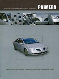
Руководство по эксплуатации, техническому обслуживанию и ремонту автомобиля Nissan Primera серии P12 2001-2005 годов выпуска с бензиновыми двигателями объемом 1,6/1,8/2,0.
- Автор: —
- Издательство: Автонавигатор
- Год издания: —
- Страниц: 648
- Формат: —
- Размер: —

Руководство по эксплуатации и ремонту автомобиля Nissan Primera 2002-2007 годов выпуска с бензиновыми двигателями объемом 1,6/1,8/2,0 л.
- Автор: П.А. Горлин, А.И. Ханов
- Издательство: Третий Рим
- Год издания: 2008
- Страниц: 368
- Формат: PDF
- Размер: 109,3 Mb

Руководство на польском языке по техническому обслуживанию и ремонту автомобиля Nissan Primera 1990-1999 годов выпуска.
- Автор: —
- Издательство: —
- Год издания: 2002
- Страниц: 437
- Формат: PDF
- Размер: 53,0 Mb

Руководство по эксплуатации и ремонту автомобиля Nissan Primera 1990-2002 годов выпуска с бензиновыми и дизельными двигателями.
- Автор: —
- Издательство: Чижовка
- Год издания: —
- Страниц: 312
- Формат: PDF
- Размер: 30,2 Mb

Руководство по эксплуатации и ремонту автомобиля Nissan Primera 1990-2002 годов выпуска с бензиновыми и дизельными двигателями.
- Автор: —
- Издательство: Гуси-Лебеди
- Год издания: —
- Страниц: 320
- Формат: —
- Размер: —

Руководство по эксплуатации и ремонту автомобиля Nissan Primera серии P11 1995-2001 годов выпуска с бензиновыми и дизельными двигателями.
- Автор: —
- Издательство: Гуси-лебеди
- Год издания: 2008
- Страниц: 298
- Формат: PDF
- Размер: 53,4 Mb

Руководство по эксплуатации и ремонту автомобиля Nissan Primera серии P11 1995-2001 годов выпуска с бензиновыми и дизельными двигателями.
- Автор: —
- Издательство: Гуси-Лебеди
- Год издания: —
- Страниц: 300
- Формат: —
- Размер: —

Руководство по эксплуатации и ремонту автомобиля Nissan Primera серии P12 с 2002 года выпуска с бензиновыми и дизельными двигателями.
- Автор: —
- Издательство: Чижовка
- Год издания: 2009
- Страниц: 472
- Формат: PDF
- Размер: 101,5 Mb

Руководство по эксплуатации, техническому обслуживанию и ремонту автомобиля Nissan Primera с 2001 года выпуска с бензиновыми двигателями объемом 1,6/1,8/2,0 л.
- Автор: —
- Издательство: Арго-Авто
- Год издания: —
- Страниц: 352
- Формат: —
- Размер: —

Руководство по эксплуатации, техническому обслуживанию и ремонту автомобиля Nissan Primera 1995-2001 годов выпуска с бензиновыми и дизельными двигателями.
- Автор: —
- Издательство: Автонавигатор
- Год издания: —
- Страниц: 512
- Формат: —
- Размер: —
Руководство по эксплуатации, техническому обслуживанию и ремонту автомобиля Nissan Primera с 2001 года выпуска
- Автор: —
- Издательство: Автонавигатор
- Год издания: 2006
- Страниц: 649
- Формат: DjVu
- Размер: 16,9 Mb

Руководство по эксплуатации, техническому обслуживанию и ремонту автомобиля Nissan Primera серии P12 с 2001 года выпуска с бензиновыми двигателями.
- Автор: —
- Издательство: Автонавигатор
- Год издания: —
- Страниц: 376
- Формат: —
- Размер: —

ультимедийное руководство по техническому обслуживанию и ремонту автомобиля Nissan Primera 1990-1992 годов выпуска.
- Автор: —
- Издательство: —
- Год издания: —
- Страниц: —
- Формат: ISO
- Размер: 36,8 Mb

Руководство по эксплуатации, техническому обслуживанию и ремонту автомобилей Nissan Avenir и Nissan Primera с 1990 года выпуска с бензиновыми и дизельными двигателями.
- Автор: —
- Издательство: Автонавигатор
- Год издания: 2004
- Страниц: 354
- Формат: —
- Размер: —


Для всех желающих:
Nissan Primera с бензиновыми двигателями: QG16DE 1.6 л (1596 см³) 109 л.с./80 кВт, QG18DE 1.8 л (1769 см³) 116-125 л.с./85-92 кВт, QR20DE 2.0 л (1998 см³) 140-150 л.с./103-110 кВт; Руководство по эксплуатации, техническому обслуживанию и ремонту. Советы по выбору запасных частей, полные технические характеристики, особенности эксплуатации и ремонта, устранения неисправностей в пути, более 2000 оригинальных фотографий, электросхемы, контрольные размеры кузова. Ниссан Примера седан, хэтчбек, универсал четвертое поколение модели P12 выпуска с 2002 по 2007 год.
—цифровая копия руководства по ремонту, обслуживанию и эксплуатации
vnx.su/content/avto/nissan/primera_2002.html
—на многие автомобили включая примеры разных годов выпуска:
autoinfo24.ru/rukovodstva…u/inomarki/nissan/primera
Данное руководство можно распечатать в цветном исполнении, а так же посмотреть БЖ ol-ko, у него можно заказать руководство на свою почту.
Всем добра!

AUTOMATIC TRANSAXLE
SECTION
AT
(H⋅CVT)
CONTENTS
TROUBLE DIAGNOSIS — INDEX ………………………………3
Alphabetical & P No. Index for DTC ………………………3
PRECAUTIONS ………………………………………………………5
Precautions for Supplemental Restraint System
(SRS) ″AIR BAG″ and ″SEAT BELT
PRE-TENSIONER″ ………………………………………………5
Precautions for On Board Diagnostic (OBD)
System of CVT and Engine…………………………………..5
Precautions …………………………………………………………5
Service Notice or Precautions ……………………………….6
Wiring Diagrams and Trouble Diagnosis…………………7
PREPARATION ………………………………………………………8
Special Service Tools …………………………………………..8
OVERALL SYSTEM ………………………………………………..9
CVT Electrical Parts Location………………………………..9
Circuit Diagram ………………………………………………….10
Cross-sectional View — RE0F06A …………………………11
Control System ………………………………………………….12
ON BOARD DIAGNOSTIC SYSTEM
DESCRIPTION ………………………………………………………15
Introduction ……………………………………………………….15
OBD Function for CVT System ……………………………15
OBD Diagnostic Trouble Code (DTC) …………………..15
Malfunction Indicator (MI) ……………………………………18
CONSULT-II ………………………………………………………18
TROUBLE DIAGNOSIS — INTRODUCTION………………29
Introduction ……………………………………………………….29
Work Flow…………………………………………………………32
TROUBLE DIAGNOSIS — BASIC INSPECTION ………..34
CVT Fluid Check ……………………………………………….34
Stall Test …………………………………………………………..34
Line Pressure Test……………………………………………..35
Road Test………………………………………………………….36
TROUBLE DIAGNOSIS — GENERAL
DESCRIPTION ………………………………………………………41
TCM Terminals and Reference Value……………………41
TROUBLE DIAGNOSIS FOR POWER SUPPLY……….45
Wiring Diagram — CVT — MAIN……………………………..45
DTC P0705 PARK/NEUTRAL POSITION (PNP)
SWITCH ……………………………………………………………….48
Description ………………………………………………………..48
Wiring Diagram — AT — PNP/SW……………………………50
Diagnostic Procedure …………………………………………51
Component Inspection………………………………………..53
DTC P0710 CVT FLUID TEMPERATURE SENSOR
CIRCUIT ……………………………………………………………….54
Description ………………………………………………………..54
Wiring Diagram — AT — FTS ………………………………….56
Diagnostic Procedure …………………………………………57
DTC P0715 PRIMARY SPEED SENSOR …………………59
Description ………………………………………………………..59
Wiring Diagram — AT — VSSA/T …………………………….60
Diagnostic Procedure …………………………………………61
Component Inspection………………………………………..61
DTC P0720 VEHICLE SPEED SENSOR CVT
(SECONDARY SPEED SENSOR) …………………………..62
Description ………………………………………………………..62
Wiring Diagram — AT — VSSA/T …………………………….64
Diagnostic Procedure …………………………………………65
Component Inspection………………………………………..65
DTC P0725 ENGINE SPEED SIGNAL …………………….66
Description ………………………………………………………..66
Wiring Diagram — AT — ENGSS …………………………….67
Diagnostic Procedure …………………………………………68
DTC P0740 TORQUE CONVERTER CLUTCH
SOLENOID VALVE………………………………………………..69
Description ………………………………………………………..69
Wiring Diagram — AT — TCV………………………………….71
Diagnostic Procedure …………………………………………72
Component Inspection………………………………………..73
DTC P0745 LINE PRESSURE SOLENOID VALVE …..74
Description ………………………………………………………..74
AT
CONTENTS
Wiring Diagram — AT — LPSV………………………………..76
Diagnostic Procedure …………………………………………77
Component Inspection………………………………………..78
DTC P1705 THROTTLE POSITION SENSOR ………….79
Description ………………………………………………………..79
Wiring Diagram — AT — TPS………………………………….81
Diagnostic Procedure …………………………………………82
Component Inspection………………………………………..85
DTC P1777 STEP MOTOR — CIRCUIT …………………….86
Description ………………………………………………………..86
Wiring Diagram — AT — STM …………………………………88
Diagnostic Procedure …………………………………………89
Component Inspection………………………………………..90
DTC P1778 STEP MOTOR — FUNCTION …………………91
Description ………………………………………………………..91
Diagnostic Procedure …………………………………………93
DTC P1791 CVT FLUID PRESSURE SENSOR ………..94
Description ………………………………………………………..94
Wiring Diagram — AT — FPS………………………………….96
Diagnostic Procedure …………………………………………97
Component Inspection………………………………………..98
CVT SAFE FUNCTION…………………………………………..99
Description ………………………………………………………..99
Diagnostic Procedure ……………………………………….100
CONTROL UNIT (RAM), CONTROL UNIT (ROM)…..101
Description ………………………………………………………101
(Cont’d)
Diagnostic Procedure ……………………………………….102
CONTROL UNIT (EEPROM) …………………………………103
Description ………………………………………………………103
Diagnostic Procedure ……………………………………….104
TROUBLE DIAGNOSES FOR NON-DETECTABLE
ITEMS…………………………………………………………………105
PNP Switch, Stop Lamp Switch and Throttle
Position Switch ………………………………………………..105
Wiring Diagram — AT — NONDTC ………………………..110
ON-VEHICLE SERVICE ……………………………………….114
Control Cable Adjustment………………………………….114
Park/Neutral Position (PNP) Switch Adjustment …..114
Differential Side Oil Seal Replacement ……………….114
REMOVAL AND INSTALLATION ………………………….116
Removal………………………………………………………….116
Inspection………………………………………………………..116
Installation……………………………………………………….117
Air Breather Hose …………………………………………….118
CVT Fluid Cooler (Hyper CVT-M6) …………………….118
Components…………………………………………………….119
SERVICE DATA AND SPECIFICATIONS (SDS) …….120
General Specifications………………………………………120
Stall Revolution………………………………………………..120
Line Pressure…………………………………………………..120
Removal and Installation …………………………………..120
AT-2
TROUBLE DIAGNOSIS — INDEX
Alphabetical & P No. Index for DTC
Alphabetical & P No. Index for DTC
NCAT0001
ALPHABETICAL INDEX FOR DTC
NCAT0001S01
DTC
Items
(CONSULT-II screen terms)
CONSULT-II
GST*2
Reference page
ECM*1
ATF TEMP SEN/CIRC
0710
P0710
AT-54
ENG SPEED SIG
0725
P0725
AT-66
LINE PRESSURE SEN
1791
P1791
AT-94
L/PRESS SOL/CIRC
0745
P0745
AT-74
PNP SW/CIRC
0705
P0705
AT-48
PRI SPEED SIG/CIRC
0715
P0715
AT-59
STEP MOTOR/CIRC
1777
P1777
AT-86
STEP MOTOR/FNCTN
1778
P1778
AT-91
TP SEN/CIRC A/T*3
1705
P1705
AT-79
TCC SOLENOID/CIRC
0740
P0740
AT-69
VEH SPD SEN/CIR A/T
0720
P0720
AT-62
*1: In Diagnostic Test Mode II (Self-diagnostic results), these numbers are controlled by NISSAN.
*2: These numbers are prescribed by ISO15031-6.
*3: When the fail-safe operation occurs, the MI illuminates.
AT-3
TROUBLE DIAGNOSIS — INDEX
Alphabetical & P No. Index for DTC (Cont’d)
P NO. INDEX FOR DTC
=NCAT0001S02
DTC
Items
(CONSULT-II screen terms)
Reference page
CONSULT-II
GST*2
ECM*1
P0705
0705
PNP SW/CIRC
AT-48
P0710
0710
ATF TEMP SEN/CIRC
AT-54
P0715
0715
PRI SPEED SIG/CIRC
AT-59
P0720
0720
VEH SPD SEN/CIR AT
AT-62
P0725
0725
ENG SPEED SIG
AT-66
P0740
0740
TCC SOLENOID/CIRC
AT-69
P0745
0745
L/PRESS SOL/CIRC
AT-74
P1705
1705
TP SEN/CIRC A/T*3
AT-79
P1777
1777
STEP MOTOR/CIRC
AT-86
P1778
1778
STEP MOTOR/FNCTN
AT-91
P1791
1791
LINE PRESSURE SEN
AT-94
*1: In Diagnostic Test Mode II (Self-diagnostic results), these numbers are controlled by NISSAN.
*2: These numbers are prescribed by ISO15031-6.
*3: When the fail-safe operation occurs, the MI illuminates.
AT-4
PRECAUTIONS
Precautions for Supplemental Restraint System (SRS) “AIR BAG” and “SEAT BELT PRE-TENSIONER”
Precautions for Supplemental Restraint System
(SRS) “AIR BAG” and “SEAT BELT
PRE-TENSIONER”
NCAT0002
The Supplemental Restraint System “AIR BAG” and “SEAT BELT PRE-TENSIONER”, used along with a seat
belt, help to reduce the risk or severity of injury to the driver and front passenger in a frontal collision. The
Supplemental Restraint System consists of air bag modules (located in the center of the steering wheel and
on the instrument panel on the passenger side), seat belt pre-tensioners, a diagnosis sensor unit, warning
lamp, wiring harness and spiral cable.
In addition to the supplemental air bag modules for a frontal collision, the supplemental side air bag used along
with the seat belt helps to reduce the risk or severity of injury to the driver and front passenger in a side collision. The supplemental side air bag consists of air bag modules (located in the outer side of front seats),
satellite sensor, diagnosis sensor unit (one of components of supplemental air bags for a frontal collision),
wiring harness, warning lamp (one of components of supplemental air bags for a frontal collision). Information
necessary to service the system safely is included in the RS section of this Service Manual.
WARNING:
I To avoid rendering the SRS inoperative, which could increase the risk of personal injury or death
in the event of a collision which would result in air bag inflation, all maintenance must be performed
by an authorized NISSAN dealer.
I Improper maintenance, including incorrect removal and installation of the SRS, can lead to personal injury caused by unintentional activation of the system.
I Do not use electrical test equipment on any circuit related to the SRS unless instructed to in this
Service Manual. SRS wiring harnesses (except “SEAT BELT PRE-TENSIONER” connector) can be
identified with yellow harness connector (and with yellow harness protector or yellow insulation
tape before the harness connectors).
Precautions for On Board Diagnostic (OBD)
System of CVT and Engine
NCAT0198
The ECM has an on board diagnostic system. It will light up the malfunction indicator (MI) to warn the driver
of a malfunction causing emission deterioration.
CAUTION:
I Be sure to turn the ignition switch “OFF” and disconnect the negative battery terminal before any
repair or inspection work. The open/short circuit of related switches, sensors, solenoid valves, etc.
will cause the MI to light up.
I Be sure to connect and lock the connectors securely after work. A loose (unlocked) connector will
cause the MI to light up due to an open circuit. (Be sure the connector is free from water, grease,
dirt, bent terminals, etc.)
I Be sure to route and secure the harnesses properly after work. Interference of the harness with a
bracket, etc. may cause the MI to light up due to a short circuit.
I Be sure to connect rubber tubes properly after work. A misconnected or disconnected rubber tube
may cause the MI to light up due to a malfunction of the EGR system or fuel injection system, etc.
I Be sure to erase the unnecessary malfunction information (repairs completed) from the TCM and
ECM before returning the vehicle to the customer.
Precautions
I
NCAT0003
Before connecting or disconnecting the TCM harness
connector, turn ignition switch OFF and disconnect negative battery terminal. Failure to do so may damage the
TCM. Because battery voltage is applied to TCM even if
ignition switch is turned off.
SEF289H
AT-5
PRECAUTIONS
Precautions (Cont’d)
I
When connecting or disconnecting pin connectors into or
from TCM, take care not to damage pin terminals (bend or
break).
Make sure that there are not any bends or breaks on TCM
pin terminal, when connecting pin connectors.
I
Before replacing TCM, perform TCM input/output signal
inspection and make sure whether TCM functions properly or not. (See page AT-41.)
I
After performing each TROUBLE DIAGNOSIS, perform
“DTC (Diagnostic Trouble Code) CONFIRMATION PROCEDURE”.
The DTC should not be displayed in the “DTC CONFIRMATION PROCEDURE” if the repair is completed.
I
It is very important to perform functional tests whenever they
are indicated.
Extreme care should be taken to avoid damage to O-rings,
seals and gaskets when assembling.
When the CVT drain plug is removed, only some of the fluid is
drained. Old CVT fluid will remain in torque converter and CVT
fluid cooling system.
Always follow the procedures under “Changing CVT Fluid” in
the MA section when changing CVT fluid.
SEF291H
Perform TCM
input/output signal
inspection before
replacement.
MEF040DA
SAT652J
I
I
Service Notice or Precautions
FAIL-SAFE
NCAT0004
NCAT0004S01
The TCM has an electronic Fail-Safe (limp home mode). This allows the vehicle to be driven even if a major
electrical input/output device circuit is damaged.
Under Fail-Safe, the vehicle always runs even with a shift lever position of “L” or “D”. The customer may complain of sluggish or poor acceleration.
When the ignition key is turned “ON” following Fail-Safe operation, CVT or SPORT indicator lamp blinks for
about 8 seconds. [For “TCM SELF-DIAGNOSTIC PROCEDURE (No Tools)”, refer to AT-25.]
Fail-Safe may occur without electrical circuit damage if the vehicle is driven under extreme conditions (such
as excessive wheel spin followed by sudden braking). To recover normal shift pattern, turn the ignition key
“OFF” for 5 seconds, then “ON”.
AT-6
PRECAUTIONS
Service Notice or Precautions (Cont’d)
The blinking of the CVT or SPORT indicator lamp for about 8 seconds will appear only once and be cleared.
The customer may resume normal driving conditions.
Always follow the “WORK FLOW” (Refer to AT-32).
The SELF-DIAGNOSIS results will be as follows:
The first SELF-DIAGNOSIS will indicate damage to the vehicle speed sensor or the revolution sensor.
During the next SELF-DIAGNOSIS, performed after checking the sensor, no damages will be indicated.
OBD SELF-DIAGNOSIS
NCAT0004S04
I
CVT self-diagnosis is performed by the TCM in combination with the ECM. The results can be read through
the blinking pattern of the CVT or SPORT indicator. Refer to the table on AT-19 for the indicator used to
display each self-diagnostic result.
I The self-diagnostic results indicated by the MI are automatically stored in both the ECM and TCM memories.
Always perform the procedure “HOW TO ERASE DTC” on AT-16 to complete the repair and avoid
unnecessary blinking of the MI.
For details of OBD, refer to EC section (“ON BOARD DIAGNOSTIC SYSTEM DESCRIPTION”).
I Certain systems and components, especially those related to OBD, may use a new style slidelocking type harness connector.
For description and how to disconnect, refer to EL section, “Description”, “HARNESS CONNECTOR”.
Wiring Diagrams and Trouble Diagnosis
When you read wiring diagrams, refer to the followings:
I “HOW TO READ WIRING DIAGRAMS” in GI section
I “POWER SUPPLY ROUTING” for power distribution circuit in EL section
When you perform trouble diagnosis, refer to the followings:
I “HOW TO FOLLOW TEST GROUP IN TROUBLE DIAGNOSIS” in GI section
I “HOW TO PERFORM EFFICIENT DIAGNOSIS FOR AN ELECTRICAL INCIDENT” in GI section
AT-7
NCAT0005
PREPARATION
Special Service Tools
Special Service Tools
Tool number
Tool name
ST2505S001
Oil pressure gauge set
1 ST25051001
Oil pressure gauge
2 ST25052000
Hose
3 ST25053000
Joint pipe
4 ST25054000
Adapter
5 ST25055000
Adapter
NCAT0006
Description
Measuring line pressure and governor pressure
NT097
KV31103000
Drift
Installing differential side oil seal
(Use with ST35325000)
a: 59 mm (2.32 in) dia.
b: 49 mm (1.93 in) dia.
NT105
ST35325000
Drift
Installing differential side oil seal
(Use with KV31103000)
a: 215 mm (8.46 in)
b: 25 mm (0.98 in) dia.
c: M12 x 1.5P
NT417
AT-8
OVERALL SYSTEM
CVT Electrical Parts Location
CVT Electrical Parts Location
Steering column
NCAT0008
Throttle position sensor and
throttle position switch
Indicator C/U
Front
TCM
SPORT indicator lamp
CVT indicator lamp
Secondary speed sensor
PNP switch
Control valve connector
SPORT mode switch
Dropping
resistor
Inside control valve
Fluid temperature sensor
Fluid pressure sensor
Lock-up solenoid
Line pressure solenoid
Step motor
Manual mode switch
Primary speed sensor
SAT671J
AT-9
OVERALL SYSTEM
Circuit Diagram
Circuit Diagram
NCAT0009
YAT250
AT-10
OVERALL SYSTEM
Cross-sectional View — RE0F06A
Cross-sectional View — RE0F06A
NCAT0011
Converter housing
Reverse brake
Primary pulley
Planet carrier
Oil pump
Forward clutch
Torque converter
Steel belt
Sun gear
Input shaft
Side cover
Internal gear
Parking gear
Output gear
Taper roller bearing
Reduction gear
Idler gear
Speedometer drive gear
Secondary pulley
Differential case
Final gear
SAT668J
AT-11
OVERALL SYSTEM
Control System
Control System
=NCAT0014
OUTLINE
NCAT0014S01
The CVT senses vehicle operating conditions through various sensors. It always controls the optimum shift
position and reduces shifting and lock-up shocks.
SENSORS
TCM
PNP switch
Throttle position sensor
Closed throttle position switch
Wide open throttle position switch
Engine speed signal
CVT fluid temperature sensor
CVT fluid pressure sensor
Primary speed sensor
Secondary speed sensor
Stop lamp switch
Sport mode switch (Hyper CVT
only)
Indicator control unit (Hyper CVT
M6 only)
ABS control unit
Shift control
Line pressure control
Lock-up control
Fail-safe control
Self-diagnosis
CONSULT-II communication line
control
Duet-EU control
On board diagnosis
E
AT-12
ACTUATORS
E
Step motor
CVT indicator (warning) lamp
(Hyper CVT M6 only)
Torque converter clutch
solenoid valve
Line pressure solenoid valve
SPORT indicator lamp (Hyper
CVT only)
OVERALL SYSTEM
Control System (Cont’d)
CONTROL SYSTEM
NCAT0014S02
Transaxle
Wheel
Differential
gear
Belt and
Pulley
Final gear
Forward and
reverse
change
Torque
converter
Engine
Oil pump
Parking
system
Oil pressure control
Control device
Electrical control
Sport mode SW or
manual mode SW
Control valve
Engine speed sensor
Primary pulley
speed and
secondary pulley
speed sensor
[Hyper CVT-M6]
Position
indicator
Indicator C/U
Throttle
opening
sensor
CVT indicator
(warning) lamp or
SPORT indicator lamp
TCM
ECM
Mechanical system
Oil system
Electrical system
ABS C/U
Stop lamp SW
PNP switch
NAT310
AT-13
OVERALL SYSTEM
Control System (Cont’d)
TCM FUNCTION
=NCAT0014S03
The function of the TCM is to:
I Receive input signals sent from various switches and sensors.
I Determine required line pressure, shifting point and lock-up operation.
I Send required output signals to the step motor and the respective solenoids.
INPUT/OUTPUT SIGNAL OF TCM
NCAT0014S04
Sensors and actuators
Input
Output
Function
PNP switch
Detects select lever position and sends a signal to TCM.
Throttle position sensor
Detects throttle valve position and sends a signal to TCM.
Closed throttle position switch
Detects throttle valve’s fully-closed position and sends a signal to TCM.
Wide open throttle position switch
Detects a throttle valve position of greater than 1/2 of full throttle and
sends a signal to TCM.
Engine speed signal
From ECM.
CVT fluid temperature sensor
Detects transmission fluid temperature and sends a signal to TCM.
CVT fluid pressure sensor
Detects transmission fluid pressure and sends a signal to TCM.
Primary speed sensor
Detects primary pulley rpm and sends a signal to TCM.
Secondary speed sensor
Detects secondary pulley rpm and sends a signal to TCM.
Stop lamp switch
Sends a signal to the TCM relaying the operation condition of the brake
pedal.
Sport mode switch
Sends a signal to the TCM relaying the operation condition of the sport
mode switch.
Indicator control unit*1
Sends a signal to the TCM operation condition of the manual mode switch
in control device.
ABS control unit
Sends a signal to the TCM operation condition of the ABS.
Step motor
Regulates pulley position in relation to a signal sent from TCM.
Line pressure solenoid valve
Regulates (or decreases) line pressure suited to driving conditions in relation to a signal sent from TCM.
Torque converter clutch solenoid
valve
Regulates (or decreases) lock-up pressure suited to driving conditions in
relation to a signal sent from TCM.
CVT indicator (warning) lamp*2
Shows TCM faults, when CVT control components malfunction.
SPORT indicator lamp*3
Shows the operation condition of the SPORT mode switch. *3
Indicator control unit *1
Receives the information of gear position on manual mode from TCM, and
sends a signal to indicator.
*1: Hyper CVT M6 models only
*2: Hyper CVT M6 models
*3: Hyper CVT models
AT-14
ON BOARD DIAGNOSTIC SYSTEM DESCRIPTION
Introduction
Introduction
NCAT0017
The CVT system has two self-diagnostic systems.
The first is the emission-related on board diagnostic system (OBD) performed by the TCM in combination with
the ECM. The malfunction is indicated by the MI (malfunction indicator) and is stored as a DTC in the ECM
memory but not the TCM memory.
The second is the TCM original self-diagnosis indicated by the CVT indicator (warning) lamp or SPORT indicator lamp. The malfunction is stored in the TCM memory. The detected items are overlapped with OBD selfdiagnostic items. For detail, refer to AT-26.
OBD Function for CVT System
NCAT0018
The ECM provides emission-related on board diagnostic (OBD) functions for the CVT system. One function
is to receive a signal from the TCM used with OBD-related parts of the CVT system. The signal is sent to the
ECM when a malfunction occurs in the corresponding OBD-related part. The other function is to indicate a
diagnostic result by means of the MI (malfunction indicator) on the instrument panel. Sensors, switches and
solenoid valves are used as sensing elements.
The MI automatically illuminates in Two Trip Detection Logic when a malfunction is sensed in relation to CVT
system parts.
OBD Diagnostic Trouble Code (DTC)
HOW TO READ DTC AND 1ST TRIP DTC
NCAT0020
NCAT0020S01
DTC and 1st trip DTC can be read by the following methods.
1. ( No Tools) The number of blinks of the malfunction indicator in the Diagnostic Test Mode II (Self-Diagnostic Results) Examples: 0705, 0710, 0715, 0720, etc. For details, refer to EC section [“Malfunction
Indicator (MI)”, “ON BOARD DIAGNOSTIC SYSTEM DESCRIPTION”].
These DTCs are controlled by NISSAN.
GST) CONSULT-II or GST (Generic Scan Tool) Examples: P0705, P0710,
2. ( with CONSULT-II or
P0720, P0725, etc.
These DTCs are prescribed by ISO15031-6.
(CONSULT-II also displays the malfunctioning component or system.)
I 1st trip DTC No. is the same as DTC No.
I Output of the diagnostic trouble code indicates that the indicated circuit has a malfunction.
However, in case of the Mode II and GST they do not indicate whether the malfunction is still
occurring or occurred in the past and returned to normal.
CONSULT-II can identify them as shown below. Therefore, using CONSULT-II (if available) is recommended.
A sample of CONSULT-II display for DTC is shown at left. DTC or 1st trip DTC of a malfunction is displayed
in SELF-DIAGNOSTIC RESULTS mode for “ENGINE” with CONSULT-II. Time data indicates how many times
the vehicle was driven after the last detection of a DTC.
SAT651J
If the DTC is being detected currently, the time data will be “0”.
AT-15
ON BOARD DIAGNOSTIC SYSTEM DESCRIPTION
OBD Diagnostic Trouble Code (DTC) (Cont’d)
SAT581J
If a 1st trip DTC is stored in the ECM, the time data will be “1t”.
SAT582J
Freeze Frame Data and 1st Trip Freeze Frame Data
NCAT0020S0101
The ECM has a memory function, which stores the driving condition such as fuel system status, calculated
load value, engine coolant temperature, short term fuel trim, long term fuel trim, engine speed and vehicle
speed at the moment the ECM detects a malfunction.
Data which are stored in the ECM memory, along with the 1st trip DTC, are called 1st trip freeze frame data,
and the data, stored together with the DTC data, are called freeze frame data and displayed on CONSULT-II
or GST. The 1st trip freeze frame data can only be displayed on the CONSULT-II screen, not on the GST. For
detail, refer to EC section (“CONSULT-II”, “ON BOARD DIAGNOSTIC SYSTEM DESCRIPTION”).
Only one set of freeze frame data (either 1st trip freeze frame data of freeze frame data) can be stored in the
ECM. 1st trip freeze frame data is stored in the ECM memory along with the 1st trip DTC. There is no priority for 1st trip freeze frame data and it is updated each time a different 1st trip DTC is detected. However, once
freeze frame data (2nd trip detection/MI on) is stored in the ECM memory, 1st trip freeze frame data is no
longer stored. Remember, only one set of freeze frame data can be stored in the ECM.
The ECM has the following priorities to update the data.
Priority
1
Items
Freeze frame data
2
3
Misfire — DTC: P0300 — P0306 (0300 — 0306)
Fuel Injection System Function — DTC: P0171 (0171), P0172 (0172), P0174 (0174), P0175
(0175)
Except the above items (Includes CVT related items)
1st trip freeze frame data
Both 1st trip freeze frame data and freeze frame data (along with the DTCs) are cleared when the ECM
memory is erased.
HOW TO ERASE DTC
NCAT0020S02
The diagnostic trouble code can be erased by CONSULT-II, GST or ECM DIAGNOSTIC TEST MODE as
described following.
I If the battery terminal is disconnected, the diagnostic trouble code will be lost within 24 hours.
I When you erase the DTC, using CONSULT-II or GST is easier and quicker than switching the mode
selector on the ECM.
AT-16
ON BOARD DIAGNOSTIC SYSTEM DESCRIPTION
OBD Diagnostic Trouble Code (DTC) (Cont’d)
The following emission-related diagnostic information is cleared from the ECM memory when erasing DTC
related to OBD. For details, refer to EC section (“Emission-related Diagnostic Information”, “ON BOARD
DIAGNOSTIC SYSTEM DESCRIPTION”).
I Diagnostic trouble codes (DTC)
I 1st trip diagnostic trouble codes (1st trip DTC)
I Freeze frame data
I 1st trip freeze frame data
I System readiness test (SRT) codes
I Test values
I Distance traveled while MI is activated
I Others
HOW TO ERASE DTC (WITH CONSULT-II)
NCAT0020S03
I If a DTC is displayed for both ECM and TCM, it needs to be erased for both ECM and TCM.
1. If the ignition switch stays “ON” after repair work, be sure to turn ignition switch “OFF” once. Wait at least
5 seconds and then turn it “ON” (engine stopped) again.
2. Turn CONSULT-II “ON” and touch “CVT”.
3. Touch “SELF-DIAG RESULTS”.
4. Touch “ERASE”. (The DTC in the TCM will be erased.) Then touch “BACK” twice.
5. Touch “ENGINE”.
6. Touch “SELF-DIAG RESULTS”.
7. Touch “ERASE”. (The DTC in the ECM will be erased.)
How to erase DTC (With CONSULT-II)
1. If the ignition switch stays “ON” after repair work, be sure to turn ignition switch “OFF” once. Wait at least 5 seconds and then turn it “ON” (engine
stopped) again.
.
2. Turn CONSULT-II “ON”, and touch “CVT”.
3. Turn “SELF DIAGNOSIS”.
4. Touch “ERASE”. (The DTC in
the TCM will be erased.)
Touch
“BACK”
Touch
“BACK”
.
5. Touch “ENGINE”.
6. Touch “SELF DIAGNOSIS”.
7. Touch “ERASE”. (The DTC in the
ECM will be erased.)
SAT681J
AT-17
ON BOARD DIAGNOSTIC SYSTEM DESCRIPTION
OBD Diagnostic Trouble Code (DTC) (Cont’d)
HOW TO ERASE DTC (WITH GST)
NCAT0020S04
1. If the ignition switch stays “ON” after repair work, be sure to turn ignition switch “OFF” once. Wait at least
5 seconds and then turn it “ON” (engine stopped) again.
2. Perform “OBD SELF-DIAGNOSTIC PROCEDURE (No Tools)”. Refer to AT-25. (The engine warm-up step
can be skipped when performing the diagnosis only to erase the DTC.)
3. Select Mode 4 with Generic Scan Tool (GST). For details, refer to EC section “Generic Scan Tool (GST)”.
HOW TO ERASE DTC (NO TOOLS)
NCAT0020S05
1. If the ignition switch stays “ON” after repair work, be sure to turn ignition switch “OFF” once. Wait at least
5 seconds and then turn it “ON” (engine stopped) again.
2. Perform “TCM SELF-DIAGNOSTIC PROCEDURE (No Tools)”. Refer to AT-25. (The engine warm-up step
can be skipped when performing the diagnosis only to erase the DTC.)
3. Change the diagnostic test mode from Mode II to Mode I by turning the mode selector on the ECM.
Refer to EC section “HOW TO SWITCH DIAGNOSTIC TEST MODES”.
Malfunction Indicator (MI)
1.
I
2.
SAT652J
NCAT0021
The malfunction indicator will light up when the ignition switch
is turned ON without the engine running. This is for checking
the lamp.
If the malfunction indicator does not light up, refer to EL section (“Warning Lamps/System Description”, “WARNING
LAMPS AND CHIME”).
(Or see MI & Data Link Connectors in EC section.)
When the engine is started, the malfunction indicator should go
off.
If the lamp remains on, the on board diagnostic system has
detected an emission-related (OBD) malfunction. For detail,
refer to EC section (“ON BOARD DIAGNOSTIC SYSTEM
DESCRIPTION”).
CONSULT-II
NCAT0022
After performing “SELF-DIAGNOSTIC PROCEDURE (WITH CONSULT-II)” (AT-19), place check marks for results on the “DIAGNOSTIC WORKSHEET”, AT-31. Reference pages are provided following the items.
NOTICE:
I Additional CONSULT-II information can be found in the Operation Manual supplied with the CONSULT-II unit.
AT-18
ON BOARD DIAGNOSTIC SYSTEM DESCRIPTION
CONSULT-II (Cont’d)
SELF-DIAGNOSTIC PROCEDURE
(WITH CONSULT-II)
NCAT0022S02
1.
Turn on CONSULT-II and touch “ENGINE” for OBD detected
items or touch “CVT” for TCM self-diagnosis.
If CVT is not displayed, check TCM power supply and ground
circuit. Refer to AT-41. If result is NG, refer to EL section
(“POWER SUPPLY ROUTING”).
2.
Touch “SELF DIAGNOSIS”.
Display shows malfunction experienced since the last erasing
operation.
CONSULT-II performs REAL-TIME SELF-DIAGNOSIS.
Also, any malfunction detected while in this mode will be displayed at real time.
SAT651J
SAT584J
SELF-DIAGNOSTIC RESULT TEST MODE
NCAT0022S03
TCM self-diagnosis
OBD (DTC)
Available by
CVT or SPORT
indicator lamp
“CVT” on CONSULT-II
Available by
malfunction
indicator lamp*2,
“ENGINE” on CONSULT-II or GST
—
P0705
I TCM does not receive the proper voltage signal from the sensor.
X
P0715
I TCM does not receive the proper voltage signal from the sensor.
X
P0720
X
P0740
X
P0745
X
P1705
Detected items
(Screen terms for CONSULT-II, “SELF
DIAGNOSIS” test mode)
Malfunction is detected when …
“CVT”
“ENGINE”
PNP switch circuit
PNP SW/CIRCUIT
PNP SW/CIRC
Primary speed sensor
I/P PULLY SPD SIG
PRI SPEED SIG/
CIRC
Secondary speed sensor
VEHICLE SPEED
SIG
VEH SPD SEN/CIR
A/T
T/C clutch solenoid valve
T/C CLUTCH
SOL/V
TCC SOLENOID/
CIRC
Line pressure solenoid valve
LINE PRESSURE
S/V
L/PRESS SOL/
CIRC
Throttle position sensor,
Throttle position switch
THROTTLE POSI
SEN
I TCM does not receive the correct voltage signal (based on the gear position) from the switch.
I TCM detects an improper voltage drop
when it tries to operate the solenoid
valve.
I TCM detects an improper voltage drop
when it tries to operate the solenoid
valve.
I TCM receives an excessively low or
high voltage from the sensor.
TP SEN/CIRC A/T
AT-19
ON BOARD DIAGNOSTIC SYSTEM DESCRIPTION
CONSULT-II (Cont’d)
TCM self-diagnosis
OBD (DTC)
Available by
CVT or SPORT
indicator lamp
“CVT” on CONSULT-II
Available by
malfunction
indicator lamp*2,
“ENGINE” on CONSULT-II or GST
I TCM does not receive the proper voltage signal from the ECM.
X
P0725
I TCM receives an excessively low or
high voltage from the sensor.
X
P0710
I Not proper voltage change of the TCM
terminal when operating step motor.
X
P1777
I Step motor is not operating according
to the TCM.
X
P1778
I TCM receives an excessively low or
high voltage from the sensor.
X
P1791
X
—
I TCM memory (RAM) is malfunctioning.
—
—
I TCM memory (ROM) is malfunctioning.
—
—
I TCM memory (EEP ROM) is malfunctioning.
—
—
X
—
X
X
Detected items
(Screen terms for CONSULT-II, “SELF
DIAGNOSIS” test mode)
Malfunction is detected when …
“CVT”
“ENGINE”
Engine speed signal
ENGINE SPEED SIG
CVT fluid temperature sensor
BATT/FLUID TEMP
SEN
ATF TEMP SEN/
CIRC
Stepping motor circuit
STEP MOTOR
STEP MOTOR/
CIRC
Stepping motor function
—
STEP MOTOR/
FNCTN
CVT fluid pressure sensor
LINE PRESSURE
SEN
LINE PRESS SEN
I TCM is malfunctioning.
CVT SAFE FUNCTION
CVT SAFE FUNCTION
—
TCM (RAM)
CONTROL UNIT
(RAM)
—
TCM (ROM)
CONTROL UNIT
(ROM)
—
TCM (EEP ROM)
CONT UNIT (EEP
ROM)
—
Initial start
*INITIAL START*
—
No failure
(NO SELF DIAGNOSTIC FAILURE INDICATED FURTHER TESTING MAY BE
REQUIRED**)
I This is not a malfunction message
(Whenever shutting off a power supply
to the TCM, this message appears on
the screen.)
I No failure has been detected.
X: Applicable
—: Not applicable
*1: These malfunctions cannot be displayed by MI
if another malfunction is assigned to MI.
*2: Refer to EC section [“Malfunction Indicator (MI)”, “ON BOARD DIAGNOSTIC SYSTEM DESCRIPTION”].
AT-20
ON BOARD DIAGNOSTIC SYSTEM DESCRIPTION
CONSULT-II (Cont’d)
DATA MONITOR MODE (CVT)
NCAT0022S04
Monitor item
Item
Display
Vehicle speed sensor
VHCL SPEED
(Secondary speed sensor) SE
[km/h] or [mph]
Throttle position sensor
CVT fluid temperature
sensor
THRTL POS
SEN
[V]
FLUID TEMP
SE
[V]
Battery voltage
BATTERY VOLT
[V]
Engine speed
ENGINE
SPEED
[rpm]
P/N position switch
R position switch
D position switch
Sport mode switch
L position switch
Closed throttle position
switch
N POSITION
SW
[ON/OFF]
R POSITION
SW
[ON/OFF]
D POSITION
SW
[ON/OFF]
S POSITION
SW
[ON/OFF]
L POSITION
SW
[ON/OFF]
CLOSED
THL/SW
[ON/OFF]
Wide open throttle position W/O THRL/
switch
P-SW
[ON/OFF]
TCM input
signals
Main
signals
Description
Remarks
I Vehicle speed computed from signal of
revolution sensor is displayed.
When racing engine in “N”
or “P” position with vehicle
stationary, CONSULT-II data
may not indicate
0 km/h (0 mph).
X
—
X
—
I Throttle position sensor
signal voltage is displayed.
—
X
—
I CVT fluid temperature
sensor signal voltage is
displayed.
I Signal voltage lowers
as fluid temperature
rises.
—
X
—
I Source voltage of TCM
is displayed.
—
X
X
I Engine speed, computed from engine
speed signal, is displayed.
Engine speed display may
not be accurate under
approx. 800 rpm. It may not
indicate 0 rpm even when
engine is not running.
—
I ON/OFF state computed from signal of
P/N position SW is displayed.
—
—
I ON/OFF state computed from signal of R
position SW is displayed.
—
—
I ON/OFF state computed from signal of D
position SW is displayed.
—
X
—
I ON/OFF status, computed from signal of
Sport mode SW, is displayed.
—
X
—
I ON/OFF status, computed from signal of L
position SW, is displayed.
—
—
I ON/OFF status, computed from signal of
closed throttle position
SW, is displayed.
—
—
I ON/OFF status, computed from signal of
wide open throttle position SW, is displayed.
—
X
X
X
X
X
AT-21
ON BOARD DIAGNOSTIC SYSTEM DESCRIPTION
CONSULT-II (Cont’d)
Monitor item
Item
Gear position
Display
Description
Remarks
X
I Gear position (when
use manual mode) data
used for computation by
TCM, is displayed.
—
—
X
I Selector lever position
I A specific value used for
data, used for computacontrol is displayed if failtion by TCM, is dissafe is activated due to
played.
error.
—
X
I Vehicle speed data,
used for computation by
TCM, is displayed.
X
I A specific value used for
I Throttle position data,
used for computation by
control is displayed if failsafe is activated due to
TCM, is displayed.
error.
X
I Control value of line
pressure solenoid valve,
computed by TCM from
each input signal, is
displayed.
—
X
I Control value of torque
converter clutch solenoid valve, computed
by TCM from each input
signal, is displayed.
—
TCM input
signals
GEAR
—
Selector lever position
Vehicle speed
Throttle position
Line pressure duty
Torque converter clutch
solenoid valve duty
Main
signals
SLCT LVR POSI
VEHICLE
SPEED
[km/h] or [mph]
THROTTLE
POSI
[/8]
LINE PRES
DTY
[%]
—
—
TCC S/V DUTY
[%]
—
Self-diagnosis display
lamp
(SPORT or CVT indicator
lamp)
PAT MONI
LAMP
[ON/OFF]
CVT fluid pressure sensor
LINE PRESSURE [V]
I Control status of
SPORT or CVT indicator lamp is displayed.
—
—
X
X
—
I CVT fluid pressure sensor signal voltage is
displayed.
—
X
I Primary pulley speed
computed from signal of
primary pulley speed
sensor is displayed.
—
—
—
I Secondary pulley speed
computed from signal of
secondary speed sensor is displayed.
—
—
Primary pulley speed
sensor
I/P PULLY SPD
[rpm]
Secondary pulley speed
sensor
O/P PULLY SPD
[rpm]
Stop lamp switch
BRAKE SW
[ON/OFF]
X
—
I ON/OFF position signal
of stop lamp switch is
displayed.
—
CLSD THL
POSI [ON/OFF]
—
—
I Idle status judged from
throttle position sensor
signal is displayed.
—
ABS SIGNAL
[ON/OFF]
X
—
I ABS operation signal
(ON/OFF) from ABS
control unit is displayed.
—
MANU MODE
SW [ON/OFF]
X
—
I ON/OFF position signal
of manual mode switch
is displayed.
—
Idle judgement
ABS signal
Manual mode switch
X
AT-22
ON BOARD DIAGNOSTIC SYSTEM DESCRIPTION
CONSULT-II (Cont’d)
Monitor item
Item
Non-manual mode switch
Up switch
Down switch
Step motor coil A
Step motor coil B
Step motor coil C
Step motor coil D
Display
I ON/OFF position signal
of non-manual mode
switch is displayed.
—
X
—
I ON/OFF position signal
of up switch is displayed.
—
X
—
I ON/OFF position signal
of down switch is displayed.
—
—
I Control valve of step
motor coil A, computed
by TCM from each input
signal is displayed.
—
—
I Control valve of step
motor coil B, computed
by TCM from each input
signal is displayed.
—
—
I Control valve of step
motor coil C, computed
by TCM from each input
signal is displayed.
—
—
—
I Control valve of step
motor coil D, computed
by TCM from each input
signal is displayed.
—
—
X
I Real CVT ratio operated
TCM is displayed.
—
—
X
I Step motor position is
displayed.
—
—
X
I Real line pressure calculated from line pressure sensor voltage
with TCM is displayed.
—
—
—
I Target primary pulley
speed operated with
TCM is displayed.
—
—
—
I Target changing the
speed ratio operated
with TCM is displayed.
—
—
—
I Target step motor position operated with TCM
is displayed.
—
X
UP SW
[ON/OFF]
DOWN SW
[ON/OFF]
S/M COIL [A]
[ON/OFF]
S/M COIL [B]
[ON/OFF]
S/M COIL [C]
[ON/OFF]
S/M COIL [D]
[ON/OFF]
Step
PLY CONT
STEP [step]
Line pressure
LINE PRESSURE [MPa]
Step 2
—
NON M MODE
SW [ON/OFF]
CVT RATIO [—]
CVT ratio 2
Remarks
Main
signals
CVT ratio
Pulley rpm⋅in 2
Description
TCM input
signals
—
—
—
T RPM [rpm]
T RATIO [—]
T STEP [step]
X: Applicable
—: Not applicable
AT-23
ON BOARD DIAGNOSTIC SYSTEM DESCRIPTION
CONSULT-II (Cont’d)
WORK SUPPORT MODE WITH CONSULT-II
Data link connector
1.
2.
3.
Turn ignition switch “OFF”.
Connect CONSULT-II to Data link connector. Data link connector is located in left side dash panel.
Turn ignition switch “ON”.
4.
Touch “START”.
5.
Touch “CVT”.
6.
Touch “WORK SUPPORT”.
7.
8.
Touch “ENGINE BRAKE ADJUSTMENT”.
Touch “START”.
NRS071
SAT586J
SAT651J
SAT732J
SAT933J
AT-24
ON BOARD DIAGNOSTIC SYSTEM DESCRIPTION
CONSULT-II (Cont’d)
9.
SAT934J
Set “ENGINE BRAKE LEVEL” by touching “UP” or “DOWN”.
ENGINE BRAKE LEVEL
0: Initial set value (Engine brake level control is
activated)
OFF: Engine brake level control is disactivated.
10. Turn ignition switch “OFF”, wait at least 5 seconds and then
turn ignition switch “ON”.
11. Engine brake level set is completed.
CAUTION:
Mode of “+1” “0” “-1” “-2” “OFF” can be selected by pressing
the “UP” “DOWN” on CONSULT screen. However, do not
select mode other than “0” and “OFF”. If the “+1” or “-1” or
“-2” is selected, that might cause the abnormality of drivability.
DIAGNOSTIC PROCEDURE WITHOUT CONSULT-II NCAT0022S07
OBD Self-diagnostic Procedure (With GST)
NCAT0022S0701
Refer to EC section [“Generic Scan Tool (GST)”, “ON BOARD
DIAGNOSTIC SYSTEM DESCRIPTION”].
OBD Self-diagnostic Procedure (No Tools)
NCAT0022S0702
Refer to EC section [“Malfunction Indicator (MI)”, “ON BOARD
DIAGNOSTIC SYSTEM DESCRIPTION”].
TCM Self-diagnostic Procedure (No Tools)
=NCAT0022S0703
Preparation
1. Turn ignition switch to “OFF” position.
2. Disconnect the throttle position switch harness connector.
3. Turn ignition switch to “ON” position.
4. Check continuity of the closed throttle position switch.
Continuity should exist.
(If continuity does not exist, check throttle opener and
closed throttle position switch. Then increase vacuum
until closed throttle position switch shows continuity.)
5. Connect the throttle position switch harness connector.
6. Warm up the engine.
7. Turn the ignition switch from ON to OFF two more times, and
then turn to OFF.
8. In the “P” position of the selector lever, turn the ignition switch
ON, and verify that the CVT warning lamp turns on for about
2 seconds.
9. Turn the ignition switch OFF.
10. Press the brake pedal, and shift the selector lever to the “D”
position.
11. Turn the ignition switch ON.
12. Release the brake, and shift the selector lever to the “L” position.
13. Fully depress both brake and accelerator pedals all the way to
the floor. Without releasing the brake and accelerator pedals,
shift the selector lever to the “D” position.
14. Read the display from the CVT warning lamp to complete the
diagnosis.
AT-25
ON BOARD DIAGNOSTIC SYSTEM DESCRIPTION
CONSULT-II (Cont’d)
Judgement of Self-diagnosis Code
NCAT0022S0704
CVT or SPORT indicator lamp*
All judgement flickers are the same.
1st judgement flicker is longer than others.
Self diagnosis
start
Start signal 10 judgement flickers
Light
Light
Shade
Shade
SAT436FA
SAT437FA
All circuits that can be confirmed by self-diagnosis are OK.
Secondary speed sensor (VEHICLE SPEED SENSOR CVT) circuit is short-circuited or disconnected.
⇒ Go to VEHICLE SPEED SENSOR CVT (SECONDARY
SPEED SENSOR) (DTC: 0720), AT-62.
2nd judgement flicker is longer than others.
3rd judgement flicker is longer than others.
Light
Light
Shade
Shade
SAT439FA
SAT441FA
Primary speed sensor circuit is short-circuited or disconnected.
⇒ Go to PRIMARY SPEED SENSOR (DTC: 0715), AT-59.
Throttle position sensor circuit is short-circuited or disconnected.
⇒ Go to THROTTLE POSITION SENSOR (DTC: 1705), AT-79.
4th judgement flicker is longer than others.
5th judgement flicker is longer than others.
Self diagnosis
start
Light
Light
Shade
Shade
SAT443FA
Step motor circuit is short-circuited or disconnected.
⇒ Go to STEP MOTOR (DTC: 1777), AT-86.
SAT445FA
CVT fluid pressure sensor circuit is short-circuited or disconnected.
⇒ Go to CVT FLUID PRESSURE SENSOR (DTC: 1791), AT-94.
AT-26
ON BOARD DIAGNOSTIC SYSTEM DESCRIPTION
CONSULT-II (Cont’d)
CVT or SPORT indicator lamp*
7th judgement flicker is longer than others.
6th judgement flicker is longer than others.
Light
Light
Shade
Shade
SAT447FA
SAT449FA
Line pressure solenoid valve circuit is short-circuited or disconnected.
⇒ Go to LINE PRESSURE SOLENOID VALVE (DTC: 0745),
AT-74.
Lock up solenoid valve circuit is short-circuited or disconnected.
⇒ Go to TORQUE CONVERTER CLUTCH SOLENOID VALVE
(DTC: 0740), AT-69.
8th judgement flicker is longer than others.
9th judgement flicker is longer than others.
Self diagnosis
start
Light
Light
Shade
Shade
SAT451FA
SAT453FA
CVT fluid temperature sensor is disconnected or TCM power
source circuit is damaged.
⇒ Go to CVT FLUID TEMPERATURE SENSOR (DTC: 0710)
AND TCM POWER SOURCE, AT-54.
Engine speed signal circuit is short-circuited or disconnected.
⇒ Go to ENGINE SPEED SIGNAL (DTC: 0725), AT-66.
10th judgement flicker is longer than others.
Flickers as shown below.
Light
Light
Shade
Shade
SAT455FA
I When “4th judgement flicker” and/or “6th judgement flicker” is
displayed, inspect “STEP MOTOR (DTC: 1777)” and/or “LINE
PRESSURE SOLENOID VALVE (DTC: 0745)”.
I When neither “4th judgement flicker” nor “6th judgement flicker”
are displayed, replace TCM.
⇒ Go to CVT SAFE FUNCTION, AT-99.
SAT457FA
Battery voltage is low.
Battery has been disconnected for a long time.
Battery is connected conversely.
(When reconnecting TCM connectors — This is not a problem)
AT-27
ON BOARD DIAGNOSTIC SYSTEM DESCRIPTION
CONSULT-II (Cont’d)
CVT or SPORT indicator lamp*
Lamp does not come on.
Self diagnosis
start
Light
Shade
SAT653J
PNP switch, stop lamp switch or throttle position switch circuit is
disconnected or TCM is damaged.
⇒ Go to TROUBLE DIAGNOSIS FOR NON-DETECTABLE
ITEMS, AT-105.
t1 = 2.5 seconds t2 = 2.0 seconds t3 = 1.0 second
*CVT indicator lamp: Hyper CVT M6
SPORT indicator lamp: Hyper CVT
t4 = 1.0 second
AT-28
TROUBLE DIAGNOSIS — INTRODUCTION
Introduction
Introduction
Sensors
TCM
Solenoid valves
ECM
SAT631IA
CAUSE
INFO.
SAT632I
NCAT0023
The TCM receives a signal from the vehicle speed sensor, throttle
position sensor or PNP switch and provides shift control or lock-up
control via step motor and CVT solenoid valves.
The TCM also communicates with the ECM by means of a signal
sent from sensing elements used with the OBD-related parts of the
CVT system for malfunction-diagnostic purposes. The TCM is
capable of diagnosing malfunctioning parts while the ECM can
store malfunctions in its memory.
Input and output signals must always be correct and stable in the
operation of the CVT system. The CVT system must be in good
operating condition and be free of valve seizure, solenoid valve
malfunction, etc.
It is much more difficult to diagnose a problem that occurs intermittently rather than continuously. Most intermittent problems are
caused by poor electric connections or improper wiring. In this
case, careful checking of suspected circuits may help prevent the
replacement of good parts.
A visual check only may not find the cause of the problems. A road
test with CONSULT-II (or GST) or a circuit tester connected should
be performed. Follow the “Work Flow”. Refer to AT-32.
Before undertaking actual checks, take a few minutes to talk with
a customer who approaches with a driveability complaint. The customer can supply good information about such problems, especially intermittent ones. Find out what symptoms are present and
under what conditions they occur. A “Diagnostic Worksheet” like the
example (AT-31) should be used.
Start your diagnosis by looking for “conventional” problems first.
This will help troubleshoot driveability problems on an electronically
controlled engine vehicle.
Also check related Service bulletins for information.
SEF234G
AT-29
TROUBLE DIAGNOSIS — INTRODUCTION
Introduction (Cont’d)
DIAGNOSTIC WORKSHEET
Information from Customer
KEY POINTS
WHAT ….. Vehicle & CVT model
WHEN….. Date, Frequencies
WHERE….. Road conditions
HOW….. Operating conditions, Symptoms
Customer name
MR/MS
Model & Year
VIN
Trans. model
Engine
Mileage
Incident Date
Manuf. Date
In Service Date
Frequency
l Continuous
l Intermittent
l Vehicle does not move.
Symptoms
(
times a day)
( l Any position l Particular position)
l Lockup malfunction
l Shift point too high or too low.
l Shift shock or slip
(lN,D
l Lockup
l Noise or vibration
l No pattern select
l Others
(
)
SPORT indicator lamp or CVT
indicator (warning) lamp
Blinks for about 8 seconds.
l Continuously lit
l Not lit
Malfunction indicator (MI)
l Continuously lit
l Not lit
AT-30
l Any drive position)
=NCAT0023S01
NCAT0023S0101
TROUBLE DIAGNOSIS — INTRODUCTION
Introduction (Cont’d)
Diagnostic Worksheet
=NCAT0023S0102
1.
l Read the Fail-safe and listen to customer complaints.
AT-6
2.
l CHECK CVT FLUID
AT-34
l Leakage (Follow specified procedure)
l Fluid condition
l Fluid level
3.
l Perform STALL TEST and LINE PRESSURE TEST.
AT-34, 35
l Stall test — Mark possible damaged components/others.
l Forward clutch
l Reverse brake
l Engine
l Line pressure is low
l Line Pressure test — Suspected parts:
4.
l Perform all ROAD TEST and mark required procedures.
AT-36
4-1. Check before engine is started.
AT-37
l SELF-DIAGNOSTIC PROCEDURE — Mark detected items.
l
l
l
l
l
l
l
l
l
l
l
l
l
l
l
PNP switch, AT-48.
CVT fluid temperature sensor, AT-54.
Vehicle speed sensor (Secondary speed sensor), AT-62.
Engine speed signal, AT-66.
Torque converter clutch solenoid valve, AT-69.
Line pressure solenoid valve, AT-74.
Step motor, AT-86, 91.
CVT fluid pressure sensor, AT-94.
Throttle position sensor, AT-79.
Stop lamp and throttle position switches.
CVT fluid temperature sensor and TCM power source, AT-54.
Primary speed sensor, AT-59.
PNP switch, stop lamp switch, throttle position switch AT-105.
Battery
Others
5.
l For self-diagnosis NG items, inspect each component. Repair or replace the damaged parts.
AT-19
6.
l Perform all ROAD TEST and re-mark required procedures.
AT-36
7.
l Perform the Diagnostic Procedures for all remaining items marked NG. Repair or replace the damaged
parts.
Refer to the Symptom Chart when you perform the procedures. (The chart also shows some other possible
symptoms and the component inspection orders.)
AT-41
AT-54
8.
l Erase DTC from TCM and ECM memories.
AT-16
AT-31
TROUBLE DIAGNOSIS — INTRODUCTION
Work Flow
Work Flow
HOW TO PERFORM TROUBLE DIAGNOSES FOR QUICK AND ACCURATE REPAIR
=NCAT0024
NCAT0024S01
A good understanding of the malfunction conditions can make troubleshooting faster and more accurate. In
general, each customer feels differently about a problem. It is important to fully understand the symptoms or
conditions for a customer complaint.
Make good use of the two sheets provided, “INFORMATION FROM CUSTOMER” (AT-30) and “DIAGNOSTIC WORKSHEET” (AT-31), to perform the best troubleshooting possible.
AT-32
TROUBLE DIAGNOSIS — INTRODUCTION
Work Flow (Cont’d)
WORK FLOW CHART
=NCAT0024S02
CHECK IN
H
LISTEN TO CUSTOMER COMPLAINTS AND FILL OUT
“INFORMATION FROM CUSTOMER”, *1
F
Refer to FAIL-SAFE Service Notice or
Precautions, *3.
F
Refer to CVT Fluid Check, *4.
F
Refer to Stall Test and Line Pressure Test, *5.
F
Follow ROAD TEST procedure, *6.
H
CHECK, PRINT OUT OR WRITE DOWN (1ST TRIP) DTC AND
FREEZE FRAME DATA. (PRE-CHECK) THEN ERASE.
PASTE IT IN REPAIR ORDER SHEET.
ALSO CHECK RELATED SERVICE BULLETINS.
H
CHECK A/T FLUID LEVEL AND CONDITION. IF NG, PLACE
CHECK ON THE DIAGNOSTIC WORKSHEET, *2.
H
PERFORM STALL TEST AND LINE PRESSURE TEST.
H
PERFORM “DTC CONFIRMATION PROCEDURE” IF THE (1ST
TRIP) DTC IS AVAILABLE.
PERFORM ROAD TEST AND PLACE CHECKS FOR NG ITEMS
ON THE DIAGNOSTIC WORKSHEET.
NG items including OBD
No NG item or NG items
(1st trip) DTC or TCM selfnot including any OBD
diagnostic item
DTC or TCM self-diagnostic
H
items
● FOR OBD or TCM SELF-DIAGNOSIS NG ITEMS:
F
-INSPECT EACH COMPONENT.
-REPAIR/REPLACE.
● PERFORM DTC CONFIRMATION PROCEDURE OR
ROAD TEST AND PLACE CHECKS FOR NG ITEMS
ON THE DIAGNOSTIC WORKSHEET AGAIN.
E
●
●
Refer to CONSULT-II, *7.
Perform ROAD TEST for all items.
Proceed if self-diagnosis detects no malfunction.
(Non-self-diagnostic items, especially those
that require CVT removal, should be repaired
in the following steps.)
H
H
●
●
●
FOR ALL REMAINING MALFUNCTIONS:
F
-INSPECT EACH COMPONENT.
-REPAIR/REPLACE.
PERFORM ROAD TEST AND CONFIRM ALL MALFUNCTIONS
ARE ELIMINATED.
Refer to
● ON BOARD DIAGNOSTIC SYSTEM
DESCRIPTION, *8 — *9.
● TROUBLE DIAGNOSIS FOR DTC, *10 — *11.
● TROUBLE DIAGNOSES FOR SYMPTOMS,
*12.
H
ERASE DTC FROM TCM AND ECM MEMORIES.
F
Refer to HOW TO ERASE DTC, *13.
F
Refer to DTC CONFIRMATION PROCEDURE.
*14 — *15.
H
NG
FINAL CHECK
Confirm that the incident is completely fixed by performing BASIC
INSPECTION and DTC CONFIRMATION PROCEDURE. Then,
erase the unnecessary (already fixed) 1st trip DTCs in ECM and
TCM.
OK
E
CHECK OUT
SAT086JC
*1:
*2:
*3:
*4:
*5:
AT-30
AT-31
AT-6
AT-34
AT-34, 35
*6:
*7:
*8:
*9:
*10:
*11:
*12:
*13:
*14:
*15:
AT-36
AT-18
AT-15
AT-26
AT-48
AT-33
AT-94
AT-110
AT-16
AT-49
AT-95
TROUBLE DIAGNOSIS — BASIC INSPECTION
CVT Fluid Check
CVT Fluid Check
NCAT0025
FLUID LEAKAGE CHECK
1.
NCAT0025S01
3.
Clean area suspected of leaking. — for example, mating surface of converter housing and transmission case.
Start engine, apply foot brake, place selector lever in “D” position and wait a few minutes.
Stop engine.
4.
Check for fluid leakage.
2.
SAT767B
Fluid leakage
SAT288G
FLUID CONDITION CHECK
Fluid color
NCAT0025S02
Suspected problem
Dark or black with burned odor
Wear of frictional material
Milky pink
Water contamination — Road water
entering through filler tube or breather
Varnished fluid, light to dark brown and Oxidation — Over or under filling, —
tacky
Overheating
SAT638A
FLUID LEVEL CHECK
NCAT0025S03
Refer to MA section (“Checking CVT Fluid”, “CHASSIS AND BODY
MAINTENANCE”).
Stall Test
STALL TEST PROCEDURE
1.
2.
NCAT0026
NCAT0026S01
Check CVT fluid and engine oil levels. If necessary, add.
Drive vehicle for approx. 10 minutes or until engine oil and CVT
fluid reach operating temperature.
CVT fluid operating temperature:
50 — 80°C (122 — 176°F)
SAT647B
AT-34
TROUBLE DIAGNOSIS — BASIC INSPECTION
Stall Test (Cont’d)
3.
4.
I
Set parking brake and block wheels.
Install a tachometer where it can be seen by driver during test.
It is good practice to mark the point of specified engine
rpm on indicator.
5.
Start engine, apply foot brake, and place selector lever in D
position.
Accelerate to wide open throttle gradually while applying foot
brake.
Quickly note the engine stall revolution and immediately
release throttle.
During test, never hold throttle wide open for more than 5
seconds.
Stall revolution:
2,350 — 2,850 rpm
SAT513G
6.
7.
Less
than
5 sec.
I
SAT514G
8.
9.
I
Move selector lever to “N” position.
Cool off CVT fluid.
Run engine at idle for at least one minute.
SAT771B
Line Pressure Test
LINE PRESSURE TEST PORTS
NCAT0027
NCAT0027S01
Location of line pressure test ports are shown in the illustration.
I Always replace pressure plugs as they are self-sealing
bolts.
Line pressure test port
SAT670J
LINE PRESSURE TEST PROCEDURE
1.
2.
NCAT0027S02
Check CVT fluid and engine oil levels. If necessary, add fluid
or oil.
Drive vehicle for approx. 10 minutes or until engine oil and CVT
fluid reach operating temperature.
CVT fluid operating temperature:
50 — 80°C (122 — 176°F)
SAT647B
AT-35
TROUBLE DIAGNOSIS — BASIC INSPECTION
Line Pressure Test (Cont’d)
3.
Install pressure gauge to corresponding line pressure port.
4.
I
Set parking brake and block wheels.
Continue to depress brake pedal fully while line pressure
test is being performed at stall speed.
SAT513G
5.
I
Start engine and measure line pressure at idle and stall speed.
When measuring line pressure at stall speed, follow the
stall test procedure.
Line pressure: Refer to SDS, AT-120.
SAT493G
Road Test
ROAD TEST PROCEDURE
DESCRIPTION
I
1. Check before engine is started.
I
1.
2.
NCAT0028
NCAT0028S01
The purpose of the test is to determine overall performance of
CVT and analyze causes of problems.
The road test consists of the following three parts:
Check before engine is started
Cruise test
2. Cruise test.
SAT692J
I
I
Before road test, familiarize yourself with all test procedures
and items to check.
Conduct tests on all items until specified symptom is found.
Troubleshoot items which check out No Good after road test.
Refer to “ON BOARD DIAGNOSTIC SYSTEM DESCRIPTION” and “TROUBLE DIAGNOSIS FOR SYMPTOMS”,
AT-15, AT-26 and AT-110.
SAT496G
AT-36
TROUBLE DIAGNOSIS — BASIC INSPECTION
Road Test (Cont’d)
1. CHECK BEFORE ENGINE IS STARTED
1
=NCAT0028S02
CHECK SPORT OR CVT INDICATOR LAMP
1. Park vehicle on flat surface.
2. Move selector lever to “P” position.
SPORT or
CVT
SAT967IA
3. Turn ignition switch to “OFF” position. Wait at least 5 seconds.
4. Turn ignition switch to “ON” position. (Do not start engine.)
5. Does CVT or SPORT indicator lamp come on for about 2 seconds?
Yes or No
Yes
©
GO TO 2.
No
©
Stop ROAD TEST.
2
CHECK CVT OR SPORT INDICATOR LAMP
Does CVT or SPORT indicator lamp flicker for about 8 seconds?
Yes or No
Yes
©
Perform self-diagnosis and check NG items on the DIAGNOSTIC WORKSHEET, AT-31.
Refer to TCM SELF-DIAGNOSIS PROCEDURE (NO TOOLS), AT-25.
No
©
1. Turn ignition switch to “OFF” position.
2. Perform self-diagnosis and note NG items.
Refer to TCM SELF-DIAGNOSIS PROCEDURE (NO TOOLS), AT-25.
3
TEST DRIVE
Drive the vehicle and verify that there are no abnormalities.
©
TEST END
2. CRUISE TEST
I
With CONSULT-II
I
I
NCAT0028S04
Check all items listed in Parts 1 through 3.
NCAT0028S0401
Using CONSULT-II, conduct a cruise test and record the result.
Print the result and ensure that shifts and lock-ups take place
as per Shift Schedule.
SAT601J
AT-37
TROUBLE DIAGNOSIS — BASIC INSPECTION
Road Test (Cont’d)
CONSULT-II Setting Procedure
Data link connector
NCAT0028S0402
1.
2.
Turn ignition switch “OFF”.
Connect CONSULT-II to Data link connector. Data link connector is located in left side dash panel.
3.
4.
Turn ignition switch “ON”.
Touch “START”.
5.
Touch “CVT”.
6.
Touch “DATA MONITOR”.
7.
8.
Touch “MAIN SIGNALS” to set recording condition.
See “Numerical Display”, “Barchart Display” or “Line Graph
Display”.
Touch “START”.
NRS071
SAT586J
SAT651J
SAT732J
9.
PAT902H
AT-38
TROUBLE DIAGNOSIS — BASIC INSPECTION
Road Test (Cont’d)
10. When performing cruise test, touch “Store Data”.
PAT071H
11. After finishing cruise test part 1, touch “STOP”.
PAT072H
12. Touch “STORE”.
PAT301C
13. Touch “DISPLAY”.
SAT608J
SAT609J
AT-39
TROUBLE DIAGNOSIS — BASIC INSPECTION
Road Test (Cont’d)
14. Touch “PRINT”.
15. Check the monitor data printed out.
16. Continue cruise test part 2 and 3.
SAT610J
Without CONSULT-II
I
NCAT0028S0403
Throttle position sensor can be checked by voltage across
terminals 41 and 42 of TCM.
Refer to “Road Test”, AT-36.
SAT417J
AT-40
TROUBLE DIAGNOSIS — GENERAL DESCRIPTION
TCM Terminals and Reference Value
TCM Terminals and Reference Value
NCAT0030
PREPARATION
I
NCAT0030S01
Measure voltage between each terminal and terminal 25 or 48
by following “TCM INSPECTION TABLE”.
Terminal
25 or p
48
p
SAT216J
TCM HARNESS CONNECTOR TERMINAL LAYOUTNCAT0030S02
SAT403J
TCM INSPECTION TABLE
NCAT0030S03
(Data are reference values.)
Terminal
No.
1
2
3
Wire color
OR/L
P/B
GY/R
Item
Judgement
standard
Condition
When releasing accelerator pedal
after warming up engine.
Line pressure
solenoid valve
Approx. 2.8V
When depressing accelerator pedal
Approx. 1.4V
fully after warming up engine.
When releasing accelerator pedal
after warming up engine.
Line pressure
solenoid valve
(with dropping
resistor)
Approx. 11.0V
When depressing accelerator pedal
Approx. 4.0V
fully after warming up engine.
Torque converter
clutch solenoid
valve
When CVT performs lock-up.
Approx. 12.0V
When CVT does not perform lockup.
Approx. 0V
5 *1
W/L
DT1
—
—
6 *1
W/PU
DT2
—
—
7 *1
R/W
DT3
—
—
8 *1
L/R
DT5
—
—
9 *1
LG/B
DT4
—
—
10
G/W
When turning ignition switch to
“ON”.
Battery voltage
When turning ignition switch to
“OFF”.
Approx. 0V
Power source
AT-41
TROUBLE DIAGNOSIS — GENERAL DESCRIPTION
TCM Terminals and Reference Value (Cont’d)
Terminal
No.
Wire color
11
PU
12
L/W
13
15 *1
16
17
OR/B
Item
Step motor A
Step motor B
Y
LG
Approx. 0V
ABS control unit
When driving slowly.
Change 0 Battery voltage
Same as No. 10
L/Y
Step motor C
21
P/L
Step motor D
27
L/OR
—
When releasing accelerator pedal
after warming up engine.
20
B
—
When depressing accelerator pedal
more than half-way after warming
Battery voltage
up engine.
Power source
25
Battery voltage
Wide open
throttle position
switch
(in throttle position switch)
G/W
BR/Y
When CVT or SPORT indicator
lamp does not illuminate
When releasing accelerator pedal
after warming up engine.
19
23
Approx. 0V
Closed throttle
position switch
(in throttle position switch)
SB
GY
When CVT or SPORT indicator
lamp illuminates
—
18
22
Within 2 seconds after key switch “ON”, the time measurement by
30.0 msec
using the pulse width measurement function (Hi level) of CONSULT-II.
I CONSULT-II cable connected to data link connector.
10.0 msec
I This inspection cannot be measured by circuit tester.
CVT or SPORT
indicator lamp
PU/Y
Judgement
standard
Condition
Battery voltage
When depressing accelerator pedal
Approx. 0V
after warming up engine.
Within 2 seconds after key switch “ON”, the time measurement by
30.0 msec
using the pulse width measurement function (Hi level) of CONSULT-II.
I CONSULT-II cable connected to data link connector.
10.0 msec.
I This inspection cannot be measured by circuit tester.
When SPORT mode switch in “ON”
Approx. 0V
position.
Sport mode
switch
When SPORT mode switch in
“OFF” position.
Approx. 10V
When ABS operates.
Approx. 0V
When ABS does not operate.
5.6 — 10.0V
ABS control unit
Ground
—
When setting selector lever to “L”
position.
PNP switch “L”
position
—
Battery voltage
When setting selector lever to other
Approx. 0V
positions.
AT-42
TROUBLE DIAGNOSIS — GENERAL DESCRIPTION
TCM Terminals and Reference Value (Cont’d)
Terminal
No.
28
Wire color
W/L
Item
Power source
(Memory backup)
Judgement
standard
Condition
When turning ignition switch to
“OFF”.
Battery voltage
When turning ignition switch to
“ON”.
Battery voltage
or
When driving (D position, 20 km/h), the pulse measurement by
Secondary speed using the pulse measurement function of CONSULT-II.
sensor
I CONSULT-II cable connected to data link connector.
I This inspection cannot be measured by circuit tester.
29
G/R
30 *2
G/B
—
—
—
31 *2
GY/L
—
—
—
32
33
34
35
36
37
G
Throttle position
sensor
(Power source)
PU/W
Indicator control
unit
LG
PNP switch “D”
position
G/W
G/R
W/G
Approx. 600 Hz
When turning ignition switch to
“ON”
4.5 — 5.5V
When turning ignition switch to
“OFF”
Approx. 0V
When setting selector lever to any
position.
1.5 — 2.0V
When setting selector lever to “D”
position.
Battery voltage
When setting selector lever to other
Approx. 0V
positions.
When setting selector lever to “R”
position.
PNP switch “R”
position
Battery voltage
When setting selector lever to other
Approx. 0V
positions.
When setting selector lever to “N”
or “P” position.
PNP switch “N”
or “P” position
Battery voltage
When setting selector lever to other
Approx. 0V
positions.
When engine runs at idle speed.
Approx. 1.0V
When engine runs at stall speed.
Approx. 4.0V
CVT fluid pressure sensor
38
G/Y
Primary speed
sensor
39
L/OR
Engine speed
signal
When driving (L position, 20 km/h), the pulse measurement by
using the pulse measurement function of CONSULT-II.
I CONSULT-II cable connected to data link connector.
I This inspection cannot be measured by circuit tester.
When engine runs at idle speed.
AT-43
Approx. 900 Hz
0.5 — 1.5V
TROUBLE DIAGNOSIS — GENERAL DESCRIPTION
TCM Terminals and Reference Value (Cont’d)
Terminal
No.
Wire color
Item
41
GY
Throttle position
sensor
42
B/W
Throttle position
sensor
(Ground)
45
R/G
Stop lamp switch
46
47
48
P/L
Y/PU
B
Judgement
standard
Condition
Fully-closed
throttle:
When depressing accelerator pedal
Approximately
slowly after warming up engine.
0.3V
(Voltage rises gradually in response
Fully-open
to throttle position.)
throttle:
Approximately 3V
—
When depressing brake pedal
Battery voltage
When releasing brake pedal
Approx. 0V
CVT fluid pressure sensor
(Power source)
—
CVT fluid temperature sensor
4.5 — 5.5V
When CVT fluid temperature is
20°C (68°F).
Approximately
1.5V
When CVT fluid temperature is
80°C (176°F).
Approximately
0.5V
Ground
—
*1: This terminal is connected to the ECM.
*2: These terminals are connected to the Data link connector for CONSULT-II.
AT-44
—
—
TROUBLE DIAGNOSIS FOR POWER SUPPLY
Wiring Diagram — CVT — MAIN
Wiring Diagram — CVT — MAIN
NCAT0031
BATTERY
FUSE
BLOCK
(J/B)
Refer to EL-POWER.
: Detectable line for DTC
: Non-detectable line for DTC
: LHD models
ENGINE
CONTROL
MODULE
RELAY
: RHD models
OFF
ON
STOP
LAMP
SWITCH
STOP
LAMP
SWITCH
OFF
ON
FUSE
BLOCK
(J/B)
TCM
(TRANSMISSION
CONTROL
MODULE)
ECM
Refer to last page
(foldout page).
YAT201
AT-45
TROUBLE DIAGNOSIS FOR POWER SUPPLY
Wiring Diagram — CVT — MAIN (Cont’d)
TCM TERMINALS AND REFERENCE VALUE
NCAT0031S01
Remarks: Specification data are reference values.
Terminal
No.
10
Wire color
G/W
19
G/W
25
B
28
48
W/L
B
Item
When turning ignition switch to
“ON”.
Battery voltage
When turning ignition switch to
“OFF”.
Approx. 0V
Power source
Power source
Same as No. 10
Ground
—
Power source
(Memory backup)
—
When turning ignition switch to
“OFF”.
Battery voltage
When turning ignition switch to
“ON”.
Battery voltage
or
Ground
—
DIAGNOSTIC PROCEDURE
1
Judgement
standard
Condition
—
NCAT0031S03
CHECK TCM POWER SOURCE
1. Turn ignition switch to “ON” position.
(Do not start engine.)
2. Check voltage between TCM terminals 10, 19, 28 and ground.
Voltage: Battery voltage
3. Turn ignition switch to “OFF” position.
4. Check voltage between TCM terminal 28 and ground.
Voltage: Battery voltage
SAT332J
OK or NG
OK
©
GO TO 2.
NG
©
Check the following items:
I Harness for short or open between ignition switch and TCM terminals 10, 19 and 25
(Main harness)
I Ignition switch and fuse
Refer to EL section (“POWER SUPPLY ROUTING”).
AT-46
TROUBLE DIAGNOSIS FOR POWER SUPPLY
Wiring Diagram — CVT — MAIN (Cont’d)
2
CHECK TCM GROUND CIRCUIT
1. Turn ignition switch to “OFF” position.
2. Disconnect TCM harness connector.
3. Check continuity between terminals 25, 48 and ground.
Continuity should exist.
SAT333J
If OK, check harness for short to ground and short to power.
OK or NG
OK
©
INSPECTION END
NG
©
Repair open circuit or short to ground or short to power in harness or connectors.
AT-47
DTC P0705 PARK/NEUTRAL POSITION (PNP) SWITCH
Description
Description
I
I
NCAT0032
The PNP switch assembly includes a transmission range
switch.
The transmission range switch detects the selector lever position and sends a signal to the TCM.
TCM TERMINALS AND REFERENCE VALUE
NCAT0032S01
Remarks: Specification data are reference values.
Terminal
No.
27
Wire color
L/OR
34
LG
35
G/W
36
G/R
Item
Judgement
standard
Condition
PNP switch “L”
position
PNP switch “D”
position
PNP switch “R”
position
PNP switch “N” or
“P” position
When setting selector lever to “L”
position.
Battery voltage
When setting selector lever to
other positions.
Approx. 0V
When setting selector lever to “D”
position.
Battery voltage
When setting selector lever to
other positions.
Approx. 0V
When setting selector lever to “R”
position.
Battery voltage
When setting selector lever to
other positions.
Approx. 0V
When setting selector lever to “N”
or “P” position.
Battery voltage
When setting selector lever to
other positions.
Approx. 0V
ON BOARD DIAGNOSIS LOGIC
Diagnostic trouble code
Malfunction is detected when …
Check items (Possible cause)
: PNP SW/CIRC
: P0705
TCM does not receive the correct voltage
signal from the switch based on the gear
position.
: MI Code No. 0705
AT-48
I Harness or connectors
(The PNP switch circuit is open or
shorted.)
I PNP switch
NCAT0032S02
DTC P0705 PARK/NEUTRAL POSITION (PNP) SWITCH
Description (Cont’d)
DIAGNOSTIC TROUBLE CODE (DTC) CONFIRMATION
PROCEDURE
NCAT0032S03
SAT651J
CAUTION:
Always drive vehicle at a safe speed.
NOTE:
If “DIAGNOSTIC TROUBLE CODE CONFIRMATION PROCEDURE” has been previously conducted, always turn ignition
switch “OFF” and wait at least 5 seconds before conducting
the next test.
After the repair, perform the following procedure to confirm the
malfunction is eliminated.
With CONSULT-II
1)
2)
SAT654J
3)
4)
Turn ignition switch “ON” and select “DATA MONITOR” mode
for “CVT” with CONSULT-II.
Make sure that output voltage of CVT fluid temperature snesor is within the range below.
FLUID TEMP SEN: 0.5 — 1.5V
If out of range, drive the vehicle to decrease the voltage
(warm up the fluid) or stop engine to increase the voltage
(cool down the fluid)
Select “DATA MONITOR” mode for “ENGINE” with CONSULTII.
Start engine and maintain the following conditions for at least
15 consecutive seconds.
VHCL SPEED SE: 10 km/h (6 MPH) or more
THRTL POS SEN: More than 1.3V
Selector lever: D position
ENG SPEED: 450 rpm or more
If the check result is “NG”, go to “Diagnostic Procedure”,
AT-51.
With GST
Follow the procedure “With CONSULT-II”.
AT-49
DTC P0705 PARK/NEUTRAL POSITION (PNP) SWITCH
Wiring Diagram — AT — PNP/SW
Wiring Diagram — AT — PNP/SW
NCAT0199
YAT251
AT-50
DTC P0705 PARK/NEUTRAL POSITION (PNP) SWITCH
Diagnostic Procedure
Diagnostic Procedure
1
NCAT0033
CHECK PNP SWITCH CIRCUIT (With CONSULT-II)
With CONSULT-II
1. Turn ignition switch to “ON” position.
(Do not start engine.)
2. Select “ECU INPUT SIGNALS” in “DATA MONITOR” mode for “CVT” with CONSULT-II.
SAT651J
3. Read out “P/N”, “R”, “D” and “L” position switches moving selector lever to each position.
Check the signal of the selector lever position is indicated properly.
OK or NG
OK
©
GO TO 3.
NG
©
Check the following items:
I PNP switch
Refer to “Component Inspection”, AT-53.
I Harness for short or open between ignition switch and PNP switch (Main harness)
I Harness for short or open between PNP switch and TCM (Main harness)
I Ignition switch and fuse
Refer to EL section (“POWER SUPPLY ROUTING”).
I Diode (P, N positions)
2
CHECK PNP SWITCH CIRCUIT (Without CONSULT-II)
Without CONSULT-II
1. Turn ignition switch to “ON” position.
(Do not start engine.)
2. Check voltage between TCM terminals 27, 34, 35, 36 and ground while moving selector lever through each position.
Voltage:
B: Battery voltage
0: 0V
Terminal No.
Lever position
MTBL0312
OK or NG
OK
©
GO TO 3.
NG
©
Check the following items:
I PNP switch
Refer to “Component Inspection”, AT-53.
I Harness for short or open between ignition switch and PNP switch (Main harness)
I Harness for short or open between PNP switch and TCM (Main harness)
I Ignition switch and fuse
Refer to EL section (“POWER SUPPLY ROUTING”).
I Diode (P, N positions)
AT-51
DTC P0705 PARK/NEUTRAL POSITION (PNP) SWITCH
Diagnostic Procedure (Cont’d)
3
CHECK DTC
Perform Diagnostic Trouble Code (DTC) confirmation procedure, AT-49.
OK or NG
OK
©
INSPECTION END
NG
©
1. Perform TCM input/output signal inspection.
2. If NG, recheck TCM pin terminals for damage or loose connection with harness connector.
AT-52
DTC P0705 PARK/NEUTRAL POSITION (PNP) SWITCH
Component Inspection
Component Inspection
=NCAT0034
PARK/NEUTRAL POSITION SWITCH
1.
Check continuity between terminals 1 and 2 and between terminals 3 and 5, 6, 7, 8, 9 while moving manual shaft through
each position.
Lever position
2.
3.
4.
5.
6.
NCAT0034S01
Terminal No.
P
3—7
R
3—8
N
3—9
D
3—6
L
3—5
1—2
1—2
If NG, check again with control cable disconnected from
manual shaft of CVT assembly. Refer to step 1.
If OK on step 2, adjust control cable. Refer to AT-114.
If NG on step 2, remove PNP switch from CVT and check
continuity of PNP switch terminals. Refer to step 1.
If OK on step 4, adjust PNP switch. Refer to AT-114.
If NG on step 4, replace PNP switch.
AT-53
DTC P0710 CVT FLUID TEMPERATURE SENSOR CIRCUIT
Description
2.5
Description
2.0
The CVT fluid temperature sensor detects the CVT fluid temperature and sends a signal to the TCM.
NCAT0035
1.5
1.0
0.5
°C (°F)
0
(-40) (-4) (32) (68) (104) (140) (176) (212) (248) (284) (320)
SAT021J
CONSULT-II REFERENCE VALUE IN DATA MONITOR
MODE
NCAT0035S01
Remarks: Specification data are reference values.
Monitor item
CVT fluid temperature sensor
Condition
Specification
Cold [20°C (68°F)]
»
Hot [80°C (176°F)]
Approximately 1.5V
»
Approximately 0.5V
TCM TERMINALS AND REFERENCE VALUE
NCAT0035S02
Remarks: Specification data are reference values.
Terminal
No.
Wire color
42
B
47
Y/PU
Item
Judgement
standard
Condition
Throttle position
sensor
(Ground)
—
CVT fluid temperature sensor
—
When CVT fluid temperature is
20°C (68°F).
Approximately
1.5V
When CVT fluid temperature is
80°C (176°F).
Approximately
0.5V
ON BOARD DIAGNOSIS LOGIC
Diagnostic trouble code
Malfunction is detected when …
NCAT0035S03
Check items (Possible cause)
: ATF TEMP SEN/CIRC
: P0710
TCM receives an excessively low or high
voltage from the sensor.
: MI Code No. 0710
AT-54
I Harness or connectors
(The sensor circuit is open or shorted.)
I CVT fluid temperature sensor
DTC P0710 CVT FLUID TEMPERATURE SENSOR CIRCUIT
Description (Cont’d)
DIAGNOSTIC TROUBLE CODE (DTC) CONFIRMATION
PROCEDURE
NCAT0035S04
SAT651J
CAUTION:
Always drive vehicle at a safe speed.
NOTE:
If “DIAGNOSTIC TROUBLE CODE CONFIRMATION PROCEDURE” has been previously conducted, always turn ignition
switch “OFF” and wait at least 5 seconds before conducting
the next test.
After the repair, perform the following procedure to confirm the
malfunction is eliminated.
With CONSULT-II
1)
SAT654J
Turn ignition switch “ON” and select “DATA MONITOR” mode
for “ENGINE” with CONSULT-II.
2) Start engine and maintain the following conditions for at least
10 minutes (Total). (It is not necessary to maintain continuously.)
ENG SPEED: 450 rpm or more
VHCL SPEED SE: 10 km/h (6 MPH) or more
THRTL POS SEN: More than 1.3 V
Selector lever: D position
If the check result is NG, go to “Diagnostic Procedure”, AT-57.
With GST
Follow the procedure “With CONSULT-II”.
AT-55
DTC P0710 CVT FLUID TEMPERATURE SENSOR CIRCUIT
Wiring Diagram — AT — FTS
Wiring Diagram — AT — FTS
NCAT0200
CONTROL VALVE
(CVT FLUID
TEMPERATURE
SENSOR)
: Detectable line for DTC
: Non-detectable line for DTC
TCM
(TRANSMISSION
CONTROL MODULE)
ECM
YAT203
AT-56
DTC P0710 CVT FLUID TEMPERATURE SENSOR CIRCUIT
Diagnostic Procedure
Diagnostic Procedure
1
NCAT0036
CHECK CVT FLUID TEMPERATURE SENSOR WITH TERMINAL CORD ASSEMBLY
1. Turn ignition switch to “OFF” position.
2. Disconnect terminal cord assembly connector in engine compartment.
3. Check resistance between terminals 6 and 7 when CVT is cold.
Resistance:
Cold [20°C (68°F)]
Approximately 2.5 kΩ
SAT419JA
4. Reinstall any part removed.
OK or NG
OK (With CONSULT-II)
©
GO TO 2.
OK (Without CONSULT-II)
©
GO TO 3.
NG
©
Replace CVT assembly
2
CHECK INPUT SIGNAL OF CVT FLUID TEMPERATURE SENSOR (With CONSULT-II)
With CONSULT-II
1. Start engine.
2. Select “ECU INPUT SIGNALS” in “DATA MONITOR” mode for “CVT” with CONSULT-II.
3. Read out the value of “FLUID TEMP SE”.
Voltage:
Cold [20°C (68°F)] → Hot [80°C (176°F)]:
Approximately 1.5V → 0.5V
OK or NG
OK
©
GO TO 4.
NG
©
Check the following item:
I Harness for short to ground or short to power or open between TCM, ECM and terminal cord assembly (Main harness)
I Ground circuit for ECM
Refer to EC section (“TROUBLE DIAGNOSIS FOR POWER SUPPLY”).
AT-57
DTC P0710 CVT FLUID TEMPERATURE SENSOR CIRCUIT
Diagnostic Procedure (Cont’d)
3
CHECK INPUT SIGNAL OF CVT FLUID TEMPERATURE SENSOR (Without CONSULT-II)
Without CONSULT-II
1. Start engine.
2. Check voltage between TCM terminal 47 and ground while warming up CVT.
Voltage:
Cold [20°C (68°F)] → Hot [80°C (176°F)]:
Approximately 1.5V → 0.5V
SAT420JA
3. Turn ignition switch to “OFF” position.
4. Disconnect TCM harness connector.
5. Check continuity between terminal 42 and ground.
Continuity should exist.
SAT421J
If OK, check harness for short to ground and short to power.
OK or NG
OK
©
GO TO 4.
NG
©
Check the following item:
I Harness for short to ground or short to power or open between TCM, ECM and terminal cord assembly (Main harness)
I Ground circuit for ECM
Refer to EC section (“TROUBLE DIAGNOSIS FOR POWER SUPPLY”).
4
CHECK DTC
Perform Diagnostic Trouble Code (DTC) confirmation procedure, AT-55.
OK or NG
OK
©
INSPECTION END
NG
©
1. Perform TCM input/output signal inspection.
2. If NG, recheck TCM pin terminals for damage or loose connection with harness connector.
AT-58
DTC P0715 PRIMARY SPEED SENSOR
Description
Description
NCAT0220
The primary speed sensor detects the primary pulley revolution
speed and sends a signal to the ECM.
TCM TERMINALS AND REFERENCE VALUE
NCAT0220S01
Remarks: Specification data are reference values.
Terminal
No.
Wire color
38
G/Y
Item
Judgement
standard
Condition
Primary speed
sensor
When driving (L position, 20 km/h), the pulse measurement by
using the pulse measurement function of CONSULT-II.
ON BOARD DIAGNOSIS LOGIC
Diagnostic trouble code
Approx. 900 Hz
NCAT0220S02
Malfunction is detected when …
Check items (Possible cause)
TCM does not receive the proper voltage
signal from the sensor.
I Harness or connectors
(The sensor circuit is open or shorted.)
I Primary speed sensor
: PRI SPEED SIG/CIRC
: P0715
: MI Code No. 0715
DIAGNOSTIC TROUBLE CODE (DTC) CONFIRMATION
PROCEDURE
NCAT0220S03
SAT651J
CAUTION:
I Always drive vehicle at a safe speed.
I Be careful not to rev engine into the red zone on the
tachometer.
NOTE:
If “DIAGNOSTIC TROUBLE CODE CONFIRMATION PROCEDURE” has been previously conducted, always turn ignition
switch “OFF” and wait at least 5 seconds before conducting
the next test.
After the repair, perform the following procedure to confirm the
malfunction is eliminated.
With CONSULT-II
1)
2)
SAT971J
Turn ignition switch “ON” and select “DATA MONITOR” mode
for “ENGINE” with CONSULT-II.
Start engine and maintain the following conditions for at least
5 consecutive seconds.
VHCL SPEED SE: 10 km/h (6 MPH) or more
THRTL POS SEN: More than 1.3V
Selector lever: D position
ENG SPEED: 450 rpm or more
Driving location: Driving the vehicle uphill (increased
engine load) will help maintain the driving conditions
required for this test.
If the check result is NG, go to “Diagnostic Procedure”, AT-61.
With GST
Follow the procedure “With CONSULT-II”.
SAT654J
AT-59
DTC P0715 PRIMARY SPEED SENSOR
Wiring Diagram — AT — VSSA/T
Wiring Diagram — AT — VSSA/T
PRIMARY
SPEED
SENSOR
NCAT0221
: Detectable line for DTC
: Non-detectable line for DTC
TCM
(TRANSMISSION
CONTROL MODULE)
ECM
YAT204
AT-60
DTC P0715 PRIMARY SPEED SENSOR
Diagnostic Procedure
Diagnostic Procedure
1
NCAT0222
CHECK PRIMARY SPEED SENSOR
Refer to “Component Inspection” AT-65.
OK or NG
OK (With CONSULT-II)
©
GO TO 2.
OK (Without CONSULT-II)
©
GO TO 3.
NG
©
Repair or replace primary speed sensor.
2
CHECK INPUT SIGNAL (With CONSULT-II)
With CONSULT-II
1. Start engine.
2. Select “ECU INPUT SIGNALS” in “DATA MONITOR” mode for “CVT” with CONSULT-II.
3. Read out the value of “I/P PULLY SPD” while driving.
Check the value changes according to driving speed. (Almost same value as engine speed)
OK or NG
OK
©
GO TO 4.
NG
©
Check the following items:
I Harness for short or open between TCM, ECM and primary speed sensor (Main harness)
I Ground circuit for ECM
Refer to EC section (“TROUBLE DIAGNOSIS FOR POWER SUPPLY”).
3
CHECK DTC
Perform Diagnostic Trouble Code (DTC) confirmation procedure, AT-62.
OK or NG
OK
©
INSPECTION END
NG
©
1. Perform TCM input/output signal inspection.
2. If NG, recheck TCM pin terminals for damage or loose connection with harness connector.
Component Inspection
REVOLUTION SENSOR
1.
2.
NCAT0223
NCAT0223S01
Jacking up the vehicle.
Check pulse by using the pulse measurement function of
CONSULT-II when front wheel rotating.
I CONSULT-II cable connected to data link connector.
At front wheel rotating (L position, 20 km/h): Approx. 900 Hz
CONSULT-II
To data link
connector
DDL
PULSE
NAT314
AT-61
DTC P0720 VEHICLE SPEED SENSOR CVT (SECONDARY SPEED SENSOR)
Description
Description
NCAT0038
The vehicle speed sensor CVT secondary speed sensor detects
the revolution of the idler gear parking pawl lock gear and emits a
pulse signal. The pulse signal is sent to the TCM which converts it
into vehicle speed.
TCM TERMINALS AND REFERENCE VALUE
NCAT0038S01
Remarks: Specification data are reference values.
Terminal
No.
Wire color
29
G/R
42
B
Item
Judgement
standard
Condition
Secondary speed
sensor
When driving (D position, 20 km/h), the pulse measurement by
using the pulse measurement function of CONSULT-II.
I CONSULT-II cable connected to data link connector.
I This inspection cannot be measured by circuit tester.
Throttle position
sensor
(Ground)
—
Approx. 600 Hz
—
ON BOARD DIAGNOSIS LOGIC
Diagnostic trouble code
Malfunction is detected when …
NCAT0038S02
Check items (Possible cause)
: VEH SPD SEN/CIR AT
: P0720
TCM does not receive the proper voltage
signal from the sensor.
I Harness or connectors
(The sensor circuit is open or shorted.)
I Secondary speed sensor
: MI Code No. 0720
DIAGNOSTIC TROUBLE CODE (DTC) CONFIRMATION
PROCEDURE
NCAT0038S03
SAT651J
CAUTION:
I Always drive vehicle at a safe speed.
I Be careful not to rev engine into the red zone on the
tachometer.
NOTE:
If “DIAGNOSTIC TROUBLE CODE CONFIRMATION PROCEDURE” has been previously conducted, always turn ignition
switch “OFF” and wait at least 5 seconds before conducting
the next test.
After the repair, perform the following procedure to confirm the
malfunction is eliminated.
AT-62
DTC P0720 VEHICLE SPEED SENSOR CVT (SECONDARY SPEED SENSOR)
Description (Cont’d)
With CONSULT-II
1)
2)
SAT971J
Turn ignition switch “ON” and select “DATA MONITOR” mode
for “ENGINE” with CONSULT-II.
Start engine and maintain the following conditions for at least
12 consecutive seconds.
THRTL POS SEN: More than 1.3V
Selector lever: D position
Driving location: Driving the vehicle uphill (increased
engine load) will help maintain the driving conditions
required for this test.
If the check result is NG, go to “DIAGNOSTIC PROCEDURE”,
AT-65.
With GST
Follow the procedure “With CONSULT-II”.
SAT654J
AT-63
DTC P0720 VEHICLE SPEED SENSOR CVT (SECONDARY SPEED SENSOR)
Wiring Diagram — AT — VSSA/T
Wiring Diagram — AT — VSSA/T
SECONDARY
SPEED
SENSOR
NCAT0201
: Detectable line for DTC
: Non-detectable line for DTC
TCM
(TRANSMISSION
CONTROL
MODULE)
ECM
YAT205
AT-64
DTC P0720 VEHICLE SPEED SENSOR CVT (SECONDARY SPEED SENSOR)
Diagnostic Procedure
Diagnostic Procedure
1
NCAT0039
CHECK SECONDARY SPEED SENSOR
Refer to “Component Inspection” AT-65.
OK or NG
OK (With CONSULT-II)
©
GO TO 2.
OK (Without CONSULT-II)
©
GO TO 3.
NG
©
Repair or replace secondary speed sensor.
2
CHECK INPUT SIGNAL (With CONSULT-II)
With CONSULT-II
1. Start engine.
2. Select “ECU INPUT SIGNALS” in “DATA MONITOR” mode for “CVT” with CONSULT-II.
3. Read out the value of “VEHICLE SPEED” while driving.
Check the value changes according to driving speed.
OK or NG
OK
©
GO TO 4.
NG
©
Check the following items:
I Harness for short or open between TCM, ECM and secondary speed sensor (Main
harness)
I Ground circuit for ECM
Refer to EC section (“TROUBLE DIAGNOSIS FOR POWER SUPPLY”).
3
CHECK DTC
Perform Diagnostic Trouble Code (DTC) confirmation procedure, AT-62.
OK or NG
OK
©
INSPECTION END
NG
©
1. Perform TCM input/output signal inspection.
2. If NG, recheck TCM pin terminals for damage or loose connection with harness connector.
Component Inspection
SECONDARY SPEED SENSOR
1.
2.
NCAT0040
NCAT0040S01
Jacking up the vehicle.
Check pulse by using the pulse measurement function of
CONSULT-II when front wheel rotating.
I CONSULT-II cable connected to data link connector.
At front wheel rotating (D position, 20 km/h): Approx. 600 Hz
CONSULT-II
To data link
connector
DDL
PULSE
NAT315
AT-65
DTC P0725 ENGINE SPEED SIGNAL
Description
Description
NCAT0041
The engine speed signal is sent from the ECM to the TCM.
TCM TERMINALS AND REFERENCE VALUE
NCAT0041S01
Remarks: Specification data are reference values.
Terminal
No.
Wire color
39
L/OR
Item
Judgement
standard
Condition
Engine speed
signal
When engine runs at idle speed.
0.5 — 1.5V
ON BOARD DIAGNOSIS LOGIC
Diagnostic trouble code
Malfunction is detected when …
NCAT0041S02
Check item (Possible cause)
: ENGINE SPEED SIG
: P0725
TCM does not receive the proper voltage I Harness or connectors
signal from ECM.
(The sensor circuit is open or shorted.)
: MI Code No. 0725
DIAGNOSTIC TROUBLE CODE (DTC) CONFIRMATION
PROCEDURE
NCAT0041S03
SAT651J
CAUTION:
Always drive vehicle at a safe speed.
NOTE:
If “DIAGNOSTIC TROUBLE CODE CONFIRMATION PROCEDURE” has been previously conducted, always turn ignition
switch “OFF” and wait at least 5 seconds before conducting
the next test.
After the repair, perform the following procedure to confirm the
malfunction is eliminated.
With CONSULT-II
1)
2)
SAT654J
Turn ignition switch “ON” and select “DATA MONITOR” mode
for “ENGINE” with CONSULT-II.
Start engine and maintain the following conditions for at least
10 consecutive seconds.
VHCL SPEED SE: 10 km/h (6 MPH) or more
THRTL POS SEN: More than 1.3V
Selector lever: D position
If the check result is “NG”, go to “Diagnostic Procedure”,
AT-68.
With GST
Follow the procedure “With CONSULT-II”.
AT-66
DTC P0725 ENGINE SPEED SIGNAL
Wiring Diagram — AT — ENGSS
Wiring Diagram — AT — ENGSS
NCAT0202
ECM
: Detectable line for DTC
: Non-detectable line for DTC
TCM
(TRANSMISSION
CONTROL MODULE)
YAT206
AT-67
DTC P0725 ENGINE SPEED SIGNAL
Diagnostic Procedure
Diagnostic Procedure
1
NCAT0042
CHECK DTC WITH ECM
Perform diagnostic test mode II (self-diagnostic results) for engine control. Check ignition signal circuit condition.
OK or NG
OK (With CONSULT-II)
©
GO TO 2.
OK (Without CONSULT-II)
©
GO TO 3.
NG
©
Check ignition signal circuit for engine control. Refer to EC section (IGNITION SIGNAL).
2
CHECK INPUT SIGNAL (With CONSULT-II)
With CONSULT-II
1. Start engine.
2. Select “ECU INPUT SIGNALS” in “DATA MONITOR” mode for “CVT” with CONSULT-II.
3. Read out the value of “ENGINE SPEED”.
Check engine speed changes according to throttle position.
OK or NG
OK
©
GO TO 4.
NG
©
Check the following items:
I Harness for short or open between TCM and ECM
I Resistor and ignition coil
Refer to EC section (IGNITION SIGNAL).
3
CHECK INPUT SIGNAL (Without CONSULT-II)
Without CONSULT-II
1. Start engine.
2. Check voltage between TCM terminal 39 and ground.
Voltage (Idle speed):
0.5 — 1.5V
SAT424JA
OK or NG
OK
©
GO TO 4.
NG
©
Check the following items:
I Harness for short or open between TCM and ECM
I Resistor and ignition coil
Refer to EC section (IGNITION SIGNAL).
4
CHECK DTC
Perform Diagnostic Trouble Code (DTC) confirmation procedure, AT-66.
OK or NG
OK
©
INSPECTION END
NG
©
1. Perform TCM input/output signal inspection.
2. If NG, recheck TCM pin terminals for damage or loose connection with harness connector.
AT-68
DTC P0740 TORQUE CONVERTER CLUTCH SOLENOID VALVE
Description
Description
NCAT0055
The torque converter clutch solenoid valve is activated, by the TCM
in response to signals sent from the vehicle speed and throttle
position sensors. Lock-up piston operation will then be controlled.
Lock-up operation, however, is prohibited when CVT fluid temperature is too low.
When the accelerator pedal is depressed (less than 2/8) in lock-up
condition, the engine speed should not change abruptly. If there is
a big jump in engine speed, there is no lock-up.
CONSULT-II REFERENCE VALUE IN DATA MONITOR
MODE
NCAT0055S01
Remarks: Specification data are reference values.
Monitor item
Torque converter clutch solenoid valve
duty
Condition
Specification
Lock-up “OFF”
»
Lock-up “ON”
Approximately 4%
»
Approximately 94%
TCM TERMINALS AND REFERENCE VALUE
NCAT0055S02
Remarks: Specification data are reference values.
Terminal
No.
3
Wire color
GY/R
Item
Judgement
standard
Condition
Torque converter
clutch solenoid
valve
When CVT performs lock-up.
Approx. 12.0V
When CVT does not perform lockup.
Approx. 0V
ON BOARD DIAGNOSIS LOGIC
Diagnostic trouble code
Malfunction is detected when …
NCAT0055S03
Check items (Possible cause)
: TCC SOLENOID/CIRC
: P0740
TCM detects an improper voltage drop
when it tries to operate the solenoid
valve.
I Harness or connectors
(The solenoid circuit is open or shorted.)
I T/C clutch solenoid valve
: MI Code No. 0740
DIAGNOSTIC TROUBLE CODE (DTC) CONFIRMATION
PROCEDURE
NCAT0055S04
NOTE:
If “DIAGNOSTIC TROUBLE CODE CONFIRMATION PROCEDURE” has been previously conducted, always turn ignition
switch “OFF” and wait at least 5 seconds before conducting
the next test.
After the repair, perform the following procedure to confirm the
malfunction is eliminated.
SAT651J
AT-69
DTC P0740 TORQUE CONVERTER CLUTCH SOLENOID VALVE
Description (Cont’d)
With CONSULT-II
1)
2)
Turn ignition switch “ON”.
Select “DATA MONITOR” mode for “ENGINE” with CONSULT-II and wait at least 10 seconds.
If the check result is “NG”, go to “Diagnostic Procedure”,
AT-72.
With GST
Follow the procedure “With CONSULT-II”.
SAT654J
AT-70
DTC P0740 TORQUE CONVERTER CLUTCH SOLENOID VALVE
Wiring Diagram — AT — TCV
Wiring Diagram — AT — TCV
NCAT0207
AT-TCV-01
LU
DUTY SOL
3
TCM
(TRANSMISSION
CONTROL
MODULE)
M48
GY/R
: Detectable line for DTC
: Non-detectable line for DTC
GY/R
M53
21
F102
GY/R
GY/R
9
CONTROL VALVE
(TORQUE
CONVERTER
CLUTCH
SOLENOID VALVE)
F71
5 4 3 2 1
10 9 8 7 6
6 7 8 9 10
1 2 3 4 5
F102
11 12 13 14 15 16 17 18 19 20 21 22 23 24
W
F71
G
1 2 3 4 5 6 7 8 9
10 11 12 13 14 15 16 17 18
19 20 21
22 23 24
M48
W
YAT149
AT-71
DTC P0740 TORQUE CONVERTER CLUTCH SOLENOID VALVE
Diagnostic Procedure
Diagnostic Procedure
1
NCAT0056
CHECK GROUND CIRCUIT
1. Turn ignition switch to “OFF” position.
2. Disconnect terminal cord assembly connector in engine compartment.
3. Check resistance between terminal 9 and ground.
Resistance:
10 — 20Ω
OK or NG
OK
©
GO TO 2.
NG
©
Replace CVT assembly
2
CHECK POWER SOURCE CIRCUIT
1. Turn ignition switch to “OFF” position.
2. Disconnect TCM harness connector.
3. Check continuity between terminal 9 and TCM harness connector terminal 3.
Continuity should exist.
SAT683J
If OK, check harness for short to ground and short to power.
4. Reinstall any part removed.
OK or NG
OK
©
GO TO 3.
NG
©
Repair open circuit or short to ground or short to power in harness or connectors.
3
CHECK DTC
Perform Diagnostic Trouble Code (DTC) confirmation procedure, AT-69.
OK or NG
OK
©
INSPECTION END
NG
©
1. Perform TCM input/output signal inspection.
2. If NG, recheck TCM pin terminals for damage or loose connection with harness connector.
AT-72
DTC P0740 TORQUE CONVERTER CLUTCH SOLENOID VALVE
Component Inspection
Component Inspection
NCAT0057
TORQUE CONVERTER CLUTCH SOLENOID VALVENCAT0057S01
I
To torque converter clutch solenoid valve
For removal, refer to AT-116.
Resistance Check
I
NCAT0057S0101
Check resistance between two terminals.
Solenoid valve
Torque converter
clutch solenoid
valve
Terminal No.
9
Ground of TCC
solenoid valve
Resistance
(Approx.)
10 — 16Ω
SAT684J
Operation Check
I
NCAT0057S0102
Check solenoid valve by listening for its operating sound while
applying battery voltage to the terminal and ground of TCC
solenoid valve.
To torque converter clutch solenoid valve
SAT685J
AT-73
DTC P0745 LINE PRESSURE SOLENOID VALVE
Description
Description
NCAT0061
The line pressure solenoid valve regulates the oil pump discharge
pressure to suit the driving condition in response to a signal sent
from the TCM.
The line pressure duty cycle value is not consistent when the
closed throttle position switch is “ON”. To confirm the line
pressure duty cycle at low pressure, the accelerator (throttle)
should be open until the closed throttle position switch is
“OFF”.
CONSULT-II REFERENCE VALUE IN DATA MONITOR
MODE
NCAT0061S01
Remarks: Specification data are reference values.
Monitor item
Line pressure solenoid valve duty
Condition
Specification
Small throttle opening
(Low line pressure)
»
Large throttle opening
(High line pressure)
Approximately 4%
»
Approximately 94%
NOTE:
The line pressure duty cycle value is not consistent when the closed throttle position switch is “ON”. To confirm the line pressure duty
cycle at low pressure, the accelerator (throttle) should be open until the closed throttle position switch is “OFF”.
TCM TERMINALS AND REFERENCE VALUE
NCAT0061S02
Remarks: Specification data are reference values.
Terminal
No.
1
2
Wire color
Item
OR/L
Line pressure solenoid valve
P/B
Judgement
standard
Condition
When releasing accelerator pedal
after warming up engine.
Approx. 2.8V
When depressing accelerator pedal
Approx. 1.4V
fully after warming up engine.
When releasing accelerator pedal
after warming up engine.
Line pressure solenoid valve (with
dropping resistor)
Approx. 11.0V
When depressing accelerator pedal
Approx. 4.0V
fully after warming up engine.
ON BOARD DIAGNOSIS LOGIC
Diagnostic trouble code
Malfunction is detected when …
NCAT0061S03
Check items (Possible cause)
: L/PRESS SOL/CIRC
: P0745
TCM detects an improper voltage drop
when it tries to operate the solenoid
valve.
: MI Code No. 0745
AT-74
I Harness or connectors
(The solenoid circuit is open or shorted.)
I Line pressure solenoid valve
DTC P0745 LINE PRESSURE SOLENOID VALVE
Description (Cont’d)
DIAGNOSTIC TROUBLE CODE (DTC) CONFIRMATION
PROCEDURE
NCAT0061S04
NOTE:
If “DIAGNOSTIC TROUBLE CODE CONFIRMATION PROCEDURE” has been previously conducted, always turn ignition
switch “OFF” and wait at least 5 seconds before conducting
the next test.
After the repair, perform the following procedure to confirm the
malfunction is eliminated.
SAT651J
With CONSULT-II
1)
2)
Turn ignition switch “ON” and select “DATA MONITOR” mode
for “ENGINE” with CONSULT-II.
Depress accelerator pedal completely and wait at least 5 seconds.
If the check result is “NG”, go to “Diagnostic Procedure”,
AT-77.
With GST
Follow the procedure “With CONSULT-II”.
SAT654J
AT-75
DTC P0745 LINE PRESSURE SOLENOID VALVE
Wiring Diagram — AT — LPSV
Wiring Diagram — AT — LPSV
TCM
(TRANSMISSION
CONTROL
MODULE)
PL DUTY
SOL (DR)
2
PL DUTY
SOL
1
P/B
OR/L
P/B
20
F102
P/B
AT-LPSV-01
M48
OR/L
M53
NCAT0209
: Detectable line for DTC
22
: Non-detectable line for DTC
OR/L
P/B
2
DROPPING
RESISTOR
F86
1
OR/L
OR/L
8
CONTROL VALVE
(LINE PRESSURE
SOLENOID VALVE)
F71
1 2
F86
GY
1 2 3 4 5 6 7 8 9
10 11 12 13 14 15 16 17 18
19 20 21
22 23 24
5 4 3 2 1
10 9 8 7 6
F71
G
1 2 3 4 5
6 7 8 9 10
F102
11 12 13 14 15 16 17 18 19 20 21 22 23 24
W
M48
W
YAT150
AT-76
DTC P0745 LINE PRESSURE SOLENOID VALVE
Diagnostic Procedure
Diagnostic Procedure
1
NCAT0062
CHECK GROUND CIRCUIT
1. Turn ignition switch to “OFF” position.
2. Disconnect terminal cord assembly connector in engine compartment.
3. Check resistance between terminal 8 and ground.
Resistance:
2.5 — 5Ω
OK or NG
OK
©
GO TO 2.
NG
©
Check the following items:
I Line pressure solenoid valve
Refer to “Component Inspection”, AT-78.
I Harness of terminal cord assembly for short or open
2
CHECK POWER SOURCE CIRCUIT
1. Turn ignition switch to “OFF” position.
2. Disconnect TCM harness connector.
3. Check resistance between terminal 8 and TCM harness connector terminal 2.
Resistance:
11.2 — 12.8Ω
OK or NG
OK
©
GO TO 3.
NG
©
Check the following items:
I Dropping resistor
Refer to “Component Inspection”, AT-78.
I Harness for short or open between TCM terminal 2 and terminal cord assembly (Main
harness)
3
CHECK POWER SOURCE CIRCUIT
1. Turn ignition switch to “OFF” position.
2. Check continuity between terminal 8 and TCM harness connector terminal 1.
Continuity should exist.
If OK, check harness for short to ground and short to power.
3. Reinstall any part removed.
OK or NG
OK
©
GO TO 4.
NG
©
Repair open circuit or short to ground or short to power in harness or connectors.
4
CHECK DTC
Perform Diagnostic Trouble Code (DTC) confirmation procedure, AT-75.
OK or NG
OK
©
INSPECTION END
NG
©
1. Perform TCM input/output signal inspection.
2. If NG, recheck TCM pin terminals for damage or loose connection with harness connector.
AT-77
DTC P0745 LINE PRESSURE SOLENOID VALVE
Component Inspection
Component Inspection
=NCAT0063
LINE PRESSURE SOLENOID VALVE
I
Resistance Check
I
To line pressure
solenoid valve
NCAT0063S01
For removal, refer to AT-116.
NCAT0063S0101
Check resistance between two terminals.
Solenoid valve
Line pressure
solenoid valve
Terminal No.
8
Ground of line
pressure solenoid
valve
Resistance
(Approx.)
2.5 — 5Ω
SAT686J
Operation Check
I
NCAT0063S0102
Check solenoid valve by listening for its operating sound while
applying battery voltage to the terminal and ground of line
pressure solenoid valve.
To line pressure
solenoid valve
SAT687J
DROPPING RESISTOR
I
Check resistance between two terminals.
Resistance:
11.2 — 12.8Ω
SAT444J
AT-78
NCAT0063S02
DTC P1705 THROTTLE POSITION SENSOR
Description
Description
Throttle position
sensor and throttle
position switch
I
I
SAT413J
NCAT0070
Throttle position sensor
The throttle position sensor detects the throttle valve position
and sends a signal to the TCM.
Throttle position switch
Consists of a wide open throttle position switch and a closed
throttle position switch.
The wide open throttle position switch sends a signal to the
TCM when the throttle valve is open at least 1/2 of the full
throttle position. The closed throttle position switch sends a
signal to the TCM when the throttle valve is fully closed.
CONSULT-II REFERENCE VALUE IN DATA MONITOR
MODE
NCAT0070S01
Remarks: Specification data are reference values.
Monitor item
Condition
Specification
Fully-closed throttle
Approximately 0.5V
Fully-open throttle
Approximately 4V
Throttle position sensor
TCM TERMINALS AND REFERENCE VALUE
NCAT0070S02
Remarks: Specification data are reference values.
Terminal
No.
16
17
32
Wire color
Item
Y
Closed throttle
position switch
(in throttle position
switch)
LG
G
When releasing accelerator pedal
after warming up engine.
When depressing accelerator pedal
more than half-way after warming
Battery voltage
up engine.
Throttle position
sensor
(Power source)
GY
Throttle position
sensor
42
B
Ground
(Throttle position
sensor)
Battery voltage
When depressing accelerator pedal
Approx. 0V
after warming up engine.
Wide open throttle
position switch
(in throttle position
switch)
41
Judgement
standard
Condition
When releasing accelerator pedal
after warming up engine.
Approx. 0V
When turning ignition switch to
“ON”.
4.5 — 5.5V
When turning ignition switch to
“OFF”.
Approx. 0V
Fully-closed
throttle:
When depressing accelerator pedal Approximately
0.3V
slowly after warming up engine.
(Voltage rises gradually in
Fully-open
throttle:
response to throttle position.)
Approximately
3V
—
AT-79
—
DTC P1705 THROTTLE POSITION SENSOR
Description (Cont’d)
ON BOARD DIAGNOSIS LOGIC
Diagnostic trouble code
Malfunction is detected when …
NCAT0070S03
Check items (Possible cause)
: TP SEN/CIRC A/T
: P1705
I
TCM receives an excessively low or high
voltage from the sensor.
I
I
Harness or connectors
(The sensor circuit is open or shorted.)
Throttle position sensor
Throttle position switch
: MI Code No. 1705
DIAGNOSTIC TROUBLE CODE (DTC) CONFIRMATION
PROCEDURE
NCAT0070S04
SAT651J
CAUTION:
Always drive vehicle at a safe speed.
NOTE:
If “DIAGNOSTIC TROUBLE CODE CONFIRMATION PROCEDURE” has been previously conducted, always turn ignition
switch “OFF” and wait at least 5 seconds before conducting
the next test.
After the repair, perform the following procedure to confirm the
malfunction is eliminated.
With CONSULT-II
1)
2)
Acceleratr pedal
condition
THRTL POS SEN
CLOSED THL/SW
W/O THRL/P⋅SW
Fully released
Less than 0.5V
ON
OFF
Partially
depressed
0.5 — 1.9V
OFF
OFF
Fully depressed
1.9 — 4.0V
OFF
ON
SAT971J
3)
4)
SAT654J
Turn ignition switch “ON” and select “DATA MONITOR” mode
for “CVT” with CONSULT-II.
Check the following.
If the check result is NG, go to “DIAGNOSTIC PROCEDURE”,
AT-82.
If the check result is OK, go to following step.
Turn ignition switch “ON” and select “DATA MONITOR” mode
for “ENGINE” with CONSULT-II.
Start engine and maintain the following conditions for at least
5 consecutive seconds. Then release accelerator pedal completely.
VHCL SPEED SE: 10 km/h (6 MPH) or more
THRTL POSI SEN: Approximately 3V or less
Selector lever: D position
If the check result is NG, go to “DIAGNOSTIC PROCEDURE”,
AT-82.
With GST
Follow the procedure “With CONSULT-II”.
AT-80
DTC P1705 THROTTLE POSITION SENSOR
Wiring Diagram — AT — TPS
Wiring Diagram — AT — TPS
NCAT0212
YAT252
AT-81
DTC P1705 THROTTLE POSITION SENSOR
Diagnostic Procedure
Diagnostic Procedure
1
NCAT0071
CHECK DTC WITH ECM
Perform diagnostic test mode II (self-diagnostic results) for engine control.
Refer to EC section [“Malfunction Indicator (MI)”, “ON BOARD DIAGNOSTIC SYSTEM DESCRIPTION”].
OK or NG
OK (With CONSULT-II)
©
GO TO 2.
OK (Without CONSULT-II)
©
GO TO 3.
NG
©
Check throttle position sensor circuit for engine control. Refer to EC section (“DTC
P0120 THROTTLE POSITION SENSOR”).
2
CHECK INPUT SIGNAL (With CONSULT-II)
With CONSULT-II
1. Turn ignition switch to “ON” position.
(Do not start engine.)
2. Select “ECU INPUT SIGNALS” in “DATA MONITOR” mode for “CVT” with CONSULT-II.
3. Read out the value of “THRTL POS SEN”.
Voltage:
Fully-closed throttle:
Approximately 0.5V
Fully-open throttle:
Approximately 4V
OK or NG
OK
©
GO TO 4.
NG
©
Check harness for short or open between ECM and TCM regarding throttle position sensor circuit. (Main harness)
3
CHECK INPUT SIGNAL (Without CONSULT-II)
Without CONSULT-II
1. Turn ignition switch to “ON” position.
(Do not start engine.)
2. Check voltage between TCM terminals 41 and 42 while accelerator pedal is depressed slowly.
Voltage:
Fully-closed throttle valve:
Approximately 0.5V
Fully-open throttle valve:
Approximately 4V
(Voltage rises gradually in response to throttle position)
SAT453J
OK or NG
OK
©
GO TO 5.
NG
©
Check harness for short or open between ECM and TCM regarding throttle position sensor circuit. (Main harness)
AT-82
DTC P1705 THROTTLE POSITION SENSOR
Diagnostic Procedure (Cont’d)
4
CHECK THROTTLE POSITION SWITCH CIRCUIT (With CONSULT-II)
With CONSULT-II
1. Turn ignition switch to “ON” position.
(Do not start engine.)
2. Select “ECU INPUT SIGNALS” in “DATA MONITOR” mode for “CVT” with CONSULT-II.
3. Read out “CLOSED THL/SW” and “W/O THRL/P-SW” depressing and releasing accelerator pedal.
Check the signal of throttle position switch is indicated properly.
Accelerator pedal
condition
Data monitor
CLOSED THL/SW
W/O THRL/P-SW
Released
ON
OFF
Fully depressed
OFF
ON
OK or NG
MTLB0011
OK
©
GO TO 6.
NG
©
Check the following items:
I Throttle position switch — Refer to “Components Inspection”, AT-85.
I Harness for short or open between ignition switch and throttle position switch (Main
harness)
I Harness for short or open between throttle position switch and TCM (Main harness)
AT-83
DTC P1705 THROTTLE POSITION SENSOR
Diagnostic Procedure (Cont’d)
5
CHECK THROTTLE POSITION SWITCH CIRCUIT (Without CONSULT-II)
Without CONSULT-II
1. Turn ignition switch to “ON” position.
(Do not start engine.)
2. Check voltage between TCM terminals 16, 17 and ground while depressing, and releasing accelerator pedal slowly. (After warming up
engine)
Voltage
Accelerator pedal
condition
Terminal No. 16
Terminal No. 17
Released
Battery voltage
1V or less
Fully depressed
1V or less
Battery voltage
MTBL0137
SAT454J
OK or NG
OK
©
GO TO 6.
NG
©
Check the following items:
I Throttle position switch — Refer to “Components Inspection”, AT-85.
I Harness for short or open between ignition switch and throttle position switch (Main
harness)
I Harness for short or open between throttle position switch and TCM (Main harness)
6
CHECK DTC
Perform Diagnostic Trouble Code (DTC) confirmation procedure, AT-80.
OK or NG
OK
©
INSPECTION END
NG
©
1. Perform TCM input/output signal inspection.
2. If NG, recheck TCM pin terminals for damage or loose connection with harness connector.
AT-84
DTC P1705 THROTTLE POSITION SENSOR
Component Inspection
Component Inspection
=NCAT0072
THROTTLE POSITION SWITCH
Closed Throttle Position Switch (Idle position)
I
Throttle position switch
harness connector
SAT688J
I
Throttle position switch
harness connector
NCAT0072S0101
Check continuity between terminals 5 and 6.
Accelerator pedal condition
Continuity
Released
Yes
Depressed
No
To adjust closed throttle position switch, refer to EC section
(“Basic Inspection”, “TROUBLE DIAGNOSIS — Basic Inspection”).
Wide Open Throttle Position Switch
I
NCAT0072S01
NCAT0072S0102
Check continuity between terminals 5 and 4.
Accelerator pedal condition
Continuity
Released
No
Depressed
Yes
SAT689J
AT-85
DTC P1777 STEP MOTOR — CIRCUIT
Description
Description
I
NCAT0224
The step motor is ON/OFF of 4 aspects changes according to
the signal from TCM.
As a result, the flow of line pressure to primary pulley is
changed and pulley ratio is controlled.
CONSULT-II REFERENCE VALUE IN DATA MONITOR
MODE
NCAT0224S01
Remarks: Specification data are reference values.
Monitor item
Step motor
Condition
Specification
The vehicle runs a safe condition and
press/depress accelerator pedal.
ON/OFF
TCM TERMINALS AND REFERENCE VALUE
NCAT0224S02
Remarks: Specification data are reference values.
Terminal
No.
Wire color
11
PU
12
L/W
20
L/Y
21
P/L
Item
Step motor
Judgement
standard
Condition
30.0 msec
Within 2 seconds after key switch “ON”, the time measurement by
using the pulse width measurement function (Hi level) of CON10.0 msec
SULT-II.
30.0 msec
I CONSULT-II cable connect to data link connector.
I This inspection cannot be measured by circuit tester.
10.0 msec
ON BOARD DIAGNOSIS LOGIC
Diagnostic trouble code
Malfunction is detected when …
NCAT0224S03
Check items (Possible cause)
: STEP MOTOR/CIRC
: P1777
When in operating step motor ON and
OFF, there is no proper change in the
voltage of the terminal TCM which corresponds to it.
: MI Code No. 1777
AT-86
I Harness or connectors
(The step motor circuit is open or
shorted.)
I Step motor
DTC P1777 STEP MOTOR — CIRCUIT
Description (Cont’d)
DIAGNOSTIC TROUBLE CODE (DTC) CONFIRMATION
PROCEDURE
NCAT0224S04
SAT651J
CAUTION:
I Always drive vehicle at a safe speed.
I Be careful not to rev engine into the red zone on the
tachometer.
NOTE:
If “DIAGNOSTIC TROUBLE CODE CONFIRMATION PROCEDURE” has been previously conducted, always turn ignition
switch “OFF” and wait at least 5 seconds before conducting
the next test.
After the repair, perform the following procedure to confirm the
malfunction is eliminated.
With CONSULT-II
1)
2)
SAT654J
Turn ignition switch “ON” and select “DATA MONITOR” mode
for “ENGINE” with CONSULT-II.
Drive vehicle for at least 5 consecutive seconds.
If the check result is “NG”, go to “Diagnostic Procedure”,
AT-89.
With GST
Follow the procedure “With CONSULT-II”.
AT-87
DTC P1777 STEP MOTOR — CIRCUIT
Wiring Diagram — AT — STM
Wiring Diagram — AT — STM
NCAT0225
TCM
(TRANSMISSION
CONTROL MODULE)
: Detectable line for DTC
: Non-detectable line for DTC
CONTROL
VALVE
(STEP MOTOR)
YAT208
AT-88
DTC P1777 STEP MOTOR — CIRCUIT
Diagnostic Procedure
Diagnostic Procedure
1
1.
2.
3.
4.
5.
6.
NCAT0226
CHECK POWER SOURCE CIRCUIT
Turn ignition switch to “ON” position.
Check “SELF-DIAGNOSIS” with CONSULT-II.
If “CVT SAFE FUNCTION” activate, refer to “CVT SAFE FUNCTION” AT-99.
Turn ignition switch to “OFF” position.
Disconnect TCM harness connector.
Check continuity between terminal 2, 3, 4, 5 and TCM harness connector terminal 11, 12, 20, 21.
Continuity should exist.
Step motor connector
SAT655J
If OK, check harness for short to ground and short to power.
7. Reinstall any part removed.
OK or NG
OK
©
GO TO 2.
NG
©
Repair open circuit or short to ground or short to power in harness or connectors.
2
CHECK DTC
Perform Diagnostic Trouble Code (DTC) confirmation procedure, AT-91.
OK or NG
OK
©
INSPECTION END
NG
©
1. Perform TCM input/output signal inspection.
2. If NG, recheck TCM pin terminals for damage or loose connection with harness connector.
AT-89
DTC P1777 STEP MOTOR — CIRCUIT
Component Inspection
Component Inspection
=NCAT0227
STEP MOTOR
Resistance Check
CVT fluid pressure sensor connector
I
NCAT0227S01
NCAT0227S0101
Check resistance between terminals.
Control valve
Terminal No.
Resistance (Approx.)
2 and 3
28Ω
4 and 5
SAT690J
2 and ground
Step motor
3 and ground
14Ω
4 and ground
5 and ground
AT-90
DTC P1778 STEP MOTOR — FUNCTION
Description
Description
I
I
I
NCAT0228
The step motor is ON/OFF of 4 aspects changes according to
the signal from TCM.
As a result, the flow of line pressure to primary pulley is
changed and pulley ratio is controlled.
This diagnosis item detects when electrical system is OK but,
mechanical system is NG.
This diagnosis item detects when the state that the changing
the speed mechanism in unit does not operate normally.
CONSULT-II REFERENCE VALUE IN DATA MONITOR
MODE
NCAT0228S01
It is monitoring whether “CVT RATIO: 2.32 — 0.47” changes similarly
to “PLY CONT STEP: 3 — 200” by DATA MONITOR mode.
ON BOARD DIAGNOSIS LOGIC
Diagnostic trouble code
Malfunction is detected when …
NCAT0228S03
Check items (Possible cause)
: STEP MOTOR/FNCTN
: P1778
When not changing the speed according
to the instruction of TCM.
I Step motor
: MI Code No. 1778
DIAGNOSTIC TROUBLE CODE (DTC) CONFIRMATION
PROCEDURE
NCAT0228S04
SAT651J
CAUTION:
I Always drive vehicle at a safe speed.
I Be careful not to rev engine into the red zone on the
tachometer.
I Before start “DIAGNOSTIC TROUBLE CODE (DTC) CONFIRMATION PROCEDURE”, confirm “Hi” or “Mid” or
“Low” fixation by “I/P PULLY SPD” and “VHCL SPEED SE”
on “DATA MONITOR MODE”.
I If hi-geared fixation, go to diagnostic procedure soon.
NOTE:
If “DIAGNOSTIC TROUBLE CODE CONFIRMATION PROCEDURE” has been previously conducted, always turn ignition
switch “OFF” and wait at least 5 seconds before conducting
the next test.
After the repair, perform the following procedure to confirm the
malfunction is eliminated.
With CONSULT-II
1)
Turn ignition switch “ON” and select “DATA MONITOR” mode
for “CVT” with CONSULT-II.
SAT971J
AT-91
DTC P1778 STEP MOTOR — FUNCTION
Description (Cont’d)
2)
3)
4)
SAT654J
Make sure that output voltage of CVT fluid temperature snesor is within the range below.
FLUID TEMP SEN: 0.5 — 1.5V
If out of range, drive the vehicle to decrease the voltage
(warm up the fluid) or stop engine to increase the voltage
(cool down the fluid)
Select “ENGINE” mode for “ENGINE” with CONSULT-II.
Start engine and maintain the following conditions for at least
30 consecutive seconds.
TEST START FROM 0 km/h (0 MPH)
CONSTANT ACCELERATION: Keep 30 sec or more
VHCL SPEED SE: 10 km/h (6 MPH) or more
THRTL POS SEN: More than 1.3V
Selector lever: D position
ENG SPEED: 450 rpm or more
If the check result is NG, go to “DIAGNOSTIC PROCEDURE”,
AT-93.
With GST
Follow the procedure “With CONSULT-II”.
AT-92
DTC P1778 STEP MOTOR — FUNCTION
Diagnostic Procedure
Diagnostic Procedure
1
CHECK STEP MOTOR
I It is monitoring whether “CVT ratio: 2.32 — 0.47” changes similarly to “PLY CONT STEP: -3 — 200” by DATA MONITOR mode.
I If no CONSULT-II, inspect the engine speed (rise and descend) about vehicle speed and throttle opening angle, and check shift
change.
OK or NG
OK
©
INSPECTION END
NG
©
Replace CVT assembly.
AT-93
NCAT0230
DTC P1791 CVT FLUID PRESSURE SENSOR
Description
Description
I
NCAT0232
The CVT fluid pressure sensor detects line pressure of CVT,
and sends TCM the signal.
CONSULT-II REFERENCE VALUE IN DATA MONITOR
MODE
NCAT0232S01
Remarks: Specification data are reference values.
Monitor item
CVT fluid pressure sensor
Condition
Specification
Throttle valve fully closed (PL Duty: 4%)
»
Throttle valve fully depressed
(PL Duty: 94%)
Approx. 1.0 V
»
Approx. 4.0 V
TCM TERMINALS AND REFERENCE VALUE
NCAT0232S02
Remarks: Specification data are reference values.
Terminal
No.
Wire color
37
Item
Judgement
standard
Condition
When engine runs at idle speed.
Approx. 1.0 V
When engine runs at stall speed.
Approx. 4.0V
W/G
CVT fluid pressure
sensor
42
B
—
—
46
P/L
—
4.5 — 5.5 V
ON BOARD DIAGNOSIS LOGIC
Diagnostic trouble code
Malfunction is detected when …
NCAT0232S03
Check items (Possible cause)
: LINE PRESS SEN
: P1791
TCM receives an excessively low or high
voltage from the step motor.
: MI Code No. 1791
AT-94
I Harness or connectors
(The sensor circuit is open or shorted.)
I CVT fluid pressure sensor
DTC P1791 CVT FLUID PRESSURE SENSOR
Description (Cont’d)
DIAGNOSTIC TROUBLE CODE (DTC) CONFIRMATION
PROCEDURE
NCAT0232S04
SAT651J
CAUTION:
I Always drive vehicle at a safe speed.
I Be careful not to rev engine into the red zone on the
tachometer.
NOTE:
If “DIAGNOSTIC TROUBLE CODE CONFIRMATION PROCEDURE” has been previously conducted, always turn ignition
switch “OFF” and wait at least 5 seconds before conducting
the next test.
After the repair, perform the following procedure to confirm the
malfunction is eliminated.
With CONSULT-II
1)
2)
SAT971J
3)
4)
SAT654J
Turn ignition switch “ON” and select “DATA MONITOR” mode
for “CVT” with CONSULT-II.
Make sure that output voltage of CVT fluid temperature snesor is within the range below.
FLUID TEMP SEN: 0.5 — 1.5V
If out of range, drive the vehicle to decrease the voltage
(warm up the fluid) or stop engine to increase the voltage
(cool down the fluid)
Select “DATA MONITOR” mode for “ENGINE” with CONSULTII.
Start engine and maintain the following conditions for at least
5 consecutive seconds.
VHCL SPEED SE: 10 km/h (6 MPH) or more
THRTL POS SEN: 1.3V
Selector lever: D position
ENG SPEED: 450 rpm or more
If the check result is NG, go to “Diagnostic Procedure”, AT-97.
With GST
Follow the procedure “With CONSULT-II”.
AT-95
DTC P1791 CVT FLUID PRESSURE SENSOR
Wiring Diagram — AT — FPS
Wiring Diagram — AT — FPS
CONTROL VALVE
(CVT FLUID
PRESSURE
SENSOR)
NCAT0233
: Detectable line for DTC
: Non-detectable line for DTC
TCM
(TRANSMISSION
CONTROL MODULE)
ECM
YAT209
AT-96
DTC P1791 CVT FLUID PRESSURE SENSOR
Diagnostic Procedure
Diagnostic Procedure
1
NCAT0234
CHECK PRESSURE SENSOR
Refer to “Component Inspection”, AT-98.
OK or NG
OK (With CONSULT-II)
©
GO TO 2.
OK (Without CONSULT-II)
©
GO TO 3.
NG
©
Repair or replace pressure sensor.
2
CHECK INPUT SIGNAL (With CONSULT-II)
With CONSULT-II
1. Start engine.
2. Select “ECU Input Item Parameter List” in “DATA MONITOR” mode for “CVT” with CONSULT-II.
3. Read out the value of “LINE PRES SEN” while driving.
I Throttle valve fully closed (PL Duty: 4%): Approx. 1.0V
I Throttle valve fully depressed (PL Duty: 94%): Approx. 4.0V
OK or NG
OK
©
GO TO 4.
NG
©
Check the following items:
I Harness for short or open between TCM, ECM and CVT fluid pressure sensor (Main
harness)
I Ground circuit for ECM
Refer to EC section (“TROUBLE DIAGNOSIS FOR POWER SUPPLY”).
3
CHECK INPUT SIGNAL (Without CONSULT-II)
Without CONSULT-II
Refer to “Component Inspection”, AT-98.
OK or NG
OK
©
GO TO 4.
NG
©
Check the following items:
I Harness for short or open between TCM, ECM and CVT fluid pressure sensor (Main
harness).
I Ground circuit for ECM
Refer to EC section (“TROUBLE DIAGNOSIS FOR POWER SUPPLY”).
4
CHECK DTC
Perform Diagnostic Trouble Code (DTC) confirmation procedure, AT-95.
OK or NG
OK
©
INSPECTION END
NG
©
1. Perform TCM input/output signal inspection.
2. If NG, recheck TCM pin terminals for damage or loose connection with harness connector.
AT-97
DTC P1791 CVT FLUID PRESSURE SENSOR
Component Inspection
Component Inspection
=NCAT0235
CVT FLUID PRESSURE SENSOR
CVT fluid pressure sensor connector
I
I
NCAT0235S01
Start engine.
Check voltage between terminals 1 and 6, 6 and 10.
Terminal No.
Voltage
1
6
Approx. 0.5 — 4.5V
6
10
Approx. 4.5 — 5.5V
SAT691J
AT-98
CVT SAFE FUNCTION
Description
Description
“CVT SAFE FUNCTION” is function to protect CVT.
ON BOARD DIAGNOSIS LOGIC
Diagnostic trouble code
Malfunction is detected when …
Check items (Possible cause)
: CVT SAFE FUNCTION
TCM is malfunctioning
TCM
: 10th judgement flicker
DIAGNOSTIC TROUBLE CODE (DTC) CONFIRMATION
PROCEDURE
With CONSULT-II
1)
2)
3)
Turn ignition switch “ON” and select “DATA MONITOR” mode
for CVT with CONSULT-II.
Start engine.
Run engine for at least 2 seconds at idle speed.
Without CONSULT-II
SAT651J
1)
2)
Start engine.
Perform self-diagnosis. Refer to SELF-DIAGNOSTIC PROCEDURE (Without CONSULT-II), AT-25.
SAT971J
Light
Shade
SAT455FA
AT-99
CVT SAFE FUNCTION
Diagnostic Procedure
Diagnostic Procedure
1
CHECK INPUT SIGNAL (With CONSULT-II)
1. Turn ignition switch to “ON” and select “SELF DIAG RESULTS” mode for CVT with CONSULT-II.
2. Touch “ERASE”.
Perform “DIAGNOSTIC TROUBLE CODE (DTC) CONFIRMATION PROCEDURE”. See previous page.
Is the “CVT SAFE FUNCTION” displayed again?
YES
©
Replace TCM
NO
©
INSPECTION END
AT-100
CONTROL UNIT (RAM), CONTROL UNIT (ROM)
Description
Description
NCAT0239
The TCM consists of a microcomputer and connectors for signal
input and output and for power supply. The unit controls the CVT.
SAT574J
ON BOARD DIAGNOSIS LOGIC
Diagnostic trouble code
: CONTROL UNIT (RAM)
: CONTROL UNIT (ROM)
Malfunction is detected when …
TCM memory (RAM) or (ROM) is malfunctioning.
NCAT0239S01
Check item (Possible cause)
TCM
DIAGNOSTIC TROUBLE CODE (DTC) CONFIRMATION
PROCEDURE
NCAT0239S02
NOTE:
If “DIAGNOSTIC TROUBLE CODE CONFIRMATION PROCEDURE” has been previously conducted, always turn ignition
switch “OFF” and wait at least 5 seconds before conducting
the next test.
With CONSULT-II
1)
SAT651J
2)
3)
Turn ignition switch “ON” and select “DATA MONITOR” mode
for CVT with CONSULT-II.
Start engine.
Run engine for at least 2 seconds at idle speed.
SAT971J
AT-101
CONTROL UNIT (RAM), CONTROL UNIT (ROM)
Diagnostic Procedure
Diagnostic Procedure
1
CHECK DTC
With CONSULT-II
1. Turn ignition switch “ON” and select “SELF DIAG RESULTS” mode for CVT with CONSULT-II.
2. Touch “ERASE”.
PERFORM DIAGNOSTIC TROUBLE CODE (DTC) CONFIRMATION PROCEDURE.
See previous page.
Is the “CONTROL UNIT (RAM) or CONTROL UNIT (ROM)” displayed again?
Yes
©
Replace TCM.
No
©
INSPECTION END
AT-102
=NCAT0240
CONTROL UNIT (EEPROM)
Description
Description
NCAT0241
The TCM consists of a microcomputer and connectors for signal
input and output and for power supply. The unit controls the CVT.
SAT574J
ON BOARD DIAGNOSIS LOGIC
Diagnostic trouble code
: CONT UNIT (EEPROM)
Malfunction is detected when …
TCM memory (EEPROM) is malfunctioning.
NCAT0241S01
Check item (Possible cause)
TCM
DIAGNOSTIC TROUBLE CODE (DTC) CONFIRMATION
PROCEDURE
NCAT0241S02
NOTE:
If “DIAGNOSTIC TROUBLE CODE CONFIRMATION PROCEDURE” has been previously conducted, always turn ignition
switch “OFF” and wait at least 5 seconds before conducting
the next test.
With CONSULT-II
1)
SAT651J
2)
3)
Turn ignition switch “ON” and select “DATA MONITOR” mode
for CVT with CONSULT-II.
Start engine.
Run engine for at least 2 seconds at idle speed.
SAT971J
AT-103
CONTROL UNIT (EEPROM)
Diagnostic Procedure
Diagnostic Procedure
1
CHECK DTC
With CONSULT-II
1. Turn ignition switch “ON” and select “SELF DIAG RESULTS” mode for CVT with CONSULT-II.
2. Move selector lever to “R” position.
3. Depress accelerator pedal (Full throttle position).
4. Touch “ERASE”.
5. Turn ignition switch “OFF” position for 10 seconds.
PERFORM DIAGNOSTIC TROUBLE CODE (DTC) CONFIRMATION PROCEDURE.
See previous page.
Is the “CONT UNIT (EEPROM)” displayed again?
Yes
©
Replace TCM.
No
©
INSPECTION END
AT-104
=NCAT0242
TROUBLE DIAGNOSES FOR NON-DETECTABLE ITEMS
PNP Switch, Stop Lamp Switch and Throttle Position Switch
PNP Switch, Stop Lamp Switch and Throttle
Position Switch
NAAT0204
SYMPTOM:
CVT or SPORT indicator lamp does not come on in TCM selfdiagnostic procedure even the lamp circuit is good.
DESCRIPTION
I
I
I
I
NAT0204S01
PNP switch
The PNP switch assemble includes a transmission range
switch. The transmission range switch detects the selector
position and sends a signal to the TCM.
Stop lamp switch
Detects the stop lamp switch position (ON or OFF) and sends
a signal to the TCM
Throttle position switch.
Consists of a wide open throttle position switch and a closed
throttle position switch.
The wide open throttle position switch sends a signal to the
TCM when the throttle valve is open at least 1/2 of the full
throttle position. The closed throttle position switch sends a
signal to the TCM when the throttle valve is fully closed.
AT-105
TROUBLE DIAGNOSES FOR NON-DETECTABLE ITEMS
PNP Switch, Stop Lamp Switch and Throttle Position Switch (Cont’d)
1
CHECK PNP SWITCH CIRCUIT (With CONSULT-II)
With CONSULT-II
1. Turn ignition switch to “ON” position.
(Do not start engine.)
2. Select “ECU INPUT SIGNALS” in “DATA MONITOR” mode for “CVT” with CONSULT-II.
SAT651J
3. Read out “P/N”, “R”, “D” and “L” position switches moving selector lever to each position.
Check the signal of the selector lever position is indicated properly.
OK or NG
OK
©
GO TO 3.
NG
©
Check the following items:
I PNP switch
Refer to “Component Inspection”, AT-53.
I Harness for short or open between ignition switch and PNP switch (Main harness)
I Harness for short or open between PNP switch and TCM (Main harness)
I Ignition switch and fuse
Refer to EL section (“POWER SUPPLY ROUTING”).
I Diode (P, N positions)
2
CHECK PNP SWITCH CIRCUIT (Without CONSULT-II)
With CONSULT-II
1. Turn ignition switch to “ON” position.
(Do not start engine.)
2. Check voltage between TCM terminals 27, 34, 35, 36 and ground while moving selector lever through each position.
Voltage:
B: Battery voltage
0: 0V
Lever
position
P,N
R
D
L
36
B
0
0
0
Terminal No.
35
34
0
0
B
0
0
B
0
0
27
0
0
0
B
MTBL0312
OK or NG
OK
©
GO TO 3.
NG
©
Check the following items:
I PNP switch
Refer to “Component Inspection”, AT-53.
I Harness for short or open between ignition switch and PNP switch (Main harness)
I Harness for short or open between PNP switch and TCM (Main harness)
I Ignition switch and fuse
Refer to EL section (“POWER SUPPLY ROUTING”).
I Diode (P, N positions)
AT-106
TROUBLE DIAGNOSES FOR NON-DETECTABLE ITEMS
PNP Switch, Stop Lamp Switch and Throttle Position Switch (Cont’d)
3
CHECK PNP SWITCH CIRCUIT (With CONSULT-II)
With CONSULT-II
1. Turn ignition switch to “ON” position.
(Do not start engine.)
2. Select “ECU INPUT SIGNALS” in “DATA MONITOR” mode for “CVT” with CONSULT-II.
SAT651J
3. Read out “BRAKE SW” moving brake pedal to each position.
Check the signal of the brake pedal is indicated properly.
OK or NG
OK
©
GO TO 5.
NG
©
Check the following items:
I Harness for short or open between fuse block and PNP switch harness terminal 3
I Fuse
I Ignition switch (Refer to EL section.)
4
CHECK STOP LAMP SWITCH CIRCUIT (Without CONSULT-II)
1. Turn ignition switch to “ON” position.
(Do not start engine.)
2. Check voltage between stop lamp switch harness terminal 1 and ground. Refer to “Wiring Diagram — CVT — MAIN”, AT-45.
Stop lamp switch
LHD models
RHD models
SAT733J
Does battery voltage exist?
OK
©
GO TO 5.
NG
©
Check the following items:
I Harness for short or open between battery and stop lamp switch harness terminal 1
I Fuse
I Ignition switch (Refer to EL section.)
AT-107
TROUBLE DIAGNOSES FOR NON-DETECTABLE ITEMS
PNP Switch, Stop Lamp Switch and Throttle Position Switch (Cont’d)
5
CHECK THROTTLE POSITION SWITCH CIRCUIT (With CONSULT-II)
With CONSULT-II
1. Turn ignition switch to “ON” position.
(Do not start engine.)
2. Select “ECU INPUT SIGNALS” in “DATA MONITOR” mode for “CVT” with CONSULT-II.
3. Read out “CLOSED THL/SW” and “W/O THRL/P-SW” depressing and releasing accelerator pedal.
Check the signal of throttle position switch is indicated properly.
Accelerator pedal
condition
Data monitor
CLOSED THL/SW
W/O THRL/P-SW
Released
ON
OFF
Fully depressed
OFF
ON
MTLB0011
OK or NG
OK
©
GO TO 7.
NG
©
Check the following items:
I Throttle position switch — Refer to “Components Inspection”, AT-85.
I Harness for short or open between ignition switch and throttle position switch (Main
harness)
I Harness for short or open between throttle position switch and TCM (Main harness)
AT-108
TROUBLE DIAGNOSES FOR NON-DETECTABLE ITEMS
PNP Switch, Stop Lamp Switch and Throttle Position Switch (Cont’d)
6
CHECK THROTTLE POSITION SWITCH CIRCUIT (Without CONSULT-II)
Without CONSULT-II
1. Turn ignition switch to “ON” position.
(Do not start engine.)
2. Check voltage between TCM terminals 16, 17 and ground while depressing, and releasing accelerator pedal slowly. (After warming up
engine)
Voltage
Accelerator pedal
condition
Terminal No. 16
Terminal No. 17
Released
Battery voltage
1V or less
Fully depressed
1V or less
Battery voltage
MTBL0137
SAT454J
OK or NG
OK
©
GO TO 7.
NG
©
Check the following items:
I Throttle position switch — Refer to “Components Inspection”, AT-85.
I Harness for short or open between ignition switch and throttle position switch (Main
harness)
I Harness for short or open between throttle position switch and TCM (Main harness)
7
CHECK DTC
Perform Diagnostic Trouble Code (DTC) confirmation procedure, AT-103.
OK or NG
OK
©
INSPECTION END
NG
©
1. Perform TCM input/output signal inspection.
2. If NG, recheck TCM pin terminals for damage or loose connection with harness connector.
AT-109
TROUBLE DIAGNOSES FOR NON-DETECTABLE ITEMS
Wiring Diagram — AT — NONDTC
Wiring Diagram — AT — NONDTC
MODELS BEFORE VIN — P11U0548750
BATTERY
NCAT0237
IGNITION SWITCH
ON or START
FUSE
BLOCK
(J/B)
Refer to
EL-POWER.
TCM
(TRANSMISSION
CONTROL MODULE)
Detectable line for DTC
Non-detectable line for DTC
Hyper CVT models
Hyper CVT M6 models
SPORT indicator lamp
CVT warning lamp
UNIFIED METER CONTROL UNIT
COMBINATION
METER
INDICATOR
CONTROL
UNIT
REFER TO THE FOLLOWING
FUSE BLOCK — Junction Box (J/B)
YAT155
AT-110
TROUBLE DIAGNOSES FOR NON-DETECTABLE ITEMS
Wiring Diagram — AT — NONDTC (Cont’d)
MODELS AFTER VIN — P11U0548750
YAT253
AT-111
TROUBLE DIAGNOSES FOR NON-DETECTABLE ITEMS
Wiring Diagram — AT — NONDTC (Cont’d)
YAT254
AT-112
TROUBLE DIAGNOSES FOR NON-DETECTABLE ITEMS
Wiring Diagram — AT — NONDTC (Cont’d)
YAT255
AT-113
ON-VEHICLE SERVICE
Control Cable Adjustment
Control Cable Adjustment
Control cable
Lock nut
Manual shaft
SAT658J
Park/Neutral Position (PNP) Switch Adjustment
Pin
NCAT0112
PNP switch
Manual shaft
(N range)
NCAT0111
Move selector lever from the “P” position to the “L” position. You
should be able to feel the detents in each position. If the detents
cannot be felt or if the pointer indicating the position is improperly
aligned, the control cable needs adjustment.
1. Place selector lever in “P” position.
2. Loosen control cable lock nut and place manual shaft in “P”
position.
CAUTION:
Turn wheels more than 1/4 rotations and apply the park lock.
3. Tighten control cable lock nut.
: 12 — 14 N⋅m (1.2 — 1.5 kg-m, 9 — 10 ft-lb)
4. Move selector lever from “P” to “L” position again. Make sure
that selector lever moves smoothly.
5. Apply grease to contacting areas of selector lever and control
cable. Install any part removed.
1.
2.
3.
Remove control cable end from manual shaft.
Set manual shaft in “N” position.
Loosen PNP switch fixing bolts.
4.
a.
b.
Use a 4 mm (0.157 in) pin for this adjustment.
Insert the pin straight into the manual shaft adjustment hole.
Rotate PNP switch until the pin can also be inserted straight
into hole in PNP switch.
Tighten PNP switch fixing bolts.
: 4.9 — 6.8 N⋅m (0.5 — 0.7 kg-m, 44 — 60 in-lb)
Remove pin from adjustment hole after adjusting PNP switch.
Reinstall any part removed.
Adjust control cable. Refer to “Control Cable Adjustment”.
Check continuity of PNP switch. Refer to AT-53.
SAT659J
5.
6.
7.
8.
9.
Differential Side Oil Seal Replacement
1.
2.
NCAT0113
Remove drive shaft assemblies. Refer to FA section (“Drive
Shaft”, “FRONT AXLE”).
Remove oil seals.
Oil seal
SAT660J
AT-114
ON-VEHICLE SERVICE
Differential Side Oil Seal Replacement (Cont’d)
3.
I
I
Install oil seals.
Apply CVT fluid to oil seal surface before installing.
Install oil seals so that dimensions “A” and “B” are within
specifications.
Unit: mm (in)
Left side
Right side
SAT661J
4.
A
B
5.5 — 6.5 (0.217 — 0.256)
−0.5 to 0.5 (−0.020 to 0.020)
Reinstall any part removed.
AT-115
REMOVAL AND INSTALLATION
Removal
Removal
SAT664J
NCAT0115
CAUTION:
Before separating transaxle from engine, remove the crankshaft position sensor (OBD) from transaxle. Be careful not to
damage sensor.
1. Remove battery and bracket.
2. Remove air duct between throttle body and air cleaner.
3. Disconnect control valve harness connector, PNP switch harness connector, secondary speed sensor harness connector,
dropping resistor harness connector, primary speed sensor
harness connector and body earth harness connector.
4. Remove crankshaft position sensor (OBD) from transaxle.
5. Drain CVT fluid from transaxle.
6. Disconnect control cable from transaxle.
7. Remove exhaust front tube. Refer to FE section (“EXHAUST
SYSTEM”).
8. Remove drive shafts. Refer to FA section (“Drive Shaft”,
“FRONT AXLE”).
9. Disconnect oil cooler hoses.
10. Remove starter motor from transaxle.
Tighten bolts to specified torque.
: 41 — 52 N⋅m (4.2 — 5.3 kg-m, 30 — 38 ft-lb)
11. Support transaxle with a jack.
12. Remove center member.
I Tighten center member fixing bolts to specified torque, Refer
to EM section (“ENGINE REMOVAL”).
13. Remove rear plate cover.
14. Remove torque converter bolts.
Rotate crankshaft to gain access to securing bolts.
15. Support engine with a jack.
16. Remove transaxle mount bolt. Refer to EM section (“ENGINE
REMOVAL”).
17. Remove oil cooler tube (outlet side).
18. Remove transaxle.
Inspection
I
NCAT0236
When connecting torque converter to transaxle, measure distance “A” to be certain that they are correctly assembled.
Distance “A”:
15.9 mm (0.626 in) or more
SAT665J
AT-116
REMOVAL AND INSTALLATION
Installation
: Transaxle to engine
Installation
: Engine to transaxle
1.
SAT666J
NCAT0116
Tighten bolts fixing transaxle.
Bolt No.
Tightening torque
N⋅m (kg-m, ft-lb)
Bolt length “”
mm (in)
1
70 — 79 (7.1 — 8.1, 51 — 59)
40 (1.57)
2
31 — 36 (3.1 — 3.7, 23 — 26)
35 (1.38)
3
31 — 36 (3.1 — 3.7, 23 — 26)
47 (1.85)
4
70 — 79 (7.1 — 8.1, 52 — 58)
65 (2.56)
2.
I
Install torque converter to drive plate.
With converter installed, rotate crankshaft several turns to
check that transaxle rotates freely without binding.
3.
4.
5.
6.
7.
Reinstall any part removed.
Adjust control cable. Refer to AT-114.
Check continuity of PNP switch. Refer to AT-53.
Refill transaxle with CVT fluid and check fluid level.
Move selector lever through all positions to be sure that transaxle operates correctly. With parking brake applied, idle
engine. A slight shock should be felt through the hand gripping
the selector each time the transaxle is shifted.
Perform road test. Refer to AT-36.
8.
SAT638A
AT-117
REMOVAL AND INSTALLATION
Air Breather Hose
Air Breather Hose
SR20DE
Air breather hose
Engine harness
Air duct
Clip
Control cable
Air conditioner tube
Paint mark upside
More than 17 mm insert
Front
NAT312
CVT Fluid Cooler (Hyper CVT-M6)
SEC. 310
Radiator core support (lower)
Hose
Radiator
4.5 — 5.7 (0.45 — 0.59)
Tube
Bumper retainer
Front
Radiator shroud
Hose
Upper bracket
Side member
Lower bracket
CVT fluid hydraulic circuit
Tube
Radiator
CVT fluid cooler
Fluid cooler
4.5 — 5.7 (0.45 — 0.59)
Hose
4.5 — 5.7 (0.45 — 0.59)
: N·m (kg-m)
NAT313
AT-118
REMOVAL AND INSTALLATION
Components
Components
SEC. 310⋅311⋅312⋅319
5.0 — 6.8 (0.5 — 0.7, 44 — 60)
5.0 — 6.8
(0.5 — 0.7, 44 — 60)
PNP SW
Fluid level gauge
Fluid charging pipe
Dropping resistor
Secondary pulley speed sensor
5.0 — 6.8
(0.5 — 0.7, 44 — 60)
4.5 — 5.7 (0.45 — 0.59, 40 — 50)
O-ring
Speedometer pinion
5.0 — 6.8 (0.5 — 0.7, 44 — 60)
Differential
oil seal
O-ring
O-ring
Primary pulley
speed sensor
O-ring
40 — 58 (4.0 — 6.0, 30 — 43)
Copper washer
4.5 — 5.7 (0.45 — 0.59, 40 — 50)
Differential
oil seal
Tube (outlet)
4.5 — 5.7
(0.45 — 0.59, 40 — 50)
Oil pump
oil seal
Torque converter
Copper washer
Input shaft O-ring
40 — 58
(4.0 — 6.0,
30 — 43)
CVT assy
Oil pan gasket
Oil pan installation bolt (18)
Tube (inlet)
Gasket
6.9 — 8.8 (0.7 — 0.9, 61 — 78)
Drain bolt
30 — 39 (3.0 — 4.0, 22 — 29)
Magnet
: N·m (kg-m, in-lb)
4.5 — 5.7 (0.45 — 0.59, 40 — 50)
Oil pan
: N·m (kg-m, ft-lb)
: CVT fluid NS-1
NAT311
AT-119
SERVICE DATA AND SPECIFICATIONS (SDS)
General Specifications
General Specifications
NCAT0179
Engine
SR20DE
Automatic transaxle model
RE0F06A
Automatic transaxle assembly
Transaxle gear ratio
Model code number
8E020
D range
Variable
Reverse
1.586
Final drive
5.473
Recommended fluid
Nissan CVT fluid NS-1*1
Fluid capacity
8.1 (7-1/8 Imp qt)
*1: Refer to MA section (“Fluids and Lubricants”, “RECOMMENDED FLUIDS AND LUBRICANTS”).
Any other fluid will damage the CVT.
Stall Revolution
Engine
NCAT0181
Stall revolution
(SR20DE)
rpm
2,350 — 2,850
Line Pressure
NCAT0182
2
Engine speed
rpm
Line pressure MPa (kg/cm , psi)
R position
D position
Idle
0.6 (6.1, 87)
Stall
4.1 (42, 595)
L position
Removal and Installation
NCAT0197
Unit: mm (in)
Distance between end of converter housing and torque converter
AT-120
15.9 (0.626) or more
BRAKE SYSTEM
SECTION
BR
CONTENTS
PRECAUTIONS ……………………………………………………. 3
Supplemental Restraint System (SRS) ″AIR
BAG″ and ″SEAT BELT PRE-TENSIONER″…………. 3
Precautions for Brake System…………………………….. 3
Precautions When Working On ABS……………………. 4
Wiring Diagrams and Trouble Diagnosis………………. 4
PRECAUTIONS AND PREPARATION…………………….. 5
Commercial Service Tools ………………………………….. 5
NOISE, VIBRATION AND HARSHNESS (NVH)
TROUBLE SHOOTING………………………………………….. 6
NVH Troubleshooting Chart………………………………… 6
CHECK AND ADJUSTMENT …………………………………. 7
Checking Brake Fluid Level………………………………… 7
Checking Brake Line …………………………………………. 7
Changing Brake Fluid ………………………………………… 7
Brake Burnishing Procedure……………………………….. 7
Bleeding Brake System ……………………………………… 8
BRAKE HYDRAULIC LINE ……………………………………. 9
Removal…………………………………………………………. 10
Inspection……………………………………………………….. 10
Installation………………………………………………………. 10
CONTROL VALVE ………………………………………………..11
Dual Proportioning Valve ……………………………………11
BRAKE PEDAL AND BRACKET………………………….. 13
Removal and Installation ………………………………….. 13
Inspection……………………………………………………….. 13
Adjustment ……………………………………………………… 13
MASTER CYLINDER…………………………………………… 15
Removal…………………………………………………………. 15
Disassembly……………………………………………………. 15
Inspection……………………………………………………….. 16
Assembly ……………………………………………………….. 16
Installation………………………………………………………. 17
BRAKE BOOSTER……………………………………………… 18
On-vehicle Service…………………………………………… 18
Removal…………………………………………………………. 18
Inspection……………………………………………………….. 19
Installation………………………………………………………. 19
VACUUM HOSE………………………………………………….. 20
Removal and Installation ………………………………….. 21
Inspection……………………………………………………….. 21
FRONT DISC BRAKE …………………………………………. 23
Pad Replacement ……………………………………………. 23
Removal…………………………………………………………. 24
Disassembly……………………………………………………. 25
Inspection — Caliper………………………………………….. 25
SR20DE — M/T
FRONT DISC BRAKE …………………………………………. 26
Pad Replacement ……………………………………………. 26
Installation………………………………………………………. 28
Removal…………………………………………………………. 29
Disassembly……………………………………………………. 29
Inspection — Caliper………………………………………….. 29
FRONT DISC BRAKE …………………………………………. 31
Inspection — Rotor ……………………………………………. 31
Assembly ……………………………………………………….. 31
Installation………………………………………………………. 32
REAR DISC BRAKE TYPE 1……………………………….. 33
Component …………………………………………………….. 33
Pad Replacement ……………………………………………. 33
Removal…………………………………………………………. 35
Disassembly……………………………………………………. 35
BR
Inspection……………………………………………………….. 36
Assembly ……………………………………………………….. 37
Installation………………………………………………………. 39
REAR DISC BRAKE TYPE 2……………………………….. 40
Component …………………………………………………….. 40
Pad Replacement ……………………………………………. 40
Removal…………………………………………………………. 42
Disassembly……………………………………………………. 42
Inspection……………………………………………………….. 42
Installation………………………………………………………. 43
REAR DRUM BRAKE …………………………………………. 44
Components……………………………………………………. 44
Removal…………………………………………………………. 44
Inspection — Wheel Cylinder ……………………………… 45
Wheel Cylinder Overhaul………………………………….. 46
Inspection — Drum ……………………………………………. 46
Inspection — Lining …………………………………………… 46
Installation………………………………………………………. 46
PARKING BRAKE CONTROL ……………………………… 48
Removal and Installation ………………………………….. 48
Inspection……………………………………………………….. 49
Adjustment ……………………………………………………… 49
ANTI-LOCK BRAKE SYSTEM……………………………… 50
Purpose………………………………………………………….. 50
Operation ……………………………………………………….. 50
ABS Hydraulic Circuit ………………………………………. 50
System Components ……………………………………….. 51
System Description………………………………………….. 51
Removal and Installation ………………………………….. 53
TROUBLE DIAGNOSES ……………………………………… 57
How to Perform Trouble Diagnoses for Quick
and Accurate Repair ………………………………………… 57
Preliminary Check……………………………………………. 59
Component Parts and Harness Connector
Location …………………………………………………………. 60
Circuit Diagram for Quick Pinpoint Check…………… 61
Wiring Diagram — ABS — ……………………………………. 62
Self-diagnosis (Only models with data link
connector terminal No.  …………………………………. 67
TROUBLE DIAGNOSIS — GENERAL
DESCRIPTION ……………………………………………………. 69
CONSULT-II ……………………………………………………. 69
CONSULT-II Inspection Procedure…………………….. 70
Ground Circuit Check ………………………………………. 75
TROUBLE DIAGNOSIS — GENERAL
DESCRIPTION ……………………………………………………. 76
Malfunction Code/Symptom Chart……………………… 76
TROUBLE DIAGNOSES FOR SELF-DIAGNOSTIC
ITEMS………………………………………………………………… 77
Diagnostic Procedure 1 (Wheel sensor or rotor) …. 77
Diagnostic Procedure 2 (ABS actuator solenoid
valve and solenoid valve relay) …………………………. 79
Diagnostic Procedure 3 (Motor Relay or motor) ….. 81
Diagnostic Procedure 4 (Low voltage) ……………….. 83
Diagnostic Procedure 5 (Control unit) ………………… 84
TROUBLE DIAGNOSES FOR SYMPTOMS…………… 85
Diagnostic Procedure 6 (ABS works frequently)….. 85
Diagnostic Procedure 7 (Unexpected pedal
action) ……………………………………………………………. 86
Diagnostic Procedure 8 (Long stopping distance) .. 86
Diagnostic Procedure 9 (ABS does not work.) ……. 87
Diagnostic Procedure 10 (Pedal vibration and
noise) …………………………………………………………….. 87
Diagnostic Procedure 11 (ABS Warning lamp
does not come on when ignition switch is turned
ON) ……………………………………………………………….. 88
Diagnostic Procedure 12 (Warning lamp stays on
when ignition switch is turned ON)…………………….. 90
SERVICE DATA AND SPECIFICATIONS (SDS) …….. 91
General Specifications……………………………………… 91
Inspection and Adjustment ……………………………….. 92
When you read wiring diagrams:
● Read GI section, “HOW TO READ WIRING DIAGRAMS”.
● See EL section, “POWER SUPPLY ROUTING” for power distribution circuit.
● See EL section for NATS information and wiring diagram.
When you perform trouble diagnoses, read GI section, “HOW TO FOLLOW FLOW
CHART IN TROUBLE DIAGNOSES” and “HOW TO PERFORM EFFICIENT DIAGNOSIS
FOR AN ELECTRICAL INCIDENT”.
BR-2
PRECAUTIONS
Supplemental Restraint System (SRS) “AIR
BAG” and “SEAT BELT PRE-TENSIONER”
The Supplemental Restraint System such as “AIR BAG” and “SEAT BELT PRE-TENSIONER” used along
with a seat belt, helps to reduce the risk or severity of injury to the driver and front passenger for certain
types of collision. The SRS system composition which is available to NISSAN MODEL P11 is as follows (The
composition varies according to the destination and optional equipment.):
● For a frontal collision
The Supplemental Restraint System consists of driver air bag module (located in the center of the
steering wheel), front passenger air bag module (located on the instrument panel on passenger side),
front seat belt pre-tensioners, a diagnosis sensor unit, warning lamp, wiring harness and spiral cable.
● For a side collision
The Supplemental Restraint System consists of front side air bag module (located in the outer side of
front seat), side air bag (satellite) sensor, diagnosis sensor unit (one of components of air bags for a
frontal collision), wiring harness, warning lamp (one of components of air bags for a frontal collision).
Information necessary to service the system safely is included in the RS section of this Service Manual.
WARNING:
● To avoid rendering the SRS inoperative, which could increase the risk of personal injury or death
in the event of a collision which would result in air bag inflation, all maintenance should be performed by an authorized NISSAN dealer.
● Improper maintenance, including incorrect removal and installation of the SRS, can lead to personal injury caused by unintentional activation of the system. For removal of Spiral Cable and
Air Bag Module, see the RS section.
● Do not use electrical test equipment on any circuit related to the SRS unless instructed to in this
Service Manual. Spiral cable and wiring harnesses covered with yellow insulation tape either just
before the harness connectors or for the complete harness are related to the SRS.
Precautions for Brake System
Recommended fluid is brake fluid “DOT 4”.
Never reuse drained brake fluid.
● Be careful not to splash brake fluid on painted areas.
● To clean or wash all parts of master cylinder, disc brake
caliper and wheel cylinder, use clean brake fluid.
● Never use mineral oils such as gasoline or kerosene.
They will ruin rubber parts of the hydraulic system.
● Use flare nut wrench when removing and installing brake
tube.
● Always torque brake lines when installing.
● Burnish the brake contact surfaces after refinishing or
replacing rotors, after replacing pads, or if a soft pedal
occurs at very low mileage.
Refer to “Brake Burnishing Procedure”, “Check and
Adjustment”, BR-7.
WARNING:
● Clean brake pads with a waste cloth, then wipe with a
dust collector.
●
●
Commercial service tool
SBR686C
BR-3
PRECAUTIONS
Precautions When Working On ABS
●
●
●
●
●
●
●
Use recommended tyres in combination with ABS.
Install tyres or studded tyres, etc. with the same size.
If different sizes of tyres, or tyres other than the ones
recommended for use with the ABS, are fitted, stopping
distance will increase and control and stability could
deteriorate.
When changing brake pads, use Nissan genuine parts.
When fitting radios etc, do not position the radio unit,
antenna, or antenna cables within an area of about 100
mm (3.94 in) of the control unit.
When doing any work that requires electro-welding, first
remove the control unit.
Make sure when taking a power supply for the audio,
lamps etc., not to take this from any ABS-related harness. (Refer to the electrical wiring diagrams for ABSrelated harnesses)
Wiring Diagrams and Trouble Diagnosis
When you read wiring diagrams, refer to the following:
● GI-11, “HOW TO READ WIRING DIAGRAMS”
● EL-10, “POWER SUPPLY ROUTING”
When you perform trouble diagnosis, refer to the following:
● GI-35, “HOW TO FOLLOW TEST GROUPS IN TROUBLE DIAGNOSIS”
● GI-24, “HOW TO PERFORM EFFICIENT DIAGNOSES FOR AN ELECTRICAL INCIDENT”
BR-4
PRECAUTIONS AND PREPARATION
Commercial Service Tools
Tool name
1
p
2
p
Description
Flare nut crows foot
Torque wrench
Removing and installing each brake piping
a: 10 mm (0.39 in)
NT360
Brake fluid pressure
gauge
Measuring brake fluid pressure
NT151
BR-5
x
x
Shims damaged
BR-23, 33
x
x
Rotor imbalance
—
x
Rotor damaged
BR-31, 37, 43
x
Rotor runout
BR-31, 37, 43
x
Rotor deformation
—
x
Rotor deflection
—
x
Rotor rust
—
x
Rotor thickness variation
BR-31, 37
PROPELLER SHAFT
NHV in PD section
DIFFERENTIAL
NHV in PD section
x
x
x
AXLE AND SUSPENSION
NHV in FA, RA section
x
x
x
TIRES
NHV in FA section
x
x
x
ROAD WHEEL
NHV in FA section
AXLE SHAFT
NHV in FA section
STEERING
NHV in ST section
NVH Troubleshooting Chart
x
BR-23 26, 33
x
x
Pads — uneven wear
x
x
x
NOISE, VIBRATION AND HARSHNESS (NVH) TROUBLE SHOOTING
Noise
Shake
Shimmy, Judder
BR-23, 26, 33
Use the chart to help you find the cause of the symptom. If necessary, repair or replace these parts.
Reference page
BRAKE
Possible cause and
SUSPECTED PARTS
Symptom
X : Applicable
BR-6
Pads — damaged
x
x
x
CHECK AND ADJUSTMENT
Checking Brake Fluid Level
●
●
MAX.
●
MIN.
Check fluid level in reservoir tank. It should be between Max.
and Min. lines on reservoir tank.
If fluid level is extremely low, check brake system for leaks.
If brake warning lamp comes on and fluid level is above
“MIN” mark, check brake fluid level switch and parking brake
switch.
NBR141
Checking Brake Line
CAUTION:
If leakage occurs around joints, retighten or, if necessary,
replace damaged parts.
1. Check brake lines (tubes and hoses) for cracks, deterioration
or other damage. Replace any damaged parts.
2. Check for oil leakage by fully depressing brake pedal while
engine is running.
ABR159
Changing Brake Fluid
SBR419C
CAUTION:
● Refill with new brake fluid “DOT 4”.
● Always keep fluid level higher than minimum line on
reservoir tank.
● Never reuse drained brake fluid.
● Be careful not to splash brake fluid on painted areas; it
may cause paint damage. If brake fluid is splashed on
painted areas, wash it away with water immediately.
1. Clean inside of reservoir tank, and refill with new brake fluid.
2. Connect a vinyl tube to each air bleeder valve.
3. Drain brake fluid from each air bleeder valve by depressing
brake pedal while keeping reservoir level higher than minimum line by adding new brake fluid.
4. Repeat until new brake fluid comes out of each air bleeder
valve.
Use same procedure as in bleeding hydraulic system to refill
brake fluid. Refer to “Bleeding Brake System”, BR-8.
Brake Burnishing Procedure
Burnish the brake contact surfaces according to the following
procedure after refinishing or replacing rotors, after replacing
pads, or if a soft pedal occurs at very low mileage.
CAUTION:
Only perform this procedure under safe road and traffic conditions. Use extreme caution.
1. Drive the vehicle on a straight smooth road at 50 km/h (31
MPH).
BR-7
CHECK AND ADJUSTMENT
Brake Burnishing Procedure (Cont’d)
2. Use medium brake pedal/foot effort to bring the vehicle to a
complete stop from 50 km/h (31 MPH). Adjust brake pedal/
foot pressure such that vehicle stopping time equals 3 to 5
seconds.
3. To cool the brake system, drive the vehicle at 50 km/h (31
MPH) for 1 minute without stopping.
4. Repeat steps 1 to 3, 10 times or more to complete the burnishing procedure.
Bleeding Brake System
SBR995
SBR419C
CAUTION:
● Carefully monitor brake fluid level at master cylinder
during bleeding operation.
● If master cylinder is suspected to have air inside, bleed
air from master cylinder first. Refer to “Installation”,
“MASTER CYLINDER”, BR-17.
● Fill reservoir with new brake fluid “DOT 4”. Make sure it
is full at all times while bleeding air out of system.
● Place a container under master cylinder to avoid spillage
of brake fluid.
● For models with ABS, turn ignition switch to the OFF
position and disconnect ABS fuse or battery cable.
● Bleed air in the following order:
1.
2.
3.
4.
5.
6.
7.
RHD models
Left rear brake,Right front brake,Right rear brake,Left
front brake
LHD models
Right rear brake,Left front brake,Left rear brake,Right
front brake.
Connect a transparent vinyl tube to air bleeder valve.
Fully depress brake pedal several times.
With brake pedal depressed, open air bleeder valve to
release air.
Close air bleeder valve.
Release brake pedal slowly.
Repeat steps 2. through 5. until clear brake fluid comes out
of air bleeder valve.
Tighten air bleeder valve.
: 7 — 9 N·m (0.7 — 0.9 kg-m, 61 — 78 in-lb)
BR-8
BRAKE HYDRAULIC LINE
NBR434
BR-9
BRAKE HYDRAULIC LINE
Removal
SBR419C
CAUTION:
● Be careful not to splash brake fluid on painted areas; it
may cause paint damage. If brake fluid is splashed on
painted areas, wash it away with water immediately.
● All hoses and tubes must be free from excessive
bending, twisting and pulling.
● For rear disc caliper, care should be taken as not to let
air enter the body.
1. Connect a vinyl tube to air bleeder valve.
2. Drain brake fluid from each air bleeder valve by depressing
brake pedal.
3. Remove flare nut securing brake tube to hose, then withdraw
lock spring.
4. Cover openings to prevent entrance of dirt whenever disconnecting hydraulic line.
Inspection
Check brake lines (tubes and hoses) for cracks, deterioration or
other damage. Replace any damaged parts.
Installation
Commercial service tool
SBR686C
CAUTION:
● Refill with new brake fluid “DOT 4”.
● Never reuse drained brake fluid.
1. Tighten all flare nuts and connecting bolts.
Flare nut:
: 15 — 18 N·m (1.5 — 1.8 kg-m, 11 — 13 ft-lb)
Connecting bolt:
: 17 — 20 N·m (1.7 — 2.0 kg-m, 12 — 14 ft-lb)
2. Refill until new brake fluid comes out of each air bleeder
valve.
3. Bleed air. Refer to “Bleeding Brake System”, BR-8.
BR-10
CONTROL VALVE
Dual Proportioning Valve
Brake fluid pressure
gauge
SBR822BA
Brake fluid pressure gauge
INSPECTION
CAUTION:
● Carefully monitor brake fluid level at master cylinder.
● Use new brake fluid “DOT 4”.
● Be careful not to splash brake fluid on painted areas; it
may cause paint damage. If brake fluid is splashed on
paint areas, wash it away with water immediately.
● Depress pedal slowly when raising front brake pressure.
● Check rear brake pressure at least 2 seconds after front
brake pressure reaches specified value.
1. Connect brake fluid pressure gauge to air bleeders of front
and rear brakes on either LH or RH side.
2. Bleed air from the tool.
3. Check fluid pressure by depressing brake pedal.
Unit: kPa (bar, kg/cm2, psi)
Applied pressure (Front brake)
5.39
(53.9, 55, 781.6)
Output pressure (Rear brake)
3.132 — 3.532
(31.32 — 35.32,
31.94 — 36.02,
454.3 — 512.3)
SBR823BA
If output pressure is out of specifications, replace dual proportioning valve.
4. Bleed air after disconnecting the Tool. Refer to “Bleeding
Brake System”, BR-8.
REMOVAL
NBR145
CAUTION:
● Be careful not to splash brake fluid on painted areas; it
may cause paint damage. If brake fluid is splashed on
painted areas, wash it away with water immediately.
● All tubes must be free from excessive bending, twisting
and pulling.
1. Connect a vinyl tube to air bleeder valve.
2. Drain brake fluid from each air bleeder valve by depressing
brake pedal.
3. Loosen flare nut.
4. Remove proportioning valve mounting bolt, then remove flare
nut.
BR-11
CONTROL VALVE
Dual Proportioning Valve (Cont’d)
INSTALLATION
CAUTION:
● Refill with new brake fluid “DOT 4”.
● Never reuse drained brake fluid.
1. Temporarily fit flare nut to proportioning valve.
2. Tighten proportioning valve mounting bolt, then tighten flare
nut with wooden block placed between proportioning valve
and dash panel.
Flare nut:
: 15 — 18 N·m (1.5 — 1.8 kg-m, 11 — 13 ft-lb)
Mounting bolt:
: 5.1 — 8.8 N·m (0.52 — 0.9 kg-m, 45 — 78 in-lb)
3. Refill until new brake fluid comes out of each air bleeder
valve.
4. Bleed air. Refer to “Bleeding Brake System”, BR-8.
BR-12
BRAKE PEDAL AND BRACKET
Removal and Installation
NBR435
Inspection
Stopper
Check brake pedal for following items:
● Brake pedal bend
● Clevis pin deformation
● Crack of any welded portion
● Crack or deformation of clevis pin stopper.
SBR997
Adjustment
Clevis lock nut
16 — 22 N·m
(1.6 — 2.2 kg-m, 12 — 16 ft-lb)
Input rod
Brake lamp switch
and redundant
brake switch
C1 or C2
Check brake pedal free height from dash reinforcement panel.
H:
Free height
Refer to SDS, BR-92.
D:
Depressed height
Refer to SDS, BR-92.
C1, C2: Clearance between pedal stopper rubber and
threaded end of brake lamp switch (or redundant brake switch).
0.75 — 2.0 mm (0.03 — 0.08 in)
A:
Pedal free play
1 — 3 mm (0.039 — 0.118 in)
A
Floor carpet
Dash insulator
90°
D
Floor carpet
H
Dash
insulator
Floor panel
Melt sheet
SBR110B
BR-13
BRAKE PEDAL AND BRACKET
Adjustment (Cont’d)
Stays inside
Lock nut
Input rod
Clevis
1. Loosen lock nut and adjust pedal free height by turning brake
booster input rod. Then tighten lock nut.
2. Check pedal free play.
Make sure that brake lamps go off when pedal is released.
3. Check brake pedal’s depressed height while engine is running.
If depressed height is below specified value, check brake
system for leaks, accumulation of air or any damage to components (master cylinder, wheel cylinder, etc.); then make
necessary repairs.
SBR229E
BR-14
MASTER CYLINDER
Removal
NBR436
1.
2.
3.
4.
Reservoir cap
Oil filter
Reservoir tank
Seal
5.
6.
7.
Cylinder body
Elastic pin
Piston stopper pin
8. Secondary piston assembly
9. Primary piston assembly
10. Circlip
CAUTION:
Be careful not to splash brake fluid on painted areas; it may
cause paint damage. If brake fluid is splashed on painted
areas, wash it away with water immediately.
1. Disconnect fluid level connector.
2. Connect a vinyl tube to air bleeder valve.
3. Drain brake fluid from each air bleeder valve, depressing
brake pedal to empty fluid from master cylinder.
4. Remove brake pipe flare nuts.
5. Remove master cylinder mounting nuts.
Disassembly
1. Drive out elastic pin from cylinder body.
2. Remove reservoir tank and seals.
SBR231E
BR-15
MASTER CYLINDER
Disassembly (Cont’d)
3. Remove the circlip with suitable pliers while piston is pushed
into cylinder.
NBR353
4. Remove piston stopper pin while piston is pushed into cylinder.
5. Remove piston assemblies.
If it is difficult to remove secondary piston assembly,
gradually apply compressed air through fluid outlet.
Push
Piston stopper pin
SBR232E
Inspection
Check for the following items.
Replace any part if damaged.
Master cylinder:
● Pin holes or scratches on inner wall.
Piston:
● Deformation of or scratches on piston cups.
Assembly
Secondary piston
1. Insert secondary piston assembly. Then insert primary piston
assembly.
● Pay attention to alignment of secondary piston slit with
valve stopper mounting hole of cylinder body.
Primary piston
SBR233E
2. Install piston stopper pin while piston is pushed into cylinder.
Then secure the primary and secondary piston assemblies
with new circlip.
3. Push reservoir tank seals and reservoir tank into cylinder
body.
4. Install elastic pin.
Push
Piston stopper pin
SBR232E
BR-16
MASTER CYLINDER
Installation
SBR236E
CAUTION:
● Refill with new brake fluid “DOT 4”.
● Never reuse drained brake fluid.
1. Place master cylinder onto brake booster and secure mounting nuts lightly.
2. Torque mounting nuts.
: 14 — 17 N·m (1.5 — 1.7 kg-m, 11 — 12 ft-lb)
3. Fill up reservoir tank with new brake fluid.
4. Plug all ports on master cylinder with fingers to prevent air
suction while releasing brake pedal.
5. Have driver depress brake pedal slowly several times until no
air comes out of master cylinder.
6. Fit brake lines to master cylinder.
7. Tighten flare nuts.
: 15 — 18 N·m (1.5 — 1.8 kg-m, 11 — 13 ft-lb)
8. Connect fluid level connector.
9. Bleed air from brake system. Refer to “Bleeding Brake
System”, BR-8.
BR-17
BRAKE BOOSTER
On-vehicle Service
OPERATING CHECK
1. Depress brake pedal several times with engine off. After
exhausting vacuum, make sure there is no change in pedal
stroke.
2. Depress brake pedal, then start engine. If pedal goes down
slightly, operation is normal.
SBR002A
AIRTIGHT CHECK
OK
NG
Third
1. Start engine, and stop it after one or two minutes. Depress
brake pedal several times slowly. Booster is airtight if pedal
stroke is less each time.
2. Depress brake pedal while engine is running, and stop
engine with pedal depressed. The pedal stroke should not
change after holding pedal down for 30 seconds.
Second
First
SBR365AA
Removal
CAUTION:
● Be careful not to splash brake fluid on painted areas; it
may cause paint damage. If brake fluid is splashed on
painted areas, wash it away with water immediately.
● Be careful not to deform or bend brake pipes, during
removal of booster.
NBR437
BR-18
BRAKE BOOSTER
Inspection
Output rod length
OUTPUT ROD LENGTH CHECK
1. Supply brake booster with vacuum of −66.7 kPa (−667 mbar,
−500 mmHg, −19.69 inHg) using a hand vacuum pump.
2. Add preload of 19.6N (2.0 kg, 4.4lb) to output rod.
3. Check output rod length.
Specified length:
10.275 — 10.525 mm (0.4045 — 0.4144 in)
SBR281A
Installation
Approx. 125 — 127.5 (4.92 — 5.02)
Clevis locknut
mm (in)
Clevis
NBR191
CAUTION:
● Be careful not to deform or bend brake pipes during
installation of booster.
● Replace clevis pin if damaged.
● Refill with new brake fluid “DOT 4”.
● Never reuse drained brake fluid.
● Take care not to damage brake booster mounting bolt
thread when installing. Due to the acute angle of
installation, the threads can be damaged on the metal
surrounding the dash panel holes.
1. Before fitting booster, temporarily adjust clevis to dimension
shown in the table.
Adjustment mm (in)
LHD
127.5 (5.02)
RHD
125 (4.92)
2. Fit booster, then secure mounting nuts (brake pedal bracket
to booster) lightly.
3. Connect brake pedal and booster input rod with clevis pin.
4. Secure mounting nuts.
Specification:
: 11 — 17 N·m (1.2 — 1.7 kg-m, 9 — 12 ft-lb)
5. Install master cylinder. Refer to BR-14.
6. Bleed air. Refer to “Bleeding Brake System”, BR-8.
7. Adjust pedal height to specification. Refer to SDS (BR-92).
Retighten clevis locknut.
Specification:
: 16 — 22 N·m (1.6 — 2.2 kg-m, 12 — 16 ft-lb)
BR-19
VACUUM HOSE
LHD Petrol models
Tube
To intake
manifold
Check valve
Vacuum hose
To Brake booster
RHD Petrol models
To brake booster
Check valve
.
To Intake manifold
Vacuum hose
Diesel models
Check valve
Vacuum reservoir
NBR421
BR-20
VACUUM HOSE
Removal and Installation
More than 24 mm
(0.94 in)
Connect hose until it contacts protrusion on vacuum tube.
CAUTION:
When installing vacuum hoses, pay attention to the following points.
● Do not apply any oil or lubricants to vacuum hose and
check valve.
● Insert vacuum tube into vacuum hose as shown.
SBR225B
●
Intake manifold
side
Install check valve, paying attention to its direction.
Brake booster
side
SBR498A
CAUTION
Caution label
ENG.
NBR385
Inspection
HOSES AND CONNECTORS
Check vacuum lines, connections and check valve for air
tightness, improper attachment, chafing and deterioration.
CHECK VALVE
Check vacuum with a vacuum pump.
Booster side
Engine side
Connect to
booster side
Vacuum should exist.
Connect to
engine side
Vacuum should not exist.
SBR943A
BR-21
VACUUM HOSE
Inspection (Cont’d)
Booster side
Engine side
Arrow indicates
engine side
SBR844B
VACUUM PUMP
Vacuum gauge
1. Install vacuum gauge.
2. Run engine at 1,000 rpm or more.
3. Check vacuum.
Specified vacuum:
86.6 kPa (866 mbar, 650 mmHg, 25.59 inHg) or
more
SBR209DA
BR-22
FRONT DISC BRAKE
NBR438
Pad Replacement
WARNING:
Clean brake pads with a vacuum dust collector to minimize
the hazard of airborne particles or other materials.
CAUTION:
● When cylinder body is open, do not depress brake pedal
because piston will pop out.
● Be careful not to damage piston boot or get oil on rotor.
Always replace shims when replacing pads.
● If shims are rusted or show peeling of the rubber coat,
replace them with new shims.
● It is not necessary to remove connecting bolt except for
disassembly or replacement of caliper assembly. In this
case, suspend cylinder body with wire so as not to
stretch brake hose.
● Burnish the brake contact surfaces after refinishing or
replacing rotors, after replacing pads, or if a soft pedal
occurs at very low mileage.
Refer to “Brake Burnishing Procedure”, “CHECK AND
ADJUSTMENT”, BR-7.
BR-23
FRONT DISC BRAKE
Pad Replacement (Cont’d)
1. Remove master cylinder reservoir cap.
2. Remove lower pin bolt.
NBR156
3. Open cylinder body upward. Then remove pad retainers, and
inner and outer shims.
Standard pad thickness:
11 mm (0.43 in)
Pad wear limit:
2.0 mm (0.079 in)
Carefully monitor brake fluid level because brake fluid will
return to reservoir when pushing back piston.
Wire
SBR079B
Removal
WARNING:
Clean brake pads with a vacuum dust collector to minimize
the hazard of airborne materials.
CAUTION:
NBR159
Suspend caliper assembly with wire so as not to stretch
brake hose.
Remove torque member fixing bolts and connecting bolt.
It is not necessary to remove connecting bolt except for
disassembly or replacement of caliper assembly.
BR-24
FRONT DISC BRAKE
Disassembly
WARNING:
Do not place your fingers in front of piston.
CAUTION:
Do not scratch or score cylinder wall.
1. Push out piston with dust seal with compressed air.
2. Remove piston seal with suitable tool.
SBR772
Inspection — Caliper
CYLINDER BODY
Check inside surface of cylinder for score, rust, wear, damage or presence of foreign materials. If any of the above
conditions are observed, replace cylinder body.
● Minor damage from rust or foreign materials may be eliminated by polishing surface with a fine emery paper. Replace
cylinder body if necessary.
CAUTION:
Use brake fluid to clean. Never use mineral oil.
●
PISTON
CAUTION:
Piston sliding surface is plated. Do not polish with emery
paper even if rust or foreign materials are stuck to sliding
surface.
Check piston for score, rust, wear, damage or presence of foreign materials. Replace if any of the above conditions are
observed.
SLIDE PIN, PIN BOLT AND PIN BOOT
Check for wear, cracks or other damage. Replace if any of the
above conditions are observed.
BR-25
FRONT DISC BRAKE
SR20DE — M/T
NBR439
Pad Replacement
WARNING:
Clean brake pads with a vacuum dust collector to minimize
the hazard of airborne particles or other materials.
CAUTION:
● When cylinder body is open, do not depress brake pedal
because piston will pop out.
● Be careful not to damage piston boot or get oil on rotor.
Always replace shims when replacing pads.
● If shims are rusted or show peeling of the rubber coat,
replace them with new shims.
● It is not necessary to remove connecting bolt except for
disassembly or replacement of caliper assembly. In this
case, suspend cylinder body with wire so as not to
stretch brake hose.
● Burnish the brake contact surfaces after refinishing or
replacing rotors, after replacing pads, or if a soft pedal
occurs at very low mileage.
Refer to “Brake Burnishing Procedure”, “CHECK AND
ADJUSTMENT”, BR-7.
BR-26
FRONT DISC BRAKE
Pad Replacement (Cont’d)
Torque member lug
Cylinder body
Spring
SR20DE — M/T
REMOVAL
1. Remove the housing retaining spring.
2. Wipe away any dirt from the guide pins between the torque
member and the cylinder body.
Locating
holes
.
Torque member lug
NBR292
Protective
caps
3. Pull out the protective caps from the guide sleeves.
4. Use a 7 — mm ALLEN key to unscrew the guide pins
from the torque member.
5. Partially remove the guide pins from the guide sleeve.
NBR300
6. Pull the cylinder body manually towards the outer side of the
vehicle so that the piston is slightly pressed back.
7. Remove the cylinder body and hang it on a wire in the wheel
arch in a suitable position.
Make sure there is no strain on the brake hose piping.
8. Remove the brake pad on the piston side from the piston.
9. Remove the second brake pad from the torque member.
Wire
Spring
NBR290
BR-27
FRONT DISC BRAKE
Pad Replacement (Cont’d)
SR20DE — M/T
CAUTION:
Do not use any sharp tools or cleaning agents which contains mineral oil. Damage to the installation can occur.
10. Clean the cylinder body and guide grooves in the torque
member.
11. Check the dust cover and guide sleeves for damage.
12. Measure the amount of wear on the brake pad
Standard pad thickness:
11 mm (0.43 in)
Pad wear limit:
2.0 mm (0.079 in)
14. Press the piston fully back with a suitable tool.
CAUTION:
Carefully monitor brake fluid level to avoid brake fluid from
returning to the reservoir when pushing back the piston.
Installation
Wire
Piston
Cylinder body
Torque
member
1. Install the brake pad with a three-pronged retaining spring
into the piston.
2. Place the second brake pad into the guide groove of the
torque member on the outer side of the brake disc.
3. Place the cylinder body with the installed brake pad over the
brake disc and the second brake pad.
Guide groove
Second brake pad
Three-pronged
brake pad
NBR303
Protective caps
Guide pins
4. Tighten the guide pins with a 7 — mm Allen key.
5. Press back the protective caps into the guides sleeve.
25 — 30
(2.5 — 3.1,
18 — 22)
.
N·m (kg-m, ft-lb)
NBR299
BR-28
FRONT DISC BRAKE
Installation (Cont’d)
Torque member lug
Cylinder body
Spring
SR20DE — M/T
6. Check the cylinder body retaining spring for damage if the
spring is defective, replace the spring.
7. Click the cylinder body retaining spring in position and make
sure that:
●
The two ends of spring click correctly into the locating
holes of the cylinder body.
●
The spring is in the correct position against the lugs of
the torque member.
Locating
holes
Torque member lug
NBR292
Removal
WARNING:
Clean brake pads with a vacuum dust collector to minimize
the hazard of airborne materials.
CAUTION:
Suspend caliper assembly with wire to avoid stretching the
brake hose.
Remove torque member fixing bolts and connecting bolt.
It is not necessary to remove connecting bolt except for
disassembly or replacement of caliper assembly.
NBR289
Disassembly
WARNING:
Do not place your fingers in front of piston.
CAUTION:
Do not scratch or score cylinder wall.
1. Push out piston with dust seal with compressed air.
2. Remove piston seal with a suitable tool.
NBR294
Inspection — Caliper
CYLINDER BODY
Check inside surface of cylinder for score, rust, wear, damage or presence of foreign materials. If any of the above
conditions are observed, replace cylinder body.
● Minor damage from rust or foreign materials may be eliminated by polishing surface with a fine emery paper. Replace
cylinder body if necessary.
CAUTION:
Use brake fluid to clean. Never use mineral oil.
●
BR-29
FRONT DISC BRAKE
Inspection — Caliper (Cont’d)
SR20DE — M/T
PISTON
CAUTION:
Piston sliding surface is plated. Do not polish with emery
paper even if rust or foreign materials are stuck to sliding
surface.
Check piston for score, rust, wear, damage or presence of foreign materials. Replace if any of the above conditions are
observed.
GUIDE PIN, BOLT, AND RETAINING SPRING
Check for wear, cracks or other damage. Replace if any of the
above conditions are observed.
BR-30
FRONT DISC BRAKE
Inspection — Rotor
RUBBING SURFACE
Check rotor for roughness, cracks or chips.
RUNOUT
SBR936A
1. Secure rotor to wheel hub with at least two nuts (M12 × 1.25).
2. Check runout using a dial indicator.
Make sure that wheel bearing axial end play is within the
specifications before measuring. Refer to section FA.
Maximum runout:
0.07 mm (0.0028 in)
3. If the runout is out of specification, find minimum runout position as follows:
a. Remove nuts and rotor from wheel hub.
b. Shift the rotor one hole and secure rotor tho wheel hub
with nuts.
c. Measure runout.
d. Repeat steps a. to c. so minimum runout position can be
found.
4. If the runout is still out of specification, turn rotor with on-car
brake lathe (“MAD, DL-8700”, “AMMCO 700 and 705” or
equivalent).
THICKNESS
Rotor repair limit:
Standard thickness
22 mm (0.87 in)
Minimum thickness
20.0 mm (0.787 in)
Thickness variation (At least 8 positions)
Maximum 0.02 mm (0.0008 in)
SBR944A
Assembly
Dust seal
Piston seal
Piston
Cylinder body
CAUTION:
Always use new piston seal.
1. Insert new piston seal into groove in cylinder body
2. With dust seal fitted to piston, insert dust seal into groove on
cylinder body and install piston.
3. Properly secure dust seal.
SBR574
BR-31
FRONT DISC BRAKE
Installation
.
Protrusions
CAUTION:
● Refill with new brake fluid “DOT 4”.
● Never reuse drained brake fluid.
1. Install brake hose to caliper securely.
2. Install all parts and secure all bolts.
3. Bleed air. Refer to “Bleeding Brake System” BR-8.
NBR160
Protrusions
NBR298
BR-32
REAR DISC BRAKE TYPE 1
Component
SEC. 440
29
p
p2
19
p
p3
p
11
31 — 38
(3.2 — 3.8, 23 — 28)
21
p
22
p
p
R
23
p
24
p
Stopper bolt
B
p
25
26
p
p
12
p
p
4
p
p
P
p
27
10 — 12
(1.0 — 1.2, 7 — 9)
p1
22 — 32
(2.3 — 3.2,
17 — 23)
R
p
20
p
13
p
R
p
to sliding portion
R
p
14
p
5
p6
15
p
16
p
17
p
18
p
28
p
R
p
p
B
R
p
p7
p8
38 — 52
(3.9 — 5.3, 28 — 38)
p9
P
p
10
p
: Do not re-use
P
p
: N·m (kg-m, ft-lb)
p
B
p
P
p
R
: Rubber grease point
: Brake fluid point
: PBC (Poly Butyl Cuprysil) grease
or silicone-based grease point
NBR366
1.
2.
3.
4.
5.
6.
7.
8.
9.
10.
Cable guide
Cylinder
Toggle lever
Pin
Pin boot
Torque member
Inner shim
Inner pad
Outer pad
Outer shim
11.
12.
13.
14.
15.
16.
17.
18.
19.
20.
Strut
O-ring
Push rod
Key plate
Retaining washer
Spring
Spring cover
Snap ring B
Piston seal
Snap ring A
21.
22.
23.
24.
25.
26.
27.
28.
29.
Washer
Wave washer
Washer
Bearing
Adjuster
Cup
Piston
Piston boot
Sleeve
Pad Replacement
WARNING:
Clean brake pads with a vacuum dust collector to minimize
the hazard of airborne particles or other materials.
CAUTION:
● When cylinder body is open, do not depress brake pedal
because piston will pop out.
● Be careful not to damage piston boot or get oil on rotor.
Always replace shims in replacing pads.
● If shims are rusted or show peeling of rubber coat,
replace them with new shims.
BR-33
REAR DISC BRAKE TYPE 1
Pad Replacement (Cont’d)
●
●
NBR192
It is not necessary to remove connecting bolt except for
disassembly or replacement of caliper assembly. In this
case, suspend cylinder body with wire so as not to
stretch brake hose.
Burnish the brake contact surfaces after refinishing or
replacing rotors, after replacing pads, or if a soft pedal
occurs at very low mileage.
Refer to “Brake Burnishing Procedure”, “CHECK AND
ADJUSTMENT”, BR-7.
1. Remove master cylinder reservoir cap.
2. Remove brake cable mounting bolt and lock spring.
3. Release parking brake control lever, then disconnect cable
from the caliper.
4. Remove upper pin bolt.
5. Open cylinder body downward. Then remove pads inner and
outer shims.
Standard pad thickness:
9.3 mm (0.366 in)
Pad wear limit:
2.0 mm (0.079 in)
Wire
SBR916C
6. When installing new pads, push piston into cylinder body by
gently turning piston clockwise, as shown.
Carefully monitor brake fluid level because brake fluid
will return to reservoir when pushing back piston.
SBR641
7. Adjust the piston to the right angle as shown in the figure.
Assembly
to the right
angle
Piston
Alignment position of
disc pad’s concave
Concave portion
NBR374
BR-34
REAR DISC BRAKE TYPE 1
Pad Replacement (Cont’d)
8. As shown in the figure, align the piston’s concave to the
pad’s convex, then install the cylinder body to the torque
member.
9. Install brake cable, brake cable mounting bolt, lock spring
and master cylinder reservoir cap.
Concave portion
Convex portion
NBR375
Removal
NBR167
WARNING:
Clean brake pads with a vacuum dust collector to minimize
the hazard of airborne particles or other materials.
1. Remove brake cable mounting bolt and lock spring.
2. Release parking brake control lever, then disconnect cable
from the caliper.
3. Remove torque member fixing bolts and connecting bolt.
It is not necessary to remove connecting bolt except for
disassembly or replacement of caliper assembly. In this
case, suspend caliper assembly with wire so as not to
stretch brake hose.
Disassembly
1. Remove piston by turning it counterclockwise with long nose
pliers or suitable tool.
SBR646
2. Pry off snap ring A from piston with suitable pliers and
remove adjusting nut.
Ring “A”
SBR889
BR-35
REAR DISC BRAKE TYPE 1
Disassembly (Cont’d)
3. Disassemble cylinder body.
a. Pry off snap ring B with suitable pliers, then remove spring
cover, spring and retaining washer.
b. Remove key plate, push rod, O-ring and strut.
SBR088B
c. Remove piston seal.
Be careful not to damage cylinder body.
SBR656
4. Remove return spring, toggle lever and cable guide.
Return spring
Stopper bolt
Lever
SBR767E
Inspection
Caliper
CAUTION:
Use brake fluid to clean cylinder. Never use mineral oil.
Cylinder Body
●
●
Check inside surface of cylinder for score, rust, wear, damage or presence of foreign materials. If any of the above
conditions are observed, replace cylinder body.
Minor damage from rust or foreign materials may be eliminated by polishing surface with a fine emery paper.
Replace cylinder body if necessary.
Torque Member
Check for wear, cracks or other damage. Replace if necessary.
Piston
CAUTION:
Piston sliding surface is plated. Do not polish with emery
paper even if rust or foreign matter is stuck to sliding surface.
Check piston for score, rust, wear, damage or presence of foreign materials.
Replace if any of the above conditions are observed.
BR-36
REAR DISC BRAKE TYPE 1
Inspection (Cont’d)
Pin and Pin Boot
Check for wear, cracks or other damage.
Replace if any of the above conditions are observed.
Rotor
Rubbing Surface
Check rotor for roughness, cracks or chips.
Runout
SBR219C
1. Secure rotor to wheel hub with two nuts (M12 x 1.25).
2. Check runout using a dial indicator.
Make sure that axial end play is within the specifications
before measuring. Refer to RA section (“REAR WHEEL
BEARING”, “On-vehicle Service”).
3. Change relative positions of rotor and wheel hub so that
runout is minimized.
Maximum runout:
0.07 mm (0.0028 in)
Thickness
Rotor repair limit:
Standard thickness
10 mm (0.39 in)
Minimum thickness
9 mm (0.35 in)
Thickness variation (At least 8 portions)
Maximum 0.02 mm (0.0008 in)
Assembly
1. Insert cam with depression facing towards open end of cylinder.
Cam
Seal
Sleeve
NBR367
2. Generously apply rubber grease to strut and push rod to
make insertion easy.
O-ring
Strut
R
p
Push rod
Rubber grease
SBR248B
BR-37
REAR DISC BRAKE TYPE 1
Assembly (Cont’d)
3. Install rod, push rod and key plate.
Key plate
Push rod
Rod
SBR754E
4. Fit push rod into square hole in key plate. Also match convex portion of key plate with concave portion of cylinder.
Concave portion
Convex portion
SBR893
5. Install retaining washer, spring, spring cover and snap ring B
with suitable press and drift.
Ring B
Spring cover
Spring
Commercial service
tool
Retaining
washer
SBR869CB
Push
Ring B
Spring cover
Tool
Spring
Retaining
washer
SBR879-B
6. Install cup in the specified direction.
Adjusting nut
SBR892
BR-38
REAR DISC BRAKE TYPE 1
Assembly (Cont’d)
7. Install cup adjuster, bearing, washers and snap ring A with a
suitable tool.
Ring A
Washer
Wave washer
Washer
Ball bearing
Adjuster
Cup
Piston
SBR755E
8. Insert piston seal into groove on cylinder body.
9. With piston boot fitted to piston, insert piston boot into groove
on cylinder body and fit piston by turning it clockwise with
long nose pliers, or suitable tool.
SBR646
10. Fit toggle lever, return spring and cable guide.
Return spring
Stopper bolt
Lever
SBR767E
11. Adjust the piston to the right angle as shown in the figure.
Assembly
to the right
angle
Piston
Alignment position of
disc pad’s concave
Concave portion
NBR374
Installation
Concave portion
Convex portion
NBR375
CAUTION:
● Refill with new brake fluid “DOT 4”.
● Never reuse drained brake fluid.
1. Install caliper assembly.
● As shown in the figure, align the piston’s concave to the
pad’s convex, then install the cylinder body to the torque
member.
2. Install brake hose to caliper securely.
3. Install all parts and secure all bolts.
4. Bleed air. Refer to “Bleeding Brake System”, BR-8
BR-39
REAR DISC BRAKE TYPE 2
Component
NBR440
1.
2.
3.
4.
Cylinder body
Pin
Pin boot
Torque member
5.
6.
7.
Inner shim
Inner pad
OUter pad
8. Outer shim
9. Bleed valve
10. Connecting bolt
NOTE:
The cylinder body cannot be disassembled.
Pad Replacement
WARNING:
Clean brake pads with a vacuum dust collector to minimize
the hazard of airborne particles or other materials.
CAUTION:
● When cylinder body is open, do not depress brake pedal
because piston will pop out.
● Be careful not to damage piston boot or get oil on rotor.
Always replace shims in replacing pads.
● If shims are rusted or show peeling of rubber coat,
replace them with new shims.
● It is not necessary to remove connecting bolt except for
replacement of caliper assembly. In this case, suspend
cylinder body with wire so as not to stretch brake hose.
● Burnish the brake contact surfaces after refinishing or
replacing rotors, after replacing pads, or if a soft pedal
occurs at very low mileage.
Refer to “Brake Burnishing Procedure”, “ON-VEHICLE
SERVICE”, BR-7.
BR-40
REAR DISC BRAKE TYPE 2
Pad Replacement (Cont’d)
1. Remove master cylinder reservoir cap.
2. Remove brake cable lock spring.
3. Release parking brake control lever, then disconnect cable
from the caliper.
4. Remove upper pin bolt.
NBR423
5. Open cylinder body downward. Then remove pad inner and
outer shims.
Standard pad thickness:
9.3 mm (0.366 in)
Pad wear limit:
2.0 mm (0.079 in)
NBR426
6. When installing new pads, push piston into cylinder body by
gently turning piston clockwise, as shown.
Carefully monitor brake fluid level because brake fluid
will return to reservoir when pushing back piston.
SBR641
7. Adjust the piston to the right angle as shown in the figure.
NBR374
8. As shown in the figure, align the piston’s concave to the
pad’s convex, then install the cylinder body to the torque
member.
9. Install brake cable, brake cable mounting bolt, lock spring
and master cylinder reservoir cap.
NBR375
BR-41
REAR DISC BRAKE TYPE 2
Removal
NBR427
WARNING:
Clean brake pads with a vacuum dust collector to minimize
the hazard of airborne particles or other materials.
1. Remove brake cable lock spring.
2. Release parking brake control lever, then disconnect cable
from the caliper.
3. Remove torque member fixing bolts and connecting bolt.
4. Remove brake hose connecting bolt.
5. Plug off the brake hose and cylinder body to prevent air
entering the system.
CAUTION:
Care should be taken as not to let:
● Air enter the cylinder body and brake hose.
● Brake fluid spill from the cylinder body and brake hose.
Disassembly
Remove pin bolts and pins.
NOTE:
Cylinder body can not be disassembled.
Inspection
CALIPER
CAUTION:
Do not drain any brake fluid from cylinder body. Cylinder
body can not be disassembled.
Cylinder Body
Check cylinder body for score, rust, wear, damage or presence
of foreign materials. If any of the above conditions are observed,
replace cylinder body.
Torque Member
Check for wear, cracks or other damage. Replace if necessary.
Pin and Pin Boot
Check for wear, cracks or other damage.
Replace if any of the above conditions are observed.
BR-42
REAR DISC BRAKE TYPE 2
Inspection (Cont’d)
ROTOR
Rubbing Surface
Check rotor for roughness, cracks or chips.
Runout
SBR219C
1. Secure rotor to wheel hub with two nuts (M12 x 1.25).
2. Check runout using a dial indicator.
Make sure that axial end play is within the specifications
before measuring. Refer to AX section (“REAR WHEEL
BEARING”, “On-vehicle Service”).
3. Change relative positions of rotor and wheel hub so that
runout is minimized.
Maximum runout:
0.07 mm (0.0028 in)
Thickness
Rotor repair limit:
Standard thickness
10 mm (0.39 in)
Minimum thickness
9 mm (0.35 in)
Thickness variation (At least 8 portions)
Maximum 0.02 mm (0.0008 in)
Installation
NBR374
CAUTION:
● Refill with new brake fluid “DOT 4”.
● Never reuse drained brake fluid.
● Do not drain (factory) filled brake fluid from (new) caliper assemblies.
1. Install caliper assembly.
● As shown in the figure, align the piston’s concave to the
pad’s convex, then install the cylinder body to the torque
member.
2. Remove the plug from the cylinder body and brake hose.
CAUTION:
Care should be taken as not to let:
● Air enter the cylinder body and brake hose.
● Brake fluid spill from the cylinder body and brake hose.
3. Install brake hose to caliper securely.
4. Install all parts and secure all bolts.
5. Bleed air. Refer to “Bleeding Brake System”, BR-8.
NBR375
BR-43
REAR DRUM BRAKE
Components
SBR616E
1.
2.
3.
4.
5.
Boot
Piston
Piston cap
Spring
Wheel cylinder
6.
7.
8.
9.
10.
Shoe hold-down pin
Plug
Brake drum
Shoe hold-down spring
Adjuster
11.
12.
13.
14.
15.
Retainer ring
Return spring (Upper)
Return spring (Lower)
Spring
Toggle lever
Removal
WARNING:
Clean brake lining with a vacuum dust collector to minimize
the hazard of airborne materials.
CAUTION:
Make sure parking brake lever is completely released.
BR-44
REAR DRUM BRAKE
Removal (Cont’d)
1. Release parking brake lever fully, then remove drum.
If drum is hard to remove, the following procedures
should be carried out.
a. Remove plug. To make shoe clearance, push shoe holddown spring to free toggle lever.
SBR617E
b. Install two bolts as shown. Tighten the two bolts gradually.
SBR020A
2. After removing retainer, remove spring by rotating shoes.
● Be careful not to damage wheel cylinder piston boots.
● Be careful not to damage parking brake cable when
separating it.
3. Remove adjuster.
4. Disconnect parking brake cable from toggle lever.
SBR214B
5. Remove retainer ring with a suitable tool. Then separate
toggle lever and brake shoe.
SBR329C
Inspection — Wheel Cylinder
●
●
Check wheel cylinder for leakage.
Check for wear, damage and loose conditions. Replace if any
such condition exists.
SBR330C
BR-45
REAR DRUM BRAKE
Wheel Cylinder Overhaul
●
●
Check all internal parts for wear, rust and damage. Replace
if necessary.
Pay attention so as not to scratch cylinder when installing
pistons.
SBR215B
Inspection — Drum
●
●
●
SBR022A
Maximum inner diameter:
204.5 mm (8.05 in)
Maximum out-of-round:
0.03 mm (0.0012 in)
Contact surface should be fine finished with No. 120 to 150
emery paper.
Using a drum lathe, resurface brake drum if it shows scoring,
partial wear or stepped wear.
After brake drum has been completely reconditioned or
replaced, check drum and shoes for proper contact pattern.
Inspection — Lining
Check lining thickness.
Standard lining thickness:
4.5 mm (0.177 in)
Lining wear limit:
1.5 mm (0.059 in)
SMA849B
Installation
Always perform shoe clearance adjustment. Refer to
BR-49.
● Burnish the brake contact surfaces after refinishing or
replacing drums or rotors, after replacing pads or
linings, or if a soft pedal occurs at very low mileage.
Refer to “Brake Burnishing Procedure”, “ON-VEHICLE
SERVICE”, BR-7.
1. Fit toggle lever to brake shoe with retainer ring.
2. Apply brake grease to the contact areas shown at left.
●
SBR618E
BR-46
REAR DRUM BRAKE
Installation (Cont’d)
SBR619E
3. Shorten adjuster by rotating it.
● To tighten loosened brake shoes, first, insert a screw driver
in the direction shown in the left. Then, move the adjuster in
the direction shown by the arrow while disengaging the tooth
contact. Never tap the area E.
4. Connect parking brake cable to toggle lever.
5. Install all parts.
Be careful not to damage wheel cylinder piston boots.
6. Check all parts are installed properly.
Pay attention to direction of adjuster assembly.
7. Install brake drum.
8. When installing new wheel cylinder or overhauling wheel
cylinder, bleed air. Refer to “Bleeding Brake System”, BR-8.
9. Adjust parking brake. Refer to BR-49.
BR-47
PARKING BRAKE CONTROL
NBR441
Removal and Installation
1.
2.
3.
4.
5.
To remove parking brake cable, first remove center console.
Disconnect warning lamp connector.
Remove adjusting nut.
Remove bolts and nuts securing parking brake cable.
Remove parking brake device.
Adjusting nut
Warning lamp connector
NBR171
6. Remove cable mounting bracket and lock plate (disc brake
only).
For drum brake models, refer to “Removal”, “REAR DRUM
BRAKE”, BR-44.
NBR163
BR-48
PARKING BRAKE CONTROL
Inspection
1. Check control lever for wear or other damage. Replace if
necessary.
2. Check wires for discontinuity or deterioration. Replace if necessary.
3. Check warning lamp and switch. Replace if necessary.
4. Check parts at each connecting portion and, if found
deformed or damaged, replace the parts.
Adjustment
Stopper bolt
Lever
Before or after adjustment, pay attention to the following points.
● Make sure the toggle lever of the rear disc brakes returns to
stopper, when the parking lever is released.
● There is no drag when parking brake lever is released.
● Vehicle is unladen.
SBR768E
1. Adjust clearance between shoe and drum or pad and rotor
as follows:
a. Release parking brake lever and loosen adjusting nut.
b. Depress brake pedal fully at least 10 times with engine running.
2. Pull control lever 10 times or more to make a lever stroke of
203.5 mm (8.01 in). At 6 — 8 notches, adjust the parking brake
cable by turning the adjusting nut.
Adjusting nut
SBR756E
3. Pull control lever with the specified amount of force. Check
lever stroke and ensure smooth operation.
Number of notches
6-8
4. Bend warning lamp switch plate to ensure:
● Warning lamp comes on when lever is lifted “A” notches.
● Warning lamp goes out when lever is fully released.
Number of “A” notches: 1
196 N (20 kg, 44 lb)
SBR033A
BR-49
ANTI-LOCK BRAKE SYSTEM
Purpose
The Anti-Lock Brake System (ABS) consists of electronic and hydraulic components. It allows for control of
braking force so that locking of the wheels can be avoided.
The ABS:
1) Provides improved steering control during braking (by preventing front wheel lock).
2) Provides improved vehicle stability and skid prevention during braking (by avoiding rear wheel lock).
Operation
●
●
●
When the vehicle speed is less than 10 km/h (6 mph) this system does not work.
The Anti-Lock Brake System (ABS) has self-test capabilities. The system turns on the ABS warning light
for 1 second after turning the ignition switch to the “ON” position. The system performs another test the
first time the vehicle reaches 6 km/h (4 mph). A mechanical noise may be heard as the ABS performs
a self-test. This is a normal part of the self-test feature. If a malfunction is found during this check, the
ABS warning light will come on.
During ABS operation, a mechanical noise may be heard. This is a normal operating condition.
ABS Hydraulic Circuit
Rear LH
wheel
Front RH
wheel
Front LH
wheel
Rear RH
wheel
NBR259
1
p
2
p
3
p
Inlet solenoid valve
Outlet solenoid valve
Reservoir
4
p
5
p
6
p
7
p
Pump
Motor
BR-50
Bypass check valve
Damper
ANTI-LOCK BRAKE SYSTEM
System Components
Warning light
Brake tube connector
Actuator
Rear wheel sensors
Control unit
Front wheel sensors
NBR260
System Description
Control unit
Magnet
.
Sensor (proximity detector)
Magnetic flux
SENSOR
Low carbon steel
Coil
Sensor rotor
Tooth
Moving time of one tooth
V: Induced electromotive force
SBR124B
The sensor unit consists of a gear-shaped sensor rotor and an
electro-magnetic proximity detector. The proximity detector
(“pick-up”) contains a bar magnet around which a coil is wound.
The detector is installed on the back side of the brake rotor. An
alternating voltage is generated in the coil of the proximity detector as each tooth of the rotor cuts the magnetic field of the
detector core. The frequency and amplitude of the voltage
increases in proportion to the rotational speed of the rotor.
CONTROL UNIT
ABS warning light
NBR284
The control unit determines the wheel rotating speed from the
signal sent from the sensor, a corresponding control signal is
then output from the control unit in the form of a DC current to
the actuator solenoid valve. The ABS control unit also controls
ON-OFF operation of the valve relay and motor relay. If any
electrical malfunction should be detected in the system, the control unit causes the warning lamp to light up. In this condition, the
ABS will be deactivated by the control unit, and the vehicle’s
brake system reverts to normal operation.
BR-51
ANTI-LOCK BRAKE SYSTEM
System Description (Cont’d)
ABS ACTUATOR AND ELECTRIC UNIT
ABS
control unit
ABS control
unit harness
connector
.
ABS actuator
NBR297
The ABS actuator and electric unit contains:
● An electric motor and pump
● Two relays
● Eight solenoid valves, each inlet and outlet for
— LH front
— RH front
— Rear LH/RH
● ABS control unit
This component controls the hydraulic circuit and increases,
holds or decreases hydraulic pressure to all or individual wheels.
The ABS actuator and electric unit can not be disassembled and
has to be serviced as an assembly.
ABS actuator operation
Inlet solenoid
valve
Outlet solenoid
valve
OFF (Open)
OFF (Closed)
Master cylinder brake fluid pressure is directly transmitted to wheel cylinder via the inlet solenoid valve.
Pressure hold
ON (Closed)
OFF (Closed)
Hydraulic circuit is shut off to hold the wheel cylinder
brake fluid pressure.
Pressure
decrease
ON (Closed)
ON (Open)
Wheel cylinder brake fluid is sent to reservoir via the
outlet solenoid valve. Then it is pushed up to the master cylinder by pump.
Pressure
increase
OFF (Open)
OFF (Closed)
Master cylinder brake fluid pressure is transmitted to
wheel cylinder.
Normal brake operation
ABS operation
BR-52
ANTI-LOCK BRAKE SYSTEM
Removal and Installation
CAUTION:
Be careful not to damage sensor edge and sensor rotor
teeth.
When removing the front or rear wheel hub assembly, disconnect the ABS wheel sensor from the assembly and move
it away. Failure to do so may result in damage to the sensor
or wiring making it inoperative.
FRONT WHEEL SENSOR
18 — 24 (1.8 — 2.4, 13 — 18)
: N·m (kg-m, ft-lb)
NBR176
REAR WHEEL SENSOR
25 — 33
(2.6 — 3.4, 18 — 24)
: N·m (kg-m, ft-lb)
NBR296
BR-53
ANTI-LOCK BRAKE SYSTEM
Removal and Installation (Cont’d)
SENSOR ROTOR
Front sensor rotor
Removal
1. Remove the drive shaft and rear wheel hub. Refer to FA, RA
section (“Drive Shaft”, FRONT AXLE” and “Wheel Hub”,
REAR AXLE”).
2. Remove the sensor rotor using suitable puller, drift and bearing replacer.
Drive shaft
SBR984C
Rear sensor rotor
Suitable drift
SBR873CA
Installation
Front sensor rotor
Install the sensor rotor. For front sensor rotor, use hammer and
wooden block. For rear sensor rotor, use suitable drift and press.
● Always replace sensor rotor with new one.
● Ensure sensor rotor is completely flush with surface indicated
on drive shaft.
Flush
Wooden
block
NBR196
●
Press
Rear sensor rotor
Pay attention to the flush position of rear sensor rotor as
shown in figure.
h: −0.3 to +0.3 mm (−0.012 to +0.012 in)
Suitable
drift
h
Sensor
rotor Wheel hub
.
NBR197
ABS control unit
harness connector
ABS actuator
CONTROL UNIT
Location: Built-in ABS actuator.
When disconnecting the harness connector, pull the lever
as shown figure.
PULL
X
1
ABS control unit
X
NBR261
BR-54
ANTI-LOCK BRAKE SYSTEM
Removal and Installation (Cont’d)
ABS ACTUATOR
Front master cylinder secondary
To front wheel cylinder (RH)
To front wheel cylinder (LH)
To rear wheel cylinder (LH)
From master cylinder primary
To rear wheel cylinder (RH)
10 — 14 (1.0 — 1.4, 7.2 — 10.1)
ABS actuator & electric control
unit
Actuator/ground cable
Unlock
Lock
10.8 — 14.7
(1.1 — 1.5,8.0 — 10.8)
7-9
(0.7 — 0.9, 5.1 — 6.5)
FRONT
11 — 15 (1.1 — 1.5, 8.0 -10.8)
Actuator bracket
: N·m (kg-m, in-lb)
: N·m (kg-m, ft-lb)
NBR262
BR-55
ANTI-LOCK BRAKE SYSTEM
Removal and Installation (Cont’d)
1. Disconnect battery cable.
2. Drain brake fluid. Refer to BR-7
ABS control unit harness connector
ABS actuator
3. Unlock the slider then disconnect the electrical harness connectors from ABS control unit.
4. Identify each brake pipe with corresponding actuator port
hole and mark them accordingly.
PULL
ABS control unit
NBR261
5. Disconnect brake pipes and move them away from actuator.
Do not force brake pipes so as to kink them or bend them
excessively.
Ensure that brake fluid does not come into contact with
any parts.
6. Loosen/remove mounting nuts between actuator and
bracket.
NBR249
CAUTION:
After installation, pay attention to the following points:
● Refill brake fluid and bleed air. Refer to “CHECK AND
ADJUSTMENT”, BR-7 and “BLEEDING BRAKE
SYSTEM”, BR-8, respectively.
ABS actuator
.
10.8 — 14.7 N·m
(1.1 — 1.5 Kg-m,
8.0 — 10.8 ft-lb)
● The installation procedure is as follows:
1. Install actuator on bracket without tightening fixings.
2. Assemble brake tubes to actuator without tightening tube
nuts. Ensure that correct tubes are connected to each port.
3. Fully tighten actuator and bracket fixings to specified torque.
4. Fully tighten flare nuts to specified torque, BR-10.
5. Secure ABS control unit harness connector and battery
cable.
NBR171
BR-56
TROUBLE DIAGNOSES
How to Perform Trouble Diagnoses for Quick
and Accurate Repair
INTRODUCTION
SEF233G
SEF234G
The ABS system has an electronic control unit to control major
braking functions. The control unit accepts input signals from
sensors and utilises the data to instantly drive the actuators. It is
essential that both input and output signals are correct and
stable. It is also important to check for conventional problems:
such as air leaks in booster lines, lack of brake fluid, or other
problems with the brake system.
It is much more difficult to diagnose a problem that occurs intermittently rather than catastrophically. Most intermittent problems
are caused by poor electric connections or faulty wiring. In this
case, careful checking of suspicious circuits may help prevent
the unnecessary replacement of good parts.
A visual check may not be sufficient to find the cause of the
problems, so a road test should also be performed.
Before undertaking actual checks, take just a few minutes to talk
with a customer who approaches with a ABS complaint. The
customer is a very good source of information on such problems;
especially intermittent ones. Through the talks with the customer,
find out what symptoms are present and under what conditions
they occur.
Start your diagnosis by looking for “conventional” problems first.
This is one of the best ways to troubleshoot brake problems on
an ABS controlled vehicle.
BR-57
TROUBLE DIAGNOSES
How to Perform Trouble Diagnoses for Quick
and Accurate Repair (Cont’d)
WORK FLOW
CHECK IN
F
Reference item
H
LISTEN TO CUSTOMER COMPLAINTS
H
INVESTIGATE ITEMS YOU SHOULD CARRY OUT
RELARED TO EACH SYMPTOM AND NOTE
F
Go to MALFUNCTION
CODE/SYMPTOM
CHART, BR-76.
F
Go to Preliminary
Check, BR-59.
F
Go to Self-diagnosis,
BR-67.
H
CHECK FOR ANY SERVICE BULLETINS.
H
E ELIMINATE GOOD SYSTEMS AND GOOD PARTS
Not self-diagnostic item
Self-diagnostic item
H
DETERMINE MALFUNCTIONING CIRCUIT(S) OR PART(S).
Self-diagnosis
●
H
H
ELIMINATE GOOD PART(S), HARNESS(ES) OR CONNECTOR(S) THROUGH ELECTRICALLY TESTING
Malfunctioning
harness(es) and
connector(s)
F
Malfunctioning parts
H
INSPECTION OF EACH
COMPONENT
H
H
REPAIR
REPAIR OR REPLACE
H
NG
●
Go to Diagnostic
Procedure(s) 6 — 12,
BR-85.
Go to Component
Parts and Harness
Connector
Location, BR-60.
H
FINAL CHECK
OK
H
CHECK OUT
BR-58
F
Go to Diagnostic Procedure(s) 1 — 5, BR-77.
TROUBLE DIAGNOSES
Preliminary Check
Check brake fluid level in reservoir
tank.
——————————————————————————————————————————————————Low fluid level may indicate brake pad
wear or leakage from brake line.
MAX.
MIN.
NBR141
H
Check brake line for leakage.
NG
E
Repair.
OK
F
H
Check brake booster for operation and
air tightness. Refer to BR-18.
NG
E
Replace.
OK
F
H
Check brake pads and rotor. Refer to
BR-23, 26, 33.
SBR389C
NG
E
Replace.
OK
H
Check brake fluid level in reservoir tank. NG
E
Fill up brake fluid.
OK
H
Check warning lamp activation.
When ignition switch is turned on,
warning lamp turns on.
NG
E
Check fuse, warning
lamp bulb and warning
lamp circuit.
OK
SBR058C
H
Check warning lamp for deactivation.
When ignition switch is turned on,
warning lamp turns on, then deactivates after 1 second.
.
NG
E
Go to Self-diagnosis,
BR-67 and BR-70.
E
Go to Self-diagnosis,
BR-67 and BR-70.
OK
H
Drive vehicle at 30 km/h (19 mph) for
at least one minute.
H
SBR059C
Ensure warning lamp remains off while
driving.
OK
H
END
ABS warning light
NBR284
BR-59
NG
TROUBLE DIAGNOSES
Component Parts and Harness Connector
Location
Warning light
Brake tube connector
ABS actuator
and electric unit
Rear wheel sensors
Rear left wheel sensor connector
Rear right wheel sensor connector
Front wheel sensors
Front left wheel sensor connector
Front right wheel sensor connector
E17
Sensor
.
E78
Sensor
E57
B33
B32
Rear left wheel
sensor connector .
Rear right wheel Rear tire
sensor connector
NBR285
BR-60
TROUBLE DIAGNOSES
Circuit Diagram for Quick Pinpoint Check
YBR228
BR-61
TROUBLE DIAGNOSES
Wiring Diagram — ABS —
MODELS WITH SELF-DIAGNOSIS FUNCTION
IGNITION SWITCH
ON or START
BATTERY
FUSE
BLOCK
(J/B)
Refer to EL-POWER.
: LHD models
: CVT models
: RHD models
: M/T models
STOP LAMP
SWITCH
DEPRESSED
RELEASED
COMBINATION METER
(ABS WARNING LAMP)
FUSE
BLOCK
(J/B)
ABS ACTUATOR
AND ELECTRIC
UNIT
(CONTROL UNIT)
TCM
(TRANSMISSION CONTROL MODULE)
DATA LINK CONNECTOR
Refer to las page (Foldout page).
YBR208
BR-62
TROUBLE DIAGNOSES
Wiring Diagram — ABS — (Cont’d)
MODELS WITHOUT SELF-DIAGNOSIS FUNCTION
YBR229
BR-63
TROUBLE DIAGNOSES
Wiring Diagram — ABS — (Cont’d)
YBR230
BR-64
TROUBLE DIAGNOSES
Wiring Diagram — ABS — (Cont’d)
YBR231
BR-65
TROUBLE DIAGNOSES
Wiring Diagram — ABS — (Cont’d)
YBR232
BR-66
TROUBLE DIAGNOSES
Self-diagnosis (Only models with data link
connector terminal No.
FUNCTION
●
When a problem occurs in the ABS, the warning lamp on the
instrument panel comes on. To start the self-diagnostic
results mode, ground the self-diagnostic (check) terminal
located on “Data Link Connector for CONSULT-II”. The location of the malfunction is indicated by the warning lamp flashing.
SELF-DIAGNOSIS PROCEDURE
.
DATA link connector for
CONSULT-II
Drive vehicle over 30 km/h (19 mph) for at
least one minute.
(Ground terminal 8 with
a suitable harness.)
H
Turn ignition switch to the “LOCK” position.
H
NBR295
Ground terminal “8” of “DATA LINK CONNECTOR for CONSULT-II” with a suitable
harness.
H
Turn ignition switch to “ON” position while
grounding terminal “8”.
Do not depress brake pedal.
H
After 3.0 seconds, the warning lamp starts
flashing to indicate the malfunction code
No. (See NOTE.)
ABS warning light
NBR284
.
DATA link connector
for CONSULT-II
(Disconnect the harness)
H
Verify the location of the malfunction with
the malfunction code chart. Refer to BR-69.
Then make the necessary repairs following
the diagnostic procedures.
H
After the malfunctions are repaired, erase
the malfunction codes stored in the control
unit. Refer to BR-68.
H
NBR305
Rerun the self-diagnostic results mode to
verify that the malfunction codes have been
erased.
H
Disconnect the check terminal from the
ground. The self-diagnostic results mode is
now complete.
H
A
p
BR-67
NOTE: The indication terminates after five
minutes.
However, when the
ignition switch is
turned from off to
on, the indication
starts flashing
again.
TROUBLE DIAGNOSES
Self-diagnosis (Only models with data link
connector terminal No. (Cont’d)
A
p
H
Check warning lamp for deactivation after
driving vehicle over 30 km/h (19 mph) for
at least one minute.
H
After making certain that warning lamp
does not come on, test the ABS in a safe
area to verify that it functions properly.
HOW TO READ SELF-DIAGNOSTIC RESULTS (Malfunction codes)
●
●
●
●
üüüDetermine the code No. by counting the number of times the warning lamp flashes on and off.
When several malfunctions occur at one time, up to three code numbers can be stored; the latest malfunction will be indicated first.
The indication begins with the start code 12. After that a maximum of three code numbers appear in
the order of the latest one first. The indication then returns to the start code 12 to repeat (the indication will stay on for five minutes at the most).
The malfunction code chart is given on the next page.
Example: Code No. 32 REAR SENSOR SHORT-CIRCUIT
Start code: 12
Tens digits Units digits
ON
Warning
lamp
OFF
3.0
0.6
0.9
0.3
0.3
CODE No. 32
Tens digits
3.3
0.3
ON
0.6 0.6
0.6
0.6
0.6
Units digits
0.9
0.3 0.3
0.3 Unit: Second
IGN
OFF
SBR457C
Self-diagnosis completed
ABS warning lamp
ON
OFF
Check terminal
Open
(disconnect)
Ground
More than 1 sec
12.5 sec
Malfunction code
memory erased ABR256
HOW TO ERASE SELF-DIAGNOSTIC RESULTS
(Malfunction codes)
1. Disconnect the check terminal from ground (ABS warning
lamp will stay lit).
2. Within 12.5 seconds, ground the check terminal 3 times.
Each terminal ground must last more than 1 second. The
ABS warning lamp goes out after the erase operation has
been completed.
3. Perform self-diagnosis again. Refer to BR-67. Only the startcode should appear, no malfunction codes.
BR-68
Trouble Diagnosis — General Description
CONSULT-II
CONSULT-II APPLICATION TO ABS
SELF-DIAGNOSTIC
RESULTS
DATA MONITOR
ACTIVE TEST
Front right wheel sensor
X
X
—
Front left wheel sensor
X
X
—
Rear right wheel sensor
X
X
—
Rear left wheel sensor
X
X
—
Stop lamp switch
—
X
—
Front right inlet solenoid valve
X
X
X
Front right outlet solenoid valve
X
X
X
Front left inlet solenoid valve
X
X
X
Front left outlet solenoid valve
X
X
X
Rear right inlet solenoid valve
X
X
X
Rear left inlet solenoid valve
X
X
X
Rear right outlet solenoid valve
X
X
X
Rear left outlet solenoid valve
X
X
X
Actuator solenoid valve relay
X
X
—
Actuator motor relay
(ABS MOTOR is shown on the Data Monitor screen.)
X
X
X
ABS warning lamp
—
X
—
Battery voltage
X
X
—
Control unit
X
—
—
ITEM
X: Applicable
—: Not applicable
ECU part number mode
Ignore the ECU part number displayed in the ECU PART NUMBER MODE. Refer to parts catalog to order
the ECU.
BR-69
Trouble Diagnosis — General Description
CONSULT-II Inspection Procedure
SELF-DIAGNOSIS PROCEDURE
Fuses
Data link connector
1) Turn ignition switch to the “LOCK”
position.
2) Connect CONSULT-II to Data Link
Connector.
.
H
NEF125A
1) Start engine.
2) Drive vehicle over 30 km/h (19 mph)
for at least one minute.
H
C2NCS01
●
1) Stop vehicle with engine running and touch “START” on
CONSULT-II screen.
2) Touch “ABS”.
3) Touch “SELF-DIAG RESULTS”.
The screen shows the detected
malfunction and how many times
the ignition switch has been
turned since the malfunction.
H
.
MALFUNCTION REPAIR
—————————————————————————————————————————————————-Make the necessary repairs following
the diagnostic procedures.
CVT
C2SSE01
H
After repairing the malfunctions, erase
the self-diagnostic results stored in the
control unit by touching “ERASE”.
H
Check warning lamp for deactivation
after driving vehicle over 30 km/h (19
mph) for at least one minute.
C2SDM01
H
End
Note: “SELF-DIAG RESULTS” screen shows the detected malfunction
and the times of ignition switch on and off after it occurred.
C2SDR01
BR-70
Trouble Diagnosis — General Description
CONSULT-II Inspection Procedure (Cont’d)
SELF-DIAGNOSTIC RESULTS MODE
Diagnostic item
FR RH SENSOR★
[OPEN]
FR LH SENSOR★
[OPEN]
RR RH SENSOR★
[OPEN]
RR LH SENSOR★
[OPEN]
FR RH SENSOR★
[SHORT]
FR LH SENSOR★
[SHORT]
RR RH SENSOR★
[SHORT]
RR LH SENSOR
[SHORT]
ABS SENSOR★
[ABNORMAL SIGNAL]
FR RH IN ABS SOL
[OPEN]
FR LH IN ABS SOL
[OPEN]
RR RH IN ABS SOL
[OPEN]
RR LH IN ABS SOL
[OPEN]
FR RH IN ABS SOL
[SHORT]
FR LH IN ABS SOL
[SHORT]
RR RH IN ABS SOL
[SHORT]
RR LH IN ABS SOL
[SHORT]
FR RH OUT ABS SOL
[OPEN]
FR LH OUT ABS SOL
[OPEN]
RR RH OUT ABS SOL
[OPEN]
RR LH OUT ABS SOL
[OPEN]
FR RH OUT ABS SOL
[SHORT]
FR LH OUT ABS SOL
[SHORT]
RR RH OUT ABS SOL
[SHORT]
RR LH OUT ABS SOL
[SHORT]
ABS ACTUATOR RELAY
[ABNORMAL]
ABS MOTOR RELAY
[ABNORMAL]
BATTERY VOLT
[VB-LOW]
CONTROL UNIT
Diagnostic item is detected when . . .
Diagnostic
procedure
●
●
●
Circuit for front right wheel sensor is open.
(An abnormally high input voltage is entered.)
Circuit for front left wheel sensor is open.
(An abnormally high input voltage is entered.)
Circuit for rear right sensor is open.
(An abnormally high input voltage is entered.)
Circuit for rear left sensor is open.
(An abnormally high input voltage is entered.)
Circuit for front right wheel sensor is shorted.
(An abnormally low input voltage is entered.)
Circuit for front left wheel sensor is shorted.
(An abnormally low input voltage is entered.)
Circuit for rear right sensor is shorted.
(An abnormally low input voltage is entered.)
Circuit for rear left sensor is shorted.
(An abnormally low input voltage is entered.)
Teeth damage on sensor rotor or improper installation of wheel sensor.
(Abnormal wheel sensor signal is entered.)
Circuit for front right inlet solenoid valve is open.
(An abnormally low output voltage is entered.)
Circuit for front left inlet solenoid valve is open.
(An abnormally low output voltage is entered.)
Circuit for rear right inlet solenoid valve is open.
(An abnormally low output voltage is entered.)
Circuit for rear left inlet solenoid valve is open.
(An abnormally low output voltage is entered.)
Circuit for front right inlet solenoid valve is shorted.
(An abnormally high output voltage is entered.)
Circuit for front left inlet solenoid valve is shorted.
(An abnormally high output voltage is entered.)
Circuit for rear right inlet solenoid valve is shorted.
(An abnormally high output voltage is entered.)
Circuit for rear left inlet solenoid valve is shorted.
(An abnormally high output voltage is entered.)
Circuit for front right outlet solenoid valve is open.
(An abnormally low output voltage is entered.)
Circuit for front left outlet solenoid valve is open.
(An abnormally low output voltage is entered.)
Circuit for rear right outlet solenoid valve is open.
(An abnormally low output voltage is entered.)
Circuit for rear left outlet solenoid valve is open.
(An abnormally low output voltage is entered.)
Circuit for front right outlet solenoid valve is shorted.
(An abnormally high output voltage is entered.)
Circuit for front left outlet solenoid valve is shorted.
(An abnormally high output voltage is entered.)
Circuit for rear right outlet solenoid valve is shorted.
(An abnormally high output voltage is entered.)
Circuit for rear left outlet solenoid valve is shorted.
(An abnormally high output voltage is entered.)
Actuator solenoid valve relay is ON, even control unit sends off signal.
Actuator solenoid valve relay is OFF, even control unit sends on signal.
Circuit for actuator motor is open or shorted.
Actuator motor relay is stuck.
Circuit for actuator is open or shorted.
●
Power source voltage supplied to ABS control unit is abnormally low.
4
●
Function of calculation in ABS control unit has failed.
5
●
●
●
●
●
●
●
●
●
●
●
●
●
●
●
●
●
●
●
●
●
●
●
●
●
●
●
1
1
1
1
1
1
1
1
1
2
2
2
2
2
2
2
2
2
2
2
2
2
2
2
2
2
3
★: If one or more wheels spin on a rough or slippery road for 40 seconds or more, the ABS warning lamp will illuminate. This does
not indicate a malfunction. Only in the case of the short-circuit after repair the ABS warning lamp also illuminates when the ignition switch is turned “ON”. In this case, drive the vehicle at speeds greater than 30 km/h (19 MPH) for approximately 1 minute
as specified in “SELF-DIAGNOSIS PROCEDURE”, BR-70. Check to ensure that the ABS warning lamp goes out while the
vehicle is being driven.
BR-71
Trouble Diagnosis — General Description
CONSULT-II Inspection Procedure (Cont’d)
DATA MONITOR PROCEDURE
1) Turn ignition switch to the off position.
2) Connect CONSULT-II to Data Link Connector.
3) Turn ignition switch to the ON position.
H
1) Touch “START” on CONSULT-II screen.
2) Touch “ABS”.
3) Touch “DATA MONITOR”.
C2NCS01
H
1) Select “SELECT MONITOR ITEM”.
H
Carry out the monitor test under the condition as described in page BR-73.
C2SSE01
C2SDM01
C2SMI01
BR-72
Trouble Diagnosis — General Description
CONSULT-II Inspection Procedure (Cont’d)
DATA MONITOR MODE
MONITOR ITEM
CONDITION
SPECIFICATION
FR RH SENSOR
FR LH SENSOR
REAR RH SENSOR
REAR LH SENSOR
Drive vehicle.
(Each wheel is rotating.)
Wheel speed signal
Almost the same speed as speedometer.
STOP LAMP SW
Brake is depressed.
Depress the pedal: ON
Release the pedal: OFF
FR RH IN SOL
FR RH OUT SOL
FR LH IN SOL
FR LH OUT SOL
RR RH IN SOL
RR RH OUT SOL
RR LH IN SOL
RR LH OUT SOL
1. Drive vehicle at speeds
over 30 km/h (19 mph) for
at least one minute.
2. Engine is running.
Operating conditions for each solenoid valve are indicated.
ABS is not operating: OFF
MOTOR RELAY
ABS is not operating: OFF
ABS is operating: ON
ACTUATOR RELAY
Ignition switch in the “ON” position (Engine stops): OFF
Engine running: ON
WARNING LAMP
BATTERY VOLT
Ignition switch is set to the
“ON” position or engine is
running.
Warning lamp is turned on: ON
Warning lamp is turned off: OFF
Power supply voltage for control unit
BR-73
Trouble Diagnosis — General Description
CONSULT-II Inspection Procedure (Cont’d)
ACTIVE TEST PROCEDURE
●
●
When conducting Active test, vehicle must be stationary.
When ABS warning lamp stays on, never conduct Active test.
1) Turn ignition switch to the “LOCK” position.
2) Connect CONSULT-II to Data Link Connector.
3) Start engine.
C2NCS01
H
1) Touch “START” on CONSULT-II screen.
2) Touch “ABS”.
3) Touch “ACTIVE TEST”.
H
.
1) Select active test item by touching screen.
2) Touch “START”.
CVT
H
Carry out the active test by touching screen key.
C2SSE01
C2SDM01
C2STI01
C2FRS01
BR-74
Trouble Diagnosis — General Description
CONSULT-II Inspection Procedure (Cont’d)
ACTIVE TEST MODE
TEST ITEM
CONDITION
JUDGEMENT
Brake fluid pressure control operation
FR RH SOLENOID
FR LH SOLENOID
RR RH SOLENOID
RR LH SOLENOID
Engine is running.
UP (Increase):
KEEP (Hold):
DOWN (Decrease):
IN SOL
OUT SOL
OFF
ON
ON
OFF
OFF
ON
ABS actuator motor
ON: Motor runs (ABS motor relay ON)
OFF: Motor stops (ABS motor relay OFF)
ABS MOTOR
Note: Active test will automatically stop ten seconds after the test starts. (LIMIT SIGNAL monitor
shows ON.)
Ground Circuit Check
ABS ACTUATOR AND ELECTRIC UNIT GROUND
●
ABS ACTUATOR AND
ELECTRIC UNIT CONNECTOR
Check resistance between ABS actuator and electric unit
connector terminals and ground.
Resistance: approximately 0Ω
YBR170
BR-75
Trouble Diagnosis — General Description
Malfunction Code/Symptom Chart
MODELS WITH SELF-DIAGNOSIS FUNCTION
Code No. (No. of LED flashes)
Malfunctioning part
Reference page
12
Self-diagnosis could not detect any malfunctions.
—
18
Sensor rotor
BR-77
21
Front right sensor (open-circuit)
BR-77
22
Front right sensor (short-circuit)
BR-77
25
Front left sensor (open-circuit)
BR-77
26
Front left sensor (short-circuit)
BR-77
31
Rear right sensor (open-circuit)
BR-77
32
Rear right sensor (short-circuit)
BR-77
35
Rear left sensor (open-circuit)
BR-77
36
Rear left sensor (short-circuit)
BR-77
41
Actuator front right outlet solenoid valve
BR-79
42
Actuator front right inlet solenoid valve
BR-79
45
Actuator front left outlet solenoid valve
BR-79
46
Actuator front left inlet solenoid valve
BR-79
51
Actuator rear right outlet solenoid valve
BR-79
52
Actuator rear right inlet solenoid valve
BR-79
55
Actuator rear left outlet solenoid valve
BR-79
56
Actuator rear left inlet solenoid valve
BR-79
57*
Power supply (Low voltage)
BR-83
61
Actuator motor or motor relay
BR-81
63
Solenoid valve relay
BR-79
71
Control unit
BR-84
ABS warning lamp stays on when
ignition switch is turned on.
Control unit power supply circuit
Warning lamp bulb circuit
Control unit or control unit connector
Solenoid valve relay stuck
Power supply for solenoid valve relay coil
BR-90
ABS warning lamp stays on, during
self-diagnosis.
Control unit
ABS warning lamp does not come
on when ignition switch is turned
on.
Fuse, warning lamp bulb or warning lamp circuit
Control unit
ABS warning lamp does not come
on during self-diagnosis.
Control unit
—
BR-88
—
Pedal vibration and noise
—
BR-87
Long stopping distance
—
BR-86
Unexpected pedal action
—
BR-86
ABS does not work.
—
BR-87
ABS works frequently.
—
BR-85
*: Under voltage that is too low, the control unit disable the ABS. It does not set the ABS in fail-safe condition. Instead, the ABS
becomes a conventional brake system. After the power supply has resumed, the warning lamp goes off, making it possible for the
ABS to be re-engaged.
BR-76
TROUBLE DIAGNOSES FOR SELF-DIAGNOSTIC ITEMS
Front RH
Front LH
Rear RH
Rear LH
Diagnostic Procedure 1 (Wheel sensor or
rotor)
(Malfunction code No. 21, 22, 25, 26, 31, 32, 35, 36 or
18 for models with self-diagnosis function)
ABS actuator and electric unit
Wheel sensor connectors (sensor side)
Rear LH
Front LH
Front RH
Rear RH
NBR420
INSPECTION STARTS
1. Disconnect connectors from ABS
actuator and electric unit and wheel
sensor of malfunction code No.
Check terminals for damage or loose
connections. Then reconnect connectors.
2. Carry out self-diagnosis again.
Does warning lamp activate
again?
ABS ACTUATOR AND
ELECTRIC UNIT CONNECTOR
No
E
Inspection end
Yes
H
NBR414
Front
sensor
Rear
sensor
YBR173
CHECK WHEEL SENSOR ELECTRICAL.
1. Disconnect ABS actuator and electric
unit connector.
2. Check resistance between ABS
actuator and electric unit connector
E78 (body side) terminals.
Code No. 21 or 22 (Front RH wheel)
Terminals p
11 and p
12
Code No. 25 or 26 (Front LH wheel)
Terminals p
9 and p
10
Code No. 31 or 32 (Rear RH wheel)
Terminals p
13 and p
15
Code No. 35 or 36 (Rear LH wheel)
Terminals p
7 and p
8
Resistance: Front 1.44 — 1.76 kΩ
Rear 1.44 — 1.76 kΩ
OK
p
E A
(Go to next page.)
NG
H
CHECK WHEEL SENSOR.
Check each sensor for resistance.
Resistance: Front 1.44 — 1.76 kΩ
Rear 1.44 — 1.76 kΩ
NG
H
REPLACE.
Replace wheel sensor.
BR-77
OK
E
Check the following.
● Harness connectors
E78
Harness for open or
short between wheel
sensor connectors and
ABS actuator and
electric unit
If NG, repair harness or
connectors.
●
TROUBLE DIAGNOSES FOR SELF-DIAGNOSTIC ITEMS
Diagnostic Procedure 1 (Wheel sensor or
rotor) (Cont’d)
Front sensor
A
p
Feeler gauge
Note
Note
H
CHECK TYRE.
Check for inflation pressure, wear and
size of each tyre.
NG
E
Adjust tyre pressure or
replace tyre(s).
E
Clean sensor fixing
portion, or replace sensor.
OK
Sensor
Note
Rotor
Sensor
Feeler gauge
H
CHECK WHEEL BEARING
Check wheel bearing axial end play and
clearance between sensor and rotor.
Clearance
Front
0.1 — 1.1 mm (0.004 — 0.043 in)
Rear
0.536 — 1.551 mm (0.021 — 0.061 in)
NG
OK
NBR391
Note
Note
H
CHECK SENSOR ROTOR.
Check sensor rotor for teeth damage.
NG
E
Replace sensor rotor.
OK
H
CHECK HARNESS CONNECTOR.
Check ABS actuator and electric unit pin
terminals for damage or the connection
of ABS actuator and electric unit harness connector.
Reconnect ABS actuator and electric
unit harness connector. Then retest.
Note: Wheel position should be indentified by code numbers except code No. 18 (sensor rotor).
BR-78
TROUBLE DIAGNOSES FOR SELF-DIAGNOSTIC ITEMS
Diagnostic Procedure 2 (ABS actuator
solenoid valve and solenoid valve relay)
Fusible link
Fuse
ABS actuator
and electric unit
To motor relay
Solenoid
valve
relay
(Malfunction code Nos. 41, 42, 45, 46, 51, 52, 55, 56,
63 for models with self-diagnosis function)
CHECK FUSIBLE LINK.
Check 40A fusible link g (petrol
engine), fusible link h (diesel engine).
For fusible link layout, refer to POWER
SUPPLY ROUTING in EL section.
H
H
ABS
actuator and
electric unit
connector
: With petrol engine
: With diesel engine
YBR174
NG
p
(Go to next page.)
E B
No
E
Inspection end
Yes
CHECK ABS ACTUATOR AND ELECTRIC UNIT GROUND CIRCUIT.
Refer to ABS ACTUATOR AND ELECTRIC UNIT GROUND in Ground Circuit
Check, BR-75.
ABS ACTUATOR AND
ELECTRIC UNIT CONNECTOR
(Go to next page.)
OK
CHECK CONNECTOR.
1. Disconnect ABS actuator and electric unit connector. Check terminals
for damage or loose connection.
Then reconnect connector.
2. Carry out self-diagnosis again.
Does warning lamp activate
again?
H
p
E A
OK
CHECK FUSE.
Check 10A fuse 19 . For fuse layout,
refer to POWER SUPPLY ROUTING in
EL section.
ABS control unit
NG
NG
E
Repair harness and connector.
E
Check the following.
● Harness connector
OK
YBR175
H
CHECK SOLENOID VALVE RELAY
POWER SUPPLY CIRCUIT.
1. Disconnect ABS actuator and electric unit connector.
2. Check voltage between ABS actuator and electric unit connector E78
(body side) terminal p
29 and ground.
Battery voltage should exist.
H
OK
REPLACE.
Replace ABS actuator and electric unit.
BR-79
NG
E78
Harness for open or
short between ABS
actuator and electric
unit and fusible link
If NG, repair harness or
connector.
●
TROUBLE DIAGNOSES FOR SELF-DIAGNOSTIC ITEMS
Diagnostic Procedure 2 (ABS actuator
solenoid valve and solenoid valve relay)
(Cont’d)
A
p
H
ABS ACTUATOR AND
ELECTRIC UNIT CONNECTOR
REPLACE.
Replace fusible link.
Does the fusible link blow out when
ignition switch is turned ON?
No
E
Inspection end
Yes
YBR176
H
CHECK SOLENOID VALVE RELAY
POWER SUPPLY CIRCUIT.
1. Disconnect battery cable and ABS
actuator and electric unit connector.
2. Check continuity between ABS
actuator and electric unit connector
E78 (body side) terminal p
29 and
ground.
Continuity should not exist.
H
NG
E
Check the following
● Harness connector
E78
Harness for open or
short between ABS
actuator and electric
unit and fusible link
If NG, repair harness or
connector.
●
OK
REPLACE.
Replace ABS actuator and electric unit.
B
p
H
REPLACE.
Replace fuse.
Does the fuse blow out when ignition
switch is turned ON?
No
H
END
Inspection end
BR-80
Yes
E
Check the following.
● Harness connector
E78
Harness for open or
short between ABS
actuator and electric
unit and fuse
If NG, repair harness or
connector.
●
TROUBLE DIAGNOSES FOR SELF-DIAGNOSTIC ITEMS
Diagnostic Procedure 3 (Motor Relay or
motor)
Fuse
Fusible link
ABS actuator
and electric
unit
Motor
relay
To
solenoid
valve
relay
CHECK FUSIBLE LINK.
Check 40A fusible link i (Petrol
engine), fusible link f (diesel engine).
For fusible link layout, refer to POWER
SUPPLY ROUTING in EL section.
H
ABS control unit
NG
p
E A
(Go to next page.)
OK
CHECK CONNECTOR
1. Disconnect ABS actuator and electric
unit connector. Check terminals for
damage or loose connection. Then
reconnect connector.
2. Carry out self-diagnosis again.
Does warning lamp activate again?
ABS
actuator and
electric unit
connector
: With petrol engine
: With diesel engine
(Malfunction code No. 61 for models with
self-diagnosis function)
No
E
Inspection end
Yes
YBR177
H
CHECK MOTOR RELAY POWER SUP- NG
PLY CIRCUIT.
1. Disconnect ABS actuator and electric
unit connector.
2. Check voltage between ABS actuator
and electric unit connector E78 (body
side) terminal p
30 and ground.
Battery voltage should exist.
ABS ACTUATOR AND
ELECTRIC UNIT CONNECTOR
H
YBR178
OK
REPLACE.
Replace ABS actuator and electric unit.
BR-81
NG
Check the following.
● Harness connector
E78
Harness for open or
short between ABS
actuator and electric
unit and fusible link.
If NG, repair harness or
connector.
●
OK
CHECK ABS ACTUATOR AND ELECTRIC UNIT GROUND.
Refer to ABS ACTUATOR AND ELECTRIC UNIT GROUND in Ground Circuit
Check, BR-75.
H
E
E
Repair harness and terminals.
TROUBLE DIAGNOSES FOR SELF-DIAGNOSTIC ITEMS
Diagnostic Procedure 3 (Motor Relay or
motor) (Cont’d)
A
p
ABS ACTUATOR AND
ELECTRIC UNIT AND CONNECTOR
H
REPLACE.
Replace fusible link.
Does the fusible link blow out when
ignition switch is turned ON?
No
E
Inspection end
OK
YBR179
H
CHECK ABS ACTUATOR MOTOR
POWER SUPPLY CIRCUIT.
1. Disconnect battery cable and ABS
actuator and electric unit connector
E78 .
2. Check continuity between ABS
actuator and electric unit connector
E78 (body side) terminal p
30 and
ground.
Continuity should not exist.
OK
H
CHECK HARNESS CONNECTOR.
Check ABS actuator and electric unit pin
terminals for damage or the connection
of ABS actuator and electric unit harness connector.
Reconnect ABS actuator and electric
unit harness connector. Then retest.
BR-82
NG
E
Check the following
● Harness connector
E78
Harness for open or
short between ABS
actuator and electric
unit and fusible link
If NG, repair harness ro
connector.
●
TROUBLE DIAGNOSES FOR SELF-DIAGNOSTIC ITEMS
.
Diagnostic Procedure 4 (Low voltage)
Fuse
(Malfunction code No. 57 for models with
self-diagnosis function)
ABS actuator and electric unit
To solenoid valve relay
CHECK CONNECTOR.
1. Disconnect ABS actuator and electric unit
connector. Check terminals for damage or
loose connections. Then reconnect connector.
2. Carry out self-diagnosis again.
Does warning lamp activate again?
ABS control unit
YBR180
H
YBR181
E
Inspection end
Yes
CHECK ABS CONTROL UNIT POWER
SUPPLY CIRCUIT
1. Disconnect ABS actuator and electric unit
connector.
2. Check voltage between ABS actuator and
electric unit connector E78 terminal p
1
and ground.
Battery voltage should exist when ignition
switch is turned ON.
ABS ACTUATOR AND
ELECTRIC UNIT CONNECTOR
No
H
A
p
E
(See below.)
OK
CHECK ABS CONTROL UNIT GROUND
Refer to ABS ACTUATOR AND ELECTRIC
UNIT GROUND in Ground Circuit Check,
BR-75.
H
NG
NG
E
Repair harness and connector.
OK
CHECK HARNESS CONNECTOR.
Check ABS actuator and electric unit pin
terminals for damage or the connection of
ABS actuator and electric unit harness connector. Reconnect ABS actuator and electric
unit harness connector. Then retest.
A
p
H
CHECK FUSE.
Check 10A fuse 19 . For fuse layout, refer
to POWER SUPPLY ROUTING in EL section.
H
OK
Check battery. Refer to BATTERY in EL
section.
BR-83
E
Replace fuse.
OK
CHECK ABS CONTROL UNIT POWER
SUPPLY CIRCUIT
Check continuity between fuse and ABS
actuator and electric unit connector E78
(body side) terminal p
1 .
H
NG
NG
E
Check the following:
● Harness connector E78
● Harness for open or short
between ABS actuator and
electric unit and fuse
If NG, repair harness or
connector.
TROUBLE DIAGNOSES FOR SELF-DIAGNOSTIC ITEMS
.
Diagnostic Procedure 5 (Control unit)
Fuse
(Malfunctioning code No. 71 for models with
self-diagnosis function)
ABS actuator and electric unit
CHECK CONNECTOR.
1. Disconnect ABS actuator and electric unit
connector.
Check terminals for damage or loose connections. Then reconnect connector.
2. Carry out self-diagnosis again.
Does warning lamp activate again?
ABS control unit
No
E
Inspection end
YBR182
H
Yes
ABS CONTROL UNIT POWER SUPPLY
CHECK
Check voltage. Refer to
in Diagnostic
Procedure 4, BR-83.
H
CHECK SELF-DIAGNOSTIC RESULTS
Does warning lamp indicate code No. 71
again?
H
No
INSPECTION
Inspect the system according to the code
No.
BR-84
Yes
E
Replace ABS actuator and
electric unit.
TROUBLE DIAGNOSES FOR SYMPTOMS
Diagnostic Procedure 6 (ABS works
frequently)
CHECK WHEEL SENSOR.
1. Check wheel sensor connector for terminal damage or loose connections.
2. Perform wheel sensor mechanical check.
Refer to Diagnostic Procedure 1, BR-77.
H
Go to
BR-86.
OK
in Diagnostic Procedure 8,
BR-85
E
Perform Preliminary check.
Refer to BR-59.
OK
CHECK FRONT AXLES
Check front axles for excessive looseness.
Refer to FA and RA section (“Front/Rear
Wheel Bearing”, “ON-VEHICLE SERVICE”).
H
NG
NG
E
Repair.
TROUBLE DIAGNOSES FOR SYMPTOMS
Diagnostic Procedure 7 (Unexpected pedal
action)
CHECK BRAKE PEDAL STROKE.
Check brake pedal stroke. Is stroke
excessively large?
H
SBR540A
Yes
E
Perform Preliminary
Check, refer to BR-59.
E
Perform Preliminary
Check, refer to BR-59.
E
Carry out self-diagnosis.
Refer to BR-67.
E
Repair.
No
CHECK BRAKE PERFORMANCE
Disconnect ABS actuator and electric
unit connector and check whether brake
is effective.
No
Yes
H
CHECK WARNING LAMP ACTIVATE.
Ensure warning lamp remains off while
driving.
NG
OK
H
ABS warning light
NBR284
CHECK WHEEL SENSOR.
1. Check wheel sensor connector for
terminal damage or loose connection.
2. Perform wheel sensor mechanical
check.
Refer to Diagnostic Procedure 1,
BR-77.
NG
OK
H
CHECK HARNESS CONNECTOR.
Check ABS actuator and electric unit
pin terminals fir damage or the connection of ABS actuator and electric unit
harness connector.
Reconnect ABS actuator and electric
unit harness connector. Then retest.
Diagnostic Procedure 8 (Long stopping
distance)
CHECK ABS PERFORMANCE
Disconnect ABS actuator and electric
unit connector and check whether stopping distance is still long.
No
E
in Diagnostic
Go to
Procedure 7, BR-86.
Yes
H
Perform Preliminary Check and air
bleeding.
Note: Stopping distance may be larger than vehicles without
ABS when road condition is slippery.
BR-86
TROUBLE DIAGNOSES FOR SYMPTOMS
Diagnostic Procedure 9 (ABS does not
work.)
CHECK WARNING LAMP ACTIVATE.
Does the ABS warning lamp activate?
Yes
E
Carry out self-diagnosis.
Refer to BR-67.
No
H
Go to
BR-86.
in Diagnostic Procedure 7,
Note: ABS does not work when vehicle speed is under 10
km/h (6 MPH).
Diagnostic Procedure 10 (Pedal vibration and
noise)
Brake pedal
INSPECTION START
1. Apply brake.
2. Start engine.
3. Does the symptom appear only
when engine is started?
Yes
E
Carry out self-diagnosis.
Refer to BR-67.
E
Go to
in Diagnostic
Procedure 7, BR-86.
E
Repair wheel sensor.
No
SAT797A
H
CHECK IF SYMPTOM APPEARS.
Does the symptom appear when electrical equipment switches (such as
headlamp) are operated?
No
Yes
H
CHECK WHEEL SENSOR.
Check wheel sensor shield ground. For
location of shield ground, refer to wiring
diagram and “HARNESS LAYOUT” in
EL section.
NG
OK
H
CHECK HARNESS CONNECTOR.
Check ABS actuator and electric unit
pin terminals for damage or the connection of ABS actuator and electric
unit harness connector.
Reconnect ABS actuator and electric
unit harness connector. Then retest.
Note: ABS may operate and cause vibration under any of
the following conditions.
BR-87
TROUBLE DIAGNOSES FOR SYMPTOMS
Diagnostic Procedure 10 (Pedal vibration
and noise) (Cont’d)
●
●
●
●
●
Applying brake gradually when shifting or operating clutch.
Low friction (slippery) road.
High speed concerning.
Driving over bumps and pot holes.
Engine speed is over 5,000 rpm with vehicle stopped.
Diagnostic Procedure 11 (ABS Warning lamp
does not come on when ignition switch is
turned ON)
.
Fuse
Combination meter
ABS
warning
lamp
CHECK FUSE.
Check 10A fuse 12 . For fuse layout,
refer to POWER SUPPLY ROUTING in
EL section.
ABS actuator and electric unit
NBR415
No
H
CHECK ABS CONTROL UNIT
POWER SUPPLY CIRCUIT.
1. Install 10A fuse.
2. Disconnect ABS actuator and electric unit connector.
3. Check voltage between control unit
connector terminal 21, 22 and
ground after turning ignition switch
“ON”.
ABS ACTUATOR AND
ELECTRIC UNIT CONNECTOR
H
CVT models
M/T models
E
Replace fuse.
OK
ABS control unit
CVT models
M/T models
NG
B
p
NBR416
BR-88
Yes
(Go to next page.)
p
E A
(Go to next page.)
TROUBLE DIAGNOSES FOR SYMPTOMS
Diagnostic Procedure 11 (ABS Warning lamp
does not come on when ignition switch is
turned ON) (Cont’d)
A
p
H
ABS warning light
NBR284
CHECK WARNING LAMP INDICATION.
Disconnect ABS actuator and electric
unit connector.
Does the warning lamp activate?
NG
p
E B
(See below)
Yes
H
CHECK HARNESS CONNECTOR.
Check ABS actuator and electric unit
pin terminals for damage or the connection of ABS actuator and electric
unit harness connector.
Reconnect ABS actuator and electric
unit harness connector. Then retest
NG
E
REPLACE.
Replace ABS actuator
and electric unit.
OK
H
Inspection end.
B
p
H
ABS ACTUATOR AND
ELECTRIC UNIT CONNECTOR
.
21: CVT models
22: M/T models
NBR417
CHECK HARNESS FOR SHORT.
1. Disconnect ABS actuator and electric unit connector.
2. Check voltage between ABS actuator and electric unit connector (body
side) terminal 21, 22, and ground.
Battery voltage should not exist.
OK
H
CHECK COMBINATION METER.
Check combination meter. Refer to
WARNING LAMPS in EL section.
BR-89
NG
E
Repair harness or connector between fuse and
ABS actuator and electric
unit connector terminal.
TROUBLE DIAGNOSES FOR SYMPTOMS
Diagnostic Procedure 12 (Warning lamp
stays on when ignition switch is turned ON)
.
Fuse
Combination meter
ABS
warning
lamp
ABS actuator and electric unit
ABS control unit
CVT models
M/T models
NBR418
CHECK WARNING LAMP.
1. Disconnect ABS actuator and electric
unit connector.
2. Connect suitable wire between ABS
actuator and electric unit connector
E78 (body side) terminal p
6 , p
22
and ground.
Warning lamp should not activate.
NG
E
E78
Harness for open or
short between ABS
actuator and electric
unit and fusible link
If NG, repair harness ro
connector
●
OK
H
ABS ACTUATOR AND
ELECTRIC UNIT CONNECTOR
CVT models
M/T models
NBR419
CHECK HARNESS CONNECTOR.
Check ABS actuator and electric unit
pin terminals for damage or the connection of ABS actuator and electric
unit harness connector.
Reconnect ABS actuator and electric
unit harness connector. Then retest.
Repair combination
meter.
Check the following
● Harness connector
OK
E
Inspection end.
NG
H
ABS ACTUATOR AND
ELECTRIC UNIT CONNECTOR
YBR186
CHECK ABS MOTOR GROUND.
1. Turn ignition switch OFF.
2. Disconnect ABS actuator and electric unit connector.
3. Check continuity between ABS
actuator and electric unit connector
E78 (body side) terminal p
31 and
ground.
Continuity should exist.
OK
H
REPLACE.
Replace ABS actuator and electric unit.
BR-90
NG
E
Check the following
● Harness connector
E78
Harness for open or
short between ABS
actuator and electric
unit and fusible link
If NG, repair harness ro
connector
●
SERVICE DATA AND SPECIFICATIONS (SDS)
General Specifications
Unit: mm (in)
Applied model
QG16DE, QG18DE and CD20T
QG16DE, QG18DE
and CD20T
For LHD models
(except Wagon)
For RHD models &
Wagon models (LHD/RHD)
Without ABS
With ABS
(optional for
LHD models)
Front brake
Brake model
SR20DE
CVT models
M/T models
With ABS
CL25VG
CL25VBG
FN3-57/22
disc brake
disc brake
disc brake
Cylinder bore diameter
57.2 (2.252)
Pad
length × width × thickness
109 x 50.1 x 11
(94.29 x 1.97 x 0.43)
109 x 50.1 x 11
(4.29 x 1.97 x 0.43)
257 × 22
(10.12 × 0.87)
Rotor outer
diameter × thickness
Rear brake
Brake model
Cylinder bore diameter
Lining or pad
length × width × thickness
Drum inner diameter or rotor
outer
Diameter × thickness
280 × 22
(11.04 × 0.87)
CL9HCG
LT20N
CL9HDG
CL11HEG
disc brake
drum brake
disc brake
disc brake
34.4 (1.354)
17.46 (0.6874)
34.4
(1.354)
38.2 (1.504)
79.8 x 38.5 x 9.3
(3.14 x 1.52 x
0.37)
195 x 35 x 4.5
(7.68 x 1.38 x
0.18)
258 x 10
(10.2 x 0.39)
203.2 (8.00)
Master cylinder
Cylinder bore diameter
79.8 x 38.5 x 9.3
(3.14 x 1.52 x 0.37)
278 x 10
(10.9 × 0.39)
258 x 10
(10.2 x 0.39)
23.81
(0.94)
Control valve
Valve model
Dual proportioning valve
—
1.96 (0.0196, 0.0200, 0.284) x 0.4
—
2
Split point [kPa (bar, kg/cm ,
psi)] × reducing ratio
112 x 56.2 x 11
(4.41 x 2.21 x
0.43)
Brake booster
Booster model
BJKCE
Diaphragm diameter
Primary: 205 (8.1)
Secondary: 180 (7.1)
Specified brake fluid
DOT 4
BR-91
SERVICE DATA AND SPECIFICATIONS (SDS)
Inspection and Adjustment
DISC BRAKE
Unit: mm (in)
CL25VG
CL25VBG
FN3-57/22
CL9HCG
CL9HDG
CL11HEG
Pad wear limit
Minimum thickness
Rotor repair limit
Minimum thickness
2.0 (0.079)
20.0
20.0
20.0
9.0
9.0
9.0
(0.787)
(0.787)
(0.787)
(0.354)
(0.354)
(0.354)
Maximum runout
0.07 (0.0028)
Maximum thickness
variation
0.02 (0.0008)
DRUM BRAKE
Unit: mm (in)
Brake model
Lining wear limit
LT20N
Minimum thickness
1.5 (0.059)
Maximum inner diameter
204.5 (8.051)
Maximum out-of-round
0.03 (0.0012)
Drum repair limit
BRAKE PEDAL
Unit: mm (in)
Applied model
RHD
LHD
M/T
160 — 170 (6.30 — 6.69)
151 — 161 (5.94 — 6.34)
CVT
169 — 179 (6.65 — 7.05)
160 — 170 (6.30 — 6.69)
M/T
80 — 90 (3.15 — 3.54)
71 — 81 (2.80 — 3.19)
CVT
89 — 99 (3.50 — 3.90)
80 — 91 (3.15 — 3.54)
Free height
Depressed height
[under force of 490 N (50 kg, 110 lb)
with engine running]
PARKING BRAKE CONTROL
Control type
Center lever
Number of notches
[under force of 196 N
(20 kg, 44 lb)]
Number of notches when
warning switch comes on
6-8
1
BR-92
BODY & TRIM
SECTION
BT
CONTENTS
PRECAUTIONS ……………………………………………………. 2
Service Notice…………………………………………………… 2
Supplemental Restraint System (SRS) ″AIR
BAG″ and ″SEAT BELT PRE-TENSIONER″…………. 2
GENERAL SERVICING …………………………………………. 3
Clip and Fastener ……………………………………………… 3
BODY END ………………………………………………………….. 5
Body Front End…………………………………………………. 5
Body Rear End and Opener……………………………….. 7
DOOR………………………………………………………………… 13
Front Door………………………………………………………. 13
Rear Door ………………………………………………………. 14
INSTRUMENT PANEL…………………………………………. 15
INTERIOR TRIM …………………………………………………. 18
Side and Floor Trim …………………………………………. 18
Door Trim ……………………………………………………….. 24
Roof Trim ……………………………………………………….. 25
Trunk Room Trim …………………………………………….. 28
Luggage Room Trim ………………………………………… 29
Back Door Trim……………………………………………….. 30
EXTERIOR …………………………………………………………. 31
SEAT …………………………………………………………………. 40
Front Seat ………………………………………………………. 40
Heated Seat……………………………………………………. 42
Rear Seat……………………………………………………….. 43
SUNROOF………………………………………………………….. 46
Trouble Diagnoses…………………………………………… 49
WINDSHIELD AND WINDOWS ……………………………. 53
Windshield and Rear Window …………………………… 54
Side Window…………………………………………………… 55
Back Door Window ………………………………………….. 56
MIRROR …………………………………………………………….. 58
Door Mirror……………………………………………………… 58
Rearview Mirror ………………………………………………. 59
BODY ALIGNMENT…………………………………………….. 60
Engine Compartment……………………………………….. 60
Underbody ……………………………………………………… 62
BT
PRECAUTIONS
Service Notice
●
●
●
●
●
When removing or installing various parts, place a cloth or padding onto the vehicle body to prevent
scratches.
Handle trim, molding, instruments, grille, etc. carefully during removing or installing. Be careful not to soil
or damage them.
Apply sealing compound where necessary when installing parts.
When applying sealing compound, be careful that the sealing compound does not protrude from parts.
When replacing any metal parts (for example body outer panel, members, etc.), be sure to take rust
prevention measures.
Supplemental Restraint System (SRS) “AIR
BAG” and “SEAT BELT PRE-TENSIONER”
The Supplemental Restraint System “Air Bag” and “Seat Belt Pre-tensioner”, used along with a seat belt,
helps to reduce the risk or severity of injury to the driver and front passenger in a frontal collision. The
Supplemental Restraint System consists of air bag modules (located in the center of the steering wheel and
on the instrument panel on the passenger side), seat belt pre-tensioners, a diagnosis sensor unit, warning
lamp, wiring harness and spiral cable. Information necessary to service the system safely is included in the
RS section of the Service Manual.
If the vehicle is equipped with side air bag as the Supplemental Restraint System, the side air bag used along
with the seat belt helps to reduce the risk or severity of injury to the driver and front passenger in a side
collision. The side air bag consists of air bag modules (located in the outer side of front seats), satellite
sensor, diagnosis sensor unit (which is one of components of air bags for a frontal collision), wiring harness,
warning lamp (which is one of components of air bags for a frontal collision).
WARNING:
● To avoid rendering the SRS inoperative (which could increase the risk of personal injury or death
in the event of a collision which would result in air bag inflation) all maintenance must be performed by an authorized NISSAN dealer.
● Improper maintenance, including incorrect removal and installation of the SRS, can lead to personal injury caused by unintentional activation of the system.
● Do not use electrical test equipment on any circuit related to the SRS unless instructed to do so
in this Service Manual. SRS wiring harnesses are covered with yellow insulation (either just
before the harness connectors or for the complete harness) for easy identification.
BT-2
GENERAL SERVICING
Clip and Fastener
●
●
Clips and fasteners in BT section correspond to the following numbers and symbols.
Replace any clips and/or fasteners which are damaged during removal or installation.
Symbol
No.
Shapes
Removal & Installation
Removal:
Remove by bending up with
flat-bladed screwdrivers or
clip remover.
C101
SBF367BA
SBF302H
C103
Removal:
Remove with a clip remover.
SBT095
SBF423H
Push
Push center pin to
catching position.
(Do not remove
center pin by hitting it.)
C203
Push
Installation:
SBF708E
SBF258G
Removal:
Screwdriver
C205
Clip
Finisher
MBT080A
BT-3
SBF638C
GENERAL SERVICING
Clip and Fastener (Cont’d)
Symbol
No.
Shapes
Removal & Installation
Removal:
Remove by bending up with a
flat-bladed screwdriver or pliers.
CE117
SBF175DA
SBF174D
Removal:
Flat-bladed screwdriver
Clip-A
Finisher
CF118
Clip-B
(Grommet)
Body
panel
Sealing
washer
Clip-B
(Grommet)
Clip-A
Sealing
washers
SBF151D
SBF259G
Removal:
Holder portion of clip must be spread
out to remove rod
CR103
SBF770B
SBF768B
Removal:
1. Screw out with a Phillips screwdriver.
2. Remove female portion with flat-bladed
screw-driver.
CS101
SBF078B
BT-4
SBF992G
BODY END
Body Front End
●
●
●
●
●
When removing or installing hood, place a cloth or other padding on the front fender panels and cowl
top. This prevents vehicle body from being scratched.
Bumper fascia is made of plastic. Do not use excessive force and be sure to keep oil away from it.
Hood adjustment: Adjust at hinge portion.
Hood lock adjustment: After adjusting, check hood lock control operation. Apply a coat of grease to hood
locks engaging mechanism.
Hood opener: Do not attempt to bend cable forcibly. Doing so increases effort required to unlock hood.
REMOVAL — Front bumper assembly
1
p
2
p
3
p
4
p
5
p
6
p
7
p
Remove clips C205 securing bumper fascia to engine undercover.
Remove screws and clips C205 securing left and right sides of front fender protector.
Remove screws securing radiator core support to bumper fascia.
Remove screws securing left and right front fenders to bumper fascia.
Remove clips CS101 securing retainer to bumper fascia.
Extract bumper fascia assembly.
Remove screws securing fog lamps. Then remove fog lamps.
10.8 — 14.6 N·m
(1.1 — 1.5 kg-m,
8.0 — 10.8 ft-lb)
YBT001
BT-5
BODY END
Body Front End (Cont’d)
SEC. 261⋅620⋅623⋅650⋅656
Hood lock adjustment
● Adjust hood so that hood primary lock
meshes at a position 1 to 1.5 mm (0.039 to
0.059 in) lower than fender.
● After hood lock adjustment, adjust bumper
rubber.
● When securing hood lock, ensure it does not
tilt. Striker must be positioned at the center of
hood primary lock.
● After adjustment, ensure that hood primary and secondary lock operate properly.
.
Hood adjustment
Hood lock secondary latch hooking length
More than 5.0 mm (0.197 in)
Hood
Secondary latch
Bumper rubber adjustment
● Adjust so that hood is aligned
with fender. At that time deflection
is approx. 2 mm (0.08 in).
[Bumper rubber free height is
approx. 13 mm (0.51 in).]
20.6 — 26.5
(2.1 — 2.7,
15 — 20)
C205
★
CS101
C205
★
Fog lamp
★
Bumper fascia assembly
★
★
★
: Bumper assembly mounting bolts, screw & clips
: N·m (kg-m, ft-lb)
NBT033
BT-6
BODY END
Body Rear End and Opener
4-DOOR SEDAN
When removing or installing trunk lid, place a cloth or other padding on rear fender panels. This prevents vehicle body from being scratched.
● Bumper fascia is made of plastic. Do not use excessive force and be sure to keep oil away from it.
● Trunk lid adjustment: Adjust at hinge-trunk lid portion for proper trunk lid fit.
● Trunk lid lock system adjustment: Adjust striker so that it is in the center of the lock. After adjustment,
check trunk lid lock operation.
WARNING:
● Be careful not to scratch trunk lid stay when installing trunk lid.
A scratched stay may cause gas leakage.
● The contents of the trunk lid stay are under pressure. Do not take apart puncture, apply heat or
allow fire near it.
● Opener cable: Do not attempt to bend cable using excessive force.
● After installation, make sure that trunk lid and fuel filler lid open smoothly.
●
5.1 — 6.37
(0.52 — 0.65,
45.1 — 56.4)
.
.
Actuator
Trunk lid lock
key cylinder
Trunk lid lock
.
Upper
Spring holder
5.1 — 6.37
(0.52 — 0.65, 45.1 — 56.4)
Opener handle
20.6 — 26.5
(2.1 — 2.7,
15 — 20)
Opener cable
Lock nut
Lower
Fuel filler lid opener & control
Trunk lid striker
.
5.1 — 6.37
(0.52 — 0.65,
45.1 — 56.4)
Cloth
: N·m (kg-m, in-lb)
: N·m (kg-m, ft-lb)
NBT034
BT-7
BODY END
Body Rear End and Opener (Cont’d)
REMOVAL — Rear bumper assembly
1
p
2
p
3
p
4
p
5
p
6
p
Remove license plate lamp.
Remove clips C203 securing left and right chipping protector.
Remove screws securing bumper fascia to left and right rear fenders.
Remove clips CS101 securing bumper fascia to real panel.
Remove clips C205 securing bumper fascia to rear panel upper.
Extract bumper fascia assembly.
YBT062
BT-8
BODY END
Body Rear End and Opener (Cont’d)
5-DOOR HATCHBACK
Back door adjustment: Adjust at hinge-body portion for proper back door fit.
Back door lock system adjustment: Adjust lock & striker so that they are in the center. After adjustment,
check back door lock operation.
WARNING:
● Be careful not to scratch back door stay when installing back door. A scratched stay may cause
gas leakage.
● The contents of the back door stay are under pressure. Do not take apart, puncture, apply heat
or allow fire near it.
● Opener cable: Do not attempt to bend cable using excessive force.
● After installation, make sure that back door and fuel filler lid open smoothly.
●
●
12.7 — 15.7
(1.30 — 1.60,
9.4 — 11.6)
12.7 — 15.7
(1.30 — 1.60,
9.4 — 11.6)
20.6 — 26.5
(2.10 — 2.70,
15.2 — 19.5)
Opener handle
Opener cable
Lock nut
12.7 — 15.7
(1.30 — 1.60,
9.4 — 11.6)
Fuel filler lid opener & control
.
5.1 — 6.37
(0.52 — 0.65, 45.1 — 56.4)
Actuator
Key
cylinder
Cloth
20.6 — 26.5
(2.10 — 2.70,
15.2 — 19.5)
: N·m (kg-m, ft-lb)
REMOVAL — Rear bumper assembly
1
p
2
p
3
p
4
p
5
p
6
p
Remove license plate lamp
Remove clips C203 securing left and right chipping protector.
Remove screws securing bumper fascia to left and right rear fenders.
Remove clips CS101 securing bumper fascia to rear panel.
Remove clips C205 securing bumper fascia to rear panel upper.
Extract bumper fascia assembly.
BT-9
NBT036
BODY END
Body Rear End and Opener (Cont’d)
YBT061
BT-10
BODY END
Body Rear End and Opener (Cont’d)
WAGON
Back door adjustment: Adjust at hinge-body portion for proper back door fit.
Back door lock system adjustment: Adjust lock & striker so that they are in the center. After adjustment,
check back door lock operation.
WARNING:
● Be careful not to scratch back door stay when installing back door. A scratched stay may cause
gas leakage.
● The contents of the back door stay are under pressure. Do not take apart, puncture, apply heat
or allow fire near it.
● Fuel filler lid opener cable: Do not attempt to bend cable using excessive force.
● After installation, make sure that back door and fuel filler lid open smoothly.
●
●
12.7 — 15.7
(1.30 — 1.60,
9.4 — 11.6)
.
12.7 — 15.7
(1.30 — 1.60,
9.4 — 11.6)
20.6 — 26.5
(2.10 — 2.70,
15.2 — 19.5)
Opener handle
Lock nut
Opener
cable
.
12.7 — 15.7
(1.30 — 1.60,
9.4 — 11.6)
Fuel filler lid opener & control
.
2.9 — 3.8 N·m
(0.30 — 0.39 kg-m,
25.7 — 33.6 in-lb)
.
5.1 — 6.37
(0.52 — 0.65,
45.1 — 56.4)
Key cylinder
Actuator
.
12.7 — 15.7
(1.30 — 1.60,
9.4 — 11.6)
: N·m (kg-m, ft-lb)
: N·m (kg-m, in-lb)
NBF270
REMOVAL — Rear bumper assembly
1
p
2
p
3
p
4
p
5
p
Remove clips C203 securing left and right chipping protector.
Remove screws securing bumper fascia to left and right rear fenders.
Remove clips C205 (small) securing bumper fascia to rear panel.
Remove clips C205 (large) securing bumper fascia to rear panel upper.
Extract bumper fascia assembly.
BT-11
BODY END
Body Rear End and Opener (Cont’d)
Back door lock control
Back door lock adjustment
Back door stay installation
Back door hinge adjustment
Opener
handle
Fuel filler lid control
Rear fender cover
Back door striker adjustment
Bumper fascia
assembly
* : Bumper assembly mounting clips and screws.
NBF271
BT-12
DOOR
Front Door
●
●
For removal of door trim, refer to “Door Trim” in “INTERIOR TRIM” for details, BT-24.
After adjusting door or door lock, check door lock operation.
SEC. 800⋅803⋅805
2.93 — 3.82
(0.30 — 0.39,
25.9 — 33.8)
Door-hinge
adjustment
5.1 — 6.37
(0.52 — 0.65, 45.1 — 56.4)
5.1 — 6.37
(0.52 — 0.65,
45.1 — 56.4)
5.1 — 6.37
(0.52 — 0.65,
45.1 — 56.4)
6.08 — 7.75
(0.62 — 0.79,
53.8 — 68.6)
20.6 — 26.5
(2.1 — 2.7,
15 — 20)
6.08 — 7.75
(0.62 — 0.79,
53.8 — 68.6)
6.08 — 7.75
(0.62 — 0.79,
53.8 — 68.6)
Door-hinge adjustment
6.08 — 7.75
(0.62 — 0.79,
53.8 — 68.6)
Striker adjustment
13 — 16
(1.3 — 1.6,
9 — 12)
: N·m (kg-m, ft-lb)
: N·m (kg-m, in-lb)
20.6 — 26.5 (2.1 — 2.7, 15 — 20)
: Apply grease
NBT038
BT-13
DOOR
Rear Door
SEC. 820⋅823⋅825
1.47- 1.86
(0.15 — 0.19,
13.0 — 16.5)
5.1 — 6.37
(0.52 — 0.65,
45.1 — 56.4)
6.08 — 7.75
(0.62 — 0.79,
53.8 — 68.6)
Door-hinge adjustment
20.6 — 26.5
(2.1 — 2.7,
15 — 20)
5.1 — 6.37
(0.52 — 0.65,
45.1 — 56.4)
5.1 — 6.37
(0.52 -0.65,
45.1 — 56.4)
6.08 — 7.75
(0.62 — 0.79,
53.8 — 68.6)
6.08 — 7.75
(0.62 — 0.79,
53.8 — 68.6)
Door-hinge adjustment
Striker adjustment
13 — 16
(1.3 — 1.6,
9 — 12)
20.6 — 26.5
(2.1 — 2.7,
15 — 20)
: N·m (kg-m, ft-lb)
: N·m (kg-m, in-lb)
: Apply grease
NBT039
BT-14
INSTRUMENT PANEL
CAUTION:
● Disconnect both battery cables in advance.
● Disconnect air bag system line in advance.
● Never tamper with or force air bag lid open, as this may adversely affect air bag performance.
● Be careful not to scratch pad and other parts.
REMOVAL — Instrument panel assembly
Instrument panel assembly
Combination meter
Remove air bag module (driver’s) and steering wheel.
Refer to “SUPPLEMENTAL RESTRAINT SYSTEM” in RS section for details.
p1
Steering column cover and combination switch
● Remove screws.
p2
Instrument lower panel on driver side
● Remove screws.
p3
Cluster lid A
● Remove screws.
p4
Combination meter
● Remove screws and disconnect harness connectors.
p5
Audio
p6
Center ventilator
● Remove screws.
● Pull out with a miniature flat-bladed screwdriver.
p7
A/C or heated control
● Remove screws.
p8
Audio bracket
p9
Glove box assembly
● Remove glove box pin.
● Then disconnect passenger air bag module connector.
10
p
11
p
12
p
13
p
14
p
15
p
16
p
17
p
Passenger air bag module
● Refer to “SUPPLEMENTAL RESTRAINT SYSTEM” in RS section for
details.
Lower cover
● Remove clip
AT finisher or MT shift lever boot
Rear console box
● Remove console mask and screws.
Front console box
● Remove screws and bolts.
Front defroster grill
● Disconnect harness connector.
Front pillar garnish
● Refer to “Side and Floor Trim” in “INTERIOR TRIM” for details, BT-18.
Instrument panel and pads
● Remove nuts and bolts.
● Remove door mirror switch and disconnect the connector.
BT-15
Audio & A/C control
Console box
INSTRUMENT PANEL
SEC. 248⋅251⋅272⋅487⋅680⋅685⋅969
2.8 — 4.8 (0.29 — 0.49, 24.8 — 42.5)
★
★
★
★
★
14.7 — 24.5
(1.50 — 2.5,
10.8 — 18.1)
★
Metal clip
Metal clip
Metal clip
Metal clip
Metal clip
: N·m (kg-m, in-lb)
: N·m (kg-m, ft-lb)
★ : Instrument panel assembly mounting bolts & nuts.
NBT040
BT-16
INSTRUMENT PANEL
Hook
.
Cloth
.
Pull
Metal clip
Bracket
Metal
clip
Metal
clip
Bolt
Metal clip
NBT041
BT-17
INTERIOR TRIM
Side and Floor Trim
CAUTION:
Wrap the tip of flat-bladed screwdriver with a cloth when removing metal clips from garnishes.
REMOVAL — Body side trim
4-door sedan
1
p
2
p
3
p
4
p
5
p
6
p
7
p
8
p
9
p
10
p
11
p
12
p
13
p
Remove front and rear seats. Refer to “SEAT” for details, BT-40.
Remove front and rear kicking plates.
Remove dash side lower finishers.
Remove front and rear body side welts.
Remove front pillar garnishes.
Remove center pillar lower garnishes.
Remove front seat belt shoulder adjustment anchor bolt covers and anchor bolts (Refer to “SEAT BELTS”
in RS section for anchor bolt details).
Remove center pillar upper garnishes.
Remove rear pillar garnishes.
High-mount stop lamp.
Remove rear parcel shelf finisher.
Remove welt.
Remove seatback finisher.
SEC. 678⋅749⋅769⋅799
Metal clip
Metal clip
Metal clip
Metal
clip
Metal clip
Metal clip
X: Metal clips
YBT011
BT-18
INTERIOR TRIM
Side and Floor Trim (Cont’d)
Metal clip
Metal clip
üüMetal clip
Garnish
Metal clip
Metal clip
Metal clip
Metal clip
Metal clip
YBT012
BT-19
INTERIOR TRIM
Side and Floor Trim (Cont’d)
REMOVAL — Body side trim
5-door hatchback
●
p
2
p
3
p
4
p
5
p
6
p
7
p
1
8
p
9
p
10
p
11
p
12
p
13
p
Remove parcel shelf before removing body side trim.
Remove front and rear seats. Refer to “SEAT” for details, BT-40.
Remove front and rear kicking plates.
Remove dash side lower finishers.
Remove front and rear body side welts.
Remove front pillar garnishes.
Remove center pillar lower garnishes.
Remove front seat belt shoulder adjustment anchor bolt covers and anchor bolts (Refer to “SEAT BELTS”
in RS section for anchor bolt details).
Remove center pillar upper garnishes.
Remove rear parcel shelf side finishers.
Remove rear pillar finishers.
Remove luggage room rear plate.
Remove luggage room rear finisher.
Remove luggage room side lower finishers.
SEC. 678⋅749⋅769⋅799
Metal clips
Metal clip
Metal clip
Metal clip
Metal clip
Metal clip
Metal clip
Metal clip
Metal clip
Metal clip
X : Metal clips
NBT042
BT-20
INTERIOR TRIM
Side and Floor Trim (Cont’d)
Metal clip
Metal clip
Metal clip
Garnish
Metal clip
Metal clip
Metal clip
Metal clip
Metal clip
Metal clip
Metal clip
Metal clip
Metal clip
YBT014
BT-21
INTERIOR TRIM
Side and Floor Trim (Cont’d)
REMOVAL — Body side trim
Wagon
●
p
2
p
3
p
4
p
5
p
6
p
7
p
1
8
p
9
p
10
p
11
p
12
p
13
p
Remove parcel shelf before removing body side trim.
Remove front and rear seats. Refer to “SEAT” for details, BT-40.
Remove front and rear kicking plates.
Remove dash side lower finishers.
Remove front and rear body side welts.
Remove front pillar garnishes.
Remove center pillar lower garnishes.
Remove front seat belt shoulder adjustment anchor bolt covers and anchor bolts (Refer to “SEAT BELTS”
in RS section for anchor bolt details).
Remove center pillar upper garnishes.
Remove luggage room side center finisher.
Remove luggage room side upper finisher.
Remove luggage room rear plate.
Remove luggage room rear finisher.
Remove luggage room side lower finisher.
Metal clip
Metal clips
Metal clip
.
Clip
Metal clip
Metal clip
Clip
Metal clip
Guard net hook
Metal clip
: Metal clips
NBF273
BT-22
INTERIOR TRIM
Side and Floor Trim (Cont’d)
Metal clip
Metal clip
Metal clip
Garnish
Metal clip
Metal clip
Metal clip
12.7 — 15.7 N·m
(1.30 — 1.60 kg-m,
9.4 — 11.6 ft-lb)
Metal clip
Metal clip
Metal clip
NBF272
BT-23
INTERIOR TRIM
Door Trim
REMOVAL — Door trim
1
p
2
p
3
p
4
p
5
p
Remove pull handle.
Remove power window switch assembly and disconnect the connector (Power window models).
Remove window regulator handle (Manual window models).
Remove bolts, screws and clips C101 securing door finisher.
Lift out door finisher.
SEC. 251⋅267⋅809⋅828
clips
Manual window regulator handle
Hook
Removal
Push
Flat-bladed
screwdriver
Metal clip
Squeeze the regulator handle clip in place with a screwdriver
and remove the regulator handle from the regulator shaft.
Set the regulator handle clip as shown in figure p
1 .
Installation
Front
Push the regulator handle to install it into the regulator shaft.
Install the regulator handle in place as shown in the figure with
the window completely closed.
YBT015
BT-24
INTERIOR TRIM
Roof Trim
REMOVAL — Headlining
4-door sedan
1
p
2
p
3
p
4
p
5
p
6
p
7
p
8
p
9
p
10
p
11
p
Remove
Remove
Remove
Remove
Remove
Remove
Remove
Remove
Remove
Remove
Remove
front and rear seats. Refer to “SEAT” for details, BT-40.
front and rear seat belts. Refer to “SEAT BELTS” in RS section for details.
body side trim. Refer to “Side and Floor Trim” for details, BT-18.
sunroof switch. (Models equipped with electric sunroof)
handle and lamp cover. (Models equipped with manual sunroof)
sunroof welt. (Models equipped with sunroof)
sun visors.
interior lamp assembly.
assist grips.
clips C103 securing headlining.
headlining.
SEC. 264⋅738⋅963⋅964
C103
Manual type
NBT043
BT-25
INTERIOR TRIM
Roof Trim (Cont’d)
REMOVAL — Headlining
5-door hatchback
1
p
2
p
3
p
4
p
5
p
6
p
7
p
8
p
9
p
10
p
11
p
Remove
Remove
Remove
Remove
Remove
Remove
Remove
Remove
Remove
Remove
Remove
front and rear seats. Refer to “SEAT” for details, BT-40.
front and rear seat belts. Refer to “SEAT BELTS” in RS section for details.
body side trim. Refer to “Side and Floor Trim” for details, BT-20.
sunroof switch. (Models equipped with electric sunroof)
handle and lamp cover. (Models equipped with manual sunroof)
sunroof welt. (Models equipped with sunroof)
sun visors.
interior lamp assembly.
assist grips.
roof rear garnish.
headlining.
SEC. 264⋅738⋅963⋅964
Manual type
Metal clip
Metal clip
NBT044
BT-26
INTERIOR TRIM
Roof Trim (Cont’d)
REMOVAL — Headlining
Wagon
1
p
2
p
3
p
4
p
5
p
6
p
7
p
8
p
9
p
10
p
11
p
12
p
13
p
14
p
Remove
Remove
Remove
Remove
Remove
Remove
Remove
Remove
Remove
Remove
Remove
Remove
Remove
Remove
front and rear seats. Refer to “SEAT” for details, BT-40.
front and rear seat belts. Refer to “SEAT BELTS” in RS section for details.
body side trim. Refer to “Side and Floor Trim” for details, BT-22.
sunroof switch. (Models equipped with electric sunroof)
handle and lamp cover. (Models equipped with manual sunroof)
sunroof welt. (Models equipped with sunroof)
sun visors.
interior lamp (center) and interior lamp (rear).
assist grips.
clips C103 .
luggage net escutcheons.
roof rear garnish.
speakers.
headlining.
9
p
C103
Manual type
Metal clip
Metal clip
NBT045
BT-27
INTERIOR TRIM
Trunk Room Trim
SEC. 849
Metal clip
Front
Metal clip
YBT018
BT-28
INTERIOR TRIM
Luggage Room Trim
NBF275
BT-29
INTERIOR TRIM
Back Door Trim
REMOVAL — Back door trim
1
p
2
p
3
p
4
p
Remove
Remove
Remove
Remove
back door lower finisher.
back door upper finisher.
back door side finisher.
high-mounted stop lamp.
Metal clip
Metal clip
Metal clip
2.9 — 3.8 N·m (0.30 — 0.39 kg-m, 26.0 — 33.9 in-lb)
Metal clip
Metal clip
Metal clip
Metal clip
NBT054
BT-30
EXTERIOR
NBT051
BT-31
EXTERIOR
NBT052
BT-32
EXTERIOR
1 p
2
p
6
p
Hood front sealing rubber
Windshield upper molding
SEC. 720
SEC. 650
Hood front sealing rubber
Radiator core support
sealing rubber
1. Cut off sealant at glass end.
2. Clean the side on which panel was mounted.
3. Set molding fastener and apply primer to body panel, and
apply sealant to body.
Molding
Clip
YBT020
3 p
4
p
Fastener
Cowl top seal and cowl top grille
Glass
SEC. 660
Double-faced
adhesive tape
Cowl top seal
Apply primer
Dam rubber
Apply sealant
Sealant
4. Install molding by aligning the molding mark
located on center with vehicle center.
Be sure to install tightly so that there is no gap
around the corner.
Cowl top grille
SBF342H
7
p
YBT021
5
p
Drip weatherstrip
Windshield side molding
Mounted with screws.
Drip
weatherstrip
Front
pillar
Drip
weatherstrip
Body
panel
Upper
Front
SEC. 720
Screw
Windshield side molding
YBT022
NBT058
BT-33
EXTERIOR
8
p
10
p
Body side welt
Door outside molding
Front door
SEC. 800
Screw
Door outer molding
Clip
Door outer panel
Rear door
SEC. 820
Outside
SBT043
9
p
Screw
Door weatherstrip
Door outer molding
EC. 800⋅820
Clip
Clip
Clip
Door panel
11
p
SBT067
Sunroof lid weatherstrip
SEC. 736
Roof panel
Clip
Clip
Glass lid
YBT024
Sunroof lid
weatherstrip
Sunroof rail
assembly
Front
YBT025
BT-34
EXTERIOR
12
p
14
p
Side guard molding
Rear window lower molding
SEC. 766
Rear window glass
Rear window lower
molding
Locating pins
Removal: Remove molding by cutting around its perimeter.
Installation: Refer to “Rear window”.
YBT027
15
p
Trunk lid weatherstrip
SEC. 843
Marking at vehicle center
: Double-faced adhesive tape
Vehicle center
Heat gun
YBT026
●
p
13
With a vehicle coated with Hard Clear Coat,
use double-faced 3M adhesive tape Product
No. 5572 or equivalent, after priming with
3M primer Product No. N-200 or C-100 or
equivalent.
Bonding portion
16
p
SBT069
Back door window molding
5-door hatchback
Back door molding
Back door molding
Rear window upper molding
Basically the same as windshield upper molding.
Refer to p
6 Windshield upper molding.
Glass
Glass
Double side adhesive tape
Back door molding
300 (11.81)
60
(2.36)
Glass
Back door molding
Back door molding
Unit: mm (in)
Glass
YBT050
Wagon
See “Back door window”. Refer to BT-57.
BT-35
EXTERIOR
17
p
Back door weatherstrip
Wagon
Vehicle center
Bonding point
NBF278
5-door hatchback
Vehicle center
Bonding portion
YBT056
BT-36
EXTERIOR
18
p
●
●
Rear combination lamp
Rear combination lamps are installed with nuts and butyl sealant.
When removing inside rear combination lamp (installed on back door), first remove “Back door finisher”.
Refer to p
22 Back door finisher.
SEC. 265
Heat gun
Heat gun
Heat gun
Butyl seal
Heat gun
● Apply butyl seal evenly as it tends to become thin in
the corners.
● Warm up lamp assembly area to a temperature of a
Butyl seal
little below 60°C (140°F).
NBT056
19
p
Center mud guard
SEC. 767
CF118
C205
Double-faced adhesive tape
NBT046
BT-37
EXTERIOR
20
p
Front hood grille
Hook
Hook
Hook
NBT047
21
p
Roof rail
Roof rail
5.1 — 6.4 N·m
(0.52 — 0.65 kg-m,
45.1 — 56.6 in-lb)
Clip
Pawl
Hook
Front
Center
Clip
Hook
Rear
NBF280
BT-38
EXTERIOR
22
p
Back door finisher
Nut x 8
NBF279
BT-39
SEAT
When removing or installing seats with side air bag module, be sure to disconnect or connect side air
bag sub harness connector.
● When removing or installing the seat trim, handle it carefully to keep dirt out and avoid damage.
★ For Wiring Diagram, refer to “POWER SEAT” in EL section.
●
Front Seat
Manual seat
18 — 24
(1.9 — 2.4, 14 — 17)
18 — 24
(1.9 — 2.4, 14 — 17)
Side airbag sub
harness connector
21 — 26
(2.1 — 2.7, 15.5 — 19.2)
18 — 24
(1.9 — 2.4, 14 — 17)
: N·m (kg-m, ft-lb)
BT-40
NBT048
SEAT
Front Seat (Cont’d)
Power Seat
18 — 24
(1.9 — 2.4, 14 — 17)
21 — 26
(2.1 — 2.7, 15.5 — 19.2)
Side airbag sub
harness connector
18 — 24
(1.9 — 2.4, 14 — 17)
18 — 24
(1.9 — 2.4, 14 — 17)
: N·m (kg-m, ft-lb)
NBF266
BT-41
SEAT
Heated Seat
●
●
●
When handling seat, be extremely careful not to scratch heating unit.
To replace heating unit, seat trim and pad should be separated.
Do not use any organic solvent, such as thinner, benzene, alcohol, gasoline, etc. to clean trims.
Seatback heating unit removal & installation
Seatback trim
Heating
unit
Thermostat
Trim temperature
°C (°F)
Increasing to
35 — 45
(95 — 113)
Decreasing to
15 — 25
(59 — 77)
Thermostat
operation
OFF
ON
Seat cushion trim
SBF424H
★ For Wiring Diagram, refer to “HEATED SEAT” in EL section.
BT-42
SEAT
●
When removing or installing the seat trim, carefully handle it to keep dirt out and avoid damage.
Rear Seat
Rear seat back hinge (center)
& hook
Rear seat back striker (RH)
Rear seat back hinge (LH)
Rear seat hook
.
43.1 — 54.9
(4.4 — 5.6,
31.8 — 40.5)
20.6 — 26.5
(2.1 — 2.7,
15.2 — 19.5)
12.7 — 15.7
(1.3 — 1.6,
9.4 — 11.6)
.
23.0 — 28.0
(2.4 — 2.9, 16.9 — 20.6)
Rear seat back hinge
(center)
Suitable tool
: N·m (kg-m, ft-lb)
: N·m (kg-m, in-lb)
NBF285
BT-43
SEAT
Rear Seat (Cont’d)
Type 1
SEC. 880
Rear seat hinge
12.7 — 15.7
(1.3 — 1.6, 9.4 — 11.6)
Rear seat hook
: N·m (kg-m, ft-lb)
YBT054
BT-44
SEAT
Rear Seat (Cont’d)
Type 2
SEC. 880
Rear seat back striker (LH)
Rear seat back striker (RH)
Rear seat side back hinge
Rear seat back hinge
Rear seat hinge
Rear seat hook
12.7 — 15.7
(1.3 — 1.6,
9.4 — 11.6)
12.7 — 15.7
(1.3 — 1.6,
9.4 — 11.6)
5.1 — 6.47 (0.52 — 0.66, 45.1 — 57.3)
43.1 — 54.8
(4.4 — 5.5,
32 — 40)
Tightening sequence
A: Finger
B
tight
B: 43.1 — 54.8
(4.4 — 5.5,
32 — 40)
C: 43.1 — 54.8
(4.4 — 5.5,
32 — 40)
43.1 — 54.8
(4.4 — 5.5,
32 — 40)
A, C
.
12.7 — 15.7
(1.3 — 1.6, 9.4 — 11.6)
: N·m (kg-m, ft-lb)
: N·m (kg-m, in-lb)
NBT057
BT-45
SUNROOF
ADJUSTMENT
Install motor & limit SW assembly and sunroof rail assembly in the following sequence:
1.
2.
3.
4.
5.
6.
7.
8.
9.
Arrange equal lengths of link and wire assemblies on both sides of sunroof opening.
Connect sunroof connector to sunroof switch and positive (+) power supply.
Set lid assembly to fully closed position
by operating open/tilt sunroof switch.
Fit outer side of lid assembly to the surface of roof on body outer panel.
Remove motor, and keep sunroof switch pressed to rear side until motor pinion gear reaches the end
of its rotating range.
Install motor.
Check that motor drive gear fits properly in wires.
Press front side of sunroof switch to check lid assembly for normal tilting.
Check sunroof lid assembly for normal operations (tilt-up, tilt-down, open, and close).
Front
Rear
Lid assembly
Tilting up & down range
Outer body panel
Closing & opening range
Closing & opening range
SBF920F
BT-46
SUNROOF
REMOVAL
After any adjustment, check sunroof operation and lid alignment.
Handle finisher plate and glass lid with care so not to cause damage.
● It is desirable for easy installation to mark each point before removal.
CAUTION:
Always work with a helper.
●
●
Link and wire
assembly
Sunroof frame
assembly
Shade assembly
Tilt glass lid up.
1
p
Sunroof lid mount screws
2
p
Lid assembly
3
p
Rear drain mount screws
4
p
Rear drain assembly
Operate sunroof switch to tilt glass lid down.
5
p
Shade assembly
Sunroof switch/interior accessories/headlining (Models equipped with sunroof)
● Refer to “Roof Trim” in “INTERIOR TRIM” for details, BT-25, BT-26, BT-27.
6
p
Motor switch bracket
7
p
Motor assembly
8
p
Wind deflector mount nuts
9
p
Wind deflector mount screws
10
p
Wind deflector assembly
11
p
Drain hoses
12
p
Sunroof unit bracket
13
p
Sunroof frame assembly
14
p
Guide stopper
15
p
Link and wire assembly
BT-47
Lid assembly
Motor assembly
SUNROOF
★ For Wiring Diagram, refer to “ELECTRIC SUNROOF” in EL section.
SEC. 736
Screw
Lid assembly
Guide stopper
Rear drain screw
Rear drain
assembly
Shade assembly
Link and wire
assembly
Guide stopper
Wind deflector mounting
screws
Wind
deflector
assembly
Wind deflector mounting nuts
Sunroof frame
assembly
Drain hose
5.1 — 6.4
(0.52 — 0.65,
45.1 — 56.4)
Motor assembly
Sunroof unit bracket
Motor
switch bracket
Manual type
5.1 — 6.4
(0.52 — 0.65,
45.1 — 56.4)
Drive
Handle
: N·m (kg-m, in-lb)
: Apply grease
NBT049
BT-48
SUNROOF
Using flat-bladed screwdriver, pry shade assembly holder off
rail. Then pull shade assembly forward to remove it from rail.
Holder
Front
Shade holder
Shade ASSY
Rail
YBT060
Trouble Diagnoses
DIAGNOSTIC TABLE
NOTE: For diagnosing electric problem, refer to “ELECTRIC SUNROOF” in EL section.
Check item (Components)
Wind deflector
Adjustment
Drain hoses
Weatherstrip
Link and wire
assembly
Reference page
BT-49
BT-50
BT-51
BT-51
BT-52
Excessive wind
noise
1
2
3
Water leaks
1
2
3
Sunroof rattles
1
4
2
3
Excessive
operation noise
1
2
3
Symptom
The numbers in this table mean checking order.
WIND DEFLECTOR
Roof panel
1. Open lid
2. Check visually for proper installation.
3. Check to ensure a proper amount of petroleum jelly has been
applied to wind deflector connection points; apply if necessary.
Wind reflector arm
Wind reflector
SBT331
Roof
panel
4. Check that wind deflector is properly retracted by hand. If it
is not, remove and visually check condition. (Refer to
removal procedures, BT-47). If wind deflector is damage,
replace with new one. If wind deflector is not damage, re-install properly.
Wind reflector arm
Wind reflector
SBT332
BT-49
SUNROOF
Trouble Diagnoses (Cont’d)
ADJUSTMENT
If any gap or height differences between lid and roof is found,
check lid and adjust as follows:
SEC. 736
5.4 — 6.3 (0.213 — 0.248)
Roof
panel
0.7 ± 0.028 ± 0.039
Lid
33.1 ± 5
(1.303 ± 0.197)
Roof
panel
12+1.2
-2.0
(0.47+0.047
-0.079 )
Lid
Unit: mm (in)
SBT381
Gap Adjustment
1. Remove shade assembly. (Refer to removal procedures
BT-47, for details).
2. Tilt lid up.
3. Loosen lid securing nuts (3 each on left and right sides), then
tilt lid down.
4. Adjust lid from outside of vehicle so it resembles “A-A” as
shown in the figure above.
5. Tilt lid up and down until it is adjusted to “B-B” as shown in
the figure above.
6. After adjusting lid, tilt lid up and tighten nuts.
7. Tilt lid up and down several times to check that it moves
smoothly.
Height difference adjustment
1. Tilt lid up and down.
2. Check height difference between roof panel and lid to see if
it is as “A-A” as shown in the figure above.
3. If necessary, adjust it by using one of following procedures:
● Adjust by adding or removing adjustments shim(s) between
lid and link assembly.
● If lid protrudes above roof panel, add shim(s) or plain washer(s) at sunroof mounting bracket or stud bolt locations to
adjust sunroof installation as required.
BT-50
SUNROOF
Trouble Diagnoses (Cont’d)
DRAIN HOSES
Drain hose
SBT335
1. Remove headlining to access drain hose connections. (Refer
to “REMOVAL — Headlining” in “INTERIOR TRIM”, BT-25,
BT-26, BT-27 for detail).
2. Check visually for proper connections, damage or deterioration.
(The figure shows only the front side.)
Sunroof frame
assembly
Drain hose
SBT333
.
3. If leakage occur around trunk room, remove trunk room side
trim and check connecting area. Check for proper
connection, damage or tear.
4. Pour water into drain hoses and find damaged portion.
● If any damaged portion is found at each step, replace the
damaged part.
Sunroof drain
hose
Front
Grommet
Rear wheel
house inner LH
Rear fender inner LH
SBT334
WEATHERSTRIP
In the case of leakage around lid, close lid and pour water
over lid to find damaged or gap portion.
1. Remove lid assembly. (Refer to removal procedures, BT-47,
for details).
2. Visually check weatherstrip for proper installation. If a gap
exists between lid and weatherstrip, check for sufficient
amount of butyl seal. If required, remove weatherstrip and
apply butyl seal.
Refer to “EXTERIOR” BT-31 for details.
●
BT-51
SUNROOF
Trouble Diagnoses (Cont’d)
3. Check weatherstrip visually for damage, deterioration, or flattening.
● If any damage is found, replace weatherstrip.
CAUTION:
Do not remove weatherstrip except when replacing, or filling up butyl seal.
LINK AND WIRE ASSEMBLY
Before replacing a suspect part, carefully ensure it is the
source of noise being experienced.
1. Check link to determine if coating film has been peeled of to
such an extent that substrate is visible. Check also to determine if link is the source of noise. If it is, replace it.
2. Visually check to determine if a sufficient amount of petroleum jelly has been applied to wire or rail groove. If not, add
petroleum jelly as required.
3. Check wire for any damage or deterioration. If any damage
is found, remove rear guide (refer to removal procedures,
BT-47 for details), then replace wire.
BT-52
WINDSHIELD AND WINDOWS
REMOVAL
Cutting sealant
After removing moldings, remove glass using piano wire or
power cutting tool and inflatable pump bag.
WARNING:
● Be careful not to scratch the glass when removing.
● Do not set or stand the glass on its edges. Small chips
may develop into cracks.
Glass
SBF034B
INSTALLATION
Use a genuine Nissan Urethane Adhesive Kit or equivalent
and follow the instructions furnished with it.
● While the urethane adhesive is curing, open a door window.
This will prevent the glass from being forced out by passenger compartment air pressure when a door is closed.
● The molding must be installed securely so that it is in position and leaves no gap.
● Inform the customer that the vehicle should remain stationary until urethane adhesive has completed cured (preferably
24 hours). Curing time varies with temperature and humidity.
WARNING:
● Keep heat and open flames away as primers and adhesive
are flameable.
● The materials contained in the kit are harmful if swallowed,
and may irritate skin and eyes.
● Use in an open , well ventilated location. Avoid breathing the
vapors. They can be harmful if inhaled. If affected by vapor
inhalation, immediately move to an area with fresh air.
● Driving the vehicle before the urethane adhesive has completely cured may affect the performance of the windshield in
case of an accident.
CAUTION
● Do not use an adhesive which is past its usable term. Shelf
life of this product is limited to six months after the date of
manufacture. Carefully adhere to expiration or manufacture
date printed on the box.
● Keep primers and adhesive in a cool, dry place. Ideally, they
should be stored in a refrigerator.
● Do not leave primers and adhesive cartridge unattended with
their caps open or off.
● The vehicle should not be driven for at least 24 hours or until
the urethane adhesive has completely cured. Curing times
varies depending on temperature and humidities. The curing
time will increase under higher temperatures lower humidities.
●
Windshield glass
Interior auto glass
cut-out knife kit
Windshield
glass
SBT472
Inflatable
pump bag
SBT473
BT-53
WINDSHIELD AND WINDOWS
Windshield and Rear Window
Glass side
Body side
Windshield
Install spacer to panel
Install dam rubber.
Windshield and
rear window
Cowl top
Glass
8 (0.31)
8 (0.31)
8 (0.31)
Spacer
joint portion
455.4 mm (17.93 in)
Apply sealant evenly
12 — 15 (0.47 — 0.59)
YBT033
Install molding fastener.
When installing it, heat body panel and fastener to
approx. 30 to 40°C (86 to 104°F).
Windshield
Vehicle center
Upper & side molding fasteners
Fastener
Unit: mm (in)
Rear window
7 — 8 (0.28 — 0.31)
Dam rubber
Glass
YBT034
Panel
Double-faced
adhesive tape
SBF017A
REPAIRING WATER LEAKS FOR WINDSHIELD
Leaks can be repaired without removing and reinstalling glass.
If water is leaking between caulking material and body or glass, determine the extent of leakage. This
can be determined by applying water while pushing glass outward.
To stop the leak, apply primer (if necessary) and then sealant to the leak point.
BT-54
WINDSHIELD AND WINDOWS
Side Window
Primer portion
Glass side
Body side
.
Window glass
A
A
A
A
B
B
B
Primer portion
B
Primer
portion
B-B
A-A
Primer
portion
Primer portion
Primer
portion
B-B
A-A
Primer
portion
Glass
Glass
NBF283
Sealing portion and installation
Clip
(bonded on
glass)
C-C
Glass
D
D
Clip
(bonded on
glass)
Glass
A
D-D
A
More than
7 (0.28)
More than
8 (0.32)
More than
8 (0.32)
More than
7 (0.28)
B
B
Glass
Glass
Molding
Apply sealant evenly
BT-55
Unit: mm (in)
NBF281
WINDSHIELD AND WINDOWS
Back Door Window
Construction and removal/reinstallation method of back door window are basically the same as those of
windshield.
5-door hatchback
● For details of moldings, refer to “EXTERIOR”, BT-31.
●
Dam rubber portion (Glass side)
Primer portion (Glass side)
Primer
Back door molding
Back door molding
Back door molding
Primer
Dam rubber
Back door molding
Primer
Sealant portion (Body side)
400 (15.75)
28 (1.10) 41 (1.61) 33 (1.30)
Primer
33 (1.30)
Primer portion (Body side)
18.4
(0.724)
41.2
(1.622)
Primer
33 (1.30)
30 (1.18)
8.75
(0.3445)
Sealant quantity
Primer
12 — 15
(0.47 — 0.59)
7-8
(0.28 — 0.31)
Unit: mm (in)
YBT035
BT-56
WINDSHIELD AND WINDOWS
Back Door Window (Cont’d)
Wagon
4.5 (0.2)
2 (0.1)
7 (0.28)
Sealant
12 (0.47)
Back door molding
Glass
Glass side
Glass
Body side
16 (0.6)
17 (0.7)
Pin
Back door molding
.
Glass
A-A
Primer portion
B-B
C-C
Primer
portion
Unit: mm (in)
NBT055
BT-57
MIRROR
Door Mirror
CAUTION:
Be careful not to scratch door rearview mirror body.
★ For Wiring Diagram, refer to “POWER DOOR MIRROR” in EL section.
REMOVAL — Door mirror
1
p
2
p
3
p
4
p
Remove door trim. Refer to “Door Trim” for details, BT-24.
Remove inner cover from front corner of door.
Disconnect door mirror harness connector.
Remove bolts securing door mirror, then remove door mirror assembly.
SEC. 963
Pawl
Removal:
● Wrap flat-blade of screwdriver with a cloth to prevent scratching.
Do not insert too far. Push mirror away from car to release.
Mirror
Inside
Cloth
Outside
Flat-bladed
screwdriver
YBT036
BT-58
MIRROR
Rearview Mirror
REMOVAL
Remove rearview mirror by pushing deflect spring with screwdriver as shown in the figure.
Windshield
Mirror assembly
Mounting
bracket
Windshield
Mirror assembly
Mounting
bracket
Side view
Mounting bracket location
Bracket
NBT059
INSTALLATION
85 — 90 mm
(3.34 — 3.54 in)
Center of windshield
YBT049
1. Install mounting bracket as follows:
(1) Determine mounting bracket position on windshield by measuring from top of windshield to top of mounting bracket as
shown in the figure.
(2) Mark location on outside of windshield with wax pencil or
equivalent.
(3) Clean attaching point on inside of windshield with an alcoholsaturated paper towel.
(4) Sand bonding surface of mounting bracket with sandpaper
(No. 320 or No. 360).
(5) Clean bonding surface of mounting bracket with an alcoholsaturated paper towel.
(6) Apply Loctite Adhesive 11067-2 or equivalent to bonding surface of mounting bracket.
(7) Install mounting bracket at premarked position and press
mounting bracket against glass for 30 to 60 seconds.
(8) After five minutes, wipe off excess adhesive with an alcoholmoistened paper towel.
2. Install rearview mirror.
BT-59
BODY ALIGNMENT
●
●
●
●
●
●
All dimensions indicated in figures are actual ones.
When using a tracking gauge, adjust both pointers to equal length. Then check the pointers and gauge
itself to make sure there is no free play.
When a measuring tape is used, check to be sure there is no elongation, twisting or bending.
Measurements should be taken at the center of the mounting holes.
An asterisk (*) following the value at the measuring point indicates that the measuring point on the other
side is symmetrically the same value.
The coordinates of the measurement points are the distances measured from the standard line of “X”,
“Y” and “Z”.
Imaginary base line
Vehicle center
“Z”: Imaginary base line
[200 mm below datum line
(“0Z” at design plan)]
Front axle center
SBF874GB
Engine Compartment
MEASUREMENT
Unit: mm
YBT038
BT-60
BODY ALIGNMENT
Engine Compartment (Cont’d)
MEASUREMENT POINTS
Unit: mm
Radiator core support side and Radiator
core support
Cowl top
7 dia.
6.2 dia.
7 dia.
Front
YBT039
.
Front suspension spring support and cowl top side
YBT040
Front side member LH side
Front
YBT041
YBT042
Hood lock stay and Radiator core support lower
Front side member RH side
Front
.
YBT043
Radiator core support upper center and
hood lock stay
YBT045
BT-61
YBT044
BT-62
Unit: mm
Front
Front
All dimension indicated in these figures are actual ones.
RH side
LH side
* This figure is underside view.
Below
Above
Rear
BODY ALIGNMENT
Underbody
MEASUREMENT
YBT046
BODY ALIGNMENT
Underbody (Cont’d)
MEASUREMENT POINTS
Bottom view of vehicle
Rear
14 dia.
12 dia.
18 dia.
16 dia.
16 dia.
12.5 dia.
16 dia.
12.5 dia.
LH side
RH side
16 dia.
Front
coordinates
A , p
a
p
x : 330
y : −650
z : 213
B , p
b
p
x : 495
y : −490
z : 356.6
C , p
c
p
x : 455
y : −35
z : 377.6
D , p
d
p
x : 450
y : 70
z : 254
E , p
e
p
x : 410
y : 310
z : 133.8
F , p
f
p
x : 587
y : 405
z : 169.4
G , p
g
p
x : 393
y : 500
z : 128.6
H , p
h
p
x : 414.5
y : 1,210
z : 124.9
Rear
coordinates
pJ , pj
x : 412.5
y : 1,625
z : 123.2
K , p
k
p
x : 524
y : 2,005
z : 209
L , p
l
p
x : 555
y : 2,085
z : 259
M
p
x : 145
y : 2,507
z : 250
N
p
x : 300
y : 2,550
z : 402.3
n
p
x : −300
y : 2,550
z : 428.3
P
p
x : 512
y : 2,900
z : 346.5
p
p
x : −544
y : 2,882
z : 347.7
Q
p
x : 542
y : 3,385.6
z : 339.4
14 dia.
q
p
x : −570.5
y : 3,380
z : 346.5
12 dia.
16 dia.
Bolt head
Unit: mm
Bolt head
Front and rear strut tower centers
12 dia.
Coordinates:
R , p
r
p
x : 527.3
y : −5.1
z : 780.1
S , p
s
p
x : 478
y : 2,522
z : 527.3
16 dia.
18 dia.
Front p
R , p
r
88 dia.
S , p
s
60.8 dia.
Rear p
Front
YBT047
BT-63
BODY ALIGNMENT
NOTE
BT-64
CLUTCH
SECTION
CL
CONTENTS
PRECAUTIONS AND PREPARATION…………………….. 2
Precautions ………………………………………………………. 2
Preparation ………………………………………………………. 2
NOISE, VIBRATION AND HARSHNESS (NVH)
TROUBLESHOOTING …………………………………………… 3
NVH Troubleshooting Chart………………………………… 3
CLUTCH SYSTEM………………………………………………… 4
INSPECTION AND ADJUSTMENT …………………………. 5
Inspecting and Adjusting Clutch Pedal…………………. 5
Bleeding Procedure …………………………………………… 7
HYDRAULIC CLUTCH CONTROL …………………………. 8
Clutch Master Cylinder ………………………………………. 8
Clutch Operating Cylinder ………………………………….. 9
Clutch Damper………………………………………………… 10
CLUTCH RELEASE MECHANISM …………………………11
CLUTCH DISC AND CLUTCH COVER …………………. 13
Clutch Disc……………………………………………………… 13
Clutch Cover and Flywheel ………………………………. 14
SERVICE DATA AND SPECIFICATIONS (SDS) …….. 15
General Specifications……………………………………… 15
Inspection and Adjustment ……………………………….. 16
CL
PRECAUTIONS AND PREPARATION
Precautions
●
●
●
●
●
●
GG94310000
SBR820B
Recommended fluid is brake fluid “DOT 4”.
Do not reuse drained brake fluid.
Be careful not to splash brake fluid on painted areas.
When removing and installing clutch piping, use Tool.
Use new brake fluid to clean or wash all parts of master
cylinder, operating cylinder and clutch damper.
Never use mineral oils such as gasoline or kerosene. It
will ruin the rubber parts of the hydraulic system.
WARNING:
After cleaning clutch disc, wipe it with a dust collector. Do
not use compressed air.
Preparation
SPECIAL SERVICE TOOLS
Tool number
Tool name
Description
GG94310000
Flare nut torque wrench
Removing and installing clutch piping
a: 10 mm (0.39 in)
NT406
KV30101600 (New)
KV30101000 (Former)
Clutch aligning bar
Installing clutch cover and clutch disc
a: 15.9 mm (0.626 in) dia.
b: 17.9 mm (0.705 in) dia.
c: 40 mm (1.57 in)
NT645
ST20050240
Diaphragm spring
adjusting wrench
Adjusting unevenness of diaphragm spring
of clutch cover
a: 150 mm (5.91 in)
b: 25 mm (0.98 in)
NT404
COMMERCIAL SERVICE TOOLS
Tool name
Description
Equivalent to
GG94310000
1
Flare nut crows foot
p
2
p Torque wrench
Removing and installing clutch piping
a: 10 mm (0.39 in)
NT360
CL-2
2
1
ENGINE MOUNTING (Loose)
Refer to EM section
CLUTCH DISC (Out of true)
CL-13
CLUTCH DISC (Runout is excessive)
CL-13
5
CLUTCH DISC (Lining broken)
CL-13
5
CLUTCH DISC (Dirty or burned)
CL-13
CL-13
CL-13
CL-13
CLUTCH DISC (Lack of spline grease)
CL-13
DIAPHRAGM SPRING (Damaged)
CL-14
DIAPHRAGM SPRING ( Out of tip alignment)
CL-14
4
CLUTCH COVER (Distortion)
CL-14
5
1
CL-11
FLYWHEEL (Discoloration)
CL-14
5
RELEASE BEARING (Worn, dirty or damaged)
2
5
2
2
2
2
CLUTCH DISC (Worn out)
2
5
CLUTCH DISC (Oily)
CLUTCH DISC (Hardened)
5
3
6
2
6
7
NOISE, VIBRATION AND HARSHNESS (NVH) TROUBLESHOOTING
2
OPERATING CYLINDER PISTON CUP (Damaged)
NVH Troubleshooting Chart
1
CL-9
MASTER CYLINDER PISTON CUP (Damaged)
4
CL-8
CLUTCH LINE (Air in line)
3
CL-7
2
CL-5
Use the chart below to help you to find the cause of the symptom. The numbers indicate the order of
inspection.
Check each part in order. If necessary, repair or replace these parts.
Reference page
Clutch grabs/chatters
Clutch pedal spongy
1
Clutch noisy
Clutch slips
1
SUSPECTED PARTS
(Possible cause)
Symptom
Clutch does not disengage
CL-3
CLUTCH PEDAL (Free play out of adjustment)
CLUTCH SYSTEM
YCL007
CL-4
INSPECTION AND ADJUSTMENT
Inspecting and Adjusting Clutch Pedal
Inspect and adjust clutch pedal stroke.
Pedal stroke “S”:
Refer to SDS, CL-16.
Pedal bracket
Pedal stopper
bolt
Pedal pad
NCL057
B Pedal fully
depressed position
Master cylinder
push rod
Pedal bracket
A Pedal fully up
position
Pedal stopper
bolt
NCL058
CL-5
INSPECTION AND ADJUSTMENT
Inspecting and Adjusting Clutch Pedal
(Cont’d)
INSPECITON
Pedal stroke
Check clutch pedal stroke using a 1-meter rule to measure the total pedal stroke. Place end of rule onto the
middle of the clutch pedal pad. Place a book/clipboard on the driver’s set to set a reference point, ensure
the book/clipboard does not move during pedal depression. Mark (A) the pedal fully up position on the rule.
Depress the clutch pedal and mark (B) the rule again next to the reference point on the book/clipboard.
Measure the distance between the marks (A and B), this is the actual pedal stroke (S). Check the specified
pedal stroke in the table, adjust actual pedal stroke if necessary (refer to “ADJUSTMENT”).
Note:
● Do not use steering wheel as a reference point, angle gives incorrect reading.
● Ensure there is no interference between the floor carpet and clutch pedal when fully depressed.
SCL702
Pedal free play
Check pedal free play. If out of specification, refer to “ADJUSTMENT”.
● Push on the clutch pedal until resistance is felt, and check the distance the pedal moves.
ADJUSTMENT
Pedal stroke
1.
2.
3.
4.
Loosen the pedal stopper bolt completely (so there is no contact between pedal and stopper bolt).
Adjust pedal stroke to the specified value with the master cylinder push rod.
Adjust the pedal stopper bolt until it is just in contact with the pedal, then tighten the lock nut.
Once stroke is set to specification, adjust clutch pedal free play.
Pedal free play
1. Adjust pedal free play to the specified value with the master cylinder push rod.
2. Tighten lock nut of the master cylinder push rod.
● Push on the clutch pedal until resistance is felt, and check the distance the pedal moves.
Pedal free play “A”:
Refer to SDS, CL-16.
CL-6
INSPECTION AND ADJUSTMENT
Bleeding Procedure
.
.
Operating cylinder
Air bleeder valve
.
NCL005
Air bleed valve
.
Clutch
damper
1. Bleed air from clutch operating cylinder according to the following procedure.
Carefully monitor fluid level at master cylinder during bleeding operation.
a. Top up reservoir with recommended brake fluid.
b. Connect a transparent vinyl tube to air bleeder valve of clutch
operating cylinder.
c. Fully depress clutch pedal several times.
d. With clutch pedal depressed, open bleeder valve to release
air.
e. Close bleeder valve.
f. Repeat steps (c) through (e) above until brake fluid flows
from air bleeder valve without air bubbles.
2. Bleed air from clutch damper according to the above procedure.
3. Repeat the above bleeding procedures 1 and 2 several
times.
NCL006
CL-7
HYDRAULIC CLUTCH CONTROL
Clutch Master Cylinder
YCL008
DISASSEMBLY AND ASSEMBLY
●
●
Push piston into cylinder body with screwdriver when removing and installing valve stopper.
Check direction of piston cups.
INSPECTION
●
●
●
●
●
Check cylinder and piston contact surfaces for uneven wear,
rust or damage. Replace if necessary.
Check piston and piston cup for wear or damage. Replace if
necessary.
Check return spring for wear or damage. Replace if necessary.
Check reservoir for deformation or damage. Replace if
necessary.
Check dust cover for cracks, deformation or damage.
Replace if necessary.
CL-8
HYDRAULIC CLUTCH CONTROL
Clutch Operating Cylinder
SEC. 306
Hydraulic pipe
18 — 25 (1.9 — 2.5, 14 — 18)
30 — 38 (3.1 — 3.8, 23 — 28)
Operating cylinder
R
p
Air bleeder valve
7 — 9 (0.8 — 0.9, 62 — 79)
Spacer
Dust cover
Push rod
Spring
Piston assembly
Piston cup
R
p
R
p
: Apply rubber
grease
: N·m (kg-m, ft-lb)
: N·m (kg-m, in-lb) NCL008
INSPECTION
●
●
●
●
Check contact surfaces of cylinder for wear, rust or damage.
Replace if necessary.
Check piston and piston cup for wear or damage. Replace if
necessary
Check piston spring for wear or damage. Replace if necessary.
Check dust cover for cracks, deformation or damage.
Replace if necessary.
CL-9
HYDRAULIC CLUTCH CONTROL
Clutch Damper
SEC. 306
Cylinder body
Bleeder Screw
6 — 10
(0.7 — 1.0,
54 — 88)
R Rubbing surp
face to piston assembly
Gasket
Spring
Piston cup
R
p
Damper cover
(LHD model)
Piston assembly
Plate
R
p
2.9 — 5.9
(0.29 — 0.60,
26 — 52)
Contact surface to piston assembly
Damper rubber
5.1 — 6.5
(0.52 — 0.66, 46 — 57)
: Do not re-use
: N·m (kg-m, in-lb)
R
p
: Apply rubber grease
NCL009
DISASSEMBLY AND ASSEMBLY
1. Remove damper assembly mounting bolts.
2. Remove gasket, damper rubber, plate, piston assembly, and
piston spring from cylinder body.
3. Clean gasket contact surface on cylinder body and damper
bracket with scrapers.
CAUTION:
Be careful not to scratch the contact surface.
INSPECTION
●
●
Check cylinder and piston contact surfaces for uneven wear,
rust or damage. Replace if necessary.
Check damper rubber and piston cup for cracks, deformation
or damage. Replace if necessary.
CL-10
CLUTCH RELEASE MECHANISM
Withdrawal lever
Release bearing spring
L
p
Release
bearing
Clutch lever
Release bearing spring
Apply lithium-based grease including molybdenum disulphide
Spring pin
SCL819
REMOVAL AND INSTALLATION
1. Remove manual transaxle from vehicle. Refer to MT section
“REMOVAL AND INSTALLATION”.
2. Remove release bearing by pulling bearing retainers outward.
SCL344
Tool
Retaining pin
Cavity of clutch housing
3. Align retaining pin with cavity of clutch housing and tap out
retaining pin.
CAUTION:
● Be sure to apply grease to the clutch components.
Otherwise, abnormal noise, poor clutch disengagement,
or clutch damage may occur. Wipe the excess grease off
completely, because it may cause the clutch components to slip and shudder.
● Keep the clutch disc facing, pressure plate, and flywheel
free of oil and grease.
SCL149
INSPECTION
●
●
●
●
Replace the release bearing if it is seized, damaged, faulty
in rotation direction, or has poor aligning function.
Replace the withdrawal lever if its contact surface is worn
abnormally.
Replace the clutch lever if its contact surface is worn abnormally.
Replace the dust seal if it is deformed or cracked.
CL-11
CLUTCH RELEASE MECHANISM
LUBRICATION
●
Apply molykote BR2 plus
●
Apply recommended grease to contact surface and rubbing
surface.
Too much lubricant might damage clutch disc facing.
SCL150
CL-12
CLUTCH DISC AND CLUTCH COVER
SEC. 300
Flywheel
Clutch disc
● Do not clean in solvent.
● When installing, be careful that grease applied to
main drive shaft does not adhere to clutch disc.
Clutch cover securing bolt
22 — 29
(2.3 — 2.9, 17 — 21)
.
.
Clutch cover
: Apply molykote BR2 plus
: N·m (kg-m, ft-lb)
SCL206
0.3 mm (0.012 in)
Clutch Disc
INSPECTION
Check clutch disc for wear of facing.
Wear limit of facing surface to rivet head:
0.3 mm (0.012 in)
SCL229
●
Runout of facing
Backlash of spline
●
Check clutch disc for backlash of spline and runout of facing.
Maximum backlash of spline (at outer edge of disc):
Model 215/225 0.9 mm (0.035 in)
Runout limit:
1.0 mm (0.039 in)
Distance of runout check point (from hub center):
Model 215 102.5 mm (4.04 in)
Model 225 107.5 mm (4.23 in)
Check clutch disc for burns, discoloration or oil or grease
contamination. Replace if necessary.
SCL221
INSTALLATION
●
●
Apply recommended grease to contact surface of spline portion.
Too much lubricant may damage clutch disc facing.
CL-13
CLUTCH DISC AND CLUTCH COVER
Clutch Cover and Flywheel
INSPECTION AND ADJUSTMENT
●
Check clutch cover installed on vehicle for unevenness of
diaphragm spring toe height.
Uneven limit:
Model 225
0.7 mm (0.028 in)
Model 215
0.8 mm (0.031 in)
SCL504
FLYWHEEL INSPECTION
Flywheel
●
●
Dial gauge
Check contact surface of flywheel for slight burns or discoloration. Repair flywheel with emery paper.
Check flywheel runout.
Maximum allowable runout:
Refer to EM section (“Inspection”, “CYLINDER
BLOCK”).
SCL349
Except for CD20T
engine
models 3
INSTALLATION
6
KV30101600
●
1
●
4
5
●
2
Insert Tool into clutch disc hub when installing clutch cover
and disc.
Tighten bolts to specified torque.
Tightening procedure
a. Tighten all bolts, in numerical order, to 10 — 20 N·m (1.1 2.0 kg-m, 8 — 14 ft-lb).
b. Tighten all bolts, in numerical order, to 22 — 29 N·m (2.3 2.9 kg-m, 17 — 21 ft-lb).
Do not allow grease to contaminate clutch facing.
NCL023
For CD20T engine models
KV30101600
7
5
1
2
4
8
9
3
6
NCL024
CL-14
SERVICE DATA AND SPECIFICATIONS (SDS)
General Specifications
CLUTCH CONTROL SYSTEM
Type of clutch control
CLUTCH MASTER CYLINDER
Hydraulic
Inner diameter
CLUTCH DAMPER
mm (in)
15.87 (5/8)
CLUTCH OPERATING CYLINDER
Inner diameter mm (in)
19.05 (3/4)
Inner diameter
mm (in)
17.46 (11/16)
CLUTCH DISC
Unit: mm (in)
Engine
QG16DE, QG18DE, SR20DE
CD20T
Model
215
225
216 x 153 x 3.5
(8.50 x 6.02 x 0.138)
225 x 150 x 3.5
(8.86 x 5.91 x 0.138)
7.3 — 7.9 (0.287 — 0.311)
with 4,900 N (499.8 kg, 1,101.5 lb)
7.6 — 8.0 (0.299 — 0.315)
with 3,923 N (400 kg, 882 lb)
Engine
QG16DE, QG18DE, SR20DE
CD20T
Model
L215K
L225K
Facing size
(Outer dia. x inner dia. x thickness)
Thickness of disc assembly with load
CLUTCH COVER
Full-load
N (kg, lb)
4,413 (450, 992)
CL-15
SERVICE DATA AND SPECIFICATIONS (SDS)
Inspection and Adjustment
CLUTCH PEDAL
Unit: mm (in)
Applied model
CD20T
RHD
LHD
145 — 150 (5.71 — 5.91)
140 — 145 (5.51 — 5.71)
153 — 158 (6.02 — 6.22)
140 — 145 (5.51 — 5.71)
QG16DE
Pedal stroke “S”
QG18DE
SR20DE
Pedal free play “A”
(at pedal pad)
1 — 3 (0.04 — 0.12)
* : Measured from surface of dash reinforcement panel to surface of pedal pad.
CLUTCH DISC
Unit: mm (in)
Disc model
215
Wear limit of facing surface to rivet head
225
0.3 (0.012)
Runout limit of facing
1.0 (0.039)
Distance of runout check point (from hub center)
102.5 (4.04)
Maximum backlash of spline (at outer edge of disc)
107.5 (4.23)
0.9 (0.035)
CLUTCH COVER
Unit: mm (in)
Cover model
Uneven limit of diaphragm spring toe height
CL-16
L215K
L225K
0.8 (0.031)
0.7 (0.028)
ENGINE CONTROL SYSTEM
SECTION
EC
EC
CONTENTS
CD20T
PRECAUTIONS AND PREPARATION…………………….. 3
Special Service Tools ………………………………………… 3
Engine Fuel & Emission Control System ……………… 5
Supplemental Restraint System (SRS) ″AIR
BAG″ and ″SEAT BELT PRE-TENSIONER″…………. 6
Precautions for On Board Diagnostic (OBD)
System of Engine ……………………………………………… 6
Precautions ………………………………………………………. 7
ENGINE AND EMISSION CONTROL OVERALL
SYSTEM………………………………………………………………. 9
Engine Control Module Component Parts
Location …………………………………………………………… 9
Circuit Diagram …………………………………………………11
System Diagram ……………………………………………… 12
Vacuum Hose Drawing …………………………………….. 13
System Chart ………………………………………………….. 14
ENGINE AND EMISSION BASIC CONTROL
SYSTEM DESCRIPTION ……………………………………… 15
Glow Control System……………………………………….. 15
Fuel Injection System ………………………………………. 15
Fuel Injection Timing System ……………………………. 18
Air Conditioning Cut Control……………………………… 20
Cooling Fan Control…………………………………………. 20
CRANKCASE VENTILATION SYSTEM…………………. 21
Description ……………………………………………………… 21
Blow-by Control Valve ……………………………………… 21
Ventilation Hose………………………………………………. 21
INJECTION NOZZLE…………………………………………… 22
Removal and Installation ………………………………….. 22
Test and Adjustment ………………………………………… 22
ELECTRONIC FUEL INJECTION PUMP……………….. 24
Removal…………………………………………………………. 24
Installation………………………………………………………. 25
Disassembly and Assembly………………………………. 26
ON BOARD DIAGNOSTIC SYSTEM
DESCRIPTION ……………………………………………………. 27
CONSULT-II ……………………………………………………. 27
TROUBLE DIAGNOSIS — INTRODUCTION……………. 33
Introduction …………………………………………………….. 33
Diagnostic Worksheet………………………………………. 34
TROUBLE DIAGNOSIS — WORK FLOW ……………….. 35
Work Flow………………………………………………………. 35
Description for Work Flow ………………………………… 36
TROUBLE DIAGNOSIS — BASIC INSPECTION……… 37
Basic Inspection………………………………………………. 37
TROUBLE DIAGNOSIS — GENERAL
DESCRIPTION ……………………………………………………. 39
Diagnostic Trouble Chart ………………………………….. 39
Symptom Matrix Chart……………………………………… 47
CONSULT-II Reference Value in Data Monitor
Mode ……………………………………………………………… 50
Major Sensor Reference Graph in Data Monitor
Mode ……………………………………………………………… 51
ECM Terminals and Reference Value ………………… 52
TROUBLE DIAGNOSIS FOR POWER SUPPLY…….. 59
Main Power Supply and Ground Circuit……………… 59
TROUBLE DIAGNOSIS 1…………………………………….. 62
Mass Air Flow Sensor (MAFS) ………………………….. 62
TROUBLE DIAGNOSIS 2…………………………………….. 66
Engine Coolant Temperature (ECT) Sensor ……….. 66
TROUBLE DIAGNOSIS 3…………………………………….. 70
Vehicle Speed Sensor (VSS) ……………………………. 70
TROUBLE DIAGNOSIS 4…………………………………….. 74
Control Sleeve Position Sensor (CSPS) …………….. 74
TROUBLE DIAGNOSIS 5…………………………………….. 78
Electric Governor …………………………………………….. 78
TROUBLE DIAGNOSIS 6…………………………………….. 82
Injection Timing Control Valve …………………………… 82
TROUBLE DIAGNOSIS 7…………………………………….. 86
Engine Control Module (ECM) ………………………….. 86
TROUBLE DIAGNOSIS 8…………………………………….. 87
Cooling Fan (Overheat) ……………………………………. 87
TROUBLE DIAGNOSIS 9…………………………………….. 97
Needle Lift Sensor (NLS) …………………………………. 97
TROUBLE DIAGNOSIS 10…………………………………. 100
Fuel Cut Solenoid Valve …………………………………. 100
TROUBLE DIAGNOSIS 11…………………………………. 104
Fuel Temperature Sensor (FTS)………………………. 104
TROUBLE DIAGNOSIS 12…………………………………. 108
Accelerator Position Sensor & Switch………………. 108
TROUBLE DIAGNOSIS 13…………………………………..114
Crankshaft Position Sensor (TDC) …………………….114
TROUBLE DIAGNOSES 14 …………………………………118
Glow Control System……………………………………….118
TROUBLE DIAGNOSES 15 ……………………………….. 126
Air Conditioner Cut Control …………………………….. 126
TROUBLE DIAGNOSES 16 ……………………………….. 129
EGRC-Solenoid Valve ……………………………………. 129
TROUBLE DIAGNOSES 17 ……………………………….. 136
Brake Switch…………………………………………………. 136
TROUBLE DIAGNOSES 18 ……………………………….. 140
ECM Relay……………………………………………………. 140
TROUBLE DIAGNOSES 19 ……………………………….. 141
MI & Data Link Connectors …………………………….. 141
TROUBLE DIAGNOSES 20 ……………………………….. 145
Start Signal …………………………………………………… 145
SERVICE DATA AND SPECIFICATIONS (SDS) …… 147
General Specifications……………………………………. 147
Injection Nozzle …………………………………………….. 147
Inspection and Adjustment ……………………………… 147
When you read wiring diagrams:
● Read GI section, “HOW TO READ WIRING DIAGRAMS”.
● See EL section, “POWER SUPPLY ROUTING” for power distribution circuit.
● See EL section for NATS information and wiring diagram.
When you perform trouble diagnoses, read GI section, “HOW TO FOLLOW FLOW CHART
IN TROUBLE DIAGNOSES” and “HOW TO PERFORM EFFICIENT DIAGNOSIS FOR AN
ELECTRICAL INCIDENT”.
For clarification of system component abbreviations and terminology read GI section
“SAE J1930 TERMINOLOGY LIST”.
EC-2
PRECAUTIONS AND PREPARATION
Special Service Tools
Tool number
Tool name
Description
KV11289004
Nozzle cleaning kit
1
KV11290012
p
Box
2
KV11290110
p
Brush
3
KV11290122
p
Nozzle oil sump
scraper
4
KV11290140
p
Nozzle needle tip
cleaner
5
KV11290150
p
Nozzle seat scraper
6
KV11290210
p
Nozzle holder
7
KV11290220
p
Nozzle hole cleaning needle
NT296
KV109E0010
Break-out box
NT825
KV109E0050
Y-cable adapter
NT826
KV11292010
Nozzle centering device
NT293
KV11100300
No. 2-4 injection nozzle
holder socket
NT563
EC-3
CD20T
PRECAUTIONS AND PREPARATION
Special Service Tools (Cont’d)
Tool number
Tool name
Description
KV119E0030
No. 1 injection nozzle
holder socket
NT648
EC-4
CD20T
PRECAUTIONS AND PREPARATION
CD20T
Engine Fuel & Emission Control System
ECM (ECCS-D control module)
● Do not disassemble ECM.
● If a battery terminal is disconnected, the memory
will return to the ECM value.
The ECM will now start to self-control at its initial
value. Engine operation can vary slightly when
the terminal is disconnected. However, this is not
an indication of a problem. Do not replace parts
because of a slight variation.
● When ECM is removed for inspection, make sure
to ground the ECM mainframe.
WIRELESS EQUIPMENT
● When installing C.B. ham radio or a mobile
1)
2)
3)
BATTERY
● Always use a 12 volt battery as power
4)
source.
phone, be sure to observe the following as it
may adversely affect electronic control systems depending on its installation location.
Keep the antenna as far as possible away
from the ECM.
Keep the antenna feeder line more than
20 cm (7.9 in) away from the harness of electronic controls.
Do not let them run parallel for a long distance.
Adjust the antenna and feeder line so that the
standing-wave ratio can be kept small.
Be sure to ground the radio to vehicle body.
● Do not attempt to disconnect battery cables
while engine is running.
ELECTRONIC FUEL INJECTOR PUMP
ECM mainframe
● Do not disconnect pump harness connectors
with engine running.
● Do not disassemble or adjust electronic fuel
injection pump, except for the following
parts.
Camshaft position sensor (pump)
Injection timing control valve
Fuel cut solenoid valve
ECM PARTS HANDLING
● Handle mass air flow sensor carefully to avoid
damage.
● Do not disassemble mass air flow sensor.
● Do not clean mass air flow sensor with any type
of detergent.
● Do not disassemble No. 1 injection nozzle (builtin needle lift sensor).
● Even a slight leak in the air intake system can
cause serious problems.
● Do not shock or jar the camshaft position sensor
(TDC).
WHEN STARTING
● Do not depress accelerator pedal when
starting.
● Immediately after starting, do not rev up
engine unnecessarily.
● Do not rev up engine just prior to shutdown.
ECM HARNESS HANDLING
● Connect ECM harness connectors securely.
A poor connection can cause an extremely
high (surge) voltage to develop in coil and
condenser, thus resulting in damage to ICs.
● Keep ECM harness at least 10 cm (3.9 in)
away from adjacent harnesses, to prevent an
ECM system malfunction due to receiving
external noise, degraded operation of ICs,
etc.
● Keep ECM parts and harnesses dry.
● Before removing parts, turn off ignition
switch and then disconnect battery ground
cable.
NEF390
EC-5
PRECAUTIONS AND PREPARATION
CD20T
Supplemental Restraint System (SRS) “AIR
BAG” and “SEAT BELT PRE-TENSIONER”
NCEC0002
The Supplemental Restraint System “AIR BAG” and “SEAT BELT PRE-TENSIONER”, used along with a seat
belt, help to reduce the risk or severity of injury to the driver and front passenger in a frontal collision. The
Supplemental Restraint System consists of air bag modules (located in the center of the steering wheel and
on the instrument panel on the passenger side), seat belt pre-tensioners, a diagnosis sensor unit, warning
lamp, wiring harness and spiral cable.
In addition to the supplemental air bag modules for a frontal collision, the supplemental side air bag used
along with the seat belt helps to reduce the risk or severity of injury to the driver and front passenger in a
side collision. The supplemental side air bag consists of air bag modules (located in the outer side of front
seats), satellite sensor, diagnosis sensor unit (one of components of supplemental air bags for a frontal
collision), wiring harness, warning lamp (one of components of supplemental air bags for a frontal collision).
Information necessary to service the system safely is included in the RS section of this Service Manual.
WARNING:
● To avoid rendering the SRS inoperative, which could increase the risk of personal injury or death
in the event of a collision which would result in air bag inflation, all maintenance must be performed by an authorized NISSAN dealer.
● Improper maintenance, including incorrect removal and installation of the SRS, can lead to personal injury caused by unintentional activation of the system.
● Do not use electrical test equipment on any circuit related to the SRS unless instructed to in this
Service Manual. SRS wiring harnesses (except “SEAT BELT PRE-TENSIONER” connector) can be
identified with yellow harness connector (and with yellow harness protector or yellow insulation
tape before the harness connectors).
Precautions for On Board Diagnostic (OBD)
System of Engine
NCEC0003
The ECM has an on board diagnostic system. It will light up the malfunction indicator (MI) to warn the driver
of a malfunction causing emission deterioration.
CAUTION:
● Be sure to turn the ignition switch “OFF” and disconnect the negative battery terminal before any
repair or inspection work. The open/short circuit of related switches, sensors, solenoid valves,
etc. will cause the MI to light up.
● Be sure to connect and lock the connectors securely after work. A loose (unlocked) connector
will cause the MI to light up due to the open circuit. (Be sure the connector is free from water,
grease, dirt, bent terminals, etc.)
● Certain systems and components, especially those related to OBD, may use a new style slidelocking type harness connector.
For description and how to disconnect, refer to EL section, “Description”, “HARNESS CONNECTOR”.
● Be sure to route and secure the harnesses properly after work. The interference of the harness
with a bracket, etc. may cause the MI to light up due to the short circuit.
● Be sure to connect rubber tubes properly after work. A misconnected or disconnected rubber
tube may cause the MI to light up due to the malfunction of the EGR system or fuel injection
system, etc.
● Be sure to erase the unnecessary malfunction information (repairs completed) from the ECM
before returning the vehicle to the customer.
EC-6
PRECAUTIONS AND PREPARATION
CD20T
Precautions
●
Before connecting or disconnecting the ECM harness
connector, turn ignition switch OFF and disconnect
negative battery terminal. Failure to do so may damage
the ECM because battery voltage is applied to ECM even
if ignition switch is turned off.
●
When connecting ECM harness connectors, push in
both sides of the connector until you hear a click.
Maneuver the lever until you hear the three connectors
on the inside click. Refer to the figure at left.
●
Before replacing ECM, perform Terminals and Reference
Value inspection and make sure ECM functions properly.
Refer to EC-CD-52.
●
If MI illuminates or blinks irregularly during engine
running, water may have accumulated in fuel filter. Drain
water from fuel filter. If this does not correct the problem,
perform specified trouble diagnostic procedures.
After performing each TROUBLE DIAGNOSIS, perform
“OVERALL FUNCTION CHECK” or “DTC (Diagnostic
Trouble Code) CONFIRMATION PROCEDURE”.
The DTC should not be displayed in the “DTC CONFIRMATION PROCEDURE” if the repair is completed. The
“OVERALL FUNCTION CHECK” should be a good result
if the repair is completed.
SEF289H
SEF881Y
MEF040D
●
SAT652J
EC-7
PRECAUTIONS AND PREPARATION
Precautions (Cont’d)
●
CD20T
When measuring ECM signals with a circuit tester, never
allow the two tester probes to contact.
Accidental contact of probes will cause a short circuit
and damage the ECM power transistor.
SEF348N
EC-8
ENGINE AND EMISSION CONTROL OVERALL SYSTEM
CD20T
Engine Control Module Component Parts
Location
YEC133A
EC-9
CD20T
ENGINE AND EMISSION CONTROL OVERALL SYSTEM
Engine Control Module Component Parts
Location (Cont’d)
YEC134A
EC-10
ENGINE AND EMISSION CONTROL OVERALL SYSTEM
CD20T
Circuit Diagram
YEC099A
EC-11
ENGINE AND EMISSION CONTROL OVERALL SYSTEM
CD20T
System Diagram
YEC125A
EC-12
ENGINE AND EMISSION CONTROL OVERALL SYSTEM
CD20T
Vacuum Hose Drawing
YEC131A
1
p
2
p
3
p
EGRC-solenoid valves A and B to EGR valve
EGRC-solenoid valves A and B to air duct
EGRC-solenoid valve A to vacuum pump
Refer to “System Diagram” on previous page for vacuum control system.
EC-13
ENGINE AND EMISSION CONTROL OVERALL SYSTEM
CD20T
System Chart
Crankshaft position sensor
(TDC)
E
Control sleeve position sensor
E
Fuel temperature sensor
E
Mass air flow sensor
E
Engine coolant temperature
sensor
E
Needle lift sensor
E
Accelerator position sensor
E
ECM
Accelerator position switch
E
Air conditioner switch
E
Ignition switch (ON & ST POS.)
E
Battery voltage
E
Vehicle speed sensor or ABS
actuator and electric unit (control unit)
E
Brake switch
E
Atmospheric pressure sensor
E
Fuel injection control
E
Electric governor
E
Fuel injection timing control
E
Injection timing control
valve
E
Fuel cut control
E
Fuel cut solenoid valve
E
Glow control system
E
Glow relay & glow lamp
E
On board diagnostic system
E
Malfunction indicator
(On the instrument panel)
E
EGR valve control
E
EGRC-solenoid valve A & B
E
Cooling fan control
E
Cooling fan relays
E
Air conditioning cut control
E
Air conditioner relay
E
Cooling fan motor control
E
Cooling fan relay
E
EC-14
ENGINE AND EMISSION BASIC CONTROL SYSTEM DESCRIPTION
CD20T
Glow Control System
SYSTEM DESCRIPTION
Crankshaft position sensor (TDC)
Engine speed
E
E
Glow relay
E
Glow lamp
E
Glow plugs
ECM
Engine coolant temperature sensor
Engine coolant temperature
E
When coolant temperature is lower than 75°C (167°F):
● Ignition switch ON
After the ignition switch has been turned to ON, the glow
relay turns ON for a period of time depending on the engine
coolant temperature, allowing current to flow through the
glow plugs.
● Starting
After starting the engine, current will flow through the glow
plugs for 300 seconds, or until the coolant temperature
exceeds 50°C (122°F).
Fuel Injection System
SYSTEM DESCRIPTION
Three types of fuel injection control are provided to accommodate the engine operating conditions; normal
control, idle control and start control. The ECM determines the appropriate fuel injection control. Under each
control, the amount of fuel injected is compensated to improve engine performance. The ECM performs duty
cycle control on the electric governor (built into the fuel injection pump) according to sensor signals to compensate the amount of fuel injected to the preset value.
START CONTROL
Input/output signal line
Engine coolant temperature sensor
Crankshaft position sensor (TDC)
Fuel injection volume
Control sleeve position sensor
Engine coolant temperature
Engine speed
Control sleeve position
E
E
ECM
E
Electric
governor
E
When starting, the ECM adapts the fuel injection system for the
start control. The amount of fuel injected at engine starting is a
preset program value in the ECM. The program is determined by
the engine speed and engine coolant temperature.
For better startability under cool engine conditions, the lower the
coolant temperature becomes, the greater the amount of fuel
injected. The ECM ends the start control when the engine speed
reaches a coolant temperature dependent value.
Coolant temperature
getting lower
Engine rpm
SEF648S
EC-15
ENGINE AND EMISSION BASIC CONTROL SYSTEM DESCRIPTION
Fuel Injection System (Cont’d)
CD20T
IDLE CONTROL
Input/output signal line
Engine coolant temperature
Engine coolant temperature sensor
Engine speed
Crankshaft position sensor (TDC)
Air conditioner operation
Air conditioner switch
Control sleeve position
Control sleeve position sensor
Idle position
Accelerator position switch
Vehicle speed sensor or ABS actuator
and electric unit (control unit)
E
E
E
ECM
E
E
Electric
governor
E
Vehicle speed
E
When the ECM determines that the engine speed is at idle, the fuel injection system is adapted for the idle
control. The ECM regulates the amount of fuel injected corresponding to changes in load applied to the
engine to keep engine speed constant. During the first 270s after a cold start, the ECM also provides the
system with a fast idle control in response to the engine coolant temperature.
NORMAL CONTROL
Input/output signal line
Engine speed
Crankshaft position sensor (TDC)
Control sleeve position
Control sleeve position sensor
Accelerator position
Accelerator position sensor
Fuel injection volume
Vehicle speed sensor or ABS actuator
and electric unit (control unit)
Vehicle speed
Accelerator
opening larger
Engine rpm
E
E
ECM
E
E
Electric
governor
E
The amount of fuel injected under normal driving conditions is
determined according to sensor signals. The crankshaft position
sensor (TDC) detects engine speed and the accelerator position
sensor detects accelerator position. These sensors send signals
to the ECM.
The fuel injection data, predetermined by correlation between
various engine speeds and accelerator positions, are stored in
the ECM memory, forming a map. The ECM determines the
optimal amount of fuel to be injected using the sensor signals in
comparison with the map.
SEF649S
EC-16
ENGINE AND EMISSION BASIC CONTROL SYSTEM DESCRIPTION
Fuel Injection System (Cont’d)
CD20T
FUEL TEMPERATURE COMPENSATION
Input/output signal line
Fuel temperature sensor
Crankshaft position sensor (TDC)
Control sleeve position sensor
Fuel temperature
Engine speed
Control sleeve position
E
E
ECM
E
Electric
governor
E
The amount of fuel leaking at or around high-pressure parts inside the fuel injection pump varies with fuel
temperature and engine speed. This will result in a difference between the target amount of fuel injected and
the actual amount. The ECM compensates for the actual amount depending on the signal from the fuel
temperature sensor, the control sleeve position sensor and the crankshaft position sensor.
DECELERATION CONTROL
Input/output signal line
Accelerator sensor
Camshaft position sensor (PUMP)
Accelerator position
Engine speed
E
ECM
E
Electric
governor
E
The ECM cuts power supply delivery to the electric governor during deceleration for better fuel efficiency.
The ECM determines the time of deceleration according to signals from the accelerator sensor and camshaft position sensor (PUMP).
EC-17
ENGINE AND EMISSION BASIC CONTROL SYSTEM DESCRIPTION
CD20T
Fuel Injection Timing System
SYSTEM DESCRIPTION
The fuel injection timing system determines the optimal fuel injection timing, based on engine speed, injection quantity, engine coolant temperature and atmospheric pressure. The timing is formed by a basic value
(Basic Control) and two correction values. By performing a duty cycle signal on the timing control valve, the
ECM allows the valve to provide optimal injection timing. The ECM also performs feedback control on the
timing control valve using the signal from the needle lift sensor which detects the actual fuel injection timing.
BASIC CONTROL
Input/output signal line
Crankshaft position sensor (TDC)
Injection timing
Needle lift sensor
Control sleeve position sensor
Fuel injection timing
BTDC
(degree)
Engine speed
Control sleeve position
E
E
ECM
E
Injection
timing control valve
E
The optimal fuel injection timing data, predetermined in proportion to engine speeds and amount of fuel injected, are stored in
the ECM memory. The ECM uses the data to control the fuel
injection timing.
Fuel injection
volume
Large
Small
Engine rpm
SEF650S
HIGH ALTITUDE COMPENSATION
Crankshaft position sensor
Control sleeve position sensor
Atmospheric pressure sensor
Engine speed
Control sleeve position
Atmospheric pressure
Injection timing
Needle lift sensor
Fuel temperature sensor
Fuel temperature
E
E
E
ECM
E
Injection
timing
control
valve
E
E
Fuel injection
timing compensation
For better drivability in high altitude areas, the fuel injection timing is advanced and the fuel quantity is reduced according to the
atmospheric pressure.
Normal
High altitude
Engine rpm
NEF771
EC-18
ENGINE AND EMISSION BASIC CONTROL SYSTEM DESCRIPTION
Fuel Injection Timing System (Cont’d)
CD20T
ENGINE COOLANT TEMPERATURE COMPENSATION (During driving)
Input/output signal line
Crankshaft position sensor (TDC)
Engine coolant temperature sensor
Engine speed
Engine coolant temperature
E
E
ECM
Injection timing
Needle lift sensor
Fuel injection
timing compensation
Control sleeve position sensor
Control sleeve position
E
E
Injection
timing control valve
E
For better exhaust efficiency under cool engine conditions, the
fuel injection timing is controlled within a compensation range
depending on the engine speed, engine coolant temperature and
amount of fuel injected.
Engine coolant
temperature
Low
High
Engine rpm
SEF652S
ENGINE COOLANT TEMPERATURE COMPENSATION (When starting)
Input/output signal line
Crankshaft position sensor (TDC)
Engine coolant temperature sensor
Engine coolant temperature
Ignition timing
Needle lift sensor
Fuel injection
timing compensation
Engine speed
E
E
ECM
E
Injection
timing control valve
E
For better startability under cool engine conditions, the fuel injection timing is compensated according to the engine coolant temperature.
Engine coolant
temperature
High
Low
Engine rpm
SEF651S
EC-19
ENGINE AND EMISSION BASIC CONTROL SYSTEM DESCRIPTION
CD20T
Air Conditioning Cut Control
INPUT/OUTPUT SIGNAL LINE
Air conditioner switch or ABS actuator
and electric unit (control unit)
Air conditioner “ON” signal
E
Accelerator valve opening angle
Accelerator position sensor
E
Vehicle speed
Vehicle speed sensor
E
Air
conditioner
relay
E
Engine coolant temperature
Engine coolant temperature sensor
ECM
E
SYSTEM DESCRIPTION
This system improves acceleration when the air conditioner is used.
When the accelerator pedal is fully depressed, the air conditioner is turned off for a few seconds.
When engine coolant temperature becomes excessively high, the air conditioner is turned off. This continues until the coolant temperature returns to normal.
Cooling Fan Control
INPUT/OUTPUT SIGNAL LINE
Vehicle speed sensor or ABS actuator
and electric unit (control unit)
Vehicle speed
Engine coolant temperature sensor
Engine coolant temperature
Air conditioner switch
Air conditioner “ON” signal
E
E
ECM
Cooling fan relay(s)
E
E
The ECM controls the cooling fan corresponding to the vehicle speed, engine coolant temperature, and air
conditioner ON signal. The control system has 3-step control [OFF/LOW/HIGH].
Operation
Air conditioner is ON
Engine coolant
temperature °C (°F)
Engine coolant
temperature °C (°F)
Air conditioner is OFF
.
102 (216)
.
96 (205)
.
.
102 (216)
.
96 (205)
.
20
80
(12)
(50)
Vehicle speed km/h (mph)
Cooling fans do not operate
.
20
(12)
.
80
(50)
Vehicle speed km/h (mph)
Cooling fans operate at low speed
EC-20
Cooling fans operate at high speed
NEF772
CRANKCASE VENTILATION SYSTEM
Blow-by control
valve
CD20T
Description
●
In this system blow-by gas is sucked into the air inlet pipe
through the control valve after oil separation by the oil separator in the rocker cover.
Baffle plate
FRESH AIR
BLOW BY
GAS
SEF851S
Blow-by Control Valve
●
Blow-by control valve
Check control valve for clogging and abnormalities.
Intake
manifold
Rocker cover
SEC586B
Ventilation Hose
1. Check hoses and hose connections for leaks.
2. Disconnect all hoses and clean with compressed air.
If any hose cannot be freed of obstructions, replace.
SEC692
EC-21
INJECTION NOZZLE
CD20T
CAUTION:
● Do not disassemble injection nozzle assembly. Entrust
disassembly or adjustment to BOSCH service shop.
● Plug flare nut with a cap or rag so that no dust enters the
nozzle.
Nozzle side
Combustion
chamber side
NEF396
No. 1 injection nozzle
Removal and Installation
1. Remove fuel injection tube and spill tube.
2. Remove injection nozzle assembly.
Also remove gasket from nozzle end.
3. Install injection nozzle in the reverse order of removal.
Injection nozzle to engine:
: 59 — 69 N·m (6.0 — 7.0 kg-m, 43 — 51 ft-lb)
Injection nozzle to tube:
: 22 — 25 N·m (2.2 — 2.5 kg-m, 16 — 18 ft-lb)
Spill tube:
: 39 — 49 N·m (4.0 — 5.0 kg-m, 29 — 36 ft-lb)
a. Always clean the nozzle holes.
b. Always use new injection nozzle gasket.
c. Note that small washer should be installed in specified
direction.
d. Bleed air from fuel system.
NEF774
Test and Adjustment
WARNING:
When using nozzle tester, be careful not to allow diesel fuel
sprayed from nozzle to contact your hands or body, and
make sure your eyes are properly protected with goggles.
INJECTION PRESSURE TEST
1. Install nozzle to injection nozzle tester and bleed air from
flare nut.
EF791A
EC-22
INJECTION NOZZLE
Test and Adjustment (Cont’d)
SEF672A
CD20T
2. Pump the tester handle slowly (one time per second) and
watch the pressure gauge.
3. Read the pressure gauge when the injection pressure just
starts dropping.
Initial injection pressure:
Used
14,423 — 15,651 kPa
(144.2 — 156.5 bar,
148 — 159 kg/cm2, 2,091 — 2,269 psi)
New
15,000 — 16,000 kPa
(150.0 — 160.0 bar,
153 — 163 kg/cm2, 2,175 — 2,320 psi)
Always check initial injection pressure using a new nozzle.
If the pressure is not correct, replace nozzle assembly.
LEAKAGE TEST
1. Maintain the pressure at about 981 to 1,961 kPa (9.8 to 19.6
bar, 10 to 20 kg/cm2, 142 to 284 psi) below initial injection
pressure.
2. Check that there is no dripping from the nozzle tip or around
the body.
3. If there is leakage, replace nozzle.
Good
Faulty
SEF674A
SPRAY PATTERN TEST
1. Check spray pattern by pumping tester handle one full stroke
per second.
a. If main spray angle is within 30 degrees as shown, injection nozzle is good.
b. It is still normal even if a thin stream of spray deviates
from the main spray (pattern B).
2. Test again and if spray pattern is not corrected, replace
nozzle.
SEF079S
EC-23
CD20T
ELECTRONIC FUEL INJECTION PUMP
6.3 — 8.2 (0.64 — 0.84, 55.6 — 72.9)
16 — 21 (1.6 — 2.1, 12 — 15)
13 — 18
(1.3 — 1.8, 9 — 13)
Front of engine
16 — 21
(1.6 — 2.1, 12 — 15)
31 — 37 (3.2 — 3.8, 23 — 27)
59 — 69 (6.0 — 7.0, 43 — 51)
49 — 59
(5.0 — 6.0, 36 — 43)
24 — 27
(2.4 — 2.8, 17 — 20)
: N·m (kg-m, in-lb)
6.3 — 8.3 (0.64 — 0.85, 55.6 — 73.8)
24 — 27 (2.4 — 2.8, 17 — 20)
: N·m (kg-m, ft-lb)
1
p
2
p
3
p
Rear back cover
Injection pump sprocket
Injection pump bracket
4
p
5
p
6
p
Water connector
Bracket
Bracket
7
p
8
p
NEF777
Electronic fuel injection pump
Key
Removal
1. Remove battery.
Disconnect electronic injection pump harness connectors.
2. Set No. 1 piston at TDC on its compression stroke.
TDC: Crankshaft pulley notch without painted mark
3. Remove fuel hoses (supply, return and spill) and injection
tubes.
4. Remove air duct and injection pump timing belt cover.
5. Remove injection pump timing belt.
Refer to EM section (“Injection Pump Timing Belt”).
Injection timing mark
(Yellow painted mark)
TDC (Without painted mark)
SEF655S
6. Remove injection pump sprocket with Tool.
● Remove key from injection pump shaft and store safely.
SEF656S
EC-24
ELECTRONIC FUEL INJECTION PUMP
Removal (Cont’d)
CD20T
7. Remove injection pump assembly.
SEF657S
Injection pump sprocket
Key
Alignment
mark
Installation
1. Install key on injection pump shaft, then install injection pump
sprocket.
2. Install injection pump timing belt.
Refer to EM section (“Injection Pump Timing Belt”).
3. Adjust injection timing.
Refer to “Basic Inspection”, EC-CD-37.
4. Install all parts removed.
NEF866
Fuel cut solenoid valve
20 — 25
(2.0 — 2.5, 14 — 18)
O-ring
Washer
20 — 25 (2.0 — 2.5, 14 — 18)
: Do not reuse
: N·m (kg-m, in-lb)
7 — 10 (0.7 — 1.0, 61 — 87)
: N·m (kg-m, ft-lb)
NEF778
EC-25
ELECTRONIC FUEL INJECTION PUMP
CD20T
Disassembly and Assembly
CAUTION:
● Do not disassemble the parts not shown in the illustration above.
● Before installing injection timing control valve, apply a
coat of diesel fuel to O-ring and its mating area. Insert
injection timing control valve straight into bore in fuel
pump body. After properly positioning injection timing
control valve, visually check for fuel leaks.
● After assembling the parts, erase Diagnostic Trouble
Code (DTC), and perform DTC CONFIRMATION PROCEDURE (or OVERALL FUNCTION CHECK).
EC-26
ON BOARD DIAGNOSTIC SYSTEM DESCRIPTION
CD20T
CONSULT-II
Fuse box
CONSULT-II INSPECTION PROCEDURE
1. Turn off ignition switch.
2. Connect “CONSULT-II” to data link connector for CONSULTII.
(Data link connector for CONSULT-II is located behind the
fuse box cover.)
Data link connector
for CONSULT-II
NEF225A
3.
4.
5.
6.
Turn on ignition switch.
Touch “START”.
Touch “ENGINE”.
Perform each diagnostic test mode according to each service
procedure.
For further information, see the CONSULT-II Operation
Manual.
PEF895K
PEF216U
EC-27
ON BOARD DIAGNOSTIC SYSTEM DESCRIPTION
CONSULT-II (Cont’d)
CD20T
ENGINE CONTROL MODULE COMPONENT PARTS/CONTROL SYSTEMS APPLICATION
DIAGNOSTIC TEST MODE
SELF-DIAGNOSTIC
RESULTS
ENGINE CONTROL MODULE COMPONENT PARTS
Item
INPUT
OUTPUT
DATA
MONITOR
Camshaft position sensor (PUMP) *1
X *2
X
Mass air flow sensor
X
X
Engine coolant temperature sensor
X
X
Control sleeve position sensor
X
X
Fuel temperature sensor
X
X
Vehicle speed sensor or ABS actuator and electric unit
(control unit)
X
X
Accelerator position sensor
X
X
Accelerator position switch
ACTIVE
TEST
X
X
Brake lamp switch
X *2
X
Crankshaft position sensor (TDC)
X
X
Needle lift sensor
X
X
Ignition switch (start signal)
X
Ignition switch (ON signal)
X
Air conditioner switch
X
Brake switch
X
Battery voltage
X
Injection timing control valve
X
X
X
Fuel cut solenoid valve
X
X
X
Air conditioner relay
X
Glow relay
X
X
EGRC-solenoid valve
X
X
Cooling fan relay
X
X
X: Applicable
*1: Imaginary sensor, which produces secondary engine revolution signal using needle lift sensor pulse.
*2: CONSULT-II may not display, but self-diagnostic results are available with MI.
EC-28
ON BOARD DIAGNOSTIC SYSTEM DESCRIPTION
CONSULT-II (Cont’d)
CD20T
SELF-DIAGNOSTIC MODE
Regarding items detected in “SELF-DIAG RESULTS” mode, refer to “Diagnostic Trouble chart”.
DATA MONITOR MODE
Monitored item
[Unit]
ECM
Main
input
signals
signals
Description
CKPS⋅RPM
(TDC) [rpm]
q q
●
The engine speed computed from the
crankshaft position sensor (TDC) signal is displayed.
CMPS⋅RPM PUMP [rpm]
q q
●
The engine speed computed from the
camshaft position sensor (PUMP) signal is displayed.
●
The engine coolant temperature (determined by the signal voltage of the
engine coolant temperature sensor) is
displayed.
●
The vehicle speed computed from the
vehicle speed sensor signal or ABS
actuator and electric unit (control unit)
signal is displayed.
●
The fuel temperature (determined by
the signal voltage of the fuel temperature sensor) is displayed.
●
The accelerator position sensor signal
voltage is displayed.
●
Indicates [ON/OFF] condition from the
accelerator position switch signal.
●
The control sleeve position sensor signal voltage is displayed.
●
The power supply voltage of ECM is
displayed.
●
Indicates [ON/OFF] condition from the
starter signal.
●
Indicates [ON/OFF] condition of the air
conditioner switch as determined by
the air conditioner signal.
●
Indicates [ON/OFF] condition of the
stio lamp switch.
●
Indicates [ON/OFF] condition of the
stio lamp switch 2.
●
Indicates [ON/OFF] condition from ignition switch.
●
The signal voltage of the mass air flow
sensor is displayed.
●
The actual injection timing angle determined by the ECM (an approximate
average angle between injection start
and end from TDC) is displayed.
●
The target fuel injection quantity
(determined by the ECM according to
the input signal) is indicated.
COOLAN TEMP/S
[°C] or [°F]
VHCL SPEED SE
[km/h] or [mph]
q q
q q
FUEL TEMP SEN
[°C] or [°F]
q q
ACCEL POS SEN
[V]
q
q
q
q
q
OFF ACCEL POS
[ON/OFF]
C/SLEEV POS/S [V]
BATTERY VOLT [V]
START SIGNAL
[ON/OFF]
q
q
q
q
q
AIR COND SIG
[ON/OFF]
q q
BRAKE SW
[ON/OFF]
q
q
q q
q q
BRAKE SW2
[ON/OFF]
IGN SW
[ON/OFF]
MAS AIR/FL SE [V]
ACT INJ TIMG [°]
TARGET F/INJ
[mm3/STROKE]
q
q
Remarks
●
When the engine coolant temperature
sensor is open or short-circuited, ECM
enters fail-safe mode. The engine coolant temperature determined by the
ECM is displayed.
●
After starting the engine, [OFF] is displayed regardless of the starter signal.
●
When the engine is stopped, a certain
value is indicated.
NOTE:
Any monitored item that does not match the vehicle being diagnosed is deleted from the display automatically.
EC-29
ON BOARD DIAGNOSTIC SYSTEM DESCRIPTION
CONSULT-II (Cont’d)
Monitored item
[Unit]
ECM
Main
input
signals
signals
FUEL CUT S/V
[ON/OFF]
Description
●
●
AIR COND RLY
[ON/OFF]
GLOW RLY
[ON/OFF]
COOLING FAN
[LOW/HI/OFF]
EGRC SOL/V A
[ON/OFF]
The control condition of the fuel cut
solenoid valve (determined by ECM
according to the input signal) is indicated.
OFF … Fuel cut solenoid valve is not
operating.
ON … Fuel cut solenoid valve is operating.
q
●
The air conditioner relay control condition (determined by ECM according to
the input signal) is indicated.
q
●
The glow relay control condition (determined by ECM according to the input
signal) is displayed.
●
Indicates the control condition of the
cooling fans (determined by ECM
according to the input signal).
LOW … Operates at low speed.
HI … Operates at high speed.
OFF … Stopped.
q
●
●
●
The control condition of the EGRCsolenoid valve (determined by ECM
according to the input signal) is indicated.
OFF … EGRC-solenoid valve is not
operating.
ON … EGRC-solenoid valve is operating.
EC-30
CD20T
Remarks
●
When the fuel cut solenoid valve is not
operating, fuel supply is shut off.
ON BOARD DIAGNOSTIC SYSTEM DESCRIPTION
CONSULT-II (Cont’d)
CD20T
ACTIVE TEST MODE
TEST ITEM
CONDITION
TARGET F/INJ
COOLING FAN
FUEL CUT SOL/V
EGRC SOL/V A
GLOW RLY
CHECK ITEM (REMEDY)
If trouble symptom disappears, see
CHECK ITEM.
●
Control sleeve position sensor
●
●
Ignition switch: ON
Operate the cooling fan at “LOW”,
“HI” speed and turn “OFF” using
CONSULT-II.
Cooling fan moves at “LOW”, “HI”
speed and stops.
●
●
Harness and connector
Cooling fan motor
●
●
Ignition switch: ON
Turn solenoid valve “ON” and
“OFF” with the CONSULT-II and
listen to operating sound.
Solenoid valve makes an operating
sound.
●
●
Harness and connector
Solenoid valve
●
●
Ignition switch: ON
Turn solenoid valve “ON” and
“OFF” with the CONSULT-II and
listen to operating sound.
Solenoid valve makes an operating
sound.
●
●
Harness and connector
Solenoid valve
●
Ignition switch: ON (Engine
stopped)
Glow relay makes the operating
Turn the glow relay “ON” and
sound.
“OFF” using CONSULT-II and listen
to operating sound.
●
●
Harness and connector
Fuel pump relay
Engine: Return to the original
trouble condition
Retard the injection timing using
CONSULT-II.
●
Adjust initial injection timing
●
●
●
INJ TIMING
JUDGEMENT
Engine: Return to the original
trouble condition
Fix the target injection quantity
using CONSULT-II.
●
●
If trouble symptom disappears, see
CHECK ITEM.
EC-31
ON BOARD DIAGNOSTIC SYSTEM DESCRIPTION
CONSULT-II (Cont’d)
CD20T
REAL TIME DIAGNOSIS IN DATA MONITOR MODE
CONSULT-II has two kinds of triggers and they can be selected by touching “SETTING” in “DATA MONITOR” mode.
1. “AUTO TRIG” (Automatic trigger):
● The malfunction will be identified on the CONSULT-II screen in real time.
In other words, DTC and malfunction item will be displayed at the moment the malfunction is detected
by ECM.
DATA MONITOR can be performed continuously until a malfunction is detected. However, DATA
MONITOR cannot continue any longer after the malfunction detection.
2. “MANU TRIG” (Manual trigger):
● Malfunction item will not be displayed automatically on CONSULT-II screen even though a malfunction is detected by ECM.
DATA MONITOR can be performed continuously even though a malfunction is detected.
Use these triggers as follows:
1. “AUTO TRIG”
● While trying to detect the malfunction item by performing the “DIAGNOSTIC TROUBLE CONFIRMATION PROCEDURE”, be sure to select to “DATA MONITOR (AUTO TRIG)” mode. You can confirm the malfunction at the moment it is detected.
● While narrowing down the possible causes, CONSULT-II should be set in “DATA MONITOR (AUTO
TRIG)” mode, especially in case the incident is intermittent.
Inspect the circuit by gently shaking (or twisting) suspicious connectors, components and harness in
the “DIAGNOSTIC TROUBLE CONFIRMATION PROCEDURE”. The moment a malfunction is found
the malfunction item will be displayed. (Refer to GI section, “Incident Simulation Tests” in “HOW TO
PERFORM EFFICIENT DIAGNOSIS FOR AN ELECTRICAL INCIDENT”.)
2. “MANU TRIG”
● If the malfunction is displayed as soon as “DATA MONITOR” is selected, reset CONSULT-II to “MANU
TRIG”. By selecting “MANU TRIG” you can monitor and store the data. The data can be utilized for
further diagnosis, such as a comparison with the value for the normal operating condition.
“SETTING”
“AUTO TRIG”
A malfunction can be
displayed on “DATA
MONITOR” screen
automatically if detected.
“MANU TRIG”
A malfunction can not be
displayed on “DATA
MONITOR” screen
automatically even if
detected.
PEF529Q
EC-32
TROUBLE DIAGNOSIS — Introduction
CD20T
Introduction
SEF858S
SEF233G
The engine has an ECM to control major systems such as fuel
injection control, fuel injection timing control, glow control
system, etc. The ECM accepts input signals from sensors and
instantly drive the electronic fuel injection pump use the data to
based on current ambient conditions. It is essential that both
input and output signals are correct and stable. At the same time,
it is important that there are no problems such as vacuum leaks,
or other problems with the engine.
It is much more difficult to diagnose a problem that occurs intermittently rather than catastrophically. Most intermittent problems
are caused by poor electric connections or faulty wiring. In this
case, careful checking of suspected circuits may help prevent the
replacement of good parts.
A visual check only may not be sufficient to determine the cause
of the problems. A road test with CONSULT-II or a circuit tester
connected should be performed. Follow the “Work Flow” on the
next page.
Before undertaking actual checks, take a few minutes to talk with
a customer who approaches with a driveability complaint. The
customer can supply good information about such problems,
especially intermittent ones. Find out what symptoms are present
and under what conditions they occur. A “Diagnostic Worksheet”
like the example on next page should be used.
Start your diagnosis by looking for “conventional” problems first.
This will help troubleshoot driveability problems on a vehicle with
an electronically controlled engine.
SEF234G
EC-33
CD20T
TROUBLE DIAGNOSIS — Introduction
Diagnostic Worksheet
KEY POINTS
WHAT …..
WHEN …..
WHERE …..
HOW
…..
Vehicle & engine model
Date, Frequencies
Road conditions
Operating conditions,
Weather conditions,
Symptoms
There are many operating conditions that lead to the malfunction
of engine components. A good grasp of such conditions can
make troubleshooting faster and more accurate.
In general, each customer feels differently about a problem. It is
important to fully understand the symptoms or conditions for a
customer complaint.
Utilize a diagnostic worksheet like the one shown below in order
to organize all the information for troubleshooting.
SEF907L
WORKSHEET SAMPLE
Customer name
Model & Year
VIN
Engine #
Trans.
Mileage
Incident Date
Manuf. Date
In Service Date
Symptoms
MR/MS
l Startability
l Impossible to start
l No combustion
l Partial combustion
l Partial combustion when warming-up engine
l Partial combustion when cooling down engine
l Possible but hard to start
l Others
[
]
l Idling
l No fast idle
l Others [
l Driveability
l Stumble
l Others [
l Engine stall
l At the time of start
l While accelerating
l Just after stopping
l Unstable
l Surge
Incident occurrence
l Just after delivery
l In the morning
Frequency
l All the time
Weather conditions
l Not affected
Weather
l Fine
[
Temperature
l Hot
Engine conditions
l Knock
l Low idle
l Lack of power
]
l While idling
l While decelerating
l While loading
l Recently
l At night
l In the daytime
l Under certain conditions
l Raining
l Snowing
]
l Warm
l Cold
l High idle
]
l Cool
l Sometimes
l Others
l Cold
l During warm-up
l Humid
°F
l After warm-up
Engine speed
0
2,000
l In suburbs
4,000
Road conditions
l In town
l Highway
Driving conditions
l Not affected
l At starting
l While idling
l At racing
l While accelerating
l While cruising
l While decelerating
l While turning (RH/LH)
6,000
8,000 rpm
l Off road (up/down)
Vehicle speed
0
Malfunction indicator
l Turned on
10
20
30
l Not turned on
EC-34
40
50
60
70
80
90
100 mph
TROUBLE DIAGNOSIS — Work Flow
CD20T
Work Flow
CHECK IN
H
Listen to customer complaints. (Get symptoms.)
……………………………………
STEP I
……………………………….
STEP II
H
Check, print out or write down, and erase Diagnostic Trouble (malfunction item).
Symptoms
collected.
No symptoms, except MI
lights up, or Malfunction
Code exists at STEP II.
H
Verify the symptom by driving in the condition the
customer described.
Normal Code
(at STEP II)
…………………………………………………………………………*1 STEP III
Malfunction Code
(at STEP II)
H
H
Verify the malfunction item by performing the “DIAGNOSTIC TROUBLE CONFIRMATION PROCEDURE”.
H
E
……………………………….
*2
Choose the appropriate action.
Malfunction Code (at STEP II or IV)
H
……………………………….*1 STEP IV
STEP V
Normal Code (at both STEP II and IV)
BASIC INSPECTION
SYMPTOM BASIS (at STEP I or III)
…………………………………………………..E
H
Perform inspections
according to Symptom
Matrix Chart.
H
H
STEP VI
TROUBLE DIAGNOSIS FOR SPECIFIC MALFUNCTION ITEM.
H
REPAIR/REPLACE
H
NG FINAL CHECK
Confirm that the incident is completely fixed by performing BASIC INSPECTION
and DIAGNOSTIC TROUBLE CONFIRMATION PROCEDURE (or OVERALL
FUNCTION CHECK). Then, erase the unnecessary (already fixed) Malfunction
Item in ECM.
……………………………….
STEP VII
OK
H
CHECK OUT
*1: If the incident cannot be duplicated, refer to GI section (“Incident Simulation Tests”, “HOW TO PERFORM EFFICIENT
DIAGNOSIS FOR AN ELECTRICAL INCIDENT”).
*2: If the on board diagnostic system cannot be performed, check main power supply and ground circuit. Refer to
“TROUBLE DIAGNOSIS FOR MAIN POWER SUPPLY AND GROUND CIRCUIT”, EC-CD-59.
EC-35
TROUBLE DIAGNOSIS — Work Flow
CD20T
Description for Work Flow
STEP
DESCRIPTION
STEP I
Get detailed information about the conditions and the environment when the incident/symptom occurred
using the “DIAGNOSTIC WORKSHEET” as shown on the previous page.
STEP II
Before confirming the concern, check and write down (print out using CONSULT-II) the malfunction item,
then erase the code. The malfunction item can be used when duplicating the incident at STEP III & IV.
Study the relationship between the cause, specified by malfunction item, and the symptom described by the
customer. (The “Symptom Matrix Chart” will be useful. Refer to EC-CD-47.)
STEP III
Try to confirm the symptom and under what conditions the incident occurs.
The “DIAGNOSTIC WORK SHEET” is useful to verify the incident. Connect CONSULT-II to the vehicle in
DATA MONITOR (AUTO TRIG) mode and check real time diagnosis results.
If the incident cannot be verified, perform INCIDENT SIMULATION TESTS. Refer to GI section.
If the malfunction code is detected, skip STEP IV and perform STEP V.
STEP IV
Try to detect the malfunction item by driving in (or performing) the “DIAGNOSTIC TROUBLE CONFIRMATION PROCEDURE”. Check and read the malfunction item by using CONSULT-II.
During the malfunction item verification, be sure to connect CONSULT-II to the vehicle in DATA MONITOR
(AUTO TRIG) mode and check real time diagnosis results.
If the incident cannot be verified, perform INCIDENT SIMULATION TESTS. Refer to GI section.
In case the “DIAGNOSTIC TROUBLE CONFIRMATION PROCEDURE” is not available, perform the “OVERALL FUNCTION CHECK” instead. The malfunction item cannot be displayed by this check, however, this
simplified “check” is an effective alternative.
The “NG” result of the “OVERALL FUNCTION CHECK” is the same as the DTC detection.
STEP V
Take the appropriate action based on the results of STEP I through IV.
If the malfunction code is indicated, proceed to specific TROUBLE DIAGNOSIS for the malfunction item.
If the normal code is indicated, proceed to the BASIC INSPECTION. Refer to EC-CD-37. Then perform
inspections according to the Symptom Matrix Chart. Refer to EC-CD-47.
STEP VI
Identify where to begin diagnosis based on the relationship study between symptom and possible causes.
Inspect the system for mechanical binding, loose connectors or wiring damage using (tracing) “Harness Layouts”.
Gently shake the related connectors, components or wiring harness with CONSULT-II set in “DATA MONITOR (AUTO TRIG)” mode.
Check the voltage of the related ECM terminals or monitor the output data from the related sensors with
CONSULT-II. Refer to EC-CD-52.
The “DIAGNOSTIC PROCEDURE” in EC section contains a description based on open circuit inspection. A
short circuit inspection is also required for the circuit check in the DIAGNOSTIC PROCEDURE. For details,
refer to GI section (“Circuit Inspection”, “HOW TO PERFORM EFFICIENT DIAGNOSIS FOR AN ELECTRICAL INCIDENT”).
Repair or replace the malfunctioning parts.
STEP VII
Once you have repaired the circuit or replaced a component, you need to run the engine in the same conditions and circumstances which resulted in the customer’s initial complaint.
Perform the “DIAGNOSTIC TROUBLE CONFIRMATION PROCEDURE” and confirm the normal code is
detected. If the incident is still detected in the final check, perform STEP VI by using a different method from
the previous one.
Before returning the vehicle to the customer, be sure to erase the unnecessary (already fixed) malfunction
item in ECM.
EC-36
TROUBLE DIAGNOSIS — Basic Inspection
CD20T
Basic Inspection
Precaution:
Perform Basic Inspection without electrical or mechanical
loads applied;
● Headlamp switch is off,
● Air Conditioner switch is off,
● Rear defogger switch is off,
● Steering wheel is in the straight-ahead position, etc.
SEF142I
Priming pump
SEF671S
.
Diesel tacho tester
BEFORE STARTING
1. Check service records for any
recent repairs that may indicate a
related problem, or the current need
for scheduled maintenance.
2. Open engine hood and check the
following:
● Harness connectors for faulty connections
● Vacuum hoses for splits, kinks, or
faulty connections
● Wiring for faulty connections,
pinches, or cuts
3. Using priming pump, bleed air from
fuel system. Refer to “Fuel Filter
Check” in MA section.
H
.
Injection tube
CONNECT CONSULT-II TO THE
VEHICLE.
Connect “CONSULT-II” to the data link
connector for CONSULT-II and select
“ENGINE” from the menu. Refer to ECCD-27.
SEF689S
H
DOES ENGINE START?
Yes
H
Run engine for 10 minutes.
H
PEF190P
CHECK IDLE SPEED.
Read engine idle speed in
“DATA MONITOR” mode with
CONSULT-II.
825 rpm ± 25 (in N position)
—————————————————————— OR —————————————————————-Check idle speed using tachometer tester.
825 rpm ± 25 (in N position)
(Go to
A
p
H
on next page.)
EC-37
No
E
Turn ignition switch to
the “LOCK” position, wait
5 seconds and then start
engine. If engine fails to
start, check malfunction
item.
CD20T
TROUBLE DIAGNOSIS — Basic Inspection
Basic Inspection (Cont’d)
A
p
H
SEF661S
Plunger lift timing mark
(Yellow painted mark)
TDC (Without painted mark)
SEF655S
Increase
Decrease
CHECK INJECTION TIMING.
1. Set No. 1 piston at TDC on its compression stroke.
TDC: Without painted mark
2. Remove injection tubes and air
bleeder on the back of injection
pump.
3. Set dial gauge so its indicator points
to somewhere between 1.0 and 2.0
mm (0.039 and 0.079 in) on the
scale.
4. Turn crankshaft 2 turns clockwise
and check that dial gauge indicates
the same value again.
5. Turn crankshaft counterclockwise
about 100 degrees, then turn crankshaft slowly clockwise, and set dial
gauge indicator to 0 mm at the position it stops.
6. Turn crankshaft clockwise and set it
at plunger lift timing mark using the
mark on the crankshaft pulley.
plunger lift timing mark: Yellow
painted mark
7. Read plunger lift.
Plunger lift:
0.89 ± 0.08 mm (0.0350 ± 0.0031
in) at plunger lift timing mark
● When repeating the checking,
start with step 5.
OK
E
Bleed air from fuel system.
After this inspection,
unnecessary diagnostic
trouble code No. might
be displayed.
Erase the stored
memory in ECM.
Refer to “ON BOARD
DIAGNOSTIC SYSTEM
DESCRIPTION”.
OK
H
INSPECTION END
NG
H
SEF662S
SEF657S
Adjusting
1. If plunger lift is not within the specified value, adjust by turning injection pump.
● If indication is smaller than the
specified value, turn pump body
away from engine.
● If indication is larger than the
specified value, turn pump body
towards engine.
2. Tighten injection pump securing
bolts and nuts.
Nut:
: 20 — 25 N·m
(2.0 — 2.6 kg-m, 15 — 18 ft-lb)
Bolt:
: 25 — 35 N·m
(2.6 — 3.6 kg-m, 18 — 26 ft-lb)
3. Remove dial gauge and install air
bleeder with new washer.
4. Install injection tubes.
Flare nut:
: 14 — 20 N·m
(1.4 — 2.0 kg-m, 10 — 15 ft-lb)
5. Bleed air from fuel system.
Refer to “Water Draining, Fuel Filter
Check and Replacement” of
“ENGINE MAINTENANCE” in MA
section.
EC-38
E
Go to
TROUBLE DIAGNOSIS — General Description
CD20T
Diagnostic Trouble Chart
ENGINE RELATED ITEMS
Detected items
Malfunction is detected when …
(Screen terms for CONSULT-II,
“SELF-DIAG RESULTS” mode)
Mass air flow sensor circuit
(MASS AIR FLOW SEN)
●
An excessively high or low voltage from the sensor is detected by the ECM.
Engine coolant temperature
sensor circuit
(COOLANT TEMP SEN)
●
An excessively high or low voltage from the sensor is detected by the ECM.
Vehicle speed sensor circuit or
ABS actuator and electric unit
(control unit) circuit
(VEHICLE SPEED SEN)
●
The almost 0 km/h (0 mph) signal from the sensor is detected by the ECM even when
vehicle is being driven.
Control sleeve position sensor
circuit
(CONT SLEEV POS SEN)
●
An excessively high or low voltage from the sensor is detected by the ECM.
An incorrect voltage signal from the sensor is detected by the ECM during engine running.
Fuel injection feedback 2
(F/INJ F/B 2)
●
The fuel injection feedback system (consists of the ECM, electric governor and control
sleeve position sensor) does not operate properly.
Fuel injection timing feedback
(F/INJ TIMG F/B)
●
The fuel injection timing feedback system (consists of the ECM, fuel injection timing control valve and needle lift sensor) does not operate properly.
●
Abbreviations for Quick Reference of “DIAGNOSTIC TROUBLE CONFIRMATION PROCEDURE”
IGN: ON : Turning the ignition switch ON is required for checking the function of the sensor, switch, solenoid and circuit.
RUNNING : Running engine is required for checking the function of the sensor, switch, solenoid and circuit.
LIFTING : Lifting up the vehicle, running engine and spinning wheels are required.
DRIVING : Driving the vehicle in the specified pattern is required.
Abbreviations for Quick Reference of “OVERALL FUNCTION CHECK”
IGN: ON : Turning the ignition switch ON is required for the ECM to detect a malfunction (if one exists).
RUNNING : Running engine is required for the ECM to detect a malfunction (if one exists).
LIFTING : Lifting up the vehicle, running engine and spinning wheels are required for the ECM to detect a malfunction (if one
exists).
DRIVING : Driving the vehicle in the specified pattern is required for the ECM to detect a malfunction (if one exists).
EC-39
TROUBLE DIAGNOSIS — General Description
Diagnostic Trouble Chart (Cont’d)
CD20T
—: Not applicable
*2
*1
Overall
Function
Check
Harness or connectors
(The sensor circuit is open or shorted.)
Mass air flow sensor
IGN: ON
—
—
EC-CD-62
Harness or connectors
(The sensor circuit is open or shorted.)
Engine coolant temperature sensor
IGN: ON
—
Lighting up
EC-CD-66
—
LIFTING
—
EC-CD-70
Harness or connectors
(The sensor circuit is open or shorted.)
Control sleeve position sensor
RUNNING
—
Lighting up
EC-CD-74
Main power supply circuit (ECM terminals 23 , 45 ),
68 and fuse
Harness or connectors
(Electric governor and control sleeve position sensor circuit)
Electronic fuel injection pump
ECM
Electric governor
RUNNING
(DRIVING)
—
Lighting up
EC-CD-78
Harness or connectors
(Injection timing control valve, Needle lift sensor and
Crankshaft position sensor (TDC) circuit]
Injection timing control valve
Needle lift sensor
Crankshaft position sensor
Air in fuel line
RUNNING
(DRIVING)
—
Lighting up
EC-CD-82
Check Items
(Possible Cause)
●
●
●
●
●
●
●
●
●
●
●
●
●
●
●
●
●
●
MI
Reference
Illumination Page
Confirmation
Procedure
Quick Ref.
Harness or connectors
(The sensor circuit is open or shorted.)
Vehicle speed sensor or ABS actuator and electric unit
(control unit)
*1:
●
*2:
●
●
●
This is Quick Reference of “DIAGNOSTIC TROUBLE CONFIRMATION PROCEDURE”.
Details are described in each TROUBLE DIAGNOSIS.
The “OVERALL FUNCTION CHECK” is a simplified and effective way to inspect a component or circuit.
In some cases, the “OVERALL FUNCTION CHECK” is used rather than a “DIAGNOSTIC TROUBLE CONFIRMATION PROCEDURE”.
When no DIAGNOSTIC TROUBLE CONFIRMATION PROCEDURE is available, the “NG” result of the OVERALL FUNCTION
CHECK can be considered to mean the same as a malfunction item detection.
During an “NG” OVERALL FUNCTION CHECK, the malfunction item might not be confirmed.
This is Quick Reference of “OVERALL FUNCTION CHECK”.
Details are described in each TROUBLE DIAGNOSIS.
EC-40
TROUBLE DIAGNOSIS — General Description
Diagnostic Trouble Chart (Cont’d)
CD20T
ENGINE RELATED ITEMS
Detected items
Malfunction is detected when …
(Screen terms for
CONSULT-II, “SELF-DIAG
RESULTS” mode)
Cooling fan
(OVER HEAT)
●
An excessive high engine coolant temperature sensor signal is detected by the ECM. (Overheat)
ECM2
(ECM2)
●
ECM calculation function is malfunctioning.
Needle lift sensor circuit
(NEEDLE LIFT SEN)
●
An incorrect signal from the sensor is detected by the ECM during engine running.
Fuel cut solenoid valve 1
(FUEL CUT S/V 1)
●
Fuel cut solenoid valve circuit is malfunctioning.
Fuel temperature sensor
circuit
(FUEL TEMP SENSOR)
●
An excessively high or low voltage from the sensor is detected by the ECM.
Accelerator position sensor
circuit
(ACCEL POS SENSOR)
●
An excessively high or low voltage from the sensor is detected by the ECM.
Crankshaft position sensor
(TDC)
[CRANK POS SEN (TDC)]
●
An incorrect signal from the sensor is detected by the ECM during engine running and
cranking.
No failure
(NO SELF DIAGNOSTIC
FAILURE INDICATED)
No malfunction is detected by the ECM.
Abbreviations for Quick Reference of “DIAGNOSTIC TROUBLE CONFIRMATION PROCEDURE”
IGN: ON : Turning the ignition switch ON is required for checking the function of the sensor, switch, solenoid and circuit.
RUNNING : Running engine is required for checking the function of the sensor, switch, solenoid and circuit.
LIFTING : Lifting up the vehicle, running engine and spinning wheels are required.
DRIVING : Driving the vehicle in the specified pattern is required.
Abbreviations for Quick Reference of “OVERALL FUNCTION CHECK”
IGN: ON : Turning the ignition switch ON is required for the ECM to detect a malfunction (if one exists).
RUNNING : Running engine is required for the ECM to detect a malfunction (if one exists).
LIFTING : Lifting up the vehicle, running engine and spinning wheels are required for the ECM to detect a malfunction (if one
exists).
DRIVING : Driving the vehicle in the specified pattern is required for the ECM to detect a malfunction (if one exists).
EC-41
TROUBLE DIAGNOSIS — General Description
Diagnostic Trouble Chart (Cont’d)
CD20T
—: Not applicable
*2
*1
Check Items
(Possible Cause)
Confirmation
Procedure
Quick Ref.
Harness or connectors
(The cooling fan circuit is open or shorted.)
● Cooling fan
● Radiator hose
● Radiator
● Radiator cap
● Water pump
● Thermostat
● Fan belt
● Engine coolant temperature sensor
For more information, refer to “12 MAIN CAUSES OF
OVERHEATING”. (EC-CD-95)
Overall
Function
Check
MI
Reference
Illumination Page
●
—
IGN: ON
(RUNNING)
Lighting up
EC-CD-78
IGN: ON
—
Lighting up
EC-CD-86
●
ECM
●
Harness or connectors
(The sensor circuit is open or shorted.)
Needle lift sensor
Air in fuel line
Clogging No. 1 injection nozzle
RUNNING
—
Lighting up
EC-CD-97
Harness or connectors
(The solenoid valve circuit is open or shorted.)
Fuel cut solenoid valve
RUNNING
—
Lighting up
EC-CD-100
Harness or connectors
(The sensor circuit is open or shorted.)
Fuel temperature sensor
IGN: ON
—
—
EC-CD-104
Harness or connectors
(The sensor circuit is open or shorted.)
Accelerator position sensor
Accelerator position switch
IGN: ON
—
Lighting up
EC-CD-108
RUNNING
—
Lighting up
EC-CD-114
●
Harness or connectors
(The sensor circuit is open or shorted.)
Crankshaft position sensor (TDC)
●
No failure
—
—
—
—
●
●
●
●
●
●
●
●
●
●
●
*1:
●
*2:
●
●
●
This is Quick Reference of “DIAGNOSTIC TROUBLE CONFIRMATION PROCEDURE”.
Details are described in each specific TROUBLE DIAGNOSIS.
The “OVERALL FUNCTION CHECK” is a simplified and effective way to inspect a component or circuit.
In some cases, the “OVERALL FUNCTION CHECK” is used rather than a “DIAGNOSTIC TROUBLE CONFIRMATION PROCEDURE”.
When no DIAGNOSTIC TROUBLE CONFIRMATION PROCEDURE is available, the “NG” result of the OVERALL FUNCTION
CHECK can be considered to mean the same as a malfunction item detection.
During an “NG” OVERALL FUNCTION CHECK, the malfunction item might not be confirmed.
This is Quick Reference of “OVERALL FUNCTION CHECK”.
Details are described in each specific TROUBLE DIAGNOSIS.
EC-42
TROUBLE DIAGNOSIS — General Description
Diagnostic Trouble Chart (Cont’d)
CD20T
ENGINE RELATED ITEMS
Detected items
Malfunction is detected when …
(Screen terms for
CONSULT-II, “SELF-DIAG
RESULTS” mode)
Atmospheric pressure
sensor *5
(—) *3
●
An excessively high or low voltage from the sensor is detected by the ECM.
Glow relay circuit
(GLOW RELAY)
●
Glow relay circuit is open or shorted.
ECM
(—)*3
●
ECM reference voltage (2.5V) is excessively high or low.
Air conditioner relay circuit
(—)*3
●
Air conditioner relay circuit is shorted.
EGRC-solenoid valve A
(EGR SYS)
●
EGRC-solenoid valve A is open or shorted.
Brake switch circuits
(—)*3
●
Brake switch circuits are open or shorted.
ECM
(—)*3
●
ECM version number or switching function is not plausible.
ECCS-D relay circuit
(—)*3
●
ECCS-D relay shut-off time is too late.
Ignition switch “ON” signal
circuit
(—)*3
●
Ignition switch “ON” signal evaluation circuit in ECM is malfunctioning.
Injection timing control
valve circuit
(INJ TIMING CONT/V)
●
Injection timing control valve circuit is open or shorted.
Camshaft position sensor
(PUMP)*4
(—)*3
●
An improper signal is calculated by the ECM.
Abbreviations for Quick Reference of “DIAGNOSTIC TROUBLE CONFIRMATION PROCEDURE”
IGN: ON : Turning the ignition switch ON is required for checking the function of the sensor, switch, solenoid and circuit.
RUNNING : Running engine is required for checking the function of the sensor, switch, solenoid and circuit.
LIFTING : Lifting up the vehicle, running engine and spinning wheels are required.
DRIVING : Driving the vehicle in the specified pattern is required.
Abbreviations for Quick Reference of “OVERALL FUNCTION CHECK”
IGN: ON : Turning the ignition switch ON is required for the ECM to detect a malfunction (if one exists).
RUNNING : Running engine is required for the ECM to detect a malfunction (if one exists).
LIFTING : Lifting up the vehicle, running engine and spinning wheels are required for the ECM to detect a malfunction (if one
exists).
DRIVING : Driving the vehicle in the specified pattern is required for the ECM to detect a malfunction (if one exists).
EC-43
TROUBLE DIAGNOSIS — General Description
Diagnostic Trouble Chart (Cont’d)
CD20T
—: Not applicable
*1
Confirmation
Procedure
Quick Ref.
Check Items
(Possible Cause)
●
*2
Overall Func- MI
Reference
tion Check
Illumination Page
ECM
IGN: ON
—
—
EC-CD-86
IGN: ON
—
—
EC-CD-118
IGN: ON
—
—
EC-CD-86
IGN: ON
—
—
EC-CD-126
Harness or connectors
(The EGRC-solenoid valve A circuit is open or shorted.)
EGRC-solenoid valve
RUNNING
—
Lighting up
EC-CD-129
RUNNING
—
Lighting up
EC-CD-136
●
Harness or connectors
(Brake switch circuits are open or shorted.)
Brake lamp switch
RDNT brake switch
●
ECM
IGN: ON
—
—
EC-CD-86
●
IGN: ON
—
Lighting up
EC-CD-86
●
Harness or connectors
(The ECCS-D relay circuit is shorted.)
ECCS-D relay
ECM
●
ECM
IGN: ON
—
Lighting up
EC-CD-86
IGN: ON
—
Lighting up
EC-CD-82
RUNNING
—
Lighting up
EC-CD-97
●
Harness or connectors
(The glow relay circuit is open or shorted.)
Glow relay
●
ECM
●
Harness or connectors
(The air conditioner relay circuit is open or shorted.)
Air conditioner relay
●
●
●
●
●
●
●
●
●
●
●
●
*1:
*2:
*3:
*4:
*5:
Harness or connectors
(The injection timing control valve circuit is open or
shorted.)
Injection timing control valve
ECM
Needle lift sensor
Low battery voltage
This is Quick Reference of “DIAGNOSTIC TROUBLE CONFIRMATION PROCEDURE”.
Details are described in each specific TROUBLE DIAGNOSIS.
● The “OVERALL FUNCTION CHECK” is a simplified and effective way to inspect a component or circuit.
In some cases, the “OVERALL FUNCTION CHECK” is used rather than a “DIAGNOSTIC TROUBLE CONFIRMATION PROCEDURE”.
When no DIAGNOSTIC TROUBLE CONFIRMATION PROCEDURE is available, the “NG” result of the OVERALL FUNCTION
CHECK can be considered to mean the same as a malfunction item detection.
● During an “NG” OVERALL FUNCTION CHECK, the malfunction item might not be confirmed.
● This is Quick Reference of “OVERALL FUNCTION CHECK”.
Details are described in each specific TROUBLE DIAGNOSIS.
CONSULT-II may not detect, but self-diagnostic results are available with MI.
Imaginary sensor, which produces secondary engine revolution signal using needle lift sensor pulse.
The atmospheric pressure sensor is located inside the ECM and is not replaceable.
●
EC-44
TROUBLE DIAGNOSIS — General Description
Diagnostic Trouble Chart (Cont’d)
CD20T
ENGINE RELATED ITEMS
Detected items
Malfunction is detected when …
(Screen terms for
CONSULT-II, “SELF-DIAG
RESULTS” mode)
MI
(—)*3
●
MI (malfunction indicator) circuit is open or shorted.
GLOW LAMP CIRCUIT
(—)*3
●
Glow lamp circuit is open or shorted.
Abbreviations for Quick Reference of “DIAGNOSTIC TROUBLE CONFIRMATION PROCEDURE”
IGN: ON : Turning the ignition switch ON is required for checking the function of the sensor, switch, solenoid and circuit.
RUNNING : Running engine is required for checking the function of the sensor, switch, solenoid and circuit.
LIFTING : Lifting up the vehicle, running engine and spinning wheels are required.
DRIVING : Driving the vehicle in the specified pattern is required.
Abbreviations for Quick Reference of “OVERALL FUNCTION CHECK”
IGN: ON : Turning the ignition switch ON is required for the ECM to detect a malfunction (if one exists).
RUNNING : Running engine is required for the ECM to detect a malfunction (if one exists).
LIFTING : Lifting up the vehicle, running engine and spinning wheels are required for the ECM to detect a malfunction (if one
exists).
DRIVING : Driving the vehicle in the specified pattern is required for the ECM to detect a malfunction (if one exists).
EC-45
TROUBLE DIAGNOSIS — General Description
Diagnostic Trouble Chart (Cont’d)
CD20T
—: Not applicable
*1
Check Items
(Possible Cause)
●
●
●
●
●
*1:
Confirmation
Procedure
Quick Ref.
*2
Overall Func- MI
Reference
tion Check
Illumination Page
Harness or connectors
(The MI circuit is open or shorted.)
MI lamp
ECM
IGN: ON
—
—
EC-CD-141
Harness or connectors
(The glow indicator lamp circuit is open or shorted.)
Glow lamp
IGN: ON
—
—
EC-CD-118
This is Quick Reference of “DIAGNOSTIC TROUBLE CONFIRMATION PROCEDURE”.
Details are described in each specific TROUBLE DIAGNOSIS.
*2: ● The “OVERALL FUNCTION CHECK” is a simplified and effective way to inspect a component or circuit.
In some cases, the “OVERALL FUNCTION CHECK” is used rather than a “DIAGNOSTIC TROUBLE CONFIRMATION PROCEDURE”.
When no DIAGNOSTIC TROUBLE CONFIRMATION PROCEDURE is available, the “NG” result of the OVERALL FUNCTION
CHECK can be considered to mean the same as a malfunction item detection.
● During an “NG” OVERALL FUNCTION CHECK, the malfunction item might not be confirmed.
● This is Quick Reference of “OVERALL FUNCTION CHECK”.
Details are described in each specific TROUBLE DIAGNOSIS.
*3: CONSULT-II may not detect, but self-diagnostic results are available with MI.
●
EC-46
CD20T
TROUBLE DIAGNOSIS — General Description
Symptom Matrix Chart
●
●
q
q q
●
●
q
●
Electric injection
pump mainframe
●
●
●
q q q q q
●
Injection nozzle
q q q q q q q
●
Glow system
q q
●
●
●
Engine body
q q
●
●
●
q q q
q q
q q
q q
q
q
●
●
●
●
●
●
q
●
q q q
●
●
●
Air cleaner and
ducts
●
●
●
EC-47
Feature of symptom, Check point
Reference page
EC-CD-38
●
q
EC-CD-38
q
q q q
—
*1
EC-CD-22
*2
●
EGR system
● ; High Possibility Item
q; Low Possibility Item
*1: Insufficient or excess amount. Governor malfunction may be the cause.
*2: Depends on open-valve pressure and spray pattern.
*3: Caused mainly by insufficient compression pressure.
*4: Symptom varies depending on off-position of air duct, etc.
HA
q
●
q
DEAD BATTERY (UNDER CHARGE)
ABNORMAL SMOKE COLOR
AP
q q
q q q
WHITE SMOKE
BLACK SMOKE
EXCESSIVE OIL CONSUMPTION
EXCESSIVE FUEL CONSUMPTION
OVERHEAT/HIGH ENGINE COOLANT TEMPERATURE
SLOW/NO RETURN TO IDLE
AG AH AJ AK AL AM
●
●
IDLING VIBRATION
ROUGH IDLE/HUNTING
LOW IDLE
HI IDLE
AF
Fuel cut
AE
q q
Injec- Advanced
tion
timing Retarded
POOR ACCELERATION
LACK OF POWER
SPARK KNOCK/DETONATION
AC AD
Can be detected by CONSULT-II?
AB
HESITATION/SURGING/FLAT SPOT
WHEN DECELERATING
DURING DRIVING
AT IDLE
HARD TO START WHEN ENGINE IS HOT
HARD TO START WHEN ENGINE IS COLD
AA
Malfunction indicator illuminates.
New CT/CS
NO START (without first firing)
NO START (with first firing)
SYSTEM
— Basic engine
control system
ENGINE STALL
HARD/NO START/RESTART (EXCP. HA)
SYMPTOM
●
EC-CD-118
●
EMsection
*3
EC-CD-129
q
MAsection
*4
HARD TO START WHEN ENGINE IS COLD
Malfunction
SYSTEM — Engine control module system
EC-48
Engine control module
open, short
HARD TO START WHEN ENGINE IS HOT
open, short
open, short
Accelerator position sensor circuit
Crankshaft position sensor (TDC)
circuit
noise
open, short
Fuel temperature sensor circuit
short
open, ground short
open, short
ground short
open, short
short
open, ground short
Control sleeve position sensor circuit
Fuel cut solenoid valve circuit
HESITATION/SURGING/FLAT SPOT
open, short
q
q
q q q
q q
q q
q
q
q
q
q q
q q q
q q
q q q
q q q
LACK OF POWER
Vehicle speed sensor circuit or ABS
actuator and electric unit (control
unit) circuit
HI IDLE
q
q
ROUGH IDLE/HUNTING
Needle lift sensor circuit
WHEN DECELERATING
q
IDLING VIBRATION
q q
q q
q q
q
q
q
q
HA
q
q
q q
q q
q q
q
q q q
q q q
q q
q q
q q
q q
q q q
q q q
q
q q
Malfunction indicator illuminates.
Injection timing control valve circuit
NO START (without first firing)
AP
Fuel cut
Electric governor circuit
AT IDLE
q
SLOW/NO RETURN TO IDLE
q
OVERHEAT/HIGH ENGINE COOLANT TEMPERATURE
open, short
EXCESSIVE FUEL CONSUMPTION
AG AH AJ AK AL AM
BLACK SMOKE
NO START (with first firing)
q
LOW IDLE
AF
EXCESSIVE OIL CONSUMPTION
short
POOR ACCELERATION
AE
WHITE SMOKE
q q
ABNORMAL SMOKE COLOR
q
EC-CD-114
EC-CD-108
Compensation for amount
fuel injected according
EC-CD-104 of
to fuel temperature does
not function.
EC-CD-100 Engine runs on after turning
ignition switch OFF.
EC-CD-97
Injection timing cannot be
EC-CD-82 controlled.
EC-CD-78
EC-CD-74
EC-CD-70
Compensation according to
EC-CD-66 engine coolant temperature
does not function.
EC-CD-62
Feature of symptom
Check point
Engine coolant temperature sensor
circuit
SPARK KNOCK/DETONATION
AC AD
Can be detected by CONSULT-II?
Mass air flow sensor circuit
HARD/NO START/
RESTART (EXCP. HA)
DURING DRIVING
AB
Reference page
open, ground short
DEAD BATTERY (UNDER CHARGE)
AA
ENGINE STALL
New CT/CS
SYMPTOM
TROUBLE DIAGNOSIS — General Description
Symptom Matrix Chart (Cont’d)
CD20T
SYSTEM — Engine control module system
EC-49
Engine control module
ECM, Connector circuit
Brake switch circuits
Malfunction
open
short
open, short
short
open
NO START (with first firing)
Air conditioner relay circuit
NO START (without first firing)
short
HARD TO START WHEN ENGINE IS COLD
Engine control module relay (Selfshutoff) circuit
HARD TO START WHEN ENGINE IS HOT
q q q
q
q q q q q q q q q q q q q
q q q q
HESITATION/SURGING/FLAT SPOT
Glow relay circuit
LACK OF POWER
EGRC-solenoid valve circuit
HI IDLE
Power supply for ECM circuit
ROUGH IDLE/HUNTING
q q q
IDLING VIBRATION
q
SLOW/NO RETURN TO IDLE
q
OVERHEAT/HIGH ENGINE COOLANT TEMPERATURE
q q
EXCESSIVE FUEL CONSUMPTION
q
BLACK SMOKE
open
short
open
short
open, short
ground short
open
short
open
WHEN DECELERATING
q
WHITE SMOKE
HA
q
q
q
q
q
q
q q
q q
EC-CD-108 Accelerator position sensor NG
signal is output.
EC-CD-145 Start control does not function.
Air conditioner does not stop
EC-CD-126 operating.
Air conditioner does not work.
EC-CD-59
Engine does not stop.
q q
EC-CD-59
q
q
EC-CD-129
q
q
Does not stop operating.
q
q
Glow lamp does not turn on.
EC-CD-118
q
Glow lamp does not turn off.
q
EC-CD-59 Ground short makes engine
q q
q
unable to stop.
Air conditioner does not operate.
EC-CD-126
Air conditioner does not stop
q
operating.
q
EC-CD-136
q
q q q q q q q q q q q q EC-CD-86
AP
Fuel cut
Ignition switch circuit (ON signal)
AT IDLE
q
EXCESSIVE OIL CONSUMPTION
AG AH AJ AK AL AM
ABNORMAL SMOKE COLOR
short
LOW IDLE
AF
Malfunction indicator illuminates.
Accelerator position switch (Idle)
circuit
POOR ACCELERATION
AE
Can be detected by CONSULT-II?
short
open, ground short
SPARK KNOCK/DETONATION
AC AD
Reference page
Air conditioner switch circuit
DURING DRIVING
AB
DEAD BATTERY (UNDER CHARGE)
AA
q q
Feature of symptom
Check point
open, ground short
HARD/NO START/
RESTART (EXCP. HA)
open, short
ENGINE STALL
New CT/CS
Start signal circuit
SYMPTOM
TROUBLE DIAGNOSIS — General Description
Symptom Matrix Chart (Cont’d)
CD20T
TROUBLE DIAGNOSIS — General Description
CD20T
CONSULT-II Reference Value in Data Monitor
Mode
Remarks:
● Specification data are reference values.
● Specification data are output/input values which are detected or supplied by the ECM at the connector.
* Specification data may not be directly related to their components signals/values/operations.
MONITOR ITEM
CONDITION
SPECIFICATION
CKPS⋅RPM (TDC)
●
CKPS⋅RPM-PUMP
●
Tachometer: Connect
Almost the same speed as the CONRun engine and compare tachometer indication with the CONSULT-II value. SULT-II value.
COOLAN TEMP/S
●
Engine: After warming up
More than 70°C (158°F)
●
Turn drive wheels and compare speedometer indication with the CONSULT-II value
Almost the same speed as
the CONSULT-II value
●
Engine: After warming up
More than 40°C (104 °F)
●
Ignition switch: ON
(Engine stopped)
Accelerator pedal: release
Approx. 0.40V
Accelerator pedal: depress
Approx. 3.3V
Ignition switch: ON
(Engine stopped)
Accelerator pedal: release
ON
Accelerator pedal: slightly open
OFF
VHCL SPEED SE
FUEL TEMP SEN
ACCEL POS SEN
OFF ACCEL POS
●
C/SLEEV POS/S
●
Engine: After warming up
BATTERY VOLT
●
Ignition switch: ON (Engine stopped)
11 — 14V
START SIGNAL
●
Ignition switch: ON , START , ON
OFF , ON , OFF
●
Engine: After warming up, idle the
engine
AIR COND SIG
IGN SW
MAS AIR/FL SE
●
Ignition switch: ON , OFF
●
Engine: After warming up
Air conditioner switch: “OFF”
Shift lever: “N”
No-load
●
●
●
●
●
ACT INJ TIMG
●
●
●
●
Engine: After warming up
Air conditioner switch: “OFF”
Shift lever: “N”
No-load
At sea level
●
Ignition switch: ON
●
●
TARGET F/INJ
●
●
BRAKE SW
Engine: After warming up
Air conditioner switch: “OFF”
Shift lever: “N”
No-load
At sea level
Approx. 2.5V
Air conditioner switch: “OFF”
OFF
Air conditioner switch: “ON”
(Compressor operates.)
ON
ON , OFF
Idle
0.8 — 2.7V
2,000 rpm
2.2 — 2.8V
Idle
-0.5 to -1.5°
2,000 rpm
+2.5° to +3.5°
Idle
8.0 — 8.8 mm3/stroke
2,000 rpm
Approx. 7.6 mm3/stroke
Brake pedal: released
OFF
Brake pedal: depressed
ON
Brake pedal: released
OFF
BRAKE SW 2
●
Ignition switch: ON
FUEL CUT S/V
●
Ignition switch: ON , OFF
ON , OFF
AIR COND RLY
●
Air conditioner switch: OFF , ON
OFF , ON
GLOW RLY
●
Refer to EC-CD-124.
●
When cooling fan is stopped.
OFF
●
When cooling fan operates at low speed.
LOW
●
When cooling fan operates at high speed.
HI
●
Engine: After warming up
Air conditioner switch: “OFF”
Shift lever: “N”
No-load
At sea level
COOLING FAN
●
EGRC SOL/V A
●
●
●
Brake pedal: depressed
ON
Idle
OFF
2,800 rpm
ON
EC-50
TROUBLE DIAGNOSIS — General Description
CD20T
Major Sensor Reference Graph in Data
Monitor Mode
The following are the major sensor reference graphs in “DATA MONITOR” mode.
(Select “HI SPEED” in “DATA MONITOR” with CONSULT-II.)
ACCEL POS SEN, C/SLEEV POS/S, ACT INJ TIMG
-00”09
+04”95
Below is the data for “ACCEL POS SEN”, “C/SLEEV POS/S” and “ACT INJ TIMG” when revving engine
quickly up to 3,000 rpm under no load after warming up engine sufficiently.
Each value is for reference, the exact value may vary.
x0.1V
● “ACCEL POS SEN” should increase
-00”09
+04”95
16:06
while depressing the accelerator
pedal and should decrease while
releasing it.
x0.1V
● “C/SLEEV POS/S” should increase
-00”09
+04”95
16:06
when depressing the accelerator
pedal and should decrease when the pedal is
released.
● “ACT INJ TIMG” should increase
ACT INJ TIMG
13:22
when depressing the accelerator
pedal and should decrease when
the pedal is released.
NEF780
EC-51
TROUBLE DIAGNOSIS — General Description
CD20T
ECM Terminals and Reference Value
PREPARATION
The ECM is located beneath the heater unit. To access the ECM,
remove the center console under cover at the passenger side.
Perform all voltage measurements with all connectors connected. Since the ECM harness connector cannot be accessed
from the backside, voltages should be measured by connecting
a break out box (SST) between ECM and ECM harness connector.
SEF883Y
When measuring:
● Use extreme care not to touch 2 pins at the same time.
● Note that the data is for comparison and may not be exact.
● Be sure ECM unit is properly grounded before checking.
ECM
Y-adapter
Breakout box
To ECM harness connector
Y-adapter
NEF162A
EC-52
CD20T
TROUBLE DIAGNOSIS — General Description
ECM Terminals and Reference Value (Cont’d)
ECM INSPECTION TABLE
Specification data are reference values and are measured between each terminal and ground.
CAUTION:
Do not use ECM ground terminals when measuring input/output voltage. Doing so may result in
damage to the ECM’s transistor. Use a ground other than ECM terminals, such as the ground.
TERWIRE
MINAL
COLOR
NO.
ITEM
CONDITION
DATA
(DC Voltage and
Pulse Signal)
qApproximately 10.5V
Engine is running. (Warm-up condition)
Idle speed
101
102
103
SEF562S
B/L
Electric governor ground
Approximately 10.5
Engine is running. (Warm-up condition)
Engine speed is 2,000 rpm
SEF563S
104
105
106
B
107
108
109
R
Engine is running.
ECM ground
Idle speed
Power supply for ECM
Ignition switch “ON”
Engine ground
(Probe this terminal with
@ tester probe when
measuring.)
BATTERY VOLTAGE
(11 — 14V)
Approximately 9V
Engine is running. (Warm-up condition)
Idle speed
202
B/W
SEF564S
Injection timing control
valve
Approximately 8V
Engine is running. (Warm-up condition)
Engine speed is 2,000 rpm
SEF565S
EC-53
CD20T
TROUBLE DIAGNOSIS — General Description
ECM Terminals and Reference Value (Cont’d)
TERWIRE
MINAL
COLOR
NO.
ITEM
CONDITION
DATA
(DC Voltage and
Pulse Signal)
Engine is running.
204
L/W
Air conditioner relay
Both A/C switch and blower switch are
“ON”
Engine is running.
A/C switch is “OFF”
Engine is running. (Warm-up condition)
Idle speed
208
P
Approximately 0.4V
BATTERY VOLTAGE
(11 — 14V)
BATTERY VOLTAGE (11
— 14V)
EGRC-solenoid valve A
Engine is running. (Warm-up condition)
Approximately 0.3V
Engine speed is 2,800 rpm
214
215
W/R
OR/L
Glow relay
Malfunction indicator
Refer to “Glow control System”.
Ignition switch “ON”
Approximately 1.0V
Engine is running.
BATTERY VOLTAGE
(11 — 14V)
Idle speed
218
OR
Mass air flow sensor
ground
Engine is running.
Approximately 0V
Idle speed
Engine is running.
219
LG/R
Cooling fan relay
(Low speed)
Cooling fan is not operating.
BATTERY VOLTAGE
(11 — 14V)
Engine is running.
Approximately 0.4V
Cooling fan is operating.
Engine is running.
220
LG
Cooling fan relay
(High speed)
Cooling fan is not operating.
Cooling fan is operating at low speed.
BATTERY VOLTAGE
(11 — 14V)
Engine is running.
Approximately 0.5V
Cooling fan is operating at high speed.
Ignition switch “ON”
Approximately 1.0V
Glow lamp is “ON”.
221
P/L
Glow lamp
Ignition switch “ON”
Glow lamp is “OFF”
223
W/L
Mass air flow sensor
power supply
Ignition switch “ON”
BATTERY VOLTAGE
(11 — 14V)
Approximately 5V
Engine is running. (Warm-up condition)
1.9 — 2.3V
Idle speed
224
L/W
Mass air flow sensor
Engine is running. (Warm-up condition)
2.5 — 2.9V
Engine speed is 2,000 rpm
EC-54
CD20T
TROUBLE DIAGNOSIS — General Description
ECM Terminals and Reference Value (Cont’d)
TERWIRE
MINAL
COLOR
NO.
ITEM
CONDITION
DATA
(DC Voltage and
Pulse Signal)
Approximately 2.6V
320
W
Control sleeve position
sensor power supply
Engine is running.
Idle speed
SEF559S
Approximately 2.6V
321
B
Control sleeve position
sensor ground
Engine is running.
Idle speed
SEF560S
Approximately 2.6V
322
R
Control sleeve position
sensor (Reference signal)
Engine is running. (Warm-up condition)
Idle speed
SEF561S
Engine is running.
Ignition switch “LOCK”
325
W/G
Engine control module
relay (Self-shutoff)
0 — 1V
For a few seconds after turning ignition
switch to the “LOCK” position
Ignition switch “LOCK”
Following a few seconds delay after turning
ignition switch to the “LOCK” position
331
OR
Crankshaft position sensor (TDC) ground
333
B
Needle lift sensor
ground
334
335
436
B
Sensors’ ground
BATTERY VOLTAGE
(11 — 14V)
Engine is running.
Approximately 0V
Idle speed
Ignition switch “ON”
Approximately 0V
Engine is running.
Approximately 0V
Idle speed
EC-55
CD20T
TROUBLE DIAGNOSIS — General Description
ECM Terminals and Reference Value (Cont’d)
TERWIRE
MINAL
COLOR
NO.
ITEM
CONDITION
DATA
(DC Voltage and
Pulse Signal)
Approximately 0V
Engine is running. (Warm-up condition)
Idle speed
344
W
NEF867
Crankshaft position sensor (TDC) (Signal)
Approximately 0V
Engine is running.
Engine speed is 2,000 rpm
NEF868
Approximately 3.8 — 4.0V
Engine is running. (Warm-up condition)
Idle speed
NEF869
345
W
Needle lift sensor
Approximately 3.8 — 4.0V
Engine is running. (Warm-up condition)
Engine speed is 2,000 rpm
NEF870
347
L/B
Engine coolant temperature sensor
348
411
R/Y
Fuel temperature sensor
349
SB
Engine is running.
0.6 — 4.8V
Output voltage varies
with engine coolant temperature.
Engine is running.
0.6 — 4.8V
Output voltage varies
with fuel temperature.
Ignition switch “LOCK”
Approximately 0V
Ignition switch “ON”
BATTERY VOLTAGE
(11 — 14V)
Fuel cut solenoid valve
EC-56
CD20T
TROUBLE DIAGNOSIS — General Description
ECM Terminals and Reference Value (Cont’d)
TERWIRE
MINAL
COLOR
NO.
ITEM
DATA
(DC Voltage and
Pulse Signal)
CONDITION
Engine is running.
403
GY
Air conditioner switch
Both air conditioner switch and blower
switch are “ON” (Compressor operates)
Engine is running.
Air conditioner switch is “OFF”
Approximately 0V
BATTERY VOLTAGE
(11 — 14V)
Ignition switch “ON”
0V
Brake pedal released
405
R/G
Stop lamp switch
Ignition switch “ON”
Brake pedal depressed
410
OR
Immobilizer communication
Ignition switch “ON”
Ignition switch “ON”
Brake pedal released
416
R/B
Battery voltage
(11 — 14V)
BATTERY VOLTAGE
(4 — 14V)
Battery voltage
(11 -14V)
Brake switch 2
Ignition switch “ON”
0V
Brake pedal depressed
0 — Approximately 4.2V
417
OR/W
Vehicle speed sensor or
ABS actuator and electric unit (control unit)
Engine is running.
Lift up the vehicle.
In 2nd gear position
Vehicle speed is 40 km/h (25 mph)
SEF552S
420
BR/W
415
G/R
425
BR
433
LG/W
Engine is running.
Data link connector for
CONSULT-II
Accelerator position sensor ground
Accelerator position sensor power supply
Idle speed (CONSULT-II is connected and
turned on)
Approximately 4 — 9V
Approximately 0V
Engine is running.
Approximately 0V
Idle speed
Ignition switch “ON”
Approximately 5V
Ignition switch “ON”
0.4 — 0.6V
434
W/PU
Accelerator position sensor
Accelerator pedal released
Ignition switch “ON”
Approximately 4.0V
Accelerator pedal fully depressed
EC-57
CD20T
TROUBLE DIAGNOSIS — General Description
ECM Terminals and Reference Value (Cont’d)
TERWIRE
MINAL
COLOR
NO.
ITEM
DATA
(DC Voltage and
Pulse Signal)
CONDITION
Ignition switch “ON”
Approximately 0V
435
GY/R
Accelerator position
switch (Idle)
Accelerator pedal released
Ignition switch “ON”
Approximately 2.7V
Accelerator pedal depressed
442
B/Y
Ignition switch “ON”
Approximately 0V
Ignition switch “START”
BATTERY VOLTAGE
(11 — 14V)
Start signal
Approximately 1.1 — 1.5V
Engine is running. (Warm-up condition)
Idle speed
SEF550S
439
L/OR
Tachometer
Approximately 1.1 — 1.5V
Engine is running.
Engine speed is 2,000 rpm
SEF551S
507
BR/Y
Ignition switch “LOCK”
0V
Ignition switch “ON”
BATTERY VOLTAGE
(11 — 14V)
Ignition switch
EC-58
TROUBLE DIAGNOSIS FOR POWER SUPPLY
CD20T
Main Power Supply and Ground Circuit
YEC100A
EC-59
CD20T
TROUBLE DIAGNOSIS FOR POWER SUPPLY
Main Power Supply and Ground Circuit
(Cont’d)
INSPECTION START
H
No
Start engine.
Is engine running?
E
Yes
NEF863
H
1. Stop engine.
2. Disconnect ECM harness connector.
3. Turn ignition switch to “ON” position.
ECM relay
YEC327
CHECK POWER SUPPLY-I.
1. Disconnect ECM harness
connector.
2. Turn ignition switch to
“ON” position.
3. Check voltage between
ECM connector terminal
507 and ground
Voltage: Battery voltage
If NG, check the following:
● 10A fuse
● Harness connectors
M52 , F103
● Harness for open or
short-circuit between
ECM and ignition switch.
If NG, replace 10A fuse or
repair harness or connectors.
OK
F
H
CHECK POWER SUPPLY-II.
1. Short between ECM connector terminal
325 and engine ground with a jump
wire.
2. Check voltage between ECM terminals
107 , 108 , 109 and ground.
Voltage: Battery voltage
OK
E
“CHECK
Go to
GROUND CIRCUIT” on
page EC-CD-61.
E
Check the following:
● Harness connectors
M89 , F96
● Harness for open or
short-circuit between
ECM relay and ECM.
If NG, repair harness or
connectors.
NG
H
NEF186A
CHECK HARNESS CONTINUITY
BETWEEN ENGINE CONTROL MODULE
RELAY AND ECM
Check harness continuity between ECM
connector terminals 107 , 108 , 109 and
ECM relay connector terminal p
5 .
Continuity should exist.
If OK, check harness for short.
H OK
A
p
NEF187A
ECM relay
connector
NEF188A
EC-60
NG
CD20T
TROUBLE DIAGNOSIS FOR POWER SUPPLY
Main Power Supply and Ground Circuit
(Cont’d)
A
p
ECM relay
connector
H
CHECK VOLTAGE BETWEEN ENGINE
CONTROL MODULE RELAY AND
GROUND.
Check voltage between ECM relay connector terminals p
2 , p
3
and ground with
CONSULT-II or tester.
Voltage: Battery voltage
NG
E
Check the following:
● 15A fuse
● Harness for open or
short-circuit between
ECM relay and battery.
If NG, replace fuse or repair
harness or connectors.
E
Check harness connectors E43 , F2
Repair harness or connectors.
E
Replace ECM relay.
E
Repair harness or connectors.
YEC352
OK
H
CHECK OUTPUT SIGNAL CIRCUIT.
Check harness continuity between ECM
connector terminal 325 and ECM relay
connector terminal p
1 .
Continuity should exist.
If OK, check harness for short-circuit.
ECM relay
connector
NG
●
OK
H
NEF189A
ECM relay
connector
CHECK ECM RELAY.
1. Apply 12V direct current between ECM
relay connector terminals p
1
and p
2 .
2. Check continuity between engine control
module relay connector terminals p
3
and
5 .
p
12V (p
1
-p
2 ) applied:
Continuity exists.
No voltage applied:
No continuity
NG
OK
H
YEC354
CHECK GROUND CIRCUIT.
1. Turn ignition switch to “LOCK” position.
2. Check harness continuity between ECM
connector terminals 104 , 105 , 106
and engine ground.
Continuity should exist.
If resistance is too high, loosen, clean and
retighten engine ground.
If OK, check harness for short-circuit.
H
OK
Check ECM pin terminals for damage and
check the connection of ECM harness connector.
NEF190A
H
INSPECTION END
Engine ground
NEF399
EC-61
NG
CD20T
TROUBLE DIAGNOSIS 1
Mass Air Flow Sensor (MAFS)
The mass air flow sensor measures the amount of intake air by
analysing a part of the entire flow. When intake air flows into the
intake manifold, heat is withdrawn from the hot film. By regulating the electrical current that flows through the hot film, the ECM
maintains the hot film temperature on a constant level. The
amount of electric current that is needed to keep the hot film on
a constant temperature level is proportional to the mass of air
that flows into the engine.
NEF663
Check Items
(Possible Cause)
Malfunction is detected when . . .
●
An excessively high or low voltage from the sensor is
entered to ECM.
●
●
Harness or connectors
(The sensor circuit is open or shorted.)
Mass air flow sensor
DIAGNOSTIC TROUBLE CONFIRMATION
PROCEDURE
1)
2)
3)
Turn ignition switch to “ON” position.
Select “DATA MONITOR” mode with CONSULT-II.
Start engine and wait for at least 20 seconds.
EC-62
CD20T
TROUBLE DIAGNOSIS 1
Mass Air Flow Sensor (MAFS) (Cont’d)
BATTERY
: Detectable line for DTC
: Non-detectable line for DTC
Refer to EL-POWER.
ENGINE
CONTROL
MODULE
RELAY
MASS AIR
FLOW SENSOR
ECM
YEC799
EC-63
CD20T
TROUBLE DIAGNOSIS 1
Mass Air Flow Sensor (MAFS) (Cont’d)
Mass air flow sensor harness connector
DIAGNOSTIC PROCEDURE
INSPECTION START
H
NEF788
CHECK POWER SUPPLY.
1. Turn ignition switch to “LOCK” position.
2. Disconnect mass air flow sensor harness
connector.
3. Turn ignition switch to “ON” position.
4. Check voltage between mass air flow
sensor connector terminal p
2
and
ground.
Voltage: Battery positive voltage
NG
E
Repair harness or connectors.
E
Repair harness or connectors.
E
Repair harness or connectors.
E
Replace mass air flow sensor.
OK
Mass air flow
sensor connector
NEF789
H
CHECK GROUND CIRCUIT.
1. Turn ignition switch to “LOCK” position.
2. Disconnect ECM harness connector.
3. Check harness continuity between mass
air flow sensor connector terminal p
3
and ECM connector terminal 218 .
Continuity should exist.
If OK, check harness for short-circuit.
NG
OK
H
Mass air
flow sensor
connector
CHECK INPUT SIGNAL CIRCUIT.
Check harness continuity between mass air
flow sensor connector terminal p
4
and
ECM connector terminal 223 , mass air
flow sensor connector terminal p
5
and
ECM connector terminal 224 .
Continuity should exist.
If OK, check harness for short.
NG
OK
NEF191A
H
Mass air flow sensor
connector
CHECK COMPONENT
(Mass air flow sensor).
Refer to “COMPONENT INSPECTION” on
next page.
OK
H
Disconnect and reconnect harness connectors in the circuits. Then retest.
Trouble is not fixed.
NEF192A
H
Check ECM pin terminals for damage or the
connection of ECM harness connector.
H
INSPECTION END
EC-64
NG
CD20T
TROUBLE DIAGNOSIS 1
Mass Air Flow Sensor (MAFS) (Cont’d)
COMPONENT INSPECTION
Mass air flow sensor
Mass air flow sensor
connector
1. Turn ignition switch to “ON” position.
2. Start engine and warm it up sufficiently.
3. Check voltage between mass air flow sensor connector terminal p
5 and ground.
Conditions
Ignition switch “ON” position (Engine stopped.)
NEF792
Idle (Engine is warmed-up sufficiently.)
Voltage V
Approximately 1.0
1.9 — 2.3
4. If NG, remove mass air flow sensor from air duct. Check hot
film for damage or dust.
NEF669
EC-65
CD20T
TROUBLE DIAGNOSIS 2
Engine Coolant Temperature (ECT) Sensor
The engine coolant temperature sensor is used to detect the
engine coolant temperature. The sensor modifies a voltage signal from the ECM. The modified signal returns to the ECM as the
engine coolant temperature input. The sensor uses a thermistor
which is sensitive to the change in temperature. The electrical
resistance of the thermistor decreases as temperature
increases.
SEF594K
Engine coolant
temperature
°C (°F)
Voltage
(V)
Resistance
(kΩ)
−10 (14)
4.4
7.0 — 11.4
20 (68)
3.5
2.1 — 2.9
50 (122)
2.3
0.68 — 1.00
90 (194)
1.0
0.236 — 0.260
SEF012P
Check Items
(Possible Cause)
Malfunction is detected when …
●
An excessively high or low voltage from the sensor is
entered to ECM.
●
●
Harness or connectors
(The sensor circuit is open or shorted.)
Engine coolant temperature sensor
DIAGNOSTIC TROUBLE CONFIRMATION
PROCEDURE
1)
2)
3)
Turn ignition switch to “ON” position.
Select “DATA MONITOR” mode with CONSULT-II.
Wait at least 5 seconds.
EC-66
CD20T
TROUBLE DIAGNOSIS 2
Engine Coolant Temperature (ECT) Sensor
(Cont’d)
ENGINE COOLANT
TEMPERATURE
SENSOR
: Detectable line for DTC
: Non-detectable line for DTC
ECM
YEC800
EC-67
CD20T
TROUBLE DIAGNOSIS 2
Engine Coolant Temperature (ECT) Sensor
(Cont’d)
.
DIAGNOSTIC PROCEDURE
RH strut tower
INSPECTION START
H
.
Engine coolant temperature
sensor harness connector
NEF401
Engine coolant temperature
sensor connector
CHECK POWER SUPPLY.
1. Turn ignition switch to “LOCK” position.
2. Disconnect engine coolant temperature sensor harness connector.
3. Turn ignition switch to “ON” position.
4. Check voltage between engine coolant temperature sensor connector
terminal p
2 and ground with CONSULT-II or tester.
Voltage:
Approximately 4.9V
NG
E
Repair harness or connectors.
E
Repair harness or connectors.
E
Replace engine coolant
temperature sensor.
OK
H
NEF193A
Engine coolant temperature
sensor connector
CHECK GROUND CIRCUIT.
1. Turn ignition switch to “LOCK” position.
2. Check harness continuity between
engine coolant temperature sensor
connector terminal p
1 and engine
ground.
Continuity should exist.
If OK, check harness for short-circuit.
NG
OK
H
SEF542P
CHECK COMPONENT
(Engine coolant temperature sensor).
Refer to “COMPONENT INSPECTION”
on next page.
OK
H
Disconnect and reconnect harness
connectors in the circuit. Then retest.
Trouble is not fixed.
H
Check ECM pin terminals for damage
and check the connection of ECM harness connector. Reconnect ECM harness connector and retest.
H
INSPECTION END
EC-68
NG
CD20T
TROUBLE DIAGNOSIS 2
Engine Coolant Temperature (ECT) Sensor
(Cont’d)
COMPONENT INSPECTION
Engine coolant temperature sensor
Check resistance as shown in the figure.
SEF152P
Temperature °C (°F)
Resistance kΩ
20 (68)
2.1 — 2.9
50 (122)
0.68 — 1.0
90 (194)
0.236 — 0.260
If NG, replace engine coolant temperature sensor.
SEF012P
EC-69
CD20T
TROUBLE DIAGNOSIS 3
Vehicle Speed Sensor (VSS)
Models with vehicle speed sensor
The vehicle speed sensor is installed in the transaxle. It contains
a pulse generator which provides a vehicle speed signal to the
speedometer. The speedometer then sends a signal to the ECM.
Vehicle speed
sensor
Models without vehicle speed sensor
The ABS actuator and electric unit (control unit) provides a
vehicle speed signal to the speedometer. The speedometer than
sends a signal to the ECM.
AEC110
Check Items
(Possible Cause)
Malfunction is detected when ….
●
The almost 0 km/h (0 mph) signal from vehicle speed sen- Models with vehicle speed sensor
sor or ABS actuator and electric unit (control unit) is sent
● Harness or connector
to ECM even when vehicle is being driven.
(The vehicle speed sensor circuit is open or shorted.)
● Vehicle speed sensor
Models without vehicle speed sensor
● Harness or connector
(The ABS actuator and electric unit (control unit) is open or
shorted.)
● ABS actuator and electric unit (control unit)
OVERALL FUNCTION CHECK
PEF651U
Use this procedure to check the overall function of the vehicle
speed sensor circuit. During this check, a DTC might not be
confirmed.
1) Jack up drive wheels.
2) Start engine.
3) Read vehicle speed sensor signal in “DATA MONITOR” mode with CONSULT-II.
The vehicle speed on CONSULT-II should be able to
exceed 10 km/h (6 mph) when rotating wheels with
suitable gear position.
——————————————————————————————————————————- OR ——————————————————————————————————————————1) Jack up drive wheels.
2) Start engine.
3) Rotate drive wheel by hand.
4) Check voltage between ECM connector terminal
417 and ground with voltage tester.
Voltage should vary between approx. 0 — 0.6V.
NEF194A
EC-70
TROUBLE DIAGNOSIS 3
Vehicle Speed Sensor (VSS) (Cont’d)
CD20T
MODELS BEFORE VIN — P11U0583350
BATTERY
IGNITION SWITCH
ON or START
FUSE
BLOCK
(J/B)
Refer to EL-POWER.
: Dectable line for DTC
: Non-detectable line for DTC
COMBINATION
METER
(SPEEDOMETER)
VEHICLE
SPEED
SENSOR
ECM
REFER TO THE FOLLOWING
FUSE BLOCK — Junction Box (J/B)
YEC801
EC-71
TROUBLE DIAGNOSIS 3
Vehicle Speed Sensor (VSS) (Cont’d)
CD20T
MODELS AFTER VIN — P11U0583350
YEC101A
EC-72
TROUBLE DIAGNOSIS 3
Vehicle Speed Sensor (VSS) (Cont’d)
CD20T
DIAGNOSTIC PROCEDURE
INSPECTION START
H
CHECK INPUT SIGNAL CIRCUIT.
1. Turn ignition switch to “LOCK” position.
2. Disconnect ECM harness connector
and combination meter harness connector.
3. Check harness continuity between
ECM connector terminal 417 and
combination meter connector terminal p
9 or p
4 .
Continuity should exist.
If OK, check harness for short-circuit.
NG
E
Check the following:
● Harness connectors
M50 , F104
● Harness for open or
short-circuit between
ECM and combination
meter.
If NG, repair harness or
connectors.
OK
YEC124A
H
CHECK SPEEDOMETER FUNCTION.
Make sure that speedometer functions
correctly.
OK
H
Disconnect and reconnect harness
connectors in the circuit. Then retest.
Trouble is not fixed.
H
Check ECM pin terminals for damage
and check the connection of ECM harness connector. Reconnect ECM harness connector and retest.
H
INSPECTION END
EC-73
NG
E
Check the following:
● Harness connectors
M50 , F104
● Harness for open or
short-circuit between
combination meter and
vehicle speed sensor
or ABS actuator and
electric unit (control
unit).
If NG, repair harness or
connectors.
Check vehicle speed
sensor or ABS actuator
and electric unit (control
unit) and its circuit.
Refer to EL section.
CD20T
TROUBLE DIAGNOSIS 4
Control Sleeve Position Sensor (CSPS)
The control sleeve position sensor is installed on the electric
governor. It senses the position of control sleeve (rotor angle)
while the control sleeve is being driven by the electric governor,
and feeds it back to the ECM.
Shaft
Sensor coil
SEF641S
Check Items
(Possible cause)
Malfunction is detected when ….
An excessively high or low voltage from the sensor is
detected by ECM.
…………………………………………………………………………………..
● An incorrect voltage signal from the sensor is detected by
ECM during engine running.
●
.
●
●
Harness or connectors
(The control sleeve position sensor circuit is open or
shorted.)
Control sleeve position sensor
DIAGNOSTIC TROUBLE CONFIRMATION
PROCEDURE
Electronic injection pump
harness connector (control
sleeve position sensor)
1)
2)
Turn ignition switch to “ON” position and select “DATA
MONITOR” mode with CONSULT-II.
Start engine and run it for at least 2 seconds at idle
speed.
NEF796
EC-74
CD20T
TROUBLE DIAGNOSIS 4
Control Sleeve Position Sensor (CSPS)
(Cont’d)
INJECTION PUMP (CONTROL SLEEVE POSITION
SENSOR)
: Detectable line for DTC
: Non-detectable line for DTC
ECM
YEC802
EC-75
CD20T
TROUBLE DIAGNOSIS 4
Control Sleeve Position Sensor (CSPS)
(Cont’d)
DIAGNOSTIC PROCEDURE
Control sleeve position
sensor connector
INSPECTION START
H
NEF196A
Control sleeve position
sensor connector
CHECK POWER SUPPLY CIRCUIT.
1. Turn ignition switch to “LOCK” position.
2. Disconnect ECM harness connector and
electronic injection pump harness connector.
3. Check harness continuity between control
sleeve position sensor connector terminal
3
and ECM connector terminal 320 .
p
Continuity should exist.
If OK, check harness for short-circuit.
NG
E
Repair harness or connectors.
E
Repair harness or connectors.
E
Repair harness or connectors.
E
Have the injection pump
assembly serviced by an
authorised service representative.
OK
H
NEF197A
CHECK INPUT SIGNAL CIRCUIT.
Check harness continuity between control
sleeve position sensor connector terminal
2
and ECM terminal 321 .
p
Continuity should exist.
If OK, check harness for short-circuit.
NG
OK
H
Control sleeve position
sensor connector
CHECK REFERENCE SIGNAL CIRCUIT.
Check harness continuity between control
sleeve position sensor connector terminal
1
and ECM connector terminal 322 .
p
Continuity should exist.
If OK, check harness for short-circuit.
NG
OK
H
NEF198A
CHECK COMPONENT
(Control sleeve position sensor).
Refer to “COMPONENT INSPECTION” on
next page.
H
OK
Disconnect and reconnect harness connectors in the circuit. Then retest.
H
Trouble is not fixed.
Check ECM pin terminals for damage and
check the connection of ECM harness connector. Reconnect ECM harness connector
and retest.
H
INSPECTION END
EC-76
NG
CD20T
TROUBLE DIAGNOSIS 4
Control Sleeve Position Sensor (CSPS)
(Cont’d)
COMPONENT INSPECTION
Control sleeve position sensor, electric
governor & fuel
temperature sensor
connector
Control sleeve position sensor
1. Disconnect electronic injection pump harness connector.
1
and p
3 , p
2
and
2. Check continuity between terminals p
3 .
p
Resistance: Approximately 6.0Ω [at 25°C (77°F)]
If NG, take proper action.
NEF680
EC-77
CD20T
TROUBLE DIAGNOSIS 5
Electric Governor
Return spring
Coil
Rotor
Core
Shaft
Ball pin
The electric governor is built into the fuel injection pump. It
moves the control sleeve to increase or decrease the amount of
fuel injected.
When current flows through the coil, a magnetic force is
produced, rotating the rotor. The rotor shaft is installed to the
control sleeve via a ball pin which is eccentrically situated in
relation to the rotor shaft. With this arrangement, the control
sleeve can be moved in relation to rotor rotation.
The rotor’s rotating angle is determined by a balanced condition
of magnetic force (generated by current flow regulated by means
of the ECM) and tension of return spring (installed to rotor). The
larger the current flow through the coil, the greater the rotor’s
rotating angle. This means that the control sleeve moves to the
right, increasing the amount of fuel injected.
The ECM regulates the current flow through the coil by changing the duty cycle ratio which controls the ON-OFF operation of
the electric governor grounding circuit.
Decrease Increase
Control sleeve
SEF632S
Magnet
Core
Rotor
Coil
SEF633S
Check Items
(Possible cause)
Malfunction is detected when ….
●
Fuel injection feedback system does not operate properly.
[This system consists essentially of ECM, electric governor
and control sleeve position sensor.]
●
●
●
●
Main power supply circuit (ECM connector terminals 107 ,
108 , 109 ) and fuse
Harness or connectors
(Electric governor and control sleeve position sensor circuit)
Electric governor
ECM
DIAGNOSTIC TROUBLE CONFIRMATION
PROCEDURE
1)
2)
3)
Turn ignition switch to “ON” position and select “DATA
MONITOR” mode with CONSULT-II.
Start engine above 1,200 rpm.
Run it for 2 seconds above 1,200 rpm. Return engine
speed to idle.
NOTE:
If malfunction occurs intermittently, conduct suitable driving pattern for 10 minutes. This makes it possible to determine the diagnostic trouble.
EC-78
TROUBLE DIAGNOSIS 5
Electric Governor (Cont’d)
CD20T
BATTERY
: Detectable line for DTC
: Non-detectable line for DTC
Refer to EL-POWER.
INJECTION PUMP
(ELECTRIC GOVERNOR)
ENGINE
CONTROL
MODULE
RELAY
ECM
YEC803
EC-79
CD20T
TROUBLE DIAGNOSIS 5
Electric Governor (Cont’d)
DIAGNOSTIC PROCEDURE
INSPECTION START
H
CHECK MAIN POWER SUPPLY.
Refer to EC-CD-59.
.
Electronic injection pump harness
connector (Electric governor)
NEF800
Injection pump
connector
NEF199A
H
CHECK POWER SUPPLY CIRCUIT.
1. Turn ignition switch to “LOCK” position.
2. Disconnect ECM harness connector
and electronic injection pump harness connector.
3. Check harness continuity between
injection pump connector terminal
7 and ECM connector terminals
p
107 , 108 , 109 .
Continuity should exist.
If OK, check harness for short-circuit.
NG
E
Repair harness or connectors.
E
Repair harness or connectors.
OK
H
CHECK GROUND CIRCUIT.
Check harness continuity between
injection pump connector terminal p
4
and ECM connector terminals 101 ,
102 , 103 .
Continuity should exist.
If OK, check harness for short-circuit.
Injection pump
connector
NG
OK
NEF200A
H
CHECK COMPONENT
(Electric governor).
Refer to “COMPONENT INSPECTION”
on next page.
OK
H
Disconnect and reconnect harness connectors in the circuit. Then retest.
H
Trouble is not fixed.
Check ECM pin terminals for damage
and check the connection of ECM harness connector. Reconnect ECM harness connector and retest.
H
INSPECTION END
EC-80
NG
E
Have the injection pump
assembly serviced by an
authorised service representative.
TROUBLE DIAGNOSIS 5
Electric Governor (Cont’d)
CD20T
COMPONENT INSPECTION
Electric governor
Electronic injection pump
harness connector
1. Disconnect electronic injection pump harness connector.
2. Check continuity between injection pump connector terminals p
4 and p
7 .
Resistance: Approximately 1.0Ω [at 25°C (77°F)]
If NG, replace.
YEC361
EC-81
CD20T
TROUBLE DIAGNOSIS 6
Injection Timing Control Valve
Timer piston
High
pressure
Low
pressure
Fuel injection timing
control valve
SEF638S
The injection timing control valve is built into the fuel injection
pump. It controls the timer piston to change the fuel injection
timing.
The timing control valve is a solenoid valve located in the line
between high-pressure chamber and low-pressure chamber. It
changes fuel pressure in the high-pressure chamber.
When current flows through the solenoid (the solenoid turns ON),
the timing control valve opens, advancing fuel injection timing.
When current does not flow through it, the timing control valve
closes, retarding injection timing.
The ECM emits an ON-OFF duty cycle signal. The longer the
OFF-duration, the greater the advance angle. The longer the
ON-duration, the greater the retard angle. This means that
changing the ON-OFF duty cycle ratio makes it possible to
achieve an optimal advance angle and accurately control fuel
injection timing.
Check Items
(Possible cause)
Malfunction is detected when ….
●
Injection timing feedback system does not operate properly. (This system consists essentially of ECM, injection
timing control valve and needle lift sensor.)
●
●
●
●
●
●
Injection timing control valve circuit it open or shorted.
●
●
Harness or connectors
[Injection timing control valve, needle lift sensor, crankshaft
position sensor (TDC) circuits]
Injection timing control valve
Needle lift sensor
Crankshaft position sensor (TDC)
Air in fuel line
Harness or connectors
(The Injection timing control valve is open or shorted.)
Injection timing control valve
DIAGNOSTIC TROUBLE CONFIRMATION
PROCEDURE FOR INJECTION TIMING CONTROL
SYSTEM
1)
Turn ignition switch to “ON” position and select “DATA
MONITOR” mode with CONSULT-II.
Start engine. Run engine for 10 seconds at idle.
2)
NOTE:
If malfunction occurs intermittently, conduct suitable driving pattern for 10 minutes. This makes it possible to determine the diagnostic trouble.
DIAGNOSTIC TROUBLE CONFIRMATION
PROCEDURE FOR INJECTION TIMING CONTROL
VALVE CIRCUIT
1)
2)
3)
Turn ignition switch to “ON” position.
Select “DATA MONITOR” mode with CONSULT-II.
Wait at least 2 seconds.
EC-82
CD20T
TROUBLE DIAGNOSIS 6
Injection Timing Control Valve (Cont’d)
BATTERY
Refer to EL-POWER.
: Detectable line for DTC
: Non-detectable line for DTC
ENGINE
CONTROL
MODULE
RELAY
INJECTION PUMP (INJECTION TIMING CONTROL
VALVE)
ECM
YEC804
EC-83
CD20T
TROUBLE DIAGNOSIS 6
Injection Timing Control Valve (Cont’d)
DIAGNOSTIC PROCEDURE
Priming pump
INSPECTION START
H
SEF671S
CHECK FOR AIR IN FUEL FILTER.
1. Move priming pump up and down to
purge air from fuel filter.
2. Perform “DIAGNOSTIC TROUBLE
CODE CONFIRMATION PROCEDURE”.
H
Fuel injection timing
control valve harness
connector
NEF804
CHECK POWER SUPPLY.
1. Turn ignition switch to “LOCK” position.
2. Disconnect injection timing control
valve harness connector.
3. Turn ignition switch to “ON” position.
4. Check voltage between injection timing control valve connector terminal
3 and ground with CONSULT-II or
p
tester.
Voltage: Battery voltage
Injection timing control
valve harness connector
NG
E
OK
Check the following:
● Harness connectors
E89 , F96
● Electronic injection
pump harness connector F49
● 15A fuse
● Harness for open or
short-circuit between
injection timing control
valve harness connector and ECM relay.
If NG, repair harness or
connectors.
H
NEF201A
Injection timing control
valve harness connector
CHECK OUTPUT SIGNAL CIRCUIT.
1. Turn ignition switch to “LOCK” position.
2. Disconnect ECM harness connector.
3. Check harness continuity between
injection timing control valve connector terminal p
2 and ECM terminals
202 .
Continuity should exist.
If OK, check harness for short-circuit.
H
NEF202A
A
p
EC-84
OK
NG
E
Check the following:
● Electronic injection
pump harness connector F49
● Harness for open or
short-circuit between
injection timing control
valve and ECM.
If NG, repair harness or
connectors.
CD20T
TROUBLE DIAGNOSIS 6
Injection Timing Control Valve (Cont’d)
A
p
H
CHECK COMPONENT
(Injection timing control valve).
Refer to “COMPONENT INSPECTION”
below.
NG
E
Replace injection timing
control valve.
OK
H
Disconnect and reconnect harness connectors in the circuit. Then retest.
H
Trouble is not fixed.
Check ECM pin terminals for damage
and check the connection of ECM harness connector. Reconnect ECM harness connector and retest.
H
INSPECTION END
COMPONENT INSPECTION
Injection timing control valve
1. Disconnect injection timing control valve harness connector.
2 and p
3 .
2. Check resistance between terminals p
Resistance: Approximately 15Ω [at 25°C (77°F)]
If NG, replace injection timing control valve.
Injection timing
control valve
YEC364
EC-85
CD20T
TROUBLE DIAGNOSIS 7
Engine Control Module (ECM)
The ECM consists of a microcomputer and connectors for signal
input and output and for power supply. The module monitors and
controls the engine operation.
SEC220B
Check Item
(Possible Cause)
Malfunction is detected when ….
●
ECM calculation function is malfunctioning.
●
ECM *
●
An excessively high or low voltage from the atmospheric
pressure sensor is detected by the ECM.
●
ECM *
●
ECM reference voltage (2.5V) is excessively high or low.
●
ECM *
●
ECM version number or switching function is not plausible.
●
ECM *
●
Ignition switch “ON” signal evaluation circuit in ECM is
malfunctioning.
●
ECM *
* Actually inspecting the ECM inside circuit is impossible. Then, ECM may be replaced.
DIAGNOSTIC TROUBLE CONFIRMATION
PROCEDURE
1)
2)
3)
Turn ignition switch to “ON” position.
Select “DATA MONITOR” mode with CONSULT-II.
Wait at least 2 seconds.
EC-86
CD20T
TROUBLE DIAGNOSIS 8
Cooling Fan (Overheat)
SYSTEM DESCRIPTION
Vehicle speed sensor
Vehicle speed
Engine coolant temperature sensor
Engine coolant temperature
Air conditioner switch
Air conditioner “ON” signal
E
E
ECM
E
Cooling
fan
relay(s)
E
The ECM controls the cooling fan corresponding to the vehicle speed, engine coolant temperature, air conditioner system pressure and air conditioner ON signal. The control system has 3-step control [HIGH/LOW/
OFF]. This system indirectly relates to diagnostic trouble code 28 (Overheat).
Operation
Air conditioner is ON
Engine coolant
temperature °C (°F)
Engine coolant
temperature °C (°F)
Air conditioner is OFF
.
102 (216)
.
96 (205)
.
.
.
102 (216)
96 (205)
.
20
80
(12)
(50)
Vehicle speed km/h (mph)
Cooling fans do not operate
.
20
(12)
.
80
(50)
Vehicle speed km/h (mph)
Cooling fans operate at low speed
Cooling fans operate at high speed
NEF772
ON-BOARD DIAGNOSIS LOGIC
This diagnosis continuously monitors the engine coolant temperature.
If the cooling fan or another component in the cooling system malfunctions, engine coolant temperature will
rise.
When the engine coolant temperature reaches an abnormally high temperature condition, a malfunction is
indicated.
Check Items
(Possible Cause)
Malfunction is detected when …
●
An excessive high engine coolant temperature sensor signal is detected by the ECM. (Overheat)
Harness or connectors
(The cooling fan circuit is open or shorted.)
● Cooling fan
● Radiator hose
● Radiator
● Radiator cap
● Water pump
● Thermostat
● Fan belt
● Engine coolant temperature sensor
For more information, refer to “12 MAIN CAUSES OF
OVERHEATING”, EC-CD-95.
●
CAUTION:
When a malfunction is indicated, be sure to replace the coolant following the procedure in the MA
section (“Changing Engine Coolant”, “ENGINE MAINTENANCE”). Also, replace the engine oil.
a. Fill radiator with coolant up to specified level with a filling speed of 2 liters per minute. Be sure
to use coolant with the proper mixture ratio. Refer to MA section (“Anti-freeze Coolant Mixture
Ratio”, “RECOMMENDED FLUIDS AND LUBRICANTS”).
b. After refilling coolant, run engine to ensure that no water-flow noise is emitted.
EC-87
TROUBLE DIAGNOSIS 8
Cooling Fan (Overheat) (Cont’d)
CD20T
OVERALL FUNCTION CHECK
MAX.
OK
MIN.
AEC640
SEF111X
SEC163BA
Cooling fan
Engine coolant
temperature sensor
harness connector
Use this procedure to check the overall function of the cooling
fan. During this check, a DTC might not be confirmed.
WARNING:
Never remove the radiator cap when the engine is hot. Serious burns could be caused by high pressure fluid escaping
from the radiator.
Wrap a thick cloth around the cap. Carefully remove the cap
by turning it a quarter turn to allow built-up pressure to
escape. Then turn the cap all the way off.
1) Check the coolant level in the reservoir tank and radiator.
Allow engine to cool before checking coolant level.
If the coolant level in the reservoir tank and/or radiator is
below the proper range, skip the following steps and go to
“DIAGNOSTIC PROCEDURE”, EC-CD-90.
2) Confirm whether customer filled the coolant or not. If customer filled the coolant, skip the following steps and go to
“DIAGNOSTIC PROCEDURE”, EC-CD-90.
3) Turn ignition switch to “ON” position.
4) Perform “COOLING FAN” in “ACTIVE TEST” mode
with CONSULT-II (LOW speed and HI speed).
——————————————————————————————————————————- OR ——————————————————————————————————————————3) Start engine.
Be careful not to overheat engine.
4) Set temperature control switch to full cold position.
5) Push Air Conditioner switch to “ON” position.
6) Turn blower fan switch to “ON” position.
7) Run engine at idle for a few minutes with Air Conditioner operating.
Be careful not to overheat engine.
Make sure that both cooling fans operate at low
speed.
9) Turn ignition switch to “LOCK” position.
10) Push Air Conditioner switch and blower fan switch
to “OFF” position.
11) Disconnect engine coolant temperature sensor
harness connector.
12) Connect 150Ω resistor to engine coolant temperature sensor harness connector.
13) Restart engine and make sure that both cooling
fans operate at higher speed than low speed.
Be careful not to overheat engine.
150Ω resistor
MEC475B
EC-88
CD20T
TROUBLE DIAGNOSIS 8
Cooling Fan (Overheat) (Cont’d)
BATTERY
IGNITION SWITCH
ON or START
FUSE
BLOCK
(J/B)
Refer to EL-POWER.
: Detectable line for DTC
: Non-detectable line for DTC
COOLING
FAN
RELAY-3
COOLING
FAN
RELAY-1
COOLING
FAN
RELAY-2
COOLING
FAN
MOTOR-1
HIGH
TRIPLEPRESSURE
SWITCH
COOLING
FAN
MOTOR-2
LOW
ECM
REFER TO THE FOLLOWING
FUSE BLOCK — Junction Box (J/B)
YEC805
EC-89
TROUBLE DIAGNOSIS 8
Cooling Fan (Overheat) (Cont’d)
CD20T
DIAGNOSTIC PROCEDURE
INSPECTION START
.
Cooling fan relay 2
H
Cooling fan relay-3
Cooling fan relay-1
YEC383
SEF111X
NG
CHECK COOLING FAN LOW
SPEED OPERATION.
1. Disconnect cooling fan relay-3.
2. Turn ignition switch to “ON”
position.
3. Perform “COOLING FAN”
in “ACTIVE TEST” mode
with CONSULT-II.
————————————————————- OR ————————————————————2. Start engine.
3. Set temperature switch at
full cold position.
4. Turn Air Conditioner switch
to “ON” position.
5. Turn blower fan switch to
“ON” position.
6. Run engine at idle speed
for a few minutes with Air
Conditioner operating.
7. Make sure that both cooling fans operate at low
speed.
E
Check cooling fan low
speed control circuit.
(Go to PROCEDURE A .)
OK
H
Cooling fan
NEF809
SEF111X
Cooling fan
Engine coolant
temperature sensor
harness connector
NG
CHECK COOLING FAN HIGH
SPEED OPERATION.
1. Turn ignition switch to “LOCK”
position.
2. Reconnect cooling fan relay-3.
3. Disconnect cooling fan relay-1.
4. Turn ignition switch to “ON”
position.
5. Perform “COOLING FAN”
in “ACTIVE TEST” mode
with CONSULT-II.
————————————————————- OR ————————————————————4. Turn Air Conditioner switch
and blower fan switch to
“OFF” position.
5. Disconnect engine coolant
temperature sensor harness connector.
6. Connect 150Ω resistor to
engine coolant temperature
sensor harness connector.
7. Restart engine and make
sure that both cooling fans
operate at higher speed
than low speed.
H
B
p
OK
(Go to EC-CD-94.)
resistor
YEC384
EC-90
E
Check cooling fan high
speed control circuit.
(Go to PROCEDURE B .)
TROUBLE DIAGNOSIS 8
Cooling Fan (Overheat) (Cont’d)
CD20T
PROCEDURE A
Cooling fan relay-1
connector
Cooling fan motor-1
connector
INSPECTION START
H
YEC385
.
Under the vehicle
.
A/C compressor
Cooling fan motor-1
harness connector
CHECK POWER SUPPLY.
1. Turn ignition switch to “LOCK” position.
2. Disconnect cooling fan relay-1 and
fan motor-1 connector.
3. Turn ignition switch to “ON” position.
4. Check voltage between cooling fan
motor-1 connector terminal p
1 , fan
1 and
relay-1 connector terminal p
ground.
Voltage: Battery voltage
NG
E
OK
NEF416
.
Under the vehicle
.
Radiator
lower hose
.
Cooling fan
motor-2
harness
connector
NEF417
Cooling fan motor-1
connector
Cooling fan
relay-1 connector
Cooling fan relay-2
connector
YEC386
Cooling fan
relay-1 connector
Cooling fan motor-2
connector
Check the following:
● 10A fuse
● 40A, 100A, fusible
links
● Harness for open or
short-circuit between
cooling fan motor-1
and battery.
● Harness for open or
short-circuit between
cooling fan relay-1 and
fuse.
If NG, replace fuse or
fusible links or repair harness or connectors.
H
CHECK GROUND CIRCUIT.
1. Turn ignition switch to “LOCK” position.
2. Disconnect cooling fan relay-2 and
fan motor-2 harness connector.
3. Check harness continuity
between cooling fan relay-1 connector terminal p
5 and cooling
fan relay-2 connector terminal
4 ; cooling fan motor-1 conp
2 and cooling
nector terminal p
fan relay-2 connector terminal
3 . Continuity should exist.
p
If OK, check harness for shortcircuit.
4. Check harness continuity
between cooling fan motor-2
connector terminal p
1 and
cooling fan relay-1 connector
terminal p
3 ; cooling fan
motor-2 connector terminal p
2
and ground. Continuity should
exist.
If OK, check harness for shortcircuit.
H
C
p
YEC387
EC-91
OK
NG
E
Repair harness or connectors.
TROUBLE DIAGNOSIS 8
Cooling Fan (Overheat) (Cont’d)
CD20T
C
p
Cooling fan relay-1
connector
NEF207A
H
NG
Check the following:
CHECK OUTPUT SIGNAL CIRCUIT.
E
1. Disconnect ECM harness connector.
● Harness connectors E43 ,
F2
2. Check harness continuity between ECM
terminal 219 and cooling fan relay-1 con● Harness for open or short2 .
nector terminal p
circuit between cooling fan
Continuity should exist.
relay-1 and ECM
If OK, check harness for short-circuit.
If NG, repair harness or connectors.
OK
H
CHECK COMPONENT
(Cooling fan relay-1, 2).
Refer to “COMPONENT INSPECTION”,
EC-CD-96.
H
E
Replace cooling fan relay.
OK
CHECK COMPONENT
(Cooling fan motors).
Refer to “COMPONENT INSPECTION”,
EC-CD-96.
H
NG
NG
E
Replace cooling fan motors.
OK
Disconnect and reconnect harness connectors in the circuit. Then retest.
Trouble is not fixed.
H
Check ECM pin terminals for damage and
check the connection of ECM harness connector. Reconnect ECM harness connector
and retest.
H
INSPECTION END
PROCEDURE B
Cooling fan
relay-3
connector
Cooling fan
motor-1
connector
Cooling fan
relay-2
connector
INSPECTION START
H
NEF203A
CHECK POWER SUPPLY.
1. Turn ignition switch to “LOCK” position.
2. Disconnect cooling fan relay-2, 3 and
cooling fan motor-1.
3. Turn ignition switch to “ON” position.
4. Check voltage between cooling fan
motor-1 connector terminal p
1 ; cooling
fan relay-2 connector terminal p
1 ; cooling fan relay-3 connector terminals p
1
&
3
and ground.
p
Voltage: Battery voltage
OK
H
D
p
EC-92
NG
E
Check the following:
● 10A-fuse
● 40A, 50A, 100A fusible
links
● Harness for open or
short-circuit between fan
motor-1, fan relay-3 and
fusible link or fan relay-2,
3 and fuse.
If NG, replace fuse or fusible link or repair harness or
connectors.
TROUBLE DIAGNOSIS 8
Cooling Fan (Overheat) (Cont’d)
CD20T
D
p
H
Cooling fan motor-1
connector
Cooling fan relay-2
connector
Cooling fan relay-3
connector
Cooling fan
motor-2
connector
CHECK GROUND CIRCUIT.
1. Turn ignition switch to “LOCK” position.
2. Disconnect cooling fan motor-2 harness
connector.
3. Check harness continuity between
cooling fan motor-1 connector terminal p
2
and cooling fan relay-2 connector terminal p
3 ; cooling fan
motor-2 connector terminal p
1
and
cooling fan relay-3 connector terminal p
5 ; cooling fan relay-2 connector terminal p
5
and ground.
Continuity should exist.
If OK, check harness for short-circuit.
4. Check harness continuity between
cooling fan motor-2 terminal p
2
and
ground.
NG
E
Repair harness or connectors.
OK
H
NEF876
Cooling fan motor-2
connector E18
CHECK OUTPUT SIGNAL CIRCUIT.
1. Disconnect ECM harness connector.
2. Check harness continuity between ECM
terminal 220 and cooling fan relay-3
connector terminal p
2
& cooling fan
relay-2 connector terminal p
2 .
Continuity should exist.
If OK, check harness for short-circuit.
H
H
H
OK
Disconnect and reconnect harness connectors in the circuit. Then retest.
Cooling fan
relay-2
connector
NEF204A
H
Trouble is not fixed
Check ECM pin terminals for damage and
check the connection of ECM harness connector. Reconnect ECM harness connector
and retest.
H
INSPECTION END
EC-93
NG
E
Check the following:
● Harness connectors
E43 , F2
● Harness for open or
short-circuit between
cooling fan relay-2, 3 and
ECM.
If NG, repair harness or
connectors.
Replace cooling fan relays.
OK
CHECK COMPONENTS
(Cooling fan motors).
Refer to “COMPONENT INSPECTION”, ECCD-96.
Cooling fan
relay-3
connector
E
OK
CHECK COMPONENT
(Cooling fan relay-2, 3).
Refer to “COMPONENT INSPECTION”, ECCD-96.
YEC389
NG
NG
E
Replace cooling fan motors.
TROUBLE DIAGNOSIS 8
Cooling Fan (Overheat) (Cont’d)
CD20T
B
p
Hose adapter
H
CHECK COOLING SYSTEM FOR LEAK.
Apply pressure to the cooling system with a
tester, and check if the pressure drops.
Testing pressure:
157kPa (1.57 bar, 1.6 kg/cm2, 23 psi)
Pressure should not drop.
CAUTION:
Higher than the specified pressure may
cause radiator damage.
.
SLC754AA
NG
E
Check the following
for leaks:
● Hose
● Radiator
● Water pump
Refer to LC section
(“Water Pump”).
E
Replace radiator
cap.
E
Replace thermostat.
E
Replace engine coolant temperature sensor.
OK
H
CHECK RADIATOR CAP.
Apply pressure to cap with a tester.
Radiator cap relief pressure:
Standard
78 — 98 kPa (0.78 — 0.98 bar,
0.8 — 1.0 kg/cm2, 11 — 14 psi)
Limit
59 — 88 kPa (0.59 — 0.88 bar,
0.6 — 0.9 kg/cm2, 9 — 13 psi)
NG
OK
SLC755AA
SLC343
H
CHECK THERMOSTAT.
1. Check valve seating condition at normal
room temperatures.
It should seat tightly.
2. Check valve opening temperature and
maximum valve lift.
Valve opening temperature:
76.5°C (170°F) [standard]
Maximum valve lift:
More than 8 mm/90°C
(0.31 in/194°F)
3. Check if valve is closed at 5°C (9°F)
below valve opening temperature.
For details, refer to LC section
(“Thermostat”).
H
OK
Check engine coolant temperature sensor.
Refer to “COMPONENT INSPECTION”,
EC-69.
H
NG
NG
OK
If the cause can not be isolated, go to “12
MAIN CAUSES OF OVERHEATING” on
next page.
H
INSPECTION END
Perform FINAL CHECK by the following procedure after
repair is completed.
1. Warm up engine. Run the vehicle for at least 20 minutes. Pay
attention to engine coolant temperature gauge on the instrument panel. If the reading shows an abnormally high
temperature, another part may be malfunctioning.
2. Stop vehicle and let engine idle. Check the intake and
exhaust systems for leaks by listening for noise or visually
inspecting the components.
3. Allow engine to cool and visually check for oil and coolant
leaks. Then, perform “OVERALL FUNCTION CHECK”.
EC-94
CD20T
TROUBLE DIAGNOSIS 8
Cooling Fan (Overheat) (Cont’d)
12 MAIN CAUSES OF OVERHEATING
Engine
Step
OFF
1
Inspection item
Standard
●
2
●
Coolant mixture
●
Coolant tester
50 — 50% coolant mixture
3
●
Coolant level
●
Visual
Coolant up to MAX level See “Changing Engine
in reservoir tank and
Coolant”, “ENGINE
radiator filler neck
MAINTENANCE” in MA
section.
4
●
Radiator cap
●
Pressure tester
78 — 98 kPa
(0.78 — 0.98 bar, 0.8 1.0 kg/cm2, 11 — 14 psi)
59 — 98 kPa
(0.59 — 0.98 bar, 0.6 1.0 kg/cm2, 9 — 14 psi)
(Limit)
See “System Check”
“ENGINE COOLING
SYSTEM” in LC section.
ON*2
5
●
Coolant leaks
●
Visual
No leaks
See “System Check”
“ENGINE COOLING
SYSTEM” in LC section.
ON*2
6
●
Thermostat
●
Touch the upper and
lower radiator hoses
Both hoses should be
hot
See “Thermostat” and
“Radiator”, “ENGINE
COOLING SYSTEM” in
LC section.
ON*1
7
●
Cooling fan
●
CONSULT
Operating
See “TROUBLE DIAGNOSIS 8”.
OFF
8
●
Combustion gas leak
●
Color checker
chemical tester
4 Gas analyzer
Negative
−
ON*3
9
●
Coolant temperature
gauge
●
Visual
Gauge less than 3/4
when driving
−
●
Coolant overflow to
reservoir tank
●
Visual
No overflow during driving and idling
See “Changing Engine
Coolant”, “ENGINE
MAINTENANCE” in MA
section.
See “ENGINE MAINTENANCE” in MA section.
●
●
●
Visual
No blocking
Reference page
Blocked
Blocked
Blocked
Blocked
●
radiator
condenser
radiator grille
bumper
Equipment
−
See “RECOMMENDED
FLUIDS AND LUBRICANTS” in MA section.
OFF*4
10
●
Coolant return from
reservoir tank to
radiator
●
Visual
Should be initial level in
reservoir tank
OFF
11
●
Cylinder head
●
Straight gauge feeler
gauge
0.1 mm (0.004 in) Maxi- See “Inspection”, “CYLmum distortion (warping) INDER HEAD” in EM
section.
12
●
Cylinder block and
pistons
●
Visual
No scuffing on cylinder
walls or piston
*1: Turn the ignition switch ON.
*2: Engine running at 3,000 rpm for 10 minutes.
*3: Drive at 90 km/h (55 mph) for 30 minutes and then let idle for 10 minutes.
*4: After 60 minutes of cool down time.
For more information, refer to “OVERHEATING CAUSE ANALYSIS” in LC section.
EC-95
See “Inspection”, “CYLINDER BLOCK” in EM
section.
CD20T
TROUBLE DIAGNOSIS 8
Cooling Fan (Overheat) (Cont’d)
COMPONENT INSPECTION
Cooling fan relays-1, -2, -3
Cooling fan relay 1
Check continuity between terminals
3
p
and
5 .
p
Conditions
5
1
2
3
Continuity
12V direct current supply between relay
terminals p
1 and p
2
Yes
No current supply
No
If NG, replace cooling fan relay.
Cooling fan relay-2
Cooling fan relay 3
Check continuity between terminals
3
p
and
Conditions
2
5
4
1
3
4 .
p
Continuity
No current supply
Yes
12V direct current supply between relay
terminals p
1 and p
2
No
Cooling fan relay 2
2
5
4
1
3
YEC391
Cooling fan motors-1 and -2
1. Disconnect cooling fan motor harness connectors.
2. Supply cooling fan motor terminals with battery voltage and
check operation.
Cooling fan
motor-1 & -2
Terminals
FUSE
Cooling fan motor-1 and -2
AEC781
Cooling fan motor should operate.
If NG, replace cooling fan motor.
EC-96
(!)
(@)
1
p
2
p
CD20T
TROUBLE DIAGNOSIS 9
Needle Lift Sensor (NLS)
Nozzle holder
Inductive
pick-up coli
The needle lift sensor is built into the No. 1 nozzle. Its inductive
pick-up element senses the lifting of the injection nozzle needle
and thus the start of injection. The signal is evaluated by the
ECM and compared with the target timing. Deviations in timing,
for example caused by changes in fuel temperature, are sensed
by the ECM and corrected.
Nozzle
NEF689
Check Items
(Possible Cause)
Malfunction is detected when ….
●
An improper signal from the sensor is sent to ECM.
●
●
●
●
Harness or connectors
(The sensor circuit is open or shorted.)
Needle lift sensor
Air in fuel line
Clogging No. 1 injection nozzle
DIAGNOSTIC TROUBLE CONFIRMATION
PROCEDURE
NOTE:
Before diagnostic trouble confirmation, be sure to check
battery voltage is above 9V.
1) Turn ignition switch to “ON” position and select
“DATA MONITOR” mode with CONSULT-II.
2) Start engine and run it for 2 seconds above 1,200
rpm.
EC-97
TROUBLE DIAGNOSIS 9
Needle Lift Sensor (NLS) (Cont’d)
CD20T
NEEDLE
LIFT SENSOR
: Detectable line for DTC
: Non-detectable line for DTC
ECM
YEC806
EC-98
TROUBLE DIAGNOSIS 9
Needle Lift Sensor (NLS) (Cont’d)
CD20T
DIAGNOSTIC PROCEDURE
Priming pump
INSPECTION START
H
SEF671S
Needle lift sensor
harness connector
CHECK FOR AIR IN FUEL FILTER.
1. Move priming pump up and down to
purge air from fuel filter.
2. Perform “DIAGNOSTIC TROUBLE
CODE CONFIRMATION PROCEDURE”.
H
SEF606S
CHECK INPUT SIGNAL CIRCUIT.
1. Turn ignition switch to “LOCK” position.
2. Disconnect ECM harness connector
and needle lift sensor harness connector.
3. Check harness continuity between
needle lift sensor connector terminal
1 and ECM connector terminal
p
345 .
Continuity should exist.
If OK, check harness for short-circuit.
Needle lift sensor
connector
CHECK GROUND CIRCUIT.
Check resistance between needle lift
sensor connector terminal p
2 and
ECM connector terminal 333 .
Continuity should exist.
If OK, check harness for short-circuit.
H
Needle lift sensor
connector
E
Repair harness or connectors.
E
Repair harness or connectors.
OK
H
NEF206A
NG
OK
CHECK NO. 1 INJECTION NOZZLE
FOR CLOGGING.
Refer to spray pattern test of “INJECTION NOZZLE”.
If NG, replace No. 1 injection nozzle.
H
Disconnect and reconnect harness
connectors in the circuit. Then retest.
NEF205A
H
Trouble is not fixed
Check ECM pin terminals for damage
and check the connection of ECM harness connector. Reconnect ECM harness connector and retest.
H
INSPECTION END
EC-99
NG
CD20T
TROUBLE DIAGNOSIS 10
Fuel Cut Solenoid Valve
Fuel cut solenoid valve
ECM
Ignition
switch
When the ignition switch is OFF, the ECM turns the fuel cut
solenoid valve OFF (under this condition, no current flows
through the fuel cut solenoid valve), shutting off fuel supply.
When the engine is not operating due to trouble, the fuel cut
solenoid valve may be OFF even when the ignition switch is ON.
SEF667S
Check Items
(Possible Cause)
Malfunction is detected when …
●
Fuel cut solenoid valve circuit is malfunctioning.
●
●
Harness or connectors
(The solenoid valve circuit is open or shorted.)
Fuel cut solenoid valve
DIAGNOSTIC TROUBLE CONFIRMATION
PROCEDURE
1)
2)
3)
4)
5)
6)
Turn ignition switch to “ON” position.
Select “DATA MONITOR” mode with CONSULT-II.
Start engine. (If no start, circuit is open).
Warm engine up sufficiently.
Turn ignition switch to “LOCK” position and wait at
least 5 seconds.
Start engine and rev it up above 1,300 rpm.
Release pedal and wait at least 3 seconds.
EC-100
TROUBLE DIAGNOSIS 10
Fuel Cut Solenoid Valve (Cont’d)
CD20T
BATTERY
Refer to EL-POWER.
: Detectable line for DTC
: Non-detectable line for DTC
INJECTION PUMP
(FUEL CUT SOLENOID VALVE)
ENGINE
CONTROL
MODULE
RELAY
ECM
YEC807
EC-101
TROUBLE DIAGNOSIS 10
Fuel Cut Solenoid Valve (Cont’d)
.
CD20T
DIAGNOSTIC PROCEDURE
Electronic injection
pump harness connector
(Fuel cut solenoid valve)
INSPECTION START
H
CHECK MAIN POWER SUPPLY.
Check power supply. Refer to
EC-CD-59.
NEF815
C2FCS01
Electronic injection
pump harness connection
NEF226A
H
NG
CHECK OUTPUT SIGNAL CIRCUIT.
1. Turn ignition switch to “ON”
position.
2. Select “FUEL CUT SOL/V” in
“ACTIVE TEST” mode with
CONSULT-II.
3. Touch “ON” and “OFF” alternately.
4. Check that operating sound is
emitted.
—————————————————————— OR —————————————————————-1. Turn ignition switch to “LOCK”
position.
2. Disconnect ECM harness connector and electronic injection
pump harness connector.
3. Check harness continuity
between fuel cut solenoid valve
connector terminal p
1 and
ECM connector terminal 349 .
Continuity should exist.
If OK, check harness for short.
E
Repair harness or connectors.
E
Replace fuel cut solenoid
valve.
OK
H
CHECK COMPONENT
(Fuel cut solenoid valve).
Refer to “COMPONENT INSPECTION”
on next page.
OK
H
Disconnect and reconnect harness
connectors in the circuit. Then retest.
H
Trouble is not fixed.
Check ECM pin terminals for damage
and check the connection of ECM harness connector. Reconnect ECM harness connector and retest.
H
INSPECTION END
EC-102
NG
TROUBLE DIAGNOSIS 10
Fuel Cut Solenoid Valve (Cont’d)
CD20T
COMPONENT INSPECTION
FUSE
Shaft
Fuel cut solenoid valve
1. Remove fuel cut solenoid valve.
2. Check for lifting shaft when applying 12V direct current to
terminals.
If NG, replace fuel cut solenoid valve.
SEF859S
EC-103
CD20T
TROUBLE DIAGNOSIS 11
Fuel Temperature Sensor (FTS)
The fuel temperature sensor is used to detect the fuel temperature in the injection pump. The sensor modifies a voltage signal
from the ECM. The modified signal returns to the ECM as the fuel
temperature input. The sensor uses a thermistor which is sensitive to the change in temperature. The electrical resistance of the
thermistor decreases as temperature increases.
The sensor is built into the inside electrical circuit of the injection
pump.
Check Items
(Possible Cause)
Malfunction is detected when …
●
An excessively high or low voltage from the sensor is
detected by ECM.
●
●
Harness or connectors
(The sensor circuit is open or shorted.)
Fuel temperature sensor
DIAGNOSTIC TROUBLE CONFIRMATION
PROCEDURE
1)
2)
3)
Turn ignition switch to “ON” position.
Select “DATA MONITOR” mode with CONSULT-II.
Wait at least 5 seconds.
EC-104
CD20T
TROUBLE DIAGNOSIS 11
Fuel Temperature Sensor (FTS) (Cont’d)
INJECTION PUMP
(FUEL TEMPERATURE
SENSOR)
: Detectable line for DTC
: Non-detectable line for DTC
ECM
YEC808
EC-105
CD20T
TROUBLE DIAGNOSIS 11
Fuel Temperature Sensor (FTS) (Cont’d)
.
DIAGNOSTIC PROCEDURE
Electronic injection
pump harness connector
(Fuel temperature sensor)
INSPECTION START
H
NEF818
Injection pump
connector
CHECK POWER SUPPLY.
1. Turn ignition switch to “LOCK” position.
2. Disconnect fuel temperature sensor
harness connector.
3. Turn ignition switch to “ON” position.
4. Check voltage between injection
pump connector terminal p
6 and
ground with CONSULT-II or voltage
tester.
Voltage:
Approximately 5V
NG
E
Repair harness or connectors.
E
Repair harness or connectors.
OK
H
NEF819
Injection pump
connector
F50
CHECK GROUND CIRCUIT.
1. Turn ignition switch to “LOCK” position.
2. Check harness continuity between
injection pump connector terminal
5 and ECM connector terminals
p
335 , 436 .
Continuity should exist.
If OK, check harness for short-circuit.
NG
OK
H
NEF208A
CHECK COMPONENT
(Fuel temperature sensor).
Refer to “COMPONENT INSPECTION”
on next page.
OK
H
Disconnect and reconnect harness
connectors in the circuits. Then retest.
Trouble is not fixed.
H
Check ECM pin terminals for damage
and check the connection of ECM harness connector. Reconnect ECM harness connector and retest.
H
INSPECTION END
EC-106
NG
E
Have the injection pump
assembly serviced by an
authorised service representative.
CD20T
TROUBLE DIAGNOSIS 11
Fuel Temperature Sensor (FTS) (Cont’d)
COMPONENT INSPECTION
Fuel temperature sensor
Wait until fuel temperature sensor reaches room temperature.
Check resistance between terminals p
5 and p
6 .
YEC366
Fuel temperature °C (°F)
Resistance kΩ
25 (77)
Approximately 1.9
If NG, have the injection pump assembly serviced by an authorised service representative.
EC-107
CD20T
TROUBLE DIAGNOSIS 12
Accelerator Position Sensor & Switch
Output voltage between terminal No. 4 and 5 (V)
The accelerator position sensor is installed on the upper end of
the accelerator pedal assembly. The sensor detects the accelerator position and sends a signal to the ECM. The ECM uses
the signal to determine the amount of fuel to be injected.
Throttle valve opening angle (deg)
NEF822
Check Items
(Possible Cause)
Malfunction is detected when …
●
An excessively low or high voltage from the sensor is
detected by the ECM.
●
●
●
Harness or connectors
(The sensor or switch circuit is open or shorted.)
Accelerator position sensor
Accelerator position switch
DIAGNOSTIC TROUBLE CONFIRMATION
PROCEDURE
1)
2)
3)
Turn ignition switch to “ON” position.
Select “DATA MONITOR” mode with CONSULT-II.
Depress accelerator pedal fully and keep it for at least
1 second. Then release it and wait at least 5 seconds.
DIAGNOSTIC TROUBLE CONFIRMATION
PROCEDURE (For accelerator stiching)
1)
2)
3)
4)
Turn ignition switch to “ON” position.
Select “DATA MONITOR” mode with CONSULT-II.
Start engine and rev it up above 1,300 rpm.
Depress brake pedal immediately after releasing
accelerator pedal and keep it at least 5 seconds.
EC-108
TROUBLE DIAGNOSIS 12
Accelerator Position Sensor & Switch
(Cont’d)
CD20T
ACCELERATOR
POSITION SENSOR
: Detectable line for DTC
: Non-detectable line for DTC
ECM
YEC809
EC-109
TROUBLE DIAGNOSIS 12
Accelerator Position Sensor & Switch
(Cont’d)
CD20T
ECM
: Detectable line for DTC
: Non-detectable line for DTC
DEPRESSED
ACCELERATOR
WORK UNIT
RELEASED
YEC810
EC-110
TROUBLE DIAGNOSIS 12
Accelerator Position Sensor & Switch
(Cont’d)
CD20T
DIAGNOSTIC PROCEDURE
Accelerator
pedal
Accelerator position
sensor harness connector
INSPECTION START
(Accelerator position sensor)
H
NEF823
Accelerator position
sensor connector
CHECK POWER SUPPLY.
1. Turn ignition switch to “LOCK” position.
2. Disconnect accelerator position sensor
harness connector.
3. Turn ignition switch to “ON” position.
4. Check voltage between accelerator position sensor connector terminal p
5
and
ground with CONSULT-II or voltage
tester.
Voltage: Approximately 5V
NG
E
Check the following:
● Harness connectors
M50 , F104
● Harness for open or
short-circuit between
ECM and accelerator
position sensor.
If NG, repair harness or
connectors.
OK
H
NEF824
CHECK GROUND CIRCUIT.
1. Turn ignition switch to “LOCK” position.
2. Check harness continuity between accelerator position sensor connector terminal
4
and engine ground.
p
Continuity should exist.
If OK, check harness for short-circuit.
E
OK
Accelerator position
sensor connector
H
NEF825
NG
CHECK INPUT SIGNAL CIRCUIT.
1. Disconnect ECM harness connector.
2. Check harness continuity between ECM
terminal 434 and accelerator position
sensor connector terminal p
2 .
Continuity should exist.
If OK, check harness for short-circuit.
NG
E
OK
H
Accelerator position
sensor connector
CHECK COMPONENT
(Accelerator position sensor).
Refer to “COMPONENT INSPECTION”
EC-CD-113.
OK
H
NEF209A
Disconnect and reconnect harness connectors in the circuit. Then retest.
Trouble is not fixed.
H
Check ECM pin terminals for damage and
check the connection of ECM harness connector. Reconnect ECM harness connector
and retest.
H
INSPECTION END
EC-111
NG
E
Check the following:
● Harness connectors
M50 , F104
● Harness for open or
short-circuit between
ECM and accelerator
position sensor.
If NG, repair harness or
connectors.
Check the following
● Harness connectors
M50 , F104
● Harness for open or
short-circuit between
ECM and accelerator
position sensor
If NG, repair harness or
connectors.
Replace accelerator pedal
assembly.
TROUBLE DIAGNOSIS 12
Accelerator Position Sensor & Switch
(Cont’d)
CD20T
DIAGNOSTIC PROCEDURE
INSPECTION START
(Accelerator position switch)
H
PEF123W
NEF210A
CHECK OVERALL FUNCTION.
1. Turn ignition switch to “ON”
position.
2. Check “OFF ACCEL POS” in
“DATA MONITOR” mode with
CONSULT-II.
Accelerator pedal released:
ON
Accelerator pedal depressed:
OFF
—————————————————————- OR —————————————————————1. Turn ignition switch to “LOCK”
position.
2. Check continuity between ECM
connector terminal 435 and
ground.
Continuity:
Accelerator pedal released:
No
Accelerator pedal depressed:
Yes
OK
E
INSPECTION END
E
Check the following:
● Harness connectors
M52 , F103
● Harness for open circuit
between accelerator switch
and ECM connector terminal 426 .
If NG, repair harness or connectors.
E
Check the following:
● Harness connectors
F103 , M52
● Harness for open or shortcircuit between accelerator
switch and ECM
E
Replace accelerator switch.
NG
H
Accelerator
switch connector
CHECK GROUND CIRCUIT.
1. Disconnect accelerator switch harness
connector.
2. Check harness continuity between
accelerator switch connector terminal
1
and ECM connector terminal 426 .
p
Continuity should exist.
NG
OK
NEF212A
Accelerator
switch connector
H
CHECK INPUT SIGNAL CIRCUIT.
Check harness continuity between ECM
connector terminal 435 and accelerator
switch connector terminal p
3 .
Continuity should exist.
H
OK
CHECK COMPONENT
(Accelerator switch).
Refer to “COMPONENT INSPECTION”
on next page.
H
NEF211A
OK
Disconnect and reconnect harness connectors in the circuit. Then retest.
H
Trouble is not fixed
Check ECM pin terminals for damage and
check the connection of ECM harness connector. Reconnect ECM harness connector
and retest.
H
INSPECTION END
EC-112
NG
NG
TROUBLE DIAGNOSIS 12
Accelerator Position Sensor & Switch
(Cont’d)
Accelerator position
sensor connector
CD20T
COMPONENT INSPECTION
M68
1 2 3 4 5
2
Accelerator position sensor
M68
4
1. Disconnect accelerator position sensor harness connector.
2. Make sure that resistance between accelerator position sensor terminals p
2
and p
4
changes when opening throttle
valve manually.
Throttle valve conditions
YEC368
Completely closed
Resistance [at 25°C (77°F)]
Approximately 1.2 kΩ
Partially open
1.2 — 1.9 kΩ
Completely open
Approximately 1.9 kΩ
If NG, replace accelerator pedal assembly.
CAUTION:
● Do not disassemble accelerator pedal assembly.
COMPONENT INSPECTION
Accelerator position
sensor connector
Accelerator switch
M68
1 2 3 4 5
1
M68
3
1. Disconnect accelerator switch harness connector.
2. Check continuity between accelerator switch connector terminals p
1 and p
3 .
Conditions
YEC369
Continuity
Accelerator pedal released
No
Accelerator pedal depressed
Yes
If NG, replace accelerator pedal assembly.
CAUTION:
● Do not disassemble accelerator pedal assembly.
EC-113
CD20E
TROUBLE DIAGNOSIS 13
Core
Crankshaft Position Sensor (TDC)
The crankshaft position sensor (TDC) monitors engine speed by
means of signals from the sensing plate (with two protrusions)
installed to the crankshaft pulley. The datum signal output is
detected at ATDC 70° and sent to the ECM. The sensor signal
is used for fuel injection control and fuel injection timing control.
Magnet
Coil
SEF615S
Crank pulley
Crankshaft position
sensor (TDC)
SEF616S
Check Items
(Possible Cause)
Malfunction is detected when ….
●
An incorrect signal from the sensor is detected by ECM
during engine running and cranking.
●
●
Harness or connectors
(The sensor circuit is open.)
Crankshaft position sensor (TDC)
DIAGNOSTIC TROUBLE CONFIRMATION
PROCEDURE
Before performing the following procedure, confirm
that battery voltage is more than 9V.
1)
2)
Turn ignition switch to “ON” position and select
“DATA MONITOR” mode with CONSULT-II.
Start engine and run it for at least 3 seconds above
1,200 rpm.
EC-114
CD20E
TROUBLE DIAGNOSIS 13
Crankshaft Position Sensor (TDC) (Cont’d)
CRANKSHAFT POSITION SENSOR (TDC)
: Detectable line for DTC
: Non-detectable line for DTC
ECM
YEC811
EC-115
CD20E
TROUBLE DIAGNOSIS 13
Crankshaft Position Sensor (TDC) (Cont’d)
DIAGNOSTIC PROCEDURE
INSPECTION START
H
Crankshaft position
sensor (TDC)
harness connector
SEF617S
Crankshaft position
harness connector
CHECK INPUT SIGNAL CIRCUIT.
1. Turn ignition switch to “LOCK” position.
2. Disconnect crankshaft position sensor (TDC) and ECM harness connectors.
3. Check continuity between ECM terminal 344 and crankshaft position
sensor (TDC) connector terminal
3 .
p
Continuity should exist.
If OK, check harness for short-circuit.
NG
E
Repair harness or connectors.
E
Repair harness or connectors.
E
Replace crankshaft position sensor (TDC).
OK
H
NEF213A
Loosen and retighten engine ground
screws.
OK
H
Crankshaft position
sensor connector
CHECK GROUND CIRCUIT.
Check harness continuity between
crankshaft position sensor (TDC) connector terminal p
2 and ECM connector terminal 331 .
Continuity should exist.
If OK, check harness for short-circuit.
NEF214A
NG
OK
H
CHECK COMPONENT
[Crankshaft position sensor (TDC)].
Refer to “COMPONENT INSPECTION”
on next page.
OK
H
Disconnect and reconnect harness
connectors in the circuit. Then retest.
Trouble is not fixed
H
Check ECM pin terminals for damage
and check the connection of ECM harness connector. Reconnect ECM harness connector and retest.
H
INSPECTION END
EC-116
NG
CD20E
TROUBLE DIAGNOSIS 13
Crankshaft Position Sensor (TDC) (Cont’d)
COMPONENT INSPECTION
Crankshaft position sensor (TDC)
SEF620S
Crankshaft position
sensor (TDC) connector
1. Disconnect crankshaft position sensor (TDC) harness connector.
2. Loosen the fixing bolt of the sensor.
3. Remove the sensor.
4. Visually check the sensor for chipping.
5. Check resistance between crankshaft position sensor (TDC)
terminals p
2 and p
3 .
Resistance: Approximately 1.2 — 1.5kΩ
[at 25°C (77°F)]
If NG, replace crankshaft position sensor (TDC).
NEF440
EC-117
CD20T
TROUBLE DIAGNOSES 14
Glow Control System
.
Time , [S]
Glow lamp indicator
.
.
(-40)
(-4)
(32)
(68)
Engine coolant temperature
(104)
1.5
When coolant temperature is lower than 75°C (167°F):
● Ignition switch ON
After ignition switch has been turned to ON, the glow relay
turns ON for a period of time depending on engine coolant
temperature, allowing current to flow through the glow plugs.
● Starting
After starting the engine, current will flow through the glow
plugs for 300 seconds, or until the coolant temperature
exceeds 50°C (122°F).
(140)
, °C (°F)
.
Time , [S]
Pre-glow
.
(-40)
(-4)
(32)
(68)
(104)
.
Engine coolant temperature
(140)
, °C (°F)
.
.
Time , [S]
Post glow
.
(-40)
(-4)
(32)
(68). (104)
(140)
.
Engine coolant temperature , °C (°F)
NEF834
COMPONENT DESCRIPTION
Glow plug
Ceramic heater
Resistor
The glow plug is provided with a ceramic heating element to
obtain a high-temperature resistance. It glows in response to a
signal sent from the ECM, allowing current to flow through the
glow plug via the glow relay.
SEF857S
Check Items
(Possible cause)
Malfunction is detected when ….
●
Glow relay signal circuit is open or shorted.
●
●
●
Glow indicator lamp circuit is open or shorted.
●
●
Harness or connectors
(The glow relay signal circuit is open or shorted)
Glow relay
Harness or connectors
(The glow indicator lamp circuit is open or shorted.)
Glow lamp
EC-118
TROUBLE DIAGNOSES 14
Glow Control System (Cont’d)
CD20T
DIAGNOSTIC TROUBLE CONFIRMATION
PROCEDURE
1)
2)
3)
Turn ignition switch to “ON” position.
Select “DATA MONITOR” mode with CONSULT-II.
Wait at least 5 seconds.
EC-119
TROUBLE DIAGNOSES 14
Glow Control System (Cont’d)
CD20T
YEC102A
EC-120
TROUBLE DIAGNOSES 14
Glow Control System (Cont’d)
CD20T
DIAGNOSTIC PROCEDURE
Glow relay
INSPECTION START
(Glow relay signal circuit)
H
CHECK MAIN POWER SUPPLY.
Check power supply to ECCS-D relay.
Refer to “TROUBLE DIAGNOSIS FOR
POWER SUPPLY” (EC-CD-59).
Glow relay
harness connector
NEF835
H
CHECK POWER SUPPLY.
1. Turn ignition switch to the “LOCK”
position.
2. Disconnect glow relay.
3. Turn ignition switch to the “ON” position.
4. Check voltage between glow relay
connector terminals p
1 , p
5 and
ground with tester.
Voltage: Battery voltage
Glow relay connector
YEC370
NEF215A
E
Check the following:
● 15A fuse
● 80A fusible link
● Harness continuity
between glow relay
and fuse.
If NG, replace fuse or
fusible link or repair harness or connectors.
OK
H
Glow relay
connector
NG
CHECK OUTPUT SIGNAL CIRCUIT.
1. Turn ignition switch to the “LOCK”
position.
2. Disconnect ECM harness connector.
3. Check harness continuity between
ECM connector terminal 214 and
2 .
glow relay connector terminal p
Continuity should exist.
If OK, check harness for short-circuit.
NG
E
Check harness connectors F96 , E89
Repair harness or connectors.
OK
H
CHECK GLOW PLUG AND GLOW
RELAY.
Refer to “COMPONENT INSPECTION”
(EC-CD-124, 125).
OK
H
Disconnect and reconnect harness
connectors in the circuit. Then retest.
Trouble is not fixed
H
Check ECM pin terminals for damage
and check the connection of ECM harness connector. Reconnect ECM harness connector and retest.
H
INSPECTION END
EC-121
NG
E
Replace glow plug or
glow relay.
TROUBLE DIAGNOSES 14
Glow Control System (Cont’d)
CD20T
INSPECTION START
(Glow indicator lamp circuit)
H
CHECK POWER SUPPLY CIRCUIT.
1. Turn ignition switch to “LOCK” position.
2. Disconnect combination meter harness connector.
3. Turn ignition switch to “ON” position.
4. Check voltage between combination
meter harness connector terminal
5 or p
1 and body ground.
p
Voltage: Battery voltage
NG
E
Check the following:
● Harness for open or
short-circuit between
combination meter and
battery.
● 10A fuse
If NG, replace fuse or
repair harness or connectors.
OK
H
YEC119A
CHECK GROUND CIRCUIT.
1. Turn ignition switch to “LOCK” position.
2. Disconnect ECM harness connector.
3. Check harness continuity between
ECM connector terminal 221 and
combination meter connector terminal p
7 or p
17 .
Continuity should exist.
If OK, check harness for short-circuit.
NG
E
Check the following:
● Harness connectors
M50 , F104
● Harness for open or
short-circuit between
ECM and combination
meter.
If NG, repair harness or
connectors.
OK
H
CHECK GLOW INDICATOR LAMP.
Make sure that glow indicator lamp is
not burnt out.
OK
H
Disconnect and reconnect harness
connectors in the circuit. Then retest.
Trouble is not fixed
H
Check ECM pin terminals for damage
and check the connection of ECM harness connector. Reconnect ECM harness connector and retest.
H
YEC120A
INSPECTION END
EC-122
NG
E
Replace glow indicator
lamp.
TROUBLE DIAGNOSES 14
Glow Control System (Cont’d)
CD20T
INSPECTION START
(Glow plug circuit)
Glow relay connector
H
NEF873
Glow relay
connector
CHECK POWER SUPPLY-I.
1. Turn ignition switch to “LOCK” position.
2. Disconnect glow relay harness connector.
3. Check voltage between glow relay
harness connector terminal p
5 and
engine ground.
Voltage: Battery voltage
NG
E
Check the following:
● Harness for open or
short-circuit between
glow relay and battery.
● 80A fusible link
If NG, replace fusible link
and repair harness connectors.
OK
Glow plug
connector
H
YEC374
CHECK POWER SUPPLY-II.
1. Disconnect glow plug harness connector.
2. Check harness continuity between
glow plug harness connector and
glow relay harness connector terminal p
3 .
Continuity should exist.
If OK, check harness for short-circuit.
NG
E
Check the following:
● Harness connectors
E2 , F46
● Harness for open or
short-circuit between
glow plug and glow
relay.
If NG, repair harness or
connector.
OK
H
CHECK GLOW PLUG AND GLOW
RELAY.
Refer to “COMPONENT INSPECTION”
(EC-CD-124, 125).
OK
H
Disconnect and reconnect harness
connectors in the circuit. Then retest.
H
INSPECTION END
EC-123
NG
E
Replace glow plug or
glow relay.
CD20T
TROUBLE DIAGNOSES 14
Glow Control System (Cont’d)
SYSTEM OPERATION CHECK
Set voltmeter between glow plug and engine body.
Glow plug plate
SEC554B
Pre-glow time
1. Pre-glow control system
a. Turn ignition switch to “ON” position.
b. Read voltage.
Voltage:
Battery voltage for an engine coolant temperature
dependent time.
* Repeatedly turning the ignition switch to “ON”
position and to “LOCK” position may change
the pre-glow time.
.
(-4)
(32)
(68)
(104)
Engine coolant temperature
NEF838
After glow time (sec.)
2. After-glow system
Start engine and read voltage.
Voltage:
Battery voltage for 5* minutes
* Engine coolant temperature is lower than 50°C
(122°F).
.
(-4)
(32)
(68)
Engine coolant temperature
(104)
NEF839
COMPONENT INSPECTION
Glow relay
Glow relay
p
p
p5
p1
3
1. Check relay for coil continuity between glow relay terminals
1 and p
2 .
p
Continuity should exist.
2. Check relay for proper operation by applying 12V dc voltage
between glow relay terminals p
1 and p
2 and checking continuity between terminals p
3 and p
5 .
2
Coil voltage
Contact point
Continuity
3
p
and
5
p
Contact point
0V
No
OFF
12V
Yes
ON
12V dc
Ohmmeter
SEC564B
EC-124
TROUBLE DIAGNOSES 14
Glow Control System (Cont’d)
CD20T
Glow plug
Ohmmeter
1. Remove glow plug connecting plate.
2. Check each glow plug for continuity.
Continuity should exist:
Approximately 0.5Ω [at 25°C (77°F)]
● If NG, replace glow plug.
SEF630K
Glow nut
Glow harness
Connecting
plate
Washer
Spring washer
Glow plug
3. Install glow plug connecting plate securely.
● Do not bump glow plug heating element. If it is bumped,
replace glow plug with new one. (If glow plug is dropped
from a height of 0.1 m (3.94 in) or greater, replace with
new one.)
● If glow plug installation hole is contaminated with
carbon, remove using a reamer or suitable tool.
● Hand-tighten glow plug by turning it 2 to 3 times, then
tighten using a tool to specified torque.
: 15 — 20 N·m (1.5 — 2.0 kg-m, 11 — 14 ft-lb)
SEC565B
EC-125
CD20T
TROUBLE DIAGNOSES 15
Air Conditioner Cut Control
The Air Conditioner relay is controlled by the ECM. During the
following conditions, the ECM will cut the power supply towards
the air conditioner relay:
● Starting engine
● Quick acceleration from low speed
● Undershooting of idle speed
● High engine coolant temperature [above 107°C (225°F)].
● Malfunctioning of engine speed sensor, accelerator position
sensor or vehicle speed sensor when engine speed is below
2,100 rpm.
Check Items
(Possible cause)
Malfunction is detected when ….
●
Air conditioner relay signal circuit is shorted.
●
●
Harness or connectors
(The air conditioner relay signal circuit is shorted).
Air conditioner relay
DIAGNOSTIC TROUBLE CONFIRMATION
PROCEDURE
1)
2)
3)
Turn ignition switch and air conditioner switch to the
“ON” position.
Select “DATA MONITOR” mode with CONSULT-II.
Wait at least 2 seconds.
EC-126
CD20T
TROUBLE DIAGNOSES 15
Air Conditioner Cut Control (Cont’d)
IGNITION SWITCH
ON or START
FUSE
BLOCK
(J/B)
Refer to EL-POWER.
: Detectable line for DTC
: Non-detectable line for DTC
AIR CONDITIONER
RELAY
To compressor
(Refer to HA-A/C.)
A/C
CONTROL
PANEL
LOW
HIGH
THERMO
CONTROL
AMP.
TRIPLEPRESSURE
SWITCH
NORMAL
THERMISTOR
ECM
REFER TO THE FOLLOWING
FUSE BLOCK — Junction Box (J/B)
FUSE BLOCK — Junction Box (J/B)
YEC813
EC-127
TROUBLE DIAGNOSES 15
Air Conditioner Cut Control (Cont’d)
CD20T
INSPECTION START
(Air conditioner relay signal circuit)
Air conditioner relay
harness connector
H
YEC375
Air conditioner relay
harness connector
CHECK POWER SUPPLY.
1. Turn ignition switch to “LOCK” position.
2. Disconnect air conditioner relay harness connector.
3. Turn ignition switch to “ON” position.
4. Check voltage between air conditioner relay connector terminals p
2 ,
5 and engine ground.
p
Voltage: Battery voltage
E
Check the following:
● Harness and connectors for open or shortcircuit between ignition
switch and air conditioner relay.
● 10A fuse
If NG, replace or repair
the parts affected.
OK
H
NEF218A
NG
CHECK GROUND CIRCUIT.
1. Turn ignition switch to “LOCK” position.
2. Disconnect ECM harness connector.
3. Check harness continuity between
ECM harness connector terminal
204 and air conditioner relay harness connector terminal p
1 .
Continuity should exist.
If OK, check harness for short-circuit.
NG
E
Check the following:
● Harness connectors
E43 , F2
● Harness for open or
short-circuit between
ECM and air conditioner relay.
If NG, repair harness or
connectors.
OK
H
CHECK AIR CONDITIONER RELAY.
Refer to HA section for inspection.
OK
H
Disconnect and reconnect harness
connectors in the circuit. Then retest.
Trouble is not fixed
H
Check ECM pin terminals for damage
and check the connection of ECM harness connector. Reconnect ECM harness connector and retest.
H
INSPECTION END
EC-128
NG
E
Replace air conditioner
relay.
CD20T
TROUBLE DIAGNOSES 16
EGRC-Solenoid Valve
SYSTEM DESCRIPTION
Camshaft position sensor (TDC)
Air conditioner switch
Engine coolant temperature sensor
Atmospheric pressure sensor
Mass air flow sensor
Engine speed
E
Air conditioner “ON” signal
E
Engine coolant temperature
E
E
EGRC-solenoid valve
ECM
Atmospheric pressure
E
Mass air flow
E
The ECM receives signals sent from the engine coolant temperature sensor, crankshaft position sensor (TDC), atmospheric pressure sensor, mass air flow sensor and air conditioner switch to
determine engine speed and operating conditions. Based on
these signals, the ECM controls the EGR control solenoid valve
operation.
No EGR operation will take place when the engine coolant temperature is below 70°C (158°F), when idling, at starting and during a period of time after starting the engine (70 — 200 seconds,
depending on engine coolant temperature).
Engine coolant
temperature °C (°F)
Below 70 (158)
Load
EGRC-solenoid valve
EGR valve
Amount of EGR gas
Any
OFF
(Closed)
Fully closed
—
Low load
ON
(Open)
Fully open
Large
High load
OFF
(Closed)
Fully closed
—
Above 70 (158)
COMPONENT DESCRIPTION
To control valve
To intake
air flow
Vacuum
signal
The EGR control solenoid valves control vacuum pressure acting on the EGR valve. The EGR control valve will then be fully
opened or fully closed, as required.
Thus, intake air passages are opened or closed in relation to
exhaust gas and intake air. Utilizing the relationship between
exhaust gas pressure and intake air pressure control, the amount
of EGR (exhaust gas recirculated) is regulated in large or small
volumes.
SEF240PH
Check Items
(Possible cause)
Malfunction is detected when ….
●
EGRC-solenoid valve A circuit is shorted.
●
●
Harness or connectors
(EGRC-solenoid valve A circuit is open or shorted).
EGRC solenoid valve A
EC-129
TROUBLE DIAGNOSES 16
EGRC-Solenoid Valve (Cont’d)
CD20T
DIAGNOSTIC TROUBLE CONFIRMATION
PROCEDURE
1)
2)
3)
Turn ignition switch to the “ON” position.
Select “DATA MONITOR” mode with CONSULT-II.
Wait at least 2 seconds.
EC-130
TROUBLE DIAGNOSES 16
EGRC-Solenoid Valve (Cont’d)
CD20T
BATTERY
: Detectable line for DTC
Refer to EL-POWER.
: Non-detectable line for DTC
ENGINE
CONTROL
MODULE
RELAY
EGRCSOLENOID
VALVE A
EGRCSOLENOID
VALVE B
ECM
YEC814
EC-131
TROUBLE DIAGNOSES 16
EGRC-Solenoid Valve (Cont’d)
CD20T
DIAGNOSTIC PROCEDURE
INSPECTION START
(Circuit for EGRC-solenoid valve A)
EGRC solenoid valve A
harness connector
H
CHECK MAIN POWER SUPPLY.
Refer to Trouble Diagnosis for main
power supply (EC-CD-59)
NEF219A
EGRC solenoid
valve A harness
connector
H
CHECK POWER SUPPLY.
1. Turn ignition switch to the “LOCK”
position.
2. Disconnect EGRC-solenoid valve A
harness connector.
3. Turn ignition switch to the “ON” position.
4. Check voltage between connector
terminal p
2 and engine ground.
Voltage: Battery voltage
NG
E
Check the following:
● Harness continuity
between ECM relay
and EGRC-solenoid
valve A connector.
If NG, repair harness or
connectors.
OK
NEF220A
H
CHECK OUTPUT SIGNAL CIRCUIT.
1. Turn ignition switch to the “LOCK”
position.
2. Disconnect ECM harness connector.
3. Check harness continuity between
ECM harness connector terminal
208 and EGRC solenoid valve A
1 .
connector terminal p
Continuity should exist.
If OK, check harness for short-circuit.
NG
E
Check the following:
● Harness for open or
short-circuit between
ECM and solenoid
valve.
If NG, repair harness or
connectors.
OK
H
CHECK COMPONENTS
(EGRC-solenoid valve).
Refer to “COMPONENT INSPECTION”
EC-CD-135.
OK
H
Disconnect and reconnect harness
connectors in the circuit. Then retest.
Trouble is not fixed
H
Check ECM pin terminals for damage
or the connection of ECM harness connector. Reconnect ECM harness connector and retest.
H
INSPECTION END
EC-132
NG
E
Replace malfunctioning
component(s).
CD20T
TROUBLE DIAGNOSES 16
EGRC-Solenoid Valve (Cont’d)
DIAGNOSTIC PROCEDURE
INSPECTION START
EGR CONTROL OPERATION
EGR
valve
H
NEF433
EGR
valve
NEF434
OK
CHECK OVERALL FUNCTION.
1. Start engine and warm it up sufficiently. (Air conditioner is “OFF”).
2. Perform diagnostic test mode II
(Self-diagnostic results).
Make sure that diagnostic trouble
code No. 55 is displayed.
3. Make sure that EGR diaphragm
moves up and down (Use your finger
or a suitable tool) under the following
conditions:
At idle:
Spring does not move.
Racing engine from idle to 2800
rpm:
Spring moves up and down.
E
INSPECTION END
NG
H
CHECK VACUUM SOURCES TO EGR
VALVE.
1. Disconnect vacuum hoses to EGR
valve.
2. Make sure that vacuum exists under
the following conditions:
At idle:
Vacuum should not exist.
Racing engine from idle to 2800
rpm:
Vacuum should exist.
H
A
p
EC-133
NG
OK
E
CHECK COMPONENTS
(EGR valve).
(See page EC-CD-135.)
NG
H
Replace malfunctioning
component(s).
TROUBLE DIAGNOSES 16
EGRC-Solenoid Valve (Cont’d)
CD20T
A
p
H
C2ESA01
OK
CHECK CONTROL FUNCTION.
1. Turn ignition switch to “ON”
position.
2. Turn EGRC-solenoid valve A
“ON” and “OFF” in “ACTIVE
TEST” mode with CONSULT-II
and check operating sound.
——————————————————————— OR ——————————————————————-1. Check voltage between EGRC
solenoid valve A connector terminal p
1 , and ground with
tester under the following conditions:
Voltage:
At idle
Battery voltage
Engine speed is 2,800 rpm
Approximately 0.4V
NEF435
NG
H
Perform electrical circuit inspection.
Refer to EC-CD-132.
Crack
H
B
p
Clogging
Improper connection
NEF846
.
.
EGRC-solenoid valve
harness connector
NEF436
EC-134
OK
E
CHECK VACUUM
HOSE.
Check vacuum hose
for clogging, cracks or
improper connection.
CD20T
TROUBLE DIAGNOSES 16
EGRC-Solenoid Valve (Cont’d)
COMPONENT INSPECTION
EGR valve
EGR valve
Apply vacuum to EGR vacuum port with a hand vacuum pump.
EGR valve spring should lift.
If NG, replace EGR valve.
MEF137D
EGRC-solenoid valve
Check air passage continuity.
FUSE
Condition
BATTERY
Air passage
continuity
between p
A and
B
p
Air passage
continuity
between p
A and
12V direct current supply between terminals
1 and p
2
p
Yes
No
No supply
No
Yes
MEC488B
If NG, replace solenoid valve.
EC-135
C
p
CD20T
TROUBLE DIAGNOSES 17
Brake Switch
The ECM receives signals from two brake switches. One is a
conventional brake lamp switch, the other is referred to as a
redundant (RDNT) brake switch.
In case the accelerator pedal does not return to the idle position
(pedal sticks), the driver will react by depressing the brake. In
this (emergency) situation, the ECM will disregard the accelerator pedal signal and bring back the engine speed to 1200 rpm.
Check Items
(Possible Cause)
Malfunction is detected when …
●
Brake switch circuits are open or shorted.
●
●
●
Harness or connectors
(Brake switch circuits are open or shorted.)
Stop lamp switch
RDNT brake switch
DIAGNOSTIC TROUBLE CONFIRMATION
PROCEDURE
1)
2)
Turn ignition switch to “ON” position and select “DATA
MONITOR” mode with CONSULT-II.
Depress brake pedal for at least 1 minute.
EC-136
TROUBLE DIAGNOSES 17
Brake Switch (Cont’d)
CD20T
YEC103A
EC-137
CD20T
TROUBLE DIAGNOSES 17
Brake Switch (Cont’d)
INSPECTION START
(RDNT brake switch)
RDNT brake switch
harness connector
H
YEC377
RDNT brake switch
harness connector
CHECK POWER SUPPLY.
1. Turn ignition switch to “LOCK” position.
2. Disconnect RDNT brake switch harness connector.
3. Turn ignition switch to “ON” position.
4. Check voltage between RDNT brake
switch harness connector terminal
1 and body ground.
p
Voltage: Battery voltage
NG
E
OK
Check the following:
● Harness connectors
F104 , M50
(RHD models)
● Harness connectors
F2 , E43
(LHD models)
● Harness for open or
short-circuit between
RDNT brake switch
harness connector terminal p
1 and ECM
connector terminal
416 .
If NG, repair harness or
connectors.
YEC378
H
CHECK GROUND CIRCUIT.
1. Turn ignition switch to “LOCK” position.
2. Check harness continuity between
RDNT brake switch harness connector terminal p
2 and body ground.
Continuity should exist.
If OK, check harness for shortcircuit.
OK
H
CHECK COMPONENT.
(RDNT brake switch)
Refer to “COMPONENT INSPECTION”
on next page.
OK
H
Disconnect and reconnect harness
connectors in the circuit. Then retest.
Trouble is not fixed
H
Check ECM pin terminals for damage
and check the connection of ECM harness connector. Reconnect ECM harness connector and retest.
H
INSPECTION END
EC-138
NG
E
Repair harness or connectors.
CD20T
TROUBLE DIAGNOSES 17
Brake Switch (Cont’d)
COMPONENT INSPECTION
2
1
Stop lamp switch and RDNT brake switch
1 2
YEC379
1. Turn ignition switch to “LOCK” position.
2. Disconnect switch harness connectors.
3. Check continuity between terminals p
1 and
Continuity:
2 .
p
Brake pedal
Stop lamp switch
RDNT brake switch
Released
No
No
Depressed
Yes
Yes
If NG, replace stop lamp switch or RDNT brake switch.
EC-139
CD20T
TROUBLE DIAGNOSES 18
ECM Relay
The ECM Relay shuts off the main power supply to the ECM
within 5 seconds after the ignition switch has turned to the
“LOCK” position.
Check Items
(Possible cause)
Malfunction is detected when ….
●
ECM relay shut-off time is too late.
●
●
●
Harness or connectors
(The ECM relay circuit is shorted).
ECM relay
ECM
DIAGNOSTIC TROUBLE CONFIRMATION
PROCEDURE
1)
2)
3)
Turn ignition switch to the “ON” position and select
“DATA MONITOR” mode with CONSULT-II.
Turn ignition switch to the “LOCK” position and wait
at least 5 seconds.
Turn ignition switch to the “ON” position and wait at
least 2 seconds.
DIAGNOSTIC PROCEDURE
Refer to “Trouble Diagnosis for Power Supply” (EC-CD-59) for
ECM relay circuit inspection.
EC-140
CD20T
TROUBLE DIAGNOSES 19
MI & Data Link Connectors
Malfunction indicator (MI) circuit is monitored for open or shortcircuit. If the circuit is malfunctioning, MI can not report it but
CONSULT-II can.
Check Items
(Possible cause)
Malfunction is detected when ….
●
MI circuit is open or shorted.
●
●
●
Harness or connectors
(MI circuit is open or shorted).
MI lamp
ECM
DIAGNOSTIC TROUBLE CONFIRMATION
PROCEDURE
1)
Turn ignition switch to “ON” position and select “DATA
MONITOR” mode with CONSULT-II.
2) Start engine and run it for at least 2 seconds at idle
speed.
——————————————————————————————————————————- OR ——————————————————————————————————————————OVERALL FUNCTION CHECK
1) Turn ignition switch to “ON” position.
2) Check that MI lits on.
EC-141
TROUBLE DIAGNOSES 19
MI & Data Link Connectors (Cont’d)
CD20T
YEC104A
EC-142
TROUBLE DIAGNOSES 19
MI & Data Link Connectors (Cont’d)
CD20T
DIAGNOSTIC PROCEDURE: MODELS BEFORE VIN P11U0548750
INSPECTION START
(MI circuit)
Combination meter
harness connector
H
YEC380
Combination meter
harness connector
CHECK MI BULB.
1. Turn ignition switch to “LOCK” position.
2. Disconnect combination meter harness connector.
3. Apply battery voltage between combination meter terminal p
5 and p
13 .
4. Check that MI lits on.
NG
E
Replace MI bulb.
OK
H
YEC381
CHECK POWER SUPPLY.
1. Turn ignition switch to “ON” position.
2. Check voltage between combination
meter terminal p
5 and body
ground.
Voltage: Battery voltage
NG
E
OK
Combination meter
harness connector
NEF222A
Check the following:
● Harness for open or
short-circuit between
combination meter and
ignition switch.
● 10A fuse
If NG, repair or replace
harness or fuse.
H
CHECK GROUND CIRCUIT.
1. Turn ignition switch to “LOCK” position.
2. Disconnect ECM harness connector.
3. Check continuity between combination meter connector terminal p
13
and ECM connector terminal 215 .
Continuity should exist.
If OK, check harness for short-circuit.
OK
H
Disconnect and reconnect harness
connectors in the circuit. Then retest.
Trouble is not fixed
H
Check ECM pin terminals for damage
and check the connection of ECM harness connector. Reconnect ECM harness connector and retest.
H
INSPECTION END
EC-143
NG
E
Check the following:
● Harness connectors
M50 , F104
If NG, repair harness or
connectors.
● Harness and connectors for open or shortcircuit between ECM
and combination meter.
TROUBLE DIAGNOSES 19
MI & Data Link Connectors (Cont’d)
CD20T
DIAGNOSTIC PROCEDURE: MODELS AFTER VIN P11U0548750
INSPECTION START
(MI circuit)
H
YEC121A
CHECK MI DIODE.
1. Turn ignition switch to “LOCK” position.
2. Disconnect combination meter harness connector.
3. Apply battery voltage between combination meter terminal p
1 and p
8 .
4. Check that MI lits on.
NG
E
Repair or replace combination meter.
OK
H
YEC122A
CHECK POWER SUPPLY.
1. Turn ignition switch to “ON” position.
2. Check voltage between combination
meter terminal p
1 and body
ground.
Voltage: Battery voltage
NG
E
OK
Check the following:
● Harness for open or
short-circuit between
combination meter and
ignition switch.
● 10A fuse
If NG, repair or replace
harness or fuse.
H
YEC123A
CHECK GROUND CIRCUIT.
1. Turn ignition switch to “LOCK” position.
2. Disconnect ECM harness connector.
3. Check continuity between combination meter connector terminal p
8
and ECM connector terminal 215 .
Continuity should exist.
If OK, check harness for short-circuit.
OK
H
Disconnect and reconnect harness
connectors in the circuit. Then retest.
Trouble is not fixed
H
Check ECM pin terminals for damage
and check the connection of ECM harness connector. Reconnect ECM harness connector and retest.
H
INSPECTION END
EC-144
NG
E
Check the following:
● Harness connectors
M50 , F104
If NG, repair harness or
connectors.
● Harness and connectors for open or shortcircuit between ECM
and combination meter.
CD20T
TROUBLE DIAGNOSES 20
Start Signal
BATTERY
Refer to EL-POWER.
: Detectable line for DTC
: Non-detectable line for DTC
OFF
ST
ACC
IGNITION
SWITCH
ON
FUSE
BLOCK
(J/B)
Refer to EL-POWER.
ECM
REFER TO THE FOLLOWING
FUSE BLOCK — Junction Box (J/B)
FUSE BLOCK — Junction Box (J/B)
YEC817
EC-145
CD20T
TROUBLE DIAGNOSES 20
Start Signal (Cont’d)
DIAGNOSTIC PROCEDURE
INSPECTION START
H
C2DMM04
NEF223A
Fuse
CHECK OVERALL FUNCTION.
1. Turn ignition switch to “ON”
position.
2. Check “START SIGNAL” in
“DATA MONITOR” mode with
CONSULT-II.
IGN “ON”
OFF
IGN “START”
ON
OK
INSPECTION END
E
——————————————————————— OR ——————————————————————-1. Turn ignition switch to the
“LOCK” position.
2. Disconnect ECM harness connector.
3. Turn ignition switch to “START”
position.
4. Check voltage between ECM
connector terminal 422 and
ground.
Voltage:
Ignition switch “START” —
Battery voltage
Except above —
Approximately 0V
H
NG
Check if 10A fuse is OK.
NG
E
Replace 10A fuse.
OK
NEF224A
H
CHECK INPUT SIGNAL CIRCUIT.
1) Turn ignition switch to “LOCK” position.
2) Disconnect 10A fuse.
3) Check harness continuity between
ECM connector terminal 422 and
fuse block.
Continuity should exist.
If OK, check harness for short-circuit.
H
OK
Disconnect and reconnect harness connectors in the circuit. Then retest.
H
Trouble is not fixed
Check ECM pin terminals for damage
and check the connection of ECM harness connector. Reconnect ECM harness
connector and retest.
H
INSPECTION END
EC-146
NG
E
Check the following:
Harness or connectors M50 , F104
● Harness for open or
short-circuit between
ECM and fuse block.
If NG, repair harness
or connectors.
●
CD20T
SERVICE DATA AND SPECIFICATIONS (SDS)
General Specifications
Unit : rpm
Engine
Pump numbers
CD20T
Maximum engine speed
5,400
A/C ON
825 ± 25
A/C OFF
825 ± 25
Idle speed
Engine
Part number
Pump assembly
number
CD20T
16700 2J620
NP-VE4/
10E2200L736
Pump data is not yet available.
Refer to CALIBRATION STANDARD published
by BOSCH.)
Injection Nozzle
INSPECTION AND ADJUSTMENT
Injection nozzle assembly
Unit: kPa (bar, kg/cm2, psi)
Initial injection pressure
New
14,423 — 15,651 (144.2 — 156.5,
148 — 159, 2,091 — 2,269)
Used
15,000 — 16,000 (150.0 — 160.0,
153 — 163, 2,175 — 2,320)
Inspection and Adjustment
Plunger lift
(Injection timing)
mm (in)
ELECTRIC GOVERNOR
0.89 ± 0.08
at plunger lift timing mark
Resistance [at 25°C (77°F)]
MASS AIR FLOW SENSOR
Ω
1.0
CRANKSHAFT POSITION SENSOR (TDC)
Supply voltage
V
5.0V
Output voltage
V
1.9 — 2.3*
Resistance [at 25°C (77°F)]
Ω
Approximately 1,215 — 1,485
Ω
0.5
*: Engine is warmed up sufficiently and idling under no-load.
GLOW PLUG
ENGINE COOLANT TEMPERATURE
SENSOR
Temperature °C (°F)
Resistance kΩ
20 (68)
2.1 — 2.9
50 (122)
0.68 — 1.00
90 (194)
0.236 — 0.260
Resistance [at 25°C (77°F)]
ACCELERATOR POSITION SENSOR
Throttle valve conditions
Completely closed
Partially open
CONTROL SLEEVE POSITION SENSOR
Resistance [at 25°C (77°F)]
Ω
Completely open
Resistance kΩ
[at 25°C (77°F)]
Approximately 1.2
1.2 — 1.9
Approximately 1.9
6.0
FUEL TEMPERATURE SENSOR
INJECTION TIMING CONTROL VALVE
Resistance [at 25°C (77°F)]
Ω
Approximately 15
EC-147
Temperature °C (°F)
Resistance kΩ
25 (77)
Approximately 1.9
SERVICE DATA AND SPECIFICATIONS (SDS)
NOTE
EC-148
CD20T
ENGINE CONTROL SYSTEM
SECTION
EC
EC
CONTENTS
QG16I18DE
TROUBLE DIAGNOSIS — INDEX ………………………………6
Alphabetical & P No. Index for DTC ………………………6
PRECAUTIONS ………………………………………………………9
Supplemental Restraint System (SRS) ″AIR
BAG″ and ″SEAT BELT PRE-TENSIONER″……………9
Precautions for On Board Diagnostic (OBD)
System of Engine ………………………………………………..9
Engine Fuel & Emission Control System ………………10
Precautions ……………………………………………………….11
Wiring Diagrams and Trouble Diagnosis……………….12
PREPARATION……………………………………………………..13
Special Service Tools …………………………………………13
Commercial Service Tool…………………………………….13
ENGINE AND EMISSION CONTROL OVERALL
SYSTEM……………………………………………………………….14
Engine Control Component Parts Location……………14
Circuit Diagram ………………………………………………….17
System Diagram ………………………………………………..18
Vacuum Hose Drawing ……………………………………….19
System Chart …………………………………………………….20
ENGINE AND EMISSION BASIC CONTROL
SYSTEM DESCRIPTION ………………………………………..21
Multiport Fuel Injection (MFI) System …………………..21
Electronic Ignition (EI) System …………………………….23
Air Conditioning Cut Control………………………………..24
Fuel Cut Control (at no load & high engine
speed) ………………………………………………………………25
Evaporative Emission System ……………………………..25
Positive Crankcase Ventilation …………………………….28
BASIC SERVICE PROCEDURE ……………………………..29
Fuel Pressure Release ……………………………………….29
Fuel Pressure Check ………………………………………….29
Fuel Pressure Regulator Check …………………………..30
Injector ……………………………………………………………..30
Idle Speed/Ignition Timing/Idle Mixture Ratio
Adjustment ………………………………………………………..32
Idle Air Volume Learning …………………………………….33
ON BOARD DIAGNOSTIC SYSTEM
DESCRIPTION ………………………………………………………36
Introduction ……………………………………………………….36
Two Trip Detection Logic …………………………………….36
Emission-related Diagnostic Information ……………….37
Malfunction Indicator (MI) ……………………………………45
OBD System Operation Chart ……………………………..50
CONSULT-II ………………………………………………………55
Generic Scan Tool (GST) ……………………………………66
TROUBLE DIAGNOSIS — INTRODUCTION………………68
Introduction ……………………………………………………….68
Work Flow…………………………………………………………70
TROUBLE DIAGNOSIS — BASIC INSPECTION………..72
Basic Inspection…………………………………………………72
TROUBLE DIAGNOSIS — GENERAL
DESCRIPTION ………………………………………………………80
DTC Inspection Priority Chart………………………………80
Fail-safe Chart …………………………………………………..81
Symptom Matrix Chart………………………………………..82
CONSULT-II Reference Value in Data Monitor
Mode ………………………………………………………………..86
Major Sensor Reference Graph in Data Monitor
Mode ………………………………………………………………..88
ECM Terminals and Reference Value …………………..91
TROUBLE DIAGNOSIS — SPECIFICATION VALUE ….98
Description ………………………………………………………..98
Testing Condition ……………………………………………….98
Inspection Procedure………………………………………….98
Diagnostic Procedure …………………………………………99
TROUBLE DIAGNOSIS FOR INTERMITTENT
INCIDENT……………………………………………………………102
Description ………………………………………………………102
Diagnostic Procedure ……………………………………….102
TROUBLE DIAGNOSIS FOR POWER SUPPLY……..103
Main Power Supply and Ground Circuit………………103
CONTENTS
DTC P0100 MASS AIR FLOW SENSOR (MAFS)……110
Component Description …………………………………….110
CONSULT-II Reference Value in Data Monitor
Mode ………………………………………………………………110
ECM Terminals and Reference Value …………………110
On Board Diagnosis Logic…………………………………110
DTC Confirmation Procedure ……………………………. 111
Wiring Diagram ………………………………………………..112
Diagnostic Procedure ……………………………………….113
Component Inspection………………………………………115
DTC P0110 INTAKE AIR TEMPERATURE
SENSOR …………………………………………………………….116
Component Description …………………………………….116
On Board Diagnosis Logic…………………………………116
DTC Confirmation Procedure …………………………….116
Wiring Diagram ………………………………………………..117
Diagnostic Procedure ……………………………………….118
Component Inspection………………………………………119
DTC P0115 ENGINE COOLANT TEMPERATURE
SENSOR (ECTS) (CIRCUIT) …………………………………120
Component Description …………………………………….120
CONSULT-II Reference Value in Data Monitor
Mode ………………………………………………………………120
On Board Diagnosis Logic…………………………………120
DTC Confirmation Procedure …………………………….121
Wiring Diagram ………………………………………………..122
Diagnostic Procedure ……………………………………….123
Component Inspection………………………………………124
DTC P0120 THROTTLE POSITION SENSOR ………..125
Component Description …………………………………….125
CONSULT-II Reference Value in Data Monitor
Mode ………………………………………………………………125
ECM Terminals and Reference Value …………………126
On Board Diagnosis Logic…………………………………126
DTC Confirmation Procedure …………………………….126
Wiring Diagram ………………………………………………..128
Diagnostic Procedure ……………………………………….129
Component Inspection………………………………………131
DTC P0130 HEATED OXYGEN SENSOR 1
(FRONT) (CIRCUIT)……………………………………………..132
Component Description …………………………………….132
CONSULT-II Reference Value in Data Monitor
Mode ………………………………………………………………132
ECM Terminals and Reference Value …………………132
On Board Diagnosis Logic…………………………………133
DTC Confirmation Procedure …………………………….133
Overall Function Check …………………………………….134
Wiring Diagram ………………………………………………..135
Diagnostic Procedure ……………………………………….136
Component Inspection………………………………………137
(Cont’d)
DTC P0131 HEATED OXYGEN SENSOR 1
(FRONT) (LEAN SHIFT MONITORING) …………………139
Component Description …………………………………….139
CONSULT-II Reference Value in Data Monitor
Mode ………………………………………………………………139
ECM Terminals and Reference Value …………………139
On Board Diagnosis Logic…………………………………140
DTC Confirmation Procedure …………………………….140
Overall Function Check …………………………………….141
Diagnostic Procedure ……………………………………….141
Component Inspection………………………………………143
DTC P0132 HEATED OXYGEN SENSOR 1
(FRONT) (RICH SHIFT MONITORING) ………………….145
Component Description …………………………………….145
CONSULT-II Reference Value in Data Monitor
Mode ………………………………………………………………145
ECM Terminals and Reference Value …………………145
On Board Diagnosis Logic…………………………………146
DTC Confirmation Procedure …………………………….146
Overall Function Check …………………………………….147
Diagnostic Procedure ……………………………………….147
Component Inspection………………………………………149
DTC P0133 HEATED OXYGEN SENSOR 1
(FRONT) (RESPONSE MONITORING)…………………..151
Component Description …………………………………….151
CONSULT-II Reference Value in Data Monitor
Mode ………………………………………………………………151
ECM Terminals and Reference Value …………………151
On Board Diagnosis Logic…………………………………152
DTC Confirmation Procedure …………………………….152
Overall Function Check …………………………………….153
Wiring Diagram ………………………………………………..154
Diagnostic Procedure ……………………………………….155
Component Inspection………………………………………158
DTC P0134 HEATED OXYGEN SENSOR 1
(FRONT) (HIGH VOLTAGE)………………………………….160
Component Description …………………………………….160
CONSULT-II Reference Value in Data Monitor
Mode ………………………………………………………………160
ECM Terminals and Reference Value …………………160
On Board Diagnosis Logic…………………………………161
DTC Confirmation Procedure …………………………….161
Wiring Diagram ………………………………………………..162
Diagnostic Procedure ……………………………………….163
Component Inspection………………………………………164
DTC P0135 HEATED OXYGEN SENSOR 1
(FRONT) HEATER……………………………………………….166
Description ………………………………………………………166
CONSULT-II Reference Value in Data Monitor
Mode ………………………………………………………………166
ECM Terminals and Reference Value …………………166
On Board Diagnosis Logic…………………………………166
EC-2
CONTENTS
DTC Confirmation Procedure …………………………….167
Wiring Diagram ………………………………………………..168
Diagnostic Procedure ……………………………………….169
Component Inspection………………………………………170
DTC P0137 HEATED OXYGEN SENSOR 2
(REAR) (MIN. VOLTAGE MONITORING)……………….171
Component Description …………………………………….171
CONSULT-II Reference Value in Data Monitor
Mode ………………………………………………………………171
ECM Terminals and Reference Value …………………171
On Board Diagnosis Logic…………………………………171
DTC Confirmation Procedure …………………………….172
Overall Function Check …………………………………….173
Wiring Diagram ………………………………………………..174
Diagnostic Procedure ……………………………………….175
Component Inspection………………………………………178
DTC P0138 HEATED OXYGEN SENSOR 2
(REAR) (MAX. VOLTAGE MONITORING) ……………..180
Component Description …………………………………….180
CONSULT-II Reference Value in Data Monitor
Mode ………………………………………………………………180
ECM Terminals and Reference Value …………………180
On Board Diagnosis Logic…………………………………180
DTC Confirmation Procedure …………………………….181
Overall Function Check …………………………………….182
Wiring Diagram ………………………………………………..183
Diagnostic Procedure ……………………………………….184
Component Inspection………………………………………186
DTC P0139 HEATED OXYGEN SENSOR 2
(REAR) (RESPONSE MONITORING)…………………….188
Component Description …………………………………….188
CONSULT-II Reference Value in Data Monitor
Mode ………………………………………………………………188
ECM Terminals and Reference Value …………………188
On Board Diagnosis Logic…………………………………188
DTC Confirmation Procedure …………………………….189
Overall Function Check …………………………………….190
Wiring Diagram ………………………………………………..191
Diagnostic Procedure ……………………………………….192
Component Inspection………………………………………195
DTC P0140 HEATED OXYGEN SENSOR 2
(REAR) (HIGH VOLTAGE) ……………………………………197
Component Description …………………………………….197
CONSULT-II Reference Value in Data Monitor
Mode ………………………………………………………………197
ECM Terminals and Reference Value …………………197
On Board Diagnosis Logic…………………………………197
DTC Confirmation Procedure …………………………….198
Overall Function Check …………………………………….198
Wiring Diagram ………………………………………………..199
Diagnostic Procedure ……………………………………….200
Component Inspection………………………………………201
(Cont’d)
DTC P0141 HEATED OXYGEN SENSOR 2
HEATER (REAR) …………………………………………………203
Description ………………………………………………………203
CONSULT-II Reference Value in Data Monitor
Mode ………………………………………………………………203
ECM Terminals and Reference Value …………………203
On Board Diagnosis Logic…………………………………204
DTC Confirmation Procedure …………………………….204
Wiring Diagram ………………………………………………..205
Diagnostic Procedure ……………………………………….206
Component Inspection………………………………………207
DTC P0171 FUEL INJECTION SYSTEM
FUNCTION (LEAN SIDE) ……………………………………..208
On Board Diagnosis Logic…………………………………208
DTC Confirmation Procedure …………………………….208
Wiring Diagram ………………………………………………..210
Diagnostic Procedure ……………………………………….211
DTC P0172 FUEL INJECTION SYSTEM
FUNCTION (RICH SIDE) ………………………………………215
On Board Diagnosis Logic…………………………………215
DTC Confirmation Procedure …………………………….215
Wiring Diagram ………………………………………………..217
Diagnostic Procedure ……………………………………….218
DTC P0300 — P0304 NO. 4 — 1 CYLINDER
MISFIRE, MULTIPLE CYLINDER MISFIRE…………….222
On Board Diagnosis Logic…………………………………222
DTC Confirmation Procedure …………………………….222
Diagnostic Procedure ……………………………………….223
DTC P0325 KNOCK SENSOR (KS) ………………………228
Component Description …………………………………….228
ECM Terminals and Reference Value …………………228
On Board Diagnosis Logic…………………………………228
DTC Confirmation Procedure …………………………….228
Wiring Diagram ………………………………………………..229
Diagnostic Procedure ……………………………………….230
Component Inspection………………………………………231
DTC P0335 CRANKSHAFT POSITION SENSOR
(POS)………………………………………………………………….232
Component Description …………………………………….232
ECM Terminals and Reference Value …………………232
On Board Diagnosis Logic…………………………………233
DTC Confirmation Procedure …………………………….233
Wiring Diagram ………………………………………………..234
Diagnostic Procedure ……………………………………….235
Component Inspection………………………………………237
DTC P0340 CAMSHAFT POSITION SENSOR
(CMPS) (PHASE)…………………………………………………238
Component Description …………………………………….238
ECM Terminals and Reference Value …………………238
On Board Diagnosis Logic…………………………………238
DTC Confirmation Procedure …………………………….239
Wiring Diagram ………………………………………………..240
EC-3
CONTENTS
Diagnostic Procedure ……………………………………….241
Component Inspection………………………………………243
DTC P0400 EGR FUNCTION (CLOSE) (IF SO
EQUIPPED)…………………………………………………………244
Description ………………………………………………………244
CONSULT-II Reference Value in Data Monitor
Mode ………………………………………………………………245
ECM Terminals and Reference Value …………………245
On Board Diagnosis Logic…………………………………245
DTC Confirmation Procedure …………………………….246
Wiring Diagram ………………………………………………..248
Diagnostic Procedure ……………………………………….249
Component Inspection………………………………………251
DTC P0403 EGR VOLUME CONTROL VALVE
(CIRCUIT) (IF SO EQUIPPED)………………………………252
Description ………………………………………………………252
CONSULT-II Reference Value in Data Monitor
Mode ………………………………………………………………253
ECM Terminals and Reference Value …………………253
On Board Diagnosis Logic…………………………………253
DTC Confirmation Procedure …………………………….253
Wiring Diagram ………………………………………………..255
Diagnostic Procedure ……………………………………….256
Component Inspection………………………………………257
DTC P0420 THREE WAY CATALYST FUNCTION …258
On Board Diagnosis Logic…………………………………258
DTC Confirmation Procedure …………………………….258
Overall Function Check …………………………………….259
Diagnostic Procedure ……………………………………….259
DTC P0443 EVAP CANISTER PURGE VOLUME
CONTROL SOLENOID VALVE (CIRCUIT) ……………..262
Description ………………………………………………………262
CONSULT-II Reference Value in Data Monitor
Mode ………………………………………………………………262
ECM Terminals and Reference Value …………………263
On Board Diagnosis Logic…………………………………263
DTC Confirmation Procedure …………………………….263
Wiring Diagram ………………………………………………..264
Diagnostic Procedure ……………………………………….265
Component Inspection………………………………………266
DTC P0500 VEHICLE SPEED SENSOR (VSS) ………267
Component Description …………………………………….267
ECM Terminals and Reference Value …………………267
On Board Diagnosis Logic…………………………………267
DTC Confirmation Procedure …………………………….267
Wiring Diagram ………………………………………………..269
Diagnostic Procedure ……………………………………….271
DTC P0505 IDLE AIR CONTROL VALVE (IACV) AUXILIARY AIR CONTROL (AAC) VALVE …………….274
Description ………………………………………………………274
CONSULT-II Reference Value in Data Monitor
Mode ………………………………………………………………275
(Cont’d)
ECM Terminals and Reference Value …………………275
On Board Diagnosis Logic…………………………………275
DTC Confirmation Procedure …………………………….275
Wiring Diagram ………………………………………………..276
Diagnostic Procedure ……………………………………….277
Component Inspection………………………………………281
DTC P0605 ECM …………………………………………………282
Component Description …………………………………….282
On Board Diagnosis Logic…………………………………282
DTC Confirmation Procedure …………………………….282
Diagnostic Procedure ……………………………………….282
DTC P1111 INTAKE VALVE TIMING CONTROL
SOLENOID VALVE ………………………………………………284
Component Description …………………………………….284
Operation ………………………………………………………..284
CONSULT-II Reference Value in Data Monitor
Mode ………………………………………………………………284
ECM Terminals and Reference Value …………………284
On Board Diagnosis Logic…………………………………284
DTC Confirmation Procedure …………………………….285
Wiring Diagram ………………………………………………..286
Diagnostic Procedure ……………………………………….287
Component Inspection………………………………………288
DTC P1217 OVERHEAT (COOLING SYSTEM) ………289
System Description…………………………………………..289
CONSULT-II Reference Value in Data Monitor
Mode ………………………………………………………………289
ECM Terminals and Reference Value …………………290
On Board Diagnosis Logic…………………………………290
Overall Function Check …………………………………….291
Wiring Diagram ………………………………………………..292
Diagnostic Procedure ……………………………………….294
Main 12 Causes of Overheating…………………………298
Component Inspection………………………………………299
DTC P1401 EGR TEMPERATURE SENSOR (IF
SO EQUIPPED) …………………………………………………..300
Component Description …………………………………….300
On Board Diagnosis Logic…………………………………300
DTC Confirmation Procedure …………………………….300
Wiring Diagram ………………………………………………..302
Diagnostic Procedure ……………………………………….303
Component Inspection………………………………………304
DTC P1402 EGR FUNCTION (OPEN) (IF SO
EQUIPPED)…………………………………………………………305
Description ………………………………………………………305
CONSULT-II Reference Value in Data Monitor
Mode ………………………………………………………………306
ECM Terminals and Reference Value …………………306
On Board Diagnosis Logic…………………………………306
DTC Confirmation Procedure …………………………….307
Wiring Diagram ………………………………………………..309
Diagnostic Procedure ……………………………………….310
EC-4
CONTENTS
Component Inspection………………………………………311
DTC P1706 PARK/NEUTRAL POSITION (PNP)
SWITCH ……………………………………………………………..313
Component Description …………………………………….313
CONSULT-II Reference Value in Data Monitor
Mode ………………………………………………………………313
ECM Terminals and Reference Value …………………313
On Board Diagnosis Logic…………………………………313
DTC Confirmation Procedure …………………………….313
Overall Function Check …………………………………….314
Wiring Diagram ………………………………………………..315
Diagnostic Procedure For M/T Models………………..316
INJECTOR ………………………………………………………….318
Component Description …………………………………….318
CONSULT-II Reference Value in Data Monitor
Mode ………………………………………………………………318
ECM Terminals and Reference Value …………………318
Wiring Diagram ………………………………………………..319
Diagnostic Procedure ……………………………………….320
Component Inspection………………………………………322
IGNITION SIGNAL……………………………………………….323
Component Description …………………………………….323
CONSULT-II Reference Value in Data Monitor
Mode ………………………………………………………………323
ECM Terminals and Reference Value …………………323
Wiring Diagram ………………………………………………..324
Diagnostic Procedure ……………………………………….326
Component Inspection………………………………………331
START SIGNAL …………………………………………………..332
CONSULT-II Reference Value in Data Monitor
Mode ………………………………………………………………332
ECM Terminals and Reference Value …………………332
Wiring Diagram ………………………………………………..333
Diagnostic Procedure ……………………………………….334
FUEL PUMP………………………………………………………..336
System Description…………………………………………..336
Component Description …………………………………….336
CONSULT-II Reference Value in Data Monitor
Mode ………………………………………………………………336
ECM Terminals and Reference Value …………………337
Wiring Diagram ………………………………………………..338
Diagnostic Procedure ……………………………………….339
(Cont’d)
Component Inspection………………………………………341
POWER STEERING OIL PRESSURE SWITCH………342
Component Description …………………………………….342
CONSULT-II Reference Value in Data Monitor
Mode ………………………………………………………………342
ECM Terminals and Reference Value …………………342
Wiring Diagram ………………………………………………..343
Diagnostic Procedure ……………………………………….344
Component Inspection………………………………………346
REFRIGERANT PRESSURE SENSOR ………………….347
Description ………………………………………………………347
ECM Terminals and Reference Value …………………347
Wiring Diagram ………………………………………………..348
Diagnostic Procedure ……………………………………….349
ELECTRICAL LOAD SIGNAL……………………………….351
CONSULT-II Reference Value in Data Monitor
Mode ………………………………………………………………351
ECM Terminals and Reference Value …………………351
Wiring Diagram ………………………………………………..352
MI & DATA LINK CONNECTORS………………………….354
Wiring Diagram ………………………………………………..354
SERVICE DATA AND SPECIFICATIONS (SDS) ……..355
Fuel Pressure Regulator……………………………………355
Idle Speed and Ignition Timing…………………………..355
Mass Air Flow Sensor……………………………………….355
Intake Air Temperature Sensor…………………………..355
Engine Coolant Temperature Sensor ………………….355
Throttle Position Sensor ……………………………………355
Heated Oxygen Sensor 1 Heater (Front) …………….355
Heated Oxygen Sensor 2 Heater (Rear)……………..355
Crankshaft Position Sensor (POS)……………………..356
Camshaft Position Sensor (PHASE) …………………..356
EGR Volume Control Valve (If so equipped)………..356
EGR Temperature Sensor (If so equipped)………….356
EVAP Canister Purge Volume Control Valve ……….356
IACV-AAC Valve ………………………………………………356
Injector ……………………………………………………………356
Ignition Coil with Power Transistor ……………………..357
Fuel Pump ………………………………………………………357
EC-5
QG16I18DE
TROUBLE DIAGNOSIS — INDEX
Alphabetical & P No. Index for DTC
Alphabetical & P No. Index for DTC
NCEC0001
ALPHABETICAL INDEX FOR DTC
NCEC0001S01
DTC*5
Items
(CONSULT-II screen terms)
Reference page
CONSULT-II
GST*2
ECM*1
Unable to access ECM
—
—
EC-QG-81
AIR TEMP SEN/CIRC*6
P0110
0110
EC-QG-116
CMP SEN/CIRCUIT
P0340
0340
EC-QG-238
COOLANT T SEN/CIRC*3
P0115
0115
EC-QG-120
CKP SEN/CIRCUIT*6
P0335
0335
EC-QG-232
CYL 1 MISFIRE*6
P0301
0301
EC-QG-222
CYL 2 MISFIRE*6
P0302
0302
EC-QG-222
CYL 3 MISFIRE*6
P0303
0303
EC-QG-222
CYL 4 MISFIRE*6
P0304
0304
EC-QG-222
ECM*6
P0605
0605
EC-QG-282
EGR SYSTEM*6*7
P0400
0400
EC-QG-244
EGR SYSTEM*6*7
P1402
1402
EC-QG-305
EGR TEMP SEN/CIRC*6*7
P1401
1401
EC-QG-300
EGR VOL CON/V CIR*6*7
P0403
0403
EC-QG-252
ENG OVER TEMP
P1217
P1217
EC-QG-289
HO2S1 HTR (B1)*6
P0135
0135
EC-QG-166
HO2S1 (B1)*6
P0130
0130
EC-QG-132
HO2S1 (B1)*6
P0131
0131
EC-QG-139
HO2S1 (B1)*6
P0132
0132
EC-QG-145
HO2S1 (B1)*6
P0133
0133
EC-QG-151
HO2S1 (B1)*6
P0134
0134
EC-QG-160
HO2S2 (B1)*6
P0137
0137
EC-QG-171
HO2S2 (B1)*6
P0138
0138
EC-QG-180
HO2S2 (B1)*6
P0139
0139
EC-QG-188
HO2S2 (B1)*6
P0140
0140
EC-QG-197
HO2S2 HTR (B1)*6
P0141
0141
EC-QG-203
FUEL SYS-LEAN/BK1*6
P0171
0171
EC-QG-208
FUEL SYS-RIGH/BK1*6
P0172
0172
EC-QG-215
IACV/AAC VLV/CIRC*6
P0505
0505
EC-QG-274
INT/V TIM V/CIR-B1*6
P1111
1111
EC-QG-284
KNOCK SEN/CIRC-B1
P0325
0325
EC-QG-228
MAF SEN/CIRCUIT*3
P0100
0100
EC-QG-110
MULTI CYL MISFIRE*6
P0300
0300
EC-QG-222
NATS MALFUNCTION
P1610 — P1615
1610 — 1615
Refer to EL section.
P0000
0000
—
NO SELF DIAGNOSTIC FAILURE INDICATED
EC-6
TROUBLE DIAGNOSIS — INDEX
QG16I18DE
Alphabetical & P No. Index for DTC (Cont’d)
DTC*5
Items
(CONSULT-II screen terms)
Reference page
CONSULT-II
GST*2
ECM*1
No DTC
Flashing*4
EC-QG-46
P-N POS SW/CIRCUIT*6
P1706
1706
EC-QG-313
PURG VOLUME CONT/V*6
P0443
0443
EC-QG-262
THRTL POS SEN/CIRC*3
P0120
0120
EC-QG-125
TW CATALYST SYS-B1*6
P0420
0420
EC-QG-258
VEH SPEED SEN/CIRC
P0500
0500
EC-QG-267
NO SELF DIAGNOSTIC FAILURE INDICATED
*1:
*2:
*3:
*4:
*5:
*6:
*7:
In Diagnostic Test Mode II (Self-diagnostic results). These numbers are controlled by NISSAN.
These numbers are prescribed by ISO15031-6.
When the fail-safe operation occurs, the MI illuminates.
While engine is running.
1st trip DTC No. is the same as DTC No.
Not available for “Eastern Europe model”.
If so equipped
P NO. INDEX FOR DTC
NCEC0001S02
DTC*5
CONSULT-II
GST*2
ECM*1
—
—
No DTC
Items
(CONSULT-II screen terms)
Reference page
Unable to access ECM
EC-QG-81
Flashing*4
NO SELF DIAGNOSTIC FAILURE INDICATED
EC-QG-46
P0000
0000
NO SELF DIAGNOSTIC FAILURE INDICATED
—
P0100
0100
MAF SEN/CIRCUIT*3
EC-QG-110
P0110
0110
AIR TEMP SEN/CIRC*6
EC-QG-116
P0115
0115
COOLANT T SEN/CIRC*3
EC-QG-120
P0120
0120
THRTL POS SEN/CIRC*3
EC-QG-125
P0130
0130
HO2S1 (B1)*6
EC-QG-132
P0131
0131
HO2S1 (B1)*6
EC-QG-139
P0132
0132
HO2S1 (B1)*6
EC-QG-145
P0133
0133
HO2S1 (B1)*6
EC-QG-151
P0134
0134
HO2S1 (B1)*6
EC-QG-160
P0135
0135
HO2S1 HTR (B1)*6
EC-QG-166
P0137
0137
HO2S2 (B1)*6
EC-QG-171
P0138
0138
HO2S2 (B1)*6
EC-QG-180
P0139
0139
HO2S2 (B1)*6
EC-QG-188
P0140
0140
HO2S2 (B1)*6
EC-QG-197
P0141
0141
HO2S2 HTR (B1)*6
EC-QG-203
P0171
0171
FUEL SYS-LEAN/BK1*6
EC-QG-208
P0172
0172
FUEL SYS-RICH/BK1*6
EC-QG-215
P0300
0300
MULTI CYL MISFIRE*6
EC-QG-222
P0301
0301
CYL 1 MISFIRE*6
EC-QG-222
EC-7
TROUBLE DIAGNOSIS — INDEX
QG16I18DE
Alphabetical & P No. Index for DTC (Cont’d)
DTC*5
*1:
*2:
*3:
*4:
*5:
*6:
*7:
Items
(CONSULT-II screen terms)
Reference page
CONSULT-II
GST*2
ECM*1
P0302
0302
CYL 2 MISFIRE*6
EC-QG-222
P0303
0303
CYL 3 MISFIRE*6
EC-QG-222
P0304
0304
CYL 4 MISFIRE*6
EC-QG-222
P0325
0325
KNOCK SEN/CIRC-B1
EC-QG-228
P0335
0335
CKP SEN/CIRCUIT *6
EC-QG-232
P0340
0340
CMP SEN/CIRCUIT
EC-QG-238
P0400
0400
EGR SYSTEM*6*7
EC-QG-244
P0403
0403
EGR VOL CON/V CIR*6*7
EC-QG-252
P0420
0420
TW CATALYST SYS-B1*6
EC-QG-258
P0443
0443
PURG VOLUME CONT/V*6
EC-QG-262
P0500
0500
VEH SPEED SEN/CIRC
EC-QG-267
P0505
0505
IACV/AAC VLV/CIRC*6
EC-QG-274
P0605
0605
ECM
EC-QG-282
P1111
1111
INT/V TIM V/CIR-B1*6
EC-QG-284
P1217
1217
ENG OVER TEMP
EC-QG-289
P1401
1401
EGR TEMP SEN/CIRC*6*7
EC-QG-300
P1402
1402
EGR SYSTEM*6*7
EC-QG-305
P1610 — 1615
1610 — 1615
P1706
1706
NATS MALFUNCTION
P-N POS SW/CIRCUIT*6
In Diagnostic Test Mode II (Self-diagnostic results). These numbers are controlled by NISSAN.
These numbers are prescribed by ISO15031-6.
When the fail-safe operation occurs, the MI illuminates.
While engine is running.
1st trip DTC No. is the same as DTC No.
Not available for “Eastern Europe model”.
If so equipped
EC-8
Refer to EL section.
EC-QG-313
PRECAUTIONS
QG16I18DE
Supplemental Restraint System (SRS) “AIR BAG” and “SEAT BELT PRE-TENSIONER”
Supplemental Restraint System (SRS) “AIR
BAG” and “SEAT BELT PRE-TENSIONER”
NCEC0002
The Supplemental Restraint System “AIR BAG” and “SEAT BELT PRE-TENSIONER”, used along with a seat
belt, help to reduce the risk or severity of injury to the driver and front passenger in a frontal collision. The
Supplemental Restraint System consists of air bag modules (located in the center of the steering wheel and
on the instrument panel on the passenger side), seat belt pre-tensioners, a diagnosis sensor unit, warning
lamp, wiring harness and spiral cable.
In addition to the supplemental air bag modules for a frontal collision, the supplemental side air bag used along
with the seat belt helps to reduce the risk or severity of injury to the driver and front passenger in a side collision. The supplemental side air bag consists of air bag modules (located in the outer side of front seats),
satellite sensor, diagnosis sensor unit (one of components of supplemental air bags for a frontal collision),
wiring harness, warning lamp (one of components of supplemental air bags for a frontal collision). Information
necessary to service the system safely is included in the RS section of this Service Manual.
WARNING:
I To avoid rendering the SRS inoperative, which could increase the risk of personal injury or death
in the event of a collision which would result in air bag inflation, all maintenance must be performed
by an authorized NISSAN dealer.
I Improper maintenance, including incorrect removal and installation of the SRS, can lead to personal injury caused by unintentional activation of the system.
I Do not use electrical test equipment on any circuit related to the SRS unless instructed to in this
Service Manual. SRS wiring harnesses (except “SEAT BELT PRE-TENSIONER” connector) can be
identified with yellow harness connector (and with yellow harness protector or yellow insulation
tape before the harness connectors).
Precautions for On Board Diagnostic (OBD)
System of Engine
NCEC0003
The ECM has an on board diagnostic system. It will light up the malfunction indicator (MI) to warn the driver
of a malfunction causing emission deterioration.
CAUTION:
I Be sure to turn the ignition switch “OFF” and disconnect the negative battery terminal before any
repair or inspection work. The open/short circuit of related switches, sensors, solenoid valves, etc.
will cause the MI to light up.
I Be sure to connect and lock the connectors securely after work. A loose (unlocked) connector will
cause the MI to light up due to the open circuit. (Be sure the connector is free from water, grease,
dirt, bent terminals, etc.)
I Certain systems and components, especially those related to OBD, may use a new style slidelocking type harness connector.
For description and how to disconnect, refer to EL section, “Description”, “HARNESS CONNECTOR”.
I Be sure to route and secure the harnesses properly after work. The interference of the harness with
a bracket, etc. may cause the MI to light up due to the short circuit.
I Be sure to connect rubber tubes properly after work. A misconnected or disconnected rubber tube
may cause the MI to light up due to the malfunction of the EGR system or fuel injection system,
etc.
I Be sure to erase the unnecessary malfunction information (repairs completed) from the ECM before
returning the vehicle to the customer.
EC-9
PRECAUTIONS
QG16I18DE
Engine Fuel & Emission Control System
Engine Fuel & Emission Control System
NCEC0004
SEF331WB
EC-10
PRECAUTIONS
QG16I18DE
Precautions
Precautions
NCEC0005
I
Before connecting or disconnecting the ECM harness
connector, turn ignition switch OFF and disconnect negative battery terminal. Failure to do so may damage the
ECM because battery voltage is applied to ECM even if
ignition switch is turned off.
I
When connecting or disconnecting ECM harness
connector, use lever as shown.
When connecting, fasten connector securely with lever
moved until it stops.
I
When connecting or disconnecting pin connectors into or
from ECM, take care not to damage pin terminals (bend or
break).
Make sure that there are not any bends or breaks on ECM
pin terminals when connecting pin connectors.
I
Before replacing ECM, perform Terminals and Reference
Value inspection and make sure ECM functions properly.
Refer to EC-QG-91.
I
After performing each TROUBLE DIAGNOSIS, perform
“Overall Function Check” or “DTC Confirmation Procedure”.
The DTC should not be displayed in the “DTC Confirmation Procedure” if the repair is completed. The “Overall
Function Check” should be a good result if the repair is
completed.
SEF289H
SEF908W
SEF291H
MEF040D
SAT652J
EC-11
PRECAUTIONS
QG16I18DE
Precautions (Cont’d)
I
I
When measuring ECM signals with a circuit tester, never
allow the two tester probes to contact.
Accidental contact of probes will cause a short circuit and
damage the ECM power transistor.
Do not use ECM ground terminals when measuring input/
output voltage. Doing so may result in damage to the
ECM’s transistor. Use a ground other than ECM terminals,
such as the ground.
SEF348N
Wiring Diagrams and Trouble Diagnosis
NCEC0006
When you read Wiring diagrams, refer to the followings:
I “HOW TO READ WIRING DIAGRAMS” in GI section
I “POWER SUPPLY ROUTING” for power distribution circuit in
EL section
When you perform trouble diagnosis, refer to the followings:
I “HOW TO FOLLOW TEST GROUP IN TROUBLE DIAGNOSIS” in GI section
I “HOW TO PERFORM EFFICIENT DIAGNOSIS FOR AN
ELECTRICAL INCIDENT” in GI section
EC-12
QG16I18DE
PREPARATION
Special Service Tools
Special Service Tools
Tool number
Tool name
NCEC0007
Description
KV10117100
Heated oxygen sensor
wrench
Loosening or tightening front heated oxygen sensor with 22 mm (0.87 in) hexagon nut
NT379
KV10114400
Heated oxygen sensor
wrench
Loosening or tightening rear heated oxygen sensor
a: 22 mm (0.87 in)
NT636
Commercial Service Tool
Tool name
NCEC0008
Description
Fuel filler cap adapter
Checking fuel tank vacuum relief valve opening
pressure
NT653
Oxygen sensor thread
cleaner
Reconditioning the exhaust system threads before
installing a new oxygen sensor. Use with anti-seize
lubricant shown below.
a: 18 mm dia. with pitch 1.5 mm for Zirconia
Oxygen Sensor
b: 12 mm dia. with pitch 1.25 mm for Titania
Oxygen Sensor
NT778
Anti-seize lubricant
(PermatexTM 133AR or
equivalent meeting MIL
specification MIL-A-907)
Lubricating oxygen sensor thread cleaning tool
when reconditioning exhaust system threads.
NT779
EC-13
ENGINE AND EMISSION CONTROL OVERALL SYSTEM QG16I18DE
Engine Control Component Parts Location
Engine Control Component Parts Location
NCEC0009
YEC128A
EC-14
ENGINE AND EMISSION CONTROL OVERALL SYSTEM QG16I18DE
Engine Control Component Parts Location (Cont’d)
YEC129A
EC-15
ENGINE AND EMISSION CONTROL OVERALL SYSTEM QG16I18DE
Engine Control Component Parts Location (Cont’d)
SEF911W
EC-16
ENGINE AND EMISSION CONTROL OVERALL SYSTEM QG16I18DE
Circuit Diagram
Circuit Diagram
NCEC0010
YEC062A
EC-17
ENGINE AND EMISSION CONTROL OVERALL SYSTEM QG16I18DE
System Diagram
System Diagram
NCEC0011
YEC116A
EC-18
ENGINE AND EMISSION CONTROL OVERALL SYSTEM QG16I18DE
Vacuum Hose Drawing
Vacuum Hose Drawing
NCEC0012
Refer to “System Diagram” on EC-QG-18 for vacuum control system.
Fuel pressure
regulator
EVAP canister purge
pipe (to EVAP
canister)
To air control valve
(Power steering)
To air duct
EVAP canister purge volume
control solenoid valve
EVAP canister
Air
Fuel tank
NEF231A
EC-19
ENGINE AND EMISSION CONTROL OVERALL SYSTEM QG16I18DE
System Chart
System Chart
Input (Sensor)
I
I
I
I
I
I
I
I
I
I
I
I
I
I
I
I
I
I
Camshaft position sensor (PHASE)
Mass air flow sensor
Engine coolant temperature sensor
Heated oxygen sensor 1 (front)
Ignition switch
Throttle position sensor
PNP switch
Air conditioner switch
Knock sensor
EGR temperature sensor*1*3
Crankshaft position sensor (POS)
Battery voltage
Power steering oil pressure switch
Vehicle speed sensor or ABS actuator and
electric unit (control unit)
Intake air temperature sensor
Heated oxygen sensor 2 (rear)*2
Electrical load
Refrigerant pressure sensor
NCEC0013
ECM Function
Output (Actuator)
Fuel injection & mixture ratio control
Injectors
Electronic ignition system
Power transistor
Idle air control system
IACV-AAC valve
Valve timing control
Intake valve timing control solenoid valve
Fuel pump control
Fuel pump relay
Heated oxygen sensor 1 monitor & on
board diagnostic system
Malfunction indicator
(On the instrument panel)
EGR control*3
EGR volume control valve*3
Heated oxygen sensor 1, 2 heater control
Heated oxygen sensor heater
EVAP canister purge flow control
EVAP canister purge volume control solenoid valve
Cooling fan control
Cooling fan relay
Air conditioning cut control
Air conditioner relay
*1: This sensor is not used to control the engine system. They are used only for the on board diagnosis.
*2: Under normal conditions, this sensor is not for engine control operation.
*3: If so equipped
EC-20
ENGINE AND EMISSION BASIC CONTROL
SYSTEM DESCRIPTION
QG16I18DE
Multiport Fuel Injection (MFI) System
Multiport Fuel Injection (MFI) System
DESCRIPTION
Input/Output Signal Chart
NCEC0014
NCEC0014S01
Sensor
Input Signal to ECM
Crankshaft position sensor (POS)
Engine speed and piston position
Camshaft position sensor (PHASE)
Cylinder number
Mass air flow sensor
Amount of intake air
Engine coolant temperature sensor
Engine coolant temperature
Heated oxygen sensor 1 (front)
Density of oxygen in exhaust gas
Throttle position sensor
Throttle position
Throttle valve idle position
PNP switch
Gear position
Vehicle speed sensor or ABS actuator and
electric unit (control unit)
Vehicle speed
Ignition switch
Start signal
Air conditioner switch
Air conditioner operation
Knock sensor
Engine knocking condition
Electrical load
Electrical load signal
Battery
Battery voltage
Power steering oil pressure switch
Power steering operation
Heated oxygen sensor 2 (rear)*
Density of oxygen in exhaust gas
ECM function
Fuel injection & mixture ratio
control
Actuator
Injector
* Under normal conditions, this sensor is not for engine control operation.
Basic Multiport Fuel Injection System
NCEC0014S02
The amount of fuel injected from the fuel injector is determined by the ECM. The ECM controls the length of
time the valve remains open (injection pulse duration). The amount of fuel injected is a program value in the
ECM memory. The program value is preset by engine operating conditions. These conditions are determined
by input signals (for engine speed and intake air) from both the camshaft position sensor and the mass air
flow sensor.
Various Fuel Injection Increase/Decrease Compensation
NCEC0014S03
In addition, the amount of fuel injected is compensated to improve engine performance under various operating conditions as listed below.
I During warm-up
I When starting the engine
I During acceleration
I Hot-engine operation
I High-load, high-speed operation
I During deceleration
I During high engine speed operation
I During high vehicle speed operation (M/T models)
I Extremely high engine coolant temperature
EC-21
ENGINE AND EMISSION BASIC CONTROL
SYSTEM DESCRIPTION
QG16I18DE
Multiport Fuel Injection (MFI) System (Cont’d)
Mixture Ratio Feedback Control (Closed loop control)
NCEC0014S04
SEF336WA
The mixture ratio feedback system provides the best air-fuel mixture ratio for driveability and emission control. The three way catalyst can then better reduce CO, HC and NOx emissions. This system uses a heated
oxygen sensor 1 (front) in the exhaust manifold to monitor if the engine operation is rich or lean. The ECM
adjusts the injection pulse width according to the sensor voltage signal. For more information about the heated
oxygen sensor 1 (front), refer to EC-QG-132. This maintains the mixture ratio within the range of stoichiometric (ideal air-fuel mixture).
This stage is referred to as the closed loop control condition.
Heated oxygen sensor 2 (rear) is located downstream of the three way catalyst. Even if the switching characteristics of the heated oxygen sensor 1 (front) shift, the air-fuel ratio is controlled to stoichiometric by the
signal from the heated oxygen sensor 2 (rear).
Open Loop Control
NCEC0014S05
The open loop system condition refers to when the ECM detects any of the following conditions. Feedback
control stops in order to maintain stabilized fuel combustion.
I Deceleration and acceleration
I High-load, high-speed operation
I Malfunction of heated oxygen sensor 1 (front) or its circuit
I Insufficient activation of heated oxygen sensor 1 (front) at low engine coolant temperature
I High engine coolant temperature
I During warm-up
I When starting the engine
Mixture Ratio Self-learning Control
NCEC0014S06
The mixture ratio feedback control system monitors the mixture ratio signal transmitted from the heated oxygen sensor 1 (front). This feedback signal is then sent to the ECM. The ECM controls the basic mixture ratio
as close to the theoretical mixture ratio as possible. However, the basic mixture ratio is not necessarily controlled as originally designed. Both manufacturing differences (i.e., mass air flow sensor hot film) and characteristic changes during operation (i.e., injector clogging) directly affect mixture ratio.
Accordingly, the difference between the basic and theoretical mixture ratios is monitored in this system. This
is then computed in terms of “injection pulse duration” to automatically compensate for the difference between
the two ratios.
“Fuel trim” refers to the feedback compensation value compared against the basic injection duration. Fuel trim
includes short term fuel trim and long term fuel trim.
“Short term fuel trim” is the short-term fuel compensation used to maintain the mixture ratio at its theoretical
value. The signal from the heated oxygen sensor 1 (front) indicates whether the mixture ratio is RICH or LEAN
compared to the theoretical value. The signal then triggers a reduction in fuel volume if the mixture ratio is
rich, and an increase in fuel volume if it is lean.
“Long term fuel trim” is overall fuel compensation carried out long-term to compensate for continual deviation
of the short term fuel trim from the central value. Such deviation will occur due to individual engine differences,
wear over time and changes in the usage environment.
EC-22
ENGINE AND EMISSION BASIC CONTROL
SYSTEM DESCRIPTION
QG16I18DE
Multiport Fuel Injection (MFI) System (Cont’d)
Fuel Injection Timing
NCEC0014S07
SEF337W
Two types of systems are used.
Sequential Multiport Fuel Injection System
NCEC0014S0701
Fuel is injected into each cylinder during each engine cycle according to the firing order. This system is used
when the engine is running.
Simultaneous Multiport Fuel Injection System
NCEC0014S0702
Fuel is injected simultaneously into all four cylinders twice each engine cycle. In other words, pulse signals of
the same width are simultaneously transmitted from the ECM.
The four injectors will then receive the signals two times for each engine cycle.
This system is used when the engine is being started and/or if the fail-safe system (CPU) is operating.
Fuel Shut-off
NCEC0014S08
Fuel to each cylinder is cut off during deceleration or operation of the engine at excessively high speeds.
Electronic Ignition (EI) System
DESCRIPTION
Input/Output Signal Chart
Sensor
NCEC0015
NCEC0015S01
Input Signal to ECM
Crankshaft position sensor (POS)
Engine speed and piston position
Camshaft position sensor (PHASE)
Cylinder number
Mass air flow sensor
Amount of intake air
Engine coolant temperature sensor
Engine coolant temperature
Throttle position sensor
Throttle position
Throttle valve idle position
Vehicle speed sensor or ABS actuator and
electric unit (control unit)
Vehicle speed
Ignition switch
Start signal
Knock sensor
Engine knocking
PNP switch
Gear position
Battery
Battery voltage
EC-23
ECM function
Actuator
Ignition timPower transistor
ing control
ENGINE AND EMISSION BASIC CONTROL
SYSTEM DESCRIPTION
QG16I18DE
Electronic Ignition (EI) System (Cont’d)
System Description
NCEC0015S02
SEF742M
The ignition timing is controlled by the ECM to maintain the best air-fuel ratio for every running condition of
the engine. The ignition timing data is stored in the ECM. This data forms the map shown above.
The ECM receives information such as the injection pulse width, crankshaft position sensor signal and camshaft position sensor signal. Computing this information, ignition signals are transmitted to the power transistor.
e.g.,
N: 1,800 rpm, Tp: 1.50 msec
A°BTDC
During the following conditions, the ignition timing is revised by the ECM according to the other data stored
in the ECM.
I At starting
I During warm-up
I At idle
I During acceleration
The knock sensor retard system is designed only for emergencies. The basic ignition timing is programmed
within the anti-knocking zone, if recommended fuel is used under dry conditions. The retard system does not
operate under normal driving conditions.
If engine knocking occurs, the knock sensor monitors the condition. The signal is transmitted to the ECM. The
ECM retards the ignition timing to eliminate the knocking condition.
Air Conditioning Cut Control
DESCRIPTION
Input/Output Signal Chart
Sensor
NCEC0016
NCEC0016S01
Input Signal to ECM
Air conditioner switch
Air conditioner “ON” signal
Throttle position sensor
Throttle valve opening angle
Crankshaft position sensor (POS)
Engine speed
Engine coolant temperature sensor
Engine coolant temperature
Ignition switch
Start signal
Refrigerant pressure sensor
Refrigerant pressure
Vehicle speed sensor or ABS actuator and
electric unit (control unit)
Vehicle speed
Power steering oil pressure switch
Power steering operation
ECM function
Air conditioner cut
control
Actuator
Air conditioner relay
System Description
NCEC0016S02
This system improves engine operation when the air conditioner is used.
Under the following conditions, the air conditioner is turned off.
I When the accelerator pedal is fully depressed.
I When cranking the engine.
I At high engine speeds.
I When the engine coolant temperature becomes excessively high.
I When operating power steering during low engine speed or low vehicle speed.
I When engine speed is excessively low.
EC-24
ENGINE AND EMISSION BASIC CONTROL
SYSTEM DESCRIPTION
QG16I18DE
Fuel Cut Control (at no load & high engine speed)
Fuel Cut Control (at no load & high engine
speed)
DESCRIPTION
Input/Output Signal Chart
Sensor
NCEC0017
NCEC0017S01
Input Signal to ECM
Vehicle speed sensor or ABS actuator and
electric unit (control unit)
Vehicle speed
PNP switch
Neutral position
Throttle position sensor
Throttle position
Engine coolant temperature sensor
Engine coolant temperature
Crankshaft position sensor (POS)
Engine speed
ECM function
Fuel cut
control
Actuator
Injectors
If the engine speed is above 3,950 rpm with no load, (for example, in Neutral and engine speed over 4,000
rpm) fuel will be cut off after some time. The exact time when the fuel is cut off varies based on engine speed.
Fuel cut will operate until the engine speed reaches 1,150 rpm, then fuel cut is cancelled.
NOTE:
This function is different from deceleration control listed under “Multiport Fuel Injection (MFI) System”,
EC-QG-21.
Evaporative Emission System
DESCRIPTION
NCEC0018
SEF916WA
The evaporative emission system is used to reduce hydrocarbons emitted into the atmosphere from the fuel
system. This reduction of hydrocarbons is accomplished by activated charcoals in the EVAP canister.
The fuel vapor in the sealed fuel tank is led into the EVAP canister which contains activated carbon and the
vapor is stored there when the engine is not operating or when refueling to the fuel tank.
The vapor in the EVAP canister is purged by the air through the purge line to the intake manifold when the
engine is operating.
EVAP canister purge volume control solenoid valve is controlled by ECM. When the engine operates, the flow
rate of vapor controlled by EVAP canister purge volume control solenoid valve is proportionally regulated as
the air flow increases.
EVAP canister purge volume control solenoid valve also shuts off the vapor purge line during decelerating and
idling.
EC-25
ENGINE AND EMISSION BASIC CONTROL
SYSTEM DESCRIPTION
QG16I18DE
Evaporative Emission System (Cont’d)
INSPECTION
EVAP Canister
NCEC0019
NCEC0019S01
Check EVAP canister as follows:
1. Block port B. Orally blow air through port A. Check that air
flows freely through port C with check valve resistance.
2. Block port A. Orally blow air through port B. Check that air
flows freely through port C.
SEF917W
Fuel Tank Vacuum Relief Valve (Built into fuel fillerNCEC0019S03
cap)
1.
2.
SEF918W
3.
Wipe clean valve housing.
Check valve opening pressure and vacuum.
Pressure:
16.0 — 20.0 kPa (0.16 — 0.20 bar, 0.163 — 0.204
kg/cm2, 2.32 — 2.90 psi)
Vacuum:
−6.0 to −3.5 kPa (−0.060 to −0.035 bar, −0.061 to
−0.036 kg/cm2, −0.87 to −0.51 psi)
If out of specification, replace fuel filler cap as an assembly.
Evaporative Emission (EVAP) Canister Purge Volume
Control Solenoid Valve
NCEC0019S07
Refer to EC-QG-266.
SEF943S
EC-26
ENGINE AND EMISSION BASIC CONTROL
SYSTEM DESCRIPTION
QG16I18DE
Evaporative Emission System (Cont’d)
EVAPORATIVE EMISSION LINE DRAWING
NCEC0020
SEF919W
EC-27
ENGINE AND EMISSION BASIC CONTROL
SYSTEM DESCRIPTION
QG16I18DE
Positive Crankcase Ventilation
Positive Crankcase Ventilation
DESCRIPTION
NCEC0022
SEF921W
This system returns blow-by gas to the intake collector.
The positive crankcase ventilation (PCV) valve is provided to conduct crankcase blow-by gas to the intake
manifold.
During partial throttle operation of the engine, the intake manifold sucks the blow-by gas through the PCV
valve.
Normally, the capacity of the valve is sufficient to handle any blow-by and a small amount of ventilating air.
The ventilating air is then drawn from the air duct into the crankcase. In this process the air passes through
the hose connecting air inlet tubes to rocker cover.
Under full-throttle condition, the manifold vacuum is insufficient to draw the blow-by flow through the valve.
The flow goes through the hose connection in the reverse direction.
On vehicles with an excessively high blow-by, the valve does not meet the requirement. This is because some
of the flow will go through the hose connection to the intake collector under all conditions.
INSPECTION
PCV (Positive Crankcase Ventilation) Valve
NCEC0023
NCEC0023S01
With engine running at idle, remove PCV valve from breather separator. A properly working valve makes a hissing noise as air passes
through it. A strong vacuum should be felt immediately when a finger is placed over the valve inlet.
SEC137A
Ventilation Hose
1.
2.
NCEC0023S02
Check hoses and hose connections for leaks.
Disconnect all hoses and clean with compressed air. If any
hose cannot be freed of obstructions, replace.
ET277
EC-28
BASIC SERVICE PROCEDURE
QG16I18DE
Fuel Pressure Release
Fuel Pressure Release
NCEC0024
Before disconnecting fuel line, release fuel pressure from fuel
line to eliminate danger.
WITH CONSULT-II
1.
2.
3.
PEF823K
4.
WITHOUT CONSULT-II
1.
2.
3.
4.
NCEC0024S01
Start engine.
Perform “FUEL PRES RELEASE” in “WORK SUPPORT”
mode with CONSULT-II.
After engine stalls, crank it two or three times to release all fuel
pressure.
Turn ignition switch OFF.
NCEC0024S02
Remove fuse for fuel pump. Refer to fuse block cover for fuse
location.
Start engine.
After engine stalls, crank it two or three times to release all fuel
pressure.
Turn ignition switch OFF and reconnect fuel pump fuse.
SEF922W
Fuel Pressure Check
I
I
I
I
I
SEF925W
1.
2.
3.
4.
5.
NCEC0025
When reconnecting fuel line, always use new clamps.
Make sure that clamp screw does not contact adjacent
parts.
Use a torque driver to tighten clamps.
Use Pressure Gauge to check fuel pressure.
Do not perform fuel pressure check with system operating. Fuel pressure gauge may indicate false readings.
Release fuel pressure to zero.
Disconnect fuel hose between fuel filter and fuel tube (engine
side).
Install pressure gauge between fuel filter and fuel tube.
Start engine and check for fuel leakage.
Read the indication of fuel pressure gauge.
At idle speed:
With vacuum hose connected
Approximately 235 kPa (2.35 bar, 2.4 kg/cm2, 34
psi)
With vacuum hose disconnected
Approximately 294 kPa (2.94 bar, 3.0 kg/cm2, 43
psi)
EC-29
BASIC SERVICE PROCEDURE
QG16I18DE
Fuel Pressure Regulator Check
If results are unsatisfactory, perform Fuel Pressure Regulator
Check, EC-QG-30.
Fuel Pressure Regulator Check
NCEC0026
1.
Stop engine and disconnect fuel pressure regulator vacuum
hose from intake manifold.
2. Plug intake manifold with a rubber cap.
3. Connect variable vacuum source to fuel pressure regulator.
4. Start engine and read indication of fuel pressure gauge as
vacuum is changed.
Fuel pressure should decrease as vacuum increases. If results
are unsatisfactory, replace fuel pressure regulator.
SEF718B
Injector
REMOVAL AND INSTALLATION
1.
2.
SEF926W
3.
4.
I
I
I
5.
I
I
I
I
I
SEF927W
I
6.
I
NCEC0027
Release fuel pressure to zero.
Remove fuel tube assemblies in numerical sequence as
shown in the Figure at left.
Expand and remove clips securing fuel injectors.
Extract fuel injectors straight from fuel tubes.
Be careful not to damage injector nozzles during removal.
Do not bump or drop fuel injectors.
Do not disassemble or adjust fuel injectors.
Install fuel injectors.
Carefully install O-rings, including the one used with the pressure regulator.
Use bare hands to install O-rings. Do not wear gloves.
Apply a coat of engine oil (with a low viscosity of 5W-30,
etc.) to O-rings before installation.
Do not use solvent to clean O-rings and other parts.
Make sure that O-rings and other parts are clean and free
from foreign particles.
Be careful not to damage O-rings with service tools or
finger nails. Do not expand or twist O-rings. If stretched,
do not insert them into fuel tubes immediately after
stretching.
Always insert O-rings straight into fuel tubes. Do not tilt
or rotate them during installation.
Position clips in grooves on fuel injectors.
Make sure that protrusions of fuel injectors are aligned
with cutouts of clips after installation.
EC-30
BASIC SERVICE PROCEDURE
QG16I18DE
Injector (Cont’d)
SEF928W
7.
8.
I
Align protrusions of fuel tubes with those of fuel injectors.
Insert fuel injectors straight into fuel tubes.
After properly inserting fuel injectors, check to make sure that
fuel tube protrusions are engaged with those of fuel injectors,
and that flanges of fuel tubes are engaged with clips.
Discard old clips; replace with new ones.
9.
SEF929W
Tighten fuel tube assembly mounting nuts in numerical
sequence (indicated in the Figure at left) and in two stages.
: Tightening torque N⋅m (kg-m, ft-lb)
1st stage:
12 — 13 (1.2 — 1.4, 9 — 10)
2nd stage:
17 — 23 (1.7 — 2.4, 13 — 17)
10. Insert fuel hoses into fuel tubes so that ends of fuel hoses butt
up against fuel tubes; fasten with clamps, avoiding bulges.
CAUTION:
After properly connecting fuel tube assembly to injector and
fuel hose, check connection for fuel leakage.
EC-31
BASIC SERVICE PROCEDURE
QG16I18DE
Idle Speed/Ignition Timing/Idle Mixture Ratio Adjustment
Idle Speed/Ignition Timing/Idle Mixture Ratio
Adjustment
NCEC0028
DIRECT IGNITION SYSTEM — HOW TO CHECK IDLE
SPEED AND IGNITION TIMING
NCEC0028S03
Idle Speed
NCEC0028S0301
I
Using CONSULT-II
Check idle speed in “DATA MONITOR” mode with CONSULTII.
NEF059A
Ignition Timing
NCEC0028S0302
Any of following two methods may be used.
I Method A
a) Attach timing light to loop wire as shown.
b) Check ignition timing.
SEF931W
I
a)
b)
c)
Method B
Remove No. 1 ignition coil.
Connect No. 1 ignition coil and No. 1 spark plug with suitable
high-tension wire as shown, and attach timing light clamp to
this wire.
Check ignition timing.
SEF933W
SEF284G
EC-32
BASIC SERVICE PROCEDURE
QG16I18DE
Idle Air Volume Learning
SEF311Q
Idle Air Volume Learning
DESCRIPTION
NCEC0541
NCEC0541S01
“Idle Air Volume Learning” is an operation to learn the idle air volume that keeps each engine within the specific range. It must be
performed under any of the following conditions:
I Each time IACV-AAC valve, throttle body or ECM is replaced.
I Idle speed or ignition timing is out of specification.
PRE-CONDITIONING
SEF452Y
SEF454Y
OPERATION PROCEDURE
With CONSULT-II
1.
2.
3.
4.
SEF455Y
NCEC0541S04
Before performing “Idle Air Volume Learning”, make sure that all of
the following conditions are satisfied.
Learning will be cancelled if any of the following conditions are
missed for even a moment.
I Battery voltage: More than 12.9V (At idle)
I Engine coolant temperature: 70 — 99°C (158 — 210°F)
I PNP switch: ON
I Electric load switch: OFF
(Air conditioner, headlamp, rear window defogger)
On vehicles equipped with daytime light systems, set lighting
switch to the 1st position to light only small lamps.
I Cooling fan motor: Not operating
I Steering wheel: Neutral (Straight-ahead position)
I Vehicle speed: Stopped
I Transmission: warmed-up (Drive vehicle for 10 minutes.)
NCEC0541S02
NCEC0541S0201
Turn ignition switch “ON” and wait at least 1 second.
Turn ignition switch “OFF” and wait at least 9 seconds.
Start the engine and warm it up to normal operating temperature.
Check that all items listed under the topic “PRE-CONDITIONING” (previously mentioned) are in good order.
EC-33
QG16I18DE
BASIC SERVICE PROCEDURE
Idle Air Volume Learning (Cont’d)
5.
6.
7.
8.
9.
Turn ignition switch “OFF” and wait at least 9 seconds.
Start the engine and let it to idle for at least 28 seconds.
Select “IDLE AIR VOL LEARN” in “WORK SUPPORT” mode.
Touch “START” and wait 20 seconds.
Make sure that “CMPLT” is displayed on CONSULT-II screen.
If “INCMP” is displayed, “Idle Air Volume Learning” will not be
carried out successfully. In this case, find the cause of the
problem by referring to the NOTE below.
10. Rev up the engine two or three times. Make sure that idle
speed and ignition timing are close to or within specifications.
Throttle body
.
Remove or install
throttle position
sensor harness
connector (brown)
IACV-AAC valve harness
connector
NEF246A
ITEM
SPECIFICATION
Idle speed
700 ± 50 rpm
Ignition timing
8° ± 5° BTDC
Without CONSULT-II
NCEC0541S0202
1.
2.
3.
Turn ignition switch “ON” and wait at least 1 second.
Turn ignition switch “OFF” and wait at least 9 seconds.
Start the engine and warm it up to normal operating temperature.
4. Check that all items listed under the topic “PRE-CONDITIONING” (previously mentioned) are in good order.
5. Turn ignition switch “OFF” and wait at least 9 seconds.
6. Start the engine and let it to idle for at least 28 seconds.
7. Disconnect throttle position sensor harness connector (brown),
then re-connect it within 5 seconds.
8. Wait 20 seconds.
9. Make sure that idle speed is within specifications. If not, the
result will be incomplete. In this case, find the cause of the
problem by referring to the NOTE below.
10. Rev up the engine two or three times. Make sure that idle
speed and ignition timing are within specifications.
ITEM
SPECIFICATION
Idle speed
700 ± 50 rpm
Ignition timing
8° ± 5° BTDC
NOTE:
If idle air volume learning cannot be performed successfully,
proceed as follows:
1) Check that throttle valve is fully closed.
2) Check PCV valve operation.
3) Check that downstream of throttle valve is free from air
leakage.
4) Adjust closed throttle position switch and reset memory.
(Refer to Basic Inspection, EC-QG-72.)
5) When the above three items check out OK, engine component parts and their installation condition are questionable. Check and eliminate the cause of the problem.
6) If any of the following conditions occur after the engine
has started, eliminate the cause of the problem and perform “Idle air volume learning” all over again:
EC-34
BASIC SERVICE PROCEDURE
QG16I18DE
Idle Air Volume Learning (Cont’d)
I
I
I
Engine stalls.
Erroneous idle.
Blown fuses related to IACV-AAC valve system.
EC-35
QG16I18DE
ON BOARD DIAGNOSTIC SYSTEM DESCRIPTION
Introduction
Introduction
NCEC0029
The ECM has an on board diagnostic system which detects malfunctions related to engine sensors or actuators. The ECM also records various emission-related diagnostic information including:
Diagnostic Trouble Code (DTC)
Mode 3 of ISO15031-5
Freeze Frame data
Mode 2 of ISO15031-5
System Readiness Test (SRT) code
Mode 1 of ISO15031-5
1st Trip Diagnostic Trouble Code (1st Trip DTC)
Mode 7 of ISO15031-5
1st Trip Freeze Frame data
Test values and Test limits
Mode 6 of ISO15031-5
Calibration ID
Mode 9 of ISO15031-5
The above information can be checked using procedures listed in the table below.
X: Applicable
—: Not applicable
DTC
1st trip DTC
Freeze Frame
data
1st trip Freeze
Frame data
SRT code
Test value
ECM*3
X
X*1
—
—
—
—
CONSULT-II*4
X
X
X
X
X
—
GST*4
X
X*2
X
—
X
X
*1:
*2:
*3:
*4:
When DTC and 1st trip DTC simultaneously appear on the display, they cannot be clearly distinguished from each other.
1st trip DTCs for self-diagnoses concerning SRT items cannot be shown on the GST display.
In diagnostic test mode II (Self-diagnostic results), DTC is displayed on MI. DTC uses a set of four digit numbers.
In SELF-DIAGNOSTIC RESULTS mode, DTC is displayed. DTC uses “P” and a set of four digit numbers.
The malfunction indicator (MI) on the instrument panel lights up when the same malfunction is detected in two
consecutive trips (Two trip detection logic), or when the ECM enters fail-safe mode. (Refer to EC-QG-81.)
Two Trip Detection Logic
NCEC0030
When a malfunction is detected for the first time, 1st trip DTC and 1st trip Freeze Frame data are stored in
the ECM memory. The MI will not light up at this stage <1st trip>.
If the same malfunction is detected again during the next drive, the DTC and Freeze Frame data are stored
in the ECM memory, and the MI lights up. The MI lights up at the same time when the DTC is stored <2nd
trip>. The “trip” in the “Two Trip Detection Logic” means a driving mode in which self-diagnosis is performed
during vehicle operation. Specific on board diagnostic items will cause the ECM to light up or blink the MI,
and store DTC and Freeze Frame data, even in the 1st trip, as shown below.
X: Applicable
MI
DTC
1st trip
Items
2nd trip
—: Not applicable
1st trip DTC
1st trip
displaying
2nd trip
displaying
1st trip
displaying
2nd trip
displaying
—
—
—
X
—
X
—
—
X
—
—
X
—
—
X*1
—
X*1
—
—
—
X
—
X
X
X
Blinking
Lighting
up
Blinking
Lighting
up
Misfire (Possible three way
catalyst damage)
— DTC: P0300 — P0304
(0300 — 0304) is being
detected
X
—
—
Misfire (Possible three way
catalyst damage)
— DTC: P0300 — P0304
(0300 — 0304) is being
detected
—
—
Fail-safe items (Refer to
EC-QG-81.)
—
Except above
—
*1: Except “ECM”.
EC-36
ON BOARD DIAGNOSTIC SYSTEM DESCRIPTION
QG16I18DE
Emission-related Diagnostic Information
Emission-related Diagnostic Information
DTC AND 1ST TRIP DTC
NCEC0031
NCEC0031S01
The 1st trip DTC (whose number is the same as the DTC number) is displayed for the latest self-diagnostic
result obtained. If the ECM memory was cleared previously, and the 1st trip DTC did not reoccur, the 1st trip
DTC will not be displayed. If a malfunction is detected during the 1st trip, the 1st trip DTC is stored in the ECM
memory. The MI will not light up (two trip detection logic). If the same malfunction is not detected in the 2nd
trip (meeting the required driving pattern), the 1st trip DTC is cleared from the ECM memory. If the same malfunction is detected in the 2nd trip, both the 1st trip DTC and DTC are stored in the ECM memory and the MI
lights up. In other words, the DTC is stored in the ECM memory and the MI lights up when the same malfunction occurs in two consecutive trips. If a 1st trip DTC is stored and a non-diagnostic operation is performed
between the 1st and 2nd trips, only the 1st trip DTC will continue to be stored. For malfunctions that blink or
light up the MI during the 1st trip, the DTC and 1st trip DTC are stored in the ECM memory.
Procedures for clearing the DTC and the 1st trip DTC from the ECM memory are described in “HOW TO
ERASE EMISSION-RELATED DIAGNOSTIC INFORMATION”. Refer to EC-QG-44.
For malfunctions in which 1st trip DTCs are displayed, refer to EC-QG-42. These items are required by legal
regulations to continuously monitor the system/component. In addition, the items monitored non-continuously
are also displayed on CONSULT-II.
1st trip DTC is specified in Mode 7 of ISO15031-5. 1st trip DTC detection occurs without lighting up the MI
and therefore does not warn the driver of a problem. However, 1st trip DTC detection will not prevent the
vehicle from being tested, for example during Inspection/Maintenance (I/M) tests.
When a 1st trip DTC is detected, check, print out or write down and erase (1st trip) DTC and Freeze Frame
data as specified in “Work Flow” procedure Step II, refer to page EC-QG-70. Then perform “DTC Confirmation Procedure” or “Overall Function Check” to try to duplicate the problem. If the malfunction is duplicated,
the item requires repair.
How to read DTC and 1st Trip DTC
NCEC0031S0101
DTC and 1st trip DTC can be read by the following methods.
1)
No Tools
The number of blinks of MI in the Diagnostic Test Mode II (Self-Diagnostic Results) Examples: 0340, 1320,
0705, 0750, etc.
These DTCs are controlled by NISSAN.
With CONSULT-II
2)
With GST
CONSULT-II or GST (Generic Scan Tool) Examples: P0340, P1320, P0705, P0750, etc.
These DTCs are prescribed by ISO15031-6.
(CONSULT-II also displays the malfunctioning component or system.)
I 1st trip DTC No. is the same as DTC No.
I Output of a DTC indicates a malfunction. However, Mode II and GST do not indicate whether the
malfunction is still occurring or has occurred in the past and has returned to normal.
CONSULT-II can identify malfunction status as shown below. Therefore, using CONSULT-II (if available) is recommended.
A sample of CONSULT-II display for DTC is shown below. DTC or 1st trip DTC of a malfunction is displayed
in SELF-DIAGNOSTIC RESULTS mode of CONSULT-II. Time data indicates how many times the vehicle was
driven after the last detection of a DTC.
If the DTC is being detected currently, the time data will be “0”.
If a 1st trip DTC is stored in the ECM, the time data will be “[1t]”.
DTC
display
1st trip
DTC
display
NEF065A
EC-37
ON BOARD DIAGNOSTIC SYSTEM DESCRIPTION
QG16I18DE
Emission-related Diagnostic Information (Cont’d)
FREEZE FRAME DATA AND 1ST TRIP FREEZE FRAME DATA
NCEC0031S02
The ECM records the driving conditions such as fuel system status, calculated load value, engine coolant
temperature, short term fuel trim, long term fuel trim, engine speed, vehicle speed and absolute pressure
sensor at the moment a malfunction is detected.
Data which are stored in the ECM memory, along with the 1st trip DTC, are called 1st trip freeze frame data.
The data, stored together with the DTC data, are called freeze frame data and displayed on CONSULT-II or
GST. The 1st trip freeze frame data can only be displayed on the CONSULT-II screen, not on the GST. For
details, see EC-QG-58.
Only one set of freeze frame data (either 1st trip freeze frame data or freeze frame data) can be stored in the
ECM. 1st trip freeze frame data is stored in the ECM memory along with the 1st trip DTC. There is no priority for 1st trip freeze frame data and it is updated each time a different 1st trip DTC is detected. However, once
freeze frame data (2nd trip detection/MI on) is stored in the ECM memory, 1st trip freeze frame data is no
longer stored. Remember, only one set of freeze frame data can be stored in the ECM. The ECM has the following priorities to update the data.
Priority
1
Items
Freeze frame data
2
3
Misfire — DTC: P0300 — P0304 (0300 — 0304)
Fuel Injection System Function — DTC: P0171 (0171), P0172 (0172)
Except the above items
1st trip freeze frame data
For example, the EGR malfunction (Priority: 2) was detected and the freeze frame data was stored in the 2nd
trip. After that when the misfire (Priority: 1) is detected in another trip, the freeze frame data will be updated
from the EGR malfunction to the misfire. The 1st trip freeze frame data is updated each time a different malfunction is detected. There is no priority for 1st trip freeze frame data. However, once freeze frame data is
stored in the ECM memory, 1st trip freeze data is no longer stored (because only one freeze frame data or
1st trip freeze frame data can be stored in the ECM). If freeze frame data is stored in the ECM memory and
freeze frame data with the same priority occurs later, the first (original) freeze frame data remains unchanged
in the ECM memory.
Both 1st trip freeze frame data and freeze frame data (along with the DTCs) are cleared when the ECM
memory is erased. Procedures for clearing the ECM memory are described in “HOW TO ERASE EMISSIONRELATED DIAGNOSTIC INFORMATION”. Refer to EC-QG-44.
SYSTEM READINESS TEST (SRT) CODE
NCEC0031S03
System Readiness Test (SRT) code is specified in Mode 1 of ISO15031-5. It indicates whether the self-diagnostic tests for non-continuously monitored items have been completed or not.
Inspection/Maintenance (I/M) tests of the on board diagnostic (OBD) II system may become the legal requirements in some states/areas. All SRT codes must be set in this case. Unless all SRT codes are set, conducting the I/M test may not be allowed.
SRT codes are set after self-diagnosis has been performed one or more times. This occurs regardless of
whether the diagnosis is in “OK” or “NG”, and whether or not the diagnosis is performed in consecutive trips.
The following table lists the four SRT items (14 test items) for the ECM used in P11 models.
SRT items
Self-diagnostic test items
Catalyst monitoring
I Three way catalyst function P0420 (0420)
Oxygen sensor monitoring
I
I
I
I
I
I
I
I
I
Oxygen sensor heater monitoring
I Heated oxygen sensor 1 (front) heater P0135 (0135)
I Heated oxygen sensor 2 (rear) heater P0141 (0141)
EGR system monitoring
(If so equipped)
I EGR function (Close) P0400 (0400)
I EGR function (Open) P1402 (1402)
Heated
Heated
Heated
Heated
Heated
Heated
Heated
Heated
Heated
oxygen
oxygen
oxygen
oxygen
oxygen
oxygen
oxygen
oxygen
oxygen
sensor
sensor
sensor
sensor
sensor
sensor
sensor
sensor
sensor
EC-38
1
1
1
1
1
2
2
2
2
(front) (Circuit) P0130 (0130)
(front) (Lean shift monitoring) P0131 (0131)
(front) (Rich shift monitoring) P0132 (0132)
(front) (Response monitoring) P0133 (0133)
(front) (High voltage) P0134 (0134)
(rear) (Min. voltage monitoring) P0137 (0137)
(rear) (Max. voltage monitoring) P0138 (0138)
(rear) (Response monitoring) P0139 (0139)
(rear) (High voltage) P0140 (0140)
ON BOARD DIAGNOSTIC SYSTEM DESCRIPTION
QG16I18DE
Emission-related Diagnostic Information (Cont’d)
Together with the DTC, the SRT code is cleared from the ECM memory using the method described later
(Refer to EC-QG-44). In addition, after engine control components/system are repaired or if the battery terminals remain disconnected for more than 24 hours, all SRT codes may be cleared from the ECM memory.
How to Display SRT Code
1.
NCEC0031S0301
With CONSULT-II
Selecting “SRT STATUS” in “DTC CONFIRMATION” mode with CONSULT-II.
For items whose SRT codes are set, a “CMPLT” is displayed on the CONSULT-II screen; for items whose
SRT codes are not set, “INCMP” is displayed as shown below.
SEF821Y
2.
With GST
Selecting Mode 1 with GST (Generic Scan Tool)
How to Set SRT Code
NCEC0031S0302
To set all SRT codes, self-diagnosis for the items indicated above must be performed one or more times. Each
diagnosis may require a long period of actual driving under various conditions. The most efficient driving pattern in which SRT codes can be properly set is explained on the next page. The driving pattern should be
performed one or more times to set all SRT codes.
EC-39
ON BOARD DIAGNOSTIC SYSTEM DESCRIPTION
QG16I18DE
Emission-related Diagnostic Information (Cont’d)
Driving Pattern
NCEC0031S0303
YEC130A
EC-40
ON BOARD DIAGNOSTIC SYSTEM DESCRIPTION
QG16I18DE
Emission-related Diagnostic Information (Cont’d)
I
The time required for each diagnosis varies with road surface conditions, weather, altitude, individual driving habits, etc.
Zone A refers to the range where the time required, for the diagnosis under normal conditions*, is the
shortest. Zone B refers to the range where the diagnosis can still be performed if the diagnosis is not
completed within zone A.
*: Normal conditions refer to the following:
−
−
−
−
Sea level
Flat road
Ambient air temperature: 20 — 30°C (68 — 86°F)
Diagnosis is performed as quickly as possible under normal conditions.
Under different conditions [For example: ambient air temperature other than 20 — 30°C (68 — 86°F)], diagnosis may
also be performed.
Pattern 1:
I The engine is started at the engine coolant temperature of −10 to 35°C (14 to 95°F) (where the voltage between the ECM terminals 70 and 58 is 3.0 — 4.3V).
I The engine must be operated at idle speed until the engine coolant temperature is greater than 70°C
(158°F) (where the voltage between the ECM terminals 70 and 58 is lower than 1.4V).
Pattern 2:
I When steady-state driving is performed again even after it is interrupted, each diagnosis can be conducted.
In this case, the time required for diagnosis may be extended.
*1: Depress the accelerator pedal until vehicle speed is 90 km/h (56 MPH), then release the accelerator pedal
and keep it released for more than 10 seconds. Depress the accelerator pedal until vehicle speed is 90
km/h (56 MPH) again.
*2: Checking the vehicle speed with CONSULT-II or GST is advised.
*3: The driving pattern may be omitted when all the followings are performed using the “DTC WORK SUPPORT” mode with CONSULT-II.
I “EGR SYSTEM P0400” (If so equipped)
I “EGR SYSTEM P1402” (If so equipped)
Suggested upshift speeds
Shown below are suggested vehicle speeds for shifting into a higher gear. These suggestions relate to fuel
economy and vehicle performance. Actual upshift speeds will vary according to road conditions, the weather
and individual driving habits.
Gear change
ACCEL shift point
km/h (MPH)
1st to 2nd
15 (9)
2nd to 3rd
35 (22)
3rd to 4th
50 (31)
4th to 5th
70 (43)
TEST VALUE AND TEST LIMIT (GST ONLY — NOT APPLICABLE TO CONSULT-II)
NCEC0031S04
The following is the information specified in Mode 6 of ISO15031-5.
The test value is a parameter used to determine whether a system/circuit diagnostic test is “OK” or “NG” while
being monitored by the ECM during self-diagnosis. The test limit is a reference value which is specified as the
maximum or minimum value and is compared with the test value being monitored.
Items for which these data (test value and test limit) are displayed are the same as SRT code items (6 test
items).
These data (test value and test limit) are specified by Test ID (TID) and Component ID (CID) and can be displayed on the GST screen.
X: Applicable
—: Not applicable
Test limit
Application
Test value (GST display)
SRT item
CATALYST
Self-diagnostic test item
TID
CID
01H
01H
Max.
X
02H
81H
Min.
X
Three way catalyst function
EC-41
ON BOARD DIAGNOSTIC SYSTEM DESCRIPTION
QG16I18DE
Emission-related Diagnostic Information (Cont’d)
Test value (GST display)
SRT item
Self-diagnostic test item
Heated oxygen sensor 1
(front)
HO2S
Heated oxygen sensor 2
(rear)
Heated oxygen sensor 1
(front) heater
Test limit
Application
04H
Max.
X
0AH
84H
Min.
X
0BH
04H
Max.
X
0CH
04H
Max.
X
0DH
04H
Max.
X
19H
86H
Min.
X
1AH
86H
Min.
X
1BH
06H
Max.
X
1CH
06H
Max.
X
29H
08H
Max.
X
2AH
88H
Min.
X
2DH
0AH
Max.
X
2EH
8AH
Min.
X
31H
8CH
Min.
X
32H
8CH
Min.
X
33H
8CH
Min.
X
34H
8CH
Min.
X
35H
0CH
Max.
X
X: Applicable
—: Not applicable
TID
CID
09H
HO2S HTR
Heated oxygen sensor 2
(rear) heater
EGR SYSTEM
(If so equipped)
EGR function
(If so equipped)
EMISSION-RELATED DIAGNOSTIC INFORMATION ITEMS
DTC*4
Items
(CONSULT-II screen terms)
NCEC0031S05
SRT code
Test value/Test
limit
(GST only)
1st trip DTC*4
Reference
page
CONSULT-II
GST*2
ECM*1
NO SELF DIAGNOSTIC
FAILURE INDICATED
P0000
0000
—
—
—
—
MAF SEN/CIRCUIT
P0100
0100
—
—
X
EC-QG-110
AIR TEMP SEN/CIRC
P0110
0110
—
—
X
EC-QG-116
COOLANT T SEN/CIRC
P0115
0115
—
—
X
EC-QG-120
THRTL POS SEN/CIRC
P0120
0120
—
—
X
EC-QG-125
HO2S1 (B1)*5
P0130
0130
X
X
X*3
EC-QG-132
HO2S1 (B1)*5
P0131
0131
X
X
X*3
EC-QG-139
HO2S1 (B1)*5
P0132
0132
X
X
X*3
EC-QG-145
HO2S1 (B1)*5
P0133
0133
X
X
X*3
EC-QG-151
HO2S1 (B1)*5
P0134
0134
X
X
X*3
EC-QG-160
HO2S1 HTR (B1)*5
P0135
0135
X
X
X*3
EC-QG-166
HO2S2 (B1)*5
P0137
0137
X
X
X*3
EC-QG-171
HO2S2 (B1)*5
P0138
0138
X
X
X*3
EC-QG-180
HO2S2 (B1)*5
P0139
0139
X
X
X*3
EC-QG-188
EC-42
ON BOARD DIAGNOSTIC SYSTEM DESCRIPTION
QG16I18DE
Emission-related Diagnostic Information (Cont’d)
DTC*4
SRT code
Test value/Test
limit
(GST only)
1st trip DTC*4
Reference
page
0140
X
X
X*3
EC-QG-197
P0141
0141
X
X
X*3
EC-QG-203
FUEL SYS LEAN/BK1*5
P0171
0171
—
—
X
EC-QG-208
FUEL SYS RICH/BK1*5
P0172
0172
—
—
X
EC-QG-215
MULTI CYL MISFIRE*5
P0300
0300
—
—
X
EC-QG-222
CYL 1 MISFIRE*5
P0301
0301
—
—
X
EC-QG-222
CYL 2 MISFIRE*5
P0302
0302
—
—
X
EC-QG-222
CYL 3 MISFIRE*5
P0303
0303
—
—
X
EC-QG-222
CYL 4 MISFIRE*5
P0304
0304
—
—
X
EC-QG-222
KNOCK SEN/CIRC-B1
P0325
0325
—
—
—
EC-QG-228
CKP SEN/CIRCUIT *5
P0335
0335
—
—
X
EC-QG-232
CMP SEN/CIRCUIT
P0340
0340
—
—
X
EC-QG-238
EGR SYSTEM*5*6
P0400
0400
X
X
X*3
EC-QG-244
EGR VOL CON/V CIR*5*6
P0403
0403
—
—
X
EC-QG-252
TW CATALYST SYS-B1*5
P0420
0420
X
X
X*3
EC-QG-258
PURG VOLUME CONT/V*5
P0443
0443
—
—
X
EC-QG-262
VEH SPEED SEN/CIRC
P0500
0500
—
—
X
EC-QG-267
IACV/AAC VLV/CIRC*5
P0505
0505
—
—
X
EC-QG-274
ECM
P0605
0605
—
—
X
EC-QG-282
INT/V TIM V/CIR-B1*5
P1111
1111
—
—
X
EC-QG-284
ENG OVER TEMP
P1217
1217
—
—
X
EC-QG-289
EGR TEMP SEN/CIRC*5*6
P1401
1401
—
—
X
EC-QG-300
EGR SYSTEM*5*6
P1402
1402
X
X
X*3
EC-QG-305
P-N POS SW/CIRCUIT*5
P1706
1706
—
—
X
EC-QG-313
Items
(CONSULT-II screen terms)
CONSULT-II
GST*2
ECM*1
HO2S2 (B1)*5
P0140
HO2S2 HTR (B1)*5
*1:
*2:
*3:
*4:
*5:
*6:
In Diagnostic Test Mode II (Self-diagnostic results). These numbers are controlled by NISSAN.
These numbers are prescribed by ISO15031-6.
These are not displayed with GST.
1st trip DTC No. is the same as DTC No.
Not available for “Eastern Europe model”.
If so equipped
EC-43
ON BOARD DIAGNOSTIC SYSTEM DESCRIPTION
QG16I18DE
Emission-related Diagnostic Information (Cont’d)
HOW TO ERASE EMISSION-RELATED DIAGNOSTIC INFORMATION
How to Erase DTC (With CONSULT-II)
NCEC0031S06
NCEC0031S0601
1. If the ignition switch stays “ON” after repair work, be sure to turn ignition switch “OFF” once. Wait at least
9 seconds and then turn it “ON” (engine stopped) again.
2. Touch “ENGINE”.
3. Touch “SELF-DIAG RESULTS”.
4. Touch “ERASE”. (The DTC in the ECM will be erased.)
SEF950W
The emission-related diagnostic information can be erased by selecting “ERASE” in the “SELF-DIAG
RESULTS” mode with CONSULT-II.
How to Erase DTC (With GST)
NCEC0031S0602
1. If the ignition switch stays “ON” after repair work, be sure to turn ignition switch “OFF” once. Wait at least
9 seconds and then turn it “ON” (engine stopped) again.
EC-44
ON BOARD DIAGNOSTIC SYSTEM DESCRIPTION
QG16I18DE
Emission-related Diagnostic Information (Cont’d)
2. Select Mode 4 with GST (Generic Scan Tool).
The emission-related diagnostic information can be erased by selecting Mode 4 with GST (Generic Scan Tool).
How to Erase DTC (No Tools)
NCEC0031S0603
1. If the ignition switch stays “ON” after repair work, be sure to turn ignition switch “OFF” once. Wait at least
9 seconds and then turn it “ON” again.
2. Change the diagnostic test mode from Mode II to Mode I by using the data link connector. (See EC-QG48.)
The emission-related diagnostic information can be erased by changing the diagnostic test mode from Diagnostic Test Mode II to Mode I by using the data link connector. (Refer to EC-QG-48.)
NOTE:
I If the battery is disconnected, the emission-related diagnostic information will be lost after approx.
24 hours.
I Erasing the emission-related diagnostic information using CONSULT-II or GST is easier and
quicker than switching the mode using the data link connector.
I The following data are cleared when the ECM memory is erased.
1) Diagnostic trouble codes
2) 1st trip diagnostic trouble codes
3) Freeze frame data
4) 1st trip freeze frame data
5) System readiness test (SRT) codes
6) Test values
7) Distance traveled while MI is activated
Others
Actual work procedures are explained using a DTC as an example. Be careful so that not only the DTC, but
all of the data listed above, are cleared from the ECM memory during work procedures.
Malfunction Indicator (MI)
NATS (Nissan Anti-Theft System)
SEF543X
I
I
I
If the security indicator lights up with the ignition switch in the “ON” position or “NATS MALFUNCTION” is displayed on “SELF-DIAG RESULTS” screen, perform self-diagnostic results mode with
CONSULT-II using NATS program card. Refer to “NATS (Nissan Anti-Theft System)” in EL section.
Confirm no self-diagnostic results of NATS is displayed before touching “ERASE” in “SELF-DIAG
RESULTS” mode with CONSULT-II.
When replacing ECM, initialization of NATS system and registration of all NATS ignition key IDs
must be carried out with CONSULT-II using NATS program card.
Therefore, be sure to receive all keys from vehicle owner. Regarding the procedures of NATS initialization and NATS ignition key ID registration, refer to CONSULT-II operation manual, NATS.
EC-45
ON BOARD DIAGNOSTIC SYSTEM DESCRIPTION
QG16I18DE
Malfunction Indicator (MI) (Cont’d)
DESCRIPTION
NCEC0032
SAT652J
The MI is located on the instrument panel.
1. The MI will light up when the ignition switch is turned ON without the engine running. This is a bulb check.
I If the MI does not light up, refer to EL section (“WARNING LAMPS”) or see EC-QG-354.
2. When the engine is started, the MI should go off.
If the MI remains on, the on board diagnostic system has detected an engine system malfunction.
On Board Diagnostic System Function
=NCEC0032S01
The on board diagnostic system has the following four functions.
Diagnostic Test Mode I
1. BULB CHECK:
This function checks the MI bulb for damage (blown, open circuit, etc.).
If the MI does not come on, check MI circuit and ECM test mode selector. (See the following page.)
2. MALFUNCTION WARNING:
This is a usual driving condition. When a malfunction is detected twice in two consecutive driving cycles
(two trip detection logic), the MI will light up to inform the driver that a malfunction has been detected.
The following malfunctions will light up or blink the MI in the 1st trip.
I “Misfire (Possible three way catalyst damage)”
I Fail-safe mode
Diagnostic Test Mode II
3. SELF-DIAGNOSTIC RESULTS:
This function allows DTCs and 1st trip DTCs to be read.
4. HEATED OXYGEN SENSOR 1 (FRONT) MONITOR:
This function allows the fuel mixture condition (lean or rich), monitored by heated oxygen sensor 1 (front),
to be read.
MI Flashing without DTC
NCEC0032S0101
If the ECM is in Diagnostic Test Mode II, MI may flash when engine is running. In this case, check ECM test
mode selector following “HOW TO SWITCH DIAGNOSTIC TEST MODES”.
How to switch the diagnostic test (function) modes, and details of the above functions are described later.
(Refer to EC-QG-48.)
EC-46
ON BOARD DIAGNOSTIC SYSTEM DESCRIPTION
QG16I18DE
Malfunction Indicator (MI) (Cont’d)
Condition
Diagnostic Test Mode I
Diagnostic Test Mode II
BULB CHECK
SELF-DIAGNOSTIC RESULTS
MALFUNCTION WARNING
HEATED OXYGEN SENSOR 1
(FRONT) MONITOR
Engine stopped
Ignition switch in “ON” position
Engine running
The following emission-related diagnostic information is cleared when the ECM memory is erased.
1) Diagnostic trouble codes
2) 1st trip diagnostic trouble codes
3) Freeze frame data
4) 1st trip freeze frame data
5) System readiness test (SRT) codes
6) Test values
7) Distance traveled while MI is activated
Others
EC-47
ON BOARD DIAGNOSTIC SYSTEM DESCRIPTION
QG16I18DE
Malfunction Indicator (MI) (Cont’d)
How to Switch Diagnostic Test Modes
NCEC0032S02
SEF951WA
*1: EC-QG-354
*2: EC-QG-46
*3: EC-QG-354
EC-48
*4: EC-QG-81
ON BOARD DIAGNOSTIC SYSTEM DESCRIPTION
QG16I18DE
Malfunction Indicator (MI) (Cont’d)
Diagnostic Test Mode I — Bulb Check
NCEC0032S03
In this mode, the MI on the instrument panel should stay ON. If it remains OFF, check the MI bulb. Refer to
EL section (“WARNING LAMPS”) or see EC-QG-354.
Diagnostic Test Mode I — Malfunction Warning
MI
I
NCEC0032S04
Condition
ON
When the malfunction is detected or the ECM’s CPU is malfunctioning.
OFF
No malfunction.
These DTC numbers are clarified in Diagnostic Test Mode II (SELF-DIAGNOSTIC RESULTS).
Diagnostic Test Mode II — Self-diagnostic Results
NCEC0032S05
In this mode, the DTC and 1st trip DTC are indicated by the number of blinks of the MI.
The DTC and 1st trip DTC are displayed at the same time. If the MI does not illuminate in diagnostic test mode
I (Malfunction warning), all displayed items are 1st trip DTCs. If only one code is displayed when the MI illuminates in diagnostic test mode II (SELF-DIAGNOSTIC RESULTS), it is a DTC; if two or more codes are
displayed, they may be either DTCs or 1st trip DTCs. DTC No. is same as that of 1st trip DTC. These unidentified codes can be identified by using the CONSULT-II or GST. A DTC will be used as an example for how
to read a code.
SEF952W
A particular trouble code can be identified by the number of four-digit numeral flashes. The “zero” is indicated
by the number of ten flashes. The length of time the 1000th-digit numeral flashes on and off is 1.2 seconds
consisting of an ON (0.6-second)-OFF (0.6-second) cycle.
The 100th-digit numeral and lower digit numerals consist of a 0.3-second ON and 0.3-second OFF cycle.
A change from one digit numeral to another occurs at an interval of 1.0 second OFF. In other words, the latter numeral appears on the display 1.3 seconds after the former numeral has disappeared.
A change from one trouble code to another occurs at an interval of 1.8 second off.
In this way, all the detected malfunctions are classified by their DTC numbers. The DTC “0000” refers to no
malfunction. (See TROUBLE DIAGNOSIS — INDEX, EC-QG-6.)
How to Erase Diagnostic Test Mode II (Self-diagnostic results)
NCEC0032S0501
The DTC can be erased from the backup memory in the ECM when the diagnostic test mode is changed from
Diagnostic Test Mode II to Diagnostic Test Mode I. (Refer to “HOW TO SWITCH DIAGNOSTIC TEST
MODES”.)
I If the battery is disconnected, the DTC will be lost from the backup memory after approx. 24 hours.
I Be careful not to erase the stored memory before starting trouble diagnoses.
EC-49
QG16I18DE
ON BOARD DIAGNOSTIC SYSTEM DESCRIPTION
Malfunction Indicator (MI) (Cont’d)
Diagnostic Test Mode II — Heated Oxygen Sensor (Front) Monitor
NCEC0032S06
In this mode, the MI displays the condition of the fuel mixture (lean or rich) which is monitored by the heated
oxygen sensor 1 (front).
MI
Fuel mixture condition in the exhaust gas
ON
Lean
OFF
Rich
*Remains ON or OFF
Any condition
Air fuel ratio feedback control condition
Closed loop system
Open loop system
*: Maintains conditions just before switching to open loop.
To check the heated oxygen sensor 1 (front) function, start engine in the Diagnostic Test Mode II and warm
it up until engine coolant temperature indicator points to the middle of the gauge.
Next run engine at about 2,000 rpm for about 2 minutes under no-load conditions. Then make sure that the
MI comes ON more than 5 times within 10 seconds with engine running at 2,000 rpm under no-load.
OBD System Operation Chart
NCEC0033
RELATIONSHIP BETWEEN MI, 1ST TRIP DTC, DTC, AND DETECTABLE ITEMS
I
I
I
I
I
NCEC0033S01
When a malfunction is detected for the first time, the 1st trip DTC and the 1st trip freeze frame data are
stored in the ECM memory.
When the same malfunction is detected in two consecutive trips, the DTC and the freeze frame data are
stored in the ECM memory, and the MI will come on. For details, refer to “Two Trip Detection Logic” on
EC-QG-36.
The MI will go off after the vehicle is driven 3 times with no malfunction. The drive is counted only when
the recorded driving pattern is met (as stored in the ECM). If another malfunction occurs while counting,
the counter will reset.
The DTC and the freeze frame data will be stored until the vehicle is driven 40 times (driving pattern A)
without the same malfunction recurring (except for Misfire and Fuel Injection System). For Misfire and Fuel
Injection System, the DTC and freeze frame data will be stored until the vehicle is driven 80 times (driving pattern C) without the same malfunction recurring. The “TIME” in “SELF-DIAGNOSTIC RESULTS”
mode of CONSULT-II will count the number of times the vehicle is driven.
The 1st trip DTC is not displayed when the self-diagnosis results in “OK” for the 2nd trip.
SUMMARY CHART
Items
MI (goes off)
DTC, Freeze Frame Data (no display)
1st Trip DTC (clear)
1st Trip Freeze Frame Data (clear)
NCEC0033S02
Fuel Injection System
Misfire
Other
3 (pattern B)
3 (pattern B)
3 (pattern B)
80 (pattern C)
80 (pattern C)
40 (pattern A)
1 (pattern C), *1
1 (pattern C), *1
1 (pattern B)
*1, *2
*1, *2
1 (pattern B)
For details about patterns “B” and “C” under “Fuel Injection System” and “Misfire”, see EC-QG-52.
For details about patterns “A” and “B” under “Except”, see EC-QG-54.
*1: Clear timing is at the moment OK is detected.
*2: Clear timing is when the same malfunction is detected in the 2nd trip.
EC-50
ON BOARD DIAGNOSTIC SYSTEM DESCRIPTION
QG16I18DE
OBD System Operation Chart (Cont’d)
RELATIONSHIP BETWEEN MI, DTC, 1ST TRIP DTC AND DRIVING PATTERNS FOR
“MISFIRE” , “FUEL INJECTION SYSTEM”
NCEC0033S03
SEF392S
*1: When the same malfunction is
detected in two consecutive trips,
MI will light up.
*2: MI will go off after vehicle is driven
3 times (pattern B) without any
malfunctions.
*3: When the same malfunction is
detected in two consecutive trips,
the DTC and the freeze frame
data will be stored in ECM.
*4: The DTC and the freeze frame
data will not be displayed any
longer after vehicle is driven 80
times (pattern C) without the same
malfunction.
(The DTC and the freeze frame
data still remain in ECM.)
*5: When a malfunction is detected
for the first time, the 1st trip DTC
and the 1st trip freeze frame data
will be stored in ECM.
*6: The 1st trip DTC and the 1st trip
EC-51
freeze frame data will be cleared
at the moment OK is detected.
*7: When the same malfunction is
detected in the 2nd trip, the 1st
trip freeze frame data will be
cleared.
*8: 1st trip DTC will be cleared when
vehicle is driven once (pattern C)
without the same malfunction after
DTC is stored in ECM.
ON BOARD DIAGNOSTIC SYSTEM DESCRIPTION
QG16I18DE
OBD System Operation Chart (Cont’d)
EXPLANATION FOR DRIVING PATTERNS FOR “MISFIRE ”, “FUEL INJECTION SYSTEM”
Driving Pattern B
NCEC0033S04
NCEC0033S0401
Driving pattern B means the vehicle operation as follows:
All components and systems should be monitored at least once by the OBD system.
I The B counter will be cleared when the malfunction is detected once regardless of the driving pattern.
I The B counter will be counted up when driving pattern B is satisfied without any malfunction.
I The MI will go off when the B counter reaches 3. (*2 in EC-QG-51)
Driving Pattern C
NCEC0033S0402
Driving pattern C means the vehicle operation as follows:
1) The following conditions should be satisfied at the same time:
Engine speed: (Engine speed in the freeze frame data) ±375 rpm
Calculated load value: (Calculated load value in the freeze frame data) × (1±0.1) [%]
Engine coolant temperature (T) condition:
I When the freeze frame data shows lower than 70°C (158°F), “T” should be lower than 70°C (158°F).
I When the freeze frame data shows higher than or equal to 70°C (158°F), “T” should be higher than or
equal to 70°C (158°F).
Example:
If the stored freeze frame data is as follows:
Engine speed: 850 rpm, Calculated load value: 30%, Engine coolant temperature: 80°C (176°F)
To be satisfied with driving pattern C, the vehicle should run under the following conditions:
Engine speed: 475 — 1,225 rpm, Calculated load value: 27 — 33%, Engine coolant temperature: more than 70°C
(158°F)
I The C counter will be cleared when the malfunction is detected regardless of driving pattern C.
I The C counter will be counted up when driving pattern C is satisfied without the same malfunction.
I The DTC will not be displayed after C counter reaches 80.
I The 1st trip DTC will be cleared when C counter is counted once without the same malfunction after DTC
is stored in ECM.
EC-52
ON BOARD DIAGNOSTIC SYSTEM DESCRIPTION
QG16I18DE
OBD System Operation Chart (Cont’d)
RELATIONSHIP BETWEEN MI, DTC, 1ST TRIP DTC AND DRIVING PATTERNS EXCEPT FOR
“MISFIRE ”, “FUEL INJECTION SYSTEM”
NCEC0033S05
SEF393S
*1: When the same malfunction is
detected in two consecutive trips,
MI will light up.
*2: MI will go off after vehicle is driven
3 times (pattern B) without any
malfunctions.
*3: When the same malfunction is
detected in two consecutive trips,
the DTC and the freeze frame
data will be stored in ECM.
*4: The DTC and the freeze frame
data will not be displayed any
longer after vehicle is driven 40
times (pattern A) without the same
malfunction.
(The DTC and the freeze frame
data still remain in ECM.)
*5: When a malfunction is detected
for the first time, the 1st trip DTC
EC-53
and the 1st trip freeze frame data
will be stored in ECM.
*6: 1st trip DTC will be cleared after
vehicle is driven once (pattern B)
without the same malfunction.
*7: When the same malfunction is
detected in the 2nd trip, the 1st
trip freeze frame data will be
cleared.
ON BOARD DIAGNOSTIC SYSTEM DESCRIPTION
QG16I18DE
OBD System Operation Chart (Cont’d)
EXPLANATION FOR DRIVING PATTERNS EXCEPT FOR “MISFIRE ”, “FUEL INJECTION SYSTEM”
NCEC0033S06
Driving Pattern A
NCEC0033S0601
AEC574
I
I
I
The A counter will be cleared when the malfunction is detected regardless of (1) — (4).
The A counter will be counted up when (1) — (4) are satisfied without the same malfunction.
The DTC will not be displayed after the A counter reaches 40.
Driving Pattern B
NCEC0033S0602
Driving pattern B means the vehicle operation as follows:
All components and systems should be monitored at least once by the OBD system.
I The B counter will be cleared when the malfunction is detected once regardless of the driving pattern.
I The B counter will be counted up when driving pattern B is satisfied without any malfunctions.
I The MI will go off when the B counter reaches 3 (*2 in EC-QG-53).
EC-54
ON BOARD DIAGNOSTIC SYSTEM DESCRIPTION
QG16I18DE
CONSULT-II
CONSULT-II
CONSULT-II INSPECTION PROCEDURE
=NCEC0034
NCEC0034S01
1.
2.
Turn ignition switch OFF.
Connect “CONSULT-II” to data link connector.
(Data link connector is located behind the fuse box cover.)
3.
4.
Turn ignition switch ON.
Touch “START”.
5.
Touch “ENGINE”.
SEF922W
PBR455D
PEF895K
6.
Perform each diagnostic test mode according to each service
procedure.
For further information, see the CONSULT-II Operation
Manual.
NEF244A
EC-55
QG16I18DE
ON BOARD DIAGNOSTIC SYSTEM DESCRIPTION
CONSULT-II (Cont’d)
ENGINE CONTROL COMPONENT PARTS/CONTROL
SYSTEMS APPLICATION
NCEC0034S02
DIAGNOSTIC TEST MODE
SELF-DIAGNOSTIC
RESULTS
ENGINE CONTROL COMPONENT PARTS
Item
INPUT
WORK
SUPPORT
DTC*1
FREEZE
FRAME
DATA*2
Camshaft position
(PHASE) sensor
X
X
Mass air flow sensor
X
Engine coolant temperature sensor
X
Heated oxygen sensor 1
(Front)
DATA
MONITOR
DATA
MONI- ACTIVE
TOR
TEST
(SPEC)
DTC & SRT
CONFIRMATION
SRT
STATUS
SRT
DTC
WORK WORK
SUPSUPPORT PORT
X
X
X
X
X
X
X
X
X
X
X
X
Heated oxygen sensor 2
(rear)
X
X
X
X
X
X
Vehicle speed sensor or
ABS actuator and electric
unit (control unit)
X
X
X
Throttle position sensor
X
X
X
EGR temperature sensor
(If so equipped)
X
X
X
Intake air temperature
sensor
X
X
X
Crankshaft position sensor (POS)
X
X
X
Knock sensor
X
Ignition switch (start signal)
X
X
Closed throttle position
switch (throttle position
sensor signal)
X
X
Air conditioner switch
X
X
Refrigerant pressure sensor
X
X
X
X
Power steering oil pressure switch
X
X
Electrical load
X
X
Battery voltage
X
X
Park/Neutral position
(PNP) switch
X
X
X
X
EC-56
X
QG16I18DE
ON BOARD DIAGNOSTIC SYSTEM DESCRIPTION
CONSULT-II (Cont’d)
DIAGNOSTIC TEST MODE
SELF-DIAGNOSTIC
RESULTS
WORK
SUPPORT
Item
DTC*1
FREEZE
FRAME
DATA*2
DATA
MONITOR
Injectors
ENGINE CONTROL COMPONENT PARTS
Power transistor (Ignition
timing)
IACV-AAC valve
X
X
X
X
X
(Ignition
signal)
X
X
X
X
X
X
X
X
X
X
X
X
X
X
X
X
X
X
X
Intake valve timing control solenoid valve
EVAP canister purge volume control solenoid
valve
OUTPUT
X
Air conditioner relay
Fuel pump relay
DATA
MONI- ACTIVE
TOR
TEST
(SPEC)
X
DTC & SRT
CONFIRMATION
SRT
STATUS
EGR volume control
valve (If so equipped)
X
X
X
Heated oxygen sensor
heater 1 (front)
X
X
X
X
Heated oxygen sensor
heater 2 (rear)
X
X
X
X
Cooling fan
X
X
X
X
X
Calculated load value
X
X
SRT
DTC
WORK WORK
SUPSUPPORT PORT
X
X
X
X: Applicable
*1: This item includes 1st trip DTCs.
*2: This mode includes 1st trip freeze frame data or freeze frame data. The items appear on CONSULT-II screen in freeze frame data
mode only if a 1st trip DTC or DTC is detected. For details, refer to EC-QG-38.
FUNCTION
Diagnostic test mode
NCEC0034S03
Function
Work support
This mode enables a technician to adjust some devices faster and more accurately by following the
indications on the CONSULT-II unit.
Self-diagnostic results
Self-diagnostic results such as 1st trip DTC, DTCs and 1st trip freeze frame data or freeze frame
data can be read and erased quickly.*1
Data monitor
Input/Output data in the ECM can be read.
Data monitor (spec)
Input/Output specifications of the basic fuel schedule, AFM, A/F feedback control value and the
other data monitor items can be read.
Active test
Diagnostic Test Mode in which CONSULT-II drives some actuators apart from the ECMs and also
shifts some parameters in a specified range.
DTC confirmation
The status of system monitoring tests and the self-diagnosis status/result can be confirmed.
ECM part number
ECM part numbers can be read.
*1 The following emission-related diagnostic information is cleared when the ECM memory is erased.
1) Diagnostic trouble codes
2) 1st trip diagnostic trouble codes
3) Freeze frame data
EC-57
QG16I18DE
ON BOARD DIAGNOSTIC SYSTEM DESCRIPTION
CONSULT-II (Cont’d)
4)
5)
6)
7)
1st trip freeze frame data
System readiness test (SRT) codes
Test values
Distance traveled while MI is activated.
Others
WORK SUPPORT MODE
WORK ITEM
NCEC0034S04
CONDITION
USAGE
FUEL PRESSURE RELEASE
I FUEL PUMP WILL STOP BY TOUCHING “START”
DURING IDLING.
CRANK A FEW TIMES AFTER ENGINE STALLS.
When releasing fuel pressure
from fuel line
TARGET IDLE RPM ADJ*
I IDLE CONDITION
When setting target idle speed
TARGET IGNITION TIMING ADJ*
I IDLE CONDITION
When adjusting target ignition timing
After adjustment, confirm target
ignition timing with a timing light.
*: This function is not necessary in the usual service procedure.
SELF DIAGNOSTIC MODE
DTC and 1st Trip DTC
NCEC0034S05
NCEC0034S0501
Regarding items of “DTC and 1st trip DTC”, refer to
“TROUBLE DIAGNOSIS — INDEX”, EC-QG-6.
Freeze Frame Data and 1st Trip Freeze Frame Data
NCEC0034S0502
Freeze frame data
item*
Description
DIAG TROUBLE
CODE
[PXXXX]
I Engine Control component part/control system has a trouble code, it is displayed as “PXXXX”. [Refer to
“Alphabetical & P No. Index for DTC” (EC-QG-6).]
FUEL SYS DATA
I “Fuel injection system status” at the moment a malfunction is detected is displayed.
I One mode in the following is displayed.
“MODE 2”: Open loop due to detected system malfunction
“MODE 3”: Open loop due to driving conditions (power enrichment, deceleration enrichment)
“MODE 4”: Closed loop — using oxygen sensor(s) as feedback for fuel control
“MODE 5”: Open loop — has not yet satisfied condition to go to closed loop
CAL/LD VALUE [%]
I The calculated load value at the moment a malfunction is detected is displayed.
COOLANT TEMP [°C]
I The engine coolant temperature at the moment a malfunction is detected is displayed.
or [°F]
S-FUEL TRIM [%]
I “Short-term fuel trim” at the moment a malfunction is detected is displayed.
I The short-term fuel trim indicates dynamic or instantaneous feedback compensation to the base fuel
schedule.
L-FUEL TRIM [%]
I “Long-term fuel trim” at the moment a malfunction is detected is displayed.
I The long-term fuel trim indicates much more gradual feedback compensation to the base fuel schedule
than short-term fuel trim.
ENGINE SPEED
[rpm]
I The engine speed at the moment a malfunction is detected is displayed.
VHCL SPEED [km/h]
or [mph]
I The vehicle speed at the moment a malfunction is detected is displayed.
*: The items are the same as those of 1st trip freeze frame data.
EC-58
ON BOARD DIAGNOSTIC SYSTEM DESCRIPTION
QG16I18DE
CONSULT-II (Cont’d)
DATA MONITOR MODE
Monitored item [Unit]
ECM
input
signals
Main
signals
Description
NCEC0034S06
Remarks
I Accuracy becomes poor if
engine speed drops below the
idle rpm.
I If the signal is interrupted while
the engine is running, an abnormal value may be indicated.
ENG SPEED
[rpm]
q
q
I Indicates the engine speed computed from the
POS signal of the crankshaft position sensor.
MAS A/F SE-B1 [V]
q
q
I The signal voltage of the mass air flow sensor is I When the engine is stopped, a
displayed.
certain value is indicated.
I When the engine coolant temperature sensor is open or
short-circuited, ECM enters failsafe mode. The engine coolant
temperature determined by the
ECM is displayed.
COOLAN TEMP/S
[°C] or [°F]
q
q
I The engine coolant temperature (determined by
the signal voltage of the engine coolant temperature sensor) is displayed.
HO2S1 (B1) [V]
q
q
I The signal voltage of the heated oxygen sensor
1 (front) is displayed.
HO2S2 (B1) [V]
q
I The signal voltage of the heated oxygen sensor
2 (rear) is displayed.
q
I Display of heated oxygen sensor 1 (front) signal
during air-fuel ratio feedback control:
RICH … means the mixture became “rich”, and
control is being affected toward a leaner mixture.
LEAN … means the mixture became “lean”, and
control is being affected toward a rich mixture.
HO2S2 MNTR (B1)
[RICH/LEAN]
q
I Display of heated oxygen sensor 2 (rear) signal:
RICH … means the amount of oxygen after
I When the engine is stopped, a
three way catalyst is relatively small.
certain value is indicated.
LEAN … means the amount of oxygen after
three way catalyst is relatively large.
VHCL SPEED SE
[km/h] or [mph]
q
BATTERY VOLT [V]
q
THRTL POS SEN [V]
q
q
I The throttle position sensor signal voltage is displayed.
EGR TEMP SEN [V]
(If so equipped)
q
q
I The signal voltage of the EGR temperature sensor is displayed.
INT/A TEMP SE
[°C] or [°F]
q
START SIGNAL
[ON/OFF]
q
q
I Indicates [ON/OFF] condition from the starter
signal.
CLSD THL POS
[ON/OFF]
q
q
I Indicates idle position [ON/OFF] computed by
ECM according to the throttle position sensor
signal.
HO2S1 MNTR (B1)
[RICH/LEAN]
q
I After turning ON the ignition
switch, “RICH” is displayed until
air-fuel mixture ratio feedback
control begins.
I When the air-fuel ratio feedback
is clamped, the value just
before the clamping is displayed continuously.
I The vehicle speed computed from the vehicle
speed sensor signal or ABS actuator and electric unit (control unit) signal is displayed.
I The power supply voltage of ECM is displayed.
I The intake air temperature determined by the
signal voltage of the intake air temperature sensor is indicated.
EC-59
I After starting the engine, [OFF]
is displayed regardless of the
starter signal.
ON BOARD DIAGNOSTIC SYSTEM DESCRIPTION
QG16I18DE
CONSULT-II (Cont’d)
ECM
input
signals
Main
signals
Description
AIR COND SIG
[ON/OFF]
q
q
I Indicates [ON/OFF] condition of the air conditioner switch as determined by the air conditioning signal.
P/N POSI SW
[ON/OFF]
q
q
I Indicates [ON/OFF] condition from the PNP
switch signal.
PW/ST SIGNAL
[ON/OFF]
q
q
I Indicates [ON/OFF] condition of the power steering oil pressure switch determined by the power
steering oil pressure switch signal.
q
I Indicates [ON/OFF] condition from the electrical
load signal and/or lighting switch.
ON … rear defogger is operating and/or lighting
switch is on.
OFF … rear defogger is not operating and lighting switch is not on.
Monitored item [Unit]
LOAD SIGNAL
[ON/OFF]
q
IGNITION SW
[ON/OFF]
q
I Indicates [ON/OFF] condition from ignition
switch.
HEATER FAN SW
[ON/OFF]
q
I Indicates [ON/OFF] condition from the heater
fan switch.
INJ PULSE-B1
[msec]
q
I Indicates the actual fuel injection pulse width
compensated by ECM according to the input
signals.
Remarks
I When the engine is stopped, a
certain computed value is indicated.
I “Base fuel schedule” indicates the fuel injection
pulse width programmed into ECM, prior to any
learned on board correction.
B/FUEL SCHDL
[msec]
IGN TIMING [BTDC]
q
I Indicates the ignition timing computed by ECM
according to the input signals.
IACV-AAC/V [step]
q
I Indicates the IACV-AAC valve control value
computed by ECM according to the input signals.
A/F ALPHA-B1 [%]
q
I Indicates the mean value of the air-fuel ratio
feedback correction factor per cycle.
AIR COND RLY
[ON/OFF]
q
I Indicates the air conditioner relay control condition determined by ECM according to the input
signals.
FUEL PUMP RLY
[ON/OFF]
q
I Indicates the fuel pump relay control condition
determined by ECM according to the input signals.
INT/V SOL-B1
[ON/OFF]
I The control condition of the valve timing solenoid valve (determined by ECM according to the
input signal) is indicated.
ON … Intake valve timing control operating
OFF … Intake valve timing control not operating
COOLING FAN
[ON/OFF]
I Indicates the control condition of the cooling fan
determined by ECM according to the input signals.
HI … High speed operation
LOW … Low speed operation
OFF … Stop
q
EC-60
I When the engine is stopped, a
certain value is indicated.
I This data also includes the data
for the air-fuel ratio learning
control.
QG16I18DE
ON BOARD DIAGNOSTIC SYSTEM DESCRIPTION
CONSULT-II (Cont’d)
Monitored item [Unit]
EGR VOL CON/V
[step]
(If so equipped)
ECM
input
signals
Main
signals
q
Description
Remarks
I Indicates the EGR volume control valve computed by the ECM according to the input signals.
I The opening becomes larger as the value
increases.
HO2S1 HTR (B1)
[ON/OFF]
I Indicates [ON/OFF] condition of heated oxygen
sensor 1 (front) heater determined by ECM
according to the input signals.
HO2S2 HTR (B1)
[ON/OFF]
I Indicates [ON/OFF] condition of heated oxygen
sensor 2 (rear) heater determined by ECM
according to the input signals.
PURG VOL C/V [%]
I Indicates the EVAP canister purge volume control solenoid valve computed by the ECM
according to the input signals.
I The opening becomes larger as the value
increases.
CAL/LD VALUE [%]
I “Calculated load value” indicates the value of
the current air flow divided by peak air flow.
ABSOL TH.P/S [%]
I “Absolute throttle position sensor” indicates the
throttle opening computed by ECM according to
the signal voltage of the throttle position sensor.
MASS AIRFLOW
[gm/s]
I Indicates the mass air flow computed by ECM
according to the signal voltage of the mass air
flow sensor.
TRVL AFTER MIL
[km] or [Mile]
I Distance travelled while MI is activated
VOLTAGE [V]
I Voltage measured by the voltage probe.
PULSE
[msec] or [Hz] or [%]
I Pulse width, frequency or duty cycle measured
by the pulse probe.
IDL A/V LEAN
I Display the condition of idle air volume learning
YET … Idle air volume learning has not been
performed yet.
CMPLT … Idle air volume learning has already
been performed successfully.
INCMP … Idle air volume learning has not been
performed successfully.
I Only “#” is displayed if item is
unable to be measured.
I Figures with “#”s are temporary
ones. They are the same figures as an actual piece of data
which was just previously measured.
NOTE:
Any monitored item that does not match the vehicle being diagnosed is deleted from the display automatically.
EC-61
ON BOARD DIAGNOSTIC SYSTEM DESCRIPTION
QG16I18DE
CONSULT-II (Cont’d)
DATA MONITOR (SPEC) MODE
Monitored item [Unit]
MAS A/F SE-B1 [V]
ECM
input
signals
Main
signals
q
q
Description
NLEC1365S07
Remarks
I The signal voltage of the mass air flow sen- I When the engine is running, specifisor specification is displayed.
cation range is indicated.
B/FUEL SCHDL
[msec]
I “Base fuel schedule” indicates the fuel injecI When the engine is running, specifition pulse width programmed into ECM,
cation range is indicated.
prior to any learned on board correction.
A/F ALPHA-B1 [%]
I When the engine is running, specifiI Indicates the mean value of the air-fuel ratio
cation range is indicated.
feedback correction factor per cycle.
I This data also includes the data for
the air-fuel ratio learning control.
q
NOTE:
Any monitored item that does not match the vehicle being diagnosed is deleted from the display automatically.
ACTIVE TEST MODE
TEST ITEM
CONDITION
NCEC0034S07
JUDGEMENT
CHECK ITEM (REMEDY)
I Engine: Return to the original
I Harness and connector
trouble condition
If trouble symptom disappears, see
FUEL INJECTION
I Fuel injectors
I Change the amount of fuel injec- CHECK ITEM.
I Heated oxygen sensor 1 (front)
tion using CONSULT-II.
IACV-AAC/V
OPENING
I Engine: After warming up, idle
the engine.
I Change the IACV-AAC valve
opening steps using CONSULTII.
Engine speed changes according
to the opening steps.
ENG COOLANT
TEMP
I Engine: Return to the original
trouble condition
I Change the engine coolant temperature indication using CONSULT-II.
I Harness and connector
If trouble symptom disappears, see I Engine coolant temperature senCHECK ITEM.
sor
I Fuel injectors
I Engine: Return to the original
trouble condition
IGNITION TIMING I Timing light: Set
I Retard the ignition timing using
CONSULT-II.
I Harness and connector
I IACV-AAC valve
I “Base Idle Air Volume Initializing”
(Refer to EC-QG-33.)
I Camshaft position sensor
If trouble symptom disappears, see
(PHASE)
CHECK ITEM.
I Crankshaft position sensor
(POS)
I Engine component parts and
installing conditions
POWER BALANCE
I Engine: After warming up, idle
the engine.
I Air conditioner switch “OFF”
I Shift lever “N”
I Cut off each injector signal one
at a time using CONSULT-II.
Engine runs rough or dies.
I
I
I
I
I
I
COOLING FAN
I Ignition switch: ON
I Turn the cooling fan “ON” and
“OFF” using CONSULT-II.
Cooling fan moves and stops.
I Harness and connector
I Cooling fan motor
FUEL PUMP
RELAY
I Ignition switch: ON
(Engine stopped)
I Turn the fuel pump relay “ON”
and “OFF” using CONSULT-II
and listen to operating sound.
Fuel pump relay makes the operat- I Harness and connector
ing sound.
I Fuel pump relay
EC-62
Harness and connector
Compression
Injectors
Power transistor
Spark plugs
Ignition coils
ON BOARD DIAGNOSTIC SYSTEM DESCRIPTION
QG16I18DE
CONSULT-II (Cont’d)
TEST ITEM
CONDITION
JUDGEMENT
CHECK ITEM (REMEDY)
EGR VOL
CONT/V
(If so equipped)
I Engine: After warming up, idle
the engine.
Engine speed changes according
I Change the EGR volume control
to the opening step.
valve opening step using CONSULT-II.
VALVE TIMING
SOL
I Ignition switch: ON
I Turn intake valve timing control
solenoid valve “ON” and “OFF”
using CONSULT-II and listen for
operating sound.
SELF-LEARNING
CONT
I In this test, the coefficient of self-learning control mixture ratio returns to the original coefficient by touching
“CLEAR” on the screen.
PURG VOL
CONT/V
I Engine: After warming up, idle
the engine.
I Change the EVAP canister purge Engine speed changes according
volume control solenoid valve
to the opening percent.
opening percent using CONSULT-II.
IDLE AIR VOL
LEARN
I In this test, the idle air volume that keeps the engine within the specified range is memorised in ECM.
I Harness and connector
I EGR volume control valve
I Harness and connector
Intake valve timing control solenoid
I Intake valve timing control solevalve makes an operating sound.
noid valve
I Harness and connector
I EVAP canister purge volume
control solenoid valve
DTC & SRT CONFIRMATION MODE
SRT STATUS Mode
NCEC0034S08
NCEC0034S0801
For details, refer to “SYSTEM READINESS TEST (SRT) CODE”,
EC-QG-38.
SRT Work Support Mode
This mode enables a technician to drive a vehicle to set the SRT
while monitoring the SRT status.
DTC Work Support Mode
TEST MODE
TEST ITEM
CONDITION
NCEC0034S0802
REFERENCE PAGE
HO2S1 (B1) P0130
EC-QG-132
HEATED OXYGEN SEN- HO2S1 (B1) P0131
SOR 1 (FRONT)
HO2S1 (B1) P0132
EC-QG-139
EC-QG-145
HO2S1 (B1) P0133
Refer to corresponding
trouble diagnosis for
DTC.
HO2S2 (B1) P0137
HEATED OXYGEN SENHO2S2 (B1) P0138
SOR 2 (REAR)
HO2S2 (B1) P0139
EGR SYSTEM
(If so equipped)
EC-QG-151
EC-QG-171
EC-QG-180
EC-QG-188
EGR SYSTEM P0400
EC-QG-244
EGR SYSTEM P1402
EC-QG-305
EC-63
ON BOARD DIAGNOSTIC SYSTEM DESCRIPTION
QG16I18DE
CONSULT-II (Cont’d)
REAL TIME DIAGNOSIS IN DATA MONITOR MODE
(RECORDING VEHICLE DATA)
NCEC0034S10
SEF705Y
SEF707X
CONSULT-II has two kinds of triggers and they can be selected by
touching “SETTING” in “DATA MONITOR” mode.
1) “AUTO TRIG” (Automatic trigger):
I The malfunction will be identified on the CONSULT-II screen in
real time.
In other words, DTC/1st trip DTC and malfunction item will be
displayed if the malfunction is detected by ECM.
At the moment a malfunction is detected by ECM, “MONITOR”
in “DATA MONITOR” screen is changed to “Recording
Data…xx%” as shown at left, and the data after the malfunction detection is recorded. Then when the percentage reached
100%, “REAL-TIME DIAG” screen is displayed. If ‘STOP” is
touched on the screen during “Recording Data … xx%, “REALTIME DIAG” screen is also displayed.
The recording time after the malfunction detection and the
recording speed can be changed by “TRIGGER POINT” and
“Recording Speed”. Refer to CONSULT-II OPERATION
MANUAL.
2) “MANU TRIG” (Manual trigger):
I DTC/1st trip DTC and malfunction item will not be displayed
automatically on CONSULT-II screen even though a malfunction is detected by ECM.
DATA MONITOR can be performed continuously even though
a malfunction is detected.
Use these triggers as follows:
1) “AUTO TRIG”
I While trying to detect the DTC/1st trip DTC by performing the
“DTC Confirmation Procedure”, be sure to select “DATA MONITOR (AUTO TRIG)” mode. You can confirm the malfunction at
the moment it is detected.
I While narrowing down the possible causes, CONSULT-II
should be set in “DATA MONITOR (AUTO TRIG)” mode, especially in case the incident is intermittent.
When you are inspecting the circuit by gently shaking (or twisting) the suspicious connectors, components and harness in
the “DTC Confirmation Procedure”, the moment a malfunction
is found the DTC/1st trip DTC will be displayed. (Refer to GI
section, “Incident Simulation Tests” in “HOW TO PERFORM
EFFICIENT DIAGNOSIS FOR AN ELECTRICAL INCIDENT”.)
2) “MANU TRIG”
I If the malfunction is displayed as soon as “DATA MONITOR”
is selected, reset CONSULT-II to “MANU TRIG”. By selecting
“MANU TRIG” you can monitor and store the data. The data
can be utilized for further diagnosis, such as a comparison with
the value for the normal operating condition.
EC-64
ON BOARD DIAGNOSTIC SYSTEM DESCRIPTION
QG16I18DE
CONSULT-II (Cont’d)
SEF720X
EC-65
ON BOARD DIAGNOSTIC SYSTEM DESCRIPTION
QG16I18DE
Generic Scan Tool (GST)
Generic Scan Tool (GST)
DESCRIPTION
=NCEC0035
NCEC0035S01
Generic Scan Tool (OBDII scan tool) complying with ISO15031-4
has 9 different functions explained on the next page.
ISO9141 is used as the protocol.
The name “GST” or “Generic Scan Tool” is used in this service
manual.
SEF139P
GST INSPECTION PROCEDURE
1.
2.
NCEC0035S02
Turn ignition switch OFF.
Connect “GST” to data link connector. (Data link connector is
located under the fuse box cover.)
SEF922W
3.
4.
Turn ignition switch ON.
Enter the program according to instruction on the screen or in
the operation manual.
(*: Regarding GST screens in this section, sample screens are
shown.)
SEF398S
5.
Perform each diagnostic mode according to each service procedure.
For further information, see the GST Operation Manual of the
tool maker.
SEF416S
EC-66
ON BOARD DIAGNOSTIC SYSTEM DESCRIPTION
QG16I18DE
Generic Scan Tool (GST) (Cont’d)
FUNCTION
Diagnostic test mode
NCEC0035S03
Function
MODE 1
READINESS TESTS
This mode gains access to current emission-related data values, including analog
inputs and outputs, digital inputs and outputs, distance traveled while MI is activated
and system status information.
MODE 2
(FREEZE DATA)
This mode gains access to emission-related data value which were stored by ECM
during the freeze frame. [For details, refer to “Freeze Frame Data” (EC-QG-58).]
MODE 3
DTCs
This mode gains access to emission-related power train trouble codes which were
stored by ECM.
MODE 4
CLEAR DIAG INFO
This mode can clear all emission-related diagnostic information. This includes:
I Clear number of diagnostic trouble codes (MODE 1)
I Clear diagnostic trouble codes (MODE 3)
I Clear trouble code for freeze frame data (MODE 1)
I Clear freeze frame data (MODE 2)
I Reset status of system monitoring test (MODE 1)
I Clear on board monitoring test results (MODE 6 and 7)
MODE 6
(ON BOARD TESTS)
This mode accesses the results of on board diagnostic monitoring tests of specific
components/systems that are not continuously monitored.
MODE 7
(ON BOARD TESTS)
This mode enables the off board test drive to obtain test results for emission-related
powertrain components/systems that are continuously monitored during normal driving
conditions.
MODE 8
MODE 9
—
(CALIBRATION ID)
This mode is not applicable on this vehicle.
This mode enables the off-board (External test equipment) to request specific vehicle
information such as Vehicle Identification Number (VIN) and Calibration IDs.
EC-67
TROUBLE DIAGNOSIS — INTRODUCTION
QG16I18DE
Introduction
Introduction
MEF036D
SEF233G
NCEC0036
The engine has an ECM to control major systems such as fuel
control, ignition control, idle air control system, etc. The ECM
accepts input signals from sensors and instantly drives actuators.
It is essential that both input and output signals are proper and
stable. At the same time, it is important that there are no problems
such as vacuum leaks, fouled spark plugs, or other problems with
the engine.
It is much more difficult to diagnose a problem that occurs intermittently rather than continuously. Most intermittent problems are
caused by poor electric connections or improper wiring. In this
case, careful checking of suspected circuits may help prevent the
replacement of good parts.
A visual check only may not find the cause of the problems. A road
test with CONSULT-II (or GST) or a circuit tester connected should
be performed. Follow the “Work Flow” on EC-QG-70.
Before undertaking actual checks, take a few minutes to talk with
a customer who approaches with a driveability complaint. The customer can supply good information about such problems, especially intermittent ones. Find out what symptoms are present and
under what conditions they occur. A “Diagnostic Worksheet” like the
example on next page should be used.
Start your diagnosis by looking for “conventional” problems first.
This will help troubleshoot driveability problems on an electronically
controlled engine vehicle.
SEF234G
DIAGNOSTIC WORKSHEET
KEY POINTS
WHAT
üü….. Vehicle & engine
model
WHEN
….. Date, Frequencies
WHERE
….. Road conditions
HOW
….. Operating conditions,
Weather conditions,
Symptoms
SEF907L
NCEC0036S01
There are many operating conditions that lead to the malfunction
of engine components. A good grasp of such conditions can make
trouble-shooting faster and more accurate.
In general, each customer feels differently about a problem. It is
important to fully understand the symptoms or conditions for a
customer complaint.
Utilize a diagnostic worksheet like the one on the next page in order
to organize all the information for troubleshooting.
Some conditions may cause the malfunction indicator to come on
steady or blink and DTC to be detected.
Example:
Vehicle ran out of fuel, which caused the engine to misfire.
EC-68
TROUBLE DIAGNOSIS — INTRODUCTION
QG16I18DE
Introduction (Cont’d)
Worksheet Sample
NCEC0036S0101
MTBL0311
EC-69
TROUBLE DIAGNOSIS — INTRODUCTION
QG16I18DE
Work Flow
Work Flow
NCEC0037
SEF510ZD
*1: If the incident cannot be
duplicated, refer to “TROUBLE
DIAGNOSIS FOR INTERMITTENT INCIDENT”, EC-QG-102.
*2: If the on board diagnostic system
cannot be performed, check main
power supply and ground circuit.
Refer to “TROUBLE DIAGNOSIS
FOR POWER SUPPLY”,
EC-QG-103.
*3: If time data of “SELF-DIAG
RESULTS” is other than “0” or “1t”
refer to “TROUBLE DIAGNOSIS
FOR INTERMITTENT INCIDENT”,
EC-QG-102.
*4: If the malfunctioning part cannot
EC-70
be found, refer to “TROUBLE
DIAGNOSIS FOR INTERMITTENT INCIDENT”, EC-QG-102.
*5: EC-QG-81
*6: EC-QG-40
*7: EC-QG-98
TROUBLE DIAGNOSIS — INTRODUCTION
QG16I18DE
Work Flow (Cont’d)
DESCRIPTION FOR WORK FLOW
STEP
NCEC0037S01
DESCRIPTION
STEP I
Get detailed information about the conditions and the environment when the incident/symptom occurred using the
“DIAGNOSTIC WORK SHEET”, EC-QG-69.
STEP II
Before confirming the concern, check and write down (print out using CONSULT-II or Generic Scan Tool) the (1st
trip) Diagnostic Trouble Code (DTC) and the (1st trip) freeze frame data, then erase the code and the data.
(Refer to EC-QG-44.) The (1st trip) DTC and the (1st trip) freeze frame data can be used when duplicating the
incident at STEP III & IV.
Study the relationship between the cause, specified by (1st trip) DTC, and the symptom described by the customer. (The “Symptom Matrix Chart” will be useful. See EC-QG-82.)
Also check related service bulletins for information.
STEP III
Try to confirm the symptom and under what conditions the incident occurs.
The “DIAGNOSTIC WORK SHEET” and the freeze frame data are useful to verify the incident. Connect CONSULT-II to the vehicle in DATA MONITOR (AUTO TRIG) mode and check real time diagnosis results.
If the incident cannot be verified, perform INCIDENT SIMULATION TESTS. (Refer to GI section.)
If the malfunction code is detected, skip STEP IV and perform STEP V.
STEP IV
Try to detect the (1st trip) Diagnostic Trouble Code by driving in (or performing) the “DIAGNOSTIC TROUBLE
CODE CONFIRMATION PROCEDURE”. Check and read the (1st trip) DTC and (1st trip) freeze frame data by
using CONSULT-II or Generic Scan Tool.
During the (1st trip) DTC verification, be sure to connect CONSULT-II to the vehicle in DATA MONITOR (AUTO
TRIG) mode and check real time diagnosis results.
If the incident cannot be verified, perform INCIDENT SIMULATION TESTS. (Refer to GI section.)
In case the “DIAGNOSTIC TROUBLE CODE CONFIRMATION PROCEDURE” is not available, perform the
“OVERALL FUNCTION CHECK” instead. The (1st trip) DTC cannot be displayed by this check, however, this
simplified “check” is an effective alternative.
The “NG” result of the “OVERALL FUNCTION CHECK” is the same as the (1st trip) DTC detection.
STEP V
Take the appropriate action based on the results of STEP I through IV.
If the malfunction code is indicated, proceed to TROUBLE DIAGNOSIS FOR DTC PXXXX.
If the normal code is indicated, proceed to the BASIC INSPECTION. (Refer to EC-QG-72.) If CONSULT-II is
available, perform “DATA MONITOR (SPEC)” mode with CONSULT-II and proceed to the “TROUBLE DIAGNOSIS-SPECIFICATION VALUE”, EC-QG-98. (If malfunction is detected, proceed to “REPAIR/REPLACE”. Then perform inspections according to the Symptom Matrix Chart. (Refer to EC-QG-82.)
STEP VI
Identify where to begin diagnosis based on the relationship study between symptom and possible causes. Inspect
the system for mechanical binding, loose connectors or wiring damage using (tracing) “Harness Layouts”.
Gently shake the related connectors, components or wiring harness with CONSULT-II set in “DATA MONITOR
(AUTO TRIG)” mode.
Check the voltage of the related ECM terminals or monitor the output data from the related sensors with CONSULT-II. Refer to EC-QG-91.
The “DIAGNOSTIC PROCEDURE” in EC section contains a description based on open circuit inspection. A short
circuit inspection is also required for the circuit check in the DIAGNOSTIC PROCEDURE. For details, refer to GI
section (“HOW TO PERFORM EFFICIENT DIAGNOSIS FOR AN ELECTRICAL INCIDENT”, “Circuit Inspection”).
Repair or replace the malfunction parts.
STEP VII
Once you have repaired the circuit or replaced a component, you need to run the engine in the same conditions
and circumstances which resulted in the customer’s initial complaint.
Perform the “DIAGNOSTIC TROUBLE CODE CONFIRMATION PROCEDURE” and confirm the normal code
[Diagnostic trouble code No. P0000 or 0000] is detected. If the incident is still detected in the final check, perform
STEP VI by using a different method from the previous one.
Before returning the vehicle to the customer, be sure to erase the unnecessary (already fixed) (1st trip) DTC in
ECM. (Refer to EC-QG-44.)
EC-71
TROUBLE DIAGNOSIS — BASIC INSPECTION
QG16I18DE
Basic Inspection
Basic Inspection
NCEC0038
Precaution:
Perform Basic Inspection without electrical or mechanical
loads applied;
I Headlamp switch is OFF,
On vehicle equipped with daytime light system, set lighting
switch to the 1st position to light only small lamps.
I Air conditioner switch is OFF,
I Rear window defogger switch is OFF,
I Steering wheel is in the straight-ahead position, etc.
1
INSPECTION START
1. Check service records for any recent repairs that may indicate a related problem, or a current need for scheduled
maintenance.
2. Open engine hood and check the following:
I Harness connectors for improper connections
I Vacuum hoses for splits, kinks and improper connections
I Wiring for improper connections, pinches and cuts
I Air cleaner clogging
I Hoses and ducts for leaks
SEF983U
©
2
GO TO 2.
CHECK THROTTLE DRUM OPERATION-I
Confirm that throttle drum is in contact with the stopper.
OK or NG
OK (with CONSULT-II)
©
GO TO 5.
OK (without CONSULTII)
©
GO TO 8.
NG
©
GO TO 3.
3
CHECK ACCELERATOR WIRE INSTALLATION
Check accelerator wire for slack
OK or NG
OK
©
GO TO 4.
NG
©
Adjust accelerator wire. Refer to FE section, “Adjusting Accelerator Wire”.
EC-72
TROUBLE DIAGNOSIS — BASIC INSPECTION
QG16I18DE
Basic Inspection (Cont’d)
4
CHECK THROTTLE VALVE OPERATION
1. Remove intake air ducts.
2. Check throttle valve operation when moving throttle drum by hand.
OK or NG
OK
©
Retighten the throttle drum fixing nuts.
NG
©
Clean the throttle body and throttle valve.
5
1.
2.
3.
4.
5.
CHECK CLOSED THROTTLE POSITION SWITCH IDLE POSITION
With CONSULT-II
Start engine and warm it up to normal operating temperature.
Stop engine.
Turn ignition switch “ON”.
Select “THRTL POS SEN” and “CLSD THL POS” in “DATA MONITOR” mode with CONSULT-II.
Make sure that “THRTL POS SEN” indicates 0.35 to 0.65V, and “CLSD THL POS” indicates “ON”. (Accelerator pedal is
fully released.)
NEF238A
OK or NG
OK
©
GO TO 11.
NG
©
GO TO 6.
6
ADJUST THROTTLE POSITION SENSOR IDLE POSITION
With CONSULT-II
1. Loosen throttle position sensor fixing bolts.
2. Turn throttle position sensor body clockwise or counterclockwise until “THRTL POS SEN” indication becomes 0.35 to
0.65V.
SEF964W
3. Tighten the throttle position sensor fixing bolts.
©
GO TO 7.
EC-73
TROUBLE DIAGNOSIS — BASIC INSPECTION
QG16I18DE
Basic Inspection (Cont’d)
7
RESET THROTTLE POSITION SENSOR IDLE POSITION MEMORY
With CONSULT-II
NOTE:
Always warm up engine to normal operating temperature. If engine is cool, the throttle position sensor idle position memory will not be reset correctly.
1. Start engine and warm it up to normal operating temperature.
2. Select “CLSD THL POS” in “DATA MONITOR” mode with CONSULT-II.
3. Stop engine. (Turn ignition switch “OFF”.)
4. Turn ignition switch “ON” and wait at least 5 seconds.
SEF864V
5. Turn ignition switch “OFF” and wait at least 9 seconds.
6. Repeat steps 4 and 6 until “CLSD THL POS” indication changes to “ON”.
SEF061Y
©
8
1.
2.
3.
4.
GO TO 11.
CHECK CLOSED THROTTLE POSITION SWITCH IDLE POSITION
Without CONSULT-II
Start engine and warm it up to normal operating temperature.
Stop engine.
Turn ignition switch “ON”.
Check voltage between ECM terminal 92 and ground with accelerator pedal fully released.
NEF239A
Voltage: 0.35 to 0.65V
OK
©
GO TO 6.
NG
©
GO TO 9.
EC-74
TROUBLE DIAGNOSIS — BASIC INSPECTION
QG16I18DE
Basic Inspection (Cont’d)
9
ADJUST THROTTLE POSITION SENSOR IDLE POSITION
Without CONSULT-II
1. Loosen throttle position sensor fixing bolts.
2. Turn throttle position sensor body clockwise or counterclockwise until the voltage between ECM terminal 92 and ground
becomes 0.35 to 0.65V.
SEF964W
3. Tighten the throttle position sensor fixing bolts.
©
10
GO TO 10.
RESET THROTTLE POSITION SENSOR IDLE POSITION MEMORY
Without CONSULT-II
NOTE:
Always warm up engine to normal operating temperature. If engine is cool, the throttle position sensor idle position memory will not be reset correctly.
1. Start engine and warm it up to normal operating temperature.
2. Stop engine. (Turn ignition switch “OFF”.)
3. Turn ignition switch “ON” and wait at least 5 seconds.
SEF864V
4. Turn ignition switch “OFF” and wait at least 9 seconds.
5. Repeat steps 4 and 6, 20 times.
©
11
GO TO 11.
CHECK (1ST TRIP) DTC
1. Start engine and warm it up to normal operating temperature.
2. Rev (2,000 to 3,000 rpm) two or three times.
3. Make sure no (1st trip) DTC is displayed with CONSULT-II GST or Diagnostic Test Mode II (Self-diagnostic Results).
OK or NG
OK
©
GO TO 13.
NG
©
GO TO 12.
12
REPAIR MALFUNCTION
Repair or replace components as necessary according to corresponding “Diagnostic Procedure”.
©
GO TO 11.
EC-75
TROUBLE DIAGNOSIS — BASIC INSPECTION
Basic Inspection (Cont’d)
13
CHECK TARGET IDLE SPEED
With CONSULT-II
1. Start engine and warm it up to normal operating temperature.
2. Select “ENG SPEED” in “DATA MONITOR” mode With CONSULT-II.
3. Check idle speed.
700±50 rpm
Without CONSULT-II
1. Start engine and warm it up to normal operating temperature.
2. Check idle speed.
700±50 rpm
OK or NG
OK
©
GO TO 22.
NG
©
GO TO 14.
14
PERFORM IDLE AIR VOLUME LEARNING
Refer to “Idle Air Volume Learning”, EC-QG-33.
Which is the result CMPLT or INCMP?
CMPLT or INCMP
CMPLT
©
GO TO 15.
INCMP
©
1. Follow the instruction of “Idle Air Volume Learning”.
2. GO TO 14.
15
CHECK TARGET IDLE SPEED AGAIN
With CONSULT-II
1. Start engine and warm it up to normal operating temperature.
2. Select “ENG SPEED” in “DATA MONITOR” mode With CONSULT-II.
3. Check idle speed.
700±50 rpm
Without CONSULT-II
1. Start engine and warm it up to normal operating temperature.
2. Check idle speed.
700±50 rpm
OK or NG
OK
©
GO TO 20.
NG
©
GO TO 16.
16
REPLACE IACV-AAC VALVE
Replace IACV-AAC valve.
©
17
GO TO 17.
PERFORM IDLE AIR VOLUME LEARNING
Refer to “Idle Air Volume Learning”, EC-QG-33.
Which is the result CMPLT or INCMP?
CMPLT or INCMP
CMPLT
©
GO TO 18.
INCMP
©
1. Follow the instruction of “Idle Air Volume Learning”.
2. GO TO 14.
EC-76
QG16I18DE
TROUBLE DIAGNOSIS — BASIC INSPECTION
QG16I18DE
Basic Inspection (Cont’d)
18
CHECK TARGET IDLE SPEED AGAIN
With CONSULT-II
1. Start engine and warm it up to normal operating temperature.
2. Select “ENG SPEED” in “DATA MONITOR” mode With CONSULT-II.
3. Check idle speed.
700±50 rpm
Without CONSULT-II
1. Start engine and warm it up to normal operating temperature.
2. Check idle speed.
700±50 rpm
OK or NG
OK
©
GO TO 20.
NG
©
GO TO 19.
19
CHECK ECM FUNCTION
1. Substitute another known-good ECM to check ECM function. (ECM may be the cause of a problem, but this is rarely
the case.)
2. Perform initialization of NATS system and registration of NATS ignition key IDs. Refer to “NATS (Nissan Anti-Theft
System)”, EC-QG-45.
©
20
GO TO 14.
CHECK IGNITION TIMING
1. Start engine and warm it up to normal operating temperature.
2. Check ignition timing at idle using a timing light.
SEM872F
Ignition timing: 8°±5° BTDC
OK
©
GO TO 28.
NG
©
GO TO 21.
21
CHECK TIMING CHAIN INSTALLATION
Check timing chain installation. Refer to EM section.
OK or NG
OK
©
GO TO 19.
NG
©
1. Repair the timing chain installation.
2. GO TO 14.
EC-77
TROUBLE DIAGNOSIS — BASIC INSPECTION
QG16I18DE
Basic Inspection (Cont’d)
22
CHECK IGNITION TIMING
1. Start engine and let it idle.
2. Check ignition timing at idle using a timing light.
SEM872F
Ignition timing: 8°±5° BTDC
OK
©
GO TO 28.
NG
©
GO TO 23.
23
PERFORM IDLE AIR VOLUME LEARNING
Refer to “Idle Air Volume Learning”, EC-QG-33.
Which is the result CMPLT or INCMP?
CMPLT or INCMP
CMPLT
©
GO TO 24.
INCMP
©
1. Follow the instruction of “Idle Air Volume Learning”.
2. GO TO 23.
24
CHECK TARGET IDLE SPEED AGAIN
With CONSULT-II
1. Start engine and warm it up to normal operating temperature.
2. Select “ENG SPEED” in “DATA MONITOR” mode With CONSULT-II.
3. Check idle speed.
700±50 rpm
Without CONSULT-II
1. Start engine and warm it up to normal operating temperature.
2. Check idle speed.
700±50 rpm
OK or NG
OK
©
GO TO 26.
NG
©
GO TO 25.
25
CHECK ECM FUNCTION
1. Substitute another known-good ECM to check ECM function. (ECM may be the cause of a problem, but this is rarely
the case.)
2. Perform initialization of NATS system and registration of NATS ignition key IDs. Refer to “NATS (Nissan Anti-Theft
System)”, EC-QG-45.
©
GO TO 23.
EC-78
TROUBLE DIAGNOSIS — BASIC INSPECTION
QG16I18DE
Basic Inspection (Cont’d)
26
CHECK IGNITION TIMING AGAIN
Check ignition timing again. Refer to Test No. 22.
OK
©
GO TO 28.
NG
©
GO TO 27.
27
CHECK TIMING CHAIN INSTALLATION
Check timing chain installation. Refer to EM section.
OK or NG
OK
©
GO TO 25.
NG
©
1. Repair the timing chain installation.
2. GO TO 23.
28
ERASE UNNECESSARY DTC
After this inspection, unnecessary DTC No. might be displayed.
Erase the stored memory in ECM.
Refer to “HOW TO ERASE EMISSION-RELATED DIAGNOSTIC INFORMATION”, EC-QG-44.
©
INSPECTION END
EC-79
TROUBLE DIAGNOSIS — GENERAL DESCRIPTION
QG16I18DE
DTC Inspection Priority Chart
DTC Inspection Priority Chart
NCEC0039
If some DTCs are displayed at the same time, perform inspections one by one based on the following priority chart.
Priority
Detected items (DTC)
1
I
I
I
I
I
I
I
I
I
I
I
P0100 Mass air flow sensor
P0110 Intake air temperature sensor
P0115 Engine coolant temperature sensor
P0120 Throttle position sensor
P0325 Knock sensor
P0340 Camshaft position sensor (PHASE) circuit
P0403 EGR volume control valve*
P0500 Vehicle speed sensor
P0605 ECM
P0335, P1336 Crankshaft position sensor (POS)
P1706 Park/Neutral position switch
2
I
I
I
I
I
I
I
P0130
P0135
P0137
P0141
P0443
P1217
P1401
3
I
I
I
I
I
I
P0171, P0172 Fuel injection system function
P0300 — P0304 Misfire
P0400, P1402 EGR function*
P0420 Three way catalyst function
P0505 IACV-AAC valve
P1111 Intake valve timing control
— P0134 Heated oxygen sensor 1 (front)
Heated oxygen sensor 1 heater (front)
— P0140 Heated oxygen sensor 2 (rear)
Heated oxygen sensor 2 heater (rear)
EVAP canister purge volume control solenoid valve
Overheat (cooling system)
EGR temperature sensor*
*: If so equipped
EC-80
TROUBLE DIAGNOSIS — GENERAL DESCRIPTION
QG16I18DE
Fail-safe Chart
Fail-safe Chart
=NCEC0040
The ECM enters fail-safe mode if any of the following malfunctions is detected due to the open or short circuit. When the ECM enters the fail-safe mode, the MI illuminates.
DTC No.
CONSULT-II
GST
ECM*1
P0100
0100
Mass air flow sensor
circuit
P0115
0115
Engine coolant tempera- Engine coolant temperature will be determined by ECM based on the time
ture sensor circuit
after turning ignition switch “ON” or “START”.
CONSULT-II displays the engine coolant temperature decided by ECM.
The radiator fan operates.
Detected items
Engine operating condition in fail-safe mode
Engine speed will not rise more than 2,400 rpm due to the fuel cut.
Condition
Just as ignition switch is
turned ON or Start
40°C (104°F)
More than approx. 4 minutes
after ignition ON or Start
80°C (176°F)
Except as shown above
P0120
0120
Throttle position sensor
circuit
When engine is idling
When accelerating
Unable to
access
Diagnostic
Test Mode
II
ECM
40 — 80°C (104 — 176°F)
(Depends on the time)
Throttle position will be determined based on the injected fuel amount and
the engine speed. Therefore, acceleration will be poor.
Condition
Unable to
access
ECM
Engine coolant temperature decided
(CONSULT-II display)
Driving condition
Normal
Poor acceleration
ECM fail-safe activating condition
The computing function of the ECM was judged to be malfunctioning.
When the fail-safe system activates (i.e., if the ECM detects a malfunction
condition in the CPU of ECM), the MI on the instrument panel lights to warn
the driver.
However it is not possible to access ECM and DTC cannot be confirmed.
Engine control with fail-safe
When ECM fail-safe is operating, fuel injection, ignition timing, fuel pump
operation and IACV-AAC valve operation are controlled under certain limitations.
ECM fail-safe operation
Engine speed
Engine speed will not rise more than
3,000 rpm
Fuel injection
Simultaneous multiport fuel injection system
Ignition timing
Ignition timing is fixed at the preset valve
Fuel pump
Fuel pump relay is “ON” when engine is
running and “OFF” when engine stalls
IACV-AAC valve
Full open
Replace ECM, if ECM fail-safe condition is confirmed.
*: In Diagnostic Test Mode II (Self-diagnostic results)
EC-81
QG16I18DE
TROUBLE DIAGNOSIS — GENERAL DESCRIPTION
Symptom Matrix Chart
Symptom Matrix Chart
NCEC0041
SYSTEM — ENGINE CONTROL SYSTEM
NCEC0041S01
Fuel pump circuit
1
1
2
3
2
Fuel pressure regulator system
3
3
4
4
4
Injector circuit
1
1
2
3
2
Evaporative emission system
3
3
4
4
4
Positive crankcase ventilation
system
3
3
4
4
4
Incorrect idle speed adjustment
3
3
IACV-AAC valve circuit
1
1
2
3
3
Incorrect ignition timing adjustment
3
3
1
1
Ignition circuit
1
1
2
2
2
Main power supply and ground circuit
Air conditioner circuit
Fuel
Air
Ignition
EGR*
AJ
AK
AL
2
2
4
4
2
2
4
4
4
4
4
1
2
AM HA
3
EC-QG-336
2
EC-QG-319
4
4
EC-QG-25
4
4
4
1
1
1
1
2
2
2
2
1
1
1
1
EC-QG-32
2
2
2
2
2
EC-QG-323
2
3
3
3
EC-QG-252
1
2
3
3
3
EC-QG-244,
252, 305
2
2
3
3
3
2
2
3
3
3
EC-82
3
3
2
2
3
3
3
3
4
2
EC-QG-30
1 — 6: The numbers refer to the order of inspection.
(continued on next page)
*: If so equipped
4
Reference
page
4
EGR volume control valve circuit
EGR system
AG AH
BATTERY DEAD (UNDER CHARGE)
AF
EXCESSIVE OIL CONSUMPTION
HIGH IDLE/LOW IDLE
AE
EXCESSIVE FUEL CONSUMPTION
LACK OF POWER/POOR ACCELERATION
AD
OVERHEATS/WATER TEMPERATURE HIGH
SPARK KNOCK/DETONATION
AC
SLOW/NO RETURN TO IDLE
HESITATION/SURGING/FLAT SPOT
AB
IDLING VIBRATION
ENGINE STALL
AA
Warranty symptom code
ROUGH IDLE/HUNTING
HARD/NO START/RESTART (EXCP. HA)
SYMPTOM
3
2
3
1
EC-QG-28
EC-QG-32
2
EC-QG-274
3
2
EC-QG-103
3
2
HA section
QG16I18DE
TROUBLE DIAGNOSIS — GENERAL DESCRIPTION
Symptom Matrix Chart (Cont’d)
HESITATION/SURGING/FLAT SPOT
SPARK KNOCK/DETONATION
LACK OF POWER/POOR ACCELERATION
HIGH IDLE/LOW IDLE
ROUGH IDLE/HUNTING
IDLING VIBRATION
SLOW/NO RETURN TO IDLE
OVERHEATS/WATER TEMPERATURE HIGH
EXCESSIVE FUEL CONSUMPTION
AB
AC
AD
AE
AF
AG
AH
AJ
AK
AL
Crankshaft position sensor (POS) circuit
2
2
Camshaft position sensor (PHASE) circuit
3
2
Mass air flow sensor circuit
1
1
2
2
2
2
1
2
3
2
1
2
3
2
Throttle position sensor circuit
1
2
Incorrect throttle position sensor adjustment
3
Vehicle speed sensor circuit or ABS
actuator and electric unit (control unit) circuit
2
Heated oxygen sensor 1 (front) circuit
Engine coolant temperature sensor circuit
1
Knock sensor circuit
2
Start signal circuit
2
2
AM HA
3
EC-QG-238
2
2
EC-QG-110
2
2
2
EC-QG-132
3
2
2
3
2
EC-QG-120
2
2
2
2
2
2
EC-QG-125
1
1
1
1
1
1
1
EC-QG-72
3
3
3
EC-QG-267
3
EC-QG-228
3
EC-QG-282,
81
3
3
3
3
3
3
3
3
EC-QG-332
PNP switch circuit
Power steering oil pressure switch circuit
Reference
page
EC-QG-232
2
ECM
BATTERY DEAD (UNDER CHARGE)
ENGINE STALL
AA
Warranty symptom code
EXCESSIVE OIL CONSUMPTION
HARD/NO START/RESTART (EXCP. HA)
SYMPTOM
3
3
2
Electrical load signal circuit
1 — 6: The numbers refer to the order of inspection.
(continued on next page)
EC-83
3
3
3
EC-QG-313
3
3
EC-QG-342
3
3
EC-QG-351
QG16I18DE
TROUBLE DIAGNOSIS — GENERAL DESCRIPTION
Symptom Matrix Chart (Cont’d)
SYSTEM — ENGINE MECHANICAL & OTHER
NCEC0041S03
Fuel
AG AH
AJ
AK
AL
BATTERY DEAD (UNDER CHARGE)
AF
EXCESSIVE OIL CONSUMPTION
AE
EXCESSIVE FUEL CONSUMPTION
HIGH IDLE/LOW IDLE
AD
OVERHEATS/WATER TEMPERATURE HIGH
LACK OF POWER/POOR ACCELERATION
AC
SLOW/NO RETURN TO IDLE
SPARK KNOCK/DETONATION
AB
IDLING VIBRATION
HESITATION/SURGING/FLAT SPOT
AA
ROUGH IDLE/HUNTING
ENGINE STALL
Warranty symptom code
HARD/NO START/RESTART (EXCP. HA)
SYMPTOM
Reference
page
AM HA
Fuel tank
FE section
5
Fuel piping
Vapor lock
5
5
5
5
5
5
5
5
5
5
5
5
5
Valve deposit
Poor fuel (Heavy weight
gasoline, Low octane)
Air
5
—
Air duct
Air cleaner
Air leakage from air duct
(Mass air flow sensor — throttle
body)
Throttle body, Throttle wire
5
5
5
5
5
5
5
5
5
5
FE section
Air leakage from intake manifold/
Collector/Gasket
Cranking
—
Battery
1
1
1
1
1
1
1
Alternator circuit
EL section
1
Starter circuit
3
Flywheel
6
EM section
1 — 6: The numbers refer to the order of inspection.
(continued on next page)
EC-84
TROUBLE DIAGNOSIS — GENERAL DESCRIPTION
QG16I18DE
Symptom Matrix Chart (Cont’d)
5
5
5
5
5
AG AH
AJ
AK
AL
BATTERY DEAD (UNDER CHARGE)
AF
EXCESSIVE OIL CONSUMPTION
AE
EXCESSIVE FUEL CONSUMPTION
AD
OVERHEATS/WATER TEMPERATURE HIGH
HIGH IDLE/LOW IDLE
AC
SLOW/NO RETURN TO IDLE
LACK OF POWER/POOR ACCELERATION
AB
IDLING VIBRATION
SPARK KNOCK/DETONATION
AA
ROUGH IDLE/HUNTING
HESITATION/SURGING/FLAT SPOT
Engine
ENGINE STALL
Warranty symptom code
HARD/NO START/RESTART (EXCP. HA)
SYMPTOM
Reference
page
AM HA
Cylinder head
5
5
5
Cylinder head gasket
4
3
Cylinder block
Piston
4
EM section
Piston ring
6
6
6
6
6
6
6
6
5
5
5
5
5
5
5
5
Connecting rod
Bearing
Crankshaft
Valve
mechanism
Timing chain
Camshaft
EM section
Intake valve
3
Exhaust valve
Exhaust
Exhaust manifold/Tube/Muffler/
Gasket
5
5
5
5
5
5
5
5
FE section
5
5
5
5
5
5
5
5
MA, EM and
LC sections
Three way catalyst
Lubrication
Oil pan/Oil strainer/Oil pump/Oil
filter/Oil gallery
Oil level (Low)/Filthy oil
Cooling
Radiator/Hose/Radiator filler cap
Thermostat
5
LC section
Water pump
Water gallery
5
5
5
5
5
Cooling fan
5
5
4
5
Coolant level (low)/
Contaminated coolant
5
EC-QG-289
MA section
1 — 6: The numbers refer to the order of inspection.
EC-85
TROUBLE DIAGNOSIS — GENERAL DESCRIPTION
QG16I18DE
CONSULT-II Reference Value in Data Monitor Mode
CONSULT-II Reference Value in Data Monitor
Mode
NCEC0042
Remarks:
I Specification data are reference values.
I Specification data are output/input values which are detected or supplied by the ECM at the connector.
* Specification data may not be directly related to their components signals/values/operations.
(i.e., Adjust ignition timing with a timing light before monitoring IGN TIMING. Specification data might be displayed even when ignition timing is not adjusted to specification. This IGN TIMING monitors the data calculated by the ECM according to the input signals
from the camshaft position sensor and other ignition timing related sensors.)
I If the real-time diagnosis results are NG, and the on board diagnostic system results are OK, when diagnosing the mass air flow sensor,
first check to see if the fuel pump control circuit is normal.
MONITOR ITEM
CONDITION
ENG SPEED
I Tachometer: Connect
I Run engine and compare tachometer indication with the CONSULT-II
value.
MAS A/F SE-B1
I
I
I
I
COOLAN TEMP/S
Engine: After warming up
Air conditioner switch: OFF
Shift lever: “N”
No-load
HO2S2 (B1)
HO2S2 MNTR (B1)
Almost the same speed as the
CONSULT-II value.
Idle
1.0 — 1.7V
2,500 rpm
1.5 — 2.1V
I Engine: After warming up
More than 70°C (158°F)
0 — 0.3V +, 0.6 — 1.0V
HO2S1 (B1)
HO2S1 MNTR (B1)
SPECIFICATION
I Engine: After warming up
Maintaining engine speed at 2,000
rpm
LEAN +, RICH
Changes more than 5 times
during 10 seconds.
I Engine: After warming up
Revving engine from idle to 3,000
rpm quickly
0 — 0.3V +, 0.6 — 1.0V
LEAN +, RICH
VHCL SPEED SE
I Turn drive wheels and compare speedometer indication with the CONSULT-II value
Almost the same speed as the
CONSULT-II value
BATTERY VOLT
I Ignition switch: ON (Engine stopped)
11 — 14V
I Engine: Idle
Throttle valve fully closed
0.35 — 0.65V
I Ignition switch: ON
(Engine stopped)
Throttle valve fully opened
3.7 — 4.5V
THRTL POS SEN
EGR TEMP SEN*
I Engine: After warming up
Less than 4.5V
START SIGNAL
I Ignition switch: ON , START , ON
OFF , ON , OFF
I Engine: Idle
Throttle valve: Idle position
ON
I Ignition switch: ON
(Engine stopped)
Throttle valve: Slightly open
OFF
A/C switch “OFF”
OFF
A/C switch “ON”
(Compressor operates)
ON
Shift lever “N”
ON
Except above
OFF
Steering wheel in neutral position
(forward direction)
OFF
The steering wheel is turned
ON
CLSD THL/P SW
CLSD THL POS
AIR COND SIG
P/N POSI SW
PW/ST SIGNAL
IGNITION SW
I Engine: After warming up, idle
the engine
I Ignition switch: ON
I Engine: After warming up, idle
the engine
I Ignition switch: ON , OFF
ON , OFF
*: If so equipped
EC-86
TROUBLE DIAGNOSIS — GENERAL DESCRIPTION
QG16I18DE
CONSULT-II Reference Value in Data Monitor Mode (Cont’d)
MONITOR ITEM
INJ PULSE-B1
LOAD SIGNAL
B/FUEL SCHDL
IGN TIMING
IACV-AAC/V
PURG VOL C/V
CONDITION
I
I
I
I
Engine: After warming up
Air conditioner switch: OFF
Shift lever: “N”
No-load
I Engine: running
SPECIFICATION
Idle
2.4 — 3.2 msec
2,000 rpm
1.9 — 3.2 msec
Rear window defogger or headlamp
“ON”
ON
Except the above
OFF
I
I
I
I
Engine: After warming up
Air conditioner switch: OFF
Shift lever: “N”
No-load
Idle
1.5 — 2.5 msec
2,000 rpm
1.5 — 2.5 msec
I
I
I
I
Engine: After warming up
Air conditioner switch: OFF
Shift lever: “N”
No-load
Idle
8° BTDC
2,000 rpm
Approx. 30° BTDC
I
I
I
I
Engine: After warming up
Air conditioner switch: OFF
Shift lever: “N”
No-load
Idle
5 — 20 steps
2,000 rpm
—
Idle
0%
Rev engine up from 2,000 to 4,000
rpm.
—
Maintaining engine speed at 2,000
rpm
75 — 125%
I Engine: After warming up
I No-load
I M/T models: Lift up drive
wheels and shift to 1st gear
position.
A/F ALPHA-B1
I Engine: After warming up
AIR COND RLY
I Air conditioner switch: OFF , ON
OFF , ON
ON
FUEL PUMP RLY
I Ignition switch is turned to ON (Operates for 1 second)
I Engine running and cranking
I When engine is stopped (stops in 1.5 seconds)
I Except as shown above
OFF
COOLING FAN
HO2S1 HTR (B1)
HO2S2 HTR (B1)
I After warming up engine, idle
the engine.
I Air conditioner switch: OFF
Engine coolant temperature is 99°C
(210°F) or less
OFF
Engine coolant temperature is 100°C
(212°F) or more
ON
I Engine speed: Below 3,200 rpm
ON
I Engine speed: Above 3,200 rpm
OFF
I Engine speed
Below 3,600 rpm [After driving for 2
minutes at a speed of 70 km/h (43
MPH) or more]
ON
Above 3,600 rpm
OFF
I Ignition switch ON (Engine stopped)
Idle
INT/V SOL-B1
I Engine: After warming up
EGR VOL CON/V*
I
I
I
I
Engine: After warming up
Air conditioner switch: “OFF”
Shift lever: “N”
No-load
OFF
OFF
Revving engine with full throttle openON
ing (Under 4,600 rpm)
Idle
0 step
Revving engine up to 3,000 rpm
quickly
10 — 55 steps
*: If so equipped
EC-87
TROUBLE DIAGNOSIS — GENERAL DESCRIPTION
QG16I18DE
CONSULT-II Reference Value in Data Monitor Mode (Cont’d)
MONITOR ITEM
HEATER FAN SW
CAL/LD VALUE
ABSOL TH⋅P/S
MASS AIRFLOW
IDL A/V LEARN
TRVL AFTER MIL
CONDITION
SPECIFICATION
I Heater fan switch is “ON”
ON
I Heater fan switch is “OFF’
OFF
I
I
I
I
Engine: After warming up
Air conditioner switch: OFF
Shift lever: “N”
No-load
Idle
Not used
2,500 rpm
Not used
I Engine: Idle
Throttle valve fully closed
0.0°
I Ignition switch: ON
(Engine stopped)
Throttle valve fully opened
Approx. 80°
Idle
1.0 — 4.0 g⋅m/s
2,500 rpm
5.0 — 10.0 g⋅m/s
IDLE AIR VOL LEARN in ACTIVE
TEST has not been performed
YET
IDLE AIR VOL LEARN in ACTIVE
TEST has already been performed
successfully
CMPLT
IDLE AIR VOL LEARN in ACTIVE
TEST has not been performed successfully
INCMP
Vehicle has traveled after MI has
turned ON.
0 — 65,535 km
(0 — 40,722 mile)
I
I
I
I
Engine: After warming up
Air conditioner switch: OFF
Shift lever: N
No-load
I Ignition switch: ON
I Ignition switch: ON
Major Sensor Reference Graph in Data Monitor
Mode
NCEC0043
The following are the major sensor reference graphs in “DATA MONITOR” mode.
(Select “HI SPEED” in “DATA MONITOR” with CONSULT-II.)
THRTL POS SEN, ABSOL TH⋅P/S, CLSD THL POS
NCEC0043S01
Below is the data for “THRTL POS SEN”, “ABSOL TH⋅P/S” and “CLSD THL POS” when depressing the accelerator pedal with the ignition switch “ON”.
The signal of “THRTL POS SEN” and “ABSOL TH⋅P/S” should rise gradually without any intermittent drop or
rise after “CLSD THL POS” is changed from “ON” to “OFF”.
CLSD THL POS
10:22
OFF
-00″09
+02″69
ON
ABSOL TH P/S
10:22
%
0
25
50
-00″09
+02″69
75
100
THRTL POS SEN
10:22
x0.1V
0
13
26
-00″09
+02″69
38
51
Full
Release
Full
Depress
SEF580W
ENG SPEED, MAS A/F SE-B1, THRTL POS SEN, HO2S2 (B1), HO2S1 (B1),
INJ PULSE-B1
NCEC0043S02
Below is the data for “ENG SPEED”, “MAS A/F SE-B1”, “THRTL POS SEN”, “HO2S1 (B1)”, “HO2S2 (B1)” and
“INJ PULSE-B1” when revving engine quickly up to 4,800 rpm under no load after warming up engine to normal operating temperature.
Each value is for reference, the exact value may vary.
EC-88
TROUBLE DIAGNOSIS — GENERAL DESCRIPTION
QG16I18DE
Major Sensor Reference Graph in Data Monitor Mode (Cont’d)
● “ENG SPEED” should increase gradually while
ENG SPEED
depressing the accelerator pedal and should
decrease gradually after releasing
the pedal without any intermittent drop.
● “MAS A/F SE-B1” should increase when
MAS A/F SE-B1
depressing the accelerator pedal and should
decrease at the moment “THRTL POS SEN” is
closed (accelerator pedal is released).
NEF066A
EC-89
TROUBLE DIAGNOSIS — GENERAL DESCRIPTION
QG16I18DE
Major Sensor Reference Graph in Data Monitor Mode (Cont’d)
SEF601Y
SEF170YA
EC-90
TROUBLE DIAGNOSIS — GENERAL DESCRIPTION
QG16I18DE
ECM Terminals and Reference Value
ECM Terminals and Reference Value
PREPARATION
1.
2.
NCEC0044
NCEC0044S01
ECM is located behind the center console. For this inspection:
Remove the front passenger center console panel.
Remove ECM harness protector.
SEF967W
3.
I
I
I
Perform all voltage measurements with the connector connected. Extend tester probe as shown to perform tests easily.
Open harness securing clip to make testing easier.
Use extreme care not to touch 2 pins at one time.
Data is for comparison and may not be exact.
SEF367I
ECM HARNESS CONNECTOR TERMINAL LAYOUTNCEC0044S02
SEF970W
ECM INSPECTION TABLE
NCEC0044S03
Specification data are reference values and are measured between
each terminal and ground.
CAUTION:
Do not use ECM ground terminals when measuring input/
output voltage. Doing so may result in damage to the ECM’s
transistor. Use a ground other than ECM terminals, such as
the ground.
EC-91
TROUBLE DIAGNOSIS — GENERAL DESCRIPTION
QG16I18DE
ECM Terminals and Reference Value (Cont’d)
TERMINAL
NO.
1
3
4
WIRE
COLOR
Y/R
W/R
L
ITEM
Intake valve timing control solenoid valve
Heated oxygen sensor
2 heater (rear)
Heated oxygen sensor
1 heater (front)
CONDITION
DATA (DC Voltage)
[Engine is running]
I Idle speed
BATTERY VOLTAGE
(11 — 14V)
[Engine is running]
I Lift up drive wheels and shift gear “ON”
I Rev engine up from 1,200 to 3,000 rpm
Approximately 0V
[Engine is running]
I Engine speed is below 3,600 rpm
I After driving for 2 minutes at a speed of 70
km/h (43 MPH) or more
Approximately 0.7V
[Ignition switch “ON”]
I Engine stopped
I Engine speed is above 3,600 rpm
BATTERY VOLTAGE
(11 — 14V)
[Engine is running]
I Engine speed is below 3,200 rpm
Approximately 0V
[Engine is running]
I Engine speed is above 3,200 rpm
BATTERY VOLTAGE
(11 — 14V)
6
7
15
16
BR
Y/B
P
OR
IACV-AAC valve
[Engine is running]
I Warm-up condition
I Idle speed
0.1 — 14V
8*
9*
17*
18*
W/B
SB
G/R
R/Y
EGR volume control
valve
[Engine is running]
I Warm-up condition
I Rev engine up from 2,000 to 4,000 rpm
0 — 14V
[Engine is running]
I Cooling fan is not operating
BATTERY VOLTAGE
(11 — 14V)
[Engine is running]
I Cooling fan is operating
Approximately 0V
13
LG/R
Cooling fan relay
5 — 12V
14
P/B
EVAP canister purge
volume control valve
(ON/OFF duty)
[Engine is running]
I Warm-up condition
I Accelerator pedal depressed
SEF975W
[Ignition switch “ON”]
I For 1 second after turning ignition switch “ON”
[Engine is running]
21
B/P
0 — 1V
Fuel pump relay
[Ignition switch “ON”]
BATTERY VOLTAGE
I More than 1 second after turning ignition switch
(11 — 14V)
“ON”
22
23
OR/L
L/W
Malfunction indicator
Air conditioner relay
[Ignition switch “ON”]
0 — 1V
[Engine is running]
I Idle speed
BATTERY VOLTAGE
(11 — 14V)
[Engine is running]
I Both A/C switch and blower switch are “ON”
Approximately 0V
[Engine is running]
I A/C switch is “OFF”
BATTERY VOLTAGE
(11 — 14V)
*: If so equipped
EC-92
TROUBLE DIAGNOSIS — GENERAL DESCRIPTION
QG16I18DE
ECM Terminals and Reference Value (Cont’d)
TERMINAL
NO.
31
WIRE
COLOR
W/G
ITEM
CONDITION
ECM relay (Self shutoff)
DATA (DC Voltage)
[Ignition switch “OFF”]
I For 9 seconds after turning ignition switch
“OFF”
0 — 1V
[Ignition switch “OFF”]
I 9 seconds passed after turning ignition switch
“OFF”
BATTERY VOLTAGE
(11 — 14V)
10 — 11V
[Engine is running]
I Warm-up condition
I Idle speed
SEF973W
32
L/OR
Tachometer
10 — 11V
[Engine is running]
I Engine speed is 2,000 rpm
SEF974W
0 — 0.3V
[Engine is running]
I Warm-up condition
I Idle speed
35
36
37
38
Y/G
PU/G
L/Y
GY/L
Ignition
Ignition
Ignition
Ignition
signal
signal
signal
signal
(No.
(No.
(No.
(No.
1)
2)
3)
4)
SEF971W
0.2 — 0.4V
[Engine is running]
I Engine speed is 2,000 rpm
SEF972W
41
42
43
B/Y
G/OR
B/R
[Ignition switch “ON”]
Approximately 0V
[Ignition switch “START”]
9 — 12V
[Ignition switch “ON”]
I Gear position is “Neutral position”
Approximately 0V
[Ignition switch “ON”]
I Except the above gear position
Approximately 5V
[Ignition switch “OFF”]
0V
[Ignition switch “ON”]
BATTERY VOLTAGE
(11 — 14V)
Start signal
PNP switch
Ignition switch
EC-93
TROUBLE DIAGNOSIS — GENERAL DESCRIPTION
QG16I18DE
ECM Terminals and Reference Value (Cont’d)
TERMINAL
NO.
44
46
48
50
WIRE
COLOR
GY
PU/W
B
R
ITEM
Air conditioner switch
Power steering oil pressure switch
ECM ground
Electrical load signal
(Headlamp
Rear defogger)
CONDITION
DATA (DC Voltage)
[Engine is running]
I Both air conditioner switch and blower switch
are “ON” (Compressor operates)
Approximately 0V
[Engine is running]
I Air conditioner switch is “OFF”
Approximately 5V
[Engine is running]
I Steering wheel is fully turned
Approximately 0V
[Engine is running]
I Steering wheel is not turned
Approximately 5V
[Engine is running]
I Idle speed
Engine ground
[Engine is running]
I Headlamp switch or rear defogger switch is
“ON”
BATTERY VOLTAGE
(11 — 14V)
[Engine is running]
I Headlamp switch and rear defogger switch are
“OFF”
Approximately 0V
51
LG/B
Blower fan SW
[Ignition switch “ON”]
I Blower fan switch is “ON”
Approximately 0V
57
B
ECM ground
[Engine is running]
I Idle speed
Engine ground
58
B
Sensors’ ground
[Engine is running]
I Warm-up condition
I Idle speed
Approximately 0V
[Engine is running]
I Warm-up condition
I Idle speed
1.0 — 1.7V
[Engine is running]
I Warm-up condition
I Engine speed is 2,500 rpm
1.5 — 2.1V
61
B
Mass air flow sensor
0 — Approximately 0.7V
62
R
Heated oxygen sensor
1 (front)
[Engine is running]
I Warm-up condition
I Engine speed is 2,000 rpm
SEF008W
63
L
Heated oxygen sensor
2 (rear)
[Engine is running]
I After warming up to normal operating temperature and engine speed is 3,000 rpm
0 — Approximately 1.0V
64
G
Intake air temperature
sensor
[Engine is running]
Approximately 0 — 4.8V
Output voltage varies with
intake air temperature
EC-94
TROUBLE DIAGNOSIS — GENERAL DESCRIPTION
QG16I18DE
ECM Terminals and Reference Value (Cont’d)
TERMINAL
NO.
WIRE
COLOR
ITEM
CONDITION
DATA (DC Voltage)
2.0 — 3.0V
[Engine is running]
I Warm-up condition
I Idle speed
66*
75
W
W
SEF977W
Camshaft position sensor (PHASE)
2.0 — 3.0V
[Engine is running]
I Engine speed is 2,000 rpm
SEF978W
67
W/L
Power supply for ECM
(Back-up)
[Ignition switch “OFF”]
BATTERY VOLTAGE
(11 — 14V)
70
BR/Y
Engine coolant temperature sensor
[Engine is running]
Approximately 0 — 4.8V
Output voltage varies with
engine coolant temperature
[Engine is running]
I Warm-up condition
I Idle speed
Less than 4.5V
[Engine is running]
I Warm-up condition
I EGR system is operating
0 — 1.0V
[Engine is running]
I Warm-up condition
I Idle speed
Approximately 0V
[Engine is running]
I Air conditioner switch is “ON”
(Compressor operates)
More than 1.5V
[Engine is running]
I Air conditioner switch is turned from “ON” to
“OFF”
Voltage is decreasing gradually
[Engine is running]
I Idle speed
1.0 — 4.0V
72*
73
74
81
PU
W
R/L
W
EGR temperature sensor
Mass air flow sensor
ground
Refrigerant pressure
sensor
Knock sensor
*: If so equipped
EC-95
TROUBLE DIAGNOSIS — GENERAL DESCRIPTION
QG16I18DE
ECM Terminals and Reference Value (Cont’d)
TERMINAL
NO.
WIRE
COLOR
ITEM
CONDITION
DATA (DC Voltage)
3.0 — 4.0V
[Engine is running]
I Warm-up condition
I Idle speed
85
W
SEF979W
Crankshaft position sensor (POS)
3.0 — 4.0V
[Engine is running]
I Engine speed is 2,000 rpm
SEF980W
2.0 — 3.0V
86
OR/W
[Engine is running]
Vehicle speed sensor or
I Lift up the vehicle
ABS actuator and elecI In 2nd gear position
tric unit (control unit)
I Vehicle speed is 40 km/h (25 MPH)
SEF976W
92
93
Y
G/R
Throttle position sensor
Data link connector
[Engine is running]
I Accelerator pedal released
0.35 — 0.65V
[Ignition switch “ON”]
I Accelerator pedal fully depressed
3.7 — 4.5V
[Engine is running]
I Idle speed (CONSULT-II or GST is disconnected)
Approximately 0V
BATTERY VOLTAGE
(11 — 14V)
[Engine is running]
I Warm-up condition
I Idle speed
101
103
105
107
R/B
Y/B
G/B
L/B
Injector
Injector
Injector
Injector
No.
No.
No.
No.
1
2
3
4
SEF011W
BATTERY VOLTAGE
(11 — 14V)
[Engine is running]
I Warm-up condition
I Engine speed is 2,000 rpm
SEF012W
106
108
B/Y
ECM ground
[Engine is running]
I Idle speed
EC-96
Engine ground
TROUBLE DIAGNOSIS — GENERAL DESCRIPTION
QG16I18DE
ECM Terminals and Reference Value (Cont’d)
TERMINAL
NO.
WIRE
COLOR
ITEM
CONDITION
DATA (DC Voltage)
110
112
R
R
Power supply for ECM
[Ignition switch “ON”]
BATTERY VOLTAGE
(11 — 14V)
111
G
Sensors’ power supply
[Ignition switch “ON”]
Approximately 5V
114
G/W
Adjust switch
[Engine is running]
I Idle speed
0V
115
BR/W
Data link connector
[Engine is running]
I Idle speed (CONSULT-II or GST is disconnected)
0 — 10V
116
Refer to
EL section
Immobilizer
[Engine is running]
I Idle speed (GST is disconnected)
BATTERY VOLTAGE
(11 — 14V)
EC-97
TROUBLE DIAGNOSIS — SPECIFICATION VALUE
QG16I18DE
Description
Description
NLEC1748
The specification (SP) value indicates the tolerance of the value that is displayed in “DATA MONITOR (SPEC)”
mode of CONSULT-II during normal operation of the Engine Control System. When the value in “DATA MONITOR (SPEC)” mode is within the SP value, the Engine Control System is confirmed OK. When the value in
“DATA MONITOR (SPEC)” mode is NOT within the SP value, the Engine Control System may have one or
more malfunctions.
The SP value is used to detect malfunctions that may affect the Engine Control System, but will not light the
MIL.
The SP value will be displayed for the following three items:
I B/FUEL SCHDL (The fuel injection pulse width programmed into ECM prior to any learned on board correction)
I A/F ALPHA-B1/B2 (The mean value of air-fuel ratio feedback correction factor per cycle)
I MAS A/F SE-B1 (The signal voltage of the mass air flow sensor)
Testing Condition
NLEC1749
I Vehicle driven distance: More than 5,000 km (3,107 miles)
I Barometric pressure: 98.3 — 104.3 kPa (0.983 — 1.043 bar, 1.003 — 1.064 kg/cm2, 14.25 — 15.12 psi)
I Atmospheric temperature: 20 — 30°C (68 — 86°F)
I Engine coolant temperature: 75 — 95°C (167 — 203°F)
I Transmission: Warmed-up*1
I Electrical load: Not applied*2
I Engine speed: Idle
*1: For after the engine is warmed up to normal operating temperature, drive vehicle until “FLUID TEMP SE”
(CVT fluid temperature sensor signal) indicates less than 0.9V.
*2: Rear window defogger switch, air conditioner switch, lighting switch are “OFF”. Cooling fans are not operating. Steering wheel is straight ahead.
Inspection Procedure
SEF601Z
NLEC1750
NOTE:
Perform “DATA MONITOR (SPEC)” mode in maximum scale display.
1. Perform “Basic Inspection”, EC-QG-72.
2. Confirm that the testing conditions indicated above are met.
3. Select “B/FUEL SCHDL”, “A/F ALPHA-B1” and “MAS A/F
SE-B1” in “DATA MONITOR (SPEC)” mode with CONSULT-II.
4. Make sure that monitor items are within the SP value.
5. If NG, go to “Diagnostic Procedure”, EC-QG-99.
EC-98
TROUBLE DIAGNOSIS — SPECIFICATION VALUE
QG16I18DE
Diagnostic Procedure
Diagnostic Procedure
NLEC1751
SEF613ZA
EC-99
TROUBLE DIAGNOSIS — SPECIFICATION VALUE
QG16I18DE
Diagnostic Procedure (Cont’d)
SEF768Z
EC-100
TROUBLE DIAGNOSIS — SPECIFICATION VALUE
QG16I18DE
Diagnostic Procedure (Cont’d)
SEF615Z
EC-101
TROUBLE DIAGNOSIS FOR INTERMITTENT INCIDENT QG16I18DE
Description
Description
NCEC0045
Intermittent incidents (I/I) may occur. In many cases, the problem resolves itself (the part or circuit function
returns to normal without intervention). It is important to realize that the symptoms described in the customer’s complaint often do not recur on DTC (1st trip) visits. Realize also that the most frequent cause of I/I
occurrences is poor electrical connections. Because of this, the conditions under which the incident occurred
may not be clear. Therefore, circuit checks made as part of the standard diagnostic procedure may not indicate the specific problem area.
COMMON I/I REPORT SITUATIONS
NCEC0045S01
STEP in Work Flow
Situation
II
The CONSULT-II is used. The SELF-DIAG RESULTS screen shows time data other than “0” or
“1t”.
III
The symptom described by the customer does not recur.
IV
(1st trip) DTC data does not appear during the DTC CONFIRMATION PROCEDURE.
VI
The TROUBLE DIAGNOSIS for PXXXX does not indicate the problem area.
Diagnostic Procedure
1
INSPECTION START
Erase (1st trip) DTCs. Refer to “HOW TO ERASE EMISSION-RELATED INFORMATION” (EC-QG-44).
©
2
GO TO 2.
CHECK GROUND TERMINALS
Check ground terminals for corroding or loose connection. Refer to “Circuit Inspection”, “GROUND INSPECTION” in GI section.
OK or NG
OK
©
GO TO 3.
NG
©
Repair or replace.
3
SEARCH FOR ELECTRICAL INCIDENT
Perform “Incident Simulation Tests” in GI section.
OK or NG
OK
©
GO TO 4.
NG
©
Repair or replace.
4
CHECK CONNECTOR TERMINALS
Refer to “How to Check Enlarged Contact Spring of Terminal” in GI section.
OK or NG
OK
©
INSPECTION END
NG
©
Repair or replace connector.
EC-102
NCEC0046
QG16I18DE
TROUBLE DIAGNOSIS FOR POWER SUPPLY
Main Power Supply and Ground Circuit
Main Power Supply and Ground Circuit
WIRING DIAGRAM
NCEC0047
BATTERY
Refer to EL-POWER.
ST
OFF
ACC
IGNITION
SWITCH
ON
ECM RELAY
FUSE
BLOCK
(J/B)
To EC-IGN/SG,
EC-TP/SW,
EC-AAC/V,
EC-EGR,
EC-EGVC/V
ECM
: Detectable line for DTC
: Non-detectable line for DTC
Refer to last page (Foldout page)
YEC770
EC-103
QG16I18DE
TROUBLE DIAGNOSIS FOR POWER SUPPLY
Main Power Supply and Ground Circuit (Cont’d)
ECM TERMINALS AND REFERENCE VALUE
NCEC0048
Specification data are reference values and are measured between each terminal and ECM.
CAUTION:
Do not use ECM ground terminals when measuring input/output voltage. Doing so may result in damage to the ECM’s transistor. Use a ground other than ECM terminals, such as the ground.
TERMINAL
NO.
31
43
WIRE
COLOR
W/G
B/R
ITEM
ECM relay (Self shut-off)
CONDITION
DATA (DC Voltage)
[Ignition switch “OFF”]
I For 9 seconds after turning ignition switch “OFF”
0 — 1V
[Ignition switch “OFF”]
I 9 seconds passed after turning ignition switch
“OFF”
BATTERY VOLTAGE
(11 — 14V)
[Ignition switch “OFF”]
0V
[Ignition switch “ON”]
BATTERY VOLTAGE
(11 — 14V)
Ignition switch
48
B
ECM ground
[Engine is running]
I Idle speed
Engine ground
57
B
ECM ground
[Engine is running]
I Idle speed
Engine ground
67
W/L
Power supply for ECM
(Back-up)
[Ignition switch “OFF”]
BATTERY VOLTAGE
(11 — 14V)
106
108
B/Y
B/Y
ECM ground
[Engine is running]
I Idle speed
Engine ground
110
112
R
R
Power supply for ECM
[Ignition switch “ON”]
BATTERY VOLTAGE
(11 — 14V)
DIAGNOSTIC PROCEDURE
1
INSPECTION START
Start engine.
Is engine running?
Yes or No
Yes
©
GO TO 9.
No
©
GO TO 2.
EC-104
NCEC0049
TROUBLE DIAGNOSIS FOR POWER SUPPLY
QG16I18DE
Main Power Supply and Ground Circuit (Cont’d)
2
CHECK POWER SUPPLY-I
1. Turn ignition switch “OFF” and then “ON”.
2. Check voltage between ECM terminal 43 and ground with CONSULT-II or tester.
Voltage: Battery voltage
SEF981W
OK or NG
OK
©
GO TO 9.
NG
©
GO TO 3.
3
DETECT MALFUNCTIONING PART
Check the following.
I 10A Fuse
I 40A fusible link
I Harness connectors M50, F104
I Harness for open or short between ECM and fuse block
I Harness for open or short between fuse block and ignition switch
©
4
Repair harness or connectors.
CHECK ECM GROUND CIRCUIT FOR OPEN AND SHORT-I
1. Turn ignition switch “OFF”.
2. Disconnect ECM harness connector.
3. Check harness continuity between ECM terminals 48, 57, 106, 108 and engine ground.
Refer to WIRING DIAGRAM.
Continuity should exist.
4. Also check harness for short to power.
OK or NG
OK
©
GO TO 5.
NG
©
Repair open circuit or short to power in harness or connectors.
EC-105
TROUBLE DIAGNOSIS FOR POWER SUPPLY
QG16I18DE
Main Power Supply and Ground Circuit (Cont’d)
5
CHECK POWER SUPPLY-II
1. Disconnect ECM relay.
SEF984W
2. Check voltage between ECM relay terminals 1, 6 and ground with CONSULT-II or tester.
SEF101Y
OK or NG
OK
©
GO TO 7.
NG
©
GO TO 6.
6
DETECT MALFUNCTIONING PART
Check the following.
I 10A fuse
I 15A fuse
I Harness for open or short between ECM relay and battery
©
7
Repair open circuit or short to ground or short to power in harness or connectors.
CHECK OUTPUT SIGNAL CIRCUIT FOR OPEN AND SHORT
1. Check harness continuity between ECM terminal 31 and ECM relay terminal 2.
Continuity should exist.
2. Also check harness for short to ground and short to power.
OK or NG
OK
©
Go to “IGNITION SIGNAL”, EC-QG-323.
NG
©
GO TO 8.
8
DETECT MALFUNCTIONING PART
Check the harness for open or short between ECM relay and ECM.
©
Repair open circuit or short to ground or short to power in harness or connectors.
EC-106
TROUBLE DIAGNOSIS FOR POWER SUPPLY
QG16I18DE
Main Power Supply and Ground Circuit (Cont’d)
9
CHECK POWER SUPPLY-II
1. Stop engine.
2. Check voltage between ECM terminals 67 and ground with CONSULT-II or tester.
SEF982W
Voltage: Battery voltage
OK or NG
OK
©
GO TO 11.
NG
©
GO TO 10.
10
DETECT MALFUNCTIONING PART
Check the following.
I Harness connectors E90, F73
I 10A fuse
I Harness for open or short between ECM and fuse
©
11
Repair harness or connectors.
CHECK POWER SUPPLY-III
1. Turn ignition switch “ON” and then “OFF”.
2. Check voltage between ECM terminals 110, 112 and ground with CONSULT-II or tester.
SEF983W
Voltage:
After turning ignition switch “OFF”, battery voltage will exist for a few seconds, then drop to approximately 0V.
OK or NG
OK
©
GO TO 17.
NG (Battery voltage does not
exist.)
©
GO TO 12.
NG (Battery voltage exists for
more than a few seconds.)
©
GO TO 16.
EC-107
TROUBLE DIAGNOSIS FOR POWER SUPPLY
QG16I18DE
Main Power Supply and Ground Circuit (Cont’d)
12
CHECK HARNESS CONTINUITY BETWEEN ECM RELAY AND ECM
1. Disconnect ECM harness connector.
2. Disconnect ECM relay.
SEF984W
3. Check harness continuity between ECM terminals 110, 112 and relay terminal 5.
Refer to wiring diagram.
Continuity should exist.
4. Also check harness for short to ground and short to power.
OK or NG
OK
©
GO TO 14.
NG
©
GO TO 13.
13
DETECT MALFUNCTIONING PART
Check the following.
I Harness connectors E90, F73
I Harness for open or short between ECM relay and ECM
©
14
Repair open circuit or short to ground or short to power in harness or connectors.
CHECK VOLTAGE BETWEEN ECM RELAY AND GROUND
Check voltage between relay terminals 1, 3 and ground with CONSULT-II or tester.
SEF985W
Voltage: Battery voltage
OK or NG
OK
©
GO TO 16.
NG
©
GO TO 15.
15
DETECT MALFUNCTIONING PART
Check the harness for open or short between ECM relay and fuse.
©
Repair harness or connectors.
EC-108
TROUBLE DIAGNOSIS FOR POWER SUPPLY
QG16I18DE
Main Power Supply and Ground Circuit (Cont’d)
16
CHECK ECM RELAY
1. Apply 12V direct current between relay terminals 1 and 2.
2. Check continuity between relay terminals 3 and 5, 6 and 7.
SEC202BC
12V (1 — 2) applied: Continuity exists.
No voltage applied: No continuity
OK or NG
OK
©
GO TO 17.
NG
©
Replace ECM relay.
17
CHECK GROUND CIRCUIT
1. Turn ignition switch “OFF”.
2. Disconnect ECM harness connector.
3. Check harness continuity between ECM terminals 48, 57, 106, 108 and engine ground.
Refer to wiring diagram.
Continuity should exist.
4. Also check harness for short to ground and short to power.
OK or NG
OK
©
GO TO 18.
NG
©
Repair open circuit or short to ground or short to power in harness or connectors.
18
CHECK INTERMITTENT INCIDENT
Perform “TROUBLE DIAGNOSIS FOR INTERMITTENT INCIDENT”, EC-QG-102.
©
INSPECTION END
EC-109
QG16I18DE
DTC P0100 MASS AIR FLOW SENSOR (MAFS)
Component Description
Component Description
SEF987W
NCEC0050
The mass air flow sensor is placed in the stream of intake air. It
measures the intake flow rate by measuring a part of the entire
intake flow. It consists of a hot wire that is supplied with electric
current from the ECM. The temperature of the hot wire is controlled
by the ECM a certain amount. The heat generated by the hot wire
is reduced as the intake air flows around it. The more air, the
greater the heat loss.
Therefore, the ECM must supply more electric current to maintain
the temperature of the hot wire as air flow increases. The ECM
detects the air flow by means of this current change.
CONSULT-II Reference Value in Data Monitor
Mode
NCEC0051
Specification data are reference values.
MONITOR ITEM
MAS A/F SE-B1
CAL/LD VALUE
MASS AIRFLOW
CONDITION
I
I
I
I
Engine: After warming up
Air conditioner switch: “OFF”
Shift lever: “N”
No-load
I
I
I
I
Engine: After warming up
Air conditioner switch: “OFF”
Shift lever: “N”
No-load
I
I
I
I
Engine: After warming up
Air conditioner switch: “OFF”
Shift lever: “N”
No-load
SPECIFICATION
Idle
1.0 — 1.7V
2,500 rpm
1.5 — 2.1V
Idle
Not used
2,500 rpm
Not used
Idle
1.0 — 4.0 g⋅m/s
2,500 rpm
5.0 — 10.0 g⋅m/s
ECM Terminals and Reference Value
NCEC0052
Specification data are reference values and are measured between each terminal and ground.
CAUTION:
Do not use ECM ground terminals when measuring input/output voltage. Doing so may result in damage to the ECM’s transistor. Use a ground other than ECM terminals, such as the ground.
TERMINAL
NO.
61
73
WIRE
COLOR
B
ITEM
Mass air flow sensor
Mass air flow sensor
ground
W
CONDITION
DATA (DC Voltage)
[Engine is running]
I Warm-up condition
I Idle speed
1.0 — 1.7V
[Engine is running]
I Warm-up condition
I Engine speed is 2,500 rpm
1.5 — 2.1V
[Engine is running]
I Warm-up condition
I Idle speed
Approximately 0V
On Board Diagnosis Logic
DTC No.
P0100*
0100
Malfunction is detected when …
Check Items (Possible Cause)
A)
An excessively high voltage from the sensor is sent I Harness or connectors
to ECM when engine is not running.
(The sensor circuit is open or shorted.)
I Mass air flow sensor
B)
An excessively low voltage from the sensor is sent
to ECM when engine is running.
I Harness or connectors
(The sensor circuit is open or shorted.)
I Intake air leaks
I Mass air flow sensor
*: When this malfunction is detected, the ECM enters fail-safe mode and the MI lights up.
EC-110
NCEC0053
DTC P0100 MASS AIR FLOW SENSOR (MAFS)
QG16I18DE
DTC Confirmation Procedure
Detected items
Engine operating condition in fail-safe mode
Mass air flow sensor circuit
Engine speed will not rise more than 2,400 rpm due to the fuel cut.
DTC Confirmation Procedure
NCEC0054
CAUTION:
Always drive vehicle at a safe speed.
NOTE:
If “DTC Confirmation Procedure” has been previously conducted,
always turn ignition switch “OFF” and wait at least 9 seconds
before conducting the next test.
PROCEDURE FOR MALFUNCTION A
NCEC0054S01
With CONSULT-II
1) Turn ignition switch “ON”.
2) Select “DATA MONITOR” mode with CONSULT-II.
3) Wait at least 2 seconds.
4) If 1st trip DTC is detected, go to “Diagnostic Procedure”, ECQG-113.
With GST
Follow the procedure “With CONSULT-II” above.
NEF068A
PROCEDURE FOR MALFUNCTION B
NCEC0054S02
With CONSULT-II
1) Turn ignition switch “ON”.
2) Select “DATA MONITOR” mode with CONSULT-II.
3) Start engine and wait 2 seconds at most.
4) If 1st trip DTC is detected, go to “Diagnostic Procedure”, ECQG-113.
With GST
Follow the procedure “With CONSULT-II” above.
NEF068A
EC-111
DTC P0100 MASS AIR FLOW SENSOR (MAFS)
QG16I18DE
Wiring Diagram
Wiring Diagram
NCEC0056
YEC063A
EC-112
DTC P0100 MASS AIR FLOW SENSOR (MAFS)
QG16I18DE
Diagnostic Procedure
Diagnostic Procedure
1
NCEC0057
INSPECTION START
Which malfunction (A, or B) is duplicated?
Malfunction A or B
A
©
GO TO 3.
B
©
GO TO 2.
2
CHECK INTAKE SYSTEM
Check the following for connection.
I Air duct
I Vacuum hoses
I Intake air passage between air duct to collector
OK or NG
OK
©
GO TO 3.
NG
©
Reconnect the parts.
3
RETIGHTEN GROUND SCREWS
1. Turn ignition switch “OFF”.
2. Loosen and retighten engine ground screws.
SEF994W
©
GO TO 4.
EC-113
DTC P0100 MASS AIR FLOW SENSOR (MAFS)
QG16I18DE
Diagnostic Procedure (Cont’d)
4
CHECK POWER SUPPLY
1. Disconnect mass air flow sensor harness connector.
SEF995W
2. Turn ignition switch “ON”.
3. Check voltage between terminals 2, 4 and ground with CONSULT-II or tester.
SEF996W
Voltage: Battery voltage
OK or NG
OK
©
GO TO 6.
NG
©
GO TO 5.
5
DETECT MALFUNCTIONING PART
Check the following.
I Harness connectors E90, F73
I Harness for open or short between ECM relay and mass air flow sensor
I Harness for open or short between mass air flow sensor and ECM
©
6
Repair harness or connectors.
CHECK GROUND CIRCUIT
1. Turn ignition switch “OFF”.
2. Disconnect ECM harness connector.
3. Check harness continuity between mass air flow sensor harness connector terminal 3 and ECM terminal 73.
Refer to wiring diagram.
Continuity should exist.
4. Also check harness for short to ground and short to power.
OK or NG
OK
©
GO TO 7.
NG
©
Repair open circuit or short to ground or short to power in harness or connectors.
EC-114
DTC P0100 MASS AIR FLOW SENSOR (MAFS)
QG16I18DE
Diagnostic Procedure (Cont’d)
7
CHECK INPUT SIGNAL CIRCUIT
1. Check harness continuity between mass air flow sensor harness connector terminal 5 and ECM terminal 61.
Refer to wiring diagram.
Continuity should exist.
2. Also check harness for short to ground and short to power.
OK or NG
OK
©
GO TO 8.
NG
©
Repair open circuit or short to ground or short to power in harness or connectors.
8
CHECK MASS AIR FLOW SENSOR
Refer to “Component Inspection”, EC-QG-115.
OK or NG
OK
©
GO TO 9.
NG
©
Replace mass air flow sensor.
9
CHECK INTERMITTENT INCIDENT
Perform “TROUBLE DIAGNOSIS FOR INTERMITTENT INCIDENT”, EC-QG-102.
©
INSPECTION END
Component Inspection
NCEC0058
MASS AIR FLOW SENSOR
1.
2.
3.
Conditions
Ignition switch “ON” (Engine stopped.)
SEF993W
NCEC0058S01
Turn ignition switch “ON”.
Start engine and warm it up to normal operating temperature.
Check voltage between ECM terminal 61 (Mass air flow sensor signal) and ground.
Voltage V
Less than 1.2
Idle (Engine is warmed-up to normal operating
temperature.)
1.0 — 1.7
2,500 rpm (Engine is warmed-up to normal operating temperature.)
1.7 — 2.1
Idle to about 4,000 rpm*
1.0 — 1.7 to Approx. 4.0
*: Check for linear voltage rise in response to increases to about 4,000 rpm in
engine speed.
4.
SEF987W
5.
If the voltage is out of specification, disconnect mass air flow
sensor harness connector and connect it again. Repeat above
check.
If NG, remove mass air flow sensor from air duct. Check hot
film for damage or dust.
EC-115
DTC P0110 INTAKE AIR TEMPERATURE SENSOR
QG16I18DE
Component Description
Component Description
NCEC0066
The intake air temperature sensor is built into the mass air flow
sensor. The sensor detects intake air temperature and transmits a
signal to the ECM.
The temperature sensing unit uses a thermistor which is sensitive
to the change in temperature. Electrical resistance of the thermistor
decreases in response to the temperature rise.
SEF987W
Intake air temperature
°C (°F)
Voltage*
V
Resistance
kΩ
20 (68)
3.5
2.2 — 2.6
80 (176)
1.23
0.31 — 0.37
*: These data are reference values and are measured between ECM terminal 64
(Intake air temperature sensor) and ground.
SEF012P
CAUTION:
Do not use ECM ground terminals when measuring input/
output voltage. Doing so may result in damage to the ECM’s
transistor. Use a ground other than ECM terminals, such as
the ground.
On Board Diagnosis Logic
DTC No.
P0110
0110
Malfunction is detected when …
An excessively low or high voltage from the sensor is sent
to ECM.
NCEC0067
Check Items (Possible Cause)
I Harness or connectors
(The sensor circuit is open or shorted.)
I Intake air temperature sensor
DTC Confirmation Procedure
NCEC0068
NOTE:
If “DTC Confirmation Procedure” has been previously conducted,
always turn ignition switch “OFF” and wait at least 9 seconds
before conducting the next test.
With CONSULT-II
1) Turn ignition switch “ON”.
2) Select “DATA MONITOR” mode with CONSULT-II.
3) Wait at least 5 seconds.
4) If 1st trip DTC is detected, go to “Diagnostic Procedure”, ECQG-118.
With GST
Follow the procedure “With CONSULT-II” above.
NEF068A
EC-116
DTC P0110 INTAKE AIR TEMPERATURE SENSOR
QG16I18DE
Wiring Diagram
Wiring Diagram
INTAKE AIR
TEMPERATURE
SENSOR
NCEC0069
: Detectable line for DTC
: Non-detectable line for DTC
ECM
YEC772
EC-117
DTC P0110 INTAKE AIR TEMPERATURE SENSOR
QG16I18DE
Diagnostic Procedure
Diagnostic Procedure
1
CHECK POWER SUPPLY
1. Turn ignition switch “OFF”.
2. Disconnect intake air temperature sensor (mass air flow sensor) harness connector.
SEF995W
3. Turn ignition switch “ON”.
4. Check voltage between terminal 1 and ground with CONSULT-II or tester.
NEF228A
Voltage: Approximately 5V
OK or NG
OK
©
GO TO 3.
NG
©
GO TO 2.
2
DETECT MALFUNCTIONING PART
Check the following.
I Harness for open or short between ECM and intake air temperature sensor
©
3
Repair harness or connectors.
CHECK GROUND CIRCUIT
1. Turn ignition switch “OFF”.
2. Check harness continuity between intake air temperature sensor (mass air flow sensor) harness connector terminal 3 and ECM terminal 73.
Refer to wiring diagram.
Continuity should exist.
3. Also check harness for short to ground and short to power.
OK or NG
OK
©
GO TO 5.
NG
©
GO TO 4.
EC-118
DTC P0110 INTAKE AIR TEMPERATURE SENSOR
QG16I18DE
Diagnostic Procedure (Cont’d)
4
DETECT MALFUNCTIONING PART
Check the following.
I Harness for open or short between ECM and intake air temperature sensor
©
5
Repair open circuit or short to ground or short to power in harness or connectors.
CHECK INTAKE AIR TEMPERATURE SENSOR
Refer to “Component Inspection”, EC-QG-119.
OK or NG
OK
©
GO TO 6.
NG
©
Replace intake air temperature sensor.
6
CHECK INTERMITTENT INCIDENT
Perform “TROUBLE DIAGNOSIS FOR INTERMITTENT INCIDENT”, EC-QG-102.
©
INSPECTION END
Component Inspection
NCEC0071
INTAKE AIR TEMPERATURE SENSOR
NCEC0071S01
Check resistance between mass air flow sensor terminal 1 and 3.
Intake air temperature
°C (°F)
Resistance kΩ
20 (68)
2.1 — 2.9
80 (176)
0.27 — 0.38
If NG, replace mass air flow sensor.
SEF012P
EC-119
DTC P0115 ENGINE COOLANT TEMPERATURE SENSOR
QG16I18DE
(ECTS) (CIRCUIT)
Component Description
Component Description
NCEC0072
The engine coolant temperature sensor is used to detect the
engine coolant temperature. The sensor modifies a voltage signal
from the ECM. The modified signal returns to the ECM as the
engine coolant temperature input. The sensor uses a thermistor
which is sensitive to the change in temperature. The electrical
resistance of the thermistor decreases as temperature increases.
SEF594K
Engine coolant temperature
°C (°F)
Voltage*
V
Resistance
kΩ
−10 (14)
4.4
7.0 — 11.4
20 (68)
3.5
2.1 — 2.9
50 (122)
2.2
0.68 — 1.00
90 (194)
0.9
0.236 — 0.260
SEF012P
*: These data are reference values and are measured between ECM terminal 70
(Engine coolant temperature sensor) and ground.
CAUTION:
Do not use ECM ground terminals when measuring input/output voltage. Doing so may result in damage to the ECM’s transistor. Use a ground other than ECM terminals, such as the ground.
CONSULT-II Reference Value in Data Monitor
Mode
NCEC0073
MONITOR ITEM
COOLAN TEMP/S
CONDITION
SPECIFICATION
I Engine: After warming up
More than 70°C (158°F)
On Board Diagnosis Logic
DTC No.
P0115
0115
Malfunction is detected when …
I An excessively high or low voltage from the sensor is
sent to ECM.*
NCEC0074
Check Items (Possible Cause)
I Harness or connectors
(The sensor circuit is open or shorted.)
I Engine coolant temperature sensor
*: When this malfunction is detected, the ECM enters fail-safe mode and the MI lights up.
Detected items
Engine operating condition in fail-safe mode
Engine coolant temperature will be determined by ECM based on the time after turning ignition switch
“ON” or “START”.
CONSULT-II displays the engine coolant temperature decided by ECM.
Engine coolant temperature decided (CONSULT-II
display)
Condition
Engine coolant temperature sensor circuit
Just as ignition switch is turned ON or Start
40°C (104°F)
More than approx. 4 minutes after ignition ON or
Start
80°C (176°F)
40 — 80°C (104 — 176°F)
(Depends on the time)
Except as shown above
When the fail-safe system for engine coolant temperature sensor is activated, the cooling fan operates
while the engine is running.
EC-120
DTC P0115 ENGINE COOLANT TEMPERATURE SENSOR
QG16I18DE
(ECTS) (CIRCUIT)
DTC Confirmation Procedure
DTC Confirmation Procedure
NEF068A
NCEC0075
NOTE:
If “DTC Confirmation Procedure” has been previously conducted,
always turn ignition switch “OFF” and wait at least 9 seconds
before conducting the next test.
With CONSULT-II
1) Turn ignition switch “ON”.
2) Select “DATA MONITOR” mode with CONSULT-II.
3) Wait at least 5 seconds.
4) If 1st trip DTC is detected, go to “Diagnostic Procedure”, ECQG-123.
With GST
Follow the procedure “With CONSULT-II” above.
EC-121
DTC P0115 ENGINE COOLANT TEMPERATURE SENSOR
QG16I18DE
(ECTS) (CIRCUIT)
Wiring Diagram
Wiring Diagram
NCEC0076
YEC261
EC-122
DTC P0115 ENGINE COOLANT TEMPERATURE SENSOR
QG16I18DE
(ECTS) (CIRCUIT)
Diagnostic Procedure
Diagnostic Procedure
1
NCEC0077
CHECK POWER SUPPLY
1. Turn ignition switch “OFF”.
2. Disconnect engine coolant temperature sensor harness connector.
SEF999W
3. Turn ignition switch “ON”.
4. Check voltage between terminal 2 and ground with CONSULT-II or tester.
SEF997W
Voltage: Approximately 5V
OK or NG
OK
©
GO TO 3.
NG
©
GO TO 2.
2
DETECT MALFUNCTIONING PART
Check the harness for open or short between ECM and engine coolant temperature sensor.
©
3
Repair harness or connectors.
CHECK GROUND CIRCUIT
1. Turn ignition switch “OFF”.
2. Check harness continuity between engine coolant temperature sensor harness connector terminal 1 and engine ground.
Refer to wiring diagram.
Continuity should exist.
3. Also check harness for short to ground and short to power.
OK or NG
OK
©
GO TO 5.
NG
©
GO TO 4.
4
DETECT MALFUNCTIONING PART
Check the following.
I Harness for open or short between ECM and engine coolant temperature sensor
©
Repair open circuit or short to ground or short to power in harness or connectors.
EC-123
DTC P0115 ENGINE COOLANT TEMPERATURE SENSOR
QG16I18DE
(ECTS) (CIRCUIT)
Diagnostic Procedure (Cont’d)
5
CHECK ENGINE COOLANT TEMPERATURE SENSOR
Refer to “Component Inspection”, EC-QG-124.
OK or NG
OK
©
GO TO 6.
NG
©
Replace engine coolant temperature sensor.
6
CHECK INTERMITTENT INCIDENT
Perform “TROUBLE DIAGNOSIS FOR INTERMITTENT INCIDENT”, EC-QG-102.
©
INSPECTION END
Component Inspection
NCEC0078
ENGINE COOLANT TEMPERATURE SENSOR
Check resistance as shown in the figure.
SEF152P
Temperature °C (°F)
Resistance kΩ
20 (68)
2.1 — 2.9
50 (122)
0.68 — 1.00
90 (194)
0.236 — 0.260
If NG, replace engine coolant temperature sensor.
SEF012P
EC-124
NCEC0078S01
QG16I18DE
DTC P0120 THROTTLE POSITION SENSOR
Component Description
Component Description
NCEC0079
Throttle
position
sensor
Output voltage between terminal No. 2 and 3 (V)
The throttle position sensor responds to the accelerator pedal movement. This sensor is a kind of potentiometer which transforms the throttle position into output voltage, and emits the voltage signal to the ECM. In
addition, the sensor detects the opening and closing speed of the throttle valve and feeds the voltage signal
to the ECM.
Idle position of the throttle valve is determined by the ECM receiving the signal from the throttle position sensor. This sensor controls engine operation such as fuel cut. On the other hand, the “Wide open and closed
throttle position switch”, which is built into the throttle position sensor unit, is not used for engine control.
Supply voltage: 5V
(Applied between terminal
No. 1 and 3)
Output voltage between
terminal No. 2 and 3)
Throttle valve opening angle (deg)
NEF245A
CONSULT-II Reference Value in Data Monitor
Mode
NCEC0080
Specification data are reference values.
MONITOR ITEM
THRTL POS SEN
ABSOL TH⋅P/S
CONDITION
SPECIFICATION
I Engine: Idle
Throttle valve fully closed
0.35 — 0.65V
I Ignition switch: ON
(Engine stopped)
Throttle valve fully opened
3.7 — 4.5V
I Engine: Idle
Throttle valve fully closed
0.0°
I Ignition switch: ON
(Engine stopped)
Throttle valve fully opened
Approx. 80°
EC-125
QG16I18DE
DTC P0120 THROTTLE POSITION SENSOR
ECM Terminals and Reference Value
ECM Terminals and Reference Value
=NCEC0081
Specification data are reference values and are measured between each terminal and ground.
CAUTION:
Do not use ECM ground terminals when measuring input/output voltage. Doing so may result in damage to the ECM’s transistor. Use a ground other than ECM terminals, such as the ground.
TERMINAL
NO.
58
92
111
WIRE
COLOR
B
Y
G
ITEM
CONDITION
Sensors’ ground
Throttle position sensor
Sensors’ power supply
DATA (DC Voltage)
[Engine is running]
I Warm up condition
I Idle speed
Approximately 0V
[Engine is running]
I Accelerator pedal fully released
0.35 — 0.65V
[Ignition switch “ON”]
I Accelerator pedal fully depressed
3.7 — 4.5V
[Ignition switch “ON”]
Approximately 5V
On Board Diagnosis Logic
DTC No.
P0120*
0120
Malfunction is detected when …
An excessively low or high voltage from the sensor is
sent to ECM while driving.
NCEC0082
Check Items (Possible Cause)
I Harness or connectors
(The throttle position sensor circuit is open or
shorted.)
I Throttle position sensor
*: When this malfunction is detected, the ECM enters fail-safe mode and the MI lights up.
Detected items
Engine operating condition in fail-safe mode
Throttle position will be determined based on the injected fuel amount and the engine speed.
Therefore, acceleration will be poor.
Throttle position sensor
circuit
Condition
Driving condition
When engine is idling
Normal
When accelerating
Poor acceleration
DTC Confirmation Procedure
NCEC0083
NOTE:
If “DTC Confirmation Procedure” has been previously conducted,
always turn ignition switch “OFF” and wait at least 9 seconds
before conducting the next test.
CAUTION:
Always drive vehicle at a safe speed.
TESTING CONDITION:
I Before performing the following procedure, confirm that
battery voltage is more than 10V at idle.
I This test may be conducted with the drive wheels lifted in
the shop or by driving the vehicle. If a road test is
expected to be easier, it is unnecessary to lift the vehicle.
EC-126
DTC P0120 THROTTLE POSITION SENSOR
QG16I18DE
DTC Confirmation Procedure (Cont’d)
With CONSULT-II
1) Turn ignition switch “ON” and select “DATA MONITOR” mode
with CONSULT-II.
2) Start engine and maintain the following conditions for at least
5 consecutive seconds.
PEF651U
VHCL SPEED SE
More than 4 km/h (2 MPH)
Selector lever
Suitable position except “N” position
3)
If 1st trip DTC is detected, go to “Diagnostic Procedure”, ECQG-129.
With GST
Follow the procedure “With CONSULT-II” above.
EC-127
DTC P0120 THROTTLE POSITION SENSOR
QG16I18DE
Wiring Diagram
Wiring Diagram
NCEC0084
YEC064A
EC-128
DTC P0120 THROTTLE POSITION SENSOR
QG16I18DE
Diagnostic Procedure
Diagnostic Procedure
1
NCEC0085
RETIGHTEN GROUND SCREWS
1. Turn ignition switch “OFF”.
2. Loosen and retighten engine ground screws.
SEF994W
©
2
GO TO 2.
CHECK POWER SUPPLY
1. Disconnect throttle position sensor harness connector.
Throttle position sensor
harness connector
Throttle body
IACV-AAC valve
harness connector
NEF246A
2. Turn ignition switch “ON”.
3. Check voltage between terminal 3 and ground with CONSULT-II or tester.
SEF209W
Voltage: Approximately 5V
OK or NG
OK
©
GO TO 3.
NG
©
Repair harness or connectors.
EC-129
DTC P0120 THROTTLE POSITION SENSOR
QG16I18DE
Diagnostic Procedure (Cont’d)
3
CHECK GROUND CIRCUIT
1. Turn ignition switch “OFF”.
2. Check harness continuity between throttle position sensor harness connector terminal 1 and engine ground.
Refer to wiring diagram.
Continuity should exist.
3. Also check harness for short to ground and short to power.
OK or NG
OK
©
GO TO 5.
NG
©
GO TO 4.
4
DETECT MALFUNCTIONING PART
Check the harness for open or short between ECM and throttle position sensor.
©
5
Repair open circuit or short to ground or short to power in harness or connectors.
CHECK INPUT SIGNAL CIRCUIT
1. Disconnect ECM harness connector.
2. Check harness continuity between ECM terminal 92 and throttle position sensor harness connector terminal 2.
Refer to wiring diagram.
Continuity should exist.
3. Also check harness for short to ground and short to power.
OK or NG
OK
©
GO TO 6.
NG
©
Repair open circuit or short to ground or short to power in harness or connectors.
6
CHECK THROTTLE POSITION SENSOR
Refer to “Component Inspection”, EC-QG-131.
OK or NG
OK
©
GO TO 7.
NG
©
Replace throttle position sensor. To adjust it, perform “Basic Inspection”, EC-QG-72.
7
CHECK INTERMITTENT INCIDENT
Perform “TROUBLE DIAGNOSIS FOR INTERMITTENT INCIDENT”, EC-QG-102.
©
INSPECTION END
EC-130
DTC P0120 THROTTLE POSITION SENSOR
QG16I18DE
Component Inspection
Component Inspection
NCEC0086
THROTTLE POSITION SENSOR
NEF069A
NCEC0086S01
With CONSULT-II
1) Stop engine (ignition switch OFF).
2) Turn ignition switch ON.
3) Select “DATA MONITOR” mode with CONSULT-II.
4) Check voltage of “THRTL POS SEN” under the following conditions.
NOTE:
Voltage measurement must be made with throttle position
sensor installed in vehicle.
Throttle valve conditions
Completely closed
Partially open
Completely open
5)
Voltage (V)
0.35 — 0.65 (a)
Between (a) and (b)
3.7 — 4.5 (b)
If NG, adjust throttle position sensor idle position. Refer to
“Basic Inspection”, EC-QG-72.
If it is impossible to adjust throttle position sensor idle position
in “Basic Inspection”, replace throttle position sensor.
Without CONSULT-II
Stop engine (ignition switch OFF).
Turn ignition switch ON.
Check voltage between ECM terminal 92 (Throttle position
sensor signal) and ground under the following conditions.
NOTE:
Voltage measurement must be made with throttle position
sensor installed in vehicle.
1)
2)
3)
Throttle valve conditions
SEF007X
Completely closed
Partially open
Completely open
4)
Voltage (V)
0.35 — 0.65 (a)
Between (a) and (b)
3.7 — 4.5 (b)
If NG, adjust throttle position sensor idle position. Refer to
“Basic Inspection”, EC-QG-72.
If it is impossible to adjust throttle position sensor idle position
in “Basic Inspection”, replace throttle position sensor.
EC-131
DTC P0130 HEATED OXYGEN SENSOR 1 (FRONT)
(CIRCUIT)
QG16I18DE
Component Description
Component Description
NLEC0094
The heated oxygen sensor 1 (front) is placed into the exhaust
manifold. It detects the amount of oxygen in the exhaust gas compared to the outside air. The heated oxygen sensor 1 (front) has a
closed-end tube made of ceramic zirconia. The zirconia generates
voltage from approximately 1V in richer conditions to 0V in leaner
conditions. The heated oxygen sensor 1 (front) signal is sent to the
ECM. The ECM adjusts the injection pulse duration to achieve the
ideal air-fuel ratio. The ideal air-fuel ratio occurs near the radical
change from 1V to 0V.
SEF463R
SEF288D
CONSULT-II Reference Value in Data Monitor
Mode
NLEC0095
Specification data are reference values.
MONITOR ITEM
CONDITION
SPECIFICATION
0 — 0.3V +, Approx. 0.6 — 1.0V
HO2S1 (B1)
HO2S1 MNTR
(B1)
I Engine: After warming up
Maintaining engine speed at 2,000
rpm
LEAN +, RICH
Changes more than 5 times during
10 seconds.
ECM Terminals and Reference Value
NLEC0096
Specification data are reference values and are measured between each terminal and ground.
CAUTION:
Do not use ECM ground terminals when measuring input/output voltage. Doing so may result in damage to the ECM’s transistor. Use a ground other than ECM terminals, such as the ground.
TERMIWIRE
NAL NO. COLOR
ITEM
CONDITION
DATA (DC Voltage)
0 — Approximately 1.0V
62
R
Heated oxygen sensor
1 (front)
[Engine is running]
I After warming up to normal operating temperature and engine speed is 2,000 rpm
SEF008W
EC-132
DTC P0130 HEATED OXYGEN SENSOR 1 (FRONT)
(CIRCUIT)
QG16I18DE
On Board Diagnosis Logic
On Board Diagnosis Logic
NLEC0097
Under the condition in which the heated oxygen sensor 1 (front)
signal is not input, the ECM circuits will read a continuous approximately 0.3V. Therefore, for this diagnosis, the time that output
voltage is within 200 to 400 mV range is monitored, and the diagnosis checks that this time is not inordinately long.
SEF237U
DTC No.
P0130
0130
Malfunction is detected when …
I The voltage from the sensor is constantly approx. 0.3V.
Check Items (Possible Cause)
I Harness or connectors
(The sensor circuit is open or shorted.)
I Heated oxygen sensor 1 (front)
DTC Confirmation Procedure
SEF825Y
SEF826
NLEC0098
CAUTION:
Always drive vehicle at a safe speed.
NOTE:
If “DTC Confirmation Procedure” has been previously conducted,
always turn ignition switch “OFF” and wait at least 9 seconds
before conducting the next test.
TESTING CONDITION:
I Before performing the following procedure, confirm that
battery voltage is more than 11V at idle.
With CONSULT-II
1) Start engine and warm it up to normal operating temperature.
2) Select “HO2S1 (B1) P0130” of “HO2S1 (B1)” in “DTC WORK
SUPPORT” mode with CONSULT-II.
3) Touch “START”.
4) Let it idle for at least 3 minutes.
NOTE:
Never raise engine speed above 3,200 rpm after this step. If
the engine speed limit is exceeded, return to step 4.
5) When the following conditions are met, “TESTING” will be displayed on the CONSULT-II screen. Maintain the conditions
continuously until “TESTING” changes to “COMPLETED”. (It
will take approximately 10 to 60 seconds.)
ENG SPEED
1,700 — 3,200 rpm
Vehicle speed
Above 64 km/h (40 MPH)
B/FUEL SCHDL
Above 3.0 msec
Selector lever
Suitable position
SEF645Y
6)
If “TESTING” is not displayed after 5 minutes, retry from
step 2.
Make sure that “OK” is displayed after touching “SELF-DIAG
EC-133
DTC P0130 HEATED OXYGEN SENSOR 1 (FRONT)
(CIRCUIT)
QG16I18DE
Overall Function Check
RESULTS”. If “NG” is displayed, refer to “Diagnostic Procedure”,
EC-QG-136.
Overall Function Check
SEF011X
NLEC0099
Use this procedure to check the overall function of the heated oxygen sensor 1 (front) circuit. During this check, a 1st trip DTC might
not be confirmed.
Without CONSULT-II
1) Start engine and warm it up to normal operating temperature.
2) Set voltmeter probes between ECM terminal 62 (HO2S1 signal) and engine ground.
3) Check the following with engine speed held at 2,000 rpm constant under no load.
I The voltage does not remain in the range of 0.2 — 0.4V.
4) If NG, go to “Diagnostic Procedure”, EC-QG-136.
EC-134
DTC P0130 HEATED OXYGEN SENSOR 1 (FRONT)
(CIRCUIT)
QG16I18DE
Wiring Diagram
Wiring Diagram
NCEC0100
YEC065A
EC-135
DTC P0130 HEATED OXYGEN SENSOR 1 (FRONT)
(CIRCUIT)
QG16I18DE
Diagnostic Procedure
Diagnostic Procedure
1
NLEC0101
INSPECTION START
1. Turn ignition switch “OFF”.
2. Loosen and retighten engine ground screws.
SEF994W
3. Disconnect heated oxygen sensor 1 (front) harness connector.
SEF012XA
©
2
GO TO 2.
CHECK INPUT SIGNAL CIRCUIT
1. Disconnect ECM harness connector.
2. Check harness continuity between ECM terminal 62 and heated oxygen sensor 1 (front) harness connector terminal 2.
Refer to wiring diagram.
Continuity should exist.
3. Check harness continuity between ECM terminal 62 (or terminal 2) and ground.
Continuity should not exist.
4. Also check harness for short to power.
OK or NG
OK
©
GO TO 3.
NG
©
Repair open circuit or short to ground or short to power in harness or connectors.
3
CHECK HEATED OXYGEN SENSOR 1 (FRONT)
Refer to “Component Inspection”, EC-QG-137.
OK or NG
OK
©
GO TO 4.
NG
©
Replace heated oxygen sensor 1 (front).
4
CHECK INTERMITTENT INCIDENT
Perform “TROUBLE DIAGNOSIS FOR INTERMITTENT INCIDENT”, EC-QG-102.
©
INSPECTION END
EC-136
DTC P0130 HEATED OXYGEN SENSOR 1 (FRONT)
(CIRCUIT)
QG16I18DE
Component Inspection
Component Inspection
HEATED OXYGEN SENSOR 1 (FRONT)
SEF646Y
SEF647Y
NLEC0102
NLEC0102S01
With CONSULT-II
1) Start engine and warm it up to normal operating temperature.
2) Select “MANU TRIG” in “DATA MONITOR” mode, and select
“HO2S1 (B1)” and “HO2S1 MNTR (B1)”.
3) Hold engine speed at 2,000 rpm under no load during the following steps.
4) Touch “RECORD” on CONSULT-II screen.
5) Check the following.
I “HO2S1 MNTR (B1)” in “DATA MONITOR” mode changes from
“RICH” to “LEAN” to “RICH” 5 times in 10 seconds.
5 times (cycles) are counted as shown below:
R = “HO2S1 MNTR (B1)”, “RICH”
L = “HO2S1 MNTR (B1)”, “LEAN”
I “HO2S1 (B1)” voltage goes above 0.6V at least once.
I “HO2S1 (B1)” voltage goes below 0.3V at least once.
I “HO2S1 (B1)” voltage never exceeds 1.0V.
CAUTION:
I Discard any heated oxygen sensor which has been
dropped from a height of more than 0.5 m (19.7 in) onto a
hard surface such as a concrete floor; use a new one.
I Before installing new oxygen sensor, clean exhaust system threads using Oxygen Sensor Thread Cleaner tool
and approved anti-seize lubricant.
SEF648Y
1)
2)
3)
I
SEF011X
I
I
Without CONSULT-II
Start engine and warm it up to normal operating temperature.
Set voltmeter probes between ECM terminal 62 (HO2S1 signal) and engine ground.
Check the following with engine speed held at 2,000 rpm constant under no load.
Malfunction indicator goes on more than five times within 10
seconds in Diagnostic Test Mode II [HEATED OXYGEN SENSOR 1 MONITOR (FRONT).]
The maximum voltage is over 0.6V at least one time.
The minimum voltage is below 0.3V at least one time.
EC-137
DTC P0130 HEATED OXYGEN SENSOR 1 (FRONT)
(CIRCUIT)
QG16I18DE
Component Inspection (Cont’d)
I The voltage never exceeds 1.0V.
CAUTION:
I Discard any heated oxygen sensor which has been
dropped from a height of more than 0.5 m (19.7 in) onto a
hard surface such as a concrete floor; use a new one.
I Before installing new oxygen sensor, clean exhaust system threads using Oxygen Sensor Thread Cleaner tool
and approved anti-seize lubricant.
EC-138
DTC P0131 HEATED OXYGEN SENSOR 1 (FRONT)
(LEAN SHIFT MONITORING)
QG16I18DE
Component Description
Component Description
NLEC0103
The heated oxygen sensor 1 (front) is placed into the exhaust
manifold. It detects the amount of oxygen in the exhaust gas compared to the outside air. The heated oxygen sensor 1 (front) has a
closed-end tube made of ceramic zirconia. The zirconia generates
voltage from approximately 1V in richer conditions to 0V in leaner
conditions. The heated oxygen sensor 1 (front) signal is sent to the
ECM. The ECM adjusts the injection pulse duration to achieve the
ideal air-fuel ratio. The ideal air-fuel ratio occurs near the radical
change from 1V to 0V.
SEF463R
SEF288D
CONSULT-II Reference Value in Data Monitor
Mode
NLEC0104
Specification data are reference values.
MONITOR ITEM
CONDITION
SPECIFICATION
0 — 0.3V +, Approx. 0.6 — 1.0V
HO2S1 (B1)
HO2S1 MNTR
(B1)
I Engine: After warming up
Maintaining engine speed at 2,000
rpm
LEAN +, RICH
Changes more than 5 times during
10 seconds.
ECM Terminals and Reference Value
NLEC0105
Specification data are reference values and are measured between each terminal and ground.
CAUTION:
Do not use ECM ground terminals when measuring input/output voltage. Doing so may result in damage to the ECM’s transistor. Use a ground other than ECM terminals, such as the ground.
TERMIWIRE
NAL
COLOR
NO.
ITEM
CONDITION
DATA (DC Voltage)
0 — Approximately 1.0V
62
R
Heated oxygen sensor
1 (front)
[Engine is running]
I After warming up to normal operating temperature
and engine speed is 2,000 rpm
SEF008W
EC-139
DTC P0131 HEATED OXYGEN SENSOR 1 (FRONT)
(LEAN SHIFT MONITORING)
QG16I18DE
On Board Diagnosis Logic
On Board Diagnosis Logic
NLEC0106
To judge the malfunction, the output from the heated oxygen sensor 1 (front) is monitored to determine whether the “rich” output is
sufficiently high and whether the “lean” output is sufficiently low.
When both the outputs are shifting to the lean side, the malfunction will be detected.
SEF300U
DTC No.
P0131
0131
Malfunction is detected when …
I The maximum and minimum voltages from the sensor
are not reached to the specified voltages.
Check Items (Possible Cause)
I
I
I
I
I
Heated oxygen sensor 1 (front)
Heated oxygen sensor 1 heater (front)
Fuel pressure
Injectors
Intake air leaks
DTC Confirmation Procedure
SEF827Y
SEF828Y
NLEC0107
CAUTION:
Always drive vehicle at a safe speed.
NOTE:
If “DTC Confirmation Procedure” has been previously conducted,
always turn ignition switch “OFF” and wait at least 9 seconds
before conducting the next test.
TESTING CONDITION:
I Always perform at a temperature above −10°C (14°F).
I Before performing the following procedure, confirm that
battery voltage is more than 11V at idle.
With CONSULT-II
1) Start engine and warm it up to normal operating temperature.
2) Stop engine and wait at least 9 seconds.
3) Turn ignition switch “ON” and select “HO2S1 (B1) P0131” of
“HO2S1” in “DTC WORK SUPPORT” mode with CONSULT-II.
4) Touch “START”.
5) Start engine and let it idle for at least 3 minutes.
NOTE:
Never raise engine speed above 3,200 rpm after this step. If
the engine speed limit is exceeded, return to step 5.
6) When the following conditions are met, “TESTING” will be displayed on the CONSULT-II screen. Maintain the conditions
continuously until “TESTING” changes to “COMPLETED”. (It
will take approximately 50 seconds or more.)
SEF651Y
EC-140
DTC P0131 HEATED OXYGEN SENSOR 1 (FRONT)
(LEAN SHIFT MONITORING)
QG16I18DE
DTC Confirmation Procedure (Cont’d)
ENG SPEED
1,700 — 2,600 rpm
Vehicle speed
64 — 100 km/h (40 — 62 MPH)
B/FUEL SCHDL
3.0 — 5.2 msec
Selector lever
Suitable position
7)
If “TESTING” is not displayed after 5 minutes, retry from
step 2.
Make sure that “OK” is displayed after touching “SELF-DIAG
RESULTS”. If “NG” is displayed, refer to “Diagnostic
Procedure”, EC-QG-141.
Overall Function Check
SEF011X
Diagnostic Procedure
1
RETIGHTEN HEATED OXYGEN SENSOR 1 (FRONT)
1. Turn ignition switch “OFF”.
2. Loosen and retighten heated oxygen sensor 1 (front).
Tightening torque:
40 — 60 N⋅m (4.1 — 6.1 kg-m, 30 — 44 ft-lb)
©
NLEC0108
Use this procedure to check the overall function of the heated oxygen sensor 1 (front) circuit. During this check, a 1st trip DTC might
not be confirmed.
Without CONSULT-II
1) Start engine and warm it up to normal operating temperature.
2) Set voltmeter probes between ECM terminal 62 (HO2S1 signal) and engine ground.
3) Check the following with engine speed held at 2,000 rpm constant under no load.
I The maximum voltage is over 0.6V at least one time.
I The minimum voltage is over 0.1V at least one time.
4) If NG, go to “Diagnostic Procedure”, EC-QG-141.
GO TO 2.
EC-141
NLEC0109
DTC P0131 HEATED OXYGEN SENSOR 1 (FRONT)
(LEAN SHIFT MONITORING)
QG16I18DE
Diagnostic Procedure (Cont’d)
2
CLEAR THE SELF-LEARNING DATA
With CONSULT-II
1. Start engine and warm it up to normal operating temperature.
2. Select “SELF-LEARNING CONT” in “WORK SUPPORT” mode with CONSULT-II.
3. Clear the self-learning control coefficient by touching “START”.
SEF652Y
4. Run engine for at least 10 minutes at idle speed.
Is the 1st trip DTC P0171 detected? Is it difficult to start engine?
Without CONSULT-II
1. Start engine and warm it up to normal operating temperature.
2. Turn ignition switch “OFF”.
3. Disconnect mass air flow sensor harness connector, and restart and run engine for at least 3 seconds at idle speed.
SEF995W
4. Stop engine and reconnect mass air flow sensor harness connector.
5. Make sure diagnostic trouble code No. 0100 is displayed in Diagnostic Test Mode II.
6. Erase the diagnostic test mode II (Self-diagnostic results) memory. Refer to “How to Erase Emission-related Diagnostic
Information”, EC-QG-44.
7. Make sure diagnostic trouble code No. 0000 is displayed in Diagnostic Test Mode II.
8. Run engine for at least 10 minutes at idle speed.
Is the 1st trip DTC 0171 detected? Is it difficult to start engine?
Yes or No
Yes
©
Perform trouble diagnosis for DTC P0171. Refer to EC-QG-208.
No
©
GO TO 3.
3
CHECK FRONT HEATED OXYGEN SENSOR HEATER
Refer to “Component Inspection”, EC-QG-170.
OK or NG
OK
©
GO TO 4.
NG
©
Replace front heated oxygen sensor.
EC-142
DTC P0131 HEATED OXYGEN SENSOR 1 (FRONT)
(LEAN SHIFT MONITORING)
QG16I18DE
Diagnostic Procedure (Cont’d)
4
CHECK HEATED OXYGEN SENSOR 1 (FRONT)
Refer to “Component Inspection”, EC-QG-143.
OK or NG
OK
©
GO TO 5.
NG
©
Replace heated oxygen sensor 1 (front).
5
CHECK INTERMITTENT INCIDENT
Perform “TROUBLE DIAGNOSIS FOR INTERMITTENT INCIDENT”, EC-QG-102.
Refer to “Wiring Diagram”, EC-QG-135, for circuit.
©
INSPECTION END
Component Inspection
HEATED OXYGEN SENSOR 1 (FRONT)
With CONSULT-II
Start engine and warm it up to normal operating temperature.
Select “MANU TRIG” in “DATA MONITOR” mode, and select
“HO2S1 (B1)” and “HO2S1 MNTR (B1)”.
3) Hold engine speed at 2,000 rpm under no load during the following steps.
4) Touch “RECORD” on CONSULT-II screen.
5) Check the following.
I “HO2S1 MNTR (B1)” in “DATA MONITOR” mode changes from
“RICH” to “LEAN” to “RICH” 5 times in 10 seconds.
5 times (cycles) are counted as shown below:
R = “HO2S1 MNTR (B1)”, “RICH”
L = “HO2S1 MNTR (B1)”, “LEAN”
I “HO2S1 (B1)” voltage goes above 0.6V at least once.
I “HO2S1 (B1)” voltage goes below 0.3V at least once.
I “HO2S1 (B1)” voltage never exceeds 1.0V.
CAUTION:
I Discard any heated oxygen sensor which has been
dropped from a height of more than 0.5 m (19.7 in) onto a
hard surface such as a concrete floor; use a new one.
I Before installing new oxygen sensor, clean exhaust system threads using Oxygen Sensor Thread Cleaner tool
and approved anti-seize lubricant.
1)
2)
SEF646Y
SEF647Y
NLEC0110
NLEC0110S02
EC-143
DTC P0131 HEATED OXYGEN SENSOR 1 (FRONT)
(LEAN SHIFT MONITORING)
QG16I18DE
Component Inspection (Cont’d)
SEF648Y
Without CONSULT-II
Start engine and warm it up to normal operating temperature.
Set voltmeter probes between ECM terminal 62 (HO2S1 signal) and engine ground.
3) Check the following with engine speed held at 2,000 rpm constant under no load.
I Malfunction indicator lamp goes on more than five times within
10 seconds in Diagnostic Test Mode II [HEATED OXYGEN
SENSOR 1 MONITOR (FRONT).]
I The maximum voltage is over 0.6V at least one time.
I The minimum voltage is below 0.3V at least one time.
I The voltage never exceeds 1.0V.
CAUTION:
I Discard any heated oxygen sensor which has been
dropped from a height of more than 0.5 m (19.7 in) onto a
hard surface such as a concrete floor; use a new one.
I Before installing new oxygen sensor, clean exhaust system threads using Oxygen Sensor Thread Cleaner tool
and approved anti-seize lubricant.
1)
2)
SEF011X
EC-144
DTC P0132 HEATED OXYGEN SENSOR 1 (FRONT)
(RICH SHIFT MONITORING)
QG16I18DE
Component Description
Component Description
NLEC0111
The heated oxygen sensor 1 (front) is placed into the exhaust
manifold. It detects the amount of oxygen in the exhaust gas compared to the outside air. The heated oxygen sensor 1 (front) has a
closed-end tube made of ceramic zirconia. The zirconia generates
voltage from approximately 1V in richer conditions to 0V in leaner
conditions. The heated oxygen sensor 1 (front) signal is sent to the
ECM. The ECM adjusts the injection pulse duration to achieve the
ideal air-fuel ratio. The ideal air-fuel ratio occurs near the radical
change from 1V to 0V.
SEF463R
SEF288D
CONSULT-II Reference Value in Data Monitor
Mode
NLEC0112
Specification data are reference values.
MONITOR ITEM
CONDITION
SPECIFICATION
0 — 0.3V +, Approx. 0.6 — 1.0V
HO2S1 (B1)
HO2S1 MNTR
(B1)
I Engine: After warming up
Maintaining engine speed at 2,000
rpm
LEAN +, RICH
Changes more than 5 times during
10 seconds.
ECM Terminals and Reference Value
NLEC0113
Specification data are reference values and are measured between each terminal and ground.
CAUTION:
Do not use ECM ground terminals when measuring input/output voltage. Doing so may result in damage to the ECM’s transistor. Use a ground other than ECM terminals, such as the ground.
TERMIWIRE
NAL
COLOR
NO.
ITEM
CONDITION
DATA (DC Voltage)
0 — Approximately 1.0V
62
R
Heated oxygen sensor
1 (front)
[Engine is running]
I After warming up to normal operating temperature
and engine speed is 2,000 rpm
SEF008W
EC-145
DTC P0132 HEATED OXYGEN SENSOR 1 (FRONT)
(RICH SHIFT MONITORING)
QG16I18DE
On Board Diagnosis Logic
On Board Diagnosis Logic
NLEC0114
To judge the malfunction, the output from the heated oxygen sensor 1 (front) is monitored to determine whether the “rich” output is
sufficiently high. The “lean” output is sufficiently low. When both the
outputs are shifting to the rich side, the malfunction will be
detected.
SEF299UA
DTC No.
P0132
0132
Malfunction is detected when …
I The maximum and minimum voltages from the sensor
are beyond the specified voltages.
Check Items (Possible Cause)
I
I
I
I
Heated oxygen sensor 1 (front)
Heated oxygen sensor 1 heater (front)
Fuel pressure
Injectors
DTC Confirmation Procedure
SEF829Y
SEF830Y
NLEC0115
CAUTION:
Always drive vehicle at a safe speed.
NOTE:
If “DTC Confirmation Procedure” has been previously conducted,
always turn ignition switch “OFF” and wait at least 9 seconds
before conducting the next test.
TESTING CONDITION:
I Always perform at a temperature above −10°C (14°F).
I Before performing the following procedure, confirm that
battery voltage is more than 11V at idle.
With CONSULT-II
1) Start engine and warm it up to normal operating temperature.
2) Stop engine and wait at least 9 seconds.
3) Turn ignition switch “ON” and select “HO2S1 (B1) P0132” of
“HO2S1” in “DTC WORK SUPPORT” mode with CONSULT-II.
4) Touch “START”.
5) Start engine and let it idle for at least 3 minutes.
NOTE:
Never raise engine speed above 3,200 rpm after this step. If
the engine speed limit is exceeded, return to step 5.
6) When the following conditions are met, “TESTING” will be displayed on the CONSULT-II screen. Maintain the conditions
continuously until “TESTING” changes to “COMPLETED”. (It
will take approximately 50 seconds or more.)
ENG SPEED
1,700 — 2,600 rpm
Vehicle speed
64 — 100 km/h (40 — 62 MPH)
B/FUEL SCHDL
3.0 — 5.2 msec
Selector lever
Suitable position
SEF655Y
EC-146
DTC P0132 HEATED OXYGEN SENSOR 1 (FRONT)
(RICH SHIFT MONITORING)
QG16I18DE
DTC Confirmation Procedure (Cont’d)
7)
If “TESTING” is not displayed after 5 minutes, retry from
step 2.
Make sure that “OK” is displayed after touching “SELF-DIAG
RESULTS”. If “NG” is displayed, refer to “Diagnostic
Procedure”, EC-QG-147.
Overall Function Check
SEF011X
Diagnostic Procedure
1
RETIGHTEN HEATED OXYGEN SENSOR 1 (FRONT)
1. Turn ignition switch “OFF”.
2. Loosen and retighten heated oxygen sensor 1 (front).
Tightening torque:
40 — 60 N⋅m (4.1 — 6.1 kg-m, 30 — 44 ft-lb)
©
NLEC0116
Use this procedure to check the overall function of the heated oxygen sensor 1 (front) circuit. During this check, a 1st trip DTC might
not be confirmed.
Without CONSULT-II
1) Start engine and warm it up to normal operating temperature.
2) Set voltmeter probes between ECM terminal 62 (HO2S1 signal) and engine ground.
3) Check the following with engine speed held at 2,000 rpm constant under no load.
I The maximum voltage is below 0.8V at least one time.
I The minimum voltage is below 0.3V at least one time.
4) If NG, go to “Diagnostic Procedure”, EC-QG-147.
GO TO 2.
EC-147
NLEC0117
DTC P0132 HEATED OXYGEN SENSOR 1 (FRONT)
(RICH SHIFT MONITORING)
QG16I18DE
Diagnostic Procedure (Cont’d)
2
CLEAR THE SELF-LEARNING DATA
With CONSULT-II
1. Start engine and warm it up to normal operating temperature.
2. Select “SELF-LEARNING CONT” in “WORK SUPPORT” mode with CONSULT-II.
3. Clear the self-learning control coefficient by touching “START”.
SEF652Y
4. Run engine for at least 10 minutes at idle speed.
Is the 1st trip DTC P0172 detected? Is it difficult to start engine?
Without CONSULT-II
1. Start engine and warm it up to normal operating temperature.
2. Turn ignition switch “OFF”.
3. Disconnect mass air flow sensor harness connector, and restart and run engine for at least 3 seconds at idle speed.
SEF995W
4. Stop engine and reconnect mass air flow sensor harness connector.
5. Make sure diagnostic trouble code No. 0100 is displayed in Diagnostic Test Mode II.
6. Erase the diagnostic test mode II (Self-diagnostic results) memory. Refer to “How to Erase Emission-related Diagnostic
Information”, EC-QG-44.
7. Make sure diagnostic trouble code No. 0000 is displayed in Diagnostic Test Mode II.
8. Run engine for at least 10 minutes at idle speed.
Is the 1st trip DTC 0172 detected? Is it difficult to start engine?
Yes or No
Yes
©
Perform trouble diagnosis for DTC P0172. Refer to EC-QG-215.
No
©
GO TO 3.
3
CHECK HARNESS CONNECTOR
1. Turn ignition switch “OFF”.
2. Disconnect heated oxygen sensor 1 (front) harness connector.
3. Check harness connector for water.
Water should not exit.
OK or NG
OK
©
GO TO 4.
NG
©
Repair or replace harness connector.
EC-148
DTC P0132 HEATED OXYGEN SENSOR 1 (FRONT)
(RICH SHIFT MONITORING)
QG16I18DE
Diagnostic Procedure (Cont’d)
4
CHECK HEATED OXYGEN SENSOR 1 HEATER (FRONT)
Refer to “Component Inspection”, EC-QG-170.
OK or NG
OK
©
GO TO 5.
NG
©
Replace heated oxygen sensor 1 (front).
5
CHECK HEATED OXYGEN SENSOR 1 (FRONT)
Refer to “Component Inspection”, EC-QG-149.
OK or NG
OK
©
GO TO 6.
NG
©
Replace heated oxygen sensor 1 (front).
6
CHECK INTERMITTENT INCIDENT
Perform “TROUBLE DIAGNOSIS FOR INTERMITTENT INCIDENT”, EC-QG-102.
Refer to “Wiring Diagram”, EC-QG-135, for circuit.
©
INSPECTION END
Component Inspection
HEATED OXYGEN SENSOR 1 (FRONT)
With CONSULT-II
Start engine and warm it up to normal operating temperature.
Select “MANU TRIG” in “DATA MONITOR” mode, and select
“HO2S1 (B1)” and “HO2S1 MNTR (B1)”.
3) Hold engine speed at 2,000 rpm under no load during the following steps.
4) Touch “RECORD” on CONSULT-II screen.
5) Check the following.
I “HO2S1 MNTR (B1)” in “DATA MONITOR” mode changes from
“RICH” to “LEAN” to “RICH” 5 times in 10 seconds.
5 times (cycles) are counted as shown below:
R = “HO2S1 MNTR (B1)”, “RICH”
L = “HO2S1 MNTR (B1)”, “LEAN”
I “HO2S1 (B1)” voltage goes above 0.6V at least once.
I “HO2S1 (B1)” voltage goes below 0.3V at least once.
I “HO2S1 (B1)” voltage never exceeds 1.0V.
CAUTION:
I Discard any heated oxygen sensor which has been
dropped from a height of more than 0.5 m (19.7 in) onto a
hard surface such as a concrete floor; use a new one.
I Before installing new oxygen sensor, clean exhaust system threads using Oxygen Sensor Thread Cleaner tool
and approved anti-seize lubricant.
1)
2)
SEF646Y
SEF647Y
NLEC0118
NLEC0118S02
EC-149
DTC P0132 HEATED OXYGEN SENSOR 1 (FRONT)
(RICH SHIFT MONITORING)
QG16I18DE
Component Inspection (Cont’d)
SEF648Y
Without CONSULT-II
Start engine and warm it up to normal operating temperature.
Set voltmeter probes between ECM terminal 62 (HO2S1 signal) and engine ground.
3) Check the following with engine speed held at 2,000 rpm constant under no load.
I Malfunction indicator lamp goes on more than 5 times within
10 seconds in Diagnostic Test Mode II [HEATED OXYGEN
SENSOR 1 MONITOR (FRONT).]
I The maximum voltage is over 0.6V at least one time.
I The minimum voltage is below 0.3V at least one time.
I The voltage never exceeds 1.0V.
CAUTION:
I Discard any heated oxygen sensor which has been
dropped from a height of more than 0.5 m (19.7 in) onto a
hard surface such as a concrete floor; use a new one.
I Before installing new oxygen sensor, clean exhaust system threads using Oxygen Sensor Thread Cleaner tool
and approved anti-seize lubricant.
1)
2)
SEF011X
EC-150
DTC P0133 HEATED OXYGEN SENSOR 1 (FRONT)
(RESPONSE MONITORING)
QG16I18DE
Component Description
Component Description
NLEC0119
The heated oxygen sensor 1 (front) is placed into the exhaust
manifold. It detects the amount of oxygen in the exhaust gas compared to the outside air. The heated oxygen sensor 1 (front) has a
closed-end tube made of ceramic zirconia. The zirconia generates
voltage from approximately 1V in richer conditions to 0V in leaner
conditions. The heated oxygen sensor 1 (front) signal is sent to the
ECM. The ECM adjusts the injection pulse duration to achieve the
ideal air-fuel ratio. The ideal air-fuel ratio occurs near the radical
change from 1V to 0V.
SEF463R
SEF288D
CONSULT-II Reference Value in Data Monitor
Mode
NLEC0120
Specification data are reference values.
MONITOR ITEM
CONDITION
SPECIFICATION
0 — 0.3V +, Approx. 0.6 — 1.0V
HO2S1 (B1)
HO2S1 MNTR
(B1)
I Engine: After warming up
Maintaining engine speed at 2,000
rpm
LEAN +, RICH
Changes more than 5 times during
10 seconds.
ECM Terminals and Reference Value
NLEC0121
Specification data are reference values and are measured between each terminal and ground.
CAUTION:
Do not use ECM ground terminals when measuring input/output voltage. Doing so may result in damage to the ECM’s transistor. Use a ground other than ECM terminals, such as the ground.
TERMIWIRE
NAL
COLOR
NO.
ITEM
CONDITION
DATA (DC Voltage)
0 — Approximately 1.0V
62
R
Heated oxygen sensor
1 (front)
[Engine is running]
I After warming up to normal operating temperature
and engine speed is 2,000 rpm
SEF008W
EC-151
DTC P0133 HEATED OXYGEN SENSOR 1 (FRONT)
(RESPONSE MONITORING)
QG16I18DE
On Board Diagnosis Logic
On Board Diagnosis Logic
NLEC0122
To judge the malfunction of heated oxygen sensor 1 (front), this
diagnosis measures response time of heated oxygen sensor 1
(front) signal. The time is compensated by engine operating (speed
and load), fuel feedback control constant, and heated oxygen sensor 1 (front) temperature index. Judgment is based on whether the
compensated time [heated oxygen sensor 1 (front) cycling time
index] is inordinately long or not.
SEF010V
DTC No.
P0133
0133
Malfunction is detected when …
Check Items (Possible Cause)
I The response of the voltage signal from the sensor takes I Harness or connectors
more than the specified time.
(The sensor circuit is open or shorted.)
I Heated oxygen sensor 1 (front)
I Heated oxygen sensor 1 heater (front)
I Fuel pressure
I Injectors
I Intake air leaks
I Exhaust gas leaks
I PCV
I Mass air flow sensor
DTC Confirmation Procedure
SEF831Y
SEF832Y
NLEC0123
CAUTION:
Always drive vehicle at a safe speed.
NOTE:
If “DTC Confirmation Procedure” has been previously conducted,
always turn ignition switch “OFF” and wait at least 9 seconds
before conducting the next test.
TESTING CONDITION:
I Always perform at a temperature above −10°C (14°F).
I Before performing the following procedure, confirm that
battery voltage is more than 11V at idle.
With CONSULT-II
1) Start engine and warm it up to normal operating temperature.
2) Stop engine and wait at least 9 seconds.
3) Turn ignition switch “ON” and select “HO2S1 (B1) P0133” of
“HO2S1” in “DTC WORK SUPPORT” mode with CONSULT-II.
4) Touch “START”.
5) Start engine and let it idle for at least 3 minutes.
NOTE:
Never raise engine speed above 3,200 rpm after this step. If
the engine speed limit is exceeded, return to step 5.
6) When the following conditions are met, “TESTING” will be displayed on the CONSULT-II screen. Maintain the conditions
continuously until “TESTING” changes to “COMPLETED”. (It
will take approximately 50 seconds.)
ENG SPEED
2,100 — 3,100 rpm
Vehicle speed
80 — 120 km/h (50 — 75 MPH)
B/FUEL SCHDL
3.8 — 7.6 msec
Selector lever
Suitable position
SEF658Y
EC-152
DTC P0133 HEATED OXYGEN SENSOR 1 (FRONT)
(RESPONSE MONITORING)
QG16I18DE
Overall Function Check
7)
Make sure that “OK” is displayed after touching “SELF-DIAG
RESULTS”. If “NG” is displayed, refer to “Diagnostic
Procedure”, EC-QG-155.
Overall Function Check
SAT652J
NLEC0124
Use this procedure to check the overall function of the heated oxygen sensor 1 (front) circuit. During this check, a 1st trip DTC might
not be confirmed.
Without CONSULT-II
1) Start engine and warm it up to normal operating temperature.
2) Set ECM in Diagnostic Test Mode II [HEATED OXYGEN SENSOR 1 MONITOR (FRONT)].
3) Check the following with engine speed held at 2,000 rpm constant under no load.
I Malfunction indicator goes on more than five times within 10
seconds in Diagnostic Test Mode II [HEATED OXYGEN SENSOR 1 MONITOR (FRONT).]
4) If NG, go to “Diagnostic Procedure”, EC-QG-155.
EC-153
DTC P0133 HEATED OXYGEN SENSOR 1 (FRONT)
(RESPONSE MONITORING)
QG16I18DE
Wiring Diagram
Wiring Diagram
NCEC0125
YEC065A
EC-154
DTC P0133 HEATED OXYGEN SENSOR 1 (FRONT)
(RESPONSE MONITORING)
QG16I18DE
Diagnostic Procedure
Diagnostic Procedure
1
NLEC0126
RETIGHTEN GROUND SCREWS
1. Turn ignition switch “OFF”.
2. Loosen and retighten engine ground screws.
SEF994W
©
2
GO TO 2.
RETIGHTEN HEATED OXYGEN SENSOR 1 (FRONT)
Loosen and retighten heated oxygen sensor 1 (front).
Tightening torque:
40 — 60 N⋅m (4.1 — 6.1 kg-m, 30 — 44 ft-lb)
©
3
GO TO 3.
CHECK EXHAUST AIR LEAK
1. Start engine and run it at idle.
2. Listen for an exhaust air leak before three way catalyst.
SEF099P
OK or NG
OK
©
GO TO 4.
NG
©
Repair or replace.
4
CHECK FOR INTAKE AIR LEAK
Listen for an intake air leak after the mass air flow sensor.
OK or NG
OK
©
GO TO 5.
NG
©
Repair or replace.
EC-155
DTC P0133 HEATED OXYGEN SENSOR 1 (FRONT)
(RESPONSE MONITORING)
QG16I18DE
Diagnostic Procedure (Cont’d)
5
CLEAR THE SELF-LEARNING DATA
With CONSULT-II
1. Start engine and warm it up to normal operating temperature.
2. Select “SELF-LEARNING CONT” in “WORK SUPPORT” mode with CONSULT-II.
3. Clear the self-learning control coefficient by touching “START”.
SEF652Y
4. Run engine for at least 10 minutes at idle speed.
Is the 1st trip DTC P0171 or P0172 detected? Is it difficult to start engine?
Without CONSULT-II
1. Start engine and warm it up to normal operating temperature.
2. Turn ignition switch “OFF”.
3. Disconnect mass air flow sensor harness connector, and restart and run engine for at least 3 seconds at idle speed.
JEF105Y
4. Stop engine and reconnect mass air flow sensor harness connector.
5. Make sure diagnostic trouble code No. 0100 is displayed in Diagnostic Test Mode II.
6. Erase the diagnostic test mode II (Self-diagnostic results) memory. Refer to “How to Erase Emission-related Diagnostic
Information”, EC-QG-44.
7. Make sure diagnostic trouble code No. 0000 is displayed in Diagnostic Test Mode II.
8. Run engine for at least 10 minutes at idle speed.
Is the 1st trip DTC 0171 or 0172 detected? Is it difficult to start engine?
Yes or No
Yes
©
Perform trouble diagnosis for DTC P0171, P0172. Refer to EC-QG-208, 215.
No
©
GO TO 6.
6
CHECK INPUT SIGNAL CIRCUIT
1. Disconnect heated oxygen sensor 1 (front) harness connector and ECM harness connector.
2. Check harness continuity between ECM terminal 62 and heated oxygen sensor 1 (front) harness connector terminal 2.
Refer to wiring diagram.
Continuity should exist.
3. Check harness continuity between ECM terminal 62 (or terminal 2) and ground.
Continuity should not exist.
4. Also check harness for short to power.
OK or NG
OK
©
GO TO 7.
NG
©
Repair open circuit or short to ground or short to power in harness or connectors.
EC-156
DTC P0133 HEATED OXYGEN SENSOR 1 (FRONT)
(RESPONSE MONITORING)
QG16I18DE
Diagnostic Procedure (Cont’d)
7
CHECK HEATED OXYGEN SENSOR 1 HEATER (FRONT)
Refer to “Component Inspection”, EC-QG-170.
OK or NG
OK
©
GO TO 8.
NG
©
Replace heated oxygen sensor 1 (front).
8
CHECK HEATED OXYGEN SENSOR 1 (FRONT)
Refer to “Component Inspection”, EC-QG-158.
OK or NG
OK
©
GO TO 9.
NG
©
Replace heated oxygen sensor 1 (front).
9
CHECK MASS AIR FLOW SENSOR
Refer to “Component Inspection”, EC-QG-115.
OK or NG
OK
©
GO TO 10.
NG
©
Replace mass air flow sensor.
10
CHECK PCV VALVE
Refer to “Positive Crankcase Ventilation”, EC-QG-28.
OK or NG
OK
©
GO TO 11.
NG
©
Repair or replace PCV valve.
11
CHECK INTERMITTENT INCIDENT
Perform “TROUBLE DIAGNOSIS FOR INTERMITTENT INCIDENT”, EC-QG-102.
©
INSPECTION END
EC-157
DTC P0133 HEATED OXYGEN SENSOR 1 (FRONT)
(RESPONSE MONITORING)
QG16I18DE
Component Inspection
Component Inspection
HEATED OXYGEN SENSOR 1 (FRONT)
SEF646Y
SEF647Y
NLEC0127
NLEC0127S02
With CONSULT-II
1) Start engine and warm it up to normal operating temperature.
2) Select “MANU TRIG” in “DATA MONITOR” mode, and select
“HO2S1 (B1)” and “HO2S1 MNTR (B1)”.
3) Hold engine speed at 2,000 rpm under no load during the following steps.
4) Touch “RECORD” on CONSULT-II screen.
5) Check the following.
I “HO2S1 MNTR (B1)” in “DATA MONITOR” mode changes from
“RICH” to “LEAN” to “RICH” five times in 10 seconds.
5 times (cycles) are counted as shown below:
R = “HO2S1 MNTR (B1)”, “RICH”
L = “HO2S1 MNTR (B1)”, “LEAN”
I “HO2S1 (B1)” voltage goes above 0.6V at least once.
I “HO2S1 (B1)” voltage goes below 0.3V at least once.
I “HO2S1 (B1)” voltage never exceeds 1.0V.
CAUTION:
I Discard any heated oxygen sensor which has been
dropped from a height of more than 0.5 m (19.7 in) onto a
hard surface such as a concrete floor; use a new one.
I Before installing new oxygen sensor, clean exhaust system threads using Oxygen Sensor Thread Cleaner tool
and approved anti-seize lubricant.
SEF648Y
1)
2)
3)
I
SEF011X
I
I
Without CONSULT-II
Start engine and warm it up to normal operating temperature.
Set voltmeter probes between ECM terminal 62 (HO2S1 signal) and engine ground.
Check the following with engine speed held at 2,000 rpm constant under no load.
Malfunction indicator lamp goes on more than five times within
10 seconds in Diagnostic Test Mode II [HEATED OXYGEN
SENSOR 1 MONITOR (FRONT).]
The maximum voltage is over 0.6V at least one time.
The minimum voltage is below 0.3V at least one time.
EC-158
DTC P0133 HEATED OXYGEN SENSOR 1 (FRONT)
(RESPONSE MONITORING)
QG16I18DE
Component Inspection (Cont’d)
I The voltage never exceeds 1.0V.
CAUTION:
I Discard any heated oxygen sensor which has been
dropped from a height of more than 0.5 m (19.7 in) onto a
hard surface such as a concrete floor; use a new one.
I Before installing new oxygen sensor, clean exhaust system threads using Oxygen Sensor Thread Cleaner tool
and approved anti-seize lubricant.
EC-159
DTC P0134 HEATED OXYGEN SENSOR 1 (FRONT)
(HIGH VOLTAGE)
QG16I18DE
Component Description
Component Description
NLEC0128
The heated oxygen sensor 1 (front) is placed into the exhaust
manifold. It detects the amount of oxygen in the exhaust gas compared to the outside air. The heated oxygen sensor 1 (front) has a
closed-end tube made of ceramic zirconia. The zirconia generates
voltage from approximately 1V in richer conditions to 0V in leaner
conditions. The heated oxygen sensor 1 (front) signal is sent to the
ECM. The ECM adjusts the injection pulse duration to achieve the
ideal air-fuel ratio. The ideal air-fuel ratio occurs near the radical
change from 1V to 0V.
SEF463R
SEF288D
CONSULT-II Reference Value in Data Monitor
Mode
NLEC0129
Specification data are reference values.
MONITOR ITEM
CONDITION
SPECIFICATION
0 — 0.3V +, Approx. 0.6 — 1.0V
HO2S1 (B1)
HO2S1 MNTR
(B1)
I Engine: After warming up
Maintaining engine speed at 2,000
rpm
LEAN +, RICH
Changes more than 5 times during
10 seconds.
ECM Terminals and Reference Value
NLEC0130
Specification data are reference values and are measured between each terminal and ground.
CAUTION:
Do not use ECM ground terminals when measuring input/output voltage. Doing so may result in damage to the ECM’s transistor. Use a ground other than ECM terminals, such as the ground.
TERMIWIRE
NAL
COLOR
NO.
ITEM
CONDITION
DATA (DC Voltage)
0 — Approximately 1.0V
62
R
Heated oxygen sensor
1 (front)
[Engine is running]
I After warming up to normal operating temperature
and engine speed is 2,000 rpm
SEF008W
EC-160
DTC P0134 HEATED OXYGEN SENSOR 1 (FRONT)
(HIGH VOLTAGE)
QG16I18DE
On Board Diagnosis Logic
On Board Diagnosis Logic
NLEC0131
To judge the malfunction, the diagnosis checks that the heated
oxygen sensor 1 (front) output is not inordinately high.
SEF301U
DTC No.
P0134
0134
Malfunction is detected when …
I An excessively high voltage from the sensor is sent to
ECM.
Check Items (Possible Cause)
I Harness or connectors
(The sensor circuit is open or shorted.)
I Heated oxygen sensor 1 (front)
DTC Confirmation Procedure
SEF174Y
NLEC0132
NOTE:
If “DTC Confirmation Procedure” has been previously conducted,
always turn ignition switch “OFF” and wait at least 9 seconds
before conducting the next test.
With CONSULT-II
1) Start engine and warm it up to normal operating temperature.
2) Turn ignition switch “OFF” and wait at least 9 seconds.
3) Turn ignition switch “ON”.
4) Select “DATA MONITOR” mode with CONSULT-II.
5) Restart engine and let it idle for 2 minutes.
6) If 1st trip DTC is detected, go to “Diagnostic Procedure”, ECQG-163.
With GST
1) Start engine and warm it up to normal operating temperature.
2) Turn ignition switch “OFF” and wait at least 9 seconds.
3) Restart engine and let it idle for 2 minutes.
4) Turn ignition switch “OFF” and wait at least 9 seconds.
5) Restart engine and let it idle for 2 minutes.
6) Select “MODE 3” with GST.
7) If DTC is detected, go to “Diagnostic Procedure”, EC-QG-163.
I When using GST, “DTC Confirmation Procedure” should
be performed twice as much as when using CONSULT-II
because GST cannot display MODE 7 (1st trip DTC) concerning this diagnosis. Therefore, using CONSULT-II is
recommended.
EC-161
DTC P0134 HEATED OXYGEN SENSOR 1 (FRONT)
(HIGH VOLTAGE)
QG16I18DE
Wiring Diagram
Wiring Diagram
NCEC0133
YEC065A
EC-162
DTC P0134 HEATED OXYGEN SENSOR 1 (FRONT)
(HIGH VOLTAGE)
QG16I18DE
Diagnostic Procedure
Diagnostic Procedure
1
NLEC0134
RETIGHTEN HEATED OXYGEN SENSOR 1 (FRONT)
Loosen and retighten heated oxygen sensor 1 (front).
Tightening torque:
40 — 60 N⋅m (4.1 — 6.1 kg-m, 30 — 44 ft-lb)
©
2
GO TO 2.
CHECK INPUT SIGNAL CIRCUIT
1. Disconnect heated oxygen sensor 1 (front) harness connector and ECM harness connector.
SEF012XA
2. Check harness continuity between ECM terminal 62 and heated oxygen sensor 1 (front) harness connector terminal 2.
Refer to wiring diagram.
Continuity should exist.
3. Check harness continuity between ECM terminal 62 (or terminal 2) and ground.
Continuity should not exist.
4. Also check harness for short to power.
OK or NG
OK
©
GO TO 3.
NG
©
Repair open circuit or short to ground or short to power in harness or connectors.
3
CHECK HARNESS CONNECTOR
Check heated oxygen sensor 1 (front) harness connector for water.
Water should not exist.
OK or NG
OK
©
GO TO 4.
NG
©
Repair or replace harness connector.
4
CHECK HEATED OXYGEN SENSOR 1 (FRONT)
Refer to “Component Inspection”, EC-QG-164.
OK or NG
OK
©
GO TO 5.
NG
©
Replace heated oxygen sensor 1 (front).
5
CHECK INTERMITTENT INCIDENT
Perform “TROUBLE DIAGNOSIS FOR INTERMITTENT INCIDENT”, EC-QG-102.
©
INSPECTION END
EC-163
DTC P0134 HEATED OXYGEN SENSOR 1 (FRONT)
(HIGH VOLTAGE)
QG16I18DE
Component Inspection
Component Inspection
HEATED OXYGEN SENSOR 1 (FRONT)
SEF646Y
SEF647Y
NLEC0135
NLEC0135S01
With CONSULT-II
1) Start engine and warm it up to normal operating temperature.
2) Select “MANU TRIG” in “DATA MONITOR” mode, and select
“HO2S1 (B1)” and “HO2S1 MNTR (B1)”.
3) Hold engine speed at 2,000 rpm under no load during the following steps.
4) Touch “RECORD” on CONSULT-II screen.
5) Check the following.
I “HO2S1 MNTR (B1)” in “DATA MONITOR” mode changes from
“RICH” to “LEAN” to “RICH” five times in 10 seconds.
5 times (cycles) are counted as shown below:
R = “HO2S1 MNTR (B1)”, “RICH”
L = “HO2S1 MNTR (B1)”, “LEAN”
I “HO2S1 (B1)” voltage goes above 0.6V at least once.
I “HO2S1 (B1)” voltage goes below 0.3V at least once.
I “HO2S1 (B1)” voltage never exceeds 1.0V.
CAUTION:
I Discard any heated oxygen sensor which has been
dropped from a height of more than 0.5 m (19.7 in) onto a
hard surface such as a concrete floor; use a new one.
I Before installing new oxygen sensor, clean exhaust system threads using Oxygen Sensor Thread Cleaner tool
and approved anti-seize lubricant.
SEF648Y
1)
2)
3)
I
SEF011X
I
I
Without CONSULT-II
Start engine and warm it up to normal operating temperature.
Set voltmeter probes between ECM terminal 62 (HO2S1 signal) and engine ground.
Check the following with engine speed held at 2,000 rpm constant under no load.
Malfunction indicator lamp goes on more than five times within
10 seconds in Diagnostic Test Mode II [HEATED OXYGEN
SENSOR 1 MONITOR (FRONT).]
The maximum voltage is over 0.6V at least one time.
The minimum voltage is below 0.3V at least one time.
EC-164
DTC P0134 HEATED OXYGEN SENSOR 1 (FRONT)
(HIGH VOLTAGE)
QG16I18DE
Component Inspection (Cont’d)
I The voltage never exceeds 1.0V.
CAUTION:
I Discard any heated oxygen sensor which has been
dropped from a height of more than 0.5 m (19.7 in) onto a
hard surface such as a concrete floor; use a new one.
I Before installing new oxygen sensor, clean exhaust system threads using Oxygen Sensor Thread Cleaner tool
and approved anti-seize lubricant.
EC-165
DTC P0135 HEATED OXYGEN SENSOR 1 (FRONT)
HEATER
QG16I18DE
Description
Description
NLEC0136
SYSTEM DESCRIPTION
NLEC0136S01
Sensor
Input Signal to ECM
Camshaft position sensor (PHASE)
Crankshaft position sensor (POS)
Engine speed
ECM function
Actuator
Heated
oxygen
sensor 1
heater
(front) control
Heated oxygen sensor 1 heater
(front)
The ECM performs ON/OFF control of the heated oxygen sensor 1 heater (front) corresponding to the engine
operating condition.
OPERATION
NLEC0136S02
Engine speed
Heated oxygen sensor 1 heater (front)
Above 3,200 rpm
OFF
Below 3,200 rpm
ON
CONSULT-II Reference Value in Data Monitor
Mode
NLEC0137
Specification data are reference values.
MONITOR ITEM
HO2S1 HTR (B1)
CONDITION
SPECIFICATION
I Engine speed: Below 3,200 rpm
ON
I Engine speed: Above 3,200 rpm
OFF
ECM Terminals and Reference Value
NLEC0138
Specification data are reference values and are measured between each terminal and ground.
CAUTION:
Do not use ECM ground terminals when measuring input/output voltage. Doing so may result in damage to the ECM’s transistor. Use a ground other than ECM terminals, such as the ground.
TERMINAL NO.
4
WIRE
COLOR
L
ITEM
CONDITION
DATA (DC Voltage)
[Engine is running]
Heated oxygen sensor 1 I Engine speed is below 3,200 rpm.
heater (front)
[Engine is running]
I Engine speed is above 3,200 rpm.
Approximately 0V
BATTERY VOLTAGE
(11 — 14V)
On Board Diagnosis Logic
DTC No.
P0135
0135
Malfunction is detected when …
I The current amperage in the heated oxygen sensor 1
heater (front) circuit is out of the normal range.
[An improper voltage drop signal is sent to ECM through
the heated oxygen sensor 1 heater (front).]
EC-166
NLEC0139
Check Items (Possible Cause)
I Harness or connectors
(The heated oxygen sensor 1 heater (front) circuit is open or shorted.)
I Heated oxygen sensor 1 heater (front)
DTC P0135 HEATED OXYGEN SENSOR 1 (FRONT)
HEATER
QG16I18DE
DTC Confirmation Procedure
DTC Confirmation Procedure
NLEC0140
NOTE:
If “DTC Confirmation Procedure” has been previously conducted,
always turn ignition switch “OFF” and wait at least 9 seconds
before conducting the next test.
TESTING CONDITION:
Before performing the following procedure, confirm that battery voltage is between 10.5V and 16V at idle.
1)
2)
3)
SEF058Y
1)
2)
3)
4)
5)
I
With CONSULT-II
Turn ignition switch “ON” and select “DATA MONITOR” mode
with CONSULT-II.
Start engine and run it for at least 5 seconds at idle speed.
If 1st trip DTC is detected, go to “Diagnostic Procedure”, ECQG-169.
With GST
Start engine and run it for at least 5 seconds at idle speed.
Turn ignition switch “OFF” and wait at least 9 seconds.
Start engine and run it for at least 5 seconds at idle speed.
Select “MODE 3” with GST.
If DTC is detected, go to “Diagnostic Procedure”, EC-QG-169.
When using GST, “DTC Confirmation Procedure” should
be performed twice as much as when using CONSULT-II
because GST cannot display MODE 7 (1st trip DTC) concerning this diagnosis. Therefore, using CONSULT-II is
recommended.
EC-167
DTC P0135 HEATED OXYGEN SENSOR 1 (FRONT)
HEATER
QG16I18DE
Wiring Diagram
Wiring Diagram
NCEC0141
YEC066A
EC-168
DTC P0135 HEATED OXYGEN SENSOR 1 (FRONT)
HEATER
QG16I18DE
Diagnostic Procedure
Diagnostic Procedure
1
NLEC0142
CHECK POWER SUPPLY
1. Turn ignition switch “OFF”.
2. Disconnect heated oxygen sensor 1 (front) harness connector.
SEF012XA
3. Turn ignition switch “ON”.
4. Check voltage between terminal 3 and ground with CONSULT-II or tester.
SEF025X
Voltage: Battery voltage
OK or NG
OK
©
GO TO 3.
NG
©
GO TO 2.
2
DETECT MALFUNCTIONING PART
Check the following.
I Harness connectors F104, M50
I 10A fuse
I Harness for open or short between heated oxygen sensor 1 (front) and fuse
©
3
Repair harness or connectors.
CHECK OUTPUT SIGNAL CIRCUIT
1. Turn ignition switch “OFF”.
2. Disconnect ECM harness connector.
3. Check harness continuity between heated oxygen sensor 1 (front) harness connector terminal 1 and ECM terminal 4.
Refer to wiring diagram.
Continuity should exist.
4. Also check harness for short to ground and short to power.
OK or NG
OK
©
GO TO 4.
NG
©
Repair open circuit or short to ground or short to power in harness or connectors.
EC-169
DTC P0135 HEATED OXYGEN SENSOR 1 (FRONT)
HEATER
QG16I18DE
Diagnostic Procedure (Cont’d)
4
CHECK HEATED OXYGEN SENSOR 1 HEATER (FRONT)
Refer to “Component Inspection”, EC-QG-170.
OK or NG
OK
©
GO TO 5.
NG
©
Replace heated oxygen sensor 1 (front).
5
CHECK INTERMITTENT INCIDENT
Perform “TROUBLE DIAGNOSIS FOR INTERMITTENT INCIDENT”, EC-QG-102.
©
INSPECTION END
Component Inspection
HEATED OXYGEN SENSOR 1 HEATER (FRONT)
SEF935X
NLEC0143
NLEC0143S01
Check resistance between terminals 3 and 1.
Resistance: 2.3 — 4.3 Ω at 25°C (77°F)
Check continuity between terminals 2 and 1, 3 and 2.
Continuity should not exist.
If NG, replace the heated oxygen sensor 1 (front).
CAUTION:
I Discard any heated oxygen sensor which has been
dropped from a height of more than 0.5 m (19.7 in) onto a
hard surface such as a concrete floor; use a new one.
I Before installing new oxygen sensor, clean exhaust system threads using Oxygen Sensor Thread Cleaner tool
and approved anti-seize lubricant.
EC-170
DTC P0137 HEATED OXYGEN SENSOR 2 (REAR)
(MIN. VOLTAGE MONITORING)
QG16I18DE
Component Description
Component Description
SEF327R
NLEC0144
The heated oxygen sensor 2 (rear), after three way catalyst, monitors the oxygen level in the exhaust gas.
Even if switching characteristics of the heated oxygen sensor 1
(front) are shifted, the air fuel ratio is controlled to stoichiometric,
by the signal from the heated oxygen sensor 2 (rear).
This sensor is made of ceramic zirconia. The zirconia generates
voltage from approximately 1V in richer conditions to 0V in leaner
conditions.
Under normal conditions the heated oxygen sensor 2 (rear) is not
used for engine control operation.
CONSULT-II Reference Value in Data Monitor
Mode
NLEC0145
Specification data are reference values.
MONITOR ITEM
CONDITION
SPECIFICATION
0 — 0.3V +, Approx. 0.6 — 1.0V
HO2S2 (B1)
I Engine: After warming up
HO2S2 MNTR
(B1)
Revving engine from idle to 3,000
rpm
LEAN +, RICH
ECM Terminals and Reference Value
NLEC0146
Specification data are reference values and are measured between each terminal and ground.
CAUTION:
Do not use ECM ground terminals when measuring input/output voltage. Doing so may result in damage to the ECM’s transistor. Use a ground other than ECM terminals, such as the ground.
TERMINAL
NO.
63
WIRE
COLOR
L
ITEM
Heated oxygen sensor 2
(rear)
CONDITION
DATA (DC Voltage)
[Engine is running]
I After warming up to normal operating temperature 0 — Approximately 1.0V
and engine speed is 3,000 rpm
On Board Diagnosis Logic
NLEC0147
The heated oxygen sensor 2 (rear) has a much longer switching
time between rich and lean than the heated oxygen sensor 1
(front). The oxygen storage capacity before the three way catalyst
causes the longer switching time. To judge the malfunctions of
heated oxygen sensor 2 (rear), ECM monitors whether the minimum voltage of the sensor is sufficiently low during various driving
conditions such as fuel-cut.
SEF258VA
DTC No.
P0137
0137
Malfunction is detected when …
I The minimum voltage from the sensor does not reach
the specified voltage.
EC-171
Check Items (Possible Cause)
I Harness or connectors
(The sensor circuit is open or shorted.)
I Heated oxygen sensor 2 (rear)
I Fuel pressure
I Injectors
DTC P0137 HEATED OXYGEN SENSOR 2 (REAR)
(MIN. VOLTAGE MONITORING)
QG16I18DE
DTC Confirmation Procedure
DTC Confirmation Procedure
SEF682X
SEF684X
NLEC0594
CAUTION:
Always drive vehicle at a safe speed.
NOTE:
If “DTC Confirmation Procedure” has been previously conducted,
always turn ignition switch “OFF” and wait at least 9 seconds
before conducting the next test.
TESTING CONDITION:
Never stop engine during this procedure. If the engine is
stopped, retry this procedure from step 2.
With CONSULT-II
NOTE:
The figure on the left will be displayed on the CONSULT-II
screen when you start the DTC Work Support. Ignore the first
figure and start the test.
“COMPLETED” will be displayed on the screen as the second
figure when the test is completed properly.
1) Start engine and warm it up to normal operating temperature.
2) Turn ignition switch “OFF” and wait at least 9 seconds.
3) Turn ignition switch “ON” and select “HO2S2 (B1) P0137” of
“HO2S2” in “DTC WORK SUPPORT” mode with CONSULT-II.
4) Touch “START”.
5) Start engine and let it idle for at least 30 seconds.
6) Rev engine up to 2,000 rpm 2 or 3 times quickly under no load.
If “COMPLETED” appears on CONSULT-II screen, go to step
10.
If “COMPLETED” does not appear on CONSULT-II screen, go
to the following step.
7) Drive vehicle at a speed of more than 70 km/h (43 MPH) for 2
consecutive minutes.
Additionally, “COMPLETED” will be displayed on the CONSULT-II screen when the accelerator pedal is completely
released after the vehicle is driven for 60 seconds or more
under the following conditions.
(It will take approximately 5 seconds.)
ENG SPEED
1,500 — 3,600 rpm
Vehicle speed
Above 70 km/h (43 MPH)
B/FUEL SCHDL
Above 2.7 msec
Selector lever
4th gear position
NOTE:
I If “COMPLETED” appears on CONSULT-II screen, go to
step 10.
I If “COMPLETED” does not appear on CONSULT-II screen,
go to the following step.
9) Stop the vehicle and let it idle until “COMPLETED” is displayed
on the CONSULT-II screen. (It will take 6 minutes at the most.)
NOTE:
If “COMPLETED” is not displayed after 6 minutes, retry from
step 2.
10) Make sure that “OK” is displayed after touching “SELF-DIAG
RESULTS”.
If “NG” is displayed, refer to “Diagnostic Procedure”, EC-QG175.
EC-172
DTC P0137 HEATED OXYGEN SENSOR 2 (REAR)
(MIN. VOLTAGE MONITORING)
QG16I18DE
Overall Function Check
Overall Function Check
SEF032X
NLEC0595
Use this procedure to check the overall function of the rear heated
oxygen sensor circuit. During this check, a 1st trip DTC might not
be confirmed.
Without CONSULT-II
1) Start engine and drive vehicle at a speed of more than 70 km/h
(43 MPH) for 2 consecutive minutes.
2) Stop vehicle with engine running.
3) Set voltmeter probes between ECM terminals 63 (HO2S2 signal) and engine ground.
4) Check the voltage when revving engine up to 4,000 rpm under
no load at least 10 times.
(Depress and release accelerator pedal as soon as possible.)
The voltage should be below 0.56V at least once during
this procedure.
If the voltage can be confirmed in step 4, step 5 is not
necessary.
5) Keep vehicle at idling for 10 minutes, then check the voltage.
Or check the voltage when coasting from 80 km/h (50 MPH)
in 3rd gear position.
The voltage should be below 0.56V at least once during
this procedure.
6) If NG, go to “Diagnostic Procedure”, EC-QG-175.
EC-173
DTC P0137 HEATED OXYGEN SENSOR 2 (REAR)
(MIN. VOLTAGE MONITORING)
QG16I18DE
Wiring Diagram
Wiring Diagram
EC-174
NCEC0150
YEC067A
DTC P0137 HEATED OXYGEN SENSOR 2 (REAR)
(MIN. VOLTAGE MONITORING)
QG16I18DE
Diagnostic Procedure
Diagnostic Procedure
1
NCEC0151
RETIGHTEN GROUND SCREWS
1. Turn ignition switch “OFF”.
2. Loosen and retighten engine ground screws.
SEF994W
©
GO TO 2.
EC-175
DTC P0137 HEATED OXYGEN SENSOR 2 (REAR)
(MIN. VOLTAGE MONITORING)
QG16I18DE
Diagnostic Procedure (Cont’d)
2
CLEAR THE SELF-LEARNING DATA
With CONSULT-II
1. Start engine and warm it up to normal operating temperature.
2. Select “SELF-LEARNING CONT” in “WORK SUPPORT” mode with CONSULT-II.
3. Clear the self-learning control coefficient by touching “START”.
SEF652Y
4. Run engine for at least 10 minutes at idle speed.
Is the 1st trip DTC P0172 detected? Is it difficult to start engine?
Without CONSULT-II
1. Start engine and warm it up to normal operating temperature.
2. Turn ignition switch “OFF”.
3. Disconnect mass air flow sensor harness connector, and restart and run engine for at least 3 seconds at idle speed.
SEF995W
4. Stop engine and reconnect mass air flow sensor harness connector.
5. Make sure diagnostic trouble code No. 0100 is displayed in Diagnostic Test Mode II.
6. Erase the diagnostic test mode II (Self-diagnostic results) memory. Refer to “How to Erase Emission-related Diagnostic
Information”, EC-QG-44.
7. Make sure diagnostic trouble code No. 0000 is displayed in Diagnostic Test Mode II.
8. Run engine for at least 10 minutes at idle speed.
Is the 1st trip DTC 0172 detected? Is it difficult to start engine?
Yes or No
Yes
©
Perform trouble diagnosis for DTC P0172. Refer to EC-QG-215.
No
©
GO TO 3.
EC-176
DTC P0137 HEATED OXYGEN SENSOR 2 (REAR)
(MIN. VOLTAGE MONITORING)
QG16I18DE
Diagnostic Procedure (Cont’d)
3
CHECK INPUT SIGNAL CIRCUIT
1. Turn ignition switch “OFF”.
2. Disconnect heated oxygen sensor 2 (rear) harness connector and ECM harness connector.
SEF033X
3. Check harness continuity between ECM terminal 63 and heated oxygen sensor 2 (rear) harness connector terminal 2.
Refer to wiring diagram.
Continuity should exist.
4. Check harness continuity between ECM terminal 63 [or heated oxygen sensor 2 (rear) harness connector terminal 2]
and ground.
Continuity should not exist.
5. Also check harness for short to ground and short to power.
OK or NG
OK
©
GO TO 5.
NG
©
GO TO 4.
4
DETECT MALFUNCTIONING PART
Check the harness for open or short between heated oxygen sensor 2 (rear) and ECM.
©
5
Repair open circuit or short to ground or short to power in harness or connectors.
CHECK GROUND CIRCUIT
1. Check harness continuity between heated oxygen sensor 2 (rear) harness connector terminal 3 and body ground.
Refer to wiring diagram.
Continuity should exist.
2. Also check harness for short to ground and short to power.
OK or NG
OK
©
GO TO 6.
NG
©
Repair open circuit or short to ground or short to power in harness or connectors.
6
CHECK HEATED OXYGEN SENSOR 2 (REAR)
Refer to “Component Inspection”, EC-QG-178.
OK or NG
OK
©
GO TO 7.
NG
©
Replace heated oxygen sensor 2 (rear).
7
CHECK INTERMITTENT INCIDENT
Perform “TROUBLE DIAGNOSIS FOR INTERMITTENT INCIDENT”, EC-QG-102.
©
INSPECTION END
EC-177
DTC P0137 HEATED OXYGEN SENSOR 2 (REAR)
(MIN. VOLTAGE MONITORING)
QG16I18DE
Component Inspection
Component Inspection
HEATED OXYGEN SENSOR 2 (REAR)
SEF662Y
NLEC0152
NLEC0152S01
With CONSULT-II
1) Start engine and drive vehicle at a speed of more than 70 km/h
(43 MPH) for 2 consecutive minutes.
2) Stop vehicle with engine running.
3) Select “FUEL INJECTION” in “ACTIVE TEST” mode, and
select “HO2S2 (B1)” as the monitor item with CONSULT-II.
4) Check “HO2S2 (B1)” at idle speed when adjusting “FUEL
INJECTION” to ±25%.
“HO2S2 (B1)” should be above 0.68V at least once when
the “FUEL INJECTION” is +25%. “HO2S2 (B1)” should be
below 0.56V at least once when the “FUEL INJECTION” is
−25%.
CAUTION:
I Discard any heated oxygen sensor which has been
dropped from a height of more than 0.5 m (19.7 in) onto a
hard surface such as a concrete floor; use a new one.
I Before installing new oxygen sensor, clean exhaust system threads using Oxygen Sensor Thread Cleaner tool
and approved anti-seize lubricant.
SEF244YA
Without CONSULT-II
Start engine and drive vehicle at a speed of more than 70 km/h
(43 MPH) for 2 consecutive minutes.
2) Stop vehicle with engine running.
3) Set voltmeter probes between ECM terminals 63 (HO2S2 signal) and engine ground.
4) Check the voltage when revving up to 4,000 rpm under no load
at least 10 times.
(Depress and release accelerator pedal as soon as possible.)
The voltage should be above 0.68V at least once.
If the voltage is above 0.68V at step 4, step 5 is not necessary.
5) Check the voltage when revving up to 6,000 rpm under no
load. Or keep vehicle at idling for 10 minutes, then check the
voltage. Or check the voltage when coasting from 80 km/h (50
MPH) in 3rd gear position.
The voltage should be below 0.56V at least once.
CAUTION:
I Discard any heated oxygen sensor which has been
dropped from a height of more than 0.5 m (19.7 in) onto a
hard surface such as a concrete floor; use a new one.
1)
SEF032X
EC-178
DTC P0137 HEATED OXYGEN SENSOR 2 (REAR)
(MIN. VOLTAGE MONITORING)
QG16I18DE
Component Inspection (Cont’d)
I
Before installing new oxygen sensor, clean exhaust system threads using Oxygen Sensor Thread Cleaner tool
and approved anti-seize lubricant.
EC-179
DTC P0138 HEATED OXYGEN SENSOR 2 (REAR)
(MAX. VOLTAGE MONITORING)
QG16I18DE
Component Description
Component Description
SEF327R
NLEC0153
The heated oxygen sensor 2 (rear), after three way catalyst, monitors the oxygen level in the exhaust gas.
Even if switching characteristics of the heated oxygen sensor 1
(front) are shifted, the air fuel ratio is controlled to stoichiometric,
by the signal from the heated oxygen sensor 2 (rear).
This sensor is made of ceramic zirconia. The zirconia generates
voltage from approximately 1V in richer conditions to 0V in leaner
conditions.
Under normal conditions the heated oxygen sensor 2 (rear) is not
used for engine control operation.
CONSULT-II Reference Value in Data Monitor
Mode
NLEC0154
Specification data are reference values.
MONITOR ITEM
CONDITION
SPECIFICATION
0 — 0.3V +, Approx. 0.6 — 1.0V
HO2S2 (B1)
I Engine: After warming up
HO2S2 MNTR
(B1)
Revving engine from idle to 3,000
rpm
LEAN +, RICH
ECM Terminals and Reference Value
NLEC0155
Specification data are reference values and are measured between each terminal and ground.
CAUTION:
Do not use ECM ground terminals when measuring input/output voltage. Doing so may result in damage to the ECM’s transistor. Use a ground other than ECM terminals, such as the ground.
TERMINAL
NO.
63
WIRE
COLOR
L
ITEM
Heated oxygen sensor 2
(rear)
CONDITION
DATA (DC Voltage)
[Engine is running]
I After warming up to normal operating temperature 0 — Approximately 1.0V
and engine speed is 2,000 rpm
On Board Diagnosis Logic
NLEC0156
The heated oxygen sensor 2 (rear) has a much longer switching
time between rich and lean than the heated oxygen sensor 1
(front). The oxygen storage capacity before the three way catalyst
causes the longer switching time. To judge the malfunctions of
heated oxygen sensor 2 (rear), ECM monitors whether the maximum voltage of the sensor is sufficiently high during various driving conditions such as fuel-cut.
SEF259VA
DTC No.
P0138
0138
Malfunction is detected when …
I The maximum voltage from the sensor does not reach
the specified voltage.
EC-180
Check Items (Possible Cause)
I Harness or connectors
(The sensor circuit is open or shorted.)
I Heated oxygen sensor 2 (rear)
I Fuel pressure
I Injectors
I Intake air leaks
DTC P0138 HEATED OXYGEN SENSOR 2 (REAR)
(MAX. VOLTAGE MONITORING)
QG16I18DE
DTC Confirmation Procedure
DTC Confirmation Procedure
SEF685X
SEF687X
NLEC0596
CAUTION:
Always drive vehicle at a safe speed.
NOTE:
If “DTC Confirmation Procedure” has been previously conducted,
always turn ignition switch “OFF” and wait at least 9 seconds
before conducting the next test.
TESTING CONDITION:
Never stop engine during this procedure. If the engine is
stopped, retry this procedure from step 2.
With CONSULT-II
NOTE:
The figure on the left will be displayed on the CONSULT-II
screen when you start the DTC Work Support. Ignore the first
figure and start the test.
“COMPLETED” will be displayed on the screen as the second
figure when the test is completed properly.
1) Start engine and warm it up to normal operating temperature.
2) Turn ignition switch “OFF” and wait at least 9 seconds.
3) Turn ignition switch “ON” and select “HO2S2 (B1) P0138” of
“HO2S2” in “DTC WORK SUPPORT” mode with CONSULT-II.
4) Touch “START”.
5) Start engine and let it idle for at least 30 seconds.
6) Rev engine up to 2,000 rpm 2 or 3 times quickly under no load.
If “COMPLETED” appears on CONSULT-II screen, go to step
10.
If “COMPLETED” does not appear on CONSULT-II screen, go
to the following step.
7) Drive vehicle at a speed of more than 70 km/h (43 MPH) for 2
consecutive minutes.
Additionally, “COMPLETED” will be displayed on the CONSULT-II screen when the accelerator pedal is completely
released after the vehicle is driven for 60 seconds or more
under the following conditions.
(It will take approximately 5 seconds.)
ENG SPEED
1,500 — 3,600 rpm
Vehicle speed
Above 70 km/h (43 MPH)
B/FUEL SCHDL
Above 2.7 msec
Selector lever
4th gear position
NOTE:
I If “COMPLETED” appears on CONSULT-II screen, go to
step 10.
I If “COMPLETED” does not appear on CONSULT-II screen,
go to the following step.
9) Stop the vehicle and let it idle until “COMPLETED” is displayed
on the CONSULT-II screen. (It will take 6 minutes at the most.)
NOTE:
If “COMPLETED” is not displayed after 6 minutes, retry from
step 2.
10) Make sure that “OK” is displayed after touching “SELF-DIAG
RESULTS”.
If “NG” is displayed, refer to “Diagnostic Procedure”, EC-QG184.
EC-181
DTC P0138 HEATED OXYGEN SENSOR 2 (REAR)
(MAX. VOLTAGE MONITORING)
QG16I18DE
Overall Function Check
Overall Function Check
SEF032X
NLEC0597
Use this procedure to check the overall function of the rear heated
oxygen sensor circuit. During this check, a 1st trip DTC might not
be confirmed.
Without CONSULT-II
1) Start engine and drive vehicle at a speed of 70 km/h (43 MPH)
for 2 consecutive minutes.
2) Stop vehicle with engine running.
3) Set voltmeter probes between ECM terminals 63 (HO2S2 signal) and engine ground.
4) Check the voltage when revving engine up to 4,000 rpm under
no load at least 10 times.
(Depress and release accelerator pedal as soon as possible.)
The voltage should be above 0.68V at least once during
this procedure.
If the voltage can be confirmed in step 4, step 5 is not
necessary.
5) Keep vehicle at idling for 10 minutes, then check the voltage.
Or check the voltage when coasting from 80 km/h (50 MPH)
in 3rd gear position.
The voltage should be above 0.68V at least once during
this procedure.
6) If NG, go to “Diagnostic Procedure”, EC-QG-184.
EC-182
DTC P0138 HEATED OXYGEN SENSOR 2 (REAR)
(MAX. VOLTAGE MONITORING)
QG16I18DE
Wiring Diagram
Wiring Diagram
EC-183
NCEC0159
YEC067A
DTC P0138 HEATED OXYGEN SENSOR 2 (REAR)
(MAX. VOLTAGE MONITORING)
QG16I18DE
Diagnostic Procedure
Diagnostic Procedure
1
NLEC0160
RETIGHTEN GROUND SCREWS
1. Turn ignition switch “OFF”.
2. Loosen and retighten engine ground screws.
SEF994W
©
GO TO 2.
EC-184
DTC P0138 HEATED OXYGEN SENSOR 2 (REAR)
(MAX. VOLTAGE MONITORING)
QG16I18DE
Diagnostic Procedure (Cont’d)
2
CLEAR THE SELF-LEARNING DATA
With CONSULT-II
1. Start engine and warm it up to normal operating temperature.
2. Select “SELF-LEARNING CONT” in “WORK SUPPORT” mode with CONSULT-II.
3. Clear the self-learning control coefficient by touching “START”.
SEF652Y
4. Run engine for at least 10 minutes at idle speed.
Is the 1st trip DTC P0171 detected? Is it difficult to start engine?
Without CONSULT-II
1. Start engine and warm it up to normal operating temperature.
2. Turn ignition switch “OFF”.
3. Disconnect mass air flow sensor harness connector, and restart and run engine for at least 3 seconds at idle speed.
SEF995W
4. Stop engine and reconnect mass air flow sensor harness connector.
5. Make sure diagnostic trouble code No. 0100 is displayed in Diagnostic Test Mode II.
6. Erase the diagnostic test mode II (Self-diagnostic results) memory. Refer to “How to Erase Emission-related Diagnostic
Information”, EC-QG-44.
7. Make sure diagnostic trouble code No. 0000 is displayed in Diagnostic Test Mode II.
8. Run engine for at least 10 minutes at idle speed.
Is the 1st trip DTC 0171 detected? Is it difficult to start engine?
Yes or No
Yes
©
Perform trouble diagnosis for DTC P0171. Refer to EC-QG-208.
No
©
GO TO 3.
EC-185
DTC P0138 HEATED OXYGEN SENSOR 2 (REAR)
(MAX. VOLTAGE MONITORING)
QG16I18DE
Diagnostic Procedure (Cont’d)
3
CHECK INPUT SIGNAL CIRCUIT
1. Disconnect heated oxygen sensor 2 (rear) harness connector and ECM harness connector.
2. Check harness continuity between ECM terminal 63 and heated oxygen sensor 2 (rear) harness connector terminal 2.
Refer to wiring diagram.
Continuity should exist.
3. Check harness continuity between ECM terminal 63 [or heated oxygen sensor 2 (rear) harness connector terminal 2]
and ground.
Continuity should not exist.
4. Also check harness for short to ground and short to power.
OK or NG
OK
©
GO TO 5.
NG
©
GO TO 4.
4
DETECT MALFUNCTIONING PART
Check the harness for open or short between ECM and heated oxygen sensor 2 (rear).
©
5
Repair open circuit or short to ground or short to power in harness or connectors.
CHECK GROUND CIRCUIT
1. Check harness continuity between heated oxygen sensor 2 (rear) harness connector terminal 3 and engine ground.
Refer to wiring diagram.
Continuity should exist.
2. Also check harness for short to power.
OK or NG
OK
©
GO TO 6.
NG
©
Repair open circuit or short to power in harness or connectors.
6
CHECK HEATED OXYGEN SENSOR 2 (REAR)
Refer to “Component Inspection”, EC-QG-186.
OK or NG
OK
©
GO TO 7.
NG
©
Replace heated oxygen sensor 2 (rear).
7
CHECK INTERMITTENT INCIDENT
Perform “TROUBLE DIAGNOSIS FOR INTERMITTENT INCIDENT”, EC-QG-102.
©
INSPECTION END
Component Inspection
HEATED OXYGEN SENSOR 2 (REAR)
1)
2)
3)
4)
SEF662Y
NLEC0161
NLEC0161S01
With CONSULT-II
Start engine and drive vehicle at a speed of more than 70 km/h
(43 MPH) for 2 consecutive minutes..
Stop vehicle with engine running.
Select “FUEL INJECTION” in “ACTIVE TEST” mode, and
select “HO2S2 (B1)” as the monitor item with CONSULT-II.
Check “HO2S2 (B1)” at idle speed when adjusting “FUEL
INJECTION” to ±25%.
“HO2S2 (B1)” should be above 0.68V at least once when
the “FUEL INJECTION” is +25%.
“HO2S2 (B1)” should be below 0.56V at least once when
the “FUEL INJECTION” is −25%.
EC-186
DTC P0138 HEATED OXYGEN SENSOR 2 (REAR)
(MAX. VOLTAGE MONITORING)
QG16I18DE
Component Inspection (Cont’d)
CAUTION:
I Discard any heated oxygen sensor which has been
dropped from a height of more than 0.5 m (19.7 in) onto a
hard surface such as a concrete floor; use a new one.
I Before installing new oxygen sensor, clean exhaust system threads using Oxygen Sensor Thread Cleaner tool
and approved anti-seize lubricant.
SEF244YA
Without CONSULT-II
Start engine and drive vehicle at a speed of 70 km/h (43 MPH)
for 2 consecutive minutes.
2) Stop vehicle with engine running.
3) Set voltmeter probes between ECM terminals 63 (HO2S2 signal) and engine ground.
4) Check the voltage when revving up to 4,000 rpm under no load
at least 10 times.
(Depress and release accelerator pedal as soon as possible.)
The voltage should be above 0.68V at least once.
If the voltage is above 0.68V at step 4, step 5 is not necessary.
5) Check the voltage when revving up to 6,000 rpm under no
load. Or keep vehicle at idling for 10 minutes, then check the
voltage. Or check the voltage when coasting from 80 km/h (50
MPH) in 3rd gear position.
The voltage should be below 0.56V at least once.
CAUTION:
I Discard any heated oxygen sensor which has been
dropped from a height of more than 0.5 m (19.7 in) onto a
hard surface such as a concrete floor; use a new one.
I Before installing new oxygen sensor, clean exhaust system threads using Oxygen Sensor Thread Cleaner tool
and approved anti-seize lubricant.
1)
SEF032X
EC-187
DTC P0139 HEATED OXYGEN SENSOR 2 (REAR)
(RESPONSE MONITORING)
QG16I18DE
Component Description
Component Description
SEF327R
NLEC0162
The heated oxygen sensor 2 (rear), after three way catalyst, monitors the oxygen level in the exhaust gas.
Even if switching characteristics of the heated oxygen sensor 1
(front) are shifted, the air fuel ratio is controlled to stoichiometric,
by the signal from the heated oxygen sensor 2 (rear).
This sensor is made of ceramic zirconia. The zirconia generates
voltage from approximately 1V in richer conditions to 0V in leaner
conditions.
Under normal conditions the heated oxygen sensor 2 (rear) is not
used for engine control operation.
CONSULT-II Reference Value in Data Monitor
Mode
NLEC0163
Specification data are reference values.
MONITOR ITEM
CONDITION
SPECIFICATION
0 — 0.3V +, Approx. 0.6 — 1.0V
HO2S2 (B1)
I Engine: After warming up
HO2S2 MNTR
(B1)
Revving engine from idle to 3,000
rpm
LEAN +, RICH
ECM Terminals and Reference Value
NLEC0164
Specification data are reference values and are measured between each terminal and ground.
CAUTION:
Do not use ECM ground terminals when measuring input/output voltage. Doing so may result in damage to the ECM’s transistor. Use a ground other than ECM terminals, such as the ground.
TERMINAL
NO.
63
WIRE
COLOR
L
ITEM
CONDITION
Heated oxygen sensor 2
(rear)
DATA (DC Voltage)
[Engine is running]
I After warming up to normal operating temperature 0 — Approximately 1.0V
and revving engine from idle to 2,000 rpm
On Board Diagnosis Logic
NLEC0165
The heated oxygen sensor 2 (rear) has a much longer switching
time between rich and lean than the heated oxygen sensor 1
(front). The oxygen storage capacity before the three way catalyst
causes the longer switching time. To judge the malfunctions of
heated oxygen sensor 2 (rear), ECM monitors whether the switching response of the sensor’s voltage is faster than specified during
various driving conditions such as fuel-cut.
SEF302U
DTC No.
P0139
0139
Malfunction is detected when …
I It takes more than the specified time for the sensor to
respond between rich and lean.
EC-188
Check Items (Possible Cause)
I Harness or connectors
(The sensor circuit is open or shorted.)
I Heated oxygen sensor 2 (rear)
I Fuel pressure
I Injectors
I Intake air leaks
DTC P0139 HEATED OXYGEN SENSOR 2 (REAR)
(RESPONSE MONITORING)
QG16I18DE
DTC Confirmation Procedure
DTC Confirmation Procedure
SEF688X
SEF690X
NLEC0598
CAUTION:
Always drive vehicle at a safe speed.
NOTE:
If “DTC Confirmation Procedure ” has been previously conducted,
always turn ignition switch “OFF” and wait at least 9 seconds
before conducting the next test.
TESTING CONDITION:
Never stop engine during this procedure. If the engine is
stopped, retry this procedure from step 2.
With CONSULT-II
NOTE:
The figure on the left will be displayed on the CONSULT-II
screen when you start the DTC Work Support. Ignore the first
figure and start the test.
“COMPLETED” will be displayed on the screen as the second
figure when the test is completed properly.
1) Start engine and warm it up to normal operating temperature.
2) Turn ignition switch “OFF” and wait at least 9 seconds.
3) Turn ignition switch “ON” and select “HO2S2 (B1) P0139” of
“HO2S2” in “DTC WORK SUPPORT” mode with CONSULT-II.
4) Touch “START”.
5) Start engine and let it idle for at least 30 seconds.
6) Rev engine up to 2,000 rpm 2 or 3 times quickly under no load.
If “COMPLETED” appears on CONSULT-II screen, go to step
10.
If “COMPLETED” does not appear on CONSULT-II screen, go
to the following step.
7) Drive vehicle at a speed of more than 70 km/h (43 MPH) for 2
consecutive minutes.
Additionally, “COMPLETED” will be displayed on the CONSULT-II screen when the accelerator pedal is completely
released after the vehicle is driven for 60 seconds or more
under the following conditions.
(It will take approximately 5 seconds.)
ENG SPEED
1,500 — 3,600 rpm
Vehicle speed
Above 70 km/h (43 MPH)
B/FUEL SCHDL
Above 2.7 msec
COOLAN TEMP/S
70 — 105°C (158 — 221°F)
Selector lever
4th gear position
NOTE:
I If “COMPLETED” appears on CONSULT-II screen, go to
step 10.
I If “COMPLETED” does not appear on CONSULT-II screen,
go to the following step.
9) Stop the vehicle and let it idle until “COMPLETED” is displayed
on the CONSULT-II screen. (It will take 6 minutes at the most.)
NOTE:
If “COMPLETED” is not displayed after 6 minutes, retry from
step 2.
10) Make sure that “OK” is displayed after touching “SELF-DIAG
RESULTS”.
If “NG” is displayed, refer to “Diagnostic Procedure”, EC-QG192.
EC-189
DTC P0139 HEATED OXYGEN SENSOR 2 (REAR)
(RESPONSE MONITORING)
QG16I18DE
Overall Function Check
Overall Function Check
SEF032X
NLEC0599
Use this procedure to check the overall function of the rear heated
oxygen sensor circuit. During this check, a 1st trip DTC might not
be confirmed.
Without CONSULT-II
1) Start engine and drive vehicle at a speed of more than 70 km/h
(43 MPH) for 2 consecutive minutes.
2) Stop vehicle with engine running.
3) Set voltmeter probes between ECM terminals 63 (HO2S2 signal) and engine ground.
4) Check the voltage when revving up to 4,000 rpm under no load
at least 10 times.
(Depress and release accelerator pedal as soon as possible.)
The voltage should change at more than 0.06V for 1 second during this procedure.
If the voltage can be confirmed in step 4, step 5 is not
necessary.
5) Keep vehicle at idling for 10 minutes, then check the voltage.
Or check the voltage when coasting from 80 km/h (50 MPH)
in 3rd gear position.
The voltage should change at more than 0.06V for 1 second during this procedure.
6) If NG, go to “Diagnostic Procedure”, EC-QG-192.
EC-190
DTC P0139 HEATED OXYGEN SENSOR 2 (REAR)
(RESPONSE MONITORING)
QG16I18DE
Wiring Diagram
Wiring Diagram
EC-191
NCEC0168
YEC067A
DTC P0139 HEATED OXYGEN SENSOR 2 (REAR)
(RESPONSE MONITORING)
QG16I18DE
Diagnostic Procedure
Diagnostic Procedure
1
NCEC0169
RETIGHTEN GROUND SCREWS
1. Turn ignition switch “OFF”.
2. Loosen and retighten engine ground screws.
SEF994W
©
GO TO 2.
EC-192
DTC P0139 HEATED OXYGEN SENSOR 2 (REAR)
(RESPONSE MONITORING)
QG16I18DE
Diagnostic Procedure (Cont’d)
2
CLEAR THE SELF-LEARNING DATA
With CONSULT-II
1. Start engine and warm it up to normal operating temperature.
2. Select “SELF-LEARN CONTROL” in “WORK SUPPORT” mode with CONSULT-II.
3. Clear the self-learning control coefficient by touching “START”.
SEF652Y
4. Run engine for at least 10 minutes at idle speed.
Is the 1st trip DTC P0172 detected? Is it difficult to start engine?
Without CONSULT-II
1. Start engine and warm it up to normal operating temperature.
2. Turn ignition switch “OFF”.
3. Disconnect mass air flow sensor harness connector, and restart and run engine for at least 3 seconds at idle speed.
SEF995W
4. Stop engine and reconnect mass air flow sensor harness connector.
5. Make sure diagnostic trouble code No. 0100 is displayed in Diagnostic Test Mode II.
6. Erase the diagnostic test mode II (Self-diagnostic results) memory. Refer to “How to Erase Emission-related Diagnostic
Information”, EC-QG-44.
7. Make sure diagnostic trouble code No. 0000 is displayed in Diagnostic Test Mode II.
8. Run engine for at least 10 minutes at idle speed.
Is the 1st trip DTC 0172 detected? Is it difficult to start engine?
Yes or No
Yes
©
Perform trouble diagnosis for DTC P0172. Refer to EC-QG-215.
No
©
GO TO 3.
EC-193
DTC P0139 HEATED OXYGEN SENSOR 2 (REAR)
(RESPONSE MONITORING)
QG16I18DE
Diagnostic Procedure (Cont’d)
3
CHECK INPUT SIGNAL CIRCUIT
1. Disconnect heated oxygen sensor 2 (rear) harness connector and ECM harness connector.
SEF033X
2. Check harness continuity between ECM terminal 63 and heated oxygen sensor 2 (rear) harness connector terminal 2.
Refer to wiring diagram.
Continuity should exist.
3. Check harness continuity between ECM terminal 63 [or heated oxygen sensor 2 (rear) harness connector terminal 2]
and ground.
Continuity should not exist.
4. Also check harness for short to ground and short to power.
OK or NG
OK
©
GO TO 5.
NG
©
GO TO 4.
4
DETECT MALFUNCTIONING PART
Check the harness for open or short between heated oxygen sensor 2 (rear) and ECM.
©
5
Repair open circuit or short to ground or short to power in harness or connectors.
CHECK GROUND CIRCUIT
1. Check harness continuity between heated oxygen sensor 2 (rear) harness connector terminal 3 and engine ground.
Refer to wiring diagram.
Continuity should exist.
2. Also check harness for short to power.
OK or NG
OK
©
GO TO 6.
NG
©
Repair open circuit or short to power in harness or connectors.
6
CHECK HEATED OXYGEN SENSOR 2 (REAR)
Refer to “Component Inspection”, EC-QG-195.
OK or NG
OK
©
GO TO 7.
NG
©
Replace heated oxygen sensor 2 (rear).
7
CHECK INTERMITTENT INCIDENT
Perform “TROUBLE DIAGNOSIS FOR INTERMITTENT INCIDENT”, EC-QG-102.
©
INSPECTION END
EC-194
DTC P0139 HEATED OXYGEN SENSOR 2 (REAR)
(RESPONSE MONITORING)
QG16I18DE
Component Inspection
Component Inspection
HEATED OXYGEN SENSOR 2 (REAR)
SEF662Y
NLEC0170
NLEC0170S01
With CONSULT-II
1) Start engine and drive vehicle at a speed of more than 70 km/h
(43 MPH) for 2 consecutive minutes.
2) Stop vehicle with engine running.
3) Select “FUEL INJECTION” in “ACTIVE TEST” mode, and
select “HO2S2 (B1)” as the monitor item with CONSULT-II.
4) Check “HO2S2 (B1)” at idle speed when adjusting “FUEL
INJECTION” to ±25%.
“HO2S2 (B1)” should be above 0.68V at least once when
the “FUEL INJECTION” is +25%.
“HO2S2 (B1)” should be below 0.56V at least once when
the “FUEL INJECTION” is −25%.
CAUTION:
I Discard any heated oxygen sensor which has been
dropped from a height of more than 0.5 m (19.7 in) onto a
hard surface such as a concrete floor; use a new one.
I Before installing new oxygen sensor, clean exhaust system threads using Oxygen Sensor Thread Cleaner tool
and approved anti-seize lubricant.
SEF244YA
Without CONSULT-II
Start engine and drive vehicle at a speed of more than 70 km/h
(43 MPH) for 2 consecutive minutes.
2) Stop vehicle with engine running.
3) Set voltmeter probes between ECM terminals 63 (HO2S2 signal) and engine ground.
4) Check the voltage when revving up to 4,000 rpm under no load
at least 10 times.
(Depress and release accelerator pedal as soon as possible.)
The voltage should be above 0.68V at least once.
If the voltage is above 0.68V at step 4, step 5 is not necessary.
5) Check the voltage when revving up to 6,000 rpm under no
load. Or keep vehicle at idling for 10 minutes, then check the
voltage. Or check the voltage when coasting from 80 km/h (50
MPH) in 3rd gear position.
The voltage should be below 0.56V at least once.
CAUTION:
I Discard any heated oxygen sensor which has been
dropped from a height of more than 0.5 m (19.7 in) onto a
hard surface such as a concrete floor; use a new one.
I Before installing new oxygen sensor, clean exhaust system threads using Oxygen Sensor Thread Cleaner tool
1)
SEF032X
EC-195
DTC P0139 HEATED OXYGEN SENSOR 2 (REAR)
(RESPONSE MONITORING)
Component Inspection (Cont’d)
and approved anti-seize lubricant.
EC-196
QG16I18DE
DTC P0140 HEATED OXYGEN SENSOR 2 (REAR)
(HIGH VOLTAGE)
QG16I18DE
Component Description
Component Description
SEF327R
NLEC0171
The heated oxygen sensor 2 (rear), after three way catalyst, monitors the oxygen level in the exhaust gas.
Even if switching characteristics of the heated oxygen sensor 1
(front) are shifted, the air fuel ratio is controlled to stoichiometric,
by the signal from the heated oxygen sensor 2 (rear).
This sensor is made of ceramic zirconia. The zirconia generates
voltage from approximately 1V in richer conditions to 0V in leaner
conditions.
Under normal conditions the heated oxygen sensor 2 (rear) is not
used for engine control operation.
CONSULT-II Reference Value in Data Monitor
Mode
NLEC0172
Specification data are reference values.
MONITOR ITEM
CONDITION
SPECIFICATION
0 — 0.3V +, Approx. 0.6 — 1.0V
HO2S2 (B1)
I Engine: After warming up
HO2S2 MNTR
(B1)
Revving engine from idle to 3,000
rpm
LEAN +, RICH
ECM Terminals and Reference Value
NLEC0173
Specification data are reference values and are measured between each terminal and ground.
CAUTION:
Do not use ECM ground terminals when measuring input/output voltage. Doing so may result in damage to the ECM’s transistor. Use a ground other than ECM terminals, such as the ground.
TERMINAL
NO.
63
WIRE
COLOR
L
ITEM
CONDITION
Heated oxygen sensor 2
(rear)
DATA (DC Voltage)
[Engine is running]
I After warming up to normal operating temperature 0 — Approximately 1.0V
and revving engine from idle to 2,000 rpm
On Board Diagnosis Logic
NLEC0174
The heated oxygen sensor 2 (rear) has a much longer switching
time between rich and lean than the heated oxygen sensor 1
(front). The oxygen storage capacity before the three way catalyst
causes the longer switching time. To judge the malfunctions of
heated oxygen sensor 2 (rear), ECM monitors whether or not the
voltage is too high during various driving conditions such as fuelcut.
SEF305U
DTC No.
P0140
0140
Malfunction is detected when …
I An excessively high voltage from the sensor is sent to
ECM.
EC-197
Check Items (Possible Cause)
I Harness or connectors
(The sensor circuit is open or shorted.)
I Heated oxygen sensor 2 (rear)
DTC P0140 HEATED OXYGEN SENSOR 2 (REAR)
(HIGH VOLTAGE)
QG16I18DE
DTC Confirmation Procedure
DTC Confirmation Procedure
SEF189Y
ENG SPEED
Above 1,500 rpm
VHCL SPEED SE
Above 70 km/h (43 MPH)
B/FUEL SCHDL
Above 2.7 msec
COOLAN TEMP/S
70 — 105°C (158 — 221°F)
Selector lever
Suitable position
6)
If 1st trip DTC is detected, go to “Diagnostic Procedure”, ECQG-200.
Overall Function Check
SEF032X
NLEC0175
NOTE:
If “DTC Confirmation Procedure ” has been previously conducted,
always turn ignition switch “OFF” and wait at least 9 seconds
before conducting the next test.
With CONSULT-II
1) Turn ignition switch “ON” and select “DATA MONITOR” mode
with CONSULT-II.
2) Start engine and drive vehicle at a speed of more than 70 km/h
(43 MPH) for 2 consecutive minutes.
3) Stop vehicle with engine running.
4) Let engine idle for 1 minute.
5) Maintain the following conditions for at least 5 consecutive
minutes.
NLEC0176
Use this procedure to check the overall function of the heated oxygen sensor 2 (rear) circuit. During this check, a 1st trip DTC might
not be confirmed.
Without CONSULT-II
1) Start engine and drive vehicle at a speed of more than 70 km/h
(43 MPH) for 2 consecutive minutes.
2) Stop vehicle with engine running.
3) Set voltmeter probes between ECM terminals 63 (HO2S2 signal) and engine ground.
4) Check the voltage after revving up to 4,000 rpm under no load
at least 10 times.
(Depress and release accelerator pedal as soon as possible.)
The voltage should be below 2V during this procedure.
5) If NG, go to “Diagnostic Procedure”, EC-QG-200.
EC-198
DTC P0140 HEATED OXYGEN SENSOR 2 (REAR)
(HIGH VOLTAGE)
QG16I18DE
Wiring Diagram
Wiring Diagram
EC-199
NCEC0177
YEC067A
DTC P0140 HEATED OXYGEN SENSOR 2 (REAR)
(HIGH VOLTAGE)
QG16I18DE
Diagnostic Procedure
Diagnostic Procedure
1
NCEC0178
RETIGHTEN GROUND SCREWS
1. Turn ignition switch “OFF”.
2. Loosen and retighten engine ground screws.
SEF994W
©
2
GO TO 2.
CHECK INPUT SIGNAL CIRCUIT
1. Disconnect heated oxygen sensor 2 (rear) harness connector and ECM harness connector.
SEF033X
2. Check harness continuity between ECM terminal 63 and heated oxygen sensor 2 (rear) harness connector terminal 2.
Refer to wiring diagram.
Continuity should exist.
3. Check harness continuity between ECM terminal 63 [or heated oxygen sensor 2 (rear) harness connector terminal 2]
and ground.
Continuity should not exist.
4. Also check harness for short to ground and short to power.
OK or NG
OK
©
GO TO 4.
NG
©
GO TO 3.
3
DETECT MALFUNCTIONING PART
Check the harness for open or short between heated oxygen sensor 2 (rear) and ECM.
©
Repair open circuit or short to ground or short to power in harness or connectors.
EC-200
DTC P0140 HEATED OXYGEN SENSOR 2 (REAR)
(HIGH VOLTAGE)
QG16I18DE
Diagnostic Procedure (Cont’d)
4
CHECK GROUND CIRCUIT
1. Check harness continuity between heated oxygen sensor 2 (rear) harness connector terminal 3 and engine ground.
Refer to wiring diagram.
Continuity should exist.
2. Also check harness for short to power.
OK or NG
OK
©
GO TO 5.
NG
©
Repair open circuit or short to power in harness or connectors.
5
CHECK HARNESS CONNECTOR
Check heated oxygen sensor 2 (rear) harness connector for water.
Water should not exist.
OK or NG
OK
©
GO TO 6.
NG
©
Repair or replace harness connector.
6
CHECK HEATED OXYGEN SENSOR 2 (REAR)
Refer to “Component Inspection”, EC-QG-201.
OK or NG
OK
©
GO TO 7.
NG
©
Replace heated oxygen sensor 2 (rear).
7
CHECK INTERMITTENT INCIDENT
Perform “TROUBLE DIAGNOSIS FOR INTERMITTENT INCIDENT”, EC-QG-102.
©
INSPECTION END
Component Inspection
HEATED OXYGEN SENSOR 2 (REAR)
With CONSULT-II
Start engine and drive vehicle at a speed of more than 70 km/h
(43 MPH) for 2 consecutive minutes.
2) Stop vehicle with engine running.
3) Select “FUEL INJECTION” in “ACTIVE TEST” mode, and
select “HO2S2 (B1)” as the monitor item with CONSULT-II.
4) Check “HO2S2 (B1)” at idle speed when adjusting “FUEL
INJECTION” to ±25%.
“HO2S2 (B1)” should be above 0.68V at least once when
the “FUEL INJECTION” is +25%.
“HO2S2 (B1)” should be below 0.56V at least once when
the “FUEL INJECTION” is −25%.
CAUTION:
I Discard any heated oxygen sensor which has been
dropped from a height of more than 0.5 m (19.7 in) onto a
hard surface such as a concrete floor; use a new one.
I Before installing new oxygen sensor, clean exhaust system threads using Oxygen Sensor Thread Cleaner tool
and approved anti-seize lubricant.
1)
SEF662Y
NLEC0179
NLEC0179S01
EC-201
DTC P0140 HEATED OXYGEN SENSOR 2 (REAR)
(HIGH VOLTAGE)
QG16I18DE
Component Inspection (Cont’d)
SEF244YA
Without CONSULT-II
Start engine and drive vehicle at a speed of more than 70 km/h
(43 MPH) for 2 consecutive minutes.
2) Stop vehicle with engine running.
3) Set voltmeter probes between ECM terminals 63 (HO2S2 signal) and engine ground.
4) Check the voltage when revving up to 4,000 rpm under no load
at least 10 times.
(Depress and release accelerator pedal as soon as possible.)
The voltage should be above 0.68V at least once.
If the voltage is above 0.68V at step 4, step 5 is not necessary.
5) Check the voltage when revving up to 6,000 rpm under no
load. Or keep vehicle at idling for 10 minutes, then check the
voltage. Or check the voltage when coasting from 80 km/h (50
MPH) in 3rd gear position.
The voltage should be below 0.56V at least once.
CAUTION:
I Discard any heated oxygen sensor which has been
dropped from a height of more than 0.5 m (19.7 in) onto a
hard surface such as a concrete floor; use a new one.
I Before installing new oxygen sensor, clean exhaust system threads using Oxygen Sensor Thread Cleaner tool
and approved anti-seize lubricant.
1)
SEF032X
EC-202
DTC P0141 HEATED OXYGEN SENSOR 2 HEATER
(REAR)
QG16I18DE
Description
Description
NLEC0180
SYSTEM DESCRIPTION
NLEC0180S01
Sensor
Input Signal to ECM
Camshaft position sensor (PHASE)
Crankshaft position sensor (POS)
ECM function
Heated
oxygen
sensor 2
heater
(rear) control
Engine speed
Actuator
Heated oxygen sensor 2 heater
(rear)
The ECM performs ON/OFF control of the heated oxygen sensor 2 heater (rear) corresponding to the engine
speed.
OPERATION
NLEC0180S02
Engine condition
Heated oxygen sensor 2 heater (rear)
Engine stopped
OFF
Engine is running.
After driving for 2 minutes at a speed
of 70 km/h (43 MPH) or more
ON
Engine speed above 3,600 rpm
OFF
CONSULT-II Reference Value in Data Monitor
Mode
NLEC0181
Specification data are reference values.
MONITOR ITEM
HO2S2 HTR (B1)
CONDITION
I Engine speed
SPECIFICATION
Below 3,600 rpm [After driving for 2 minutes at a
speed of 70 km/h (43 MPH) or more]
ON
Above 3,600 rpm
OFF
I Ignition switch ON (Engine stopped)
OFF
ECM Terminals and Reference Value
NLEC0182
Specification data are reference values and are measured between each terminal and ground.
CAUTION:
Do not use ECM ground terminals when measuring input/output voltage. Doing so may result in damage to the ECM’s transistor. Use a ground other than ECM terminals, such as the ground.
TERMIWIRE
NAL NO. COLOR
3
W/R
ITEM
Heated oxygen sensor 2
heater (rear)
CONDITION
DATA (DC Voltage)
[Engine is running]
I Engine speed is below 3,600 rpm [After driving
Approximately 0.7V
for 2 minutes at a speed of 70 km/h (43 MPH) or
more]
[Engine is running]
I Engine speed is above 3,600 rpm
[Ignition switch “ON”]
I Engine stopped
EC-203
BATTERY VOLTAGE
(11 — 14V)
DTC P0141 HEATED OXYGEN SENSOR 2 HEATER
(REAR)
QG16I18DE
On Board Diagnosis Logic
On Board Diagnosis Logic
DTC No.
P0141
0141
Malfunction is detected when …
I The current amperage in the heated oxygen sensor 2
heater (rear) circuit is out of the normal range.
[An improper voltage drop signal is sent to ECM through
the heated oxygen sensor 2 heater (rear).]
Check Items (Possible Cause)
I Harness or connectors
(The heated oxygen sensor 2 heater (rear) circuit is open or shorted.)
I Heated oxygen sensor 2 heater (rear)
DTC Confirmation Procedure
SEF175Y
NLEC0183
NLEC0184
NOTE:
If “DTC Confirmation Procedure ” has been previously conducted,
always turn ignition switch “OFF” and wait at least 9 seconds
before conducting the next test.
TESTING CONDITION:
Before performing the following procedure, confirm that battery voltage is in between 10.5V and 16V at idle.
With CONSULT-II
1) Turn ignition switch “ON” and select “DATA MONITOR” mode
with CONSULT-II.
2) Start engine and drive vehicle at a speed of more than 70 km/h
(43 MPH) for 2 consecutive minutes. Engine speed must be
maintained at speeds of 3,600 rpm or less during vehicle
operations.
3) If 1st trip DTC is detected, go to “Diagnostic Procedure”, ECQG-206.
With GST
1) Start engine and drive vehicle at a speed of more than 70 km/h
(43 MPH) for 2 consecutive minutes. Engine speed must be
maintained at speeds of 3,600 rpm or less during vehicle
operations.
2) Turn ignition switch “OFF” and wait at least 9 seconds.
3) Start engine and drive vehicle at a speed of more than 70 km/h
(43 MPH) for 2 consecutive minutes.
4) Select “MODE 3” with GST.
5) If DTC is detected, go to “Diagnostic Procedure”, EC-QG-206.
When using GST, “DTC Confirmation Procedure ” should be
performed twice as much as when using CONSULT-II because
GST cannot display MODE 7 (1st trip DTC) concerning this
diagnosis. Therefore, using CONSULT-II is recommended.
EC-204
DTC P0141 HEATED OXYGEN SENSOR 2 HEATER
(REAR)
QG16I18DE
Wiring Diagram
Wiring Diagram
EC-205
NCEC0185
YEC068A
DTC P0141 HEATED OXYGEN SENSOR 2 HEATER
(REAR)
QG16I18DE
Diagnostic Procedure
Diagnostic Procedure
1
NCEC0186
CHECK POWER SUPPLY
1. Turn ignition switch “OFF”.
2. Disconnect heated oxygen sensor 2 (rear) harness connector.
SEF033X
3. Turn ignition switch “ON”.
4. Check voltage between terminal 4 and ground.
SEF047X
Voltage: Battery voltage
OK or NG
OK
©
GO TO 3.
NG
©
GO TO 2.
2
DETECT MALFUNCTIONING PART
Check the following.
I Harness connectors F104, M50
I Harness for open or short between heated oxygen sensor 2 (rear) and fuse
I 10A fuse
©
3
Repair harness or connectors.
CHECK OUTPUT SIGNAL CIRCUIT
1. Turn ignition switch “OFF”.
2. Disconnect ECM harness connector.
3. Check harness continuity between heated oxygen sensor 2 (rear) harness connector terminal 1 and ECM terminal 3.
Refer to wiring diagram.
Continuity should exist.
4. Also check harness for short to ground and short to power.
OK or NG
OK
©
GO TO 5.
NG
©
GO TO 4.
EC-206
DTC P0141 HEATED OXYGEN SENSOR 2 HEATER
(REAR)
QG16I18DE
Diagnostic Procedure (Cont’d)
5
CHECK HEATED OXYGEN SENSOR 2 HEATER (REAR)
Refer to “Component Inspection”, EC-QG-207.
OK or NG
OK
©
GO TO 6.
NG
©
Replace heated oxygen sensor 2 (rear).
6
CHECK INTERMITTENT INCIDENT
Perform “TROUBLE DIAGNOSIS FOR INTERMITTENT INCIDENT”, EC-QG-102.
©
INSPECTION END
Component Inspection
NLEC0187
HEATED OXYGEN SENSOR 2 HEATER (REAR)
NLEC0187S01
Check the following.
1. Check resistance between terminals 1 and 4.
Resistance: 2.3 — 4.3Ω at 25°C (77°F)
2. Check continuity.
Terminal No.
Continuity
2 and 1, 3, 4
No
3 and 1, 2, 4
If NG, replace the heated oxygen sensor 2 (rear).
CAUTION:
I Discard any heated oxygen sensor which has been
dropped from a height of more than 0.5 m (19.7 in) onto a
hard surface such as a concrete floor; use a new one.
I Before installing new oxygen sensor, clean exhaust system threads using Oxygen Sensor Thread Cleaner tool
and approved anti-seize lubricant.
SEF048X
EC-207
DTC P0171 FUEL INJECTION SYSTEM FUNCTION
(LEAN SIDE)
QG16I18DE
On Board Diagnosis Logic
On Board Diagnosis Logic
NCEC0188
With the Air/Fuel Mixture Ratio Self-Learning Control, the actual mixture ratio can be brought closely to the
theoretical mixture ratio based on the mixture ratio feedback signal from the Heated oxygen sensor 1 (front).
The ECM calculates the necessary compensation to correct the offset between the actual and the theoretical
ratios.
In case the amount of the compensation value is extremely large (The actual mixture ratio is too lean.), the
ECM judges the condition as the fuel injection system malfunction and lights up the MI (2 trip detection logic).
Sensor
Heated oxygen sensor 1 (front)
DTC No.
P0171
0171
ECM function
Input Signal to ECM
Fuel injection & mixture ratio
control
Density of oxygen in exhaust gas
(Mixture ratio feedback signal)
Malfunction is detected when …
I Fuel injection system does not operate properly.
I The amount of mixture ratio compensation is too large.
(The mixture ratio is too lean.)
Actuator
Injectors
Check Items (Possible Cause)
I
I
I
I
I
I
I
Intake air leaks
Heated oxygen sensor 1 (front)
Injectors
Exhaust gas leaks
Incorrect fuel pressure
Lack of fuel
Mass air flow sensor
DTC Confirmation Procedure
NCEC0189
NEF068A
NOTE:
If “DTC Confirmation Procedure” has been previously conducted,
always turn ignition switch “OFF” and wait at least 9 seconds
before conducting the next test.
With CONSULT-II
1) Start engine and warm it up to normal operating temperature.
2) Turn ignition switch “OFF” and wait at least 9 seconds.
3) Turn ignition switch “ON” and select “SELF-LEARNING CONT”
in “WORK SUPPORT” mode with CONSULT-II.
4) Clear the self-learning control coefficient by touching “CLEAR”.
5) Select “DATA MONITOR” mode with CONSULT-II.
6) Start engine again and let it idle for at least 10 minutes.
The 1st trip DTC P0171 should be detected at this stage, if a
malfunction exists. If so, go to “Diagnostic Procedure”, EC-QG211.
7) If it is difficult to start engine at step 6, the fuel injection system has a malfunction.
Crank engine while depressing accelerator pedal. If engine
starts, go to “Diagnostic Procedure”, EC-QG-211. If engine
does not start, visually check for exhaust and intake air leak.
SEF995W
With GST
Start engine and warm it up to normal operating temperature.
Turn ignition switch “OFF” and wait at least 9 seconds.
Disconnect mass air flow sensor harness connector. Then
restart and run engine for at least 3 seconds at idle speed.
Stop engine and reconnect mass air flow sensor harness connector.
Select “MODE 7” with GST. Make sure 1st trip DTC P0100 is
detected.
Select “MODE 4” with GST and erase the 1st trip DTC P0100.
SEF652Y
1)
2)
3)
4)
5)
6)
EC-208
DTC P0171 FUEL INJECTION SYSTEM FUNCTION
(LEAN SIDE)
QG16I18DE
DTC Confirmation Procedure (Cont’d)
7)
Start engine again and run it for at least 10 minutes at idle
speed.
Select “MODE 7” with GST. The 1st trip DTC P0171 should be
detected at this stage, if a malfunction exists. If so, go to
“Diagnostic Procedure”, EC-QG-211.
9) If it is difficult to start engine at step 8, the fuel injection system has a malfunction.
10) Crank engine while depressing accelerator pedal. If engine
starts, go to “Diagnostic Procedure”, EC-QG-211. If engine
does not start, visually check for exhaust and intake air leak.
EC-209
DTC P0171 FUEL INJECTION SYSTEM FUNCTION
(LEAN SIDE)
QG16I18DE
Wiring Diagram
Wiring Diagram
EC-210
NCEC0190
YEC069A
DTC P0171 FUEL INJECTION SYSTEM FUNCTION
(LEAN SIDE)
QG16I18DE
Diagnostic Procedure
Diagnostic Procedure
1
NCEC0191
CHECK EXHAUST AIR LEAK
1. Start engine and run it at idle.
2. Listen for an exhaust air leak before three way catalyst.
SEF099P
OK or NG
OK
©
GO TO 2.
NG
©
Repair or replace.
2
CHECK FOR INTAKE AIR LEAK
Listen for an intake air leak after the mass air flow sensor.
OK or NG
OK
©
GO TO 3.
NG
©
Repair or replace.
3
CHECK HEATED OXYGEN SENSOR 1 (FRONT) CIRCUIT
1. Turn ignition switch “OFF”.
2. Disconnect Heated oxygen sensor 1 (front) harness connector and ECM harness connector.
SEF012XA
3. Check harness continuity between ECM terminal 62 and Heated oxygen sensor 1 (front) harness connector terminal 2.
Refer to wiring diagram.
Continuity should exist.
4. Check harness continuity between ECM terminal 62 (or terminal 2) and ground.
Continuity should not exist.
5. Also check harness for short to ground and short to power.
OK or NG
OK
©
GO TO 4.
NG
©
Repair open circuit or short to ground or short to power in harness or connectors.
EC-211
DTC P0171 FUEL INJECTION SYSTEM FUNCTION
(LEAN SIDE)
QG16I18DE
Diagnostic Procedure (Cont’d)
4
CHECK FUEL PRESSURE
1. Release fuel pressure to zero.
Refer to EC-QG-29.
2. Install fuel pressure gauge and check fuel pressure.
At idling:
When fuel pressure regulator valve vacuum hose is connected.
235 kPa (2.35 bar, 2.4 kg/cm2, 34 psi)
When fuel pressure regulator valve vacuum hose is disconnected.
294 kPa (2.94 bar, 3.0 kg/cm2, 43 psi)
OK or NG
OK
©
GO TO 6.
NG
©
GO TO 5.
5
DETECT MALFUNCTIONING PART
Check the following.
I Fuel pump and circuit Refer to EC-QG-336.
I Fuel pressure regulator Refer to EC-QG-30.
I Fuel lines Refer to “ENGINE MAINTENANCE” in MA section.
I Fuel filter for clogging
©
6
Repair or replace.
CHECK MASS AIR FLOW SENSOR
With CONSULT-II
Check “MASS AIR FLOW” in “DATA MONITOR” mode with CONSULT-II.
at idling: 1.0 — 4.0 g⋅m/sec
at 2,500 rpm: 5.0 — 10.0 g⋅m/sec
With GST
Check mass air flow sensor signal in MODE 1 with GST.
at idling: 1.0 — 5.0 g⋅m/sec
at 2,500 rpm: 5.0 — 10.0 g⋅m/sec
OK or NG
OK
©
GO TO 7.
NG
©
Check connectors for rusted terminals or loose connections in the mass air flow sensor
circuit or engine grounds. Refer to EC-QG-110.
EC-212
DTC P0171 FUEL INJECTION SYSTEM FUNCTION
(LEAN SIDE)
QG16I18DE
Diagnostic Procedure (Cont’d)
7
CHECK FUNCTION OF INJECTORS
With CONSULT-II
1. Install all parts removed.
2. Start engine.
3. Perform “POWER BALANCE” in “ACTIVE TEST” mode with CONSULT-II.
NEF105A
4. Make sure that each circuit produces a momentary engine speed drop.
Without CONSULT-II
1. Install all parts removed.
2. Start engine.
3. Listen to each injector operating sound.
MEC703B
Clicking noise should be heard.
OK or NG
OK
©
GO TO 8.
NG
©
Perform trouble diagnosis for “INJECTORS”, EC-QG-319.
8
REMOVE INJECTOR
1. Confirm that the engine is cooled down and there are no fire hazards near the vehicle.
2. Turn ignition switch “OFF”.
3. Remove injector with fuel tube assembly. Refer to EC-QG-30.
Keep fuel hose and all injectors connected to injector gallery. The injector harness connectors should remain connected.
©
GO TO 9.
EC-213
DTC P0171 FUEL INJECTION SYSTEM FUNCTION
(LEAN SIDE)
QG16I18DE
Diagnostic Procedure (Cont’d)
9
CHECK INJECTOR
1. Disconnect all ignition coil harness connectors.
2. Place pans or saucers under each injector.
3. Crank engine for about 3 seconds. Make sure that fuel sprays out from injectors.
SEF595Q
Fuel should be sprayed evenly for each cylinder.
OK or NG
OK
©
GO TO 10.
NG
©
Replace injectors from which fuel does not spray out. Always replace O-ring with new
one.
10
CHECK INTERMITTENT INCIDENT
Perform “TROUBLE DIAGNOSIS FOR INTERMITTENT INCIDENT”, EC-QG-102.
©
INSPECTION END
EC-214
DTC P0172 FUEL INJECTION SYSTEM FUNCTION
(RICH SIDE)
QG16I18DE
On Board Diagnosis Logic
On Board Diagnosis Logic
NCEC0192
With the Air/Fuel Mixture Ratio Self-Learning Control, the actual mixture ratio can be brought closely to the
theoretical mixture ratio based on the mixture ratio feedback signal from the Heated oxygen sensor 1 (front).
The ECM calculates the necessary compensation to correct the offset between the actual and the theoretical
ratios.
In case the amount of the compensation value is extremely large (The actual mixture ratio is too rich.), the
ECM judges the condition as the fuel injection system malfunction and lights up the MI (2 trip detection logic).
Sensor
Heated oxygen sensor 1 (front)
DTC No.
P0172
0172
ECM function
Input Signal to ECM
Fuel injection & mixture ratio
control
Density of oxygen in exhaust gas
(Mixture ratio feedback signal)
Malfunction is detected when …
I Fuel injection system does not operate properly.
I The amount of mixture ratio compensation is too large.
(The mixture ratio is too rich.)
Actuator
Injectors
Check Items (Possible Cause)
I
I
I
I
I
Heated oxygen sensor 1 (front)
Injectors
Exhaust gas leaks
Incorrect fuel pressure
Mass air flow sensor
DTC Confirmation Procedure
NCEC0193
NEF068A
NOTE:
If “DTC Confirmation Procedure” has been previously conducted,
always turn ignition switch “OFF” and wait at least 9 seconds
before conducting the next test.
With CONSULT-II
1) Start engine and warm it up to normal operating temperature.
2) Turn ignition switch “OFF” and wait at least 9 seconds.
3) Turn ignition switch “ON” and select “SELF-LEARN CONTROL” in “WORK SUPPORT” mode with CONSULT-II.
4) Clear the self-learning control coefficient by touching “CLEAR”.
5) Select “DATA MONITOR” mode with CONSULT-II.
6) Start engine again and let it idle for at least 10 minutes.
The 1st trip DTC P0172 should be detected at this stage, if a
malfunction exists. If so, go to “Diagnostic Procedure”, EC-QG218.
7) If it is difficult to start engine at step 6, the fuel injection system has a malfunction.
Crank engine while depressing accelerator pedal. If engine
starts, go to “Diagnostic Procedure”, EC-QG-218. If engine
does not start, remove ignition plugs and check for fouling, etc.
SEF995W
With GST
Start engine and warm it up to normal operating temperature.
Turn ignition switch “OFF” and wait at least 9 seconds.
Disconnect mass air flow sensor harness connector. Then
restart and run engine for at least 3 seconds at idle speed.
Stop engine and reconnect mass air flow sensor harness connector.
Select “MODE 7” with GST. Make sure 1st trip DTC P0100 is
detected.
Select “MODE 4” with GST and erase the 1st trip DTC P0100.
SEF652Y
1)
2)
3)
4)
5)
6)
EC-215
DTC P0172 FUEL INJECTION SYSTEM FUNCTION
(RICH SIDE)
QG16I18DE
DTC Confirmation Procedure (Cont’d)
7)
Start engine again and run it for at least 10 minutes at idle
speed.
Select “MODE 7” with GST. The 1st trip DTC P0172 should be
detected at this stage, if a malfunction exists. If so, go to
“Diagnostic Procedure”, EC-QG-218.
9) If it is difficult to start engine at step 8, the fuel injection system has a malfunction.
10) Crank engine while depressing accelerator pedal.
If engine starts, go to “Diagnostic Procedure”, EC-QG-218. If
engine does not start, remove ignition plugs and check for
fouling, etc.
EC-216
DTC P0172 FUEL INJECTION SYSTEM FUNCTION
(RICH SIDE)
QG16I18DE
Wiring Diagram
Wiring Diagram
EC-217
NCEC0194
YEC069A
DTC P0172 FUEL INJECTION SYSTEM FUNCTION
(RICH SIDE)
QG16I18DE
Diagnostic Procedure
Diagnostic Procedure
1
NCEC0195
CHECK FOR EXHAUST AIR LEAK
1. Start engine and run it at idle.
2. Listen for an exhaust air leak before the three way catalyst.
SEF099P
OK or NG
OK
©
GO TO 2.
NG
©
Repair or replace.
2
CHECK HEATED OXYGEN SENSOR 1 (FRONT) CIRCUIT
1. Turn ignition switch “OFF”.
2. Disconnect Heated oxygen sensor 1 (front) harness connector and ECM harness connector.
SEF012XA
3. Check harness continuity between ECM terminal 62 and Heated oxygen sensor 1 (front) harness connector terminal 2.
Refer to wiring diagram.
Continuity should exist.
4. Check harness continuity between ECM terminal 62 (or terminal 2) and ground.
Continuity should not exist.
5. Also check harness for short to ground and short to power.
OK or NG
OK
©
GO TO 3.
NG
©
Repair open circuit or short to ground or short to power in harness or connectors.
EC-218
DTC P0172 FUEL INJECTION SYSTEM FUNCTION
(RICH SIDE)
QG16I18DE
Diagnostic Procedure (Cont’d)
3
CHECK FUEL PRESSURE
1. Release fuel pressure to zero.
Refer to EC-QG-29.
2. Install fuel pressure gauge and check fuel pressure.
At idling:
When fuel pressure regulator valve vacuum hose is connected.
Approximately 235 kPa (2.35 bar, 2.4 kg/cm2, 34 psi)
When fuel pressure regulator valve vacuum hose is disconnected.
Approximately 294 kPa (2.94 bar, 3.0 kg/cm2, 43 psi)
OK or NG
OK
©
GO TO 5.
NG
©
GO TO 4.
4
DETECT MALFUNCTIONING PART
Check the following.
I Fuel pump and circuit (Refer to EC-QG-336.)
I Fuel pressure regulator (Refer to EC-QG-30.)
©
5
Repair or replace.
CHECK MASS AIR FLOW SENSOR
With CONSULT-II
Check “MASS AIR FLOW” in “DATA MONITOR” mode with CONSULT-II.
at idling: 1.0 — 4.0 g⋅m/sec
at 2,500 rpm: 5.0 — 10.0 g⋅m/sec
With GST
Check mass air flow sensor signal in MODE 1 with GST.
at idling: 1.0 — 4.0 g⋅m/sec
at 2,500 rpm: 5.0 — 10.0 g⋅m/sec
OK or NG
OK
©
GO TO 6.
NG
©
Check connectors for rusted terminals or loose connections in the mass air flow sensor
circuit or engine grounds. Refer to EC-QG-113.
EC-219
DTC P0172 FUEL INJECTION SYSTEM FUNCTION
(RICH SIDE)
QG16I18DE
Diagnostic Procedure (Cont’d)
6
CHECK FUNCTION OF INJECTORS
With CONSULT-II
1. Install all parts removed.
2. Start engine.
3. Perform “POWER BALANCE” in “ACTIVE TEST” mode with CONSULT-II.
NEF105A
4. Make sure that each circuit produces a momentary engine speed drop.
Without CONSULT-II
1. Install all parts removed.
2. Start engine.
3. Listen to each injector operating sound.
MEC703B
Clicking noise should be heard.
OK or NG
OK
©
GO TO 7.
NG
©
Perform trouble diagnosis for “INJECTORS”, EC-QG-319319.
7
REMOVE INJECTOR
1. Confirm that the engine is cooled down and there are no fire hazards near the vehicle.
2. Turn ignition switch “OFF”.
3. Remove injector assembly. Refer to EC-QG-30.
Keep fuel hose and all injectors connected to injector gallery.
©
8
1.
2.
3.
4.
GO TO 8.
CHECK INJECTOR
Disconnect all injector harness connectors.
Disconnect all ignition coil harness connectors.
Prepare pans or saucers under each injectors.
Crank engine for about 3 seconds.
Make sure fuel does not drip from injector.
OK or NG
OK (Does not drip)
©
GO TO 9.
NG (Drips)
©
Replace the injectors from which fuel is dripping. Always replace O-ring with new one.
EC-220
DTC P0172 FUEL INJECTION SYSTEM FUNCTION
(RICH SIDE)
QG16I18DE
Diagnostic Procedure (Cont’d)
9
CHECK INTERMITTENT INCIDENT
Perform “TROUBLE DIAGNOSIS FOR INTERMITTENT INCIDENT”, EC-QG-102.
©
INSPECTION END
EC-221
DTC P0300 — P0304 NO. 4 — 1 CYLINDER MISFIRE,
MULTIPLE CYLINDER MISFIRE
QG16I18DE
On Board Diagnosis Logic
On Board Diagnosis Logic
NCEC0202
When a misfire occurs, the engine speed will fluctuate. If the engine speed fluctuates enough to cause the
CKP sensor signal to vary, The ECM can determine that a misfire is occurring.
Sensor
Input Signal to ECM
Crankshaft position sensor (POS)
ECM function
Engine speed
On board diagnosis of misfire
The misfire detection logic consists of the following two conditions.
1. One Trip Detection Logic (Three Way Catalyst Damage)
On the first trip that a misfire condition occurs that can damage the three way catalyst (TWC) due to
overheating, the MI will blink.
When a misfire condition occurs, the ECM monitors the CKP sensor signal every 200 engine revolutions
for a change.
When the misfire condition decreases to a level that will not damage the TWC, the MI will turn off.
If another misfire condition occurs that can damage the TWC on a second trip, the MI will blink.
When the misfire condition decreases to a level that will not damage the TWC, the MI will remain on.
If another misfire condition occurs that can damage the TWC, the MI will begin to blink again.
(After the first trip detection, the MI will light up from engine starting. If a misfire is detected that will cause
three way catalyst damage, the MI will start blinking.)
2. Two Trip Detection Logic (Exhaust quality deterioration)
For misfire conditions that will not damage the TWC (but will affect emissions), the MI will only light when
the misfire is detected on a second trip. During this condition, the ECM monitors the CKP sensor signal
every 1,000 engine revolutions.
A misfire malfunction can be detected on any one cylinder or on multiple cylinders.
DTC No.
Malfunction is detected when …
P0300
0300
I Multiple cylinders misfire.
P0301
0301
I No. 1 cylinder misfires.
P0302
0302
I No. 2 cylinder misfires.
P0303
0303
I No. 3 cylinder misfires.
P0304
0304
I No. 4 cylinder misfires.
Check Items (Possible Cause)
I
I
I
I
I
I
I
I
I
I
Improper spark plug
Insufficient compression
Incorrect fuel pressure
EGR volume control valve (If so equipped)
The injector circuit is open or shorted
Injectors
Intake air leak
Insufficient ignition spark
Lack of fuel
Heated oxygen sensor 1 (front)
DTC Confirmation Procedure
NEF068A
NCEC0203
CAUTION:
Always drive vehicle at a safe speed.
NOTE:
If “DTC Confirmation Procedure” has been previously conducted,
always turn ignition switch “OFF” and wait at least 9 seconds
before conducting the next test.
With CONSULT-II
1) Turn ignition switch “ON”, and select “DATA MONITOR” mode
with CONSULT-II.
EC-222
DTC P0300 — P0304 NO. 4 — 1 CYLINDER MISFIRE,
MULTIPLE CYLINDER MISFIRE
QG16I18DE
DTC Confirmation Procedure (Cont’d)
2)
3)
4)
Start engine and warm it up to normal operating temperature.
Turn ignition switch “OFF” and wait at least 9 seconds.
Start engine again and drive at 1,500 — 3,000 rpm for at least
3 minutes.
Hold the accelerator pedal as steady as possible.
NOTE:
Refer to the freeze frame data for the test driving conditions.
5) If 1st trip DTC is detected, go to “Diagnostic Procedure”, ECQG-223.
With GST
Follow the procedure “With CONSULT-II” above.
Diagnostic Procedure
1
CHECK FOR INTAKE AIR LEAK
1. Start engine and run it at idle speed.
2. Listen for the sound of the intake air leak.
OK or NG
OK
©
GO TO 2.
NG
©
Discover air leak location and repair.
2
CHECK FOR EXHAUST SYSTEM CLOGGING
Stop engine and visually check exhaust tube, three way catalyst and muffler for dents.
OK or NG
OK
©
GO TO 3.
NG
©
Repair or replace it.
3
CHECK EGR FUNCTION (If so equipped)
Perform DTC Confirmation Procedure for DTC P1402 EGR FUNCTION (OPEN).
Refer to EC-QG-305.
OK or NG
OK
©
GO TO 4.
NG
©
Repair EGR system.
EC-223
NCEC0204
DTC P0300 — P0304 NO. 4 — 1 CYLINDER MISFIRE,
MULTIPLE CYLINDER MISFIRE
QG16I18DE
Diagnostic Procedure (Cont’d)
4
PERFORM POWER BALANCE TEST
With CONSULT-II
1. Perform “POWER BALANCE” in “ACTIVE TEST” mode.
NEF105A
2. Is there any cylinder which does not produce a momentary engine speed drop?
Without CONSULT-II
When disconnecting each injector harness connector one at a time, is there any cylinder which does not produce a
momentary engine speed drop?
SEF055X
Yes or No
Yes
©
GO TO 5.
No
©
GO TO 7.
5
CHECK INJECTOR
Does each injector make an operating sound at idle?
MEC703B
Yes or No
Yes
©
GO TO 6.
No
©
Check injector(s) and circuit(s). Refer to EC-QG-319.
EC-224
DTC P0300 — P0304 NO. 4 — 1 CYLINDER MISFIRE,
MULTIPLE CYLINDER MISFIRE
QG16I18DE
Diagnostic Procedure (Cont’d)
6
1.
2.
3.
4.
5.
CHECK IGNITION SPARK
Turn Ignition switch “OFF”.
Disconnect ignition coil assembly from rocker cover.
Connect a known good spark plug to the ignition coil assembly.
Place end of spark plug against a suitable ground and crank engine.
Check for spark.
SEF575Q
OK or NG
OK
©
GO TO 7.
NG
©
Check ignition coil, power transistor and their circuits. Refer to EC-QG-323.
7
CHECK SPARK PLUGS
Remove the spark plugs and check for fouling, etc.
SEF156I
OK or NG
OK
©
GO TO 8.
NG
©
Repair or replace spark plug(s) with standard type one(s). For spark plug type, refer to
“ENGINE MAINTENANCE” in MA section.
8
CHECK COMPRESSION PRESSURE
Refer to EM section.
I Check compression pressure.
Standard:
1,324 kPa (13.24 bar, 13.5 kg/cm2, 192 psi)/350 rpm
Minimum:
1,128 kPa (11.28 bar, 11.5 kg/cm2, 164 psi)/350 rpm
Difference between each cylinder:
98 kPa (0.98 bar, 1.0 kg/cm2, 14 psi)/350 rpm
OK or NG
OK
©
GO TO 9.
NG
©
Check pistons, piston rings, valves, valve seats and cylinder head gaskets.
EC-225
DTC P0300 — P0304 NO. 4 — 1 CYLINDER MISFIRE,
MULTIPLE CYLINDER MISFIRE
QG16I18DE
Diagnostic Procedure (Cont’d)
9
CHECK FUEL PRESSURE
1. Install any parts removed.
2. Release fuel pressure to zero. Refer to EC-QG-29.
3. Install fuel pressure gauge and check fuel pressure.
SEF925W
At idle: Approx. 235 kPa (2.35 bar, 2.4 kg/cm2, 34 psi)
OK or NG
OK
©
GO TO 11.
NG
©
GO TO 10.
10
DETECT MALFUNCTIONING PART
Check the following.
I Fuel pump and circuit Refer to EC-QG-336.
I Fuel pressure regulator Refer to EC-QG-30.
I Fuel lines Refer to “ENGINE MAINTENANCE” in MA section.
I Fuel filter for clogging
©
11
Repair or replace.
CHECK IGNITION TIMING
Perform “Basic Inspection”.
Refer to EC-QG-72.
OK or NG
OK
©
GO TO 12.
NG
©
1. Perform “Idle Air Volume Learning”. Refer to EC-QG-33.
2. Check camshaft position sensor (PHASE) (EC-QG-238) and crankshaft position sensor (POS) (EC-QG-232).
12
CHECK HEATED OXYGEN SENSOR 1 (FRONT)
Refer to “Component Inspection”, EC-QG-231.
OK or NG
OK
©
GO TO 13.
NG
©
Replace Heated oxygen sensor 1 (front).
EC-226
DTC P0300 — P0304 NO. 4 — 1 CYLINDER MISFIRE,
MULTIPLE CYLINDER MISFIRE
QG16I18DE
Diagnostic Procedure (Cont’d)
13
CHECK MASS AIR FLOW SENSOR
With CONSULT-II
Check “MASS AIR FLOW” in “DATA MONITOR” mode with CONSULT-II.
at idling: 1.0 — 4.0 g⋅m/sec
at 2,500 rpm: 5.0 — 10.0 g⋅m/sec
With GST
Check mass air flow sensor signal in MODE 1 with GST.
at idling: 1.0 — 4.0 g⋅m/sec
at 2,500 rpm: 5.0 — 10.0 g⋅m/sec
OK or NG
OK
©
GO TO 15.
NG
©
GO TO 14.
14
CHECK CONNECTORS
Check connectors for rusted terminals or loose connections in the mass air flow sensor circuit or engine grounds.
Refer to EC-QG-110.
OK or NG
NG
15
©
Repair or replace it.
CHECK SYMPTOM MATRIX CHART
Check items on the rough idle symptom in “Symptom Matrix Chart”, EC-QG-82.
OK or NG
OK
©
GO TO 16.
NG
©
Repair or replace.
16
ERASE THE 1ST TRIP DTC
Some tests may cause a 1st trip DTC to be set.
Erase the 1st trip DTC from the ECM memory after performing the tests. Refer to EC-QG-44.
©
17
GO TO 17.
CHECK INTERMITTENT INCIDENT
Perform “TROUBLE DIAGNOSIS FOR INTERMITTENT INCIDENT”, EC-QG-102.
©
INSPECTION END
EC-227
QG16I18DE
DTC P0325 KNOCK SENSOR (KS)
Component Description
Component Description
NCEC0206
The knock sensor is attached to the cylinder block. It senses
engine knocking using a piezoelectric element. A knocking vibration
from the cylinder block is sensed as vibrational pressure. This
pressure is converted into a voltage signal and sent to the ECM.
Freeze frame data will not be stored in the ECM for the knock
sensor. The MI will not light for knock sensor malfunction. The
knock sensor has one trip detection logic.
SEF598K
ECM Terminals and Reference Value
NCEC0207
Specification data are reference values and are measured between each terminal and ground.
CAUTION:
Do not use ECM ground terminals when measuring input/output voltage. Doing so may result in damage to the ECM’s transistor. Use a ground other than ECM terminals, such as the ground.
TERMINAL
NO.
81
WIRE
COLOR
W
ITEM
CONDITION
DATA (DC Voltage)
[Engine is running]
I Idle speed
Knock sensor
1.0 — 4.0V
On Board Diagnosis Logic
DTC No.
P0325
0325
Malfunction is detected when …
I An excessively low or high voltage from the knock sensor is sent to ECM.
Check Items (Possible Cause)
I Harness or connectors
(The knock sensor circuit is open or shorted.)
I Knock sensor
DTC Confirmation Procedure
NEF068A
NCEC0208
NCEC0209
NOTE:
If “DTC Confirmation Procedure” has been previously conducted,
always turn ignition switch “OFF” and wait at least 9 seconds
before conducting the next test.
TESTING CONDITION:
Before performing the following procedure, confirm that battery voltage is more than 10V at idle.
With CONSULT-II
1) Turn ignition switch “ON” and select “DATA MONITOR” mode
with CONSULT-II.
2) Start engine and run it for at least 5 seconds at idle speed.
3) If DTC is detected, go to “Diagnostic Procedure”, EC-QG-230.
With GST
Follow the procedure “With CONSULT-II” above.
EC-228
DTC P0325 KNOCK SENSOR (KS)
QG16I18DE
Wiring Diagram
Wiring Diagram
NCEC0210
ECM
Detectable line for DTC
Non-detectable line for DTC
KNOCK
SENSOR
EC-229
YEC269
DTC P0325 KNOCK SENSOR (KS)
QG16I18DE
Diagnostic Procedure
Diagnostic Procedure
1
NCEC0211
RETIGHTEN GROUND SCREWS
Loosen and retighten engine ground screws.
SEF994W
©
2
GO TO 2.
CHECK INPUT SIGNAL CIRCUIT-1
1. Turn ignition switch “OFF”.
2. Disconnect ECM harness connector and knock sensor harness connector.
View from the underside of the vehicle
Knock sensor
harness
connector
Oil filter
SEF056X
3. Check harness continuity between knock sensor signal terminal 2 and ECM terminal 81.
Refer to wiring diagram.
Continuity should exist.
4. Also check harness for short to ground and short to power.
OK or NG
OK
©
GO TO 4.
NG
©
GO TO 3.
3
DETECT MALFUNCTIONING PART
Check the harness for open or short between knock sensor and ECM.
©
4
Repair open circuit or short to ground or short to power in harness or connectors.
CHECK KNOCK SENSOR
Knock sensor
Refer to “Component Inspection”, EC-QG-231.
OK or NG
OK
©
GO TO 5.
NG
©
Replace knock sensor.
EC-230
DTC P0325 KNOCK SENSOR (KS)
QG16I18DE
Diagnostic Procedure (Cont’d)
5
CHECK INTERMITTENT INCIDENT
Perform “TROUBLE DIAGNOSIS FOR INTERMITTENT INCIDENT”, EC-QG-102.
©
INSPECTION END
Component Inspection
KNOCK SENSOR
I
1.
2.
NCEC0212
NCEC0212S01
Use an ohmmeter which can measure more than 10 MΩ.
Disconnect knock sensor harness connector.
Check resistance between terminal 2 and ground.
Resistance: 500 — 620 kΩ [at 25°C (77°F)]
CAUTION:
Discard any knock sensors that have been dropped or physically damaged. Use only new ones.
SEF057X
EC-231
DTC P0335 CRANKSHAFT POSITION SENSOR (POS)
QG16I18DE
Component Description
Component Description
SEF058X
SEF117X
NCEC0551
The crankshaft position sensor is located on the right rear wall of
the cylinder block in relation to the signal plate on the No. 6 counterweight.
The crankshaft position sensor is a basic component of the engine
control system. It monitors engine speed, piston position, and fluctuation of the engine revolution. These input signals to the engine
control system are used to control fuel injection, ignition timing and
other functions.
The sensor consists of a permanent magnet, core and coil.
When the engine is running, the high and low parts of the teeth
cause the gap with the sensor to change.
The signal plate is provided with 34 teeth to emit a signal at an
interval of 10° during crankshaft operations. However, it is not provided with 2 teeth to emit a signal at an interval of 180°.
The changing gap causes the magnetic field near the sensor to
change.
Due to the changing magnetic field, the voltage from the sensor
changes.
The ECM receives a voltage signal to provide “time processing” for
engine speed, piston position and fluctuation of engine revolutions.
This sensor is not used to control the engine system. It is used only
for the on board diagnosis.
ECM Terminals and Reference Value
NCEC0552
Specification data are reference values and are measured between each terminal and ground.
CAUTION:
Do not use ECM ground terminals when measuring input/output voltage. Doing so may result in damage to the ECM’s transistor. Use a ground other than ECM terminals, such as the ground.
TERMINAL NO.
WIRE
COLOR
ITEM
CONDITION
DATA (AC Voltage)
3 — 4V
[Engine is running]
I Warm-up condition
I Idle speed
85
W
SEF979W
Crankshaft position
sensor
3 — 4V
[Engine is running]
I Engine speed is 2,000 rpm
SEF980W
EC-232
DTC P0335 CRANKSHAFT POSITION SENSOR (POS)
QG16I18DE
On Board Diagnosis Logic
On Board Diagnosis Logic
DTC No.
P0335
0335
Malfunction is detected when …
I The 10° signal is not entered to ECM for the first few seconds
during engine cranking.
…………………………………………………………………………………………….
I The 10° signal is not entered to ECM during engine running.
…………………………………………………………………………………………….
I The 10° signal is not in the normal pattern at each engine
revolution.
Check Items (Possible Cause)
I Harness or connectors
(The crankshaft position sensor (POS) circuit is
open or shorted.)
I Crankshaft position sensor (POS)
I Starter motor (Refer to EL section.)
I Starting system circuit (Refer to EL section.)
I Dead (Weak) battery
DTC Confirmation Procedure
NEF068A
NCEC0553
NCEC0554
NOTE:
If “DTC Confirmation Procedure” has been previously conducted,
always turn ignition switch “OFF” and wait at least 9 seconds
before conducting the next test.
With CONSULT-II
1) Turn ignition switch “ON” and select “DATA MONITOR” mode
with CONSULT-II.
2) Start engine and run it for at least 2 seconds at idle speed.
3) If 1st trip DTC is detected, go to “Diagnostic Procedure”, ECQG-235.
With GST
Follow the procedure “With CONSULT-II” above.
EC-233
DTC P0335 CRANKSHAFT POSITION SENSOR (POS)
QG16I18DE
Wiring Diagram
Wiring Diagram
EC-234
NCEC0555
YEC070A
DTC P0335 CRANKSHAFT POSITION SENSOR (POS)
QG16I18DE
Diagnostic Procedure
Diagnostic Procedure
1
NCEC0556
RETIGHTEN GROUND SCREWS
1. Turn ignition switch “OFF”.
2. Loosen and retighten engine ground screws.
SEF994W
©
2
GO TO 2.
CHECK POWER SUPPLY
1. Disconnect crankshaft position sensor harness connector.
SEF117X
2. Turn ignition switch “ON”.
3. Check voltage between terminal 1 and ground with CONSULT-II or tester.
YEC132A
Voltage: Battery voltage
OK or NG
OK
©
GO TO 4.
NG
©
GO TO 3.
EC-235
DTC P0335 CRANKSHAFT POSITION SENSOR (POS)
QG16I18DE
Diagnostic Procedure (Cont’d)
3
DETECT MALFUNCTIONING PART
Check the following.
I Harness connectors E90, F73
I Harness for open or short between crankshaft position sensor and ECM relay
I Harness for open or short between crankshaft position sensor and ECM
I ECM relay
©
4
Repair open circuit or short to ground or short to power in harness or connectors.
CHECK INPUT SIGNAL CIRCUIT
1. Disconnect crankshaft position sensor and ECM harness connectors.
SEF117X
2. Check continuity between ECM terminal 85 and crankshaft position sensor harness connector terminal 2.
Refer to wiring diagram.
Continuity should exist.
3. Also check harness for short to ground and short to power.
OK or NG
OK
©
GO TO 5.
NG
©
Repair open circuit or short to ground or short to power in harness or connectors.
5
CHECK GROUND CIRCUIT
1. Reconnect ECM harness connector.
2. Check harness continuity between terminal 3 and engine ground.
Refer to wiring diagram.
Continuity should exist.
3. Also check harness for short to ground and short to power.
OK or NG
OK
©
GO TO 6.
NG
©
Repair open circuit or short to ground or short to power in harness or connectors.
6
CHECK CRANKSHAFT POSITION SENSOR
Refer to “Component Inspection”, EC-QG-237.
OK or NG
OK
©
GO TO 7.
NG
©
Replace crankshaft position sensor.
7
CHECK INTERMITTENT INCIDENT
Perform “TROUBLE DIAGNOSIS FOR INTERMITTENT INCIDENT”, EC-QG-102.
©
INSPECTION END
EC-236
DTC P0335 CRANKSHAFT POSITION SENSOR (POS)
QG16I18DE
Component Inspection
Component Inspection
NCEC0557
CRANKSHAFT POSITION SENSOR (POS)
1.
NCEC0557S01
2.
3.
4.
Disconnect crankshaft position sensor (POS) harness connector.
Loosen the fixing bolt of the sensor.
Remove the sensor.
Visually check the sensor for chipping.
5.
Check resistance as shown in the figure.
SEF121X
Terminal No. (Polarity)
Resistance Ω [at 25°C (77°F)]
3 (+) — 1 (−)
2 (+) — 1 (−)
Except 0 or ∞
3 (+) — 2 (−)
If NG, replace crankshaft position sensor.
SEF122X
EC-237
DTC P0340 CAMSHAFT POSITION SENSOR (CMPS)
(PHASE)
QG16I18DE
Component Description
Component Description
SEF058X
NCEC0220
The camshaft position sensor senses the protrusion provided with
exhaust valve cam sprocket to identify a particular cylinder. The
crankshaft position sensor senses the piston position.
When the crankshaft position sensor system becomes inoperative,
the camshaft position sensor provides various controls of engine
parts instead, utilizing timing of cylinder identification signals.
The sensor consists of a permanent magnet, core and coil.
When the engine is running, the high and low parts of the teeth
cause the gap with the sensor to change.
The changing gap causes the magnetic field near the sensor to
change.
Due to the changing magnetic field, the voltage from the sensor
changes.
ECM Terminals and Reference Value
NCEC0221
Specification data are reference values and are measured between each terminal and ground.
CAUTION:
Do not use ECM ground terminals when measuring input/output voltage. Doing so may result in damage to the ECM’s transistor. Use a ground other than ECM terminals, such as the ground.
TERMIWIRE
NAL
COLOR
NO.
ITEM
CONDITION
DATA (DC Voltage)
3 — 4V
[Engine is running]
I Warm-up condition
I Idle speed
SEF977W
66*
75
W
Camshaft position sensor (PHASE)
3 — 4V
[Engine is running]
I Engine speed is 2,000 rpm
SEF978W
*: If so equipped
On Board Diagnosis Logic
DTC No.
P0340
0340
NCEC0222
Malfunction is detected when …
Check Items (Possible Cause)
I The cylinder No. signal is not entered to ECM for the first
few seconds during engine cranking.
…………………………………………………………………………………….
I The cylinder No. signal is not enter to ECM during engine
running.
…………………………………………………………………………………….
I The cylinder No. signal is not in the normal pattern during
engine running.
I Harness or connectors
(The camshaft position sensor (PHASE) circuit is
open or shorted.)
I Camshaft position sensor (PHASE)
I Starter motor (Refer to EL section.)
I Starting system circuit (Refer to EL section.)
EC-238
DTC P0340 CAMSHAFT POSITION SENSOR (CMPS)
(PHASE)
QG16I18DE
DTC Confirmation Procedure
DTC Confirmation Procedure
NCEC0223
NOTE:
If “DTC Confirmation Procedure” has been previously conducted,
always turn ignition switch “OFF” and wait at least 9 seconds
before conducting the next test.
TESTING CONDITION:
Before performing the following procedure, confirm that battery voltage is more than 10.5V.
With CONSULT-II
Turn ignition switch “ON”.
Select “DATA MONITOR” mode with CONSULT-II.
Crank engine for at least 2 seconds.
If 1st trip DTC is detected, go to “Diagnostic Procedure”, ECQG-241.
With GST
Follow the procedure “With CONSULT-II” above.
1)
2)
3)
4)
PEF002P
EC-239
DTC P0340 CAMSHAFT POSITION SENSOR (CMPS)
(PHASE)
QG16I18DE
Wiring Diagram
Wiring Diagram
EC-240
NCEC0224
YEC071A
DTC P0340 CAMSHAFT POSITION SENSOR (CMPS)
(PHASE)
QG16I18DE
Diagnostic Procedure
Diagnostic Procedure
1
NCEC0225
CHECK STARTING SYSTEM
Does the engine turn over?
(Does the starter motor operate?)
Yes or No
Yes
©
GO TO 2.
No
©
Check starting system. (Refer to EL section.)
2
RETIGHTEN GROUND SCREWS
1. Turn ignition switch “OFF”.
2. Loosen and retighten engine ground screws.
SEF994W
©
3
GO TO 3.
CHECK POWER SUPPLY
1. Disconnect camshaft position sensor harness connector.
2. Turn ignition switch “ON”.
3. Check voltage between terminal 1 and ground with CONSULT-II or tester.
Voltage: Battery voltage
SEF060X
SEF061X
OK or NG
OK
©
GO TO 5.
NG
©
GO TO 4.
EC-241
DTC P0340 CAMSHAFT POSITION SENSOR (CMPS)
(PHASE)
QG16I18DE
Diagnostic Procedure (Cont’d)
4
DETECT MALFUNCTIONING PART
Check the following.
I Harness connectors E90, F73
I Harness for open or short between camshaft position sensor and ECM relay
I Harness for open or short between camshaft position sensor and ECM
©
5
Repair open circuit or short to ground or short to power in harness or connectors.
CHECK INPUT SIGNAL CIRCUIT
1. Turn ignition switch “OFF”.
2. Disconnect ECM harness connector.
3. Check harness continuity between sensor terminal 2 and ECM terminal 75.
Refer to wiring diagram.
Continuity should exist.
4. Also check harness for short to ground and short to power.
OK or NG
OK
©
GO TO 6.
NG
©
Repair open circuit or short to ground or short to power in harness or connectors.
6
CHECK GROUND CIRCUIT
1. Turn ignition switch “OFF”.
2. Check harness continuity between sensor terminal 3 and engine ground.
Refer to wiring diagram.
Continuity should exist.
3. Also check harness for short to ground and short to power.
OK or NG
OK
©
GO TO 7.
NG
©
Repair open circuit or short to ground or short to power in harness or connectors.
7
CHECK CAMSHAFT POSITION SENSOR
Refer to “Component Inspection”, EC-QG-243.
OK or NG
OK
©
GO TO 8.
NG
©
Replace camshaft position sensor.
8
CHECK INTERMITTENT INCIDENT
Perform “TROUBLE DIAGNOSIS FOR INTERMITTENT INCIDENT”, EC-QG-102.
©
INSPECTION END
EC-242
DTC P0340 CAMSHAFT POSITION SENSOR (CMPS)
(PHASE)
QG16I18DE
Component Inspection
Component Inspection
=NCEC0226
CAMSHAFT POSITION SENSOR
1.
2.
3.
4.
5.
SEF122X
NCEC0226S01
Disconnect camshaft position sensor (PHASE) harness connector.
Loosen the fixing bolt of the sensor.
Remove the sensor.
Visually check the sensor for chipping.
Check resistance as shown in the figure.
Terminal No. (Polarity)
Resistance Ω [at 25°C (77°F)]
3 (+) — 1 (−)
2 (+) — 1 (−)
3 (+) — 2 (−)
If NG, replace camshaft position sensor.
EC-243
Except 0 or ∞
DTC P0400 EGR FUNCTION (CLOSE) (IF SO EQUIPPED) QG16I18DE
Description
Description
NCEC0227
SYSTEM DESCRIPTION
Sensor
Input Signal to ECM
Crankshaft position sensor
Engine speed
Mass air flow sensor
Amount of intake air
Engine coolant temperature sensor
Engine coolant temperature
Ignition switch
Start signal
Throttle position sensor
Throttle position
ECM function
EGR control
NCEC0227S01
Actuator
EGR volume control valve
Vehicle speed sensor or ABS actuator and
Vehicle speed
electric unit (control unit)
Battery
Battery voltage
This system controls flow rate of EGR led from exhaust manifold
to intake manifold. The opening of the EGR by-pass passage in the
EGR volume control valve changes to control the flow rate. A
built-in step motor moves the valve in steps corresponding to the
ECM output pulses. The opening of the valve varies for optimum
engine control. The optimum value stored in the ECM is determined
by considering various engine conditions. The EGR volume control
valve remains closed under the following conditions.
I Low engine coolant temperature
I Engine starting
I High-speed engine operation
I Extremely light load engine operation
I Engine idling
I Excessively high engine coolant temperature
I Wide open throttle
I Mass air flow sensor malfunction
I Low battery voltage
SEF551W
COMPONENT DESCRIPTION
EGR Volume Control Valve
NCEC0227S02
NCEC0227S0201
The EGR volume control valve uses a step motor to control the flow
rate of EGR from exhaust manifold. This motor has four winding
phases. It operates according to the output pulse signal of the
ECM. Two windings are turned ON and OFF in sequence. Each
time an ON pulse is issued, the valve opens or closes, changing
the flow rate. When no change in the flow rate is needed, the ECM
does not issue the pulse signal. A certain voltage signal is issued
so that the valve remains at that particular opening.
SEF552W
EC-244
DTC P0400 EGR FUNCTION (CLOSE) (IF SO EQUIPPED) QG16I18DE
CONSULT-II Reference Value in Data Monitor Mode
CONSULT-II Reference Value in Data Monitor
Mode
NCEC0502
Specification data are reference values.
MONITOR ITEM
CONDITION
EGR TEMP SEN
I Engine: After warming up
EGR VOL CON/V
I
I
I
I
SPECIFICATION
Less than 4.5V
Engine: After warming up
Air conditioner switch: “OFF”
Shift lever: “N”
No-load
Idle
0 step
Revving engine up to 3,000 rpm
quickly
10 — 55 step
ECM Terminals and Reference Value
NCEC0503
Specification data are reference values and are measured between each terminal and ground.
CAUTION:
Do not use ECM ground terminals when measuring input/output voltage. Doing so may result in damage to the ECM’s transistor. Use a ground other than ECM terminals, such as the ground.
TERMIWIRE
NAL
COLOR
NO.
ITEM
CONDITION
DATA (DC Voltage)
8
9
17
18
W/B
SB
G/R
R/Y
EGR volume control valve
[Engine is running]
I Warm-up condition
I Rev engine up from 2,000 to 4,000 rpm
0 — 14V
58
B
Sensor’s ground
[Engine is running]
I Warm-up condition
I Idle speed
0V
[Engine is running]
I Warm-up condition
I Idle speed
Less than 4.5V
[Engine is running]
I Warm-up condition
I EGR system is operating.
0 — 1V
72
PU
EGR temperature sensor
On Board Diagnosis Logic
NCEC0228
If the absence of EGR flow is detected by EGR temperature sensor under the condition that calls for EGR, a low-flow malfunction
is diagnosed.
SEF073P
DTC No.
P0400
0400
Malfunction is detected when …
I No EGR flow is detected under conditions that call for
EGR.
EC-245
Check Items (Possible Cause)
I Harness or connectors
(The valve circuit is open or shorted.)
I EGR valve stuck closed
I Dead (Weak) battery
I EGR passage
I EGR temperature sensor
I Exhaust gas leaks
DTC P0400 EGR FUNCTION (CLOSE) (IF SO EQUIPPED) QG16I18DE
DTC Confirmation Procedure
DTC Confirmation Procedure
NEF107A
NEF108A
PEF785UA
NCEC0229
CAUTION:
Always drive vehicle at a safe speed.
NOTE:
I If “DTC Confirmation Procedure” has been previously
conducted, always turn ignition switch “OFF” and wait at least
9 seconds before conducting the next test.
I P0400 will not be displayed at “SELF-DIAG RESULTS” mode
with CONSULT-II even though DTC work support test result is
“NG”.
TESTING CONDITION:
I Before performing the following procedure, confirm battery voltage is more than 10V at idle, then stop engine
immediately.
I It will be better to perform the test at a temperature above
0°C (32°F).
With CONSULT-II
1) Turn ignition switch “ON”.
2) Check “COOLAN TEMP/S” in “DATA MONITOR” mode with
CONSULT-II and confirm it is within the range listed below.
COOLAN TEMP/S: Less than 40°C (104°F)
If the value is out of range, park the vehicle in a cool place and
allow the engine temperature to stabilize. Do not attempt to
lower the coolant temperature with a fan or means other than
ambient air. Doing so may produce an inaccurate diagnostic
result.
3) Start engine and let it idle monitoring “COOLAN TEMP/S”
value. When the “COOLAN TEMP/S” value reaches 70°C
(158°F), immediately go to the next step.
4) Select “EGR SYSTEM P0400” of “EGR SYSTEM” in “DTC
WORK SUPPORT” mode with CONSULT-II.
5) Touch “START”.
6) Accelerate vehicle to a speed of 40 km/h (25 MPH) once and
then stop vehicle with engine running.
If “COMPLETED” appears on CONSULT-II screen, go to step
8.
If “COMPLETED” does not appear on CONSULT-II screen, go
to the following step.
7) When the following conditions are met, “TESTING” will be displayed on the CONSULT-II screen. Maintain the conditions
until “TESTING” changes to “COMPLETED”. (It will take
approximately 45 seconds or more.)
ENG SPEED
Above 2,400 rpm
Vehicle speed
Above 90 km/h (56 MPH)
B/FUEL SCHDL
4.0 — 8.0 msec
Selector lever
4th or 5th
If “TESTING” is not displayed after 5 minutes, retry from
step 2.
Make sure that “OK” is displayed after touching “SELF-DIAG
RESULTS”. If “NG” is displayed, refer to “Diagnostic
Procedure”, EC-QG-249.
With GST
1) Turn ignition switch “ON”.
EC-246
DTC P0400 EGR FUNCTION (CLOSE) (IF SO EQUIPPED) QG16I18DE
DTC Confirmation Procedure (Cont’d)
2)
3)
4)
Check engine coolant temperature in MODE 1 with GST.
Engine coolant temperature: Less than 40°C (104°F)
If the value is out of range, park the vehicle in a cool place and
allow the engine temperature to stabilize. Do not attempt to
lower the coolant temperature with a fan or means other than
ambient air. Doing so may produce an inaccurate diagnostic
result.
Start engine and let it idle monitoring the value of “COOLAN
TEMP/S”. When the engine coolant temperature reaches 70°C
(158°F), immediately go to the next step.
Maintain the following conditions for at least 1 minute.
Engine speed
Above 2,400 rpm
Vehicle speed
Above 90 km/h (56 MPH)
Selector lever
4th or 5th
5)
6)
7)
9)
I
Stop vehicle.
Turn ignition switch “OFF” and wait at least 9 seconds, then
turn “ON”.
Repeat step 2 to 4.
Select “MODE 3” with GST.
If DTC is detected, go to “Diagnostic Procedure”, EC-QG-249.
When using GST, “DTC CONFIRMATION PROCEDURE”
should be performed twice as much as when using CONSULT-II or ECM (Diagnostic Test Mode II) because GST
cannot display MODE 7 (1st trip DTC) concerning this
diagnosis. Therefore, using CONSULT-II or ECM (Diagnostic Test Mode II) is recommended.
EC-247
DTC P0400 EGR FUNCTION (CLOSE) (IF SO EQUIPPED) QG16I18DE
Wiring Diagram
Wiring Diagram
EC-248
NCEC0231
YEC072A
DTC P0400 EGR FUNCTION (CLOSE) (IF SO EQUIPPED) QG16I18DE
Diagnostic Procedure
Diagnostic Procedure
1
NCEC0232
CHECK EXHAUST SYSTEM
1. Start engine.
2. Check exhaust pipes and muffler for leaks.
SEF099P
OK or NG
OK (With CONSULT-II)
©
GO TO 2.
OK (Without CONSULT-II)
©
GO TO 3.
NG
©
Repair or replace exhaust system.
2
CHECK POWER SUPPLY
1. Disconnect EGR volume control valve harness connector.
2. Turn ignition switch “ON”.
3. Check voltage between terminals 2, 5 and ground with CONSULT-II or tester.
DISCONNECT
SEF556WA
Voltage: Battery voltage
OK or NG
OK
©
GO TO 3.
NG
©
Check the following.
I Harness or connectors E90, F73
I Harness for open or short between EGR volume control valve and engine control
module relay
If NG, repair harness or connectors.
EC-249
DTC P0400 EGR FUNCTION (CLOSE) (IF SO EQUIPPED) QG16I18DE
Diagnostic Procedure (Cont’d)
3
CHECK OUTPUT SIGNAL CIRCUIT
1. Turn ignition switch “OFF”.
2. Disconnect ECM harness connector.
3. Check harness continuity between
ECM terminal 8 and EGR volume control valve terminal 1,
ECM terminal 9 and EGR volume control valve terminal 4,
ECM terminal 17 and EGR volume control valve terminal 3,
ECM terminal 18 and EGR volume control valve terminal 6.
Refer to wiring diagram.
Continuity should exist.
If OK, check harness for short to ground and short to power.
OK or NG
OK
©
GO TO 4.
NG
©
Repair open circuit, short to ground or short to power in harness connectors.
4
CHECK EGR PASSAGE
Check EGR passage for clogging and cracks.
OK or NG
OK
©
GO TO 5.
NG
©
Repair or replace EGR passage.
5
CHECK EGR TEMPERATURE SENSOR
Refer to “TROUBLE DIAGNOSIS FOR DTC P1401”, EC-QG-300.
OK or NG
OK
©
GO TO 6.
NG
©
Replace EGR temperature sensor.
6
CHECK EGR VOLUME CONTROL VALVE
Refer to “Component Inspection”, EC-QG-251.
OK or NG
OK
©
GO TO 7.
NG
©
Replace EGR volume control valve.
7
CHECK INTERMITTENT INCIDENT
Perform “TROUBLE DIAGNOSIS FOR INTERMITTENT INCIDENT”, EC-QG-102.
©
INSPECTION END
EC-250
DTC P0400 EGR FUNCTION (CLOSE) (IF SO EQUIPPED) QG16I18DE
Component Inspection
Component Inspection
NCEC0233
EGR VOLUME CONTROL VALVE
NCEC0233S01
With CONSULT-II
1) Disconnect EGR volume control valve harness connector.
2) Check resistance between the following terminals.
terminal 2 and terminals 1, 3
terminal 5 and terminals 4, 6
SEF069X
3)
4)
5)
6)
1)
2)
SEF558W
3)
Temperature °C (°F)
Resistance Ω
20 (68)
20 — 24
Reconnect EGR volume control valve harness connector.
Remove EGR volume control valve from cylinder head.
(The EGR volume control valve harness connector should
remain connected.)
Turn ignition switch “ON”.
Perform “EGR VOL CONT/V” in “ACTIVE TEST” mode with
CONSULT-II. Check that EGR volume control valve shaft
moves smoothly forward and backward according to the valve
opening.
If NG, replace the EGR volume control valve.
Without CONSULT-II
Disconnect EGR volume control valve harness connector.
Check resistance between the following terminals.
terminal 2 and terminals 1, 3
terminal 5 and terminals 4, 6
Temperature °C (°F)
Resistance Ω
20 (68)
20 — 24
Turn ignition switch “ON” and “OFF”. Check that EGR volume
control valve shaft moves smoothly forward and backward
according to the ignition switch position.
If NG, replace the EGR volume control valve.
NEF109A
SEF560W
EC-251
DTC P0403 EGR VOLUME CONTROL VALVE (CIRCUIT)
QG16I18DE
(IF SO EQUIPPED)
Description
Description
NCEC0504
SYSTEM DESCRIPTION
Sensor
Input Signal to ECM
Crankshaft position sensor
Engine speed
Mass air flow sensor
Amount of intake air
Engine coolant temperature sensor
Engine coolant temperature
Ignition switch
Start signal
Throttle position sensor
Throttle position
ECM function
EGR control
NCEC0504S01
Actuator
EGR volume control valve
Vehicle speed sensor or ABS actuator and
Vehicle speed
electric unit (control unit)
Battery
Battery voltage
This system controls flow rate of EGR led from exhaust manifold
to intake manifold. The opening of the EGR by-pass passage in the
EGR volume control valve changes to control the flow rate. A
built-in step motor moves the valve in steps corresponding to the
ECM output pulses. The opening of the valve varies for optimum
engine control. The optimum value stored in the ECM is determined
by considering various engine conditions. The EGR volume control
valve remains closed under the following conditions.
I Low engine coolant temperature
I Engine starting
I High-speed engine operation
I Extremely light load engine operation
I Engine idling
I Excessively high engine coolant temperature
I Wide open throttle
I Mass air flow sensor malfunction
I Low battery voltage
SEF551W
COMPONENT DESCRIPTION
NCEC0504S02
The EGR volume control valve uses a step motor to control the flow
rate of EGR from exhaust manifold. This motor has four winding
phases. It operates according to the output pulse signal of the
ECM. Two windings are turned ON and OFF in sequence. Each
time an ON pulse is issued, the valve opens or closes, changing
the flow rate. When no change in the flow rate is needed, the ECM
does not issue the pulse signal. A certain voltage signal is issued
so that the valve remains at that particular opening.
SEF552W
EC-252
DTC P0403 EGR VOLUME CONTROL VALVE (CIRCUIT)
QG16I18DE
(IF SO EQUIPPED)
CONSULT-II Reference Value in Data Monitor Mode
CONSULT-II Reference Value in Data Monitor
Mode
NCEC0506
Specification data are reference values.
MONITOR ITEM
EGR VOL CON/V
CONDITION
I Engine: After warming up
I Shift lever: “N”
I No-load
SPECIFICATION
Idle
0 step
Revving engine up to 3,000 rpm
quickly
10 — 55 step
ECM Terminals and Reference Value
NCEC0507
Specification data are reference values and are measured between
each terminal and ground.
CAUTION:
Do not use ECM ground terminals when measuring input/
output voltage. Doing so may result in damage to the ECM’s
transistor. Use a ground other than ECM terminals, such as
the ground.
TERMIWIRE
NAL
COLOR
NO.
8
9
17
18
W/B
SB
G/R
R/Y
ITEM
EGR volume control valve
CONDITION
DATA (DC Voltage)
[Engine is running]
I Warm-up condition
I Rev engine up from 2,000 to 4,000 rpm
0 — 14V
On Board Diagnosis Logic
DTC No.
P0403
0403
Malfunction is detected when …
I An improper voltage signal is sent to ECM through the
valve.
Check Items (Possible Cause)
I Harness or connectors
(The EGR volume control valve circuit is open or
shorted.)
I EGR volume control valve
DTC Confirmation Procedure
NEF110A
NCEC0508
NCEC0509
NOTE:
If “DTC Confirmation Procedure” has been previously conducted,
always turn ignition switch “OFF” and wait at least 9 seconds
before conducting the next test.
With CONSULT-II
1) Turn ignition switch “ON”.
2) Select “DATA MONITOR” mode with CONSULT-II.
3) Start engine and warm it up to normal operating temperature.
4) Rev engine from idle to 2,000 rpm 20 times.
EC-253
DTC P0403 EGR VOLUME CONTROL VALVE (CIRCUIT)
QG16I18DE
(IF SO EQUIPPED)
DTC Confirmation Procedure (Cont’d)
If 1st trip DTC is detected, go to “Diagnostic Procedure”, ECQG-256.
With GST
Follow the procedure “With CONSULT-II” above.
EC-254
DTC P0403 EGR VOLUME CONTROL VALVE (CIRCUIT)
QG16I18DE
(IF SO EQUIPPED)
Wiring Diagram
Wiring Diagram
NCEC0510
BATTERY
: Detectable line for DTC
Refer to
EL-POWER.
: Non-detectable line for DTC
EGR
VOLUME
CONTROL
VALVE
ECM RELAY
ECM
EC-255
YEC782
DTC P0403 EGR VOLUME CONTROL VALVE (CIRCUIT)
QG16I18DE
(IF SO EQUIPPED)
Diagnostic Procedure
Diagnostic Procedure
1
NCEC0511
CHECK POWER SUPPLY
1. Disconnect EGR volume control valve harness connector.
2. Turn ignition switch “ON”.
3. Check voltage between terminals 2, 5 and ground with CONSULT-II or tester.
SEF556W
Voltage: Battery voltage
OK or NG
OK
©
GO TO 2.
NG
©
Check the following.
I Harness or connectors E90, F73
I Harness for open or short between EGR volume control valve and engine control
module relay
If NG, repair harness or connectors.
2
CHECK OUTPUT SIGNAL CIRCUIT
1. Turn ignition switch “OFF”.
2. Disconnect ECM harness connector.
3. Check harness continuity between
ECM terminal 8 and EGR volume control valve terminal 1,
ECM terminal 9 and EGR volume control valve terminal 4,
ECM terminal 17 and EGR volume control valve terminal 3,
ECM terminal 18 and EGR volume control valve terminal 6.
Refer to wiring diagram.
Continuity should exist.
If OK, check harness for short to ground and short to power.
OK or NG
OK
©
GO TO 3.
NG
©
Repair open circuit, short to ground or short to power in harness connectors.
3
CHECK EGR VOLUME CONTROL VALVE
Refer to “Component Inspection”, EC-QG-257.
OK or NG
OK
©
GO TO 4.
NG
©
Replace EGR volume control valve.
4
CHECK INTERMITTENT INCIDENT
Perform “TROUBLE DIAGNOSIS FOR INTERMITTENT INCIDENT”, EC-QG-102.
©
INSPECTION END
EC-256
DTC P0403 EGR VOLUME CONTROL VALVE (CIRCUIT)
QG16I18DE
(IF SO EQUIPPED)
Component Inspection
Component Inspection
NCEC0512
EGR VOLUME CONTROL VALVE
NCEC0512S01
With CONSULT-II
1) Disconnect EGR volume control valve harness connector.
2) Check resistance between the following terminals.
terminal 2 and terminals 1, 3
terminal 5 and terminals 4, 6
SEF069X
3)
4)
5)
6)
1)
2)
SEF558W
3)
Temperature °C (°F)
Resistance Ω
20 (68)
20 — 24
Reconnect EGR volume control valve harness connector.
Remove EGR volume control valve from cylinder head.
(The EGR volume control valve harness connector should
remain connected.)
Turn ignition switch “ON”.
Perform “EGR VOL CONT/V” in “ACTIVE TEST” mode with
CONSULT-II. Check that EGR volume control valve shaft
moves smoothly forward and backward according to the valve
opening.
If NG, replace the EGR volume control valve.
Without CONSULT-II
Disconnect EGR volume control valve harness connector.
Check resistance between the following terminals.
terminal 2 and terminals 1, 3
terminal 5 and terminals 4, 6
Temperature °C (°F)
Resistance Ω
20 (68)
20 — 24
Turn ignition switch “ON” and “OFF”. Check that EGR volume
control valve shaft moves smoothly forward and backward
according to the ignition switch position.
If NG, replace the EGR volume control valve.
NEF109A
SEF560W
EC-257
DTC P0420 THREE WAY CATALYST FUNCTION
QG16I18DE
On Board Diagnosis Logic
On Board Diagnosis Logic
NLEC0240
The ECM monitors the switching frequency ratio of heated oxygen
sensors 1 (front) and 2 (rear).
A three way catalyst with high oxygen storage capacity will indicate
a low switching frequency of heated oxygen sensor 2 (rear). As
oxygen storage capacity decreases, the heated oxygen sensor 2
(rear) switching frequency will increase.
When the frequency ratio of heated oxygen sensors 1 (front) and
2 (rear) approaches a specified limit value, the three way catalyst
malfunction is diagnosed.
SEF184UD
DTC No.
P0420
0420
Malfunction is detected when …
I Three way catalyst does not operate properly.
I Three way catalyst does not have enough oxygen storage capacity.
Check Items (Possible Cause)
I
I
I
I
I
I
I
Three way catalyst
Exhaust tube
Intake air leaks
Injectors
Injector leaks
Spark plug
Improper ignition timing
DTC Confirmation Procedure
SEF847Y
SEF848Y
NLEC0241
CAUTION:
Always drive vehicle at a safe speed.
NOTE:
If “DTC Confirmation Procedure” has been previously conducted,
always turn ignition switch “OFF” and wait at least 9 seconds
before conducting the next test.
With CONSULT-II
TESTING CONDITION:
I Open engine hood before conducting following procedure.
I Do not hold engine speed more than specified minutes
below.
1) Turn ignition switch “ON”.
2) Select “DTC & SRT CONFIRMATION” then “SRT WORK SUPPORT” mode with CONSULT-II.
3) Start engine.
4) Rev engine up to 3,000±500 rpm and hold it for 3 consecutive
minutes then release the accelerator pedal completely.
If “COMPLETED” appears on the CONSULT-II screen, go to
step 7.
5) Wait 5 seconds at idle.
6) Rev engine up to 2,500±500 rpm and maintain it until “INCMP”
of CATALYST changes to “CMPLT” (it will take approximately
5 minutes.)
If not “CMPLT”, stop engine and cool it down to less than 70°C
(158°F) and then retest from step 1.
7) Select “SELF-DIAG RESULTS” mode with CONSULT-II.
Confirm that the 1st trip DTC is not detected.
If the 1st trip DTC is detected, go to “Diagnostic Procedure”,
EC-259.
SEF560X
EC-258
DTC P0420 THREE WAY CATALYST FUNCTION
QG16I18DE
Overall Function Check
Overall Function Check
SEF074X
Diagnostic Procedure
1
NCEC0242
Use this procedure to check the overall function of the three way
catalyst. During this check, a 1st trip DTC might not be confirmed.
Without CONSULT-II
1) Start engine and drive vehicle at a speed of more than 70 km/h
(43 MPH) for 2 consecutive minutes.
2) Stop vehicle with engine running.
3) Set voltmeters probes between ECM terminals 62 (HO2S1
signal), 63 (HO2S2 signal) and engine ground.
4) Keep engine speed at 2,000 rpm constant under no load.
5) Make sure that the voltage switching frequency (high & low)
between ECM terminal 63 and engine ground is much less
than that of ECM terminal 62 and engine ground.
Switching frequency ratio = A/B
A: Heated oxygen sensor 2 (rear) voltage switching frequency
B: Heated oxygen sensor 1 (front) voltage switching frequency
This ratio should be less than 0.75.
If the ratio is greater than above, it means three way catalyst
does not operate properly.
NOTE:
If the voltage at terminal 62 does not switch periodically more
than 5 times within 10 seconds at step 4, perform trouble
diagnosis for DTC P0133 first. (See EC-QG-155.)
NCEC0243
CHECK EXHAUST SYSTEM
Visually check exhaust tubes and muffler for dent.
OK or NG
OK
©
GO TO 2.
NG
©
Repair or replace.
2
CHECK EXHAUST AIR LEAK
1. Start engine and run it at idle.
2. Listen for an exhaust air leak before the three way catalyst.
SEF099P
OK or NG
OK
©
GO TO 3.
NG
©
Repair or replace.
EC-259
DTC P0420 THREE WAY CATALYST FUNCTION
QG16I18DE
Diagnostic Procedure (Cont’d)
3
CHECK INTAKE AIR LEAK
Listen for an intake air leak after the mass air flow sensor.
OK or NG
OK
©
GO TO 4.
NG
©
Repair or replace.
4
CHECK IGNITION TIMING
Check for ignition timing.
Refer to TROUBLE DIAGNOSIS — “BASIC INSPECTION”, EC-QG-72.
OK or NG
OK
©
GO TO 5.
NG
©
Check camshaft position sensor (PHASE) (EC-QG-238) and crankshaft position sensor
(POS) (EC-QG-232).
5
CHECK INJECTORS
1. Refer to Wiring Diagram for Injectors, EC-QG-319.
2. Stop engine and then turn ignition switch “ON”.
3. Check voltage between ECM terminals 101, 103, 105 and 107 and ground with CONSULT-II or tester.
SEF075X
Battery voltage should exist.
OK or NG
OK
©
GO TO 6.
NG
©
Perform “Diagnostic Procedure” INJECTOR, EC-QG-320.
EC-260
DTC P0420 THREE WAY CATALYST FUNCTION
QG16I18DE
Diagnostic Procedure (Cont’d)
6
1.
2.
3.
4.
CHECK IGNITION SPARK
Disconnect ignition coil assembly from rocker cover.
Connect a known good spark plug to the ignition coil assembly.
Place end of spark plug against a suitable ground and crank engine.
Check for spark.
SEF575Q
OK or NG
OK
©
GO TO 7.
NG
©
Check ignition coil, power transistor and their circuits. Refer to EC-QG-323.
7
CHECK INJECTOR
1. Turn ignition switch “OFF”.
2. Remove injector assembly. Refer to EC-QG-30.
Keep fuel hose and all injectors connected to injector gallery.
3. Disconnect camshaft position sensor harness connector.
4. Turn ignition switch “ON”.
Make sure fuel does not drip from injector.
OK or NG
OK (Does not drip)
©
GO TO 8.
NG (Drips)
©
Replace the injector(s) from which fuel is dripping.
8
CHECK INTERMITTENT INCIDENT
Perform “TROUBLE DIAGNOSIS FOR INTERMITTENT INCIDENT”, EC-QG-102.
Trouble is fixed
©
INSPECTION END
Trouble is not fixed
©
Replace three way catalyst.
EC-261
DTC P0443 EVAP CANISTER PURGE VOLUME CONTROL
QG16I18DE
SOLENOID VALVE (CIRCUIT)
Description
Description
NCEC0248
SYSTEM DESCRIPTION
Sensor
Input Signal to ECM
Crankshaft position sensor (POS)
Engine speed
Mass air flow sensor
Amount of intake air
Engine coolant temperature sensor
Engine coolant temperature
Battery
Battery voltage
Ignition switch
Start signal
Throttle position sensor
Throttle position
Heated oxygen 1 sensor
Density of oxygen in exhaust gas
(Mixture ratio feedback signal)
Vehicle speed sensor or ABS actuator and
electric unit (control unit)
Vehicle speed
NCEC0248S01
ECM function
EVAP canister purge
control
Actuator
EVAP canister purge volume
control solenoid valve
This system controls flow rate of fuel vapor from the EVAP canister. The opening of the vapor by-pass passage in the EVAP canister purge volume control solenoid valve changes to control the flow
rate. The EVAP canister purge volume control solenoid valve
repeats ON/OFF operation according to the signal sent from the
ECM. The opening of the valve varies for optimum engine control.
The optimum value stored in the ECM is determined by considering various engine conditions. When the engine is operating, the
flow rate of fuel vapor from the EVAP canister is regulated as the
air flow changes.
COMPONENT DESCRIPTION
NCEC0248S02
The EVAP canister purge volume control solenoid valve uses a
ON/OFF duty to control the flow rate of fuel vapor from the EVAP
canister. The EVAP canister purge volume control solenoid valve
is moved by ON/OFF pulses from the ECM. The longer the ON
pulse, the greater the amount of fuel vapor that will flow through the
valve.
SEF337U
CONSULT-II Reference Value in Data Monitor
Mode
NCEC0249
MONITOR ITEM
PURG VOL C/V
CONDITION
I Engine: After warming up
I No-load
I Lift up drive wheels and shift to
1st gear position.
I Air conditioner switch “OFF”
SPECIFICATION
Idle
0%
More than 2,000 rpm
—
EC-262
DTC P0443 EVAP CANISTER PURGE VOLUME CONTROL
QG16I18DE
SOLENOID VALVE (CIRCUIT)
ECM Terminals and Reference Value
ECM Terminals and Reference Value
NCEC0250
Specification data are reference values and are measured between each terminal and ground.
CAUTION:
Do not use ECM ground terminals when measuring input/output voltage. Doing so may result in damage to the ECM’s transistor. Use a ground other than ECM terminals, such as the ground.
TERWIRE
MINAL
COLOR
NO.
14
P/B
ITEM
CONDITION
DATA (DC Voltage)
[Engine is running]
I Warm-up condition
I Idle speed
BATTERY VOLTAGE
(11 — 14V)
EVAP canister purge volume control solenoid valve [Vehicle is running]
I Warm-up condition
I 2,000 rpm
5 — 12V
On Board Diagnosis Logic
DTC No.
P0443
0443
Malfunction is detected when …
I An improper voltage signal is sent to ECM through the
valve.
NCEC0251
Check Items (Possible Cause)
I Harness or connectors
(The valve circuit is open or shorted.)
I EVAP canister purge volume control solenoid
valve
DTC Confirmation Procedure
NCEC0252
NOTE:
If “DTC Confirmation Procedure” has been previously conducted,
always turn ignition switch “OFF” and wait at least 9 seconds
before conducting the next test.
TESTING CONDITION:
Before performing the following procedure, confirm battery
voltage is more than 11V.
With CONSULT-II
Turn ignition switch “ON”.
Select “DATA MONITOR” mode with CONSULT-II.
Start engine and let it idle for at least 5 seconds.
If 1st trip DTC is detected, go to “Diagnostic Procedure”, ECQG-265.
With GST
Follow the procedure “With CONSULT-II” above.
1)
2)
3)
4)
NEF068A
EC-263
DTC P0443 EVAP CANISTER PURGE VOLUME CONTROL
QG16I18DE
SOLENOID VALVE (CIRCUIT)
Wiring Diagram
Wiring Diagram
NCEC0253
: Detectable line for DTC
IGNITION SWITCH
ON or START
: Non-detectable line for DTC
FUSE
BLOCK
(J/B)
Refer to EL-POWER.
EVAP CANISTER
PURGE VOLUME
CONTROL SOLENOID
VALVE
ECM
Refer to last page (Foldout page)
EC-264
YEC783
DTC P0443 EVAP CANISTER PURGE VOLUME CONTROL
QG16I18DE
SOLENOID VALVE (CIRCUIT)
Diagnostic Procedure
Diagnostic Procedure
1
NCEC0254
CHECK POWER SUPPLY
1. Turn ignition switch “OFF”.
2. Disconnect EVAP canister purge volume control solenoid valve harness connector.
SEF076X
3. Turn ignition switch “ON”.
4. Check voltage between terminals 2 and engine ground with CONSULT-II or tester.
SEF077X
Voltage: Battery voltage
OK or NG
OK
©
GO TO 3.
NG
©
GO TO 2.
2
DETECT MALFUNCTIONING PART
Check the following.
I Harness connectors M50, F104
I 10A fuse
I Harness for open or short between EVAP canister purge volume control valve and fuse
©
3
Repair harness or connectors.
CHECK OUTPUT SIGNAL CIRCUIT
1. Turn ignition switch “OFF”.
2. Disconnect ECM harness connector.
3. Check harness continuity between
ECM terminal 14 and terminal 1.
Refer to wiring diagram.
Continuity should exist.
4. Also check harness for short to ground and short to power.
OK or NG
OK
©
GO TO 4.
NG
©
Repair open circuit or short to ground or short to power in harness or connectors.
EC-265
DTC P0443 EVAP CANISTER PURGE VOLUME CONTROL
QG16I18DE
SOLENOID VALVE (CIRCUIT)
Diagnostic Procedure (Cont’d)
4
CHECK EVAP CANISTER PURGE VOLUME CONTROL SOLENOID VALVE
Refer to “Component Inspection” EC-QG-266.
OK or NG
OK
©
GO TO 5.
NG
©
Replace EVAP canister purge volume control solenoid valve.
5
CHECK INTERMITTENT INCIDENT
Perform “TROUBLE DIAGNOSIS FOR INTERMITTENT INCIDENT”, EC-QG-102.
©
INSPECTION END
Component Inspection
NCEC0255
EVAP CANISTER PURGE VOLUME CONTROL
SOLENOID VALVE
NEF111A
NCEC0255S01
With CONSULT-II
1) Start engine.
2) Perform “PURG VOL CONT/V” in “ACTIVE TEST” mode with
CONSULT-II. Check that engine speed varies according to the
valve opening.
If OK, inspection end. If NG, go to following step.
3) Check air passage continuity.
Condition
PURG VOL CONT/V value
Air passage continuity
between A and B
100.0%
Yes
0.0%
No
If NG, replace the EVAP canister purge volume control solenoid valve.
Without CONSULT-II
Check air passage continuity.
SEF079X
Condition
Air passage continuity
between A and B
12V direct current supply between terminals
Yes
No supply
No
If NG or operation takes more than 1 second, replace solenoid
valve.
EC-266
QG16I18DE
DTC P0500 VEHICLE SPEED SENSOR (VSS)
Component Description
Component Description
NCEC0272
MODELS WITH VEHICLE SPEED SENSOR
The vehicle speed sensor is installed in the transaxle. It contains a
pulse generator which provides a vehicle speed signal to the
speedometer. The speedometer then sends a signal to the ECM.
MODELS WITHOUT VEHICLE SPEED SENSOR
The ABS actuator and electric unit (control unit) provides a vehicle
speed signal to the speedometer. The speedometer then sends a
signal to the ECM.
SEF080X
ECM Terminals and Reference Value
NCEC0273
Specification data are reference values and are measured between each terminal and ground.
CAUTION:
Do not use ECM ground terminals when measuring input/output voltage. Doing so may result in damage to the ECM’s transistor. Use a ground other than ECM terminals, such as the ground.
TERMINAL
NO.
WIRE
COLOR
ITEM
CONDITION
DATA (DC Voltage)
2.0 — 3.0 V
86
OR/W
[Engine is running]
Vehicle speed sensor or
I Lift up the vehicle
ABS actuator and elecI In 2nd gear position
tric unit (control unit)
I Vehicle speed is 40 km/h (25 MPH)
SEF976W
On Board Diagnosis Logic
DTC No.
P0500
0500
Malfunction is detected when …
I The almost 0 km/h (0 MPH) signal from vehicle speed
sensor or ABS actuator and electric unit (control unit) is
sent to ECM even when vehicle is being driven.
NCEC0274
Check Items (Possible Cause)
Models with vehicle speed sensor
I Harness or connector
(The vehicle speed sensor circuit is open or
shorted.)
I Vehicle speed sensor
Models without vehicle speed sensor
I Harness or connector (The ABS actuator and
electric unit (control unit) is open or shorted.)
I ABS actuator and electric unit (control unit)
DTC Confirmation Procedure
NCEC0275
CAUTION:
Always drive vehicle at a safe speed.
NOTE:
If “DTC Confirmation Procedure” has been previously conducted,
always turn ignition switch “OFF” and wait at least 9 seconds
before conducting the next test.
TESTING CONDITION:
This procedure may be conducted with the drive wheels lifted
in the shop or by driving the vehicle. If a road test is expected
to be easier, it is unnecessary to lift the vehicle.
EC-267
DTC P0500 VEHICLE SPEED SENSOR (VSS)
QG16I18DE
DTC Confirmation Procedure (Cont’d)
1)
2)
3)
NEF112A
4)
5)
6)
With CONSULT-II
Start engine
Read vehicle speed sensor signal in “DATA MONITOR” mode
with CONSULT-II. The vehicle speed on CONSULT-II should
exceed 10 km/h (6 MPH) when rotating wheels with suitable
gear position.
If NG, go to “Diagnostic Procedure”, EC-QG-271.
If OK, go to following step.
Select “DATA MONITOR” mode with CONSULT-II.
Warm engine up to normal operating temperature.
Maintain the following conditions for at least 10 consecutive
seconds.
ENG SPEED
2,600 — 4,000 rpm
COOLAN TEMP/S
More than 70°C (158°F)
B/FUEL SCHDL
6.0 — 11.7 msec
Selector lever
Suitable position
PW/ST SIGNAL
OFF
7)
If 1st trip DTC is detected, go to “Diagnostic Procedure”, ECQG-271.
With GST
Follow the procedure “With CONSULT-II” above.
EC-268
DTC P0500 VEHICLE SPEED SENSOR (VSS)
QG16I18DE
Wiring Diagram
Wiring Diagram
NCEC0277
MODELS BEFORE VIN — P11U0548750
IGNITION SWITCH
ON or START
BATTERY
: Detectable line for DTC
FUSE
BLOCK
(J/B)
: Non-detectable line for DTC
Refer to EL-POWER.
COMBINATION
METER
(SPEEDOMETER)
VEHICLE
SPEED
SENSOR
ECM
Refer to last page (Foldout page)
YEC784
EC-269
DTC P0500 VEHICLE SPEED SENSOR (VSS)
QG16I18DE
Wiring Diagram (Cont’d)
MODELS AFTER VIN — P11U0548750
YEC073A
EC-270
DTC P0500 VEHICLE SPEED SENSOR (VSS)
QG16I18DE
Diagnostic Procedure
Diagnostic Procedure
NCEC0278
MODELS BEFORE VIN — P11U0548750
1
CHECK INPUT SIGNAL CIRCUIT
1. Turn ignition switch “OFF”.
2. Disconnect ECM harness connector and combination meter harness connector.
3. Check harness continuity between ECM terminal 86 and meter terminal 9.
Refer to wiring diagram.
Continuity should exist.
4. Also check harness for short to ground and short to power.
OK or NG
OK
©
GO TO 3.
NG
©
GO TO 2.
2
DETECT MALFUNCTIONING PART
Check the following.
I Harness connectors F104, M50
I Harness for open or short between ECM and combination meter
©
3
Repair open circuit or short to ground or short to power in harness or connectors.
Check Audio circuit and other linked circuit for short to ground or short to power. Refer to
EL section.
CHECK SPEEDOMETER FUNCTION
Make sure that speedometer functions properly.
OK or NG
OK
©
GO TO 5.
NG
©
GO TO 4.
4
DETECT MALFUNCTIONING PART
Check the following.
I Harness connectors M50, F104 and M52, F103
I Harness for open or short between combination meter and vehicle speed sensor
©
5
Repair harness or connectors. Check vehicle speed sensor and its circuit. Refer to EL
section.
CHECK INTERMITTENT INCIDENT
Check combination meter internal circuit for short to ground or short to power. Refer to EL section.
Perform “TROUBLE DIAGNOSIS FOR INTERMITTENT INCIDENT”, EC-QG-102.
©
INSPECTION END
EC-271
DTC P0500 VEHICLE SPEED SENSOR (VSS)
QG16I18DE
Diagnostic Procedure (Cont’d)
MODELS WITH VSS AFTER VIN — P11U0548750
1
CHECK INPUT SIGNAL CIRCUIT
1. Turn ignition switch “OFF”.
2. Disconnect ECM harness connector and combination meter harness connector.
3. Check harness continuity between ECM terminal 86 and meter terminal 4.
Refer to wiring diagram.
Continuity should exist.
4. Also check harness for short to ground and short to power.
OK or NG
OK
©
GO TO 3.
NG
©
GO TO 2.
2
DETECT MALFUNCTIONING PART
Check the following.
I Harness connectors F104, M50
I Harness for open or short between ECM and combination meter
©
3
Repair open circuit or short to ground or short to power in harness or connectors.
Check Audio circuit and other linked circuit for short to ground or short to power. Refer to
EL section.
CHECK SPEEDOMETER FUNCTION
Make sure that speedometer functions properly.
OK or NG
OK
©
GO TO 5.
NG
©
GO TO 4.
4
DETECT MALFUNCTIONING PART
Check the following.
I Harness connectors M50, F104, F73, E90 and M52, F103
I Harness for open or short between combination meter and vehicle speed sensor
©
5
Repair harness or connectors. Check vehicle speed sensor and its circuit. Refer to EL
section.
CHECK INTERMITTENT INCIDENT
Check combination meter internal circuit for short to ground or short to power. Refer to EL section.
Perform “TROUBLE DIAGNOSIS FOR INTERMITTENT INCIDENT”, EC-QG-102.
©
INSPECTION END
EC-272
DTC P0500 VEHICLE SPEED SENSOR (VSS)
QG16I18DE
Diagnostic Procedure (Cont’d)
MODELS WITHOUT VSS AFTER VIN — P11U0548750
1
CHECK INPUT SIGNAL CIRCUIT
1. Turn ignition switch “OFF”.
2. Disconnect ECM harness connector and combination meter harness connector.
3. Check harness continuity between ECM terminal 86 and meter terminal 4.
Refer to wiring diagram.
Continuity should exist.
4. Also check harness for short to ground and short to power.
OK or NG
OK
©
GO TO 3.
NG
©
GO TO 2.
2
DETECT MALFUNCTIONING PART
Check the following.
I Harness connectors F104, M50
I Harness for open or short between ECM and combination meter
©
3
Repair open circuit or short to ground or short to power in harness or connectors.
Check Audio circuit and other linked circuit for short to ground or short to power. Refer to
EL section.
CHECK SPEEDOMETER FUNCTION
Make sure that speedometer functions properly.
OK or NG
OK
©
GO TO 5.
NG
©
GO TO 4.
4
DETECT MALFUNCTIONING PART
Check the following.
I Harness for open or short between combination meter and ABS actuator and electric unit (control unit)
©
5
Repair harness or connectors. Check ABS actuator and electric unit (control unit) and its
circuit. Refer to EL section.
CHECK INTERMITTENT INCIDENT
Check combination meter internal circuit for short to ground or short to power. Refer to EL section.
Perform “TROUBLE DIAGNOSIS FOR INTERMITTENT INCIDENT”, EC-QG-102.
©
INSPECTION END
EC-273
DTC P0505 IDLE AIR CONTROL VALVE (IACV) —
AUXILIARY AIR CONTROL (AAC) VALVE
QG16I18DE
Description
Description
NCEC0279
SYSTEM DESCRIPTION
Sensor
Input Signal to ECM
Crankshaft position sensor (POS)
Engine speed
Engine coolant temperature sensor
Engine coolant temperature
Ignition switch
Start signal
Throttle position sensor
Throttle position
PNP switch
Park/Neutral position
Air conditioner switch
Air conditioner operation
Power steering oil pressure switch
Power steering load signal
Battery
Battery voltage
Vehicle speed sensor or ABS actuator and
electric unit (control unit)
Vehicle speed
Cooling fan
Cooling fan operation
Electrical load
Electrical load signal
NCEC0279S01
ECM function
Actuator
Idle air conIACV-AAC valve
trol
This system automatically controls engine idle speed to a specified
level. Idle speed is controlled through fine adjustment of the
amount of air which by-passes the throttle valve via IACV-AAC
valve. The IACV-AAC valve changes the opening of the air by-pass
passage to control the amount of auxiliary air. This valve is actuated by a step motor built into the valve, which moves the valve in
the axial direction in steps corresponding to the ECM output signals. One step of IACV-AAC valve movement causes the respective opening of the air by-pass passage. (i.e. when the step
advances, the opening is enlarged.) The opening of the valve is
varied to allow for optimum control of the engine idling speed. The
crankshaft position sensor (POS) detects the actual engine speed
and sends a signal to the ECM. The ECM then controls the step
position of the IACV-AAC valve so that engine speed coincides with
the target value memorized in ECM. The target engine speed is the
lowest speed at which the engine can operate steadily. The optimum value stored in the ECM is determined by taking into consideration various engine conditions, such as during warm up,
deceleration, and engine load (air conditioner, power steering, cooling fan operation and electrical load).
COMPONENT DESCRIPTION
NCEC0279S02
The IACV-AAC valve is operated by a step motor for centralized
control of auxiliary air supply. This motor has four winding phases
and is actuated by the output signals of ECM which turns ON and
OFF two windings each in sequence. Each time the IACV-AAC
valve opens or closes to change the auxiliary air quantity, the ECM
sends a pulse signal to the step motor. When no change in the
auxiliary air quantity is needed, the ECM does not issue the pulse
signal. A certain voltage signal is issued so that the valve remains
at that particular opening.
SEF937W
EC-274
DTC P0505 IDLE AIR CONTROL VALVE (IACV) —
AUXILIARY AIR CONTROL (AAC) VALVE
QG16I18DE
CONSULT-II Reference Value in Data Monitor Mode
CONSULT-II Reference Value in Data Monitor
Mode
NCEC0280
MONITOR ITEM
CONDITION
I
I
I
I
IACV-AAC/V
Engine: After warming up
Air conditioner switch: OFF
Shift lever: “N”
No-load
SPECIFICATION
Idle
5 — 20 steps
2,000 rpm
—
ECM Terminals and Reference Value
NCEC0281
Specification data are reference values and are measured between each terminal and ground.
CAUTION:
Do not use ECM ground terminals when measuring input/output voltage. Doing so may result in damage to the ECM’s transistor. Use a ground other than ECM terminals, such as the ground.
TERMINAL
NO.
6
7
15
16
WIRE
COLOR
BR
Y/B
P
OR
ITEM
CONDITION
DATA (DC Voltage)
[Engine is running]
I Warm-up condition
I Idle speed
IACV-AAC valve
0.1 — 14V
On Board Diagnosis Logic
DTC No.
P0505
0505
Malfunction is detected when …
I An improper voltage signal is sent to ECM through the
valve.
Check Items (Possible Cause)
I Harness or connectors
(The IACV-AAC valve circuit is open.)
I IACV-AAC valve
DTC Confirmation Procedure
NEF085A
NCEC0282
NCEC0283
NOTE:
If “DTC Confirmation Procedure” has been previously conducted,
always turn ignition switch “OFF” and wait at least 9 seconds
before conducting the next test.
If the target idle speed is out of the specified value, perform
“Idle Air Volume Learning”, EC-QG-33, before conducting
“DTC Confirmation Procedure”. For the target idle speed, refer
to “Service Data and Specifications (SDS)”, EC-QG-355.
With CONSULT-II
1) Turn ignition switch “ON”.
2) Select “DATA MONITOR” mode with CONSULT-II.
3) Start engine and warm it up to normal operating temperature.
4) Rev engine from idle to more than 2,000 rpm 20 times.
If 1st trip DTC is detected, go to “Diagnostic Procedure”, ECQG-277.
With GST
Follow the procedure “With CONSULT-II” above.
EC-275
DTC P0505 IDLE AIR CONTROL VALVE (IACV) —
AUXILIARY AIR CONTROL (AAC) VALVE
QG16I18DE
Wiring Diagram
Wiring Diagram
NCEC0284
BATTERY
: Detectable line for DTC
: Non-detectable line for DTC
Refer to EL-POWER.
IACV-AAC
VALVE
ECM RELAY
ECM
YEC785
EC-276
DTC P0505 IDLE AIR CONTROL VALVE (IACV) —
AUXILIARY AIR CONTROL (AAC) VALVE
QG16I18DE
Diagnostic Procedure
Diagnostic Procedure
1
NCEC0285
CHECK POWER SUPPLY
1. Turn ignition switch “OFF”.
2. Disconnect IACV-AAC valve harness connector.
Throttle body
Throttle position sensor
harness connector
IACV-AAC valve
harness connector
NEF246A
3. Turn ignition switch “ON”.
4. Check voltage between terminal 2, 5 and ground with CONSULT-II or tester.
Voltage: Battery voltage
SEF352QA
OK or NG
OK
©
GO TO 3.
NG
©
GO TO 2.
2
DETECT MALFUNCTIONING PART
Check the following.
I Harness connectors E90, F73
I 10A fuse
I Harness for open or short between IACV-AAC valve and battery
©
3
Repair harness or connectors.
CHECK OUTPUT SIGNAL CIRCUIT
1. Turn ignition switch “OFF”.
2. Disconnect ECM harness connector.
3. Check harness continuity between
ECM terminal 6 and IACV-AAC valve terminal 1,
ECM terminal 7 and IACV-AAC valve terminal 4,
ECM terminal 15 and IACV-AAC valve terminal 3,
ECM terminal 16 and IACV-AAC valve terminal 6.
Refer to wiring diagram.
Continuity should exist.
4. Also check harness for short to ground and short to power.
OK or NG
OK
©
GO TO 4.
NG
©
Repair open circuit or short to ground or short to power in harness or connectors.
EC-277
DTC P0505 IDLE AIR CONTROL VALVE (IACV) —
AUXILIARY AIR CONTROL (AAC) VALVE
QG16I18DE
Diagnostic Procedure (Cont’d)
4
1.
2.
3.
4.
CHECK AIR CONTROL VALVE (POWER STEERING) OPERATION-I
Reconnect the ECM harness connector and IACV-AAC valve harness connector.
Disconnect the vacuum hose connected to the air control valve (Power steering) at the intake air duct.
Start engine and let it idle.
Check vacuum hose for vacuum existence.
SEF162Z
Vacuum does not exist or slightly exist.
OK or NG
OK
©
GO TO 5.
NG
©
Replace air control valve (Power steering).
5
CHECK AIR CONTROL VALVE (POWER STEERING) OPERATION-II
Check the vacuum hose for vacuum existence when steering wheel is turned.
SEF162Z
Vacuum should exist.
OK or NG
OK
©
GO TO 8.
NG
©
GO TO 6.
EC-278
DTC P0505 IDLE AIR CONTROL VALVE (IACV) —
AUXILIARY AIR CONTROL (AAC) VALVE
QG16I18DE
Diagnostic Procedure (Cont’d)
6
1.
2.
3.
4.
CHECK VACUUM PORT
Stop engine.
Disconnect the vacuum hose connected to the air control valve (Power steering) at the vacuum port.
Blow air into vacuum port.
Check that air flows freely.
SEF924Y
OK or NG
OK
©
GO TO 7.
NG
©
Repair or clean vacuum port.
7
CHECK VACUUM HOSES AND TUBES
1. Disconnect vacuum hoses between the air control valve (Power steering) and vacuum port, air control valve (Power
steering) and air duct.
2. Check hoses and tubes for cracks, clogging, improper connection or disconnection.
SEF109L
OK or NG
OK
©
GO TO 8.
NG
©
Repair hoses or tubes.
8
CHECK IACV-AAC VALVE
Refer to “Component Inspection”, EC-QG-281.
OK or NG
OK
©
GO TO 10.
NG
©
GO TO 9.
EC-279
DTC P0505 IDLE AIR CONTROL VALVE (IACV) —
AUXILIARY AIR CONTROL (AAC) VALVE
Diagnostic Procedure (Cont’d)
9
REPLACE IACV-AAC VALVE
1. Replace IACV-AAC valve assembly.
2. Perform “Idle Air Volume Learning”, EC-QG-33.
Is the result CMPLT or INCMP?
CMPLT or INCMP
CMPLT
©
INSPECTION END
INCMP
©
Follow the instruction of “Idle Air Volume Learning”.
10
CHECK TARGET IDLE SPEED
1. Turn ignition switch “OFF”.
2. Reconnect all harness connectors and vacuum hoses.
3. Start engine and warm it up to normal operating temperature.
4. Also warm up transmission to normal operating temperature.
I Drive vehicle for 10 minutes.
5. Stop vehicle with engine running.
6. Check target idle speed.
700±50 rpm
OK or NG
OK
©
GO TO 11.
NG
©
Perform “Idle Air Volume Learning”, EC-QG-33.
11
CHECK INTERMITTENT INCIDENT
Perform “TROUBLE DIAGNOSIS FOR INTERMITTENT INCIDENT”, EC-QG-102.
©
INSPECTION END
EC-280
QG16I18DE
DTC P0505 IDLE AIR CONTROL VALVE (IACV) —
AUXILIARY AIR CONTROL (AAC) VALVE
QG16I18DE
Component Inspection
Component Inspection
NCEC0286
IACV-AAC VALVE
1)
2)
NCEC0286S01
Disconnect IACV-AAC valve harness connector.
Check IACV-AAC valve resistance.
Condition
Resistance
Terminal 2 and terminals 1, 3
20 — 24Ω [at 20°C (68°F)]
Terminal 5 and terminals 4, 6
3)
4)
5)
Reconnect IACV-AAC valve harness connector.
Remove idle air adjusting unit assembly (IACV-AAC valve is
built-in) from engine.
(The IACV-AAC valve harness connector should remain connected.)
Turn ignition switch “ON” and “OFF”, and ensure the IACVAAC valve shaft smoothly moves forward and backward,
according to the ignition switch position.
If NG, replace the IACV-AAC valve.
SEF353QA
SEF089X
EC-281
QG16I18DE
DTC P0605 ECM
Component Description
Component Description
NCEC0295
The ECM consists of a microcomputer, diagnostic test mode
selector, and connectors for signal input and output and for power
supply. The ECM controls the engine.
SEF093X
DTC No.
P0605
0605
On Board Diagnosis Logic
Malfunction is detected when …
I ECM calculation function is malfunctioning.
Check Items (Possible Cause)
I ECM
DTC Confirmation Procedure
NEF068A
NCEC0297
NOTE:
If “DTC Confirmation Procedure” has been previously conducted,
always turn ignition switch “OFF” and wait at least 9 seconds
before conducting the next test.
With CONSULT-II
1) Turn ignition switch “ON”.
2) Select “DATA MONITOR” mode with CONSULT-II.
3) Start engine.
4) Run engine for at least 1 second at idle speed.
5) If 1st trip DTC is detected, go to “Diagnostic Procedure”, ECQG-282.
With GST
Follow the procedure “With CONSULT-II” above.
Diagnostic Procedure
1
NCEC0296
INSPECTION START
With CONSULT-II
Turn ignition switch “ON”.
Select “SELF DIAG RESULTS” mode with CONSULT-II.
Touch “ERASE”.
Perform “DTC Confirmation Procedure”.
See previous page.
5. Is the 1st trip DTC P0605 displayed again?
1.
2.
3.
4.
With GST
Turn ignition switch “ON”.
Select MODE 4 with GST.
Touch “ERASE”.
Perform “DTC Confirmation Procedure”.
See previous page.
5. Is the 1st trip DTC P0605 displayed again?
1.
2.
3.
4.
Yes or No
Yes
©
GO TO 2.
No
©
INSPECTION END
EC-282
=NCEC0298
DTC P0605 ECM
QG16I18DE
Diagnostic Procedure (Cont’d)
2
REPLACE ECM
1. Replace ECM.
2. Perform initialization of NATS (NISSAN ANTI-THEFT SYSTEM) system and registration of all NATS ignition key IDs.
Refer to “NATS (NISSAN ANTI-THEFT SYSTEM)”, EC-QG-45.
3. Perform “Idle Air Volume Learning”, EC-QG-33.
Which is the result CMPLT or INCMP?
CMPLT or INCMP
CMPLT
©
INSPECTION END
INCMP
©
Follow the construction of “Idle Air Volume Learning”.
EC-283
DTC P1111 INTAKE VALVE TIMING CONTROL
SOLENOID VALVE
QG16I18DE
Component Description
Component Description
NCEC0513
The valve timing control system is utilized to control intake valve
opening and closing timing. Engine coolant temperature signals,
engine speed and throttle position are used to determine intake
valve timing.
The intake camshaft sprocket position is regulated by oil pressure
controlled by the intake valve timing control.
When ECM sends ON signal to intake valve timing control solenoid
valve, oil pressure is transmitted to camshaft sprocket. Then, intake
side camshaft is advanced.
SEF095X
Operation
NCEC0514
Engine operating condition
Engine coolant
temperature
Engine speed
20°C (68°F) 70°C (158°F)
B/FUEL SCHDL
Intake valve
opening and
closing time
Valve overlap
Neutral switch
Intake valve timing control solenoid valve
OFF
ON
Advance
Increased
OFF
Normal
Normal
Above 3 msec
1,150 — 4,600
rpm
Above 70°C
(158°F)
Above 7 msec
Conditions other than those above
CONSULT-II Reference Value in Data Monitor
Mode
NCEC0515
MONITOR ITEM
INT/V SOL-B1
CONDITION
I Engine: After warming up
SPECIFICATION
Idle
OFF
Revving engine with full throttle
opening (Under 4,600 rpm)
ON
ECM Terminals and Reference Value
NCEC0516
Specification data are reference values and are measured between each terminal and engine ground.
CAUTION:
Do not use ECM ground terminals when measuring input/output voltage. Doing so may result in damage to the ECM’s transistor. Use a ground other than ECM terminals, such as the ground.
TERWIRE
MINAL
COLOR
NO.
1
Y/R
ITEM
Intake valve timing control
solenoid valve
CONDITION
DATA (DC Voltage)
BATTERY VOLTAGE
(11 — 14V)
Ignition “ON”
On Board Diagnosis Logic
DTC No.
P1111
1111
Malfunction is detected when …
I An improper voltage signal is entered to ECM through
intake valve timing control solenoid valve.
EC-284
NCEC0517
Check Items (Possible Cause)
I Harness or connectors
(The intake valve timing control solenoid valve
circuit is open or shorted.)
I Intake valve timing control solenoid valve
DTC P1111 INTAKE VALVE TIMING CONTROL
SOLENOID VALVE
QG16I18DE
DTC Confirmation Procedure
DTC Confirmation Procedure
NEF121A
NCEC0518
NOTE:
If “DTC Confirmation Procedure” has been previously conducted,
always turn ignition switch “OFF” and wait at least 9 seconds
before conducting the next test.
With CONSULT-II
1) Turn ignition switch “ON”.
2) Select “DATA MONITOR” mode with CONSULT-II.
3) Wait at least 5 seconds.
4) If 1st trip DTC is detected, go to “Diagnostic Procedure”, ECQG-287.
Without CONSULT-II
Follow the procedure “With CONSULT-II” above.
EC-285
DTC P1111 INTAKE VALVE TIMING CONTROL
SOLENOID VALVE
QG16I18DE
Wiring Diagram
Wiring Diagram
NCEC0519
IGNITION SWITCH
ON or START
: Detectable line for DTC
: Non-detectable line for DTC
FUSE
BLOCK
(J/B)
Refer to
EL-POWER.
INTAKE VALVE
TIMING CONTROL
SOLENOID
VALVE
.
IVC
ECM
Refer to last page (Foldout page)
EC-286
YEC787
DTC P1111 INTAKE VALVE TIMING CONTROL
SOLENOID VALVE
QG16I18DE
Diagnostic Procedure
Diagnostic Procedure
1
NCEC0520
CHECK POWER SUPPLY
1. Turn ignition switch “OFF”.
2. Disconnect intake valve timing control solenoid valve harness connector.
SEF149X
3. Turn ignition switch “ON”.
4. Check voltage between terminal 2 and engine ground with CONSULT-II or tester.
SEF097X
Voltage: Battery voltage
OK or NG
OK
©
GO TO 3.
NG
©
GO TO 2.
2
DETECT MALFUNCTIONING PART
Check the following.
I Harness connector F104, M50
I 10A fuse
I Harness for open or short between intake valve timing control solenoid valve and fuse
©
3
Repair harness or connectors.
CHECK OUTPUT SIGNAL CIRCUIT
1. Turn ignition switch “OFF”.
2. Disconnect ECM harness connector.
3. Check harness continuity between ECM terminal 1 and intake valve timing control solenoid valve harness connector terminal 1. Refer
to wiring diagram.
Continuity should exist.
4. Also check harness for short to ground and short to power.
OK or NG
OK
©
GO TO 4.
NG
©
Repair open circuit or short to ground to short to power or connectors.
EC-287
DTC P1111 INTAKE VALVE TIMING CONTROL
SOLENOID VALVE
QG16I18DE
Diagnostic Procedure (Cont’d)
4
CHECK VALVE TIMING CONTROL SOLENOID VALVE
Refer to “Component Inspection”, EC-QG-288.
OK or NG
OK
©
GO TO 5.
NG
©
Replace valve timing control solenoid valve.
5
CHECK INTERMITTENT INCIDENT
Perform “TROUBLE DIAGNOSIS FOR INTERMITTENT INCIDENT”, EC-QG-102.
©
INSPECTION END
Intake valve timing
control solenoid valve
Component Inspection
NCEC0521
INTAKE VALVE TIMING CONTROL SOLENOID VALVE
NCEC0521S01
1.
2.
3.
Check oil passage visually for any metal debris.
Supply intake valve timing control solenoid valve terminals with
battery voltage.
Make sure that inside plunger protrudes.
If NG, replace intake valve timing control solenoid valve.
Plunger
FUSE
SEF524T
EC-288
QG16I18DE
DTC P1217 OVERHEAT (COOLING SYSTEM)
System Description
System Description
NCEC0433
COOLING FAN CONTROL
NCEC0433S01
Sensor
ECM function
Input Signal to ECM
Vehicle speed sensor or ABS actuator and
electric unit (control unit)
Vehicle speed
Engine coolant temperature sensor
Engine coolant temperature
Air conditioner switch
Air conditioner “ON” signal
Ignition switch
Start signal
Refrigerant pressure sensor
Refrigerant pressure
Actuator
Cooling fan
Cooling fan relay(s)
control
The ECM controls the cooling fan corresponding to the vehicle speed, engine coolant temperature, refrigerant pressure, and air conditioner ON signal. The control system has ON-OFF control.
The refrigerant pressure sensor uses an electrostatic volume pressure transducer to convert refrigerant pressure to voltage. The transducer is installed in the liquid tank of the air conditioner system.
SEF099X
OPERATION
NCEC0433S02
Engine coolant temperatures at which the cooling fan turns “ON” are indicated in the Table below.
Vehicle speed km/h (MPH)
Air conditioner switch
ON
High pressure of
refrigerant
kPa (bar, kg/cm2, psi)
Less than 20 (12)
20 — 80 (12 — 50)
More than 80 (50)
More than 1,760
(17.6, 17.95, 255)
Always
Always
More than 95°C (203°F)
Less than 1,760
(17.6, 17.95, 255)
Always
More than 95°C (203°F)
More than 95°C (203°F)
More than 100°C
(212°F)
More than 95°C (203°F)
More than 95°C (203°F)
OFF
CONSULT-II Reference Value in Data Monitor
Mode
NCEC0486
Specification data are reference values.
MONITOR ITEM
AIR COND SIG
COOLING FAN
CONDITION
I Engine: After warming up, idle
the engine
I After warming up engine, idle
the engine.
I Air conditioner switch: OFF
SPECIFICATION
Air conditioner switch: OFF
OFF
Air conditioner switch: ON
(Compressor operates)
ON
Engine coolant temperature is less
OFF
than 99°C (210°F)
Engine coolant temperature is
100°C (212°F) or more
EC-289
ON
QG16I18DE
DTC P1217 OVERHEAT (COOLING SYSTEM)
ECM Terminals and Reference Value
ECM Terminals and Reference Value
=NCEC0487
Specification data are reference values and are measured between each terminal and ground.
CAUTION:
Do not use ECM ground terminals when measuring input/output voltage. Doing so may result in damage to the ECM’s transistor. Use a ground other than ECM terminals, such as the ground.
TERWIRE
MINAL
COLOR
NO.
13
23
LG/R
L/W
ITEM
Cooling fan relay
Air conditioner switch
CONDITION
DATA (DC Voltage)
[Engine is running]
I Cooling fan is not operating
BATTERY VOLTAGE
(11 — 14V)
[Engine is running]
I Cooling fan is operating
Approximately 0V
[Engine is running]
I Both air conditioner switch and blower switch are
“ON” (Compressor operates)
Approximately 0V
[Engine is running]
I Air conditioner switch is “OFF”
BATTERY VOLTAGE
(11 — 14V)
On Board Diagnosis Logic
NCE0488
If the cooling fan or another component in the cooling system malfunctions, engine coolant temperature will
rise.
When the engine coolant temperature reaches an abnormally high temperature condition, a malfunction is
indicated.
Diagnostic
Trouble Code
No.
P1217
1217
Malfunction is detected when …
Check Items
(Possible Cause)
I Cooling fan does not operate properly (Overheat).
I Harness or connectors
I Cooling fan system does not operate properly (Overheat).
(The cooling fan circuit is open or shorted).
I Engine coolant was not added to the system using the
I Cooling fan
proper filling method.
I Radiator hose
I Radiator
I Radiator cap
I Water pump
I Thermostat
For more information, refer to “MAIN 12 CAUSES
OF OVERHEATING”, EC-QG-298.
CAUTION:
When a malfunction is indicated, be sure to replace the coolant following the procedure in the MA
section (“Changing Engine Coolant”, “ENGINE MAINTENANCE”). Also, replace the engine oil.
1) Fill radiator with coolant up to specified level with a filling speed of 2 liters per minute. Be sure to use
coolant with the proper mixture ratio. Refer to MA section (“Anti-freeze Coolant Mixture Ratio”, “RECOMMENDED FLUIDS AND LUBRICANTS”).
2) After refilling coolant, run engine to ensure that no water-flow noise is emitted.
EC-290
DTC P1217 OVERHEAT (COOLING SYSTEM)
QG16I18DE
Overall Function Check
Overall Function Check
SEF621WA
SEF111X
SEC163BA
NCEC0489
Use this procedure to check the overall function of the cooling fan.
During this check, a DTC might not be confirmed.
WARNING:
Never remove the radiator cap when the engine is hot. Serious
burns could be caused by high pressure fluid escaping from
the radiator.
Wrap a thick cloth around cap. Carefully remove the cap by
turning it a quarter turn to allow built-up pressure to escape.
Then turn the cap all the way off.
With CONSULT-II
1) Check the coolant level in the reservoir tank and radiator.
Allow engine to cool before checking coolant level.
If the coolant level in the reservoir tank and/or radiator is below
the proper range, skip the following steps and go to “Diagnostic Procedure”, EC-QG-294.
2) Confirm whether customer filled the coolant or not. If customer
filled the coolant, skip the following steps and go to “Diagnostic Procedure”, EC-QG-294.
3) Turn ignition switch “ON”.
4) Perform “COOLING FAN” in “ACTIVE TEST” mode with CONSULT-II.
5) If the results are NG, go to “Diagnostic Procedure”, EC-QG294.
Without CONSULT-II
1) Check the coolant level in the reservoir tank and radiator.
Allow engine to cool before checking coolant level.
If the coolant level in the reservoir tank and/or radiator is below
the proper range, skip the following steps and go to “Diagnostic Procedure”, EC-QG-294.
2) Confirm whether customer filled the coolant or not. If customer
filled the coolant, skip the following steps and go to “Diagnostic Procedure”, EC-QG-294.
3) Start engine.
Be careful not to overheat engine.
4) Set temperature control lever to full cold position.
5) Turn air conditioner switch “ON”.
6) Turn blower fan switch “ON”.
7) Run engine at idle for a few minutes with air conditioner operating.
Be careful not to overheat engine.
Make sure that cooling fan operates.
If NG, go to “Diagnostic Procedure”, EC-QG-294.
EC-291
DTC P1217 OVERHEAT (COOLING SYSTEM)
QG16I18DE
Wiring Diagram
Wiring Diagram
IGNITION SWITCH
ON or START
NCEC0490
BATTERY
: Detectable line for DTC
FUSE
BLOCK
(J/B)
: Non-detectable line for DTC
Refer to EL-POWER.
COOLING
FAN
RELAY
COOLING
FAN
MOTOR-1
COOLING
FAN
MOTOR-2
Refer to last page (Foldout page)
EC-292
YEC789
DTC P1217 OVERHEAT (COOLING SYSTEM)
QG16I18DE
Wiring Diagram (Cont’d)
REFRIGERANT
SENSOR
: Detectable line for DTC
: Non-detectable line for DTC
ECM
YEC790
EC-293
DTC P1217 OVERHEAT (COOLING SYSTEM)
QG16I18DE
Diagnostic Procedure
Diagnostic Procedure
1
1.
2.
3.
4.
5.
NCEC0491
CHECK COOLING FAN OPERATION
Start engine and let it idle.
Set temperature lever at full cold position.
Turn air conditioner switch “ON”.
Turn blower fan switch “ON”.
Make sure that cooling fans-1 and -2 operate.
SEC163BA
OK or NG
OK
©
GO TO 11.
NG
©
GO TO 2.
2
CHECK AIR CONDITIONER OPERATION
Is air conditioner operating?
(Check operation of compressor and blower motor.)
OK or NG
OK
©
GO TO 3.
NG
©
Check for failure of air conditioner to operate. Refer to HA section.
3
1.
2.
3.
4.
CHECK POWER SUPPLY
Turn ignition switch “OFF”.
Disconnect cooling fan relay.
Turn ignition switch “ON”.
Check voltage between terminals 2, 3 and ground with CONSULT-II or tester.
SEF112X
Voltage: Battery voltage
OK or NG
OK
©
GO TO 5.
NG
©
GO TO 4.
EC-294
DTC P1217 OVERHEAT (COOLING SYSTEM)
QG16I18DE
Diagnostic Procedure (Cont’d)
4
DETECT MALFUNCTIONING PART
Check the following.
I Harness connectors M70, E125
I 10A fuse
I 40A fusible link
I Harness for open or short between cooling fan relay and fuse
I Harness for open or short between cooling fan relay and battery
©
5
Repair open circuit or short to ground or short to power in harness or connectors.
CHECK GROUND CIRCUIT
1. Turn ignition switch “OFF”.
2. Disconnect cooling fan motor-1 harness connector and cooling fan motor-2 harness connector.
SEF113X
3. Check harness continuity between relay terminal 5 and motor-1 terminal 1, motor-1 terminal 2 and body ground. Refer to wiring diagram.
Continuity should exist.
4. Also check harness for short to ground and short to power.
5. Check harness continuity between relay terminal 5 and motor-2 terminal 1, motor-2 terminal 2 and body ground. Refer to wiring diagram.
Continuity should exist.
6. Also check harness for short to ground and short to power.
OK or NG
OK
©
GO TO 6.
NG
©
Repair open circuit or short to ground or short to power in harness or connectors.
6
CHECK OUTPUT SIGNAL CIRCUIT
1. Disconnect ECM harness connector.
2. Check harness continuity between ECM terminal 13 and relay terminal 1. Refer to wiring diagram.
Continuity should exist.
3. Also check harness for short to ground and short to power.
OK or NG
OK
©
GO TO 8.
NG
©
GO TO 7.
7
DETECT MALFUNCTIONING PART
Check the following.
I Harness connectors E42, F4
I Harness for open or short between cooling fan relay and ECM
©
Repair open circuit or short to ground or short to power in harness or connectors.
EC-295
DTC P1217 OVERHEAT (COOLING SYSTEM)
QG16I18DE
Diagnostic Procedure (Cont’d)
8
CHECK COOLING FAN RELAY
Refer to “Component Inspection”, EC-QG-299.
OK or NG
OK
©
GO TO 9.
NG
©
Replace cooling fan relay.
9
CHECK COOLING FAN MOTORS-1 AND -2
Refer to “Component Inspection”, EC-QG-299.
OK or NG
OK
©
GO TO 10.
NG
©
Replace cooling fan motors.
10
CHECK INTERMITTENT INCIDENT
Perform “TROUBLE DIAGNOSIS FOR INTERMITTENT INCIDENT”, EC-QG-102.
©
11
INSPECTION END
CHECK COOLING SYSTEM FOR LEAK
Apply pressure to the cooling system with a tester, and check if the pressure drops.
Testing pressure: 157 kPa (1.57 bar, 1.6 kg/cm2, 23 psi)
CAUTION:
Higher than the specified pressure may cause radiator damage.
SLC754A
Pressure should not drop.
OK or NG
OK
©
GO TO 12.
NG
©
Check the following for leak
I Hose
I Radiator
I Water pump
Refer to LC section (“Water Pump”).
EC-296
DTC P1217 OVERHEAT (COOLING SYSTEM)
QG16I18DE
Diagnostic Procedure (Cont’d)
12
CHECK RADIATOR CAP
Apply pressure to cap with a tester.
SLC755A
Radiator cap relief pressure:
59 — 98 kPa (0.59 — 0.98 bar, 0.6 — 1.0 kg/cm2, 9 — 14 psi)
OK or NG
OK
©
GO TO 13.
NG
©
Replace radiator cap.
13
CHECK THERMOSTAT
1. Check valve seating condition at normal room temperatures.
It should seat tightly.
2. Check valve opening temperature and valve lift.
Valve opening temperature:
76.5°C (170°F) [standard]
Valve lift:
More than 8 mm/90°C (0.31 in/194°F)
3. Check if valve is closed at 5°C (9°F) below valve opening temperature.
For details, refer to LC section (“Thermostat”).
OK or NG
OK
©
GO TO 14.
NG
©
Replace thermostat
14
CHECK ENGINE COOLANT TEMPERATURE SENSOR
Refer to “Component Inspection”, EC-QG-124.
OK or NG
OK
©
GO TO 15.
NG
©
Replace engine coolant temperature sensor.
15
CHECK MAIN 12 CAUSES
If the cause cannot be isolated, go to “MAIN 12 CAUSES OF OVERHEATING”, EC-QG-298.
©
INSPECTION END
EC-297
SLC343
DTC P1217 OVERHEAT (COOLING SYSTEM)
QG16I18DE
Main 12 Causes of Overheating
Main 12 Causes of Overheating
Engine
Step
Inspection item
OFF
1
I
I
I
I
2
Equipment
Standard
NCEC0492
Reference page
I Visual
No blocking
I Coolant mixture
I Coolant tester
50 — 50% coolant mixture
See “RECOMMENDED
FLUIDS AND LUBRICANTS” in MA section.
3
I Coolant level
I Visual
Coolant up to MAX level
in reservoir tank and
radiator filler neck
See “Changing Engine
Coolant”, “ENGINE
MAINTENANCE” in MA
section.
4
I Radiator cap
I Pressure tester
59 — 98 kPa
See “System Check”,
(0.59 — 0.98 bar, 0.6 — 1.0 “ENGINE COOLING
kg/cm2, 9 — 14 psi) (Limit) SYSTEM” in LC section.
ON*2
5
I Coolant leaks
I Visual
No leaks
ON*2
6
I Thermostat
I Touch the upper and
lower radiator hoses
Both hoses should be hot See “Thermostat” and
“Radiator”, “ENGINE
COOLING SYSTEM” in
LC section.
ON*1
7
I Cooling fan
I CONSULT-II
Operating
OFF
8
I Combustion gas leak
I Color checker chemical Negative
tester 4 Gas analyzer
—
ON*3
9
I Coolant temperature
gauge
I Visual
Gauge less than 3/4
when driving
—
I Coolant overflow to
reservoir tank
I Visual
No overflow during driving and idling
See “Changing Engine
Coolant”, “ENGINE
MAINTENANCE” in MA
section.
Blocked
Blocked
Blocked
Blocked
radiator
condenser
radiator grille
bumper
—
See “System Check”,
“ENGINE COOLING
SYSTEM” in LC section.
See “TROUBLE DIAGNOSIS FOR OVERHEAT” (EC-QG-289).
OFF*4
10
I Coolant return from
reservoir tank to radiator
I Visual
Should be initial level in
reservoir tank
See “ENGINE MAINTENANCE” in MA section.
OFF
11
I Cylinder head
I Straight gauge feeler
gauge
0.1 mm (0.004 in) Maximum distortion (warping)
See “Inspection”, “CYLINDER HEAD” in EM section.
12
I Cylinder block and pis- I Visual
tons
No scuffing on cylinder
walls or piston
See “Inspection”, “CYLINDER BLOCK” in EM section.
*1: Turn the ignition switch ON.
*2: Engine running at 3,000 rpm for 10 minutes.
*3: Drive at 90 km/h (55 MPH) for 30 minutes and then let idle for 10 minutes.
*4: After 60 minutes of cool down time.
For more information, refer to “OVERHEATING CAUSE ANALYSIS” in LC section.
EC-298
QG16I18DE
DTC P1217 OVERHEAT (COOLING SYSTEM)
Component Inspection
Component Inspection
NCEC0493
COOLING FAN RELAYS
NCEC0493S01
Check continuity between terminals 3 and 5.
Conditions
SEF511P
Continuity
12V direct current supply between terminals 1 and
2
Yes
No current supply
No
If NG, replace relay.
COOLING FAN MOTORS-1 AND -2
1.
2.
NCEC0493S02
Disconnect cooling fan motor harness connectors.
Supply cooling fan motor terminals with battery voltage and
check operation.
Terminals
Cooling fan motor
SEF721Q
(+)
(−)
1
2
Cooling fan motor should operate.
If NG, replace cooling fan motor.
REFRIGERANT PRESSURE SENSOR
NCEC0493S03
With the refrigerant pressure sensor installed on the vehicle, start
the engine and while idling, read the voltage at refrigerant pressure
sensor terminals 1 and 2. (Refer to wiring diagram.)
Air conditioner condition
Voltage V
OFF
More than approx. 0.3V
ON
More than approx. 1.5V
ON to OFF
Decreasing gradually
If results are NG, check for 5V between refrigerant sensor terminal 3 and ground. If there is 5V, replace sensor.
EC-299
DTC P1401 EGR TEMPERATURE SENSOR
(IF SO EQUIPPED)
QG16I18DE
Component Description
Component Description
NCEC0342
The EGR temperature sensor detects temperature changes in the
EGR passageway. When the EGR volume control valve opens, hot
exhaust gases flow, and the temperature in the passageway
changes. The EGR temperature sensor is a thermistor that modifies a voltage signal sent from the ECM. This modified signal then
returns to the ECM as an input signal. As the temperature
increases, EGR temperature sensor resistance decreases. This
sensor is not used to control the engine system.
It is used only for the on board diagnosis.
SEF599K
EGR temperature
°C (°F)
Voltage*
V
Resistance
MΩ
0 (32)
4.56
0.62 — 1.05
50 (122)
2.25
0.065 — 0.094
100 (212)
0.59
0.011 — 0.015
*: These data are reference values and are measured between ECM terminal 72
(EGR temperature sensor) and ground.
When EGR system is operating.
Voltage: 0 — 1.5V
CAUTION:
Do not use ECM ground terminals when measuring input/
output voltage. Doing so may result in damage to the ECM’s
transistor. Use a ground other than ECM terminals, such as
the ground.
SEF068X
On Board Diagnosis Logic
DTC No.
P1401
1401
Malfunction is detected when …
NCEC0343
Check Items (Possible Cause)
A)
An excessively low voltage from the EGR temperature sensor is sent to ECM even when engine coolant temperature is low.
I Harness or connectors
(The EGR temperature sensor circuit is shorted.)
I EGR temperature sensor
I Malfunction of EGR function
B)
An excessively high voltage from the EGR temperature sensor is sent to ECM even when engine coolant temperature is high.
I Harness or connectors
(The EGR temperature sensor circuit is open.)
I EGR temperature sensor
I Malfunction of EGR function
DTC Confirmation Procedure
NCEC0344
Perform “PROCEDURE FOR MALFUNCTION A” first. If 1st trip
DTC cannot be confirmed, perform “PROCEDURE FOR MALFUNCTION B”.
NOTE:
If “DTC Confirmation Procedure” has been previously conducted,
always turn ignition switch “OFF” and wait at least 9 seconds
before conducting the next test.
EC-300
DTC P1401 EGR TEMPERATURE SENSOR
(IF SO EQUIPPED)
QG16I18DE
DTC Confirmation Procedure (Cont’d)
PROCEDURE FOR MALFUNCTION A
NEF113A
PROCEDURE FOR MALFUNCTION B
NEF114A
=NCEC0344S01
With CONSULT-II
1) Turn ignition switch “ON”.
2) Select “DATA MONITOR” mode with CONSULT-II.
3) Verify that engine coolant temperature is less than 50°C
(122°F).
If the engine coolant temperature is above the range, cool
the engine down.
4) Start engine and let it idle for at least 5 seconds.
5) If 1st trip DTC is detected, go to “Diagnostic Procedure”, ECQG-303.
With GST
Follow the procedure “With CONSULT-II” above.
NCEC0344S02
CAUTION:
Always drive vehicle at a safe speed.
TESTING CONDITION:
Always perform the test at a temperature above −10°C (14°F).
With CONSULT-II
1) Start engine and warm it up to above 80°C (176°F).
2) Select “EGR VOL CONT/V” in “ACTIVE TEST” mode with
CONSULT.
3) Hold engine speed at 1,500 rpm.
4) Touch “Qu” and set the EGR volume control valve opening to
50 step and check EGR TEMP SEN.
EGR TEMP SEN should decrease to less than 1.0V.
If the check result is NG, go to “Diagnostic Procedure”, ECQG-303.
If the check result is OK, go to the following step.
5) Turn ignition switch “OFF” and wait at least 9 seconds.
6) Start engine and maintain the following conditions for at least
5 consecutive seconds.
ENG SPEED
Above 2,400 rpm
VHCL SPEED SE
Above 90 km/h (56 MPH) or more
B/FUEL SCHDL
4.0 — 4.8 msec
Selector lever
4th or 5th
7)
If 1st trip DTC is detected, go to “Diagnostic Procedure”, ECQG-303.
With GST
Follow the procedure “With CONSULT-II” above.
EC-301
DTC P1401 EGR TEMPERATURE SENSOR
(IF SO EQUIPPED)
QG16I18DE
Wiring Diagram
Wiring Diagram
NCEC0346
YEC074A
EC-302
DTC P1401 EGR TEMPERATURE SENSOR
(IF SO EQUIPPED)
QG16I18DE
Diagnostic Procedure
Diagnostic Procedure
1
NCEC0347
CHECK POWER SUPPLY
1. Turn ignition switch “OFF”.
2. Disconnect EGR temperature sensor harness connector.
SEF127X
3. Turn ignition switch “ON”.
4. Check voltage between terminal 2 and ground with CONSULT-II or tester.
SEF128X
Voltage: Approximately 5V
OK or NG
OK
©
GO TO 2.
NG
©
Repair harness or connectors.
2
CHECK GROUND CIRCUIT
1. Turn ignition switch “OFF”.
2. Check harness continuity between EGR temperature sensor harness terminal 1 and engine ground. Refer to wiring diagram.
Continuity should exist.
3. Also check harness for short to ground and short to power.
OK or NG
OK
©
GO TO 4.
NG
©
GO TO 3.
3
DETECT MALFUNCTIONING PART
Check the harness for open or short between EGR temperature sensor and ECM.
©
4
Repair open circuit or short to ground or short to power in harness or connector.
CHECK EGR TEMPERATURE SENSOR
Refer to “Component Inspection”, EC-QG-304.
OK or NG
OK
©
GO TO 5.
NG
©
Replace EGR temperature sensor.
EC-303
DTC P1401 EGR TEMPERATURE SENSOR
(IF SO EQUIPPED)
QG16I18DE
Diagnostic Procedure (Cont’d)
5
CHECK EGR VOLUME CONTROL VALVE
Refer to “Component Inspection”, EC-QG-251.
OK or NG
OK
©
GO TO 6.
NG
©
Replace EGR volume control valve.
6
CHECK INTERMITTENT INCIDENT
Perform “TROUBLE DIAGNOSIS FOR INTERMITTENT INCIDENT”, EC-QG-102.
©
INSPECTION END
Component Inspection
EGR TEMPERATURE SENSOR
NCEC0348
NCEC0348S01
Check resistance change and resistance value.
SEF643Q
EGR temperature
°C (°F)
Voltage
V
Resistance
MΩ
0 (32)
4.56
0.62 — 1.05
50 (122)
2.25
0.065 — 0.094
100 (212)
0.59
0.011 — 0.015
If NG, replace EGR temperature sensor.
SEF068X
EC-304
DTC P1402 EGR FUNCTION (OPEN) (IF SO EQUIPPED) QG16I18DE
Description
Description
NCEC0349
SYSTEM DESCRIPTION
Sensor
Input Signal to ECM
Crankshaft position sensor (POS)
Engine speed
Mass air flow sensor
Amount of intake air
Engine coolant temperature sensor
Engine coolant temperature
Ignition switch
Start signal
Throttle position sensor
Throttle position
Vehicle speed sensor or ABS actuator and
electric unit (control unit)
Vehicle speed
Battery
Battery voltage
NCEC0349S01
ECM
function
Actuator
EGR control EGR volume control valve
This system controls flow rate of EGR led from exhaust manifold
to intake manifold. The opening of the EGR by-pass passage in the
EGR volume control valve changes to control the flow rate. A
built-in step motor moves the valve in steps corresponding to the
ECM output pulses. The opening of the valve varies for optimum
engine control. The optimum value stored in the ECM is determined
by considering various engine conditions. The EGR volume control
valve remains close under the following conditions.
I Extremely light load engine operation
I Mass air flow sensor malfunction
I Engine idling
I Low engine coolant temperature
I Excessively high engine coolant temperature
I High-speed engine operation
I Wide open throttle
I Low battery voltage
I Engine starting
SEF551W
COMPONENT DESCRIPTION
EGR Volume Control Valve
NCEC0349S02
NCEC0349S0201
The EGR volume control valve uses a step motor to control the flow
rate of EGR from exhaust manifold. This motor has four winding
phases. It operates according to the output pulse signal of the
ECM. Two windings are turned ON and OFF in sequence. Each
time an ON pulse is issued, the valve opens or closes, changing
the flow rate. When no change in the flow rate is needed, the ECM
does not issue the pulse signal. A certain voltage signal is issued
so that the valve remains at that particular opening.
SEF552W
EC-305
DTC P1402 EGR FUNCTION (OPEN) (IF SO EQUIPPED) QG16I18DE
CONSULT-II Reference Value in Data Monitor Mode
CONSULT-II Reference Value in Data Monitor
Mode
NCEC0539
Specification data are reference values.
MONITOR ITEM
CONDITION
EGR TEMP SEN
I Engine: After warming up
EGR VOL CON/V
I
I
I
I
SPECIFICATION
Less than 4.5V
Engine: After warming up
Air conditioner switch: “OFF”
Shift lever: “N”
No-load
Idle
0 step
Revving engine up to 3,000 rpm
quickly
10 — 55 step
ECM Terminals and Reference Value
NCEC0540
Specification data are reference values, and are measured between each terminal and ground.
CAUTION:
Do not use ECM ground terminals when measuring input/output voltage. Doing so may result in damage to the ECM’s transistor. Use a ground other than ECM terminals, such as the ground.
TERMIWIRE
NAL
COLOR
NO.
ITEM
CONDITION
DATA (DC Voltage)
8
9
17
18
W/B
SB
G/R
R/Y
EGR volume control valve
[Engine is running.]
I Warm-up condition
I Rev engine up from 2,000 to 4,000 rpm.
0 — 14V
58
B
Sensor’s ground
[Engine is running.]
I Warm-up condition
I Idle speed
0V
[Engine is running.]
I Warm-up condition
I Idle speed
Less than 4.5V
[Engine is running.]
I Warm-up condition
I EGR system is operating.
0 — 1.0V
72
PU
EGR temperature sensor
On Board Diagnosis Logic
NCEC0350
If EGR temperature sensor detects EGR flow under the condition
that does not call for EGR, a high-flow malfunction is diagnosed.
SEF073P
DTC No.
P1402
1402
Malfunction is detected when …
Check Items (Possible Cause)
I EGR flow is detected under conditions that do not call for I Harness or connectors
EGR.
(The valve circuit is open or shorted.)
I EGR volume control valve leaking or stuck open
I EGR temperature sensor
EC-306
DTC P1402 EGR FUNCTION (OPEN) (IF SO EQUIPPED) QG16I18DE
DTC Confirmation Procedure
DTC Confirmation Procedure
PEF347U
NCEC0351
NOTE:
If “DTC Confirmation Procedure” has been previously conducted,
always turn ignition switch “OFF” and wait at least 9 seconds
before conducting the next test.
TESTING CONDITION:
I Always perform at a temperature above −10°C (14°F).
I Engine coolant temperature and EGR temperature must
be verified in “DATA MONITOR” mode with CONSULT-II
before starting DTC WORK SUPPORT test. If it is out of
range below, the test cannot be conducted.
COOLAN TEMP/S: −10 to 40°C (14 to 104°F)*
EGR TEMP SEN: Less than 4.8V
If the values are out of the ranges indicated above, park
the vehicle in a cool place and allow the engine temperature to stabilize. Do not attempt to reduce the engine coolant or EGR temperature with a fan or means other than
ambient air. Doing so may produce an inaccurate diagnostic result.
*: Although CONSULT-II screen displays “−10 to 40°C (14 to
104°F)” as a range of engine coolant temperature, ignore it.
SEF127X
EC-307
DTC P1402 EGR FUNCTION (OPEN) (IF SO EQUIPPED) QG16I18DE
DTC Confirmation Procedure (Cont’d)
1)
2)
3)
4)
NEF115A
5)
1)
2)
3)
NEF116A
4)
5)
6)
7)
With CONSULT-II
Turn ignition switch “OFF” and wait at least 9 seconds, then
turn ignition switch “ON”.
Select “EGR SYSTEM P1402” of “EGR SYSTEM” in “DTC
WORK SUPPORT” mode with CONSULT-II.
Touch “START”. Follow instructions of CONSULT-II.
Start engine and let it idle until “TESTING” on CONSULT-II
screen is turned to “COMPLETED”. (It will take 45 seconds or
more.)
If “TESTING” is not displayed after 5 minutes, turn ignition
“OFF” and cool the engine coolant temperature to the
range of −10 to 40°C (14 to 104°F). Retry from step 1.
Make sure that “OK” is displayed after touching “SELF-DIAG
RESULTS”. If “NG” is displayed, refer to “Diagnostic
Procedure”, EC-QG-310.
With GST
Turn ignition switch “ON” and select “MODE 1” with GST.
Check that engine coolant temperature is within the range of
−10 to 40°C (14 to 104°F).
Check that voltage between ECM terminal 72 (EGR temperature sensor signal) and ground is less than 4.8V.
Start engine and let it idle for at least 45 seconds.
Stop engine.
Perform from step 1 to 4.
Select “MODE 3” with GST.
If DTC is detected, go to “Diagnostic Procedure”, EC-QG-310.
PEF897U
EC-308
DTC P1402 EGR FUNCTION (OPEN) (IF SO EQUIPPED) QG16I18DE
Wiring Diagram
Wiring Diagram
EC-309
NCEC0352
YEC072A
DTC P1402 EGR FUNCTION (OPEN) (IF SO EQUIPPED) QG16I18DE
Diagnostic Procedure
Diagnostic Procedure
1
NCEC0353
CHECK POWER SUPPLY
1. Disconnect EGR volume control valve harness connector.
2. Turn ignition switch “ON”.
3. Check voltage between terminals 2, 5 and ground with CONSULT-II or tester.
SEF556W
Voltage: Battery voltage
OK or NG
OK
©
GO TO 2.
NG
©
Check the following.
I Harness or connectors E90, F73
I Harness for open or short between EGR volume control valve and engine control
module relay
If NG, repair harness or connectors.
2
CHECK OUTPUT SIGNAL CIRCUIT
1. Turn ignition switch “OFF”.
2. Disconnect ECM harness connector.
3. Check harness continuity between
ECM terminal 8 and EGR volume control valve terminal 1,
ECM terminal 9 and EGR volume control valve terminal 4,
ECM terminal 17 and EGR volume control valve terminal 3,
ECM terminal 18 and EGR volume control valve terminal 6.
Refer to wiring diagram.
Continuity should exist.
If OK, check harness for short to ground and short to power.
OK or NG
OK
©
GO TO 3.
NG
©
Repair open circuit, short to ground or short to power in harness connectors.
3
CHECK EGR TEMPERATURE SENSOR
Refer to “Component Inspection”, EC-QG-304.
OK or NG
OK
©
GO TO 4.
NG
©
Replace EGR temperature sensor.
4
CHECK EGR VOLUME CONTROL VALVE
Refer to “Component Inspection”, EC-QG-251.
OK or NG
OK
©
GO TO 5.
NG
©
Replace EGR volume control valve.
EC-310
DTC P1402 EGR FUNCTION (OPEN) (IF SO EQUIPPED) QG16I18DE
Diagnostic Procedure (Cont’d)
5
CHECK INTERMITTENT INCIDENT
Perform “TROUBLE DIAGNOSIS FOR INTERMITTENT INCIDENT”, EC-QG-102.
©
INSPECTION END
Component Inspection
EGR TEMPERATURE SENSOR
NCEC0354
NCEC0354S01
Check resistance change and resistance value.
EGR temperature
°C (°F)
Voltage
V
Resistance
MΩ
0 (32)
4.56
0.62 — 1.05
50 (122)
2.25
0.065 — 0.094
100 (212)
0.59
0.011 — 0.015
SEF643Q
If NG, replace EGR temperature sensor.
SEF068X
EC-311
DTC P1402 EGR FUNCTION (OPEN) (IF SO EQUIPPED) QG16I18DE
Component Inspection (Cont’d)
EGR VOLUME CONTROL VALVE
NCEC0354S04
With CONSULT-II
1) Disconnect EGR volume control valve harness connector.
2) Check resistance between the following terminals.
terminal 2 and terminals 1, 3
terminal 5 and terminals 4, 6
Temperature °C (°F)
Resistance Ω
20 (68)
20 — 24
SEF069X
3)
4)
5)
6)
1)
2)
3)
SEF558W
Reconnect EGR volume control valve harness connector.
Remove EGR volume control valve from cylinder head.
(The EGR volume control valve harness connector should
remain connected.)
Turn ignition switch “ON”.
Perform “EGR VOL CONT/V” in “ACTIVE TEST” mode with
CONSULT-II. Check that EGR volume control valve shaft
moves smoothly forward and backward according to the valve
opening
If NG, replace the EGR volume control valve.
Without CONSULT-II
Disconnect EGR volume control valve harness connector.
Check resistance between the following terminals.
terminal 2 and terminals 1, 3
terminal 5 and terminals 4, 6
Temperature °C (°F)
Resistance Ω
20 (68)
20 — 24
Turn ignition switch “ON” and “OFF”. Check that EGR volume
control valve shaft moves smoothly forward and backward
according to the ignition switch position.
If NG, replace the EGR volume control valve.
NEF122A
SEF560W
EC-312
DTC P1706 PARK/NEUTRAL POSITION (PNP) SWITCH QG16I18DE
Component Description
Component Description
NCEC0424
When the gear position is “N”, park/neutral position (PNP) switch
is “ON”.
ECM detects the park/neutral position when continuity with ground
exists.
SEF740W
CONSULT-II Reference Value in Data Monitor
Mode
NCEC0425
Specification data are reference values.
MONITOR ITEM
CONDITION
I Ignition switch: ON
P/N POSI SW
SPECIFICATION
Shift lever: “N”
ON
Except above
OFF
ECM Terminals and Reference Value
NCEC0426
Specification data are reference values, and are measured between each terminal and ground.
CAUTION:
Do not use ECM ground terminals when measuring input/output voltage. Doing so may result in damage to the ECM’s transistor. Use a ground other than ECM terminals, such as the ground.
TERMINAL
NO.
42
WIRE
COLOR
G/OR
ITEM
PNP switch
CONDITION
DATA (DC Voltage)
[Ignition switch “ON”]
I Gear position is “Neutral position”
Approximately 0V
[Ignition switch “ON”]
I Except the above gear position
Approximately 5V
On Board Diagnosis Logic
DTC No.
P1706
1706
Malfunction is detected when …
I The signal of the PNP switch is not changed in the process of engine starting and driving.
NCEC0427
Check Items (Possible Cause)
I Harness or connectors
(The PNP switch circuit is open or shorted.)
I PNP switch
DTC Confirmation Procedure
NCEC0428
CAUTION:
Always drive vehicle at a safe speed.
NOTE:
If “DTC Confirmation Procedure” has been previously conducted,
always turn ignition switch “OFF” and wait at least 9 seconds
before conducting the next test.
EC-313
DTC P1706 PARK/NEUTRAL POSITION (PNP) SWITCH QG16I18DE
DTC Confirmation Procedure (Cont’d)
1)
2)
3)
4)
NEF118A
With CONSULT-II
Turn ignition switch “ON”.
Select “DATA MONITOR” mode with CONSULT-II.
Start engine and warm it up to normal operating temperature.
Maintain the following conditions for at least 50 consecutive
seconds.
ENG SPEED
1,550 — 3,800 rpm
COOLAN TEMP/S
More than 70°C (158°F)
B/FUEL SCHDL
3.0 msec or more
VHCL SPEED SE
70 — 100 km/h (43 — 62 MPH)
Selector lever
Suitable position (Except “N” position)
5)
If 1st trip DTC is detected, go to “Diagnostic Procedure”, ECQG-316.
Overall Function Check
NCEC0429
Use this procedure to check the overall function of the park/neutral
position switch circuit. During this check, a 1st trip DTC might not
be confirmed.
Without CONSULT-II
1) Turn ignition switch “ON”.
2) Check voltage between ECM terminal 42 (PNP switch signal)
and body ground under the following conditions.
Condition (Gear position)
SEF137X
Voltage (V) (Known good data)
“N” position
Approx. 0
Except the above position
Approx. 5
3)
If NG, go to “Diagnostic Procedure”, EC-QG-316.
EC-314
DTC P1706 PARK/NEUTRAL POSITION (PNP) SWITCH QG16I18DE
Wiring Diagram
Wiring Diagram
NCEC0430
: Detectable line for DTC
: Non-detectable line for DTC
PARK/NEUTRAL
POSITION (PNP)
SWITCH
EC-315
YEC791
DTC P1706 PARK/NEUTRAL POSITION (PNP) SWITCH QG16I18DE
Diagnostic Procedure For M/T Models
Diagnostic Procedure For M/T Models
1
NCEC0431
CHECK GROUND CIRCUIT
1. Turn ignition switch “OFF”.
2. Disconnect PNP switch harness connector.
SEF740W
3. Check harness continuity between PNP switch harness connector terminal 2 and body ground.
Refer to wiring diagram.
Continuity should exist.
4. Also check harness for short to ground and short to power.
OK or NG
OK
©
GO TO 3.
NG
©
GO TO 2.
2
DETECT MALFUNCTIONING PART
Check the harness for open or short between PNP switch and body ground.
©
3
Repair open circuit or short to ground or short to power in harness or connectors.
CHECK INPUT SIGNAL CIRCUIT
1. Disconnect ECM harness connector.
2. Check harness continuity between ECM terminal 42 and PNP switch harness connector terminal 1.
Refer to wiring diagram.
Continuity should exist.
3. Also check harness for short to ground and short to power.
OK or NG
OK
©
GO TO 5.
NG
©
GO TO 4.
4
DETECT MALFUNCTIONING PART
Check the harness for open or short between ECM and PNP switch.
©
5
Repair open circuit or short to ground or short to power in harness or connectors.
CHECK PNP SWITCH
Refer to MT section.
OK or NG
OK
©
GO TO 6.
NG
©
Replace PNP switch.
EC-316
DTC P1706 PARK/NEUTRAL POSITION (PNP) SWITCH QG16I18DE
Diagnostic Procedure For M/T Models (Cont’d)
6
CHECK INTERMITTENT INCIDENT
Perform “TROUBLE DIAGNOSIS FOR INTERMITTENT INCIDENT”, EC-QG-102.
©
INSPECTION END
EC-317
QG16I18DE
INJECTOR
Component Description
Component Description
NCEC0435
The fuel injector is a small, precise solenoid valve. When the ECM
supplies a ground to the injector circuit, the coil in the injector is
energized. The energized coil pulls the needle valve back and
allows fuel to flow through the injector into the intake manifold. The
amount of fuel injected depends upon the injection pulse duration.
Pulse duration is the length of time the injector remains open. The
ECM controls the injection pulse duration based on engine fuel
needs.
SEF138X
CONSULT-II Reference Value in Data Monitor
Mode
NCEC0436
MONITOR ITEM
INJ PULSE — B1
B/FUEL SCHDL
CONDITION
SPECIFICATION
I
I
I
I
Engine: After warming up
Air conditioner switch: OFF
Shift lever: “N”
No-load
Idle
2.4 — 3.2 msec
2,000 rpm
1.9 — 3.2 msec
I
I
I
I
Engine: After warming up
Air conditioner switch: OFF
Shift lever: “N”
No-load
Idle
1.5 — 2.5 msec
2,000 rpm
1.5 — 2.5 msec
ECM Terminals and Reference Value
NCEC0437
Specification data are reference values and are measured between each terminal and ground.
CAUTION:
Do not use ECM ground terminals when measuring input/output voltage. Doing so may result in damage to the ECM’s transistor. Use a ground other than ECM terminals, such as the ground.
TERMIWIRE
NAL
COLOR
NO.
ITEM
CONDITION
DATA (DC Voltage)
BATTERY VOLTAGE
(11 — 14V)
[Engine is running]
I Warm-up condition
I Idle speed
101
103
105
107
R/B
Y/B
G/B
L/B
Injector
Injector
Injector
Injector
No.
No.
No.
No.
1
2
3
4
SEF011W
BATTERY VOLTAGE
(11 — 14V)
[Engine is running]
I Warm-up condition
I Engine speed is 2,000 rpm
SEF012W
EC-318
QG16I18DE
INJECTOR
Wiring Diagram
Wiring Diagram
NCEC0434
IGNITION SWITCH
ON or START
: Detectable line for DTC
FUSE
BLOCK
(J/B)
INJECTOR
No.1
: Non-detectable line for DTC
Refer to
EL-POWER.
INJECTOR
No.2
INJECTOR
No.3
INJECTOR
No.4
ECM
Refer to last page (Foldout page)
EC-319
YEC792
INJECTOR
QG16I18DE
Diagnostic Procedure
Diagnostic Procedure
1
NCEC0438
CHECK OVERALL FUNCTION
With CONSULT-II
1. Start engine.
2. Perform “POWER BALANCE” in “ACTIVE TEST” mode with CONSULT-II.
NEF105A
3. Make sure that each circuit produces a momentary engine speed drop.
Without CONSULT-II
1. Start engine.
2. Listen to each injector operating sound.
MEC703B
Clicking noise should be heard.
OK or NG
OK
©
INSPECTION END
NG
©
GO TO 2.
EC-320
QG16I18DE
INJECTOR
Diagnostic Procedure (Cont’d)
2
1.
2.
3.
4.
CHECK POWER SUPPLY
Stop engine.
Disconnect injector harness connector.
Turn ignition switch “ON”.
Check voltage between terminal 2 and ground with CONSULT-II or tester.
SEF986W
Voltage: Battery voltage
OK or NG
OK
©
GO TO 4.
NG
©
GO TO 3.
3
DETECT MALFUNCTIONING PART
Check the following.
I 10A fuse
I Harness connectors M50, F104
I Harness for open or short between injector and fuse
©
4
Repair harness or connectors.
CHECK OUTPUT SIGNAL CIRCUIT
1. Turn ignition switch “OFF”.
2. Disconnect ECM harness connector.
3. Check harness continuity between injector harness connector terminal 1 and ECM terminals 101, 103, 105, 107.
Refer to wiring diagram.
Continuity should exist.
4. Also check harness for short to ground and short to power.
OK or NG
OK
©
GO TO 6.
NG
©
GO TO 5.
5
DETECT MALFUNCTIONING PART
Check the harness for open or short between ECM and injector.
©
Repair open circuit or short to ground or short to power in harness or connectors.
EC-321
INJECTOR
QG16I18DE
Diagnostic Procedure (Cont’d)
6
CHECK INJECTOR
Refer to “Component Inspection”, EC-QG-322.
OK or NG
OK
©
GO TO 7.
NG
©
Replace injector.
7
CHECK INTERMITTENT INCIDENT
Perform “TROUBLE DIAGNOSIS FOR INTERMITTENT INCIDENT”, EC-QG-102.
©
INSPECTION END
Component Inspection
INJECTOR
1.
2.
NCEC0439
NCEC0439S01
Disconnect injector harness connector.
Check resistance between terminals as shown in the figure.
Resistance: 13.5 — 17.5Ω [at 25°C (77°F)]
If NG, replace injector.
SEF139X
EC-322
QG16I18DE
IGNITION SIGNAL
Component Description
Component Description
NCEC0542
IGNITION COIL AND POWER TRANSISTOR
NCEC0542S01
The ignition signal from the ECM is sent to and amplified by the
power transistor. The power transistor turns on and off the ignition
coil primary circuit. This on-off operation induces the proper high
voltage in the coil secondary circuit.
CONSULT-II Reference Value in Data Monitor
Mode
NCEC0543
Specification data are reference values.
MONITOR ITEM
IGNITION SW
CONDITION
SPECIFICATION
I Ignition switch: ON , OFF , ON
ON , OFF , ON
ECM Terminals and Reference Value
NCEC0544
Specification data are reference values and are measured between each terminal and ground.
CAUTION:
Do not use ECM ground terminals when measuring input/output voltage. Doing so may result in damage to the ECM’s transistor. Use a ground other than ECM terminals, such as the ground.
TERMIWIRE
NAL
COLOR
NO.
ITEM
CONDITION
DATA (DC Voltage)
0 — 0.3V
[Engine is running]
I Warm-up condition
I Idle speed
35
36
37
38
Y/R
PU/G
L/Y
GY/L
Ignition
Ignition
Ignition
Ignition
signal
signal
signal
signal
(No.
(No.
(No.
(No.
1)
2)
3)
4)
SEF971W
0.2 — 0.4V
[Engine is running]
I Engine speed is 2,000 rpm
SEF972W
EC-323
IGNITION SIGNAL
QG16I18DE
Wiring Diagram
Wiring Diagram
NCEC0545
BATTERY
: Detectable line for DTC
Refer to EL-POWER.
: Non-detectable line for DTC
ENGINE
CONTROL
MODULE
RELAY
Next page
CONDENSER
Next page
EC-324
YEC793
QG16I18DE
IGNITION SIGNAL
Wiring Diagram (Cont’d)
Preceding
page
IGNITION
COIL No. 2
(WITH POWER
TRANSISTOR)
IGNITION
COIL No. 4
(WITH POWER
TRANSISTOR)
SPARK
PLUG
SPARK
PLUG
IGNITION
COIL No. 1
(WITH POWER
TRANSISTOR)
IGNITION
COIL No. 3
(WITH POWER
TRANSISTOR)
SPARK
PLUG
SPARK
PLUG
Preceding
page
: Detectable line for DTC
: Non-detectable line for DTC
YEC794
EC-325
IGNITION SIGNAL
QG16I18DE
Diagnostic Procedure
Diagnostic Procedure
1
NCEC0546
INSPECTION START
Turn ignition switch “OFF”, and restart engine.
Is engine running?
Yes or No
Yes (With CONSULT-II)
©
GO TO 2.
Yes (Without CONSULT-II)
©
GO TO 3.
No
©
GO TO 4.
2
CHECK OVERALL FUNCTION
With CONSULT-II
1. Perform “POWER BALANCE” in “ACTIVE TEST” mode with CONSULT-II.
2. Make sure that all circuits do not produce a momentary engine speed drop.
SEF190Y
OK or NG
OK
©
INSPECTION END
NG
©
GO TO 13.
3
CHECK OVERALL FUNCTION
Without CONSULT-II
1. Let engine idle.
2. Read the voltage signal between ECM terminals 35, 36, 37, 38 and ground with an oscilloscope.
3. Verify that the oscilloscope screen shows the signal wave as shown below.
NEF236A
OK or NG
OK
©
INSPECTION END
NG
©
GO TO 13.
EC-326
QG16I18DE
IGNITION SIGNAL
Diagnostic Procedure (Cont’d)
4
CHECK IGNITION COIL POWER SUPPLY CIRCUIT-I
1. Turn ignition switch ON.
2. Check voltage between ECM terminals 110, 112 and ground with CONSULT-II or tester.
SEF366X
OK or NG
OK
©
GO TO 5.
NG
©
Go to TROUBLE DIAGNOSIS FOR POWER SUPPLY, EC-QG-103.
5
1.
2.
3.
4.
CHECK IGNITION COIL POWER SUPPLY CIRCUIT-II
Turn ignition switch OFF.
Disconnect condenser harness connector.
Turn ignition switch ON.
Check voltage between condenser terminal 1 and ground with CONSULT-II or tester.
SEF367X
OK or NG
OK
©
GO TO 11.
NG
©
GO TO 6.
EC-327
IGNITION SIGNAL
QG16I18DE
Diagnostic Procedure (Cont’d)
6
CHECK IGNITION COIL POWER SUPPLY CIRCUIT-III
1. Turn ignition switch OFF.
2. Disconnect ECM relay.
SEF984W
3. Check harness continuity between ECM relay terminal 7 and condenser terminal 1. Refer to wiring diagram.
Continuity should exist.
4. Also check harness for short to ground and short to power.
OK or NG
OK
©
GO TO 8.
NG
©
GO TO 7.
7
DETECT MALFUNCTIONING PART
Check the following.
I Harness connectors F73, E90
I Harness for open or short between ECM relay and condenser
©
8
Repair open circuit or short to ground or short to power in harness or connectors.
CHECK IGNITION COIL POWER SUPPLY CIRCUIT-IV
1. Check voltage between ECM relay terminal 6 and ground with CONSULT-II or tester.
SEF368X
OK or NG
OK
©
GO TO 10.
NG
©
GO TO 9.
9
DETECT MALFUNCTIONING PART
Check the following.
I 15A fuses
I Harness for open and short between ECM relay and fuse
©
Repair or replace harness or connectors.
EC-328
IGNITION SIGNAL
QG16I18DE
Diagnostic Procedure (Cont’d)
10
CHECK ECM RELAY
1. Apply 12V direct current between ECM relay terminals 1 and 2.
2. Check continuity between ECM relay terminals 3 and 5, 6 and 7.
SEF296X
OK or NG
OK
©
GO TO 18.
NG
©
Replace ECM relay.
11
CHECK CONDENSER GROUND CIRCUIT FOR OPEN AND SHORT
1. Turn ignition switch OFF.
2. Check harness continuity between condenser terminal 2 and engine ground. Refer to wiring diagram.
Continuity should exist.
3. Also check harness for short to ground and short to power.
OK or NG
OK
©
GO TO 12.
NG
©
Repair open circuit or short to ground or short to power in harness or connectors.
12
CHECK CONDENSER
Refer to “Component Inspection”, EC-QG-331.
SEF369X
OK or NG
OK
©
GO TO 13.
NG
©
Replace condenser.
EC-329
IGNITION SIGNAL
QG16I18DE
Diagnostic Procedure (Cont’d)
13
1.
2.
3.
4.
5.
CHECK IGNITION COIL POWER SUPPLY CIRCUIT-V
Turn ignition switch OFF.
Reconnect harness connectors disconnected.
Disconnect ignition coil harness connector.
Turn ignition switch ON.
Check voltage between ignition coil terminal 1 and ground with CONSULT-II or tester.
NEF237A
Voltage: Battery voltage
OK or NG
OK
©
GO TO 15.
NG
©
GO TO 14.
14
DETECT MALFUNCTIONING PART
Check the harness for open or short ignition coil harness connector F73.
©
15
Repair or replace harness or connectors.
CHECK IGNITION COIL GROUND CIRCUIT FOR OPEN AND SHORT
1. Turn ignition switch OFF.
2. Check harness continuity between ignition coil terminal 2 and engine ground. Refer to wiring diagram.
Continuity should exist.
3. Also check harness for short to ground and short to power.
OK or NG
OK
©
GO TO 16.
NG
©
Repair open circuit or short to ground or short to power in harness or connectors.
16
CHECK OUTPUT SIGNAL CIRCUIT FOR OPEN AND SHORT
1. Disconnect ECM harness connector.
2. Check harness continuity between ECM terminals 35, 36, 37, 38 and ignition coil terminal 3. Refer to wiring diagram.
Continuity should exist.
3. Also check harness for short to ground and short to power.
OK or NG
OK
©
GO TO 17.
NG
©
Repair open circuit or short to ground or short to power in harness or connectors.
17
CHECK IGNITION COIL WITH POWER TRANSISTOR
Refer to “Component Inspection”, EC-QG-331331.
OK or NG
OK
©
GO TO 18.
NG
©
Replace ignition coil with power transistor.
EC-330
QG16I18DE
IGNITION SIGNAL
Diagnostic Procedure (Cont’d)
18
CHECK INTERMITTENT INCIDENT
Perform “TROUBLE DIAGNOSIS FOR INTERMITTENT INCIDENT”, EC-QG-102.
©
INSPECTION END
Component Inspection
NCEC0547
IGNITION COIL WITH POWER TRANSISTOR
1.
2.
NCEC0547S01
Disconnect ignition coil with power transistor harness connector.
Check ignition coil with power transistor for resistance as show
in the figure.
Terminal No. (Polarity)
Resistance Ω [at 25°C (77°F)]
3 (+) — 2 (−)
Except 0 or ∞
SEF371Q
1 (+) — 3 (−)
Except 0
1 (+) — 2 (−)
If NG, replace ignition coil with power transistor assembly.
CONDENSER
1.
2.
NCEC0547S02
Disconnect condenser harness connector.
Check condenser continuity between terminals 1 and 2.
Resistance: Above 1 MΩ at 25°C (77°F)
SEF059X
EC-331
QG16I18DE
START SIGNAL
CONSULT-II Reference Value in Data Monitor Mode
CONSULT-II Reference Value in Data Monitor
Mode
NCEC0441
Specification data are reference values.
MONITOR ITEM
START SIGNAL
CONDITION
SPECIFICATION
I Ignition switch: ON , START , ON
OFF , ON , OFF
ECM Terminals and Reference Value
NCEC0442
Specification data are reference values and are measured between each terminal and ground.
CAUTION:
Do not use ECM ground terminals when measuring input/output voltage. Doing so may result in damage to the ECM’s transistor. Use a ground other than ECM terminals, such as the ground.
TERMINAL
NO.
41
WIRE
COLOR
B/Y
ITEM
CONDITION
DATA (DC Voltage)
[Ignition switch “ON”]
Approximately 0V
[Ignition switch “START”]
9 — 12V
Start signal
EC-332
START SIGNAL
QG16I18DE
Wiring Diagram
Wiring Diagram
NCEC0440
BATTERY
Refer to EL-POWER.
: Detectable line for DTC
: Non-detectable line for DTC
OFF
ST
IGNITION
SWITCH
ACC
ON
FUSE
BLOCK
(J/B)
REFER TO THE FOLLOWING
FUSE BLOCK — Junction Box (J/B)
FUSE BLOCK — Junction Box (J/B)
EC-333
YEC282
START SIGNAL
QG16I18DE
Diagnostic Procedure
Diagnostic Procedure
1
=NCEC0443
INSPECTION START
Do you have CONSULT-II?
Yes or No
Yes
©
GO TO 2.
No
©
GO TO 3.
2
CHECK OVERALL FUNCTION
With CONSULT-II
1. Turn ignition switch “ON”.
2. Check “START SIGNAL” in “DATA MONITOR” mode with CONSULT-II under the following conditions.
PEF111P
Condition
“START SIGNAL”
IGN “ON”
OFF
IGN “START”
ON
OK or NG
OK
©
INSPECTION END
NG
©
GO TO 4.
EC-334
MTBL0140
START SIGNAL
QG16I18DE
Diagnostic Procedure (Cont’d)
3
CHECK OVERALL FUNCTION
Without CONSULT-II
1. Turn ignition switch to “START”.
2. Check voltage between ECM terminal 41 and ground under the following conditions.
SEF142X
Condition
Voltage
Ignition switch “START”
Except above
Battery voltage
Approximately 0V
MTBL0143
OK or NG
OK
©
INSPECTION END
NG
©
GO TO 4.
4
DETECT MALFUNCTIONING PART
Check the following.
I Harness connectors M50, F104
I 10A fuse
I Harness for open or short between ECM and ignition switch
OK or NG
OK
©
GO TO 5.
NG
©
Repair open circuit or short to ground or short to power in harness or connectors.
5
CHECK INTERMITTENT INCIDENT
Perform “TROUBLE DIAGNOSIS FOR INTERMITTENT INCIDENT”, EC-QG-102.
©
INSPECTION END
EC-335
QG16I18DE
FUEL PUMP
System Description
System Description
Sensor
Input Signal to ECM
Camshaft position sensor (PHASE)
Engine speed
Ignition switch
Start signal
NCEC0444
ECM function
Fuel pump
control
Actuator
Fuel pump relay
The ECM activates the fuel pump for several seconds after the ignition switch is turned on to improve engine
startability. If the ECM receives a 180° signal from the camshaft position sensor, it knows that the engine is
rotating, and causes the pump to perform. If the 180° signal is not received when the ignition switch is on, the
engine stalls. The ECM stops pump operation and prevents battery discharging, thereby improving safety. The
ECM does not directly drive the fuel pump. It controls the ON/OFF fuel pump relay, which in turn controls the
fuel pump.
Condition
Fuel pump operation
Ignition switch is turned to ON.
Operates for 1 second
Engine running and cranking
Operates
When engine is stopped (Signal is not sent from camshaft position sensor.)
Stops in 1.5 seconds
Except as shown above
Stops
Component Description
NCEC0501
A turbine type design fuel pump is used in the fuel tank.
AEC801
CONSULT-II Reference Value in Data Monitor
Mode
NCEC0445
MONITOR ITEM
FUEL PUMP RLY
CONDITION
SPECIFICATION
I Ignition switch is turned to ON (Operates for 1 second)
I Engine running and cranking
I When engine is stopped (stops in 1.5 seconds)
ON
I Except as shown above
OFF
EC-336
QG16I18DE
FUEL PUMP
ECM Terminals and Reference Value
ECM Terminals and Reference Value
NCEC0446
Specification data are reference values and are measured between each terminal and ground.
CAUTION:
Do not use ECM ground terminals when measuring input/output voltage. Doing so may result in damage to the ECM’s transistor. Use a ground other than ECM terminals, such as the ground.
TERMINAL
NO.
21
WIRE
COLOR
B/P
ITEM
CONDITION
DATA (DC Voltage)
[Ignition switch “ON”]
I For 1 second after turning ignition switch “ON”
[Engine is running]
0 — 1V
[Ignition switch “ON”]
I More than 1 second after turning ignition switch
“ON”
BATTERY VOLTAGE
(11 — 14V)
Fuel pump relay
EC-337
FUEL PUMP
QG16I18DE
Wiring Diagram
Wiring Diagram
NCEC0447
YEC280
EC-338
QG16I18DE
FUEL PUMP
Diagnostic Procedure
Diagnostic Procedure
1
NCEC0448
CHECK OVERALL FUNCTION
1. Turn ignition switch “ON”.
2. Pinch fuel feed hose with fingers.
SEF143X
Fuel pressure pulsation should be felt on the fuel feed hose for 1 second after ignition switch is turned “ON”.
OK or NG
OK
©
INSPECTION END
NG
©
GO TO 2.
2
CHECK POWER SUPPLY
1. Turn ignition switch “OFF”.
2. Disconnect fuel pump relay.
SEF071X
3. Turn ignition switch “ON”.
4. Check voltage between terminals 1, 3 and ground with CONSULT-II or tester.
SEF144X
Voltage: Battery voltage
OK or NG
OK
©
GO TO 4.
NG
©
GO TO 3.
EC-339
FUEL PUMP
QG16I18DE
Diagnostic Procedure (Cont’d)
3
DETECT MALFUNCTIONING PART
Check the following.
I 15A fuse
I Harness for open or short between fuse and fuel pump relay
©
4
Repair harness or connectors.
CHECK POWER GROUND CIRCUIT
1. Turn ignition switch “OFF”.
2. Disconnect fuel pump harness connector.
SEF299W
3. Check harness continuity between fuel pump harness connector terminal 2 and body ground, terminal 1 and fuel pump relay connector
terminal 9J.
Refer to wiring diagram.
Continuity should exist.
4. Also check harness for short to ground and short to power.
OK or NG
OK
©
GO TO 6.
NG
©
GO TO 5.
5
DETECT MALFUNCTIONING PART
Check the following.
I Harness for open or short between fuel pump and body ground
I Harness for open or short between fuel pump and fuel pump relay
©
6
Repair open circuit or short to ground or short to power in harness or connectors.
CHECK OUTPUT SIGNAL CIRCUIT
1. Disconnect ECM harness connector.
2. Check harness continuity between ECM terminal 21 and fuel pump relay connector terminal 19C.
Refer to wiring diagram.
Continuity should exist.
3. Also check harness for short to ground and short to power.
OK or NG
OK
©
GO TO 8.
NG
©
GO TO 7.
7
DETECT MALFUNCTIONING PART
Check the following.
I Harness connectors M50, F104
I Harness for open or short between ECM and fuel pump relay
NG
©
Repair open circuit or short to ground or short to power in harness or connectors.
EC-340
QG16I18DE
FUEL PUMP
Diagnostic Procedure (Cont’d)
8
CHECK FUEL PUMP RELAY
Refer to “Component Inspection”, EC-QG-341.
OK or NG
OK
©
GO TO 9.
NG
©
Replace fuel pump relay.
9
CHECK FUEL PUMP
Refer to “Component Inspection”, EC-QG-341.
OK or NG
OK
©
GO TO 10.
NG
©
Replace fuel pump.
10
CHECK INTERMITTENT INCIDENT
Perform “TROUBLE DIAGNOSIS FOR INTERMITTENT INCIDENT”, EC-QG-102.
©
INSPECTION END
Component Inspection
NCEC0449
FUEL PUMP RELAY
NCEC0449S01
Check continuity between terminals 3 and 5.
Conditions
Continuity
12V direct current supply between terminals 1 and 2
Yes
No current supply
No
If NG, replace relay.
SEF145X
FUEL PUMP
1.
2.
Disconnect fuel pump harness connector.
Check resistance between terminals 1 and 2.
Resistance: 0.2 — 5.0Ω [at 25°C (77°F)]
If NG, replace fuel pump.
SEF326W
EC-341
NCEC0449S02
QG16I18DE
POWER STEERING OIL PRESSURE SWITCH
Component Description
Component Description
Power steering oil pressure switch
NCEC0451
The power steering oil pressure switch is attached to the power
steering high-pressure tube and detects a power steering load.
When a power steering load is detected, it signals the ECM. The
ECM adjusts the IACV-AAC valve to increase the idle speed and
adjust for the increased load.
NEF124A
CONSULT-II Reference Value in Data Monitor
Mode
NCEC0452
Specification data are reference values.
MONITOR ITEM
PW/ST SIGNAL
CONDITION
I Engine: After warming up, idle
the engine
SPECIFICATION
Steering wheel in neutral position
(forward direction)
OFF
The steering wheel is fully turned
ON
ECM Terminals and Reference Value
NCEC0453
Specification data are reference values and are measured between each terminal and ground.
CAUTION:
Do not use ECM ground terminals when measuring input/output voltage. Doing so may result in damage to the ECM’s transistor. Use a ground other than ECM terminals, such as the ground.
TERMINAL
NO.
46
WIRE
COLOR
PU/W
ITEM
CONDITION
[Engine is
Power steering oil pressure I Steering
switch
[Engine is
I Steering
DATA (DC Voltage)
running]
wheel is fully turned
Approximately 0V
running]
wheel is not turned
Approximately 5V
EC-342
POWER STEERING OIL PRESSURE SWITCH
QG16I18DE
Wiring Diagram
Wiring Diagram
NCEC0450
YEC254
EC-343
POWER STEERING OIL PRESSURE SWITCH
QG16I18DE
Diagnostic Procedure
Diagnostic Procedure
1
=NCEC0454
INSPECTION START
Do you have CONSULT-II?
Yes or No
Yes
©
GO TO 2.
No
©
GO TO 3.
2
CHECK OVERALL FUNCTION
With CONSULT-II
1. Start engine.
2. Check “PW/ST SIGNAL” in “DATA MONITOR” mode with CONSULT-II under the following conditions.
PEF591I
Steering is in neutral position
OFF
Steering is turned
ON
MTBL0141
OK or NG
OK
©
INSPECTION END
NG
©
GO TO 4.
EC-344
POWER STEERING OIL PRESSURE SWITCH
QG16I18DE
Diagnostic Procedure (Cont’d)
3
CHECK OVERALL FUNCTION
Without CONSULT-II
1. Start engine.
2. Check voltage between ECM terminal 46 and ground under the following conditions.
SEF148X
Condition
Voltage
When steering wheel is turned quickly
Approximately 0V
Except above
Approximately 5V
MTBL0142
OK or NG
OK
©
INSPECTION END
NG
©
GO TO 4.
4
CHECK GROUND CIRCUIT
1. Turn ignition switch “OFF”.
2. Disconnect power steering oil pressure switch harness connector.
3. Check harness continuity between power steering oil pressure switch harness terminal 2 and engine ground.
Refer to wiring diagram.
Continuity should exist.
4. Also check harness for short to ground and short to power.
OK or NG
OK
©
GO TO 5.
NG
©
Repair open circuit or short to ground or short to power in harness or connectors.
5
CHECK INPUT SIGNAL CIRCUIT
1. Disconnect ECM harness connector.
2. Check harness continuity between ECM terminal 46 and power steering oil pressure switch harness terminal 1.
Refer to wiring diagram.
Continuity should exist.
3. Also check harness for short to ground and short to power.
OK or NG
OK
©
GO TO 7.
NG
©
GO TO 6.
6
DETECT MALFUNCTIONING PART
Check the following.
I Harness connectors F4, E42
I Harness for open or short between ECM and power steering oil pressure switch
©
Repair open circuit or short to ground or short to power in harness or connectors.
EC-345
POWER STEERING OIL PRESSURE SWITCH
QG16I18DE
Diagnostic Procedure (Cont’d)
7
CHECK POWER STEERING OIL PRESSURE SWITCH
Refer to “Component Inspection”, EC-QG-346.
OK or NG
OK
©
GO TO 8.
NG
©
Replace power steering oil pressure switch.
8
CHECK INTERMITTENT INCIDENT
Perform “TROUBLE DIAGNOSIS FOR INTERMITTENT INCIDENT”, EC-QG-102.
©
INSPECTION END
Component Inspection
NCEC0455
POWER STEERING OIL PRESSURE SWITCH
1.
2.
NCEC0455S01
Disconnect power steering oil pressure switch harness connector then start engine.
Check continuity between terminals 1 and 2.
Refer to wiring diagram.
Conditions
Continuity
Steering wheel is being turned.
Yes
Steering wheel is not being turned.
No
If NG, replace power steering oil pressure switch.
EC-346
QG16I18DE
REFRIGERANT PRESSURE SENSOR
Description
Description
NLEC0580
The refrigerant pressure sensor is installed at the liquid tank of the
air conditioner system. The sensor uses an electrostatic volume
pressure transducer to convert refrigerant pressure to voltage. The
voltage signal is sent to ECM, and ECM controls cooling fan system.
JEF147Y
SEF099X
ECM Terminals and Reference Value
NLEC0581
Specification data are reference values and are measured between each terminal and ground.
CAUTION:
Do not use ECM ground terminals when measuring input/output voltage. Doing so may result in damage to the ECM’s transistor. Use a ground other than ECM terminals, such as the ground.
TERMINAL
NO.
WIRE
COLOR
ITEM
CONDITION
DATA (DC Voltage)
58
B
Sensor’s ground
[Engine is running]
I Warm-up condition
I Idle speed
Approximately 0V
74
R/L
Refrigerant pressure
sensor
[Engine is running]
I Warm-up condition
I Both A/C switch and blower switch are “ON”
(Compressor operates.)
1.0 — 4.0V
111
G
Sensor’s power supply
[Ignition switch “ON”]
Approximately 5V
EC-347
REFRIGERANT PRESSURE SENSOR
QG16I18DE
Wiring Diagram
Wiring Diagram
REFRIGERANT
SENSOR
: Detectable line for DTC
: Non-detectable line for DTC
ECM
EC-348
YEC790
QG16I18DE
REFRIGERANT PRESSURE SENSOR
Diagnostic Procedure
Diagnostic Procedure
1
NLEC0590
CHECK REFRIGERANT PRESSURE SENSOR OVERALL FUNCTION
1. Start engine and warm it up to normal operating temperature.
2. Turn A/C switch and blower switch “ON”.
3. Check voltage between ECM terminal 74 and ground with CONSULT-II or tester.
SEF952XA
OK or NG
OK
©
INSPECTION END
NG
©
GO TO 2.
2
CHECK REFRIGERANT PRESSURE SENSOR POWER SUPPLY CIRCUIT
1. Turn A/C switch and blower switch “OFF”.
2. Stop engine.
3. Disconnect refrigerant pressure sensor harness connector.
JEF147Y
4. Turn ignition switch “ON”.
5. Check voltage between refrigerant pressure sensor terminal 1 and ground with CONSULT-II or tester.
NEF243A
OK or NG
OK
©
GO TO 4.
NG
©
GO TO 3.
EC-349
REFRIGERANT PRESSURE SENSOR
QG16I18DE
Diagnostic Procedure (Cont’d)
3
DETECT MALFUNCTIONING PART
Check the following.
I Harness connectors E90, F73
I Harness for open or short between ECM and refrigerant pressure sensor
©
4
Repair harness or connectors.
CHECK REFRIGERANT PRESSURE SENSOR GROUND CIRCUIT
1. Turn ignition switch “OFF”.
2. Check harness continuity between refrigerant pressure sensor terminal 3 and engine ground. Refer to Wiring Diagram.
Continuity should exist.
3. Also check harness for short to power.
OK or NG
OK
©
GO TO 6.
NG
©
GO TO 5.
5
DETECT MALFUNCTIONING PART
Check the following.
I Harness connectors E42, F4
I Harness for open or short between ECM and refrigerant pressure sensor
©
6
Repair open circuit or short to power in harness or connectors.
CHECK REFRIGERANT PRESSURE SENSOR INPUT SIGNAL CIRCUIT
1. Disconnect ECM harness connector.
2. Check harness continuity between ECM terminal 74 and refrigerant pressure sensor terminal 2. Refer to Wiring Diagram.
Continuity should exist.
3. Also check harness for short to ground and short to power.
OK or NG
OK
©
GO TO 8.
NG
©
GO TO 7.
7
DETECT MALFUNCTIONING PART
Check the following.
I Harness connectors E42, F4
I Harness for open or short between ECM and refrigerant pressure sensor
©
8
Repair open circuit or short to ground or short to power in harness or connectors.
CHECK REFRIGERANT PRESSURE SENSOR
Refer to HA section, “Refrigerant pressure sensor”.
OK or NG
OK
©
GO TO 9.
NG
©
Replace refrigerant pressure sensor.
9
CHECK INTERMITTENT INCIDENT
Refer to “TROUBLE DIAGNOSIS FOR INTERMITTENT INCIDENT”, EC-QG-102.
©
INSPECTION END
EC-350
QG16I18DE
ELECTRICAL LOAD SIGNAL
CONSULT-II Reference Value in Data Monitor Mode
CONSULT-II Reference Value in Data Monitor
Mode
NCEC0548
Specification data are reference values.
MONITOR ITEM
CONDITION
I Ignition switch: ON
LOAD SIGNAL
HEATER FAN SW
I Ignition switch: ON
SPECIFICATION
Rear window defogger is operating
ON
and/or lighting switch is on.
Rear window defogger is not operOFF
ating and lighting switch is not on.
Blower fan motor is operating
ON
Blower fan motor is not operating
OFF
ECM Terminals and Reference Value
NCEC0549
Specification data are reference values and are measured between each terminal and ground.
CAUTION:
Do not use ECM ground terminals when measuring input/output voltage. Doing so may result in damage to the ECM’s transistor. Use a ground other than ECM terminals, such as the ground.
TERWIRE
MINAL
COLOR
NO.
50
51
R
LG/B
ITEM
Electric load signal
(Load switch)
Blower fan motor switch
CONDITION
DATA (DC Voltage)
[Engine is running]
I Rear window defogger is operating and/or lighting
switch is on
BATTERY VOLTAGE
(11 — 14V)
[Engine is running]
I Rear window defogger is not operating and lighting
switch is not on
Approximately 0V
[Engine is running]
I Blower fan motor is operating
Approximately 0V
[Engine is running]
I Blower fan motor is not operating
Approximately 5V
EC-351
ELECTRICAL LOAD SIGNAL
QG16I18DE
Wiring Diagram
Wiring Diagram
NCEC0550
YEC255
EC-352
ELECTRICAL LOAD SIGNAL
QG16I18DE
Wiring Diagram (Cont’d)
YEC077A
EC-353
MI & DATA LINK CONNECTORS
QG16I18DE
Wiring Diagram
Wiring Diagram
NCEC0466
YEC078A
EC-354
SERVICE DATA AND SPECIFICATIONS (SDS)
Fuel Pressure Regulator
Fuel Pressure Regulator
Fuel pressure at idling
kPa (bar, kg/cm2, psi)
NCEC0467
Vacuum hose is connected
Approximately 235 (2.35, 2.4, 34)
Vacuum hose is disconnected
Approximately 294 (2.94, 3.0, 43)
Idle Speed and Ignition Timing
Target idle speed*
Air conditioner: ON
rpm
NCEC0468
700±50
rpm
825 or more
Ignition timing
8°±5° BTDC
Throttle position sensor idle position
V
0.35 — 0.65
*: Under the following conditions:
I
Air conditioner switch: OFF
I
Electrical load: OFF (Lights, heater fan & rear window defogger)
I
Steering wheel: Kept in straight-ahead position
Mass Air Flow Sensor
NCEC0470
Supply voltage (Heater)
V
Battery voltage (11 — 14)
Supply voltage (Sensor)
V
Approximately 5
Output voltage
V
1.0 — 1.7*
Mass air flow
(Using CONSULT-II or GST)
1.0 — 4.0 at idle*
5.0 — 10.0 at 2,500 rpm*
g⋅m/sec
*: Engine is warmed up to normal operating temperature and idling under no-load.
Intake Air Temperature Sensor
Temperature
°C (°F)
Resistance
NCEC0480
kΩ
20 (68)
2.1 — 2.9
80 (176)
0.27 — 0.38
Engine Coolant Temperature Sensor
Temperature
°C (°F)
Resistance
kΩ
20 (68)
2.1 — 2.9
50 (122)
0.68 — 1.00
90 (194)
0.236 — 0.260
Throttle Position Sensor
Throttle valve conditions
NCEC0471
NCEC0477
Resistance [at 25°C (77°F)]
Completely closed
Approximately 0.6 kΩ (a)
Partially open
Between (a) and (b)
Completely open
Approximately 4.0 kΩ (b)
Heated Oxygen Sensor 1 Heater (Front)
Resistance [at 25°C (77°F)] Ω
NCEC0478
2.3 — 4.3
Heated Oxygen Sensor 2 Heater (Rear)
Resistance [at 25°C (77°F)] Ω
2.3 — 4.3
EC-355
NCEC0483
SERVICE DATA AND SPECIFICATIONS (SDS)
Crankshaft Position Sensor (POS)
Crankshaft Position Sensor (POS)
NCEC0558
Resistance Ω [at 25°C (77°F)]
Terminal No. (Polarity)
3 (+) — 1 (−)
Except 0 or ∞
2 (+) — 1 (−)
3 (+) — 2 (−)
Camshaft Position Sensor (PHASE)
NCEC0559
Resistance Ω [at 25°C (77°F)]
Terminal No. (Polarity)
3 (+) — 1 (−)
Except 0 or ∞
2 (+) — 1 (−)
3 (+) — 2 (−)
EGR Volume Control Valve (If so equipped)
NCEC0560
Resistance Ω [at 20°C (68°F)]
Terminal No.
1-2
2-3
20 — 24
4-5
5-6
EGR Temperature Sensor (If so equipped)
EGR temperature
°C (°F)
Voltage
V
Resistance
MΩ
0 (32)
4.56
0.62 — 1.05
50 (122)
2.25
0.065 — 0.094
100 (212)
0.59
0.011 — 0.015
EVAP Canister Purge Volume Control Valve
Resistance [at 20°C (68°F)] Ω
NCEC0472
NCEC0481
31 — 35
IACV-AAC Valve
NCEC0474
Resistance Ω [at 20°C (68°F)]
Terminal No.
1-2
2-3
20 — 24
4-5
5-6
Injector
Resistance [at 25°C (77°F)] Ω
NCEC0475
13.5 — 17.5
EC-356
SERVICE DATA AND SPECIFICATIONS (SDS)
Ignition Coil with Power Transistor
Ignition Coil with Power Transistor
Terminal No. (Polarity)
Resistance Ω [at 25°C (77°F)]
3 (+) — 2 (−)
Except 0 or ∞
NCEC0561
1 (+) — 3 (−)
Except 0
1 (+) — 2 (−)
Fuel Pump
Resistance [at 25°C (77°F)] Ω
NCEC0473
0.2 — 5.0
EC-357
SERVICE DATA AND SPECIFICATIONS (SDS)
NOTE
EC-358
ENGINE CONTROL SYSTEM
SECTION
EC
EC
CONTENTS
SR20DE
TROUBLE DIAGNOSIS — INDEX ………………………………6
Alphabetical & P No. Index for DTC ………………………6
PRECAUTIONS …………………………………………………….10
Supplemental Restraint System (SRS) ″AIR
BAG″ and ″SEAT BELT PRE-TENSIONER″………….10
Precautions for On Board Diagnostic (OBD)
System of Engine and CVT…………………………………10
Engine Fuel & Emission Control System ………………11
Precautions ……………………………………………………….12
Wiring Diagrams and Trouble Diagnosis……………….13
PREPARATION …………………………………………………….14
Special Service Tools …………………………………………14
Commercial Service Tool…………………………………….14
ENGINE AND EMISSION CONTROL OVERALL
SYSTEM……………………………………………………………….15
Engine Control Component Parts Location……………15
Circuit Diagram ………………………………………………….19
System Diagram ………………………………………………..20
Vacuum Hose Drawing ……………………………………….21
System Chart …………………………………………………….22
ENGINE AND EMISSION BASIC CONTROL
SYSTEM DESCRIPTION ………………………………………..23
Multiport Fuel Injection (MFI) System …………………..23
Distributor Ignition (DI) System ……………………………25
Air Conditioning Cut Control………………………………..26
Fuel Cut Control (at no load & high engine
speed) ………………………………………………………………27
Evaporative Emission System ……………………………..27
Positive Crankcase Ventilation …………………………….30
BASIC SERVICE PROCEDURE ……………………………..31
Fuel Pressure Release ……………………………………….31
Fuel Pressure Check ………………………………………….31
Fuel Pressure Regulator Check …………………………..32
Injector ……………………………………………………………..32
Idle Speed/Ignition Timing/Idle Mixture Ratio
Adjustment ………………………………………………………..34
Idle Air Volume Learning …………………………………….46
ON BOARD DIAGNOSTIC SYSTEM
DESCRIPTION ………………………………………………………48
Introduction ……………………………………………………….48
Two Trip Detection Logic …………………………………….48
Emission-related Diagnostic Information ……………….49
Malfunction Indicator (MI) ……………………………………58
OBD System Operation Chart ……………………………..63
CONSULT-II ………………………………………………………68
Generic Scan Tool (GST) ……………………………………78
TROUBLE DIAGNOSIS — INTRODUCTION………………80
Introduction ……………………………………………………….80
Work Flow…………………………………………………………82
TROUBLE DIAGNOSIS — BASIC INSPECTION ………..84
Basic Inspection…………………………………………………84
TROUBLE DIAGNOSIS — GENERAL
DESCRIPTION ………………………………………………………92
DTC Inspection Priority Chart………………………………92
Fail-safe Chart …………………………………………………..93
Symptom Matrix Chart………………………………………..94
CONSULT-II Reference Value in Data Monitor
Mode ………………………………………………………………..98
Major Sensor Reference Graph in Data Monitor
Mode ………………………………………………………………100
ECM Terminals and Reference Value …………………103
TROUBLE DIAGNOSIS — SPECIFICATION VALUE ..110
Description ………………………………………………………110
Testing Condition ……………………………………………..110
Inspection Procedure………………………………………..110
Diagnostic Procedure ………………………………………. 111
TROUBLE DIAGNOSIS FOR INTERMITTENT
INCIDENT……………………………………………………………114
Description ………………………………………………………114
Diagnostic Procedure ……………………………………….114
TROUBLE DIAGNOSIS FOR POWER SUPPLY……..115
Main Power Supply and Ground Circuit………………115
CONTENTS
DTC P0100 MASS AIR FLOW SENSOR (MAFS)……120
Component Description …………………………………….120
CONSULT-II Reference Value in Data Monitor
Mode ………………………………………………………………120
ECM Terminals and Reference Value …………………120
On Board Diagnosis Logic…………………………………120
DTC Confirmation Procedure …………………………….121
Wiring Diagram ………………………………………………..122
Diagnostic Procedure ……………………………………….123
Component Inspection………………………………………126
DTC P0110 INTAKE AIR TEMPERATURE
SENSOR …………………………………………………………….127
Component Description …………………………………….127
On Board Diagnosis Logic…………………………………127
DTC Confirmation Procedure …………………………….127
Wiring Diagram ………………………………………………..128
Diagnostic Procedure ……………………………………….129
Component Inspection………………………………………131
DTC P0115 ENGINE COOLANT TEMPERATURE
SENSOR (ECTS) (CIRCUIT) …………………………………132
Component Description …………………………………….132
CONSULT-II Reference Value in Data Monitor
Mode ………………………………………………………………132
On Board Diagnosis Logic…………………………………132
DTC Confirmation Procedure …………………………….133
Wiring Diagram ………………………………………………..134
Diagnostic Procedure ……………………………………….135
Component Inspection………………………………………136
DTC P0120 THROTTLE POSITION SENSOR ………..137
Component Description …………………………………….137
CONSULT-II Reference Value in Data Monitor
Mode ………………………………………………………………137
ECM Terminals and Reference Value …………………138
On Board Diagnosis Logic…………………………………138
DTC Confirmation Procedure …………………………….138
Wiring Diagram ………………………………………………..140
Diagnostic Procedure ……………………………………….141
Component Inspection………………………………………142
DTC P0130 HEATED OXYGEN SENSOR 1
(FRONT) (CIRCUIT)……………………………………………..144
Component Description …………………………………….144
CONSULT-II Reference Value in Data Monitor
Mode ………………………………………………………………144
ECM Terminals and Reference Value …………………144
On Board Diagnosis Logic…………………………………145
DTC Confirmation Procedure …………………………….145
Overall Function Check …………………………………….146
Wiring Diagram ………………………………………………..147
Diagnostic Procedure ……………………………………….148
Component Inspection………………………………………149
(Cont’d)
DTC P0131 HEATED OXYGEN SENSOR 1
(FRONT) (LEAN SHIFT MONITORING) …………………150
Component Description …………………………………….150
CONSULT-II Reference Value in Data Monitor
Mode ………………………………………………………………150
ECM Terminals and Reference Value …………………150
On Board Diagnosis Logic…………………………………151
DTC Confirmation Procedure …………………………….151
Overall Function Check …………………………………….152
Diagnostic Procedure ……………………………………….153
Component Inspection………………………………………154
DTC P0132 HEATED OXYGEN SENSOR 1
(FRONT) (RICH SHIFT MONITORING) ………………….156
Component Description …………………………………….156
CONSULT-II Reference Value in Data Monitor
Mode ………………………………………………………………156
ECM Terminals and Reference Value …………………156
On Board Diagnosis Logic…………………………………157
DTC Confirmation Procedure …………………………….157
Overall Function Check …………………………………….158
Diagnostic Procedure ……………………………………….159
Component Inspection………………………………………160
DTC P0133 HEATED OXYGEN SENSOR 1
(FRONT) (RESPONSE MONITORING)…………………..162
Component Description …………………………………….162
CONSULT-II Reference Value in Data Monitor
Mode ………………………………………………………………162
ECM Terminals and Reference Value …………………162
On Board Diagnosis Logic…………………………………163
DTC Confirmation Procedure …………………………….163
Overall Function Check …………………………………….164
Wiring Diagram ………………………………………………..165
Diagnostic Procedure ……………………………………….166
Component Inspection………………………………………169
DTC P0134 HEATED OXYGEN SENSOR 1
(FRONT) (HIGH VOLTAGE)………………………………….170
Component Description …………………………………….170
CONSULT-II Reference Value in Data Monitor
Mode ………………………………………………………………170
ECM Terminals and Reference Value …………………170
On Board Diagnosis Logic…………………………………171
DTC Confirmation Procedure …………………………….171
Wiring Diagram ………………………………………………..172
Diagnostic Procedure ……………………………………….173
Component Inspection………………………………………174
DTC P0135 HEATED OXYGEN SENSOR 1
(FRONT) HEATER……………………………………………….175
Description ………………………………………………………175
CONSULT-II Reference Value in Data Monitor
Mode ………………………………………………………………175
ECM Terminals and Reference Value …………………175
On Board Diagnosis Logic…………………………………175
EC-2
CONTENTS
DTC Confirmation Procedure …………………………….175
Wiring Diagram ………………………………………………..177
Diagnostic Procedure ……………………………………….178
Component Inspection………………………………………179
DTC P0137 HEATED OXYGEN SENSOR 2(REAR)
(MIN. VOLTAGE MONITORING)……………………………180
Component Description …………………………………….180
CONSULT-II Reference Value in Data Monitor
Mode ………………………………………………………………180
ECM Terminals and Reference Value …………………180
On Board Diagnosis Logic…………………………………180
DTC Confirmation Procedure …………………………….181
Overall Function Check …………………………………….182
Wiring Diagram ………………………………………………..183
Diagnostic Procedure ……………………………………….184
Component Inspection………………………………………186
DTC P0138 HEATED OXYGEN SENSOR 2(REAR)
(MAX. VOLTAGE MONITORING) ………………………….187
Component Description …………………………………….187
CONSULT-II Reference Value in Data Monitor
Mode ………………………………………………………………187
ECM Terminals and Reference Value …………………187
On Board Diagnosis Logic…………………………………187
DTC Confirmation Procedure …………………………….188
Overall Function Check …………………………………….189
Wiring Diagram ………………………………………………..190
Diagnostic Procedure ……………………………………….191
Component Inspection………………………………………193
DTC P0139 HEATED OXYGEN SENSOR 2(REAR)
(RESPONSE MONITORING)…………………………………194
Component Description …………………………………….194
CONSULT-II Reference Value in Data Monitor
Mode ………………………………………………………………194
ECM Terminals and Reference Value …………………194
On Board Diagnosis Logic…………………………………194
DTC Confirmation Procedure …………………………….195
Overall Function Check …………………………………….196
Wiring Diagram ………………………………………………..197
Diagnostic Procedure ……………………………………….198
Component Inspection………………………………………200
DTC P0140 HEATED OXYGEN SENSOR 2(REAR)
(HIGH VOLTAGE)………………………………………………..201
Component Description …………………………………….201
CONSULT-II Reference Value in Data Monitor
Mode ………………………………………………………………201
ECM Terminals and Reference Value …………………201
On Board Diagnosis Logic…………………………………201
DTC Confirmation Procedure …………………………….202
Overall Function Check …………………………………….202
Wiring Diagram ………………………………………………..203
Diagnostic Procedure ……………………………………….204
Component Inspection………………………………………205
(Cont’d)
DTC P0141 HEATED OXYGEN SENSOR 2
(REAR) HEATER …………………………………………………207
Description ………………………………………………………207
CONSULT-II Reference Value in Data Monitor
Mode ………………………………………………………………207
ECM Terminals and Reference Value …………………207
On Board Diagnosis Logic…………………………………207
DTC Confirmation Procedure …………………………….208
Wiring Diagram ………………………………………………..209
Diagnostic Procedure ……………………………………….210
Component Inspection………………………………………211
DTC P0171 FUEL INJECTION SYSTEM
FUNCTION (LEAN SIDE) ……………………………………..212
On Board Diagnosis Logic…………………………………212
DTC Confirmation Procedure …………………………….212
Wiring Diagram ………………………………………………..213
Diagnostic Procedure ……………………………………….214
DTC P0172 FUEL INJECTION SYSTEM
FUNCTION (RICH SIDE) ………………………………………218
On Board Diagnosis Logic…………………………………218
DTC Confirmation Procedure …………………………….218
Wiring Diagram ………………………………………………..220
Diagnostic Procedure ……………………………………….221
DTC P0300 — P0304 NO. 4 — 1 CYLINDER
MISFIRE, MULTIPLE CYLINDER MISFIRE ……………224
On Board Diagnosis Logic…………………………………224
DTC Confirmation Procedure …………………………….224
Diagnostic Procedure ……………………………………….225
Component Inspection………………………………………229
DTC P0325 KNOCK SENSOR (KS) ………………………230
Component Description …………………………………….230
ECM Terminals and Reference Value …………………230
On Board Diagnosis Logic…………………………………230
DTC Confirmation Procedure …………………………….230
Wiring Diagram ………………………………………………..231
Diagnostic Procedure ……………………………………….232
Component Inspection………………………………………233
DTC P0335 CRANKSHAFT POSITION SENSOR
(CKPS) (OBD)……………………………………………………..234
Component Description …………………………………….234
ECM Terminals and Reference Value …………………234
On Board Diagnosis Logic…………………………………234
DTC Confirmation Procedure …………………………….235
Wiring Diagram ………………………………………………..236
Diagnostic Procedure ……………………………………….237
Component Inspection………………………………………238
DTC P0340 CAMSHAFT POSITION SENSOR
(CMPS)……………………………………………………………….239
Component Description …………………………………….239
ECM Terminals and Reference Value …………………239
On Board Diagnosis Logic…………………………………240
DTC Confirmation Procedure …………………………….240
EC-3
CONTENTS
Wiring Diagram ………………………………………………..242
Diagnostic Procedure ……………………………………….243
Component Inspection………………………………………245
DTC P0420 THREE WAY CATALYST FUNCTION …246
On Board Diagnosis Logic…………………………………246
DTC Confirmation Procedure …………………………….246
Overall Function Check …………………………………….247
Diagnostic Procedure ……………………………………….247
DTC P0443 EVAP CANISTER PURGE VOLUME
CONTROL SOLENOID VALVE (CIRCUIT)……………..250
Description ………………………………………………………250
CONSULT-II Reference Value in Data Monitor
Mode ………………………………………………………………250
ECM Terminals and Reference Value …………………251
On Board Diagnosis Logic…………………………………251
DTC Confirmation Procedure …………………………….251
Wiring Diagram ………………………………………………..252
Diagnostic Procedure ……………………………………….253
Component Inspection………………………………………254
DTC P0500 VEHICLE SPEED SENSOR (VSS) ………255
Component Description …………………………………….255
ECM Terminals and Reference Value …………………255
On Board Diagnosis Logic…………………………………255
DTC Confirmation Procedure …………………………….255
Wiring Diagram ………………………………………………..257
Diagnostic Procedure ……………………………………….260
DTC P0505 IDLE AIR CONTROL VALVE (IACV) AUXILIARY AIR CONTROL (AAC) VALVE ……………263
Description ………………………………………………………263
CONSULT-II Reference Value in Data Monitor
Mode ………………………………………………………………264
ECM Terminals and Reference Value …………………264
On Board Diagnosis Logic…………………………………264
DTC Confirmation Procedure …………………………….264
Wiring Diagram ………………………………………………..265
Diagnostic Procedure ……………………………………….266
Component Inspection………………………………………270
DTC P0510 CLOSED THROTTLE POSITION
SWITCH (IF SO EQUIPPED) ………………………………..271
Component Description …………………………………….271
CONSULT-II Reference Value in Data Monitor
Mode ………………………………………………………………271
ECM Terminals and Reference Value …………………271
On Board Diagnosis Logic…………………………………271
DTC Confirmation Procedure …………………………….272
Overall Function Check …………………………………….272
Wiring Diagram ………………………………………………..273
Diagnostic Procedure ……………………………………….274
Component Inspection………………………………………276
DTC P0605 ECM …………………………………………………277
Component Description …………………………………….277
On Board Diagnosis Logic…………………………………277
(Cont’d)
DTC Confirmation Procedure …………………………….277
Diagnostic Procedure ……………………………………….278
DTC P1217 OVERHEAT (COOLING SYSTEM) ………279
System Description…………………………………………..279
CONSULT-II Reference Value in Data Monitor
Mode ………………………………………………………………280
ECM Terminals and Reference Value …………………280
On Board Diagnosis Logic…………………………………280
Overall Function Check …………………………………….281
Wiring Diagram ………………………………………………..282
Diagnostic Procedure ……………………………………….284
Main 12 Causes of Overheating…………………………288
Component Inspection………………………………………289
DTC P1336 CRANKSHAFT POSITION SENSOR
(CKPS) (OBD) (COG)…………………………………………..290
Component Description …………………………………….290
ECM Terminals and Reference Value …………………290
On Board Diagnosis Logic…………………………………290
DTC Confirmation Procedure …………………………….291
Wiring Diagram ………………………………………………..292
Diagnostic Procedure ……………………………………….293
Component Inspection………………………………………294
DTC P1605 A/T DIAGNOSIS COMMUNICATION
LINE …………………………………………………………………..295
System Description…………………………………………..295
ECM Terminals and Reference Value …………………295
On Board Diagnosis Logic…………………………………295
DTC Confirmation Procedure …………………………….295
Wiring Diagram ………………………………………………..296
Diagnostic Procedure ……………………………………….297
DTC P1706 PARK/NEUTRAL POSITION (PNP)
SWITCH ……………………………………………………………..298
Component Description …………………………………….298
CONSULT-II Reference Value in Data Monitor
Mode ………………………………………………………………298
ECM Terminals and Reference Value …………………298
On Board Diagnosis Logic…………………………………298
DTC Confirmation Procedure …………………………….298
Overall Function Check …………………………………….299
Wiring Diagram ………………………………………………..300
Diagnostic Procedure ……………………………………….301
INJECTOR ………………………………………………………….302
Component Description …………………………………….302
CONSULT-II Reference Value in Data Monitor
Mode ………………………………………………………………302
ECM Terminals and Reference Value …………………302
Wiring Diagram ………………………………………………..303
Diagnostic Procedure ……………………………………….304
Component Inspection………………………………………305
IGNITION SIGNAL……………………………………………….306
Component Description …………………………………….306
EC-4
CONTENTS
CONSULT-II Reference Value in Data Monitor
Mode ………………………………………………………………306
ECM Terminals and Reference Value …………………306
Wiring Diagram ………………………………………………..308
Diagnostic Procedure ……………………………………….309
Component Inspection………………………………………310
START SIGNAL…………………………………………………..312
CONSULT-II Reference Value in Data Monitor
Mode ………………………………………………………………312
ECM Terminals and Reference Value …………………312
Wiring Diagram ………………………………………………..313
Diagnostic Procedure ……………………………………….314
FUEL PUMP………………………………………………………..316
System Description…………………………………………..316
Component Description …………………………………….316
CONSULT-II Reference Value in Data Monitor
Mode ………………………………………………………………316
ECM Terminals and Reference Value …………………316
Wiring Diagram ………………………………………………..317
Diagnostic Procedure ……………………………………….318
Component Inspection………………………………………320
POWER STEERING OIL PRESSURE SWITCH………321
Component Description …………………………………….321
CONSULT-II Reference Value in Data Monitor
Mode ………………………………………………………………321
ECM Terminals and Reference Value …………………321
Wiring Diagram ………………………………………………..322
(Cont’d)
Diagnostic Procedure ……………………………………….323
Component Inspection………………………………………324
ELECTRICAL LOAD SIGNAL……………………………….325
CONSULT-II Reference Value in Data Monitor
Mode ………………………………………………………………325
ECM Terminals and Reference Value …………………325
Wiring Diagram ………………………………………………..326
MI & DATA LINK CONNECTORS …………………………329
Wiring Diagram ………………………………………………..329
SERVICE DATA AND SPECIFICATIONS (SDS) …….330
Fuel Pressure Regulator……………………………………330
Idle Speed and Ignition Timing…………………………..330
Ignition Coil ……………………………………………………..330
Mass Air Flow Sensor……………………………………….330
Engine Coolant Temperature Sensor ………………….330
Fuel Pump ………………………………………………………330
IACV-AAC Valve ………………………………………………330
Injector ……………………………………………………………330
Throttle Position Sensor ……………………………………331
Heated Oxygen Sensor 1 (Front) Heater …………….331
Intake Air Temperature Sensor…………………………..331
EVAP Canister Purge Volume Control Valve ……….331
Heated Oxygen Sensor 1 (Rear) Heater……………..331
Crankshaft Position Sensor (OBD)……………………..331
EC-5
SR20DE
TROUBLE DIAGNOSIS — INDEX
Alphabetical & P No. Index for DTC
Alphabetical & P No. Index for DTC
NCEC0001
ALPHABETICAL INDEX FOR DTC
NCEC0001S01
DTC*6
Items
(CONSULT-II screen terms)
Reference page
CONSULT-II
GST*2
ECM*1
—
—
EC-SR-93
AIR TEMP SEN/CIRC *7
P0110
0110
EC-SR-127
A/T DIAG COMM LINE *7
P1605
1605
EC-SR-295
ATF TEMP SEN/CIRC *7
P0710
0710
Refer to AT section.
CAM POS SEN/CIRC
P0340
0340
EC-SR-239
CLOSED TP SW/CIRC *7
P0510
0510
EC-SR-271
COOLANT T SEN/CIRC
P0115
0115
EC-SR-132
CPS/CIRC (OBD) COG *7
P1336
1336
EC-SR-290
CPS/CIRCUIT (OBD) *7
P0335
0335
EC-SR-234
CYL 1 MISFIRE *7
P0301
0301
EC-SR-224
CYL 2 MISFIRE *7
P0302
0302
EC-SR-224
CYL 3 MISFIRE *7
P0303
0303
EC-SR-224
CYL 4 MISFIRE *7
P0304
0304
EC-SR-224
ECM *7
P0605
0605
EC-SR-277
ENGINE SPEED SIG *7
P0725
0725
Refer to AT section.
LINE PRESS SE *7
P1791
1791
Refer to AT section.
HO2S1 HTR (B1)
P0135
0135
EC-SR-175
HO2S1 (B1)
P0130
0130
EC-SR-144
HO2S1 (B1) *7
P0131
0131
EC-SR-150
HO2S1 (B1) *7
P0132
0132
EC-SR-156
HO2S1 (B1) *7
P0133
0133
EC-SR-162
HO2S1 (B1) *7
P0134
0134
EC-SR-170
FUEL SYS -LEAN/BK1 *7
P0171
0171
EC-SR-212
FUEL SYS -RICH/BK1 *7
P0172
0172
EC-SR-218
IACV/AAC VLV/CIRC *7
P0505
0505
EC-SR-263
IN PY SPD SEN/CIRC *7
P0715
0715
Refer to AT section.
KNOCK SEN/CIRC -B1
P0325
0325
EC-SR-230
L/PRESS SOL/CIRC *7
P0745
0745
Refer to AT section.
MAF SEN/CIRCUIT *3
P0100
0100
EC-SR-120
MULTI CYL MISFIRE *7
P0300
0300
EC-SR-224
P1610 — P1615
1610 — 1615
Refer to EL section.
NO SELF DIAGNOSTIC FAILURE INDICATED
P0000
0000
—
NO SELF DIAGNOSTIC FAILURE INDICATED
No DTC
Flashing*5
EC-SR-59
ENG OVER TEMP
P1217
1217
EC-SR-279
P-N POS SW/CIRCUIT *7
P1706
1706
EC-SR-298
Unable to access ECM
NATS MALFUNCTION
EC-6
TROUBLE DIAGNOSIS — INDEX
SR20DE
Alphabetical & P No. Index for DTC (Cont’d)
DTC*6
Items
(CONSULT-II screen terms)
Reference page
CONSULT-II
GST*2
ECM*1
PNP SW/CIRC *7
P0705
0705
Refer to AT section.
PURG VOLUME CONT/V *7
P0443
0443
EC-SR-250
HO2S2 (B1) *7
P0137
0137
EC-SR-180
HO2S2 (B1) *7
P0138
0138
EC-SR-187
HO2S2 (B1) *7
P0139
0139
EC-SR-194
HO2S2 (B1) *7
P0140
0140
EC-SR-201
HO2S2 HTR (B1) *7
P0141
0141
EC-SR-207
STEP MOTOR CIRC -B1 *7
P1777
1777
Refer to AT section.
STEP MOTOR FNC *7
P1778
1778
Refer to AT section.
TCC SOLENOID/CIRC *7
P0740
0740
Refer to AT section.
THRTL POS SEN/CIRC *3
P0120
0120
EC-SR-137
TP SEN/CIRC A/T *7
P1705
1705
Refer to AT section.
TW CATALYST SYSTEM *7
P0420
0420
EC-SR-246
VEH SPD SEN/CIR AT *4 *7
P0720
0720
Refer to AT section.
VEH SPEED SEN/CIRC *4
P0500
0500
EC-SR-255
*1:
*2:
*3:
*4:
In Diagnostic Test Mode II (Self-diagnostic results). These numbers are controlled by NISSAN.
These numbers are prescribed by ISO 15031-6.
When the fail-safe operation occurs, the MI illuminates.
The MI illuminates when the “Secondary speed sensor signal” and the “Vehicle speed sensor signal” meet the fail-safe condition at
the same time.
*5: While engine is running.
*6: 1st trip DTC No. is the same as DTC No.
*7: Not available for “Eastern Europe models”.
P NO. INDEX FOR DTC
NCEC0001S02
DTC*6
CONSULT-II
GST*2
ECM*1
—
—
No DTC
Items
(CONSULT-II screen terms)
Reference page
Unable to access ECM
EC-SR-93
Flashing*5
NO SELF DIAGNOSTIC FAILURE INDICATED
EC-SR-59
P0000
0000
NO SELF DIAGNOSTIC FAILURE INDICATED
—
P0100
0100
MAF SEN/CIRCUIT*3
EC-SR-120
P0110
0110
AIR TEMP SEN/CIRC *7
EC-SR-127
P0115
0115
COOLANT T SEN/CIRC *3
EC-SR-132
P0120
0120
THRTL POS SEN/CIRC *3
EC-SR-137
P0130
0130
HO2S1 (B1)
EC-SR-144
P0131
0131
HO2S1 (B1) *7
EC-SR-150
P0132
0132
HO2S1 (B1) *7
EC-SR-156
P0133
0133
HO2S1 (B1) *7
EC-SR-162
P0134
0134
HO2S1 (B1) *7
EC-SR-170
P0135
0135
HO2S1 HTR (B1) *7
EC-SR-175
EC-7
TROUBLE DIAGNOSIS — INDEX
SR20DE
Alphabetical & P No. Index for DTC (Cont’d)
DTC*6
Items
(CONSULT-II screen terms)
Reference page
CONSULT-II
GST*2
ECM*1
P0137
0137
HO2S2 (B1) *7
EC-SR-180
P0138
0138
HO2S2 (B1) *7
EC-SR-187
P0139
0139
HO2S2 (B1) *7
EC-SR-194
P0140
0140
HO2S2 (B1) *7
EC-SR-201
P0141
0141
HO2S2 HTR (B1) *7
EC-SR-207
P0171
0171
FUEL SYS -LEAN/BK1 *7
EC-SR-212
P0172
0172
FUEL SYS -RICH/BK1 *7
EC-SR-218
P0300
0300
MULTI CYL MISFIRE *7
EC-SR-224
P0301
0301
CYL 1 MISFIRE *7
EC-SR-224
P0302
0302
CYL 2 MISFIRE *7
EC-SR-224
P0303
0303
CYL 3 MISFIRE *7
EC-SR-224
P0304
0304
CYL 4 MISFIRE *7
EC-SR-224
P0325
0325
KNOCK SEN/CIRC -B1
EC-SR-230
P0335
0335
CPS/CIRCUIT (POS) *7
EC-SR-234
P0340
0340
CAM POS SEN/CIRC
EC-SR-239
P0420
0420
TW CATALYST SYS -B1 *7
EC-SR-246
P0443
0443
PURG VOLUME CONT/V *7
EC-SR-250
P0500
0500
VEH SPEED SEN/CIRC *4
EC-SR-255
P0505
0505
IACV/AAC VLV/CIRC *7
EC-SR-263
P0510
0510
CLOSED TP SW/CIRC *7
EC-SR-271
P0605
0605
ECM *7
EC-SR-277
P0705
0705
PNP SW/CIRC *7
Refer to AT section.
P0710
0710
ATF TEMP SEN/CIRC *7
Refer to AT section.
P0715
0715
IN PY SPD SEN/CIRC *7
Refer to AT section.
P0720
0720
VEH SPD SEN/CIR AT *4 *7
Refer to AT section.
P0725
0725
ENGINE SPEED SIG *7
Refer to AT section.
P0740
0740
TCC SOLENOID/CIRC *7
Refer to AT section.
P0745
0745
L/PRESS SOL/CIRC *7
Refer to AT section.
P1217
1217
ENG OVER TEMP
EC-SR-279
P1336
1336
CPS/CIRC (OBD) COG *7
EC-SR-290
EC-8
TROUBLE DIAGNOSIS — INDEX
SR20DE
Alphabetical & P No. Index for DTC (Cont’d)
P1605
1605
P1610 — 1615
1610 — 1615
P1705
A/T DIAG COMM LINE *7
EC-SR-295
NATS MALFUNCTION
Refer to EL section.
1705
TP SEN/CIRC A/T *7
Refer to AT section.
P1706
1706
P-N POS SW/CIRCUIT *7
P1777
1777
STEP MOTOR CIRC *7
Refer to AT section.
P1778
1778
STEP MOTOR FNC *7
Refer to AT section.
P1791
1791
LINE PRESS SE *7
Refer to AT section.
*1:
*2:
*3:
*4:
EC-SR-298
In Diagnostic Test Mode II (Self-diagnostic results). These numbers are controlled by NISSAN.
These numbers are prescribed by ISO 15031-6.
When the fail-safe operation occurs, the MI illuminates.
The MI illuminates when the “Secondary speed sensor signal” and the “Vehicle speed sensor signal or ABS actuator and electric
unit (control unit) signal” meet the fail-safe condition at the same time.
*5: While engine is running.
*6: 1st trip DTC No. is the same as DTC No.
*7: Not available for “Eastern Europe models”.
EC-9
PRECAUTIONS
SR20DE
Supplemental Restraint System (SRS) “AIR BAG” and “SEAT BELT PRE-TENSIONER”
Supplemental Restraint System (SRS) “AIR
BAG” and “SEAT BELT PRE-TENSIONER”
NCEC0002
The Supplemental Restraint System “AIR BAG” and “SEAT BELT PRE-TENSIONER”, used along with a seat
belt, help to reduce the risk or severity of injury to the driver and front passenger in a frontal collision. The
Supplemental Restraint System consists of air bag modules (located in the center of the steering wheel and
on the instrument panel on the passenger side), seat belt pre-tensioners, a diagnosis sensor unit, warning
lamp, wiring harness and spiral cable.
In addition to the supplemental air bag modules for a frontal collision, the supplemental side air bag used along
with the seat belt helps to reduce the risk or severity of injury to the driver and front passenger in a side collision. The supplemental side air bag consists of air bag modules (located in the outer side of front seats),
satellite sensor, diagnosis sensor unit (one of components of supplemental air bags for a frontal collision),
wiring harness, warning lamp (one of components of supplemental air bags for a frontal collision). Information
necessary to service the system safely is included in the RS section of this Service Manual.
WARNING:
I To avoid rendering the SRS inoperative, which could increase the risk of personal injury or death
in the event of a collision which would result in air bag inflation, all maintenance must be performed
by an authorized NISSAN dealer.
I Improper maintenance, including incorrect removal and installation of the SRS, can lead to personal injury caused by unintentional activation of the system.
I Do not use electrical test equipment on any circuit related to the SRS unless instructed to in this
Service Manual. SRS wiring harnesses (except “SEAT BELT PRE-TENSIONER” connector) can be
identified with yellow harness connector (and with yellow harness protector or yellow insulation
tape before the harness connectors).
Precautions for On Board Diagnostic (OBD)
System of Engine and CVT
NCEC0003
The ECM has an on board diagnostic system. It will light up the malfunction indicator (MI) to warn the driver
of a malfunction causing emission deterioration.
CAUTION:
I Be sure to turn the ignition switch “OFF” and disconnect the negative battery terminal before any
repair or inspection work. The open/short circuit of related switches, sensors, solenoid valves, etc.
will cause the MI to light up.
I Be sure to connect and lock the connectors securely after work. A loose (unlocked) connector will
cause the MI to light up due to the open circuit. (Be sure the connector is free from water, grease,
dirt, bent terminals, etc.)
I Certain systems and components, especially those related to OBD, may use a new style slidelocking type harness connector.
For description and how to disconnect, refer to EL section, “Description”, “HARNESS CONNECTOR”.
I Be sure to route and secure the harnesses properly after work. The interference of the harness with
a bracket, etc. may cause the MI to light up due to the short circuit.
I Be sure to connect rubber tubes properly after work. A misconnected or disconnected rubber tube
may cause the MI to light up due to the malfunction of the fuel injection system, etc.
I Be sure to erase the unnecessary malfunction information (repairs completed) from the ECM and
TCM (Transmission Control Module) before returning the vehicle to the customer.
EC-10
SR20DE
PRECAUTIONS
Engine Fuel & Emission Control System
Engine Fuel & Emission Control System
NCEC0004
SEF331WB
EC-11
PRECAUTIONS
SR20DE
Precautions
Precautions
NCEC0005
I
Before connecting or disconnecting the ECM harness
connector, turn ignition switch OFF and disconnect negative battery terminal. Failure to do so may damage the
ECM because battery voltage is applied to ECM even if
ignition switch is turned off.
I
When connecting or disconnecting ECM harness
connector, use lever as shown.
When connecting, fasten connector securely with lever
moved until it stops.
I
When connecting or disconnecting pin connectors into or
from ECM, take care not to damage pin terminals (bend or
break).
Make sure that there are not any bends or breaks on ECM
pin terminals when connecting pin connectors.
I
Before replacing ECM, perform Terminals and Reference
Value inspection and make sure ECM functions properly.
Refer to EC-SR-103.
I
After performing each TROUBLE DIAGNOSIS, perform
“Overall Function Check” or “DTC Confirmation Procedure”.
The DTC should not be displayed in the “DTC Confirmation Procedure” if the repair is completed. The “Overall
Function Check” should be a good result if the repair is
completed.
SEF289H
SEF908W
SEF291H
MEF040D
SAT652J
EC-12
SR20DE
PRECAUTIONS
Precautions (Cont’d)
I
When measuring ECM signals with a circuit tester, never
allow the two tester probes to contact.
Accidental contact of probes will cause a short circuit and
damage the ECM power transistor.
SEF348N
Wiring Diagrams and Trouble Diagnosis
NCEC0006
When you read Wiring diagrams, refer to the followings:
I “HOW TO READ WIRING DIAGRAMS” in GI section
I “POWER SUPPLY ROUTING” for power distribution circuit in
EL section
When you perform trouble diagnosis, refer to the followings:
I “HOW TO FOLLOW TEST GROUP IN TROUBLE DIAGNOSIS” in GI section
I “HOW TO PERFORM EFFICIENT DIAGNOSIS FOR AN
ELECTRICAL INCIDENT” in GI section
EC-13
SR20DE
PREPARATION
Special Service Tools
Special Service Tools
Tool number
Tool name
NCEC0007
Description
KV10117100
Heated oxygen sensor
wrench
Loosening or tightening heated oxygen sensor 1
(front) with 22 mm (0.87 in) hexagon nut
NT379
KV10114400
Heated oxygen sensor
wrench
Loosening or tightening heated oxygen sensor 2
(rear)
a: 22 mm (0.87 in)
NT636
Commercial Service Tool
Tool name
NCEC0008
Description
Fuel filler cap adapter
Checking fuel tank vacuum relief valve opening
pressure
NT653
EC-14
ENGINE AND EMISSION CONTROL OVERALL SYSTEM
SR20DE
Engine Control Component Parts Location
Engine Control Component Parts Location
NCEC0009
Throttle position sensor
IACV-AAC valve
Power steering
oil pressure switch
Relay box
EVAP canister
Mass air flow sensor and intake
air temperature sensor
Heated oxygen
sensor 1 (front)
EVAP purge volume
control solenoid valve
Ignition coil, power transistor &
camshaft position sensor built
into distributor
Crankshaft position sensor
NEF235A
EC-15
ENGINE AND EMISSION CONTROL OVERALL SYSTEM
SR20DE
Engine Control Component Parts Location (Cont’d)
View from under the vehicle
.
IACV-AAC valve
Knock sensor
harness connector
Knock sensor
.
Mass air flow sensor
Drive shaft
View from under the vehicle
Heated oxygen sensor 1
(front) harness connector
Radiator
lower hose
Crankshaft position
sensor (OBD)
Heated oxygen
sensor 1 (front)
NEF232A
EC-16
ENGINE AND EMISSION CONTROL OVERALL SYSTEM
SR20DE
Engine Control Component Parts Location (Cont’d)
View from under the vehicle
Front exhaust tube
ECM
Coolant temperature
sensor harness connector
Glove box
ECM harness
connector
Front
Heated oxygen
sensor 2 (rear)
Fuel pump
harness connector
Heated oxygen sensor 2 (rear)
Fuel tank
gauge unit
harness connector
Under rear seat cushion
Front exhaust tube
Power steering
oil pressure switch
Harness connector
EVAP canister (LHD models)
Oil filler cap
EVAP canister purge
volume control solenoid
valve
SEF188X
EC-17
ENGINE AND EMISSION CONTROL OVERALL SYSTEM
SR20DE
Engine Control Component Parts Location (Cont’d)
Headlamp
(Left side)
Intake manifold
collector
Fuel pressure
regulator
Front
Refrigerant
pressure sensor and
harness connector
Terminal for ignition coil
Power transistor
Camshaft position sensor,
power transistor and ignition
coil (built into distributor)
Camshaft position
sensor
Metal tip of ignition coil tower
(Terminal of coil circuit)
Terminal for camshaft position sensor
and power transistor
NOTE: Power transistor, camshaft position sensor,
and ignition coil have to be replaced as a
distributor assembly.
SEF189X
EC-18
ENGINE AND EMISSION CONTROL OVERALL SYSTEM
SR20DE
Circuit Diagram
Circuit Diagram
NCEC0010
YEC080A
EC-19
ENGINE AND EMISSION CONTROL OVERALL SYSTEM
SR20DE
System Diagram
System Diagram
NCEC0011
YEC117A
EC-20
ENGINE AND EMISSION CONTROL OVERALL SYSTEM
SR20DE
Vacuum Hose Drawing
Vacuum Hose Drawing
NCEC0012
Refer to “System Diagram” on EC-SR-20 for vacuum control system.
NOTE:
Do not use soapy water or any type of solvent while installing vacuum hoses or purge hoses.
Rear view (Right side)
Rear view (Left side)
Intake manifold collector
Intake manifold collector
Throttle body
Fuel pressure
regulator
To brake
booster
Air hose to
power steering
air valve
EVAP purge
line to
engine
EVAP purge line to engine
Fuel filter
To EVAP
canister
(RHD models)
Front view
EVAP purge volume
control solenoid valve
EVAP canister
(LHD models)
Power steering air valve
To intake manifold
collector
To EVAP
canister
(LHD models)
Air tube for power
steering air valve
To EVAP
canister
(RHD models)
SEF191X
EC-21
ENGINE AND EMISSION CONTROL OVERALL SYSTEM
SR20DE
System Chart
System Chart
Input (Sensor)
I
I
I
I
I
I
I
I
I
I
I
I
I
I
I
I
I
I
I
Camshaft position sensor
Mass air flow sensor
Engine coolant temperature sensor
Heated oxygen sensor 1 (front)
Ignition switch
Throttle position sensor
PNP switch
Air conditioner switch
Knock sensor
Crankshaft position sensor (OBD)*1
Battery voltage
Power steering oil pressure switch
Vehicle speed sensor or ABS actuator and
electric unit (control unit)
Intake air temperature sensor
Heated oxygen sensor 2 (rear)*2
TCM (Transmission control module)*3
Closed throttle position switch
Electrical load
Refrigerant pressure sensor
NCEC0013
ECM Function
Output (Actuator)
Fuel injection & mixture ratio control
Injectors
Distributor ignition system
Power transistor
Idle air control system
IACV-AAC valve
Fuel pump control
Fuel pump relay
Heated oxygen sensor 1 (front) monitor &
on board diagnostic system
Malfunction indicator
(On the instrument panel)
Heated oxygen sensor 1 & 2 (front & rear)
heater control
Heated oxygen sensor 1 & 2
heater (front & rear)
EVAP canister purge flow control
EVAP canister purge volume control solenoid valve
Cooling fan control
Cooling fan relay
Air conditioning cut control
Air conditioner relay
*1: These sensors are not used to control the engine system. They are used only for the on board diagnosis.
*2: Under normal conditions, this sensor is not for engine control operation.
*3: The DTC related to CVT will be sent to ECM.
EC-22
ENGINE AND EMISSION BASIC CONTROL
SYSTEM DESCRIPTION
SR20DE
Multiport Fuel Injection (MFI) System
Multiport Fuel Injection (MFI) System
DESCRIPTION
Input/Output Signal Chart
NCEC0014
NCEC0014S01
Sensor
Input Signal to ECM
Camshaft position sensor
Engine speed and piston position
Mass air flow sensor
Amount of intake air
Engine coolant temperature sensor
Engine coolant temperature
Heated oxygen sensor 1 (front)
Density of oxygen in exhaust gas
Throttle position sensor
Throttle position
Throttle valve idle position
PNP switch
Gear position
Vehicle speed sensor or ABS actuator and
electric unit (control unit)
Vehicle speed
Ignition switch
Start signal
Air conditioner switch
Air conditioner operation
Knock sensor
Engine knocking condition
Electrical load
Electrical load signal
Battery
Battery voltage
Power steering oil pressure switch
Power steering operation
Heated oxygen sensor 2 (rear)*
Density of oxygen in exhaust gas
ECM function
Fuel injection & mixture ratio
control
Actuator
Injector
* Under normal conditions, this sensor is not for engine control operation.
Basic Multiport Fuel Injection System
NCEC0014S02
The amount of fuel injected from the fuel injector is determined by the ECM. The ECM controls the length of
time the valve remains open (injection pulse duration). The amount of fuel injected is a program value in the
ECM memory. The program value is preset by engine operating conditions. These conditions are determined
by input signals (for engine speed and intake air) from both the camshaft position sensor and the mass air
flow sensor.
Various Fuel Injection Increase/Decrease Compensation
NCEC0014S03
In addition, the amount of fuel injected is compensated to improve engine performance under various operating conditions as listed below.
I During warm-up
I When starting the engine
I During acceleration
I Hot-engine operation
I When selector lever is changed from “N” to “D” (CVT models only)
I High-load, high-speed operation
I During deceleration
I During high engine speed operation
I During high vehicle speed operation (M/T models)
I Extremely high engine coolant temperature
EC-23
ENGINE AND EMISSION BASIC CONTROL
SYSTEM DESCRIPTION
SR20DE
Multiport Fuel Injection (MFI) System (Cont’d)
Mixture Ratio Feedback Control (Closed loop control)
NCEC0014S04
SEF336WA
The mixture ratio feedback system provides the best air-fuel mixture ratio for driveability and emission control. The three way catalyst can then better reduce CO, HC and NOx emissions. This system uses a heated
oxygen sensor 1 (front) in the exhaust manifold to monitor if the engine operation is rich or lean. The ECM
adjusts the injection pulse width according to the sensor voltage signal. For more information about the heated
oxygen sensor 1 (front), refer to EC-SR-144. This maintains the mixture ratio within the range of stoichiometric (ideal air-fuel mixture).
This stage is referred to as the closed loop control condition.
Heated oxygen sensor 2 (rear) is located downstream of the three way catalyst. Even if the switching characteristics of the heated oxygen sensor 1 (front) shift, the air-fuel ratio is controlled to stoichiometric by the
signal from the heated oxygen sensor 2 (rear).
Open Loop Control
NCEC0014S05
The open loop system condition refers to when the ECM detects any of the following conditions. Feedback
control stops in order to maintain stabilized fuel combustion.
I Deceleration and acceleration
I High-load, high-speed operation
I Malfunction of heated oxygen sensor 1 (front) or its circuit
I Insufficient activation of heated oxygen sensor 1 (front) at low engine coolant temperature
I High engine coolant temperature
I During warm-up
I When starting the engine
Mixture Ratio Self-learning Control
NCEC0014S06
The mixture ratio feedback control system monitors the mixture ratio signal transmitted from the heated oxygen sensor 1 (front). This feedback signal is then sent to the ECM. The ECM controls the basic mixture ratio
as close to the theoretical mixture ratio as possible. However, the basic mixture ratio is not necessarily controlled as originally designed. Both manufacturing differences (i.e., mass air flow sensor hot film) and characteristic changes during operation (i.e., injector clogging) directly affect mixture ratio.
Accordingly, the difference between the basic and theoretical mixture ratios is monitored in this system. This
is then computed in terms of “injection pulse duration” to automatically compensate for the difference between
the two ratios.
“Fuel trim” refers to the feedback compensation value compared against the basic injection duration. Fuel trim
includes short term fuel trim and long term fuel trim.
“Short term fuel trim” is the short-term fuel compensation used to maintain the mixture ratio at its theoretical
value. The signal from the heated oxygen sensor 1 (front) indicates whether the mixture ratio is RICH or LEAN
compared to the theoretical value. The signal then triggers a reduction in fuel volume if the mixture ratio is
rich, and an increase in fuel volume if it is lean.
“Long term fuel trim” is overall fuel compensation carried out long-term to compensate for continual deviation
of the short term fuel trim from the central value. Such deviation will occur due to individual engine differences,
wear over time and changes in the usage environment.
EC-24
ENGINE AND EMISSION BASIC CONTROL
SYSTEM DESCRIPTION
SR20DE
Multiport Fuel Injection (MFI) System (Cont’d)
Fuel Injection Timing
NCEC0014S07
SEF337W
Two types of systems are used.
Sequential Multiport Fuel Injection System
NCEC0014S0701
Fuel is injected into each cylinder during each engine cycle according to the firing order. This system is used
when the engine is running.
Simultaneous Multiport Fuel Injection System
NCEC0014S0702
Fuel is injected simultaneously into all four cylinders twice each engine cycle. In other words, pulse signals of
the same width are simultaneously transmitted from the ECM.
The four injectors will then receive the signals two times for each engine cycle.
This system is used when the engine is being started and/or if the fail-safe system (CPU) is operating.
Fuel Shut-off
NCEC0014S08
Fuel to each cylinder is cut off during deceleration or operation of the engine at excessively high speeds.
Distributor Ignition (DI) System
DESCRIPTION
Input/Output Signal Chart
Sensor
NCEC0015
NCEC0015S01
Input Signal to ECM
Camshaft position sensor
Engine speed and piston position
Mass air flow sensor
Amount of intake air
Engine coolant temperature sensor
Engine coolant temperature
Throttle position sensor
Throttle position
Throttle valve idle position
Vehicle speed sensor or ABS actuator and
electric unit (control unit)
Vehicle speed
Ignition switch
Start signal
Knock sensor
Engine knocking
PNP switch
Gear position
Battery
Battery voltage
ECM function
Actuator
Ignition timPower transistor
ing control
EC-25
ENGINE AND EMISSION BASIC CONTROL
SYSTEM DESCRIPTION
SR20DE
Distributor Ignition (DI) System (Cont’d)
System Description
NCEC0015S02
SEF742M
The ignition timing is controlled by the ECM to maintain the best air-fuel ratio for every running condition of
the engine. The ignition timing data is stored in the ECM. This data forms the map shown above.
The ECM receives information such as the injection pulse width and camshaft position sensor signal. Computing this information, ignition signals are transmitted to the power transistor.
e.g.,
N: 1,800 rpm, Tp: 1.50 msec
A°BTDC
During the following conditions, the ignition timing is revised by the ECM according to the other data stored
in the ECM.
I At starting
I During warm-up
I At idle
I At low battery voltage
I During acceleration
The knock sensor retard system is designed only for emergencies. The basic ignition timing is programmed
within the anti-knocking zone, if recommended fuel is used under dry conditions. The retard system does not
operate under normal driving conditions.
If engine knocking occurs, the knock sensor monitors the condition. The signal is transmitted to the ECM. The
ECM retards the ignition timing to eliminate the knocking condition.
Air Conditioning Cut Control
DESCRIPTION
Input/Output Signal Chart
Sensor
NCEC0016
NCEC0016S01
Input Signal to ECM
Air conditioner switch
Air conditioner “ON” signal
PNP switch
Neutral position
Throttle position sensor
Throttle valve opening angle
Camshaft position sensor
Engine speed
Engine coolant temperature sensor
Engine coolant temperature
Ignition switch
Start signal
Refrigerant pressure sensor
Refrigerant pressure
Vehicle speed sensor or ABS actuator and
electric unit (control unit)
Vehicle speed
Power steering oil pressure switch
Power steering operation
ECM function
Air conditioner cut
control
System Description
Actuator
Air conditioner relay
NCEC0016S02
This system improves engine operation when the air conditioner is used.
Under the following conditions, the air conditioner is turned off.
I When the accelerator pedal is fully depressed.
I When cranking the engine.
EC-26
ENGINE AND EMISSION BASIC CONTROL
SYSTEM DESCRIPTION
SR20DE
Air Conditioning Cut Control (Cont’d)
I
I
I
I
At high engine speeds.
When the engine coolant temperature becomes excessively high.
When operating power steering during low engine speed or low vehicle speed.
When engine speed is excessively low.
Fuel Cut Control (at no load & high engine
speed)
DESCRIPTION
Input/Output Signal Chart
NCEC0017
NCEC0017S01
Sensor
Input Signal to ECM
Vehicle speed sensor or ABS actuator and
electric unit (control unit)
Vehicle speed
PNP switch
Neutral position
Throttle position sensor
Throttle position
Engine coolant temperature sensor
Engine coolant temperature
Camshaft position sensor
Engine speed
ECM function
Fuel cut
control
Actuator
Injectors
If the engine speed is above 3,950 rpm with no load, (for example, in Neutral and engine speed over 4,000
rpm) fuel will be cut off after some time. The exact time when the fuel is cut off varies based on engine speed.
Fuel cut will operate until the engine speed reaches 1,150 rpm, then fuel cut is cancelled.
NOTE:
This function is different from deceleration control listed under “Multiport Fuel Injection (MFI) System”,
EC-SR-23.
Evaporative Emission System
DESCRIPTION
NCEC0018
Intake manifold
Throttle body
Purge line
EVAP canister
purge volume
control solenoid
valve
Relief of vacuum
Sealing gas cap with
pressure relief valve
and vacuum relief
valve
EVAP
canister
Air
Fuel vapor
SEF916W
Fuel tank
The evaporative emission system is used to reduce hydrocarbons emitted into the atmosphere from the fuel
system. This reduction of hydrocarbons is accomplished by activated charcoals in the EVAP canister.
The fuel vapor in the sealed fuel tank is led into the EVAP canister which contains activated carbon and the
vapor is stored there when the engine is not operating or when refueling to the fuel tank.
The vapor in the EVAP canister is purged by the air through the purge line to the intake manifold when the
engine is operating.
EVAP canister purge volume control solenoid valve is controlled by ECM. When the engine operates, the flow
EC-27
ENGINE AND EMISSION BASIC CONTROL
SYSTEM DESCRIPTION
SR20DE
Evaporative Emission System (Cont’d)
rate of vapor controlled by EVAP canister purge volume control solenoid valve is proportionally regulated as
the air flow increases.
EVAP canister purge volume control solenoid valve also shuts off the vapor purge line during decelerating and
idling.
INSPECTION
EVAP Canister
NCEC0019
NCEC0019S01
Check EVAP canister as follows:
1. Block port B. Orally blow air through port A. Check that air
flows freely through port C with check valve resistance.
2. Block port A. Orally blow air through port B. Check that air
flows freely through port C.
SEF917W
Fuel Tank Vacuum Relief Valve (Built into fuel fillerNCEC0019S03
cap)
1.
2.
SEF918W
3.
Wipe clean valve housing.
Check valve opening pressure and vacuum.
Pressure:
16.0 — 20.0 kPa (0.16 — 0.20 bar, 0.163 — 0.204
kg/cm2, 2.32 — 2.90 psi)
Vacuum:
−6.0 to −3.5 kPa (−0.060 to −0.035 bar, −0.061 to
−0.036 kg/cm2, −0.87 to −0.51 psi)
If out of specification, replace fuel filler cap as an assembly.
Evaporative Emission (EVAP) Canister Purge Volume
Control Solenoid Valve
NCEC0019S07
Refer to EC-SR-250.
SEF943S
EC-28
ENGINE AND EMISSION BASIC CONTROL
SYSTEM DESCRIPTION
SR20DE
Evaporative Emission System (Cont’d)
EVAPORATIVE EMISSION LINE DRAWING
NCEC0020
NOTE:
Do not use soapy water or any type of solvent while installing
vacuum hoses or purge hoses.
Rear view (Right side)
Rear view (Left side)
Intake manifold collector
Intake manifold collector
Throttle body
Fuel pressure
regulator
To brake
booster
Air hose to
power steering
air valve
EVAP purge line to engine
EVAP purge
line to
engine
Fuel filter
To EVAP
canister
(RHD models)
Front view
EVAP purge volume
control solenoid valve
EVAP canister
(LHD models)
Power steering air valve
To intake manifold
collector
To EVAP
canister
(LHD models)
Air tube for power
steering air valve
To EVAP
canister
(RHD models)
SEF193X
EC-29
ENGINE AND EMISSION BASIC CONTROL
SYSTEM DESCRIPTION
SR20DE
Positive Crankcase Ventilation
Positive Crankcase Ventilation
DESCRIPTION
NCEC0022
SEF921W
This system returns blow-by gas to the intake collector.
The positive crankcase ventilation (PCV) valve is provided to conduct crankcase blow-by gas to the intake
manifold.
During partial throttle operation of the engine, the intake manifold sucks the blow-by gas through the PCV
valve.
Normally, the capacity of the valve is sufficient to handle any blow-by and a small amount of ventilating air.
The ventilating air is then drawn from the air duct into the crankcase. In this process the air passes through
the hose connecting air inlet tubes to rocker cover.
Under full-throttle condition, the manifold vacuum is insufficient to draw the blow-by flow through the valve.
The flow goes through the hose connection in the reverse direction.
On vehicles with an excessively high blow-by, the valve does not meet the requirement. This is because some
of the flow will go through the hose connection to the intake collector under all conditions.
INSPECTION
PCV (Positive Crankcase Ventilation) Valve
NCEC0023
NCEC0023S01
With engine running at idle, remove PCV valve from breather separator. A properly working valve makes a hissing noise as air passes
through it. A strong vacuum should be felt immediately when a finger is placed over the valve inlet.
SEC137A
Ventilation Hose
1.
2.
NCEC0023S02
Check hoses and hose connections for leaks.
Disconnect all hoses and clean with compressed air. If any
hose cannot be freed of obstructions, replace.
ET277
EC-30
BASIC SERVICE PROCEDURE
SR20DE
Fuel Pressure Release
Fuel Pressure Release
NCEC0024
Before disconnecting fuel line, release fuel pressure from fuel
line to eliminate danger.
WITH CONSULT-II
1.
2.
3.
PEF823K
4.
WITHOUT CONSULT-II
Fuel pump fuse
1.
2.
3.
4.
NCEC0024S01
Start engine.
Perform “FUEL PRES RELEASE” in “WORK SUPPORT”
mode with CONSULT-II.
After engine stalls, crank it two or three times to release all fuel
pressure.
Turn ignition switch OFF.
NCEC0024S02
Remove fuse for fuel pump. Refer to fuse block cover for fuse
location.
Start engine.
After engine stalls, crank it two or three times to release all fuel
pressure.
Turn ignition switch OFF and reconnect fuel pump fuse.
Fuel pump
relay
Data link connector
SEF192X
Fuel Pressure Check
I
I
Fuel filter
SEF194X
I
I
I
1.
2.
3.
4.
5.
NCEC0025
When reconnecting fuel line, always use new clamps.
Make sure that clamp screw does not contact adjacent
parts.
Use a torque driver to tighten clamps.
Use Pressure Gauge to check fuel pressure.
Do not perform fuel pressure check with system operating. Fuel pressure gauge may indicate false readings.
Release fuel pressure to zero.
Disconnect fuel hose between fuel filter and fuel tube (engine
side).
Install pressure gauge between fuel filter and fuel tube.
Start engine and check for fuel leakage.
Read the indication of fuel pressure gauge.
At idle speed:
With vacuum hose connected
Approximately 235 kPa (2.35 bar, 2.4 kg/cm2, 34
psi)
With vacuum hose disconnected
Approximately 294 kPa (2.94 bar, 3.0 kg/cm2, 43
psi)
EC-31
BASIC SERVICE PROCEDURE
SR20DE
Fuel Pressure Regulator Check
If results are unsatisfactory, perform Fuel Pressure Regulator
Check, EC-SR-32.
Fuel Pressure Regulator Check
NCEC0026
1.
SEF718B
Stop engine and disconnect fuel pressure regulator vacuum
hose from intake manifold.
2. Plug intake manifold with a rubber cap.
3. Connect variable vacuum source to fuel pressure regulator.
4. Start engine and read indication of fuel pressure gauge as
vacuum is changed.
Fuel pressure should decrease as vacuum increases. If results
are unsatisfactory, replace fuel pressure regulator.
I Do not reuse O-ring.
Injector
REMOVAL AND INSTALLATION
1.
2.
3.
4.
5.
I
I
I
6.
I
I
I
I
I
I
SEF927W
I
7.
I
8.
9.
NCEC0027
Release fuel pressure to zero.
Disconnect fuel hoses and injector harness connectors.
Remove fuel tube assemblies with fuel injectors.
Expand and remove clips securing fuel injectors.
Extract fuel injectors straight from fuel tubes.
Be careful not to damage injector nozzles during removal.
Do not bump or drop fuel injectors.
Do not disassemble or adjust fuel injectors.
Install fuel injectors with extra care for O-rings.
Do not reuse O-rings.
Use bare hands to install O-rings. Do not wear gloves.
Apply a coat of new engine oil (with a low viscosity of
5W-30, etc.) to O-rings before installation.
Do not use solvent to clean O-rings and other parts.
Make sure that O-rings and other parts are clean and free
from foreign particles.
Be careful not to damage O-rings with service tools, clip
or finger nails. Do not expand or twist O-rings. If
stretched, do not insert them into fuel tubes immediately
after stretching.
Always insert O-rings straight into fuel tubes. Do not tilt
or rotate them during installation.
Position clips in grooves on fuel injectors.
Make sure that protrusions of fuel injectors are aligned
with cutouts of clips after installation.
Align protrusions of fuel tubes with those of fuel injectors.
Insert fuel injectors straight into fuel tubes.
After properly inserting fuel injectors, check to make sure that
fuel tube protrusions are engaged with those of fuel injectors,
and that flanges of fuel tubes are engaged with clips.
EC-32
BASIC SERVICE PROCEDURE
SR20DE
Injector (Cont’d)
I
Fuel tube
O-ring
Discard old clips; replace with new ones.
10. Install injectors with fuel tube assembly to intake manifold.
I Pay extra care to prevent O-rings from being scratched by
sharp edges.
I Apply a coat of new engine oil to O-rings before installation.
Spacer
Clip
Injector
Apply engine oil.
SEF195X
SEF196X
11. Tighten fuel tube assembly mounting bolts in numerical
sequence (indicated in the Figure at left) and in two stages.
: Tightening torque N⋅m (kg-m, ft-lb)
1st stage:
9.4 — 10.7 (0.95 — 1.10, 83 — 95)
2nd stage:
21 — 26 (2.1 — 2.7, 16 — 19)
12. Insert fuel hoses into fuel tubes so that ends of fuel hoses butt
up against fuel tubes; fasten with clamps, avoiding bulges.
I Lubricate fuel hoses with a smear of silicone oil.
13. Reinstall any parts removed in reverse order of removal.
CAUTION:
After properly connecting fuel hose to injector and fuel tube
assembly, check connection for fuel leakage.
EC-33
BASIC SERVICE PROCEDURE
SR20DE
Idle Speed/Ignition Timing/Idle Mixture Ratio Adjustment
Idle Speed/Ignition Timing/Idle Mixture Ratio
Adjustment
NCEC0028
PREPARATION
I
a)
b)
c)
d)
e)
f)
g)
h)
i)
j)
k)
I
I
I
I
I
I
I
a)
b)
c)
I
NCEC0028S01
Make sure that the following parts are in good order.
Battery
Ignition system
Engine oil and coolant levels
Fuses
ECM harness connector
Vacuum hoses
Air intake system
(Oil filler cap, oil level gauge, etc.)
Fuel pressure
Engine compression
Throttle valve
EVAP system
On models equipped with air conditioner, checks should
be carried out while the air conditioner is “OFF”.
When checking idle speed on models equipped with CVT,
ignition timing and mixture ratio, checks should be carried
out while shift lever is in “P” or “N” position.
When measuring “CO” percentage, insert probe more
than 40 cm (15.7 in) into tail pipe.
Turn off headlamps, heater blower, rear window defogger.
On vehicles equipped with daytime running light systems,
set lighting switch to the 1st position to light only small
lamps.
Keep front wheels pointed straight ahead.
If engine stops immediately after starting or idle condition
is unstable, perform the following to initialize IACV-AAC
valve:
Stop engine and wait 9 seconds.
Turn ignition “ON” and wait 1 second.
Turn ignition “OFF” and wait 9 seconds.
Make the check after the cooling fan has stopped.
EC-34
SR20DE
BASIC SERVICE PROCEDURE
Idle Speed/Ignition Timing/Idle Mixture Ratio Adjustment (Cont’d)
Overall Inspection Sequence
NCEC0028S0101
INSPECTION
Perform diagnostic test mode II
(Self-diagnostic results).
NG
Check ignition timing and idle
speed.
Idle air volume learning.*
COMPLETE
INCOMPLETE
H
Find reason for incompleteness,
and remove.*
OK
Check heated oxygen sensor 1 (front)
function.
Repair or replace.
NG
Check heated oxygen sensor 1 (front)
harness.
NG
Repair or replace harness.
OK
OK
Check CO%.
Replace front heated oxygen
sensor.
NG
Check emission control parts and
repair or replace if necessary.
NG
Check front heated oxygen
sensor function.
OK
INSPECTION END
SEF104X
*: Refer to EC-SR-46.
EC-35
BASIC SERVICE PROCEDURE
SR20DE
Idle Speed/Ignition Timing/Idle Mixture Ratio Adjustment (Cont’d)
INSPECTION PROCEDURE
1
NCEC0028S02
INSPECTION START
1. Visually check the following:
I Air cleaner clogging
I Hoses and duct for leaks
I Electrical connectors
I Gasket (intake manifold, cylinder head, exhaust system)
I Throttle valve and throttle position sensor operation
2. Start engine and warm it up until engine coolant temperature indicator points to the middle of gauge.
Ensure engine speed stays below 1,000 rpm.
SEF935W
3. Open engine hood and run engine at about 2,000 rpm for about 2 minutes under no-load.
4. Perform the Diagnostic Test Mode II (Self-diagnostic results). Refer to EC-SR-61.
SAT652J
OK or NG
OK
©
I GO TO 2. (With CONSULT-II)
I GO TO 3. (Without CONSULT-II)
NG
©
1. Repair or replace components as necessary.
2. GO TO 2. (With CONSULT-II)
3. GO TO 3. (Without CONSULT-II)
EC-36
BASIC SERVICE PROCEDURE
SR20DE
Idle Speed/Ignition Timing/Idle Mixture Ratio Adjustment (Cont’d)
2
CHECK IGNITION TIMING
With CONSULT-II
1. Run engine at about 2,000 rpm for about 2 minutes under no-load.
2. Rev engine two or three times under no-load, then run engine at idle speed for about 1 minute.
SEF978U
3. Select “IGNITION TIMING ADJ” in WORK SUPPORT mode.
4. Touch “START”.
PEF546N
5. Rev engine (2,000 to 3,000 rpm) two or three times under no-load, then run engine at idle speed.
6. Check ignition timing with a timing light.
BTDC
White painting
AEC804
15°±2° BTDC
(in “P” or “N” position for CVT)
OK
©
I GO TO 5. (With CONSULT-II)
I GO TO 6. (Without CONSULT-II)
NG
©
1. Perform “Idle air volume learning”. Refer to EC-SR-46
2. If still NG, GO TO 4.
EC-37
BASIC SERVICE PROCEDURE
SR20DE
Idle Speed/Ignition Timing/Idle Mixture Ratio Adjustment (Cont’d)
3
CHECK IGNITION TIMING
Without CONSULT-II
1. Run engine at about 2,000 rpm for about 2 minutes under no-load.
2. Rev engine two or three times under no-load, then run engine at idle speed for about 1 minute.
SEF978U
3. Turn off engine and disconnect throttle position sensor harness connector (CVT models only).
Throttle position
sensor harness
connector
Throttle body
Closed throttle position switch
harness connector (CVT
models)
SEF197X
4. Start engine and rev it (2,000 to 3,000 rpm) two or three times under no-load, then run engine at idle speed.
5. Check ignition timing with a timing light.
BTDC
White painting
AEC804
15°±2° BTDC
(in “P” or “N” position for CVT)
OK or NG
OK
©
GO TO 5.
NG
©
1. Perform “Idle air volume learning”. Refer to EC-SR-46.
2. If still NG, GO TO 4.
EC-38
BASIC SERVICE PROCEDURE
SR20DE
Idle Speed/Ignition Timing/Idle Mixture Ratio Adjustment (Cont’d)
4
ADJUST IGNITION TIMING
With CONSULT-II
1. Adjust ignition timing to the specified value by turning distributor after loosening bolts which secure distributor.
Without CONSULT-II
1. Adjust ignition timing to the specified value by turning distributor after loosening bolts which secure distributor.
2. Turn off engine and connect throttle position sensor harness connector to throttle position sensor. (CVT models only)
Throttle position
sensor harness
connector
Throttle body
Closed throttle position switch
harness connector (CVT models)
SEF197X
Models with CONSULT-II
©
GO TO 2.
Models without CONSULT-II
©
GO TO 3.
5
CHECK TARGET IDLE SPEED
With CONSULT-II
1. Rev engine (2,000 to 3,000 rpm) two or three times under no-load, then run engine at idle speed.
2. Read idle speed in “DATA MONITOR” mode with CONSULT-II.
NEF059A
750±50 rpm
(in “P” or “N” position for CVT)
OK or NG
OK
©
GO TO 8.
NG
©
1. Perform “Idle air volume learning”. Refer to EC-SR-46.
2. If still NG, GO TO 7.
EC-39
BASIC SERVICE PROCEDURE
SR20DE
Idle Speed/Ignition Timing/Idle Mixture Ratio Adjustment (Cont’d)
6
CHECK TARGET IDLE SPEED
Without CONSULT-II
1. Turn off engine and connect throttle position sensor harness connector (CVT models only).
Throttle position
sensor harness
connector
Throttle body
Closed throttle position switch
harness connector (CVT models)
SEF197X
2. Start engine.
3. Rev engine (2,000 to 3,000 rpm) two or three times under no-load, then run engine at idle speed.
4. Check target idle speed.
750±50 rpm
(in “P” or “N” position for CVT)
OK or NG
OK
©
GO TO 8.
OK (Ignition timing NG)
©
GO TO 7.
NG
©
GO TO 7.
7
DETECT MALFUNCTIONING PART
Check the following.
1. Check closed throttle position switch idle position. Refer to EC-SR-84.
2. Check IACV-AAC valve and replace if necessary. Refer to EC-SR-263.
3. Check IACV-AAC valve harness and repair if necessary. Refer to EC-SR-263.
4. Perform “Idle air volume learning”. Refer to EC-SR-46.
5. Check ECM function by substituting another known good ECM.
(ECM may be the cause of a problem, but this is rarely the case.)
©
GO TO 8.
EC-40
BASIC SERVICE PROCEDURE
SR20DE
Idle Speed/Ignition Timing/Idle Mixture Ratio Adjustment (Cont’d)
8
CHECK HEATED OXYGEN SENSOR 1 (FRONT) SIGNAL
With CONSULT-II
1. See “HO2S1 MNTR (B1)” in “DATA MONITOR” mode.
2. Run engine at about 2,000 rpm for about 2 minutes under no-load.
3. Maintain engine at 2,000 rpm under no-load (engine is warmed up to normal operating temperature) and check that the monitor fluctuates between “LEAN” and “RICH” more than five times during 10 seconds.
SEF820Y
1 cycle: RICH → LEAN → RICH
2 cycles: RICH → LEAN → RICH → LEAN → RICH
Without CONSULT-II
1. Set “Heated oxygen sensor 1 (front) monitor” in the Diagnostic Test Mode II. (See page EC-SR-58.)
Short terminals between “IGN” and “CHK” for 2 seconds or more. Then open the circuit.
SEF945W
2. Run engine at about 2,000 rpm for about 2 minutes under no-load (engine is warmed up to normal operating temperature).
3. Maintain engine at 2,000 rpm under no-load and check that MI goes on more than five times during 10 seconds.
SAT652J
OK or NG
OK
©
INSPECTION END
NG
©
GO TO 9.
EC-41
BASIC SERVICE PROCEDURE
SR20DE
Idle Speed/Ignition Timing/Idle Mixture Ratio Adjustment (Cont’d)
9
1.
2.
3.
4.
CHECK HEATED OXYGEN SENSOR 1 (FRONT) HARNESS
Turn off engine and disconnect battery ground cable.
Disconnect ECM harness connector.
Disconnect heated oxygen sensor 1 (front) harness connector.
Then connect harness connector terminal for heated oxygen sensor 1 (front) to ground with a jumper wire.
Heated oxygen sensor 1 (front)
harness connector
MEF031DA
5. Check for continuity between terminal 62 of ECM harness connector and body ground.
Continuity exists…OK
Continuity does not exist…NG
OK or NG
OK
©
1. Connect ECM harness connector to ECM.
2. GO TO 10.
NG
©
1. Repair or replace harness.
2. GO TO 5. (With CONSULT-II)
3. GO TO 6. (Without CONSULT-II)
EC-42
BASIC SERVICE PROCEDURE
SR20DE
Idle Speed/Ignition Timing/Idle Mixture Ratio Adjustment (Cont’d)
10
1.
2.
3.
4.
PREPARATION FOR “CO” % CHECK
With CONSULT-II
Connect ECM harness connector to ECM.
Connect battery ground cable.
Select “ENGINE COOLANT TEMP” in “ACTIVE TEST” mode.
Set “COOLANT TEMP” to 5°C (41°F) by touching “Qu” and “Qd” and “UP”, “DOWN”.
NEF061A
Without CONSULT-II
1. Connect ECM harness connector to ECM.
2. Disconnect engine coolant temperature sensor harness connector.
3. Connect a resistor (4.4 kΩ) between terminals of engine coolant temperature sensor harness connector.
Engine coolant
temperature sensor
harness connector
4.4 kΩ resistor
4. Connect battery ground cable.
©
GO TO 11.
EC-43
SEF053RA
BASIC SERVICE PROCEDURE
SR20DE
Idle Speed/Ignition Timing/Idle Mixture Ratio Adjustment (Cont’d)
11
CHECK “CO” %
1. Start engine and warm it up until engine coolant temperature indicator points to middle of gauge.
(Be sure to start engine after setting “COOLANT TEMP” or installing a 4.4 kΩ resistor.)
SEF935W
2. Rev engine two or three times under no-load, then run engine at idle speed.
SEF978U
3. Check “CO”%.
Idle CO: Less than 11% and engine runs smoothly.
4.
Without CONSULT-II
After checking CO%, stop engine and
a. Disconnect the resistor from terminals of engine coolant temperature sensor harness connector.
b. Connect engine coolant temperature sensor harness connector to engine coolant temperature sensor.
OK or NG
OK
©
GO TO 12.
NG
©
GO TO 13.
12
CHECK HEATED OXYGEN SENSOR 1 (FRONT) SIGNAL
With CONSULT-II
1. Replace heated oxygen sensor 1 (front).
2. See “HO2S1 MNTR (B1)” in “DATA MONITOR” mode.
3. Maintain engine at 2,000 rpm under no-load (engine is warmed up to normal operating temperature.). Check that the monitor fluctuates between “LEAN” and “RICH” more than five times during 10 seconds.
1 cycle: RICH → LEAN → RICH
2 cycles: RICH → LEAN → RICH → LEAN → RICH
Without CONSULT-II
1. Replace heated oxygen sensor 1 (front).
2. Set “Heated oxygen sensor 1 (front) monitor” in the Diagnostic Test Mode II.
(See page EC-SR-61.)
3. Maintain engine at 2,000 rpm under no-load. Check that the malfunction indicator goes on and off more than five times during 10 seconds.
OK or NG
OK
©
GO TO 5. (With CONSULT-II)
GO TO 6. (Without CONSULT-II)
NG
©
GO TO 13.
EC-44
BASIC SERVICE PROCEDURE
SR20DE
Idle Speed/Ignition Timing/Idle Mixture Ratio Adjustment (Cont’d)
13
DETECT MALFUNCTIONING PART
1. Connect heated oxygen sensor 1 (front) harness connector to heated oxygen sensor 1 (front).
2. Check fuel pressure regulator. Refer to EC-SR-32.
3. Check mass air flow sensor and its circuit.
Refer to EC-SR-120.
4. Check injector and its circuit.
Refer to EC-SR-302.
Clean or replace if necessary.
5. Check engine coolant temperature sensor and its circuit. Refer to EC-SR-132.
6. Check ECM function by substituting another known good ECM.
(ECM may be the cause of a problem, but this is rarely the case.)
©
GO TO 5. (With CONSULT-II)
GO TO 6. (Without CONSULT-II)
I
If a vehicle contains a part which is operating outside of
design specifications with no MI illumination, the part
shall not be replaced prior to emission testing unless it is
determined that the part has been tampered with or
abused in such a way that the diagnostic system cannot
reasonably be expected to detect the resulting malfunction.
EC-45
BASIC SERVICE PROCEDURE
SR20DE
Idle Air Volume Learning
Idle Air Volume Learning
NCEC0541
DESCRIPTION
NCEC0541S01
“Idle Air Volume Learning” is an operation to learn the idle air volume that keeps each engine within the specific range. It must be
performed under any of the following conditions:
I Each time IACV-AAC valve, throttle body or ECM is replaced.
I Idle speed or ignition timing is out of specification.
PRE-CONDITIONING
SEF712X
SEF713X
OPERATION PROCEDURE
With CONSULT-II
SEF714X
NCEC0541S04
Before performing “Idle Air Volume Learning”, make sure that all of
the following conditions are satisfied.
Learning will be cancelled if any of the following conditions are
missed for even a moment.
I Battery voltage: More than 12.9V (At idle)
I Engine coolant temperature: 70 — 94°C (158 — 201°F)
I PNP switch: ON
I Electric load switch: OFF
(Air conditioner, headlamp, rear window defogger)
On vehicles equipped with daytime running light systems, set
lighting switch to the 1st position to light only small lamps.
I Cooling fan motor: Not operating
I Steering wheel: Neutral (Straight-ahead position)
I Vehicle speed: Stopped
I Transmission : Warmed up
For CVT models with CONSULT-II, drive vehicle until “FLUID
TEMP SE” in “DATA MONITOR” mode of “CVT” system indicates less than 0.9V.
For CVT models without CONSULT-II and M/T models, drive
vehicle for 10 minutes.
1.
2.
3.
4.
5.
6.
7.
8.
NCEC0541S02
NCEC0541S0201
Start engine and warm it up to normal operating temperature.
Check that all items listed under the topic “Pre-Conditioning”
(previously mentioned) are in good order.
Turn ignition switch “OFF” and wait at least 9 seconds.
Start the engine and allow it to idle for at least 28 seconds.
Select “IDLE AIR VOL LEARN” in “WORK SUPPORT” mode.
Touch “START” and wait 20 seconds.
Make sure that “CMPLT” is displayed on CONSULT-II screen.
If “INCMP” is displayed, “Idle Air Volume Learning” will not be
carried out successfully. In this case, find the cause of the
problem by referring to the NOTE below.
Rev up the engine two or three times. Make sure that idle
speed and ignition timing are within specifications.
ITEM
SPECIFICATION
Idle speed
750 ± 50rpm (in “P” or “N” position for CVT)
Ignition timing
15 ± 2° BTDC
EC-46
BASIC SERVICE PROCEDURE
SR20DE
Idle Air Volume Learning (Cont’d)
Throttle body
Throttle position
sensor harness
connector
Without CONSULT-II
1.
2.
3.
4.
5.
Closed throttle position switch
harness connector (CVT models)
SEF197X
6.
7.
8.
NCEC0541S0202
Start engine and warm it up to normal operating temperature.
Check that all items listed under the topic “Pre-Conditioning”
(previously mentioned) are in good order.
Turn ignition switch “OFF” and wait at least 9 seconds.
Start the engine and allow it to idle for at least 28 seconds.
Disconnect throttle position sensor harness connector (brown),
then re-connect it within 5 seconds. (CVT models only)
Wait 20 seconds.
Make sure that the idle speed is within specifications. If not, the
result will be incomplete. In this case, find the cause of the
problem by referring to the NOTE below.
Rev up the engine two or three times. Make sure that idle
speed and ignition timing are within specifications.
ITEM
SPECIFICATION
Idle speed
750 ± 50rpm (in “P” or “N” position for CVT)
Ignition timing
15 ± 2° BTDC
NOTE:
I If idle air volume learning cannot be performed
successfully, proceed as follows:
a) Check the throttle valve is fully closed.
b) Check that downstream of throttle valve is free from air
leakage.
c) Adjust closed throttle position switch and reset memory.
(Refer to Basic Inspection, EC-SR-84.)
d) When the above three items check out OK, engine component parts and their installation condition are questionable. Check and eliminate the cause of the problem.
e) If any of the following conditions occur after the engine has
started, eliminate the cause of the problem and perform “Idle
air volume learning” all over again:
I Engine stalls.
I Erroneous idle.
I Blown fuses related to the IACV-AAC valve system.
EC-47
SR20DE
ON BOARD DIAGNOSTIC SYSTEM DESCRIPTION
Introduction
Introduction
NCEC0029
The ECM has an on board diagnostic system which detects malfunctions related to engine sensors or actuators. The ECM also records various emission-related diagnostic information including:
Diagnostic Trouble Code (DTC)
Mode 3 of ISO 15031-5
Freeze Frame data
Mode 2 of ISO 15031-5
System Readiness Test (SRT) code
Mode 1 of ISO 15031-5
1st Trip Diagnostic Trouble Code (1st Trip DTC)
Mode 7 of ISO 15031-5
1st Trip Freeze Frame data
Test values and Test limits
Mode 6 of ISO 15031-5
Calibration ID
Mode 9 of ISO 15031-5
The above information can be checked using procedures listed in the table below.
X: Applicable
—: Not applicable
DTC
1st trip DTC
Freeze Frame
data
1st trip Freeze
Frame data
SRT code
Test value
ECM*3
X
X*1
—
—
—
—
CONSULT-II*4
X
X
X
X
X
—
GST*4
X
X*2
X
—
X
X
*1:
*2:
*3:
*4:
When DTC and 1st trip DTC simultaneously appear on the display, they cannot be clearly distinguished from each other.
1st trip DTCs for self-diagnoses concerning SRT items cannot be shown on the GST display.
In diagnostic test mode II (Self-diagnostic results), DTC is displayed on MI. DTC uses a set of four digit numbers.
In SELF-DIAGNOSTIC RESULTS mode, DTC is displayed. DTC uses “P” and a set of four digit numbers.
The malfunction indicator (MI) on the instrument panel lights up when the same malfunction is detected in two
consecutive trips (Two trip detection logic), or when the ECM enters fail-safe mode. (Refer to EC-SR-93.)
Two Trip Detection Logic
NCEC0030
When a malfunction is detected for the first time, 1st trip DTC and 1st trip Freeze Frame data are stored in
the ECM memory. The MI will not light up at this stage <1st trip>.
If the same malfunction is detected again during the next drive, the DTC and Freeze Frame data are stored
in the ECM memory, and the MI lights up. The MI lights up at the same time when the DTC is stored <2nd
trip>. The “trip” in the “Two Trip Detection Logic” means a driving mode in which self-diagnosis is performed
during vehicle operation. Specific on board diagnostic items will cause the ECM to light up or blink the MI,
and store DTC and Freeze Frame data, even in the 1st trip, as shown below.
X: Applicable
MI
DTC
1st trip
Items
—: Not applicable
1st trip DTC
2nd trip
1st trip
displaying
2nd trip
displaying
1st trip
displaying
2nd trip
displaying
—
X
—
X
—
X
—
—
X
—
—
X
—
—
X*1
—
X*1
—
—
—
X
—
X
X
X
Blinking
Lighting
up
Blinking
Lighting
up
Misfire (Possible three way
catalyst damage)
— DTC: P0300 — P0304 (0300
— 0304) is being detected
X
—
—
Misfire (Possible three way
catalyst damage)
— DTC: P0300 — P0304 (0300
— 0304) has been detected
—
—
Fail-safe items (Refer to ECSR-93.)
—
Except above
—
*1: Except “ECM”.
EC-48
ON BOARD DIAGNOSTIC SYSTEM DESCRIPTION
SR20DE
Emission-related Diagnostic Information
Emission-related Diagnostic Information
DTC AND 1ST TRIP DTC
NCEC0031
NCEC0031S01
The 1st trip DTC (whose number is the same as the DTC number) is displayed for the latest self-diagnostic
result obtained. If the ECM memory was cleared previously, and the 1st trip DTC did not reoccur, the 1st trip
DTC will not be displayed. If a malfunction is detected during the 1st trip, the 1st trip DTC is stored in the ECM
memory. The MI will not light up (two trip detection logic). If the same malfunction is not detected in the 2nd
trip (meeting the required driving pattern), the 1st trip DTC is cleared from the ECM memory. If the same malfunction is detected in the 2nd trip, both the 1st trip DTC and DTC are stored in the ECM memory and the MI
lights up. In other words, the DTC is stored in the ECM memory and the MI lights up when the same malfunction occurs in two consecutive trips. If a 1st trip DTC is stored and a non-diagnostic operation is performed
between the 1st and 2nd trips, only the 1st trip DTC will continue to be stored. For malfunctions that blink or
light up the MI during the 1st trip, the DTC and 1st trip DTC are stored in the ECM memory.
Procedures for clearing the DTC and the 1st trip DTC from the ECM memory are described in “HOW TO
ERASE EMISSION-RELATED DIAGNOSTIC INFORMATION”. Refer to EC-SR-56.
For malfunctions in which 1st trip DTCs are displayed, refer to EC-SR-54. These items are required by legal
regulations to continuously monitor the system/component. In addition, the items monitored non-continuously
are also displayed on CONSULT-II.
1st trip DTC is specified in Mode 7 of ISO 15031-5. 1st trip DTC detection occurs without lighting up the MI
and therefore does not warn the driver of a problem. However, 1st trip DTC detection will not prevent the
vehicle from being tested, for example during Inspection/Maintenance (I/M) tests.
When a 1st trip DTC is detected, check, print out or write down and erase (1st trip) DTC and Freeze Frame
data as specified in “Work Flow” procedure Step II, refer to page EC-SR-82. Then perform “DTC Confirmation Procedure” or “Overall Function Check” to try to duplicate the problem. If the malfunction is duplicated,
the item requires repair.
How to read DTC and 1st Trip DTC
NCEC0031S0101
DTC and 1st trip DTC can be read by the following methods.
1)
No Tools
The number of blinks of MI in the Diagnostic Test Mode II (Self-Diagnostic Results) Examples: 0340, 1320,
0705, 0750, etc.
These DTCs are controlled by NISSAN.
2)
With CONSULT-II
With GST
CONSULT-II or GST (Generic Scan Tool) Examples: P0340, P1320, P0705, P0750, etc.
These DTCs are prescribed by ISO 15031-6.
(CONSULT-II also displays the malfunctioning component or system.)
I 1st trip DTC No. is the same as DTC No.
I Output of a DTC indicates a malfunction. However, Mode II and GST do not indicate whether the
malfunction is still occurring or has occurred in the past and has returned to normal.
CONSULT-II can identify malfunction status as shown below. Therefore, using CONSULT-II (if available) is recommended.
A sample of CONSULT-II display for DTC is shown below. DTC or 1st trip DTC of a malfunction is displayed
in SELF-DIAGNOSTIC RESULTS mode of CONSULT-II. Time data indicates how many times the vehicle was
driven after the last detection of a DTC.
If the DTC is being detected currently, the time data will be “0”.
If a 1st trip DTC is stored in the ECM, the time data will be “[1t]”.
1st trip
DTC
display
DTC
display
NEF065A
EC-49
ON BOARD DIAGNOSTIC SYSTEM DESCRIPTION
SR20DE
Emission-related Diagnostic Information (Cont’d)
FREEZE FRAME DATA AND 1ST TRIP FREEZE FRAME DATA
NCEC0031S02
The ECM records the driving conditions such as fuel system status, calculated load value, engine coolant
temperature, short term fuel trim, long term fuel trim, engine speed, vehicle speed and absolute pressure
sensor at the moment a malfunction is detected.
Data which are stored in the ECM memory, along with the 1st trip DTC, are called 1st trip freeze frame data.
The data, stored together with the DTC data, are called freeze frame data and displayed on CONSULT-II or
GST. The 1st trip freeze frame data can only be displayed on the CONSULT-II screen, not on the GST. For
details, see EC-SR-71.
Only one set of freeze frame data (either 1st trip freeze frame data or freeze frame data) can be stored in the
ECM. 1st trip freeze frame data is stored in the ECM memory along with the 1st trip DTC. There is no priority for 1st trip freeze frame data and it is updated each time a different 1st trip DTC is detected. However, once
freeze frame data (2nd trip detection/MI on) is stored in the ECM memory, 1st trip freeze frame data is no
longer stored. Remember, only one set of freeze frame data can be stored in the ECM. The ECM has the following priorities to update the data.
Priority
1
Items
Freeze frame data
2
3
Misfire — DTC: P0300 — P0304 (0300 — 0304)
Fuel Injection System Function — DTC: P0171 (0171), P0172 (0172)
Except the above items (Includes CVT related items)
1st trip freeze frame data
For example, the CVT malfunction (Priority: 2) was detected and the freeze frame data was stored in the 2nd
trip. After that when the misfire (Priority: 1) is detected in another trip, the freeze frame data will be updated
from the CVT malfunction to the misfire. The 1st trip freeze frame data is updated each time a different malfunction is detected. There is no priority for 1st trip freeze frame data. However, once freeze frame data is
stored in the ECM memory, 1st trip freeze data is no longer stored (because only one freeze frame data or
1st trip freeze frame data can be stored in the ECM). If freeze frame data is stored in the ECM memory and
freeze frame data with the same priority occurs later, the first (original) freeze frame data remains unchanged
in the ECM memory.
Both 1st trip freeze frame data and freeze frame data (along with the DTCs) are cleared when the ECM
memory is erased. Procedures for clearing the ECM memory are described in “HOW TO ERASE EMISSIONRELATED DIAGNOSTIC INFORMATION”. Refer to EC-SR-56.
SYSTEM READINESS TEST (SRT) CODE
NCEC0031S03
System Readiness Test (SRT) code is specified in Mode 1 of ISO 15031-5. It indicates whether the self-diagnostic tests for non-continuously monitored items have been completed or not.
Inspection/Maintenance (I/M) tests of the on board diagnostic (OBD) II system may become the legal requirements in some states/areas. All SRT codes must be set in this case. Unless all SRT codes are set, conducting the I/M test may not be allowed.
SRT codes are set after self-diagnosis has been performed one or more times. This occurs regardless of
whether the diagnosis is in “OK” or “NG”, and whether or not the diagnosis is performed in consecutive trips.
The following table lists the four SRT items (14 test items) for the ECM used in P11 models.
SRT items
Self-diagnostic test items
Catalyst monitoring
I Three way catalyst function P0420 (0420)
Oxygen sensor monitoring
I
I
I
I
I
I
I
I
I
Oxygen sensor heater monitoring
I Heated oxygen sensor 1 (front) heater P0135 (0135)
I Heated oxygen sensor 2 (rear) heater P0141 (0141)
Heated
Heated
Heated
Heated
Heated
Heated
Heated
Heated
Heated
oxygen
oxygen
oxygen
oxygen
oxygen
oxygen
oxygen
oxygen
oxygen
sensor
sensor
sensor
sensor
sensor
sensor
sensor
sensor
sensor
EC-50
1
1
1
1
1
2
2
2
2
(front) (Circuit) P0130 (0130)
(front) (Lean shift monitoring) P0131 (0131)
(front) (Rich shift monitoring) P0132 (0132)
(front) (Response monitoring) P0133 (0133)
(front) (High voltage) P0134 (0134)
(rear) (Min. voltage monitoring) P0137 (0137)
(rear) (Max. voltage monitoring) P0138 (0138)
(rear) (Response monitoring) P0139 (0139)
(rear) (High voltage) P0140 (0140)
ON BOARD DIAGNOSTIC SYSTEM DESCRIPTION
SR20DE
Emission-related Diagnostic Information (Cont’d)
Together with the DTC, the SRT code is cleared from the ECM memory using the method described later
(Refer to EC-SR-56). In addition, after engine control components/system are repaired or if the battery terminals remain disconnected for more than 24 hours, all SRT codes may be cleared from the ECM memory.
How to Display SRT Code
1.
NCEC0031S0301
With CONSULT-II
Selecting “SRT STATUS” in “DTC CONFIRMATION” mode with CONSULT-II.
For items whose SRT codes are set, a “CMPLT” is displayed on the CONSULT-II screen; for items whose
SRT codes are not set, “INCMP” is displayed as shown below.
NEF249A
2.
With GST
Selecting Mode 1 with GST (Generic Scan Tool)
How to Set SRT Code
NCEC0031S0302
To set all SRT codes, self-diagnosis for the items indicated above must be performed one or more times. Each
diagnosis may require a long period of actual driving under various conditions. The most efficient driving pattern in which SRT codes can be properly set is explained on the next page. The driving pattern should be
performed one or more times to set all SRT codes.
EC-51
HO2S
HTR
HO2S
EC-52
Pattern 1
*1
Engine coolant temperature
becomes 70°C (158°F).
Engine
start [Engine coolant temperature is below 50°C (122°F).]
0 km/h
(0 MPH)
26 — 96 km/h
(53 — 60 MPH)
*2
HO2S2
HTR
HO2S1
HTR
HO2S2
Keep idling
TW CATALYST
SYS
CATALYST
HO2S1
Self-diagnostic
test item (CONSULT-II
screen term)
Zone A
Zone B
Pattern 2
Note: Always drive vehicle in safe manner according to traffic conditions and obey all traffic laws.
Refer to next page for more information and explanation of chart.
SRT item
(CONSULT-II
screen term)
Driving pattern
Engine
stop
(minutes)
ON BOARD DIAGNOSTIC SYSTEM DESCRIPTION
SR20DE
Emission-related Diagnostic Information (Cont’d)
Driving Pattern
NCEC0031S0303
NEF234A
SR20DE
ON BOARD DIAGNOSTIC SYSTEM DESCRIPTION
Emission-related Diagnostic Information (Cont’d)
I
The time required for each diagnosis varies with road surface conditions, weather, altitude, individual driving habits, etc.
Zone A refers to the range where the time required, for the diagnosis under normal conditions*, is the
shortest. Zone B refers to the range where the diagnosis can still be performed if the diagnosis is not
completed within zone A.
*: Normal conditions refer to the following:
−
−
−
−
Sea level
Flat road
Ambient air temperature: 20 — 30°C (68 — 86°F)
Diagnosis is performed as quickly as possible under normal conditions.
Under different conditions [For example: ambient air temperature other than 20 — 30°C (68 — 86°F)], diagnosis may
also be performed.
Pattern 1:
I The engine is started at the engine coolant temperature of −10 to 35°C (14 to 95°F) (where the voltage between the ECM terminals 70 and 58 is 3.0 — 4.3V).
I The engine must be operated at idle speed until the engine coolant temperature is greater than 70°C
(158°F) (where the voltage between the ECM terminals 70 and 58 is lower than 1.4V).
Pattern 2:
I When steady-state driving is performed again even after it is interrupted, each diagnosis can be conducted.
In this case, the time required for diagnosis may be extended.
*1: Depress the accelerator pedal until vehicle speed is 90 km/h (56 MPH), then release the accelerator pedal
and keep it released for more than 10 seconds. Depress the accelerator pedal until vehicle speed is 90 km/h
(56 MPH) again.
*2: Checking the vehicle speed with CONSULT-II or GST is advised.
Suggested transmission gear position for CVT models
Set the selector lever in the “D” position with “SPORTS MODE SW” “OFF” or without “MANUAL MODE”.
Suggested upshift speeds for M/T models
Shown below are suggested vehicle speeds for shifting into a higher gear. These suggestions relate to fuel
economy and vehicle performance. Actual upshift speeds will vary according to road conditions, the weather
and individual driving habits.
Gear change
ACCEL shift point
km/h (MPH)
1st to 2nd
15 (9)
2nd to 3rd
35 (22)
3rd to 4th
50 (31)
4th to 5th
70 (43)
TEST VALUE AND TEST LIMIT (GST ONLY — NOT APPLICABLE TO CONSULT-II)
NCEC0031S04
The following is the information specified in Mode 6 of ISO 15031-5.
The test value is a parameter used to determine whether a system/circuit diagnostic test is “OK” or “NG” while
being monitored by the ECM during self-diagnosis. The test limit is a reference value which is specified as the
maximum or minimum value and is compared with the test value being monitored.
Items for which these data (test value and test limit) are displayed are the same as SRT code items (6 test
items).
These data (test value and test limit) are specified by Test ID (TID) and Component ID (CID) and can be displayed on the GST screen.
X: Applicable
—: Not applicable
Test value (GST display)
SRT item
CATALYST
Self-diagnostic test item
Test limit
Application
01H
Max.
X
81H
Min.
X
TID
CID
01H
02H
Three way catalyst function
EC-53
ON BOARD DIAGNOSTIC SYSTEM DESCRIPTION
SR20DE
Emission-related Diagnostic Information (Cont’d)
Test value (GST display)
SRT item
Self-diagnostic test item
Heated oxygen sensor 1
(front)
HO2S
Heated oxygen sensor 2
(rear)
Heated oxygen sensor 1
(front) heater
Test limit
Application
04H
Max.
X
0AH
84H
Min.
X
0BH
04H
Max.
X
0CH
04H
Max.
X
0DH
04H
Max.
X
19H
86H
Min.
X
1AH
86H
Min.
X
1BH
06H
Max.
X
1CH
06H
Max.
X
29H
08H
Max.
X
2AH
88H
Min.
X
2DH
0AH
Max.
X
2EH
8AH
Min.
X
TID
CID
09H
HO2S HTR
Heated oxygen sensor 2
(rear) heater
EMISSION-RELATED DIAGNOSTIC INFORMATION ITEMS
NCEC0031S05
X: Applicable
DTC*4
Items
(CONSULT-II screen terms)
SRT code
Test value/Test
limit
1st trip DTC*4
(GST only)
—: Not applicable
Reference
page
CONSULT-II
GST*2
ECM*1
NO SELF DIAGNOSTIC
FAILURE INDICATED
P0000
0000
—
—
—
—
MAF SEN/CIRCUIT
P0100
0100
—
—
X
EC-SR-120
AIR TEMP SEN/CIRC *5
P0110
0110
—
—
X
EC-SR-127
COOLANT T SEN/CIRC
P0115
0115
—
—
X
EC-SR-132
THRTL POS SEN/CIRC
P0120
0120
—
—
X
EC-SR-137
HO2S1 (B1)
P0130
0130
X
X
X*3
EC-SR-144
HO2S1 (B1)*5
P0131
0131
X
X
X*3
EC-SR-150
HO2S1 (B1)*5
P0132
0132
X
X
X*3
EC-SR-156
HO2S1 (B1)*5
P0133
0133
X
X
X*3
EC-SR-162
HO2S1 (B1)*5
P0134
0134
X
X
X*3
EC-SR-170
HO2S1 HTR (B1)*5
P0135
0135
X
X
X*3
EC-SR-175
HO2S2 (B1) *5
P0137
0137
X
X
X*3
EC-SR-180
HO2S2 (B1) *5
P0138
0138
X
X
X*3
EC-SR-187
HO2S2 (B1) *5
P0139
0139
X
X
X*3
EC-SR-194
HO2S2 (B1) *5
P0140
0140
X
X
X*3
EC-SR-201
HO2S2 HTR (B1) *5
P0141
0141
X
X
X*3
EC-SR-207
FUEL SYS LEAN/BK1*5
P0171
0171
—
—
X
EC-SR-212
FUEL SYS RICH/BK1 *5
P0172
0172
—
—
X
EC-SR-218
MULTI CYL MISFIRE *5
P0300
0300
—
—
X
EC-SR-224
EC-54
ON BOARD DIAGNOSTIC SYSTEM DESCRIPTION
SR20DE
Emission-related Diagnostic Information (Cont’d)
DTC*4
Items
(CONSULT-II screen terms)
SRT code
Test value/Test
limit
1st trip DTC*4
(GST only)
Reference
page
CONSULT-II
GST*2
ECM*1
CYL 1 MISFIRE *5
P0301
0301
—
—
X
EC-SR-224
CYL 2 MISFIRE *5
P0302
0302
—
—
X
EC-SR-224
CYL 3 MISFIRE *5
P0303
0303
—
—
X
EC-SR-224
CYL 4 MISFIRE *5
P0304
0304
—
—
X
EC-SR-224
KNOCK SEN/CIRC-B1
P0325
0325
—
—
—
EC-SR-230
CPS/CIRCUIT (OBD) *5
P0335
0335
—
—
X
EC-SR-234
CAM POS SEN/CIRC
P0340
0340
—
—
X
EC-SR-239
TW CATALYST SYS-B1 *5
P0420
0420
X
X
X*3
EC-SR-246
PURG VOLUME CONT/V *5
P0443
0443
—
—
X
EC-SR-250
VEH SPEED SEN/CIRC
P0500
0500
—
—
X
EC-SR-255
IACV/AAC VLV/CIRC *5
P0505
0505
—
—
X
EC-SR-263
CLOSED TP SW/CIRC *5 *6
P0510
0510
—
—
X
EC-SR-271
ECM *5
P0605
0605
—
—
X
EC-SR-277
PNP SW/CIRC *5
P0705
0705
—
—
X
AT section
ATF TEMP SEN/CIRC *5
P0710
0710
—
—
X
AT section
IN PY SPD SEN/CIRC *5
P0715
0715
—
—
X
AT section
VEH SPD SEN/CIR AT *5
P0720
0720
—
—
X
AT section
ENGINE SPEED SIG *5
P0725
0725
—
—
X
AT section
TCC SOLENOID/CIRC *5
P0740
0740
—
—
X
AT section
L/PRESS SOL/CIRC *5
P0745
0745
—
—
X
AT section
ENG OVER TEMP
P1217
1217
—
—
X
EC-SR-279
CPS/CIRC (OBD) COG *5
P1336
1336
—
—
X
EC-SR-290
A/T DIAG COMM LINE *5
P1605
1605
—
—
X
EC-SR-295
TP SEN/CIRC A/T *5
P1705
1705
—
—
X
AT section
P-N POS SW/CIRCUIT *5
P1706
1706
—
—
X
EC-SR-298
STEP MOTOR CIRC *5
P1777
1777
—
—
X
AT section
STEP MOTOR FNC *5
P1778
1778
—
—
X
AT section
LINE PRESSURE SEN *5
P1791
1791
—
—
X
AT section
*1:
*2:
*3:
*4:
*5:
*6:
In Diagnostic Test Mode II (Self-diagnostic results). These numbers are controlled by NISSAN.
These numbers are prescribed by ISO 15031-6.
These are not displayed with GST.
1st trip DTC No. is the same as DTC No.
Not available for “Eastern Europe models”.
CVT models only
EC-55
ON BOARD DIAGNOSTIC SYSTEM DESCRIPTION
SR20DE
Emission-related Diagnostic Information (Cont’d)
HOW TO ERASE EMISSION-RELATED DIAGNOSTIC INFORMATION
How to Erase DTC (With CONSULT-II)
NCEC0031S06
NCEC0031S0601
NOTE:
If the diagnostic trouble code is not for CVT related items (see EC-SR-6), skip steps 2 through 4.
1. If the ignition switch stays “ON” after repair work, be sure to turn ignition switch “OFF” once. Wait at least
9 seconds and then turn it “ON” (engine stopped) again.
2. Turn CONSULT-II “ON” and touch “A/T”.
3. Touch “SELF-DIAG RESULTS”.
4. Touch “ERASE”. [The DTC in the TCM (Transmission control module) will be erased.] Then touch “BACK”
twice.
5. Touch “ENGINE”.
6. Touch “SELF-DIAG RESULTS”.
7. Touch “ERASE”. (The DTC in the ECM will be erased.)
I If DTCs are displayed for both ECM and TCM (Transmission control module), they need to be erased
individually from the ECM and TCM (Transmission control module).
EC-56
ON BOARD DIAGNOSTIC SYSTEM DESCRIPTION
SR20DE
Emission-related Diagnostic Information (Cont’d)
SEF950W
The emission-related diagnostic information can be erased by selecting “ERASE” in the “SELF-DIAG
RESULTS” mode with CONSULT-II.
How to Erase DTC (With GST)
NCEC0031S0602
NOTE:
If the diagnostic trouble code is not for CVT related items (see EC-SR-6), skip step 2.
1. If the ignition switch stays “ON” after repair work, be sure to turn ignition switch “OFF” once. Wait at least
9 seconds and then turn it “ON” (engine stopped) again.
2. Perform “SELF-DIAGNOSTIC PROCEDURE (Without CONSULT-II)” in AT section titled “TROUBLE
DIAGNOSIS”, “Self-diagnosis”. (The engine warm-up step can be skipped when performing the diagnosis
only to erase the DTC.)
3. Select Mode 4 with GST (Generic Scan Tool).
The emission-related diagnostic information can be erased by selecting Mode 4 with GST (Generic Scan Tool).
EC-57
ON BOARD DIAGNOSTIC SYSTEM DESCRIPTION
SR20DE
Emission-related Diagnostic Information (Cont’d)
How to Erase DTC (No Tools)
NCEC0031S0603
NOTE:
If the diagnostic trouble code is not for CVT related items (see EC-SR-6), skip step 2.
1. If the ignition switch stays “ON” after repair work, be sure to turn ignition switch “OFF” once. Wait at least
9 seconds and then turn it “ON” again.
2. Perform “SELF-DIAGNOSTIC PROCEDURE (Without CONSULT-II)” in AT section titled “TROUBLE
DIAGNOSIS”, “Self-diagnosis”. (The engine warm-up step can be skipped when performing the diagnosis
only to erase the DTC.)
3. Change the diagnostic test mode from Mode II to Mode I by using the data link connector. (See EC-SR61.)
The emission-related diagnostic information can be erased by changing the diagnostic test mode from Diagnostic Test Mode II to Mode I by using the data link connector. (Refer to EC-SR-61.)
NOTE:
I If the battery is disconnected, the emission-related diagnostic information will be lost after approx.
24 hours.
I Erasing the emission-related diagnostic information using CONSULT-II or GST is easier and
quicker than switching the mode using the data link connector.
I The following data are cleared when the ECM memory is erased.
1) Diagnostic trouble codes
2) 1st trip diagnostic trouble codes
3) Freeze frame data
4) 1st trip freeze frame data
5) System readiness test (SRT) codes
6) Test values
7) Distance traveled while MI is activated
Others
Actual work procedures are explained using a DTC as an example. Be careful so that not only the DTC, but
all of the data listed above, are cleared from the ECM memory during work procedures.
Malfunction Indicator (MI)
NATS (NISSAN ANTI-THEFT SYSTEM)
SEF543X
I
I
I
If the security indicator lights up with the ignition switch in the “ON” position or “NATS MALFUNCTION” is displayed on “SELF-DIAG RESULTS” screen, perform self-diagnostic results mode with
CONSULT-II using NATS program card. Refer to NATS (Nissan Anti-Theft System) in EL section.
Confirm no self-diagnostic results of NATS is displayed before touching “ERASE” in “SELF-DIAG
RESULTS” mode with CONSULT-II.
When replacing ECM, initialization of NATS system and registration of all NATS ignition key IDs
must be carried out with CONSULT-II using NATS program card.
Therefore, be sure to receive all keys from vehicle owner. Regarding the procedure of NATS initilialization and NATS ignition key ID registration, refer to CONSULT-II operation manual, NATS.
EC-58
ON BOARD DIAGNOSTIC SYSTEM DESCRIPTION
SR20DE
Malfunction Indicator (MI) (Cont’d)
DESCRIPTION
NCEC0032
SAT652J
The MI is located on the instrument panel.
1. The MI will light up when the ignition switch is turned ON without the engine running. This is a bulb check.
I If the MI does not light up, refer to EL section (“WARNING LAMPS”) or see EC-SR-329.
2. When the engine is started, the MI should go off.
If the MI remains on, the on board diagnostic system has detected an engine system malfunction.
On Board Diagnostic System Function
NCEC0032S01
The on board diagnostic system has the following four functions.
Diagnostic Test Mode I
1. BULB CHECK:
This function checks the MI bulb for damage (blown, open circuit, etc.).
If the MI does not come on, check MI circuit and ECM test mode selector. (See the following page.)
2. MALFUNCTION WARNING:
This is a usual driving condition. When a malfunction is detected twice in two consecutive driving cycles
(two trip detection logic), the MI will light up to inform the driver that a malfunction has been detected.
The following malfunctions will light up or blink the MI in the 1st trip.
I “Misfire (Possible three way catalyst damage)”
I “Closed loop control”
I Fail-safe mode
Diagnostic Test Mode II
3. SELF-DIAGNOSTIC RESULTS:
This function allows DTCs and 1st trip DTCs to be read.
4. HEATED OXYGEN SENSOR 1 (FRONT) MONITOR:
This function allows the fuel mixture condition (lean or rich), monitored by heated oxygen sensor 1 (front),
to be read.
MI Flashing without DTC
NCEC0032S0101
If the ECM is in Diagnostic Test Mode II, MI may flash when engine is running. In this case, check ECM test
mode following “HOW TO SWITCH DIAGNOSTIC TEST MODES”.
How to switch the diagnostic test (function) modes, and details of the above functions are described later.
(Refer to EC-SR-61.)
Condition
Diagnostic Test Mode I
Diagnostic Test Mode II
BULB CHECK
SELF-DIAGNOSTIC RESULTS
MALFUNCTION WARNING
HEATED OXYGEN SENSOR 1
(FRONT) MONITOR
Engine stopped
Ignition switch in “ON” position
Engine running
The following emission-related diagnostic information is cleared when the ECM memory is erased.
1) Diagnostic trouble codes
2) 1st trip diagnostic trouble codes
3) Freeze frame data
EC-59
ON BOARD DIAGNOSTIC SYSTEM DESCRIPTION
Malfunction Indicator (MI) (Cont’d)
4)
5)
6)
7)
1st trip freeze frame data
System readiness test (SRT) codes
Test values
Distance traveled while MI is activated
Others
EC-60
SR20DE
SR20DE
ON BOARD DIAGNOSTIC SYSTEM DESCRIPTION
Malfunction Indicator (MI) (Cont’d)
How to Switch Diagnostic Test Modes
NCEC0032S02
NG
Check MI circuit. *1
Turn ignition switch
“ON” (Do not start
engine.)
Repair harness or connector.
OK
Mode I — MALFUNCTION
INDICATOR LAMP CHECK. *2
MI should come on.
NG
Diagnostic Test Mode I
— MALFUNCTION WARNING
Start engine.
NG
NG
Repair harness or connectors.
Check MI and DDL circuits. *3
Data link
connector
OK
OK
Connect CHK and IGN terminals
with a suitable harness.
MI should come off.
Check ECM fail-safe. *4
OK
OK
Wait at least 2 seconds.
Data link
connector
Disconnect the suitable harness
between CHK and IGN terminals.
DIAGNOSTIC TEST MODE II
— SELF-DIAGNOSTIC RESULTS
(ERASING ECM MEMORY)
Data link
connector
Start engine
Diagnostic Test Mode II
— HEATED OXYGEN SENSOR 1 (FRONT)
MONITOR
● Switching the modes is not possible when the
engine is running.
● When ignition switch is turned off during
diagnosis, power to ECM will drop after
approx. 9 seconds.
The diagnosis will automatically return to
Diagnostic Test Mode I.
Wait at least 2 seconds.
Data link
connector
*1: EC-SR-329
*2: EC-SR-59
If the suitable harness is disconnected
at this time, the diagnostic trouble code
will be erased from the backup memory
in the ECM.
*3: EC-SR-329
EC-61
*4: EC-SR-93
SEF951W
ON BOARD DIAGNOSTIC SYSTEM DESCRIPTION
SR20DE
Malfunction Indicator (MI) (Cont’d)
Diagnostic Test Mode I — Bulb Check
NCEC0032S03
In this mode, the MI on the instrument panel should stay ON. If it remains OFF, check the MI bulb. Refer to
EL section (“WARNING LAMPS”) or see EC-SR-329.
Diagnostic Test Mode I — Malfunction Warning
MI
I
NCEC0032S04
Condition
ON
When the malfunction is detected or the ECM’s CPU is malfunctioning.
OFF
No malfunction.
These DTC numbers are clarified in Diagnostic Test Mode II (SELF-DIAGNOSTIC RESULTS).
Diagnostic Test Mode II — Self-diagnostic Results
NCEC0032S05
In this mode, the DTC and 1st trip DTC are indicated by the number of blinks of the MI.
The DTC and 1st trip DTC are displayed at the same time. If the MI does not illuminate in diagnostic test mode
I (Malfunction warning), all displayed items are 1st trip DTCs. If only one code is displayed when the MI illuminates in diagnostic test mode II (SELF-DIAGNOSTIC RESULTS), it is a DTC; if two or more codes are
displayed, they may be either DTCs or 1st trip DTCs. DTC No. is same as that of 1st trip DTC. These unidentified codes can be identified by using the CONSULT or GST. A DTC will be used as an example for how
to read a code.
SEF952W
A particular trouble code can be identified by the number of four-digit numeral flashes. The “zero” is indicated
by the number of ten flashes. The length of time the 1000th-digit numeral flashes on and off is 1.2 seconds
consisting of an ON (0.6-second)-OFF (0.6-second) cycle.
The 100th-digit numeral and lower digit numerals consist of a 0.3-second ON and 0.3-second OFF cycle.
A change from one digit numeral to another occurs at an interval of 1.0 second OFF. In other words, the latter numeral appears on the display 1.3 seconds after the former numeral has disappeared.
A change from one trouble code to another occurs at an interval of 1.8 second off.
In this way, all the detected malfunctions are classified by their DTC numbers. The DTC “0000” refers to no
malfunction. (See TROUBLE DIAGNOSIS — INDEX, EC-SR-6.)
How to Erase Diagnostic Test Mode II (Self-diagnostic results)
NCEC0032S0501
The DTC can be erased from the backup memory in the ECM when the diagnostic test mode is changed from
Diagnostic Test Mode II to Diagnostic Test Mode I. (Refer to “HOW TO SWITCH DIAGNOSTIC TEST
MODES”.)
I If the battery is disconnected, the DTC will be lost from the backup memory after approx. 24 hours.
I Be careful not to erase the stored memory before starting trouble diagnoses.
EC-62
SR20DE
ON BOARD DIAGNOSTIC SYSTEM DESCRIPTION
Malfunction Indicator (MI) (Cont’d)
Diagnostic Test Mode II — Front Heated Oxygen Sensor Monitor
NCEC0032S06
In this mode, the MI displays the condition of the fuel mixture (lean or rich) which is monitored by the heated
oxygen sensor 1 (front).
MI
Fuel mixture condition in the exhaust gas
ON
Lean
OFF
Rich
*Remains ON or OFF
Any condition
Air fuel ratio feedback control condition
Closed loop system
Open loop system
*: Maintains conditions just before switching to open loop.
To check the heated oxygen sensor 1 (front) function, start engine in the Diagnostic Test Mode II and warm
it up until engine coolant temperature indicator points to the middle of the gauge.
Next run engine at about 2,000 rpm for about 2 minutes under no-load conditions. Then make sure that the
MI comes ON more than 5 times within 10 seconds with engine running at 2,000 rpm under no-load.
OBD System Operation Chart
NCEC0033
RELATIONSHIP BETWEEN MI, 1ST TRIP DTC, DTC, AND DETECTABLE ITEMS
I
I
I
I
I
NCEC0033S01
When a malfunction is detected for the first time, the 1st trip DTC and the 1st trip freeze frame data are
stored in the ECM memory.
When the same malfunction is detected in two consecutive trips, the DTC and the freeze frame data are
stored in the ECM memory, and the MI will come on. For details, refer to “Two Trip Detection Logic” on
EC-SR-48.
The MI will go off after the vehicle is driven 3 times with no malfunction. The drive is counted only when
the recorded driving pattern is met (as stored in the ECM). If another malfunction occurs while counting,
the counter will reset.
The DTC and the freeze frame data will be stored until the vehicle is driven 40 times (driving pattern A)
without the same malfunction recurring (except for Misfire and Fuel Injection System). For Misfire and Fuel
Injection System, the DTC and freeze frame data will be stored until the vehicle is driven 80 times (driving pattern C) without the same malfunction recurring. The “TIME” in “SELF-DIAGNOSTIC RESULTS”
mode of CONSULT-II will count the number of times the vehicle is driven.
The 1st trip DTC is not displayed when the self-diagnosis results in “OK” for the 2nd trip.
SUMMARY CHART
Items
MI (goes off)
DTC, Freeze Frame Data (no display)
1st Trip DTC (clear)
1st Trip Freeze Frame Data (clear)
NCEC0033S02
Fuel Injection System
Misfire
Other
3 (pattern B)
3 (pattern B)
3 (pattern B)
80 (pattern C)
80 (pattern C)
40 (pattern A)
1 (pattern C), *1
1 (pattern C), *1
1 (pattern B)
*1, *2
*1, *2
1 (pattern B)
For details about patterns “B” and “C” under “Fuel Injection System” and “Misfire”, see EC-SR-65.
For details about patterns “A” and “B” under “Other”, see EC-SR-67.
*1: Clear timing is at the moment OK is detected.
*2: Clear timing is when the same malfunction is detected in the 2nd trip.
EC-63
ON BOARD DIAGNOSTIC SYSTEM DESCRIPTION
SR20DE
OBD System Operation Chart (Cont’d)
RELATIONSHIP BETWEEN MI, DTC, 1ST TRIP DTC AND DRIVING PATTERNS FOR
“MISFIRE” , “FUEL INJECTION SYSTEM”
NCEC0033S03
SEF392S
*1: When the same malfunction is
detected in two consecutive trips,
MI will light up.
*2: MI will go off after vehicle is driven
3 times (pattern B) without any
malfunctions.
*3: When the same malfunction is
detected in two consecutive trips,
the DTC and the freeze frame
data will be stored in ECM.
*4: The DTC and the freeze frame
data will not be displayed any
longer after vehicle is driven 80
times (pattern C) without the same
malfunction.
(The DTC and the freeze frame
data still remain in ECM.)
*5: When a malfunction is detected
for the first time, the 1st trip DTC
and the 1st trip freeze frame data
will be stored in ECM.
*6: The 1st trip DTC and the 1st trip
EC-64
freeze frame data will be cleared
at the moment OK is detected.
*7: When the same malfunction is
detected in the 2nd trip, the 1st
trip freeze frame data will be
cleared.
*8: 1st trip DTC will be cleared when
vehicle is driven once (pattern C)
without the same malfunction after
DTC is stored in ECM.
ON BOARD DIAGNOSTIC SYSTEM DESCRIPTION
SR20DE
OBD System Operation Chart (Cont’d)
EXPLANATION FOR DRIVING PATTERNS FOR “MISFIRE ”, “FUEL INJECTION SYSTEM”
Driving Pattern B
NCEC0033S04
NCEC0033S0401
Driving pattern B means the vehicle operation as follows:
All components and systems should be monitored at least once by the OBD system.
I The B counter will be cleared when the malfunction is detected once regardless of the driving pattern.
I The B counter will be counted up when driving pattern B is satisfied without any malfunction.
I The MI will go off when the B counter reaches 3. (*2 in EC-SR-64)
Driving Pattern C
NCEC0033S0402
Driving pattern C means the vehicle operation as follows:
1) The following conditions should be satisfied at the same time:
Engine speed: (Engine speed in the freeze frame data) ±375 rpm
Calculated load value: (Calculated load value in the freeze frame data) × (1±0.1) [%]
Engine coolant temperature (T) condition:
I When the freeze frame data shows lower than 70°C (158°F), “T” should be lower than 70°C (158°F).
I When the freeze frame data shows higher than or equal to 70°C (158°F), “T” should be higher than or
equal to 70°C (158°F).
Example:
If the stored freeze frame data is as follows:
Engine speed: 850 rpm, Calculated load value: 30%, Engine coolant temperature: 80°C (176°F)
To be satisfied with driving pattern C, the vehicle should run under the following conditions:
Engine speed: 475 — 1,225 rpm, Calculated load value: 27 — 33%, Engine coolant temperature: more than 70°C
(158°F)
I The C counter will be cleared when the malfunction is detected regardless of driving pattern C.
I The C counter will be counted up when driving pattern C is satisfied without the same malfunction.
I The DTC will not be displayed after C counter reaches 80.
I The 1st trip DTC will be cleared when C counter is counted once without the same malfunction after DTC
is stored in ECM.
EC-65
ON BOARD DIAGNOSTIC SYSTEM DESCRIPTION
SR20DE
OBD System Operation Chart (Cont’d)
RELATIONSHIP BETWEEN MI, DTC, 1ST TRIP DTC AND DRIVING PATTERNS EXCEPT FOR
“MISFIRE ”, “FUEL INJECTION SYSTEM”
NCEC0033S05
SEF393S
*1: When the same malfunction is
detected in two consecutive trips,
MI will light up.
*2: MI will go off after vehicle is driven
3 times (pattern B) without any
malfunctions.
*3: When the same malfunction is
detected in two consecutive trips,
the DTC and the freeze frame
data will be stored in ECM.
*4: The DTC and the freeze frame
data will not be displayed any
longer after vehicle is driven 40
times (pattern A) without the same
malfunction.
(The DTC and the freeze frame
data still remain in ECM.)
*5: When a malfunction is detected
for the first time, the 1st trip DTC
EC-66
and the 1st trip freeze frame data
will be stored in ECM.
*6: 1st trip DTC will be cleared after
vehicle is driven once (pattern B)
without the same malfunction.
*7: When the same malfunction is
detected in the 2nd trip, the 1st
trip freeze frame data will be
cleared.
ON BOARD DIAGNOSTIC SYSTEM DESCRIPTION
SR20DE
OBD System Operation Chart (Cont’d)
EXPLANATION FOR DRIVING PATTERNS EXCEPT FOR “MISFIRE ”, “FUEL INJECTION SYSTEM”
NCEC0033S06
Driving Pattern A
NCEC0033S0601
AEC574
I
I
I
The A counter will be cleared when the malfunction is detected regardless of (1) — (4).
The A counter will be counted up when (1) — (4) are satisfied without the same malfunction.
The DTC will not be displayed after the A counter reaches 40.
Driving Pattern B
NCEC0033S0602
Driving pattern B means the vehicle operation as follows:
All components and systems should be monitored at least once by the OBD system.
I The B counter will be cleared when the malfunction is detected once regardless of the driving pattern.
I The B counter will be counted up when driving pattern B is satisfied without any malfunctions.
I The MI will go off when the B counter reaches 3 (*2 in EC-SR-66).
EC-67
ON BOARD DIAGNOSTIC SYSTEM DESCRIPTION
SR20DE
CONSULT-II
CONSULT-II
Fuel pump fuse
CONSULT-II INSPECTION PROCEDURE
=NCEC0034
NCEC0034S01
1.
2.
Turn ignition switch OFF.
Connect “CONSULT-II” to data link connector.
(Data link connector is located behind the fuse box cover.)
3.
4.
Turn ignition switch ON.
Touch “START”.
5.
Touch “ENGINE”.
Fuel pump
relay
Data link connector
SEF192X
PBR455D
PEF895K
6.
Perform each diagnostic test mode according to each service
procedure.
For further information, see the CONSULT-II Operation
Manual.
PEF216U
EC-68
SR20DE
ON BOARD DIAGNOSTIC SYSTEM DESCRIPTION
CONSULT-II (Cont’d)
ENGINE CONTROL COMPONENT PARTS/CONTROL
SYSTEMS APPLICATION
NCEC0034S02
DIAGNOSTIC TEST MODE
SELF-DIAGNOSTIC RESULTS
ENGINE CONTROL COMPONENT PARTS
Item
INPUT
WORK
SUPPORT
DATA
MONITOR
DATA
MONITOR
(SPEC)
X
X
X
X
X
X
DTC
CONFIRMATION
ACTIVE
TEST
SRT
STATUS
DTC
WORK
SUPPORT
DTC*1
FREEZE
FRAME
DATA*2
Camshaft position sensor
X
X
Mass air flow sensor
X
Engine coolant temperature sensor
X
Heated oxygen sensor 1 (front)
X
X
X
X
X
Heated oxygen sensor 2 (rear)
X
X
X
X
X
Vehicle speed sensor or ABS
actuator and electric unit (control
unit)
X
X
X
Throttle position sensor
X
X
X
Intake air temperature sensor
X
X
X
Crankshaft position sensor (OBD)
X
X
X
Knock sensor
X
X
X
X
X
Closed throttle position switch
(throttle position sensor signal)
X
X
Air conditioner switch
X
X
Refrigerant pressure sensor
X
X
X
X
Power steering oil pressure switch
X
X
Battery voltage
X
X
Electrical load
X
X
Ignition switch (start signal)
Closed throttle position switch
Park/Neutral position (PNP) switch
X
X
EC-69
X
X
X
X
SR20DE
ON BOARD DIAGNOSTIC SYSTEM DESCRIPTION
CONSULT-II (Cont’d)
DIAGNOSTIC TEST MODE
SELF-DIAGNOSTIC RESULTS
WORK
SUPPORT
Item
DTC*1
FREEZE
FRAME
DATA*2
ENGINE CONTROL COMPONENT PARTS
Injectors
DATA
MONITOR
DATA
MONITOR
(SPEC)
ACTIVE
TEST
X
X
X
Power transistor (Ignition timing)
X
X
(Ignition
signal)
X
X
X
IACV-AAC valve
X
X
X
X
X
X
X
X
X
X
X
X
X
EVAP canister purge volume control solenoid valve
OUTPUT
DTC
CONFIRMATION
Air conditioner relay
Fuel pump relay
X
SRT
STATUS
X
Heated oxygen sensor 1 (front)
heater
X
X
X
X
Heated oxygen sensor 2 (rear)
heater
X
X
X
X
Cooling fan
X
X
X
X
X
Calculated load value
X
DTC
WORK
SUPPORT
X
X: Applicable
*1: This item includes 1st trip DTCs.
*2: This mode includes 1st trip freeze frame data or freeze frame data. The items appear on CONSULT-II screen in freeze frame data
mode only if a 1st trip DTC or DTC is detected. For details, refer to EC-SR-50.
FUNCTION
Diagnostic test mode
NCEC0034S03
Function
Work support
This mode enables a technician to adjust some devices faster and more accurately by following the
indications on the CONSULT-II unit.
Self-diagnostic results
Self-diagnostic results such as 1st trip DTC, DTCs and 1st trip freeze frame data or freeze frame
data can be read and erased quickly.*1
Data monitor
Input/Output data in the ECM can be read.
Data monitor (spec)
Input/Output specifications of the basic fuel schedule, AFM, A/F feedback control value and the
other data monitor items can be read.
Active test
Diagnostic Test Mode in which CONSULT-II drives some actuators apart from the ECMs and also
shifts some parameters in a specified range.
DTC confirmation
The status of system monitoring tests and the self-diagnosis status/result can be confirmed.
ECM part number
ECM part numbers can be read.
*1 The following emission-related diagnostic information is cleared when the ECM memory is erased.
1) Diagnostic trouble codes
2) 1st trip diagnostic trouble codes
3) Freeze frame data
4) 1st trip freeze frame data
5) System readiness test (SRT) codes
6) Test values
7) Distance traveled while MI is activated
Others
EC-70
SR20DE
ON BOARD DIAGNOSTIC SYSTEM DESCRIPTION
CONSULT-II (Cont’d)
WORK SUPPORT MODE
WORK ITEM
NCEC0034S04
CONDITION
USAGE
IGNITION TIMING ADJ
I IGNITION TIMING FEEDBACK CONTROL WILL BE
HELD BY TOUCHING “START”. AFTER DOING SO,
ADJUST IGNITION TIMING WITH A TIMING LIGHT BY
TURNING THE CAMSHAFT POSITION SENSOR.
When adjusting initial ignition timing
FUEL PRESSURE RELEASE
I FUEL PUMP WILL STOP BY TOUCHING “START”
DURING IDLING.
CRANK A FEW TIMES AFTER ENGINE STALLS.
When releasing fuel pressure
from fuel line
TARGET IDLE RPM ADJ
I IDLE CONDITION
When setting target idle speed
TARGET IGNITION TIMING ADJ
I IDLE CONDITION
When adjusting target ignition
timing
After adjustment, confirm target
ignition timing with a timing light.
SELF DIAGNOSTIC MODE
DTC and 1st Trip DTC
NCEC0034S05
NCEC0034S0501
Regarding items of “DTC and 1st trip DTC”, refer to
“TROUBLE DIAGNOSIS — INDEX”, EC-SR-6.
Freeze Frame Data and 1st Trip Freeze Frame Data
NCEC0034S0502
Freeze frame data
item*
Description
DIAG TROUBLE
CODE
[PXXXX]
I Engine Control component part/control system has a trouble code, it is displayed as “PXXXX”. [Refer
to “Alphabetical & P No. Index for DTC” (EC-SR-6).]
FUEL SYS DATA
I “Fuel injection system status” at the moment a malfunction is detected is displayed.
I One mode in the following is displayed.
“MODE 2”: Open loop due to detected system malfunction
“MODE 3”: Open loop due to driving conditions (power enrichment, deceleration enrichment)
“MODE 4”: Closed loop — using oxygen sensor(s) as feedback for fuel control
“MODE 5”: Open loop — has not yet satisfied condition to go to closed loop
CAL/LD VALUE [%]
I The calculated load value at the moment a malfunction is detected is displayed.
COOLANT TEMP [°C]
or [°F]
I The engine coolant temperature at the moment a malfunction is detected is displayed.
S-FUEL TRIM [%]
I “Short-term fuel trim” at the moment a malfunction is detected is displayed.
I The short-term fuel trim indicates dynamic or instantaneous feedback compensation to the base fuel
schedule.
L-FUEL TRIM [%]
I “Long-term fuel trim” at the moment a malfunction is detected is displayed.
I The long-term fuel trim indicates much more gradual feedback compensation to the base fuel schedule
than short-term fuel trim.
ENGINE SPEED [rpm] I The engine speed at the moment a malfunction is detected is displayed.
VHCL SPEED [km/h]
or [mph]
I The vehicle speed at the moment a malfunction is detected is displayed.
*: The items are the same as those of 1st trip freeze frame data.
EC-71
ON BOARD DIAGNOSTIC SYSTEM DESCRIPTION
SR20DE
CONSULT-II (Cont’d)
DATA MONITOR MODE
Monitored item [Unit]
ECM
input
signals
NCEC0034S06
Main
signals
Description
Remarks
I Accuracy becomes poor if engine
speed drops below the idle rpm.
I If the signal is interrupted while the
engine is running, an abnormal value
may be indicated.
ENG SPEED [rpm]
q
q
I Indicates the engine speed computed
from the REF signal (180° signal) of the
camshaft position sensor.
MAS A/F SE-B1 [V]
q
q
I The signal voltage of the mass air flow
sensor is displayed.
I When the engine is stopped, a certain value is indicated.
I When the engine coolant temperature sensor is open or short-circuited,
ECM enters fail-safe mode. The
engine coolant temperature determined by the ECM is displayed.
COOLAN TEMP/S
[°C] or [°F]
q
q
I The engine coolant temperature (determined by the signal voltage of the
engine coolant temperature sensor) is
displayed.
HO2S1 (B1) [V]
q
q
I The signal voltage of the heated oxygen
sensor 1 (front) is displayed.
HO2S2 (B1) [V]
q
I The signal voltage of the heated oxygen
sensor 2 (rear) is displayed.
q
I Display of heated oxygen sensor 1
(front) signal during air-fuel ratio feedback control:
RICH … means the mixture became
“rich”, and control is being affected
toward a leaner mixture.
LEAN … means the mixture became
“lean”, and control is being affected
toward a rich mixture.
HO2S2 MNTR (B1)
[RICH/LEAN]
q
I Display of heated oxygen sensor 2 (rear)
signal:
RICH … means the amount of oxygen
I When the engine is stopped, a cerafter three way catalyst is relatively
tain value is indicated.
small.
LEAN … means the amount of oxygen
after three way catalyst is relatively
large.
VHCL SPEED SE
[km/h] or [mph]
q
BATTERY VOLT [V]
q
THRTL POS SEN [V]
q
INT/A TEMP SE
[°C] or [°F]
q
START SIGNAL
[ON/OFF]
q
HO2S1 MNTR (B1)
[RICH/LEAN]
q
I The vehicle speed computed from the
vehicle speed sensor signal or ABS
actuator and electric unit (control unit)
signal is displayed.
I The power supply voltage of ECM is displayed.
q
I The throttle position sensor signal voltage is displayed.
I The intake air temperature determined
by the signal voltage of the intake air
temperature sensor is indicated.
q
I Indicates [ON/OFF] condition from the
starter signal.
I Indicates mechanical contact [ON/OFF]
condition of the closed throttle position
switch.
CLSD THL/P SW
[ON/OFF]
CLSD THL POS
[ON/OFF]
q
I After turning ON the ignition switch,
“RICH” is displayed until air-fuel mixture ratio feedback control begins.
I When the air-fuel ratio feedback is
clamped, the value just before the
clamping is displayed continuously.
q
I Indicates idle position [ON/OFF] computed by ECM according to the throttle
position sensor signal.
EC-72
I After starting the engine, [OFF] is
displayed regardless of the starter
signal.
SR20DE
ON BOARD DIAGNOSTIC SYSTEM DESCRIPTION
CONSULT-II (Cont’d)
ECM
input
signals
Main
signals
AIR COND SIG
[ON/OFF]
q
q
I Indicates [ON/OFF] condition of the air
conditioner switch as determined by the
air conditioning signal.
P/N POSI SW
[ON/OFF]
q
q
I Indicates [ON/OFF] condition from the
PNP switch signal.
q
I Indicates [ON/OFF] condition of the
power steering oil pressure switch determined by the power steering oil pressure
switch signal.
q
I Indicates [ON/OFF] condition from the
electrical load signal and/or lighting
switch.
ON … rear defogger is operating and/or
lighting switch is on.
OFF … rear defogger is not operating
and lighting switch is not on.
Monitored item [Unit]
PW/ST SIGNAL
[ON/OFF]
q
Description
LOAD SIGNAL
[ON/OFF]
q
IGNITION SW
[ON/OFF]
q
I Indicates [ON/OFF] condition from ignition switch.
HEATER FAN SW
[ON/OFF]
q
I Indicates [ON/OFF] condition from the
heater fan switch.
INJ PULSE -B1
[msec]
q
I Indicates the actual fuel injection pulse
I When the engine is stopped, a cerwidth compensated by ECM according to
tain computed value is indicated.
the input signals.
I “Base fuel schedule” indicates the fuel
injection pulse width programmed into
ECM, prior to any learned on board correction.
B/FUEL SCHDL
[msec]
IGN TIMING [BTDC]
q
I Indicates the ignition timing computed by
ECM according to the input signals.
IACV-AAC/V [step]
q
I Indicates the IACV-AAC valve control
value computed by ECM according to
the input signals.
A/F ALPHA -B1 [%]
q
I Indicates the mean value of the air-fuel
ratio feedback correction factor per
cycle.
AIR COND RLY
[ON/OFF]
q
I Indicates the air conditioner relay control
condition determined by ECM according
to the input signals.
FUEL PUMP RLY
[ON/OFF]
q
I Indicates the fuel pump relay control
condition determined by ECM according
to the input signals.
q
I Indicates the control condition of the
cooling fan determined by ECM according to the input signals.
HI … High speed operation
LOW … Low speed operation
OFF … Stop
COOLING FAN
[HI/LOW/OFF]
HO2S1 HTR (B1)
[ON/OFF]
Remarks
I Indicates [ON/OFF] condition of heated
oxygen sensor 1 (front) heater determined by ECM according to the input
signals.
EC-73
I When the engine is stopped, a certain value is indicated.
I This data also includes the data for
the air-fuel ratio learning control.
ON BOARD DIAGNOSTIC SYSTEM DESCRIPTION
SR20DE
CONSULT-II (Cont’d)
Monitored item [Unit]
ECM
input
signals
Main
signals
Description
HO2S2 HTR (B1)
[ON/OFF]
I Indicates [ON/OFF] condition of heated
oxygen sensor 2 (rear) heater determined by ECM according to the input
signals.
PURG VOL C/V [%]
I Indicates the EVAP canister purge volume control solenoid valve computed by
the ECM according to the input signals.
I The opening becomes larger as the
value increases.
CAL/LD VALUE [%]
I “Calculated load value” indicates the
value of the current airflow divided by
peak airflow.
ABSOL TH⋅P/S [%]
I “Absolute throttle position sensor” indicates the throttle opening computed by
ECM according to the signal voltage of
the throttle position sensor.
MASS AIRFLOW
[gm/s]
I Indicates the mass airflow computed by
ECM according to the signal voltage of
the mass air flow sensor.
IDL A/V LEAN
I Display the condition of idle air volume
learning
YET…Idle air volume learning has not
been performed yet.
CMPLT…Idle air volume learning has
already been performed successfully.
INCMP…Idle air volume learning has not
been performed successfully.
TRVL AFTER MIL
[km] or [Mile]
I Distance traveled while MI is activated
VOLTAGE [V]
I Voltage measured by the voltage probe.
I Pulse width, frequency or duty cycle
measured by the pulse probe.
PULSE
[msec] or [Hz] or [%]
Remarks
I Only “#” is displayed if item is unable
to be measured.
I Figures with “#”s are temporary ones.
They are the same figures as an
actual piece of data which was just
previously measured.
DATA MONITOR (SPEC) MODE
Monitored item [Unit]
MAS A/F SE-B1 [V]
ECM
input
signals
Main
signals
q
q
Description
NLEC1365S07
Remarks
I The signal voltage of the mass air flow sen- I When the engine is running, specifisor specification is displayed.
cation range is indicated.
B/FUEL SCHDL
[msec]
I “Base fuel schedule” indicates the fuel injecI When the engine is running, specifition pulse width programmed into ECM,
cation range is indicated.
prior to any learned on board correction.
A/F ALPHA-B1 [%]
I When the engine is running, specifiI Indicates the mean value of the air-fuel ratio
cation range is indicated.
feedback correction factor per cycle.
I This data also includes the data for
the air-fuel ratio learning control.
q
NOTE:
Any monitored item that does not match the vehicle being diagnosed is deleted from the display automatically.
EC-74
ON BOARD DIAGNOSTIC SYSTEM DESCRIPTION
SR20DE
CONSULT-II (Cont’d)
ACTIVE TEST MODE
TEST ITEM
CONDITION
NCEC0034S07
JUDGEMENT
CHECK ITEM (REMEDY)
FUEL INJECTION
I Engine: Return to the original
trouble condition
If trouble symptom disappears, see
I Change the amount of fuel injec- CHECK ITEM.
tion using CONSULT-II.
I Harness and connector
I Fuel injectors
I Heated oxygen sensor 1 (front)
IACV-AAC/V
OPENING
I Engine: After warming up, idle
the engine.
I Change the IACV-AAC valve
opening steps using CONSULTII.
Engine speed changes according
to the opening steps.
I Harness and connector
I IACV-AAC valve
ENG COOLANT
TEMP
I Engine: Return to the original
trouble condition
I Change the engine coolant temperature indication using CONSULT-II.
If trouble symptom disappears, see
CHECK ITEM.
I Harness and connector
I Engine coolant temperature sensor
I Fuel injectors
IGNITION TIMING
I Engine: Return to the original
trouble condition
I Timing light: Set
I Retard the ignition timing using
CONSULT-II.
If trouble symptom disappears, see
CHECK ITEM.
I Adjust initial ignition timing
POWER BALANCE
I Engine: After warming up, idle
the engine.
I Air conditioner switch “OFF”
I Shift lever “N”
I Cut off each injector signal one
at a time using CONSULT-II.
Engine runs rough or dies.
I
I
I
I
I
I
COOLING FAN
I Ignition switch: ON
I Turn the cooling fan “ON” and
“OFF” using CONSULT-II.
Cooling fan moves and stops.
I Harness and connector
I Cooling fan motor
FUEL PUMP
RELAY
I Ignition switch: ON
(Engine stopped)
I Turn the fuel pump relay “ON”
and “OFF” using CONSULT-II
and listen to operating sound.
Fuel pump relay makes the operating sound.
I Harness and connector
I Fuel pump relay
Harness and connector
Compression
Injectors
Power transistor
Spark plugs
Ignition coils
SELF-LEARNING I In this test, the coefficient of self-learning control mixture ratio returns to the original coefficient by touching
CONT
“CLEAR” on the screen.
PURG VOL
CONT/V
I Engine: After warming up, idle
the engine.
I Change the EVAP canister purge Engine speed changes according
volume control solenoid valve
to the opening percent.
opening percent using CONSULT-II.
IDLE AIR VOL
LEARN
I In this test, the idle air volume that keeps the engine within the specified range is memorized in ECM.
DTC CONFIRMATION MODE
SRT STATUS Mode
I Harness and connector
I EVAP canister purge volume
control solenoid valve
NCEC0034S08
NCEC0034S0801
For details, refer to “SYSTEM READINESS TEST (SRT) CODE”,
EC-SR-49.
SRT Work Support Mode
This mode enables a technician to drive a vehicle to set the SRT
while monitoring the SRT status.
EC-75
ON BOARD DIAGNOSTIC SYSTEM DESCRIPTION
SR20DE
CONSULT-II (Cont’d)
DTC Work Support Mode
TEST MODE
Heated oxygen sensor 1
(front)
TEST ITEM
CONDITION
REFERENCE PAGE
HO2S1 (B1) P0130
EC-SR-144
HO2S1 (B1) P0131
EC-SR-150
HO2S1 (B1) P0132
Refer to corresponding
trouble diagnosis for
DTC.
HO2S1 (B1) P0133
HO2S2 (B1) P0137
Heated oxygen sensor 2
(rear)
NCEC0034S0802
EC-SR-156
EC-SR-162
EC-SR-180
HO2S2 (B1) P0138
EC-SR-187
HO2S2 (B1) P0139
EC-SR-194
REAL TIME DIAGNOSIS IN DATA MONITOR MODE
(RECORDING VEHICLE DATA)
NCEC0034S10
SEF705Y
SEF707X
CONSULT-II has two kinds of triggers and they can be selected by
touching “SETTING” in “DATA MONITOR” mode.
1) “AUTO TRIG” (Automatic trigger):
I The malfunction will be identified on the CONSULT-II screen in
real time.
In other words, DTC 1st trip DTC and malfunction item will be
displayed if the malfunction is detected by ECM.
At the moment a malfunction is detected by ECM, “MONITOR”
in “DATA MONITOR” screen is changed to “Recording
Data…xx%” as shown at left, and the data after the malfunction detection is recorded. Then when the percentage reached
is 100%, “REAL-TIME DIAG” screen is displayed. If “STOP” is
touched on the screen during “Recording Data…xx%”, “REALTIME DIAG” screen is also displayed.
The recording time after the malfunction detection and the
recording speed can be changed by “TRIGGER POINT” and
“Recording Speed”. Refer to CONSULT-II OPERATION
MANUAL.
2) “MANU TRIG” (Manual trigger):
I DTC/1st trip DTC and malfunction item will not be displayed
automatically on CONSULT-II screen even though a malfunction is detected by ECM.
DATA MONITOR can be performed continuously even though
a malfunction is detected.
Use these triggers as follows:
1) “AUTO TRIG”
I While trying to detect the DTC/1st trip DTC by performing the
“DTC Confirmation Procedure”, be sure to select to “DATA
MONITOR (AUTO TRIG)” mode. You can confirm the malfunction at the moment it is detected.
I While narrowing down the possible causes, CONSULT-II
should be set in “DATA MONITOR (AUTO TRIG)” mode, especially in case the incident is intermittent.
EC-76
ON BOARD DIAGNOSTIC SYSTEM DESCRIPTION
SR20DE
CONSULT-II (Cont’d)
2)
I
When you are inspecting the circuit by gently shaking (or twisting) the suspicious connectors, components and harness in
the “DTC Confirmation Procedure”, the moment a malfunction
is found the DTC/1st trip DTC will be displayed. (Refer to GI
section, “Incident Simulation Tests” in “HOW TO PERFORM
EFFICIENT DIAGNOSIS FOR AN ELECTRICAL INCIDENT”.)
“MANU TRIG”
If the malfunction is displayed as soon as “DATA MONITOR”
is selected, reset CONSULT-II to “MANU TRIG”. By selecting
“MANU TRIG” you can monitor and store the data. The data
can be utilized for further diagnosis, such as a comparison with
the value for the normal operating condition.
SEF720X
EC-77
ON BOARD DIAGNOSTIC SYSTEM DESCRIPTION
SR20DE
Generic Scan Tool (GST)
Generic Scan Tool (GST)
DESCRIPTION
NCEC0035
NCEC0035S01
Generic Scan Tool (OBDII scan tool) complying with ISO 15031-4
ISO 15031-4 has 9 different functions explained on the next page.
ISO9141 is used as the protocol.
The name “GST” or “Generic Scan Tool” is used in this service
manual.
SEF139P
GST INSPECTION PROCEDURE
Fuel pump fuse
1.
2.
NCEC0035S02
Turn ignition switch OFF.
Connect “GST” to data link connector. (Data link connector is
located under the fuse box cover.)
Fuel pump
relay
Data link connector
SEF192X
3.
4.
Turn ignition switch ON.
Enter the program according to instruction on the screen or in
the operation manual.
(*: Regarding GST screens in this section, sample screens are
shown.)
SEF398S
5.
Perform each diagnostic mode according to each service procedure.
For further information, see the GST Operation Manual of the
tool maker.
SEF416S
EC-78
ON BOARD DIAGNOSTIC SYSTEM DESCRIPTION
SR20DE
Generic Scan Tool (GST) (Cont’d)
FUNCTION
Diagnostic test mode
NCEC0035S03
Function
MODE 1
READINESS TESTS
This mode gains access to current emission-related data values, including analog
inputs and outputs, digital inputs and outputs, distance traveled while MI is activated
and system status information.
MODE 2
(FREEZE DATA)
This mode gains access to emission-related data value which were stored by ECM
during the freeze frame. [For details, refer to “Freeze Frame Data” (EC-SR-68).]
MODE 3
DTCs
This mode gains access to emission-related power train trouble codes which were
stored by ECM.
MODE 4
CLEAR DIAG INFO
This mode can clear all emission-related diagnostic information. This includes:
I Clear number of diagnostic trouble codes (MODE 1)
I Clear diagnostic trouble codes (MODE 3)
I Clear trouble code for freeze frame data (MODE 1)
I Clear freeze frame data (MODE 2)
I Reset status of system monitoring test (MODE 1)
I Clear on board monitoring test results (MODE 6 and 7)
MODE 6
(ON BOARD TESTS)
This mode accesses the results of on board diagnostic monitoring tests of specific
components/systems that are not continuously monitored.
MODE 7
(ON BOARD TESTS)
This mode enables the off board test drive to obtain test results for emission-related
powertrain components/systems that are continuously monitored during normal driving
conditions.
MODE 8
MODE 9
—
(CALIBRATION ID)
This mode is not applicable on this vehicle.
This mode enables the off-board (External test equipment) to request specific vehicle
information such as Vehicle Identification Number (VIN) and Calibration IDs.
EC-79
TROUBLE DIAGNOSIS — INTRODUCTION
SR20DE
Introduction
Introduction
MEF036D
SEF233G
NCEC0036
The engine has an ECM to control major systems such as fuel
control, ignition control, idle air control system, etc. The ECM
accepts input signals from sensors and instantly drives actuators.
It is essential that both input and output signals are proper and
stable. At the same time, it is important that there are no problems
such as vacuum leaks, fouled spark plugs, or other problems with
the engine.
It is much more difficult to diagnose a problem that occurs intermittently rather than continuously. Most intermittent problems are
caused by poor electric connections or improper wiring. In this
case, careful checking of suspected circuits may help prevent the
replacement of good parts.
A visual check only may not find the cause of the problems. A road
test with CONSULT-II (or GST) or a circuit tester connected should
be performed. Follow the “Work Flow” on EC-SR-82.
Before undertaking actual checks, take a few minutes to talk with
a customer who approaches with a driveability complaint. The customer can supply good information about such problems, especially intermittent ones. Find out what symptoms are present and
under what conditions they occur. A “Diagnostic Worksheet” like the
example on next page should be used.
Start your diagnosis by looking for “conventional” problems first.
This will help troubleshoot driveability problems on an electronically
controlled engine vehicle.
SEF234G
DIAGNOSTIC WORKSHEET
KEY POINTS
WHAT …..
WHEN …..
WHERE …..
HOW
…..
Vehicle & engine model
Date, Frequencies
Road conditions
Operating conditions,
Weather conditions,
Symptoms
SEF907L
NCEC0036S01
There are many operating conditions that lead to the malfunction
of engine components. A good grasp of such conditions can make
trouble-shooting faster and more accurate.
In general, each customer feels differently about a problem. It is
important to fully understand the symptoms or conditions for a
customer complaint.
Utilize a diagnostic worksheet like the one on the next page in order
to organize all the information for troubleshooting.
Some conditions may cause the malfunction indicator to come on
steady or blink and DTC to be detected.
Example:
Vehicle ran out of fuel, which caused the engine to misfire.
EC-80
TROUBLE DIAGNOSIS — INTRODUCTION
SR20DE
Introduction (Cont’d)
Worksheet Sample
NCEC0036S0101
MTBL0311
EC-81
TROUBLE DIAGNOSIS — INTRODUCTION
SR20DE
Work Flow
Work Flow
NCEC0037
SEF510ZD
*1: If the incident cannot be
duplicated, refer to “TROUBLE
DIAGNOSIS FOR INTERMITTENT INCIDENT”, EC-SR-114.
*2: If the on board diagnostic system
cannot be performed, check main
power supply and ground circuit.
Refer to “TROUBLE DIAGNOSIS
FOR POWER SUPPLY”,
EC-SR-115.
*3: If time data of “SELF-DIAG
RESULTS” is other than “0” or “1t”
refer to “TROUBLE DIAGNOSIS
FOR INTERMITTENT INCIDENT”,
EC-SR-114.
*4: If the malfunctioning part cannot
EC-82
be found, refer to “TROUBLE
DIAGNOSIS FOR INTERMITTENT INCIDENT”, EC-SR-114.
*5: EC-SR-93
*6: EC-SR-52
*7: EC-SR-110
TROUBLE DIAGNOSIS — INTRODUCTION
SR20DE
Work Flow (Cont’d)
DESCRIPTION FOR WORK FLOW
STEP
NCEC0037S01
DESCRIPTION
STEP I
Get detailed information about the conditions and the environment when the incident/symptom occurred using the
“DIAGNOSTIC WORK SHEET”, EC-SR-82.
STEP II
Before confirming the concern, check and write down (print out using CONSULT-II or Generic Scan Tool) the (1st
trip) Diagnostic Trouble Code (DTC) and the (1st trip) freeze frame data, then erase the code and the data.
(Refer to EC-SR-49.) The (1st trip) DTC and the (1st trip) freeze frame data can be used when duplicating the
incident at STEP III & IV.
Study the relationship between the cause, specified by (1st trip) DTC, and the symptom described by the customer. (The “Symptom Matrix Chart” will be useful. See EC-SR-94.)
Also check related service bulletins for information.
STEP III
Try to confirm the symptom and under what conditions the incident occurs.
The “DIAGNOSTIC WORK SHEET” and the freeze frame data are useful to verify the incident. Connect CONSULT-II to the vehicle in DATA MONITOR (AUTO TRIG) mode and check real time diagnosis results.
If the incident cannot be verified, perform INCIDENT SIMULATION TESTS. (Refer to GI section.)
If the malfunction code is detected, skip STEP IV and perform STEP V.
STEP IV
Try to detect the (1st trip) Diagnostic Trouble Code by driving in (or performing) the “DIAGNOSTIC TROUBLE
CODE CONFIRMATION PROCEDURE”. Check and read the (1st trip) DTC and (1st trip) freeze frame data by
using CONSULT-II or Generic Scan Tool.
During the (1st trip) DTC verification, be sure to connect CONSULT-II to the vehicle in DATA MONITOR (AUTO
TRIG) mode and check real time diagnosis results.
If the incident cannot be verified, perform INCIDENT SIMULATION TESTS. (Refer to GI section.)
In case the “DIAGNOSTIC TROUBLE CODE CONFIRMATION PROCEDURE” is not available, perform the
“OVERALL FUNCTION CHECK” instead. The (1st trip) DTC cannot be displayed by this check, however, this
simplified “check” is an effective alternative.
The “NG” result of the “OVERALL FUNCTION CHECK” is the same as the (1st trip) DTC detection.
STEP V
Take the appropriate action based on the results of STEP I through IV.
If the malfunction code is indicated, proceed to TROUBLE DIAGNOSIS FOR DTC PXXXX.
If the normal code is indicated, proceed to the BASIC INSPECTION. (Refer to EC-SR-84.) If CONSULT-II is
available, perform “DATA MONITOR (SPEC)” mode with CONSULT-II and proceed to the “TROUBLE DIAGNOSIS-SPECIFICATION VALUE”. (Refer to EC-SR-110.) (If malfunction is detected, proceed to “REPAIR/
REPLACE”). Then perform inspections according to the Symptom Matrix Chart. (Refer to EC-SR-94.)
STEP VI
Identify where to begin diagnosis based on the relationship study between symptom and possible causes. Inspect
the system for mechanical binding, loose connectors or wiring damage using (tracing) “Harness Layouts”.
Gently shake the related connectors, components or wiring harness with CONSULT-II set in “DATA MONITOR
(AUTO TRIG)” mode.
Check the voltage of the related ECM terminals or monitor the output data from the related sensors with CONSULT-II. Refer to EC-SR-103.
The “DIAGNOSTIC PROCEDURE” in EC section contains a description based on open circuit inspection. A short
circuit inspection is also required for the circuit check in the DIAGNOSTIC PROCEDURE. For details, refer to GI
section (“HOW TO PERFORM EFFICIENT DIAGNOSIS FOR AN ELECTRICAL INCIDENT”, “Circuit Inspection”).
Repair or replace the malfunction parts.
STEP VII
Once you have repaired the circuit or replaced a component, you need to run the engine in the same conditions
and circumstances which resulted in the customer’s initial complaint.
Perform the “DIAGNOSTIC TROUBLE CODE CONFIRMATION PROCEDURE” and confirm the normal code
[Diagnostic trouble code No. P0000 or 0000] is detected. If the incident is still detected in the final check, perform
STEP VI by using a different method from the previous one.
Before returning the vehicle to the customer, be sure to erase the unnecessary (already fixed) (1st trip) DTC in
ECM. (Refer to EC-SR-49.)
EC-83
TROUBLE DIAGNOSIS — BASIC INSPECTION
SR20DE
Basic Inspection
Basic Inspection
NCEC0038
Precaution:
Perform Basic Inspection without electrical or mechanical loads applied;
I Headlamp switch is OFF,
I On vehicles equipped with daytime running light systems, set lighting switch to the 1st position to light only
small lamps.
I Air conditioner switch is OFF,
I Rear window defogger switch is OFF,
I Steering wheel is in the straight-ahead position, etc.
1
INSPECTION START
1. Check service records for any recent repairs that may indicate a related problem, or the current need for scheduled maintenance.
2. Open engine hood and check the following:
I Harness connectors for improper connections
I Vacuum hoses for splits, kinks, or improper connections
I Wiring for improper connections, pinches, or cuts
I Air cleaner clogging
I Hoses and ducts for leaks
SEF983U
©
2
GO TO 2.
CHECK THROTTLE DRUM OPERATION
Confirm that throttle drum is in contact with stopper.
OK or NG
OK (With CONSULT-II)
©
GO TO 5.
OK (Without CONSULT-II)
©
GO TO 8.
NG
©
GO TO 3.
3
CHECK ACCELERATOR WIRE INSTALLATION
Check accelerator wire for slack.
OK or NG
OK
©
GO TO 4.
NG
©
Adjust accelerator wire. Refer to FE-section, “Adjusting Accelerator Wire”.
4
CHECK THROTTLE VALVE OPERATION
1. Remove intake air ducts.
2. Check throttle valve operation when moving throttle drum by hand.
OK or NG
OK
©
Retighten the throttle drum fixing nuts.
NG
©
Clean the throttle body and throttle valve.
EC-84
TROUBLE DIAGNOSIS — BASIC INSPECTION
SR20DE
Basic Inspection (Cont’d)
5
1.
2.
3.
4.
5.
CHECK THROTTLE POSITION SENSOR IDLE POSITION
With CONSULT-II
Start engine and warm it up to normal operating temperature.
Stop engine.
Turn ignition switch “ON”.
Select ”THRTL POS SEN” and “CLSD THL POS” in “DATA MONITOR” mode with CONSULT-II.
Make sure that “THRTL POS SEN” indicates 0.35 to 0.65 V, and “CLSD THL POS” indicates “ON”. (Accelerator pedal is fully
released.)
NEF238A
OK or NG
OK
©
GO TO 11.
NG
©
GO TO 6.
6
ADJUSTMENT THROTTLE POSITION SENSOR IDLE POSITION
With CONSULT-II
1. Loosen throttle position sensor fixing bolts.
2. Turn throttle position sensor body clockwise or counterclockwise until “THRTL POS SEN” indication becomes 0.35 to 0.65 V.
SEF964W
3. Tighten the throttle position sensor fixing bolts.
©
GO TO 7.
EC-85
TROUBLE DIAGNOSIS — BASIC INSPECTION
SR20DE
Basic Inspection (Cont’d)
7
RESET THROTTLE POSITION SENSOR IDLE POSITION MEMORY
With CONSULT-II
NOTE:
Always warm up engine to normal operating temperature. If engine is cold, the throttle position sensor idle position memory will
not reset correctly.
1. Start engine and warm it up to normal operating temperature.
2. Select “CLSD THL POS” in “DATA MONITOR” mode with CONSULT-II.
3. Stop engine. (Turn ignition switch “OFF”.)
4. Turn ignition switch “ON” and wait at least 5 seconds.
or
SEF864V
5. Turn ignition switch “OFF” and wait at least 5 seconds.
6. Repeat steps 4 and 6 until “CLSD THL POS” indication changes to “ON”.
SEF061Y
©
8
1.
2.
3.
4.
GO TO 11.
CHECK THROTTLE POSITION SENSOR IDLE POSITION
Without CONSULT-II
Start engine and warm it up to normal operating temperature.
Stop engine.
Turn ignition switch “ON”.
Check voltage between ECM terminal 92 and ground with accelerator pedal fully released.
NEF239A
Voltage: 0.35 to 0.65V
OK or NG
OK
©
GO TO 6.
NG
©
GO TO 9.
EC-86
SR20DE
TROUBLE DIAGNOSIS — BASIC INSPECTION
Basic Inspection (Cont’d)
9
ADJUST THROTTLE POSITION SENSOR IDLE POSITION
Without CONSULT-II
1. Loosen throttle position sensor fixing bolts.
2. Turn throttle position sensor body clockwise or counterclockwise until the voltage between ECM terminal 92 and ground becomes
0.35 to 0.65 V.
SEF964W
3. Tighten the throttle position sensor fixing bolts.
©
10
GO TO 10.
RESET THROTTLE POSITION SENSOR IDLE POSITION MEMORY
Without CONSULT-II
NOTE:
Always warm up engine to normal operating temperature. If engine is cold, the throttle position sensor idle position memory will
not reset correctly.
1. Start engine and warm it up to normal operating temperature.
2. Stop engine. (Turn ignition switch “OFF”.)
3. Turn ignition switch “ON” and wait at least 5 seconds.
SEF864V
4. Turn ignition switch “OFF” and wait at least 9 seconds.
5. Repeat steps 4 and 6, 20 times.
©
11
GO TO 11.
CHECK (1ST TRIP) DTC
1. Start engine and warm it up to normal operating temperature.
2. Rev (2,000 to 3,000 rpm) two or three times.
3. Make sure no (1st trip) DTC is displayed with CONSULT-II, GST or Diagnostic Test Mode II (Self-diagnostic Result).
OK or NG
OK
©
GO TO 13.
NG
©
GO TO 12.
EC-87
TROUBLE DIAGNOSIS — BASIC INSPECTION
Basic Inspection (Cont’d)
12
REPAIR MALFUNCTION
Repair or replace components as necessary according to corresponding “Diagnostic Procedure”.
©
13
GO TO 11.
CHECK TARGET IDLE SPEED
With CONSULT-II
1. Start engine and warm it up to normal operating temperature.
2. Select “ENG SPEED” in “DATA MONITOR” mode with CONSULT-II.
3. Check idle speed.
750±50 rpm
Without CONSULT-II
1. Start engine and warm it up to normal operating temperature.
2. Check idle speed.
750±50 rpm
OK or NG
OK
©
GO TO 22.
NG
©
GO TO 14.
14
PERFORM IDLE AIR VOLUME LEARNING
Refer to “Idle Air Volume Learning”, EC-SR-46
Which is the result CMPLT or INCMP?
CMPLT or INCMP
CMPLT
©
GO TO 15.
INCMP
©
1. Follow the instruction of “Idle Air Volume Learning”.
2. GO TO 14.
15
CHECK TARGET IDLE SPEED AGAIN
With CONSULT-II
1. Start engine and warm it up to normal operating temperature.
2. Select “ENG SPEED” in “DATA MONITOR” mode with CONSULT-II.
3. Check idle speed.
750±50 rpm
Without CONSULT-II
1. Start engine and warm it up to normal operating temperature.
2. Check idle speed.
750±50 rpm
OK or NG
OK
©
GO TO 20.
NG
©
GO TO 16.
16
REPLACE IACV-AAC VALVE
Replace IACV-AAC valve.
©
17
GO TO 17.
PERFORM IDLE AIR VOLUME LEARNING
Refer to “Idle Air Volume Learning”, EC-SR-46
Which is the result CMPLT or INCMP?
CMPLT or INCMP
CMPLT
©
GO TO 18.
INCMP
©
1. Follow the instruction of “Idle Air Volume Learning”.
2. GO TO 14.
EC-88
SR20DE
TROUBLE DIAGNOSIS — BASIC INSPECTION
SR20DE
Basic Inspection (Cont’d)
18
CHECK TARGET IDLE SPEED AGAIN
With CONSULT-II
1. Start engine and warm it up to normal operating temperature.
2. Select “ENG SPEED” in “DATA MONITOR” mode with CONSULT-II.
3. Check idle speed.
750±50 rpm
Without CONSULT-II
1. Start engine and warm it up to normal operating temperature.
2. Check idle speed.
750±50 rpm
OK or NG
OK
©
GO TO 20.
NG
©
GO TO 19.
19
CHECK ECM FUNCTION
1. Substitute another known-good ECM to check ECM function. (ECM may be the cause of a problem, but this is rarely the case.)
2. Perform initialization of NATS system and registration of NATS ignition key IDs. Refer to “NATS (Nissan Anti-Theft System)”, EC-SR58.
©
20
GO TO 14.
CHECK IGNITION TIMING
1. Start engine and warm it up to normal operating temperature.
2. Check ignition timing at idle using a timing light.
Timing light
SEF984U
Ignition timing:
15°±2° BTDC
OK or NG
OK
©
GO TO 28.
NG
©
GO TO 21.
21
CHECK TIMING CHAIN INSTALLATION
Check timing chain installation. Refer to EM-section.
OK or NG
OK
©
GO TO 19.
NG
©
1. Repair the timing chain installation.
2. GO TO 14.
EC-89
TROUBLE DIAGNOSIS — BASIC INSPECTION
SR20DE
Basic Inspection (Cont’d)
22
CHECK IGNITION TIMING
1. Start engine and let it idle.
2. Check ignition timing at idle using a timing light.
Timing light
SEF984U
Ignition timing:
15°±2° BTDC
OK or NG
OK
©
GO TO 28.
NG
©
GO TO 23.
23
PERFORM IDLE AIR VOLUME LEARNING
Refer to “Idle Air Volume Learning”, EC-SR-46
Which is the result CMPLT or INCMP?
CMPLT or INCMP
CMPLT
©
GO TO 24.
INCMP
©
GO TO 23.
24
CHECK TARGET IDLE SPEED AGAIN
With CONSULT-II
1. Start engine and warm it up to normal operating temperature.
2. Select “ENG SPEED” in “DATA MONITOR” mode with CONSULT-II.
3. Check idle speed.
750±50 rpm
Without CONSULT-II
1. Start engine and warm it up to normal operating temperature.
2. Check idle speed.
750±50 rpm
OK or NG
OK
©
GO TO 26.
NG
©
GO TO 15.
25
CHECK ECM FUNCTION
1. Substitute another known-good ECM to check ECM function.
(ECM may be the cause of a problem, but this is rarely the case.)
2. Perform initialization of NATS system and registration of NATS ignition key IDs. Refer to “NATS (Nissan Anti-Theft System)”,
EC-SR-58.
©
26
GO TO 23.
CHECK IGNITION TIMING AGAIN
Check ignition timing again. Refer to Test No. 22.
OK or NG
OK
©
GO TO 28.
NG
©
GO TO 27.
EC-90
TROUBLE DIAGNOSIS — BASIC INSPECTION
SR20DE
Basic Inspection (Cont’d)
27
CHECK TIMING CHAIN INSTALLATION
Check timing chain installation. Refer to EM-section.
OK or NG
OK
©
GO TO 25.
NG
©
1. Repair the timing chain installation.
2. GO TO 23.
28
ERASE UNNECESSARY DTC
After this inspection, unnecessary DTC No. might be displayed.
Erase the stored memory in ECM.
Refer to “HOW TO ERASE EMISSION-RELATED DIAGNOSTIC INFORMATION”, EC-SR-56.
©
INSPECTION END
EC-91
TROUBLE DIAGNOSIS — GENERAL DESCRIPTION
SR20DE
DTC Inspection Priority Chart
DTC Inspection Priority Chart
NCEC0039
If some DTCs are displayed at the same time, perform inspections one by one based on the following priority chart.
Priority
Detected items (DTC)
1
I
I
I
I
I
I
I
I
I
I
I
P0100 Mass air flow sensor
P0110 Intake air temperature sensor
P0115 Engine coolant temperature sensor
P0120 Throttle position sensor
P0325 Knock sensor
P0340 Camshaft position sensor
P0500 Vehicle speed sensor
P0605 ECM
P0335, P1336 Crankshaft position sensor (OBD)
P1605 A/T diagnosis communication line
P1706 Park/Neutral position switch
2
I
I
I
I
I
I
I
I
P0130
P0135
P0137
P0141
P0443
P0510
P0705
P1217
3
I
I
I
I
I
P0171, P0172 Fuel injection system function
P0300 — P0304 Misfire
P0420 Three way catalyst function
P0505 IACV-AAC valve
P1778 CVT step motor function
— P0134 Heated oxygen sensor 1 (front)
Heated oxygen sensor 1 (front) heater
— P0140 Heated oxygen sensor 2 (rear)
Heated oxygen sensor 2 (rear) heater
EVAP canister purge volume control solenoid valve
Closed throttle position switch
— P0725, P0740 — P1791 CVT related sensors, solenoid valves and switches
Overheat (Cooling system)
EC-92
SR20DE
TROUBLE DIAGNOSIS — GENERAL DESCRIPTION
Fail-safe Chart
Fail-safe Chart
NCEC0040
The ECM enters fail-safe mode if any of the following malfunctions is detected due to the open or short circuit. When the ECM enters the fail-safe mode, the MI illuminates.
DTC No.
CONSULT-II
GST
ECM*1
P0100
0100
Mass air flow sensor
circuit
P0115
0115
Engine coolant tempera- Engine coolant temperature will be determined by ECM based on the time
ture sensor circuit
after turning ignition switch “ON” or “START”.
CONSULT-II displays the engine coolant temperature decided by ECM.
The radiator fan operates.
Detected items
Engine operating condition in fail-safe mode
Engine speed will not rise more than 2,400 rpm due to the fuel cut.
Condition
Just as ignition switch is
turned ON or Start
40°C (104°F)
More than approx. 4 minutes
after ignition ON or Start
80°C (176°F)
Except as shown above
P0120
0120
Throttle position sensor
circuit
When engine is idling
When accelerating
Unable to
access
Diagnostic
Test Mode
II
ECM
40 — 80°C (104 — 176°F)
(Depends on the time)
Throttle position will be determined based on the injected fuel amount and
the engine speed. Therefore, acceleration will be poor.
Condition
Unable to
access
ECM
Engine coolant temperature decided (CONSULT-II display)
Driving condition
Normal
Poor acceleration
ECM fail-safe activating condition
The computing function of the ECM was judged to be malfunctioning.
When the fail-safe system activates (i.e., if the ECM detects a malfunction
condition in the CPU of ECM), the MI on the instrument panel lights to warn
the driver.
However it is not possible to access ECM and DTC cannot be confirmed.
Engine control with fail-safe
When ECM fail-safe is operating, fuel injection, ignition timing, fuel pump
operation and IACV-AAC valve operation are controlled under certain limitations.
ECM fail-safe operation
Engine speed
Engine speed will not rise more than
3,000 rpm
Fuel injection
Simultaneous multiport fuel injection system
Ignition timing
Ignition timing is fixed at the preset valve
Fuel pump
Fuel pump relay is “ON” when engine is
running and “OFF” when engine stalls
IACV-AAC valve
Full open
Replace ECM, if ECM fail-safe condition is confirmed.
*: In Diagnostic Test Mode II (Self-diagnostic results)
EC-93
SR20DE
TROUBLE DIAGNOSIS — GENERAL DESCRIPTION
Symptom Matrix Chart
Symptom Matrix Chart
NCEC0041
SYSTEM — ENGINE CONTROL SYSTEM
NCEC0041S01
Fuel
Fuel pump circuit
1
1
2
3
2
Fuel pressure regulator system
3
3
4
4
4
Injector circuit
1
1
2
3
2
Evaporative emission system
3
3
4
4
4
Positive crankcase ventilation system
3
3
4
4
4
Incorrect idle speed adjustment
3
3
IACV-AAC valve circuit
1
1
2
3
3
Incorrect ignition timing adjustment
3
3
1
1
Ignition circuit
1
1
2
Main power supply and ground circuit
2
2
Air conditioner circuit
2
2
Air
Ignition
EXCESSIVE FUEL CONSUMPTION
AL AM HA
2
2
4
4
2
2
4
4
4
4
4
1
2
EC-SR-316
EC-SR-32
2
EC-SR-32
4
4
EC-SR-27
4
4
4
1
1
1
1
2
2
2
2
1
1
1
1
EC-SR-34
2
2
2
2
2
EC-SR-306
3
3
3
3
3
3
3
3
3
3
EC-94
3
4
2
Reference
page
4
1 — 6: The numbers refer to the order of inspection.
(continued on next page)
4
3
BATTERY DEAD (UNDER CHARGE)
OVERHEATS/WATER TEMPERATURE HIGH
AK
EXCESSIVE OIL CONSUMPTION
SLOW/NO RETURN TO IDLE
AJ
ROUGH IDLE/HUNTING
AF AG AH
HIGH IDLE/LOW IDLE
LACK OF POWER/POOR ACCELERATION
SPARK KNOCK/DETONATION
HESITATION/SURGING/FLAT SPOT
AA AB AC AD AE
IDLING VIBRATION
Warranty symptom code
ENGINE STALL
HARD/NO START/RESTART (EXCP. HA)
SYMPTOM
2
3
1
EC-SR-30
EC-SR-34
2
EC-SR-263
3
2
EC-SR-115
3
2
HA section
SR20DE
TROUBLE DIAGNOSIS — GENERAL DESCRIPTION
Symptom Matrix Chart (Cont’d)
ROUGH IDLE/HUNTING
IDLING VIBRATION
SLOW/NO RETURN TO IDLE
OVERHEATS/WATER TEMPERATURE HIGH
EXCESSIVE FUEL CONSUMPTION
EXCESSIVE OIL CONSUMPTION
BATTERY DEAD (UNDER CHARGE)
AK
AL
AM
HA
3
3
3
3
EC-SR239
2
2
2
2
2
EC-SR120
2
3
2
2
2
2
EC-SR144, 150
1
2
3
2
3
2
2
3
2
EC-SR132
Throttle position sensor circuit
1
2
2
2
2
2
2
2
EC-SR137
Incorrect throttle position sensor
adjustment
3
1
1
1
1
1
1
1
EC-SR-84
Vehicle speed sensor circuit or
ABS actuator and electric unit
(control unit) circuit
2
3
3
3
EC-SR255
3
EC-SR230
3
EC-SR277, 93
LACK OF POWER/POOR ACCELERATION
AJ
SPARK KNOCK/DETONATION
AH
HESITATION/SURGING/FLAT SPOT
AG
ENGINE STALL
AF
HARD/NO START/RESTART (EXCP. HA)
HIGH IDLE/LOW IDLE
SYMPTOM
AA
AB
AC
AD
AE
Camshaft position sensor circuit
2
2
3
3
Mass air flow sensor circuit
1
1
2
1
Warranty symptom code
Heated oxygen sensor 1 (front)
circuit
Engine coolant temperature sensor circuit
1
Knock sensor circuit
2
ECM
2
Start signal circuit
2
2
3
3
3
3
3
3
3
EC-SR312
PNP switch circuit
Power steering oil pressure
switch circuit
3
Reference
page
3
3
2
Electrical load signal circuit
1 — 6: The numbers refer to the order of inspection.
(continued on next page)
EC-95
3
EC-SR298
3
3
3
3
EC-SR322
3
3
EC-SR326
SR20DE
TROUBLE DIAGNOSIS — GENERAL DESCRIPTION
Symptom Matrix Chart (Cont’d)
SYSTEM — ENGINE MECHANICAL & OTHER
NCEC0041S03
Fuel
EXCESSIVE FUEL CONSUMPTION
AL AM HA
BATTERY DEAD (UNDER CHARGE)
OVERHEATS/WATER TEMPERATURE HIGH
AK
EXCESSIVE OIL CONSUMPTION
SLOW/NO RETURN TO IDLE
AJ
ROUGH IDLE/HUNTING
AF AG AH
HIGH IDLE/LOW IDLE
LACK OF POWER/POOR ACCELERATION
SPARK KNOCK/DETONATION
HESITATION/SURGING/FLAT SPOT
AA AB AC AD AE
IDLING VIBRATION
Warranty symptom code
ENGINE STALL
HARD/NO START/RESTART (EXCP. HA)
SYMPTOM
Fuel tank
Reference
page
FE section
5
Fuel piping
Vapor lock
5
5
5
5
5
5
5
5
5
5
5
5
5
Valve deposit
Poor fuel (Heavy weight gasoline,
Low octane)
Air
5
—
Air duct
Air cleaner
Air leakage from air duct
(Mass air flow sensor — throttle
body)
Throttle body, Throttle wire
5
5
5
5
5
5
5
5
5
5
FE section
Air leakage from intake manifold/
Collector/Gasket
Cranking
—
Battery
1
1
1
1
1
1
1
Alternator circuit
EL section
Starter circuit
3
Flywheel
6
EM section
PNP switch
4
AT section
1
1 — 6: The numbers refer to the order of inspection.
(continued on next page)
EC-96
SR20DE
TROUBLE DIAGNOSIS — GENERAL DESCRIPTION
Symptom Matrix Chart (Cont’d)
Engine
EXCESSIVE FUEL CONSUMPTION
AL AM HA
BATTERY DEAD (UNDER CHARGE)
OVERHEATS/WATER TEMPERATURE HIGH
AK
EXCESSIVE OIL CONSUMPTION
SLOW/NO RETURN TO IDLE
AJ
ROUGH IDLE/HUNTING
AF AG AH
HIGH IDLE/LOW IDLE
LACK OF POWER/POOR ACCELERATION
SPARK KNOCK/DETONATION
HESITATION/SURGING/FLAT SPOT
AA AB AC AD AE
IDLING VIBRATION
Warranty symptom code
ENGINE STALL
HARD/NO START/RESTART (EXCP. HA)
SYMPTOM
Reference
page
Cylinder head
5
5
5
5
5
5
5
5
Cylinder head gasket
4
3
Cylinder block
Piston
4
EM section
Piston ring
6
6
6
6
6
6
6
6
5
5
5
5
5
5
5
5
Connecting rod
Bearing
Crankshaft
Valve
mechanism
Timing chain
Camshaft
EM section
Intake valve
3
Exhaust valve
Exhaust
Exhaust manifold/Tube/Muffler/
Gasket
5
5
5
5
5
5
5
5
FE section
5
5
5
5
5
5
5
5
MA, EM and
LC sections
Three way catalyst
Lubrication
Oil pan/Oil strainer/Oil pump/Oil
filter/Oil gallery
Oil level (Low)/Filthy oil
Cooling
Radiator/Hose/Radiator filler cap
Thermostat
5
LC section
Water pump
Water gallery
5
5
5
5
Cooling fan
5
5
5
4
5
Coolant level (low)/Contaminated
coolant
5
EC-SR-279
MA section
1 — 6: The numbers refer to the order of inspection.
EC-97
TROUBLE DIAGNOSIS — GENERAL DESCRIPTION
SR20DE
CONSULT-II Reference Value in Data Monitor Mode
CONSULT-II Reference Value in Data Monitor
Mode
NCEC0042
Remarks:
I Specification data are reference values.
I Specification data are output/input values which are detected or supplied by the ECM at the connector.
* Specification data may not be directly related to their components signals/values/operations.
(i.e., Adjust ignition timing with a timing light before monitoring IGN TIMING. Specification data might be displayed even when ignition timing is not adjusted to specification. This IGN TIMING monitors the data calculated by the ECM according to the input signals
from the camshaft position sensor and other ignition timing related sensors.)
I If the real-time diagnosis results are NG, and the on board diagnostic system results are OK, when diagnosing the mass air flow sensor,
first check to see if the fuel pump control circuit is normal.
MONITOR ITEM
CONDITION
ENG SPEED
I Tachometer: Connect
I Run engine and compare tachometer indication with the CONSULT-II
value.
MAS A/F SE -B1
I
I
I
I
COOLAN TEMP/S
Engine: After warming up
Air conditioner switch: OFF
Shift lever: “N”
No-load
HO2S2 (B1)
HO2S2 MNTR (B1)
Almost the same speed as the
CONSULT-II value.
Idle
1.0 — 1.7V
2,500 rpm
1.5 — 2.4V
I Engine: After warming up
More than 70°C (158°F)
0 — 0.3V +, 0.6 — 1.0V
HO2S1 (B1)
HO2S1 MNTR (B1)
SPECIFICATION
I Engine: After warming up
Maintaining engine speed at 2,000
rpm
LEAN +, RICH
Changes more than 5 times
during 10 seconds.
I Engine: After warming up
Revving engine from idle to 3,000
rpm quickly
0 — 0.3V +, 0.6 — 1.0V
LEAN +, RICH
VHCL SPEED SE
I Turn drive wheels and compare speedometer indication with the CONSULT-II value
Almost the same speed as the
CONSULT-II value
BATTERY VOLT
I Ignition switch: ON (Engine stopped)
11 — 14V
I Engine is idling
Throttle valve fully closed
0.35 — 0.65V
I Ignition switch: ON
(Engine stopped)
Throttle valve fully opened
3.5 — 4.5V
THRTL POS SEN
START SIGNAL
I Ignition switch: ON , START , ON
CLSD THL/P SW
CLSD THL POS
I Engine: Idle
AIR COND SIG
I Engine: After warming up, idle
the engine
P/N POSI SW
PW/ST SIGNAL
I Ignition switch: ON
I Engine: After warming up, idle
the engine
IGNITION SW
I Ignition switch: ON , OFF
INJ PULSE -B1
I
I
I
I
HEATER FAN SW
Engine: After warming up
Air conditioner switch: OFF
Shift lever: “N”
No-load
I Ignition switch: ON
OFF , ON , OFF
Throttle valve: Idle position
ON
Throttle valve: Slightly open
OFF
A/C switch “OFF”
OFF
A/C switch “ON”
(Compressor operates)
ON
Shift lever “P” or “N”
ON
Except above
OFF
Steering wheel in neutral position
(forward direction)
OFF
The steering wheel is fully turned
ON
ON , OFF
Idle
2.4 — 3.2 msec
2,000 rpm
1.9 — 2.8 msec
Heater fan switch: ON
ON
Heater fan switch: OFF
OFF
EC-98
TROUBLE DIAGNOSIS — GENERAL DESCRIPTION
SR20DE
CONSULT-II Reference Value in Data Monitor Mode (Cont’d)
MONITOR ITEM
LOAD SIGNAL
B/FUEL SCHDL
IGN TIMING
IACV-AAC/V
PURG VOL C/V
CONDITION
I Engine: running
SPECIFICATION
Rear window defogger or headlamp
“ON”
ON
Except the above
OFF
I
I
I
I
Engine: After warming up
Air conditioner switch: OFF
Shift lever: “N”
No-load
Idle
2.4 — 3.2 msec
2,000 rpm
1.4 — 2.8 msec
I
I
I
I
Engine: After warming up
Air conditioner switch: OFF
Shift lever: “N”
No-load
Idle
15° BTDC
2,000 rpm
Approx. 40° BTDC
I
I
I
I
Engine: After warming up
Air conditioner switch: OFF
Shift lever: “N”
No-load
Idle
5 — 20 steps
2,000 rpm
—
Vehicle stopped
0%
Vehicle running
—
Maintaining engine speed at 2,000
rpm
53 — 155%
I Engine: Running
A/F ALPHA -B1
I Engine: After warming up
AIR COND RLY
I Air conditioner switch: OFF , ON
OFF , ON
ON
FUEL PUMP RLY
I Ignition switch is turned to ON (Operates for 2 seconds)
I Engine running and cranking
I When engine is stopped (stops in 1.5 seconds)
I Except as shown above
OFF
Engine coolant temperature is 94°C
(201°F) or less
COOLING FAN
I After warming up engine, idle the Engine coolant temperature is
engine.
between 95°C (203°F) and 104°C
I Air conditioner switch: OFF
(219°F).
Engine coolant temperature is 105°C
(221°F) or more
HO2S1 HTR (B1)
HO2S2 HTR (B1)
CAL/LD VALUE
ABSOL TH⋅P/S
MASS AIRFLOW
OFF
LOW
HIGH
I Engine speed: Below 3,200 rpm
ON
I More than 20 seconds after exceeding 3,200 rpm
OFF
I Engine speed: Below 3,600 rpm [After driving for 2 minutes at a speed
of 70 km/h (43 MPH) or more]
ON
I Engine speed: Above 3,600 rpm
I Ignition switch ON (Engine stopped)
OFF
I
I
I
I
Engine: After warming up
Air conditioner switch: OFF
Shift lever: “N”
No-load
Idle
Not used
2,500 rpm
Not used
I Engine: Idle
Throttle valve fully closed
0.0°
I Ignition switch: ON
(Engine stopped)
Throttle valve fully opened
Approx. 80°
Idle
2.5 — 5.0 g⋅m/s
2,500 rpm
7.1 — 12.5 g⋅m/s
I
I
I
I
Engine: After warming up
Air conditioner switch: OFF
Shift lever: N
No-load
EC-99
SR20DE
TROUBLE DIAGNOSIS — GENERAL DESCRIPTION
CONSULT-II Reference Value in Data Monitor Mode (Cont’d)
MONITOR ITEM
IDL A/V LEARN
TRVL AFTER MIL
CONDITION
I Ignition switch: ON
I Ignition switch: ON
SPECIFICATION
IDLE AIR VOL LEARN in ACTIVE
TEST has not been performed
YET
IDLE AIR VOL LEARN in ACTIVE
TEST has already been performed
successfully
CMPLT
IDLE AIR VOL LEARN in ACTIVE
TEST has not been performed successfully
INCMP
Vehicle has travelled after MI
has turned ON.
0 — 65,535 km
(0 — 40,722 mile)
Major Sensor Reference Graph in Data Monitor
Mode
NCEC0043
The following are the major sensor reference graphs in “DATA MONITOR” mode.
(Select “HI SPEED” in “DATA MONITOR” with CONSULT-II.)
THRTL POS SEN, ABSOL TH⋅P/S, CLSD THL POS
NCEC0043S01
Below is the data for “THRTL POS SEN”, “ABSOL TH⋅P/S” and “CLSD THL POS” when depressing the accelerator pedal with the ignition switch “ON”.
The signal of “THRTL POS SEN” and “ABSOL TH⋅P/S” should rise gradually without any intermittent drop or
rise after “CLSD THL POS” is changed from “ON” to “OFF”.
CLSD THL POS
10:22
OFF
-00″09
+02″69
ON
ABSOL TH P/S
10:22
%
0
25
50
-00″09
+02″69
75
100
THRTL POS SEN
10:22
x0.1V
0
13
26
-00″09
+02″69
38
51
Full
Release
Full
Depress
SEF580W
ENG SPEED, MAS A/F SE -B1, THRTL POS SEN, HO2S2 (B1), HO2S1 (B1), INJ PULSE NCEC0043S02
-B1
Below is the data for “ENG SPEED”, “MAS A/F SE -B1”, “THRTL POS SEN”, “HO2S2 (B1)”, “HO2S1 (B1)”
and “INJ PULSE -B1” when revving engine quickly up to 4,800 rpm under no load after warming up engine
to normal operating temperature.
Each value is for reference, the exact value may vary.
EC-100
TROUBLE DIAGNOSIS — GENERAL DESCRIPTION
SR20DE
Major Sensor Reference Graph in Data Monitor Mode (Cont’d)
● “ENG SPEED” should increase gradually while
.
ENG SPEED
depressing the accelerator pedal and should
decrease gradually after releasing
the pedal without any intermittent drop or rise.
● “MAS A/F SE -B1” should increase when
.
MAS A/F SE -B1
depressing the accelerator pedal and should
decrease at the moment “THRTL POS SEN” is
closed (accelerator pedal is released).
NEF066A
SEF601Y
EC-101
TROUBLE DIAGNOSIS — GENERAL DESCRIPTION
SR20DE
Major Sensor Reference Graph in Data Monitor Mode (Cont’d)
SEF170YA
EC-102
TROUBLE DIAGNOSIS — GENERAL DESCRIPTION
SR20DE
ECM Terminals and Reference Value
ECM Terminals and Reference Value
PREPARATION
1.
2.
NCEC0044
NCEC0044S01
ECM is located behind the center console. For this inspection:
Remove the front passenger center console panel.
Remove ECM harness protector.
SEF967W
3.
I
I
I
Perform all voltage measurements with the connector connected. Extend tester probe as shown to perform tests easily.
Open harness securing clip to make testing easier.
Use extreme care not to touch 2 pins at one time.
Data is for comparison and may not be exact.
SEF367I
ECM HARNESS CONNECTOR TERMINAL LAYOUTNCEC0044S02
SEF970W
ECM INSPECTION TABLE
NCEC0044S03
Specification data are reference values and are measured between
each terminal and 48 (ECM ground).
EC-103
TROUBLE DIAGNOSIS — GENERAL DESCRIPTION
SR20DE
ECM Terminals and Reference Value (Cont’d)
TERMINAL
NO.
3
4
WIRE
COLOR
W/R
L
ITEM
Heated oxygen sensor
2 (rear) heater
Heated oxygen sensor
1 (front) heater
CONDITION
DATA (DC Voltage)
[Engine is running]
I Below 3,600 rpm [After driving for 2 minutes
at a speed of 70 km/h (43 MPH) or more]
Approximately 0.7V
[Ignition switch “ON”]
I Engine stopped
I Engine speed is above 3,600 rpm
BATTERY VOLTAGE
(11 — 14V)
[Engine is running]
I Idle speed
Approximately 0V
[Engine is running]
I More than 20 seconds after exceeding 3,200
rpm
BATTERY VOLTAGE
(11 — 14V)
6
7
15
16
BR
Y/B
P
OR
IACV-AAC valve
[Engine is running]
I Warm-up condition
I Idle speed
0 — 14V
10
R/W
CVT signal No. 3
[Engine is running]
I Idle speed
0V
[Engine is running]
I Cooling fan is not operating
BATTERY VOLTAGE
(11 — 14V)
[Engine is running]
I Cooling fan is operating
Approximately 0V
[Engine is running]
I Warm-up condition
I Idle speed
BATTERY VOLTAGE
(11 — 14V)
13
LG/R
Cooling fan relay
5 — 12V
14
P/B
EVAP canister purge
volume control solenoid
valve (ON/OFF duty)
[Engine is running]
I Warm-up condition
I 2,000 rpm
SEF975W
19
21
22
23
L/R
B/P
OR/L
—
CVT signal No. 5
Fuel pump relay
Malfunction indicator
Air conditioner switch
[Engine is running]
I Idle speed
Approximately 7.5V
[Ignition switch “ON”]
I For 2 seconds after turning ignition switch
“ON”
[Engine is running]
0 — 1V
[Ignition switch “ON”]
I More than 1 second after turning ignition
switch “ON”
BATTERY VOLTAGE
(11 — 14V)
[Ignition switch “ON”]
0 — 1V
[Engine is running]
I Idle speed
BATTERY VOLTAGE
(11 — 14V)
[Engine is running]
I Both A/C switch and blower switch are “ON”
Approximately 0V
[Engine is running]
I A/C switch is “OFF”
BATTERY VOLTAGE
(11 — 14V)
EC-104
TROUBLE DIAGNOSIS — GENERAL DESCRIPTION
SR20DE
ECM Terminals and Reference Value (Cont’d)
TERMINAL
NO.
31
WIRE
COLOR
W/G
ITEM
ECM relay (Self shutoff)
CONDITION
DATA (DC Voltage)
[Engine is running]
[Ignition switch “OFF”]
I For 9 seconds after turning ignition switch
“OFF”
0 — 1V
[Ignition switch “OFF”]
I 9 seconds passed after turning ignition switch
“OFF”
BATTERY VOLTAGE
(11 — 14V)
Approximately 10.5V
[Engine is running]
I Warm-up condition
I Idle speed
SEF973W
32
L/OR
Tachometer
Approximately 10.5V
[Engine is running]
I Engine speed is 2,000 rpm
SEF974W
Approximately 0.3V
[Engine is running]
I Warm-up condition
I Idle speed
SEF996V
35
W/L
Ignition signal
Approximately 0.8V
[Engine is running]
I Engine speed is 2,000 rpm
SEF997V
EC-105
TROUBLE DIAGNOSIS — GENERAL DESCRIPTION
SR20DE
ECM Terminals and Reference Value (Cont’d)
TERMINAL
NO.
WIRE
COLOR
ITEM
CONDITION
DATA (DC Voltage)
Approximately 13V
[Engine is running]
I Warm-up condition
I Idle speed
SEF998V
36*1
G
Ignition check
Approximately 12V
[Engine is running]
I Engine speed is 2,000 rpm
SEF999V
40
41
42
43
44
46
Y
B/Y
G/OR
B/R
—
PU/W
Throttle position switch
(Closed position)
[Engine is running]
I Accelerator pedal released
BATTERY VOLTAGE
(11 — 14V)
[Ignition switch “ON”]
I Accelerator pedal depressed
Approximately 0V
[Ignition switch “ON”]
Approximately 0V
[Ignition switch “START”]
9 — 12V
[Ignition switch “ON”]
I Gear position is “Neutral position” (M/T models)
I Gear position is “P” or “N” (CVT models)
Approximately 0V
[Ignition switch “ON”]
I Except the above gear position
BATTERY VOLTAGE
(11 — 14V)
[Ignition switch “OFF”]
0V
[Ignition switch “ON”]
BATTERY VOLTAGE
(11 — 14V)
[Engine is running]
I Both air conditioner switch and blower switch
are “ON” (Compressor operates)
Approximately 0V
[Engine is running]
I Air conditioner switch is “OFF”
Approximately 5V
[Engine is running]
I Steering wheel is fully turned
Approximately 0V
[Engine is running]
I Steering wheel is not turned
Approximately 5V
Start signal
PNP switch
Ignition switch
Air conditioner switch
Power steering oil pressure switch
48
B
ECM ground
[Engine is running]
I Idle speed
Engine ground
(Probe this terminal with (−)
tester probe when measuring)
50
R
Electric load signal
[Engine is running]
I Headlamp switch or rear window defogger
switch is “ON”
BATTERY VOLTAGE
(11 — 14V)
*1: If so equipped
EC-106
TROUBLE DIAGNOSIS — GENERAL DESCRIPTION
SR20DE
ECM Terminals and Reference Value (Cont’d)
TERMINAL
NO.
51
WIRE
COLOR
LG/B
ITEM
Blower fan SW
CONDITION
DATA (DC Voltage)
[Ignition switch “ON”]
I Blower fan switch is “ON”
Approximately 0V
[Ignition switch “ON”]
I Blower fan switch is “OFF”
Approximately 5V
54
W/L
CVT signal No. 1
[Engine is running]
I Idle speed
Approximately 0 — 3.5V
55
W/PU
CVT signal No. 2
[Engine is running]
I Idle speed
Approximately 0 — 3.5V
56
LG/B
CVT signal No. 4
[Engine is running]
I Idle speed
I “R” position
0 — 3.5V
57
B
ECM ground
[Engine is running]
I Idle speed
Engine ground
58
B
Sensors’ ground
[Engine is running]
I Warm-up condition
I Idle speed
Approximately 0V
[Engine is running]
I Warm-up condition
I Idle speed
1.3 — 1.7V
[Engine is running]
I Warm-up condition
I Engine speed is 2,500 rpm
1.8 — 2.4V
61
B
Mass air flow sensor
0 — Approximately 1.0V
62
R
Heated oxygen sensor
1 (front)
[Engine is running]
I Warm-up condition
I Engine speed is 2,000 rpm
SEF008W
63
L
Heated oxygen sensor
2 (rear)
[Engine is running]
I After warming up to normal operating temperature and engine speed is 3,000 rpm
0 — Approximately 1.0V
64
G
Intake air temperature
sensor
[Engine is running]
Approximately 0 — 4.8V
Output voltage varies with
intake air temperature
3 — 5V (AC range)
[Engine is running]
I Warm-up condition
I Idle speed
0.2 ms
65
W
SEF721W
Crankshaft position sensor (OBD)
6 — 9V (AC range)
[Engine is running]
I Engine speed is 2,000 rpm
0.2 ms
SEF722W
EC-107
TROUBLE DIAGNOSIS — GENERAL DESCRIPTION
SR20DE
ECM Terminals and Reference Value (Cont’d)
TERMINAL
NO.
WIRE
COLOR
ITEM
CONDITION
DATA (DC Voltage)
0.1 — 0.4V
[Engine is running]
I Warm-up condition
I Idle speed
66*2
75
L
L
SEF006W
Camshaft position sensor (REF)
0.1 — 0.4V
[Engine is running]
I Engine speed is 2,000 rpm
SEF007W
67
W/L
Power supply for ECM
(Back-up)
[Ignition switch “OFF”]
BATTERY VOLTAGE
(11 — 14V)
70
BR/Y
Engine coolant temperature sensor
[Engine is running]
Approximately 0 — 4.8V
Output voltage varies with
engine coolant temperature
—
Y
[Engine is running]
I Accelerator pedal released
0.35 — 0.65V
71
92
[Ignition switch “ON”]
I Accelerator pedal fully depressed
Approximately 4V
Throttle position sensor
W
Mass air flow sensor
ground
[Engine is running]
I Warm-up condition
I Idle speed
Approximately 0V
74
R/L
Refrigerant pressure
sensor
[Engine is running]
I Warm-up condition
I Idle speed
I Air conditioner is “ON”
More than 1.5V
81
W
Knock sensor
[Engine is running]
I Idle speed
2.0 — 3.0V
73
Approximately 2.5V
[Engine is running]
I Warm-up condition
I Idle speed
SEF004W
85
B/W
Camshaft position sensor (Position signal)
Approximately 2.4V
[Engine is running]
I Engine speed is 2,000 rpm
SEF005W
*2: Models before VIN — P11U0548750
EC-108
TROUBLE DIAGNOSIS — GENERAL DESCRIPTION
SR20DE
ECM Terminals and Reference Value (Cont’d)
TERMINAL
NO.
WIRE
COLOR
ITEM
CONDITION
DATA (DC Voltage)
Approximately 2.5V
86
OR/W
[Engine is running]
Vehicle speed sensor or
I Lift up the vehicle
ABS actuator and elecI In 2nd gear position
tric unit (control unit)
I Vehicle speed is 40 km/h (25 MPH)
SEF976W
91
PU/Y
CVT check signal
[Engine is running]
I Idle speed
0 — Approximately 5V
93*1
G/R
Data link connector
[Engine is running]
● Idle speed (CONSULT-II or GST is disconnected)
Approximately 0V
BATTERY VOLTAGE
(11 — 14V)
[Engine is running]
I Warm-up condition
I Idle speed
101
103
105
107
R/B
Y/B
G/B
L/B
Injector
Injector
Injector
Injector
No.
No.
No.
No.
1
2
3
4
SEF011W
BATTERY VOLTAGE
(11 — 14V)
[Engine is running]
I Warm-up condition
I Engine speed is 2,000 rpm
SEF012W
106
108
B/Y
ECM ground
[Engine is running]
I Idle speed
0V
110
112
R
R
Power supply for ECM
[Ignition switch “ON”]
BATTERY VOLTAGE
(11 — 14V)
111
G
Sensors’ power supply
[Ignition switch “ON”]
Approximately 5V
G/W
Adjust switch
[Engine is running]
I Idle speed
0V
BR/W
Data link connector
[Engine is running]
I Idle speed (CONSULT-II or GST is disconnected)
0 — 10V
Refer to
EL
section
Immobilizer
[Engine is running]
I Idle speed
BATTERY VOLTAGE
(11 — 14V)
114*1
115
116
*1: If so equipped
EC-109
TROUBLE DIAGNOSIS — SPECIFICATION VALUE
SR20DE
Description
Description
NLEC1748
The specification (SP) value indicates the tolerance of the value that is displayed in “DATA MONITOR (SPEC)”
mode of CONSULT-II during normal operation of the Engine Control System. When the value in “DATA MONITOR (SPEC)” mode is within the SP value, the Engine Control System is confirmed OK. When the value in
“DATA MONITOR (SPEC)” mode is NOT within the SP value, the Engine Control System may have one or
more malfunctions.
The SP value is used to detect malfunctions that may affect the Engine Control System, but will not light the
MIL.
The SP value will be displayed for the following three items:
I B/FUEL SCHDL (The fuel injection pulse width programmed into ECM prior to any learned on board correction)
I A/F ALPHA-B1/B2 (The mean value of air-fuel ratio feedback correction factor per cycle)
I MAS A/F SE-B1 (The signal voltage of the mass air flow sensor)
Testing Condition
NLEC1749
I Vehicle driven distance: More than 5,000 km (3,107 miles)
I Barometric pressure: 98.3 — 104.3 kPa (0.983 — 1.043 bar, 1.003 — 1.064 kg/cm2, 14.25 — 15.12 psi)
I Atmospheric temperature: 20 — 30°C (68 — 86°F)
I Engine coolant temperature: 75 — 95°C (167 — 203°F)
I Transmission: Warmed-up*1
I Electrical load: Not applied*2
I Engine speed: Idle
*1: For after the engine is warmed up to normal operating temperature, drive vehicle until “FLUID TEMP SE”
(CVT fluid temperature sensor signal) indicates less than 0.9V.
*2: Rear window defogger switch, air conditioner switch, lighting switch are “OFF”. Cooling fans are not operating. Steering wheel is straight ahead.
Inspection Procedure
SEF601Z
NLEC1750
NOTE:
Perform “DATA MONITOR (SPEC)” mode in maximum scale display.
1. Perform “Basic Inspection”, EC-84.
2. Confirm that the testing conditions indicated above are met.
3. Select “B/FUEL SCHDL”, “A/F ALPHA-B1” and “MAS A/F
SE-B1” in “DATA MONITOR (SPEC)” mode with CONSULT-II.
4. Make sure that monitor items are within the SP value.
5. If NG, go to “Diagnostic Procedure”, EC-111.
EC-110
TROUBLE DIAGNOSIS — SPECIFICATION VALUE
SR20DE
Diagnostic Procedure
Diagnostic Procedure
NLEC1751
SEF613ZA
EC-111
TROUBLE DIAGNOSIS — SPECIFICATION VALUE
SR20DE
Diagnostic Procedure (Cont’d)
SEF768Z
EC-112
TROUBLE DIAGNOSIS — SPECIFICATION VALUE
SR20DE
Diagnostic Procedure (Cont’d)
SEF615Z
EC-113
TROUBLE DIAGNOSIS FOR INTERMITTENT INCIDENT
SR20DE
Description
Description
NCEC0045
Intermittent incidents (I/I) may occur. In many cases, the problem resolves itself (the part or circuit function
returns to normal without intervention). It is important to realize that the symptoms described in the customer’s complaint often do not recur on DTC (1st trip) visits. Realize also that the most frequent cause of I/I
occurrences is poor electrical connections. Because of this, the conditions under which the incident occurred
may not be clear. Therefore, circuit checks made as part of the standard diagnostic procedure may not indicate the specific problem area.
COMMON I/I REPORT SITUATIONS
NCEC0045S01
STEP in Work Flow
Situation
II
The CONSULT-II is used. The SELF-DIAG RESULTS screen shows time data other than “0” or
“1t”.
III
The symptom described by the customer does not recur.
IV
(1st trip) DTC data does not appear during the DTC CONFIRMATION PROCEDURE.
VI
The TROUBLE DIAGNOSIS for PXXXX does not indicate the problem area.
Diagnostic Procedure
1
INSPECTION START
Erase (1st trip) DTCs. Refer to “HOW TO ERASE EMISSION-RELATED INFORMATION” (EC-SR-56).
©
2
GO TO 2.
CHECK GROUND TERMINALS
Check ground terminals for corroding or loose connection. Refer to “Circuit Inspection”, “GROUND INSPECTION” in GI section.
OK or NG
OK
©
GO TO 3.
NG
©
Repair or replace.
3
SEARCH FOR ELECTRICAL INCIDENT
Perform “Incident Simulation Tests” in GI section.
OK or NG
OK
©
GO TO 4.
NG
©
Repair or replace.
4
CHECK CONNECTOR TERMINALS
Refer to “How to Check Enlarged Contact Spring of Terminal” in GI section.
OK or NG
OK
©
INSPECTION END
NG
©
Repair or replace connector.
EC-114
NCEC0046
SR20DE
TROUBLE DIAGNOSIS FOR POWER SUPPLY
Main Power Supply and Ground Circuit
Main Power Supply and Ground Circuit
WIRING DIAGRAM
NCEC0047
BATTERY
Refer to EL-POWER.
ST
OFF
ECM
RELAY
ACC
IGNITION
SWITCH
ON
FUSE
BLOCK
(J/B)
To EC-IBN/SG,
EC-TP/SW,
EC-AAC/V,
EC-EGR
ECM
★ 1 :
C
17
M
23
: Detectable line for DTC
: Non-detectable line for DTC
: Hyper CVT models
: M/T models
.
REFER TO THE FOLLOWING
M1 FUSE BLOCK Junction Box (J/B)
E103 FUSE BLOCK Junction Box (J/B)
YEC828
EC-115
SR20DE
TROUBLE DIAGNOSIS FOR POWER SUPPLY
Main Power Supply and Ground Circuit (Cont’d)
ECM TERMINALS AND REFERENCE VALUE
NCEC0048
Specification data are reference values and are measured between each terminal and 48 (ECM ground).
TERMINAL
NO.
31
WIRE
COLOR
W/G
43
ITEM
CONDITION
ECM relay (Self shut-off)
B/R
DATA (DC Voltage)
[Engine is running]
[Ignition switch “OFF”]
I For 9 seconds after turning ignition switch “OFF”
0 — 1V
[Ignition switch “OFF”]
I 9 seconds passed after turning ignition switch
“OFF”
BATTERY VOLTAGE
(11 — 14V)
[Ignition switch “OFF”]
0V
[Ignition switch “ON”]
BATTERY VOLTAGE
(11 — 14V)
Engine ground
(Probe this terminal with
(−) tester probe when
measuring)
Ignition switch
48
B
ECM ground
[Engine is running]
I Idle speed
57
B
ECM ground
[Engine is running]
I Idle speed
Engine ground
67
W/L
Power supply for ECM
(Back-up)
[Ignition switch “OFF”]
BATTERY VOLTAGE
(11 — 14V)
106
108
B/Y
B/Y
ECM ground
[Engine is running]
I Idle speed
Engine ground
110
112
R
R
Power supply for ECM
[Ignition switch “ON”]
BATTERY VOLTAGE
(11 — 14V)
DIAGNOSTIC PROCEDURE
1
NCEC0049
INSPECTION START
Start engine.
Is engine running?
Yes or No
Yes
©
GO TO 4.
No
©
GO TO 2.
2
CHECK POWER SUPPLY-I
1. Turn ignition switch “OFF” and then “ON”.
2. Check voltage between ECM terminal 43 and ground with CONSULT-II or tester.
SEF981W
Voltage: Battery voltage
OK or NG
OK
©
GO TO 4.
NG
©
GO TO 3.
EC-116
TROUBLE DIAGNOSIS FOR POWER SUPPLY
SR20DE
Main Power Supply and Ground Circuit (Cont’d)
3
DETECT MALFUNCTIONING PART
Check the following.
I Fuse 10A, 40A
I Harness connectors M50, F104 (CVT: M81, F115)
I Harness for open or short between ECM and fuse block
I Harness for open or short between fuse block and ignition switch. Refer to wiring diagram.
©
4
Repair harness or connectors.
CHECK POWER SUPPLY-II
1. Stop engine.
2. Check voltage between ECM terminals 67 and ground with CONSULT-II or tester.
SEF982W
Voltage: Battery voltage
OK or NG
©
©
OK
NG
5
GO TO 6.
GO TO 5.
DETECT MALFUNCTIONING PART
Check the following.
I Harness connectors E90, F73
I 10A fuse
I Harness for open or short between ECM and fuse
©
6
Repair harness or connectors.
CHECK POWER SUPPLY-III
1. Turn ignition switch “ON” and then “OFF”.
2. Check voltage between ECM terminals 110, 112 and ground with CONSULT-II or tester.
SEF983W
Voltage:
After turning ignition switch “OFF”, battery voltage will exist for a few seconds, then drop to approximately 0V.
OK or NG
OK
NG (Battery voltage does not
exist.)
NG (Battery voltage exists for
more than a few seconds.)
©
©
GO TO 14.
GO TO 7.
©
GO TO 13.
EC-117
TROUBLE DIAGNOSIS FOR POWER SUPPLY
SR20DE
Main Power Supply and Ground Circuit (Cont’d)
7
CHECK HARNESS CONTINUITY BETWEEN ECM RELAY AND ECM
1. Disconnect ECM harness connector.
2. Disconnect ECM relay.
SEF984W
3. Check harness continuity between ECM terminals 110, 112 and relay terminal 5.
Refer to wiring diagram.
Continuity should exist.
4. Also check harness for short to ground and short to power.
OK or NG
OK
©
GO TO 9.
NG
©
GO TO 8.
8
DETECT MALFUNCTIONING PART
Check the following.
I Harness connectors E90, F73
I Harness for open or short between ECM relay and ECM
©
9
Repair open circuit or short to ground or short to power in harness or connectors.
CHECK VOLTAGE BETWEEN ECM RELAY AND GROUND
Check voltage between relay terminals 1, 3 and ground with CONSULT-II or tester.
SEF985W
Voltage: Battery voltage
OK or NG
OK
©
GO TO 11.
NG
©
GO TO 10.
10
DETECT MALFUNCTIONING PART
Check the harness for open or short between ECM relay and fuse.
©
Repair harness or connectors.
EC-118
TROUBLE DIAGNOSIS FOR POWER SUPPLY
SR20DE
Main Power Supply and Ground Circuit (Cont’d)
11
CHECK OUTPUT SIGNAL CIRCUIT
1. Check harness continuity between ECM terminal 31 and relay terminal 2.
Refer to wiring diagram.
Continuity should exist.
2. Also check harness for short to ground and short to power.
OK or NG
OK
©
GO TO 13.
NG
©
GO TO 12.
12
DETECT MALFUNCTIONING PART
Check the following.
I Harness connectors E42, F4
I Harness for open or short between ECM relay and ECM
©
13
Repair open circuit or short to ground or short to power in harness or connectors.
CHECK ECM RELAY
1. Apply 12V direct current between relay terminals 1 and 2.
2. Check continuity between relay terminals 3 and 5, 6 and 7.
SEC202BC
12V (1 — 2) applied: Continuity exists.
No voltage applied: No continuity
OK or NG
OK
©
GO TO 14.
NG
©
Replace ECM relay.
14
CHECK GROUND CIRCUIT
1. Turn ignition switch “OFF”.
2. Disconnect ECM harness connector.
3. Check harness continuity between ECM terminals 48, 57, 106, 108 and engine ground.
Refer to wiring diagram.
Continuity should exist.
4. Also check harness for short to ground and short to power.
OK or NG
OK
©
GO TO 15.
NG
©
Repair open circuit or short to ground or short to power in harness or connectors.
15
CHECK INTERMITTENT INCIDENT
Perform “TROUBLE DIAGNOSIS FOR INTERMITTENT INCIDENT”, EC-SR-114.
©
INSPECTION END
EC-119
SR20DE
DTC P0100 MASS AIR FLOW SENSOR (MAFS)
Component Description
Component Description
SEF987W
NCEC0050
The mass air flow sensor is placed in the stream of intake air. It
measures the intake flow rate by measuring a part of the entire
intake flow. It consists of a hot wire that is supplied with electric
current from the ECM. The temperature of the hot wire is controlled
by the ECM a certain amount. The heat generated by the hot wire
is reduced as the intake air flows around it. The more air, the
greater the heat loss.
Therefore, the ECM must supply more electric current to maintain
the temperature of the hot wire as air flow increases. The ECM
detects the air flow by means of this current change.
CONSULT-II Reference Value in Data Monitor
Mode
NCEC0051
Specification data are reference values.
MONITOR ITEM
MAS A/F SE -B1
CAL/LD VALUE
MASS AIRFLOW
CONDITION
SPECIFICATION
I
I
I
I
Engine: After warming up
Air conditioner switch: “OFF”
Shift lever: “N”
No-load
Idle
1.0 — 1.7V
2,500 rpm
1.5 — 2.4V
I
I
I
I
Engine: After warming up
Air conditioner switch: “OFF”
Shift lever: “N”
No-load
Idle
Not used
2,500 rpm
Not used
I
I
I
I
Engine: After warming up
Air conditioner switch: “OFF”
Shift lever: “N”
No-load
Idle
2.5 — 5.0 g⋅m/s
2,500 rpm
7.1 — 12.5 g⋅m/s
ECM Terminals and Reference Value
NCEC0052
Specification data are reference values and are measured between each terminal and 48 (ECM ground).
TERMINAL
NO.
61
73
WIRE
COLOR
B
ITEM
Mass air flow sensor
Mass air flow sensor
ground
W
CONDITION
DATA (DC Voltage)
[Engine is running]
I Warm-up condition
I Idle speed
1.3 — 1.7V
[Engine is running]
I Warm-up condition
I Engine speed is 2,500 rpm
1.8 — 2.4V
[Engine is running]
I Warm-up condition
I Idle speed
Approximately 0V
On Board Diagnosis Logic
DTC No.
P0100*
0100
Malfunction is detected when …
NCEC0053
Check Items (Possible Cause)
A)
An excessively high voltage from the sensor is sent to
ECM when engine is not running.
I Harness or connectors
(The sensor circuit is open or shorted.)
I Mass air flow sensor
B)
An excessively low voltage from the sensor is sent to
ECM when engine is running.
I Harness or connectors
(The sensor circuit is open or shorted.)
I Intake air leaks
I Mass air flow sensor
*: When this malfunction is detected, the ECM enters fail-safe mode and the MI lights up.
EC-120
DTC P0100 MASS AIR FLOW SENSOR (MAFS)
SR20DE
DTC Confirmation Procedure
Detected items
Engine operating condition in fail-safe mode
Engine speed will not rise more than 2,400 rpm due to the fuel
cut.
Mass air flow sensor circuit
DTC Confirmation Procedure
NCEC0054
Perform “PROCEDURE FOR MALFUNCTION A” first. If the 1st
trip DTC cannot be confirmed, perform “PROCEDURE FOR
MALFUNCTION B”.
CAUTION:
Always drive vehicle at a safe speed.
NOTE:
If “DTC Confirmation Procedure” has been previously conducted,
always turn ignition switch “OFF” and wait at least 9 seconds
before conducting the next test.
PROCEDURE FOR MALFUNCTION A
NCEC0054S05
With CONSULT-II
1) Turn ignition switch “ON”.
2) Select “DATA MONITOR” mode with CONSULT-II.
3) Wait at least 2 seconds.
4) If 1st trip DTC is detected, go to “Diagnostic Procedure”, ECSR-123.
With GST
Follow the procedure “With CONSULT-II” above.
NEF068A
PROCEDURE FOR MALFUNCTION B
NCEC0054S06
With CONSULT-II
1) Turn ignition switch “ON”.
2) Select “DATA MONITOR” mode with CONSULT-II.
3) Start engine and wait 2 seconds at most.
4) If 1st trip DTC is detected, go to “Diagnostic Procedure”, ECSR-123.
With GST
Follow the procedure “With CONSULT-II” above.
NEF068A
EC-121
DTC P0100 MASS AIR FLOW SENSOR (MAFS)
SR20DE
Wiring Diagram
Wiring Diagram
NCEC0056
YEC081A
EC-122
DTC P0100 MASS AIR FLOW SENSOR (MAFS)
SR20DE
Diagnostic Procedure
Diagnostic Procedure
1
NCEC0057
INSPECTION START
Which malfunction (A or B) is duplicated?
Malfunction A or B
A
©
GO TO 3.
B
©
GO TO 2.
2
CHECK INTAKE SYSTEM
Check the following for connection.
I Air cut
I Vacuum hoses
I Intake air passage between air duct to collector
OK or NG
OK
©
GO TO 3.
NG
©
Reconnect the parts.
3
RETIGHTEN GROUND SCREWS
1. Turn ignition switch “OFF”.
2. Loosen and retighten engine ground screws.
Intake manifold
collector
Engine
ground
SEF202X
©
GO TO 4.
EC-123
DTC P0100 MASS AIR FLOW SENSOR (MAFS)
SR20DE
Diagnostic Procedure (Cont’d)
4
CHECK POWER SUPPLY-I
1. Disconnect mass air flow sensor harness connector.
Mass air flow sensor
harness connector
Air cleaner
SEF203X
2. Turn ignition switch “ON”.
3. Check voltage between terminal 2 and ground with CONSULT-II or tester.
SEF996W
Voltage: Battery voltage
OK or NG
OK
©
GO TO 6.
NG
©
GO TO 5.
5
DETECT MALFUNCTIONING PART
Check the following.
I Harness connectors E90, F73
I Harness for open or short between ECM relay and mass air flow sensor
I Harness for open or short between mass air flow sensor and ECM
©
Repair harness or connectors.
EC-124
DTC P0100 MASS AIR FLOW SENSOR (MAFS)
SR20DE
Diagnostic Procedure (Cont’d)
6
CHECK POWER SUPPLY-II
Check voltage between terminal 4 and ground with CONSULT-II or tester.
SEF201X
Voltage: 5V
OK or NG
OK
©
GO TO 8.
NG
©
GO TO 7.
7
DETECT MALFUNCTIONING PART
Check the harness for open or short between mass air flow sensor terminal 4 and ECM terminal 111.
©
8
Repair harness.
CHECK GROUND CIRCUIT
1. Turn ignition switch “OFF”.
2. Disconnect ECM harness connector.
3. Check harness continuity between mass air flow sensor harness connector terminal 3 and ECM terminal 73.
Refer to wiring diagram.
Continuity should exist.
4. Also check harness for short to ground and short to power.
OK or NG
OK
©
GO TO 9.
NG
©
Repair open circuit or short to ground or short to power in harness or connectors.
9
CHECK INPUT SIGNAL CIRCUIT
1. Check harness continuity between mass air flow sensor harness connector terminal 5 and ECM terminal 61.
Refer to wiring diagram.
Continuity should exist.
2. Also check harness for short to ground and short to power.
OK or NG
OK
©
GO TO 10.
NG
©
Repair open circuit or short to ground or short to power in harness or connectors.
10
CHECK MASS AIR FLOW SENSOR
Refer to “Component Inspection”, EC-SR-126.
OK or NG
OK
©
GO TO 11.
NG
©
Replace mass air flow sensor.
11
CHECK INTERMITTENT INCIDENT
Perform “TROUBLE DIAGNOSIS FOR INTERMITTENT INCIDENT”, EC-SR-114.
©
INSPECTION END
EC-125
DTC P0100 MASS AIR FLOW SENSOR (MAFS)
SR20DE
Component Inspection
Component Inspection
NCEC0058
MASS AIR FLOW SENSOR
1.
2.
3.
Conditions
Ignition switch “ON” (Engine stopped.)
SEF993W
NCEC0058S01
Turn ignition switch “ON”.
Start engine and warm it up to normal operating temperature.
Check voltage between ECM terminal 61 (Mass air flow sensor signal) and ground.
Voltage V
Less than 1.2
Idle (Engine is warmed-up to normal operating
temperature.)
1.3 — 1.7
2,500 rpm (Engine is warmed-up to normal operating temperature.)
1.8 — 2.4
Idle to about 4,000 rpm*
1.3 — 1.7 to Approx. 4.0
*: Check for linear voltage rise in response to increases to about 4,000 rpm in
engine speed.
4.
SEF987W
5.
If the voltage is out of specification, disconnect mass air flow
sensor harness connector and connect it again. Repeat above
check.
If NG, remove mass air flow sensor from air duct. Check hot
film for damage or dust.
EC-126
SR20DE
DTC P0110 INTAKE AIR TEMPERATURE SENSOR
Component Description
Component Description
NCEC0066
The intake air temperature sensor is built into the mass air flow
sensor. The sensor detects intake air temperature and transmits a
signal to the ECM.
The temperature sensing unit uses a thermistor which is sensitive
to the change in temperature. Electrical resistance of the thermistor
decreases in response to the temperature rise.
SEF987W
Intake air temperature
°C (°F)
Resistance
kΩ
20 (68)
2.2 — 2.6
80 (176)
0.31 — 0.37
*: These data are reference values and are measured between ECM terminal 64
(Intake air temperature sensor) and ECM terminal 48 (ECM ground).
SEF012P
On Board Diagnosis Logic
DTC No.
P0110
0110
Malfunction is detected when …
An excessively low or high voltage from the sensor is sent
to ECM.
NCEC0067
Check Items (Possible Cause)
I Harness or connectors
(The sensor circuit is open or shorted.)
I Intake air temperature sensor
DTC Confirmation Procedure
NCEC0068
NOTE:
If “DTC Confirmation Procedure” has been previously conducted,
always turn ignition switch “OFF” and wait at least 9 seconds
before conducting the next test.
With CONSULT-II
Turn ignition switch “ON”.
Select “DATA MONITOR” mode with CONSULT-II.
Wait at least 5 seconds.
If 1st trip DTC is detected, go to “Diagnostic Procedure”, ECSR-129.
With GST
Follow the procedure “With CONSULT-II” above.
1)
2)
3)
4)
NEF068A
EC-127
DTC P0110 INTAKE AIR TEMPERATURE SENSOR
SR20DE
Wiring Diagram
Wiring Diagram
NCEC0069
: Detectable line for DTC
: Non-detectable line for DTC
INTAKE AIR
TEMPERATURE
SENSOR
: Hyper CVT models
ECM
YEC830
EC-128
DTC P0110 INTAKE AIR TEMPERATURE SENSOR
SR20DE
Diagnostic Procedure
Diagnostic Procedure
1
NCEC0070
CHECK POWER SUPPLY
1. Turn ignition switch “OFF”.
2. Disconnect mass air flow sensor harness connector.
Mass air flow sensor
harness connector
Air cleaner
SEF203X
3. Turn ignition switch “ON”.
4. Check voltage between terminal 1 and ground with CONSULT-II or tester.
NEF228A
Voltage: Approximately 5V
OK or NG
OK
©
GO TO 3.
NG
©
GO TO 2.
2
DETECT MALFUNCTIONING PART
Check the following.
I Harness for open or short between ECM and intake air temperature sensor
©
Repair harness or connectors.
EC-129
DTC P0110 INTAKE AIR TEMPERATURE SENSOR
SR20DE
Diagnostic Procedure (Cont’d)
3
CHECK GROUND CIRCUIT
1. Turn ignition switch “OFF”.
2. Check harness continuity between intake air temperature sensor (mass air flow sensor) harness connector terminal 3 and ECM terminal 73.
Refer to wiring diagram.
Continuity should exist.
3. Also check harness for short to ground and short to power.
OK or NG
OK
©
GO TO 5.
NG
©
GO TO 4.
4
DETECT MALFUNCTIONING PART
Check the following.
I Harness for open or short between ECM and intake air temperature sensor
©
5
Repair open circuit or short to ground or short to power in harness or connectors.
CHECK INTAKE AIR TEMPERATURE SENSOR
Refer to “Component Inspection”, EC-SR-131.
OK or NG
OK
©
GO TO 6.
NG
©
Replace mass air flow sensor.
6
CHECK INTERMITTENT INCIDENT
Perform “TROUBLE DIAGNOSIS FOR INTERMITTENT INCIDENT”, EC-SR-114.
©
INSPECTION END
EC-130
SR20DE
DTC P0110 INTAKE AIR TEMPERATURE SENSOR
Component Inspection
Component Inspection
NCEC0071
INTAKE AIR TEMPERATURE SENSOR
NCEC0071S01
Check resistance between mass air flow sensor terminal 1 and 3.
Intake air temperature
°C (°F)
Resistance kΩ
20 (68)
2.2 — 2.6
80 (176)
0.31 — 0.37
SEF012P
If NG, replace mass air flow sensor.
EC-131
DTC P0115 ENGINE COOLANT TEMPERATURE SENSOR
(ECTS) (CIRCUIT)
SR20DE
Component Description
Component Description
NCEC0072
The engine coolant temperature sensor is used to detect the
engine coolant temperature. The sensor modifies a voltage signal
from the ECM. The modified signal returns to the ECM as the
engine coolant temperature input. The sensor uses a thermistor
which is sensitive to the change in temperature. The electrical
resistance of the thermistor decreases as temperature increases.
SEF594K
Engine coolant temperature
°C (°F)
Voltage*
V
Resistance
kΩ
−10 (14)
4.4
7.0 — 11.4
20 (68)
3.5
2.1 — 2.9
50 (122)
2.2
0.68 — 1.00
90 (194)
0.9
0.236 — 0.260
SEF012P
*: These data are reference values and are measured between ECM terminal 70
(Engine coolant temperature sensor) and ECM terminal 48 (ECM ground).
CONSULT-II Reference Value in Data Monitor
Mode
NCEC0073
MONITOR ITEM
COOLAN TEMP/S
CONDITION
SPECIFICATION
I Engine: After warming up
More than 70°C (158°F)
On Board Diagnosis Logic
DTC No.
P0115
0115
Malfunction is detected when …
I An excessively high or low voltage from the sensor is
sent to ECM.*
NCEC0074
Check Items (Possible Cause)
I Harness or connectors
(The sensor circuit is open or shorted.)
I Engine coolant temperature sensor
*: When this malfunction is detected, the ECM enters fail-safe mode and the MI lights up.
Detected items
Engine operating condition in fail-safe mode
Engine coolant temperature will be determined by ECM based on the time after turning ignition switch
“ON” or “START”.
CONSULT-II displays the engine coolant temperature decided by ECM.
Engine coolant temperature decided (CONSULT-II
display)
Condition
Engine coolant temperature sensor circuit
Just as ignition switch is turned ON or Start
40°C (104°F)
More than approx. 4 minutes after ignition ON or
Start
80°C (176°F)
40 — 80°C (104 — 176°F)
(Depends on the time)
Except as shown above
When the fail-safe system for engine coolant temperature sensor is activated, the cooling fan operates
while the engine is running.
EC-132
DTC P0115 ENGINE COOLANT TEMPERATURE SENSOR
(ECTS) (CIRCUIT)
SR20DE
DTC Confirmation Procedure
DTC Confirmation Procedure
PEF002P
NCEC0075
NOTE:
If “DTC Confirmation Procedure” has been previously conducted,
always turn ignition switch “OFF” and wait at least 9 seconds
before conducting the next test.
With CONSULT-II
1) Turn ignition switch “ON”.
2) Select “DATA MONITOR” mode with CONSULT-II.
3) Wait at least 5 seconds.
4) If 1st trip DTC is detected, go to “Diagnostic Procedure”, ECSR-135.
With GST
Follow the procedure “With CONSULT-II” above.
EC-133
DTC P0115 ENGINE COOLANT TEMPERATURE SENSOR
(ECTS) (CIRCUIT)
SR20DE
Wiring Diagram
Wiring Diagram
NCEC0076
YEC082A
EC-134
DTC P0115 ENGINE COOLANT TEMPERATURE SENSOR
(ECTS) (CIRCUIT)
SR20DE
Diagnostic Procedure
Diagnostic Procedure
1
NCEC0077
CHECK POWER SUPPLY
1. Turn ignition switch “OFF”.
2. Disconnect engine coolant temperature sensor harness connector.
Front exhaust tube
Coolant temperature
sensor harness
connector
Front
SEF205X
3. Turn ignition switch “ON”.
4. Check voltage between terminal 2 and ground with CONSULT-II or tester.
SEF997W
Voltage: Approximately 5V
OK or NG
OK
©
GO TO 3.
NG
©
GO TO 2.
2
DETECT MALFUNCTIONING PART
Check the harness for open or short between ECM and engine coolant temperature sensor.
©
3
Repair harness or connectors.
CHECK GROUND CIRCUIT
1. Turn ignition switch “OFF”.
2. Check harness continuity between engine coolant temperature sensor harness connector terminal 1 and engine ground.
Refer to wiring diagram.
Continuity should exist.
3. Also check harness for short to ground and short to power.
OK or NG
OK
©
GO TO 5.
NG
©
GO TO 4.
EC-135
DTC P0115 ENGINE COOLANT TEMPERATURE SENSOR
(ECTS) (CIRCUIT)
SR20DE
Component Inspection
4
DETECT MALFUNCTIONING PART
Check the following.
I Harness for open or short between ECM and engine coolant temperature sensor
I Harness for open or short between engine coolant temperature sensor and TCM (Transmission control module)
©
5
Repair open circuit or short to ground or short to power in harness or connectors.
CHECK ENGINE COOLANT TEMPERATURE SENSOR
Refer to “Component Inspection”, EC-SR-136.
OK or NG
OK
©
GO TO 6.
NG
©
Replace engine coolant temperature sensor.
6
CHECK INTERMITTENT INCIDENT
Perform “TROUBLE DIAGNOSIS FOR INTERMITTENT INCIDENT”, EC-SR-114.
©
INSPECTION END
Component Inspection
NCEC0078
ENGINE COOLANT TEMPERATURE SENSOR
Check resistance as shown in the figure.
SEF152P
Temperature °C (°F)
Resistance kΩ
20 (68)
2.1 — 2.9
50 (122)
0.68 — 1.00
90 (194)
0.236 — 0.260
If NG, replace engine coolant temperature sensor.
SEF012P
EC-136
NCEC0078S01
SR20DE
DTC P0120 THROTTLE POSITION SENSOR
Component Description
Component Description
NCEC0079
NOTE:
If DTC P0120 (0120) is displayed with DTC P0510 (0510), first perform trouble diagnosis for DTC P0510,
EC-SR-271.
The throttle position sensor responds to the accelerator pedal movement. This sensor is a kind of potentiometer which transforms the throttle position into output voltage, and emits the voltage signal to the ECM. In
addition, the sensor detects the opening and closing speed of the throttle valve and feeds the voltage signal
to the ECM.
Idle position of the throttle valve is determined by the ECM receiving the signal from the throttle position sensor. This sensor controls engine operation such as fuel cut. On the other hand, the “Wide open and closed
throttle position switch”, which is built into the throttle position sensor unit, is not used for engine control.
YEC118A
CONSULT-II Reference Value in Data Monitor
Mode
NCEC0080
Specification data are reference values.
MONITOR ITEM
THRTL POS SEN
ABSOL TH⋅P/S
CONDITION
SPECIFICATION
I Engine is idling.
Throttle valve: fully closed
0.35 — 0.65V
I Ignition switch: ON
(Engine stopped)
Throttle valve: fully opened
3.5 — 4.5V
I Engine: Idle the engine
Throttle valve: fully closed
0.0°
I Ignition switch: ON
(Engine stopped)
Throttle valve: fully opened
Approx. 80°
EC-137
SR20DE
DTC P0120 THROTTLE POSITION SENSOR
ECM Terminals and Reference Value
ECM Terminals and Reference Value
=NCEC0081
Specification data are reference values and are measured between each terminal and 48 (ECM ground).
TERMINAL
NO.
58
92
111
WIRE
COLOR
B
ITEM
CONDITION
Sensors’ ground
Y
Throttle position sensor
G
Sensors’ power supply
DATA (DC Voltage)
[Engine is running]
I Warm up condition
I Idle speed
Approximately 0V
[Engine is running]
I Accelerator pedal fully released
0.35 — 0.65V
[Ignition switch “ON”]
I Accelerator pedal fully depressed
Approximately 4.0V
[Ignition switch “ON”]
Approximately 5V
On Board Diagnosis Logic
DTC No.
P0120
0120
Malfunction is detected when …
An excessively low or high voltage from the sensor is
sent to ECM while driving*.
NCEC0082
Check Items (Possible Cause)
I Harness or connectors
(The throttle position sensor circuit is open or
shorted.)
I Throttle position sensor
*: When this malfunction is detected, the ECM enters fail-safe mode and the MI lights up.
Detected items
Engine operating condition in fail-safe mode
Throttle position will be determined based on the injected fuel amount and the engine speed.
Therefore, acceleration will be poor.
Throttle position sensor
circuit
Condition
Driving condition
When engine is idling
Normal
When accelerating
Poor acceleration
DTC Confirmation Procedure
NCEC0083
NOTE:
If “DTC Confirmation Procedure” has been previously conducted,
always turn ignition switch “OFF” and wait at least 9 seconds
before conducting the next test.
CAUTION:
Always drive vehicle at a safe speed.
TESTING CONDITION:
I Before performing the following procedure, confirm that
battery voltage is more than 10V at idle.
I This test may be conducted with the drive wheels lifted in
the shop or by driving the vehicle. If a road test is
expected to be easier, it is unnecessary to lift the vehicle.
EC-138
DTC P0120 THROTTLE POSITION SENSOR
SR20DE
DTC Confirmation Procedure (Cont’d)
With CONSULT-II
1) Turn ignition switch “ON” and select “DATA MONITOR” mode
with CONSULT-II.
2) Start engine and maintain the following conditions for at least
5 consecutive seconds.
PEF651U
VHCL SPEED SE
More than 4 km/h (2 MPH)
Selector lever
Suitable position except “P” or “N”
position
3)
If 1st trip DTC is detected, go to “Diagnostic Procedure”, ECSR-141.
With GST
Follow the procedure “With CONSULT-II” above.
EC-139
DTC P0120 THROTTLE POSITION SENSOR
SR20DE
Wiring Diagram
Wiring Diagram
NCEC0084
YEC083A
EC-140
DTC P0120 THROTTLE POSITION SENSOR
SR20DE
Diagnostic Procedure
Diagnostic Procedure
1
NCEC0085
RETIGHTEN GROUND SCREWS
1. Turn ignition switch “OFF”.
2. Loosen and retighten engine ground screws.
Intake manifold
collector
Engine
ground
SEF202X
©
2
GO TO 2.
CHECK POWER SUPPLY
1. Disconnect throttle position sensor harness connector.
Throttle position
sensor harness
connector
Throttle body
Closed throttle position switch
harness connector (CVT
models)
SEF197X
2. Turn ignition switch “ON”.
3. Check voltage between terminal 3 and ground with CONSULT-II or tester.
SEF209W
Voltage: Approximately 5V
OK or NG
OK
©
GO TO 3.
NG
©
Repair harness or connectors.
3
CHECK GROUND CIRCUIT
1. Turn ignition switch “OFF”.
2. Check harness continuity between throttle position sensor harness connector terminal 1 and engine ground.
Refer to wiring diagram.
Continuity should exist.
3. Also check harness for short to ground and short to power.
OK or NG
OK
©
GO TO 5.
NG
©
GO TO 4.
EC-141
SR20DE
DTC P0120 THROTTLE POSITION SENSOR
Component Inspection
4
DETECT MALFUNCTIONING PART
Check the following.
I Harness for open or short between ECM and throttle position sensor
I Harness for open or short between throttle position sensor and TCM (Transmission control module)
©
5
Repair open circuit or short to ground or short to power in harness or connectors.
CHECK INPUT SIGNAL CIRCUIT
1. Disconnect ECM harness connector.
2. Check harness continuity between ECM terminal 92 and throttle position sensor harness connector terminal 2.
Refer to wiring diagram.
Continuity should exist.
3. Also check harness for short to ground and short to power.
OK or NG
OK
©
GO TO 6.
NG
©
Repair open circuit or short to ground or short to power in harness or connectors.
6
CHECK THROTTLE POSITION SENSOR
Refer to “Component Inspection”, EC-SR-142.
OK or NG
OK
©
GO TO 7.
NG
©
Replace throttle position sensor. To adjust it, perform “Basic Inspection”, EC-SR-84.
7
CHECK INTERMITTENT INCIDENT
Perform “TROUBLE DIAGNOSIS FOR INTERMITTENT INCIDENT”, EC-SR-114.
©
INSPECTION END
Component Inspection
NCEC0086
THROTTLE POSITION SENSOR
NEF069A
NCEC0086S01
With CONSULT-II
1) Start engine and warm it up to normal operating temperature.
2) Stop engine (ignition switch OFF).
3) Turn ignition switch ON.
4) Select “DATA MONITOR” mode with CONSULT-II.
5) Check voltage of “THRTL POS SEN” under the following conditions.
NOTE:
Voltage measurement must be made with throttle position
sensor installed in vehicle.
Throttle valve conditions
Completely closed
Partially open
Completely open
Voltage V
0.35 — 0.65 (a)
Between (a) and (b)
3.5 — 4.5 (b)
If NG, adjust throttle position sensor idle position. Refer to
“Basic Inspection”, EC-SR-84.
EC-142
SR20DE
DTC P0120 THROTTLE POSITION SENSOR
Component Inspection (Cont’d)
6)
If it is impossible to adjust throttle position sensor idle position
in “Basic Inspection”, replace throttle position sensor.
Without CONSULT-II
Start engine and warm it up to normal operating temperature.
Stop engine (ignition switch OFF).
Turn ignition switch ON.
Check voltage between ECM terminal 92 (Throttle position
sensor signal) and ground under the following conditions.
NOTE:
Voltage measurement must be made with throttle position
sensor installed in vehicle.
1)
2)
3)
4)
SEF007X
Throttle valve conditions
Completely closed
Partially open
Completely open
5)
Voltage V
0.35 — 0.65 (a)
Between (a) and (b)
Approx. 4.0 (b)
If NG, adjust throttle position sensor idle position. Refer to
“Basic Inspection”, EC-SR-84.
If it is impossible to adjust throttle position sensor idle position
in “Basic Inspection”, replace throttle position sensor.
EC-143
DTC P0130 HEATED OXYGEN SENSOR 1
(FRONT) (CIRCUIT)
SR20DE
Component Description
Component Description
NCEC0094
The heated oxygen sensor 1 (front) is placed into the exhaust
manifold. It detects the amount of oxygen in the exhaust gas compared to the outside air. The heated oxygen sensor 1 (front) has a
closed-end tube made of ceramic zirconia. The zirconia generates
voltage from approximately 1V in richer conditions to 0V in leaner
conditions. The heated oxygen sensor 1 (front) signal is sent to the
ECM. The ECM adjusts the injection pulse duration to achieve the
ideal air-fuel ratio. The ideal air-fuel ratio occurs near the radical
change from 1V to 0V.
SEF463R
SEF288D
CONSULT-II Reference Value in Data Monitor
Mode
NCEC0095
Specification data are reference values.
MONITOR ITEM
CONDITION
SPECIFICATION
0 — 0.3V +, Approx. 0.6 — 1.0V
HO2S1 (B1)
HO2S1 MNTR
(B1)
I Engine: After warming up
Maintaining engine speed at 2,000
rpm
LEAN +, RICH
Changes more than 5 times during
10 seconds.
ECM Terminals and Reference Value
NCEC0096
Specification data are reference values and are measured between each terminal and 48 (ECM ground).
TERMIWIRE
NAL NO. COLOR
ITEM
CONDITION
DATA (DC Voltage)
0 — Approximately 1.0V
62
R
Heated oxygen sensor
1 (front)
[Engine is running]
I After warming up to normal operating temperature and engine speed is 2,000 rpm
SEF008W
EC-144
DTC P0130 HEATED OXYGEN SENSOR 1
(FRONT) (CIRCUIT)
SR20DE
On Board Diagnosis Logic
On Board Diagnosis Logic
NCEC0097
Under the condition in which the heated oxygen sensor 1 (front)
signal is not input, the ECM circuits will read a continuous approximately 0.3V. Therefore, for this diagnosis, the time that output
voltage is within 200 to 400 mV range is monitored, and the diagnosis checks that this time is not inordinately long.
SEF237U
DTC No.
P0130
0130
Malfunction is detected when …
I The voltage from the sensor is constantly approx. 0.3V.
Check Items (Possible Cause)
I Harness or connectors
(The sensor circuit is open or shorted.)
I Heated oxygen sensor 1 (front)
DTC Confirmation Procedure
SEF825Y
SEF826Y
SEF645Y
NCEC0098
CAUTION:
Always drive vehicle at a safe speed.
NOTE:
If “DTC Confirmation Procedure” has been previously conducted,
always turn ignition switch “OFF” and wait at least 9 seconds
before conducting the next test.
TESTING CONDITION:
I Always perform at a temperature above −10°C (14°F).
I Before performing the following procedure, confirm that
battery voltage is more than 11V at idle.
With CONSULT-II
1) Start engine and warm it up to normal operating temperature.
2) Select “HO2S1 (B1) P0130” of “HO2S1” in “DTC WORK SUPPORT” mode with CONSULT-II.
3) Touch “START”.
4) Let it idle for at least 3.5 minutes.
NOTE:
Never raise engine speed above 3,200 rpm after this step. If
the engine speed limit is exceeded, return to step 4.
5) When the following conditions are met, “TESTING” will be displayed on the CONSULT-II screen. Maintain the conditions
continuously until “TESTING” changes to “COMPLETED”. (It
will take approximately 10 to 60 seconds.)
ENG SPEED
1,500 — 3,200 rpm
Vehicle speed
64 — 130 km/h (40 — 81 MPH)
B/FUEL SCHDL
2.4 — 11.0 msec
Selector lever
Suitable position
If “TESTING” is not displayed after 5 minutes, retry from
step 2.
EC-145
DTC P0130 HEATED OXYGEN SENSOR 1
(FRONT) (CIRCUIT)
SR20DE
Overall Function Check
6)
Make sure that “OK” is displayed after touching “SELF-DIAG
RESULTS”. If “NG” is displayed, refer to “Diagnostic
Procedure”, EC-SR-148.
Overall Function Check
SEF011X
NCEC0099
Use this procedure to check the overall function of the heated oxygen sensor 1 (front) circuit. During this check, a 1st trip DTC might
not be confirmed.
Without CONSULT-II
1) Start engine and warm it up to normal operating temperature.
2) Set voltmeter probes between ECM terminal 62 (Heated oxygen sensor 1 (front) signal) and engine ground.
3) Check the following with engine speed held at 2,000 rpm constant under no load.
I The voltage does not remain in the range of 0.2 — 0.4V.
4) If NG, go to “Diagnostic Procedure”, EC-SR-148.
EC-146
DTC P0130 HEATED OXYGEN SENSOR 1
(FRONT) (CIRCUIT)
SR20DE
Wiring Diagram
Wiring Diagram
NCEC0100
YEC084A
EC-147
DTC P0130 HEATED OXYGEN SENSOR 1
(FRONT) (CIRCUIT)
SR20DE
Diagnostic Procedure
Diagnostic Procedure
1
NCEC0101
INSPECTION START
1. Turn ignition switch “OFF”.
2. Loosen and retighten engine ground screws.
Intake manifold
collector
Engine
ground
SEF202X
3. Disconnect heated oxygen sensor 1 (front) harness connector.
Heated oxygen sensor 1
(front) harness connector
Heated oxygen
sensor 1 (front)
SEF207X
©
2
GO TO 2.
CHECK INPUT SIGNAL CIRCUIT
1. Disconnect ECM harness connector.
2. Check harness continuity between ECM terminal 62 and heated oxygen sensor 1 (front) harness connector terminal 2.
Refer to wiring diagram.
Continuity should exist.
3. Check harness continuity between ECM terminal 62 (or terminal 2) and ground.
Continuity should not exist.
4. Also check harness for short to power.
OK or NG
OK
©
GO TO 3.
NG
©
Repair open circuit or short to ground or short to power in harness or connectors.
3
CHECK HEATED OXYGEN SENSOR 1 (FRONT)
Refer to “Component Inspection”, EC-SR-149.
OK or NG
OK
©
GO TO 4.
NG
©
Replace heated oxygen sensor 1 (front).
4
CHECK INTERMITTENT INCIDENT
Perform “TROUBLE DIAGNOSIS FOR INTERMITTENT INCIDENT”, EC-SR-114.
©
INSPECTION END
EC-148
DTC P0130 HEATED OXYGEN SENSOR 1
(FRONT) (CIRCUIT)
SR20DE
Component Inspection
Component Inspection
HEATED OXYGEN SENSOR 1 (FRONT)
SEF646Y
NCEC0102S01
With CONSULT-II
1) Start engine and warm it up to normal operating temperature.
2) Select “MANU TRIG” and “HI SPEED” in “DATA MONITOR”
mode, and select “HO2S1 (B1)” and “HO2S1 MNTR (B1)”.
3) Hold engine speed at 2,000 rpm under no load during the following steps.
4) Touch “RECORD” on CONSULT-II screen.
5) Check the following.
I “HO2S1 MNTR (B1)” in “DATA MONITOR” mode changes from
“RICH” to “LEAN” to “RICH” 5 times in 10 seconds.
5 times (cycles) are counted as shown below:
R = “HO2S1 MNTR (B1)”, “RICH”
L = “HO2S1 MNTR (B1)”, “LEAN”
I “HO2S1 (B1)” voltage goes above 0.6V at least once.
I “HO2S1 (B1)” voltage goes below 0.3V at least once.
I “HO2S1 (B1)” voltage never exceeds 1.0V.
CAUTION:
Discard any heated oxygen sensor which has been dropped
from a height of more than 0.5 m (19.7 in) onto a hard surface
such as a concrete floor; use a new one.
FR O2 SENSOR
x0.01V
-09″99
-02″89
SEF647Y
NCEC0102
SEF648Y
Without CONSULT-II
Start engine and warm it up to normal operating temperature.
Set voltmeter probes between ECM terminal 62 (Heated oxygen sensor 1 (front) signal) and engine ground.
3) Check the following with engine speed held at 2,000 rpm constant under no load.
I Malfunction indicator goes on more than five times within 10
seconds in Diagnostic Test Mode II (HEATED OXYGEN SENSOR 1 (FRONT) MONITOR).
I The maximum voltage is over 0.6V at least one time.
I The minimum voltage is below 0.3V at least one time.
I The voltage never exceeds 1.0V.
CAUTION:
Discard any heated oxygen sensor which has been dropped
from a height of more than 0.5 m (19.7 in) onto a hard surface
such as a concrete floor; use a new one.
1)
2)
SEF011X
EC-149
DTC P0131 HEATED OXYGEN SENSOR 1
(FRONT) (LEAN SHIFT MONITORING)
SR20DE
Component Description
Component Description
NCEC0103
The heated oxygen sensor 1 (front) is placed into the exhaust
manifold. It detects the amount of oxygen in the exhaust gas compared to the outside air. The heated oxygen sensor 1 (front) has a
closed-end tube made of ceramic zirconia. The zirconia generates
voltage from approximately 1V in richer conditions to 0V in leaner
conditions. The heated oxygen sensor 1 (front) signal is sent to the
ECM. The ECM adjusts the injection pulse duration to achieve the
ideal air-fuel ratio. The ideal air-fuel ratio occurs near the radical
change from 1V to 0V.
SEF463R
SEF288D
CONSULT-II Reference Value in Data Monitor
Mode
NCEC0104
Specification data are reference values.
MONITOR ITEM
CONDITION
SPECIFICATION
0 — 0.3V +, Approx. 0.6 — 1.0V
HO2S1 (B1)
HO2S1 MNTR
(B1)
I Engine: After warming up
Maintaining engine speed at 2,000
rpm
LEAN +, RICH
Changes more than 5 times during
10 seconds.
ECM Terminals and Reference Value
NCEC0105
Specification data are reference values and are measured between each terminal and 48 (ECM ground).
TERMIWIRE
NAL
COLOR
NO.
ITEM
CONDITION
DATA (DC Voltage)
0 — Approximately 1.0V
62
R
Heated oxygen sensor
1 (front)
[Engine is running]
I After warming up to normal operating temperature
and engine speed is 2,000 rpm
SEF008W
EC-150
DTC P0131 HEATED OXYGEN SENSOR 1
(FRONT) (LEAN SHIFT MONITORING)
SR20DE
On Board Diagnosis Logic
On Board Diagnosis Logic
NCEC0106
To judge the malfunction, the output from the heated oxygen sensor 1 (front) is monitored to determine whether the “rich” output is
sufficiently high and whether the “lean” output is sufficiently low.
When both the outputs are shifting to the lean side, the malfunction will be detected.
SEF300U
DTC No.
P0131
0131
Malfunction is detected when …
I The maximum and minimum voltages from the sensor
are not reached to the specified voltages.
Check Items (Possible Cause)
I
I
I
I
I
Heated oxygen sensor 1 (front)
Heated oxygen sensor 1 (front) heater
Fuel pressure
Injectors
Intake air leaks
DTC Confirmation Procedure
SEF827Y
SEF828Y
NCEC0107
CAUTION:
Always drive vehicle at a safe speed.
NOTE:
If “DTC Confirmation Procedure” has been previously conducted,
always turn ignition switch “OFF” and wait at least 9 seconds
before conducting the next test.
TESTING CONDITION:
I Always perform at a temperature above −10°C (14°F).
I Before performing the following procedure, confirm that
battery voltage is more than 11V at idle.
With CONSULT-II
1) Start engine and warm it up to normal operating temperature.
2) Stop engine and wait at least 9 seconds.
3) Turn ignition switch “ON” and select “HO2S1 P0131” of
“HO2S1” in “DTC WORK SUPPORT” mode with CONSULT-II.
4) Touch “START”.
5) Start engine and let it idle for at least 3.5 minutes.
NOTE:
Never raise engine speed above 3,200 rpm after this step. If
the engine speed limit is exceeded, return to step 5.
6) When the following conditions are met, “TESTING” will be displayed on the CONSULT-II screen. Maintain the conditions
continuously until “TESTING” changes to “COMPLETED”. (It
will take approximately 20 seconds or more.)
SEF651Y
EC-151
DTC P0131 HEATED OXYGEN SENSOR 1
(FRONT) (LEAN SHIFT MONITORING)
SR20DE
DTC Confirmation Procedure (Cont’d)
ENG SPEED
1,800 — 2,900 rpm (CVT)
2,000 — 3,100 rpm (M/T)
Vehicle speed
80 — 120 km/h (50 — 75 MPH)
B/FUEL SCHDL
4.5 — 14.0 msec (CVT)
3.5 — 12.0 msec (M/T)
Selector lever
Suitable position
7)
If “TESTING” is not displayed after 5 minutes, retry from
step 2.
Make sure that “OK” is displayed after touching “SELF-DIAG
RESULTS”. If “NG” is displayed, refer to “Diagnostic
Procedure”, EC-SR-153.
Overall Function Check
SEF011X
NCEC0108
Use this procedure to check the overall function of the heated oxygen sensor 1 (front) circuit. During this check, a 1st trip DTC might
not be confirmed.
Without CONSULT-II
1) Start engine and warm it up to normal operating temperature.
2) Set voltmeter probes between ECM terminal 62 (Heated oxygen sensor 1 (front) signal) and engine ground.
3) Check the following with engine speed held at 2,000 rpm constant under no load.
I The maximum voltage is over 0.6V at least one time.
I The minimum voltage is over 0.1V at least one time.
4) If NG, go to “Diagnostic Procedure”, EC-SR-153.
EC-152
DTC P0131 HEATED OXYGEN SENSOR 1
(FRONT) (LEAN SHIFT MONITORING)
SR20DE
Diagnostic Procedure
Diagnostic Procedure
1
NCEC0109
RETIGHTEN HEATED OXYGEN SENSOR 1 (FRONT)
1. Turn ignition switch “OFF”.
2. Loosen and retighten heated oxygen sensor 1 (front).
Tightening torque:
40 — 60 N⋅m (4.1 — 6.1 kg-m, 30 — 44 ft-lb)
©
2
GO TO 2.
CLEAR THE SELF-LEARNING DATA.
With CONSULT-II
1. Start engine and warm it up to normal operating temperature.
2. Select “SELF-LEARN CONTROL” in “WORK SUPPORT” mode with CONSULT-II.
3. Clear the self-learning control coefficient by touching “CLEAR”.
SEF652Y
4. Run engine for at least 10 minutes at idle speed.
Is the 1st trip DTC P0171 detected? Is it difficult to start engine?
Without CONSULT-II
1. Start engine and warm it up to normal operating temperature.
2. Turn ignition switch “OFF”.
3. Disconnect mass air flow sensor harness connector, and restart and run engine for at least 3 seconds at idle speed.
Mass air flow sensor
harness connector
Air cleaner
SEF203X
4. Stop engine and reconnect mass air flow sensor harness connector.
5. Make sure diagnostic trouble code No. 0100 is displayed in Diagnostic Test Mode II.
6. Erase the diagnostic test mode II (Self-diagnostic results) memory. Refer to “HOW TO ERASE EMISSION-RELATED DIAGNOSTIC
INFORMATION”, EC-SR-56.
7. Make sure diagnostic trouble code No. 0000 is displayed in Diagnostic Test Mode II.
8. Run engine for at least 10 minutes at idle speed.
Is the 1st trip DTC 0171 detected? Is it difficult to start engine?
Yes or No
Yes
©
Perform trouble diagnosis for DTC P0171. Refer to EC-SR-212.
No
©
GO TO 3.
EC-153
DTC P0131 HEATED OXYGEN SENSOR 1
(FRONT) (LEAN SHIFT MONITORING)
SR20DE
Diagnostic Procedure (Cont’d)
3
CHECK HEATED OXYGEN SENSOR 1 (FRONT) HEATER
Refer to “Component Inspection”, EC-SR-179.
OK or NG
OK
©
GO TO 4.
NG
©
Replace heated oxygen sensor 1 (front).
4
CHECK HEATED OXYGEN SENSOR 1 (FRONT)
Refer to “Component Inspection”, EC-SR-154.
OK or NG
OK
©
GO TO 5.
NG
©
Replace heated oxygen sensor 1 (front).
5
CHECK INTERMITTENT INCIDENT
Perform “TROUBLE DIAGNOSIS FOR INTERMITTENT INCIDENT”, EC-SR-114.
Refer to “Wiring Diagram”, EC-SR-147, for circuit.
©
INSPECTION END
Component Inspection
HEATED OXYGEN SENSOR 1 (FRONT)
NCEC0110
NCEC0110S02
With CONSULT-II
Start engine and warm it up to normal operating temperature.
Select “MANU TRIG” and “HI SPEED” in “DATA MONITOR”
mode, and select “HO2S1 (B1)” and “HO2S1 MNTR (B1)”.
3) Hold engine speed at 2,000 rpm under no load during the following steps.
4) Touch “RECORD” on CONSULT-II screen.
5) Check the following.
I “HO2S1 MNTR (B1)” in “DATA MONITOR” mode changes from
“RICH” to “LEAN” to “RICH” 5 times in 10 seconds.
5 times (cycles) are counted as shown below:
R = “HO2S1 MNTR (B1)”, “RICH”
L = “HO2S1 MNTR (B1)”, “LEAN”
I “HO2S1 (B1)” voltage goes above 0.6V at least once.
I “HO2S1 (B1)” voltage goes below 0.3V at least once.
I “HO2S1 (B1)” voltage never exceeds 1.0V.
CAUTION:
Discard any heated oxygen sensor which has been dropped
from a height of more than 0.5 m (19.7 in) onto a hard surface
such as a concrete floor; use a new one.
1)
2)
SEF646Y
FR O2 SENSOR
x0.01V
-09″99
-02″89
SEF647Y
SEF648Y
EC-154
DTC P0131 HEATED OXYGEN SENSOR 1
(FRONT) (LEAN SHIFT MONITORING)
SR20DE
Component Inspection (Cont’d)
SEF011X
Without CONSULT-II
1) Start engine and warm it up to normal operating temperature.
2) Set voltmeter probes between ECM terminal 62 (Heated oxygen sensor 1 (front) signal) and engine ground.
3) Check the following with engine speed held at 2,000 rpm constant under no load.
I Malfunction indicator goes on more than five times within 10
seconds in Diagnostic Test Mode II (HEATED OXYGEN SENSOR 1 (FRONT) MONITOR).
I The maximum voltage is over 0.6V at least one time.
I The minimum voltage is below 0.3V at least one time.
I The voltage never exceeds 1.0V.
CAUTION:
Discard any heated oxygen sensor which has been dropped
from a height of more than 0.5 m (19.7 in) onto a hard surface
such as a concrete floor; use a new one.
EC-155
DTC P0132 HEATED OXYGEN SENSOR 1
(FRONT) (RICH SHIFT MONITORING)
SR20DE
Component Description
Component Description
NCEC0111
The heated oxygen sensor 1 (front) is placed into the exhaust
manifold. It detects the amount of oxygen in the exhaust gas compared to the outside air. The heated oxygen sensor 1 (front) has a
closed-end tube made of ceramic zirconia. The zirconia generates
voltage from approximately 1V in richer conditions to 0V in leaner
conditions. The heated oxygen sensor 1 (front) signal is sent to the
ECM. The ECM adjusts the injection pulse duration to achieve the
ideal air-fuel ratio. The ideal air-fuel ratio occurs near the radical
change from 1V to 0V.
SEF463R
SEF288D
CONSULT-II Reference Value in Data Monitor
Mode
NCEC0112
Specification data are reference values.
MONITOR ITEM
CONDITION
SPECIFICATION
0 — 0.3V +, Approx. 0.6 — 1.0V
HO2S1 (B1)
HO2S1 MNTR
(B1)
I Engine: After warming up
Maintaining engine speed at 2,000
rpm
LEAN +, RICH
Changes more than 5 times during
10 seconds.
ECM Terminals and Reference Value
NCEC0113
Specification data are reference values and are measured between each terminal and 48 (ECM ground).
TERMIWIRE
NAL
COLOR
NO.
ITEM
CONDITION
DATA (DC Voltage)
0 — Approximately 1.0V
62
R
Heated oxygen sensor
1 (front)
[Engine is running]
I After warming up to normal operating temperature
and engine speed is 2,000 rpm
SEF008W
EC-156
DTC P0132 HEATED OXYGEN SENSOR 1
(FRONT) (RICH SHIFT MONITORING)
SR20DE
On Board Diagnosis Logic
On Board Diagnosis Logic
OK
NCEC0114
To judge the malfunction, the output from the heated oxygen sensor 1 (front) is monitored to determine whether the “rich” output is
sufficiently high. The “lean” output is sufficiently low. When both the
outputs are shifting to the rich side, the malfunction will be
detected.
NG
1V
0.8V
0.35V
0V
SEF299U
DTC No.
P0132
0132
Malfunction is detected when …
I The maximum and minimum voltages from the sensor
are beyond the specified voltages.
Check Items (Possible Cause)
I
I
I
I
Heated oxygen sensor 1 (front)
Heated oxygen sensor 1 (front) heater
Fuel pressure
Injectors
DTC Confirmation Procedure
SEF829Y
SEF830Y
NCEC0115
CAUTION:
Always drive vehicle at a safe speed.
NOTE:
If “DTC Confirmation Procedure” has been previously conducted,
always turn ignition switch “OFF” and wait at least 9 seconds
before conducting the next test.
TESTING CONDITION:
I Always perform at a temperature above −10°C (14°F).
I Before performing the following procedure, confirm that
battery voltage is more than 11V at idle.
With CONSULT-II
1) Start engine and warm it up to normal operating temperature.
2) Stop engine and wait at least 9 seconds.
3) Turn ignition switch “ON” and select “HO2S1 (B1) P0132” of
“HO2S1” in “DTC WORK SUPPORT” mode with CONSULT-II.
4) Touch “START”.
5) Start engine and let it idle for at least 3.5 minutes.
NOTE:
Never raise engine speed above 3,200 rpm after this step. If
the engine speed limit is exceeded, return to step 5.
6) When the following conditions are met, “TESTING” will be displayed on the CONSULT-II screen. Maintain the conditions
continuously until “TESTING” changes to “COMPLETED”. (It
will take approximately 20 seconds or more.)
SEF655Y
EC-157
DTC P0132 HEATED OXYGEN SENSOR 1
(FRONT) (RICH SHIFT MONITORING)
SR20DE
DTC Confirmation Procedure (Cont’d)
ENG SPEED
1,800 — 2,900 rpm (CVT)
2,000 — 3,100 rpm (M/T)
Vehicle speed
80 — 120 km/h (50 — 75 MPH)
B/FUEL SCHDL
4.5 — 14.0 msec (CVT)
3.5 — 12.0 msec (M/T)
Selector lever
Suitable position
7)
If “TESTING” is not displayed after 5 minutes, retry from
step 2.
Make sure that “OK” is displayed after touching “SELF-DIAG
RESULTS”. If “NG” is displayed, refer to “Diagnostic
Procedure”, EC-SR-159.
Overall Function Check
SEF011X
NCEC0116
Use this procedure to check the overall function of the heated oxygen sensor 1 (front) circuit. During this check, a 1st trip DTC might
not be confirmed.
Without CONSULT-II
1) Start engine and warm it up to normal operating temperature.
2) Set voltmeter probes between ECM terminal 62 (Heated oxygen sensor 1 (front) signal) and engine ground.
3) Check the following with engine speed held at 2,000 rpm constant under no load.
I The maximum voltage is below 0.8V at least one time.
I The minimum voltage is below 0.35V at least one time.
4) If NG, go to “Diagnostic Procedure”, EC-SR-159.
EC-158
DTC P0132 HEATED OXYGEN SENSOR 1
(FRONT) (RICH SHIFT MONITORING)
SR20DE
Diagnostic Procedure
Diagnostic Procedure
1
=NCEC0117
RETIGHTEN HEATED OXYGEN SENSOR 1 (FRONT)
1. Turn ignition switch “OFF”.
2. Loosen and retighten heated oxygen sensor 1 (front).
Tightening torque:
40 — 60 N⋅m (4.1 — 6.1 kg-m, 30 — 44 ft-lb)
©
2
GO TO 2.
CLEAR THE SELF-LEARNING DATA
With CONSULT-II
1. Start engine and warm it up to normal operating temperature.
2. Select “SELF-LEARN CONTROL” in “WORK SUPPORT” mode with CONSULT-II.
3. Clear the self-learning control coefficient by touching “CLEAR”.
SEF652Y
4. Run engine for at least 10 minutes at idle speed.
Is the 1st trip DTC P0172 detected? Is it difficult to start engine?
Without CONSULT-II
1. Start engine and warm it up to normal operating temperature.
2. Turn ignition switch “OFF”.
3. Disconnect mass air flow sensor harness connector, and restart and run engine for at least 3 seconds at idle speed.
Mass air flow sensor
harness connector
Air cleaner
SEF203X
4. Stop engine and reconnect mass air flow sensor harness connector.
5. Make sure diagnostic trouble code No. 0100 is displayed in Diagnostic Test Mode II.
6. Erase the diagnostic test mode II (Self-diagnostic results) memory. Refer to “HOW TO ERASE EMISSION-RELATED DIAGNOSTIC
INFORMATION”, EC-SR-56.
7. Make sure diagnostic trouble code No. 0000 is displayed in Diagnostic Test Mode II.
8. Run engine for at least 10 minutes at idle speed.
Is the 1st trip DTC 0172 detected? Is it difficult to start engine?
Yes or No
Yes
©
Perform trouble diagnosis for DTC P0172. Refer to EC-SR-218.
No
©
GO TO 3.
EC-159
DTC P0132 HEATED OXYGEN SENSOR 1
(FRONT) (RICH SHIFT MONITORING)
SR20DE
Diagnostic Procedure (Cont’d)
3
CHECK HARNESS CONNECTOR
1. Turn ignition switch “OFF”.
2. Disconnect heated oxygen sensor 1 (front) harness connector.
3. Check harness connector for water.
Water should not exit.
OK or NG
OK
©
GO TO 4.
NG
©
Repair or replace harness connector.
4
CHECK HEATED OXYGEN SENSOR 1 (FRONT) HEATER
Refer to “Component Inspection”, EC-SR-179.
OK or NG
OK
©
GO TO 5.
NG
©
Replace heated oxygen sensor 1 (front).
5
CHECK HEATED OXYGEN SENSOR 1 (FRONT)
Refer to “Component Inspection”, EC-SR-160.
OK or NG
OK
©
GO TO 6.
NG
©
Replace heated oxygen sensor 1 (front).
6
CHECK INTERMITTENT INCIDENT
Perform “TROUBLE DIAGNOSIS FOR INTERMITTENT INCIDENT”, EC-SR-114.
Refer to “Wiring Diagram”, EC-SR-147, for circuit.
©
INSPECTION END
Component Inspection
HEATED OXYGEN SENSOR 1 (FRONT)
SEF646Y
SEF647Y
NCEC0118
NCEC0118S02
With CONSULT-II
1) Start engine and warm it up to normal operating temperature.
2) Select “MANU TRIG” and “HI SPEED” in “DATA MONITOR”
mode, and select “HO2S1 (B1)” and “HO2S1 MNTR (B1)”.
3) Hold engine speed at 2,000 rpm under no load during the following steps.
4) Touch “RECORD” on CONSULT-II screen.
5) Check the following.
I “HO2S1 MNTR (B1)” in “DATA MONITOR” mode changes from
“RICH” to “LEAN” to “RICH” 5 times in 10 seconds.
5 times (cycles) are counted as shown below:
R = “HO2S1 MNTR (B1)”, “RICH”
L = “HO2S1 MNTR (B1)”, “LEAN”
I “HO2S1 (B1)” voltage goes above 0.6V at least once.
I “HO2S1 (B1)” voltage goes below 0.3V at least once.
I “HO2S1 (B1)” voltage never exceeds 1.0V.
CAUTION:
Discard any heated oxygen sensor which has been dropped
from a height of more than 0.5 m (19.7 in) onto a hard surface
such as a concrete floor; use a new one.
EC-160
DTC P0132 HEATED OXYGEN SENSOR 1
(FRONT) (RICH SHIFT MONITORING)
SR20DE
FR O2 SENSOR
x0.01V
-09″99
-02″89
Component Inspection (Cont’d)
SEF648Y
Without CONSULT-II
Start engine and warm it up to normal operating temperature.
Set voltmeter probes between ECM terminal 62 (Heated oxygen sensor 1 (front) signal) and engine ground.
3) Check the following with engine speed held at 2,000 rpm constant under no load.
I Malfunction indicator goes on more than 5 times within 10
seconds in Diagnostic Test Mode II (HEATED OXYGEN SENSOR 1 (FRONT) MONITOR).
I The maximum voltage is over 0.6V at least one time.
I The minimum voltage is below 0.3V at least one time.
I The voltage never exceeds 1.0V.
CAUTION:
Discard any heated oxygen sensor which has been dropped
from a height of more than 0.5 m (19.7 in) onto a hard surface
such as a concrete floor; use a new one.
1)
2)
SEF011X
EC-161
DTC P0133 HEATED OXYGEN SENSOR 1
(FRONT) (RESPONSE MONITORING)
SR20DE
Component Description
Component Description
NCEC0119
The heated oxygen sensor 1 (front) is placed into the exhaust
manifold. It detects the amount of oxygen in the exhaust gas compared to the outside air. The heated oxygen sensor 1 (front) has a
closed-end tube made of ceramic zirconia. The zirconia generates
voltage from approximately 1V in richer conditions to 0V in leaner
conditions. The heated oxygen sensor 1 (front) signal is sent to the
ECM. The ECM adjusts the injection pulse duration to achieve the
ideal air-fuel ratio. The ideal air-fuel ratio occurs near the radical
change from 1V to 0V.
SEF463R
SEF288D
CONSULT-II Reference Value in Data Monitor
Mode
NCEC0120
Specification data are reference values.
MONITOR ITEM
CONDITION
SPECIFICATION
0 — 0.3V +, Approx. 0.6 — 1.0V
HO2S1 (B1)
HO2S1 MNTR
(B1)
I Engine: After warming up
Maintaining engine speed at 2,000
rpm
LEAN +, RICH
Changes more than 5 times during
10 seconds.
ECM Terminals and Reference Value
NCEC0121
Specification data are reference values and are measured between each terminal and 48 (ECM ground).
TERMIWIRE
NAL
COLOR
NO.
ITEM
CONDITION
DATA (DC Voltage)
0 — Approximately 1.0V
62
R
Heated oxygen sensor
1 (front)
[Engine is running]
I After warming up to normal operating temperature
and engine speed is 2,000 rpm
SEF008W
EC-162
DTC P0133 HEATED OXYGEN SENSOR 1
(FRONT) (RESPONSE MONITORING)
SR20DE
On Board Diagnosis Logic
On Board Diagnosis Logic
NCEC0122
To judge the malfunction of heated oxygen sensor 1 (front), this
diagnosis measures response time of heated oxygen sensor 1
(front) signal. The time is compensated by engine operating (speed
and load), fuel feedback control constant, and heated oxygen sensor 1 (front) temperature index. Judgment is based on whether the
compensated time (heated oxygen sensor 1 (front) cycling time
index) is inordinately long or not.
SEF010V
DTC No.
P0133
0133
Malfunction is detected when …
Check Items (Possible Cause)
I The response of the voltage signal from the sensor takes I Harness or connectors
more than the specified time.
(The sensor circuit is open or shorted.)
I Heated oxygen sensor 1 (front)
I Heated oxygen sensor 1 (front) heater
I Fuel pressure
I Injectors
I Intake air leaks
I Exhaust gas leaks
I PCV
I Mass air flow sensor
DTC Confirmation Procedure
SEF831Y
SEF832Y
NCEC0123
CAUTION:
Always drive vehicle at a safe speed.
NOTE:
If “DTC Confirmation Procedure” has been previously conducted,
always turn ignition switch “OFF” and wait at least 9 seconds
before conducting the next test.
TESTING CONDITION:
I Always perform at a temperature above −10°C (14°F).
I Before performing the following procedure, confirm that
battery voltage is more than 11V at idle.
With CONSULT-II
1) Start engine and warm it up to normal operating temperature.
2) Stop engine and wait at least 9 seconds.
3) Turn ignition switch “ON” and select “HO2S1 (B1) P0133” of
“HO2S1” in “DTC WORK SUPPORT” mode with CONSULT-II.
4) Touch “START”.
5) Start engine and let it idle for at least 3.5 minutes.
NOTE:
Never raise engine speed above 3,200 rpm after this step. If
the engine speed limit is exceeded, return to step 5.
6) When the following conditions are met, “TESTING” will be displayed on the CONSULT-II screen. Maintain the conditions
continuously until “TESTING” changes to “COMPLETED”. (It
will take approximately 20 seconds.)
SEF658Y
EC-163
DTC P0133 HEATED OXYGEN SENSOR 1
(FRONT) (RESPONSE MONITORING)
SR20DE
DTC Confirmation Procedure (Cont’d)
ENG SPEED
1,800 — 2,900 rpm (CVT)
2,000 — 3,100 rpm (M/T)
Vehicle speed
80 — 120 km/h (50 — 75 MPH)
B/FUEL SCHDL
4.5 — 14.0 msec (CVT)
3.5 — 12.0 msec (M/T)
Selector lever
Suitable position
7)
If “TESTING” is not displayed after 5 minutes, retry from
step 2.
Make sure that “OK” is displayed after touching “SELF-DIAG
RESULTS”. If “NG” is displayed, refer to “Diagnostic
Procedure”, EC-SR-166.
Overall Function Check
SEF011X
NCEC0124
Use this procedure to check the overall function of the heated oxygen sensor 1 (front) circuit. During this check, a 1st trip DTC might
not be confirmed.
Without CONSULT-II
1) Start engine and warm it up to normal operating temperature.
2) Set voltmeter probes between ECM terminal 62 (Heated oxygen sensor 1 (front) signal) and engine ground.
3) Check the following with engine speed held at 2,000 rpm constant under no load.
I Malfunction indicator goes on more than five times within 10
seconds in Diagnostic Test Mode II (HEATED OXYGEN SENSOR 1 (FRONT) MONITOR).
4) If NG, go to “Diagnostic Procedure”, EC-SR-166.
EC-164
DTC P0133 HEATED OXYGEN SENSOR 1
(FRONT) (RESPONSE MONITORING)
SR20DE
Wiring Diagram
Wiring Diagram
NCEC0125
YEC084A
EC-165
DTC P0133 HEATED OXYGEN SENSOR 1
(FRONT) (RESPONSE MONITORING)
SR20DE
Diagnostic Procedure
Diagnostic Procedure
1
NCEC0126
RETIGHTEN GROUND SCREWS
1. Turn ignition switch “OFF”.
2. Loosen and retighten engine ground screws.
Intake manifold
collector
Engine
ground
SEF202X
©
2
GO TO 2.
RETIGHTEN HEATED OXYGEN SENSOR 1 (FRONT)
Loosen and retighten heated oxygen sensor 1 (front).
Tightening torque:
40 — 60 N⋅m (4.1 — 6.1 kg-m, 30 — 44 ft-lb)
©
3
GO TO 3.
CHECK EXHAUST AIR LEAK
1. Start engine and run it at idle.
2. Listen for an exhaust air leak before three way catalyst.
SEF099P
OK or NG
OK
©
GO TO 4.
NG
©
Repair or replace.
4
CHECK FOR INTAKE AIR LEAK
Listen for an intake air leak after the mass air flow sensor.
OK or NG
OK
©
GO TO 5.
NG
©
Repair or replace.
EC-166
DTC P0133 HEATED OXYGEN SENSOR 1
(FRONT) (RESPONSE MONITORING)
SR20DE
Diagnostic Procedure (Cont’d)
5
CLEAR THE SELF-LEARNING DATA
With CONSULT-II
1. Start engine and warm it up to normal operating temperature.
2. Select “SELF-LEARN CONTROL” in “WORK SUPPORT” mode with CONSULT-II.
3. Clear the self-learning control coefficient by touching “CLEAR”.
SEF652Y
4. Run engine for at least 10 minutes at idle speed.
Is the 1st trip DTC P0171 or P0172 detected? Is it difficult to start engine?
Without CONSULT-II
1. Start engine and warm it up to normal operating temperature.
2. Turn ignition switch “OFF”.
3. Disconnect mass air flow sensor harness connector, and restart and run engine for at least 3 seconds at idle speed.
Mass air flow sensor
harness connector
Air cleaner
SEF203X
4. Stop engine and reconnect mass air flow sensor harness connector.
5. Make sure diagnostic trouble code No. 0100 is displayed in Diagnostic Test Mode II.
6. Erase the diagnostic test mode II (Self-diagnostic results) memory. Refer to “HOW TO ERASE EMISSION-RELATED DIAGNOSTIC
INFORMATION”, EC-SR-56.
7. Make sure diagnostic trouble code No. 0000 is displayed in Diagnostic Test Mode II.
8. Run engine for at least 10 minutes at idle speed.
Is the 1st trip DTC 0171 or 0172 detected? Is it difficult to start engine?
Yes or No
Yes
©
Perform trouble diagnosis for DTC P0171, P0172. Refer to EC-SR-212, 218.
No
©
GO TO 6.
6
CHECK INPUT SIGNAL CIRCUIT
1. Disconnect heated oxygen sensor 1 (front) harness connector and ECM harness connector.
2. Check harness continuity between ECM terminal 62 and heated oxygen sensor 1 (front) harness connector terminal 2.
Continuity should exist.
3. Check harness continuity between ECM terminal 62 (or terminal 2) and ground.
Continuity should not exist.
4. Also check harness for short to power.
OK or NG
OK
©
GO TO 7.
NG
©
Repair open circuit or short to ground or short to power in harness or connectors.
EC-167
DTC P0133 HEATED OXYGEN SENSOR 1
(FRONT) (RESPONSE MONITORING)
Diagnostic Procedure (Cont’d)
7
CHECK HEATED OXYGEN SENSOR 1 (FRONT) HEATER
Refer to “Component Inspection”, EC-SR-179.
OK or NG
OK
©
GO TO 8.
NG
©
Replace heated oxygen sensor 1 (front).
8
CHECK HEATED OXYGEN SENSOR 1 (FRONT)
Refer to “Component Inspection”, EC-SR-169.
OK or NG
OK
©
GO TO 9.
NG
©
Replace heated oxygen sensor 1 (front).
9
CHECK MASS AIR FLOW SENSOR
Refer to “Component Inspection”, EC-SR-126.
OK or NG
OK
©
GO TO 10.
NG
©
Replace mass air flow sensor.
10
CHECK PCV VALVE
Refer to “Positive Crankcase Ventilation”, EC-SR-30.
OK or NG
OK
©
GO TO 11.
NG
©
Repair or replace PCV valve.
11
CHECK INTERMITTENT INCIDENT
Perform “TROUBLE DIAGNOSIS FOR INTERMITTENT INCIDENT”, EC-SR-114.
©
INSPECTION END
EC-168
SR20DE
DTC P0133 HEATED OXYGEN SENSOR 1
(FRONT) (RESPONSE MONITORING)
SR20DE
Component Inspection
Component Inspection
HEATED OXYGEN SENSOR 1 (B1)
SEF646Y
NCEC0127S02
With CONSULT-II
1) Start engine and warm it up to normal operating temperature.
2) Select “MANU TRIG” and “HI SPEED” in “DATA MONITOR”
mode, and select “HO2S1 (B1)” and “HO2S1 MNTR (B1)”.
3) Hold engine speed at 2,000 rpm under no load during the following steps.
4) Touch “RECORD” on CONSULT-II screen.
5) Check the following.
I “HO2S1 MNTR (B1)” in “DATA MONITOR” mode changes from
“RICH” to “LEAN” to “RICH” five times in 10 seconds.
5 times (cycles) are counted as shown below:
R = “HO2S1 MNTR (B1)”, “RICH”
L = “HO2S1 MNTR (B1)”, “LEAN”
I “HO2S1 (B1)” voltage goes above 0.6V at least once.
I “HO2S1 (B1)” voltage goes below 0.3V at least once.
I “HO2S1 (B1)” voltage never exceeds 1.0V.
CAUTION:
Discard any heated oxygen sensor which has been dropped
from a height of more than 0.5 m (19.7 in) onto a hard surface
such as a concrete floor; use a new one.
FR O2 SENSOR
x0.01V
-09″99
-02″89
SEF647Y
NCEC0127
SEF648Y
Without CONSULT-II
Start engine and warm it up to normal operating temperature.
Set voltmeter probes between ECM terminal 62 (Heated oxygen sensor 1 (front) signal) and engine ground.
3) Check the following with engine speed held at 2,000 rpm constant under no load.
I Malfunction indicator goes on more than five times within 10
seconds in Diagnostic Test Mode II (HEATED OXYGEN SENSOR 1 (FRONT) MONITOR).
I The maximum voltage is over 0.6V at least one time.
I The minimum voltage is below 0.3V at least one time.
I The voltage never exceeds 1.0V.
CAUTION:
Discard any heated oxygen sensor which has been dropped
from a height of more than 0.5 m (19.7 in) onto a hard surface
such as a concrete floor; use a new one.
1)
2)
SEF011X
EC-169
DTC P0134 HEATED OXYGEN SENSOR 1
(FRONT) (HIGH VOLTAGE)
SR20DE
Component Description
Component Description
NCEC0128
The heated oxygen sensor 1 (front) is placed into the exhaust
manifold. It detects the amount of oxygen in the exhaust gas compared to the outside air. The heated oxygen sensor 1 (front) has a
closed-end tube made of ceramic zirconia. The zirconia generates
voltage from approximately 1V in richer conditions to 0V in leaner
conditions. The heated oxygen sensor 1 (front) signal is sent to the
ECM. The ECM adjusts the injection pulse duration to achieve the
ideal air-fuel ratio. The ideal air-fuel ratio occurs near the radical
change from 1V to 0V.
SEF463R
SEF288D
CONSULT-II Reference Value in Data Monitor
Mode
NCEC0129
Specification data are reference values.
MONITOR ITEM
CONDITION
SPECIFICATION
0 — 0.3V +, Approx. 0.6 — 1.0V
HO2S1 (B1)
HO2S1 MNTR
(B1)
I Engine: After warming up
Maintaining engine speed at 2,000
rpm
LEAN +, RICH
Changes more than 5 times during
10 seconds.
ECM Terminals and Reference Value
NCEC0130
Specification data are reference values and are measured between each terminal and 48 (ECM ground).
TERMIWIRE
NAL
COLOR
NO.
ITEM
CONDITION
DATA (DC Voltage)
0 — Approximately 1.0V
62
R
Heated oxygen sensor
1 (front)
[Engine is running]
I After warming up to normal operating temperature
and engine speed is 2,000 rpm
SEF008W
EC-170
DTC P0134 HEATED OXYGEN SENSOR 1
(FRONT) (HIGH VOLTAGE)
SR20DE
On Board Diagnosis Logic
On Board Diagnosis Logic
NCEC0131
To judge the malfunction, the diagnosis checks that the heated
oxygen sensor 1 (front) output is not inordinately high.
SEF301U
DTC No.
P0134
0134
Malfunction is detected when …
I An excessively high voltage from the sensor is sent to
ECM.
Check Items (Possible Cause)
I Harness or connectors
(The sensor circuit is open or shorted.)
I Heated oxygen sensor 1 (front)
DTC Confirmation Procedure
SEF058Y
NCEC0132
NOTE:
If “DTC Confirmation Procedure” has been previously conducted,
always turn ignition switch “OFF” and wait at least 9 seconds
before conducting the next test.
With CONSULT-II
1) Start engine and warm it up to normal operating temperature.
2) Turn ignition switch “OFF” and wait at least 9 seconds.
3) Turn ignition switch “ON”.
4) Select “DATA MONITOR” mode with CONSULT-II.
5) Restart engine and let it idle for 2 minutes.
6) If 1st trip DTC is detected, go to “Diagnostic Procedure”, ECSR-173.
With GST
1) Start engine and warm it up to normal operating temperature.
2) Turn ignition switch “OFF” and wait at least 9 seconds.
3) Restart engine and let it idle for 2 minutes.
4) Turn ignition switch “OFF” and wait at least 9 seconds.
5) Restart engine and let it idle for 2 minutes.
6) Select “MODE 3” with GST.
7) If DTC is detected, go to “Diagnostic Procedure”, EC-SR-173.
I When using GST, “DTC Confirmation Procedure” should
be performed twice as much as when using CONSULT-II or
ECM (Diagnostic Test Mode II) because GST cannot display MODE 7 (1st trip DTC) concerning this diagnosis.
Therefore, using CONSULT-II or ECM (Diagnostic Test
Mode II) is recommended.
EC-171
DTC P0134 HEATED OXYGEN SENSOR 1
(FRONT) (HIGH VOLTAGE)
SR20DE
Wiring Diagram
Wiring Diagram
NCEC0133
YEC084A
EC-172
DTC P0134 HEATED OXYGEN SENSOR 1
(FRONT) (HIGH VOLTAGE)
SR20DE
Diagnostic Procedure
Diagnostic Procedure
1
NCEC0134
RETIGHTEN HEATED OXYGEN SENSOR 1 (FRONT)
Loosen and retighten heated oxygen sensor 1 (front).
Tightening torque:
40 — 60 N⋅m (4.1 — 6.1 kg-m, 30 — 44 ft-lb)
©
2
GO TO 2.
CHECK INPUT SIGNAL CIRCUIT
1. Disconnect heated oxygen sensor 1 (front) harness connector and ECM harness connector.
Heated oxygen sensor 1
(front) harness connector
Heated oxygen
sensor1 (front)
SEF207X
2. Check harness continuity between ECM terminal 62 and heated oxygen sensor 1 (front) harness connector terminal 2.
Refer to wiring diagram.
Continuity should exist.
3. Check harness continuity between ECM terminal 62 (or terminal 2) and ground.
Continuity should not exist.
4. Also check harness for short to power.
OK or NG
OK
©
GO TO 3.
NG
©
Repair open circuit or short to ground or short to power in harness or connectors.
3
CHECK HARNESS CONNECTOR
Check heated oxygen sensor 1 (front) harness connector for water.
Water should not exist.
OK or NG
OK
©
GO TO 4.
NG
©
Repair or replace harness connector.
4
CHECK HEATED OXYGEN SENSOR 1 (FRONT)
Refer to “Component Inspection”, EC-SR-174.
OK or NG
OK
©
GO TO 5.
NG
©
Replace heated oxygen sensor 1 (front).
5
CHECK INTERMITTENT INCIDENT
Perform “TROUBLE DIAGNOSIS FOR INTERMITTENT INCIDENT”, EC-SR-114.
©
INSPECTION END
EC-173
DTC P0134 HEATED OXYGEN SENSOR 1
(FRONT) (HIGH VOLTAGE)
SR20DE
Component Inspection
Component Inspection
HEATED OXYGEN SENSOR 1 (FRONT)
SEF646Y
NCEC0135S01
With CONSULT-II
1) Start engine and warm it up to normal operating temperature.
2) Select “MANU TRIG” and “HI SPEED” in “DATA MONITOR”
mode, and select “HO2S1 (B1)” and “HO2S1 MNTR (B1)”.
3) Hold engine speed at 2,000 rpm under no load during the following steps.
4) Touch “RECORD” on CONSULT-II screen.
5) Check the following.
I “HO2S1 MNTR (B1)” in “DATA MONITOR” mode changes from
“RICH” to “LEAN” to “RICH” five times in 10 seconds.
5 times (cycles) are counted as shown below:
R = “HO2S1 MNTR (B1)”, “RICH”
L = “HO2S1 MNTR (B1)”, “LEAN”
I “HO2S1 (B1)” voltage goes above 0.6V at least once.
I “HO2S1 (B1)” voltage goes below 0.3V at least once.
I “HO2S1 (B1)” voltage never exceeds 1.0V.
CAUTION:
Discard any heated oxygen sensor which has been dropped
from a height of more than 0.5 m (19.7 in) onto a hard surface
such as a concrete floor; use a new one.
FR O2 SENSOR
x0.01V
-09″99
-02″89
SEF647Y
NCEC0135
SEF648Y
Without CONSULT-II
Start engine and warm it up to normal operating temperature.
Set voltmeter probes between ECM terminal 62 (Heated oxygen sensor 1 (front) signal) and engine ground.
3) Check the following with engine speed held at 2,000 rpm constant under no load.
I Malfunction indicator goes on more than five times within 10
seconds in Diagnostic Test Mode II (HEATED OXYGEN SENSOR 1 (FRONT) MONITOR).
I The maximum voltage is over 0.6V at least one time.
I The minimum voltage is below 0.3V at least one time.
I The voltage never exceeds 1.0V.
CAUTION:
Discard any heated oxygen sensor which has been dropped
from a height of more than 0.5 m (19.7 in) onto a hard surface
such as a concrete floor; use a new one.
1)
2)
SEF011X
EC-174
DTC P0135 HEATED OXYGEN SENSOR 1 (FRONT) HEATER SR20DE
Description
Description
NCEC0136
SYSTEM DESCRIPTION
NCEC0136S01
Sensor
ECM function
Input Signal to ECM
Camshaft position sensor
Actuator
Heated oxygen sensor
Heated oxygen sensor 1 (front)
1 (front)
heater
heater control
Engine speed
The ECM performs ON/OFF control of the heated oxygen sensor 1 (front) heater corresponding to the engine
operating condition.
OPERATION
NCEC0136S02
Engine speed
Heated oxygen sensor 1 (front) heater
Above 3,200 rpm
OFF
More than 20 seconds after exceeding 3,200 rpm
ON
CONSULT-II Reference Value in Data Monitor
Mode
NCEC0137
Specification data are reference values.
MONITOR ITEM
HO2S2 HTR (B1)
CONDITION
SPECIFICATION
I Engine speed: Below 3,200 rpm
ON
I More than 20 seconds after exceeding 3,200 rpm
OFF
ECM Terminals and Reference Value
NCEC0138
Specification data are reference values and are measured between each terminal and 48 (ECM ground).
TERMINAL NO.
4
WIRE
COLOR
L
ITEM
Heated oxygen sensor 1
(front) heater
CONDITION
DATA (DC Voltage)
[Engine is running]
I Engine speed is below 3,200 rpm.
Approximately 0V
[Engine is running]
I More than 20 seconds after exceeding
3,200 rpm.
BATTERY VOLTAGE
(11 — 14V)
On Board Diagnosis Logic
DTC No.
P0135
0135
Malfunction is detected when …
I The current amperage in the heated oxygen sensor 1
(front) heater circuit is out of the normal range.
(An improper voltage drop signal is sent to ECM through
the heated oxygen sensor 1 (front) heater.)
NCEC0139
Check Items (Possible Cause)
I Harness or connectors
(The heated oxygen sensor 1 (front) heater circuit is open or shorted.)
I Heated oxygen sensor 1 (front) heater
DTC Confirmation Procedure
NCEC0140
NOTE:
If “DTC Confirmation Procedure” has been previously conducted,
always turn ignition switch “OFF” and wait at least 9 seconds
before conducting the next test.
TESTING CONDITION:
Before performing the following procedure, confirm that battery voltage is between 10.5V and 16V at idle.
EC-175
DTC P0135 HEATED OXYGEN SENSOR 1 (FRONT) HEATER SR20DE
DTC Confirmation Procedure (Cont’d)
1)
2)
3)
NEF068A
1)
2)
3)
4)
5)
I
With CONSULT-II
Turn ignition switch “ON” and select “DATA MONITOR” mode
with CONSULT-II.
Start engine and run it for at least 5 seconds at idle speed.
If 1st trip DTC is detected, go to “Diagnostic Procedure”, ECSR-178.
With GST
Start engine and run it for at least 5 seconds at idle speed.
Turn ignition switch “OFF” and wait at least 9 seconds.
Start engine and run it for at least 5 seconds at idle speed.
Select “MODE 3” with GST.
If DTC is detected, go to “Diagnostic Procedure”, EC-SR-178.
When using GST, “DTC Confirmation Procedure” should
be performed twice as much as when using CONSULT-II or
ECM (Diagnostic Test Mode II) because GST cannot display MODE 7 (1st trip DTC) concerning this diagnosis.
Therefore, using CONSULT-II or ECM (Diagnostic Test
Mode II) is recommended.
EC-176
DTC P0135 HEATED OXYGEN SENSOR 1 (FRONT) HEATER SR20DE
Wiring Diagram
Wiring Diagram
NCEC0141
YEC085A
EC-177
DTC P0135 HEATED OXYGEN SENSOR 1 (FRONT) HEATER SR20DE
Diagnostic Procedure
Diagnostic Procedure
1
NCEC0142
CHECK POWER SUPPLY
1. Turn ignition switch “OFF”.
2. Disconnect heated oxygen sensor 1 (front) harness connector.
Heated oxygen sensor 1
(front) harness connector
Heated oxygen
sensor 1 (front)
SEF207X
3. Turn ignition switch “ON”.
4. Check voltage between terminal 3 and ground with CONSULT or tester.
DISCONNECT
SEF025X
Voltage: Battery voltage
OK or NG
OK
©
GO TO 3.
NG
©
GO TO 2.
2
DETECT MALFUNCTIONING PART
Check the following.
I Harness connectors M50, F104 (M81, F115 for CVT models)
I 10A fuse
I Harness for open or short between heated oxygen sensor 1 (front) and fuse
©
3
Repair harness or connectors.
CHECK GROUND CIRCUIT
1. Turn ignition switch “OFF”.
2. Disconnect ECM harness connector.
3. Check harness continuity between heated oxygen sensor 1 (front) harness connector terminal 1 and ECM terminal 4.
Refer to wiring diagram.
Continuity should exist.
4. Also check harness for short to ground and short to power.
OK or NG
OK
©
GO TO 4.
NG
©
Repair open circuit or short to ground or short to power in harness or connectors.
EC-178
DTC P0135 HEATED OXYGEN SENSOR 1 (FRONT) HEATER SR20DE
Component Inspection
4
CHECK HEATED OXYGEN SENSOR 1 (FRONT) HEATER
Refer to “Component Inspection”, EC-SR-179.
OK or NG
OK
©
GO TO 5.
NG
©
Replace heated oxygen sensor 1 (front).
5
CHECK INTERMITTENT INCIDENT
Perform “TROUBLE DIAGNOSIS FOR INTERMITTENT INCIDENT”, EC-SR-114.
©
INSPECTION END
Component Inspection
HEATED OXYGEN SENSOR 1 (FRONT) HEATER
DISCONNECT
SEF026X
NCEC0143
NCEC0143S01
Check resistance between terminals 3 and 1.
Resistance: 2.3 — 4.3 Ω at 25°C (77°F)
Check continuity between terminals 2 and 1, 3 and 2.
Continuity should not exist.
If NG, replace the heated oxygen sensor 1 (front).
CAUTION:
Discard any heated oxygen sensor which has been dropped
from a height of more than 0.5 m (19.7 in) onto a hard surface
such as a concrete floor; use a new one.
EC-179
DTC P0137 HEATED OXYGEN SENSOR 2
(REAR) (MIN. VOLTAGE MONITORING)
SR20DE
Component Description
Component Description
SEF327R
NCEC0144
The heated oxygen sensor 2 (rear) (Rear HO2S), after three way
catalyst, monitors the oxygen level in the exhaust gas.
Even if switching characteristics of the heated oxygen sensor 1
(front) are shifted, the air fuel ratio is controlled to stoichiometric,
by the signal from the heated oxygen sensor 2 (rear).
This sensor is made of ceramic zirconia. The zirconia generates
voltage from approximately 1V in richer conditions to 0V in leaner
conditions.
Under normal conditions the heated oxygen sensor 2 (rear) is not
used for engine control operation.
CONSULT-II Reference Value in Data Monitor
Mode
NCEC0145
Specification data are reference values.
MONITOR ITEM
CONDITION
SPECIFICATION
0 — 0.3V +, Approx. 0.6 — 1.0V
HO2S2 (B)
I Engine: After warming up
HO2S2 MNTR
(B1)
Revving engine from idle to 3,000
rpm
LEAN +, RICH
ECM Terminals and Reference Value
NCEC0146
Specification data are reference values and are measured between each terminal and 48 (ECM ground).
TERMINAL
NO.
63
WIRE
COLOR
ITEM
CONDITION
Heated oxygen sensor 2
(rear)
L
DATA (DC Voltage)
[Engine is running]
I After warming up to normal operating temperature 0 — Approximately 1.0V
and engine speed is 3,000 rpm
On Board Diagnosis Logic
OK
1V
0.43V
0V
SEF258V
DTC No.
P0137
0137
NCEC0147
The heated oxygen sensor 2 (rear) has a much longer switching
time between rich and lean than the heated oxygen sensor 1
(front). The oxygen storage capacity before the three way catalyst
causes the longer switching time. To judge the malfunctions of
heated oxygen sensor 2 (rear), ECM monitors whether the minimum voltage of the sensor is sufficiently low during various driving
conditions such as fuel-cut.
NG
Malfunction is detected when …
I The minimum voltage from the sensor does not reach
the specified voltage.
EC-180
Check Items (Possible Cause)
I Harness or connectors
(The sensor circuit is open or shorted.)
I Heated oxygen sensor 2 (rear)
I Fuel pressure
I Injectors
DTC P0137 HEATED OXYGEN SENSOR 2
(REAR) (MIN. VOLTAGE MONITORING)
SR20DE
DTC Confirmation Procedure
DTC Confirmation Procedure
SEF682X
SEF684X
NCEC0148
CAUTION:
Always drive vehicle at a safe speed.
NOTE:
If “DTC Confirmation Procedure” has been previously conducted,
always turn ignition switch “OFF” and wait at least 9 seconds
before conducting the next test.
TESTING CONDITION:
I Always perform at a temperature above −10°C (14°F).
I Never stop engine during this procedure. If the engine is
stopped, retry this procedure from step 2.
With CONSULT-II
NOTE:
The figure on the left will be displayed on the CONSULT-II
screen when you start the DTC Work Support. Ignore the first
figure and start the test.
“COMPLETED” will be displayed on the screen as the second
figure when the test is completed properly.
1) Start engine and warm it up to normal operating temperature.
2) Turn ignition switch “OFF” and wait at least 9 seconds.
3) Turn ignition switch “ON” and select “HO2S2 (B1) P0137” of
“HO2S2” in “DTC WORK SUPPORT” mode with CONSULT-II.
4) Touch “START”.
5) Start engine and let it idle for at least 30 seconds.
6) Rev engine up to 2,000 rpm 2 or 3 times quickly under no load.
If “COMPLETED” appears on CONSULT-II screen, go to step
10.
If “COMPLETED” does not appear on CONSULT-II screen, go
to the following step.
7) Drive vehicle at a speed of more than 70 km/h (43 MPH) for 2
consecutive minutes.
Additionally, “COMPLETED” will be displayed on the CONSULT-II screen when the accelerator pedal is completely
released after the vehicle is driven for 60 seconds or more
under the following conditions.
(It will take approximately 5 seconds.)
ENG SPEED
1,650 — 3,600 rpm (CVT)
1,500 — 3,600 rpm (M/T)
Vehicle speed
68 — 130 km/h (42 — 81 MPH)
B/FUEL SCHDL
3.2 — 15.0 msec (CVT)
3.2 — 13.5 msec (M/T)
Selector lever
D position (CVT)
4th gear position (M/T)
NOTE:
I If “COMPLETED” appears on CONSULT-II screen, go to
step 10.
I If “COMPLETED” does not appear on CONSULT-II screen,
go to the following step.
9) Stop the vehicle and let it idle until “COMPLETED” is displayed
on the CONSULT-II screen. (It will take 6 minutes at the most.)
NOTE:
If “COMPLETED” is not displayed after 6 minutes, retry from
step 2.
10) Make sure that “OK” is displayed after touching “SELF-DIAG
EC-181
DTC P0137 HEATED OXYGEN SENSOR 2
(REAR) (MIN. VOLTAGE MONITORING)
SR20DE
Overall Function Check
RESULTS”. If “NG” is displayed, refer to “Diagnostic
Procedure”, EC-SR-184.
Overall Function Check
SEF032X
NCEC0149
Use this procedure to check the overall function of the heated oxygen sensor 2 (rear) circuit. During this check, a 1st trip DTC might
not be confirmed.
Without CONSULT-II
1) Start engine and drive vehicle at a speed of more than 70 km/h
(43 MPH) for 2 consecutive minutes.
2) Stop vehicle with engine running.
3) Set voltmeter probes between ECM terminals 63 (Heated oxygen sensor 2 (rear) signal) and engine ground.
4) Check the voltage when revving engine up to 4,000 rpm under
no load at least 10 times.
(Depress and release accelerator pedal as soon as possible.)
The voltage should be below 0.43V at least once during
this procedure.
If the voltage can be confirmed in step 4, step 5 is not
necessary.
5) Keep vehicle at idling for 10 minutes, then check the voltage.
Or check the voltage when coasting from 80 km/h (50 MPH)
in 3rd gear position (M/T), D position with “SPORTS MODE
SW” OFF or without “MANUAL MODE” (CVT).
The voltage should be below 0.43V at least once during
this procedure.
6) If NG, go to “Diagnostic Procedure”, EC-SR-184.
EC-182
DTC P0137 HEATED OXYGEN SENSOR 2
(REAR) (MIN. VOLTAGE MONITORING)
SR20DE
Wiring Diagram
Wiring Diagram
NCEC0150
YEC086A
EC-183
DTC P0137 HEATED OXYGEN SENSOR 2
(REAR) (MIN. VOLTAGE MONITORING)
SR20DE
Diagnostic Procedure
Diagnostic Procedure
1
NCEC0151
RETIGHTEN GROUND SCREWS
1. Turn ignition switch “OFF”.
2. Loosen and retighten engine ground screws.
Intake manifold
collector
Engine
ground
SEF202X
©
2
GO TO 2.
CLEAR THE SELF-LEARNING DATA
With CONSULT-II
1. Start engine and warm it up to normal operating temperature.
2. Select “SELF-LEARN CONTROL” in “WORK SUPPORT” mode with CONSULT-II.
3. Clear the self-learning control coefficient by touching “CLEAR”.
SEF652Y
4. Run engine for at least 10 minutes at idle speed. Is the 1st trip DTC P0172 detected? Is it difficult to start engine?
Without CONSULT-II
1. Start engine and warm it up to normal operating temperature.
2. Turn ignition switch “OFF”.
3. Disconnect mass air flow sensor harness connector, and restart and run engine for at least 3 seconds at idle speed.
Mass air flow sensor
harness connector
Air cleaner
SEF203X
4. Stop engine and reconnect mass air flow sensor harness connector.
5. Make sure diagnostic trouble code No. 0100 is displayed in Diagnostic Test Mode II.
6. Erase the diagnostic test mode II (Self-diagnostic results) memory. Refer to “HOW TO ERASE EMISSION-RELATED DIAGNOSTIC
INFORMATION”, EC-SR-56.
7. Make sure diagnostic trouble code No. 0000 is displayed in Diagnostic Test Mode II.
8. Run engine for at least 10 minutes at idle speed. Is the 1st trip DTC 0172 detected? Is it difficult to start engine?
Yes or No
Yes
©
Perform trouble diagnosis for DTC P0172. Refer to EC-SR-218.
No
©
GO TO 3.
EC-184
DTC P0137 HEATED OXYGEN SENSOR 2
(REAR) (MIN. VOLTAGE MONITORING)
SR20DE
Diagnostic Procedure (Cont’d)
3
CHECK INPUT SIGNAL CIRCUIT
1. Turn ignition switch “OFF”.
2. Disconnect heated oxygen sensor 2 (rear) harness connector and ECM harness connector.
Heated oxygen sensor 2
(rear) harness connector
Heated oxygen
sensor 2 (rear)
Front exhaust tube
SEF209X
3. Check harness continuity between ECM terminal 63 and heated oxygen sensor 2 (rear) harness connector terminal 2.
Refer to wiring diagram.
Continuity should exist.
4. Check harness continuity between ECM terminal 63 (or terminal 2) and ground.
Continuity should not exist.
5. Also check harness for short to ground and short to power.
OK or NG
OK
©
GO TO 5.
NG
©
GO TO 4.
4
DETECT MALFUNCTIONING PART
Check the harness for open or short between heated oxygen sensor 2 (rear) and ECM.
©
5
Repair open circuit or short to ground or short to power in harness or connectors.
CHECK GROUND CIRCUIT
1. Check harness continuity between heated oxygen sensor 2 (rear) harness connector terminal 3 and body ground.
Refer to wiring diagram.
Continuity should exist.
2. Also check harness for short to ground and short to power.
OK or NG
OK
©
GO TO 6.
NG
©
Repair open circuit or short to ground or short to power in harness or connectors.
6
CHECK HEATED OXYGEN SENSOR 2 (REAR)
Refer to “Component Inspection”, EC-SR-186.
OK or NG
OK
©
GO TO 7.
NG
©
Replace heated oxygen sensor 2 (rear).
7
CHECK INTERMITTENT INCIDENT
Perform “TROUBLE DIAGNOSIS FOR INTERMITTENT INCIDENT”, EC-SR-114.
©
INSPECTION END
EC-185
DTC P0137 HEATED OXYGEN SENSOR 2
(REAR) (MIN. VOLTAGE MONITORING)
SR20DE
Component Inspection
Component Inspection
NCEC0152
HEATED OXYGEN SENSOR 2 (REAR)
SEF662Y
NCEC0152S01
With CONSULT-II
1) Start engine and drive vehicle at a speed of more than 70 km/h
(43 MPH) for 2 consecutive minutes.
2) Stop vehicle with engine running.
3) Select “FUEL INJECTION” in “ACTIVE TEST” mode, and
select “HO2S2 (B1)” as the monitor item with CONSULT-II.
4) Check “HO2S2 (B1)” at idle speed when adjusting “FUEL
INJECTION” to ±25%.
“RR O2 SEN -B1” should be above 0.48V at least once
when the “FUEL INJECTION” is +25%.“HO2S2 (B1)”
should be below 0.43V at least once when the “FUEL
INJECTION” is −25%.
CAUTION:
Discard any heated oxygen sensor which has been dropped
from a height of more than 0.5 m (19.7 in) onto a hard surface
such as a concrete floor; use a new one.
x0.01V
(Reference data)
The voltage should be above
0.48V at least one time.
The voltage should be below
0.43V at least one time.
SEF989R
CONNECT
Without CONSULT-II
Start engine and drive vehicle at a speed of more than 70 km/h
(43 MPH) for 2 consecutive minutes.
2) Stop vehicle with engine running.
3) Set voltmeter probes between ECM terminals 63 (Heated oxygen sensor 2 (rear) signal) and engine ground.
4) Check the voltage when revving up to 4,000 rpm under no load
at least 10 times.
(Depress and release accelerator pedal as soon as possible.)
The voltage should be above 0.48V at least once.
If the voltage is above 0.48V at step 4, step 5 is not necessary.
5) Check the voltage when revving up to 6,000 rpm under no
load. Or keep vehicle at idling for 10 minutes, then check the
voltage. Or check the voltage when coasting from 80 km/h (50
MPH) in 3rd gear position (M/T), D position with “SPORTS
MODE SW” OFF or without “MANUAL MODE” (CVT).
The voltage should be below 0.43V at least once.
CAUTION:
Discard any heated oxygen sensor which has been dropped
from a height of more than 0.5 m (19.7 in) onto a hard surface
such as a concrete floor; use a new one.
1)
SEF032X
EC-186
DTC P0138 HEATED OXYGEN SENSOR 2
(REAR) (MAX. VOLTAGE MONITORING)
SR20DE
Component Description
Component Description
SEF327R
NCEC0153
The heated oxygen sensor 2 (rear) (Rear HO2S), after three way
catalyst, monitors the oxygen level in the exhaust gas.
Even if switching characteristics of the heated oxygen sensor 1
(front) are shifted, the air fuel ratio is controlled to stoichiometric,
by the signal from the heated oxygen sensor 2 (rear).
This sensor is made of ceramic zirconia. The zirconia generates
voltage from approximately 1V in richer conditions to 0V in leaner
conditions.
Under normal conditions the heated oxygen sensor 2 (rear) is not
used for engine control operation.
CONSULT-II Reference Value in Data Monitor
Mode
NCEC0154
Specification data are reference values.
MONITOR ITEM
CONDITION
SPECIFICATION
0 — 0.3V +, Approx. 0.6 — 1.0V
HO2S2 (B1)
I Engine: After warming up
HO2S2 MNTR
(B1)
Revving engine from idle to 3,000
rpm
LEAN +, RICH
ECM Terminals and Reference Value
NCEC0155
Specification data are reference values and are measured between each terminal and 48 (ECM ground).
TERMINAL
NO.
63
WIRE
COLOR
ITEM
CONDITION
Heated oxygen sensor 2
(rear)
L
DATA (DC Voltage)
[Engine is running]
I After warming up to normal operating temperature 0 — Approximately 1.0V
and engine speed is 2,000 rpm
On Board Diagnosis Logic
OK
1V
0.43V
0V
SEF259V
DTC No.
P0138
0138
NCEC0156
The heated oxygen sensor 2 (rear) has a much longer switching
time between rich and lean than the heated oxygen sensor 1
(front). The oxygen storage capacity before the three way catalyst
causes the longer switching time. To judge the malfunctions of
heated oxygen sensor 2 (rear), ECM monitors whether the maximum voltage of the sensor is sufficiently high during various driving conditions such as fuel-cut.
NG
Malfunction is detected when …
I The maximum voltage from the sensor does not reach
the specified voltage.
EC-187
Check Items (Possible Cause)
I Harness or connectors
(The sensor circuit is open or shorted.)
I Heated oxygen sensor 2 (rear)
I Fuel pressure
I Injectors
I Intake air leaks
DTC P0138 HEATED OXYGEN SENSOR 2
(REAR) (MAX. VOLTAGE MONITORING)
SR20DE
DTC Confirmation Procedure
DTC Confirmation Procedure
SEF685X
SEF687X
NCEC0157
CAUTION:
Always drive vehicle at a safe speed.
NOTE:
If “DTC Confirmation Procedure” has been previously conducted,
always turn ignition switch “OFF” and wait at least 9 seconds
before conducting the next test.
TESTING CONDITION:
I Always perform at a temperature above −10°C (14°F).
I Never stop engine during this procedure. If the engine is
stopped, retry this procedure from step 2.
With CONSULT-II
NOTE:
The figure on the left will be displayed on the CONSULT-II
screen when you start the DTC Work Support. Ignore the first
figure and start the test.
“COMPLETED” will be displayed on the screen as the second
figure when the test is completed properly.
1) Start engine and warm it up to normal operating temperature.
2) Turn ignition switch “OFF” and wait at least 9 seconds.
3) Turn ignition switch “ON” and select “HO2S2 (B1) P0138” of
“HO2S2” in “DTC WORK SUPPORT” mode with CONSULT-II.
4) Touch “START”.
5) Start engine and let it idle for at least 30 seconds.
6) Rev engine up to 2,000 rpm 2 or 3 times quickly under no load.
If “COMPLETED” appears on CONSULT-II screen, go to step
10.
If “COMPLETED” does not appear on CONSULT-II screen, go
to the following step.
7) Drive vehicle at a speed of more than 70 km/h (43 MPH) for 2
consecutive minutes.
Additionally, “COMPLETED” will be displayed on the CONSULT-II screen when the accelerator pedal is completely
released after the vehicle is driven for 60 seconds or more
under the following conditions.
(It will take approximately 5 seconds.)
ENG SPEED
1,650 — 3,600 rpm (CVT)
1,500 — 3,600 rpm (M/T)
Vehicle speed
68 — 130 km/h (42 — 81 MPH)
B/FUEL SCHDL
3.2 — 15.0 msec (CVT)
3.2 — 13.5 msec (M/T)
Selector lever
D position (CVT)
4th gear position (M/T)
NOTE:
I If “COMPLETED” appears on CONSULT-II screen, go to
step 10.
I If “COMPLETED” does not appear on CONSULT-II screen,
go to the following step.
9) Stop the vehicle and let it idle until “COMPLETED” is displayed
on the CONSULT-II screen. (It will take 6 minutes at the most.)
NOTE:
If “COMPLETED” is not displayed after 6 minutes, retry from
step 2.
10) Make sure that “OK” is displayed after touching “SELF-DIAG
EC-188
DTC P0138 HEATED OXYGEN SENSOR 2
(REAR) (MAX. VOLTAGE MONITORING)
SR20DE
Overall Function Check
RESULTS”. If “NG” is displayed, refer to “Diagnostic
Procedure”, EC-SR-191.
Overall Function Check
CONNECT
SEF032X
NCEC0158
Use this procedure to check the overall function of the heated oxygen sensor 2 (rear) circuit. During this check, a 1st trip DTC might
not be confirmed.
Without CONSULT-II
1) Start engine and drive vehicle at a speed of 70 km/h (43 MPH)
for 2 consecutive minutes.
2) Stop vehicle with engine running.
3) Set voltmeter probes between ECM terminals 63 (Heated oxygen sensor 2 (rear) signal) and engine ground.
4) Check the voltage when revving engine up to 4,000 rpm under
no load at least 10 times.
(Depress and release accelerator pedal as soon as possible.)
The voltage should be above 0.48V at least once during
this procedure.
If the voltage can be confirmed in step 4, step 5 is not
necessary.
5) Keep vehicle at idling for 10 minutes, then check the voltage.
Or check the voltage when coasting from 80 km/h (50 MPH)
in 3rd gear position (M/T), D position with “SPORTS MODE
SW” OFF or without “MANUAL MODE” (CVT).
The voltage should be above 0.48V at least once during
this procedure.
6) If NG, go to “Diagnostic Procedure”, EC-SR-191.
EC-189
DTC P0138 HEATED OXYGEN SENSOR 2
(REAR) (MAX. VOLTAGE MONITORING)
SR20DE
Wiring Diagram
Wiring Diagram
NCEC0159
YEC086A
EC-190
DTC P0138 HEATED OXYGEN SENSOR 2
(REAR) (MAX. VOLTAGE MONITORING)
SR20DE
Diagnostic Procedure
Diagnostic Procedure
1
NCEC0160
RETIGHTEN GROUND SCREWS
1. Turn ignition switch “OFF”.
2. Loosen and retighten engine ground screws.
Intake manifold
collector
Engine
ground
SEF202X
©
2
GO TO 2.
CLEAR THE SELF-LEARNING DATA
With CONSULT-II
1. Start engine and warm it up to normal operating temperature.
2. Select “SELF-LEARN CONTROL” in “WORK SUPPORT” mode with CONSULT-II.
3. Clear the self-learning control coefficient by touching “CLEAR”.
SEF652Y
4. Run engine for at least 10 minutes at idle speed. Is the 1st trip DTC P0171 detected? Is it difficult to start engine?
Without CONSULT-II
1. Start engine and warm it up to normal operating temperature.
2. Turn ignition switch “OFF”.
3. Disconnect mass air flow sensor harness connector, and restart and run engine for at least 3 seconds at idle speed.
Mass air flow sensor
harness connector
Air cleaner
SEF203X
4. Stop engine and reconnect mass air flow sensor harness connector.
5. Make sure diagnostic trouble code No. 0100 is displayed in Diagnostic Test Mode II.
6. Erase the diagnostic test mode II (Self-diagnostic results) memory. Refer to “HOW TO ERASE EMISSION-RELATED DIAGNOSTIC
INFORMATION”, EC-SR-56.
7. Make sure diagnostic trouble code No. 0000 is displayed in Diagnostic Test Mode II.
8. Run engine for at least 10 minutes at idle speed. Is the 1st trip DTC 0171 detected? Is it difficult to start engine?
Yes or No
Yes
©
Perform trouble diagnosis for DTC P0171. Refer to EC-SR-212.
No
©
GO TO 3.
EC-191
DTC P0138 HEATED OXYGEN SENSOR 2
(REAR) (MAX. VOLTAGE MONITORING)
SR20DE
Diagnostic Procedure (Cont’d)
3
CHECK INPUT SIGNAL CIRCUIT
1. Disconnect heated oxygen sensor 2 (rear) harness connector and ECM harness connector.
2. Check harness continuity between ECM terminal 63 and heated oxygen sensor 2 (rear) harness connector terminal 2.
Refer to wiring diagram.
Continuity should exist.
3. Check harness continuity between ECM terminal 63 (or terminal 2) and ground.
Continuity should not exist.
4. Also check harness for short to ground and short to power.
OK or NG
OK
©
GO TO 5.
NG
©
GO TO 4.
4
DETECT MALFUNCTIONING PART
Check the harness for open or short between ECM and heated oxygen sensor 2 (rear).
©
5
Repair open circuit or short to ground or short to power in harness or connectors.
CHECK GROUND CIRCUIT
1. Check harness continuity between heated oxygen sensor 2 (rear) harness connector terminal 3 and engine ground.
Refer to wiring diagram.
Continuity should exist.
2. Also check harness for short to ground and short to power.
OK or NG
OK
©
GO TO 6.
NG
©
Repair open circuit or short to ground or short to power in harness or connectors.
6
CHECK HEATED OXYGEN SENSOR 2 (REAR)
Refer to “Component Inspection”, EC-SR-193.
OK or NG
OK
©
GO TO 7.
NG
©
Replace heated oxygen sensor 2 (rear).
7
CHECK INTERMITTENT INCIDENT
Perform “TROUBLE DIAGNOSIS FOR INTERMITTENT INCIDENT”, EC-SR-114.
©
INSPECTION END
EC-192
DTC P0138 HEATED OXYGEN SENSOR 2
(REAR) (MAX. VOLTAGE MONITORING)
SR20DE
Component Inspection
Component Inspection
NCEC0161
HEATED OXYGEN SENSOR 2 (REAR)
NEF091A
NCEC0161S01
With CONSULT-II
1) Start engine and drive vehicle at a speed of more than 70 km/h
(43 MPH) for 2 consecutive minutes..
2) Stop vehicle with engine running.
3) Select “FUEL INJECTION” in “ACTIVE TEST” mode, and
select “HO2S2 (B1)” as the monitor item with CONSULT-II.
4) Check “HO2S2 (B1)” at idle speed when adjusting “FUEL
INJECTION” to ±25%.
“HO2S2 (B1)” should be above 0.48V at least once when
the “FUEL INJECTION” is +25%.
“HO2S2 (B1)” should be below 0.43V at least once when
the “FUEL INJECTION” is −25%.
CAUTION:
Discard any heated oxygen sensor which has been dropped
from a height of more than 0.5 m (19.7 in) onto a hard surface
such as a concrete floor; use a new one.
x0.01V
(Reference data)
The voltage should be above
0.48V at least one time.
The voltage should be below
0.43V at least one time.
SEF989R
Without CONSULT-II
Start engine and drive vehicle at a speed of 70 km/h (43 MPH)
for 2 consecutive minutes.
2) Stop vehicle with engine running.
3) Set voltmeter probes between ECM terminals 63 (Heated oxygen sensor 2 (rear) signal) and engine ground.
4) Check the voltage when revving up to 4,000 rpm under no load
at least 10 times.
(Depress and release accelerator pedal as soon as possible.)
The voltage should be above 0.48V at least once.
If the voltage is above 0.48V at step 4, step 5 is not necessary.
5) Check the voltage when revving up to 6,000 rpm under no
load. Or keep vehicle at idling for 10 minutes, then check the
voltage. Or check the voltage when coasting from 80 km/h (50
MPH) in 3rd gear position (M/T), D position with “SPORTS
MODE SW” OFF or without “MANUAL MODE” (CVT).
The voltage should be below 0.43V at least once.
CAUTION:
Discard any heated oxygen sensor which has been dropped
from a height of more than 0.5 m (19.7 in) onto a hard surface
such as a concrete floor; use a new one.
1)
SEF032X
EC-193
DTC P0139 HEATED OXYGEN SENSOR 2
(REAR) (RESPONSE MONITORING)
SR20DE
Component Description
Component Description
SEF327R
NCEC0162
The heated oxygen sensor 2 (rear) (Rear HO2S), after three way
catalyst, monitors the oxygen level in the exhaust gas.
Even if switching characteristics of the heated oxygen sensor 1
(front) are shifted, the air fuel ratio is controlled to stoichiometric,
by the signal from the heated oxygen sensor 2 (rear).
This sensor is made of ceramic zirconia. The zirconia generates
voltage from approximately 1V in richer conditions to 0V in leaner
conditions.
Under normal conditions the heated oxygen sensor 2 (rear) is not
used for engine control operation.
CONSULT-II Reference Value in Data Monitor
Mode
NCEC0163
Specification data are reference values.
MONITOR ITEM
CONDITION
SPECIFICATION
0 — 0.3V +, Approx. 0.6 — 1.0V
HO2S2 (B1)
I Engine: After warming up
HO2S2 MNTR
(B1)
Revving engine from idle to 3,000
rpm
LEAN +, RICH
ECM Terminals and Reference Value
NCEC0164
Specification data are reference values and are measured between each terminal and 48 (ECM ground).
TERMINAL
NO.
63
WIRE
COLOR
ITEM
CONDITION
Heated oxygen sensor 2
(rear)
L
DATA (DC Voltage)
[Engine is running]
I After warming up to normal operating temperature 0 — Approximately 1.0V
and revving engine from idle to 2,000 rpm
On Board Diagnosis Logic
OK
SEF302U
DTC No.
P0139
0139
NCEC0165
The heated oxygen sensor 2 (rear) has a much longer switching
time between rich and lean than the heated oxygen sensor 1
(front). The oxygen storage capacity before the three way catalyst
causes the longer switching time. To judge the malfunctions of
heated oxygen sensor 2 (rear), ECM monitors whether the switching response of the sensor’s voltage is faster than specified during
various driving conditions such as fuel-cut.
NG
Malfunction is detected when …
I It takes more than the specified time for the sensor to
respond between rich and lean.
EC-194
Check Items (Possible Cause)
I Harness or connectors
(The sensor circuit is open or shorted.)
I Heated oxygen sensor 2 (rear)
I Fuel pressure
I Injectors
I Intake air leaks
DTC P0139 HEATED OXYGEN SENSOR 2
(REAR) (RESPONSE MONITORING)
SR20DE
DTC Confirmation Procedure
DTC Confirmation Procedure
SEF688X
SEF690X
NCEC0166
CAUTION:
Always drive vehicle at a safe speed.
NOTE:
If “DTC Confirmation Procedure ” has been previously conducted,
always turn ignition switch “OFF” and wait at least 9 seconds
before conducting the next test.
TESTING CONDITION:
I Always perform at a temperature above −10°C (14°F).
I Never stop engine during this procedure. If the engine is
stopped, retry this procedure from step 2.
With CONSULT-II
NOTE:
The figure on the left will be displayed on the CONSULT-II
screen when you start the DTC Work Support. Ignore the first
figure and start the test.
“COMPLETED” will be displayed on the screen as the second
figure when the test is completed properly.
1) Start engine and warm it up to normal operating temperature.
2) Turn ignition switch “OFF” and wait at least 9 seconds.
3) Turn ignition switch “ON” and select “HO2S2 (B1) P0139” of
“HO2S2” in “DTC WORK SUPPORT” mode with CONSULT-II.
4) Touch “START”.
5) Start engine and let it idle for at least 30 seconds.
6) Rev engine up to 2,000 rpm 2 or 3 times quickly under no load.
If “COMPLETED” appears on CONSULT-II screen, go to step
10.
If “COMPLETED” does not appear on CONSULT-II screen, go
to the following step.
7) Drive vehicle at a speed of more than 70 km/h (43 MPH) for 2
consecutive minutes.
Additionally, “COMPLETED” will be displayed on the CONSULT-II screen when the accelerator pedal is completely
released after the vehicle is driven for 60 seconds or more
under the following conditions.
(It will take approximately 5 seconds.)
ENG SPEED
1,650 — 3,600 rpm (CVT)
1,500 — 3,600 rpm (M/T)
Vehicle speed
68 — 130 km/h (42 — 81 MPH)
B/FUEL SCHDL
3.2 — 15.0 msec (CVT)
3.2 — 13.5 msec (M/T)
Selector lever
D position (CVT)
4th gear position (M/T)
NOTE:
I If “COMPLETED” appears on CONSULT-II screen, go to
step 10.
I If “COMPLETED” does not appear on CONSULT-II screen,
go to the following step.
9) Stop the vehicle and let it idle until “COMPLETED” is displayed
on the CONSULT-II screen. (It will take 6 minutes at the most.)
NOTE:
If “COMPLETED” is not displayed after 6 minutes, retry from
step 2.
10) Make sure that “OK” is displayed after touching “SELF-DIAG
EC-195
DTC P0139 HEATED OXYGEN SENSOR 2
(REAR) (RESPONSE MONITORING)
SR20DE
Overall Function Check
RESULTS”. If “NG” is displayed, refer to “Diagnostic
Procedure”, EC-SR-198.
Overall Function Check
CONNECT
SEF032X
NCEC0167
Use this procedure to check the overall function of the heated oxygen sensor 2 (rear) circuit. During this check, a 1st trip DTC might
not be confirmed.
Without CONSULT-II
1) Start engine and drive vehicle at a speed of more than 70 km/h
(43 MPH) for 2 consecutive minutes.
2) Stop vehicle with engine running.
3) Set voltmeter probes between ECM terminals 63 (Heated oxygen sensor 2 (rear) signal) and engine ground.
4) Check the voltage when revving up to 4,000 rpm under no load
at least 10 times.
(Depress and release accelerator pedal as soon as possible.)
The voltage should change at more than 0.06V for 1 second during this procedure.
If the voltage can be confirmed in step 4, step 5 is not
necessary.
5) Keep vehicle at idling for 10 minutes, then check the voltage.
Or check the voltage when coasting from 80 km/h (50 MPH)
in 3rd gear position (M/T), D position with “SPORTS MODE
SW” OFF or without “MANUAL MODE” (CVT).
The voltage should change at more than 0.06V for 1 second during this procedure.
6) If NG, go to “Diagnostic Procedure”, EC-SR-198.
EC-196
DTC P0139 HEATED OXYGEN SENSOR 2
(REAR) (RESPONSE MONITORING)
SR20DE
Wiring Diagram
Wiring Diagram
NCEC0168
YEC086A
EC-197
DTC P0139 HEATED OXYGEN SENSOR 2
(REAR) (RESPONSE MONITORING)
SR20DE
Diagnostic Procedure
Diagnostic Procedure
1
NCEC0169
RETIGHTEN GROUND SCREWS
1. Turn ignition switch “OFF”.
2. Loosen and retighten engine ground screws.
Intake manifold
collector
Engine
ground
SEF202X
©
2
GO TO 2.
CLEAR THE SELF-LEARNING DATA
With CONSULT-II
1. Start engine and warm it up to normal operating temperature.
2. Select “SELF-LEARN CONTROL” in “WORK SUPPORT” mode with CONSULT-II.
3. Clear the self-learning control coefficient by touching “CLEAR”.
SEF652Y
4. Run engine for at least 10 minutes at idle speed. Is the 1st trip DTC P0172 detected? Is it difficult to start engine?
Without CONSULT-II
1. Start engine and warm it up to normal operating temperature.
2. Turn ignition switch “OFF”.
3. Disconnect mass air flow sensor harness connector, and restart and run engine for at least 3 seconds at idle speed.
Mass air flow sensor
harness connector
Air cleaner
SEF203X
4. Stop engine and reconnect mass air flow sensor harness connector.
5. Make sure diagnostic trouble code No. 0100 is displayed in Diagnostic Test Mode II.
6. Erase the diagnostic test mode II (Self-diagnostic results) memory. Refer to “HOW TO ERASE EMISSION-RELATED DIAGNOSTIC
INFORMATION”, EC-SR-56.
7. Make sure diagnostic trouble code No. 0000 is displayed in Diagnostic Test Mode II.
8. Run engine for at least 10 minutes at idle speed. Is the 1st trip DTC 0172 detected? Is it difficult to start engine?
Yes or No
Yes
©
Perform trouble diagnosis for DTC P0172. Refer to EC-SR-218.
No
©
GO TO 3.
EC-198
DTC P0139 HEATED OXYGEN SENSOR 2
(REAR) (RESPONSE MONITORING)
SR20DE
Diagnostic Procedure (Cont’d)
3
CHECK INPUT SIGNAL CIRCUIT
1. Disconnect heated oxygen sensor 2 (rear) harness connector and ECM harness connector.
Heated oxygen sensor 2
(rear) harness connector
Heated oxygen
sensor 2 (rear)
Front exhaust tube
SEF209X
2. Check harness continuity between ECM terminal 63 and rear heated oxygen harness connector terminal 2.
Refer to wiring diagram.
Continuity should exist.
3. Check harness continuity between ECM terminal 63 (or terminal 2) and ground.
Continuity should not exist.
4. Also check harness for short to ground and short to power.
OK or NG
OK
©
GO TO 5.
NG
©
GO TO 4.
4
DETECT MALFUNCTIONING PART
Check the harness for open or short between heated oxygen sensor 2 (rear) and ECM.
©
5
Repair open circuit or short to ground or short to power in harness or connectors.
CHECK GROUND CIRCUIT
1. Check harness continuity between heated oxygen sensor 2 (rear) harness connector terminal 1 and engine ground.
Refer to wiring diagram.
Continuity should exist.
2. Also check harness for short to ground and short to power.
OK or NG
OK
©
GO TO 6.
NG
©
Repair open circuit or short to ground or short to power in harness or connectors.
6
CHECK HEATED OXYGEN SENSOR 2 (REAR)
Refer to “Component Inspection”, EC-SR-200.
OK or NG
OK
©
GO TO 7.
NG
©
Replace heated oxygen sensor 2 (rear).
7
CHECK INTERMITTENT INCIDENT
Perform “TROUBLE DIAGNOSIS FOR INTERMITTENT INCIDENT”, EC-SR-114.
©
INSPECTION END
EC-199
DTC P0139 HEATED OXYGEN SENSOR 2
(REAR) (RESPONSE MONITORING)
SR20DE
Component Inspection
Component Inspection
NCEC0170
HEATED OXYGEN SENSOR 2 (REAR)
SEF662Y
NCEC0170S01
With CONSULT-II
1) Start engine and drive vehicle at a speed of more than 70 km/h
(43 MPH) for 2 consecutive minutes.
2) Stop vehicle with engine running.
3) Select “FUEL INJECTION” in “ACTIVE TEST” mode, and
select “HO2S2 (B1)” as the monitor item with CONSULT-II.
4) Check “HO2S2 (B1)” at idle speed when adjusting “FUEL
INJECTION” to ±25%.
“HO2S2 (B1)” should be above 0.48V at least once when
the “FUEL INJECTION” is +25%.
“HO2S2 (B1)” should be below 0.43V at least once when
the “FUEL INJECTION” is −25%.
CAUTION:
Discard any heated oxygen sensor which has been dropped
from a height of more than 0.5 m (19.7 in) onto a hard surface
such as a concrete floor; use a new one.
x0.01V
(Reference data)
The voltage should be above
0.48V at least one time.
The voltage should be below
0.43V at least one time.
SEF989R
Without CONSULT-II
Start engine and drive vehicle at a speed of more than 70 km/h
(43 MPH) for 2 consecutive minutes.
2) Stop vehicle with engine running.
3) Set voltmeter probes between ECM terminals 63 (Heated oxygen sensor 2 (rear) signal) and engine ground.
4) Check the voltage when revving up to 4,000 rpm under no load
at least 10 times.
(Depress and release accelerator pedal as soon as possible.)
The voltage should be above 0.48V at least once.
If the voltage is above 0.48V at step 4, step 5 is not necessary.
5) Check the voltage when revving up to 6,000 rpm under no
load. Or keep vehicle at idling for 10 minutes, then check the
voltage. Or check the voltage when coasting from 80 km/h (50
MPH) in 3rd gear position (M/T), D position with “SPORTS
MODE SW” OFF or without “MANUAL MODE” (CVT).
The voltage should be below 0.43V at least once.
CAUTION:
Discard any heated oxygen sensor which has been dropped
from a height of more than 0.5 m (19.7 in) onto a hard surface
such as a concrete floor; use a new one.
1)
SEF032X
EC-200
DTC P0140 HEATED OXYGEN SENSOR 2
(REAR) (HIGH VOLTAGE)
SR20DE
Component Description
Component Description
SEF327R
NCEC0171
The heated oxygen sensor 2 (rear) (Rear HO2S), after three way
catalyst, monitors the oxygen level in the exhaust gas.
Even if switching characteristics of the heated oxygen sensor 1
(front) are shifted, the air fuel ratio is controlled to stoichiometric,
by the signal from the heated oxygen sensor 2 (rear).
This sensor is made of ceramic zirconia. The zirconia generates
voltage from approximately 1V in richer conditions to 0V in leaner
conditions.
Under normal conditions the heated oxygen sensor 2 (rear) is not
used for engine control operation.
CONSULT-II Reference Value in Data Monitor
Mode
NCEC0172
Specification data are reference values.
MONITOR ITEM
CONDITION
SPECIFICATION
0 — 0.3V +, Approx. 0.6 — 1.0V
HO2S2 (B1)
I Engine: After warming up
HO2S2 MNTR
(B1)
Revving engine from idle to 3,000
rpm
LEAN +, RICH
ECM Terminals and Reference Value
NCEC0173
Specification data are reference values and are measured between each terminal and 48 (ECM ground).
TERMINAL
NO.
63
WIRE
COLOR
ITEM
CONDITION
Heated oxygen sensor 2
(rear)
L
DATA (DC Voltage)
[Engine is running]
I After warming up to normal operating temperature 0 — Approximately 1.0V
and revving engine from idle to 2,000 rpm
On Board Diagnosis Logic
OK
SEF305U
DTC No.
P0140
0140
NCEC0174
The heated oxygen sensor 2 (rear) has a much longer switching
time between rich and lean than the heated oxygen sensor 1
(front). The oxygen storage capacity before the three way catalyst
causes the longer switching time. To judge the malfunctions of
heated oxygen sensor 2 (rear), ECM monitors whether or not the
voltage is too high during various driving conditions such as fuelcut.
NG
Malfunction is detected when …
I An excessively high voltage from the sensor is sent to
ECM.
EC-201
Check Items (Possible Cause)
I Harness or connectors
(The sensor circuit is open or shorted.)
I Heated oxygen sensor 2 (rear)
DTC P0140 HEATED OXYGEN SENSOR 2
(REAR) (HIGH VOLTAGE)
SR20DE
DTC Confirmation Procedure
DTC Confirmation Procedure
NEF102A
ENG SPEED
1,650 — 3,600 rpm (CVT)
1,500 — 3,600 rpm (M/T)
VHCL SPEED SE
68 — 130 km/h (42 — 81 MPH)
B/FUEL SCHDL
3.2 — 15.0 msec (CVT)
3.2 — 13.5 msec (M/T)
COOLAN TEMP/S
70 — 100°C (158 — 212°F)
Selector lever
Suitable position
6)
If 1st trip DTC is detected, go to “Diagnostic Procedure”, ECSR-204.
Overall Function Check
SEF032X
NCEC0175
NOTE:
If “DTC Confirmation Procedure ” has been previously conducted,
always turn ignition switch “OFF” and wait at least 9 seconds
before conducting the next test.
With CONSULT-II
1) Turn ignition switch “ON” and select “DATA MONITOR” mode
with CONSULT-II.
2) Start engine and drive vehicle at a speed of more than 70 km/h
(43 MPH) for 2 consecutive minutes.
3) Stop vehicle with engine running.
4) Let engine idle for 1 minute.
5) Maintain the following conditions for at least 5 consecutive
seconds.
NCEC0176
Use this procedure to check the overall function of the heated oxygen sensor 2 (rear) circuit. During this check, a 1st trip DTC might
not be confirmed.
Without CONSULT-II
1) Start engine and drive vehicle at a speed of more than 70 km/h
(43 MPH) for 2 consecutive minutes.
2) Stop vehicle with engine running.
3) Set voltmeter probes between ECM terminals 63 (Heated oxygen sensor 2 (rear) signal) and engine ground.
4) Check the voltage after revving up to 4,000 rpm under no load
at least 10 times.
(Depress and release accelerator pedal as soon as possible.)
The voltage should be below 2V during this procedure.
5) If NG, go to “Diagnostic Procedure”, EC-SR-204.
EC-202
DTC P0140 HEATED OXYGEN SENSOR 2
(REAR) (HIGH VOLTAGE)
SR20DE
Wiring Diagram
Wiring Diagram
NCEC0177
YEC086A
EC-203
DTC P0140 HEATED OXYGEN SENSOR 2
(REAR) (HIGH VOLTAGE)
SR20DE
Diagnostic Procedure
Diagnostic Procedure
1
NCEC0178
RETIGHTEN GROUND SCREWS
1. Turn ignition switch “OFF”.
2. Loosen and retighten engine ground screws.
Intake manifold
collector
Engine
ground
SEF202X
©
2
GO TO 2.
CHECK INPUT SIGNAL CIRCUIT
1. Disconnect heated oxygen sensor 2 (rear) harness connector and ECM harness connector.
Heated oxygen sensor 2
(rear) harness connector
Heated oxygen
sensor 2 (rear)
Front exhaust tube
SEF209X
2. Check harness continuity between ECM terminal 63 and heated oxygen sensor 2 (rear) harness connector terminal 2.
Refer to wiring diagram.
Continuity should exist.
3. Check harness continuity between ECM terminal 63 (or terminal 2) and ground.
Continuity should not exist.
4. Also check harness for short to ground and short to power.
OK or NG
OK
©
GO TO 4.
NG
©
GO TO 3.
3
DETECT MALFUNCTIONING PART
Check the harness for open or short between heated oxygen sensor 2 (rear) and ECM.
©
4
Repair open circuit or short to ground or short to power in harness or connectors.
CHECK GROUND CIRCUIT
1. Check harness continuity between heated oxygen sensor 2 (rear) harness connector terminal 4 and engine ground.
Refer to wiring diagram.
Continuity should exist.
2. Also check harness for short to ground and short to power.
OK or NG
OK
©
GO TO 5.
NG
©
Repair open circuit or short to ground or short to power in harness or connectors.
EC-204
DTC P0140 HEATED OXYGEN SENSOR 2
(REAR) (HIGH VOLTAGE)
SR20DE
Component Inspection
5
CHECK HARNESS CONNECTOR
Check heated oxygen sensor 2 (rear) harness connector for water.
Water should not exist.
OK or NG
OK
©
GO TO 6.
NG
©
Repair or replace harness connector.
6
CHECK HEATED OXYGEN SENSOR 2 (REAR)
Refer to “Component Inspection”, EC-SR-205.
OK or NG
OK
©
GO TO 7.
NG
©
Replace heated oxygen sensor 2 (rear).
7
CHECK INTERMITTENT INCIDENT
Perform “TROUBLE DIAGNOSIS FOR INTERMITTENT INCIDENT”, EC-SR-114.
©
INSPECTION END
Component Inspection
REAR HEATED OXYGEN SENSOR
x0.01V
SEF662Y
NCEC0179
NCEC0179S01
With CONSULT-II
1) Start engine and drive vehicle at a speed of more than 70 km/h
(43 MPH) for 2 consecutive minutes.
2) Stop vehicle with engine running.
3) Select “FUEL INJECTION” in “ACTIVE TEST” mode, and
select “HO2S2 (B1)” as the monitor item with CONSULT-II.
4) Check “HO2S2 (B1)” at idle speed when adjusting “FUEL
INJECTION” to ±25%.
“HO2S2 (B1)” should be above 0.48V at least once when
the “FUEL INJECTION” is +25%.
“HO2S2 (B1)” should be below 0.43V at least once when
the “FUEL INJECTION” is −25%.
CAUTION:
Discard any heated oxygen sensor which has been dropped
from a height of more than 0.5 m (19.7 in) onto a hard surface
such as a concrete floor; use a new one.
(Reference data)
The voltage should be above
0.48V at least one time.
The voltage should be below
0.43V at least one time.
SEF989R
EC-205
DTC P0140 HEATED OXYGEN SENSOR 2
(REAR) (HIGH VOLTAGE)
SR20DE
Component Inspection (Cont’d)
SEF032X
Without CONSULT-II
1) Start engine and drive vehicle at a speed of more than 70 km/h
(43 MPH) for 2 consecutive minutes.
2) Stop vehicle with engine running.
3) Set voltmeter probes between ECM terminals 63 (Heated oxygen sensor 2 (rear) signal) and engine ground.
4) Check the voltage when revving up to 4,000 rpm under no load
at least 10 times.
(Depress and release accelerator pedal as soon as possible.)
The voltage should be above 0.48V at least once.
If the voltage is above 0.48V at step 4, step 5 is not necessary.
5) Check the voltage when revving up to 6,000 rpm under no
load. Or keep vehicle at idling for 10 minutes, then check the
voltage. Or check the voltage when coasting from 80 km/h (50
MPH) in 3rd gear position (M/T), D position with “SPORTS
MODE SW” OFF or without “MANUAL MODE” (CVT).
The voltage should be below 0.43V at least once.
CAUTION:
Discard any heated oxygen sensor which has been dropped
from a height of more than 0.5 m (19.7 in) onto a hard surface
such as a concrete floor; use a new one.
EC-206
DTC P0141 HEATED OXYGEN SENSOR 2 (REAR) HEATER
SR20DE
Description
Description
NCEC0180
SYSTEM DESCRIPTION
NCEC0180S01
Sensor
ECM function
Input Signal to ECM
Camshaft position sensor
Actuator
Heated oxygen sensor
Heated oxygen sensor 2 (rear)
2 (rear)
heater
heater control
Engine speed
The ECM performs ON/OFF control of the heated oxygen sensor 2 (rear) heater corresponding to the engine
speed.
OPERATION
NCEC0180S02
Engine condition
Heated oxygen sensor 2 (rear) heater
Engine stopped
OFF
Engine is running below 3,600 rpm. [After driving for 2 minutes at a speed of 70 km/h
(43 MPH) or more]
ON
CONSULT-II Reference Value in Data Monitor
Mode
NCEC0181
Specification data are reference values.
MONITOR ITEM
HO2S2 HTR (B1)
CONDITION
SPECIFICATION
I Engine speed: Below 3,600 rpm [After driving for 2 minutes at a
speed of 70 km/h (43 MPH) or more]
ON
I Ignition switch ON (Engine stopped)
OFF
ECM Terminals and Reference Value
NCEC0182
Specification data are reference values and are measured between each terminal and 48 (ECM ground).
TERWIRE
MINAL
COLOR
NO.
3
W/R
ITEM
Heated oxygen sensor 2
(rear) heater
CONDITION
DATA (DC Voltage)
[Engine is running]
I Below 3,600 rpm [After driving for 2 minutes at a
speed of 70 km/h (43 MPH) or more]
Approximately 0.7V
[Ignition switch “ON”]
I Engine stopped
BATTERY VOLTAGE
(11 — 14V)
On Board Diagnosis Logic
DTC No.
P0141
0141
Malfunction is detected when …
I The current amperage in the heated oxygen sensor 2
(rear) heater circuit is out of the normal range.
(An improper voltage drop signal is sent to ECM through
the heated oxygen sensor 2 (rear) heater.)
EC-207
NCEC0183
Check Items (Possible Cause)
I Harness or connectors
(The heated oxygen sensor 2 (rear) heater circuit is open or shorted.)
I Heated oxygen sensor 2 (rear) heater
DTC P0141 HEATED OXYGEN SENSOR 2 (REAR) HEATER
SR20DE
DTC Confirmation Procedure
DTC Confirmation Procedure
NCEC0184
NOTE:
If “DTC Confirmation Procedure ” has been previously conducted,
always turn ignition switch “OFF” and wait at least 9 seconds
before conducting the next test.
TESTING CONDITION:
Before performing the following procedure, confirm that battery voltage is in between 10.5V and 16V at idle.
With CONSULT-II
Turn ignition switch “ON” and select “DATA MONITOR” mode
with CONSULT-II.
2) Start engine and drive vehicle at a speed of more than 70 km/h
(43 MPH) for 2 consecutive minutes.
3) If 1st trip DTC is detected, go to “Diagnostic Procedure”, ECSR-210.
With GST
1) Start engine and drive vehicle at a speed of more than 70 km/h
(43 MPH) for 2 consecutive minutes.
2) Turn ignition switch “OFF” and wait at least 9 seconds.
3) Start engine and drive vehicle at a speed of more than 70 km/h
(43 MPH) for 2 consecutive minutes.
4) Select “MODE 3” with GST.
5) If DTC is detected, go to “Diagnostic Procedure”, EC-SR-210.
When using GST, “DTC Confirmation Procedure ” should be
performed twice as much as when using CONSULT-II or ECM
(Diagnostic Test Mode II) because GST cannot display MODE
7 (1st trip DTC) concerning this diagnosis. Therefore, using
CONSULT-II or ECM (Diagnostic Test Mode II) is
recommended.
1)
NEF103A
EC-208
DTC P0141 HEATED OXYGEN SENSOR 2 (REAR) HEATER
SR20DE
Wiring Diagram
Wiring Diagram
NCEC0185
YEC087A
EC-209
DTC P0141 HEATED OXYGEN SENSOR 2 (REAR) HEATER
SR20DE
Diagnostic Procedure
Diagnostic Procedure
1
NCEC0186
CHECK POWER SUPPLY
1. Turn ignition switch “OFF”.
2. Disconnect heated oxygen sensor 2 (rear) harness connector.
Heated oxygen sensor 2
(rear) harness connector
Heated oxygen
sensor 2 (rear)
Front exhaust
tube
SEF209X
3. Turn ignition switch “ON”.
4. Check voltage between terminal 4 and ground.
SEF047X
Voltage: Battery voltage
OK or NG
OK
©
GO TO 3.
NG
©
GO TO 2.
2
DETECT MALFUNCTIONING PART
Check the following.
I Harness connectors M50, F104 (M81, F115 for CVT models)
I Harness for open or short between heated oxygen sensor 2 (rear) and fuse
©
3
Repair harness or connectors.
CHECK GROUND CIRCUIT
1. Turn ignition switch “OFF”.
2. Disconnect ECM harness connector.
3. Check harness continuity between heated oxygen sensor 2 (rear) harness connector terminal 1 and ECM terminal 3.
Refer to wiring diagram.
Continuity should exist.
4. Also check harness for short to ground and short to power.
OK or NG
OK
©
GO TO 5.
NG
©
GO TO 4.
4
DETECT MALFUNCTIONING PART
Check the harness for open or short between heated oxygen sensor 2 (rear) heater and ECM.
©
Repair open circuit or short to ground or short to power in harness or connectors.
EC-210
DTC P0141 HEATED OXYGEN SENSOR 2 (REAR) HEATER
SR20DE
Component Inspection
5
CHECK HEATED OXYGEN SENSOR 2 (REAR) HEATER
Refer to “Component Inspection”, EC-SR-211.
OK or NG
OK
©
GO TO 6.
NG
©
Replace heated oxygen sensor 2 (rear).
6
CHECK INTERMITTENT INCIDENT
Perform “TROUBLE DIAGNOSIS FOR INTERMITTENT INCIDENT”, EC-SR-114.
©
INSPECTION END
Component Inspection
NCEC0187
HEATED OXYGEN SENSOR 2 (REAR) HEATER
NCEC0187S01
Check the following.
1. Check resistance between terminals 1 and 4.
Resistance: 2.3 — 4.3Ω at 25°C (77°F)
2. Check continuity.
Terminal No.
Continuity
2 and 1, 3, 4
No
3 and 1, 2, 4
If NG, replace the heated oxygen sensor 2 (rear).
CAUTION:
Discard any heated oxygen sensor which has been dropped
from a height of more than 0.5 m (19.7 in) onto a hard surface
such as a concrete floor; use a new one.
SEF048X
EC-211
DTC P0171 FUEL INJECTION SYSTEM FUNCTION
(LEAN SIDE)
SR20DE
On Board Diagnosis Logic
On Board Diagnosis Logic
NCEC0188
With the Air/Fuel Mixture Ratio Self-Learning Control, the actual mixture ratio can be brought closely to the
theoretical mixture ratio based on the mixture ratio feedback signal from the heated oxygen sensor 1 (front).
The ECM calculates the necessary compensation to correct the offset between the actual and the theoretical
ratios.
In case the amount of the compensation value is extremely large (The actual mixture ratio is too lean.), the
ECM judges the condition as the fuel injection system malfunction and lights up the MI (2 trip detection logic).
Sensor
P0171
0171
Fuel injection & mixture ratio
control
Density of oxygen in exhaust gas
(Mixture ratio feedback signal)
Heated oxygen sensor 1 (front)
DTC No.
ECM function
Input Signal to ECM
Malfunction is detected when …
I Fuel injection system does not operate properly.
I The amount of mixture ratio compensation is too large.
(The mixture ratio is too lean.)
Actuator
Injectors
Check Items (Possible Cause)
I
I
I
I
I
I
I
Intake air leaks
Heated oxygen sensor 1 (front)
Injectors
Exhaust gas leaks
Incorrect fuel pressure
Lack of fuel
Mass air flow sensor
DTC Confirmation Procedure
SEF652Y
SEF058Y
Mass air flow sensor
harness connector
Air cleaner
NCEC0189
NOTE:
If “DTC Confirmation Procedure” has been previously conducted,
always turn ignition switch “OFF” and wait at least 9 seconds
before conducting the next test.
TESTING CONDITION:
I Always perform at a temperature above −10°C (14°F).
With CONSULT-II
1) Start engine and warm it up to normal operating temperature.
2) Turn ignition switch “OFF” and wait at least 9 seconds.
3) Turn ignition switch “ON” and select “SELF-LEARN CONTROL” in “WORK SUPPORT” mode with CONSULT-II.
4) Clear the self-learning control coefficient by touching “CLEAR”.
5) Select “DATA MONITOR” mode with CONSULT-II.
6) Start engine again and let it idle for at least 10 minutes.
The 1st trip DTC P0171 should be detected at this stage, if a
malfunction exists. If so, go to “Diagnostic Procedure”, EC-SR214.
7) If it is difficult to start engine at step 6, the fuel injection system has a malfunction.
Crank engine while depressing accelerator pedal. If engine
starts, go to “Diagnostic Procedure”, EC-SR-214. If engine
does not start, visually check for exhaust and intake air leak.
With GST
Follow the procedure “With CONSULT-II” above.
SEF203X
EC-212
DTC P0171 FUEL INJECTION SYSTEM FUNCTION
(LEAN SIDE)
SR20DE
Wiring Diagram
Wiring Diagram
NCEC0190
YEC088A
EC-213
DTC P0171 FUEL INJECTION SYSTEM FUNCTION
(LEAN SIDE)
SR20DE
Diagnostic Procedure
Diagnostic Procedure
1
NCEC0191
CHECK EXHAUST AIR LEAK
1. Start engine and run it at idle.
2. Listen for an exhaust air leak before three way catalyst.
SEF099P
OK or NG
OK
©
GO TO 2.
NG
©
Repair or replace.
2
CHECK FOR INTAKE AIR LEAK
Listen for an intake air leak after the mass air flow sensor.
OK or NG
OK
©
GO TO 3.
NG
©
Repair or replace.
3
CHECK HEATED OXYGEN SENSOR 1 (FRONT) CIRCUIT
1. Turn ignition switch “OFF”.
2. Disconnect heated oxygen sensor 1 (front) harness connector and ECM harness connector.
Heated oxygen
sensor 1 (front) harness
connector
Heated oxygen
sensor 1 (front)
SEF207X
3. Check harness continuity between ECM terminal 62 and heated oxygen sensor 1 (front) harness connector terminal 2.
Refer to wiring diagram.
Continuity should exist.
4. Check harness continuity between ECM terminal 62 (or terminal 2) and ground.
Continuity should not exist.
5. Also check harness for short to ground and short to power.
OK or NG
OK
©
GO TO 4.
NG
©
Repair open circuit or short to ground or short to power in harness or connectors.
EC-214
DTC P0171 FUEL INJECTION SYSTEM FUNCTION
(LEAN SIDE)
SR20DE
Diagnostic Procedure (Cont’d)
4
CHECK FUEL PRESSURE
1. Release fuel pressure to zero.
Refer to EC-SR-31.
2. Install fuel pressure gauge and check fuel pressure.
At idling:
When fuel pressure regulator valve vacuum hose is connected.
235 kPa (2.35 bar, 2.4 kg/cm2, 34 psi)
When fuel pressure regulator valve vacuum hose is disconnected.
294 kPa (2.94 bar, 3.0 kg/cm2, 43 psi)
OK or NG
OK
©
GO TO 6.
NG
©
GO TO 5.
5
DETECT MALFUNCTIONING PART
Check the following.
I Fuel pump and circuit Refer to EC-SR-316.
I Fuel pressure regulator Refer to EC-SR-32.
I Fuel lines Refer to “ENGINE MAINTENANCE” in MA section.
I Fuel filter for clogging
©
6
Repair or replace.
CHECK MASS AIR FLOW SENSOR
With CONSULT-II
Check “MASS AIR FLOW” in “DATA MONITOR” mode with CONSULT-II.
at idling: 2.5 — 5.0 g⋅m/sec
at 2,500 rpm: 7.1 — 12.5 g⋅m/sec
With GST
Check mass air flow sensor signal in MODE 1 with GST.
at idling: 2.5 — 5.0 g⋅m/sec
at 2,500 rpm: 7.1 — 12.5 g⋅m/sec
OK or NG
OK
©
GO TO 7.
NG
©
Check connectors for rusted terminals or loose connections in the mass air flow sensor
circuit or engine grounds. Refer to EC-SR-120.
EC-215
DTC P0171 FUEL INJECTION SYSTEM FUNCTION
(LEAN SIDE)
SR20DE
Diagnostic Procedure (Cont’d)
7
CHECK FUNCTION OF INJECTORS
With CONSULT-II
1. Install all parts removed.
2. Start engine.
3. Perform “POWER BALANCE” in “ACTIVE TEST” mode with CONSULT-II.
NEF105A
4. Make sure that each circuit produces a momentary engine speed drop.
Without CONSULT-II
1. Install all parts removed.
2. Start engine.
3. Listen to each injector operating sound.
At idle
Suitable tool
MEC703B
Clicking noise should be heard.
OK or NG
OK
©
GO TO 8.
NG
©
Perform trouble diagnosis for “INJECTORS”, EC-SR-304.
8
REMOVE INJECTOR
1. Confirm that the engine is cooled down and there are no fire hazards near the vehicle.
2. Turn ignition switch “OFF”.
3. Remove injector with fuel tube assembly. Refer to EC-SR-32.
Keep fuel hose and all injectors connected to injector gallery. The injector harness connectors should remain connected.
©
GO TO 9.
EC-216
DTC P0171 FUEL INJECTION SYSTEM FUNCTION
(LEAN SIDE)
SR20DE
Diagnostic Procedure (Cont’d)
9
CHECK INJECTOR
1. Disconnect all ignition coil harness connectors.
2. Place pans or saucers under each injector.
3. Crank engine for about 3 seconds. Make sure that fuel sprays out from injectors.
SEF595Q
Fuel should be sprayed evenly for each cylinder.
OK or NG
OK
©
GO TO 10.
NG
©
Replace injectors from which fuel does not spray out. Always replace O-ring with new
one.
10
CHECK INTERMITTENT INCIDENT
Perform “TROUBLE DIAGNOSIS FOR INTERMITTENT INCIDENT”, EC-SR-114.
©
INSPECTION END
EC-217
DTC P0172 FUEL INJECTION SYSTEM FUNCTION
(RICH SIDE)
SR20DE
On Board Diagnosis Logic
On Board Diagnosis Logic
NCEC0192
With the Air/Fuel Mixture Ratio Self-Learning Control, the actual mixture ratio can be brought closely to the
theoretical mixture ratio based on the mixture ratio feedback signal from the heated oxygen sensor 1 (front).
The ECM calculates the necessary compensation to correct the offset between the actual and the theoretical
ratios.
In case the amount of the compensation value is extremely large (The actual mixture ratio is too rich.), the
ECM judges the condition as a fuel injection system malfunction and lights up the MI (2 trip detection logic).
Sensor
Heated oxygen sensor 1 (front)
DTC No.
P0172
0172
ECM function
Input Signal to ECM
Fuel injection & mixture ratio
control
Density of oxygen in exhaust gas
(Mixture ratio feedback signal)
Malfunction is detected when …
I Fuel injection system does not operate properly.
I The amount of mixture ratio compensation is too large.
(The mixture ratio is too rich.)
Actuator
Injectors
Check Items (Possible Cause)
I
I
I
I
I
Heated oxygen sensor 1 (front)
Injectors
Exhaust gas leaks
Incorrect fuel pressure
Mass air flow sensor
DTC Confirmation Procedure
SEF652Y
SEF058Y
NCEC0193
NOTE:
If “DTC Confirmation Procedure ” has been previously conducted,
always turn ignition switch “OFF” and wait at least 9 seconds
before conducting the next test.
TESTING CONDITION:
I Always perform at a temperature above −10°C (14°F).
With CONSULT-II
1) Start engine and warm it up to normal operating temperature.
2) Turn ignition switch “OFF” and wait at least 9 seconds.
3) Turn ignition switch “ON” and select “SELF-LEARN CONTROL” in “WORK SUPPORT” mode with CONSULT-II.
4) Clear the self-learning control coefficient by touching “CLEAR”.
5) Select “DATA MONITOR” mode with CONSULT-II.
6) Start engine again and let it idle for at least 10 minutes.
The 1st trip DTC P0172 should be detected at this stage, if a
malfunction exists. If so, go to “Diagnostic Procedure”, EC-SR221.
7) If it is difficult to start engine at step 6, the fuel injection system has a malfunction.
Crank engine while depressing accelerator pedal. If engine
starts, go to “Diagnostic Procedure”, EC-SR-221. If engine
does not start, remove ignition plugs and check for fouling, etc.
EC-218
DTC P0172 FUEL INJECTION SYSTEM FUNCTION
(RICH SIDE)
SR20DE
DTC Confirmation Procedure (Cont’d)
With GST
Follow the procedure “With CONSULT-II” above.
Mass air flow sensor
harness connector
Air cleaner
SEF203X
EC-219
DTC P0172 FUEL INJECTION SYSTEM FUNCTION
(RICH SIDE)
SR20DE
Wiring Diagram
Wiring Diagram
NCEC0194
YEC088A
EC-220
DTC P0172 FUEL INJECTION SYSTEM FUNCTION
(RICH SIDE)
SR20DE
Diagnostic Procedure
Diagnostic Procedure
1
NCEC0195
CHECK FOR EXHAUST AIR LEAK
1. Start engine and run it at idle.
2. Listen for an exhaust air leak before the three way catalyst.
SEF099P
OK or NG
OK
©
GO TO 2.
NG
©
Repair or replace.
2
CHECK HEATED OXYGEN SENSOR 1 (FRONT) CIRCUIT
1. Turn ignition switch “OFF”.
2. Disconnect heated oxygen sensor 1 (front) harness connector and ECM harness connector.
Heated oxygen sensor 1
(front) harness connector
Heated oxygen
sensor 1 (front)
SEF207X
3. Check harness continuity between ECM terminal 62 and heated oxygen sensor 1 (front) harness connector terminal 2.
Refer to wiring diagram.
Continuity should exist.
4. Check harness continuity between ECM terminal 62 (or terminal 2) and ground.
Continuity should not exist.
5. Also check harness for short to ground and short to power.
OK or NG
OK
©
GO TO 3.
NG
©
Repair open circuit or short to ground or short to power in harness or connectors.
3
CHECK FUEL PRESSURE
1. Release fuel pressure to zero.
Refer to EC-SR-31.
2. Install fuel pressure gauge and check fuel pressure.
At idling:
When fuel pressure regulator valve vacuum hose is connected.
Approximately 235 kPa (2.35 bar, 2.4 kg/cm2, 34 psi)
When fuel pressure regulator valve vacuum hose is disconnected.
Approximately 294 kPa (2.94 bar, 3.0 kg/cm2, 43 psi)
OK or NG
OK
©
GO TO 5.
NG
©
GO TO 4.
EC-221
DTC P0172 FUEL INJECTION SYSTEM FUNCTION
(RICH SIDE)
SR20DE
Diagnostic Procedure (Cont’d)
4
DETECT MALFUNCTIONING PART
Check the following.
I Fuel pump and circuit (Refer to EC-SR-316.)
I Fuel pressure regulator (Refer to EC-SR-32.)
©
5
Repair or replace.
CHECK MASS AIR FLOW SENSOR
With CONSULT-II
Check “MASS AIR FLOW” in “DATA MONITOR” mode with CONSULT-II.
at idling: 2.5 — 5.0 g⋅m/sec
at 2,500 rpm: 7.1 — 12.5 g⋅m/sec
With GST
Check mass air flow sensor signal in MODE 1 with GST.
at idling: 2.5 — 5.0 g⋅m/sec
at 2,500 rpm: 7.1 — 12.5 g⋅m/sec
OK or NG
OK
©
GO TO 6.
NG
©
Check connectors for rusted terminals or loose connections in the mass air flow sensor
circuit or engine grounds. Refer to EC-SR-123.
6
CHECK FUNCTION OF INJECTORS
With CONSULT-II
1. Install all parts removed.
2. Start engine.
3. Perform “POWER BALANCE” in “ACTIVE TEST” mode with CONSULT-II.
NEF105A
4. Make sure that each circuit produces a momentary engine speed drop.
Without CONSULT-II
1. Install all parts removed.
2. Start engine.
3. Listen to each injector operating sound.
MEC703B
Clicking noise should be heard.
OK or NG
OK
©
GO TO 7.
NG
©
Perform trouble diagnosis for “INJECTORS”, EC-SR-304.
EC-222
DTC P0172 FUEL INJECTION SYSTEM FUNCTION
(RICH SIDE)
SR20DE
Diagnostic Procedure (Cont’d)
7
REMOVE INJECTOR
1. Confirm that the engine is cooled down and there are no fire hazards near the vehicle.
2. Turn ignition switch “OFF”.
3. Remove injector assembly. Refer to EC-SR-32. Keep fuel hose and all injectors connected to injector gallery.
©
8
1.
2.
3.
4.
GO TO 8.
CHECK INJECTOR
Disconnect all injector harness connectors.
Disconnect all ignition coil harness connectors.
Prepare pans or saucers under each injectors.
Crank engine for about 3 seconds. Make sure fuel does not drip from injector.
OK or NG
OK (Does not drip)
©
GO TO 9.
NG (Drips)
©
Replace the injectors from which fuel is dripping. Always replace O-ring with new one.
9
CHECK INTERMITTENT INCIDENT
Perform “TROUBLE DIAGNOSIS FOR INTERMITTENT INCIDENT”, EC-SR-114.
©
INSPECTION END
EC-223
DTC P0300 — P0304 NO. 4 — 1 CYLINDER MISFIRE,
MULTIPLE CYLINDER MISFIRE
SR20DE
On Board Diagnosis Logic
On Board Diagnosis Logic
NCEC0202
If a misfire occurs, the engine speed will fluctuate. If the fluctuation is detected by the crankshaft position sensor (OBD), the misfire is diagnosed.
Sensor
Input Signal to ECM
Crankshaft position sensor (OBD)
ECM function
Engine speed
On board diagnosis of misfire
The misfire detection logic consists of the following two conditions.
1. One Trip Detection Logic (Three Way Catalyst Damage)
On the first trip that a misfire condition occurs that can damage the three way catalyst (TWC) due to
overheating, the MI will blink.
When a misfire condition occurs, the ECM monitors the CKP sensor signal every 200 engine revolutions
for a change.
When the misfire condition decreases to a level that will not damage the TWC, the MI will turn off.
If another misfire condition occurs that can damage the TWC on a second trip, the MI will blink.
When the misfire condition decreases to a level that will not damage the TWC, the MI will remain on.
If another misfire condition occurs that can damage the TWC, the MI will begin to blink again.
2. Two Trip Detection Logic (Exhaust quality deterioration)
For misfire conditions that will not damage the TWC (but will affect exhaust vehicle emissions), the MI will
only light when the misfire is detected on a second trip. During this condition, the ECM monitors the CKP
sensor signal every 1,000 engine revolutions.
A misfire malfunction can be detected on any one cylinder or on multiple cylinders.
DTC No.
P0300
0300
P0301
0301
P0302
0302
P0303
0303
P0304
0304
Malfunction is detected when …
I Multiple cylinders misfire.
I No. 1 cylinder misfires.
I No. 2 cylinder misfires.
I No. 3 cylinder misfires.
I
I
I
I
I
I
I
I
I
I
I
I No. 4 cylinder misfires.
Check Items (Possible Cause)
Improper spark plug
Insufficient compression
Incorrect fuel pressure
The injector circuit is open or shorted
Injectors
Intake air leak
The ignition secondary circuit is open or
shorted
Lack of fuel
Heated oxygen sensor 1 (front)
Drive plate/Flywheel
Incorrect distributor rotor
DTC Confirmation Procedure
NEF068A
NCEC0203
CAUTION:
Always drive vehicle at a safe speed.
NOTE:
If “DTC Confirmation Procedure” has been previously conducted,
always turn ignition switch “OFF” and wait at least 9 seconds
before conducting the next test.
TESTING CONDITION:
I Always perform at a temperature above −10°C (14°F).
With CONSULT-II
1) Turn ignition switch “ON”, and select “DATA MONITOR” mode
with CONSULT-II.
2) Start engine and warm it up to normal operating temperature.
3) Turn ignition switch “OFF” and wait at least 9 seconds.
4) Start engine again and drive at 1,500 — 3,000 rpm for at least
3 minutes.
Hold the accelerator pedal as steady as possible.
NOTE:
Refer to the freeze frame data for the test driving conditions.
5) If 1st trip DTC is detected, go to “Diagnostic Procedure”,
EC-SR-225.
With GST
Follow the procedure “With CONSULT-II” above.
EC-224
DTC P0300 — P0304 NO. 4 — 1 CYLINDER MISFIRE,
MULTIPLE CYLINDER MISFIRE
SR20DE
Diagnostic Procedure
Diagnostic Procedure
1
NCEC0204
CHECK FOR INTAKE AIR LEAK
1. Start engine and run it at idle speed.
2. Listen for the sound of the intake air leak.
OK or NG
OK
©
GO TO 2.
NG
©
Discover air leak location and repair.
2
CHECK FOR EXHAUST SYSTEM CLOGGING
Stop engine and visually check exhaust tube, three way catalyst and muffler for dents.
OK or NG
OK
©
GO TO 3.
NG
©
Repair or replace it.
3
PERFORM POWER BALANCE TEST
With CONSULT-II
1. Perform “POWER BALANCE” in “ACTIVE TEST” mode.
NEF105A
2. Is there any cylinder which does not produce a momentary engine speed drop?
Without CONSULT-II
When disconnecting each injector harness connector one at a time, is there any cylinder which does not produce a momentary engine
speed drop?
Remove to
test other injectors
Injector harness
connector (for No. 2 cylinder)
Yes or No
Yes
©
GO TO 5.
No
©
GO TO 8.
EC-225
SEF233X
DTC P0300 — P0304 NO. 4 — 1 CYLINDER MISFIRE,
MULTIPLE CYLINDER MISFIRE
SR20DE
Diagnostic Procedure (Cont’d)
4
CHECK INJECTOR
Does each injector make an operating sound at idle?
MEC703B
Yes or No
Yes
©
GO TO 6.
No
©
Check injector(s) and circuit(s). Refer to EC-SR-304.
5
1.
2.
3.
4.
5.
CHECK IGNITION SPARK
Turn Ignition switch “OFF”.
Disconnect ignition wire from spark plug.
Connect a known good spark plug to the ignition wire.
Place end of spark plug against a suitable ground and crank engine.
Check for spark.
Ignition wire
Spark plug
SEF282G
OK or NG
OK
©
GO TO 8.
NG
©
GO TO 7.
6
CHECK IGNITION WIRES
Refer to “Component Inspection”, EC-SR-229.
OK or NG
OK
©
Check distributor rotor head for incorrect parts. Check ignition coil, power transistor and
their circuits. Refer to EC-SR-310.
NG
©
Replace.
EC-226
DTC P0300 — P0304 NO. 4 — 1 CYLINDER MISFIRE,
MULTIPLE CYLINDER MISFIRE
SR20DE
Diagnostic Procedure (Cont’d)
7
CHECK SPARK PLUGS
Remove the spark plugs and check for fouling, etc.
SEF156I
OK or NG
OK
©
GO TO 9.
NG
©
Repair or replace spark plug(s) with standard type one(s). For spark plug type, refer to
“ENGINE MAINTENANCE” in MA section.
8
CHECK COMPRESSION PRESSURE
Refer to EM section.
I Check compression pressure.
Standard:
1,226 kPa (12.26 bar, 12.5 kg/cm2, 178 psi)/300 rpm
Minimum:
1,030 kPa (10.30 bar, 10.5 kg/cm2, 149 psi)/300 rpm
Difference between each cylinder:
98 kPa (0.98 bar, 1.0 kg/cm2, 14 psi)/300 rpm
OK or NG
OK
©
GO TO 10.
NG
©
Check pistons, piston rings, valves, valve seats and cylinder head gaskets.
9
CHECK FUEL PRESSURE
1. Install any parts removed.
2. Release fuel pressure to zero. Refer to EC-SR-31.
3. Install fuel pressure gauge and check fuel pressure.
Fuel filter
SEF194X
At idle:
Approx. 235 kPa (2.35 bar, 2.4 kg/cm2, 34 psi)
OK or NG
OK
©
GO TO 12.
NG
©
GO TO 11.
EC-227
DTC P0300 — P0304 NO. 4 — 1 CYLINDER MISFIRE,
MULTIPLE CYLINDER MISFIRE
Diagnostic Procedure (Cont’d)
10
DETECT MALFUNCTIONING PART
Check the following.
I Fuel pump and circuit Refer to EC-SR-320.
I Fuel pressure regulator Refer to EC-SR-32.
I Fuel lines Refer to “ENGINE MAINTENANCE” in MA section.
I Fuel filter for clogging
©
11
Repair or replace.
CHECK IGNITION TIMING
Perform “Basic Inspection”, EC-SR-84.
OK or NG
OK
©
GO TO 13.
NG
©
Adjust ignition timing.
12
CHECK HEATED OXYGEN SENSOR 1 (FRONT)
Refer to “Component Inspection”, EC-SR-154.
OK or NG
OK
©
GO TO 14.
NG
©
Replace heated oxygen sensor 1 (front).
13
CHECK MASS AIR FLOW SENSOR
With CONSULT-II
Check “MASS AIR FLOW” in “DATA MONITOR” mode with CONSULT-II.
at idling: 2.5 — 5.0 g⋅m/sec
at 2,500 rpm: 7.1 — 12.5 g⋅m/sec
With GST
Check mass air flow sensor signal in MODE 1 with GST.
at idling: 2.5 — 5.0 g⋅m/sec
at 2,500 rpm: 7.1 — 12.5 g⋅m/sec
OK or NG
OK
©
GO TO 16.
NG
©
GO TO 15.
14
CHECK CONNECTORS
Check connectors for rusted terminals or loose connections in the mass air flow sensor circuit or engine grounds.
Refer to EC-SR-120.
OK or NG
NG
15
©
Repair or replace it.
CHECK SYMPTOM MATRIX CHART
Check items on the rough idle symptom in “Symptom Matrix Chart”, EC-SR-94.
OK or NG
OK
©
GO TO 17.
NG
©
Repair or replace.
EC-228
SR20DE
DTC P0300 — P0304 NO. 4 — 1 CYLINDER MISFIRE,
MULTIPLE CYLINDER MISFIRE
SR20DE
Component Inspection
16
ERASE THE 1ST TRIP DTC
Some tests may cause a 1st trip DTC to be set.
Erase the 1st trip DTC from the ECM memory after performing the tests. Refer to EC-SR-56.
©
17
GO TO 18.
CHECK INTERMITTENT INCIDENT
Perform “TROUBLE DIAGNOSIS FOR INTERMITTENT INCIDENT”, EC-SR-114.
©
INSPECTION END
Component Inspection
IGNITION WIRES
1.
2.
SEF174P
NCEC0576
NCEC0576S01
Inspect wires for cracks, damage, burned terminals and for
improper fit.
Measure the resistance of wires to their distributor cap terminal. Move each wire while testing to check for intermittent
breaks.
Resistance:
4.5 — 6.7 kΩ/m (1.37 — 2.04 kΩ/ft) at 25°C (77°F)
If the resistance exceeds the above specification, inspect ignition wire to distributor cap connection. Clean connection or
replace the ignition wire with a new one.
EC-229
SR20DE
DTC P0325 KNOCK SENSOR (KS)
Component Description
Component Description
NCEC0206
The knock sensor is attached to the cylinder block. It senses
engine knocking using a piezoelectric element. A knocking vibration
from the cylinder block is sensed as vibrational pressure. This
pressure is converted into a voltage signal and sent to the ECM.
Freeze frame data will not be stored in the ECM for the knock
sensor. The MI will not light for knock sensor malfunction. The
knock sensor has one trip detection logic.
SEF598K
ECM Terminals and Reference Value
NCEC0207
Specification data are reference values and are measured between each terminal and 48 (ECM ground).
TERMINAL
NO.
81
WIRE
COLOR
W
ITEM
CONDITION
DATA (DC Voltage)
[Engine is running]
I Idle speed
Knock sensor
2.0 — 3.0V
On Board Diagnosis Logic
DTC No.
P0325
0325
Malfunction is detected when …
I An excessively low or high voltage from the knock sensor is sent to ECM.
Check Items (Possible Cause)
I Harness or connectors
(The knock sensor circuit is open or shorted.)
I Knock sensor
DTC Confirmation Procedure
NEF068A
NCEC0208
NCEC0209
NOTE:
If “DTC Confirmation Procedure” has been previously conducted,
always turn ignition switch “OFF” and wait at least 9 seconds
before conducting the next test.
TESTING CONDITION:
Before performing the following procedure, confirm that battery voltage is more than 10V at idle.
With CONSULT-II
1) Turn ignition switch “ON” and select “DATA MONITOR” mode
with CONSULT-II.
2) Start engine and run it for at least 5 seconds at idle speed.
3) If DTC is detected, go to “Diagnostic Procedure”, EC-SR-232.
With GST
Follow the procedure “With CONSULT-II” above.
EC-230
DTC P0325 KNOCK SENSOR (KS)
SR20DE
Wiring Diagram
Wiring Diagram
NCEC0210
YEC089A
EC-231
DTC P0325 KNOCK SENSOR (KS)
SR20DE
Diagnostic Procedure
Diagnostic Procedure
1
NCEC0211
RETIGHTEN GROUND SCREWS
Loosen and retighten engine ground screws.
Intake manifold collector
Engine ground
SEF202X
©
2
GO TO 2.
CHECK INPUT SIGNAL CIRCUIT-1
1. Turn ignition switch “OFF”.
2. Disconnect ECM harness connector and knock sensor harness connector.
View from under the vehicle
Knock sensor harness connector
Knock sensor
Drive shaft
SEF210X
3. Check harness continuity between knock sensor signal terminal 2 and ECM terminal 81.
Refer to wiring diagram.
Continuity should exist.
4. Also check harness for short to ground and short to power.
OK or NG
OK
©
GO TO 4.
NG
©
GO TO 3.
3
DETECT MALFUNCTIONING PART
Check the harness for open or short between knock sensor and ECM.
©
4
Repair open circuit or short to ground or short to power in harness or connectors.
CHECK KNOCK SENSOR
Knock sensor
Refer to “Component Inspection”, EC-SR-233.
OK or NG
OK
©
GO TO 5.
NG
©
Replace knock sensor.
EC-232
DTC P0325 KNOCK SENSOR (KS)
SR20DE
Component Inspection
5
CHECK INTERMITTENT INCIDENT
Perform “TROUBLE DIAGNOSIS FOR INTERMITTENT INCIDENT”, EC-SR-114.
©
INSPECTION END
Component Inspection
KNOCK SENSOR
I
1.
2.
NCEC0212
NCEC0212S01
Use an ohmmeter which can measure more than 10 MΩ.
Disconnect knock sensor harness connector.
Check resistance between terminal 2 and ground.
Resistance: 532 — 588 kΩ [at 20°C (68°F)]
CAUTION:
Discard any knock sensors that have been dropped or physically damaged. Use only new ones.
SEF057X
EC-233
DTC P0335 CRANKSHAFT POSITION SENSOR (CKPS) (OBD) SR20DE
Component Description
Component Description
Core
Coil
Permanent magnet
SEF956N
NCEC0577
The crankshaft position sensor (OBD) is located on the transmission housing facing the gear teeth (cogs) of the flywheel or drive
plate. It detects the fluctuation of the engine revolution.
The sensor consists of a permanent magnet, core and coil.
When the engine is running, the high and low parts of the teeth
cause the gap with the sensor to change.
The changing gap causes the magnetic field near the sensor to
change.
Due to the changing magnetic field, the voltage from the sensor
changes.
The ECM receives the voltage signal and detects the fluctuation of
the engine revolution.
This sensor is not used to control the engine system.
It is used only for the on board diagnosis.
Crankshaft position
sensor (OBD) harness connector
Cooling fan motor
(Left side)
SEF226X
ECM Terminals and Reference Value
NCEC0578
Specification data are reference values and are measured between each terminal and 48 (ECM ground).
TERMINAL
NO.
58
WIRE
COLOR
B
ITEM
Sensors’ ground
CONDITION
DATA (AC Voltage)
[Engine is running]
I Warm-up condition
I Idle speed
Approximately 0V
3 — 5V (AC range)
[Engine is running]
I Warm-up condition
I Idle speed
SEF721W
65
W
Crankshaft position sensor (OBD)
6 — 9V (AC range)
[Engine is running]
I Engine speed is 2,000 rpm
SEF722W
On Board Diagnosis Logic
DTC No.
P0335
0335
Malfunction is detected when …
NCEC0579
Check Items (Possible Cause)
I The proper pulse signal from the crankshaft position sen- I Harness or connectors
sor (OBD) is not sent to ECM while the engine is running
(The crankshaft position sensor (OBD) circuit is
at the specified engine speed.
open.)
I Crankshaft position sensor (OBD)
EC-234
DTC P0335 CRANKSHAFT POSITION SENSOR (CKPS) (OBD) SR20DE
DTC Confirmation Procedure
DTC Confirmation Procedure
NCEC0580
NOTE:
If “DTC Confirmation Procedure” has been previously conducted,
always turn ignition switch “OFF” and wait at least 9 seconds
before conducting the next test.
With CONSULT-II
1) Turn ignition switch “ON” and select “DATA MONITOR” mode
with CONSULT-II.
2) Start engine and run it for at least 10 seconds at idle speed.
3) If 1st trip DTC is detected, go to “Diagnostic Procedure”, ECSR-237.
With GST
Follow the procedure “With CONSULT-II” above.
EC-235
DTC P0335 CRANKSHAFT POSITION SENSOR (CKPS) (OBD) SR20DE
Wiring Diagram
Wiring Diagram
NCEC0581
: Detectable line for DTC
: Non-detectable line for DTC
: Hyper CVT models
CRANKSHAFT
POSITION
SENSOR (OBD)
TCM
(TRANSMISSION
CONTROL
MODULE)
ECM
YEC839
EC-236
DTC P0335 CRANKSHAFT POSITION SENSOR (CKPS) (OBD) SR20DE
Diagnostic Procedure
Diagnostic Procedure
1
NCEC0582
RETIGHTEN GROUND SCREWS
1. Turn ignition switch “OFF”.
2. Loosen and retighten engine ground screws.
©
2
GO TO 2.
CHECK INPUT SIGNAL CIRCUIT
1. Disconnect crankshaft position sensor (OBD) and ECM harness connectors.
Crankshaft position
sensor (OBD) harness connector
Cooling fan motor
(Left side)
SEF226X
2. Check continuity between ECM terminal 65 and crankshaft position sensor (OBD) harness connector terminal 1.
Refer to wiring diagram.
Continuity should exist.
3. Also check harness for short to ground and short to power.
OK or NG
OK
©
GO TO 4.
NG
©
GO TO 3.
3
DETECT MALFUNCTIONING PART
Check the harness for open or short between crankshaft position sensor (OBD) and ECM.
©
4
Repair open circuit or short to ground or short to power in harness or connectors.
CHECK GROUND CIRCUIT
1. Reconnect ECM harness connectors.
2. Check harness continuity between crankshaft position sensor harness connector terminal 2 and engine ground.
Refer to wiring diagram.
Continuity should exist.
3. Also check harness for short to ground and short to power.
OK or NG
OK
©
GO TO 6.
NG
©
GO TO 5.
5
DETECT MALFUNCTIONING PART
Check the following.
I Harness for open or short between crankshaft position sensor (OBD) and ECM
I Harness for open or short between crankshaft position sensor (OBD) and TCM (Transmission control module)
©
Repair open circuit or short to ground or short to power in harness or connectors.
EC-237
DTC P0335 CRANKSHAFT POSITION SENSOR (CKPS) (OBD) SR20DE
Component Inspection
6
CHECK IMPROPER INSTALLATION
Loosen and retighten the fixing bolt of the crankshaft position sensor (OBD). Then retest.
Trouble is not fixed.
7
©
GO TO 7.
CHECK CRANKSHAFT POSITION SENSOR (OBD)
Refer to “Component Inspection”, EC-SR-238.
OK or NG
OK
©
GO TO 8.
NG
©
Replace crankshaft position sensor (OBD).
8
CHECK INTERMITTENT INCIDENT
Perform “TROUBLE DIAGNOSIS FOR INTERMITTENT INCIDENT”, EC-SR-114.
©
INSPECTION END
Component Inspection
CRANKSHAFT POSITION SENSOR (OBD)
1.
2.
3.
4.
Disconnect crankshaft position sensor (OBD) harness connector.
Loosen the fixing bolt of the sensor.
Remove the sensor.
Visually check the sensor for chipping.
SEF960N
5.
NCEC0583
NCEC0583S01
Check resistance as shown in the figure.
Resistance:
M/T models
166 — 204 Ω [at 20°C (68°F)]
CVT models
Approx. 285 Ω [at 20°C (68°F)]
SEF231W
EC-238
DTC P0340 CAMSHAFT POSITION SENSOR (CMPS)
SR20DE
Component Description
Rotor head
Sealed
cover
Light
emitting
diode
Photo diode
Ignition coil
with power
transistor
SEF998R
180° signal slit for No. 1 cylinder
1° signal slit
180° signal slit
Component Description
NCEC0220
The camshaft position sensor is a basic component of the engine
control system. It monitors engine speed and piston position.
These input signals to the engine control system are used to control fuel injection, ignition timing and other functions.
The camshaft position sensor has a rotor plate and a wave-forming circuit. The rotor plate has 360 slits for a 1° (POS) signal and
4 slits for a 180° (REF) signal. The wave-forming circuit consists
of Light Emitting Diodes (LED) and photo diodes.
The rotor plate is positioned between the LED and the photo diode.
The LED transmits light to the photo diode. As the rotor plate turns,
the slits cut the light to generate rough-shaped pulses. These
pulses are converted into on-off signals by the wave-forming circuit
and sent to the ECM.
The distributor is not repairable and must be replaced as an
assembly except distributor cap and rotor head.
SEF853B
Rotor plate
ECM Terminals and Reference Value
NCEC0221
Specification data are reference values and are measured between each terminal and 48 (ECM ground).
TERMINAL
NO.
WIRE
COLOR
ITEM
CONDITION
DATA (DC Voltage)
0.1 — 0.4V
66*1
[Engine is running]
I Warm-up condition
I Idle speed
L
SEF006W
Camshaft position sensor (Reference signal)
75
L
0.1 — 0.4V
[Engine is running]
I Engine speed is 2,000 rpm
SEF007W
*1: Models before VIN — P11U0548750
EC-239
DTC P0340 CAMSHAFT POSITION SENSOR (CMPS)
SR20DE
ECM Terminals and Reference Value (Cont’d)
TERMINAL
NO.
WIRE
COLOR
ITEM
CONDITION
DATA (DC Voltage)
Approximately 2.5V
[Engine is running]
I Warm-up condition
I Idle speed
0.2 ms
SEF004W
85
Camshaft position sensor (Position signal)
B/W
Approximately 2.4V
[Engine is running]
I Engine speed is 2,000 rpm
0.2 ms
SEF005W
On Board Diagnosis Logic
DTC No.
P0340
0340
Malfunction is detected when …
A)
Either 1° or 180° signal is not sent to ECM for the
first few seconds during engine cranking.
B)
Either 1° or 180° signal is not sent to ECM often
enough while the engine speed is higher than the
specified engine speed.
C)
The relation between 1° and 180° signal is not in
the normal range during the specified engine speed.
NCEC0222
Check Items (Possible Cause)
I Harness or connectors
(The camshaft position sensor circuit is open or
shorted.)
I Camshaft position sensor
I Starter motor (Refer to EL section.)
I Starting system circuit (Refer to EL section.)
I Dead (Weak) battery
DTC Confirmation Procedure
NCEC0223
Perform “Procedure for malfunction A” first. If DTC cannot be
confirmed, perform “Procedure for malfunction B and C”.
NOTE:
If “DTC Confirmation Procedure” has been previously conducted,
always turn ignition switch “OFF” and wait at least 9 seconds
before conducting the next test.
TESTING CONDITION:
Before performing the following procedure, confirm that battery voltage is more than 10.5V.
PROCEDURE FOR MALFUNCTION A
NCEC0223S01
With CONSULT-II
1) Turn ignition switch “ON”.
2) Select “DATA MONITOR” mode with CONSULT-II.
3) Crank engine for at least 2 seconds.
4) If 1st trip DTC is detected, go to “Diagnostic Procedure”, ECSR-243.
With GST
Follow the procedure “With CONSULT-II” above.
NEF068A
EC-240
DTC P0340 CAMSHAFT POSITION SENSOR (CMPS)
SR20DE
DTC Confirmation Procedure (Cont’d)
PROCEDURE FOR MALFUNCTION B AND C
NCEC0223S02
With CONSULT-II
1) Turn ignition switch “ON”.
2) Select “DATA MONITOR” mode with CONSULT-II.
3) Start engine and run it for at least 2 seconds at idle speed.
4) If 1st trip DTC is detected, go to “Diagnostic Procedure”, ECSR-243.
With GST
Follow the procedure “With CONSULT-II” above.
NEF068A
EC-241
DTC P0340 CAMSHAFT POSITION SENSOR (CMPS)
SR20DE
Wiring Diagram
Wiring Diagram
NCEC0224
YEC090A
EC-242
DTC P0340 CAMSHAFT POSITION SENSOR (CMPS)
SR20DE
Diagnostic Procedure
Diagnostic Procedure
1
NCEC0225
CHECK STARTING SYSTEM
Does the engine turn over?
(Does the starter motor operate?)
Yes or No
Yes
©
GO TO 2.
No
©
Check starting system. (Refer to EL section.)
2
RETIGHTEN GROUND SCREWS
1. Turn ignition switch “OFF”.
2. Loosen and retighten engine ground screws.
Intake manifold
collector
Engine
ground
SEF202X
©
3
GO TO 3.
CHECK POWER SUPPLY
1. Disconnect camshaft position sensor harness connector.
Ignition coil
harness connector
Camshaft position sensor
and power transistor
harness connector
Distributor
SEF211X
2. Turn ignition switch “ON”.
3. Check voltage between terminal 2 and ground with CONSULT-II or tester.
SEF232W
Voltage: Battery voltage
OK or NG
OK
©
GO TO 5.
NG
©
GO TO 4.
EC-243
DTC P0340 CAMSHAFT POSITION SENSOR (CMPS)
SR20DE
Diagnostic Procedure (Cont’d)
4
DETECT MALFUNCTIONING PART
Check the following.
I Harness connectors E90, F73
I Harness for open or short between camshaft position sensor and ECM relay
I Harness for open or short between camshaft position sensor and ECM
©
5
Repair open circuit or short to ground or short to power in harness or connectors.
CHECK INPUT SIGNAL CIRCUIT
1. Turn ignition switch “OFF”.
2. Disconnect ECM harness connector.
3. Check harness continuity between sensor terminal 3 and ECM terminal 85, sensor terminal 4 and ECM terminals 66 (Models before
VIN-P11U0548750), 75.
Refer to wiring diagram.
Continuity should exist.
4. Also check harness for short to ground and short to power.
OK or NG
OK
©
GO TO 6.
NG
©
Repair open circuit or short to ground or short to power in harness or connectors.
6
CHECK GROUND CIRCUIT
1. Turn ignition switch “OFF”.
2. Check harness continuity between sensor terminal 1 and engine ground.
Refer to wiring diagram.
Continuity should exist.
3. Also check harness for short to ground and short to power.
OK or NG
OK
©
GO TO 7.
NG
©
Repair open circuit or short to ground or short to power in harness or connectors.
7
CHECK CAMSHAFT POSITION SENSOR
Refer to “Component Inspection”, EC-SR-245.
OK or NG
OK
©
GO TO 8.
NG
©
Replace camshaft position sensor.
8
CHECK INTERMITTENT INCIDENT
Perform “TROUBLE DIAGNOSIS FOR INTERMITTENT INCIDENT”, EC-SR-114.
©
INSPECTION END
EC-244
SR20DE
DTC P0340 CAMSHAFT POSITION SENSOR (CMPS)
Component Inspection
Component Inspection
NCEC0226
CAMSHAFT POSITION SENSOR
NCEC0226S01
1.
2.
Start engine and warm it up to normal operating temperature.
Check voltage between ECM terminals 75, 85 and engine
ground under the following conditions.
Terminal 66 (or 75) and engine ground
SEF215X
Condition
Idle
2,000 rpm
Voltage
0.1 — 0.4V
0.1 — 0.4V
Pulse signal
SEF007W
SEF006W
Terminal 85 and engine ground
Condition
Idle
2,000 rpm
Voltage
Approximately 2.5V
Approximately 2.4V
Pulse signal
0.2 ms
0.2 ms
SEF004W
SEF005W
If NG, replace distributor assembly with camshaft position sensor.
EC-245
DTC P0420 THREE WAY CATALYST FUNCTION
SR20DE
On Board Diagnosis Logic
On Board Diagnosis Logic
NCEC0240
The ECM monitors the switching frequency ratio of front and
heated oxygen sensor 2 (rear)s.
A three way catalyst with high oxygen storage capacity will indicate
a low switching frequency of heated oxygen sensor 2 (rear). As
oxygen storage capacity decreases, the heated oxygen sensor 2
(rear) switching frequency will increase.
When the frequency ratio of front and heated oxygen sensor 2
(rear)s approaches a specified limit value, the three way catalyst
malfunction is diagnosed.
SEF184UD
DTC No.
P0420
0420
Malfunction is detected when …
I Three way catalyst does not operate properly.
I Three way catalyst does not have enough oxygen storage capacity.
Check Items (Possible Cause)
I
I
I
I
I
I
I
Three way catalyst
Exhaust tube
Intake air leaks
Injectors
Injector leaks
Spark plug
Improper ignition timing
DTC Confirmation Procedure
NCEC0241
CAUTION:
Always drive vehicle at a safe speed.
NOTE:
If “DTC Confirmation Procedure” has been previously conducted,
always turn ignition switch “OFF” and wait at least 9 seconds
before conducting the next test.
WITH CONSULT-II
NEF247A
NEF248A
TESTING CONDITION:
I Open engine hood before conducting the following procedure.
I Do not hold engine speed for more than the specified minutes below.
1) Turn ignition switch “ON”.
2) Select “DTC & SRT CONFIRMATION” then “SRT WORK SUPPORT” mode with CONSULT-II.
3) Start engine.
4) Rev engine up to 3,000±500 rpm and hold it for 3 consecutive
minutes then release the accelerator pedal completely.
5) Wait 5 seconds at idle.
6) Rev engine up to 2,500±500 rpm and maintain it until “INCMP”
of CATALYST changes to “CMPLT” (It will take approximately
5 minutes).
If not “CMPLT”, stop engine and cool it down to less than 70°C
(158°F) and then retest from step 1.
7) Select “SELF-DIAG RESULTS” mode with CONSULT-II.
Confirm that the 1st trip DTC is not detected.
If the 1st trip DTC is detected, go to “Diagnostic Procedure”,
EC-SR-247.
SEF560X
EC-246
DTC P0420 THREE WAY CATALYST FUNCTION
SR20DE
Overall Function Check
Overall Function Check
SEF074X
Diagnostic Procedure
1
NCEC0242
Use this procedure to check the overall function of the three way
catalyst. During this check, a 1st trip DTC might not be confirmed.
Without CONSULT-II
1) Start engine and drive vehicle at a speed of more than 70 km/h
(43 MPH) for 2 consecutive minutes.
2) Stop vehicle with engine running.
3) Set voltmeters probes between ECM terminals 62 (Heated
oxygen sensor 1 (front) signal), 63 (Heated oxygen sensor 2
(rear) signal) and engine ground.
4) Keep engine speed at 2,000 rpm constant under no load.
5) Make sure that the voltage switching frequency (high & low)
between ECM terminal 63 and engine ground is much less
than that of ECM terminal 62 and engine ground.
Switching frequency ratio = A/B
A: Heated oxygen sensor 2 (rear) voltage switching frequency
B: Heated oxygen sensor 1 (front) voltage switching frequency
This ratio should be less than 0.75.
If the ratio is greater than above, it means three way catalyst
does not operate properly.
NOTE:
If the voltage at terminal 62 does not switch periodically more
than 5 times within 10 seconds at step 4, perform trouble
diagnosis for DTC P0133 first. (See EC-SR-163.)
CHECK EXHAUST SYSTEM
Visually check exhaust tubes and muffler for dent.
OK or NG
OK
©
GO TO 2.
NG
©
Repair or replace.
EC-247
NCEC0243
DTC P0420 THREE WAY CATALYST FUNCTION
SR20DE
Diagnostic Procedure (Cont’d)
2
CHECK EXHAUST AIR LEAK
1. Start engine and run it at idle.
2. Listen for an exhaust air leak before the three way catalyst.
SEF099P
OK or NG
OK
©
GO TO 3.
NG
©
Repair or replace.
3
CHECK INTAKE AIR LEAK
Listen for an intake air leak after the mass air flow sensor.
OK or NG
OK
©
GO TO 4.
NG
©
Repair or replace.
4
CHECK IGNITION TIMING
Check for ignition timing.
Refer to TROUBLE DIAGNOSIS — “BASIC INSPECTION”, EC-SR-84.
OK or NG
OK
©
GO TO 5.
NG
©
Adjust ignition timing.
5
CHECK INJECTORS
1. Refer to Wiring Diagram for Injectors, EC-SR-304.
2. Stop engine and then turn ignition switch “ON”.
3. Check voltage between ECM terminals 101, 103, 105 and 107 and ground with CONSULT-II or tester.
SEF075X
Battery voltage should exist.
OK or NG
OK
©
GO TO 6.
NG
©
Perform “Diagnostic Procedure” INJECTOR, EC-SR-304.
EC-248
DTC P0420 THREE WAY CATALYST FUNCTION
SR20DE
Diagnostic Procedure (Cont’d)
6
1.
2.
3.
4.
CHECK IGNITION SPARK
Disconnect ignition wire from spark plug.
Connect a known good spark plug to the ignition wire.
Place end of spark plug against a suitable ground and crank engine.
Check for spark.
Ignition wire
Spark plug
SEF282G
OK or NG
OK
©
GO TO 8.
NG
©
GO TO 7.
7
CHECK IGNITION WIRES
Refer to “Component Inspection”, EC-SR-310.
OK or NG
OK
©
Check ignition coil, power transistor and their circuits. Refer to EC-SR-310.
NG
©
Replace.
8
CHECK INJECTOR
1. Turn ignition switch “OFF”.
2. Remove injector assembly. Refer to EC-SR-32.
Keep fuel hose and all injectors connected to injector gallery.
3. Disconnect camshaft position sensor harness connector.
4. Turn ignition switch “ON”.
Make sure fuel does not drip from injector.
OK or NG
OK (Does not drip)
©
GO TO 9.
NG (Drips)
©
Replace the injector(s) from which fuel is dripping.
9
CHECK INTERMITTENT INCIDENT
Perform “TROUBLE DIAGNOSIS FOR INTERMITTENT INCIDENT”, EC-SR-114.
Trouble is fixed
©
INSPECTION END
Trouble is not fixed
©
Replace three way catalyst.
EC-249
DTC P0443 EVAP CANISTER PURGE VOLUME CONTROL
SOLENOID VALVE (CIRCUIT)
SR20DE
Description
Description
NCEC0248
SYSTEM DESCRIPTION
Sensor
Input Signal to ECM
Crankshaft position sensor (POS)
Engine speed
Mass air flow sensor
Amount of intake air
Engine coolant temperature sensor
Engine coolant temperature
Battery
Battery voltage
Ignition switch
Start signal
Closed throttle position switch
Closed throttle position
Throttle position sensor
Throttle position
Heated oxygen sensor 1 (front)
Density of oxygen in exhaust gas
(Mixture ratio feedback signal)
Vehicle speed sensor or ABS actuator and
electric unit (control unit)
Vehicle speed
NCEC0248S01
ECM function
EVAP canister purge
control
Actuator
EVAP canister purge volume
control solenoid valve
This system controls flow rate of fuel vapor from the EVAP canister. The opening of the vapor by-pass passage in the EVAP canister purge volume control solenoid valve changes to control the flow
rate. The EVAP canister purge volume control solenoid valve
repeats ON/OFF operation according to the signal sent from the
ECM. The opening of the valve varies for optimum engine control.
The optimum value stored in the ECM is determined by considering various engine conditions. When the engine is operating, the
flow rate of fuel vapor from the EVAP canister is regulated as the
air flow changes.
COMPONENT DESCRIPTION
NCEC0248S02
The EVAP canister purge volume control solenoid valve uses a
ON/OFF duty to control the flow rate of fuel vapor from the EVAP
canister. The EVAP canister purge volume control solenoid valve
is moved by ON/OFF pulses from the ECM. The longer the ON
pulse, the greater the amount of fuel vapor that will flow through the
valve.
SEF337U
CONSULT-II Reference Value in Data Monitor
Mode
NCEC0249
MONITOR ITEM
PURG VOL C/V
CONDITION
I Engine: Running
SPECIFICATION
Vehicle stopped
0%
Vehicle running
—
EC-250
DTC P0443 EVAP CANISTER PURGE VOLUME CONTROL
SOLENOID VALVE (CIRCUIT)
SR20DE
ECM Terminals and Reference Value
ECM Terminals and Reference Value
NCEC0250
Specification data are reference values and are measured between each terminal and 48 (ECM ground).
TERMINAL
NO.
WIRE
COLOR
ITEM
CONDITION
DATA (DC Voltage)
[Engine is running]
I Warm-up condition
I Idle speed
BATTERY VOLTAGE
(11 — 14V)
5 — 12V
14
P/B
EVAP canister purge
volume control solenoid
valve (ON/OFF duty)
[Engine is running]
I Warm-up condition
I 2,000 rpm
SEF975W
On Board Diagnosis Logic
DTC No.
P0443
0443
Malfunction is detected when …
I An improper voltage signal is sent to ECM through the
valve.
NCEC0251
Check Items (Possible Cause)
I Harness or connectors
(The valve circuit is open or shorted.)
I EVAP canister purge volume control solenoid
valve
DTC Confirmation Procedure
NCEC0252
NOTE:
If “DTC Confirmation Procedure” has been previously conducted,
always turn ignition switch “OFF” and wait at least 9 seconds
before conducting the next test.
TESTING CONDITION:
Before performing the following procedure, confirm battery
voltage is more than 11V.
With CONSULT-II
Turn ignition switch “ON”.
Select “DATA MONITOR” mode with CONSULT-II.
Start engine and let it idle for at least 5 seconds.
If 1st trip DTC is detected, go to “DIAGNOSTIC
PROCEDURE”, EC-SR-253.
With GST
1) Start engine and let it idle for at least 5 seconds.
2) Select “MODE 7” with GST.
3) If 1st trip DTC is detected, go to “DIAGNOSTIC
PROCEDURE”, EC-SR-253.
1)
2)
3)
4)
SEF058Y
EC-251
DTC P0443 EVAP CANISTER PURGE VOLUME CONTROL
SOLENOID VALVE (CIRCUIT)
SR20DE
Wiring Diagram
Wiring Diagram
NCEC0253
IGNITION SWITCH
ON or START
FUSE
BLOCK
(J/B)
Refer to EL-POWER.
: Detectable line for DTC
: Non-detectable line for DTC
: Hyper CVT models
: M/T models
EVAP
CANISTER
PURGE
CONTROL
SOLENOID
VALVE
.
ECM
REFER TO THE FOLLOWING
FUSE BLOCK Junction Box (J/B)
YEC843
EC-252
DTC P0443 EVAP CANISTER PURGE VOLUME CONTROL
SOLENOID VALVE (CIRCUIT)
SR20DE
Diagnostic Procedure
Diagnostic Procedure
1
NCEC0254
CHECK POWER SUPPLY
1. Turn ignition switch “OFF”.
2. Disconnect EVAP canister purge volume control solenoid valve harness connector.
Harness connector
EVAP canister purge
volume control solenoid
valve
Oil filler cap
SEF219X
3. Turn ignition switch “ON”.
4. Check voltage between terminals 2 and engine ground with CONSULT-II or tester.
DISCONNECT
SEF077X
Voltage: Battery voltage
OK or NG
OK
©
GO TO 3.
NG
©
GO TO 2.
2
DETECT MALFUNCTIONING PART
Check the harness connectors M50, F104 (M81, F115 for CVT models).
©
3
Repair harness or connectors.
CHECK OUTPUT SIGNAL CIRCUIT
1. Turn ignition switch “OFF”.
2. Disconnect ECM harness connector.
3. Check harness continuity between
ECM terminal 14 and terminal 1.
Refer to wiring diagram.
Continuity should exist.
4. Also check harness for short to ground and short to power.
OK or NG
OK
©
GO TO 4.
NG
©
Repair open circuit or short to ground or short to power in harness or connectors.
EC-253
DTC P0443 EVAP CANISTER PURGE VOLUME CONTROL
SOLENOID VALVE (CIRCUIT)
SR20DE
Component Inspection
4
CHECK EVAP CANISTER PURGE VOLUME CONTROL SOLENOID VALVE
Refer to “Component Inspection” EC-SR-254.
OK or NG
OK
©
GO TO 5.
NG
©
Replace EVAP canister purge volume control solenoid valve.
5
CHECK INTERMITTENT INCIDENT
Perform “TROUBLE DIAGNOSIS FOR INTERMITTENT INCIDENT”, EC-SR-114.
©
INSPECTION END
Component Inspection
NCEC0255
EVAP CANISTER PURGE VOLUME CONTROL
SOLENOID VALVE
NEF111A
NCEC0255S01
With CONSULT-II
1) Start engine.
2) Perform “PURG VOL CONT/V” in “ACTIVE TEST” mode with
CONSULT-II. Check that engine speed varies according to the
valve opening.
If OK, inspection end. If NG, go to following step.
3) Check air passage continuity.
Condition
PURG VOL CONT/V value
Air passage continuity
between A and B
100.0%
Yes
0.0%
No
If NG, replace the EVAP canister purge volume control solenoid valve.
Without CONSULT-II
Check air passage continuity.
SEF079X
Condition
Air passage continuity
between A and B
12V direct current supply between terminals
Yes
No supply
No
If NG or operation takes more than 1 second, replace solenoid
valve.
EC-254
SR20DE
DTC P0500 VEHICLE SPEED SENSOR (VSS)
Component Description
Component Description
NCEC0272
MODELS WITH VEHICLE SPEED SENSOR
The vehicle speed sensor is installed in the transaxle. It contains a
pulse generator which provides a vehicle speed signal to the
speedometer. The speedometer then sends a signal to the ECM.
MODELS WITHOUT VEHICLE SPEED SENSOR
The ABS actuator and electric unit (control unit) provides a vehicle
speed signal to the speedometer. The speedometer then sends a
signal to the ECM.
SEF080X
ECM Terminals and Reference Value
NCEC0273
Specification data are reference values and are measured between each terminal and 48 (ECM ground).
TERMINAL NO.
WIRE
COLOR
ITEM
CONDITION
DATA (DC Voltage)
Approximately 2.5V
86
OR/W
[Engine is running]
Vehicle speed sensor or
I Lift up the vehicle
ABS actuator and electric
I In 2nd gear position
unit (control unit)
I Vehicle speed is 40 km/h (25 MPH)
SEF976W
On Board Diagnosis Logic
DTC No.
P0500
0500
Malfunction is detected when …
I The almost 0 km/h (0 MPH) signal from vehicle speed
sensor or ABS actuator and electric unit (control unit) is
sent to ECM even when vehicle is being driven.
NCEC0274
Check Items (Possible Cause)
Models with vehicle speed sensor
I Harness or connector
(The vehicle speed sensor circuit is open or
shorted.)
I Vehicle speed sensor
Models without vehicle speed sensor
I Harness or connector
(The ABS actuator and electric unit (control unit)
is open or shorted.)
I ABS actuator and electric unit (control unit)
DTC Confirmation Procedure
NCEC0275
CAUTION:
Always drive vehicle at a safe speed.
NOTE:
If “DTC Confirmation Procedure” has been previously conducted,
always turn ignition switch “OFF” and wait at least 9 seconds
before conducting the next test.
TESTING CONDITION:
This procedure may be conducted with the drive wheels lifted
in the shop or by driving the vehicle. If a road test is expected
to be easier, it is unnecessary to lift the vehicle.
EC-255
DTC P0500 VEHICLE SPEED SENSOR (VSS)
SR20DE
DTC Confirmation Procedure (Cont’d)
1)
2)
3)
NEF112A
4)
5)
6)
With CONSULT-II
Start engine
Read vehicle speed sensor signal in “DATA MONITOR” mode
with CONSULT-II. The vehicle speed on CONSULT-II should
exceed 10 km/h (6 MPH) when rotating wheels with suitable
gear position.
If NG, go to “Diagnostic Procedure”, EC-SR-260.
If OK, go to following step.
Select “DATA MONITOR” mode with CONSULT-II.
Warm engine up to normal operating temperature.
Maintain the following conditions for at least 10 consecutive
seconds.
ENG SPEED
2,000 — 3,000 rpm (CVT)
2,700 — 3,000 rpm (M/T)
COOLAN TEMP/S
More than 70°C (158°F)
B/FUEL SCHDL
5 — 8.5 msec (CVT)
5 — 14.5 msec (M/T)
Selector lever
Suitable position
PW/ST SIGNAL
OFF
7)
If 1st trip DTC is detected, go to “Diagnostic Procedure”, ECSR-260.
With GST
Follow the procedure “With CONSULT-II” above.
EC-256
SR20DE
DTC P0500 VEHICLE SPEED SENSOR (VSS)
Wiring Diagram
Wiring Diagram
NCEC0277
MODELS BEFORE VIN — P11U0548750
IGNITION SWITCH
ON or START
BATTERY
: Detectable line for DTC
FUSE
BLOCK
(J/B)
Refer to EL-POWER.
: Non-detectable line for DTC
: Hyper CVT models
: M/T models
COMBINATION
METER
(SPEEDOMETER)
VEHICLE
SPEED
SENSOR
ECM
REFER TO THE FOLLOWING
FUSE BLOCK Junction Box (J/B)
YEC844
EC-257
DTC P0500 VEHICLE SPEED SENSOR (VSS)
SR20DE
Wiring Diagram (Cont’d)
MT MODELS WITH ABS AFTER VIN — P11U0548750
YEC091A
EC-258
DTC P0500 VEHICLE SPEED SENSOR (VSS)
SR20DE
Wiring Diagram (Cont’d)
EXCEPT MT MODELS WITH ABS AFTER VIN — P11U0548750
YEC092A
EC-259
DTC P0500 VEHICLE SPEED SENSOR (VSS)
SR20DE
Diagnostic Procedure
Diagnostic Procedure
NCEC0278
MODELS BEFORE VIN — P11U0548750
1
CHECK INPUT SIGNAL CIRCUIT
1. Turn ignition switch “OFF”.
2. Disconnect ECM harness connector and combination meter harness connector.
3. Check harness continuity between ECM terminal 86 and meter terminal 9.
Refer to wiring diagram.
Continuity should exist.
4. Also check harness for short to ground and short to power.
OK or NG
OK
©
GO TO 3.
NG
©
GO TO 2.
2
DETECT MALFUNCTIONING PART
Check the following.
I Harness connectors F104, M50 (CVT: F115, M81)
I Harness for open or short between ECM and combination meter
©
3
Repair open circuit or short to ground or short to power in harness or connectors.
Check Audio circuit and other linked circuit for short to ground or short to power power.
Refer to EL section.
CHECK SPEEDOMETER FUNCTION
Make sure that speedometer functions properly.
OK or NG
OK
©
GO TO 5.
NG
©
GO TO 4.
4
DETECT MALFUNCTIONING PART
Check the following.
I Harness connectors M50, F104 and M52, F103 (CVT: M81, F115 and M80, F114)
I Harness for open or short between combination meter and vehicle speed sensor
©
5
Repair harness or connectors. Check vehicle speed sensor and its circuit. Refer to EL
section.
CHECK INTERMITTENT INCIDENT
Check combination meter internal circuit for short to ground or short to power. Refer to EL section.
Perform “TROUBLE DIAGNOSIS FOR INTERMITTENT INCIDENT”, EC-SR-114.
©
INSPECTION END
EC-260
DTC P0500 VEHICLE SPEED SENSOR (VSS)
SR20DE
Diagnostic Procedure (Cont’d)
MT MODELS WITH ABS AFTER VIN — P11U0548750
1
CHECK INPUT SIGNAL CIRCUIT
1. Turn ignition switch “OFF”.
2. Disconnect ECM harness connector and combination meter harness connector.
3. Check harness continuity between ECM terminal 86 and meter terminal 4.
Refer to wiring diagram.
Continuity should exist.
4. Also check harness for short to ground and short to power.
OK or NG
OK
©
GO TO 3.
NG
©
GO TO 2.
2
DETECT MALFUNCTIONING PART
Check the following.
I Harness connectors F104, M50 (CVT: F115, M81)
I Harness for open or short between ECM and combination meter
©
3
Repair open circuit or short to ground or short to power in harness or connectors.
Check Audio circuit and other linked circuit for short to ground or short to power. Refer to
EL section.
CHECK SPEEDOMETER FUNCTION
Make sure that speedometer functions properly.
OK or NG
OK
©
GO TO 5.
NG
©
GO TO 4.
4
DETECT MALFUNCTIONING PART
Check the following.
I Harness connectors M50, F104
I Harness for open or short between combination meter and vehicle speed sensor
©
5
Repair harness or connectors. Check vehicle speed sensor and its circuit. Refer to EL
section.
CHECK INTERMITTENT INCIDENT
Check combination meter internal circuit for short to ground or short to power. Refer to EL section.
Perform “TROUBLE DIAGNOSIS FOR INTERMITTENT INCIDENT”, EC-SR-114.
©
INSPECTION END
EC-261
DTC P0500 VEHICLE SPEED SENSOR (VSS)
SR20DE
Diagnostic Procedure (Cont’d)
EXCEPT MT MODELS WITH ABS AFTER VIN — P11U0548750
1
CHECK INPUT SIGNAL CIRCUIT
1. Turn ignition switch “OFF”.
2. Disconnect ECM harness connector and combination meter harness connector.
3. Check harness continuity between ECM terminal 86 and meter terminal 4.
Refer to wiring diagram.
Continuity should exist.
4. Also check harness for short to ground and short to power.
OK or NG
OK
©
GO TO 3.
NG
©
GO TO 2.
2
DETECT MALFUNCTIONING PART
Check the following.
I Harness connectors F104, M50 (CVT: F115, M81)
I Harness for open or short between ECM and combination meter
©
3
Repair open circuit or short to ground or short to power in harness or connectors.
Check Audio circuit and other linked circuit for short to ground or short to power power.
Refer to EL section.
CHECK SPEEDOMETER FUNCTION
Make sure that speedometer functions properly.
OK or NG
OK
©
GO TO 5.
NG
©
GO TO 4.
4
DETECT MALFUNCTIONING PART
Check the following.
I Harness connectors M80, F114 and M81, F115
I Harness for open or short between combination meter and vehicle speed sensor
©
5
Repair harness or connectors. Check vehicle speed sensor and its circuit. Refer to EL
section.
CHECK INTERMITTENT INCIDENT
Check combination meter internal circuit for short to ground or short to power. Refer to EL section.
Perform “TROUBLE DIAGNOSIS FOR INTERMITTENT INCIDENT”, EC-SR-114.
©
INSPECTION END
EC-262
DTC P0505 IDLE AIR CONTROL VALVE (IACV) —
AUXILIARY AIR CONTROL (AAC) VALVE
SR20DE
Description
Description
NCEC0279
SYSTEM DESCRIPTION
Sensor
Input Signal to ECM
Camshaft position sensor
Engine speed
Engine coolant temperature sensor
Engine coolant temperature
Ignition switch
Start signal
Throttle position sensor
Throttle position
PNP switch
Park/Neutral position
Air conditioner switch
Air conditioner operation
Power steering oil pressure switch
Power steering load signal
Battery
Battery voltage
Vehicle speed sensor or ABS actuator and
electric unit (control unit)
Vehicle speed
Cooling fan
Cooling fan operation
Electrical load
Electrical load signal
NCEC0279S01
ECM function
ECM
Actuator
IACV-AAC valve
This system automatically controls engine idle speed to a specified
level. Idle speed is controlled through fine adjustment of the
amount of air which by-passes the throttle valve via IACV-AAC
valve. The IACV-AAC valve changes the opening of the air by-pass
passage to control the amount of auxiliary air. This valve is actuated by a step motor built into the valve, which moves the valve in
the axial direction in steps corresponding to the ECM output signals. One step of IACV-AAC valve movement causes the respective opening of the air by-pass passage. (i.e. when the step
advances, the opening is enlarged.) The opening of the valve is
varied to allow for optimum control of the engine idling speed. The
crankshaft position sensor (POS) detects the actual engine speed
and sends a signal to the ECM. The ECM then controls the step
position of the IACV-AAC valve so that engine speed coincides with
the target value memorized in ECM. The target engine speed is the
lowest speed at which the engine can operate steadily. The optimum value stored in the ECM is determined by taking into consideration various engine conditions, such as during warm up,
deceleration, and engine load (air conditioner, power steering, cooling fan operation and electrical load).
COMPONENT DESCRIPTION
NCEC0279S02
The IACV-AAC valve is operated by a step motor for centralized
control of auxiliary air supply. This motor has four winding phases
and is actuated by the output signals of ECM which turns ON and
OFF two windings each in sequence. Each time the IACV-AAC
valve opens or closes to change the auxiliary air quantity, the ECM
sends a pulse signal to the step motor. When no change in the
auxiliary air quantity is needed, the ECM does not issue the pulse
signal. A certain voltage signal is issued so that the valve remains
at that particular opening.
SEF937W
EC-263
DTC P0505 IDLE AIR CONTROL VALVE (IACV) —
AUXILIARY AIR CONTROL (AAC) VALVE
SR20DE
CONSULT-II Reference Value in Data Monitor Mode
CONSULT-II Reference Value in Data Monitor
Mode
NCEC0280
MONITOR ITEM
CONDITION
I
I
I
I
IACV-AAC/V
Engine: After warming up
Air conditioner switch: OFF
Shift lever: “N” or “P”
No-load
SPECIFICATION
Idle
5 — 20 steps
2,000 rpm
—
ECM Terminals and Reference Value
NCEC0281
Specification data are reference values and are measured between each terminal and 48 (ECM ground).
TERMINAL
NO.
6
7
15
16
WIRE
COLOR
BR
Y/B
P
OR
ITEM
CONDITION
DATA (DC Voltage)
[Engine is running]
I Warm-up condition
I Idle speed
IACV-AAC valve
0 — 14V
On Board Diagnosis Logic
DTC No.
P0505
0505
Malfunction is detected when …
I An improper voltage signal is sent to ECM through the
valve.
Check Items (Possible Cause)
I Harness or connectors
(The IACV-AAC valve circuit is open.)
I IACV-AAC valve
DTC Confirmation Procedure
NEF085A
NCEC0282
NCEC0283
NOTE:
If “DTC Confirmation Procedure” has been previously conducted,
always turn ignition switch “OFF” and wait at least 9 seconds
before conducting the next test.
If the target idle speed is out of the specified value, perform
“Idle Air Volume Learning” EC-SR-46, before conducting “DTC
Confirmation Procedure”. For the target idle speed, refer to
the “Service Data and Specifications (SDS)”, EC-SR-330.
With CONSULT-II
1) Turn ignition switch “ON”.
2) Select “DATA MONITOR” mode with CONSULT-II.
3) Start engine and warm it up to normal operating temperature.
4) Rev engine from idle to more than 2,000 rpm 20 times.
If 1st trip DTC is detected, go to “DIAGNOSTIC
PROCEDURE”, EC-SR-266.
With GST
Follow the procedure “With CONSULT-II” above.
EC-264
DTC P0505 IDLE AIR CONTROL VALVE (IACV) —
AUXILIARY AIR CONTROL (AAC) VALVE
SR20DE
Wiring Diagram
Wiring Diagram
NCEC0284
BATTERY
: Detectable line for DTC
: Non-detectable line for DTC
Refer to EL-POWER.
IACV-AAC
VALVE
ECM
RELAY
ECM
YEC845
EC-265
DTC P0505 IDLE AIR CONTROL VALVE (IACV) —
AUXILIARY AIR CONTROL (AAC) VALVE
SR20DE
Diagnostic Procedure
Diagnostic Procedure
1
NCEC0285
CHECK POWER SUPPLY
1. Turn ignition switch “OFF”.
2. Disconnect IACV-AAC valve harness connector.
IACV-AAC valve
harness connector
SEF221X
3. Turn ignition switch “ON”.
4. Check voltage between terminal 2, 5 and ground with CONSULT-II or tester.
SEF352QA
Voltage: Battery voltage
OK or NG
OK
©
GO TO 3.
NG
©
GO TO 2.
2
DETECT MALFUNCTIONING PART
Check the following.
I Harness connectors F73, E90
I Harness for open or short between IACV-AAC and ECM relay
I 10A fuse
©
3
Repair harness or connectors.
CHECK OUTPUT SIGNAL CIRCUIT
1. Turn ignition switch “OFF”.
2. Disconnect ECM harness connector.
3. Check harness continuity between
ECM terminal 6 and terminal 1,
ECM terminal 7 and terminal 4,
ECM terminal 15 and terminal 3,
ECM terminal 16 and terminal 6.
Refer to wiring diagram.
Continuity should exist.
4. Also check harness for short to ground and short to power.
OK or NG
OK
©
GO TO 4.
NG
©
Repair open circuit or short to ground or short to power in harness or connectors.
EC-266
DTC P0505 IDLE AIR CONTROL VALVE (IACV) —
AUXILIARY AIR CONTROL (AAC) VALVE
SR20DE
Diagnostic Procedure (Cont’d)
4
1.
2.
3.
4.
CHECK AIR CONTROL VALVE (POWER STEERING) OPERATION-I
Reconnect the ECM harness connector and IACV-AAC valve harness connector.
Disconnect vacuum hose connected to air control valve (Power steering) at intake air duct.
Start and let it idle.
Check vacuum hose for vacuum existence.
SEF969X
Vacuum slightly exists or does not exist.
OK or NG
OK
©
GO TO 5.
NG
©
Replace air control valve (Power steering).
5
CHECK AIR CONTROL VALVE (POWER STEERING) OPERATION-II
Check the vacuum hose for vacuum existence when steering wheel is turned.
SEF969X
Vacuum should exist.
OK or NG
OK
©
GO TO 8.
NG
©
GO TO 6.
EC-267
DTC P0505 IDLE AIR CONTROL VALVE (IACV) —
AUXILIARY AIR CONTROL (AAC) VALVE
SR20DE
Diagnostic Procedure (Cont’d)
6
1.
2.
3.
4.
CHECK VACUUM PORT
Stop engine.
Disconnect vacuum hose connected to air control valve (Power steering) at the vacuum port.
Blow air into vacuum port.
Check that air flows freely.
SEF970X
OK or NG
OK
©
GO TO 7.
NG
©
Repair or clean vacuum port.
7
CHECK VACUUM HOSES AND TUBES
1. Disconnect vacuum hoses between air control valve (Power steering) and vacuum port, air control valve (Power steering) and intake air duct.
2. Check hoses and tubes for cracks, clogging, improper connection or disconnection.
SEF109L
OK or NG
OK
©
GO TO 8.
NG
©
Repair hoses or tubes.
EC-268
DTC P0505 IDLE AIR CONTROL VALVE (IACV) —
AUXILIARY AIR CONTROL (AAC) VALVE
SR20DE
Diagnostic Procedure (Cont’d)
8
CHECK IACV-AAC VALVE
Refer to “Component Inspection”, EC-SR-270.
OK or NG
OK
©
GO TO 9.
NG
©
Replace IACV-AAC valve.
9
REPLACE IACV-AAC VALVE
1. Replace IACV-AAC valve assembly.
2. Perform “Idle Air Volume Learning”, EC-46.
Is the result CMPLT or INCMP?
CMPLT or INCMP
CMPLT
©
INSPECTION END
INCMP
©
Follow the construction of “Idle Air Volume Learning”.
10
CHECK TARGET IDLE SPEED
1. Turn ignition switch “OFF”.
2. Reconnect all harness connectors and vacuum hoses.
3. Start engine and warm it up to normal operating temperature.
4. Also warm up transmission to normal operating temperature
I For CVT models with CONSULT-II, drive vehicle until “FLUID TEMP SE” in “DATA MONITOR” mode of “CVT” system
indicates less than 0.9V.
I For CVT models without CONSULT-II and M/T models, drive vehicle for 10 minutes.
5. Stop vehicle with engine running.
6. Check target idle speed.
M/T: 750±50 rpm
A/T: 750±50 rpm (in “P” or “N” position)
OK or NG
OK
©
GO TO 11.
NG
©
Perform “Idle Air Volume Learning”, EC-45.
11
CHECK INTERMITTENT INCIDENT
Perform “TROUBLE DIAGNOSIS FOR INTERMITTENT INCIDENT”, EC-SR-114.
©
INSPECTION END
EC-269
DTC P0505 IDLE AIR CONTROL VALVE (IACV) —
AUXILIARY AIR CONTROL (AAC) VALVE
SR20DE
Component Inspection
Component Inspection
NCEC0286
IACV-AAC VALVE
1)
2)
NCEC0286S01
Disconnect IACV-AAC valve harness connector.
Check IACV-AAC valve resistance.
Condition
Resistance
Terminal 2 and terminals 1, 3
20 — 24Ω [at 20°C (68°F)]
Terminal 5 and terminals 4, 6
3)
4)
5)
Reconnect IACV-AAC valve harness connector.
Remove idle air adjusting unit assembly (IACV-AAC valve is
built-in) from engine.
(The IACV-AAC valve harness connector should remain connected.)
Turn ignition switch “ON” and “OFF”, and ensure the IACVAAC valve shaft smoothly moves forward and backward,
according to the ignition switch position.
If NG, replace the IACV-AAC valve.
SEF353QA
SEF089X
EC-270
DTC P0510 CLOSED THROTTLE POSITION SWITCH
(IF SO EQUIPPED)
SR20DE
Component Description
Component Description
Throttle position switch
built into throttle
position sensor
NCEC0287
A closed throttle position switch and wide open throttle position
switch are built into the throttle position sensor unit. The wide open
throttle position switch is used only for CVT control.
When the throttle valve is in the closed position, the closed throttle
position switch sends a voltage signal to the ECM. The ECM only
uses this signal to open or close the EVAP canister purge control
valve when the throttle position sensor is malfunctioning.
Throttle position
switch connector
Throttle position
sensor connector
SEF505V
CONSULT-II Reference Value in Data Monitor
Mode
NFEC0257
Specification data are reference values.
MONITOR ITEM
CLSD THL/P SE
CONDITION
I Engine: Idle
SPECIFICATION
Throttle valve: Idle position
ON
Throttle valve: Slightly open
OFF
ECM Terminals and Reference Value
NCEC0288
Specification data are reference values and are measured between each terminal and 48 (ECM ground).
TERWIRE
MINAL
COLOR
NO.
40
Y
ITEM
Throttle position switch
(Closed position)
CONDITION
DATA (DC Voltage)
[Engine is running]
I Accelerator pedal released
BATTERY VOLTAGE
(11 — 14V)
[Ignition switch “ON”]
I Accelerator pedal depressed
Approximately 0V
On Board Diagnosis Logic
DTC No.
P0510
0510
Malfunction is detected when …
Check Items (Possible Cause)
I Battery voltage from the closed throttle position switch is I Harness or connectors
sent to ECM with the throttle valve opened.
(The closed throttle position switch circuit is
shorted.)
I Closed throttle position switch
I Throttle position sensor
EC-271
NCEC0289
DTC P0510 CLOSED THROTTLE POSITION SWITCH
(IF SO EQUIPPED)
SR20DE
DTC Confirmation Procedure
DTC Confirmation Procedure
SEF092X
NCEC0290
CAUTION:
Always drive vehicle at a safe speed.
NOTE:
If “DTC Confirmation Procedure” has been previously conducted,
always turn ignition switch “OFF” and wait at least 9 seconds
before conducting the next test.
With CONSULT-II
1) Start engine and warm it up to normal operating temperature.
2) Check ignition switch “OFF”, wait at least 9 seconds and then
start engine.
3) Select “CLSD THL/P SW” in “DATA MONITOR” mode.
If “CLSD THL/P SW” is not available, go to step 5.
4) Check the signal under the following conditions.
Condition
Signal indication
Throttle valve: Idle position
ON
Throttle valve: Slightly open
OFF
PEF329U
5)
6)
If the result is NG, go to “Diagnostic Procedure”, EC-SR-274.
If OK, go to following step.
Select “DATA MONITOR” mode with CONSULT-II.
Drive the vehicle for at least 5 consecutive seconds under the
following condition.
THRTL POS SEN
More than 2.3V
VHCL SPEED SE
More than 4 km/h (2 MPH)
Selector lever
Suitable position
Driving pattern
Driving vehicle uphill (Increased engine load)
will help maintain the driving conditions
required for this test.
7)
If 1st trip DTC is detected, go to “Diagnostic Procedure”, ECSR-274.
Overall Function Check
CONNECT
NCEC0291
Use this procedure to check the overall function of the closed
throttle position switch circuit. During this check, a 1st trip DTC
might not be confirmed.
Without CONSULT-II
1) Start engine and warm it up to normal operating temperature.
2) Check the voltage between ECM terminal 40 (Closed throttle
position switch signal) and ground under the following conditions.
Condition
SEF090X
Voltage
At idle
Battery voltage
At 2,000 rpm
Approximately 0V
3)
If NG, go to “Diagnostic Procedure”, EC-SR-274.
EC-272
DTC P0510 CLOSED THROTTLE POSITION SWITCH
(IF SO EQUIPPED)
SR20DE
Wiring Diagram
Wiring Diagram
NCEC0292
BATTERY
: Detectable line for DTC
: Non-detectable line for DTC
Refer to
EL-POWER.
ECM
RELAY
WIDE
OPEN
OFF
CLOSED
THROTTLE
POSITION
SWITCH
(CLOSED THROTTLE POSITION
SWITCH AND WIDE OPEN
THROTTLE POSITION SWITCH
OFF
ECM
YEC846
EC-273
DTC P0510 CLOSED THROTTLE POSITION SWITCH
(IF SO EQUIPPED)
SR20DE
Diagnostic Procedure
Diagnostic Procedure
1
NCEC0293
CHECK POWER SUPPLY
1. Turn ignition switch “OFF”.
2. Disconnect throttle position switch harness connector.
Throttle position
sensor harness
connector
Throttle body
Closed throttle position switch
harness connector
SEF197X
3. Turn ignition switch “ON”.
4. Check voltage between terminal 5 and engine ground with CONSULT-II or tester.
SEF250W
Voltage: Battery voltage
OK or NG
OK
©
GO TO 3.
NG
©
GO TO 2.
2
DETECT MALFUNCTIONING PART
Check the following.
I Harness connectors F73, E90
I Harness for open or short between throttle position switch and ECM relay
I 10A fuse
©
3
Repair harness or connectors.
CHECK INPUT SIGNAL CIRCUIT
1. Turn ignition switch “OFF”.
2. Disconnect ECM harness connector.
3. Check harness continuity between ECM terminal 40 and terminal 4.
Refer to wiring diagram.
Continuity should exist.
4. Also check harness for short to ground and short to power.
OK or NG
OK
©
GO TO 5.
NG
©
GO TO 4.
EC-274
DTC P0510 CLOSED THROTTLE POSITION SWITCH
(IF SO EQUIPPED)
SR20DE
Diagnostic Procedure (Cont’d)
4
DETECT MALFUNCTIONING PART
Check the following.
I Harness for open or short between throttle position switch and ECM
I Harness for open or short between throttle position switch and TCM (Transmission control module)
©
5
Repair open circuit or short to ground or short to power in harness or connectors.
ADJUST THROTTLE POSITION SWITCH IDLE POSITION
Perform Basic Inspection, EC-SR-84.
©
6
GO TO 6.
CHECK CLOSED THROTTLE POSITION SWITCH
Refer to “Component Inspection”, EC-SR-276.
OK or NG
OK
©
GO TO 7.
NG
©
Replace throttle position switch.
7
CHECK THROTTLE POSITION SENSOR
Refer to “Component Inspection”, EC-SR-142.
OK or NG
OK
©
GO TO 8.
NG
©
Replace throttle position sensor.
8
CHECK INTERMITTENT INCIDENT
Perform “TROUBLE DIAGNOSIS FOR INTERMITTENT INCIDENT”, EC-SR-114.
©
INSPECTION END
EC-275
DTC P0510 CLOSED THROTTLE POSITION SWITCH
(IF SO EQUIPPED)
SR20DE
Component Inspection
Component Inspection
NCEC0294
CLOSED THROTTLE POSITION SWITCH
NCEC0294S01
With CONSULT-II
1) Start engine and warm it up to normal operating temperature.
2) Stop engine and turn ignition switch “ON”.
3) Select “DATA MONITOR” mode with CONSULT-II.
4) Check indication of “CLSD THL/P SW” under the following
conditions.
NOTE:
Measurement must be made with closed throttle position
switch installed in vehicle.
Throttle valve conditions
CLSD THL/P SW
Completely closed
ON
Partially open or completely open
OFF
If NG, adjust closed throttle position switch. Refer to “Basic
Inspection”, EC-SR-84.
5) If it is impossible to adjust closed throttle position switch in
“Basic Inspection”, replace closed throttle position switch.
Without CONSULT-II
1) Start engine and warm it up to normal operating temperature.
2) Turn ignition switch “OFF”.
3) Disconnect throttle position switch harness connector.
4) Check continuity between terminals 4 and 5 under the following conditions. Refer to wiring diagram.
NOTE:
Continuity measurement must be made with closed throttle
position switch installed in vehicle.
Throttle valve conditions
Continuity
Completely closed
Yes
Partially open or completely open
No
5)
If NG, adjust closed throttle position switch. Refer to “Basic
Inspection”, EC-SR-84.
If it is impossible to adjust closed throttle position switch in
“Basic Inspection”, replace closed throttle position switch.
EC-276
SR20DE
DTC P0605 ECM
Component Description
Component Description
NCEC0295
The ECM consists of a microcomputer, diagnostic test mode
selector, and connectors for signal input and output and for power
supply. The ECM controls the engine.
SEF093X
On Board Diagnosis Logic
DTC No.
P0605
0605
Malfunction is detected when …
I ECM calculation function is malfunctioning.
Check Items (Possible Cause)
I ECM
DTC Confirmation Procedure
NEF068A
NCEC0296
NCEC0297
NOTE:
If “DTC Confirmation Procedure” has been previously conducted,
always turn ignition switch “OFF” and wait at least 9 seconds
before conducting the next test.
With CONSULT-II
1) Turn ignition switch “ON”.
2) Select “DATA MONITOR” mode with CONSULT-II.
3) Start engine.
4) Run engine for at least 1 second at idle speed.
5) If 1st trip DTC is detected, go to “Diagnostic Procedure”, ECSR-278.
With GST
Follow the procedure “With CONSULT-II” above.
EC-277
DTC P0605 ECM
SR20DE
Diagnostic Procedure
Diagnostic Procedure
1
INSPECTION START
With CONSULT-II
Turn ignition switch “ON”.
Select “SELF DIAG RESULTS” mode with CONSULT-II.
Touch “ERASE”.
Perform “DTC Confirmation Procedure”.
See previous page.
5. Is the 1st trip DTC P0605 displayed again?
1.
2.
3.
4.
With GST
Turn ignition switch “ON”.
Select MODE 4 with GST.
Touch “ERASE”.
Perform “DTC Confirmation Procedure”.
See previous page.
5. Is the 1st trip DTC P0605 displayed again?
1.
2.
3.
4.
Yes or No
Yes
©
Replace ECM.
No
©
INSPECTION END
EC-278
=NCEC0298
SR20DE
DTC P1217 OVERHEAT (COOLING SYSTEM)
System Description
System Description
NCEC0433
COOLING FAN CONTROL
NCEC0433S01
Sensor
Input Signal to ECM
ECM function
Actuator
Vehicle speed sensor or ABS actuator and
Vehicle speed
electric unit (control unit)
Engine coolant temperature sensor
Engine coolant temperature
Air conditioner switch
Air conditioner “ON” signal
Ignition switch
Start signal
Refrigerant pressure sensor
Refrigerant pressure
ECM
Cooling fan relay(s)
The ECM controls the cooling fan corresponding to the vehicle speed, engine coolant temperature, refrigerant pressure, and air conditioner ON signal. The control system has ON-OFF control.
The refrigerant pressure sensor uses an electrostatic volume pressure transducer to convert refrigerant pressure to voltage. The transducer is installed in the liquid tank of the air conditioner system.
SEF099X
OPERATION
NCEC0433S02
Engine coolant temperature
°C (°F)
Refrigerant pressure is less than 1.76 Mpa.
105 (221)
100 (212)
95 (203)
Engine coolant temperature
°C (°F)
Engine coolant temperature
°C (°F)
20 (12) 80 (50)
Vehicle speed km/h (MPH)
Refrigerant pressure is above 2.06 Mpa.
Refrigerant pressure is between 1.76 Mpa and 2.06 Mpa.
105 (221)
100 (212)
95 (203)
105 (221)
Cooling fans operate
at “High” speed.
100 (212)
95 (203)
Cooling fans operate
at “Low” speed.
Cooling fans
do no operate
20 (12) 80 (50)
Vehicle speed km/h (MPH)
20 (12) 80 (50)
Vehicle speed km/h (MPH)
EC-279
SEF198X
SR20DE
DTC P1217 OVERHEAT (COOLING SYSTEM)
CONSULT-II Reference Value in Data Monitor Mode
CONSULT-II Reference Value in Data Monitor
Mode
NCEC0486
Specification data are reference values.
MONITOR ITEM
CONDITION
I Engine: After warming up, idle the
engine
AIR COND SIG
I After warming up engine, idle the
engine.
I Air conditioner switch: OFF
COOLING FAN
SPECIFICATION
Air conditioner switch: OFF
OFF
Air conditioner switch: ON
(Compressor operates)
ON
Engine coolant temperature is 94°C
(201°F) or less
OFF
Engine coolant temperature is between
95°C (203°F) and 104°C (219°F)
LOW
Engine coolant temperature is 105°C
(221°F) or more
HIGH
ECM Terminals and Reference Value
NCEC0487
Specification data are reference values and are measured between each terminal and 48 (ECM ground).
TERMINAL NO.
13
23
74
WIRE
COLOR
LG/R
—
R/L
ITEM
Cooling fan relay
Air conditioner switch
Refrigerant pressure
sensor
CONDITION
DATA (DC Voltage)
[Engine is running]
I Cooling fan is not operating
BATTERY VOLTAGE
(11 — 14V)
[Engine is running]
I Cooling fan is operating
Approximately 0V
[Engine is running]
I Both air conditioner switch and blower switch are
“ON” (Compressor operates)
Approximately 0V
[Engine is running]
I Air conditioner switch is “OFF”
BATTERY VOLTAGE
(11 — 14V)
[Engine is running]
I Warm-up condition
I Idle speed
I Air conditioner is “ON”
More than 1.5V
On Board Diagnosis Logic
NCE0488
If the cooling fan or another component in the cooling system malfunctions, engine coolant temperature will
rise.
When the engine coolant temperature reaches an abnormally high temperature condition, a malfunction is
indicated.
DTC No.
P1217
1217
Malfunction is detected when …
Check Items
(Possible Cause)
I Cooling fan does not operate properly (Overheat).
I Harness or connectors
I Cooling fan system does not operate properly (Overheat).
(The cooling fan circuit is open or shorted).
I Engine coolant was not added to the system using the
I Cooling fan
I Radiator hose
proper filling method.
I Radiator
I Radiator cap
I Water pump
I Thermostat
For more information, refer to “MAIN 12 CAUSES
OF OVERHEATING”, EC-SR-288.
CAUTION:
When a malfunction is indicated, be sure to replace the coolant following the procedure in the MA
section (“Changing Engine Coolant”, “ENGINE MAINTENANCE”). Also, replace the engine oil.
1) Fill radiator with coolant up to specified level with a filling speed of 2 liters per minute. Be sure to
use coolant with the proper mixture ratio. Refer to MA section (“Anti-freeze Coolant Mixture Ratio”,
“RECOMMENDED FLUIDS AND LUBRICANTS”).
2) After refilling coolant, run engine to ensure that no water-flow noise is emitted.
EC-280
DTC P1217 OVERHEAT (COOLING SYSTEM)
SR20DE
Overall Function Check
Overall Function Check
SEF621WA
SEF111X
SEC163BA
NCEC0489
Use this procedure to check the overall function of the cooling fan.
During this check, a DTC might not be confirmed.
WARNING:
Never remove the radiator cap when the engine is hot. Serious
burns could be caused by high pressure fluid escaping from
the radiator.
Wrap a thick cloth around cap. Carefully remove the cap by
turning it a quarter turn to allow built-up pressure to escape.
Then turn the cap all the way off.
With CONSULT-II
1) Check the coolant level in the reservoir tank and radiator.
Allow engine to cool before checking coolant level.
If the coolant level in the reservoir tank and/or radiator is below
the proper range, skip the following steps and go to “Diagnostic Procedure”, EC-SR-284.
2) Confirm whether customer filled the coolant or not. If customer
filled the coolant, skip the following steps and go to “Diagnostic Procedure”, EC-SR-284.
3) Turn ignition switch “ON”.
4) Perform “COOLING FAN” in “ACTIVE TEST” mode with CONSULT-II.
5) If the results are NG, go to “Diagnostic Procedure”, EC-SR284.
Without CONSULT-II
1) Check the coolant level in the reservoir tank and radiator.
Allow engine to cool before checking coolant level.
If the coolant level in the reservoir tank and/or radiator is below
the proper range, skip the following steps and go to “Diagnostic Procedure”, EC-SR-284.
2) Confirm whether customer filled the coolant or not. If customer
filled the coolant, skip the following steps and go to “Diagnostic Procedure”, EC-SR-284.
3) Start engine.
Be careful not to overheat engine.
4) Set temperature control lever to full cold position.
5) Turn air conditioner switch “ON”.
6) Turn blower fan switch “ON”.
7) Run engine at idle for a few minutes with air conditioner operating.
Be careful not to overheat engine.
Make sure that cooling fan operates.
If NG, go to “Diagnostic Procedure”, EC-SR-284.
EC-281
DTC P1217 OVERHEAT (COOLING SYSTEM)
SR20DE
Wiring Diagram
Wiring Diagram
IGNITION SWITCH
ON or START
NCEC0490
BATTERY
Detectable line for DTC
Non-detectable line for DTC
FUSE
BLOCK
(J/B)
Refer to EL-POWER.
COOLING
FAN
RELAY
COOLING
FAN
MOTOR-1
COOLING
FAN
MOTOR-2
REFER TO THE FOLLOWING
FUSE BLOCK Junction Box (J/B)
YEC847
EC-282
SR20DE
DTC P1217 OVERHEAT (COOLING SYSTEM)
Wiring Diagram (Cont’d)
: Detectable line for DTC
REFRIGERANT
SENSOR
: Non-detectable line for DTC
: Hyper CVT models
TCM
(TRANSMISSION
CONTROL
MODULE)
ECM
YEC848
EC-283
DTC P1217 OVERHEAT (COOLING SYSTEM)
SR20DE
Diagnostic Procedure
Diagnostic Procedure
1
1.
2.
3.
4.
5.
NCEC0491
CHECK COOLING FAN OPERATION
Start engine and let it idle.
Set temperature lever at full cold position.
Turn air conditioner switch “ON”.
Turn blower fan switch “ON”.
Make sure that cooling fans-1 and -2 operate.
SEC163BA
OK or NG
OK
©
GO TO 11.
NG
©
GO TO 2.
2
CHECK AIR CONDITIONER OPERATION
Is air conditioner operating?
(Check operation of compressor and blower motor.)
OK or NG
OK
©
GO TO 3.
NG
©
Check for failure of air conditioner to operate. Refer to HA section.
3
1.
2.
3.
4.
CHECK POWER SUPPLY
Turn ignition switch “OFF”.
Disconnect cooling fan relay.
Turn ignition switch “ON”.
Check voltage between terminals 2, 3 and ground with CONSULT-II or tester.
SEF112X
Voltage: Battery voltage
OK or NG
OK
©
GO TO 5.
NG
©
GO TO 4.
EC-284
DTC P1217 OVERHEAT (COOLING SYSTEM)
SR20DE
Diagnostic Procedure (Cont’d)
4
DETECT MALFUNCTIONING PART
Check the following.
I Harness connectors M70, E125
I 10A fuse
I 40A fusible link
I Harness for open or short between cooling fan relay and fuse
©
5
Repair open circuit or short to ground or short to power in harness or connectors.
CHECK GROUND CIRCUIT
1. Turn ignition switch “OFF”.
2. Disconnect cooling fan motor-1 harness connector and cooling fan motor-2 harness connector.
Right side
(View from under the
vehicle)
Left side
Cooling fan motor
harness connector
SEF225X
3. Check harness continuity between relay terminal 5 and motor-1 terminal 1, motor-1 terminal 2 and body ground. Refer to wiring diagram.
Continuity should exist.
4. Also check harness for short to ground and short to power.
5. Check harness continuity between relay terminal 5 and motor-2 terminal 1, motor-2 terminal 2 and body ground. Refer to wiring diagram.
Continuity should exist.
6. Also check harness for short to ground and short to power.
OK or NG
OK
©
GO TO 6.
NG
©
Repair open circuit or short to ground or short to power in harness or connectors.
6
CHECK OUTPUT SIGNAL CIRCUIT
1. Disconnect ECM harness connector.
2. Check harness continuity between ECM terminal 13 and relay terminal 1. Refer to wiring diagram.
Continuity should exist.
3. Also check harness for short to ground and short to power.
OK or NG
OK
©
GO TO 8.
NG
©
GO TO 7.
7
DETECT MALFUNCTIONING PART
Check the following.
I Harness connectors E42, F4
I Harness for open or short between cooling fan relay and ECM
©
Repair open circuit or short to ground or short to power in harness or connectors.
EC-285
DTC P1217 OVERHEAT (COOLING SYSTEM)
SR20DE
Diagnostic Procedure (Cont’d)
8
CHECK COOLING FAN RELAY
Refer to “Component Inspection”, EC-SR-289.
OK or NG
OK
©
GO TO 9.
NG
©
Replace cooling fan relay.
9
CHECK COOLING FAN MOTORS-1 AND -2
Refer to “Component Inspection”, EC-SR-289.
OK or NG
OK
©
GO TO 10.
NG
©
Replace cooling fan motors.
10
CHECK INTERMITTENT INCIDENT
Perform “TROUBLE DIAGNOSIS FOR INTERMITTENT INCIDENT”, EC-SR-114.
©
11
INSPECTION END
CHECK COOLING SYSTEM FOR LEAK
Apply pressure to the cooling system with a tester, and check if the pressure drops.
Testing pressure: 157 kPa (1.57 bar, 1.6 kg/cm2, 23 psi)
CAUTION:
Higher than the specified pressure may cause radiator damage.
SLC754A
Pressure should not drop.
OK or NG
OK
©
GO TO 12.
NG
©
Check the following for leak
I Hose
I Radiator
I Water pump
Refer to LC section (“Water Pump”).
EC-286
DTC P1217 OVERHEAT (COOLING SYSTEM)
SR20DE
Diagnostic Procedure (Cont’d)
12
CHECK RADIATOR CAP
Apply pressure to cap with a tester.
SLC755A
Radiator cap relief pressure:
59 — 98 kPa (0.59 — 0.98 bar, 0.6 — 1.0 kg/cm2, 9 — 14 psi)
OK or NG
OK
©
GO TO 13.
NG
©
Replace radiator cap.
13
CHECK THERMOSTAT
1. Check valve seating condition at normal room temperatures.
It should seat tightly.
2. Check valve opening temperature and valve lift.
SLC343
Valve opening temperature:
76.5°C (170°F) [standard]
Valve lift:
More than 8 mm/90°C (0.31 in/194°F)
3. Check if valve is closed at 5°C (9°F) below valve opening temperature.
For details, refer to LC section (“Thermostat”).
OK or NG
OK
©
GO TO 14.
NG
©
Replace thermostat
14
CHECK ENGINE COOLANT TEMPERATURE SENSOR
Refer to “COMPONENT INSPECTION”, EC-SR-136.
OK or NG
OK
©
GO TO 15.
NG
©
Replace engine coolant temperature sensor.
15
CHECK MAIN 12 CAUSES
If the cause cannot be isolated, go to “MAIN 12 CAUSES OF OVERHEATING”, EC-SR-288.
©
INSPECTION END
EC-287
SR20DE
DTC P1217 OVERHEAT (COOLING SYSTEM)
Main 12 Causes of Overheating
Main 12 Causes of Overheating
Engine
Step
Inspection item
OFF
1
I
I
I
I
2
Equipment
Standard
NCEC0492
Reference page
I Visual
No blocking
I Coolant mixture
I Coolant tester
50 — 50% coolant mixture
3
I Coolant level
I Visual
Coolant up to MAX level in See “Changing Engine
reservoir tank and radiator Coolant”, “ENGINE
filler neck
MAINTENANCE” in MA
section.
4
I Radiator cap
I Pressure tester
59 — 98 kPa (0.59 — 0.98
bar, 0.6 — 1.0 kg/cm2, 9 14 psi) (Limit)
See “System Check”,
“ENGINE COOLING
SYSTEM” in LC section.
ON*2
5
I Coolant leaks
I Visual
No leaks
See “System Check”,
“ENGINE COOLING
SYSTEM” in LC section.
ON*2
6
I Thermostat
I Touch the upper and
lower radiator hoses
Both hoses should be hot
See “Thermostat” and
“Radiator”, “ENGINE
COOLING SYSTEM” in
LC section.
ON*1
7
I Cooling fan
I CONSULT-II
Operating
See “TROUBLE DIAGNOSIS FOR OVERHEAT” (EC-SR-279).
OFF
8
I Combustion gas leak
I Color checker chemical tester 4 Gas analyzer
Negative
—
ON*3
9
I Coolant temperature
gauge
I Visual
Gauge less than 3/4 when
driving
—
I Coolant overflow to reservoir tank
I Visual
No overflow during driving
and idling
See “Changing Engine
Coolant”, “ENGINE
MAINTENANCE” in MA
section.
Blocked
Blocked
Blocked
Blocked
radiator
condenser
radiator grille
bumper
—
See “RECOMMENDED
FLUIDS AND LUBRICANTS” in MA section.
OFF*4
10
I Coolant return from reservoir tank to radiator
I Visual
Should be initial level in
reservoir tank
See “ENGINE MAINTENANCE” in MA section.
OFF
11
I Cylinder head
I Straight gauge feeler
gauge
0.1 mm (0.004 in) Maximum distortion (warping)
See “Inspection”, “CYLINDER HEAD” in EM
section.
12
I Cylinder block and pistons
I Visual
No scuffing on cylinder
walls or piston
See “Inspection”, “CYLINDER BLOCK” in EM
section.
*1: Turn the ignition switch ON.
*2: Engine running at 3,000 rpm for 10 minutes.
*3: Drive at 90 km/h (55 MPH) for 30 minutes and then let idle for 10 minutes.
*4: After 60 minutes of cool down time.
For more information, refer to “OVERHEATING CAUSE ANALYSIS” in LC section.
EC-288
SR20DE
DTC P1217 OVERHEAT (COOLING SYSTEM)
Component Inspection
Component Inspection
NCEC0493
COOLING FAN RELAYS
NCEC0493S01
Check continuity between terminals 3 and 5.
SEF511P
Conditions
Continuity
12V direct current supply between terminals 1 and
2
Yes
No current supply
No
If NG, replace relay.
COOLING FAN MOTORS-1 AND -2
1.
2.
NCEC0493S02
Disconnect cooling fan motor harness connectors.
Supply cooling fan motor terminals with battery voltage and
check operation.
Terminals
Cooling fan motor
SEF721Q
(+)
(−)
1
2
Cooling fan motor should operate.
If NG, replace cooling fan motor.
REFRIGERANT PRESSURE SENSOR
NCEC0493S03
With the refrigerant pressure sensor installed on the vehicle, start
the engine and while idling, read the voltage at refrigerant pressure
sensor terminals 1 and 2. (Refer to wiring diagram.)
Air conditioner condition
Voltage V
OFF
More than approx. 0.3V
ON
More than approx. 1.5
ON to OFF
Decreasing gradually
If results are NG, check for 5V between refrigerant sensor terminal 3 and ground. If there is 5V, replace sensor.
EC-289
DTC P1336 CRANKSHAFT POSITION SENSOR
(CKPS) (OBD) (COG)
SR20DE
Component Description
Component Description
Core
Coil
Permanent magnet
SEF956N
NCEC0327
The crankshaft position sensor (OBD) is located on the transmission housing facing the gear teeth (cogs) of the flywheel or drive
plate. It detects the fluctuation of the engine revolution.
The sensor consists of a permanent magnet, core and coil.
When the engine is running, the high and low parts of the teeth
cause the gap with the sensor to change.
The changing gap causes the magnetic field near the sensor to
change.
Due to the changing magnetic field, the voltage from the sensor
changes.
The ECM receives the voltage signal and detects the fluctuation of
the engine revolution.
This sensor is not used to control the engine system.
It is used only for the on board diagnosis.
Crankshaft position
sensor (OBD) harness connector
Cooling fan motor
(Left side)
SEF226X
ECM Terminals and Reference Value
NCEC0328
Specification data are reference values and are measured between each terminal and 48 (ECM ground).
TERMINAL
NO.
58
WIRE
COLOR
B
ITEM
Sensors’ ground
CONDITION
DATA (AC Voltage)
[Engine is running]
I Warm-up condition
I Idle speed
Approximately 0V
3 — 5V (AC range)
[Engine is running]
I Warm-up condition
I Idle speed
0.2 ms
SEF721W
65
W
Crankshaft position sensor (OBD)
6 — 9V (AC range)
[Engine is running]
I Engine speed is 2,000 rpm
0.2 ms
SEF722W
On Board Diagnosis Logic
DTC No.
P1336
1336
Malfunction is detected when …
Check Items (Possible Cause)
I A chipping of the flywheel or drive plate gear tooth (cog) I Harness or connectors
is detected by the ECM.
I Crankshaft position sensor (OBD)
I Drive plate/Flywheel
EC-290
NCEC0329
DTC P1336 CRANKSHAFT POSITION SENSOR
(CKPS) (OBD) (COG)
SR20DE
DTC Confirmation Procedure
DTC Confirmation Procedure
NEF068A
NCEC0330
NOTE:
If “DTC Confirmation Procedure” has been previously conducted,
always turn ignition switch “OFF” and wait at least 5 seconds
before conducting the next test.
With CONSULT-II
1) Turn ignition switch “ON” and select “DATA MONITOR” mode
with CONSULT-II.
2) Start engine and run it for at least 4 minutes at idle speed.
3) If 1st trip DTC is detected, go to “Diagnostic Procedure”, ECSR-293.
With GST
Follow the procedure “With CONSULT-II” above.
EC-291
DTC P1336 CRANKSHAFT POSITION SENSOR
(CKPS) (OBD) (COG)
SR20DE
Wiring Diagram
Wiring Diagram
NCEC0331
: Detectable line for DTC
: Non-detectable line for DTC
: Hyper CVT models
CRANKSHAFT
POSITION
SENSOR (OBD)
TCM
(TRANSMISSION
CONTROL
MODULE)
ECM
YEC839
EC-292
DTC P1336 CRANKSHAFT POSITION SENSOR
(CKPS) (OBD) (COG)
SR20DE
Diagnostic Procedure
Diagnostic Procedure
1
NCEC0332
RETIGHTEN GROUND SCREWS
1. Turn ignition switch “OFF”.
2. Loosen and retighten engine ground screws.
©
2
GO TO 2.
CHECK INPUT SIGNAL CIRCUIT
1. Disconnect crankshaft position sensor (OBD) and ECM harness connectors.
Crankshaft position
sensor (OBD) harness connector
Cooling fan motor
(Left side)
SEF226X
2. Check continuity between ECM terminal 65 and crankshaft position sensor (OBD) harness connector terminal 1.
Refer to wiring diagram.
Continuity should exist.
3. Also check harness for short to ground and short to power.
OK or NG
OK
©
GO TO 4.
NG
©
GO TO 3.
3
DETECT MALFUNCTIONING PART
Check the harness for open or short between crankshaft position sensor (OBD) and ECM.
©
4
Repair open circuit or short to ground or short to power in harness or connectors.
CHECK GROUND CIRCUIT
1. Reconnect ECM harness connectors.
2. Check harness continuity between crankshaft position sensor harness connector terminal 2 and engine ground.
Refer to wiring diagram.
Continuity should exist.
3. Also check harness for short to ground and short to power.
OK or NG
OK
©
GO TO 6.
NG
©
GO TO 5.
5
DETECT MALFUNCTIONING PART
Check the following.
I Harness for open or short between crankshaft position sensor (OBD) and ECM
I Harness for open or short between crankshaft position sensor (OBD) and TCM (Transmission control module)
©
Repair open circuit or short to ground or short to power in harness or connectors.
EC-293
DTC P1336 CRANKSHAFT POSITION SENSOR
(CKPS) (OBD) (COG)
SR20DE
Component Inspection
6
CHECK IMPROPER INSTALLATION
Loosen and retighten the fixing bolt of the crankshaft position sensor (OBD). Then retest.
Trouble is not fixed.
7
©
GO TO 7.
CHECK CRANKSHAFT POSITION SENSOR (OBD)
Refer to “Component Inspection”, EC-SR-294.
OK or NG
OK
©
GO TO 8.
NG
©
Replace crankshaft position sensor (OBD).
8
CHECK GEAR TOOTH
Visually check for chipping flywheel or drive plate gear tooth (cog).
OK or NG
OK
©
GO TO 9.
NG
©
Replace the flywheel or drive plate.
9
CHECK INTERMITTENT INCIDENT
Perform “TROUBLE DIAGNOSIS FOR INTERMITTENT INCIDENT”, EC-SR-114.
©
INSPECTION END
Component Inspection
CRANKSHAFT POSITION SENSOR (OBD)
1.
2.
3.
4.
NCEC0333S01
Disconnect crankshaft position sensor (OBD) harness connector.
Loosen the fixing bolt of the sensor.
Remove the sensor.
Visually check the sensor for chipping.
SEF960N
5.
NCEC0333
Check resistance as shown in the figure.
Resistance:
M/T models
166 — 204 Ω [at 20°C (68°F)]
CVT models
Approx. 285 Ω [at 20°C (68°F)]
SEF231W
EC-294
SR20DE
DTC P1605 A/T DIAGNOSIS COMMUNICATION LINE
System Description
System Description
NCEC0560
The malfunction information related to CVT is transferred through the line (circuit) from TCM (Transmission
Control Module) to ECM. Therefore, be sure to erase the malfunction information such as DTC not only in TCM
(Transmission Control Module) but also ECM after the CVT related repair.
ECM Terminals and Reference Value
NCEC0561
Specification data are reference values and are measured between each terminal and 48 (ECM ground).
TERMINAL
NO.
91
WIRE
COLOR
PU/Y
ITEM
CONDITION
CVT check signal
DATA (DC Voltage)
[Ignition switch “ON”]
[Engine is running]
0 — Approximately 5V
On Board Diagnosis Logic
DTC No.
P1605
1605
Malfunction is detected when …
I An incorrect signal from TCM (Transmission Control
Module) is sent to ECM.
Check Items (Possible Cause)
I Harness or connectors
[The communication line circuit between ECM and
TCM (Transmission Control Module) is open or
shorted.]
I Dead (Weak) battery
I TCM (Transmission Control Module)
DTC Confirmation Procedure
NEF068A
NCEC0562
NCEC0563
NOTE:
If “DTC CONFIRMATION PROCEDURE” has been previously
conducted, always turn ignition switch “OFF” and wait at least 9
seconds before conducting the next test.
With CONSULT-II
1) Turn ignition switch “ON”.
2) Select “DATA MONITOR” mode with CONSULT-II.
3) Start engine and let it idle for at least 40 seconds.
4) If 1st trip DTC is detected, go to “Diagnostic Procedure”, ECSR-297.
With GST
Follow the procedure “With CONSULT-II” above.
EC-295
DTC P1605 A/T DIAGNOSIS COMMUNICATION LINE
SR20DE
Wiring Diagram
Wiring Diagram
TCM
(TRANSMISSION
CONTROL
MODULE)
.
NCEC0564
: Detectable line for DTC
: Non-detectable line for DTC
ATCK
ECM F101
YEC850
EC-296
DTC P1605 A/T DIAGNOSIS COMMUNICATION LINE
SR20DE
Diagnostic Procedure
Diagnostic Procedure
1
1.
2.
3.
4.
CHECK INPUT SIGNAL CIRCUIT
Turn ignition switch “OFF”.
Disconnect ECM harness connector and TCM harness connector. Refer to A/T section for TCM location.
Check harness continuity between ECM terminal 91 and TCM terminal 15. Refer to wiring diagram.
Also check harness for short to ground and short to power.
OK or NG
OK
©
GO TO 2.
NG
©
Repair open circuit or short to ground or short to power in harness or connectors.
2
CHECK INTERMITTENT INCIDENT
Perform “TROUBLE DIAGNOSIS FOR INTERMITTENT INCIDENT”, EC-SR-114.
©
INSPECTION END
EC-297
NCEC0565
DTC P1706 PARK/NEUTRAL POSITION (PNP) SWITCH
SR20DE
Component Description
Component Description
NCEC0424
When the gear position is “P” (CVT models only) or “N”, park/
neutral position (PNP) switch is “ON”.
ECM detects the park/neutral position when continuity with ground
exists.
SEF740W
CONSULT-II Reference Value in Data Monitor
Mode
NCEC0425
Specification data are reference values.
MONITOR ITEM
CONDITION
I Ignition switch: ON
P/N POSI SW
SPECIFICATION
Shift lever: “P” or “N”
ON
Except above
OFF
ECM Terminals and Reference Value
NCEC0426
Specification data are reference values and are measured between each terminal and 48 (ECM ground).
TERMINAL
NO.
42
WIRE
COLOR
G/OR
ITEM
PNP switch
CONDITION
DATA (DC Voltage)
[Ignition switch “ON”]
I Gear position is “Neutral position” (M/T models)
I Gear position is “N” or “P” (CVT models)
Approximately 0V
[Ignition switch “ON”]
I Except the above gear position
BATTERY VOLTAGE
(11 — 14V)
On Board Diagnosis Logic
DTC No.
P1706
1706
Malfunction is detected when …
I The signal of the PNP switch is not changed in the process of engine starting and driving.
NCEC0427
Check Items (Possible Cause)
I Harness or connectors
(The PNP switch circuit is open or shorted.)
I PNP switch
DTC Confirmation Procedure
NCEC0428
CAUTION:
Always drive vehicle at a safe speed.
NOTE:
If “DTC Confirmation Procedure” has been previously conducted,
always turn ignition switch “OFF” and wait at least 9 seconds
before conducting the next test.
EC-298
DTC P1706 PARK/NEUTRAL POSITION (PNP) SWITCH
SR20DE
DTC Confirmation Procedure (Cont’d)
1)
2)
3)
4)
NEF118A
With CONSULT-II
Turn ignition switch “ON”.
Select “DATA MONITOR” mode with CONSULT-II.
Start engine and warm it up to normal operating temperature.
Maintain the following conditions for at least 50 consecutive
seconds.
ENG SPEED
1,500 — 3,400 rpm
COOLAN TEMP/S
More than 70°C (158°F)
B/FUEL SCHDL
2.4 — 12.0 msec
VHCL SPEED SE
64 — 130 km/h (40 — 81 MPH)
Selector lever
Suitable position
5)
If 1st trip DTC is detected, go to “Diagnostic Procedure”, ECSR-301.
Overall Function Check
NCEC0429
Use this procedure to check the overall function of the park/neutral
position switch circuit. During this check, a 1st trip DTC might not
be confirmed.
Without CONSULT-II
1) Turn ignition switch “ON”.
2) Check voltage between ECM terminal 42 (PNP switch signal)
and body ground under the following conditions.
Condition (Gear position)
SEF137X
“P” (CVT only) and “N” position
Except the above position
3)
Voltage (V) (Known good data)
Approx. 0
BATTERY VOLTAGE (11 — 14V)
If NG, go to “Diagnostic Procedure”, EC-SR-301.
EC-299
DTC P1706 PARK/NEUTRAL POSITION (PNP) SWITCH
SR20DE
Wiring Diagram
Wiring Diagram
NCEC0430
ECM
: Detectable line for DTC
: Non-detectable line for DTC
: Hyper CVT models
: M/T models
NEUTRAL
NEUTRAL
POSITION
SWITCH
P
Ds
R
OTHERS
N
D
PARK/NEUTRAL
POSITION
SWITCH
YEC851
EC-300
DTC P1706 PARK/NEUTRAL POSITION (PNP) SWITCH
SR20DE
Diagnostic Procedure
Diagnostic Procedure
1
NCEC0431
CHECK GROUND CIRCUIT
1. Turn ignition switch “OFF”.
2. Disconnect PNP switch harness connector.
SEF740W
3. Check harness continuity between PNP switch harness connector terminal 2 and body ground.
Refer to wiring diagram.
Continuity should exist.
4. Also check harness for short to ground and short to power.
OK or NG
OK
©
GO TO 3.
NG
©
GO TO 2.
2
DETECT MALFUNCTIONING PART
Check the harness for open or short between PNP switch and body ground.
©
3
Repair open circuit or short to ground or short to power in harness or connectors.
CHECK INPUT SIGNAL CIRCUIT
1. Disconnect ECM harness connector.
2. Check harness continuity between ECM terminal 42 and PNP switch harness connector terminal 1.
Refer to wiring diagram.
Continuity should exist.
3. Also check harness for short to ground and short to power.
OK or NG
OK
©
GO TO 5.
NG
©
GO TO 4.
4
DETECT MALFUNCTIONING PART
Check the harness for open or short between ECM and PNP switch.
©
5
Repair open circuit or short to ground or short to power in harness or connectors.
CHECK PNP SWITCH
Refer to MT section or AT section.
OK or NG
OK
©
GO TO 6.
NG
©
Replace PNP switch.
6
CHECK INTERMITTENT INCIDENT
Perform “TROUBLE DIAGNOSIS FOR INTERMITTENT INCIDENT”, EC-SR-114.
©
INSPECTION END
EC-301
SR20DE
INJECTOR
Component Description
Component Description
NCEC0435
The fuel injector is a small, precise solenoid valve. When the ECM
supplies a ground to the injector circuit, the coil in the injector is
energized. The energized coil pulls the needle valve back and
allows fuel to flow through the injector into the intake manifold. The
amount of fuel injected depends upon the injection pulse duration.
Pulse duration is the length of time the injector remains open. The
ECM controls the injection pulse duration based on engine fuel
needs.
SEF138X
CONSULT-II Reference Value in Data Monitor
Mode
NCEC0436
MONITOR ITEM
INJ PULSE -B1
B/FUEL SCHDL
CONDITION
SPECIFICATION
I
I
I
I
Engine: After warming up
Air conditioner switch: OFF
Shift lever: “N”
No-load
Idle
2.4 — 3.2 msec
2,000 rpm
1.9 — 2.8 msec
I
I
I
I
Engine: After warming up
Air conditioner switch: OFF
Shift lever: “N”
No-load
Idle
2.4 — 3.2 msec
2,000 rpm
1.4 — 2.8 msec
ECM Terminals and Reference Value
NCEC0437
Specification data are reference values and are measured between each terminal and 48 (ECM ground).
TERMIWIRE
NAL
COLOR
NO.
ITEM
CONDITION
DATA (DC Voltage)
BATTERY VOLTAGE
(11 — 14V)
[Engine is running]
I Warm-up condition
I Idle speed
101
103
105
107
R/B
Y/B
G/B
L/B
Injector
Injector
Injector
Injector
No.
No.
No.
No.
1
2
3
4
SEF011W
BATTERY VOLTAGE
(11 — 14V)
[Engine is running]
I Warm-up condition
I Engine speed is 2,000 rpm
SEF012W
EC-302
SR20DE
INJECTOR
Wiring Diagram
Wiring Diagram
NCEC0434
IGNITION SWITCH
ON or START
FUSE
BLOCK
(J/B)
Refer to
EL-POWER.
Detectable line for DTC
Non-detectable line for DTC
Hyper CVT models
M/T models
INJECTOR
No.1
INJECTOR
No.2
INJECTOR
No.3
INJECTOR
No.4
ECM
REFER TO THE FOLLOWING
FUSE BLOCK Junction Box (J/B)
YEC251
EC-303
INJECTOR
SR20DE
Diagnostic Procedure
Diagnostic Procedure
1
NCEC0438
CHECK OVERALL FUNCTION
With CONSULT-II
1. Start engine.
2. Perform “POWER BALANCE” in “ACTIVE TEST” mode with CONSULT-II.
NEF105A
3. Make sure that each circuit produces a momentary engine speed drop.
Without CONSULT-II
1. Start engine.
2. Listen to each injector operating sound.
MEC703B
Clicking noise should be heard.
OK or NG
OK
©
INSPECTION END
NG
©
GO TO 2.
2
1.
2.
3.
4.
CHECK POWER SUPPLY
Stop engine.
Disconnect injector harness connector.
Turn ignition switch “ON”.
Check voltage between terminal 2 and ground with CONSULT-II or tester.
SEF986W
Voltage: Battery voltage
OK or NG
OK
©
GO TO 4.
NG
©
GO TO 3.
EC-304
SR20DE
INJECTOR
Component Inspection
3
DETECT MALFUNCTIONING PART
Check the following.
I 10A fuse
I Harness connectors F13, F60
I Harness connectors M50, F104 (CVT: M81, F115)
I Harness for open or short between injector and fuse
©
4
Repair harness or connectors.
CHECK OUTPUT SIGNAL CIRCUIT
1. Turn ignition switch “OFF”.
2. Disconnect ECM harness connector.
3. Check harness continuity between injector harness connector terminal 1 and ECM terminals 101, 103, 105, 107.
Refer to wiring diagram.
Continuity should exist.
4. Also check harness for short to ground and short to power.
OK or NG
OK
©
GO TO 6.
NG
©
GO TO 5.
5
DETECT MALFUNCTIONING PART
Check the following.
I Harness connectors F13, F60
I Harness for open or short between ECM and injector
©
6
Repair open circuit or short to ground or short to power in harness or connectors.
CHECK INJECTOR
Refer to “Component Inspection”, EC-SR-305.
OK or NG
OK
©
GO TO 7.
NG
©
Replace injector.
7
CHECK INTERMITTENT INCIDENT
Perform “TROUBLE DIAGNOSIS FOR INTERMITTENT INCIDENT”, EC-SR-114.
©
INSPECTION END
Component Inspection
INJECTOR
1.
2.
NCEC0439
NCEC0439S01
Disconnect injector harness connector.
Check resistance between terminals as shown in the figure.
Resistance: 13.5 — 17.5Ω [at 25°C (77°F)]
If NG, replace injector.
SEF139X
EC-305
SR20DE
IGNITION SIGNAL
Component Description
Component Description
Ignition coil
harness connector
Camshaft position sensor
and power transistor
harness connector
NCEC0566
IGNITION COIL & POWER TRANSISTOR (BUILT INTO
DISTRIBUTOR)
NCEC0566S01
Distributor
SEF211X
The ignition coil is built into distributor. The ignition signal from the
ECM is sent to the power transistor. The power transistor switches
on and off the ignition coil primary circuit. As the primary circuit is
turned on and off, the proper high voltage is induced in the coil
secondary circuit.
The distributor is not repairable and must be replaced as an
assembly except distributor cap and rotor head.
CONSULT-II Reference Value in Data Monitor
Mode
NCEC0567
MONITOR ITEM
IGN TIMING
CONDITION
I
I
I
I
Engine: After warming up
Air conditioner switch: OFF
Shift lever: “N”
No-load
SPECIFICATION
Idle
15° BTDC
2,000 rpm
Approx. 40° BTDC
ECM Terminals and Reference Value
NCEC0568
Specification data are reference values and are measured between each terminal and 43 (ECM ground).
TERMIWIRE
NAL
COLOR
NO.
ITEM
CONDITION
DATA (DC Voltage)
Approximately 0.3V
[Engine is running]
I Warm-up condition
I Idle speed
SEF996V
35
W/L
Ignition signal
Approximately 0.8V
[Engine is running]
I Engine speed is 2,000 rpm
SEF997V
EC-306
SR20DE
IGNITION SIGNAL
ECM Terminals and Reference Value (Cont’d)
TERMIWIRE
NAL
COLOR
NO.
ITEM
CONDITION
DATA (DC Voltage)
Approximately 13V
[Engine is running]
I Warm-up condition
I Idle speed
SEF998V
36*1
G
Ignition check
Approximately 12V
[Engine is running]
I Engine speed is 2,000 rpm
SEF999V
*1: If so equipped
EC-307
SR20DE
IGNITION SIGNAL
Wiring Diagram
Wiring Diagram
NCEC0571
BATTERY
Refer to
EL-POWER.
ECM
RELAY
CONDENSER
RESISTOR
IGNITION
COIL
POWER
TRANSISTOR
DISTRIBUTOR
SPARK
PLUG
YEC852
EC-308
IGNITION SIGNAL
SR20DE
Diagnostic Procedure
Diagnostic Procedure
1
NCEC0572
CHECK ENGINE START
Turn ignition switch “OFF”, and restart engine.
Is engine running?
Yes or No
Yes
©
GO TO 7.
No
©
GO TO 2.
2
CHECK POWER SUPPLY
1. Turn ignition switch “OFF”.
2. Disconnect ignition coil harness connector.
Ignition coil
harness connector
Camshaft position sensor
and power transistor
harness connector
Distributor
SEF211X
3. Turn ignition switch “ON”.
4. Check voltage between terminal 8 and ground with CONSULT-II or tester.
SEF257W
Voltage: Battery voltage
OK or NG
OK
©
GO TO 4.
NG
©
GO TO 3.
3
DETECT MALFUNCTIONING PART
Check the following.
I Harness connectors E90, F73
I Harness for open or short between ignition coil and ignition switch
©
4
Repair harness or connectors.
CHECK GROUND CIRCUIT
1. Turn ignition switch “OFF”.
2. Disconnect power transistor harness connector.
3. Check harness continuity between terminal 5 and engine ground.
Refer to wiring diagram.
Continuity should exist.
4. Also check harness for short to ground and short to power.
OK or NG
OK
©
GO TO 5.
NG
©
Repair open circuit or short to ground or short to power in harness or connectors.
EC-309
IGNITION SIGNAL
SR20DE
Component Inspection
5
CHECK INPUT SIGNAL CIRCUIT
1. Disconnect ECM harness connector.
2. Check harness continuity between ECM terminal 35 and power transistor terminal 6.
Refer to wiring diagram.
Continuity should exist.
3. Also check harness for short to ground and short to power.
OK or NG
OK
©
GO TO 6.
NG
©
Repair open circuit or short to ground or short to power in harness or connectors.
6
CHECK IGNITION COIL, POWER TRANSISTOR
Refer to “Component Inspection”, EC-SR-310.
OK or NG
OK
©
GO TO 7.
NG
©
Replace malfunctioning component(s).
7
CHECK INPUT SIGNAL CIRCUIT (If so equipped)
1.
2.
3.
4.
Stop engine.
Disconnect ignition coil harness connector.
Disconnect ECM harness connector.
Check harness continuity between ignition coil terminal 7 and ECM terminal 36.
Refer to wiring diagram.
Continuity should exist.
5. Also check harness for short to ground and short to power.
OK or NG
OK
©
GO TO 8.
NG
©
Repair open circuit or short to ground or short to power in harness or connectors.
8
CHECK INTERMITTENT INCIDENT
Perform “TROUBLE DIAGNOSIS FOR INTERMITTENT INCIDENT”, EC-SR-114.
©
INSPECTION END
Component Inspection
NCEC0573
IGNITION COIL
Coil tower metal tip
Disconnect distributor harness connector.
Check continuity between terminal 7 and 8 on distributor.
Continuity should exist.
If NG, replace distributor.
3.
4.
For checking secondary coil, remove distributor cap.
Check resistance between ignition coil harness connector terminal 7 and coil tower metal tip 9 (secondary terminal) on the
distributor head.
SEF237X
Terminal
7 — 8 (Primary coil)
8 — secondary terminal on distributor
head (Secondary coil)
Coil tower metal tip
NCEC0573S01
1.
2.
SEF238X
If NG, replace distributor.
EC-310
Resistance [at 25°C (77°F)]
Approximately 0.5 — 1.0Ω
Approximately 25 kΩ
SR20DE
IGNITION SIGNAL
Component Inspection (Cont’d)
POWER TRANSISTOR
1.
2.
Distributor
NCEC0573S02
Disconnect power transistor harness connector.
Check power transistor resistance between terminals 5 and 7.
Terminals
Resistance
Result
Except 0Ω
OK
0Ω
NG
5 and 7
If NG, replace distributor.
SEF239X
EC-311
SR20DE
START SIGNAL
CONSULT-II Reference Value in Data Monitor Mode
CONSULT-II Reference Value in Data Monitor
Mode
NCEC0441
Specification data are reference values.
MONITOR ITEM
START SIGNAL
CONDITION
SPECIFICATION
I Ignition switch: ON , START , ON
OFF , ON , OFF
ECM Terminals and Reference Value
NCEC0442
Specification data are reference values and are measured between each terminal and 48 (ECM ground).
TERMINAL
NO.
41
WIRE
COLOR
B/Y
ITEM
CONDITION
DATA (DC Voltage)
[Ignition switch “ON”]
Approximately 0V
[Ignition switch “START”]
9 — 12V
Start signal
EC-312
SR20DE
START SIGNAL
Wiring Diagram
Wiring Diagram
NCEC0440
BATTERY
Refer to EL-POWER.
Detectable line for DTC
Non-detectable line for DTC
Hyper CVT models
OFF
ST
IGNITION
SWITCH
M/T models
ACC
ON
FUSE
BLOCK
(J/B)
ECM
.
REFER TO THE FOLLOWING
M1 FUSE BLOCK Junction Box (J/B)
E104 FUSE BLOCK Junction Box (J/B)
YEC252
EC-313
SR20DE
START SIGNAL
Diagnostic Procedure
Diagnostic Procedure
1
=NCEC0443
INSPECTION START
Do you have CONSULT-II?
Yes or No
Yes
©
GO TO 2.
No
©
GO TO 3.
2
CHECK OVERALL FUNCTION
With CONSULT-II
1. Turn ignition switch “ON”.
2. Check “START SIGNAL” in “DATA MONITOR” mode with CONSULT-II under the following conditions.
PEF111P
Condition
“START SIGNAL”
IGN “ON”
OFF
IGN “START”
ON
MTBL0140
OK or NG
OK
©
INSPECTION END
NG
©
GO TO 4.
3
CHECK OVERALL FUNCTION
Without CONSULT-II
1. Turn ignition switch to “START”.
2. Check voltage between ECM terminal 41 and ground under the following conditions.
CONNECT
SEF142X
Condition
Voltage
Ignition switch “START”
Except above
Battery voltage
Approximately 0V
MTBL0143
OK or NG
OK
©
INSPECTION END
NG
©
GO TO 4.
EC-314
START SIGNAL
SR20DE
Diagnostic Procedure (Cont’d)
4
DETECT MALFUNCTIONING PART
Check the following.
I Harness connectors M50, F104 (CVT: M81, F115)
I 10A fuse
I Harness for open or short between ECM and ignition switch
OK or NG
OK
©
GO TO 5.
NG
©
Repair open circuit or short to ground or short to power in harness or connectors.
5
CHECK INTERMITTENT INCIDENT
Perform “TROUBLE DIAGNOSIS FOR INTERMITTENT INCIDENT”, EC-SR-114.
©
INSPECTION END
EC-315
SR20DE
FUEL PUMP
System Description
System Description
Sensor
Input Signal to ECM
Camshaft position sensor (REF)
Engine speed
Ignition switch
Start signal
NCEC0444
ECM function
ECM
Actuator
Fuel pump relay
The ECM activates the fuel pump for several seconds after the ignition switch is turned on to improve engine
startability. If the ECM receives a 180° signal from the camshaft position sensor, it knows that the engine is
rotating, and causes the pump to perform. If the 180° signal is not received when the ignition switch is on, the
engine stalls. The ECM stops pump operation and prevents battery discharging, thereby improving safety. The
ECM does not directly drive the fuel pump. It controls the ON/OFF fuel pump relay, which in turn controls the
fuel pump.
Condition
Fuel pump operation
Ignition switch is turned to ON.
Operates for 2 seconds
Engine running and cranking
Operates
When engine is stopped
Stops in 1.5 seconds
Except as shown above
Stops
Component Description
NCEC0501
A turbine type design fuel pump is used in the fuel tank.
AEC801
CONSULT-II Reference Value in Data Monitor
Mode
NCEC0445
MONITOR ITEM
FUEL PUMP RLY
CONDITION
SPECIFICATION
I Ignition switch is turned to ON (Operates for 2 seconds)
I Engine running and cranking
I When engine is stopped (stops in 1.5 seconds)
ON
I Except as shown above
OFF
ECM Terminals and Reference Value
NCEC0446
Specification data are reference values and are measured between each terminal and 48 (ECM ground).
TERMINAL
NO.
21
WIRE
COLOR
B/P
ITEM
CONDITION
DATA (DC Voltage)
[Ignition switch “ON”]
I For 2 seconds after turning ignition switch “ON”
[Engine is running]
0 — 1V
[Ignition switch “ON”]
I More than 1 second after turning ignition switch
“ON”
BATTERY VOLTAGE
(11 — 14V)
Fuel pump relay
EC-316
SR20DE
FUEL PUMP
Wiring Diagram
Wiring Diagram
NCEC0447
IGNITION SWITCH
ON or START
FUSE
BLOCK
(J/B)
Refer to EL-POWER.
Detectable line for DTC
Non-detectable line for DTC
Hyper CVT models
FUEL
PUMP
RELAY
M/T models
FUEL PUMP
ECM
.
REFER TO THE FOLLOWING
M1 FUSE BLOCK Junction Box (J/B)
B8 FUSE BLOCK Junction Box (J/B)
YEC253
EC-317
FUEL PUMP
SR20DE
Diagnostic Procedure
Diagnostic Procedure
1
NCEC0448
CHECK OVERALL FUNCTION
1. Turn ignition switch “ON”.
2. Pinch fuel feed hose with fingers.
Fuel filter
Pinch
SEF241X
Fuel pressure pulsation should be felt on the fuel feed hose for 1 second after ignition switch is turned “ON”.
OK or NG
OK
©
INSPECTION END
NG
©
GO TO 2.
2
CHECK POWER SUPPLY
1. Turn ignition switch “OFF”.
2. Disconnect fuel pump relay located on the fuse block.
SEF071X
3. Turn ignition switch “ON”.
4. Check voltage between terminals 1, 3 and ground with CONSULT-II or tester.
SEF144X
Voltage: Battery voltage
OK or NG
OK
©
GO TO 4.
NG
©
GO TO 3.
EC-318
FUEL PUMP
SR20DE
Diagnostic Procedure (Cont’d)
3
DETECT MALFUNCTIONING PART
Check the following.
I 15A fuse
I Harness for open or short between fuse and fuel pump relay
©
4
Repair harness or connectors.
CHECK POWER GROUND CIRCUIT
1. Turn ignition switch “OFF”.
2. Disconnect fuel pump harness connector.
SEF299W
3. Check harness continuity between fuel pump harness connector terminal 2 and body ground, terminal 1 and fuel pump relay connector
terminal 9J.
Refer to wiring diagram.
Continuity should exist.
4. Also check harness for short to ground and short to power.
OK or NG
OK
©
GO TO 6.
NG
©
GO TO 5.
5
DETECT MALFUNCTIONING PART
Check the following.
I Harness for open or short between fuel pump and body ground
I Harness for open or short between fuel pump and fuel pump relay
©
6
Repair open circuit or short to ground or short to power in harness or connectors.
CHECK OUTPUT SIGNAL CIRCUIT
1. Disconnect ECM harness connector.
2. Check harness continuity between ECM terminal 21 and fuel pump relay connector terminal 19C.
Refer to wiring diagram.
Continuity should exist.
3. Also check harness for short to ground and short to power.
OK or NG
OK
©
GO TO 8.
NG
©
GO TO 7.
7
DETECT MALFUNCTIONING PART
Check the following.
I Harness connectors M50, F104 (CVT: M81, F115)
I Harness for open or short between ECM and fuel pump relay
NG
©
Repair open circuit or short to ground or short to power in harness or connectors.
EC-319
FUEL PUMP
SR20DE
Component Inspection
8
CHECK FUEL PUMP RELAY
Refer to “Component Inspection”, EC-SR-320.
OK or NG
OK
©
GO TO 9.
NG
©
Replace fuel pump relay.
9
CHECK FUEL PUMP
Refer to “Component Inspection”, EC-SR-320.
OK or NG
OK
©
GO TO 10.
NG
©
Replace fuel pump.
10
CHECK INTERMITTENT INCIDENT
Perform “TROUBLE DIAGNOSIS FOR INTERMITTENT INCIDENT”, EC-SR-114.
©
INSPECTION END
Component Inspection
NCEC0449
FUEL PUMP RELAY
NCEC0449S01
Check continuity between terminals 3 and 5.
Conditions
Continuity
12V direct current supply between terminals 1 and 2
Yes
No current supply
No
If NG, replace relay.
SEF145X
FUEL PUMP
1.
2.
Disconnect fuel pump harness connector.
Check resistance between terminals 1 and 2.
Resistance: 0.2 — 5.0Ω [at 25°C (77°F)]
If NG, replace fuel pump.
SEF326W
EC-320
NCEC0449S02
SR20DE
POWER STEERING OIL PRESSURE SWITCH
Component Description
Component Description
Power steering oil pressure switch
NCEC0451
The power steering oil pressure switch is attached to the power
steering high-pressure tube and detects a power steering load.
When a power steering load is detected, it signals the ECM. The
ECM adjusts the IACV-AAC valve to increase the idle speed and
adjust for the increased load.
NEF124A
CONSULT-II Reference Value in Data Monitor
Mode
NCEC0452
Specification data are reference values.
MONITOR ITEM
PW/ST SIGNAL
CONDITION
I Engine: After warming up, idle
the engine
SPECIFICATION
Steering wheel in neutral position
(forward direction)
OFF
The steering wheel is fully turned
ON
ECM Terminals and Reference Value
NCEC0453
Specification data are reference values and are measured between each terminal and 48 (ECM ground).
TERMINAL
NO.
46
WIRE
COLOR
PU/W
ITEM
CONDITION
[Engine is running]
Power steering oil pressure I Steering wheel is fully turned
switch
[Engine is running]
I Steering wheel is not turned
EC-321
DATA (DC Voltage)
Approximately 0V
Approximately 5V
POWER STEERING OIL PRESSURE SWITCH
SR20DE
Wiring Diagram
Wiring Diagram
NCEC0450
YEC254
EC-322
POWER STEERING OIL PRESSURE SWITCH
SR20DE
Diagnostic Procedure
Diagnostic Procedure
1
=NCEC0454
INSPECTION START
Do you have CONSULT-II?
Yes or No
Yes
©
GO TO 2.
No
©
GO TO 3.
CONNECT
2
CHECK OVERALL FUNCTION
With CONSULT-II
1. Start engine.
2. Check “PW/ST SIGNAL” in “DATA MONITOR” mode with CONSULT-II under the following conditions.
PEF591I
Steering is in neutral position
OFF
Steering is turned
ON
MTBL0141
OK or NG
OK
©
INSPECTION END
NG
©
GO TO 4.
3
CHECK OVERALL FUNCTION
Without CONSULT-II
1. Start engine.
2. Check voltage between ECM terminal 46 and ground under the following conditions.
SEF148X
Condition
Voltage
When steering wheel is turned quickly
Approximately 0V
Except above
Approximately 5V
MTBL0142
OK or NG
OK
©
INSPECTION END
NG
©
GO TO 4.
EC-323
SR20DE
POWER STEERING OIL PRESSURE SWITCH
Component Inspection
4
CHECK GROUND CIRCUIT
1. Turn ignition switch “OFF”.
2. Disconnect power steering oil pressure switch harness connector.
3. Check harness continuity between power steering oil pressure switch harness terminal 2 and engine ground.
Refer to wiring diagram.
Continuity should exist.
4. Also check harness for short to ground and short to power.
OK or NG
OK
©
GO TO 5.
NG
©
Repair open circuit or short to ground or short to power in harness or connectors.
5
CHECK INPUT SIGNAL CIRCUIT
1. Disconnect ECM harness connector.
2. Check harness continuity between ECM terminal 46 and power steering oil pressure switch harness terminal 1.
Refer to wiring diagram.
Continuity should exist.
3. Also check harness for short to ground and short to power.
OK or NG
OK
©
GO TO 7.
NG
©
GO TO 6.
6
DETECT MALFUNCTIONING PART
Check the following.
I Harness connectors F4, E42
I Harness for open or short between ECM and power steering oil pressure switch
©
7
Repair open circuit or short to ground or short to power in harness or connectors.
CHECK POWER STEERING OIL PRESSURE SWITCH
Refer to “Component Inspection”, EC-SR-324.
OK or NG
OK
©
GO TO 8.
NG
©
Replace power steering oil pressure switch.
8
CHECK INTERMITTENT INCIDENT
Perform “TROUBLE DIAGNOSIS FOR INTERMITTENT INCIDENT”, EC-SR-114.
©
INSPECTION END
Component Inspection
NCEC0455
POWER STEERING OIL PRESSURE SWITCH
1.
2.
NCEC0455S01
Disconnect power steering oil pressure switch harness connector then start engine.
Check continuity between terminals 1 and 2.
Refer to wiring diagram.
Conditions
Continuity
Steering wheel is being turned
Yes
Steering wheel is not being turned
No
If NG, replace power steering oil pressure switch.
EC-324
SR20DE
ELECTRICAL LOAD SIGNAL
CONSULT-II Reference Value in Data Monitor Mode
CONSULT-II Reference Value in Data Monitor
Mode
NCEC0548
Specification data are reference values.
MONITOR ITEM
LOAD SIGNAL
HEATER FAN SW
CONDITION
I Engine: running
I Ignition switch: ON
SPECIFICATION
Rear window defogger or headlamp “ON”
ON
Except the above
OFF
Heater fan switch: ON
ON
Heater fan switch: OFF
OFF
ECM Terminals and Reference Value
NCEC0549
Specification data are reference values and are measured between each terminal and 48 (ECM ground).
TERMINAL
NO.
50
51
WIRE
COLOR
R
LG/B
ITEM
Electric load signal
Blower fan SW
CONDITION
DATA (DC Voltage)
[Engine is running]
I Headlamp switch or rear window defogger switch
is “ON”
BATTERY VOLTAGE
(11 — 14V)
[Ignition switch “ON”]
I Blower fan switch is “ON”
Approximately 0V
[Ignition switch “ON”]
I Blower fan switch is “OFF”
Approximately 5V
EC-325
ELECTRICAL LOAD SIGNAL
SR20DE
Wiring Diagram
Wiring Diagram
NCEC0550
YEC255
EC-326
SR20DE
ELECTRICAL LOAD SIGNAL
Wiring Diagram (Cont’d)
DIODE TYPE — 1
To
EL-DEF
: Detectable line for DTC
FUSE
BLOCK
(J/B)
: Non-detectable line for DTC
Refer to
EL-POWER.
TIME
CONTROL
UNIT
: With XENON headlamp or daytime light system
: Except
HD
: Hyper CVT models
: M/T models
To EL-H/LAMP
OFF
2ND
1ST
PASS
COMBINATION
SWITCH
(LIGHTING
SWITCH)
With XENON headlamp . . . R/W
Except XENON headlamp . . . G
With daytime light system . . . 1
Without daytime light system . . . 2
With daytime light system . . . 2
Without daytime light system . . . 1
With daytime light system and
with XENON headlamp. . . R/l
LOW
HIGH
With daytime light system and
without XENON headlamp. . . P/B
Without daytime light system . . . OR/L
Headlamp
relay LH
DIODE
To
EL-LAMP
ECM
REFER TO THE FOLLOWING
FUSE BLOCK Junction Box (J/B)
: This connector is not shown in “HARNESS LAYOUT” of EL section.
YEC853
EC-327
ELECTRICAL LOAD SIGNAL
SR20DE
Wiring Diagram (Cont’d)
DIODE TYPE — 2
YEC095A
EC-328
MI & DATA LINK CONNECTORS
SR20DE
Wiring Diagram
Wiring Diagram
NCEC0466
YEC096A
EC-329
SERVICE DATA AND SPECIFICATIONS (SDS)
Fuel Pressure Regulator
Fuel Pressure Regulator
Fuel pressure at idling
kPa (bar, kg/cm2, psi)
NCEC0467
Vacuum hose is connected
Approximately 235 (2.35, 2.4, 34)
Vacuum hose is disconnected
Approximately 294 (2.94, 3.0, 43)
Idle Speed and Ignition Timing
NCEC0468
Target idle speed*1
rpm
No-load*3 (in “P” or “N” position)
Air conditioner: ON
rpm
In “P” or “N” position
825 or more
In “P” or “N” position
15°±2° BTDC
Ignition timing*2
Throttle position sensor idle position
*1:
*2:
*3:
I
I
I
750±50
V
0.35 — 0.65
Throttle position sensor harness connector connected
Throttle position sensor harness connector disconnected
Under the following conditions:
Air conditioner switch: OFF
Electrical load: OFF (Lights, heater fan & rear window defogger)
Steering wheel: Kept in straight-ahead position
Ignition Coil
Primary voltage
V
NCEC0574
Battery voltage (11 — 14)
Primary resistance [at 25°C (77°F)]
kΩ
Secondary resistance [at 25°C (77°F)]
2.2
kΩ
Approximately 17
Mass Air Flow Sensor
NCEC0470
Supply voltage (Heater)
V
Battery voltage (11 — 14)
Supply voltage (Sensor)
V
Approximately 5
Output voltage
V
1.3 — 1.7*
Mass air flow
(Using CONSULT-II or GST)
2.5 — 5.0 at idle*
7.1 — 12.5 at 2,500 rpm*
g⋅m/sec
*: Engine is warmed up to normal operating temperature and idling under no-load.
Engine Coolant Temperature Sensor
Temperature
°C (°F)
Resistance
kΩ
20 (68)
2.1 — 2.9
50 (122)
0.68 — 1.00
90 (194)
0.236 — 0.260
Fuel Pump
Resistance [at 25°C (77°F)] Ω
NCEC0471
NCEC0473
0.2 — 5.0
IACV-AAC Valve
Resistance [at 20°C (68°F)] Ω
Between terminals 1 — 2, 2 — 3, 4 — 5 and 5 — 6
NCEC0474
20 — 24
Injector
Resistance [at 25°C (77°F)] Ω
NCEC0475
13.5 — 17.5
EC-330
SERVICE DATA AND SPECIFICATIONS (SDS)
Throttle Position Sensor
Throttle Position Sensor
Throttle valve conditions
NCEC0477
Resistance [at 25°C (77°F)]
Completely closed
Approximately 0.6 kΩ
Partially open
0.6 — 4.0 kΩ
Completely open
Approximately 4.0 kΩ
Heated Oxygen Sensor 1 (Front) Heater
Resistance [at 25°C (77°F)] Ω
NCEC0478
2.3 — 4.3
Intake Air Temperature Sensor
Temperature
°C (°F)
Resistance
NCEC0480
kΩ
20 (68)
2.2 — 2.6
80 (176)
0.31 — 0.37
EVAP Canister Purge Volume Control Valve
Resistance [at 20°C (68°F)] Ω
NCEC0481
31 — 35
Heated Oxygen Sensor 1 (Rear) Heater
Resistance [at 25°C (77°F)] Ω
NCEC0483
2.3 — 4.3
Crankshaft Position Sensor (OBD)
Resistance [at 25°C (77°F)] Ω
166 — 204
EC-331
NCEC0575
SERVICE DATA AND SPECIFICATIONS (SDS)
NOTE
EC-332
ELECTRICAL SYSTEM
SECTION
EL
When you read wiring diagrams:
● Read GI section, “HOW TO READ WIRING DIAGRAMS”.
When you perform trouble diagnoses, read GI section, “HOW TO FOLLOW FLOW
CHART IN TROUBLE DIAGNOSES” and “HOW TO PERFORM EFFICIENT DIAGNOSIS
FOR AN ELECTRICAL INCIDENT”.
CONTENTS
PRECAUTIONS AND PREPARATION…………………….. 5
Precautions ………………………………………………………. 5
HARNESS CONNECTOR………………………………………. 6
Description ……………………………………………………….. 6
STANDARDIZED RELAY ………………………………………. 8
Description ……………………………………………………….. 8
POWER SUPPLY ROUTING ………………………………… 10
Schematic ………………………………………………………. 10
Wiring Diagram — POWER — ……………………………… 12
Fuse ………………………………………………………………. 22
Fusible Link…………………………………………………….. 22
Circuit Breaker Inspection ………………………………… 22
GROUND DISTRIBUTION……………………………………. 23
BATTERY …………………………………………………………… 29
How to Handle Battery …………………………………….. 29
Battery Test and Charging Chart……………………….. 32
Service Data and Specifications (SDS)………………. 36
STARTING SYSTEM …………………………………………… 37
Wiring Diagram — START -………………………………… 37
Trouble Diagnoses…………………………………………… 40
Construction……………………………………………………. 41
Removal and Installation ………………………………….. 47
Inspection……………………………………………………….. 47
Assembly ……………………………………………………….. 51
Service Data and Specifications (SDS)………………. 52
CHARGING SYSTEM ………………………………………….. 53
Wiring Diagram — CHARGE -…………………………….. 53
Trouble Diagnoses…………………………………………… 55
Construction……………………………………………………. 56
Removal and Installation ………………………………….. 60
Disassembly……………………………………………………. 60
Inspection……………………………………………………….. 60
Assembly ……………………………………………………….. 62
Service Data and Specifications (SDS)………………. 63
COMBINATION SWITCH……………………………………… 64
Combination Switch/Check……………………………….. 64
STEERING SWITCH……………………………………………. 65
Check…………………………………………………………….. 65
Replacement…………………………………………………… 66
HEADLAMP (WITHOUT DAYTIME LIGHT
SYSTEM) — CONVENTIONAL TYPE — …………………… 67
Wiring Diagram — H/LAMP -………………………………. 67
Trouble Diagnoses…………………………………………… 69
Bulb Replacement …………………………………………… 70
Aiming Adjustment …………………………………………… 70
HEADLAMP (WITHOUT DAYTIME LIGHT
SYSTEM) — XENON TYPE — …………………………………. 72
System Description………………………………………….. 72
Wiring Diagram — H/LAMP -………………………………. 73
Trouble Diagnoses…………………………………………… 75
Bulb Replacement …………………………………………… 76
HEADLAMP — DAYTIME LIGHT SYSTEM — …………… 78
Schematic ………………………………………………………. 78
Wiring Diagram — DTRL -………………………………….. 79
HEADLAMP — DAYTIME LIGHT SYSTEM WITH
XENON TYPE — …………………………………………………… 82
Schematic ………………………………………………………. 82
Wiring Diagram — DTRL -………………………………….. 83
HEADLAMP — DAYTIME LIGHT SYSTEM — …………… 86
Trouble Diagnoses…………………………………………… 86
EL
HEADLAMP — HEADLAMP AIMING CONTROL
(MANUAL) — ……………………………………………………….. 87
Wiring Diagram — H/AIM — …………………………………. 87
HEADLAMP — HEADLAMP AIMING CONTROL
(AUTO) -…………………………………………………………….. 91
System Description………………………………………….. 91
Initialisation …………………………………………………….. 91
Component Parts and Harness …………………………. 92
Wiring Diagram — H/AIM — …………………………………. 93
Trouble Diagnosis ……………………………………………. 95
Removal and Installation ………………………………….. 99
PARKING, LICENSE AND TAIL LAMPS……………… 100
Wiring Diagram — TAIL/L -……………………………….. 100
STOP LAMP …………………………………………………….. 104
Wiring Diagram — STOP — ……………………………….. 104
BACK-UP LAMP……………………………………………….. 107
Wiring Diagram — BACK/L — …………………………….. 107
FRONT FOG LAMP…………………………………………….110
Wiring Diagram — F/FOG — ………………………………..110
Aiming Adjustment ………………………………………….. 111
Bulb Specifications …………………………………………. 111
REAR FOG LAMP ………………………………………………112
Wiring Diagram — R/FOG -………………………………..112
TURN SIGNAL AND HAZARD WARNING LAMPS ..117
Schematic ………………………………………………………117
Wiring Diagram — TURN — …………………………………118
Trouble Diagnoses…………………………………………. 123
ILLUMINATION …………………………………………………. 124
Schematic …………………………………………………….. 124
Wiring Diagram — ILL — ……………………………………. 125
INTERIOR, SPOT, VANITY MIRROR AND
LUGGAGE ROOM LAMPS ………………………………… 130
System Description………………………………………… 130
Schematic …………………………………………………….. 131
Wiring Diagram — INT/L — ………………………………… 132
BULB SPECIFICATIONS …………………………………… 137
Headlamp……………………………………………………… 137
Exterior Lamp ……………………………………………….. 137
Interior Lamp…………………………………………………. 137
METER AND GAUGES ……………………………………… 138
System Description………………………………………… 138
Combination Meter ………………………………………… 139
Wiring Diagram — METER -/MODELS BEFORE
VIN — P11U0548750……………………………………….. 141
Schematic …………………………………………………….. 144
Wiring Diagram — METER -/M/T MODELS
AFTER VIN — P11U0548750……………………………. 146
Wiring Diagram — METER -/CVT MODELS
AFTER VIN — P11U0548750……………………………. 149
Combination Meter Self-Diagnosis …………………… 152
Trouble Diagnoses (Models before VIN P11U0548750) ………………………………………………. 155
Trouble Diagnoses (Models after VIN P11U0548750) ………………………………………………. 159
Fuel Level Sensor Unit Check…………………………. 164
QG & SR Engine Models ……………………………….. 164
CD20T Engine Models …………………………………… 164
Thermal Transmitter Check …………………………….. 164
WARNING LAMPS ……………………………………………. 165
Warning Lamps/Schematic ……………………………… 165
Wiring Diagram — WARN — ………………………………. 167
Electrical Components Inspection ……………………. 179
WARNING CHIME …………………………………………….. 180
System Description………………………………………… 180
Wiring Diagram — CHIME — ……………………………… 181
Trouble Diagnoses…………………………………………. 183
Electrical Components Inspection ……………………. 185
FRONT WIPER AND WASHER ………………………….. 186
System Description………………………………………… 186
Wiring Diagram — WIPER — ……………………………… 188
Removal and Installation ………………………………… 190
Front Washer Nozzle Adjustment …………………….. 192
Front Washer Tube Layout ……………………………… 192
REAR WIPER AND WASHER ……………………………. 193
System Description………………………………………… 193
Wiring Diagram — WIP/R -……………………………….. 195
Removal and Installation ………………………………… 197
Washer Nozzle Adjustment …………………………….. 197
Washer Tube Layout ……………………………………… 199
Check Valve………………………………………………….. 199
HEADLAMP WASHER ………………………………………. 200
Wiring Diagram — HLC -………………………………….. 200
Washer Tube Layout ……………………………………… 202
Check Valve………………………………………………….. 202
HORN, CIGARETTE LIGHTER AND CLOCK ………. 203
Wiring Diagram — HORN — ………………………………. 203
REAR WINDOW DEFOGGER AND DOOR
MIRROR DEFOGGER ……………………………………….. 207
System Description………………………………………… 207
Schematic …………………………………………………….. 208
Wiring Diagram — DEF -………………………………….. 209
Trouble Diagnoses…………………………………………. 212
Electrical Components Inspection ……………………. 213
Filament Check……………………………………………… 213
Filament Repair …………………………………………….. 214
AUDIO ……………………………………………………………… 216
Anti-theft System …………………………………………… 216
Speed Dependent Volume Control…………………… 217
Personal Audio Settings …………………………………. 217
Schematic …………………………………………………….. 218
Wiring Diagram — AUDIO -………………………………. 219
Trouble Diagnoses…………………………………………. 226
Inspection……………………………………………………… 228
AUDIO ANTENNA …………………………………………….. 229
Location of Antenna……………………………………….. 229
ELECTRIC SUNROOF ………………………………………. 230
Wiring Diagram — SROOF — …………………………….. 230
POWER DOOR MIRROR …………………………………… 231
Wiring Diagram — MIRROR — …………………………… 231
POWER SEAT ………………………………………………….. 233
Power Seat/Wiring Diagram — SEAT — ………………. 233
HEATED SEAT …………………………………………………. 234
EL-2
Heated Seat/Wiring Diagram — HSEAT — …………… 234
POWER WINDOW …………………………………………….. 236
System Description………………………………………… 236
Schematic …………………………………………………….. 239
Wiring Diagram — WINDOW — ………………………….. 240
Trouble Diagnoses…………………………………………. 243
POWER DOOR LOCK……………………………………….. 245
System Description/Door Lock for LHD Models…. 245
Schematic …………………………………………………….. 246
Wiring Diagram — D/LOCK -…………………………….. 248
Trouble Diagnoses…………………………………………. 256
POWER DOOR LOCK — SUPER LOCK -…………….. 265
Component Parts Location ……………………………… 265
System Description/Super Lock for RHD Models . 266
Schematic …………………………………………………….. 268
Wiring Diagram — S/LOCK -…………………………….. 270
Trouble Diagnoses…………………………………………. 283
MULTI-REMOTE CONTROL SYSTEM ………………… 296
System Description………………………………………… 296
Schematic …………………………………………………….. 297
Wiring Diagram — MULTI — ………………………………. 298
Trouble Diagnoses…………………………………………. 303
ID Code Entry Procedure ……………………………….. 305
TIME CONTROL UNIT (TCU) …………………………….. 306
System Description………………………………………… 306
Trouble Diagnosis ………………………………………….. 309
THEFT WARNING SYSTEM ………………………………..311
Components Parts and Harness Connector
Location …………………………………………………………311
System Description………………………………………… 312
Schematic …………………………………………………….. 315
Wiring Diagram — THEFT -………………………………. 316
Trouble Diagnoses…………………………………………. 328
NATS (NISSAN ANTI-THEFT SYSTEM)………………. 342
Component Parts Location ……………………………… 342
Wiring Diagram — NATS -………………………………… 343
NATS (NISSAN ANTI-THEFT SYSTEM)………………. 345
System Description………………………………………… 345
System Composition………………………………………. 346
CONSULT-II ………………………………………………….. 347
Trouble Diagnoses…………………………………………. 349
How to Replace NATS IMMU………………………….. 363
LOCATION OF ELECTRICAL UNITS………………….. 365
Engine Compartment……………………………………… 365
Passenger Compartment………………………………… 366
HARNESS LAYOUT ………………………………………….. 368
Outline………………………………………………………….. 368
How to Read Harness Layout …………………………. 369
Engine Control Harness …………………………………. 370
Engine Room Harness …………………………………… 376
Main Harness………………………………………………… 382
Body Harness ……………………………………………….. 386
Air Conditioner Harness …………………………………. 402
Room Lamp Harness……………………………………… 403
Back Door Harness ……………………………………….. 404
Front Door Harness (LH side) …………………………. 406
Front Door Harness (RH side) ………………………… 407
Rear Door Harness………………………………………… 408
WIRING DIAGRAM REFERENCE CHART
ECCS (Ignition system) …………………………………………………………………………………………………………..
AUTOMATIC TRANSAXLE CONTROL SYSTEM ………………………………………………………………………..
ANTI-LOCK BRAKE SYSTEM ………………………………………………………………………………………………….
SRS “AIR BAG” and “SEAT BELT PRE-TENSIONER” ………………………………………………………………
HEATER AND AIR CONDITIONER ……………………………………………………………………………………………
EL-3
EC SECTION
AT SECTION
BR SECTION
RS SECTION
HA SECTION
NOTE
EL-4
PRECAUTIONS AND PREPARATION
Precautions
SUPPLEMENTAL RESTRAINT SYSTEM (SRS) “AIR
BAG” and “SEAT BELT PRE-TENSIONER”
The Supplemental Restraint System “Air Bag” and “Seat Belt Pre-tensioner”, used along with a seat belt,
help to reduce the risk or severity of injury to the driver and front passenger in a frontal collision. The
Supplemental Restraint System consists of an air bag module (located in the center of the steering wheel
and on the instrument panel on the passenger side, where fitted), seat belt pre-tensioners, a diagnosis sensor unit, warning lamp, wiring harness and spiral cable.
In addition to the supplemental air bag modules for a frontal collision, the supplemental side air bag used
along with the seat belt help to reduce the risk or severity of injury to the driver and front passenger in a
side collision. The supplemental side air bag consists of air bag modules (located in the outer side of front
seats), satellite sensor, diagnosis sensor unit (one of components of supplemental air bags for a frontal
collision), wiring harness, warning lamp (one of components of supplemental air bags for a frontal collision).
Information necessary to service the system safely is included in the RS section of this Service Manual.
WARNING:
● To avoid rendering the SRS inoperative (which could increase the risk of personal injury or death
in the event of a collision which would result in air bag inflation), all maintenance must be performed by an authorized NISSAN dealer.
● Improper maintenance, including incorrect removal and installation of the SRS, can lead to personal injury caused by unintentional activation of the system.
● Do not use electrical test equipment on any circuit related to the SRS unless instructed to in this
Service Manual. SRS wiring harnesses (except “SEAT BELT-TENSIONER” connector) can be
identified with yellow harness connector (and with yellow harness protector or yellow insulation
tape before the harness connectors). Not use electrical test equipment on any circuit related to
the SRS.
EL-5
HARNESS CONNECTOR
Description
HARNESS CONNECTOR (TAB-LOCKING TYPE)
The tab-locking type connectors help prevent accidental looseness or disconnection.
The tab-locking type connectors are disconnected by pushing or lifting the locking tab(s). Refer to the
illustration below.
Refer to the next page for description of the slide-locking type connector.
CAUTION:
Do not pull the harness or wires when disconnecting the connector.
[Example]
●
●
PUSH
Terminal retainer
PUSH
Packing
(Water-proof type)
Connector housing
LIFT
PUSH
PUSH
PUSH
PUSH
PUSH
(For combination meter)
(For relay)
SEL769D
EL-6
HARNESS CONNECTOR
Description (Cont’d)
HARNESS CONNECTOR (SLIDE-LOCKING TYPE)
A new style slide-locking type connector is used on certain systems and components, especially those
related to OBD.
● The slide-locking type connectors help prevent incomplete locking and accidental looseness or disconnection.
● The slide-locking type connectors are disconnected by pushing or lifting the slider. Refer to the illustration below.
CAUTION:
Do not pull the harness or wires when disconnecting the connector.
Be careful not to damage the connector support bracket when disconnecting the connector.
[Example]
●
Waterproof type
쑗1
Firmly grasp shell of connector housing at A.
쑗2
Push slider until
connector pops or
snaps apart.
쑗3
Disconnect harness
connector.
Non-waterproof type
쑗1
Firmly grasp shell
of connector housing at A.
쑗2
Pull back on the slider
while pulling apart
male and female
halves of connector.
쑗3
Disconnect harness
connector.
SEL769V
EL-7
STANDARDIZED RELAY
Description
NORMAL OPEN, NORMAL CLOSED AND MIXED TYPE RELAYS
Relays can mainly be divided into three types: normal open, normal closed and mixed type relays.
NORMAL OPEN RELAY
NORMAL CLOSED RELAY
MIXED TYPE RELAY
SW 1 “OFF”
Flows
Flows
Does not
flow
Does not
flow
SW 1
SW 1
BATTERY
SW 1
BATTERY
BATTERY
Flows
Does not
flow
SW 1 “ON”
Does not
flow
Flows
SW 1
SW 1
BATTERY
SW 1
BATTERY
BATTERY
SEL881H
TYPE OF STANDARDIZED RELAYS
1M
………. 1 Make
2M
1T
………. 1 Transfer
1M⋅1B ………. 1 Make 1 Break
1M
………. 2 Make
2M
1M
2M
1T
1M⋅1B
1T
1B
1M
SEL882H
EL-8
STANDARDIZED RELAY
Description (Cont’d)
Type
Outer view
Circuit
Connector symbol
and connection
Case color
BLACK
BROWN
GRAY
BLUE
The arrangement of terminal numbers on the actual relays may differ from those shown above.
EL-9
SEL188W
POWER SUPPLY ROUTING
Schematic
BATTERY
COMBINATION
SWITCH
LIGHTING
SWITCH
R/FOG
SWITCH
IGNITION
SWITCH
ACCESSORY
RELAY
POWER
FUSE
IGNITION
RELAY
POWER
WINDOW
RELAY
REAR WINDOW DEFFOGGER
RELAY
TIME CONTROL UNIT
YEL218C
EL-10
POWER SUPPLY ROUTING
Schematic (Cont’d)
YEL948C
EL-11
POWER SUPPLY ROUTING
Wiring Diagram — POWER —
BATTERY POWER SUPPLY — IGNITION SWITCH IN ANY POSITION
Gasoline engine models
YEL949C
EL-12
POWER SUPPLY ROUTING
Wiring Diagram — POWER — (Cont’d)
Diesel engine models
YEL950C
EL-13
POWER SUPPLY ROUTING
Wiring Diagram — POWER — (Cont’d)
To ELPOWER-01
To ELPOWER-05
FUSE AND
FUSIBLE
LINK BOX
To ELPOWER-02
To
EL-H/LAMP
EL-DTRL
EL-HLC
EL-H/AIM
To
EL-HORN
To
EL-H/LAMP
EL-DTRL
EL-HLC
To
EL-DTRL
To
EL-H/LAMP
EL-DTRL
EL-H/AIM
To
EC-MAIN
EC-EGR
EC-EGVC/V
EC-AAC/V
EC-TP/SW
EC-IGN/SG
AT-MAIN
To
EC-MAIN
EC-CMPS
EC-MAFS
EC-EGR
EC-EGVC/V
EC-AAC/V
EC-TP/SW
EC-IGN/SG
EC-POS
EC-PHASE
AT-MAIN
LIGHTING
SWITCH
OFF
1ST
2ND
OFF
1ST
2ND
ON
OFF
REAR FOG
LAMP
SWITCH
COMBINATION
SWITCH
FRONT
AND
REAR
OFF
OFF
FRONT
FRONT
AND
REAR
FRONT
FRONT AND
REAR FOG
LAMP
SWITCH
: With gasoline engine
: With diesel engine
To ELPOWER-06
Next
page
: With daytime light system
: Without daytime light system
To
EL-R/FOG
: With front fog lamp
: Without front fog lamp
To
EL-HLC
EL-DTRL
EL-H/AIM
EL-ILL
YEL222C
EL-14
POWER SUPPLY ROUTING
Wiring Diagram — POWER — (Cont’d)
YEL951C
EL-15
POWER SUPPLY ROUTING
Wiring Diagram — POWER — (Cont’d)
YEL952C
EL-16
POWER SUPPLY ROUTING
Wiring Diagram — POWER — (Cont’d)
To
EL-POWER-03
: With daytime light system
: Without daytime light system
: With glove box lamp
DAYTIME
LIGHT
CONTROL
UNIT
To
EL-TAIL/L
EL-H/AIM
FUSE BLOCK
(J/B)
TIME CONTROL UNIT
To
EL-ILL
To
EL-ILL
To
EL-ILL
To
EL-TAIL/L
EL-H/AIM
EL-ILL
To
EL-ILL
EL-AUDIO
To
EL-ILL
To
EL-ILL
To
EL-ILL
To
EL-ILL
REFER TO THE FOLLOWING
FUSE BLOCK — Junction Box (J/B)
FUSE BLOCK — Junction Box (J/B)
FUSE BLOCK — Junction Box (J/B)
: This connector is not shown in “HARNESS LAYOUT” of EL section.
YEL225C
EL-17
POWER SUPPLY ROUTING
Wiring Diagram — POWER — (Cont’d)
ACCESSORY POWER SUPPLY — IGNITION SWITCH IN “ACC” OR “ON”
BATTERY
: With gasoline engine
Refer to
EL-POWER-01,
EL-POWER-02,
EL-POWER-03,
EL-POWER-04
EL-POWER-05
: With diesel engine
: With gasoline engine and
with XENON headlamp
: Except
OFF
ACC
ST
IGNITION
SWITCH
POWER
FUSE 15A
ON
ACCESSORY
RELAY
FUSE
BLOCK
(J/B)
To
EL-AUDIO
EL-MIRROR
To
EL-HORN
To
EL-HORN
REFER TO THE FOLLOWING
FUSE BLOCK Junction Box (J/B)
YEL226C
EL-18
POWER SUPPLY ROUTING
Wiring Diagram — POWER — (Cont’d)
IGNITION POWER SUPPLY — IGNITION SWITCH IN “ON” AND/OR “START”
BATTERY
Refer to
EL-POWER-01,
EL-POWER-02,
EL-POWER-03,
EL-POWER-05
To
EL-POWER-10
ST
OFF
: With gasoline engine
: With diesel engine
IGNITION
SWITCH
ACC
ON
Next
page
To
EC-MAIN
EC-IGN/SG
FUSE
BLOCK
(J/B)
Next
page
IGNITION
RELAY
To
EL-POWER-10
Next
page
To
BR-ABS
To
EL-WIP/R
To
EC-VSS
EC-MIL/DL
EC-GLOW
BR-ABS
RS-SRS
EL-HORN
EL-WARN
EL-METER
EL-CHARGE
EL-ILL
EL-H/AIM
AT-NONDTC
To
EL-WIP/R
To
EL-NATS
EL-HLC
To
RS-SRS
To
EC-VSS
AT-PNP/SW
AT-NONDTC
EL-BACK/L
EL-METER
To
EC-INJECT
EC-MIL/DL
EC-FUEL
EC-MAIN
To
EL-DTRL
HA-A/C
EC-COOL/F
To
EC-O2S1B1
EC-O2H1B1
EC-O2S2B1
EC-O2H2B1
EC-FUEL
EC-PGC/V
EC-SWL/V
EC-IVC
EC-EGRC/V
EC-HO2S
EC-AAC/V
EC-MAIN
EL-START
EL-DTRL
HA-A/C
EC-COOL/F
REFER TO THE FOLLOWING
FUSE BLOCK Junction Box (J/B)
YEL227C
EL-19
POWER SUPPLY ROUTING
Wiring Diagram — POWER — (Cont’d)
Preceding page
FUSE
BLOCK
(J/B)
Preceding
page
Next page
REAR WINDOW
DEFOGGER
RELAY
FUEL
PUMP
RELAY
TIME CONTROL UNIT
To
EL-WIPER
To
EL-WIP/R
EL-WIPER
To
EC-F/PUMP
To
HA-HEATER
HA-A/C
To
EL-HSEAT
To
EL-DEF
To
EL-DEF
To
EC-F/PUMP
REFER TO THE FOLLOWING
FUSE BLOCK Junction Box (J/B)
: This connector is not shown in “HARNESS LAYOUT” of EL section.
YEL228C
EL-20
POWER SUPPLY ROUTING
Wiring Diagram — POWER — (Cont’d)
: CVT models
To
EL-POWER-08
OFF
IGNITION
SWITCH
ST
: M/T models
: With gasoline engine
: With diesel engine
ON
ACC
To
EL-START
FUSE
BLOCK
(J/B)
To
EL-POWER-08
Preceding
page
BLOWER
RELAY
To
EL-POWER-01
POWER WINDOW RELAY
To
EL-POWER-02
To
EL-POWER-08
To
EL-SROOF
To
EL-WINDOW
To
HA-HEATER
HA-A/C
To
HA-A/C
EC-FICD
EC-A/CCUT
To
HA-HEATER
HA-A/C
EC-FICD
EC-A/CCUT
To
EL-DTRL
EC-S/SIG
EC-MAIN
REFER TO THE FOLLOWING
FUSE BLOCK Junction Box (J/B)
YEL250B
EL-21
POWER SUPPLY ROUTING
Fuse
OK
a. If fuse is blown, be sure to eliminate cause of problem before
installing new fuse.
b. Use fuse of specified rating. Never use fuse of more than
specified rating.
c. Do not partially install fuse; always insert it into fuse holder
properly.
d. Remove fuse for “ELECTRICAL PARTS (BAT)” if vehicle is
not used for a long period of time.
Blown
CEL083
Fusible Link
Fusible link
Fuse
NEL545
A melted fusible link can be detected either by visual inspection
or by feeling with finger tip. If its condition is questionable, use
circuit tester or test lamp.
CAUTION:
● If fusible link should melt, it is possible that critical circuit (power supply or large current carrying circuit) is
shorted. In such a case, carefully check and eliminate
cause of problem.
● Never wrap outside of fusible link with vinyl tape.
Important: Never let fusible link touch any other wiring
harness or vinyl or rubber parts.
Circuit Breaker Inspection
Time (sec.)
For example, when current is 30A, the circuit is broken within 8
to 20 seconds.
Break point
Current (A)
SBF284E
Circuit Breaker (PTC Thermistor Type)
The PTC thermister generates heat in response to current flow.
The temperature (and resistance) of the thermister element varies with current flow. Excessive current flow will cause the
element’s temperature to rise. When the temperature reaches a
specified level, the electrical resistance will rise sharply to control the circuit current.
Reduced current flow will cause the element to cool. Resistance
falls accordingly and normal circuit current flow is allowed to
resume.
SEL109W
EL-22
GROUND DISTRIBUTION
GROUND
M6/M26/M28
E10
CONNECT TO
A/C AUTO AMP.
A/C CONTROL PANEL
A/C HIGH RELAY
A/C LOW RELAY (Type-1)
A/C LOW RELAY (Type-2)
A/C MH RELAY (Type-1)
A/C MED-HIGH RELAY (Type-2)
A/C MED-LOW RELAY
AUDIO
CIGARETTE LIGHTER SOCKET
COMBINATION METER (ILLUMINATION)
(Without illumination control switch) (Models before VIN P11U0548750)
COMBINATION METER (ABS WARNING LAMP) (Models before
VIN — P11U0548750)
COMBINATION METER (AIR BAG WARNING LAMP) (Models
before VIN — P11U0548750)
COMBINATION METER (AIR BAG WARNING LAMP) (Models
after VIN — P11U0548750)
COMBINATION METER (HIGH BEAM INDICATOR) (Models
before VIN — P11U0548750)
COMBINATION METER (Hyper CVT M6 models) (Models before
VIN — P11U0548750)
COMBINATION METER (Hyper CVT M6 models) (Models after
VIN — P11U0548750)
COMBINATION METER (SPEEDOMETER) (Models before VIN P11U0548750)
COMBINATION METER (SPEEDOMETER) (Models after VIN P11U0548750)
COMBINATION METER (Models before VIN — P11U0548750)
COMBINATION METER (Models after VIN — P11U0548750)
COMBINATION METER (Models after VIN — P11U0548750)
CONTROL DEVICE (Hyper CVT M6 models)
CONTROL DEVICE (Hyper CVT models)
DATA LINK CONNECTOR
DATA LINK CONNECTOR (TERMINAL NO. 13)
AIRBAG DIAGNOSIS SENSOR UNIT
DONGLE CONTROL UNIT (RHD)
DOOR MIRROR REMOTE CONTROL SWITCH
FAN SWITCH
FAN SWITCH (Gasoline engine) (without A/C)
FUSE BLOCK (J/B) (IGNITION RELAY, BLOWER RELAY)
FUSE BLOCK (J/B) (FRONT FOG LAMP RELAY)
CONN.
M115
M44, M47
M119
M120
M123
M118
M122
M121
M42
M39
E124
EL-ILL
M38
BR-ABS
M38
RS-SRS
M89
RS-SRS
E124
EL-H/LAMP, EL-DTRL
M38
AT-NONDTC
M89
AT-NONDTC
M38
EC-VSS
M89
EC-VSS
M38
M89
E131
M79
M49
M59
M59
M87
M85
M5
M46
M46
M1
M1
EL-METER, EL-WARN, EL-HORN
EL-METER, EL-WARN, EL-HORN
AT-NONDTC, EL-ILL
AT-NONDTC, EL-ILL
AT-NONDTC, EL-ILL
EC-MIL/DL
RS-SRS
RS-SRS
EL-NATS, EL-AUDIO
EL-MIRROR
HA-HEATER
EC-LOAD
EL-POWER
EL-F/FOG, EL-POWER
EL-WINDOW, EL-SROOF,
EL-POWER
EL-ILL
EL-TURN, EL-ILL
EL-ILL
AT-NONDTC
EC-BRK/SW
EL-ILL, EL-DEF
HA-HEATER, EL-ILL
EL-SLOOF
EL-ILL
EL-BUZZER, EL-S/LOCK,
EL-D/LOCK, EL-THEFT, EL-DEF,
EL-MULTI, EL-INT/L, EL-TURN
EL-INT/L
EL-INT/L
EL-METER, EC-VSS
BR-ABS
FUSE BLOCK (J/B) (POWER WINDOW RELAY)
M1
GLOVE BOX LAMP (ILLUMINATION)
HAZARD SWITCH
HEATER (ILLUMINATION)
INDICATOR CONTROL UNIT (Hyper CVT M6 models)
RDNT BRAKE SWITCH (RHD) (CD20 engine)
A/C CONTROL PANEL (REAR WINDOW DEFOGGER SWITCH)
A/C CONTROL PANEL (RECIRCULATION SWITCH)
SUNROOF SWITCH
SPOT LAMP
M24
M58
M45
M72
M64
M44
M47
R4
R5
TIME CONTROL UNIT
B96
VANITY MIRROR LAMP (LHD)
VANITY MIRROR LAMP (RHD)
VEHICLE SPEED SENSOR
ABS ACTUATOR AND ELECTRIC UNIT (CONTROL UNIT)
R9
R2
F25
E78
EL-23
CELL CODE
HA-A/C
HA-A/C
HA-A/C
HA-A/C
HA-A/C
HA-A/C
HA-A/C
HA-A/C
EL-ILL, EL-AUDIO
EL-HORN
GROUND DISTRIBUTION
GROUND
E11/E37
E68
E88
F9
CONNECT TO
ACCESSORY RELAY
BRAKE FLUID LEVEL SWITCH
CLEARANCE LAMP LH
CLEARANCE LAMP RH
COMBINATION METER (FRONT FOG LAMP INDICATOR) (Models before VIN — P11U0548750)
COMBINATION METER (FRONT FOG LAMP INDICATOR) (Models after VIN — P11U0548750)
COMBINATION METER (REAR FOG LAMP INDICATOR) (Models
before VIN — P11U0548750)
COMBINATION METER (REAR FOG LAMP INDICATOR) (Models
after VIN — P11U0548750)
COMBINATION METER (HIGH BEAM INDICATOR) (Models after
VIN — P11U0548750)
COMBINATION METER (ILLUMINATION) (Models after VIN P11U0548750)
COMBINATION METER (TURN) (Models before VIN P11U0548750)
COMBINATION METER (TURN) (Models after VIN P11U0548750)
COMBINATION SWITCH (FRONT WIPER SWITCH)
COMBINATION SWITCH (TRIP COMPUTER SWITCH)
COMBINATION SWITCH (TURN SIGNAL SWITCH)
COOLING FAN MOTOR-1 (Gasoline engine)
COOLING FAN MOTOR-2 (CD20 engine)
COOLING FAN MOTOR-2 (QG18, SR20 engine)
COOLING FAN MOTOR-2 (With A/C) (GA16 engine)
COOLING FAN RELAY-2 (CD engine)
DAYTIME LIGHT CONTROL UNIT
FRONT FOG LAMP LH (Type-1)
FRONT FOG LAMP LH (Type-2)
FRONT FOG LAMP RH (Type-1)
FRONT FOG LAMP RH (Type-2)
FRONT TURN SIGNAL LAMP LH
FRONT TURN SIGNAL LAMP RH
FRONT WIPER MOTOR
FRONT WIPER RELAY
HEAD LAMP RELAY LH
HEAD LAMP RELAY RH
HEAD LAMP WASHER MOTOR
HEAD LAMP WASHER SWITCH
HEADLAMP AIMING MOTOR LH
HEADLAMP AIMING MOTOR RH
HEADLAMP LH
HEADLAMP RH
HOOD SWITCH
NATS IMMU
POWER STEERING OIL PRESSURE SWITCH (Gasoline)
RDNT BRAKE SWITCH (LHD) (CD20 engine)
REAR WIPER RELAY
SEDIMENTER SENSOR
SIDE TURN SIGNAL LAMP LH (Type-1)
SIDE TURN SIGNAL LAMP LH (Type-2)
SIDE TURN SIGNAL LAMP RH (Type-1)
SIDE TURN SIGNAL LAMP RH (Type-2)
TRIPLE-PRESSURE SWITCH (CD engine)
WASHER LEVEL SWITCH
ALTERNATOR (GA engine)
ABS ACTUATOR AND ELECTRIC UNIT (CONTROL UNIT)
ALTERNATOR (QG16, QG18, SR20, CD engine)
EL-24
CONN.
E95
E14
E85
E87
CELL CODE
EL-POWER, EL-HORN
EL-WARN
EL-TAIL/L
EL-TAIL/L
E124
EL-F/FOG
E131
EL-F/FOG
E124
EL-R/FOG
E131
EL-R/FOG
E131
EL-H/LAMP, EL-DTRL
E131
EL-ILL
E124
EL-TURN
E131
EL-TURN
E114
E114
E111
E19
E18
E28
E94
E54
E117
E6
E146
E34
E147
E8
E36
E62
E70
E74
E75
E38
E128
E4
E33
E5
E32
E12
E121
E60
E122
E52
E13
E9
E148
E59
E149
E20
E39
E71
E78
F10
EL-WIPER, EL-WIP/R
EL-METER
EL-TURN
HA-A/C, EC-COOL/F
HA-A/C, EC-COOL/F
HA-A/C, EC-COOL/F
HA-A/C, EC-COOL/F
HA-A/C, EL-COOL/F
EL-DTRL
EL-F/FOG
EL-F/FOG
EL-F/FOG
EL-F/FOG
EL-TURN, EL-THEFT
EL-TURN, EL-THEFT
EL-WIPER
EL-WIPER
EL-H/LAMP, EL-DTRL
EL-HLC, EL-H/LAMP, EL-DTRL
EL-HLC
EL-HLC, EL-ILL
EL-H/AIM
EL-H/AIM
EL-H/LAMP, EL-DTRL
EL-H/LAMP, EL-DTRL
EL-THEFT
EL-NATS
EC-PST/SW
EC-BRK/SW
EL-WIP/R
EL-WARN
EL-TURN, EL-THEFT
EL-TURN, EL-THEFT
EL-TURN, EL-THEFT
EL-TURN, EL-THEFT
HA-A/C, EC-COOL/F
EL-WARN
EL-CHARGE
BR-ABS
EL-CHARGE
GROUND DISTRIBUTION
GROUND
F15/F18
CONNECT TO
CAMSHAFT POSITION SENSOR (QG16, QG18 engine)
CONDENSER (QG16, QG18 engine)
CRANKSHAFT POSITION SENSOR (QG16, QG18 engine)
DATA LINK CONNECTOR
DISTRIBUTOR (CAMSHAFT POSITION SENSOR) (GA16, SR20
engine)
DISTRIBUTOR (GA16, SR20 engine)
ECM (CD20 engine)
ECM (Gasoline engine)
HEATED OXYGEN SENSOR 2 (REAR) (QG18, SR20 engine)
(Type-1)
HEATED OXYGEN SENSOR 2 (REAR) (QG16, QG18 engine)
(Type-2)
HEATED OXYGEN SENSOR 2 (REAR) (SR20 engine) (Type-2)
IACV-FICD SOLENOID VALVE (GA16 engine)
IGNITION COIL NO. 1 (QG16, QG18 engine)
IGNITION COIL NO. 2 (QG16, QG18 engine)
IGNITION COIL NO. 3 (QG16, QG18 engine)
IGNITION COIL NO. 4 (QG16, QG18 engine)
PARK/NEUTRAL POSITION (PNP) SWITCH (M/T models)
PARK/NEUTRAL POSITION (PNP) SWITCH (CVT models)
SHIELD WIRE (CAMSHAFT POSITION SENSOR) (QG18 engine)
(If so equipped)
SHIELD WIRE (CRANKSHAFT POSITION SENSOR) (QG18
engine) (If so equipped)
SHIELD WIRE (CRANKSHAFT POSITION SENSOR) (SR20
engine)
SHIELD WIRE (DISTRIBUTOR) (GA16, SR20 engine) (If so
equipped)
SHIELD WIRE (HEATED OXYGEN SENSOR) (GA16 engine)
SHIELD WIRE (HEATED OXYGEN SENSOR 1 (FRONT)) (QG18,
SR20 engine) (If so equipped)
SHIELD WIRE (HEATED OXYGEN SENSOR 2 (REAR) (QG18,
SR20 engine) (If so equipped)
SHIELD WIRE (MASS AIR FLOW SENSOR) (Gasoline engine) (If
so equipped)
SHIELD WIRE (THROTTLE POSITION SENSOR) (Gasoline
engine) (If so equipped)
TCM (TRANSMISSION CONTROL MODULE)
EL-25
CONN.
F95
F94
F88
M59
CELL CODE
EC-PHASE
EC-IGN/SG
EC-POS
EC-MIL/DL
F33
EC-CMPS
F33
F116
F101
EC-IGN/SG
EC-MAIN
EC-MAIN
F76
EC-O2S2B1, EC-02HSB1
F123
EC-O2S2B1, EC-02HSB1
F117
F40
F89
F90
F91
F92
F28
F72
EC-O2S2B1, EC-02HSB1
EC-FICD, HA-A/C
EC-IGN/SG
EC-IGN/SG
EC-IGN/SG
EC-IGN/SG
EC-PNP/SW
EC-PNP/SW, EL-START
F95
EC-PHASE
F88
EC-POS
F83
EC-CKPS
F33
EC-CMPS
F34
EC-HO2S
EC-O2S1B1, EC-O2H1B1,
EC-FUEL
F34
F76
EC-O2S2B1, EC-O2H2B1
F38
EC-MAFS
F16
EC-TPS, AT-TPS
M78
AT-MAIN, AT-TPS
GROUND DISTRIBUTION
GROUND
B18/B27
CONNECT TO
AUTO LEVEL CONTROL UNIT
BACK-UP LAMP (Sedan) (LHD)
BACK-UP LAMP (Sedan) (RHD)
CD AUTO CHANGER
CENTRAL UNLOCK/TRUNK OR BACK DOOR RELEASE
SWITCH
DOOR LOCK ACTUATOR ASSEMBLY (DRIVER’S SIDE)
(UNLOCK SENSOR) (With super lock)
DOOR LOCK ACTUATOR ASSEMBLY (DRIVER’S SIDE)
(UNLOCK SENSOR) (With power door lock)
DOOR LOCK ACTUATOR ASSEMBLY (PASSENGER SIDE)
(UNLOCK SENSOR) (With super lock)
DOOR LOCK ACTUATOR ASSEMBLY (PASSENGER SIDE)
(UNLOCK SENSOR) (With power door lock)
DOOR LOCK ACTUATOR ASSEMBLY REAR LH (UNLOCK SENSOR) (With super lock)
DOOR LOCK ACTUATOR ASSEMBLY REAR LH (UNLOCK SENSOR) (With power door lock)
DOOR LOCK ACTUATOR ASSEMBLY REAR RH (UNLOCK SENSOR) (With super lock)
DOOR LOCK ACTUATOR ASSEMBLY REAR RH (UNLOCK SENSOR) (With power door lock)
DOOR MIRROR HEATER (DRIVER’S SIDE) (Type-1)
DOOR MIRROR HEATER (DRIVER’S SIDE) (Type-2)
DOOR MIRROR HEATER (PASSENGER SIDE) (Type-1)
DOOR MIRROR HEATER (PASSENGER SIDE) (Type-2)
EXTERNAL TRUNK RELEASE SWITCH (Sedan)
FUEL PUMP (GA16, QG18, SR20 engine)
FUEL LEVEL SENSOR UNIT
HEADLAMP AIMING SWITCH (Type-1)
HEADLAMP AIMING SWITCH (Type-2)
HEATED SEAT LH
HEATED SEAT RH
HEATED SEAT SWITCH LH
HEATED SEAT SWITCH RH
KEY CYLINDER SWITCH (DRIVER’S SIDE)
KEY CYLINDER SWITCH (PASSENGER SIDE)
POWER SEAT
POWER SOCKET (Wagon)
POWER WINDOW MAIN SWITCH
REAR FOG LAMP (LHD) (Sedan with type-1)
REAR FOG LAMP (RHD) (Sedan with type-1)
REAR WIPER MOTOR (Sedan)
SIDE AIR BAG MODULE LH
SIDE AIR BAG MODULE RH
TRUNK ROOM LAMP SWITCH (Sedan)
CONN.
B123
T13
T8
B47
B121
EL-S/LOCK, EL-MULTI, EL-THEFT
D26
EL-D/LOCK, EL-MULTI, EL-THEFT
D16
EL-S/LOCK, EL-MULTI, EL-THEFT
D27
EL-D/LOCK, EL-MULTI, EL-THEFT
D21
EL-THEFT, EL-MULTI
D28
EL-MULTI, EL-THEFT
D25
EL-THEFT, EL-MULTI
D29
EL-MULTI, EL-THEFT
D4
D31
D13
D30
T20
B30
B31
B106
E129
B21
B61
B104
B105
D9
D17
B22
B86
D5
T8
T13
B52
B142
B143
EL-DEF
EL-DEF
EL-DEF
EL-DEF
EL-S/LOCK, EL-D/LOCK
EC-F/PUMP
EL-METER, EL-WARN
EL-H/AIM, EL-ILL
EL-H/AIM, EL-ILL
EL-HSEAT
EL-HSEAT
EL-HSEAT
EL-HSEAT
EL-S/LOCK, EL-THEFT, EL-D/LOCK
EL-S/LOCK, EL-D/LOCK
EL-SEAT
EL-HORN
EL-WINDOW
EL-R/FOG
EL-R/FOG
EL-WIP/R
RS-SRS
RS-SRS
EL-INT/L, EL-WARN, EL-THEFT, ELMULTI
EL-THEFT
B102
EL-26
EL-S/LOCK, EL-D/LOCK
D7
T10
ULTRA SONIC CANCEL SWITCH
CELL CODE
EL-H/AIM
EL-BACK/L
EL-BACK/L
EL-AUDIO
GROUND DISTRIBUTION
GROUND
B48/D110
CONNECT TO
BACK-UP LAMP (Hatchback) (LHD)
BACK-UP LAMP (Hatchback) (RHD)
EXTERNAL BACK DOOR RELEASE SWITCH (Hatchback)
HIGH-MOUNTED STOP LAMP (Hatchback)
HIGH-MOUNTED STOP LAMP (Wagon)
LICENSE PLATE LAMP LH (Hatchback with type-1)
LICENSE PLATE LAMP LH (Hatchback with type-2)
LICENSE PLATE LAMP LH (Wagon)
LICENSE PLATE LAMP RH (Hatchback with type-1)
LICENSE PLATE LAMP RH (Hatchback with type-2)
LICENSE PLATE LAMP RH (Wagon)
LUGGAGE ROOM LAMP SWITCH (Hatchback) (Wagon)
B65
B72
B119
B150/B151
REAR COMBINATION LAMP LH (BACK-UP LAMP) (Wagon for
LHD)
REAR COMBINATION LAMP LH (REAR FOG LAMP LH) (with
type-1)
REAR COMBINATION LAMP LH (STOP LAMP)
(Hatchback) (Wagon)
REAR COMBINATION LAMP LH (TAIL LAMP) (Hatchback)
(Wagon)
REAR COMBINATION LAMP LH (TURN SIGNAL)
(Hatchback) (Wagon)
REAR COMBINATION LAMP RH (BACK-UP LAMP) (Wagon for
RHD)
REAR COMBINATION LAMP RH (REAR FOG LAMP RH) (with
type-1)
REAR COMBINATION LAMP RH (STOP LAMP)
(Hatchback) (Wagon)
REAR COMBINATION LAMP RH (TAIL LAMP) (Hatchback)
(Wagon)
REAR COMBINATION LAMP RH (TURN SIGNAL)
(Hatchback) (Wagon)
REAR FOG LAMP (LHD) (Hatchback)
REAR FOG LAMP (RHD) (Hatchback)
REAR WINDOW DEFOGGER (Hatchback)
REAR WINDOW DEFOGGER (Wagon)
REAR WIPER MOTOR (Hatchback) (Wagon)
SHIELD WIRE (SATELLITE SENSOR LH) (with type-1)
SHIELD WIRE (SATELLITE SENSOR LH) (with type-2)
SHIELD WIRE (SATELLITE SENSOR RH)
REAR WINDOW DEFOGGER (Sedan)
LICENSE PLATE LAMP LH (Sedan with type-2)
LICENSE PLATE LAMP RH (Sedan with type-2)
REAR COMBINATION LAMP LH (STOP LAMP) (Sedan with
type-2)
REAR COMBINATION LAMP LH (TAIL LAMP) (Sedan with type-2)
REAR COMBINATION LAMP LH (TURN SIGNAL) (Sedan with
type-2)
REAR COMBINATION LAMP RH (STOP LAMP) (Sedan with
type-2)
REAR COMBINATION LAMP RH (TAIL LAMP) (Sedan with type-2)
REAR COMBINATION LAMP RH (TURN SIGNAL) (Sedan with
type-2)
EL-27
CONN.
D108
B134
D117
D114
B85
B127
B149
D106
B128
B148
D116
D105
CELL CODE
EL-BACK/L
EL-BACK/L
EL-S/LOCK, EL-D/LOCK
EL-STOP
EL-STOP
EL-TAIL/L
EL-TAIL/L
EL-TAIL/L
EL-TAIL/L
EL-TAIL/L
EL-TAIL/L
EL-INT/L, EL-WARN, EL-THEFT, ELMULTI
D104
EL-BACK
D104
EL-R/FOG
B46
EL-STOP
B46
EL-TAIL/L
B46
EL-TURN, EL-THEFT
D108
EL-BACK/L
D108
EL-R/FOG
B49
EL-STOP
B49
EL-TAIL/L
B49
EL-TURN, EL-THEFT
B135
D119
B41
D113
D107
B70
B137
B71
B120
B149
B148
EL-R/FOG
EL-R/FOG
EL-DEF
EL-DEF
EL-WIP/R
RS-SRS
RS-SRS
RS-SRS
EL-DEF
EL-TAIL/L
EL-TAIL/L
B145
EL-STOP
B145
EL-TAIL/L
B145
EL-TURN, EL-THEFT
B152
EL-STOP
B152
EL-TAIL/L
B152
EL-TURN, EL-THEFT
GROUND DISTRIBUTION
GROUND
T3/T4
CONNECT TO
LICENSE PLATE LAMP LH (Sedan with type-1)
LICENSE PLATE LAMP RH (Sedan with type-1)
REAR COMBINATION LAMP LH (STOP LAMP) (Sedan with
type-1)
REAR COMBINATION LAMP LH (TAIL LAMP) (Sedan with type-1)
REAR COMBINATION LAMP LH (TURN SIGNAL) (Sedan with
type-1)
REAR COMBINATION LAMP RH (STOP LAMP) (Sedan with
type-1)
REAR COMBINATION LAMP RH (TAIL LAMP) (Sedan with type-1)
REAR COMBINATION LAMP RH (TURN SIGNAL) (Sedan with
type-1)
EL-28
CONN.
T9
T19
EL-TAIL/L
EL-TAIL/L
CELL CODE
T2
EL-STOP
T2
EL-TAIL/L
T2
EL-TURN, EL-THEFT
T5
EL-STOP
T5
EL-TAIL/L
T5
EL-TURN, EL-THEFT
BATTERY
CAUTION:
● If it becomes necessary to start the engine with a
booster battery and jumper cables, use a 12-volt booster
battery.
● After connecting battery cables, ensure that they are
tightly clamped to battery terminals for good contact.
● Never add distilled water through the hole used to check
specific gravity.
How to Handle Battery
Keep clean and dry.
METHODS OF PREVENTING OVER-DISCHARGE
The following precautions must be taken to prevent over-discharging a battery.
● The battery surface (particularly its top) should always be
kept clean and dry.
● The terminal connections should be clean and tight.
● At every routine maintenance, check the electrolyte level.
SEL711E
Remove negative
terminal.
●
When the vehicle is not going to be used over a long period
of time, disconnect the negative battery terminal. (If the
vehicle has an extended storage switch, turn it off.)
●
Check the charge condition of the battery.
Periodically check the specific gravity of the electrolyte. Keep
a close check on charge condition to prevent overdischarge.
SEL712E
Hydrometer
Thermometer
SEL459R
CHECKING ELECTROLYTE LEVEL
WARNING:
Do not allow battery fluid to come in contact with skin, eyes,
fabrics, or painted surfaces. After touching a battery, do not
touch or rub your eyes until you have thoroughly washed
your hands. If the acid contacts the eyes, skin or clothing,
immediately flush with water for 15 minutes and seek medical attention.
EL-29
BATTERY
How to Handle Battery (Cont’d)
●
●
Remove the cell plug using a suitable tool.
Add distilled water up to the MAX level.
Cell plug
“MAX” level
“MIN” level
SEL001K
SULPHATION
Normal battery
Sulphated battery
Charging voltage
Charging voltage
Charging current
Charging current
A battery will be completely discharged if it is left unattended for
a long time and the specific gravity becomes less than 1.100.
This may result in sulphation on the cell plates.
To find if a discharged battery has been “sulphated”, pay attention to its voltage and current when charging it. As shown in the
figure at left, if the battery has been “sulphated”, less current and
higher voltage may be observed in the initial stage of charging.
Duration of charge
SEL005Z
Read top level
with scale
Hydrometer
SPECIFIC GRAVITY CHECK
1. Read hydrometer and thermometer indications at eye level.
Thermometer
SEL442D
●
Hydrometer
When electrolyte level is low, tilt battery case for easy measurement.
Thermal
gauge
SEL006Z
EL-30
BATTERY
How to Handle Battery (Cont’d)
2. Convert into specific gravity at 20°C (68°F).
Example:
● When electrolyte temperature is 35°C (95°F) and specific
gravity of electrolyte is 1.230, converted specific gravity at
20°C (68°F) is 1.240.
● When electrolyte temperature is 0°C (32°F) and specific
gravity of electrolyte is 1.210, converted specific gravity at
20°C (68°F) is 1.196.
Specific gravity at electrolyte temperature
Converted specific gravity
.
Freezing zone
(−22)
(−4)
(14)
(32)
(50)
(68)
Electrolyte temperature °C (°F)
EL-31
(86)
(104)
(122)
SEL007Z
BATTERY
Battery Test and Charging Chart
Chart I
VISUAL INSPECTION
● Check battery case for cracks or bends.
● Check battery terminals for damage.
● If the difference between the max. and min. electrolyte level in cells is within 10 mm (0.39 in), it is OK.
OK
왔
왔
Replace
battery.
CHECKING SPECIFIC GRAVITY
Refer to “Specific Gravity Check”.
왔
왔
Below 1.100
왔
SLOW CHARGE
Refer to “A: Slow
Charge”.
왔
1.100 — 1.220
*
Above 1.220
QUICK CHARGE
Refer to “C: Quick Charge”.
STANDARD
CHARGE
Refer to “B: Standard
Charge”.
Ready for use
● Mount battery again
and check loose terminals. Also check
other related circuits.
CAPACITY TEST
Refer to “Chart II”.
CAPACITY TEST
Refer to “Chart II”.
NG
OK
Ready for Replace
use
battery.
Ready for
use
왔
왔
NG
왔
왔
CHECKING SPECIFIC
GRAVITY
Refer to “Specific Gravity
Check”.
QUICK CHARGE
Refer to “C: Quick Charge”.
● Time required: 45 min.
왔
왔
RECHARGE
Refer to “C: Quick Charge”.
● If battery temperature rises above 60°C (140°F),
stop charging. Always charge battery when its temperature is below 60°C (140°F).
Ready
for use
OK
Ready for use
CAPACITY TEST
Refer to “Chart II”.
OK
CAPACITY TEST
Refer to “Chart II”.
왔
왔
왔
왔
NG
왔
왔
OK
CAPACITY TEST
Refer to “Chart II”.
OK
왔
왔
왔
왔
왔
NG
NG
Replace
battery.
* “STANDARD CHARGE” is recommended if the vehicle is in storage after charging.
EL-32
NG
왔
Replace
battery.
BATTERY
Battery Test and Charging Chart (Cont’d)
Check battery type and determine the specified current
using the following table.
Fig. 1 DISCHARGING CURRENT
(Load Tester)
●
Chart II
CAPACITY TEST
왔
왔
Test using battery checker.
Test using load tester.
왔
왔
Follow manufacturer’s
instructions to check and
determine if battery is serviceable.
OK
왔
Ready for use
NG
Type (YUASA type code)
Current (A)
025
240
027
285
096
375
063
210
065
255
075
300
Read load tester voltage
when specified discharging
current (Refer to Fig. 1.)
flows through battery for 15
seconds.
왔
Go to next
step.
왔
Above 9.6
volts
왔
Below 9.6
volts
OK
왔
Ready for use
NG
왔
SEL008Z
Go to next
step.
EL-33
BATTERY
Battery Test and Charging Chart (Cont’d)
A: SLOW CHARGE
Determine initial charging current from specific gravity
referring to Fig. 2.
Fig. 2 INITIAL CHARGING CURRENT SETTING (Slow charge)
왔
●
●
Charge battery.
Check charging voltage 30 minutes after starting the
battery charge.
CONVERTED
SPECIFIC
GRAVITY
Below 1.100
●
왔
왔
●
Below 12 volts or above
15 volts
12 to 15 volts
OK
BATTERY TYPE
(YUASA type code)
025
027
096
063
065
075
7.0
(A)
7.0
(A)
8.5
(A)
8.0
(A)
10.0
(A)
10.0
(A)
Check battery type and determine the specified current using the
table shown above.
After starting charging, adjustment of charging current is not necessary.
NG
왔
왔
Fig. 3 ADDITIONAL CHARGE (Slow charge)
Replace battery.
Continue to charge for 12
hours.
Below 1.150
왔
왔
CHECKING SPECIFIC GRAVITY
Refer to “Specific Gravity Check”.
왔
Charge for 5
hours at
initial charging current
setting.
1.150 — 1.200
1.200 — 1.240
왔
Above 1.240
왔
Charge for 4
hours at
initial charging current
setting.
Charge for 2
hours at
initial charging current
setting.
Conduct additional charge as per Fig. 3, if necessary.
왔
왔
왔
왔
왔
Go to “CAPACITY TEST”.
왔
Go to “CAPACITY TEST”.
CAUTION:
● Set charging current to value specified in Fig. 2. If
charger is not capable of producing specified current
value, set its charging current as close to that value as
possible.
● Keep battery away from open flame while it is being
charged.
● When connecting charger, connect leads first, then turn
on charger. Do not turn on charger first, as this may
cause a spark.
● If battery temperature rises above 60°C (140°F), stop
charging. Always charge battery when its temperature is
below 60°C (140°F).
● Remove cell caps during charging.
EL-34
BATTERY
Battery Test and Charging Chart (Cont’d)
B: STANDARD CHARGE
Determine initial charging current from
specific gravity, referring to Fig. 4.
왔
Charge battery for 8 hours.
Fig. 4 INITIAL CHARGING CURRENT SETTING
(Standard charge)
025
027
096
063
065, 075
1.100 — 1.130
6.0 (A)
6.0 (A)
7.5 (A)
7.0 (A)
9.0 (A)
1.130 — 1.160
5.0 (A)
5.0 (A)
6.0 (A)
6.0 (A)
8.0 (A)
1.160 — 1.190
4.0 (A)
4.0 (A)
5.0 (A)
5.0 (A)
7.0 (A)
1.190 — 1.220
3.0 (A)
3.0 (A)
4.0 (A)
4.5 (A)
5.0 (A)
●
●
왔
CHECKING SPECIFIC GRAVITY
Refer to “Specific Gravity Check”.
왔
Conduct additional charge as per Fig.
5, if necessary.
왔
Go to “CAPACITY TEST”.
BATTERY TYPE
(YUASA type code)
CONVERTED
SPECIFIC
GRAVITY
Check battery type and determine the specified current using the table shown
above.
After starting charging, adjustment of charging current is not necessary.
Fig. 5 ADDITIONAL CHARGE (Standard charge)
Below 1.150
왔
1.150 — 1.200
1.200 — 1.240
왔
Charge for 3.5
hours at initial
charging current
setting.
왔
Above 1.240
왔
Charge for 2.5
hours at initial
charging current
setting.
Charge for 1.5
hours at initial
charging current
setting.
왔
왔
왔
왔
Go to “CAPACITY TEST”.
CAUTION:
● Do not use standard charge method on a battery whose specific gravity is less than 1.100.
● Set charging current to value specified in Fig. 4. If charger is not capable of producing specified
current value, set its charging current as close to that value as possible.
● Keep battery away from open flame while it is being charged.
● When connecting charger, connect leads first, then turn on charger. Do not turn on charger first,
as this may cause a spark.
● If battery temperature rises above 60°C (140°F), stop charging. Always charge battery when its
temperature is below 60°C (140°F).
● Remove cell caps during charging.
EL-35
BATTERY
Battery Test and Charging Chart (Cont’d)
C: QUICK CHARGE
Fig. 6 INITIAL CHARGING CURRENT SETTING AND CHARGING TIME
(Quick charge)
BATTERY TYPE
(YUASA type code)
Determine initial charging current setting and
charging time from specific gravity, referring to
Fig. 6.
025, 027,
063
096, 065,
075
20 (A)
25 (A)
CONVERTED SPECIFIC GRAVITY
CURRENT [A]
왔
Charge battery.
왔
Go to “CAPACITY TEST”.
●
●
1.100 — 1.130
2.5 hours
1.130 — 1.160
2.0 hours
1.160 — 1.190
1.5 hours
1.190 — 1.220
1.0 hours
Above 1.220
0.75 hours (45 min.)
Check battery type and determine the specified current using the table
shown above.
After starting charging, adjustment of charging current is not necessary.
CAUTION:
● Do not use quick charge method on a battery whose specific gravity is less than 1.100.
● Set initial charging current to value specified in Fig. 6. If charger is not capable of producing
specified current value, set its charging current as close to that value as possible.
● Keep battery away from open flame while it is being charged.
● When connecting charger, connect leads first, then turn on charger. Do not turn on charger first,
as this may cause a spark.
● Be careful of a rise in battery temperature because a large current flow is required during quickcharge operation.
If battery temperature rises above 60°C (140°F), stop charging. Always charge battery when its
temperature is below 60°C (140°F).
● Do not exceed the charging time specified in Fig. 6, because charging battery over the charging
time can cause deterioration of the battery.
Service Data and Specifications (SDS)
Applied model
Type
(YUASA type
code)
Capacity
V-AH
CCA
EL-36
SR
engine
SR
with CVT
engine
(cold
with CVT
area)
(stanCD
dard)
engine
(standard)
QG
engine
(standard)
QG
engine
(cold
area)
SR
engine
with MT
(standard)
SR
engine
with MT
(cold
area
CD
engine
(cold
area)
025
027
063
065
075
096
12 — 61
12 — 61
12 — 47
12 — 55
12 — 50
12 — 75
480
570
420
510
600
750
STARTING SYSTEM
Wiring Diagram — START —
GASOLINE ENGINE MODELS WITH M/T
BATTERY
Refer to EL-POWER.
: With GA engine and QG engine for Nordic
: Except
: With GA engine
ST
OFF
IGNITION
SWITCH
ON
: With QG engine
: With SR engine or QG engine
ACC
STARTER
MOTOR
BATTERY
YEL128C
EL-37
STARTING SYSTEM
Wiring Diagram — START — (Cont’d)
GASOLINE ENGINE MODELS WITH CVT
YEL999C
EL-38
STARTING SYSTEM
Wiring Diagram — START — (Cont’d)
DIESEL ENGINE MODELS
BATTERY
Refer to EL-POWER.
ST
OFF
IGNITION
SWITCH
ON
ACC
STARTER
MOTOR
BATTERY
YEL130C
EL-39
STARTING SYSTEM
Trouble Diagnoses
If any abnormality is found, immediately disconnect battery negative terminal.
Starter does not stop.
왘
Replace magnetic switch.
왘
Does engine turn normally?
Engine does not start.
왔
Does engine turn by cranking?
Yes
Yes
왘
Check ignition/fuel system.
왘
Repair starter motor.
왘
Check pinion clutch.
왘
Replace magnetic switch.
왘
Repair starter motor.
No (Turns slowly.)
No
왔
OK
Check battery as follows:
● Charging condition
● Terminal connections
● Terminal corrosion
왔
NG
A
쑗
왔
Does starter motor turn?
Yes
왘
Yes
Does gear shaft turn?
No
No
왔
Check reduction gear, armature
and gear shaft.
왔
Check fuse and fusible link.
NG
왘
Replace.
OK
왔
Check battery as follows:
● Charging condition
● Terminal connections
● Terminal corrosion
A
쑗
NG
왔
왘
OK
왔
Check starting system wiring.
NG
●
●
Charge battery.
Repair connections and corrosion of battery terminals.
왘
Repair.
왘
Replace magnetic switch
왘
Does starter turn under no load
by connecting wires as follows?
OK
왔
Does magnetic switch operation
sound occur?
No
Yes
왔
Check condition of pinion and
ring gear mesh.
OK
Yes
NG
왔
●
●
●
No
Adjust pinion movement.
Check pinion moving mechanism.
Check ring gear.
SEL009Z
EL-40
STARTING SYSTEM
Construction
Internal gear
SEC. 233
S114-806A
Through-bolts
Packing
4.9 — 6.4
(0.50 — 0.65,
43.4 — 56.40)
7.4 — 9.8
(0.75 — 1.00, 65.1 — 86.8)
Magnetic switch assembly
Center bracket (P)
Dust cover kit
Planetary gear
Shift lever set
Pinion shaft
Gear case assembly
Thrust washer
E-ring
Rear cover assembly
Thrust washer
Brush spring
Pinion assembly
Pinion stopper
.
.
Brush
Brush
(-)
Brush assembly
(+)
Armature assembly
6.4 — 7.8
(0.65 — 0.80, 56.4 — 69.4)
Yoke assembly
N·m (kg-m, in-lb)
High-temperature grease point
Center bracket (A)
MEL675EB
SEC. 233
S114-871
Internal gear
Through-bolts
Packing
7.4 — 9.8
(0.75 — 1.00, 65.1 — 86.8)
Magnetic switch assembly
4.9 — 6.4
(0.50 — 0.65,
43.4 — 56.40)
Center bracket (P)
Dust cover kit
Shift lever set
Planetary gear
Pinion shaft
Gear case assembly
E-ring
Thrust washer
Rear cover assembly
Thrust washer
Pinion assembly
Pinion stopper
Brush spring
Brush (-)
Brush (+)
Brush assembly
Armature assembly
6.4 — 7.8
(0.65 — 0.80, 56.4 — 69.4)
Yoke assembly
: N·m (kg-m, in-lb)
: High-temperature grease point
Center bracket (A)
EL-41
YEL420B
STARTING SYSTEM
Construction (Cont’d)
SEC. 233
S114-800B
쑗4
쑗3
4.9 — 6.4
(0.50 — 0.65,
43.4 — 56.4)
쑗2
쑗1
쑗5
쑗6
쑗8
13
쑗
10
쑗
쑗7
1.7 — 2.4
(0.17 — 0.24,
14.8 — 20.8)
쑗9
11
쑗
14
쑗
12
쑗
6.4 — 8.3
(0.65 — 0.85, 56.4 — 73.8)
: N·m (kg-m, in-lb)
: High-temperature
grease point
YEL421B
1
쑗
2
쑗
3
쑗
4
쑗
5
쑗
Shift lever
Adjusting plate
Magnetic switch assembly
Internal gear
Planetary gear
6
쑗
7
쑗
8
쑗
9
쑗
10
쑗
Pinion shaft
Rear cover
Brush spring
Brush (−)
Brush (+)
EL-42
11
쑗
12
쑗
13
쑗
14
쑗
Armature
Yoke
Pinion assembly
Gear case
STARTING SYSTEM
Construction (Cont’d)
SEC. 233
M70R
8 (0.8, 69)
: N·m (kg-m, in-lb)
YEL422B
1
쑗
2
쑗
3
쑗
4
쑗
5
쑗
Magnetic switch assembly
Shift lever assembly
Gear case
Pinion assembly
Pinion shaft assembly
6
쑗
7
쑗
8
쑗
9
쑗
10
쑗
Planetary gear assembly
Centre bracket
Armature
Pinion stopper
Yoke assembly
EL-43
11
쑗
12
쑗
13
쑗
14
쑗
Brush holder
Rear cover
Drain hose
Through-bolts
STARTING SYSTEM
Construction (Cont’d)
SEC. 233
S13 — 305
6.4 — 7.8 (0.65 — 0.80, 56.4 — 69.4)
7.4 — 9.8
(0.75 — 1.00,
65.1 — 86.8)
N·m (kg-m, in-lb)
High-temperature grease point
NEL299
1
쑗
2
쑗
3
쑗
4
쑗
5
쑗
6
쑗
7
쑗
Bearing retainer
Pinion shaft
Clutch assembly
Return spring
Pinion stopper
Stopper clip
Gear case
8
쑗
9
쑗
10
쑗
11
쑗
12
쑗
13
쑗
14
쑗
Adjusting plates
Torsion spring
Shift lever
Magnetic switch assembly
Armature assembly
Field coil
Yoke
EL-44
15
쑗
16
쑗
17
쑗
18
쑗
19
쑗
20
쑗
Brush (+)
Brush spring
Brush (−)
Brush holder
Rear cover
Through-bolt
STARTING SYSTEM
Construction (Cont’d)
SEC. 233
M2M62071
4.9 — 6.9
(0.50 — 0.70, 43.4 — 60.8)
3.9 — 7.8
(0.40 — 0.80, 34.7 — 69.4)
2.5 — 4.4
(0.25 — 0.45, 21.7 — 39.1)
N·m (kg-m, in-lb)
MEL780DB
1
쑗
2
쑗
3
쑗
4
쑗
5
쑗
6
쑗
Pinion stopper
Pinion assembly
Gear case
Pinion shaft assembly
Shift lever
Spring
7
쑗
8
쑗
9
쑗
10
쑗
11
쑗
12
쑗
Holder
Reduction gear
Washer
Center bracket
Magnetic switch assembly
Armature
13
쑗
14
쑗
15
쑗
16
쑗
17
쑗
18
쑗
Yoke
Brush (+)
Brush spring
Brush (-)
Brush holder
Rear cover
MEL232M
EL-45
STARTING SYSTEM
Construction (Cont’d)
SEC. 233
S13-531
6.4 — 7.8 (0.65 — 0.80, 56.4 — 69.4)
7.4 — 9.8
(0.75 — 1.00,
65.1 — 86.8)
N·m (kg-m, in-lb)
High temperature grease point
MEL233FB
1
쑗
2
쑗
3
쑗
4
쑗
5
쑗
6
쑗
7
쑗
Bearing retainer
Pinion shaft
Clutch assembly
Return spring
Pinion stopper
Stopper clip
Gear case
8
쑗
9
쑗
10
쑗
11
쑗
12
쑗
13
쑗
14
쑗
Dust cover
Torsion spring
Shift lever
Magnetic switch assembly
Armature assembly
Field coil
Yoke
EL-46
15
쑗
16
쑗
17
쑗
18
쑗
19
쑗
20
쑗
Brush (+)
Brush spring
Brush (−)
Brush holder
Rear cover
Through-bolt
STARTING SYSTEM
: N·m (kg-m, ft-lb)
Removal and Installation
Removal
1.
2.
3.
4.
5.
6.
7.
36 — 48 (3.7 — 4.9, 26.6 — 35.4)
NEL301
Remove battery negative cable from battery.
Remove intake air duct.
Remove starter motor mounting bolts.
Remove battery cable from starter motor.
Disconnect harness connector from starter motor harness.
Remove intake manifold support bracket.
Remove starter motor from under the vehicle.
Installation
●
Installation is reverse order of removal.
YEL947C
Inspection
Type 1
MAGNETIC SWITCH CHECK
“M” terminal
Before starting to check, disconnect battery ground cable.
Disconnect “M” terminal of starter motor.
1. Continuity test (between “S” terminal and switch body).
● No continuity … Replace.
2. Continuity test (between “S” terminal and “M” terminal).
● No continuity … Replace.
●
●
Type 2
“M” terminal
NEL302
EL-47
STARTING SYSTEM
Inspection (Cont’d)
PINION/CLUTCH CHECK
1. Inspect pinion teeth.
● Replace pinion if teeth are worn or damaged. (Also check
condition of ring gear teeth.)
2. Inspect reduction gear teeth.
● Replace reduction gear if teeth are worn or damaged. (Also
check condition of armature shaft gear teeth.)
3. Check to see if pinion locks in one direction and rotates
smoothly in the opposite direction.
● If it locks or rotates in both directions, or unusual resistance
is evident. … Replace.
Type 1
Type 2
NEL303
BRUSH CHECK
Brush cap and lever
Check wear of brush.
Wear limit length:
Refer to SDS (EL-52).
● Excessive wear … Replace.
Vernier caliper
Brush
SEL014Z
Brush Spring Pressure
Brush spring
Check brush spring pressure with brush spring detached from
brush.
Spring pressure (with new brush):
Refer to SDS (EL-52).
● Not within the specified values … Replace.
Brush
SEL015Z
Brush Holder
Type 1
1. Perform insulation test between brush holder (positive side)
and its base (negative side).
● Continuity exists. … Replace.
2. Check brush to see if it moves smoothly.
● If brush holder is damaged or deformed, replace it; clear
sliding surface if dirty.
NEL304
EL-48
STARTING SYSTEM
Inspection (Cont’d)
Type 1
YOKE CHECK
Magnet
Holder
Magnet is secured to yoke by bonding agent. Check magnet to
see that it is secured to yoke and for any cracks. Replace malfunctioning parts as an assembly.
Holder may move slightly as it is only inserted and not bonded.
CAUTION:
Do not clamp yoke in a vice or strike it with a hammer.
Type 2
Magnet
SEL018Z
ARMATURE CHECK
1. Continuity test (between two segments side by side).
● No continuity … Replace.
2. Insulation test (between each commutator bar and shaft).
● Continuity exists. … Replace.
SEL019Z
3. Check commutator surface.
● Rough … Sand lightly with No. 500 — 600 emery paper.
Emery paper
SEL020Z
4. Check diameter of commutator.
Commutator minimum diameter:
Refer to SDS (EL-52).
● Less than specified value … Replace.
Vernier caliper
Commutator
SEL021Z
EL-49
STARTING SYSTEM
Inspection (Cont’d)
M70R
5. Check depth of insulating mica from commutator surface.
● Less than 0.3 mm (0.012 in) … Replace.
0,3 mm (0,012 in)
SEL207P
S13-305, S13-531, S114-800B, S114-806A, S114-871,
M2M62071, 0 001 116 006
6. Check depth of insulating mold from commutator surface.
● Less than 0.2 mm (0.008 in) … Undercut to 0.5 to 0.8 mm
(0.020 to 0.031 in)
Round
0.5 — 0.8 mm
(0.020 — 0.031 in)
Correct
File
Commutator
Segment
Mold
Incorrect
SEL022Z
EL-50
STARTING SYSTEM
Assembly
Apply high-temperature grease to lubricate the bearing, gears
and frictional surface when assembling the starter.
Carefully observe the following instructions.
PINION PROTRUSION LENGTH ADJUSTMENT
Pinion stopper
Clearance “l”
With pinion driven out by magnetic switch, push pinion back to
remove slack and measure clearance “l” between the front edge
of the pinion and the pinion stopper.
Clearance “l”:
Refer to SDS (EL-52).
Clearance “l”
SEL026Z
Movement “”
Compare movement “” in height of pinion when it is pushed out
with magnetic switch energized and when it is pulled out by hand
until it touches stopper.
Movement “”
Refer to SDS (EL-52).
SEL497D
●
Not in the specified value … Adjust by selecting the correct
adjusting plate.
Adjusting plate
NEL305
EL-51
STARTING SYSTEM
Service Data and Specifications (SDS)
STARTER
Type
M70R
M2T62071
0 001 116 006
MAGNETI MARELLI
MITSUBISHI
BOSCH
Reduction gear type
Reduction gear type
Non-Reduction
SR20
CD20T
QG18
QG16
Applied model
System voltage
V
12
No load
Terminal voltage
V
11.5
11.0
11.5
Current
A
115
Less than 105
Less than 48
rev/min
More than 4500
More than 4,030
More than 5,800
Min. commutator dia.
mm (in)
28.8 (1.134)
31.4 (1.236)
33.5 (1.319)
Min. brush of length
mm (in)
5.0 (0.197)
11.5 (0.453)
3.5 (0.138)
14.3 — 25.2
(1.46 — 2.57,
3.22 — 5.69)
13.7 — 25.5
(1.4 — 2.6,
3.1 — 5.7)
5.2 (0.53, 1.17)
at 7.5 mm (0.295 in) brush
length
Movement “” in height of pinion
assembly
mm (in)
—
—
—
Clearance “I” between pinion front
edge & pinion stopper
mm (in)
0 — 3.0 (0 — 0.118)
—
0.0 — 3.9 (0 — 0.154)
Revolution
Brush spring tension
N (kg, lb)
S114-806A
S114-871
Type
S13-305
S13-531
S114-800B
CD20T
cold area
QG18⋅QG16
cold area
HITACHI
Reduction gear type
Applied model
System voltage
SR20
with CVT models
SR20
CD20T
V
12
V
11.0
No load
Terminal voltage
Current
Revolution
A
rev/min
Less than 90
More than 2,700
More than 2,300
Less than 140
Less than 90
More than 3900
More than 2750
Min. commutator dia.
mm (in)
28.0 (1.102)
35.5 (1.398)
28.0 (1.102)
Min. brush length
mm (in)
10.5 (0.413)
11.0 (0.433)
10.5 (0.413)
28.4 — 34.3 (2.90 — 3.50, 6.39 — 7.72)
12.7 — 17.7
(1.29 — 1.80,
2.84 — 3.97)
Brush spring tension
N (kg, lb)
16.2 (1.65, 3.64)
12.7 — 17.7 (1.29 1.80, 2.84, 3.97)
Clearance between bearing &
armature shaft
mm (in)
Clearance “I” between pinion front
edge & pinion stopper
mm (in)
Less than 0.2 (0.008)
0.3 — 2.5
(0.012 — 0.098)
0.3 — 2.0
(0.012 — 0.079)
EL-52
0.3 — 0.8
(0.012 — 0.031)
0.3 — 2.5
(0.012 — 0.098)
CHARGING SYSTEM
Wiring Diagram — CHARGE —
GASOLINE ENGINE MODELS
YEL001D
EL-53
CHARGING SYSTEM
Wiring Diagram — CHARGE — (Cont’d)
DIESEL ENGINE MODELS
YEL002D
EL-54
CHARGING SYSTEM
Trouble Diagnoses
Before conducting an alternator test, make sure that the battery is fully charged. A 30-volt voltmeter and
suitable test probes are necessary for the test. The alternator can be checked easily by referring to the
Inspection Table.
● Before starting, inspect the fusible link.
● Use fully charged battery.
WITH IC REGULATOR
Ignition
switch “ON”
Warning lamp
“OFF”
Disconnect connector (S, L) and
ground L harness side.
Check the
following:
⋅ Warning
lamp bulb
⋅ Fuse for
warning
lamp
Warning lamp
“OFF”
Warning lamp
“ON”
Damaged IC
regulator.
Replace.
Warning lamp
“ON”
Engine start.
Engine
speed: 1,500
rpm
Warning lamp
“ON”
Warning lamp
“OFF”
OK
Check the following:
⋅ Drive belt
⋅ Fuse for S terminal
⋅ Connector (S, L terminal)
connection
Engine idling
Warning lamp
“OFF”
OK
More than
15.5V
Damaged IC
regulator.
Replace.
No
generation
Field circuit is
open.
Warning lamp
“ON”
Engine
speed:
1,500 rpm
(Measured B
terminal
voltage)
Warning lamp: “CHARGE” warning lamp in combination meter
Note:
● If the inspection result is OK even though the charging system is malfunctioning, check the B
terminal connection. (Check the tightening torque.)
● When field circuit is open, check condition of rotor coil, rotor slip ring and brush. If necessary,
replace faulty parts with new ones.
MALFUNCTION INDICATOR
The IC regulator warning function activates to illuminate “CHARGE” warning lamp, if any of the following
symptoms occur while alternator is operating:
● Excessive voltage is produced.
● No voltage is produced.
EL-55
CHARGING SYSTEM
Construction
SEC. 231
LR190-734E
쑗7
쑗5
3.14 — 3.9 (0.320 — 0.398, 27.8 — 34.5)
쑗6
7.8 — 10.8
(0.80 — 1.10, 69.4 — 95.5)
3.14 — 3.9 (0.320 — 0.398, 27.8 — 34.5)
쑗2
쑗3
10
쑗
쑗4
쑗1
3.14 — 3.9
(0.320 — 0.398, 27.8 — 34.5)
쑗9
63.7 — 83.3
(6.50 — 8.50, 46.99 — 61.44)
: N·m (kg-m, in-lb)
: N·m (kg-m, ft-lb)
쑗8
NEL320
1
쑗
2
쑗
3
쑗
4
쑗
Pulley assembly
Front cover
Front bearing
Retainer
5
쑗
6
쑗
7
쑗
8
쑗
9
쑗
10
쑗
Rotor
Slip ring
Stator
EL-56
IC voltage regulator assembly
Diode assembly
Rear cover
CHARGING SYSTEM
Construction (Cont’d)
SEC. 231
A2TB3691
A2TB3891
12.8 — 18.6
(1.3 — 1.9,
10 — 13)
3.5 — 5.3
(0.36 — 0.54, 31.0 — 46.9)
2.0 — 5.3
(0.20 — 0.54,
17.7 — 46.9)
99 — 137
(10.1 — 12.9, 73 — 101)
2.0 — 5.3
(0.20 — 0.54, 17.7 — 46.9)
: N·m (kg-m, in-lb)
: N·m (kg-m, ft-lb)
YEL427B
1
쑗
2
쑗
3
쑗
4
쑗
Pulley assembly
Front cover
Front bearing
Bearing retainer
5
쑗
6
쑗
7
쑗
Rotor
Rear bearing
Stator
EL-57
8
쑗
9
쑗
10
쑗
IC voltage regulator assembly
Diode assembly
Rear cover
CHARGING SYSTEM
Construction (Cont’d)
MEL141LA
EL-58
CHARGING SYSTEM
Construction (Cont’d)
SEC. 231
A115I-80A
8
쑗
70 — 90
(7.1 — 9.2, 51.6 — 66.4)
3.5 — 5.5 (0.36 — 0.56, 31 — 49)
9
쑗
10
쑗
7
쑗
쑗1
4
쑗
6-8
(0.6 — 0.8,
53 — 71)
3
쑗
5
쑗
11
쑗
6
쑗
2
쑗
3-4
(0.3 — 0.4, 27 — 35)
: N·m (kg-m, ft-lb)
: N·m (kg-m, in-lb)
YEL429B
1
쑗
2
쑗
3
쑗
4
쑗
Pulley assembly
Front cover
Front bearing
Bearing retainer
5
쑗
6
쑗
7
쑗
8
쑗
Stator
Rotor
Special bolt
Rear cover
EL-59
9
쑗
10
쑗
11
쑗
Diode assembly
Brush holder
Dust cover
CHARGING SYSTEM
Removal and Installation
Loosen
1.
2.
3.
4.
5.
6.
7.
Adjusting bolt
Tighten
Lock bolt
.
NEL327
: N·m (kg-m, ft-lb)
16 — 21
(1.6 — 2.1, 12 — 15)
Loosen lock bolt.
Remove RH undertray.
Loosen alternator mounting bolt and remove drive belt.
Remove lock bolt and adjust.
Remove harness connectors.
Remove alternator mounting bolt.
Support engine with jack, and remove front engine mounting
bolt.
8. Remove alternator.
Disassembly
REAR COVER
CAUTION:
Rear cover may be hard to remove because a ring is used
to lock outer race of rear bearing. To facilitate removal of
rear cover, heat bearing box section with a 200W soldering
iron.
Do not use a heat gun, as it can damage diode assembly.
37 — 50 (3.8 — 5.1, 27 — 37)
37 — 50 (3.8 — 5.1,
27 — 37) SEL910T
REAR BEARING
CAUTION:
● Do not reuse rear bearing after removal. Replace with a
new one.
● Do not lubricate rear bearing outer race.
Soldering iron
(200W capacity)
Bearing box
SEL032Z
Inspection
ROTOR CHECK
Slip rings
SEL033Z
1. Resistance test
Resistance: Refer to SDS (EL-63).
● Not within the specified values … Replace rotor.
2. Insulator test
● Continuity exists … Replace rotor.
3. Check slip ring for wear.
Slip ring minimum outer diameter:
Refer to SDS (EL-63).
● Not within the specified values … Replace rotor.
EL-60
CHARGING SYSTEM
Inspection (Cont’d)
BRUSH CHECK
Type 1
1. Check smooth movement of brush.
● Not smooth … Check brush holder and clean.
2. Check brush for wear.
● Replace brush if it is worn down to the limit line.
Brush wear limit line
Type 2
Brush wear
limit line
SEL034Z
STATOR CHECK
Type 1
1. Continuity test
● No continuity … Replace stator.
2. Ground test
● Continuity exists … Replace stator.
Lead wire
Type 2
SEL037Z
EL-61
CHARGING SYSTEM
Amount of protrusion:
Fix ring at the position
of minimum protrusion.
Ring
Assembly
RING FITTING IN REAR BEARING
Fix ring into groove in rear bearing so that it is as close to
the adjacent area as possible.
CAUTION:
Do not reuse rear bearing after removal.
●
Eccentric
groove
Rear bearing
SEL044Z
REAR COVER INSTALLATION
(1) Fit brush assembly, diode assembly, regulator assembly and
stator.
(2) Push brushes up with fingers and install them to rotor.
Take care not to damage slip ring sliding surface.
SEL048Z
SEL049Z
EL-62
CHARGING SYSTEM
Service Data and Specifications (SDS)
ALTERNATOR
Type
A2TB3691
A2TB3891
LR180-762
LR190-734E
MITSUBISHI
Applied model
Nominal rating
V-A
HITACHI
SR20, MT
SR20, CVT
QG18, QG16
CD20T
12-80
12-90
12-80
12-90
Ground polarity
Negative
Minimum revs under noload (When 13.5V is
applied)
rev/min
Less than 1,300
Hot output current
More than 23/1,300
(when 13.5V is applied)
More than 64/2,500
A/rev/min More than 82/5,000
Less then 1,000
More than 22/1,300
More than 64/2,500
More than 85/5,000
Regulated output
voltage
More than 23/1,300
More than 65/2,500
More than 87/5,000
More than 32/1,300
More than 54/2,500
More than 87/5,000
14.1 — 14.7
V
Brush minimum length
mm (in)
5.0 (0.197)
6.0 (0.236)
Brush spring pressure
N (g, oz)
4.8 — 6.0 (490 — 610, 17.28 — 21.51)
1.0 — 3.43
(102 — 350,
3.60 — 12.34)
Slip ring minimum diameter
mm (in)
22.1 (0.870)
26.0 (1.024)
Rotor coil resistance at
20°C (68°F)
2.2 — 2.6
1.8 — 2.1
EL-63
2.67
2.60
COMBINATION SWITCH
Combination Switch/Check
FOG
TURN
FRONT WIPER
AND WASHER
INT
MIST
WASH
(Rear)
FR and RR
LIGHT
REAR WIPER
AND WASHER
FR or RR
2ND
TRIP
COMPUTER
OFF
OFF
OFF
ON
OFF
1ST
VOLUME
WASH
(Front)
OFF
INT
LO
HI
(Light)
(Wiper)
LIGHTING SWITCH
(With rear fog lamp)
OFF
2ND
1ST
(Wiper)
WIPER AND WASHER SWITCH
FOG LAMP SWITCH
OFF REAR
FRONT
MIST OFF INT LO
HI
FR/WASH
WASH
OFF RR/WASH
OFF
REAR
INT ON
TRIP
INT ON
LIGHTING SWITCH
(With front and rear fog lamp)
OFF
1ST
2ND
WIPER
AMP.
FOG LAMP SWITCH
FR AND RR
OFF
FR
TURN
SIGNAL
SWITCH
INTERMITTENT
WIPER VOLUME
YEL230C
EL-64
STEERING SWITCH
Check
YEL954C
EL-65
STEERING SWITCH
Replacement
Wiper and washer switch
Switch base
Lighting switch
For removal and installation of spiral cable, refer to RS section [“Installation — Air Bag Module and Spiral Cable”,
“SUPPLEMENTAL RESTRAINT SYSTEM (SRS)”].
● Each switch can be replaced without removing combination
switch base.
YEL903
●
To remove combination switch base, remove base attaching
screw.
●
Before installing the steering wheel, align the steering wheel
guide pins with the screws which secure the combination
switch as shown in the left figure.
YEL904
Screw
Combination
switch
Steering wheel
guide pin
SEL151V
EL-66
HEADLAMP (without Daytime Light System) — Conventional Type —
Wiring Diagram — H/LAMP —
EL-H/LAMP-01
BATTERY
Refer to EL-POWER.
15A
31 :
32 :
GS
15A
32 :
GS
DI
33 :
DI
R/W
: With gasoline engine
DI
: With diesel engine
R
R/W
R
8
5
2ND
OFF
GS
2ND
OFF
1ST
COMBINATION
SWITCH
(LIGHTING
SWITCH)
1ST
PASS
PASS
PASS
LOW
PASS
PASS
PASS
LOW
LOW
HIGH
LOW
HIGH
HIGH
HIGH
10
9
7
6
R/Y
R/B
P/L
R/G
HIGH
HIGH
R/B
R/Y
R/B
P/L
R/G
3
1
3
1
HEADLAMP
LH
LOW
HIGH
E5
HIGH
2
2
B
B
B
B
B
E37
1 2 3
LOW
E5
GY
E111
LOW
LOW
A
Next page
HEADLAMP
RH
E32
B
E11
, E32
GY
1
3 13 2 12 14 11 E111
9 6 5 7 8 10 W
YEL257B
EL-67
HEADLAMP (without Daytime Light System) — Conventional Type —
Wiring Diagram — H/LAMP — (Cont’d)
YEL003D
EL-68
HEADLAMP (without Daytime Light System) — Conventional Type —
Trouble Diagnoses
Symptom
LH headlamps do not operate.
Possible cause
1. Bulb
2. Grounds
3. 15A fuse
E11
and
E37
4. Lighting switch
RH headlamps do not operate.
1. Bulb
2. Grounds
3. 15A fuse
E11
and
E37
4. Lighting switch
Repair order
1. Check bulb.
2. Check grounds E11 and E37
3. Check 15A fuse [No. 31 (gasoline engine),
32 (diesel engine) located in fuse and fusible link
box].
Verify battery positive voltage is present at terminal 쑗
8 of lighting switch.
4. Check lighting switch.
1. Check bulb.
2. Check grounds E11 and E37
3. Check 15A fuse [No. 32 (gasoline engine),
33 (diesel engine) located in fuse and fusible link
box].
Verify battery positive voltage is present at terminal 쑗
5 of lighting switch.
4. Check lighting switch.
LH high beams do not operate,
but LH low beam operates.
1. Bulbs
1. Check bulbs.
2. Open in LH high beams circuit 2. Check R/B wire between lighting switch and LH
headlamps for an open circuit.
3. Check lighting switch.
3. Lighting switch
LH low beam does not operate,
but LH high beam operates.
1. Bulb
2. Open in LH low beam circuit
3. Lighting switch
1. Check bulb.
2. Check R/Y wire between lighting switch and LH
headlamp for an open circuit.
3. Check lighting switch.
RH high beams do not operate,
but RH low beam operates.
1. Bulbs
2. Open in RH high beams circuit
3. Lighting switch.
1. Check bulbs.
2. Check R/G wire between lighting switch and RH
headlamps for an open circuit.
3. Check lighting switch.
RH low beam does not operate,
but RH high beam operates.
1. Bulb
2. Open in RH low beam circuit
1. Check bulb.
2. Check P/L wire between lighting switch and RH
headlamp for an open circuit.
3. Check lighting switch.
3. Lighting switch
High beam indicator does not
work.
1. Bulb
2. Grounds M6 , M26 and M28
or E11 and E39
3. Open in high beam circuit
EL-69
1. Check bulb in combination meter.
2. Check grounds M6 , M26 and M28 or E11 and
E39 .
3. Check R/B wire between lighting switch and combination meter for an open circuit.
HEADLAMP (without Daytime Light System) — Conventional Type —
Bulb cover
Open
Rubber
cap
Lock
Push
to
remove
Bulb Replacement
The headlamp is a semi-sealed beam type which uses a replaceable halogen bulb. The bulb can be replaced from the engine
compartment side without removing the headlamp body.
● Grasp only the plastic base when handling the bulb.
Never touch the glass envelope.
1. Disconnect the battery cable.
2. Turn the bulb retaining ring counterclockwise until it is free
from the headlamp reflector, and then remove it.
3. Disconnect the harness connector from the back side of the
bulb.
4. Remove the headlamp bulb carefully. Do not shake or rotate
the bulb when removing it.
5. Install in the reverse order of removal.
CAUTION:
Do not leave headlamp reflector without bulb for a long
period of time. Dust, moisture, smoke, etc. entering headlamp body may affect the performance of the headlamp.
Remove headlamp bulb from the headlamp reflector just
before a replacement bulb is installed.
SEL995K
Aiming Adjustment
When performing headlamp aiming adjustment, use an aiming
machine, aiming wall screen or headlamp tester. Aimers should
be in good repair, calibrated and operated in accordance with
respective operation manuals.
If any aimer is not available, aiming adjustment can be done as
follows:
For details, refer to the regulations in your own country.
a. Keep all tires inflated to correct pressures.
b. Place vehicle and tester on one and same flat surface.
c. See that there is no-load in vehicle (coolant, engine oil
filled up to correct level and full fuel tank) other than the
driver (or equivalent weight placed in driver’s position).
CAUTION:
Be sure aiming switch is set to “0” when performing aiming
adjustment on vehicles equipped with headlamp aiming
control.
SEL466V
EL-70
HEADLAMP (without Daytime Light System) — Conventional Type —
Aiming Adjustment (Cont’d)
LOW BEAM
1. Turn headlamp low beam on.
2. Use adjusting screws to perform aiming adjustment.
● First tighten the adjusting screw all the way and then
make adjustment by loosening the screw.
Left and right
adjusting screw
Up and down
adjusting screw
NEL548
Screen
Vertical center line
ahead of head lamps
Center of low
beam bulb
300 (11.81)
Basic illuminating
area for adjustment
Horizontal center
line of head lamps
Unit: mm (in)
33.5 (1.319)
Cut off line
Aiming allowable
area
Screen
27.5 (1.083)
Cut off line
25,000 (984.25)
NEL563
●
●
Adjust headlamps so that main axis of light is parallel to
center line of body and is aligned with point P shown in
illustration.
Figure to the above shows headlamp aiming pattern for
driving on left side of road; for driving on right side of
road, aiming pattern is reversed.
EL-71
HEADLAMP (without Daytime Light System) — Xenon Type —
System Description
Xenon type headlamp is adopted to the low beam headlamps. Xenon bulbs do not use a filament. Instead,
they produce light when a high voltage current is passed between two tungsten electrodes through a mixture of xenon (an insert gas) and certain other metal hallides. In addition to added lighting power, electronic
control of the power supply gives the headlamps stable quality and tone color.
Following are some of the many advantage of the xenon type headlamp.
● The light produced by the headlamps is white color approximating sunlight that is easy on the eyes.
● Light output is nearly double that of halogen headlamps, affording increased area of illumination.
● The light features a high relative spectral distribution at wavelengths to the human eye is most sensitive,
which means that even in the rain, more light is reflected back from the road surface toward the vehicle,
for added visibility.
● Power consumption is approximately 25 percent less than halogen headlamps, reducing battery load.
Provide an optimum illumination
pattern designed to prevent dazzling
effect on drivers of oncoming vehicles
Cut-line Shade
Reflector
Bulb
Bulb socket
Booster
Provides initial
voltage amplification
Battery connector (DC12V)
HID control unit
Xenon
Transforms battery voltage
into illumination
Structure of the new xenon lamp
Conventional
Comparison of xenon headlamp and conventional halogen headlamp
lighting performance (example)
HID: High Intensity Discharge
SEL440V
EL-72
HEADLAMP (without Daytime Light System) — Xenon Type —
Wiring Diagram — H/LAMP —
BATTERY
: With gasoline engine
Refer to EL-POWER.
2ND
OFF
2ND
OFF
1ST
: With diesel engine
COMBINATION
SWITCH
(LIGHTING
SWITCH)
1ST
LOW
PASS
PASS
PASS
PASS
PASS
PASS
LOW
LOW
HIGH
HIGH
LOW
HIGH
HIGH
LOW
LOW
HIGH
HIGH
Next page
YEL133C
EL-73
HEADLAMP (without Daytime Light System) — Xenon Type —
Wiring Diagram — H/LAMP — (Cont’d)
YEL004D
EL-74
HEADLAMP (without Daytime Light System) — Xenon Type —
WARNING:
● The xenon headlamp has a high-tension current generating area. Be extremely careful when
removing and installing. Be certain to disconnect the battery negative cable prior to removing or
installing.
● When the xenon headlamp is lit, do not touch the harness (covered with red or amber insulation),
bulb itself or the bulb socket with your bare hands.
● Never service a xenon headlamp with wet hands.
● When checking body side harness with a circuit tester, be certain to disconnect the harness
connector from the xenon headlamp.
● When the xenon headlamp is lit, the xenon bulb must be installed in the headlamp housing.
(Never turn on xenon headlamp, if the bulb is out of the headlamp housing.)
CAUTION:
Make sure to install the bulb securely; if the xenon bulb is improperly installed in its socket, hightension current leaks occur. This may lead to a melted bulb and/or bulb socket.
Trouble Diagnoses
Symptom
LH or RH xenon headlamp
(low beam) blinks, lacks
brightness or does not illuminate.
Possible cause
Repair order
1. Check 20A fuse [No. 30 (gasoline engine),
43 (diesel engine) : LH, No. 38 (gasoline engine),
39 (diesel engine), : RH, located in fuse and fusible
link box].
Relay
2. Check Headlamp relay.
Power supply circuit to headlamp 3. Verify battery positive voltage is present at terminal
low beam
3 of headlamp harness with lighting switch in
쑗
“2nd” and “Low” positions. (Before inspecting headlamp terminal, disconnect headlamp connector with
lighting switch in “OFF” position.)
Xenon bulb
4. Replace the xenon bulb with the other side bulb or
new one. (If headlamps illuminate correctly, replace
the bulb.)
HID control unit and booster
5. Replace the HID control unit and booster as a headlamp assembly.
1. 15A fuse
2.
3.
4.
5.
1. Check 15A fuse [No. 30 (Gasoline engine), No. 43
(diesel engine), : LH, No. 38 (gasoline engine),
No. 39 (diesel engine) located in fuse and fusible
link box].
2. Check continuity between headlamp harness terminal 쑗
2 and body ground. (Before inspecting headlamp terminal, disconnect headlamp connector with
lighting switch in “OFF” position.)
1. 15A fuse
LH or RH [both headlamp
high and xenon (low) beam]
do not illuminate.
2. Ground circuit
LH or RH headlamp high
beam does not illuminate.
1. Check bulb.
1. Bulb
2. Power supply circuit to headlamp 2. Verify battery positive voltage is present at terminal
high beam
1 of headlamp harness with lighting switch in
쑗
“2nd” and “HIGH” position. (Before inspecting headlamp terminal, disconnect headlamp connector with
lighting switch in “OFF” position.)
HID: High Intensity Discharge
EL-75
HEADLAMP (without Daytime Light System) — Xenon Type —
Bulb Replacement
CAUTION:
● After replacing a new xenon bulb, be sure to make aiming adjustments.
● Hold only the plastic base when handling the bulb. Never
touch the glass envelope.
● Do not leave headlamp reflector without bulb for a long
period of time. Dust, moisture, smoke, etc. entering
headlamp body may affect the performance of the headlamp. Remove headlamp bulb from the headlamp reflector just before a replacement bulb is installed.
1. Disconnect negative battery cable.
2. Remove side combination lamp and radiator grille.
3. Disconnect headlamp connector.
4. Remove headlamp assembly.
WARNING:
Never service a xenon headlamp with wet hands.
XENON BULB (LOW BEAM)
1. Remove headlamp seal cover.
.
2. Turn bulb socket counterclockwise with keep pushing, then
remove it.
Bulb Socket
NEL765
3. Release retaining pin.
4. Remove the xenon bulb.
5. Install in the reverse order of removal.
CAUTION:
● When disposing of the xenon bulb, do not break it;
always dispose of it as is.
● Make sure to install the bulb securely; if the xenon bulb
is improperly installed in its socket, high-tension current
leaks occur. This may lead to a melted bulb and/or bulb
socket.
Retaining pin
NEL551
EL-76
HEADLAMP (without Daytime Light System) — Xenon Type —
Bulb Replacement (Cont’d)
HIGH BEAM
.
1.
2.
3.
4.
5.
Seal cover
Pull off headlamp seal cover.
Disconnect bulb connector.
Release retaining pin.
Remove the bulb.
Install in the reverse order of removal.
Retaining pin
NEL564
EL-77
COMBINATION SWITCH
(LIGHTING SWITCH)
OFF
1ST
IGNITION SWITCH
ON or START
IGNITION SWITCH
START
FUSE
2ND
Schematic
DAYTIME LIGHT CONTROL UNIT
EL-78
LOW
HIGH HEADLAMP LH
LOW
HIGH
To tail lamp
HEADLAMP RH
ALTERNATOR
HEADLAMP — Daytime Light System —
HEADLAMP
RELAY RH
HEADLAMP
RELAY LH
COMBINATION
METER
(HI BEAM INDICATOR)
CONVENTIONAL TYPE
BATTERY
YEL273C
HEADLAMP — Daytime Light System —
Wiring Diagram — DTRL —
CONVENTIONAL TYPE
EL-DTRL-01
BATTERY
Refer to EL-POWER.
15A
31 :
32 :
GS
15A
32 :
GS
DI
33 :
DI
R/W
F
R
To EL-DTRL-03
R/W
R
8
5
2ND
DI
: With diesel engine
G
To EL-DTRL-03
2ND
OFF
1ST
1ST
PASS
LOW
: With gasoline engine
R
R/W
OFF
GS
PASS
LOW
PASS
LOW
LOW
HIGH
HIGH
HIGH
HIGH
10
9
7
6
G
R/B
P
R/G
PASS
PASS
PASS
COMBINATION
SWITCH
(LIGHTING
SWITCH)
E111
LOW
LOW
HIGH
HIGH
R/G
H
P
I
R/B
J
G
K
Next page
1
3 13 2 12 14 11 E111
9 6 5 7 8 10 W
YEL262B
EL-79
HEADLAMP — Daytime Light System —
Wiring Diagram — DTRL — (Cont’d)
CONVENTIONAL TYPE
YEL005D
EL-80
HEADLAMP — Daytime Light System —
Wiring Diagram — DTRL — (Cont’d)
CONVENTIONAL TYPE
IGNITION SWITCH
ON or START
IGNITION SWITCH
START
BATTERY
Refer to EL-POWER.
FUSE BLOCK
(J/B)
2ND
COMBINATION SWITCH
(LIGHTING SWITCH)
1ST
OFF
To EL-TAIL/L
Preceding
page
DAYTIME LIGHT CONTROL UNIT
Preceding
page
To
EL-DTRL-01
Preceding
page
: With GA engine or diesel engine
: With GA engine
: With SR engine or QG engine
ALTERNATOR
ALTERNATOR
ALTERNATOR
: With diesel engine
REFER TO THE FOLLOWING
FUSE BLOCK — Junction Box (J/B)
FUSE BLOCK — Junction Box (J/B)
YEL137C
EL-81
OFF
1.a
FUSE
2.a
HEADLAMP
RELAY LH
Schematic
HEADLAMP
RELAY RH
DAYTIME LIGHT CONTROL UNIT
EL-82
COMBINATION
METER
(HI BEAM INDICATOR)
HEADLAMP LH
LOW
HIGH
HEADLAMP RH
LOW
To tail lamp
HIGH
ALTERNATOR
HEADLAMP — Daytime Light System With Xenon Type —
COMBINATION SWITCH
(LIGHTING SWITCH)
IGNITION SWITCH
START
XENON TYPE
IGNITION SWITCH
ON or START
BATTERY
YEL274C
HEADLAMP — Daytime Light System With Xenon Type —
Wiring Diagram — DTRL —
XENON TYPE
BATTERY
: With gasoline engine
: With diesel engine
Refer to EL-POWER.
To EL-DTRL-06
2ND
OFF
To EL-DTRL-06
2ND
OFF
1ST
COMBINATION
SWITCH
(LIGHTING
SWITCH)
1ST
PASS
LOW
PASS
LOW
PASS
LOW
HIGH
HIGH
LOW
HIGH
HIGH
PASS
PASS
PASS
LOW
LOW
HIGH
HIGH
DIODE
Next page
YEL138C
EL-83
HEADLAMP — Daytime Light System With Xenon Type —
Wiring Diagram — DTRL — (Cont’d)
XENON TYPE
YEL006D
EL-84
HEADLAMP — Daytime Light System With Xenon Type —
Wiring Diagram — DTRL — (Cont’d)
XENON TYPE
IGNITION SWITCH
ON or START
IGNITION SWITCH
START
BATTERY
Refer to EL-POWER.
FUSE BLOCK
(J/B)
.
2ND
.
COMBINATION SWITCH
(LIGHTING SWITCH)
1ST
.
OFF
To EL-TAIL/L
DAYTIME LIGHT CONTROL UNIT
Preceding
page
To
EL-DTRL-04
Preceding
page
: With GA engine or diesel engine
: With GA engine
: With SR engine or QG engine
ALTERNATOR
ALTERNATOR
ALTERNATOR
: With diesel engine
.
REFER TO THE FOLLOWING
FUSE BLOCK — Junction Box (J/B)
FUSE BLOCK — Junction Box (J/B)
YEL140C
EL-85
HEADLAMP — Daytime Light System —
Trouble Diagnoses
DAYTIME LIGHT CONTROL UNIT INSPECTION TABLE
Terminal No.
Connections
INPUT (I)/
OUTPUT (O)
Operated condition
Voltage (V)
(Approximate
values)
1
Power source for illumination & tail
lamp
—
—
12
2
Alternator “L” terminal
I
3
Lighting switch
I
5
Power source for headlamp RH
—
6
Illumination & tail lamp
O
7
Power source for headlamp LH
—
8
Start signal
I
9
Headlamp LH (conventional type),
Headlamp relay LH (xenon type)
O
10
Ground
—
11
Headlamp RH (conventional type),
Headlamp relay RH (xenon type)
O
12
Power source
—
Engine
Running
12
Stopped
0
1ST⋅2ND position
12
OFF
0
—
12
ON (daytime light operating*)
12
OFF
0
—
12
START
12
ON, ACC or
OFF
0
ON (daytime light operating*)
12
OFF
0
Ignition switch
—
—
ON (daytime light operating*)
12
OFF
0
Ignition switch
ON or START
12
ACC or OFF
0
*: Daytime light operating: Lighting switch in “OFF” position with engine running.
Bulb Replacement/Conventional Type
For bulb replacement refer to EL-70.
Bulb specifications/Conventional Type
For bulb specifications, refer to EL-137.
Aiming Adjustment/Conventional Type
For aiming adjustment, refer to EL-70.
Bulb replacement/Xenon Type
For bulb replacement, refer to EL-76.
Aiming Adjustment/Xenon Type
For aiming adjustment, refer to EL-91.
EL-86
HEADLAMP — Headlamp Aiming Control (Manual) —
Wiring Diagram — H/AIM —
MODELS BEFORE VIN — P11U0548750
BATTERY
: With daytime light system
Refer to EL-POWER.
: Without daytime light system
Next page
2ND
OFF
COMBINATION SWITCH
(LIGHTING SWITCH)
FUSE BLOCK
(J/B)
1ST
Next page
DAYTIME LIGHT CONTROL UNIT
REFER TO THE FOLLOWING
FUSE BLOCK — Junction Box (J/B)
FUSE BLOCK — Junction Box (J/B)
YEL141C
EL-87
HEADLAMP — Headlamp Aiming Control (Manual) —
Wiring Diagram — H/AIM — (Cont’d)
Preceding
page
HEADLAMP AIMING SWITCH
Preceding
page
HEADLAMP
AIMING
MOTOR RH
HEADLAMP
AIMING
MOTOR LH
YEL142C
EL-88
HEADLAMP — Headlamp Aiming Control (Manual) —
Wiring Diagram — H/AIM — (Cont’d)
MODELS AFTER VIN — P11U0548750
YEL834C
EL-89
HEADLAMP — Headlamp Aiming Control (Manual) —
Wiring Diagram — H/AIM — (Cont’d)
YEL835C
EL-90
HEADLAMP — Headlamp Aiming Control (Auto) —
System Description
The auto level control unit is designed to adjust the beam angle of the headlamp in response to the loading conditions of the vehicle. It is not designed to compensate for the dynamic handling of the vehicle.
The vehicle’s front and rear height is measured by sensors attached to the front stabilizer bar and the rear
suspension lateral link arm. The sensors provide a signal to the auto level control unit, which calculates the
correct headlamp aiming position and sends a signal to the aiming motors.
Initialisation
After the replacement or adjustment of any suspension sensor, the system must be self calibrated. This is
achieved as follows.
The vehicle must be empty, since any load will result in an invalid calibration. From outside of the vehicle
turn ignition on and then within 7 seconds the light switch must be turned from off to side lights on position,
5 times, finishing with the lamps in the on position.
The headlamps will then move to the highest, then the lowest then the normal position to indicate that the
calibration is successful, as can be seen by the moving beam pattern.
After successful calibration the headlamps must then be aimed in the conventional manner. Refer to EL-70.
EL-91
HEADLAMP — Headlamp Aiming Control (Auto) —
Component Parts and Harness
Connector Location
Rear sensor
Auto level control unit
Headlamp aiming motor RH
Front sensor
Headlamp aiming motor LH
Rear sensor
Headlamp
aiming motor
Front sensor
Auto level control unit
NEL528
EL-92
HEADLAMP — Headlamp Aiming Control (Auto) —
Wiring Diagram — H/AIM —
AUTO
YEL836C
EL-93
HEADLAMP — Headlamp Aiming Control (Auto) —
Wiring Diagram — H/AIM — (Cont’d)
YEL837C
EL-94
HEADLAMP — Headlamp Aiming Control (Auto) —
Bulb (1.2 W or 2 W only)
Trouble Diagnosis
PERFORMING SELF-DIAGNOSIS
Auto level control unit
NEL530
Check headlamp aiming control (auto) system using a bulb as
follows:
1. Connect a bulb 1.2W or 2W between auto level control unit
1 and 쑗
5 .
connector terminal 쑗
NOTE:
Do not use another bulb. This will damage the auto level
control unit. Use a 1.2W or 2W bulb only.
2. After turning the ignition switch from “OFF” to “ON”, the bulb
operates.
3. Compare the bulb operation to the chart below.
EL-95
HEADLAMP — Headlamp Aiming Control (Auto) —
Trouble Diagnosis (Cont’d)
Lighting condition of the bulb
System condition
Reference item
No malfunction is detected.
No further action is necessary.
IGN ON
ON
1 sec.
—
OFF
NEL531
IGN ON
ON
2 sec.
1 sec.
OFF
Front sensor or front sensor
circuit is malfunctioning.
(When rear sensor OK)
Go to DIAGNOSTIC
PROCEDURE 1
(EL-97).
Rear sensor or rear sensor
circuit is malfunctioning.
(Whatever the state of front
sensor)
Go to DIAGNOSTIC
PROCEDURE 2
(EL-97).
2 sec.
0.5 sec.
NEL532
IGN ON
ON
2 sec.
1 sec.
OFF
2 sec.
0.5 sec.
0.5 sec.
NEL533
Sensor supply is malfunction- Go to DIAGNOSTIC
ing.
PROCEDURE 1 and
2 (EL-97).
IGN ON
ON
2 sec.
1 sec.
OFF
2 sec.
0.5 sec.
0.5 sec.
NEL534
Aiming motor or aiming motor Go to DIAGNOSTIC
circuit is malfunctioning.
PROCEDURE 3
(EL-98).
IGN ON
ON
1 sec.
OFF
2 sec.
0.5 sec.
2 sec.
0.5 sec.
NEL535
Auto level control unit is malfunctioning.
IGN ON
ON
OFF
NEL536
EL-96
Replace auto level
control unit.
HEADLAMP — Headlamp Aiming Control (Auto) —
Trouble Diagnosis (Cont’d)
DIAGNOSTIC PROCEDURE 1
(Front sensor check)
Auto leveling control
unit B123
Front sensor
B131
1) Disconnect control unit and front
sensor connector.
2) Check harness continuity between
control unit and front sensor.
Continuity should exist.
NG
왘
Check harness between
control unit and front
sensor.
OK
왔
NEL537
1) Remove sensor.
2) Check front sensor linkage operation.
NG
왘
Replace sensor linkage.
OK
왔
Replace front sensor.
DIAGNOSTIC PROCEDURE 2
(Rear sensor check)
Auto leveling control
unit B123
Rear sensor
B133
1) Disconnect control unit and rear
sensor connector.
2) Check harness continuity between
control unit and rear sensor.
Continuity should exist.
NG
왘
Check harness between
control unit and rear sensor.
OK
왔
NEL538
1) Remove the sensor.
2) Check rear sensor linkage operation.
OK
왔
Replace rear sensor.
EL-97
NG
왘
Replace sensor linkage.
HEADLAMP — Headlamp Aiming Control (Auto) —
Trouble Diagnosis (Cont’d)
DIAGNOSTIC PROCEDURE 3
(Aiming motor check)
Headlamp
aiming motor
Lighting switch
“2nd”
CHECK POWER SUPPLY
1) Turn lighting switch to 2nd position.
2) Check voltage between aiming
motor terminal 쑗
3 and ground.
Battery voltage should exist.
NG
왘
Check harness between
combination switch and
aiming motor.
OK
YEL618B
왔
CHECK GROUND CIRCUIT
1) Turn lighting switch to OFF position.
2) Check continuity between aiming
motor terminal 쑗
1 and ground.
Continuity should exist.
Headlamp aiming
motor
LH: E4
RH: E33
왘
Check harness between
aiming motor and
ground.
OK
왔
NEL540
1) Disconnect control unit and aiming
motor connector.
2) Check harness continuity between
control unit terminal 쑗
4 and aiming
motor terminal 쑗
2 .
Continuity should exist.
OK
왔
Auto leveling control
unit B123
NG
Headlamp aiming
motor
LH: E4
Replace aiming motor.
RH: E33
NEL541
EL-98
NG
왘
Check harness between
control unit and aiming
motor.
HEADLAMP — Headlamp Aiming Control (Auto) —
Removal and Installation
Front sensor
4.0 — 5.0 (0.4 — 0.51, 35 — 44)
Front linkage to be clamped onto
stabilizer bar with wheels down
and suspension settled. Rotation
to be fixed with link arm in horizontal plane.
18 mm (0.71 in)
3.3 — 7.7 (0.33 — 0.79, 29 — 68)
3.3 — 7.7 (0.33 — 0.79, 29 — 68)
Rear sensor
The rear sensor linkage does not
require setting, but with the wheel on
the ground and the suspension
settled, ensure that the link arm in the
same plane as the connector wire.
: N·m (kg-m, in-lb)
3.3 — 7.7 (0.33 — 0.79, 29 — 68)
YEL621B
EL-99
PARKING, LICENSE AND TAIL LAMPS
Wiring Diagram — TAIL/L —
YEL838C
EL-100
PARKING, LICENSE AND TAIL LAMPS
Wiring Diagram — TAIL/L — (Cont’d)
4-DOOR MODELS
YEL839C
EL-101
PARKING, LICENSE AND TAIL LAMPS
Wiring Diagram — TAIL/L — (Cont’d)
5-DOOR HATCH-BACK MODELS
YEL840C
EL-102
PARKING, LICENSE AND TAIL LAMPS
Wiring Diagram — TAIL/L — (Cont’d)
WAGON MODELS
YEL841C
EL-103
STOP LAMP
Wiring Diagram — STOP —
YEL842C
EL-104
STOP LAMP
Wiring Diagram — STOP — (Cont’d)
4-DOOR MODELS AND 5-DOOR HATCH-BACK MODELS
YEL843C
EL-105
STOP LAMP
Wiring Diagram — STOP — (Cont’d)
WAGON MODELS
YEL844C
EL-106
BACK-UP LAMP
Wiring Diagram — BACK/L —
IGNITION SWITCH
ON or START
: With CVT
FUSE BLOCK
(J/B)
: With M/T
Refer to EL-POWER.
: With GA engine or diesel engine
: With SR engine or QG engine
: Wagon models
: 4 door models and
5 door hatchback models
P
L
R
N
D
BACK-UP
LAMP SWITCH
PARK/NEUTRAL
POSITION
SWTICH
OTHERS
Next page
To EL-BACK/L-03
REFER TO THE FOLLOWING
FUSE BLOCK — Junction Box (J/B)
YEL149C
EL-107
BACK-UP LAMP
Wiring Diagram — BACK/L — (Cont’d)
4-DOOR MODELS AND 5-DOOR HATCH-BACK MODELS
Preceding
page
: LHD models
: RHD models
: 4 doors models
: 5 door hatchback models
BACK-UP
LAMP
BACK-UP
LAMP
BACK-UP
LAMP
BACK-UP
LAMP
YEL150C
EL-108
BACK-UP LAMP
Wiring Diagram — BACK/L — (Cont’d)
WAGON MODELS
To
EL-BACK/L-01
: LHD models
: RHD models
REAR COMBINATION LAMP LH
(BACK-UP LAMP)
REAR
COMBINATION
LAMP RH
(BACK-UP LAMP)
YEL270C
EL-109
FRONT FOG LAMP
Wiring Diagram — F/FOG —
YEL845C
EL-110
FRONT FOG LAMP
Aiming Adjustment
Before performing aiming adjustment, make sure of the following.
a. Keep all tires inflated to correct pressure.
b. Place vehicle on level ground.
c. Check that vehicle is unloaded (except for full levels of
coolant, engine oil and fuel, and spare tire, jack, and tools).
Have the driver or equivalent weight placed in driver’s seat.
Aiming adjusting screw
NEL553
1. Set the distance between the screen and the center of the
fog lamp lens as shown at left.
2. Turn front fog lamps ON.
Screen
Main axis of light
7.6 m (25 ft)
MEL327G
Vertical centerline
ahead of left fog lamp
Top edge of high
intensity zone
Vertical centerline
ahead of right
fog lamp
Car
axis
.
100 (4)
Unit: mm (in)
3. Adjust front fog lamps so that the top edge of the high intensity zone is 100 mm (4 in) below the height of the fog lamp
centers as shown at left.
● When performing adjustment, if necessary, cover the headlamps and opposite fog lamp.
Floor to center
of foglamp lens
(height of fog
lamp centers)
.
100 (4)
High-intensity areas
MEL328G
Bulb Specifications
Item
Front fog lamp
EL-111
Wattage (W)
55
REAR FOG LAMP
Wiring Diagram — R/FOG —
MODELS BEFORE VIN — P11U0548750
YEL846C
EL-112
REAR FOG LAMP
Wiring Diagram — R/FOG — (Cont’d)
4-door models and 5-door Hatch-back models
Preceding
page
: LHD models
: RHD models
: 4 door models
: 5 doors hatchback models
REAR FOG
LAMP
REAR FOG
LAMP
REAR FOG
LAMP
REAR FOG
LAMP
YEL153C
EL-113
REAR FOG LAMP
Wiring Diagram — R/FOG — (Cont’d)
MODELS AFTER VIN — P11U0548750
YEL847C
EL-114
REAR FOG LAMP
Wiring Diagram — R/FOG — (Cont’d)
4-door models and 5-door Hatch-back models
YEL848C
EL-115
REAR FOG LAMP
Wiring Diagram — R/FOG — (Cont’d)
WAGON MODELS
YEL849C
EL-116
TURN SIGNAL AND HAZARD WARNING LAMPS
Schematic
YEL289B
EL-117
TURN SIGNAL AND HAZARD WARNING LAMPS
Wiring Diagram — TURN —
YEL850C
EL-118
TURN SIGNAL AND HAZARD WARNING LAMPS
Wiring Diagram — TURN — (Cont’d)
MODELS BEFORE VIN — P11U0548750
YEL851C
EL-119
TURN SIGNAL AND HAZARD WARNING LAMPS
Wiring Diagram — TURN — (Cont’d)
YEL852C
EL-120
TURN SIGNAL AND HAZARD WARNING LAMPS
Wiring Diagram — TURN — (Cont’d)
MODELS AFTER VIN — P11U0548750
YEL854C
EL-121
TURN SIGNAL AND HAZARD WARNING LAMPS
Wiring Diagram — TURN — (Cont’d)
YEL855C
EL-122
TURN SIGNAL AND HAZARD WARNING LAMPS
Trouble Diagnoses
Symptom
Turn signal and hazard warning
lamps do not operate.
Possible cause
1. Hazard switch
2. Turn signal switch
3. Harness connector
E104
Turn signal lamps do not operate 1. Turn signal switch
but hazard warning lamps oper2. Open in turn signal switch cirate.
cuit
Repair order
1. Check hazard switch.
2. Check turn signal switch.
3. Check harness connector
E104
.
1. Check turn signal switch.
2. Check L/G and G/Y wires between time control
unit and turn signal switch for open circuit.
3. Check B wire between turn signal switch and
ground for open circuit.
Hazard warning lamps do not
operate but turn signal lamps
operate.
1. Hazard switch
2. Open in hazard switch circuit
1. Check hazard switch.
2. Check G/R wire between time control unit and
hazard switch for open circuit.
Check B wire between hazard switch unit and
ground for open circuit.
Front turn signal lamp LH or RH
does not operate.
1. Bulb
2. Grounds
1. Check bulb.
2. Check grounds
E11
and
E37
Rear turn signal lamp LH or RH
does not operate.
1. Bulb
2. Grounds
1. Check bulb.
2. Check grounds T3
or B150 and B151 .
and
T4
LH and RH turn indicators do not 1. Grounds
operate.
1. Check grounds
and
E37
LH or RH turn indicator does not
operate.
1. Check bulb in combination meter.
1. Bulb
EL-123
E11
.
or
.
B48
and
D110
ILLUMINATION
Schematic
YEL856C
EL-124
ILLUMINATION
Wiring Diagram — ILL —
MODELS BEFORE VIN — P11U0548750
BATTERY
IGNITION SWITCH
ON or START
FUSE
BLOCK
(J/B)
Refer to EL-POWER.
Next
page
2ND
1ST
OFF
COMBINATION
SWITCH
(LIGHTING SWITCH)
COMBINATION
METER
(ILLUMINATION)
HEAD LAMP
WASHER
SWITCH
(ILLUMINATION)
DAYTIME LIGHT
CONTROL
UNIT
: With daytime light system
: Without daytime light system
REFER TO THE FOLLOWING
FUSE BLOCK — Junction Box (J/B)
FUSE BLOCK — Junction Box (J/B)
YEL157C
EL-125
ILLUMINATION
Wiring Diagram — ILL — (Cont’d)
YEL857C
EL-126
ILLUMINATION
Wiring Diagram — ILL — (Cont’d)
MODELS AFTER VIN — P11U0548750
YEL858C
EL-127
ILLUMINATION
Wiring Diagram — ILL — (Cont’d)
YEL859C
EL-128
ILLUMINATION
Wiring Diagram — ILL — (Cont’d)
YEL860C
EL-129
INTERIOR, SPOT, VANITY MIRROR AND LUGGAGE ROOM LAMPS
System Description
INTERIOR LAMP TIMER OPERATION
The time control unit keeps the interior lamp illuminated for about 30 seconds when:
● the ignition key is turned from “ON” to “Acc” to “LOCK”
● the driver’s door is unlocked
● a door is opened and then closed while the ignition switch is in the “OFF” position. (Interior lamp switch
in the “DOOR” position).
The timer is canceled when:
● driver’s door is locked, or
● ignition switch is turned “ON”.
EL-130
INTERIOR, SPOT, VANITY MIRROR AND LUGGAGE ROOM LAMPS
Schematic
YEL861C
EL-131
INTERIOR, SPOT, VANITY MIRROR AND LUGGAGE ROOM LAMPS
Wiring Diagram — INT/L —
MODELS BEFORE VIN — P11U0548750
YEL862C
EL-132
INTERIOR, SPOT, VANITY MIRROR AND LUGGAGE ROOM LAMPS
Wiring Diagram — INT/L — (Cont’d)
YEL865C
EL-133
INTERIOR, SPOT, VANITY MIRROR AND LUGGAGE ROOM LAMPS
Wiring Diagram — INT/L — (Cont’d)
MODELS AFTER VIN — P11U0548750
YEL863C
EL-134
INTERIOR, SPOT, VANITY MIRROR AND LUGGAGE ROOM LAMPS
Wiring Diagram — INT/L — (Cont’d)
YEL866C
EL-135
INTERIOR, SPOT, VANITY MIRROR AND LUGGAGE ROOM LAMPS
Wiring Diagram — INT/L — (Cont’d)
YEL864C
EL-136
BULB SPECIFICATIONS
Headlamp
Wattage (12 volt)
High/low (without xenon headlamp)
High/low (with xenon headlamp)
55/55
55/Discharge D2S type
Exterior Lamp
Wattage (12 volt)
Front combination lamp
Parking
5
Turn signal
21
Front fog lamp
55 (H1)
Turn signal
21
Rear combination lamp Stop/Tail
21/5
Back-up
21
Side turn signal lamp
5
License plate lamp
5
High-mounted stop lamp
21
Interior Lamp
Wattage (12 volt)
Interior lamp
10
Map lamp
3
Step lamp
3.4
Trunk room lamp
3.4
Luggage room lamp
EL-137
5
METER AND GAUGES
System Description
UNIFIED CONTROL METER
●
●
●
●
Speedometer, odo/trip meter, tachometer, fuel gauge and water temperature gauge are controlled totally
by control unit combined with speedometer.
Digital meter is adopted for odo/trip meter.*
*The record of the odometer is kept even if the battery cable is disconnected. The record of the trip meter
is erased when the battery cable is disconnected.
Odo/trip meter segment can be checked in diagnosis mode.
Meter/gauge can be checked in diagnosis mode.
EL-138
METER AND GAUGES
Combination Meter
MODELS BEFORE VIN — P11U0548750
YEL229C
EL-139
METER AND GAUGES
Combination Meter (Cont’d)
MODELS AFTER VIN — P11U0548750
YEL956C
EL-140
METER AND GAUGES
Wiring Diagram — METER —/MODELS
BEFORE VIN — P11U0548750
BATTERY
IGNITION SWITCH
ON or START
: With CVT
FUSE
BLOCK
(J/B)
Refer to
EL-POWER.
: With M/T
: With trip computer
: With outside air temperature gauge
.
ELECTRIC SPEEDOMETER
TACHOMETER
WATER TEMPERATURE GAUGE
FUEL GAUGE
FUEL WARNING LAMP
TRIP COMPUTER:
TC
OUTSIDE AIR TEMPERATURE GAUGE:
COMBINATION
METER
OG
VEHICLE
SPEED SENSOR
ON
COMBINATION
SWITCH
(TRIP COMPUTER
SWITCH)
OFF
REFER TO THE FOLLOWING
FUSE BLOCK — Junction Box (J/B)
YEL164C
EL-141
METER AND GAUGES
Wiring Diagram — METER —/MODELS
BEFORE VIN — P11U0548750 (Cont’d)
.
ELECTRIC SPEEDOMETER
TACHOMETER
WATER TEMPERATURE GAUGE
FUEL GAUGE
FUEL WARNING LAMP
TRIP COMPUTER: TC
OUTSIDE AIR TEMPERATURE GAUGE:
COMBINATION
METER
OG
: With CVT
: With M/T
: With gasoline engine
: With diesel engine
: With SR engine or QG engine
: With trip computer
: With outside air temperature gauge
: With GA engine
ECM
OUTSIDE AIR TEMPERATURE SENSOR
REFER TO THE FOLLOWING
ELECTRICAL UNITS
ELECTRICAL UNITS
YEL165C
EL-142
METER AND GAUGES
Wiring Diagram — METER —/MODELS
BEFORE VIN — P11U0548750 (Cont’d)
.
ELECTRIC SPEEDOMETER
TACHOMETER
WATER TEMPERATURE GAUGE
FUEL GAUGE
FUEL WARNING LAMP
TRIP COMPUTER: TC
OUTSIDE AIR TEMPERATURE GAUGE:
A/C CONTROL
PANEL
COMBINATION
METER
OG
HEATER ILLUMINATION
: With CVT
: With M/T
: With air conditioner
: Without air conditioner
: With GA engine
: With SR engine or QG engine
FUEL LEVEL
SENSOR UNIT
: With gasoline engine
: With diesel engine
: With trip computer
: With outside air temperature gauge
THERMAL TRANSMITTER
REFER TO THE FOLLOWING
ELECTRICAL UNITS
ELECTRICAL UNITS
YEL166C
EL-143
METER AND GAUGES
Schematic
M/T MODELS AFTER VIN — P11U0548750
YEL867C
EL-144
METER AND GAUGES
Schematic (Cont’d)
CVT MODELS AFTER VIN — P11U0548750
YEL937C
EL-145
METER AND GAUGES
Wiring Diagram — METER —/M/T MODELS
AFTER VIN — P11U0548750
YEL868C
EL-146
METER AND GAUGES
Wiring Diagram — METER —/M/T MODELS
AFTER VIN — P11U0548750 (Cont’d)
YEL869C
EL-147
METER AND GAUGES
Wiring Diagram — METER —/M/T MODELS
AFTER VIN — P11U0548750 (Cont’d)
YEL870C
EL-148
METER AND GAUGES
Wiring Diagram — METER —/CVT MODELS
AFTER VIN — P11U0548750
YEL871C
EL-149
METER AND GAUGES
Wiring Diagram — METER —/CVT MODELS
AFTER VIN — P11U0548750 (Cont’d)
YEL872C
EL-150
METER AND GAUGES
Wiring Diagram — METER —/CVT MODELS
AFTER VIN — P11U0548750 (Cont’d)
YEL873C
EL-151
METER AND GAUGES
Combination Meter Self-Diagnosis
PERFORMING SELF-DIAGNOSIS MODE
1. Turn the ignition switch to the “LOCK” position.
2. Press both reset buttons on the combination meter and keep
them depressed.
3. Turn the ignition switch to the “ON” position, while keeping
the reset buttons pressed.
4. Release both reset buttons then self-diagnosis will start. The
sequence (A to L) is activated by press the either reset buttons.
NOTE:
If either reset button is not pressed for 20 seconds at each step
or if the ignition switch is turned OFF, the self-diagnosis mode is
exited.
A)
Check items
Odometer segment test
B)
Work instruction code
Display
Remarks
All odo trip meter segments are ON.
This information is not used for service. Please skip this
step.
SEL435X
C)
This information is not used for service. Please skip this
step.
Software code
NEL735
D)
This information is not used for service. Please skip this
step.
EEPROM code
NEL736
E)
This information is not used for service. Please skip this
step.
Hardware code
NEL737
F)
This information is not used for service. Please skip this
step.
PCB code
NEL738
G)
Meter/gauge test
(Sweeping movement)
SEL440X
Tachometer, speedometer, fuel level gauge and water
temperature gauge have sweeping movement test.
(The meter/gauges operate MIN. , MAX., MAX. , MIN.
for 2 times)
The odo trip meter segment flashes during the sweep
movement.
EL-152
METER AND GAUGES
Combination Meter Self-Diagnosis (Cont’d)
Check items
H)
Display
Remarks
Error 1
(Bit 0 — Bit 3)
SEL441X
I)
Error E
(Bit 4 — Bit 7)
The segment of each bit displays “0”, meaning no failure.
If the bit(s) displays figures other than “0”, the item of the
bit has failed.
For details, refer to “Failure chart for Error 1 and Error E”
below.
SEL442X
J)
Fuel warning lamp is on and odo trip meter segment
“FUEL” flashes.
Fuel warning lamp test
SEL443X
K)
Fuel gauge calibration
(CAL)
This information is not used for service. Please skip this
step.
SEL444X
L)
Fuel gauge calibration
(OLD)
This information is not used for service. Please skip this
step.
SEL445X
Failure Chart for “Error 1” and “Error E”
Bit
Detectable items
Description of the failure
Speedometer input
signal
No input signal
When no signal is detected for 30 minutes continuously
with the ignition ON, it should be judged as signal failure.
(If input signal is detected later, then the judgement will be
canceled immediately.)
Abnormal input signal
When any signal of frequency which would not exist in normal conditions is detected, it should be judged as signal
failure.
0
Tachometer input
signal
1
EL-153
Displayed figure on the
bit
Failure
No failure
1
0
2
1
0
2
METER AND GAUGES
Combination Meter Self-Diagnosis (Cont’d)
Bit
2
3
4
5
6
7
Detectable items
Description of the failure
Fuel level input sig- Short circuit
nal
When short circuit of the signal line is detected for 5 seconds or more, it should be judged as short-circuit failure.
Open circuit
When open circuit of the signal line is detected for 5 seconds or more, it should be judged as open-circuit failure.
Water temperature Short circuit
input signal
When short circuit of the signal line is detected for 5 seconds or more, it should be judged as short-circuit failure.
Open circuit
When open circuit of the signal line is detected for 5 seconds or more, it should be judged as open-circuit failure.
Short circuit
Outside air temperature input sig- When short circuit of the signal line is detected for 5 seconds or more, it should be judged as short-circuit failure.
nal
Open circuit
When open circuit of the signal line is detected for 5 seconds or more, it should be judged as open-circuit failure.
Right side reset button
Reset buttons
Short circuit for reset buttons
has failed.
When the short circuit is continuously detected for 5 minLeft side reset button has
utes or more, it should be
failed.
judged as short-circuit failure.
Both reset buttons have
failed.
—
—
CPU
EEPROM failure
CPU RAM failure
EL-154
Displayed figure on the
bit
Failure
No failure
1
0
2
1
0
2
1
0
2
1
2
0
3
0
1
2
0
0
METER AND GAUGES
Trouble Diagnoses (Models before VIN P11U0548750)
Combination meter
connector
POWER SUPPLY AND GROUND CIRCUIT CHECK
Power supply circuit check
Terminals
䊝
YEL489B
Ignition switch position
䊞
OFF
ACC
ON
2
쑗
Ground
Battery
voltage
Battery
voltage
Battery
voltage
5
쑗
Ground
0V
0V
Battery
voltage
If NG, check the following,
● 10A fuse [No. 16 , located in fuse block (J/B)]
● 10A fuse [No. 12 , located in fuse block (J/B)]
● Harness for open or short between fuse and combination
meter
Ground circuit check
Terminals
1
쑗
Combination meter
connector
— Ground
YEL490B
EL-155
Continuity
Yes
METER AND GAUGES
Trouble Diagnoses (Models before VIN P11U0548750) (Cont’d)
Combination meter
connector
INSPECTION/VEHICLE SPEED SENSOR
CHECK VEHICLE SPEED SENSOR OUTPUT.
1) Remove vehicle speed sensor from
transmission.
2) Check voltage between combination
3
and 쑗
1
while
meter terminals 쑗
quickly turning speed sensor pinion.
왘
Vehicle speed sensor is OK.
왘
Check harness for open or
short between speedometer
and vehicle speed sensor.
왘
Repair harness or connector
왘
Repair harness and connector.
OK
Vehicle speed
sensor
왔
CHECK POWER SOURCE.
● Re-install vehicle speed sensor.
● Turn ignition switch to “ON” position.
Check voltage between vehicle speed sen3
and ground.
sor connector terminal 쑗
Battery voltage should exist.
This connector should
remain connected.
NG
NG
OK
Vehicle speed
sensor pinion
왔
YEL491B
Combination meter connector
CHECK GROUND CIRCUIT OF VEHICLE
SPEED SENSOR
● Turn ignition switch to the “LOCK” position.
Disconnect vehicle speed sensor connector.
Check continuity between vehicle speed
1
and
sensor harness connector terminal 쑗
body ground.
Continuity should exist.
NG
OK
왔
YEL493B
Check continuity between speedometer harness connector terminal 쑗
3
and vehicle
2 .
speed sensor connector terminal 쑗
Continuity should exist.
OK
왔
Replace vehicle speed sensor.
Vehicle speed sensor connectors
YEL494B
Vehicle speed
sensor
connectors
Combination
meter connector
YEL495B
EL-156
NG
METER AND GAUGES
Trouble Diagnoses (Models before VIN P11U0548750) (Cont’d)
INSPECTION/ENGINE REVOLUTION SIGNAL
Combination meter connector
YEL492B
CHECK ECM OUTPUT.
1. Start engine.
2. Check voltage between combination
1
and 쑗
11 at idle and
meter terminals 쑗
2,000 rpm.
Higher rpm = Higher voltage
Lower rpm = Lower voltage
Voltage should change with rpm.
왔
OK
왘
Engine revolution signal is
OK.
NG
Check the following
● Combination meter terminal 쑗
1
ground
circuit
● Harness for open or short between ECM
and combination meter
INSPECTION/FUEL LEVEL SENSOR
CHECK GROUND CIRCUIT FOR
FUEL LEVEL SENSOR UNIT.
Check harness continuity between fuel
level sensor unit terminal 쑗
3 and
ground.
Continuity should exist.
Fuel level sensor
unit connector
왔
NEL764
NG
왘
Repair harness or connector.
OK
CHECK GAUGE UNITS.
Refer to “FUEL LEVEL SENSOR UNIT
CHECK” (EL-164).
NG
왘
Repair or replace.
Refer to FE section in
Service Manual.
OK
Combination meter
connector
Fuel level sensor unit
connector
NEL763
왔
CHECK HARNESS FOR OPEN OR
SHORT
1. Disconnect combination connector
and fuel level sensor unit connector.
2. Check continuity between combination meter terminal 쑗
20 and fuel
level sensor unit terminal 쑗
1 .
Continuity should exist.
3. Check continuity between combination meter 쑗
20 and ground.
Continuity should exist.
왔
OK
Fuel level sensor is OK.
EL-157
NG
왘
Repair harness or connector.
METER AND GAUGES
Trouble Diagnoses (Models before VIN P11U0548750) (Cont’d)
INSPECTION/THERMAL TRANSMITTER
Combination meter
connector
Thermal transmitter
connector
CHECK THERMAL TRANSMITTER.
Refer to “THERMAL TRANSMITTER
CHECK ” (EL-164).
NG
왘
Repair or replace.
OK
왔
YEL498B
CHECK HARNESS FOR OPEN OR SHORT
1. Disconnect combination connector and
thermal transmitter connector.
2. Check continuity between combination
10 and thermal transmitmeter terminal 쑗
ter terminal 쑗
1 .
Continuity should exist.
3. Check continuity between combination
10 and ground.
meter terminal 쑗
Continuity should exist.
왔
OK
Thermal transmitter is OK.
EL-158
NG
왘
Repair harness or connector.
METER AND GAUGES
Trouble Diagnoses (Models after VIN P11U0548750)
POWER SUPPLY AND GROUND CIRCUIT CHECK
Power supply circuit check
Terminals
䊝
YEL007D
Ignition switch position
䊞
OFF
ACC
ON
23
쑗
Ground
Battery
voltage
Battery
voltage
Battery
voltage
쑗1
Ground
0V
0V
Battery
voltage
If NG, check the following,
● 10A fuse [No. 16 , located in fuse block (J/B)]
● 10A fuse [No. 12 , located in fuse block (J/B)]
● Harness for open or short between fuse and combination
meter
Ground circuit check
Terminals
10
쑗
— Ground
YEL008D
EL-159
Continuity
Yes
METER AND GAUGES
Trouble Diagnoses (Models after VIN P11U0548750) (Cont’d)
INSPECTION/VEHICLE SPEED SENSOR
(MT models without ABS, and CVT models)
CHECK VEHICLE SPEED SENSOR
OUTPUT.
1) Remove vehicle speed sensor from
transmission.
2) Check voltage between combination
meter terminals 쑗
10 and 쑗
31 while
quickly turning speed sensor pinion.
NG
왘
Vehicle speed sensor is
OK.
OK
왔
YEL009D
CHECK POWER SOURCE.
● Re-install vehicle speed sensor.
● Turn ignition switch to “ON” position.
Check voltage between vehicle speed
sensor connector terminal 쑗
3 and
ground.
Battery voltage should exist.
NG
왘
Check harness for open
or short between speedometer and vehicle
speed sensor.
OK
왔
Combination meter connector
YEL493B
CHECK GROUND CIRCUIT OF
VEHICLE SPEED SENSOR
● Turn ignition switch to the “LOCK”
position.
Disconnect vehicle speed sensor connector.
Check continuity between vehicle
speed sensor harness connector terminal 쑗
1 and body ground.
Continuity should exist.
NG
왘
Repair harness or connector
왘
Repair harness and connector.
OK
왔
Check continuity between speedometer
harness connector terminal 쑗
31 and
vehicle speed sensor connector terminal 쑗
2 .
Continuity should exist.
Vehicle speed sensor connectors
OK
왔
YEL494B
Replace vehicle speed sensor.
YEL011D
EL-160
NG
METER AND GAUGES
Trouble Diagnoses (Models after VIN P11U0548750) (Cont’d)
INSPECTION/VEHICLE SPEED SENSOR
(MT models with ABS)
CHECK VEHICLE SPEED SENSOR
OUTPUT.
1) Jack up the front wheels.
2) Turn ignition switch “ON”.
3) Check voltage between combination
meter terminals 쑗
3 and 쑗
1 while
turning front wheels.
NG
왘
Vehicle speed sensor is
OK.
왘
Repair harness and connector.
OK
왔
Check continuity between speedometer
harness connector terminal 쑗
31 and
ABS actuator and electric unit connector terminal 쑗
6 .
Continuity should exist.
OK
YEL010D
왔
Replace vehicle speed sensor.
YEL012D
EL-161
NG
METER AND GAUGES
Trouble Diagnoses (Models after VIN P11U0548750) (Cont’d)
INSPECTION/ENGINE REVOLUTION SIGNAL
YEL013D
CHECK ECM OUTPUT.
1. Start engine.
2. Check voltage between combination
meter terminals 쑗
10 and 쑗
22 at idle
and 2,000 rpm.
Higher rpm = Higher voltage
Lower rpm = Lower voltage
Voltage should change with rpm.
왔
OK
왘
Engine revolution signal
is OK.
NG
Check the following
● Combination meter terminal 쑗
1
ground circuit
● Harness for open or short between
ECM and combination meter
INSPECTION/FUEL LEVEL SENSOR
CHECK GROUND CIRCUIT FOR
FUEL LEVEL SENSOR UNIT.
Check harness continuity between fuel
level sensor unit terminal 쑗
3 and
ground.
Continuity should exist.
Fuel level sensor
unit connector
왔
NEL764
NG
왘
Repair harness or connector.
OK
CHECK GAUGE UNITS.
Refer to “FUEL LEVEL SENSOR UNIT
CHECK”.
NG
왘
Repair or replace.
Refer to FE section in
Service Manual.
OK
왔
YEL014D
CHECK HARNESS FOR OPEN OR
SHORT
1. Disconnect combination connector
and fuel level sensor unit connector.
2. Check continuity between combination meter terminal 쑗
24 and fuel
level sensor unit terminal 쑗
1 .
Continuity should exist.
3. Check continuity between combination meter 쑗
24 and ground.
Continuity should exist.
왔
OK
Fuel level sensor is OK.
EL-162
NG
왘
Repair harness or connector.
METER AND GAUGES
Trouble Diagnoses (Models after VIN P11U0548750) (Cont’d)
INSPECTION/THERMAL TRANSMITTER
CHECK THERMAL TRANSMITTER.
Refer to “THERMAL TRANSMITTER
CHECK”.
NG
왘
Repair or replace.
OK
왔
YEL015D
CHECK HARNESS FOR OPEN OR
SHORT
1. Disconnect combination connector
and thermal transmitter connector.
2. Check continuity between combination meter terminal 쑗
20 and thermal
transmitter terminal 쑗
1 .
Continuity should exist.
3. Check continuity between combination meter terminal 쑗
20 and ground.
Continuity should exist.
왔
OK
Thermal transmitter is OK.
EL-163
NG
왘
Repair harness or connector.
METER AND GAUGES
Fuel Level Sensor Unit Check
G
E
*3
● For removal, refer to FE section (“FUEL SYSTEM”).
Check the resistance between terminals (G) and (E).
QG & SR Engine Models
Resistance
value
(Ω)
Ohmmeter
Float position mm (in)
*2
(+)
(−)
*1
*3
NEL330
E
G
E
Full
151 (5.945)
7.5 — 9.5
*2
1/2
88 (3.465)
88.5 — 93.5
*1
Empty
15 (0.591)
180.0 — 186.8
*1 and *3: When float rod is in contact with stopper.
G
CD20T Engine Models
*1
Resistance
value
(Ω)
Ohmmeter
*2
Float position mm (in)
*3
(+)
(−)
G
E
NEL329
*3
Full
18 (0.709)
7.5 — 9.5
*2
1/2
84 (3.307)
88.5 — 93.5
*1
Empty
158 (6.220)
180.0 — 186.8
*1 and *3: When float rod is in contact with stopper.
Thermal Transmitter Check
Check the resistance between the terminals of thermal transmitter and body ground.
Ohmmeter
Water temperature °C (°F)
Resistance (Ω)
65 (149)
Approx. 951 — 1109
91 (196)
Approx. 433 — 510
SEL233P
EL-164
: CVT models
: H⋅CVT models
IGNITION SWITCH
ON or START
: H⋅CVT (M6) models
: With GA engine
: With SR engine or QG engine
FUSE
: With diesel engine
REAR
FRONT
DOOR
DOOR
SWITCH SWITCH
(PASSEN- LH
GER SIDE)
REAR
WASHER BRAKE PARKING VACUUM SEDIMENTER ABS
SWITCH SENSOR
ACTUATOR
DOOR
LEVEL
FLUID BRAKE
AND ELECSWITCH SWITCH LEVEL SWITCH
TRIC UNIT
RH
SWITCH
(CONTROL
UNIT)
ECM
TCM (TRANSMISSION CONTROL MODULE)
WARNING LAMPS
TRUNK ROOM
LAMP SWITCH
OR
LUGGAGE
ROOM LAMP
SWITCH
Warning Lamps/Schematic
FUEL
OIL PRES- ALTER- FRONT
LEVEL
SURE
NATOR DOOR
SENSOR SWITCH
SWITCH
UNIT
(DRIVER
SIDE)
GLOW
Electronic
speedometer
module
DIAGNOSIS
SENSOR
UNIT
MALFUNCTION INDICATOR LAMP
ABS
BRAKE
WASH
DOOR
CHARGE
OIL
FUEL
COMBINATION METER
EL-165
TIME CONTROL UNIT
CVT WARNING LAMP
SPORT INDICATOR LAMP
AIR BAG
MODELS BEFORE VIN — P11U0548750
: M/T models
YEL167C
WARNING LAMPS
Warning Lamps/Schematic (Cont’d)
MODELS AFTER VIN — P11U0548750
YEL874C
EL-166
WARNING LAMPS
Wiring Diagram — WARN —
MODELS BEFORE VIN — P11U0548750
IGNITION SWITCH
ON or START
FUSE BLOCK
(J/B)
: CVT models
Refer to EL-POWER.
: M/T models
Next
page
To
EL-WARN-06
FUEL
COMBINATION
METER
OIL
AIR BAG
ELECTRONIC
SPEEDOMETER
MODULE
FUSE BLOCK
(J/B)
FUEL LEVEL SENSOR UNIT
DIAGNOSIS
SENSOR
UNIT
OIL PRESSURE SWITCH
HIGH
LOW
REFER TO THE FOLLOWING
FUSE BLOCK — Junction Box (J/B)
YEL168C
EL-167
WARNING LAMPS
Wiring Diagram — WARN — (Cont’d)
EL-WARN-02
C
CV
Preceding
page
A
C
CVT WARNING LAMP
CHARGE
14
Y/R
OR/B
GA : With GA engine
E124
CV
: H⋅CVT models
MC : H⋅CVT (M6) models
COMBINATION
METER
MC
SPORT INDICATOR LAMP
22
Next
page
: CVT models
SQ : With SR engine or QG engine
M38
DI
: With diesel engine
GA
SQ
DI
Y/R
8
Y/R
E42
6
F4
Y/R
Y/R
E43
F2
Y/R
Y/R
Y/R
1
L
1
L
ALTERNATOR
F6
:
OR/B
13
L
ALTERNATOR
F6
SQ
:
DI
ALTERNATOR
E72 :
TCM (TRANSMISSION CONTROL MODULE)
GA
M48 :
1 2 3 4
5 6 7 8
1 2
F6
GY
F2
GY
33 34 35 36
37 38 39 40
E124
21 22 23 24 25 26 27 28 29 30 31 32
W
1 2 3 4 5
6 7 8 9 10
F4
GY
C
13 14 15 16
17 18 19 20
M38
1 2 3 4 5 6 7 8 9 10 11 12
GY
9 2 7 6 5 4 3 8 1
M48
18 17 16 15 14 13 12 11 10
W
24 23 22
21 20 19
YEL307B
EL-168
WARNING LAMPS
Wiring Diagram — WARN — (Cont’d)
Preceding
page
To
EL-WARN-05
COMBINATION
METER
DOOR
Next page
TIME
CONTROL
UNIT
FUSE
BLOCK
(J/B)
OPEN
FRONT DOOR
SWITCH (PASSENGER SIDE)
OPEN
CLOSED
OPEN
REAR DOOR
SWITCH RH
CLOSED
FRONT DOOR
SWITCH
(DRIVER SIDE)
OPEN
CLOSED
REAR DOOR
SWITCH LH
CLOSED
REFER TO THE FOLLOWING
FUSE BLOCK — Junction Box (J/B)
*:
This connector is not shown in “HARNESS LAYOUT” of el section.
YEL169C
EL-169
WARNING LAMPS
Wiring Diagram — WARN — (Cont’d)
Preceding
page
: 4 door models
: 5 door hatchback models
: Wagon models
: 5 door hatchback models
and Wagon models
OPEN
TRUNK ROOM
LAMP SWITCH
OPEN
CLOSED
LUGGAGE
ROOM
LAMP SWITCH
CLOSED
YEL170C
EL-170
WARNING LAMPS
Wiring Diagram — WARN — (Cont’d)
To
EL-WARN-03
Next
page
WASH
LOW
HIGH
WASHER
LEVEL
SWITCH
LOW
: With diesel engine
COMBINATION
METER
BRAKE
BRAKE
FLUID
LEVEL
SWITCH
HIGH
LOW
HIGH
VACUUM
SWITCH
APPLIED
PARKING
BRAKE SWITCH
RELEASED
YEL171C
EL-171
WARNING LAMPS
Wiring Diagram — WARN — (Cont’d)
To
EL-WARN-01
Preceding
page
MALFUNCTION
INDICATOR
LAMP
ABS
GLOW
COMBINATION
METER
: CVT models
: M/T models
: With gasoline engine
: With diesel engine
: With GA engine
: With SR engine or QG engine
HIGH
SEDIMENTER
SENSOR
LOW
ABS ACTUATOR AND
ELECTRIC
UNIT (CONTROL UNIT)
ECM
REFER TO THE FOLLOWING
ELECTRICAL UNITS
ELECTRICAL UNITS
YEL172C
EL-172
WARNING LAMPS
Wiring Diagram — WARN — (Cont’d)
MODELS AFTER VIN — P11U0548750
YEL875C
EL-173
WARNING LAMPS
Wiring Diagram — WARN — (Cont’d)
YEL876C
EL-174
WARNING LAMPS
Wiring Diagram — WARN — (Cont’d)
YEL877C
EL-175
WARNING LAMPS
Wiring Diagram — WARN — (Cont’d)
YEL878C
EL-176
WARNING LAMPS
Wiring Diagram — WARN — (Cont’d)
YEL879C
EL-177
WARNING LAMPS
Wiring Diagram — WARN — (Cont’d)
YEL880C
EL-178
WARNING LAMPS
Electrical Components Inspection
FUEL WARNING LAMP OPERATION CHECK
Fuel level sensor unit connector
172 — 180Ω resistor
1. Turn ignition switch “OFF”.
2. Disconnect fuel level sensor unit harness connector B31 .
3. Connect a resistor (172 — 180Ω) between fuel tank gauge unit
1 and 쑗
3 .
harness connector terminals 쑗
4. Turn ignition switch “ON”.
The fuel warning lamp should come on.
YEL455B
OIL PRESSURE SWITCH CHECK
Ohmmeter
MEL425F
Oil pressure
kPa (kg/cm2, psi)
Continuity
Engine start
More than 10 — 20
(0.1 — 0.2, 1 — 3)
NO
Engine stop
Less than 10 — 20
(0.1 — 0.2, 1 — 3)
YES
Check the continuity between the terminals of oil pressure switch
and body ground.
EL-179
WARNING CHIME
System Description
The warning chime is combined with the time control unit.
The light warning chime will not sound, when ignition switch in the ON or START position. (When power
supply exists at time control unit terminal 쑗
1 .)
LIGHT WARNING CHIME
With ignition switch in the OFF position, driver’s door open, and lighting switch in 1ST or 2ND position,
warning chime will sound. A battery positive voltage is supplied
● from lighting switch terminal 쑗
12 or daytime light control unit terminal 쑗
6
● to time control unit terminal 쑗
10 .
Ground is supplied
● through driver side door switch
● to time control unit terminal 쑗
6 .
EL-180
WARNING CHIME
Wiring Diagram — CHIME —
YEL348D
EL-181
WARNING CHIME
Wiring Diagram — CHIME — (Cont’d)
YEL881C
EL-182
WARNING CHIME
Trouble Diagnoses
EL-184
EL-184
EL-185
DIAGNOSTIC PROCEDURE 3
DIAGNOSTIC PROCEDURE 1
(Lighting switch input signal check)
EL-183
POWER SUPPLY AND
GROUND CIRCUIT CHECK
REFERENCE PAGE
DIAGNOSTIC PROCEDURE 2
(Key switch input signal check)
SYMPTOM CHART
Light warning chime does not activate.
X
X
Ignition key warning chime does
not activate.
X
All warning chimes do not activate.
X
SYMPTOM
X
X
X
X
POWER SUPPLY AND GROUND CIRCUIT CHECK
Power Supply Circuit Check
Time control
unit connector
Terminals
䊝
Ignition switch position
䊞
OFF
ACC
ON
9
쑗
Ground
Battery
voltage
Battery
voltage
Battery
voltage
1
쑗
Ground
0V
0V
Battery
voltage
YEL430B
Ground Circuit Check
Time control unit connector
Terminals
16
쑗
— Ground
YEL431B
EL-183
Continuity
Yes
WARNING CHIME
Trouble Diagnoses (Cont’d)
DIAGNOSTIC PROCEDURE 1
(Lighting switch input signal check)
Time control
unit connector
CHECK LIGHTING SWITCH INPUT
SIGNAL.
Check voltage between control unit
terminal 쑗
10 and ground.
YEL432B
Condition of lighting
switch
Voltage [V]
1ST or 2ND
Approx. 12
OFF
0
NG
왘
Check the following.
15A fuse (No. 34 ,
located in the fuse and
fusible link box)
● Harness for open or
short between control
unit and lighting switch
●
OK
왔
Go to Procedure 3.
DIAGNOSTIC PROCEDURE 2
(Key switch input signal check)
Time control
unit connector
: Approx.
12V
: 0V
CHECK KEY SWITCH INPUT SIGNAL.
Check voltage between control unit
terminal 쑗
22 and ground.
Condition of key switch
Voltage [V]
Key is inserted.
Approx. 12
Key is withdrawn.
0
YEL433B
OK
왔
Go to Procedure 3.
EL-184
NG
왘
Check the following.
Key switch
Refer to “Electrical
Components Inspection” (EL-185).
● 10A fuse [No. 16 ,
located in fuse block
(J/B)]
● Harness for open or
short between key
switch and fuse
● Harness for open or
short between control
unit and key switch
●
WARNING CHIME
Trouble Diagnoses (Cont’d)
DIAGNOSTIC PROCEDURE 3
CHECK DOOR SWITCH INPUT SIGNAL.
Check voltage between fuse block (J/B)
terminal 16J and ground.
Fuse block (J/B) connector
YEL434B
Condition of driver’s door
Voltage [V]
Driver side door is closed.
Approx. 12
Driver side door is open.
NG
왘
0
OK
왔
Time control unit
connector
Fuse block (J/B)
connector
Check continuity between fuse block
(J/B) terminal 16J and control unit terminal 쑗
6 .
Continuity should exist.
NG
왘
Check the following.
● Driver side door switch
Refer to “Electrical
Components Inspection” (EL-185).
● Door switch ground
circuit
● Harness for open or
short between control
unit and door switch
Replace fuse block (J/B).
OK
왔
Replace time control unit.
YEL435B
Electrical Components Inspection
KEY SWITCH (insert)
Key switch connector
Check continuity between terminals when key is inserted in ignition key cylinder and key is removed from ignition key cylinder.
Terminal No.
1 — 쑗
2
쑗
Condition
Continuity
Key is inserted.
Yes
Key is removed.
No
YEL436B
DRIVER SIDE DOOR SWITCH
Check continuity between terminals when door switch is pushed
and released.
Terminal No.
2 — 쑗
3 (Type-1) or
쑗
1 — Ground (Type-2)
쑗
YEL026D
YEL025D
EL-185
Condition
Continuity
Door switch is pushed.
No
Door switch is
released.
Yes
FRONT WIPER AND WASHER
System Description
WIPER OPERATION
The wiper switch is controlled by a lever built into the combination switch.
There are three wiper switch positions:
● LO speed
● HI speed
● INT (Intermittent).
With the ignition switch in the ON or START position, power is supplied
● through 20A fuse (No.
located in the fuse block)
● to wiper motor terminal 쑗
6 and 쑗
3 .
Low and high speed wiper operation
Ground is supplied to wiper switch terminal 쑗
17 through body grounds E11 and
When the wiper switch is placed in the LO position, ground is supplied
● Through terminal 쑗
14 of the wiper switch
● to wiper motor terminal 쑗
2 .
With power and ground supplied, the wiper motor operates at low speed.
When the wiper switch is placed in the HI position, ground is supplied
● Through terminal 쑗
16 of the wiper switch
● to wiper motor terminal 쑗
1 .
With power and ground supplied, the wiper motor operates at high speed.
E37
.
Auto stop operation
With wiper switch turned OFF, wiper motor will continue to operate until wiper arms reach windshield base.
When wiper arms are not located at base of windshield with wiper switch OFF, ground is provided
● from terminal 쑗
14 of the wiper switch
● to wiper motor terminal 쑗
2 , in order to continue wiper motor operation at low speed.
Ground is also supplied
● through terminal 쑗
13 of the wiper switch
● to front wiper relay terminal 쑗
3
● through terminal 쑗
4 of the front wiper relay
● to wiper motor terminal 쑗
5
● through terminal 쑗
4 of the wiper motor, and
● through body grounds E11 and E37 .
When wiper arms reach base of windshield, wiper motor terminals 쑗
5 and 쑗
3 are connected instead of
terminals 쑗
5 and 쑗
4 . Wiper motor will then stop wiper arms at the PARK position.
Intermittent operation
With variable intermittent
The wiper motor operates the wiper arms at a set interval of approximately 2 to 20 seconds. This feature is
controlled by the combination switch wiper amplifier.
When the wiper switch is placed in the INT position, ground is supplied
● to front wiper relay terminal 쑗
5
● from wiper switch terminal 쑗
13
● through body grounds E37 and E11 .
● to wiper motor terminal 쑗
2
● through the wiper switch terminal 쑗
14
● to wiper switch terminal 쑗
13
● through front wiper relay terminal 쑗
3
The desired interval time is input
● to front wiper relay terminal 쑗
1
● from wiper switch terminal 쑗
20 .
The wiper motor operates at low speed at the desired time interval.
EL-186
FRONT WIPER AND WASHER
System Description (Cont’d)
WIPER OPERATION
Without variable intermittent
The wiper motor operates the wiper arms at an interval of approximately 7 seconds. This feature is controlled
by the combination switch wiper amplifier.
When the wiper switch is placed in the INT position, ground is supplied
● to front wiper relay terminal 쑗
5
● from wiper switch terminal 쑗
13
● to wiper motor terminal 쑗
2
● through the wiper switch terminal 쑗
14
● to wiper switch terminal 쑗
13
● through front wiper relay terminal 쑗
3
WASHER OPERATION
With the ignition switch in the ON or START position, power is supplied
● through 10A fuse (No. 21 , located in the fuse block)
● to washer switch terminal 쑗
5 .
When the lever is pulled to the WASH/F position, ground is supplied
● to washer motor terminal 쑗
2
● from terminal 쑗
18 of the wiper switch
● through terminal 쑗
4 of the wiper switch, and
● through body grounds E37 and E11 .
Power is supplied
● from terminal 쑗
3 of the washer switch
● to washer motor terminal 쑗
1 .
With power and ground supplied, the washer motor operates.
When the lever is pulled to the WASH position for one second or more, the wiper motor operates at low speed
for approximately 3 seconds to clean windshield. This feature is controlled by the combination switch (wiper
amplifier) in the same manner as the intermittent operation.
EL-187
FRONT WIPER AND WASHER
Wiring Diagram — WIPER —
IGNITION SWITCH
ON or START
FUSE BLOCK
(J/B)
: LHD models
Refer to EL-POWER.
: RHD models
Next page
OFF
MIST
Next page
HI
OFF
INT
LO
OFF
COMBINATION
SWITCH
(FRONT WIPER
SWITCH)
HI
INT
LO
Next
page
LOW
HIGH
FRONT WIPER
MOTOR
Next page
Next page
REFER TO THE FOLLOWING
FUSE BLOCK — Junction Box (J/B)
YEL175C
EL-188
FRONT WIPER AND WASHER
Wiring Diagram — WIPER — (Cont’d)
YEL882C
EL-189
FRONT WIPER AND WASHER
Removal and Installation
WIPER ARMS
Clearance “C”
(Passenger side)
Clearance “C”
(Driver side)
Cowl top seal
NEL310
1. Prior to wiper arm installation, turn on wiper switch to operate wiper motor and then turn it “OFF” (Auto Stop).
2. Lift the blade up and then set it down onto glass surface. Set
the blade center to clearance “C” immediately before tightening nut.
3. Eject washer fluid. Turn on wiper switch to operate wiper
motor and then turn it “OFF”.
4. Ensure that wiper blades stop within clearance “C”.
Clearance “C”: 19 — 33 mm (0.75 — 1.30 in)
● Tighten windshield wiper arm nuts to specified torque.
: 21 — 26 N·m (2.1 — 2.7 kg-m, 15 — 20 ft-lb)
●
Before reinstalling wiper arm, clean up the pivot area as
illustrated. This will reduce possibility of wiper arm
looseness.
SEL024J
EL-190
FRONT WIPER AND WASHER
Removal and Installation (Cont’d)
WIPER LINKAGE
LHD models*
3.8 — 5.1 (0.39 — 0.52, 33.9 — 45.1)
3.8 — 5.1 (0.39 — 0.52, 33.9 — 45.1)
: N·m (kg-m, in-lb)
MEL664DA
* Structure is basically the opposite for RHD models.
Removal
1.
2.
3.
Be
Remove 4 bolts that secure wiper motor.
Detach wiper motor from wiper linkage at ball joint.
Remove wiper linkage.
careful not to break ball joint rubber boot.
Installation
● Grease ball joint area before installation.
1. Installation is the reverse order of removal.
EL-191
FRONT WIPER AND WASHER
Front Washer Nozzle Adjustment
Suitable tool
●
Max.
10°
Nozzle hole
bore diameter
0.8 mm (0.031 in)
Adjust washer nozzle with suitable tool as shown in the figure at left.
Adjustable range: ±10° (In any direction)
GEL013
Unit: mm (in)
Front washer
RHD models
*1
375 (14.76)
*5
115 (4.53)
*2
160 (6.30)
*6
190 (7.48)
*3
440 (17.32)
*7
320 (12.60)
*4
100 (3.94)
*8
450 (17.72)
Circle diameters are approx. 80 mm (3.15 in).
Black
printed edge
LHD models
Black
printed edge
NEL311
Front Washer Tube Layout
Front washer tube
Front washer nozzle
To rear washer
Washer tank
NEL312
EL-192
REAR WIPER AND WASHER
System Description
WIPER OPERATION
The rear wiper switch and rear intermittent wiper control is built into the combination switch.
There are two rear wiper switch positions:
● ON (LO speed)
● INT (Intermittent).
With the ignition switch in the ON or START position, power is supplied
● through 15A fuse (No. 18 , located in the fuse block)
● to rear wiper motor terminal 쑗
3 (Sedan and H/B); 쑗
4 (Wagon), and
● to rear wiper relay terminal 쑗
2 .
Low speed wiper operation
Ground is supplied to rear wiper switch terminal 쑗
4 through body grounds E37 and
When the rear wiper is placed in the ON position, ground is supplied
● through rear wiper switch terminal 쑗
2
● to rear wiper relay terminal 쑗
1 .
The rear wiper relay is energized and power is supplied
● through 15A fuse (No. 18 , located in the fuse block)
● to rear wiper relay terminal 쑗
5
● through rear wiper relay terminal 쑗
3
● to rear wiper motor terminal 쑗
2 .
Ground is supplied
● to rear wiper motor terminal 쑗
1 (sedan and H/B); 쑗
3 (Wagon)
● through body grounds B18 and B27 (Sedan); D110 and B48 (H/B and Wagon).
E11
.
Auto stop operation
With the rear wiper switch turned OFF, rear wiper motor will continue to operate until wiper arm reaches rear
window base.
When wiper arm is not located at base of rear window with rear wiper switch OFF, rear wiper relay is not
energized.
Power is supplied
● through 15A fuse (No. 18 , located in the fuse block)
● to rear wiper motor terminal 쑗
3 (Sedan and H/B); 쑗
4 (Wagon).
Ground is also supplied
● to rear wiper motor terminal 쑗
1 (Sedan and H/B); 쑗
3 (Wagon)
● through body grounds B18 and B27 (Sedan); D110 and B48 (H/B and Wagon).
When wiper arm reaches base of rear window, rear wiper motor will then stop wiper arm at the PARK position.
Intermittent operation
The rear wiper motor operates the wiper arm one time at low speed at an interval of approximately 7 seconds. This feature is controlled by the rear wiper amplifier.
With the ignition switch in the ON or START position, power is supplied
● through 15A fuse (No. 18 , located in the fuse block)
● to rear wiper relay terminal 쑗
2 .
When the rear wiper is placed in the INT position, ground is supplied
● to rear wiper relay terminal 쑗
1
● through rear wiper switch terminal 쑗
2
● to rear wiper amplifier
● from rear wiper switch terminal 쑗
4
● through bogy grounds E37 and E11 .
When the rear wiper relay is energized, power is supplied
● through 15A fuse (No. 18 , located in the fuse block)
● to rear wiper relay terminal 쑗
5
● through rear wiper relay terminal 쑗
3
● to rear wiper motor terminal 쑗
2 .
EL-193
REAR WIPER AND WASHER
System Description (Cont’d)
Ground is also supplied
● to rear wiper motor terminal 쑗
1 (Sedan and H/B); 쑗
3 (Wagon)
● through body grounds B18 and B27 (Sedan); D110 and B48 (H/B and Wagon).
With power and ground supplied, the rear wiper motor operates intermittently.
WASHER OPERATION
With the ignition switch in the ON or START position, power is supplied
● through 10A fuse (No. 21 , located in the fuse block)
● to rear washer switch connector terminal 쑗
5 .
When the rear washer switch is pushed to the WASH/R position, ground is supplied
● to rear washer motor terminal 쑗
1
● from terminal 쑗
3 of rear wiper switch
● through terminal 쑗
4 of rear wiper switch, and
● through body grounds E37 and E11 .
Power is supplied
● from terminal 쑗
18 of the washer switch
● to washer motor terminal 쑗
2 .
With power and ground is supplied, the rear washer motor operates.
The rear wiper motor operates when the control switch is pushed to WASH position for one second or more
and for approximately 3 seconds after the switch is released. This feature is controlled by the rear wiper
amplifier in the same manner as the intermittent operation.
EL-194
REAR WIPER AND WASHER
Wiring Diagram — WIP/R —
YEL883C
EL-195
REAR WIPER AND WASHER
Wiring Diagram — WIP/R — (Cont’d)
: 4 door models
Preceding page
: 5 door hatch-back models
: Wagon models
: 5 door hatchback models
and Wagon models
STOP
STOP
MOVE
REAR WIPER
MOTOR
MOVE
REAR WIPER
MOTOR
YEL178C
EL-196
REAR WIPER AND WASHER
Removal and Installation
Sedan
60 (2.4)
WIPER ARM
1. Prior to wiper arm installation, turn on wiper switch to operate wiper motor and then turn it off (Auto Stop).
2. Lift the blade up and then set it down onto glass surface. Set
the blade center before tightening nut.
3. Eject washer fluid. Turn on wiper switch to operate wiper
motor and then turn it off.
4. Ensure that wiper blade stops in the correct position.
● Tighten windshield wiper arm nut to specified torque.
: 13 — 18 N·m (1.4 — 1.8 kg-m, 10 — 13 ft-lb)
Molding
edge
Hatchback
170.3 (6.7)
Back
door
side
Wagon
66 (2.6)
Unit: mm (in)
YEL456B
●
Before reinstalling wiper arm, clean up the pivot area as
illustrated. This will reduce possibility of wiper arm
looseness.
SEL024J
Suitable tool
Washer Nozzle Adjustment
●
Adjust washer nozzle with suitable tool as shown in the figure at left.
Adjustable range: ±10° (In any direction)
Max. 10°
Nozzle hole bore diameter
1.0 mm (0.039 in)
NEL314
EL-197
REAR WIPER AND WASHER
Washer Nozzle Adjustment (Cont’d)
*3
*1
*4
Unit: mm (in)
*2
*1
150 (5.91)
*3
135 (5.31)
*2
290 (11.42)
*4
170 (6.69)
Circle diameters are approx. 80 mm (3.15 in)
Black printed edge
All these diameters of these circles
Unit: mm (in) NEL315
are less than 80 (3.15)
EL-198
REAR WIPER AND WASHER
Washer Tube Layout
Sedan and
Hatchback
Nozzle
Check valve
Wagon
Rear washer tube
To reservoir tank
Rear washer tube
Check valve
Nozzle (Sedan)
Nozzle
Check valve
●
Check valve
To
nozzle
A check valve is provided in the washer fluid line. Be careful
not to connect check valve to washer tube in the wrong
direction.
SEL411H
Hatchback and wagon
From reservoir
tank
NEL557
Check Valve
Sedan
From reservoir
tank
To reservoir tank
Check valve
To
nozzle
NEL552
EL-199
HEADLAMP WASHER
Wiring Diagram — HLC —
EL-HLC-01
IGNITION SWITCH
ON or START
BATTERY
30A
d
10A
12
FUSE
BLOCK
(J/B)
HD
: With XENON headlamp or daytime light system
XH
: Except
Refer to EL-POWER.
HD
E104
LG/B
13G
G
XH
LG/B
G
P/L
5
4
2
P/L
A
Next page
HD
P/L
B
HEADLAMP
WASHER TIMER
E126
3
1
OR/B
R/B
OR/B
R/B
2
2
M
HEADLAMP
WASHER
MOTOR
ON
E38
HEADLAMP
WASHER
SWITCH
E128
OFF
1
3
B
B
B
B
E11
E37
REFER TO THE FOLLOWING
3
2 4 1
5
E104
E126
B
1 2
E38
1 6 4
3 2 5
FUSE BLOCK — Junction Box (J/B)
E128
L
YEL319B
EL-200
HEADLAMP WASHER
Wiring Diagram — HLC — (Cont’d)
BATTERY
Refer to EL-POWER.
: With gasoline engine
: With diesel engine
: With XENON headlamp or
daytime light system
: Except
: With daytime light system and
without XENON headlamp
: With daytime light system
and XENON headlamp
: With XENON headlamp and
without daytime light system.
1ST
OFF
2ND
OFF
1ST
2ND
COMBINATION
SWITCH
(LIGHTING SWITCH)
PASS
LOW
HIGH
Preceding
page
HEADLAMP
RELAY RH
HEADLAMP
RELAY RH
DIODE
HEADLAMP
RELAY RH
Preceding
page
To Headlamp RH
(Refer to EL-H/LAMP and
EL-DTRL)
YEL179C
EL-201
HEADLAMP WASHER
Washer Tube Layout
Washer nozzle
To reservoir tank
Check valve
NEL555
Check Valve
Check valve
From reservoir
tank
To
nozzle
●
A check valve is provided in the washer fluid line. Be careful
not to connect check valve to washer tube in the wrong
direction.
To
nozzle
NEL554
EL-202
HORN, CIGARETTE LIGHTER AND CLOCK
Wiring Diagram — HORN —
Type-1
BATTERY
: With gasoline engine
Refer to EL-POWER.
: With diesel engine
: With steering wheel switch
: Without steering wheel switch
HORN
RELAY
FUSE
BLOCK
(J/B)
SPIRAL
CABLE
HORN
LOW
ON
HORN
HIGH
OFF
HORN
SWITCH
ON
HORN
SWITCH
OFF
REFER TO THE FOLLOWING
FUSE BLOCK — Junction Box (J/B)
FUSE BLOCK — Junction Box (J/B)
*:
This connector is not shown in “HARNESS LAYOUT” of EL section.
YEL180C
EL-203
HORN, CIGARETTE LIGHTER AND CLOCK
Wiring Diagram — HORN — (Cont’d)
IGNITION SWITCH
ACC or ON
BATTERY
IGNITION SWITCH
ON or START
BATTERY
FUSE
BLOCK
(J/B)
Refer to EL-POWER.
: With gasoline engine
: With diesel engine
: With XENON headlamp,
gasoline engine
: Except
POWER
FUSE
15A
COMBINATION
METER
(CLOCK)
CLOCK
CIGARETTE
LIGHTER
SOCKET
ST
OFF
ON
ACC
IGNITION
SWITCH
ACC
POWER
SOCKET
ACCESSORY
RELAY
REFER TO THE FOLLOWING
FUSE BLOCK — Junction Box (J/B)
YEL181C
EL-204
HORN, CIGARETTE LIGHTER AND CLOCK
Wiring Diagram — HORN — (Cont’d)
Type-2
YEL885C
EL-205
HORN, CIGARETTE LIGHTER AND CLOCK
Wiring Diagram — HORN — (Cont’d)
YEL886C
EL-206
REAR WINDOW DEFOGGER AND DOOR MIRROR DEFOGGER
System Description
The rear window and door mirror defogger system is controlled by the time control unit. The rear window
and door mirror defogger operates only for approximately 15 minutes.
Power is supplied at all times
● to rear window defogger relay
With the ignition switch in the ON or START position, power is supplied
● to rear window defogger relay
● to time control unit terminal 쑗
1
● through 10A fuse [No. 26 , located in the fuse block (J/B)].
Ground is supplied to terminal 쑗
14 of the rear window defogger switch through body grounds M6 , M28 and
M26 .
When the rear window defogger switch is turned ON, ground is supplied
● through terminal 쑗
16 rear window defogger switch
● to fuse block (J/B) terminal 9C .
● through time control unit terminal 쑗
3 .
Terminal 쑗
13 of the time control unit then supplies ground to the rear window defogger relay.
With power and ground supplied, the rear window defogger relay is energized.
For rear window defogger system, power is supplied
● through 15A fuse [No. 14 and 15 , located in the fuse block (J/B)].
● to rear window defogger.
For door mirror defogger system, power is supplied
● through 10A fuse [No. 1 , located in the fuse block (J/B)].
● to door mirror defogger.
The rear window and door mirror defogger have an independent ground.
With power and ground supplied, the rear window and door mirror filaments heat and defog the rear window and door mirrors.
When the system is activated, the rear defogger indicator illuminates in the rear window defogger switch.
Power is supplied
● to terminal 쑗
13 of the rear window defogger switch
● from 10A fuse [No. 1 , located in the fuse block (J/B)].
M6 , M28 and M26 .
14 of the rear window defogger switch is grounded through body grounds
Terminal 쑗
EL-207
IGNITION SWITCH
ON or START
BATTERY
: With door mirror heater
REAR WINDOW DEFOGGER RELAY
REAR WINDOW DEFOGGER SWITCH
FUSE
Schematic
EL-208
DOOR MIRROR HEATER
(PASSENGER SIDE)
DOOR MIRROR HEATER
(DRIVER’S SIDE)
TIME
CONTROL UNIT
REAR WINDOW
DEFOGGER
CONDENSER
REAR WINDOW DEFOGGER AND DOOR MIRROR DEFOGGER
FUSE
FUSE
YEL182C
REAR WINDOW DEFOGGER AND DOOR MIRROR DEFOGGER
Wiring Diagram — DEF —
BATTERY
IGNITION SWITCH
ON or START
BATTERY
REAR WINDOW
DEFOGGER
RELAY
TIME
CONTROL
UNIT
FUSE
BLOCK
(J/B)
Refer to EL-POWER.
: With door mirror heater
: 4 door models and
5 door hatchback models
: Wagon models
To EL-DEF-03
ON
INDICATOR
LAMP
REAR WINDOW DEFOGGER SWITCH
Next page
OFF
REAR WINDOW
DEFOGGER
REAR WINDOW
DEFOGGER
CONDENSER
REFER TO THE FOLLOWING
FUSE BLOCK — Junction Box (J/B)
FUSE BLOCK — Junction Box (J/B)
: This connector is not shown in “HARNESS LAYOUT” of EL section.
YEL183C
EL-209
REAR WINDOW DEFOGGER AND DOOR MIRROR DEFOGGER
Wiring Diagram — DEF — (Cont’d)
EL-DEF-02
Preceding
page
A
L/R
4D
: 4 door models
5H
: 5 door hatchback models
5H
4D
L/R
L/R
B44
1
D103
L/R
3
L/R
R/W
D113 :
5H
3
REAR
WINDOW
DEFOGGER
1
B41 :
5H
B
B
B59 -3 :
4D
3
REAR
WINDOW
DEFOGGER
L/R
B
1
2
1
B120
B
B44
L/R
R/W
1
2
CONDENSER
D111 , D115 :
4D
*
*
D111
B
1
B59 -1
B
D115
B
2
2
*
3
B59 -2
B
D103
2
B
CONDENSER
B59 -1 , B59 -2 :
1
B
D113
B
3
1
*
B59 -3
B
B119
B41
B
1
2 3
5H
B
B
B48
D110
B44
W
*
1 B120
B
: These connectors are not shown in “HARNESS LAYOUT” of EL section.
YEL343B
EL-210
REAR WINDOW DEFOGGER AND DOOR MIRROR DEFOGGER
Wiring Diagram — DEF — (Cont’d)
YEL887C
EL-211
REAR WINDOW DEFOGGER AND DOOR MIRROR DEFOGGER
Trouble Diagnoses
DIAGNOSTIC PROCEDURE
SYMPTOM: Rear window defogger/door mirror
defogger does not activate, or does not
go off after activating.
Time control unit connector
YEL438B
Time control unit connector
CHECK REAR WINDOW DEFOGGER
INPUT SIGNAL.
1. Remove control unit from fuse block
(J/B).
2. Check continuity between control unit
3
and ground.
harness terminal 쑗
Condition
Continuity
Rear window defogger
switch is “OFF”.
No
Rear window defogger
switch is “ON”.
Yes
NG
왘
Check the following.
● Rear window defogger
switch
● Harness for open or short
between control unit and
rear window defogger
switch
● Rear window defogger
switch ground circuit
OK
왔
YEL439B
1. Turn ignition switch to ON position.
2. Check voltage between control unit termi1
and ground.
nal 쑗
Battery voltage should exist.
NG
왘
Check the following.
● 10A fuse [No. 26 , located
in the fuse block (J/B)]
OK
왔
Time control unit connector
1. Turn ignition switch to ON position.
2. Check voltage between control unit termi13 and ground.
nal 쑗
Battery voltage should exist.
NG
왘
Check the following.
● Rear window defogger
relay
OK
왔
YEL440B
Fuse block (J/B) connector
CHECK REAR WINDOW DEFOGGER
OUTPUT SIGNAL.
1. Install control unit to fuse block (J/B).
2. Turn ignition switch to ON POSITION.
3. Check voltage between fuse block (J/B)
harness terminal 1K and ground.
Condition
Voltage [V]
Rear window defogger
switch is “OFF”.
0
Rear window defogger
switch is “ON”.
Approx. 12
OK
왘
Check the following.
● Rear window defogger
filament
(Refer to EL-213.)
NG
YEL441B
Super multiple junction (SMJ) connector
왔
CHECK CONTROL UNIT GROUND CIRCUIT.
Check continuity between fuse block (J/B)
terminal 1B and ground.
Continuity should exist.
OK
NG
왘
Check the following.
● 15A fuse [No. 14 , 15 ,
located in the fuse block
(J/B)]
● Rear window defogger
relay
OK
왔
왔
Replace
relay or fuse.
Repair harness or connectors.
왔
Replace control unit.
YEL442B
EL-212
NG
REAR WINDOW DEFOGGER AND DOOR MIRROR DEFOGGER
Electrical Components Inspection
REAR WINDOW DEFOGGER RELAY
Check continuity between terminals
3
쑗
and
Condition
5 .
쑗
Continuity
12V direct current supply between
1 and 쑗
2
terminals 쑗
Yes
No current supply
No
YEL443B
REAR WINDOW DEFOGGER SWITCH
Check continuity between terminals when rear window defogger
switch is pushed and released.
Rear window defogger switch
Terminals
16 — 쑗
14
쑗
Condition
Continuity
Rear window defogger
switch is pushed
Yes
Rear window defogger
switch is released
No
YEL444B
Filament Check
1. Attach probe circuit tester (in volt range) to middle portion of
each filament.
6 volts (normal filament)
SEL263
●
Heat wire
Press
When measuring voltage, wrap tin foil around the top of
the negative probe. Then press the foil against the wire
with your finger.
Tester probe
Tin foil
SEL122R
EL-213
REAR WINDOW DEFOGGER AND DOOR MIRROR DEFOGGER
Filament Check (Cont’d)
2. If a filament is burned out, circuit tester registers 0 or 12 volts.
Burned out point
12 volts
Burned out point
0 volts
SEL265
3. To locate burned out point, move probe to left and right along
filament. Test needle will swing abruptly when probe passes
the point.
SEL266
Filament Repair
REPAIR EQUIPMENT
Heat wire
REPAIRING PROCEDURE
5 (0.20)
5 (0.20)
1. Conductive silver composition (Dupont No. 4817 or equivalent)
2. Ruler 30 cm (11.8 in) long
3. Drawing pen
4. Heat gun
5. Alcohol
6. Cloth
Break
Ruler
Drawing pen
Unit: mm (in)
BE540
1. Wipe broken heat wire and its surrounding area clean with a
cloth dampened in alcohol.
2. Apply a small amount of conductive silver composition to tip
of drawing pen.
Shake silver composition container before use.
3. Place ruler on glass along broken line. Deposit conductive
silver composition on break with drawing pen. Slightly overlap existing heat wire on both sides [preferably 5 mm (0.20
in)] of the break.
EL-214
REAR WINDOW DEFOGGER AND DOOR MIRROR DEFOGGER
Filament Repair (Cont’d)
4. After repair has been completed, check repaired wire for
continuity. This check should be conducted 10 minutes after
silver composition is deposited.
Do not touch repaired area while test is being conducted.
Repaired point
SEL012D
5. Apply a constant stream of hot air directly to the repaired
area for approximately 20 minutes with a heat gun. A minimum distance of 3 cm (1.2 in) should be kept between
repaired area and hot air outlet. If a heat gun is not available,
let the repaired area dry for 24 hours.
Repaired point
Heat gun
SEL013D
EL-215
AUDIO
Anti-theft System
NATS Audio Link
Description
The link with the NATS IMMU implies that the audio unit can basically only be operated if connected to the
matching NATS IMMU to which the audio unit was initially fitted on the production line.
Since radio operation is impossible after the link with the NATS is disrupted theft of the audio unit is basically useless since special equipment is required to reset the audio unit.
Initialization process for audio units that are linked to the NATS IMMU
New audio units will be delivered to the factories in the “NEW” state, i.e. ready to be linked with the vehicle’s NATS. When the audio unit in “NEW” state is first switched on at the factory, it will start up communication with the vehicle’s immobiliser control unit (IMMU) and send a code (the “audio unit Code”) to the
IMMU. The IMMU will then store this code, which is unique to each audio unit, in its (permanent) memory.
Upon receipt of the code by the IMMU, the NATS will confirm correct receipt of the audio unit code to the
audio unit. Hereafter, the audio unit will operate as normal.
During the initialisation process, “NEW” is displayed on the audio unit display. Normally though, communication between audio unit and IMMU takes such a short time (300 ms) that the audio unit seems to switch
on directly without showing “NEW” on its display.
Normal operation
Each time the audio unit is switched on afterwards, the audio unit code will be verified between the audio
unit and the NATS before the audio unit becomes operational. During the code verification process, “WAIT”
is shown on the audio unit display. Again, the communication takes such a short time (300 ms) that the audio
unit seems to switch on directly without showing “WAIT” on its display.
When the radio is locked
In case of a audio unit being linked with the vehicle’s NATS (immobilizer system), disconnection of the link
between the audio unit and the IMMU will cause the audio unit to switch into the lock (“SECURE”) mode in
which the audio unit is fully inoperative. Hence, repair of the audio unit is basically impossible, unless the
audio unit is reset to the “NEW” state for which special decoding equipment is required.
The radio manufacturer has provided their authorized service representatives with so called “decoder boxes”
which can bring the audio unit back to the “NEW” state, enabling the audio unit to be switched on after which
repair can be carried out. Subsequently, when the repaired audio unit is delivered to the final user again, it
will be in the “NEW” state as to enable re-linking the audio unit to the vehicle’s immobiliser system. As a
result of the above, repair of the audio unit can only be done by an authorized representative of the radio
manufacturer.
Service instruction
Item
Radio linked with IMMU and/or SECU
Battery disconnection
No additional action required
Radio needs repair
Repair needs to be done by authorised representative of radio manufacturer since radio cannot
be operated unless it is reset to NEW state, using special decoding equipment
Replacement of radio by new part
Radio is delivered in NEW state. If possible, the radio will automatically link up with the immobiliser system. If this appears not possible, the audio unit code needs to be manually input
Transferring radio to another
vehicle / replacement of radio by
an ‘‘old’’part
Radio needs to be reset to NEW state by authorised representative of radio manufacturer
Replacement of IMMU by new part
Radio will request for the audio unit code input prior to establishing the link with the IMMU
Replacement of IMMU by old part
If a radio code has already been stored in memory of the IMMU, the radio cannot be linked to it.
After switching on the radio, it will display ‘‘SECURE’’ after 1 minute. Operation can only be
established after resetting the ratio by an authorised representative of radio manufacturer
No communication from IMMU to radio
Radio will display ‘‘SECURE’’ after 180 attempts to communicate with IMMU. Further use of radio
impossible until communication is established again, or after radio is reset by authorised representative of (radio) manufacturer
EL-216
AUDIO
Anti-theft System (Cont’d)
Audio unit code input procedure
1. Radio displays “CODE IN” after the power is switched ON.
2. Enter the audio unit code (4−digits) by pressing the preset buttons (using 1 to 4).
Press the preset buttons for the necessary amount of times for the number of each digits.
e.g. the audio unit code is “5432”
Press No. 1 preset button for 5 times
Press No. 2 preset button for 4 times
Press No. 3 preset button for 3 times
Press No. 4 preset button for 2 times
3. Press the
button.
4. If the code is OK, the radio will power ON.
If the code is NG, the radio will be locked up as below. After the lock up, the radio will display “CODE
IN” again.
1st to 3rd attempt: The radio will be locked for 10 seconds after each attempt
4th to 20th attempt: The radio will be locked for 60 minutes after each attempt
Over 20th attempt: The radio will be locked completely
Speed Dependent Volume Control
Description
If activated, the radio output volume will be automatically adjusted to compensate for increasing driving
noises at higher driving speeds.
The radio receives a speed signal from the vehicle speed sensor (VSS) and selects the output volume.
Personal Audio Settings
Description
The radio is designed to store several settings (volume, bass, treble, preset stations and level of speed
dependent volume control) with every NATS ignition key used. Up to a maximum of 4 NATS keys can be
registered. During the communication as mentioned under “Anti-theft System”, the radio will recognize the
used ignition key and select the accompanying settings.
EL-217
: RHD models
: With steering wheel switch
: With daytime light system
: Without daytime light system
: With CD auto changer
IGNITION SWITCH
ACC or ON
COMBINATION
SWITCH (LIGHTING SWITCH)
FUSE
FUSE
CD AUTO
CHANGER
BATTERY
FUSE
COMBINATION
METER
(SPEEDOMETER)
ROOF
ANTENNA
DT
AUDIO
SOURCE
SWITCH
SEEK
UP
SWITCH
VOLUME
SWITCH
SPIRAL
CABLE
SEEK
DOWN
SWITCH
SPECIAL
SWITCH
AUDIO STEERING
WHEEL SWITCH
FRONT
SPEAKER
LH
TWEETER
LH
FRONT
SPEAKER
RH
TWEETER
RH
REAR
SPEAKER
LH
REAR
SPEAKER
RH
NATS
IMMU
DONGLE
CONTROL
UNIT
AUDIO
DAYTIME
LIGHT
CONTROL
UNIT
Schematic
EL-218
.
YEL184C
AUDIO
Wiring Diagram — AUDIO —
YEL888C
EL-219
AUDIO
Wiring Diagram — AUDIO — (Cont’d)
BATTERY
: LHD models
: RHD models
: With daytime light system
: Without daytime light system
OFF
1ST
2ND
COMBINATION
SWITCH
(LIGHTING SWITCH)
FUSE BLOCK
(J/B)
AUDIO
DAYTIME
LIGHT CONTROL
UNIT
FRONT
SPEAKER LH
FRONT
SPEAKER LH
TWEETER
LH
REFER TO THE FOLLOWING
FUSE BLOCK — Junction Box (J/B)
FUSE BLOCK — Junction Box (J/B)
YEL186C
EL-220
AUDIO
Wiring Diagram — AUDIO — (Cont’d)
AUDIO
: LHD models
: RHD models
FRONT
SPEAKER RH
FRONT
SPEAKER RH
TWEETER
RH
YEL187C
EL-221
AUDIO
Wiring Diagram — AUDIO — (Cont’d)
AUDIO
: 4 door models and 5 door
hatchback models
: Wagon models
REAR
SPEAKER LH
REAR
SPEAKER LH
YEL188C
EL-222
AUDIO
Wiring Diagram — AUDIO — (Cont’d)
DONGLE
CONTROL
UNIT
NATS
IMMU
: RHD models
: With steering wheel
switch
ROOF
ANTENNA
AUDIO
SPIRAL
CABLE
AUDIO
STEERING
WHEEL
SWITCH
SOURCE
SWITCH
SEEK
UP
SWITCH
VOLUME
SWITCH
SEEK
DOWN
SWITCH
SPECIAL
SWITCH
: This connector is not shown in “HARNESS LAYOUT” of EL section.
YEL217C
EL-223
AUDIO
Wiring Diagram — AUDIO — (Cont’d)
AUDIO
To ELAUDIO-01
CD AUTO
CHANGER
YEL189C
EL-224
AUDIO
Wiring Diagram — AUDIO — (Cont’d)
AUDIO
CD AUTO
CHANGER
YEL190C
EL-225
AUDIO
Trouble Diagnoses
Symptom
Possible cause
Repair order
Radio inoperative (no digital 1. 10A Fuse
display and no sound from
speakers).
2. Poor radio case ground
3. Radio
1. Check 10A fuse [No. 3 , located in fuse block
(J/B)]. Turn ignition switch ON and verify battery
positive voltage is present at terminal 쑗
3 of radio
2. Check radio case ground.
3. Remove radio for repair.
1. Radio output
Radio controls are
operational, but no sound is 2. Radio
heard from any speaker.
1. Check radio output voltages.
2. Remove radio for repair.
Radio presets are lost
when ignition switch is
turned OFF.
1. 15A fuse
1. Check 15A fuse [No. 35 , located in fuse and fusible box and verify battery positive voltage is
present at terminal 쑗
9 of radio.
2. Remove radio for repair.
2. Radio
Individual speaker is noisy
or inoperative.
4. Radio
1. Check speaker
2. Check radio output voltages.
3. Check wires for open or short between radio and
speaker.
4. Remove radio for repair.
Radio stations are weak or
noisy.
1. Antenna
2. Poor radio ground
3. Radio
1. Check antenna.
2. Check radio ground.
3. Remove radio for repair.
Radio generates noise in
AM and FM modes with
engine running.
1. Poor radio ground
2. Loose or missing ground bonding
straps
3. Ignition condenser or rear window
defogger noise suppressor condenser
4. Alternator
5. Ignition coil or secondary wiring
6. Radio
1. Check radio ground.
2. Check ground bonding straps.
1. Poor radio ground
2. Antenna
3. Accessory ground
4. Faulty accessory
1. Check radio ground.
2. Check antenna.
3. Check accessory ground.
4. Replace accessory.
Radio generates noise in
AM and FM modes with
accessories on (switch
pops and motor noise).
1. Speaker
2. Radio output
3. Speaker circuit
EL-226
3. Replace ignition condenser or rear window defogger
noise suppressor condenser.
4. Check alternator
5. Check ignition coil and secondary wiring.
6. Remove radio for repair.
AUDIO
Trouble Diagnoses (Cont’d)
CD AUTOCHANGER
Symptom
No play of the CD after CD play
button is pushed.
Possible cause
1. Radio
(The radio is not working.)
2. Harness connection
(Magazine does not eject.)
3. Discs
4. Magazine does not eject or a
disc remains in CD player.
5. Changer
CD skipping.
1. Rough road driving
2. Discs
3. Bracket
4. Changer
Error code [NO DISC] is shown
on the radio after CD play button
is pressed.
1. Magazine setting
2. Magazine
Repair order
1. Remove the radio for repair.
2. Check harness connection.
3. Inspect disc.
(Refer to testing magazines and discs.)
4. Reset the changer.
(Disconnect harness connector at the changer
and reconnect after 30 sec.)
5. Remove the changer for repair.
1. System is not malfunctioning.
2. Inspect discs.
(Refer to testing magazines and discs.)
3. Check and repair bracket and installation
of changer.
4. Remove the changer for repair.
1. Confirm the magazine is pushed completely.
2. Inspect magazine.
(Refer to testing magazines and discs.)
3. Remove the changer for repair.
3. Changer
Testing magazines and discs
1. Confirm discs are installed correctly into the magazine (not upside down).
2. Visually inspect/compare the customer’s discs with each other and other discs.
Identify any of the following conditions:
● Discs with a large outside diameter. [Normal size is 120 mm (4.72 in).]
● Discs with rough or lipped edges.
● Discs with excessive thickness [Normal size is 1.2 mm (0.047 in).]
● Discs with scratches, abrasions, or pits on the surface.
● Discs with grease/oil, fingerprints, foreign material.
● Discs are warped due to excessive heat exposure.
3. Slide/place the discs in and out of the various magazine positions.
Identify any discs and/or positions that require additional force for placement/ejection. If interference
(sticking, excessive tensions) is found, replace the magazine or the discs.
Note:
● Discs which are marginally out of specification (ex. dirty, scratched and so on) may play correctly
on a home stereo.
However, when used in the automative environment skipping may occur due to the added vehicle
movement and/or vibration due to road conditions. Autochangers should not be replaced when
discs are at fault.
● Use a soft damp cloth to wipe the discs starting from the center outward in radial direction. Never
use chemical cleaning solutions to clean the discs.
EL-227
AUDIO
Inspection
SPEAKER
1. Disconnect speaker harness connector.
1 and 쑗
2 .
2. Measure the resistance between speaker terminals 쑗
● The resistance should be 2 — 4Ω.
3. Using jumper wires, momentarily connect a 9V battery between speaker terminals
● A momentary hum or pop should be heard.
1
쑗
and
2 .
쑗
ANTENNA
Using a jumper wire, clip an auxiliary ground between antenna and body.
● If reception improves, check antenna ground (at body surface).
● If reception does not improve, check main feeder cable for short circuit or open circuit.
RADIO
All voltage inspections are made with:
● Ignition switch ON or ACC
● Radio ON
● Radio connected (If removed for inspection, supply a ground to the case using a jumper wire.)
EL-228
AUDIO ANTENNA
Location of Antenna
NEL769
EL-229
ELECTRIC SUNROOF
Wiring Diagram — SROOF —
IGNITION SWITCH
ON or START
BATTERY
FUSE
BLOCK
(J/B)
Refer to
EL-POWER.
POWER
WINDOW
RELAY
CIRCUIT
BREAKR-1
: LHD models
: RHD models
SUNROOF
SWITCH
OPEN
CLOSE
OPEN
CLOSE
SUNROOF
MOTOR
REFER TO THE FOLLOWING
FUSE BLOCK — Junction Box (J/B)
FUSE BLOCK — Junction Box (J/B)
FUSE BLOCK — Junction Box (J/B)
FUSE BLOCK — Junction Box (J/B)
YEL191C
EL-230
POWER DOOR MIRROR
Wiring Diagram — MIRROR —
LHD models
★ For removal of door mirror, refer to “DOOR MIRROR” in BT section.
YEL890C
EL-231
POWER DOOR MIRROR
Wiring Diagram — MIRROR — (Cont’d)
RHD models
YEL891C
EL-232
POWER SEAT
Power Seat/Wiring Diagram — SEAT —
YEL892C
EL-233
HEATED SEAT
Heated Seat/Wiring Diagram — HSEAT —
★ For location of heating unit, refer to “SEAT” in BT section.
IGNITION SWITCH
ON or START
FUSE
BLOCK
(J/B)
HIGH
LOW
OFF
HIGH HIGH
HIGH
OFF
Refer to EL-POWER
LOW
OFF
HEATED
SEAT
SWITCH
LH
INDICATOR
LAMP
HIGH
LOW
OFF
LOW
HIGH
OFF
HIGH
LOW
OFF
HEATED
SEAT
SWITCH
RH
INDICATOR
LAMP
Next
page
Next
page
REFER TO THE FOLLOWING
FUSE BLOCK — Junction Box (J/B)
YEL195C
EL-234
HEATED SEAT
Heated Seat/Wiring Diagram — HSEAT —
(Cont’d)
Preceding
page
Preceding
page
THERMOSTAT
SWITCH
HEATED
SEAT RH
HEATED
SEAT LH
THERMOSTAT
SWITCH
YEL196C
EL-235
POWER WINDOW
System Description
Power is supplied at all times
● from 40A fusible link (Letter e , located in the fusible link and fuse box)
● through circuit breaker-1
● to power window relay.
With ignition switch in ON or START position, power is supplied
● to power window relay.
Ground is supplied to power window relay
● through body grounds M6 , M28 and M26 .
The power window relay is energized and power is supplied
● through power window relay.
● to power window main switch terminal 쑗
12 ,
● to passenger side power window sub-switch terminal 쑗
5 ,
● to rear power window sub-switch LH terminal 쑗
5 ,
● to rear power window sub-switch RH terminal 쑗
5 .
MANUAL OPERATION
Driver’s door
Ground is supplied
● to front power window main switch terminals
● through body grounds B18 and B27 .
2
쑗
WINDOW UP
When a driver side switch in the power window main switch is pressed in the up position,
power is supplied
● to driver side power window regulator terminal 쑗
1
● through power window main switch terminal 쑗
3 .
Ground is supplied
● to driver side power window regulator terminal 쑗
2
● through power window main switch terminal 쑗
4 .
Then, the motor raises the window until the switch is released.
WINDOW DOWN
When a driver side switch in the power window main switch is pressed in the down position,
power is supplied
● to driver side power window regulator terminal 쑗
2
● through power window main switch terminal 쑗
4 .
Ground is supplied
● to driver side power window regulator terminal 쑗
1
● through power window main switch terminal 쑗
3 .
Then, the motor lowers the window until the switch is released.
Except driver’s door
Ground is supplied
● to power window main switch terminal
● through body grounds B18 and B27 .
2
쑗
EL-236
POWER WINDOW
System Description (Cont’d)
PASSENGER’S DOOR
NOTE:
Figures in parentheses ( ) refer to terminal Nos. arranged in order when the UP or DOWN section
of power window switch is pressed.
Operation by main switch.
Power is supplied
● through power window main switch (쑗
6 , 쑗
10 )
● to passenger side power window sub-switch (쑗
3 , 쑗
1 ).
The subsequent operations are the same as those outlined under “Operation by sub-switches”.
Operation by sub-switches
Power is supplied
● through passenger side power window sub-switch (쑗
2 , 쑗
4 )
● to passenger side power window regulator (쑗
1 , 쑗
2 ).
Ground is supplied
● to passenger side power window regulator (쑗
2 , 쑗
1 )
● through passenger side power window sub-switch (쑗
2 , 쑗
4 )
● to passenger side power window sub-switch (쑗
1 , 쑗
3 )
● through power window main switch (쑗
6 , 쑗
10 ).
Then, the motor raises or lowers the window until the switch is released.
REAR DOOR LH
NOTE:
Figures in parentheses ( ) refer to terminal Nos. arranged in order when the UP or DOWN section
of power window switch is pressed.
Operation by main switch
Power is supplied
● through power window main switch (쑗
13 , 쑗
14 )
● to rear power window sub-switch LH (쑗
3 , 쑗
1 ).
The subsequent operations are the same as those outlined under “Operation by sub-switches”.
Operation by sub-switches
Power is supplied
● through rear power window sub-switch LH (쑗
2 , 쑗
4 )
● to rear power window regulator LH (쑗
1 , 쑗
2 ).
Ground is supplied
● to rear power window regulator LH (쑗
2 , 쑗
1 )
● through rear power window sub-switch LH (쑗
4 , 쑗
2 )
● to rear power window sub-switch LH (쑗
1 , 쑗
3 )
● through power window main switch LH (쑗
14 , 쑗
13 ).
Then, the motor raises or lowers the window until the switch is released.
EL-237
POWER WINDOW
System Description (Cont’d)
REAR DOOR RH
NOTE:
Figures in parentheses ( ) refer to terminal Nos. arranged in order when the UP or DOWN section
of power window switch is pressed.
Operation by main switch
Power is supplied
● through power window main switch (쑗
15 , 쑗
16 )
● to rear power window sub-switch RH (쑗
3 , 쑗
1 ).
The subsequent operations are the same as those outlined under “Operation by sub-switches”.
Operation by sub-switches
Power is supplied
● through rear power window sub-switch RH (쑗
2 , 쑗
4 )
● to rear power window regulator RH (쑗
1 , 쑗
2 ).
Ground is supplied
● to rear power window regulator RH (쑗
2 , 쑗
1 )
● through rear power window sub-switch RH (쑗
4 , 쑗
2 )
● to rear power window sub-switch RH (쑗
1 , 쑗
3 )
● through power window main switch (쑗
16 , 쑗
15 )
Then, the motor raises or lowers the window until the switch is released.
AUTO OPERATION
The power window AUTO feature enables the driver to open or close the driver’s window without holding
the window switch in the respective position.
When the AUTO switch in the main switch is pressed and released, the driver’s window will travel to the
fully open or closed position.
POWER WINDOW LOCK
The power window lock is designed to lock-out window operation to all windows except the driver’s door
window.
When the lock switch is pressed to lock position, ground of the passenger side switch, rear RH switch and
rear LH switch in the power window main switch is disconnected. This prevents the power window motors
from operating.
EL-238
IGNITION SWITCH
ON or START
BATTERY
(Via fusible link)
: With rear power window
FUSIBLE LINK
CIRCUIT
BREAKER-1
POWER WINDOW MAIN SWITCH
DRIVER’S SIDE
LOCK
SWITCH
PASSENGER
SIDE
REAR LH
REAR RH
POWER WINDOW RELAY
FRONT POWER WINDOW SUB-SWITCH
AUTO AMP.
UP
RELAY
DOWN
RELAY
REAR POWER
WINDOW
SUB-SWITCH RH
REAR POWER
WINDOW
REGULATOR RH
ILL
FRONT POWER
WINDOW
REGULATOR
(DRIVER’S SIDE)
POWER WINDOW
REAR POWER
WINDOW
REGULATOR LH
Schematic
EL-239
REAR POWER
WINDOW
SUB-SWITCH LH
FRONT POWER WINDOW
REGULATOR (PASSENGER’S SIDE)
YEL197C
POWER WINDOW
Wiring Diagram — WINDOW —
YEL894C
EL-240
POWER WINDOW
Wiring Diagram — WINDOW — (Cont’d)
YEL895C
EL-241
POWER WINDOW
Wiring Diagram — WINDOW — (Cont’d)
YEL896C
EL-242
POWER WINDOW
Trouble Diagnoses
Symptom
None of the power windows can
be operated using any switch.
Possible cause
1. 40A fusible link and circuit
breaker-1.
Repair order
1. Check 40A fusible link (letter e , located in fuse
and fusible link box) and circuit breaker-1. Turn
ignition switch to “ON” position and verify battery
positive voltage is present at terminal 쑗
12 of
power window main switch, and other switches as
follows.
Location of sub-switch
Terminals
Passenger
Rear RH
Rear LH
5
쑗
5
쑗
5
쑗
2. Grounds B18 and B27 .
3. Power window relay.
4. Open/short in power window
main switch circuit.
2. Check grounds B18 and B27 .
3. Check power window relay.
4. Check W/R wire between fuse block (J/B) and
power window main switch for open/short circuit.
Driver’s side power window cannot be operated but other windows can be operated.
1. Driver’s side power window
regulator circuit.
2. Driver’s side power window
regulator.
1. Check driver’s side power window regulator circuit
One or more passenger power
windows cannot be operated.
1. Power window switches (front
sub-switch, rear sub-switch
RH, rear sub-switch LH).
2. Power window regulators.
(Passenger side, rear LH,
rear LH.)
3. Power window main switch.
4. Power window circuit.
1. Check power window switches (front sub-switch,
rear sub-switch RH, rear sub-switch LH)
1. Power window main switch.
1. Check power window main switch.
Driver’s side power window auto 1. Power window main switch.
function cannot be operated
using power window main switch.
1. Check power window main switch.
One or more passenger power
windows cannot be operated
using power window main switch
but can be operated by power
window sub-switches.
EL-243
2. Check driver’s side power window regulator
2. Check power window regulators (front sub-switch,
rear sub-switch RH, rear sub-switch LH)
3. Check power window main switch
4-1. Check harnesses between power window main
switch and power window sub-switches for
open/short circuit.
4-2. Check harnesses between power window subswitches and power window regulators for open/
short circuit.
POWER WINDOW
NOTE
EL-244
POWER DOOR LOCK
System Description/Door Lock for LHD
Models
OPERATION
Power door lock/unlock operation by door key cylinder
● With the key inserted into front door key cylinder, turning it to LOCK will lock all doors.
● With the key inserted into front door key cylinder, turning it to UNLOCK will unlock all doors.
Power door lock/unlock operation by multi-remote controller (If equipped)
● Pressing multi-remote controller LOCK button will lock all doors.
● Pressing multi-remote controller UNLOCK button once will unlock driver door. Then, if an unlock signal is
sent from the remote controller again within 5 seconds, all other doors will be unlocked.
Power door lock/unlock operation by lock/unlock switch
● With lock/unlock switch on driver door trim setting to LOCK will lock all doors.
● With lock/unlock switch on driver door trim setting to UNLOCK will unlock all doors.
Key reminder system
● If the ignition key is in the ignition key cylinder and driver door is open, setting lock/unlock switch, lock
knob, key or multi-remote controller to “LOCK” locks the door once but then immediately unlocks all doors.
(signal from door unlock sensor driver side)
EL-245
POWER DOOR LOCK
Schematic
YEL897C
EL-246
POWER DOOR LOCK
Schematic (Cont’d)
YEL898C
EL-247
POWER DOOR LOCK
Wiring Diagram — D/LOCK —
YEL899C
EL-248
POWER DOOR LOCK
Wiring Diagram — D/LOCK — (Cont’d)
YEL900C
EL-249
POWER DOOR LOCK
Wiring Diagram — D/LOCK — (Cont’d)
YEL901C
EL-250
POWER DOOR LOCK
Wiring Diagram — D/LOCK — (Cont’d)
YEL902C
EL-251
POWER DOOR LOCK
Wiring Diagram — D/LOCK — (Cont’d)
YEL903C
EL-252
POWER DOOR LOCK
Wiring Diagram — D/LOCK — (Cont’d)
YEL904C
EL-253
POWER DOOR LOCK
Wiring Diagram — D/LOCK — (Cont’d)
YEL905C
EL-254
POWER DOOR LOCK
Wiring Diagram — D/LOCK — (Cont’d)
YEL906C
EL-255
POWER DOOR LOCK
Trouble Diagnoses
PRELIMINARY CHECK
CHECK-IN
왔
Open all windows and remove
key from ignition key cylinder.
왔
Does power door lock operate
properly?
No (All doors)
왘
Power door lock does not operate by using;
— any switch.
…………………………………………………………….
— driver side lock knob switch and/or key
cylinder.
…………………………………………………………….
— passenger side lock knob switch and/or
key cylinder.★
Yes
왘
SYMPTOM 1
왘
SYMPTOM 2
왘
SYMPTOM 3
No (Specific door)
SYMPTOM 4
왔
Insert key to ignition key
cylinder, open any door and
lock the door using driver side
knob lock switch.
왔
Does key reminder system
operate properly?
왔
No
왘
SYMPTOM 5
Yes
INSPECTION END
After performing preliminary check, go to symptom chart on the next page.
★ When one or more doors are opened, with lock knob on passenger door setting to LOCK, will lock passenger door only. (Power door lock system will not operate.)
EL-256
POWER DOOR LOCK
Trouble Diagnoses (Cont’d)
Before starting trouble diagnoses below, perform preliminary check, EL-256.
Symptom numbers in the symptom chart correspond with those of Preliminary check.
Power door lock does not operate
with lock/unlock switch.
3
Power door lock does not operate
with door key cylinder switch.
4
Specific door lock acutator does
not operate.
5
*Key reminder system does not
operate.
EL-262
EL-263
Procedure 5
(Key switch check)
2
EL-261
Procedure 4
(Door switch check)
Power door lock does not operate
using any switch.
EL-260
Procedure 3
(Door lock actuator check)
1
EL-259
Procedure 2
(Door key cylinder switch check)
SYMPTOM
EL-258
Procedure 1
(Door unlock sensor check)
REFERENCE PAGE
Power supply and ground circuit check
SYMPTOM CHART
X
X
X
X
X
X
X
X: Applicable
*: Make sure the power door lock and key reminder system operate properly.
EL-257
POWER DOOR LOCK
Trouble Diagnoses (Cont’d)
POWER SUPPLY AND GROUND CIRCUIT CHECK
Main power supply circuit check
Time control
unit connector
Terminals
䊝
9
쑗
Ignition switch position
䊞
LOCK
ACC
ON
Ground
Battery
voltage
Battery
voltage
Battery
voltage
YEL445B
Ground circuit check
Time control unit connector
Terminals
16
쑗
— Ground
YEL431B
EL-258
Continuity
Yes
POWER DOOR LOCK
Trouble Diagnoses (Cont’d)
DIAGNOSTIC PROCEDURE 1
(Door unlock sensor check)
Time control unit connector
CHECK DOOR UNLOCK SENSOR
INPUT SIGNAL.
Check voltage between time control
unit connector terminals 쑗
35 or 쑗
36
and ground.
Terminals
YEL446B
䊝
Driver
side
35
쑗
Passenger
side
36
쑗
䊞
Condition
Voltage
[V]
Locked
Approx.
2
(Approx.
20 sec.)
Unlocked
0
Locked
Approx.
12
(Approx.
20 sec.)
Unlocked
0
Ground
Ground
OK
왘
Door unlock sensor is
OK.
왘
Replace door lock actuator assembly.
YEL027D
NG
왔
CHECK DOOR UNLOCK SENSOR.
1) Disconnect door unlock sensor connector.
2) Check continuity between door
unlock sensor terminals.
Terminals
2
-쑗
5
쑗
Condition
Continuity
Locked
No
Unlocked
Yes
OK
왔
Check the following:
● Door unlock sensor ground circuit.
● Harness for open or short-circuit
between control unit and door unlock
sensor
EL-259
NG
POWER DOOR LOCK
Trouble Diagnoses (Cont’d)
DIAGNOSTIC PROCEDURE 2
(Door key cylinder switch check)
CHECK DOOR KEY CYLINDER
SWITCH INPUT SIGNAL (LOCK SIGNAL).
Check voltage between time control
unit connector terminal 쑗
29 and
ground.
Key cylinder switch operation
Voltage [V]
Between neutral and lock
0
Unlock/neutral
Approx. 5
OK
왘
Door key cylinder switch
is OK.
왘
Replace key cylinder
switch.
NG
왔
YEL028D
CHECK DOOR KEY CYLINDER
SWITCH.
1) Disconnect door key cylinder switch
connector.
2) Check continuity between door key
cylinder switch terminals.
Terminals
Key cylinder switch
Driver side
:
Passenger side:
1
-쑗
2
쑗
YEL817
Key position
Continuity
Neutral
No
Between
neutral and
lock
Yes
Unlock/
neutral
No
Full stroke
(Lock)
No
OK
왔
Check the following:
● Harness connectors B3 , M13
● Harness connectors M7 , D1
● Harness connectors B5 , D2
● Harness connectors B56 , D11
● Door key cylinder switch ground circuit
● Harness for open or short-circuit
between super lock control unit and
door key cylinder.
EL-260
NG
POWER DOOR LOCK
Trouble Diagnoses (Cont’d)
DIAGNOSTIC PROCEDURE 3
(Door lock actuator check)
CHECK DOOR LOCK ACTUATOR
CIRCUIT.
Check voltage for door lock actuator.
Terminals
Knob lock
switch condition
YEL029D
䊝
䊞
쑗
42
쑗
44
쑗
Ground
41
Unlock , Lock
Lock , Unlock
NG
왘
Door lock actuator is OK.
Voltage
(V)
Approx. 12
Ground (Approx. 5
seconds)
Ground
Before operating passenger side
knob lock switch, close all doors.
OK
왔
YEL030D
CHECK DOOR LOCK ACTUATOR.
1. Disconnect door lock actuator connector.
2. Apply 12V direct current to door lock
actuator and check operation.
Driver side
Terminals
Door lock actuator
operation
YEL031D
䊝
䊞
Unlocked ,
Locked
6
쑗
3
쑗
Locked ,
Unlocked
3
쑗
6
쑗
Passenger side
Terminals
Door lock actuator
operation
䊝
䊞
Unlocked ,
Locked
3
쑗
6
쑗
Locked ,
Unlocked
6
쑗
3
쑗
Rear door LH and RH
YEL032D
Terminals
Door lock actuator
operation
Unlocked ,
Locked
Locked ,
Unlocked
䊝
䊞
4 : (LH)
쑗
1 : (RH)
쑗
1 : (LH)
쑗
4
쑗 : (RH)
1 : (LH)
쑗
4 : (RH)
쑗
4 : (LH)
쑗
1
쑗 : (RH)
NG
왔
Replace door lock actuator assembly.
EL-261
OK
왘
Check harness between
control unit and door lock
actuator.
POWER DOOR LOCK
Trouble Diagnoses (Cont’d)
DIAGNOSTIC PROCEDURE 4
(Door switch check)
Fuse block (J/B) connector
CHECK DOOR SWITCH INPUT SIGNAL.
Check voltage between fuse block (J/B)
and ground.
Terminals
YEL450B
Driver
side door
Condition
Voltage [V]
Opened
0
OK
왘
Door switch is OK.
16J
Closed
Approx. 12
Other
door
Opened
0
Closed
Approx. 12
7J
NG
왔
YEL033D
CHECK DOOR SWITCH.
1) Disconnect door switch connector.
2) Check continuity between door
switch terminals.
Terminals
1 — ground
쑗
Condition
Continuity
Closed
No
Open
Yes
OK
왔
Check the following.
● Door switch ground condition
● Harness for open or short between
control unit and door switch
EL-262
NG
왘
Replace door switch.
POWER DOOR LOCK
Trouble Diagnoses (Cont’d)
DIAGNOSTIC PROCEDURE 5
(Key switch check)
CHECK IGNITION KEY SWITCH
INPUT SIGNAL.
Check voltage between control unit terminal 쑗
22 and ground.
Condition of key switch
Voltage [V]
Key is inserted
Approx. 12
Key withdrawn
0
YEL034D
OK
왘
Key switch is OK.
NG
왔
Key switch connector
CHECK KEY SWITCH POWER SUPPLY.
Check voltage between key switch harness terminal 쑗
2 and ground.
Battery voltage should exist.
왔
CHECK KEY SWITCH.
1) Disconnect key switch connector.
2) Check continuity between key
switch terminals.
Terminals
쑗 쑗
1
YEL827
왘
OK
YEL826
Key switch connector
NG
—
Condition
Continuity
Key is
inserted.
Yes
Key is withdrawn.
No
2
OK
왔
Check harness for open or short
between control unit and key switch.
EL-263
NG
왘
Check the following.
● 10A fuse [No. 16 ,
located in fuse block
(J/B)]
● Harness for open or
short between key
switch and fuse
Replace key switch.
POWER DOOR LOCK
NOTE
EL-264
POWER DOOR LOCK — Super Lock —
Component Parts Location
Door key cylinder switch
Time control unit
Lock knob
Door switch
Door lock actuator assembly
Door lock switch
Door key
cylinder switch
connector
D9 , D17
Fuse block (J/B)
Time control unit
B11 , B12 ,
B96
Door lock actuator
assembly
D7 , D16
NEL562
EL-265
POWER DOOR LOCK — Super Lock —
System Description/Super Lock for RHD
Models
OUTLINE
Power door lock system with super lock and key reminder is controlled by time control unit. Super lock has
a higher anti-theft performance than conventional power door lock systems.
When super lock is in released condition, lock knob operation locks or unlocks door.
When super lock is in set condition; lock knob operation cannot lock nor unlock door.
With super lock set
With super lock released
Door key cylinder
UNLOCK
LOCK
Door lock knob
Door knob rod
Lever B
Lever B
UNLOCK
With super lock set, the connecting
rod is disengaged from lever B.
This enables the linkage to convey
operational force from lever B to lever A.
The door lock knob can still be operated
but this operation does not lock nor
unlock door.
Connecting rod
LOCK
Door lock actuator assembly
Lever A
Door lock actuator assembly
Lever A
SEL831U
OPERATION
Power door lock/unlock and super lock set/release operation by door key cylinder
● With the key inserted into front door key cylinder, turning it to LOCK will lock all doors and set super
lock while all doors are closed or any door is open. (Super lock will not be set while key is inserted in
the ignition key cylinder.)
● With the key inserted into front door key cylinder, turning it to UNLOCK will unlock all doors and release
super lock.
Power door lock/unlock and super lock set/release operation by multi-remote controller (if equipped)
● Pressing multi-remote controller LOCK button will lock all doors and set super lock while all doors are
closed and key is not inserted in the ignition key cylinder.
● Pressing once will release super lock and unlock driver’s door.
● Pressing twice will release super lock and unlock all doors.
Power door lock and super lock release operation (by NATS IMMU signal)
● When the super lock is set, turning ignition key switch to ON will release super lock and unlock all doors.
EL-266
POWER DOOR LOCK — Super Lock —
System Description/Super Lock for RHD
Models (Cont’d)
Power door lock/unlock operation by lock knob
● With lock knob on driver or passenger door setting to LOCK while all doors are closed will lock all doors.
When one or more door is opened, with lock knob on passenger door setting to LOCK will lock
passenger door only. (Power door lock system will not operate.)
● With lock knob on driver or passenger door setting to UNLOCK while all doors are closed will unlock all
doors.
Lock knob operation cannot control super lock.
Key reminder system
● If the ignition key is in the ignition key cylinder and any door is open, setting the lock/unlock switch or
lock knob on driver or passenger door to “LOCK” locks the door once but then immediately unlocks all
doors.
Central unlock/trunk or back door release switch
Signal input
Short press
Status
Long press
DR
AS
RL
RR
Trunk release
U
U
U
U
Trunk release
Trunk release
U
U
U
L
No action
Trunk release
Trunk release
U
U
L
U
No action
Central unlock
(not DR door)
Trunk release
Central unlock
(not DR door) +
Trunk release
U
U
L
L
DR and AS
doors
unlocked
Central unlock
(not DR door)
Central unlock
(not DR door)
Central unlock
(not DR door) +
Trunk release
Central unlock
(not DR door) +
Trunk release
U
L
X
X
DR door
unlocked, AS
door locked
Central unlock
Central unlock
Central unlock +
Trunk release
Central unlock +
Trunk release
L
L
X
X
Both front
doors locked
No action
No action
No action
No action
L
L
L
L
Super locked
Without ultra sonic With ultra sonic
Without ultra sonic With ultra sonic
No action
No action
Trunk release
No action
No action
No action
Fully
unlocked
U: Unlocked; L: locked; X: Don’t care
System initialisation
● System initialisation is required when battery cables are reconnected. Conduct one of the followings to
release super lock once;
— insert the key into ignition key cylinder and turn it to ON.
— LOCK/UNLOCK operation using door key cylinder.
EL-267
POWER DOOR LOCK — Super Lock —
Schematic
YEL907C
EL-268
POWER DOOR LOCK — Super Lock —
Schematic (Cont’d)
UNLOCK
LOCK
RELEASE
UNLOCK
UNLOCK
UNLOCK
SENSOR
SET
LOCK
SUPER LOCK
ACTUATOR
DOOR LOCK
ACTUATOR
ASSEMBLY
(DRIVER’S SIDE)
DOOR LOCK
ACTUATOR
LOCK
UNLOCK SENSOR
RELEASE
UNLOCK
RELEASE
SET
SUPER LOCK
ACTUATOR
DOOR LOCK
ACTUATOR
ASSEMBLY
(PASSENGER
SIDE)
LOCK DOOR LOCK
ACTUATOR
SET
UNLOCK
LOCK
RELEASE
SET
UNLOCK
LOCK
UNLOCK
LOCK
SUPER LOCK
ACTUATOR
DOOR LOCK
ACTUATOR
DOOR LOCK
ACTUATOR
ASSEMBLY
REAR LH
SUPER LOCK
ACTUATOR
DOOR LOCK
ACTUATOR
DOOR LOCK
ACTUATOR
ASSEMBLY
REAR RH
: 4 door models and
5 door hatchbak models
: Wagon models
DOOR LOCK
ACTUATOR
DOOR LOCK
ACTUATOR
ASSEMBLY
(BACK DOOR)
YEL325B
EL-269
POWER DOOR LOCK — Super Lock —
Wiring Diagram — S/LOCK —
YEL908C
EL-270
POWER DOOR LOCK — Super Lock —
Wiring Diagram — S/LOCK — (Cont’d)
YEL909C
EL-271
POWER DOOR LOCK — Super Lock —
Wiring Diagram — S/LOCK — (Cont’d)
YEL910C
EL-272
POWER DOOR LOCK — Super Lock —
Wiring Diagram — S/LOCK — (Cont’d)
EL-S/LOCK-04
TIME CONTROL
UNIT
B12
35
36
Y/R
Y/L
Y/L
Y/R
B5
B56
1
3
D11
D2
Y/R
Y/L
Y/R
Y/L
5
5
DOOR LOCK
ACTUATOR ASSEMBLY
(DRIVER’S SIDE)
(UNLOCK SENSOR)
UNLOCK
UNLOCK
D7
LOCK
D16
LOCK
2
2
B
B
B
B
D11
D2
4
11
B
1 2 3
4 5
6 7 8 9 10 11 12
DOOR LOCK
ACTUATOR ASSEMBLY
(PASSENGER SIDE)
(UNLOCK SENSOR)
B5
B
B
B
B18
B27
B56
B5
W
1 2
3 4
B56
5 6 7 8 9 10
W
1 2 3
4 5 6
D7
B
3 2 1
6 5 4
D16
B
24 23 22 21
20 19 18 17
B12
36 35 34 33 32 31 30 29 28 27 26 25
W
YEL329B
EL-273
POWER DOOR LOCK — Super Lock —
Wiring Diagram — S/LOCK — (Cont’d)
Type-1 for Super Lock Actuator
YEL911C
EL-274
POWER DOOR LOCK — Super Lock —
Wiring Diagram — S/LOCK — (Cont’d)
Type-1 for Super Lock Actuator
: RHD models
Preceding
page
Next page
Next page
Preceding
page
DOOR LOCK
ACTUATOR
UNLOCK
LOCK
SUPER LOCK
ACTUATOR
SET
DOOR LOCK
ACTUATOR
ASSEMBLY
(DRIVER’S
SIDE)
DOOR LOCK
ACTUATOR
LOCK
RELEASE
UNLOCK
SUPER LOCK
ACTUATOR
DOOR LOCK
ACTUATOR
ASSEMBLY
(PASSENGER
SIDE)
RELEASE SET
YEL277C
EL-275
POWER DOOR LOCK — Super Lock —
Wiring Diagram — S/LOCK — (Cont’d)
Type-1 for Super Lock Actuator
YEL913C
EL-276
POWER DOOR LOCK — Super Lock —
Wiring Diagram — S/LOCK — (Cont’d)
Type-2 for Super Lock Actuator
YEL914C
EL-277
POWER DOOR LOCK — Super Lock —
Wiring Diagram — S/LOCK — (Cont’d)
Type-2 for Super Lock Actuator
YEL915C
EL-278
POWER DOOR LOCK — Super Lock —
Wiring Diagram — S/LOCK — (Cont’d)
Type-2 for Super Lock Actuator
YEL916C
EL-279
POWER DOOR LOCK — Super Lock —
Wiring Diagram — S/LOCK — (Cont’d)
WAGON MODELS
YEL917C
EL-280
POWER DOOR LOCK — Super Lock —
Wiring Diagram — S/LOCK — (Cont’d)
YEL918C
EL-281
POWER DOOR LOCK — Super Lock —
Wiring Diagram — S/LOCK — (Cont’d)
YEL919C
EL-282
POWER DOOR LOCK — Super Lock —
Trouble Diagnoses
PRELIMINARY CHECK
CHECK-IN
왔
Open all windows and remove
key from ignition key cylinder.
왔
Does power door lock operate
properly?
No (All doors)
왘
Power door lock does not operate by using;
— any switch.
…………………………………………………………….
— driver side lock knob switch and/or key
cylinder.
…………………………………………………………….
— passenger side lock knob switch and/or
key cylinder.★
Yes
왘
SYMPTOM 1
왘
SYMPTOM 2
왘
SYMPTOM 3
No (Specific door)
왔
No (All doors)
Does super lock set by using
door key cylinder?
SYMPTOM 4
왘
Super lock does not set by using;
— both door key cylinders.
…………………………………………………………….
— one of door key cylinders.
Yes
왘
SYMPTOM 5
왘
SYMPTOM 6
No (Specific door)
왔
Does super lock release by
using door key cylinder or IGN
key switch?
No All doors
SYMPTOM 9
왘
Super lock does not release by using;
— one or both door key cylinders.
…………………………………………………………….
— IGN key switch.
(Signal from NATS IMMU)
Yes
왘
SYMPTOM 7
왘
SYMPTOM 8
No (Specific door)
SYMPTOM 9
왔
Insert key to ignition key
cylinder, open any door and
lock the door using driver side
knob lock switch.
왔
Does key reminder system
operate properly?
왔
No
왘
SYMPTOM 10
Yes
INSPECTION END
After performing preliminary check, go to symptom chart on the next page.
★ When one or more doors are opened, with lock knob on passenger door setting to LOCK, will lock passenger door only. (Power door lock system will not operate.)
EL-283
POWER DOOR LOCK — Super Lock —
Trouble Diagnoses (Cont’d)
Before starting trouble diagnoses below, perform preliminary check, EL-283.
Symptom numbers in the symptom chart correspond with those of Preliminary check.
SYMPTOM CHART
X
3
Power door lock does not operate
with any switch of passenger side.
X
4
Specific door lock acutator does
not operate.
5
Super lock cannot be set by both
door key cylinders.
6
Super lock cannot be set by one of
door key cylinders.
7
*Super lock cannot be released by
one or both door key cylinders.
8
*Super lock cannot be released by
ignition key switch. (Signal from
NATS IMMU)
9
Specific super lock actuator does
not operate.
10
*Key reminder system does not
operate.
Procedure 6
(NATS release signal check)
Procedure 5
(Door switch check)
Procedure 8
(Ignition switch “ON” circuit check)
Power door lock does not operate
with any switch of driver side.
Procedure 7
(Key switch check)
2
Procedure 4
(Super lock actuator check)
X
Power door lock does not operate
using any switch.
EL-288, EL-290, EL-292,
EL-294 EL-295 EL-295
289
291
293
Procedure 3
(Door lock actuator check)
X
1
Procedure 2
(Door key cylinder switch check)
Procedure 1
(Door unlock sensor check)
SYMPTOM
EL-285 EL-286 EL-287
Power supply and ground circuit check
REFERENCE PAGE
X
X
X
X
X
X
X
X
X
X
X
X
X
X: Applicable
*: Make sure the power door lock and key reminder system operate properly.
EL-284
X
POWER DOOR LOCK — Super Lock —
Trouble Diagnoses (Cont’d)
POWER SUPPLY AND GROUND CIRCUIT CHECK
Main power supply circuit check
Time control
unit connector
Terminals
Ignition switch position
䊝
䊞
LOCK
ACC
ON
9
쑗
Ground
Battery
voltage
Battery
voltage
Battery
voltage
YEL445B
Ground circuit check
Time control unit connector
Terminals
16
쑗
— Ground
YEL431B
EL-285
Continuity
Yes
POWER DOOR LOCK — Super Lock —
Trouble Diagnoses (Cont’d)
DIAGNOSTIC PROCEDURE 1
(Door unlock sensor check)
Time control unit connector
CHECK DOOR UNLOCK SENSOR
INPUT SIGNAL.
Check voltage between time control
unit connector terminals 쑗
35 or 쑗
36
and ground.
Terminals
YEL446B
䊝
Driver
side
Door lock actuator assembly connectors
Driver side
:
35
쑗
䊞
36
쑗
Voltage
[V]
Locked
Approx.
2
(Approx.
20 sec.)
Unlocked
0
Locked
Approx.
12
(Approx.
20 sec.)
Unlocked
0
Ground
Passenger side:
Passenger
side
Condition
Ground
OK
왘
Door unlock sensor is
OK.
왘
Replace door lock actuator assembly.
YEL815
NG
왔
CHECK DOOR UNLOCK SENSOR.
1) Disconnect door unlock sensor connector.
2) Check continuity between door
unlock sensor terminals.
Terminals
2
-쑗
5
쑗
Condition
Continuity
Locked
No
Unlocked
Yes
OK
왔
Check the following:
● Door unlock sensor ground circuit.
● Harness for open or short-circuit
between control unit and door unlock
sensor
EL-286
NG
POWER DOOR LOCK — Super Lock —
Trouble Diagnoses (Cont’d)
DIAGNOSTIC PROCEDURE 2
(Door key cylinder switch check)
CHECK DOOR KEY CYLINDER
SWITCH INPUT SIGNAL (LOCK SIGNAL).
Check voltage between time control
unit connector terminal 쑗
29 and
ground.
Key cylinder switch operation
Voltage [V]
Between neutral and lock
0
Unlock/neutral
Approx. 5
OK
왘
Door key cylinder switch
is OK.
왘
Replace key cylinder
switch.
NG
왔
YEL028D
CHECK DOOR KEY CYLINDER
SWITCH.
1) Disconnect door key cylinder switch
connector.
2) Check continuity between door key
cylinder switch terminals.
Terminals
Key cylinder switch
Driver side
:
Passenger side:
1
-쑗
2
쑗
YEL817
Key position
Continuity
Neutral
No
Between
neutral and
lock
Yes
Unlock/
neutral
No
Full stroke
(Lock)
No
OK
왔
Check the following:
● Harness connectors B3 , M13
● Harness connectors M7 , D1
● Harness connectors B5 , D2
● Harness connectors B56 , D11
● Door key cylinder switch ground circuit
● Harness for open or short-circuit
between super lock control unit and
door key cylinder.
EL-287
NG
POWER DOOR LOCK — Super Lock —
Trouble Diagnoses (Cont’d)
DIAGNOSTIC PROCEDURE 3
— Type-1 for Super Lock Actuator —
(Door lock actuator check)
CHECK DOOR LOCK ACTUATOR
CIRCUIT.
Check voltage for door lock actuator.
Terminals
Knob lock
switch condition
YEL029D
Unlock , Lock
Lock , Unlock
䊝
䊞
41
쑗
42
쑗
44
쑗
NG
왘
Door lock actuator is OK.
왘
Check harness between
control unit and door lock
actuator.
Voltage
(V)
Ground
Approx. 12
Ground (Approx. 5
seconds)
Ground
Before operating passenger side
knob lock switch, close all doors.
OK
왔
YEL035D
CHECK DOOR LOCK ACTUATOR.
1. Disconnect door lock actuator connector.
2. Apply 12V direct current to door lock
actuator and check operation.
Driver side
Terminals
Door lock actuator
operation
Unlocked ,
Locked
Locked ,
Unlocked
䊝
䊞
1 :
쑗
(RHD)
4 : (RHD)
쑗
4 : (RHD) 쑗
1 : (RHD)
쑗
YEL036D
Passenger side
Door lock actuator
assembly connector
Rear door RH
Rear door LH
Terminals
Door lock actuator
operation
䊝
䊞
Unlocked ,
Locked
4 : (RHD) 쑗
1 : (RHD)
쑗
Locked ,
Unlocked
1 : (RHD) 쑗
4 : (RHD)
쑗
Rear door
YEL820
Terminals
Door lock actuator
operation
Unlocked ,
Locked
Locked ,
Unlocked
䊝
䊞
쑗
1 : (RHD)
쑗
3 : (LHD)
쑗
4
쑗 : (RHD)
쑗
4 : (RHD)
쑗
6 : (LHD)
쑗
1
쑗 : (RHD)
6 : (LHD)
왔
3 : (LHD)
NG
Replace door lock actuator assembly.
EL-288
OK
POWER DOOR LOCK — Super Lock —
Trouble Diagnoses (Cont’d)
DIAGNOSTIC PROCEDURE 3
— Type-2 for Super Lock Actuator —
(Door lock actuator check)
CHECK DOOR LOCK ACTUATOR
CIRCUIT.
Check voltage for door lock actuator.
Terminals
Knob lock
switch condition
YEL029D
LHD model
Door lock actuator
assembly connector
Driver side:
Unlock , Lock
RHD model
Lock , Unlock
䊝
41
쑗
42
쑗
44
쑗
䊞
NG
왘
Door lock actuator is OK.
왘
Check harness between
control unit and door lock
actuator.
Voltage
(V)
Ground
Approx. 12
Ground (Approx. 5
seconds)
Ground
Before operating passenger side
knob lock switch, close all doors.
OK
왔
YEL819
CHECK DOOR LOCK ACTUATOR.
1. Disconnect door lock actuator connector.
2. Apply 12V direct current to door lock
actuator and check operation.
Driver side
Terminals
Door lock actuator
operation
Unlocked ,
Locked
Locked ,
Unlocked
䊝
䊞
6 : (LHD)
쑗
1 : (RHD)
쑗
3 : (LHD)
쑗
4 : (RHD)
쑗
3 : (LHD)
쑗
4 : (RHD)
쑗
6 : (LHD)
쑗
1 : (RHD)
쑗
YEL022AA
Passenger side
Door lock actuator
assembly connector
Rear door RH
Rear door LH
Terminals
Door lock actuator
operation
Unlocked ,
Locked
Locked ,
Unlocked
䊝
䊞
3 : (LHD)
쑗
4 : (RHD)
쑗
6 : (LHD)
쑗
1 : (RHD)
쑗
6 : (LHD)
쑗
1 : (RHD)
쑗
3 : (LHD)
쑗
4 : (RHD)
쑗
Rear door
YEL820
Terminals
Door lock actuator
operation
Unlocked ,
Locked
Locked ,
Unlocked
䊝
䊞
6 : (LHD)
쑗
1 : (RHD)
쑗
3 : (LHD)
쑗
4 : (RHD)
쑗
3 : (LHD)
쑗
4 : (RHD)
쑗
6 : (LHD)
쑗
1 : (RHD)
쑗
왔
NG
Replace door lock actuator assembly.
EL-289
OK
POWER DOOR LOCK — Super Lock —
Trouble Diagnoses (Cont’d)
DIAGNOSTIC PROCEDURE 4
— Type-1 for Super Lock Actuator —
(Super lock actuator check)
Time control unit connector
CHECK SUPER LOCK ACTUATOR CIRCUIT.
Check voltage for super lock actuator.
Door key cylinder switch condition
YEL449B
Terminals
䊝
䊞
Lock (Set)
40
쑗
Ground
Unlock
(Released)
44
쑗
Ground
Super lock actuator
is OK.
왘
Check harness
between control unit
and door lock actuator assembly.
Voltage
(V)
Approx. 12
OK
RHD model
왔
CHECK SUPER LOCK ACTUATOR.
1. Disconnect door lock actuator assembly
connector.
2. Set lever A in lock position.
3. Apply 12V direct current to door lock
actuator assembly and check operation.
Driver side
Super
lock
actuator
operation
Lever B
Terminals
䊝
䊞
Connection from
lever A
to lever B
Front
Door lock
actuator assembly
Released
, Set
6 : (RHD) 쑗
3 : (RHD)
쑗
Disconnect
Set ,
Released
3 : (RHD) 쑗
6 : (RHD)
쑗
Connect
NEF767
Passenger side
Door lock actuator
assembly connector
Passenger side:
왘
Note:
Put the system in set condition before
checking release signal.
Door lock actuator
assembly connector
Driver side:
Lock
lever
A
NG
Super
lock
actuator
operation
RHD model
Terminals
䊝
䊞
Connection from
lever A
to lever B
Released
, Set
3 : (RHD) 쑗
6 : (RHD)
쑗
Disconnect
Set ,
Released
6 : (RHD) 쑗
3 : (RHD)
쑗
Connect
Rear door
NEF768
Door lock actuator assembly connector
Super
lock
actuator
operation
Rear door RH
Rear door LH
Released
, Set
Set ,
Released
Terminals
䊝
䊞
1 : (LH)
쑗
6 : (RH)
쑗
4 : (LH)
쑗
3 : (RH)
쑗
4 : (LH)
쑗
3 : (RH)
쑗
1 : (LH)
쑗
6 : (RH)
쑗
왔
Connection from
lever A
to lever B
Disconnect
Connect
NG
Replace door lock actuator assembly.
YEL255A
EL-290
OK
POWER DOOR LOCK — Super Lock —
Trouble Diagnoses (Cont’d)
DIAGNOSTIC PROCEDURE 4
— Type-2 for Super Lock Actuator —
(Super lock actuator check)
Time control unit connector
CHECK SUPER LOCK ACTUATOR CIRCUIT.
Check voltage for super lock actuator.
Door key cylinder switch condition
YEL449B
䊝
䊞
Lock (Set)
40
쑗
Ground
Unlock
(Released)
44
쑗
Ground
Lever B
Front
Lock
Lever
A
Super
lock
actuator
operation
Released
, Set
Door lock
actuator
assembly
Door lock
actuator
assembly
Set ,
Released
YEL822
Terminals
䊝
䊞
1 : (LHD)
쑗
6
쑗 : (RHD)
4 : (LHD)
쑗
3 : (RHD)
쑗
4 : (LHD)
쑗
3
쑗 : (RHD)
1 : (LHD)
쑗
6 : (RHD)
쑗
Connection from
lever A
to lever B
Disconnect
Connect
Passenger side
LHD model
Door lock actuator
assembly connector
Passenger side:
Check harness
between control unit
and door lock actuator assembly.
OK
CHECK SUPER LOCK ACTUATOR.
1. Disconnect door lock actuator assembly
connector.
2. Set lever A in lock position.
3. Apply 12V direct current to door lock
actuator assembly and check operation.
Driver side
Lock
Lever
A
왘
Voltage
(V)
왔
Front
Super lock actuator
is OK.
Approx. 12
RHD model
Lever B
왘
Note:
Put the system in set condition before
checking release signal.
Door lock actuator
assembly connector
Driver side:
LHD model
Terminals
NG
RHD model
Super
lock
actuator
operation
Released
, Set
Set ,
Released
Terminals
䊝
䊞
4 : (LHD)
쑗
3
쑗 : (RHD)
1 : (LHD)
쑗
6 : (RHD)
쑗
1 : (LHD)
쑗
6
쑗 : (RHD)
4 : (LHD)
쑗
3 : (RHD)
쑗
Connection from
lever A
to lever B
Disconnect
Connect
Rear door
YEL023A
Door lock actuator assembly connector
Super
lock
actuator
operation
Rear door RH
Rear door LH
Released
, Set
Set ,
Released
Terminals
䊝
䊞
1 : (LH)
쑗
6 : (RH)
쑗
4 : (LH)
쑗
3 : (RH)
쑗
4 : (LH)
쑗
3 : (RH)
쑗
1 : (LH)
쑗
6 : (RH)
쑗
왔
Connection from
lever A
to lever B
Disconnect
Connect
NG
Replace door lock actuator assembly.
YEL255A
EL-291
OK
POWER DOOR LOCK — Super Lock —
Trouble Diagnoses (Cont’d)
DIAGNOSTIC PROCEDURE 5
— With driver door switch type-1 —
(Door switch check)
Fuse block (J/B) connector
CHECK DOOR SWITCH INPUT SIGNAL.
Check voltage between fuse block (J/B)
and ground.
Terminals
YEL450B
Door switch connector
Driver side:
Driver
side door
16J
Other
door
7J
Condition
Voltage [V]
Opened
0
Closed
Approx. 12
Opened
0
Closed
Approx. 12
OK
왘
Door switch is OK.
NG
왔
YEL831
CHECK GROUND CIRCUIT.
1) Disconnect driver side door switch
connector.
2) Check harness continuity between
terminal 쑗
2 and ground.
Continuity should exist.
Door switch connector
Driver side:
NG
왘
Repair harness or connector.
OK
왔
CHECK DOOR SWITCH.
1) Disconnect door switch connector.
2) Check continuity between door
switch terminals.
Terminals Condition
Driver
side door
switch
Door switch connector
Passenger side:
Other
door
switches
Rear side:
2 -쑗
3
쑗
1 쑗
ground
Continuity
Closed
No
Open
Yes
Closed
No
Open
Yes
OK
왔
YEL830
Check the following.
● Door switch ground condition (Except
driver side)
● Harness for open or short between
control unit and door switch
EL-292
NG
왘
Replace door switch.
POWER DOOR LOCK — Super Lock —
Trouble Diagnoses (Cont’d)
DIAGNOSTIC PROCEDURE 5
— With driver door switch type-2 —
(Door switch check)
Fuse block (J/B) connector
CHECK DOOR SWITCH INPUT SIGNAL.
Check voltage between fuse block (J/B)
and ground.
Terminals
YEL450B
Driver
side door
Other
door
Condition
Voltage [V]
Opened
0
OK
왘
Door switch is OK.
16J
Closed
Approx. 12
Opened
0
Closed
Approx. 12
7J
NG
왔
YEL033D
CHECK DOOR SWITCH.
1) Disconnect door switch connector.
2) Check continuity between door
switch terminals.
Terminals
1 — ground
쑗
Condition
Continuity
Closed
No
Open
Yes
OK
왔
Check the following.
● Door switch ground condition
● Harness for open or short between
control unit and door switch
EL-293
NG
왘
Replace door switch.
POWER DOOR LOCK — Super Lock —
Trouble Diagnoses (Cont’d)
DIAGNOSTIC PROCEDURE 6
(NATS release signal check)
Time control
unit connector
NATS IMMU
No
Does engine start properly?
왘
Check NATS system.
Yes
왔
YEL451B
Time control
unit connector
CHECK NATS SIGNAL CIRCUIT.
1) Disconnect control unit connector
and NATS IMMU connector.
2) Check continuity between control
unit terminal 쑗
26 and NATS IMMU
terminal 쑗
3 .
Continuity should exist.
3) Check continuity between control
unit terminal 쑗
26 and ground.
Continuity should not exist.
NG
왘
Repair harness.
OK
왔
CHECK NATS RELEASE SIGNAL.
1) Connect control unit connector and
NATS IMMU connector.
2) Check voltage between control unit
terminal 쑗
26 and ground.
Ignition switch condition
Voltage
[V]
LOCK
More than 10 seconds after ignition switch turned to “ON” position
YEL452B
For 10 seconds after ignition
switch turned to “ON” position
OK
왔
Replace super lock control unit.
EL-294
12
Pulse
NG
왘
Check NATS system.
POWER DOOR LOCK — Super Lock —
Trouble Diagnoses (Cont’d)
DIAGNOSTIC PROCEDURE 7
(Key switch check)
Time control unit
connector
CHECK IGNITION KEY SWITCH
INPUT SIGNAL.
Check voltage between control unit terminal 쑗
22 and ground.
Condition of key switch
Voltage [V]
Key is inserted
Approx. 12
Key withdrawn
0
YEL453B
OK
왘
Key switch is OK.
NG
왔
Key switch connector
CHECK KEY SWITCH POWER SUPPLY.
Check voltage between key switch harness terminal 쑗
2 and ground.
Battery voltage should exist.
왘
OK
YEL826
왔
NG
CHECK KEY SWITCH.
1) Disconnect key switch connector.
2) Check continuity between key
switch terminals.
Key switch connector
NG
Terminals
쑗
1
-쑗
2
YEL827
Condition
Continuity
Key is
inserted.
Yes
Key is withdrawn.
No
왘
Check the following.
● 10A fuse [No. 16 ,
located in fuse block
(J/B)]
● Harness for open or
short between key
switch and fuse
Replace key switch.
OK
왔
Check harness for open or short
between control unit and key switch.
DIAGNOSTIC PROCEDURE 8
(Ignition switch “ON” circuit check)
Terminals
Time control
unit connector
䊝
1
쑗
Ignition switch position
䊞
OFF
ACC
ON
Ground
0V
0V
Battery voltage
If NG, check the following.
● 10A fuse [No. 26 , located in the fuse block (J/B)]
● Harness for open or short
YEL454B
EL-295
MULTI-REMOTE CONTROL SYSTEM
System Description
The multi-remote control system controls operation of the
● power door lock (and super lock)
OPERATED PROCEDURE
Power door lock operation
When the following input signals are both supplied:
● Key switch OFF (when ignition key is not inserted in key cylinder);
● door switch CLOSED (when all the doors are closed);
The two above signals are already input into time control unit. At this point, time control unit receives a LOCK
signal from remote controller. Time control unit locks all doors and set super lock with input of LOCK signal
from remote controller.
When an UNLOCK signal is sent from remote controller once, driver’s door will be unlocked and release
super lock.
Then, if an UNLOCK signal is sent from remote controller again, all other door will be unlocked.
Multi-remote controller ID code entry
For detailed procedure, refer to “ID Code Entry Procedure” in EL-305.
EL-296
MULTI-REMOTE CONTROL SYSTEM
Schematic
IGNITION SWITCH
On or START
FUSE
BATTERY
BATTERY
(Via fusible link)
FUSE
FUSIBLE
LINK
KEY
SWITCH
CIRCUIT
BREAKER-1
To door lock
actuators
TIME CONTROL UNIT
DOOR LOCK
ACTUATOR
ASSEMBLY
(REAR LH)
DOOR LOCK
ACTUATOR
ASSEMBLY
(DRIVER’S SIDE)
UNLOCK
LOCK
UNLOCK
SENSOR
FRONT
DOOR
SWITCH
(DRIVER’S
SIDE)
FRONT
DOOR
SWITCH
(PASSENGER
SIDE)
REAR
DOOR
SWITCH
LH
LOCK
UNLOCK
SENSOR
DOOR LOCK
ACTUATOR
ASSEMBLY
(REAR RH)
DOOR LOCK
ACTUATOR
ASSEMBLY
(PASSENGER SIDE)
UNLOCK
UNLOCK LOCK
UNLOCK
SENSOR
UNLOCK
LOCK
UNLOCK
SENSOR
TRUNK OR
LUGGAGE
ROOM
LAMP SWITCH
REAR
DOOR
SWITCH
RH
YEL206C
EL-297
MULTI-REMOTE CONTROL SYSTEM
Wiring Diagram — MULTI —
IGNITION SWITCH
ON or START
BATTERY
Refer to EL-POWER
FUSE
BLOCK
(J/B)
CIRCUIT
BREAKER-1
TIME
CONTROL
UNIT
INSERTED
KEY
SWITCH
WITHDRAWN
REFER TO THE FOLLOWING
FUSE BLOCK — Junction Box (J/B)
FUSE BLOCK — Junction Box (J/B)
FUSE BLOCK — Junction Box (J/B)
: This connector is not shown in “HARNESS LAYOUT” of EL section.
YEL207C
EL-298
MULTI-REMOTE CONTROL SYSTEM
Wiring Diagram — MULTI — (Cont’d)
YEL920C
EL-299
MULTI-REMOTE CONTROL SYSTEM
Wiring Diagram — MULTI — (Cont’d)
YEL921C
EL-300
MULTI-REMOTE CONTROL SYSTEM
Wiring Diagram — MULTI — (Cont’d)
MODELS WITHOUT SUPER LOCK
YEL922C
EL-301
MULTI-REMOTE CONTROL SYSTEM
Wiring Diagram — MULTI — (Cont’d)
MODELS WITH SUPER LOCK
YEL923C
EL-302
MULTI-REMOTE CONTROL SYSTEM
Trouble Diagnoses
If no doors can not be unlocked by remote controller operation then the following procedure is required.
A) Unlock the vehicle by a mechanical key in the drivers door key cylinder.
Note: this may cause the alarm to sound.
B) Put the key in ignition, turn to ON position for at least five seconds. Assuming the ignition key contains
a valid transponder then a signal will be generated by the immobilizer which will disarm the alarm and
allow key learn mode to be entered.
C) Turn ignition OFF and wait for ten seconds.
SYMPTOM CHART
Symptom
No doors can be locked or
unlocked by remote control
operation.
Possible cause
1. Remote controller battery
2. Power door lock system
3. Key switch (insert)
4. Door switch
5. Power supply circuit for time
control unit
6. Ground circuit for time control
unit
7. Remote controller
The new ID of remote controller
cannot be entered.
1. Remote controller battery
2. Key switch (insert)
3. Door switch
4. Driver’s door unlock sensor
5. Ignition ON power supply
circuit for time control unit
6. Remote controller
Diagnoses/service order
1. Check remote controller battery. Refer to EL-304.
2. Check that power door lock operates properly. If
NG, check power door lock.
3. Check key switch (insert) signal at terminal 쑗
22
of time control unit.
4. Check door switch signal at terminals 쑗
6 and
7 of time control unit.
쑗
5. Make sure battery voltage is present at terminal
9 of time control unit.
쑗
6. Check continuity between terminal 쑗
16 of time
control unit and ground.
7. Replace remote controller. Refer to EL-305.
1. Check remote controller battery. Refer to EL-304.
29
2. Check key switch (insert) signal at terminal 쑗
of time control unit.
3. Check door switch signal at terminals 쑗
6 and
7
of
time
control
unit.
쑗
4. Check driver’s door unlock sensor signal at terminal 쑗
35 of time control unit.
5. Make sure battery voltage is present at terminal
1 of time control unit while ignition switch is in
쑗
ON position.
6. Replace remote controller. Refer to EL-305.
Refer to “TIME CONTROL UNIT INSPECTION TABLE” on next page to check the control unit signals.
NOTE:
● The unlock operation of multi-remote control system does not activate with key inserted in the ignition
key cylinder.
● The lock operation of multi-remote controller does not activate with the key inserted ignition key cylinder or if one of the door is opened.
EL-303
MULTI-REMOTE CONTROL SYSTEM
Trouble Diagnoses (Cont’d)
TIME CONTROL UNIT INSPECTION TABLE
Voltage (V)
(approximate
values)
Terminal
No.
Wire
color
1
—
Ignition switch (ON)
Ignition key “ON” position
5
—
Driver door switch
OFF (Closed) , ON (Open)
12V , 0V
7
—
All door switches
OFF (Closed) , ON (Open)
12V , 0V
8
—
Power source (C/B)
—
12V
9
—
Power source (Fuse)
—
12V
16
—
Ground
22
Connections
Operated condition
12V
—
Ignition key switch
BR/W
(Insert)
12V
Key inserted , key removed from IGNB key cylinder
0V , 12V
Rear door unlock
sensors
Rear doors: Locked , Unlocked
12V , 0V
Trunk or luggage room lamp
switches
OFF (Closed) , ON (Open)
12V , 0V
25
Y/G
33
R
35
Y/R
Driver door unlock sensor
Driver door: Locked , Unlocked
12V , 0V
36
Y/L
Passenger door unlock sensor
Passenger door: Locked , Unlocked
12V , 0V
REMOTE CONTROLLER BATTERY CHECK
Remove battery and measure voltage across battery positive
and negative terminals, 䊝 and 䊞.
Measuring terminal
Stamped (+)
SEL672U
䊝
䊞
Standard
value
Battery positive terminal 䊝
Battery negative terminal 䊞
2.5 — 3.0V
Note:
Remote controller does not function if battery is not set
correctly.
EL-304
MULTI-REMOTE CONTROL SYSTEM
ID Code Entry Procedure
Activation of the registration mode:
The vehicle must have been unlocked by either the multi-remote controller or a transponder OK signal
(TPOK) from the vehicle’s immobilizer.
Preparation: — Make sure all doors unlock.
— Make sure all multi-remote controllers to be registered are available.
— Make sure the batteries of all multi-remote controllers are in a good condition.
— Make sure all transmitting sources are out of the neighbourhood of the vehicle .
— Make sure the battery of the vehicle is in a good condition.
왗
왔
Switch ignition-switch exactly six times from the “LOCK” to the “ON” position within 10 seconds and return
the ignition switch to the “LOCK” position (leaving the key in the ignition switch).
왗
왔
NG
After 2 seconds the registration mode is activated. The turn signal lamps will flash twice.
OK
왔
Proceed with the registration mode.
NOTE
The registration mode is operated when: ● The ignition-switch is turned to the “ON” position.
● 4 multi remote controllers have been learned.
● No multi-remote controller or ignition switch input is received within
120 seconds.
Registration mode
왔
Press and hold the “UNLOCK” button of the multi-remote controller.
왗
왔
Press the “LOCK” button 3 times.
NEL569
왔
Release the “UNLOCK” button.
If the multi-remote controller
code is registered correctly,
the turn signal lamp will
OK flash once.
왘
왔
Do you want to register another multi-remote controller? (max. 4)
No
왗
Yes
왔
After registration of the requested No. of multi-remote controller(s),
confirm the ID-code(s) by switching the ignition switch to the “ON”
position.
Take the ignition key out of the ignition switch and confirm the functioning of all multi-remote controllers by locking and unlocking the
vehicle with each of the multi-remote controllers.
왔
End
EL-305
왘
If the multi-remote controller
registration is performed
correctly, the turn signal
lamp will flash twice.
왗
OK
NG
NG
왘
왖
TIME CONTROL UNIT (TCU)
System Description
The TCU has the following functions.
INTERIOR LAMP TIMER
The interior lamp timer is controlled by the TCU.
For further information, refer to “INTERIOR, SPOT, VANITY MIRROR AND LUGGAGE ROOM LAMPS”
(EL-130).
IGNITION KEY WARNING CHIME AND LIGHT WARNING CHIME
The ignition key and light warning chime are controlled by the TCU.
For further information, refer to “WARNING CHIME” (EL-180).
REAR WINDOW DEFOGGER TIMER
Ther rear window defogger and door mirror defogger system are controlled by the TCU.
For further information, refer to “REAR WINDOW DEFOGGER AND DOOR MIRROR DEFOGGER”
(EL-207).
POWER DOOR LOCK (Super Lock)
The power door lock (super lock) is controlled by the TCU.
For further information, refer to “POWER DOOR LOCK — Super Lock” (EL-265).
MULTI-REMOTE CONTROL SYSTEM
The multi-remote control system is controlled by the TCU.
For further information, refer to “MULTI-REMOTE CONTROL SYSTEM” (EL-296).
THEFT WARNING SYSTEM
The theft warning system is controlled by the TCU.
For further information, refer to “THEFT WARNING SYSTEM” (EL-311).
EL-306
TIME CONTROL UNIT (TCU)
System Description (Cont’d)
FUNCTION
●
The TCU has the following control functions.
Item
Details of control
Direction indicators
Switches the director indicators (Left, Right or All) when the combination switch or
hazard switch is operated.
Trailer direction indicator buzzer
Sounds a buzzer during direction indicator operation when towing a trailer.
Light warning buzzer
Sounds warning buzzer when driver’s door is opened with light switch in the 1st or
2nd position and ignition switch “OFF”.
Ignition key warning buzzer
Sounds warning buzzer when driver’s door is opened with key in ignition and the
driver door lock knob is moved from the “unlock” position to the “lock” position.
Rear window defogger timer
Turn off rear window defogger and door mirror heater, if equipped, about 15 minutes
after the rear window defogger switch is turned “ON”.
Battery saver
Shuts off interior lamp in 30 minutes if any door is left open when ignition switch is
“OFF”. The battery saver will reset if ignition switch is cycled or any door is opened
or closed.
Interior lamp timer
Keep interior lamp illuminated for about 30 seconds when:
driver’s door is unlocked,
● the ignition is switched off,
● driver’s door is opened and then closed.
The timer is cancelled, and interior lamp turns off when:
● driver’s door is locked, or
● ignition switch is turned “ON”.
●
Theft warning
system
Normal operation
Monitors doors, hood, boot lid, door locks, volumetric sensors (if not excluded), ignition and glass break sensors (wagon) when armed.
Flashes the direction indicators and sounds the horn for 30 seconds in case one of
the monitored sensors is triggered.
Diagnostic mode
Indicates the last three alarm triggers by flashing the direction indicators.
Central door lock
Centrally locks and unlocks the vehicle
Super lock
Activates and de-activates the super lock system.
EL-307
TIME CONTROL UNIT (TCU)
System Description (Cont’d)
REAR WINDOW DEFOGGER TIMER
The rear window defogger and door mirror defogger system are controlled by the TCU. With the ignition
switch in the ON or START position, power is supplied
● to the rear window defogger relay
● to TCU terminal 쑗
1
● through 10A fuses [No. 5 , located in the fuse block (J/B)].
Ground is supplied to terminal 쑗
14 of the rear window defogger switch through body grounds M6 , M26 and
M28 .
When the rear window defogger switch is ON, ground is supplied
● through terminal 쑗
16 of the rear window defogger switch
● to TCU terminal 쑗
3 .
13 of the TCU then supplies ground to the rear window defogger relay.
Terminal 쑗
With power and ground supplied, the rear window defogger relay is energized to operate rear window
defogger and door mirror defogger for about 15 minutes.
For further information, refer to REAR WINDOW DEFOGGER DOOR and MIRROR DEFOGGER (EL-207).
IGNITION KEY WARNING BUZZER
Ground is supplied to TCU terminal 쑗
6 through front driver’s side door switch when switch is in OPEN
position from body ground.
With the key in the ignition switch in the ACC or OFF position, and locking the driver’s door from the inside,
the warning buzzer will sound.
LIGHT WARNING BUZZER
Power is supplied at all times
● through 30A fusible link (letter g , located in the fuse and fusible link box) (LHD models)
● through 15A fuse (No. 66 , located in the fuse and fusible link box) (RHD models)
● to lighting switch terminal 쑗
11 .
Power is supplied at all times
● through 7.5A fuse [No. 40 , located in the fuse block (J/B)]
● to warning buzzer terminal 쑗
1 .
With the ignition switch in the ON or START position, power is supplied
● through 7.5A fuse [No. 12 , located in the fuse block (J/B)]
● to BCM terminal 쑗
29 .
Ground is supplied to TCU terminal 쑗
6 through front driver’s side door switch when switch is in OPEN
position from body ground.
With the ignition switch in the ACC or OFF position, the driver’s door OPEN, and the lighting switch in the
1st or 2nd position, the warning buzzer will sound.
INTERIOR LAMP TIMER
Power is supplied at all times
● through 10A fuse [No. 5 , located in the fuse block (J/B)]
● to interior lamp terminal 쑗
1
With the ignition switch in the ON or START position, power is supplied
● through 10A fuse [No. 26 , located in the fuse block (J/B)]
● to TCU terminal 쑗
1 .
When the driver’s door is unlocked, a door is opened and then closed, or the ignition is turned from “ON”
2 for approximately 30 seconds.
to “Acc” or “LOCK”, ground is supplied to the interior lamp terminal 쑗
The 30 seconds timer will be cancelled if the ignition switch is turned to “ON”, or the driver’s door is locked.
EL-308
TIME CONTROL UNIT (TCU)
Trouble Diagnosis
The Timer Control Unit includes software to help during development testing, manufacturing and service.
It allows the technician to put it into Diagnostic Mode. In this mode, all switch inputs can be tested for continuity and if so equipped, alarm triggers identified.
When the time control unit is in Diagnostic Mode, the control unit tests the component and indicate the result
by the hazard lamp flashing.
On vehicles with a theft warning system, the TCU will first indicate the source of the last three alarm triggers by flashing the hazard lamp. (Refer to “THEFT WARNING SYSTEM”, EL-311.)
왘
START
NOTE: Before entering diagnostic mode, make sure the vehicle is fully unlocked,
the ignition is switched off and the hazard switch is off.
왔
Press the rear defogger switch exactly 6 times within 10 seconds.
NG
왗
왔
The hazard lamp flash at 3Hz for 1 second to confirm step I.
OK
왔
Within 10 seconds after confirmation of step I, turn the ignition ON, for at least 2 seconds.
NG
왗
왔
The hazard lamp flash at 3Hz for 1 second to confirm step II.
OK
왔
Within 10 seconds after confirmation of step II, turn the ignition off,
remove the ignition key and press the rear defogger switch for at least 5 seconds.
NG
왔
The hazard lamp flash at 3Hz for 3 seconds to confirm diagnostic mode is entered.
EL-309
TIME CONTROL UNIT (TCU)
Trouble Diagnosis (Cont’d)
Checks
Once in Diagnostic Mode (and after identifying the last three alarm triggers in case a theft warning system
is equipped on the vehicle), the following inputs can be tested.
USER ACTION
TCU Reaction
COMPONENT TESTED
Driver’s door opened from closed
(all other doors closed)
Hazards flash once
Driver’s door open signal
Passenger or rear door opened from closed
(all other doors closed)
Hazards flash once
Door open signal for opened door
Driver’s door locked from unlocked
Hazards flash once
Driver’s door status signal
Passenger door locked from unlocked
Hazards flash once
Assist door status signal
Rear doors locked from unlocked (with ultrasonic model)
Hazards flash once
Rear doors status signal
Ultrasonics cancel switch is pressed (with ultrasonic model)
Hazards flash once
U/S cancel signal
Trunk or back door is opened from closed
Hazards flash once
Trunk open signal
Hood is opened from closed (with ultrasonic
model)
Hazards flash once
Hood open signal
Hazard switch is pressed from off
Hazards flash once
Hazard switch signal
Turn signal switch is moved to left from off
Hazards flash once
Left turn signal
Turn signal switch is moved to right from off
Hazards flash once
Right turn signal
Key turned to lock position in door
Hazards flash once *
Key cylinder lock switch signal
Lighting switch turned 1st position or 2nd position from off
Hazards flash once
Tail lamp signal
Key put in ignition from out
Hazards flash once
Key in detect signal
Central unlock/Trunk release switch is pressed
Hazards flash once
Central unlock/Trunk release signal
External trunk release switch pressed from off
Hazards flash once
External trunk release switch signal
*) Hazards may flash a second time because of Driver’s door status signal change. The min. delay time between flash actions is
100ms.
In case the system does not operate as described above, check the concerned circuit for open or short.
After completion, the Diagnostic Mode can be switched off by pressing the rear defogger switch or by turning the ignition to “ON”. The hazard lamp will flash at 3Hz for 3 seconds to confirm that Diagnostic Mode
has been switched off.
EL-310
THEFT WARNING SYSTEM
Components Parts and Harness Connector
Location
Rear door switch RH
Door unlock sensor RH
Trunk room/Luggange room lamp switch
Ultrasonic sub sensor
Ultra sonic sensor
Door unlock sensor
Theft warning horn
Front door switch RH
Security indicator light
Rear door switch
Door unlock sensor LH
Ultrasonic
cancel switch
Door key cylinder
switch
Door unlock sensor
Front door switch LH
Time control unit
Hood switch
Theft warning horn relay
Time control unit
Hood switch
Theft
warning
horn
.
.
Trunk room/luggage
room lamp switch
Door key cylinder switch
Door unlock sensor
Ultrasonic sensor
Ultrasonic cancel switch
Ultrasonic
sub sensor
NEL529
EL-311
THEFT WARNING SYSTEM
System Description
OPERATION FLOW
The SECURITY indicator can be operated by both the IMMU (for NATS) and the TCU (for Theft Warning).
The flow chart shows both operations.
SYSTEM phase
Theft warning (TCU)
NATS (IMMU)
Ignition “ON”
Disarmed
Ignition “ACC”
or “LOCK” Disarmed
T1 (0.2 sec)
T2 (2.4 sec)
Ignition “ACC” or
“LOCK” Pressing
Ultrasonic Cancel
Switch
T3 (6 sec)
T4 (30 sec)
Ignition “LOCK”
Pre-armed
(4/5DR)
f=8Mhz
T4 (30 sec)
Ignition “LOCK”
Pre-armed
(Wagon)
T5 (1 sec)
Ignition “LOCK”
Armed
Ignition “LOCK”
Disarmed
NEL568
EL-312
THEFT WARNING SYSTEM
System Description (Cont’d)
SETTING THE THEFT WARNING SYSTEM
Initial condition
(1) Close all doors.
(2) Close hood and trunk lid.
Pre-armed phase and armed phase
The theft warning system turns into the “pre-armed” phase when hood, trunk lid and all doors are closed
and locked by key or multi-remote controller. (The security indicator lamp blinks intermittently for 30 seconds.)
After about 30 seconds, the system automatically shifts into the “armed” phase (the system is set).
CANCELING THE SET THEFT WARNING SYSTEM
When the following (a) or (b) operation is performed, the armed phase is canceled.
(a) Unlock the doors with the multi-remote controller.
(b) Insert key in ignition key cylinder and turn it to ON. Then NATS IMMU will send a disarm signal to the
time control unit.
ACTIVATING THE ALARM OPERATION OF THE THEFT WARNING SYSTEM
Make sure the system is in the armed phase. When the following operation (a) (b) (c) (d) or (e)is performed,
the system sounds the horns and flashes the hazard lamp for about 30 seconds.
(a) Engine hood, trunk lid or any doors is opened before unlocking door with the multi-remote controller.
(b) A door is unlocked without using the multi-remote controller.
(c) The ignition is switched ON without using a NATS registered key.
(d) The ultra sonic sensing is triggered.
(e) A rear side or rear screen breakage is detected (Wagon).
POWER SUPPLY AND GROUND CIRCUIT
Power is supplied at all times.
● Through 10A fuse [No. 16 , located in the fuse block (J/B)]
● to security indicator lamp terminal 쑗
2 .
Power is supplied at all times
● through 10A fuse [No. 5 , located in the fuse block (J/B)]
● to time control unit terminal 쑗
9 .
With the ignition switch in the ON or START position, power is supplied
● through 10A fuse [No. 26 , located in the fuse block (J/B)]
● to time control unit terminal 쑗
1 .
Ground is supplied
● to time control unit terminal 쑗
16 .
● through body grounds M6 , M28 and M26 .
INITIAL CONDITION TO ARM THE SYSTEM
The operation of the theft warning system is controlled by all the doors, hood and trunk lid.
To activate the theft warning system, the time control unit must receive signals indicating all the doors, hood
and trunk lid are closed and the doors are locked.
6 or 쑗
7 receives a ground signal from each door switch.
When a door is open, time control unit terminal 쑗
When a door is unlocked, time control unit terminal 쑗
25 , 쑗
35 or 쑗
36 receives a ground signal from terminal
5
of
each
door
unlock
sensor.
쑗
When the hood is open, time control unit terminal 쑗
32 receives a ground signal
● from terminal 쑗
1 of the hood switch
● through body grounds E11 and E37 .
When the trunk lid is open, time control unit terminal 쑗
33 receives a ground signal
● from terminal 쑗
1 of the trunk room lamp switch
● through body grounds B18 and B27 .
33 receives a ground signal
When the back door, trunk or tail gate is open, time control unit terminal 쑗
● from terminal 쑗
1 of the luggage room lamp switch
● through body grounds B48 and D110 .
EL-313
THEFT WARNING SYSTEM
System Description (Cont’d)
THEFT WARNING SYSTEM ARMING (With key or remote controller used to lock doors)
If the key is used to lock doors, time control unit terminal 쑗
29 receives a ground signal
● from terminal 쑗
2 of the key cylinder switch
● through body grounds B18 and B27 .
If this signal or lock signal from remote controller is received by the time control unit, the theft warning system will arm automatically.
When arming the theft warning system, time control unit terminal 쑗
18 supplies ground intermittently to ter1 of the security indicator lamp. The security lamp will blink intermittently for approximately 30 secminal 쑗
onds (and then blink every 2.6 seconds, due to NATS).
Now the theft warning system is in armed phase.
THEFT WARNING SYSTEM ALARM OPERATION
The theft warning system is triggered by
● opening a door
● opening the trunk lid or back door
● opening the hood
● unlocking door without using the multi-remote controller
● switching the ignition ON without a NATS registered key
● triggering the ultra sonic sensors
● smashing the back door or rear side quarter window (wagon model only).
Once the theft warning system is in armed phase, if the time control unit receives a signal at terminal 쑗
25 ,
35
,
36
(door
unlock
sensor),
6
,
7
(door
switch),
33
(trunk
room
lamp
switch
or
luggage
room
lamp
쑗 쑗
쑗 쑗
쑗
switch), 쑗
32 (hood switch),쑗
31 (smash sensor) or 쑗
17 (ultra sonic sensor) the theft warning system will be
triggered. The hazard lamps flash and the horn sounds intermittently.
Power is supplied at all times
● through 10A fuse [No. 16 , located in the fuse block (J/B)].
● to theft warning relay terminal 쑗
2 .
If the theft warning system is triggered, ground is supplied
● from terminal 쑗
43 of the time control unit
● to theft warning relay terminal 쑗
1 .
The hazard lamps flash and the horn sounds intermittently.
The alarm automatically turns off after 30 seconds but will reactivate if the vehicle is tampered with again,
or if the initial cause remains present.
THEFT WARNING SYSTEM ALARM DISARMING
The theft warning system alarm operation can be deactivated by either unlocking the vehicle with the remote
controller, or turning the ignition to the “ON” position with a registered NATS key.
SMASH SENSOR
The smash sensor will trigger the alarm when the rear side or rear screen is broken. There are three windshield protected:
1. Back door window. Sensor circuit is bonded to the glass.
2. Rear side quarter windows (one each side). Sensor circuit is bonded to the glass.
All three sensor are wired in series. By breaking any of the three windshields (sensor circuit open), the alarm
will sound.
EL-314
THEFT WARNING SYSTEM
Schematic
YEL924C
EL-315
THEFT WARNING SYSTEM
Wiring Diagram — THEFT —
YEL925C
EL-316
THEFT WARNING SYSTEM
Wiring Diagram — THEFT — (Cont’d)
EL-THEFT-02
TIME
CONTROL
UNIT
B12
32
21
17
20
Y/B
P
PU
B/Y
P
PU
B/Y
7
2
8
Y/B
B57
ULTRASONIC
SENSOR
E115
B29
9
Y/B
6
5
4
3
Y
L
SB
G
Y/B
P
Y
L
SB
G
B/Y
1
5
4
3
2
1
6
ULTRASONIC
SUB SENSOR
HOOD
SWITCH
OPEN
B15
E12
CLOSED
2
B
1 2
E12
GY
B
B
E11
E37
1 2 3 4 5 6
1 2 3 4 5 6 7 8
B29
W
B15
W
1 2 3
4 5 6 7
B57
8 9 10 11 12 13 14 15 16
W
24 23 22 21
20 19 18 17
B12
36 35 34 33 32 31 30 29 28 27 26 25
W
YEL358B
EL-317
THEFT WARNING SYSTEM
Wiring Diagram — THEFT — (Cont’d)
YEL927C
EL-318
THEFT WARNING SYSTEM
Wiring Diagram — THEFT — (Cont’d)
Models before VIN — P11U0548750
TIME
CONTROL
UNIT
To EL-THEFT-01
: 4 door models
: 5 door hatchback models
THEFT
WARNING
HORN
RELAY
OPEN
CLOSED
TRUNK
ROOM LAMP
SWITCH
OPEN
: 5 door hatchback models and
wagon models
: Wagon models
LUGGAGE
ROOM LAMP
SWITCH
CLOSED
THEFT
WARNING
HORN
YEL213C
EL-319
THEFT WARNING SYSTEM
Wiring Diagram — THEFT — (Cont’d)
Models before VIN — P11U0548750
YEL928C
EL-320
THEFT WARNING SYSTEM
Wiring Diagram — THEFT — (Cont’d)
Models before VIN — P11U0548750
YEL929C
EL-321
THEFT WARNING SYSTEM
Wiring Diagram — THEFT — (Cont’d)
Models after VIN — P11U0548750
YEL930C
EL-322
THEFT WARNING SYSTEM
Wiring Diagram — THEFT — (Cont’d)
Models after VIN — P11U0548750
YEL931C
EL-323
THEFT WARNING SYSTEM
Wiring Diagram — THEFT — (Cont’d)
Models after VIN — P11U0548750
YEL932C
EL-324
THEFT WARNING SYSTEM
Wiring Diagram — THEFT — (Cont’d)
YEL933C
EL-325
THEFT WARNING SYSTEM
Wiring Diagram — THEFT — (Cont’d)
YEL934C
EL-326
THEFT WARNING SYSTEM
Wiring Diagram — THEFT — (Cont’d)
YEL935C
EL-327
THEFT WARNING SYSTEM
Trouble Diagnoses
Alarm Trigger Feedback
To verify the last three triggers that activated the theft warning system, the Time Control Unit (TCU) can be
switched into Diagnostic Mode (see page EL-309 how to enter Diagnostic Mode).
Approximately 2 seconds after the TCU has finished flashing the hazard lamp to confirm that the Diagnostic Mode has been successfully entered, the TCU will generate a short beep indicating the trigger that will
be displayed. A single beep means the most recent trigger, three beeps means the oldest trigger. Following
each beep or group of beeps, the hazard lamp will flash to indicate the alarm trigger.
Source of Alarm Trigger
Number (of flashes)
Driver’s door lock status switch
1
Passenger door lock status switch
2
Rear door lock status switch
3
Ignition line
4
Driver’s door open switch
5
Other door open switch
6
Trunk or back door open switch
8
Hood switch
9
Ultra sonic sensors
10
Smash sensor (Wagon vehicles)
11
In case there have been no alarm triggers, there will be no indicator flashes between the audible signals.
After completing the alarm trigger feedback, the TCU will enter Diagnostic Mode as described on page
EL-309.
Before continuing trouble diagnoses on the next page, perform the checks as mentioned in the table on page
EL-310.
EL-328
THEFT WARNING SYSTEM
Trouble Diagnoses (Cont’d)
PRELIMINARY CHECK
The system operation is canceled by turning the ignition switch to “ON” at any step between START and
ARMED in the following flow chart.
System phase
왘DISARMED
START
Note: Before starting operation check, open front windows.
왔
Turn ignition switch “OFF” and remove the ignition key.
“SECURITY” indicator lamp will blink every 2.6 seconds.
(NATS)
NG
Refer to
NATS trouble
diagnosis.
NG
SYMPTOM 1
NG
SYMPTOM 2
왘
OK
왔
Close all doors, hood and trunk lid.
왔
Press the ultrasonic cancel switch. The “SECURITY” indicator
lamp will go on for approximately 6 seconds.
OK
왔
PRE-ARMED
왔
Lock doors using key or multi-remote controller.
왔
ARMED
왘
왔
For about 30 seconds, “SECURITY” indicator lamp will blink
intermittently.
왘
OK
왔
Disarm the system by unlocking the vehicle using the remote
controller. Arm the system again without excluding the ultrasonic sensors.
왔
ALARM
왔
NG SYMPTOM 3
Unlock any door without multi-remote controller, activate the
왘
ultra sonic sensors by inserting an object into the vehicle’s
interior, or open hood or trunk.
………………………………………………………………………………………….
NG SYMPTOM 4
Alarm (horn and hazard lamp) will operate.
왘
OK
왔
왘DISARMED
왔
Unlock the vehicle using the multi-remote controller or insert
the key in the ignition and switch it to ON.
Alarm (horn and hazard lamp) will stop.
OK
왔
System is OK.
After performing preliminary check, go to symptom chart on next page.
EL-329
NG
왘
SYMPTOM 5
THEFT WARNING SYSTEM
Trouble Diagnoses (Cont’d)
Before starting trouble diagnoses below, perform preliminary check, EL-329.
Symptom numbers in the symptom chart correspond with those of Preliminary check.
SYMPTOM CHART
EL-331
EL-331
EL-332
EL-336
EL-337
EL-338
EL-339
EL-340
EL-341
EL-296
EL-342
Power supply circuit check
Ground circuit check
Diagnostic Procedure 1
(Door, hood and trunk room lamp switch check)
Diagnostic Procedure 2
(Security indicator lamp check)
Diagnostic Procedure 3
(Door unlock sensor check)
Diagnostic Procedure 4
(Door key cylinder switch check)
Diagnostic Procedures 5
(Smash sensor check)
Diagnostic Procedure 6
(Theft warning horn alarm check)
Diagnostic procedure 7
(Hazard lamp alarm check)
Check “MULTI-REMOTE
CONTROL” system.
Check “NATS (Nissan Anti-Theft system)”.
5
Theft warning
system cannot
be set by…
*1 Theft warning
system does not
alarm when…
Theft warning
alarm does not
activate.
4
—
X
All items
X
X
X
Door out side key
X
X
X
Multi-remote control
X
X
X
Any door is opened.
X
X
X
Any door is unlocked without using key or multi-remote controller
X
X
X
Glass breakage is deteted
(Wagon)
X
X
X
All function
X
X
X
Horn alarm
X
X
X
Hazard lamp
X
X
X
Turning the ignition ON *2
X
X
X
Multi-remote controller
X
X
X
Security indicator does not turn “ON”
or blinking.
Theft warning
system cannot be
canceled by…
3
—
X
SYMPTOM
2
Diagnostic procedure
X
REFERENCE PAGE
1
Power supply
and ground
circuit check
EL-329
—
Preliminary check
Procedure
X
X
X
X
X
X
X
X
X
X: Applicable
*1: Make sure the system is in the armed phase.
*2: Make sure the key is NATS registered.
EL-330
X
X
X
X
X
THEFT WARNING SYSTEM
Trouble Diagnoses (Cont’d)
POWER SUPPLY AND GROUND CIRCUIT CHECK
Main power supply circuit check
Time control
unit connector
Terminals
䊝
Ignition switch position
䊞
OFF
ACC
ON
9
쑗
Ground
Battery
voltage
Battery
voltage
Battery
voltage
1
쑗
Ground
0V
0V
Battery
voltage
YEL430B
Ground circuit check
Time control unit connector
Terminals
16
쑗
— Ground
YEL431B
EL-331
Continuity
Yes
THEFT WARNING SYSTEM
Trouble Diagnoses (Cont’d)
DIAGNOSTIC PROCEDURE 1-(1)
— With driver door switch type-1 —
(Door switch check)
Fuse block (J/B) connector
YEL829
CHECK DOOR SWITCH INPUT SIGNAL.
Remove time control unit from fuse
block.
Note: Fuse block (J/B) is very fragile. TCU should be removed carefully to avoid breaking the locking
bars.
Check continuity between fuse block
(J/B) and ground.
Terminals
Door switch connector
Driver side:
Driver
side door
Other
door
Condition
Continuity
Opened
Yes
OK
왘
Door switch is OK.
16J
Closed
No
Opened
Yes
Closed
No
7J
YEL831
NG
왔
CHECK GROUND CIRCUIT.
1) Disconnect driver side door switch
connector.
2) Check harness continuity between
terminal 쑗
2 and ground.
Continuity should exist.
Door switch connector
Driver side:
NG
왘
Repair harness or connector.
OK
왔
CHECK DOOR SWITCH.
1) Disconnect door switch connector.
2) Check continuity between door
switch terminals.
Door switch connector
Passenger side:
Terminals Condition
Rear side:
Driver
side door
switch
YEL830
Other
door
switches
2 -쑗
3
쑗
1 쑗
ground
Continuity
Closed
No
Open
Yes
Closed
No
Open
Yes
OK
왔
Check the following.
● Door switch ground condition
(Except driver side)
● Harness for open or short between
control unit and door switch
EL-332
NG
왘
Replace door switch.
THEFT WARNING SYSTEM
Trouble Diagnoses (Cont’d)
DIAGNOSTIC PROCEDURE 1-(1)
— With driver door switch type-2 —
(Door switch check)
Fuse block (J/B) connector
YEL829
CHECK DOOR SWITCH INPUT SIGNAL.
Remove time control unit from fuse
block.
Note: Fuse block (J/B) is very fragile. TCU should be removed carefully to avoid breaking the locking
bars.
Check continuity between fuse block
(J/B) and ground.
Terminals
Driver
side door
Other
door
Condition
Continuity
Opened
Yes
OK
왘
Door switch is OK.
16J
Closed
No
Opened
Yes
Closed
No
7J
YEL033D
NG
왔
CHECK DOOR SWITCH.
1) Disconnect door switch connector.
2) Check continuity between door
switch terminals.
Terminals
1 — ground
쑗
Condition
Continuity
Closed
No
Open
Yes
OK
왔
Check the following.
● Door switch ground condition
● Harness for open or short between
control unit and door switch
EL-333
NG
왘
Replace door switch.
THEFT WARNING SYSTEM
Trouble Diagnoses (Cont’d)
DIAGNOSTIC PROCEDURE 1-(2)
(Hood switch check)
Time control
unit connector
YEL457B
Hood switch connector
CHECK HOOD SWITCH INPUT SIGNAL.
Remove time control unit from fuse
block.
Note: Fuse block (J/B) is very fragile. TCU should be removed carefully to avoid breaking the locking
bars.
Check continuity between control unit
terminal 쑗
32 and ground.
Condition
Continuity
Hood is open.
Yes
Hood is closed.
No
OK
왘
Hood switch is OK.
Refer to wiring diagram in EL-317.
OK
왔
YEL458B
CHECK HOOD SWITCH.
1. Disconnect hood switch connector.
2. Check continuity between hood
switch terminals.
Terminals
1
-쑗
2
쑗
Condition
Continuity
Pushed
No
Released
Yes
OK
왔
Check the following.
● Hood switch ground circuit
● Harness for open or short between
control unit and hood switch
EL-334
NG
왘
Replace hood switch.
THEFT WARNING SYSTEM
Trouble Diagnoses (Cont’d)
DIAGNOSTIC PROCEDURE 1-(3)
(Trunk room or luggage room lamp switch check)
Time control
unit connector
YEL459B
Trunk room lamp switch connector
Luggage room lamp switch
CHECK TRUNK ROOM OR LUGGAGE ROOM LAMP SWITCH INPUT
SIGNAL.
Remove time control unit from fuse
block.
Note: Fuse block (J/B) is very fragile. TCU should be removed carefully to avoid breaking the locking
bars.
Check continuity between control unit
terminal 쑗
33 and ground.
Condition
Continuity
Trunk lid or back
door is open.
Yes
Trunk lid or back
door is closed.
No
OK
왘
Trunk room or luggage
room lamp switch is OK.
Refer to wiring diagram in EL-319.
NG
왔
CHECK TRUNK ROOM OR LUGGAGE ROOM LAMP SWITCH.
1. Disconnect trunk room or luggage
room lamp switch connector.
2. Check continuity between trunk
room lamp switch terminals.
Luggage room lamp switch
Terminals
YEL460B
1
-쑗
2
쑗
Condition
Continuity
Closed
No
Open
Yes
OK
왔
Check the following.
● Trunk room or luggage room lamp
switch ground circuit
● Harness for open or short between
control unit and trunk room or luggage room lamp switch
EL-335
NG
왘
Replace trunk room or
luggage room lamp
switch.
THEFT WARNING SYSTEM
Trouble Diagnoses (Cont’d)
DIAGNOSTIC PROCEDURE 2
(Security indicator check)
Time control
unit connector
YEL461B
CHECK INDICATOR LAMP OUTPUT
SIGNAL.
1) Remove time control unit from fuse
block.
Note: Fuse block (J/B) is very
fragile. TCU should be removed
carefully to avoid breaking the
locking bars.
2) Check voltage between control unit
terminal 쑗
18 and ground.
Battery voltage should exist.
Refer to wiring diagram EL-316.
Security indicator
connector
OK
왘
Security indicator lamp is
OK.
NG
Security
indicator on
dashboard
Security indicator built-in combination meter
왔
CHECK INDICATOR LAMP.
NG
YEL462B
왘
왘
A
쑗
Replace indicator lamp.
OK
왔
CHECK POWER SUPPLY CIRCUIT
FOR INDICATOR.
1) Disconnect security indicator connector.
2) Check voltage between indicator
terminal 쑗
2 and ground.
Battery voltage should exist.
NG
왘
OK
Check the following:
10A fuse [No. 16 ,
located in the fuse
block (J/B)]
● Harness for open or
short between security
indicator lamp and
fuse
●
왔
Check harness for open or short
between security indicator and control
unit.
A
쑗
왔
CHECK INDICATOR LAMP.
NG
왘
Replace combination
meter.
왘
Check the following:
10A fuse [No. 16 ,
located in the fuse
block (J/B)]
● Harness for open or
short between combination meter and fuse
OK
왔
YEL037D
CHECK POWER SUPPLY CIRCUIT
FOR INDICATOR.
1) Disconnect combination meter connector.
2) Check voltage between indicator
terminal 쑗
23 and ground.
Battery voltage should exist.
왔
OK
Check harness for open or short
between combination meter and control unit.
EL-336
NG
●
THEFT WARNING SYSTEM
Trouble Diagnoses (Cont’d)
DIAGNOSTIC PROCEDURE 3
(Door unlock sensor check)
Time control
unit connector
YEL463B
CHECK DOOR UNLOCK SENSOR INPUT
SIGNAL.
Remove time control unit from fuse block.
Note: Fuse block (J/B) is very fragile.
TCU should be removed carefully to
avoid breaking the locking bars.
Check continuity between control unit terminals 쑗
25 , 쑗
35 , 쑗
36 and ground.
OK
왘
Door unlock sensor
is OK.
왘
Replace door
unlock sensor.
Terminals
䊝
䊞
Driver
side door
35
쑗
Ground
Passenger
side door
36
쑗
Ground
Rear
door
25
쑗
Ground
YEL038D
Condition
Continuity
Locked
No
Unlocked
Yes
Locked
No
Unlocked
Yes
Locked
No
Unlocked
Yes
Refer to wiring diagram in EL-327.
NG
왔
CHECK DOOR UNLOCK SENSOR.
1. Disconnect door unlock sensor connector.
2. Check continuity between door unlock
sensor terminals.
Terminals
2
-쑗
5
쑗
Condition
Continuity
Locked
No
Unlocked
Yes
OK
왔
Check the following:
● Door unlock sensor ground circuit
● Harness for open or short between control unit and door unlock sensor
EL-337
NG
THEFT WARNING SYSTEM
Trouble Diagnoses (Cont’d)
DIAGNOSTIC PROCEDURE 4
(Door key cylinder switch check)
Time control unit connector
CHECK DOOR KEY CYLINDER
SWITCH INPUT SIGNAL (LOCK SIGNAL).
Remove time control unit from fuse
block.
Note: Fuse block (J/B) is very fragile.
TCU should be removed carefully to
avoid breaking the locking bars.
Check continuity between time control
unit connector terminal 쑗
29 and
ground.
Continuity exists
Neutral
Unlock
Lock
LH side
Neutral
Unlock
OK
왘
Door key cylinder switch
is OK.
왘
Replace key cylinder
switch.
Continuity exists
Lock
Key cylinder switch operation
Continuity
Between neutral and lock
Yes
Unlock/neutral
No
NG
YEL447B
RH side
왔
CHECK DOOR KEY CYLINDER
SWITCH.
1) Disconnect door key cylinder switch
connector.
2) Check continuity between door key
cylinder switch terminals.
Key cylinder switch
Driver side
:
Passenger side:
Terminals
YEL817
1
-쑗
2
쑗
Key position
Continuity
Neutral
No
Between
neutral and
lock
Yes
Unlock/
neutral
No
Full stroke
(Lock)
No
OK
왔
Check the following:
● Harness connectors B3 , M13
● Harness connectors M7 , D1
● Harness connectors B5 , D2
● Harness connectors B56 , D11
● Door key cylinder switch ground circuit
● Harness for open or short-circuit
between super lock control unit and
door key cylinder.
EL-338
NG
THEFT WARNING SYSTEM
Trouble Diagnoses (Cont’d)
DIAGNOSTIC PROCEDURE 5
(Smash sensor check)
Time control
unit connector
YEL457B
1. Remove time control unit from fuse
block.
Note: Fuse block (J/B) is very
fragile. TCU should be removed
carefully to avoid breaking the
locking bars.
2. Check harness continuity between
control unit terminal 쑗
31 and ground.
Continuity should exist.
NG
왘
Check the following.
● Smash sensor circuit
for open.
● Harness for open
between control unit,
smash sensors and
ground.
OK
왔
1. Disconnect rear window smash sensor connector.
2. Check harness continuity between
control unit and ground.
Continuity should not exist.
NG
Time control unit connector
왔
Check harness for short between control unit and ground.
NEL546
EL-339
OK
왘
Smash sensor is OK.
THEFT WARNING SYSTEM
Trouble Diagnoses (Cont’d)
DIAGNOSTIC PROCEDURE 6
(Theft warning horn alarm check)
Time control unit connector
YEL465B
Theft warning horn
relay connector
CHECK THEFT WARNING HORN
ALARM OPERATION.
1. Remove time control unit from fuse
block.
Note: Fuse block (J/B) is very
fragile. TCU should be removed
carefully to avoid breaking the
locking bars.
2. Apply ground to control unit connector terminal 쑗
43 .
Does horn alarm activate?
Refer to wiring diagram EL-319.
Yes
왘
Horn alarm is OK.
No
왔
Check theft warning horn relay.
NG
왘
Replace.
OK
YEL466B
왔
CHECK POWER SUPPLY FOR THEFT
WARNING HORN RELAY.
1) Disconnect theft warning horn relay
connector.
2) Check voltage between terminal 쑗
2
and ground, and 쑗
3 and ground.
Battery voltage should exist.
Theft warning horn
relay connector
NG
왘
OK
왔
YEL467B
CHECK THEFT WARNING HORN
RELAY CIRCUIT.
1. Disconnect theft warning horn relay
connector.
2. Check continuity between theft
warning horn relay 쑗
1 and control
unit terminal 쑗
43 .
Continuity should exist.
3. Check continuity between theft
warning horn relay 쑗
5 and theft
warning horn connector terminal
1 .
쑗
Continuity should exist.
OK
왔
Check harness for open or short
between theft warning horn relay and
control unit.
EL-340
NG
왘
Check the following:
● 10A fuse (No. 16 ,
located in the fuse and
fusible link box)
● Harness for open or
short between theft
warning horn relay and
fuse
Repair harness.
THEFT WARNING SYSTEM
Trouble Diagnoses (Cont’d)
DIAGNOSTIC PROCEDURE 7
(Hazard lamp alarm check)
Push hazard switch to ON.
Check hazard lamp operation.
Time control unit connector
OK
왘
Replace time control unit.
NG
왔
NEL561
1. Remove time control unit from fuse
block (J/B).
Remove time control unit from fuse
block.
Note: Fuse block (J/B) is very
fragile. TCU should be removed
carefully to avoid breaking the
locking bars.
2. Check harness continuity between
control unit terminals 쑗
11 and 쑗
15
and ground.
Continuity should exist.
OK
왔
Replace time control unit.
EL-341
NG
왘
Check the following.
● Harness connectors
E104 , B96
● Fuse block (J/B)
● Turn signal lamps
NATS (Nissan Anti-Theft System)
Component Parts Location
YEL039D
EL-342
NATS (Nissan Anti-Theft System)
Wiring Diagram — NATS —
MODELS BEFORE VIN — P11U0548750 (Type-1)
BATTERY
IGNITION SWITCH
ON or START
BATTERY
FUSE
BLOCK
(J/B)
: With gasoline engine
: With diesel engine
Refer to EL-POWER.
: With GA engine
: With SR engine or
QG engine
: RHD models
AUDIO
NATS
SECURITY
INDICATOR
DONGLE
CONTROL UNIT
INJECTION
PUMP
: Except
TIME
CONTROL
UNIT
REFER TO THE FOLLOWING
FUSE BLOCK — Junction Box (J/B)
FUSE BLOCK — Junction Box (J/B)
FUSE BLOCK — Junction Box (J/B)
FUSE BLOCK — Junction Box (J/B)
FUSE BLOCK — Junction Box (J/B)
YEL216C
EL-343
NATS (Nissan Anti-Theft System)
Wiring Diagram — NATS — (Cont’d)
MODELS AFTER VIN — P11U0548750 (Type-2)
YEL936C
EL-344
NATS (Nissan Anti-Theft System)
System Description
NATS has the following immobiliser functions:
● This version of NATS has dongle unit to improve its anti-theft performance (RHD models for Europe).
Dongle unit has its own ID which is registered into NATS IMMU. So if dongle unit is replaced, initialization must be carried out.
● When malfunction of dongle unit is detected:
The security indicator lamp illuminates for about 15 minutes after ignition switch is turned to ON.
− When dongle unit has a malfunction, and the indicator lamp is illuminated, engine can not be started.
However engine can be started only one time when security indicator lamp turns off in about 15 minutes
after ignition switch is turned to ON.
● Since only NATS ignition keys, whose ID nos. have been registered into the ECM and IMMU of NATS,
allow the engine to run, operation of a stolen vehicle without a NATS registered key is prevented by
NATS.
That is to say, NATS will immobilize the engine if someone tries to start it without the registered key of
NATS.
● All of the originally supplied ignition key IDs have been NATS registered.
If requested by the vehicle owner, a maximum of five key IDs can be registered into the NATS components.
● The NATS security indicator (NATS security ind.) blinks when the ignition switch is in “OFF” or “ACC”
position. Therefore, NATS warns outsiders that the vehicle is equipped with the anti-theft system.
● When NATS detects trouble, the security indicator lamp lights up as follows.
Condition IGN ON and
With dongle
MIL
Security indicator
—
6 times blinking
Staying ON after ignition switch is turned
ON
—
Staying ON
—
Staying ON for about
15 minutes after ignition switch is turned
ON
—
—
Malfunction of NATS
and engine related
parts are detected.
Staying ON
6 times blinking
Staying ON after ignition switch is turned
ON
Staying ON
Staying ON
Only engine related
part malfunction is
detected.
Staying ON
Staying ON
—
—
—
NATS malfunction
(except dongle unit) is
detected
Only malfunction of
dongle unit is detected.
Just after initialization
of NATS
●
●
MIL
Without dongle
—
Security indicator
—
6 times blinking
NATS trouble diagnoses, system initialisation and additional registration of other NATS ignition key IDs
must be carried out using CONSULT-II hardware and CONSULT-II NATS software.
Regarding the procedures of NATS initialisation and NATS ignition key ID registration, refer to CONSULT-II operation manual, NATS.
When servicing a malfunction of the NATS (indicated by lighting up of security Indicator Lamp)
or registering another NATS ignition key ID no., it may be necessary to re-register original key
identification. Therefore, be sure to receive all keys and the PIN code from vehicle owner.
EL-345
NATS (Nissan Anti-Theft System)
System Composition
The immobiliser function of the NATS for Nissan model P11 consists of the following:
● NATS ignition key
● NATS immobiliser control unit (NATS IMMU), located in the ignition key cylinder
● Engine control module (ECM)
● Dongle unit (RHD models for Europe)
● NATS security indicator
● NATS audio link
NATS security ind
NATS ignition key
NATS IMMU
ECM
DONGLE UNIT
(RHD models for Europe)
AUDIO
NEL558
EL-346
NATS (Nissan Anti-Theft System)
Data link connector
CONSULT-II
CONSULT-II INSPECTION PROCEDURE
1. Turn ignition switch OFF.
2. Connect “CONSULT-II” to Data link connector.
NRS071
3. Insert NATS program card into CONSULT-II.
: Program card
NATS (AEN00B)
4. Turn ignition switch ON.
5. Touch “START”.
PBR455D
6. Perform each diagnostic test mode according to each service
procedure.
For further information, see the CONSULT-II Operation
Manual, NATS.
SEL150X
CONSULT-II DIAGNOSTIC TEST MODE FUNCTION
CONSULT-II DIAGNOSTIC TEST
MODE
Description
C/U INITIALIZATION
When replacing any of the following components, C/U initialization is necessary.
[NATS ignition key/IMMU/ECM/Dongle]
SELF-DIAGNOSTIC RESULTS
Detected items (screen terms) are as shown in the chart below.
NOTE:
When any initialisation is performed, all ID previously registered will be erased and all NATS ignition keys must be registered again.
The engine cannot be started with an unregistered key. In
this case, the system may show “DIFFERENCE OF KEY” or
“LOCK MODE” as a self-diagnostic result on the CONSULT-II screen.
When initialisation is performed for RHD models for Europe,
security indicator will flash six times to demonstrate recognition of dongle ID.
EL-347
NATS (Nissan Anti-Theft System)
CONSULT-II (Cont’d)
HOW TO READ SELF-DIAGNOSTIC RESULTS
SEL308W
NATS SELF-DIAGNOSTIC RESULTS ITEM CHART
Detected items
(NATS program card screen
terms)
P No. Code
(Self-diagnostic result of
“ENGINE”)
Malfunction is detected when …
Reference
page
ECM INT CIRC-IMMU
NATS MALFUNCTION
P1613
The malfunction of ECM internal circuit of IMMU communication line is
detected.
EL-352
CHAIN OF ECM-IMMU
NATS MALFUNCTION
P1612
Communication impossible between ECM and IMMU
EL-353
DIFFERENCE OF KEY
NATS MALFUNCTION
P1615
IMMU can receive the key ID signal but the result of ID verification
between key ID and IMMU is NG.
EL-355
CHAIN OF IMMU-KEY
NATS MALFUNCTION
P1614
IMMU cannot receive the key ID signal. Or the registered ID signal from
dongle unit can not be received when the IMMU request the ID.
EL-356
ID DISCORD, IMM-ECM
NATS MALFUNCTION
P1611
The result of ID verification between IMMU and ECM is NG. System initialization is required.
EL-358
All engine trouble codes except NATS trouble code have been detected
in ECM.
EL-349
When the starting operation is carried out five or more times consecutively under the following conditions, NATS will shift the mode to one
which prevents the engine from being started.
● Unregistered ignition key is used.
● IMMU or ECM is malfunctioning.
EL-361
DON’T ERASE BEFORE
CHECKING ENG DIAG
LOCK MODE
—
NATS MALFUNCTION
P1610
EL-348
NATS (Nissan Anti-Theft System)
Trouble Diagnoses
WORK FLOW
CHECK IN
왔
Listen to customer complaints or request. (Get symptoms)
TROUBLE
KEY SERVICE REQUEST (Additional key ID registration)
왔
왔
Verify the security indicator and MI*.
INITIALISATION
(Refer to CONSULT-II operation manual NATS.)
왔
왘
Using the CONSULT-II program card for NATS check the
“SELF-DIAG RESULTS” with CONSULT-II.
왗
왔
왔
왔
Self-diagnostic results referring to NATS and “DON’T
ERASE BEFORE CHECKING ENG DIAG” are displayed
on CONSULT-II.
(This means that engine trouble data has been detected
in ECM.)
왔
Turn ignition switch “OFF”.
Self-diagnostic results referring to NATS, but no information about engine self-diagnostic results is displayed on
CONSULT-II.
Turn ignition switch “OFF”.
왔
Repair NATS.
(If necessary, carry out “C/U INITIALIZATION” with CONSULT-II.)
왔
Turn ignition switch “ON”.
왔
왔
Erase the NATS “SELF-DIAG RESULTS” by using CONSULT-II. (Touch “ERASE”.)
Do not erase the NATS “SELF-DIAG RESULTS” by
using CONSULT-II.
왔
왔
Check the engine “SELF-DIAG RESULTS” with CON왗
SULT-II by using the CONSULT-II generic program card.
(Engine diagnostic software included)
Start the engine.
NG
왔
Repair NATS according to self-diagnostic results referring to NATS.
(If necessary, carry out “C/U INITIALIZATION” with
CONSULT-II.)
왔
Verify no lighting up of the security indicator.
왔
OK
CHECK OUT
왔
Repair engine control system (Refer to EC section.)
when self-diagnostic results except “NATS MALFUNCTION” are detected. When only “NATS MALFUNCTION”
is detected, erase the self-diagnostic results and go to
the next step.
왔
Perform running test with CONSULT-II in engine “SELFDIAG RESULTS” mode.
왔
Start the engine. Does the engine start properly?
왔
왔
NG Verify “NO DTC IS DETECTED” displayed on the CONSULT-II screen.
왔
OK
Erase the NATS and engine “SELF-DIAG RESULTS” by
using the CONSULT-II program card for NATS and
generic program card.
OK
왔
CHECK OUT
Start the engine.
EL-349
NG
NATS (Nissan Anti-Theft System)
Trouble Diagnoses (Cont’d)
SYMPTOM MATRIX CHART 1
(Self-diagnosis related item)
SYMPTOM
●
●
Security indicator
lighting up*
Engine does not start
Displayed “SELF-DIAG
RESULTS” on
CONSULT-II screen
ECM INT CIRC-IMMU
CHAIN OF ECM-IMMU
●
●
Security indicator
lighting up*
Engine does not start
DIFFERENCE OF KEY
CHAIN OF IMMU-KEY
ID DISCORD, IMM-ECM
LOCK MODE
●
●
MI staying ON
Security indicator
lighting up*
DON’T ERASE
BEFORE CHECKING
ENG DIAG
DIAGNOSTIC
PROCEDURE
(Reference page)
PROCEDURE 1
(EL-352)
PROCEDURE 2
(EL-353)
PROCEDURE 3
(EL-355)
PROCEDURE 4
(EL-356)
PROCEDURE 5
(EL-358)
PROCEDURE 7
(EL-361)
WORK FLOW
(EL-349)
SYSTEM
(Malfunctioning part or mode)
ECM
REFERENCE PART
NO. OF ILLUSTRATION
ON NEXT PAGE
B
Open circuit in battery voltage
line of IMMU circuit
C1
Open circuit in ignition line of
IMMU circuit
C2
Open circuit in ground line of
IMMU circuit
C3
Open circuit in communication
line between IMMU and ECM
C4
Short circuit between IMMU and
ECM communication line and battery voltage line
C4
Short circuit between IMMU and
ECM communication line and
ground line
C4
ECM
B
IMMU
A
Unregistered key
D
IMMU
A
Malfunction of key ID chip
E
IMMU
A
Open circuit in ground line of
dongle circuit
C6
Open or short circuit in communication line between IMMU and
dongle unit
C5
Dongle control unit
G
System initialisation has not yet
been completed.
F
ECM
B
LOCK MODE
D
Engine trouble data and NATS
trouble data have been detected
in ECM.
—
*: When NATS detects trouble, the security indicator lights up while ignition key is in the “ON” position.
*: When the vehicle is equipped with dongle unit (RHD models for Europe), the security indicator blinks 6 times just after ignition switch is turned
to ON. Then the security indicator lights up while ignition key is in the “ON” position.
EL-350
NATS (Nissan Anti-Theft System)
Trouble Diagnoses (Cont’d)
SYMPTOM MATRIX CHART 2
(Non self-diagnosis related item)
DIAGNOSTIC PROCEDURE
(Reference page)
SYMPTOM
REFERENCE PART
NO. OF ILLUSTRATION
ON NEXT PAGE
SYSTEM
(Malfunctioning part or mode)
Security ind.
●
Open circuit between Fuse and
NATS IMMU
PROCEDURE 6
(EL-360)
Security ind. does not light up.
Continuation of initialization mode
NATS IMMU
Security ind. does not blink just
after initialization even if the
vehicle is equipped with dongle
unit.
NATS might be initialized without connecting dongle unit properly.
PROCEDURE 8
(EL-362)
Security ind. does not blink just
after ignition switch is turned to
ON when some malfunction
related to NATS is detected even
if the vehicle is equipped with
dongle unit.
Open circuit in ground line of
dongle circuit
C6
Open or short circuit in communication line between IMMU and
dongle unit
C5
Dongle control unit
G
DIAGNOSTIC SYSTEM DIAGRAM
PART D
Key ID chip (PART E)
Security
indicator
PART C2
PART C1
PART C5
PART C4
NATS
ignition key
PART G
PART A
PART B
PART F
PART C6
PART C3
NEL559
EL-351
NATS (Nissan Anti-Theft System)
Trouble Diagnoses (Cont’d)
DIAGNOSTIC PROCEDURE 1
Self-diagnostic results:
“ECM INT CIRC-IMMU” displayed on CONSULT-II screen
Confirm SELF-DIAGNOSTIC RESULTS “ECM INT CIRC-IMMU”
displayed on CONSULT-II screen.
Ref. part No. B.
왔
Replace ECM.
SEL314W
왔
Perform initialisation with CONSULT-II.
For the operation of initialisation, refer to “CONSULT-II operation
manual NATS”.
EL-352
NATS (Nissan Anti-Theft System)
Trouble Diagnoses (Cont’d)
DIAGNOSTIC PROCEDURE 2
SELF DIAGNOSIS
DTC RESULTS
Self-diagnostic results:
“CHAIN OF ECM-IMMU” displayed on CONSULT-II screen
TIME
CHAIN OF ECM-IMMU
0
Confirm SELF-DIAGNOSTIC
RESULTS “CHAIN OF ECMIMMU” displayed on CONSULT-II screen.
OK
YEL471B
왔
CHECK POWER SUPPLY CIRCUIT
FOR IMMU.
Check voltage between IMMU terminal
8 and ground.
쑗
Battery voltage should exist.
IMMU connector
NG
왘
OK
YEL472B
왔
CHECK IGN SW. ON SIGNAL.
Check voltage between IMMU terminal
7 and ground while ignition switch is
쑗
“ON” position.
Battery voltage should exist.
IMMU connector
NG
왘
OK
왔
YEL473B
CHECK GROUND CIRCUIT FOR
IMMU.
Check continuity between IMMU terminal 쑗
4 and ground.
Continuity should exist.
Check the following.
10A fuse [No. 12 ,
located in the fuse
block (J/B)]
● Harness for open or
short between fuse
and IMMU connector
Ref. part No. C2
●
왘
Repair harness.
Ref. part No. C3
왘
Repair harness.
Ref. part No. C4
OK
IMMU connector
왔
YEL474B
CHECK COMMUNICATION OPEN
CIRCUIT.
Check continuity between IMMU termi116 (Gasonal 쑗
1 and ECM terminal
line engine) or 410 (Diesel engine).
Continuity should exist.
OK
왔
ECM connector
NG
Check the following.
10A fuse (No. 39 :
gasoline engine,
located in the fuse
and fusible link box)
● Harness for open or
short between fuse
and IMMU connector
Ref. part No, C1
●
IMMU connector
A
쑗
NEL762
EL-353
NG
NATS (Nissan Anti-Theft System)
Trouble Diagnoses (Cont’d)
A
쑗
IMMU connector
왔
CHECK COMMUNICATION LINE
SHORT CIRCUIT.
1. Disconnect ECM connector and
IMMU connector.
2. Check continuity between IMMU terminal 쑗
1 and ground.
Continuity should not exist.
3. Turn ignition switch to ON.
4. Check voltage between IMMU terminal 쑗
1 and ground.
No voltage should exist.
Short to ground check
IMMU connector
NG
왘
Repair harness.
Ref. part No. C4
OK
왔
Short to power circuit check
YEL476B
Check the signal from ECM to IMMU.
1. Check the signal between ECM terminal 쑗
116 and ground with CONSULT-II or oscilloscope when ignition switch is turned ON.
2. Some signals can be detected during 750 msec. just after ignition
switch is turned “ON”.
OK
왔
IMMU is malfunctioning.
1. Replace IMMU.
Ref. part No. A
2. Perform initialization with CONSULTII.
For the initialization procedure, refer
to “CONSULT-II operation manual
NATS”.
NEL543
EL-354
NG
왘
ECM is malfunctioning.
1. Replace ECM.
Ref part No. B
2. Perform initialization
procedure, refer to
“CONSULT-II operation manual NATS”.
NATS (Nissan Anti-Theft System)
Trouble Diagnoses (Cont’d)
DIAGNOSTIC PROCEDURE 3
SELF DIAGNOSIS
DTC RESULTS
Self-diagnostic results:
“DIFFERENCE OF KEY” displayed on CONSULT-II screen
TIME
DIFFERENCE OF KEY
0
Confirm SELF-DIAGNOSTIC
RESULTS “DIFFERENCE OF
KEY” displayed on CONSULT-II
screen.
OK
왔
YEL478B
PERFORM INITIALISATION.
Perform initialisation with CONSULT-II.
Re-register all NATS ignition key IDs.
For the initialisation procedure, refer to
“CONSULT-II operation manual NATS”.
Can the system be initialized?
Note: If the initialisation is not completed or fails, CONSULT-II
shows
message on the
screen.
IMMU INITIALIZATION
INITIALIZATION
FAIL
THEN IGN KEY SW ‘OFF’ AND
‘ON’, AFTER CONFIRMING
SELF-DIAG AND PASSWORD,
PERFORM C/U INITIALIZATION
AGAIN.
Yes
YEL479B
왔
Start engine.
왔
END
(Ignition key ID had been unregistered.)
EL-355
No
왘
IMMU is malfunctioning.
1. Replace IMMU.
Ref. part No. A
2. Perform initialisation
with CONSULT-II.
For the initialisation
procedure, refer to
“CONSULT-II operation manual NATS”.
●
NATS (Nissan Anti-Theft System)
Trouble Diagnoses (Cont’d)
DIAGNOSTIC PROCEDURE 4
SELF DIAGNOSIS
DTC RESULTS
CHAIN OF IMMU-KEY
Self-diagnostic results:
“CHAIN OF IMMU-KEY” displayed on CONSULT-II screen
TIME
0
Confirm SELF-DIAGNOSTIC
RESULTS “CHAIN OF IMMUKEY” displayed on CONSULT-II
screen.
OK
YEL480B
왔
CHECK NATS IGNITION KEY ID CHIP.
Can the engine start with another registered NATS ignition key?
Yes
왘
No
왔
CHECK NATS IMMU INSTALLATION.
Refer to “How to Replace NATS IMMU”
in EL-363.
NG
왘
Ignition key ID chip is
malfunctioning.
1. Replace the ignition
key.
Ref. part No. E
2. Perform initialisation
with CONSULT-II.
For the initialisation
procedure, refer to
“CONSULT-II operation manual NATS”.
●
Reinstall NATS IMMU
correctly.
OK
왔
Is this vehicle equipped with dongle
unit (RHD models for Europe)?
Yes
왔
A
쑗
EL-356
No
왘
IMMU is malfunctioning.
1. Replace IMMU.
Ref part No. A
2. Perform initialisation
with CONSULT-II
For the initialisation
procedure, refer to
“CONSULT-II operation manual NATS”.
NATS (Nissan Anti-Theft System)
Trouble Diagnoses (Cont’d)
A
쑗
Dongle unit connector
왔
CHECK HARNESS CONNECTOR
CONNECTION.
Check the following harness connector
connection.
E125 / M70
Yes
왘
System is OK.
(The malfunction is
caused by improper connector connection.)
M85
SEL417W
Does the engine start?
No
왔
IMMU connector
Dongle unit
connector
CHECK GROUND CIRCUIT FOR
DONGLE UNIT.
Check continuity between dongle unit
terminal 쑗
3 and ground.
Continuity should exist.
No
왘
Repair harness.
Yes
왔
Short circuit check
SEL418W
IMMU connector
CHECK INTERFACE CIRCUIT.
1. Check continuity between IMMU terminal 쑗
2 and dongle unit terminal
5 (Open circuit check)
쑗
Continuity should exist.
2. Check continuity between IMMU terminal 쑗
2 and ground. (Short circuit
check)
Continuity should not exist.
Yes
왔
Short circuit check
SEL419W
Dongle unit is malfunctioning.
1. Replace dongle unit.
2. Perform initialisation with CONSULTII.
For the initialisation procedure, refer
to “CONSULT-II operation manual
NATS”.
EL-357
No
왘
Repair harness.
NATS (Nissan Anti-Theft System)
Trouble Diagnoses (Cont’d)
DIAGNOSTIC PROCEDURE 5
Self-diagnostic results:
“ID DISCORD, IMM-ECM” displayed on CONSULT-II screen
Confirm SELF-DIAGNOSTIC
RESULTS “ID DISCORD, IMMECM*” displayed on CONSULT-II screen.
C2SDD01
왔
PERFORM INITIALISATION.
Perform initialisation with CONSULT-II.
Re-register all NATS ignition key IDs.
For the initialisation procedure, refer to
“CONSULT-II operation manual NATS”.
Can the system be initialized?
Note: If the initialisation is not completed or fails, CONSULT-II
message on the
shows
screen.
IMMU INITIALIZATION
INITIALIZATION
FAIL
THEN IGN KEY SW ‘OFF’ AND
‘ON’, AFTER CONFIRMING
SELF-DIAG AND PASSWORD,
PERFORM C/U INITIALIZATION
AGAIN.
Yes
YEL479B
왔
Start engine. (END)
(System initialisation was not completed. Ref. part No. F)
EL-358
* “ID DISCORD, IMM-ECM”:
Registered ID of IMMU is in
discord with that of ECM.
No
왘
● ECM is malfunctioning.
1. Replace ECM.
Ref. part No. B
2. Perform initialisation
with CONSULT-II.
For the initialisation
procedure, refer to
“CONSULT-II operation manual NATS”.
NATS (Nissan Anti-Theft System)
Trouble Diagnoses (Cont’d)
DIAGNOSTIC PROCEDURE 6
— With security indicator on dashboard —
“SECURITY INDICATOR LAMP DOES NOT LIGHT UP”
Security indicator
lamp connector
Check 10A fuse [No. 16 , located in the
fuse block (J/B)].
NG
왘
Replace fuse.
OK
왔
YEL482B
IMMU connector
NATS INITIALISATION
1) Install the 10A fuse.
2) Perform initialisation with
CONSULT-II.
For the operation of
initialisation, refer to “CONSULT-II operation manual
NATS”.
왔
Turn ignition switch “OFF”.
왔
YEL483B
Start engine and turn ignition switch
“OFF”.
왔
Check the security ind. lighting.
OK
왘
INSPECTION END
NG
왔
Check voltage between security indicator lamp connector terminal 쑗
2 and
ground.
Voltage: Battery voltage
NG
왘
Check harness for open
or short between fuse
and security indicator
lamp.
OK
왔
CHECK INDICATOR LAMP.
NG
왘
Replace indicator lamp.
OK
왔
CHECK NATS IMMU FUNCTION.
1. Connect NATS IMMU connector.
2. Disconnect security indicator lamp
connector.
3. Check continuity between NATS
IMMU terminal 쑗
6 and ground.
Continuity should exist intermittently.
OK
왔
Check harness for open or short
between security indicator and NATS
IMMU.
EL-359
NG
왘
NATS IMMU is malfunctioning. Replace IMMU.
왔
Perform initialisation with CONSULT-II.
For the operation
of initialisation,
refer to “CONSULT-II operation
manual NATS”.
NATS (Nissan Anti-Theft System)
Trouble Diagnoses (Cont’d)
DIAGNOSTIC PROCEDURE 6
— With security indicator built-in combination
meter —
“SECURITY INDICATOR LAMP DOES NOT LIGHT UP”
Check 10A fuse [No. 16 , located in the
fuse block (J/B)].
NG
왘
Replace fuse.
OK
왔
YEL037D
IMMU connector
NATS INITIALISATION
1) Install the 10A fuse.
2) Perform initialisation with
CONSULT-II.
For the operation of
initialisation, refer to “CONSULT-II operation manual
NATS”.
왔
Turn ignition switch “OFF”.
YEL483B
왔
Start engine and turn ignition switch
“OFF”.
왔
Check the security ind. lighting.
OK
왘
INSPECTION END
NG
왔
Check voltage between combination
meter connector terminal 쑗
2 and
ground.
Voltage: Battery voltage
NG
왘
Check harness for open
or short between fuse
and combination meter.
OK
왔
CHECK INDICATOR LAMP.
NG
왘
Replace combination
meter.
왘
NATS IMMU is malfunctioning. Replace IMMU.
OK
왔
CHECK NATS IMMU FUNCTION.
1. Connect NATS IMMU connector.
2. Disconnect combination meter connector.
3. Check continuity between NATS
IMMU terminal 쑗
6 and ground.
Continuity should exist intermittently.
OK
왔
Check harness for open or short
between combination meter and NATS
IMMU.
EL-360
NG
왔
Perform initialisation with CONSULT-II.
For the operation
of initialisation,
refer to “CONSULT-II operation
manual NATS”.
NATS (Nissan Anti-Theft System)
Trouble Diagnoses (Cont’d)
DIAGNOSTIC PROCEDURE 7
SELF DIAGNOSIS
DTC RESULTS
Self-diagnostic results:
“LOCK MODE” displayed on CONSULT-II screen
TIME
LOCK MODE
0
Confirm SELF-DIAGNOSTIC
RESULTS “LOCK MODE” is displayed on CONSULT-II screen.
왔
YEL484B
IMMU INITIALIZATION
INITIALIZATION
FAIL
THEN IGN KEY SW ‘OFF’ AND
‘ON’, AFTER CONFIRMING
SELF-DIAG AND PASSWORD,
PERFORM C/U INITIALIZATION
AGAIN.
1. Turn the ignition switch to OFF position.
2. Turn the ignition key switch to ON
position with a registered key.
(Do not start engine.) Wait for 5 seconds.
3. Return the key to the OFF position.
4. Repeat steps 2 and 3 twice (total of
three cycles).
5. Start the engine.
Can the engine start?
Yes
왘
System is OK.
(Now the system is
escaped from “LOCK
MODE”.)
No
YEL479B
왔
CHECK NATS IMMU INSTALLATION.
Refer to “How to Replace NATS IMMU”
in EL-363.
NG
왘
Reinstall NATS IMMU
correctly.
OK
왔
PERFORM INITIALISATION.
Perform initialisation with CONSULT-II.
For the initialisation procedure, refer to
“CONSULT-II operation manual NATS”.
Can the system be initialized?
Note: If the initialisation is incompleted
or failed, CONSULT-II shows
message on the screen.
No
왔
Go to DIAGNOSTIC PROCEDURE 4,
EL-356 to check “CHAIN OF IMMUKEY”.
EL-361
Yes
왘
System is OK.
NATS (Nissan Anti-Theft System)
Trouble Diagnoses (Cont’d)
DIAGNOSTIC PROCEDURE 8
Perform initialization with CONSULT-II
Check the following harness connector
connection.
E125 / M70
Dongle unit connector
Yes
왘
System is OK.
(The malfunction is
caused by improper connector connection.)
M85
SEL417W
Then initialize NATS. For the operation
of initialization, refer to “CONSULT-II
operation manual NATS”.
Does the security indicator blink just
after the initialization?
No
왔
IMMU connector
Dongle unit
connector
CHECK GROUND CIRCUIT FOR
DONGLE UNIT.
Check continuity between dongle unit
terminal 쑗
3 and ground.
Continuity should exist.
No
왘
Repair harness.
Yes
왔
Short circuit check
SEL418W
IMMU connector
CHECK INTERFACE CIRCUIT.
1. Check continuity between IMMU terminal 쑗
2 and dongle unit terminal
5 (Open circuit check)
쑗
Continuity should exist.
2. Check continuity between IMMU terminal 쑗
2 and ground. (Short circuit
check)
Continuity should not exist.
Yes
왔
Short circuit check
SEL419W
Dongle unit is malfunctioning.
1. Replace dongle unit.
2. Perform initialisation with CONSULTII.
For the initialisation procedure, refer
to “CONSULT-II operation manual
NATS”.
EL-362
No
왘
Repair harness.
NATS (Nissan Anti-Theft System)
NVIS (NATS) IMMU
How to Replace NATS IMMU
NOTE:
● If NATS IMMU is not installed correctly, NATS system will
not operate properly and SELF-DIAG RESULTS on CONSULT-II screen will show “LOCK MODE” or “CHAIN OF
IMMU-KEY”.
SEL096WA
EL-363
NATS (Nissan Anti-Theft System)
NOTE
EL-364
LOCATION OF ELECTRICAL UNITS
Engine Compartment
Front wiper motor (LHD models)
Front wiper motor (RHD models)
Relay box
ABS actuator and electric unit
(Control unit)
Fusible link and fuse box
Glow relay (CD engine models)
Headlamp relay LH
Horn relay
Cooling fan relay-3
ECM relay
Cooling fan relay-1
Cooling fan relay-2 or power fuse
Accessory relay
Glow relay
(CD engine models)
Park/Neutral position relay
Air conditioner relay
Rear wiper relay
Headlamp relay RH
Front wiper relay
YEL234C
EL-365
LOCATION OF ELECTRICAL UNITS
Passenger Compartment
LHD MODELS
NATS IMMU
Auto level control unit
Headlamp washer timer
Daytime light control unit
Indicator control unit
Stop lamp switch
Time control unit
Fuse block (J/B)
Time control unt
Blower
relay
Circuit
breaker-1
Ignition
relay
Circuit breaker-2
Theft warning horn relay
Air bag diagnosis sensor unit
TCM (Transmission control module)
Fuse block (J/B)
Rear window defogger relay
Power window relay
ECM
A/C LOW relay, A/C MED-LOW relay, A/C MED-HIGH relay, A/C HIGH relay
Front fog lamp relay
Fuel pump relay
YEL235C
EL-366
LOCATION OF ELECTRICAL UNITS
Passenger Compartment (Cont’d)
RHD MODELS
Headlamp washer timer
NATS IMMU
Indicator control unit
Stop lamp switch
Auto level control unit
Time control unit
Fuse block (J/B)
Time control unit
Ignition
relay
Circuit
breaker-1
Blower relay
Circuit breaker-2
Theft warning horn relay
Air bag diagnosis sensor unit
Fuse block (J/B)
TCM (Transmission control module)
ECM
A/C LOW relay. A/C MED-LOW relay. A/C MED-HIGH relay. A/C HIGH relay
Fuel pump relay
Front fog lamp relay
Power window relay
Rear window defogger relay
YEL236C
EL-367
HARNESS LAYOUT
Outline
LHD MODELS
Room lamp harness
Rear door harness RH
(5-door Hatchback and Wagon)
Back door harness
Front door harness RH
Main harness
Hatchback and Wagon
Rear door harness LH
(5-door Hatchback and Wagon)
Tail harness
Tail sub harness
Tail harness No. 2
Rear door harness RH
Body harness
Front door harness LH
Console harness
Engine room harness
Air conditioner harness
Engine control harness
Sedan
Rear door harness LH
Body harness
Console harness
YEL367B
RHD MODELS
Rear door harness RH
(5-door Hatchback and Wagon)
Room lamp harness
Back door harness
Front door
harness RH
Main harness
Hatchback and Wagon
Rear door harness LH
(5-door Hatchback and Wagon)
Tail harness
Tail sub harness
Tail harness No. 2
Rear door harness RH
Body harness
Front door harness LH
Console harness
Engine room harness
Air conditioner harness
Engine control harness
Sedan
Rear door
harness LH
Body harness
Console harness
EL-368
YEL237C
HARNESS LAYOUT
How to Read Harness Layout
Example:
G2
E1
B/6
: ASCD ACTUATOR
Connector color / Cavity
Connector number
Grid reference
The following Harness Layouts use a map style grid to help locate connectors on the drawings:
● Engine Room Harness (Engine Compartment)
● Main Harness
● Body Harness
To
1)
2)
3)
4)
5)
use the grid reference
Find the desired connector number on the connector list.
Find the grid reference.
On the drawing, find the crossing of the grid reference letter column and number row.
Find the connector number in the crossing zone.
Follow the line (if used) to the connector.
CONNECTOR SYMBOL
Main symbols of connector (in Harness Layout) are indicated in the below.
Connector type
●
Cavity: Less than 4
Relay connector
●
Cavity: From 5 to 8
●
Cavity: More than 9
●
Ground terminal etc.
●
Water proof type
Male
Female
—
—
Standard type
Male
—
EL-369
Female
HARNESS LAYOUT
Engine Control Harness
QG ENGINE
YEL957C
EL-370
HARNESS LAYOUT
Engine Control Harness (Cont’d)
YEL958C
EL-371
HARNESS LAYOUT
Engine Control Harness (Cont’d)
SR20DE ENGINE
YEL959C
EL-372
HARNESS LAYOUT
Engine Control Harness (Cont’d)
YEL960C
EL-373
CD20T ENGINE
Body ground
Engine ground
LHD models
Be sure to connect and lock the connectors securely after repair work.
Failure to do so may cause the ECM to have diagnostic trouble codes.
Do not disconnect these connectors except in the case of working
according to WORK FLOW of TROUBLE DIAGNOSES in EC and AT sections.
HARNESS LAYOUT
Engine Control Harness (Cont’d)
EL-374
RHD models
YEL243C
HARNESS LAYOUT
Engine Control Harness (Cont’d)
YEL962C
EL-375
HARNESS LAYOUT
Engine Room Harness
ENGINE COMPARTMENT — LHD models
YEL963C
EL-376
HARNESS LAYOUT
Engine Room Harness (Cont’d)
YEL964C
EL-377
HARNESS LAYOUT
Engine Room Harness (Cont’d)
ENGINE COMPARTMENT — RHD models
YEL965C
EL-378
HARNESS LAYOUT
Engine Room Harness (Cont’d)
YEL966C
EL-379
HARNESS LAYOUT
Engine Room Harness (Cont’d)
PASSENGER COMPARTMENT — LHD models
YEL967C
EL-380
HARNESS LAYOUT
Engine Room Harness (Cont’d)
PASSENGER COMPARTMENT — RHD models
YEL968C
EL-381
HARNESS LAYOUT
Main Harness
LHD MODELS
YEL969C
EL-382
HARNESS LAYOUT
Main Harness (Cont’d)
YEL970C
EL-383
HARNESS LAYOUT
Main Harness (Cont’d)
RHD MODELS
YEL971C
EL-384
HARNESS LAYOUT
Main Harness (Cont’d)
YEL972C
EL-385
★
Be sure to connect and lock the connectors securely after repair work.
Failure to do so may cause the ECM to have diagnostic trouble codes.
Do not disconnect these connectors except in the case of working
according to WORK FLOW of TROUBLE DIAGNOSES in EC and AT sections.
Body ground
HARNESS LAYOUT
Body ground
Body Harness
EL-386
Body ground
SEDAN — LHD models before VIN — P11U0548750
.
YEL253C
Body harness
B3
B4
B5
B8
B11
B12
B15
B16
B17
B18
B19
B20
B21
B22
B24
B26
B27
B28
B29
B30
B31
B32
B33
B34
B37
B38
B40
B47
B50
B51
B52
B53
B54
B56
B57
B58
B59
B61
B65
B66
B67
B68
YEL254C
B69
B70
W/24
W/6
W/12
BR/16
W/8
W/20
W/6
W/8
W/4
—
BR/1
B/3
W/3
W/2
B/1
W/4
—
W/8
W/8
GY/2
GY/3
GY/2
BR/2
BR/1
B/2
BR/1
B/2
W/16
B/1
W/2
W/4
W/8
W/8
W/10
W/16
W/12
B/1
W/3
—
Y/12
Y/12
Y/2
Y/2
OR/2
:
:
:
:
:
:
:
:
:
:
:
:
:
:
:
:
:
:
:
:
:
:
:
:
:
:
:
:
:
:
:
:
:
:
:
:
:
:
:
:
:
:
:
:
To M13
To M14
To D2
Fuse block (J/B)
Time control unit
Time control unit
Ultra sonic sub-sensor
To D22
Seat belt pre-tensioner (Passenger side)
Body ground
Front door switch (Passenger side)
Front door switch (Driver’s side)
Heated seat LH
Power seat
Parking brake switch
Seat belt pre-tensioner (Driver’s side)
Body ground
To D18
Ultra sonic sensor
Fuel pump
Fuel level sensor unit
Rear wheel sensor RH
Rear wheel sensor LH
Rear door switch RH
Rear speaker RH
Rear door switch LH
Rear speaker LH
CD auto changer
High mounted stop lamp
Trunk room lamp
Rear wiper motor
To T1
To T14
To D11
To E115
To B101
Rear window defogger
Heated seat RH
Body ground
Diagnosis sensor unit
Diagnosis sensor unit
Side air bag module LH
Side air bag module RH
Satellite sensor LH
D2
D2
B1
A3
A3
A1
C3
C2
C4
C4
B2
D4
F3
B71
B72
B97
B98
B99
B121
B122
B123
B124
B130
B131
B132
B133
Y/2
—
B/2
L/4
GY/2
W/6
W/3
W/12
W/3
W/3
−/3
W/3
−/3
:
:
:
:
:
:
:
:
:
:
:
:
:
Satellite sensor RH
Body ground
Fuse block (J/B)
Theft warning horn relay
Circuit breaker-2
Central unlock/trunk release switch
To B130
Auto level control unit
To B132
To B122
Front sensor
To B124
Rear sensor
Console harness
C2
C2
B3
C2
C2
B101
B102
B104
B105
B106
W/12
W/6
L/4
W/4
W/4
:
:
:
:
:
To B58
Ultrasonic cancel switch
Heated seat switch LH
Heated seat switch RH
Headlamp aiming switch
:
:
:
:
:
:
:
:
:
:
To B53
Rear combination lamp LH
Body ground
Body ground
Rear combination lamp RH
Theft warning horn
License plate lamp LH
Not used (To trailer tow connection)
Link
License plate lamp RH
Tail harness
E3
F4
F3
G3
G3
G2
F4
D4
E4
F3
T1
T2
T3
T4
T5
T6
T9
T17
T18
T19
W/8
W/4
—
—
W/4
B/1
BR/2
BR/4
BR/4
BR/2
Tail harness No. 2
F3
F4
G3
G2
G2
G3
T7
T8
T10
T12
T13
T20
W/8
W/2
B/2
W/4
W/2
W/3
:
:
:
:
:
:
To T16
Rear fog lamp
Trunk room lamp switch
Door unlock actuator assembly (Trunk)
Back-up lamp
External trunk release switch
Tail sub-harness
E4
E4
T14
T16
W/8
W/8
:
:
To B54
To T7
HARNESS LAYOUT
Body Harness (Cont’d)
EL-387
A3
A2★
A1
B2
A1
A1
D1
E1
E2
E1
D2
B3
B4
C4
C2
B4
B2
B2
B3
D4
D4★
E3
D4
E1
F2
D3
E2
D2
F2
F3
F3
E3
E3
C1
C1
C2
D1
D3
B3
C3
C3
B4
D3
B4
HARNESS LAYOUT
Body Harness (Cont’d)
SEDAN — LHD models after VIN — P11U0548750
YEL973C
EL-388
HARNESS LAYOUT
Body Harness (Cont’d)
YEL974C
EL-389
Body ground
Body ground
.
★
Be sure to connect and lock the connectors securely after repair work.
Failure to do so may cause the ECM to have diagnostic trouble codes.
Do not disconnect these connectors except in the case of working
according to WORK FLOW of TROUBLE DIAGNOSES in EC and AT sections.
HARNESS LAYOUT
Body Harness (Cont’d)
SEDAN — RHD models before VIN — P11U0548750
EL-390
Body ground
YEL255C
Body harness
B3
B4
B5
B8
B11
B12
B15
B16
B17
B18
B19
B20
B21
B22
B24
B26
B27
B28
B29
B30
B31
B32
B33
B34
B37
B38
B40
B47
B50
B51
B52
B53
B54
B56
B57
B58
B59
B61
B65
B66
B67
B68
YEL256C
B69
B70
W/24
W/6
W/12
BR/16
W/8
W/20
W/6
W/8
W/4
—
BR/1
B/3
W/3
W/2
B/1
W/4
—
W/8
W/8
GY/2
GY/3
GY/2
BR/2
BR/1
B/2
BR/1
B/2
W/16
B/1
W/2
W/4
W/8
W/8
W/10
W/16
W/12
B/1
W/3
—
Y/12
Y/12
Y/2
Y/2
OR/2
:
:
:
:
:
:
:
:
:
:
:
:
:
:
:
:
:
:
:
:
:
:
:
:
:
:
:
:
:
:
:
:
:
:
:
:
:
:
:
:
:
:
:
:
To M13
To M14
To D2
Fuse block (J/B)
Time control unit
Time control unit
Ultra sonic sub-sensor
To D22
Seat belt pre-tensioner (Driver’s side)
Body ground
Front door switch (Passenger side)
Front door switch (Driver’s side)
Heated seat LH
Power seat
Parking brake switch
Seat belt pre-tensioner (Passenger side)
Body ground
To D18
Ultra sonic sensor
Fuel pump
Fuel level sensor unit
Rear wheel sensor RH
Rear wheel sensor LH
Rear door switch RH
Rear speaker RH
Rear door switch LH
Rear speaker LH
CD auto changer
High mounted stop lamp
Trunk room lamp
Rear wiper motor
To T1
To T14
To D11
To E115
To B101
Rear window defogger
Heated seat RH
Body ground
Diagnosis sensor unit
Diagnosis sensor unit
Side air bag module LH
Side air bag module RH
Satellite sensor LH
F4
F3
F1
G3
G3
G1
D3
E1
B2
D3
F2
B2
B3
B71
B72
B97
B98
B99
B121
B122
B123
B124
B130
B131
B132
B133
Y/2
—
B/2
L/4
GY/2
W/6
W/3
W/12
W/3
W/3
—/3
W/3
—/3
:
:
:
:
:
:
:
:
:
:
:
:
:
Satellite sensor RH
Body ground
Fuse block (J/B)
Theft warning horn relay
Circuit breaker-2
Central unlock/trunk release switch
To B130
Auto level control unit
To B132
To B122
Front sensor
To B124
Rear sensor
Console harness
E2
D2
D2
E2
E2
B101
B102
B104
B105
B106
W/12
W/6
L/4
W/4
W/4
:
:
:
:
:
To B58
Ultrasonic cancel switch
Heated seat switch LH
Heated seat switch RH
Headlamp aiming switch
:
:
:
:
:
:
:
:
:
:
To B53
Rear combination lamp LH
Body ground
Body ground
Rear combination lamp RH
Theft warning horn
License plate lamp LH
Not used (To trailer tow connection)
Link
License plate lamp RH
Tail harness
A2
A3
B4
B4
B4
C4
A3
A3
A3
A3
T1
T2
T3
T4
T5
T6
T9
T17
T18
T19
W/8
W/4
—
—
W/4
B/1
BR/2
BR/4
BR/4
BR/2
Tail harness No. 2
A3
A3
B3
C3
B3
B3
T7
T8
T10
T12
T13
T20
W/8
W/2
B/2
W/4
W/2
W/3
:
:
:
:
:
:
To T16
Back-up lamp
Trunk room lamp switch
Door unlock actuator assembly (Trunk)
Rear fog lamp
External trunk release switch
Tail sub-harness
A2
A2
T14
T16
W/8
W/8
:
:
To B54
To T7
HARNESS LAYOUT
Body Harness (Cont’d)
EL-391
G3
G3★
G2
F1
F1
G1
F3
F2
E4
F2
D1
F3
C3
E3
E3
C1
C2
D1
C1
D4
D3★
E4
C2
D1
C1
C1
B1
A1
B1
B2
C1
A2
A2
E1
E1
E2
B1
E3
C2
D3
E3
C3
E3
C2
HARNESS LAYOUT
Body Harness (Cont’d)
SEDAN — RHD models after VIN — P11U0548750
YEL975C
EL-392
HARNESS LAYOUT
Body Harness (Cont’d)
YEL976C
EL-393
HARNESS LAYOUT
Body Harness (Cont’d)
5-DOOR HATCHBACK — LHD models
YEL977C
EL-394
HARNESS LAYOUT
Body Harness (Cont’d)
YEL978C
EL-395
HARNESS LAYOUT
Body Harness (Cont’d)
5-DOOR HATCHBACK — RHD models
YEL979C
EL-396
HARNESS LAYOUT
Body Harness (Cont’d)
YEL980C
EL-397
HARNESS LAYOUT
Body Harness (Cont’d)
WAGON — LHD MODELS
YEL981C
EL-398
HARNESS LAYOUT
Body Harness (Cont’d)
YEL982C
EL-399
HARNESS LAYOUT
Body Harness (Cont’d)
WAGON — RHD models
YEL983C
EL-400
HARNESS LAYOUT
Body Harness (Cont’d)
YEL984C
EL-401
HARNESS LAYOUT
LHD MODELS
Air Conditioner Harness
YEL985C
RHD MODELS
YEL986C
EL-402
R1
R2
R3
R4
R5
R6
R8
R9
R10
W/6
B/2
W/2
W/8
W/2
W/2
W/2
B/2
W/6
:
:
:
:
:
:
:
:
:
To M15 (RHD models)
Vanity mirror lamp (RHD models)
Sunroof motor
Sunroof switch
Spot lamp
Interior lamp (Without sunroof)
Interior lamp (With sunroof)
Vanity mirror lamp (LHD models)
Fuse block (J/B) (LHD models)
HARNESS LAYOUT
Room Lamp Harness
EL-403
.
YEL267C
HARNESS LAYOUT
Back Door Harness
5-DOOR HATCHBACK
YEL988C
EL-404
HARNESS LAYOUT
Back Door Harness (Cont’d)
WAGON
D108
D109
D110
D116
D107
D105
D102
D106
D104
D113
D101
.
D101
D101
D102
D102
D104
D104
D105
D105
D106
D106
D107
D107
D108
D108
D109
D109
D110
D110
D113
D113
D116
D116
W/4
W/4
W/6
W/6
W/4
W/4
W/2
W/2
W/2
W/2
W/4
W/4
W/4
W/4
W/4
W/4
—
–
B/1
B/1
W/2
W/2
:
:
:
:
:
:
:
:
:
:
:
B42
: To B42
B43
: To B43
: Rear combination lamp LH
: Luggage room lamp switch
: Licence plate lamp LH
: Rear wiper motor
Rear combination lamp RH
:
Door lock actuator assembly
:
Body ground
:
Rear window defogger
:
Licence plate lamp RH
:
Body ground
D110
YEL405B
EL-405
HARNESS LAYOUT
LHD MODELS
Front Door Harness (LH side)
YEL989C
RHD MODELS
YEL990C
EL-406
HARNESS LAYOUT
LHD MODELS
Front Door Harness (RH side)
YEL991C
RHD MODELS
YEL992C
EL-407
HARNESS LAYOUT
LH SIDE
Rear Door Harness
YEL993C
RH SIDE
YEL994C
EL-408
ENGINE MECHANICAL
SECTION
EM
CONTENTS
PRECAUTIONS ………………………………………………………5
Parts Requiring Angular Tightening………………………..5
Liquid Gasket Application Procedure ……………………..5
PREPARATION……………………………………………………….6
Special Service Tools …………………………………………..6
Commercial Service Tools …………………………………..10
QG
NOISE, VIBRATION AND HARSHNESS (NVH)
TROUBLESHOOTING ……………………………………………11
NVH Troubleshooting — Engine Noise …………………..11
OUTER COMPONENT PARTS ……………………………….13
Removal and Installation …………………………………….13
MEASUREMENT OF COMPRESSION PRESSURE ….16
OIL PAN ……………………………………………………………….17
Components………………………………………………………17
Removal……………………………………………………………17
Installation…………………………………………………………18
TIMING CHAIN ……………………………………………………..19
Components………………………………………………………19
Removal……………………………………………………………20
Inspection………………………………………………………….24
Installation…………………………………………………………24
OIL SEAL……………………………………………………………..29
Replacement……………………………………………………..29
VALVE OIL SEAL ……………………………………………..29
FRONT OIL SEAL …………………………………………….29
REAR OIL SEAL ………………………………………………30
CYLINDER HEAD………………………………………………….31
Components………………………………………………………31
Removal……………………………………………………………32
Disassembly………………………………………………………34
Inspection………………………………………………………….34
CYLINDER HEAD DISTORTION ………………………….34
CAMSHAFT VISUAL CHECK ………………………………34
CAMSHAFT RUNOUT ……………………………………….35
CAMSHAFT CAM HEIGHT …………………………………35
CAMSHAFT JOURNAL CLEARANCE ……………………35
CAMSHAFT END PLAY ……………………………………..36
CAMSHAFT SPROCKET RUNOUT ………………………36
VALVE GUIDE CLEARANCE ………………………………36
VALVE GUIDE REPLACEMENT …………………………..37
VALVE SEATS …………………………………………………38
REPLACING VALVE SEAT FOR SERVICE PARTS …..38
VALVE DIMENSIONS ………………………………………..39
VALVE SPRING ……………………………………………….39
VALVE LIFTER AND VALVE SHIM………………………..40
Valve Clearance…………………………………………………40
CHECKING …………………………………………………….40
ADJUSTING ……………………………………………………41
Assembly ………………………………………………………….43
Installation…………………………………………………………43
ENGINE REMOVAL……………………………………………….48
Removal and Installation …………………………………….48
REMOVAL ………………………………………………………49
INSTALLATION ………………………………………………..51
CYLINDER BLOCK ……………………………………………….52
Components………………………………………………………52
Removal and Installation …………………………………….53
Disassembly………………………………………………………53
PISTON AND CRANKSHAFT ………………………………53
Inspection………………………………………………………….54
PISTON AND PISTON PIN CLEARANCE……………….54
PISTON RING SIDE CLEARANCE ……………………….54
PISTON RING END GAP ……………………………………54
CONNECTING ROD BEND AND TORSION ……………55
CYLINDER BLOCK DISTORTION AND WEAR ………..55
PISTON-TO-BORE CLEARANCE …………………………56
CRANKSHAFT…………………………………………………57
BEARING CLEARANCE …………………………………….57
CONNECTING ROD BUSHING CLEARANCE
(Small end) ……………………………………………………..59
REPLACEMENT OF CONNECTING ROD
BUSHING (Small end) ……………………………………….60
FLYWHEEL/DRIVE PLATE RUNOUT …………………….60
EM
CONTENTS
Assembly ………………………………………………………….60
PISTON …………………………………………………………60
CRANKSHAFT…………………………………………………61
Inspection………………………………………………………..110
PISTON AND PISTON PIN CLEARANCE……………..110
PISTON RING SIDE CLEARANCE …………………….. 111
PISTON RING END GAP …………………………………. 111
CONNECTING ROD BEND AND TORSION …………. 111
CYLINDER BLOCK DISTORTION AND WEAR ………112
PISTON-TO-BORE CLEARANCE ……………………….112
CRANKSHAFT……………………………………………….113
BEARING CLEARANCE …………………………………..114
SR20DE
NOISE, VIBRATION AND HARSHNESS (NVH)
TROUBLESHOOTING
………………………………….64
NVH Troubleshooting — Engine Noise …………………..65
OUTER COMPONENT PARTS ……………………………….66
COMPRESSION PRESSURE………………………………….69
Measurement of Compression Pressure……………….69
OIL PAN ……………………………………………………………….70
Removal……………………………………………………………70
Installation…………………………………………………………73
TIMING CHAIN ……………………………………………………..75
Components………………………………………………………75
Removal……………………………………………………………76
Inspection………………………………………………………….79
Installation…………………………………………………………79
OIL SEAL REPLACEMENT ……………………………………84
VALVE OIL SEAL ……………………………………………..84
FRONT OIL SEAL …………………………………………….84
REAR OIL SEAL ………………………………………………85
CYLINDER HEAD………………………………………………….86
Components………………………………………………………86
Removal……………………………………………………………87
Disassembly………………………………………………………89
Inspection………………………………………………………….91
CYLINDER HEAD DISTORTION ………………………….91
CAMSHAFT VISUAL CHECK ………………………………91
CAMSHAFT RUNOUT ……………………………………….92
CAMSHAFT CAM HEIGHT …………………………………92
CAMSHAFT JOURNAL CLEARANCE ……………………92
CAMSHAFT END PLAY ……………………………………..93
CAMSHAFT SPROCKET RUNOUT ………………………93
VALVE GUIDE CLEARANCE ………………………………93
VALVE GUIDE REPLACEMENT …………………………..94
VALVE SEATS …………………………………………………95
REPLACING VALVE SEAT FOR SERVICE PARTS …..95
VALVE DIMENSIONS ………………………………………..95
VALVE SPRING ……………………………………………….96
HYDRAULIC LASH ADJUSTER …………………………..96
ROCKER ARM, SHIM AND ROCKER ARM GUIDE …..97
Assembly ………………………………………………………….97
Installation…………………………………………………………99
ENGINE REMOVAL……………………………………………..106
Components…………………………………………………….106
Removal………………………………………………………….107
Installation……………………………………………………….108
CYLINDER BLOCK ……………………………………………..109
Components…………………………………………………….109
Disassembly…………………………………………………….110
PISTON AND CRANKSHAFT …………………………….110
(Cont’d)
CONNECTING ROD BUSHING CLEARANCE
(Small end) ……………………………………………………116
REPLACEMENT OF CONNECTING ROD
BUSHING (Small end) ……………………………………..117
REPLACEMENT OF PILOT BUSHING (M/T) OR
PILOT CONVERTER (CVT) ………………………………117
FLYWHEEL/DRIVE PLATE RUNOUT …………………..117
Assembly ………………………………………………………..117
PISTON ……………………………………………………….117
CRANKSHAFT……………………………………………….118
CD20T
NOISE, VIBRATION AND HARSHNESS (NVH)
TROUBLESHOOTING
……………………………….121
NVH Troubleshooting Chart — Engine Noise ………..122
OUTER COMPONENT PARTS ……………………………..123
COMPRESSION PRESSURE………………………………..126
OIL PAN ……………………………………………………………..129
Removal………………………………………………………….129
Installation……………………………………………………….129
TIMING BELT………………………………………………………131
Camshaft Timing Belt ……………………………………….131
REMOVAL …………………………………………………….131
Inspection………………………………………………………..133
Installation……………………………………………………….134
Injection Pump Timing Belt………………………………..135
REMOVAL …………………………………………………….135
INSTALLATION ………………………………………………136
OIL SEAL REPLACEMENT ………………………………….138
VALVE OIL SEAL ……………………………………………138
CAMSHAFT AND CRANKSHAFT OIL SEAL
INSTALLING DIRECTION AND MANNER …………….138
CAMSHAFT OIL SEALS …………………………………..138
CRANKSHAFT FRONT OIL SEAL ………………………139
CRANKSHAFT REAR OIL SEAL ………………………..139
CYLINDER HEAD………………………………………………..140
Components…………………………………………………….140
Removal………………………………………………………….141
Disassembly…………………………………………………….141
Inspection………………………………………………………..142
CYLINDER HEAD DISTORTION ………………………..142
VALVE GUIDE CLEARANCE …………………………….142
VALVE GUIDE REPLACEMENT …………………………142
VALVE SEATS ……………………………………………….143
VALVE SEAT REPLACEMENT …………………………..143
EM-2
CONTENTS
VALVE DIMENSIONS ………………………………………144
VALVE SPRING SQUARENESS …………………………145
VALVE SPRING PRESSURE LOAD ……………………145
VALVE LIFTER ………………………………………………145
COMBUSTION CHAMBER REPLACEMENT …………146
CAMSHAFT VISUAL CHECK …………………………….147
CAMSHAFT END PLAY ……………………………………147
CAMSHAFT RUNOUT ……………………………………..147
CAMSHAFT CAM HEIGHT ……………………………….147
CAMSHAFT JOURNAL CLEARANCE ………………….147
Valve clearance ……………………………………………….148
Checking …………………………………………………………148
Adjusting …………………………………………………………149
Assembly ………………………………………………………..151
Installation……………………………………………………….151
TURBOCHARGER……………………………………………….156
Removal………………………………………………………….156
Disassembly…………………………………………………….157
Inspection………………………………………………………..158
OIL AND WATER TUBES………………………………….158
ROTOR SHAFT ……………………………………………..158
TURBINE WHEEL …………………………………………..159
COMPRESSOR WHEEL …………………………………..159
WASTEGATE VALVE……………………………………….160
WASTEGATE VALVE ACTUATOR ………………………160
Assembly ………………………………………………………..160
Installation……………………………………………………….160
ENGINE REMOVAL……………………………………………..162
CYLINDER BLOCK ……………………………………………..166
Components…………………………………………………….166
Preparation ……………………………………………………..167
Disassembly…………………………………………………….167
PISTON AND CRANKSHAFT …………………………….167
Inspection………………………………………………………..168
PISTON AND PISTON PIN CLEARANCE……………..168
PISTON RING SIDE CLEARANCE ……………………..168
PISTON RING END GAP ………………………………….169
MAIN BEARING CLEARANCE …………………………..169
CONNECTING ROD BEARING CLEARANCE (Big
end) …………………………………………………………….170
CONNECTING ROD AND PISTON PIN
CLEARANCE (Small end) …………………………………171
CONNECTING ROD BEND AND TORSION ………….172
CRANKSHAFT……………………………………………….172
CYLINDER BLOCK DISTORTION ………………………173
CYLINDER BORE …………………………………………..173
PISTON-TO-BORE CLEARANCE ……………………….174
Assembly ………………………………………………………..175
PISTON ……………………………………………………….175
CRANKSHAFT……………………………………………….175
PISTON WITH CONNECTING ROD ……………………176
FLYWHEEL RUNOUT………………………………………177
(Cont’d)
QG
SERVICE DATA AND SPECIFICATIONS (SDS) ……..178
General Specifications………………………………………178
Compression Pressure ……………………………………..178
Cylinder Head ………………………………………………….178
Valve ………………………………………………………………179
VALVE………………………………………………………….179
VALVE SPRING ……………………………………………..179
VALVE LIFTER ………………………………………………179
VALVE CLEARANCE ……………………………………….179
VALVE GUIDE ……………………………………………….180
AVAILABLE SHIMS …………………………………………180
VALVE SEAT …………………………………………………182
VALVE SEAT RESURFACE LIMIT ………………………183
Camshaft and Camshaft Bearing ……………………….183
Cylinder Block………………………………………………….184
Piston, Piston Ring and Piston Pin …………………….185
PISTON ……………………………………………………….185
PISTON RING ……………………………………………….185
PISTON PIN ………………………………………………….185
Connecting Rod ……………………………………………….186
Crankshaft……………………………………………………….186
Main Bearing……………………………………………………186
STANDARD …………………………………………………..186
UNDERSIZE ………………………………………………….186
Connecting Rod Bearing …………………………………..187
STANDARD SIZE ……………………………………………187
UNDERSIZE ………………………………………………….187
Bearing Clearance ……………………………………………187
Miscellaneous Components……………………………….187
SR20DE
SERVICE DATA AND SPECIFICATIONS (SDS) ……..188
General Specifications………………………………………188
Inspection and Adjustment ………………………………..188
COMPRESSION PRESSURE ……………………………188
CYLINDER HEAD …………………………………………..188
VALVE………………………………………………………….189
CAMSHAFT AND CAMSHAFT BEARING ……………..192
CYLINDER BLOCK …………………………………………192
PISTON, PISTON RING AND PISTON PIN …………..193
CONNECTING ROD………………………………………..193
CRANKSHAFT……………………………………………….194
AVAILABLE MAIN BEARING ……………………………..194
AVAILABLE CONNECTING ROD BEARING ………….195
MISCELLANEOUS COMPONENTS …………………….195
CD20T
SERVICE DATA AND SPECIFICATIONS (SDS) ……..196
General Specifications………………………………………196
Inspection and Adjustment ………………………………..196
COMPRESSION PRESSURE ……………………………196
CYLINDER HEAD …………………………………………..196
EM-3
CONTENTS
CAMSHAFT AND CAMSHAFT BEARING ……………..196
VALVE………………………………………………………….197
VALVE LIFTER ………………………………………………198
AVAILABLE SHIMS …………………………………………198
VALVE CLEARANCE……………………………………….198
CYLINDER BLOCK …………………………………………199
EM-4
(Cont’d)
PISTON, PISTON RING AND PISTON PIN …………..199
CONNECTING ROD………………………………………..200
CRANKSHAFT……………………………………………….200
AVAILABLE MAIN BEARINGS ……………………………200
TURBOCHARGER ………………………………………….201
MISCELLANEOUS COMPONENTS …………………….201
PRECAUTIONS
Parts Requiring Angular Tightening
Parts Requiring Angular Tightening
I
I
I
I
I
I
Some important engine parts are tightened using an angulartightening method rather than a torque setting method.
If these parts are tightened using a torque setting method,
dispersal of the tightening force (axial bolt force) will be two or
three times that of the dispersal produced by using the correct
angular-tightening method.
Although the torque setting values (described in this manual)
are equivalent to those used when bolts and nuts are tightened
with an angular-tightening method, they should be used for
reference only.
To assure the satisfactory maintenance of the engine, bolts
and nuts must be tightened using an angular-tightening
method.
Before tightening the bolts and nuts, ensure that the thread
and seating surfaces are clean and then coated with engine oil.
The bolts and nuts which require the angular-tightening
method are as follows:
(1) Cylinder head bolts ….. SR, CD, QG
(2) Main bearing cap bolts ….. SR
(3) Connecting rod cap nuts ….. SR, QG
Liquid Gasket Application Procedure
a.
Inner
side
b.
Groove
Bolt hole
SEM164F
c.
d.
Groove
Before applying liquid gasket, use a scraper to remove
all traces of old liquid gasket from mating surface and
groove, and then completely clean any oil stains from
these areas.
Apply a continuous bead of liquid gasket to mating surfaces. (Use Genuine Liquid Gasket or equivalent.)
I Be sure liquid gasket is 4.0 to 5.0 mm (0.157 to 0.197
in) wide for SR engine and 3.5 to 4.5 mm (0.138 to
0.177 in) wide for QG and CD engine (for oil pan).
I Be sure liquid gasket is 2.0 to 3.0 mm (0.079 to
0.118 in) wide (in areas except oil pan).
Apply liquid gasket to inner surface around hole perimeter area.
(Assembly should be done within 5 minutes after coating.)
Wait at least 30 minutes before refilling with engine oil
and engine coolant.
Inner side
AEM080
EM-5
PREPARATION
Special Service Tools
Special Service Tools
Tool number
Tool name
Engine
application
Description
ST0501S000
Engine stand
assembly
1 ST05011000
p
Engine stand
2 ST05012000
p
Base
SR
CD
QG
X
X
X
X
—
X
X
—
—
—
—
X
—
X
—
X
—
X
When overhauling engine
NT042
KV10106500
Engine stand shaft
When overhauling engine
NT028
KV10115300
Engine sub-attachment
When overhauling engine
NT008
Engine attachment
assembly
1 KV10106500
p
Engine attachment
2 KV10113300
p
Sub-attachment
When overhauling engine
NT029
1 KV10108101
p
2
p
When overhauling engine
Engine attachment
KV10102500
Engine stand
shaft
NT366
ST10120000
Cylinder head bolt
wrench
Loosening and tightening cylinder
head bolt
a: 13 (0.51) dia.
b: 12 (0.47)
c: 10 (0.39)
Unit: mm (in)
NT583
EM-6
PREPARATION
Special Service Tools (Cont’d)
Tool number
Tool name
Engine
application
Description
KV10116200
Valve spring
compressor
1 KV10115900
p
Attachment
SR
CD
QG
X
—
X
—
X
—
Disassembling and assembling
valve mechanism
NT022
KV101092S0
Valve spring
compressor
1 KV10109210
p
Compressor
2 KV10109220
p
Adapter
Disassembling and assembling
valve mechanism
NT021
KV10115600
Valve oil seal drift
Installing valve oil seal
Side A
Side B
Side A
a: 20 (0.79)
b: 13 (0.51)
c: 10.3 (0.406)
d: 8 (0.31)
e: 10.7 (0.421)
f: 5 (0.20)
Side B
20 (0.79)
14.2 (0.559)
11 (0.43)
8 (0.31)
10.7 (0.421)
5 (0.20)
X
(Side
B)
X
— (Side
A)
Unit: mm (in)
NT603
KV10107902
Valve oil seal
puller
1 KV10116100
p
Valve oil seal
puller adapter
Removing valve oil seal
X
X
X
—
—
X
—
X
X
X
X
X
NT605
KV10115700
Dial gauge stand
Adjusting shims
NT012
KV101151S0
Lifter stopper set
1 KV10115110
p
Camshaft
pliers
2 KV10115120
p
Lifter stopper
Changing shims
NT041
EM03470000
Piston ring compressor
Installing piston assembly into cylinder bore
NT044
EM-7
PREPARATION
Special Service Tools (Cont’d)
Tool number
Tool name
KV10107400
Piston pin press
stand
1 KV10107310
p
Center shaft
2 ST13040020
p
Stand
3 ST13040030
p
Spring
4
KV10107320
p
Cap
5 ST13040050
p
Drift
Engine
application
Description
SR
CD
QG
X
—
X
—
X
—
—
X
—
—
X
—
—
X
—
X
X
X
Disassembling and
assembling piston pin
NT013
KV10109300*
Pulley holder
Removing and installing camshaft
sprocket
a: 68 mm (2.68 in)
b: 8 mm (0.31 in) dia.
NT628
ED19600000*
Compression
gauge set
Measuring compression pressure
NT626
KV11100300
Nozzle holder
socket
No. 2-4 injection
nozzle holder
socket
Loosening and tightening injector
nozzle
NT563
KV119E0030
No. 1 injection
nozzle holder
socket
Loosening and tightening injector
nozzle
NT648
KV10111100
Seal cutter
Removing oil pan
NT046
*: Special tool or commercial equivalent
EM-8
PREPARATION
Special Service Tools (Cont’d)
Tool number
Tool name
Engine
application
Description
WS39930000
Tube presser
SR
CD
QG
X
X
X
X
X
X
X
X
—
—
X
—
—
X
X
Pressing the tube of liquid gasket
NT052
KV10112100
Angle wrench
Tightening bolts for bearing cap,
cylinder head, etc.
NT014
ST16610001*
Pilot bushing puller
Removing pilot bushing
NT045
KV11102900*
Pulley puller
Removing injection pump pulley
NT647
KV101056S0*
Ring gear stopper
1 KV10105630
p
Adapter
2 KV10105620
p
Adapter
3
KV10105610
p
Plate assembly
Preventing crankshaft from rotating
a: 3 (0.12)
b: 6.4 (0.252)
c: 2.8 (0.110)
d: 6.6 (0.260)
e: 107 (4.21)
f: 14 (0.55)
g: 20 (0.79)
h: 14 (0.55) dia.
Unit: mm (in)
NT617
*: Special tool or commercial equivalent
EM-9
PREPARATION
Commercial Service Tools
Commercial Service Tools
Tool name
Engine
application
Description
Spark plug wrench
SR
CD
QG
X
—
X
X
X
X
X
X
X
X
—
X
X
—
X
X
—
X
X
—
X
Removing and installing spark
plug
16 mm
(0.63 in)
NT047
Valve seat cutter set
Finishing valve seat dimensions
NT048
Piston ring expander
Removing and installing piston
ring
NT030
Valve guide drift
Removing and installing valve
guide
SR Intake & Exhaust
a = 9.5 mm (0.374 in) dia.
b = 5.0 mm (0.197 in) dia.
QG Intake & Exhaust
a = 9.5 mm (0.374 in) dia.
b = 5.5 mm (0.217 in) dia.
NT015
Reaming valve guide p
1
or hole for oversize valve guide
Valve guide reamer
2
p
SR
d1 =
d2 =
QG
d1 =
d2 =
Front oil seal drift
Intake & Exhaust
6.0 mm (0.236 in) dia.
10.175 mm (0.4006 in) dia.
Intake & Exhaust
5.5 mm (0.217 in) dia.
9.685 mm (0.3813 in) dia.
Installing front oil seal
NT016
a = 75 mm (2.95 in) dia.
b = 45 mm (1.77 in) dia.
NT049
Rear oil seal drift
Installing rear oil seal
a = 110 mm (4.33 in) dia.
b = 80 mm (3.15 in) dia.
NT049
EM-10
NOISE, VIBRATION AND HARSHNESS
(NVH) TROUBLESHOOTING
QG
NVH Troubleshooting — Engine Noise
NVH Troubleshooting — Engine Noise
NCEM0005S01
Use the chart below to help you find the cause of the symptom.
1. Locate the area where noise occurs.
2. Confirm the type of noise.
3. Specify the operating condition of engine.
4. Check specified noise source.
If necessary, repair or replace these parts.
Operating condition of engine
Location of
noise
Type of
noise
Top of
Engine
Rocker
Cover Cylinder Head
Crankshaft
Pulley
Cylinder
block (Side
of Engine)
Oil pan
Source of
noise
Reference
page
Before After
warm- warmup
up
When
starting
When
idling
When While
racing driving
Ticking or
click
C
A
—
A
B
—
Tappet
noise
Valve clearance
EM-40
Rattle
C
A
—
A
B
C
Camshaft
bearing
noise
Camshaft journal clearance
Camshaft runout
EM-35
Slap or
knock
—
A
—
B
B
—
Piston pin
noise
Piston and piston pin
clearance
Connecting rod bushing
clearance
EM-54, 59
Slap or
rap
A
—
—
B
B
A
Piston slap
noise
Piston-to-bore clearance EM-54, 55,
Piston ring side clearance 56
Piston ring end gap
Connecting rod bend and
torsion
Knock
A
B
C
B
B
B
Connecting
rod-bearing
noise
Connecting rod bearing
clearance (Big end)
Connecting rod bushing
clearance (Small end)
EM-58, 59
Knock
A
B
—
A
B
C
Main bearing noise
Main bearing oil clearance
Crankshaft runout
EM-57
Front of
Tapping or A
Engine Tim- ticking
ing Chain
Cover
A
—
B
B
B
Timing
chain and
chain tensioner noise
Timing chain cracks and
wear
Timing chain tensioner
operation
EM-24
Front of
Engine
Squeak or A
fizzing
B
—
B
—
C
Other drive
belts (sticking or slipping)
Drive belts deflection
Creaking
A
B
A
B
A
B
Other drive
belts (slipping)
Idler pulley bearing
operation
MA Section
(“Checking
Drive Belts”,
“Engine
Maintenance”)
Squall or
creak
A
B
—
B
A
B
Water pump Water pump operation
noise
A: Closely related
B: Related
C: Sometimes related
—: Not related
EM-11
Check item
LC Section
(“Water
Pump
Inspection”,
“Engine
Cooling
System”)
NOISE, VIBRATION AND HARSHNESS
(NVH) TROUBLESHOOTING
QG
NVH Troubleshooting — Engine Noise (Cont’d)
Camshaft bearing noise
Tappet noise
Timing chain
and chain
tensioner noise
VALVE MECHANISM
Valve
TIMING CHAIN
Water pump noise
Piston pin noise
ROTATION
MECHANISM
DRIVE BELT
Connecting rod
bearing noise
Piston slap noise
Main bearing noise
SEM937F
EM-12
QG
OUTER COMPONENT PARTS
Removal and Installation
Removal and Installation
NCEM0006
YEM026
1.
2.
3.
4.
Oil pressure switch
EGR valve*
EGR guide tube*
Air relief plug
5.
6.
7.
8.
Intake manifold
Intake manifold upper support
Intake manifold rear supports
Oil filter
*: If so equipped
EM-13
9. Thermostat
10. Water pump
11. Water pump pulley
QG
OUTER COMPONENT PARTS
Removal and Installation (Cont’d)
6.9 — 9.5 (0.70 — 0.97, 60.8 — 84.2)
.
1st 12 — 14 (1.2 — 1.4, 9 — 10)
6.9 — 9.5 (0.70 — 0.97, 60.8 — 84.2)
2nd 17 — 24 (1.7 — 2.4, 12 — 17)
6.9 — 9.5 (0.70 — 0.97, 60.8 — 84.2)
2.0 — 2.5
(0.20 — 0.26, 17.4 — 22.6)
Gasket
Clip
.
2.9 — 3.8
(0.30 — 0.39,
26.0 — 33.9)
O-ring
O-ring
Gasket
6.9 — 9.5
(0.70 — 0.97,
60.8 — 84.2)
Gasket
3.0 — 4.0
(0.31 — 0.41, 26.9 — 35.6)
3.0 — 4.0
(0.31 — 0.41, 26.9 — 35.6)
17 — 24 (1.7 — 2.4, 12 — 17)
: N·m (kg-m, ft-lb)
: N·m (kg-m, in-lb)
17 — 24 (1.7 — 2.4, 12 — 17)
: Do not re-use.
Intake manifold bolts and nuts tightening order
Throttle body bolts tightening procedure
1) Tighten all bolts to 9 to 11 N·m (0.9 to 1.1 kg-m, 6.5 to 8.0 ft-lb)
2) Tighten all bolts to 18 to 22 N·m (1.8 to 2.2 kg-m, 13 to 16 ft-lb)
Engine
front
Tighten in numerical order.
Tighten in numerical order.
SEM865F
1.
2.
3.
Throttle position sensor
IACV-AAC valve
Throttle body
4.
5.
6.
Injector
Injector tube
Pressure regulator
EM-14
7.
8.
Intake manifold
Canister purge control valve
QG
OUTER COMPONENT PARTS
Removal and Installation (Cont’d)
5.10 — 6.37 (0.52 — 0.66, 45.1 — 57.3)
13
p
20 — 26
(2.0 — 2.7, 14 — 20)
20 — 29
(2.0 — 3.0, 14 — 22)
Washer
20 — 29
(2.0 — 3.0, 14 — 22)
30 — 40
(3.1 — 4.0, 23 — 29)
40 — 60
(4.1 — 6.1,
30 — 44)
58.8 — 78.4
(6.0 — 8.0, 43 — 58)
29 — 34
(3.0 — 3.5,
22 — 25)
6.3 — 8.3
(0.64 — 0.85,
55.6 — 73.8)
34.3 — 44.1
(3.50 — 4.50,
25.3 — 32.5)
Washer
132 — 152 (13.5 — 15.5, 98 — 112)
★
26 — 29
(2.7 — 3.0,
20 — 22)
6.3 — 8.3
(0.64 — 0.85,
55.6 — 73.8)
29 — 34
(3.0 — 3.5,
22 — 25)
Exhaust manifold nuts
tightening order
6.3 — 8.3
(0.64 — 0.83,
55.6 — 72.0)
33 — 46
(3.4 — 4.7,
25 — 34)
16 — 21
(1.6 — 2.1,
12 — 15)
: N·m (kg-m, in-lb)
33 — 46
(3.4 — 4.7,
25 — 34)
: N·m (kg-m, ft-lb)
Engine
front
6.3 — 8.3
(0.64 — 0.83,
55.6 — 72.0)
: Use Genuine Liquid Gasket or equivalent.
16 — 21
(1.6 — 2.1,
12 — 15)
: Do not re-use.
Tighten in
numerical order.
: Lubricate with new engine oil.
SEM866F
1.
2.
3.
4.
5.
Crankshaft pulley
Engine coolant temperature
Gasket
Exhaust manifold
Exhaust manifold cover
6.
7.
8.
9.
Thermal transmitter
Water drain plug
Heated oxygen sensor
Three way catalyst
EM-15
10.
11.
12.
13.
Converter cap
Converter cover
Ignition coil
Spark plug
MEASUREMENT OF COMPRESSION PRESSURE
1.
2.
3.
4.
5.
I
Warm up engine.
Turn ignition switch OFF.
Release fuel pressure.
Refer to “Releasing Fuel Pressure” in EC section.
Remove ignition coils.
Remove spark plugs.
Clean area around plug with compressed air before removing
the spark plug.
6.
7.
SEM973E
20 mm (0.79 in) dia.
Use compression tester whose end (rubber
portion) is less than 20 mm (0.79 in) dia.
Otherwise, it may be caught by cylinder
head during removal.
AEM308
QG
Attach a compression tester to No. 1 cylinder.
Depress accelerator pedal fully to keep throttle valve wide
open.
8. Crank engine and record highest gauge indication.
9. Repeat the measurement on each cylinder as shown above.
I Always use a fully-charged battery to obtain specified
engine speed.
Compression pressure: kPa (bar, kg/cm2, psi)/rpm
Standard
1,324 (13.24, 13.5, 192)/350
Minimum
1,128 (11.28, 11.5, 164)/350
Maximum allowable difference between cylinders
98 (0.98, 1.0, 14)/300
10. If cylinder compression in one or more cylinders is low, pour a
small amount of engine oil into the cylinder through the spark
plug hole and retest compression.
I If adding oil improves cylinder compression, piston rings
may be worn or damaged. If so, replace piston rings after
checking piston.
I If pressure stays low, a valve may be sticking or seating
improperly. Inspect and repair valve and valve seat. Refer
to SDS, EM-178. If valve or valve seat is damaged
excessively, replace them.
I If compression in any two adjacent cylinders is low and if adding oil does not improve compression, there is leakage past the
gasket surface. If so, replace cylinder head gasket.
11. Reinstall spark plugs, ignition coils and fuel pump fuse.
12. Perform “Self-diagnosis Procedure” referring to EC section.
Erase DTC if any DTC appears.
EM-16
QG
OIL PAN
Components
Components
NCEM0008
Gasket
Oil pan
Oil pan side
Oil strainer
6.3 — 8.3
(0.64 — 0.85,
55.6 — 73.8)
Washer
Drain plug
29.4 — 39.2
(3.00 — 4.00, 21.69 — 28.91)
6.28 — 8.34
(0.641 — 0.851,
55.6 — 73.8)
6.28 — 8.34
(0.641 — 0.851, 55.6 — 73.8)
: N·m (kg-m, in-lb)
: N·m (kg-m, ft-lb)
6.28 — 8.34 (0.641 — 0.851, 55.6 — 73.8)
: Use Genuine Liquid Gasket or equivalent
SEM867F
Removal
1.
2.
3.
Centre member
NCEM0009
5.
Remove engine RH side cover and under covers.
Drain engine oil.
Remove front exhaust tube.
Refer to FE section (“EXHAUST SYSTEM”).
Set a suitable transmission jack under transaxle and lift engine
with engine slinger.
Remove center member.
6.
Remove rear engine gussets.
4.
SEM067F
Drain plug
Lower rear engine plate
Gusset
.
SEM071FA
EM-17
OIL PAN
QG
Removal (Cont’d)
7.
a.
1)
b.
Remove oil pan.
Insert Tool between cylinder block and oil pan.
Be careful not to damage aluminum mating face.
Do not insert screwdriver, or oil pan flange will be damaged.
Slide Tool by tapping on the side of the Tool with a hammer.
SEM365EB
Installation
1.
I
NCEM0010
Use a scraper to remove old liquid gasket from mating surface
of oil pan.
Also remove old liquid gasket from mating surface of cylinder block.
Scraper
SEM295C
2.
Cut here.
7 mm (0.28 in)
I
I
I
Liquid gasket
Apply a continuous bead of liquid gasket to mating surface of
oil pan.
Use Genuine Liquid Gasket or equivalent.
Apply to groove on mating surface.
Allow 7 mm (0.28 in) clearance around bolt holes.
Inner
side
Groove
Bolt hole
SEM015E
I
Tube presser
I
Be sure liquid gasket diameter is 3.5 to 4.5 mm (0.138 to
0.177 in).
Attaching should be done within 5 minutes after coating.
3.
I
I
4.
Install oil pan.
Tighten oil pan nuts and bolts in the numerical order.
Wait at least 30 minutes before refilling engine oil.
Install parts in reverse order of removal.
SEM296CB
Engine front
SEM072F
EM-18
QG
TIMING CHAIN
Components
Components
NCEM0011
108 — 118
(11.0 — 12.0, 80 — 87)
7.2 — 10.8
(0.73 — 1.10, 63.4 — 95.5)
6.9 — 9.5
(0.70 — 0.97, 60.8 — 84.2)
O-ring
98 — 128
(10.0 — 13.1, 72 — 95)
6.9 — 9.5
(0.70 — 0.97,
60.8 — 84.2)
17 — 24
(1.7 — 2.4, 12 — 17)
6.3 — 8.3
(0.64 — 0.85, 55.6 — 73.8)
17 — 24
(1.7 — 2.4, 12 — 17)
6.9 — 9.5
(0.70 — 0.97, 60.8 — 84.2)
6.9 — 9.5
(0.70 — 0.97, 60.8 — 84.2)
16 — 21
(1.6 — 2.1, 12 — 15)
: N·m (kg-m, in-lb)
: N·m (kg-m, ft-lb)
6.9 — 9.5
(0.70 — 0.97, 60.8 — 84.2)
132 — 152
(13.5 — 15.5, 98 — 112)
: Use Genuine Liquid Gasket or
equivalent
: Lubricate with new engine oil.
: Do not re-use.
SEM868F
1.
2.
3.
4.
5.
6.
Chain tensioner
Camshaft sprocket (Intake)
Camshaft sprocket (Exhaust)
O-ring
Slack side timing chain guide
Timing chain tension guide
7.
8.
9.
10.
11.
12.
Timing chain
Crankshaft sprocket
Oil pump drive spacer
Front cover
O-ring
Oil seal
EM-19
13. Crankshaft pulley
14. Cylinder head front cover
15. Camshaft position sensor
(PHASE)
16. Cylinder block dowels
TIMING CHAIN
QG
Components (Cont’d)
CAUTION:
I After removing timing chain, do not turn crankshaft and
camshaft separately, or valves will strike piston heads.
I When installing chain tensioner, oil seals, or other sliding
parts, lubricate contacting surfaces with new engine oil.
I Apply new engine oil to bolt threads and seat surfaces
when installing camshaft sprocket and crankshaft pulley.
I When removing oil pump assembly, remove camshaft
position sensor (PHASE), then remove timing chain from
engine.
I Be careful not to damage sensor edges.
Removal
Drain plug
1.
2.
SEM869F
3.
I
I
4.
5.
6.
7.
8.
NCEM0012
Drain engine coolant from radiator and cylinder block.
Be careful not to spill coolant on drive belts.
Release fuel pressure.
Refer to EC section (“Fuel Pressure Release”, “BASIC SERVICE PROCEDURE”).
Remove the following belts.
Power steering pump drive belt
Alternator drive belt
Remove power steering pulley and pump with bracket.
Remove front right-side wheel.
Remove front right-side splash cover.
Remove front undercovers.
Remove front exhaust tube.
9. Remove vacuum hoses, fuel hoses, and so on.
10. Remove ignition coils.
11. Remove cylinder head front mounting bracket.
Ignition coil
Engine front
SEM870F
12. Remove rocker cover bolts in numerical order as shown in the
figure.
13. Remove spark plugs.
Remove in numerical order.
SEM871F
EM-20
QG
TIMING CHAIN
Removal (Cont’d)
14. Set No. 1 piston at TDC on its compression stroke.
SEM872F
I
Mating mark
(INT)
RH camshaft
sprocket
Mating mark
Rotate crankshaft until mating mark on camshaft sprocket
is set at position indicated in figure at left.
(EXH)
LH camshaft
sprocket
SEM873F
15. Remove camshaft position sensor (PHASE).
I Do not allow any magnetic materials to contact the camshaft position sensor (PHASE).
I Be careful not to damage sensor.
16. Remove cylinder head front cover.
Cylinder head
front cover
O-ring
Camshaft position
sensor (PHASE)
SEM874F
17. Remove timing chain guide from camshaft bracket.
18. Attach a suitable stopper pin to chain tensioner.
19. Remove chain tensioner.
Chain guide
Stopper pin
Chain tensioner
SEM875F
Mating mark
20. Remove camshaft sprocket bolts.
I Apply paint to timing chain and cam sprockets for alignment during installation.
21. Remove camshaft sprockets.
SEM876F
EM-21
TIMING CHAIN
QG
Removal (Cont’d)
22. Remove cylinder head bolts at engine front side.
Engine front
Loosen in numerical order.
SEM008G
23.
24.
25.
26.
Remove center member.
Support engine with a suitable hoist or jack.
Remove oil pan. Refer to “Removal” in “OIL PAN” (EM-17).
Remove oil strainer.
Oil strainer
SEM879F
27. Remove starter motor, and set ring gear stopper using mounting bolt holes.
SEM880F
28. Loosen crankshaft pulley bolt.
29. Remove crankshaft pulley with a suitable puller.
Suitable puller
Crankshaft pulley
SEM881F
30. Remove engine front mounting.
Engine front mounting
SEM079FA
EM-22
QG
TIMING CHAIN
Removal (Cont’d)
31. Remove engine front mounting bracket.
Engine front
mounting bracket
SEM882F
32. Remove water pump pulley and water pump.
33. Remove front cover bolts and front cover as shown.
★1: Located on water pump
★2: Located on power steering pump adjusting bar
I Inspect for oil leakage at front oil seal. Replace seal if oil leak
is present.
SEM883F
Timing
chain
Chain
guides
O-rings
34.
35.
36.
37.
38.
Remove
Remove
Remove
Remove
Remove
timing chain.
oil pump drive spacer.
chain guides.
crankshaft sprocket.
O-rings from cylinder block and front cover.
Crankshaft
sprocket
Oil pump
drive spacer
SEM884F
O-rings
SEM897F
39. Remove cylinder block dowels by using locking pliers for easyto-install front cover.
I Do not hit dowels because cylinder block may be cracked.
Locking pliers
Cylinder block dowels
SEM944F
EM-23
TIMING CHAIN
QG
Inspection
Inspection
NCEM0013
Check for cracks and excessive wear at roller links. Replace
if necessary.
Crack
Wear
SEM885F
Crankshaft sprocket
Crankshaft
side
Installation
NCEM0014
1.
I
Install crankshaft sprocket on crankshaft.
Make sure mating marks on crankshaft sprocket face front
of engine.
2.
Position crankshaft so that No. 1 piston is at TDC and key way
is at 12 o’clock.
3.
Install slack side timing chain guide and timing chain tension
guide.
4.
I
Install timing chain on crankshaft sprocket.
Set timing chain by aligning its mating mark with that on
the crankshaft sprocket.
Make sure sprocket’s mating mark faces engine front.
Engine front
Mating mark
SEM886F
Crankshaft key
No. 1 piston at TDC
SEM890F
Slack side
timing chain
guide
Timing chain
tension guide
SEM891F
Crankshaft sprocket
Timing chain
I
Mating mark (different colour)
SEM892F
EM-24
QG
TIMING CHAIN
Installation (Cont’d)
5.
Install O-rings to cylinder block.
6.
Before installing front cover, remove all traces of liquid gasket
from mating surface using a scraper.
Also remove traces of liquid gasket from mating surface of
cylinder block.
O-rings
SEM893F
Scraper
I
SEM894F
7.
I
I
I
Liquid
gasket
Front cover
2.0 — 3.0 mm
(0.079 0.118 in) dia.
Apply a continuous bead of liquid gasket to mating surface of
front cover.
Check alignment of mating marks on chain and crankshaft
sprocket.
Align oil drive spacer with oil pump.
Place timing chain to the side of chain guide. This prevents the chain from making contact with water seal area
of front cover.
SEM895F
8.
Install front cover.
Bolt No.
Tightening torque
N⋅m (kg-m, in-lb)
“”
mm (in)
a.
6.9 — 9.5 (0.70 — 0.97, 61 — 84)
20 (0.79)
b.
6.9 — 9.5 (0.70 — 0.97, 61 — 84)
40 (1.57)
c.
17 — 24 (1.7 — 2.4, 148 — 208*)
70 (2.76)
d.
6.9 — 9.5 (0.70 — 0.97, 61 — 84)
72.8 (2.866)
e.
6.9 — 9.5 (0.70 — 0.97, 61 — 84)
12 (0.47)
SEM896F
*: 12 — 17 ft-lb
I
I
O-rings
Make sure two O-rings are present.
Be careful not to damage oil seal when installing front
cover.
SEM897F
EM-25
TIMING CHAIN
QG
Installation (Cont’d)
9.
I
Engine front
Tighten in numerical order
Install cylinder head bolts at engine front side.
Tightening procedure
Tightening bolts (1 — 4) to 6.3 to 8.3 N⋅m (0.64 to 0.85 kg-m,
55.8 to 73.5 in-lb).
SEM009G
10. Install oil pump drive spacer.
Oil pump
drive spacer
Point mark
SEM945F
11. Install cylinder block dowels.
I When installing cylinder block dowels, use new ones.
Cylinder block
dowels
SEM946F
Engine front
mounting bracket
SEM898F
12. Install water pump and water pump pulley.
Refer to LC section (“Water Pump”, “ENGINE COOLING SYSTEM”).
13. Install engine front mounting bracket.
14. Install oil strainer.
15. Install oil pan. Refer to “Installation” in “OIL PAN” EM-18.
16. Install crankshaft pulley.
17. Install center member.
18. Remove ring gear stopper.
19. Install starter motor.
20. Install camshaft sprocket.
I Set timing chain by aligning mating marks with those of
camshaft sprockets.
Mating
mark
Mating
mark
Camshaft sprocket
(INT)
Camshaft sprocket
(EXH)
SEM905F
EM-26
QG
TIMING CHAIN
Installation (Cont’d)
21. Install camshaft sprocket bolts to correct torque.
I Apply new engine oil to bolt threads and seat surface.
SEM906F
22. Install chain tensioner.
I Before installing chain tensioner, insert a suitable pin into
pin hole of chain tensioner.
I After installing chain tensioner, remove the pin.
23. Install timing chain guide.
Chain guide
Chain tensioner
Stopper pin
SEM907F
24. Install cylinder head front cover.
I Apply liquid gasket to cylinder head front cover.
I Use Genuine Liquid Gasket or equivalent.
Cylinder head front cover
2.0 — 3.0 mm
(0.079 0.118 in) dia.
SEM887F
Camshaft position
sensor (PHASE)
25. Install camshaft position sensor (PHASE).
O-ring
SEM889F
26. Before installing rocker cover, apply a continuous bead of liquid gasket to mating surface of cylinder head.
Liquid gasket
3 mm (0.12 in) dia.
Cylinder head
Cylinder head front cover
SEM888F
EM-27
TIMING CHAIN
QG
Installation (Cont’d)
Tighten in numerical order
SEM908F
27. Install rocker cover and tighten bolts in numerical order as
shown in the figure.
28. Install spark plugs.
29. Install ignition coils.
30. Install engine front mounting.
31. Install front exhaust tube.
32. Install front undercover.
33. Install front right splash cover.
34. Install front right wheel.
35. Install power steering pulley and pump with bracket.
To check power steering fluid, refer to MA section (“Checking
Power Steering Fluid and Lines”, “CHASSIS AND BODY
MAINTENANCE”).
36. Drive belts.
For adjusting drive belt deflection, refer to MA section (“Checking Drive Belts”, “ENGINE MAINTENANCE”).
37. Reinstall parts in reverse order of removal.
EM-28
OIL SEAL
QG
Replacement
Replacement
VALVE OIL SEAL
NCEM0015
NCEM0015S01
1. Remove rocker cover.
2. Remove camshaft.
3. Remove valve spring. Refer to EM-34.
4. Remove valve oil seal with Tool.
Piston concerned should be set at TDC to prevent valve from
falling.
KV10107902
SEM909F
5.
13.5±
0.3 mm
(0.531±
0.012 in)
Apply new engine oil to new valve oil seal and install it with
Tool.
KV10115600
SEM910F
FRONT OIL SEAL
Front oil seal
NCEM0015S02
1.
I
I
I
I
2.
I
Remove the following parts:
Engine under cover
RH engine side cover
Generator and power steering drive belts
Crankshaft pulley
Remove front oil seal from front cover.
Be careful not to scratch front cover.
3.
Apply new engine oil to new oil seal and install it using a suitable tool.
Install new oil seal in the direction shown.
SEM911F
I
Engine
inside
Oil seal lip
Engine
outside
Dust seal lip
SEM715A
Suitable tool
SEM912F
EM-29
OIL SEAL
QG
Replacement (Cont’d)
REAR OIL SEAL
NCEM0015S03
1.
2.
I
Remove flywheel or drive plate.
Remove rear oil seal.
Be careful not to scratch rear oil seal retainer.
3.
Apply new engine oil to new oil seal and install it using a suitable tool.
Install new oil seal in the direction shown.
SEM096F
I
Engine
inside
Oil seal lip
Engine
outside
Dust seal lip
SEM715A
Suitable tool
SEM097F
EM-30
QG
CYLINDER HEAD
Components
Components
NCEM0016
To intake manifold
2.0 — 3.9 (0.20 — 0.40, 17.4 — 34.7)
6.3 — 8.3
(0.64 — 0.85, 55.6 — 73.8)
Refer to “Installation” in
“TIMING CHAIN”.
9
p
4
p
Refer to “Installation” in
“TIMING CHAIN”.
24.5 — 34.3
(2.5 — 3.5,
18 — 25)
O-ring
: N·m (kg-m, in-lb)
6.3 — 8.3
(0.64 — 0.85,
55.6 — 73.8)
: N·m (kg-m, ft-lb)
: Use Genuine Liquid Gasket
or equivalent.
: Lubricate with new engine oil.
: Do not re-use.
SEM913F
1.
2.
3.
4.
5.
6.
7.
Oil filler cap
Rocker cover
Rocker cover gasket
VTC solenoid
Camshaft bracket
Intake camshaft
Exhaust camshaft
8.
9.
10.
11.
12.
13.
14.
Timing chain guide
Cylinder head bolt
Shim
Valve lifter
Valve cotter
Valve spring retainer
Valve spring
EM-31
15.
16.
17.
18.
19.
20.
21.
Valve spring seat
Valve oil seal
Valve guide
Cylinder head
Cylinder head gasket
Valve seat
Valve
CYLINDER HEAD
QG
Components (Cont’d)
CAUTION:
I When installing camshaft and oil seal, lubricate contacting
surfaces with new engine oil.
I When tightening cylinder head bolts, camshaft sprocket
bolts and camshaft bracket bolts, lubricate bolt threads
and seat surfaces with new engine oil.
I Attach tags to valve lifters so as not to mix them up.
Removal
Drain plug
1.
2.
3.
4.
5.
NCEM0017
Drain engine coolant from radiator and cylinder block.
Be careful not to spill coolant on drive belts.
Release fuel pressure.
Refer to EC section (“Fuel Pressure Release”, “BASIC SERVICE PROCEDURE”).
Remove air duct to intake manifold collector.
Remove front undercovers.
Remove front exhaust tube.
SEM869F
6.
7.
Remove vacuum hoses, fuel hoses, water hoses, wires,
harness, connectors and so on.
Remove ignition coils.
Ignition coil
Engine front
SEM870F
8.
Remove rocker cover bolts in numerical order as shown in the
figure.
9. Remove spark plugs.
10. Remove intake manifold rear supports.
Remove in numerical order.
SEM871F
11. Set No. 1 piston at TDC on its compression stroke.
SEM872F
EM-32
QG
CYLINDER HEAD
Removal (Cont’d)
I
Mating mark
(INT)
RH camshaft
sprocket
Mating mark
Rotate crankshaft until mating mark on camshaft sprocket
is set at position indicated in figure at left.
(EXH)
LH camshaft
sprocket
SEM873F
12. Remove camshaft position sensor (PHASE).
I Do not allow any magnetic materials to contact the camshaft position sensor (PHASE).
I Be careful not to damage sensor.
13. Remove cylinder head front cover.
Cylinder head
front cover
O-ring
Camshaft position
sensor (PHASE)
SEM874F
14. Remove timing chain guide from camshaft bracket.
15. Attach a suitable stopper pin to chain tensioner.
16. Remove chain tensioner.
Chain guide
Stopper pin
Chain tensioner
SEM875F
17. Remove camshaft sprocket bolts.
I Apply paint to timing chain and cam sprockets for alignment during installation.
18. Remove camshaft sprockets.
Mating mark
SEM876F
19. Remove camshaft brackets and camshafts.
I Apply I.D. marks to brackets to ensure correct reassembly.
I Bolts should be loosened in two or three steps.
Engine front
Loosen in numerical order.
877F
EM-33
CYLINDER HEAD
QG
Removal (Cont’d)
20. Remove cylinder head bolts.
21. Remove cylinder head with manifolds.
I Head warpage or cracking could result from removing in
incorrect order.
I Cylinder head bolts should be loosened in two or three
steps.
Engine front
Loosen in numerical order.
SEM878F
Disassembly
1.
2.
KV10109220
NCEM0018
Remove valve components with Tool.
Remove valve oil seal with a suitable tool.
KV10116200
SEM914F
Inspection
Straightedge
CYLINDER HEAD DISTORTION
I
I
Feeler gauge
SEM915F
NCEM0019
NCEM0019S01
Clean surface of cylinder head.
Use a reliable straightedge and feeler gauge to check the flatness of cylinder head mating surface.
I Check along six positions shown in figure.
Head surface flatness:
Standard: Less than 0.03 mm (0.0012 in)
Limit: 0.1 mm (0.004 in)
If beyond the specified limit, replace or resurface it.
Resurfacing limit:
The limit for cylinder head resurfacing is determined by the
amount of cylinder block resurfacing.
Amount of cylinder head resurfacing is “A”.
Amount of cylinder block resurfacing is “B”.
The maximum limit is as follows:
A + B = 0.2 mm (0.008 in)
After resurfacing cylinder head, check that camshaft rotates freely
by hand. If resistance is felt, replace cylinder head.
Nominal cylinder head height:
117.8 — 118.0 mm (4.638 — 4.646 in)
CAMSHAFT VISUAL CHECK
Check camshaft for scratches, seizure and wear.
EM-34
NCEM0019S02
QG
CYLINDER HEAD
Inspection (Cont’d)
CAMSHAFT RUNOUT
1.
2.
NCEM0019S03
Measure camshaft runout at the center journal.
Runout (Total indicator reading):
Standard
Less than 0.02 mm (0.0008 in)
Limit
0.1 mm (0.004 in)
If it exceeds the limit, replace camshaft.
SEM154D
CAMSHAFT CAM HEIGHT
1.
Micrometer
SEM916F
2.
CAMSHAFT JOURNAL CLEARANCE
Inside
micrometer
1.
2.
NCEM0019S04
Measure camshaft cam height.
Standard cam height:
Intake
QG16DE
40.220 — 40.410 mm (1.5835 — 1.5909 in)
QG18DE
40.610 — 40.800 mm (1.5988 — 1.6063 in)
Exhaust
40.056 — 40.245 mm (1.5770 — 1.5844 in)
Cam wear limit:
0.20 mm (0.0079 in)
If wear is beyond the limit, replace camshaft.
NCEM0019S05
Install camshaft bracket and tighten bolts to the specified
torque.
Measure inner diameter of camshaft bearing.
Standard inner diameter:
No. 1 bearing
28.000 — 28.021 mm (1.1024 — 1.1032 in)
No. 2 to No. 5 bearings
24.000 — 24.021 mm (0.9449 — 0.9457 in)
SEM917F
3.
4.
SEM156D
Measure outer diameter of camshaft journal.
Standard outer diameter:
No. 1 journal
27.935 — 27.955 mm (1.0998 — 1.1006 in)
No. 2 to No. 5 journals
23.935 — 23.955 mm (0.9423 — 0.9431 in)
If clearance exceeds the limit, replace camshaft and/or cylinder head.
Camshaft journal clearance:
Standard
EM-35
CYLINDER HEAD
QG
Inspection (Cont’d)
0.045 — 0.086 mm (0.0018 — 0.0034 in)
Limit
0.15 mm (0.0059 in)
CAMSHAFT END PLAY
Dial guage
1.
2.
SEM918F
3.
I
CAMSHAFT SPROCKET RUNOUT
1.
2.
3.
NCEM0019S06
Install camshaft in cylinder head. Refer to EM-24.
Measure camshaft end play.
Camshaft end play:
Standard
0.115 — 0.188 mm (0.0045 — 0.0074 in)
Limit
0.20 mm (0.0079 in)
If limit is exceeded, replace camshaft and remeasure end play.
If limit is still exceeded after replacing camshaft, replace
cylinder head.
NCEM0019S07
Install sprocket on camshaft.
Measure camshaft sprocket runout.
Runout (Total indicator reading):
Limit 0.15 mm (0.0059 in)
If it exceeds the limit, replace camshaft sprocket.
SEM919F
VALVE GUIDE CLEARANCE
1.
Approx. 25 mm (0.98 in)
NCEM0019S08
Measure valve deflection as shown in figure. (Valve and valve
guide wear the most in this direction.)
Valve deflection limit (Dial gauge reading):
Intake & Exhaust
0.2 mm (0.008 in)
SEM345D
EM-36
QG
CYLINDER HEAD
Inspection (Cont’d)
Micrometer
2.
a.
b.
c.
If it exceeds the limit, check valve to valve guide clearance.
Measure valve stem diameter and valve guide inner diameter.
Calculate valve to valve guide clearance.
Valve to valve guide clearance = Valve guide inner diameter − Valve stem diameter.
Check that clearance is within specification.
Unit: mm (in)
SEM938C
Standard
Limit
Intake
0.020 — 0.050
(0.0008 — 0.0020)
0.1 (0.004)
Exhaust
0.040 — 0.070
(0.0016 — 0.0028)
0.1 (0.004)
I
I
Oil
If it exceeds the limit, replace valve and remeasure clearance.
If limit is still exceeded after replacing valve, replace valve
guide.
VALVE GUIDE REPLACEMENT
NCEM0019S09
1.
To remove valve guide, heat cylinder head to 110 to 130°C
(230 to 266°F).
2.
Drive out valve guide with a press [under a 20 kN (2 ton, 2.2
US ton, 2.0 Imp ton) pressure] or hammer and suitable tool.
SEM008A
SEM931C
EM-37
CYLINDER HEAD
QG
Inspection (Cont’d)
3.
Ream cylinder head valve guide hole.
Valve guide hole diameter
(for service parts):
Intake & Exhaust
9.685 — 9.696 mm (0.3813 — 0.3817 in)
4.
Heat cylinder head to 110 to 130°C (230 to 266°F) and press
service valve guide into cylinder head.
Projection “L”:
11.5 — 11.7 mm (0.453 — 0.461 in)
5.
Ream valve guide.
Finished size:
Intake & Exhaust
5.500 — 5.515 mm (0.2165 — 0.2171 in)
Suitable reamer
SEM932C
MEM096A
Suitable reamer
SEM932C
VALVE SEATS
NCEM0019S10
Check valve seats for pitting at contact surface. Resurface or
replace if excessively worn.
I Before repairing valve seats, check valve and valve guide
for wear. If they have worn, replace them. Then correct
valve seat.
I Use both hands to cut uniformly.
SEM934C
REPLACING VALVE SEAT FOR SERVICE PARTS
.
1.
Recess diameter
SEM795A
NCEM0019S11
Bore out old seat until it collapses. Set machine depth stop so
that boring cannot contact the bottom face of seat recess in
cylinder head.
2. Ream cylinder head recess.
Reaming bore for service valve seat
Oversize [0.5 mm (0.020 in)]:
Refer to SDS, EM-182.
Use the valve guide center for reaming to ensure valve seat
will have the correct fit.
EM-38
QG
CYLINDER HEAD
Inspection (Cont’d)
Oil
3.
4.
Heat cylinder head to 110 to 130°C (230 to 266°F).
Press fit valve seat until it seats on the bottom.
5.
Cut or grind valve seat using suitable tool to the specified
dimensions as shown in SDS, EM-179.
After cutting, lap valve seat with abrasive compound.
Check valve seating condition.
Seat face angle “α”:
45°15′ — 45°45′
Contacting width “W”:
Intake
1.06 — 1.34 mm (0.0417 — 0.0528 in)
Exhaust
1.20 — 1.68 mm (0.0472 — 0.0661 in)
Use a depth gauge to measure the distance “L” between the
mounting surface of the cylinder head spring seat and the
valve stem end. If the distance is shorter than specified, repeat
step 5 above to correct it. If the distance is longer, replace the
valve seat.
Valve seat resurface limit:
Intake
35.95 — 36.55 mm (1.4154 — 1.4390 in)
Exhaust
35.92 — 36.52 mm (1.4142 — 1.4378 in)
SEM008A
6.
7.
SEM892B
8.
AEM343
VALVE DIMENSIONS
T (Margin thickness)
NCEM0019S12
Check dimensions of each valve. Refer to SDS, EM-182 for dimensions.
When valve head has been worn down to 0.5 mm (0.020 in) in
margin thickness, replace valve.
Grinding allowance for valve stem tip is 0.2 mm (0.008 in) or
less.
SEM188A
S (Out-of-square)
VALVE SPRING
Squareness
1.
2.
Measure dimension “S”.
Out-of-square “S”:
Less than 1.75 mm (0.0689 in)
If it exceeds the limit, replace spring.
SEM288A
EM-39
NCEM0019S13
NCEM0019S1301
QG
CYLINDER HEAD
Inspection (Cont’d)
Pressure
EM113
NCEM0019S1302
Check valve spring pressure at specified spring height.
Pressure:
Standard
370.0 N (37.73 kg, 83.19 lb) at 23.64 mm
(0.9307 in)
Limit
More than 347.8 N (35.46 kg, 78.19 lb) at
23.64 mm (0.9307 in)
If it exceeds the limit, replace spring.
VALVE LIFTER AND VALVE SHIM
NCEM0019S16
1.
Check contact and sliding surfaces for wear or scratches.
2.
Check diameter of valve lifter and valve lifter guide bore.
Valve lifter outside diameter:
29.960 — 29.975 mm (1.1795 — 1.1801 in)
SEM160D
SEM161D
Lifter guide inside diameter:
30.000 — 30.021 mm (1.1811 — 1.1819 in)
Clearance between valve lifter and valve lifter guide:
0.025 — 0.065 mm (0.0010 — 0.0024 in)
If it exceeds the limit, replace valve lifter or cylinder head which
exceeds the standard diameter tolerance.
SEM920F
Valve Clearance
CHECKING
Pointer
NCEM0041
NCEM0041S01
Check valve clearance while engine is warm and not running.
1. Remove rocker cover.
2. Remove all spark plugs.
3. Set No. 1 cylinder at TDC on its compression stroke.
I Align pointer with TDC mark on crankshaft pulley.
I Check that valve lifters on No. 1 cylinder are loose and valve
lifters on No. 4 are tight.
Timing
mark
Crankshaft pulley
SEM921F
EM-40
QG
CYLINDER HEAD
Valve Clearance (Cont’d)
INT
No. 1
No. 2
No. 3
I
If not, turn crankshaft one revolution (360°) and align as
described above.
4.
Check only those valves shown in the figure.
I
Using a feeler gauge, measure clearance between valve lifter
and camshaft.
Record any valve clearance measurements which are out of
specification. They will be used later to determine the required
replacement adjusting shim.
Valve clearance for checking (Hot):
Intake
0.21 — 0.49 mm (0.008 — 0.019 in)
Exhaust
0.30 — 0.58 mm (0.012 — 0.023 in)
No. 4
EXH
Engine front
SEM922F
I
.
SEM139D
5.
INT
No. 1
No. 2
No. 3
No. 4
6.
I
7.
I
I
EXH
Turn crankshaft one revolution (360°) and align mark on crankshaft pulley with pointer.
Check only those valves shown in the figure.
Use the same procedure as mentioned in step 4.
If all valve clearances are within specification, install the following parts:
Rocker cover
All spark plugs
Engine front
SEM923F
ADJUSTING
Tool (A) KV10115110
NCEM0041S02
Adjust valve clearance while engine is cold.
1. Turn crankshaft. Position cam lobe upward on camshaft for
valve that must be adjusted.
2. Place Tool (A) around camshaft as shown in figure.
Before placing Tool (A), rotate notch toward center of cylinder
head. (See figure.) This will simplify shim removal later.
CAUTION:
Be careful not to damage cam surface with Tool (A).
Notch
SEM941F
EM-41
CYLINDER HEAD
QG
Valve Clearance (Cont’d)
3.
Tool (A)
KV10115110
Rotate Tool (A) so that valve lifter is pushed down.
SEM924F
4.
Tool (B)
KV10115120
Tool (A)
Place Tool (B) between camshaft and valve lifter to retain valve
lifter.
CAUTION:
I Tool (B) must be placed as close to camshaft bracket as
possible.
I Be careful not to damage cam surface with Tool (B).
5. Remove Tool (A).
SEM925F
.
Magnetic
finger
6.
Tool (B)
SEM144D
Remove adjusting shim using a small screwdriver and a magnetic finger.
7. Determine replacement adjusting shim size using the following
formula.
I Use a micrometer to determine thickness of removed shim.
I Calculate thickness of new adjusting shim so valve clearance
comes within specified values.
R = Thickness of removed shim
N = Thickness of new shim
M = Measured valve clearance
Intake:
N = R + [M − 0.37 mm (0.0146 in)]
Exhaust:
N = R + [M − 0.40 mm (0.0157 in)]
Shims are available in 50 sizes from 2.00 mm (0.0787 in) to 2.98
mm (0.1173 in), in steps of 0.02 mm (0.0008 in).
SEM145D
I
Shim
Select the closest size shim to the calculated thickness. Refer
to chart in SDS, EM-180.
Indicate
T1 = 2.800 mm
(0.1102 in)
AEM236
EM-42
QG
CYLINDER HEAD
Valve Clearance (Cont’d)
8.
I
Tool (B)
Install new shim using a suitable tool.
Install with the surface on which the thickness is stamped
facing down.
Suitable tool
SEM146D
9. Place Tool (A) as explained in steps 2 and 3.
10. Remove Tool (B).
11. Remove Tool (A).
12. Recheck valve clearance.
Valve clearance:
Tool (B)
Tool (A)
Unit: mm (in)
For adjusting
For checking
Hot
Cold* (reference
data)
Hot
Intake
0.32 — 0.40
(0.013 — 0.016)
0.25 — 0.33
(0.010 — 0.013)
0.21 — 0.49
(0.008 — 0.019)
Exhaust
0.37 — 0.45
(0.015 — 0.018)
0.32 — 0.40
(0.013 — 0.016)
0.30 — 0.58
(0.012 — 0.023)
SEM147D
*: At a temperature of approximately 20°C (68°F)
Whenever valve clearances are adjusted to cold specifications, check that
the clearances satisfy hot specifications and adjust again if necessary.
Assembly
1.
I
I
I
Narrow pitch
Wide pitch
I
Narrow pitch
NCEM0020
Install valve component parts.
Always use new valve oil seal. Refer to EM-29.
Before installing valve oil seal, install valve spring seat.
After installing valve components, tap valve stem tip with
a plastic hammer to assure a proper fit.
Install valve spring (narrow pitch at both ends of spring)
with either end toward cylinder head.
AEM293
Installation
Liquid gasket
1.
2.0 — 3.0 mm
(0.079 — 0.118 in) dia.
2.
I
Engine
front
NCEM0021
Before installing cylinder head gasket, apply a continuous
bead of liquid gasket to mating surface of cylinder block.
Install cylinder head gasket.
When installing cylinder head with manifolds, use new
cylinder head gasket.
SEM899F
EM-43
QG
CYLINDER HEAD
Installation (Cont’d)
3.
I
Cylinder head bolt washer
I
I
Install cylinder head with manifolds.
Be sure to install washers between bolts and cylinder
head.
Do not rotate crankshaft and camshaft separately, or
valves will strike piston heads.
Apply new engine oil to cylinder head bolt threads and
seat surfaces.
Cylinder head side
SEM877A
I
Engine front
Tightening procedure
Tighten bolts to 29 N⋅m (3 kg-m, 22 ft-lb).
Tighten bolts to 59 N⋅m (6 kg-m, 43 ft-lb).
Loosen bolts completely.
Tighten bolts to 29 N⋅m (3 kg-m, 22 ft-lb).
Turn bolts 50 to 55 degrees clockwise or if angle
wrench is not available, tighten bolts to 59±4.9 N⋅m (6±0.5
kg-m, 43±3.6 ft-lb).
f Tightening bolts (11 — 14) to 6.3 to 8.3 N⋅m (0.64 to 0.85
p
kg-m, 55.8 to 73.5 in-lb).
a
p
b
p
c
p
d
p
e
p
Tighten in numerical order.
SEM900F
Tightening torque N⋅m (kg-m, ft-lb)
Tightening torque
N·m (kg-m, ft-lb)
a
59 (6, 43)
Bolts
(1 — 10)
29
(3, 22)
b
59
(6, 43)
c
0
(0, 0)
d
e, f
29
(3, 22)
50 — 55
degrees or
59±4.9
(6±0.5,
43±3.6
ft-lb)
—
6.3 — 8.3
(0.64 0.85, 55.8 73.5 in-lb)
29 (3, 22)
Bolts
(11 — 14)
—
SEM614EC
Intake
—
—
4.
Install camshaft.
I
Make sure camshafts are aligned as shown in figure.
Exhaust
SEM901F
Intake
Knock pin
Exhaust
Knock pin
SEM902F
EM-44
CYLINDER HEAD
QG
Installation (Cont’d)
No.
Front mark
Intake side
5.
I
Install camshaft brackets.
Make sure camshaft brackets are aligned as marked during disassembly.
I
I
Apply new engine oil to bolt threads and seat surface.
Tighten camshaft bracket bolts in the following steps.
a Tighten bolts 9 — 12, then 1 — 8.
2.0 N⋅m (0.204 kg-m, 17.7 in-lb)
b Tighten bolts 1 — 12.
5.9 N⋅m (0.60 kg-m, 52.2 in-lb)
c Tighten bolts 1 — 12.
9.8 — 11.8 N⋅m (1.00 — 1.20 kg-m, 86.7 — 104.4 in-lb)
If any part of valve assembly or camshaft is replaced,
check valve clearance according to reference data.
After completing assembly check valve clearance. Refer
to “Checking” and “Adjusting” in “VALVE CLEARANCE”
(EM-40).
Reference data valve clearance (Cold):
Intake
0.25 — 0.33 mm (0.010 — 0.013 in)
Exhaust
0.32 — 0.40 mm (0.013 — 0.016 in)
Intake
mark
No.
Engine front
Exhaust side
Front
mark
Exhaust
mark
SEM903F
Engine front
I
Tighten in numerical order.
Mating
mark
Camshaft sprocket
(INT)
SEM904F
6.
I
Install camshaft sprocket.
Set timing chain by aligning mating marks with those of
camshaft sprockets.
7.
I
Install camshaft sprocket bolts to correct torque.
Apply new engine oil to bolt threads and seat surface.
Mating
mark
Camshaft sprocket
(EXH)
SEM905F
SEM906F
EM-45
CYLINDER HEAD
QG
Installation (Cont’d)
8.
I
Chain guide
I
9.
Install chain tensioner.
Before installing chain tensioner, insert a suitable pin into
pin hole of chain tensioner.
After installing chain tensioner, remove the pin.
Install timing chain guide.
Chain tensioner
Stopper pin
SEM907F
10. Install cylinder head front cover.
I Apply liquid gasket to cylinder head front cover.
I Use Genuine Liquid Gasket or equivalent.
Cylinder head front cover
2.0 3.0 mm
(0.079 0.118 in) dia.
SEM887F
Camshaft position
sensor (PHASE)
11. Install camshaft position sensor (PHASE).
O-ring
SEM889F
12. Before installing rocker cover, apply a continuous bead of liquid gasket to mating surface of cylinder head.
Liquid gasket
3 mm (0.12 in) dia.
Cylinder head
Cylinder head front cover
SEM888F
Tighten in numerical order.
SEM908F
13. Install rocker cover and tighten bolts in numerical order as
shown in the figure.
14. Install spark plugs.
15. Install ignition coils.
16. Install intake manifold rear supports.
17. Install front exhaust tube.
18. Install front undercover.
19. Install air duct to intake manifold collector.
20. Install power steering pulley and pump with bracket.
To check power steering fluid, refer to MA section (“Checking
EM-46
CYLINDER HEAD
QG
Installation (Cont’d)
Power Steering Fluid and Lines”, “CHASSIS AND BODY
MAINTENANCE”).
21. Drive belts.
For adjusting drive belt deflection, refer to MA section (“Checking Drive Belts”, “ENGINE MAINTENANCE”).
22. Reinstall parts in reverse order of removal.
EM-47
QG
ENGINE REMOVAL
Removal and Installation
Removal and Installation
SEC. 112
NCEM0022
49 — 59 (5.0 — 6.0, 37 — 43)
16 — 21 (1.7 — 2.1, 12 — 15)
43 — 55 (4.4 — 5.6, 32 — 41)
1
p
43 — 55 (4.4 — 5.6, 32 — 41)
43 — 55 (4.4 — 5.6, 32 — 40)
2
p
30 — 40
(3.1 — 4.0, 23 — 29)
p
5
64 — 74
(6.6 — 7.5, 48 — 54)
62 — 78
(6.4 — 7.9,
46 — 57)
.
22 — 28
(2.3 — 2.8,
17 — 20)
60 — 70
(6.2 — 7.1,
45 — 51)
64 — 74
(6.6 — 7.5, 48 — 54)
.
3
p
43 — 55
(4.4 — 5.6,
32 — 41)
43 — 55
(4.4 — 5.6,
32 — 40)
64 — 74
(6.6 — 7.5,
48 — 54)
43 — 55
(4.4 — 5.6,
32 — 40)
6
p
4
p
7
p
43 — 55 (4.4 — 5.6, 32 — 40)
8
p
62 — 78
(6.4 — 7.9, 46 — 57)
60 — 70
(6.2 — 7.1, 45 — 51)
9
p
77 — 98
(7.9 — 9.9,
57 — 72)
77 — 98 (7.9 — 9.9, 57 — 72)
: N·m (kg-m, ft-lb)
NEM372
1.
2.
3.
Engine front mounting
Cylinder head front mouting
bracket
Engine front mouting bracket
4.
5.
6.
LH engine mounting
Engine rear mounting bracket
Engine rear mounting
EM-48
7.
8.
9.
Center member
Front mounting bracket
Front mounting
ENGINE REMOVAL
QG
Removal and Installation (Cont’d)
WARNING:
I Position vehicle on a flat and solid surface.
I Place chocks at front and back of rear wheels.
I Do not remove engine until exhaust system has completely cooled off, otherwise, you may burn yourself
and/or fire may break out in fuel line.
I Before disconnecting fuel hose, release pressure.
Refer to EC section (“Fuel Pressure Release”, “BASIC
SERVICE PROCEDURE”).
I Be sure to lift engine and transaxle in a safe manner.
I For engines not equipped with engine slingers, attach
proper slingers and bolts described in PARTS CATALOG.
CAUTION:
I When lifting engine, be sure to clear surrounding parts.
Use special care near accelerator wire casing, brake lines
and brake master cylinder.
I When lifting the engine, always use engine slingers in a
safe manner.
I When removing drive shaft, be careful not to damage
grease seal of transaxle.
I Before separating engine and transaxle, remove crankshaft position sensor (POS) from the cylinder block
assembly.
I Always be extra careful not to damage edge of crankshaft
position sensor (POS), or signal plate teeth.
Engine cannot be removed separately from transaxle. Remove
engine with transaxle as an assembly.
REMOVAL
1.
NCEM0022S01
Drain coolant from radiator and cylinder block. Refer to (LC)
section (“Changing Engine Coolant”, “ENGINE MAINTENANCE”).
2. Drain engine oil.
3. Remove battery.
4. Remove coolant reservoir tank and bracket.
5. Remove drive belts.
6. Remove generator and air conditioner compressor from
engine.
7. Remove power steering oil pump from engine and position
aside.
Power steering oil pump does not need to be disconnected
from power steering tubes.
EM-49
ENGINE REMOVAL
QG
Removal and Installation (Cont’d)
8.
I
I
I
I
I
SEM174D
Remove the following parts:
RH and LH front tires
Undercovers
Splash covers
RH and LH brake caliper assemblies
: 54 — 64 N⋅m (5.5 — 6.5 kg-m, 40 — 47 ft-lb)
Brake hose does not need to be disconnected from brake
caliper assembly. Never depress brake pedal.
RH & LH drive shaft. Refer to FA section (“Drive Shaft”,
“FRONT AXLE”).
When removing drive shaft, be careful not to damage transaxle side grease seal.
I
Disconnect control rod and support rod from transaxle.
Control rod:
: 14 — 18 N⋅m (1.4 — 1.8 kg-m, 10 — 13 ft-lb)
Support rod:
: 35 — 47 N⋅m (3.6 — 4.8 kg-m, 26 — 35 ft-lb)
I
I
I
I
I
Center member
Front exhaust tube
Stabilizer bar
Cooling fan
Radiator
NEM330
.
SEM875DA
I
I
Cylinder head front mounting bracket
Remove air duct and disconnect wires, harness, pipes, hoses
and so on.
9. Lift up engine slightly and disconnect or remove all engine
mountings.
When lifting engine, be sure to clear surrounding parts. Use
special care near brake tubes and brake master cylinder.
10. Remove engine with transaxle as shown.
SEM419D
EM-50
QG
ENGINE REMOVAL
Removal and Installation (Cont’d)
Wooden
block
Jack
SEM420D
INSTALLATION
I
Install in reverse order of removal.
EM-51
NCEM0022S02
QG
CYLINDER BLOCK
Components
Components
83.4 — 93.2 (8.5 — 9.5, 61 — 69)
7.2 — 10.8 (0.73 — 1.10, 63.4 — 95.5)
20.6 — 26.5
(2.1 — 2.7, 15 — 20)
O-ring
6.28 — 8.34
(0.64 — 0.85, 55.6 — 73.8)
34.3 — 44.1
(3.50 — 4.50, 25.3 — 32.5)
6.3 — 8.3 (0.64 — 0.85, 55.6 — 73.8)
7.64 — 9.22 (0.78 — 0.94, 67.7 — 81.6)
: N·m (kg-m, in-lb)
: N·m (kg-m, ft-lb)
: Use Genuine Liquid Gasket or equivalent.
: Lubricate with new engine oil.
: Do not re-use.
46.1 — 52.0 (4.70 — 5.30, 34.0 — 38.3)
For installation of connecting rod cap, refer to “Assembly”.
NEM331
1.
2.
3.
4.
5.
6.
7.
8.
9.
Oil level gauge guide
Cylinder block
Rear oil seal retainer
Rear oil seal
Rear plate
Flywheel
Drain plug
Buffle plate
Top ring
10.
11.
12.
13.
14.
15.
16.
17.
2nd ring
Oil ring
Piston
Snap ring
Piston pin
Connecting rod
Connecting rod bearing
Connecting rod cap
EM-52
18.
19.
20.
21.
22.
23.
24.
25.
Key
Main bearing
Thrust bearing
Crankshaft
Main bearing cap
Knock sensor
Crankshaft position sensor (POS)
Signal plate
CYLINDER BLOCK
QG
Removal and Installation
Removal and Installation
NCEM0024
CAUTION:
I When installing sliding parts such as bearings and
pistons, apply engine oil on the sliding surfaces.
I Place removed parts, such as bearings and bearing caps,
in their proper order and direction.
I When installing connecting rod nuts and main bearing cap
bolts, apply new engine oil to threads and seating surfaces.
I Do not allow any magnetic materials to contact the signal
plate teeth of flywheel or drive plate, and rear plate.
I Remove the crankshaft position sensor (POS).
I Be careful not to damage sensor edges and single plate
teeth.
Disassembly
KV10106500
PISTON AND CRANKSHAFT
1.
2.
3.
KV10113300
NCEM0025
NCEM0025S01
Place engine on a work stand.
Drain coolant and oil.
Remove timing chain.
Refer to EM-20.
ST0501S000
SEM927F
Piston heater
Oil
4.
I
Remove pistons with connecting rod.
When disassembling piston and connecting rod, remove snap
ring first. Then heat piston to 60 to 70°C (140 to 158°F) or use
piston pin press stand at room temperature.
CAUTION:
I When piston rings are not replaced, make sure that piston
rings are mounted in their original positions.
I When replacing piston rings, if there is no punch mark,
install with either side up.
SEM877B
5.
Front
6.
I
I
Loosen main bearing caps in numerical order as shown in figure.
Remove bearing caps, main bearings and crankshaft.
Before removing bearing caps, measure crankshaft end
play. Refer to EM-61.
Bolts should be loosened in two or three steps.
SEM165DB
EM-53
CYLINDER BLOCK
QG
Disassembly (Cont’d)
7.
Remove signal plate from crankshaft.
Crankshaft
Signal plate
SEM928F
Inspection
PISTON AND PISTON PIN CLEARANCE
NCEM0026
NCEM0026S01
1.
Measure inner diameter of piston pin hole “dp”.
Standard diameter “dp”:
QG16DE
18.987 — 18.999 mm (0.7474 — 0.7480 in)
QG18DE
18.993 — 19.005 mm (0.7478 — 0.7482 in)
2.
Measure outer diameter of piston pin “Dp”.
Standard diameter “Dp”:
18.989 — 19.001 mm (0.7476 — 0.7481 in)
Calculate piston pin clearance.
QG16DE
Dp — dp: -0.004 — 0 (-0.0002 — 0 in)
QG18DE
Dp − dp: 0.002 — 0.006 (0.0001 — 0.0002 in)
If it exceeds the above value, replace piston assembly with pin.
AEM023
3.
Micrometer
AEM024
PISTON RING SIDE CLEARANCE
NG
NCEM0026S02
Side clearance:
Refer to SDS, EM-185
Max. limit of side clearance:
Refer to SDS, EM-185
If out of specification, replace piston and/or piston ring assembly.
Feeler
gauge
OK
Feeler gauge
Ring
SEM024AA
PISTON RING END GAP
Piston
Press-fit
Feeler
gauge
Ring
End gap:
Refer to SDS, EM-185
Max. limit of ring gap:
Refer to SDS, EM-185
Ring
AEM096
EM-54
NCEM0026S03
QG
CYLINDER BLOCK
Inspection (Cont’d)
If out of specification, replace piston ring. If gap exceeds maximum
limit with a new ring, rebore cylinder and use oversized piston and
piston rings.
Refer to SDS, EM-185.
I When replacing the piston, check the cylinder block surface for
scratches or seizure. If scratches or seizure is found, hone or
replace the cylinder block.
CONNECTING ROD BEND AND TORSION
Feeler gauge
NCEM0026S04
Bend:
Limit 0.15 mm (0.0059 in)
per 100 mm (3.94 in) length
Torsion:
Limit 0.3 mm (0.012 in)
per 100 mm (3.94 in) length
If it exceeds the limit, replace connecting rod assembly.
SEM150B
Torsion
Feeler gauge
SEM003F
CYLINDER BLOCK DISTORTION AND WEAR
Straightedge
Feeler gauge
213.95 — 214.05 mm
(8.4232 — 8.4271 in)
SEM486C
NCEM0026S05
Clean upper surface of cylinder block.
Use a reliable straightedge and feeler gauge to check the flatness
of cylinder block surface. Check along six positions shown in figure.
Block surface flatness:
Standard Less than 0.03 mm (0.0012 in)
Limit 0.10 mm (0.004 in)
If out of specification, resurface it.
The limit for cylinder block resurfacing is determined by the amount
of cylinder head resurfacing.
Amount of cylinder head resurfacing is “A”.
Amount of cylinder block resurfacing is “B”.
The maximum limit is as follows:
A + B = 0.2 mm (0.008 in)
Nominal cylinder block height
from crankshaft center:
213.95 — 214.05 mm (8.4232 — 8.4271 in)
If necessary, replace cylinder block.
SEM102F
EM-55
CYLINDER BLOCK
QG
Inspection (Cont’d)
20 (0.79)
60 (2.36)
100 (3.94)
PISTON-TO-BORE CLEARANCE
1.
Unit: mm (in)
SEM166D
Front
Cylinder bore
grade number
(1, 2, 3)
2.
I
No.2 No.4
No.1
No.3
Cylinder
block
NCEM0026S06
Using a bore gauge, measure cylinder bore for wear, out-ofround and taper.
Standard inner diameter:
Refer to SDS, EM-184
Wear limit:
0.2 mm (0.008 in)
Out-of-round (X − Y) standard:
Less than 0.015 mm (0.0006 in)
Taper (A − B) standard:
Less than 0.01 mm (0.0004 in)
If it exceeds the limit, rebore all cylinders. Replace cylinder
block if necessary.
Check for score and seizure. If seizure is found, hone it.
If cylinder block or piston is replaced, match piston grade
with grade number on cylinder block lower surface.
SEM929F
3.
SEM258C
Measure piston skirt diameter.
Piston diameter “A”:
Refer to SDS, EM-185.
Measuring point “a” (Distance from the top):
Refer to SDS, EM-185
4. Check that piston-to-bore clearance is within specification.
Piston-to-bore clearance = Cylinder bore measurement “B” − Piston diameter “A”:
Refer to SDS, EM-185
5. Determine piston oversize according to amount of cylinder
wear.
Oversize pistons are available for service. Refer to SDS
EM-185.
6. Cylinder bore size is determined by adding piston-to-bore
clearance to piston diameter “A”.
Rebored size calculation:
D=A+B−C
where,
D: Bored diameter
A: Piston diameter as measured
B: Piston-to-bore clearance
C: Honing allowance 0.02 mm (0.0008 in)
7. Install main bearing caps and tighten bolts to the specified
torque. This will prevent distortion of cylinder bores.
8. Cut cylinder bores.
I When any cylinder needs boring, all other cylinders must
also be bored.
I Do not cut too much out of cylinder bore at a time. Cut
only 0.05 mm (0.0020 in) or so at a time.
9. Hone cylinders to obtain specified piston-to-bore clearance.
10. Measure finished cylinder bore for out-of-round and taper.
I Measurement should be done after cylinder bore cools
down.
EM-56
CYLINDER BLOCK
QG
Inspection (Cont’d)
CRANKSHAFT
1.
2.
Taper:
Out-of-round:
NCEM0026S07
Check crankshaft main and pin journals for score, wear or
cracks.
With a micrometer, measure journals for taper and out-ofround.
Out-of-round (X − Y):
Less than 0.003 mm (0.0001 in)
Taper (A − B):
Less than 0.004 mm (0.0002 in)
SEM316A
3.
Measure crankshaft runout.
Runout (Total indicator reading):
Less than 0.04 mm (0.0016 in)
SEM346D
BEARING CLEARANCE
I
NCEM0026S08
Use Method A or Method B. Method A is preferred because it
is more accurate.
Method A (Using bore gauge and micrometer)
Oil hole
Main bearing
1.
NCEM0026S0801
Set main bearings in their proper positions on cylinder block
and main bearing cap.
Oil groove
Front
SEM366E
2. Install main bearing cap to cylinder block.
Tighten all bolts in correct order in two or three stages. Refer
to EM-52.
3. Measure inner diameter “A” of each main bearing.
Bore gauge
AEM153
4.
5.
.
Measure outer diameter “Dm” of each main journal in crankshaft.
Calculate main bearing clearance.
Main bearing clearance = A − Dm
Standard: 0.020 — 0.044 mm (0.0008 — 0.0017 in)
Limit: 0.1 mm (0.004 in)
If it exceeds the limit, replace bearing.
If clearance cannot be adjusted within standard of any bearing,
grind crankshaft journal and use undersized bearing.
AEM026
EM-57
QG
CYLINDER BLOCK
Inspection (Cont’d)
Main journal and pin journal
I
I
When grinding crank pin and crank journal:
Grind until clearance is within specified standard bearing
clearance.
Fillets should be finished as shown in the figure. R: 2.3 2.5 mm (0.091 — 0.098 in)
Refer to SDS, EM-187 for standard bearing clearance and
available spare parts.
SEM588A
6.
Front
a.
Main journal
grade number
(0, 1, 2)
If the crankshaft is replaced, select thickness of main bearings
as follows:
Grade number of each cylinder block main journal is punched
on the respective cylinder block. These numbers are punched
in either Arabic or Roman numerals.
No.1 No.3 No.5
No.2 No.4
Cylinder block
SEM930F
b.
Crankshaft journal
grade number
No. 1
No. 5
Grade number of each crankshaft main journal is punched on
the respective crankshaft. These numbers are punched in
either Arabic or Roman numerals.
c. Select main bearing with suitable thickness according to the
following table.
Main bearing grade color:
Crankshaft main journal grade number
AEM172
Oil hole
0
1
2
0
Black
Red
Green
1
Red
Green
Yellow
2
Green
Yellow
Blue
For example:
Cylinder block main journal grade number: 1
Crankshaft main journal grade number: 2
Main bearing grade number = 1 + 2 = Yellow
Oil groove
Front
Identification colour
Cylinder block main journal grade number
SEM194C
Connecting rod bearing (Big end)
NCEM0026S0802
1. Install connecting rod bearing to connecting rod and cap.
2. Install connecting rod cap to connecting rod.
Tighten bolts to the specified torque.
3. Measure inner diameter “C” of each bearing.
Inside micrometer
AEM027
EM-58
QG
CYLINDER BLOCK
Inspection (Cont’d)
4.
5.
Measure outer diameter “Dp” of each crankshaft pin journal.
Calculate connecting rod bearing clearance.
Connecting rod bearing clearance = C − Dp
Standard: 0.014 — 0.039 mm (0.0006 — 0.0015 in)
Limit: 0.1 mm (0.004 in)
If it exceeds the limit, replace bearing.
If clearance cannot be adjusted using any standard bearing
grade, grind crankshaft journal and use undersized bearing.
Refer to step 5, EM-57.
AEM028
I
Crankshaft pin journal
grade number
No. 1
No. 4
If a new bearing, crankshaft or connecting rod is replaced,
select connecting rod bearing according to the following table.
Connecting rod bearing grade number:
These numbers are punched in either Arabic or Roman numerals.
Crankshaft pin journal grade number
Connecting rod bearing grade color
0
—
1
Brown
2
Green
SEM437CA
Method B (Using Plastigage)
CAUTION:
I Do not turn crankshaft or connecting rod while Plastigage
is being inserted.
I If incorrect bearing clearance exists, use a thicker or
undersized main bearing to ensure specified clearance.
EM142
CONNECTING ROD BUSHING CLEARANCE (SmallNCEM0026S09
end)
1.
Measure inner diameter “C” of bushing.
AEM029
2.
3.
Measure outer diameter “Dp” of piston pin.
Calculate connecting rod bushing clearance.
Connecting rod bushing clearance = C − Dp
Standard:
0.005 — 0.017 mm (0.0002 — 0.0007 in)
Limit:
0.023 mm (0.0009 in)
If it exceeds the limit, replace connecting rod assembly or
connecting rod bushing and/or piston pin.
Micrometer
AEM030
EM-59
CYLINDER BLOCK
QG
Inspection (Cont’d)
REPLACEMENT OF CONNECTING ROD BUSHING
(Small end)
NCEM0026S10
1.
Align.
SEM062A
Drive in small end bushing until it is flush with end surface of
rod.
Be sure to align the oil holes.
2. Ream the bushing so that clearance with piston pin is within
specification.
Clearance between connecting rod bushing and piston pin:
0.005 — 0.017 mm (0.0002 — 0.0007 in)
FLYWHEEL/DRIVE PLATE RUNOUT
Dial gauge
NCEM0026S12
Runout (Total indicator reading):
Flywheel
Less than 0.15 mm (0.0059 in)
CAUTION:
I Do not allow any magnetic materials to contact the ring
gear teeth and rear plate.
I Do not resurface flywheel. Replace as necessary.
SEM931F
Assembly
PISTON
NCEM0027
NCEM0027S01
1.
Install new snap ring on one side of piston pin hole.
2.
Heat piston to 60 to 70°C (140 to 158°F) and assemble piston,
piston pin, connecting rod and new snap ring.
Align the direction of piston and connecting rod.
Numbers stamped on connecting rod and cap correspond
to each cylinder.
After assembly, make sure connecting rod swings
smoothly.
SEM166B
Piston pin
grade number
Piston grade
number
Oil hole
Cylinder
number
Front mark
I
I
I
Front
SEM932F
Punchmark side up
(if mark is present.)
3.
Set piston rings as shown.
CAUTION:
I When piston rings are not replaced, make sure that piston
rings are mounted in their original position.
I Install new piston rings either side up if there is no punch
mark.
SEM965E
EM-60
CYLINDER BLOCK
QG
Assembly (Cont’d)
Oil ring
expander
Top ring
Oil ring
upper rail
I
Align piston rings so that end gaps are positioned as
shown.
Engine
front
Oil ring
lower rail
2nd ring
SEM160B
CRANKSHAFT
1.
2.
Signal plate
Duel pin
I
I
NCEM0027S02
Install signal plate to crankshaft.
Set main bearings in their proper positions on cylinder block
and main bearing cap.
Confirm that correct main bearings are selected by using
Method A or Method B. Refer to EM-57.
Apply new engine oil to bearing surfaces.
Crankshaft
SEM934F
Oil hole
Oil groove
Front
SEM366E
Identification No.
Cap
Engine front
SEM420C
3.
Engine
front
I
I
I
I
Tighten in numerical order.
Install crankshaft and main bearing caps and tighten bolts to
the specified torque.
Apply new engine oil to the bolt thread and seat surface.
Prior to tightening bearing cap bolts, shift crankshaft back
and forth to properly seat the bearing caps.
Tighten bearing cap bolts gradually in two or three stages.
Start with center bearing and move outward as shown in
figure.
After securing bearing cap bolts, make sure crankshaft
turns smoothly by hand.
SEM933F
EM-61
CYLINDER BLOCK
QG
Assembly (Cont’d)
4.
Measure crankshaft end play.
Crankshaft end play:
Standard
0.060 — 0.260 mm (0.0024 — 0.0102 in)
Limit
0.3 mm (0.012 in)
If beyond the limit, replace thrust bearing with new ones.
SEM116F
5.
Align oil hole.
I
I
I
Install connecting rod bearings in connecting rods and connecting rod caps.
Confirm that correct bearings are used. Refer to EM-58.
Install bearings so that oil hole in connecting rod aligns
with oil hole of bearing.
Apply new engine oil to bolt threads and bearing surfaces.
SEM168D
6.
a.
I
I
Piston ring compressor
EM03470000
I
I
Install pistons with connecting rods.
Install them into corresponding cylinders with Tool.
Make sure connecting rod does not scratch cylinder wall.
Make sure connecting rod bolts do not scratch crankshaft
pin journals.
Arrange so that front mark on piston head faces engine.
Apply new engine oil to piston rings and sliding surface
of piston.
SEM942F
b.
KV10112100
I
I
Install connecting rod caps.
Apply new engine oil to bolt threads and nut seating surfaces.
Tighten connecting rod cap nuts in the following procedure:
Tighten to 13.72 to 15.68 N⋅m (1.399 to 1.599 kg-m, 10.120
— 11.566 ft-lb).
Turn nuts to 35° to 40° degrees clockwise with an angle
wrench. If an angle wrench is not available, tighten nuts to
23 to 28 N⋅m (2.3 to 2.9 kg-m, 17 to 21 ft-lb).
SEM943F
7.
Feeler gauge
Measure connecting rod side clearance.
Connecting rod side clearance:
Standard
0.200 — 0.470 mm (0.0079 — 0.0185 in)
Limit
0.5 mm (0.0205 in)
If beyond the limit, replace connecting rod and/or crankshaft.
SEM935F
EM-62
CYLINDER BLOCK
QG
Assembly (Cont’d)
Apply liquid gasket.
8.
a.
b.
.
Rear oil seal retainer
2.0 — 3.0 mm
(0.079 — 0.118 in) dia.
I
I
9.
Install rear oil seal retainer.
Before installing rear oil seal retainer, remove old liquid gasket
from cylinder block and retainer.
Apply a continuous bead of liquid gasket to rear oil seal
retainer.
Use Genuine Liquid Gasket or equivalent.
Apply around inner side of bolt holes.
Install crankshaft positon sensor (POS).
AEM248
Engine front
10. Install knock sensor.
SEM936F
EM-63
NOISE, VIBRATION AND HARSHNESS (NVH) TROUBLESHOOTING SR20DE
Camshaft bearing noise
Rocker noise
Timing chain
and chain
tensioner noise
VALVE MECHANISM
TIMING CHAIN
Valve
Water pump noise
Piston pin noise
ROTATION
MECHANISM
DRIVE BELT
Drive belt noise
(stick/slipping)
Piston
slap noise
Connecting rod
bearing noise
Drive belt noise
(stick/slipping)
Main bearing noise
NEM335
EM-64
NOISE, VIBRATION AND HARSHNESS (NVH) TROUBLESHOOTING SR20DE
NVH Troubleshooting — Engine Noise
NVH Troubleshooting — Engine Noise
Use the chart below to help you find the cause of the symptom.
1. Locate the area where noise occurs.
2. Confirm the type of noise.
3. Specify the operating condition of engine.
4. Check specified noise source.
If necessary, repair or replace these parts.
Operating condition of engine
Location of
noise
Top of
Engine
rocker
cover
Cylinder
head
Type of
noise
When
starting
When
idling
When While
racing driving
Source of
noise
Front of
engine
Timing
chain cover
Front of
Engine
Reference
page
C
A
—
A
B
—
Rocker
noise
Hydraulic lash adjuster
EM-96
Rattle
C
A
—
A
B
C
Camshaft
bearing
noise
Camshaft journal clearance
Camshaft runout
EM-92
—
Piston pin
noise
Piston and piston pin
clearance
Connecting rod bushing
clearance
EM-110, 116
A
Piston slap
noise
Piston-to-bore clearance
Piston ring side clearance
EM-111, 112
Piston ring end gap
Connecting rod bend and
torsion
Connecting rod bearing
clearance (Big end)
Connecting rod bushing
clearance (Small end)
EM-115, 116
Main bearing oil clearance
Crankshaft runout
EM-113, 114
—
Slap or
rap
A
A
—
—
—
B
B
B
B
Cylinder
block (Side
of Engine)
Oil pan
Check item
Ticking or
clicking
Slap or
knock
Crankshaft
Pulley
Before After
warm- warmup
up
Knock
A
B
C
B
B
B
Connecting
rod-bearing
noise
Knock
A
B
—
A
B
C
Main bearing noise
B
Timing
chain and
Timing chain cracks and
chain tenwear
sioner noise
Drive belt deflection
Idler pulley bearing
operation
Tapping or
ticking
A
A
—
B
B
Squeak or
fizzing
A
B
—
B
—
C
Other drive
belts (sticking or slipping)
Creaking
A
B
A
B
A
B
Other drive
belts (slipping)
Squall or
creak
A: Closely related
B: Related
A
B
—
C: Sometimes related
B
A
—: Not related
EM-65
B
Water pump
Water pump operation
noise
EM-132
MA Section
(“Checking
Drive Belts”,
“ENGINE
MAINTENANCE”)
LC Section
(“Water Pump
Inspection”,
“ENGINE
COOLING
SYSTEM”)
SR20DE
OUTER COMPONENT PARTS
SEC. 130⋅140⋅150⋅210⋅211⋅221
13 — 16 (1.3 — 1.6, 9 — 12)
Refer to “Installation”
in “TIMING CHAIN”.
Washer
16 — 21
(1.6 — 2.1,
12 — 15)
6.3 — 8.3
(0.64 — 0.85, 55.6 — 73.8)
Insulator
Gasket
Gasket
Gasket
6.3 — 8.3
(0.64 — 0.85, 55.6 — 73.8)
16 — 22
(1.6 — 2.2,
12 — 16)
.
41 — 52
(4.2 — 5.3,
30 — 38)
18 — 21
(1.8 — 2.1,
13 — 15)
21 — 26
(2.1 — 2.7,
15 — 20)
.
16 — 21
(1.6 — 2.1,
12 — 15)
45 — 60
(4.6 — 6.1,
33 — 44)
16 — 21
(1.6 — 2.1, 12 — 15)
16 — 21
(1.6 — 2.1, 12 — 15)
16 — 22
(1.6 — 2.2, 12 — 16)
6.3 — 8.3
(0.64 — 0.85,
55.6 — 73.8)
★
16 — 19 (1.6 — 1.9, 12 — 14)
★
15 — 21
(1.5 — 2.1,
11 — 15)
16 — 19
(1.6 — 1.9, 12 — 14)
Oil seal
3.7 — 5.0
(0.38 — 0.51, 33.0 — 44.3)
16 — 21 (1.6 — 2.1, 12 — 15)
: Do not re-use.
N·m (kg-m, ft-lb)
: Lubricate with new engine oil.
N·m (kg-m, in-lb)
★
Apply liquid gasket.
1
p
2
p
3
p
4
p
5
p
Oil filler cap
Rocker cover
PCV valve
Camshaft position sensor, ignition
coil and power transistor built into
distributor
Intake manifold supports
6
p
7
p
8
p
9
p
10
p
11
p
: Refer to LC section.
(“Thermostat”, “ENGINE COOLING SYSTEM”).
Knock sensor
Oil filter bracket
Oil catcher
Oil filter
Water pipe assembly
Thermostat housing
EM-66
12
p
13
p
14
p
15
p
16
p
17
p
NEM373
Air relief plug
Thermostat
Water inlet
Starter motor
Power steering oil pump adjusting
bar
Power steering oil pump bracket
SR20DE
OUTER COMPONENT PARTS
SEC. 140⋅147⋅163⋅164
2.9 — 3.8 (0.30 — 0.39, 26.0 — 33.9)
O-ring
6.9 — 9.5
(0.70 — 0.97, 60.8 — 84.2)
6.9 — 9.5
(0.70 — 0.97,
60.8 — 84.2)
1st 9 — 11 (1.0 — 1.1, .
7.0 — 8.0)
2nd 21 — 26 (2.2 — 2.6,
16.0 — 19.0)
✩
O-ring
Clip
6.9 — 9.5
(0.70 — 0.97,
60.8 — 84.2)
Gasket
6.9 — 9.5
(0.70 — 0.97, 60.8 — 84.2)
Gasket
Gasket
2.0 — 2.5
(0.20 — 0.26,
17.4 — 22.6)
Gasket
18 — 21
(1.9 — 2.2,
13.3 — 15.4)
3.0 — 4.0 (0.31 — 0.41, 26.9 — 35.6)
✩ Throttle body bolts tightening procedure
1) Tighten all bolts to 9 to 11 N·m (0.9 — 1.1 kg-m, 6.5 — 8.0 ft-lb)
2) Tighten all bolts to 18 to 22 N·m (1.8 — 2.2 kg-m, 13 — 16 ft-lb)
18 — 21 (1.9 — 2.2, 13.3 — 15.4)
: N·m (kg-m, ft-lb)
: N·m (kg-m, in-lb)
ü : Do not re-use
Tighten in
numerical order.
NEM337
1
p
2
p
3
p
Injector
Pressure regulator
IACV-AAC valve
4
p
5
p
6
p
Canister purge control valve
Injector tube
Throttle body
EM-67
7
p
8
p
Throttle position sensor
Intake manifold
SR20DE
OUTER COMPONENT PARTS
SEC. 118⋅140⋅230⋅275
Gasket
5.1 — 6.5
(0.52 — 0.66,
45.1 — 57.3)
8 — 12
(0.8 — 1.2, 64 — 104)
40 — 50
(4.1 — 5.1,
30.0 — 36.8)
6.3 — 8.3
(0.64 — 0.85,
55.6 — 73.8)
45 — 60
(4.6 — 6.1, 33 — 44)
37 — 48
(7.8 — 4.9, 27.3 — 35.4)
45 — 60
(4.6 — 6.1, 33 — 44)
44 — 52
(4.5 — 5.3, 32.5 — 38.3)
16 — 22
(1.6 — 2.2,
12 — 16)
16 — 22
(1.6 — 2.2, 12 — 16)
39 — 46
(4.0 — 4.7, 28.8 — 33.9)
16 — 22
(1.6 — 2.2, 12 — 16)
45 — 60
(4.6 — 6.1, 33 — 44)
: N·m (kg-m, in-lb)
: N·m (kg-m, ft-lb)
: Apply liquid gasket.
16 — 22
(1.6 — 2.2, 12 — 16)
: Do not re-use
1
p
2
p
3
p
4
p
Oil level gauge
Alternator adjusting bar
Compressor bracket
Alternator bracket
NEM339
5
p
6
p
7
p
8
p
Water outlet
Drain plug
Exhaust manifold
Heated oxygen sensor
EM-68
9
p
10
p
11
p
Exhaust manifold cover
Blow-by hose
Catalytic convertor
SR20DE
COMPRESSION PRESSURE
Measurement of Compression Pressure
Measurement of Compression Pressure
1.
2.
3.
4.
5.
6.
7.
8.
9.
I
Warm up engine.
Turn ignition switch off.
Release fuel pressure.
Refer to “Releasing Fuel Pressure” in EC-section.
Remove all spark plugs.
Disconnect distributor center cable.
Attach a compression tester to No. 1 cylinder.
Depress accelerator pedal fully to keep throttle valve wide
open.
Crank engine and record highest gauge indication.
Repeat the measurement for each cylinder.
Always use a fully-charged battery to obtain specified
engine revolution.
Compression pressure:
kPa (bar, kg/cm2, psi)/300 rpm
SEM968C
Standard
1,275 (12.75, 13.0, 185)
Minimum
1,079 (10.79, 11.0, 156)
Difference limit between cylinders
20 mm (0.79 in) dia
Compression tester rubber adaptor
diameter should be less than 20 mm (0.79 in)
to prevent fouling with cylinder head.
NEM118
98 (0.98, 1.0, 14)
10. If cylinder compression in one or more cylinders is low:
A: pour a small amount of engine oil into cylinders through
spark plug holes.
B: retest compression.
I If adding oil helps compression, piston rings may be worn
or damaged. If so, replace piston rings after checking piston condition.
I If pressure stays low, a valve may be sticking or seating
badly. Inspect and repair valve and valve seat. (Refer to
SDS). If valve or valve seat is damaged excessively,
replace them.
I If compression stays low in two cylinders that are next to
each other:
A. The cylinder head gasket may be leaking, or
B. Both cylinders may have valve component damage.
Inspect and repair as necessary.
EM-69
SR20DE
OIL PAN
Removal
SEC. 110
Refer to “Installation”.
1
p
Refer to “Installation”.
p
2
6.4 — 7.5 (0.65 — 0.76, 56.6 — 66.0)
5
p
3
p
29 — 39 (3.0 — 4.0, 22 — 29)
1
Aluminum oil pan
p
2
Rear cover plate
p
3
Drain plug
p
4
Steel oil pan
p
5
p Baffle plate
: N·m (kg-m, in-lb)
: N·m (kg-m, ft-lb)
: Apply liquid gasket.
Washer
üü
üü: Do not re-use
6.4 — 7.5 (0.65 — 0.76, 56.6 — 66.0)
Refer to
“Installation”.
4
p
6.4 — 7.5 (0.65 — 0.76, 56.4 — 66.0)
NEM217
Removal
9
p
11
p
Remove engine under cover.
Drain engine oil.
3.
Remove steel oil pan bolts.
4.
a.
I
I
Remove steel oil pan.
Insert Tool between aluminum oil pan and steel oil pan.
Be careful not to damage aluminum mating surface.
Do not insert screwdriver, or oil pan flange will be
deformed.
7
p
4
p
Engine
front
1.
2.
3
p
2
p
1
p
8
6
p
p
Loosen in numerical order.
10
p
5
p
NEM218
SEM602E
EM-70
OIL PAN
SR20DE
Removal (Cont’d)
b.
c.
Slide Tool by tapping on the side of the Tool with a hammer.
Remove steel oil pan.
d.
Remove baffle plate.
5.
6.
7.
Remove front exhaust tube.
Set a suitable transmission jack under transaxle and hoist
engine with engine slinger.
Remove center member.
8.
Remove compressor gussets.
9.
Remove rear cover plate.
SEM603E
.
Engine
front
.
Baffle plate
NEM219
Center
member
Transmission jack
SEM045D
Front compressor
gusset
Compressor bracket
Rear compressor .
SEM048D
gusset
Rear cover plate
SEM043D
EM-71
OIL PAN
SR20DE
Removal (Cont’d)
10. Remove aluminum oil pan bolts.
Engine
front
Loosen in numercal order.
SEM044D
11. Remove the two engine-to-transaxle bolts and install them into
open bolt holes shown. Tighten the bolts to release aluminum
oil pan from cylinder block.
SEM783E
12.
a.
I
I
Remove aluminum oil pan.
Insert Tool between cylinder block and aluminum oil pan.
Be careful not to damage aluminum mating surface.
Do not insert screwdriver, or oil pan flange will be damaged.
b.
Slide Tool by tapping on the side of the Tool with a hammer.
SEM046D
SEM047D
13. Remove the two engine-to-transaxle bolts previously installed
in aluminum oil pan.
SEM223D
EM-72
OIL PAN
SR20DE
Installation
Installation
1.
a.
I
Install aluminum oil pan.
Before installation use a scraper to remove all traces of liquid
gasket from mating surfaces.
Also remove traces of liquid gasket from mating surface of
cylinder block and front cover.
SEM050D
b.
Cut here.
I
I
7 mm (0.28 in)
Liquid gasket
I
Groove
Apply a continuous bead of liquid gasket to mating surface of
aluminum oil pan.
Use Genuine Liquid Gasket or equivalent.
Be sure liquid gasket diameter is 4.0 to 5.0 mm (0.157 to
0.197 in).
Attaching should be done within 5 minutes after coating.
Bolt hole
SEM357E
I
For areas marked with “★”, apply liquid gasket to the
outer side of the bolt hole.
c.
I
Install aluminum oil pan.
Install bolts in the reverse order of removal.
1 — p
16 bolts:
p
: 16 — 19 N·m (1.6 — 1.9 kg-m, 12 — 14 ft-lb)
17 , p
18 bolts:
p
: 8.14 — 9.51 N·m (0.830 — 0.970 kg-m, 72.05 84.77 in-lb)
2.
Install the two engine to transaxle bolts.
: 30 — 40 N·m (3.1 — 4.1 kg-m, 22 — 30 ft-lb)
Install rear cover plate.
4.0 — 5.0 mm
(0.157 — 0.197 in)
Tube presser
Liquid gasket
.
SEM065D
Engine
front
Tighten in numerical order.
SEM052D
3.
Install
Install
SEM224D
EM-73
OIL PAN
SR20DE
Installation (Cont’d)
Front compressor
gusset
4.
5.
6.
7.
Install
Install
Install
Install
compressor gussets.
center member.
front exhaust tube.
baffle plate.
8.
a.
Install steel oil pan.
Before installation, use a scraper to remove all traces of liquid
gasket from mating surfaces.
Also remove traces of liquid gasket from mating surface of
aluminum oil pan.
Compressor bracket
Rear compressor
gusset
SEM363D
Tighten in numerical order.
I
NEM220
b.
Cut here.
7 mm (0.28 in)
I
I
Liquid gasket
Inner
side
Groove
I
Apply a continuous bead of liquid gasket to mating surface of
steel oil pan.
Use Genuine Liquid Gasket or equivalent.
Be sure liquid gasket diameter is 4.0 to 5.0 mm (0.157 to
0.197 in).
Attaching should be done within 5 minutes after coating.
Bolt hole
SEM015E
Liquid gasket
4.0 — 5.0 mm
(0.157 0.197 in)
NEM221
5
p
8
p
Engine
front
c.
I
1
p
3
p
I
Install steel oil pan.
Tighten bolts in numerical order as shown together with heated
oxygen sensor harness bracket.
Wait at least 30 minutes before refilling engine oil.
9
p
10
p
11
p
6
p
4
p
2
p
7
p
NEM222
EM-74
SR20DE
TIMING CHAIN
Components
Components
SEM718EC
1
p
2
p
3
p
4
p
Cylinder block
Upper chain guide
Intake camshaft sprocket
Chain tensioner
5
p
6
p
7
p
8
p
Chain guide
Front cover
Crank pulley
Oil pump spacer
EM-75
9
p
10
p
11
p
12
p
Crankshaft sprocket
Chain guide
Timing chain
Exhaust camshaft sprocket
TIMING CHAIN
SR20DE
Components (Cont’d)
CAUTION:
I After removing timing chain, do not turn crankshaft and
camshaft separately, or valves will strike piston heads.
I When installing chain tensioner, oil seals, or other sliding
parts, lubricate contacting surfaces with new engine oil.
I Apply new engine oil to bolt threads and seat surfaces
when installing camshaft sprocket and crankshaft pulley.
Removal
1.
2.
3.
Rocker cover
4.
5.
I
I
I
I
6.
7.
Remove rocker cover bolts in numerical order.
Remove rocker cover.
8.
Remove cylinder head outside bolts.
Engine
front
Loosen in numerical order.
NLEM0126
Remove engine under cover.
Remove front RH wheel and engine side cover.
Drain coolant by removing cylinder block drain plug and lower
radiator hose. Refer to MA-29, “Changing Engine Coolant”.
Remove drive belts and water pump pulley.
Disconnect the following parts:
Vacuum hoses
Wires
Harness
Connectors
SEM029G
Front cover
SEM287G
EM-76
SR20DE
TIMING CHAIN
Removal (Cont’d)
9.
Set No. 1 piston at TDC of its compression stroke.
I
Rotate crankshaft until mating mark on camshaft sprocket
is set at position indicated in figure.
SEM983C
SEM695DA
10. Remove oil pans.
Refer to EM-70, “Oil Pan”.
11. Remove oil strainer.
12. Temporarily install center member to support engine.
SEM038G
13.
14.
15.
16.
17.
Suitable puller
Remove crankshaft pulley.
Remove generator.
Remove A/C compressor and position it to the side.
Remove A/C bracket.
Remove generator bracket.
SEM980C
EM-77
TIMING CHAIN
SR20DE
Removal (Cont’d)
18. Set a suitable transmission jack under main bearing beam.
Engine
front
Transmission
jack
SEM039G
19. Remove RH engine mounting.
RH engine mounting
SEM040G
RH engine mounting bracket
20. Remove RH engine mounting bracket.
Water pump
SEM041G
21. Remove oil pump drive spacer.
CAUTION:
Be careful not to damage oil pump drive spacer and front oil
seal.
22. Remove front cover.
CAUTION:
I Be careful not to tear or damage the cylinder gasket.
I Inspect for oil leakage at front oil seal. Replace seal if oil
leak is present.
SEM721E
23. Remove chain tensioner.
Chain
tensioner
.
SEM032G
EM-78
TIMING CHAIN
SR20DE
Removal (Cont’d)
24. Remove timing chain guides.
SEM982CA
25. Remove camshaft sprockets.
I For retiming, apply paint mark to timing chain matched
with mating marks of camshaft sprockets.
26. Remove timing chain and crankshaft sprocket.
SEM034G
Inspection
NLEM0127
Check for cracks and excessive wear at roller links. Replace
chain if necessary.
SEM984C
Installation
Engine
front
NLEM0128
1.
I
Install crankshaft sprocket on crankshaft.
Make sure mating marks on crankshaft sprocket face front
of engine.
2.
Position crankshaft so that No. 1 piston is set at TDC and key
way is at 12 oclock. Fit timing chain on crankshaft sprocket,
aligning the mating marks.
Crankshaft
side
Crankshaft sprocket
SEM470E
SEM985C
EM-79
TIMING CHAIN
SR20DE
Installation (Cont’d)
20 rollers
I
Mating mark color on timing chain.
1: Golden
2, 3: White
3.
Install timing chain and timing chain guides.
4.
Install camshaft sprockets and timing chain on them.
Line up mating marks on timing chain with mating marks
on camshaft sprockets.
Mating mark
Mating mark
56 rollers
48 rollers
Mating mark SEM500E
SEM982CA
Mating mark
Mating mark
Mating mark
.
Mating mark
.
RH camshaft sprocket
LH camshaft sprocket
SEM048G
I
Lock camshafts as shown in figure and tighten to specified
torque.
: 137 — 157 N⋅m (14.0 — 16.0 kg-m, 101 — 116 ft-lb)
Apply new engine oil to threads and seating surfaces of camshaft sprocket bolts before installing them.
SEM049G
EM-80
TIMING CHAIN
SR20DE
Installation (Cont’d)
5. Install chain tensioner.
Make sure the camshaft sprockets are tightened completely.
Press cam stopper down and press-in sleeve until hook can
be engaged on pin. When tensioner is bolted in position the
hook will release automatically. Make sure arrow A points
toward engine front.
SEM990C
SEM991C
6.
I
Use a scraper to remove old liquid gasket from mating surface
of front cover.
Also remove old liquid gasket from mating surface of cylinder block.
SCL491A
7.
2.0 — 3.0 mm
I
Apply a continuous bead of liquid gasket to front cover.
Also apply liquid gasket to matching surface to cylinder head
gasket.
Use Genuine RTV silicone sealant part No. 999MP-A7007
or equivalent.
Be sure to install new front oil seal in the right direction.
Refer to EM-84, “FRONT OIL SEAL”.
8.
9.
Install oil pump drive spacer.
Install front cover.
Never apply liquid
gasket to this
groove.
BEM010
SEM721E
EM-81
TIMING CHAIN
Installation (Cont’d)
I
Wipe off excessive liquid gasket.
Wipe off liquid
gasket
SEM042G
10. Install cylinder head outside bolts.
Front cover
SEM287G
11. Install RH engine mounting and bracket.
12. Install generator bracket and generator.
13. Install A/C compressor bracket and compressor.
RH engine mounting
SEM040G
14. Install crankshaft pulley.
15. Set No. 1 piston at TDC of its compression stroke.
Crankshaft pulley
.
SEM073D
16. Install oil strainer.
17. Install oil pans.
Refer to EM-70, “Oil Pan”.
SEM038G
EM-82
SR20DE
TIMING CHAIN
SR20DE
Installation (Cont’d)
(0.39)
Engine
front
Unit: mm (in)
18. Remove old liquid gasket from mating surfaces of rocker cover
and cylinder head.
19. Apply a continuous bead of liquid gasket to rocker cover gasket and cylinder head as shown in the illustrations.
I Use Genuine RTV silicone sealant Part No. 999MP-A7007
or equivalent.
(0.39)
3 (0.12)
BEM006
3 mm
(0.12 in) dia.
SEM051G
Rocker cover
Engine
front
Tighten in numerical order.
SEM052G
20. Install rocker cover and oil separator.
I Be sure to install washers between bolts and rocker cover.
I Tightening procedure
STEP 1: Tighten bolts 1 — 10 — 11 — 13 — 8 in that order.
STEP 2: Tighten bolts 1 — 13 in that order.
: 8 — 10 N⋅m (0.8 — 1.0 kg-m, 69 — 87 in-lb)
21. Install the following parts:
I Spark plugs and leads
I Water pump pulley and drive belts.
For adjusting drive belt deflection, refer to MA-28, “Checking
Drive Belts”.
I Refit lower radiator hose and cylinder block drain plug.
I Refill with engine coolant. Refer to MA-29, “Changing Engine
Coolant”.
I Front RH wheel
I Engine under cover
22. Connect the following:
I Vacuum hoses
I Wire harnesses and connectors
EM-83
OIL SEAL REPLACEMENT
SR20DE
VALVE OIL SEAL
1.
2.
3.
4.
5.
SEM077D
6.
Remove accelerator cable.
Remove rocker cover and oil separator.
Remove camshafts and sprockets.
Refer to “Removal” in “CYLINDER HEAD” (EM-87).
Remove spark plugs.
Install air hose adapter into spark plug hole and apply air
pressure to hold valves in place. Apply a pressure of 490 kPa
(4.9 bar, 5 kg/cm2, 71 psi).
Remove rocker arm, rocker arm guide and shim.
7. Remove valve spring with Tool.
Piston concerned should be set at TDC to prevent valve from
falling.
Attachment
Compressor assembly
SEM604E
8.
Remove valve oil seal.
9.
Apply engine oil to new valve oil seal and install it with Tool.
10.7 mm
(0.421 in)
SEM994C
KV10115600
SEM358E
FRONT OIL SEAL
1.
I
I
I
I
2.
Be
Remove the following parts:
Engine undercover
Front RH wheel and engine side cover
Drive belts
Crankshaft pulley
Remove front oil seal.
careful not to scratch front cover.
SEM997C
EM-84
OIL SEAL REPLACEMENT
Engine
inside
Oil seal lip
SR20DE
I
Install new oil seal in the direction shown.
3.
Apply engine oil to new oil seal and install it using a suitable
tool.
Engine
outside
Dust seal lip
SEM715A
SEM998C
REAR OIL SEAL
1.
2.
3.
I
Remove transaxle. (Refer to MT or AT section.)
Remove flywheel or drive plate.
Remove rear oil seal.
Be careful not to scratch rear oil seal retainer.
I
Install new oil seal in the direction shown.
4.
Apply engine oil to new oil seal and install it using a suitable
tool.
SEM999C
Engine
inside
Oil seal lip
Engine
outside
Dust seal lip
SEM715A
Suitable tool
SEM001D
EM-85
SR20DE
CYLINDER HEAD
Components
Components
.
NLEM0130
SEC. 111⋅130
Refer to “Installation” in
“CYLINDER HEAD”.
Washer
Intake side
Rocker cover
gasket
Refer to
“Installation” in
“CYLINDER HEAD”.
Exhaust side
Gasket
6.3 — 8.3
(0.64 — 0.85, 55.6 — 73.8)
Valve oil seal
O-ring
Refer to LC section (“Water
Outlet”, “ENGINE COOLING
SYSTEM”).
Gasket
6.3 — 8.3
(0.64 — 0.85, 55.6 — 73.8)
9.0 — 11.8
(0.92 — 1.2,
79.9 — 104.2)
Refer to “Installation” in “CYLINDER HEAD”.
Refer to “Installation”
in “CYLINDER HEAD”.
N·m (kg-m, in-lb)
N·m (kg-m, ft-lb)
Apply Genuine RTV Silicone SEALANT Part No. 999
MP-A7007 or equivalent.
137 — 157 (14 — 16, 101 — 116)
1.
2.
3.
4.
5.
6.
7.
Oil filler cap
Rocker cover
Rocker arm guide
Rocker arm
Shim
Hydraulic lash adjuster
Chain tensioner
8.
9.
10.
11.
12.
13.
Lubricate with new engine oil.
Camshaft sprocket
Camshaft
Camshaft bracket
Water outlet
Cylinder head
Valve
EM-86
14.
15.
16.
17.
18.
19.
Valve spring seat
Valve spring
Valve spring retainer
Valve collet
Spark plug
Cylinder head bolt
NEM355
CYLINDER HEAD
SR20DE
Removal
Removal
1.
2.
3.
4.
5.
6.
7.
I
I
I
I
I
I
8.
Rocker cover
9. Remove rocker cover bolts in numerical order.
10. Remove rocker cover.
Engine
front
Loosen in numerical order.
SEM029G
11. Remove intake manifold supports.
Intake manifold
supports
SEM030G
Intake
manifold
NLEM0131
Release fuel pressure.
Refer to EC-SR-31, “Fuel Pressure Release”.
Remove engine under covers.
Remove front RH wheel and engine side cover.
Drain coolant by removing cylinder block drain plug and radiator drain cock. Refer to MA-29, “Changing Engine Coolant”.
Remove radiator.
Remove air duct to intake manifold.
Disconnect the following parts:
Vacuum hoses
Fuel hoses
Wires
Harness
Connectors
Front exhaust tube
Remove all spark plugs.
12. Remove water pipe assembly.
SEM065G
EM-87
CYLINDER HEAD
SR20DE
Removal (Cont’d)
13. Set No. 1 piston at TDC of its compression stroke.
SEM983C
Mating mark
Mating mark
I
Rotate crankshaft until mating mark on camshaft sprocket
is set at position indicated in figure.
LH camshaft sprocket
RH camshaft sprocket
SEM031G
14. Remove chain tensioner.
Chain
tensioner
.
SEM032G
Rotor head position
(No. 1 cylinder at TDC)
15. Remove distributor.
Do not turn rotor with distributor removed.
SEM033G
16. Remove camshaft sprockets.
I For retiming in cylinder head removal, apply paint mark to
timing chain matched with mating marks of camshaft
sprockets.
SEM034G
EM-88
CYLINDER HEAD
SR20DE
Removal (Cont’d)
RH camshaft
Camshaft bracket
17. Remove camshaft brackets and camshafts.
I Mark these parts’ original positions for reassembly.
Engine
front
LH camshaft
Loosen in numerical order.
SEM035G
18.
19.
I
I
Remove starter motor.
Remove the following water hoses:
Water hose for cylinder block.
Water hoses for heater.
SEM036G
20. Remove cylinder head outside bolts.
Water inlet
Water outlet
SEM037G
21. Remove cylinder head bolts in numerical order.
I Removing bolts in incorrect order could result in a warped
or cracked cylinder head.
I Loosen cylinder head bolts in two or three steps.
22. Remove cylinder head completely with intake and exhaust
manifolds.
SEM978C
Disassembly
OK
NG
SEM878CA
CAUTION:
I When installing camshafts, chain tensioners, oil seals or
other sliding parts, lubricate contacting surfaces with new
engine oil.
I When tightening cylinder head bolts, camshaft sprocket
bolts, cramshaft pulley bolt and seat surfaces, lubricate
with new engine oil.
I If a hydraulic lash adjuster is kept on its side, there is a
risk of air entering it. After removal, always set hydraulic
EM-89
CYLINDER HEAD
SR20DE
Disassembly (Cont’d)
lash adjuster straight up, or keep it soaked in new engine
oil.
I Do not disassemble hydraulic lash adjusters.
I Attach tags to lash adjusters so as not to mix them up.
1. Remove rocker arms, shims, rocker arm guides and hydraulic
lash adjusters from cylinder head.
CAUTION:
Keep parts in order so that they can be installed in their original positions during assembly.
Rocker arm guide
Rocker arm
Shim
Hydraulic
lash adjuster
SEM202D
2.
3.
Remove exhaust manifold cover.
Remove exhaust manifold.
4.
Remove water outlet.
5.
Remove intake manifold.
6.
Remove thermostat housing with water pipe.
Loosen in numerical order.
SEM059G
Water
outlet
.
SEM082D
Loosen in numerical order.
SEM061G
Thermostat
housing
Water pipe
NEM215
EM-90
CYLINDER HEAD
SR20DE
Inspection
7.
Remove valve components with Tool.
8.
Remove valve oil seal with a suitable tool.
Attachment
Compressor assembly
SEM604E
SEM994C
Inspection
CYLINDER HEAD DISTORTION
SEM925C
Head surface flatness:
Standard
Less than 0.03 mm (0.0012 in)
Limit
0.1 mm (0.004 in)
If beyond the specified limit, replace or resurface.
Resurfacing limit:
The limit of cylinder head is determined by the cylinder block
resurfacing in an engine.
Amount of cylinder head resurfacing is “A”.
Amount of cylinder block resurfacing is “B”.
The maximum limit is as follows:
A + B = 0.2 mm (0.008 in)
After resurfacing cylinder head, check that camshaft rotates freely
by hand. If resistance is felt, cylinder head must be replaced.
Nominal cylinder head height:
136.9 — 137.1 mm (5.390 — 5.398 in)
CAMSHAFT VISUAL CHECK
Check camshaft for scratches, seizure and wear.
EM-91
CYLINDER HEAD
SR20DE
Inspection (Cont’d)
CAMSHAFT RUNOUT
1.
2.
Measure camshaft runout at the center journal.
Runout (Total indicator reading):
Standard
Less than 0.02 mm (0.0008 in)
Limit
0.1 mm (0.004 in)
If it exceeds the limit, replace camshaft.
SEM926C
CAMSHAFT CAM HEIGHT
1.
SEM549A
2.
Measure camshaft cam height.
Standard cam height:
Intake
37.775 mm (1.4872 in)
Exhaust
37.404 mm (1.4726 in)
Cam wear limit:
Intake & Exhaust
0.2 mm (0.008 in)
If wear is beyond the limit, replace camshaft.
CAMSHAFT JOURNAL CLEARANCE
1.
2.
Install camshaft bracket and tighten bolts to the specified
torque.
Measure inner diameter of camshaft bearing.
Standard inner diameter:
28.000 — 28.021 mm (1.1024 — 1.1032 in)
SEM927C
3.
4.
.
SEM012A
Measure outer diameter of camshaft journal.
Standard outer diameter:
27.950 — 27.970 mm (1.1004 — 1.1012 in)
If clearance exceeds the limit, replace camshaft and/or cylinder head.
Camshaft journal clearance:
Standard
0.030 — 0.071 mm (0.0012 — 0.0028 in)
Limit
0.15 mm (0.0059 in)
EM-92
SR20DE
CYLINDER HEAD
Inspection (Cont’d)
CAMSHAFT END PLAY
1.
2.
Install camshaft in cylinder head.
Measure camshaft end play.
Camshaft end play:
Standard
0.055 — 0.139 mm (0.0022 — 0.0055 in)
Limit
0.20 mm (0.0079 in)
SEM002D
CAMSHAFT SPROCKET RUNOUT
1.
2.
3.
Install sprocket on camshaft.
Measure camshaft sprocket runout.
Runout (Total indicator reading):
Limit 0.25 mm (0.0098 in)
If it exceeds the limit, replace camshaft sprocket.
SEM929C
VALVE GUIDE CLEARANCE
1.
Measure valve deflection in a parallel direction with rocker arm.
(Valve and valve guide mostly wear in this direction.)
Valve deflection limit (Dial gauge reading):
Intake & Exhaust
0.2 mm (0.008 in)
2.
a.
b.
If it exceeds the limit, check valve to valve guide clearance.
Measure valve stem diameter and valve guide inner diameter.
Check that clearance is within specification.
Valve to valve guide clearance:
Standard
Intake 0.020 — 0.053 mm (0.0008 — 0.0021 in)
Exhaust 0.040 — 0.073 mm (0.0016 — 0.0029 in)
Limit
Intake 0.08 mm (0.0031 in)
Exhaust 0.1 mm (0.004 in)
If it exceeds the limit, replace valve or valve guide.
Approx. 15 mm (0.59 in)
SEM003D
Micrometer
SEM938C
c.
EM-93
CYLINDER HEAD
SR20DE
Inspection (Cont’d)
Oil
VALVE GUIDE REPLACEMENT
1.
To remove valve guide, heat cylinder head to 110 to 130°C
(230 to 266°F).
2.
Press out valve guide or use a hammer and suitable tool.
3.
Ream cylinder head valve guide hole.
Valve guide hole diameter
(for service parts):
Intake:
10.175 — 10.196 mm (0.4006 — 0.4014 in)
Exhaust:
10.175 — 10.196 mm (0.4006 — 0.4014 in)
4.
Heat cylinder head to 110 to 130°C (230 to 266°F) and press
service valve guide onto cylinder head.
Projection “L”:
14.0 — 14.2 mm (0.551 — 0.559 in)
5.
Ream valve guide.
Valve guide inner diameter:
Intake:
6.000 — 6.018 mm (0.2362 — 0.2369 in)
Exhaust:
6.000 — 6.018 mm (0.2362 — 0.2369 in)
SEM008A
SEM931C
Suitable reamer
.
SEM932C
SEM083D
Suitable reamer
.
SEM932C
EM-94
CYLINDER HEAD
SR20DE
Inspection (Cont’d)
VALVE SEATS
Check valve seats for any evidence of pitting at valve contact surface. Reset or replace if it has worn out excessively.
I Before repairing valve seats, check valve and valve guide
for wear. If they have worn, replace them. Then correct
valve seat.
I Use both hands to cut uniformly.
SEM934C
REPLACING VALVE SEAT FOR SERVICE PARTS
.
1.
Recess diameter
SEM795A
Oil
Bore out old seat until it collapses. Boring should not continue
beyond the bottom face of the seat recess in cylinder head. Set
the machine depth stop to ensure this.
2. Ream cylinder head recess.
Reaming bore for service valve seat
Oversize [0.5 mm (0.020 in)]:
Intake 35.500 — 35.516 mm (1.3976 — 1.3983 in)
Exhaust 31.500 — 31.516 mm (1.2402 — 1.2408 in)
Be sure to ream in circles concentric to the valve guide center. This will enable valve seat to fit correctly.
3. Heat cylinder head to 110 to 130°C (230 to 266°F).
4. Press fit valve seat until it seats on the bottom.
SEM008A
5.
6.
7.
SEM892B
Cut or grind valve seat using a suitable tool at the specified
dimensions as shown in SDS (EM-190).
After cutting, lap valve seat with abrasive compound.
Check valve seating condition.
Seat face angle “α”:
44°53′ — 45°07′
Contacting width “W”:
Intake
1.385 — 1.401 mm (0.0545 — 0.0552 in)
Exhaust
1.385 — 1.401 mm (0.0545 — 0.0552 in)
VALVE DIMENSIONS
T (Margin thickness)
Check dimensions in each valve. For dimensions, refer to SDS
(EM-189).
When valve head has been worn down to 0.5 mm (0.020 in) in
margin thickness, replace valve.
Grinding allowance for valve stem tip is 0.2 mm (0.008 in) or
less.
.
SEM188A
EM-95
CYLINDER HEAD
SR20DE
Inspection (Cont’d)
S (Out-of-square)
VALVE SPRING
Squareness
1.
2.
Measure “S” dimension.
Out-of-square:
Less than 2.2 mm (0.087 in)
If it exceeds the limit, replace spring.
Free height
Check free height: 49.36 mm (1.9433 in)
SEM288A
Pressure
Check valve spring pressure.
Pressure: N (kg, lb) at height mm (in)
Standard
519 — 571 (52.9 — 58.2, 116.6 — 128.3) at 27 (1.063)
Limit
Replace if load is less than 501 (51.1 — 112.7) at
27 (1.063)
EM113
HYDRAULIC LASH ADJUSTER
1.
Check contact and sliding surfaces for wear or scratches.
2.
Check diameter of lash adjuster.
Outer diameter:
16.980 — 16.993 mm (0.6685 — 0.6690 in)
3.
Check lash adjuster guide inner diameter.
Inner diameter:
17.000 — 17.020 mm (0.6693 — 0.6701 in)
Standard clearance between lash adjuster and
adjuster guide:
0.007 — 0.040 mm (0.0003 — 0.0016 in)
SEM935C
SEM936C
.
SEM084D
EM-96
CYLINDER HEAD
SR20DE
Assembly
ROCKER ARM, SHIM AND ROCKER ARM GUIDE
Bearing surface
Rocker arm
Check contact and sliding surfaces of rocker arms, shims and
rocker arm guides for wear or scratches.
Shim
Rocker arm guide
NEM144
Assembly
Tighten in numerical order.
1.
Install intake manifold.
2.
I
1)
2)
3)
4)
Install thermostat housing with water pipe.
Tightening procedure:
A to 2 — 5 N·m (0.2 — 0.5 kg-m, 1.4 — 3.6 ft-lb).
Tighten bolt p
Tighten bolt p
C to 16 — 21 N·m (1.6 — 2.1 kg-m, 12 — 15 ft-lb).
A to 16 — 21 N·m (1.6 — 2.1 kg-m, 12 — 15 ft-lb).
Tighten bolt p
B to 16 — 21 N·m (1.6 — 2.1 kg-m, 12 — 15 ft-lb).
Tighten bolt p
3.
4.
Install exhaust manifold.
Install exhaust manifold cover.
5.
a.
Install water outlet.
Before installing water outlet, remove all traces of liquid gasket from mating surface using a scraper.
Also remove traces of liquid gasket from mating surface of
cylinder head.
Apply a continuous bead of liquid gasket to mating surface of
water outlet.
Use Genuine Liquid Gasket or equivalent.
Install valve component parts.
Install valves with larger diameter head on the intake side.
SEM064G
Thermostat
housing
Water pipe
NEM216
Tighten in numerical order.
SEM059GA
I
2.0 — 3.0 mm
(0.079 — 0.118 in)
Liquid gasket
SEM086D
b.
I
6.
I
EM-97
CYLINDER HEAD
SR20DE
Assembly (Cont’d)
I
I
I
Wide pitch
I
Narrow pitch
Always use new valve oil seal.
Refer to OIL SEAL REPLACEMENT.
Before installing valve oil seal, install valve spring seat.
Install valve spring (uneven pitch type) with its narrow
pitched side toward cylinder head side (paint mark).
After installing valve component parts, tap valve stem tip
with plastic hammer to assure a proper fit.
Paint mark
SEM085D
Cylinder head side
7.
a.
Push
Check hydraulic lash adjusters.
Push rocker arm at hydraulic lash adjuster location, and see if
rocker arm moves. If it moves at least 1 mm (0.04 in), it indicates that there is air in the high pressure chamber.
Noise will be emitted from hydraulic lash adjuster if engine is
started without bleeding air.
NEM146
b.
Rod
Engine oil
Remove hydraulic lash adjuster and dip in a container filled
with engine oil. While pushing plunger as shown in figure,
lightly push check ball using a thin rod. Air is completely bled
when plunger no longer moves.
Air cannot be bled from this type of lash adjuster by running
the engine.
NEM147
8.
Install rocker arms, shims, rocker arm guides and hydraulic
lash adjusters.
CAUTION:
Install all parts in their original positions.
Rocker arm guide
Rocker arm
Shim
Hydraulic
lash adjuster
SEM202D
9.
Shim
Rocker arm guide
Valve collet
a.
I
Valve spring
retainer
Valve spring
Select a suitable shim when replacing any of the following
parts with a new one: Cylinder head, shim, rocker arm guide
and valve seat. Proceed as follows to select the shim of correct thickness.
Install valve component parts to cylinder head (Except shim).
Always replace rocker arm guide with a new one.
Valve spring seat
Valve oil seal
Valve
SEM364D
EM-98
CYLINDER HEAD
SR20DE
Assembly (Cont’d)
Dial gauge
b.
c.
Remove hydraulic lash adjuster.
Install Tool* into hydraulic lash adjuster fixing hole.
* Tool (KV10115700) is screwed into magnetic stand rod used
with dial gauge.
Rod
SEM365DA
SEM899D
d.
Make sure that the following parts are installed to the cylinder
head: Valve, valve spring, collet, retainer and rocker arm guide
(except shim). Measure difference (T1) between sliding surface
of rocker arm guide and valve stem end on shim side.
When measuring, lightly pull dial indicator rod toward you to
eliminate play in Tool (KV10115700).
e.
I
Shim
Select correct shim.
Shim thickness (T):
T1 ± 0.025 mm (0.0010 in)
Shims are available in different thicknesses from 2.800 mm
(0.1102 in) to 3.200 mm (0.1260 in) in increments of 0.025 mm
(0.0010 in).
Indicate
T = 2.800 mm
(0.1102 in)
SEM096D
Installation
1.
2.0 — 3.0 mm
(0.079 — 0.118 in)
dia.
NLEM0136
Before installing cylinder head gasket, apply liquid gasket as
shown in the illustration.
Liquid gasket
AEM250
EM-99
CYLINDER HEAD
SR20DE
Installation (Cont’d)
2.
SEM390G
Install cylinder head completely with intake and exhaust manifolds.
Cylinder head bolts are tightened by plastic zone tightening
method. Whenever the size difference between d1 and d2
exceeds the limit, replace them with new ones.
Limit (d1 − d2):
0.15 mm (0.0059 in)
CAUTION:
If reduction of outer diameter appears in a position other than
d2, use it as d2 point.
Cylinder head bolt washer
Cylinder head side
SEM877A
3.
a.
b.
c.
d.
Tighten cylinder head bolts using the following procedure.
Tighten all bolts to 39 N⋅m (4.0 kg-m, 29 ft-lb).
Tighten all bolts to 78 N⋅m (8.0 kg-m, 58 ft-lb).
Loosen all bolts completely.
Tighten all bolts to 39 N⋅m (4.0 kg-m, 29 ft-lb).
SEM986C
e.
Method A
degrees
degrees
SEM043G
Method B
Method A:
Turn all bolts 90 to 95 degrees clockwise with Tool or
suitable angle wrench.
Method B:
If an angle wrench is not available, mark all cylinder head
bolts on the side facing engine front. Then, turn each cylinder head bolt 90 to 95 degrees clockwise.
f. Turn all bolts another 90 to 95 degrees clockwise.
g. Ensure that paint mark on each bolt faces the rear of the
engine. (Method B only)
Do not turn any bolt 180 to 190 degrees clockwise all at once.
degrees
degrees
Engine
front
Paint mark
SEM044G
EM-100
SR20DE
CYLINDER HEAD
Installation (Cont’d)
N·m (kg-m, ft-lb)
Tightening torque N⋅m (kg-m, ft-lb)
118
(12, 87)
Plastic zone
78
(8, 58)
Elastic zone
39
(4, 29)
AEM113
Water inlet
Water outlet
a.
39 (4.0, 29)
b.
78 (8.0, 58)
c.
0 (0, 0)
d.
39 (4.0, 29)
e.
90 — 95 degrees (90 degrees preferred)
f.
90 — 95 degrees (90 degrees preferred)
4.
5.
I
I
Install
Install
Water
Water
cylinder head outside bolts.
the following water hoses:
hose for cylinder block.
hoses for heater.
6.
Install starter motor.
7.
Remove old liquid gasket from mating surface of LH camshaft
end bracket.
Also remove old liquid gasket from mating surface of cylinder head.
Apply liquid gasket to mating surface of LH camshaft end
bracket as shown in illustration.
Use Genuine RTV silicone sealant part No. 999MP-A7007
or equivalent.
SEM037G
SEM036G
Apply liquid gasket to the
shaded area.
I
8.
I
LH camshaft end bracket
BEM004
9.
I
I
I
RH camshaft key
LH camshaft key
Install camshafts, camshaft brackets.
Position camshaft.
LH camshaft key at about 12 o’clock.
RH camshaft key at about 10 o’clock.
Apply new engine oil to bearing and cam surfaces of camshafts before installing them.
SEM045G
EM-101
CYLINDER HEAD
SR20DE
Installation (Cont’d)
I
Position camshaft brackets as shown in the illustration.
Apply new engine oil to threads and seating surfaces of
camshaft bracket bolts before installing them.
I
Arrange bolts (Size and length).
A: M6 x 53.8 mm (2.12 in)
B: M6 x 37 mm (1.46 in)
C: M8 x 35 mm (1.38 in)
I
Tightening procedure
STEP 1:
RH camshaft
Tighten bolts 9 — 10 in that order then tighten
bolts 1 — 8 in numerical order.
: 2 N⋅m (0.2 kg-m, 17 in-lb)
LH camshaft
Tighten bolts 11 — 12 in that order then tighten
bolts 1 — 10 in numerical order.
: 2 N⋅m (0.2 kg-m, 17 in-lb)
STEP 2:
Tighten bolts in numerical order.
: 6 N⋅m (0.6 kg-m, 52 in-lb)
STEP 3:
Tighten bolts in numerical order.
Bolt type A B
: 9.8 — 11.8 N⋅m (1.0 — 1.2 kg-m, 7.2 — 8.7 ft-lb)
Bolt type C
: 18 — 25 N⋅m (1.8 — 2.6 kg-m, 13 — 19 ft-lb)
End bracket
RH camshaft
bracket
End bracket
Engine
front
No. 1 to 4
brackets
No. 1 to 4 brackets
LH camshaft
bracket
SEM098DA
Engine
front
Bolt type
SEM046G
RH camshaft
Engine
front
LH camshaft
Tighten in numerical order.
SEM047G
Engine
front
Bolt type
SEM046G
Mating mark
Mating mark
Mating mark
.
Mating mark
.
RH camshaft sprocket
10. Install camshaft sprockets and timing chain on them.
Line up mating marks on timing chain with mating marks
on camshaft sprockets.
LH camshaft sprocket
SEM048G
EM-102
CYLINDER HEAD
SR20DE
Installation (Cont’d)
I
Lock camshafts as shown in figure and tighten to specified
torque.
: 137 — 157 N⋅m (14.0 — 16.0 kg-m, 101 — 116 ft-lb)
Apply new engine oil to threads and seating surfaces of camshaft sprocket bolts before installing them.
SEM049G
11. Install distributor.
I Make sure that position of camshaft is as shown in figure.
SEM050G
Rotor head position
(No. 1 cylinder at TDC)
I
Make sure that No. 1 piston is set at TDC and that distributor rotor is set at No. 1 cylinder spark position.
SEM033G
12. Install chain tensioner.
Make sure the camshaft sprockets are tightened completely.
Press cam stopper down and “press-in” sleeve until hook can
be engaged on pin. When tensioner is bolted in position the
hook will release automatically. Make sure arrow “A” points
toward engine front.
SEM990C
SEM991C
EM-103
CYLINDER HEAD
SR20DE
Installation (Cont’d)
13. Install thermostat housing with water pipe.
16 — 20
(1.6 — 2.1, 12 — 15)
16 — 20
(1.6 — 2.1, 12 — 15)
6.3 — 8.3
(0.64 — 0.85,
56 — 73)
16 — 20
(1.6 — 2.1,
12 — 15)
6.3 — 8.3
(0.64 — 0.85,
56 — 73)
16 — 20
(1.6 — 2.1, 12 — 15)
N·m (kg-m, in-lb)
N·m (kg-m, ft-lb)
SEM066G
14. Install intake manifold supports.
Intake manifold
supports
SEM030G
(0.39)
Engine
front
Unit: mm (in)
15. Remove old liquid gasket from mating surfaces of rocker cover
and cylinder head.
16. Apply a continuous bead of liquid gasket to rocker cover gasket and cylinder head as shown in the illustrations.
I Use Genuine RTV silicone sealant Part No. 999MP-A7007
or equivalent.
(0.39)
3 (0.12)
BEM006
3 mm
(0.12 in) dia.
SEM051G
EM-104
CYLINDER HEAD
SR20DE
Installation (Cont’d)
Rocker cover
Engine
front
Tighten in numerical order.
SEM052G
17. Install rocker cover and oil separator.
I Be sure to install washers between bolts and rocker cover.
I Tightening procedure
STEP 1: Tighten bolts 1 — 10 — 11 — 13 — 8 in that order.
STEP 2: Tighten bolts 1 — 13 in that order.
: 8 — 10 N⋅m (0.8 — 1.0 kg-m, 69 — 87 in-lb)
18. Install the following parts:
I Spark plugs and leads
I Radiator
Refit hoses and refill with coolant.
Refer to MA-29, “Changing Engine Coolant”.
I Front RH wheel
I Engine undercovers
19. Connect the following:
I Vacuum hoses
I Fuel hoses
I Wire harnesses and connectors
I Air duct to intake manifold
I Front exhaust tube
EM-105
SR20DE
ENGINE REMOVAL
Components
Components
SEC. 112
Rear engine slinger
Front engine slinger
20.6 — 26.5
(2.1 — 2.7,
15 — 20)
20.6 — 26.5
(2.1 — 2.7, 15 — 20)
43 — 55
(4.9 — 5.6, 32 — 41)
43 — 55
(4.4 — 5.6,
32 — 41)
49 — 59
(5.0 — 6.0,
36 — 44)
43 — 55
(4.4 — 5.6,
32 — 41)
Front engine
mounting
Rear engine mounting
Mounting
bracket
CVT models
.
.
43 — 55
(4.4 — 5.6, 32 — 41)
49 — 59
(5.0 — 6.0,
36 — 44)
74 — 83 (7.5 — 8.5, 54 — 61)
43 — 55
(4.4 — 5.6, 32 — 41)
.
64 — 74
(6.5 — 7.5, 47 — 54)
43 — 55
(4.4 — 5.6, 32 — 41)
43 — 55
(4.4 — 5.6,
32 — 41)
43 — 55
(4.4 — 5.6, 32 — 41)
64 — 74
(6.5 — 7.5, 47 — 54)
62 — 78
(6.3 — 8.0, 46 — 58)
55 — 65
(5.6 — 6.6, 41 — 48)
64 — 74
(6.5 — 7.5, 47 — 54)
Front mounting
bracket
49 — 59
(5.0 — 6.0, 36 — 44)
49 — 59 (5.0 — 6.0, 36 — 44)
Rear insulator
Insulator
Center member
77 — 98
(7.9 — 100, 57 — 72)
: N·m (kg-m, ft-lb)
NEM340
EM-106
ENGINE REMOVAL
SR20DE
Components (Cont’d)
WARNING:
I Position vehicle on a flat and solid surface.
I Place chocks at front and back of rear wheels.
I Do not remove engine until exhaust system has completely cooled;
Otherwise, you may burn yourself and/or fire may break
out in fuel line.
I Before disconnecting fuel hose, release fuel pressure
from fuel line.
Refer to “Releasing Fuel Pressure” in EC section.
I Be sure to hoist engine and transaxle in a safe manner.
I For engines not equipped with engine slingers, attach
slingers and bolts described in PARTS CATALOG.
CAUTION:
I When lifting engine, be sure to clear surrounding parts.
Use special care for accelerator cable, brake lines and
brake master cylinder.
I In hoisting the engine, always use engine slingers in a
safe manner.
I When removing drive shaft, be careful not to damage
grease seal of transaxle.
Removal
1.
2.
3.
4.
5.
6.
7.
8.
9.
Remove engine under cover and hood.
Drain coolant from both cylinder block, and radiator.
Drain engine oil.
Remove vacuum hoses, fuel hoses, wires, harness and connectors.
Remove exhaust tubes, ball joints and drive shafts.
Remove radiator and fans.
Remove drive belts.
Remove alternator, compressor and power steering oil pump
from engine.
Set a suitable transmission jack under transaxle. Hoist engine
with engine slinger.
10. Remove center member.
Center member
Transmission jack
SEM092D
EM-107
ENGINE REMOVAL
SR20DE
Removal (Cont’d)
11. Remove engine mounting bolts from both sides and then
slowly lower transmission jack.
Front engine
mounting
SEM597D
.
Rear engine mounting
NEM224
12. Remove engine with transaxle as shown.
SEM195F
Installation
1. Install engine mounting bracket and fixing bolts.
Be sure that insulators are correctly positioned on the brackets.
2. Carefully lower the engine onto engine mounting insulators.
Rubber seat
Insulator
SEM312D
EM-108
SR20DE
CYLINDER BLOCK
Components
Components
SEC. 110⋅120⋅150
16 — 21 (1.6 — 2.1, 12 — 15)
4
p
1
p
2
p
p
3
6.3 — 8.3
(0.64 — 0.85, 55.8 — 73.5)
16 — 21 (1.6 — 2.1, 12 — 15)
.
6.4 — 7.5 (0.65 — 0.76, 56.4 — 66.0)
★
5
p
★
.
6.4 — 7.5 (0.65 — 0.76, 56.6 — 66.0)
6
p
Gasket
16 — 19 (1.6 — 1.9, 12 — 14)
6.4 — 7.5 (0.65 — 0.76,
56.6 — 66.0)
24
p
pp p
23
22
21
83 — 93 (8.5 — 9.5, 61 — 69)
7
p
8
p
9
p
10
p
20
p
p
12
p
11
Snap ring
Refer to “Assembly”
13
p
Refer to “Assembly”
16
p
6.4 — 7.5
ü★ üü: Refer to LC section.
(0.65 — 0.76, 56.6 — 66.0)
★★
: Refer to “Installation” in
“OIL PAN”.
17
29 — 39
p
(3.0 — 4.0, 22 — 29)
: N·m (kg-m, in-lb)
: N·m (kg-m, ft-lb)
: Apply liquid gasket.
: Lubricate with new engine oil.
üü
: Do not re-use
★★
14
p
15
p
★★
19
p
Washer
6.4 — 7.5
(0.65 — 0.76,
56.6 — 66.4)
18
p
★★
6.4 — 7.5 (0.65 — 0.76, 56.4 — 66.0)
NEM225
1
p
2
p
3
p
4
p
5
p
6
p
7
p
8
p
Rear oil seal retainer
Cylinder block
Water pump
Power steering oil pump
adjusting bar
Front cover with oil pump
Oil strainer
Thrust bearing
Crankshaft
9
p
10
p
11
p
12
p
13
p
14
p
15
p
16
p
Connecting rod bushing
Piston rings
Piston
Piston pin
Connecting rod
Connecting rod bearing
Aluminum oil pan
Rear cover plate
EM-109
17
p
18
p
19
p
20
p
21
p
22
p
23
p
24
p
Drain plug
Steel oil pan
Baffle plate
Main bearing cap
Flywheel
Pilot bushing
Rear plate
Main bearing
CYLINDER BLOCK
SR20DE
Components (Cont’d)
CAUTION:
I When installing sliding parts (bearings, pistons, etc.),
apply new engine oil to the sliding surfaces.
I Place removed parts such as bearings and bearing caps
in their correct order and direction.
I When installing connecting rod nuts and main bearing cap
bolts, apply new engine oil to threads and seating surfaces.
I Do not allow any magnetic materials to contact the ring
gear teeth of flywheel/drive plate.
Disassembly
: N·m (kg-m, ft-lb)
PISTON AND CRANKSHAFT
1.
2.
25 — 34
(2.5 -3.5,
18 — 25)
Spacer
[5 mm (0.20 in)
thickness]
3.
4.
25 — 34
(2.5 — 3.5, 18 — 25)
Place engine on a work stand.
Remove cylinder head.
Refer to “Removal” in “CYLINDER HEAD” (EM-87).
Remove oil pan.
Refer to “Removal” in “OIL PAN” (EM-70).
Remove timing chain.
Refer to “Removal” in “TIMING CHAIN” (EM-76).
SEM141FA
5.
I
Piston heater
Oil
6.
Remove pistons with connecting rods.
When disassembling piston and connecting rod, remove snap
ring first. Then heat piston to 60 to 70°C (140 to 158°F), or use
piston pin press stand at room temperature.
Remove rear oil seal retainer.
SEM877B
7.
Front
I
4
p
8
p
10
p
6
p
2
p
3
p
7
p
9
p
5
p
1
p
I
Remove bearing caps and crankshaft in numerical order as
shown in the figure.
Before removing bearing cap, measure crankshaft end
play.
Bolts should be loosened in two or three steps.
NEM150
Inspection
PISTON AND PISTON PIN CLEARANCE
1.
Measure inner diameter of piston pin hole “dp”.
Standard diameter “dp”:
21.993 — 22.005 mm (0.8659 — 0.8663 in)
AEM023
EM-110
CYLINDER BLOCK
SR20DE
Inspection (Cont’d)
2.
3.
Measure outer diameter of piston pin “Dp”.
Standard diameter “Dp”:
21.989 — 22.001 mm (0.8657 — 0.8662 in)
Calculate piston pin clearance.
dp − Dp = 0.002 — 0.006 mm (0.0001 — 0.0002 in)
If it exceeds the above value, replace piston assembly with pin.
Micrometer
AEM024
PISTON RING SIDE CLEARANCE
NG
Side clearance:
Top ring 0.045 — 0.080 mm (0.0018 — 0.0031 in)
2nd ring 0.030 — 0.070 mm (0.0012 — 0.0028 in)
Oil ring 0.065 — 0.135 mm (0.0026 — 0.0053 in)
Max. limit of side clearance:
0.2 mm (0.008 in)
If out of specification, replace piston and/or piston ring assembly.
Feeler
gauge
OK
Feeler gauge
Ring
SEM024AA
PISTON RING END GAP
SEM822B
Bend
Feeler gauge
End gap:
Top ring 0.20 — 0.30 mm (0.0079 — 0.0118 in)
2nd ring 0.35 — 0.50 mm (0.0138 — 0.0197 in)
Oil ring 0.20 — 0.60 mm (0.0079 — 0.0236 in)
Max. limit of ring gap:
1.0 mm (0.039 in)
If out of specification, replace piston ring. If gap still exceeds the
limit even with a new ring, do the following. Rebore cylinder and
use over-sized piston and piston rings.
Refer to SDS (EM-193).
I When replacing the piston, inspect cylinder block surface for
scratches or seizure. If scratches or seizure are found, hone
or replace the cylinder block.
CONNECTING ROD BEND AND TORSION
SEM038F
Torsion
Feeler gauge
Bend:
Limit 0.15 mm (0.0059 in)
per 100 mm (3.94 in) length
Torsion:
Limit 0.30 mm (0.0118 in)
per 100 mm (3.94 in) length
If it exceeds the limit, replace connecting rod assembly.
SEM003F
EM-111
CYLINDER BLOCK
SR20DE
Inspection (Cont’d)
CYLINDER BLOCK DISTORTION AND WEAR
Straightedge
1.
2.
Feeler gauge
Clean upper face of cylinder block and measure the distortion.
Standard:
Less than 0.03 mm (0.0012 in)
Limit:
0.10 mm (0.0039 in)
If out of specification, resurface it.
The resurfacing limit is determined by cylinder head resurfacing in engine.
SEM123C
211.25 — 211.35 mm
(8.3169 — 8.3208 in)
Amount of cylinder head resurfacing is “A”.
Amount of cylinder block resurfacing is “B”.
The maximum limit is as follows:
A + B = 0.2 mm (0.008 in)
Nominal cylinder block height
from crankshaft center:
211.25 — 211.35 mm (8.3169 — 8.3208 in)
3. If necessary, replace cylinder block.
SEM008D
PISTON-TO-BORE CLEARANCE
100 (3.94)
60 (2.36)
10 (0.39)
1.
SEM363E
Cylinder bore grade number
2.
I
.
Using a bore gauge, measure cylinder bore for wear, out-ofround and taper.
Standard inner diameter:
86.000 — 86.030 mm (3.3858 — 3.3870 in)
Wear limit: 0.20 mm (0.0079 in)
If it exceeds the limit, rebore all cylinders. Replace cylinder
block if necessary.
Out-of-round (X − Y) standard:
Less than 0.015 mm (0.0006 in)
Taper (A − B and A − C) standard:
Less than 0.010 mm (0.0004 in)
Check for scratches and seizure. If seizure is found, hone it.
When replacing both cylinder block and piston with new
ones, select piston making sure of grade numbers. Piston
grade number should be the same as the grade number
punched on cylinder block upper surface.
SEM011D
3.
SEM012D
Measure piston skirt diameter.
Piston diameter “A”: Refer to SDS (EM-193).
Measuring point “a” (Distance from the bottom):
13.1 mm (0.516 in)
4. Check that piston-to-bore clearance is within specification.
Piston-to-bore clearance “B”:
0.010 — 0.030 mm (0.0004 — 0.0012 in)
5. Determine piston oversize according to amount of cylinder
wear.
Oversize pistons are available for service. Refer to SDS (EM193).
EM-112
CYLINDER BLOCK
SR20DE
Inspection (Cont’d)
6.
Cylinder bore size is determined by adding piston-to-bore
clearance to piston diameter “A”.
Rebored size calculation:
D= A+B−C
where,
D: Bored diameter
A: Piston diameter as measured
B: Piston-to-bore clearance
C: Honing allowance 0.02 mm (0.0008 in)
7. Install main bearing caps, and tighten to the specified torque.
I Otherwise, cylinder bores may be distorted in final assembly.
8. Cut cylinder bores.
I When any cylinder needs boring, all other cylinders must
also be bored.
I Do not cut too much out of cylinder bore at a time. Cut
only 0.05 mm (0.0020 in) or so in diameter at a time.
9. Hone cylinders to obtain specified piston-to-bore clearance.
10. Measure finished cylinder bore for out-of-round and taper.
I Measurement should be done after cylinder bore cools
down.
CRANKSHAFT
1.
2.
Taper:
Out-of-round:
SEM316A
3.
Check crankshaft main and pin journals for score, wear or
cracks.
With a micrometer, measure journals for taper and out-ofround.
Out-of-round (X − Y) standard:
Main journal:
Less than 0.005 mm (0.0002 in)
Pin journal:
Less than 0.0025 mm (0.0001 in)
Taper (A − B) standard:
Main journal:
Less than 0.005 mm (0.0002 in)
Pin journal:
Less than 0.0025 mm (0.0001 in)
Measure crankshaft runout.
Runout (Total indicator reading) limit:
Less than 0.05 mm (0.0020 in)
.
SEM434
EM-113
CYLINDER BLOCK
SR20DE
Inspection (Cont’d)
BEARING CLEARANCE
I
Use either of the following two methods, however, method “A”
gives more reliable results and is preferred.
Method A (Using bore gauge & micrometer)
Main bearing
1.
Set main bearings in their proper positions on cylinder block
and main bearing cap.
SEM685D
2. Install main bearing caps to cylinder block.
Tighten all bolts in correct order in two or three stages.
3. Measure inner diameter “A” of each main bearing.
SEM100D
4.
5.
6.
7.
Measure outer diameter “Dm” of each crankshaft main journal.
Calculate main bearing clearance.
Main bearing clearance = A − Dm
Standard: 0.004 — 0.022 mm (0.0002 — 0.0009 in)
Limit: 0.050 mm (0.0020 in)
If it exceeds the limit, replace bearing.
If clearance cannot be adjusted within the standard of any
bearing, grind crankshaft journal and use undersized bearing.
AEM026
a.
b.
When grinding crankshaft journal, confirm that “L” dimension in
fillet roll is more than the specified limit.
“L”: 0.1 mm (0.004 in)
Refer to SDS for grinding crankshaft and available service
parts.
SEM964
8.
Main journal grade number
No. 5
a.
No. 1
If crankshaft is reused, measure main bearing clearances and
select thickness of main bearings.
If crankshaft is replaced with a new one, select thickness of
main bearings as follows:
Grade number of each cylinder block main journal is punched
on the respective cylinder block. These numbers are punched
in either Arabic or Roman numerals.
Engine
front
SEM313D
EM-114
SR20DE
CYLINDER BLOCK
Inspection (Cont’d)
Type I
b.
Main journal grade number
No. 5
c.
Grade number of each crankshaft main journal is punched on
the respective crankshaft. These numbers are punched in
either Arabic or Roman numerals.
Select main bearing with suitable thickness according to the
following table.
No. 1
No. 4
Crankshaft
front view
Type II
SEM013D
How to select main bearings
(Identification mark and color)
Crankshaft
main journal
grade number
Main journal grade number
No. 1
Cylinder block main journal grade number
0
1
2
3
0
0
(A, Black)
1
(B, Red)
2
(C, Green)
3
(D, Yellow)
1
1
(B, Red)
2
(C, Green)
3
(D, Yellow)
4
(E, Blue)
2
2
(C, Green)
3
(D, Yellow)
4
(E, Blue)
5
(F, Pink)
3
3
(D, Yellow)
4
(E, Blue)
5
(F, Pink)
6
(G, White)
No. 5 journal
Crankshaft
front view
For example:
Main journal grade number: 1
Crankshaft journal grade number: 2
Main bearing grade number = 1 + 2
= 3 (D, Yellow)
SEM203D
Connecting rod bearing (Big end)
1. Install connecting rod bearing to connecting rod and cap.
2. Install connecting rod cap to connecting rod.
Tighten bolts to the specified torque.
3. Measure inner diameter “C” of each bearing.
Inside micrometer
AEM027
4.
5.
6.
7.
Measure outer diameter “Dp” of each crankshaft pin journal.
Calculate connecting rod bearing clearance.
Connecting rod bearing clearance = C − Dp
Standard: 0.020 — 0.045 mm (0.0008 — 0.0018 in)
Limit: 0.065 mm (0.0026 in)
If it exceeds the limit, replace bearing.
If clearance cannot be adjusted within the standard of any
bearing, grind crankshaft journal and use undersized bearing.
Refer to step 7 of “BEARING CLEARANCE − Main bearing”
(EM-114).
AEM028
EM-115
SR20DE
CYLINDER BLOCK
Inspection (Cont’d)
Type I
8.
If crankshaft is replaced with a new one, select connecting rod
bearing according to the following table.
Connecting rod bearing grade number:
These numbers are punched in either Arabic or Roman numerals.
Main journal grade number
No. 5
No. 1
No. 4
Crankshaft
front view
Crank pin grade number
Connecting rod bearing grade
number
0
0
1
1
2
2
SEM013D
Identification color:
Grade 0; Black or Yellow
Grade 1; Brown or Red
Grade 2; Green or Blue
Type II
No. 3
No. 2
No. 4 cylinder
Grade 0
Grade 1
No. 1
Grade 2
Pin journal
grade number
Crankshaft
rear view
SEM204D
Method B (Using plastigage)
CAUTION:
I Do not turn crankshaft or connecting rod while plastigage
is being inserted.
I When bearing clearance exceeds the specified limit,
ensure that the proper bearing has been installed. If incorrect bearing clearance exists, use a thicker or undersized
main bearing to ensure specified clearance.
EM142
CONNECTING ROD BUSHING CLEARANCE (Small end)
1.
Measure inner diameter “C” of bushing.
Refer to SDS EM-193 — “CONNECTING ROD”.
2.
3.
Measure outer diameter “Dp” of piston pin.
Calculate connecting rod bushing clearance.
Connecting rod bushing clearance = C − Dp
Standard:
0.005 — 0.017 mm (0.0002 — 0.0007 in)
Limit:
0.023 mm (0.0009 in)
If it exceeds the limit, replace connecting rod assembly or
connecting rod bushing and/or piston set with pin.
AEM029
Micrometer
AEM030
EM-116
SR20DE
CYLINDER BLOCK
Inspection (Cont’d)
REPLACEMENT OF CONNECTING ROD BUSHING
(Small end)
1.
Align.
SEM062A
Drive in small end bushing until it is flush with end surface of
rod.
Be sure to align the oil holes.
2. After driving in small end bushing, ream the bushing. This is
to ensure the clearance between connecting rod bushing and
piston pin is the specified value.
Clearance between connecting rod bushing and piston pin:
0.005 — 0.017 mm (0.0002 — 0.0007 in)
REPLACEMENT OF PILOT BUSHING (M/T) OR PILOT
CONVERTER (CVT)
1.
Remove pilot bushing or pilot converter using Tool or suitable
tool.
2.
Install pilot bushing or pilot converter as shown.
SEM916AB
Crankshaft side
M/T
CVT
SEM163B
FLYWHEEL/DRIVE PLATE RUNOUT
Runout (Total indicator reading):
Flywheel (M/T model)
Less than 0.15 mm (0.0059 in)
Drive plate (CVT model)
Less than 0.20 mm (0.0079 in)
CAUTION:
Do not allow any magnetic materials to contact the ring gear
teeth.
.
SEM901E
Assembly
PISTON
1.
Install new snap ring on one side of piston pin hole.
SEM166B
EM-117
CYLINDER BLOCK
SR20DE
Assembly (Cont’d)
2.
I
I
I
Heat piston to 60 to 70°C (140 to 158°F) and assemble piston,
piston pin, connecting rod and new snap ring.
Align the direction of piston and connecting rod.
Numbers stamped on connecting rod and cap correspond
to each cylinder.
After assembly, make sure connecting rod swings
smoothly.
SEM946C
Punchmark side up
(if mark is present.)
3. Set piston rings as shown.
CAUTION:
I When piston rings are not replaced, make sure that piston
rings are mounted in their original positions.
I When replacing piston rings, those without punchmarks
can be mounted with either side up.
SEM965E
Oil ring
expander
● Top ring
● Oil ring
upper rail
Engine
front
2nd ring
Oil ring
lower rail
NEM336
CRANKSHAFT
1.
I
I
Set main bearings in their proper positions on cylinder block
and main bearing cap.
Confirm that correct main bearings are used. Refer to
“Inspection” of this section.
Apply new engine oil to bearing surfaces.
SEM685D
EM-118
CYLINDER BLOCK
SR20DE
Assembly (Cont’d)
2.
Front
7
p
8
p
3
p
1
p
4
p
2
p
5
p
6
p
9
p
10
p
NEM151
I
I
I
a.
b.
I
KV10112100
I
Install crankshaft and main bearing caps and tighten bolts to
the specified torque and in numerical order as shown in the
figure.
Apply new engine oil to thread of bearing cap bolts.
Prior to tightening bearing cap bolts, shift crankshaft back
and forth to properly seat the bearing cap.
Tightening procedure
Tighten all bolts to 32 to 38 N·m (3.3 to 3.9 kg-m, 24 to
28 ft-lb).
Turn all bolts 30 to 35 degrees clockwise with Tool or
suitable angle wrench.
If an angle wrench is not available, mark all bearing cap
bolts on the side facing engine rear. Then, turn each bolt
specified degrees clockwise. Confirm angle of degrees
with a graduator, not by eye-measurement.
After securing bearing cap bolts, make sure crankshaft
turns smoothly by hand.
NEM152
3.
Measure crankshaft end play.
Crankshaft end play:
Standard
0.10 — 0.26 mm (0.0039 — 0.0102 in)
Limit
0.30 mm (0.0118 in)
If beyond the limit, replace thrust bearings with new ones.
4.
Install connecting rod bearings in connecting rods and connecting rod caps.
Confirm that correct bearings are used. Refer to “Inspection”.
Install bearings so that oil hole in connecting rod aligns
with oil hole of bearing.
Apply new engine oil to bolt threads and bearing surfaces.
Feeler gauge
NEM153
Align oil hole.
I
I
I
SEM159B
5.
a.
I
I
I
Install pistons with connecting rods.
Install them into corresponding cylinders with Tool.
Be careful not to scratch cylinder wall by connecting rod.
Arrange so that front mark on piston head faces toward
front of engine.
Apply new engine oil to piston rings and sliding surface
of piston.
EM03470000
or suitable tool
SEM554EA
EM-119
CYLINDER BLOCK
SR20DE
Assembly (Cont’d)
b.
Install connecting rod caps.
Tighten connecting rod cap nuts to the specified torque.
Tightening procedure:
1) Tighten nuts to 14 to 16 N·m (1.4 to 1.6 kg-m, 10
to 12 ft-lb).
2) Turn nuts 60 to 65 degrees clockwise with
angle wrench. If angle wrench is not available,
tighten nuts to 38 to 44 N·m (3.9 to 4.5 kg-m, 28
to 33 ft-lb).
6.
Measure connecting rod side clearance.
Connecting rod side clearance:
Standard
0.20 — 0.35 mm (0.0079 — 0.0138 in)
Limit
0.50 mm (0.0197 in)
If beyond the limit, replace connecting rod and/or crankshaft.
7.
a.
Install rear oil seal retainer.
Before installing rear oil seal retainer, remove all traces of liquid gasket from mating surface using a scraper.
Also remove traces of liquid gasket from mating surface of
cylinder block.
Engine
front
Connecting rod cap nut
NEM154
Feeler gauge
NEM153
●
SEM218D
b.
Liquid
gasket
●
Apply a continuous bead of liquid gasket to mating surface of
rear oil seal retainer.
Use Genuine Liquid Gasket or equivalent.
2.0 — 3.0 mm
(0.079 0.118 in)
SEM219D
EM-120
NOISE, VIBRATION AND HARSHNESS (NVH) TROUBLESHOOTING
Camshaft
bearing noise
CD20T
Tappet noise
Belt tensioner
noise
Valve mechanism
Timing belt
Belt tensioner
noise
Water pump
Rotation
mechanism
Piston pin noise
Drive belt
Piston
slap noise
Main bearing noise
Connecting rod
bearing noise
Drive belt noise
(stick/slipping)
Drive belt noise
(Slipping)
NEM333
EM-121
NOISE, VIBRATION AND HARSHNESS (NVH) TROUBLESHOOTING
CD20T
NVH Troubleshooting Chart — Engine Noise
NVH Troubleshooting Chart — Engine Noise
Use the chart below to help you find the cause of the problem.
1. Locate the area where noise occurs.
2. Confirm the type of noise.
3. Specify the operating condition of engine.
4. Check specified noise source.
If necessary, repair or replace these parts.
Operating condition of engine
Location of
noise
Top of
engine
Rocker
cover
Cylinder
head
Crankshaft
pulley
Cylinder
block (Side
of engine)
Oil pan
Type of
noise
When
starting
When
idling
When
racing
While
driving
Source of
noise
Check item
Reference
page
Ticking or
clicking
C
A
—
A
B
—
Tappet
noise
Valve clearance
—
Rattle
C
A
—
A
B
C
Camshaft
bearing
noise
Camshaft journal clearance
Camshaft runout
EM-147
Slap or
knock
—
A
—
B
B
—
Piston pin
noise
Piston and piston pin clearance
Connecting rod bushing
clearance
EM-168,
171
EM-168,
169, 172,
174
Slap or rap
A
—
—
B
B
A
Piston slap
noise
Piston-to-bore clearance
Piston ring side clearance
Piston ring end gap
Connecting rod bend and
torsion
Knock
A
B
C
B
B
B
Connecting
rod bearing
noise
Connecting rod bushing
clearance (Small end)
Connecting rod bearing
clearance (Big end)
EM-170,
171
Knock
A
B
—
A
B
C
Main bearing noise
Main bearing oil clearance
Crankshaft runout
EM-169,
172
C
A
—
A
A
—
Timing belt
noise (too
tight)
Loose timing belt
Belt contacting case
EM-135
Whine or
Camshaft
and injection hissing
pump
Timing belt
Clatter
cover
Squeaking
or fizzing
Front of
engine
Before
After
warm-up warm-up
A
B
—
C
A
—
Timing belt
noise (too
loose)
A
B
—
B
—
C
Other drive
belts
(Sticking or
slipping)
Drive belts deflection
Idler pulley bearing operation
Water pump operation
Creaking
A
B
A
B
A
B
Other drive
belts (Slipping)
Squall
Creak
A
B
—
B
A
B
Water pump
noise
A: Closely related B: Related C: Sometimes related —: Not related
*1: MA section (“Checking Drive Belts”, “ENGINE MAINTENANCE”)
*2: LC section (“Water Pump Inspection”, “ENGINE COOLING SYSTEM”)
EM-122
*1
*2
CD20T
OUTER COMPONENT PARTS
Right side
SEC. 130⋅135⋅185⋅186⋅210⋅213⋅233
17 — 21 (1.7 — 2.1, 12 — 15)
2 — 4 (0.2 — 0.4, 18 — 35)
3 — 5 (0.3 0.5, 26 — 43)
16 — 21 (1.6 — 2.1, 12 — 15)
49 — 59
(5.0 — 6.0, 36 — 43)
49 — 59 (5.0 — 6.0,
36 — 43)
16 — 21 (1.6 — 2.1, 12 — 15)
16 — 21
(1.6 — 2.1,
12 — 15)
31 — 42
(3.2 — 4.3, 23 — 31)
22 — 25 (2.2 — 2.5, 16 — 18)
54 — 64 (5.5 — 6.5, 40 — 47)
16 — 21 (1.6 — 2.1, 12 — 15)
üü
: Apply liquid gasket
: N·m (kg-m, in-lb)
üü
: N·m (kg-m, ft-lb)
: Do not re-use
NEM240
1
p
2
p
3
p
4
p
5
p
6
p
7
p
Starter motor
Injection pump
Injection tube
Thermostat housing
Injection nozzle
Spill hose
Water outlet
8
p
9
p
10
p
11
p
12
p
13
p
14
p
Belt cover
Timing belt
Injection pump sprocket
Rear camshaft sprocket
Tensioner
Vacuum pump
Rear back cover
EM-123
15
p
16
p
17
p
18
p
19
p
Oil cooler
Gasket
Bracket
Power steering oil pump
adjusting bar
Gasket
CD20T
OUTER COMPONENT PARTS
Left side
SEC. 120⋅135⋅140⋅144⋅210⋅230
18 — 22 (1.8 — 2.2, 13 — 16)
3.8 — 4.5
(0.39 — 0.46,
33.6 — 39.8)
3 — 5 (0.3 — 0.5,
27 — 44)
37 — 50
(3.8 — 5.1,
27 — 37)
6.3 — 8.3
(0.64 — 0.85,
55.8- 73.5)
p
11
p
8
16
p
.
9
p
1
p
21 — 26
(2.1 — 2.7,
15 — 20)
10
p
8
p
12
p
6.4 — 8.4
(0.65 — 0.86,
56.6 — 74.3)
13
p
18 — 22
(1.8 — 2.2,
13 — 16)
2
p
8
p
3
p
p
8
p
7
p
3-5
(0.3 — 0.5,
26 — 44)
4
p
21 — 26
(2.1 — 2.7,
15 — 20)
14
39 — 49
(4.0 — 5.0, 29 — 36)
18 — 22
(1.8 — 2.2,
13 — 16)
.
142 — 152
(14.5 — 15.5, 105 — 112)
6
p
18 — 22
(1.8 — 2.2, 13 — 16)
17
p
20 — 31
(2.0 — 3.2,
14 — 23)
15
p
4-5
(0.4 — 0.5,
35 — 44)
70 — 89 (7.1 — 9.1, 51 — 66)
16 — 21 (1.6 — 2.1, 12 — 15)
5
p
üü
: Apply liquid gasket
: N·m (kg-m, in-lb)
16 — 21 (1.6 — 2.1,
12 — 15)
üü
: N·m (kg-m, ft-lb)
: Do not re-use
41 — 52 (4.2 — 5.3, 30 — 38)
1
p
2
p
3
p
4
p
5
p
6
p
Belt cover upper
Water pump pulley
Belt cover lower
Crankshaft pulley
Alternator
Alternator bracket
7
p
8
p
9
p
10
p
Exhaust manifold with turbocharger assembly
Gasket
Intake manifold
EGR passage (To install, face
EGR gas discharge port upward)
EM-124
11
p
12
p
13
p
14
p
15
p
16
p
17
p
NEM197
EGR valve
Air inlet
Air inlet hose
EGR tube
Exhaust manifold cover
Blow-by gas control valve
Turbocharger oil return hose
CD20T
OUTER COMPONENT PARTS
Left side
SEC. 140⋅144
2
p
20 — 31 (2.0 — 3.2, 14 — 23)
20 — 31
(2.0 — 3.2, 14 — 23)
12
p
13
p
3
p
4
p
20 — 31 (2.0 — 3.2, 14 — 23)
5.1 — 6.5
(0.52 — 0.66,
45.1 — 57.5)
1
p
6
p
22 — 29 (2.2 — 3.0, 16 — 22)
7
p
5
p
5.1 — 6.5
(0.52 — 0.66,
45.1 — 57.5)
8
p
3
p
p
14
p
3
9
p
13 — 19
(1.3 — 1.9,
9 — 14)
.
10
p
7.2 — 9.6
(0.73 — 0.98,
63.7 — 85.0)
10 — 13 (1.0 — 1.3, 7.2 — 9.4)
20 — 31
(2.0 — 3.2, 14 — 23)
15
p
üü
: Apply liquid gasket
: N·m (kg-m, in-lb)
22 — 29 (2.2 — 3.0, 16 — 22)
üü
: N·m (kg-m, ft-lb)
: Do not re-use
15
p
6.3 — 8.3
(0.64 — 0.85, 55.8 — 73.5)
11
p
NEM375
1
p
2
p
3
p
4
p
5
p
Turbocharger assembly
Exhaust manifold
Gasket
Air inlet hose
Air hose
6
p
7
p
8
p
9
p
10
p
Lock plate
Exhaust outlet
Exhaust outlet cover
Turbocharger oil return pipe
Turbocharger oil return hose
EM-125
11
p
12
p
13
p
14
p
15
p
Insulator
Turbocharger oil feed tube
Turbocharger water feed tube
Turbocharger water return tube
Bracket
COMPRESSION PRESSURE
CD20T
1.
2.
Warm up engine sufficiently.
Remove spill hoses.
3.
Disconnect injection tubes on nozzle side and loosen injection
tubes on pump side. Release clamps on injection tubes.
Use two wrenches to prevent delivery holder on pump
side from loosening.
NEM241
I
SEM501D
4.
Remove all injection nozzles using S.S.T. KV119E0030.
5.
Turn ignition switch off and disconnect harness connector
(black colored) at injection pump.
6.
Fit compression gauge to cylinder head.
NEM242
NEM243
SEM505D
EM-126
CD20T
COMPRESSION PRESSURE
7.
8.
Crank engine and read compression gauge indication.
Cranking speed: 200 rpm
Compression pressure: kPa (bar, kg/cm2, psi)
Standard
3,138 (31.4, 32, 455)
Limit
2,452 (24.5, 25, 356)
Limit of difference between cylinders
490 (4.9, 5, 71)
If the pressure appears low, pour about 3 m (0.11 Imp fl oz)
of engine oil through nozzle holes and repeat test.
For indications of test, refer to the following table.
Gauge indication during tests
Trouble diagnosis
● Piston rings are worn or damaged.
● If two adjacent cylinders are low, gasket is damaged.
● Valve is sticking.
● Valve seat or valve contact surface is incorrect.
EM-127
COMPRESSION PRESSURE
Nozzle side
CD20T
9. Replace nozzle gaskets and re-install injection nozzles.
New nozzle gaskets must be installed in the direction shown.
Nozzle to cylinder head:
: 54 — 64 N·m (5.5 — 6.5 kg-m, 40 — 47 ft-lb)
Combustion
chamber side
NEM244
10. Install injection tubes using two wrenches as shown.
Injection tubes:
: 22 — 25 N·m (2.2 — 2.5 kg-m, 16 — 18 ft-lb)
SEM501D
NEM242
11. Install spill hoses.
12. Initialize the ECM.
Refer to EC-section (“HOW TO ERASE DTC”).
NEM241
EM-128
OIL PAN
CD20T
Removal
Removal
1.
2.
1)
I
I
Drain oil.
Remove oil pan using tool as illustrated.
Insert Tool between oil pan and cylinder block.
Do not drive seal cutter into oil pump or rear oil seal
retainer portion, or aluminum mating surfaces will be
damaged.
Do not insert screwdriver, or oil pan flange will be
deformed.
SEM230D
2)
Slide Tool by tapping it with a hammer, and remove oil pan.
SEM231D
Installation
1.
Scraper
I
Before installing oil pan, remove all traces of liquid gasket from
mating surface using a scraper.
Also remove traces of liquid gasket from mating surface of
cylinder block.
SEM350B
I Be sure liquid gasket is 3.5 to 4.5 mm (0.138 to 0.177 in) wide.
Use Genuine Liquid Gasket or equivalent.
SLC906
2.
Apply liquid gasket to inner sealing surface as shown at left.
SEM909B
EM-129
OIL PAN
CD20T
Installation (Cont’d)
3.
Apply liquid gasket to oil pan front oil seal and rear oil seal.
4.
Apply a continuous bead of liquid gasket to mating surface of
oil pan.
Attaching should be done within 5 minutes after coating.
SEM894BA
Tube presser
I
SEM351B
5.
Install oil pan and tighten bolts in the order shown in the figure.
Wait at least 30 minutes before refilling engine oil.
Oil pan bolts:
: 6.3 — 8.3 N·m (0.64 — 0.85 kg-m, 55.8 — 73.5 in-lb)
Engine
front
SEM369D
EM-130
CD20T
TIMING BELT
Camshaft Timing Belt
Camshaft Timing Belt
CAUTION:
a. Do not bend or twist timing belt.
b. After removing timing belt, do not turn crankshaft and camshaft separately because valves will
strike piston heads.
c. Ensure that timing belt, camshaft sprocket, crankshaft sprocket and belt tensioner are clean and
free from oil and water.
SEC. 112⋅120⋅130⋅135
87 — 107
(8.9 — 10.9,
64 — 79)
5.3 — 7.3
(0.54 — 0.74,
46.9 — 64.6)
3-5
(0.3 — 0.5, 27 — 44)
32 — 40
(3.3 — 4.1, 24 — 30)
32 — 40
(3.3 — 4.1, 24 — 30)
43 — 58 (4.4 — 5.9, 32 — 43)
142 — 152
(14.5 — 15.5,
105 — 112)
: üDo not re-use
Lubricate with new engine oil.
N·m (kg-m, in-lb)
N·m (kg-m, ft-lb)
6.4 — 8.4
(0.65 — 0.86, 56.6 — 74.3)
3 — 5 (0.3 — 0.5, 27 — 44)
Locking sealant
SEM368FA
1
p
2
p
3
p
4
p
Front camshaft sprocket
Idler
Belt tensioner
Crankshaft sprocket
5
p
6
p
7
p
Belt cover lower
Belt cover center
(Engine mounting bracket)
Timing belt
8
p
9
p
10
p
Belt cover upper
Gasket
Front camshaft sprocket plate
REMOVAL
1.
2.
3.
Drain engine coolant from radiator.
Remove upper radiator hose and upper belt cover.
Remove water pump pulley.
Upper radiator hose
SEM047F
EM-131
TIMING BELT
CD20T
Camshaft Timing Belt (Cont’d)
4.
Set No. 1 cylinder at TDC on its compression stroke. (TDC is
indicated by crankshaft pulley notch without painted mark.)
5.
Remove starter motor, and install ring gear stopper using
mounting bolt holes.
Remove crank pulley bolt.
Remove crank pulley using puller.
Be sure to securely attach puller jaws. Attach jaws only to
the rear side of pulley.
Remove lower belt cover.
SEM369F
6.
7.
8.
SEM681D
9. Remove timing belt.
(1) Loosen tensioner pulley bolt, turn tensioner pulley counterclockwise then tighten bolt.
(2) Remove camshaft sprocket plate.
Tighten
Loosen
SEM520D
(3) Remove idler pulley.
SEM515D
(4) Remove timing belt with crankshaft sprocket.
CAUTION:
Do not allow any magnetic materials to contact crankshaft
sprocket.
(5) Remove tensioner pulley and return spring.
SMA398A
EM-132
CD20T
TIMING BELT
Inspection
Inspection
Timing belt
Visually check the condition of timing belt.
Replace if any abnormality is found.
Item to check
Problem
Cause
I Camshaft jamming
I Damaged camshaft/crankshaft oil seal
Tooth is broken/tooth root
is cracked.
SEM394A
I Tensioner jamming
I Overheated engine
I Interference with belt cover
Back surface is cracked/
worn.
SEM395A
I Improper installation of belt
I Malfunctioning crankshaft pulley plate/timing belt
plate
Side surface is worn.
I Belt corners are worn and round.
I Wicks are frayed and coming out.
SEM396A
I
I
I
I
Teeth are worn.
Poor belt cover sealing
Coolant leakage at water pump
Camshaft not functioning properly
Excessive belt tension
Rotating direction
I Canvas on tooth face is worn down.
I Canvas on tooth is fluffy, rubber layer is worn
down and faded white, or weft is worn down and
SEM397A
invisible.
I Poor oil sealing of each oil seal
I Coolant leakage at water pump
I Poor belt cover sealing
Oil, coolant or water is
stuck to belt.
EM-133
TIMING BELT
CD20T
Inspection (Cont’d)
Belt tensioner, tensioner spring and idler
1.
2.
Check belt tensioner and idler for smooth turning.
Check condition of tensioner spring.
SEM558
Crankshaft sprocket and front camshaft sprocket
Check teeth for abnormal signs.
SEM516D
Installation
1.
Confirm that No. 1 piston is set at TDC on its compression
stroke. (TDC is indicated by crankshaft pulley notch without
painted mark.)
SEM517D
2. Install tensioner and return spring.
Temporarily tighten bolts so that tensioner is set at the fully
outside position.
3. Install idler and tighten bolt to the specified torque.
SEM518D
Mark
Align
4.
a.
43 cogs
b.
5.
Install timing belt with crankshaft sprocket.
Align white lines on timing belt with punchmarks on
camshaft sprocket and crankshaft sprocket.
Point arrow on timing belt toward belt cover.
Install camshaft sprocket plate and secure screws with Loctite.
Align
SEM519DA
EM-134
CD20T
TIMING BELT
Installation (Cont’d)
6.
1)
2)
Tighten
3)
Loosen
SEM520D
Adjust timing belt tension.
Loosen tensioner lock bolt to apply tension to timing belt.
Rotate crankshaft clockwise two turns to apply the specified
tension to timing belt.
Tighten tensioner lock bolt while holding tensioner pulley
with hexagon wrench.
Belt tension:
147.1 ± 24.5 N (15 ± 2.5 kg, 33.1 ± 5.5 lb)
Injection Pump Timing Belt
SEC. 130⋅135
31 — 37 (3.2 — 3.8, 23 — 27)
3-5
(0.3 — 0.5,
27 — 44)
17 — 21
(1.7 — 2.1,
12 — 15)
87 — 107 (8.9 — 10.9, 64 — 79)
59 — 69
(6.0 — 7.0, 43 — 51)
Engine front
N·m (kg-m, in-lb)
N·m (kg-m, ft-lb)
Lubricate with new engine oil
16 — 21 (1.6 — 2.1, 12 — 15)
SEM349F
1
p
2
p
3
p
Timing belt
Tensioner spring
Tensioner
4
p
5
p
6
p
Rear camshaft sprocket
Injection pump sprocket
Vacuum pump
7
p
8
p
Timing belt cover
Grommet
REMOVAL
1.
2.
3.
4.
5.
Remove battery from engine room.
Remove air cleaner case, air duct and resonator.
Disconnect all piping connections from vacuum pump.
Remove water pipe mounting bolt under injection pump timing
belt cover, then remove water pipe.
Remove timing belt cover.
EM-135
TIMING BELT
CD20T
Injection Pump Timing Belt (Cont’d)
6.
Set No. 1 cylinder at TDC on its compression stroke. (TDC is
indicated by crankshaft pulley notch without painted mark.)
I
Make sure that alignment marks of rear camshaft sprocket and
injection pump sprocket are positioned as shown.
7.
Apply alignment marks on the back of timing belt according to
rear camshaft sprocket and injection pump sprocket alignment
marks. Also apply a front mark on the back of timing belt.
SEM369F
Alignment
mark
Alignment
mark
SEM350F
Front mark
Alignment
mark
Alignment mark
SEM351F
8.
Loosen tensioner mounting nut. Using a screwdriver, turn tensioner in direction of arrow to release belt tension.
9. Remove vacuum pump.
10. Remove timing belt.
Tensioner
.
SEM352F
INSTALLATION
1.
I
Confirm that No. 1 piston is set at TDC on its compression
stroke. (TDC is indicated by crankshaft pulley notch without
painted mark.)
If injection pump sprocket was removed, confirm that it is reinstalled as illustrated.
Identification of alignment:
Use mark “p
B ”
SEM370F
EM-136
TIMING BELT
CD20T
Injection Pump Timing Belt (Cont’d)
Front mark
Alignment
mark
2.
1)
2)
3)
Install timing belt.
Set timing belt with the front mark facing front of engine.
Install vacuum pump.
Position timing belt matching the alignment marks with rear
camshaft sprocket and injection pump sprocket alignment
marks.
3.
1)
I
Adjust belt tension.
Loosen tensioner lock nut to apply tension to timing belt.
Make sure that all sprocket and timing belt alignment marks
are positioned as shown.
Alignment mark
SEM351F
Alignment
mark
Alignment
mark
SEM350F
2) Rotate crankshaft clockwise by two revolutions.
Do not turn crankshaft by camshaft sprockets
3) Tighten tensioner lock nut while holding tensioner with a
screwdriver.
Belt tension:
98±49 N (10±5 kg, 22±11 lb)
4. Install timing belt cover.
5. Install remaining parts in the reverse order of removal.
.
SEM353F
EM-137
OIL SEAL REPLACEMENT
CD20T
VALVE OIL SEAL
1.
2.
3.
4.
Remove both timing belts.
Remove camshaft sprockets and back covers.
Remove camshaft brackets by loosening bracket nuts from
center to outside in two or three stages.
Remove camshaft oil seals and camshaft.
SEM888
5. Remove valve lifters and mark order No. on each lifter.
6. Replace valve oil seal according to the following procedure.
When replacing valve oil seal, set the corresponding piston at
TDC. Failure to do so causes the valve to drop into the cylinder.
1) Set No. 1 cylinder at TDC.
2) Remove valve springs and valve oil seals for No. 1 and No. 4
cylinders. Valve spring seats should not be removed.
KV10107902
NEM200
12.2 ± 0.3 mm
(0.480 ± 0.012 in)
3)
4)
5)
6)
7)
Install new valve oil seals for No. 1 and No. 4 cylinders as
illustrated. Reinstall valve springs. (Narrow pitch side toward
cylinder head)
Install valve spring retainers on intake valves and valve rotators on exhaust valves, and remount valve assembly.
Set No. 2 cylinder at TDC.
Replace valve oil seals for No. 2 and No. 3 cylinders according to steps 2) and 3).
Install valve lifters in original positions.
NEM201
CAMSHAFT AND CRANKSHAFT OIL SEAL INSTALLING
DIRECTION AND MANNER
I
I
Engine
outside
Engine
inside
Oil seal lip
I
When installing camshaft and crankshaft oil seals, be
careful to install them correctly, as shown in the figure.
Apply engine oil to oil seal lip, outer face, camshaft and
bracket.
Wipe off excess oil after installing oil seal.
Dust seal lip
SEM715A
CAMSHAFT OIL SEALS
1.
2.
Tape
Remove timing belts, sprockets and back covers.
Pull out oil seal with a suitable tool.
.
SEM887
EM-138
OIL SEAL REPLACEMENT
CD20T
3. Install new oil seals with a suitable tool.
Confirm turning direction of both oil seals and camshaft.
Rear
Front
SEM240D
CRANKSHAFT FRONT OIL SEAL
1.
2.
Remove valve timing belt and crankshaft sprocket.
Remove oil seal with a suitable tool.
3.
Apply engine oil to new oil seal and install oil seal using a
suitable tool.
SEM889
SEM241D
CRANKSHAFT REAR OIL SEAL
1.
2.
3.
Remove transaxle assembly. (Refer to “REMOVAL AND
INSTALLATION” in MT section.)
Remove flywheel.
Remove rear oil seal with a suitable tool.
SEM891
1.
Apply engine oil to new oil seal and install oil seal using a
suitable tool.
SEM242D
EM-139
CD20T
CYLINDER HEAD
Components
Components
SEM356F
1
p
2
p
3
p
4
p
5
p
6
p
7
p
8
p
Camshaft
Front oil seal
Collar
Grommet
Front back cover
Front camshaft sprocket plate
Front camshaft sprocket
Spring
9
p
10
p
11
p
12
p
13
p
14
p
15
p
Selective cylinder head gasket
Valve
Spring seat
Valve spring
Valve oil seal
Spring retainer (INT)/Valve rotator
(EXH)
Valve cotter
EM-140
16
p
17
p
18
p
19
p
20
p
21
p
22
p
23
p
Valve lifter with shim
Rear back cover
Rear camshaft sprocket
Grommet
Collar
Rocker cover gasket
Cam bracket
Rear oil seal
CYLINDER HEAD
CD20T
Removal
Removal
1.
2.
3.
4.
5.
Drain plug
(cylinder block)
SEM373D
Drain coolant and disconnect front exhaust pipe from manifold.
Remove water hoses, air duct and intake manifold.
Remove heat shield and exhaust manifold.
Remove rocker cover and injection tubes.
Remove both timing belts.
Set No. 1 cylinder at TDC on its compression stroke. Refer to
“TIMING BELT” (EM-134).
After timing belts have been removed, do not rotate crankshaft
and/or camshaft separately as valves will hit piston heads.
6.
Remove cylinder head bolts in numerical order as shown in the
figure.
SEM682D
Disassembly
1.
SEM864
Remove front camshaft sprocket plate, front and rear sprockets using special service tool or a suitable tool, and front back
cover.
2. Remove camshaft brackets in order from outside to inside.
I Loosen camshaft bracket nuts in two or three stages.
3. Remove camshaft and oil seals.
4. Remove valve lifters.
For valve lifter
I Attach tags to valve lifters for identification.
5.
I
Remove valve component parts using special service tool or a
suitable tool.
Keep each valve and its components together and mark
them so they can be reassembled in their original positions.
6.
Remove valve oil seals using special tool.
SEM716B
SEM745BA
EM-141
CYLINDER HEAD
CD20T
Inspection
Inspection
CYLINDER HEAD DISTORTION
1.
2.
Warpage of surface:
Less than 0.1 mm (0.004 in)
SEM595A
Visually check for cracks and deformation.
Check cylinder head for distortion.
Head surface flatness:
Less than 0.1 mm (0.004 in)
If beyond the specified limit, replace or resurface cylinder
head.
Resurfacing limit:
The resurfacing limit of the cylinder head is related to the
amount of resurfacing of the cylinder block.
When:
“A” is the amount of resurfacing needed for the cylinder head
and “B” is the amount of resurfacing needed for the cylinder
block, the maximum limit is determined by
A + B = 0.1 mm (0.004 in)
After resurfacing cylinder head, check that camshaft rotates freely
by hand. If resistance is felt, the cylinder head must be replaced.
Nominal height of cylinder head:
137.9 — 138.1 mm (5.429 — 5.437 in)
VALVE GUIDE CLEARANCE
1.
Measure deflection across the cylinder head as illustrated.
Valve deflection limit (dial gauge reading):
0.1 mm (0.004 in)
2.
a)
If exceeding the limit, check valve-to-guide clearance.
Measure valve stem diameter and valve guide inner diameter
as illustrated.
Check that clearance is within the specification.
Valve stem to valve guide clearance limit:
0.1 mm (0.004 in)
If exceeding the limit, replace valve or valve guide.
SEM870
Micrometer
b)
c)
Top
Center
Bottom
Valve guide Valve
SEM244D
VALVE GUIDE REPLACEMENT
1.
2.
Heat cylinder head in oil to 150 to 160°C (302 to 320°F).
Drive out valve guide using a press or hammer and a suitable
tool.
SEM871
EM-142
CD20T
CYLINDER HEAD
Inspection (Cont’d)
.
3.
Ream cylinder head valve guide bore.
Reaming bore (service part):
11.185 — 11.196 mm (0.4404 — 0.4408 in)
4.
Heat cylinder head to 150 to 160°C (302 to 320°F) and press
service valve guide onto cylinder head.
Ream valve guide.
Final size:
7.000 — 7.015 mm (0.2756 — 0.2762 in)
SEM245D
10.3 mm
(0.406 in)
5.
SEM246DA
VALVE SEATS
1.
Check valve and valve seat for contact.
Coat the valve face with prussian red lead. If contact is wrong,
correct valve seat. If the valve red lead appears 360° around
face, the valve stem and face are concentric. If not, repair or
replace valve.
SEM722BA
2.
Check valve seats for pitting at contact surface. Resurface or
replace if excessively worn.
Correct valve seat surface.
When repairing valve seat, check valve and valve guide for
wear beforehand. If worn, replace them. Then correct valve
seat.
VALVE SEAT REPLACEMENT
1.
Recess diameter
SEM795A
Bore out old seat until it collapses.
Set machine depth stop so that boring cannot contact bottom
face of seat recess in cylinder head.
2. Ream the cylinder head recess.
Reaming bore for service valve seat
[Oversize 0.5 mm (0.020 in)]:
Intake 41.432 — 41.454 mm (1.6312 — 1.6320 in)
Exhaust 35.432 — 35.454 mm (1.3950 — 1.3958 in)
Use the valve guide center for reaming to ensure valve seat
will have the correct fit.
EM-143
CYLINDER HEAD
CD20T
Inspection (Cont’d)
3.
Heat cylinder head to a temperature of 150 to 160°C (302 to
320°F) and press fit seat until it seats on the bottom.
4. Install valve seats.
When replacing valve seat, valve should be replaced as well.
5.
Cut or grind valve seat using a suitable tool at the specified
dimensions as shown in SDS (EM-198).
The cutting should be done with both hands to obtain a uniform and concentric finish.
SEM876
6.
Apply a small amount of fine grinding compound to the valve’s
contacting face and put the valve into its guide.
Lap valve against its seat until proper valve seating is
obtained.
7.
Check valve seating condition.
SEM877
W: Refer to SDS.
SEM635AA
VALVE DIMENSIONS
T (Margin thickness)
1.
2.
Check dimensions of each valve. For dimensions, refer to SDS
(EM-197).
Correct or replace any valve that is faulty.
SEM188A
EM-144
CYLINDER HEAD
CD20T
Inspection (Cont’d)
3.
Valve face or valve stem end surface should be refaced by
using a valve grinder.
When valve head has been worn down to 0.5 mm (0.020 in) in
margin thickness, replace the valve.
Grinding allowance for valve stem tip is 0.5 mm (0.020 in) or
less.
EM111
VALVE SPRING SQUARENESS
SEM333
Check valve spring for squareness using a steel square and flat
surface plate.
If spring is out of square “S” more than specified limit, replace with
new one.
Out-of-square:
Outer
Less than 1.8 mm (0.071 in) — Intake —
Less than 2.2 mm (0.087 in) — Exhaust —
Inner
Less than 1.6 mm (0.063 in) — Intake —
Less than 1.8 mm (0.071 in) — Exhaust —
VALVE SPRING PRESSURE LOAD
Measure the free length and the tension of each spring. If the
measured value exceeds the specified limit, replace spring. Refer
to SDS (EM-197).
EM113
VALVE LIFTER
1.
Check contact and sliding surfaces for wear or scratches.
SEM723B
EM-145
CYLINDER HEAD
CD20T
Inspection (Cont’d)
2.
Check diameter of valve lifters.
Outer diameter:
34.959 — 34.975 mm (1.3763 — 1.3770 in)
3.
Check valve lifter guide bore.
Bore diameter
34.998 — 35.018 mm (1.3779 — 1.3787 in)
Standard clearance
0.023 — 0.059 mm (0.0009 — 0.0023 in)
SEM724B
SEM725B
COMBUSTION CHAMBER REPLACEMENT
SEM720B
Usually combustion chambers should not be removed.
However, if they show cracks or extensive damage, they
should be replaced.
1. Remove glow plug connecting plate, glow plugs and injection
nozzle.
2. Heat cylinder head in oil to between 150 and 160°C (302 and
320°F).
3. Remove combustion chamber so that cylinder head will not be
damaged.
Be careful not to scratch inside of nozzle hole.
4.
a.
b.
.
Install combustion chamber.
Heat cylinder head 150 to 160°C (302 to 320°F) in oil.
Align combustion chamber knock pin with cylinder head notch,
and install it into cylinder head using a plastic-tip hammer.
SEM721B
EM-146
CD20T
CYLINDER HEAD
Inspection (Cont’d)
CAMSHAFT VISUAL CHECK
Check camshaft for scratches, seizure and wear.
CAMSHAFT END PLAY
1.
2.
3.
SEM726B
Install camshaft in cylinder head.
Tighten bracket bolts to the specified torque.
Measure camshaft end play.
Camshaft end play: Standard
0.115 — 0.188 mm (0.0045 — 0.0074 in)
CAMSHAFT RUNOUT
1.
2.
Measure camshaft runout at the center journal.
Runout (Total indicator reading):
Limit 0.05 mm (0.0020 in)
If it exceeds the limit, replace camshaft.
SEM155
CAMSHAFT CAM HEIGHT
1. Measure camshaft cam height.
Cam height: Standard
Unit: mm (in)
2.
.
Intake
48.70 — 48.75 (1.9173 — 1.9193)
Exhaust
49.15 — 49.20 (1.9350 — 1.9370)
If wear is beyond the limit, replace camshaft.
SEM730B
CAMSHAFT JOURNAL CLEARANCE
Using micrometer
1.
Measure the inner diameter of camshaft bearings.
Standard inner diameter:
30.000 — 30.021 mm (1.1811 — 1.1819 in)
Tighten bracket bolts to the specified torque.
.
SEM727B
2.
Measure the outer diameter of camshaft journals.
Standard outer diameter:
29.935 — 29.955 mm (1.1785 — 1.1793 in)
If clearance exceeds the limit, replace camshaft and/or cylinder
head.
Standard clearance:
0.045 — 0.086 mm (0.0018 — 0.0034 in)
Limit: 0.1 mm (0.004 in)
SEM728B
EM-147
CYLINDER HEAD
CD20T
Inspection (Cont’d)
Using plastigage
1.
2.
3.
Wipe off oil from camshaft journal bracket caps and brackets.
Install camshaft in journal bracket caps and put plastigage on
each camshaft journal.
Install cam bracket caps and tighten cam bracket cap nuts in
the correct order to the specified torque.
: 18 — 22 N·m (1.8 — 2.2 kg-m, 13 — 16 ft-lb)
SEM879
4.
5.
I
Remove cam bracket caps and measure maximum width of
plastigage.
Camshaft bearing clearance:
Limit
0.1 mm (0.004 in)
If clearance appears to exceed the limit, replace camshaft or
cylinder head.
Which parts to be replaced should be decided upon after measuring the diameters of the parts concerned.
SEM880
Valve clearance
Checking
Check valve clearance while engine is warm and not running.
1. Remove rocker cover.
2. Set No. 1 cylinder at TDC on its compression stroke.
I Align pointer with TDC mark on crankshaft pulley.
1 and p
2 are loose and valve
I Check that valve lifters No. p
lifters No. p
7 and p
8 are tight.
SEM369F
If not, turn crankshaft one revolution (360°) and align as
described above.
3.
Check valve clearances of valve lifter No.
6 .
p
SMA406A
EM-148
1 , p
2 , p
4
p
and
CYLINDER HEAD
CD20T
Checking (Cont’d)
I
I
Feeler gauge
Using a feeler gauge, measure clearance between valve lifter
and camshaft.
Record any valve clearance measurements which are out of
specification. They will be used later to determine the required
replacement adjusting shim.
Valve clearance for checking (Hot):
Intake
0.25 — 0.35 mm (0.010 — 0.014 in)
Exhaust
0.39 — 0.49 mm (0.015 — 0.019 in)
SEM634F
3.
4.
I
5.
I
Turn crankshaft one revolution (360°) until No. 4 cylinder is at
TDC on its compression stroke.
Check valve clearances of valve lifter No. p
3 , p
5 , p
7 and
8 .
p
Use the same procedure as mentioned in step 3.
If all valve clearances are within specification, install the following parts:
Rocker cover
SMA406A
Adjusting
Face directly upwards.
Adjust valve clearance while engine is cold.
1. Turn crankshaft. Position cam lobe upward on camshaft for
valve that must be adjusted.
Notch
.
SEM636F
Tool (B)
KV10115120
Tool (A)
KV10115110
.
SEM637F
2. Place Tool (A) around camshaft as shown in figure.
Before placing Tool (A), rotate notch toward center of cylinder
head. (See figure.) This will simplify shim removal later.
CAUTION:
Be careful not to damage cam surface with Tool (A).
3. Rotate Tool (A) (See figure.) so that valve lifter is pushed down.
4. Place Tool (B) between camshaft and valve lifter to retain valve
lifter.
CAUTION:
I Tool (B) must be placed as close to camshaft bracket as
possible.
I Be careful not to damage cam surface with Tool (B).
5. Remove Tool (A).
EM-149
CD20T
CYLINDER HEAD
Adjusting (Cont’d)
6.
7.
Small screwdriver
I
I
Magnetic finger
SEM638F
Remove adjusting shim using a small screwdriver and a magnetic finger.
Determine replacement adjusting shim size using the following
formula.
Use a micrometer to determine thickness of removed shim.
Calculate thickness of new adjusting shim so valve clearance
comes within specified values.
R = Thickness of removed shim
N = Thickness of new shim
M = Measured valve clearance
S = Standard valve clearance (neutral value for calculation)
Unit: mm (in)
HOT
COLD
SEM145D
Shim
Intake
0.30 (0.012)
Exhaust
Intake
Exhaust
0.44 (0.017)
0.25 (0.010)
0.38 (0.015)
Intake:
N = R + [M − S]
Exhaust:
N = R + [M − S]
Shims are available in 15 sizes from 2.20 mm (0.0866 in) to 2.90
mm (0.1142 in), in steps of 0.05 mm (0.0020 in).
I Select the closest size shim to the calculated thickness.
Refer to chart in SDS, EM-198.
Indicate
T1 = 2.800 mm
(0.1102 in)
AEM236
8.
I
Install new shim using a suitable tool.
Install with the surface on which the thickness is stamped
facing down.
9. Place Tool (A) as explained in steps 2 and 3.
10. Remove Tool (B).
11. Remove Tool (A).
12. Recheck valve clearance.
Valve clearance:
Unit: mm (in)
Intake
Exhaust
For adjusting
Hot
Cold* (reference data)
0.25 — 0.35
0.20 — 0.30
(0.010 — 0.014)
(0.008 — 0.012)
0.39 — 0.49
0.33 — 0.43
(0.015 — 0.019)
(0.013 — 0.017)
*: At a temperature of approximately 20°C (68°F)
Whenever valve clearances are adjusted to cold specifications, check that the
clearances satisfy hot specifications and adjust again if necessary.
EM-150
CYLINDER HEAD
CD20T
Assembly
Assembly
Painted side
Cylinder
head side
Narrow
pitch
Wide pitch
SEM202
1. Install valve component parts.
Install valve spring with its narrow pitch side toward cylinder
head side.
I Always install new valve oil seals.
Refer to oil seal replacement.
I Before installing oil seal, install valve-spring seat.
I When installing valve, apply engine oil on the valve stem
and lip of valve oil seal.
I Check whether the valve face is free from foreign matter.
I
I
I
I
Install valve spring retainers on the intake side and valve
rotators on the exhaust side.
Valve rotators cannot be disassembled.
Install valve shims
Adjust valve clearance
SEM731BA
2.
Grade number
Tightening sequence
I
I
I
I
Facing front of engine
(position 2)
SEM528D
17.5 (0.689)
Install camshaft and brackets and tighten bracket nuts to the
specified torque in two or three stages.
Camshaft-bracket nuts:
: 18 — 22 N·m (1.8 — 2.2 kg-m, 13 — 16 ft-lb)
Tighten bracket from center to outside.
Apply sealant to brackets No. 1 and No. 5.
When installing brackets, set camshaft so that the pin of
camshaft front head is uppermost.
Install new camshaft oil seals.
Refer to oil seal replacement.
13.0 (0.512)
No. 1 journal bracket
No. 5 journal bracket
Unit: mm (in)
SEM676D
Installation
Cylinder head bolt
Cylinder head
1.
I
I
I
Washer
SEM675D
2.
Install cylinder head gasket.
When replacing only cylinder head gasket, install same
grade gasket as the one formerly used.
When replacing or repairing cylinder block, piston, connecting rod and crankshaft, select gasket referring to
“Selecting cylinder head gasket”.
Pay attention to the direction of the cylinder head bolt
washer as shown in the figure.
Install cylinder head and tighten cylinder head bolts according
to the following sequence.
EM-151
CYLINDER HEAD
CD20T
Installation (Cont’d)
CAUTION:
The cylinder head bolts can be reused providing dimension
“A” is not exceeded.
Dimension “A”:
118.7 mm (4.6732 in)
Cylinder head bolt
12 mm
“A”
NEM328
EM-152
CD20T
CYLINDER HEAD
Installation (Cont’d)
Tightening procedure
Engine front
I
SEM672D
Apply engine oil to threads and underhead seating face of
each bolt.
Tighten bolts in the numerical order shown in the figure and following the steps below.
a
31 — 37 N·m (3.2 — 3.8 kg-m, 23 — 27 ft-lb)
p
b
p Tighten to 180 — 190°
c
Completely loosen the bolts in reverse order
p
d
p 31 — 37 N·m (3.2 — 3.8 kg-m, 23 — 27 ft-lb)
e
Tighten to 90 — 95°
p
f
Tighten to 90 — 95°
p
SEM848F
Marking
NEM211
3.
I
Install rocker cover.
Install rocker cover in the sequence shown at left.
I
Apply sealing compound (THREE-BOND No. 10 or equivalent)
to both ends of brackets No. 1 and No. 5.
SEM678D
Apply sealant.
SEM677D
EM-153
CD20T
CYLINDER HEAD
Installation (Cont’d)
Selecting cylinder head gasket
SEM593A
When replacing only cylinder head gasket, install the same
grade (Number of notches) gasket as the one formerly used.
Step 1
Measure projection of piston to cylinder head surface.
a) Set dial gauge and needle on cylinder block and adjust dial
gauge to zero.
b) Set dial gauge needle at measuring point on piston, taking care
not to disturb its zero setting.
c) Rotate crankshaft around the top dead center position.
d)
e)
25
25
(0.98) (0.98)
30
30
(1.18) (1.18)
Unit: mm (in)
SEM529D
Record the maximum value.
Reset dial gauge on cylinder block and confirm that zero setting has not been disturbed during measurement.
f) Repeat steps b through d for all measuring points as illustrated
and for each cylinder.
I Be sure that piston whose projection is being measured is at
its TDC.
Step 2
Calculate the average value of measurements taken for each piston.
Step 3
Calculate the average value of measurements for all pistons from
the values obtained from step 2.
Step 4
Round off the value obtained.
Step 5
Determine required thickness of gasket, referring to chart A.
Relation between piston average projection and cylinder head
gasket (Chart A)
Notch
Average value of
piston projections
mm (in)
SEM530D
Gasket thickness
mm (in)
Grade
(Number of
notches)
New parts
In assembly
Less than 0.505
(0.0199)
1.30 (0.0512)
1.15±0.05
(0.0453±0.0020)
1
0.505 — 0.555
(0.0199 — 0.0219)
1.35 (0.0531)
1.20±0.05
(0.0472±0.0020)
2
Over 0.555 (0.0219)
1.40 (0.0551)
1.25±0.05
(0.0492±0.0020)
3
Step 6
Check if the average value of each projection obtained from step
2 is larger than the max. value of the standard projection (of
selected gasket) incremented by 0.05 mm (0.0020 in).
If so, use gasket that is 1 grade thicker. If not, use gasket as
selected in step 4.
EM-154
CD20T
CYLINDER HEAD
Installation (Cont’d)
Example
Unit: mm (in)
Cylinder No.
Step
Item
1.
Measured
value
2.
Average value
of each piston
3.
Average value
of all pistons
4.
Round off
value
5.
Determined
gasket thickness (Temporarily)
1
M1
M2
2
M3
M4
M1
M2
3
M3
M4
M1
M2
4
M3
M4
M1
M2
M3
M4
0.53
0.56
0.53
0.56
0.59
0.55
0.59
0.55
0.53
0.58
0.57
0.54
0.58
0.51
0.52
0.57
(0.0209) (0.0220) (0.0209) (0.0220) (0.0232) (0.0217) (0.0232) (0.0217) (0.0209) (0.0228) (0.0224) (0.0213) (0.0228) (0.0201) (0.0205) (0.0224)
0.545
(0.0215)
0.570
(0.0224)
0.555
(0.0219)
0.545
(0.0215)
0.55375 (0.02180)
0.554 (0.0218)*1
1.20 (0.0472) (Grade 2)
X: Maximum value of standard projection of selected gasket . . . 0.555 (0.0219) (in chart A) + 0.05 (0.0020) = 0.605 (0.0238)
6. Y: Maximum value in step 2 = 0.57 (0.0224)
The relationship between X and Y is “X > Y”. *2
Determined
7. gasket thickness (Finally)
1.20 (0.0472) (Grade 2)*2
*1: If the average value of projections for all pistons is, for example, 0.553 (7) 5, as shown in the table above, it should be rounded off as follows:
If the digit in the fourth decimal place (which is enclosed by a circle in this case) is smaller than 5, the average value should be regarded
as 0.553 mm (0.0218 in); if it is larger than 5, the average value should be regarded as 0.554 mm (0.0218 in).
*2: If X < Y, then the thicker grade 3 gasket must be used.
EM-155
TURBOCHARGER
CD20T
Removal
Removal
.
.
.
Turbocharger water
return tube
1.
2.
3.
4.
5.
Disconnect radiator lower hose and drain coolant.
Drain coolant from cylinder block.
Remove engine under cover.
Remove front exhaust tube.
Remove air inlet hose from turbocharger unit.
6.
Remove connector bolts of turbocharger oil feed tube and
hoses for turbocharger water feed and return tubes.
7.
8.
9.
Remove EGR tube.
Remove exhaust manifold cover.
Remove insulator.
Turbocharger water
feed tube
Turbocharger oil
feed tube
NEM204
EGR
tube
Air inlet
hose
Exhaust
manifold
cover
Insulator
NEM202
10. Remove turbocharger oil return hose from oil pan.
.
Turbocharger
oil return hose
.
Oil pan
.
NEM203
11. Remove exhaust manifold fixing nuts and bolts.
3
p
1
p
4
p
2
p
Loosen in numerical order
NEM205
EM-156
CD20T
TURBOCHARGER
Removal (Cont’d)
12. Remove exhaust manifold with turbocharger unit.
Exhaust
manifold
Turbocharger
NEM206
Disassembly
Turbocharger
water
feed tube
1.
Remove oil tubes and water tubes. Before removing tubes, put
mating marks on tube connectors and turbocharger.
2.
Unbend locking plates for turbocharger unit fastening nuts.
3.
Remove exhaust outlet cover, exhaust outlet, and heat insulator brackets.
4.
Remove exhaust manifold from turbocharger unit.
Turbocharger
water return
tube
Turbocharger
oil feed tube
Turbocharger
oil return tube
NEM207
Exhaust manifold side
Turbocharger side
SEM367F
SEM026F
NEM208
EM-157
CD20T
TURBOCHARGER
Inspection
Inspection
Perform the following checks. If NG, replace turbocharger unit.
Check for cracks
Actuator rod
Wastegate valve actuator
Compressor wheel
Wastegate valve
Compressor housing
Center housing
Check for leaks
Check for leaks
Turbine wheel
Check for leaks
Turbine housing
SEM366F
OIL AND WATER TUBES
Check tubes for clogging.
SEM029F
ROTOR SHAFT
1.
Check rotor shaft for smooth rotation.
SEM030F
EM-158
CD20T
TURBOCHARGER
Inspection (Cont’d)
2.
Check rotor shaft for carbon deposits.
3.
Measure rotor shaft runout.
Runout (Total indicator reading):
Standard
0.056 — 0.127 mm (0.0022 — 0.0050 in)
4.
Measure rotor shaft end play.
End play:
Standard
0.013 — 0.097 mm (0.0005 — 0.0038 in)
Do not allow wheels to turn when axial play is being measured.
Rotor shaft
.
SEM031F
SEM032F
I
SEM827D
TURBINE WHEEL
Check turbine wheel for the following:
I Oil
I Carbon deposits
I Deformed fins
I Contact with turbine housing
SEM828D
COMPRESSOR WHEEL
Check compressor wheel for the following:
I Oil
I Deformed fins
I Contact with compressor housing
SEM829D
EM-159
TURBOCHARGER
CD20T
Inspection (Cont’d)
WASTEGATE VALVE
Remove rod pin and check wastegate valve for cracks, deformation and smooth movement. Check valve seat surface for smoothness.
SEM830D
WASTEGATE VALVE ACTUATOR
Apply compressed air to wastegate valve actuator and check it for
smooth movement.
I Do not apply compressed air to the actuator continuously.
I The air pressure should be in the range of 73.3 to 101.3
kPa (733 to 1,013 mbar, 550 to 760 mmHg, 21.65 to 29.92
inHg).
SEM831D
Assembly
Small hanging flap
Assembly is the reverse order of disassembly.
I Install gasket between exhaust manifold and turbocharger with
small hanging flap side facing exhaust manifold.
NEM228
I
Exhaust manifold side
Bend locking plates along the side of turbocharger fastening
nuts.
Always use new locking plates.
Turbocharger side
SEM367F
Installation
1.
2
p
4
p
Install exhaust manifold fixing nuts.
1
p
3
p
Tighten in numerical order
NEM209
EM-160
TURBOCHARGER
CD20T
Installation (Cont’d)
2.
I
Turbocharger
water
feed tube
Turbocharger
water return
tube
Installation is the reverse order of removal.
Install oil tubes and water tubes in the following order, aligning
the mating marks.
a. Oil feed tube
b. Water return tube
c. Water feed tube
d. Oil return tube
Turbocharger
oil feed tube
Turbocharger
oil return tube
NEM207
EM-161
CD20T
ENGINE REMOVAL
43 — 55 (4.4 — 5.6, 32 — 41)
SEC. 112
43 — 55
(4.4 — 5.6,
32 — 41)
Rear engine
mounting
64 — 74 (6.5 — 7.5, 47 — 54)
64 — 74
(6.5 — 7.5,
47 — 54)
49 — 59 (5.0 — 6.0, 36 — 44)
43 — 55 (4.4 — 5.6, 32 — 41)
62 — 78 (6.3 — 8.0, 46 — 58)
Front mounting
bracket
49 — 59 (5.0 — 6.0, 36 — 44)
Insulator
77 — 98 (7.9 — 100, 57 — 72)
49 — 59
(5.0 — 6.0,
36 — 44)
77 — 98 (7.9 — 100, 57 — 72)
43 — 55
(4.4 — 5.6,
32 — 41)
: N·m (kg-m, ft-lb)
NEM226
EM-162
ENGINE REMOVAL
CD20T
WARNING:
I Situate vehicle on a flat and solid surface.
I Place chocks at front and back of rear wheels.
I Do not remove engine until exhaust system has completely cooled down.
I For safety during subsequent steps, the tension of wires
should be slackened against the engine.
I Before removing front axle from transaxle, place safety
stands under designated front supporting points. Refer to
GI section for lifting points and towing.
I Be sure to hoist engine and transaxle in a safe manner.
I For engines not equipped with engine slingers, attach
proper slingers and bolts described in PARTS CATALOG
or Eurofast.
CAUTION:
I When lifting engine, be careful not to strike adjacent parts,
especially accelerator wire casing, brake lines, and brake
master cylinder.
I Always use engine slingers when hoisting the engine.
I When removing drive shaft, be careful not to damage transaxle oil seal.
1.
2.
3.
4.
5.
6.
7.
.
SEM531D
8.
9.
10.
11.
12.
13.
14.
Remove engine undercovers and splash covers.
Remove front exhaust tube.
Disconnect lower water hose from radiator and drain coolant.
Drain transaxle oil.
Remove power steering mounting bolt. (See left.)
Drain coolant from cylinder head.
Disconnect water hoses and electrical wiring from radiator and
remove radiator.
Disconnect fuel tubes and vacuum tubes.
Release power steering belt adjusting nut and remove power
steering pump from engine.
Bind pump properly to the vehicle.
Remove A/C compressor.
Disconnect or remove electrical wiring where necessary.
Release clutch lever cable.
Release tachometer cable from transaxle housing.
Remove front wheels.
15. Remove brake caliper mounting bolts and bind caliper properly
to vehicle LH & RH.
SEM532D
EM-163
ENGINE REMOVAL
16.
17.
18.
1)
2)
CD20T
Disconnect tie rod ball joints and lower ball joints (LH & RH).
Remove stabilizer.
Remove drive shafts from transaxle.
RH: Split drive shaft center thrust bearing.
RH & LH: Remove hub mounting bolts and remove drive shaft
carefully from transaxle.
19. Mount suitable slingers to cylinder head. Use a suitable hoist
to release the force on the engine mountings.
SEM534D
20. Remove upper mounting (Right side).
SEM535D
21. Release transaxle shift linkages.
SEM536D
22. Release left engine mounting.
EM-164
ENGINE REMOVAL
23. Remove center member fixing bolts from chassis.
SEM538D
24. Remove engine with transaxle as shown.
.
SEM247D
EM-165
CD20T
CD20T
CYLINDER BLOCK
Components
Components
SEC. 110⋅120
30 — 40 (3.1 — 4.1, 266 — 354)
16 — 21 (1.6 — 2.1, 12 — 15)
30 — 40 (3.1 — 4.1, 22 — 30)
54 — 74
(5.5 — 7.5,
40 — 54)
83 — 93
(8.5 — 9.5,
61 — 69)
30 — 40
(3.1 — 4.1, 22 — 30)
8.4 — 11.0 (0.86 — 1.12, 74.35 — 97.36)
30 — 40 (3.1 — 4.1, 22 — 30)
16 — 21 (1.6 — 2.1, 12 — 15)
69 — 78 (7.0 — 8.0, 51 — 58)
: Do not re-use.
: N·m (kg-m, in-lb)
üü
: N·m (kg-m, ft-lb)
ü
: Lubricate with new engine oil.
1
p
2
p
3
p
4
p
5
p
6
p
7
p
Piston ring
Piston
Piston pin
Connecting rod bearing
Connecting rod
Main bearing cap
Rear plate
Refer to
“Assembly”
NEM376
8
p
9
p
10
p
11
p
12
p
13
p
14
p
Flywheel
Rear oil seal
Rear oil seal retainer
Gusset
Cylinder block
Main bearing
Crankshaft
EM-166
15
p
16
p
17
p
18
p
19
p
20
p
Main bearing
Gusset
Drain plug
Pilot bushing
Plate
Oil jet
CD20T
CYLINDER BLOCK
Preparation
Preparation
I
Drill a hole into the attachment (KV10108101).
SEM707D
Disassembly
PISTON AND CRANKSHAFT
SEM895
Piston with connecting rod
Heater
Place engine on a work stand.
Drain coolant and oil.
Remove timing belt.
Remove water pump.
Remove oil pan and oil pump.
Remove cylinder head.
Remove pistons with connecting rods.
When disassembling piston and connecting rod, heat piston
to 60 to 70°C (140 to 158°F) or use piston pin press stand at
room temperature.
SEM360D
8. Remove main bearing cap and crankshaft.
Place the bearings and caps in their proper order.
Upper bearings (cylinder block side) have oil groove.
Engine front
Loosen in numerical order
1.
2.
3.
4.
5.
6.
7.
SEM359F
9.
Remove piston rings with a tool.
SEM291
EM-167
CD20T
CYLINDER BLOCK
Inspection
Inspection
PISTON AND PISTON PIN CLEARANCE
1.
Measure outer diameter of piston pin and inner diameter of
piston pin hole.
2. Calculate piston to piston pin clearance.
Pin diameter:
27.994 — 28.000 mm (1.1021 — 1.1024 in)
Pin hole diameter:
27.991 — 27.999 mm (1.1020 — 1.1023 in)
Clearance:
−0.004 to 0 mm (−0.0002 to 0 in)
(Interference fit)
Service parts are available as a set of piston and piston pin.
PISTON RING SIDE CLEARANCE
NG
Side clearance:
Unit: mm (in)
Feeler
gauge
OK
Feeler gauge
Ring
Standard
Limit
Top ring
0.020 — 0.040
(0.0008 — 0.0016)
0.10 (0.0039)
2nd ring
0.050 — 0.085
(0.0020 — 0.0033)
0.10 (0.0039)
Oil ring
0.030 — 0.070
(0.0012 — 0.0028)
0.10 (0.0039)
SEM024AA
If out of specification, replace piston and/or piston ring assembly.
EM-168
CD20T
CYLINDER BLOCK
Inspection (Cont’d)
PISTON RING END GAP
Piston
Press-fit
End gap:
Feeler
gauge
Unit: mm (in)
Ring
Ring
SEM599A
Standard
Limit
Top ring
Bore grade 1, 2, 3
0.22 — 0.32 (0.0087 — 0.0126)
Bore grade 4, 5
0.12 — 0.22 (0.0047 — 0.0087)
1.0 (0.039)
2nd ring
0.38 — 0.53 (0.0150 — 0.0209)
0.7 (0.028)
Oil ring
0.30 — 0.55 (0.0118 — 0.0217)
0.6 (0.024)
I
If out of specification, replace piston ring. If gap exceeds maximum limit with new ring, rebore cylinder and use oversize piston and piston rings.
Refer to SDS (EM-199).
I When replacing the piston, check the cylinder block surface for
scratches or evidence of seizure. If scratches or evidence of
seizure is found, hone or replace the cylinder block.
MAIN BEARING CLEARANCE
1. Install main bearings to cylinder block and main bearing cap.
2. Install main bearing cap with bearing to cylinder block.
Tighten all bolts in two or three stages.
: 69 — 78 N·m (7.0 — 8.0 kg-m, 51 — 58 ft-lb)
3. Measure inside diameter “A” of main journal.
SEM360F
4.
5.
I
Measure outside diameter “Dm” of main journal of crankshaft.
Journal diameter:
Refer to SDS (EM-199).
Calculate main bearing clearance.
Main bearing clearance = A − Dm
Standard:
0.039 — 0.065 mm (0.0015 — 0.0026 in)
If it exceeds the limit, replace the bearing.
SEM506A
EM-169
CD20T
CYLINDER BLOCK
Inspection (Cont’d)
I
I
Counter weight
I
Main journal
.
Maintain more than 0.13 mm (0.0051 in)
If crankshaft main journal is worn or shows any abnormality,
regrind crank journal and use undersized bearings to maintain
the specified oil clearance.
Refer to SDS for regrinding crankshaft journal diameter
and available service parts (EM-200).
When regrinding crankshaft journal, do not grind fillet-roll.
SEM566B
I
If either bearing, crankshaft or cylinder block is replaced with
a new one, select main bearing according to the following
table. These numbers are punched in either Arabic or Roman
numerals.
Crankshaft main journal
grade number
0
1
2
Main bearing housing grade number
0
1
2
Main bearing grade number
0
1
2
1
2
3
2
3
4
Identification color:
Grade 0
Yellow
Grade 1
Green
Grade 2
Brown
Grade 3
Black
Grade 4
Blue
SEM706DA
For example:
Main journal grade number: 1
Crankshaft journal grade number: 2
Main bearing grade number = 1 + 2 = 3
Main bearing thickness:
Refer to SDS (EM-200).
SEM706A
CONNECTING ROD BEARING CLEARANCE (Big end)
1. Install connecting rod bearing to connecting rod and cap.
2. Install connecting rod cap with bearing to connecting rod.
Apply oil to the threaded portion of bolts and seating surface
of nuts.
: 37 — 45 N·m (3.8 — 4.6 kg-m, 27 — 33 ft-lb)
3. Measure inside diameter “C” of bearing.
Inside micrometer
AEM027
EM-170
CD20T
CYLINDER BLOCK
Inspection (Cont’d)
4.
5.
Counter weight
Pin journal
.
Maintain more than 0.13 mm (0.051 in)
SEM361D
I
I
I
I
Measure outside diameter “Dp” of crankshaft pin journal.
Calculate connecting rod bearing clearance.
Connecting rod bearing clearance = C − Dp
Standard:
0.031 — 0.055 mm (0.0012 — 0.0022 in)
If it exceeds the limit, replace the bearing.
If crankshaft pin journal is worn or shows any abnormality,
regrind crank pin and use undersized bearings to maintain the
specified oil clearance.
Refer to SDS for regrinding diameter of crankshaft pin and
available service parts (EM-200).
When regrinding crankshaft pin, do not grind fillet-roll.
Selective connecting rod bearing
I If either bearings or crankshaft are being replaced with new
ones, select connecting rod bearings according to the following table. Grade numbers are punched in either Arabic or
Roman numerals.
Crankshaft pin journal grade number
Connecting rod bearing grade
number
SEM705D
0
1
2
0
1
2
Identification color
Grade 0: Black
Grade 1: Yellow
Grade 2: Blue
CONNECTING ROD AND PISTON PIN CLEARANCE
(Small end)
I
Clearance (D − d):
0.025 — 0.044 mm (0.0010 — 0.0017 in)
If clearance exceeds the specifications, replace the bearing.
Clearance = D − d
SEM575B
EM-171
CYLINDER BLOCK
CD20T
Inspection (Cont’d)
Bearing replacement
I Remove bearing with a suitable tool.
Do not scratch inner surface of connecting rod.
SEM906
1.
2.
Install new bearing with oil holes aligned correctly.
Ream bore using a suitable tool.
Ream bore:
28.025 — 28.038 mm (1.1033 — 1.1039 in)
SEM907
CONNECTING ROD BEND AND TORSION
Bend and torsion [per 100 mm (3.94 in) length]:
Bend Less than 0.025 mm (0.0010 in)
Torsion Less than 0.025 mm (0.0010 in)
EM133
CRANKSHAFT
1.
2.
Taper:
Check crankshaft journals and pins for score, bias, wear or
cracks. If faults are minor, correct with fine emery paper.
Check journals and pins with a micrometer for taper and outof-round.
Out-of-round (X − Y):
Less than 0.005 mm (0.0002 in)
Taper (A − B):
Less than 0.005 mm (0.0002 in)
Out-of-round:
SEM316A
3.
.
Check crankshaft runout.
Runout (Total indicator reading):
Less than 0.05 mm (0.0020 in)
SEM601A
EM-172
CD20T
CYLINDER BLOCK
Inspection (Cont’d)
CYLINDER BLOCK DISTORTION
Clean upper face of cylinder block and measure the distortion.
Limit:
0.10 mm (0.0039 in)
If out of specification, resurface it.
The resurfacing limit of cylinder block is determined by cylinder head resurfacing in an engine.
Measuring points
Warpage of surface:
Less than 0.1 mm (0.004 in)
SEM655A
H = 227.75-227.85 mm
(8.9665-8.9705 in)
Amount of cylinder head resurfacing is “A”.
Amount of cylinder block resurfacing is “B”.
The maximum limit is as follows:
A + B = 0.1 mm (0.004 in)
Nominal cylinder block height from crankshaft center:
227.75 — 227.85 mm (8.9665 — 8.9705 in)
If necessary, replace cylinder block.
NEM210
CYLINDER BORE
1.
2.
Check for scratches or seizure. If seizure is found, hone bore.
Using a bore gauge, measure cylinder bore for wear, out-ofround or taper.
Standard bore diameter:
84.500 — 84.550 mm (3.3268 — 3.3287 in)
Unit: mm (in)
Bore wear limit
0.2 (0.008)
Out-of-round (X − Y) standard
0.015 (0.0006)
Taper (A − B) standard
0.010 (0.0004)
If it exceeds the limit, rebore all four cylinders. Replace cylinder
block if necessary.
If cylinder block or piston is replaced, match piston grade with
grade number on cylinder block upper surface.
SEM704DA
EM-173
CYLINDER BLOCK
CD20T
Inspection (Cont’d)
Piston grade number
Front
SEM176B
Reboring
1.
SEM904-A
The size to which cylinders must be honed, is determined by
adding piston-to-cylinder clearance to the piston skirt diameter
“A”.
Dimension “a”:
Approximately 62 mm (2.44 in)
Rebored size calculation
D = A + B − C = A + [0.03 to 0.05 mm
(0.0012 to 0.0020 in)]
where,
D: Honed diameter
A: Skirt diameter as measured
B: Piston-to-wall clearance
C: Machining allowance
0.02 mm (0.0008 in)
2. Install main bearing caps and tighten bolts to the specified
torque. This will prevent distortion of cylinder bores.
3. Cut cylinder bores in the order of 2-4-1-3.
Do not cut too much out of the cylinder bore at a time. Cut only
0.05 mm (0.0020 in) or so in diameter at a time.
4. Hone the cylinders to the required size referring to SDS (EM199).
5. Measure the finished cylinder bore for out-of-round and taper.
Measurement of a just machined cylinder bore requires
utmost care since it is expanded by cutting heat.
PISTON-TO-BORE CLEARANCE
Using micrometer
1.
2.
Measure piston and cylinder bore diameter.
Piston diameter “A”:
Refer to SDS (EM-199).
Measuring point “a” (Distance from the bottom):
Approximately 62 mm (2.44 in)
Bore diameter “D”:
Refer to SDS (EM-199).
Measuring point (Distance from the top):
Approximately 70 mm (2.76 in)
Check that piston clearance is within the specification.
Piston clearance (D − A):
0.030 — 0.050 mm (0.0012 — 0.0020 in)
EM-174
CD20T
CYLINDER BLOCK
Inspection (Cont’d)
Using feeler gauge
1.
2.
Set piston and feeler gauge with spring scale.
Measure extracting force while pulling up scale slowly.
Feeler gauge used:
0.05 — 0.07 mm (0.0020 — 0.0028 in)
Extracting force:
7.8 — 14.7 N (0.8 — 1.5 kg, 1.8 — 3.3 lb)
SEM550
Assembly
PISTON
I
Numbers stamped on connecting rod and cap correspond
to each cylinder. Care should be taken to avoid a wrong
combination including bearing and connecting rod direction.
I
I
Install new snap ring on one side of piston pin hole.
When assembling piston and connecting rod with piston
pin, heat piston to between 60 and 80°C (140 and 176°F)
and install piston pin with a suitable tool.
Install new snap ring.
After assembling, ascertain that piston swings smoothly.
SEM703D
I
I
EM156
Punch mark side up
I Install piston rings with a suitable tool.
Selective top ring; When installing new top ring or replacing
cylinder block, select top ring to adjust ring gap.
Teflon tube
set position
Cylinder bore grade
Top ring grade No.
1, 2, 3
4, 5
No mark
S
SEM251D
CRANKSHAFT
1.
I
I
I
Front
Set main bearings in the proper position on cylinder block and
main bearing caps.
If either crankshaft, cylinder block or main bearing is
reused again, it is necessary to measure main bearing
clearance.
Upper bearings (cylinder block side) have oil groove.
Apply new engine oil to bearing surfaces.
SEM617
EM-175
CYLINDER BLOCK
CD20T
Assembly (Cont’d)
Bearing No.
2.
3.
4.
I
I
Engine
front
NEM377
I
I
Engine front
Tighten in numerical order.
Apply engine oil to main bearing surfaces on crankshaft journal side.
Install crankshaft and main bearing caps.
Tighten main bearing cap bolts.
: 69 — 78 N·m (7.0 — 8.0 kg-m, 51 — 58 ft-lb)
Arrange the parts so that the indicated numbers on bearing caps are in a row from the front of engine.
Tighten bearing cap bolts gradually in two or three stages
and outwardly from center bearing in sequence.
After securing bearing cap bolts, ascertain that crankshaft
turns smoothly.
Apply new engine oil to threads of bearing cap bolts.
SEM362F
5.
Feeler gauge
Measure crankshaft free end play at center bearing.
Crankshaft free end play:
Standard
0.05 — 0.18 mm (0.0020 — 0.0071 in)
Limit
0.30 mm (0.0118 in)
SEM363F
PISTON WITH CONNECTING ROD
Align oil hole.
1.
Install connecting rod bearings in the connecting rods and
connecting rod caps.
I Confirm that correct size of bearings is used.
Refer to “Inspection” (EM-170).
I Install the bearings so that the oil hole in the connecting rod
aligns with the oil hole of the bearing.
I Apply engine oil to connecting rod bearing surfaces on
the crankshaft journal side.
SEM159B
I
Set piston rings as shown.
SEM909
EM-176
CD20T
CYLINDER BLOCK
Assembly (Cont’d)
2.
I
I
EM03470000 or suitable tool
I
I
Install pistons with connecting rods.
Install them into corresponding cylinder using Tool.
Be careful not to scratch cylinder wall with connecting
rod.
Apply engine oil to cylinder wall, piston and bearing.
Arrange so that the front mark on piston head faces to the
front of engine.
SEM620-A
3.
I
KV10112100
SEM364F
Install connecting rod bearing caps.
Apply engine oil to the thread of connecting rod bearing
nut.
(1) Tighten connecting rod bearing nut to 15±1 N·m (1.5±0.1 kg-m,
10.8±0.7 ft-lb).
(2) Then tighten an additional 60+5°
−0° turns with an angular tightening wrench.
: 15±1 N·m (1.5±0.1 kg-m, 11±0.7 ft-lb) plus
60+5°
−0° or
: 37 — 45 N·m (3.8 — 4.6 kg-m, 27 — 33 ft-lb)
4.
Feeler gauge
Measure connecting rod side clearance.
Connecting rod side clearance (Big end play):
Limit
0.3 mm (0.012 in)
SEM365F
FLYWHEEL RUNOUT
Runout (Total indicator reading):
Less than 0.15 mm (0.0059 in)
EM426
EM-177
QG
SERVICE DATA AND SPECIFICATIONS (SDS)
General Specifications
General Specifications
Engine
NCEM0028
QG16DE
QG18DE
Classification
Gasoline
Cylinder arrangement
4, in-line
Displacement
cm3 (cu in)
1,596 (97.39)
1,769 (107.94)
Bore × stroke
mm (in)
76.0 × 88.0 (2.992 × 3.465)
80.0 × 88.0 (3.150 × 3.465)
Valve arrangement
DOHC
Firing order
1-3-4-2
Compression
2
Oil
1
Number of piston rings
Number of main bearings
5
Compression ratio
9.5
EM120
a
b
c
d
e
f
QG16DE
222°
228°
-4° (16°)
52° (32°)
−2°
44°
QG18DE
222°
236°
0° (20°)
56° (36°)
−2°
44°
Valve timing
(
): Valve timing control ON
Compression Pressure
NJEM0029
Unit: kPa (bar, kg/cm2, psi)/350 rpm
Standard
1,324 (13.24, 13.5, 192)
Minimum
1,128 (11.28, 11.5, 164)
Difference limit between cylinders
98 (0.98, 1.0, 14)
Cylinder Head
NCEM0030
Unit: mm (in)
Head surface flatness
Height
Standard
Limit
Less than 0.03 (0.0012)
0.1 (0.004)
117.8 — 118.0 (4.638 — 4.646)
—
EM-178
QG
SERVICE DATA AND SPECIFICATIONS (SDS)
Valve
Valve
NCEM0031
VALVE
NCEM0031S01
Unit: mm (in)
T (Margin thickness)
SEM188A
Intake
29.9 — 30.2 (1.177 — 1.189)
Exhaust
24.9 — 25.2 (0.980 — 0.992)
Valve head diameter “D”
Intake
92.00 — 92.50 (3.6220 — 3.6417)
Exhaust
92.37 — 92.87 (3.6366 — 3.6563)
Intake
5.465 — 5.480 (0.2152 — 0.2157)
Exhaust
5.445 — 5.460 (0.2144 — 0.2150)
Valve length “L”
Valve stem diameter “d”
Valve face angle “α”
45°15′ — 45°45′
Valve margin “T” limit
More than 0.5 (0.020)
Valve stem end surface grinding limit
0.2 (0.008)
VALVE SPRING
NCEM0031S02
Free height
mm (in)
40.0 (1.575)
Standard
370.0 (37.73, 83.19) at 23.64 (0.9307)
Limit
347.8 (35.46, 78.19) at 23.64 (0.9307)
Pressure N (kg, lb) at height mm (in)
Out-of-square mm (in)
Less than 1.75 (0.0689)
VALVE LIFTER
NCEM0031S10
Unit: mm (in)
Valve lifter outside diameter
29.960 — 29.975 (1.1795 — 1.1801)
Lifter guide inside diameter
30.000 — 30.021 (1.1811 — 1.1819)
Clearance between valve lifter and valve lifter guide
0.025 — 0.061 (0.0010 — 0.0024)
VALVE CLEARANCE
NCEM0031S11
Unit: mm (in)
For adjusting
For checking
Hot
Cold* (reference data)
Hot
Intake
0.32 — 0.40 (0.013 — 0.016)
0.25 — 0.33 (0.010 — 0.013)
0.21 — 0.49 (0.008 — 0.019)
Exhaust
0.37 — 0.45 (0.015 — 0.018)
0.32 — 0.40 (0.013 — 0.016)
0.30 — 0.58 (0.012 — 0.023)
*: At a temperature of approximately 20°C (68°F)
Whenever valve clearances are adjusted to cold specifications, check that the clearances satisfy hot specifications and adjust
again if necessary.
EM-179
QG
SERVICE DATA AND SPECIFICATIONS (SDS)
Valve (Cont’d)
VALVE GUIDE
NCEM0031S04
Unit: mm (in)
MEM096A
Intake
Outer diameter
Exhaust
Standard
Service
Standard
Service
9.523 — 9.534 (0.3749
— 0.3754)
9.723 — 9.734 (0.3828
— 0.3832)
9.523 — 9.534 (0.3749
— 0.3754)
9.723 — 9.734 (0.3828
— 0.3832)
Valve guide
Inner diameter
[Finished size]
5.500 — 5.515 (0.2165 — 0.2171)
5.500 — 5.515 (0.2165 — 0.2171)
Cylinder head valve guide hole diameter
9.475 — 9.496 (0.3730
— 0.3739)
Interference fit of valve guide
0.027 — 0.059 (0.0011 — 0.027 — 0.049 (0.0011 — 0.027 — 0.059 (0.0011 — 0.027 — 0.049 (0.0011 0.0023)
0.0019)
0.0023)
0.0019)
Stem to guide clearance
9.685 — 9.696 (0.3813
— 0.3817)
9.475 — 9.496 (0.3730
— 0.3739)
0.020 — 0.050 (0.0008 — 0.0020)
Valve deflection limit (Dial gauge reading)
9.685 — 9.696 (0.3813
— 0.3817)
0.040 — 0.070 (0.0016 — 0.0028)
0.2 (0.008)
Projection length “L”
11.5 — 11.7 (0.453 — 0.461)
AVAILABLE SHIMS
NCEM0031S07
Thickness mm (in)
Identification mark
2.00 (0.0787)
2.00
2.02 (0.0795)
2.02
2.04 (0.0803)
2.04
2.06 (0.0811)
2.06
2.08 (0.0819)
2.08
2.10 (0.0827)
2.10
2.12 (0.0835)
2.12
2.14 (0.0843)
2.14
2.16 (0.0850)
2.16
2.18 (0.0858)
2.18
2.20 (0.0866)
2.20
2.22 (0.0874)
2.22
2.24 (0.0882)
2.24
2.26 (0.0890)
2.26
2.28 (0.0898)
2.28
2.30 (0.0906)
2.30
2.32 (0.0913)
2.32
EM-180
SERVICE DATA AND SPECIFICATIONS (SDS)
QG
Valve (Cont’d)
Thickness mm (in)
Identification mark
2.34 (0.0921)
2.34
2.36 (0.0929)
2.36
2.38 (0.0937)
2.38
2.40 (0.0945)
2.40
2.42 (0.0953)
2.42
2.44 (0.0961)
2.44
2.46 (0.0969)
2.46
2.48 (0.0976)
2.48
2.50 (0.0984)
2.50
2.52 (0.0992)
2.52
2.54 (0.1000)
2.54
2.56 (0.1008)
2.56
2.58 (0.1016)
2.58
2.60 (0.1024)
2.60
2.62 (0.1031)
2.62
2.64 (0.1039)
2.64
2.66 (0.1047)
2.66
2.68 (0.1055)
2.68
2.70 (0.1063)
2.70
2.72 (0.1071)
2.72
2.74 (0.1079)
2.74
2.76 (0.1087)
2.76
2.78 (0.1094)
2.78
2.80 (0.1102)
2.80
2.82 (0.1110)
2.82
2.84 (0.1118)
2.84
2.86 (0.1126)
2.86
2.88 (0.1134)
2.88
2.90 (0.1142)
2.90
2.92 (0.1150)
2.92
2.94 (0.1157)
2.94
2.96 (0.1165)
2.96
2.98 (0.1173)
2.98
EM-181
QG
SERVICE DATA AND SPECIFICATIONS (SDS)
Valve (Cont’d)
Indicate
T1 = 2.800 mm
(0.1102 in)
Shim
AEM236
VALVE SEAT
NCEM0031S05
Unit: mm (in)
INTAKE
Standard
EXHAUST
Standard
1.20 — 1.68
(0.0472 — 0.0661)
1.06 — 1.34
(0.0417 — 0.0528)
5.9 (0.232)
5.65 (0.2224)
Oversize
1.20 — 1.68
(0.0472 — 0.0661)
Oversize
1.06 — 1.34
(0.0417 — 0.0528)
5.65 (0.2224)
5.9 (0.232)
Cylinder head machining data
Cylinder head machining data
SEM574DA
SEM573DA
Dia.
QG
Dia.
QG
A
27.8 — 28.0 (1.094 — 1.102) dia.
E
24.5 — 24.7 (0.965 — 0.972)
B
29.5 — 29.7 (1.161 — 1.169) dia.
F
26.2 — 26.4 (1.031 — 1.039)
C
31.9 — 32.1 (1.256 — 1.264)
G
26.500 — 26.516 (1.0433 — 1.0439)
D
31.500 — 31.516 (1.2402 — 1.2408)
EM-182
QG
SERVICE DATA AND SPECIFICATIONS (SDS)
Valve (Cont’d)
VALVE SEAT RESURFACE LIMIT
NCEM0031S08
Unit: mm (in)
AEM343
Intake
35.95 — 36.55 (1.4154 — 1.4390)
Exhaust
35.92 — 36.52 (1.4142 — 1.4378)
Depth (L)
Camshaft and Camshaft Bearing
NCEM0032
Unit: mm (in)
Engine model
Intake
QG16DE
QG18DE
40.220 — 40.410 (1.5835 — 1.5909)
40.610 — 40.800 (1.5988 — 1.6063)
Cam height “A”
Exhaust
40.056 — 40.245 (1.5770 — 1.5844)
Cam wear limit
0.20 (0.0079)
EM671
Camshaft journal to bearing clearance
Standard
Limit
0.045 — 0.086 (0.0018 — 0.0034)
0.15 (0.0059)
Inner diameter of
camshaft bearing
No. 1
28.000 — 28.021 (1.1024 — 1.1032)
No. 2 to No. 5
24.000 — 24.021 (0.9449 — 0.9457)
Outer diameter of
camshaft journal
No. 1
27.935 — 27.955 (1.0998 — 1.1006)
No. 2 to No. 5
23.935 — 23.955 (0.9423 — 0.9431)
Camshaft runout [TIR*]
Camshaft end play
—
—
Less than 0.02 (0.0008)
0.1 (0.004)
0.115 — 0.188 (0.0045 — 0.0074)
0.20 (0.0079)
*Total indicator reading
EM-183
QG
SERVICE DATA AND SPECIFICATIONS (SDS)
Cylinder Block
Cylinder Block
NCEM0033
100 (3.94)
60 (2.36)
20 (0.79)
Unit: mm (in)
Crankshaft center
SEM171D
QG16DE
QG18DE
Limit
Standard
Surface flatness
Height “H” (nominal)
Cylinder bore
inner diameter
Standard
Less than 0.03 (0.0012)
0.1 (0.004)
213.95 — 214.05 (8.4232 — 8.4271)
—
Grade No. 1
76.000 — 76.0610
(2.9921 — 2.9925)
80.000 — 80.010
(3.1496 — 3.1500)
Grade No. 2
76.010 — 76.020
(2.7957 — 2.7961)
80.010 — 80.020
(3.1500 — 3.1504)
Grade No. 3
76.020 — 76.030
(2.7961 — 2.9933)
80.020 — 80.030
(3.1504 — 3.1508)
0.2 (0.008)
Out-of-round (X − Y)
Less than 0.015 (0.0006)
—
Taper (A − B)
Less than 0.01 (0.0004)
—
0.05 (0.0020)
0.2 (0.008)
Difference in inner diameter between cylinders
EM-184
QG
SERVICE DATA AND SPECIFICATIONS (SDS)
Piston, Piston Ring and Piston Pin
Piston, Piston Ring and Piston Pin
NCEM0034
PISTON
NCEM0034S01
Unit: mm (in)
SEM882E
QG16DE
QG18DE
Grade No. 1
75.975 — 75.985
(2.9911 — 2.9915)
79.965 — 79.975
(3.1482 — 3.1486)
Grade No. 2
75.985 — 75.995
(2.9915 — 2.9919)
79.975 — 79.985
(3.1486 — 3.1490)
Grade No. 3
75.995 — 76.005
(2.9919 — 2.9923)
79.985 — 79.995
(3.1490 — 3.1494)
0.5 (0.002) oversize (service)
76.475 — 76.505
(3.0108 — 3.0120)
80.215 — 80.245
(3.1581 — 3.1592)
1.0 (0.039) oversize (service)
76.975 — 77.005
(3.0305 — 3.0317)
80.465 — 80.495
(3.1679 — 3.1691)
44.5 (1.7520)
42.3 (1.665)
Piston pin hole inner diameter
18.987 — 18.999
(0.7475 — 0.7080)
18.993 — 19.005
(0.7478 — 0.7482)
Piston to bore clearance
0.015 — 0.035
(0.0006 — 0.0014)
0.025 — 0.045
(0.0010 — 0.0018)
Piston skirt diameter “A”
Standard
“a” dimension
PISTON RING
NCEM0034S02
Unit: mm (in)
QG16DE
QG18DE
Limit
Standard
Top
Side clearance
0.045 — 0.080 (0.0018 — 0.0031)
2nd
Oil
2nd
0.110 (0.0043)
0.030 — 0.070 (0.0012 — 0.0028)
0.065 — 0.135 (0.0026 — 0.0053)
Top
End gap
0.040 — 0.080 (0.0016 — 0.0031)
0.100 (0.0039)
0.045 — 0.155 (0.0018 — 0.0061)
—
0.20 — 0.30 (0.0079 — 0.0118)
0.50 — 0.65 (0.0197 — 0.0256)
Oil
0.53 (0.0209)
0.32 — 0.47 (0.0126 — 0.0185)
0.98 (0.0386)
0.20 — 0.60 (0.0079 — 0.0236)
0.95 (0.0374)
PISTON PIN
NCEM0034S03
Unit: mm (in)
QG16DE
Piston pin outer diameter
Piston pin to piston clearance
Piston pin to connecting rod bushing
clearance
QG18DE
18.989 — 19.001 (0.7476 — 0.7481)
−0.004 to 0 (−0.0002 to 0)
Standard
0.002 — 0.006 (0.0001 — 0.0002)
0.005 — 0.017 (0.0002 — 0.0007)
Limit
0.023 (0.0009)
EM-185
SERVICE DATA AND SPECIFICATIONS (SDS)
QG
Connecting Rod
Connecting Rod
NCEM0035
Unit: mm (in)
Center distance
140.45 — 140.55 (5.5295 — 5.5335)
Bend limit [per 100 (3.94)]
0.15 (0.0059)
Torsion limit [per 100 (3.94)]
0.3 (0.012)
Connecting rod bushing inner diameter* (small end)
19.000 — 19.012 (0.7480 — 0.7485)
Connecting rod big end inner diameter
43.000 — 43.013 (1.6929 — 1.6934)
Standard
0.200 — 0.470 (0.0079 — 0.0185)
Side clearance
Limit
0.5 (0.020)
*After installing in connecting rod
Crankshaft
NCEM0036
Unit: mm (in)
Main journal dia. “Dm”
Pin journal dia. “Dp”
Grade No. 0
49.956 — 49.964 (1.9668 — 1.9671)
Grade No. 1
49.948 — 49.956 (1.9665 — 1.9668)
Grade No. 2
49.940 — 49.948 (1.9661 — 1.9665)
Grade No. 0
39.968 — 39.974 (1.5735 — 1.5738)
Grade No. 1
39.962 — 39.968 (1.5733 — 1.5735)
Grade No. 2
39.956 — 39.962 (1.5731 — 1.5733)
Center distance “r”
43.95 — 44.05 (1.7303 — 1.7342)
Standard
Less than 0.003 (0.0001)
Limit
Less than 0.005 (0.0002)
Standard
Less than 0.004 (0.0002)
Limit
Less than 0.005 (0.0002)
Standard
Less than 0.04 (0.0016)
Limit
Less than 0.05 (0.0020)
Out-of-round (X − Y)
Taper (A − B)
Runout [TIR*]
Standard
0.060 — 0.260 (0.0024 — 0.0102)
Free end play
Limit
0.3 (0.012)
*: Total indicator reading
Main Bearing
NCEM0037
STANDARD
NCEM0037S01
Grade No.
Thickness “T” mm (in)
Identification color
0
1.826 — 1.830 (0.0719 — 0.0720)
Black
1
1.830 — 1.834 (0.0720 — 0.0722)
Red
2
1.834 — 1.838 (0.0722 — 0.0724)
Green
3
1.838 — 1.842 (0.0724 — 0.0725)
Yellow
4
1.842 — 1.846 (0.0725 — 0.0727)
Blue
UNDERSIZE
NCEM0037S02
Unit: mm (in)
Thickness “T”
0.25 (0.0098)
1.960 — 1.964 (0.0772 — 0.0773)
0.50 (0.0197)
2.085 — 2.089 (0.0821 — 0.0822)
EM-186
QG
SERVICE DATA AND SPECIFICATIONS (SDS)
Connecting Rod Bearing
Connecting Rod Bearing
NCEM0038
STANDARD SIZE
NCEM0038S01
Unit: mm (in)
Grade No.
Thickness
Identification color or number
0
1.503 — 1.506 (0.0592 — 0.0593)
—
1
1.506 — 1.509 (0.0593 — 0.0594)
Brown
2
1.509 — 1.512 (0.0594 — 0.0595)
Green
UNDERSIZE
NCEM0038S02
Unit: mm (in)
Grade No.
Thickness
Identification color or number
0.08 (0.0031)
1.542 — 1.546 (0.0607 — 0.0609)
—
0.12 (0.0047)
1.562 — 1.566 (0.0615 — 0.0617)
—
0.25 (0.0098)
1.627 — 1.631 (0.0641 — 0.0642)
—
Bearing Clearance
NCEM0039
Unit: mm (in)
Standard
0.020 — 0.044 (0.0008 — 0.0017)
Main bearing clearance
Limit
0.1 (0.004)
Standard
0.014 — 0.039 (0.0006 — 0.0015)
Connecting rod bearing clearance
Limit
0.1 (0.004)
Miscellaneous Components
NCEM0040
Unit: mm (in)
Flywheel runout [TIR*]
Less than 0.15 (0.0059)
Camshaft sprocket runout [TIR*]
Less than 0.15 (0.0059)
*: Total indicator reading
EM-187
SR20DE
SERVICE DATA AND SPECIFICATIONS (SDS)
General Specifications
General Specifications
Cylinder arrangement
cm3 (cu in)
Displacement
Valve timing
In-line 4
Bore and stroke
mm (in)
1,998 (121.92)
86 x 86 (3.39 x 3.39)
Valve arrangement
DOHC
Firing order
1-3-4-2
Number of piston rings
Compression
2
Oil
1
Number of main bearings
5
Compression ratio
10.0
EM120
Unit: degree
SR20DE
a
b
c
d
e
f
232°
240°
6°
54°
3°
49°
Inspection and Adjustment
COMPRESSION PRESSURE
Unit: kPa (bar, kg/cm2, psi)/300 rpm
Standard
1,275
(12.75, 13.0, 185)
Minimum
1,079
(10.79, 11.0, 156)
Differential limit between cylinders
98
(0.98, 1.0, 14)
CYLINDER HEAD
Unit: mm (in)
Head surface distortion
Standard
Limit
Less than
0.03 (0.0012)
0.1 (0.004)
Nominal cylinder head height:
H = 136.9 — 137.1 mm (5.390 — 5.398 in)
SEM956C
EM-188
SR20DE
SERVICE DATA AND SPECIFICATIONS (SDS)
Inspection and Adjustment (Cont’d)
VALVE
Hydraulic lash adjuster (HLA)
Unit: mm (in)
Unit: mm (in)
HLA outer diameter
16.980 — 16.993
(0.6685 — 0.6690)
HLA guide inner diameter
17.000 — 17.020
(0.6693 — 0.6701)
Clearance between HLA and HLA guide
0.007 — 0.040
(0.0003 — 0.0016)
Valve guide
Unit: mm (in)
SEM188
Valve head diameter “D”
Intake
34.0 — 34.2 (1.339 — 1.346)
Exhaust
30.0 — 30.2 (1.181 — 1.189)
Valve length “L”
Intake
98.17 — 98.63 (3.8650 — 3.8831)
Exhaust
99.09 — 99.55 (3.9012 — 3.9193)
Valve stem diameter “d”
Intake
5.965 — 5.980 (0.2348 — 0.2354)
Exhaust
5.945 — 5.960 (0.2341 — 0.2346)
NEM032
Intake
45°15′ — 45°45′
Exhaust
Intake
10.023 — 10.034
(0.3946 — 0.3950)
10.223 — 10.234
(0.4025 — 0.4029)
Exhaust
10.023 — 10.034
(0.3946 — 0.3950)
10.223 — 10.234
(0.4025 — 0.4029)
Outer
diameter
Valve margin “T”
Intake
1.3 (0.051)
Exhaust
1.6 (0.063)
Valve margin “T” limit
More than 0.5 (0.020)
Valve stem end surface
grinding limit
Less than 0.2 (0.008)
Valve guide
Inner diam- Intake
eter (Finished size) Exhaust
Cylinder head
valve guide
hole diameter
Valve clearance
Intake
0 (0)
Exhaust
0 (0)
mm (in)
49.36 (1.9433)
569.00 — 641.57
(58.02 — 65.42, 127.93 — 144.25)
at 30.0 (1.181)
Standard
mm (in)
10.175 — 10.196
(0.4006 — 0.4014)
Exhaust
9.975 — 9.996
(0.3927 — 0.3935)
10.175 — 10.196
(0.4006 — 0.4014)
0.027 — 0.059 (0.0011 — 0.0023)
Standard
Limit
Intake
0.020 — 0.053
(0.0008 — 0.0021)
0.08 (0.0031)
Exhaust
0.040 — 0.073
(0.0016 — 0.0029)
0.1 (0.004)
Valve deflection limit
0.2 (0.008)
Projection length “L”
14.0 — 14.2 (0.551 — 0.559)
549.2 (56.0, 123.5)
at 30.0 (1.181)
Limit
6.000 — 6.018 (0.2362 — 0.2369)
Intake
Stem to guide
clearance
Pressure
N (kg, lb) at height mm (in)
6.000 — 6.018
(0.2362 — 0.2369)
9.975 — 9.996
(0.3927 — 0.3935)
Interference fit of valve
guide
Valve spring
Out-of-square
Service
Valve guide
Valve seat angle “α”
Free height
Standard
Less than 2.2 (0.087)
EM-189
SR20DE
SERVICE DATA AND SPECIFICATIONS (SDS)
Inspection and Adjustment (Cont’d)
Valve seat
SR20DE engine
Unit: mm (in)
Cylinder head
INTAKE
EXHAUST
Standard
Standard
*29.35 — 29.65
(1.1555 — 1.1673)
*44°53′ — 45°07′
*33.6 — 33.8
(1.323 — 1.331)
Contacting width (W): 1.385 — 1.401
(0.0545 — 0.0552)
*44°53′ — 45°07′
*29.4 -29.6 (1.157 — 1.165)
Contacting width (W): 1.385 — 1.401 (0.0545 — 0.0552)
Oversize
Oversize
*44°53′ — 45°07′
*33.6 — 33.8
(1.323 — 1.331)
Contacting width (W): 1.385 — 1.401
(0.0545 — 0.0552)
:* Machining data
*44°53′ — 45°07′
*29.4 — 29.6 (1.157 — 1.165)
Contacting width (W): 1.385 — 1.401 (0.0545 — 0.0552)
Standard
NEM212
Service
In.
35.000 — 35.016 (1.3780 — 1.3786)
35.500 — 35.516 (1.3976 — 1.3983)
Ex.
31.000 — 31.016 (1.2205 — 1.2211)
31.500 — 31.516 (1.2402 — 1.2408)
Cylinder head seat recess diameter (D)
In.
0.064 — 0.096 (0.0025 — 0.0038)
Ex.
0.064 — 0.096 (0.0025 — 0.0038)
Valve seat interference fit
In.
35.080 — 35.096 (1.3811 — 1.3817)
35.580 — 35.596 (1.4008 — 1.4014)
Ex.
31.080 — 31.096 (1.2236 — 1.2242)
31.580 — 31.596 (1.2433 — 1.2439)
Valve seat outer diameter (d)
In.
6.25 (0.2461)
Ex.
6.25 (0.2461)
Depth (H)
Height (h)
6.2 — 6.3 (0.244 — 0.248)
EM-190
SR20DE
SERVICE DATA AND SPECIFICATIONS (SDS)
Inspection and Adjustment (Cont’d)
Valve clearance adjustment
Unit: mm (in)
Rocker arm
guide
Valve clearance
Intake
0 (0)
Exhaust
0 (0)
Valve clearance “T”
T1±0.025 (0.001)
Valve
Available shim
Valve
SEM095D
Thickness mm (in)
Identification mark
2.800 (0.1102)
28
00
2.825 (0.1112)
28
25
2.850 (0.1122)
28
50
2.875 (0.1132)
28
75
2.900 (0.1142)
29
00
2.925 (0.1152)
29
25
2.950 (0.1161)
29
50
2.975 (0.1171)
29
75
3.000 (0.1181)
30
00
3.025 (0.1191)
30
25
3.050 (0.1201)
30
50
3.075 (0.1211)
30
75
3.100 (0.1220)
31
00
3.125 (0.1230)
31
25
3.150 (0.1240)
31
50
3.175 (0.1250)
31
75
3.200 (0.1260)
32
00
Shim
Indicate
T = 2.800 mm
(0.1102 in)
SEM096D
EM-191
SR20DE
SERVICE DATA AND SPECIFICATIONS (SDS)
Inspection and Adjustment (Cont’d)
CAMSHAFT AND CAMSHAFT BEARING
CYLINDER BLOCK
Unit: mm (in)
Limit
0.030 — 0.071
(0.0012 — 0.0028)
0.15 (0.0059)
Inner diameter of
camshaft bearing
28.000 — 28.021
(1.1024 — 1.1032)
—
Outer diameter of
camshaft journal
27.950 — 27.970
(1.1004 — 1.1012)
—
Camshaft runout [TIR*]
Less than
0.02 (0.0008)
0.1 (0.004)
Camshaft sprocket
runout [TIR*]
Less than
0.25 (0.0098)
—
Camshaft end play
0.055 — 0.139
(0.0022 — 0.0055)
0.20 (0.0079)
211.25 — 211.35
(8.3169 — 8.3208)
Standard
Camshaft journal to
bearing clearance
Unit: mm (in)
100 (3.94)
60 (2.36)
10 (0.39)
SEM008D
EM671
SR20DE
SEM010D
Surface flatness
Cam height “A”
Standard
Intake
37.775 (1.4872)
Exhaust
37.404 (1.4726)
Cam wear limit
Limit
Less than 0.03 (0.0012)
0.10 (0.0039)
Cylinder bore
0.2 (0.008)
Inner diameter
*Total indicator reading
Standard
Grade No. 1
86.000 — 86.010 (3.3858 — 3.3862)
Grade No. 2
86.010 — 86.020 (3.3862 — 3.3866)
Grade No. 3
86.020 — 86.030 (3.3866 — 3.3870)
Wear limit
0.20 (0.0079)
Out-of-round (X − Y)
Less than 0.015 (0.0006)
Taper (A − B − C)
Less than 0.010 (0.0004)
Difference in inner diameter between cylinders
Limit
Less than 0.05 (0.0020)
Main journal inner
diameter
EM-192
Grade No. 0
58.944 — 58.950 (2.3206 — 2.3209)
Grade No. 1
58.950 — 58.956 (2.3209 — 2.3211)
Grade No. 2
58.956 — 58.962 (2.3211 — 2.3213)
Grade No. 3
58.962 — 58.968 (2.3213 — 2.3216)
SR20DE
SERVICE DATA AND SPECIFICATIONS (SDS)
Inspection and Adjustment (Cont’d)
PISTON, PISTON RING AND PISTON PIN
Piston pin
Unit: mm (in)
Available piston
Unit: mm (in)
Piston pin outer diameter
Interference fit of piston pin
to piston
21.989 — 22.001 (0.8657 — 0.8662)
0.002 — 0.006 (0.0001 — 0.0002)
Piston pin to connecting rod
bushing clearance
Standard
Limit
0.005 — 0.017 (0.0002 — 0.0007)
0.023 (0.0009)
* Values measured at ambient temperature of 20°C (68°F)
CONNECTING ROD
SEM750C
Piston skirt diameter “A”
Center distance
Standard
85.980 — 85.990 (3.3850 — 3.3854)
Grade No. 2
85.990 — 86.000 (3.3854 — 3.3858)
Grade No. 3
86.000 — 86.010 (3.3858 — 3.3862)
“a” dimension
Piston clearance to cylinder
block
Piston pin hole diameter
136.30 (5.3661)
Bend, torsion [per 100 (3.94)]
Grade No. 1
0.20 (0.0079)
oversize (Service)
Unit: mm (in)
Limit
0.15 (0.0059)
Torsion [per 100 (3.94)]
Limit
86.180 — 86.210 (3.3929 — 3.3941)
13.1 (0.5157)
0.3 (0.0012)
Connecting rod small end
inner diameter
24.980 — 25.000 (0.9835 — 0.9843)
Piston pin bushing inner
diameter*
22.000 — 22.012 (0.8661 — 0.8666)
Connecting rod big end inner
diameter
51.000 — 51.013 (2.0079 — 2.0084)
0.010 — 0.030 (0.0004 — 0.0012)
21.993 — 22.005 (0.8659 — 0.8663)
Side clearance
Standard
Piston ring
Limit
Unit: mm (in)
* After installing in connecting rod
Side clearance
Top
Standard
Limit
0.045 — 0.080 (0.0018 — 0.0031)
0.2 (0.008)
2nd
Standard
Limit
Oil ring
0.030 — 0.070 (0.0012 — 0.0028)
0.2 (0.008)
0.065 — 0.135 (0.0026 — 0.0053)
Ring gap
Top
Standard
Limit
0.20 — 0.30 (0.0079 — 0.0118)
1.0 (0.039)
2nd
Standard
Limit
0.35 — 0.50 (0.0138 — 0.0197)
1.0 (0.039)
Oil
Standard
Limit
0.20 — 0.60 (0.0079 — 0.0236)
1.0 (0.039)
EM-193
0.20 — 0.35 (0.0079 — 0.0138)
0.5 (0.020)
SR20DE
SERVICE DATA AND SPECIFICATIONS (SDS)
Inspection and Adjustment (Cont’d)
CRANKSHAFT
AVAILABLE MAIN BEARING
Unit: mm (in)
Main journal dia. “Dm”
Grade No. 0
54.974 — 54.980 (2.1643 — 2.1646)
Grade No. 1
54.968 — 54.974 (2.1641 — 2.1643)
Grade No. 2
54.962 — 54.968 (2.1639 — 2.1641)
Grade No. 3
54.956 — 54.962 (2.1636 — 2.1639)
Pin journal dia. “Dp”
Grade No. 0
47.968 — 47.974 (1.8885 — 1.8887)
Grade No. 1
47.962 — 47.968 (1.8883 — 1.8885)
Grade No. 2
47.956 — 47.962 (1.8880 — 1.8883)
Center distance “r”
SEM021D
42.96 — 43.04 (1.6913 — 1.6945)
Out-of-round (X − Y)
Pin journal: Less than 0.0025 (0.0001)
Main journal: Less than 0.005 (0.0002)
Standard
Main bearing (Standard)
Unit: mm (in)
Taper (A − B)
Pin journal: Less than 0.0025 (0.0001)
Main journal: Less than 0.005 (0.0002)
Standard
Grade
number
Thickness “T”
0
1.977 — 1.980
(0.0778 — 0.0780)
Black (A)
1
1.980 — 1.983
(0.0780 — 0.0781)
Red (B)
2
1.983 — 1.986
(0.0781 — 0.0782)
Green (C)
3
1.986 — 1.989
(0.0782 — 0.0783)
4
1.989 — 1.992
(0.0783 — 0.0784)
Blue (E)
5
1.992 — 1.995
(0.0784 — 0.0785)
Pink (F)
6
1.995 — 1.998
(0.0785 — 0.0787)
White (G)
Runout [TIR]
Standard
Less than 0.025 (0.0010)
Limit
Less than 0.05 (0.0020)
Free end play
Standard
0.10 — 0.26 (0.0039 — 0.0102)
Limit
0.30 (0.0118)
Identification
color (mark)
Width “W”
18.9 — 19.1
(0.744 — 0.752)
Yellow (D)
Main bearing (Undersize)
Unit: mm (in)
SEM954C
Out-of-round X — Y
Taper
A-B
A
B
Y
X
EM715
EM-194
Undersize
Thickness “T”
Main journal
diameter “Dm”
0.25 (0.0098)
2.109 — 2.117
(0.0830 — 0.0833)
Grind so that bearing
clearance is the
specified value.
SR20DE
SERVICE DATA AND SPECIFICATIONS (SDS)
Inspection and Adjustment (Cont’d)
AVAILABLE CONNECTING ROD BEARING
Bearing clearance
Unit: mm (in)
Connecting rod bearing
Main bearing clearance
Standard size
Standard
Unit: mm (in)
Grade
number
Thickness “T”
0
1.500 — 1.503
(0.0591 — 0.0592)
1
1.503 — 1.506
(0.0592 — 0.0593)
2
1.506 — 1.509
(0.0593 — 0.0594)
Width “W”
0.004 — 0.022 (0.0002 — 0.0009)
Limit
Identification
color (mark)
0.05 (0.0020)
Connecting rod bearing clearance
Standard
Black or Yellow
0.020 — 0.045 (0.0008 — 0.0018)
Limit
16.9 — 17.1
(0.665 — 0.673)
0.065 (0.00256)
Brown or Red
Green or Blue
MISCELLANEOUS COMPONENTS
Unit: mm (in)
Undersize
Unit: mm (in)
Undersize
Thickness “T”
0.08 (0.0031)
1.541 — 1.549
(0.0607 — 0.0610)
0.12 (0.0047)
1.561 — 1.569
(0.0615 — 0.0618)
0.25 (0.0098)
1.626 — 1.634
(0.0640 — 0.0643)
Camshaft sprocket runout limit [TIR]
0.25 (0.0098)
Flywheel runout limit [TIR]
0.15 (0.0059)
Drive plate runout limit [TIR]
Crank pin journal
diameter “Dp”
Grind so that bearing
clearance is the
specified value.
EM-195
0.2 (0.008)
CD20T
SERVICE DATA AND SPECIFICATIONS (SDS)
General Specifications
General Specifications
Cylinder arrangement
Displacement
In-line 4
3
cm (cu in)
Bore and stroke
mm (in)
Valve timing
1,974 (120.45)
84.5 × 88.0 (3.329 × 3.465)
Valve arrangement
OHC
Firing order
1-3-4-2
Number of piston rings
Compression
2
Oil
1
Number of main bearing
5
Compression ratio
22.2
EM120
Unit: degree
a
b
c
d
e
f
248°
232°
14°
38°
12°
56°
Inspection and Adjustment
COMPRESSION PRESSURE
CAMSHAFT AND CAMSHAFT BEARING
Unit: kPa (bar, kg/cm2, psi) at 200 rpm
Standard
3,138 (31.4, 32, 455)
Limit
2,452 (24.5, 25, 356)
Difference limit
between cylinders
490 (4.9, 5, 71)
CYLINDER HEAD
Unit: mm (in)
Unit: mm (in)
Standard
Max. tolerance
Camshaft journal
clearance
0.045 — 0.086
(0.0018 — 0.0034)
0.1 (0.004)
Inner diameter of
camshaft bearing
30.000 — 30.021
(1.1811 — 1.1819)
—
Outer diameter of
camshaft journal
29.935 — 29.955
(1.1785 — 1.1793)
—
Camshaft runout
Less than
0.02 (0.0008)
0.05 (0.0020)
0.115 — 0.188
(0.0045 — 0.0074)
—
Head surface flatness
Camshaft end play
Standard
Limit
Nominal cylinder head
height
Less than 0.03 (0.0012)
0.1 (0.004)
137.9 — 138.1
(5.429 — 5.437)
EM671
Cam height “A”
EM-196
Intake
48.70 — 48.75 (1.9173 — 1.9193)
Exhaust
49.15 — 49.20 (1.9350 — 1.9370)
SERVICE DATA AND SPECIFICATIONS (SDS)
CD20T
Inspection and Adjustment (Cont’d)
VALVE
Valve spring
Unit: mm (in)
Inner
Free height
Outer
mm (in)
Intake
36.57 (1.4398)
42.25 (1.6634)
Exhaust
41.27 (1.6248)
49.35 (1.9429)
Intake
233.21
(23.78, 52.43)
at 22.2 (0.874)
437.69
(44.63, 98.41)
at 25.7 (1.012)
Exhaust
233.4
(23.8, 52.5)
at 22.2 (0.874)
437.4
(44.6, 98.3)
at 25.7 (1.012)
Intake
208.01
(21.21, 46.77)
at 22.2 (0.874)
392.28
(40.00, 88.20)
at 25.7 (1.012)
Exhaust
208.69
(21.28, 46.92)
at 22.2 (0.874)
390.42
(39.81, 87.78)
at 25.7 (1.012)
Pressure
N (kg, lb)
at height
mm (in)
Standard
SEM188
Valve head diameter “D”
Intake
39.0 — 39.3 (1.535 — 1.547)
Exhaust
32.0 — 32.3 (1.260 — 1.272)
Valve length “L”
Intake
99.53 — 99.97
(3.9185 — 3.9358)
Exhaust
99.38 — 99.82
(3.9126 — 3.9299)
Valve stem diameter “d”
Limit
Out-of-square
mm (in)
Intake
6.965 — 6.980
(0.2742 — 0.2748)
Intake
Less than 1.6
(0.063)
Less than 1.8
(0.071)
Exhaust
6.945 — 6.960
(0.2734 — 0.2740)
Exhaust
Less than 1.8
(0.071)
Less than 2.2
(0.087)
Valve seat angle “α”
45°30′
Valve margin “T” limit
0.5 (0.020)
Valve stem end surface grinding
limit
0.5 (0.020)
Valve guide
Unit: mm (in)
Standard
Service
11.023 — 11.034
(0.4340 — 0.4344)
11.223 — 11.234
(0.4418 — 0.4423)
Valve guide
Outer diameter
Valve guide
Inner diameter
(Finished size)
7.000 — 7.015
(0.2756 — 0.2762)
Cylinder head valve
guide hole diameter
10.985 — 10.996
(0.4325 — 0.4329)
Interference fit of valve
guide
0.027 — 0.049
(0.0011 — 0.0019)
11.185 — 11.196
(0.4404 — 0.4408)
Standard
Max. tolerance
Intake
0.020 — 0.050
(0.0008 — 0.0020)
0.10 (0.0039)
Exhaust
0.040 — 0.070
(0.0016 — 0.0028)
0.10 (0.0039)
Stem to guide clearance
Valve deflection limit
EM-197
0.1 (0.004)
CD20T
SERVICE DATA AND SPECIFICATIONS (SDS)
Inspection and Adjustment (Cont’d)
Valve seat resurfacing
Unit: mm (in)
VALVE LIFTER
Unit: mm (in)
Valve lifter outer diameter
34.959 — 34.975
(1.3763 — 1.3770)
Standard
Cylinder head valve lifter hole
diameter
34.998 — 35.018
(1.3779 — 1.3787)
Clearance
0.023 — 0.059
(0.0009 — 0.0023)
Standard
Limit
0.1 (0.004)
AVAILABLE SHIMS
Thickness mm (in)
Identification mark
2.20 (0.0866)
220
2.25 (0.0886)
225
2.30 (0.0906)
230
2.35 (0.0925)
235
2.40 (0.0945)
240
2.45 (0.0965)
245
2.50 (0.0984)
250
2.55 (0.1004)
255
2.60 (0.1024)
260
2.65 (0.1043)
265
2.70 (0.1063)
270
2.75 (0.1083)
275
2.80 (0.1102)
280
2.85 (0.1122)
285
2.90 (0.1142)
290
SEM917-B
VALVE CLEARANCE
Unit: mm (in)
For adjusting
Hot
Intake
Exhaust
0.25
(0.010
0.39
(0.015
—
0.35
0.014)
0.49
0.019)
Cold*
(reference data)
0.20 — 0.30
(0.008 — 0.012)
0.33 — 0.43
(0.013 — 0.017)
*: At a temperature of approximately 20°C (68°F)
SEM113FA
EM-198
CD20T
SERVICE DATA AND SPECIFICATIONS (SDS)
Inspection and Adjustment (Cont’d)
CYLINDER BLOCK
Unit: mm (in)
PISTON, PISTON RING AND PISTON PIN
Piston
Unit: mm (in)
Standard
Piston
skirt
diameter
Grade No. 1
84.460 — 84.470
(3.3252 — 3.3256)
Grade No. 2
84.470 — 84.480
(3.3256 — 3.3260)
Grade No. 3
84.480 — 84.490
(3.3260 — 3.3264)
Grade No. 4
84.490 — 84.500
(3.3264 — 3.3268)
Grade No. 5
84.500 — 84.510
(3.3268 — 3.3272)
0.25 (0.0098)
84.710 — 84.760
(3.3350 — 3.3370)
0.5 (0.020)
84.960 — 85.010
(3.3449 — 3.3468)
Oversize
Measure position (From Top)
SEM902-A
Surface flatness
Piston pin hole diameter
Standard
Limit
Less than 0.03 (0.0012)
0.10 (0.0039)
62 (2.44)
27.991 — 27.999
(1.1020 — 1.1023)
Grade No. 1
84.500 — 84.510
(3.3268 — 3.3272)
Piston ring
Grade No. 2
Unit: mm (in)
84.510 — 84.520
(3.3272 — 3.3276)
Inner
diameter
Cylinder
bore
Grade No. 3
84.520 — 84.530
(3.3276 — 3.3279)
Side clearance
0.2
(0.008)
Top
Standard
Grade No. 4
Limit
84.530 — 84.540
(3.3279 — 3.3283)
Standard
Grade No. 5
Limit
0.050 — 0.085 (0.0020 — 0.0033)
0.10 (0.0039)
Oil
Out-ofround
(X − Y)
Less than 0.015 (0.0006)
0.04 (0.0016)
Taper
(A − B)
Less than 0.010 (0.0004)
0.04 (0.0016)
0.030 — 0.050
(0.0012 — 0.0020)
—
Standard
0.030 — 0.070 (0.0012 — 0.0028)
End gap
Top
Standard
Grade No. 0
56.654 — 56.663
(2.2305 — 2.2308)
Main journal inner
diameter
0.10 (0.0039)
2nd
84.540 — 84.550
(3.3283 — 3.3287)
Piston to cylinder clearance
0.020 — 0.040 (0.0008 — 0.0016)
0.22 — 0.32 (0.0087 — 0.0126)
Bore grade 4, 5
0.12 — 0.22 (0.0047 — 0.0087)
Limit
Grade No. 1
56.663 — 56.672
(2.2308 — 2.2312)
Bore grade 1, 2, 3
1.0 (0.039)
2nd
—
Standard
Grade No. 2
Limit
56.672 — 56.680
(2.2312 — 2.2315)
0.38 — 0.53 (0.0150 — 0.0209)
0.7 (0.028)
Oil
Standard
Limit
EM-199
0.30 — 0.55 (0.0118 — 0.0217)
0.6 (0.024)
CD20T
SERVICE DATA AND SPECIFICATIONS (SDS)
Inspection and Adjustment (Cont’d)
Piston pin
CRANKSHAFT
Unit: mm (in)
Unit: mm (in)
27.994 — 28.000
(1.1021 — 1.1024)
Piston pin outer diameter
Interference fit of piston pin to
piston
Main journal dia.
Grade No. 0
52.967 — 52.975
(2.0853 — 2.0856)
Grade No. 1
52.959 — 52.967
(2.0850 — 2.0853)
Grade No. 2
52.951 — 52.959
(2.0847 — 2.0850)
Pin journal dia.
Grade No. 0
49.968 — 49.974
(1.9672 — 1.9675)
Grade No. 1
49.961 — 49.968
(1.9670 — 1.9672)
Grade No. 2
49.954 — 49.961
(1.9667 — 1.9670)
−0.004 to 0 (−0.0002 to 0)
Piston pin to connecting rod
clearance
0.025 — 0.044
(0.0010 — 0.0017)
CONNECTING ROD
Unit: mm (in)
Bend [per 100 mm (3.94 in)]
Standard
Less than 0.025 (0.0010)
Torsion
Standard
Less than 0.025 (0.0010)
Out-of-round (X − Y) and
taper (A − B)
28.025 — 28.038
(1.1033 — 1.1039)
Piston pin bore dia.
Standard
Less than 0.005 (0.0002)
Big end play
Runout
Limit
0.3 (0.012)
Standard
Less than 0.05 (0.0020)
Free end play
Standard
0.05 — 0.18 (0.0020 — 0.0071)
Limit
0.3 (0.012)
Width “W” mm (in)
Identification color
AVAILABLE MAIN BEARINGS
No. 1, No. 2, No. 4 and No. 5 main bearings
Grade number
Thickness “T” mm (in)
0
1.816 — 1.820 (0.0715 — 0.0717)
Yellow
1
1.820 — 1.824 (0.0717 — 0.0718)
Green
2
1.824 — 1.828 (0.0718 — 0.0720)
3
1.828 — 1.832 (0.0720 — 0.0721)
Black
4
1.832 — 1.836 (0.0721 — 0.0723)
Blue
20.0 (0.787)
17.8 (0.701)*
Brown
*: Contacting width
No. 3 main bearings
Grade number
Thickness “T” mm (in)
0
1.816 — 1.820 (0.0715 — 0.0717)
Width “W” mm (in)
Yellow
1
1.820 — 1.824 (0.0717 — 0.0718)
Green
2
1.824 — 1.828 (0.0718 — 0.0720)
3
1.828 — 1.832 (0.0720 — 0.0721)
Black
4
1.832 — 1.836 (0.0721 — 0.0723)
Blue
27.95 (1.1004)
21.35 (0.8405)*
*: Contacting width
EM-200
Identification color
Brown
CD20T
SERVICE DATA AND SPECIFICATIONS (SDS)
Inspection and Adjustment (Cont’d)
Main bearing undersize
Bearing clearance
Unit: mm (in)
Crank journal diameter
STD
52.951 — 52.975
(2.0847 — 2.0856)
0.25 (0.0098) undersize
52.701 — 52.725
(2.0748 — 2.0758)
Unit: mm (in)
Main bearing clearance
0.039 — 0.065
(0.0015 — 0.0026)
Standard
Connecting rod bearing clearance
Standard
0.031 — 0.055
(0.0012 — 0.0022)
Connecting rod bearing undersize
Unit: mm (in)
TURBOCHARGER
Unit: mm (in)
Crank pin diameter
Grade 0
STD
Grade 1
Grade 2
Black
49.968 — 49.974
(1.9672 — 1.9675)
Yellow
49.961 — 49.968
(1.9670 — 1.9672)
Blue
49.954 — 49.961
(1.9667 — 1.9670)
0.08 (0.0031) undersize
49.874 — 49.894*
(1.9635 — 1.9643)
0.12 (0.0047) undersize
49.834 — 49.854*
(1.9620 — 1.9628)
0.25 (0.0098) undersize
49.704 — 49.724*
(1.9568 — 1.9576)
*: Reference value
Rotor shaft
Runout [TIR*]
0.056 — 0.127 (0.0022 — 0.0050)
End play
0.013 — 0.097 (0.0005 — 0.0038)
*: Total indicator reading
MISCELLANEOUS COMPONENTS
Unit: mm (in)
Flywheel
Runout [TIR*]
*: Total indicator reading
EM-201
Less than 0.15 (0.0059)
SERVICE DATA AND SPECIFICATIONS (SDS)
NOTE
EM-202
CD20T
FRONT AXLE &
FRONT SUSPENSION
SECTION
FA
CONTENTS
PRECAUTIONS AND PREPARATION…………………….. 2
Precautions ………………………………………………………. 2
Special Service Tools ………………………………………… 2
NOISE, VIBRATION AND HARSHNESS (NVH)
TROUBLESHOOTING …………………………………………… 3
NVH Troubleshooting Chart………………………………… 3
FRONT SUSPENSION SYSTEM ……………………………. 4
ON-VEHICLE SERVICE ………………………………………… 5
Front Axle and Front Suspension Parts ……………….. 5
Front Wheel Bearing………………………………………….. 6
Front Wheel Alignment ………………………………………. 6
Drive Shaft ……………………………………………………….. 8
FRONT AXLE ………………………………………………………. 9
Wheel Hub and Knuckle…………………………………….11
Drive shaft………………………………………………………. 15
FRONT SUSPENSION ………………………………………… 26
Coil Spring and Shock Absorber ……………………….. 28
Third Link and Upper Link ………………………………… 29
Transverse Link and Lower Ball Joint ………………… 32
Stabilizer Bar ………………………………………………….. 32
SERVICE DATA AND SPECIFICATIONS (SDS) …….. 34
General Specifications……………………………………… 34
Inspection and Adjustment ……………………………….. 35
FA
PRECAUTIONS AND PREPARATION
Precautions
●
●
GG94310000
SBR500
●
●
When installing each rubber part, final tightening must
be carried out under unladen condition* with tires on
ground.
*: Fuel, radiator coolant and engine oil full. Spare tire,
jack, hand tools and mats in designated positions.
When removing each suspension part, check wheel
alignment and adjust if necessary.
Use Tool when removing or installing brake tubes.
Always torque brake lines when installing.
Special Service Tools
Tool number
Tool name
Description
HT72520000
Ball joint remover
Removing tie-rod outer end and lower
ball joint
a: 33 (1.30)
b: 50 (1.97)
v: 11.5 (0.453)
Unit: mm (in)
NT546
HT71780000
Spring compressor
Removing and installing coil spring
NT144
GG94310000
Flare nut torque wrench
Removing and installing brake piping
NT406
a: 10 mm (0.39 in)
KV38106700
KV38106800
Differential side oil seal
protector
Installing drive shaft
LH : KV38106700
NT147
RH : KV38106800
IM23600800
Attachment
Wheel alignment
Measure wheel alignment
a: Screw M24 x 1.5
b: 35 (1.38) dia.
c: 65 (2.56) dia.
d: 56 (2.20)
NT148
e: 12 (0.47)
ST35652000
Strut attachment
Fixing strut assembly
NT145
FA-2
Unit: mm (in)
DRIVE
SHAFT
FRONT
AXLE AND
FRONT
SUSPENSION
Symptom
TIRES
ROAD
WHEEL
Noise, Vibration
Shake
Noise
Shake
Vibration
Shimmy
Judder
Poor quality ride
or handling
Noise
Shake
Vibration
Shimmy
Judder
Poor quality ride
or handling
Noise
Shake
Shimmy, Judder
Poor quality ride
or handling
X
X
X
X
X
X
X
X
X
X
X
X
X
X
X
X
X
X
X
X
X
X
X
X
X
X
X
X: Applicable
FA-3
—
X
X
X
X
X
X
X
X
X
X
X
X
X
X
X
X
X
X
X
X
X
X
X
X
X
X
X
X
X
X
X
X
X
X
X
X
X
X
X
X
X
X
X
X
X
X
X
X
X
X
X
X
X
X
X
X
X
X
Refer to FRONT AXLE AND FRONT SUSPENSION in this chart.
Refer to TIRES in this chart.
Refer to ROAD WHEEL in this chart.
NVH in RA section
NVH in BR section
NHV in ST section
TIRES
ROAD WHEEL
REAR AXLE AND REAR SUSPENSION
BRAKES
STEERING
—
Incorrect tire size
Refer to DRIVE SHAFT in this chart.
—
Non-uniformity
FRONT AXLE AND FRONT SUSPENSION
—
DRIVE SHAFT
—
Deformation or damage
Out-of-round
—
FA-6
Wheel bearing damage
Uneven tire wear
FA-6
Stabilizer bar fatigue
Incorrect air pressure
FA-6
FA-32
Incorrect wheel alignment
FA-5
Spring fatigue
Suspension looseness
—
FA-29, FA-29
Parts interference
Bushing or mounting deterioration
FA-29
Shock absorber deformation, damage or deflection
—
FA-5
Improper installation, looseness
Imbalance
—
FA-21
Possible cause and
SUSPECTED PARTS
Joint sliding resistance
Reference page
Excessive joint angle
NOISE, VIBRATION AND HARSHNESS (NVH) TROUBLESHOOTING
NVH Troubleshooting Chart
Use the chart below to help you find cause of the symptom. If necessary, repair or replace these parts.
X
X
X
X
X
X
X
X
X
X
X
X
X
X
X
X
X
X
X
X
X
X
X
X
X
X
X
X
X
X
X
X
X
X
X
X
X
X
X
X
X
X
X
X
X
X
X
X
X
X
X
X
X
X
X
X
X
X
X
X
X
X
X
X
X
X
X
X
X
X
X
X
X
X
X
X
X
X
X
X
X
X
X
X
X
X
X
X
X
X
X
X
X
X
X
FRONT SUSPENSION SYSTEM
SEC. 391⋅400⋅401
When installing each rubber part, final tightening
must be carried out under unladen condition*
with tires on ground.
* Fuel, radiator coolant and engine oil full.
Spare tire, jack, hand tools and mats in designated positions.
Shock absorber mounting insulator
Coil spring
88 — 123
(9.0 — 12.5, 65 — 90)
18 — 21
(1.9 — 2.1,
14 — 15)
Upper link bracket
93 — 123
(9.5 — 12.5, 69 — 90)
Front suspension
member
61 — 80
(6.3 — 8.1,
45 — 59)
Shock absorber
Upper link
Third link
40 — 49
(4.1 — 4.9, 30 — 36)
Stay
Knuckle
98 — 114
(10.0 — 11.6,
73 — 84)
Front
Drive shaft
118 — 147
(12 — 14, 87 — 108)
Transverse link
118 — 147
(12 — 14, 87 — 108)
42 — 49
(4.3 — 4.4,
31 — 36)
Stabilizer bar
42 — 49
(4.3 — 4.9, 31 — 36)
: N·m (kg-m, ft-lb)
NFA028
FA-4
ON-VEHICLE SERVICE
Front Axle and Front Suspension Parts
Check front axle and front suspension parts for excessive play,
cracks, wear or other damage.
● Shake each front wheel to check for excessive play.
● Ensure that new cotter pins are used, and are correctly fitted.
SMA525A
●
Retighten all axle and suspension nuts and bolts to the specified torque.
Tightening torque:
Refer to FRONT SUSPENSION, FA-26.
●
Check strut (shock absorber) for oil leakage or other damage.
●
Check suspension ball joint for grease leakage and ball joint
dust cover for cracks or other damage.
If ball joint dust cover is cracked or damaged, replace transverse link.
SMA614
NFA029
SMA113
.
SFA911A
SFA911A
FA-5
ON-VEHICLE SERVICE
Front Axle and Front Suspension Parts
(Cont’d)
Transverse link
Brake caliper
Dial indicator
Pry bar
Lower ball joint
SFA504A
● Check suspension ball joint end play.
a. Jack up front of vehicle and set the stands.
b. Clamp dial indicator onto transverse link and place indicator
tip on lower edge of brake caliper.
c. Make sure front wheels are straight and brake pedal is
depressed.
d. Place a pry bar between transverse link and inner rim of road
wheel.
e. While raising and releasing pry bar, observe maximum dial
indicator value.
Vertical end play:
0 mm (0 in)
f. If ball joint vertical end play exists, remove transverse link
and recheck the ball joint. Refer to “FRONT SUSPENSION”,
FA-32.
Front Wheel Bearing
●
●
●
Check that wheel bearings operate smoothly.
Check axial end play.
Axial end play:
0.05 mm (0.0020 in) or less
If axial end play is not within specification or wheel bearing
does not turn smoothly, replace wheel bearing assembly.
Refer to “Wheel Hub and Knuckle”, “FRONT AXLE”, FA-FA11.
SFA912A
Front Wheel Alignment
Before checking front wheel alignment, be sure to make a preliminary inspection (Unladen*).
*: Fuel, radiator coolant and engine oil full. Spare tire, jack, hand
tools and mats in designated positions.
Lateral
runout
Radial
runout
SFA975B
PRELIMINARY INSPECTION
1. Check tires for wear and improper inflation.
2. Check wheels for deformation, cracks and other damage. If
deformed, remove tire and check wheel runout.
Wheel runout:
Refer to SDS, FA-35.
3. Check front wheel bearings for looseness.
4. Check front suspension for looseness.
5. Check steering linkage for looseness.
6. Check that front shock absorbers work correctly by using the
standard bounce test.
7. Check vehicle posture (Unladen).
FA-6
ON-VEHICLE SERVICE
Front Wheel Alignment (Cont’d)
CAMBER, CASTER AND KINGPIN INCLINATION
Attachment
IM23600800
Alignment
gauge
SRA096A
Camber, caster and kingpin inclination are preset at factory
and cannot be adjusted.
1. Measure camber, caster and kingpin inclination of both right
and left wheels with a suitable alignment gauge.
Camber, Caster and Kingpin inclination:
Refer to SDS, FA-35.
2. If camber, caster and kingpin inclination are not within
specification, inspect front suspension parts. Replace any
damaged or worn out parts.
TOE-IN
Front
Hub center
height
Base line
Measuring point
SFA614B
Lines parallel to
center line of body
Toe-in = A − B
Total toe-in angle = 2 θ
SFA234A
Front
Measure toe-in using following procedure:
WARNING:
● Always perform following procedure on a flat surface.
● Ensure the way in front of the vehicle is clear before
pushing it.
1. Bounce front of vehicle up and down to stabilize the posture.
2. Push the vehicle straight ahead for about 5 m (16 ft).
3. Put a mark on base line of the tread (rear side) of both tires
at the same height as hub center. These are measuring
points.
4. Measure distance “A” (rear tires).
5. Push the vehicle slowly forwards to rotate the wheels 180
degrees (1/2 turn).
If the wheels have passed 180 degrees, try the above procedure again from the beginning. Never push vehicle backward.
6. Measure distance “B” (front tires).
Toe-in (A − B):
Refer to SDS, FA-35.
7. Adjust toe-in by varying the length of steering tie-rods.
a. Loosen lock nuts.
Lock nut
.
SFA913A
FA-7
ON-VEHICLE SERVICE
Front Wheel Alignment (Cont’d)
b. Adjust toe-in by screwing tie-rods in and out.
Standard length “L”:
Refer to ST section (“General Specifications”,
“SDS”).
c. Tighten lock nuts to specified torque.
: 38 — 47 N·m (3.9 — 4.7 kg-m, 28 — 34 ft-lb)
Lock nut
SFA486A
FRONT WHEEL TURNING ANGLE
SFA439B
1. Set wheels in straight-ahead position. Then move vehicle
forward until front wheels rest on turning radius gauge properly.
2. Rotate steering wheel all the way right and left; measure
turning angle.
● On power steering models, turn steering wheel to full lock
and apply force (at circumference of steering wheel) of 98 to
147 N (10 to 15 kg, 22 to 33 lb) with engine at idle.
Do not hold the steering wheel at full lock for more than
15 seconds.
Wheel turning angle (Full turn):
Refer to SDS, FA-35.
Drive Shaft
Check for grease leakage or other damage.
.
SFA914A
FA-8
FRONT AXLE
MODELS BEFORE VIN — P11U0559000
SEC. 400
Drive shaft
Front
98 — 118
(10 — 12, 73 — 87)
Baffle plate
Inner grease seal
Wheel bearing assembly
Snap ring
Snap ring
Knuckle
.
18 — 24
(1.8 — 2.4,
13 — 17)
ABS sensor
Wheel bolt
Disc rotor
Outer grease seal
Wheel hub
Plain washer
Wheel bearing lock nut
255 — 333 (26 — 34, 188 — 246)
Cotter pin
Wheel nut
98 — 118 (10 — 12, 73 — 87)
: N·m (kg-m, ft-lb)
: Apply grease
NFA056
FA-9
FRONT AXLE
MODELS AFTER VIN — P11U0559000
YFA001
FA-10
FRONT AXLE
Wheel Hub and Knuckle
REMOVAL
CAUTION:
Before removing front axle assembly, disconnect ABS wheel
sensor from assembly and move it from front axle assembly area.
Failure to do so may result in damage to sensor wires and
the sensor becoming inoperative.
1. Remove wheel bearing lock nut.
SFA897A
2. Remove brake caliper assembly and rotor.
Brake hose need not be disconnected from brake caliper.
In this case, suspend the caliper assembly with a wire so as
not to stretch the brake hose.
Be careful not to depress the brake pedal, to prevent the
piston from popping out.
Make sure brake hose is not twisted.
SFA898A
3. Separate tie-rod from knuckle with tool.
Install stud nut inverted on stud bolt to prevent damage to
stud bolt.
HT72520000
SFA899A
4. Remove kingpin cap and securing nut. Separate kingpin from
knuckle.
SFA907A
5. Separate drive shaft from knuckle with drift.
When removing drive shaft, cover drive shaft boots with
waste cloth to prevent damage to them.
Wood
SFA900A
FA-11
FRONT AXLE
Wheel Hub and Knuckle (Cont’d)
●
Remove ball joint securing nut. Separate from knuckle using
Tool (as for tie-rod).
HT72520000
SFA901A
INSTALLATION
●
●
●
Install knuckle with wheel hub.
Tighten wheel bearing lock nut.
: 236 — 313 N·m
(24 — 32 kg-m, 174 — 230 ft-lb)
Check that wheel bearings operate smoothly.
SFA906A
●
Check wheel bearing axial end play.
Axial end play:
0.05 mm (0.0020 in) or less.
SFA902A
DISASSEMBLY
CAUTION:
When removing wheel hub or wheel bearing from knuckle,
replace wheel bearing assembly (outer race, inner races and
grease seals) with a new one.
Suitable tool
Wheel Hub
Drive out hub with inner race (outside) from knuckle with a suitable tool.
SFA903A
Wheel Bearing
Suitable tool
When replacing wheel bearing, replace complete wheel
bearing assembly (including inner and outer races).
● Remove bearing inner race (outside), then remove outer
grease seal.
SFA654A
FA-12
FRONT AXLE
Wheel Hub and Knuckle (Cont’d)
●
Remove inner grease seal from knuckle.
●
Remove inner and outer snap rings.
●
Press out bearing outer race.
SFA904A
Suitable tool
SFA685
Suitable tool
SFA905A
INSPECTION
Wheel Hub and Knuckle
Check wheel hub and knuckle for cracks by using a magnetic
exploration or dyeing test.
Snap Ring
Check snap ring for wear or cracks. Replace if necessary.
ASSEMBLY
Suitable tool
Wheel bearing
assembly
Knuckle
Inner snap ring
Suitable tool
SFA655A
1. Install inner snap ring into groove of knuckle.
2. Press new wheel bearing assembly into knuckle until it contacts snap ring.
Maximum load P:
49 kN (5 t, 5.5 US ton, 4.9 lmp ton)
CAUTION:
● Do not press inner race of wheel bearing assembly.
● Do not apply oil or grease to mating surfaces of wheel
bearing outer race and knuckle.
3. Install outer snap ring into groove of knuckle.
FA-13
FRONT AXLE
Wheel Hub and Knuckle (Cont’d)
4. Pack grease seal lip with multi-purpose grease.
Inner side
SFA747
5. Install outer grease seal.
Maximum load P:
10 kN (1 ton, 1.1 US ton, 1.0 Imp ton)
Suitable tool
Grease seal
SFA656A
6. Install inner grease seal.
Maximum load P:
10 kN (1 ton, 1.1 US ton, 1.0 Imp ton)
Suitable tool
Grease seal
Suitable tool
SFA657A
7. Press wheel hub into knuckle.
Maximum load P:
29 kN (3 ton, 3.3 US ton, 3.0 Imp ton)
Be careful not to damage grease seal.
Suitable tool
Wheel
bearing
assembly
Wheel hub
Knuckle
Suitable tool SFA658A
8. Check bearing operation.
(1) Add load P with press.
Load P:
34.3 — 49.0 kN
(3.5 — 5.0 ton, 3.9 — 5.5 US ton, 3.44 — 4.92 Imp ton)
SFA659A
FA-14
FRONT AXLE
Wheel Hub and Knuckle (Cont’d)
(2) Spin knuckle several turns in both directions.
(3) Make sure that wheel bearings operate smoothly.
SFA182A
Drive shaft
REMOVAL
1. Remove wheel bearing lock nut.
2. Remove brake caliper assembly and rotor.
Brake hose need not be disconnected from brake caliper. In
this case, suspend caliper assembly with wire so as not to
stretch brake hose. Be careful not to depress brake pedal,
or piston will pop out.
Make sure brake hose is not twisted.
SFA897A
3. Remove tie-rod ball joint.
4. Remove upper knuckle nut.
5. Separate drive shaft from knuckle by lightly tapping it. If it is
hard to remove, use a puller.
When removing drive shaft, cover drive shaft boots with
waste cloth to prevent damage to them.
Refer to “FRONT AXLE”, “Wheel Hub and Knuckle”, FA-11.
SFA907A
6. Remove right drive shaft from transaxle.
− Models without support bearing −
.
SFA499A
− Models with support bearing −
.
SFA989
FA-15
FRONT AXLE
Drive shaft (Cont’d)
.
7. Remove left drive shaft from transaxle.
− For M/T models −
● Pry off drive shaft from transaxle as shown.
M/T model
.
SFA991
− For CVT models −
● Insert screwdriver into transaxle opening for right drive shaft
and strike with a hammer.
Be careful not to damage pinion mate shaft and side gear.
CVT model
Screwdriver
5 mm
(0.20 in)
Pinion
mate shaft
Side gear
Drive shaft
SFA730
INSTALLATION
RH
Transaxle side
1. Install a new oil seal to transaxle. Refer to MT or AT section
(“Differential Side Oil Seal Replacement”, “ON-VEHICLE
SERVICE”).
2. Set Tool along the inner circumference of oil seal.
KV38106800
SFA482
LH
3. Insert drive shaft into transaxle. Be sure to correctly align the
splines and then withdraw Tool.
4. Push drive shaft, then press-fit circular clip on the drive shaft
into circular clip groove of side gear.
5. After its insertion, try to pull the flange out of the slide joint
by hand. If it pulls out, the circular clip is not properly meshed
with the side gear.
KV38106700
SFA483
FA-16
FRONT AXLE
Drive shaft (Cont’d)
Wheel side
●
●
Install drive shaft into knuckle.
Tighten upper knuckle nut and wheel bearing lock nut. Refer
to “FRONT AXLE”, “Wheel Hub and Knuckle”, FA-11.
COMPONENTS
SEC. 391
Circulair clip:
Make sure circular clip is properly meshed with side gear
(transaxle side) and joint assembly (wheel side), and will
not come out.
Wheel side
(90AC type and 98AC type)
Spacer ring
ABS rotor
Boot band
Be careful not to damage boots. Use suitable protector
or cloth during removal and installation.
All M/T models
Joint assembly
Drive shaft
Boot
Circular clip B
Boot
Spider assembly
Boot band
Snap ring C
Side joint housing
Dust shield
Circular clip
Transaxle side
(GI69 type and GI82 type)
FA-17
NFA054
FRONT AXLE
Drive shaft (Cont’d)
Circular clip:
Make sure circular clip is properly meshed with side gear (transaxle
side) and joint assembly (wheel side), and will not come out.
Wheel side (B86 type)
Be careful not to damage boots. Use suitable protector
or cloth during removal and installation.
All CVT models
For type with support bearing
25 — 35 (2.6 — 3.6, 19 — 26)
25 — 35 (2.6 — 3.6, 19 — 26)
43 — 58
(4.4 — 5.9, 32 — 43)
Left drive shaft
13 — 19 (1.3 — 1.9, 9 — 14)
: N·m (kg-m, ft-lb)
Transaxle side (D83/T83 type)
Right drive shaft
NFA055
1
p
2
p
3
p
4
p
5
p
6
p
7
p
8
p
Joint assembly
Boot band
Boot
Circular clip B
Drive shaft
Boot band
Boot
Snap ring A
9
p
10
p
11
p
12
p
13
p
14
p
15
p
16
p
Snap ring B
Inner race
Cage
Ball
Snap ring C
Slide joint housing
Dust shield
Circular clip A
FA-18
17
p
18
p
19
p
20
p
21
p
22
p
23
p
24
p
Slide joint housing with
extention shaft
Snap ring E
Dust shield
Support bearing
Support bearing retainer
Bracket
Snap ring D
Dust shield
FRONT AXLE
Drive shaft (Cont’d)
DISASSEMBLY
Matching mark
TRANSAXLE SIDE (GI69 type and GI82 type)
1. Remove boot bands.
2. Put matching marks on slide joint housing and drive shaft
before separating joint assembly.
3. Put matching marks on spider assembly and drive shaft.
SFA963
4. Pry off snap ring, then remove spider assembly.
CAUTION:
Do not disassemble spider assembly.
5. Draw out boot.
Cover drive shaft serration with tape to prevent damage to
the boot.
Snap ring
SFA612
TRANSAXLE SIDE (D83/T83 type)
1. Remove boot bands.
2. Put matchmarks on slide joint housing and inner race, before
separating joint assembly.
3. Remove snap ring “A” with a screwdriver, and pull out slide
joint housing.
SFA476
4. Put matchmarks on inner race and drive shaft.
5. Remove snap ring “C”, then remove ball cage, inner race and
balls as a unit.
6. Remove snap ring “B”.
7. Draw out boot.
Cover drive shaft serrations with tape so as not to damage
the boot.
SFA514A
WHEEL SIDE (90AC, 98AC and B86 type)
Suitable tool
(Sliding hammer)
CAUTION:
The joint on the wheel side cannot be disassembled.
Before separating joint assembly, put matching marks on
drive shaft and joint assembly.
● Separate joint assembly with a suitable tool.
Be careful not to damage threads on drive shaft.
● Remove boot bands and draw out boot.
●
Wheel bearing
lock nut
SFA092A
FA-19
FRONT AXLE
Drive shaft (Cont’d)
SUPPORT BEARING
●
Remove outer dust shield.
●
Remove inner dust shield.
●
Pry off snap ring.
●
Press support bearing assembly out of drive shaft.
●
Press support bearing out of retainer.
SFA613
SFA691
Suitable tool
Snap ring
SFA692
SFA693
Suitable tool
SFA617
FA-20
FRONT AXLE
Drive shaft (Cont’d)
INSPECTION
Thoroughly clean all parts in cleaning solvent, and dry with compressed air. Check parts for evidence of deformation or other
damage.
Drive shaft
Replace drive shaft if it is twisted or cracked.
Boot
Check boot for fatigue, cracks or wear. Replace boot with new
boot bands.
Joint assembly (Transaxle side)
GI69 and GI82 type
● Check spider assembly for needle bearing and washer damage. Replace if necessary.
● Check roller surfaces for scratches, wear or other damage.
Replace if necessary.
● Check serration for deformation. Replace if necessary.
● Check slide joint housing for any damage. Replace if necessary.
D83/T83 type
● Replace joint assembly if it is deformed or damaged.
Joint assembly (Wheel side)
Replace joint assembly if it is deformed or damaged.
Support bearing
Make sure bearing rolls freely, and is free from noise, cracks,
pitting or wear.
Support bearing bracket
Check support bearing bracket for cracks with a magnetic exploration or dyeing test.
ASSEMBLY
●
●
After drive shaft has been assembled, ensure that it
moves smoothly over its entire range without binding.
Use NISSAN GENUINE GREASE or equivalent after every
overhaul.
FA-21
FRONT AXLE
Drive shaft (Cont’d)
Wheel side (90AC, 98AC and B86 type)
1. Install boot and new small boot band on drive shaft.
Cover drive shaft serration with tape so as not to damage
boot during installation.
Tape
SFA800
Wheel bearing lock nut
2. Set joint assembly onto drive shaft by lightly tapping it.
Install joint assembly securely, ensuring marks which were
made during disassembly are correctly aligned.
SFA942A
3. Pack drive shaft with specified amount of grease.
Specified amount of grease:
90AC type
80 — 110 m (2.8 — 3.9 Imp fl oz)
98AC type
110 — 130 m (3.9 — 4.6 Imp fl oz)
B86 type
95 — 115 m (3.3 — 4.0 Imp fl oz)
SFA885
4. Make sure that boot is correctly installed on the drive shaft
groove.
Set boot so that it does not swell and deform when its length
is “L1”.
Length “L1”:
90AC type
89 — 91 mm (3.50 — 3.58 in)
98AC type
96 — 98 mm (3.78 — 3.86 in)
L1
SFA886
5. Lock new larger and smaller boot bands securely with a
suitable tool.
Boot band
SFA395
FA-22
FRONT AXLE
Drive shaft (Cont’d)
Suitable
tool
.
SFA472
SFA472
Transaxle side (GI69 type and GI82 type)
1. Install boot and new small boot band on drive shaft.
Cover drive shaft serration with tape to prevent damage to
boot during installation.
Tape
SFA800
2. Install spider assembly securely, making sure the marks
which were made during disassembly are properly aligned.
3. Install new snap ring.
Snap ring
SFA023A
4. Pack drive shaft with specified amount of grease.
Specified amount of grease:
GI69 type
165 — 175 m (5.8 — 6.2 Imp fl. oz)
GI82 type
160 — 170 m (5.6 — 6.0 Imp fl. oz)
5. Install slide joint housing.
6. Make sure that boot is properly installed on the drive shaft
groove.
Set boot so that it does not swell and deform.
Shaft groove
SFA065A
7. Lock new larger and smaller boot bands securely with a
suitable tool.
Boot band
SFA395
FA-23
FRONT AXLE
Drive shaft (Cont’d)
Transaxle side (D83/T83 type)
1. Install boot and new small boot band on drive shaft.
Cover drive shaft serration with tape to prevent damage
boot during installation.
Tape
SFA800
2. Install ball cage, inner race and balls as a unit, making sure
the matching marks which were made during disassembly
are properly aligned.
3. Install new snap ring “C”.
SFA514A
4. Pack drive shaft with specified amount of grease.
Specified amount of grease:
115 — 135 m (4.0 — 4.8 Imp fl oz)
5. Install slide joint housing, then install new snap ring “A”.
6. Make sure that boot is properly installed on the drive shaft
groove.
Set boot so that it does not swell and deform.
NFA050
7. Lock new larger and smaller boot bands securely with a
suitable tool.
Boot band
SFA395
Support bearing
●
Press bearing into retainer.
Suitable tool
SFA618
FA-24
FRONT AXLE
Drive shaft (Cont’d)
●
Press drive shaft into bearing.
●
●
Install snap ring.
Install new dust shield.
Suitable tool
SFA694
SFA695
Transaxle side
SFA621
FA-25
FRONT SUSPENSION
MODELS BEFORE VIN — P11U0559000
SEC. 391⋅400⋅401
When installing stabilizer bar and transverse link, final tightening requires to be carried out under unladen condition*
with tires on the ground.
42 — 54
* Fuel, radiator coolant and engine oil full.
(4.3 — 5.5,
Spare tire, jack, hand tools and mats in
31 — 40)
designated positions.
18 — 24 (1.8 — 2.4, 13 — 17)
Upper bushing A
Gasket
Upper mounting
Upper rubber seat
Upper bushing B
Dust cover
Bound bumper rubber
Coil spring
Shock absorber
16 — 22 (1.6 — 2.2, 12 — 16)
Washer
88 — 123
(9.0 — 12.5,
65 — 90)
Bushing
Third link
Upper link
112 — 126
(11.4 — 12.8, 82 — 93)
88 — 123
(9.0 — 12.5,
65 — 90)
Upper link
bracket
98 — 118
(10 — 12, 72 — 87)
112 — 126
(11.4 — 12.8, 82 — 93)
88 — 123
(9.0 — 12.5, 65 — 90)
Wheel hub end steering
knuckle assembly
Cotter pin
71 — 86 (7.2 — 8.8, 52 — 63)
118 — 147 (12.0 — 15.0, 87.0 — 108.4)
Cotter pin
Adjusting cap
Drive shaft
.
255 — 333
(26 — 34,
188 — 246)
Gusset pin
Insulator
118 — 147 (12 — 15, 87 — 108)
Transverse link
118 — 147
(12 — 15,
87 — 108)
Connecting rod
Stabilizer bar
: N·m (kg-m, ft-lb)
42 — 49
(4.3 — 5.0,
31 — 36)
FA-26
42 — 49 (4.3 — 5.0, 31 — 36)
NFA057
FRONT SUSPENSION
MODELS AFTER VIN — P11U0559000
YFA002
FA-27
FRONT SUSPENSION
Coil Spring and Shock Absorber
REMOVAL AND INSTALLATION
●
●
Strut upper
mounting
Remove shock absorber fixing bolt and nut (to hoodledge).
Do not remove piston rod lock nut.
NFA034
DISASSEMBLY
Suitable bar
1. Set shock absorber on vise, then loosen piston rod lock nut.
WARNING:
● Do not remove piston rod lock nut.
ST35652000
SFA020A
2. Compress spring with Tool so that shock absorber mounting
insulator can be turned by hand.
WARNING:
Make sure that the pawls of the two spring compressors are
firmly hooked on the spring. The spring compressors must
be tightened alternately so as not to tilt the spring.
HT71780000
SFA918A
3. Remove piston rod lock nut.
SFA919A
FA-28
FRONT SUSPENSION
Coil Spring and Shock Absorber (Cont’d)
INSPECTION
Shock absorber assembly
●
●
●
Check for smooth operation through a full stroke, both compression and extension.
Check for oil leakage occurring on welded or gland packing
portions.
Check piston rod for cracks, deformation or other damage.
Replace if necessary.
Mounting insulator and rubber parts
●
●
Check cemented rubber-to-metal portion for separation or
cracks.
Check rubber parts for deterioration. Replace if necessary.
Coil spring
●
Check for cracks, deformation or other damage. Replace if
necessary.
ASSEMBLY
●
When shock absorber is installed, it must be positioned so
that arrow point A faces rearward on LH side, and forward on
RH side.
●
Install upper spring seat with its cutout facing the inside of the
vehicle.
SFA920A
Inside
Cutout
SFA921A
Third Link and Upper Link
REMOVAL
CAUTION:
Kingpin bearing usually does not require maintenance. If
any of the following symptoms are noted, replace kingpin
bearing assembly.
● Growling noise is emitted from kingpin bearing during
operation.
● Kingpin bearing drags or turns roughly when steering
knuckle is turned by hand.
FA-29
FRONT SUSPENSION
Third Link and Upper Link (Cont’d)
1.
2.
3.
4.
Remove cap and kingpin nut.
Remove shock absorber fixing nut and upper link fixing bolts.
Remove stabilizer connecting rod.
Remove third link and upper link.
SFA922A
INSTALLATION
Third link
●
Pack kingpin housing and cap with multi-purpose grease.
Grease capacity:
Kingpin housing 4 g (0.14 oz)
Cap
10 g (0.35 oz)
●
Install third link and cap.
Grease
SFA727A
SFA923A
Upper link
● Upper link has “L” or “R” stamped on it as shown.
Upper link bushings cannot be disassembled.
● When installing upper link, make sure that parts are in their
correct positions.
● Bushings have in-built play of between 0.5 to 1.0 mm (0.020
to 0.039 in).
R = Upper link (right)
L = Upper link (left)
Stamping
SFA924A
DISASSEMBLY
●
Remove upper bearing (inner race and ball).
Upper bearing
SFA721A
FA-30
FRONT SUSPENSION
Third Link and Upper Link (Cont’d)
●
Remove kingpin grease seal.
Remove lower bearing (inner race and ball).
●
●
Remove upper and lower outer race.
Be careful not to damage kingpin housing.
●
Lower bearing
Kingpin grease seal
SFA722A
Outer race
Kingpin housing
Outer race
SFA723A
ASSEMBLY
Press
Press
Kingpin housing
Install lower bearing.
●
Install upper bearing.
●
Install lower oil seal.
Apply multi-purpose grease to oil seal lip.
SFA724A
2.5 ± 0.2 mm
(0.098 ± 0.008 in)
Kingpin housing
●
SFA725A
Press
●
Grease
Kingpin
grease seal
SFA726A
FA-31
FRONT SUSPENSION
Transverse Link and Lower Ball Joint
REMOVAL AND INSTALLATION
●
●
●
Remove tension rod, ball joint and transverse link assembly.
During installation, final tightening must be done at curb
weight with tires on ground.
After installation, check wheel alignment.
Refer to “Front Wheel Alignment”, “ON-VEHICLE SERVICE”, FA-6.
NFA036
INSPECTION
Transverse link
●
●
Check transverse link for damage, cracks or deformation.
Replace it if necessary.
Check rubber bushing for damage, cracks and deformation.
Replace transverse link if necessary.
Lower ball joint
A
●
B
C
SFA858A
●
Check ball joint for excessive play. Replace transverse link
assembly if any of the following exists:
● Ball stud is worn.
● Joint is hard to swing.
● Play in axial direction is excessive.
Before checking, turn ball joint at least 10 revolutions so that
ball joint is properly broken in.
Swinging force “A”:
(measuring point: cotter pin hole of ball stud)
7.8 — 57.9 N (0.8 — 5.9 kg, 1.8 — 13.0 lb)
Turning torque “B”:
0.5 — 3.4 (5 — 35 kg-cm, 4.3 — 30.4 in-lb)
Vertical end play “C”:
0 mm (0 in)
Check dust cover for damage. Replace it and cover clamp if
necessary.
Stabilizer Bar
REMOVAL AND INSTALLATION
CAUTION:
— For models with xenon headlamps only
● When removing or installing stabilizer bar, take care not
to damage headlamp leveling sensor.
● After installation of the stabilizer bar, the headlamp sensor has to be recalibrated. Refer to EL-section.
● Remove stabilizer bar.
.
SFA925A
FA-32
FRONT SUSPENSION
Stabilizer Bar (Cont’d)
●
When installing stabilizer, make sure that paint mark and
clamp face in their correct directions.
●
When removing and installing stabilizer bar, hold part A as
shown.
●
Install stabilizer bar with ball joint socket correctly located.
Stabilizer
Rear
Paint mark
SRA198A
.
SFA926A
View from B
O.K.
N.G.
SFA002A
INSPECTION
●
●
●
Check stabilizer bar for deformation or cracks. Replace if
necessary.
Check rubber bushings for deterioration or cracks. Replace
if necessary.
Check ball joint can rotate in all directions. If movement is not
smooth and free, replace stabilizer bar link.
ARA027
FA-33
SERVICE DATA AND SPECIFICATIONS (SDS)
General Specifications
Suspension type
Independent multi-link strut with coil spring
Strut type
Double-acting hydraulic
Stabilizer bar
Standard equipment
DRIVE SHAFT
QG16DE/
QG18DE
Applied model
CD20T
SR20DE
M/T
CVT
Joint type
Transaxle side
GI82
D83/T83
Wheel side
98AC
B86
Transaxle side “D1”
26 (1.02)
25 (0.98)
Wheel side “D2”
28 (1.10)
27 (1.06)
Diameter (Serration)
mm (in)
Grease
Quality
Capacity
Nissan Genuine Grease or equivalent
m (Imp fl oz)
Transaxle side
175 — 185 (6.2 — 6.5)
115 — 135 (4.0 — 4.8)
Wheel side
110 — 130 (3.9 — 4.6)
95 — 115 (3.3 — 4.0)
96 — 98 (3.78 — 3.86)
96 — 98 (3.78 — 3.86)
Boot length
mm (in)
Wheel side “L”
Wheel side
Transaxle side
SFA928A
FA-34
SERVICE DATA AND SPECIFICATIONS (SDS)
Inspection and Adjustment
WHEEL ALIGNMENT (Unladen*1)
195/60 R15
195/60 VR15
185/65 HR15
Applied model
Camber
205/50 R16
Minimum
−0°45′
Degree minute Nominal
Caster
0°
Maximum
0°45′
Minimum
1°10′
Degree minute Nominal
Kingpin inclination
1°55′
Maximum
2°40′
Minimum
13°45′
Degree minute Nominal
14°30′
Maximum
Total toe-in
15°15′
Minimum
Distance (A — B)
0 (0)
Nominal
1 (0.04)
mm (in) Maximum
Angle (left plus right)
2 (0.08)
Minimum
0°
Degree minute Nominal
0°6′
Maximum
Wheel turning angle
Full turn *2
0°12′
Minimum
32
31
Nominal
35
34
Inside
Degree minute Maximum
36
35
Outside
Degree minute Nominal
30
29
*1: Fuel, radiator coolant and engine oil full. Spare tire, jack, hand tools and mats in designated positions.
*2: Wheel turning force (at circumference of steering wheel) of 98 to 147 N (10 to 15 kg, 22 to 33 lb) with engine idle.
WHEEL BEARING
LOWER BALL JOINT
Wheel bearing axial end
play limit
mm (in)
0.05 (0.0020) or less
Wheel bearing lock nut
tightening torque
N·m (kg-m, ft-lb)
235 — 314
(24 — 32, 174 — 231)
Ball stud swinging force
at cotter pin hole
N (kg, lb)
7.8 — 57.9
(0.8 — 5.9, 6 — 42)
Ball stud rotating torque
N·m (kg-cm, in-lb)
0.5 — 3.4
(5 — 34, 5 — 30)
Ball stud axial end play
limit
mm (in)
0 (0)
WHEEL RUNOUT
Wheel type
Aluminium
Steel
Radial runout limit
mm (in)
0.3 (0.012)
0.5 (0.020)
Lateral runout limit
mm (in)
0.3 (0.012)
0.8 (0.031)
FA-35
SERVICE DATA AND SPECIFICATIONS (SDS)
NOTE
FA-36
ACCELERATOR CONTROL, FUEL &
EXHAUST SYSTEMS
SECTION
FE
FE
CONTENTS
PREPARATION…………………………………………………….. 2
Special Service Tool ………………………………………….. 2
QG16DE, QG18DE, SR20DE
ACCELERATOR CONTROL SYSTEM ……………………. 3
Adjusting Accelerator Cable ……………………………….. 4
CD20T
ACCELERATOR CONTROL SYSTEM ……………………. 5
QG16DE, QG18DE, SR20De, CD20T
FUEL SYSTEM …………………………………………………….. 6
Fuel Pump and Gauge ………………………………………. 7
EXHAUST SYSTEM ……………………………………………… 9
PREPARATION
Special Service Tool
Tool number
Tool name
Description
KV999G0010
Fuel tank lock ring socket
Removing and installing fuel tank
lock ring
NT057
FE-2
ACCELERATOR
CONTROL SYSTEM
QG16DE, QG18DE, SR20DE
CAUTION:
● When removing accelerator cable, mark location to indicate lock nut’s initial position.
● Check that throttle valve is completely open when accelerator pedal is fully depressed. Check
that throttle valve returns to idle position when accelerator pedal is released.
● Check accelerator control does not interfere with any adjacent parts.
● When connecting accelerator cable, be careful not to twist or scratch cable.
SEC. 180
p1
p2
(LHD models)
p1
p2
(RHD models)
3 — 4 (0.3 — 0.4, 27 — 35)
3 — 4 (0.3 — 0.4, 27 — 35)
p3
3 — 4 (0.3 — 0.4, 27 — 35)
p4
p5
: N·m (kg-m, in-lb)
NFE062
1
p
2
p
Accelerator cable
Cable bracket
3
p
4
p
Pedal bracket
Return spring
FE-3
5
p
Accelerator pedal
ACCELERATOR
CONTROL SYSTEM
QG16DE, QG18DE, SR20DE
Adjusting Accelerator Cable
Throttle drum
Lock nut
8 — 11 N·m
(0.8 — 1.1 kg-m,
71 — 97 in-lb)
1. Loosen lock nut, and tighten adjusting nut until throttle drum
starts to move.
2. From that position turn back adjusting nut 1.5 to 2 turns, and
secure lock nut.
Accelerator
Adjusting nut
NFE020
FE-4
CD20T
ACCELERATOR CONTROL SYSTEM
SEC. 180
6 — 7 (0.61 — 0.71, 53.1 — 62.0)
2.9 — 3.9 (0.3 — 0.4, 25.7 — 34.5)
p1
p2
p3
p5
2.9 — 3.9 (0.30 — 0.40, 25.7 — 34.5)
p4
: Apply grease
: N·m (kg-m, in-lb)
: Do not re-use
NFE043
1
p
2
p
Pedal bracket
Accelerator position sensor
3
p
4
p
Accelerator cable
Return spring
●
5
p
Accelerator pedal
If MIL illuminates after engine has started, refer to “ON
BOARD DIAGNOSTIC SYSTEM DESCRIPTION” in EC
section for instructions.
FE-5
FUEL SYSTEM
WARNING:
When replacing fuel line parts, be sure to observe the following:
● Display a “CAUTION: INFLAMMABLE” sign in workshop.
● Do not smoke while servicing fuel system. Keep open flames and sparks away from work area.
● Be sure to disconnect battery ground cable before conducting service operations.
● Be sure to furnish workshop with a CO2 fire extinguisher.
● Pour drained fuel into an explosion-proof container then ensure container lid is installed securely.
CAUTION:
● For ECCS engine models, release fuel pressure from fuel line. Refer to EC section (“Fuel Pressure Release”, “BASIC SERVICE PROCEDURE”).
● Do not disconnect any fuel line unless absolutely necessary.
● Plug hose and pipe openings to prevent entry of dust or dirt.
● Always replace top lid seal and hose clamps with new ones.
● Do not kink or twist hoses and tubes during installation.
● Do not tighten hose clamps excessively because this could cause damage to the hose.
● Ensure fuel check valve is installed in the correct orientation. Refer to EC section (“FUEL CHECK
VALVE”, “EVAPORATIVE EMISSION SYSTEM”).
● After installation, run engine and check for fuel leaks at connections.
QG & SR engine
models
SEC. 172
CD engine models
p
1
p1
p4
p3
p2
p2
27 — 36 (2.8 — 3.9, 20 — 27)
7.9 — 10.4 (0.81 — 1.06, 69.9 — 92.1)
31 — 35
(3.2 — 3.6, 23 — 26)
: N·m (kg-m, ft-lb)
: N·m (kg-m, in-lb)
NFE078
1
p
2
p
Top lid
Fuel gauge
3
p
4
p
Fuel pump
Fuel chamber
FE-6
FUEL SYSTEM
Fuel Pump and Gauge
REMOVAL
1. Release fuel pressure from fuel line.
Refer to EC section (“Fuel Pressure Release”, “BASIC SERVICE PROCEDURE”).
2. Remove inspection hole cover located under the rear seat.
NFE023
3. Remove fuel filler lid.
4. Disconnect fuel outlet, return tube and connectors.
CAUTION:
Mark the fuel tubes to ensure correct position during installation.
Fuel tube
Connectors
SFE385A
5. Using SST KV999G0010, remove fuel gauge locking ring.
6. Lift the top plate from the fuel tank.
CAUTION:
● Do not disconnect fuel hoses from top plate. Top plate
has to be removed together with fuel chamber assy.
● For CD20T models the fuel gauge sender unit is attached
to the top plate.
UFE004
.
.
Slide chamber
QG16DE, QG18DE & SR20DE models only:
7. Remove fuel pump with fuel tank chamber assy as follows:
a. Push the locking clip upwards and slide the pump chamber
assy towards the rear of the vehicle.
b. Lift the pump chamber assy from the bracket.
c. Carefully remove the pump chamber assy and top plate from
the tank.
CAUTION:
While removing the pump chamber assy lift the fuel gauge
sender float, to prevent it from bending.
PUSH
Locking clip
NFE015
8. Take off the fuel pump chamber lid by opening out the 4 clips.
Remove the fuel pump from the fuel pump chamber.
9. Remove the fuel gauge sender unit from the chamber by lifting the clip and sliding the sender unit upwards.
NFE016
FE-7
FUEL SYSTEM
Fuel Pump and Gauge (Cont’d)
INSTALLATION
Installation is reverse procedure of removal.
CAUTION:
● Always use a new top plate seal.
● Use the alignment marks to position the top plate.
● Tighten to specified torque.
FE-8
EXHAUST SYSTEM
SFE180A
CAUTION:
● Always replace exhaust gaskets with new ones when
reassembling.
Scrape off all residue of old gasket from flange surface.
● With engine running, check all tube connections for
exhaust gas leaks, and entire system for unusual noises.
● After installation, check to ensure that mounting brackets and mounting insulators are free from undue stress.
If any of the above parts are not installed properly,
excessive noise or vibration may be transmitted to the
vehicle body.
QG engine models
SEC. 200⋅208
12.7 — 15.7 (1.30 — 1.60, 9.4 11.6)
12.7 — 15.7 (1.30 — 1.60, 9.4 — 11.6)
51.0 — 64.7 (5.20 — 6.60,
37.6 — 47.7)
40 — 60
(4.1 — 6.1,
30 — 44)
5.1 — 6.4
(0.52 — 0.65,
45.1 — 56.6)
Gasket
Catalyst
36.3 — 45.1 (3.7 — 4.6, 26.8 — 33.3)
30 — 35
(3.1 — 3.5,
23 — 25)
Gasket
51.0 — 64.7 (5.20 — 6.60, 37.6 — 47.7)
Gasket
Gasket
Without catalyst
5.1 — 6.4 (0.52 — 0.65, 45.1 — 56.6)
5.1 — 6.4
(0.52 — 0.65,
45.1 — 56.6)
: N·m (kg-m, ft-lb)
: N·m (kg-m, in-lb)
: Do not re-use
NFE079
FE-9
EXHAUST SYSTEM
SR engine models
SEC. 200⋅208
12.7 — 15.7 (1.30 — 1.60, 9.4 11.6)
12.7 — 15.7 (1.30 — 1.60, 9.4 — 11.6)
51.0 — 64.7 (5.20 — 6.60,
37.6 — 47.7)
40 — 60
(4.1 — 6.1,
30 — 44)
5.1 — 6.4
(0.52 — 0.65,
45.1 — 56.6)
Gasket
Catalyst
36.3 — 45.1 (3.7 — 4.6, 26.8 — 33.3)
60 — 70
(6.1 — 7.1,
44 — 51)
Gasket
51.0 — 64.7 (5.20 — 6.60, 37.6 — 47.7)
Gasket
Gasket
Without catalyst
5.1 — 6.4 (0.52 — 0.65, 45.1 — 56.6)
5.1 — 6.4
(0.52 — 0.65,
45.1 — 56.6)
: N·m (kg-m, ft-lb)
: N·m (kg-m, in-lb)
: Do not re-use
NFE080
FE-10
EXHAUST SYSTEM
CD engine model
SEC. 200⋅208
Gasket
12.7 — 15.7
(1.30 — 1.60, 9.4 — 11.6)
51.0 — 64.7
(5.20 — 6.60,
37.6 — 47.7)
36.3 — 45.1
(3.7 — 4.6, 26.8 — 33.3)
12.7 — 15.7 (1.30 — 1.60, 9.4 — 11.6)
60.0 — 70.0
(6.12 — 7.14,
44.3 — 51.6)
Gasket
Gasket
: N·m (kg-m, ft-lb)
: N·m (kg-m, in-lb)
: Do not re-use
NFE077
FE-11
EXHAUST SYSTEM
NOTE
FE-12
Edition: May 2001
Revision: December 2001 (01)
Publication No.: SM1A00-1P11E0E
QUICK REFERENCE INDEX
GENERAL INFORMATION
GI
MAINTENANCE
MA
ENGINE MECHANICAL
EM
PRIMERA
ENGINE LUBRICATION &
COOLING SYSTEMS
LC
MODEL P11-144 SERIES
ENGINE CONTROL SYSTEM
QG16/18DE
ENGINE CONTROL SYSTEM
SR20DE
ENGINE CONTROL SYSTEM
CD20T
ACCELERATOR CONTROL,
FUEL & EXHAUST SYSTEMS
FE
CLUTCH
CL
MANUAL TRANSAXLE
MT
AUTOMATIC TRANSAXLE
AT
FRONT AXLE & FRONT SUSPENSION
FA
REAR AXLE & REAR SUSPENSION
RA
BRAKE SYSTEM
BR
STEERING SYSTEM
ST
RESTRAINT SYSTEM
RS
BODY & TRIM
BT
HEATER & AIR CONDITIONER
HA
ELECTRICAL SYSTEM
EL
ALPHABETICAL INDEX
IDX
NISSAN EUROPE N.V.
© 2001 NISSAN EUROPE N.V.
Produced in The Netherlands
Not to be reproduced in whole or in part
without the prior written permission of
Nissan Europe N.V., Amsterdam, the Netherlands.
FOREWORD
This manual contains maintenance and repair procedures for NISSAN
PRIMERA, model P11-144 series.
In order to assure your safety and the efficient functioning of the vehicle,
this manual should be read thoroughly. It is especially important that the
PRECAUTIONS in the GI section be completely understood before starting
any repair task.
All information in this manual is based on the latest product information
at the time of publication. The right is reserved to make changes in specifications and methods at any time without notice.
IMPORTANT SAFETY NOTICE
The proper performance of service is essential for both the safety of the
technician and the efficient functioning of the vehicle.
The service methods in this Service Manual are described in such a manner that the service may be performed safely and accurately.
Service varies with the procedures used, the skills of the technician and the
tools and parts available. Accordingly, anyone using service procedures,
tools or parts which are not specifically recommended by NISSAN must
first completely satisfy himself that neither his safety nor the vehicle’s
safety will be jeopardized by the service method selected.
NISSAN EUROPE N.V.
Service Operations Section
Amsterdam, The Netherlands
GENERAL INFORMATION
SECTION
GI
CONTENTS
MODIFICATIONS ………………………………………………….. 2
PRECAUTIONS ……………………………………………………. 3
Supplemental Restraint System (SRS) ″AIR
BAG″ and ″SEAT BELT PRE-TENSIONER″…………. 3
Precautions for NATS ………………………………………… 3
Precautions for Super Lock System…………………….. 4
General Precautions ………………………………………….. 4
Precautions for Multiport Fuel Injection System
or Engine Control Module…………………………………… 6
Precautions for Three Way Catalyst…………………….. 6
Precautions for Turbocharger ……………………………… 6
Precautions for Engine Oils………………………………… 6
Precautions for Fuel ………………………………………….. 7
Precautions for Air Conditioning ………………………….. 8
HOW TO USE THIS MANUAL……………………………….. 9
HOW TO READ WIRING DIAGRAMS…………………….11
Sample/Wiring Diagram — EXAMPL — …………………..11
Description ……………………………………………………… 13
Wiring Diagram Codes (Cell Codes) ………………….. 20
HOW TO CHECK TERMINAL………………………………. 21
How to Probe Connectors ………………………………… 21
How to Check Enlarged Contact Spring of
Terminal …………………………………………………………. 22
Waterproof Connector Inspection ………………………. 23
Terminal Lock Inspection ………………………………….. 23
HOW TO PERFORM EFFICIENT DIAGNOSIS FOR
AN ELECTRICAL INCIDENT ……………………………….. 24
Work Flow………………………………………………………. 24
Incident Simulation Tests………………………………….. 25
Circuit Inspection …………………………………………….. 29
HOW TO FOLLOW TROUBLE DIAGNOSES ………… 35
How to Follow Test Groups in Trouble Diagnoses.. 35
CONSULT-II CHECKING SYSTEM ……………………….. 39
Function and System Application ………………………. 39
Nickel Metal Hydride Battery Replacement…………. 39
Checking Equipment………………………………………… 39
CONSULT-II Data Link Connector (DLC) Circuit …. 40
IDENTIFICATION INFORMATION…………………………. 41
Model Variation ……………………………………………….. 41
Identification Number……………………………………….. 43
Dimensions …………………………………………………….. 45
Wheels and Tires…………………………………………….. 45
LIFTING POINTS AND TOW TRUCK TOWING……… 46
Preparation …………………………………………………….. 46
Board-on Lift …………………………………………………… 46
Garage Jack and Safety Stand …………………………. 47
2-pole Lift ……………………………………………………….. 48
Tow Truck Towing ……………………………………………. 49
TIGHTENING TORQUE OF STANDARD BOLTS …… 50
ISO 15031-2 TERMINOLOGY LIST ………………………. 51
ISO 15031-2 Terminology List …………………………… 51
GI
MODIFICATIONS
APPLIED FROM:
SJN *** P11U 0526000
* : Any of the possibilities. See Vehicle Identification Number Arrangement.
OUTLINE OF MODIFICATIONS
GENERAL
●
Various running changes on engine control system, electrical systems, body etc. Note that the introduction timing of some of the running changes may not be entirely in line with the above mentioned VIN.
●
For some running changes, the VIN (Vehicle Identification Number) is mentioned to specify the timing
of the change implemention.
The VIN No. may not be an exact number, there is an error range of approx. ±50 cars.
GI-2
PRECAUTIONS
Observe the following precautions to ensure safe and
proper servicing.
Supplemental Restraint System (SRS) “AIR
BAG” and “SEAT BELT PRE-TENSIONER”
The Supplemental Restraint System “Air Bag” and “Seat Belt
Pre-tensioner”, used along with a seat belt, help to reduce the
risk or severity of injury to the driver and front passenger in a
frontal collision. The Supplemental Restraint System consists of
air bag modules (located in the center of the steering wheel and
on the instrument panel on the passenger side), seat belt pretensioners, a diagnosis sensor unit, warning lamp, wiring harness and spiral cable.
If the vehicle is equipped with side air bag as the Supplemental
Restraint System, the side air bag used along with the seat belt
helps to reduce the risk or severity of injury to the driver and front
passenger in a side collision. The side air bag consists of air bag
modules (located in the outer side of front seats), satellite sensor,
diagnosis sensor unit (which is one of components of air bags for
a frontal collision), wiring harness, warning lamp (which is one of
components of air bags for a frontal collision).
WARNING:
● To avoid rendering the SRS inoperative, (which could
increase the risk of personal injury or death in the event
of a collision which would result in air bag inflation) all
maintenance must be performed by an authorized
NISSAN dealer.
● Improper maintenance, including incorrect removal and
installation of the SRS, can lead to personal injury
caused by unintentional activation of the system.
● Do not use electrical test equipment on any circuit
related to the SRS unless instructed to do so in this
Service Manual. SRS wiring harnesses are covered with
yellow insulation (either just before the harness connectors or for the complete harness), for easy identification.
Precautions for NATS
NATS (Nissan Anti-Theft System)
SGI916
NATS will immobilize the engine if someone tries to start it without the registered key of NATS.
Both of the originally supplied ignition key IDs have been NATS
registered.
The NATS security indicator is located on the instrument panel.
The indicator flashes when the ignition switch is in “LOCK” or
“Acc” position. Therefore, NATS warns outsiders that the vehicle
is equipped with the anti-theft system.
● When NATS detects trouble, the malfunction indicator (MI)
flashes.
This flashing indicates that the anti-theft is not functioning, so
prompt service is required.
● When servicing NATS (trouble diagnoses, system initialisation and additional registration of other NATS ignition key
IDs), CONSULT-II hardware and CONSULT-II NATS software is necessary.
GI-3
PRECAUTIONS
Precautions for NATS (Cont’d)
Regarding the procedures of NATS initialisation and NATS ignition key ID registration, refer to CONSULT-II operation manual
for NATS.
Therefore, CONSULT-II NATS software (program card and
operation manual) must be kept strictly confidential to maintain the integrity of the anti-theft function.
● When servicing NATS (trouble diagnoses, system initialisation and additional registration of other NATS ignition key
IDs), it may be necessary to re-register original key identification. Therefore, be sure to obtain all keys from vehicle
owner.
A maximum of four key IDs can be registered into NATS.
Precautions for Super Lock System
Locking the driver’s door or front passenger’s door with the key
or remote control will lock all doors and activate the Super Lock
System.
The Super Lock System is designed to prevent theft as it can
only be released when a front door is unlocked using a key or
remote control.
This means, none of the door locks can be operated from the
inside using the door lock knob when the Super Lock System is
activated.
General Precautions
●
Do not operate the engine for an extended period of time
without proper exhaust ventilation.
Keep the work area well ventilated and free of any flammable
materials. Special care should be taken when handling any
flammable or poisonous materials, such as gasoline, refrigerant gas, etc. When working in a pit or other enclosed area,
be sure to properly ventilate the area before working with
hazardous materials.
Do not smoke while working on the vehicle.
●
Before jacking up the vehicle, apply wheel chocks or other
tire blocks to the wheels to prevent the vehicle from moving.
After jacking up the vehicle, support the vehicle weight with
safety stands at the points designated for proper lifting before
working on the vehicle.
These operations should be done on a level surface.
When removing a heavy component such as the engine or
transaxle/transmission, be careful not to lose your balance
and drop them. Also, do not allow them to strike adjacent
parts, especially the brake tubes and master cylinder.
SGI285
●
SGI231
GI-4
PRECAUTIONS
General Precautions (Cont’d)
●
Before starting repairs which do not require battery power:
Turn off ignition switch.
Disconnect the negative battery terminal.
●
To prevent serious burns:
Avoid contact with hot metal parts.
Do not remove the radiator cap when the engine is hot.
●
Before servicing the vehicle:
Protect fenders, upholstery and carpeting with appropriate
covers.
Take care that keys, buckles or buttons do not scratch paint.
●
Clean all disassembled parts in the designated liquid or solvent prior to inspection or assembly.
Replace oil seals, gaskets, packings, O-rings, locking
washers, cotter pins, self-locking nuts, etc. with new ones.
Replace inner and outer races of tapered roller bearings and
needle bearings as a set.
Arrange the disassembled parts in accordance with their
assembled locations and sequence.
Do not touch the terminals of electrical components which
use microcomputers (such as ECMs).
Static electricity may damage internal electronic components.
After disconnecting vacuum or air hoses, attach a tag to
indicate the proper connection.
Use only the fluids and lubricants specified in this manual.
Use approved bonding agent, sealants or their equivalents
when required.
Use tools and recommended special tools where specified
for safe and efficient service repairs.
When repairing the fuel, oil, water, vacuum or exhaust
systems, check all affected lines for leaks.
Dispose of drained oil or solvent used for cleaning parts in
an appropriate manner.
SEF289H
SGI233
Seat cover
Fender cover
SGI234
●
●
●
●
●
●
●
●
●
●
GI-5
PRECAUTIONS
Precautions for Multiport Fuel Injection
System or Engine Control Module
●
●
SGI787
●
Before connecting or disconnecting any harness connector
for the multiport fuel injection system or ECM (Engine Control Module):
Turn ignition switch to “LOCK” position.
Disconnect negative battery terminal.
Otherwise, there may be damage to ECM.
Before disconnecting pressurized fuel line from fuel pump to
injectors, be sure to release fuel pressure.
Be careful not to jar components such as ECM and mass air
flow sensor.
Precautions for Three Way Catalyst
If a large amount of unburned fuel flows into the catalyst, the
catalyst temperature will be excessively high. To prevent this,
follow the instructions below:
● Use unleaded gasoline only. Leaded gasoline will seriously
damage the three way catalyst.
● When checking for ignition spark or measuring engine
compression, make tests quickly and only when necessary.
● Do not run engine when the fuel tank level is low, otherwise
the engine may misfire causing damage to the catalyst.
Do not place the vehicle on flammable material. Keep flammable
material off the exhaust pipe and the three way catalyst.
Precautions for Turbocharger
Cold engine
SGI292
The turbocharger turbine revolves at extremely high speeds and
becomes very hot. Therefore, it is essential to maintain a clean
supply of oil flowing through the turbocharger and to follow all
required maintenance instructions and operating procedures.
● Always use the recommended oil. Follow the instructions for
proper time to change the oil and proper oil level.
● Avoid accelerating engine to a high rpm immediately after
starting.
● If engine had been operating at high rpm for an extended
period of time, let it idle for a few minutes prior to shutting it
off.
Precautions for Engine Oils
Prolonged and repeated contact with used engine oil may cause
skin cancer. Try to avoid direct skin contact with used oil.
If skin contact is made, wash thoroughly with soap or hand
cleaner as soon as possible.
HEALTH PROTECTION PRECAUTIONS
●
Avoid prolonged and repeated contact with oils, particularly
used engine oils.
GI-6
PRECAUTIONS
Precautions for Engine Oils (Cont’d)
●
●
●
●
●
●
●
●
●
●
●
Wear protective clothing, including impervious gloves where
practicable.
Do not put oily rags in pockets.
Avoid contaminating clothes, particularly underpants, with oil.
Heavily soiled clothing and oil-impregnated footwear should
not be worn. Overalls must be cleaned regularly.
First Aid treatment should be obtained immediately for open
cuts and wounds.
Use barrier creams, applying them before each work period,
to help the removal of oil from the skin.
Wash with soap and water to ensure all oil is removed (skin
cleansers and nail brushes will help). Preparations containing lanolin replace the natural skin oils which have been
removed.
Do not use gasoline, kerosine, diesel fuel, gas oil, thinners
or solvents for cleaning skin.
If skin disorders develop, obtain medical advice without
delay.
Where practicable, degrease components prior to handling.
Where there is a risk of eye contact, eye protection should
be worn, for example, chemical goggles or face shields; in
addition an eye wash facility should be provided.
ENVIRONMENTAL PROTECTION PRECAUTIONS
Burning used engine oil in small space heaters or boilers can be
recommended only for units of approved design. The heating
system must meet the requirements of HM Inspectorate of Pollution for small burners of less than 0.4 MW. If in doubt check
with the appropriate local authority and/or manufacturer of the
approved appliance.
Dispose of used oil and used oil filters through authorized waste
disposal contractors to licensed waste disposal sites, or to the
waste oil reclamation trade. If in doubt, contact the local authority for advice on disposal facilities.
It is illegal to pour used oil on to the ground, down sewers or
drains, or into water courses.
The regulations concerning the pollution of the environment
will vary between regions.
Precautions for Fuel
GASOLINE ENGINE:
Unleaded gasoline of at least 95 octane (RON)
CAUTION:
Do not use leaded gasoline. Using leaded gasoline will damage the catalytic converter.
DIESEL ENGINE*:
Diesel fuel of at least 50 cetane
* If two types of diesel fuel are available, use summer or winter fuel properly according to the following temperature conditions.
● Above −7°C (20°F) … Summer type diesel fuel.
● Below −7°C (20°F) … Winter type diesel fuel.
GI-7
PRECAUTIONS
Precautions for Fuel (Cont’d)
CAUTION:
● Do not use home heating oil, gasoline, or other alternate
fuels in your diesel engine. The use of those can cause
engine damage.
● Do not use summer fuel at temperatures below −7°C
(20°F). Cold temperatures will cause wax to form in the
fuel, as a result, it may prevent the engine from running
smoothly.
● Do not add gasoline or other alternative fuels to diesel
fuel.
Precautions for Air Conditioning
Use an approved refrigerant recovery unit any time the air conditioning system must be discharged. Refer to HA section (“HFC134a (R134a) Service Procedure”, “SERVICE PROCEDURES”)
for specific instructions.
GI-8
HOW TO USE THIS MANUAL
●
●
●
●
●
●
ALPHABETICAL INDEX is provided at the end of this manual so that you can rapidly find the item and
page you are searching for.
A QUICK REFERENCE INDEX, a black tab (e.g.
) is provided on the first page. You can quickly
find the first page of each section by mating it to the section’s black tab.
THE CONTENTS are listed on the first page of each section.
THE TITLE is indicated on the upper portion of each page and shows the part or system.
THE PAGE NUMBER of each section consists of two letters which designate the particular section and
a number (e.g. “BR-5”).
THE LARGE ILLUSTRATIONS are exploded views (See below) and contain tightening torques, lubrication points, section number of the PARTS CATALOG (MICROFICHE) or (EURO)FAST system (E.g.
SEC440) and other information necessary to perform repairs.
The illustrations should be used in reference to service matters only. When ordering parts, refer to the
appropriate PARTS CATALOG.
“Example”
SEC. 440
Pad retainer
(Upper side)
54 — 64 (5.5 — 6.5, 40 — 47)
Main pin
Torque
member
to sliding portion
Pin boot
Inner shim
Copper washer
17 — 20
(1.7 — 2.0, 12 — 14)
Pad retainer
(Lower side)
Brake hose
Outer shim
Cylinder body
Piston seal
Pad
Dust seal
Piston
Air bleeder
7 — 9 (0.7 — 0.9, 62 — 80)
Pin bolt
22 — 31 (2.2 — 3.2, 16 — 23)
N·m (kg-m, ft-lb)
N·m (kg-m, in-lb)
SBR364AC
●
THE SMALL ILLUSTRATIONS show the important steps such as inspection, use of special tools, knacks
of work and hidden or tricky steps which are not shown in the previous large illustrations.
Assembly, inspection and adjustment procedures for the complicated units such as the automatic transaxle or transmission, etc. are presented in a step-by-step format where necessary.
GI-9
HOW TO USE THIS MANUAL
The following SYMBOLS AND ABBREVIATIONS are used:
: Tightening torque
M/T
: Should be lubricated with grease.
A/T
Unless otherwise indicated, use
A/C
recommended multi-purpose
P/S
grease.
SST
: Should be lubricated with oil.
SAE
: Sealing point
: Checking point
SMJ
ATF
: Always replace after every disasD1
sembly.
D2
P
:
Apply
petroleum
jelly.
p
: Apply ATF.
D3
★
: Select with proper thickness.
D4
✩
: Adjustment is required.
OD
SDS
: Service Data and Specifications
22
LH, RH
: Left-Hand, Right-Hand
21
LHD, RHD : Left-Hand Drive, Right-Hand Drive
12
FR, RR
: Front, Rear
11
●
,
●
●
●
●
:
:
:
:
:
:
:
:
:
:
:
:
:
:
:
:
:
Manual Transaxle/Transmission
Automatic Transaxle/Transmission
Air Conditioner
Power Steering
Special Service Tools
Society of Automotive Engineers,
Inc.
Super Multiple Junction
Automatic Transmission Fluid
Drive range 1st gear
Drive range 2nd gear
Drive range 3rd gear
Drive range 4th gear
Overdrive
2nd range 2nd gear
2nd range 1st gear
1st range 2nd gear
1st range 1st gear
The UNITS given in this manual are primarily expressed as an SI UNIT (International System of Unit),
and alternatively expressed in the metric system and in the yard/pound system.
“Example”
Tightening torque:
59 — 78 N·m (6.0 — 8.0 kg-m, 43 — 58 ft-lb)
TROUBLE DIAGNOSES are included in sections dealing with complicated components and systems.
SERVICE DATA AND SPECIFICATIONS are contained at the end of each section for quick reference
of data.
The captions WARNING and CAUTION warn you of steps that must be followed to prevent personal
injury and/or damage to some part of the vehicle.
WARNING indicates the possibility of personal injury if instructions are not followed.
CAUTION indicates the possibility of component damage if instructions are not followed.
BOLD TYPED STATEMENTS except WARNING and CAUTION give you helpful information.
GI-10
HOW TO READ WIRING DIAGRAMS
Sample/Wiring Diagram — EXAMPL —
●
For Description, refer to GI-13.
BATTERY
Refer to optional splice.
JOINT
CONNECTOR-1
To ELEXAMPL
Preceding
page
Next page
To GIEXAMPL-04
SWITCH
DIODE
RELAY
POWER POSITION
A
GND
MOTOR
POSITION
B
SIGNAL
UNIT
GND
MOTOR
CONTROL
MODULE
A/T models
M/T models
.
REFER TO THE FOLLOWING
M1 , E103 FUSE BLOCK Junction Box (J/B)
M2 FUSE BLOCK Junction Box (J/B)
E127 FUSE BLOCK Junction Box (J/B)
YGI001
GI-11
HOW TO READ WIRING DIAGRAMS
Sample/Wiring Diagram — EXAMPL —
(Cont’d)
OPTIONAL SPLICE
Optional splice
M/T models
A/T models
BATTERY
BATTERY
RELAY
RELAY
SGI858
GI-12
HOW TO READ WIRING DIAGRAMS
Description
Number
Item
1
p
Power condition
2
p
Fusible link
3
p
Fusible link/fuse location
4
p
Fuse
5
p
Current rating
6
p
Connectors
7
p
Optional splice
8
p
Splice
9
p
Page crossing
10
p
Common connector
11
p
Option abbreviation
12
p
Relay
13
p
Connectors
14
p
Wire color
15
p
Option description
16
p
Switch
17
p
Assembly parts
18
p
Cell code
Description
●
This shows the condition when the system receives battery positive voltage
(can be operated).
●
The double line shows that this is a fusible link.
The open circle shows current flow in, and the shaded circle shows current
flow out.
●
●
This shows the location of the fusible link or fuse in the fusible link or fuse
box. For arrangement, refer to EL section (“POWER SUPPLY ROUTING”).
●
●
The single line shows that this is a fuse.
The open circle shows current flow in, and the shaded circle shows current
flow out.
●
This shows the current rating of the fusible link or fuse.
●
This shows that connector E3 is female and connector M1 is male.
The G/R wire is located in the 1A terminal of both connectors.
Terminal number with an alphanumeric reference (1A, 5B, etc.) indicates that
the connector is an SMJ connector.
●
●
●
The open circle shows that the splice is optional depending on vehicle application.
●
The shaded circle shows that the splice is always on the vehicle.
●
This arrow shows that the circuit continues to an adjacent page.
The A will match with the A on the preceding or next page.
●
●
The dotted lines between terminals show that these terminals are part of the
same connector.
●
This shows that the circuit is optional depending on vehicle application.
●
This shows an internal representation of the relay. For details, refer to EL section (“STANDARDIZED RELAY”).
●
This shows that the connector is connected to the body or a terminal with bolt
or nut.
●
This shows a code for the color of the wire.
B = Black
BR = Brown
W = White
OR = Orange
R = Red
P = Pink
G = Green
PU = Purple
L = Blue
GY = Gray
Y = Yellow
SB = Sky Blue
LG = Light Green
CH = Dark Brown
DG = Dark Green
When the wire color is striped, the base color is given first, followed by the
stripe color as shown below:
Example: L/W = Blue with White Stripe
●
This shows a description of the option abbreviation used on the page.
●
This shows that continuity exists between terminals 1 and 2 when the switch
is in the A position. Continuity exists between terminals 1 and 3 when the
switch is in the B position.
●
Connector terminal in component shows that it is a harness incorporated
assembly.
●
This identifies each page of the wiring diagram by section, system and wiring
diagram page number.
GI-13
HOW TO READ WIRING DIAGRAMS
Description (Cont’d)
Number
Item
Description
●
19
p
Current flow arrow
20
p
System branch
●
Arrow indicates electric current flow, especially where the direction of standard flow (vertically downward or horizontally from left to right) is difficult to
follow.
A double arrow “F—E” shows that current can flow in either direction depending on circuit operation.
●
This shows that the system branches to another system identified by cell
code (section and system).
●
This arrow shows that the circuit continues to another page identified by cell
code.
The C will match with the C on another page within the system other than the
next or preceding pages.
21
p
Page crossing
22
p
Shielded line
●
The line enclosed by broken line circle shows shield wire.
23
p
Component box in wave
line
●
This shows that another part of the component is also shown on another
page (indicated by wave line) within the system.
24
p
Component name
●
This shows the name of a component.
●
This shows the connector number.
The letter shows which harness the connector is located in.
Example: M: main harness. For details and to locate the connector, refer to
EL section (“Main Harness”, “HARNESS LAYOUT”). A coordinate grid is
included for complex harnesses to aid in locating connectors.
●
●
25
p
Connector number
26
p
Ground (GND)
27
p
Ground (GND)
28
p
Connector views
29
p
Common component
30
p
Connector color
31
p
Fusible link and fuse box
32
p
Reference area
●
The line spliced and grounded under wire color shows that ground line is
spliced at the grounded connector.
●
This shows the ground connection.
●
This area shows the connector faces of the components in the wiring diagram
on the page.
●
Connectors enclosed in broken line show that these connectors belong to the
same component.
●
This shows a code for the color of the connector. For code meaning, refer to
14 of this chart.
wire color codes, Number p
●
This shows the arrangement of fusible link(s) and fuse(s), used for connector
views of “POWER SUPPLY ROUTING” in EL section.
The open square shows current flow in, and the shaded square shows current flow out.
●
This shows that more information on the Super Multiple Junction (SMJ) and
Joint Connectors (J/C) exists on the foldout page.
GI-14
HOW TO READ WIRING DIAGRAMS
Description (Cont’d)
Example
View from terminal side
CONNECTOR SYMBOLS
Connector symbol
Single line
Connector
View from harness side
Direction mark
Most of connector symbols in wiring diagrams are shown from
the terminal side.
● Connector symbols shown from the terminal side are
enclosed by a single line and followed by the direction mark
.
●
Connector symbols shown from the harness side are
enclosed by a double line and followed by the direction mark
.
●
Male and female terminals
Connector guides for male terminals are shown in black and
female terminals in white in wiring diagrams.
Connector symbol
Double line
Direction mark
Connector
SGI364
Example
Male terminal
Guide
Connector
Connector symbol
Female terminal
Guide
Connector
Connector symbol
SGI363
GI-15
HOW TO READ WIRING DIAGRAMS
Description (Cont’d)
●
Example:
Harness
indication
●
BCM connector
Single line
Connector numbers that indicate the harness side are
enclosed by a single line.
Connector numbers that indicate components are enclosed
by a double line.
Component indication
A/C mode switch connector
Double line
SGI940
SWITCH POSITIONS
Switches are shown in wiring diagrams as if the vehicle is in the
“normal” condition.
A vehicle is in the “normal” condition when:
● ignition switch is in the “LOCK” position,
● doors, hood and trunk lid/back door are closed,
● pedals are not depressed, and
● parking brake is released.
Normally open
Normally closed
SGI860
GI-16
HOW TO READ WIRING DIAGRAMS
Description (Cont’d)
DETECTABLE LINES AND NON-DETECTABLE LINES
IGNITION SWITCH
ON or START
VEHICLE
SPEED
SENSOR
SPEED
OMETER
M27
In some wiring diagrams, two kinds of lines, representing wires,
with different weight are used.
● A line with regular weight (wider line) represents a “detectable line for DTC (Diagnostic Trouble Code)”. A “detectable
line for DTC” is a circuit in which ECM (Engine Control Module) can detect its malfunctions with the on-board diagnostic
system.
● A line with less weight (thinner line) represents a “non-detectable line for DTC”. A “non-detectable line for DTC” is a circuit in which ECM cannot detect its malfunctions with the
on-board diagnostic system.
Detectable line
for DTC
Non-detectable
line for DTC
ECM
(ENGINE CONTROL MODULE)
SGI862
GI-17
HOW TO READ WIRING DIAGRAMS
Description (Cont’d)
MULTIPLE SWITCH
The continuity of a multiple switch is described in two ways as
shown below.
● The switch chart is used in schematic diagrams.
● The switch diagram is used in wiring diagrams.
Example
(SWITCH CHART)
(SWITCH DIAGRAM)
WIPER SWITCH
INT
HI
INT
LO
OFF
WASH
OFF
LO
HI
WASH
WIPER
SWITCH
Both switches are turned in
combination
Continuity circuit of wiper switch
SWITCH POSITION
CONTINUITY CIRCUIT
OFF
INT
LO
HI
WASH
SGI875
GI-18
HOW TO READ WIRING DIAGRAMS
Description (Cont’d)
REFERENCE AREA
The Reference Area of the wiring diagram contains references to
additional electrical reference pages at the end of the manual. If
connector numbers and titles are shown in the Reference Area
of the wiring diagram, these connector symbols are not shown
in the Connector Area.
Example
Super Multiple Junction
(SMJ)
(Main
harness)
(Engine
room
harness)
(Main harness)
(Engine room harness)
Connector Area
Reference Area:
Refer to the electrical reference pages at the end of the manual
for the terminal arrangement of the connectors shown here in the “Reference Area”.
SGI092A
Super multiple junction (SMJ)
In a wiring diagram, the SMJ connectors include a letter of the
alphabet in the terminal number. SMJ connector numbers are
shown in the Reference Area of the wiring diagram. SMJ terminal arrangement can be found on the electrical reference pages
at the end of the manual. For terminal arrangement of these
connectors, refer to “SUPER MULTIPLE JUNCTION (SMJ)”
electrical reference page at the end of the manual.
GI-19
HOW TO READ WIRING DIAGRAMS
Wiring Diagram Codes (Cell Codes)
Use the chart below to find out what each wiring diagram code
stands for.
Code
Section
Wiring Diagram Name
Code
Section
Wiring Diagram Name
AAC/V
EC
IACV-AAC Valve
ILL
EL
Illumination
ABS
ACL/SW
BR
EC
Anti-lock Brake System
Accelerator Position Switch
INJECT
EC
Injector
INT/L
EL
ADJRES
EC
Adjustment Resistor
A/C
HA
Manual Air Conditioner
KS
EC
Interior, Spot and Trunk Room
Lamps
Knock Sensor
A/CCUT
ACC/SW
EC
EC
Air Conditioner Cut Control
Accelerator Switch (FC)
LOAD
EC
Load Signal
LKUP
EC
A/T
AT
Automatic Transmission
Torque Converter Clutch Solenoid
Valve
AIM
EL
Headlamp Aiming Control
LOAD
EC
Load Signal
APS
AIRREG
AT/C
AUDIO
BACK/L
BUZZER
CHARGE
CKPS
CHIME
CMPS
COOL/F
CSPS
EC
EC
EC
EL
EL
EL
EL
EC
EL
EC
EC
EC
EC
MAIN
EC
METER
EL
MI
MIRROR
NATS
NLS
O2S
EC
EL
EL
EC
EC
PGC/V
EC
DTRL
EL
PLA
PNP/SW
POWER
EC
EC
EL
DEF
D/LOCK
EL
EL
PST/SW
EC
DTRL
EL
ECTS
EC
EGRC/V
EC
FCUT
F/FOG
FICD
F/PUMP
FTS
GLOW
GOVNR
EC
EL
EC
EC
EC
EC
EC
R/FOG
SROOF
SRS
S/LOCK
S/SIG
START
STOP/L
EL
EL
RS
EL
EC
EL
EL
TAIL/L
EL
TCV
TPS
EC
EC
TURN
EL
H/LAMP
EL
H/SEAT
HEAT
HLC
HO2S
HORN
IATS
IGN/SG
EL
HA
EL
EC
EL
EC
EC
Accelerator Position Sensor
IACV-Air Regulator
A/T Control
Audio
Back-up Lamp
Warning Buzzer
Charging System
Crankshaft Position Sensor
Warning Chime
Camshaft Position Sensor
Cooling Fan Control
Control Sleeve Position Sensor
Headlamp — With Daytime Light
System
Rear Window Defogger
Power Door Lock
Headlamp — With Daytime Light
System
Engine Coolant Temperature
Sensor
EGR and canister Control Solenoid
Valve
Fuel Cut Solenoid Valve
Front Fog Lamp
IACV-FICD Solenoid Valve
Fuel Pump
Fuel Temperature Sensor
Quick-glow system
Electric Governor
Headlamp — Without Daytime
Light System
Heated Seat
Heater
Headlamp Washer
Heated Oxygen Sensor
Horn, Cigarette Lighter, Clock
Intake Air Temperature Sensor
Ignition Signal
MAFS
VSS
VTC
WARN
WINDOW
WIPER
WIP/R
EC
EC
EL
EL
EL
EL
Mass Air Flow Sensor
Main Power Supply and Ground
Circuit
Speedometer, Tachometer, Temp.
and Fuel Gauges
Malfunction Indicator
Door Mirror
Nissan Anti-Theft System
Needle Lift Sensor
Oxygen Sensor
EVAP Canister Purge Control
Solenoid Valve
Partial Load Advance Control
Park/Neutral Position Switch
Power Supply Routing
Power Steering Oil Pressure
Switch
Rear Fog Lamp
Sun Roof
Supplemental Restraint System
Power Door Lock — Super Lock
Start Signal
Starting System
Stop Lamp
Clearance, License, and Tail
Lamps
Injection Timing Control Valve
Throttle Position Sensor
Turn Signal and Hazard Warning
Lamps
Vehicle Speed Sensor
VTC Solenoid Valve
Warning Lamps
Power Window
Front Wiper and Washer
Rear Wiper and Washer
GI-20
HOW TO CHECK TERMINAL
How to Probe Connectors
Connector damage and an intermittent connection can result
from improperly probing of the connector during circuit checks.
The probe of a digital multimeter (DMM) may not correctly fit the
connector cavity. To correctly probe the connector, follow the
procedures below using a “T” pin. For the best contact grasp the
“T” pin using an alligator clip.
PROBING FROM HARNESS SIDE
Connector
Alligator clip
Standard type (not waterproof type) connector should be probed
from harness side with “T” pin.
● If the connector has a rear cover such as a ECM
connector, remove the rear cover before probing the terminal.
● Do not probe waterproof connector from harness side.
Damage to the seal between wire and connector may
result.
DMM
“T” pin
SGI841
PROBING FROM TERMINAL SIDE
Female Terminal
● There is a small notch above each female terminal. Probe
each terminal with the “T” pin through the notch.
Do not insert any object other than the same type male
terminal into female terminal.
“T” pin
Sectional view (Female)
SEL265V
●
Some connectors do not have a notch above each terminal.
To probe each terminal, remove the connector retainer to
make contact space for probing.
Retainer
SEL266V
Male Terminal
Carefully probe the contact surface of each terminal using a “T”
pin.
Do not bend terminal.
Sectional view (Male)
“T” pin
Male terminal
SEL267V
GI-21
HOW TO CHECK TERMINAL
How to Check Enlarged Contact Spring of
Terminal
An enlarged contact spring of a terminal may create intermittent
signals in the circuit.
If the intermittent open circuit occurs, follow the procedure below
to inspect for open wires and enlarged contact spring of female
terminal.
1. Assemble a male terminal and approx. 10 cm (3.9 in) of wire.
Use a male terminal which matches the female terminal.
2. Disconnect the suspected faulty connector and hold it terminal side up.
Male terminal
Wire
SEL270V
3. While holding the wire of the male terminal, try to insert the
male terminal into the female terminal.
Do not force the male terminal into the female terminal
with your hands.
Do not apply force
against the terminal.
SEL271V
4. While moving the connector, check whether the male terminal can be easily inserted or not.
SEL272V
●
OK
If the male terminal can be easily inserted into the female
terminal, replace the female terminal.
NG
SEL273V
GI-22
HOW TO CHECK TERMINAL
Waterproof Connector Inspection
Wire seal
If water enters the connector, it can short interior circuits. This
may lead to intermittent problems.
Check the following items to maintain the original waterproof
characteristics.
Connector housing
RUBBER SEAL INSPECTION
●
Rubber seal
SEL275V
●
Most waterproof connectors are provided with a rubber seal
between the male and female connectors. If the seal is
missing, the waterproof performance may not meet specifications.
The rubber seal may come off when connectors are disconnected. Whenever connectors are reconnected, make sure
the rubber seal is properly installed on either side of male or
female connector.
WIRE SEAL INSPECTION
The wire seal must be installed on the wire insertion area of a
waterproof connector. Be sure that the seal is installed properly.
Terminal Lock Inspection
Male connector
Female connector
Locked terminal
Check for unlocked terminals by pulling wire at the end of connector. An unlocked terminal may create intermittent signals in
the circuit.
Intermittent contact
Unlocked terminal
SEL330V
GI-23
HOW TO PERFORM EFFICIENT DIAGNOSIS
FOR AN ELECTRICAL INCIDENT
Work Flow
START
LISTEN TO CUSTOMER COMPLAINTS
STEP 1
VERIFY THE SYMPTOM
STEP 2
SYMPTOM SIMULATION
NARROW THE POSSIBLE CAUSE
STEP 3
INSPECT THE CIRCUIT
STEP 4
REPAIR THE CIRCUIT
STEP 5
STEP 6
MAKE SURE THE CIRCUIT WORKS
END
SGI838
STEP
STEP 1
DESCRIPTION
Get detailed information about the conditions and the environment when the incident occurred.
The following are key pieces of information required to make a good analysis:
WHAT
Vehicle Model, Engine, Transmission and the System (i.e. Radio).
WHEN
Date, Time of Day, Weather Conditions, Frequency.
WHERE
Road Conditions, Altitude and Traffic Situation.
HOW
System Symptoms, Operating Conditions (Other Components Interaction).
Service History and if any After Market Accessories have been installed.
STEP 2
Operate the system, road test if necessary.
Verify the parameter of the incident.
If the problem can not be duplicated, refer to “Incident Simulation Tests” next page.
STEP 3
Get the proper diagnosis materials together including:
POWER SUPPLY ROUTING
System Operation Descriptions
Applicable Service Manual Sections
Identify where to begin diagnosis based upon your knowledge of the system operation and the customer comments.
STEP 4
Inspect the system for mechanical binding, loose connectors or wiring damage.
Determine which circuits and components are involved and diagnose using the Power Supply Routing and Harness Layouts.
STEP 5
Repair or replace the incident circuit or component.
STEP 6
Operate the system in all modes. Verify the system works properly under all conditions. Make sure you have not
inadvertently created a new incident during your diagnosis or repair steps.
GI-24
HOW TO PERFORM EFFICIENT DIAGNOSIS
FOR AN ELECTRICAL INCIDENT
Incident Simulation Tests
INTRODUCTION
Sometimes the symptom is not present when the vehicle is brought in for service. If possible, re-create the
conditions present at the time of the incident. Doing so may help avoid a No Trouble Found Diagnosis. The
following section illustrates ways to simulate the conditions/environment under which the owner experiences
an electrical incident.
The section is broken into the six following topics:
● Vehicle vibration
● Heat sensitive
● Freezing
● Water intrusion
● Electrical load
● Cold or hot start up
Get a thorough description of the incident from the customer. It is important for simulating the conditions of
the problem.
VEHICLE VIBRATION
The problem may occur or become worse while driving on a rough road or when engine is vibrating (idle
with A/C on). In such a case, you will want to check for a vibration related condition. Refer to the illustration
below.
Connectors & harness
Determine which connectors and wiring harness would affect the electrical system you are inspecting. Gently
shake each connector and harness while monitoring the system for the incident you are trying to duplicate.
This test may indicate a loose or poor electrical connection.
Hint
Connectors can be exposed to moisture. It is possible to get a thin film of corrosion on the connector terminals. A visual inspection may not reveal this without disconnecting the connector. If the problem occurs
intermittently, perhaps the problem is caused by corrosion. It is a good idea to disconnect, inspect and clean
the terminals on related connectors in the system.
Sensors & relays
Gently apply a slight vibration to sensors and relays in the system you are inspecting.
This test may indicate a loose or poorly mounted sensor or relay.
Vibration test
Tap gently.
Shake gently.
Bend gently.
GI-25
SGI839
HOW TO PERFORM EFFICIENT DIAGNOSIS
FOR AN ELECTRICAL INCIDENT
Incident Simulation Tests (Cont’d)
Possible cause
Any probe entering the
terminal may enlarge
the contact spring
opening creating an
intermittent signal.
Intermittent
signals
through
pierced
insulation
Enlarged
Proper crimp
Normal
Insulation not
removed
Wire strands
missing
DEFORMED (ENLARGED) FEMALE TERMINALS
DEFECTIVE INSULATION STRIPPING
Male half
Female half
Seal
Locked terminal
Loose
Seal
Unlocked terminal
(Hidden by wire seal)
Intermittent
contact
Check for unlocked terminals by
pulling each wire at the end of
the connector.
TERMINAL NOT PROPERLY SEATED
SGI840
Tester probe
Connector
Alligator clip
“T” pin
DMM
SGI841
When probing a connector it is possible to enlarge the contact
spring opening. If this occurs it may create an intermittent signal
in the circuit. When probing a connector, use care not to enlarge
the opening. The probe of the Digital Multimeter (DMM) may not
fit into the connector cavity. In such cases make an extension of
a “T” pin and probe it from the harness side of the connector.
Most DMMs have accessory alligator clips. Slide these over the
probe to allow clipping the “T” pin for a better contact. If you have
any difficulty probing a terminal, inspect the terminal. Ensure you
have not accidentally opened the contact spring or pulled a wire
loose.
GI-26
HOW TO PERFORM EFFICIENT DIAGNOSIS
FOR AN ELECTRICAL INCIDENT
Incident Simulation Tests (Cont’d)
Engine compartment
There are several reasons a vehicle or engine vibration could
cause an electrical complaint. Some of the things to check for
are:
●
●
●
●
●
Connectors not fully seated.
Wiring harness not long enough and is being stressed due
to engine vibrations or rocking.
Wires laying across brackets or moving components.
Loose, dirty or corroded ground wires.
Wires routed too close to hot components.
To inspect components under the hood, start by verifying the
integrity of ground connections. (Refer to GROUND INSPECTION described later.) First check that the system is properly
grounded. Then check for loose connection by gently shaking
the wiring or components as previously explained. Using the
wiring diagrams inspect the wiring for continuity.
Behind the instrument panel
An improperly routed or improperly clamped harness can
become pinched during accessory installation. Vehicle vibration
can aggravate a harness which is routed along a bracket or near
a screw.
Under seating areas
An unclamped or loose harness can cause wiring to be pinched
by seat components (such as slide guides) during vehicle vibration. If the wiring runs under seating areas, inspect wire routing
for possible damage or pinching.
HEAT SENSITIVE
Heating test
The owner’s problem may occur during hot weather or after car
has sat for a short time. In such cases you will want to check for
a heat sensitive condition.
To determine if an electrical component is heat sensitive, heat
the component with a heat gun or equivalent.
Do not heat components above 60°C (140°F). If incident
occurs while heating the unit, either replace or properly insulate
the component.
Heat gun
Do not heat above 60°C (140°F).
SGI842
GI-27
HOW TO PERFORM EFFICIENT DIAGNOSIS
FOR AN ELECTRICAL INCIDENT
Incident Simulation Tests (Cont’d)
FREEZING
Freezing test
Water in
connector
Short
Solenoid
SGI843
The customer may indicate the incident goes away after the car
warms up (winter time). The cause could be related to water
freezing somewhere in the wiring/electrical system.
There are two methods to check for this. The first is to arrange
for the owner to leave his car overnight. Make sure it will get cold
enough to demonstrate his complaint. Leave the car parked outside overnight. In the morning, do a quick and thorough diagnosis of those electrical components which could be affected.
The second method is to put the suspect component into a
freezer long enough for any water to freeze. Reinstall the part
into the car and check for the reoccurrence of the incident. If it
occurs, repair or replace the component.
WATER INTRUSION
Water intrusion test
The incident may occur only during high humidity or in rainy/
snowy weather. In such cases the incident could be caused by
water intrusion on an electrical part. This can be simulated by
soaking the car or running it through a car wash.
Do not spray water directly on any electrical components.
SGI844
ELECTRICAL LOAD
Electrical load test
The incident may be electrical load sensitive. Perform diagnosis
with all accessories (including A/C, rear window defogger, radio,
fog lamps) turned on.
“ON”
COLD OR HOT START UP
A/C
Rear window defogger
Light switch
SGI845
On some occasions an electrical incident may occur only when
the car is started cold. Or it may occur when the car is restarted
hot shortly after being turned off. In these cases you may have
to keep the car overnight to make a proper diagnosis.
GI-28
HOW TO PERFORM EFFICIENT DIAGNOSIS
FOR AN ELECTRICAL INCIDENT
Circuit Inspection
INTRODUCTION
In general, testing electrical circuits is an easy task if it is approached in a logical and organized method.
Before beginning it is important to have all available information on the system to be tested. Also, get a
thorough understanding of system operation. Then you will be able to use the appropriate equipment and
follow the correct test procedure.
You may have to simulate vehicle vibrations while testing electrical components. Gently shake the wiring
harness or electrical component to do this.
OPEN
A circuit is open when there is no continuity through a section of the circuit.
SHORT
There are two types of shorts.
●
SHORT CIRCUIT
When a circuit contacts another circuit and causes the
normal resistance to change.
●
SHORT TO GROUND
When a circuit contacts a ground source and grounds the
circuit.
TESTING FOR “OPENS” IN THE CIRCUIT
Before you begin to diagnose and test the system, you should rough sketch a schematic of the system. This
will help you to logically walk through the diagnosis process. Drawing the sketch will also reinforce your
working knowledge of the system.
Inspection for opens
(Voltage check)
DMM
FUSE BLOCK
N.C. RELAY
SOLENOID
SW1
OPEN
A
B+
SIDE
OPEN
B
OPEN
C
DMM
DMM
(Continuity check)
SW2
SGI846
Continuity check method
The continuity check is used to find an open in the circuit. The Digital Multimeter (DMM) set on the resistance function will indicate an open circuit as over limit (OL, no beep tone or no ohms symbol). Make sure
to always start with the DMM at the highest resistance level.
To help in understanding the diagnosis of open circuits please refer to the schematic above.
1.
2.
3.
4.
Disconnect the battery negative cable.
Start at one end of the circuit and work your way to the other end. (At the fuse block in this example)
Connect one probe of the DMM to the fuse block terminal on the load side.
Connect the other probe to the fuse block (power) side of SW1. Little or no resistance will indicate that
portion of the circuit has good continuity. If there were an open in the circuit, the DMM would indicate
an over limit or infinite resistance condition. (point A)
5. Connect the probes between SW1 and the relay. Little or no resistance will indicate that portion of the
circuit has good continuity. If there were an open in the circuit, the DMM would indicate an over limit or
infinite resistance condition. (point B)
6. Connect the probes between the relay and the solenoid. Little or no resistance will indicate that portion
of the circuit has good continuity. If there were an open in the circuit, the DMM would indicate an over
limit or infinite resistance condition. (point C)
Any circuit can be diagnosed using the approach in the above example.
GI-29
HOW TO PERFORM EFFICIENT DIAGNOSIS
FOR AN ELECTRICAL INCIDENT
Circuit Inspection (Cont’d)
Voltage check method
To help in understanding the diagnosis of open circuits please refer to the previous schematic.
In any powered circuit, an open can be found by methodically checking the system for the presence of voltage. This is done by switching the DMM to the voltage function.
1. Connect one probe of the DMM to a known good ground.
2. Begin probing at one end of the circuit and work your way to the other end.
3. With SW1 open, probe at SW1 to check for voltage.
voltage;
open is further down the circuit than SW1.
no voltage; open is between fuse block and SW1 (point A).
4. Close SW1 and probe at relay.
voltage;
open is further down the circuit than the relay.
no voltage; open is between SW1 and relay (point B).
5. Close the relay and probe at the solenoid.
voltage;
open is further down the circuit than the solenoid.
no voltage; open is between relay and solenoid (point C).
Any powered circuit can be diagnosed using the approach in the above example.
TESTING FOR “SHORTS” IN THE CIRCUIT
To simplify the discussion of shorts in the system please refer to the schematic below.
Inspection for shorts
IGN “ON”
OR “START”
(Resistance check)
FUSE BLOCK
DMM
RELAY
SOLENOID
SW1
B+
SIDE
SHORT
A
SHORT
B
DMM
(Voltage check)
SW2
SHORT
C
SGI847
Resistance check method
1. Disconnect the battery negative cable and remove the blown fuse.
2. Disconnect all loads (SW1 open, relay disconnected and solenoid disconnected) powered through the
fuse.
3. Connect one probe of the ohmmeter to the load side of the fuse terminal. Connect the other probe to a
known good ground.
4. With SW1 open, check for continuity.
continuity;
short is between fuse terminal and SW1 (point A).
no continuity; short is further down the circuit than SW1.
5. Close SW1 and disconnect the relay. Put probes at the load side of fuse terminal and a known good
ground. Then, check for continuity.
continuity;
short is between SW1 and the relay (point B).
no continuity; short is further down the circuit than the relay.
6. Close SW1 and jump the relay contacts with jumper wire. Put probes at the load side of fuse terminal
and a known good ground. Then, check for continuity.
continuity;
short is between relay and solenoid (point C).
no continuity; check solenoid, retrace steps.
GI-30
HOW TO PERFORM EFFICIENT DIAGNOSIS
FOR AN ELECTRICAL INCIDENT
Circuit Inspection (Cont’d)
Voltage check method
1. Remove the blown fuse and disconnect all loads (i.e. SW1 open, relay disconnected and solenoid disconnected) powered through the fuse.
2. Turn the ignition key to the ON or START position. Verify battery voltage at the B + side of the fuse terminal (one lead on the B + terminal side of the fuse block and one lead on a known good ground).
3. With SW1 open and the DMM leads across both fuse terminals, check for voltage.
voltage;
short is between fuse block and SW1 (point A).
no voltage; short is further down the circuit than SW1.
4. With SW1 closed, relay and solenoid disconnected and the DMM leads across both fuse terminals, check
for voltage.
voltage;
short is between SW1 and the relay (point B).
no voltage; short is further down the circuit than the relay.
5. With SW1 closed, relay contacts jumped with fused jumper wire check for voltage.
voltage;
short is down the circuit of the relay or between the relay and the disconnected solenoid
(point C).
no voltage; retrace steps and check power to fuse block.
GROUND INSPECTION
Ground connections are very important to the proper operation of electrical and electronic circuits. Ground
connections are often exposed to moisture, dirt and other corrosive elements. The corrosion (rust) can
become an unwanted resistance. This unwanted resistance can change the way a circuit works.
Electronically controlled circuits are very sensitive to proper grounding. A loose or corroded ground can
drastically affect an electronically controlled circuit. A poor or corroded ground can easily affect the circuit.
Even when the ground connection looks clean, there can be a thin film of rust on the surface.
When inspecting a ground connection follow these rules:
1. Remove the ground bolt screw or clip.
2. Inspect all mating surfaces for tarnish, dirt, rust, etc.
3. Clean as required to assure good contact.
4. Reinstall bolt or screw securely.
5. Inspect for “add-on” accessories which may be interfering with the ground circuit.
6. If several wires are crimped into one ground eyelet terminal, check for proper crimps. Make sure all of
the wires are clean, securely fastened and providing a good ground path. If multiple wires are cased in
one eyelet make sure no ground wires have excess wire insulation.
Ground Inspection
Remove bolt (screw).
Inspect mating surfaces
for tarnish, dirt, rust, etc.
Clean as required to
assure good contact.
Reinstall bolt (screw)
securely.
SGI853
GI-31
HOW TO PERFORM EFFICIENT DIAGNOSIS
FOR AN ELECTRICAL INCIDENT
Circuit Inspection (Cont’d)
VOLTAGE DROP TESTS
Voltage drop tests are often used to find components or circuits which have excessive resistance. A voltage
drop in a circuit is caused by a resistance when the circuit is in operation.
Check the wire in the illustration. When measuring resistance with ohmmeter, contact by a single strand of
wire will give reading of 0 ohms. This would indicate a good circuit. When the circuit operates, this single
strand of wire is not able to carry the current. The single strand will have a high resistance to the current.
This will be picked up as a slight voltage drop.
Unwanted resistance can be caused by many situations as follows:
Undersized wiring (single strand example)
Corrosion on switch contacts
Loose wire connections or splices.
If repairs are needed always use wire that is of the same or larger gauge.
Measuring voltage drop — Accumulated method
1. Connect the voltmeter across the connector or part of the circuit you want to check. The positive lead
of the voltmeter should be closer to power and the negative lead closer to ground.
2. Operate the circuit.
3. The voltmeter will indicate how many volts are being used to “push” current through that part of the circuit.
Note in the illustration that there is an excessive 4.1 volt drop between the battery and the bulb.
Symptom: Dim bulb or no operation
0 (zero) ohm
resistance
between switch
and bulb
DMM
Load
Switch
Power
Ground
Connection with
high resistance
Battery
Ground
SGI848
Measuring voltage drop — Step by step
The step by step method is most useful for isolating excessive drops in low voltage systems (such as those
in “Computer Controlled Systems”).
Circuits in the “Computer Controlled System” operate on very low amperage.
The (Computer Controlled) system operations can be adversely affected by any variation in resistance in
the system. Such resistance variation may be caused by poor connection, improper installation, improper
wire gauge or corrosion.
The step by step voltage drop test can identify a component or wire with too much resistance.
GI-32
HOW TO PERFORM EFFICIENT DIAGNOSIS
FOR AN ELECTRICAL INCIDENT
Circuit Inspection (Cont’d)
1. Connect the voltmeter as shown, starting at the battery and
working your way around the circuit.
2. An unusually large voltage drop will indicate a component or
wire that needs to be repaired. The illustration shows a poor
connection causes a 4 volt drop.
Switch
Battery
Connection
with high
resistance
The chart that follows illustrates some maximum allowable voltage drops. These values are given as a guideline, the exact value for each component
may vary.
COMPONENT
Wire
Ground Connections
Switch Contacts
VOLTAGE DROP
Negligible <.001 volts
Approx. 0.1 volts
Approx. 0.3 volts
SGI854
GI-33
HOW TO PERFORM EFFICIENT DIAGNOSIS
FOR AN ELECTRICAL INCIDENT
Circuit Inspection (Cont’d)
Relationship between open/short (high resistance) circuit and the ECM pin control
System Description: When the switch is ON, the ECM lights up the lamp.
Case 1
Switch
FUSE
TERMINAL: 1
Monitoring
of the switch
operation (ON/OFF)
TERMINAL: 2
Power supply
to light up
the lamp
Lamp
Battery
Short:
Open:
FUSE blows.
Inoperative lamp
Short: FUSE blows
when switch is ON.
Open: Inoperative lamp
ECM
Short:
Open:
Short & Open:
Inoperative lamp
No problem
Inoperative lamp
High resistance:
(Single strand) See below.*
Input-output voltage chart
Pin
No.
Item
Condition
Voltage
value [V]
In case of high resistance such
as single strand [V] *
1
Switch
Switch
ON
Battery
voltage
Lower than battery voltage
Approx. 8 (Example)
Approx. 0
Approx. 0
Battery
voltage
Approx. 0
(Inoperative lamp)
Approx. 0
Approx. 0
OFF
2
Lamp
Switch
ON
OFF
The voltage value is based on the body ground.
* : If high resistance exists in the switch side circuit (caused by a single strand), terminal 1 does not detect battery voltage. ECM does not detect the
switch is ON even if the switch does turn ON. Therefore, the ECM does not supply power to light up the lamp.
Case 2
Lamp
FUSE
TERMINAL: 2
Monitoring
of the switch
operation (ON/OFF)
TERMINAL: 1
Ground control
to light up the lamp
Switch
Battery
ECM
Short:
Open:
FUSE blows.
Inoperative lamp
Short:
Open:
Lamp stays ON.
Inoperative lamp
Short: Lamp stays ON.
(Same as the switch ON)
Open: Inoperative lamp
Short:
Open:
No problem
Inoperative lamp
High resistance: See below.
(Single strand)*
Input-output voltage chart
Pin
No.
Item
Condition
Voltage
value [V]
In case of high resistance
such as single strand [V] *
1
Lamp
Switch
ON
Approx. 0
Battery voltage
(Inoperative lamp)
Battery
voltage
Battery voltage
Approx. 0
Higher than 0
Approx. 4 (Example)
Approx. 5
Approx. 5
OFF
2
Switch
Switch
ON
OFF
The voltage value is based on the body ground.
* : If high resistance exists in the switch side circuit (caused by a single strand), terminal 2 does not detect approx. 0V. ECM does not detect the switch
is ON even if the switch does turn ON. Therefore, the ECM does not control ground to light up the lamp.
SGI849-A
GI-34
HOW TO FOLLOW TROUBLE DIAGNOSES
NOTICE
Trouble diagnoses indicates work procedures required to diagnose problems effectively. Observe the following instructions
before diagnosing.
1) Before performing trouble diagnoses, read the “Preliminary Check”, the “Symptom Chart” or the “Work Flow”.
2) After repairs, re-check that the problem has been completely eliminated.
3) Refer to Component Parts and Harness Connector Location for the Systems described in each section for
identification/location of components and harness connectors.
4) Refer to the Circuit Diagram for Quick Pinpoint Check.
If you need to check circuit continuity between harness
connectors in more detail, such as when a sub-harness
is used, refer to Wiring Diagram in each individual section and Harness Layout in EL section for identification
of harness connectors.
5) When checking circuit continuity, ignition switch should
be in the “LOCK” position.
6) Before checking voltage at connectors, check battery
voltage.
7) After accomplishing the Diagnostic Procedures and
Electrical Components Inspection, make sure that all
harness connectors are reconnected as they were.
How to Follow Test Groups in Trouble
Diagnoses
Example Type A
INSPECTION START
H
CHECK POWER SUPPLY.
1) Turn ignition switch to “ON” position.
2) Check voltage between terminal
b and ground.
p
NG
E
Check the following
items.
1) Harness continuity
between camshaft
position sensor and
battery
2) Engine relay-1
3) “BR” fusible link
4) Power source for
ECM
5) Ignition switch
E
Check the following
items.
1) Harness continuity
between camshaft
position sensor and
ground
2) Ground circuit for
ECM
Battery voltage should exist
OK
H
CHECK GROUND CIRCUIT.
1) Turn ignition switch to “OFF” position.
2) Disconnect camshaft position sensor harness connector.
3) Check resistance between terminal p
d and ground.
Resistance:
NG
Approximately 0Ω
H
OK
SGI800-C
GI-35
HOW TO FOLLOW TROUBLE DIAGNOSES
How to Follow Test Groups in Trouble
Diagnoses (Cont’d)
HOW TO FOLLOW THIS FLOW CHART
Work and diagnostic procedure
Start to diagnose a problem using procedures indicated in
enclosed blocks, as shown in the following example.
CHECK POWER SUPPLY.
1) Turn ignition switch to “ON” position.
2) Check voltage between terminal
b and ground.
p
Battery voltage should exist.
F
Check item being performed.
Procedure, steps or measurement results
Measurement results
Required results are indicated in bold type in the corresponding block, as shown below:
These have the following meanings:
Battery voltage → 11 — 14V or approximately 12V
Voltage: Approximately 0V → Less than 1V
Cross reference of work symbols in the text and
illustrations
Illustrations are provided as visual aids for work procedures.
indicated in the left upper portion of
For example, symbol
each illustration corresponds with the symbol in the flow chart
for easy identification. More precisely, the procedure under
the “CHECK POWER SUPPLY” outlined previously is indicated by an illustration
.
Symbols used in illustrations
Symbols included in illustrations refer to measurements or
procedures. Before diagnosing a problem, familiarize yourself with each symbol.
Direction mark
Refer to “CONNECTOR SYMBOLS” on GI-15.
GI-36
HOW TO FOLLOW TROUBLE DIAGNOSES
How to Follow Test Groups in Trouble
Diagnoses (Cont’d)
Example Type B
Example
CHECK POWER SUPPLY CIRCUIT
CHECK GAUGE OPERATION
1. Turn ignition switch “ON”.
2. Check voltage between combination meter terminal 15
and ground.
Battery voltage should exist.
1. Turn ignition switch “ON”.
2. Connect terminals B (Fuel), C (Temp.) and ground with
wire for less than 10 seconds.
Fuel gauge
Water temperature gauge
3. Check operation of gauge.
Gauge should move smoothly to full scale.
OK or NG
OK or NG
OK
NG
GO TO 2.
Check the following.
● 10A fuse [No. 7, located in the fuse
block (J/B)]
OK
GO TO 4.
NG
Repair or replace gauge.
● Harness for open or short between
fuse and combination meter
CHECK GROUND CIRCUIT FOR GAUGES
Check continuity between combination meter terminal 23
and ground.
Continuity should exist.
CHECK GROUND CIRCUIT FOR FUEL TANK
GAUGE UNIT
Check harness continuity between fuel tank gauge unit
terminal 2 and ground.
Continuity should exist.
SGI975
1) Work and diagnostic procedure
Start to diagnose a problem using procedures indicated in
enclosed test groups.
2) Questions and required results.
Questions and required results are indicated in bold type in
test group.
The meaning of are as follows:
a. Battery voltage → 11 — 14V or approximately 12V
b. Voltage: Approximately 0V → Less than 1V
3) Symbol used in illustration
Symbols included in illustrations refer to measurements or
procedures. Before diagnosing a problem, familiarize yourself with each symbol. For symbols, refer to “CONNECTOR
SYMBOLS” (GI-15) and “Key to Symbols Signifying Measurements or Procedures” (GI-38).
4) Action items
Next action for each test group is indicated based on result
of each question. Test group number is shown in the left
upper portion of each test group.
GI-37
HOW TO FOLLOW TROUBLE DIAGNOSES
How to Follow Test Groups in Trouble
Diagnoses (Cont’d)
Key to symbols signifying measurements or procedures
Symbol
Symbol explanation
Symbol
Symbol explanation
Check after disconnecting the connector to be measured.
Procedure with CONSULT-II.
Check after connecting the connector
to be measured.
Procedure without CONSULT-II.
Insert key into ignition switch.
Procedure with Generic Scan Tool
(GST, E-OBD scan tool)
Remove key from ignition switch.
Procedure without CONSULT-II or GST
Turn ignition switch to “LOCK” position.
A/C switch is “OFF”.
Turn ignition switch to “ON” position.
A/C switch is “ON”.
Turn ignition switch to “START” position.
Fan switch is “ON”. (At any position
except for “OFF” position)
Turn ignition switch from “LOCK” to
“ACC” position.
Fan switch is “OFF”.
Turn ignition switch from “ACC” to
“LOCK” position.
Apply positive voltage from battery with
fuse directly to components.
Turn ignition switch from “LOCK” to
“ON” position.
Drive vehicle.
Turn ignition switch from “ON” to
“LOCK” position.
Disconnect battery negative cable.
Do not start engine, or check with
engine stopped.
Depress brake pedal.
Start engine, or check with engine running.
Release brake pedal.
Apply parking brake.
Depress accelerator pedal.
Release parking brake.
Release accelerator pedal.
Check after engine is warmed up sufficiently.
Pin terminal check for SMJ type ECM
and A/T control unit connectors.
For details regarding the terminal
arrangement, refer to the foldout
page.
Voltage should be measured with a
voltmeter.
Circuit resistance should be measured
with an ohmmeter.
Current should be measured with an
ammeter.
GI-38
CONSULT-II CHECKING SYSTEM
Function and System Application
Diagnostic
test mode
Function
ENGINE
H⋅CVT
ABS
AIR
BAG
NATS
Work support
This mode enables a technician to adjust some devices faster
and more accurate by following the indications on CONSULT-II.
×
—
—
—
—
Self-diagnostic
results
Self-diagnostic results can be read and erased quickly.
×
x
x
×
×
Trouble diagnostic
record
Current self-diagnostic results and all trouble diagnostic records
previously stored can be read.
—
—
—
x
—
ECU discriminated
No.
Classification number of a replacement ECU can be read to prevent an incorrect ECU from being installed.
—
—
—
×
—
Data monitor
Input/Output data in the ECM can be read.
×
x
x
—
—
DTC work support
This mode enables a technician to set operating conditions to
confirm self-diagnosis status/results.
x
x
—
—
—
Active test
Diagnostic Test Mode in which CONSULT-II drives some actuators apart from the ECMs and also shifts some parameters in a
specified range.
×
—
x
—
—
ECM part number
ECM part number can be read.
×
x
x
—
—
Control unit initialisation
All registered ignition key IDs in NATS components can be initialised and new IDs can be registered.
—
—
—
—
x
x
—
—
—
—
DTC & SRT confirma- The results of SRT (System Readiness Test) and the self-diagtion
nosis status/results can be confirmed.
×: Applicable
*1: NATS: Nissan Anti-Theft System
Nickel Metal Hydride Battery Replacement
CONSULT-II contains a nickel metal hydride battery. When replacing the battery obey the following:
WARNING:
Replace the nickel metal hydride battery with genuine CONSULT-II battery only. Use of another battery may present a risk of fire or explosion. The battery may present a fire or chemical burn hazard
if mistreated. Do not recharge, disassemble of dispose of in fire.
Keep the battery out of reach of children and discard used battery conforming to the local regulations.
Checking Equipment
When ordering the equipment below, contact your NISSAN distributor.
Tool name
NISSAN CONSULT-II
1 CONSULT-II unit
p
and accessories
2
Program
card
p
AED00B-1 and
AEN00A (for NATS)
Refer to the CONSULT-II
operation manual to confirm
the best combination of the
tester internal software and
the software mentioned
above.
Description
1
p
2
p
NGI045
GI-39
CONSULT-II CHECKING SYSTEM
Checking Equipment (Cont’d)
NOTE:
● The CONSULT-II must be used in conjunction with a program card.
CONSULT-II does not require loading (Initialisation) procedure.
● Be sure the CONSULT-II is turned off before installing or removing a program card.
CONSULT-II Data Link Connector (DLC)
Circuit
Example
IGNITION SWITCH
ON or START
ECM
AIR BAG DIAGNOSIS SENSOR
UNIT
DATA LINK CONNECTOR
(DLC-II FOR CONSULT-II
AND GST)
To each diagnosed system
: DDL2 communication line (J1962)
SGI084A
INSPECTION PROCEDURE
If the CONSULT-II cannot diagnose the system properly, check the following items.
Symptom
Check item
CONSULT-II cannot access ● CONSULT-II DLC power supply circuit (Terminal 9) and ground circuit (Terminal 13)
any system.
(For detailed circuit, refer to “MIL & Data Link Connectors Wiring Diagram” in EC section.)
● CONSULT-II DDL cable
CONSULT-II cannot access ● CONSULT-II program card (Check the appropriate CONSULT-II program card for the sysindividual system. (Other
tem.)
systems can be accessed.) ● Power supply and ground circuit for the control unit of the system
(For detailed circuit, refer to wiring diagram for each system.)
● Open or short circuit between the system and CONSULT-II DLC
(For detailed circuit, refer to wiring diagram for each system.)
GI-40
IDENTIFICATION INFORMATION
Model Variation
Body
Engine
Transaxle
QG16DE
RS5F70A
QG18DE
Grade
RHD
LHD
Low
BDGARBF-EEA
BDGALBF-EGA
High
BDGARUF-EEA
BDGALUF-EGA
Low
BATARBF-EEA
BATALBF-EGA
RS5F70A
High
BATARUF-EEA
BATALUF-EGA
Low
BBYARBF-EEA
BBYALBF-EGA
High
BBYARUF-EEA
BBYALUF-EGA
Low
BBYARBZ-EEA
BBYALBZ-EGA
High
BBYARUZ-EEA
BBYALUZ-EGA
High
BBYARUW-EEA
BBYALUW-EGA
Low
BVCARBF-TEA
BVCALBF-TGA
High
BVCARUF-TEA
BVCALUF-TGA
Low
FDGARBF-EEA
FDGALBF-EGA
High
FDGARUF-EEA
FDGALUF-EGA
RS5F70A
4 Door
SR20DE
RE0F06A
RE0F06A (M6)
CD20T
QG16DE
QG18DE
RS5F32A
RS5F70A
Low
FATARBF-EEA
FATALBF-EGA
High
FATARUF-EEA
FATALUF-EGA
Low
FBYARBF-EEA
FBYALBF-EGA
High
FBYARUF-EEA
FBYALUF-EGA
Low
FBYARBZ-EEA
FBYALBZ-EGA
RS5F70A
RS5F70A
5 Door
SR20DE
RE0F06A
RE0F06A (M6)
CD20T
QG18DE
High
FBYARUZ-EEA
FBYALUZ-EGA
High
FBYARUW-EEA
FBYALUW-EGA
Low
FVCARBF-TEA
FVCALBF-TGA
High
FVCARUF-TEA
FVCALUF-TGA
Low
TATARBF-EEA
TATALBF-EGA
RS5F32A
RS5F70A
High
TATARUF-EEA
TATALUF-EGA
Low
TBYARBF-EEA
TBYALBF-EGA
High
TBYARUF-EEA
TBYALUF-EGA
Low
TBYARBZ-EEA
TBYALBZ-EGA
High
TBYARUZ-EEA
TBYALUZ-EGA
High
TBYARUW-EEA
TBYALUW-EGA
Low
TVCARBF-TEA
TVCALBF-TGA
High
TVCARUF-TEA
TVCALUF-TGA
RS5F70A
WAGON
SR20DE
RE0F06A
RE0F06A (M6)
CD20T
RS5F32A
GI-41
IDENTIFICATION INFORMATION
Model Variation (Cont’d)
Prefix and suffix designations:
B
DG
A
L
B
F
P11
E
G
A
A: Standard
E: RHD models
G: LHD models
E: EGI
T: Turbo (CD20T)
Model
F: 5-speed manual transaxle
Z: H-CVT
W: H-CVT (M6)
B: LOW
U: HIGH
L: Left-hand drive
R: Right-hand drive
A: 2-wheel drive models
DG: QG16DE engine
AT: QG18DE engine
BY: SR20DE engine
VC: CD20T engine
B: 4-door Sedan
F: 5-door Hatchback
T: Wagon
GI-42
IDENTIFICATION INFORMATION
Identification Number
Vehicle identification number
Vehicle identification plate
Air conditioner specification label
NGI046
VEHICLE IDENTIFICATION NUMBER ARRANGEMENT
For Europe
SJN
B
F
A
P11
U
0
XXXXXX
Vehicle serial number
0 : Stopgap (no meaning)
Destination
U : Europe
Model
A : 2-wheel drive
Engine type
F : QG16DE engine
E : QG18DE engine
C : SR20DE engine
D : CD20T engine
Body type
B : 4-door Sedan
F : 5-door Hatchback
T: Wagon
Manufacturer
SJN : Nissan, Passenger vehicle
GI-43
IDENTIFICATION INFORMATION
Identification Number (Cont’d)
IDENTIFICATION PLATE
A
B
C
D
E
F
G
H
I
J
Type approval number
Vehicle identification number (chassis number)
Gross vehicle weight (GVW)
Gross combination weight (GCW)
Gross axle weight (Front)
Gross axle weight (Rear)
Vehicle type specification
Body colour code
Trim colour code
Model
NGI011
ENGINE SERIAL NUMBER
SR20DE engine
QG16DE/QG18DE
engine
Front
CD20T engine
Front
Front
MANUAL TRANSAXLE NUMBER
NGI060
H⋅CVT NUMBER
RS5F32A and RS5F70A
RE0F06A
Transaxle type
NGI048
NGI061
GI-44
IDENTIFICATION INFORMATION
Dimensions
Unit: mm (in)
H/B & Sedan
Wagon
Overall length
4522 (178.03)
4566 (179.76)
Overall width
1715 (67.52) *1
1715 (67.52) *1
Overall height
1410 (55.51) *2
1410 (55.51) *2
Front tread
1470 (57.87)
1470 (57.87)
Rear tread
1450 (57.09)
1450 (57.09)
Wheelbase
2600 (102.36)
2600 (102.36)
*1: Without mirrors.
*2: Without roof mounted antenna.
Wheels and Tires
Steel
Offset
mm (in)
Road
wheel Aluminum
Offset
mm (in)
Tire
size
Conventional
Spare
GI-45
15 x 6J
45 (1.77)
—
—
—
—
15 x 6J
15 x 6J
16 x 7J
45 (1.77)
45 (1.77)
45 (1.77)
185/65HR15 195/60VR15 195/60R15 205/50R16
Conventional
Conventional
Conventional
185/65
HR15
LIFTING POINTS AND TOW TRUCK TOWING
Preparation
SPECIAL SERVICE TOOLS
Tool number
Tool name
Description
LM4086-0200
Board on attachment
NT001
LM4519-0000
Safety stand attachment
NT002
Board-on Lift
Front
Pantograph jack point
Attachment
Side sill
CAUTION:
Make sure vehicle is empty when lifting.
● The board-on lift attachment (LM4086-0200) set at front
end of vehicle should be set on the front of the sill under
the front door opening.
● Position attachments at front and rear ends of board-on
lift.
Attachment
(SST. No. LM4086-0200)
AGI016
GI-46
LIFTING POINTS AND TOW TRUCK TOWING
Garage Jack and Safety Stand
WARNING:
● Never get under the vehicle while it is supported only by the jack. Always use safety stands when
you have to get under the vehicle.
● Place wheel chocks at both front and back of the wheels on the ground.
Garage jack points
Note:
Safety stand
points are the
same as
pantograph
jack points.
Safety stand points
Use safety stand
adapter as shown
for stable support.
Fit the lower side
sill into groove.
Attachment
SST No. LM4519-0000
Safety stand
NGI021
GI-47
LIFTING POINTS AND TOW TRUCK TOWING
2-pole Lift
WARNING:
When lifting the vehicle, open the lift arms as wide as possible and ensure that the front and rear of
the vehicle are well balanced.
When setting the lift arm, do not allow the arm to contact the brake tubes and fuel lines.
Note:
Lift-up points are
the same as pantograph jack points.
Lift pad
Put the sill in the groove of the lift pad to prevent the
sill from deforming. If the pad does not have a groove,
prepare a suitable attachment with one.
Sill
NGI022
GI-48
LIFTING POINTS AND TOW TRUCK TOWING
Tow Truck Towing
CAUTION:
● All applicable local laws regarding the towing operation
must be obeyed.
● It is necessary to use proper towing equipment to avoid
possible damage to the vehicle during towing operation.
Towing is in accordance with Towing Procedure Manual
at dealer.
● When towing with the rear wheels on the ground, release
the parking brake and move the gearshift lever to neutral position.
NISSAN recommends that vehicle be towed with the driving
(front) wheels off the ground as illustrated.
TOWING A H⋅CVT MODEL WITH FOUR WHEELS ON
GROUND
SGI805
H⋅CVT model
Observe the following restricted towing speeds and distances.
Speed:
Below 50 km/h (30 mph)
Distance:
Less than 65 km (40 miles)
CAUTION:
Never tow a H⋅CVT model from the rear (i.e., backward) with
four wheels on the ground as this may cause serious and
expensive damage to the transaxle.
TOWING A H⋅CVT MODEL WITH REAR WHEELS
RAISED (With front wheels on ground)
Never tow a H⋅CVT model with rear wheels raised (with front
wheels on ground) as this may cause serious and expensive
damage to the transaxle. If it is necessary to tow it with rear
wheels raised, always use a towing dolly under the front wheels.
SGI806-A
TOWING POINT
Always pull the cable straight out from the vehicle. Never
pull on the hook at a sideways angle.
CAUTION:
Remove the front spoiler when towing the vehicle forward.
Otherwise, the towing device may damage the front spoiler.
Removable towing hook
Towing hook
GI-49
NGI049
TIGHTENING TORQUE OF STANDARD BOLTS
Grade
4T
Bolt size
Pitch
mm
N·m
kg-m
ft-lb
in-lb
N·m
kg-m
ft-lb
in-lb
M6
6.0
1.0
5.1
0.52
3.8
45.1
6.1
0.62
4.5
53.8
1.25
13
1.3
9
—
15
1.5
11
—
M8
8.0
1.0
13
1.3
9
—
16
1.6
12
—
1.5
25
2.5
18
—
29
3.0
22
—
1.25
25
2.6
19
—
30
3.1
22
—
1.75
42
4.3
31
—
51
5.2
38
—
1.25
46
4.7
34
—
56
5.7
41
—
M10
M12
7T
9T
Tightening torque (Without lubricant)
Bolt
diameter*
mm
Hexagon head bolt
Hexagon flange bolt
10.0
12.0
M14
14.0
1.5
74
7.5
54
—
88
9.0
65
—
M6
6.0
1.0
8.4
0.86
6.2
74.6
10
1.0
7
87
M8
8.0
M10
1.25
21
2.1
15
—
25
2.5
18
—
1.0
22
2.2
16
—
26
2.7
20
—
1.5
41
4.2
30
—
48
4.9
35
—
1.25
43
4.4
32
—
51
5.2
38
—
1.75
71
7.2
52
—
84
8.6
62
—
10.0
M12
12.0
1.25
77
7.9
57
—
92
9.4
68
—
M14
14.0
1.5
127
13.0
94
—
147
15.0
108
—
M6
6.0
1.0
12
1.2
9
—
15
1.5
11
—
1.25
29
3.0
22
—
35
3.6
26
—
M8
8.0
1.0
31
3.2
23
—
37
3.8
27
—
M10
M12
M14
1.5
59
6.0
43
—
70
7.1
51
—
1.25
62
6.3
46
—
74
7.5
54
—
1.75
98
10.0
72
—
118
12.0
87
—
1.25
108
11.0
80
—
137
14.0
101
—
1.5
177
18.0
130
—
206
21.0
152
—
10.0
12.0
14.0
1. Special parts are excluded.
2. This standard is applicable to bolts having the following
marks embossed on the bolt head.
Grade
*: Nominal diameter
Mark
4T
…………
4
7T
…………
7
9T
…………
9
M
6
üüüNominal diameter of bolt threads (Unit: mm)
üüüMetric screw threads
GI-50
ISO 15031-2 TERMINOLOGY LIST
ISO 15031-2 Terminology List
All emission related terms used in this publication in accordance with SAE J1930 are listed. Accordingly, new
terms, new acronyms/abbreviations and old terms are listed in the following chart.
***: Not applicable
NEW ACRONYM /
ABBREVIATION
NEW TERM
OLD TERM
Absolute pressure sensor
***
***
Air cleaner
ACL
Air cleaner
Barometric pressure
BARO
***
Barometric pressure sensor-BCDD
BAROS-BCDD
BCDD
Camshaft position
CMP
***
Camshaft position sensor
CMPS
Crank angle sensor
Carburetor
CARB
Carburetor
Charge air cooler
CAC
Intercooler
Closed loop
CL
Closed loop
Closed throttle position switch
CTP switch
Idle switch
Clutch pedal position switch
CPP switch
Clutch switch
Continuous fuel injection system
CFI system
***
Continuous trap oxidizer system
CTOX system
***
Crankshaft position
CKP
***
Crankshaft position sensor
CKPS
***
Data link connector
DLC
***
Data link connector for CONSULT-II
DLC for CONSULT-II
Diagnostic connector for CONSULT-II
Diagnostic test mode
DTM
Diagnostic mode
Diagnostic test mode selector
DTM selector
Diagnostic mode selector
Diagnostic test mode I
DTM I
Mode I
Diagnostic test mode II
DTM II
Mode II
Diagnostic trouble code
DTC
Malfunction code
Direct fuel injection system
DFI system
***
Distributor ignition system
DI system
Ignition timing control
Early fuel evaporation-mixture heater
EFE-mixture heater
Mixture heater
Early fuel evaporation system
EFE system
Mixture heater control
Electrically erasable programmable read only
EEPROM
memory
***
Electronic ignition system
EI system
Ignition timing control
Engine control module
ECM
Engine control unit
Engine coolant temperature
ECT
Engine temperature
Engine coolant temperature sensor
ECTS
Engine temperature sensor
Engine modification
EM
***
Engine speed
RPM
Engine speed
Erasable programmable read only memory
EPROM
***
Evaporative emission canister or Canister
EVAP canister or Canister
Canister
Evaporative emission canister purge control
solenoid valve
EVAP canister purge control
solenoid valve
Canister control solenoid valve
GI-51
ISO 15031-2 TERMINOLOGY LIST
ISO 15031-2 Terminology List (Cont’d)
***: Not applicable
NEW ACRONYM /
ABBREVIATION
NEW TERM
OLD TERM
Evaporative emission canister purge control
valve
EVAP canister purge control
valve
Canister purge cut valve
Evaporative emission canister vent control
valve
EVAP canister vent control
valve
***
Evaporative emission canister purge volume
control valve
EVAP canister purge volume
control valve
Canister purge control valve
Evaporative emission control system pressure sensor
EVAP control system pressure sensor
***
Evaporative emission shut valve
EVAP shut valve
Shutoff valve
Evaporative emission system
EVAP system
Evaporative emission control system
Exhaust gas recirculation valve
EGR valve
EGR valve
Exhaust gas recirculation control-BPT valve
EGRC-BPT valve
BPT valve
Exhaust gas recirculation control-solenoid
valve
EGRC-solenoid valve
EGR control solenoid valve
Exhaust gas recirculation temperature sensor EGR temperature sensor
Exhaust gas temperature sensor
Flash electrically erasable programmable
read only memory
FEEPROM
***
Flash erasable programmable read only
memory
FEPROM
***
Flexible fuel sensor
FFS
***
Flexible fuel system
FF system
***
Heated Oxygen sensor
HO2S
Exhaust gas sensor
Idle air control system
IAC system
Idle speed control
Idle air control valve-air regulator
IACV-air regulator
Air regulator
Idle air control valve-auxiliary air control
valve
IACV-AAC valve
Auxiliary air control (AAC) valve
Idle air control valve-FICD solenoid valve
IACV-FICD solenoid valve
FICD solenoid valve
Idle air control valve-idle up control solenoid
valve
IACV-idle up control solenoid
valve
Idle up control solenoid valve
Idle speed control-FI pot
ISC-FI pot
FI pot
Idle speed control system
ISC system
***
Ignition control module
ICM
***
Indirect fuel injection system
IFI system
***
Intake air temperature sensor
IATS
Air temperature sensor
Knock
***
Detonation
Knock sensor
KS
Detonation sensor
Malfunction indicator
MI
Check engine light
Manifold absolute pressure
MAP
***
Manifold absolute pressure/Barometric pressure switch solenoid valve
MAP/BARO switch solenoid
valve
***
Manifold absolute pressure sensor
MAPS
***
Manifold differential pressure
MDP
***
Manifold differential pressure sensor
MDPS
***
GI-52
ISO 15031-2 TERMINOLOGY LIST
ISO 15031-2 Terminology List (Cont’d)
***: Not applicable
NEW ACRONYM /
ABBREVIATION
NEW TERM
OLD TERM
Manifold surface temperature
MST
***
Manifold surface temperature sensor
MSTS
***
Manifold vacuum zone
MVZ
***
Manifold vacuum zone sensor
MVZS
***
Mass air flow sensor
MAFS
Air flow meter
Mixture control solenoid valve
MC solenoid valve
Air-fuel ratio control solenoid valve
Multiport fuel injection System
MFI system
Fuel injection control
Neutral position switch
***
Neutral switch
Non-volatile random access memory
NVRAM
***
On-board diagnostic system
OBD system
Self-diagnosis
Open loop
OL
Open loop
Oxidation catalyst
OC
Catalyst
Oxidation catalytic converter system
OC system
***
Oxygen sensor
O2S
Exhaust gas sensor
Park position switch
***
Park switch
Park/neutral position switch
PNP switch
Park/neutral switch
Periodic trap oxidizer system
PTOX system
***
Powertrain control module
PCM
***
Programmable read only memory
PROM
***
Pulsed secondary air injection control solenoid valve
PAIRC solenoid valve
AIV control solenoid valve
Pulsed secondary air injection system
PAIR system
Air induction valve (AIV) control
Pulsed secondary air injection valve
PAIR valve
Air induction valve
Random access memory
RAM
***
Read only memory
ROM
***
Scan tool
ST
***
Secondary air injection pump
AIR pump
***
Secondary air injection system
AIR system
***
Sequential multiport fuel injection system
SFI system
Sequential fuel injection
Service reminder indicator
SRI
***
Simultaneous multiport fuel injection system
***
Simultaneous fuel injection
Smoke puff limiter system
SPL system
***
Supercharger
SC
***
Supercharger bypass
SCB
***
System readiness test
SRT
***
Tank fuel temperature sensor
***
***
Thermal vacuum valve
TVV
Thermal vacuum valve
Three way catalyst
TWC
Catalyst
Three way catalytic converter system
TWC system
***
Three way+oxidation catalyst
TWC+OC
Catalyst
GI-53
ISO 15031-2 TERMINOLOGY LIST
ISO 15031-2 Terminology List (Cont’d)
***: Not applicable
NEW ACRONYM /
ABBREVIATION
NEW TERM
OLD TERM
Three way + oxidation catalytic converter
system
TWC + OC system
***
Throttle body
TB
Throttle chamber
SPI body
Throttle body fuel injection system
TBI system
Fuel injection control
Throttle position
TP
Throttle position
Throttle position sensor
TPS
Throttle sensor
Throttle position switch
TP switch
Throttle switch
Torque converter clutch solenoid valve
TCC solenoid valve
Lock-up cancel solenoid
Lock-up solenoid
Turbocharger
TC
Turbocharger
Vacuum cut valve
***
Vacuum control valve
Vacuum cut valve bypass valve
***
***
Vehicle speed sensor
VSS
Vehicle speed sensor
Volume air flow sensor
VAFS
Air flow meter
Warm up oxidation catalyst
WU-OC
Catalyst
Warm up oxidation catalytic converter system WU-OC system
***
Warm up three way catalyst
WU-TWC
Catalyst
Warm up three way catalytic converter system
WU-TWC system
***
Wide open throttle position switch
WOTP switch
Full switch
GI-54
HEATER &
AIR CONDITIONER
SECTION
HA
CONTENTS
PRECAUTIONS AND PREPARATION…………………….. 3
Supplemental Restraint System (SRS) ″AIR
BAG″ and ″SEAT BELT PRE-TENSIONER″…………. 3
Precautions for Working with HFC-134a (R-134a) … 3
General Refrigerant Precautions …………………………. 4
Precautions for Refrigerant Connection ……………….. 4
Precautions for Servicing Compressor…………………. 7
Special Service Tools ………………………………………… 7
HFC-134a (R-134a) Service Tools and
Equipment………………………………………………………… 8
Precautions for Service Equipment ……………………. 10
DESCRIPTION ……………………………………………………. 12
Refrigeration Cycle ………………………………………….. 12
CSV613 Variable Displacement Compressor………. 14
Component Layout ………………………………………….. 18
HEATER
DESCRIPTION ……………………………………………………. 19
Control Operation ……………………………………………. 19
Air Flow………………………………………………………….. 19
AUTO
DESCRIPTION ……………………………………………………. 20
Introduction …………………………………………………….. 20
Features…………………………………………………………. 20
Control Operation ……………………………………………. 21
Discharge Air Flow…………………………………………… 23
HEATER
TROUBLE DIAGNOSES ……………………………………… 24
Operational Check …………………………………………… 24
AUTO
TROUBLE DIAGNOSES ……………………………………… 26
How to Perform Trouble Diagnoses for Quick
and Accurate Repair ………………………………………… 26
Symptom Chart……………………………………………….. 28
Checking Resistor……………………………………………. 30
Preliminary Check……………………………………………. 30
Performance Test Diagnoses ……………………………. 33
A/C Performance Chart ……………………………………. 35
Trouble Diagnoses for Abnormal Pressure …………. 36
Component Location………………………………………… 39
Wiring Diagram — HEATER -……………………………… 40
Circuit Diagram — Air Conditioner……………………….. 41
Wiring Diagram — A/C — …………………………………….. 42
Main Power Supply and Ground Circuit Check …… 51
Diagnostic Procedure 1 ……………………………………. 52
Diagnostic Procedure 2: Models with relay type 1.. 54
Diagnostic Procedure 2: Models with relay type 2.. 56
Diagnostic Procedure 3: Models with relay type 1.. 57
Diagnostic Procedure 3: Models with relay type 2.. 59
Diagnostic Procedure 4: Models with relay type 1.. 61
Diagnostic Procedure 4: Models with relay type 2.. 63
Diagnostic Procedure 5 ……………………………………. 65
Diagnostic Procedure 6 ……………………………………. 66
Diagnostic Procedure 7 ……………………………………. 68
Diagnostic Procedure 9 ……………………………………. 69
Diagnostic Procedure 10 ………………………………….. 70
Diagnostic Procedure 11 ………………………………….. 74
Diagnostic Procedure 12 ………………………………….. 75
Diagnostic Procedure 13 ………………………………….. 76
Diagnostic Procedure 14 ………………………………….. 77
Electrical Components Inspection ……………………… 78
Control Panel System………………………………………. 80
HA
Removal and Installation ………………………………….. 81
Control Linkage Adjustment………………………………. 82
SYSTEM DESCRIPTION ……………………………………… 84
Overview of Control System……………………………… 84
Control System Input Components ……………………. 84
Control System Auto Amplifier (Auto amp.)…………. 87
Control System Output Components………………….. 90
SERVICE PROCEDURES ………………………………….. 100
HFC-134a (R-134a) Service Procedure ……………. 100
Maintenance of Lubricant Quantity in
Compressor ………………………………………………….. 102
Refrigerant Lines …………………………………………… 104
Checking Refrigerant Leaks ……………………………. 106
Compressor Mounting ……………………………………. 109
Compressor — Model CR-14 (Calsonic make) …….. 111
Compressor Clutch …………………………………………. 111
Thermal Protector ……………………………………………113
CSV613 Compressor……………………………………….114
Compressor Clutch ………………………………………….114
Ventilation Air Filter………………………………………….117
SERVICE DATA AND SPECIFICATIONS (SDS) …….118
General Specifications……………………………………..118
Inspection and Adjustment ……………………………….118
HA-2
PRECAUTIONS AND PREPARATION
Supplemental Restraint System (SRS) “AIR
BAG” and “SEAT BELT PRE-TENSIONER”
The Supplemental Restraint System such as “AIR BAG” and “SEAT BELT PRE-TENSIONER” used along
with a seat belt, helps to reduce the risk or severity of injury to the driver and front passenger for certain
types of collision. The SRS system composition which is available to NISSAN MODEL P11 is as follows (The
composition varies according to optional equipment):
● For a frontal collision
The Supplemental Restraint System consists of driver’s air bag module (located in the center of the
steering wheel), front passenger’s air bag module (located on the instrument panel on passenger’s side),
seat belt pre-tensioners, a diagnosis sensor unit, warning lamp, wiring harness and spiral cable.
● For a side collision
The Supplemental Restraint System consists of front side air bag module (located in the outer side of
front seat), satellite sensor, diagnosis sensor unit (one of components of air bags for a frontal collision),
wiring harness, warning lamp (one of components of air bags for a frontal collision).
Information necessary to service the system safely is included in the RS section of this Service Manual.
WARNING:
● To avoid rendering the SRS inoperative, which could increase the risk of personal injury or death
in the event of a collision which would result in air bag inflation, all maintenance must be performed by an authorized NISSAN dealer.
● Improper maintenance, including incorrect removal and installation of the SRS, can lead to personal injury caused by unintentional activation of the system. For removal of Spiral Cable and
Air Bag Module, see the RS section.
● Do not use electrical test equipment on any circuit related to the SRS unless instructed to in this
Service Manual. Spiral cable and wiring harnesses covered with yellow insulation or tape either
just before the harness connectors or for the complete harness are related to the SRS.
WARNING:
●
●
●
Precautions for Working with HFC-134a
(R-134a)
CFC-12 (R-12) refrigerant and HFC-134a (R-134a) refrigerant are not compatible. These refrigerants must never be mixed, even in the smallest amounts. If the refrigerants are mixed, compressor failure is likely to occur.
Use only specified lubricant for the HFC-134a (R-134a) A/C system and HFC-134a (R-134a)
components. If lubricant other than that specified is used, compressor failure is likely to occur.
The specified HFC-134a (R-134a) lubricant rapidly absorbs moisture from the atmosphere. The
following handling precautions must be observed:
a: When removing refrigerant components from a vehicle, immediately cap (seal) the component to minimize the entry of moisture from the atmosphere.
b: When installing refrigerant components to a vehicle, do not remove the caps (unseal) until
just before connecting the components. Connect all refrigerant loop components as quickly
as possible to minimize the entry of moisture into system.
c: Only use the specified lubricant from a sealed container. Immediately reseal containers of
lubricant. Without proper sealing, lubricant will become moisture saturated and should not
be used.
d: Avoid breathing A/C refrigerant and lubricant vapor or mist. Exposure may irritate eyes, nose
and throat. Remove R-134a from the A/C system, using certified service equipment meeting
requirements of SAE J2210 (R-134a recycling equipment), or J2209 (R-134a recovery equipment). If accidental system discharge occurs, ventilate work area before resuming service.
Additional health and safety information may be obtained from refrigerant and lubricant
manufacturers.
e: Do not allow lubricant (Nissan A/C System Oil Type S or type R) to come in contact with styrofoam parts. Damage may result.
HA-3
PRECAUTIONS AND PREPARATION
General Refrigerant Precautions
WARNING:
● Do not release refrigerant into the air. Use approved recovery/recycling equipment to capture the
refrigerant every time an air conditioning system is discharged.
● Always wear eye and hand protection (goggles and gloves) when working with any refrigerant or
air conditioning system.
● Do not store or heat refrigerant containers above 52°C (126°F).
● Do not heat a refrigerant container with an open flame; if container warming is required, place
the bottom of the container in a warm pail of water.
● Do not intentionally drop, puncture, or incinerate refrigerant containers.
● Keep refrigerant away from open flames: poisonous gas will be produced if refrigerant burns.
● Refrigerant will displace oxygen, therefore be certain to work in well ventilated areas to prevent
suffocation.
● Do not introduce compressed air to any refrigerant container or refrigerant component.
Precautions for Refrigerant Connection
A new type refrigerant connection has been introduced to all refrigerant lines except the following location.
● Expansion valve to cooling unit.
FEATURES OF NEW TYPE REFRIGERANT CONNECTION
●
●
The O-ring is relocated in a groove for proper installation. This eliminates the change of the O-ring being
caught in, or damaged by, the mating part. The sealing direction of the O-ring is now set vertically in
relation to the connecting surface of the mating part to improve sealing characteristics.
The reaction force of the O-ring will not occur in the direction that causes the joint to pull out, thereby
facilitating piping connections.
Flange portion
Union-nut portion
New
Former
New
Former
Nut
Flange
O-ring
O-ring
O-ring
O-ring
Union
O-ring
O-ring
O-ring
O-ring
Sealed direction
SHA815E
HA-4
PRECAUTIONS AND PREPARATION
Precautions for Refrigerant Connection
(Cont’d)
O-RING AND REFRIGERANT CONNECTION
N
p
N
p
Cooling unit
N
p
N
p
N
p
F
p
Compressor
Condenser
N
p
N
p
N : New type refrigerant connection
p
F : Formertype refrigerant connection
p
F
p
Expansion valve
Liquid tank
l : O-ring size
KHA101
CAUTION:
The new and former connections use different O-ring configurations. Do not confuse O-rings since
they are interchangeable. If a wrong O-ring is installed, refrigerant will leak at, or around, the connection.
O-ring parts number and specifications
Connection
type
O-ring size
Part number
D
mm (in)
W
mm (in)
92471 N8210
6.8 (0.268)
1.85 (0.0728)
Former
92470 N8200
6.07 (0.2390)
1.78 (0.0701)
New
9247 N8210
10.9 (0.429)
2.43 (0.0957)
92475 71L00
11.0 (0.433)
2.4 (0.094)
92473 N8210
13.6 (0.535)
2.43 (0.0957)
Former
92475 72L00
14.3 (0.563)
2.3 (0.091)
New
92474 72L00
14.3 (0.563)
2.43 (0.0957)
New
8
12
Former
New
16
SHA814E
19
HA-5
PRECAUTIONS AND PREPARATION
Precautions for Refrigerant Connection
(Cont’d)
WARNING:
Make sure all refrigerant is discharged into the recycling equipment and the pressure in the system
is less than atmospheric pressure. Then gradually loosen the discharge side hose fitting and remove
it.
CAUTION:
When replacing or cleaning refrigerant cycle components, observe the following:
● When the compressor is removed, store it in the same position as it is when mounted on the car.
Failure to do so will cause lubricant to enter the low pressure chamber.
● When connecting tubes, always use a torque wrench and a back-up wrench.
● After disconnecting tubes, immediately plug all openings to prevent entry of dirt and moisture.
● When installing an air conditioner in the vehicle, connect the pipes as the final stage of the
operation. Do not remove the seal caps of pipes and other components until just before connection.
● Allow components stored in cool areas to warm to ambient temperature before removing seal
caps. This prevents condensation from forming inside A/C components.
● Thoroughly remove moisture from the refrigeration system before charging the refrigerant.
● Always replace used O-rings.
● When connecting tube, apply lubricant to circle of the O-rings shown in illustration. Be careful
not to apply lubricant to threaded portion.
Lubricant name: Nissan A/C System Oil Type R for compressor-model CR-14
Part number: KLH00-PAGR0
Lubricant name: Nissan A/C System Oil Type S for compressor-model CSV613
Part number: KLH00-PAGS0
● O-ring must be closely attached to dented portion of tube.
● When replacing the O-ring, be careful not to damage O-ring and tube.
● Connect tube until you hear it click, then tighten the nut or bolt by hand until snug.
Make sure that the O-ring is installed to tube correctly.
● After connecting line, conduct leak test and make sure that there is no leakage from connections.
When the gas leaking point is found, disconnect that line and replace the O-ring. Then tighten
connections of seal seat to the specified torque.
Torque wrench
Apply lubricant
Do not apply
lubricant to
thread.
OK
NG
O-ring
NG
NG
Inflated portion
OK
OK
NG
Plug
RHA861F
HA-6
PRECAUTIONS AND PREPARATION
Precautions for Servicing Compressor
●
●
●
●
●
●
Plug all openings to prevent moisture and foreign matter from entering.
When the compressor is removed, store it in the same position as it is when mounted on the car.
When replacing or repairing compressor, follow “Maintenance of Lubricant Quantity in Compressor” exactly. Refer to HA-102.
Keep friction surfaces between clutch and pulley clean. If the surface is contaminated, with
lubricant, wipe it off by using a clean waste cloth moistened with thinner.
After compressor service operation, turn the compressor shaft by hand more than five turns in
both directions. This will equally distribute lubricant inside the compressor. After the compressor is installed, let the engine idle and operate the compressor for one hour.
After replacing the compressor magnet clutch, apply voltage to the new one and check for normal operation.
Special Service Tools
CR-14 compressor
Tool number
Tool name
Description
KV99106700
Clutch disc wrench
Removing shaft nut and clutch disc
NT351
KV99106800
Pulley installer
Installing pulley
NT352
CSV613 compressor
Tool number
Tool name
Description
KV99106100
Clutch disc wrench
Removing center bolt
When replacing the magnet clutch in the above
compressor, use a clutch disc wrench with the pin side
on the clutch disc to remove it.
NT232
Pin
Clutch disc wrench
NT378
HA-7
PRECAUTIONS AND PREPARATION
Special Service Tools (Cont’d)
Tool number
Tool name
Description
KV99232340
or
KV99107400
Clutch disc puller
Removing clutch disc
NT376
KV99106200
Pulley installer
Installing pulley
NT235
HFC-134a (R-134a) Service Tools and
Equipment
Never mix HFC-134a refrigerant and/or its specified lubricant with CFC-12 (R-12) refrigerant and/or its lubrication oil.
Separate and non-interchangeable service equipment must be used for each type of refrigerant/lubricant.
Refrigerant container fittings, service hose fittings and service equipment fittings (equipment which handles
refrigerant and/or lubricant) are different between CFC-12 (R-12) and HFC-134a (R-134a). This is to avoid
mixed use of the refrigerants/lubricant.
Adapters that convert one size fitting to another must never be used: refrigerant/lubricant contamination will
occur and compressor failure will result.
Tool name
Description
Note
Container color: Light blue
Container marking: HFC-134a (R-134a)
Fitting size: Thread size
● large container 1/2”-16 ACME
HFC-134a (R-134a)
refrigerant
NT196
Nissan A/C System Oil
Type R
(Part No.: KLH00-PAGR0)
Type S
(Part No: KLH00-PAGS0)
Type: Poly alkyline glycol oil (PAG), type R
Application: HFC-134a (R-134a) vane
rotary compressors (Nissan only)
Capacity: 40m (1.4 Imp fl oz)
NT197
Recovery/Recycling/
Recharging equipment
Function: Refrigerant Recovery and Recycling and Recharging
NT195
HA-8
PRECAUTIONS AND PREPARATION
HFC-134a (R-134a) Service Tools and
Equipment (Cont’d)
Tool name
Description
Note
Power supply:
● DC 12 V (Cigarette lighter)
Electrical leak detector
NT198
Manifold gauge set (with
hoses and couplers)
Identification:
● The gauge face indicates R-134a.
Fitting size: Thread size
● 1/2”-16 ACME
NT199
Service hoses
High side hose
● Low side hose
● Utility hose
Hose color:
● Low hose: Blue with black stripe
● High hose: Red with black stripe
● Utility hose: Yellow with black stripe or
green with black stripe
Hose fitting to gauge:
● 1/2”-16 ACME
●
NT201
Hose fitting to service hose:
● M14 x 1,5 fitting is optional or permanently attached.
Service couplers
High side coupler
● Low side coupler
●
NT202
Refrigerant weight scale
For measuring of refrigerant
Fitting size: Thread size
● 1/2”-16 ACME
NT200
Vacuum pump
(Including the isolator
valve)
Capacity:
● Air displacement: 4 CFM
● Micron rating: 20 microns
● Oil capacity: 482 g (17 oz)
Fitting size: Thread size
● 1/2”-16 ACME
NT203
HA-9
PRECAUTIONS AND PREPARATION
Precautions for Service Equipment
RECOVERY/RECYCLING/RECHARGING EQUIPMENT
Be certain to follow the manufacturer’s instructions for machine
operation and machine maintenance. Never introduce any refrigerant other than that specified into the machine.
ELECTRONIC LEAK DETECTOR
Be certain to follow the manufacturer’s instructions for tester
operation and tester maintenance.
With isolator valve
Hose fittings:
1/2”-16ACME
Isolator valve
Open
Close
Without isolator valve
Shut off valve
VACUUM PUMP
The lubricant contained inside the vacuum pump is not compatible with the specified lubricant for HFC-134a (R-134a) A/C systems. The vent side of the vacuum pump is exposed to atmospheric pressure, so the vacuum pump lubricant may migrate out
of the pump into the service hose. This is possible when the
pump is switched off after evacuation (vacuuming) and hose is
connected to it.
To prevent this migration, use a manual valve placed near the
hose-to-pump connection, as follows:
● Usually vacuum pumps have a manual isolator valve as part
of the pump. Close this valve to isolate the service hose from
the pump.
● For pumps without an isolator, use a hose equipped with a
manual shut-off valve near the pump end. Close the valve to
isolate the hose from the pump.
● If the hose has an automatic shut off valve, disconnect the
hose from the pump. As long as the hose is connected, the
valve is open and lubricating oil may migrate.
Some one-way valves open when vacuum is applied and close
under a no vacuum condition. Such valves may restrict the
pump’s ability to pull a deep vacuum and are not recommended.
RHA270D
MANIFOLD GAUGE SET
Be certain that the gauge face indicates R-134a or 134a. Be sure
the gauge set has 1/2”-16 ACME threaded connections for service hoses. Confirm the set has been used only with refrigerant
HFC-134a (R-134a) and specified lubricants.
1/2′′-16ACME
SHA533D
Hose fittings to
manifold gauge orrecovery/recycling
equipment; 1/2”-16ACME
Black stripe
M14 × 1.5 fitting optional
(Hose may be permanentlyattached to
coupler)
SERVICE HOSES
Be certain that the service hoses display the markings described
(colored hose with black stripe). All hoses must include positive
shut off devices (either manual or automatic) near the end of the
hoses opposite the manifold gauge.
RHA272D
HA-10
PRECAUTIONS AND PREPARATION
Precautions for Service Equipment (Cont’d)
SERVICE COUPLERS
Shut-off
valve
A/C service
valve
M14 × 1.5 fitting
optional
(Hose may be permanentlyattached to
coupler)
Never attempt to connect HFC-134a (R-134a) service couplers
to an CFC-12 (R-12) A/C system. The HFC-134a (R-134a) couplers will not properly connect to the CFC-12 (R-12) system.
However, if an improper connection is attempted, discharging
and contamination may occur.
Shut off valve rotation
A/C service valve
Clockwise
Open
Counterclockwise
Close
RHA273D
REFRIGERANT WEIGHT SCALE
Refrigerant container
(HFC-134a)
Hose fittings:
1/2′′-16ACME
Verify that no refrigerant other than HFC-134a (R-134a) and
specified lubricants have been used with the scale. If the scale
controls refrigerant flow electronically, the hose fitting must be
1/2″-16 ACME.
To manifold gauge
Weight scale
RHA274D
CHARGING CYLINDER
Using a charging cylinder is not recommended. Refrigerant may
be vented into air from cylinder’s top valve when filling the cylinder with refrigerant. Also, the accuracy of the cylinder is generally less than that of an electronic scale or of quality recycle/
recharge equipment.
HA-11
DESCRIPTION
Refrigeration Cycle
REFRIGERANT FLOW
The refrigerant flow is in the standard pattern. Refrigerant flows through the compressor, condenser, liquid
tank, evaporator, and back to the compressor.
The refrigerant evaporation through the evaporator coil is controlled by an externally equalized expansion
valve, located inside the evaporator case.
FREEZE PROTECTION
Variable displacement (CSV613)
Under normal operating conditions, when the A/C is switched on, the compressor runs continuously, and the
evaporator pressure, therefore temperature, is controlled by the CSV613 variable displacement compressor
to prevent freeze up.
Vane rotary (CR-14)
The compressor cycles on and off to maintain the evaporator temperature within a specified range. When
the evaporator coil temperature falls below a specified point, the thermo control amplifier interrupts the
compressor operation. When the evaporator coil temperature rises above the specification, the thermo control amplifier allows compressor operation.
REFRIGERANT SYSTEM PROTECTION
Dual-pressure switch (System with CR-14 compressor)
The refrigerant system is protected against excessively high or low pressure by the dual-pressure switch,
located on the liquid tank. If the system pressure rises above, or falls below the specifications, the dualpressure switch opens to interrupt the compressor operation.
Pressure sensor (System with CSV613 compressor)
The pressure sensor is located on the liquid tank. It converts the system pressure into a voltage value witch
is then input into ECM.
If the system pressure rises above, or falls below the specifications, ECM interrupt the compressor operation.
Fusible plug
Open at temperatures above 105°C (221°F), thereby discharging refrigerant to the atmosphere. If this plug
is melted and opened, check the refrigerant line and replace liquid tank.
Pressure relief valve (CSV613 compressor)
The refrigerant system is also protected by a pressure relief valve, located in the rear head of the compressor. When the pressure of refrigerant in the system increases to an abnormal level [more than 3,727 kPa
(38 kg/cm2, 540 psi)], the release port on the pressure relief valve automatically opens and releases refrigerant into the atmosphere.
HA-12
DESCRIPTION
Refrigeration Cycle (Cont’d)
Pressure relief valve (CSV613 only)
Compressor
High-pressure
gas
Low-pressure
liquid
High-pressure
liquid
Low-pressure
gas
Outside air
Condenser
Evaporator
Blower motor
Liquid tank
Expansion valve
Dual-pressure switch/ pressure sensor
HA-13
RHA896FA
DESCRIPTION
CSV613 Variable Displacement Compressor
GENERAL INFORMATION
1. The CSV613 compressor differs from previous units. The vent temperatures of the CSV613 compress
or do not drop too far below 5°C (41°F) when:
● evaporator intake air temperature is less than 20°C (68°F)
● engine is running at speeds less than 1,500 rpm.
This is because the CSV613 compressor provides a means of “capacity” control.
2. The CSV613 compressor provides refrigerant control under varying conditions. During cold winters, it
may not produce high refrigerant pressure discharge (compared to previous units) when used with air
conditioning systems.
3. A “clanking” sound may occasionally be heard during refrigerant charge. The sound indicates that the
tilt angle of the swash plate has changed and is not a problem.
4. For air conditioning systems with the CSV613 compressor, the clutch remains engaged unless: the system main switch, fan switch or ignition switch is turned OFF. When ambient (outside) temperatures are
low or when the amount of refrigerant is insufficient, the clutch is disengaged to protect the compressor.
5. A constant range of suction pressure is maintained when engine speed is greater than a certain value.
It normally ranges from 147 to 177 kPa (1.47 to 1.77 bar, 1.5 to 1.8 kg/cm2, 21 to 26 psi) under varying conditions.
In previous compressors, however, suction pressure was reduced with increases in engine speed.
HA-14
DESCRIPTION
CSV613 Variable Displacement Compressor
(Cont’d)
DESCRIPTION
General
The variable compressor is basically a swash plate type that changes piston stroke in response to the
required cooling capacity.
The tilt of the swash plate allows the piston’s stroke to change so that refrigerant discharge can be continuously changed from 6 to 125 cm3 (0.366 to 7.63 cu in).
Journal pin
Swash plate
Rear Head
Seal
Discharge
valve plate
Shaft
Control valve
Oil drain bolt
Cylinder
Piston
Long stroke
(Large amount of refrigerant discharge)
Swash plate
tilting angle
changes
Short stroke
(Small amount of refrigerant
discharge)
Discharge
capacity
cm3 (cu in)/rev.
Pistonstroke
length
mm (in)
Minimum
6 (0.366)
1.2(0.039)
Maximum
125 (7.63)
25.9 (1.02)
Discharge
control
Journal pin
Drive lug
KHA103
HA-15
DESCRIPTION
CSV613 Variable Displacement Compressor
(Cont’d)
Operation
1. Operation control valve
Operation control valve is located in the suction port (low-pressure) side, and opens or closes in response
to changes in refrigerant suction pressure.
Operation of the valve controls the internal pressure of the crankcase.
The angle of the swash plate is controlled between the crankcase’s internal pressure and the piston cylinder pressure.
2. Maximum cooling
Refrigerant pressure on the low-pressure side increases with an increase in heat loads.
When this occurs, the control valve’s bellows compress to open the low-pressure side valve and close
the high-pressure side valve.
This causes the following pressure changes:
● the crankcase’s internal pressure to equal the pressure on the low-pressure side;
● the cylinder’s internal pressure to be greater than the crankcase’s internal pressure.
Under this condition, the swash plate is set to the maximum stroke position.
Discharge port
Cylinder pressure
Crankcase
Suction port
Crankcase pressure
Low-pressure valve: Open
Spring pressure
Bellows
Forces needed to increase stroke
Valve position for lowering
crankcase pressure
RHA473C
HA-16
DESCRIPTION
CSV613 Variable Displacement Compressor
(Cont’d)
3. Capacity control
● Refrigerant pressure on suction side is low during high speed driving or when ambient or interior temperature is low.
● The bellows expands when refrigerant pressure on the suction pressure side drops below approximately
177 kPa (1.77 bar, 1.8 kg/cm2, 26 psi).
Since suction pressure is low, it makes the suction port close and the discharge port open. Thus, crankcase pressure becomes high as high pressure enters the crankcase.
● The force acts around the journal pin near the swash plate, and is generated by the pressure difference
before and behind the piston.
The drive lug and journal pin are located where the piston generates the highest pressure. Piston pressure is between suction pressure Ps and discharge pressure Pd, which is near suction pressure Ps. If
crankcase pressure Pc rises due to capacity control, the force around the journal pin makes the swash
plate angle decrease and also the piston stroke decrease. In other words, crankcase pressure increase
triggers pressure difference between the piston and the crankcase. The pressure difference changes the
angle of the swash plate.
Discharge port
Low-pressure valve: Open
Crankcase
Cylinder pressure
Crankcase pressure
Suction port
Spring pressure
Forces needed to increase stroke
Valve position for lowering
crankcase pressure
RHA474C
HA-17
DESCRIPTION
Component Layout
SEC. 270⋅271⋅272⋅273
Side defroster nozzle
Defroster nozzle
Side defroster nozzle
Side ventilator duct
Center ventilator duct
Side ventilator duct
Heater unit
Fresh vent
control lever
Cooler unit
Intake unit
For Scandinavian models only:
Rear heater duct
(Whenremoving rear heater
duct, it is necessary
to remove frontseats.)
Control assembly
(Heater)
Control assembly
(Air conditioner)
KHA104
HA-18
HEATER
DESCRIPTION
Control Operation
LHD models
Temperature
control knob
Fan
control knob
Mode
control knob
.
Recirculation
switch
Rear defroster
switch
RHD models
Mode
control knob
Temperature
control knob
Fan
control knob
Recirculation
switch
Rear defroster
switch
KHA105
FAN CONTROL KNOB
This knob turns the fan ON and OFF, and controls fan speed.
MODE CONTROL KNOB
This knob controls the outlet air flow.
TEMPERATURE CONTROL KNOB
This knob allows adjustment of the temperature of the outlet air.
RECIRCULATION (REC) SWITCH
OFF position:
Outside air is drawn into the passenger compartment.
ON position:
Interior air is recirculated inside the vehicle.
The indicator lamp will also light.
Air Flow
FRESH VENT SYSTEM
This system is controlled by means of the fresh air vent lever which is mechanically linked to the fresh vent
door by the control cable.
Fresh vent air always comes from the center vent in any mode when the fresh air vent lever is set at the
blue dot position.
Fresh air vent
control lever
Set at blue dot position
To defroster
Heater core
Evaporator
Outside air
To floor
Fresh air vent control cable
To floor
KHA064
HA-19
DESCRIPTION
AUTO
Introduction
The automatic temperature control (ATC) system provides automatic regulation of the discharged air temperature and the discharged air volume (Blower speed).
The air outlet door, intake door and compressor magnet clutch are controlled by the manual operation of
each switch.
Features
Air mix door control (Automatic temperature control)
The air mix door is automatically controlled so that in-vehicle temperature will reach, and be maintained at
the operator selected “set temperature”. For a given set temperature, the air mix door position will depend
on: Ambient temperature, in-vehicle temperature, amount of sunload, set temperature and A/C switch signals.
Fan speed control
When the fan control switch is in the Auto position, the blower speed is automatically controlled, depending
on: Ambient temperature, in-vehicle temperature, amount of sunload, set temperature, and A/C switch signals. It is also controlled by the manual operation of the fan control switch.
Starting fan speed control
When engine coolant temperature is low, the air outlet door position is detected by the A/C control panel
and if this is set in B/L, FOOT or FOOT/DEF blower speed is controlled to prevent a large amount of cold
air from being discharged into the floor area.
Outlet door control
This can be selected by operation of the mode control knob.
Intake door control
This can be selected by changing the REC switch position.
Compressor magnet clutch control
System with CR-14 compressor
When the A/C switch is ON, the thermistor detects evaporator temperature. The thermo control amplifier
controls clutch ON/OFF operation depending on the evaporator temperature.
System with CSV613 compressor
Under normal operating conditions, when the A/C is switched on, the compressor runs continuously, and the
evaporator pressure, and therefore temperature, is controlled by the CSV613 variable displacement compressor to prevent freeze up.
HA-20
AUTO
DESCRIPTION
Control Operation
The control system consist of a) input sensors and switches, b) the automatic amplifier (microcomputer), and
c) outputs.
The relationship of these components is shown in the diagram below:
Control unit
● Set temperature Control
(Potentio temperature control)
Ambient sensor
In-vehicle sensor
Sunload sensor
Air mix door motor
Automatic
amplifier
(Micro- computer)
Air mix door
PBR
(Potentio Balance Resistor)built-into air mix door
motor
Thermal transmitter
Blower motor
Fan
KHA111
Auto air conditioner
Air conditioner switch
Mode control knob
Auto switch
Fan control
Temperature control
switch (PTC)
Rear window
defogger switch
Recirculation
switch
KHA112
HA-21
DESCRIPTION
Control Operation (Cont’d)
AUTO
FAN CONTROL SWITCH
Manual control of the blower speed. Four speeds are available for manual control (as shown on the display
screen):
low I, medium low II, medium high III, high IIII
MODE CONTROL KNOB
This knob controls outlet air flow.
) mode, the intake door is set to “FRESH”, and the A/C on.
In “DEF” (
AUTO SWITCH
The air mix door, and blower speed are automatically controlled so that the in-vehicle temperature will reach,
and be maintained at the set temperature selected by the operator.
TEMPERATURE CONTROL SWITCH (POTENTIO TEMPERATURE CONTROL)
Increases or decreases the set temperature.
RECIRCULATION (REC) SWITCH
OFF position: Outside air is drawn into the passenger compartment.
ON position: Interior air is recirculated inside the vehicle.
RECIRC is canceled when DEF mode is selected.
AIR CONDITIONING SWITCH
The air conditioner switch controls the A/C system. When the switch is depressed with the fan ON, the
compressor will turn ON. The display screen indicates “A/C”.
A/C switch will turn on when DEF mode is selected.
The air conditioner cooling function operates only when the engine is running.
HA-22
AUTO
DESCRIPTION
Discharge Air Flow
p1
p2
: Ventilation
p3
: Foot
★ : Air flow in REC position
: Defroster
p3
p3
Foot
p3
p3
To defroster
p3
Outside air
p2
p2
To floor
p2
To floor
Foot and defroster
Vent
p3
p1
To ventilator
To defroster
Defroster door
Fresh vent door
Heater core
Intake air ★
Outside air
p2
To floor
Floor door
p2
Air mix door
Ventilator door
To floor
Intake door
Defroster
Bi-level
p1
p3
To defroster
To ventilator
Outside air
Outside air
p2
To floor
p2
Air passed through heater core
To floor
Mixed air (
+
)
Air not passed through heater core
This illustration is for LHD models.
The layout for RHD models issymmetrically opposite.
KHA113
HA-23
TROUBLE DIAGNOSES
HEATER
Operational Check
The purpose of the operational check is to confirm that the system operates as it should. The systems which are checked are
the blower, mode (discharge air), intake air, temperature
decrease, temperature increase.
CONDITIONS:
Engine running at normal operating temperature.
PROCEDURE:
1. Check blower
1) Turn fan control knob to 1-speed.
Blower should operate on 1-speed.
2) Then turn fan control knob to 2-speed.
3) Continue checking blower speed until all four speeds are
checked.
4) Leave blower on 4-speed.
KHA106
2. Check discharge air
1) Turn mode control knob.
KHA107
2) Confirm that discharge air comes out according to the air
distribution table at left.
Refer to “Discharge Air Flow” in “DESCRIPTION” (HA-23).
Discharge airflow
Switch
mode/
indicator
Airoutlet/distribution
Face
Foot
Defroster
100%
—
—
60%
40%
—
15%*
65%
20%
15%*
55%
30%
15%*
—
85%
* Face air from SIDE VENT only
KHA032
HA-24
TROUBLE DIAGNOSES
Operational Check (Cont’d)
HEATER
3. Check recirculation
1) Press recirculation switch.
Recirculation indicator should light.
2) Listen for intake door position change (you should hear
blower sound change slightly).
KHA108
4. Check temperature decrease
1) Turn temperature control knob to full cold.
2) Check for cold air at discharge air outlets.
KHA109
5. Check temperature increase
1) Turn temperature control knob to full hot.
2) Check for hot air at discharge air outlets.
KHA110
HA-25
AUTO
TROUBLE DIAGNOSES
How to Perform Trouble Diagnoses for Quick
and Accurate Repair
WORK FLOW
F
CHECK IN
Reference item
H
LISTEN TO CUSTOMER COMPLAINT AND CONFIRM
BY PERFORMING OPERATIONAL CHECK.
F
Operational check
(Refer to HA-24.)
Symptom Chart (Refer
to HA-28.)
H
INVESTIGATE ITEMS YOU SHOULD CARRY OUT
RELATED TO EACH SYMPTOM.
F
Symptom Chart
(Refer to HA-28.)
H
E
ELIMINATE GOOD SYSTEM(S)/PART(S).
F
Preliminary Check
(Refer to HA-30.)
F
Main Power Supply and
Ground Circuit Check
(Refer to HA-51.)
H
CHECK MAIN POWER SUPPLY AND GROUND CIRCUITS.
H
●
●
Diagnostic Procedure(s) (Refer to
HA-32.)
Circuit Diagram
(Refer to HA-41.)
E
ELIMINATE GOOD PART(S)/HARNESS(ES)/
CONNECTOR(S) ELECTRICALLY.
F
Malfunctioning
part(s)
Malfunctioning
harness(es)/
connector(s)
H
INSPECT EACH COMPONENT.
H
H
REPAIR.
NG
Harness layout (Refer
to “HARNESS LAYOUT”
in EL section for details.
REPAIR/REPLACE.
H
H
FINAL CHECK
OK
H
CHECK OUT
HA-26
F
Electrical Components
Inspection
(Refer to HA-78.)
TROUBLE DIAGNOSES
NOTE
HA-27
AUTO
AUTO
TROUBLE DIAGNOSES
Symptom Chart
HA-51
Auto amp.
HA-51
q
q
q
q
Blower motor does not rotate at all.
(Fan switch [AUTO] [1] [2] [3] [4])
q
q
Blower motor does not rotate at all when the
fan speed is in AUTO. (It operates in 1, 2, 3
or 4-speed.)
q
q
q
Blower motor fan speed does not change
when fan speed is in AUTO. (Fan speed is
fixed in Hi or MH.)
q
q
q
Blower motor fan speed does not change
when fan speed is in AUTO. (Fan speed is
fixed in LO.)
q
q
q
SYMPTOM
A/C does not blow cold air.
q
q
q
15A Fuses
A/C control panel
HA-77
Diagnostic Procedure 14
7.5A Fuse
HA-76
HA-69
Diagnostic Procedure 9
Diagnostic Procedure 13
HA-68
Diagnostic Procedure 7
HA-75
HA-66
Diagnostic Procedure 6
Diagnostic Procedure 12
HA-65
Diagnostic Procedure 5
HA-74
HA-61
Diagnostic Procedure 4
Diagnostic Procedure 11
HA-57
Diagnostic Procedure 3
HA-70
HA-56
Diagnostic Procedure 2
Diagnostic Procedure 10
HA-52
HA-32
Preliminary check 3
Diagnostic Procedure 1
HA-31
HA-51
Main Power Supply
and Ground Circuit
Check
Diagnostic Procedure
Preliminary check 2
Preliminary check 1
REFERENCE PAGE
HA-30
PROCEDURE
HA-51
Preliminary Check
DIAGNOSTIC TABLE
Starting fan speed control does not operate.
q
q
There is too much difference between setting
temp. on P.T.C. and in-vehicle temp.
q
q
Air mix door motor does not operate normally.
q
q
Intake door does not change in VENT, B/L
FOOT DEF or FOOT mode.
q
Magnetic clutch does not engage when A/C
switch and fan switch are ON.
q
Ambient sensor circuit is open or shorted.
q
q
In-vehicle sensor circuit is open or shorted.
q
q
Sunload sensor circuit is open or shorted.
q
q
Thermal transmitter circuit is open or
shorted.
q
q
Illumination or indicators of control unit do
not come on.
q
Noise
,
: The number means checking order.
q: As for the order of inspection, refer to each flow chart. (It depends on malfunctioning portion.)
HA-28
q
—
REC switch
q
q
q
q
q
q
q
q
q
q
q
q
q
q
q
q
q
q
q
q
q
q
q
HA-86
Refer to
EL section.
Air mix door
PBR
Intake door motor
Auto amp.
Ambient sensor
In-vehicle sensor
Sunload sensor
Thermal transmitter
q
q
q
q
q
q
q
q
q
q
q
q
q
q
q
q
q
q
HA-29
q
q
q
q
q
q
q
q
q
q
q
q
q
q
q
q
q
q
q
Harness
Refer to
EL section.
q
—
HA-113
HA-70
q
Compressor
Illumination system
HA-80
Thermo control amp.
Refer to
EC section.
HA-98
HI relay
ECM
HA-98
MH relay
Thermal protector
HA-98
ML relay
HA-79
HA-98
LO relay
Magnetic clutch
q
Pressure switch/sensor
HA-87
A/C relay
HA-85
HA-86
HA-51
HA-81
HA-94
HA-93
HA-84
PTC
—
Fan switch
Control
unit
—
A/C switch
q
—
—
Fan resistor
Blower motor
TROUBLE DIAGNOSES
Symptom Chart (Cont’d)
AUTO
Electrical Components Inspection
q
q
q
q
q
q
q
q
q
q
q
q
q
q
q
q
q
q
q
q
q
q
q
q
q
q
q
AUTO
TROUBLE DIAGNOSES
Checking Resistor
Checking resistors are used for trouble diagnoses of blower
motor operation and air mix door motor operation. Use checking
resistor when inspecting portions with C/R *1, C/R *2 in flow
chart.
CAUTION:
Select checking resistors which have resistance values corresponding with those indicated in table below, and connect
to respective sensors.
Checking
resistor
Blower motor operation check
Air mix door motor
operation check
Ambient
sensor
In-vehicle
sensor
Wattage
1,500Ω
C/R *1
1,000Ω
1/4W
2,490Ω
C/R *2
1. Disconnect ambient sensor and in-vehicle sensor harness
connectors.
2. Connect checking resistors to ambient sensor harness connector and in-vehicle sensor harness connector when
inspecting portions with C/R *1, C/R *2 in flow chart in
trouble diagnoses.
3. Turn ignition switch ON.
4. Turn A/C switch ON.
5. Turn VENT mode.
6. Keep sunload sensor away from sunlight by covering it.
Preliminary Check
PRELIMINARY CHECK 1
Intake door is not set at “FRESH”.
Is intake door in “Fresh” position when
REC switch is turned from ON to OFF
with ignition switch at ON?
(Can you hear air moving from the
intake unit?)
No
E
Go to Diagnostic Procedure 9 (HA-69).
E
Go to Diagnostic Procedure 9 (HA-69).
Yes
H
Is intake door in “REC” position when
REC switch is turned from OFF to ON
with ignition switch at ON?
(Can you hear air moving from the
intake unit?)
Yes
H
INSPECTION END
HA-30
No
AUTO
TROUBLE DIAGNOSES
Preliminary Check (Cont’d)
PRELIMINARY CHECK 2
A/C does not blow cold air.
DOES AIR FLOW FROM
VENTS?
Condition
● Engine running at operating
temperature.
● Ignition switch, A/C switch, and
fan switch are ON.
● Mode control knob is in VENT
mode and temperature control
knob is in full cold position.
No
E
IS BLOWER MOTOR OPERATING NORMALLY?
Yes
CHECK
BLOWER
MOTOR
OPERATION.
Go to Diagnostic Procedure 1
(HA-52).
Yes
CHECK COMPRESSOR BELT
TENSION.
Refer to “Checking Drive Belts” in
MA section.
NG
NG
F
H
H
CHECK COMPRESSOR OPERATION.
CHECK FOR EVAPORATOR
COIL FREEZE UP.
Remove intake unit. Check if
evaporator freezes.
OK
OK
NG
(Freezes up.)
H
H
NG
OK
Go to Diagnostic Procedure
10 (HA-70).
H
CHECK VENTILATOR
DUCT FOR
AIR LEAKS.
OK
H
H
H
CHECK THERMO CONTROL
AMP. AND A/C RELAY OPERATION.
Go to Performance Test
Diagnoses.
CHECK AMOUNT OF REFRIGERANT.
Check amount of refrigerant using
refrigerant recovery & recharging
equipment.
NG
H
CHECK WATER COCK OPERA- NG
TION.
Warm up engine before checking.
CHECK FOR
REFRIGERANT LEAKS.
CHECK VENTILATOR DUCT FOR
AIR LEAKS.
OK
(Does not
freeze up.)
H
CHECK REFRIGERATION
CYCLE PRESSURE WITH
RECOVERY/RECYCLING
EQUIPMENT CONNECTED.
Refer to Performance Chart.
Adjust or
replace compressor belt.
Refer to MA
section
(“ENGINE
MAINTENANCE”).
H
No
H
OK
F
H
OK
CHECK EVAPORATOR OUTLET
AIR TEMPERATURE.
Refer to Performance Chart.
H
NG
CHECK AIR MIX DOOR OPERATION.
(Refer to HA-90.)
HA-31
E
Adjust or replace water cock.
AUTO
TROUBLE DIAGNOSES
Preliminary Check (Cont’d)
PRELIMINARY CHECK 3
Noise
Check where noise comes from.
H
Blower motor
H
H
Check for noise in
all modes and temperature settings.
H
Compressor
H
OK
Replace expansion valve.
H
H
Check blower
motor and fan
for wear.
H
The line is
fixed directly
to the body.
NG
H
Check blower
motor for foreign particles.
H
Refrigerant line
Belt
H
Inspect the compressor clutch and pulley and idler pulley.
Noise is
constant.
H
Expansion valve
H
Replace compressor clutch
and pulley.
Refer to
HA-111, 114.
Fix the line
with rubber or
some vibration
absorbing
material.
H
The line is
not fixed.
H
Fix the line
tightly.
H
Check disc-to-pulley
clearance.
Refer to HA-113,
116.
OK
H
Noise is
intermittent. H
Check air discharge
ducts for obstructions, foreign materials or air leakage.
H
The belt vibration is intense.
Check and adjust
lubricant.
H
Side of belt
is worn out.
OK
H
H
Replace compressor and liquid tank.
Readjust belt
tension.
Refer to MA
section
(“Checking
Drive Belts”,
“ENGINE
MAINTENANCE”).
HA-32
H
The pulley
center does
not match.
Readjust
the pulley
center.
AUTO
TROUBLE DIAGNOSES
Performance Test Diagnoses
INSUFFICIENT COOLING
INSUFFICIENT COOLING
H
NG
CHECK AIR FLOW.
OK
H
E
CHECK BLOWER MOTOR OPERATION.
H
CHECK COMPRESSOR OPERATION.
OK
OK
H
Clogged blower inlet/
Clogged duct/Loose duct
connection/Air leakage, etc.
NG
H
NG
A
p
(Go to
next
page.)
B
p
(Go to
next page.)
OK
H
CHECK HIGH AND LOW SIDE PRESSURE. USE
PERFORMANCE CHART. (Refer to HA-35.)
RECOVER REFRIGERANT USING RECOVERY
RECYCLING EQUIPMENT AND CHARGE
SPECIFIED AMOUNT OF REFRIGERANT.
NG
F
H
H
CHECK HIGH AND LOW SIDE PRESSURE. USE
PERFORMANCE CHART. (Refer to HA-35.)
BOTH HIGH AND LOW
PRESSURE SIDES ARE
TOO HIGH.
Note
E
H
E
CHECK DISCHARGE AIR TEMPERATURE. USE
PERFORMANCE CHART. (Refer to HA-35.)
NG
OK
HIGH PRESSURE SIDE
IS TOO HIGH AND LOW
PRESSURE SIDE IS
TOO LOW.
E
HIGH PRESSURE SIDE
IS TOO LOW AND LOW
PRESSURE SIDE IS
TOO HIGH.
E
BOTH HIGH AND LOW
PRESSURE SIDES ARE
TOO LOW.
E
LOW PRESSURE SIDE
SOMETIMES BECOMES
NEGATIVE.
E
LOW PRESSURE SIDE
BECOMES NEGATIVE.
E
H
END
H
Malfunctioning temperature control operation (air
mix door position improperly adjusted)/
Malfunctioning water cock operation (incorrect
valve closure)
Note:
−
correspond to those in TROUBLE DIAGNOSES FOR
ABNORMAL PRESSURE.
(Refer to HA-36.)
HA-33
TROUBLE DIAGNOSES
Performance Test Diagnoses (Cont’d)
AUTO
A
p
H
Malfunctioning blower motor fan
H
Loose fan/Improper contact of fan
and case/Deformed fan
H
H
Malfunctioning electrical circuit
Malfunctioning blower motor internal circuit
H
Discontinued wiring or component
circuits or poor connection/
Malfunctioning resistor, amplifier,
etc./ Burned out fuse or low battery voltage.
B
p
H
Magnet clutch does not engage.
H
H
Magnet clutch slipping
Belt slipping
H
H
CHECK MAGNET CLUTCH
(coil circuit, disc-to-pulley clearance).
CHECK COMPRESSOR BELT
AND BELT TENSION.
H
CHECK ELECTRICAL CIRCUIT
(wiring, components circuit).
E
Malfunctioning internal parts of
clutch, compressor
H
CHECK ACTIVATION OF
SAFETY/PROTECTION DEVICES
(such as pressure switch, etc.).
E
E
HA-34
Foreign particles on clutch frictional surface or excessive disc
clearance
Malfunctioning electrical circuit
(poor connection, low battery
voltage, etc.)
AUTO
TROUBLE DIAGNOSES
A/C Performance Chart
TEST CONDITION
Testing must be performed as follows:
Vehicle location: Indoors or in shade (in a well ventilated
place)
Doors: Closed
Door window: Open
Temp lever position: Max COLD
Mode switch position: Ventilation
Intake switch position: Recirculation
Fan switch position: Max
Engine speed: Idling 825-850 rpm
TEST READING (RHD & LHD MODELS)
Recirculating-to-discharge air temperature table
Inside air (Recirculating air)
at blower assembly inlet
Relative humidity
%
Discharge air temperature at center ventilator
°C (°F)
Air temperature
°C (°F)
50 — 60
60 — 70
20 (68)
6.4 — 8.0 (44 — 46)
25 (77)
10.6 — 12.4 (51 — 54)
30 (86)
14.6 — 17.0 (58 — 63)
35 (95)
19.0 — 22.0 (66 — 72)
40 (104)
23.3 — 27.2 (74 — 81)
20 (68)
8.0 — 9.6 (46 — 49)
25 (77)
12.4 — 14.6 (54 — 58)
30 (86)
17.0 — 19.7 (63 — 67)
35 (95)
22.0 — 24.9 (72 — 77)
40 (104)
27.2 — 30.2 (81 — 86)
Ambient air temperature-to-operating pressure table
Ambient air
Relative humidity
%
50 — 70
High-pressure (Discharge side)
kPa (bar, kg/cm2, psi)
Low-pressure (Suction side)
kPa (bar, kg/cm2, psi)
20 (68)
736 — 902
(7.36 — 9.02, 7.5 — 9.2, 107 — 131)
118 — 186
(1.18 — 1.86, 1.2 — 1.9, 17 — 27)
25 (77)
873 — 1098
(8.73 — 10.98, 8.9 — 11.2, 127 — 159)
137 — 216
(1.37 — 2.16, 1.4 — 2.2, 20 — 31)
30 (86)
1,079 — 1,275
(10.79 — 12.75, 11.0 — 13.0, 156 — 185)
157 — 245
(1.57 — 2.45, 1.6 — 2.5, 23 — 36)
35 (95)
1,304 — 1,608
(13.04 — 16.08, 13.3 — 16.4, 189 — 233)
206 — 304
(2.06 — 3.04, 2.1 — 3.1, 30 — 44)
40 (104)
1,550 — 1,912
(15.50 — 19.13, 15.8 — 19.5, 225 — 277)
255 — 363
(2.55 — 3.63, 2.6 — 3.7, 37 — 53)
Air temperature
°C (°F)
HA-35
TROUBLE DIAGNOSES
AUTO
Trouble Diagnoses for Abnormal Pressure
Whenever the system’s high and/or low side pressure is abnormal, diagnose using a manifold gauge. The
marker above the gauge scale in the following tables indicates the standard (normal) pressure range. Since
the standard (normal) pressure, differs from vehicle to vehicle, refer to HA-35 (“Ambient air temperature-tooperating pressure table”).
Gauge indication
Refrigerant cycle
Probable cause
Reduce refrigerant until
specified pressure is
obtained.
Insufficient condenser cooling ● Clean condenser.
performance
● Check and repair cooling
»
fan as necessary.
1
Condenser fins are
p
clogged.
2
Improper cooling fan
p
rotation.
Evacuate repeatedly and
● Low-pressure pipe is not
Poor heat exchange in conrecharge system.
cold.
denser
(After compressor operation
● When compressor is
stops, high pressure
stopped high-pressure
decreases too slowly.)
value quickly drops by
AC359A
»
approximately 196 kPa (2.0
Air in refrigeration cycle.
bar, 2 kg/cm2, 28 psi). It
then decreases gradually
thereafter.
Engine tends to overheat.
Engine cooling systems mal- Check and repair each
function.
engine cooling system.
● An area of the low-pres● Excessive liquid refrigerant Replace expansion valve.
sure pipe is colder than
on low-pressure side
areas near the evaporator ● Excessive refrigerant disoutlet.
charge flow
● Plates are sometimes cov● Expansion valve is open a
ered with frost.
little compared with the
specification.
»
1
Improper thermal valve
p
installation.
2
Improper
expansion
p
valve adjustment.
High-pressure side is too high Upper side of condenser and High-pressure tube or parts
● Check and repair or
and low-pressure side is too high-pressure side are hot,
located between compressor
replace malfunctioning
low.
however, liquid tank is not so and condenser are clogged
parts.
or crushed.
hot.
● Check lubricant for contamination.
Both high and low-pressure
sides are too high.
Pressure is reduced soon
after water is splashed on
condenser.
Air suction by cooling fan is
insufficient.
●
Excessive refrigerant charge
in refrigeration cycle.
Corrective action
AC360A
HA-36
AUTO
TROUBLE DIAGNOSES
Trouble Diagnoses for Abnormal Pressure
(Cont’d)
Gauge indication
Refrigerant cycle
High-pressure side is too low
and low-pressure side is too
high.
Probable cause
Corrective action
High and low-pressure sides
become equal soon after
compressor operation stops.
Compressor pressure operation is incorrect.
»
Damage inside compressor
packings.
Replace compressor.
No temperature difference
between high and low-pressure sides.
Compressor operation is
incorrect.
»
Damage inside compressor
packings.
Replace compressor.
There is a big temperature
difference between liquid
tank outlet and inlet. Outlet
temperature is extremely
low.
● Liquid tank inlet and
expansion valve are
frosted.
● Temperature of expansion
valve inlet is extremely low
as compared with areas
near liquid tank.
● Expansion valve inlet may
be frosted.
● Temperature difference
occurs somewhere in highpressure side.
There is a big temperature
difference between expansion
valve inlet and outlet while
the valve itself is frosted.
Liquid tank inside is clogged
a little.
●
High-pressure pipe located
between liquid tank and
expansion valve is clogged.
●
AC356A
Both high- and low-pressure
sides are too low.
AC353A
Both high- and low-pressure
sides are too low.
AC353A
●
Expansion valve closes a
little compared with the specification.
»
1
Improper
expansion
p
valve adjustment.
2
Malfunctioning thermal
p
valve.
3
Outlet
and inlet may be
p
clogged.
Low-pressure pipe is clogged
An area of the low-pressure
pipe is colder than areas near or crushed.
the evaporator outlet.
Air flow volume is not enough Compressor operation is
or is too low.
incorrect.
»
Damaged inside compressor
packings.
HA-37
●
●
●
●
Replace liquid tank.
Check lubricant for contamination.
Check and repair malfunctioning parts.
Check lubricant for contamination.
Remove foreign particles
by using compressed air.
Check lubricant for contamination.
Check and repair malfunctioning parts.
● Check lubricant for contamination.
Replace compressor.
●
AUTO
TROUBLE DIAGNOSES
Trouble Diagnoses for Abnormal Pressure
(Cont’d)
Gauge indication
Refrigerant cycle
Low-pressure side sometimes
becomes negative.
●
●
Probable cause
Air conditioning system
does not function and does
not cyclically cool the compartment air.
The system constantly
functions for a certain
period of time after compressor is stopped and
restarted.
Corrective action
Drain water from refrigerant
or replace refrigerant.
Replace liquid tank.
Refrigerant does not discharge cyclically.
»
Moisture is frozen at expansion valve outlet and inlet.
»
Water is mixed with refrigerant.
●
High-pressure side is closed
and refrigerant does not flow.
»
Expansion valve or liquid tank
is frosted.
Leave the system at rest until
no frost is present. Start it
again to check whether or not
the problem is caused by
water or foreign particles.
● If water is the cause, initial
cooling is okay, then the
water freezes causing a
blockage. Drain water from
refrigerant or replace refrigerant.
● If due to foreign particles,
remove expansion valve
and remove the particles
with dry and compressed
air (not shop air).
● If either of the above methods cannot correct the
problem, replace expansion
valve.
● Replace liquid tank.
● Check lubricant for contamination.
●
AC354A
Low-pressure side becomes
negative.
Liquid tank or front/rear side
of expansion valve’s pipe is
frosted or dewed.
AC362A
HA-38
AUTO
TROUBLE DIAGNOSES
Component Location
A/C control
panel
In-vehicle sensor
A/C relay
Sunload sensor
Intake door
motor
Blower motor
fan resistor
.
Blower fan
motor relay
.
Ambient sensor
Air mix
door motor
Auto amp.
HI.ML.LH.LO
relay
Triple-pressure switch
(With dieselengine)
Dual-pressure switch (With GA engine)
Pressure sensor (SRand QG engine)
Compressor
.
.
.
Compressor
.
Triple-pressure switch
Dual-pressure
switch/sensor
Ambient sensor
.
A/C relay
LO relay
.
.
Auto amp.
Fuse block (J/B)
.
.
.
Blower fan motor relay
● Behind fuse block (J/B)
.
ML relay
HI relay
MH relay
.
Blower motor
Fan resistor
Air mix door motor
Intake door motor
.
.
Sunload
sensor
.
In-vehicle sensor
A/C control panel
NHA290
HA-39
AUTO
TROUBLE DIAGNOSES
Wiring Diagram — HEATER —
IGNITION SWITCH
ON
IGNITION SWITCH
ON or START
FUSE BLOCK
(J/B)
BLOWER
MOTOR
Refer to EL-POWER.
INTAKE DOOR
MOTOR
FRE
REC
FAN RESISTOR
RECIRCULATION
SWITCH
REC
FRE
REC
FRE
FAN
SWITCH
OFF
REFER TO THE FOLLOWING
FUSE BLOCK — Junction Box (J/B)
YHA336
HA-40
AIR MIX
DOOR
MOTOR
FAN
RESISTOR
BLOWER
MOTOR
HA-41
INVEHICLE
SENSOR
A/C AUTO AMP
A/C LOW
RELAY
A/C ML
RELAY
A/C MH
RELAY
A/C HIGH
RELAY
FUSE
IGNITION SWITCH
ON
INTAKE
DOOR
MOTOR
AMBIENT
SENSOR
SUN LOAD
SENSOR
To illumination
system
THERMAL
TRANSMITTER
A/C CONTROL
PANEL
COMBINATION
METER
(WATER TEMPERATURE
GAUGE)
REFRIGENT
PRESSURE
SENSOR
THERMO
CONTROL
AMPLIFIER
FUSE
AIR CONDITIONER
RELAY
IGNITION SWITCH
ON or START
COMPRESSOR
THERMAL PROTECTOR
COOLING
FAN
MOTOR-1
COOLING
FAN
RELAY-1
IACV-FIDC
SOLENOID
VALVE
COOLING
FAN
MOTOR-2
DUALPRESSURE
SWITCH
TRIPLEPRESSURE
SWITCH
COOLING
FAN
MOTOR-2
COOLING FAN
RELAY-1
COOLING
FAN
RELAY-3
FUSIBLE
LINK
: With GA engine or
diesel engine
: With SR engine or
QG engine
: With GA engine
: With diesel engine
: With gasoline engine
COOLING
FAN
RELAY-2
COOLING
FAN
MOTOR-1
FUSIBLE
LINK
BATTERY
TROUBLE DIAGNOSES
AUTO
Circuit Diagram — Air Conditioner
YHA337
AUTO
TROUBLE DIAGNOSES
Wiring Diagram — A/C —
IGNITION SWITCH
ON or START
Refer to EL-POWER
FUSE
BLOCK
(J/B)
To EL-ILL
SIDE
LIGHT
SIDE
LIGHT
A/C
CONTROL
PANEL
To HA-A/C-03
A/C
AUTO
AMP
REFER TO THE FOLLOWING
FUSE BLOCK — Junction Box (J/B)
YHA338
HA-42
AUTO
TROUBLE DIAGNOSES
Wiring Diagram — A/C — (Cont’d)
HA-A/C-02
IGNITION SWITCH
ON
15A
7
15A
10
FUSE
BLOCK
(J/B)
Refer to EL-POWER
M1
6B
L/Y
L/Y
1
M
BLOWER
MOTOR
M30
2
L/B
L/B
11
L/B
L/B
B
Next page
L/B
5
FAN
RESISTOR
M29
6
7
8
L/R
L/Y
L/W
M84
M112
L/W
14
L/W
L/W
C
L/Y
13
L/Y
L/Y
D
L/R
12
L/R
L/R
E
Next page
REFER TO THE FOLLOWING
M1
6 8 5 7 M29
BR
1
2
M30
W
FUSE BLOCK — Junction Box (J/B)
16 14 13 12 11 15 M84
W
YHA229
HA-43
TROUBLE DIAGNOSES
Wiring Diagram — A/C — (Cont’d)
AUTO
YHA376
HA-44
TROUBLE DIAGNOSES
Wiring Diagram — A/C — (Cont’d)
AUTO
YHA377
HA-45
AUTO
TROUBLE DIAGNOSES
Wiring Diagram — A/C — (Cont’d)
IGNITION SWITCH
ON
Refer to EL-POWER.
FUSE
BLOCK (J/B)
To HA-A/C-07
Next page
INTAKE
DOOR
MOTOR
THERMISTOR
THERMO
CONTROL
AMPLIFER
To HA-A/C-07
To HA-A/C-09
Next page
To HA-A/C-07
Next page
A/C CONTROL
PANEL
AIR MIX
DOOR
MOTOR
: With diesel engine
: With GA engine
A/C AUTO
AMP.
:With GA engine or diesel engine
: With SR engine or QG engine
REFER TO THE FOLLOWING
FUSE BLOCK — Junction Box (J/B)
FUSE BLOCK — Junction Box (J/B)
YHA341
HA-46
TROUBLE DIAGNOSES
Wiring Diagram — A/C — (Cont’d)
AUTO
WITH SR ENGINE or QG ENGINE
Preceding
page
FUSE
BLOCK
(J/B)
AIR
CONDITIONER
RELAY
REFRIGERANT
PRESSURE
SENSOR
COMPRESSOR
CVT models
ECM
MT models
REFER TO THE FOLLOWING
FUSE BLOCK — Junction Box (J/B)
FUSE BLOCK — Junction Box (J/B)
ELECTRICAL UNITS
YHA342
HA-47
AUTO
TROUBLE DIAGNOSES
Wiring Diagram — A/C — (Cont’d)
WITH GA ENGINE or DIESEL ENGINE
To HA-A/C-05
LOW
HIGH
DUAL-PRESSURE
SWITCH
AIR
CONDITIONER
RELAY
NORMAL
To HA-A/C-09
: With GA engine
: With diesel engine
Lotemp
ECM
Hitemp
THERMAL
PROTECTOR
IACV-FICD
SOLENOID
VALVE
COMPRESSOR
REFER TO THE FOLLOWING
ELECTRICAL UNITS
ELECTRICAL UNITS
: This connector is not shown in “HARNESS LAYOUT” of EL section.
YHA343
HA-48
AUTO
TROUBLE DIAGNOSES
Wiring Diagram — A/C — (Cont’d)
WITH GASOLINE ENGINE
IGNITION SWITCH
ON or START
HA-A/C-08
BATTERY
Refer to EL-POWER.
10A
11
M1
SQ
5H
BR
BR
BR
, E127
G
GA
17C
12
40A
f
FUSE BLOCK
(J/B)
M70
E125
GA
SQ
BR
G
2
3
1
5
LG/R
G/B
COOLING
FAN
RELAY-1
E45
G/B
LG/R
*
GA
: With GA engine
SQ
: With SR engine or QG engine
*
1
*2
1
LG/R
SQ
: E42
GA
: E65
SQ
:
GA
: F70
F4
G/B
1
1
M
COOLING
FAN
MOTOR-1
M
E19
2
2
B
B
COOLING
FAN
MOTOR-2
E28 :
SQ
E94 :
GA
SQ : 7
GA : 4
LG/R
SQ : 13
2
RFRL
*
GA : 9
ECM
F101
B
B
E11
E37
REFER TO THE FOLLOWING
M1
3
1 2
1
E19 , E28 , E94
B
GY
B
1 2 3 4 5
6 7 8 9 10
F4
GY
2
5
1
2 3 4 5
6 7 8 9
E45
B
1 2 3
4 5 6 7
E125
8 9 10 11 12 13 14 15 16
BR
FUSE BLOCK — Junction Box (J/B)
E127 FUSE BLOCK — Junction Box (J/B)
F101 ELECTRICAL UNITS
F70
GY
YHA235
HA-49
TROUBLE DIAGNOSES
Wiring Diagram — A/C — (Cont’d)
AUTO
WITH DIESEL ENGINE
IGNITION SWITCH
ON or START
BATTERY
Refer to
EL-POWER
FUSE
BLOCK (J/B)
COOLING
FAN
MOTOR-1
COOLING
FAN
RELAY-3
COOLING
FAN
RELAY-1
COOLING
FAN
RELAY-2
To HA-A/C-07
NORMAL
HIGH
HIGH
LOW
COOLING
FAN MOTOR-2
TRIPLEPRESSURE
SWITCH
LOW
ECM
To HA-A/C-05
REFER TO THE FOLLOWING
FUSE BLOCK — Junction Box (J/B)
ELECTRICAL UNITS
YHA344
HA-50
AUTO
TROUBLE DIAGNOSES
Main Power Supply and Ground Circuit
Check
POWER SUPPLY CIRCUIT CHECK FOR AUTO A/C
SYSTEM
Check power supply circuit for auto air conditioning system.
Refer to “POWER SUPPLY ROUTING” in EL section and Wiring Diagram.
A/C CONTROL PANEL
Check power supply circuit for A/C control panel unit with ignition switch ON.
1. Disconnect A/C control panel harness connector.
2. Connect voltmeter from harness side.
3. Measure voltage across terminal No. p
1 and body ground.
A/C control panel connector
Voltmeter terminal
!
YHA237
@
1
p
Body ground
Voltage
Approx. 12V
Check body ground circuit for A/C control panel with ignition
switch OFF.
1. Disconnect A/C control panel harness connector.
2. Connect ohmmeter from harness side.
3. Check for continuity between terminal No. p
2 , p
8 , p
14 , p
20
and body ground.
A/C control panel
connector
Ohmmeter terminal
!
@
2
p
8
p
14
p
20
p
A/C control panel connector
Body ground
Continuity
Yes
YHA238
AUTO AMP. CHECK
Check power supply circuit for auto amp. with ignition switch ON.
1. Disconnect auto amp. harness connector.
2. Connect voltmeter from harness side.
3. Measure voltage across terminal No. p
1 and body ground.
Auto amp. connector
Voltmeter terminal
!
1
p
YHA239
HA-51
@
Body ground
Voltage
Approx. 12V
AUTO
TROUBLE DIAGNOSES
Main Power Supply and Ground Circuit
Check (Cont’d)
Check body ground circuit for auto amp. with ignition switch OFF.
1. Disconnect auto amp. harness connector.
2. Connect ohmmeter from harness side.
3. Check for continuity between terminal No. p
17 and body
ground.
Auto amp. connector
Ohmmeter terminal
!
YHA240
Continuity
@
17
p
Body ground
Yes
Diagnostic Procedure 1
SYMPTOM: Blower motor does not rotate at all. (Fan switch
“AUTO”, “1”, “2”, “3”, “4”)
● Perform PRELIMINARY CHECK 2 before referring to the
following flow chart.
Blower motor
connector
KHA118
CHECK POWER SUPPLY FOR
BLOWER MOTOR.
Disconnect blower motor harness connector.
Do approx. 12 volts exist between
blower motor harness terminal No. p
1
and body ground?
NG
E
Check 15A fuses (No.
,
at fuse block.
(Refer to “POWER SUPPLY ROUTING” in EL
section and Wiring Diagram.)
OK
Blower motor
connector
H
Check circuit continuity between
blower motor harness terminal No.
and body ground.
NG
2
p
E
Reconnect blower motor
harness connector.
OK
H
Continuity should exist.
KHA119
CHECK BLOWER MOTOR.
NG
H
Replace blower motor.
Resistor connector
H
KHA120
CHECK BLOWER MOTOR CIRCUIT
BETWEEN BLOWER MOTOR AND
RESISTOR.
Do approx. 12 volts exist between
resistor harness terminal No. p
5 and
body ground?
OK
Blower motor
connector
Resistor
connector
H
NG
E
Disconnect blower motor
and resistor harness
connectors.
H
Note
Check circuit continuity
between blower motor
harness terminal No.
2 and resistor harness
p
terminal No. p
5 .
A
p
(Go to next page.)
YHA244
Note:
If the result is NG or No after checking circuit continuity, repair harness or
connector.
HA-52
TROUBLE DIAGNOSES
Diagnostic Procedure 1 (Cont’d)
AUTO
A
p
A/C Control
panel connector
H
CHECK RESISTOR AFTER DISCONNECTING IT.
NG
E
Replace resistor.
OK
H
CHECK FAN SWITCH. (Refer to Electrical Components Inspection.) (HA-78)
NG
E
Replace A/C control
panel.
OK
NHA447
Note
H
Check circuit continuity between fan
switch harness terminal No. p
2 ,
8 , p
14 , p
20 and body ground.
p
Check body ground circuit for A/C
control panel. (Refer to Main Power
Supply and Ground Circuit Check,
HA-51).
OK
H
Replace blower motor.
Note:
If the result is NG or No after checking circuit continuity, repair harness or
connector.
HA-53
AUTO
TROUBLE DIAGNOSES
Diagnostic Procedure 2: Models with relay
type 1
SYMPTOM: Blower motor does not rotate at all when the fan
speed is in AUTO. (It operates in 1, 2, 3, or
4-speed only.)
LO relay
connector
YHA245
CHECK POWER SUPPLY FOR A/C
(LO) RELAY.
Disconnect LO relay harness connector.
Do approx. 12 volts exist between
AUTO relay harness terminal No. p
1
and body ground?
NG
E
Check 10A fuse (No.
26 )
at fuse block.
(Refer to “POWER SUPPLY ROUTING” in EL section and Wiring Diagram.)
OK
LO relay
connector
H
Check circuit continuity between LO
2 and
relay harness terminal No. p
body ground.
YHA246
NG
E
OK
CHECK FAN SWITCH
(Refer to Electrical Components Inspection.)
(HA-78)
OK
NG
H
Replace
A/C control panel.
LO relay
connector
H
Check circuit continuity
between LO relay harness terminal No. p
2
and A/C control panel
harness terminal No.
33 .
p
YHA247
LO relay
connector
Resistor
connector
Note
Note
H
CHECK POWER SUPPLY FOR LO
RELAY.
Do approx. 12 volts exist between LO
relay harness terminal No. p
3 and
body ground?
YHA248
NG
E
Check circuit continuity
between resistor harness
terminal No. p
8 and LO
relay harness terminal
No. p
3 .
OK
H
A
p
A/C control panel
connector
(Go to next page.)
LO relay
connector
Continuity should exist when test leads
are connected as shown; itshould not
exist when test leads are reversed.
Note:
If the result is NG or No after checking circuit continuity, repair harness or
connector.
NHA448
HA-54
AUTO
TROUBLE DIAGNOSES
Diagnostic Procedure 2: Models with relay
type 1 (Cont’d)
A
p
LO relay
connector
Note
H
Check circuit continuity between LO relay
5 and body
harness terminal No. p
ground.
OK
YHA250
H
CHECK LO RELAY AFTER DISCONNECTING IT.
HA-55
NG
E
Replace LO relay.
AUTO
TROUBLE DIAGNOSES
Diagnostic Procedure 2: Models with relay
type 2
SYMPTOM: Blower motor does not rotate at all when the fan
speed is in AUTO. (It operates in 1, 2, 3, or
4-speed only.)
YHA379
CHECK POWER SUPPLY FOR A/C
(LO) RELAY.
Disconnect LO relay harness connector.
Do approx. 12 volts exist between
AUTO relay harness terminal No. p
1
and body ground?
NG
E
Check 10A fuse (No.
26 )
at fuse block.
(Refer to “POWER SUPPLY ROUTING” in EL section and Wiring Diagram.)
OK
H
Check circuit continuity between LO
2 and
relay harness terminal No. p
body ground.
YHA380
NG
E
OK
CHECK FAN SWITCH
(Refer to Electrical Components Inspection.)
(HA-78)
OK
NG
H
Replace
A/C control panel.
H
Note
Check circuit continuity
between LO relay harness terminal No. p
2
and A/C control panel
harness terminal No.
33 .
p
YHA381
Note
H
CHECK POWER SUPPLY FOR LO
RELAY.
Do approx. 12 volts exist between LO
relay harness terminal No. p
3 and
body ground?
YHA382
NG
E
Check circuit continuity
between resistor harness
terminal No. p
8 and LO
relay harness terminal
No. p
3 .
OK
H
A
p
(Go to next page.)
Note:
If the result is NG or No after checking circuit continuity, repair harness or
connector.
YHA389
HA-56
AUTO
TROUBLE DIAGNOSES
Diagnostic Procedure 2: Models with relay
type 2 (Cont’d)
A
p
Note
Check circuit continuity between LO relay
harness terminal No. p
5 and body ground.
H
H
OK
NG
CHECK LO RELAY AFTER DISCONNECTING IT.
E
Replace LO relay.
YHA384
Diagnostic Procedure 3: Models with relay
type 1
Control panel
connector
SYMPTOM: Blower motor fan speed does not change when
fan speed is in AUTO. (Fan speed is fixed in
HIGH or MED.)
Auto amp.
connector
C/R *1
YHA262
Auto amp.
connector
CHECK AUTO AMP. AND PTC.
Connect checking resistor.
(Refer to HA-51.)
Does blower motor fan speed change
when you move PTC from 18°C (64°F)
to 32°C (90°F)?
Note
NG
E
OK
Control panel
connector
CHECK PTC CIRCUIT
BETWEEN CONTROL
PANEL AND AUTO
AMP.
Disconnect control panel
and auto amp. harness
connectors.
Check circuit continuity
between control panel
harness terminal No.
21 and auto amp. harp
ness terminal No. p
4 .
OK
H
YHA263
Note
H
Check circuit continuity
between control panel
harness terminal No.
25 and auto amp. harp
5 .
ness terminal No. p
CHECK SENSOR CIRCUIT.
How to repair
Ambient sensor
circuit
Go to Diagnostic
Procedure 11.
In-vehicle sensor
circuit
Go to Diagnostic
Procedure 12.
Reconnect control panel harness connector.
OK
OK
F
H
CHECK A/C CONTROL
PANEL.
(Refer to HA-51.)
NG
H
Replace A/C Control
panel.
H
p
A
(Go to next page.)
Note:
If the result is NG or No after checking circuit continuity, repair harness or
connector.
HA-57
AUTO
TROUBLE DIAGNOSES
Diagnostic Procedure 3: Models with relay
type 1 (Cont’d)
A
p
Auto amp. connector
H
Checking resistor
Refer to pageHA-30.
NHA301
CHECK AUTO AMP.
Connect checking resistor.
(Refer to HA-30.)
Do approx. 12 volts exist between auto
amp. harness terminal No. p
15 , p
16
and body ground?
NG
E
Replace auto amp.
OK
H
Blower motor
connector
CHECK HIGH OR MED-HIGH, MEDLOW RELAY AFTER DISCONNECTING IT. (Refer to HA-78.)
HIGH relay
connector
E
Replace HIGH relay or
MED-HIGH, MED-LOW
relay.
OK
Note
H
NHA449
Does continuity exist between blower
motor harness terminal No. p
2 and
3 ?
HIGH relay terminal No. p
Yes
Note
H
Fan resistor
connector
NG
MED-HIGH Relay
connector
Does continuity exist between resistor
harness terminal No. p
6 and MEDHIGH relay harness terminal No. p
3 ?
Yes
H
Replace auto amp.
YHA253
Note:
If the result is NG or No after checking circuit continuity, repair harness or
connector.
HA-58
AUTO
TROUBLE DIAGNOSES
Diagnostic Procedure 3: Models with relay
type 2
Control panel
connector
SYMPTOM: Blower motor fan speed does not change when
fan speed is in AUTO. (Fan speed is fixed in
HIGH or MED.)
Auto amp.
connector
C/R *1
YHA262
Auto amp.
connector
CHECK AUTO AMP. AND PTC.
Connect checking resistor.
(Refer to HA-51.)
Does blower motor fan speed change
when you move PTC from 18°C (64°F)
to 32°C (90°F)?
Note
NG
E
OK
Control panel
connector
CHECK PTC CIRCUIT
BETWEEN CONTROL
PANEL AND AUTO
AMP.
Disconnect control panel
and auto amp. harness
connectors.
Check circuit continuity
between control panel
harness terminal No.
21 and auto amp. harp
4 .
ness terminal No. p
OK
H
YHA263
Note
H
CHECK SENSOR CIRCUIT.
Check circuit continuity
between control panel
harness terminal No.
25 and auto amp. harp
ness terminal No. p
5 .
How to repair
Ambient sensor
circuit
Go to Diagnostic
Procedure 11.
In-vehicle sensor
circuit
Go to Diagnostic
Procedure 12.
Reconnect control panel harness connector.
OK
OK
F
H
CHECK A/C CONTROL
PANEL.
(Refer to HA-51.)
NG
H
Replace A/C Control
panel.
H
p
A
(Go to next page.)
Note:
If the result is NG or No after checking circuit continuity, repair harness or
connector.
HA-59
AUTO
TROUBLE DIAGNOSES
Diagnostic Procedure 3: Models with relay
type 2 (Cont’d)
A
p
Auto amp. connector
H
Checking resistor
Refer to pageHA-30.
NHA301
CHECK AUTO AMP.
Connect checking resistor.
(Refer to HA-30.)
Do approx. 12 volts exist between auto
amp. harness terminal No. p
15 , p
16
and body ground?
NG
E
Replace auto amp.
OK
H
Blower motor
connector
CHECK HIGH OR MED-HIGH, MEDLOW RELAY AFTER DISCONNECTING IT. (Refer to HA-78.)
HIGH relay
connector
NG
E
Replace HIGH relay or
MED-HIGH, MED-LOW
relay.
OK
Note
H
NHA449
Does continuity exist between blower
motor harness terminal No. p
2 and
3 ?
HIGH relay terminal No. p
Yes
Note
H
Does continuity exist between resistor
harness terminal No. p
6 and MEDHIGH relay harness terminal No. p
3 ?
Yes
H
Replace auto amp.
YHA385
Note:
If the result is NG or No after checking circuit continuity, repair harness or
connector.
HA-60
AUTO
TROUBLE DIAGNOSES
Diagnostic Procedure 4: Models with relay
type 1
Auto amp. connector
AUTO amp.
connector
YHA254
SYMPTOM: Blower motor fan speed does not change when
fan speed is in AUTO. (Fan speed is fixed in
LOW.)
CHECK THERMAL TRANSMITTER.
Disconnect auto amp. harness connector.
Is resistance between auto amplifier
terminal No. p
10 and p
5 lower than
approx. 940Ω?
OK
E
NG
CHECK POWER SUPPLY FOR LOW RELAY.
Disconnect low relay.
Do approx. 12 volts exist
between low relay harness terminal No. p
1
and body ground?
OK
NG
H
CHECK THERMAL TRANSMITTER
CIRCUIT.
Go to Diagnostic Procedure 14.
(HA-77)
YHA390
H
H
Reconnect low relay.
Check 10A fuse (No.
26 )
at fuse block.
(Refer to “POWER SUPPLY ROUTING” in EL section and Wiring Diagram.)
A/C control panel
connector
H
NHA450
NG
CHECK A/C CONTROL PANEL
Do approx. 0.5V exist between A/C
control panel terminal p
35 and body
ground when you select AUTO position?
E
Replace A/C control
panel.
OK
Auto amp.
connector
A/C control panel
connector
Note
H
Check circuit continuity between A/C
control panel harness terminal p
35 and
11 .
auto amp. harness terminal p
OK
H
YHA259
CHECK AUTO AMP.
Connect checking resistor.
(Refer to HA-30.)
Do approx. 0 volts exist between low
relay harness terminal No. p
2 and
body ground when you move PTC
from 18°C (64°F) to 32°C (90°F)?
H
NG
E
Replace low relay.
OK
A
p
(Go to next page)
YHA391
Note:
If the result is NG or No after checking circuit continuity, repair harness or
connector.
HA-61
AUTO
TROUBLE DIAGNOSES
Diagnostic Procedure 4: Models with relay
type 1 (Cont’d)
A
p
Auto amp. connector
H
YHA257
CHECK POWER SUPPLY FOR AUTO
AMP.
Disconnect auto amp. harness connector.
Do approx. 12 volts exist between auto
amp. harness terminal No. p
1 and
body ground?
NG
E
Check 10A fuse (No.
26 )
at fuse block.
(Refer to “POWER SUPPLY ROUTING” in EL section and Wiring Diagram.)
OK
Note
H
Auto amp. connector
CHECK BODY GROUND CIRCUIT
FOR AUTO AMP.
Does continuity exist between auto
amp. harness terminal No. p
17 and
body ground?
OK
YHA258
H
Replace auto amp.
Note:
If the result is NG or No after checking circuit continuity, repair harness or
connector.
HA-62
AUTO
TROUBLE DIAGNOSES
Diagnostic Procedure 4: Models with relay
type 2
Auto amp. connector
AUTO amp.
connector
YHA254
SYMPTOM: Blower motor fan speed does not change when
fan speed is in AUTO. (Fan speed is fixed in
LOW.)
CHECK THERMAL TRANSMITTER.
Disconnect auto amp. harness connector.
Is resistance between auto amplifier
terminal No. p
10 and p
5 lower than
approx. 940Ω?
OK
E
NG
CHECK POWER SUPPLY FOR LOW RELAY.
Disconnect low relay.
Do approx. 12 volts exist
between low relay harness terminal No. p
1
and body ground?
OK
NG
H
CHECK THERMAL TRANSMITTER
CIRCUIT.
Go to Diagnostic Procedure 14.
(HA-77)
YHA386
H
H
Reconnect low relay.
Check 10A fuse (No.
26 )
at fuse block.
(Refer to “POWER SUPPLY ROUTING” in EL section and Wiring Diagram.)
A/C control panel
connector
H
NHA450
NG
CHECK A/C CONTROL PANEL
Do approx. 0.5V exist between A/C
control panel terminal p
35 and body
ground when you select AUTO position?
E
Replace A/C control
panel.
OK
Auto amp.
connector
A/C control panel
connector
Note
H
Check circuit continuity between A/C
control panel harness terminal p
35 and
11 .
auto amp. harness terminal p
OK
H
YHA259
CHECK AUTO AMP.
Connect checking resistor.
(Refer to HA-30.)
Do approx. 0 volts exist between low
relay harness terminal No. p
2 and
body ground when you move PTC
from 18°C (64°F) to 32°C (90°F)?
H
NG
E
Replace low relay.
OK
A
p
(Go to next page)
YHA387
Note:
If the result is NG or No after checking circuit continuity, repair harness or
connector.
HA-63
AUTO
TROUBLE DIAGNOSES
Diagnostic Procedure 4: Models with relay
type 2 (Cont’d)
A
p
Auto amp. connector
H
YHA257
CHECK POWER SUPPLY FOR AUTO
AMP.
Disconnect auto amp. harness connector.
Do approx. 12 volts exist between auto
amp. harness terminal No. p
1 and
body ground?
NG
E
Check 10A fuse (No.
26 )
at fuse block.
(Refer to “POWER SUPPLY ROUTING” in EL section and Wiring Diagram.)
OK
Note
H
Auto amp. connector
CHECK BODY GROUND CIRCUIT
FOR AUTO AMP.
Does continuity exist between auto
amp. harness terminal No. p
17 and
body ground?
OK
YHA258
H
Replace auto amp.
Note:
If the result is NG or No after checking circuit continuity, repair harness or
connector.
HA-64
AUTO
TROUBLE DIAGNOSES
Diagnostic Procedure 5
SYMPTOM: Starting fan speed control does not operate.
A/C control panel
connector
CHECK THERMAL TRANSMITTER
CIRCUIT.
Go to Diagnostic Procedure 14. (HA77)
NG
E
Replace engine thermal
transmitter.
E
Replace A/C control
panel
OK
NHA451
Auto amp.
connector
A/C control panel
connector
H
CHECK A/C CONTROL PANEL
OPERATION
Do approx. 12V exist between A/C
control panel harness terminal p
22 and
body ground when water temp. is
below 56°C (133°F)?
NG
NG
Note
H
YHA259
Disconnect auto amp. and A/C control
panel harness connector.
Check circuit continuity between auto
amp. harness terminal No. p
11 and
A/C control panel harness terminal No.
35 .
p
OK
H
Replace auto amp.
Note:
If the result is NG or No after checking circuit continuity, repair harness or
connector.
HA-65
AUTO
TROUBLE DIAGNOSES
Diagnostic Procedure 6
SYMPTOM: There is too much difference between setting
temp. on PTC and in-vehicle temperature.
● Perform PRELIMINARY CHECK 2 before referring to the
following flow chart.
Air mix door motor connector
C/R *2
Checking resistor
Refer to pageHA-30.
RHA963G
CHECK PBR.
Connect checking resistor.
(Refer to HA-30.)
Do approx. 5 volts exist between air
mix door motor harness terminal No.
4 and p
3 when PTC is set at
p
25°C (77°F)?
NG
E
CHECK PTC.
(Refer to HA-84.)
OK
H
Replace
A/C control
panel.
OK
H
A
p
(Go to next page.)
NG
H
CHECK PBR.
Refer to Inspection of Sensor.
OK
H
Replace auto amp.
NG
H
CHECK AIR MIX DOOR
MECHANISM.
Refer to Control Linkage
Adjustment. (Refer to
HA-83.)
OK
NG
H
Repair or
adjust.
H
Replace AIR MIX MOTOR.
HA-66
AUTO
TROUBLE DIAGNOSES
Diagnostic Procedure 6 (Cont’d)
A
p
CONNECT
H
Auto amp.
connector M421
CHECK IN-VEHICLE SENSOR AND
AMBIENT SENSOR.
(Refer to Control System Input Components.) (HA-85, 86)
NG
E
Replace in-vehicle sensor or ambient sensor.
E
Replace sunload sensor
or auto amp.
OK
H
CHECK SUNLOAD SENSOR.
Go to Diagnostic Procedure 13. (HA76)
Auto amp.
connector M421
NG
OK
H
RHA037H
CHECK AUTO AMP. OPERATION.
Do approx. 0.5 volts exist between
auto amp. harness terminal No. p
9
and body ground when A/C switch
is ON?
Do approx. 0 volts exist between
auto amp. harness terminal No. p
9
and body ground when A/C switch
is OFF?
NG
E
CHECK A/C CONTROL
PANEL OPERATION.
Do approx. 0.5 volts
exist between A/C control panel connector terminal No. p
29 and body
ground when A/C switch
is ON?
OK
OK
NG
H
Replace
A/C control panel
H
Replace auto amp.
H
Note
Check circuit continuity
between A/C control
panel harness terminal
29 and Auto amp. harp
ness terminal p
9
Note:
If the result is NG or No after checking circuit continuity, repair harness or
connector.
HA-67
AUTO
TROUBLE DIAGNOSES
Diagnostic Procedure 7
Control panel
connector
SYMPTOM: Air mix door motor does not operate normally.
● Perform PRELIMINARY CHECK 2 before referring to the
following flow chart.
Auto amp.
connector
C/R *2
YHA262
CHECK AUTO AMP. AND PTC.
Connect checking resistor.
(Refer to page HA-30.)
Does air outlet temperature change
when you move PTC from 20°C (68°F)
to 30°C (86°F)?
NG
E
OK
Auto amp.
connector
Control panel
connector
Note
CHECK PTC CIRCUIT
BETWEEN PTC AND
AUTO AMP.
Disconnect control panel
and auto amp. harness
connectors.
Check circuit continuity
between control panel
harness terminal No.
21 and auto amp. harp
ness terminal No. p
4 .
OK
H
Check circuit continuity
between control panel
harness terminal No.
25 and auto amp. harp
ness terminal No. p
5 .
CHECK SENSOR CIRCUIT.
How to repair
YHA263
Ambient sensor
circuit
Go to Diagnostic
Procedure 11.
In-vehicle sensor
circuit
Go to Diagnostic
Procedure 12.
Air mix door motor
connector
Note
H
H
OK
NG
CHECK PTC.
(Refer to HA-84.)
E
Replace A/C control
panel.
OK
H
CHECK FOR OUTPUT OF AUTO
AMP.
Connect checking resistor.
Do approx. 10.5 volts exist between air
mix door motor harness terminals No.
4 and p
1 when you move PTC
p
from 18°C (64°F) to 32°C (90°F) or
when you move PTC from 32°C (90°F)
to 18°C (64°F)?
Air mix door
operation
NHA303
Terminal No.
1
p
4
p
Cold , Hot
!
@
Hot , Cold
@
!
Stop
—
—
Voltage
Approx.
10.5V
0V
NG
E
Disconnect auto amp.
and air mix door motor
harness connectors.
Note
H
Check circuit continuity
between auto amp. harness terminal No. p
12
(p
13 ) and air mix door
motor harness terminal
No. p
1 (p
4 ).
OK
H
Replace auto amp.
H
OK
Replace air mix door motor.
Note:
If the result is NG or No after checking circuit continuity, repair harness or
connector.
HA-68
AUTO
TROUBLE DIAGNOSES
Diagnostic Procedure 9
SYMPTOM: Intake door does not change.
● Perform PRELIMINARY CHECK 1 and Main Power Supply and Ground Circuit Check before referring to the following flow chart.
Intake door motor
connector
YHA261
CHECK POWER SUPPLY FOR
INTAKE DOOR MOTOR.
Disconnect intake door motor harness
connector.
Do approx. 12 volts exist between
intake door motor harness terminal No.
1 and body ground?
p
NG
E
Check 10A fuses (No.
20 ) at fuse block.
(Refer to “POWER SUPPLY ROUTING” in EL
section and Wiring Diagram.)
OK
Intake door motor
connector
Continuity should exist when
test leads are connected as
shown; itshould not exist
when test leads are reversed.
Intake door motor
connector
H
CHECK BODY GROUND CIRCUIT
FOR INTAKE DOOR MOTOR.
Does continuity exist between intake
door motor harness terminal No. p
3
and body ground when REC switch is
ON?
Does continuity exist between intake
door motor harness terminal No. p
4
and body ground when REC switch is
OFF?
OK
NG
E
Disconnect control panel
harness connector.
Note
H
Check circuit continuity
between control panel
harness terminal No.
4 (p
6 ) and intake
p
door motor harness terminal No. p
3 (p
4 )?
OK
H
Replace intake door motor.
NHA452
Control panel
connector
Intake door motor
connector
H
Replace A/C control
panel.
Note:
If the result is NG or No after checking circuit continuity, repair harness or
connector.
YHA265
HA-69
AUTO
TROUBLE DIAGNOSES
Diagnostic Procedure 10
SYMPTOM: Magnet clutch does not engage when A/C
switch and fan switch are ON.
Compressure
connector
YHA266
Yes
Check the following.
CHECK POWER SUPPLY FOR
E
COMPRESSOR.
● Magnet clutch coil
Disconnect compressor harness conNG
nector.
H
Do approx. 12 volts exist between
Replace magnet clutch.
compressor harness terminal No.
Refer to HA-111.
1 and body ground?
p
No
Compressure
connector
Note
H
Check circuit continuity between A/C NG
relay harness terminal No. p
3 and
compressor harness terminal No.
1 .
p
Continuity should exist.
If OK, check harness for short.
A/C relay
connector
E
Check the following.
● Thermal protector (GA,
diesel engine)
OK
YHA267
H
CHECK POWER SUPPLY FOR A/C
RELAY.
Do approx. 12 volts exist between
A/C relay harness terminal No. p
5
and body ground?
A/C relay
connector
No
E
Yes
H
YHA268
CHECK POWER SUPPLY FOR A/C
RELAY.
Do approx. 12 volts exist between
A/C relay harness terminal No. p
2
and body ground?
Yes
E
No
H
CHECK A/C RELAY AFTER DISCONNECTING IT.
Refer to HA-78.
A/C relay connector
NG
E
Check power supply circuit
and 10A fuse (No. 20 ),
located in the fuse block).
(Refer to “POWER SUPPLY
ROUTING” in EL section
and Wiring Diagram.)
Check power supply circuit
and 10A fuse (No. 20 ),
located in the fuse block).
(Refer to “POWER SUPPLY
ROUTING” in EL section
and Wiring Diagram.)
Replace A/C relay.
OK
H
Reconnect A/C relay.
YHA269
For Diesel engine
p
(Go to
HA-71)
p
(Go to
HA-73)
E A
For SR engine or
QG engine
EC
Note:
If the result is NG or No after checking circuit continuity, repair harness or
connector.
HA-70
TROUBLE DIAGNOSES
Diagnostic Procedure 10 (Cont’d)
AUTO
A
p
H
ECM connector
CHECK COIL SIDE CIRCUIT OF
A/C RELAY
Do approx. 12 volts exist between
ECM harness terminal No. 204 and
body ground?
No
E
Disconnect A/C relay.
Disconnect ECM harness
connector.
Yes
Note
H
CHECK CIRCUIT CONTINUITY BETWEEN A/C
RELAY HARNESS TERMINAL NO. p
1 AND ECM
HARNESS TERMINAL NO.
204 .
Continuity should exist.
If OK, check harness for
short.
NHA454
A/C relay
connector
ECM connector
H
p
B
NHA455
(Go to next page.)
Note:
If the result is NG or No after checking circuit continuity, repair harness or
connector.
HA-71
TROUBLE DIAGNOSES
Diagnostic Procedure 10 (Cont’d)
AUTO
B
p
ECM connector
H
No
CHECK VOLTAGE FOR ECM.
Do approx. 12 volts exist between ECM harness terminal No. 403 and body ground?
H
NHA456
E
CHECK ECM. Refer to EC
section.
Yes
Disconnect ECM harness connector.
Disconnect triple-pressure switch harness
connector.
Yes
H
ECM connector
Triplepressure
switch
connector
CHECK CIRCUIT CONTINUITY BETWEEN
ECM HARNESS TERMINAL NO. 403 AND
TRIPLE-PRESSURE SWITCH HARNESS
TERMINAL NO. p
4 .
Continuity should exist.
If OK, check harness for short.
H
NHA457
NG
E Replace triple-pressure
CHECK TRIPLE-PRESSURE SWITCH.
Refer to HA-79.
H
switch.
OK
Disconnect thermo control amp. switch harness connector.
Triple-pressure switch
connector
Thermo control
amp.
Note
H
YHA280
CHECK CIRCUIT CONTINUITY BETWEEN
TRIPLE-PRESSURE SWITCH HARNESS
TERMINAL NO. p
1 AND THERMO CONTROL AMP. SWITCH HARNESS TERMINAL
NO. p
3 .
Continuity should exist.
If OK, check harness for short.
H
Thermo control
amp.
OK
CHECK THERMO CONTROL AMP. Refer to
HA-80.
Control panel
connector
YHA275
Note
H
OK
Check circuit continuity between control
CHECK FOR A/C CONE
10 and thermo
panel harness terminal No. p
TROL PANEL OPERATION.
control amp. No. p
2 .
Does approx. 0.5V exist
between A/C control panel
harness terminal No.
10 and body ground?
p
OK
Check ECM
A/C control panel
connector
F
NG
H
Replace
A/C control panel
Note:
If the result is NG or No after checking circuit continuity, repair harness or
connector.
NHA453
HA-72
AUTO
TROUBLE DIAGNOSES
Diagnostic Procedure 10 (Cont’d)
C
p
ECM connector
H
CHECK COIL SIDE CIRCUIT OF A/C
RELAY
Do approx. 12 volts exist between ECM
harness terminal No.p
23 and body
ground?
No
E
Disconnect A/C relay.
Disconnect ECM harness
connector.
Yes
YHA281
A/C relay
connector
Note
CHECK CIRCUIT CONTINUITY BETWEEN A/C
RELAY HARNESS TERMINAL NO. p
1 AND
ECM HARNESS TERMINAL NO. p
23 .
Continuity should exist.
If OK, check harness for
short.
H
ECM connector
H
YHA282
CHECK VOLTAGE FOR ECM.
Do approx. 12 volts exist between ECM
harness terminal No. p
44 and body
ground?
ECM connector
No
E
CHECK ECM. Refer to
EC section.
E
Replace pressure sensor.
Yes
H
Disconnect ECM harness connector.
Disconnect refrigerant pressure sensor
harness connector.
Yes
Note
H
NHA458
ECM connector
Refrigerant pressure sensor connector
CHECK CIRCUIT CONTINUITY
BETWEEN ECM HARNESS TERMINAL
NO. p
74 AND PRESSURE SENSOR
HARNESS TERMINAL NO. p
2 .
Continuity should exist.
If OK, check harness for short.
H
NG
CHECK PRESSURE SENSOR.
Refer to HA-80.
H
YHA273
D
p
OK
(Go to next page.)
HA-73
AUTO
TROUBLE DIAGNOSES
Diagnostic Procedure 10 (Cont’d)
D
p
H
A/C control panel
connector
CHECK FOR A/C CONTROL PANEL
OPERATION.
Does approx. 0.5V exist between A/C
control panel harness terminal No. p
10
and body ground?
NG
E
Replace A/C control
panel.
OK
NHA453
Thermo control
amp.
H
Note
Check circuit continuity between control
panel harness terminal No. p
10 and
thermo control amp. No. p
2 .
Control panel
connector
H
OK
Check ECM.
Note:
If the result is NG or No after checking circuit continuity, repair harness or
connector.
YHA275
Diagnostic Procedure 11
SYMPTOM: Ambient sensor circuit is open or shorted.
Ambient sensor connector
YHA283
CHECK AMBIENT SENSOR CIRCUIT
BETWEEN AMBIENT SENSOR AND
AUTO AMP.
Disconnect ambient sensor harness connector.
Do approx. 5 volts exist between ambient
sensor harness terminal No. p
1
and body
ground?
NG
E
Ambient sensor
connector
Check circuit continuity
between auto amp. harness
terminal No. p
8
and ambient sensor harness terminal
No. p
1 , and between auto
amp. harness terminal No.
8
and body ground.
p
H
H
Disconnect auto amp. harness connector.
Ambient sensor
connector
Replace auto amp.
Check circuit continuity between ambient
sensor harness terminal No. p
2
and auto
amp. harness terminal No. p
5 .
H
Auto amp. connector
OK
Note
H
YHA284
Note
H
OK
Auto amp. connector
Disconnect auto amp. harness connector.
OK
CHECK AMBIENT SENSOR.
(Refer to HA-86.)
H
NG
E
Replace ambient sensor.
OK
Replace auto amp.
Note:
If the result is NG or No after checking circuit continuity, repair harness or
connector.
YHA285
HA-74
AUTO
TROUBLE DIAGNOSES
Diagnostic Procedure 12
SYMPTOM: In-vehicle sensor circuit is open or shorted.
In-vehicle sensor
connector
YHA286
CHECK IN-VEHICLE SENSOR CIRCUIT BETWEEN IN-VEHICLE SENSOR AND AUTO AMP.
Disconnect in-vehicle sensor harness
connector.
Do approx. 5 volts exist between invehicle sensor harness terminal No.
1 and body ground?
p
NG
E
Disconnect auto amp.
harness connector.
OK
Auto amp. connector
In-vehicle sensor
connector
H
Note
H
Check circuit continuity
between auto amp. harness terminal No. p
7
and in-vehicle sensor
harness terminal No.
1 , and between auto
p
amp. harness terminal
No. p
7 and body
ground.
Disconnect auto amp. harness connector.
YHA287
OK
Auto amp. connector
In-vehicle sensor
connector
Note
H
H
Check circuit continuity between invehicle sensor harness terminal No.
2 and auto amp. harness terminal
p
8 .
No. p
Replace auto amp.
OK
H
YHA288
CHECK IN-VEHICLE SENSOR.
(Refer to HA-85.)
NG
E
Replace in-vehicle sensor.
OK
H
Replace auto amp.
Note:
If the result is NG or No after checking circuit continuity, repair harness or
connector.
HA-75
AUTO
TROUBLE DIAGNOSES
Diagnostic Procedure 13
SYMPTOM: Sunload sensor circuit is open or shorted.
Sunload sensor
connector
YHA289
CHECK SUNLOAD SENSOR CIRCUIT BETWEEN SUNLOAD SENSOR
AND AUTO AMP.
Disconnect sunload sensor harness
connector.
Do approx. 5 volts exist between sunload sensor harness terminal No. p
1
and body ground?
NG
E
Note
H
Check circuit continuity
between auto amp. harness terminal No. p
6
and sunload sensor harness terminal No. p
1
and between auto amp.
harness terminal No.
6 and body ground.
p
OK
Auto amp. connector
Disconnect auto amp.
harness connector.
Sunload sensor
connector
OK
H
H
Disconnect auto amp. harness connector.
Replace auto amp.
YHA290
Note
H
Auto amp. connector
Sunload sensor
connector
Check circuit continuity between sunload sensor harness terminal No. p
2
and auto amp. harness terminal No.
5 .
p
OK
H
CHECK SUNLOAD SENSOR.
(Refer to HA-86.)
YHA291
NG
E
Replace sunload sensor.
OK
H
Replace auto amp.
Note:
If the result is NG or No after checking circuit continuity, repair harness or
connector.
HA-76
AUTO
TROUBLE DIAGNOSES
Diagnostic Procedure 14
SYMPTOM: Thermal transmitter circuit is open or shorted.
Note
Thermal transmitter
connector
YHA292
CHECK THERMAL TRANSMITTER
CIRCUIT.
Disconnect thermal transmitter harness
connector.
Do approx. 12 volts exist between thermal transmitter harness terminal No.
1 and body ground?
p
NG
E
Check circuit continuity
between thermal transmitter harness terminal
No. p
1 and control
panel harness terminal
No. p
24 .
OK
H
Replace control panel
Control panel
connector
Thermal transmitter
connector
H
Disconnect control panel harness connector.
H
YHA293
CHECK THERMAL TRANSMITTER.
(Refer to “THERMAL TRANSMITTER
CHECK” in EL section.)
NG
E
Replace thermal transmitter.
OK
H
Replace control panel
Note:
If the result is NG or No after checking circuit continuity, repair harness or
connector.
HA-77
AUTO
TROUBLE DIAGNOSES
Electrical Components Inspection
FAN SWITCH
Check voltage terminals at each switch position.
A/C control panel
FUNCTION
NHA291
A/C
CONTROL
PANEL
TERMINAL
SWITCH POSITION
LOW
OFF
MEDIUM MEDIUM
LOW
HIGH
I
I
I
I
II
HIGH
II
II
OFF
—
—
—
—
—
—
FAN RELAY LO
33
12V
<0.5V
<0.5V
<0.5V
<0.5V
FAN RELAY MLO
32
12V
12V
<0.5V
<0.5V
<0.5V
FAN RELAY MHI
31
12V
12V
12V
<0.5V
<0.5V
FAN RELAY HI
30
12V
12V
12V
12V
<0.5V
A/C SWITCH
Check voltage terminals at each switch position.
Switch condition
Terminal No.
10
p
A/C
29
p
ON
< 0.5V
< 0.5V
OFF
0
0
A/C control panel
NHA292
A/C, LOW, MED-LOW, MED-HIGH and HIGH RELAYS
Check continuity between terminal Nos.
3
p
and
5 .
p
Conditions
Continuity
1
p
12V direct current supply between terminal Nos.
and p
2
Yes
No current supply
No
If NG, replace relay.
YHA389
HA-78
AUTO
TROUBLE DIAGNOSES
Electrical Components Inspection (Cont’d)
.
TRIPLE-PRESSURE SWITCH (WITH DIESEL ENGINE)
Triple-pressure switch
Terminals
RHA364G
Lowpressure
side
Mediumpressure
side*
Highpressure
side
1 — p
4
p
2 — p
3
p
1 — p
4
p
High-pressure side line
pressure
kPa (bar, kg/cm2, psi)
Operation
Continuity
Increasing to
152.0 — 201.0
(1.520 — 2.010,
1.55 — 2.05, 22.0 — 29.2)
ON
Exists.
Decreasing to
152.0 — 201.0
(1.520 — 2.010,
1.55 — 2.05, 22.0 — 29.2)
OFF
Does not
exist.
Increasing to
1,422 — 1,618
(14.22 — 16.18,
14.5 — 16.5, 206 — 235)
ON
Exists.
Decreasing to
1,128 — 1,422
(11.28 — 14.22,
11.5 — 14.5, 164 — 206)
OFF
Does not
exist.
Decreasing to
2,059 — 2,256
(20.6 — 22.6,
21 — 23, 299 — 327)
ON
Exists.
Increasing to
2,648 — 2,844
(26.5 — 28.4,
27 — 29, 384 — 412)
OFF
Does not
exist.
* For cooling fan motor operation
HA-79
AUTO
TROUBLE DIAGNOSES
Electrical Components Inspection (Cont’d)
PRESSURE SENSOR
V out (V)
Vcc = 5.0 (VDC)
Dual-pressure switch
(3.882)
GND
V out
V cc
Pg
(0.362)
0.278 (1.8)
Kpa
(kgf/cm2G)
KHA121
2.65 (26)
THERMO CONTROL AMP.
Evaporator outlet air temperature
°C (°F)
Thermo amp.
operation
Tester
Decreasing to 0.1 — 0.9 (32 — 34)
Turn OFF
Approx. 12V
Increasing to 2.5 — 3.5 (37 — 38)
Turn ON
Approx. 0V
RHA329F
Control Panel System
This control panel system operates the intake door motor to activate their corresponding doors.
SWITCHES AND THEIR CONTROL FUNCTIONS
Knob/Switch position
A/C
Compressor
q
ON*1
Air outlet Intake air
Knob/Switch
A/C
q
VENT
Mode
q
B/L
q
FOOT
q
F/D
q
DEF
q
*1: Compressor is operated by thermo control amp. (With diesel engine)
Compressor is operated by ECM (with SR engine and QG engine).
HA-80
FRE
REC
ON*1
TROUBLE DIAGNOSES
Control Panel System (Cont’d)
AUTO
INTAKE DOOR MOTOR
The intake door motor is installed on the intake unit. When the
door position is determined by pushing the “REC” switch on the
control panel, the motor rotates and the air inlet is changed.
NHA293
Ignition switch
ON
Intake
door
motor
To A/C
control
YHA294
Removal and Installation
Refer to “INSTRUMENT PANEL” in BT section for details.
Snap ring
Mode
cable
NOTE:
When removing the control panel, the Mode control cable should
be disconnected from the control panel rather than from the
heater.
Removal of the mode cable will result in breakage of the ferrule
retaining clips. On reassembly, the cable is retained by a snap
ring (Part number: 9-22504-1) which is pushed into a slot in the
control base plate which aligns with a groove in the cable sleeve.
Control panel
KHA125
HA-81
TROUBLE DIAGNOSES
AUTO
Control Linkage Adjustment
MODE CONTROL CABLE
.
ZHA176A
1. For RHD models, turn the mode control knob to the VENT
position.
For LHD models, turn the mode control knob to the DEF
position.
2. For RHD models, set the side link in the VENT position by
hand.
For LHD models, set the side link in the DEF position by
hand.
3. Pull on the cable cover in the direction of the arrow, then
clamp it.
After positioning control cable, check that it operates correctly.
RHA630E
WATER COCK CONTROL ROD
When adjusting water cock control rod, first disconnect
temperature control cable from air mix door lever and
then adjust control rod. Reconnect temperature control
cable and readjust it. (Refer to TEMPERATURE CONTROL CABLE.)
1. Push air mix door lever in direction of arrow.
2. Pull control rod of water cock in direction of arrow so as to
make clearance of about 2 mm (0.08 in) between ends of rod
and link lever and connect the rod to door lever.
After connecting control rod, check it operates correctly.
●
SHA522E
HA-82
TROUBLE DIAGNOSES
Control Linkage Adjustment (Cont’d)
AUTO
AIR MIX DOOR
Heater unit
Air mix door link
Air mix door lever
Air mix door motor
KHA127
1. Install air mix door motor on heater unit.
Ensure that the air mix door motor lever is fitted into slit portion of air mix door link.
2. Connect the air mix door motor harness connector.
3. Turn ignition switch to “ON” position.
4. Check that air mix door operates properly when PTC is
moved from 18 to 32°C (64 to 90°F).
After positioning control cable, check that it operates correctly.
FRESH VENT CONTROL CABLE
1. Turn the fresh vent control knob to the shut position.
2. Set the fresh vent door lever in shut position.
3. Adjust the position of the cable cover for proper operation,
then secure to the clamps.
After positioning control cables, check that it operates
correctly.
Clamp
Pull
Clamp
Cable cover
KHA126
INTAKE DOOR MOTOR
1. Install intake door motor on intake unit.
Ensure that the intake door motor lever is fitted into the slit
portion of intake door link.
2. Connect the intake door motor harness connector.
3. Turn ignition switch to “ON” position.
4. Check that intake door operates properly when REC switch
is turned ON and OFF.
ZHA178A
HA-83
AUTO
SYSTEM DESCRIPTION
Overview of Control System
The control system consists of a) input sensors and switches, b)
the automatic amplifier (microcomputer), and c) outputs. The
relationship of these components is shown in the diagram below.
A/C control panel
PTC
(Potentio temperature Control)
A/C switch
Autoswitch
Fan switch
Ambient sensor
Automatic amplifier
(Micro-computer)
Air mix door motor
Air mix door
In-vehicle sensor
PBR (Potentio Balance Resistor)built-into air mix door motor
sunload sensor
LOW, MED, HIGH and AUTO
Blower motor
Thermal transmitter
YHA295
Control System Input Components
POTENTIO TEMPERATURE CONTROL (PTC)
The PTC is built into the control panel. It can be set at an interval of 1°C in the 18°C to 32°C temperature range by pushing the
temperature button. The set temperature is digitally displayed.
Temperature
button
NHA294
Measure voltage between auto amp. terminal
ground.
Auto amp. connector
NHA315
HA-84
4
p
and body
AUTO
SYSTEM DESCRIPTION
Control System Input Components (Cont’d)
Output voltage
PTC Output voltage
Set temperature
(°C)
KHA128
IN-VEHICLE SENSOR
The in-vehicle sensor is attached to the right side of the control
unit. It converts variations in the temperature of the compartment
air drawn in by the aspirator into a resistance value, which is then
input into the auto amplifier.
In-vehicle
sensor
NHA295
After disconnecting in-vehicle sensor harness connector, measure resistance between terminals p
1 and p
2 at sensor harness side, using the table below.
In-vehicle
sensor
Temperature °C (°F)
Resistance kΩ
0 (32)
6.0
5 (41)
4.95
10 (50)
3.99
15 (59)
3.24
20 (68)
2.65
25 (77)
2.19
30 (86)
1.81
35 (95)
1.51
40 (104)
1.27
In-vehicle
sensor
NHA287
Aspirator
Aspirator
duct
Aspirator
The aspirator is located in front of heater unit. It produces
vacuum pressure due to air discharged from the heater unit,
continuously taking compartment air in the aspirator.
NHA312
HA-85
AUTO
SYSTEM DESCRIPTION
Control System Input Components (Cont’d)
Aspirator
Aspirator duct
Heater unit case
RHA979G
AMBIENT SENSOR
The ambient sensor is located on the hood lock stay. It detects
the ambient temperature and converts it into a resistance value,
which is then input into the auto amplifier.
Ambient sensor
NHA313
After disconnecting ambient sensor harness connector, measure
resistance between terminals p
1
and p
2
at sensor harness
side, using the table below.
Ambient sensor
harness connector
Temperature °C (°F)
Resistance kΩ
−20 (−4)
9.98
−10 (14)
5.57
0 (32)
3.26
10 (50)
1.98
20 (68)
1.25
25 (77)
1.00
30 (86)
0.81
40 (104)
0.54
Ambient
sensor
NHA288
SUNLOAD SENSOR
The sunload sensor is located on the center defroster grille. It
detects sunload entering through the windshield by means of a
photo diode and converts it into a current value which is then
input to the auto amplifier.
Sunload
sensor
NHA314
HA-86
AUTO
SYSTEM DESCRIPTION
Control System Input Components (Cont’d)
Measure voltage between terminals p
5 and p
6 at auto air conditioner harness side, using the table below.
Auto amplifier
Auto amp.
connector
Auto amp.
connector
●
Input current
mA
Output voltage
V
0
5.00
0.1
4.09
0.2
3.18
0.3
2.27
0.4
1.36
0.5
0.45
When checking sunload sensor, select a place where
sun shines directly on it.
NHA289
A/C RELAY
.
The A/C relay is located on the left side of the engine room.
When the A/C remain and fan switch are ON, the A/C relay
operates and transmits A/C operation signals to ECM.
A/C Relay
NHA298
Control System Auto Amplifier (Auto amp.)
The auto amplifier has a built-in microcomputer which processes
the information sent from the various sensors needed for air
conditioner operation. The air mix door motor and blower motor
are then controlled.
Signals from the various switches and the Potentio Temperature
Control (PTC) are directly entered into the auto amplifier.
Auto amplifier
RHA024H
SUNLOAD INPUT PROCESS
The auto amp. also includes a processing circuit which “averages” the variations in detected sunload over a period of time.
This prevents drastic swings in the ATC system operation due to
small or quick variations in detected sunload.
For example, consider driving along a road bordered by an occasional group of large trees. The sunload detected by the sunload
sensor will vary whenever the trees obstruct the sunlight. The
processing circuit averages the detected sunload over a period
of time, so that the (insignificant) effect of the trees momentarily
obstructing the sunlight does not cause any change in the ATC
HA-87
AUTO
SYSTEM DESCRIPTION
Control System Auto Amplifier (Auto amp.)
(Cont’d)
system operation. On the other hand, shortly after entering a
long tunnel, the system will recognize the change in sunload, and
the system will react accordingly.
SUNLOAD COMPENSATION
The auto amplifier compensates for sunload by altering the air
mix door position and air flow volume according to the amount
of sunload detected by the sunload sensor. When the amount of
sunload is great, the air mix door is moved toward the “COLD”
side. Along with this air mix door movement, air flow volume will
also be changed.
Auto amplifier
A/C control panel PTC
In-vehicle sensor
Air mix door position arithmetic circuit
Air mix door motor
Air flow volume
arithmetic circuit
LOW, MED, HIGH
and AUTO relays
Ambient sensor
Sunload compensation
Sunload sensor
Air mix door position
compensation amount
YHA296
Sunload kW (kcal/h, BTU/h)/m2
[kW (kcal/h,BTU/h)/sq ft]
0.768 (660, 2,619)
[0.0713 (61.31, 243.3)]
Sunload compensation specifications
SHA493CA
HA-88
AUTO
SYSTEM DESCRIPTION
Control System Auto Amplifier (Auto amp.)
(Cont’d)
A/C SWITCH COMPENSATION
The auto amplifier alters the air mix door position and air flow volume according to a signal emitted from the
A/C switch.
When the A/C switch is “ON”, the auto amplifier compensates for the PBR’s input signal and moves the air
mix door toward the “HOT” side.
Auto amplifier
A/C control panel PTC
In-vehicle sensor
Air mix door position arithmetic circuit
Ambient sensor
Air mix door
motor
Output signal process
Sunload sensor
A/C control panel
A/C switch
PBR
Sunload compensation
YHA297
Air mix door opening ratio
(%)
100
15
0
0
100
(%)
Air mix door position arithmetic value
A/C switchcompensation specifications
KHA115
HA-89
SYSTEM DESCRIPTION
AUTO
Control System Output Components
AIR MIX DOOR CONTROL (Automatic temperature control)
Component parts
Air
1)
2)
3)
4)
5)
6)
mix door control system components are:
Auto amplifier
Ambient sensor
In-vehicle sensor
Sunload sensor
Air mix door motor (PBR)
A/C switch
System operation
The air mix door is automatically controlled so that in-vehicle temperature is maintained to the set temperature. The temperature set by the PTC (Potentio Temperature Control) and the temperature detected by the
in-vehicle sensor and ambient sensor are compensated by the sunload sensor signal. The auto amplifier then
determines the air mix door position. The air mix door position detected by the PBR is compensated by the
ON-OFF operation of the A/C switch. The air mix door position determined by the auto amplifier is compared
with that detected by the PBR. The auto amplifier then transmits the signal to the air mix door motor in order
to activate it.
Auto amplifier
Constant voltage
transformation
PTC
In-vehicle sensor
Ambient
sensor
PBR
Air mix door position arithmetic circuit
Air mix
door motor
Sunload compensation
sunload
sensor
Air mix door position detection
A/C switch
A/C switch compensation
KHA116
HA-90
AUTO
SYSTEM DESCRIPTION
Control System Output Components (Cont’d)
Air mix door control specifications
PTC: 25°C (77°F)
Condition
Fan switch Auto
Withoutsunload
Ambient
temperature °C (°F)
2.4
Voltage (V)
2.3
-20 (-4)
-10 (-4)
0 (32)
2.2
A/C switch OFF
10(50)
2.1
20 (68)
A/C switch ON
25 (77)
2.0
30(86)
1.9
54.5
Air mix door opening angle
0.5
1.0
1.5
2.0
2.5
PBRresistance (kΩ)
40 (104)
(59)
(68)
(77)
(86)
In vehicle temperature °C (°F)
(95)
(104)
3.0
SHA497CB
SENSOR INPUT PROCESS
Auto amplifier
The auto amplifier detects the voltage produced by each sensor,
the PBR and fixed resistor. The fixed resistor is built into the auto
amplifier. 12-volt power voltage is first converted to approximately 5 volts by the constant voltage circuit where it is then
applied to the ground line of the auto amplifier via the fixed
resistor and the sensor. In this manner, the auto amplifier monitors the voltages of the fixed resistor, each sensor and the PBR
to determine sensor input.
Constant-voltage
circuit
Fixed resistor
Detection of sensor voltage
Each sensor
RHA790A
HA-91
AUTO
SYSTEM DESCRIPTION
Control System Output Components (Cont’d)
OPERATION OF AIR MIX DOOR MOTOR
●
Auto amp.
Comparator
(1)
Air mix door
position arithmetic circuit
Air mix
door
motor
Example p
1
When the temperature in the vehicle is lower than the set
temperature.
When the temperature in the vehicle is low, in-vehicle sensor resistance is great and the input voltage to the auto
amplifier becomes great. As a result, the voltage from the air
mix door position arithmetic circuit also becomes great.
When this voltage is greater than the voltage from the PBR,
comparator (1), Tr p
1 and Tr p
4 turn ON.
12 becomes ! and terminal No.
Accordingly terminal No. p
13 becomes @. The air mix door motor rotates clockwise and
p
the air mix door moves toward the “HOT” side.
PBR
Comparator
(2)
RHA514DB
As the air mix door moves toward the “HOT” side, the voltage from the PBR becomes greater and consequently
becomes equal to that from the air mix door position arithmetic circuit. As a result, comparator (1) turns OFF and the
air mix door motor stops.
Auto amp.
Comparator
(1)
Air mix door
position
arithmetic
circuit
Air mix
door
motor
PBR
Comparator
(2)
SHA568CB
HA-92
AUTO
SYSTEM DESCRIPTION
Control System Output Components (Cont’d)
● Example p
2
Auto amp.
Comparator
(1)
Air mix door
position
arithmetic
circuit
Air mix
door
motor
When the temperature in the vehicle is higher than the set
temperature.
When the temperature in the vehicle is high, in-vehicle sensor resistance is small and the input voltage to the auto
amplifier becomes small. As a result, the voltage from the air
mix door position arithmetic circuit also becomes small.
When this voltage is smaller than the voltage from the PBR,
comparator (2), Tr p
2 and Tr p
3 turn ON.
13 becomes ! and terminal No.
Accordingly terminal No. p
12 becomes @. The air mix door motor rotates counterclockp
wise and the air mix door moves toward the “COLD” side.
PBR
Comparator
(2)
SHA569CB
As the air mix door moves toward the “COLD” side, the voltage from the PBR becomes smaller and consequently
becomes equal to that from the air mix door position arithmetic circuit. As a result, comparator (2) turns OFF and the
air mix door motor stops.
Auto amp.
Comparator
(1)
Air mix door
position
arithmetic
circuit
Air mix
door
motor
PBR
Comparator
(2)
SHA570CB
AIR MIX DOOR MOTOR
Heater unit
Air mix door link
The air mix door motor is attached to the heater unit. It rotates
so that the air mix door is opened to a position set by the auto
amplifier. Motor rotation is conveyed through a shaft. The air mix
door position is then fed back to the auto amplifier by the PBR
built into the air mix door motor.
Air mix door lever
Air mix door motor
KHA127
HA-93
AUTO
SYSTEM DESCRIPTION
Control System Output Components (Cont’d)
Air mix door motor
connector M413
(Cold
side)
(HOT
side)
2
1
Air mix door
operation
Direction of lever movement
!
@
COLD , HOT
Clockwise
(Toward passenger compartment)
—
—
STOP
STOP
@
!
HOT , COLD
Counterclockwise
(Toward engine compartment)
PBR
RHA026H
Characteristic PBR
Resistance of PBR (Ω)
4
andp
3 )
(resistance between terminal p
.
3.0
2.5
2.0
1.5
1.0
0.5
60°
COLD
Air mix door opening angle
HOT
KHA129
PBR
Measure voltage between terminals
ness side.
Air mix door motor
and
4
p
at vehicle har-
NHA311
Ignition switch: ON
5.0
●
4.0
Voltage (V)
3
p
Ensure tester pointer deflects smoothly when PTC is moved
from 18°C (64°F) to 32°C (90°F) and vice versa.
3.0
2.0
1.0
0
Full cold
Full hot
Air mix door opening angle PBR
RHA607AA
specification
HA-94
AUTO
SYSTEM DESCRIPTION
Control System Output Components (Cont’d)
FAN SPEED CONTROL
Component parts
Fan speed control system components are:
1) Auto amplifier
2) In-vehicle sensor
3) Ambient sensor
4) Sunload sensor
5) A/C switch relay
6) A/C switch
7) Fan switch
Blower motor
9) Resistance
10) HI, MH, ML and LO relays
System operation
Blower fan speed is automatically controlled so that the in-vehicle temperature is maintained to the set temperature.
The temperature set by the PTC (Potentio Temperature Control) and the temperature detected by the invehicle sensor and ambient sensor are compensated by the sunload sensor signal. The auto amplifier then
determines fan speed from the ON-OFF operation of the A/C switch. The fan speed decision by the auto
amplifier activates the fan relay and the blower fan motor rotates. When the A/C switch is ON, fan speed is
activated in 4 steps, HI, MH, ML, and LO. When the A/C switch is OFF, fan speed is activated in 3 steps,
MH, ML, and LO.
Auto amplifier
HI relay
Constant voltage
transformation
Air mix door position arithmetic circuit
In-vehicle
sensor
Ambient
sensor
Sunload
sensor
A/C operation
signal detection
Blower
motor
Resistor
MH
relay
Sunload compensation
Air flow volume
arithmetic circuit
ML
relay
A/C switch
LO relay
Fan switch
(AUTO)
KHA130
HA-95
AUTO
SYSTEM DESCRIPTION
Control System Output Components (Cont’d)
SHA573CC
HI
relay
Blower
motor
Signals from each sensor, PTC, A/C switch etc. are sent to the
air flow volume arithmetic circuit in the auto amplifier. Air flow
volume is determined by this circuit.
(1) When the air flow volume is set to ML
The air flow volume arithmetic circuit gives current to Tr p
3 ,
which turns the ML relay on. Thus, the blower motor rotates
in the ML condition.
Resistor
MH relay
Air flows
volume
arithmetic
circuit
ML relay
Fan switch
(AUTO)
A/C (LO) relay
SHA574CA
HA-96
AUTO
SYSTEM DESCRIPTION
Control System Output Components (Cont’d)
(2) When set to HI
The air flow volume arithmetic circuit gives current to Tr p
1 ,
which turns the HI relay on. Thus, the blower motor rotates
in the HI condition. Also, Tr p
2 and Tr p
3 are receiving current and as a result the ML and MH relays are on.
Auto amp.
HI
relay
Blower
motor
Resistor
MH relay
Air flows
volume
arithmetic
circuit
ML relay
Fan switch
(AUTO)
LO relay
SHA574CA
Auto amp.
(3) When set to LO
The air flow volume arithmetic circuit does not give any current to Tr p
1 , p
2 nor p
3 .
Only the LO relay turns on and so the blower motor rotates
in the LO condition.
HI
relay
Blower
motor
Resistor
MH relay
Air flows
volume
arithmetic
circuit
ML relay
Fan switch
(AUTO)
LO relay
SHA576CA
HA-97
AUTO
SYSTEM DESCRIPTION
Control System Output Components (Cont’d)
STARTING FAN SPEED CONTROL
Blower speed
The starting fan control system is so designed to prevent excess cold air from being expelled after the engine
is started when the engine coolant temperature is low.
The component parts related to this system are the water temperature sensor microswitch, HI, MH, ML and
LO relays, blower motor, resistance and auto amplifier.
When the fan switch is set to AUTO, the mode is selected either B/L, FOOT or FOOT/DEF and the engine
coolant temperature is below 56°C (133°F), the speed of the blower motor is fixed in the LO position.
1.0
0 (32)
50 (122)
°C (°F)
Auto amp.
.
.
Constant voltage
transformation
Blower motor
HI relay
.
Sensor voltage
Air mix door
position arithmetic
circuit
Air flow volume
arithmetic circuit
Mode switch
Resistor
MH relay
ML relay
LO relay
Water temperature meter
Fan switch (AUTO)
Thermal
transmitter
SHA188DA
LO, ML, MH AND HI RELAYS
.
.
.
.
HI relay
ML relay
LO relay
The LO and ML relays are located on the auto amplifier bracket,
and the MH and HI relays are installed on the back side of the
audio unit. Each fan relay operates according to the air flow volume determined by the auto amplifier. The blower motor then
operates accordingly.
MH relay
NHA304
HA-98
AUTO
SYSTEM DESCRIPTION
Control System Output Components (Cont’d)
IGN
ACC
Auto amplifier
HI relay
Resistor
MH relay
Air flows volume arithmetic circuit
ML relay
LO relay
Fan switch (AUTO)
SHA578CA
HA-99
AUTO
SERVICE PROCEDURES
HFC-134a (R-134a) Service Procedure
SETTING OF SERVICE TOOLS AND EQUIPMENT
DISCHARGING REFRIGERANT
WARNING:
Avoid breathing A/C refrigerant and lubricant vapor or mist. Exposure may irritate eyes, nose and
throat. Remove HFC-134a (R-134a) from A/C system using certified service equipment meeting
requirements of HFC-134a (R-134a) recycling equipment or HFC-134a (R-134a) recovery equipment.
If accidental system discharge occurs, ventilate work area before resuming service. Additional health
and safety information may be obtained from refrigerant and lubricant manufacturers.
Shut-off valve
A/C service
valve
Recovery/Recycling/Recharghing equipment
SHA539DC
EVACUATING SYSTEM AND CHARGING REFRIGERANT
Manifold gauge set
Shut-off
valve
Shut-off
valve
A/C service
valve
A/C service
valve
For charging
Refrigerant
container
(HFC-134a)
Weight
scale
Recovery/Recycling/Recharging equipment
For evacuating
vacuum pump
SHA540DC
HA-100
SERVICE PROCEDURES
HFC-134a (R-134a) Service Procedure
(Cont’d)
Set the recovery/recycling equipment.
Recovered lubricant. HA-100.
H
Discharge refrigerant into recovery/
recycling equipment.
H
Repair or replace parts.
H
Evacuate the unwanted air in
charging hoses.
H
Evacuating (over 25 minutes).
H
E
Check airtightness
H
E
Repair.
E
Repair.
E
Repair.
*-1
Partial charging [approx. 200 g
(7.05 oz)].
H
Preliminary refrigerant leak check.
H
*-1
Complete charging [specified
amount -200 g (7.05 oz)]
H
*-2
Check for refrigerant leaks.
H
Check for A/C operation and A/C
cooling performance
H
Remove service couplers from A/C
service valves.
H
Recover refrigerant in charging
hoses.
H
Remove service tools.
Note: *-1 Before charging refrigerant, ensure engine is OFF.
*-2 Before checking for leaks, start engine to activate air conditioner system then turn it OFF.
Service valve caps must be attached to valves (to prevent leakage).
HA-101
AUTO
AUTO
SERVICE PROCEDURES
Maintenance of Lubricant Quantity in
Compressor
The lubricant used to lubricate the compressor circulates through
the system with the refrigerant. Add lubricant to compressor
when replacing any component or after a large gas leakage
occurred. It is important to maintain the specified amount.
If lubricant quantity is not maintained properly, the following malfunctions may result:
● Lack of lubricant: May lead to a seized compressor
● Excessive lubricant: Inadequate cooling (thermal exchange
interference)
LUBRICANT
CR-14
Name: Nissan A/C System Oil Type R
Part number: KLH00-PAGR0
CSV613
Name: Nissan A/C System Oil Type S
Part number: KLH00-PAGS0
CHECKING AND ADJUSTING
Adjust the lubricant quantity according to the flowchart shown
below.
START
H
Yes
Can lubricant return operation be performed?
● A/C system works properly.
● There is no evidence of a large amount
of lubricant leakage.
E
No
H
Should the compressor be replaced?
No
F
Yes
H
A
p
(Go to next page.)
H
Is there any part to be replaced?
(Evaporator, condenser, liquid tank or in
case there is evidence of a large amount
of lubricant leakage.)
Yes
E
After replacing any of the following major components, add the correct
amount of lubricant to the system.
Amount of lubricant to be added
Lubricant to be added to system
Part replaced
No
H
Carry out the A/C performance test.
Perform lubricant return operation, proceeding as follows:
——————————————————————————————————————————————————————————————————————————————————————1. Start engine, and set the following conditions:
● Test condition
Engine speed: Idling to 1,200 rpm
A/C or AUTO switch: ON
Blower speed: Max. position
Temp. control: Optional [Set so that intake air temperature
is 25 to 30°C (77 to 86°F).]
2. Next item is for CSV613 compressor. Connect the manifold
gauge, and check that the high pressure side pressure is 588
kPa (5.9 bar, 6 kg/cm2, 85 psi) or higher.
If less than the reference level, attach a cover to the front face
of the condenser to raise the pressure.
3. Perform lubricant return operation for about 10 minutes.
4. Stop engine.
CAUTION:
If excessive lubricant leakage is noted, do not perform the lubricant return operation.
F
Amount of lubricant
m (Imp fl oz)
Remarks
Evaporator
75 (2.6)
—
Condenser
75 (2.6)
—
Liquid tank
5 (0.2)
Add if compressor is
not replaced. *1
In case of refrigerant
leak
30 (1.1)
Large leak
—
Small leak*2
*1: If compressor is replaced, addition of lubricant is included in the
flow chart.
*2: If refrigerant leak is small, no addition of lubricant is needed.
HA-102
SERVICE PROCEDURES
Maintenance of Lubricant Quantity in
Compressor (Cont’d)
AUTO
A
p
H
1.Discharge refrigerant into the refrigerant recovery/recycling equipment. Measure lubricant discharged into the recovery/
recycling equipment.
2. Remove the drain plug of the “old”(removed) compressor (applicable only to V-5, V-6, DKS-16H or DKS-17CH compressor). Drain the lubricant into a graduated container and recordthe amount of drained lubricant.
3. Remove the drain plugand drain the lubricant from the “new” compressor into aseparate, clean container.
4. Measure an amount of newlubricant installed equal to amount drained from “old” compressor. Add this lubricant to
“new” compressor through thesuction port opening.
5. Measure an amount of new lubricant equal to the amount recovered during discharging. Add this lubricant to “new”
compressor through the suction port opening.
6.Torque the drain plug.
CWV618 or CSV613compressor: 18 — 19 (1.8 — 1.9 kg-m, 13 — 14 ft-lb)
DKS-16Hcompressor: 14 — 16 (1.4 — 1.6 kg-m, 10 — 12 ft-lb)
DKS-17CHcompressor: 14 — 16 (1.4 — 1.6 kg-m, 10 — 12ft-lb)
7. If the liquid tank also needs tobe replaced, add an additional 5 m (0.2 Imp fl oz) of lubricant atthis time.
Do not add this 5 m (0.2 Imp fl oz) of lubricantif only replacing thecompressor.
Recovery/
Recycling
equipment
New
compressor
Old
compressor
Record amount
Drain lubricant
from new compressor into clean
container
Record amount
Reinstall
“X” m + “Y” m
of newlubricant
New
lubricant
New
compressor
Add an additional
5 m (0.2 US fl oz,
0.2 Imp fl oz) ofnew
lubricant when
replacing liquid
tank.
RHA065DD
HA-103
AUTO
SERVICE PROCEDURES
Refrigerant Lines
●
Refer to page HA-4 regarding “Precautions for RefrigerantConnection”.
LHD MODELS
SEC. 271 ⋅ 274 ⋅ 276
Hexagonal socket screw
Expansion valve
2.9 — 4.4N·m
(0.3 — 0.45 kg-m,
26.0 — 39.1 in-lb)
KHA051
SEC. 271 ⋅ 274 ⋅ 276
G
p
E
p
B
p
17 19
A
p
F
p
p
Pressure switch
H
p
D
p
l
ll
l
: Refrigerant leak checking order
: (Tightening torque)
: (Wrench size)
: (O-ring size)
: N·m (kg-m, ft-lb)
p
C
: 25 — 34 (2.5 — 3.5, 18 — 25)
: N·m (kg-m, in-lb)
: 10 — 20 (1.0 — 2.0, 87 — 174)
: 3 — 4 (0.3 — 0.4, 26 — 35)
: 8 — 11 (0.8 — 1.1, 69 — 95)
KHA052
HA-104
AUTO
SERVICE PROCEDURES
Refrigerant Lines (Cont’d)
RHD MODELS
Hexagonal socket screw
SEC. 271 ⋅ 274 ⋅ 276
2.9 — 5.3N·m
(0.3 — 0.54 kg-m,
26.0 — 46.9 in-lb)
Expansion valve
KHA053
SEC. 271 ⋅ 274 ⋅ 276
Cooling unit
F
p
p
B
E
p
Compressor
Pressure
D
switch p
G
p
p
p
C
p
A
l
ll
l
: Refrigerant leak checking order
: (Tightening torque)
: (Wrench size)
: (O-ring size)
: N·m (kg-m, ft-lb)
: 25 — 34 (2.5 — 3.5, 18 — 25)
: N·m (kg-m, in-lb)
Condenser
: 10 — 20 (1.0 — 2.0, 87 — 174)
: 3 — 4 (0.3 — 0.4, 26 — 35)
: 8 — 11 (0.8 — 1.1, 69 — 95)
KHA054
HA-105
SERVICE PROCEDURES
AUTO
Checking Refrigerant Leaks
PRELIMINARY CHECK
Perform a visual inspection of all refrigeration parts, fittings,
hoses, and components for signs of A/C lubricant leakage, damage and corrosion.
PRECAUTIONS FOR HANDLING LEAK DETECTOR
A/C leak
detector
SHA705EB
When performing a refrigerant leak check, use an A/C leak
detector or equivalent. Ensure that the instrument is calibrated
and set properly per the operating instructions.
The leak detector is a delicate device. In order to use the leak
detector properly, read the operating instructions and perform
any specified maintenance.
Other gases in the work area or substances on the A/C
components, for example, anti-freeze, windshield washer
fluid, solvents and cleaners, may falsely trigger the leak
detector. Make sure the surfaces to be checked are clean.
Do not allow the sensor tip of the detector to come into
contact with any substance. This can also cause false readings and may damage the detector.
1. Position probe approximately 5 mm (3/16 in) away from point
to be checked.
SHA707E
2. When testing, circle each fitting completely with probe.
SHA706E
HA-106
SERVICE PROCEDURES
Checking Refrigerant Leaks (Cont’d)
AUTO
3. Move probe along component approximately 25 to 50 mm
(1 to 2 in)/sec.
SHA708E
CHECKING PROCEDURE
To prevent inaccurate or false readings, make sure there is
no refrigerant vapor or tobacco smoke in the vicinity of the
vehicle. Perform the leak test in calm area (low air/wind
movement) so that the leaking refrigerant is not dispersed.
1. Charge the system with the specified amount of refrigerant.
2. Run the engine with the A/C compressor On for at least 2
minutes.
3. Stop engine.
Pressure
Pressure in high
pressure line
Refrigerant leaks should be checked immediately after stopping the engine. Begin with the leak detector on the high
pressure line. The pressure in the high pressure line will
gradually drop after refrigerant circulation stops and pressure in the low pressure line will gradually rise, as shown in
the graph. Leaks are more easily detected when pressure is
high.
Pressure in low
pressure line
Time
Compressor stops
RHA604B
4. Conduct the leak test from the high side to the low side at
points p
A through p
H . Refer to HA-104, LHD models); p
A
through p
G (Refer to HA-105, RHD models).
Perform a leak check for the following areas carefully. Clean
the component to be checked and move the leak detector
probe completely around the connection/component.
● Compressor
Check the fitting of high and low pressure hoses, relief valve
and shaft seal.
● Liquid tank
Check the pressure switch, tube fitting and the fusible plug
mounts.
● Service valves
Check all around the service valves. Ensure service valve
caps are secured on the service valves (to prevent leaks).
● Cooling unit (Evaporator)
Turn blower fan on “High” for at least 15 seconds to dissipate
any refrigerant trace in the cooling unit. Insert the leak detector probe into the drain hose immediately after stopping the
engine. (Keep the probe inserted for at least ten seconds.)
5. If a leak detector detects a leak, verify at least once by
blowing compressed air into area of suspected leak, then
repeat check.
HA-107
SERVICE PROCEDURES
Checking Refrigerant Leaks (Cont’d)
AUTO
6. Do not stop when one leak is found. Continue to check for
additional leaks at all system components.
7. Start engine.
HA-108
AUTO
SERVICE PROCEDURES
Compressor Mounting
CD engine models
SEC. 274⋅275
37 — 50 (3.8 — 5.1, 27 — 37)
45 — 60 (4.6 — 6.1, 33 — 44)
Bracket
27 — 35 (2.8 — 3.6, 20 — 26)
Idler pulley
Compressor
37 — 50 (3.8 — 5.1, 27 — 37)
.
: N·m (kg-m, ft-lb)
KHA056
HA-109
AUTO
SERVICE PROCEDURES
Compressor Mounting (Cont’d)
SR engine models
SEC. 274⋅275
16 — 19 (1.6 — 1.9, 12 — 14)
45 — 60 (4.6 — 6.1, 33 — 44)
45 — 60 (4.6 — 6.1, 33 — 44)
16 — 19
(1.6 — 1.9, 12 — 14)
16 — 19
(1.6 — 1.9, 12 — 14)
: N·m (kg-m, ft-lb)
45 — 60
(4.6 — 6.1, 33 — 44)
KHA057
QG engine models
SEC.274⋅275
45 — 60 (4.6 — 6.1, 33 — 44)
31 — 40 (3.1 — 4.1, 23 — 29)
25 — 31
(2.4 — 3.2, 18 — 23)
34 — 46 (3.4 — 4.6, 25 — 33)
31 — 40 (3.1 — 4.1, 23 — 29)
: N·m (kg-m, ft-lb)
NHA316
HA-110
SERVICE PROCEDURES
Compressor Mounting (Cont’d)
AUTO
Belt tension
●
Refer to MA section.
Fast Idle Control Device (FICD)
●
refer to EC section.
Compressor — Model CR-14 (Calsonic make)
SEC. 274
Magnet clutch assembly
Field coil
Compressor
Snap ring
Pulley assembly
Shim
Snap ring
Clutch disc
Center bolt
12 — 15 N·m (1.2 — 1.5 kg-m, 9 — 11ft-lb)
RHA314E
Compressor Clutch
REMOVAL
●
●
When removing center bolt, hold clutch disc with clutch disc
wrench.
Take off clutch disc.
RHA315EA
●
Remove snap ring (which secures rotor pulley) by using
external snap ring pliers.
Snap ring pliers
RHA316E
HA-111
SERVICE PROCEDURES
Compressor Clutch (Cont’d)
Gear puller
●
Pulley removal
Position the center pulley puller on the end of the drive shaft,
and remove the pulley assembly using any commercially
available pulley puller.
To prevent the pulley groove from being deformed, the
puller claws should be positioned onto the edge of the
pulley assembly.
●
Remove snap ring (which secures field coil) by using external snap ring pliers.
Rotor pulley
Pulley puller
claws
Pulley assembly
AUTO
RHA317E
External snap
ring pliers
.
Clutch disc
Snap ring
RHA318E
Field coil
Snap ring
INSPECTION
Clutch disc
If the contact surface shows signs of damage due to excessive
heat, the clutch disc and pulley should be replaced.
Pulley
Pulley assembly
Center bolt
Shim
RHA319E
Check the appearance of the pulley assembly. If the contact
surface of the pulley shows signs of excessive grooving due to
slippage, both the pulley and clutch disc should be replaced. The
contact surfaces of the pulley assembly should be cleaned with
a suitable solvent before reinstallation.
Coil
Check coil for loose connection or cracked insulation.
INSTALLATION
● Position the field coil.
Be sure to align the coil’s pin with the hole in compressor’s
front head.
● Install snap ring (which secures field coil) by using external
snap ring pliers.
RHA320E
HA-112
SERVICE PROCEDURES
Compressor Clutch (Cont’d)
●
●
Snap ring
Position and install pulley assembly securely by using plastic hammer.
Install snap ring (which secures rotor pulley) by using external snap ring pliers.
RHA321EA
●
Shim
AUTO
Install the clutch disc on the drive shaft, together with the
original shim(s). Press the disc down by hand.
Clutch disc
RHA322E
Using the clutch wrench disc to prevent clutch disc rotation,
tighten the bolt to 12 to 15 N·m (1.2 to 1.5 kg-m, 9 to 11 ft-lb)
torque.
After tightening the bolt, check that the pulley rotates
smoothly.
●
Torque wrench
RHA323E
●
Clutch disc
Pulley assembly
Check clearance around the entire periphery of clutch disc.
Disc-to-pulley clearance:
0.3 — 0.6 mm (0.012 — 0.024 in)
If the specified clearance is not obtained, replace adjusting
spacer and readjust.
BREAK-IN OPERATION
0.3 — 0.6 mm
(0.012 — 0.024 in)
Feeler gauge
RHA087E
When replacing compressor clutch assembly, do not forget
break-in operation, accomplished by engaging and disengaging
the clutch about thirty times. Break-in operation raises the level
of transmitted torque.
Thermal Protector
INSPECTION
●
Thermal protector
●
When servicing, do not allow foreign matter to get into compressor.
Check continuity between two terminals.
SHA055B
HA-113
SERVICE PROCEDURES
AUTO
CSV613 Compressor
Center bolt
14 N·m (1.4 kg-m, 10 ft-lb)
Clutch disc
Snap ring
Compressor
unit
Field coil
Snap ring
Pulley assembly
Shim
KHA114
KV99106100
Compressor Clutch
REMOVAL
●
When removing center bolt, hold clutch disc with clutch disc
wrench.
RHA136E
KV99232340
RHA399FA
HA-114
SERVICE PROCEDURES
Compressor Clutch (Cont’d)
AUTO
●
Remove the clutch disc using the clutch disc puller.
Insert the holder’s three pins into the holes in the clutch disc.
Rotate the holder clockwise to hook it onto the plate. Then,
tighten the center bolt to remove the clutch disc.
After removing the clutch disc, remove the shims from either
the drive shaft or the clutch disc.
●
Remove the snap ring using external snap ring pliers.
●
Pulley removal
Position the center pulley puller on the end of the drive shaft,
and remove the pulley assembly using any commercially
available pulley puller.
To prevent the pulley groove from being deformed, the
puller claws should be positioned onto the edge of the
pulley assembly.
●
Remove the field coil harness clip.
Remove the snap ring using external snap ring pliers.
KV99106100
RHA124FA
External snap
ring pliers
Snap ring
RHA138E
Pulley puller
Pulley assembly
RHA139E
●
Snap ring
RHA145E
INSPECTION
Clutch disc
If the contact surface shows signs of damage due to excessive
heat, replace clutch disc and pulley.
Pulley
Coil
Pulley
Clutch disc
RHA126F
Check the appearance of the pulley assembly. Check if the contact surface of the pulley shows sign of excessive grooving,
replace clutch disc and pulley. The contact surfaces of the pulley assembly should be cleaned with a suitable solvent before
reinstallation.
HA-115
SERVICE PROCEDURES
Compressor Clutch (Cont’d)
Field coil
AUTO
Coil
Check coil for loose connection or cracked insulation.
INSTALLATION
● Install the field coil.
Be sure to align the coil’s pin with the hole in the compressor’s front head.
● Install the field coil harness clip using a screwdriver.
Pin
RHA142E
●
Install the pulley assembly using the installer and a hand
press, and then install the snap ring using snap ring pliers.
●
Install the clutch disc on the drive shaft, together with the
original shim(s). Press the clutch disc down by hand.
KV99106200
Snap ring
Pulley assembly
RHA143E
Shim
RHA127F
Using the holder to prevent clutch disc rotation, tighten the
bolt to 14 N·m (1.4 kg-m, 10 ft-lb) torque.
After tightening the bolt, check that the pulley rotates
smoothly.
●
Torque wrench
RHA086E
●
Clutch disc
Pulley assembly
Check clearance around the entire periphery of clutch disc.
Disc-to-pulley clearance:
0.3 — 0.6 mm (0.012 — 0.024 in)
If the specified clearance is not obtained, replace adjusting
spacer and readjust.
0.3 — 0.6 mm
(0.012 — 0.024 in)
Feeler gauge
NHA310
HA-116
SERVICE PROCEDURES
AUTO
BREAK-IN OPERATION
When replacing compressor clutch assembly, always carry out
the break-in operation. This is done by engaging and disengaging the clutch about thirty times. Break-in operation raises the
level of transmitted torque.
Ventilation Air Filter
Ventilation air filter
Fresh air
Recirculation
air
Evaporator
FUNCTION
Air inside passenger compartment is kept clean at either recirculation or fresh mode by installing ventilation air filter into cooling unit.
Intake unit
RHA336F
REPLACEMENT TIMING
Replace ventilation air filter every 2 years or 30,000 km (15,000
miles).
Caution label is fixed inside the glove box.
SHA868E
REPLACEMENT PROCEDURES
●
Ventilation air filter
●
●
Remove instrument lower cover with glove box.
Refer to BT section.
Take out ventilation air filter which is secured with one clip,
from cooling unit.
Replace with new one and reinstall instrument lower cover
and glove box.
KHA058
HA-117
AUTO
SERVICE DATA AND SPECIFICATIONS (SDS)
General Specifications
COMPRESSOR
CD20T engine
SR20DE, QG16⋅18DE engine
CALSONIC make CR-14
CALSONIC make CSV613
Vane rotary
Variable displacement
144 (8.79)
6 to 125 (0.37 to 7.63)
Model
Type
3
Displacement
cm (cu in)/Rev
Clockwise
(Viewed from drive end)
Direction of rotation
Drive belt
CD engine model: Type A
Poly V
LUBRICANT
Model
CALSONIC make CR-14
CALSONIC make CSV613
Name
Nissan A/C System Oil Type R
Nissan A/C system Oil Type S
KLH00-PAGR0
KLH00-PAGS0
Total in system
180 (6.3)
200 (7.04)
Compressor (Service parts)
charging amount
180 (6.3)
200 (7.04)
Part number
Capacity
m (Imp fl oz)
REFRIGERANT
Type
Capacity
HFC-134a
kg (lb)
0.60 ± 0.05 (1.32 ± 0.11)
Inspection and Adjustment
ENGINE IDLING SPEED
When A/C is ON
Refer to EC section.
BELT TENSION
COMPRESSOR
Model
CR-14/CSV613
Clutch disc-to-pulley clearance
mm (in)
0.3 — 0.6
(0.012 — 0.024)
Refer to Checking Drive Belts (MA section).
HA-118
MAINTENANCE
SECTION
MA
CONTENTS
PRECAUTIONS AND PREPARATION…………………….. 3
Special Service Tools ………………………………………… 3
Commercial Service Tool……………………………………. 3
PRE-DELIVERY INSPECTION ITEMS…………………….. 4
GENERAL MAINTENANCE …………………………………… 5
PERIODIC MAINTENANCE …………………………………… 6
Maintenance Schedule for Petrol Engines
(Annual Mileage < 30,000 km/year) …………………….. 6
Chassis and Body Maintenance………………………….. 7
Maintenance Schedule for Diesel Engines
(Annual Mileage < 30,000 km/year) …………………….. 8
Chassis and Body Maintenance………………………….. 9
Maintenance Under Severe Driving Conditions
(Annual Driving Distance < 30,000 km/year) ………. 10
Maintenance Schedule for Petrol Engines
(Annual Mileage > 30,000 km/year) …………………….11
Chassis and Body Maintenance………………………… 12
Maintenance Schedule for Diesel Engines
(Annual Mileage > 30,000 km/year) …………………… 13
Chassis and Body Maintenance………………………… 14
Maintenance Under Severe Driving Conditions
(Annual Driving Distance > 30,000 km) ……………… 15
RECOMMENDED FLUIDS AND LUBRICANTS……… 16
Fluids and Lubricants ………………………………………. 16
SAE Viscosity Number …………………………………….. 17
QG
ENGINE MAINTENANCE …………………………………….. 18
Checking Drive Belts ……………………………………….. 18
Changing Engine Coolant…………………………………. 19
Checking Cooling System ………………………………… 21
Checking Radiator Cap ……………………………………. 21
Checking Fuel Lines ………………………………………… 22
Changing Fuel Filter ………………………………………… 23
Changing Air Cleaner Filter ………………………………. 23
Changing Engine Oil………………………………………… 24
Changing Engine Oil Filter ……………………………….. 24
Checking and Changing Spark Plugs ………………… 25
Checking Positive Crankcase Ventilation (PCV)
System …………………………………………………………… 26
Checking Vacuum Hoses and Connections ………… 26
Checking EVAP Vapour Lines …………………………… 26
Checking Front Heated Oxygen Sensor (HO2S) …. 27
SR20DE
ENGINE MAINTENANCE …………………………………….. 28
Checking Drive Belts ……………………………………….. 28
Changing Engine Coolant…………………………………. 29
Checking Cooling System ………………………………… 31
Checking Fuel Lines ………………………………………… 33
Changing Fuel Filter ………………………………………… 33
Changing Air Cleaner Filter ………………………………. 34
Changing Engine Oil………………………………………… 34
Changing Engine Oil Filter ……………………………….. 35
Checking and Changing Spark Plugs ………………… 35
Checking Ignition Leads …………………………………… 36
Checking Positive Crankcase Ventilation (PCV)
System …………………………………………………………… 36
Checking Vacuum Hoses and Connections ………… 37
Checking EVAP Vapor Lines …………………………….. 37
Checking Front Heated Oxygen Sensor (HO2S) …. 38
CD20T
ENGINE MAINTENANCE …………………………………….. 39
Checking Drive Belts ……………………………………….. 39
Changing Engine Coolant…………………………………. 40
MA
Checking Cooling System ………………………………… 42
Checking Fuel Lines ………………………………………… 43
Checking and Replacing Fuel Filter and Draining
Water …………………………………………………………….. 43
Changing Air Cleaner Filter ………………………………. 44
Changing Engine Oil………………………………………… 45
Changing Engine Oil Filter ……………………………….. 45
Checking Injection Nozzles ………………………………. 46
Replacing Timing Belt………………………………………. 47
Tire Rotation …………………………………………………… 53
Checking Steering Gear and Linkage ………………… 53
Checking Power Steering Fluid and Lines ………….. 53
Lubricating Hood Latches, Locks and Hinges……… 54
Checking Seat Belts, Buckles, Retractors,
Anchors and Adjusters……………………………………… 54
Checking Body Corrosion…………………………………. 55
QG
SERVICE DATA AND SPECIFICATIONS (SDS) …….. 56
Engine Maintenance ………………………………………… 56
CHASSIS AND BODY MAINTENANCE ………………… 48
Checking Exhaust System………………………………… 48
Checking Clutch Fluid Level and Leaks……………… 48
Checking Clutch System ………………………………….. 48
Checking M/T Oil …………………………………………….. 48
Changing M/T Oil…………………………………………….. 49
Checking CVT Fluid Level………………………………… 49
Changing CVT Fluid ………………………………………… 50
Checking Brake Fluid Level and Leaks………………. 51
Checking Brake System …………………………………… 51
Changing Brake Fluid ………………………………………. 51
Checking Brake Booster, Vacuum Hoses,
Connections and Check Valve ………………………….. 51
Checking Disc Brake ……………………………………….. 51
Balancing Wheels ……………………………………………. 53
SR20DE
SERVICE DATA AND SPECIFICATIONS (SDS) …….. 57
Engine Maintenance ………………………………………… 57
CD20T
SERVICE DATA AND SPECIFICATIONS (SDS) …….. 58
Engine Maintenance ………………………………………… 58
SERVICE DATA AND SPECIFICATIONS (SDS) …….. 59
Chassis and Body Maintenance………………………… 59
MA-2
PRECAUTIONS AND PREPARATION
Special Service Tools
The actual shapes of Kent-Moore tools may differ from those of special service tools illustrated here.
Tool number
Tool name
Engine application
Description
KV10115800
Oil filter cap wrench
65 mm (2.56 in) dia.
QG
SR
CD
−
X
−
X
−
−
−
−
X
X
X
X
−
−
X
Removing oil
filter
NT346
Removing oil
filter
KV10105900
Oil filter cap wrench
15 faces,
Inner span: 80 mm (3.15 in)
(Face to opposite corner)
NT555
99545R2500
(KV101060S0)
Oil filter wrench
Removing oil
filter
15 faces,
Inner span: 92.5 mm (3.642 in)
(Face to opposite corner)
NT631
EG17650301
Radiator cap tester
adapter
a: 28 (1.10) dia.
b: 31.4 (1.236) dia.
c: 41.3 (1.626) dia.
Unit: mm (in)
NT564
KV119E0030
Nozzle holder socket
Removing and
installing
injection nozzle
assembly
NT648
Commercial Service Tool
Tool name
Engine application
Description
QG
SR
CD
X
X
−
Wrench with a
magnet to hold
spark plug
Spark plug wrench
16 mm
(0.63 in)
NT047
MA-3
PRE-DELIVERY INSPECTION ITEMS
Shown below are Pre-delivery Inspection Items required for the new vehicle. It is recommended that
necessary items other than those listed here be added, paying due regard to the conditions in each
country.
Perform applicable items on each model. Consult text of this section for specifications.
UNDER HOOD − engine off
UNDER BODY
Radiator coolant level and coolant hose connections for leaks
Battery fluid level, specific gravity and conditions of battery terminals
Drive belts tension
Fuel filter for water or dust, fuel lines and connections for leaks
Engine oil level and oil leaks
Clutch and brake reservoir fluid level and fluid
lines for leaks
Windshield and rear window washer and headlamp cleaner reservoir fluid level
Power steering reservoir fluid level and hose
connections for leaks
Manual transmission/transaxle, transfer and
differential gear oil level
Brake and fuel lines and oil/fluid reservoirs for
leaks
Tighten bolts and nuts of steering linkage and
gear box, suspension, propeller shafts and
drive shafts
Tighten rear body bolts and nuts (Models with
wooden bed only)
ROAD TEST
Clutch operation
Parking brake operation
Service brake operation
Automatic transmission/transaxle shift timing
and kickdown
Steering control and returnability
Engine performance
Squeaks and rattles
ON INSIDE AND OUTSIDE
Remove front spring/strut spacer (If applicable)
Operation of all instruments, gauges, lights and
accessories
Operation of horn(s), wiper and washer
Steering lock for operation
Check air conditioner for gas leaks
Front and rear seats, and seat belts for operation
All moldings, trims and fittings for fit and alignment
All windows for operation and alignment
Hood, trunk lid, door panels for fit and alignment
Latches, keys and locks for operation
Weatherstrips for adhesion and fit
Headlamp aiming
Tighten wheel nuts (Inc. inner nuts if applicable)
Tire pressure (Inc. spare tire)
Check front wheels for toe-in
Install clock/voltmeter/room lamp fuse (If applicable)
Install deodorizing filter to air purifier (If applicable)
Remove wiper blade protectors (If applicable)
ENGINE OPERATING AND HOT
Adjust idle mixture and speed (and ignition timing*1)
Automatic transmission/transaxle fluid level
Engine idling and stop knob operation (Diesel
only)
FINAL INSPECTION
Install necessary parts (outside mirror, wheel
covers, seat belts, mat, carpet or mud flaps)
Inspect for interior and exterior metal and paint
damage
Check for spare tire, jack, tools (wheel chock),
and literature
Wash, clean interior and exterior
*1: Not required on models with a direct ignition system
: Not applicable to this model.
MA-4
GENERAL MAINTENANCE
General maintenance includes those items which should be checked during normal day-to-day operation of
the vehicle. They are essential if the vehicle is to continue functioning correctly. Owners can perform the
checks and inspections themselves, or they can be carried out by a NISSAN dealer.
Item
Reference pages
OUTSIDE THE VEHICLE
The maintenance items listed here should be checked periodically, unless otherwise specified.
Tires Check the pressure with a gauge weekly when at a service station, including the spare,
and adjust to the specified pressure if necessary. Check carefully for damage, cuts or excessive wear.
−
Windshield wiper blades Check for cracks or wear if not functioning correctly.
−
Doors and engine hood Check that all doors, the engine hood, the trunk lid and back door
function correctly. Also ensure that all latches lock securely. Lubricate if necessary. Make sure
that the secondary latch prevents the hood from opening when the primary latch is released.
When driving in areas using road salt or other corrosive materials, check for lubrication more
often.
MA-54
Tire rotation Tires should be rotated every 10,000 km (6,000 miles).
MA-53
INSIDE THE VEHICLE
The maintenance items listed here should be checked on a regular basis, such as when performing periodic maintenance, cleaning the vehicle etc.
Lights Make sure that the headlights, stop lights, tail lights, turn signal lights, and other lights
are all operating correctly and installed securely. Also check headlight aim.
−
Warning lights and buzzers/chimes Make sure that all warning lights and buzzers/chimes
are functioning correctly.
−
Steering wheel Check that it has the specified play. Check for changes in the steering
operation, such as excessive free play, hard steering or strange noises.
Free play: Less than 35 mm (1.38 in.)
−
Seat belts Check that all parts of the seat belt system (e.g. buckles, anchors, adjusters and
retractors) operate properly and smoothly, and are installed securely. Check the belt webbing
for cuts, fraying, wear or damage.
MA-54
UNDER THE HOOD AND VEHICLE
The maintenance items listed here should be checked periodically e. g. each time you check
the engine oil or refuel.
Windshield washer fluid Check that there is adequate fluid in the tank.
−
Engine coolant level Check the coolant level when the engine is cold.
−
Engine oil level Check the level after parking the vehicle (on level ground) and turning off the
engine.
MA-24 / MA-34 /
MA-45
Brake and clutch fluid levels Make sure that the brake and clutch fluid levels are between
the “MAX” and “MIN” lines on the reservoir.
MA-51 / MA-48
Battery Check the fluid level in each cell. It should be between the “MAX” and “MIN” lines.
MA-5
−
PERIODIC MAINTENANCE
Maintenance Schedule for Petrol Engines
(Annual Mileage < 30,000 km/year)
QG16DE/QG18DE/SR20DE engines
Abbreviations:
R = Replace
I = Inspect: Correct or replace if necessary
[ ] = At the specified mileage only
MAINTENANCE OPERATION
MAINTENANCE INTERVAL
km × 1,000
Perform on a kilometer basis, but on
(miles × 1,000)
an annual basis when driving less
than 15,000 km (9,000 miles) per year
Months
15
(9)
12
30
45
60
75
90
105 120
(18) (27) (36) (45) (54) (63) (72)
24
36
48
60
72
84
96
Engine compartment and under vehicle
QG16DE/
QG18DE
SR20DE
Reference pages
Engine oil (Use recommended oil)*
R
R
R
R
R
R
R
R
MA-24
MA-34
Engine oil filter (Use NISSAN genuine
part or equivalent)*
R
R
R
R
R
R
R
R
MA-24
MA-35
Drive belts
I
I
I
I
I
I
I
I
MA-18
MA-28
Cooling system
I
I
I
I
I
I
I
I
MA-21
MA-31
MA-19
MA-29
MA-23
MA-34
EM-92
—
Engine anti-freeze coolant (Use genuine
NISSAN Anti-Freeze Coolant (L2N) or
equivalent)
See NOTE (1)
Air cleaner filter*
R
Intake and exhaust valve clearance
(Non HLA models)
See NOTE (2)
Fuel and vapour lines
Spark plugs
(Conventional type)
I
I
I
I
MA-22/MA-26
MA-33/
MA-37
R
R
R
R
MA-25
MA-35
I
—
MA-36
R
MA-23
MA-33
MA-27,
EC-QG-134/
EC-QG-173
MA-38,
EC-SR-146/
EC-SR-182
MA-26
MA-36
Ignition leads
I
Fuel filter*
Heated oxygen sensor*
PCV system
R
See NOTE (3)
I
I
I
I
NOTE: (1) First replace at 90,000 km (54,000 miles)/72 months, then every 60,000 km (36,000 miles)/48 months.
(2) Periodic maintenance is not required for QG engine models. However, if valve noise increases, check valve clearance.
(3) Perform only according to “Maintenance under severe driving conditions”.
* Maintenance items with “*” should be performed more frequently according to “Maintenance under severe driving conditions”.
MA-6
PERIODIC MAINTENANCE
Chassis and Body Maintenance
Abbreviations:
R = Replace
age only
I = Inspect: Correct or replace if necessary
L = Lubricate
MAINTENANCE OPERATION
T = Tighten
[ ] = At the specified mile-
MAINTENANCE INTERVAL
Perform on a kilometer basis, but
on an annual basis when driving
less than
15,000 km (9,000 miles) in a year
km × 1,000
15
(miles × 1,000)
(9)
Months
12
30
45
60
75
90
105
120
(18) (27) (36) (45) (54) (63) (72)
24
36
48
60
72
84
96
Underhood and under vehicle
Reference pages
Headlamp aiming
I
I
I
I
I
I
I
I
EL-87
Wheel alignment (if necessary, balance & rotate
wheels)
I
I
I
I
I
I
I
I
FA-6/RA-6
MA-53
Brake pads, rotors & other components*
I
I
I
I
I
I
I
I
MA-51
Foot brake, parking brake & clutch (for free play,
stroke & operation)
I
I
I
I
I
I
I
I
BR-13/BR-48/CL-5
I
MA-51
I
MA-51/MA-48
R
BR-7
I
MA-53
Brake booster vacuum hoses, connections, check
valve
Brake & clutch, systems and fluid (for level and leaks)
I
I
Brake fluid*
I
R
Power steering fluid and lines (for
level and leaks)
Air bag system
I
I
I
I
I
I
I
R
I
I
I
I
R
I
I
I
See NOTE (1)
RS-11
Ventilation air filter*
R
R
R
R
HA-117
Manual transmission oil (check for
leakage. Use genuine NISSAN XZ
gear oil or exact equivalent)
I
I
I
I
I
I
I
I
MA-49
CVT fluid (for level and leaks or
replace. Use genuine NISSAN CVT
fluid (NS-1) or exact equivalent)*
I
I
I
[R]
I
I
I
[R]
MA-50
Steering gear & linkage, axle & suspension, exhaust
system*
Body corrosion
I
See NOTE (2)
I
I
I
MA-53/FA-5/
RA-5/MA-48
MA-55
NOTE: (1) Inspect after 10 years, then every 2 years.
(2) Inspect once per year.
* Maintenance items with “*” should be performed more frequently according to “Maintenance under severe driving conditions”.
MA-7
PERIODIC MAINTENANCE
Maintenance Schedule for Diesel Engines
(Annual Mileage < 30,000 km/year)
CD20T engine
Abbreviations:
R = Replace
I = Inspect: Correct or replace if necessary
C = Clean
MAINTENANCE OPERATION
[ ] = At the specified mileage only
MAINTENANCE INTERVAL
km × 1,000
Perform on a kilometer basis, but on a
semi-annual basis when driving less than (miles x 1,000)
20,000 km (12,000 miles) per year.
Months
10
20
30
40
50
60
70
80
90 100 110 120
(6) (12) (18) (24) (30) (36) (42) (48) (54) (60) (66) (72)
6
12
18
24
30
36
42
48
54
60
66
72 CD20T
Reference
pages
Engine compartment and under vehicle
Engine oil (Use recommended oil)*
R
R
R
R
R
R
R
R
R
R
R
R
MA-45
Engine oil filter (Use NISSAN genuine part or equivalent)*
R
R
R
R
R
R
R
R
R
R
R
R
MA-45
Drive belts
I
I
I
I
I
I
I
I
I
I
I
I
MA-39
Camshaft
[R]
EM-59
Injection pump
[R]
EM-59
Timing belts
Cooling system
Engine anti-freeze coolant (Use genuine
NISSAN Anti-freeze Coolant (L2N) or
equivalent)
I
I
I
I
I
See NOTE (1)
R
Fuel lines
I
I
R
MA-44
I
MA-43
See NOTE (2)
Fuel filter
MA-42
MA-40
Air cleaner filter*
Injection nozzles
I
MA-46
R
R
R
MA-43
NOTE: (1) First replace at 80,000 km (48,000 miles)/48 months, then every 60,000 km (36,000 miles)/36 months.
(2) If engine power decreases, black exhaust smoke is emitted or engine noise increases, inspect and if necessary,
adjust the fuel injection nozzles starting pressure and spray pattern.
* Maintenance items with “*” should be performed more frequently according to “Maintenance under severe driving
conditions”.
MA-8
PERIODIC MAINTENANCE
Chassis and Body Maintenance
Abbreviations:
R = Replace
age only
I = Inspect: Correct or replace if necessary
L = Lubricate
MAINTENANCE OPERATION
Perform on a kilometer basis,
but on a semi-annual basis
when driving less than 20,000
km (12,000 miles) per year
T = Tighten
[ ] = At the specified mile-
MAINTENANCE INTERVAL
km × 1,000
10
(miles x 1,000)
(6)
Months
6
20
30
40
50
60
70
80
90
100 110 120
(12) (18) (24) (30) (36) (42) (48) (54) (60) (66) (72)
12
18
24
30
36
42
48
54
60
66
72
Reference
pages
Underhood and under vehicle
Headlamp aiming
I
I
I
I
I
I
EL-87
Wheel alignment (if necessary, balance & rotate wheels)
I
I
I
I
I
I
FA-6/RA-6/
(MA-53)
Brake pads, rotors & other components*
I
I
I
I
I
I
MA-51
Foot brake, parking brake & clutch (for free play, stroke &
operation)
I
I
I
I
I
I
BR-48/
BR-13/CL-5
I
MA-51
I
MA-51/
MA-48
R
BR-7
I
MA-53
Brake booster vacuum hoses, connections, check valve
Brake & clutch, systems and fluid (for level and
leaks)
I
I
I
Brake fluid*
I
I
I
I
R
I
I
I
See NOTE (1)
RS-11
Ventilation air filter*
R
Manual transmission oil (check for leakage. Use
genuine NISSAN XZ gear oil or exact equivalent)
I
Steering gear & linkage, axle & suspension, exhaust
system*
Body corrosion
I
R
Power steering fluid and lines (for level and leaks)
Air bag system
I
R
I
I
See NOTE (2)
I
R
I
I
I
R
HA-117
I
MA-49
I
MA-53/FA-5/
RA-5/MA-48
MA-55
NOTE: (1) Inspect after 10 years, then every 2 years.
(2) Inspect once per year.
* Maintenance items with “*” should be performed more frequently according to “Maintenance under severe driving
conditions”.
MA-9
PERIODIC MAINTENANCE
Maintenance Under Severe Driving
Conditions (Annual Driving Distance < 30,000
km/year)
The maintenance intervals shown on the preceding pages are for normal operating conditions. If the vehicle
is mainly operated under severe driving conditions as shown below, more frequent maintenance must be
performed on the following items as shown in the table.
A
B
C
D
E
—
—
—
—
—
Driving under dusty conditions
Driving repeatedly short distances
Towing a trailer or caravan
Extensive idling
Driving in extremely adverse weather conditions or in areas where ambient temperatures are either extremely low or extremely
high
— Driving in high humidity areas or in mountainous areas
F
Driving condition
A B C D .
A .
A .
.
.
.
.
.
.
.
.
.
.
.
E .
.
.
.
.
.
.
.
.
.
.
.
.
.
.
G — Driving in areas using salt or other corrosive
materials
H — Driving on rough and/or muddy roads or in
the desert
I — Driving with frequent use of braking or in
mountainous areas
J — Frequent off road use or driving in water
K — Sustained high speed driving
L — Low quality lubricants or fuel
Maintenance item
.
.
.
.
.
.
.
.
.
.
.
L
.
.
.
.
.
.
.
.
C .
.
.
.
.
F
.
.
.
.
.
.
.
.
H .
.
.
.
.
.
.
.
.
.
Petrol models
Replace
Every 7,500 km (4,500 miles) or 6 months
Diesel models
Replace
Every 5,000 km (3,000 miles) or 3 months
Petrol models
Replace
Every 30,000 km (18,000 miles) or 24 months
Diesel models
Replace
Every 20,000 km (12,000 miles) or 12 months
Petrol models
Replace
Every 45,000 km (27,000 miles) or 36 months
Diesel models
Replace
Every 20,000 km (12,000 miles) or 12 months
Inspect
Every 30,000 km (18,000 miles) or 24 months
Petrol models
Replace
Every 15,000 km (9,000 miles) or 12 months
Diesel models
Replace
Every 20,000 km (12,000 miles) or 12 months
Petrol models
Replace
Every 15,000 km (9,000 miles) or 12 months
Diesel models
Replace
Every 20,000 km (12,000 miles) or 12 months
Replace
Every 30,000 km (18,000 miles)
Air cleaner filter
Fuel filter
Front/Rear Heated
Oxygen Sensor
Ventilation air filter
Brake fluid
CVT fluid
Petrol models
A .
.
.
C .
.
.
.
.
.
.
G H I
G H .
.
.
.
.
.
.
Maintenance interval
Engine oil & engine oil filter
Petrol models
A .
Maintenance
operation
Brake pads, rotors & other brake system components
Petrol models
Inspect
Every 7,500 km (4,500 miles) or 6 months
Diesel models
Inspect
Every 10,000 km (6,000 miles) or 6 months
Steering gear & linkage, axle & suspension parts, exhaust system
Petrol models
Inspect
Every 15,000 km (9,000 miles) or 12 months
Diesel models
Inspect
Every 20,000 km (12,000 miles) or 12 months
MA-10
PERIODIC MAINTENANCE
Maintenance Schedule for Petrol Engines
(Annual Mileage > 30,000 km/year)
QG16DE/QG18DE/SR20DE engines
Abbreviations:
R = Replace
I = Inspect: Correct or replace if necessary
MAINTENANCE OPERATION
Perform on a kilometer
basis only.
MAINTENANCE INTERVAL
km × 1,000
15
(miles x 1,000)
(9)
30
45
60
75
90
105 120
(18) (27) (36) (45) (54) (63) (72)
Engine compartment and under vehicle
QG16DE/
QG18DE
SR20DE
Reference pages
Engine oil (Use recommended oil)*
R
R
R
R
R
R
R
R
MA-24
MA-34
Engine oil filter (Use NISSAN
genuine part or equivalent)*
R
R
R
R
R
R
R
R
MA-24
MA-35
Drive belts
I
I
I
I
I
I
I
I
MA-18
MA-28
I
MA-21
MA-31
MA-19
MA-29
MA-23
MA-34
EM-92
—
I
MA-22/
MA-26
MA-33/
MA-37
R
Cooling system
I
Engine anti-freeze coolant
(Use genuine NISSAN AntiFreeze Coolant (L2N) or
equivalent)
I
See NOTE (1)
Air cleaner filter*
R
Intake & exhaust valve clearance (Non HLA models)
R
See NOTE (2)
Fuel and vapour lines
Spark plugs
I
I
MA-25
MA-35
Ignition leads
(Conventional type)
I
—
MA-36
Fuel filter*
R
MA-23
MA-33
Heated oxygen sensor*
PCV system
R
R
R
EC-QG-134/ EC-SR-146/
EC-QG-173 EC-SR-182
See NOTE (3)
I
PCV filter*
I
R
I
I
MA-26
MA-36
R
—
—
NOTE: (1) First replace at 90,000 km (54,000 miles), then every 60,000 km (36,000 miles).
(2) Periodic maintenance is not required for QG engine models. However, if valve noise increases, check valve clearance.
(3) Perform only according to “Maintenance under severe driving conditions”.
* Maintenance items with “*” should be performed more frequently according to “Maintenance under severe driving
conditions”.
MA-11
PERIODIC MAINTENANCE
Chassis and Body Maintenance
Abbreviations:
R = Replace
age only
I = Inspect: Correct or replace if necessary
L = Lubricate
MAINTENANCE OPERATION
Perform on a kilometer basis only.
T = Tighten
[ ] = At the specified mile-
MAINTENANCE INTERVAL
km × 1,000
15
30
45
60
75
90
105
120
(miles x 1,000)
(9)
(18)
(27)
(36)
(45)
(54)
(63)
(72)
Reference
pages
Underhood and under vehicle
Headlamp aiming
I
I
I
I
EL-87
Wheel alignment (if necessary, balance & rotate wheels)
I
I
I
I
FA-6/RA-6/
(MA-53)
Brake pads, rotors & other components*
I
I
I
I
MA-51
I
BR-48/BR-13/
CL-5
I
MA-51
Foot brake, parking brake & clutch (for free play, stroke & operation)
I
Brake booster vacuum hoses, connections, check valve
I
I
Brake & clutch, systems and fluid (for level and leaks)
I
Brake fluid*
I
I
R
Power steering fluid and lines (for level and leaks)
Air bag system
I
I
I
I
I
MA-51/MA-48
R
BR-7
I
MA-53
See NOTE (1)
RS-11
Ventilation air filter*
R
R
R
R
HA-117
Manual transmission oil (check for leakage. Use genuine
NISSAN XZ gear oil or exact equivalent.)
I
I
I
I
MA-49
CVT fluid (for level and leaks or replace.
Use genuine NISSAN CVT fluid (NS-1) or exact equivalent)*
I
[R]
I
[R]
MA-50
Steering gear and linkage, axle & suspension, exhaust system*
Body corrosion
See NOTE (2)
I
I
MA-53/FA-5/
RA-5/MA-48
MA-55
NOTE: (1) Inspect after 10 years, then every 2 years.
(2) Inspect once per year.
* Maintenance items with “*” should be performed more frequently according to “Maintenance under severe driving
conditions”.
MA-12
PERIODIC MAINTENANCE
Maintenance Schedule for Diesel Engines
(Annual Mileage > 30,000 km/year)
CD20T engine
Abbreviations:
R = Replace
I = Inspect: Correct or replace if necessary
C = Clean
MAINTENANCE OPERATION
Perform on a kilometer basis only.
MAINTENANCE INTERVAL
km × 1,000
10
(miles x 1,000)
(6) (12) (18) (24) (30) (36) (42) (48) (54) (60) (66) (72) CD20T
20
30
40
50
60
70
80
90 100 110 120
Reference
pages
Engine compartment and under vehicle
Engine oil (Use recommended oil)*
R
R
R
R
R
R
R
R
R
R
R
R
MA-45
Engine oil filter (Use NISSAN genuine part or equivalent)*
R
R
R
R
R
R
R
R
R
R
R
R
MA-45
Drive belts
I
I
I
I
I
I
I
I
I
I
I
I
MA-39
Camshaft
R
MA-47
Injection pump
R
MA-47
Timing belts
Cooling system
Engine anti-freeze coolant (Use genuine NISSAN
Anti-Freeze Coolant (L2N) or equivalent)
I
I
I
See NOTE (1)
Air cleaner filter*
Fuel lines
Injection nozzles
I
MA-40
R
R
I
I
See NOTE (2)
Fuel filter
MA-42
MA-44
MA-43
MA-46
R
R
MA-43
NOTE: (1) First replace at 90,000 km (54,000 miles), then every 60,000 km (36,000 miles).
(2) If engine power decreases, black exhaust smoke is emitted or engine noise increases, inspect and if necessary,
adjust the fuel injection nozzles starting pressure and spray pattern.
* Maintenance items with “*” should be performed more frequently according to “Maintenance under severe driving conditions”.
MA-13
PERIODIC MAINTENANCE
Chassis and Body Maintenance
Abbreviations:
R = Replace
I = Inspect: Correct or replace if necessary
L = Lubricate
MAINTENANCE OPERATION
Perform on a kilometer
basis only.
T = Tighten
MAINTENANCE INTERVAL
km × 1,000
10
(miles x 1,000)
(6)
20
30
40
50
60
70
80
90
100 110 120
(12) (18) (24) (30) (36) (42) (48) (54) (60) (66) (72)
Reference
pages
Underhood and under vehicle
Headlamp aiming
I
I
I
I
EL-87
Wheel alignment (if necessary, balance & rotate
wheels)
I
I
I
I
FA-6/RA-6/
(MA-53)
Brake pads, rotors & other components*
I
I
I
I
MA-51
Foot brake, parking brake & clutch (for free play, stroke
& operation)
I
I
I
I
BR-13/BR-48/
CL-5
I
MA-51
I
MA-51/MA-48
R
BR-7
I
MA-53
Brake booster vacuum hoses, connections, check valve
Brake & clutch, systems and fluid (for level and
leaks)
I
I
Brake fluid*
I
R
Power steering fluid and lines (for level and leaks)
Air bag system
I
I
I
I
See NOTE (1)
RS-11
Ventilation air filter*
R
R
R
R
HA-117
Manual transmission oil (check for leakage. Use
genuine NISSAN XZ gear oil or exact equivalent.)
I
I
I
I
MA-49
I
MA-53/FA-5/
RA-5/MA-48
Steering gear & linkage, axle & suspension, exhaust
system*
Body corrosion
I
See NOTE (2)
MA-55
NOTE: (1) Inspect after 10 years, then every 2 years.
(2) Inspect once per year.
* Maintenance items with “*” should be performed more frequently according to “Maintenance under severe driving
conditions”.
MA-14
PERIODIC MAINTENANCE
Maintenance Under Severe Driving
Conditions (Annual Driving Distance > 30,000
km)
The maintenance intervals shown on the preceding pages are for normal operating conditions. If the vehicle
is mainly operated under severe driving conditions as shown below, more frequent maintenance must be
performed on the following items as shown in the table.
A
B
C
D
E
—
—
—
—
—
Driving under dusty conditions
Driving repeatedly short distances
Towing a trailer or caravan
Extensive idling
Driving in extremely adverse weather conditions or in areas where ambient temperatures are either extremely low or extremely
high
— Driving in high humidity areas or in mountainous areas
F
Driving condition
A B C D .
A .
A .
A .
.
.
.
.
.
.
.
.
.
E .
.
.
.
.
.
.
.
.
.
.
.
.
.
.
G — Driving in areas using salt or other corrosive
materials
H — Driving on rough and/or muddy roads or in
the desert
I — Driving with frequent use of braking or in
mountainous areas
J — Frequent off road use or driving in water
K — Sustained high speed driving
L — Low quality lubricants or fuel
Maintenance item
.
.
.
.
.
.
.
.
.
.
.
.
.
.
.
.
.
.
.
.
.
.
L
Petrol models
Replace
Every 7,500 km (4,500 miles)
Diesel models
Replace
Every 5,000 km (3,000 miles)
Petrol models
Replace
Every 30,000 km (18,000 miles)
Diesel models
Replace
Every 30,000 km (18,000 miles)
Petrol models
Replace
Every 45,000 km (27,000 miles)
Diesel models
Replace
Every 30,000 km (18,000 miles)
Replace
Every 30,000 km (18,000 miles)
Inspect
Every 60,000 km (36,000 miles)
Petrol models
Replace
Every 15,000 km (9,000 miles)
Diesel models
Replace
Every 15,000 km (9,000 miles)
Petrol models
Replace
Every 30,000 km (18,000 miles)
Diesel models
Replace
Every 30,000 km (18,000 miles)
Replace
Every 22,500 km (13,500 miles)
Air cleaner filter
Fuel filter
PCV filter
Front/Rear Heated
Oxygen Sensor
Petrol Models
A .
.
.
.
.
.
.
.
.
.
.
F
.
.
.
.
.
.
.
.
.
.
.
.
Maintenance interval
Engine oil & engine oil filter
QG16DE
.
Maintenance
operation
Ventilation air filter
Brake fluid
.
C .
.
.
.
H .
.
.
.
CVT fluid
A .
C .
.
.
G H I
.
.
.
Brake pads, rotors & other brake system components
Petrol models
.
.
.
.
.
.
G H .
.
.
.
Petrol models
Inspect
Every 15,000 km (9,000 miles)
Diesel models
Inspect
Every 15,000 km (9,000 miles)
Steering gear & linkage, axle & suspension parts, exhaust system
Petrol models
Inspect
Every 30,000 km (18,000 miles)
Diesel models
Inspect
Every 30,000 km (18,000 miles)
MA-15
RECOMMENDED FLUIDS AND LUBRICANTS
Fluids and Lubricants
Capacity (Approximate)
Recommended fluids and
lubricants
Liter
Imp measure
QG16DE/QG18DE
2.9
5-1/8 pts
SR20DE
3.7
6-1/2 pts
CD20T
5.0
8-3/4 pts
QG16DE/QG18DE
2.7
4-3/4 pts
SR20DE
3.5
6-1/8 pts
CD20T
4.5
7-7/8 pts
QG16DE/QG18DE
6.1
10-3/4 pts
M/T
6.6
11-5/8 pts
CVT
6.8
12 pts
6.4
11-1/4 pts
0.8
1-3/8 pts
RS5F70A
3.0
5-1/4 pts
RS5F32A
3.6
6-3/8 pts
CVT fluid
8.1
14-1/8 pts
Power steering fluid
1.1
2 pts
Brake fluid
−
−
DOT 4 (US FMVSS No. 116)
Multi-purpose grease
−
−
NLGI No. 2 (Lithium soap base)
Engine oil (Refill)
With oil filter
Without oil filter
Cooling system (With
reservoir tank)
SR20DE
CD20T
Reservoir
Manual transmission
gear oil
Air conditioning system refrigerant
Petrol engines:
API SH or SJ*/ACEA A2/96
Diesel engines:
ACEA B2-96 (CCMC-PD2)*
Genuine NISSAN Anti-freeze
Coolant (L2N) or equivalent.
Genuine NISSAN XZ gear oil or
exact equivalent.
Genuine NISSAN CVT fluid
(NS-1) or exact equivalent
Type DEXRONTM III or equivalent
R-134a
compressor CR-14
NISSAN A/C System Oil Type R
or exact equivalent
compressor CSV613
NISSAN A/C System Oil Type S
or equivalent
Air conditioning system lubricants
*: For further details, see “SAE Viscosity Number”.
MA-16
RECOMMENDED FLUIDS AND LUBRICANTS
SAE Viscosity Number
Outside Temperature Range
Anticipated Before Next Oil Change
Outside Temperature Range
Anticipated Before Next Oil Change
PETROL ENGINE OIL
DIESEL ENGINE OIL
* Not recommended for
sustained high speed
driving
* Not recommended
for sustained high
speed driving
NTI035
●
●
TI0006
For warm and cold areas: 10W-30 is suitable. The use of 5W-30 can have a positive
effect on fuel economy (ACEA A1-98).
For hot areas: 20W-40 and 20W-50 are suitable.
●
●
●
MA-17
For cold and warm areas: 10W-30 is preferable for ambient temperatures above −20°C
(−4°F).
On turbocharger models, 5W-20 is not
recommended, and 5W-30 should be used
only below 0°C (32°F).
For hot areas: 20W-40 and 20W-50 are suitable.
QG
ENGINE MAINTENANCE
Checking Drive Belts
Lock bolt
.
Adjusting bolt
.
16 — 21
(1.6 — 2.1,
12 — 15)
Alternator
Water pump pulley
Power
steering pump
Loosen
Idler pulley
Lock nut
6.3 — 8.3
(0.64 — 0.85, 56 — 74)
.
Adjusting
bolt
Compressor
Loosen
Crankshaft
pulley
Water pump pulley
With air conditioner
Alternator
Power
steering
pump
.
Without air conditioner
: N·m (kg-m, in-lb)
: N·m (kg-m, ft-lb)
왔 : Check point
Crankshaft pulley
NMA106
1. Inspect belt for cracks, fraying, wear and oil. If necessary,
replace.
2. Inspect drive belt deflection or tension at a point on the belt
midway between pulleys.
● Inspect drive belt deflection or tension when engine is
cold.
● Adjust if belt deflection exceeds the limit or if belt tension is not within specifications.
● Turn crankshaft two revolutions and recheck drive belt
deflection or tension.
Deflection adjustment
Unit: mm (in)
Tension adjustment*
Used belt
Limit
Unit: N (kg, lb)
Used belt
New belt
After
adjustment
Limit
After
adjustment
New belt
292
(29.8, 65.6)
652 — 740
(66.5 — 75.5,
146.6 — 166.4)
789 — 877
(80.5 — 89.7,
177.4 — 197.6)
196
(20.0, 44.1)
495 — 583
(50.5 — 59.5,
111.3 — 131.1)
603 — 691
(61.5 — 70.5,
135.6 — 155.3)
Alternator
Without airconditioner compressor
With airconditioner
compressor
Power steering
oil pump
Applied pushing force
10.2
(0.402)
6.5 — 7.0
5.5 — 6.1
(0.256 — 0.276) (0.217 — 0.240)
8.1
(0.319)
5.3 — 5.7
4.5 — 5.0
(0.209 — 0.224) (0.177 — 0.197)
10.8
(0.425)
6.6 — 7.5
6.0 — 6.6
(0.260 — 0.295) (0.236 — 0.260)
98 N (10 kg, 22 lb)
—
*: If belt tension gauge cannot be installed at check points shown, check drive belt tension at a different location on the belt.
MA-18
ENGINE MAINTENANCE
QG
Changing Engine Coolant
Turn to HOT
WARNING:
To avoid being scalded, never change the coolant when the
engine is hot.
— DRAINING ENGINE COOLANT —
Heater
1. Set heater system as follows to prevent coolant from remaining in the system.
● Move temperature control dial all the way to “HOT”.
Temperature control dial
NMA104
Semi-automatic air conditioning
1. Set air conditioning system as follows to prevent coolant from
remaining in the system.
a. Turn ignition switch “ON” and enter a temperature of 32°C on
the heater control.
b. Wait 30 seconds before turning ignition switch “OFF”.
Temperature control
NMA103
Front
.
Front
.
Lower
radiator
hose
.
.
Radiator cap
Loosen
2. Disconnect lower radiator hose and remove radiator cap.
3. Remove reservoir tank, drain coolant, then clean reservoir
tank.
Install it temporarily.
● Be careful not to allow coolant to contact drive belts.
NMA051
4. Remove cylinder block drain plug and air relief plug.
5. Check drained coolant for contaminants such as rust, corrosion or discoloration.
If contaminated, flush engine cooling system.
Refer to “FLUSHING COOLING SYSTEM”, MA-21.
Drain plug
Loosen
NMA001
Air relief plug
NMA107
MA-19
ENGINE MAINTENANCE
Changing Engine Coolant (Cont’d)
QG
— REFILLING ENGINE COOLANT —
6. Install lower radiator hose, reservoir tank and tighten cylinder
block drain plug securely.
● Apply sealant to the thread of the cylinder block drain
plug.
: 34 — 44 N·m (3.5 — 4.5 kg-m, 25 — 33 ft-lb)
7. Fill up radiator with coolant at the speed of less than 3 (2-5/8
Imp qt)/min.
● If coolant spills from the air relief hole without bubbles, reinstall the plug.
Air relief plug:
: 7 — 8 N·m (0,7 — 0,8 kg-m, 5,1 — 5,8 ft-lb)
Then pour coolant in again.
● Use genuine NISSAN Anti-Freeze Coolant or equivalent.
Refer to “RECOMMENDED FLUIDS AND LUBRICANTS”,
MA-16.
Coolant capacity (With reservoir tank):
Unit: (Imp qt)
QG16DE/QG18DE
6.1 (5-3/8)
8. Fill radiator and reservoir tank to specified level.
9. Start engine without installing radiator cap and warm it up at
2,000 rpm until radiator lower hose becomes hot.
● If coolant level becomes low, refill coolant until coolant level
does not change.
● If coolant overflows radiator filler hole, install filler cap.
Radiator
SMA182B
MAX.
MIN.
SMA412B
10. Run engine at 2,500 rpm for 10 seconds and return to idle
speed.
● Repeat 2 or 3 times.
Watch coolant temperature gauge so as not to overheat the
engine.
11. Stop engine and wait until it cools down.
● If necessary, refill radiator up to filler neck.
12. Refill reservoir tank to Max line with coolant.
13. Repeat steps 9 through 12 two or more times with radiator
cap installed until coolant level no longer drops.
14. Check cooling system for leaks with engine running.
15. Warm up engine, and check for sound of coolant flow while
running engine from idle up to 3,000 rpm with heater temperature control set at several positions between COOL and
HOT.
● Sound may be noticeable at heater water cock.
16. If the sound is heard, bleed air from cooling system by
repeating steps 9 through 12 until coolant level no longer
drops.
MA-20
ENGINE MAINTENANCE
Changing Engine Coolant (Cont’d)
QG
— FLUSHING COOLING SYSTEM —
1. Open air relief plug.
2. Fill radiator with water until water spills from the air relief
hole. Then reinstall air relief plug.
Air relief plug
: 7 — 8 N·m (0.7 — 0.8 kg-m, 5.1 — 5.8 ft-lb)
Fill radiator and reservoir tank with water and reinstall radiator cap.
3. Run engine and warm it up sufficiently.
4. Rev engine 2 or 3 times under no-load.
● Make sure that blower fan is “OFF”.
5. Stop engine and wait until it cools down.
6. Drain water.
7. Repeat steps 1 through 6 until clear water begins to drain
from radiator.
Checking Cooling System
CHECKING HOSES
Check hoses for proper attachment and for leaks, cracks,
damage, loose connections, chafing and deterioration.
CHECKING RADIATOR
Check radiator for mud or clogging. If necessary, clean radiator
as follows.
● Be careful not to bend or damage the radiator fins.
● When radiator is cleaned without removal, remove all surrounding parts such as cooling fan, radiator shroud and
horns. Then tape the harness and connectors to prevent
water from entering.
1. Apply water by hose to the back side of the radiator core
vertically downward.
2. Apply water again to all radiator core surfaces once per
minute.
3. Stop washing if any stains no longer flow out from the radiator.
4. Blow air into the back side of radiator core vertically downward.
2
● Use compressed air lower than 5 kg/cm and keep distance
more than 30 cm (11.8 in).
5. Blow air again into all the radiator core surfaces once per
minute until no water sprays out.
Checking Radiator Cap
EG17650301
SLC613
Apply pressure to radiator cap with cap tester to see if it is satisfactory.
Radiator cap relief pressure:
Standard
78 — 98 kPa
(0.78 — 0.98 bar, 0.8 — 1.0 kg/cm2, 11 — 14 psi)
Limit
59 — 98 kPa
(0.59 — 0.98 bar, 0.6 — 1.0 kg/cm2, 9 — 14 psi)
MA-21
ENGINE MAINTENANCE
Checking Radiator Cap (Cont’d)
●
QG
When installing radiator cap to the tester, apply water or
coolant to the radiator cap seal.
Pull the negative-pressure valve to open it. Check that it closes
completely when released.
SMA871B
CHECKING COOLING SYSTEM FOR LEAKS
Hose adapter
EG17650301
Apply pressure to the cooling system with cap tester to check for
leakage.
Testing pressure:
157 kPa (1.57 bar, 1.6 kg/cm2, 23 psi)
CAUTION:
Higher pressure than the specified value may cause damage
to radiator.
SMA990A
Checking Fuel Lines
Inspect fuel lines and tank for improper attachment and for leaks,
cracks, damage, loose connections, chafing and deterioration.
If necessary, repair or replace faulty parts.
Engine
Fuel line
Fuel tank
SMA803A
3 (0.12)
Unit: mm (in)
CAUTION:
Tighten high-pressure rubber hose clamp so that clamp end
is 3 mm (0.12 in) from hose end.
Tightening torque specifications are the same for all rubber
hose clamps.
Ensure that screw does not contact adjacent parts.
28 (1.10)
Fuel hose clamps
1.0 — 1.5 N·m
(0.10 — 0.15 kg-m,
8.7 — 13.0 in-lb)
MMA104A
MA-22
ENGINE MAINTENANCE
QG
Changing Fuel Filter
WARNING:
Before removing fuel filter, release fuel pressure from fuel
line.
With Consult II
1. Release fuel pressure using the following procedure.
a. Start engine.
b. Perform “FUEL PRESSURE RELEASE” in “WORK
SUPPORT” mode to release fuel pressure to zero.
c. After engine stalls, crank engine two or three times to
make sure that fuel pressure is released.
d. Turn ignition switch “OFF”.
PEF823K
.
SMA288C
WARNING:
Use rubber gloves to prevent fuel from contacting the skin
when removing fuel hoses and filter.
2. Loosen fuel hose clamps.
3. Replace fuel filter.
● Be careful not to spill fuel over engine compartment.
Place a shop towel to absorb fuel.
● Use a high-pressure type fuel filter. Do not use a synthetic resinous fuel filter.
● When tightening fuel hose clamps, refer to “Checking
Fuel Lines”, MA-22
Changing Air Cleaner Filter
Viscous paper type
Unfasten clamps to change air cleaner filter.
The viscous paper type filter does not need cleaning.
.
NMA006
MA-23
QG
ENGINE MAINTENANCE
Oil filler cap
Oil filter
Drain plug
SMA672C
Changing Engine Oil
WARNING:
● Be careful not to burn yourself, as the engine oil is hot.
● Prolonged and repeated contact with used engine oil
may cause skin cancer; try to avoid direct skin contact
with used oil. If skin contact is made, wash thoroughly
with soap or hand cleaner as soon as possible.
1. Warm up engine, and check for oil leakage from engine components.
2. Stop engine.
3. Remove drain plug and oil filler cap.
4. Drain oil and refill with new engine oil.
Oil grade: API SH or SJ/ACEA A2/96
Viscosity: See “RECOMMENDED FLUIDS AND LUBRICANTS”, MA-16.
Refill oil capacity (Approximate):
Unit: (Imp pts)
Drain and refill
With oil filter change
2.9
Without oil filter change
2.7
Dry engine (engine overhaul)
3.0
CAUTION:
● Be sure to clean drain plug and install with new washer.
Drain plug:
: 29 — 39 N·m (3.0 — 4.0 kg-m, 22 — 29 ft-lb)
● The refill oil capacity depends on oil temperature and
drain time. Use these specifications as a reference only.
Always use the dipstick to determine when the proper
amount of oil is in the engine.
5. Start engine and check area around drain plug and oil filter
for oil leakage.
6. Run engine for a few minutes, then turn it off. After several
minutes, check oil level.
Refill oil to this
“H” level.
Do not overfill.
SMA390C
Changing Engine Oil Filter
1. Remove oil filter with Tool.
WARNING:
Be careful not to burn yourself, as the engine and the engine
oil are hot.
2. Clean the oil filter mounting surface on the cylinder block.
Coat the rubber seal of the new oil filter with engine oil.
SMA010
MA-24
QG
ENGINE MAINTENANCE
Changing Engine Oil Filter (Cont’d)
3. Screw in the oil filter until a slight resistance is felt, then
tighten an additional 2/3 turn.
4. Add engine oil.
Refer to “Changing Engine Oil”, MA-24.
● Clean excess oil from engine.
2/3 turn
SMA229B
Checking and Changing Spark Plugs
1. Remove ignition coils.
.
Ignition coils
SEM870F
Wrench with a magnet to
hold spark plug
2. Remove spark plugs with spark plug wrench.
3. Check insulator for cracks or chips, gasket for damage or
deterioration and electrode for wear and burning. If excessively worn, replace with new spark plugs.
Spark plug:
16 mm
(0.63 in)
Make
SMA294A
CHAMPION
NGK
Standard type
RC10YCC4, RC10YC4
BKR5E-11
Hot type
RC12YCC4, RC12YC4
BKR4E-11
Cold type
RC7YCC4, RC7YC4
BKR6E-11
Use standard type spark plug for normal condition.
The hot type spark plug is suitable when fouling may occur with
the standard type spark plug such as:
● frequent engine starts
● low ambient temperatures
The cold type spark plug is suitable when spark knock may occur
with the standard type spark plug such as:
● extended highway driving
● frequent high engine revolution
Side electrode
Gap
4. Check spark plug gap.
Gap: 1.0 — 1.1 mm (0.039 — 0.043 in)
5. Install spark plugs. Reinstall ignition coils.
Spark plug:
: 20 — 29 N·m (2.0 — 3.0 kg-m, 14 — 22 ft-lb)
SMA476
MA-25
ENGINE MAINTENANCE
QG
Checking Positive Crankcase Ventilation
(PCV) System
CHECKING PCV VALVE
With engine running at idle, disconnect ventilation hose from
PCV valve. If valve is working correctly, a hissing noise will be
heard as air passes through it, and a strong vacuum should be
felt immediately when a finger is placed over valve inlet.
SMA048
CHECKING VENTILATION HOSES
1. Check hoses and hose connections for leaks.
2. Disconnect all hoses and clean with compressed air. If any
hose cannot be freed of obstructions, replace.
Checking Vacuum Hoses and Connections
Check vacuum hoses for leaks, cracks, damage, loose
connections, chafing and deterioration.
Refer to Vacuum Hose Drawing in EMISSION CONTROL
OVERALL SYSTEM in EC section.
Checking EVAP Vapour Lines
Vapor line
Purge line
1. Visually inspect vapor lines for leaks, cracks, damage, loose
connections, chafing and deterioration.
2. Inspect vacuum relief valve of fuel tank filler cap for clogging,
sticking, etc.
Refer to EVAPORATIVE EMISSION CONTROL SYSTEM
INSPECTION in EC section.
SMA275C
MA-26
QG
ENGINE MAINTENANCE
Checking Front Heated Oxygen Sensor
(HO2S)
Checking procedure
INSPECTION START
왔
Start engine and warm it up until water temperature indicator points to the
middle of gauge.
C2DMM06
왔
1. See “M/R F/C MNT” in “Data monitor” mode.
2. Run engine at about 2,000 rpm for about 2 minutes under noload.
3. Maintaining engine at 2,000 rpm under no-load (engine is
warmed up sufficiently.), check that the monitor fluctuates
between “LEAN” and “RICH” more than 5 times during 10 seconds.
1 time RICH → LEAN → RICH
2 times RICH → LEAN → RICH → LEAN → RICH …
Fuse box
Data link connector
.
NEF125A
NEF125A
왔
OK
왔
INSPECTION END
Malfunction indicator lamp
SEF051PA
MA-27
NG
Check and adjustment should be made by
referring to IDLE SPEED/IGNITION TIMING/
IDLE MIXTURE RATIO INSPECTION (BASIC
SERVICE PROCEDURE) in EC section.
SR20DE
ENGINE MAINTENANCE
Checking Drive Belts
Adjusting bolt
Adjusting bolt
Loosen
Loosen
Tighten
Tighten
16 — 22
(1.6 — 2.2,12 — 16)
Loosen
16 — 22 (1.6 — 2.2, 12 — 16)
Water pump
Alternator
Water pump
Alternator
Power steering
oil pump
Power steering oil
pump
Crankshaft pulley
Crankshaft pulley
Compressor
: N·m (kg-m, ft-lb)
Without air conditioner
With air conditioner
SMA266C
1. Inspect belt for cracks, fraying, wear and oil. If necessary,
replace.
2. Inspect drive belt deflection or tension at a point on the belt
midway between pulleys.
● Inspect drive belt deflection or tension when engine is
cold.
● Adjust if belt deflection exceeds the limit or if belt tension is not within specifications.
● Turn crankshaft two revolutions and recheck drive belt
deflection or tension.
Deflection adjustment
Unit: mm (in)
Tension adjustment*
Used belt
Limit
After adjustment
New belt
12 — 13
(0.47 — 0.51)
8-9
(0.31 — 0.35)
Air conditioner
compressor
Power steering
oil pump
Alternator
Applied pushing
force
Unit: N (kg, lb)
Used belt
Limit
After adjustment
7-8
(0.28 — 0.31)
264
(26.9, 59.3)
493 — 583
(50.3 — 59.5,
110.8 — 131.1)
9 (0.35)
5.5 — 6.5
(0.217 — 0.256)
4.5 — 5.5
(0.177 — 0.217)
304
(31.0, 68.3)
534 — 623
(54.5 — 63.5,
120.0 — 140.1)
12
(0.47)
8-9
(0.31 — 0.35)
7-8
(0.28 — 0.31)
264
(26.9, 59.3)
493 — 583
(50.3 — 59.5,
110.8 — 131.1)
98 N (10 kg, 22 lb)
New belt
11720 70J00
11720 70J05
603 — 691
(61.5 — 70.5,
135.6 — 155.3)
652 — 740
(66.5 — 75.5,
146.6 — 166.4)
11920 9F500
11920 9F505
652 — 740
(66.5 — 75.5,
146.6 — 166.4)
838 — 926
(85.5 — 94.5,
188 — 208)
603 — 691
(61.5 — 70.5,
135.6 — 155.3)
603 — 691
(61.5 — 70.5,
135.6 — 155.3)
—
*: If belt tension gauge cannot be installed at check points shown, check drive belt tension at a different location on the belt.
MA-28
ENGINE MAINTENANCE
Checking Drive Belts (Cont’d)
SR20DE
Alternator drive belt fitting place
(Models without air conditioner)
Alternator drive belt
Crankshaft pulley
Engine
front
Alternator drive belt
Engine
front
Set a belt in both crankshaft
and alternator pulleys as
shown in the figure.
Alternator
pulley
SMA328C
Changing Engine Coolant
Turn to HOT
WARNING:
To avoid being scalded, never change the coolant when the
engine is hot.
Heater
— DRAINING ENGINE COOLANT —
1. Set heater system as follows to prevent coolant from remaining in the system.
● Move temperature control dial all the way to “HOT”.
Temperature control dial
NMA104
Semi-automatic air conditioning
1. Set air conditioner system as follows to prevent coolant from
remaining in the system.
a. Turn ignition switch “ON” and enter a temperature of 32°C on
the heater control.
b. Wait 30 seconds before turning ignition switch “OFF”.
Temperature control
NMA103
Lower radiator
hose
2. Disconnect lower radiator hose and remove radiator cap.
3. Remove reservoir tank, drain coolant, then clean reservoir
tank.
Install it temporarily.
● Be careful not to allow coolant to contact drive belts.
Remove
.
SMA285C
MA-29
SR20DE
ENGINE MAINTENANCE
Changing Engine Coolant (Cont’d)
.
.
4. Remove cylinder block drain plug on water pipe and air relief
plug.
5. Check drained coolant for contaminants such as rust, corrosion or discoloration.
If contaminated, flush engine cooling system.
Refer to “FLUSHING COOLING SYSTEM”, MA-31.
Remove
Radiator filler cap
NMA048
Drain plug
Remove
Oil level gauge guide
.
SMA269c
Loosen
NMA005
— REFILLING ENGINE COOLANT —
6. Install lower radiator hose, reservoir tank and tighten cylinder
block drain plug securely.
● Apply sealant to the thread of the cylinder block drain
plug.
: 34 — 44 N·m (3.5 — 4.5 kg-m, 25 — 33 ft-lb)
7. Fill up radiator with coolant at the speed of less than 3 (2-5/8
Imp qt)/min.
● If coolant spills from the air relief hole without bubbles, re-install the plug.
Air relief plug:
: 10 N·m (1.0 kg-m, 7 ft-lb)
Then pour coolant in again
● Use genuine NISSAN Anti-Freeze Coolant or equivalent.
Refer to “RECOMMENDED FLUIDS AND LUBRICANTS”,
MA-16.
Coolant capacity (With reservoir tank):
Unit: (Imp qt)
SR20DE
Radiator
SMA182B
MA-30
M/T
6.6 (5-7/8)
CVT
6.8 (6)
ENGINE MAINTENANCE
Changing Engine Coolant (Cont’d)
MAX.
MIN.
SMA412B
SR20DE
8. Fill radiator and reservoir tank to specified level.
9. Start engine without installing radiator cap and warm it up at
2,000 rpm until radiator lower hose becomes hot.
● If coolant level becomes low, refill coolant until coolant level
does not change.
● If coolant overflows radiator filler hole, install filler cap.
10. Run engine at 2,500 prm for 10 seconds and return to idle
speed.
● Repeat 2 or 3 times.
Watch coolant temperature gauge so as not to overheat the
engine.
11. Stop engine and cool it down.
● Cool down using a fan to reduce the time.
● If necessary, refill radiator up to filler neck.
12. Refill reservoir tank to Max line with coolant.
13. Repeat steps 9 through 12 two or more times with radiator
cap installed until coolant level no longer drops.
14. Check cooling system for leaks with engine running.
15. Warm up engine, and check for sound of coolant flow while
running engine from idle up to 3,000 rpm with heater temperature control set at several positions between COOL and
HOT.
● Sound may be noticeable at heater water cock.
16. If the sound is heard, bleed air from cooling system by
repeating steps 9 through 12 until coolant level no longer
drops.
— FLUSHING COOLING SYSTEM —
1. Open air relief plug.
2. Fill radiator with water until water spills from air relief hole,
then reinstall air relief plug.
Air relief plug:
: 7 — 8 N·m (0.7 — 0.8 kg-m, 5,1 — 5.8 ft-lb)
Fill radiator and reservoir tank with water and reinstall radiator cap.
3. Run engine and warm it up sufficiently.
4. Rev engine 2 or 3 times under no-load.
● Make sure that blower fan is “OFF”.
5. Stop engine and wait until it cools down.
6. Drain water.
7. Repeat steps 1 through 6 until clear water begins to drain
from radiator.
Checking Cooling System
CHECKING HOSES
Check hoses for proper attachment and for leaks, cracks,
damage, loose connections, chafing and deterioration.
CHECKING RADIATOR
Check radiator for mud or clogging. If necessary, clean radiator
as follows.
● Be careful not to bend or damage the radiator fins.
● When radiator is cleaned without removal, remove all surrounding parts such as cooling fan, radiator shroud and
horns. Then tape the harness and connectors to prevent
water from entering.
MA-31
ENGINE MAINTENANCE
Checking Cooling System (Cont’d)
SR20DE
1. Apply water by hose to the back side of the radiator core
vertically downward.
2. Apply water again to all radiator core surfaces once per
minute.
3. Stop washing if any stains no longer flow out from the radiator.
4. Blow air into the back side of radiator core vertically downward.
2
● Use compressed air lower than 5 kg/cm and keep distance
more than 30 cm (11.8 in).
5. Blow air again into all the radiator core surfaces once per
minute until no water sprays out.
CHECKING RADIATOR CAP
EG17650301
SLC613
Apply pressure to radiator cap with cap tester to see if it is satisfactory.
Radiator cap relief pressure:
Standard
78 — 98 kPa
(0.78 — 0.98 bar, 0.8 — 1.0 kg/cm2, 11 — 14 psi)
Limit
59 — 98 kPa
(0.59 — 0.98 bar, 0.6 — 1.0 kg/cm2, 9 — 14 psi)
● When installing radiator cap to the tester, apply water or
coolant to the radiator cap seal.
Pull the negative-pressure valve to open it. Check that it closes
completely when released.
SMA871B
CHECKING COOLING SYSTEM FOR LEAKS
Hose adapter
EG17650301
Apply pressure to the cooling system with cap tester to check for
leakage.
Testing pressure:
157 kPa (1.57 bar, 1.6 kg/cm2, 23 psi)
CAUTION:
Higher pressure than the specified value may cause damage
to radiator.
SMA990A
MA-32
ENGINE MAINTENANCE
SR20DE
Checking Fuel Lines
Inspect fuel lines and tank for improper attachment and for leaks,
cracks, damage, loose connections, chafing and deterioration.
If necessary, repair or replace faulty parts.
Engine
Fuel line
Fuel tank
SMA803A
3 (0.12)
Unit: mm (in)
CAUTION:
Tighten high-pressure rubber hose clamp so that clamp end
is 3 mm (0.12 in) from hose end.
Tightening torque specifications are the same for all rubber
hose clamps.
Ensure that screw does not contact adjacent parts.
28 (1.10)
Fuel hose clamps
1.0 — 1.5 N·m
(0.10 — 0.15 kg-m,
8.7 — 13.0 in-lb)
MMA104A
Changing Fuel Filter
WARNING:
Before removing fuel filter, release fuel pressure from fuel
line.
With Consult II
1. Release fuel pressure using the following procedure.
a. Start engine.
b. Perform “FUEL PRESSURE RELEASE” in “WORK
SUPPORT” mode to release fuel pressure to zero.
c. After engine stalls, crank engine two or three times to
make sure that fuel pressure is released.
d. Turn ignition switch “OFF”.
PEF823K
WARNING:
Use rubber gloves to prevent fuel from contacting the skin
when removing fuel hoses and filter.
2. Loosen fuel hose clamps.
3. Replace fuel filter.
● Be careful not to spill fuel over engine compartment.
Place a shop towel to absorb fuel.
● Use a high-pressure type fuel filter. Do not use a synthetic resinous fuel filter.
.
SMA288C
MA-33
ENGINE MAINTENANCE
SR20DE
Changing Air Cleaner Filter
Viscous paper type
Unfasten clamps to change air cleaner filter.
The viscous paper type filter does not need cleaning.
NMA006
Changing Engine Oil
SR20DE engine model
Oil filter
NMA039
WARNING:
● Be careful not to burn yourself, as the engine oil is hot.
● Prolonged and repeated contact with used engine oil
may cause skin cancer; try to avoid direct skin contact
with used oil. If skin contact is made, wash thoroughly
with soap or hand cleaner as soon as possible.
1. Warm up engine, and check for oil leakage from engine components.
2. Stop engine.
3. Remove drain plug and oil filler cap.
4. Drain oil and refill with new engine oil.
Oil grade: API SH or SJ/ACEA A2/96
Viscosity: See “RECOMMENDED FLUIDS AND LUBRICANTS”, MA-16.
Refill oil capacity (Approximate):
Unit: (Imp pts)
Drain and refill
With oil filter change
3.7 (6 — 1/2)
Without oil filter change
3.5 (6 — 1/8)
Dry engine (engine overhaul)
3.9 (6 — 7/8)
CAUTION:
● Be sure to clean drain plug and install with new washer.
Drain plug:
: 29 — 39 N·m (3.0 — 4.0 kg-m, 22 — 29 ft-lb)
● The refill oil capacity depends on oil temperature and
drain time. Use these specifications as a reference only.
Always use the dipstick to determine when the proper
amount of oil is in the engine.
5. Start engine and check area around drain plug and oil filter
for oil leakage.
6. Run engine for a few minutes, then turn it off. After several
minutes, check oil level.
Overfill
Add
Normal range
NDI021
MA-34
SR20DE
ENGINE MAINTENANCE
.
Changing Engine Oil Filter
SR20DE engine model
1. Remove oil filter with Tool.
WARNING:
Be careful not to burn yourself, as the engine and the engine
oil are hot.
Loosen
.
KV10115800
NMA041
2. Clean the oil filter mounting surface on cylinder block. Coat
the rubber seal of the new oil filter with engine oil.
SMA010
3. Screw in the oil filter until a slight resistance is felt, then
tighten an additional 2/3 turn.
4. Add engine oil.
Refer to “Changing Engine Oil”, MA-34.
● Clean excess oil from engine.
2/3 turn
SMA229B
OK
Checking and Changing Spark Plugs
NG
1. Disconnect ignition wires from spark plugs at boot. Do not
pull on the wire.
SMA273C
Wrench with a magnet to
hold spark plug
2. Remove spark plugs with spark plug wrench.
3. Check insulator for cracks or chips, gasket for damage or
deterioration and electrode for wear and burning. If excessively worn, replace with new spark plugs.
Spark plug
16 mm
(0.63 in)
Make
NGK
Standard type
BKR6EY-11
Hot type
—
Cold type
—
SMA294A
MA-35
Side electrode
ENGINE MAINTENANCE
Checking and Changing Spark Plugs
(Cont’d)
SR20DE
4. Check spark plug gap.
Gap: 1.0 — 1.1 mm (0.039 — 0.043 in)
Gap
SMA476
5. Install spark plugs. Reconnect ignition wires according to
numbers indicated on them.
Spark plug:
: 20 — 29 N·m (2 — 3 kg-m, 14 — 22 ft-lb)
Checking Ignition Leads
1. Inspect wires for cracks, damage, burned terminals and for
improper fit.
2. Measure the resistance of wires and check for intermittent
breaks.
Resistance:
Cylinder No.
Resistance kΩ [at 25°C (77°F)]
1
Approximately 3.8
2
Approximately 3.5
3
Approximately 2.7
4
Approximately 2.4
SMA015A
For U.K. (Made by Bougicord)
4.48 — 6.72 kΩ/m (1.365 — 2.048 kΩ/ft) [at 25°C (77°F)]
If it exceeds the limit, replace the ignition wire with a new one.
Checking Positive Crankcase Ventilation
(PCV) System
CHECKING PCV VALVE
With engine running at idle, disconnect ventilation hose from
PCV valve. If valve is working correctly, a hissing noise will be
heard as air passes through it, and a strong vacuum should be
felt immediately when a finger is placed over valve inlet.
SMA048
MA-36
SR20DE
ENGINE MAINTENANCE
Checking Positive Crankcase Ventilation
(PCV) System (Cont’d)
CHECKING VENTILATION HOSES
1. Check hoses and hose connections for leaks.
2. Disconnect all hoses and clean with compressed air. If any
hose cannot be freed of obstructions, replace.
Checking Vacuum Hoses and Connections
Check vacuum hoses for leaks, cracks, damage, loose
connections, chafing and deterioration.
Refer to Vacuum Hose Drawing in EMISSION CONTROL
OVERALL SYSTEM in EC section.
Checking EVAP Vapor Lines
Vapor line
Purge line
1. Visually inspect vapor lines for leaks, cracks, damage, loose
connections, chafing and deterioration.
2. Inspect vacuum relief valve of fuel tank filler cap for clogging,
sticking, etc.
Refer to EVAPORATIVE EMISSION CONTROL SYSTEM
INSPECTION in EC section.
SMA275C
MA-37
SR20DE
ENGINE MAINTENANCE
Checking Front Heated Oxygen Sensor
(HO2S)
Checking procedure
INSPECTION START
왔
Start engine and warm up until water temperature indicator points to the
middle of gauge.
PEF054P
왔
1. See “M/R F/C MNT” in “Data monitor” mode.
2. Run engine at about 2,000 rpm for about 2 minutes under noload.
3. Maintaining engine at 2,000 rpm under no-load (engine is
warmed up sufficiently.), check that the monitor fluctuates
between “LEAN” and “RICH” more than 5 times during 10 seconds.
1 time RICH → LEAN → RICH
2 times RICH → LEAN → RICH → LEAN → RICH …
Fuse box
Data link connector
.
NEF125A
NEF125A
왔
OK
왔
INSPECTION END
Malfunction indicator lamp
SEF051PA
MA-38
NG
Check and adjustment should be made by
referring to IDLE SPEED/IGNITION TIMING/
IDLE MIXTURE RATIO INSPECTION (BASIC
SERVICE PROCEDURE) in EC section.
CD20T
ENGINE MAINTENANCE
Checking Drive Belts
SMA880C
1. Inspect belt for cracks, fraying, wear and oil. If necessary,
replace.
2. Inspect drive belt deflection or tension at a point on the belt
midway between pulleys.
● Inspect drive belt deflection or tension when engine is
cold.
● Adjust if belt deflection exceeds the limit or if belt tension is not within specifications.
● Turn crankshaft two revolutions and recheck drive belt
deflection or tension.
Deflection adjustment
Unit: mm (in)
Used belt
New belt
Limit
After adjustment
Generator
17 (0.67)
10.5 — 12.5
(0.413 — 0.492)
8.5 — 10.5
(0.335 — 0.413)
Air conditioner compressor
17 (0.67)
11.5 — 13.5
(0.453 — 0.531)
9.5 — 11.5
(0.374 — 0.453)
Power steering oil pump
8 (0.31)
5-7
(0.20 — 0.28)
4-6
(0.16 — 0.24)
Applied pushing force
98 N (10 kg, 22 lb)
MA-39
ENGINE MAINTENANCE
CD20T
Changing Engine Coolant
Turn to HOT
WARNING:
To avoid being scalded, never change the coolant when the
engine is hot.
— DRAINING ENGINE COOLANT —
Heater
1. Set heater system as follows to prevent coolant from remaining in the system.
● Move temperature control dial all the way to “HOT”.
Temperature control dial
NMA104
Semi-automatic air conditioning
1. Set air conditioning system as follows to prevent coolant from
remaining in the system.
a. Turn ignition switch “ON” and enter a temperature of 32°C on
the heater control.
b. Wait 30 seconds before turning ignition switch “OFF”.
Temperature control
.
NMA103
Radiator
lower hose
.
2. Disconnect lower radiator hose and remove radiator cap.
3. Remove reservoir tank, drain coolant, then clean reservoir
tank.
Install it temporarily.
● Be careful not to allow coolant to contact drive belts.
NLC040
4. Remove cylinder block drain plug and air relief plug.
5. Check drained coolant for contaminants such as rust, corrosion or discoloration.
If contaminated, flush engine cooling system.
Refer to “FLUSHING COOLING SYSTEM”, MA-41.
Drain plug
(cylinder block)
NLC041
— REFILLING ENGINE COOLANT —
Air
bleeder
SMA353C
6. Install lower radiator hose, reservoir tank and tighten cylinder
block drain plug securely.
● Apply sealant to the thread of the cylinder block drain
plug.
: 55 — 75 N·m (5.7 — 7.6 kg-m, 41 — 55 ft-lb)
7. Fill up radiator with coolant at the speed of less than 3 (2-5/8
Imp qt)/min.
● If coolant spills from the air relief hole without bubbles, install
the plug and then pour coolant in again.
MA-40
CD20T
ENGINE MAINTENANCE
Changing Engine Coolant (Cont’d)
Air relief plug:
: 8 — 9 N·m (0.8 — 0.9 kg-m, 5.9 — 6.6 ft-lb)
● Use genuine NISSAN Anti-Freeze Coolant or equivalent.
Refer to “RECOMMENDED FLUIDS AND LUBRICANTS”,
MA-16.
Coolant capacity (With reservoir tank):
Radiator
Unit: (Imp qt)
CD20T
6.1 (5-3/8)
SMA182B
MAX.
MIN.
SMA412B
8. Fill radiator and reservoir tank to specified level.
9. Start engine without installing radiator cap and warm it up at
2,000 rpm until radiator lower hose becomes hot.
● If coolant level becomes low, refill coolant until coolant level
does not change.
● If coolant overflows radiator filler hole, install filler cap.
10. Run engine at 2,500 prm for 10 seconds and return to idle
speed.
● Repeat 2 or 3 times.
Watch coolant temperature gauge so as not to overheat the
engine.
11. Stop engine and wait until it cools down.
● If necessary, refill radiator up to filler neck.
12. Refill reservoir tank to Max line with coolant.
13. Repeat steps 9 through 12 two or more times with radiator
cap installed until coolant level no longer drops.
14. Check cooling system for leaks with engine running.
15. Warm up engine, and check for sound of coolant flow while
running engine from idle up to 3,000 rpm with heater temperature control lever set at several positions between COOL
and HOT.
● Sound may be noticeable at heater water cock.
16. If the sound is heard, bleed air from cooling system by
repeating steps 9 through 12 until coolant level no longer
drops.
— FLUSHING COOLING SYSTEM —
1. Open air relief plug.
2. Fill radiator with water until water spills from the air relief
hole, then close air relief plug.
Air relief plug
: 7 — 8 N·m (0.7 — 0.8 kg-m, 5.1 — 5.8 ft-lb)
Fill radiator and reservoir tank with water and reinstall radiator cap.
3. Run engine and warm it up sufficiently.
4. Rev engine 2 or 3 times under no-load.
● Make sure that blower is “OFF”.
5. Stop engine and wait until it cools down.
6. Drain water.
7. Repeat steps 1 through 6 until clear water begins to drain
from radiator.
MA-41
ENGINE MAINTENANCE
CD20T
Checking Cooling System
CHECKING HOSES
Check hoses for proper attachment and for leaks, cracks,
damage, loose connections, chafing and deterioration.
CHECKING RADIATOR
Check radiator for mud or clogging. If necessary, clean radiator
as follows.
● Be careful not to bend or damage the radiator fins.
● When radiator is cleaned without removal, remove all surrounding parts such as cooling fan, radiator shroud and
horns. Then tape the harness and connectors to prevent
water from entering.
1. Apply water by hose to the back side of the radiator core
vertically downward.
2. Apply water again to all radiator core surfaces once per
minute.
3. Stop washing if any stains no longer flow out from the radiator.
4. Blow air into the back side of radiator core vertically downward.
2
● Use compressed air lower than 5 kg/cm and keep distance
more than 30 cm (11.8 in).
5. Blow air again into all the radiator core surfaces once per
minute until no water sprays out.
CHECKING RADIATOR CAP
EG17650301
SLC613
Apply pressure to radiator cap with cap tester to see if it is satisfactory.
Radiator cap relief pressure:
Standard
98 — 118 kPa
(0.98 — 1.18 bar, 1.0 — 1.2 kg/cm2, 14 — 17 psi)
Limit
59 — 118 kPa
(0.59 — 1.18 bar, 0.6 — 1.2 kg/cm2, 9 — 17 psi)
● When installing radiator cap to the tester, apply water or
coolant to the radiator cap seal.
MA-42
ENGINE MAINTENANCE
Checking Cooling System (Cont’d)
CD20T
Pull the negative-pressure valve to open it. Check that it closes
completely when released.
SMA871B
CHECKING COOLING SYSTEM FOR LEAKS
Hose adapter
EG17650301
Apply pressure to the cooling system with cap tester to check for
leakage.
Testing pressure:
157 kPa (1.57 bar, 1.6 kg/cm2, 23 psi)
CAUTION:
Higher pressure than the specified value may cause damage
to radiator.
SMA990A
Checking Fuel Lines
Inspect fuel lines and tank for improper attachment and for leaks,
cracks, damage, loose connections, chafing and deterioration.
If necessary, repair or replace faulty parts.
Engine
Fuel line
Fuel tank
SMA803A
Checking and Replacing Fuel Filter and
Draining Water
CHECKING FUEL FILTER
Check fuel filter for fuel leakage, damage and other abnormal
signs.
Loosen
Drain valve
SMA794C
REPLACING FUEL FILTER
1. Disconnect fuel filter sensor connector and drain fuel.
MA-43
CD20T
ENGINE MAINTENANCE
Checking and Replacing Fuel Filter and
Draining Water (Cont’d)
2. Remove fuel filter, using a suitable tool.
SMA896A
3. Wipe clean fuel filter mounting surface on fuel filter bracket
and smear a little fuel on rubber seal of fuel filter.
4. Screw fuel filter on until O-ring touches mounting surface,
then tighten an additional 2/3 turn. Follow instructions on fuel
filter.
5. Install fuel filter sensor to new fuel filter.
6. Bleed air from fuel line.
7. Start engine and check for leaks.
SMA010
Up and
down
Loosen
Drain valve
DRAINING WATER
1. Set a container under fuel filter.
2. Loosen drain cock and drain water.
Loosening drain cock 4 to 5 turns causes water to start
draining. Do not remove drain cock by loosening it excessively.
If water does not drain properly, move the priming pump up and
down.
3. Bleed air.
MMA105A
FUEL SYSTEM AIR BLEEDING
1. Move priming pump up and down until there is suddenly
more resistance in the movement. Then stop this action and
start the engine.
2. If engine does not operate smoothly after being started, rev
it two or three times.
When refilling empty fuel tank, bleed air out of fuel system.
Up and down
SMA795C
Changing Air Cleaner Filter
Air filter
.
Unfasten clamps to change air cleaner filter.
The viscous paper type filter does not need cleaning.
SMA668B
MA-44
CD20T
ENGINE MAINTENANCE
Changing Engine Oil
Engine oil drain plug
SMA418C
Oil filter cap
WARNING:
● Be careful not to burn yourself, as the engine oil is hot.
● Prolonged and repeated contact with used engine oil
may cause skin cancer; try to avoid direct skin contact
with used oil. If skin contact is made, wash thoroughly
with soap or hand cleaner as soon as possible.
1. Warm up engine, and check for oil leakage from engine components.
2. Stop engine.
3. Remove drain plug and oil filler cap.
4. Drain oil and refill with new engine oil.
Oil specification and viscosity:
● ACEA B2-96 (CCMC-PD2)
● See “RECOMMENDED FLUIDS AND LUBRICANTS”,
MA-16.
Oil capacity (Approximately):
Unit: (Imp pts)
Engine oil
level gauge
Drain and refill
With oil filter change
5.0
Without oil filter change
4.5
Dry engine (engine overhaul)
5.1
.
SMA411C
Refill oil to this “H”
level.
Do not overfill.
SMA822C
CAUTION:
● Be sure to clean drain plug and install with new washer.
Drain plug:
: 29 — 39 N·m (3.0 — 4.0 kg-m, 22 — 29 ft-lb)
● The refill capacity depends on the oil temperature and
drain time. Use these specifications for reference only.
Always use the dipstick to determine when the proper
amount of oil is in the engine.
5. Warm up engine, and check area around drain plug and oil
filter for oil leakage.
6. Stop engine.
7. Check oil level.
Changing Engine Oil Filter
1. Remove oil filter with Tool.
WARNING:
Be careful not to burn yourself, as engine and engine oil are
hot.
Engine oil
filter
SMA412C
MA-45
ENGINE MAINTENANCE
Changing Engine Oil Filter (Cont’d)
.
CD20T
99545R2500
(KV101060S0)
NMA037
2. Clean the oil filter mounting surface on cylinder block. Coat
the rubber seal of the new oil filter with engine oil.
SMA010
3. Screw in the oil filter until a slight resistance is felt, then
tighten an additional 2/3 turn.
4. Add engine oil.
Refer to “Changing Engine Oil”, MA-45.
● Clean excess oil from engine.
2/3 turn
SMA229B
Injection nozzle assembly
Checking Injection Nozzles
1. Remove injection delivery tubes and fuel spill tube.
2. Remove nozzle assembly with S.S.T. KV119E0030.
No. 1 cylinder nozzle assembly should not be disassembled
as it is provided with a needle lift sensor.
SMA419C
WARNING:
When using nozzle tester, be careful not to allow diesel fuel
sprayed from nozzle to come into contact with your hand or
body, and make sure that your eyes are properly protected.
3. Clean and check nozzles.
4. Install nozzle to injection nozzle tester and bleed air from
flare nut.
EF791A
MA-46
ENGINE MAINTENANCE
Checking Injection Nozzles (Cont’d)
CD20T
5. Check initial injection pressure by pumping tester handle
slowly (one time per second).
Injection pressure:
12,749 kPa (127.5 bar, 130 kg/cm2, 1,849 psi)
● Always check initial injection pressure before installing
new nozzle.
SEF672A
6. Check fuel spray pattern by pumping tester handle quickly (4
or 6 times per second).
a. If main spray angle is within 30 degrees as shown, injection nozzle is good.
b. It is still normal even if a thin stream of spray deviates
from main spray (pattern B).
SEF079S
7. If spray is not correct, clean injection nozzle tip or replace it.
Refer to EC section for injection pressure adjustment, cleaning and replacement.
8. Install all injection nozzles with S.S.T. KV119E0030 and
securely connect fuel spill hoses and delivery tubes.
9. Bleed air from fuel system and check for fuel leakage with
engine running.
Replacing Timing Belt
Refer to “TIMING BELT” in EM section.
MA-47
CHASSIS AND BODY MAINTENANCE
Checking Exhaust System
Check exhaust pipes, silencers and mountings are attached correctly and inspect for leaks, cracks, damage, loose connections,
chafing or deterioration.
SMA211A
Checking Clutch Fluid Level and Leaks
If fluid level is very low, check clutch system for leaks.
.
SMA449C
Checking Clutch System
HYDRAULIC TYPE
Check fluid lines, operating cylinder & damper for leaks, cracks,
damage, loose connections, chafing & deterioration.
NMA044
MECHANICAL TYPE
Check cable and linkage for incorrect attachment, chafing, wear
and deterioration.
SMA141A
Checking M/T Oil
Check for oil leakage and oil level.
Never start engine while checking oil level.
Filler plug:
: 25 — 34 N·m (2.6 — 3.4 kg-m, 19 — 25 ft-lb)
SMA065C
MA-48
CHASSIS AND BODY MAINTENANCE
Checking M/T Oil (Cont’d)
3.7 — 5.0
(0.38 — 0.51, 33 — 44)
Speedometer
pinion assembly
O-ring
Check that oil is not leaking from transaxle or around it.
● Remove speedometer pinion and check oil level distance “L”
as shown.
Oil level (“L”):
RS5F70A (QG16DE/QG18DE)
75.5 — 80.5 mm (2.97 — 3.17 in)
RS5F70A (SR20DE)
56.5 — 61.0 mm (2.22 — 2.60 in)
RS5F32A (CD20T)
57 — 62 mm (2.24 — 2.44 in)
Use genuine NISSAN XZ gear oil or exact equivalent.
Ruler
Transmission
case
: N·m
(kg-m, in-lb)
NMA045
Changing M/T Oil
Oil capacity (reference values only):
RS5F70A 3.0 (5-1/4 Imp pts)
RS5F32A 3.6 — 3.8 (6-3/8 — 6-3/4 Imp pts)
Drain plug:
: 25 — 34 N·m (2.5 — 3.5 kg-m, 18 — 25 ft-lb)
Use genuine NISSAN XZ gear oil or exact equivalent.
Drain plug
SMA145A
Checking CVT Fluid Level
1. Check for fluid leakage.
SMA146B
MIN
MAX
MIN MAX
UMA036
2. Check fluid level.
Fluid level should be check using “HOT” range on dipstick at
fluid temperatures of 50 to 80°C (122 to 176°F) after vehicle
has been driven approximately 10 minutes in urban areas
after engine is warmed up. But it can be checked at fluid
temperatures of 30 to 50°C (86 to 122°F) using “COLD”
range on dipstick for reference after engine is warmed up
and before driving. However, fluid level must be rechecked
using “HOT” range.
a. Park vehicle on level surface and set parking brake.
b. Start engine and then move selector lever through reach
gear range, ending in “P”.
MA-49
CHASSIS AND BODY MAINTENANCE
Checking CVT Fluid Level (Cont’d)
c.
d.
e.
f.
Check fluid level with engine idling.
Remove dipstick and wipe it clean with lint-free paper.
Re-insert dipstick into charging pipe as far as it will go.
Remove dipstick and note reading. If level is at low side of
either range, add fluid.
Use genuine NISSAN CVT fluid (NS-1) or exact equivalent.
CAUTION
Do not overfill.
CAUTION:
Firmly fix the dipstick using a lip attached to the fluid charging pipe.
Stopper
(when fixing)
Stopper
(when releasing)
A/T fluid level
gauge
A/T fluid
charging pipe
SMA051D
3. Check fluid condition.
Check fluid for contamination. If fluid is very dark, smells
burned or contains frictional material check operation of CVT.
Refer to section AT for checking operation of CVT.
Check fluid for contamination.
SMA853B
Changing CVT Fluid
Drain
plug
SMA294C
1. Warm up CVT fluid by driving the vehicle for 10 minutes.
2. Stop engine.
3. Drain CVT fluid from drain plug and refill with new CVT fluid.
Always refill same volume compared with drained fluid.
Oil capacity:
8.1 (14 — 1/4 Imp pt)
Drain plug:
: 23 — 27 N·m (2.4 — 2.8 kg-m, 17 — 20 ft-lb)
Use genuine NISSAN CVT fluid (NS-1) or exact equivalent.
4. Run engine at idle speed for five minutes.
5. Jack up the front of the vehicle, and rotate front wheels by
selecting “D” and depressing accelerator pedal slowly until
50 km/h (2 or 3 times).
6. Check fluid level and condition. Refer to “Checking CVT Fluid
Level”. If fluid is still dirty, repeat step 2. throught 6.
MA-50
CHASSIS AND BODY MAINTENANCE
Checking Brake Fluid Level and Leaks
If fluid level is extremely low, check brake system for leaks, and
brake pads for wear.
SBR991
Checking Brake System
Check brake fluid lines and parking brake cables for security,
leaks, chafing, abrasion, deterioration, etc.
ABR159
Changing Brake Fluid
SBR992
1. Drain brake fluid from each air bleeder valve.
2. Refill until new brake fluid comes out from each air bleeder
valve. Use same procedure as in bleeding hydraulic system
to refill brake fluid.
Refer to section BR.
● Refill with recommended brake fluid “DOT 4”.
● Never reuse drained brake fluid.
● Be careful not to splash brake fluid on painted areas.
● Avoid skin contamination and ingestion.
Checking Brake Booster, Vacuum Hoses,
Connections and Check Valve
Check vacuum lines, connections and check valve for security,
air tightness, chafing and deterioration.
SMA402A
Checking Disc Brake
Check condition of disc brake components.
ROTOR
SMA260A
Check condition and thickness.
CL25VBG:
Standard thickness
22.0 mm (0.866 in)
Minimum thickness
20.0 mm (0.787 in)
MA-51
CHASSIS AND BODY MAINTENANCE
Checking Disc Brake (Cont’d)
CL25VG:
Standard thickness
22.0 mm (0.866 in)
Minimum thickness
20.0 mm (0.787 in)
CL9HG:
Standard thickness
10.0 mm (0.394 in)
Minimum thickness
9.0 mm (0.354 in)
CL9HDG:
Standard thickness
10.0 mm (0.394 in)
Minimum thickness
9.0 mm (0.354 in)
CALIPER
Check operation and for leakage.
SMA922A
PAD
SMA847B
Check for wear or damage.
CL25VBG:
Standard thickness
11.0 mm (0.433 in)
Minimum thickness
2.0 mm (0.079 in)
CL25VG:
Standard thickness
11.0 mm (0.433 in)
Minimum thickness
2.0 mm (0.079 in)
CL9HG:
Standard thickness
9.3 mm (0.366 in)
Minimum thickness
2.0 mm (0.079 in)
CL9HDG:
Standard thickness
9.3 mm (0.366 in)
Minimum thickness
2.0 mm (0.079 in)
MA-52
CHASSIS AND BODY MAINTENANCE
Balancing Wheels
Wheel balance (maximum allowable unbalance):
10 g (0.35 oz) at rim flange.
Tire balance weight:
5 — 60 g (0.18 — 2.12 oz)
Tire Rotation
Right front
●
Right rear
Spare tire
Radial tire
Left front
Do not include the T-type or space saver spare tire when
rotating the tires.
Wheel nuts:
: 98 — 118 N·m (10 — 12 kg-m, 72 — 87 ft-lb)
Left rear
SMA785C
Checking Steering Gear and Linkage
STEERING GEAR
●
●
STEERING LINKAGE
: Check grease leakage.
: Check tightening torque.
●
SMA316C
Check ball joint, dust cover and other component parts for
security, wear, damage or grease leakage.
Checking Power Steering Fluid and Lines
OPEN
.
HOT MAX
COLD MAX
COLD MIN
.
Front
Check gear housing and boots for security, damage or
grease leakage.
Check connection with steering column for security.
: Refer to ST section.
HOT MIN
Check fluid level in reservoir with engine off.
Use “HOT” range at fluid temperatures of 50 to 80°C (122 to
196°F). Use “COLD” range at fluid temperatures of 0 to 30°C (32
to 86°F).
CAUTION:
● Do not overfill.
● Recommended fluid is Automatic Transmission Fluid
“DEXRONTM III” type.
NMA052
CHECKING LINES
●
●
Check lines for leaks, cracks, damage, loose connections,
chafing and deterioration.
Check rack boots for accumulation of power steering fluid.
SST575B
MA-53
CHASSIS AND BODY MAINTENANCE
Lubricating Hood Latches, Locks and Hinges
: Greasing point
MMA106A
Checking Seat Belts, Buckles, Retractors,
Anchors and Adjusters
CAUTION:
● After any collision, inspect all seat
belt assemblies, including retractors
and other attached hardwares (i.e.
guide rail set). Nissan recommends to
replace all seat belt assemblies in
use during a collision, unless not
damaged and properly operating after
minor collision.
Also inspect seat belt assemblies not
in use during a collision, and replace
if damaged or improperly operating.
● If any component of seat belt assembly is questionable, do not repair.
Replace as seat belt assembly.
● If webbing is cut, frayed, or damaged,
replace belt assembly.
● Never oil tongue and buckle.
● Use a genuine seat belt assembly.
Check anchors for loose
mounting.
Check belts
for damage.
Check retractor
for smooth
operation.
For seat belt pre-tensioner,
refer to section RS.
Check functioning of buckles
and tongues when buckled
and released.
Anchor bolt
43 — 55 N·m
(4.4 — 5.6 kg-m,
32 — 41 ft-lb)
MMA098A
MA-54
CHASSIS AND BODY MAINTENANCE
Checking Body Corrosion
Visually check body panels for corrosion, paint damage (scratches, chipping, rubbing, etc.) or damage to
the anti-corrosion materials. In particular, check the following locations.
Hemmed panels
Hood front end, door lower end, trunk lid rear end, etc.
Panel joint
Side sill of rear fender and center pillar, rear wheel housing of rear fender, around strut tower in engine
compartment, etc.
Panel edge
Trunk lid opening, sunroof opening, fender wheel-arch flange, fuel filler lid flange, around holes in panel, etc.
Parts contact
Waist moulding, windshield moulding, bumper, etc.
Protectors
Damage or condition of mudguard, fender protector, chipping protector, etc.
Anti-corrosion materials
Damage or separation of anti-corrosion materials under the body.
Drain holes
Condition of drain holes at door and side sill.
When repairing corroded areas, refer to the Corrosion Repair Manual.
MA-55
QG
SERVICE DATA AND SPECIFICATIONS (SDS)
Engine Maintenance
INSPECTION AND ADJUSTMENT
Drive belt deflection and tension
Deflection adjustment
Unit: mm (in)
Tension adjustment*
Used belt
Used belt
New belt
After
adjustment
Limit
Unit: N (kg, lb)
Limit
After
adjustment
New belt
292
(29.8, 65.6)
652 — 740
(66.5 — 75.5,
146.6 — 166.4)
789 — 877
(80.5 — 89.7,
177.4 — 197.6)
196
(20.0, 44.1)
495 — 583
(50.5 — 59.5,
111.3 — 131.1)
603 — 691
(61.5 — 70.5,
135.6 — 155.3)
Alternator
Without airconditioner compressor
With airconditioner
compressor
Power steering
oil pump
10.2
(0.402)
6.5 — 7.0
5.5 — 6.1
(0.256 — 0.276) (0.217 — 0.240)
8.1
(0.319)
5.3 — 5.7
4.5 — 5.0
(0.209 — 0.224) (0.177 — 0.197)
10.8
(0.425)
6.6 — 7.5
6.0 — 6.6
(0.260 — 0.295) (0.236 — 0.260)
Applied pushing force
98 N (10 kg, 22 lb)
—
*: If belt tension gauge cannot be installed at check points shown, check drive belt tension at a different location on the belt.
Oil capacity (Refill capacity)
Unit: (Imp pts)
Spark plug
With oil filter change
2.9 (5 — 1/8)
Make
Without oil filter change
2.7 (4 — 3/4)
Standard type
RC10YCC4
RC10YC4
BKR5E-11
Hot type
RC12YCC4
RC12YC4
BKR4E-11
Cold type
RC7YCC4
RC7YC4
BKR6E-11
Coolant capacity
CHAMPION
Unit: (Imp pts)
With reservoir tank
6.1 (10 — 3/4)
Reservoir tank
0.8 (1 — 3/8)
Plug gap
MA-56
mm (in)
NGK
1.0 — 1.1 (0.039 — 0.043)
SR20DE
SERVICE DATA AND SPECIFICATIONS (SDS)
Engine Maintenance
INSPECTION AND ADJUSTMENT
Drive belt deflection and tension
Deflection adjustment
Unit: mm (in)
Tension adjustment*
Used belt
Alternator
Used belt
Limit
After adjustment
New belt
12 — 13
(0.47 — 0.51)
8-9
(0.31 — 0.35)
Air conditioner compressor
Power steering oil pump
Unit: N (kg, lb)
New belt
Limit
After adjustment
7-8
(0.28 — 0.31)
264
(26.9, 59.3)
493 — 583
(50.3 — 59.5,
110.8 — 131.1)
9 (0.35)
5.5 — 6.5
(0.217 0.256)
4.5 — 5.5
(0.177 0.217)
304
(31.0, 68.3)
534 — 623
(54.5 — 63.5,
120.0 — 140.1)
12
(0.47)
8-9
(0.31 — 0.35)
7-8
(0.28 — 0.31)
264
(26.9, 59.3)
603 — 691
603 — 691
493 — 583
(61.5 — 70.5,
(61.5 — 70.5,
(50.3 — 59.5,
110.8 — 131.1) 135.6 — 155.3) 135.6 — 155.3)
Applied pushing force
98 N (10 kg, 22 lb)
11720 70J00
11720 70J05
652 — 740
603 — 691
(66.5 — 75.5,
(61.5 — 70.5,
135.6 — 155.3) 146.6 — 166.4)
11920 9F500
11920 9F505
652 — 740
(66.5 — 75.5,
146.6 — 166.4)
838 — 926
(85.5 — 94.5,
188 — 208)
—
*: If belt tension gauge cannot be installed at check points shown, check drive belt tension at a different location on the belt.
Oil capacity (Refill capacity)
Unit: (Imp pts)
Spark plug
Make
With oil filter change
3.7 (6 — 1/2)
Without oil filter change
3.5 (6 — 1/8)
Type
Standard
Coolant capacity (Refill capacity)
Unit: (Imp pts)
Engine
BKR6EY-11
Hot
—
Cold
—
Plug gap
mm (in)
1.0 — 1.1 (0.039 — 0.043)
SR20DE
M/T
6.6 (11 — 5/8)
CVT
6.8 (12)
With reservoir tank
Reservoir tank
NGK
Ignition lead
Ignition lead
0.8 (1 — 3/8)
Unit: kΩ/m
Resistance [at 25°C (77°F)]
No. 1 cylinder
Approx 3.8
No. 2 cylinder
Approx 3.5
No. 3 cylinder
Approx 2.7
No. 4 cylinder
Approx 2.4
For U.K. (Made by Bougicord) 4.48 — 6.72 kΩ (1.365 — 2.048
kΩ/ft) [at 25°C (77°F)]
MA-57
CD20T
SERVICE DATA AND SPECIFICATIONS (SDS)
Engine Maintenance
INSPECTION AND ADJUSTMENT
Drive belt deflection
Deflection adjustment
Unit: mm (in)
Used belt
New belt
Limit
After adjustment
Alternator
17 (0.67)
10.5 — 12.5
(0.413 — 0.492)
8.5 — 10.5
(0.335 — 0.413)
Air conditioner compressor
17 (0.67)
11.5 — 13.5
(0.453 — 0.531)
9.5 — 11.5
(0.374 — 0.453)
Power steering oil pump
8 (0.31)
5-7
(0.20 — 0.28)
4-6
(0.16 — 0.24)
Applied pushing force
98 N (10 kg, 22 lb)
Coolant capacity (Refill capacity)
Injection nozzle
Unit: kPa (bar, kg/cm2, psi)
Unit: (Imp pts)
With reservoir tank
6.4 (11 — 1/4)
Reservoir tank
0.8 (1 — 3/8)
Injection pressure
Engine oil capacity (Refill capacity)
Unit: (Imp pts)
With oil filter
5.0 (8 — 3/4)
Without oil filter
4.5 (7 — 7/8)
MA-58
12,749 (127.5, 130, 1,849)
SERVICE DATA AND SPECIFICATIONS (SDS)
Chassis and Body Maintenance
Wheel balance
Wheel balance
(Maximum allowable unbalance
at rim flange)
g (oz)
Tire balance weight
g (oz)
10 (0.35)
5 — 60 (0.18 — 2.12)
Spacing 5 (0.18)
MA-59
SERVICE DATA AND SPECIFICATIONS (SDS)
NOTE
MA-60
MANUAL TRANSAXLE
SECTION
MT
CONTENTS
PREPARATION ………………………………………………………3
Special Service Tools …………………………………………..3
Commercial Service Tools …………………………………….6
NOISE, VIBRATION AND HARSHNESS (NVH)
TROUBLESHOOTING ……………………………………………..7
NVH Troubleshooting Chart…………………………………..7
ON-VEHICLE SERVICE …………………………………………..8
Replacing Oil Seal ……………………………………………….8
DIFFERENTIAL OIL SEAL ……………………………………8
STRIKING ROD OIL SEAL……………………………………8
Position Switch Check ………………………………………….9
BACK-UP LAMP SWITCH…………………………………….9
NEUTRAL POSITION SWITCH ……………………………..9
REMOVAL AND INSTALLATION ……………………………10
Removal……………………………………………………………10
Installation…………………………………………………………12
RS5F32A
DESCRIPTION ………………………………………………………13
Cross-sectional View ………………………………………….13
MAJOR OVERHAUL ……………………………………………..14
Transaxle Gear Control ………………………………………14
Case Components ……………………………………………..15
Gear Components ……………………………………………..16
Shift Control Components …………………………………..17
DISASSEMBLY……………………………………………………..18
REPAIR FOR COMPONENT PARTS……………………….21
Input Shaft and Gears ………………………………………..21
DISASSEMBLY ………………………………………………..21
INSPECTION …………………………………………………..22
ASSEMBLY …………………………………………………….23
Mainshaft and Gears ………………………………………….24
DISASSEMBLY ………………………………………………..24
INSPECTION …………………………………………………..26
ASSEMBLY …………………………………………………….28
Final Drive…………………………………………………………32
DISASSEMBLY ………………………………………………..32
INSPECTION …………………………………………………..33
ASSEMBLY …………………………………………………….33
Shift Control Components …………………………………..35
INSPECTION …………………………………………………..35
ADJUSTMENT OF INPUT SHAFT BRAKING
MECHANISM …………………………………………………..36
Case Components ……………………………………………..37
REMOVAL AND INSTALLATION …………………………..37
ADJUSTMENT ………………………………………………………39
Differential Side Bearing Preload …………………………39
ASSEMBLY…………………………………………………………..41
RS5F70A
DESCRIPTION ………………………………………………………45
Cross-sectional View ………………………………………….45
DOUBLE-CONE SYNCHRONIZER ……………………….46
MAJOR OVERHAUL ……………………………………………..47
Transaxle Gear Control ………………………………………47
Case Components ……………………………………………..48
Gear Components ……………………………………………..49
Shift Control Components …………………………………..50
Final Drive Components ……………………………………..51
DISASSEMBLY……………………………………………………..52
Transaxle Case………………………………………………….52
Clutch Housing ………………………………………………….54
REPAIR FOR COMPONENT PARTS ………………………58
Input Shaft and Gears ………………………………………..58
DISASSEMBLY ………………………………………………..58
INSPECTION …………………………………………………..59
ASSEMBLY …………………………………………………….60
Mainshaft and Gears ………………………………………….63
DISASSEMBLY ………………………………………………..63
INSPECTION …………………………………………………..64
ASSEMBLY …………………………………………………….66
Final Drive…………………………………………………………71
PRE-INSPECTION ……………………………………………71
DISASSEMBLY ………………………………………………..72
INSPECTION …………………………………………………..72
MT
CONTENTS
ASSEMBLY …………………………………………………….73
Shift Control Components …………………………………..74
INSPECTION …………………………………………………..74
ASSEMBLY…………………………………………………………..76
Clutch Housing ………………………………………………….76
Transaxle Case………………………………………………….80
(Cont’d)
AVAILABLE C-RINGS ………………………………………..87
AVAILABLE SPACERS ………………………………………88
AVAILABLE WASHERS ……………………………………..88
AVAILABLE SHIMS — DIFFERENTIAL SIDE
BEARING PRELOAD AND ADJUSTING SHIM…………88
INPUT SHAFT BRAKING MECHANISM …………………89
MAINSHAFT END PLAY …………………………………….89
RS5F70A
SERVICE DATA AND SPECIFICATIONS (SDS) ……….86
General Specifications — RS5F32A and RS5F70A….86
TRANSAXLE …………………………………………………..86
FINAL GEAR …………………………………………………..86
SERVICE DATA AND SPECIFICATIONS (SDS) ………90
Inspection and Adjustment — RS5F70A …………………90
GEAR END PLAY …………………………………………….90
RS5F32A
SERVICE DATA AND SPECIFICATIONS (SDS) ……….87
Inspection and Adjustment — RS5F32A …………………87
GEAR END PLAY …………………………………………….87
CLEARANCE BETWEEN BAULK RING AND
GEAR ……………………………………………………………87
AVAILABLE CHECK PLUGS ……………………………….87
AVAILABLE SNAP RINGS ………………………………….87
MT-2
CLEARANCE BETWEEN BAULK RING AND
GEAR ……………………………………………………………90
AVAILABLE SNAP RINGS ………………………………….90
AVAILABLE C-RINGS ……………………………………….90
AVAILABLE ADJUSTING SHIMS ………………………….91
AVAILABLE THRUST WASHER …………………………..92
AVAILABLE WASHERS ……………………………………..92
AVAILABLE SHIMS — DIFFERENTIAL SIDE
BEARING PRELOAD AND ADJUSTING SHIM ………..92
PREPARATION
Special Service Tools
Special Service Tools
Tool number
Tool name
NCMT0001
Description
KV38107700
Preload adapter
Measuring turning torque of final drive assembly
Measuring total turning torque
Measuring clearance between side gear and differential case with washer
Selecting differential side bearing adjusting shim
(Use with KV38106000.)
NT087
KV38106000
Height gauge adapter
(differential side bearing)
Selecting differential side bearing adjusting shim
(Use with KV38107700 or KV38105900.)
a: 140 mm (5.51 in)
b: 40 mm (1.57 in)
c: 16 mm (0.63 in) dia.
d: M8 × 1.25P
NT418
KV32101000
Pin punch
Removing and installing retaining pin
Removing and installing lock pin
Removing selector shaft
Removing welch plug
a: 4 mm (0.16 in) dia.
NT410
KV31100300
Pin punch
Removing and installing retaining pin
a: 4.5 mm (0.177 in) dia.
NT410
ST30031000
Puller
NT411
Removing 3rd, 5th input gear
Removing 3rd & 4th and 5th & Rev synchronizer
hub
Removing mainshaft rear bearing
Removing 2nd gear, 5th gear bushing
Removing 1st & 2nd synchronizer hub, 1st and
4th main gear
Removing and installing differential side bearing
a: 90 mm (3.54 in) dia.
b: 50 mm (1.97 in) dia.
NT411
Removing input shaft front and rear bearing
Installing input shaft front and rear bearing
Installing 5th input gear, 3rd main gear and 4th
main gear
Installing 1st & 2nd, 3rd & 4th and 5th & Rev synchronizer hub
Installing 2nd gear bush, 5th gear bush, Rev gear
bushing
Installing mainshaft rear bearing
a: 110 mm (4.33 in) dia.
b: 68 mm (2.68 in) dia.
ST30021000
Puller
ST22730000
Puller
Removing mainshaft front and rear bearing inner
race (F31A)
Removing 5th main gear
a: 82 mm (3.23 in) dia.
b: 30 mm (1.18 in) dia.
NT411
MT-3
PREPARATION
Special Service Tools (Cont’d)
Tool number
Tool name
Description
Removing differential side bearing
a: 49 mm (1.93 in) dia.
b: 41 mm (1.61 in) dia.
ST35321000
Drift
NT073
I Removing idler gear bearing outer race
a: 250 mm (9.84 in)
b: 160 mm (6.30 in)
KV381054S0
Puller
NT414
ST33200000
Drift
Installing mainshaft front bearing outer race
(F31A)
Installing mainshaft front bearing (F32A)
a: 60 mm (2.36 in) dia.
b: 44.5 mm (1.752 in) dia.
NT091
ST33230000
Drift
Removing differential oil seal
Installing differential side bearing
a: 51 mm (2.01 in) dia.
b: 28.5 mm (1.122 in) dia.
NT084
ST33400001
Drift
Installing differential oil seal (F31A)
a: 60 mm (2.36 in) dia.
b: 47 mm (1.85 in) dia.
NT086
KV38102100
Drift
Installing differential oil seal
a: 44 mm (1.73 in) dia.
b: 24.5 mm (0.965 in) dia.
NT427
KV38100200
Drift
Installing differential oil seal
a: 65 mm (2.56 in) dia.
b: 49 mm (1.93 in) dia.
NT120
ST3072000
Drift
Installing side bearing outer race
a: 77 mm (3.03 in) dia.
b: 55.5 mm (2.185 in) dia.
NT115
MT-4
PREPARATION
Special Service Tools (Cont’d)
Tool number
Tool name
Description
Installing input shaft front and rear bearing
a: 34 mm (1.34 in) dia.
b: 28 mm (1.10 in) dia.
ST22350000
Drift
NT065
ST22360002
Drift
Installing mainshaft rear bearing inner race (F31A)
a: 29 mm (1.14 in) dia.
b: 23 mm (0.91 in) dia.
NT065
ST22452000
Drift
Installing 3rd and 4th main gear
Installing 5th gear bush
Installing 5th & Rev synchronizer hub
Installing Rev gear bush
Installing mainshft rear bearing
a: 45 mm (1.77 in) dia.
b: 36 mm (1.42 in) dia.
NT065
ST37750000
Drift
Installing input shaft oil seal
Installing 5th synchronizer
Installing mainshaft rear bearing
Installing 5th main gear
Installing 3rd & 4th synchronizer hub
Installing striking rod oil seal
Installing clutch housing dust seal
a: 40 mm (1.57 in) dia.
b: 31 mm (1.22 in) dia.
NT065
ST23860000
Drift
Installing 2nd gear bush
a: 38 mm (1.50 in) dia.
b: 33 mm (1.30 in) dia.
NT065
ST01530000
Drift
Installing 3rd & 4th and 1st & 2nd synchronizer
hub
Installing mainshaft front bearing
a: 50 mm (1.97 in) dia.
b: 41 mm (1.61 in) dia.
NT065
KV38100130
Drift
Installing input shaft oil seal
Installing 5th input gear
a: 39 mm (1.54 in) dia.
b: 30 mm (1.18 in) dia.
NT065
ST30621000
Drift
Installing differential side bearing outer race
(Use with ST30611000.)
a: 79 mm (3.11 in) dia.
b: 59 mm (2.32 in) dia.
NT073
KV31103000
Drift
Installing differential oil seal (F32A)
Right and left sides
(Use with ST35325000.)
a: 56 mm (2.20 in) dia.
b: 49 mm (1.93 in) dia.
NT105
MT-5
PREPARATION
Special Service Tools (Cont’d)
Tool number
Tool name
Description
Removing input shaft rear bearing
Removing mainshaft rear bearing
a: 22 mm (0.87 in) dia.
b: 28 mm (1.10 in) dia.
ST33052000
Drift
NT431
ST30611000
Drift handle
Installing differential side bearing outer race
(Use with ST30621000.)
a: 15 mm (0.59 in)
b: 335 mm (13.19 in)
c: 25 mm (0.98 in) dia.
d: M12 × 1.5P
NT419
ST35325000
Drift handle
Installing differential oil seal (F32A)
(Use with KV31103000.)
a: 215 mm (8.46 in)
b: 25 mm (0.98 in) dia.
c: M12 × 1.5P
NT417
Commercial Service Tools
Tool name
Description
Puller
Removing input shaft front bearing
(F31A)
Removing mainshaft rear bearing (F32A)
NT077
Drift
Installing differential side bearing inner race
a: 12 mm (0.47 in) dia.
b: 10 mm (0.39 in) dia.
NT065
Drift
Installing mainshaft front bearing inner race
a: 26 mm (1.02 in) dia.
b: 21 mm (0.83 in) dia. (F30A)
a: 31 mm (1.22 in) dia.
b: 26 mm (1.02 in) dia. (F32A)
NT065
Drift
Installing differential side bearing inner race
(F31A and F32A)
a: 56 mm (2.20 in) dia.
b: 50.5 mm (1.988 in) dia.
NT065
Drift
Installing striking rod oil seal
(F31A and F32A)
a: 38 mm (1.50 in) dia.
b: 32 mm (1.26 in) dia.
NT065
MT-6
NCMT0002
2
O-RING (Worn or damaged)
MT-15, 48
CONTROL ROD (Worn)
MT-14, 47
2
CHECK PLUG RETURN SPRING AND CHECK BALL (Worn or damaged)
MT-17, 50
3
SHIFT FORK (Worn)
MT-17, 50
3
3
GEAR (Worn or damaged)
MT-16, 49
3
BEARING (Worn or damaged)
MT-16, 49
3
BAULK RING (Worn or damaged)
MT-16, 49
3
INSERT SPRING, SHIFTING INSERT (Damaged)
MT-16, 49
1
2
1
NCMT0003
MT-15, 48
NVH Troubleshooting Chart
2
OIL SEAL (Worn or damaged)
NOISE, VIBRATION AND HARSHNESS (NVH) TROUBLESHOOTING
2
MT-15, 48
NCMT0003S01
1
GASKET (Damaged)
MT-7
(Oil level is high.)
NVH Troubleshooting Chart
2
Refer to MA section (“Checking
M/T Oil”, “CHASSIS AND BODY
MAINTENANCE”).
Use the chart below to help you find the cause of the symptom. The numbers indicate the order of the inspection. If necessary, repair or replace these parts.
1
3
1
(Wrong oil)
Reference page
Noise
Oil leakage
Hard to shift or will not shift
SUSPECTED PARTS
(Possible cause)
Symptom
Jumps out of gear
(Oil level is low.)
ON-VEHICLE SERVICE
Replacing Oil Seal
Replacing Oil Seal
ST33290001
NCMT0005
DIFFERENTIAL OIL SEAL
NCMT0005S01
1.
2.
3.
Drain gear oil from transaxle.
Remove drive shafts — Refer to section FA.
Remove differential oil seal.
4.
I
Install differential oil seal.
Apply multi-purpose grease to seal lip of oil seal before
installing.
Install drive shafts — Refer to section FA.
SMT563A
Drift
5.
.
Drift: LH side ST33400001 (F31A)
KV31103000 and ST35325000 (F32A
& F32V) RH side ST30720000 (F31A)
LH and RH side KV38100200 (F70A) SMT564AB
F32A
Transmission
case side
Clutch housing side
I
Install differential oil seal so that dimension “A” and “B”
are within specifications.
Unit: mm (in)
Oil seal
Item
A
F32A
5.9 — 6.1 (0.232 — 0.240)
F70A
0.5 (0.020) or less
B
0.5 (0.020) or less
SMT738B
F70A
Transaxle case side
Clutch housing side
Differential oil seal
Differential oil seal
SMT869D
STRIKING ROD OIL SEAL
KV32101000
1.
2.
I
Remove transaxle control rod from yoke.
Remove retaining pin of yoke.
Be careful not to damage boot.
SMT565A
MT-8
NCMT0005S02
ON-VEHICLE SERVICE
Replacing Oil Seal (Cont’d)
Drift
3.
Remove striking rod oil seal.
4.
I
Install striking rod oil seal.
Apply multi-purpose grease to seal lip of oil seal before
installing.
SMT566A
Drift
SMT570A
Position Switch Check
F31A and F32A
NCMT0006
BACK-UP LAMP SWITCH
I
Neutral position
switch connector
Back-up lamp
switch harness
connector
SMT715B
F70A
Back-up lamp
switch harness
connector
Neutral position
switch harness
connector
NCMT0006S01
Check continuity
Gear Position
Continuity
Reverse
Yes
Except reverse
No
NEUTRAL POSITION SWITCH
I
NCMT0006S02
Check continuity.
Gear position
Continuity
Neutral
Yes
Except neutral
No
NMT090
MT-9
REMOVAL AND INSTALLATION
Removal
Removal
1.
2.
3.
4.
5.
Front
.
.
SMT653B
6.
Remove starter motor from transaxle.
7.
8.
9.
Remove shift control rod and support rod from transaxle.
Drain gear oil from transaxle.
Remove exhaust front tube.
Starter motor
Front
.
NCMT0007S01
Remove battery negative terminal.
Remove air duct.
Disconnect clutch control cable from transaxle (GA16 models).
Remove clutch operating cylinder from transaxle (except GA16
models).
Disconnect back-up lamp switch, speedometer sensor, neutral
position switch and ground harness connectors.
SMT654B
F31A and F32A
Shift control rod
Shift support rod
SMT655B
.
F70A
.
Support rod
.
Control rod
NMT091
10. Draw out drive shafts from transaxle — Refer to section FA.
Knuckle
spindle
upper nut
Drive shaft
SMT656B
MT-10
REMOVAL AND INSTALLATION
Removal (Cont’d)
.
11. Supprt engine by placing a jack under oil pan.
CAUTION:
Do not place jack under oil pan drain plug.
12. Remove rear and LH mounts.
F31A and F32A
SMT657B
.
F70A
NMT092
13. Raise jack for access to lower housing bolts. Remove bolts.
Lower jack.
Center
member
Front
SMT658B
MT-11
REMOVAL AND INSTALLATION
Installation
14. Remove bolts securing transaxle.
15. Lower transaxle while supporting it with a jack.
SMT659B
Installation
I Tighten bolts securing transaxle.
QG engine models:
NCMT0007S02
Bolt No.
Tightening torque
N·m (kg-m, ft-lb)
in mm (in)
1
30 — 40 (3.1 — 4.1, 22 — 30)
70 (2.76)
2
30 — 40 (3.1 — 4.1, 22 — 30)
80 (3.15)
3
16 — 21 (1.6 — 2.1, 12 — 15)
25 (0.98)
4
30 — 40 (3.1 — 4.1, 22 — 30)
30 (1.18)
Bolt No.
Tightening torque
N·m (kg-m, ft-lb)
in mm (in)
1
70 — 79 (7.1 — 8.1, 51 — 59)
55 (2.17)
2
70 — 79 (7.1 — 8.1, 51 — 59)
65 (2.56)
3
30 — 40 (3.1 — 4.1, 22 — 30)
35 (1.38)
4
30 — 40 (3.1 — 4.1, 22 — 30)
45 (1.77)
NMT094
SR engine models:
: M/T to engine
: Engine to M/T
SMT661B
CD20T engine models:
M/T to engine
Engine
(gusset)
to M/T
Bolt No.
Tightening torque
N·m (kg-m, ft-lb)
in mm (in)
1
30 — 40 (3.1 — 4.1, 22 — 30)
120 (4.72)
2
30 — 40 (3.1 — 4.1, 22 — 30)
85 (3.35)
3
64 — 74 (6.5 — 7.5, 47.2 — 54.6)
75 (2.95)
4
16 — 21 (1.6 — 2.1, 12 — 15)
30 (1.18)
5
16 — 21 (1.6 — 2.1, 12 — 15)
25 (0.98)
Front gusset to
engine
30 — 40 (3.1 — 4.1, 22 — 30)
35 (1.38)
Rear gusset to
engine
30 — 40 (3.1 — 4.1, 22 — 30)
M10 × 1.25 (nut)
SMT740A
MT-12
DESCRIPTION
RS5F32A
Cross-sectional View
Cross-sectional View
SMT123D
MT-13
RS5F32A
MAJOR OVERHAUL
Transaxle Gear Control
Transaxle Gear Control
SEC. 341
4.4 — 5.9 (0.45 — 0.60, 39.1 — 52.1)
12 — 15
(1.2 — 1.5, 9 — 11)
12 — 15
(1.2 — 1.5, 9 — 11)
22 — 29 (2.2 — 3.0, 16 — 22)
43 — 55
(4.4 — 5.6,
32 — 41)
18 — 24 (1.8 — 2.4, 13 — 17)
: Apply multi purpose grease
: N·m (kg-m, in-lb)
: N·m (kg-m, ft-lb)
14 — 18 (1.4 — 1.8, 10 — 13)
NMT097
1
p
2
p
3
p
4
p
5
p
6
p
Control lever knob
Boot
Control lever socket
Control lever
Bushing
Hand lever socket
7
p
8
p
9
p
10
p
11
p
12
p
Plate bolt
Transaxle hole cover
Support rod
Plate
Collar
Bushing
MT-14
13
p
14
p
15
p
16
p
17
p
18
p
Collar
Bushing
Control rod
Return spring
Holder bracket
Dynamic damper
MAJOR OVERHAUL
RS5F32A
Case Components
Case Components
YMT004
MT-15
Input shaft front bearing
5th gear needle bearing
5th input gear
Baulk ring
Coupling sleeve
Spread ring
Input
shaft
MT-16
: N·m (kg-m, ft-lb)
★ : Select correct thickness
L : Apply locking sealant
p
✩ : Ensure correct direction
° : Apply gear oil
: Do not re-use
: Apply gear oil
3rd & 4th synchronizer hub
Insert spring
Baulk ring
4th main gear
4th gear bushing
5th main gear
Spacer ★
Mainshaft rear bering
C-ring ★
C-ring holder
Snap ring
Differential side bearing adjusting shim ★
Snap ring
Differential side bearing
L
p
Snap ring ★
Mainshaft
1st main gear
Steel ball
Mainshaft front bearing
Pinion mate shaft
Thrust washer
Pinion mate shaft
.
Side gear Thrust washer ★
2nd outer baulk ring
2nd gear synchronizer cone
2nd inner baulk. ring
Speedometer drive gear
Speedometer stopper
Differential side bearing
Differential case
Retaining pin
98 — 100
(10.0 — 11.0, 72 — 80)
Final gear
3rd gear synchronizer cone
3rd outer baulk ring
Coupling sleeve
.
Spacer
Baulk ring
1st gear needle bearing
.
Reverse main gear (Coupling sleeve)
✩
Insert spring
1st & 2nd synchronizer hub
2nd main gear
2nd & 3rd bushing °
5th gear synchronizer hub
Spread ring
3rd main gear
5th stopper
.
3rd inner baulk ring
Snap ring ★
Input shaft bearing
Insert spring
Reverse idler spacer
Reverse idler gear
Reverse idler bushing
MAJOR OVERHAUL
RS5F32A
Gear Components
Gear Components
SEC. 322
NMT024
RS5F32A
MAJOR OVERHAUL
Shift Control Components
Shift Control Components
SEC. 328
.
6.3 — 8.3
(0.64 0.85, 55.6 — 73.8)
12 — 16
(1.2 — 1.6, 9 — 12)
.
6.3 — 8.3
(0.64 — 0.85, 55.6 — 73.8)
.
: Apply gear oil
: Do not re-use
: N·m (kg-m, ft-lb)
: N·m (kg-m, in-lb)
L :
p
★:
✩:
Apply locking sealant
Select correct length
Select correct part. Adjustment required
NMT025
1
p
2
p
3
p
4
p
5
p
6
p
7
p
8
p
9
p
10
p
Check plunger
Select return spring
O-ring
Check sleeve
Striking lever
Snap ring
Striking interlock
Reverse brake cam
Reverse brake cam spring
Check ball plug
11
p
12
p
13
p
14
p
15
p
16
p
17
p
18
p
19
p
20
p
Shift check ball
Check spring
Fork shaft support spring
Fork shaft
5th shift fork
Shifter cap
3rd & 4th shift fork
Shifter cap
1st & 2nd shift fork
Control bracket
MT-17
21
p
22
p
23
p
24
p
25
p
26
p
27
p
28
p
29
p
Control bracket pin
Retaining pin
Striking rod
Retaining pin
Yoke
Reverse check plug
Check ball (Large)
Check ball (Small)
Stopper pin
DISASSEMBLY
RS5F32A
1.
Remove case cover.
2.
Remove mainshaft bearing snap ring.
3.
Remove transmission case while slightly tilting it to prevent 5th
shift fork from interfering with case.
4.
Draw out reverse idler spacer and fork shaft.
5.
I
Remove 5th and 3rd & 4th shift forks.
Be careful not to lose shifter cap.
Case cover
SMT664B
Snap ring
SMT665B
SMT666B
Fork shaft
SMT667B
5th
shift
fork
3rd & 4th
shift fork
SMT188A
MT-18
DISASSEMBLY
.
RS5F32A
6.
Remove control bracket with 1st & 2nd shift fork.
7.
a.
Remove gear components from clutch housing.
Remove input shaft front bearing retainer securing bolts.
b.
Remove input shaft with bearing retainer, mainshaft assembly
and reverse idler gear.
Always withdraw mainshaft straight out. Failure to do so
can damage resin oil channel on clutch housing side.
Do not draw out reverse idler shaft from clutch housing
because these fittings will be loose.
When removing input shaft, be careful not to scratch oil
seal lip with shaft spline.
1st & 2nd shift
fork
Control bracket
SMT668B
Bearing retainer
SMT669B
I
I
SMT670B
c.
Remove final drive assembly.
8.
Remove oil pocket, shift check ball, check spring and check
ball plug.
Be careful not to lose check ball.
SMT671B
Check spring
I
Shift check ball
Check ball plug
SMT648A
MT-19
DISASSEMBLY
9.
KV320101000
I
RS5F32A
Drive retaining pin out of striking lever, then remove striking
rod, striking lever and striking interlock.
Ensure striking lever is positioned so that retaining pin
does not foul clutch housing during removal.
SMT599A
I
Oil seal
Be careful not to damage oil seal lip, when removing striking rod. If necessary, tape edges of striking rod.
SMT583
10. Remove reverse check plug, then detach reverse check spring
and check balls.
I Be careful not to lose check balls.
I If the smaller ball does not come out, remove it together
with check sleeve assembly.
SMT584
11. Remove check sleeve assembly.
SMT585
MT-20
RS5F32A
REPAIR FOR COMPONENT PARTS
Input Shaft and Gears
Input Shaft and Gears
DISASSEMBLY
1.
Before disassembly, check 5th input gear end play.
Feeler gauge
Gears
End play mm (in)
5th input gear
0.18 — 0.31 (0.0071 — 0.0122)
End play
Gear
Needle bearing
I
If not within specification, disassemble and check contact surface of gear, shaft and hub. Then check clearance of snap ring
groove — Refer to “Assembly”.
2.
Remove snap ring and 5th stopper.
3.
Remove 5th synchronizer, 5th input gear and 5th gear needle
bearing.
4.
Remove snap ring of input shaft front bearing and input gear
spacer.
SMT734A
SMT673B
5th input gear
Set tool below
5th input gear
5th synchronizer
hub
ST30021000
SMT417CA
Snap ring
Spacer
Input shaft
front bearing
SMT674B
MT-21
REPAIR FOR COMPONENT PARTS
RS5F32A
Input Shaft and Gears (Cont’d)
5.
6.
Pull out input shaft front bearing.
Remove bearing retainer.
Puller
Bearing retainer
Vise
SMT675B
INSPECTION
Gear and shaft
I Check shaft for cracks, wear or bending.
I Check gears for excessive wear, chips or cracks.
SMT602A
Synchronizer
Shifting insert
Spline
area
I
I
I
Check spline area of coupling sleeves, hubs and gears for
wear or cracks.
Check baulk rings for cracks or deformation.
Check insert springs for wear or deformation.
NMT022
I
Baulk ring to
gear clearance
Measure clearance between baulk ring and gear.
Clearance between baulk ring and 5th input gear:
Standard
1.0 — 1.35 mm (0.0394 — 0.0531 in)
Wear limit
0.7 mm (0.028 in)
SMT140
Bearing
●
Make sure bearings roll freely and are free from noise, cracks,
pitting or wear.
SMT148A
MT-22
REPAIR FOR COMPONENT PARTS
RS5F32A
Input Shaft and Gears (Cont’d)
ASSEMBLY
1.
Assemble 5th synchronizer.
I
Be careful not to hook front and rear ends of spread
spring to the same shifting insert.
2.
3.
4.
Install bearing retainer.
Press on input shaft front bearing.
Install input gear spacer.
SMT736A
Spread spring
Shifting insert
SMT761B
ST22350000
Bearing retainer
SMT731
5.
Snap ring
Select correct snap ring of input shaft front bearing to minimize
clearance of groove in input shaft and then install it.
Allowable clearance of groove:
0 — 0.1 mm (0 — 0.004 in)
Snap rings of input shaft front bearing:
Refer to SDS, MT-87.
SMT708B
6.
7.
ST37750000
Install 5th gear needle bearing, 5th input gear, 5th synchronizer and 5th stopper.
Measure gear end play as a final check — Refer to “Disassembly”.
5th
synchronizer
hub
SMT779A
MT-23
RS5F32A
REPAIR FOR COMPONENT PARTS
Input Shaft and Gears (Cont’d)
8.
Select correct snap ring of 5th synchronizer hub to minimize
clearance of groove in input shaft and install it.
Allowable clearance of groove:
0 — 0.1 mm (0 — 0.004 in)
Snap rings of 5th synchronizer:
Refer to SDS, MT-87.
5th stopper
Snap ring
SMT591
Mainshaft and Gears
End play
DISASSEMBLY
Gear
Feeler gauge
1. Before disassembly, measure gear end play.
Gear end play:
Needle bearing
or bushing
Gears
End play mm (in)
1st main gear
0.18 — 0.31 (0.0071 — 0.0122)
2nd-4th main gear
0.20 — 0.30 (0.0079 — 0.0118)
SMT605
●
If end play is not within the specified limit, disassemble and
check the parts.
2.
Remove mainshaft rear bearing snap ring, C-ring holder and
C-rings.
Snap ring
C-ring holder
SMT709B
Snap ring
C-ring holder
C-ring
Bearing
SMT676B
MT-24
RS5F32A
REPAIR FOR COMPONENT PARTS
Mainshaft and Gears (Cont’d)
3.
Remove mainshaft bearing and spacer.
4.
Remove 5th main gear.
5.
I
Remove 4th main gear, 4th gear bushing and steel ball.
Take care not to lose steel ball.
6.
Remove 3rd & 4th synchronizer and 3rd main gear.
Puller
Suitable
drift
Mainshaft bearing
Spacer
SMT677B
ST22730000
Hook tool under
flange as indicated
by arrows
SMT593
4th main gear
Bushing
Steel ball
SMT418C
Drift
SMT679B
MT-25
REPAIR FOR COMPONENT PARTS
RS5F32A
Mainshaft and Gears (Cont’d)
7.
I
Remove 2nd & 3rd bushing and 2nd gear.
Take care not to lose the steel ball.
8.
Remove 1st & 2nd synchronizer hub and 1st main gear.
SMT740B
Drift
SMT681B
INSPECTION
Gear and shaft
I
I
Check shaft for cracks, wear or bending.
Check gears for excessive wear, chips or cracks.
SMT604A
MT-26
REPAIR FOR COMPONENT PARTS
RS5F32A
Mainshaft and Gears (Cont’d)
Synchronizer
Shifting insert
Spline
area
I
I
I
Check spline area of coupling sleeves, hubs and gears for
wear or cracks.
Check baulk rings for cracks or deformation.
Check insert springs for deformation.
NMT022
I
Baulk ring to
gear clearance
I
Measure clearance between baulk ring and gear.
Clearance between baulk rings and gears,
for 1st and 4th gears only:
Standard
1.0 — 1.35 mm (0.0394 — 0.0531 in)
Wear limit
0.7 mm (0.028 in)
2nd and 3rd gears have inner and outer baulk rings and so
have different measurements.
SMT140
I
a.
b.
c.
Inner baulk ring
Measure wear of 2nd and 3rd baulk ring.
Place baulk rings in position on synchronizer cone.
While holding baulk ring against synchronizer cone as far as it
will go, measure dimensions “A” and “B”.
Standard:
A 0.7 — 0.9 mm (0.028 — 0.035 in)
B 0.6 — 1.1 mm (0.024 — 0.043 in)
Wear limit:
0.2 mm (0.008 in)
If dimension “A” or “B” is smaller than the wear limit,
replace outer baulk ring, inner baulk ring and synchronizer cone as a set.
Synchronizer
cone
SMT695B
MT-27
REPAIR FOR COMPONENT PARTS
RS5F32A
Mainshaft and Gears (Cont’d)
Outer baulk ring
Synchronizer cone
SMT682B
Bearing
I
I
Make sure bearings roll freely and are free from noise, cracks,
pitting or wear.
The mainshaft front bearing cannot be re-used. It must be
replaced once removed.
SPD715
ASSEMBLY
1.
2.
Install 1st gear needle bearing, 1st main gear and baulk ring.
Press on 1st & 2nd synchronizer hub.
ST22452000
SMT689B
MT-28
REPAIR FOR COMPONENT PARTS
RS5F32A
Mainshaft and Gears (Cont’d)
1st
gear
I
Ensure correct fitting of 1st & 2nd synchronizer hub.
3.
Install 2nd synchronizer cone, outer & inner baulk ring and 1st
& 2nd coupling sleeve.
4.
I
I
Install steel ball, 2nd main gear, 2nd & 3rd bushing.
Apply gear oil to 2nd & 3rd gear bushing.
Apply multi-purpose grease to steel ball before installing
it.
2nd & 3rd bushing has a groove in which steel ball fits.
2nd
gear
SMT701B
SMT683B
2nd & 3rd gear
bushing
2nd gear
I
Steel ball
SMT680B
MT-29
REPAIR FOR COMPONENT PARTS
RS5F32A
Mainshaft and Gears (Cont’d)
5.
6.
Install 3rd main gear, synchronizer cone, and outer & inner
baulk ring.
Press on 3rd & 4th synchronizer hub.
7.
I
Install 3rd & 4th coupling sleeve and 4th baulk ring.
Ensure correct fitting of 3rd & 4th synchronizer hub.
8.
I
Install steel ball, 4th bushing and 4th main gear.
Apply multi-purpose grease to steel ball before installing
it.
4th bushing has a groove in which steel ball fits.
ST37750000
SMT690B
4th
gear
3rd
gear
SMT702B
I
Steel ball
SMT691B
MT-30
REPAIR FOR COMPONENT PARTS
RS5F32A
Mainshaft and Gears (Cont’d)
9.
Press on 5th main gear.
ST37750000
SMT692B
Mainshaft rear bearing
Mainshaft adjusting
spacer
Mainshaft
10. Install spacer and measure distance “C”.
11. Select proper mainshaft bearing spacer to give correct bearing
distance.
Bearing distance “C”:
230.15 — 230.25 mm (9.0610 — 9.0649 in)
Spacers available:
Refer to SDS, MT-88.
SMT693B
12. Press on mainshaft rear bearing.
ST22360002
SMT694B
MT-31
REPAIR FOR COMPONENT PARTS
RS5F32A
Mainshaft and Gears (Cont’d)
13. Select proper C-ring to minimize clearance of groove in mainshaft and install it.
Allowable clearance of groove:
0 — 0.1 mm (0 — 0.004 in)
Mainshaft C-rings:
Refer to SDS, MT-87.
Snap ring
C-ring holder
C-ring
Bearing
SMT676B
14. Install C-ring holder and snap ring.
15. Measure gear end play as a final check — Refer to “Disassembly”.
C-ring
SMT712B
Final Drive
DISASSEMBLY
ST30031000
Drift
1.
Remove final gear.
2.
3.
I
Remove speedometer drive gear by cutting it.
Press out differential side bearings.
Be careful not to mix up the right and left bearings.
4.
5.
Drive out retaining pin and draw out pinion mate shaft.
Remove pinion mate gears and side gears.
SMT647A
SMT699B
MT-32
REPAIR FOR COMPONENT PARTS
RS5F32A
Final Drive (Cont’d)
INSPECTION
Gear, washer, shaft and case
I
I
Check mating surfaces of differential case, side gears and
pinion mate gears.
Check washers for wear.
SMT083A
Bearing
I
I
Make sure bearings roll freely and are free from noise, cracks,
pitting or wear.
When replacing tapered roller bearing, replace outer and
inner race as a set.
SPD715
ASSEMBLY
1.
Attach side gear thrust washers to side gears, then install pinion mate washers and pinion mate gears in place.
2.
I
Insert pinion mate shaft.
When inserting, be careful not to damage pinion mate
thrust washers.
3.
Measure clearance between side gear and differential case
with washers using the following procedure:
Set Tool and dial indicator on side gear.
Move side gear up and down to measure dial indicator deflection. Always measure indicator deflection on both side gears.
Clearance between side gear and differential case
with washers:
0.1 — 0.2 mm (0.004 — 0.008 in)
If not within specification, adjust clearance by changing thickness of side gear thrust washers.
SMT839
SMT840
Dial gauge
KV38107700
a.
b.
c.
SMT610A
MT-33
REPAIR FOR COMPONENT PARTS
RS5F32A
Final Drive (Cont’d)
Side gear thrust washers:
Refer to SDS, MT-88.
SMT611A
4.
I
Install retaining pin.
Make sure that retaining pin is flush with case.
5.
I
6.
Install final gear.
Apply locking sealant to final gear fixing bolts before
installing them.
Install speedometer drive gear.
7.
Press on differential side bearings.
SMT699B
Chamfer
SMT609A
Drift
SMT648
MT-34
REPAIR FOR COMPONENT PARTS
RS5F32A
Shift Control Components
Shift Control Components
Striking rod
INSPECTION
I
Check contact surface and sliding surface for wear, scratches,
projections or other damage.
Control bracket
Shift fork and
shifter cap
SMT703B
SMT727B
MT-35
REPAIR FOR COMPONENT PARTS
RS5F32A
Shift Control Components (Cont’d)
ADJUSTMENT OF INPUT SHAFT BRAKING
MECHANISM
1.
I
Control bracket
Install striking lever & rod, striking interlock assembly and control bracket on clutch housing exactly.
When installing control bracket on clutch housing, assure
protrusion beneath bracket is correctly seated.
Clutch housing
SMT774B
2.
Measure maximum height “H” while shifting from neutral to
reverse position.
Maximum height “H”:
67.16 — 67.64 mm (2.6441 — 2.6630 in)
3.
4.
Remove control bracket from clutch housing.
Measure clearance “C” between reverse brake cam and striking lever at reverse position.
Clearance “C”:
0.05 — 0.125 mm (0.0020 — 0.0044 in)
If height “H” and clearance “C” are not within specifications,
replace control bracket, striking lever and striking interlock
assembly as a set.
1st & 2nd shifter
Height
gauge
1st & 2nd shifter
Striking lever
Control bracket
fitting surface
.
Reverse brake cam
SMT728B
5.
Reverse brake cam
Striking lever
SMT729B
MT-36
REPAIR FOR COMPONENT PARTS
RS5F32A
Case Components
Case Components
REMOVAL AND INSTALLATION
Input shaft oil seal
Drift
SMT660A
I
Apply multi-purpose grease to seal lip of oil seal before
installing.
KV38102100
SMT751BA
Input shaft rear bearing
1.
Remove welch plug from transmission case.
2.
Remove input shaft rear bearing by tapping it from welch plug
hole.
3.
I
Install welch plug.
Apply recommended sealant to mating surface of transmission case.
SMT705B
SMT704B
SMT705B
MT-37
REPAIR FOR COMPONENT PARTS
RS5F32A
Case Components (Cont’d)
4.
Install input shaft rear bearing.
SMT706B
Mainshaft front bearing and oil channel
1.
Remove mainshaft front bearing retainer.
2.
3.
Remove mainshaft front bearing.
Remove oil channel.
4.
I
Install oil channel.
Ensure that oil groove in oil channel always faces toward
oil pocket when installing it on clutch housing.
5.
6.
I
Install mainshaft front bearing.
Install mainshaft front bearing retainer.
Apply locking sealant to thread of screw before installation.
Bearing
retainer
SMT707B
Mainshaft
front bearing
SMT714B
Toward
oil pocket
Oil groove
SMT595
Drift
SMT752BA
MT-38
RS5F32A
ADJUSTMENT
Differential Side Bearing Preload
Differential Side Bearing Preload
If any of the following parts are replaced, adjust differential side
bearing preload.
I Differential case
I Differential side bearing
I Clutch housing
I Transmission case
1.
Remove differential side bearing outer race (transmission case
side) and shim.
2.
3.
4.
I
Reinstall differential side bearing outer race without shim.
Install final drive assembly on clutch housing.
Install transmission case on clutch housing.
Tighten transmission case fixing bolts to the specified
torque.
ST33290001
SMT645
SMT646A
5. Set dial indicator on front end of differential case.
6. Insert Tool all the way into differential side gear.
7. Move Tool up and down and measure dial indicator deflection.
8. Select shim of proper thickness using SDS table as a guide.
Differential side bearing adjusting shims:
Refer to SDS MT-88.
KV38106000
KV38107700
SMT454
MT-39
ADJUSTMENT
RS5F32A
Differential Side Bearing Preload (Cont’d)
9.
10.
a.
b.
I
Install selected shim and differential side bearing outer race.
Check differential side bearing turning torque.
Install final drive assembly on clutch housing.
Install transmission case on clutch housing.
Tighten transmission case fixing bolts to the specified
torque. Page MT-15
c.
Measure turning torque of final drive assembly.
Turning torque of final drive assembly
(New bearing):
2.9 — 6.9 N·m (30 — 70 kg-cm, 26 — 61 in-lb)
When old bearing is used again, turning torque will be
slightly less than the above.
Make sure torque is close to the specified range.
Changes in turning torque of final drive assembly per
revolution should be within 1.0 N·m (10 kg-cm, 8.7 in-lb)
without binding.
KV38107700
I
I
I
SMT600
MT-40
ASSEMBLY
Cellophane tape
Striking rod
RS5F32A
1.
I
Install striking rod, lever and interlock.
When inserting striking rod into clutch housing, tape
edges of striking rod to avoid damaging oil seal lip.
2.
3.
Install reverse check sleeve assembly.
Install check balls, reverse check spring and reverse check
plug.
Oil seal
SMT586
SMT584
4.
Suitable bar
Vice
SMT688
Check spring
Check reverse check force.
Reverse check force:
4.9 — 7.4 N·m
(50 — 75 kg-cm, 43 — 65 in-lb)
I If not within specification, select another check plug having a
different length and reinstall it.
Available reverse check plugs:
Refer to SDS MT-87.
5. Install selected reverse check plug.
I Apply locking sealant to thread of plug before installing it.
6.
7.
Install check ball plug, shift check ball and check spring.
Install oil pocket.
8.
a.
Install gear components onto clutch housing.
Install final drive assembly.
Shift check ball
Check ball plug
SMT648A
SMT671B
MT-41
ASSEMBLY
b.
I
I
RS5F32A
Install input shaft assembly with bearing retainer, mainshaft
assembly and reverse idler gear.
Be careful not to damage oil seal lip with splines of input
shaft while shaft is being inserted into clutch housing.
Be careful not to damage oil channel when inserting mainshaft into clutch housing.
.
SMT670B
c.
Install input shaft front bearing retainer.
9.
Apply grease to shifter caps, then install it to control bracket.
Install control bracket with 1st & 2nd shift fork.
Bearing retainer
.
SMT669B
SMT666
I
Ensure control bracket is seated correctly on clutch housing.
10. Install 3rd & 4th and 5th shift forks.
Control bracket
Clutch housing
SMT774B
11. Insert fork shaft.
I Apply multi-purpose grease to support spring before
installing.
12. Install reverse idler spacer.
SMT596
MT-42
ASSEMBLY
Apply sealant
continuously
RS5F32A
13. Apply recommended sealant to mating surface of clutch housing.
SMT587
14. Install transmission case on clutch housing.
SMT666B
15. Install mainshaft front bearing snap ring.
Snap ring
SMT665B
16. Tap mainshaft with a soft hammer to ensure mainshaft rear
bearing snap ring contacts the surface of transmission case.
SMT758B
MT-43
ASSEMBLY
RS5F32A
17. Select case cover using the following procedure.
a. Measure distance between case cover fitting surface and
mainshaft rear bearing outer race.
Clearance “C” between the end of case cover and
main shaft rear bearing outer race (Main shaft end
play):
0 — 0.1 mm (0 — 0.004 in)
b. Select case cover so that clearance “C” will be specified clearance.
Case cover:
Refer to SDS MT-89.
Case cover
Thickness of cover
End
play
SMT775B
18. Install O-ring and case cover on transmission case.
I Apply recommended sealant to mating surface of transmission case.
Case cover
SMT664B
MT-44
NCMT0004
RS5F70A
DESCRIPTION
Cross-sectional View
Cross-sectional View
NCMT0004S01
Clutch housing
3rd input gear
3rd & 4th synchronizer
4th input gear
5th input gear
Reverse idler gear
Input shaft front
bearing
Input shaft rear
bearing
Input shaft
Mainshaft
Mainshaft rear
bearing
.
Mainshaft front
bearing
Sub-gear
Reverse main gear
5th & reverse synchronizer
assembly
5th main gear
4th main gear
3rd main gear
2nd main gear
Differential side
bearing
1st & 2nd synchronizer
assembly
1st main
gear
Speedometer drive gear
Differential side
bearing
Differential case
Final gear
SMT834D
MT-45
DESCRIPTION
RS5F70A
Cross-sectional View (Cont’d)
DOUBLE-CONE SYNCHRONIZER
2nd main gear
NCMT0004S0101
Double-cone synchronizer is adopted for 1st and 2nd gears to
reduce operating force of the shift lever.
Clutch gear coupling
Sleeve
Synchronizer
hub
Outer baulk ring
Synchronizer cone
Inner baulk ring
SMT837D
MT-46
NCMT0008
RS5F70A
MAJOR OVERHAUL
Transaxle Gear Control
Transaxle Gear Control
NCMT0008S01
4.4 — 5.9 (0.45 — 0.60, 39 — 52)
12 — 15 (1.2 — 1.5, 9 — 11)
22 — 29 (2.2 — 3.0, 16 — 22)
18 -24 (1.8 -2.4, 13 — 17)
12 — 15 (1.2 — 1.5, 9 — 11)
Apply multi-purpose grease.
N·m (kg-m, in-lb)
N·m (kg-m, ft-lb)
29 — 37 (3.0 — 3.8, 21 — 27)
1.
2.
3.
4.
5.
6.
7.
Control lever knob
Boot
Finisher
Control lever bracket
Dust cover
Socket
Control lever
14 — 18 (1.4 — 1.8, 10 -13)
8.
9.
10.
11.
12.
13.
14.
O-ring
O-ring
Ring spring
Bearing seat
Seat
Return spring
Control rod
MT-47
SMT135D
15.
16.
17.
18.
19.
20.
21.
Bush
Collar
Bush
Bracket
Bush
Collar
Washer
RS5F70A
MAJOR OVERHAUL
Case Components
Case Components
=NCMT0008S02
3.7 — 5.0
(0.38 — 0.51, 33 — 44)
16 — 22 (1.6 — 2.1, 12 — 16)
6.3 — 8.3
(0.64 — 0.85, 56 — 74)
23 — 33 (2.3 — 3.4, 17 — 25)
10 — 19 (1.0 — 2.0,
87 — 174)
7.4 — 9.7
(0.75 — 0.99,
65 — 86)
N·m (kg-m, in-lb)
N·m (kg-m, ft-lb)
Apply genuine anaerobic liquid
gasket, Three Bond TB1215,
Loctite Part No. 51813 or
equivalent.
29 — 33
(3.0 — 3.4,
22 — 25)
23 — 33
(2.3 — 3.4, 17 — 25)
7.4 — 9.7 (0.75 — 0.99, 65 — 86)
Apply locking sealant.
Apply gear oil.
Select with proper thickness.
25 — 34
(2.5 — 3.5, 18 — 25)
1.
2.
3.
4.
5.
6.
7.
8.
9.
10.
Clutch housing
Welch plug
Oil pocket
Check plug
Input shaft oil seal
Oil channel
Mainshaft front bearing
Bearing retainer
Magnet
Reverse idler gear rear thrust
washer
11. Reverse idler gear
12. Reverse idler gear bearing
13. Reverse idler gear front thrust
washer
14. O-ring
15. Reverse idler gear shaft
16. Snap ring
17. Reverse switch
18. Filler plug
19. Side cover gasket
20. Side cover
21. Welch plug
22. Mainshaft bearing snap ring
23. Mainshaft bearing adjusting shim
24. O-ring
MT-48
SMT640D
25.
26.
27.
28.
29.
30.
31.
32.
33.
34.
35.
36.
37.
38.
Rear cover
Differential oil seal
Drain plug
PNP switch
Transmission case
Oil gutter
Welch plug
Magnet
Boot
Striking rod oil seal
Welch plug
Differential oil seal
O-ring
Speedometer pinion
(If so equipped)
RS5F70A
MAJOR OVERHAUL
Gear Components
Gear Components
=NCMT0008S03
Apply gear oil.
Select with proper
thickness.
SMT641D
1.
2.
3.
4.
5.
6.
7.
8.
9.
10.
11.
12.
13.
14.
15.
16.
17.
18.
19.
20.
21.
22.
23.
Reverse idler gear rear thrust
washer
Reverse idler gear
Reverse idler gear bearing
Reverse idler gear front thrust
washer
O-ring
Reverse idler gear shaft
Snap ring
Input shaft front bearing
Input shaft
3rd gear needle bearing
3rd input gear
3rd gear baulk ring
Coupling sleeve
Spread spring
Shifting insert
Coupling sleeve
Spread spring
4th gear C-ring
4th gear needle bearing
4th gear baulk ring
4th input gear
5th gear front C-ring
5th input gear
24.
25.
26.
27.
28.
29.
30.
31.
32.
33.
34.
35.
36.
37.
38.
39.
40.
41.
42.
43.
44.
45.
46.
5th gear rear C-ring
C-ring holder
Input shaft rear bearing
Oil channel
Input shaft rear bearing adjusting
shim
Mainshaft front bearing
Mainshaft
1st gear needle bearing
1st main gear
1st inner baulk ring
1st synchronizer cone
1st outer baulk ring
1st & 2nd synchronizer hub
Coupling sleeve
Insert spring
2nd gear bushing
2nd gear needle bearing
2nd gear outer baulk ring
2nd gear synchronizer cone
2nd inner baulk ring
2nd main gear
3rd main gear
Spacer
MT-49
47.
48.
49.
50.
51.
52.
53.
54.
55.
56.
57.
58.
59.
60.
61.
62.
63.
64.
65.
66.
67.
68.
69.
Mainshaft adjusting shim
4th main gear
5th gear bushing
5th gear needle bearing
5th main gear
5th gear baulk ring
Spread spring
Shifting insert
5th & reverse synchronizer hub
Spread spring
Coupling sleeve
Reverse gear bush
Reverse gear needle bearing
Reverse gear baulk ring
Reverse main gear
Sub-gear
Sub-gear washer
Snap ring
Mainshaft thrust washer
Mainshaft rear bearing
Mainshaft C-ring
C-ring holder
Snap ring
RS5F70A
MAJOR OVERHAUL
Shift Control Components
Shift Control Components
=NCMT0008S04
16 — 21
(1.6 -2.1, 12 — 15)
N·m (kg-m, ft-lb)
Apply genuine anaerobic liquid
gasket, Three Bond TB1215,
Loctite Part No. 51813 or
equivalent.
16 — 22
(1.6 — 2.2, 12 — 16)
16 — 21
(1.6 — 2.1, 12 — 15)
Apply gear oil.
16 — 21
(1.6 — 2.1, 12 — 15)
1.
2.
3.
4.
5.
6.
7.
8.
9.
10.
11.
12.
13.
14.
15.
16.
Clutch housing
3rd & 4th bracket
3rd & 4th shift fork
Retaining pin
Check ball
Check pin
Check spring
Check plug
Stopper ring
3rd & 4th fork rod
Selector shaft pin
Selector
5th & reverse bracket
Reverse switch bracket
Retaining pin
5th & reverse shift fork
17.
18.
19.
20.
21.
22.
23.
24.
25.
26.
27.
28.
29.
30.
31.
SMT642D
Interlock plunger
Check ball
Interlock pin
Stopper ring
5th & reverse fork rod
Striking lever
Retaining pin
1st & 2nd bracket
1st & 2nd shift fork
Check ball
1st & 2nd fork rod
Transaxle case
Check ball
Check spring
Check plug
MT-50
32.
33.
34.
35.
36.
37.
38.
39.
40.
41.
42.
43.
44.
45.
46.
Reverse gate
Return spring
Steel ball
Reverse gate
Return bearing
Selector arm
Bushing
Welch plug
Selector shaft
Striking yoke
Retaining pin
Striking rod
Dust boot
Striking rod oil seal
Welch plug
RS5F70A
MAJOR OVERHAUL
Final Drive Components
Final Drive Components
Apply locking sealant
=NCMT0008S05
98 — 108 (10.0 — 11.0, 72 — 80)
N·m (kg-m, ft-lb)
Select with proper thickness.
SMT643D
1.
2.
3.
4.
5.
Differential
shim
Differential
Differential
Final gear
Differential
side bearing adjusting
side bearing outer race
side bearing
6.
7.
8.
9.
10.
Speedometer drive gear
Speedometer stopper
Differential side bearing
Differential side bearing outer race
Pinion mate thrust washer
case
MT-51
11.
12.
13.
14.
15.
Pinion mate gear
Side gear thrust washer
Side gear
Pinion mate shaft
Lock pin
NCMT0009
DISASSEMBLY
RS5F70A
Transaxle Case
Transaxle Case
Reverse switch
PNP switch
Filler plug
NCMT0009S01
1.
Remove reverse switch, PNP switch, drain plug, and filler plug
from transaxle case.
2.
3.
4.
Remove snap rings from reverse idler shaft.
Remove side cover and rear cover from case.
Remove O-ring and mainshaft bearing adjusting shim.
5.
a.
b.
Remove reverse idler gear shaft.
Attach bolt (M6) to thread of reverse idler gear shaft end.
Pull out the attached bolt, and remove reverse idler gear shaft
from case.
Remove reverse idler gear, thrust washer, and bearing from
case.
Drain plug
SMT648D
Snap ring
Rear cover
Side cover
SMT644D
Bolt (M6)
6.
SMT645D
7.
Remove snap ring of mainshaft bearing from case.
8.
Remove check plugs, springs, and check balls from case.
Flat-head screwdriver
Mainshaft rear bearing snap ring
SMT646D
Check plug
SMT647D
MT-52
DISASSEMBLY
RS5F70A
Transaxle Case (Cont’d)
Clutch housing
Transaxle case
9. Remove mounting bolts.
10. Remove input shaft rear bearing adjusting shim from transaxle
case.
SMT649D
11. Remove oil gutter from case.
Oil gutter
SMT650D
12. Remove differential side bearing outer race and adjusting shim
from case.
SMT651D
13. Remove differential oil seal from case.
SMT653D
14. Remove welch plugs from case.
SMT839D
MT-53
DISASSEMBLY
RS5F70A
Clutch Housing
Clutch Housing
NCMT0009S02
1.
2.
3.
Remove transaxle case from clutch housing.
Remove magnet from housing.
Remove check plugs, check springs, check pins, and check
balls from housing.
4.
Remove 3rd & 4th bracket retaining pin.
5.
6.
7.
Remove 3rd & 4th shift fork stopper ring.
Remove 3rd & 4th fork rod.
Remove 3rd & 4th shift fork and bracket.
8.
9.
Remove interlock plunger and check ball.
Remove 5th & reverse bracket stopper ring.
Check plug
Clutch
housing
SMT654D
3rd & 4th shift fork
3rd & 4th bracket
SMT656D
Stopper ring
3rd & 4th
shift fork
3rd & 4th bracket
SMT655D
Stopper ring
5th & reverse
bracket
Check ball
Interlock plunger
SMT658D
5th & reverse
shift fork
5th & reverse
bracket
10. Remove retaining pin from 5th & reverse shift fork and reverse
switch bracket.
11. Remove 5th & reverse fork rod.
12. Remove interlock pin from 5th & reverse fork rod.
13. Remove reverse switch bracket and 5th & reverse bracket.
SMT657D
MT-54
RS5F70A
DISASSEMBLY
Clutch Housing (Cont’d)
1st & 2nd
shift fork
14.
15.
16.
17.
Remove check ball from housing.
Remove retaining pin for 1st & 2nd shift fork and bracket.
Remove 1st & 2nd fork rod.
Remove 5th & reverse and 1st & 2nd shift forks, and 1st & 2nd
bracket.
1st & 2nd bracket
Check balls
SMT659D
Mainshaft assembly
18. Remove both input shaft and mainshaft assemblies from housing.
Input shaft
assembly
SMT660D
Final drive
assembly
Oil pocket
19. Remove final drive assembly from housing.
20. Remove oil pocket from housing.
SMT661D
21. Remove mainshaft bearing retainer from housing.
22. Cut off oil channel using a cutter as shown in the figure.
Cut area
Oil channel
Mainshaft bearing
retainer
SMT662D
23. Remove mainshaft front bearing from housing.
Mainshaft front bearing
SMT663D
MT-55
DISASSEMBLY
RS5F70A
Clutch Housing (Cont’d)
24. Using a magnet or other suitable tool, remove retaining pin
from selector shaft.
Selector
Selector pin
SMT664D
25. Remove selector shaft and plug, then remove selector.
Selector
Selector
shaft
SMT665D
26. Remove reamer bolt, then remove selector leaf spring, return
spring, steel ball, reverse gate, selector arm, bearing, and
bushing.
CAUTION:
Be careful not to lose the steel ball.
Selector leaf spring
Return spring
SMT666D
27. Remove retaining pin and plug from striking lever.
28. Remove striking rod, then striking lever from housing.
Striking lever
SMT667D
Flat-head
screwdriver
29. Using a flat-head screwdriver or other suitable tool, remove
dust seal, input shaft oil seal, and striking rod oil seal from
housing.
CAUTION:
When removing dust and oil seals, be careful not to damage
mounting surfaces of dust seal and oil seal.
Flat-head
screwdriver
Input shaft
oil seal
Dust seal
SMT668D
MT-56
RS5F70A
DISASSEMBLY
Clutch Housing (Cont’d)
30. Remove differential oil seal from housing.
Differential
oil seal
SMT669D
31. Remove differential side outer race from housing.
Differential
side bearing
outer race
SMT670D
MT-57
REPAIR FOR COMPONENT PARTS
RS5F70A
Input Shaft and Gears
Input Shaft and Gears
Feeler gauge
DISASSEMBLY
1.
I
Input shaft assembly
SMT759D
2.
Remove oil channel from input shaft rear bearing.
3.
Press out input shaft rear bearing.
4.
5.
Remove C-ring holder.
Remove 5th gear rear C-ring.
6.
7.
Remove 5th input gear from input shaft.
Remove 5th gear front C-ring.
Oil channel
Input shaft
SMT671D
Input shaft
rear bearing
SMT672D
C-ring holder
Flat-head screwdriver
5th gear rear C-ring
SMT673D
5th input gear
NCMT0010
Before disassembly, measure the end plays of 3rd and 4th
input gears.
Gear end play:
Refer to SDS, MT-90.
If end play is not within specification, disassemble and check
the parts.
SMT674D
MT-58
RS5F70A
REPAIR FOR COMPONENT PARTS
Input Shaft and Gears (Cont’d)
8.
3rd & 4th
synchronizer
hub assembly
Remove 4th input gear, baulk ring, 4th gear needle bearing,
and 4th gear C-ring from input shaft.
9. Press out both 3rd & 4th synchronizer hub assembly and 3rd
input gear from input shaft.
10. Remove 3rd gear needle bearing.
3rd input gear
SMT675D
11. Press out input shaft front bearing from input shaft.
Input shaft
front bearing
SMT676D
INSPECTION
Gear and Shaft
I
I
NCMT0011
NCMT0011S01
Check shaft for cracks, wear or bending.
Check gears for excessive wear, chips or cracks.
SMT693D
Synchronizers
I
I
I
NCMT0011S02
Check spline area of coupling sleeves, hubs and gears for
wear or cracks.
Check baulk rings for cracks or deformation.
Check insert springs for wear or deformation.
SMT637A
I
If any crack, damage, or excessive wear is found on cam face
of baulk ring or working face of insert, replace it.
SMT867D
MT-59
RS5F70A
REPAIR FOR COMPONENT PARTS
Input Shaft and Gears (Cont’d)
I
Fixed
3rd & 4th coupling sleeve
Measure the movement (play, dimension “L”) of 3rd & 4th coupling sleeve with their end fixed and the other end lifted as
shown in the figure. If the movement exceeds specification,
replace the sleeve.
Coupling sleeve
Dimension “L”
3rd & 4th
Length “L”
0 — 0.95 mm (0 — 0.0374 in)
SMT841D
I
Baulk ring to
gear clearance
Measure clearance between baulk ring and gear.
Clearance between baulk ring and gear:
Refer to SDS, MT-90.
SMT140
Bearing
I
NCMT0011S03
Make sure bearings roll freely and are free from noise, cracks,
pitting or wear.
SMT148A
ASSEMBLY
1.
2.
NCMT0012
Press on input shaft front bearing.
Install 3rd gear needle, 3rd input gear and 3rd gear baulk ring
bearing to input shaft.
Input shaft
front bearing
Input shaft
SMT696D
3.
Install spread spring, shifting insert, and 3rd & 4th synchronizer
hub onto 3rd & 4th coupling sleeve.
I Pay attention to the shape of spread spring and shifting insert
for correct assembly.
Do not install spread spring hook onto the same shifting insert.
CAUTION:
Do not reuse 3rd & 4th synchronizer hub.
Shifting insert
(3rd & 4th) (5th & reverse)
Flat shape
R-shape
Spread spring
Shifting insert
SMT694D
MT-60
REPAIR FOR COMPONENT PARTS
RS5F70A
Input Shaft and Gears (Cont’d)
I
Install synchronizer hub with its three grooves facing the front
side (3rd input gear side).
I
Install 3rd & 4th coupling sleeve with its chamfered surface
facing the 4th input gear side.
4.
Position bearing replacer to the front side of input shaft front
bearing.
Align grooves of shifting insert and 3rd gear baulk ring. Then,
press it onto 3rd & 4th synchronizer hub assembly using a drift.
Install 4th gear C-ring onto input shaft.
Front
SMT695D
4th input gear
3rd input gear
SMT699D
3rd & 4th
synchronizer
hub assembly
I
5.
SMT698D
6.
Feeler gauge
3rd & 4th
synchronizer
hub assembly
7.
Measure the end play of 3rd & 4th synchronizer hub, and
check if it is within allowable specification below.
End play specification:
0 — 0.06 mm (0 — 0.0024 in)
If not within specification, adjust the end play by changing
thickness of 4th gear C-ring.
Available C-ring:
Refer to SDS, MT-90.
4th gear C-ring
SMT700D
8.
5th gear front C-ring
4th gear needle
bearing
9.
Install 4th gear needle bearing, 4th gear baulk ring, and 5th
gear front C-ring.
Install 4th input gear.
4th gear baulk ring
SMT701D
MT-61
REPAIR FOR COMPONENT PARTS
RS5F70A
Input Shaft and Gears (Cont’d)
10. Position 5th input gear as shown in the figure, and install it on
input shaft.
5th input gear
4th input gear
SMT703D
5th input gear
4th input gear
11. Install 5th input gear.
CAUTION:
Do not reuse 5th input gear.
12. Install 5th gear rear C-ring onto input shaft.
SMT702D
5th input gear
13. Measure the end play of 5th input gear, and check if it is within
the allowable specification below.
End play specification:
0 — 0.06 mm (0 — 0.0024 in)
14. If not within specification, adjust the end play by changing
thickness of the 5th gear rear C-ring.
Available C-ring:
Refer to SDS, MT-90.
5th rear C-ring
Feeler gauge
SMT704D
Input shaft rear bearing
C-ring holder
15. Install C-ring holder onto 5th gear rear C-ring.
CAUTION:
Do not reuse C-ring holder.
16. Install input shaft rear bearing.
CAUTION:
Install input shaft rear bearing with its brown surface facing
the input gear side.
SMT705D
17. Install oil channel onto input shaft.
18. Measure gear end play as a final check. Refer to, MT-58.
Oil channel
Input shaft
SMT671D
MT-62
RS5F70A
REPAIR FOR COMPONENT PARTS
Mainshaft and Gears
Mainshaft and Gears
Mainshaft assembly
DISASSEMBLY
1.
I
NCMT0013
Before disassembly, measure gear end play.
Gear end play:
Refer to SDS, MT-90.
If end play is not within the specificed limit, disassemble and
check the parts.
Feeler
gauge
SMT760D
2.
Remove snap ring.
3.
Remove C-ring holder and mainshaft C-ring.
4.
Press out mainshaft rear bearing from mainshaft.
5.
6.
Remove mainshaft thrust washer.
Remove snap ring from mainshaft. Then, remove reverse main
gear assembly, reverse gear needle bearing, and reverse gear
baulk ring.
Snap ring
SMT677D
C-ring holder
Mainshaft C-ring
SMT678D
Mainshaft rear
bearing
SMT679D
Mainshaft
thrust washer
Reverse main
gear assembly
SMT680D
MT-63
REPAIR FOR COMPONENT PARTS
RS5F70A
Mainshaft and Gears (Cont’d)
Reverse gear bush
5th & reverse
synchronizer
hub assembly
7.
8.
Place bearing replacer between 5th & reverse synchronizer
hub and 5th main gear, and press out both reverse gear bushing and 5th & reverse synchronizer assembly.
Remove 5th main gear, 5th gear baulk ring, and 5th gear
needle bearing.
SMT681D
9.
Place bearing replacer between 3rd and 4th main gears, and
press out both 5th gear bushing and 4th main gear.
5th gear bush
4th main gear
SMT682D
10. Remove mainshaft adjusting shim and spacer.
11. Place bearing replacer between 2nd main gear and 1st & 2nd
synchronizer hub, and press out both 3rd and 2nd main gears.
3rd main gear
Bearing replacer
2nd main
gear
SMT683D
2nd gear bush
1st & 2nd
synchronizer hub
12. Remove 2nd double cone assembly, 2nd gear bushing, and
coupling sleeve assembly.
13. Place bearing replacer on 1st gear front side, and press out all
of 2nd gear bushing, 1st & 2nd synchronizer hub, 1st main
gear, and 1st double cone.
14. Remove 1st gear needle bearing.
1st main gear
SMT684D
INSPECTION
Gear and Shaft
I
I
Check shaft for cracks, wear or bending.
Check gears for excessive wear, chips or cracks.
SMT693D
MT-64
NCMT0014
NCMT0014S01
RS5F70A
REPAIR FOR COMPONENT PARTS
Mainshaft and Gears (Cont’d)
Synchronizers
I
I
I
NCMT0014S02
Check spline area of coupling sleeves, hubs and gears for
wear or cracks.
Check baulk rings for cracks or deformation.
Check insert springs for wear or deformation.
SMT637A
I
If any crack, damage, or excessive wear is found on cam face
of baulk ring or working face of insert, replace it.
I
Measure the movement (play, dimension “L”) of 1st & 2nd
coupling sleeve and 5th & reverse coupling sleeve with their
end fixed and the other end lifted as shown in the figure. If the
movement exceeds specification, replace the sleeve.
SMT867D
Fixed
1st & 2nd coupling sleeve
Dimension “L”
Coupling sleeve
Fixed
5th & reverse coupling sleeve
Dimension “L”
Length “L”
1st & 2nd
0 — 0.68 mm (0 — 0.0268 in)
5th & Reverse
0 — 0.89 mm (0 — 0.0350 in)
SMT868D
I
Baulk ring to
gear clearance
Measure clearance between baulk ring and gear.
Clearance between baulk ring and gear:
Refer to SDS, MT-90.
SMT140
Bearing
I
NCMT0014S03
Make sure bearings roll freely and are free from noise, cracks,
pitting or wear.
SMT148A
MT-65
RS5F70A
REPAIR FOR COMPONENT PARTS
Mainshaft and Gears (Cont’d)
Outer baulk ring
Inner baulk ring
Synchronizer
cone
Synchronizer cone
SMT714CB
I
a)
b)
I
Measure wear of 1st and 2nd baulk ring.
Place baulk rings in position on synchronizer cone.
While holding baulk ring against synchronizer cone as far as it
will go, measure dimensions “A” and “B”.
Standard:
A 0.6 — 0.8 mm (0.024 — 0.031 in)
B 0.6 — 1.1 mm (0.024 — 0.043 in)
Wear limit:
0.2 mm (0.008 in)
If dimension “A” or “B” is smaller than the wear limit,
replace outer baulk ring, inner baulk ring and synchronizer cone as a set.
ASSEMBLY
1st gear needle bearing
1.
1st main gear
2.
NCMT0015
Install 1st gear needle bearing and 1st main gear onto mainshaft.
Install 1st double cone assembly onto mainshaft.
Mainshaft
SMT706D
3.
Install 1st & 2nd synchronizer hub with its three grooves facing the front side (1st main gear side) onto mainshaft.
CAUTION:
Do not reuse 1st & 2nd synchronizer hub.
Front
SMT695D
MT-66
REPAIR FOR COMPONENT PARTS
RS5F70A
Mainshaft and Gears (Cont’d)
4.
Install 1st & 2nd synchronizer hub.
5.
Install insert spring onto 1st & 2nd coupling sleeve.
6.
Install 1st & 2nd coupling sleeve with its chamfered surface
facing the 1st main gear side onto 1st & 2nd synchronizer hub.
7.
Install 2nd gear bushing with its flange surface facing 1st & 2nd
synchronizer hub side.
1st & 2nd
synchronizer hub
1st gear double
cone assembly
SMT707D
1st & 2nd coupling sleeve
SMT994BB
2nd main gear
1st main gear
1st & 2nd coupling sleeve
SMT708D
2nd gear bush
SMT709D
2nd main
gear
8.
4th main
gear
3rd main gear
2nd needle
bearing
3rd main gear
2nd main
gear
Install 2nd needle bearing, 2nd double cone assembly, and
2nd main gear onto mainshaft.
9. Position 3rd main gear as shown in the figure, and install it.
CAUTION:
Do not reuse 3rd main gear.
SMT710D
MT-67
REPAIR FOR COMPONENT PARTS
RS5F70A
Mainshaft and Gears (Cont’d)
10. Install spacer and mainshaft adjusting shim onto mainshaft.
11. Select a mainshaft adjusting shim suitable to satisfy the following specification of dimension “L” and install it onto mainshaft.
Specification of dimension “L”:
151.35 — 151.45 mm (5.9586 — 5.9626 in)
Available mainshaft adjusting shims:
Refer to SDS, MT-91.
3rd main gear
shim
151.35 — 151.45 mm
(5.9586 — 5.9626 in)
Dimension “L”
SMT711D
12. Position 4th main gear as shown in the figure, and install it onto
mainshaft.
5th main gear
3rd main gear
4th main gear
SMT713D
13. Install 4th main gear onto mainshaft.
CAUTION:
Do not reuse 4th main gear.
4th main gear
SMT712D
14. Install 5th gear bushing with its flange surface facing the 4th
main gear side.
5th gear bush
SMT714D
MT-68
RS5F70A
REPAIR FOR COMPONENT PARTS
Mainshaft and Gears (Cont’d)
15. Install 5th needle bearing, 5th main gear, and 5th gear baulk
ring onto mainshaft.
Reverse
SMT761D
16. Being careful of the following points, install spread spring, shifting insert, and 5th & reverse synchronizer hub onto 5th &
reverse coupling sleeve.
I Pay attention to the shape of spread spring and shifting insert
for correct assembly.
Do not install spread spring hook onto the same shifting insert.
Shifting insert
(3rd & 4th) (5th & reverse)
Flat shape
R-shape
Spread spring
Shifting insert
SMT694D
I
Install synchronizer hub with its three grooves facing the front
side (5th main gear side).
CAUTION:
Do not reuse 5th & reverse synchronizer hub.
Front
SMT695D
I
Reverse
main gear
Install 5th & reverse coupling sleeve with its chamfered surface
facing the reverse main gear side.
5th main gear
5th & reverse coupling sleeve
SMT716D
17. Install 5th & reverse synchronizer hub assembly.
5th & reverse
synchronizer
hub assembly
SMT715D
MT-69
REPAIR FOR COMPONENT PARTS
RS5F70A
Mainshaft and Gears (Cont’d)
Reverse gear bush
18. Install reverse gear baulk ring.
19. Install reverse gear bushing.
20. Install reverse gear needle bearing.
Reverse gear baulk ring
SMT717D
Reverse main gear
21. Install sub-gear, sub-gear washer, and snap ring onto reverse
main gear.
CAUTION:
I Pay attention to direction of sub-gear washer.
I Do not reuse snap ring.
Sub-gear
washer
Sub-gear
Reverse
main gear
Sub-gear washer
Snap ring
SMT718D
22. Install reverse main gear assembly onto mainshaft.
23. Select a thrust washer suitable to satisfy the following specification of dimension “M” (as shown in the figure), and install it
onto mainshaft.
Specification of dimension “M”:
244.20 — 244.30 mm (9.6142 — 9.6181 in)
Available thrust washers:
Refer to SDS, MT-92.
244.20 — 244.30 mm
(9.6142 — 9.6181 in)
Thrust washer
Dimension “M”
SMT719D
24. Install mainshaft rear bearing.
Mainshaft
rear bearing
SMT720D
MT-70
REPAIR FOR COMPONENT PARTS
RS5F70A
Mainshaft and Gears (Cont’d)
Feeler gauge
Mainshaft C-ring
25. Install mainshaft C-ring.
26. Using feeler gauge, measure the end play of mainshaft rear
bearing, and check if it satisfies the following specification.
End play specification:
0 — 0.06 mm (0 — 0.0024 in)
Available mainshaft C-rings:
Refer to SDS, MT-91.
SMT721D
27. Install C-ring holder.
C-ring holder
Mainshaft C-ring
SMT678D
28. Install snap ring.
29. Measure gear end play as a final check. Refer to, MT-63.
CAUTION:
I Do not reuse snap ring.
Snap ring
SMT677D
Final Drive
Dial gauge
PRE-INSPECTION
I
1.
NCMT0036
Check the clearance between side gear and differential case
as follows.
Clean final drive assembly sufficiently to prevent side gear
thrust washer, differential case, side gear, and other parts from
sticking by gear oil.
SMT610AE
2.
3.
4.
5.
SMT685D
Upright the differential case so that the side gear to be measured faces upward.
Place final drive adapter and dial gauge onto side gear. Move
side gear up and down, and measure the clearance.
Clearance between side gear and differential case:
0.1 — 0.2 mm (0.004 — 0.008 in)
If not within specification, adjust the clearance by changing
thrust washer thickness.
Turn differential case upside down, and measure the clearance
between side gear and differential case on the other side in the
same way.
MT-71
REPAIR FOR COMPONENT PARTS
RS5F70A
Final Drive (Cont’d)
DISASSEMBLY
Chamfer
1.
2.
I
NCMT0016
Remove mounting bolts. Then, separate the final gear from
differential case.
Make a notch and remove speedometer drive gear using a
scraper or other suitable tool.
Bearing replacer cannot be positioned unless speedometer drive gear is removed.
SMT609A
Puller
Puller
3.
4.
5.
Remove differential side bearing of final gear side.
Turn differential case upside down, and remove differential
side bearing of speedometer drive gear side.
Remove speedometer stopper.
6.
Remove lock pins from pinion mate shaft.
7.
8.
Remove pinion mate shaft.
Rotate pinion mate gear, and remove pinion mate gear, pinion
mate thrust washer, side gear, and side gear thrust washer
from differential case.
SMT840D
SMT689D
SMT839
INSPECTION
Gear, Washer, Shaft and Case
I
I
NCMT0017
NCMT0017S01
Check side gear, side gear thrust washer, pinion mate shaft,
pinion mate gear, pinion mate gear washer, and differential
case.
Check washers for wear.
SMT083A
MT-72
RS5F70A
REPAIR FOR COMPONENT PARTS
Final Drive (Cont’d)
Bearing
I
I
NCMT0017S04
Make sure bearings roll freely and are free from noise, cracks,
pitting or wear.
When replacing tapered roller bearing, replace outer and
inner race as a set.
SPD715
ASSEMBLY
1.
2.
3.
NCMT0018
Apply gear oil to sliding area of differential case, each gear,
and thrust washer.
Install side gear thrust washer and side gear into differential
case.
Position pinion mate gear and pinion mate thrust washer
diagonally, and install them into differential case while rotating.
SMT062A
4.
Insert pinion mate shaft into differential case.
SMT087A
5.
SMT685D
Upright the differential case so that its side gear to be measured faces upward.
6. Place preload adapter and dial gauge onto side gear. Move
side gear up and down, and measure the clearance.
7. Turn differential case upside down, and measure the clearance
between side gear and differential case on the other side in the
same way.
Clearance of side gear and differential case:
0.1 — 0.2 mm (0.004 — 0.008 in)
Available differential thrust washers:
Refer to SDS, MT-92.
8. Hammer the retaining pin into pinion mate shaft.
CAUTION:
Do not reuse retaining pin.
SMT750D
MT-73
REPAIR FOR COMPONENT PARTS
RS5F70A
Final Drive (Cont’d)
9. Align and install speedometer drive gear into differential case.
10. Install speedometer stopper.
Speedometer drive gear
Installation
direction
Alignment
position
SMT842D
11. Install differential side bearing.
12. Turn differential case upside down, and install another differential side bearing on the other side in the same way.
Speedometer
drive gear
SMT751D
13. Install final gear into differential case. Apply sealant onto
mounting bolts, and tighten them in order as shown in the figure with specified torque.
Tightening torque:
Refer to MT-48.
SMT752D
Shift Control Components
INSPECTION
I
NCMT0019
Check if the width of shift fork hook (sliding area with coupling
sleeve) is within allowable specification below.
One-side wear
One-side wear
One-side wear
specification
Sliding width of new part
1st & 2nd
0.2 mm (0.008 in)
7.80 — 7.93 mm
(0.3071 — 0.3122 in)
3rd & 4th
0.2 mm (0.008 in)
7.80 — 7.93 mm
(0.3071 — 0.3122 in)
5th & reverse
0.2 mm (0.008 in)
7.80 — 7.93 mm
(0.3071 — 0.3122 in)
Item
Sliding width of
new part
SMT801D
MT-74
REPAIR FOR COMPONENT PARTS
RS5F70A
Shift Control Components (Cont’d)
I
1st & 2nd fork rod
Check if shift check groove of fork rod or 5th & reverse check
groove is worn, or has any other abnormalities.
5th & reverse fork rod
3rd & 4th fork rod
SMT692D
MT-75
NCMT0023
ASSEMBLY
RS5F70A
Clutch Housing
Clutch Housing
NCMT0023S01
1.
Hammer the striking rod oil seal into clutch housing as far as
it will go.
CAUTION:
Do not reuse striking rod oil seal.
Striking rod
oil seal
SMT722D
2.
Hammer the differential oil seal into clutch housing until it
becomes flush with clutch housing end face.
CAUTION:
Do not reuse differential oil seal.
Differential oil seal
SMT723D
3.
Hammer input shaft oil seal into clutch housing as far as it will
go.
CAUTION:
Do not reuse input shaft oil seal.
Input shaft oil seal
SMT724D
4. Hammer the dust seal into clutch housing as far as it will go.
CAUTION:
Do not reuse dust seal.
Dust seal
SMT725D
5.
Install outer race of differential side bearing.
Differential side bearing
outer race
SMT726D
MT-76
ASSEMBLY
RS5F70A
Clutch Housing (Cont’d)
6. Install new oil channel (mainshaft).
CAUTION:
Pay attention to installation direction of oil channel.
Oil channel
SMT727D
Notch on
bearing
Transaxle
case
7.
Align the notches on mainshaft front bearing and transaxle
case. Then, install mainshaft front bearing.
8.
Install mainshaft bearing retainer, and tighten bolts with specified torque.
Mounting direction
of bearing
Mainshaft
front bearing
SMT728D
Mainshaft
bearing retainer
6.3 — 8.3
(0.64 — 0.85, 56 — 74)
N·m (kg-m, in-lb)
SMT729D
9.
Attach boot, striking rod, and striking lever to clutch housing.
And install retaining pin for selector lever.
CAUTION:
I Before installing striking rod, wrap the end with a vinyl
tape or the like to prevent oil seal from being damaged.
I Do not reuse retaining pin.
Striking lever
SMT667D
10. Hammer the welch plug (striking lever side) with a generalpurpose drift [OD: 12 mm (0.47 in)].
CAUTION:
Do not reuse welch plug.
Drift
Welch plug
drift depth
Welch plug
0 — 0.5 mm
(0 — 0.020 in)
Welch plug
SMT730D
MT-77
ASSEMBLY
RS5F70A
Clutch Housing (Cont’d)
11. Install selector, selector shaft, and selector shaft pin into clutch
housing.
Selector shaft pin
Selector
Welch plug
Selector shaft
SMT731D
12. Hammer the welch plug (selector shaft side) with a generalpurpose drift [OD: 12 mm (0.47 in)].
CAUTION:
Do not reuse welch plug.
Drift
Welch plug
drift depth
Welch plug
0 — 0.5 mm
(0 — 0.020 in)
Welch plug
SMT732D
Reamer bolt
(short)
Reamer bolt
(long)
Selector
leaf spring
Return
spring
Bushing
Reverse
gate
Return bearing
13. Install selector leaf spring, return spring, steel ball, reverse
gate, selector arm, bushing, and return bearing. Then, tighten
two reamer bolts with specified torque.
CAUTION:
Use correct reamer bolts for each installation point, because
each bolt has a different length.
Selector
arm
SMT733D
Steel ball
N·m
(kg-m, ft-lb)
16 — 21
(1.6 — 2.1, 12 — 15)
SMT734D
14. Install oil pocket.
Oil pocket
SMT735D
MT-78
RS5F70A
ASSEMBLY
Clutch Housing (Cont’d)
15. Install differential assembly, input shaft assembly, and mainshaft assembly into clutch housing.
CAUTION:
Be careful not to damage input shaft oil seal during installation of input shaft assembly.
SMT736D
1st & 2nd
shift fork
16. Install 5th & reverse shift fork.
17. Install 1st & 2nd shift fork, bracket, and fork rod.
18. Install retaining pin for 1st & 2nd bracket.
CAUTION:
Do not reuse retaining pin.
19. Install two check balls.
1st & 2nd bracket
Check balls
SMT659D
5th & reverse
shift fork
5th & reverse
bracket
SMT657D
20. Install interlock pin into 5th & reverse fork rod.
21. Install reverse switch bracket, 5th & reverse bracket, and fork
rod.
22. Install retaining pin for 5th & reverse shift fork and reverse
switch bracket.
CAUTION:
Do not reuse retaining pin.
23. Install 5th & reverse bracket stopper ring.
CAUTION:
Do not reuse stopper pin.
24. Install check ball and interlock plunger.
25. Install 3rd & 4th shift fork, bracket, and fork rod.
26. Install 3rd & 4th bracket retaining pin.
CAUTION:
Do not reuse retaining pin.
3rd & 4th shift fork
3rd & 4th bracket
SMT656D
27. Install 3rd & 4th shift fork stopper ring.
CAUTION:
Do not reuse stopper ring.
28. Install check ball, check pin, and check spring, and apply
Three Bond TB1215, Loctite Part No. 51813 or equivalent onto
check plug. Then, tighten it with specified torque.
Tightening torque:
Refer to MT-48.
Stopper ring
3rd & 4th
shift fork
.
3rd & 4th bracket
SMT655D
MT-79
ASSEMBLY
RS5F70A
Transaxle Case
Transaxle Case
Differential oil seal
Drift
NCMT0023S02
1.
Insert differential oil seal into differential case until it becomes
flush with case end face.
2.
Install welch plug into transaxle case.
3.
Calculate dimension “N” (thickness of adjusting shim) using
the following procedure to satisfy specification of end play for
differential side bearing.
End play: 0.15 — 0.21 mm (0.0059 — 0.0083 in)
Dimension “N” = (N1 − N2) + End play
N : Thickness of adjusting shim
N1: Distance between clutch housing case end
face and mounting face of adjusting shim
N2: Distance between differential side bearing
and transaxle case
Available differential side bearing adjusting shims:
Refer to SDS, MT-92.
a.
Using dial gauge and scale, measure dimension “N1” between
clutch housing case end face and mounting face of adjusting
shim.
SMT737D
Welch plug
drift depth
Welch plug
Welch plug
1.0 — 1.5 mm
(0.039 — 0.059 in)
Outer race
adjusting shim
SMT739D
Outer race
Transaxle
case
SMT740D
Scale
SMT741D
MT-80
RS5F70A
ASSEMBLY
Transaxle Case (Cont’d)
Scale
b.
c.
Scale
Install outer race onto differential side bearing on final gear
side. Holding lightly the outer race horizontally by hand, rotate
final gear five times or more (for smooth movement of bearing
roller).
Using dial gauge and scale as shown in the figure, measure
dimension “N2” between differential side bearing outer race
and transaxle case end face.
SMT742D
4.
Install selected shim and bearing outer race.
5.
Measure turning torque of final drive assembly.
Turning torque of final drive assembly
(New bearing):
2.9 — 6.9 N⋅m (30 — 70 kg-cm, 26 — 61 in-lb)
When old bearing is used again, turning torque will be
slightly less than the above.
Make sure torque is close to the specified range.
Changes in turning torque of final drive assembly per
revolution should be within 1.0 N⋅m (10 kg-cm, 8.7 in-lb)
without binding.
Outer race
SMT738D
I
I
I
SMT600-D
6.
Transaxle case
Input shaft
rear bearing
Input shaft rear
bearing adjusting shim
Rear cover
Dimension “O”
SMT743D
Calculate dimension “O” (thickness of adjusting shim) using
the following procedure to satisfy specification of end play for
input shaft rear bearing.
End play: 0 — 0.06 mm (0 — 0.0024 in)
Dimension “O” = (O1 − O2) + End play
O : Thickness of adjusting shim
O1: Distance between transaxle case end face
and mounting face of adjusting shim
O2: Distance between clutch housing case end
face and end face of input shaft rear bearing
Available input shaft rear bearing adjusting shims:
Refer to SDS, MT-91.
MT-81
ASSEMBLY
RS5F70A
Transaxle Case (Cont’d)
a.
Using block gauge, scale, and dial gauge, measure dimension
“O1” between transaxle case end face and mounting face of
adjusting shim.
b.
Using gauge block, scale, and dial gauge as shown in the
figure, measure dimension “O2” between clutch housing case
end face and end face of input shaft rear bearing.
Install selected input shaft rear bearing adjusting shim onto
input shaft.
Scale
Block gauge
SMT744D
Scale
7.
Block gauge
SMT745D
Oil gutter
8.
Install oil gutter into transaxle case.
9.
Install two magnets.
SMT650D
Magnets
SMT755D
10. Clean mating surfaces of clutch housing and transaxle case.
Check for cracks and damage. Then, apply Three Bond
TB1215, Loctite Part No. 51813 or equivalent.
SMT802D
MT-82
ASSEMBLY
RS5F70A
Transaxle Case (Cont’d)
Clutch housing
Transaxle case
SMT649D
Reverse switch
PNP switch
Filler plug
11. Install transaxle case onto clutch housing, and tighten mounting bolts with specified torque.
Tightening torque:
Refer to MT-48.
12. Apply Three Bond TB1215, Loctite Part No. 51813 or equivalent to threads of reverse switch, PNP switch, and drain plug,
and install them. (Fill the case with oil before installation of filler
plug.)
13. Install speedometer pinion assembly.
CAUTION:
Do not reuse O-ring.
Drain plug
SMT648D
14. Install check springs and check balls. Apply sealant to the
thread on the check plug, and install it.
Check balls
Check springs
Check plugs
16 — 22
(1.6 -2.2,
12 -16)
N·m (kg-m, ft-lb)
SMT749D
Rear cover
Mainshaft rear bearing
adjusting shim
Mainshaft rear
bearing
Dimension “P”
SMT746D
15. Calculate thickness of adjusting shim using the following procedure to satisfy specification of end play for mainshaft rear
bearing.
End play: 0 — 0.06 mm (0 — 0.0024 in)
Dimension “P” = (P1 − P2) + End play
P : Thickness of adjusting shim
P1: Distance between transaxle case end face
and mainshaft rear bearing
P2: Distance between adjusting shim end face of
rear cover and transaxle mounting face
Available mainshaft rear bearing adjusting shims:
Refer to SDS, MT-92.
MT-83
ASSEMBLY
RS5F70A
Transaxle Case (Cont’d)
a.
Using dial gauge as shown in the figure, measure dimension
“P1” between transaxle case end face and mainshaft rear
bearing.
b.
Using dial gauge as shown in the figure, measure dimension
“P2” between adjusting shim mounting face of rear cover and
transaxle mounting face.
Mainshaft rear bearing
SMT747D
Rear cover
SMT748D
16. Using snap ring pliers as shown in the figure, install snap ring.
CAUTION:
Do not reuse snap ring.
17. Install selected mainshaft adjusting shim.
Flat-head screwdriver
Mainshaft rear bearing snap ring
SMT646D
Reverse idler gear rear thrust washer
Reverse idler gear
Reverse idler gear bearing
18. Install reverse idler gear, O-ring, thrust washers (front, rear),
and bearing onto reverse idler shaft.
19. Install snap ring into transaxle case using snap ring pliers.
CAUTION:
I Do not reuse snap ring.
I Do not reuse O-ring.
I Before installation, apply gear oil to O-ring.
Reverse idler gear front
thrust washer
O-ring
Reverse idler gear shaft
Feeler gauge
SMT753D
20. Using feeler gauge, measure the end play of snap ring, and
select a snap ring suitable to satisfy the following specification.
End play:
0.05 — 0.25 mm (0.0020 — 0.0098 in)
Available snap ring:
Refer to SDS, MT-90.
Snap ring
SMT754D
MT-84
ASSEMBLY
RS5F70A
Transaxle Case (Cont’d)
Snap ring
Rear cover
Side cover
SMT644D
21. Install selected snap ring.
CAUTION:
Do not reuse snap ring.
22. Apply gear oil to rear cover O-ring, and install rear cover, side
cover gasket, and side cover. Then tighten mounting bolts with
specified torque.
Tightening torque:
Refer to MT-48.
CAUTION:
Do not reuse mounting bolts for rear cover and side cover.
MT-85
SERVICE DATA AND SPECIFICATIONS (SDS)
General Specifications — RS5F32A and RS5F70A
General Specifications — RS5F32A and
RS5F70A
TRANSAXLE
Engine
CD20T
Transaxle model
QG16DE
QG18DE
RS5F32A
Transaxle model code number
SR20DE
RS5F70A
2J624
8E069
7J006
Number of speeds
5
Synchromesh type
Warner
6J016
Shift pattern
NMT031
Gear ratio
Number of teeth
1st
3.3333
3.3333
2nd
1.9545
1.9545
3rd
1.2857
1.2857
4th
0.9268
0.9268
5th
0.7333
0.7556
Reverse
3.2143
3.2143
Input gear
Main gear
1st
15
15
2nd
22
22
3rd
28
28
4th
41
41
5th
45
45
Rev.
14
14
1st
50
50
2nd
43
43
3rd
36
36
4th
38
38
5th
33
34
Rev.
45
Reverse idler gear
Oil capacity (Reference)
Oil level
(Imp pt)
mm (in)
45
31
37
3.6 — 3.8 (6-3/8 — 6-3/4)
3.0 (5-1/4)
75.5 — 80.5
(2.972 — 3.169)
57 — 62 (2.244 — 2.441)
FINAL GEAR
Engine
QG16DE
QG18DE/ SR20DE
CD20T
4.4375
4.1765
3.8888
Final gear/
Pinion
71/16
71/17
70/18
Side gear/
Pinion
16/10
14/10
14/10
Final gear ratio
Number of
teeth
MT-86
56.5 — 61.0
(2.224 — 2.402)
RS5F32A
SERVICE DATA AND SPECIFICATIONS (SDS)
Inspection and Adjustment — RS5F32A
Inspection and Adjustment — RS5F32A
GEAR END PLAY
AVAILABLE SNAP RINGS
Gear
Input shaft front bearing
End play mm (in)
1st main gear
0.18 — 0.31 (0.0071 — 0.0122)
2nd main gear
0.20 — 0.30 (0.0079 — 0.0118)
Thickness mm (in)
Part number
3rd main gear
0.20 — 0.30 (0.0079 — 0.0118)
1.27 (0.0500)
32204-M8004
4th main gear
0.20 — 0.30 (0.0079 — 0.0118)
1.33 (0.0524)
32204-M8005
5th input gear
0.18 — 0.31 (0.0071 — 0.0122)
1.39 (0.0547)
32204-M8006
1.45 (0.0571)
32204-M8007
Allowable clearance
CLEARANCE BETWEEN BAULK RING AND
GEAR
0 — 0.1 mm (0 — 0.004 in)
Input shaft 5th synchronizer hub
1st, 4th, 5th baulk ring
Unit: mm (in)
Standard
Allowable clearance
0 — 0.1 mm (0 — 0.004 in)
Thickness mm (in)
Part number
2.00 (0.0787)
32311-M8812
2.05 (0.0807)
32311-M8813
2.10 (0.0827)
32311-M8814
2.15 (0.0846)
32311-M8815
2.20 (0.0866)
32311-M8816
2.25 (0.0886)
32311-M8817
2.30 (0.0906)
32311-M8818
Wear limit
1st
0.95 — 1.45 (0.0374 — 0.0571)
4th
0.90 — 1.45 (0.0354 — 0.0571)
5th
0.90 — 1.50 (0.0354 — 0.0591)
0.7 (0.028)
2nd and 3rd baulk ring
Outer baulk ring
B
AVAILABLE C-RINGS
Mainshaft C-ring
A
Allowable clearance
Inner baulk ring
Synchronizer cone
0 — 0.1 mm (0 — 0.004 in)
Thickness mm (in)
Part number
4.45 (0.1752)
32348-50J00
4.52 (0.1780)
32348-50J01
4.59 (0.1807)
32348-50J02
4.66 (0.1835)
32348-50J03
4.73 (0.1862)
32348-50J04
4.80 (0.1890)
32348-50J05
4.87 (0.1917)
32348-50J06
4.94 (0.1945)
32348-50J07
NMT026
Dimension
Standard
A
0.7 — 0.9
(0.028 — 0.035)
B
0.6 — 1.1
(0.024 — 0.043)
Wear limit
0.2 (0.008)
AVAILABLE CHECK PLUGS
Reverse check plug
Reverse check turning torque
(At striking rod)
4.9 — 7.4 N·m
(50 — 75 kg-cm, 43 — 65 in-lb)
Length mm (in)
Part number
8.3 (0.327)
32188-M8001*
7.1 (0.280)
32188-M8002
7.7 (0.303)
32188-M8003
8.9 (0.350)
32188-M8004
* Standard check plug
MT-87
RS5F32A
SERVICE DATA AND SPECIFICATIONS (SDS)
Inspection and Adjustment — RS5F32A (Cont’d)
AVAILABLE SPACERS
AVAILABLE SHIMS
— DIFFERENTIAL SIDE BEARING
PRELOAD AND ADJUSTING SHIM
Mainshaft bearing adjusting spacer
Bearing preload (Re-used bearing)
Mainshaft rear bearing
Unit: mm (in)
Mainshaft
Mainshaft adjusting
spacing
Differential side bearing preload:
T*
0.25 — 0.30 (0.0098 — 0.0118)
* Install shims which are “deflection of differential case” + “T” in thickness.
SMT693B
Turning torque (New bearing)
Unit: N·m (kg-cm, in-lb)
230.15 — 230.25 mm
(9.0610 — 9.0649 in)
Bearing distance: C
Final drive
2.9 — 6.9 (30 — 70, 26 — 61)
Thickness mm (in)
Part number
18.91 (0.7445)
32347-50J00
18.98 (0.7472)
32347-50J01
19.05 (0.7500)
32347-50J02
Thickness mm (in)
Part number
19.12 (0.7528)
32347-50J03
0.44 (0.0173)
38454-M8000
19.19 (0.7555)
32347-50J04
0.48 (0.0189)
38454-M8001
19.26 (0.7583)
32347-50J05
0.56 (0.0220)
38454-M8003
19.33 (0.7610)
32347-50J06
0.60 (0.0236)
38454-M8004
19.40 (0.7638)
32347-50J07
0.64 (0.0252)
38454-M8005
19.47 (0.7665)
32347-50J08
0.68 (0.0268)
38454-M8006
0.72 (0.0283)
38454-M8007
AVAILABLE WASHERS
0.76 (0.0299)
38454-M8008
Differential side gear thrust washer
0.80 (0.0315)
38454-M8009
0.84 (0.0331)
38454-M8010
0.88 (0.0346)
38454-M8011
Allowable clearance between side gear and
differential case with washer
F32A
Differential side bearing adjusting shims
0.1 — 0.2 mm
(0.004 — 0.008 in)
Thickness mm (in)
Part number
0.75 — 0.80
(0.0295 — 0.0315)
38424-D2111
0.80 — 0.85
(0.0315 — 0.0335)
38424-D2112
0.85 — 0.90
(0.0335 — 0.0354)
38424-D2113
0.90 — 0.95
(0.0354 — 0.0374)
38424-D2114
0.95 — 1.00
(0.0374 — 0.0394)
38424-D2115
MT-88
SERVICE DATA AND SPECIFICATIONS (SDS)
RS5F32A
Inspection and Adjustment — RS5F32A (Cont’d)
INPUT SHAFT BRAKING MECHANISM
1st & 2nd shifter
Striking lever
Control bracket
fitting surface
MAINSHAFT END PLAY
Mainshaft end play
(Clearance between end of case cover and
mainshaft rear bearing outer race)
Reverse brake cam
0 — 0.1 mm
(0 — 0.004 in)
SMT735B
Maximum height “H” between the
control bracket fitting surface and
1-2 shifter
mm (in)
67.16 — 67.64
(2.6441 — 2.6630)
Case cover
Reverse brake cam
Striking lever
T
SMT760B
Thickness “T” mm (in)
Part No.
10.78 (0.4244)
32131-50J00
10.83 (0.4264)
32131-50J01
10.88 (0.4283)
32131-50J02
10.93 (0.4303)
32131-50J03
SMT736B
Clearance “C” between reverse
brake cam and striking lever
mm (in)
0.05 — 0.125
(0.0020 — 0.0049)
MT-89
10.98 (0.4323)
32131-50J04
11.03 (0.4343)
32131-50J05
RS5F70A
SERVICE DATA AND SPECIFICATIONS (SDS)
Inspection and Adjustment — RS5F70A
Inspection and Adjustment — RS5F70A
GEAR END PLAY
NCMT0025
Unit: mm (in)
Gear
AVAILABLE SNAP RINGS
Snap Ring
NCMT0028
NCMT0028S01
End play
Allowable clearance
1st main gear
2nd main gear
0.05 — 0.25 mm (0.0020 — 0.0098
in)
Thickness
Part number*
1.45 mm (0.0571 in)
32204-6J000
Reverse main gear
1.55 mm (0.0610 in)
32204-6J001
3rd input gear
1.65 mm (0.0650 in)
32204-6J002
1.75 mm (0.0689 in)
32204-6J003
1.85 mm (0.0728 in)
32204-6J004
5th main gear
0.18 — 0.31 (0.0071 — 0.0122)
4th input gear
0.17 — 0.44 (0.0067 — 0.0173)
CLEARANCE BETWEEN BAULK RING AND
GEAR
NCMT0026
3rd, 4th, 5th, Reverse Baulk Ring
NCMT0026S01
Unit: mm (in)
Standard
Wear limit
*: Always check with the parts department for the latest information.
AVAILABLE C-RINGS
4th Input Gear C-ring
3rd
Allowable clearance
4th
0.90 — 1.45 (0.0354 — 0.0571)
0.7 (0.028)
5th
Reverse
0.9 — 1.35 (0.0354 — 0.0531)
1st and 2nd Baulk Ring
NCMT0026S02
Unit: mm (in)
NCMT0029
NCMT0029S01
0 — 0.06 mm (0 — 0.0024 in)
Thickness
Part number*
3.00 mm (0.1181 in)
32205-6J000
3.03 mm (0.1193 in)
32205-6J001
3.06 mm (0.1205 in)
32205-6J002
3.09 mm (0.1217 in)
32205-6J003
Outer baulk ring
5th Input Gear Rear C-ring
Allowable clearance
Inner baulk ring
NCMT0029S02
0 — 0.06 mm (0 — 0.0024 in)
Thickness
Part number*
2.59 mm (0.1020 in)
32205-6J005
2.62 mm (0.1031 in)
32205-6J006
2.65 mm (0.1043 in)
32205-6J007
2.68 mm (0.1055 in)
32205-6J008
2.71 mm (0.1067 in)
32205-6J009
2.74 mm (0.1079 in)
32205-6J010
Synchronizer cone
SMT757C
Dimension
Standard
A
0.6 — 0.8 (0.024 0.031)
B
0.6 — 1.1 (0.024 0.043)
Wear limit
0.2 (0.008)
MT-90
RS5F70A
SERVICE DATA AND SPECIFICATIONS (SDS)
Inspection and Adjustment — RS5F70A (Cont’d)
Mainshaft C-ring
Allowable clearance
NCMT0029S03
0 — 0.06 mm (0 — 0.0024 in)
AVAILABLE ADJUSTING SHIMS
NCMT0037
Input Shaft Rear Bearing Adjusting Shim
NCMT0037S01
Allowable clearance
0 — 0.06 mm (0 — 0.0024 in)
Thickness
Part number*
3.48 mm (0.1370 in)
32348-6J000
Thickness
Part number*
3.51 mm (0.1382 in)
32348-6J001
0.74 mm (0.0291 in)
32225-6J003
3.54 mm (0.1394 in)
32348-6J002
0.78 mm (0.0307 in)
32225-6J004
3.57 mm (0.1406 in)
32348-6J003
0.82 mm (0.0323 in)
32225-6J005
3.60 mm (0.1417 in)
32348-6J004
0.86 mm (0.0339 in)
32225-6J006
3.63 mm (0.1429 in)
32348-6J005
0.90 mm (0.0354 in)
32225-6J007
3.66 mm (0.1441 in)
32348-6J006
0.94 mm (0.0370 in)
32225-6J008
3.69 mm (0.1453 in)
32348-6J007
0.98 mm (0.0386 in)
32225-6J009
3.72 mm (0.1465 in)
32348-6J008
1.02 mm (0.0402 in)
32225-6J010
3.75 mm (0.1476 in)
32348-6J009
1.06 mm (0.0417 in)
32225-6J011
3.78 mm (0.1488 in)
32348-6J010
1.10 mm (0.0433 in)
32225-6J012
3.81 mm (0.1500 in)
32348-6J011
1.14 mm (0.0449 in)
32225-6J013
3.84 mm (0.1512 in)
32348-6J012
1.18 mm (0.0465 in)
32225-6J014
3.87 mm (0.1524 in)
32348-6J013
1.22 mm (0.0480 in)
32225-6J015
3.90 mm (0.1535 in)
32348-6J014
1.26 mm (0.0496 in)
32225-6J016
3.93 mm (0.1547 in)
32348-6J015
1.30 mm (0.0512 in)
32225-6J017
3.96 mm (0.1559 in)
32348-6J016
1.34 mm (0.0528 in)
32225-6J018
1.38 mm (0.0543 in)
32225-6J019
1.42 mm (0.0559 in)
32225-6J020
1.46 mm (0.0575 in)
32225-6J021
1.50 mm (0.0591 in)
32225-6J022
1.54 mm (0.0606 in)
32225-6J023
1.58 mm (0.0622 in)
32225-6J024
1.62 mm (0.0638 in)
32225-6J060
1.66 mm (0.0654 in)
32225-6J061
*: Always check with the parts department for the latest information.
Mainshaft Adjusting Shim
Standard length “L”
NCMT0037S02
151.35 — 151.45 mm (5.9586 5.9626 in)
Thickness
Part number*
0.48 mm (0.0189 in)
32238-6J000
0.56 mm (0.0220 in)
32238-6J001
0.64 mm (0.0252 in)
32238-6J002
0.72 mm (0.0283 in)
32238-6J003
0.80 mm (0.0315 in)
32238-6J004
0.88 mm (0.0346 in)
32238-6J005
*: Always check with the parts department for the latest information.
MT-91
SERVICE DATA AND SPECIFICATIONS (SDS)
RS5F70A
Inspection and Adjustment — RS5F70A (Cont’d)
Mainshaft Rear Bearing Adjusting Shim
NCMT0037S03
AVAILABLE WASHERS
NCMT0031
Differential Side Gear Thrust Washer NCMT0031S01
Thickness
Part number*
2.99 mm (0.1177 in)
32238-6J010
3.03 mm (0.1193 in)
32238-6J011
3.07 mm (0.1209 in)
32238-6J012
Thickness mm (in)
Part number*
3.11 mm (0.1224 in)
32238-6J013
0.75 — 0.80 (0.0295 — 0.0315)
38424-D2111
3.15 mm (0.1240 in)
32238-6J014
0.80 — 0.85 (0.0315 — 0.0335)
38424-D2112
3.19 mm (0.1256 in)
32238-6J015
0.85 — 0.90 (0.0335 — 0.0354)
38424-D2113
3.23 mm (0.1272 in)
32238-6J016
0.90 — 0.95 (0.0354 — 0.0374)
38424-D2114
3.27 mm (0.1287 in)
32238-6J017
0.95 — 1.00 (0.0374 — 0.0394)
38424-D2115
3.31 mm (0.1303 in)
32238-6J018
3.35 mm (0.1319 in)
32238-6J019
3.39 mm (0.1335 in)
32238-6J020
3.43 mm (0.1350 in)
32238-6J021
3.47 mm (0.1366 in)
32238-6J022
3.51 mm (0.1382 in)
32238-6J023
AVAILABLE THRUST WASHER
Mainshaft Thrust Washer
Allowable clearance between
side gear and differential case
with washer
0.1 — 0.2 mm (0.004 — 0.008 in)
AVAILABLE SHIMS — DIFFERENTIAL SIDE
BEARING PRELOAD AND ADJUSTING
SHIM
NCMT0032
Bearing Preload
NCMT0032S01
Unit: mm (in)
Differential side bearing preload:
T*
NCMT0038
0.15 — 0.21 (0.0059 — 0.0083)
* Install shims which are “deflection of differential case” + “T” in
thickness.
NCMT0038S01
Differential Side Bearing Adjusting Shims
NCMT0032S03
244.20 — 244.30 mm
(9.6142 — 9.6181 in)
Thickness mm (in)
Part number*
0.44 (0.0173)
38454-M8000
0.48 (0.0189)
38454-M8001
0.52 (0.0205)
38454-M8002
0.56 (0.0220)
38454-M8003
0.60 (0.0236)
38454-M8004
0.64 (0.0252)
38454-M8005
SMT843D
0.68 (0.0268)
38454-M8006
244.20 — 244.30 mm (9.6142 9.6181 in)
0.72 (0.0283)
38454-M8007
Thickness
Part number*
0.76 (0.0299)
38454-M8008
6.04 mm (0.2378 in)
32246-6J000
0.80 (0.0315)
38454-M8009
6.12 mm (0.2409 in)
32246-6J001
0.84 (0.0331)
38454-M8010
6.20 mm (0.2441 in)
32246-6J002
0.88 (0.0346)
38454-M8011
6.28 mm (0.2472 in)
32246-6J003
6.36 mm (0.2504 in)
32246-6J004
Standard length “M”
*: Always check with the parts department for the latest information.
*: Always check with the parts department for the latest information.
MT-92
REAR AXLE &
REAR SUSPENSION
SECTION
RA
CONTENTS
PRECAUTIONS AND PREPARATION…………………….. 2
Precautions ………………………………………………………. 2
Special Service Tools ………………………………………… 2
Commercial Service Tools ………………………………….. 2
NOISE, VIBRATION AND HARSHNESS (NVH)
TROUBLESHOOTING …………………………………………… 3
NVH Troubleshooting Chart………………………………… 3
REAR SUSPENSION SYSTEM………………………………. 4
ON-VEHICLE SERVICE ………………………………………… 5
Rear Axle and Rear Suspension Parts ………………… 5
Rear Wheel Bearing ………………………………………….. 5
Rear Wheel Alignment……………………………………….. 6
REAR AXLE…………………………………………………………. 7
Wheel Hub ……………………………………………………….. 7
REAR SUSPENSION…………………………………………….. 9
Removal and Installation ………………………………….. 10
Coil Spring and Shock Absorber …………………………11
Torsion Beam, Lateral Link and Control Rod ………. 12
SERVICE DATA AND SPECIFICATIONS (SDS) …….. 14
General Specifications……………………………………… 14
Inspection and Adjustment ……………………………….. 14
RA
PRECAUTIONS AND PREPARATION
Precautions
●
●
GG94310000
●
SBR820B
●
●
When installing each rubber part, final tightening must
be carried out under unladen condition* with tires on
ground.
*: Fuel, radiator coolant and engine oil full. Spare tire,
jack, hand tools and mats in designated positions.
Use flare nut wrench when removing or installing brake
tubes.
After installing removed suspension parts, check wheel
alignment.
Do not jack up at the trailing arm and lateral link.
Always torque brake lines when installing.
Special Service Tools
Tool number
Tool name
Description
GG94310000
Flare nut torque
wrench
Removing and installing brake piping
a: 10 mm (0.39 in)
NT406
HT71780000
Spring compressor
Removing and installing coil spring
NT144
KV40106400
Piston rod lock nut
wrench
a:
b:
c:
d:
e:
f :
NT369
ST35652000
Shock absorber
attachment
5 mm (0.20)
16.2 mm (0.64 in) DIA
52 mm (2.05 in)
14 mm (0.55 in)
25.4 mm (1.00 in) DIA
55 mm (2.17 in)
Fixing strut assembly
NT145
Commercial Service Tools
Tool name
Description
Equivalent to
GG94310000
1
Flare nut crows foot
p
2
p Torque wrench
Removing and installing brake piping
a: 10 mm (0.39 in)
NT360
RA-2
X
X
X
X
—
X
Suspension looseness
RA-9
Incorrect wheel alignment
RA-14
Wheel bearing damage
RA-5
X
X
Spring fatigue
X
—
X
X
X
Parts interference
X
NVH in FA section
ROAD WHEEL
NVH in FA section
BRAKES
NVH in BR section
X
X
TIRES
X
X
X
X
X
NVH in FA section
X
X
X
X
FRONT AXLE AND FRONT SUSPENSION
X
X
X
X
X
X
NVH in FA section
X
X
X
X
X
X
X
X
X
X
X
X
DRIVE SHAFT
STEERING
NVH in ST section
NVH Troubleshooting Chart
RA-11
Bushing or mounting deterioration
X
RA-11
X
X
X
X
X
X
X
X
X
X
X
X
X
X
X
X
X
X
Shock absorber deformation, damage or deflection
NOISE, VIBRATION AND HARSHNESS (NVH) TROUBLESHOOTING
Noise
Shake
Vibration
Shimmy
Judder
Poor quality ride or
handling
RA-9
Use the chart below to help you to find the cause of the symptom. If necessary, repair or replace these parts.
Reference page
REAR AXLE
AND REAR
SUSPENSION
Possible cause and
SUSPECTED PARTS
Symptom
X: Applicable
RA-3
Improper installation, looseness
REAR SUSPENSION SYSTEM
SEC. 431
When installing each rubber part, final tightening
must be carried out under unladen condition*
with tires on ground.
* Fuel, radiator coolant and engine oil full.
Spare tire, jack, hand tools and mats in
designated positions.
p1
98 — 118 (10 — 12, 73 — 87)
42 — 57
(4.3 — 5.8, 31 — 42)
p2
p4
p5
p3
Front
98 — 118 (10 — 12, 73 — 87)
: Do not re-use
: N·m (kg-m, ft-lb)
NRA004
1
p
2
p
Coil spring
Shock absorber
3
p
4
p
Torsion beam
Lateral link
RA-4
5
p
Control rod
ON-VEHICLE SERVICE
Rear Axle and Rear Suspension Parts
Check axle and suspension parts for excessive play, wear or
damage.
● Shake each rear wheel to check for excessive play.
SMA525A
●
Retighten all nuts and bolts to the specified torque.
Tightening torque:
Refer to REAR SUSPENSION (RA-9).
●
Check shock absorber for oil leakage or other damage.
NRA005
SMA113
Rear Wheel Bearing
●
●
●
●
SRA690A
Check axial end play.
Axial end play:
0.00 mm (0.0000 in)
Check that wheel hub bearings operate smoothly.
Check tightening torque of wheel bearing lock nut.
: 187 — 255 N·m (19 — 26 kg-m, 138 — 188 ft-lb)
Replace wheel bearing assembly if there is axial end play
or wheel bearing does not turn smoothly.
Refer to REAR AXLE — Wheel Hub (RA-7).
RA-5
ON-VEHICLE SERVICE
Rear Wheel Alignment
PRELIMINARY INSPECTION
Lateral
runout
Radial
runout
SFA975B
Make following checks. Adjust, repair or replace if necessary.
● Check tires for wear and for improper inflation.
● Check rear wheel bearings for excessive play.
● Check wheels for deformation, cracks and other damage. If
deformed, remove tire and check wheel runout.
Wheel runout: Refer to SDS in FA section.
● Check that rear shock absorber functions correctly.
● Check rear axle and rear suspension parts for excessive
play.
● Check vehicle posture (Unladen*).
*: Fuel, radiator and engine oil full. Spare tire, jack, hand
tools and mats in designated positions.
CAMBER
Camber is preset at factory and cannot be adjusted.
Camber:
Refer to SDS (RA-14).
● If the camber is not within specification, inspect and replace
any damaged or worn rear suspension parts.
SFA948A
TOE-IN
Front
Hub center
height
Base line
Measuring point
SFA614B
SFA234AC
Toe-in is preset at factory and cannot be adjusted.
Measure toe-in using following procedure. If out of
specification, inspect and replace any damaged or worn rear
suspension parts.
WARNING:
● Always perform following procedure on a flat surface.
● Make sure that no person is in front of the vehicle before
pushing it.
1. Bounce rear of vehicle up and down to stabilize the posture.
2. Push the vehicle straight ahead about 5 m (16 ft).
3. Put a mark on base line of the tread (rear side) of both tires
at the same height of hub center. This mark is a measuring
point.
4. Measure distance “A” (rear side).
5. Push the vehicle slowly ahead to rotate the wheels 180
degrees (1/2 turn).
If the wheels have rotated more than 180 degrees (1/2 turn),
try the above procedure again from the beginning. Never
push vehicle backward.
6. Measure distance “B” (front side).
Total toe-in:
Refer to SDS, RA-14.
RA-6
REAR AXLE
Wheel Hub
SEC. 430
187 — 255
(19 — 26, 138 — 188)
25 — 33 (2.6 — 3.3, 19 — 24)
22 — 29
(2.3 — 2.9, 17 — 21)
Front
: Do not re-use
: N·m (kg-m, ft-lb)
1
p
2
p
3
p
Spindle
Baffle plate
Wheel hub bearing
NRA015
4
p
5
p
Wheel bearing lock nut
Cotter pin
6
p
7
p
Hub cap
ABS sensor
REMOVAL
CAUTION:
● Before removing the rear wheel hub assembly, disconnect the ABS wheel sensor from the assembly. Then
move it away from the hub assembly. Failure to do so
may result in damage to the sensor wires and the sensor becoming inoperative.
● Wheel hub bearing does not require maintenance. If any
of the following symptoms are noted, replace wheel hub
bearing assembly.
● Growling noise is emitted from wheel hub bearing during
operation.
● Wheel hub bearing drags or turns roughly. This occurs when
turning hub by hand after bearing lock nut is tightened to
specified torque.
RA-7
REAR AXLE
Wheel Hub (Cont’d)
1. Remove brake caliper assembly.
2. Remove brake rotor.
3. Remove wheel bearing lock nut.
4. Remove wheel hub bearing from spindle.
Brake hose does not need to be disconnected from brake
caliper.
Suspend caliper assembly with wire so as not to stretch
brake hose.
Be careful not to depress brake pedal, or piston will pop out.
Make sure brake hose is not twisted.
SRA711A
INSTALLATION
●
●
●
Install wheel hub bearing.
Tighten wheel bearing lock nut.
Before tightening, apply oil to threaded portion of rear spindle
and both sides of plain washer.
: 187 — 255 N·m (19 — 26 kg-m, 138 — 188 ft-lb)
Check that wheel bearings operate smoothly.
SRA712A
●
Check wheel hub bearing axial end play.
Axial end play:
0.00 mm (0.0000 in)
SRA690A
RA-8
REAR SUSPENSION
SEC. 431
When installing each rubber part, final tightening
must be carried out under unladen condition*
with tires on ground.
* Fuel, radiator coolant and engine oil full.
Spare tire, jack, hand tools and mats in
designated positions.
36 — 47 (3.7 — 4.7, 27 — 34)
p6
p1
p2
p3
42 — 57
(4.3 — 5.8,
31 — 42)
p7
p
4
25 — 33
(2.6 — 3.3,
19 — 24)
p5
11
p
p8
98 — 118
(10 — 12, 73 — 87)
p9
98 — 118
(10 — 12,
73 — 87)
59 — 78
(6.1 — 7.9,
44 — 57)
98 — 118
(10 — 12, 73 — 87)
10
p
98 — 118 (10 — 12, 73 — 87)
98 — 118 (10 — 12, 73 — 87)
: N·m (kg-m, ft-lb)
Front
: Do not re-use
1
p
2
p
3
p
4
p
Washer
Bushing
Shock absorber mounting
bracket
Bound bumper cover
5
p
6
p
7
p
8
p
Bound bumper
Coil spring
Shock absorber
Torsion beam
RA-9
9
p
10
p
11
p
Lateral link
Control rod
ABS sensor
NRA018
REAR SUSPENSION
Removal and Installation
SRA695A
CAUTION:
● Before removing the rear suspension assembly, disconnect the ABS wheel sensor and headlamp leveling sensor from the assembly. Failure to do so may result in
damage to the sensor wires and the sensor becoming
inoperative.
● Remove suspension assembly.
1. Disconnect parking brake cable from caliper and remove
brake caliper and rotor.
Suspend caliper assembly with wire so as not to stretch
brake hose.
Be careful not to depress brake pedal, or piston will pop out.
Make sure brake hose is not twisted.
2. Using a transmission jack, raise torsion beam a little, and
remove nuts and bolts from the trailing arm, shock absorber
assembly (lower side) and lateral link.
3. Lower transmission jack, and remove suspension.
4. Remove shock absorber assembly.
NRA016
● Install suspension assembly.
CAUTION:
Refill with new brake fluid “DOT 4”.
Never reuse drained brake fluid.
● After installation of the suspension assembly the headlamp leveling sensor has to be recalibrated. Refer to EL
section (models equipped with xenon headlamps only).
1. Attach torsion beam, at trailing arm and lateral link, to
vehicle. Do not tighten bolts at this time.
SRA697A
2. Using a transmission jack, place lateral link and control rod
horizontally against torsion beam. Tighten lateral link on
vehicle.
3. Attach shock absorber assembly to vehicle. Then tighten the
lower side of shock absorber assembly.
4. Lower torsion beam to fully extended position. Remove
transmission jack and tighten torsion beam, at trailing arm, to
specified torque. Refer to RA-9.
5. Install ABS-wheel sensor.
SRA698A
RA-10
REAR SUSPENSION
Coil Spring and Shock Absorber
REMOVAL
Remove shock absorber upper and lower fixing nuts.
Do not remove piston rod lock nut on vehicle.
DISASSEMBLY
1. Set shock absorber in vise with attachment, then loosen
piston rod lock nut.
WARNING:
Do not remove piston rod lock nut at this time.
2. Compress spring with Tool so that the shock absorber upper
spring seat can be turned by hand.
Suitable
bar
NRA008
3. Remove piston rod lock nut.
NRA009
INSPECTION
Shock absorber assembly
●
●
●
Check for smooth operation through a full stroke, both compression and extension.
Check for oil leakage on welded or gland packing portions.
Check piston rod for cracks, deformation or other damage.
Replace if necessary.
Upper rubber seat and bushing
Check rubber parts for deterioration or cracks.
Replace if necessary.
Coil spring
Check for cracks, deformation or other damage. Replace if necessary.
RA-11
REAR SUSPENSION
Coil Spring and Shock Absorber (Cont’d)
Shock absorber
lower bushing
center
LH
Front
12.8°
12.8°
Spring lower
end position
Spring lower
end position
ASSEMBLY
●
Locate upper spring seat as shown.
●
When installing coil spring, be careful not to reverse top and
bottom direction. (Top end is flat.)
When installing coil spring on shock absorber, it must be
positioned as shown in figure at left.
RH
NRA010
●
SFA436B
Torsion Beam, Lateral Link and Control Rod
DISASSEMBLY
●
●
Remove torsion beam assembly. Refer to Removal and
Installation in REAR SUSPENSION (RA-10).
Remove lateral link and control rod from torsion beam.
INSPECTION
●
SRA703A
●
Check for cracks, distortion or other damage. Replace if necessary.
Standard length:
A 207 — 208 mm (8.15 — 8.19 in)
B 394 — 395 mm (15.51 — 15.55 in)
C 601 — 603 mm (23.66 — 23.74 in)
D 106 — 108 mm (4.17 — 4.25 in)
Check all rubber parts for wear, cracks or deformation.
Replace if necessary.
ASSEMBLY
1. Temporarily assemble lateral link and control rod.
● When installing the control rod, connect the bush with the
smaller inner diameter to the lateral link.
SRA700A
RA-12
REAR SUSPENSION
Torsion Beam, Lateral Link and Control Rod
(Cont’d)
2. Temporarily install lateral link and control rod on torsion
beam.
● When installing, place lateral link with the arrow topside.
SRA701A
3. Place lateral link and control rod horizontally against torsion
beam, and tighten to the specified torque.
4. Install torsion beam assembly. Refer to Removal and Installation in REAR SUSPENSION (RA-10).
SRA702A
RA-13
SERVICE DATA AND SPECIFICATIONS (SDS)
General Specifications
Suspension type
Multi-link beam suspension
Shock absorber type
Double-acting hydraulic
Stabilizer
Standard equipment
Inspection and Adjustment
WHEEL ALIGNMENT (Unladen*)
Camber
Minimum
−2°9′ (−2.15°)
Nominal
−1°24′ (−1.4°)
Degree minute
(Decimal degree) Maximum
Total toe-in
WHEEL BEARING
−0°39′ (−0.65°)
Minimum
−1.8 (−0.07)
Nominal
2.2 (0.09)
Distance (A−B)
mm (in) Maximum
Angle (left plus right) Minimum
Nominal
Degree minute
(Decimal degree) Maximum
Wheel bearing axial end play
mm (in)
0.0 (0.00)
Wheel bearing lock nut tightening torque
N·m (kg-m, ft-lb)
187 — 255
(19 — 26, 138 — 188)
6.2 (0.24)
−0°11′24″ (−0.19°)
0°12′36″ (0.21°)
0°36′36″ (0.61°)
*: Fuel, radiator coolant and engine oil full. Spare tire, jack,
hand tools and mats in designated positions.
RA-14
RESTRAINT SYSTEM
SECTION
RS
CONTENTS
PRECAUTION………………………………………………………. 2
Supplemental Restraint System (SRS) ″AIR
BAG″ and ″SEAT BELT PRE-TENSIONER″…………. 2
SEAT BELT………………………………………………………….. 3
Front Seat Belt………………………………………………….. 3
Rear Seat Belt (4-door models) ………………………….. 4
Rear Seat Belt (Wagon and 5-door models)…………. 6
SUPPLEMENTAL RESTRAINT SYSTEM (SRS)………. 8
Precautions for SRS ″AIR BAG″ and ″SEAT
BELT PRE-TENSIONER″ Service……………………….. 8
Special Service Tools ………………………………………… 8
Description ……………………………………………………… 10
SRS Component Parts Location …………………………11
Maintenance Items ………………………………………….. 12
Removal and Installation — Diagnosis Sensor
Unit, Seat Belt Pre-tensioner and Satellite
Sensor……………………………………………………………. 13
Removal — Air Bag Module and Spiral Cable ………. 14
Installation — Air Bag Module and Spiral Cable ……. 16
Removal — Front Passenger’s Air Bag Module…….. 17
Installation — Front Passenger’s Air Bag Module….. 18
Removal — Side Air Bag Module ………………………… 19
Installation — Side Air Bag Module ……………………… 20
Disposal of Air Bag Module and Seat Belt Pretensioner ………………………………………………………… 22
TROUBLE DIAGNOSES — SUPPLEMENTAL
RESTRAINT SYSTEM (SRS) ……………………………….. 28
Trouble Diagnoses Introduction…………………………. 28
How to Perform Trouble Diagnoses for Quick
and Accurate Repair ………………………………………… 30
Schematic ………………………………………………………. 32
Wiring Diagram — SRS -……………………………………. 33
SRS-Operation Check ……………………………………… 37
Trouble Diagnoses with CONSULT-II…………….. 38
Trouble Diagnoses without CONSULT-II………… 48
Trouble Diagnoses for Air Bag Warning Lamp…….. 56
COLLISION DIAGNOSIS……………………………………… 57
When you read wiring diagrams:
● Read GI section, “HOW TO READ WIRING DIAGRAMS”.
● See EL section, “POWER SUPPLY ROUTING” for power distribution circuit.
● See EL section for NATS information and wiring diagram.
When you perform trouble diagnoses, read GI section, “HOW TO FOLLOW FLOW
CHART IN TROUBLE DIAGNOSES” and “HOW TO PERFORM EFFICIENT DIAGNOSIS
FOR AN ELECTRICAL INCIDENT”.
RS
PRECAUTION
Supplemental Restraint System (SRS) “AIR
BAG” and “SEAT BELT PRE-TENSIONER”
The Supplemental Restraint System such as “AIR BAG” and “SEAT BELT PRE-TENSIONER” used along
with a seat belt, help to reduce the risk or severity of injury to the driver and front passenger in certain types
of collision. The SRS system composition which is available to NISSAN MODEL P11 is as follows (The
composition varies according to the destination and optional equipment):
● For a frontal collision
The Supplemental Restraint System consists of driver’s air bag module (located in the center of the
steering wheel), front passenger’s air bag module (located on the instrument panel on passenger’s side),
seat belt pre-tensioners, a diagnosis sensor unit, warning lamp, wiring harness and spiral cable.
● For a side collision
The Supplemental Restraint System consists of air bag modules (located in the outer side of front seats),
satellite sensor, diagnosis sensor unit (one of components of supplemental air bags for a frontal collision),
wiring harness, warning lamp (one of components of supplemental air bags for a frontal collision).
WARNING:
● To avoid rendering the SRS inoperative, which could increase the risk of personal injury or death
in the event of a collision which would result in air bag inflation, all maintenance must be performed by an authorized NISSAN dealer.
● Improper maintenance, including incorrect removal and installation of the SRS, can lead to personal injury caused by unintentional activation of the system.
● Do not use electrical test equipment on any circuit related to the SRS unless instructed to in this
Service Manual. Spiral cable and SRS wiring harnesses except “SEAT BELT PRE-TENSIONER”
connectors can be identified by yellow harness connector (and with yellow harness protector or
yellow insulation tape before the harness connectors).
CAUTION:
● Before removing the seat belt pre-tensioner assembly, turn the ignition switch OFF, disconnect
both battery cables and wait at least 3 minutes.
● Do not use electrical test equipment for seat belt pre-tensioner connector.
● After replacing or installing seat belt pre-tensioner assembly, or reconnecting seat belt pre-tensioner connector, check the system function. Refer to “SRS Operation Check” (RS-37) for details.
● Do not disassemble buckle or seat belt assembly.
● Replace anchor bolts if they are deformed or worn out.
● Never oil tongue and buckle.
● If any component of seat belt assembly is questionable, do not repair. Replace the whole seat
belt assembly.
● If webbing is cut, frayed, or damaged, replace seat belt assembly.
● When replacing seat belt assembly, use a genuine seat belt assembly.
● After any collision, inspect all seat belt assemblies, including retractors and other attached
hardwares (i.e., guide rail set).
RS-2
SEAT BELT
Front Seat Belt
1
p
2
p
3
p
4
p
5
p
6
p
7
p
8
p
9
p
10
p
Slide the seat all the way forward.
Remove center pillar lower garnish. Refer to “INTERIOR TRIM” in BT section for details.
Disconnect seat belt pre-tensioner subharness connector from the main harness.
Remove the cover of the shoulder adjustment.
Remove the seat belt from the shoulder adjuster.
Remove center pillar upper garnish. Refer to “INTERIOR TRIM” in BT section for details.
Remove bolts securing sash guide, then remove sash guide.
Remove the seat belt pre-tensioner retractor anchor bolt.
Remove the bolt securing seat belt pre-tensioner retractor, then remove seat belt and seat belt pre-tensioner retractor.
Remove shoulder adjustment, taking care not to damage plastic garnish.
43 — 55
(4.4 — 5.6, 32 — 41)
Adjuster cover
43 — 55
(4.4 — 5.6,
32 — 41)
.
Washer
5.1 — 6.3
(0.52 — 0.64,
45 — 56)
.
5.1 — 6.3
(0.52 — 0.64,
45 — 56)
Bush
Washer
Washer
Anchor bolt
Bush
Washer
.
: N·m (kg-m, ft-lb)
Washer
43 — 55
(4.4 — 5.6, 32 — 41)
: N·m (kg-m, in-lb)
.
Anchor bolt
RS-3
43 — 55
(4.4 — 5.6, 32 — 41)
: Do not re-use
NRS054
SEAT BELT
Rear Seat Belt (4-door models)
MODELS WITH 2-POINT CENTER SEAT BELT
1
p
2
p
3
p
4
p
5
p
6
p
7
p
8
p
Remove rear seat cushion. Refer to “SEAT” in BT-section for details.
Remove each anchor bolt.
Remove both sides of the back of the seat.
Fold down rear seat.
Remove high mounted stop lamp from parcel shelf (where fitted).
Remove rear pillar garnish.
Remove the parcel shelf.
Remove the bolt and screw which secure the rear seat belt retractors.
.
20.6 — 26.5
(2.1 — 2.7,
16 — 19)
Child seat anchorage
43 — 55
(4.4 — 5.6,
32 — 41)
20.6 — 26.5
(2.1 — 2.7,
16 — 19)
2.0 — 3.0
(0.2 — 0.31, 1 — 2)
43 — 55
(4.4 — 5.6,
32 — 41)
.
: N·m (kg-m, ft-lb)
: N·m (kg-m, in-lb)
NRS055
RS-4
SEAT BELT
Rear Seat Belt (4-door models) (Cont’d)
MODELS WITH 3-POINT CENTER SEAT BELT:
For outboard seat belts refer to “models with 2 point center seat belt”.
1 Remove rear seat cushion. Refer to “SEAT” in BT section for details.
p
2 Remove anchor bolts.
p
3 Fold down LH-side backrest.
p
4 Remove finisher located behind the armrest (where fitted).
p
5 Remove trim on the rearside of the backrest.
p
6 Remove finisher.
p
7 Remove anchor bolt.
p
8 Pull the retractor out of the backrest.
p
.
.
20.6 — 26.5
(2.1 — 2.7,
16 — 19)
43 — 55
(4.4 — 5.6,
32 — 41)
Child seat anchorage
43 — 55
(4.4 — 5.6, 32 — 41)
20.6 — 26.5
(2.1 — 2.7,
16 — 19)
B Tightening sequence
A: finger tight
B: 43 — 55 (4.4 — 5.6,
32 — 41)
C: 43 — 55 (4.4 — 5.6,
32 — 41)
43 — 55
(4.4 — 5.6,
32 — 41)
A, C
N·m (kg-m, ft-lb)
RS-5
NRS056
SEAT BELT
Rear Seat Belt (Wagon and 5-door models)
MODELS WITH 2-POINT CENTER SEAT BELT
1
p
2
p
3
p
4
p
5
p
6
p
7
p
8
p
9
p
10
p
Remove rear seat cushion. Refer to “SEAT” in BT-section for details.
Remove each anchor bolt.
Fold down rear seat back.
Remove rear seat back carpet and clips.
Remove seat belt retractor escutcheon.
Unclip rear seat back lock release button then remove the lock release escutcheon.
Remove fabric covering portion of the seat belt retractor.
Remove the seat belt retractor cover.
Loosen the seat belt retractor anchor bolt, then remove the seat belt retractor.
Remove interlock cable end from the seat belt retractor. (If necessary)
MODELS WITH 3-POINT CENTER SEAT BELT
The procedure is same as 2-point center seat belt models.
6 should be skipped.
When removing 3-point center seatbelt, the procedure p
RS-6
SEAT BELT
Rear Seat Belt (Wagon and 5-door models)
(Cont’d)
.
.
Child seat anchorage
43 — 55
(4.4 — 5.6, 32 — 41)
.
20.6 — 26.5
20.6 — 26.5
(2.1 — 2.7,
(2.1 — 2.7,
16 — 19)
16 — 19)
Clip
.
Rear seat back
Suitable
tool
43 — 55
(4.4 — 5.6,
32 — 41)
Clip
Seat belt
retractor
Seat belt
retractor
Pawl
RS-7
Pawl
NRS057
SUPPLEMENTAL RESTRAINT SYSTEM (SRS)
Precautions for SRS “AIR BAG” and “SEAT
BELT PRE-TENSIONER” Service
●
●
●
●
●
●
●
Do not use electrical test equipment to check the SRS unless instructed to do in this Service Manual.
Before servicing the SRS, turn ignition switch “OFF”, disconnect both battery cables and wait at least 3
minutes.
For approximately 3 minutes after the cables are removed, it is still possible for the air bag and seat belt
pre-tensioner to deploy. Therefore, do not work on any SRS connectors or wires until at least 3 minutes
have passed.
Diagnosis sensor unit must always be installed with their arrow marks “S” pointing towards the front of
the vehicle for proper operation. Also check diagnosis sensor unit for cracks, deformities or rust before
installation and replace as required.
The spiral cable must be aligned with the neutral position since its rotations are limited. Do not attempt
to turn steering wheel or column after removal of steering gear.
Handle air bag module carefully. Always place driver’s and passenger’s air bag modules with the pad
side facing upward and place side air bag module (built-in type) standing with stud bolt side setting bottom.
Conduct self-diagnosis to check entire SRS for proper function after replacing any components.
After air bag inflates, the front instrument panel assembly should be replaced if damaged.
Special Service Tools
Tool number
Tool name
Description
KV99106400
Deployment tool
Disposing of air bag module
NT357
KV99105300
Air bag module bracket
Anchoring air bag module
NRS016
HT61961000 and
HT62152000 combined
*Special torx bit
Use for special bolts
[TAMPER RESISTANT TORX (Size T50)]
a: 3.5 (0.138) dia.
b: 8.5 — 8.6 (0.335 — 0.339) dia.
c: approx. 10 (0.39) sq.
Unit: mm (in)
NT361
Tamper resistant torx
socket
Size: T30
NT757
*: Special tool or commercial equivalent
RS-8
SUPPLEMENTAL RESTRAINT SYSTEM (SRS)
Special Service Tools (Cont’d)
Tool number
Tool name
Description
KV99108200
Deployment tool adapter
for front seat belt pretensioner
For front seat belt
pre-tensioner
NT796
—
KV99108300
Deployment tool adapters for Passenger and
built-in type side air bag
modules
For passenger airbag module
and side airbag
NT744
*: Special tool or commercial equivalent
RS-9
SUPPLEMENTAL RESTRAINT SYSTEM (SRS)
Description
Driver’s air bag
module
Seat belt pre-tensioner
(Driver’s side)
Satellite sensor (LH)
(G sensor for side
air bag LH)
Passenger’s air bag
module
Seat belt pre-tensioner
(passenger’s side)
Diagnosis sensor unit
●
●
●
●
Auxiliary power source (condenser)
Drive circuit
CPU
Satellite sensor (RH)
(G sensor for side air bag
RH)
G sensor
(for driver’s and passenger’s air bags,
seat belt pre-tensioner)
● Safing sensor
Side air bag module (LH)
(Built-in type)
(for driver’s and passenger’s air bags,
seat belt pre-tensioner)
Side air bag module
(RH) (Built-in type)
● Safing sensor
(for side air bag)
SRS585
The air bag deploys if the diagnosis sensor unit activates while the ignition switch is in “ON” or “START”
position.
The collision modes for which supplemental restraint systems are activated are different among the SRS
systems. For example, the driver’s air bag module and passenger’s air bag module are activated in a frontal collision but not in a side collision.
SRS configurations which are activated for some collision modes are as follows;
SRS configuration
Frontal collision
Left side collision
Right side collision
Driver’s air bag module
q
—
—
Passenger’s air bag module
q
—
—
Seat belt pre-tensioner (Driver’s side)
q
—
—
Seat belt pre-tensioner (Passenger’s side)
q
—
—
Side air bag module (LH)
—
q
—
Side air bag module (RH)
—
—
q
RS-10
SUPPLEMENTAL RESTRAINT SYSTEM (SRS)
.
Built-in Type Side Air Bag
Front seat back with front side air bag
(Built-in type)
Front side air bag is built-in type.
The front seat back with built-in type side air bag has the labels
as shown on the left figure.
NRS059
SRS Component Parts Location
.
Passenger’s air bag module
Side air bag modules
(Built-in type)
Driver’s air bag module
Spiral cable
.
.
Diagnosis
sensor unit
Seat belt pretensioner retractors
Satellite sensors
Wiring harness
NRS125
RS-11
SUPPLEMENTAL RESTRAINT SYSTEM (SRS)
Maintenance Items
SRS797-A
CAUTION:
Do not use electrical test equipment to check SRS circuit.
1. Check operation of “AIR BAG” warning lamp.
After turning ignition key to “ON” position, the “AIR BAG”
warning lamp illuminates. The “AIR BAG” warning lamp will
go off after about 7 seconds if no malfunction is detected.
If any of the following warning lamp conditions occur, immediately check the air bag system. Refer to “SRS-Operation
Check” for details. (RS-37)
● The “AIR BAG” warning lamp does not come on when the
ignition switch is turned “ON”.
● The “AIR BAG” warning lamp does not go off about 7 seconds after the ignition switch is turned “ON”.
● The “AIR BAG” warning lamp blinks about 7 seconds after
the ignition switch is turned “ON”.
2. Visually check SRS components.
(1) Diagnosis sensor unit
● Check diagnosis sensor unit and bracket for dents, cracks or
deformities.
● Check connectors for damage, and terminals for deformities.
(2) Air bag module and steering wheel
● Remove air bag module from steering wheel, instrument
panel or seat back. Check harness cover and connectors for
damage, terminals for deformities, and harness for binding.
● Install driver’s air bag module to steering wheel to check fit
or alignment with the wheel.
● Check steering wheel for excessive free play.
● Install passenger’s air bag module to instrument panel to
check fit or alignment with the instrument panel.
● Install side air bag module to seatback to check fit and alignment with the seat.
(3) Spiral cable
● Check spiral cable for dents, cracks, or deformities.
● Check connectors and protective tape for damage.
● Check steering wheel for noise, binding or heavy operation.
(4) Main harness, body harness and air bag harness
● Check connectors for poor connections, damage, and terminals for deformities.
● Check harnesses for binding, chafing or cuts.
(5) Seat belt pre-tensioner
● Check harness cover and connectors for damage, terminals
for deformities, and harness for binding.
● Check belts for damage and anchors for loose mounting.
● Check retractor for smooth operation.
● Perform self-diagnosis for seat belt pre-tensioner using “AIR
BAG” warning lamp or CONSULT-II. Refer to “SRS Operation
Check” for details. (RS-37)
(6) Side airbag (Satellite) sensor
● Check Side airbag (Satellite) sensor (including bracket portion) for dents, cracks or deformities.
● Check connectors for damage, and terminals for deformities.
RS-12
SUPPLEMENTAL RESTRAINT SYSTEM (SRS)
CAUTION:
Replace previously used special bolts, ground bolt and nuts
coated with bonding agent and also the anchor bolt with
new ones.
Removal and Installation — Diagnosis
Sensor Unit, Seat Belt Pre-tensioner and
Satellite Sensor
CAUTION:
● Before servicing SRS, turn the ignition switch “OFF”, disconnect both battery cables and wait at
least 3 minutes.
● The special bolts are coated with bonding agent while the other bolt is for ground. Do not use
old bolts after removal; replace with new ones.
● Check diagnosis sensor unit, seat belt pre-tensioner and satellite sensor for proper installation.
● Check diagnosis sensor unit and satellite sensor to ensure they are free of deformities, dents,
cracks or rust. If it shows any visible signs of damage, replace them with new ones.
● Check diagnosis sensor unit brackets to ensure they are free of deformities and rust.
● After replacement of diagnosis sensor unit, seat belt pre-tensioner and satellite sensor check
SRS function and perform self-diagnosis for SRS. Refer to “SRS Operation Check” for details.
(RS-37)
● Do not attempt to disassemble diagosis sensor unit,seat belt pre-tensioner and satellite sensor
● Replace diagnosis sensor unit, seat belt pre-tensioner and satellite sensor if it has been dropped
or sustained an impact.
● Do not expose seat belt pre-tensioner to temperatures exceeding 80°C (176°F).
REMOVAL OF DIAGNOSIS SENSOR UNIT
Diagnosis sensor unit
.
Forward mark
Ground
bolt
Special bolt
15 — 25 N·m
(1.5 — 2.5 kg-m, 11 — 18 ft-lb)
FRONT
NRS061
.
5.1 — 6.3 N·m
(0.52 — 0.64 kg-m,
45 — 56 in-lb)
.
.
Connector
Seat belt
pre-tensioner
1. Disconnect driver’s, passenger’s- and side air bag module
connectors. Also, disconnect seat belt pre-tensioner connector.
2. Remove lower instrument center panel. Refer to “INSTRUMENT PANEL” in BT section.
3. Disconnect diagnosis sensor unit connector.
4. Remove ground bolt and the special bolts by using the
TAMPER RESISTANT TORX (Size T50), from diagnosis sensor unit.
Then remove the diagnosis sensor unit.
NOTE:
● To install, reverse the removal procedure sequence.
● Diagnosis sensor unit must always be installed with
their arrow marks “S” pointing towards the front of the
vehicle for proper installation.
REMOVAL OF SEAT BELT PRE-TENSIONER
For removal of seat belt pre-tensioner, refer to “Front Seat Belt”
for details. (RS-3)
NOTE:
● To install, reverse the removal procedure sequence.
.
Anchor bolt
43 — 55 N·m
(4.4 — 5.6 kg-m,
32 — 41 ft-lb)
NRS062
RS-13
SUPPLEMENTAL RESTRAINT SYSTEM (SRS)
Removal and Installation — Diagnosis
Sensor Unit, Seat Belt Pre-tensioner and
Satellite Sensor (Cont’d)
REMOVAL SATELLITE SENSOR
Connector
.
Ground bolt
2.94 — 4.9
(0.30 — 0.50,
26 — 43)
1. Remove seat belt pre-tensioner. Refer to “Front Seat Belt” for
details. (RS-3)
2. Disconnect satellite sensor connector.
3. Remove bolt and nuts from satellite sensor unit. Then
remove the satellite sensor.
NOTE:
● To install, reverse the removal procedure sequence.
14.5 — 24.5
(1.5 — 2.5,
11 — 18)
: N·m (kg-m, ft-lb)
: N·m (kg-m, in-lb)
7 — 13
(0.8 — 1.3,
62 — 115)
NRS126
Removal — Air Bag Module and Spiral Cable
SEC. 253⋅484
Special bolt
Audio steering switch
(where fitted)
Side lid RH
(where fitted)
7.8 — 13.7 N·m (0.8 — 1.4 kg-m, 69 — 121 in-lb)
Side lid RH
29 — 39 N·m
(3.0 — 4.0 kg-m, 22 — 29 ft-lb)
Spiral
cable
Lower lid
Air bag module
Combination switch
Special bolt
Side lid LH
7.8 — 13.7 N·m (0.8 — 1.4 kg-m, 69 — 121 in-lb)
NRS123
RS-14
SUPPLEMENTAL RESTRAINT SYSTEM (SRS)
Removal — Air Bag Module and Spiral Cable
(Cont’d)
CAUTION:
● Before servicing SRS, turn the ignition switch “OFF”,
disconnect both battery cables and wait for at least 3
minutes.
● Always work from the side of air bag module.
1. Remove lower lid from steering wheel, and disconnect air
bag module connector.
SBF811E
2. Remove side lids. Using the TAMPER RESISTANT TORX
(Size T50), remove left and right special bolts.
Air bag module can then be removed.
Special bolt
SBF812E
CAUTION:
● Always place air bag module with pad side facing
upward.
● Do not attempt to disassemble air bag module.
● The special bolts are coated with bonding agent. Do not
use old bolts after removal; replace with new ones.
● Do not insert any foreign objects (screwdriver, etc.) into
air bag module connector.
Up
SRS443
●
●
Air bag
module
●
Replace air bag module if it has been dropped or sustained an impact.
Do not expose the air bag module to temperatures
exceeding 90°C (194°F).
Do not allow oil, grease or water to come in contact with
the air bag module.
SBF814E
3. Set steering wheel in the neutral position, with the front
wheels straight ahead.
4. Disconnect horn connector and remove nut.
5. Using steering wheel puller, remove steering wheel. Be careful not to over-tighten puller bolt on steering wheel.
CAUTION:
● Do not tap or bump the steering wheel.
6. Remove steering column cover.
SBF239F
RS-15
SUPPLEMENTAL RESTRAINT SYSTEM (SRS)
Removal — Air Bag Module and Spiral Cable
(Cont’d)
Connector
Unlock
Lock
7. Disconnect connector and remove the four screws. The spiral cable can then be removed.
CAUTION:
● Do not attempt to disassemble spiral cable.
● Do not apply lubricant to the spiral cable.
SRS384
Right end
Installation — Air Bag Module and Spiral
Cable
1. Set the front wheels in the straight-ahead position.
2. Make sure that the spiral cable is in the neutral position. The
neutral position is detected by turning left (clock wise) about
3.5 revolutions from the right end position. Align the two
marks ( ) or make sure the white indicator is visible in the
upper part of the indicator window, with the cable pointed
down wards.
Indicator not
visible
Indicator window
CAUTION:
The spiral cable may snap during steering operation if
the cable is installed incorrectly.
● Also, with the steering linkage disconnected, the cable
may snap by turning the steering wheel beyond the limited number of turns.
(The spiral cable can be turned up to 3.5 turns from the
neutral position to both the right and left.)
3. Connect spiral cable connector and tighten with screws.
Install steering column cover.
●
Indicator is visible
Indicator
window
Neutral
position
NRS121
4. Install steering wheel setting spiral cable pin guides, and pull
spiral cable through.
5. Connect horn connector and engage spiral cable with pawls
in steering wheel. Move other connectors away from steering wheel lower lid opener.
6. Tighten nut.
: 29 — 39 N·m (3.0 — 4.0 kg-m, 22 — 29 ft-lb)
SRS076
Special bolt
7.8 — 13.7 N·m
(0.8 — 1.4 kg-m,
57 — 99 ft-lb)
SBF812EA
7. Position the driver’s air bag module and tighten with new
special bolts.
● Always service the air bag module from the side.
8. Connect other connectors.
9. Install all lids and steering switch (where fitted).
10. Connect both battery cables.
11. Conduct self-diagnosis to ensure entire SRS operates properly. (Use CONSULT-II or warning lamp check.)
12. Turn steering wheel to the left end and then to the right end
fully to make sure that spiral cable is set in the neutral position.
RS-16
SUPPLEMENTAL RESTRAINT SYSTEM (SRS)
Installation — Air Bag Module and Spiral
Cable (Cont’d)
If air bag warning lamp blinks or stays ON (at the user mode),
it shows the spiral cable may be snapped due to its improper
position. Perform self-diagnosis again (use CONSULT-II or
warning lamp). If a malfunction is detected, replace the spiral cable with a new one.
13. Perform self-diagnosis again to check that no malfunction is
detected.
Removal — Front Passenger’s Air Bag
Module
.
Connector
.
NRS009
.
Remove special bolts
CAUTION:
● Before servicing SRS, turn the ignition switch “OFF”,
disconnect both battery cables and wait at least 3 minutes.
● Always work from the side of or under air bag module.
1. Open the glove box lid.
2. Disconnect inflator connector from body harness air bag connector.
3. Remove glove box assembly. Refer to “INSTRUMENT
PANEL” in BT section for details.
4. Remove the bolts and special bolts using the TAMPER
RESISTANT TORX (Size T50) from front passenger’s air bag
module.
Take out the air bag module from the instrument panel.
● The air bag module is heavy and should be supported using
both hands during removal.
.
NRS010
5.2 — 7.0 N·m
(0.53 — 0.71 kg-m,
46 — 61 in-lb)
5.2 — 7.0 N·m
(0.53 — 0.71 kg-m,
46 — 61 in-lb)
NRS124
Bolts
Nuts
CAUTION:
● Always place air bag module with pad side facing
upward.
● Do not attempt to disassemble air bag module.
● The special bolts are coated with bonding agent. Do not
use old bolts after removal; replace with new coated
bolts.
● Do not insert any foreign objects (screwdriver, etc.) into
air bag module connector.
Passenger’s air bag module
NRS011
RS-17
SUPPLEMENTAL RESTRAINT SYSTEM (SRS)
Removal — Front Passenger’s Air Bag
Module (Cont’d)
●
●
Air bag
module
●
●
Replace air bag module if it has been dropped or sustained an impact.
Do not expose the air bag module to temperatures
exceeding 90°C (194°F).
Do not allow oil, grease or water to come in contact with
the air bag module.
After air bag inflates, the front instrument panel assembly should be replaced if damaged.
SBF814E
5.2 — 7.0 N·m
(0.53 — 0.71 kg-m,
46 — 61 in-lb)
5.2 — 7.0 N·m
(0.53 — 0.71 kg-m,
46 — 61 in-lb)
.
Installation — Front Passenger’s Air Bag
Module
● Always work from the side of or under air bag module.
1. Install front passenger’s air bag module on steering member.
● Ensure harness is not caught between rear of air bag
module and steering member.
2. Install lower instrument panel.
NRS124
15 — 25 N·m
(1.5 — 2.5 kg-m, 11 — 18 ft-lb)
.
.
NRS014
3. Connect air bag module connector to air bag harness connector.
4. Install glove box.
5. Connect both battery cables.
6. Conduct self-diagnosis to ensure entire SRS operates correctly. (Use CONSULT-II or warning lamp check).
Connector
.
NRS009
RS-18
SUPPLEMENTAL RESTRAINT SYSTEM (SRS)
Removal — Side Air Bag Module
CAUTION:
● Before servicing SRS, turn the ignition switch “OFF”,
disconnect both battery cables and wait at least 3 minutes.
1. Slide the front seat all the way forward.
2. Disconnect side air bag module connector under the seat.
(The connector with a different shape is for a side air bag
module of Renault make.)
Connector
Connector
NRS064
3. Remove screw securing the front seat convenience hook
(where fitted).
● When using a clip removal tool to remove the seat back
finisher, take care not to damage the air bag harness.
4. Remove the seat back board.
NRS068
5. Pull up the seat back trim.
6. Remove the bolts securing the inner cloth with seat back
frame.
Then pull up the inner cloth.
7. Remove the seat back trim. Refer to “Front Seat” in BT section for details.
Inner cloth
6.1 — 7.7 N·m
.
(0.62 — 0.79 kg-m,
54 — 68 in-lb)
NRS065
.
6.1 — 7.7 N·m
(0.62 — 0.79 kg-m,
54 — 68 in-lb)
8. Remove the torx nuts coated with bonding agent from the
side air bag module.
9. Remove side air bag connector. Side air bag module can
then be removed.
Side air bag
module
NRS066
RS-19
SUPPLEMENTAL RESTRAINT SYSTEM (SRS)
Removal — Side Air Bag Module (Cont’d)
CAUTION:
● Always place the air bag module with the stud bolts side
facing down.
● Do not attempt to disassemble air bag module.
● The torx nuts are coated with bonding agent. Do not use
old nuts after removal; replace with new coated nuts.
● Do not insert any foreign objects (screwdriver, etc.) into
air bag module connector.
UP
SRS483
●
●
Air bag
module
●
●
Replace air bag module if it has been dropped or sustained an impact.
Do not expose the air bag module to temperatures
exceeding 90°C (194°F).
Do not allow oil, grease or water to come in contact with
the air bag module.
After air bag inflates, all parts of front seat back (including front seat back frame) should be replaced.
SBF814E
Installation — Side Air Bag Module
.
6.1 — 7.7 N·m
(0.62 — 0.79 kg-m,
54 — 68 in-lb)
1. Install side air bag module on seat back frame with new torx
nuts coated with bonding agent.
Side air bag
module
NRS066
2. Install the seat back trim. Refer to “Front Seat” in BT-section.
3. Secure the inner cloth which covers the side air bag module
with bolts.
Inner cloth
.
6.1 — 7.7 N·m
(0.62 — 0.79 kg-m,
53.8 — 68.6 ft-lb)
NRS065
4. Install the seat back board with new clips.
5. Install the front seat convenience hook (where fitted) and
secure with screw.
NRS081
RS-20
SUPPLEMENTAL RESTRAINT SYSTEM (SRS)
Installation — Side Air Bag Module (Cont’d)
6. Connect side air bag module connector.
7. Connect both battery cables.
8. Go to “SRS Operation Check”, RS-37 and perform self-diagnosis to ensure entire SRS operates properly. (Use CONSULT-II or AIR BAG warning lamp).
Connector
Connector
NRS082
RS-21
SUPPLEMENTAL RESTRAINT SYSTEM (SRS)
Disposal of Air Bag Module and Seat Belt
Pre-tensioner
●
●
●
●
●
●
●
●
●
●
●
●
Before disposing of air bag module and seat belt pre-tensioner, or vehicles equipped with such systems,
deploy the systems. If such systems have already been deployed due to an accident, dispose of as
indicated in “DISPOSING OF AIR BAG MODULE AND SEAT BELT PRE-TENSIONER” (RS-27).
When deploying the air bag module and seat belt pre-tensioner, always use the Special Service Tool;
Deployment tool KV99106400.
When deploying the air bag module and seat belt pre-tensioner, stand at least 5 m (16 ft) away from
deployment component.
When deploying air bag module and seat belt pre-tensioner a fairly loud noise is made, followed by
smoke being released. The smoke is not poisonous, however, be careful not to inhale smoke since it
irritates the throat and can cause choking.
Always activate one air bag module at a time.
Due to heat, leave air bag module unattended for more than 30 minutes after deployment. Also leave
seat belt pre-tensioner unattended for more than 10 minutes after deployment.
Be sure to wear gloves when handling a deployed air bag module and seat belt pre-tensioner.
Never apply water to a deployed air bag module and seat belt pre-tensioner.
Wash your hands clean after finishing work.
Place the vehicle outdoors with an open space of at least 6 m (20 ft) on all sides when deploying air
bag module and seat belt pre-tensioner while mounted in vehicle.
Use a voltmeter to make sure the vehicle battery is fully charged.
Do not dispose of the air bag module and seat belt pre-tensioner un-deployed.
CHECKING DEPLOYMENT TOOL
Red
Connecting to battery
Black
Deployment tool
(KV99106400)
SRS019-A
CAUTION:
The battery must show voltage of 9.6V or more.
Remove the battery from the vehicle and place it on dry wood
blocks approximately 5 m (16 ft) away from the vehicle.
● Wait 3 minutes after the vehicle battery is disconnected
before proceeding.
● Connect red clip of deployment tool to battery positive terminal and black clip to negative terminal.
Make sure the polarity is correct. The right side lamp in the
tool, marked “deployment tool power”, should glow with a
green light. If the right side lamp glows red, reverse the
connections to the battery.
RS-22
SUPPLEMENTAL RESTRAINT SYSTEM (SRS)
Disposal of Air Bag Module and Seat Belt
Pre-tensioner (Cont’d)
Deployment tool check
Lamp
Press the deployment tool push button to the “ON” position. The
left side lamp in the tool, marked “air bag connector voltage”
should illuminate. If it does not illuminate, replace the tool.
Push
Air bag deployment tool lamp illumination chart
(Battery connected)
SBF266H
Switch operation
Left side lamp, green*
“AIR BAG CONNECTOR
VOLTAGE”
Right side lamp, green*
“DEPLOYMENT TOOL
POWER”
OFF
OFF
ON
ON
ON
ON
*: If this lamp glows red, the tool is connected to the battery incorrectly.
Reverse the connections and make sure the lamp glows green.
DEPLOYMENT PROCEDURES FOR AIR BAG
MODULE AND SEAT BELT PRE-TENSIONER
(OUTSIDE OF VEHICLE)
Unless the vehicle is being scrapped, deploying the air bag module and seat belt pre-tensioner in the vehicle is not recommended. This may cause damage to the vehicle interior.
Anchor air bag module and seat belt pre-tensioner in a vise
secured to a firm foundation during deployment.
Wire
Wire
Air bag module
bracket
[KV99105300]
Deployment of Driver’s Air Bag Module (Outside of
vehicle)
1. Using wire, secure air bag module to air bag module bracket
[SST: KV99105300] at two places.
CAUTION:
Use wire of at least 1 mm (0.04 in) diameter.
2. Attach tightly the air bag module bracket [SST: KV99105300]
with air bag module in a vise.
SRS233
Wire
Wire
3. Connect deployment tool [SST: KV99106400] to air bag module connector.
Deployment tool
[KV99106400]
Air bag module
connector
Air bag module bracket
[KV99105300]
SRS234
4. Connect red clip of deployment tool to battery positive terminal and black clip to negative terminal.
5. The lamp on the right side of the tool, marked “deployment
tool power”, should glow green, not red.
6. Press the button on the deployment tool. The left side lamp
on the tool, marked “air bag connector voltage”, will illuminate
and the air bag module will deploy.
CAUTION:
When deploying the air bag module, stand at least 5 m (16 ft)
away from the air bag module.
Air bag module
Deployment tool
(KV99106400)
SRS235
RS-23
SUPPLEMENTAL RESTRAINT SYSTEM (SRS)
Disposal of Air Bag Module and Seat Belt
Pre-tensioner (Cont’d)
15 (0.59)
15 (0.59)
Deployment of Passenger’s Air bag Module (outside
of vehicle)
8.5 (0.335 dia.)
1. Make an 8.5 mm (0.335 in) diameter hole in air bag module
bracket [SST: KV99105300] at the position as shown in the
left figure.
2. Attach tightly the air bag module bracket [SST: KV99105300]
in a vise.
144 (5.67)
Unit: mm (in)
Air bag module bracket
[KV99105300]
NRS084
Air bag
bracket
[KV99105300]
Bolt
M 8 x 25 — 30 mm
(0.98 — 1.18 in)
3. Match the two holes in air bag module bracket (held in vise)
and passenger’s air bag module and fix them with two bolts
[M8 x 25 — 30 mm (0.98 — 1.18 in)].
CAUTION:
If a gap exists between passenger’s air bag module and air
bag module bracket, use a piece of wood inserted in the gap
to stabilize the air bag module.
NRS022
4. Connect deployment tool adapter [SST: KV99108300] to
deployment tool [SST: KV99106400] connector and air bag
module connector.
Deployment tool adapter
Deployment tool
[KV99108300]
[KV99106400]
.
NRS023
Air bag module
Deployment tool
[KV99106400]
SRS020-B
.
6.5 (0.256) dia.
13 (0.51)
5. Connect red clip of deployment tool to battery positive terminal and black clip to negative terminal.
6. The lamp on the right side of the tool, marked “deployment
tool power”, should glow green, not red.
7. Press the button on the deployment tool. The left side lamp
on the tool, marked “air bag connector voltage”, will illuminate
and the air bag module will deploy.
CAUTION:
When deploying the air bag module, stand at least 5 m (16 ft)
away from the air bag module and do not stand on the
deploying side.
Deployment of Side Air bag Module (outside of
vehicle)
1. Make 6.5 mm (0.256 in) diameter holes in air bag module
bracket [SST: KV99105300] at the position as shown on the
left figure.
(2.76)
Unit: mm (in)
(3.15)
Air bag module bracket
[KV99105300]
SRS490
RS-24
SUPPLEMENTAL RESTRAINT SYSTEM (SRS)
Disposal of Air Bag Module and Seat Belt
Pre-tensioner (Cont’d)
Front side air bag module
UP
Metal portion
M6 nut
Air bag module bracket
[KV99105300]
SRS491
Deployment tool
KV99106400]
Deployment tool adapter
[KV99108300]
2. Attach tightly the air bag module bracket [SST: KV99105300]
in a vise.
3. Insert the stud bolts of side air bag module into the two holes
in air bag module bracket held in vise and fix them with two
M6 nuts.
CAUTION:
Side air bag module should be secured to air bag module
bracket [SST: KV99105300] in a vise with metal portion facing down.
4. Connect deployment tool adapter [SST: KV99108300] to
deployment tool [SST: KV99106400] connector and connector on air bag module.
SRS492
5. Connect red clip of deployment tool to battery positive terminal and black clip to negative terminal.
6. The lamp on the right side of the tool, marked “deployment
tool power” should glow green, not red.
7. Press the button on the deployment tool. The left side lamp
on the tool, marked “air bag connector voltage”, will illumminate and the air bag module will deploy.
CAUTION:
When deploying the air bag module, stand at least 5 m (16 ft)
away from the air bag module.
Air bag module
Deployment tool
[KV99106400]
SRS020-A
Deployment of seat belt pre-tensioner (outside of
vehicle)
Firmly place pre-tensioner
and webbing in the vise
1. Firmly anchor seat belt pre-tensioner in a vise.
CAUTION:
Ensure bracket and webbing are place in the vise.
SBF272H
Deployment tool adapter
(KV99108200)
2. Connect deployment tool adapter [SST: KV99108200] to
deployment tool [SST: KV99106400] connector and seat belt
pre-tensioner connector.
Deployment tool
(KV99106400)
NRS025
RS-25
SUPPLEMENTAL RESTRAINT SYSTEM (SRS)
Disposal of Air Bag Module and Seat Belt
Pre-tensioner (Cont’d)
Deployment tool
(KV99106400)
SRS021-A
3. Connect red clip of deployment tool to battery positive terminal and black clip to negative terminal.
4. The lamp on the right side of the tool, marked “deployment
tool power”, should glow green, not red.
5. Press the button on the deployment tool. The left side lamp
on the tool, marked “seat belt pre-tensioner connector
voltage”, will illuminate and the seat belt pre-tensioner will
deploy.
CAUTION:
When deploying the seat belt pretensioner, stand at least
5 m (16 ft) away from the seat belt pre-tensioner.
DEPLOYMENT OF AIR BAG MODULE AND SEAT
BELT PRE-TENSIONER WHILE MOUNTED IN
VEHICLE
SBF811E
.
Deployment tool
[KV99106400]
SRS006
When disposing of a vehicle, deploy air bag modules and seat
belt pre-tensioners while they are mounted in vehicle.
CAUTION:
When deploying air bag modules or seat belt pre-tensioner,
ensure vehicle is empty.
1. Disconnect both the vehicle battery cables and wait 3 minutes.
2. Disconnect air bag modules and seat belt pre-tensioners
connector.
3. Connect deployment tool [SST: KV99106400] to air bag module or seat belt pre-tensioner.
For front passenger’s air bag module and front side air bag
module (built-in type), attach deployment tool adapter [SST:
KV99108300] to the tool connector.
For seat belt pre-tensioner attach deployment tool adapter
[SST: KV99108200].
4. Connect red clip of deployment tool to battery positive terminal and black clip to negative terminal.
5. The lamp on the right side of the tool, marked “deployment
tool power”, should glow green, not red.
6. Press the button on the deployment tool. The left side lamp
on the tool, marked “air bag connector voltage”, will illuminate
and the air bag module or seat belt pre-tensioner will deploy.
CAUTION:
Activate only one passenger’s air bag module or seat belt
pre-tensioner at a time.
RS-26
SUPPLEMENTAL RESTRAINT SYSTEM (SRS)
Disposal of Air Bag Module and Seat Belt
Pre-tensioner (Cont’d)
DISPOSING OF AIR BAG MODULE AND SEAT BELT
PRE-TENSIONER
SBF276H
Deployed air bag modules and seat belt pre-tensioners are very
hot. Before disposing of air bag module, and seat belt pretensioner, wait at least 30 minutes, and 10 minutes, respectively.
Seal them in a plastic bag before disposal.
CAUTION:
● Never apply water to a deployed air bag module and seat
belt pre-tensioner.
● Be sure to wear gloves when handling a deployed air
bag module and seat belt pre-tensioner.
● No poisonous gas is produced upon air bag module
deployment. However, be careful not to inhale gas since
it irritates throat and can cause choking.
● Do not attempt to disassemble air bag module and seat
belt pre-tensioner.
● Air bag module and seat belt pre-tensioner cannot be
re-used.
● Wash your hands clean after finishing work.
RS-27
TROUBLE DIAGNOSES — Supplemental Restraint System (SRS)
Trouble Diagnoses Introduction
CAUTION:
● Do not use electrical test equipment on any circuit related to the SRS unless instructed to in this
Service Manual. Spiral cable and SRS wiring harnesses (except “SEAT BELT PRE-TENSIONER
CONNECTOR”) can be identified by yellow harness connector (and with yellow harness protector or yellow insulation tape before the harness connectors.
● Do not attempt to repair, splice or modify the SRS wiring harness. If the harness is damaged,
replace it with a new one.
● Keep ground portion clean.
DIAGNOSIS FUNCTION
The SRS self-diagnosis results can be read by using “AIR BAG” warning lamp and/or CONSULT-II. The
reading of these results is accomplished using one of two modes — “User mode” and “Diagnosis mode”.
The User mode is exclusively prepared for the customer (driver). This mode warns the driver of a system
malfunction through the operation of the “AIR BAG” warning lamp.
The Diagnosis mode allows the technician to locate and inspect the malfunctioning part.
The mode applications for the “AIR BAG” warning lamp and CONSULT-II are as follows:
●
User mode
Diagnosis mode
Display type
“AIR BAG” warning lamp
X
X
ON-OFF operation
CONSULT-II
—
X
Monitoring
Seat belt pre-tensioner system can only be diagnosed by CONSULT-II.
DIAGNOSIS MODE FOR CONSULT-II
●
●
●
●
SELF-DIAG [CURRENT]
A current Self-diagnosis result (also indicated by the number of warning lamp flashes in the Diagnosis
mode) is displayed on the CONSULT-II screen in real time. This refers to a malfunctioning part requiring repairs.
SELF-DIAG [PAST]
Diagnosis results previously stored in the memory (also indicated by the warning lamp flashes in the
Diagnosis mode) are displayed on the CONSULT-II screen. The stored results are not erased until
memory erasing is executed.
TROUBLE DIAG RECORD
With TROUBLE DIAG RECORD, diagnosis results previously erased by a reset operation can be displayed on the CONSULT-II screen.
“ECU DISCRIMINATED NO.”
The diagnosis sensor unit for each vehicle model is assigned with its own, individual classification number (refer to the table below). This number will be displayed on the CONSULT-II screen. When replacing the diagnosis sensor unit, refer to the part number for the compatibility. After installation, replacement with a correct unit can be checked by confirming this classification number on the CONSULT-II
screen.
For NISSAN MODEL P11, the diagnosis sensor unit classification numbers are as follows:
MODEL
ECU DISCRIMINATED NO.
Models with single air bag and seat belt pre-tensioner
A914
Models with dual air bags and seat belt pre-tensioner
A915
Models with dual air bags, side air bag and seat belt pre-tensioner
A916
RS-28
TROUBLE DIAGNOSES — Supplemental Restraint System (SRS)
Trouble Diagnoses Introduction (Cont’d)
HOW TO CHANGE SELF-DIAGNOSIS MODE
With CONSULT-II
From User mode to Diagnosis mode
After selecting AIR BAG on the “SELECT SYSTEM” screen, User mode automatically changes to Diagnosis mode.
“AIRBAG” warning lamp operation
indicates Diagnosis mode.
NRS115
From Diagnosis mode to User mode
To return to User mode from diagnosis mode, touch “BACK” key of CONSULT-II until “SELECT SYSTEM”
appears. Diagnosis mode automatically changes to User mode.
“AIRBAG” warning lamp operation
indicates User mode.
NRS116
How to Change Self-diagnosis Mode without CONSULT-II
From User Mode to Diagnosis Mode
Diagnosis mode activates only when a malfunction is detected, by turning ignition switch as follows:
1) Turn ignition switch “ON”.
2) After “AIR BAG” warning lamp lights for 7 seconds, turn ignition switch “OFF” within 1 second.
3) Wait more than 3 seconds.
4) Repeat steps 1 to 3 three times.
5) Turn ignition switch “ON”.
SRS will not enter Diagnosis mode, if no malfunction is detected.
From Diagnosis Mode to User Mode
After a malfunction is repaired, switch the ignition “OFF” for at least one second, then back “ON”. Diagnosis mode is returned to User mode.
If switching Diagnosis mode to User mode is required while malfunction is being detected, by turning ignition switch as follows:
1) Turn ignition switch “ON”.
2) After “AIR BAG” warning lamp lights for 7 seconds, turn ignition switch “OFF” within 1 second.
3) Wait more than 3 seconds.
4) Repeat steps 1 to 3 three times.
5) Turn ignition switch “ON”.
RS-29
TROUBLE DIAGNOSES — Supplemental Restraint System (SRS)
Trouble Diagnoses Introduction (Cont’d)
HOW TO ERASE SELF-DIAGNOSIS RESULTS
With CONSULT-II
●
“SELF-DAIG [CURRENT]”
A current Self-diagnosis result is displayed on the CONSULT-II screen in real time. After the malfunction
is repaired completely, no malfunction is detected on “SELF-DIAG [CURRENT]”.
“SELF-DIAG [PAST]”
Return to the “SELF-DIAG [CURRENT]” CONSULT-II screen
by pushing “BACK” key of CONSULT-II and select “SELFDIAG [CURRENT]” in “SELECT DIAG MODE”. Touch
“ERASE” in “SELF-DIAG [CURRENT]” mode.
NOTE:
If the memory of the malfunction in “SELF-DIAG [PAST]” is
not erased, the User mode shows the system malfunction by
the operation of the warning lamp even if the malfunction is
repaired completely.
●
C2SDC02
●
“TROUBLE DIAG RECORD”
The memory of “TROUBLE DIAG RECORD” cannot be erased.
Without CONSULT-II
After a malfunction is repaired, return to User mode from Diagnosis mode by switching the ignition “OFF”
for at least 1 second, then back “ON”. Diagnosis mode returns to the User mode. At that time, self-diagnosis result is cleared.
How to Perform Trouble Diagnoses for Quick
and Accurate Repair
A good understanding of the malfunction conditions can make troubleshooting faster and more accurate. In
general, each customer feels differently about a malfunction. It is important to fully understand the symptoms or conditions for a customer complaint.
INFORMATION FROM CUSTOMER
WHAT …….
WHEN ……
WHERE ….
HOW ……..
Vehicle model
Date, Frequencies
Road conditions
Operating conditions, Symptoms
PRELIMINARY CHECK
Check that the following parts are in good order.
● Battery [Refer to EL section (“BATTERY”).]
● Fuse [Refer to EL section (“Fuse”, “POWER SUPPLY ROUTING”).]
● System component-to-harness connections
RS-30
TROUBLE DIAGNOSES — Supplemental Restraint System (SRS)
How to Perform Trouble Diagnoses for Quick
and Accurate Repair (Cont’d)
ACTION ITEM
REFERENCE ITEM
Check in
H
Listen to customer complaints and requests.
H
Perform preliminary check.
F
Preliminary check (RS-30)
F
SRS Operation Check
DIAGNOSTIC PROCEDURE 1
(RS-37)
H
Check for any Service Bulletin.
H
Check air bag system operation by using “AIR BAG” warning lamp.
— User mode
H
E
Inspect malfunctioning part. — Diagnosis mode
F
Perform self-diagnosis using CONSULT-II.
—————————————————————————————————————— OR ——————————————————————————————————————Perform self-diagnosis using “AIR BAG” warning lamp.
●
●
DIAGNOSTIC PROCEDURE 2:
Using CONSULT-II (RS-38)
DIAGNOSTIC PROCEDURE 6:
Using “AIR BAG” warning lamp
(RS-48)
H
Repair/Replace
NG
H
Final check — Diagnosis mode and User mode
OK
F
●
●
H
Check out
RS-31
DIAGNOSTIC PROCEDURE 3:
Using CONSULT-II (RS-42)
DIAGNOSTIC PROCEDURE 7:
Using “AIR BAG” warning lamp
(RS-53)
TROUBLE DIAGNOSES — Supplemental Restraint System (SRS)
Schematic
YRS058
RS-32
TROUBLE DIAGNOSES — Supplemental Restraint System (SRS)
Wiring Diagram — SRS —
YRS059
RS-33
TROUBLE DIAGNOSES — Supplemental Restraint System (SRS)
Wiring Diagram — SRS — (Cont’d)
DIAGNOSIS
SENSOR UNIT
SPIRAL
CABLE
AIR BAG MODULE
(PASSENGER’S SIDE)
AIR BAG MODULE
(DRIVER’S SIDE)
: With dual air bag
: This connector is not shown in “HARNESS LAYOUT” of EL section.
YRS049
RS-34
TROUBLE DIAGNOSES — Supplemental Restraint System (SRS)
Wiring Diagram — SRS — (Cont’d)
YRS060
RS-35
TROUBLE DIAGNOSES — Supplemental Restraint System (SRS)
Wiring Diagram — SRS — (Cont’d)
YRS061
RS-36
TROUBLE DIAGNOSES — Supplemental Restraint System (SRS)
SRS-Operation Check
DIAGNOSTIC PROCEDURE 1
Checking Air Bag Operation by using “AIR BAG” Warning
Lamp — User mode
1. After turning ignition switch from “OFF” to “ON”, “AIR BAG”
warning lamp operates.
2. Compare “AIR BAG” warning lamp operation to the chart
below.
SRS800
“AIR BAG” warning lamp operation — User mode —
SRS condition
No malfunction is
detected. No further
action is necessary.
IGN ON
ON
OFF
Reference item
—
7 sec.
MRS095A
IGN ON
ON
The system is malfunctioning and needs to be
repaired as indicated.
Go to DIAGNOSTIC
PROCEDURE 2, or 6
(RS-38 or 48 ).
Air bag or/and seat belt
pre-tensioner is
deployed.
Go to COLLISION DIAGNOSIS (RS-57).
Air bag fuse, diagnosis
sensor unit or harness is
malfuncitoning and
needs to be repaired.
Go to DIAGNOSTIC
PROCEDURE 9 (RS-56).
One of the following has
occurred and needs to
be repaired.
● Meter fuse is blown.
● “AIR BAG” warning
lamp circuit has open
or short.
● Diagnosis sensor unit
is malfunctioning.
Go to DIAGNOSTIC
PROCEDURE 10 (RS56).
OFF
0.5 sec.
0.5 sec.
MRS096A
IGN ON
ON
OFF
MRS097A
IGN ON
ON
OFF
MRS098A
NOTE:
If “AIR BAG” warning lamp operates differently from the
operations shown above, refer to “AIR BAG” warning lamp
operation — Diagnosis mode —, DIAGNOSTIC PROCEDURE
6 (step 4), RS-48.
RS-37
TROUBLE DIAGNOSES — Supplemental Restraint System (SRS)
Trouble Diagnoses with CONSULT-II
Data link connector
DIAGNOSTIC PROCEDURE 2
Inspecting SRS malfunctioning parts by using CONSULT-II
— Diagnosis mode
1. Turn ignition switch to the “OFF”.
2. Connect “CONSULT-II” to Data link connector.
NRS071
3. Turn ignition switch “ON”.
4. Touch “START”.
SRS695
5. Touch “AIRBAG”.
C2SSE01
6. Touch “SELF-DIAG [CURRENT]”.
C2SDM02
7. Diagnostic codes are displayed on “SELF-DIAG [CURRENT]”.
SRS772
RS-38
TROUBLE DIAGNOSES — Supplemental Restraint System (SRS)
Trouble Diagnoses with CONSULT-II
(Cont’d)
If no malfunction is detected on “SELF-DIAG [CURRENT]” but
malfunction is indicated by the “AIR BAG”, warning lamp, go to
DIAGNOSTIC PROCEDURE 4, page RS-43, to diagnose the
following situations:
● Self-diagnostic result “SELF-DIAG [PAST]” (previously
stored in the memory) might not be erased after repair.
● The SRS system malfunctions intermittently.
C2SDC02
8. Touch “PRINT”.
9. Compare diagnostic codes to “CONSULT-II Diagnostic Code
Chart”, page RS-39.
10. Touch “BACK” key of CONSULT-II until “SELECT SYSTEM ”
appears in order to return to User mode from Diagnosis
mode.
11. Turn ignition switch “OFF”, then turn off and disconnect CONSULT-II and both battery cables.
12. Repair the system as outlined by the “Repair order” in “CONSULT-II Diagnostic Code Chart”, that corresponds to the selfdiagnostic result. For replacement procedure of component
parts, refer to RS-13.
13. After repairing the system, go to DIAGNOSTIC PROCEDURE 3, page RS-42 for final checking.
CONSULT-II Diagnostic Code Chart
(“SELF-DIAGNOSIS”)
Diagnostic item
NO DTC IS DETECTED.
When malfunction is indicated by the “AIR BAG”
warning lamp in User mode
●
Low battery voltage (Less
than 9V).
Self-diagnostic result
“SELF-DIAG [PAST]” (previously stored in the
memory) might not be
erased after repair.
● Intermittent malfunction has
been detected in the past.
●
No malfunction is detected.
AIRBAG MODULE
[OPEN]
Repair order
Recheck SRS at each
replacement.
Explanation
●
Driver’s air bag module circuit is open. (including the spiral
cable)
RS-39
●
Go to DIAGNOSTIC PROCEDURE 3 (RS-42) after
charging battery.
Go to DIAGNOSTIC PROCEDURE 4 (RS-43).
●
Go to DIAGNOSTIC PROCEDURE 3 (RS-42).
1. Visually check the wiring
harness connection.
2. Replace the harness if it
has visible damage.
3. Replace driver’s air bag
module.
(Before disposing of it, it
must be deployed.)
4. Replace the spiral cable.
5. Replace the diagnosis
sensor unit.
6. Replace the related harness.
TROUBLE DIAGNOSES — Supplemental Restraint System (SRS)
Trouble Diagnoses with CONSULT-II
(Cont’d)
Diagnostic item
Explanation
AIRBAG MODULE
[VB-SHORT]
●
Driver’s air bag module circuit is shorted to a power supply
circuit. (including the spiral cable)
AIRBAG MODULE
[GND-SHORT]
●
Driver’s air bag module circuit is shorted to ground. (including the spiral cable)
AIRBAG MODULE
[SHORT]
●
Driver’s air bag module circuits are shorted to each other.
ASSIST A/B MODULE
[VB/SHORT]
●
Passenger’s air bag module circuit is shorted to some
power supply circuit.
ASSIST A/B MODULE
[OPEN]
●
Passenger’s air bag module circuit is open.
ASSIST A/B MODULE
[GND-SHORT]
●
Passenger’s air bag module circuit is shorted to ground.
ASSIST A/B MODULE
[SHORT]
●
Passenger’s air bag module circuits are shorted to each
other.
SIDE MODULE LH
[OPEN]
●
Side air bag module (LH) circuit is open.
SIDE MODULE LH
[VB-SHORT]
●
Side air bag module (LH) circuit is shorted to some power
supply circuits.
SIDE MODULE LH
[GND-SHORT]
●
Side air bag module (LH) circuit is shorted to ground.
SIDE MODULE LH
[SHORT]
●
Side air bag module (LH) circuits are shorted to each other.
SIDE MODULE RH
[OPEN]
●
Side air bag module (RH) circuit is open.
SIDE MODULE RH
[VB-SHORT]
●
Side air bag module (RH) circuit is shorted to some power
supply circuits.
SIDE MODULE RH
[GND-SHORT]
●
Side air bag module (RH) circuit is shorted to ground.
SIDE MODULE RH
[SHORT]
●
Side air bag module (RH) circuits are shorted to each
other.
SATELLITE SENS LH
[UNIT FAIL]
SATELLITE SENS LH
[COMM FAIL]
●
Satellite sensor (LH)
Repair order
Recheck SRS at each
replacement.
1. Visually check the wiring
harness connection.
2. Replace the harness if it
has visible damage.
3. Replace the spriral cable.
4. Replace driver’s air bag
module.
(Before disposing of it, it
must be deployed.)
5. Replace the diagnosis
sensor unit.
6. Replace the related harness.
1. Visually check the wiring
harness connection.
2. Replace the harness if it
has visible damage.
3. Replace passenger’s air
bag module. (Before disposal of it, it must be
deployed.)
4. Replace the diagnosis
sensor unit.
5. Replace the related harness.
1. Visually check the wiring
harness connection.
2. Replace the harness if it
has visible damage.
3. Replace the side air bag
module (LH). (Before
disposal, it must be
deployed.)
4. Replace the diagnosis
sensor unit.
5. Replace the related harness.
1. Visually check the wiring
harness connection.
2. Replace the harness if it
has visible damage.
3. Replace the side air bag
module (RH). (Before
disposal, it must be
deployed.)
4. Replace the diagnosis
sensor unit.
5. Replace the related harness.
1. Visually check the wiring
harness connection.
2. Replace the harness if it
has visible damage.
3. Replace the satellite sensor (LH).
4. Replace the diagnosis
sensor unit.
5. Replace the related harness.
RS-40
TROUBLE DIAGNOSES — Supplemental Restraint System (SRS)
Trouble Diagnoses with CONSULT-II
(Cont’d)
Diagnostic item
Repair order
Recheck SRS at each
replacement.
Explanation
SATELLITE SENS RH
[UNIT FAIL]
SATELLITE SENS RH
[COMM FAIL]
●
Satellite sensor (RH)
1. Visually check the wiring
harness connection.
2. Replace the harness if it
has visible damage.
3. Replace the satellite sensor (RH).
4. Replace the diagnosis
sensor unit.
5. Replace the related harness.
PRE-TEN LH
[OPEN/VB-SHORT]
●
The circuit for LH pre-tensioner is open or shorted to some
power supply circuit.
PRE-TEN LH
[GND-SHORT]
●
The circuit for LH pre-tensioner is shorted to ground.
1. Visually check the wiring
harness connections.
2. Replace the harness if it
has visible damage.
3. Replace LH seat belt.
(Before disposing, it must
be deactivated.)
4. Replace the diagnosis
sensor unit
5. Replace the related harness.
PRE-TEN RH
[OPEN/VB-SHORT]
●
The circuit for RH pre-tensioner is open or shorted to some
power supply circuit.
PRE-TEN RH
[GND-SHORT]
●
The circuit for RH pre-tensioner is shorted to ground.
CONTROL UNIT
●
Low battery voltage or diagnosis sensor unit is out of order.
1. Charge battery.
2. Visually check wiring harness connections.
3. Replace diagnosis sensor
unit.
CONTROL UNIT
●
Low battery voltage (Less than 9V)
●
●
Diagnosis sensor unit is malfunctioning.
1. Visually check wiring harness connections.
2. Replace the harness if it
has visible damage.
3. Replace diagnosis sensor
unit.
4. Replace the related harness.
1. Visually check the wiring
harness connections.
2. Replace the harness if it
has visible damage.
3. Replace RH seat belt.
(Before disposing, it must
be deactivated.)
4. Replace the diagnosis
sensor unit
5. Replace the related harness.
Go to DIAGNOSTIC PROCEDURE 3 (RS-42) to after
charging battery.
* Follow the procedures in numerical order when repairing malfunctioning parts. Confirm whether malfunction is eliminated
using the air bag warning lamp or CONSULT-II each time repair is finished. If malfunction is still observed, proceed to the
next step. When malfunction is eliminated, further repair work is not required.
RS-41
TROUBLE DIAGNOSES — Supplemental Restraint System (SRS)
Trouble Diagnoses with CONSULT-II
(Cont’d)
Data link connector
DIAGNOSTIC PROCEDURE 3
Final checking after repairing SRS by using CONSULT-II —
Diagnosis mode
1. After repairing SRS, connect both battery cables.
2. Connect CONSULT-II to Data link connector.
3. Turn ignition switch from “OFF” to “ON”.
NRS071
4. Touch “START”.
SRS695
5. Touch “AIRBAG”.
C2SSE01
6. Touch “SELF-DIAG [CURRENT]”.
C2SDM02
7. If no malfunction is detected on “SELF-DIAG [CURRENT]”,
repair of SRS is completed. Go to step 8.
If any malfunction is displayed on “SELF-DIAG [CURRENT]”,
the malfunctioning part is not repaired completely or another
malfunctioning part is detected. Go to DIAGNOSTIC PROCEDURE 2, page RS-38, and repair malfunctioning part
completely.
C2SDC02
RS-42
TROUBLE DIAGNOSES — Supplemental Restraint System (SRS)
Trouble Diagnoses with CONSULT-II
(Cont’d)
8. Touch “ERASE”.
NOTE:
Touch “ERASE” to clear the memory of the malfunction
(“SELF-DIAG [PAST]”).
If the memory of the malfunction in “SELF-DIAG [PAST] is not
erased, the User mode shows the system malfunction by the
operation of the warning lamp even if the malfunction is repaired
completely.
C2SDC01
9. Touch “BACK” key of CONSULT-II to “SELECT SYSTEM”
screen. Touch “SELF-DIAG [PAST]”.
C2SDM02
10. Check that no malfunction is detected on “SELF-DIAG
[PAST]”.
C2SDP02
11. Touch “BACK” key of CONSULT-II until “SELECT SYSTEM”
appears in order to return to User mode from Diagnosis
mode.
12. Turn ignition switch “OFF” then turn off and disconnect CONSULT-II.
13. Go to “SRS Operation Check”, page RS-37 to check SRS
operation by using “AIR BAG” warning lamp with User mode.
DIAGNOSTIC PROCEDURE 4 (CONTINUED FROM
DIAGNOSTIC PROCEDURE 2)
Inspecting SRS malfunctioning record
Is it the first time for maintenance of SRS?
Yes
H
Go to DIAGNOSTIC PROCEDURE 5
(RS-44).
RS-43
No
E
Self-diagnostic results
“SELF-DIAG [PAST]” (previously stored in the memory)
might not be erased after
repair. Go to DIAGNOSTIC
PROCEDURE 3, step 8
(RS-42).
TROUBLE DIAGNOSES — Supplemental Restraint System (SRS)
Trouble Diagnoses with CONSULT-II
(Cont’d)
Data link connector
DIAGNOSTIC PROCEDURE 5
Inspecting SRS intermittent malfunction by using CONSULT-II — Diagnosis mode
1. Turn ignition switch “OFF”.
2. Connect CONSULT-II to Data link connector.
SRS701
3. Turn ignition switch “ON”.
4. Touch “START”.
SRS695
5. Touch “AIR BAG”.
C2SSE01
6. Touch “SELF-DIAG [PAST]”.
C2SDM02
7. If diagnostic codes are displayed on “SELF-DIAG [PAST]”,
go to step 10.
C2SDP01
RS-44
TROUBLE DIAGNOSES — Supplemental Restraint System (SRS)
Trouble Diagnoses with CONSULT-II
(Cont’d)
If no malfunction is detected on “SELF-DIAG [PAST]”, touch
“BACK” and go back to “SELECT DIAG MODE”.
C2SDP02
8. Touch “TROUBLE DIAG RECORD”.
NOTE:
With “TROUBLE DIAG RECORD”, diagnosis results previously erased by a reset operation can be displayed.
C2SDM02
9. Diagnostic code
RECORD”.
is
displayed
on
“TROUBLE
DIAG
C2TDR02
10. Touch “PRINT”.
11. Compare diagnostic codes to “Intermittent Malfunction Diagnostic Code Chart”, page RS-46.
12. Touch “BACK” key of CONSULT-II until “SELECT SYSTEM”
appears.
13. Turn ignition switch “OFF”, then turn off and disconnect
CONSULT-II, and both battery cables.
14. Repair the system as outlined by the “Repair order” in “Intermittent Malfunction Diagnostic Code Chart”, that corresponds to the self-diagnostic result. For replacement procedure of component parts, refer to RS-13.
15. Go to DIAGNOSTIC PROCEDURE 3, page RS-42, for final
checking.
RS-45
TROUBLE DIAGNOSES — Supplemental Restraint System (SRS)
Trouble Diagnoses with CONSULT-II
(Cont’d)
Intermittent Malfunction Diagnostic Code Chart
(“SELF DIAG [PAST]” or “TROUBLE DIAG RECORD”)
Diagnostic item
NO DTC IS DETECTED.
Explanation
When malfunction is indicated by the “AIR BAG”
warning lamp in User mode
●
Low battery voltage (Less
than 9V).
No malfunction is detected.
AIRBAG MODULE
[OPEN]
●
Driver’s air bag module circuit is open. (including the spiral
cable)
AIRBAG MODULE
[VB-SHORT]
●
Driver’s air bag module circuit is shorted to some power
supply circuit. (including the spiral cable)
AIRBAG MODULE
[GND-SHORT]
●
Driver’s air bag module circuit is shorted to ground. (including the spiral cable)
AIRBAG MODULE
[SHORT]
●
Driver’s air bag module circuits are shorted to each other.
ASSIST A/B MODULE
[VB/SHORT]
●
Passenger’s air bag module circuit is shorted to some
power supply circuit.
ASSIST A/B MODULE
[OPEN]
●
Passenger’s air bag module is open.
ASSIST A/B MODULE
[GND-SHORT]
●
Passenger’s air bag module circuit is shorted to ground.
ASSIST A/B MODULE
[SHORT]
●
Passenger’s air bag module circuits are shorted to each
other.
SIDE MODULE LH
[OPEN]
●
Side air bag module (LH) circuit is open.
SIDE MODULE LH
[VB-SHORT]
●
Side air bag module (LH) circuit is shorted to some power
supply circuits.
SIDE MODULE LH
[GND-SHORT]
●
Side air bag module (LH) circuit is shorted to ground.
SIDE MODULE LH
[SHORT]
●
Side air bag module (LH) circuits are shorted to each other.
SIDE MODULE RH
[OPEN]
●
Side air bag module (RH) circuit is open.
SIDE MODULE RH
[VB-SHORT]
●
Side air bag module (RH) circuit is shorted to some power
supply circuits.
SIDE MODULE RH
[GND-SHORT]
●
Side air bag module (RH) circuit is shorted to ground.
SIDE MODULE RH
[SHORT]
●
Side air bag module (RH) circuits are shorted to each
other.
SATELLITE SENS LH
[UNIT FAIL]
SATELLITE SENS LH
[COMM FAIL]
●
Satellite sensor (LH)
Repair order
●
Go to DIAGNOSTIC PROCEDURE 3 (RS-42) after
charging battery.
●
Go to DIAGNOSTIC PROCEDURE 3 (RS-42).
1. Visually check the wiring
harness connection.
2. Replace the harness if it
has visible damage.
3. If the harness check result
is OK, replace driver’s air
bag module (Before disposal of it, it must be
deployed.), diagnosis sensor unit and spiral cable.
1. Visually check the wiring
harness connection.
2. Replace the air bag harness if it has visible damage.
3. If the harness check result
is OK, replace front air
bag module (Before disposal of it, it must be
deployed.), and diagnosis
sensor unit.
1. Visually check the wiring
harness connection.
2. Replace the harness if it
has visible damage.
3. If the harness check is
OK, replace the diagnosis
sensor unit and side air
bag module (LH). (Before
disposing the side air bag
module (LH), it must be
deployed.)
1. Visually check the wiring
harness connection.
2. Replace the harness if it
has visible damage.
3. If the harness check is
OK, replace the diagnosis
sensor unit and side air
bag module (RH). (Before
disposing the side air bag
module (RH), it must be
deployed.)
1. Visually check the wiring
harness connection.
2. Replace the harness if it
has visible damage.
3. If the harness check is
OK, replace the diagnosis
sensor unit and satellite
sensor (LH).
RS-46
TROUBLE DIAGNOSES — Supplemental Restraint System (SRS)
Trouble Diagnoses with CONSULT-II
(Cont’d)
Diagnostic item
Explanation
Repair order
SATELLITE SENS RH
[UNIT FAIL]
SATELLITE SENS RH
[COMM FAIL]
●
Satellite sensor (RH)
1. Visually check the wiring
harness connection.
2. Replace the harness if it
has visible damage.
3. If the harness check is
OK, replace the diagnosis
sensor unit and satellite
sensor (RH).
PRE-TEN LH
[OPEN/VB-SHORT]
●
The circuit for LH seat belt pre-tensioner is open or shorted
to some power supply circuit.
PRE-TEN LH
[GND-SHORT]
●
The circuit for LH seat belt pre-tensioner is shorted to
ground.
1. Visually check the wiring
harness connections.
2. Replace the harness if it
has visible damage.
3. If the harness check is
OK, replace the diagnosis
sensor unit and LH seat
belt. (Before disposing the
LH seat belt pre-tensioner,
if must be deployed.)
PRE-TEN RH
[OPEN/VB-SHORT]
●
The circuit for RH seat belt pre-tensioner is open or shorted
to some power supply circuit.
PRE-TEN RH
[GND-SHORT]
●
The circuit for RH seat belt pre-tensioner is shorted to
ground.
CONTROL UNIT
●
Diagnosis sensor unit is malfunctioning.
1. Visually check the wiring
harness connections.
2. Replace the harness if it
has visible damage.
3. If the harness check is
OK, replace the diagnosis
sensor unit and RH seat
belt. (Before disposing the
RH seat belt pre-tensioner,
if must be deployed.)
1. Visually check the wiring
harness connection.
2. Replace the harness if it
has visible damage.
3. If the harness check is
OK, replace the diagnosis
sensor unit.
* Follow the procedures in numerical order when repairing malfunctioning parts, then make the final system check.
RS-47
TROUBLE DIAGNOSES — Supplemental Restraint System (SRS)
Trouble Diagnoses without CONSULT-II
DIAGNOSTIC PROCEDURE 6
SRS800
Inspecting SRS malfunction parts by using “AIR BAG”
warning lamp — Diagnosis mode
NOTE:
SRS will not enter Diagnosis mode if no malfunction is
detected in User mode.
1. Turn ignition switch “ON”.
2. After “AIR BAG” warning lamp lights for 7 seconds, turn ignition switch “OFF” within 1 second.
3. Wait more than 3 seconds.
4. Repeat steps 1 to 3 three times.
5. Turn ignition switch “ON”.
SRS is now in Diagnosis mode.
6. “AIR BAG” warning lamp operates in Diagnosis mode as follows:
NOTE:
If SRS does not enter Diagnosis mode even though malfunction
is detected in User mode, check the battery voltage.
If the battery voltage is less than 9V, charge the battery. Then go
to DIAGNOSTIC PROCEDURE 7, page RS-53.
If the battery voltage is OK, replace the diagnosis sensor unit.
RS-48
TROUBLE DIAGNOSES — Supplemental Restraint System (SRS)
Trouble Diagnoses without CONSULT-II
(Cont’d)
No.
“AIR BAG” warning lamp flash pattern — Diagnosis mode —
a
p
through
SRS condition
b
p
are repeated.
IGN ON
ON
OFF
3 sec.
7 sec.
2 sec.
1
SRS333
a
p
b
p
through p
d are repeated.
— Driver and passenger’s
air bag marker (For identifying
driver’s passenger’s air bag
and/or front seat belt pre-tensioner malfunctioning)
d — Indicates malfunctioning
p
part. The number of flash varies with malfunctioning part
(0.5 sec. ON and 0.5 sec. OFF
is counted as one flash.)
IGN ON
ON
OFF
2
3 sec.
7 sec.
2 sec.
2 sec.
Diagnosis
results (previously
stored in the
memory)
might not be
erased after
repair.
● Intermittent
malfunction
has been
detected in
the past.
Go to DIAGNOSTIC
PROCEDURE
8 (RS-55).
●
The system is
malfunctioning
and needs to
be repaired.
SRS341
a through p
f
are repeated.
p
b
,
c
,
d
—
Side
air bag
p p p
IGN ON
ON
marker (For identifying side air
bag malfunctioning)
pf — Indicates malfunctioning
part. The number of flash varies with malfunctioning part
(0.5 sec. ON and 0.5 sec. OFF
is counted as one flash.)
OFF
3
7 sec.
2 sec.
2sec.
1.5 sec.
1.5 sec. 0.5 sec.
SRS342-A
7. Malfunctioning part is indicated by the number of flashes
(part p
d or p
f ). Compare the number of flashes to “Air Bag
Warning Lamp Flash Code Chart”, page RS-50, and locate
malfunctioning part.
8. Turn ignition switch “OFF”, and disconnect both battery
cables.
9. Repair the system as outlined by the “Repair order” in “Warning Lamp Flash Code Chart” that corresponds to the flash
code. For replacement procedure of component parts, refer
to RS-13.
10. After repairing the system, go to DIAGNOSTIC PROCEDURE 7, page RS-53.
RS-49
TROUBLE DIAGNOSES — Supplemental Restraint System (SRS)
Trouble Diagnoses without CONSULT-II
(Cont’d)
Air Bag Warning Lamp Flash Code Chart (Diagnosis
mode)
Flash pattern
IGN ON
●
●
Diagnosis results (previously stored in the
memory) might not be
erased after repair.
Intermittent malfunction
has been detected in the
past.
ON
a
p
through p
b
are repeated.
OFF
3 sec.
7 sec.
2 sec.
SRS333
Repair order
●
Go to DIAGNOSTIC PROCEDURE 8 (RS-55).
Flash pattern
IGN ON
a
p
through p
d
are repeated.
d — Two flashes
p
indicated malfunctioning driver’s air
bag module circuit.
ON
OFF
3 sec.
7 sec.
The driver’s air bag module
circuit is malfunctioning.
(p
d : 2 flashes)
2 sec.
2 sec.
SRS334
Repair order (“Recheck SRS at each replacement.”)
1.
2.
3.
4.
Visually check the wiring harness connection.
Replace the harness if it has visible damage.
Replace the spiral cable.
Replace driver’s air bag module.
(Before disposal, it must be deployed.)
5. Replace the diagnosis sensor unit.
6. Replace the related harness.
Flash pattern
IGN ON
a
p
through p
d
are repeated.
d — Seven
p
flashes indicate
malfunctioning diagnosis sensor unit.
ON
OFF
2 sec.
7 sec.
The diagnosis sensor unit is
malfunctioning.
(p
d : 7 flashes)
2 sec.
1.5 sec.
SRS335
Repair order (“Recheck SRS at each replacement.”)
1.
2.
3.
4.
Visually check the wiring harness connection.
Replace the harness if it has visible damage.
Replace the diagnosis sensor unit.
Replace the related harness.
RS-50
TROUBLE DIAGNOSES — Supplemental Restraint System (SRS)
Trouble Diagnoses without CONSULT-II
(Cont’d)
Flash pattern
IGN ON
a
p
through p
d
are repeated.
d — Eight
p
flashes indicated
malfunctioning passenger’s air bag
module circuit.
ON
OFF
The passenger’s air bag
module circuit is malfunctioning.
d : 8 flashes)
(p
3 sec.
7 sec.
2 sec.
2 sec.
SRS336
Repair order (“Recheck SRS at each replacement.”)
1. Visually check the wiring harness connection.
2. Replace the harness if it has visible damage.
3. Replace passenger’s air bag module.
(Before disposal, it must be deployed.)
4. Replace the diagnosis sensor unit.
5. Replace the related harness.
Flash pattern
IGN ON
a
p
through p
d
are repeated.
d — One flash
p
indicates malfunctioning RH seat belt
pre-tensioner circuit.
ON
OFF
3 sec.
7 sec.
The RH seat belt pre-tensioner circuit is malfunctioning. (p
d 1 flash)
2 sec.
2 sec.
SRS801
Repair order (“Recheck SRS at each replacement.”)
1. Visually check the wiring harness connection.
2. Replace the harness if it has visible damage.
3. Replace RH seat belt pre-tensioner.
(Before disposing, it must be deactivated.)
4. Replace the diagnosis sensor unit.
5. Replace the related harness.
Flash pattern
IGN ON
a
p
through p
d
are repeated.
d — Three flash
p
indicates malfunctioning LH seat belt
pre-tensioner circuit.
ON
OFF
7 sec.
The LH seat belt pre-tensioner circuit is malfunctioning. (p
d 3 flash)
3 sec.
2 sec.
2 sec.
SRS802
Repair order (“Recheck SRS at each replacement.”)
1. Visually check the wiring harness connection.
2. Replace the harness if it has visible damage.
3. Replace LH seat belt pre-tensioner.
(Before disposing, it must be deactivated.)
4. Replace the diagnosis sensor unit.
5. Replace the related harness.
RS-51
TROUBLE DIAGNOSES — Supplemental Restraint System (SRS)
Trouble Diagnoses without CONSULT-II
(Cont’d)
Flash pattern
IGN ON
a
p
through p
f
are repeated.
pf — One flash
indicates malfunctioning side air bag
module (RH) circuit.
ON
OFF
2 sec.
7 sec.
The side air bag module
(RH) circuit is malfunctioning.
(p
f : 1 flash)
2 sec.
1.5 sec. 0.5 sec.1.5 sec.
SRS338
Repair order (“Recheck SRS at each replacement.”)
1. Visually check the wiring harness connection.
2. Replace the harness if it has visible damage.
3. Replace side air bag module (RH).
(Before disposal, it must be deployed.)
4. Replace the diagnosis sensor unit.
5. Replace the related harness.
Flash pattern
IGN ON
a
p
through p
f
are repeated.
pf — Two flashes
indicate malfunctioning side air bag
module (LH) circuit.
ON
OFF
7 sec.
The side air bag module
(LH) circuit is malfunctioning.
(p
f : 2 flashes)
2 sec.
2 sec.
1.5 sec.
1.5 sec.
0.5 sec.
SRS337
Repair order (“Recheck SRS at each replacement.”)
1. Visually check the wiring harness connection.
2. Replace the harness if it has visible damage.
3. Replace side air bag module (LH).
(Before disposal, it must be deployed.)
4. Replace the diagnosis sensor unit.
5. Replace the related harness.
Flash pattern
IGN ON
a
p
through p
f
are repeated.
pf — Three
flashes indicated
malfunctioning satellite sensor (RH)
circuit.
ON
OFF
7 sec.
The satellite sensor (RH) is
malfunctioning.
(p
f : 3 flashes)
2 sec.
2 sec.
1.5 sec.
0.5 sec. 1.5 sec.
SRS340
Repair order (“Recheck SRS at each replacement.”)
1.
2.
3.
4.
5.
Visually check the wiring harness connection.
Replace the harness if it has visible damage.
Replace the satellite sensor (RH).
Replace the diagnosis sensor unit.
Replace the related harness.
RS-52
TROUBLE DIAGNOSES — Supplemental Restraint System (SRS)
Trouble Diagnoses without CONSULT-II
(Cont’d)
Flash pattern
IGN ON
a
p
through p
f are
repeated.
pf — Four flashes
indicate
malfunctioning satellite sensor (LH) circuit.
ON
OFF
2 sec.
7 sec.
The satellite sensor (LH) is
malfunctioning.
(p
f : 4 flashes)
2 sec.
1.5 sec.
1.5 sec. 0.5 sec.
SRS339-A
Repair order (“Recheck SRS at each replacement.”)
1.
2.
3.
4.
5.
Visually check the wiring harness connection.
Replace the harness if it has visible damage.
Replace the satellite sensor (LH).
Replace the diagnosis sensor unit.
Replace the related harness.
* Follow the procedures in numerical order when repairing malfunctioning parts. Confirm whether malfunction is eliminated
using the air bag warning lamp or CONSULT-II each time repair is finished. If malfunction is still observed, proceed to the
next step. When malfunction is eliminated, further repair work is not required.
DIAGNOSTIC PROCEDURE 7
Final checking after repairing SRS by using “AIR BAG”
warning lamp — Diagnosis mode and User mode
1. After repairing SRS connect both battery cables.
2. Turn ignition switch from “OFF” to “ON”.
3. “AIR BAG” warning lamp operates in Diagnosis mode as follows:
SRS800
RS-53
TROUBLE DIAGNOSES — Supplemental Restraint System (SRS)
Trouble Diagnoses without CONSULT-II
(Cont’d)
No.
“AIR BAG” warning lamp flash pattern — Diagnosis mode —
a
p
through
SRS condition
b
p
are repeated.
IGN ON
ON
1
OFF
3 sec.
7 sec.
2 sec.
No malfunction is
detected or
repair is completed.
No further
action is necessary.
SRS333
a
p
b
p
IGN ON
ON
OFF
2
3 sec.
7 sec.
2 sec.
2 sec.
SRS341
The system is
malfunctioning
and needs to
be repaired.
a through p
f
are repeated.
p
b
,
c
,
d
—
Side
air bag
p p p
IGN ON
ON
marker (For identifying side air
bag malfunctioning)
pf — Indicates malfunctioning
part. The number of flashes
varies with malfunctioning part
(0.5 sec. ON and 0.5 sec. OFF
is counted as one flash.)
OFF
3
through p
d are repeated.
— Driver, passenger’s air
bag, seat belt pre-tensioner
marker (For identifying driver’s,
passenger’s air bag and/or seat
belt pre-tensioner malfunctioning)
d — Indicates malfunctioning
p
part. The number of flashes
varies with malfunctioning part
(0.5 sec. ON and 0.5 sec. OFF
is counted as one flash.)
7 sec.
2 sec.
2sec.
1.5 sec. 0.5 sec.1.5 sec.
SRS342-A
NOTE:
When diagnosis sensor unit is replaced with a new one,
“AIR BAG” warning lamp will operate in User mode. Checking “AIR BAG” warning lamp operation in Diagnosis mode
is not required. Go to step 6.
4. If “AIR BAG” warning lamp operates as shown in No. 1 in
chart above, turn ignition switch “OFF” to reset from Diagnosis mode to User mode and to erase memory of the malfunction. Then go to step 6.
If “AIR BAG” warning lamp operates as shown in No. 2 or No.
3 in chart above, the malfunctioning part is not repaired
completely, or another malfunctioning part is detected. Go to
DIAGNOSTIC PROCEDURE 6, page RS-48, and repair malfunctioning part completely.
5. Turn ignition switch “ON”. “AIR BAG” warning lamp operates
in User mode. Compare “AIR BAG” warning lamp operation
to the chart on the next page.
NOTE:
When a malfunction is detected, switch from Diagnosis mode to
user mode by turning the ignition switch as follows:
1) Turn ignition switch “ON”.
2) After “AIR BAG” warning lamp lights for 7 seconds, turn ignition switch “OFF” within 1 second.
RS-54
TROUBLE DIAGNOSES — Supplemental Restraint System (SRS)
Trouble Diagnoses without CONSULT-II
(Cont’d)
3) Wait more than 3 seconds.
4) Repeat steps 1 to 3 three times.
5) Turn ignition switch “ON”.
SRS is now in User mode.
“AIR BAG” warning lamp operation — User mode —
SRS condition
No malfunction is
detected.
No further action is necessary.
IGN ON
ON
OFF
Reference item
—
7 sec.
MRS095A
IGN ON
ON
The system is malfunctioning and needs to be
repaired as indicated.
Go to DIAGNOSTIC
PROCEDURE 6 (RS-48).
Air bag and/or seat belt
pre-tensioner is
deployed.
Go to COLLISION DIAGNOSIS (RS-57).
Air bag fuse, diagnosis
sensor unit or harness is
malfunctioning and
needs to be repaired.
Go to DIAGNOSTIC
PROCEDURE 9 (RS-56).
One of the following has
occurred and needs to
be repaired.
● Meter fuse is blown.
● “AIR BAG” warning
lamp circuit has open
or short.
● Diagnosis sensor unit
is malfunctioning.
Go to DIAGNOSTIC
PROCEDURE 10 (RS56).
OFF
0.5 sec.
0.5 sec.
MRS096A
IGN ON
ON
OFF
MRS097A
IGN ON
ON
OFF
MRS098A
DIAGNOSTIC PROCEDURE 8 (CONTINUED FROM
DIAGNOSTIC PROCEDURE 6)
Inspecting SRS malfunctioning record
Is it the first time for maintenance of
SRS?
Yes
H
Go to DIAGNOSTIC PROCEDURE 5
(RS-44). (Further inspection cannot
be performed without CONSULT-II).
RS-55
No
E
Diagnosis results (previously stored in the
memory) might not be
erased after repair. Go to
DIAGNOSTIC PROCEDURE 7, step 5 (RS-53).
TROUBLE DIAGNOSES — Supplemental Restraint System (SRS)
Trouble Diagnoses for Air Bag Warning Lamp
FUSE
DIAGNOSTIC PROCEDURE 9
AIR BAG
SYMPTOM: “AIR BAG” warning lamp does not turn off.
Up
side
Is air bag module deployed?
Yes
E
Replace or repair SRS components. Refer to COLLISION DIAGNOSIS, (RS-57).
E
Replace fuse and turn ignition switch ON. If SRS “Air
Bag” fuse is blown again,
repair related harness.
E
Visually check the wiring
harness connection of diagnosis sensor unit. If the harness connection check is
OK, replace diagnosis sensor unit.
E
Connect warning lamp and
diagnosis sensor unit properly. If warning lamp still
does not go off, replace harness.
No
H
YRS036
Is SRS “Air Bag” fuse OK?
No
Yes
H
Connect CONSULT-II and touch
“START”.
● Is “AIRBAG” displayed on
CONSULT-II?
No
Yes
H
C2SSE01
Is harness connection between warning
lamp and diagnosis sensor unit OK?
No
Yes
H
Replace diagnosis sensor unit.
DIAGNOSTIC PROCEDURE 10
FUSE
SYMPTOM: “AIR BAG” warning lamp does not turn on.
METER
Is warning lamp fuse OK?
No
E
Replace fuse and turn ignition swtich ON. If meter fuse
is blown again, repair
related harness.
E
Replace warning lamp LED.
E
Connect warning lamp and
diagnosis sensor unit properly. If warning lamp still
does not come on, replace
harness.
Yes
Up
side
H
Is warning lamp LED OK?
No
Yes
YRS038
H
1. Disconnect diagnosis sensor unit connector.
2. Turn the ignition key to ON position.
● Does warning lamp turn on?
Yes
H
Replace diagnosis sensor unit.
RS-56
No
COLLISION DIAGNOSIS
FOR FRONTAL COLLISION
To repair the SRS for a frontal collision, perform the following steps.
When SRS (except the side airbag) is activated in a collision:
1 Replace the diagnosis sensor unit.
p
2 Remove the air bag modules (except the side airbag module) and seat belt pre-tensioner assemblies.
p
3 Check the SRS components using the table shown below:
p
● Replace any SRS components showing visible signs of damage (dents, cracks, deformation).
4 Install new air bag modules (except the side airbag module) and seat belt pre-tensioner assemblies.
p
5
Conduct self-diagnosis using CONSULT-II, and “AIR BAG” warning lamp. Refer to “SRS Operation
p
Check” for details (RS-37). Ensure entire SRS operates properly.
When SRS is not activated in a collision:
1 Check the SRS components using the table shown below:
p
● Replace any SRS components showing visible signs of damage (dents, cracks, deformation).
2
p Conduct self-diagnosis using CONSULT-II, and “AIR BAG” warning lamp. Refer to “SRS Operation
Check” for details (RS-37). Ensure entire SRS operates properly.
SRS inspection
Part
SRS (except the side
air bag) is activated
SRS is NOT activated
Air bag module (driver’s and passenger’s
side)
REPLACE
Install air bag module
with new bolts coated
with bonding agent.
1. Remove air bag module. Check harness cover and connectors for damage, terminals
for deformities, and harness for binding.
2-1. Install driver’s air bag module into the steering wheel to check fit and alignment with
the wheel.
2-2. Install passenger’s air bag module into the instrument panel to check fit with the
instrument panel.
3. No damage found, reinstall with new bolts coated with bonding agent.
4. If damaged—REPLACE. Install airbag modules with new special bolt coated with
bonding agent. Air bag must be deployed before discarding.
Seat belt pre-tensioner assembly
REPLACE
Install seat belt pretensioner with new
bolts coated with
bonding agent.
1. Remove seat belt pre-tensioners.
Check harness cover and connectors for damage, terminals for deformities, and harness for binding.
2. Check belts for damage and anchors for loose mounting.
3. Check retractor for smooth operation.
4. If no damage is found, reinstall with new bolts coated with bonding agent.
5. If damaged—REPLACE. Install the seat belt pre-tensioners with new bolts coated with
bonding agent. Seat belt pre-tensioners must be deployed before discarding.
Diagnosis sensor unit
REPLACE
Install diagnosis sensor unit with new bolts
coated with bonding
agent.
1. Check case and bracket for dents, cracks or deformities.
2. Check connectors for damage, and terminals for deformities.
3. If no damage is found, reinstall with new special bolts and ground bolt coated with
bonding agent.
4. If damaged—REPLACE. Install diagnosis sensor unit with new bolts and ground bolt
coated with bonding agent.
Steering wheel
1.
2.
3.
4.
5.
6.
Visually check steering wheel for deformities.
Check harness (built into steering wheel) and connectors for damage, and terminals for deformities.
Install driver’s air bag module to check fit or alignment with steering wheel.
Check steering wheel for excessive free play.
If no damage is found, reinstall the steering wheel.
If damaged—REPLACE.
Spiral cable
1.
2.
3.
4.
5.
Visually check spiral cable and combination switch for damage.
Check connectors, flat cable and protective tape for damage.
Check steering wheel for noise, binding or heavy operation.
If no damage is found, reinstall the spiral cable.
If damaged—REPLACE.
Harness and Connectors
1.
2.
3.
4.
Check connectors for poor connection, damage, and terminals for deformities.
Check harness for binding, chafing, cuts, or deformities.
If no damage is found, reinstall harness and connectors.
Damaged—REPLACE damaged section of harness. Do not attempt to repair, splice or modify any SRS harness.
Instrument panel
Refer to the table on the next page.
RS-57
COLLISION DIAGNOSIS
Part
Instrument panel
SRS (except the
side air bag) is activated
SRS is NOT activated
1. When passenger’s air bag inflates, check the following points for bending, deformities or cracks.
● Opening portion for passenger’s air bag
Check points
NRS072
●
Passenger’s air bag module brackets
Back face of instrument panel
Check points
NRS079
●
The portions securing the instrument panel
Check points
NRS073
2. If no damage is found, reinstall the instrument panel.
3. If damaged—REPLACE the instrument panel with bolts.
RS-58
COLLISION DIAGNOSIS
FOR SIDE COLLISION
To repair the SRS for a side collision, perform the following steps.
When the built-in type front side air bag is activated in the side collision:
1 Replace the following components:
p
− All parts of front seat back (including front seat back frame) with side air bag modules (on the side on
which side air bag is activated)
− Diagnosis sensor unit
− Satellite sensor (on the side on which side air bag is activated)
2 Check the SRS components and the related parts using the table shown below.
p
● Replace the SRS components and the related parts showing visible signs of damage (dents, cracks,
deformation).
3 Conduct self-diagnosis using CONSULT-II, or “AIR BAG” warning lamp. Refer to “SRS Operation Check”
p
for details (RS-37). Ensure entire SRS operates properly.
When SRS is not activated in the side collision:
1 Check the SRS components and the related parts using the table shown below.
p
● Replace any SRS components and the related parts showing visible signs of damage (dents, cracks,
deformation).
2
Conduct
self-diagnosis using CONSULT-II, or “AIR BAG” warning lamp. Refer to “SRS Operation Check”
p
for details (RS-37). Ensure entire SRS operates properly.
In the case of the side collision
Part
Side air bag is
activated
SRS is NOT activated
Built-in type front
side air bags module (LH or RH)
REPLACE all parts
of seat back with
deployed side air
bag module.
1. Check for visible sign of damage (dents, tears, deformation) of the seat back
on the collision side.
2. If damaged—REPLACE the damaged seat parts with new bolts and remove
the side air bag module.
3. Check for visible signs of damage (tears etc.) of the side air bag module.
4. Check harness and connectors for damage, and terminals for deformities.
5. If no damage is found, reinstall the side air bag module with new torx nuts
coated with bonding agent.
6. If damaged—REPLACE the side air bag module with new torx nuts coated
with bonding agent. Air bag must be deployed before disposing of it.
Satellite sensor (LH
or RH)
REPLACE the satellite sensor on the
collision side with
new nuts.
(Repair the center
pillar inner, etc.
before installing
new one if damaged.)
1. Remove the satellite sensor on the collision side. Check harness connectors
for damage, terminals for deformities, and harness for binding.
2. Check for visible signs of damage (dents, cracks, deformation) of the satellite sensor.
3. Install the satellite sensor to check fit.
4. If no damage is found, reinstall the satellite sensor with new nuts coated with
bonding agent.
5. If damaged—REPLACE the satellite sensor with new nuts coated with bonding agent.
Diagnosis sensor
REPLACE the
diagnosis sensor
unit with the new
bolts.
1. Check case and bracket for dents, cracks or deformities.
2. Check connectors for damage, and terminals for deformities.
3. If no damage is found, reinstall the diagnosis sensor unit with new special
bolts and ground bolt coated with bonding agent.
4. If damaged—REPLACE the diagnosis sensor unit with new special bolts and
ground bolt coated with bonding agent.
Seat belt pre-tensioner assembly
1. Check if the seat belt can be extended smoothly.
If the seat belt cannot be extended smoothly.
− Check for deformities of the center pillar inner.
− If the center pillar inner has no damage, REPLACE the seat belt pre-tensioner assembly.
2. Remove the seat belt pre-tensioner assembly on the collision side. Check harness cover ad connectors for damage, terminals for deformities, and harness for binding.
3. Check for visible signs of damage (dents, cracks, deformation) of the seat belt pre-tensioner
assembly.
4. If no damage is found, reinstall the seat belt pre-tensioner assembly with new bolts coated with
bonding agent.
5. If damaged—REPLACE the seat belt pre-tensioner assembly with new bolts coated with bonding
agent. The seat belt pre-tensioner assembly must be deployed before disposing of it.
RS-59
COLLISION DIAGNOSIS
Part
Side air bag is activated
SRS is NOT activated
Seat with built-in
type front side air
bag
REPLACE all parts
of seat back
(including seat back
frame)
1. Visually check the seat on the collision side.
2. Remove the seat on the collision side and check the following for damage
and deformities.
● Harness, connectors and terminals
● Frame and recliner (for front seat), and also adjuster and slides (for front
seat)
3. If no damage is found, reinstall the seat.
4. If damaged—REPLACE the damaged seat parts with new bolts.
Center pillar inner
1. Check the center pillar inner on the collision side for damage (dents, cracks, deformation).
2. If damaged—REPAIR the center pillar inner.
Trim
1. Check for visible signs of damage (dents, racks, deformation) of the interior trim on the collision
side.
2. If damaged—REPLACE the damaged trim parts.
RS-60
STEERING SYSTEM
SECTION
ST
CONTENTS
PRECAUTIONS AND PREPARATION…………………….. 2
Precautions ………………………………………………………. 2
Preparation ………………………………………………………. 2
PREPARATION…………………………………………………….. 3
NOISE, VIBRATION AND HARSHNESS (NVH)
TROUBLESHOOTING …………………………………………… 4
NVH Troubleshooting Chart………………………………… 4
ON-VEHICLE INSPECTION …………………………………… 5
Checking Steering Wheel Play……………………………. 5
Checking Neutral Position on Steering Wheel ………. 5
Front Wheel Turning Angle…………………………………. 5
Checking Gear Housing Movement …………………….. 5
Checking and Adjusting Drive Belts …………………….. 6
Checking Fluid Level …………………………………………. 6
Checking Fluid Leakage …………………………………….. 6
Bleeding Hydraulic System…………………………………. 6
Checking Steering Wheel Turning Force ……………… 7
Checking Hydraulic System………………………………… 8
STEERING WHEEL AND STEERING COLUMN………. 9
Removal and Installation ………………………………….. 10
Disassembly and Assembly………………………………..11
Inspection……………………………………………………….. 12
POWER STEERING GEAR AND LINKAGE ………….. 14
Removal and Installation ………………………………….. 14
Disassembly……………………………………………………. 17
Inspection……………………………………………………….. 17
Assembly ……………………………………………………….. 19
SR20DE
POWER STEERING OIL PUMP……………………………. 20
CD20T
POWER STEERING OIL PUMP……………………………. 21
QG16, 18DE
POWER STEERING OIL PUMP……………………………. 22
SR20DE, CD20T, QG16DE, QG18DE
SERVICE DATA AND SPECIFICATIONS (SDS) …….. 23
General Specifications……………………………………… 23
Inspection and Adjustment ……………………………….. 23
ST
PRECAUTIONS AND PREPARATION
Precautions
Supplemental Restraint System (SRS) “AIR BAG”
and “SEAT BELT PRE-TENSIONER”
The Supplemental Restraint System “Air Bag” and “Seat Belt Pre-tensioner”, used along with a seat belt,
help to reduce the risk or severity of injury to the driver and front passenger in a frontal collision. The
Supplemental Restraint System consists of air bag modules (located in the center of the steering wheel and
on the instrument panel on the passenger side), seat belt pre-tensioners, a diagnosis sensor unit, warning
lamp, wiring harness and spiral cable.
If the vehicle is equipped with side air bag as the Supplemental Restraint System, the side air bag used along
with the seat belt helps to reduce the risk or severity of injury to the driver and front passenger in a side
collision. The side air bag consists of air bag modules (located in the outer side of front seats), satellite
sensor, diagnosis sensor unit (which is one of components of air bags for a frontal collision), wiring harness,
warning lamp (which is one of components of air bags for a frontal collision).
WARNING:
● To avoid rendering the SRS inoperative, which could increase the risk of personal injury or death
(in the event of a collision which would result in air bag inflation), all maintenance must be performed by an authorized NISSAN dealer.
● Improper maintenance, including incorrect removal and installation of the SRS, can lead to personal injury caused by unintentional activation of the system.
● Do not use electrical test equipment on any circuit related to the SRS unless instructed to do so
in this Service Manual. SRS wiring harnesses are covered with yellow insulation (either just
before the harness connectors or for the complete harness), for easy identification.
STEERING SYSTEM
●
●
●
●
●
●
●
Before disassembly, thoroughly clean the outside of the unit.
Disassembly should be done in a clean work area. It is important to prevent the internal parts
from becoming contaminated by dirt or other foreign matter.
When disassembling parts, be sure to place them in order on a part rack so they can be reinstalled in their correct positions.
Only use nylon cloths or paper towels to clean parts. Do not use rags or other materials containing lint. Residual debris may damage the system.
Before inspection or reassembly, carefully clean all parts with a general purpose, non-flammable
solvent.
Before assembly, apply a coat of recommended ATF* to hydraulic parts. Vaseline may be applied
to O-rings and seals. Do not use any grease.
Replace all gaskets, seals and O-rings. Avoid damaging O-rings, seals and gaskets during installation. Perform functional tests whenever designated.
*: Automatic transmission fluid
Preparation
SPECIAL SERVICE TOOL
Tool number
Tool name
Description
ST27180001
Steering wheel puller
Removing and installing steering wheel
NT170
ST-2
PREPARATION
SPECIAL SERVICE TOOLS
Tool number
Tool name
Description
KV48100700
Torque adapter
Measuring pinion rotating torque
HT72520000
Ball joint remover
Removing ball joint
ST27091000
Pressure gauge
Measuring oil pressure
KV48102500
Pressure gauge adapter
Measuring oil pressure
ST3127S000
1 GG91030000
p
Torque wrench
2
HT62940000
p
Socket adapter
3
HT62900000
p
Socket adapter
Measuring turning torque
ST-3
Symptom
STEERING
ST-18
ST-19
ST-6
ST-5
ST-7
Tie-rod ball joint rotating torque
Tie-rod ball joint end play
Steering gear fluid leakage
Steering wheel play
Steering wheel turning force
Drive belt looseness
X
X
X
X
X
X
X
X
Judder
X: Applicable
ST-4
X
X
X
X
X
X
X
X
X
X
X
X
X
X
ST-5
ST-13
ST-11
ST-14
Mounting rubber deterioration
Steering column deformation or damage
Improper installation or looseness of steering column
Steering linkage looseness
NVH in BR section
X
X
BRAKES
X
X
NCH in FA section
X
X
ROAD WHEEL
X
Shimmy
NVH in FA section
Vibration
TIRES
X
NVH in FA, RA section
X
AXLE AND SUSPENSION
X
NVH in FA section
Shake
DRIVE SHAFT
ST-12
—
Improper installation or looseness of tilt lock lever
Improper steering wheel
ST-18
Tie-rod ball joint swinging force
X
Refer to MA section.
ST-6
Noise
Air in hydraulic system
Possible cause and
SUSPECTED PARTS
ST-6
Reference page
Fluid level
NOISE, VIBRATION AND HARSHNESS (NVH) TROUBLESHOOTING
NVH Troubleshooting Chart
Use the chart below to help you find the cause of the symptom.
If necessary, repair or replace these parts.
X
X
X
X
X
X
X
X
X
X
X
ON-VEHICLE INSPECTION
Checking Steering Wheel Play
1. With wheels in a straight-ahead position, check steering
wheel play.
Steering wheel play:
35 mm (1.38 in) or less
2. If it is not within specification, check steering gear assembly
when front suspension and axle, steering gear assembly and
steering column are mounted correctly.
.
SST489B
Checking Neutral Position on Steering Wheel
Pre-checking
●
●
Make sure that wheel alignment is correct.
Wheel alignment:
Refer to SDS in FA section
Verify that the steering gear is centered before removing the
steering wheel.
Checking
SST490BA
1. Check that the steering wheel is in the neutral position when
driving straight ahead.
2. If it is not in the neutral position, remove the steering wheel
and reinstall it correctly.
3. If the neutral position is between two serrated teeth, loosen
tie-rod lock nut and move tie-rod in the opposite direction by
the same amount on both left and right sides to compensate
for error in the neutral position.
Front Wheel Turning Angle
1. Rotate steering wheel all the way right and left; measure
turning angle.
Turning angle of full turns:
Refer to SDS in FA section
2. If it is not within specification, check rack stroke.
Rack stroke “S”:
Refer to SDS (ST-23)
SMA127
Checking Gear Housing Movement
.
SST059B
1. Check the movement of steering gear housing during stationary steering on a dry paved surface.
● Apply a force of 49 N (5 kg, 11 lb) to steering wheel to check
the gear housing movement.
Turn off ignition key while checking.
Movement of gear housing:
±2 mm (±0.08 in) or less
2. If movement exceeds the limit, replace mount insulator after
confirming correct installation of gear housing clamps.
ST-5
ON-VEHICLE INSPECTION
Checking and Adjusting Drive Belts
Refer to section MA for Drive Belt Inspection.
Checking Fluid Level
COLD:
0 — 30°C
(32 — 86°F)
HOT:
50 — 80°C
(122 — 176°F)
Check fluid level.
Fluid level should be checked using “HOT” range on dipstick at
fluid temperatures of 50 to 80°C (122 to 176°F) or using “COLD”
range on dipstick at fluid temperatures of 0 to 30°C (32 to 86°F).
CAUTION:
● Do not overfill.
● Recommended fluid is Automatic Transmission Fluid
“DEXRONTM” type.
NST031
Checking Fluid Leakage
SST681B
Check the lines for security, leaks, cracks, damage, loose
connections, chafing or deterioration.
1. Run engine between idle speed and 1,000 rpm.
Make sure temperature of fluid in oil tank rises to 60 to 80°C
(140 to 176°F).
2. Turn steering wheel right-to-left several times.
3. Hold steering wheel at each “lock” position for five seconds
and carefully check for fluid leakage.
CAUTION:
Do not hold the steering wheel in a locked position for more
than 15 seconds.
4. If fluid leakage at connectors is noticed, loosen flare nut and
then retighten.
Do not overtighten connector as this can damage O-ring,
washer and connector.
5. Check rack boots for accumulation of power steering fluid.
Bleeding Hydraulic System
1. Raise front end of vehicle until wheels are clear of the
ground.
2. Add fluid into oil tank to specified level. Then quickly turn
steering wheel fully to right and left and lightly touch steering stoppers.
Repeat steering wheel operation until fluid level no longer
decreases.
3. Start engine.
Repeat step 2 above.
ST-6
ON-VEHICLE INSPECTION
Bleeding Hydraulic System (Cont’d)
Incomplete air bleeding will cause the following to occur.
When this happens, bleed air again.
a. Generation of air bubbles in reservoir tank
b. Generation of clicking noise in oil pump
c. Excessive buzzing in oil pump
While the vehicle is stationary or while moving the steering wheel
slowly, fluid noise may occur in the valve or oil pump. This noise
is inherent in this steering system, and it will not affect performance or durability of the system.
●
Checking Steering Wheel Turning Force
SST491B
SST090B
1. Park vehicle on a level, dry surface and set parking brake.
2. Start engine.
3. Bring power steering fluid up to adequate operating temperature. [Make sure temperature of fluid is approximately 60 to
80°C (140 to 176°F).]
Tires need to be inflated to normal pressure.
4. Check steering wheel turning force when steering wheel has
been turned 360° from neutral position.
Steering wheel turning force:
44.1 N (4.5 kg, 9.9 lb) or less
5. If steering wheel turning force is out of specification, check
rack sliding force to detect condition of steering gear assembly.
a. Disconnect steering column lower joint and knuckle arms
from the gear.
b. Start and run engine at idle to make sure steering fluid has
reached normal operating temperature.
c. While pulling tie-rod slowly from the neutral position, make
sure rack sliding force is within specification.
Rack sliding force:
284 N (29 kg, 64 lb) or less
6. If rack sliding force is not within specification, replace steering gear assembly.
ST-7
ON-VEHICLE INSPECTION
Checking Hydraulic System
ST27091000
Highpressure
hose
Pump
Gear
Tank
Direction of oil flow
Low-pressure
hose
SST834
Before starting, check belt tension, driving pulley and tire pressure.
1. Set Tool. Open shut-off valve. Then bleed air. (See “Bleeding Hydraulic System”.)
2. Run engine.
Make sure temperature of fluid in tank rises to 60 to 80°C
(140 to 176°F).
WARNING:
Warm up engine with shut-off valve fully opened. If engine
is started with shut-off valve closed, oil pressure in oil pump
will increase to relief pressure, resulting in an abnormal rise
in oil temperature.
3. Check pressure with steering wheel fully turned to left and
right positions with engine idling at 1,000 rpm.
CAUTION:
Do not hold the steering wheel in a locked position for more
than 15 seconds.
Oil pump maximum standard pressure:
QG: 7,502 — 8,101 kpa
(75 — 81 bar, 76.5 — 82.6 kg/cm2,
1,088 — 1,175 psi)
SR: 7,002 — 7,600 kPa
(70 — 76 bar, 71.4 — 77.5 kg/cm2,
1,015 — 1,102 psi)
CD: 7,690 — 8,493 kpa
(77 — 85 bar, 78,5 — 86,6 kg/cm2,
1,116 — 1,231 psi)
4. If oil pressure is below the standard pressure, slowly close
shut-off valve and check pressure.
● When pressure reaches above standard pressure, gear is
damaged.
● When pressure remains below standard pressure, pump is
damaged.
CAUTION:
Do not close shut-off valve for more than 15 seconds.
5. After checking hydraulic system, remove Tool and add fluid
as necessary, then completely bleed air out of system.
ST-8
STEERING WHEEL AND STEERING COLUMN
SEC. 484⋅487⋅488
Spiral cable
Upper column cover
29 — 39
(3.0 — 4.0,
22 — 29)
Horn pad (Including Airbag module)
Steering column
assembly
Ignition switch grommet
13 — 18
(1.3 — 1.8, 9 — 13)
Steering wheel
Lower column cover
15 — 19
(1.5 — 1.9, 11 — 14)
: N·m (kg-m, ft-lb)
Push-on nut
NST019
CAUTION:
● The rotation of the spiral cable (SRS “Air bag” component
part) is limited. If the steering gear must be removed, set
the front wheels in the straight-ahead direction. Do not
rotate the steering column while the steering gear is
removed.
● Remove the steering wheel before removing the steering
lower joint to avoid damaging the SRS spiral cable.
ST-9
STEERING WHEEL AND STEERING COLUMN
Removal and Installation
STEERING WHEEL
●
●
Remove screws from both sides of steering wheel and pull
out horn pad. Refer to RS section for Air Bag Module and
Spiral Cable Removal.
Align spiral cable correctly when installing steering wheel.
Refer to RS-section.
NBF004
STEERING COLUMN
●
●
When installing steering column, fingertighten all lower
bracket and clamp retaining bolts; then tighten them
securely. Do not apply undue stress to steering column.
When attaching coupling joint, be sure tightening bolt faces
cutout portion.
NST003
●
Align slit of lower joint with projection on dust cover. Insert
joint until surface A contacts surface B.
CAUTION:
After installing steering column, turn steering wheel to make
sure it moves smoothly and that the number of turns from
the straight forward position to left and right locks are equal.
Be sure that the steering wheel is in a neutral position when
driving straight ahead.
Steering gear
SST491C
ST-10
STEERING WHEEL AND STEERING COLUMN
Disassembly and Assembly
SEC. 488
Combination
switch assembly
Spiral cable assy
Snap ring
Washer
O-ring
Jacket tube assembly
Boot
24 — 29
(2.4 — 3.0, 17 — 22)
24 — 29
(2.4 — 3.0,
17 — 22)
Column shaft assembly
: N·m (kg-m, ft-lb)
: Do not re-use
Lower joint
NST020
WARNING:
Refer to ‘PRECAUTIONS” (on page ST-2) and to RS section
for spiral cable servicing information.
●
Screws remain captive in switch
Remove
To remove combination switch, remove attaching screws,
disconnect harnesses and remove switch.
NST021
ST-11
STEERING WHEEL AND STEERING COLUMN
Disassembly and Assembly (Cont’d)
●
●
Ensure that rounded surface of snap ring faces toward bearing when snap ring is installed.
Install snap ring on upper shaft with a suitable tool.
SST770A
● Steering lock
a. Break self-shear type screws with a drill or other appropriate
tool.
SST741A
b. Install self-shear type screws and then cut off self-shear type
screw heads.
SST742A
Inspection
Tilt mechanism
● After installing steering column, check tilt mechanism operation.
SST582B
ST-12
STEERING WHEEL AND STEERING COLUMN
Inspection (Cont’d)
When steering wheel does not turn smoothly, check the
steering column as follows and replace damaged parts.
a. Check column bearings for damage or unevenness. Lubricate with recommended multi-purpose grease or replace
steering column as an assembly, if necessary.
b. Check jacket tube for deformation or breakage. Replace if
necessary.
● When the vehicle is involved in a light collision, check column
length “L”. If it is not within specifications, replace steering
column as an assembly.
Column length “L”:
536.0 — 538.0 mm (21.10 — 21.18 in)
●
SST583B
ST-13
POWER STEERING GEAR AND LINKAGE
Removal and Installation
SEC. 492
: Do not re-use
SST584B
●
Detach tie-rod outer sockets from knuckle arms with Tool.
CAUTION:
● The rotation of the spiral cable (SRS “Air bag” component part) is limited. If the steering gear must be
removed, set the front wheels in the straight-ahead
direction. Do not rotate the steering column while the
steering gear is removed.
● Remove the steering wheel before removing the steering
lower joint to avoid damaging the SRS spiral cable.
HT72520000
SFA372
●
●
Remove low and high pressure connectors
Remove exhaust front tube.
SST574B
ST-14
1
p
and
2 .
p
POWER STEERING GEAR AND LINKAGE
Removal and Installation (Cont’d)
●
Remove dust cover from steering lower joint. Remove joint.
●
Remove harness from subframe mounting bracket.
●
Remove gear housing brackets.
●
Support transmission housing with engine jack.
Remove center member with engine mounting rear bracket.
SST578B
UST003
SST577B
●
SST579B
●
.
Guide transfer tube over harness mounting bracket. Slide
gear to left side of vehicle, lower and remove from right side
as illustrated.
SST581B
ST-15
POWER STEERING GEAR AND LINKAGE
Removal and Installation (Cont’d)
●
●
●
SST574B
●
●
Install pipe connector.
Observe specified tightening torque when tightening highpressure and low-pressure pipe connectors. Excessive tightening can damage threads or damage connector O- ring.
The O-ring in low-pressure pipe connector is larger than that
in high-pressure connector. Take care to install the correct
O-ring.
Connector tightening torque:
Low-pressure side “p
1 ”
20 — 25 N·m (2.0 — 2.6 kg-m, 14 — 19 ft-lb)
High-pressure side “p
2 ”
15 — 25 N·m (1.5 — 2.5 kg-m, 11 — 18 ft-lb)
Ensure that steering gear is correctly aligned in housing
brackets, and that transfer tubes do not foul bulkhead or
subframe.
Initially, tighten nut on tie-rod outer socket and knuckle arm
to 29 to 39 N·m (3 to 4 kg-m, 22 to 29 ft-lb). Then tighten
further to align nut groove with first pin hole so that cotter pin
can be installed.
CAUTION:
Tightening torque must not exceed 49 N·m (5 kg-m, 36 ft-lb).
SST824A
ST-16
POWER STEERING GEAR AND LINKAGE
Removal and Installation (Cont’d)
SEC. 492
SST585B
Disassembly
Always use soft jaws when clamping steering gear housing
in a vise. Handle gear housing carefully, as it is made of
aluminum.
1. Remove outer tie-rod.
2. Remove dust boot.
.
Jaw
protectors
NST022
Inspection
Thoroughly clean all parts in cleaning solvent or automatic transmission fluid “DexronTM” type, and blow dry with compressed air,
if available.
ST-17
POWER STEERING GEAR AND LINKAGE
Inspection (Cont’d)
STEERING GEAR ASSEMBLY
●
●
●
Check for smooth operation through a full stroke.
Check rack and tie-rod for cracks, deformation or other damage.
Check pinion rotating torque.
Pinion rotating torque:
0.8 — 1.3 N·m (8 — 13 kg-cm, 6.9 — 11.3 in-lb)
SST587B
●
Check rack sliding force.
Rack sliding force:
284 N (29 kg, 64 lb) or less
SST090B
BOOT
Check condition of boot. If cracked, replace it.
TIE-ROD OUTER AND INNER SOCKET
●
Check ball joint for swinging force.
A Tie-rod outer ball joint:
3.3 — 67 N
(0.34 — 6.8 kg, 0.74 — 15.1 lb)
B Tie-rod inner ball joint:
0.3 — 24.5 N
(0.03 — 2.5 kg, 0.07 — 5.5 lb)
●
Check ball joint for rotating torque.
Tie-rod outer ball joint:
0.15 — 2.9 N·m
(1.5 — 30 kg-cm, 1.3 — 26.0 in-lb)
Measuring point
SST588B
ST3127S000
SST751A
ST-18
POWER STEERING GEAR AND LINKAGE
Inspection (Cont’d)
●
●
Check ball joint for axial end play.
Tie-rod outer ball joint:
0 mm (0 in)
Tie-rod inner ball joint:
0 mm (0 in)
Check condition of dust cover. If cracked excessively, replace
it.
SST334B
Assembly
1. Measure rack stroke.
Rack stroke “S”:
Refer to SDS (ST-23)
NST023
2. Before installing boot, coat the contact surfaces between
boot and tie-rod with grease.
SST589B
3. Tighten outer socket lock nut.
Tie-rod length “L”:
Refer to SDS (ST-24)
SST093B
ST-19
POWER STEERING OIL PUMP
Adjuster bolt
SR20DE
Bracket
49 — 68 (5.0 — 6.9,
37 — 50)
13.4 — 18
(1.4 — 1.8, 10 — 13)
: N·m (kg-m, ft-lb)
: Do not re-use
NST043
ST-20
POWER STEERING OIL PUMP
Adjuster bolt
CD20T
Bracket
38 — 49
(3.9 — 4.9,
28 — 36)
49 — 68 (5.0 — 6.9, 28 — 36)
: N·m (kg-m, ft-lb)
: Do not re-use
NST044
ST-21
QG16, 18DE
POWER STEERING OIL PUMP
Align so that white mark on hose
aligns with mark on suction port
Adjuster bolt
CLIP TO FACE
REARWARDS
49 — 68 (5.0 — 6.9, 28 — 36)
Bracket
Switch
Hose
: N·m (kg-m, ft-lb)
: Do not re-use
NST045
ST-22
SERVICE DATA AND SPECIFICATIONS (SDS)
General Specifications
Applied model
15″ tire
Steering model
16″ tire
Power steering
Steering gear type
PR25T
Steering overall gear ratio
Turn of steering wheel
(Lock to lock)
16.7
2.7
Steering column type
2.6
Tilt / collapsible
Inspection and Adjustment
STEERING WHEEL AND COLUMN
Applied model
STEERING GEAR
Tilt
Power PR25T
Steering gear type
Steering wheel axial play
mm (in)
0 (0)
Rack stroke “S”
Steering wheel play
35 (1.38) or less
mm (in)
Steering column length “L”
mm (in)
mm (in)
Pinion rotating torque
N·m (kg-cm, in-lb)
536 — 538 (21.10 — 21.18 in)
Rack sliding force
N (kg, lb)
L
15” tire
16” tire
68 (2.68)
66 (2.60)
0.8 — 1.3
(8 — 13, 6.9 — 11.3)
284 (29, 64) or less
Steering wheel turning force
(Measured at one full turn
from neutral)
N (kg, lb)
44.1 (4.5, 9.9) or less
Fluid capacity (Approximate)
(Imp qt)
0.9 (3/4)
Oil pump relief pressure
kPa (bar, kg/cm2, psi)
SR: 7,002 — 7,600, (70 — 76,
71.4 — 77.5, 1,109 — 1,194)
QG: 7,502 — 8,101, (75 — 81,
76.5 — 82,6)
CD: 7,748 — 8,532 (77.5 — 85.3,
79 — 87, 1,123 — 1,237)
SST583B
NST023
ST-23
SERVICE DATA AND SPECIFICATIONS (SDS)
Inspection and Adjustment (Cont’d)
STEERING LINKAGE
Power
PR25T
Steering gear type
Movement of gear housing
mm (in)
±2 (±0.08) or less
Tie-rod outer ball joint
A
Swinging force at cotter
pin hole
N (kg, lb)
3.3 — 67 (0.34 — 6.8, 0.74 — 15.1)
Rotating torque
N·m (kg-cm, in-lb)
0.15 — 2.4 (1.5 — 30, 1.3 — 26.0)
Axial end play mm (in)
0 (0)
Tie-rod inner ball joint
B
Swinging force*
N (kg, lb)
0.3 — 24.5 (0.03 — 2.5, 0.07 — 5.5)
Axial end play mm (in)
0 (0)
Tie-rod standard length “L”
mm (in)
183.6 (7.23)
*Measuring point
SST588B
SST093B
ST-24
-
10.03.2007, 12:56
#1
Сервисное руководство на Nissan Primera P12 (мануал англ + книга на рус)
Руководство по ремонту цветное с картинками на русском языке , издательство «Третий Рим»

Книга на русском языке по Р12. Автонавигатор 2006г. черно-белая, Формат DJvu
Сервисное руководство на Nissan Primera P12 (97Мб, на английском, архив ZIP)
Скачать
Образ диска Мануала.
Спасибо alois и Mr.TAU за ссылку
Мануалы все которые выкладывали сюда
http://depositfiles.com/files/3668264 — часть 1 — 162мБ
http://depositfiles.com/files/3667977 — часть 2 — 153мБ
http://rapidshare.com/files/93754421/manual_p12.part1.rar
http://rapidshare.com/files/93775499/manual_p12.part2.rar
http://rapidshare.com/files/93792520/manual_p12.part3.rar
http://rapidshare.com/files/93875557/manual_p12.part4.rarhttp://www.rapidshare.ru/740962 http://www.rapidshare.ru/740964
Подытожим
Первый…
В архиве 60 мб, после распаковки 169 мб
ссылка собстнаВторой…
В архиве 107 мб, после распаковки 243 мб
ссылка собстнаТретий…
В архиве 123 мб, после распаковки 427 мб
ссылка собстнаНу и наконец четвертый…По утверждениям:
Самое подробное руководство по ремонту и техническому обслуживанию автомобиля Nissan Primera P12. Данное руководство поставляется только официальным диллерам.
В архиве размер архива 316Mb, после распаковки 511 мб
ссылкаВсе архивы запаковани при одинаковых условиях, с помощью «7z» кроме последнего,полного.(он в zip) В принципе winrar его открывает. Если нет, то либо обновить версию(у меня 3.80), либо скачать 7z
Помогите найти мануал бортового компьютера Р12 японца. Плиз, можно на английском, но от японца.
http://xanavi.ru/upload/image/settings_1.gif
http://xanavi.ru/upload/image/settings_2.gif
http://xanavi.ru/upload/image/info_1.gif
http://xanavi.ru/upload/image/info_2.gif
http://xanavi.ru/upload/image/trip_1.gif
http://xanavi.ru/upload/image/trip_2.gif
http://xanavi.ru/upload/image/fuel_1.gif
http://xanavi.ru/upload/image/fuel_2.gif
http://xanavi.ru/upload/image/service_1.gif
http://xanavi.ru/upload/image/service_2.gif
только такой))))Так же мануалы на другие ниссаны
Последний раз редактировалось ROW111; 23.01.2017 в 17:24.
-
10.03.2007, 17:33
#2
Сервисное руководство на Nissan Primera P12
ох… 100 метров
надо с работы качнуть
-
05.04.2007, 15:24
#3
Сервисное руководство на Nissan Primera P12
-
05.04.2007, 15:34
#4
Ton4ik
Руководитель клуба
Сервисное руководство на Nissan Primera P12
только в бумажном виде !!!! офицалы не дают !
-
05.04.2007, 17:59
#5
Сервисное руководство на Nissan Primera P12
Сообщение от Ton4ik только в бумажном виде !!!! офицалы не дают !
А где купить можно, мне надо на модель 2001 универсал
-
06.04.2007, 14:24
#6
Ton4ik
Руководитель клуба
Сервисное руководство на Nissan Primera P12
а кузов какой ? 11 или 12 ???? и город какой ? заполни профиль ! можно через инет заказать ..ссылки есть !http://www.primera-club.ru/forum/topic/413.htm
-
06.04.2007, 16:45
#7
Сервисное руководство на Nissan Primera P12
Сообщение от Ton4ik у меня 11 кузов, город Ижевск
-
10.04.2007, 14:47
#8
Сервисное руководство на Nissan Primera P12
Ребята где можно найти электрическую схему Р12 1.6 механика. Очень нужно…
-
10.04.2007, 23:50
#9
Сервисное руководство на Nissan Primera P12
Электрическую схему ЧЕГО?
Просто в книге нет схемы как таковой, есть отдельные куски.Какой те надо, может выложу.
-
07.06.2007, 10:32
#10
Сервисное руководство на Nissan Primera P12
Сообщение от Kostiks Сервисное руководство на Nissan Primera P12 (97Мб, на английском, архив ZIP)
Скачать
Спасибо alois и Mr.TAU за ссылку
там в книжке, если кто смотрел, какие движки и коробка? про QR25DD ченить написано?


Данное руководство является электронной версией рускоязычного перевода официального издания Nissan Service Manual, которое предоставляется компанией производителем для сервисных центров обслуживания автомобилей.
Перевод указанного руководства носит неофициальный характер, но содержит в себе весь практический материал максимально приближенный к первоисточнику. Вы обязуетесь использовать материал предоставленного перевода на свой страх и риск. Автор всячески приветствует замечания и предложения к данной публикации.
Содержание руководства
Модель P11-144
- Общая информация.
- Меры предосторожности.
- Меры предосторожности для системы многоточечного впрыска топлива или модуля управления двигателем.
- Как пользоваться этим руководством.
- Как читать монтажные схемы.
- Описание. Символы.
- Коды на монтажной схеме.
- Как проверять клеммы.
- Как провести эффективную диагностику электрических компонентов.
- Под капотом. Моторный отсек.
- Техническое обслуживание.
- Двигатель. Механика.
- Двигатель. Смазка и система охлаждения.
- Двигатель QG.
- Циркуляционный смазочный контур. Проверка давления масла.
- Масляный насос.
- Контур охлаждения.
- Проверка системы охлаждения на утечки.
- Водяной насос.
- Термостат.
- Компоненты радиатора.
- Двигатель SR20DE.
- Циркуляционный смазочный контур. Проверка давления масла.
- Масляный насос.
- Масляный радиатор.
- Охлаждающий контур.
- Водяной насос.
- Термостат.
- Радиатор.
- Двигатель CD20T.
- Циркуляционный смазочный контур. Проверка давления масла.
- Масляный насос, сборка – разборка.
- Контур охлаждения.
- Водяной насос.
- Термостат.
- Радиатор.
- Таблица анализа причин перегрева двигателя.
- Сервисные данные и спецификации. Двигатель QG, SR20DE, CD20T.
- Двигатель QG.
- Система управления двигателем. QG16/18DE.
- Система управления двигателем. SR20DE.
- Система управления двигателем. CD20T.
- Управление акселератором, топливная и выпускная системы.
- Акселератор.
- Топливная система.
- Выпускная система.
- Сцепление.
- Проверка и регулировка педали сцепления.
- Главный цилиндр сцепления. Рабочий цилиндр сцепления. Демпфер сцепления.
- Механизм выключения сцепления. Диск сцепления. Кожух сцепления и маховик.
- Сервисные данные и технические условия.
- Ручная трансмиссия.
- Автоматическая трансмиссия.
- Передний мост и передняя подвеска.
- Устройство передней подвески.
- Проверка шаровой опоры и передней подвески.
- Развал, схождение.
- Ступица колеса и поворотный кулак.
- Ступица колеса и поворотный кулак, установка, инспектирование, разборка, сборка.
- Снятие и установка ведущего вала.
- Схема ведущего вала.
- Опорный подшипник ведущего вала.
- Сборка ведущего вала.
- Схема передней подвески.
- Винтовая пружина и амортизатор.
- Средний рычаг и верхний рычаг.
- Поперечный рычаг и нижняя шаровая.
- Тяга стабилизатора.
- Сервисные данные и спецификации.
- Задний мост и задняя подвеска.
- Задняя подвеска.
- Регулировка задних колес.
- Ступица колеса.
- Схема задней подвески, снятие и установка.
- Винтовая пружина и амортизатор.
- Торсионная балка, поперечный рычаг и управляющий стержень.
- Сервисные данные и спецификации.
- Тормозная система.
- Рулевое управление.
- Проверка люфта рулевого колеса.
- Проверка уровня жидкости в ГУР.
- Проверка гидравлической системы.
- Снятие и установка рулевого колеса и рулевой колонки.
- Разборка рулевого колеса, рулевой колонки и их инспекция.
- Снятие и установка рулевой рейки.
- Разборка и проверка рулевой рейки.
- Помпа рулевой рейки.
- Сервисные данные и спецификации.
- Система устройств пассивной безопасности.
- Кузов и обвесы.
- Система обогрева и кондиционирования.
- Электрическая схема.
- Жгутовый разъем.
- Унифицированное реле.
- Схема электропитания.
- Схема электропроводки.
- Электропитание вспомогательного оборудования. Электропитание системы зажигания.
-
nekesha
- Администратор
- Сообщения: 1668
- Зарегистрирован: 17 дек 2014, 03:43
- Благодарил (а): 2 раза
- Поблагодарили: 6 раз
Nissan Primera P11 1995-2001
Сообщение nekesha » 28 дек 2014, 23:36
Руководство по эксплуатации, техобслуживанию и ремонту Nissan Primera P11

- Выпуск: с 1995 по 2001 год
Бензиновые двигатели: GA16DE, QG16DE, QG18DE, SR20DE
Дизельный двигатель CD20T
- Язык: Русский
Формат: PDF
Размер: 38,2 Мб
Скачать документацию Nissan Primera P11
Сейчас на сайте
35 посетителей на сайте. Из них:
Пользователи2
Гости28
Роботы5
Список пользователей
feca
Был(a) в сети 15 минут назад
gollpas
Был(a) в сети 23 минуты назад
xdudekx
Был(a) в сети 49 минут назад
gena202
Был(a) в сети 58 минут назад
suyun
Был(a) в сети 1 час назад
mob-3
Был(a) в сети 2 часа назад
Magua
Был(a) в сети 2 часа назад
yurcim
Был(a) в сети 2 часа назад
Fox43
Был(a) в сети 3 часа назад
sktem
Был(a) в сети 4 часа назад
gil16
Был(a) в сети 5 часов назад
sunok
Был(a) в сети 7 часов назад
yegorka
Был(a) в сети 8 часов назад
bedoo54
Был(a) в сети 9 часов назад
choma
Был(a) в сети 9 часов назад
vcvcvc
Был(a) в сети 10 часов назад