-
Contents
-
Table of Contents
-
Bookmarks
Quick Links
GESTRA Steam Systems
NRR 2-2e
Betriebsanleitung 808322-01
Niveauregler NRR 2-2e
Installation and Service Instructions 808322-01
Level Controller NRR 2-2e
Instructions de montage et de mise en service 808322-01
Régulateur de niveau NRR 2-2e
Instrucciones de montaje y servicio 808322-01
Regulador de nivel NRR 2-2e
DE
Deutsch
EN
English
FR
Français
ES
Español
1
Related Manuals for GESTRA NRR 2-2e
Summary of Contents for GESTRA NRR 2-2e
-
Page 1
Niveauregler NRR 2-2e Installation and Service Instructions 808322-01 English Level Controller NRR 2-2e Instructions de montage et de mise en service 808322-01 Français Régulateur de niveau NRR 2-2e Instrucciones de montaje y servicio 808322-01 Regulador de nivel NRR 2-2e Español… -
Page 2
Wiring diagram for level controller type NRR 2-2e, level probe type NRG 21 or 26 and actuator Schéma de raccordement du régulateur de niveau type NRR 2-2e, de la sonde de niveau type NRG 21 ou 26 et de la motorisation Esquema de conexión del regulador de nivel NRR 2-2e,… -
Page 3
Gehäuse Polycarbonat, glasfaserverstärkt, schwarz. 1. 100 %-Einsteller zehn Umdrehungen nach links Frontplatte Aluminium, eloxiert. drehen. Der Niveauregler NRR 2-2e dient in Verbindung mit den Gewicht Niveausonden NRG 21 oder NRG 26 und einem elektri- 2. Umschalter Stellung schalten. Ca. 0,8 kg schen Stellventil zur kontinuierlichen Füllstandregelung. -
Page 4: Betrieb
DEUTSCH Fortsetzung Schritt 8 Betrieb Fehleranalyse Wahl des X -Faktors § Der Proportionalfaktor „X “ bestimmt die maximale Regelbetrieb Fehler: NRR 2-2 signalisiert Hochwasseralarm obwohl oder minimale Abweichung des Ist-Niveaus vom einge- nach visueller Kontrolle kein Hochwasser im Behälter 1. Umschalter Stellung schalten.
-
Page 5: Installation
Approx. 0.8 kg 5. Turn 0 % adjustor until the error-signal meter “X ” tion with the GESTRA level probe type NRG 21 or NRG 26 Dimensions shows 0 %. and a control valve with electric actuator. See Fig. 1…
-
Page 6: Operation
ENGLISH – continued – deviation “X ” will be + 10 %, viz 20 mm above the Operation Important note adjusted set point and at full load – 10 %, viz 20 mm below the adjusted set point. In this case the proportional Automatic control If the level probe is installed in a boiler external level band is 40 mm.
-
Page 7
Panneau frontal: Aluminium, anodisé. Préréglages Régulateur de niveau continu, en combinaison avec la Poids sonde de niveau GESTRA type NRG 21 ou NRG 26 et un Env. 0,8 kg robinet de réglage à motorisation électrique. Pas 1 Dimensions Réglage du point zéro (0 %) Voir Fig. -
Page 8: Avis Important
FRANÇAIS – suite – Pas 9 Manœuvre manuelle 3. Tourner le dispositif de réglage cinq fois à Réglage de la valeur de consigne 1. Mettre l’inverseur manuel / automatique en posi- gauche. L’échelle graduée du dispositif de réglage de la valeur de tion 4.
-
Page 9: Instalación
Regulador de nivel para la regulación continua de niveles, La tensión de la red es indicada en la placa de carac- Materiales en combinación con la sonda de nivel GESTRA NRG 21 o terísticas. Cuerpo: policarbonato, reforzado con fibra de vidrio, NRG 26 y una válvula de ajuste eléctrica.
-
Page 10
Para obtener una regulación sin brusquedades, el factor se produce ocasionalmente un alarma de nivel alto o § & janse a nuestra representación o sociedad GESTRA de nivel bajo (LED rojos ), deberá reducirse de «X »… -
Page 11
Esta declaración pierde su validez en caso que se realicen modificaciones en los equipos que no hayan sido acordadas con nosotros. ) NSP = Baja tensión ) EMV = Compatibilidad électromagnética Bremen, 28. April 1997 GESTRA AG Dipl.-Ing. Uwe Bledschun Dipl.-Ing. Lars Bohl Leiter Konstruktion Qualitätsbeauftragter… -
Page 12
GESTRA AG Münchener Straße 77, 28215 Bremen, Germany Telefon +49 421 3503-0, Telefax +49 421 3503-393 E-mail info@de.gestra.com, Web www.gestra.de 808322-01/798cs · 1992 GESTRA AG · Bremen · Printed in Germany…
NRR 2-2e
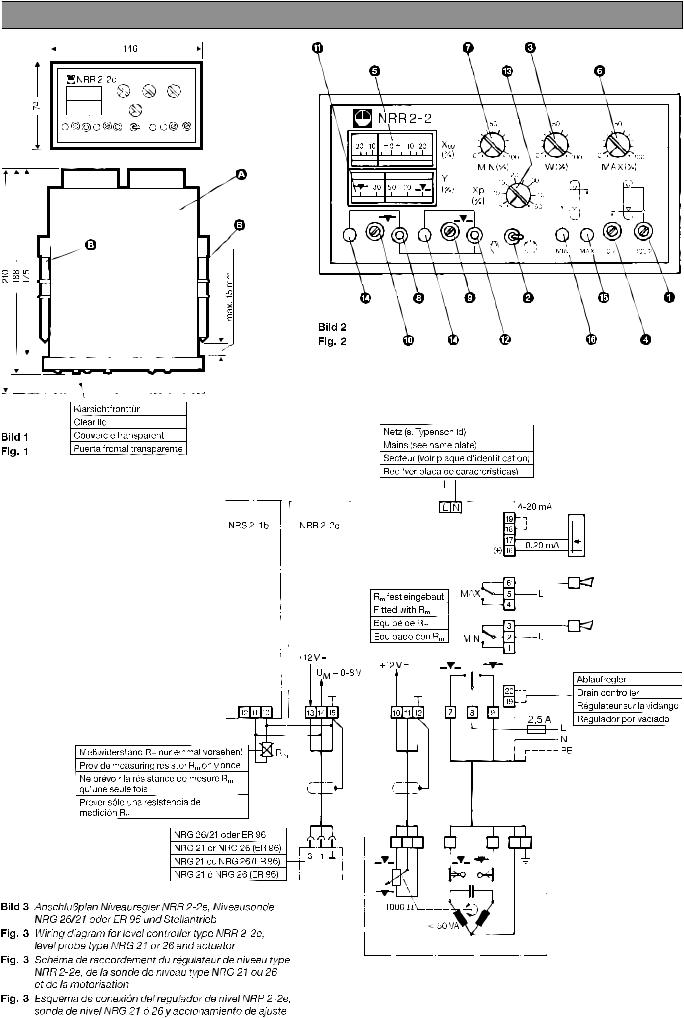
Maße / Dimensions / Dimensions / Dimensiones
B
Klarsichtfronttür
Clear lid
Couvercle transparent
Fig. 1
Puerta frontal transparente
Anschlussplan / Wiring diagram / Schéma de raccordement / Esquema de conexión
Messwiderstand R
nur einmal vorsehen!
m
Provide measuring resistor R
Ne prévoir la résistance de mesure R
Prever sólo una resistencia de medición R
Fig. 3: Anschlussplan Niveauregler NRR 2-2e,
Niveausonde NRG 26/21 oder ER 96
und Stellantrieb
Wiring diagram for level controller type NRR 2-2e,
level probe type NRG 21 or 26 and actuator
Schéma de raccordement du régulateur de niveau type NRR 2-2e,
de la sonde de niveau type NRG 21 ou 26 et de la motorisation
Esquema de conexión del regulador de nivel NRR 2-2e,
sonda de nivel NRG 21 ó 26 y accionamiento de ajuste
2
A
B
only once.
m
qu’une seule fois.
m
.
m
NRG 26/21 oder ER 96
NRG 21 or NRG 26 (ER 96)
NRG 21 ou NRG 26 (ER 96)
NRG 21 ó NRG 26 (ER 96)
!
5
$
0
8
$ 9 «
Fig. 2
Netz (siehe Typenschild)
Mains (see name plate)
Secteur (voir plaque d’identification)
Red (ver placa de características)
R
fest eingebaut
m
Fitted with R
Equipé de R
Equipado con R
7
§ 3
6
2
& % 4
m
m
m
Ablaufregler
Drain controller
Régulateur sur la vidange
Regulador por vaciado
1
Note for Owners:
Guidesimo.com webproject is not a service center of GESTRA trademark and does not carries out works for diagnosis and repair of faulty GESTRA NRR 2-2e equipment. For quality services, please contact an official service center of GESTRA company. On our website you can read and download documentation for your GESTRA NRR 2-2e device for free and familiarize yourself with the technical specifications of device.
-
Siemens SIMOTION D410
SIMOTION SIMOTION SCOUT D410 Preface Description 1 Operation (hardware) 2 Interfaces 3 Assembling 4 Connecting 5 Technical data 6 Spare parts/Accessories 7 Standards and approvals A ESD directives B SIMOTION SIMOTION SCOUT D410 Manual 05/2009 Valid for SIMOTION D410 DP and D410 PN …
SIMOTION D410 Industrial Equipment, 108
-
Danfoss ECL Comfort 310
OperatingGuideECLComfort310,applicationP3181.0TableofContents1.0TableofContents………………………………………..11.1Importantsafetyandproductinformation…………………22.0Installation………………………………………………..62.1Beforeyoustart……………………………………………..62.2Identifyingthesystemtype………………………………..182. …
ECL Comfort 310 Thermostat, 128
-
RNA ESR 2000
Rhein-Nadel Automation GmbH 1 14.04.2014 VT-BA ESR2000-GB Operating Instructions for the Control Units for Vibratory Drives Type ESR 2000 BA Rhein-Nadel Automation GmbH …
ESR 2000 Controller, 19
-
Exhausto VEX100 Series
EXHAUSTO A/SOdensevej 76DK-5550 LangeskovTel. +45 65 66 12 34Fax +45 65 66 11 [email protected]ng base, Montagesokkel, Montagesockel, Montasjesokkel, Sockel, Montageframe, Asennussokkeli.VEX140-160VEX140CF-160CFVEX240-250VEX310T-350T …
VEX100 Series Racks & Stands, 12
-
Siemens VAG61 Series
Siemens Building Technologies 74 319 0922 0 C M4212 2019-01-22 1 / 2s48 45 Z0190°4716Z1690°4211Z01122.1 VAG61..A – AB = 100 %A – AB = 0 %2.1 VBG61..A – AB = 100 %B – AB = 100 %4213Z114213Z174213Z224213Z1774 319 0922 0M4212deMontageanleitungDrehantriebenMounting instructionsRotary-type actuatorfrInstructions de montageServo-moteur à action angulairesvMonteringsinstruktionSpjällställdon …
VAG61 Series Control Unit, 2
-
Siemens SIMATIC NET MM900 Series
SIMATIC NETIndustrial Ethernet switchesMM900 media modules for SCALANCE XR-500MCompact Operating Instructions04/2022A5E03275846-05Introduction1Safety notes2Recommendations on network security3Device description4installing and removing5Connecting6Service and maintenance7Technical data8Dimension drawings9Approvals10 …
SIMATIC NET MM900 Series Switch, 48
-
S&C Scada-Mate CCU-SP
S&C Scada-Mate® Switching Systems Communication and Control UnitsTypes CCU-SP and CCU-XP Outdoor Distribution (14.4 kV through 34.5 kV)Instruction Sheet 768-550© S&C Electric Company 2001-2017, all rights reservedDecember 11, 2017Instructions for Installation, Operation, Maintenance, and CongurationTable of ContentsSection Page Section PageIntroductionQualified Persons ………….. …
Scada-Mate CCU-SP Control Unit, 29
-
Siemens Modem Block
INTRODUCTION The SIEMENS Modem Block module is a component of the HUB-4 assembly. EachModem Block module provides 1 independent data channel. The HUB-4 can supportup to 4 independent data channels. The Modem Block module mounts on the HUB-4,COM-2 board, which in turn mounts on the HUB -4 Main-2 board. Refer to the tablebelow to determine the required modules for the desired configuration.TABLE 1HU …
Modem Block Control Unit, 2
Popular Control Unit User Guides:
 Loading…
![]()
NRR 2-2e
NRR 2-2e
Betriebsanleitung 808322-01
Niveauregler NRR 2-2e
Installation and Service Instructions 808322-01
Level Controller NRR 2-2e
Instructions de montage
et de mise en service 808322-01
Régulateur de niveau NRR 2-2e
Instrucciones de montaje y servicio 808322-01
Regulador de nivel NRR 2-2e

You can only view or download manuals with
Sign Up and get 5 for free
Upload your files to the site. You get 1 for each file you add
Get 1 for every time someone downloads your manual
Buy as many as you need