-
Contents
-
Table of Contents
-
Troubleshooting
-
Bookmarks
Quick Links
ODEN AT
High Current System
User’s manual
Related Manuals for PEWA ODEN AT
Summary of Contents for PEWA ODEN AT
-
Page 1
ODEN AT High Current System User’s manual… -
Page 3
O D E N A T User’s Manual High Current System ODEN AT NOTICE OF COPYRIGHT & PROPRIETARY RIGHTS © 2002, Programma Electric AB. All rights reserved. The contents of this document are the property of Programma Electric AB. No part of this work may be reproduced or trans- mitted in any form or by any means, except as permitted in written license agreement with Programma Electric AB. -
Page 4: Table Of Contents
2.3 Reservations ….15 6.8 Grounding Oden AT ….31 3 Control panel ……..
-
Page 5
Message: ”Curr units have diff settings” 68 ODEN AT system ….50 Message: ”Curr units are of diff types” . 68 Distance to the test object . -
Page 6
O D E N A T 10 Calibration ……..71 Oden AT/1S (400 V) ..84 Oden AT/2S (400 V) ..84 10.1 General . -
Page 7
O D E N A T A1.4 Transfers in applications ”TEST RECLOSER” and ”SECTIONALIZER” ..105 Appendix 2 ……..107 A2.1 Resistance measurement accuracy . . 107 Factors that influence accuracy ..107 Accuracy estimation . -
Page 8
O D E N A T P r o g r a m m a E l e c t r i c A B Z P — C F 0 2 D R 1 0 0… -
Page 9: Safety Precautions
• Make certain that all personnel who work with Oden AT have been trained in its use and that all DANGER applicable safety precautions are taken. The voltages and currents that are gener- ated by Oden AT can cause serious injury.
-
Page 10: Precaution Level — Warning
WARNING Never switch between the 30 and 60 V settings when Oden AT is generating. WARNING When loading Oden AT on a carriage. To prevent tip-over, the current units must be loaded onto the carriage from bottom WARNING The carriage is primarily intended for transportation but may also be used when testing.
-
Page 11: Precaution Level — Important
WARNING Never try to service Oden AT yourself. If Never connect Oden AT to a mains volt- you open the casings of the current units age other than that specified on the da-…
-
Page 12
1 S a f e t y p r e c a u t i o n s O d e n A T P r o g r a m m a E l e c t r i c A B Z P — B H 0 2 E R 1 0 0… -
Page 13: Introduction
2.1 General 0-30V/60V output, providing either a 30 V or a 60 Oden AT is intended for use in high-voltage substa- V output. For data, see chapter 11 ”Specifications”. tions and industrial environments, for laboratories The control unit controls the current output (genera- and testing purposes.
-
Page 14: Fields Of Application
It is not necessary to clear the display first. • You can save different settings for Oden AT in ten different memories. P r o g r a m m a E l e c t r i c A B…
-
Page 15: Reservations
O d e n A T 2 I n t r o d u c t i o n 2.3 Reservations When set at maximum current, Oden AT is designed only for temporary (short-duration) current genera- tion. Do not use Oden AT for long-term generation at full current.
-
Page 16
2 I n t r o d u c t i o n O d e n A T P r o g r a m m a E l e c t r i c A B Z P — B H 0 2 E R 1 0 0… -
Page 17: Control Panel
3 C o n t r o l p a n e l 3 Control panel 3.1 Oden AT control panel MAINS block This chapter presents an overview of the Oden AT MAINS control panel. The control panel is divided into a number of blocks:…
-
Page 18: Current Adjust Block
<V/A METER> menu option in the MENU block. LATCHED An indicator lamp lights up to indicate whether you have activated the voltmeter or Oden AT’s ammeter 250V 2 (A-METER 2). In this block you enter the stop condition. When this…
-
Page 19
LATCHED a specified period of time. Press 250V the button until the MAX TIME Oden AT is set to respond to the opening or closing of an lamp lights up, and enter the external contact. maximum generation time using the <CHANGE> knob. -
Page 20: Menu Block
METER METER MORY CATION tings for Oden AT in 10 memories. See section 5.3. <APPLICATION> In this menu option can you set Oden AT for the fol- ENTER lowing applications: CHANGE • Normal use. • Microhm measurement. In this block you can select special functions and change the settings for the measuring instruments.
-
Page 21: Display
• Presents measured values. The directional indicators that appear on the dis- play show which direction you can scroll using the • Presents Oden AT´s settings. <CHANGE> knob. There are three types of direc- • Guides you by providing helpful messages, warn- tional markers: ings and prompts.
-
Page 22
4 D i s p l a y O d e n A T P r o g r a m m a E l e c t r i c A B Z P — B H 0 2 E R 1 0 0… -
Page 23: Menu Options
METER> menu option you can set Oden AT’s sec- ond ammeter (A-METER 2) and Oden AT’s volt- You can only select a menu option while Oden AT is meter. In the <SYSTEM> menu option you can set in the OFF state (i.e. not generating).
-
Page 24: A-Meter 1
5 M e n u o p t i o n s O d e n A T A-METER 1 V/A METER In this menu option you can make settings for Oden In this menu option you can select to use the volt- AT’s first ammeter (A-METER 1).
-
Page 25: System
11.6 Ammeter 1 ranges. be used the next time you turn Oden AT on, you can save them in memory 0 before turning Oden AT off. Note: The DC- measurement function is used…
-
Page 26: Application
3. Turn the <CHANGE>-knob until the number of the desired memory appears. 4. Press <ENTER>. APPLICATION In this menu option you can change Oden AT’s mode of operation for different types of tests. The available settings are listed in the table below. Application…
-
Page 27: How To Install Oden At
Fig 6.1 Different positions for the Oden AT carriage. Note, in working position the carriage must be secured to prevent tip over. Secure it to a suitable object e.g. a pole or a table. P r o g r a m m a E l e c t r i c A B…
-
Page 28: Connecting The Test Object And The Current Units To Each Other
See fig 6.1 damage to the current units. When you connect Oden AT to the object being tested, you should check that the contacts on the connectors are clean and that the cable clamps are placed as close together as possible on the object being tested.
-
Page 29: Series Connection (Output High I)
O d e n A T 6 H o w t o i n s t a l l O d e n A T rent units, you can connect them either in series or 6.4 Series connection (output HIGH I) in parallel.
-
Page 30: Parallel Connection (Output High I)
Never use a high-current output while simultaneously using a low-curret output! WARNING Never switch between the 30 and 60 V settings when Oden AT is generating. Important! All type X current units that are connect- Load ed together must have the same connec- tion setting for the low-current output, i.e.
-
Page 31: Connecting Current Units To The Control Unit
Fig 6.6 Current units connected to control unit If you should want to connect an old current unit with Grounded a 16-pin connector to the control unit in an Oden AT, mains cable Ground cable you must use a separately-ordered adapter.
-
Page 32: Connecting Oden At To The Mains
Mains voltage Important! ODEN AT is designed either for 240 V, 400 V Make sure that the mains voltage cor- or 480 V. The 480 V version is for 60 Hz only. responds to that specified on the data…
-
Page 33: Current Cables And Conductors
At each end there is an end-bar in- terconnecting the cables. The bar also enables single bolt connection to ODEN AT and the test object. See figure below. Impedance of the cable set is very dependent onhow cables are arranged.
-
Page 34
6 H o w t o i n s t a l l O d e n A T O d e n A T Length 2 x 0.5 m (distance to test object 0.5 m) Number Total cross section Impedance Impedance Impedance… -
Page 35
O d e n A T 6 H o w t o i n s t a l l O d e n A T Number Total cross section Impedance, cables twisted Max. current in Max. cont. current Weight (total set) of cables area (mW) -
Page 36: How To Arrange The Cable Sets
6 H o w t o i n s t a l l O d e n A T O d e n A T 6.12 How to arrange the cable sets Minimising impedance in cables Just increasing cross-section area helps only to a certain extent.
-
Page 37
O d e n A T 6 H o w t o i n s t a l l O d e n A T P r o g r a m m a E l e c t r i c A B Z P — B H 0 2 E R 1 0 0… -
Page 38: How To Arrange Bars
6 H o w t o i n s t a l l O d e n A T O d e n A T Make parallel connections between the terminals of 6.13 How To Arrange Bars the current units. Contact must be good, preferably Copper-bars are in many cases a better solution than use bars.
-
Page 39: How To Use Oden At
”Applica- described in chapter 6. tion examples”. 2. Turn on Oden AT using the mains switch on the side of the control unit. 3. Specify the desired settings in the OUTPUT block on the control panel.
-
Page 40: Rules Of Thumb When Generating Current
High currents can generate a great deal of heat in • If the object being tested has a low impedance both Oden AT and the object being tested. To avoid connect the current units in parallel. Connect unneccesary heating, you can: them in series if the object has high impedance.
-
Page 41: Setting Times For Limited-Time Generation
O d e n A T 7 H o w t o u s e O d e n A T 7.4 Setting times for limited-time 7.5 Continuous current generation generation (MAX TIME) If you want to generate current for an unlimited time, i.e.
-
Page 42: Getting Maximum Current From Oden At
(0-30 V) if you are using a single type X • Oden AT’s internal impedance current unit. To obtain maximum current from Oden AT proceed • Increase the impedance in the circuit, for in- as follows: stance use longer, lighter-gauge (thinner) current cables.
-
Page 43: Generating Pulse Trains
7.8 Generating pulse trains 7.9 Holding (freezing) measured values You can set Oden AT to generate a pulse-train (in- termittent current generation at regular intervals, i.e. Press the <HOLD> button to activate the holding pulse-pause-pulse-pause etc.). This will continue un- (freeze) function.
-
Page 44: Measuring Phase Angle And Polarity
Example: polarity Load Oden AT can display the phase angle between the current from Oden AT and a) the current (I2) passing through Oden AT’s second ammeter (A-METER 2) VOLTMETER AMMETER 2 or b) the voltage (V) at the voltmeter input. Press the <ESC>-button until the sign for degrees (”°”)
-
Page 45: Measuring Z, P, R, X, S, Q And Power Factor (Cos )
7.12 Reading maximun current at an power factor (cos ) operation When Oden AT’s voltmeter is activated you can The highest current value showed on the display measure impedance (Z), active power (P), resistance at an operation is stored. Press <ESC> repeatedly (R), reactance (X), virtual power (S), reactive power until a current value and the text «max»…
-
Page 46: Measuring Operating Limits
7 H o w t o u s e O d e n A T O d e n A T 7. Start generation by pressing <ON+TIME> and 7.13 Measuring operating limits turn up the current until the protective relay There are three ways to measure operating limits: equipment operates (pick-up).
-
Page 47: Method 3: Limited-Time Generation
O d e n A T 7 H o w t o u s e O d e n A T 3. Press <MOM ON> briefly. Note, however, that 7.14 Measuring tripping/operation current must be sent out for a period longer than times the operating time.
-
Page 48: Instantaneous Trip Unit Measurement
7 H o w t o u s e O d e n A T O d e n A T 4. If neccesary readjust the current and inject 7.15 Instantaneous trip unit again. Repeat this until you have achieved the measurement desired current value.
-
Page 49: Selecting Oden At Configuration And Current Cables
Ohms law I x Z volt is required to push current Examples of different applications: I through the impedance. If voltage at ODEN AT • Up to 5 — 7 kA through 5 m current cables. Ap- terminals is less, current will be lower than desired.
-
Page 50: How To Succeed In Selecting A Suitable Oden At System
Low Voltage air breaker rated 4 kA: 7.17 How to succeed in selecting a 0.09 — 0.2 mΩ suitable ODEN AT system b) Low Voltage circuit breaker rated 630 A: Please follow the procedure below. It implies that 0.3 — 1mΩ…
-
Page 51: Current Calculation Example
• Impedance can be reduced by: 6 Check input current a) twisting cables since it reduces the reactance. Again, to avoid surprises. ODEN AT is like a Important! transformer, high output power requires high input b) using sets with more cables current.
-
Page 52
7 H o w t o u s e O d e n A T O d e n A T Example: An ODEN AT/3H with units in series is used and test circuit impedance is 1.2 mΩ. The line should start at 0 kA, 0V. -
Page 53: Examples
Current cable length 5 meter Mains voltage 400 V 2. Selected output configuration ODEN AT 1/S is a possible choice. It can supply 3 kA for more than 10 seconds and has 4.0 V output voltage. 3. Maximum allowed test circuit impedance 3.9 V / 3 kA = 1.3 mΩ…
-
Page 54: Example 2, Low Voltage Circuit Breaker
Mains voltage 240 V. Mains voltage 400 V 2. Selected output configuration ODEN AT 2/S with units in parallel can supply 7 2. Selected output configuration kA for more than 5 seconds and has 3.6 V output ODEN AT 3/H with units in parallel can supply voltage.
-
Page 55: Form 1
O d e n A T 7 H o w t o u s e O d e n A T Form 1 Selection of configuration & cables See explanations in chapter 7, ”Selecting ODEN AT system and current cables” Required information: • Desired Current ______ A •…
-
Page 56
7 H o w t o u s e O d e n A T O d e n A T P r o g r a m m a E l e c t r i c A B Z P — B H 0 2 E R 1 0 0… -
Page 57: Form 2
7 H o w t o u s e O d e n A T Form 2 Selection of configuration when using a certain cable set Use this form when you must use a certain cable set. See explanations in chapter 7, ”Selecting ODEN AT system and current cables” Required information: • Application _________________________________________________________________________ •…
-
Page 58
7 H o w t o u s e O d e n A T O d e n A T P r o g r a m m a E l e c t r i c A B Z P — B H 0 2 E R 1 0 0… -
Page 59: Application Examples
When current first is generated for a load (while the current is being set), Oden AT adapts itself so that all subsequent genera- tion operations start at the current’s zero-cross-over points. This ensures minimized transient DC offset when the injection is initiated.
-
Page 60: Testing The Ratio Of A Current Transformer
CURRENT ADJUST: Close to the tripping limit AMMETER1, UNIT: AMPERE HOLD function: 2. Connect the Oden AT output to the primary 2. Set the stop condition to INT. terminals on the current transformer. 3. Select a suitable current setting. 3. Connect Oden AT’s second ammeter (A-ME- TER 2) input to the current transformer winding 4.
-
Page 61: Measuring The Polarity Of A Current Transformer
CT. 5. Connect the other terminal of A-METER 2 to S1 (X1). 6. Activate Oden AT’s second ammeter (A-METER 2) under the «A-METER 2» menu heading in the <V/A METER> menu option. 7. Press the <ESC>-button (normally twice) until the sign for degrees («°») appears in the upper-…
-
Page 62: Measuring The Resistances Of Breakers And Electrical Connections (Microhmmeter Testing)
WARNING Current ohms Do not measure on outdoor High Voltage 10. To return Oden AT to normal use, press the Circuit Breakers due to risk for capaci- <APPLICATION>-button and then turn the tively coupled currents. It could cause <CHANGE> knob until «NORMAL USE» ap- danger and/or damage.
-
Page 63: Testing A Direct Acting Automatic Recloser
1. Set the current, <APPLICATION> should be set 11. Press <ON+TIME> to start a new test. to «NORMAL», see 8.1. 12. To return Oden AT to normal use, press the 2. Press the <APPLICATION> menu option. <APPLICATION>-button and then turn the 3.
-
Page 64: Testing A Sectionalizer
12. Press <ON+TIME> to start a new test . • The current at the first four trip occations. 13. To return Oden AT to normal use, press the <APPLICATION>-button and then turn the Prior to the test 4 different puls-duration times (T1 <CHANGE>-knob until «NORMAL USE»…
-
Page 65: Testing A Ground Grid
Activate it in the <V/A ME- TER> menu option HOLD function: 2. Set Oden AT to generate 300 A, and allow the current to flow for about three minutes. 3. Then measure the portion of the current that flows through the ground network and the portion that proceeds via other routes using a clamp-on ammeter.
-
Page 66
8 A p p l i c a t i o n e x a m p l e s O d e n A T P r o g r a m m a E l e c t r i c A B Z P — B H 0 2 E R 1 0 0… -
Page 67: Troubleshooting
• Check that the mains cable is plugged in properly Remedy: Disconnect unused current units. and that mains voltage is present. Possible cause: Oden AT is set for DC-Measure- Problem: Generation stops immediately or ment while AC is generated or vice versa. (Fault after half a cycle.
-
Page 68: Error Messages
9 T r o u b l e s h o o t i n g O d e n A T 3. Press <ON+TIME> and turn the knob up to 100% 9.2 Error messages and then down to 0%. You can encounter the following error messages on 4.
-
Page 69: Measurement Errors
9 T r o u b l e s h o o t i n g O d e n A T 9.3 Measurement errors Problem: Unexpectively long trip-time while testing instantaneous trip on a cir- cuit breaker. Problem: No reading on voltmeter and am- meter 2.
-
Page 70
9 T r o u b l e s h o o t i n g O d e n A T P r o g r a m m a E l e c t r i c A B Z P — B H 0 2 E R 1 0 0… -
Page 71: Calibration
It is recommended that you calibrate 4. While simultaneously pressing the but- your Oden AT system once a year, but also if a new tons <ESC> and <ENTER>quickly turn the current unit is added to your system or if the system <CHANGE>…
-
Page 72: Calibration Of Scale Factor, Ammeter
1 0 C a l i b r a t i o n O d e n A T 10.3 Calibration of scale factor, 10.4 Scale factor for the I/30- ammeter 1 function. 1. See that the I/30-function is turned off. Scale factor, range LOW 2.
-
Page 73: Calibration Of Scale Factor, Ammeter
O d e n A T 1 0 C a l i b r a t i o n 10.5 Calibration of scale factor, 10.6 Calibration of scale factor, ammeter 2 voltmeter Scale factor, range 0 – 2 A Scale factor, range 0 – 0.2 V 1.
-
Page 74: Resetting To Preset (Standardized) Calibration Values
Performing a reset 1. Press down the <RESET> button while Oden AT is switched on. P r o g r a m m a E l e c t r i c A B…
-
Page 75: Specifications
System designation 0 – 9600 A / 0 – 30 kA An ODEN AT-system consists of a control unit an one, two or three 0 – 960 A / 0 – 3 kA current units. There are three different versions of the current units:…
-
Page 76: Output Specifications For 240 V Oden At Systems At 50 Hz
Oden AT/1X (240 V) Continuous 1000 Continuous OUTPUT HIGH I 2000 3 min See section 11.2 Oden AT/1S (240 V) 3000 1 min 4000 40 sec 5000 30 sec OUTPUT 0 – 30 V/60 V — Switch pos: 0 – 30 V…
-
Page 77: Oden At/3X (240 V)
5 sec Input current: Output current/66 (approximate) OUTPUT HIGH I See section 11.2 Oden AT/3S (240 V) Oden AT/2H (240 V) OUTPUT 0 – 30 V/60 V — Switch pos: 0 – 30 V OUTPUT HIGH I — Units in PARALLEL…
-
Page 78: Oden At/3H (240 V)
Continuous 2000 5 min 3000 2 min 4000 1 min 6000 5 sec Input current: Output current/33 (approximate) Oden AT/3H (240 V) OUTPUT HIGH I — Units in PARALLEL Output (A) Voltage (V) Time on Continuous 2000 Continuous 3800 Continuous…
-
Page 79: Load Curves, Oden At Systems
1 1 S p e c i f i c a t i o n s 11.3 Load curves, Oden AT systems for 240 V OUTPUT HIGH I, Oden AT systems for 240 V at 50/60 Hz operation 4/ 5…
-
Page 80: Output High I, Oden At Systems
1 1 S p e c i f i c a t i o n s O d e n A T OUTPUT HIGH I, Oden AT systems for 240 V 3 S or X units in series 2 S or X units in series…
-
Page 81
O d e n A T 1 1 S p e c i f i c a t i o n s 3 H units in series 2 H units in series 3 H units in parallel 2 H units in parallel 1 H unit 3 H units in series 2 H units in series… -
Page 82: Output 0-30V/60V, Oden At Systems For 240 V At 50/60 Hz Operation
1 1 S p e c i f i c a t i o n s O d e n A T OUTPUT 0-30V/60V, Oden AT systems for 240 V at 50/60 Hz operation 100 200 300 400 500 600 700 800 900 1000 1100 1200 1300 1400 1500 1600 1700 1800 1900 2000…
-
Page 83: Output 0-30V/60V, Oden At Systems For 240 V At 50 Hz Operation
O d e n A T 1 1 S p e c i f i c a t i o n s OUTPUT 0-30V/60V, Oden AT systems for 240 V at 50 Hz operation Current (A) Oden AT/1X 30 V range…
-
Page 84: Output Specifications For 400 V Oden At Systems At 50 Hz
OUTPUT HIGH I — Units in PARALLEL Output (A) Voltage (V) Time on Oden AT/1X (400 V) Continuous OUTPUT HIGH I 1000 Continuous See section 11.4. Oden AT/1S (400 V) 1900 Continuous 3000 10 min 4000 3 min 6000 30 sec OUTPUT 0 –…
-
Page 85: Oden At/2X (400 V)
OUTPUT 0 – 30 V/60 V — Switch pos: 0 – 60 V Output (A) Voltage (V) Time on OUTPUT HIGH I Continuous See section 11.4 Oden AT/3S (400 V) Continuous 3 min 12 sec 8 sec OUTPUT 0 – 30 V/60 V — Switch pos: 0 – 30 V…
-
Page 86: Oden At/2H (400 V)
1 1 S p e c i f i c a t i o n s O d e n A T Oden AT/2H (400 V) OUTPUT HIGH I — Units in PARALLEL Output (A) Voltage (V) Time on Continuous…
-
Page 87: Load Curves, Oden At Systems
1 1 S p e c i f i c a t i o n s 11.5 Load curves, Oden AT systems for 400 V OUTPUT HIGH I, Oden AT systems for 400 V 50/60 Hz and 480 V 60 Hz 7/ 8…
-
Page 88: Output High I, Oden At Systems
1 1 S p e c i f i c a t i o n s O d e n A T OUTPUT HIGH I, Oden AT systems for 400 V 3 S or X units in series 2 S or X units in series…
-
Page 89
O d e n A T 1 1 S p e c i f i c a t i o n s 3 H units in series 2 H units in series 3 H units in parallel 1 H unit 2 H units in parallel 3 H units in series 2 H units in series… -
Page 90: Output 0 — 30 V/60 V, Oden At Systems For 400 V 50 Hz
1 1 S p e c i f i c a t i o n s O d e n A T OUTPUT 0 – 30 V/60 V, Oden AT systems for 400 V 50 Hz 5/ 6 2/ 3…
-
Page 91: Output 0 — 30 V/60 V, Oden At Systems For 400 V 50 Hz
O d e n A T 1 1 S p e c i f i c a t i o n s OUTPUT 0 – 30 V/60 V, Oden AT systems for 400 V 50 Hz Current (A) Oden AT/1X…
-
Page 92: Output Specifications For 480 V Oden At Systems At 60 Hz
OUTPUT HIGH I — Units in PARALLEL Output (A) Voltage (V) Time on Oden AT/1X (480 V 60 Hz) Continuous OUTPUT HIGH I 1000 Continuous See section 11.4 Oden AT/1S (480 V 60 Hz) 1900 Continuous 3000 10 min 4000 3 min 6000 30 sec OUTPUT 0 –…
-
Page 93: Oden At/2X (480 V 60 Hz)
Units in SERIES OUTPUT HIGH I Output (A) Voltage (V) Time on See section 11.4 Oden AT/2S (480 V 60 Hz) Continuous Continuous 1 min 30 sec OUTPUT 0 – 30 V/60 V — Switch pos: 0 – 30 V…
-
Page 94: Oden At/2H (480 V 60 Hz)
1 1 S p e c i f i c a t i o n s O d e n A T Oden AT/2H (480 V 60 Hz) OUTPUT HIGH I — Units in PARALLEL Output (A) Voltage (V) Time on…
-
Page 95: Load Curves, Oden At Systems For 480 V 60 Hz
O d e n A T 1 1 S p e c i f i c a t i o n s 11.7 Load curves, Oden AT systems for 480 V 60 Hz 3 S units in series 2 S units in series…
-
Page 96
1 1 S p e c i f i c a t i o n s O d e n A T 3 X units in series (60 V) 2 X units in series (60 V) 3 X units in series (30 V) 3 X units in parallel (60 V) 1 X unit (60 V) 2 X units in parallel (60 V) -
Page 97
O d e n A T 1 1 S p e c i f i c a t i o n s 3 H units in series 2 H units in series 3 H units in parallel 1 H unit 2 H units in parallel P r o g r a m m a E l e c t r i c A B Z P — B H 0 2 E R 1 0 0… -
Page 98: Ammeter 1
1 1 S p e c i f i c a t i o n s O d e n A T 11.8 Ammeter 1 Measurement method: AC, true RMS value Accuracy: 1% of range Ranges: Se table below Ammeter 1 — Ranges Range LOW Measurement Range HIGH Measurement…
-
Page 99: Stop Input
O d e n A T 1 1 S p e c i f i c a t i o n s 11.9 Stop input This input is equipped with a 400 V voltage sup- pressor between the terminals. STOP INPUT Parameter Type Unit…
-
Page 100
1 1 S p e c i f i c a t i o n s O d e n A T P r o g r a m m a E l e c t r i c A B 1 0 0 Z P — B H 0 2 E R 1 0 0… -
Page 101: A1.1 Transferring Test Data To A Pc Or A Printer
A1.1 Transferring test data to a PC A1.2 Setting up the connection or a printer 1. Connect the serial port on Oden AT to the serial port on the PC using a straight pin-to-pin cable. Test data from Oden AT can be transferred to a PC…
-
Page 102: How To Connect Via Win 9X Hyper Terminal
A p p e n d i x 1 O d e n A T How to connect via Win 9X Hyper Terminal Start Hyper Terminal in the Accessories menu. Note If Hyper Terminal is not installed you will have to install it in the «Install/uninstall softwares»…
-
Page 103: How To Connect Via Win 2000 Hyper Terminal
O d e n A T A p p e n d i x 1 How to connect via Win 2000 Hyper Terminal 1. Start Hyper Terminal. You will find it under Start, Programs, Accessories, Communications 2. Type the name of the connection and click OK 4.
-
Page 104: A1.3 Transfers In «Normal Use
A p p e n d i x 1 O d e n A T A1.3 Transfers in ”NORMAL USE” Data measured by Oden AT will be dumped to the PC (or printer) each time you press <ENTER>. The downloaded data contains this: •…
-
Page 105: A1.4 Transfers In Applications «Test Recloser» And «Sectionalizer
O d e n A T A p p e n d i x 1 A1.4 Transfers in applications ”TEST RECLOSER” and ”SECTIONALIZER” Measured data from a test in the ”TEST RECLOS- ER” and ”SECTIONALIZER”applications will be dumped to the PC (or printer) each time you press <ENTER>.
-
Page 106
A p p e n d i x 1 O d e n A T P r o g r a m m a E l e c t r i c A B 1 0 6 Z P — B H 0 2 E R 1 0 0… -
Page 107: A2.1 Resistance Measurement Accuracy
O d e n A T A p p e n d i x 2 Appendix 2 A2.1 Resistance measurement accuracy Factors that influence accuracy • Flux inducing voltage in the sense cables • High phase shift between voltage and current •…
-
Page 108
A p p e n d i x 2 O d e n A T P r o g r a m m a E l e c t r i c A B 1 0 8 Z P — B H 0 2 E R 1 0 0… -
Page 109: Index
Ammeter 1 ….. . . 98 Oden AT ….. . . 31 APPLICATION .
-
Page 110
Micro-ohm measurement ….62 selecting ODEN AT system ….50 induced currents ….62 SERIAL port . -
Page 111
O d e n A T I n d e x X ……45 Z . -
Page 114
S u b j e c t t o c h a n g e w i t h o u t n o t i c e . P r i n t e d m a t t e r N o . Z P — B H 0 2 E R 1 0 0 D o c : B H 0 2 2 4 K E 2 0 0 5…
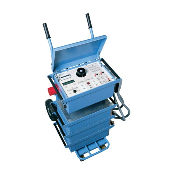
ODEN AT является необычайно многофункциональным переносным проверочным прибором, который способен генерировать ток силой от нескольких сотен до 22000 ампер. Устанавливаемый на тележку ODEN AT легко перемещать с место на место — каждый модуль является достаточно легким для одного человека. Модульная компоновка состоит из блока управления и одного, двух или трёх источников тока.
ODEN AT — Система испытания первичным током
ODEN AT — дальнейшая модификация хорошо зарекомендовавшего себя переносного источника тока серии ODEN производства фирмы “Programma” — воплощает в себе много новых и передовых технических характеристик. ODEN AT является необычайно многофункциональным переносным проверочным прибором, который способен генерировать ток силой от нескольких сотен до 22000 ампер. Устанавливаемый на тележку ODEN AT легко перемещать с место на место — каждый модуль является достаточно легким для одного человека. Модульная компоновка состоит из блока управления и одного, двух или трёх источников тока.
ЛЁГКОСТЬ В ОБРАЩЕНИИ: для того, чтобы совместить многофункциональность системы с легкостью в обращении её создатели уделили первостепенное внимание контрольной панели и интерфейсу пользователя. Для панели управления используются понятные обозначения и она разделяется на несколько секций. Для наиболее часто встречающихся применений существует ряд предварительно запрограммированных установок. Система ODEN AT легка в обращении, вы можете повторить любые испытания, нажав всего одну кнопку.
МНОГОСТОРОННИЙ КОНТРОЛЬ ЗА ГЕНЕРИРОВАНИЕМ ТОКА: время генерирования тока контролируется с помощью встроенного таймера и, кроме того, подачу тока можно прекратить, используя внешнее напряжение или внешний контакт. ODEN AT может выдавать кратковременный ток с помощью одной единственной кнопки, причем, возможно получить последовательность импульсов, при которой как величина импульсов, так и интервалы задаются пользователем. С помощью функции “Удержать” и способности системы подавать кратковременный ток возможно добиться тока нужной величины, избежав при этом перегрева тестируемого объекта. Более того, можно установить необходимый выходной ток, используя всего лишь 1/30 часть тока, от требуемой величины.
ШИРОКИЙ ДИАПАЗОН ИЗМЕРЯЕМЫХ ПАРАМЕТРОВ: сила тока и время выводятся на цифровом дисплее. Может быть использован вторичный измерительный канал для измерения тока или напряжения. Вычисляются и выводятся на дисплей коэффициент мощности (косинус φ), а также фазовый угол. Сила тока и напряжение могут быть представлены в процентах от номинального значения. Быстродействующая функция “Удержание” способна сохранить на цифровом дисплее те кратковременные значения, при которых напряжение или управляющий сигнал поступают на вход “Стоп” и генерирование тока прерывается.
Испытание первичным током и проверка автоматических выключателей: подобные испытания требуют токов большой силы и способности измерять очень короткие импульсы тока и интервалы времени. Система ODEN AT специально предназначена для таких целей. Для измерения времени срабатывания низковольтного выключателя не требуется никаких дополнительных контактов. Тестирование прекращается в тот самый момент, когда главные контакты размыкаются, чтобы отключить ток. Начало подачи тока синхронизируется с точкой перехода синусоиды тока через нулевое значение для того, чтобы обеспечить возможность повторять тест и минимизировать смещение постоянной составляющей.
Проверка трансформаторов тока: при определении коэффициента трансформации по соотношению витков на дисплее одновременно высвечиваются значения первичного и вторичного токов, или коэффициент трансформации. Так как коэффициент трансформации показывается как номинальное значение (например, 1000 / 5), нет необходимости осуществлять дальнейшие вычисления.
Проверка полярности: Показывается сдвиг фаз и чётко обозначается полярность выходов.
Определение активного и полного сопротивлений: нажатием нескольких клавиш ODEN AT может быть быстро и легко превращен в микроомметр. Измерение сопротивления с помощью очень высоких токов является исключительной особенностью системы. Могут быть измерены импеданс, фазовый угол, нагрузка в соединённых цепях, а также другие параметры.
Устройства АПВ и секционные разделители: ODEN AT также может быть настроен на проверку устройств АПВ прямого действия и секционных разделителей. Могут быть измерены пороги срабатывания, частичное и полное время, а также количество срабатываний перед выключением. По выбору пользователя может быть запрограммирована последовательность повторных включений для проверки разъединителей.
Проверка системы заземления и устройств защитного заземления: одним из способов проведения этого теста является подача тока между базовым заземлением и заземлением, которое должно быть проверено, и измерение падения напряжения, а также силы тока в процентах через сеть заземления. Для такого применения предназначена система ODEN AT с источником тока типа “Х”. Защитное заземление должно испытываться при расчетных токах, задача, для которой хорошо подходит эта система.
Тепловые испытания: система ODEN AT идеальна для проведения испытаний на перегрев. Ток может подаваться непрерывно или через запрограммированные интервалы. Время может показываться в минутах и часах, что облегчает проведение долговременных тестов.
Дополнительный модуль: позволяет прогружать выключатели постоянным током (4,5 кА в течении 5 секунд).
Производство компании PROGRAMMA
 Loading…
![]()
ODEN AT
Primary Current Injection Test System
ODEN AT
Primary Current Injection Test System
▪▪Most Advanced Primary Current Injection
Test System to simplify all types of switchgear and CT commissioning, ground grid, circuit breaker testing and more
▪▪Modular design to permit optimal user configuration of output current vs. unit size
▪▪Compact transport cart facilitates portability into switchgear rooms with limited space
▪▪Unique I/30 function allows the current to be pre-set using low current to prevent test sample heating, thus eliminating corruption of test result
Description
This powerful test system is designed for primary injection testing of protective relay equipment and circuit breakers. It is also used to test the turns ratio of current transformers and for other applications that require high variable currents.
The system consists of a control unit together with one, two or three current units. There are three versions of the current unit: S, X and H. The S and X current units are identical except that the X unit has an additional 30/60 V output. The H unit is rated for even higher current. This makes it possible to configure an ODEN AT system in a suitable way. All parts are portable, and ODEN AT can be quickly assembled and connected.
The control unit has many advanced features – a powerful measurement section for example, that can display turns ratio as well as time, voltage and current. A second measurement channel can be used to measure an additional current or voltage. Current transformer turns ratio, impedance, resistance, power, power factor (cos φ) and phase angle are calculated and shown in the display. Current and voltage can be presented as percentages
of nominal value. The fast-acting hold function freezes shortduration readings on the digital display when the voltage or contact signal arrives at the stop input, the object under test interrupts the current or injection is stopped
Application
Primary current injection testing and breaker testing
These tests require high currents and the ability to measure very short duration, current flow. ODEN AT has been designed especially to meet these needs. No extra contacts are needed to measure the operating time of a low-voltage breaker. Testing stops at the instant when the main breaker contacts open to interrupt the current. Output current initiation is synchronized with the currents zero-crossover point to ensure good repeatability and minimized DC offset.
Testing current transformers
For turns ratio testing, the primary current and either the secondary current or the turns ratio are displayed simultaneously. Since the turns ratio is displayed directly as the nominal value (1000/5 for example), no further calculation is needed. Burden of secondary circuits can be measured and presented in VA.
Polarity testing
The currents phase displacement is shown, and the polarities of the outputs are clearly marked.
Heat runs
ODEN AT is ideal for performing heat runs. Current can be applied continuously or through programmable intervals. The times can be shown in minutes and hours which facilitates longterm testing capability.
Automatic reclosers and sectionalizers
ODEN AT can also be set to test circuit breakers with reclosing relays. Operating limits, partial times, total times and the number of operations before lockout can be measured. User-selectable reclosing sequences can be programmed for testing sectionalizers.
Testing integrity of ground grids and safety-ground devices
One way to test ground grids is by injecting current between a reference ground and the ground to be tested and measuring the voltage drop and the percentage of current flowing through the ground grid. The type X current unit included with ODEN AT is designed for this type of application. Personal safety grounds
must be tested at rated current, a task for which ODEN AT is well suited.

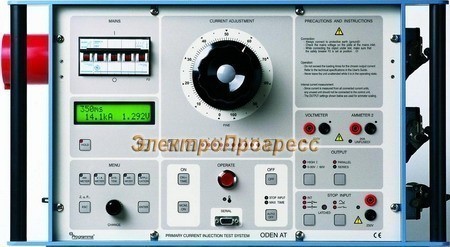
Features and Benefits
1.Display. The display presents time, output current, voltage, current shown on ammeter 2 and phase angle. You can scroll through entities Z, P, Q, R, X, S, power factor (cos φ) and I max.
2.Miniature circuit breaker used for current output. Interrupts output current. Can also be actuated manually for safe disconnection of load.
3.Current reduction button. Used during setting to reduce the output current to 1/30. Useful in order to avoid for example unintentional tripping and overheating.
4.Fine adjustment knob. Knob for fine adjustment of current and +/- buttons for coarse adjustment.
5.Indicator lamps. Indicate whether ammeter 2 or the voltmeter is enabled.
6.Input for voltmeter. Used to measure voltage and for microhmmeter measurement.
7.Input for ammeter 2. Used to measure current in an external circuit (in a current transformer´s secondary winding for example).
8.Hold function. This function freezes readings on the display.
9.Selection/setting (CHANGE) knob. Selects the desired menu option (shown in the display window). Also used to change numerical values.
10.Setting buttons. Personnel unfamiliar with ODEN AT can use the pre-defined settings very effectively, while experienced users can make their own basic settings.
•Ammeter. Used to set the main current-output ammeter. You can select the desired range or select autoranging.
•V/A Meter. Toggles between the voltmeter and ammeter 2. Also used to select the desired range or select autoranging.
•System. Used for general settings.
•Memory. Used to save or recall settings to or from the ten ODEN AT memories. One of these memories contains the default (pre-defined) settings that are invoked when ODEN AT is powered up.
ODEN AT
Primary Current Injection Test System
• Application. Used to invoke the desired measurement mode: automatic recloser, sectionalizer or microhmmeter.
ODEN AT can also be set to generate pulse trains with user-se- lectable pulse and pause times.
11.Injection. Starts current injection and timing.
12.Momentary Injection. When this button is used, injection continues only as long as it is pressed. Useful in order to avoid for example overheating.
13.RS232 for computer. ODEN AT is equipped with a serial port for communication with PC (for transfer of test data for example).
14.Manual shut-off. Injection and timing are stopped when this button is pressed.
15.Automatic injection stop. Generation stops after a user-spec- ified interval or when condition at the input is met. The diodes show the selected OFF condition.
16.Stop-condition indicator. Indicates that a stop condition is met, voltage or contact triggered.
17.Status indicator. Indicates if a contact connected to the input is closed or if voltage is present.
18.Stop input. Used to freeze a reading or stop injection. Activated when current is interrupted by the object being tested, when an external contact is actuated or when a voltage is applied or removed.
|
8 |
9 |
10 |
11 |
12 |
13 |
14 |
15 |
16 |
17 |
18 |

Specifications ODEN AT
Specifications are valid at nominal input voltage and an ambient temperature of +25°C, (77°F). Specifications are subject to change without notice.
System designation
An ODEN AT-system consists of a control unit and one, two or three current units. There are three different versions of the current units: S-unit (standard), X-unit (extra 30/60 V outlet) and H-unit (high current). The system designation indicates the number and version of current units included.
Example: ODEN AT/2X
2 = Number of current units
X = Version of current unit (S, X or H)
Environment
|
Application field |
The instrument is intended for use |
|
in high-voltage substations and |
|
|
industrial environments. |
|
|
Temperature |
|
|
Operating |
0°C to +50°C (+32°F to +122°F) |
|
Storage & transport |
-25°C to +55°C (-13°F to +127°F) |
|
Humidity |
5% – 95% RH, non-condensing |
|
CE-marking |
|
|
LVD |
2006/95/EC |
|
EMC |
2004/108/EC |
|
General |
|
|
Mains voltage |
240 / 400 V AC, 50 / 60 Hz |
|
480 V AC / 60 Hz |
|
|
Mains inlet |
IEC 60309-2, 63 A |
|
Input current |
Output current x open circuit voltage |
|
/ input voltage |
|
|
Protection |
The output transformer has a built-in |
|
thermal cut-out, and the primary |
|
|
side is protected by a miniature |
|
|
circuit breaker. |
|
|
Dimensions |
|
|
Control unit AT |
570 x 310 x 230 mm |
|
(22.4” x 12.2” x 9”) |
|
|
Current unit S, X H |
570 x 310 x 155 mm |
|
(22.4” x 12.2” x 6”) |
|
|
Complete with cart |
690 x 350 x 860 mm |
|
(27.2” x 13.8” x 33.9”) |
|
|
Weight |
|
|
Control unit AT |
25 kg (55 lbs) |
|
Current unit S |
42 kg (92.6 lbs) |
|
Current unit X |
45 kg (99.3 lbs) |
|
Current unit H |
49 kg (108 lbs) |
|
Cart |
11 kg (24.3 lbs) |
|
Display |
LCD |
|
Available languages |
English, German, French, Spanish, |
|
Swedish. |
ODEN AT
Primary Current Injection Test System
Measurement section
Ammeters
|
Measurement method |
AC, true RMS |
|
|
Inaccuracy |
1% of range ±1 digit |
|
|
Ammeter 1 |
||
|
Ranges |
0 |
– 4800 A / 0 –15 kA |
|
0 |
– 9600 A / 0 – 30 kA |
|
|
0 |
– 960 A / 0 – 3 kA |
|
|
Ammeter 2 |
||
|
Ranges |
0 |
– 2.000 A / 0 – 20.00 A |
|
Maximum current |
20 A (The input is not protected by |
|
|
a fuse) |
||
|
Voltmeter |
||
|
Measurement method |
AC, true RMS |
|
|
Ranges |
0 |
– 0.2 V, 0 – 2 V, 0 – 20 V, |
|
0 |
– 200 V, AUTO |
|
|
Inaccuracy |
1% of range ±1 digit |
|
|
Input resistance (Rin) |
240 kΩ (range 0 – 200 V) |
|
|
24 kΩ (other ranges) |
||
|
Dielectric withstand |
2.5 kV |
|
|
Timer |
||
|
Presentation |
In seconds, mains frequency cycles |
|
|
or hours and minutes |
||
|
Ranges |
0.000 – 999.9 s |
|
|
0 |
– 9999 cycles |
|
|
0.001 s – 99 h 59 min |
||
|
Inaccuracy |
±(1 digit + 0.01% of value) |
|
|
For the stop condition in INT-mode |
||
|
1 ms shall be added to the specified |
||
|
measurement error. |
||
|
Stop input |
||
|
Max. input voltage |
250 V AC / 275 V DC |
|
|
Phase angle |
||
|
Range |
0 |
– 359º |
|
Resolution |
1º |
|
|
Inaccuracy |
±2º (for voltage and current readings |
|
|
that are higher than 10% of the |
||
|
selected range) |
Z, P, R, X, S, Q and power factor (cos φ)
For these measurements the result is calculated using U, I and sometimes φ.
Imax
Stores highest current value that exists ≥100 ms
INT-level
Threshold indicating that current is interrupted. Can be set to 0.7% or 2.1% of Ammeter 1 range.

ODEN AT
Primary Current Injection Test System
Description
This powerful test system is designed for primary injection testing
of protective relay equipment and circuit breakers. It is also used
to test the turns ratio of current transformers and for other
applications that require high variable currents.
The system consists of a control unit together with one, two or
three current units. There are three versions of the current unit: S,
X and H. The S and X current units are identical except that the X
unit has an additional 30/60 V output. The H unit is rated for even
higher current. This makes it possible to configure an ODEN AT
system in a suitable way. All parts are portable, and ODEN AT can
be quickly assembled and connected.
The control unit has many advanced features – a powerful
measurement section for example, that can display turns ratio as
well as time, voltage and current. A second measurement channel
can be used to measure an additional current or voltage. Current
transformer turns ratio, impedance, resistance, power, power
factor (cos φ) and phase angle are calculated and shown in the
display. Current and voltage can be presented as percentages
of nominal value. The fast-acting hold function freezes short-
duration readings on the digital display when the voltage or contact
signal arrives at the stop input, the object under test interrupts the
current or injection is stopped
Testing current transformers
For turns ratio testing, the primary current and either the
secondary current or the turns ratio are displayed simultaneously.
Since the turns ratio is displayed directly as the nominal value
(1000/5 for example), no further calculation is needed. Burden of
secondary circuits can be measured and presented in VA.
Polarity testing
The currents phase displacement is shown, and the polarities of
the outputs are clearly marked.
Heat runs
ODEN AT is ideal for performing heat runs. Current can be
applied continuously or through programmable intervals. The
times can be shown in minutes and hours which facilitates long-
term testing capability.
Automatic reclosers and sectionalizers
ODEN AT can also be set to test circuit breakers with reclosing
relays. Operating limits, partial times, total times and the number
of operations before lockout can be measured. User-selectable
reclosing sequences can be programmed for testing sectionalizers.
Testing integrity of ground grids and safety-ground devices
One way to test ground grids is by injecting current between a
reference ground and the ground to be tested and measuring the
voltage drop and the percentage of current flowing through the
ground grid. The type X current unit included with ODEN AT
is designed for this type of application. Personal safety grounds
must be tested at rated current, a task for which ODEN AT is well
suited.
Application
Primary current injection testing and breaker testing
These tests require high currents and the ability to measure very
short duration, current flow. ODEN AT has been designed
especially to meet these needs. No extra contacts are needed to
measure the operating time of a low-voltage breaker. Testing stops
at the instant when the main breaker contacts open to interrupt
the current. Output current initiation is synchronized with the
currents zero-crossover point to ensure good repeatability and
minimized DC offset.
▪
Most Advanced Primary Current Injection
Test System to simplify all types of
switchgear and CT commissioning, ground
grid, circuit breaker testing and more
▪
Modular design to permit optimal
user configuration of output current
vs. unit size
▪
Compact transport cart facilitates
portability into switchgear rooms
with limited space
▪
Unique I/30 function allows the current to
be pre-set using low current to prevent
test sample heating, thus eliminating
corruption of test result
ODEN AT
Primary Current Injection Test System
- Самая современная система испытания первичным током для тестирования всех типов распределительных устройств, трансформаторов тока, наземных сетей, выключателей и др.
- Модульная конструкция, обеспечивающая оптимальную пользовательскую конфигурацию выходного тока по сравнению с размером блока
- Компактная транспортная тележка облегчает перенос устройства в ограниченном пространстве
- Уникальная функция I/30 позволяет задавать ток, используя низкий ток, чтобы предотвратить нагрев тестируемого объекта, тем самым устраняя повреждение
Эта мощная тестовая система проверки первичным током предназначена для тестирования релейного оборудования и автоматических выключателей. Он также используется для проверки коэффициента трансформации трансформаторов тока и для других устройств, для которых требуются высокие значения переменного тока.