ZEN.fm
| Наименование | Краткое описание | Карточка товара |
||
|---|---|---|---|---|
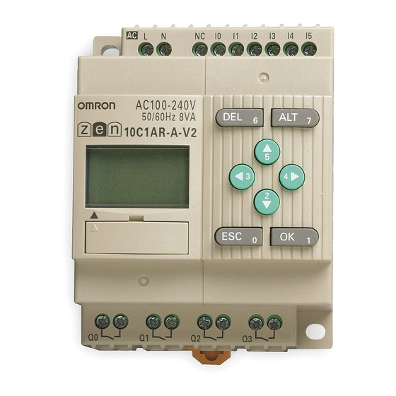
| ZEN-10C1AR-A-V2 (OMRON-IA) |
|
— | модуль цпу | |
| ZEN-10C1DR-D-V2 (OMRON-IA) |
|
— | — | |
| ZEN-10C1DT-D-V2 (OMRON-IA) |
|
— | модуль цпу | |
| ZEN-10C2AR-A-V2 (OMRON-IA) |
|
ZEN10COM | модуль цпу | |
| ZEN-10C2DR-D-V2 (OMRON-IA) |
|
— | модуль цпу | |
| ZEN-10C2DT-D-V2 (OMRON-IA) |
|
ZEN10COM | модуль цпу | |
| ZEN-10C3AR-A-V2 (OMRON-IA) |
|
— | модуль цпу | |
| ZEN-10C3DR-D-V2 (OMRON-IA) |
|
— | модуль цпу | |
| ZEN-10C4AR-A-V2 (OMRON-IA) |
|
— | модуль цпу | |
| ZEN-10C4DR-D-V2 (OMRON-IA) |
|
— | модуль цпу | |
| ZEN-20C1AR-A-V2 (OMRON-IA) |
|
— | модуль цпу | |
| ZEN-20C1DR-D-V2 (OMRON-IA) |
|
— | модуль цпу | |
| ZEN-20C1DT-D-V2 (OMRON-IA) |
|
— | модуль цпу | |
| ZEN-20C2AR-A-V2 (OMRON-IA) |
|
— | модуль цпу | |
| ZEN-20C2DR-D-V2 (OMRON-IA) |
|
— | модуль цпу | |
| ZEN-20C2DT-D-V2 (OMRON-IA) |
|
— | модуль цпу | |
| ZEN-20C3AR-A-V2 (OMRON-IA) |
|
— | модуль цпу | |
| ZEN-20C3DR-D-V2 (OMRON-IA) |
|
— | модуль цпу | |
| ZEN10C1ARAV2.1 (OMRON-IA) |
|
— | модуль цпу | |
| ZEN10C1DRDV2.1 (OMRON-IA) |
|
— | модуль цпу | |
| ZEN10C1DTDV2.1 (OMRON-IA) |
|
— | модуль цпу | |
| ZEN10C2ARAV2.1 (OMRON-IA) |
|
— | модуль цпу | |
| ZEN10C2DRDV2.1 (OMRON-IA) |
|
— | модуль цпу | |
| ZEN10C2DTDV2.1 (OMRON-IA) |
|
— | модуль цпу | |
| ZEN10C3ARAV2.1 (OMRON-IA) |
|
— | модуль цпу | |
| ZEN10C3DRDV2.1 (OMRON-IA) |
|
— | модуль цпу | |
| ZEN10C4ARAV2.1 (OMRON-IA) |
|
— | модуль цпу | |
| ZEN10C4DRDV2.1 (OMRON-IA) |
|
— | модуль цпу | |
| ZEN20C1ARAV2.1 (OMRON-IA) |
|
— | модуль цпу | |
| ZEN20C1DRDV2.1 (OMRON-IA) |
|
— | модуль цпу |
Скачать документацию: Документация на серию ZEN10 (1.3 Мб)
OMRON ZEN — простой и доступный способ решения задач автоматизации!
Программируемые реле ZEN — это компактный микроконтроллер для локальной автоматизации.
Благодаря возможности выбора из 4 различных модулей ЦПУ с 10 входами/выходами мы предлагаем идеальное решение для широкого спектра задач автоматизации. Три модели модулей (С1/С2/С3) имеют возможности расширения до 34 входов/ выходов. Модель С3 имеет только 10 входов/выходов. Все модели на постоянный ток снабжены аналоговым входом и входом высокоскоростного счетчика до 150Гц. Модель С4 обладает коммуникационными возможностями.
- Аналоговый вход в модулях со входом/питанием постоянного тока + высокоскоростной счетчик
- Наличие RS-485 интерфейса у модуля ZEN-10C4
- Возможности расширения с модулями релейных или транзисторных выходов
- Лучший выбор для начала работы — наборы ZEN-Kits
- Автоматизация котельных и тепловых пунктов
- Автоматизация помещений
- Локальные установки
- Кондиционирование
- Автоматические двери
- Миксеры и мешалки
- Эскалаторы
- Контроль водоснабжения
- и многое другое…
| Модуль | Название | Количество вх/вых | ЖК-дисплей | Питание | Входы | Выходы | Кнопки, календарь, часы | Аналоговый вход | Модель | ||
|---|---|---|---|---|---|---|---|---|---|---|---|
| CPU модули | Стандартный с ЖК-дисплеем | 10 | Да | 100 to 240 VAC | 6 | 100 to 240 VAC | 4 | Реле | Да | Нет | ZEN-10C1AR-A-V2 |
| 12 to 24 VDC | 12 to 24 VDC | Да | ZEN-10C1DR-D-V2 | ||||||||
| Транзисторы | ZEN-10C1DT-D-V2 | ||||||||||
| 20 | 100 to 240 VAC | 12 | 100 to 240 VAC | 8 | Реле | Нет | ZEN-20C1AR-A-V2 | ||||
| 12 to 24 VDC | 12 to 24 VDC | Да | ZEN-20C1DR-D-V2 | ||||||||
| Транзисторы | ZEN-20C1DT-D-V2 | ||||||||||
| Со светодиодами без ЖК-Дисплея | 10 | Нет | 100 to 240 VAC | 6 | 100 to 240 VAC | 4 | Реле | Нет | Нет | ZEN-10C2AR-A-V2 | |
| 12 to 24 VDC | 12 to 24 VDC | Да | ZEN-10C2DR-D-V2 | ||||||||
| Транзисторы | ZEN-10C2DT-D-V2 | ||||||||||
| 20 | 100 to 240 VAC | 12 | 100 to 240V AC | 8 | Реле | Нет | ZEN-20C2AR-A-V2 | ||||
| 12 to 24 VDC | 12 to 24 VDC | Транзисторы | Да | ZEN-20C2DR-D-V2 | |||||||
| ZEN-20C2DT-D-V2 | |||||||||||
| Экономичный вариант (без возможности расширения) | 10 | Да | 100 to 240 VAC | 6 | 100 to 240 VAC | 4 | Реле | Да | Нет | ZEN-10C3AR-A-V2 | |
| 12 to 24 VDC | 12 to 24 VDC | Да | ZEN-10C3DR-D-V2 | ||||||||
| 20 | 100 to 240 VAC | 12 | 100 to 240 VAC | 8 | Реле | Нет | ZEN-20C3AR-A-V2 | ||||
| 12 to 24 VDC | 12 to 24 VDC | Да | ZEN-20C3DR-D-V2 | ||||||||
| С интерфейсом RS-485 | 10 | 100 to 240 VAC | 6 | 100 to 240 VAC | 3 | Реле | Нет | ZEN-10C4AR-A-V2 | |||
| 12 to 24 VDC | 12 to 24 VDC | Да | ZEN-10C4DR-D-V2 | ||||||||
| ZEN Набор | Набор содержит CPU модуль (ZEN-10C1AR-A-V2), кабель связи с ПК, ZEN Support Software, описание. | ZEN-KIT01-EV4 | |||||||||
| Набор содержит CPU модуль (ZEN-10C1DR-D-V2), кабель связи с ПК, ZEN Support Software, описание. | ZEN-KIT02-EV4 | ||||||||||
| Модули расширения Вх./Вых. | 8 | — | 100 to 240 VAC | 4 | 100 to 240 VAC | 4 | Реле | — | ZEN-8E1AR (прим. 2, 3.) | ||
| 12 to 24 VDC | 12 to 24 VDC | ZEN-8E1DR (прим. 2.) | |||||||||
| — | Транзисторы | ZEN-8E1DT (прим. 2.) |
- Для программирования ZEN cо светодиодами без ЖК-дисплея обязательно необходим кабель для связи с ПК и ПО ZEN Support Software или карта памяти.
- Модули CPU версии V1 не совместимы с модулями раcширения V2 и, соответственно, модули CPU V2 не совместимы с модулями расширения версии V1.
- Модуль расширения ZEN-8E1AR не может быть подключен к модулям с напряжением питания 12-24 VDC.
Модули расширения ZEN
Для расширения возможностей применения программируемых реле ZEN предлагаются три различных типа модулей расширения ZEN в корпусе шириной всего лишь 35мм. Все модули расширения имеют 4 стандартных входа и выхода соответственно. Возможно подключение максимально 3 модулей расширения к одному модулю ЦПУ.
- 4 входа, 100-240В~ или 12-24В=
- 4 выхода, релейные либо транзисторные (только в моделях постоянного тока)
- Установка на DIN-рейку
- 90 x 35 x 56 мм (В x Ш x Г)
Модуль источника питания Zen
Модуль источника питания ZEN имеет те же самые компактные размеры как и модули ЦПУ с 10 входами/выходами. С характеристиками тока/мощности, составляющими 1.3А/30Вт, этот модуль обеспечивает питание как самого программируемого реле ZEN, так и возможных подключаемых датчиков. При необходимости возможно подключение источников в параллель.
- Выходное напряжение 24В=
- Выходной ток 1.3A
- Мощность 30Вт
- Допускается параллельное включение
- 90 x 70 x 56 мм (В x Ш x Г)
| Power rating | Inputs voltage | Output current | Order code |
|---|---|---|---|
| 30 W | 100 to 240 VAC | 1.3 A | ZEN-PA03024 |
| Название | Описание | Модель |
|---|---|---|
| Карта памяти | EEPROM (для хранения и копирования данных) | ZEN-ME01 |
| Кабель связи с ПК | 2 m RS-232C (9-pin D-sub connector) | ZEN-CIF01 |
| ПО ZEN Support Software | Поддерживается Windows 95, 98, 2000, ME, XP, or NT 4.0. | ZEN-SOFT01-V4 |
-
Contents
-
Table of Contents
-
Troubleshooting
-
Bookmarks
Related Manuals for Omron ZEN
Summary of Contents for Omron ZEN
-
Page 1
Cat. No.Z211-E1-03 Programmable Relay OPERATION MANUAL… -
Page 3
ZEN Programmable Relay Operation Manual Revised December 2008 This operation manual is for version-2 (-V2) ZEN Programmable Relays only. For version-1 or pre-version-1 ZEN Programmable Relays, refer to operation manual with Cat. No. Z183. -
Page 4
Expansion I/O Units have been downsized to half the width. This manual describes how to use version 2 of the ZEN. Before using the ZEN, read this manual carefully so that you can use the ZEN correctly. Keep the manual close at hand so that you can refer to it whenever necessary. -
Page 5
WARRANTY OMRON’s exclusive warranty is that the products are free from defects in materials and workmanship for a period of one year (or other period if specified) from date of sale by OMRON. OMRON MAKES NO WARRANTY OR REPRESENTATION, EXPRESS OR IMPLIED, REGARDING NON-INFRINGEMENT, MERCHANTABILITY, OR FITNESS FOR PARTICULAR PURPOSE OF THE PRODUCTS. -
Page 6
The following are some examples of applications for which particular attention must be given. This is not intended to be an exhaustive list of all possible uses of the products, nor is it intended to imply that the uses listed may be suitable for the products: •… -
Page 7
PERFORMANCE DATA Performance data given in this manual is provided as a guide for the user in determining suitability and does not constitute a warranty. It may represent the result of OMRON’s test conditions, and the users must correlate it to actual application requirements. -
Page 8
OMRON product, regardless of whether or not it appears in the proper name of the product. Visual Aids The following headings appear in the left column of the manual to help you locate different types of information. Note Indicates information of particular interest for efficient and convenient operation of the product. -
Page 9
For version-1 or pre-version-1 ZEN Programmable Relays, refer to operation manual with Cat. No. Z183. When using a CPU Unit with an LED display (without LCD display), refer to the ZEN Support Software Operation Manual (Cat. No. Z184). Manual Contents… -
Page 10
Visual Aids The following headings appear in the left column of the manual to help you locate different types of information. Note Indicates information of particular interest for efficient and convenient operation of the product. 1,2,3… Indicates lists of one sort or another, such as procedures, checklists, etc. -
Page 11: Table Of Contents
Using Weekly Timers (@) ……..
-
Page 12
Using Memory Cassettes …….. -
Page 13: Precautions
Conformance to EC Directives ……..xxi…
-
Page 14: Safety Precautions
Precautions Safety Precautions Definition of Precautionary Information The following notation is used in this manual to provide precautions required to ensure safe usage of the product. The safety precautions that are provided are extremely important to safety. Always read and heed the information provided in all safety precautions.
-
Page 15
Precautions WARNING Serious human hazard may occasionally occur due to ignition or rupture of the lithium battery used in the Battery Unit. Do not short the battery terminals or charge, disassemble, deform under pressure, or incinerate the battery. Never use any battery that has been dropped on the floor or otherwise subjected to excessive shock. -
Page 16: Precautions For Safe Use
ZEN control circuits to ensure safety of the overall system in the event of ZEN failure or external factors. If the ZEN discovers an error during self-diagnosis, operation will be stopped and all outputs will be turned OFF.
-
Page 17
Refer to Cycle Time Calculation Method on page 130 and confirm that the increase in the cycle time will not affect operation. If the cycle time is too long, it may become impossible to read input signals accurately. The increase in the cycle time will be particularly noticeable when set values are written in RUN mode for a CPU Unit with communications (ZEN-10C4@R-@-V2). -
Page 18
Store the ZEN at an ambient temperature of −40 to 75°C for LED-type CPU Units and −20 to 75°C for all other types of CPU Units. If the ZEN has been stored at −10°C or lower, allow it to stand at room temperature for 3 hours or longer before turning ON the power supply. -
Page 19: Precautions For Correct Use
• Locations subject to corrosive gas • Locations subject to direct sunlight Do not install the ZEN in locations subject to shock or vibration. Extended use in such location may cause damage from stress. In environments subject to static electricity (e.g., close to pipes conveying forming materials, powders, or fluid materials), separate the ZEN as far as possible from the source of static electricity.
-
Page 20
Precautions Do not remove the label from the left side of the CPU Unit if a Battery Unit is not mounted. Other The execution of the ladder program in the ZEN is different from that for other PLCs. Refer to Appendix B Ladder Program Execution when writing the ladder program. -
Page 21: Conformance To Ec Directives
OMRON devices that comply with EC Directives also conform to the related EMC standards so that they can be more easily built into other devices or the overall machine. The actual products have been checked for conformity to EMC standards. The ZEN complies with IEC/EN61131-2 clause 8.
-
Page 22
The ZEN conforms to EN 61131-2 of the EMC Directives. However, noise generated by relay output switching may not satisfy these Standards. In such a case, a noise filter must be connected to the load side or other appropriate countermeasures must be provided external to the ZEN. -
Page 23
The reversed dielectric parallel with the load strength value of the diode changes energy must be at least 10 times as accumulated by the coil large as the circuit voltage into a current, which then value. The forward current of… -
Page 24
Precautions xxiv… -
Page 25: Outline
Screen Transitions ……..20…
-
Page 26: Outline
LED-type CPU Units (without LCD display) with Memory Cassettes (optional), ladder programs can be easily copied. Smaller Control Panels The ZEN is very small at 90 x 70 x 56 mm (H x W x D) and mounts essentially anywhere. Note Dimensions are 90 x 122.5 x 56 mm (H x W x D) for CPU Units…
-
Page 27
Section 1-1 Refer to page 38. Future System Expandability I/O capacity can be expanded to up to 24 inputs and 20 outputs by connecting 3 Expansion I/O Units. Refer to page 9 and 37. Expansion I/O Units (up to 3) -
Page 28
(for CPU Units with 10 I/O points). Refer to page 51. 8 A max. 250 V AC Inputs For CPU Units with AC power supply inputs, 100 to 240 VAC can be directly connected. Refer to page 41. 100 to 240 VAC Circuit protector… -
Page 29
Outline Section 1-1 Complicated Timers without Additional Programming Any of the 16 timers support 5 types of operation and 3 timing ranges. There are also 8 built-in holding timers that hold data during power interruptions. Refer to page 74. ON delay 0.01 to 99.99 s… -
Page 30
Section 1-1 Outline Direct Analog Inputs CPU Units with DC power supply inputs have 2 analog input points (0 to 10 V) and 4 analog comparators. Refer to page 87. Temperature control for hot houses and tanks. Prevent freezing of swimming pools. -
Page 31
Outline Section 1-1 Prevent Chattering and Noise-related Malfunctions Set the input filters to extend the filter timer and prevent malfunctions. Refer to page 104. Filter timer Exporting Systems Overseas Display for CPU Units is available in 6 languages. A Daylight Saving Time (DST) function also supported. -
Page 32: Features And Models
Features and Models Features and Models 1-2-1 Features and System Configuration The ZEN is small but has a wide range of functions and is easy to use. The ZEN facilitates small-scale automatic control. Standard LCD-type, Economy-type, and Communications-type CPU Units •…
-
Page 33
Section 1-2 Work bits, holding timer data, counter data, and date/time data will be backed up during long-term Expansion I/O Units (up to 3 can be connected) power supply CPU Unit interruptions if a Battery Unit (optional) is mounted. ZEN-BAT01… -
Page 34: List Of Models
12 to 24 VDC ZEN-10C4DR-D-V2 LED type 100 to ZEN-10C2AR-A-V2 240 VAC, outputs Without display 50/60 Hz 12 to 24 VDC ZEN-10C2DR-D-V2 12 to 24 VDC Transis- ZEN-10C2DT-D-V2 tors Refer to Input Specifications on page 123 for input specifications. Note…
-
Page 35
100 to ZEN-20C2AR-A-V2 240 VAC, Without display 50/60 Hz I 6 I 7 I 9 I a 12 to ZEN-20C2DR-D-V2 20C2AR-A-V2 24 VDC 12 to Tran- ZEN-20C2DT-D-V2 24 VDC sistors Refer to Input Specifications on page 123 for input specifications. Note… -
Page 36
ON.) Memory Cassette initialization Battery Unit connection ZEN Support Software connection Note Standard LCD-type, Economy-type, and Communications-type CPU Units: All models except ZEN-@C2@@-@-V2 LED-type CPU Units: ZEN-@C2@@-@-V2 Operations using ZEN Support Software are also possible. -
Page 37
4 inputs Tran- ZEN-8E1DT 24 VDC sistors outputs Note The ZEN-8E1AR cannot be connected to a CPU Unit with DC power supply. Refer to Input Specifications on page 123 for input specifications. Power Supply Unit Name and appearance Specifications Model number… -
Page 38
Battery Unit Uses a battery to back up programs and data. ZEN-BAT01 Mount a Battery Unit if the loss of calendar, clock, holding bit, holding timer, and counter present values will cause problems in systems with long power interruptions. (Battery life: 10 years minimum) -
Page 39: Nomenclature And Basic Operation
Remove this cover to connect the Battery Unit.) connect Expansion Unit. Note Economy-type CPU Units do not have an Expansion Unit connector. Do not remove the Expansion Unit connector cover on these CPU Units. Models with 20 I/O Points Right Side Left Side…
-
Page 40
▲ ▼ Icon Meaning Displayed while in RUN mode. Indicates an error. Displayed when there is a higher-level menu or ladder ▲ program line than the one currently displayed. Displayed when there is a lower-level menu or ladder ▼ program line than the one currently displayed. -
Page 41
Nomenclature and Basic Operation Section 1-3 Operation Button Names and Operations Button Function Menus Writing ladder program Setting parameters Button switch (See page 99.) Deletes inputs, outputs, B6 ON connection lines, and blank lines. Switches between normally B7 ON open and normally closed conditions. -
Page 42
Section 1-3 Nomenclature and Basic Operation LED-type CPU Units without Display Models with 10 I/O Points Right Side Left Side Front Power supply Input terminals terminals Output terminals Personal computer Battery Unit connector connector (also used for Expansion Unit (Remove the seal to Memory Cassette.) -
Page 43
Nomenclature and Basic Operation Section 1-3 Models with 20 I/O Points Left Side Front Right Side Power supply Input terminals terminals 20C2AR-A-V2 Output terminals Battery Unit Personal computer connector (also used for Expansion Unit connector Memory Cassette.) connector cover (Remove the… -
Page 44: Screen Transitions
(User- (User- specified specified message) message) Note: The display will be Note: The display will be blank if the display function is blank if the display function is not being used. not being used. STOP Mode RUN Mode PROGRAM MONITOR…
-
Page 45
Time (min:s) ( : OFF/●: ON) CPU Units CPU Units with 10 I/O with 20 I/O I0 I1 I2 I3 I4 I5 I6 I7 I8 I9 I0 I1 I2 I3 I4 I5 points points Ia Ib CPU output bit (Q) status (@: OFF/■: ON) -
Page 46
Section 1-3 Nomenclature and Basic Operation Menu Screen Configuration RUN Mode Ladder Monitor Screen MONITOR The ON/OFF status of input bits can be checked by STOP monitoring the ladder program. PARAMETER SET CLOCK ▼ Switches to STOP mode. The operation status of the timers, counters, and analog comparators can be monitored and the settings changed during operation. -
Page 47
2min 2 min, 10 min, 30 min, Always ON Setting Input Filters (Refer to page 104.) INNER Set the input filters to ON or OFF for the CPU EXP1 EXP2 Unit or Expansion I/O Units. Set to ON when EXP3 noise or chattering may affect operation. -
Page 48: Basic Operation
Main menu PARAMETER cursor. SET CLOCK display LANGUAGE ▲ ▼ Flashing cursor Press the OK Button to select the flashing LANGUAGE menu. The settings will flash on a reversed display. ENGLISH Settings cannot be changed during reversed display. Highlighted cursor…
-
Page 49
Nomenclature and Basic Operation Section 1-3 Example Operation in the Ladder Program Edit Screen The highlighted cursor will appear in the Select initial write position. During highlighted Program/ cursor display, the cursor can be moved to Edit. the input or output write positions. -
Page 50
Up/Down Buttons: Draw vertical connecting lines. Left/Right Buttons: Draw horizontal connecting lines. Press the Right Button twice to draw a line to the output bit. The cursor will change to a highlighted cursor at the output bit write ▼ position. -
Page 51
Nomenclature and Basic Operation Section 1-3 Example Parameter Settings Screen Operation When PARAMETER is selected, the settings Select for bits that are being used by the ladder Parameters on menu program are displayed. screen. (1) Selecting Parameters to Display Press the OK Button to change the highlighted cursor to a flashing cursor. -
Page 52
Press the ESC Button to complete the settings. Note If the ESC Button is pressed while ladder program or parameter settings are being input, the input to that point will be canceled and the settings will return to the original settings. -
Page 53: Memory Areas
ON/OFF status when power is turned OFF. Note Output bit Q3 of CPU Units with communications cannot be output externally. It can be used as a work bit. The following additional functions can be selected for bit outputs.
-
Page 54
Cannot be used for LED-type CPU Units. Timer Types X ON delay Times down while the trigger input is ON and turns ON the timer bit when the set time is reached. ■ OFF Turns ON the timer bit while the trigger input is ON, starts timing down when the delay trigger input turns OFF, and turns OFF the timer bit when the set time is reached. -
Page 55
Page addresses ladder bits programs Display 0 to f Display user-specified Output character strings, times, timer present values, counter present values, or analog-converted values. Cannot be used for LED-type CPU Units. Function switching Display No. Display Function switching Clear display… -
Page 56: Allocating I/O Bit Numbers
Allocating I/O Bit Numbers Allocating I/O Bit Numbers For CPU Units with 10 I/O points, the input bit addresses I0 to I5 and output bit addresses Q0 to Q3 (Q0 to Q2 for CPU Units with communications) are always allocated to the CPU Unit.
-
Page 57: Preparations For Operation
Section 1-6 Preparations for Operation Mount ZEN to Control Panels DIN Track The ZEN can be mounted to either a DIN Track or directly onto the surface of the control panel. Refer to page 36. Connect Power Supply, Input, and Output…
-
Page 58
Section 1-6 Preparations for Operation… -
Page 59: Installation And Wiring
Connectable Wires ……..40…
-
Page 60: Mounting
2-1-1 Attention: Meeting the EC Low Voltage Directive The ZEN is an open-structure device. The right side of the enclosure (i.e., the vertical surface where the Expansion Unit connector cover is located) does not provide the mechanical strength against impact of a 500-g, 50-mm-dia.
-
Page 61: Installation Method
Mounting Section 2-1 2-1-3 Installation Method Always mount the ZEN inside a control panel. The ZEN can either be mounted to the surface of the control panel or onto a DIN Track. Mounting Direction Standard (Vertical) installation Horizontal installation Mounting to DIN Track…
-
Page 62: Wiring
Unit to secure the Unit with screws. Wiring 2-2-1 External Wiring Do not run ZEN I/O lines in the same duct or conduit as power lines. ■ Hanging Ducts Leave at least 300 mm between the power cables and the I/O or…
-
Page 63
Control cables and power lines 300 mm min. Power cables ■ Floor Ducts Leave at least 200 mm between the wiring and the top of the duct, as shown in the following diagram. Control cables and I/O lines power lines Power cables Metal plate (iron) 200 mm min. -
Page 64: Connectable Wires
When using a 2-line connection, use terminals of the same size for both lines. • Use a flat-blade screwdriver to tighten the terminal block screws and tighten the screws to a torque of 0.565 to 0.6 N·m (5 to 5.3 in-lb). • Recommended screwdriver: SZS0.6X3.5 or SZF1-0.6X3.5…
-
Page 65: Wiring Cpu Units With Ac Power Supplies
ZEN power supply circuit separately from other power circuits. • When using more than one ZEN, to prevent voltage drops due to inrush current and circuit-breaker malfunctions, it is recommended that each one is wired separately.
-
Page 66
Precautions for Safe Use • Supply power to both the CPU Unit and Expansion I/O Units from the same power supply and turn them ON and OFF at the same time. • When connecting Expansion I/O Units with DC inputs to a CPU Unit with an AC power supply, the burst noise immunity will be 1 kV (IEC 61000-4-4). -
Page 67
Wiring Section 2-2 Connecting 2-Wire AC Sensors A two-wire sensor cannot be connected directly to the AC input. To connect a two-wire sensor, attach an external bleeder resistance in the way shown below. • Example: Connecting to a CPU Unit or Expansion I/O Unit… -
Page 68: Wiring Cpu Units With Dc Power Supplies
Section 2-2 Wiring 25 V or less (i.e., the OFF voltage for the ZEN) is 5 mA, as shown in the residual voltage characteristic graph. From the formulas given above, R1 ≤ 25 V AC/1.7 mA= 14.7 kΩ R2 ≤ 85 V AC/5 mA = 17 kΩ…
-
Page 69
Precautions for Correct Use • Apply the power supply voltage through a relay or switch in such a way that the voltage reaches the rated value within 4 s. If the voltage is applied gradually, the power may not be reset or unstable output operations may result. -
Page 70
Precautions for Correct Use • Apply the power supply voltage through a relay or switch in such a way that the voltage reaches the rated value within 4 s. If the voltage is applied gradually, the power may not be reset or unstable output operations may result. -
Page 71
Precautions for Safe Use • Supply power to both the CPU Unit and Expansion I/O Units from the same power supply and turn them ON and OFF at the same time. • Expansion I/O Units with AC inputs (ZEN-8E1AR) cannot be connected to a CPU Unit with a DC power supply. -
Page 72
COM (+) − ■ Leakage Current from Input Devices A leakage current can cause false inputs when using 2-wire DC sensors (proximity switches or photoelectric switches) or limit switches with LEDs. False inputs won’t occur if the leakage current is… -
Page 73
Wiring Section 2-2 less than 0.8 mA. If the leakage current exceeds this value, insert a bleeder resistor in the circuit to reduce the input impedance, as shown in the following diagram. Note The OFF voltage of the analog/digital input terminals on the CPU Unit is 30 V DC. -
Page 74
Section 2-2 Wiring ■ Inductive Loads When connecting an inductive load to an input, connect a diode in parallel with the load. The diode should satisfy the following requirements: 1,2,3… Peak reverse-breakdown voltage must be at least 3 times the load voltage. -
Page 75: Wiring Output Circuits
For CPU Units with 10 I/O points and Expansion I/O Units, all 4 outputs in the relay output circuits have independent contacts. For CPU Units with 20 I/O points, outputs Q0 to Q3 in the relay output circuits have independent contacts and outputs Q4 to Q7 have 2 points per common.
-
Page 76
For CPU Units with 20 I/O points, outputs Q0 to Q3 in the transistor output circuits have independent circuits and outputs Q4 to Q7 have 2 points per common. The terminals of output Q0 to Q3 have polarity given on the terminal block, but no problem will result from reversing the connection positions of the power supply and load. -
Page 77
Section 2-2 Output Wiring Precautions (1) Output Short Circuit Protection We recommend adding a protective fuse to all output circuits to protect the output elements and PCBs from burning if the load connected to the output terminal short-circuits. (2) Inductive Loads When connecting an inductive load to an input, connect a surge protector or diode in parallel with the load. -
Page 78
Section 2-2 Wiring (3) Inrush Current Considerations When switching a load with a high inrush current in the ZEN relay output or transistor output model, such as an incandescent lamp, suppress the inrush current as shown below. Countermeasure 1 Countermeasure 2… -
Page 79: Programming And Operating Methods
Selecting Display Language ……..
-
Page 80
3-13 Displaying Messages (Display Bits (D)) ……96 3-13-1 Settings in the Ladder Program Edit Screen …..96 3-13-2 Settings in the Parameter Settings Screen . -
Page 81: Selecting Display Language
Selecting Display Language Section 3-1 Selecting Display Language There is a choice of 6 display languages. The default language is English. Operation to Select German Turn ON the power. Press the OK Button to change to the Menu Screen. ▼…
-
Page 82: Setting The Date And Time
Setting the Date and Time Setting the Date and Time The date and time are not set when the product is shipped. The date and time must be set before the ZEN can be used. LED-type CPU Units (ZEN- @0C2@@-@-V2) do not have a calendar and clock function.
-
Page 83
Setting the Date and Time Section 3-2 This may cause programs using calendar timers or weekly timers to malfunction. Therefore, mount a Battery Unit for the system if the power supply is expected to be interrupted for an extended time. -
Page 84: Creating Ladder Programs
Input terminals and I1. When SW1, connected to input bit I0, turns ON or OFF, I0 (indicated by (1) in the diagram) turns ON or OFF. When SW2, connected to input bit Ladder I1, turns ON or OFF, I1 (indicated…
-
Page 85: Writing Ladder Programs
Creating Ladder Programs Section 3-3 STOP mode display Press the OK Button to switch to the Menu PROGRAM Screen and select PROGRAM. PARAMETER SET CLOCK ▼ Select DELETE PROG. EDIT PROG DELETE PROG If a password has been set, a Password Input Screen will be displayed.
-
Page 86
Ladder program line number at cursor ▲ ▼ Bit address Bit type Displayed when there are more lines. Use the Down Button to display the lines. Displayed when there are more lines. Use the Up Button to display the lines. -
Page 87
Up/Down Buttons to select the bit type. Use the Right Button to move the flashing cursor to the 0 position and then use the Up/ Down Buttons to select the bit address. Press the OK Button twice to complete the write operation for input I0. -
Page 88
Button switches B0 to B7 (8 points) (See note 4.) Note I0 to Ib (12 points) for CPU Units with 20 I/O points. Q0 to Q7 (8 points) for CPU Units with 20 I/O points. Q3 of CPU Units with communications cannot be output externally. -
Page 89
M0 to Mf (16 bits) Holding bits H0 to Hf (16 bits) Note Q0 to Q7 (8 points) for CPU Units with 20 I/O points. Q3 of CPU Units with communications cannot be output externally. Can be used only when Expansion I/O Units are connected. -
Page 90
Note Cannot be used for LED-type CPU Units. 3-3-3-3 Writing an Output to Q0 Press the Right Button again to draw a line to the output and move the highlighted cursor to the output write position. ▼ Press the OK Button to display the initial… -
Page 91
Creating Ladder Programs Section 3-3 Press the OK Button twice to complete writing output Q0. The highlighted cursor will move to the input at the beginning of the next ▼ line. 3-3-3-4 Writing a Parallel Input for Q0 Press the OK Button to display input I0 and move the flashing cursor to the bit type I position. -
Page 92
Precautions for Correct Use Always press the ESC Button and return to the Menu Screen after creating a program. If you do not press the ESC Button and return to the Menu Screen before turning OFF the power, the program and settings will be deleted. -
Page 93: Confirming Ladder Program Operation
Always check the ladder program operation before using the ZEN. Precautions for Safe Use • Before turning ON the power, check that all wiring has been performed correctly. • For systems with loads connected to the outputs that may cause serious injury or damage to equipment if operation is incorrect, remove the output wiring before performing trial operation.
-
Page 94
Section 3-4 Confirming Ladder Program Operation Checking Operation Changing Operating Mode Press the OK Button to display the Menu PROGRAM Screen and press the Down Button to move PARAMETER SET CLOCK the flashing cursor to RUN. ▼ Press the OK Button to switch from STOP… -
Page 95: Correcting Ladder Programs
▼ Press the OK Button to change the highlighted cursor to a flashing cursor and move the flashing cursor to the bit type ▼ position. Use the Up/Down Buttons to select M. Press the Right Button to move the flashing cursor to the bit address position.
-
Page 96: Deleting Inputs, Outputs, And Connection Lines
▼ 3-5-4 Inserting Lines • To insert a blank line, move the highlighted cursor to the beginning of the line where the blank line is to be inserted and press the ALT Button. Move the highlighted cursor to the beginning A circuit will be added here.
-
Page 97: Deleting Blank Lines
Blank line The vertical connection lines will be automatically extended. Note A blank line cannot be inserted if an input or connection line is written in the last line (the 96th line). 3-5-5 Deleting Blank Lines To delete a blank line, move the highlighted…
-
Page 98: Using Timers (T) And Holding Timers (#)
The present value being timed is held even when the timer switches from RUN mode to STOP mode or the power is turned OFF. The time will continue when the trigger input turns ON again. The ON status of the timer bit is also held when the timer times out.
-
Page 99
Useful as an alarm circuit for flashing emergency lighting or buzzers. W: Twin timer Turns ON and OFF repeatedly at set intervals Trigger input while the trigger input is ON. The ON time and Reset input OFF time can be set independently. ON time OFF time… -
Page 100: Settings In The Ladder Program Edit Screen
ON. Reset input R (RES) Controls the timer reset output. When the reset input turns ON, the present value is reset to 0 and the timer bit turns OFF. Trigger inputs are not accepted while the reset input is ON.
-
Page 101: Parameter Monitor Screen Display
Time Units and Settings 00.01 to 99.99 s (in 0.01-s units) M:S 00 min 01 s to 99 min 59 s (in minutes and seconds) H:M 00 h 01 m to 99 h 59 m (in hours and minutes) Monitor Enabled or Disabled Operating parameters can be monitored and settings changed.
-
Page 102: Using Counters (C) And The 8-Digit Counter (F)
Using Counters (C) and the 8-Digit Counter (F) Using Counters (C) and the 8-Digit Counter (F) Up to 16 counters and one 8-digit counter can be used in incremental or decremental mode. The present value for counters and the status of counter bits (ON/OFF) are held even when the operating mode is changed or there is a power interruption.
-
Page 103: Settings In The Parameter Settings Screen
Operating parameters can be monitored and disabled settings changed. Operating parameters cannot be monitored or settings changed. The speed of the counter depends on whether a filter is used. Refer to page 104. 8-Digit Counter (F) Counter speed Counter address…
-
Page 104: Parameter Monitor Screen Display
Using Counters (C) and the 8-Digit Counter (F) counting speed using the following formula. The calculation serves as a guide only, so allow a suitable margin in the actual machine. Maximum counting speed: 1,000,000/(cycle time in µs × 2.2) Hz…
-
Page 105: Using Weekly Timers (@)
Using Weekly Timers (@) Section 3-8 Using Weekly Timers (@) Any of the following three operations, which vary in the day of week, time, and output time settings, can be selected for weekly timers. Weekly Timer Operation (Standard LCD-type, Economy-type, and…
-
Page 106: Settings In The Ladder Program Edit Screen
0:00 Weekly timer bit Operation time setting: 15 minutes, 30 seconds In this example, the weekly timer turns ON for 15 minutes 30 seconds from 8:15 every day from Tuesday to Friday. 3-8-1 Settings in the Ladder Program Edit Screen Weekly timer inputs are written in the Ladder Program Edit Screen.
-
Page 107: Settings In The Parameter Settings Screen
When the flashing cursor is on the start day, press the Right Button and then the Up/Down Buttons to set the stop day. If the stop day is not set, the timer will operate according to the set time only.
-
Page 108
OFF: 13:00 the same Note The multiple-day operation shown here is for when the start and stop days are the same (SU-SU). Start time is before stop time (ON: 08:00/OFF: 17:00): Operates from 08:00 Sunday until 17:00 Sunday. -
Page 109: Parameter Monitor Screen Display
Normal Operation (N) Type of operation Start day Current day Stop day Current time Weekly timer bit status ( : OFF/● : ON) Start time Stop time Operation between Days (D) Type of operation Start day Current time @0 D MO 09:32●…
-
Page 110: Using Calendar Timers (*)
Jan 1 to Dec 31 Monitor enabled/ Operating parameters can be monitored and disabled settings changed. Operating parameters cannot be monitored or settings changed. Note To stop operation on August 31, set the stop date to the following day (September 1).
-
Page 111: Analog Inputs (Analog Comparators (A))
Two analog voltage inputs between 0 and 10 V can be incorporated into the CPU Units with a DC power supply. I4 and I5 for CPU Units with 10 I/O points and Ia and Ib for CPU Units with 20 I/O points can be used as analog voltage inputs.
-
Page 112
• Do not make negative signal inputs to analog inputs. If negative signals are made, the internal elements may be damaged. • A delay of up to 26 times the cycle time may occur from the time an analog voltage equivalent to the SV is input until the analog comparator bit turns ON. -
Page 113: Settings In The Ladder Program Edit Screen
Comparison data 2 Refer to page 25 for parameter setting methods. Comparison data 1 determines the comparison pattern. When comparing to a constant, the constant is set for comparison data 2 next. The operator is specified last. Analog A0 to A3 (4 comparators)
-
Page 114: Parameter Monitor Screen Display
Section 3-10 Analog Inputs (Analog Comparators (A)) Note For CPU Units with 20 I/O points, Ia is analog input 1 and Ib is analog input 2. 3-10-3 Parameter Monitor Screen Display • Comparing Analog Inputs • Comparing Analog Inputs (When I4 (Ia) ≤ I5 (Ib)) and Constants (When I4 (Ia) ≥…
-
Page 115: Comparing Timer/Counter Present Values Using Comparators (P)
Comparing Timer/Counter Present Values Using Comparators (P) Timer (T), holding timer (#), and counter (C) present values can be compared. The present values of the same type of timer or counter can be compared, or they can be compared to constants.
-
Page 116: Settings In The Parameter Settings Screen
Monitor enabled/disabled Monitor enabled/disabled Operator Operator Comparison data 2 Comparison data 2 Note Press the ALT Button to switch between comparison data 2 timer/ counter address and constants. Comparison type T: Timer #: Holding timer C: Counter Comparison data T: T0 to Tf Timers 0 to f * Size comparison between T and T or T and constant.
-
Page 117: Parameter Monitor Screen Display
The time unit is determined as follows when timers or holding timers have been specified under comparison type: When a constant has been set to as comparison data 2, the time unit is automatically aligned with the unit for comparison data 1 timers or holding timers.
-
Page 118: Comparing The 8-Digit Counter (F) Present Value Using 8-Digit Comparators (G)
Comparing the 8-Digit Counter (F) Present Value Using 8-Digit Comparators (G) 3-12 Comparing the 8-Digit Counter (F) Present Value Using 8-Digit Comparators (G) The present value of the 8-digit counter (F) can be compared to a constant. Operation Example for 8-Digit Counter ≥ 12000000…
-
Page 119: Parameter Monitor Screen Display
Section 3-12 Comparing the 8-Digit Counter (F) Present Value Using 8-Digit Comparators (G) Refer to page 25 for parameter setting methods. Comparison item 8-Digit counter (F0) Comparison data Constant: 00000000 to 99999999 >=: Comparator bit turns ON when 8-digit counter present value ≥…
-
Page 120: Displaying Messages (Display Bits (D))
Note The ZEN ladder program is executed in order of ascending line numbers. If more than one item is displayed on the same line, the display function that was executed last will be shown on the display and previous ones will be deleted.
-
Page 121: Settings In The Parameter Settings Screen
Operating parameters cannot be monitored. Note When L0 or L1 are selected to disable the display function screen, the display function screen will not be displayed automatically. Use operation buttons to move to the display function screen. When L2 or L 3 are selected (switching to display function screen), the ZEN switches to the display function screen if the display function is enabled and the specified data is displayed.
-
Page 122
! » # $ % & ‘ ( ) * + , — . / 0 1 2 3 4 5 6 7 8 9 : ; < = > ? @ A B C D E F G H I J K L M N O P Q R S T U V W X Y Z [ ] ^ _ ‘… -
Page 123: Using Button Input Bits (B)
Section 3-14 3-14 Using Button Input Bits (B) The operation buttons are assigned operations of input bits. They are useful when checking program operations or forcefully resetting timer/ counter present values. LED-type CPU Units do not have button switches. Button switch address…
-
Page 124
Section 3-14 Using Button Input Bits (B) Using Button Input Bits • The buttons can also be used as “hidden keys” for software resets of counters or holding bit present values. Press the DEL+ALT Buttons simultaneously during operation to reset the counter C2 present value to 0 and the holding bit H5 to OFF. -
Page 125: Special Functions
Setting a Password ……..
-
Page 126: Protecting Programs
Precautions for Correct Use Always record your password for future reference when using the password function. You will no longer be able to operate the ZEN if you forget your password. If you forget the password, clear the ZEN memory from the ZEN Support Software.
-
Page 127: Setting A Password
Note The display will automatically change to the Waiting for Password Input Screen when making settings that require a password to be input. Use the same method as outlined above to input the registered password. 4-1-2…
-
Page 128: Stabilizing Input Operations
Stabilizing Input Operations If external input contacts chatter, ZEN operation may become unstable. Set an input filter to stabilize operation. Input filters can be set separately for the CPU Unit and each Expansion I/O Unit. Operation (Example: DC Input Circuits)
-
Page 129
Press the OK Button to confirm the setting. Press the OK Button again to complete the setting. Note 1.The filter timers outlined in the following table are set for each input type when the input filter function is set. Input specifications Input… -
Page 130: Changing Backlight Automatic Cutout Time
The LCD backlight automatically turns ON when button operations are performed. It then turns OFF automatically 2 minutes after button operations stop. The default backlight cutout setting of 2 minutes can be changed to 10 or 30 minutes or the backlight can be set to remain ON continuously. Button Operation .
-
Page 131: Setting Daylight Saving Time (Dst)
Press the OK Button to confirm the setting. Press the OK Button again to complete the setting. Cancel Daylight Saving Time (DST) settings are not made. Any Daylight Saving Time (DST) settings that have been made will be deleted. Manual Moves the clock forward 1 hour.
-
Page 132: Reading System Information
Daylight Saving Time (DST) 01/05/01 period. 00:00(TU) Reading System Information The software version of the CPU Unit, the number of CPU Unit and Expansion I/O Unit I/O points, and other information can be read. PASSWORD Select Other/ BACKLIGHT System…
-
Page 133: Optional Products
Using Memory Cassettes ……..
-
Page 134: Mounting Battery Units
Battery Unit Mounting Method 1,2,3… Tilt the Battery Unit to the side and insert the claw at the bottom of the Battery Unit into the mounting hole on the left side of the CPU Unit. Connect the Battery Unit cord to the CPU Unit connector.
-
Page 135: Using Memory Cassettes
Precautions for Correct Use • Turn OFF the power supply to the CPU Unit before mounting the Battery Unit. • Do not remove the label from the left side of the CPU Unit if a Batter Unit is not mounted. Note The Battery Unit has a life of 10 years min.
-
Page 136
Section 5-2 Using Memory Cassettes Mount the Memory Cassette. ZEN-ME01 Memory Cassette Precautions for Correct Use Always turn OFF the power supply to the CPU Unit before removing or mounting Memory Cassettes. Transferring Programs PROGRAM Select PARAMETER Program in SET CLOCK STOP mode. -
Page 137
CPU Unit. The existing program in the CPU Unit will be overwritten. The operating mode will switch to RUN mode and the program on the Memory Cassette will be executed. Always confirm safety before turning ON the power supply. (Refer to Appendix C Operating Mode at Startup.) -
Page 138: Connecting The Zen Support Software
CPU Units with communications. If a Personal Computer Connecting Cable is connected to the ZEN when the power supply is turned ON, a message will be displayed on the ZEN asking if it is okay to stop RS-485 communications. Computer Specifications…
-
Page 139: Troubleshooting
Deleting Error Messages ……..
-
Page 140: Troubleshooting
Troubleshooting Search for the cause of the error and take immediate countermeasures if ERR or any other error message appears on the LCD screen (for CPU Units with display) or the ERROR indicator is lit (on LED-type CPU Units). ERROR…
-
Page 141
Error Messages Section 6-2 Display function (D): • For AC power supply types, analog-converted values (I4/I5 or Ia/ Ib) are specified as the displayed items. • For LED-type CPU Units, the date (DAT), day/month (DAT1), and time (CLK) are specified as the displayed items. -
Page 142: Deleting Error Messages
Deleting Error Messages Deleting Error Messages A flashing error message is displayed when an error occurs. Turn OFF the power supply and remove the cause of the error. Press any operation button to delete the error message. Once the error has been removed the display will return to normal.
-
Page 143: Specifications
10% to 90% (with no condensation) Storage temperature –20 to 75°C (–40 to 75°C for LED type CPU Units) Tightening torque: 0.565 to 0.6 N ⋅ m (5 to 5.3 in-lb) Terminal block Degree of protection IP20 (Mounted inside a control panel)
-
Page 144
Between all terminals of CPU Unit and all terminals of Expansion I/O Unit. Vibration resistance Conforms to IEC 60068-2-6, 5 to 9 Hz, single amplitude: 3.5 mm, 9 to 150 Hz, acceleration: 9.8 m/s , 10 sweeps each in X, Y, and Z directions… -
Page 145
(See Noise Terminal Voltage Emission CISPR11 Class A, Group 1 note 1.) Electrostatic Discharge Immunity IEC 61000-4-2 In air: 8 kV, In contact: 6 kV Electromagnetic Field Immunity IEC 61000-4-3 10 V/m Electrical Fast Transient/Burst Immunity IEC 61000-4-4 Power line… -
Page 146
Q0 to Q7, 8 bits Expansion I/O Unit input bits (X) X0 to Xb, 12 bits (See note 3.) Expansion I/O Unit output bits (Y) Y0 to Yb, 12 bits (See note 3.) Work bits (M) M0 to Mf, 16 bits… -
Page 147
OFF response time Note Can be selected using the input filter settings. DC Inputs I0 to I3 (I0 to I9 for Units with 20 I/O Points) (Not Isolated) Item Specifications Circuit drawing Input voltage 12 to 24 VDC +20%, –10% Input impedance 5.3 k Ω… -
Page 148
Appendix A Specifications DC Inputs I4 and I5 (Ia and Ib for Units with 20 I/O points) (Not Isolated) Item Specifications Circuit drawing Input voltage 12 to 24 VDC +20%, –10% Analog 150 kΩ inputs 5.5 k Ω (14 VDC min.) -
Page 149
Max. switching Each circuit is made up of an capacity 24 VDC/5 A independent common circuit. The total for all outputs must be as follows Q0 to Q3/ for each Unit: OUT0 to OUT3 10-point CPU Unit: 20 A max. -
Page 150
Appendix A Specifications Guidelines for the normal durability of the ZEN relay outputs are shown in the following diagram. Usage: 360 times/hour 1,000 250 VAC resistive load 24 VDC resistive load/250 VAC inductive load 24 VDC inductive load (1.7 ms) -
Page 151
Specifications Appendix A External Dimensions • CPU Units with 10 I/O Points ZEN-10C@@@-@-V2 (With slide: 13 max.) • CPU Units with 20 I/O Points 122.5 ZEN-20C@@@-@-V2 112.5 20C1AR-A-V2 (With slide: 13 max.) • Dimensions with the Battery Unit Mounted CPU Units with 10 I/O Points CPU Units with 20 I/O Points 87.5… -
Page 152
Appendix A Specifications • Expansion I/O Units DIN Track hook ZEN-8E1@@ (Using slide) Two, 3.5 dia. • Switching Power Supply Unit ZEN-PA03024 90 80 (Sliding, 13 max.) -
Page 153: Ladder Program Execution
Ladder Program Execution Executing Ladder Programs ZEN executes up to 96 lines of a ladder program in one cycle from first to last line. Starting from the first line of the bus bar, the ZEN repeatedly executes each line from left to right.
-
Page 154
Refer to the following table for ZEN execution times. The execution times are provided as a guide. External factors, button operations, execution of ZEN Support Software operations, and timing of the processing affects the actual processing times. -
Page 155
8-Digit Comparators (G) Example Calculation of Ladder Program Execution Time Ladder program execution time = (30 × 5) + (4 × 3) + 15 + 4 + 7 = 188 ( µ s) *5: P0 *4: @0 *3: T0 (output) -
Page 156
Appendix B Ladder Program Execution… -
Page 157: Operating Mode At Startup
Appendix C Operating Mode at Startup The operating mode at startup depends on the model and the presence of a user program as shown in the following table. User In CPU program In Memory Cassette LCD-type CPU Unit STOP RUN mode…
-
Page 158
Appendix C Operating Mode at Startup… -
Page 159: Version Upgrades
“-V2.” Note The number of the system software version in the CPU Unit is not related to the model number. The system software version of CPU Units with LCDs can be read by selecting SYSTEM INFO from the OTHER Menu. “V03.00” will be displayed as the system software…
-
Page 160
Node number setting deleted. Connectable ZEN-8E1@ (See note.) ZEN-4E@ and ZEN-8E@ Expansion I/O Units RS-485 CPU Units with RS-485 None communications communications added (ZEN- 10C4@R-@-V2). Note Refer to page 138 for details on compatible combinations of CPU Units and Expansion I/O Units. -
Page 161
Work bits (M) Holding bits (H) Expansion I/O Unit input bits Expansion I/O Unit output bits Analog comparators (A) Comparators (P) 16 8-Digit counter 8-Digit comparator (G) Note Output bit Q3 of CPU Units with communications cannot be output externally. -
Page 162
ZEN-@C1D@-D-V1 ZEN-8EDT ZEN-@C1D@-D ZEN-@C2D@-D-V1 ZEN-@C2D@-D Input Specifications DC Inputs I0 to I3 on Units with 10 I/O Points, I0 to I9 on Units with 20 I/O Points Item V2 CPU Units V1 CPU Units Pre-V1 CPU Units Input voltage range 10.8 to 28.8 VDC… -
Page 163
Version Upgrades Appendix D Output Specifications Item V2 CPU Units V1 and Pre-V1 CPU Units Contact current for 8 A/contact 8 A/contact Models with Relay The total for all Outputs outputs for each Unit must be as follows: 10-point CPU Units: 20 A max. -
Page 164
Maximum voltage for Models 28.8 VDC 26.4 VDC with Transistor Outputs Connectable CPU Units V2 CPU Units (See note.) V1 and Pre-V1 CPU Units Note Refer to page 138 for details on compatible combinations of CPU Units and Expansion I/O Units. -
Page 165
Memory Cassette Compatibility Be aware of the following restrictions when using a Memory Cassette containing a program that was stored from a CPU Unit with a different version of system software. Version of CPU Unit Version of CPU Unit used to read the Memory Cassette used to write the Ver. -
Page 166
The display functions (display clear: -CD@ and day/month display: DAT1) cannot be used and will be ignored. Only the memory area ranges supported by the pre-V1 CPU Units can be used for Timers, Holding Timers, Counters, Weekly Timers, Calendar Timers, and Displays (i.e., only half of each). -
Page 167: Application Examples
Appendix E Application Examples Lighting Pattern Control Application The ZEN can help conserve energy if the lighting patterns required for offices and similar environments are set to the ZEN. Use the switch operation to switch between lighting patterns. Operation Switch…
-
Page 168
(Weekly Timer, OFF Delay Timer) Application The ZEN can be simply used to conserve energy for an escalator with an automatic operation function. The escalator can be set to operate continuously from 7:00 to 10:00 and 17:00 to 22:00 weekdays and then operate at other times and on weekends only when people approach the escalator. -
Page 169
ON 17:00 OFF22:00 OFF22:00 Water Supply Tank Control Application Basic water supply control is possible with the 61F Switch (without float) alone, however relay logic is required for inverter control of high-speed operation (when empty) and low- speed operation (when half-full). -
Page 170
Program Example I2 Stop (upper limit) Inverter forward/stop I0 (lower limit) I1 (intermediate) Inverter multistep speed command 1 (intermediate speed) I0 (lower limit) I1 (intermediate) Inverter multistep speed command 2 (high speed) Example: 3G3FV Inverter Speed Frequency Motor speed… -
Page 171
In this example, two circulation fans are operated at set intervals. The starting current is kept to a minimum and, as a result, the circulation fans are set to start operating at different times. -
Page 172
During the operation period, the fans operate intermittently, 60 minutes ON, 30 minutes OFF. The low startup current results in a 30 second difference in the fan startup times. The start and stop operation days during winter (November 15 and March 20) are set using the calendar timer (*0). -
Page 173
(200 VAC) R S T SW1 (I0) (Operate) SW2 (I1) (Stop) ZEN- 10C1AR-A-V2 MC1 (Q0) MC2 (Q1) Circulation fan 1 Circulation fan 2 Program Example I0 Operates I1 Stops Fan 1 starts Startup time offset timer Fan 2 starts Operation timer… -
Page 174
Greenhouse Air Circulation Control (3/3) (Analog Comparator) Application The ZEN can be used to start the circulation fans once the temperature has reached a set level. A low startup current would result from a difference in the fan startup times. System Configuration… -
Page 175
The ZEN can be used to make an alarm light flash when errors occur. In this example, a flashing pulse timer is used to make an alarm light flash when errors occur. Ladder programs can be created easily when a flashing pulse timer is used. -
Page 176
Timer) Application The ZEN can be used to change the operating time of a machine, such as a coin- operated car wash, depending on the number of coins inserted. If a holding timer is used and holding bits used for the self-holding bits, the remaining time will not be reset if there are unexpected power interruptions. -
Page 177
1st coin timer startup detected Self-holding for 1st coin cleared Self-holding for 2nd coin cleared Self-holding for Insertion of 3rd coin 2nd coin cleared detected Holding timer reset Insertion of 3rd coin detected Parameter Settings Holding Timer Set to 3 minutes. -
Page 178
Application The ZEN can be used to improve molding efficiency by warming up the molding machine before the work shift starts. This allows molding work to begin immediately at the start of the work shift. When work shifts vary, pre-set weekly timers can be selected using a switch. -
Page 179
Application Examples Appendix E Program Example Pattern 1 Stops selected Operates Switches Pattern 2 operation selected pattern Pattern 3 selected Parameter Settings Weekly Timer Setting @0 to @2… -
Page 180
Appendix E Application Examples… -
Page 181: Allocations And Setting Table
AC DC V AC DC V Expansion AC DC V I/O Unit AC DC V AC DC V AC DC V * Output bit Q3 of CPU Units with communications cannot be output externally. It can be used as a work bit.
-
Page 182
I/O Unit Expansion AC DC V I/O Unit CPU Unit IN I0 to Ib Expansion I/O Unit OUT X0 to Xb (Bits allocated in order of connection.) I 6 I 7 I 9 I a 20C1AR-A-V2 CPU Unit OUT Q0 to Q7 Expansion I/O Unit OUT Y0 to Yb (Bits allocated in order of connection.) -
Page 183
Allocations and Setting Table Appendix F Unit name Output device name and specifications Output CPU Unit AC DC V A bits AC DC V A AC DC V A AC DC V A AC DC V A AC DC V A… -
Page 184
H:M M:S S — H:M M:S S H:M M:S S H:M M:S S H:M M:S S H:M M:S S H:M M:S S H:M M:S S — X: ON delay; ■: OFF delay; O: One-shot pulse; F: Flashing pulse; W: Twin timer Note… -
Page 185
Allocations and Setting Table Appendix F Counter Settings Counter Setting (No. of Application address times) Incrementing: Decrementing: Reset: Incrementing: Decrementing: Reset: Incrementing: Decrementing: Reset: Incrementing: Decrementing: Reset: Incrementing: Decrementing: Reset: Incrementing: Decrementing: Reset: Incrementing: Decrementing: Reset: Incrementing: Decrementing: Reset: Incrementing:… -
Page 186
SU MO TU WE TH FR SA None SU MO TU WE TH FR SA SU MO TU WE TH FR SA None Note N: Normal operation; D: Operation between days; P: Pulse operation Calendar Timer Settings Calendar Start date… -
Page 187
Input device and Input/ No. of points Input device and address specifications specifications ≤ ≥ I4 (la) I5 (lb) Constant ( . V) I5 (Ib) ≤ ≥ I4 (la) I5 (lb) Constant ( . V) I5 (Ib) ≤ ≥ I4 (la) I5 (lb) Constant ( . -
Page 188
L0 L1 L2 L3 L0 L1 L2 L3 L0 L1 L2 L3 L0 L1 L2 L3 L0 L1 L2 L3 Backlight Display function display screen switching Characters (12 digits max.) Month/day (5 digits: @@/@@) Day/month (5 digits: @@/@@) DAT1 Hour:minutes (5 digits: @@:@@) Analog conversion (4 digits: @@.@) -
Page 189: Index
Index specifications additional functions for bit outputs allocations allocation tables date I/O allocations setting alternate operation Daylight Saving Time (DST) analog inputs setting application dimensions – examples DIN track available models mounting display bits addresses displaying messages backlight display language…
-
Page 190
Ladder Program Edit Screen settings output bits analog inputs wiring output circuits calendar timers writing comparing present values counters… -
Page 191
Index setting input output photoelectric switches preventing false inputs Support Software connecting power cables switching capacity power supply wiring system configuration Programming Device system information available models reading programs clearing correcting time creating setting examples timers executing addresses execution time… -
Page 192
Index… -
Page 193: Revision History
Revision History A manual revision code appears as a suffix to the catalog number on the front cover of the manual. Cat. No. Z211-E1-03 Revision code The following table outlines the changes made to the manual during each revision. Page numbers refer to the previous version.
-
Page 196
Analog Controller Division Shiokoji Horikawa, Shimogyo-ku, Kyoto, 600-8530 Japan OMRON ASIA PACIFIC PTE. LTD. Tel: (81) 75-344-7080/Fax: (81) 75-344-7149 No. 438A Alexandra Road # 05-05/08 (Lobby 2), 2-2-1 Nishikusatsu, Kusatsu-shi, Alexandra Technopark, Singapore 119967 Shiga, 525-0035 Japan Tel: (65) 6835-3011/Fax: (65) 6835-2711…
Программируемое реле ZEN-20C1AR-A-V2

ZEN-20C1AR-A-V2 Программируемое реле ZEN, питание 100-240В
, 8 вых. (реле), ЖК-дисплей, часы, календарь, возм. расширение
Уточните у наших менеджеров
| Параметр | Значение | Параметр | Значение |
|---|---|---|---|
| Ширина | 122.5 | Высота | 90 |
| Глубина | 56 | Количество других HW-интерфейсов | 1 |
| Количество цифров. входов | 12 | Коммутируем. ток | 8 |
| Количество цифров. выходов | 8 | Напряжение питания 50 Гц перемен. тока (AC) | 85.000-264.000 |
| Напряжение питания 60 Гц перемен. тока (AC) | 85.000-264.000 | Тип питающего напряжения | Переменный (AC) |
| Степень защиты (IP) | IP20 | EC_Group | EC001417 |
- Модели с 20 входами/ выходами ZEN-20C1/C2 возможно расширить до 44 выходов/выходов
- Модели реле ZEN постоянного тока имеют аналоговый вход 0-10В=
- Модели постоянного тока также обладают функцией 150Гц высокоскоростного счетчика.
- Возможности расширения с модулями релейных или транзисторных выходов
Характеристики
12 to 24 VDC (DC ripple rate: 5%)
Rated power supply voltage
0°C to 55°C (-25°C to 55°C for ZEN-20C2 models (LED))
-20°C to 55°C (-40°C to 75°C for ZEN-20C2 models (LED))
96 lines (3 input conditions and 1 output per line)
12 characters x 4 lines, with backlight (LCD-type CPU unit only)
8 (4 cursor keys and 4 operation keys) (LCD-type CPU unit only)
Super-capacitor holding time
Accuracy: ±15 s/month (at 25°C) if applicable
Информация для заказа
LCD, buttons (B), calendar and clock
Analog input/
comparators (A)
8-digit counter (F)/
comparators (G)
Work bits (M)
Holding bits (H)
Timers (T)
Counters (C)
Weekly timers (☐)
LCD display (D)
Timer/counter
comparator (P)
Holding timers (#)
Button input (B)
Аксессуары
EEPROM (for data security and copying)
Battery (keeps time, date and bit values for 10 years at 25°C)
For the programming software, RS-232C cable, 9-way `D’ connector for PC
USB-Serial conversion cable
USB-Serial conversion cable (to be used in combination with ZEN-CIF01)
Runs on Windows ME, 2000, XP, NT4.0 Service Pack 3, Vista
Источник
ZEN-20C1AR-A-V2
ZEN-20C1AR-A-V2 — оборудование, являющийся одним из самых качественных и надежных в линейке данного производителя. Купите ZEN-20C1AR-A-V2 и Вы поймете, что не ошиблись в выборе. На нашем сайте представлена исчерпывающая информация по техническим характеристикам и цена на ZEN-20C1AR-A-V2.
Программируемые реле Omron ZEN.
Общее описание ZEN-20C1AR-A-V2 содержит в себе как технические характеристики, так и информацию о стоимости, гарантии, способах доставки и дополнительных услугах.
Общее описание ZEN-20C1AR-A-V2
Логические модули ZEN являются гибким инструментом автоматизации. Базовый модуль выпускается в двух конфигурациях – модели ZEN-10C (6 входов и 4 выхода, ЦПУ с возможностью подключения связи имеет 6 вводов и 3 вывода) и модели ZEN-20C (12 входов и 8 выходов). Модели с питанием от постоянного напряжения 2 входа могут работать в цифровом иили аналоговом (от 0 до 10 В) режиме и имеют четыре аналоговых компаратора.
Модули имеют ЖК-дисплей, кнопочное управление и объединяют функциональные возможности таймеров, счетчиков и реле. К каждому базовому модулю можно подключить до трех модулей расширения ZEN-8E1.
Размеры:
| ZEN-10C: | 90х70х56 |
| ZEN-20C: | 90х122,5х56 |
Сделать заказ на оборудование Вы можете как с помощью нашего сайта, так и по телефону. Забронировав данный товар и приехав за ним к нам в офис самостоятельно, Вы можете сэкономить на доставке.
Сопроводительная документация, инструкция по эксплуатации, руководство пользователя для ZEN-20C1AR-A-V2 находятся на нашем сайте etk-elcom.ru (www.etk-elcom.ru) в разделе «Техническая документация».
Если у вас остались вопросы, в том числе по поводу цены — не стесняйтесь и обращайтесь к нам.
Вопросы о ZEN-20C1AR-A-V2
Поля отмеченные * обязательны для заполнения.
Мы предлагаем электротехническое оборудование:
| Название | Цена (без НДС) |
| EASY512-AB-RC10 | — |
| EASY512-AB-RCX10 | — |
| ZEN-10C1AR-A-V2 | — |
| ZEN-20C1AR-A-V2
Промышленная автоматика / Программируемые контроллеры и логические модули / Программируемые реле, логические модули Источник Omron логическое программируемое реле 20c1ar a v2
Описание, применение ZEN-20C1AR-A-V2 OmronО производителе OmronOMRON Corporation — крупная японская корпорация, производитель электроники и один из мировых лидеров в производстве средств автоматизации. Постоянные инвестиции в исследования и разработки сделали компанию OMRON одним из самых значительных поставщиков с высочайшими требованиями к качеству. Поскольку основной род деятельности OMRON — системы и компоненты автоматизации, собственное производство автоматизировано до такой степени, чтобы человек своим участием в производственных операциях не смог прямо или косвенно послужить причиной дефектов продукции. Полностью автоматизированное производство гарантирует высокое качество изготовления каждого изделия OMRON. Контроль качества происходит не только на выходе производственной линии: после каждой технологической операции предусмотрены несколько операций контроля качества. В корпорации гибкие возможности, но жесткие стандарты: никаких дефектов, 100% контроля и 100% надежности. Основные линии компонентов автоматизации Omron: Источник ZEN-20C1AR-A-V2 240989 OMRON ЦП 12/8 Низ. AC Соли. реле LCD RTC 240 ACЕдиницы измерения в упаковке 1 Данные сроки приблизительные и могут незначительно измениться после реализации заказа. О любых изменениях в сроках доставки после оформления заказа Вам будет сообщено. ЦП 12/8 Низ. AC Соли. реле LCD RTC 240 AC категории: Программируемые реле > ZEN * Новый продукт в оригинальной упаковке со всеми гарантиями и сертификатами OMRON Спасибо за Ваш интерес к нашим продуктам. Надеемся, что предложенные сроки окажутся приемлемыми для Вас.
Во время оформления заказа можете выбрать наиболее приемлимый для Вас вид доставки: Aéreo Express 24hrs, Terrestre Standard 48/72hrs, и т.д. Покупатели этого товара так же приобрели:ОписаниеРасширенные средства гибкой автоматизацииМодули программируемого реле ZEN с 20 точками входов/выходов обеспечивают 12 выходов и 8 выходов (релейных или транзисторных) в одном модуле. Применение этих модулей дает возможность для решения гораздо большего числа задач автоматизации, для которых 10 точек входов/выходов’ просто недостаточно. Модули на 20 входов/выходов предлагаются в трех различных версиях, начиная от модели С1 с ЖК-дисплеем, программируемыми кнопками управления, календарем и часами, модели С2 со светодиодными индикаторами состояния до модели С3, аналогичной С1, только с фиксированным количеством входов/выходов.
Источник ➤ Adblock |