E5CSL/E5CWL
Temperature Controller
EN
Instruction Manual
Thank you for purchasing the OMRON E5CSL/E5CWL
Temperature Controller. This manual describes the functions,
performance, and application methods needed for optimum use
of the product.
Please observe the following items when using the product.
knowledge of electrical systems.
this manual to ensure correct use.
OMRON CORPORATION
©
All Rights Reserved
2113603-9B
Wiring
Model Number Legends
Dimensions (mm)
Models with Single Display Models with Dual Display
E5CSL-
E5CWL-
1
1 3
1
2 3
1
Control output
R
Relay output: 250 VAC, 3 A
Q
Voltage output (for driving SSR): 12 VDC, 21 mA
2
Alarm (E5CWL only)
1
Relay output: 250 VAC, 1 A (resistive load)
Sensor type
3
Package Contents
P
Platinum resistance thermometer (Pt100)
Front Panel Part Names and Functions
(1)
(5)
(3)
(7)
(6)
(4)
(6)
(7)
(9)
(10)
(9)
(8)
(11)
(8)
(12)
(13)
E5CSL
(14)
Operation Menu
Parameter Operations
POWER ON
Press
+
for at least
Press
for less
3 seconds.
than 1 second.
Press
Protect
Operation
+
Level
Level
for at least
1 second.
Operation/
25
o
a
p
t
Adjustment
PV/SP
Protect
SP
M
Initial
M
inpt
Setting
Protect
100
M
Set Point
Operation
*E5CSL only
o
k
p
t
SP
Protect
M
Alarm Value
al-1
*E5CWL only
M
r-s
RUN/STOP
Procedure for Changing E5CSL Settings
Press the U or D
setting is to be changed. The parameter setting display will appear.
Use the U or D
Example: Changing the Input Type from 0 to 1
in-t
0
U
D
U
Input Type
Parameter Setting
Parameter Display
Display
Parameter Tables
Step 1
Initial Setting Level: Used to set basic specifications.
Parameter name
Description
Display
in-t
Input Type
Set the input sensor type.
d-u
Temperature Unit
Set the unit for temperature input to Celsius (°C) or Fahrenheit (°F).
cntl
PID ON/OFF
Set either 2-PID control or ON/OFF control.
Set the time-proportional control period for the control output.
cp
Control Period
(Displayed only when PID control is selected.)
orev
Direct/Reverse Operation
Set either reverse option (heating control) or direct operation (cooling control).
alt1
Alarm Type
Set the alarm type.*E5CWL only.
Step 2
Operation Level: Used to monitor the process value and to set the set point, alarm value, etc.
Display
Parameter name
Description
PV/SP
Monitor the process value and set the set point.
al-1
Alarm value
Set the alarm value. The location of the decimal point depends on the input type. *E5CWL only.
*1
r-s
RUN/STOP
Start and stop control operation.
Step 3
Adjustment Level: Used to tune parameters and set control parameters.
Parameter name
Description
Display
l.adj
Adjustment Level
This display indicates that you have moved to Adjustment Level.
at
AT Execute/Cancel
Starts and stops autotuning. (Displayed only when PID control is selected.)
ins
Set a compensation value for the temperature input in increments of 0.1°C or 0.1°F.
Temperature Input Shift
p
Set the proportional band in increments of 0.1°C or 0.1°F.(Displayed only when PID control is selected.)
i
Integral Time
Set the integral time in increments of 1 s. (Displayed only when PID control is selected.)
d
Derivative Time
Set the derivative time in increments of 1 s. (Displayed only when PID control is selected.)
of-r
Manual Reset Value
Set the manipulated value to use for P or PD control (I = 0). The offset will be canceled.
Set the hysteresis to use to achieve stable operation when switching the control output
hys
Hysteresis
ON/OFF during ON/OFF control. (Displayed only when ON/OFF control is selected.)
Step 4
Protect Level: Used to set parameters to restrict key operations.
Display
Parameter name
Description
oapt
Operation/Adjustment Protect
Set protection for Operation Level and Adjustment Level.
inpt
Initial Setting Protect
Set protection for Initial Setting Level.
okpt
*2: The setting cannot be changed during autotuning. Autotuning will be stopped if you move to Initial Setting Level or stop control operation.
Displays during Autotuning
E5CSL: The current deviation indicator will flash.
E5CWL: The AT Execute/Cancel characters on display No. 1 and the PV/SP characters on display No. 2 will flash.
Safety Precautions
Indicates a potentially hazardous situation which, if not avoided, is
CAUTION
likely to result in minor or moderate injury or property damage. Read
this manual carefully before using the product.
Warning Symbols
CAUTION
Do not touch the terminals while power is being supplied.
Doing so may occasionally result in minor injury due to electric shock.
Do not allow pieces of metal, wire clippings, or fine metallic shavings or filings from installation to enter the
product. Doing so may occasionally result in electric shock, fire, or malfunction.
Do not use the product where subject to flammable or explosive gas. Otherwise, minor injury from explosion may
occasionally occur.
Never disassemble, modify, or repair the product or touch any of the internal parts. Minor electric shock, fire, or
malfunction may occasionally occur.
If the output relays are used past their life expectancy, contact fusing or burning may occasionally occur. Always
consider the application conditions and use the output relays within their rated load and electrical life expectancy.
The life expectancy of output relays varies considerably with the output load and switching conditions.
Tighten the terminal screws to between 0.74 and 0.90 N·m. Loose screws may occasionally result in fire.
Set the parameters of the product so that they are suitable for the system being controlled. If they are not
suitable, unexpected operation may occasionally result in property damage or accidents.
A malfunction in the Temperature Controller may occasionally make control operations impossible or prevent
alarm outputs, resulting in property damage. To maintain safety in the event of malfunction of the Temperature
Controller, take appropriate safety measures, such as installing a monitoring device on a separate line.
Suitability for Use
OMRON shall not be responsible for conformity with any standards, codes, or regulations that apply to the combination
CL1
of the products in the customer’s application or use of the product. Take all necessary steps to determine the suitability
See also product catalog for Warranty and Limitation of Liability.
48×48
64
4
60
58
Adapter
Solderless terminal size: M3.5
Terminal Cover: E53-COV19 (sold separately)
*The dimensions are the same for the E5CSL.
Front Panel: E53-COV20 (sold separately)
(1)
(2)
(10)
(11)
(12)
(13)
E5CWL
(14)
Press
for at least 1 second.
Press
for at least 3 seconds.
Adjustment
Initial Setting
Level
Level
Adjustment
l.adj
i
n
—
t
Input Type
Level
M
M
AT Execute/
Temperature
at
d-u
Cancel
Unit
M
M
Temperature
i
n
s
cntl
PID ON/OFF
Input Shift
M
M
Proportional
p
cp
Control Period
M
M
Direct/Reverse
i
oreV
Integral Time
Operation
M
M
Derivative
d
alt1
Alarm Type
Time
*E5CWL only
M
Manual Reset
of-r
Value
M
hys
Hysteresis
d-u
1
1
After
M
2 seconds
Setting confirmed.
Next Parameter Display
Setting/monitoring range
Default
*Refer to table on the right.
0 or 8
c(°C)/f(°F)
°C
ON/OFF
onof/pid
20 or 2 (s)
0.5, 1 to 99
or-r (reverse control)
Or-r
or-d (direct control)
(reverse control)
*Refer to table on the right.
2 (Deviation upper limit)
Setting/monitoring range
Default
SV: 0 (°C)
-1999 to 9999
0 (°C)
run/stop
RUN
Setting/monitoring range
Default
*1*2
off/on
OFF
-199.9 to 999.9
0.0 (°C)
0.1 to 999.9
8.0 (°C)
0 to 3999
233 (s)
0 to 3999
40 (s)
0.0 to 100.0
50.0 (%)
0.1 to 999.9
1.0 (°C)
Setting/monitoring range
Default
0
*Refer to table on the right.
1
*Refer to table on the right.
0
*Refer to table on the right.
Precautions for Safe Use
Be sure to observe the following precautions to prevent operation failure, malfunction, or adverse affects on
the performance and functions of the product. Not doing so may occasionally result in unexpected events.
(1) The product is designed for indoor use only. Do not use the product outdoors or in any of the following
locations.
Places directly subject to heat radiated from heating equipment.
Places subject to splashing liquid or oil atmosphere.
Places subject to direct sunlight.
Places subject to dust or corrosive gas (in particular, sulfide gas and ammonia gas).
Places subject to intense temperature change.
Places subject to icing and condensation.
Places subject to vibration and large shocks.
(2) Use/store within the rated temperature and humidity ranges.
Provide forced-cooling if required.
(3) To allow heat to escape, do not block the area around the product.
Do not block the ventilation holes on the product.
(4) Be sure to wire properly with correct polarity of terminals.
(5) Use specified size (M3.5, width 7.2 mm or less) crimped terminals for wiring. To connect bare wires to
the terminal block, use copper braided or solid wires with a rated temperature of over 70°C and a
gauge of AWG24 to AWG14 (equal to a cross-sectional area of 0.205 to 2.081 mm
length is 5 to 6 mm.) Up to two wires of same size and type, or two crimped terminals can be inserted
into a single terminal.
(6) Do not wire the terminals which are not used.
(7) Allow as much space as possible between the controller and devices that generate a powerful high-
frequency or surge.
Separate the high-voltage or large-current power lines from other lines, and avoid parallel or common
wiring with the power lines when you are wiring to the terminals.
(8) Use this product within the rated load and power supply.
(9) Make sure that the rated voltage is attained within two seconds of turning ON the power using a switch
or relay contact. If the voltage is applied gradually, the power may not be reset or output malfunctions
may occur.
(10) Make sure that the Controller has 30 minutes or more to warm up after turning ON the power before
starting actual control operations to ensure the correct temperature display.
(11) A switch or circuit breaker should be provided close to this unit.
The switch or circuit breaker should be within easy reach of the operator, and must be marked as a
disconnecting means for this unit.
(12) Do not use paint thinner or similar chemical to clean with. Use standard grade alcohol.
(13) Design system (control panel, etc) considering the 2 second of delay that the controller’s output to be
set after power ON.
(14) The output may turn OFF when shifting to certain levels. Take this into consideration when performing
control.
(15) The number of non-volatile memory write operations is limited.
Installation (mm)
Individual Mounting
44.8×44.8
+0.6
45
0
+0.6
45
0
60 min.
Insert the Controller through the hole in the panel. Push the adapter on from the
rear to secure the Controller.
Make sure that the surrounding temperature does not exceed the allowable
operating temperature given in the specifications, especially when two or more
Controllers are mounted.
(1) Display No. 1
Displays the process value (PV) or parameter. For the E5CSL,
the set point or parameter setting is also displayed.
(2) Display No. 2
Displays the set point (SP) or parameter setting.
(3) Deviation Indicators
Show the relation between the process value and the set point.
Lit: The process value is more than 5°C/°F higher than the set point.
Lit: The process value is more than 5°C/°F lower than the set point.
Lit: The process value is within 5°C/°F of the set point.
The relevant deviation indicator will flash during autotuning.
(4) SP
Lit while the set point is displayed on display No. 1 (E5CSL only).
(5) ALM
Lit while the alarm is ON. Not lit while the alarm is OFF.
(6) OUT
Lit while the control output is ON. Not lit while the control output is OFF.
(7) STOP
Not lit during operation. Lit while operation is stopped.
(8) O
(9) M
Alarms
Positive alarm
Setting
Alarm type
value (X)
0
No alarm
ON
1
Deviation upper/lower limit
OFF
ON
2
Deviation upper limit
OFF
ON
3
Deviation lower limit
OFF
ON
4
Deviation upper/lower range
OFF
Deviation upper/lower limit
ON
5
OFF
Deviation upper limit standby
ON
6
OFF
Deviation lower limit standby
ON
7
OFF
ON
8
Absolute value upper limit
OFF
0
ON
9
Absolute value lower limit
OFF
0
Absolute value upper limit
ON
10
OFF
0
Absolute value lower limit
ON
11
OFF
0
Do not set.
12
The default alarm type is 2.
Input type: Thermocouple
Input
Setting
Setting range (°C)
Setting range (°F)
0
200 to 1300
300 to 2300
1
20.0 to 500.0
0.0 to 900.0
2
100 to 850
100 to 1500
3
20.0 to 400.0
0.0 to 750.0
200 to 400
4
300 to 700
T
199.9 to 400.0
199.9 to 700.0
5
R
6
0 to 1700
0 to 3000
S
7
0 to 1700
0 to 3000
The default input type is 0.
Input type: Platinum Resistance Thermometer
Input
Setting
Setting range (°C)
Setting range (°F)
8
200 to 850
300 to 1500
Pt100
9
199.9 to 500.0
199.9 to 900.0
The default input type is 8.
Troubleshooting
Display
Meaning
s.err
Check the wiring of inputs, disconnections, short circuits
*1
Input error
(S.ERR)
and input type.
e111
RAM memory error
Turn the power OFF then back ON again.
(E111)
e111/sum
Non-volatile memory
Press the U and D
*3
(E111)/(SUM)
memory error
initialize the settings and clear the non-volatile memory error.
The control output and the alarm output will turn OFF when an error occurs.
(For s.err, the alarm output will be processed for a high temperature error.)
If the input value exceeds the display limit (-1999 to 9999) but it is still within the control range,
[[[[ will be displayed for values under -1999.
Under these conditions, the control output and alarm output will operate normally.
*1: This error is displayed only when the process value and set point are displayed.
*2: If the display does not change, the Controller needs to be repaired.
If operation returns to normal, then noise may have caused the problem. Check for noise.
*3: On the E5CSL, e111 and sum will alternate on the display at 1-second intervals.
On the E5CWL, e111 will be displayed on display No. 1 and sum will be displayed on display No. 2.
2
). (The stripping
Connections
Control Output
Side-by-side Mounting
Relay output: 250 VAC, 3 A (resistive load)
+1.0
0
Voltage output (for driving SSR): 12 VDC, 21 mA
Control output
+0.6
45
0
A
DO NOT
Recommended panel thickness is 1 to 5 mm.
USE
Pt input
TC input
The voltage output (control output) is not electrically isolated from the internal
wiring. One or the other of the control output terminals must therefore be left
ungrounded when using a grounded thermocouple thermometer. (If both are
grounded, measurements will be unreliable due to sneak current.)
(10) D
(11) U
(12) O+M
Press these keys for at least 3 seconds in Operation Level or Adjustment Level to go to Protect Level.
Press these keys for at least 1 second in Protect Level to return to Operation Level.
(13) M+D
Press these keys for at least 2 seconds to start or stop autotuning.*1
(14) M+U
Press these keys for at least 2 seconds to start or stop operation.*2
*1: These keys are disabled when starting and stopping autotuning has been disabled with operation control key protection.
*2: These keys are disabled when starting and stopping operation has been disabled with operation control key protection.
Deviation/ab
Deviation Alarm
Negative alarm
solute value
Use a deviation alarm to link the alarm to the SP.
value (X)
alarm
If the SP is changed, the alarm operating point will also change.
Output OFF
Set this difference.
X
X
Deviation
Always ON
alarm
SP
X
X
Deviation
ON
Absolute Value Alarm
OFF
alarm
SP
SP
Use an absolute value alarm when the alarm is not linked to the SP.
X
X
Deviation
ON
Set the alarm operating point as the temperature (absolute value).
OFF
alarm
SP
SP
X
X
Deviation
Always OFF
alarm
SP
X
X
Deviation
Always OFF
alarm
SP
X
X
The alarm is blocked until the first safe-state is reached.
Deviation
ON
OFF
alarm
Unwanted alarm during start-up are prevented.
SP
SP
X
X
Deviation
ON
alarm
OFF
SP
SP
X
X
Absolute
ON
OFF
value alarm
Alarm value
0
X
X
Absolute
ON
value alarm
OFF
0
X
X
Absolute
ON
value alarm
OFF
0
Absolute
X
X
ON
value alarm
OFF
0
Operation is started (power is turned ON or operation is switched from stop to run).
The alarm value is changed.
The temperature input offset is changed.
The set point is changed.
Protection
Operation/Adjustment Protection
Initial Setting Protection
Setting
Level
0
2
1
3
Initial Setting Level
Process value
Operation
PV/SP
Default: 1
Level
: Can be displayed and changed.
Others (Alarm Value)
: Display or changing to another level is not possible.
Adjustment Level
Default: 0
: Can be displayed and changed.
Operation Control
: Can only be displayed.
: Display or changing to another level is not possible.
AT Execute/Cancel (M+D)
RUN/STOP
Default: 0
: Operation control keys are enabled but operation control using
parameters is disabled.
: Operation control keys are disabled but operation control using
parameters is enabled.
: Operation control keys and operation control using parameters
are disabled.
Action
Conformance to EN/IEC Standards
This is a class A product.
In residential areas it may cause radio interference, in which case the user
*2
may be required to take adequate measures to reduce interference.
*2
OMRON EUROPE B.V.
Wegalaan 67-69, NL-2132 JD Hoofddorp The Netherlands
Phone 31-2356-81-300
FAX 31-2356-81-388
OMRON ELECTRONICS LLC
One Commerce Drive Schaumburg, IL 60173-5302 U.S.A
Phone 1-847-843-7900
FAX 1-847-843-7787
OMRON ASIA PACIFIC PTE. LTD.
No. 438A Alexandra Road # 05-05/08 (Lobby 2),
Alexandra Technopark, Singapore 119967
Phone 65-6835-3011
FAX 65-6835-2711
OMRON Corporation
Shiokoji Horikawa, Shimogyo-ku, Kyoto 600-8530 JAPAN
Specifications
Power supply voltage
100 to 240 VAC, 50/60 Hz
Operating voltage range
85% to 110% of the rated voltage
Power consumption
Approx. 3.5 VA
Sensor type
Platinum resistance thermometer: Pt100
( 0.5% of indication value or 1 C, whichever is greater)
Indication accuracy
1 digit max.
(ambient temperature: 23°C)
R, S thermocouple at 200 C or less: 3 C 1 digit max.
100 C or less: 2 C 1 digit max.
Relay output: 250 VAC, 3 A (resistive load)
Control output
Voltage output (for driving SSR): 12 VDC
+25%/ 15%, 21 mA
Alarm output
Relay output: 250 VAC, 1 A (resistive load)
ON/OFF or 2-PID control
Control method
Electrical life of relay
100,000 operations
Sampling period
250 ms
Malfunction vibration
2
10 to 55 Hz, 20 m/s
Vibration resistance
10 to 55 Hz, 20 m/s
2
100 m/s
2
Malfunction shock
300 m/s
2
Shock resistance
Ambient temperature
Ambient humidity
25% to 85%
Storage temperature
Altitude
2,000 m max.
T2A, 250 VAC, time-lag, low-breaking capacity
Recommended fuse
Weight
Approx. 100 g (Controller only)
Front panel: IP50, Rear case: IP20,
Degree of protection
Terminal section: IP00
Installation category II,
Installation environment
pollution degree 2 (as per IEC 61010-1)
Non-volatile memory
Memory protection
(number of write operations: 100,000)
1
2
7
3
8
Alarm Output
Relay output: 250 VAC, 1 A
(resistive load)
4
9
Input power supply:
100 to 240 VAC,
5
10
50/60 Hz
Alarm
operating
Linked
point
Set the difference
SP
(deviation) from the SP.
Fixed
Alarm
Set the temperature (absolute value)
operating
at which to output an alarm.
point
0
Alarm hysteresis
(always 0.2 C/ F)
Process value
Time
Setting
Level
1
2
0
Do not set.
Setting
0
1
2
3
4
(M+U)
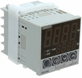
Терморегулятор Omron E5CWL — базовый электронный регулятор температуры, который используется в сушильных шкафах и печах под маркой СНОЛ. Прибор обладает двухстрочным дисплеем с отображением заданной и текущей температуры на экране. Отличительные особенности терморегулятора Omron E5CWL:
— автонастройка параметров прибора;
— напряжение питания 100-240AC;
— высокая частота дискретизации: 250 мс;
— 2 Пид регулирование;
— размер панели 48х48х60;
— работа с термопарами типа: «J», «K», «T»,»S», «R»;
— сверхчеткий семисегментный дисплей высотой их на экране размером 16,2 мм.
Инструкцию на русском языке к терморегулятору Omron E5CWL Вы можете запросить связавшись с нашими менеджерами.
| Модели регуляторов | |
| E5CWL-R1TC | тип датчика — термопара, релейный выход |
| E5CWL-R1P | тип датчика — термометр сопротивления, релейный выход |
| E5CWL-Q1TC | тип датчика — термопара, выход — напряжение |
| E5CWL-Q1P | тип датчика — термометр сопротивления, выход — напряжение |
Новые терморегуляторы Omron E5CSL и Omron E5CWL позволяют заметно снизить время настройки оборудования, т.к. позволяют пользователю сделать все настройки просто и быстро. Терморегуляторы E5CSL и E5CWL обеспечивают высокую производительность, что характерно всем терморегуляторам Омрон. Максимальная продолжительность и стабильность работы достигаются за счет функций автонастройки и ПИД-регулирования.

Основные особенности:
- Простая настройка несколькими нажатиями кнопок управления
- Уникальная технология Omron 2-ПИД регулирования и Автонастройка
- Время цикла контроля 250 мс
- Большой цифровой дисплей 16,7 или 21,7 мм, различимый с расстояния 5 м
- Компактный размер корпуса (глубина 60 мм)
Регуляторы температуры Omron E5CSL и E5CWL разработаны с учетом особенностей и технических требований для задач регулирования температуры в простых печах и упаковочных машинах.
Термоконтроллеры E5CSL (один дисплей)
| Размер | Напряжение питания, В | Тип датчика | Аварийный выход | Управляющий выход | Модель |
|---|---|---|---|---|---|
| 1/16 DIN 48 х 48 х 60 (W х Н х D) |
100 — 240 | Термопара | нет | Релейный | E5CSL-RTC |
| Термометр сопротивления | E5CSL-RP | ||||
| Термопара | Напряжение (для управления твердотельными реле) | E5CSL-QTC | |||
| Термометр сопротивления | E5CSL-QP |
Термоконтроллеры E5CWL (два дисплея)
| Размер | Напряжение питания, В | Тип датчика | Аварийный выход | Управляющий выход | Модель |
|---|---|---|---|---|---|
| 1/16 DIN 48 х 48 х 60 (W х Н х D) |
100 — 240 | Термопара | 1 | Релейный | E5CWL-R1TC |
| Термометр сопротивления | E5CWL-R1P | ||||
| Термопара | Напряжение (для управления твердотельными реле) | E5CWL-Q1TC | |||
| Термометр сопротивления | E5CWL-Q1P |
Аксессуары для регуляторов температуры Омрон
| Клеммная крышка | E53-COV19 |
| Крышка лицевой панели | E53-COV20 |
| Адаптер | Y92F-45 |
* Изображения служат только для ознакомления,
см. техническую документацию
Добавить в корзину 1 шт.
на сумму 87 440 руб.
Номенклатурный номер: 8005889289
Страна происхождения: КИТАЙ
Бренд / Производитель: Omron

Описание
Industrial Automation and ControlsControllers — Process, Temperature
Контроллер температуры (RTD) 100 ~ 240 В переменного тока для монтажа на панели
Технические параметры
| Control Method | On/Off, Proportional (PID) |
| Display Characters — Height | 0.638″» (16.20mm) |
| Display Type | LED — Dual Color Characters |
| ECCN | EAR99 |
| HTSUS | 9032.10.0090 |
| Ingress Protection | IP50 — Dust Protected |
| Input Range | -200В°C ~ 850В°C |
| Moisture Sensitivity Level (MSL) | 1 (Unlimited) |
| Mounting Type | Panel Mount |
| Number of Characters Per Row | 4, 4 |
| Operating Temperature | -10В°C ~ 55В°C |
| Output Type | Relay (2) |
| Package | Box |
| Panel Cutout Dimensions | Square — 45.00mm x 45.00mm |
| RoHS Status | RoHS Compliant |
| Series | E5CWL -> |
| Termination Style | Screw Terminal |
| Type | Temperature Controller (RTD) |
| Voltage — Supply | 100 ~ 240VAC |
| Weight | 0.221 lb (100.24 g) |
Техническая документация
Сроки доставки
Доставка в регион Курск
| Магазин «ЧИП и ДИП» | 5 июля1 | бесплатно |
| ПВЗ Boxberry | 3 июля1 | бесплатно |
| ПВЗ СДЭК | 4 июля1 | бесплатно |
| ПВЗ Л-Пост | 4 июля1 | бесплатно |
| ПВЗ 5Post | 5 июля1 | бесплатно |
| Почта России | 12 июля1 | бесплатно |
| Курьер | 4 июля1 | 416 руб.2 |
| ТК DPD | 3 июля1 | 546 руб.2 |
| ТК «Деловые линии» | 4 июля1 | 824 руб.2 |
Цена и наличие в магазинах
| ул. Карла Маркса, 68, ТЦ «Мега Гринн», 1 этаж | нет в наличии |