-
Contents
-
Table of Contents
-
Troubleshooting
-
Bookmarks
Quick Links
Manual No.
TOEPC71060605-02-OY
VARISPEED V7
Compact Sensorless Vector Inverter
USER’S MANUAL
Related Manuals for Omron VARISPEED V7
Summary of Contents for Omron VARISPEED V7
-
Page 1
Manual No. TOEPC71060605-02-OY VARISPEED V7 Compact Sensorless Vector Inverter USER’S MANUAL… -
Page 2: General Precautions
Such modifications are indicated by revising the manual number. • To order a copy of this manual, or if your copy has been damaged or lost, contact your OMRON representative. • OMRON YASKAWA is not responsible for any modification of the product…
-
Page 3: Notation For Safety Precautions
NOTATION FOR SAFETY PRECAUTIONS Read this instruction manual thoroughly before installation, operation, mainte- nance, or inspection of the V7AZ. In this manual, safety precautions are classi- fied as either warnings or cautions and are indicated as shown below. WARNING Indicates a potentially hazardous situation which, if not avoided, may result in death or serious injury.
-
Page 4
Confirm that all indicators are OFF before proceeding. • Do not perform a withstand voltage test on any part of the Inverter. The Inverter is an electronic device that uses semiconductors, and is thus vul- nerable to high voltage. -
Page 5
CAUTION (Ref. page) • Lift the Inverter by the heatsinks. When moving the Inverter, never lift it by the plastic case or the terminal cover. Otherwise, the main unit may fall and be damaged. • Mount the Inverter on nonflammable material (i.e., metal). -
Page 6
Failure to observe this warning may result in an elec- tric shock or a fire. • For 400 V Class, make sure to ground the sup- ply neutral. Failure to observe this warning may result in an elec- tric shock or a fire. -
Page 7
• Verify that the Inverter rated voltage coincides with the AC power supply voltage. Failure to observe this caution may result in personal injury or a fire. • Do not perform a withstand voltage test on the Inverter. Performing withstand voltage tests may damage semiconductor elements. -
Page 8
OPERATION WARNING (Ref. page) • Only turn ON the input power supply after con- firming that the Digital Operator or blank cover (optional) are in place. Do not remove the Digital Operator or the covers while current is flowing. Failure to observe this warning may result in an elec- tric shock. -
Page 9
WARNING (Ref. page) • If an alarm is reset with the operation signal ON, the Inverter will restart automatically. Reset an alarm only after verifying that the operation sig- nal is OFF. Failure to observe this warning may result in injury. -
Page 10
CAUTION (Ref. page) • If using an Inverter with an elevator, take safety measures on the elevator to prevent the eleva- tor from dropping. Failure to observe this caution may result in injury. • Do not perform signal checks during operation. -
Page 11
WARNING (Ref. page) • Never touch high-voltage terminals on the Inverter. Failure to observe this warning may result in an elec- trical shock. • Disconnect all power before performing mainte- nance or inspection, and then wait at least one minute after the power supply is disconnected. -
Page 12
Failure to observe this caution may result in injury. OTHERS WARNING • Never modify the product. Failure to observe this warning may result in an electrical shock or injury and will void the guarantee. CAUTION • Do not subject the Inverter to halogen gases, such as fluorine, chlorine, bromine, and iodine, at any time even during trans- portation or installation. -
Page 13: Warning Label
WARNING LABEL A warning label is provided on the front cover of the Inverter, as shown below. Follow the warnings when handling the Inverter. Plastic Case Status Indicators Nameplate Warning Label Location Certification Mark Warning Labels FPST31042-8 FPST31042-74 Example of 5.5 kW for 400 V…
-
Page 14: Table Of Contents
Test Run — — — — — — — — — — — — — — — — — — — — — — — — — — — — — — — — — — — — — -…
-
Page 15
6 Programming Features — — — — — — — — — — — — — — — — — — 52 Hardware — — — — — — — — — — — — — — — — — — — — — — — — — — — — — — — — — — 52… -
Page 16
Slip Compensation (n002 = 0) — — — — — — — — — — — — — — — — — — 135 Motor Protection — — — — — — — — — — — — — — — — — — — — — — — — — — — — — — — — 136… -
Page 17
Software No. Display — — — — — — — — — — — — — — — — — — — — — — — — — 178 Display List — — — — — — — — — — — — — — — — — — — — — — — — — — — — — — — — 179… -
Page 18
10 Conformance to CE Markings — — — — — — — — — — — — 247 CE Markings — — — — — — — — — — — — — — — — — — — — — — — — — — — — — — — — — — 247… -
Page 19: Receiving The Product
After unpacking the V7AZ, check the following. • Verify that the model number matches your purchase order or packing slip. • Check the Inverter for physical damage that may have occurred during shipping. If any part of V7AZ is missing or damaged, call for service immediately.
-
Page 20: Checking The Nameplate
Inverter Software Version The inverter software version can be read out from the monitor parameter U-10 or parameter n179. The parameter shows the last for digits of the software number (e.g. display is“5740”for the software version VSP015740). The manual describes the functionality of the Inverter software version VSP015740 (0.1 to 4.0 kW) and VSP105750 (5.5 and 7.5 kW).
-
Page 21: Identifying The Parts
(without potentiometer) In models without a JVOP-140 JVOP-147 Digital Operator, the Used for setting or Used for setting or blank cover is mounted changing constants. changing constants. in place of the Digital Frequency can be set Operator. using the potentiometer.
-
Page 22
Voltage/Current Change Switch for Analog Frequency Reference Input Short-circuit Control Circuit Terminal Block Main Circuit Terminal Block Ground Terminals Example for 3-phase (200 V Class, 1.5 kW) Inverter Frequency-setting Potentiometer Inverter Operation Status Indicators Terminal Resistor Switch for Communication Circuit Input Polarity… -
Page 23
Main Circuit Terminal Arrangement The terminal arrangement of the main circuit terminals depends on the Inverter model. CIMR-V7AZ20P1 to 20P7, B0P1 to B0P4 CIMR-V7AZ21P5, 22P2, B0P7, B1P5, 40P2 to 42P2 CIMR-V7AZ24P0, B2P2, 43P0, 44P0 CIMR-V7AZB4P0 CIMR-V7AZ25P5, 27P5, 45P5, 47P5 R/L1 S/L2 T/L3… -
Page 24: Mounting
• Extreme cold and heat. Use only within the specified ambient tem- perature range: −10 to 50 °C (14 to 122 °F) for IP20 (open chassis type), −10 to 40 °C (14 to 105 °F) for NEMA 1 (TYPE 1) •…
-
Page 25: Mounting Dimensions
7.5 kW • Lift the Inverter by the heatsinks. When moving the CAUTION Inverter, never lift it by the plastic case or the termi- nal cover. Otherwise, the main unit may fall and be damaged. • The V7AZ generates heat. For effective cooling,…
-
Page 26: Mounting/Removing Components
NOTE Enclosed Wall-mounted (NEMA 1) Inverters. • Always remove the top and bottom covers before install- ing a 200 or 400 V Class Inverter with an output of 5.5/7.5 kW in a panel. Mounting/Removing Components Removing and Mounting the Digital Operator and Covers…
-
Page 27: Mounting The Terminal Cover
Removing the Digital Operator After removing the front cover, (fol- low the procedure on page 25) lift the upper and lower sides (section C) of the right side of the Digital Operator in direction 1.
-
Page 28: Mounting The Bottom Cover
3 Mounting Removing the Bottom Cover • 200 V class Inverters with 1.1 kW and more and all 400 V class Inverters: After removing the front cover and the terminal cover, tilt the bottom cover in direction 1 with section A as a supporting point.
-
Page 29: Wiring
• When wiring the emergency stop circuit, check the wiring thoroughly before operation. Failure to observe this warning may result in injury. • For the 400 V Class, make sure to ground the supply neutral. Failure to observe this warning may result in an electric shock or a fire.
-
Page 30
Inverter carrier frequency. For details, refer to Carrier Frequency Selection (n080)14kHz max on page 3. Control wiring must be less than 50 m (164 ft) in length and must be separated from power wiring. Use shielded twisted-pair cable when inputting the frequency signal externally. -
Page 31: Wire And Terminal Screw Sizes
× Wire resistance (Ω/km) × Wiring distance (m) × Current (A) × 10 Select a wire size so that voltage drop will be less than 2% of the normal rated voltage. 7. If the Inverter is connected to a power transformer exceed-…
-
Page 32
, +1, +2, B1, B2, (22.13) 25P5 U/T1, V/T2, W/T3 CIMR- R/L1, S/L2, T/L3, — 5.5 to 8 10 to 8 V7ΑΖ , +1, +2, B1, B2, (22.13) 27P5 U/T1, V/T2, W/T3 Note: The wire size is given for copper wire at 75°C (160°F). -
Page 33
+2, B1, B2, U/T1, B4P0 V/T2, W/T3 1.2 to 1.5 2 to 8 14 to 8 (10.65 to 13.31) Note: 1. The wire size is given for copper wire at 75°C (160°F). 2. Do not use terminal T/L3 on Inverters with single-phase input. -
Page 34
-, +1, +2, B1, B2, (12.39) 45P5 U/T1, V/T2, W/T3 CIMR- R/L1, S/L2, T/L3, 5.5 to 8 10 to 8 V7ΑΖ -, +1, +2, B1, B2, (22.13) 47P5 U/T1, V/T2, W/T3 Note: The wire size is given for copper wire at 75°C (160°F). -
Page 35: Wiring The Main Circuits
Always connect the power supply line to input terminals R/L1, S/L2, and T/L3. Never con- nect them to terminals U/T1, V/T2, W/T3, B1, B2, −, +1, or +2. The Inverter may be dam- aged if the wrong terminals are connected.
-
Page 36
• Inverter Output Connect the motor terminals to U/T1, V/T2, and W/T3. • Wiring the Main Circuit Terminals Pass the cables through the wiring hole to connect them. Always mount the cover in its original position. Connect with a Phillips screwdriver. -
Page 37: Wiring The Control Circuits
Refer to pages 126 and 142 for SW2. Wiring the Control Circuit Terminals Screwdriver Blade Width 2.5 mm max 0.4 mm max (0.098 in.) (0.016 in.) Insert the wire into the lower part of the terminal block and connect it tightly with a screwdriver.
-
Page 38: Wiring Inspection
• Refer to Page 30 for tightening torques. 5.5 mm (0.22 in.) The wire sheath strip length must be 5.5 mm (0.22 in.). Open the front cover and verify that the strip length is 5.5 mm (0.22 in.). 5.5mm Scale…
-
Page 39: Operating The Inverter
5 Operating the Inverter The Control Mode Selection (n002) is initially set to V/f control mode. • Only turn ON the input power supply after confirm- WARNING ing that the Digital Operator or blank cover (optional) are in place. Do not remove the Digital Operator or the covers while current is flowing.
-
Page 40: Test Run
= 1 — Enables Frequency Reference 1 (constant n024). Selection = 2 — Enables a voltage reference (0 to 10 V) at the control circuit terminal. = 3 — Enables a current reference (4 to 20 mA) at the control circuit terminal.
-
Page 41
PRGM ALARM 3. Set the following constants. PRGM n019: 15.0 (acceleration time) 15.0 n020: 5.0 (deceleration time) ALARM 4. Select forward or reverse run by press- key. (Forward) ALARM Never select REV when reverse run is prohibited. NOTE (Reverse) 60.00 5. -
Page 42: Selecting Rotation Direction
5 Operating the Inverter Selecting Rotation Direction It is possible to select the direction in which the motor rotates when the Forward Run Command is executed. The motor rotates in the opposite direction when the Reverse Run Com- mand is executed.
-
Page 43: Operating The Digital Operator
CN2-2: Operator circuit terminal (current reference) CN2-1: Operator circuit terminal (voltage reference) * For details, refer to Operator Analog Speed Reference Block Diagram on page 167. Details of Indicators (Color in parenthesis indicates the color of the indicator.) FOUT FREF…
-
Page 44: Description Of Status Indicators
ALARM The following table shows the relationship between the Inverter condi- tions and the indicator on the RUN button of the Digital Operator as well as the RUN and ALARM indicators on the face of the V7AZ. The indicators are lit, unlit or flashing reflecting the order of priority.
-
Page 45
For details on how the status indicators function for Inverter faults, refer to Chapter 8 Fault Diagnosis. If a fault occurs, the ALARM indicator will light. The fault can be reset by turning ON the Fault Reset signal NOTE (or by pressing the… -
Page 46: Function Indicator Description
5 Operating the Inverter Function Indicator Description By pressing on the Digital Operator, each of the function indi- cators can be selected. The following flowchart describes each function indicator. Power ON Frequency reference setting/monitoring (Hz) Sets V7AZ operating speed. Output frequency monitoring (Hz)
-
Page 47: Mntr Multi-Function Monitoring
If n001=5, a Run Command can be received even WARNING while changing a constant. If sending a Run Com- mand while changing a constant, such as during a test run, be sure to observe all safety precautions. Failure to observe this warning may result in injury.
-
Page 48
* 3. The display range is from −99.9 to 99.99 kW. When regenerating, the output power will be displayed in units of − 0.01 kW when 9.99 kW or less and in units of 0.1 kW when more − than 9.99 kW. -
Page 49: Input/Output Terminal Status
In vector control mode, “—” will be displayed. * 4. Applicable only for Inverters of 5.5 kW and 7.5 kW (200 V and 400 V Classes). * 5. Refer to the next page for data reception error. * 6. Displayed in units of 0.1% when less than 100% and in units of 1% when 100% or more.
-
Page 50
Fault History Display Method When U-09 is selected, a four-digit box is displayed. The three digits from the right show the fault description, and the digit on the left shows the order of fault (from one to four). Number 1 represents the most recent fault, and numbers 2, 3, 4 represent the other faults, in ascending order of fault occurrence. -
Page 51: Simple Data Setting
Digital setting (refer to 5 Operating the Inverter) and potentiometer set- ting are both possible for simple acceleration/deceleration operation of the V7AZ. Digital setting is set at the factory (n004=1). For the model with JVOP- 140 Digital Operator (with potentiometer), factory setting is set by a fre- quency-setting potentiometer (n004=0).
-
Page 52
Data Setting by Frequency-setting Potentiometer Operation Steps Operator Function Status Display Indicators Indicators 1. Turn the potentiometer fully to the left. 0.00 FREF Then, turn the power ON. ALARM 2. F/R flashes. Select FWD/REV Run using keys. ALARM Never select REV when reverse NOTE run is prohibited. -
Page 53: Programming Features
6 Programming Features Factory settings of the constants are shaded in the tables.After wiring is complete, be sure to make the following settings before operation. Hardware Make the following settings before the Inverter is turned ON. Item Ref. page Sequence input signal (S1 to S7) polarity selection…
-
Page 54: Constant Setup And Initialization
Failure to observe this warning may result in injury. The following table lists the data that can be set or read when n001 is set. By setting this constant, the fault history can be cleared and the con- stants initialized.
-
Page 55
(n050 to n056) are the same 2. If the following conditions are not satisfied in the V/f pat- tern setting: Max. Output Frequency (n011) ≥ Max. Voltage Output Frequency (n013) > Mid. Output Frequency (n014) ≥ Min. Output Frequency (n016) Note: Mid. -
Page 56: Using V/F Control Mode
Adjust motor torque by using the V/f pattern and full-range automatic torque boost settings. V/f Pattern Setting Set the V/f pattern in n011 to n017 as described below. Set each pattern when using a special motor (e.g., high-speed motor) or when requiring special torque adjustment of the machine.
-
Page 57
* 10.0 V (20.0 V) for Inverters of 5.5 kW and 7.5 kW (200 V and 400 V Classes). -
Page 58
6 Programming Features Typical Setting of the V/f Pattern Set the V/f pattern according to the application as described below. For 400-V Class Inverters, the voltage values (n012, n015, and n017) should be doubled. When running at a frequency exceeding 50/60 Hz, change the Maximum Output Frequency (n011). -
Page 59
Gain (n103, factory setting: 1.0). When the wiring distance between the Inverter and the motor is long, or when the motor generates vibration, change the automatic torque boost gain. In these cases, set the V/f pat- tern (n011 to n017). -
Page 60: Using Vector Control Mode
Vector control requires motor constants. The factory settings constants have been set at the factory prior to shipment. Therefore, when a motor designed for an Inverter is used or when a motor from any other manu- facturer is driven, the required torque characteristics or speed control characteristics may not be maintained because the constants are not suit- able.
-
Page 61: Motor Constant Calculation
• If the speed is less than the target value, increase the slip compensa- tion gain. • If the speed is more than the target value, reduce the slip compensa- tion gain. Adjustment of the Slip Compensation Time Constant (n112) is normally not required.
-
Page 62: V/F Pattern During Vector Control
Line-to-neutral Resistance), and n110 (Motor No-load Current) accord- ing to the motor test report. To connect a reactor between the Inverter and the motor, set n108 to the sum of the initial value of n108 (Motor Leakage Inductance) and the externally mounted reactor inductance.
-
Page 63: Switching Local/Remote Mode
When operating with a frequency larger than 60/50 Hz, change only the Max. Output Frequency (n011). Constant output or Constant torque variable output n012 =200 V Base point n013 n011 =60 or 50 Hz =90 Hz Switching LOCAL/REMOTE Mode The following functions can be selected by switching LOCAL or REMOTE mode.
-
Page 64: How To Select Local/Remote Mode
LOCAL Mode When Lo (local mode) is selected for Digital Operator mode, or when the LOCAL/REMOTE switching function is set and the input terminals are turned ON, run operation is enabled by the STOP…
-
Page 65: Remote Mode
2 (Factory setting) • For an example of three-wire sequence, refer to page 112. • For more information on how to select the sequence polarity, refer to page 226. Note: When the Inverter is operated without the Digital Operator, always set constant n010 to 0.
-
Page 66: Local Mode
Factory setting of models with the Digital Operator with a potentiometer (JVOP-140) is n004=0. =2: Enables a voltage reference (0 to 10 V) (refer to the figure on page 65). =3: Enables a current reference (4 to 20 mA) (refer to page 126).
-
Page 67: Setting Operation Conditions
Autotuning Selection (n139) Motor data required for vector control can be measured and set by inputting the data from the nameplate of the motor to be used and per- forming autotuning for the motor. Autotuning is possible only for motor…
-
Page 68
• Rotational Autotuning (n139 = 1) Rotational autotuning is used only for open-vector control. Set n139 to 1, input the data from the nameplate, and then press the RUN key on the Digital Operator. The Inverter will stop the motor for approximately 1 minute and then set the required motor constants automatically while operating the motor for approximately 1 minute. -
Page 69
• When speed precision is required at high speeds (i.e., 90% of the rated speed or higher), use a motor with a rated voltage that is 20 V less than the input power supply voltage of the Inverter for 200V- class Inverters and 40 V less for 400V-class Inverters. -
Page 70: Operating Procedure
NOTE voltage × 0.9. 2. When operating at high speeds (i.e., 90% of the rated speed or higher), the output current will increase as the input power supply voltage is reduced. Be sure to provide sufficient margin in the Inverter current.
-
Page 71
Base frequency − Rated speed × Number of poles / 120 When performing precision setting (i.e., when performing autotun- ing using a motor test report or design data), the input data to set when autotuning will differ. Refer to the table below. Name… -
Page 72
DSPL tuning. Error Processing during Autotuning • Errors and alarms that occur during normal operation are also detected during autotuning. • If an error or alarm occurs, the motor will coast to a stop (baseblock) and autotuning will be cancelled. -
Page 73
• If autotuning is cancelled, constants changed by autotuning will auto- matically return to their values before the start of autotuning. • If an error occurs while decelerating to a stop at the end of autotun- ing, an error will be displayed on the Digital Operator, but autotuning processing will not be cancelled. -
Page 74
6 Programming Features Digital Operator Displays during Autotuning Function indicators on the Digital Operator change during autotuning as in the following diagram. Function Indicators Set constants required for autotuning. PRGM • Maximum Voltage • Maximum Voltage Frequency • Motor Rated Current •… -
Page 75: Reverse Run Prohibit (N006)
Description Reverse run enabled. Reverse run disabled. Multi-step Speed Selection Up to 17 speed steps (including Jog frequency reference) can be set using the following combinations of frequency reference and input ter- minal selections. 8-step speed change n054=6 (Multi-function contact input terminal S5)
-
Page 76: Operating At Low Speed
= 8 (Input terminal S7) (Change the setting to 8.) 16-step speed operation Set frequency references 9 to 16 for n120 to n127. Set the input terminal for a multi-step speed reference using the multi- function input selection. Operating at Low Speed By inputting a Jog Command and then a Forward (Reverse) Run Com- mand, operation is enabled at the jog frequency set in n032.
-
Page 77: Adjusting Speed Setting Signal
* Factory setting: 100% 2. Analog Frequency Reference Bias (n061) The frequency reference provided when the analog input is 0 V (4 mA or 0 mA) can be set in units of 1%. (Max. Output Frequency n011=100%) * Factory setting: 0% Typical Settings •…
-
Page 78: Adjusting Frequency Upper And Lower Limits
When operating at a frequency reference of 0, operation is continued at the frequency reference lower limit. However, if the frequency reference lower limit is set to less than the Minimum Output Frequency (n016), operation is not performed. Factory setting: 0%…
-
Page 79
By setting a multi-function input selection (any one of n050 to n056) to 11 (acceleration/deceleration time selection 1) or 27 (acceleration/ deceleration time selection 2), the acceleration/deceleration time is selected by ON/OFF combinations of acceleration/deceleration time selection 1 and acceleration/deceleration time selection 2 (terminals S1 to S7). -
Page 80: Momentary Power Loss Ridethrough Method (N081)
Note: Constant n018 can be set while stopped. If a value exceeding 600.0 s is set for the acceleration/deceleration time when n018=0 (in units of 0.1 s), 1 cannot be set for n018. • Acceleration time Set the time needed for the output frequency to reach 100% from 0%.
-
Page 81: S-Curve Selection (N023)
* 1. Hold the operation signal to continue operation after recovery from a momentary power loss. * 2. When 2 is selected, the Inverter restarts if power supply voltage recovers while the control power supply is held. No fault signal is output.
-
Page 82: Torque Detection
6 Programming Features Torque Detection If an excessive load is applied to the machine, an increase in the output current can be detected to output an alarm signal to multi-function out- put terminal MA, MB, P1, or P2. To output an overtorque detection signal, set one of the output terminal function selections n057 to n059 for overtorque detection (Setting: 6 (NO contact) or 7 (NC contact)).
-
Page 83: Frequency Detection Level (N095)
Overtorque/Undertorque Detection Function Selection 2 (n097) When vector control mode is selected, overtorque/undertorque detec- tion can be performed either by detecting the output current or the out- put torque. When V/f control mode is selected, the setting of n097 is invalid, and overtorque/undertorque is detected by the output current.
-
Page 84: Frequency Detection
6 Programming Features (Set n057, n058 or n059 to 4.) Release Width −2Hz Frequency Detection Level [Hz] (n095) Output Frequency Frequency Detection Signal Frequency Detection 2 Output frequency ≤ Frequency Detection Level n095 (Set n057, n058 or n059 to 5.)
-
Page 85: Jump Frequencies (N083 To N086)
Inverter should restart.) Failure to observe this warn- ing may result in injury. The Inverter can be set to restart and reset fault detection after a fault occurs. The number of self-diagnosis and retry attempts can be set to up to 10 in n082.
-
Page 86: Frequency Offset Selection (N146)
6 Programming Features Frequency Offset Selection (n146) An offset frequency (which can be set with a constant) can be added to or subtracted from the frequency reference using multi-function inputs. Constant Name Description Factory Setting n083 Jump Frequency 1 1st digit of n146 is 0 or 1: 0.00 Hz…
-
Page 87
0. • If the 1st digit “x” of Frequency Offset Selection (n146) is 0 (fre- quency offsets disabled), the set values of constants n083 to n085 will function as jump frequencies. -
Page 88
6 Programming Features • If the 1st digit “x” of Frequency Offset Selection (n146) is 1 or 2 (fre- quency offsets enabled), the set values of constants n083 to n085 will function as frequency offsets. • In order to activate the offset frequencies 1 to 3 of the Multi-function Input Selections (n050 to n056) must be programmed to 30, 31 or 33. -
Page 89: Operating A Coasting Motor Without Tripping
15 (Search Command from set frequency). Build a sequence so that a FWD (REV) Run Command is input at the same time as the Search Command or after the Search Command. If the Run Command is input before the Search Command, the Search Com-…
-
Page 90: Holding Acceleration/Deceleration Temporarily
Operation The deceleration time for speed search operation can be set in n101. If the setting is 0, however, an initial value of 2.0 s will be used. The speed search starts when the Inverter’s output current is greater than or equal to the speed search operation level (n102).
-
Page 91: External Analog Monitoring(N066)
Agree Signal Note: If a FWD (REV) Run Command is input at the same time as an Acceler- ation/Deceleration Hold Command, the motor will not operate. How- ever, if the Frequency Reference Lower Limit (n034) is set to a value greater than or equal to the Min.
-
Page 92: Calibrating Frequency Meter Or Ammerter (N067)
6 Programming Features In factory setting, analog voltage of approx. 10 V is output when output frequency (output current) is 100 %. Output Frequency (Output Current) Frequency Meter 100 % Analog monitor gain can be set by n067. 10 V…
-
Page 93
12F: Output frequency × 12 24F: Output frequency × 24 36F: Output frequency × 36 Data Output 0 to 14,400 Hz output (MEMO- via Communi- BUS register No.000AH) (1 Hz/ cations Note: Enabled only when n065 is set to 1 (pulse monitor output). -
Page 94
6 Programming Features At the factory setting, the pulse of 1440 Hz can be output when output frequency is 100 %. Output Frequency 100 % Pulse AC (0 V) 1440 Hz Pulse Monitor Output Peripheral devices must be connected according to the fol- lowing load conditions when using pulse monitor output. -
Page 95: Carrier Frequency Selection (N080)14Khz Max
24 fout (Hz) 36 fout (Hz) Higher Smaller 2.5 (kHz) 5.0 (kHz) Larger audible 7.5 (kHz) 10.0 (kHz) 14 (kHz) Note: When the carrier frequency has been set to 14 kHz, use a MEMOBUS baud rate of 4,800 bps or lower.
-
Page 96
6 Programming Features If the set value is 7, 8, or 9, the carrier frequency will be multiplied by the same factor as the output frequency. n080=7 fc=Carrier Frequency 2.5 kHz fc=12 fout 1.0 kHz fout=Output Frequency 83.3 Hz 208.3 Hz… -
Page 97
The factory setting depends on the Inverter capacity (kVA). Voltage Capacity Factory Setting Maximum Reduced Continu- Class (V) (kW) Continuous Current ous Output Output Current Current (A) (Reduction Output Current) Setting Carrier FC = Frequency 14 kHz (kHz) 200 V Sin- 0.7 (88%) -
Page 98
7, 8, 9) 3. Set the Carrier Frequency Selection (n080) to 1, 2, 3, or 4 when using vector control mode. Do not set it to 7, 8, or 9. 4. If the Inverter repeatedly stops and starts with a load… -
Page 99: Operator Stop Key Selection (N007)
Reducing Carrier Frequency Selection at Low Speed (n175) is set to 0 (disabled). 7. When the carrier frequency is set to 14 kHz, the following functions will be disabled: • Fast digital input (START/STOP) •…
-
Page 100: Second Motor Selection
Motor 2 Rated Slip 0.1 Hz 0.0 to 20.0 Hz Note: Not initialized when constants are initialized. * 1. Upper limit of setting range and factory setting are doubled for 400-V Class Inverters. * 2. Depends on Inverter capacity.
-
Page 101
7: Overtorque detection (NC contact output) 8: Undertorque detection (NO con- tact output) 9: Undertorque detection (NC con- tact output) 10: Minor fault (Alarm is indicated) 11: Base blocked 12: Operating mode 13: Inverter operation ready 14: Fault retry 15: UV… -
Page 102
Motor Selection Monitor (Motor 2 selected when closed.) Note: Switching of motor 1 and motor 2 as well as checking motor status should be performed using an external sequence. • By setting one of the constants from n050 to n056 (Multi-function Input Selections) to 28 (Motor Switching Command) and by opening and closing the input signal when stopped (i.e. -
Page 103
Motor Constant Table (New Parameters are shown in bold letters) Motor Switching Command Open Closed (Motor 1 Selected) (Motor 2 Selected) Control Mode n002 V/f control must be used. Selection n011: Maximum Output Fre- n140: Motor 2 Maximum Out- Characteristics… -
Page 104
1 with an output cur- rent of 0.0 A. If motor 2 is selected, output current detection data will be calculated for motor 2 with the actual output current, and output current detection data will be calculated for motor 1 with an output current of 0.0 A.) -
Page 105
If constant n037 is set to 3 (standard motor, motor 1 only) or 4 (special motor, motor 1 only), however, OL1 calculations for motor 1 will always be performed, regardless of the status of the Motor Switching Command. (Regardless of whether motor 1 or motor 2 is selected, out-… -
Page 106
Fre- quency Reference Upper Limit (n033). Example: If n011 = 60 Hz, n140 = 50 Hz, and n033 = 100%, opera- tion will be at 50 Hz when a multi-step speed reference of 60 Hz is mistakenly input when motor 2 is selected. -
Page 107: Selecting The Stopping Method
If the FWD/REV Run Command is turned ON after turning the Motor Switching Command ON (or OFF) but before the Motor Selection Mon- itor turns ON (or OFF), Inverter output will begin immediately after the Motor Selection Monitor turns ON (or OFF).
-
Page 108: Applying Dc Injection Braking
DC Injection Braking Time at Stop (n090) Sets the DC injection braking time at stopping in units of 0.1 s. When the setting of n090 is 0, DC injection braking is not performed, but the Inverter output is turned OFF when DC injection braking is started.
-
Page 109
(less than maximum output frequency) until decelerating to a stop, are the same. (Control is performed to stop at the same position when the Run Command is input from a sequence input terminal regardless of the output frequency.) -
Page 110
Deceleration 1: No stall prevention (when a brak- ing resistor is installed) Note: If Stall Prevention during De- celeration is used with simple positioning control, position- ing will not be performed prop- erly, so use a set value of 1. -
Page 111: Building Interface Circuits With External Devices
Building Interface Circuits with External Devices Using Input Signals The functions of multi-function input terminals S1 to S7 can be changed as necessary by setting constants n050 to n056. The same value cannot be set for more than one of these constants.
-
Page 112
Stopping Method Selec- Emergency stop alarm, tion (n005). When coast to NO contact input stop (n005 = 1) is selected, the Inverter coasts to stop. Emergency stop fault, Digital Operator displays NC contact input (flashing). -
Page 113
Do not set. FWD/REV Run 2 Command (2-wire sequence 2) * 1. For more information on how to select the sequence polarity, refer to page 226. * 2. Numbers 1 to 7 are displayed for to indicate the terminal numbers S1 to… -
Page 114
Operation can thus be performed at the desired speed. When Up/Down Commands are specified in n056, any function set in n055 is disabled, terminal S6 is the input terminal for the Up Command, and terminal S7 is the input terminal for the Down Command. -
Page 115
U1 = Up status, clamping at upper limit speed D1 = Down status, clamping at lower limit speed Note: 1. When Up/Down Commands are selected, the upper limit speed is set regardless of frequency reference. Upper limit speed = Maximum Output Frequency (n011) ×… -
Page 116
Digital Operator commands. Run Commands from communications and the frequency reference are effective when the multi-function input terminal for this setting is closed (register No. 0001H, 0002H). Run Commands in LOCAL/REMOTE mode and the frequency refer- ence are effective when the terminal is open. -
Page 117
(n056 <> 36) • Frequency reference method is changed (n004 setting) • n100 is changed from 0 to 1 • n100=0 and Run signal is • When n045= 0 and n047= 1 and S6/S7 are both set ON or OFF •… -
Page 118
6 Programming Features If n045 > 0 the frequency reference is changed in steps of n045 value Fref Reference changes n045 according to setting in n045 For n045=0, acceleration / deceleration rate is selected by n046: n046 = 0: Accel/Decel time 1 time (n019 / n020) -
Page 119
Frequency reference bias is changed by time n046 = 1 Use Acceleration / Deceleration time 4 n047 = 0 Bias value is held if S6, S7 are both ON or OFF n100 = 1 Bias value is saved to EEPROM FOUT (Hz) -
Page 120
6 Programming Features Up/Down Command 2 by step n056 = 36 Up/Down command 2 on S6 / S7 n003 = 1 Run command source is digital input n004 = 1 Main frequency reference input is n024 n045 = 5.00Hz Frequency reference bias is changed by step… -
Page 121: Using The Multi-Function Analog Inputs
Using the Multi-function Analog Inputs (n077, n078, n079) The input analog signal (0 to 10 V or 4 to 20 mA) for the CN2 terminal of the JVOP-140 Digital Operator can be used as an auxiliary function for the master frequency reference input to the control circuit terminals (FR or RP).
-
Page 122
6 Programming Features Multi-function Input Selection (n077) Name Unit Setting Factory Range Setting n077 Multi-function Input Selection 0 to 4… -
Page 123
When frequency reference 2 is select- reference (FREF2) ed using the multi-step speed referenc- es, the input analog signal for the CN2 terminal will be the frequency refer- ence. The n025 setting will be invalid. Note: Set the Frequency Reference Gain in n068 or n071, and the Frequency Ref- erence Bias in n069 or n072. -
Page 124
2.00 1.00 10 V 10 V (4 mA) (20 mA) (4 mA) (20 mA) 100%=Max. Output Frequency (n011) 3. Frequency Reference Bias (n077=3) 4. Output Voltage Bias (n077=4) VBIAS FBIAS 100 V n079 10 V (4 mA) (20 mA) -n079… -
Page 125: Using Output Signals (N057, N058, N059)
Using Output Signals (n057, n058, n059) The functions of multi-function output terminals MA, MB, P1 and P2 can be changed as necessary by setting constants n057, n058, and n059. • Terminal MA and MB functions: Set in n057 • Terminal P1 function: Set in n058 •…
-
Page 126
Closed during PID feedback loss. Frequency reference Closed during frequency reference loss loss. Inverter overheat alert Closed during Inverter overheat alert. monitor motor selection closed during select motor 2 Factory Settings Terminal Factory Setting n057 MA, MB 0 (fault) n058… -
Page 127: Setting Frequency By Current Reference Input
DIP switch SW2 on the con- trol circuit board to the “I” side. Never input a voltage reference to control circuit terminal FR NOTE when DIP switch SW2 is switched to the “I” side. The Inverter might be damaged.
-
Page 128
6 Programming Features Current Reference Selection After changing the DIP switch (V-I switch of SW2) to the “I” side, press on the Digital Operator, then set the following constants. PRGM Current reference (4 to 20 mA): constant n004 = 3 Current reference (0 to 20 mA): constant n004 = 4 •… -
Page 129: Frequency Reference By Pulse Train Input
Frequency Reference by Pulse Train Input Frequency reference can be set by pulse train input from the control cir- cuit terminals. • Input pulse specifications • Low-level voltage: 0.8 V or less • High-level voltage: 3.5 to 32 V • H duty: 30 % to 70 % •…
-
Page 130
1 for n050 to n056) works as a RUN/STOP command (i.e. it starts and stops the inverter operation). An “ERR” alarm will be displayed when it is tried to set the REV Run Command (set value: 2) and the FWD/REV Run 2 Command (set value: 37) simultaneously. -
Page 131: Two-Wire Sequence 2
2. Three-wire Sequence Multi-function input selection 1 (constant n050): 1 (Any setting) Multi-function input selection 2 (constant n051): 2 (Any setting) Multi-function input selection 3 (constant n052): 0 FWD Run FWD Run Output frequency REV Run S1 terminal: Run Command…
-
Page 132: Preventing The Motor From Stalling (Current Limit)
Factory setting: 170% A setting of 200% disables the stall prevention (current limit) during acceleration. If the output current exceeds the value set for n093 during acceleration, acceleration stops and the frequency is maintained. When the output current goes to the value set for n093, acceleration starts.
-
Page 133
100 ms, deceleration starts. If the output current exceeds the value set for n094, deceleration contin- ues. If the output current goes to the value set for n094, acceleration to the set frequency starts. -
Page 134: Stall Prevention During Operation
6 Programming Features Stall Prevention during Operation Stall Prevention above Base Speed during Run (n115) The stall prevention level can be decreased automatically in the constant output range. Constant Name Unit Setting Factory Range Setting n115 Stall Prevention above 0=Disabled…
-
Page 135
Stall Prevention during Setting Deceleration Provided Time Not provided (with braking Decel resistor mounted) Time Note: If Stall Prevention during Deceleration is used with simple positioning control, positioning will not be performed properly, so use a set value of… -
Page 136: Decreasing Motor Speed Fluctuation
Decreasing Motor Speed Fluctuation Slip Compensation (n002 = 0) As the load becomes larger, the motor speed is reduced and the motor slip value is increased. The slip compensating function controls the motor speed at a constant value even if the load varies.
-
Page 137: Motor Protection
The electronic thermal overload function monitors the motor tempera- ture based on Inverter output current and time to protect the motor from overheating. When the electronic thermal overload relay is enabled, an error occurs, and the Inverter output is turned OFF to prevent excessive overheating in the motor.
-
Page 138
50/ 60 Hz or less at 100% load. Operation Frequency (Hz) Base Frequency 60 Hz (V/f for 50 Hz, 220 V Input Voltage) For low-speed operation, torque must be limited in order to stop mo- tor temperature rise. Effective even… -
Page 139: Ptc Thermistor Input For Motor Overheat Protection
OH errors are detected according to the voltage in respect to the temperature-resistance characteristics of the PTC thermistor. After a motor OH alarm is detected (FR input > 0.94 V), operation con- tinues according to the n141 Motor Overheat Operation Selection (and the OH8 indicator on the Digital Operator will flash).
-
Page 140
Setting Range: 0.0 to 10.0 s Constant Note: When the analog signal (0 to 10 V) input into terminal FR is used as the motor overheat signal for the PTC thermistor input (FR) (when n141 is set to 1 or higher), the signal cannot be used as a frequency reference or for PID feedback. -
Page 141
When n128 (PID Control Selection) is set to a value other than 0 (with PID control), n164 (PID Feedback Value Selection) cannot be set to 0, 1, or 2 (feedback values of 0 to 10 V, 4 to 20 mA, or 0 to 20 mA, respectively). -
Page 142: Selecting Cooling Fan Operation
6 Programming Features Selecting Cooling Fan Operation In order to increase the life of the cooling fan, the fan can be set to oper- ate only when Inverter is running n039 = 0 (Factory setting): Operates only when Inverter is running (Continues operation for 1 minute after Inverter is stopped.)
-
Page 143: Communications Specifications
(to prevent noise malfunction). 3. When communication is performed through RS- 485, connect S+ and R+, S- and R- terminals outside the Inverter as shown at the right.
-
Page 144: Setting Constants Necessary For Communication
2. Turn the power ON. 3. Set the constants (n151 to n157) required for communication by using the Digital Operator. 4. Turn the power OFF once to verify that the Digital Operator displays have been completely erased. 5. Turn the power ON again.
-
Page 145: Message Format
0: RTS control 1: No RTS control (RS-422A: 1-to-1 communication) * The slave does not respond to the command from the master when set to 0. Monitoring run status from the PLC, setting/referencing of constants, Fault Reset and multi-function input reference can be done regardless of Run Command or frequency reference selection.
-
Page 146
Reads out the contents of the specified number of continuous hold- ing registers. The contents of each holding register is divided into the upper 8 bits and the lower 8 bits. They become the data items in the response message in numerical order. -
Page 147
Example: Reads out the status signal, fault contents, data link status, and fre- quency reference from the V7AZ (slave 2). Response Message Response Message Reference Message (at Normal Operation) (at Fault Occurrence) Slave address Slave address Slave address Function code… -
Page 148
Example: Set forward run at frequency reference 60.0 Hz to slave 1 V7AZ from the PLC. Response Message Response Message… -
Page 149
Setting range: 0 to 1100 0007H [0 to 11 V output/0 to 1100 (when Monitor Gain (n067) = 1.00)] Note: Enabled only when n065 is set to 0 (analog monitor output) and n066 is set to 8 (data output via communications). -
Page 150
7-D Digital Operator 7-segment LED 4th digit display data (ASCII) E-F (Not used) 000EH Reserved 001FH Note: Write in “0” for an unused bit. Never write in data for the reserved reg- ister. * Codes that cannot be expressed on 7-segment LEDs will be displayed as «−». -
Page 151
0002H (Data is converted into 0.01 Hz inside the Inverter, and fractions are rounded off.) Bit signals not defined as the broadcast operation signals are used as the local station data signals. • Monitor Data (available only for read out) -
Page 152
Overcurrent (OC) Overvoltage (OV) Inverter overload (OL2) Inverter overheat (OH) (Not used) (Not used) PID feedback loss (FbL) External fault (EF, EFO), Emergency stop (STP) 0021H Hardware fault (FXX) Motor overload (OL1) Overtorque detection (OL3) Undertorque detection (UL3) Power loss (UV1) -
Page 153
Input open phase (PF) Output open phase (LF) (Not used) Operation function stop (STP) Sequence error (SER) Simultaneous FWD/REV Run Commands (EF) External Baseblock (BB) Overtorque detection (OL3) Cooling fan overheat (OH) Main circuit overvoltage (OV) Main circuit undervoltage (UV) -
Page 154
Frequency reference loss 1: Frequency reference loss 002EH (Not used) 002FH- Reserved 0030H 0031H Main circuit DC voltage (1/1 V) 0032H Torque monitor (1/1 %; 100 %/Motor rated torque; with sign) 0033H- (Not used) 0036H 0037H Output Power (1/1 W: with sign) -
Page 155
Register Description PID feedback value (100 % /Input equivalent to max. output frequency; 0038H 10/1 %; without sign) 0039H PID input value (±100 %/±Max. output frequency; 10/1 %; with sign) 003AH PID output value (±100 %/±Max. output frequency; 10/1 %; with sign) -
Page 156: Storing Constants [Enter Command]
When a constant is written from the PLC by communications, the con- stant is written to the constant data area on the RAM in the V7AZ. The Enter Command is a command to write the constant data on the RAM to the non-volatile memory in the V7AZ.
-
Page 157
If the Enter Command is not used, how- ever, the value returns to the stored value when the power supply is turned ON again. Register number 0900H is used only for write-in. If this register is read- out, a register number error (error code: 02H) occurs. -
Page 158: Error Code
• Enter Command “0900H” (an exclusive-use register for write-in) was read out. Improper quantity • The number of data items to be read or written-in is not in the range between 1 and 16. • The number of data items in a message is not the value obtained by multiplying the quantity by two in the write-in mode.
-
Page 159: Performing Self-Test
In the self-test, connect the sending terminal with the receiving terminal in the communication section. It checks if the data received by V7AZ is not being changed. It also checks if the data can be received normally. Carry out the self-test in the following procedure.
-
Page 160: Using Pid Control Mode
6 Programming Features Using PID Control Mode For details on the PID control settings, refer to the block diagram of the Inverter’s internal PID control or the block diagram of the Operator ana- log speed reference. PID Control Selection (n128)
-
Page 161
Example: When the frequency reference from the control circuit terminal FR, with a voltage of 0 to 10 V, is selected as the target value and n004=2, and when at the same time the frequency reference from the control circuit terminal FR, with a current of 4 to 20 mA, is selected as the… -
Page 162
6 Programming Features 3. When using an analog signal (0 to 10 V/4 to 20 mA) input to the CN2 terminal of the JVOP-140 Digital Operator as the target or feedback value of PID control, do not use it as a multi-function analog input. -
Page 163
PID Offset Adjustment -100 to 100 Constant n133 adjusts the PID control offset. If both the target value and the feedback values are zero, adjust n133 so that the Inverter output frequency is zero. Primary Delay Time Constant for PID Output (n135) -
Page 164: Analog Position Control With Bi-Directional Pid Output
0.0 to 25.5 Loss Detection Time PID Upper Limit Sets the upper limit after PID control as a percentage of the maximum output frequency. Prohibition of PID Output Zero limit occurs when the PID output is negative. Analog Position Control with Bi-directional PID Output(n145)
-
Page 165: Bidirectional Reference Control
Input from a Multi-function Input = ON (Bi-directional Range Function Enabled): If the frequency reference is from 0% to 50% after PID control, the input rotation direction command will be reversed. If the reference is from 50% to 100%, operation will be performed without reversing the input rotation direction command.
-
Page 166
6 Programming Features • If PID Control Selection (n128) is set to 0 (disabled), or a PID cancel input using a multi-function input is ON (Bi-directional Range Func- tion Enabled): If the input frequency reference is from 0% to 50%, the input rotation direction command will be reversed. -
Page 168
6 Programming Features… -
Page 169: Using Constant Copy Function
(V/ f control or vector control). However, some constants may not be cop- ied. It is also impossible to copy constants between V7AZ and VS mini J7 Inverters. Prohibiting reading constants from the Inverter can be set in n177. The constant data cannot be changed when this constant is set.
-
Page 170
0. The constant data stored in the Digital Operator are safe from accidental overwriting. If reading is attempted while this constant is set to 0, PrE will flash. Press and return to the constant number display. -
Page 171: Read Function
READ Function Reads out the constants in batch from the Inverter and stores them in EEPROM inside the Digital Operator. When the read-out is executed, the previously stored constants data in the EEPROM are cleared and replaced with the newly entered constants.
-
Page 172
0 by pressing the key. • Press (Lit for one second.) ENTER ↓ (The constant number is displayed.) * 1. When reading is enabled (n177=1), this setting is not necessary. * 2. This setting is not necessary unless read-prohibition is selected. -
Page 173: Copy Function
(V/ f control or vector control). Therefore, writing from 200 V Class to 400 V Class Inverters (or vice versa), from V/f control mode to vector control mode Inverters (or vice versa), or from V7AZ to VS mini J7 Inverters is not possible.
-
Page 174
Inverter. If a constant error is found, the written constants are discarded and the constants stored before writing are restored. When a setting range error is found, the constant number where an error occurs is indicated by flashing. When an inconsistency in the settings is found, ( : a number) is indicated by flashing. -
Page 175: Verify Function
(V/f control or vector control). When the constants stored in the Digital Operator are the same as those in the Inverter, vFy will flash, and then End will be displayed.
-
Page 176
6 Programming Features Example: Comparing Constants Stored in EEPROM in Operator with Constants in Inverter Explanation Operator Display • Enable the set- • Press DSPL tings for con- (May be a different constant number) stants n001 to PRGM will light. -
Page 177: Inverter Capacity Display
While a constant number that is not the same is displayed or a constant value is displayed, press to interrupt the execution of the STOP/RESET verification. End will be displayed. Press to return ENTER DSPL to the constant number display.
-
Page 178
6 Programming Features * The following figure shows the Inverter Capacity Display. Voltage Class Single-phase 200 V Three-phase 200 V Three-phase 400 V Max. Applicable Motor Capacity 0.1 kW 0.25 kW 0.55 kW 1.1 kW 1.5 kW 2.2 kW 3.0 kW 4.0 kW… -
Page 179: Software No. Display
Software No. Display The software number of the Inverter for which constants are stored in the Digital Operator is displayed. Example: Displaying Software No. of Inverter for which Constants are Stored in EEPROM in Digital Operator Explanation Operator Display • Enable the •…
-
Page 180: Display List
Lit: A checksum error occurred in the constant Initialize the constants. If an error occurs data stored in the Inverter. again, replace the Inverter due to a failure of constant memory element (EEPROM) in the Inverter. Flashes: Attempt made to execute COPY or…
-
Page 181
If a communications error occurs during the READ operation or writing (COPY) operation, always re-execute the READ or COPY. Note: While rEd, CPy, or vFy is flashing, key input on the Digital Operator is disabled. While rEd, CPy and vFy are not flashing, pressing DSPL redisplays the constant number. -
Page 182: Customer Specific Display Scaling
Output Frequency Display (U-02) Setting/Displaying Unit Selection for Frequency Reference (n035) The frequency reference, output frequency, and the numeric data of fre- quency reference constants can be displayed in %, rpm, or m/min according to the set value of constant n035.
-
Page 183
Settings Setting Description • Setting unit: 0.01 Hz (below 100 Hz), 0.1 Hz (above 100 Hz ) • Setting in units of 0.1%: 100.0% at Fmax (n011) 2 to 39 • Setting in units of 1 rpm: (Set number of motor poles in n035) Display = 120 x frequency value [Hz] / number of motor poles •… -
Page 184: Selecting Processing For Frequency Reference Loss (N064)
6 Programming Features Note: 1. The frequency reference constants and monitor display data for which this selection of the unit is valid are stored in the Inverter in units of Hz. The units are converted as shown below: Frequency reference constants…
-
Page 185: Input/Output Open-Phase Detection
* 2. Not detected when set to 0.0 s. The recommended settings for input open-phase detection are n166=7 % and n167=10 s. (Open-phase cannot be detected correctly depending on the load status.) The recommended settings for output open-phase detection are n168=5 % and n169=0.2 s.
-
Page 186: Undertorque Detection
2. To continue operation after undertorque detection, set to 1 or 3. During detection, the operation displays the “UL3” alarm (flashing). 3. To halt the Inverter by a fault at undertorque detection, set to 2 or 4. At detection, the Operation displays the “UL3” fault (continuously…
-
Page 187
100 %. Factory setting=10 % Undertorque Detection Time (n119) If the time for which the motor current is less than the undertorque detection level (n118) is longer than the undertorque detection time (n119), the undertorque detection function operates. -
Page 188: Using Inverter For Elevating Machines
If the set value is too low, the motor torque is insufficient and the load may shift when the brake is applied. Be sure to set n095 to a value larger than that of the Minimum Output Frequency (n016) and larger than that of the braker releasing width shown in the following figure.
-
Page 189
Output Frequency Time n095 Frequency Detection Level 1 • Sequence Circuit Configuration and Timing Chart Examples For the AC sequence cir- Holding Brake cuit, connect the signal Inverter V7AZ Auxiliary Relay Coil between P1 and PC to the Fault Contacts MA… -
Page 190: Stall Prevention During Deceleration
Also, take safety measures such as protection against falls on the machine. Carrier Frequency Set the carrier frequency selection (n080) to 5 kHz or more (n080: 2 to 4 or 12) to secure the motor torque even if an overcurrent occurs (the cur- rent is limited).
-
Page 191: External Baseblock Signal
If the delay time for the holding brake’s mechanical operation is not taken into consideration and the acceleration/deceleration time on the Inverter side is set to a time that is too short, an overcurrent or wear on the brakes may occur at starting or the load will shift at stopping because the holding brake does not operate on time.
-
Page 192: Using Mechatrolink-Ii Communications
Using MECHATROLINK-II Communications MECHATROLINK-II can be used with the SI-T/V7 option unit. For details, refer to V7AZ OPTION UNIT MECHATROLINK COMMU- NICATIONS INTERFACE UNIT INSTRUCTIONS (TOBPC73060003). The following constants are used for communications error settings for SI-T/V7. Constant Name Unit…
-
Page 193: Maintenance And Inspection
OFF before proceeding. If the indicators are not OFF, the capacitors are still charged and can be dangerous. • Do not perform a withstand voltage test on any part of the V7AZ. The Inverter is an electronic device that uses semi- conductors, and is thus vulnerable to high voltage.
-
Page 194: Periodic Inspection
7 Maintenance and Inspection Periodic Inspection Periodically inspect the Inverter as described in the following table to prevent accidents and to ensure high performance with high reliability. Location to Check for Solution Check Terminals, In- Improper seating or Properly seat and tighten…
-
Page 195: Part Replacement
Part Replacement Inverter’s maintenance periods are given below. Keep them as guide- lines. Part Replacement Guidelines Part Standard Replacement Method Replacement Period Cooling fan 2 to 3 years Replace with new part. Smoothing capacitor 5 years Replace the Inverter unit with a new one.(Determine need by inspection.)
-
Page 196: Replacement Of Cooling Fan
Replacement of Cooling Fan Inverters of 200 V class, single-phase, 0.1 to 0.55, 2.2 and 4.0 kW, 200 V class, three-phase, 0.1 to 1.1 and 4.0 to 5.5 kW, 400 V class, three-phase, 3.0 to 7.5 kW: 1. Removal 1. Press the right and left catches…
-
Page 197
Inverters of 200 V class single-phase, 1.5 and 2.2 kW, 200 V class three-phase, 1.1 and 1.5 kW, 400 V class three-phase, 0.37 to 2.2 kW: 1. Removal 1. Remove the front cover and terminal cover, and then remove the cooling fan con- nector (CN10). -
Page 198: Fault Diagnosis
To reset the fault, turn ON the reset signal with the Run Command OFF or cycle the power after taking the corrective action. * Selecting «always ON» mode at fan operation selection, the power must be cycled to release the alarm display.
-
Page 199: Corrective Actions Of Models With Digital Operator
Corrective Actions of Models with Digital Operator : ON : Flashing : OFF Alarm Display Alarm Displays and Meaning Alarm Display Inverter Description Causes and Status Corrective Actions Digital RUN (Green) Operator ALARM (Red) Detected as UV (Main circuit low volt-…
-
Page 200
Corrective Actions Digital RUN (Green) Operator ALARM (Red) OH8 (Motor Overheat- Detected as • Check the size of the load an alarm and the length of the ing) only. Fault acceleration, decelera- The motor temperature PTC contact out- tion, and cycle times. -
Page 201
The Inverter’s output current cause. was less than the under- torque detection level (n118). When vector mode is select- ed: The output current or out- Flashing put torque was less than the detection level (n097 or n118). Operation when undertorque is detected will be determined by the setting in n117. -
Page 202
Command of control cir- stop) cuit terminals. was pressed during running via a control circuit terminal FWD/REV Run Command, or by a Run Com- mand from communications. The Inverter stops according Flashing to constant n005. Check the following: STP (Emergency stop) •… -
Page 203
• Wiring is made properly. FBL (PID feedback loss Check the mechanical sys- tem and correct the cause, or detection) increase the value of n137. PID feedback value dropped below the detection level (n137). When PID feedback… -
Page 204: Fault Display
* 1. Indicates that an Inverter of 5.5 kW and 7.5 kW (200 V and 400 V Classes) is attached. * 2. The ground fault here is one which occurs in the motor wiring while the motor is running. A ground fault may not be detected in the following cases.
-
Page 205
Confirm that the load Voltage between terminals does not have any prob- «+1» and «-«) lem. 200 V: Approx. 410 V or more 2. Input voltage is errone- 400 V: Approx. 820 V or more ous. Confirm that DC voltage exceeding the left value is not input. -
Page 206
Excessive motor regener- overheat) * ative energy Protection of externally mounting-type ⇓ braking resistor operated. • Increase deceleration time • Reduce regenerative load * Indicates that an Inverter of 5.5 kW and 7.5 kW (200 V and 400 V Classes) is attached. -
Page 207
Status Actions Digital RUN (Green) Operator ALARM (Red) OL1 (Motor overload) Protective • Check the load size or V/f Operation pattern setting (constants Motor overload protection op- Output is n011 to n017). erated by built-in electronic turned OFF • Set the motor rated cur- thermal overload relay. -
Page 208
• Check the driven Operation machine and correct the tion) Output is cause of the fault, or V/f mode: Inverter output cur- turned OFF increase the value of rent exceeded the preset val- and motor constant n098 up to the ue in constant n098. -
Page 209
CPF-01 Cycle power after confirming that the Digital Operator is se- Transmission fault occurred curely mounted. If the fault re- for 5 s or more when trans- mains, replace the Digital mission starts with the Digital Operator or Inverter. Operator. -
Page 210
Commu- nications Option Card. Communication option card model code error Communication option card DPRAM error OPR (Operator con- Cycle power. If the fault re- mains, replace the Inverter. necting fault) CE (MEMOBUS com- Check the following: • Communications… -
Page 211
• Control power sup- turned OFF ply connections (OFF) ply fault and motor • Terminal screws: Loose? • Hardware fault coasts to a • Control sequence. stop. • Replace the Inverter. * To display or clear the fault history, refer to page 49. -
Page 212
• Change the Maximum Voltage if the Maximum Voltage is higher than the Inverter input power supply voltage. Acceleration The motor did not accelerate in the • Increase Acceleration Time 1 error specified time. (n019). • If Stall Prevention Level during… -
Page 213: Troubleshooting
For analog input, make sure that the Frequency Reference (n004) and SW2 wrong. settings are correct. Example: The reference 4 to 20 mA is input, but SW2 is set to “V.” The setting of NPN/PNP switch Set SW1 correctly. (SW1) is not correct.
-
Page 214
The V/f set value is too high for Set the V/f (n011 to n017) according to the load characteristics. a low-speed operation. Because the set value for the V/f is too high, over-excitation occurs at low speeds. The maximum frequency (n011) -
Page 215: Specifications
0.55 Inverter Capacity (kVA) Rated Output Current 17.5 Max. Output Voltage 3-phase, 200 to 230 V (proportional to input voltage) Single-phase, 200 to 240 V (proportional to input voltage) Max. Output Fre- 400 Hz (Programmable) quency (Hz) Rated Input Voltage…
-
Page 216
0.01 Hz Resolution Overload Capacity 150% rated output current for one minute 0 to 10 VDC (20 kΩ), 4 to 20 mA (250 Ω), 0 to 20 mA (250 Ω) pulse train Frequency Reference Signal input, frequency setting potentiometer (Selectable) Acceleration/ 0.00 to 6000 s… -
Page 217
Motor coasts to a stop at approx. 250% or more of Inverter rated current current Overload Motor coasts to a stop after 1 minute at 150% of Inverter rated output cur- rent Overvoltage Motor coasts to a stop if DC bus voltage exceeds 410 V Undervoltage Stops when DC bus voltage is approx. -
Page 218
* 3. The operation level becomes approx. 50% of Inverter rated output current in case of Inverters of 5.5 kW or 7.5 kW. * 4. The ground fault here is one which occurs in the motor wiring while the motor is running. A ground fault may not be detected in the following cases. -
Page 219: Standard Specifications (400 V Class)
* 7. 0P1 to 3P7 are of IP20. Be sure to remove the top and bottom covers when Inverter 5P5 or 7P5 of open chassis mounting type is used. * 8. NEMA 1 of 0P1 to 3P7 is optional, while NEMA 1 of 5P5 and 7P5 is pro- vided as standard.
-
Page 220
0.01 Hz Resolution Overload Capacity 150% rated output current for one minute 0 to 10 VDC (20 kΩ), 4 to 20 mA (250 Ω), 0 to 20 mA (250 Ω) pulse train Frequency Reference Signal input, frequency setting potentiometer (Selectable) Acceleration/Decelera- 0.00 to 6000 s… -
Page 221
400 V, 1.5 kW or larger Inverters (3-phase) Other models are self-cooling. Open chassis (IP20, IP00): −10 to 50 °C (14 to 122 °F) Ambient Temperature Enclosed wall-mounted NEMA 1 (TYPE 1): −10 to 40 °C (14 to 105°F) (not frozen) Humidity 95 % or less (non-condensing) −20 to 60 °C (−4 to 140 °F) -
Page 222
* 7. 0P1 to 3P7 are of IP20. Be sure to remove the top and bottom covers when Inverter 5P5 or 7P5 of open chassis mounting type is used. * 8. NEMA 1 of 0P1 to 3P7 is optional, while NEMA 1 of 5P5 and 7P5 is pro- vided as standard. -
Page 223: Standard Wiring
(1/2 W, 120 Ω) Shielded Shielded twisted-pair cable : Only basic insulation (protective class 1, overvoltage category II) is provided for the control circuit terminals. Additional insulation may be necessary in the end product to conform to CE requirements. *1. Short-circuit bar should be removed when connecting a DC reactor.
-
Page 224
Braking Resistor Unit Overload Relay Trip Contact Fault Contact * Disable stall prevention during deceleration by setting n092 to 1 when using a Braking Resistor Unit. The motor may not stop within the deceleration time if this setting is not changed. -
Page 225
Power for frequency +12 V (permissible current 20 mA max.) setting Master frequency 0 to +10 VDC (20 kΩ) or 4 to 20 mA (250 kΩ) or 0 to 20 mA (250 Ω) (1/1000 resolution) reference Frequency reference common… -
Page 226
Communications output (+) Communications output (-) * 1. DC power supply input terminal does not conform to CE/UL standards. * 2. Can be switched to pulse monitor output. * 3. Minimum permissible load: 5 VDC, 10 mA (as reference value) -
Page 227: Sequence Input Connection With Npn/Pnp Transistor
Transistor When connecting sequence inputs (S1 to S7) with a transistor, turn the rotary switch SW1 depending on the polarity (0 V common: NPN side, +24 V common: PNP side). Factory setting: NPN side Sequence Connection with NPN Transistor (0 V Common)
-
Page 228
9 Specifications Sequence Connection with PNP Transistor (+24 V Common) V7AZ Forward Run/Stop Reverse Run/Stop External Fault (NO) External Multi- power Fault Reset function supply Multi-step Speed input Reference 1 +24V Multi-step Speed Reference 2 SW1 NPN +24 V… -
Page 229: Dimensions/Heat Loss
Dimensions/Heat Loss (0.33) Fig. 1 (0.33) Fig. 2…
-
Page 230
9 Specifications Fig. 3 Dimensions in mm (inches)/Mass in kg (lb)/Heat Loss (W) Voltage Capaci- Mass Heat Loss (W) Fig. class ty (kW) Heat- Unit Total sink 200 V 13.0 3-phase (2.68) (5.04) (2.99) (2.20) (4.65) (0.20) (1.32) 0.25 10.3 18.0… -
Page 231
(0.20) (4.62) 79.9 49.2 129.1 (5.51) (5.04) (5.63) (5.04) (4.65) (0.20) (4.62) 168.8 87.7 256.5 209.6 99.3 308.9 Note: Remove the top and bottom covers so that Inverters of 5.5/7.5 kW (200/ 400 V Classes) can be used as IP00. -
Page 232: Recommended Peripheral Devices
• MCCB (Molded-case Circuit Breaker)/Fuse: Always connect for wiring protection. • Magnetic Contactor: Mount a surge suppressor on the coil. (Refer to the table shown below.) When using a magnetic contactor to start and stop the Inverter, do not exceed one start per hour.
-
Page 233
200 mA or higher and the operating time 0.1 s or longer. Example: • NV series by Mitsubishi Electric Co., Ltd. (manufactured in 1988 and after) • EGSG series by Fuji Electric Co., Ltd. (manufactured in 1984 and after) -
Page 234
9 Specifications • AC and DC Reactor: Install an AC reactor to connect to a power supply transformer of large capacity (600 kVA or more) or to improve power factor on the power supply side. • Noise Filter: Use a noise filter exclusively for the Inverter if radio noise generated from the Inverter causes other control devices to malfunction. -
Page 235: Constants List
Constants List First Functions (Constants n001 to n049) No. Register Name Setting Range Setting Unit Factory Change User Ref. No. for Setting during Set- Page Trans- Opera- ting mission tion 0101H Password 0 to 6, 12, 13 0102 Control Mode Selection…
-
Page 236
Set- Page Trans- Opera- ting mission tion 0113 Acceleration Time 1 0.00 to 6000 s Depends on 10.0 s n018 setting 0114 Deceleration Time 1 0.00 to 6000 s Depends on 10.0 s n018 setting 0115 Acceleration Time 2 0.00 to 6000 s Depends on… -
Page 237
Selecting Cooling Fan 0, 1 Operation 0128 Motor Rotation Direction 0, 1 0129 Acceleration Time 3 0.00 to 6000 s Depends on 10.0 s n018 setting 012A Deceleration Time 3 0.00 to 6000 s Depends on 10.0 s n018 setting… -
Page 238
9 Specifications Second Functions (Constants n050 to n079) No. Register Name Setting Range Setting Unit Factory Change User Ref. No. for Setting during Set- Page Trans- Opera- ting mission tion 0132 Multi-function Input Selection 1 to 37 1 (Terminal S1) -
Page 239
014E Multi-function Analog Input 0, 1 Signal Selection 014F Frequency Reference Bias 0 % to 50 % 10 % (FBIAS) Value Third Functions (Constants n080 to n119) No. Register Name Setting Range Setting Unit Factory Change User Ref. No. for… -
Page 240
0 to 6550 1 = 10H (Note 0159 DC Injection Braking Current 0 to 100 % 015A DC Injection Braking Time at 0.0 to 25.5 s 0.1 s 0.5 s Stop 015B DC Injection Braking Time at 0.0 to 25.5 s 0.1 s…
 -
Page 241
(Note 6) 0171 Slip Compensation during 0, 1 Regenerative Operation 0172 Number of Transmission Cy- 2 to 10 cle Error Detection (For SI-T/ 0173 Stall Prevention above Base 0, 1 Speed during Run 0174 Acceleration/Deceleration 0, 1 Time during Stall Prevention… -
Page 242
9 Specifications Fourth Functions (Constants n120 to n179) No. Register Name Setting Range Setting Unit Factory Change User Ref. No. for Setting during Set- Page Trans- Opera- ting mission tion 0178 Frequency Reference 9 0.00 to 400.0 0.01 Hz 0.00 Hz (less than 100 Hz)/0.1… -
Page 243
Trans- Opera- ting mission tion −100% to 0185 PID Offset Adjustment 100% 0186 Upper Limit of Integral Values 0% to 100% 100% 0187 Primary Delay Time Constant 0.0 to 10.0 s 0.1 s 0.0 s for PID Output 0188 Selection of PID Feedback… -
Page 244
9 Specifications No. Register Name Setting Range Setting Unit Factory Change User Ref. No. for Setting during Set- Page Trans- Opera- ting mission tion 0199 MEMOBUS Slave Address 0 to 32 019A MEMOBUS BPS Selection 0 to 3 019B MEMOBUS Parity Selection… -
Page 245
7. Constant that is provided for 5.5 kW and 7.5 kW Inverters of 200 V and 400 V Classes. 8. 1 (Enabled) for 5.5 kW and 7.5 kW Inverters of 200 V and 400 V Classes. 9. Do not select 3 to 100 as they are reserved for future use. -
Page 246
0.2 s * 1. Values are doubled for 400 V Class. * 2. 10.0 V for 5.5 kW and 7.5 kW Inverters of 200 V Class and 20.0 V of 400 V Class. Factory Settings That Change with the Inverter Capacity •… -
Page 247
• 200 V Class Single-phase Name Unit Factory Setting Inverter Capacity 0.1 kW 0.25 kW 0.55 kW 1.1 kW 1.5 kW 2.2 kW 4.0 kW n036 Motor Rated Current 14.1 n105 Torque Compensation Iron 11.1 11.8 Loss n106 Motor Rated Slip Ω… -
Page 248: 10 Conformance To Ce Markings
V7AZ Series Inverters must satisfy the following conditions in order to conform to the Low Voltage Directive. • Only basic insulation to meet the requirements of protection class 1 and overvoltage category II is provided with control circuit terminals. Additional insulation may be necessary in the end product to conform…
-
Page 249: Emc Directive
• For 400 V Class Inverters, always ground the supply neutral to con- form to CE requirements. EMC Directive V7AZ Series Inverters satisfy testing for conformance to the EMC Directive under the conditions described in European Standard EN61800-3. Installation Method…
-
Page 250
10 Conformance to CE Markings Installation and Wiring of Inverter and Noise Filter (Model: CIMR-V7 20P1 to 27P5), (Model: CIMR-V7 40P1 to 45P5) L1 L2 L3 Control Panel Metal Mounting Plate 3-phase Noise Filter Grounding Face Inverter Shielded Grounding Cable Face Motor cable: 20 m max. -
Page 251
Installation and Wiring of Inverter and Noise Filter (Model: CIMR-V7 B0P1 to B4P0) Control Panel Metal Mounting Plate Single-phase Noise Filter Grounding Face Inverter U V W Shielded Grounding Cable Face Motor cable: 20 m max. -
Page 252: Emc Noise Filter
10 Conformance to CE Markings EMC Noise Filter Volt- Inverter Noise Filter (Manufacturer: RASMI) Model Class CIMR- φd Model No. Num- Rated Mass Dimensions Y×X V7AZ ber of Current (kg) W×L×H Phases 71 × 169 × 45 51 × 156…
-
Page 253
The EMC-compliant V7 Series noise filter is footprint type. φd C I M R — V 7 A to Z: Specifications A to Z: Type… -
Page 254: Revision History
Revision History The revision dates and numbers of the revised manuals are given on the bottom of the back cover. MANUAL NO. TOEP C710606 05A Printed in Japan March 2005 05-03 Date of Date of original printing publication Date of Rev.
 0159 DC Injection Braking Current 0 to 100 % 015A DC Injection Braking Time at 0.0 to 25.5 s 0.1 s 0.5 s Stop 015B DC Injection Braking Time at 0.0 to 25.5 s 0.1 s…
-
Contents
-
Table of Contents
-
Bookmarks
Quick Links
Manual No.
I43-EN-01
VARISPEED V7
Compact Sensorless Vector Inverter
Model: CIMR-V7AZ
200V Class 3-phase 0.1 to 7.5kW
200V Class Single-phase 0.1 to 4.0kW
400V Class 3-phase 0.2 to 7.5kW
QUICK MANUAL
Related Manuals for Omron V7
Summary of Contents for Omron V7
-
Page 1
Manual No. I43-EN-01 VARISPEED V7 Compact Sensorless Vector Inverter Model: CIMR-V7AZ 200V Class 3-phase 0.1 to 7.5kW 200V Class Single-phase 0.1 to 4.0kW 400V Class 3-phase 0.2 to 7.5kW QUICK MANUAL… -
Page 2: Safety Information
• This manual may be modified when necessary because of improvements to the product, modifications, or changes in specifications. • To order a copy of this manual, or if your copy has been damaged or lost , contact your OMRON YASKAWA Motion Control B. V.
-
Page 3
Low voltage wires shall be wired with Class I Wiring. Precautions for CE Markings • Only basic insulation to meet the requirements of protection class I and over voltage category II is provided with control circuit terminals. Additional insulation may be necessary in the end product to conform to CE requirements. -
Page 4
• For 400V class, make sure to ground the supply neutral. Failure to observe this warning may result in an electric shock or a fire. • If the power supply is turned ON during the FWD(or REV) RUN command is given, the motor will start automatically. -
Page 5
Failure to observe this warning may result in injury. • If the parameter access (n001) is set to 5, a Run command can be received via control terminal, even while changing a constant. If sending a Run command while changing a constant, such as during a test run, be sure to observe all safety precautions. -
Page 6: Maintenance And Inspection
• Never touch the heatsinks, which can be extremely hot. Failure to observe this caution may result in harmful burns to the body. • It is easy to change operation speed from low to high. Verify the safe working range of the motor and machine before operation.
-
Page 7
Others WARNING • Never modify the product. Failure to observe this warning can result in an electric shock or injury and will invalidate the guarantee. CAUTION • Do not subject the Inverter to halogen gases, such as fluorine, chlorine, bromine, and iodine, at any time even during transportation or installation. -
Page 8
VARISPEED V7 Kurzanleitung 1. Installation DE-2 2. Verdrahtung DE-5 3. Steuerklemmen DE-6 4. Verwendung der Bedienkonsole DE-8 5. Schritte zur Inbetriebnahme DE-9 6. Vollständige Parameterliste DE-14 7. Überwachungsgrößen DE-20 8. Fehler und Alarme DE-22 DE-1… -
Page 9
Modell Abmessungen (mm) Empfohlene Zuleitungen Leistungs- Leiter- Nenn- V7AZ schalter (A) querschnitt Spannung 20P1 20P2 20P4 20P7 Dreiphasig 21P5 200 V AC 22P2 24P0 25P5 27P5 B0P1 B0P2 B0P4 Einphasig B0P7 200 V AC B1P5 B2P2 B4P0 40P2 40P4 40P7… -
Page 10
Netzfilter-Spezifikationen Modell Abmessungen (mm) Filter V7AZ 3G3MV- 20P1 20P2 PFI2010-SE 20P4 20P7 21P5 PFI2020-SE 22P2 24P0 PFI2030-SE 25P5 PFI2050-SE 27P5 B0P1 B0P2 PFI1010-SE B0P4 B0P7 PFI1020-SE B1P5 B2P2 PFI1030-SE B4P0 PFI1040-SE 40P2 PFI3005-SE 40P4 40P7 41P5 PFI3010-SE 42P2 43P0 PFI3020-SE… -
Page 11
(max. 20 m) (max. 20 m) CIMR-V7AZ40P2 bis 47P5 CIMR-V7AZB0P1 bis B4P0 CIMR-V7AZ20P1 bis 27P5 Einbauabmessungen min. 30 mm* min. 30 mm* Luft min. 100 mm Luft min. 100 mm *: Freiraum bei Frequenzumrichtern mit 5,5/7,5 kW Leistung: min. 50 mm DE-4… -
Page 12
Ausgang wählbar Abgeschirmt Abgeschirmtes paarweise verdrilltes Kabel Die Steuerklemmen sind nur mit einer Basisisolierung (Schutzklasse 1, Überspannungskategorie II) versehen. Möglicherweise ist eine zusätzliche Isolation im Endprodukt erforderlich, um die Konformität mit den CE-Anforderungen zu erzielen. *1. Die Kurzschlussbrücke muss beim Anschluss einer DC-Drossel entfernt werden. -
Page 13
Frequenzsollwert- DC-Spannungsversorgung für die 20 mA bei 12 V DC Spannungsversorgung Einstellung des Frequenzsollwerts Frequenzsollwert- Eingangsklemme für die Einstellung 0 bis 10 V DC, 20 k Eingang des Frequenzsollwertes Frequenzsollwert- Bezugspotenzial für die Einstellung 4 bis 20 mA Bezugspotenzial des Frequenzsollwertes 0 bis 20 mA Ausgänge MA… -
Page 14
Stellen Sie beim Anschließen der Transistor- eingänge (S1 bis S7) den Drehschalter SW1 auf die passende Polarität ein (0-V-Bezugspotenzial: NPN, +24-V-Bezugspotenzial: PNP). Werkseinstellung: NPN. Auswahl der Sequenzeingangs-Polarität Mit Hilfe des Schalters SW1 kann die Eingangspolarität wie dargestellt zwischen NPN und PNP umgeschaltet werden. (Werkseinstellung) DE-7… -
Page 15
Bezeichnung Funktion Anzeige entsprechender Datenelemente, z. B. Frequenzsollwert, Datenanzeige Ausgangsfrequenz, Parameter-Einstellwerte. Sollwert- Einstellung des Frequenzsollwerts auf einen zwischen 0 Hz und der potenziometer Maximalfrequenz liegenden Wert. FREF-Anzeige Wenn diese Anzeige leuchtet, wird der Frequenzsollwert angezeigt und kann eingestellt werden. FOUT-Anzeige Wenn diese Anzeige leuchtet, wird die Ausgangsfrequenz des Frequenzumrichters angezeigt. -
Page 16
1-5) Trennen Sie den Motor von der Last (der Maschine). Schritt 2 – Anschließen der Spannungsversorgung und Überprüfen des Anzeigestatus 2-1) Schließen Sie nach Durchführen der Überprüfungen in Schritt 1 die Spannungsversorgung an den Frequenzumrichter an. 2-2) Nach dem Einschalten wird Folgendes angezeigt:… -
Page 17
Einstellung dieses Parameters verhindert der Frequenzumrichter das Durchbrennen des Motors bei Überlastung. Lesen Sie den auf dem Typenschild des Motors angegebenen Nennstrom (in A) ab, und stellen Sie Parameter n036 auf diesen Wert ein. Das folgende Beispiel zeigt die Einstellung des Werts auf 1,8 A. -
Page 18
Vorwärtslauf bei so genannter Zweidraht-Ansteuerung. Dazu muss Parameter n003 = 1 gesetzt sein. Um mit einem weiteren Schalter an Steuerklemme S2 den Rückwärtslauf zu aktivieren, müssen zusätzlich Parameter n051 = 2 und Parameter n050 = 1 gesetzt sein (dies ist die Werkseinstellung für die Parameter n050 und n051). -
Page 19
Parameterübersicht Parameter Beschreibung Einstellbereich Werkseinstellung Parameterschutz: 0 bis 13 n001 1: Beschränkter Zugriff auf die Parameter 4: Vollständiger Zugriff auf die Parameter 12: Zurücksetzen der Parameter auf die Werkseinstellungen Regelmodus-Auswahl: n002 0: U/f-Regelung 1: Vektorregelung Betriebsbefehl 0 bis 3 n003… -
Page 20
50 % n089 DC-Bremsstrom beim Stopp 0,0 bis 25,5 s 0,5 s n090 DC-Bremsstrom beim Start 0,0 bis 25,5 s 0,0 s n091 Blockierschutz bei Verzögerung: n092 0: Aktiviert 1: Deaktiviert Hinweis: Eine vollständige Liste finden Sie im Bedienerhandbuch. DE-13… -
Page 21
Frequenzsollwert-Obergrenze 100 % (Hinweis 2) n013 Frequenz bei max. 50,0 Hz n034 Frequenzsollwert-Untergrenze Ausgangsspannung n035 Auswahl der Einheit für Anzeige/ n014 Mittlere Ausgangsfrequenz 1,3 Hz Einstellung des Frequenzsollwerts (Hinweis 4) n036 Motornennstrom (Hinweis 3) n015 Spannung bei mittlerer 12,0 V… -
Page 22
Funktion des Analogausganges Schritt (AUF/AB-Befehl 2) n067 Verstärkung des Analogausgan- 1,00 n046 Verstärkung für Beschl.-/Verz.- Rate (AUF/AB-Befehl 2) n068 Verstärkung für analogen Fre- 100 % n047 Verstärkungs-Modus quenzsollwert (Spannungsein- (AUF/AB-Befehl 2) gang von Bedienkonsole) 0,0 % n048 Verstärkungswert n069 Offset für analogen Frequenzsoll-… -
Page 23
Ausblendfrequenz 3 0,00 Hz n106 Motor-Nennschlupf (Hinweis 3) n086 Ausblendfrequenz-Bandbreite 0,00 Hz n107 Motor-Wicklungswiderstand (Hinweis 3) n087 Funktionsauswahl für kumulative n108 Motorstreuinduktivität (Hinweis 3) Betriebszeit n109 Spannungsbegrenzung für 150 % n088 Kumulative Betriebszeit Drehmomentkompensation n089 DC-Bremsstrom 50 %… -
Page 24
10 ms n135 Primäre Verzögerungszeitkon- 0,0 s stante für PID-Ausgang n157 RTS-Steuerung n136 Auswahl für PID-Istwertverlust- Erkennung n158 Max. Spannung (2. Motor) 200 V (Hinweis 2) n137 Grenzwert für PID-Istwertverlust- Erkennung n159 Spannung bei mittlerer 12,0 V Ausgangsfrequenz (2. Motor) (Hinweise n138 Erkennungszeit für PID-Istwert-… -
Page 25
Überdrehmoment erkannt (Schließer) Festdrehzahl Bit 0 RUN-Betriebsart Festdrehzahl Bit 1 Frequenzumrichter bereit Festdrehzahl Bit 2 Unterspannung erkannt Analogausgangsfunktionen Tippfrequenzbefehl Externe Endstufensperre (Schließer) Wert Funktion Externe Endstufensperre (Öffner) Ausgangsfrequenz Auswahl lokal/dezentral Ausgangsstrom Hinweis: Eine vollständige Liste der Einstellwerte finden Sie im Bedienerhandbuch. DE-18… -
Page 26
Parameter wird angezeigt. Hinweis 2: Einige Parameter können nicht geändert werden, während der Frequenzumrichter in Betrieb ist. Näheres finden Sie in der Parameterliste. Wenn Sie versuchen, einen dieser Parameter zu ändern, zeigt die Datenanzeige beim Drücken der Erhöhen- oder Verringern-Taste keine Änderung. -
Page 27
7. Überwachungsgrößen Der Frequenzumrichter V7 ermöglicht die kontinuierliche Anzeige bestimmter Betriebsparameter (z. B. Ausgangsstrom oder Status der Multifunktionseingänge). Diese Anzeigeparameter sind durch ein „U-“ gekennzeichnet. Tastenfolge Anzeige Datenanzeige Erläuterung (Beispiel) Spannungsversorgung EIN Drücken Sie wiederholt die Betriebsarten-Taste, bis die PRGM-Anzeige leuchtet. -
Page 28
Eingangs-/Ausgangsklemmenstatus Eingangsklemmenstatus 1: Klemme S1 ist auf EIN gesetzt 1: Klemme S2 ist auf EIN gesetzt 1: Klemme S3 ist auf EIN gesetzt 1: Klemme S4 ist auf EIN gesetzt 1: Klemme S5 ist auf EIN gesetzt 1: Klemme S6 ist auf EIN gesetzt… -
Page 29
Mögliche Ursachen und Abhilfemaßnahmen zeige Überstrom Ausgang auf Kurz- oder Erdschluss überprüfen. Der Ausgangsstrom beträgt mehr als Die Last ist zu groß. Last reduzieren oder leistungs- 250 % des Frequenzumrichternenn- fähigeren Frequenzumrichter einsetzen. Maxima- stroms. len Motorstrom in Hinsicht auf maximalen Frequenzumrichter-Ausgangsstrom und U/f-Einstellung überprüfen. -
Page 30: Quick Start Guide
VARISPEED V7 Quick Start Guide 1. Installation EN-2 2. Wiring EN-5 3. Control Circuit Terminals EN-6 4. Operator Use EN-8 5. Start up Steps EN-9 6. Full parameter list EN-14 7. Monitors EN-20 8. Faults and alarms EN-22 EN-1…
-
Page 31
1. Installation Model Supply Dimensions (mm) Rated Recommendations V7AZ MCCB Wire Voltage 20P1 20P2 20P4 20P7 Three Phase 21P5 200 VAC 22P2 24P0 25P5 27P5 B0P1 B0P2 B0P4 Single Phase B0P7 200 VAC B1P5 B2P2 B4P0 40P2 40P4 40P7 41P5… -
Page 32
Input Filter Specifications Model Dimensions (mm) Filter V7AZ 3G3MV- 20P1 20P2 PFI2010-SE 20P4 20P7 21P5 PFI2020-SE 22P2 24P0 PFI2030-SE 25P5 PFI2050-SE 27P5 B0P1 B0P2 PFI1010-SE B0P4 B0P7 PFI1020-SE B1P5 B2P2 PFI1030-SE B4P0 PFI1040-SE 40P2 PFI3005-SE 40P4 40P7 41P5 PFI3010-SE 42P2… -
Page 33: Mounting Dimensions
CIMR-V7AZ20P1 to 27P5 Mounting Dimensions 30 mm* 30 mm* (1,18 in.) (1,18 in.) or more or more 100 mm (3,94 in.) or more 100 mm (3,94 in.) or more *: Inverter size 5.5 / 7.5 kW min. space 50 mm EN-4…
-
Page 34
Monitor selectable Shielded Shielded twisted-pair cable Only basic insulation (protective class 1, overvoltage category II) is provided for the control circuit terminals. Additional insulation may be necessary in the end product to conform to CE requirements. *1. Short-circuit bar should be removed when connecting a DC reactor. -
Page 35: Control Circuit Terminals
Set by parameter n57 Relay output Multi-function Default setting: Fault 1A max. at 30 output: NC VDC and 250 VAC Multi-function Common for MA and MB use output common Photo-coupler Set by parameter n58 output 1 Default setting: RUNNING Photo-coupler Photo-coupler…
-
Page 36
SW1 depending on the polarity (0V common: NPN side, +24 V common: PNP side). Factory setting: NPN side Selecting Sequence Input Method By using SW1, NPN or PNP input can be selected as shown below. (Default setting) EN-7… -
Page 37: Operator Use
The values set in U-01 through U-19 are monitored while this indicator is lit. F/R indicator The direction of rotation can be selected while this indicator is lit when operating the inverter with the run key. LO/RE indicator The operating of the inverter through the Digital Operator or according to the set parameters is selected while this indicator is lit.
-
Page 38: Start Up Steps
Setting/monitor indicators: FREF, FOUT or IOUT is lit. Data display: displays the corresponding data for the indicator that is lit. When fault has occurred, the details of the fault will be displayed. In that case, refer to user’s manual and take necessary action.
-
Page 39
This parameter is used for the electronic thermal function for motor overload detection (OL1). By correctly setting this, the V7 will protect an overloaded motor from burning out. Read the rated current (in amps) on the motor nameplate, and enter this into parameter n036. The example to the below shows entering a value of 1.8Amps. -
Page 40
Step 6 – Set the operation command This is the method for motor run and stop commands (i.e. how the inverter will start and stop the motor). The two basic operations are for the RUN and STOP/RESET keys on the Digital Operator, or for one of multi-function inputs through the control circuit terminals. -
Page 41
4: Control circuit terminal (0 to 20mA) 5: Control circuit terminal (Pulstrain reference) 6: Communications (MEMOBUS) 7: Digital operator circuit (0 to 10V) 8: Digital operator circuit (4 to 20 mA) 9: Communication (option) Maximum output frequency 50 to 400Hz… -
Page 42
0 to 100% n089 DC injection braking at stop 0.0 to 25.5sec 0.5sec n090 DC injection braking at start 0.0 to 25.5sec 0.0sec n091 Stall prevention during deceleration: n092 0: Enabled 1: Disabled Note: Refer to user´s manual for complete list. EN-13… -
Page 43: Full Parameter List
Frequency Reference 7 0.00Hz n009 Frequency Reference Setting Method From Digital Operator n031 Frequency Reference 8 0.00Hz n010 Detecting Fault Contact of Digi- tal Operator n032 Jog Frequency 6.00Hz n011 Max. Output Frequency 50.0Hz n033 Frequency Reference Upper 100%…
-
Page 44
1.00 command 2) n047 Frequency reference bias op- n068 Analog Frequency Reference 100% eration mode selection (UP/ Gain (Voltage input from Opera- DOWN command 2) tor) 0.0% n048 Frequency reference bias val- n069 Analog Frequency Reference ue (UP/DOWN command 2) -
Page 45
Cumulative operation time n110 Motor No-load Current (Note3) n089 DC Injection Braking Current n111 Slip Compensation Gain 0.0s (Note4) n090 DC Injection Braking Time at 0.5s n112 Slip Compensation Time 2.0s Stop Constant (Note4) n091 DC Injection Braking Time at 0.0s… -
Page 46
Derivative Time (D) 0.00 n155 MEMOBUS Parity Selection n133 PID Offset Adjustment n156 Transmission Waiting Time 10ms n134 Upper Limit of Integral Values 100% n157 RTS Control n135 Primary Delay Time Constant 0.0s for PID Output n158 Max. Voltage (2nd Motor) -
Page 47
Inverter ready Multi-step reference 3 Undervoltage in progress Analogue Output Functions JOG command External base block (NO) Value Function External base block (NC) Output frequency Local/Remote selection Output current Note: Refer to user’s manual for full set value listings EN-18… -
Page 48
Note 1: To cancel the set value, press the Mode Key instead. The parameter will be displayed. Note 2: There are parameters that cannot be changed while the Inverter is in operation. Refer to the list of parameters. When attempting to change such parameters, the data display will not change by pressing the Increment or Decrement Key. -
Page 49: Unit Description
7. Monitors The V7 allows you to monitor various conditions, such as output current and status of multi-function inputs. These monitors are indicated by «U-«. Key sequence Indicator Display example Explanation Power ON Press the Mode Key repeatedly until the PRGM indicator is lit.
-
Page 50: Data Reception Error Display
Input / Output terminal status Input terminal status 1: Terminals S1 is «closed.» 1: Terminals S2 is «closed.» 1: Terminals S3 is «closed.» 1: Terminals S4 is «closed.» 1: Terminals S5 is «closed.» 1: Terminals S6 is «closed.» 1: Terminals S7 is «closed.»…
-
Page 51: Faults And Alarms
Possible cause and remedy Overcurrent Check output for shortcircuit or ground fault. Output current is higher than 250% of The load is too large, reduce it or use larger inverter rated current. inverter. Check motor FLA rating compared to inverter and V/f setting.
-
Page 52: Table Of Contents
VARISPEED V7 Guía rápida 1. Instalación ES-2 2. Cableado ES-5 3. Terminales del circuito de control ES-6 4. Manejo del Operador ES-8 5. Pasos iniciales ES-9 6. Lista de parámetros completa ES-14 7. Monitorizaciones ES-20 8. Fallos y alarmas ES-22…
-
Page 53
1. Instalación Modelo Recomendaciones para la Dimensiones (mm) Tensión alimentación V7AZ MCCB (A) Cable (mm nominal 20P1 20P2 20P4 20P7 Trifásico 21P5 200 Vc.a. 22P2 24P0 25P5 27P5 B0P1 B0P2 B0P4 Monofásico B0P7 200 Vc.a. B1P5 B2P2 B4P0 40P2 40P4… -
Page 54
Especificaciones de filtro de entrada Modelo Dimensiones (mm) Filtro 3G3MV- V7AZ 20P1 20P2 PFI2010-SE 20P4 20P7 21P5 PFI2020-SE 22P2 24P0 PFI2030-SE 25P5 PFI2050-SE 27P5 B0P1 B0P2 PFI1010-SE B0P4 B0P7 PFI1020-SE B1P5 B2P2 PFI1030-SE B4P0 PFI1040-SE 40P2 PFI3005-SE 40P4 40P7 41P5… -
Page 55
CIMR-V7AZ20P1 a 27P5 Dimensiones de instalación 30 mm* 30 mm* (1,18 in.) (1,18 in.) como como 100 mm (3,94 in.) como mínimo 100 mm (3,94 in.) como mínimo *: Convertidor de 5,5 / 7,5 kW, espacio mín. de 50 mm ES-4… -
Page 56
Apantallado Cable de par trenzado apantallado Los terminales del circuito de control sólo disponen de aislamiento básico (Clase de protección 1, Categoría de sobretensión II). Es posible que sea necesario un aislamiento adicional en los extremos de conexión del producto para cumplir con las normativas CE. -
Page 57: Terminales Del Circuito De Control
Configuración predeterminada: Comando JOG Común de entrada de Común para S1 hasta S7 secuencia Entrada de tren de re- Señal de entrada de tren de pulsos Máx. 33 kHz ferencia de velocidad maestra Alimentación de refe- Alimentación de c.c. para configuración de 20 mA a 12 Vc.c.
-
Page 58
(0V común: lado NPN, +24 V común: lado PNP). Configuración de fábrica: lado NPN Selección de método de entrada de secuencia La entrada NPN o PNP puede seleccionarse empleando SW1, tal y como se indica a continuación. (Configuración predeterminada) ES-7… -
Page 59: Manejo Del Operador
Muestra datos relevantes, como la referencia de frecuencia, la Display de datos frecuencia de salida y los valores seleccionados de parámetro. Selecciona la referencia de frecuencia en un intervalo entre 0 Hz y Potenciómetro de la frecuencia máxima. ajuste de frecuencia…
-
Page 60: Pasos Iniciales
CIMR-V7AZB: Monofásica de 200 a 240 Vc.a. (hilo R/L1 y S/L2) CIMR-V7AZ4: Trifásica de 380 a 460 Vc.a. 1-2) Asegúrese de que los terminales de salida del motor (U/T1, V/T2, W/T3) estén conectados al motor. 1-3) Asegúrese de que los terminales del circuito de control y el dispositivo de control estén cableados correctamente.
-
Page 61
V7 impedirá que un motor sobrecargado se queme. Lea la corriente nominal (en amperios) en la placa de referencia del motor, y especifique este valor en el parámetro n036. En el siguiente ejemplo se ha especificado un valor de 1,8 amperios. -
Page 62
Convertidor pondrá en marcha y parará el motor). Las dos operaciones básicas corresponden a las teclas RUN y STOP/RESET del Operador digital, o bien a una de las entradas multifuncionales de los terminales del circuito de control. -
Page 63
0: operador digital (potenciómetro) 1: referencia de frecuencia 1 (n024) 2: terminal del circuito de control (0 a 10 V) 3: terminal del circuito de control (4 a 20 mA) 4: terminal del circuito de control (0 a 20 mA) -
Page 64
0,0 a 25,5 seg. 0,5 seg. n090 Freno de inyección de c.c. al inicio 0,0 a 25,5 seg. 0,0 seg. n091 Prevención de bloqueo durante deceleración: n092 0: habilitada 1: inhabilitada Nota: Consulte la lista completa en el manual del usuario ES-13… -
Page 65: Lista De Parámetros Completa
100% n011 Frecuencia de salida máx. 50,0Hz de frecuencia n012 Tensión máx. 200V n034 Límite inferior de la referencia de (Nota 2) frecuencia n013 Frecuencia de salida de tensión 50,0Hz n035 Selección de unidad de configu- de máx. ración/visualización para refe-…
-
Page 66
Selección de detección de pérdi- n044 Tiempo de deceleración 4 10,0s da de referencia de frecuencia 0,00Hz n045 Volumen de paso de bias de re- n065 Tipo de salida de monitorización ferencia de frecuencia (Comando UP/DOWN 2) n066 Selección de elemento de moni- torización… -
Page 67
Salto de frecuencia 2 0,00Hz n106 Deslizamiento nominal del motor (Nota 3) n085 Salto de frecuencia 3 0,00Hz n107 Resistencia línea a neutro del motor (Nota 3) n086 Rango de salto de frecuencia 0,00Hz n108 Inductancia de fuga del motor (Nota 3) n087 Selección de función de tiempo… -
Page 68
Memorización de parámetros en detección de UV n127 Referencia de frecuencia 16 0,00Hz n149 Escala de entrada de tren de pul- 2500 (25kHz) n128 Selección de control PID n150 Selección de frecuencia de sali- da de monitorización de pulsos n129 Ganancia de realimentación PID… -
Page 69
Funciones de salida analógica Comando JOG Base block externo (NA) Valor Función Base block externo (NC) Frecuencia de salida Selección Local/Remoto Corriente de salida Nota: En el manual de usuario encontrará un listado completo de los valores de configuración ES-18… -
Page 70
Se mostrará el número de parámetro. En aprox. 1s Nota 1: Para cancelar el valor seleccionado, pulse la tecla Modo. Se visualizará el parámetro. Nota 2: Existen parámetros que no pueden modificarse mientras el Convertidor está en funcionamiento. Consulte la lista de parámetros. Si se intentan modificar dichos parámetros, el display de datos no cambiará… -
Page 71
7. Monitorizaciones El V7 permite monitorizar diversas situaciones, como por ejemplo la corriente de salida y el estado de las entradas multifunción. Estas monitorizaciones se indican mediante «U-«. Secuencia Indicador Ejemplo de Explicación de teclas display Alimentación conectada Pulse varias veces la tecla Modo hasta que se ilumine el indicador PRGM. -
Page 72
Estado de terminal de salida 1: Terminal MA-MC “cerrado” 1: Terminal P1-PC “cerrado” 1: Terminal P2-PC “cerrado” No se utiliza Display de error de recepción de datos 1: Error CRC 1: Fallo de longitud de datos 1: No se utiliza 1: Error de paridad… -
Page 73: Fallos Y Alarmas
Se ha producido un error de secuencia. directa e inversa. Compruebe la secuencia y asegúrese de que Run FORWARD y REVER- SE no estén configurados al mismo tiempo. Nota: Consulte en el manual del usuario la lista completa de códigos de fallo. ES-22…
-
Page 74
VARISPEED V7 Guide de démarrage rapide 1. Installation FR-2 2. Câblage FR-5 3. Bornes de circuit de contrôle FR-6 4. Utilisation par l’opérateur FR-8 5. Étapes de démarrage FR-9 6. Liste complète des paramètres FR-14 7. Moniteurs FR-20 8. Erreurs et alarmes… -
Page 75
1. Installation Modèle Dimensions (mm) Conseil d’alimentation Tension MCCB (A) Câble (mm nominale V7AZ 20P1 20P2 20P4 20P7 Triphasé 21P5 200 V c.a. 22P2 24P0 25P5 27P5 B0P1 B0P2 B0P4 Monophasé B0P7 200 V c.a. B1P5 B2P2 B4P0 40P2 40P4… -
Page 76
Caractéristiques du filtre d’entrée Modèle Dimensions (mm) Filtre V7AZ 3G3MV- 20P1 20P2 PFI2010-SE 20P4 20P7 21P5 PFI2020-SE 22P2 24P0 PFI2030-SE 25P5 PFI2050-SE 27P5 B0P1 B0P2 PFI1010-SE B0P4 B0P7 PFI1020-SE B1P5 B2P2 PFI1030-SE B4P0 PFI1040-SE 40P2 PFI3005-SE 40P4 40P7 41P5 PFI3010-SE… -
Page 77
CIMR-V7AZ40P2 à 47P5 CIMR-V7AZB0P1 à B4P0 CIMR-V7AZ20P1 à 27P5 Dimensions de montage 30 mm* 30 mm* ou plus ou plus 100 mm ou plus 100 mm ou plus *: Taille du variateur 5,5 / 7,5 kW espace min. 50 mm FR-4… -
Page 78
Câble blindé à paire torsadée Blindé Les bornes du circuit de contrôle sont livrées avec un isolement de base (classe de protection 1, catégorie de surtension II). Un isolement supplémentaire peut s’avérer nécessaire dans le produit final afin que celui-ci soit conforme aux exigences CE. -
Page 79
Entrée de réfé- Borne d’entrée pour le réglage de 0 à 10 V c.c. 20 k rence de fréquence la référence de fréquence Commun de réfé- Commun pour l’utilisation de la 4 à 20 mA rence de fréquence… -
Page 80
(0V commun : côté NPN, +24 V commun : côté PNP). Réglage par défaut : côté NPN Choix de la méthode d’entrée de séquence Si vous utilisez SW1, l’entrée NPN ou PNP est sélectionnable de la manière suivante. (paramètre par défaut) FR-7… -
Page 81
Ajusteur FREQ Définit la référence de fréquence dans une plage entre 0 Hz et la fréquence maximale. Voyant FREF La référence de fréquence peut être surveillée ou définie quand ce voyant est allumé. -
Page 82
1-2) Veillez à ce que les bornes de sortie du moteur (U/T1, V/T2, W/T3) soient correctement connectées au moteur. 1-3) Veillez à ce que les bornes du circuit de contrôle et l’appareil de contrôle soient correctement câblés. 1-4) Veillez à ce que toutes les bornes de contrôle soient hors tension. -
Page 83
= 12. Le V7 acceptera ainsi les commandes MARCHE/ARRÊT pour ce que nous avons appelé le « contrôle à 2 câbles », c-à-d. 1 câble pour la commande MARCHE/ARRÊT d’un moteur et 1 câble pour la commande MARCHE/ARRÊT d’un moteur. -
Page 84
Étape 6 – Définir la commande de fonctionnement Il s’agit de la méthode de commande de marche et d’arrêt du moteur (c-à-d la manière dont le variateur démarrera et arrêtera le moteur). Les deux opérations de base sont pour les touches RUN et STOP/RESET de l’opérateur numérique ou pour l’une des entrées multifonctions via les bornes du… -
Page 85
0: Opérateur numérique (potentiomètre) 1: Référence de fréquence 1 (n024) 2: Borne du circuit de contrôle (0 à 10 V) 3: Borne du circuit de contrôle (4 à 20 mA) 4: Borne du circuit de contrôle (0 à 20 mA) 5: Borne du circuit de contrôle… -
Page 86
0,0 à 25,5 sec 0,5 sec n090 Freinage c.c. à injection au démarrage 0,0 à 25,5 sec 0,0 sec n091 Protection anticalage lors de la décélération n092 0: Activée 1: Désactivée Note : Consultez le manuel de l’utilisateur pour la liste complète. FR-13… -
Page 87
Sélection des courbes en S (Note1, 4) n024 Référence de fréquence 1 (Réfé- 6,00Hz n003 Commande RUN rence de fréquence maîtresse) n004 Sélection de la référence de fré- n025 Référence de fréquence 2 0,00Hz quence n026 Référence de fréquence 3 0,00Hz n005 Sélection de la méthode d’arrêt… -
Page 88
(commande UP/DOWN 2) n067 Gain moniteur 1,00 n047 Sélection du mode de fonctionne- ment de la polarisation de la réfé- n068 Gain de référence de fréquence 100% rence de fréquence (commande analogique (entrée de tension de UP/DOWN 2) l’opérateur) -
Page 89
Compteurs de détection du BUS SI-T/V7 n093 Niveau de protection anticalage 170% pendant l’accélération n115 Protection anticalage au-dessus de vitesse de base durant le fonc- n094 Niveau de protection anticalage 160% tionnement pendant le fonctionnement n116 Temps d’accélération/décélération n095 Niveau de détection de fréquence… -
Page 90
0,00Hz n148 Mémorisation des paramètres lors de détection UV n127 Référence de fréquence 16 0,00Hz n149 Mise à l’échelle de l’entrée du 2500 train d’impulsions (25kHz) n128 Sélection du contrôle PID n150 Sélection de la fréquence de la sortie moniteur d’impulsions n129 Gain de rétroaction PID… -
Page 91
1. Pas initialisé par l’initialisation n170 Sélection de la commande de constante. fonctionnement ENTREE (communication MEMOBUS) 2. La limite supérieure de la plage de réglage et du réglage par défaut est n171 Limite supérieure de polarisation 0,0% doublée pour le modèle 400 V. -
Page 92
En approx. Le chiffre du paramètre s’affiche. Remarque 1 : Pour annuler la valeur définie, appuyez sur la touche Mode. Le paramètre s’affiche. Remarque 2 : Certains paramètres ne peuvent pas être modifiés pendant que le variateur fonctionne. Consultez la liste des paramètres. Si vous essayez de modifier ces paramètres, l’affichage des données ne changera pas en appuyant sur la touche Augmenter ou Diminuer. -
Page 93
7. Moniteurs Le V7 vous permet de surveiller plusieurs situations, telles que le courant de sortie et le statut des entrées multifonctions. Ces moniteurs sont indiqués par «U-«. Séquence des Voyant Exemple Explication opérations d’affichage Sous tension Appuyez plusieurs fois sur la touche Mode jusqu’à ce que le voyant PRGM s’allume. -
Page 94
État de la borne d’entrée/sortie État de la borne d’entrée 1 : La borne S1 est « fermée » 1 : La borne S2 est « fermée » 1 : La borne S3 est « fermée » 1 : La borne S4 est « fermée »… -
Page 95
été demandé en même temps. Vérifiez la ment) séquence et assurez-vous que les comman- des AVANT et INVERSE ne sont pas activées en même temps. Remarque : Consultez le manuel de l’utilisateur pour connaître toute la liste des codes d’erreur FR-22… -
Page 96
Manuale di avvio rapido 1. Installazione IT-2 2. Cablaggio IT-5 3. Terminali del circuito di controllo IT-6 4. Utilizzo della console di programmazione IT-8 5. Passaggi iniziali IT-9 6. Elenco dei parametri completo IT-14 7. Monitoraggio IT-20 8. Errori e allarmi… -
Page 97
1. Installazione Modello Raccomandazioni per Tensione Dimensioni (mm) nominale l’alimentazione V7AZ MCCB (A) Filo (mm 20P1 20P2 20P4 20P7 Trifase 21P5 200 Vc.a. 22P2 24P0 25P5 27P5 B0P1 B0P2 B0P4 Monofase B0P7 200 Vc.a. B1P5 B2P2 B4P0 40P2 40P4 40P7… -
Page 98
Caratteristiche del filtro di ingresso Modello Dimensioni (mm) Filtro 3G3MV- V7AZ 20P1 20P2 PFI2010-SE 20P4 20P7 21P5 PFI2020-SE 22P2 24P0 PFI2030-SE 25P5 PFI2050-SE 27P5 B0P1 B0P2 PFI1010-SE B0P4 B0P7 PFI1020-SE B1P5 B2P2 PFI1030-SE B4P0 PFI1040-SE 40P2 PFI3005-SE 40P4 40P7 41P5… -
Page 99
CIMR-V7AZ40P2 … 47P5 CIMR-V7AZB0P1 … B4P0 CIMR-V7AZ20P1 … 27P5 Dimensioni di montaggio 30 mm* 30 mm* o più o più Aria 100 mm o più Aria 100 mm o più *: Spazio minimo per inverter da 5,5/7,5 kW 50 mm IT-4… -
Page 100
Schermato Cavo a doppini intrecciati schermato Per i terminali del circuito di controllo viene fornito solo un isolamento di base (classe di protezione 1 e categoria di sovratensione II). Il prodotto finale potrebbe richiedere un isolamento aggiuntivo per essere conforme allo standard CE. -
Page 101
Livello del segnale Ingresso multifunzione1 Impostato mediante il parametro n50 Ingresso Impostazione predefinita: Avanti/Arresto Fotoaccoppiatore Ingresso multifunzione 2 Impostato mediante il parametro n51 8 mA a 24 Vc.c. Impostazione predefinita: Indietro/Arresto Ingresso multifunzione 3 Impostato mediante il parametro n52 Nota: l’impostazione… -
Page 102
SW1 in base alla polarità (comune 0 V: lato NPN, comune +24 V: lato PNP) Impostazione di fabbrica: lato NPN Selezione del metodo di ingresso sequenza Mediante SW1 è possibile selezionare l’ingresso NPN o PNP come illustrato di seguito (Impostazione predefinita) IT-7… -
Page 103
Tasto di invio Conferma i valori di monitoraggio multifunzione, i numeri dei parametri e i valori dei dati interni dopo che sono stati impostati o modificati. Tasto RUN Avvia la marcia dell’inverter quando viene azionato mediante la… -
Page 104
CIMR-V7AZ4: trifase a 380 … 460 Vc.a. 1-2) Verificare che i terminali di uscita del motore (U/T1, V/T2, W/T3) siano collegati al motore. 1-3) Verificare che i terminali del circuito di controllo e il dispositivo di controllo siano cablati in modo corretto. -
Page 105
Per inizializzare i parametri dell’inverter sui valori predefiniti di fabbrica, impostare il parametro n001 su 12. In questa configurazione l’inverter V7 accetta i comandi di avvio/arresto in base al controllo a 2 fili, dove 1 filo viene utilizzato per l’invio del comando di marcia avanti/arresto e l’altro per il comando di marcia indietro/arresto del motore. -
Page 106
Il seguente schema illustra come collegare un interruttore per avviare/arrestare il motore in marcia avanti utilizzando il metodo di controllo a 2 fili. Impostare il parametro n003 su 1. Per consentire l’uso di un altro interruttore per la marcia indietro sul terminale di controllo S2, impostare il parametro n051 su 2 e il parametro n050 su 1, impostazioni che corrispondono a quelle predefinite di fabbrica. -
Page 107
0: Console di programmazione (potenziometro) 1: Frequenza di riferimento 1 (n024) 2: Terminale del circuito di controllo (0 … 10 V) 3: Terminale del circuito di controllo (4 … 20 mA) 4: Terminale del circuito di controllo (0 … 20 mA) -
Page 108
0,0 … 25,5 s 0,5 s n090 Tempo di frenatura ad iniezione c.c. all’avvio 0,0 … 25,5 s 0,0 s n091 Prevenzione dello stallo durante la n092 decelerazione 0: abilitata 1: disabilitata Nota: per l’elenco completo fare riferimento al manuale per l’utente. IT-13… -
Page 109
Tensione della frequenza 12,0 V protezione termica elettronica del di uscita minima (note 2 e 4) motore n018 Selezione unità di misura di impostazio- n039 Selezione funzionamento ne del tempo di accelerazione/decelera- della ventola di raffreddamento zione n040 Direzione di rotazione del motore… -
Page 110
1,0 % n049 Livello limite di variazione della frequen- za di riferimento analogica (comando n070 Costante di tempo del filtro della fre- 0,10 s UP2/DOWN2) quenza di riferimento analogica (ingres- so in tensione da console di programmazione) -
Page 111
0,00 Hz n106 Scorrimento nominale del motore (nota 3) n085 Frequenza di salto 3 0,00 Hz n107 Resistenza da linea a neutra del motore (nota 3) n086 Gamma frequenza di salto 0,00 Hz n108 Induttanza di dispersione del motore (nota 3) -
Page 112
Frequenza di riferimento 15 0,00 Hz n148 Salvataggio dei parametri in caso di sot- totensione n127 Frequenza di riferimento 16 0,00 Hz n149 Scala ingresso a treno di impulsi 2500 (25 kHz) -
Page 113
(100 ms) Fare riferimento al manuale per n175 Selezione di riduzione della frequenza l’utente. portante a basse velocità (nota 5) 5. Abilitato (1) per inverter da 5,5 e 7,5 kW. n176 Selezione funzione di copia costante n177 Lettura costante inibita n178… -
Page 114
Dopo circa Viene visualizzato il numero del parametro. Nota 1: per cancellare il valore impostato, premere il tasto di selezione modalità. Verrà visualizzato il numero del parametro. Nota 2: alcuni parametri non possono essere modificati mentre l’inverter è in funzione. Fare riferimento all’elenco dei parametri. -
Page 115
7. Monitoraggio L’inverter V7 consente di monitorare varie condizioni, quali la corrente in uscita e lo stato de- gli ingressi multifunzione. Questi parametri da monitorare sono identificati dal prefisso «U-«. Sequenza Spia Esempio di Spiegazione tasti visualizzazione Accensione Premere ripetutamente il tasto di selezione modalità fino all’accensione della spia PRGM. -
Page 116
Stato dei terminali di ingresso/uscita Stato dei terminali di ingresso 1: Il terminale S1 è «chiuso». 1: Il terminale S2 è «chiuso». 1: Il terminale S3 è «chiuso». 1: Il terminale S4 è «chiuso». 1: Il terminale S5 è «chiuso». -
Page 117: Errori E Allarmi
Si è verificato un errore di sequenza. vati contemporaneamente. Verificare la sequenza per garantire che i comandi di marcia aventi e in- dietro non vengano attivati contemporaneamente. Nota: fare riferimento al manuale per l’utente per un elenco completo dei codici di errore. IT-22…
-
Page 118
VARISPEED V7 Guia Rápido 1. Instalação PT-2 2. Ligações PT-5 3. Terminais do circuito de controlo PT-6 4. Operação PT-8 5. Passos de inicialização PT-9 6. Lista completa de parâmetros PT-14 7. Monitores PT-20 8. Falhas e alarmes PT-22 PT-1… -
Page 119
1. Instalação Modelo Recomendações de Tensão Dimensões (mm) alimentação V7AZ nominal MCCB (A) Fio (mm 20P1 20P2 20P4 20P7 Trifásico 21P5 200 VAC 22P2 24P0 25P5 27P5 B0P1 B0P2 B0P4 Monofásico B0P7 200 VAC B1P5 B2P2 B4P0 40P2 40P4 40P7 41P5 Trifásico… -
Page 120
Especificações dos filtros de entrada Modelo Dimensões (mm) Filtro 3G3MV- V7AZ 20P1 20P2 PFI2010-SE 20P4 20P7 21P5 PFI2020-SE 22P2 24P0 PFI2030-SE 25P5 PFI2050-SE 27P5 B0P1 B0P2 PFI1010-SE B0P4 B0P7 PFI1020-SE B1P5 B2P2 PFI1030-SE B4P0 PFI1040-SE 40P2 PFI3005-SE 40P4 40P7 41P5… -
Page 121
Dimensões de montagem 30 mm* 30 mm* (1,18 pol.) (1,18 pol.) ou mais ou mais 100 mm (3,94 pol.) ou mais 100 mm (3,94 pol.) ou mais *: Tamanho do variador 5,5 / 7,5 kW min. espaço 50 mm PT-4… -
Page 122
Blindado Condutor de pares entrançados blindado Apenas é fornecido o isolamento base (classe de protecção 1, categoria II para sobretensão) para os terminais do circuito de controlo. Pode ser necessário isolamento adicional no produto final para estar de acordo com os requisitos CE. -
Page 123
3. Terminais do circuito de controlo Símbolo Nome Função Nível do sinal Entrada Entrada Definida pelo parâmetro n50 multifunções 1 Predefinição Directo/Paragem Fotoacoplador Entrada Definida pelo parâmetro n51 Isolamento, multifunções 2 Predefinição Inverso/Paragem 8 mA a 24 VDC Entrada Definida pelo parâmetro n52 multifunções 3… -
Page 124
(comum 0V: lado NPN, comum +24 V: lado PNP). Definição de fábrica: lado PNP Seleccionar o método de entrada de sequência Ao utilizar SW1, é possível seleccionar a entrada tipo NPN ou PNP conforme mostrado abaixo. (Predefinição) PT-7… -
Page 125
Qualquer entrada do comando RUN é ignorada quando este indicador está iluminado. Indicador PRGM É possível monitorizar ou definir os parâmetros de n01 a n79 quando este indicador está iluminado. Nota: enquanto o Variador está em funcionamento, os parâmetros apenas podem ser monitorizados e apenas alguns podem ser alterados. -
Page 126
CIMR-V7AZ4: Trifásica de 380 a 460VAC 1-2) Certifique-se de que os terminais de saída do motor (U/T1, V/T2, W/T3) estão ligados ao motor. 1-3) Certifique-se de que os terminais do circuito de controlo e o dispositivo de controlo estão ligados correctamente. -
Page 127
1 s. Passo 4 – Definir a corrente nominal do motor Este parâmetro é utilizado para a função térmica electrónica de detecção de sobrecarga do motor (OL1). Ao parametrizar correctamente esta definição, o V7 protege um motor em sobrecarga de queimar. -
Page 128
Passo 6 – Definir o comando de operação Trata-se do método de comandos para arranque e paragem do motor (ou seja, o modo como o Variador arranca e pára o motor). As duas operações básicas são executadas utilizando as teclas RUN e STOP/RESET na Consola digital ou utilizando umas das entradas multi-funções através dos… -
Page 129
0: Consola digital (potenciómetro) 1: Frequência de referência 1 (n24) 2: Terminal do circuito de controlo (0 a 10V) 3: Terminal do circuito de controlo (4 a 20mA) 4: Terminal do circuito de controlo (0 a 20mA) 5: Terminal de circuitos de controlo (referência Pulstrain) -
Page 130
0,5 seg n090 Frenagem por injecção de CC no arranque 0,0 a 25,5 seg 0,0 seg n091 Prevenção contra frenagem durante a n092 desaceleração: 0: Activada 1: Desactivada Nota: Consulte o manual de utilizador para obter a lista completa. PT-13… -
Page 131
0,00Hz n009 Definição da frequência de referência Método da Consola Digital n031 Frequência de referência 8 0,00Hz n010 Detecção do contacto em falha da n032 Frequência da regulação ponto a 6,00Hz Consola Digital ponto n011 Frequência de saída máxima 50,0Hz n033 Limite superior da frequência de… -
Page 132
Valor da influência da frequência analógico (entrada de tensão do de referência (comando UP/ operador) DOWN 2) n070 Constante de tempo do filtro da fre- 0,10s 1,0% n049 Nível limite de oscilação da fre- quência de referência analógico quência de referência analógica (entrada de tensão do operador) -
Page 133
Resistência da fase do motor (Nota3) n086 Intervalo de frequências de salto 0,00Hz n108 Indução de fuga do motor (Nota3) n087 Selecção da função de tempo de n109 Limitador de tensão de 150% operação cumulativo compensação de binário n088 Tempo de operação cumulativo n110… -
Page 134
Tempo de espera de transmissão 10ms principal de saída do PID n157 Controlo RTS n136 Selecção da detecção de perda de realimentação do PID n158 Tensão máxima (2º motor) 200 V n137 Nível de detecção de perda de (Nota 2) realimentação do PID… -
Page 135
Funções de saída analógica Comando por impulsos Base block externo (NO) Valor Função Base block externo (NC) Frequência de saída Selecção local/remota Corrente de saída Nota: Consulte o manual de utilizador para obter as listagens completa de conjuntos de valores PT-18… -
Page 136
Em aprox. O número do parâmetro é apresentado. Nota 1: Para cancelar o valor definido prima a tecla de modo. O parâmetro é apresentado. Nota 2: Não é possível alterar determinados parâmetros quando o Variador está em funcionamento. Consulte a lista de parâmetros. Quando tentar alterar estes parâmetros, o visor de apresentação de dados não se altera ao premir na tecla de incrementar ou na tecla de decrementar. -
Page 137
7. Monitores O V7 permite monitorizar várias condições, tais como a corrente de saída e o estado das entradas multi-funções. Estes monitores estão indicados com «U-«. Sequência Indi- Exemplo de visor Explicação de teclas cador Ligado Prima a tecla de modo repetidamente até que o indicador PRGM fique iluminado. -
Page 138
1: O terminal MA-MC está “fechado”. 1: O terminal P1-PC está “fechado”. 1: O terminal P2-PC está “fechado”. Não utilizado Visor de erro de recepção de dados 1: Erro de CRC 1: Falha no comprimento dos dados 1: Não utilizado 1: Erro de paridade 1: Erro de sobreposição… -
Page 139
Ocorreu um Erro de Sequência. cionamento directo ou inverso. Verifique a se- quência e certifique-se de que o funcionamento em DIRECTO e INVERSO não estão definidos ao mesmo tempo. Nota: Consulte o manual de utilizador para obter as listagens de códigos de falhas PT-22… -
Page 140
VARISPEED V7 Инструкция по быстрому запуску 1. Монтаж RU-2 2. Подключение цепей RU-5 3. Клеммы схемы управления RU-6 4. Органы управления и индикации RU-8 5. Последовательность действий для быстрого запуска RU-9 6. Полный список параметров RU-14 7. Контролируемые параметры RU-20 8. -
Page 141
1. Монтаж Модель Рекомендуемые Номинальное Размеры (мм) номиналы V7AZ напряжение MCCB (A) Провод (мм 20P1 20P2 20P4 20Р7 3-фазное 21Р5 200 В~ 22Р2 24P0 25P5 27P5 B0P1 B0P2 B0P4 1-фазное B0P7 200 В~ B1P5 B2P2 B4P0 40P2 40Р4 40Р7 41Р5 3-фазное… -
Page 142
Технические характеристики входного фильтра Модель Размеры (мм) Фильтр V7AZ 3G3MV- 20P1 20P2 PFI2010-SE 20P4 20Р7 21Р5 PFI2020-SE 22Р2 24P0 PFI2030-SE 25P5 PFI2050-SE 27P5 B0P1 B0P2 PFI1010-SE B0P4 B0P7 PFI1020-SE B1P5 B2P2 PFI1030-SE B4P0 PFI1040-SE 40P2 PFI3005-SE 40Р4 40Р7 41Р5 PFI3010-SE 42Р2… -
Page 143
Монтаж V7 в соответствии с требованиями ЭМС CIMR-V7AZ40P2 … 47P5 CIMR-V7AZB0P1 … B4P0 CIMR-V7AZ20P1 … 27P5 Монтажные размеры RU-4… -
Page 144
2. Подключение цепей RU-5… -
Page 145
тока для аналогового входа задания опорной частоты Вход опорной частоты Аналоговый вход задания опорной 0 …10 В=, 20 кОм частоты Общая цепь входа Общая цепь входа опорной частоты 4 … 20 мА опорной частоты 0 … 20 мА Выход МА Многофункциональный выход: норм. разомкн. -
Page 146
Настройка входов Выбор способа ввода дискретных сигналов С помощью переключателя SW1 можно выбрать тип дискретных входов (NPN или PNP). RU-7… -
Page 147
Информационный Отображение значений соответствующих параметров, например, дисплей опорной частоты, выходной частоты и настраиваемых параметров. Ручка регули- Настройка значения опорной частоты в диапазоне от 0 Гц до ровки FREQ максимального значения частоты. Индикатор FREF Когда светится этот индикатор, можно контролировать или… -
Page 148
CIMR-V7AZB: 200 … 240 В~, 1-фазное (на клеммы R/L1 и S/L2) CIMR-V7AZ4: 380 … 460 В~, 3-фазное 1-2) Убедитесь в том, что к выходным силовым клеммам (U/T1, V/T2, W/T3) подключен двигатель. 1-3) Проверьте цепи, подключенные к клеммам схемы управления, и цепи управляющего… -
Page 149
Этот параметр используется функцией электронной тепловой защиты и предназначен для обнаружения перегрузки двигателя (OL1). Если этот параметр задан правильно, инвертор V7 предотвратит перегорание двигателя в случае его перегрузки. Введите в параметр n036 значение номинального тока (в амперах), указанное на паспортной табличке двигателя. Ниже показан пример ввода значения 1.8 А. Нажимаем- Инди-… -
Page 150
Шаг 6 – Выберите способ подачи команд Выберите способ подачи команд на запуск и останов двигателя (т.е., как инвертор будет запускать и останавливать двигатель). Предусмотрено два основных способа управления: с помощью клавиш RUN и STOP/RESET на Цифровой панели управления, либо с помощью одного из… -
Page 151
0: Режим V/f-регулирования 1: Режим векторного управления Команда «Ход» от 0 до 3 n003 0: Клавиши RUN и STOP/RESET на Цифровой панели управления 1: Подача команд «Ход»/»Стоп» на клеммы схемы управления 2: Интерфейс связи (MEMOBUS) 3: Опциональный интерфейс связи… -
Page 152
постоянным током при останове Продолжительность торможения с подпиткой 0,0 … 25,5 сек 0,0 сек n091 постоянным током при запуске Предотвращение опрокидывания ротора при n092 торможении: 0: Включено 1: Функция отключена Примечание: Полный список приведен в Руководстве по эксплуатации. RU-13… -
Page 153
Выбор метода регулирования n023 Выбор S-профиля (Прим. 1, 4) n024 Опорная частота 1 6,00 Гц n003 Выбор способа подачи команды «Ход» (основная опорная частота) n004 Выбор способа задания опорной n025 Опорная частота 2 0,00 Гц частоты n026 Опорная частота 3 0,00 Гц… -
Page 154
Выбор контролируемого параметра n046 Скорость разгона/торможения при смещении опорной частоты (кома- n067 Коэффициент масштабирования 1,00 нда 2 «Увеличить»/»Уменьшить») n047 Выбор режима работы при смещении n068 Коэффициент масштабирования 100% опорной частоты (команда 2 аналогового входа опорной частоты «Увеличить»/»Уменьшить») (вход напряжения) 0,0% n048 Величина… -
Page 155
Постоянная времени для 0,3 с компенсации момента (Прим. 4) n085 Частота пропуска 3 0,00 Гц n105 Потери в сердечнике двигателя для (Прим. 3) функции компенсации момента n086 Диапазон частот пропуска 0,00 Гц n106 Номинальное скольжение двигателя (Прим. 3) n087 Выбор… -
Page 156
обратной связи ПИД-контура n151 Обнаружение превышения времени для сети MEMOBUS n130 Коэффициент передачи пропо- рционального звена (P-звено) n152 Шаг (дискретность) установки и контроля опорной частоты через n131 Время интегрирования (I-звено) 1,0 с интерфейс MEMOBUS n132 Время дифференцирования 0,00 n153 Адрес ведомого устройства в сети… -
Page 157
Пониженное напряжение Функции аналоговых выходов Команда «Тестовый ход» (JOG) Внешний сигнал блокировки выхода (норм.-разомкн. цепь Значение Функция Внешний сигнал блокировки выхода (норм.-замкн. цепь) Выходная частота Выбор локального/дистанционного управления Выходной ток Примечание: Полный список возможных значений приведен в Руководстве по эксплуатации RU-18… -
Page 158
Примечание 1: Чтобы отменить введенное значение, нажмите вместо клавиши «Ввод» клавишу «Режим». Будет отображен номер параметра. Примечание 2: Некоторые параметры нельзя изменить, когда инвертор находится в режиме управления двигателем (см. список параметров). При попытке изменения таких параметров значение, отображаемое на дисплее, не изменяется при нажатии клавиш увеличения/ уменьшения. -
Page 159
7. Контролируемые параметры В инверторе V7 предусмотрена возможность контроля различных параметров, например, выходного тока или состояния многофункциональных входов. Для этих контролируемых параметров используется символ «U-«. Нажимаемые Инди- Пример дисплея Пояснение клавиши катор Включение питания Нажмите клавишу «Режим» несколько раз, пока не… -
Page 160
Состояние входных/выходных клемм Дисплей в случае ошибки приема данных RU-21… -
Page 161
Ошибка команды дискретного входа Одновременно поданы сигналы «Ход вперед» (мигает) Ошибка управления через дискретные и «Ход назад». Проверьте правильность подачи входы. команд и исключите одновременное поступление команд «Ход вперед» и «Ход назад». Примечание: Полный список кодов ошибок содержится в Руководстве по эксплуатации RU-22… -
Page 162
YASKAWA In the event that the end user of this product is to be the military and said product is to be employed in any wea- pons sxstems or the manufacture thereof, the export will fall under the relevand regulations as stipulated in the Foreign Exchange and Foreign Trade Regulations.
 Loading…

Manual No.
TOEPC71060605-02-OY
VARISPEED V7
Compact Sensorless Vector Inverter
USER’S MANUAL

PREFACE
Omron Yaskawa Motion Control (from now OYMC) V7AZ is a small and simple Inverter, as easy to use as a contactor. This instruction manual describes installation, maintenance, inspection, troubleshooting, and specifications of the V7AZ. Read this instruction manual thoroughly before operation.
OMRON YASKAWA MOTION CONTROL
General Precautions
•Some drawings in this manual are shown with protective covers or shields removed in order to show detail with more clarity. Make sure all covers and shields are replaced before operating the product.
•This manual may be modified when necessary because of improvements to the product, modifications, or changes in specifications.
Such modifications are indicated by revising the manual number.
•To order a copy of this manual, or if your copy has been damaged or lost, contact your OMRON representative.
•OMRON YASKAWA is not responsible for any modification of the product made by the user, since that will void the guarantee.
1
NOTATION FOR SAFETY PRECAUTIONS
Read this instruction manual thoroughly before installation, operation, maintenance, or inspection of the V7AZ. In this manual, safety precautions are classified as either warnings or cautions and are indicated as shown below.

 WARNING
Indicates a potentially hazardous situation which, if not avoided, may result in death or serious injury.

 CAUTION
Indicates a potentially hazardous situation which, if not avoided, may result in minor or moderate injury or damage to equipment.
It may also be used to alert against unsafe practices.
Even items classified as cautions may result in serious accidents in some situations. Always follow these important precautions.
NOTE : Indicates information to insure proper operation.
2

PRECAUTIONS FOR UL/cUL MARKING
•Do not connect or disconnect wiring, or perform signal checks while the power supply is turned ON.
•The Inverter internal capacitor is still charged even after the power supply is turned OFF. To prevent electric shock, disconnect all power before servicing the Inverter, and then wait at least one minute after the power supply is disconnected. Confirm that all indicators are OFF before proceeding.
•Do not perform a withstand voltage test on any part of the Inverter. The Inverter is an electronic device that uses semiconductors, and is thus vulnerable to high voltage.
•Do not remove the Digital Operator or the blank cover unless the power supply is turned OFF. Never touch the printed circuit board (PCB) while the power supply is turned ON.
•This Inverter is not suitable for use on a circuit capable of delivering more than 18,000 RMS symmetrical amperes, 250 V maximum (200 V Class Inverters) or 18,000 RMS symmetrical amperes, 480 V maximum (400 V Class Inverters).
 CAUTION
• Use 75°C copper wire or the equivalent.
PRECAUTIONS FOR CE MARKINGS
•Only basic insulation to meet the requirements of protection class 1 and overvoltage category II is provided with control circuit terminals. Additional insulation may be necessary in the end product to conform to CE requirements.
•For 400 V Class Inverters, make sure to ground the supply neutral to conform to CE requirements.
•For conformance to EMC directives, refer to the relevant manuals for the requirements.
Document No. EZZ006543
3

RECEIVING THE PRODUCT
 CAUTION
(Ref. page)
• Do not install or operate any Inverter that is 18 damaged or has missing parts.
Failure to observe this caution may result in injury or equipment damage.
MOUNTING
 CAUTION
|
(Ref. page) |
||
|
• |
Lift the Inverter by the heatsinks. When moving |
23 |
|
the Inverter, never lift it by the plastic case or the |
||
|
terminal cover. |
||
|
Otherwise, the main unit may fall and be damaged. |
||
|
• |
Mount the Inverter on nonflammable material |
23 |
|
(i.e., metal). |
||
|
Failure to observe this caution may result in a fire. |
||
|
• When mounting Inverters in an enclosure, install |
23 |
|
|
a fan or other cooling device to keep the intake |
||
|
air temperature below 50 °C (122 °F) for IP20 |
||
|
(open chassis type), or below 40 °C (105 °F) for |
||
|
NEMA 1 (TYPE 1). |
||
|
Overheating may cause a fire or damage the Inverter. |
||
|
• The V7AZ generates heat. For effective cooling, |
24 |
|
|
mount it vertically. |
||
|
Refer to the figure in Choosing a Location to |
||
|
Mount the Inverter on page 24. |
4

WIRING
 WARNING
|
(Ref. page) |
|||
|
• |
Only begin wiring after verifying that the power |
28 |
|
|
supply is turned OFF. |
|||
|
Failure to observe this warning may result in an elec- |
|||
|
tric shock or a fire. |
|||
|
• |
Wiring should be performed only by qualified |
28 |
|
|
personnel. |
|||
|
Failure to observe this warning may result in an elec- |
|||
|
tric shock or a fire. |
|||
|
• |
When wiring the emergency stop circuit, check |
28 |
|
|
the wiring thoroughly before operation. |
|||
|
Failure to observe this warning may result in injury. |
|||
|
• |
Always ground the ground terminal |
accord- |
34 |
|
ing to the local grounding code. |
|||
|
Failure to observe this warning may result in an elec- |
|||
|
tric shock or a fire. |
|||
|
• |
For 400 V Class, make sure to ground the sup- |
37 |
|
|
ply neutral. |
|||
|
Failure to observe this warning may result in an elec- |
|||
|
tric shock or a fire. |
|||
|
• If the power supply is turned ON while the FWD |
37 |
||
|
(or REV) Run Command is being given, the |
|||
|
motor will start automatically. |
|||
|
Turn the power supply ON after verifying that |
|||
|
the RUN signal is OFF. |
|||
|
Failure to observe this warning may result in injury. |
|||
|
• |
When the 3-wire sequence is set, do not make |
112 |
|
|
the wiring for the control circuit unless the multi- |
|||
|
function input terminal parameter is set. |
|||
|
Failure to observe this warning may result in injury. |
5

 CAUTION
|
(Ref. page) |
||
|
• |
Verify that the Inverter rated voltage coincides |
28 |
|
with the AC power supply voltage. |
||
|
Failure to observe this caution may result in personal |
||
|
injury or a fire. |
||
|
• |
Do not perform a withstand voltage test on the |
28 |
|
Inverter. |
||
|
Performing withstand voltage tests may damage |
||
|
semiconductor elements. |
||
|
• To connect a Braking Resistor, Braking Resistor |
34 |
|
|
Unit, or Braking Unit, follow the procedure |
||
|
described in this manual. |
||
|
Improper connection may cause a fire. |
||
|
• |
Always tighten terminal screws of the main cir- |
28 |
|
cuit and the control circuits. |
||
|
Failure to observe this caution may result in a mal- |
||
|
function, damage, or a fire. |
||
|
• Never connect the AC main circuit power supply |
28 |
|
|
to output terminals U/T1, V/T2, W/T3, B1, B2, -, |
||
|
+1, or +2. |
||
|
The Inverter will be damaged and the guarantee will |
||
|
be voided. |
||
|
• |
Do not connect or disconnect wires or connec- |
28 |
|
tors while power is applied to the circuits. |
||
|
Failure to observe this caution may result in injury. |
||
|
• |
Do not perform signal checks during operation. |
28 |
|
The machine or the Inverter may be damaged. |
||
|
• |
To store a constant with an Enter Command by |
155 |
|
communications, be sure to take measures for |
||
|
an emergency stop by using the external termi- |
||
|
nals. |
Delayed response may cause injury or damage the machine.
6

OPERATION
 WARNING
|
(Ref. page) |
||
|
• |
Only turn ON the input power supply after con- |
38 |
|
firming that the Digital Operator or blank cover |
||
|
(optional) are in place. Do not remove the |
||
|
Digital Operator or the covers while current is |
||
|
flowing. |
||
|
Failure to observe this warning may result in an elec- |
||
|
tric shock. |
||
|
• |
Never operate the Digital Operator or DIP |
38 |
|
switches with wet hands. |
||
|
Failure to observe this warning may result in an elec- |
||
|
tric shock. |
||
|
• |
Never touch the terminals while current is flow- |
38 |
|
ing, even if the Inverter is stopped. |
||
|
Failure to observe this warning may result in an elec- |
||
|
tric shock. |
||
|
• |
When the fault retry function is selected, stand |
84 |
|
clear of the Inverter or the load. The Inverter |
||
|
may restart suddenly after stopping. |
||
|
(Construct the system to ensure safety, even if the |
||
|
Inverter should restart.) Failure to observe this warn- |
||
|
ing may result in injury. |
||
|
• |
When continuous operation after power recov- |
79 |
|
ery is selected, stand clear of the Inverter or the |
||
|
load. The Inverter may restart suddenly after |
||
|
stopping. |
||
|
(Construct the system to ensure safety, even if the |
||
|
Inverter should restart.) Failure to observe this warn- |
||
|
ing may result in injury. |
||
|
• |
The Digital Operator stop button can be dis- |
98 |
|
abled by a setting in the Inverter. Install a sepa- |
||
|
rate emergency stop switch. |
||
|
Failure to observe this warning may result in injury. |
7

 WARNING
|
(Ref. page) |
|
|
• If an alarm is reset with the operation signal ON, |
37 |
|
the Inverter will restart automatically. Reset an |
|
|
alarm only after verifying that the operation sig- |
|
|
nal is OFF. |
|
|
Failure to observe this warning may result in injury. |
|
|
• When the 3-wire sequence is set, do not make |
112 |
|
the wiring for the control circuit unless the multi- |
|
|
function input terminal parameter is set. |
|
|
Failure to observe this warning may result in injury. |
|
|
• If n001=5, a Run Command can be received |
46, 53 |
|
even while changing a constant. If sending a |
|
|
Run Command while changing a constant, such |
|
|
as during a test run, be sure to observe all |
|
|
safety precautions. |
|
|
Failure to observe this warning may result in injury. |
 CAUTION
|
(Ref. page) |
||
|
• |
Never touch the heatsinks, which can be |
38 |
|
extremely hot. |
||
|
Failure to observe this caution may result in harmful |
||
|
burns to the body. |
||
|
• It is easy to change operation speed from low to |
38 |
|
|
high. Verify the safe working range of the motor |
||
|
and machine before operation. |
||
|
Failure to observe this caution may result in injury |
||
|
and machine damage. |
||
|
• |
Install a holding brake separately if necessary. |
38 |
|
Failure to observe this caution may result in injury. |
8

 CAUTION
(Ref. page)
• If using an Inverter with an elevator, take safety 187 measures on the elevator to prevent the eleva-
tor from dropping.
Failure to observe this caution may result in injury.
|
• Do not perform signal checks during operation. |
38 |
The machine or the Inverter may be damaged.
|
• All the constants set in the Inverter have been |
38 |
preset at the factory. Do not change the settings unnecessarily.
The Inverter may be damaged.
9
![]()
MAINTENANCE AND INSPECTION
 WARNING
|
(Ref. page) |
||
|
• |
Never touch high-voltage terminals on the |
192 |
|
Inverter. |
||
|
Failure to observe this warning may result in an elec- |
||
|
trical shock. |
||
|
• |
Disconnect all power before performing mainte- |
192 |
|
nance or inspection, and then wait at least one |
||
|
minute after the power supply is disconnected. |
||
|
For 400 V Class Inverters, confirm that all indi- |
||
|
cators are OFF before proceeding. |
||
|
If the indicators are not OFF, the capacitors are still |
||
|
charged and can be dangerous. |
||
|
• |
Do not perform a withstand voltage test on any |
192 |
|
part of the V7AZ. |
||
|
The Inverter is an electronic device that uses semi- |
||
|
conductors, and is thus vulnerable to high voltage. |
||
|
• |
Only authorized personnel should be permitted |
192 |
|
to perform maintenance, inspection, or parts |
||
|
replacement. |
||
|
(Remove all metal objects (watches, bracelets, etc.) |
before starting work.)
(Use tools which are insulated against electrical shock.)
Failure to observe these warnings may result in an electric shock.
10

 CAUTION
|
(Ref. page) |
|
|
• The control PCB employs CMOS ICs. |
192 |
|
Do not touch the CMOS elements. |
They are easily damaged by static electricity.
|
• Do not connect or disconnect wires, connectors, |
192 |
or the cooling fan while power is applied to the circuit.
Failure to observe this caution may result in injury.
OTHERS
 WARNING
•Never modify the product.
Failure to observe this warning may result in an electrical shock or injury and will void the guarantee.
 CAUTION
•Do not subject the Inverter to halogen gases, such as fluorine, chlorine, bromine, and iodine, at any time even during transportation or installation.
Otherwise, the Inverter can be damaged or interior parts burnt.
11
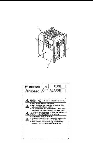
WARNING LABEL
A warning label is provided on the front cover of the Inverter, as shown below. Follow the warnings when handling the Inverter.
Status Indicators
Nameplate
Warning Label Location
Certification Mark
Warning Labels
FPST31042-874
Example of 5.5 kW for 400 V
12

CONTENTS
NOTATION FOR SAFETY PRECAUTIONS — — — — — — 2 1 Receiving the Product — — — — — — — — — — — — — — — — — — — 18
|
Checking the Nameplate — — — — — — — — — — — — — — — — — — — — — — — — — — |
19 |
2 Identifying the Parts — — — — — — — — — — — — — — — — — — — — — 20
3 Mounting — — — — — — — — — — — — — — — — — — — — — — — — — — — — 23
|
Choosing a Location to Mount the Inverter — — — — — — — — — — — — — — |
23 |
|
Mounting Dimensions — — — — — — — — — — — — — — — — — — — — — — — — — — — — — |
24 |
|
Mounting/Removing Components- — — — — — — — — — — — — — — — — — — — — |
25 |
|
Removing the Front Cover- — — — — — — — — — — — — — — — — — — — — — |
25 |
|
Mounting the Front Cover — — — — — — — — — — — — — — — — — — — — — — |
25 |
|
Removing the Terminal Cover — — — — — — — — — — — — — — — — — — — |
25 |
|
Mounting the Terminal Cover — — — — — — — — — — — — — — — — — — — — |
26 |
|
Removing the Digital Operator — — — — — — — — — — — — — — — — — — — |
26 |
|
Mounting the Digital Operator — — — — — — — — — — — — — — — — — — — |
26 |
|
Mounting the Bottom Cover — — — — — — — — — — — — — — — — — — — — — |
27 |
4 Wiring — — — — — — — — — — — — — — — — — — — — — — — — — — — — — — 28
|
Wire and Terminal Screw Sizes — — — — — — — — — — — — — — — — — — — — — — |
30 |
|
Wiring the Main Circuits- — — — — — — — — — — — — — — — — — — — — — — — — — — — |
34 |
|
Wiring the Control Circuits — — — — — — — — — — — — — — — — — — — — — — — — — — |
36 |
|
Wiring Inspection — — — — — — — — — — — — — — — — — — — — — — — — — — — — — — — — |
37 |
5 Operating the Inverter — — — — — — — — — — — — — — — — — — — 38
Test Run — — — — — — — — — — — — — — — — — — — — — — — — — — — — — — — — — — — — — — 39
Selecting Rotation Direction- — — — — — — — — — — — — — — — — — — — — 41
Operation Check Points- — — — — — — — — — — — — — — — — — — — — — — — 41
Operating the Digital Operator — — — — — — — — — — — — — — — — — — — — — — — 42
Description of Status Indicators — — — — — — — — — — — — — — — — — — 43
Function Indicator Description — — — — — — — — — — — — — — — — — — — — — — — 45
MNTR Multi-function Monitoring — — — — — — — — — — — — — — — — — — 46
Input/Output Terminal Status — — — — — — — — — — — — — — — — — — — — 48
Data Reception Error Display- — — — — — — — — — — — — — — — — — — — 48
13

Simple Data Setting — — — — — — — — — — — — — — — — — — — — — — — — — — — — — — -50
6 Programming Features — — — — — — — — — — — — — — — — — — 52
Hardware — — — — — — — — — — — — — — — — — — — — — — — — — — — — — — — — — — 52Software (Constant) — — — — — — — — — — — — — — — — — — — — — — — — — — -52Constant Setup and Initialization — — — — — — — — — — — — — — — — — — — — — — 53Constant Selection/Initialization (n001) — — — — — — — — — — — — — 53
Using V/f Control Mode — — — — — — — — — — — — — — — — — — — — — — — — — — — -55Adjusting Torque According to Application — — — — — — — — — — -55Using Vector Control Mode — — — — — — — — — — — — — — — — — — — — — — — — — — 59Precautions for Voltage Vector Control Application — — — — -59Motor Constant Calculation- — — — — — — — — — — — — — — — — — — — — — 60V/f Pattern during Vector Control- — — — — — — — — — — — — — — — — — 61
Switching LOCAL/REMOTE Mode — — — — — — — — — — — — — — — — — — — — 62How to Select LOCAL/REMOTE Mode — — — — — — — — — — — — — 63Selecting Run/Stop Commands- — — — — — — — — — — — — — — — — — — — — — — 63LOCAL Mode — — — — — — — — — — — — — — — — — — — — — — — — — — — — — — -63REMOTE Mode — — — — — — — — — — — — — — — — — — — — — — — — — — — — — -64Operating (Run/Stop Commands) by Communications — — 64
Selecting Frequency Reference — — — — — — — — — — — — — — — — — — — — — — 64LOCAL Mode — — — — — — — — — — — — — — — — — — — — — — — — — — — — — — -65REMOTE Mode — — — — — — — — — — — — — — — — — — — — — — — — — — — — — -65
Setting Operation Conditions — — — — — — — — — — — — — — — — — — — — — — — — 66Autotuning Selection (n139) — — — — — — — — — — — — — — — — — — — — -66Reverse Run Prohibit (n006)- — — — — — — — — — — — — — — — — — — — — 74Multi-step Speed Selection — — — — — — — — — — — — — — — — — — — — — — 74Operating at Low Speed — — — — — — — — — — — — — — — — — — — — — — — -75Adjusting Speed Setting Signal — — — — — — — — — — — — — — — — — — — 76Adjusting Frequency Upper and Lower Limits- — — — — — — — — 77Using Four Acceleration/Deceleration Times — — — — — — — — — 77Momentary Power Loss Ridethrough Method (n081)- — — -79S-curve Selection (n023) — — — — — — — — — — — — — — — — — — — — — — — 80Torque Detection — — — — — — — — — — — — — — — — — — — — — — — — — — — — — 81Frequency Detection Level (n095)- — — — — — — — — — — — — — — — -82Jump Frequencies (n083 to n086) — — — — — — — — — — — — — — — — -84Continuing Operation Using Automatic Retry Attempts — — 84Frequency Offset Selection (n146) — — — — — — — — — — — — — — — — 85
14

Operating a Coasting Motor without Tripping — — — — — — — — — 88Holding Acceleration/Deceleration Temporarily — — — — — — — 89External Analog Monitoring(n066) — — — — — — — — — — — — — — — — 90Calibrating Frequency Meter or Ammerter (n067) — — — — — 91Using Analog Output (AM-AC) as Pulse Train Signal — — — 91Carrier Frequency Selection (n080)14kHz max — — — — — — — 94Operator Stop Key Selection (n007) — — — — — — — — — — — — — — — 98Second motor selection- — — — — — — — — — — — — — — — — — — — — — — — 99
Selecting the Stopping Method- — — — — — — — — — — — — — — — — — — — — — 106Stopping Method Selection (n005) — — — — — — — — — — — — — — — 106Applying DC Injection Braking — — — — — — — — — — — — — — — — — — 107Simple Positioning Control when Stopping — — — — — — — — — 107
Building Interface Circuits with External Devices — — — — — — — — — 110Using Input Signals- — — — — — — — — — — — — — — — — — — — — — — — — — 110Using the Multi-function Analog Inputs — — — — — — — — — — — — 120Using Output Signals (n057, n058, n059) — — — — — — — — — — 124
|
Setting Frequency by Current Reference Input — — — — — — — — — — |
126 |
|
Frequency Reference by Pulse Train Input — — — — — — — — — — — — — |
128 |
|
Two-wire Sequence 2 — — — — — — — — — — — — — — — — — — — — — — — — — — — — |
129 |
|
Preventing the Motor from Stalling (Current Limit) — — — — — — — — |
131 |
|
Stall Prevention during Operation — — — — — — — — — — — — — — — — |
133 |
Decreasing Motor Speed Fluctuation — — — — — — — — — — — — — — — — — 135Slip Compensation (n002 = 0) — — — — — — — — — — — — — — — — — — 135Motor Protection — — — — — — — — — — — — — — — — — — — — — — — — — — — — — — — — 136Motor Overload Detection — — — — — — — — — — — — — — — — — — — — — 136PTC Thermistor Input for Motor Overheat Protection — — 138
Selecting Cooling Fan Operation — — — — — — — — — — — — — — — — — — — — 141Using MEMOBUS (MODBUS) Communications — — — — — — — — — 141MEMOBUS (MODBUS) Communications — — — — — — — — — — 141Communications Specifications — — — — — — — — — — — — — — — — — 142Communications Connection Terminal — — — — — — — — — — — — 142Setting Constants Necessary for Communication- — — — — 143Message Format- — — — — — — — — — — — — — — — — — — — — — — — — — — — 144Storing Constants [Enter Command] — — — — — — — — — — — — — 155Performing Self-test — — — — — — — — — — — — — — — — — — — — — — — — — 158
Using PID Control Mode — — — — — — — — — — — — — — — — — — — — — — — — — — 159PID Control Selection (n128) — — — — — — — — — — — — — — — — — — — 159
15

Analog Position Control with Bi-directional PID Output — 163
Bidirectional Reference Control- — — — — — — — — — — — — — — — — — 164
Using Constant Copy Function — — — — — — — — — — — — — — — — — — — — — — 168
Constant Copy Function — — — — — — — — — — — — — — — — — — — — — — — 168
READ Function — — — — — — — — — — — — — — — — — — — — — — — — — — — — — 170
COPY Function — — — — — — — — — — — — — — — — — — — — — — — — — — — — — 172
VERIFY Function- — — — — — — — — — — — — — — — — — — — — — — — — — — — 174
Inverter Capacity Display — — — — — — — — — — — — — — — — — — — — — — 176
Software No. Display — — — — — — — — — — — — — — — — — — — — — — — — — 178
Display List — — — — — — — — — — — — — — — — — — — — — — — — — — — — — — — — 179
|
Customer Specific Display Scaling — — — — — — — — — — — — — — — — — — |
— 181 |
|
|
Selecting Processing for Frequency Reference Loss (n064) — 183 |
||
|
Input/Output Open-phase Detection — — — — — — — — — — — — — — — — — |
— 184 |
|
|
Undertorque Detection — — — — — — — — — — — — — — — — — — — — — — — — — — — |
— 185 |
|
|
Using Inverter for Elevating Machines — — — — — — — — — — — — — — — — |
— 187 |
|
|
Brake ON/OFF Sequence- — — — — — — — — — — — — — — — — — — — — |
— 187 |
|
|
Stall Prevention during Deceleration — — — — — — — — — — — — — |
— 189 |
|
|
Settings for V/f Pattern and Motor Constants — — — — — — — |
— 189 |
|
|
Momentary Power Loss Restart and Fault Restart — — — |
— 189 |
|
|
I/O Open-phase Protection and Overtorque Detection- |
— 189 |
|
|
Carrier Frequency — — — — — — — — — — — — — — — — — — — — — — — — — — |
— 189 |
|
|
External Baseblock Signal — — — — — — — — — — — — — — — — — — — — |
— 190 |
|
|
Acceleration/Deceleration Time- — — — — — — — — — — — — — — — — |
— 190 |
|
|
Contactor on the Inverter’s Output-side — — — — — — — — — — — |
— 190 |
|
|
Using MECHATROLINK-II Communications — — — — — — — — — — — |
— 191 |
|
|
7 Maintenance and Inspection — — — — — — — — — — — — — |
192 |
|
|
Periodic Inspection — — — — — — — — — — — — — — — — — — — — — — — — — — — — — |
— 193 |
|
|
Part Replacement — — — — — — — — — — — — — — — — — — — — — — — — — — — — — — |
— 194 |
|
|
Replacement of Cooling Fan- — — — — — — — — — — — — — — — — — — |
— 195 |
|
|
8 Fault Diagnosis — — — — — — — — — — — — — — — — — — — — — — — |
197 |
Protective and Diagnostic Functions — — — — — — — — — — — — — — — — — — 197Corrective Actions of Models with Blank Cover- — — — — — — 197Corrective Actions of Models with Digital Operator — — — — 198
Troubleshooting- — — — — — — — — — — — — — — — — — — — — — — — — — — — — — — — — 212
16

9 Specifications — — — — — — — — — — — — — — — — — — — — — — — — 214
Standard Specifications (200 V Class) — — — — — — — — — — — — — — — — 214Standard Specifications (400 V Class) — — — — — — — — — — — — — — — — 218Standard Wiring — — — — — — — — — — — — — — — — — — — — — — — — — — — — — — — — 222Sequence Input Connection with NPN/PNP Transistor — — — — — 226Dimensions/Heat Loss — — — — — — — — — — — — — — — — — — — — — — — — — — — 228Recommended Peripheral Devices- — — — — — — — — — — — — — — — — — — 231Constants List — — — — — — — — — — — — — — — — — — — — — — — — — — — — — — — — — 234
10 Conformance to CE Markings — — — — — — — — — — — — 247
|
CE Markings — — — — — — — — — — — — — — — — — — — — — — — — — — — — — — — — — — |
247 |
|
|
Requirements for Conformance to CE Markings — — — — — — — — — |
247 |
|
|
Low Voltage Directive — — — — — — — — — — — — — — — — — — — — — — — — |
247 |
|
|
EMC Directive — — — — — — — — — — — — — — — — — — — — — — — — — — — — — |
248 |
17

1 Receiving the Product
Do not install or operate any Inverter that is dam-  CAUTION aged or has missing parts.
Failure to observe this caution may result in injury or equipment damage.
After unpacking the V7AZ, check the following.
•Verify that the model number matches your purchase order or packing slip.
•Check the Inverter for physical damage that may have occurred during shipping.
If any part of V7AZ is missing or damaged, call for service immediately.
18
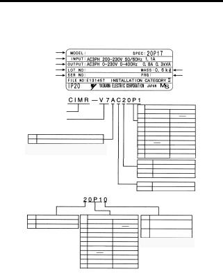
1 Receiving the Product
Checking the Nameplate
Example for 3-phase, 200-VAC, 0.1-kW (0.13 HP) Inverter for European standards
|
Inverter Model |
CIMR-V7AZ20P1 |
20P10 |
||
|
Input Spec. |
||||
|
Output Spec. |
||||
|
Lot No. |
Mass |
|||
|
Serial No. |
Software Number |
|||
Inverter
V7AZ Series
No. Type
A With Digital Operator (with potentiometer)
Note: Contact your OMRON representatives for models without heatsinks.
Specifications
|
B |
Single-phase 200 VAC |
Applicable maximum motor output |
||
|
2 |
Three-phase 200 VAC |
200 V class |
400 V class |
|
|
4 |
Three-phase 400 VAC |
0P1 |
0.1 kW |
|
|
0P2 |
0.25 kW |
0.37 kW |
||
|
0P4 |
0.55 kW |
0.55 kW |
||
|
0P7 |
1.1 kW |
1.1 kW |
||
|
1P5 |
1.5 kW |
1.5 kW |
||
|
2P2 |
2.2 kW |
2.2 kW |
||
|
3P0 |
3.0 kW |
|||
|
4P0 |
4.0 kW |
4.0 kW |
||
|
5P5 |
5.5 kW |
5.5 kW |
||
|
7P5 |
7.5 kW |
7.5 kW |
Applicable maximum motor output
|
200 V class |
400 V class |
|
|
0P1 |
0.1 kW |
|
|
0P2 |
0.25 kW |
0.37 kW |
|
0P4 |
0.55 kW |
0.55 kW |
|
0P7 |
1.1 kW |
1.1 kW |
|
1P5 |
1.5 kW |
1.5 kW |
|
2P2 |
2.2 kW |
2.2 kW |
|
3P0 |
3.0 kW |
|
|
4P0 |
4.0 kW |
4.0 kW |
|
5P5 |
5.5 kW |
5.5 kW |
|
7P5 |
7.5 kW |
7.5 kW |
|
No. |
Voltage Class |
|
|
B |
Single-phase 200 VAC |
|
|
2 |
Three-phase 200 VAC |
|
|
4 |
Three-phase 400 VAC |
|
|
No. |
Specifications |
|
|
Z |
European standards |
No. Protective structure
Open chassis
0(IP20, IP00)*1
Enclosed wall-mounted
1(NEMA1)*2
*1: Inverters with outputs 0P1 to 3P7 are rated IP20. Be sure to remove the top and bottom
covers if using open-chassis mounted Inverters with a 5P5 or 7P5 output.
*2: A NEMA 1 rating is optional for Inverters with outputs 0P1 to 3P7 but standard for 5P5 or 7P5.
Inverter Software Version
The inverter software version can be read out from the monitor parameter U-10 or parameter n179. The parameter shows the last for digits of the software number (e.g. display is“5740”for the software version VSP015740).
The manual describes the functionality of the Inverter software version VSP015740 (0.1 to 4.0 kW) and VSP105750 (5.5 and 7.5 kW). Older software versions do not support all described functions. Check the software version before starting to work with this manual.
19
![]()
2 Identifying the Parts
|
Terminal Cover |
Digital Operator |
|
|
Wiring Holes |
||
|
for Control Circuit |
Front Cover |
|
|
Wiring Holes |
Nameplate |
|
|
for Main Circuit |
||
|
Ground Terminal |
Heatsink |
|
|
Bottom Cover |
||
|
Cooling Fan |
||
|
Fan Cover |
|
Digital Operator |
Digital Operator |
Blank cover |
|
(with potentiometer) |
(without potentiometer) |
In models without a |
|
JVOP-140 |
JVOP-147 |
Digital Operator, the |
|
Used for setting or |
Used for setting or |
blank cover is mounted |
|
changing constants. |
changing constants. |
in place of the Digital |
|
Frequency can be set |
Operator. |
|
|
using the potentiometer. |
20
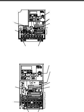
|
2 Identifying the Parts |
||
|
V7AZ Inverters with the Covers Removed |
||
|
Frequency-setting Potentiometer |
||
|
Inverter Operation Status Indicators |
||
|
Input Polarity |
Terminal Resistor Switch for |
|
|
Switch |
Communication Circuit |
|
|
Voltage/Current Change Switch for |
||
|
Short-circuit |
Analog Frequency Reference Input |
|
|
Control Circuit Terminal Block |
||
|
Bar |


 Main Circuit Terminal Block
Ground Terminals
Example for 3-phase (200 V Class, 1.5 kW) Inverter
|
Frequency-setting Potentiometer |
|
|
Inverter Operation Status Indicators |
|
|
Terminal Resistor Switch for |
|
|
Communication Circuit |
|
|
Input Polarity |
Voltage/Current Change Switch for |
|
Switch |
Analog Frequency Reference Input |
|
Control Circuit Terminal Block |
|
|
Short-circuit |
Main Circuit Terminal Block |
|
Bar |
|
|
Ground Terminals |
Example for 3-phase (200 V Class, 0.1 kW) Inverter
21
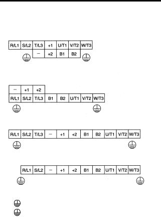
Main Circuit Terminal Arrangement
The terminal arrangement of the main circuit terminals depends on the Inverter model.
CIMR-V7AZ20P1 to 20P7, B0P1 to B0P4
CIMR-V7AZ21P5, 22P2, B0P7, B1P5, 40P2 to 42P2
CIMR-V7AZ24P0, B2P2, 43P0, 44P0
CIMR-V7AZB4P0
CIMR-V7AZ25P5, 27P5, 45P5, 47P5
|
R/L1 |
S/L2 |
T/L3 |
+1 |
+2 |
B1 |
B2 |
U/T1 |
V/T2 |
W/T3 |
||
22

3 Mounting
3 Mounting
Choosing a Location to Mount the Inverter
Be sure the Inverter is protected from the following conditions.
•Extreme cold and heat. Use only within the specified ambient temperature range:
−10 to 50 °C (14 to 122 °F) for IP20 (open chassis type), −10 to 40 °C (14 to 105 °F) for NEMA 1 (TYPE 1)
•Rain and moisture
•Oil sprays and splashes
•Salt spray
•Direct sunlight (Avoid using outdoors.)
•Corrosive gases (e.g., sulfurized gas) or liquids
•Dust or metallic particles in the air
•Physical shock or vibration
•Magnetic noise (Examples: Welding machines, power devices, etc.)
•High humidity
•Radioactive substances
•Combustibles, such as thinner or solvents
23
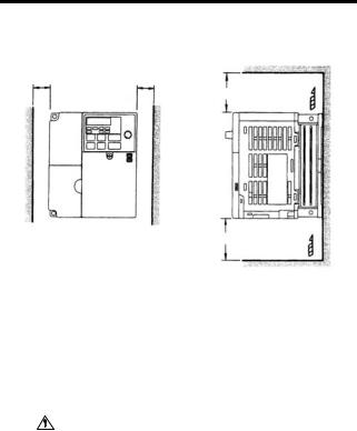
Mounting Dimensions
To mount the V7AZ, the dimensions shown below are required.
100 mm (3.94 in.) or more
|
Air |
|||
|
100 mm (3.94 in.) or more |
|||
|
Voltage Class |
Max. Applicable |
Length a |
|
|
Motor Capacity |
|||
|
(V) |
|||
|
(kW) |
|||
|
200 V Single-phase |
3.7 kW or less |
30 mm (1.18 in.) min. |
|
|
3-phase |
|||
|
400 V 3-phase |
|||
|
200 V 3-phase |
5.5 kW |
50 mm (1.97 in.) min. |
|
|
400 V 3-phase |
7.5 kW |
||
|
CAUTION • |
Lift the Inverter by the heatsinks. When moving the |
||
|
Inverter, never lift it by the plastic case or the termi- |
|||
|
nal cover. |
|||
|
Otherwise, the main unit may fall and be damaged. |
|||
|
• |
The V7AZ generates heat. For effective cooling, |
||
|
mount it vertically. |
24
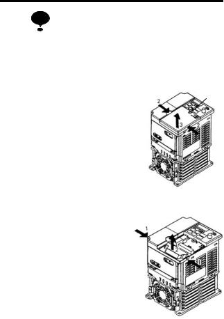
3 Mounting
• The same space is required horizontally and vertically and NOTE right and left for both Open Chassis (IP00, IP20) and
Enclosed Wall-mounted (NEMA 1) Inverters.
•Always remove the top and bottom covers before installing a 200 or 400 V Class Inverter with an output of 5.5/7.5 kW in a panel.
Mounting/Removing Components
Removing and Mounting the Digital Operator and Covers
Removing the Front Cover
|
A |
|||||||
|
Use a screwdriver to loosen the screw |
1 |
||||||
|
(section A) on the front cover. (To pre- |
|||||||
|
vent loss, this screw cannot be |
|||||||
|
removed.) Then press the right and left |
2 |
||||||
|
1 |
|||||||
sides in direction 1 and lift the front cover in direction 2.
Mounting the Front Cover
Mount the front cover by reversing the order of the above procedure for removal.
Removing the Terminal Cover
• 200 V class Inverters with 1.1 kW and more and all 400 V class Inverters:
After removing the front cover, press the right and left sides of the terminal cover in direction 1 and lift the terminal cover in direction 2.
25
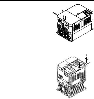
|
• Inverters of 5.5 and 7.5 kW: |
|
|
Use a screwdriver to loosen |
B |
|
the screw (section B) on the |
1 |
|
terminal cover surface. (To |
2 |
|
prevent loss, this screw cannot |
|
|
be removed.) Then press the |
right and left sides in direction 1 and lift the terminal cover in direction 2.
Mounting the Terminal Cover
Mount the terminal cover by reversing the order of the above procedure for removal.
Removing the Digital Operator
After removing the front cover, (follow the procedure on page 25) lift the upper and lower sides (section C) of the right side of the Digital Operator in direction 1.
Mounting the Digital Operator
Mount the Digital Operator by reversing the order of the above procedure for removal.
26
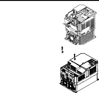
3 Mounting
Removing the Bottom Cover
•200 V class Inverters with 1.1 kW and more and all 400 V class Inverters:
|
After removing the front cover and |
A |
|
the terminal cover, tilt the bottom |
|
|
cover in direction 1 with section A |
|
|
as a supporting point. |
A |
|
• Inverters of 5.5 and 7.5 kW |
1 |
|
After removing the terminal cover, |
1 |
|
use a screwdriver to loosen the |
|
|
mounting screw in direction 1. |
Mounting the Bottom Cover
Mount the bottom cover by reversing the order of the above procedure for removal.
27

4 Wiring
 WARNING
CAUTION
•Only begin wiring after verifying that the power supply is turned OFF.
Failure to observe this warning may result in an electric shock or a fire.
•Wiring should be performed only by qualified personnel.
Failure to observe this warning may result in an electric shock or a fire.
•When wiring the emergency stop circuit, check the wiring thoroughly before operation.
Failure to observe this warning may result in injury.
•For the 400 V Class, make sure to ground the supply neutral.
Failure to observe this warning may result in an electric shock or a fire.
•Verify that the Inverter rated voltage coincides with the AC power supply voltage.
Failure to observe this caution may result in personal injury or a fire.
•Do not perform a withstand voltage test on the Inverter.
Performing withstand voltage tests may damage semiconductor elements.
•Always tighten terminal screws of the main circuit and the control circuits.
Failure to observe this caution may result in a malfunction, damage, or a fire.
•Never connect the AC main circuit power supply to output terminals U/T1, V/T2, W/T3, B1, B2, -, +1, or +2.
The Inverter will be damaged and the guarantee will be voided.
•Do not connect or disconnect wires or connectors while power is applied to the circuits.
Failure to observe this caution may result in injury.
•Do not perform signal checks during operation.
The machine or the Inverter may be damaged.
•To store a constant with an Enter Command by communications, be sure to take measures for an emergency stop by using the external terminals.
28

4 Wiring
Delayed response may cause injury or damage the machine.
Wiring Instructions
NOTE 1. Always connect the power supply for the main circuit
inputs to the power input terminals R/L1, S/L2, and T/L3 (R/L1, S/L2 for single-phase power) via a molded-case circuit breaker (MCCB) or a fuse. Never connect the power supply to terminals U/T1, V/T2, W/T3, B1, B2, −, +1, or +2. The Inverter may be damaged.
For single-phase Inverters, always use terminals R/L1 and S/L2. Never connect terminal T/L3. Fuses must be of ULclass RK5 fuse or an equivalent.
Refer to page 231 for recommended peripheral devices.
Inverter Power Supply Connection Terminals
|
200-V 3-phase Input |
200-V Single Input |
400-V 3-phase Input |
|
Power Supply Speci- |
Power Supply Speci- |
Power Supply Speci- |
|
fication Inverters |
fication Inverters |
fication Inverters |
|
CIMR-V7 2 |
CIMR-V7 B |
CIMR-V7 4 |
|
Connect to R/L1, |
Connect to R/L1 and |
Connect to R/L1, |
|
S/L2, and T/L3. |
S/L2. |
S/L2, and T/L3. |
2.If the wiring distance between Inverter and motor is long, reduce the Inverter carrier frequency. For details, refer to
Carrier Frequency Selection (n080)14kHz max on page 94.
3.Control wiring must be less than 50 m (164 ft) in length and must be separated from power wiring. Use shielded twisted-pair cable when inputting the frequency signal externally.
4.Only basic insulation to meet the requirements of protection class 1 and overvoltage category II is provided with control circuit terminals. Additional insulation may be necessary in the end product to conform to CE requirements.
5.Closed-loop connectors should be used when wiring to the main circuit terminals.
29
![]()
6.Voltage drop should be considered when determining the wire size.
Voltage drop can be calculated using the following equation:
Phase-to-phase voltage drop (V)
=  3 × Wire resistance (Ω/km) × Wiring distance (m) × Current
(A) × 10-3
Select a wire size so that voltage drop will be less than 2% of the normal rated voltage.
7.If the Inverter is connected to a power transformer exceeding 600 kVA, excessive peak current may flow into the input power supply circuit, and break the converter section. In this case, attach an AC reactor (optional) to the Inverter input side, or a DC reactor (optional) to the DC reactor connection terminal.
Wire and Terminal Screw Sizes
1.Control Circuits
|
Model |
Terminal |
Screws |
Tightening |
Wires |
|||||
|
Symbols |
Torque |
||||||||
|
N•m (lb•in) |
Applicable Size |
Recom- |
Type |
||||||
|
mended Size |
|||||||||
|
mm2 |
AWG |
mm2 |
AWG |
||||||
|
Same |
MA, MB, MC |
M3 |
0.5 to 0.6 |
Twisted wires: |
20 to 16, |
0.75 |
18 |
Shielded or |
|
|
for all |
(4.44 to 5.33) |
0.5 to 1.25, |
20 to 16 |
equivalent |
|||||
|
models |
Single: 0.5 to 1.25 |
||||||||
|
S1 to S7, P1, |
M2 |
0.22 to 0.25 |
Twisted wires: |
20 to 18, |
0.75 |
18 |
|||
|
P2, SC, PC, |
(1.94 to 2.21) |
0.5 to 0.75, |
20 to 16 |
||||||
|
R+, R-, S+, S-, |
Single: 0.5 to 1.25 |
||||||||
|
FS, FR, FC, |
|||||||||
|
AM, AC, RP |
|||||||||
30

|
4 |
Wiring |
||||||||
|
2. Main Circuits |
|||||||||
|
200 V Class 3-phase Input Inverters |
|||||||||
|
Model |
Terminal Symbols |
Screws |
Tightening |
Wires |
|||||
|
Torque |
|||||||||
|
N•m (lb•in) |
Applicable Size |
Recommended |
Type |
||||||
|
Size |
|||||||||
|
mm2 |
AWG |
mm2 |
AWG |
||||||
|
CIMR- |
R/L1, S/L2, T/L3, — |
M3.5 |
0.8 to 1.0 |
0.75 to 2 |
18 to 14 |
2 |
14 |
600-V |
|
|
V7ΑΖ |
, +1, +2, B1, B2, |
(7.1 to 8.88) |
vinyl- |
||||||
|
20P1 |
U/T1, V/T2, W/T3 |
sheathed |
|||||||
|
or equiva- |
|||||||||
|
lent |
|||||||||
|
CIMR- |
R/L1, S/L2, T/L3, — |
M3.5 |
0.8 to |
1.0 |
0.75 to 2 |
18 to 14 |
2 |
14 |
|
|
V7ΑΖ |
, +1, +2, B1, B2, |
(7.1 to 8.88) |
|||||||
|
20P2 |
U/T1, V/T2, W/T3 |
||||||||
|
CIMR- |
R/L1, S/L2, T/L3, — |
M3.5 |
0.8 to |
1.0 |
0.75 to 2 |
18 to 14 |
2 |
14 |
|
|
V7ΑΖ |
, +1, +2, B1, B2, |
(7.1 to 8.88) |
|||||||
|
20P4 |
U/T1, V/T2, W/T3 |
||||||||
|
CIMR- |
R/L1, S/L2, T/L3, — |
M3.5 |
0.8 to |
1.0 |
0.75 to 2 |
18 to 14 |
2 |
14 |
|
|
V7ΑΖ |
, +1, +2, B1, B2, |
(7.1 to 8.88) |
|||||||
|
20P7 |
U/T1, V/T2, W/T3 |
||||||||
|
CIMR- |
R/L1, S/L2, T/L3, — |
M4 |
1.2 to |
1.5 |
2 to 5.5 |
14 to 10 |
2 |
14 |
|
|
V7ΑΖ |
, +1, +2, B1, B2, |
(10.65 to |
13.31) |
||||||
|
21P5 |
U/T1, V/T2, W/T3 |
||||||||
|
3.5 |
12 |
||||||||
|
CIMR- |
R/L1, S/L2, T/L3, — |
M4 |
1.2 to |
1.5 |
2 to 5.5 |
14 to 10 |
3.5 |
12 |
|
|
V7ΑΖ |
, +1, +2, B1, B2, |
(10.65 to |
13.31) |
||||||
|
22P2 |
U/T1, V/T2, W/T3 |
||||||||
|
CIMR- |
R/L1, S/L2, T/L3, — |
M4 |
1.2 to |
1.5 |
2 to 5.5 |
14 to 10 |
5.5 |
10 |
|
|
V7ΑΖ |
, +1, +2, B1, B2, |
(10.65 to |
13.31) |
||||||
|
24P0 |
U/T1, V/T2, W/T3 |
||||||||
|
CIMR- |
R/L1, S/L2, T/L3, — |
M5 |
2.5 |
5.5 to 8 |
10 to 8 |
8 |
8 |
||
|
V7ΑΖ |
, +1, +2, B1, B2, |
(22.13) |
|||||||
|
25P5 |
U/T1, V/T2, W/T3 |
||||||||
|
CIMR- |
R/L1, S/L2, T/L3, — |
M5 |
2.5 |
5.5 to 8 |
10 to 8 |
8 |
8 |
||
|
V7ΑΖ |
, +1, +2, B1, B2, |
(22.13) |
|||||||
|
27P5 |
U/T1, V/T2, W/T3 |
Note: The wire size is given for copper wire at 75°C (160°F).
31

200 V Class Single-phase Input Inverters
|
Model |
Terminal Symbols |
Screws |
Tightening |
Wires |
||||
|
Torque |
||||||||
|
N•m (lb•in) |
Applicable Size |
Recommended |
Type |
|||||
|
Size |
||||||||
|
mm2 |
AWG |
mm2 |
AWG |
|||||
|
CIMR- |
R/L1, S/L2, T/L3, |
M3.5 |
0.8 to 1.0 |
0.75 to 2 |
18 to 14 |
2 |
14 |
600-V vinyl- |
|
V7ΑΖ |
-, +1, +2, B1, B2, |
(7.1 to 8.88) |
sheathed or |
|||||
|
B0P1 |
U/T1, V/T2, W/T3 |
equivalent |
||||||
|
CIMR- |
R/L1, S/L2, T/L3, |
M3.5 |
0.8 to 1.0 |
0.75 to 2 |
18 to 14 |
2 |
14 |
|
|
V7ΑΖ |
-, +1, +2, B1, B2, |
(7.1 to 8.88) |
||||||
|
B0P2 |
U/T1, V/T2, W/T3 |
|||||||
|
CIMR- |
R/L1, S/L2, T/L3, |
M3.5 |
0.8 to 1.0 |
0.75 to 2 |
18 to 14 |
2 |
14 |
|
|
V7ΑΖ |
-, +1, +2, B1, B2, |
(7.1 to 8.88) |
||||||
|
B0P4 |
U/T1, V/T2, W/T3 |
|||||||
|
CIMR- |
R/L1, S/L2, T/L3, |
M4 |
1.2 to 1.5 |
2 to 5.5 |
14 to 10 |
3.5 |
12 |
|
|
V7ΑΖ |
-, +1, +2, B1, B2, |
(10.65 to |
||||||
|
B0P7 |
U/T1, V/T2, W/T3 |
13.31) |
||||||
|
CIMR- |
R/L1, S/L2, -, +1, |
M4 |
1.2 to 1.5 |
2 to 5.5 |
14 to 10 |
5.5 |
10 |
|
|
V7ΑΖ |
+2, B1, B2, U/T1, |
(10.65 to |
||||||
|
B1P5 |
V/T2, W/T3 |
13.31) |
||||||
|
CIMR- |
R/L1, S/L2, -, +1, |
M4 |
1.2 to 1.5 |
2 to 5.5 |
14 to 10 |
5.5 |
10 |
|
|
V7ΑΖ |
+2, B1, B2, U/T1, |
(10.65 to |
||||||
|
B2P2 |
V/T2, W/T3 |
13.31) |
||||||
|
CIMR- |
R/L1, S/L2, -, +1, |
M5 |
3.0 (26.62) |
3.5 to 8 |
12 to 8 |
8 |
8 |
|
|
V7ΑΖ |
+2, B1, B2, U/T1, |
|||||||
|
B4P0 |
V/T2, W/T3 |
|||||||
|
M4 |
1.2 to 1.5 |
2 to 8 |
14 to 8 |
|||||
|
(10.65 to |
||||||||
|
13.31) |
Note: 1. The wire size is given for copper wire at 75°C (160°F).
2. Do not use terminal T/L3 on Inverters with single-phase input.
32

|
4 |
Wiring |
|||||||||
|
400 V Class 3-phase Input Inverters |
||||||||||
|
Model |
Terminal Sym- |
Screws |
Tightening |
Wires |
||||||
|
bols |
Torque |
|||||||||
|
N•m (lb•in) |
Applicable Size |
Recommended |
Type |
|||||||
|
Size |
||||||||||
|
mm2 |
AWG |
mm2 |
AWG |
|||||||
|
CIMR- |
R/L1, S/L2, T/L3, |
M4 |
1.2 to 1.5 |
2 to 5.5 |
14 to 10 |
2 |
14 |
600-V vinyl- |
||
|
V7ΑΖ |
-, +1, +2, B1, B2, |
(10.65 to |
sheathed or |
|||||||
|
40P2 |
U/T1, V/T2, W/T3 |
13.31) |
equivalent |
|||||||
|
CIMR- |
R/L1, S/L2, T/L3, |
M4 |
1.2 to 1.5 |
2 to 5.5 |
14 to 10 |
2 |
14 |
|||
|
V7ΑΖ |
-, +1, +2, B1, B2, |
(10.65 to |
||||||||
|
40P4 |
U/T1, V/T2, W/T3 |
13.31) |
||||||||
|
CIMR- |
R/L1, S/L2, T/L3, |
M4 |
1.2 to 1.5 |
2 to 5.5 |
14 to 10 |
2 |
14 |
|||
|
V7ΑΖ |
-, +1, +2, B1, B2, |
(10.65 to |
||||||||
|
40P7 |
U/T1, V/T2, W/T3 |
13.31) |
||||||||
|
CIMR- |
R/L1, S/L2, T/L3, |
M4 |
1.2 to 1.5 |
2 to 5.5 |
14 to 10 |
2 |
14 |
|||
|
V7ΑΖ |
-, +1, +2, B1, B2, |
(10.65 to |
||||||||
|
41P5 |
U/T1, V/T2, W/T3 |
13.31) |
||||||||
|
CIMR- |
R/L1, S/L2, T/L3, |
M4 |
1.2 to 1.5 |
2 to 5.5 |
14 to 10 |
2 |
14 |
|||
|
V7ΑΖ |
-, +1, +2, B1, B2, |
(10.65 to |
||||||||
|
42P2 |
U/T1, V/T2, W/T3 |
13.31) |
||||||||
|
CIMR- |
R/L1, S/L2, T/L3, |
M4 |
1.2 to 1.5 |
2 to 5.5 |
14 to 10 |
2 |
14 |
|||
|
V7ΑΖ |
-, +1, +2, B1, B2, |
(10.65 to |
||||||||
|
43P0 |
U/T1, V/T2, W/T3 |
13.31) |
||||||||
|
3.5 |
12 |
|||||||||
|
CIMR- |
R/L1, S/L2, T/L3, |
M4 |
1.2 to 1.5 |
2 to 5.5 |
14 to 10 |
2 |
14 |
|||
|
V7ΑΖ |
-, +1, +2, B1, B2, |
(10.65 to |
||||||||
|
44P0 |
U/T1, V/T2, W/T3 |
13.31) |
||||||||
|
3.5 |
12 |
|||||||||
|
CIMR- |
R/L1, S/L2, T/L3, |
M4 |
1.4 |
3.5 to |
12 to 10 |
5.5 |
10 |
|||
|
V7ΑΖ |
-, +1, +2, B1, B2, |
(12.39) |
5.5 |
|||||||
|
45P5 |
U/T1, V/T2, W/T3 |
|||||||||
|
CIMR- |
R/L1, S/L2, T/L3, |
M5 |
2.5 |
5.5 to 8 |
10 to 8 |
5.5 |
10 |
|||
|
V7ΑΖ |
-, +1, +2, B1, B2, |
(22.13) |
||||||||
|
47P5 |
U/T1, V/T2, W/T3 |
Note: The wire size is given for copper wire at 75°C (160°F).
33

Wiring the Main Circuits
|
[Example of 3-phase, |
|
|
L1 L2 L3 |
400 V Class, 0.37 kW Inverters] |
MCCB or
Leakage
Breaker
Grounding
• Main Circuit Input Power Supply
Always connect the power supply line to input terminals R/L1, S/L2, and T/L3. Never connect them to terminals U/T1, V/T2, W/T3, B1, B2, −, +1, or +2. The Inverter may be damaged if the wrong terminals are connected.
For single-phase Inverters, always use terminals R/L1 and S/L2. Never connect NOTE terminal T/L3.
• Grounding (Use ground terminal  .)
.)
|
WARNING |
Always ground the ground terminal according to the |
|
local grounding code. |
Failure to observe this warning may result in an electric shock or a fire.
Never ground the V7AZ to the same ground as welding machines, motors, or other electrical equipment.
When several V7AZ Inverters are used side by side, ground each as shown in the following examples. Do not loop the ground wires.
Good Good Poor
34

|
4 Wiring |
|
|
• Braking Resistor Connection (Optional) |
|
|
WARNING |
To connect the braking resistor, cut the protector on terminals |
|
B1 and B2. |
To protect the braking resistor from overheating, install a thermal overload relay between the braking resistor and the Inverter. This provides a sequence that turns OFF the power supply with thermal relay trip contacts.
Failure to observe this warning may result in a fire.
Use this same procedure when connecting a Braking Resistor Unit. Refer to page 223.
• Inverter Output
Connect the motor terminals to U/T1, V/T2, and W/T3.
• Wiring the Main Circuit Terminals
Pass the cables through the wiring hole to connect them. Always mount the cover in its original position.
Connect with a Phillips screwdriver.
35

Wiring the Control Circuits
Only basic insulation is provided for the control circuit terminals.
Additional insulation may be necessary in the end product.
• Control Circuit Terminals
Pass the cable through the wiring hole to connect it. Always mount the cover in its original position.
Contact Output
SW1 can be changed according to sequence input signal (S1 to S7) polarity.
0 V common: NPN side (factory setting)
+24 V common: PNP side
Refer to pages 226 and 227 for SW1. Refer to pages 126 and 142 for SW2.
Wiring the Control Circuit Terminals Screwdriver Blade Width
|
0.4 mm max |
2.5 mm max |
|
|
(0.098 in.) |
||
|
(0.016 in.) |
||
Insert the wire into the lower part of the terminal block and connect it tightly with a screwdriver.
36

4 Wiring
|
NOTE |
• |
Keep the screwdriver vertical to the Inverter. |
|
|
• |
Refer to Page 30 for tightening torques. |
||
5.5 mm
(0.22 in.)
The wire sheath strip length must be 5.5 mm (0.22 in.).
Open the front cover and verify that the strip length is 5.5 mm (0.22 in.).
5.5mm
|
Scale |
CONTACT OUTPUT |
|||
|
SW1 |
||||
|
SW2 |
Wiring Inspection
After completing wiring, check the following.
•Wiring is proper.
•Wire clippings or screws are not left in the Inverter.
•Screws are securely tightened.
•Bare wires in the terminals do not contact other terminals.
|
WARNING |
If the power supply is turned ON while the FWD (or |
|
REV) Run Command is given, the motor will start |
|
|
automatically. |
|
|
Turn the power supply ON after verifying that the |
|
|
RUN signal is OFF. |
|
|
Failure to observe this warning may result in injury. |
|
1. If the FWD (or REV) Run Command is given when the |
|
|
NOTE |
Run Command from the control circuit terminal is |
|
selected (n003 = 1), the motor will start automatically |
|
|
after the main circuit input power supply is turned ON. |
2. To set the 3-wire sequence, set terminal S3 (n052) to 0.
37

5 Operating the Inverter
The Control Mode Selection (n002) is initially set to V/f control mode.
|
WARNING |
• Only turn ON the input power supply after confirm- |
|
ing that the Digital Operator or blank cover |
|
|
(optional) are in place. Do not remove the Digital |
|
|
Operator or the covers while current is flowing. |
|
|
Failure to observe this warning may result in an |
|
|
electric shock. |
•Never operate the Digital Operator or DIP switches with wet hands.
Failure to observe this warning may result in an electric shock.
•Never touch the terminals while current is flowing, even if the Inverter is stopped.
Failure to observe this warning may result in an electric shock.
|
CAUTION |
• |
Never touch the heatsinks, which can be extremely |
|
hot. |
||
|
Failure to observe this caution may result in harmful |
||
|
burns to the body. |
||
|
• |
It is easy to change operation speed from low to |
|
|
high. Verify the safe working range of the motor and |
||
|
machine before operation. |
||
|
Failure to observe this caution may result in injury |
||
|
and machine damage. |
||
|
• |
Install a holding brake separately if necessary. |
|
|
Failure to observe this caution may result in injury. |
||
|
• |
Do not perform signal checks during operation. |
|
|
The machine or the Inverter may be damaged. |
||
|
• |
All the constants set in the Inverter have been preset |
|
|
at the factory. Do not change the settings unneces- |
||
|
sarily. |
||
|
The Inverter may be damaged. |
38

5 Operating the Inverter
Test Run
The Inverter operates when a frequency (speed) is set.
There are four operating modes for the V7AZ:
1.Run Command from the Digital Operator (potentiometer/digital setting)
2.Run Command from the control circuit terminals
3.Run Command from MEMOBUS communications
4.Run Command from communication card (optional)
Prior to shipping, the Inverter is set up to receive the Run Command and frequency reference from the Operator. Below are instructions for running the V7AZ using the JVOP-147 Digital Operator (without potentiometer). For instructions on operation, refer to page 50.
Operation reference or frequency reference constants can be selected separately as shown below.
|
Name |
Constant |
|
Run |
n003 = 0 — Enables run, stop, and reset from Digital Operator. |
|
Command |
= 1 — Enables run and stop from control circuit terminals. |
|
Selection |
= 2 — Enables MEMOBUS communications. |
|
= 3 — Enables communication card (optional). |
|
|
Frequency |
n004 = 0 — Enables the Digital Operator’s potentiometer setting. |
|
Reference |
= 1 — Enables Frequency Reference 1 (constant n024). |
|
Selection |
= 2 — Enables a voltage reference (0 to 10 V) at the control circuit |
|
terminal. |
|
|
= 3 — Enables a current reference (4 to 20 mA) at the control circuit |
|
|
terminal. |
|
|
= 4 — Enables a current reference (0 to 20 mA) at the control circuit |
|
|
terminal. |
|
|
= 5 — Enables a pulse train reference at the control circuit terminal. |
|
|
= 6 — Enables MEMOBUS communications. |
|
|
= 7 — Enables a voltage reference (0 to 10 V) at the Digital Operator’s |
|
|
circuit terminal. |
|
|
= 8 — Enables a current reference (4 to 20 mA) at the Digital Operator’s |
|
|
circuit terminal. |
|
|
= 9 — Enables communication card (optional). |
|
39
![]()
|
Operation Steps |
Operator |
Function |
Status |
|||||||
|
Display |
Indicators |
Indicators |
||||||||
|
1. |
Turn ON the power supply. |
6.00 |
FREF |
RUN |
||||||
|
ALARM |
||||||||||
|
2. |
Set constant n004 to 1. |
1 |
PRGM |
RUN |
||||||
|
ALARM |
||||||||||
|
3. Set the following constants. |
PRGM |
RUN |
||||||||
|
n019: 15.0 (acceleration time) |
15.0 |
|||||||||
|
n020: 5.0 (deceleration time) |
5.0 |
ALARM |
||||||||
|
4. Select forward or reverse run by press- |
F/R |
RUN |
||||||||
|
ing |
or |
key. |
(Forward) |
|||||||
|
ALARM |
||||||||||
|
Never select REV when reverse |
or |
|||||||||
|
NOTE |
run is prohibited. |
|||||||||
|
(Reverse) |
||||||||||
|
5. |
Set the reference by pressing |
or |
60.00 |
FREF |
RUN |
|||||
|
key. |
ALARM |
|||||||||
|
6. |
Press |
. |
0.00→60.00 |
FOUT |
RUN |
|||||
|
ALARM |
||||||||||
|
7. |
Press |
to stop. |
60.00→0.00 |
FOUT |
RUN |
|||||
|
If the potentiometer is switched |
||||||||||
|
NOTE |
rapidly, the motor also acceler- |
|||||||||
|
ates or decelerates rapidly in |
||||||||||
|
proportion to the potentiometer |
ALARM |
|||||||||
|
movement. Pay attention to load |
||||||||||
|
status and switch the potentiom- |
||||||||||
|
eter at the speed that will not |
||||||||||
|
adversely affect motor move- |
||||||||||
|
ment. |
||||||||||
|
Status indicators |
: ON |
: Flashing (Long flashing) |
: Flashing |
: OFF |
40

5 Operating the Inverter
Selecting Rotation Direction
It is possible to select the direction in which the motor rotates when the Forward Run Command is executed.
The motor rotates in the opposite direction when the Reverse Run Command is executed.
0The motor rotates in the counterclockwise direction as viewed from the load when the Forward Run Command is executed.
1The motor rotates in the clockwise direction as viewed from the load when the Forward Run Command is executed.
Operation Check Points
•Motor rotates smoothly.
•Motor rotates in the correct direction.
•Motor does not have abnormal vibration or noise.
•Acceleration and deceleration are smooth.
•Motor current consumption is matching to load condition .
•Status indicators and Digital Operator display are correct.
41

Operating the Digital Operator
All functions of the V7AZ are set using the Digital Operator. Below are descriptions of the display and keypad sections.
JVOP-140 Digital Operator
|
Data Display Section |
Indicator/Display Section |
Function Indicators Indicators switch to another function each time
is pressed.
The displayed data can be changed.
Press to switch between functions.
|
Press to enter the |
Press to increase |
|||||
|
constant data. |
Status indicator |
|||||
|
constant No./data |
||||||
|
(Displays the constant |
(same function as |
|||||
|
value. |
||||||
|
data when selecting a |
RUN indicator) |
|||||
|
constant No. |
||||||
|
for |
the |
PRGM |
indicator.) |
|||
|
Operator CN2 terminal* Press to decrease |
||||||
|
constant No./data |
||||||
|
value. |
||||||
|
(Rear side of the Operator) |
Frequency setting potentiometer Used to change frequency setting.
Press to run the motor.
Press to stop the motor. (Press to reset faults.)
|
CN2-3: GND for Operator circuit terminal |
|||
|
CN2-2: Operator circuit terminal |
|||
|
CN2-1: Operator circuit terminal |
(current reference) |
||
|
(voltage reference) |
* For details, refer to Operator Analog Speed Reference Block Diagram on page 167.
Details of Indicators (Color in parenthesis indicates the color of the indicator.)
|
FREF |
FOUT |
IOUT |
MNTR |
|
Frequency reference |
Output frequency |
Output current |
Multi-function |
|
setting/monitoring |
monitoring |
monitoring |
monitoring |
|
(GREEN) |
(GREEN) |
(GREEN) |
(GREEN) |
|
F/R |
LO/RE |
PRGM |
|
|
Operator Run |
|||
|
LOCAL/REMOTE |
Constant No./data |
||
|
Command FWD/REV |
|||
|
Selection |
(RED) |
||
|
selection |
|||
|
(RED) |
|||
|
(GREEN) |
|||
42

5 Operating the Inverter
Description of Status Indicators
There are two Inverter operation status indicators on the middle right section of the face of the V7AZ. The combinations of these indicators indicate the status of the Inverter (ON, flashing, and OFF). The RUN
indicator and status indicator on the  button have the same function.
|
:ON |
:Flashing (long flashing) |
:Flashing |
:OFF |
|
|
RUN |
(Green) |
Operation ready |
Coast to |
Normal |
|
ALARM |
(Red) |
(During stop) |
a stop |
operation |
The following table shows the relationship between the Inverter conditions and the indicator on the RUN button of the Digital Operator as well as the RUN and ALARM indicators on the face of the V7AZ.
The indicators are lit, unlit or flashing reflecting the order of priority.
|
Digital |
Face of |
||
|
Priority |
Operator |
the V7AZ |
Conditions |
|
RUN |
RUN ALARM |
||
|
1 |
Power supply is shut down. |
||
|
Until the Inverter become ready after the power is |
|||
|
turned ON. |
|||
|
2 |
Fault |
||
Emergency stop (Stop Command is sent from the Digital Operator when the control circuit terminals were used to operate the Inverter.)
3 Emergency stop (Emergency stop alarm is sent from the control circuit terminal.)
Note: Indicators will be the same as with alarm (stopped) occurring after the Inverter is stopped.
|
Emergency stop (Emergency stop fault is sent from |
||
|
4 |
the control circuit terminal.) |
|
|
Note: Indicators will be the same as with fault occur- |
||
|
ring after the Inverter is stopped. |
Alarm (Stopped)
5
Alarm (Operating)
6 The Run Command is carried out when the External Baseblock Command using the multi-function contact input terminal is issued.
Stopped (during baseblock)
7
Operating (Including the status that the Inverter is op- 8 erating at a frequency below the minimum output fre-
quency.)
During dynamic braking when starting.
|
9 |
During deceleration to a stop |
|
During dynamic braking when stopping. |
43

For details on how the status indicators function for Inverter faults, refer to Chapter 8 Fault Diagnosis. If a fault occurs, the ALARM indicator will light.
The fault can be reset by turning ON the Fault Reset signal
|
NOTE (or by pressing the |
key on the Digital Operator) with |
the operation signal OFF, or by turning OFF the power supply. If the operation signal is ON, the fault cannot be reset using the Fault Reset signal.
44

|
5 Operating the Inverter |
|
Function Indicator Description |
|
|
By pressing |
on the Digital Operator, each of the function indi- |
cators can be selected.
The following flowchart describes each function indicator.
Power ON
Frequency reference setting/monitoring (Hz)
Sets V7AZ operating speed.
Output frequency monitoring (Hz) Displays frequency that V7AZ is currently outputting.
Setting disabled.
Output current monitoring (A) Displays current that V7AZ is currently outputting.
Setting disabled.
AMulti-function monitoring 46Description of the selected monitor is
displayed.
(Refer to page 48 for details.)
FWD/REV Run selection
Sets the motor rotation direction when the RUN
|
command is given from the Digital Operator. |
key. |
||||
|
Setting can be changed using |
the |
or |
|||
|
(forward run) |
run) |
||||
|
(reverse |
|||||
If the V7AZ loses power while in one of these modes, it will return to the same mode once power is restored.
Monitor No.
U-01: Frequency reference (FREF) U-02: Output frequency (FOUT) U-03: Output current (IOUT)
U-04: Output voltage reference (Unit: 1V) U-05: DC voltage (Unit: 1V)
U-06: Input terminal status U-07: Output terminal status U-08: Torque monitor
U-09: Fault history (Last 4 faults) U-10: Software number
U-11: Output power
U-13: Cumulative operation time (5.5/7.5 kW only)
U-15: Data reception error U-16: PID feedback U-17: PID input
U-18: PID output
U-19: Frequency reference bias monitor (%) (for software No. VSP010028 or later)
45

LOCAL/REMOTE Selection
This function switches the operation: operation using the Digital Operator including frequency setting with potentiometer, operation using the
input terminals, or operation through communications.
|
Setting can be changed using the |
or |
key. |
|
(Local) |
(Remote) |
Constant No./data
Sets and changes data for a constant No. (Refer to page 49 for details.)
Return to
If the V7AZ is stopped after it has changed to any of these modes during operation, it changes to Program mode from Drive mode. Even if the Run Command is turned ON again, the V7AZ does not operate. However, if n001=5, the Run Command can be received and the V7AZ will operate.
|
WARNING |
If n001=5, a Run Command can be received even |
|
while changing a constant. If sending a Run Com- |
|
|
mand while changing a constant, such as during a test |
|
|
run, be sure to observe all safety precautions. |
|
|
Failure to observe this warning may result in injury. |
MNTR Multi-function Monitoring Selecting the Monitor
Press the key. When is ON, data can be displayed by selecting the monitor number.
Example: Monitoring the Output Voltage Reference
or
|
Select U-04 by |
||
|
pressing the |
Output voltage reference |
|
|
or |
key. |
is displayed. |
46

5 Operating the Inverter
Monitoring
The following items can be monitored using U constants.
|
Con- |
Name |
Unit |
Description |
|
stant No. |
|||
|
U-01 |
Frequency Reference |
Hz |
Frequency reference can be monitored. |
|
(FREF)*1 |
(Same as FREF) |
||
|
U-02 |
Output Frequency |
Hz |
Output frequency can be monitored. |
|
(FOUT)*1 |
(Same as FOUT) |
||
|
U-03 |
Output Current (IOUT)*1 |
A |
Output current can be monitored. |
|
(Same as IOUT) |
|||
|
U-04 |
Output Voltage |
V |
Output voltage can be monitored. |
|
U-05 |
DC Voltage |
V |
Main circuit DC voltage can be monitored. |
|
U-06 |
Input Terminal Status*2 |
— |
Input terminal status of control circuit terminals can |
|
be monitored. |
|||
|
U-07 |
Output Terminal Status*2 |
— |
Output terminal status of control circuit terminals can |
|
be monitored. |
|||
|
U-08 |
Torque Monitor |
% |
The amount of output torque per rated torque of the |
|
motor can be monitored. When V/f control mode is |
|||
|
selected, “—” is displayed. |
|||
|
U-09 |
Fault History |
— |
The last four fault history records are displayed. |
|
(Last 4 Faults) |
|||
|
U-10 |
Software No. |
— |
Software number can be checked. |
|
U-11 |
Output Power*3 |
kW |
Output power can be monitored. |
|
U-13 |
Cumulative |
×10 H |
Cumulative operation time can be monitored in units |
|
Operation Time *4 |
of 10 hours. |
||
|
U-15 |
Data Reception Error*5 |
— |
Contents of MEMOBUS communication data recep- |
|
tion error can be checked. |
|||
|
(Contents of transmission register No. 003DH are |
|||
|
the same.) |
|||
|
U-16 |
PID Feedback*6 |
% |
Input 100(%)/Max. output frequency or equivalent |
|
U-17 |
PID Input*6 |
% |
±100(%)/± Max. output frequency |
|
U-18 |
PID Output*6 |
% |
±100(%)/± Max. output frequency |
|
U-19 |
Frequency Reference |
% |
Bias can be monitored when Up/Down Command 2 |
|
Bias Monitor *7 |
is used. |
*1. The status indicator is not turned ON.
*2. Refer to the next page for input/output terminal status.
*3. The display range is from −99.9 to 99.99 kW.
When regenerating, the output power will be displayed in units of 0.01 kW when −9.99 kW or less and in units of 0.1 kW when more than −9.99 kW.
47

In vector control mode, “—” will be displayed.
*4. Applicable only for Inverters of 5.5 kW and 7.5 kW (200 V and 400 V Classes).
*5. Refer to the next page for data reception error.
*6. Displayed in units of 0.1% when less than 100% and in units of 1% when 100% or more. The display range is from −999% to 999%.
*7. Applicable for Inverters with software version VSP0105740(4.0kW or less) and VSP015750(5.5kW and 7.5kW).
Input/Output Terminal Status
Input Terminal Status
1: Terminal S1 is closed. 1: Terminal S2 is closed. 1: Terminal S3 is closed. 1: Terminal S4 is closed. 1: Terminal S5 is closed. 1: Terminal S6 is closed. 1: Terminal S7 is closed. Not used
Output Terminal Status
1: Terminal MA-MC is closed. 1: Terminal P1-PC is closed. 1: Terminal P2-PC is closed.
Not used
Data Reception Error Display
1: CRC error
1: Data length error Not used
1: Parity error 1: Over run error 1: Framing error 1: Timeover
Not used
48

5 Operating the Inverter
Fault History Display Method
When U-09 is selected, a four-digit box is displayed. The three digits from the right show the fault description, and the digit on the left shows the order of fault (from one to four). Number 1 represents the most recent fault, and numbers 2, 3, 4 represent the other faults, in ascending order of fault occurrence.
Example:
yyyyyy 4-digit number
|
: Order of fault (1 to 4) |
: Fault description
«—» is displayed if there is no fault.
(Refer to Chapter 8 Fault Diagnosis for details.)
Switching Fault History Records
The fault that is displayed can be changed using the  or
or  key.
key.
Clearing the Fault History
Set constant n001 to 6 to clear the fault history. The display will return to n001 after 6 is set.
Note: Initializing the constants (n001=12, 13) also clears the fault history.
Setting and Referencing Constants
The following diagram shows how to select and change constants.
REMOTE/LOCAL selection
• Setting n003 (Run Command selection)
Constant No./
data
n003 Operation reference selection
|
Factory setting: 0 |
Set to 1 |
|
Operator reference |
Control circuit |
|
terminal reference |
|
|
(flashing when changing) |
|
|
Return to |
Data set |
|
constant No. |
|
|
display after |
|
|
1 second |
49