
Всем приветы!
Вслед за размещением графика TO на Opel Corsa С у некоторых товарищей возникло мнение, что у меня, как в Греции есть все))
К сожалению — нет, далеко не все, но для особо требовательных имеется довольно редкий мануал
OPEL Corsa C, Combo & Meriva 2000-2006 — руководство по обслуживанию и ремонту
Corsa С выпускается с марта 2000 года в двух вариантах кузова: 3-дверный и 5-дверный Хэтчбэк. Кроме того, данный модельный ряд дополняют модели Combo, кузов которых выполнен в виде фургона со сдвижной задней боковой дверью и двухстворчатой дверью задка.
Meriva выпускается с мая 2003 года и представляет собой минивэн, созданный на базе автомобиля Corsa С. Он отличается от базовой модели габаритными размерами, увеличенной колесной базой и несколько усиленной подвеской. Конструкция задних сидений, благодаря возможности складывания их вровень с полом салона, позволяет легко трансформировать багажное отделение автомобиля.
Руководство написано очень хорошо, картинки черно-белые, но качественные.
Файл PDF, вес 41 Мб.
Ссылка на скачивание —
yadi.sk/i/cqR6QDPC3P66Wj
Удачи на зимних дорогах!
Представленные на сайте изображения автомобилей могут отличаться от автомобилей, доступных в дилерских центрах. Отображение цветов на экранах различных устройств может незначительно отличаться от цвета реального автомобиля. В стандартное оборудование автомобилей могут входить не все опции и варианты отделки интерьера и экстерьера, видимые на изображениях. Некоторые опции могут быть доступны за дополнительную плату.
Любая информация, размещенная на данном сайте, носит исключительно справочный характер и ни при каких обстоятельствах не является публичной офертой, определяемой положениями Статьи 437 (2) Гражданского кодекса Российской Федерации. Все цены, указанные на сайте, не являются окончательными и устанавливаются дилерскими центрами на индивидуальной основе. Для получения подробной информации, обращайтесь в официальные дилерские центры.
Бренд Opel не гарантирует своевременность, точность и полноту информации на сайте, а также беспрепятственный доступ к сайту в любое время. Опубликованная на данном сайте информация может быть изменена в любое время без предварительного уведомления.
инструкцияOpel Combo (2007)

COMBO
©Copyright by Vauxhall Motors Ltd., England.
Reproduction or translation, in whole or in parts, is not
permitted without prior written consent from Vauxhall Motors
Ltd.
All rights as understood under the copyright laws are explicitly
reserved by Vauxhall Motors Ltd.
All information, illustrations and specifications contained in this
manual are based on the latest production information
available at the time of publication.
The right is reserved to make changes at any time without
notice.
Edition: January 2007.
TS 1649-B-07
Operation, Safety and Maintenance
Owner’s Manual
Посмотреть инструкция для Opel Combo (2007) бесплатно. Руководство относится к категории Автомобили, 1 человек(а) дали ему среднюю оценку 8.9. Руководство доступно на следующих языках: английский. У вас есть вопрос о Opel Combo (2007) или вам нужна помощь? Задайте свой вопрос здесь
Главная
Не можете найти ответ на свой вопрос в руководстве? Вы можете найти ответ на свой вопрос ниже, в разделе часто задаваемых вопросов о Opel Combo (2007).
Не нашли свой вопрос? Задайте свой вопрос здесь
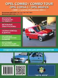
Руководство по эксплуатации, техническому обслуживанию и ремонту автомобилей Opel Corsa/Combo/Combo Tour/Meriva с 2000 года выпуска с бензиновыми и дизельными двигателями.
- Автор: —
- Издательство: Автоклуб
- Год издания: —
- Страниц: 222
- Формат: —
- Размер: —
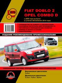
Руководство по эксплуатации и ремонту Fiat Doblo 2 и Opel Combo D с 2009 года выпуска с бензиновыми и дизельными двигателями.
- Автор: —
- Издательство: Монолит
- Год издания: —
- Страниц: 484
- Формат: —
- Размер: —
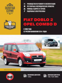
Руководство по эксплуатации и ремонту автомобилей Fiat Doblo 2 и Opel Combo D с 2009 года выпуска с бензиновыми и дизельными двигателями.
- Автор: —
- Издательство: Монолит
- Год издания: —
- Страниц: 484
- Формат: —
- Размер: —
Мультимедийное руководство по техническому обслуживанию и ремонту автомобилей Opel Combo/Corsa/Tigra 1993-2000 годов выпуска.
- Автор: —
- Издательство: —
- Год издания: —
- Страниц: —
- Формат: —
- Размер: 68,1 Mb
Руководство по эксплуатации, техническому обслуживанию и ремонту автомобилей Opel Combo/Corsa/Meriva 2000-2006 годов выпуска.
- Автор: —
- Издательство: Арус
- Год издания: —
- Страниц: 355
- Формат: PDF
- Размер: 32,8 Mb

- Manuals
- Brands
- Opel Manuals
- Automobile
- 2010 Combo
- Owner’s manual
-
Contents
-
Table of Contents
-
Bookmarks
Quick Links
Chapters
-
Table of Contents
3 -
Instrument Panel Overview
13 -
Windows
22 -
Seats, Restraints 35 Seats, Restraints Head Restraints
37 -
60 Storage Storage Storage Compartments
62 -
Instruments and Controls 69 Instruments and
71 -
Lighting 99 Lighting Exterior Lighting High Beam Light Switch
101 -
Driving and Operating 113 Driving and Driving Hints
115 -
140 Vehicle Care Vehicle Care General Information
142
Related Manuals for Opel COMBO
Summary of Contents for Opel COMBO
-
Page 1
COMBO Owner’s Manual… -
Page 3: Table Of Contents
Contents Introduction ……..2 In brief ……….6 Keys, doors and windows …. 20 Seats, restraints ……35 Storage ……..60 Instruments and controls ….. 69 Lighting ……..99 Climate control ……106 Driving and operating ….113 Vehicle care ……. 140 Service and maintenance ..
-
Page 4: Introduction
Introduction Introduction…
-
Page 5
Operation is Introduction prices. Experienced mechanics similar for right-hand drive trained by Opel work according to vehicles. Your vehicle is a designed specific Opel instructions. ● The Owner’s Manual uses the combination of advanced technology, The customer literature pack should engine identifier code. -
Page 6
We wish you many hours of Disregarding this information may pleasurable driving. endanger life. Adam Opel AG 9 Warning Text marked 9 Warning provides information on risk of accident or injury. Disregarding this information may lead to injury. -
Page 7
Introduction… -
Page 8: In Brief
In brief In brief Vehicle unlocking Unlocking with remote control Unlocking with key Initial drive information Press Ä to unlock the vehicle. Open the doors by pulling the handles. Turn the key in the driver’s door lock Press Å to unlock the load towards the front of the vehicle.
-
Page 9
In brief Seat adjustment Backrests inclination Seat height Longitudinal adjustment Turn handwheel. Do not lean on Lever pumping motion backrest when adjusting. : higher Pull handle, slide seat, release Seat position 3 36. down : lower handle. Seat adjustment 3 37. Operate lever and adjust body weight Try to move the seat back and forth to on seat to raise or lower it. -
Page 10: Head Restraint Adjustment
In brief Head restraint adjustment Seat belt Mirror adjustment Interior mirror Press release button, adjust height, Pull out the seat belt and fasten in belt engage. buckle. The seat belt must not be To adjust the mirror, move the mirror twisted and must fit close against the Head restraints 3 35.
-
Page 11: Steering Wheel Adjustment
In brief Exterior mirrors Electric adjustment Steering wheel adjustment Manual adjustment Select the relevant exterior mirror by Unlock the lever, adjust the steering turning the control to left _ or right 6. wheel, then engage lever and ensure Swivel lever in required direction. Then swivel the control to adjust the it is fully locked.
-
Page 12
In brief Instrument panel overview… -
Page 13
In brief Fixed air vents ….. 111 Trip computer ……96 14 Steering wheel controls ..70 Side air vents …… 110 15 Horn ……..70 Instrument illumination ..102 Light switch ……99 Driver airbag ……52 Hazard warning flashers ..100 High beam, low beam … -
Page 14
In brief… -
Page 15
In brief Exterior lighting Fog lights Headlight flash, high beam and low beam Press light switch: Turn light switch: headlight flash : pull lever > : front fog lights § : off / daytime running lights high beam : push lever ø… -
Page 16
In brief Turn and lane-change signals Hazard warning flashers Horn lever up : right turn signal Operated by pressing ¨. Press j. lever down : left turn signal Hazard warning flashers 3 100. Horn 3 70. Turn and lane-change signals 3 101. -
Page 17: Washer And Wiper Systems
In brief Washer and wiper systems Windscreen and headlight Rear window wiper and washer washer systems systems Windscreen wiper Pull lever. Rotate band to position e to activate Rotate lever: the rear window wiper. Windscreen and headlight washer : off §…
-
Page 18
In brief Climate control Demisting and defrosting the Electronic climate control system windows Heated rear window, heated Air conditioning system exterior mirrors Press Ê. Temperature and air distribution are set automatically and the fan runs at Set the temperature control to The heating is operated by pressing a high speed. -
Page 19: Starting Off
In brief Transmission Manual transmission automated Starting off Manual transmission Check before starting-off ● Tyre pressure and condition 3 159, 3 190. ● Engine oil level and fluid levels 3 143. ● All windows, mirrors, exterior lighting and number plates are free from dirt, snow and ice and are operational.
-
Page 20
In brief Starting the engine ● Diesel engines: turn the key to Stop-start system position 1 for preheating and wait until control indicator ! goes out. ● Turn key to position 2 and release. Starting the engine 3 115. ● Turn key to position 1. If the vehicle is at a low speed or at a standstill and certain conditions are ●… -
Page 21
In brief Parking ● Close the windows. ● Turn the ignition key to position 9 Warning 0 and remove it from the ignition switch. Turn the ● Do not park the vehicle on an steering wheel until the easily ignitable surface. The steering wheel lock is felt to high temperature of the engage. -
Page 22: Keys, Doors And Windows
Keys, doors and windows Keys, doors and Keys, locks Windows ……..32 Windscreen ……. 32 windows Keys Manual windows ……32 Power windows ……32 Rear windows ……34 Caution Heated rear window ….34 Keys, locks ……..20 Sun visors ……..34 Do not attach heavy or bulky items Keys ……….
-
Page 23: Car Pass
Keys, doors and windows Key with foldaway key section Radio remote control Fault If the central locking system cannot be operated with the remote control, it may be due to the following: ● Fault in remote control. ● The range is exceeded. ●…
-
Page 24: Manual Door Locks
Keys, doors and windows holder from the key and replace the Manually unlock the driver’s door by battery (type CR 2032), paying inserting the key in the lock cylinder attention to the installation position. and turning towards the front of the vehicle.
-
Page 25
Keys, doors and windows Sliding side door manual lock Push down inside locking knob on top Close front passenger door from of interior handle (if available) on the inside then push down inside locking To prevent the sliding side door from sliding side door(s) and/or engage the knob. -
Page 26: Central Locking System
Keys, doors and windows To disengage, open the door from Combi, Combo Tour inside the vehicle then turn the switch Press Ä: All doors, including rear to unlocked position 2. doors / tailgate and sliding side doors are unlocked. Central locking system Press Å: Rear doors / tailgate only…
-
Page 27: Child Locks
Keys, doors and windows Unlocking the load compartment Child locks from inside the vehicle 9 Warning Use the child locks whenever children are occupying the rear seats. Press e. All doors, including rear doors / tailgate and sliding side doors are locked.
-
Page 28: Doors
Keys, doors and windows Doors Rear doors Caution Unlock the rear doors with the remote Sliding door control or by turning the key in the rear Ensure the sliding side door is fully closed and secure before driving door lock cylinder. Unlock the sliding side door with the the vehicle.
-
Page 29
Keys, doors and windows The right hand rear door is released The doors are retained in the 90º using the lever. position by locking stays. To open the doors to 180º, push the latch and 9 Warning swing open to the desired position. 9 Warning The rear lights may be obscured if the rear doors are open and the… -
Page 30: Load Compartment
Keys, doors and windows Load compartment Closing Emergency tailgate opening from inside the vehicle Tailgate Opening Unlock the tailgate with the remote control 3 24. Use the interior loop. An access hole (arrowed) enables the Do not press button underneath the tailgate latch to be released using a tailgate handle whilst closing as this suitable tool.
-
Page 31: Vehicle Security
Keys, doors and windows Vehicle security Note Caution Depending on version, turning the manual key twice in the driver’s door Anti-theft locking system Before opening the tailgate check lock cylinder towards the rear of the overhead obstructions, such as a vehicle only deadlocks the rear 9 Warning garage door, to avoid damage to…
-
Page 32: Exterior Mirrors
Keys, doors and windows Exterior mirrors If d remains illuminated, attempt to Electric adjustment start the engine using the spare key and seek the assistance of a Convex shape workshop. The convex exterior mirror contains Note an aspherical area and reduces blind Radio Frequency Identification spots.
-
Page 33: Folding Mirrors
Keys, doors and windows Interior mirrors Folding mirrors Heated mirrors Manual anti-dazzle For pedestrian safety, the exterior Operated by pressing Ü. mirrors will swing out of their normal Heating works with the engine mounting position if they are struck To reduce dazzle, adjust the lever on running and is switched off with sufficient force.
-
Page 34: Windows
Keys, doors and windows Windows Pushing or pulling firmly and then Keep a close watch on the releasing: window moves up or down windows when closing them. fully with safety function enabled. To Windscreen Ensure that nothing becomes stop movement, operate the switch trapped in them as they move.
-
Page 35
Keys, doors and windows Overload Child safety system for rear windows If the windows are repeatedly operated within short intervals, the window operation is disabled for some time. Initialising the power windows If the windows cannot be closed automatically (e.g. after disconnecting the vehicle battery), activate the window electronics as follows:… -
Page 36: Heated Rear Window
Keys, doors and windows Rear windows Heated rear window Opening rear windows Operated by pressing Ü. Heating works with the engine To open, move lever outwards until running and is switched off the window is fully open. automatically after a short time. To close, pull lever then push until window is fully closed.
-
Page 37: Seats, Restraints
Seats, restraints Seats, restraints Head restraints Adjustment Front head restraints, height Position adjustment Head restraints ……35 9 Warning Front seats ……..36 Seat position ……36 Only drive with the head restraint Seat adjustment ……37 set to the proper position. Seat folding …….
-
Page 38: Front Seats
Seats, restraints Front seats Rear head restraints, height Note adjustment Approved accessories may only be attached if the seat is not in use. Seat position 9 Warning Only drive with the seat correctly adjusted. 9 Danger Do not sit nearer than 25 cm from the steering wheel, to permit safe airbag deployment.
-
Page 39: Seat Adjustment
Seats, restraints ● Sit with shoulders as far back Seat positioning against the backrest as possible. Set the backrest rake so that it is possible to reach the steering wheel with arms slightly bent. Maintain contact between shoulders and the backrest when turning the steering wheel.
-
Page 40: Seat Folding
Seats, restraints Seat backrests Seat height Lumbar support Turn handwheel. Do not lean on Lever pumping motion Adjust lumbar support using backrest when adjusting. handwheel to suit personal : higher requirements. down : lower Rotate handwheel to increase and Operate lever and adjust body weight decrease support.
-
Page 41
Seats, restraints Slide the front passenger seat as far 9 Warning back as possible, to avoid contact with the instrument panel during When the front passenger seat is folding. in the folded position, the front Note passenger airbag system must be When seat height is in its highest deactivated. -
Page 42: Armrest
Seats, restraints Armrest Heating Seat heating is operational with the ignition on and during an Autostop. Stop-start system 3 116. Raise or lower the front seat armrest Activate seat heating by pressing ß as required. for the respective front seat. Activation is indicated by the LED in the button.
-
Page 43: Rear Seats
Seats, restraints Rear seats Folding the seats Note The backrest is divided into two ● Press release buttons and push parts. Both parts can be folded Second row seats the head restraint downwards down, if necessary. 3 35. 9 Warning ●…
-
Page 44: Third Row Seats
Seats, restraints Failure to do so may result in Caution personal injury in the event of hard braking or a collision. For safety reasons, do not place loads on the folded rear seats. 9 Warning Unfolding the seats Only drive the vehicle if the 1.
-
Page 45
Seats, restraints Depending on version, the load Note 9 Warning compartment area can be increased The red mark on the release lever by folding up the third row seats. becomes visible when the backrest When folding the seat use caution is disengaged. -
Page 46
Seats, restraints 2. Remove the flexible cord and of personal injury or damage to the lower the seat assembly to the load or vehicle in the event of hard floor, ensuring the rear support is braking or a collision. located on the anchor point and securely latched into position. -
Page 47: Seat Belts
Seats, restraints Seat belts Installing the seats Note The backrest is properly engaged when the red mark on the release lever is no longer visible. 9 Warning When installing the rear seats, ensure that the seat assembly is properly located on the anchor points, the locks are fully engaged, and the backrest is returned to the correct position.
-
Page 48: Three-Point Seat Belt
Seats, restraints Seat belts are designed to be used by Belt pretensioners Three-point seat belt only one person at a time. Child In the event of a head-on or rear-end restraint system 3 55. Fastening collision of a certain severity, the front Periodically check all parts of the belt seat belts are tightened.
-
Page 49
Seats, restraints Height adjustment Loose or bulky clothing prevents the Adjust the height so that the belt lies belt from fitting snugly. Do not place across the shoulder. It must not lie 1. Pull belt out slightly. objects such as handbags or mobile across the throat or upper arm. -
Page 50: Airbag System
Seats, restraints Airbag system Unfastening Using the seat belt while pregnant The airbag system consists of a number of individual systems depending on the scope of equipment. When triggered, the airbags inflate within milliseconds. They also deflate so quickly that it is often unnoticeable during the collision.
-
Page 51
Seats, restraints 9 Warning 9 Warning If handled improperly the airbag When the airbags inflate, escaping systems can be triggered in an hot gases may cause burns. explosive manner. Control indicator v for airbag systems Note 3 82. The airbag systems and belt Fault pretensioner control electronics are located in the centre console area. -
Page 52
Seats, restraints sous peine d’infliger des SV: Använd ALDRIG en bakåtvänd AIRBAG ATTIVO di fronte ad esso: BLESSURES GRAVES, voire barnstol på ett säte som skyddas med pericolo di MORTE o LESIONI MORTELLES à l’ENFANT. en framförvarande AKTIV AIRBAG. GRAVI per il BAMBINO! DÖDSFALL eller ALLVARLIGA ES: NUNCA utilice un sistema de EL: ΠΟΤΕ… -
Page 53
Seats, restraints на сидінні з УВІМКНЕНОЮ JASTUKOM ispred sedišta zato što AIRBAGEM. Mohlo by dojít k ПОДУШКОЮ БЕЗПЕКИ, інакше це DETE može da NASTRADA ili da se VÁŽNÉMU PORANĚNÍ nebo ÚMRTÍ може призвести до СМЕРТІ чи TEŠKO POVREDI. DÍTĚTE. СЕРЙОЗНОГО ТРАВМУВАННЯ MK: НИКОГАШ… -
Page 54: Front Airbag System
Seats, restraints MT: QATT tuża trażżin għat-tfal li jħares lejn in-naħa ta’ wara fuq sit protett b’AIRBAG ATTIV quddiemu; dan jista’ jikkawża l-MEWT jew ĠRIEĦI SERJI lit-TFAL. Beyond the warning required by ECE R94.02, for safety reasons never use a forward-facing child restraint system on the front passenger seat with active front airbag.
-
Page 55: Side Airbag System
Seats, restraints The inflated airbags cushion the Depending on vehicle, there is a Keep the area in which the airbag impact, thereby reducing the risk of warning on the airbag label located on inflates clear of obstructions. injury to the upper body and pelvis in the front passenger sun visor.
-
Page 56
Seats, restraints — or — Otherwise, there is a risk of fatal Passenger bag (in Multifunction injury for a person occupying a version) seat with a deactivated front passenger airbag. is displayed. 3. Press SETq to access this menu As long as the control indicator * is option. -
Page 57: Child Restraints
Seats, restraints Child restraints Always comply with local or national regulations. In some countries, the use of child restraint systems is Child restraint systems forbidden on certain seats. Child restraint systems can be 9 Danger fastened with: If using a rear-facing child restraint ●…
-
Page 58
Seats, restraints Top-Tether fastening eyes Children should travel facing A child restraint system which has rearwards in the vehicle as long as been subjected to stress in an Top-Tether fastening eyes are possible. This makes sure that the accident must be replaced. located on the back of the seat. -
Page 59: Child Restraint Installation Locations
Seats, restraints Child restraint installation locations Permissible options for fitting a child restraint system Front passenger seat Second row Third row Weight and age class activated airbag deactivated airbag outboard seat centre seat Group 0: up to 10 kg U, < or approx.
-
Page 60
Seats, restraints Permissible options for fitting an ISOFIX child restraint system On outboard On centre On the On front seats in the seat in the seats in the Weight class Size class Fixture passenger seat second row second row third row Group 0: up to 10 kg ISO/R1 X or approx. -
Page 61
Seats, restraints ISOFIX size class and seat device A – ISO/F3 : forward-facing child restraint system for children of maximum size in the weight class 9 to 18 kg B – ISO/F2 : forward-facing child restraint system for smaller children in the weight class 9 to 18 kg B1 –… -
Page 62: Storage
Storage Storage Storage compartments Document holder 9 Warning Storage compartments ….60 Instrument panel storage … 60 Do not store heavy or sharp Glovebox ……..61 objects in the storage Cupholders …….. 61 compartments. Otherwise vehicle Front storage ……61 occupants could be injured by Overhead console …..
-
Page 63: Glovebox
Storage Glovebox Cupholders Overhead console Pull lever to open the glovebox cover. Cupholders are located in the console Store only lightweight items such as between the front seats. paperwork or maps in the overhead Depending on version, the glovebox console. may be lockable using the ignition The cupholders can also be used to key.
-
Page 64: Underseat Storage
Storage Load compartment Underseat storage No materials (e.g. rubber, plastic) should be placed between the feet of the bars and the vehicle body, to Rear storage ensure proper fastening. Storage compartments are located in the rear door pockets and in the load 9 Warning compartment sidewalls.
-
Page 65: Load Compartment Cover
Storage 1. On one side of the vehicle, rotate Load compartment cover Opening handle below first roof bar (located beneath the bracket) to Extendable load compartment loosen, then slide handle inwards cover towards centre of vehicle. Do not place any heavy or sharp- 2.
-
Page 66
Storage Removing Rear parcel shelf The rear parcel shelf consists of two parts — a front part and rear part. The front part can be opened or closed, allowing for greater flexibility in the load compartment. Do not place any excessively heavy or sharp-edged objects on the rear parcel shelf. -
Page 67: Lashing Eyes
Lift the rear part of the parcel shelf by Removing releasing it from the rear retainers (2 Combo Tour If the rear seats are in the folded and 3) on both sides. position, remove the parcel shelf and…
-
Page 68: Load Compartment Grille
Storage Load compartment grille ● Insert the pin in the slot (2) on the backrest of the folded front Depending on version, the load passenger seat to lock in compartment area can be increased position. by opening the load compartment partition on the front passenger side 9 Warning (where fitted).
-
Page 69: Roof Rack System
Storage Roof rack system Loading information Note Roof racks are not permitted on high roof variants (H2). Roof rack ● Heavy objects in the load Vehicle dimensions 3 187. compartment should be evenly For safety reasons and to avoid distributed and placed as far damage to the roof, the vehicle forward as possible.
-
Page 70
Storage ● The load must not obstruct the luggage (7 kg) and all fluids (fuel operation of the pedals, parking tank 90% full). brake and gear selector lever, or Optional equipment and hinder the freedom of movement accessories increase the kerb of the driver. -
Page 71: Instruments And Controls
Instruments and controls Instruments and Transmission display ….79 High beam ……… 89 Control indicators …… 79 Fog light ……..90 controls Generic warning ……81 Rear fog light ……90 Turn signal ……… 82 Cruise control ……90 Seat belt reminder ….. 82 Door open ……..
-
Page 72: Controls
Instruments and controls Controls Steering wheel controls Horn Steering wheel adjustment The Infotainment system and a Press j. connected mobile phone can be The horn will sound regardless of operated via the controls on the Unlock lever, adjust steering wheel, ignition switch position.
-
Page 73: Windscreen Wiper/Washer
Instruments and controls Windscreen wiper/washer Adjustable wiper interval Rear window wiper/washer Wiper lever in position Ç. Windscreen wiper The windscreen wiper will automatically adapt to the speed of the vehicle. Windscreen washer Rotate band to position e to activate the rear window wiper. Rotate lever: Push lever.
-
Page 74: Headlamp Washer
Instruments and controls Headlamp washer displayed in the Driver Information Values can be adjusted via SETq, Centre by pressing TRIP on the end R and S on the instrument panel. With low beam on, washer fluid is of the wiper lever 3 96. sprayed onto the headlights when the Set time in Driver Information windscreen washer is activated…
-
Page 75
Instruments and controls Set time and date in Driver 4. Press R or S to increase or 3. Press SETq to access this menu Information Centre — Multifunction decrease the displayed value. option; the year will flash in the display. version 5. -
Page 76: Power Outlets
Instruments and controls Power outlets Short wheelbase van Combo Tour Do not exceed the maximum power Long wheelbase van A 12 Volt power outlet is located at the consumption of 180 watts. front of the centre console. With ignition off, the power outlets are Rear power outlets deactivated.
-
Page 77: Cigarette Lighter
Instruments and controls A USB port and AUX socket for the Press in cigarette lighter. It switches Caution connection of external audio sources off automatically once the element is is located at the rear of the centre glowing. Pull out lighter. Do not connect any current- console.
-
Page 78: Warning Lights, Gauges And Indicators
Instruments and controls Warning lights, gauges Odometer To reset the trip odometer, press and hold TRIP on the end of the wiper and indicators lever 3 96 for a few seconds while the relevant trip odometer is Instrument cluster displayed. The needles of the instruments may Tachometer briefly rotate to the end position when…
-
Page 79: Fuel Gauge
Instruments and controls Fuel gauge Never run the tank dry. the cylinders. As the fuel level diminishes, the bars in the CNG fuel Because of the fuel remaining in the gauge disappear. tank, the top-up quantity may be less than the specified tank capacity. CNG and the one remaining bar will flash if the methane level in the The needle will point to 0 and control…
-
Page 80: Engine Coolant Temperature Gauge
Instruments and controls 1 off : natural gas If control indicator $ illuminates, the Service display is available in operation vehicles with Multifunction version of coolant temperature is too high. 1 illuminates : petrol operation the Driver Information Centre 3 90. Depending on version, a message also appears in the Driver Information When the ignition is switched on, the…
-
Page 81: Transmission Display
Instruments and controls Resetting the service display Control indicators The control indicators described are After a service, the service display not present in all vehicles. The must be reset by a workshop. description applies to all instrument Service information 3 176. versions.
-
Page 82
Instruments and controls Control indicators in the instrument cluster… -
Page 83: Generic Warning
Instruments and controls Control indicator in the roof Malfunction indicator light Low engine oil level 3 88 console 3 83 Low fuel 3 88 Brake system 3 84 Drain fuel filter 3 89 Brake pad wear 3 84 Immobiliser 3 89 Antilock brake system (ABS) Stop-start system 3 89 Æ…
-
Page 84: Turn Signal
Instruments and controls Turn signals 3 101. If 9 illuminates together with I 9 Warning 3 88; stop engine immediately and seek the assistance of a workshop. Seat belt reminder Fasten seat belt before each trip. In the event of the failure of control In the event of an accident, people Seat belt reminder for front seats indicator v for airbags and belt…
-
Page 85: Airbag Deactivation
Instruments and controls With the front passenger airbag Illuminates when the ignition is Depending on version, 9 will illuminate in the event of the failure of switched on and extinguishes shortly activated: after the engine starts. control indicator v. When the ignition is switched on, Generic warning 9 3 81.
-
Page 86: Brake System
Instruments and controls Flashes when the engine is Illuminates if the brake vacuum servo Antilock brake system fails; the brake pedal becomes stiff running (ABS) when pressed. The brake system Fault that could lead to catalytic u illuminates yellow. remains operational however, converter damage.
-
Page 87: Gear Shifting
Instruments and controls s illuminates during driving when a fault in the Hill start assist. Seek the Interference due to external sources fault is present in the transmission. assistance of a workshop to have the of ultrasound. Once the source of fault remedied.
-
Page 88: Engine Coolant Temperature
Instruments and controls Flashes during driving If control indicator $ illuminates, the Note In very hot outside coolant temperature is too high. The system is actively engaged. temperatures, ! may illuminate Depending on version, a warning Engine output may be reduced and message may also be displayed in briefly when the ignition is switched the vehicle may be braked…
-
Page 89: Tyre Pressure Monitoring System
Instruments and controls Continue driving until % a corresponding message also Caution appears when a puncture or severely extinguishes. Depending on version, under-inflated tyre is detected. a warning message may also be Engine lubrication may be displayed in the Driver Information interrupted.
-
Page 90: Change Engine Oil
Instruments and controls Depending on version, a If the control indicator does not 9 Warning corresponding warning message, extinguish after a few seconds, or if it e.g. Change engine oil, may also be illuminates while driving, the engine When the engine is off, displayed in the Driver Information oil level is insufficient.
-
Page 91: Drain Fuel Filter
Instruments and controls Flashes If d illuminates when starting, there Exterior light is a fault in the immobiliser system. 8 illuminates green. Fault in fuel system. Have the cause The engine cannot be started. of the fault remedied by a workshop. The exterior lights are on 3 99.
-
Page 92: Fog Light
Instruments and controls Information displays Fog light When the vehicle starts to move, a warning chime also sounds. > illuminates green. Driver Information Centre The front fog lights are on 3 101. The Driver Information Centre is located in the instrument cluster Rear fog light between the speedometer and ø…
-
Page 93
Instruments and controls ● transmission display 3 122 Press R or S to scroll through the available settings or to increase/ ● stop-start system indicator decrease the displayed value. 3 116 Press and hold R or S to increase/ ● vehicle messages 3 95 decrease a value rapidly (press again ●… -
Page 94
Instruments and controls ● UNIT HOUR (Setting the clock) 9 Danger Adjust the hours setting (flashing ● bUZZ value) and confirm. Adjust minutes ● BAG P Risk of fatal injury for a child using setting (flashing value) and confirm. a child restraint system on a seat ●… -
Page 95
Instruments and controls Settings menu options — Dimmer (Brightness of interior TripB data lighting) Multifunction version Activate or deactivate the second trip When driving at night with the low computer (set to On or Off). The settings menu contains the beam on, adjust the brightness of the Trip B records average consumption, following options:… -
Page 96
Instruments and controls See radio or Radio info (Display audio measurement for fuel consumption to Belt buzzer or Seat belt buzzer and radio information) (Reactivate warning chime for driver either l/100km or km/l. When the Distance unit is set to mi (miles), fuel and/or front passenger seat belt Available depending on version, consumption is shown in mpg. -
Page 97: Vehicle Messages
Instruments and controls Vehicle messages Passenger bag or Passenger airbag Day lights or Daytime running lights (Passenger front and side airbags Activate the daytime running lights to activation/deactivation) increase visibility of the vehicle during Warning chimes Activate the front passenger airbags daylight (set to On).
-
Page 98: Fuel System Messages
Instruments and controls Trip computer ● Vehicles with manual When the vehicle is parked transmission automated; brake and/or the driver’s door is opened pedal has not been depressed The trip computer provides ● When the key is in the ignition when starting the engine.
-
Page 99
Instruments and controls ● average consumption ● average speed Outside temperature 3 72, 3 90. ● instantaneous consumption ● travel time (driving time) Range ● average speed Trip B can be deactivated via the The range is calculated from the Driver Information Centre 3 90. -
Page 100
Instruments and controls Average consumption The measurement can be restarted at any time. Average consumption is displayed, taking into consideration the distance Exit trip computer travelled and the fuel used since the To exit the trip computer, press and last reset. hold SETq for more than The measurement can be restarted at two seconds. -
Page 101: Lighting
Lighting Lighting Exterior lighting High beam Light switch Exterior lighting ……99 Light switch …….. 99 High beam ……… 99 Headlight flash ……99 Headlight range adjustment ..100 Headlights when driving abroad ……..100 Daytime running lights ….. 100 Hazard warning flashers ..
-
Page 102: Headlight Range Adjustment
Lighting Headlight range adjustment Headlights when driving Note The driver remains responsible for abroad Manual headlight range switching on the low beam when The asymmetrical headlight beam required, e.g. when driving through adjustment extends visibility at the edge of the a tunnel or at night.
-
Page 103: Turn And Lane-Change Signals
Lighting Depending on version, hazard For five flashes, e.g. when changing Rear fog lights warning flashers may come on lanes, press the lever until resistance automatically during hard braking. is felt and then release. Move the lever to the resistance point Turn and lane-change and hold for longer indication.
-
Page 104: Misted Light Covers
Lighting Interior lighting Misted light covers 1. Press SETq once to access the settings menu. The inside of the light housing may Instrument panel 2. Scroll through the menu options mist up briefly in poor, wet and cold by pressing R or S until menu illumination control weather conditions, in heavy rain or option ILLU appears in the…
-
Page 105: Interior Lights
Lighting 4. Press R or S to increase or Front courtesy light Front courtesy light with reading decrease the displayed value. lights 5. Press SETq briefly to confirm changes and automatically return to the previous display screen. Depending on version, it may also be possible to adjust the brightness by pressing R or S without accessing the settings menu.
-
Page 106: Load Compartment Lighting
Lighting Rear courtesy lights Removable rear courtesy light torch down carefully and remove. Press switch on the end of torch to turn the light on/off. Replace the torch in its original position to recharge the battery after use. Centre switch position: automatic Depending on model variant, the interior light.
-
Page 107: Lighting Features
Lighting Lighting features This action can be repeated up to seven times to a maximum period of 210 seconds. Exit lighting Control indicator 8 3 89 illuminates in the instrument cluster during use. Depending on version, a warning message may also be displayed in the Driver Information Centre 3 90.
-
Page 108: Climate Control
Climate control Climate control Climate control systems Heating will not be fully effective until the engine has reached normal operating temperature. Heating and ventilation system Fan speed Climate control systems ….. 106 Heating and ventilation system 106 Adjust the air flow by switching the fan Air conditioning system …
-
Page 109: Air Conditioning System
Climate control ● Open side air vents as required Heated rear window Ü 3 34. Cooling n and direct them towards door Heated front seats ß 3 40. Press n to switch on cooling. windows. Activation is indicated by the LED in Temperature ●…
-
Page 110: Electronic Climate Control System
Climate control ● Set fan speed to highest level. Electronic climate control 9 Warning ● Open all air vents. system The exchange of fresh air is Demisting and defrosting the reduced in air recirculation mode. windows In operation without cooling the air humidity increases, so the ●…
-
Page 111
Climate control The preselected temperature is clockwise : warm maximum fan : all bars displayed automatically regulated. In the anticlockwise : cold speed automatic mode the fan speed and air minimum fan : one bar displayed Heating will not be fully effective until distribution automatically regulate the speed the engine has reached normal… -
Page 112: Side Air Vents
Climate control Air vents Cooling 9 Warning Press n to switch on cooling. Cooling Adjustable air vents is only functional when the engine is The exchange of fresh air is reduced in air recirculation mode. running and climate control fan is At least one air vent must be open In operation without cooling the air switched on.
-
Page 113: Fixed Air Vents
Climate control Maintenance Slide knob to the left to open vent. Air conditioning regular Direct the flow of air by swivelling the operation Air intake vent. In order to ensure continuously Slide knob to the right to close vent. efficient performance, cooling must be operated for a few minutes once a Fixed air vents month, irrespective of the weather…
-
Page 114
Climate control Note Refrigerant R-134a contains fluorinated greenhouse gases with a global warming potential of 1430. The air conditioning system is filled with 0.45 kg and has a CO equivalent of 0.644 tonnes. -
Page 115: Driving And Operating
Driving and operating Driving and Driving hints Brakes ……..126 Antilock brake system ….. 126 operating Control of the vehicle Parking brake ……127 Brake assist ……127 Never coast with engine not Hill start assist ……127 running (except during Autostop) Ride control systems ….
-
Page 116: Steering
Driving and operating Starting and operating Steering If power steering assist is lost New vehicle running-in because the engine stops or due to a system malfunction, the vehicle can Do not brake unnecessarily hard for be steered but may require increased the first few journeys.
-
Page 117: Starting The Engine
Driving and operating Steering wheel lock Diesel engine: turn key to position 1 Starting the vehicle at low for preheating until control temperatures Remove key from ignition switch and indicator ! extinguishes. turn steering wheel until it engages. The start of the engine without Turn key briefly to position 2 and additional heaters is possible down to release.
-
Page 118: Overrun Cut-Off
Driving and operating 4. Fully actuate the left turn signal Stop-start system Control indicator 9 illuminates if the fuel cut-off switch is triggered and, light. The stop-start system helps to save depending on version, a 5. Deactivate the left turn signal fuel and to reduce exhaust emissions.
-
Page 119
Driving and operating Deactivation Autostop Caution If the vehicle is at a low speed or at a standstill, activate an Autostop as The power steering assist may be reduced during an Autostop. follows: ● depress the clutch pedal Conditions for an Autostop ●… -
Page 120
Driving and operating ● the self-cleaning function of the Restarting the engine In this event, control indicator ^ diesel particle filter is not active flashes in the Driver Information Manual transmission Centre in conjunction with a warning ● the vehicle has moved since the The selector lever must be in neutral chime. -
Page 121: Parking
Driving and operating Parking Note ● Close the windows. In the event of an accident with ● Turn the ignition key to position airbag deployment, the engine is 9 Warning 0 and remove it from the switched off automatically if the ignition switch.
-
Page 122: Engine Exhaust
Driving and operating Engine exhaust needs 15 minutes. Autostop is not Control indicator % illuminates when available and fuel consumption may diesel particle filter is full. Start be higher during this period. The cleaning process as soon as possible emission of smells and smoke during to avoid damage to the engine.
-
Page 123: Manual Transmission
Driving and operating Manual transmission Caution Caution Fuel grades other than those listed It is inadvisable to drive with hand on pages 3 134, 3 182 could resting on the selector lever. damage the catalytic converter or electronic components. When gearshifting is recommended to improve fuel economy, control Unburnt petrol will overheat and indicator [ or Ò…
-
Page 124: Manual Transmission Automated
Driving and operating Manual transmission If the brake pedal is not depressed, a Selector lever warning chime will sound 3 95 and automated the engine cannot be started. Depending on version, a The manual transmission automated corresponding warning message, (MTA) permits manual (manual e.g.
-
Page 125
Driving and operating malfunction and a warning message Move the selector lever towards A/M Caution may be displayed in the Driver to engage automatic mode; the Information Centre. transmission shifts to other gears It is not advisable to drive with the automatically, dependent on driving Return the selector lever to the hand resting on the selector lever. -
Page 126: Manual Mode
Driving and operating Switch off engine if stopping for a Parking speed is too high, the transmission lengthy period, e.g. in traffic jams. only switches to a higher gear via Apply the parking brake. The most kickdown 3 124. recently engaged gear (see Engine braking When gearshifting is recommended transmission display) remains…
-
Page 127: Fault
Driving and operating Eco mode selects the most suitable depending on engine speed. Full message may appear in the Driver gear depending on the speed of the engine power is available for Information Centre in conjunction with vehicle, the engine speed and the acceleration.
-
Page 128: Brakes
Driving and operating Brakes ABS starts to regulate brake pressure 9 Warning as soon as a wheel shows a tendency to lock. The vehicle remains The brake system comprises two If there is a fault in the ABS, the steerable, even during hard braking. independent brake circuits.
-
Page 129: Parking Brake
Driving and operating Parking brake Hill start assist To reduce the operating forces of the parking brake, depress the The system helps prevent unintended Manual parking brake brake pedal at the same time. movement when driving away on inclines. A warning chime will sound if a certain When releasing the brake pedal after speed is exceeded with the parking stopping on an incline, the brakes…
-
Page 130: Ride Control Systems
Driving and operating Ride control systems be displayed in the Driver Information Centre 3 90. Seek the assistance of a workshop to have the fault Traction Control system remedied. The Anti-Slip Regulator (ASR) is a The Hill start assist is not active component of the Electronic Stability during an Autostop.
-
Page 131: Electronic Stability Control
Driving and operating Deactivation Fault ASR will switch off automatically in the event of a fault. Control indicator R will illuminate in the instrument cluster. Depending on version, a corresponding message, e.g. ESP unavailable, may also appear in the Driver Information Centre 3 90. Have the cause of the fault remedied by a workshop.
-
Page 132: Driver Assistance Systems
Driving and operating Driver assistance Fault systems In the event of a fault, ESC will be automatically switched off and control indicator R will illuminate in the 9 Warning instrument cluster. Depending on version, a corresponding message, Driver assistance systems are e.g.
-
Page 133: Parking Assist
Driving and operating Turn end of lever to the ON position; Alternatively accelerate to the desired Switching off control indicator m 3 90 illuminates in speed and store by pushing lever Turn end of lever to the OFF position; the instrument cluster. Depending on upwards (+).
-
Page 134
Driving and operating Deactivation The following conditions could affect the system’s performance: The parking assist automatically ● The ultrasonic sensors are not switches off when reverse gear is clean. Keep the bumper free of disengaged. mud, dirt, snow, ice and slush. Fault ●… -
Page 135
Driving and operating A warning chime is also sounded The sensor may detect a non- Caution briefly if a fault is present when existent object (echo disturbance) reverse gear is engaged 3 95. caused by external acoustic or Performance of the sensor can be mechanical disturbances. -
Page 136: Fuel
Driving and operating Fuel Caution Caution Fuel for petrol engines Use of fuel that does not comply to Use of fuel that does not comply to EN 228 or E DIN 51626-1 or EN 590 or similar can lead to Only use unleaded fuel that complies equivalent can lead to deposits or engine powerloss, increased wear…
-
Page 137: Refuelling
Driving and operating Fuel selector When switching automatically 9 Danger between petrol or gas operation, a brief delay of engine tractive power Fuel is flammable and explosive. may be noticeable. No smoking. No naked flames or Every six months run the petrol tank sparks.
-
Page 138
Driving and operating Note Caution 9 Warning Depending on model, the sliding side door may be fitted with a safety Wipe off any overflowing fuel Refuel only with a maximum system that prevents the door from immediately. output pressure of 250 bar. Use being opened fully when the fuel only temperature compensated filler flap is open. -
Page 139: Fuel Consumption — Co 2 — Emissions
The fuel consumption (combined) of English CNG = Compressed The figures are provided only for the the model Opel Combo is within a Natural Gas purpose of comparison between range of 7.7 to 4.1 l/100 km.
-
Page 140: Trailer Hitch
Driving and operating Trailer hitch For trailers with low driving stability The permissible trailer loads are and caravan trailers with a permitted specified in the vehicle documents. In gross vehicle weight of more than general, they are valid for gradients General information 1300 kg the use of a stabiliser is up to max.
-
Page 141
Driving and operating The maximum permissible vertical coupling load (60 kg) is specified on the towing equipment identification plate and in the vehicle documents. Always aim for the maximum load, especially in the case of heavy trailers. The vertical coupling load should never fall below 25 kg. -
Page 142: Vehicle Care
Wheel covers ……162 units) may invalidate the warranty Brake fluid ……. 145 Tyre chains ……163 offered by Opel. Furthermore, such Vehicle battery ……146 Tyre repair kit ……163 changes may impact fuel Wiper blade replacement ..147 Wheel changing …….
-
Page 143: Vehicle Storage
Vehicle care ● Park the vehicle in a dry, well End-of-life vehicle recovery Caution ventilated place. Engage first or Information on end-of-life vehicle reverse gear to prevent the recovery centres and the recycling of When transporting the vehicle on vehicle from rolling. a train or on a recovery vehicle, the end-of-life vehicles is available on our ●…
-
Page 144: Vehicle Checks
Vehicle care Vehicle checks Bonnet Opening Performing work 9 Warning Only perform engine compartment checks when the ignition is off. The cooling fan may start operating even if the ignition is off. 9 Danger Move the safety catch sideways and open the bonnet.
-
Page 145: Engine Oil
Vehicle care If the bonnet is opened during an The maximum engine oil When the engine oil level has Autostop, the engine will be restarted consumption is 0.6 litres per dropped to the MIN mark, top up automatically for safety reasons. 1000 km.
-
Page 146: Engine Coolant
Vehicle care Capacities 3 189. the coolant concentration checked and have the cause of the coolant Fit the cap on straight and tighten it. loss remedied by a workshop. Coolant and antifreeze 3 177. Engine coolant The coolant provides freeze Power steering fluid protection down to approx.
-
Page 147: Washer Fluid
Vehicle care If the fluid level in the reservoir falls Brake fluid Caution below the MIN mark consult a workshop. 9 Warning Only washer fluid with a sufficient If an unusual noise sounds during antifreeze concentration provides steering or the power steering reacts Brake fluid is poisonous and protection at low temperatures or conspicuously, seek the assistance of…
-
Page 148: Vehicle Battery
Vehicle care Only use high-performance brake In vehicles with stop-start system, fluid approved for the vehicle. ensure the correct battery is used when replacing the vehicle battery. Brake and clutch fluid 3 177. We recommend that you have the vehicle battery replaced by a Vehicle battery workshop.
-
Page 149: Wiper Blade Replacement
Vehicle care Warning label ● See the Owner’s Manual for Wiper blade on rear swing door further information. ● Explosive gas may be present in the vicinity of the vehicle battery. Wiper blade replacement Meaning of symbols: Lift wiper arm, press and hold retaining clip and detach wiper blade.
-
Page 150: Bulb Replacement
Vehicle care Bulb replacement Wiper blade on tailgate Halogen headlights Switch off the ignition and switch off the relevant switch or close the doors. Only hold a new bulb at the base! Do not touch the bulb glass with bare hands.
-
Page 151
Vehicle care 4. Insert new bulb in reflector so that 4. Insert new bulb in reflector so that 2. Remove bulb from socket, insert the locating tab of the bulb aligns the bulb aligns with the reflector new bulb. with the reflector recess. recess. -
Page 152: Fog Lights
Vehicle care Tail lights 2. Withdraw bulb holder from 2. Withdraw bulb holder from reflector by turning anticlockwise. reflector by turning anticlockwise. 1. Remove the three retaining 3. Remove bulb from socket, insert 3. Push bulb into holder slightly, screws. new bulb.
-
Page 153: Side Turn Signal Lights
Vehicle care 10. Insert lamp assembly in body, ensuring correct positioning. Tighten the three retaining screws. 11. Switch on ignition, operate and check all lights. Side turn signal lights Have bulbs replaced by a workshop. Centre high-mounted brake Brake light (1) 4.
-
Page 154: Number Plate Light
Vehicle care Number plate light Rear doors Tailgate 2. Turn the bulb holder anticlockwise to remove from the bulb housing. 1. Insert screwdriver as indicated by Remove the bulb by pulling. the arrows, press to the left and 3. Replace the bulb. 1.
-
Page 155: Interior Lights
Vehicle care Interior lights Front courtesy light, reading lights Removable rear courtesy light Front and rear courtesy light 1. Remove lens using a flat blade 1. Press the button at the top of the screwdriver. lamp assembly to release it. 1.
-
Page 156: Instrument Panel Illumination
Vehicle care Electrical system 2. Prise the lamp assembly out at the points illustrated. Fuses 3. Renew bulb, ensuring it engages correctly. Data on the replacement fuse must 4. Reinstall lamp assembly. match the data on the defective fuse. There are two fuse boxes in the Instrument panel vehicle: illumination…
-
Page 157: Engine Compartment Fuse Box
Vehicle care It is advisable to carry a full set of Engine compartment fuse fuses. Some functions are protected by several fuses. Fuses may also be inserted without existence of a function. Note Not all fuse box descriptions in this Owner’s Manual may apply to your vehicle.
-
Page 158: Instrument Panel Fuse Box
Vehicle care Instrument panel fuse box No. Circuit F09 Rear door switch F10 Horn F14 High beam F15 PTCI additional heater F19 Air conditioning system F20 Heated rear window F21 Fuel pump F30 Fog lights The fuse box is located behind a F84 CNG system cover on the lower part of the F85 Power outlets…
-
Page 159
Vehicle care No. Circuit No. Circuit F12 Right low beam F49 Exterior mirrors/Infotainment system/Parking assist/Tyre F13 Left low beam/Headlight range pressure monitoring system/ adjustment Instrument illumination/Rain sensor F31 Fusebox relays/Body control unit relays F50 — F32 Courtesy lights F51 Infotainment system/Braking system/Clutch/Interior heater F36 Diagnostic connector/Climate control system/Infotainment… -
Page 160: Vehicle Tools
Vehicle care Vehicle tools The single panel of fuses may be Combi, Combo Tour located on the right-hand side of the fuse compartment in right-hand drive Tools vehicles. After having changed defective fuses, refit the cover. If the fuse box cover is not closed correctly, malfunction may occur.
-
Page 161: Wheels And Tyres
Vehicle care Wheels and tyres Tyre designations Directional tyres E.g. 215/60 R 16 95 H Directional tyres must be mounted so that they rotate in the correct Tyre condition, wheel condition 215 : tyre width, mm direction. The proper rotation 60 : cross-section ratio (tyre height Drive over edges slowly and at right direction is indicated by a symbol…
-
Page 162: Tyre Pressure Monitoring System
Vehicle care Incorrect tyre pressures will impair Tyre pressure monitoring 9 Warning safety, vehicle handling, comfort and system fuel economy and will increase tyre For specific tyres the The tyre pressure monitoring system wear. recommended tyre pressure as uses radio and sensor technology to Tyre pressures differ depending on shown in the tyre pressure table check tyre pressure levels.
-
Page 163
Vehicle care Note for these wheels. For the further three If w illuminates, stop as soon as In countries where the tyre pressure possible and inflate the tyres as wheels, tyre pressure monitoring monitoring system is legally system remains operational. recommended 3 190. -
Page 164: Tread Depth
Vehicle care General information Changing tyre and wheel size The use of tyre chains or commercially available liquid tyre If tyres of a different size than those repair kits can impair the function of fitted at the factory are used, it may be the system.
-
Page 165: Tyre Chains
Vehicle care Wheel covers must not impair brake Always use fine mesh chains that add Apply the parking brake and engage cooling. no more than 10 mm to the tyre tread first or reverse gear. and the inboard sides (including chain The tyre repair kit may be located 9 Warning lock).
-
Page 166
Vehicle care damaged. Seek the assistance of a workshop. Do not run the compressor longer than 20 minutes. 11. Detach the tyre repair kit. 12. Remove any excess sealant using a cloth. 13. Take the label indicating maximum permitted speed from the sealant bottle and affix in the driver’s field of view. -
Page 167: Wheel Changing
Vehicle care Note the expiry date of the kit. After 2. Turn the canister anticlockwise to this date its sealing capability is no lift it out. longer guaranteed. Pay attention to 3. Insert the new canister and turn it storage information on sealant clockwise.
-
Page 168
Vehicle care ● The jack is maintenance-free. ● If the ground on which the vehicle is standing is soft, a solid board (max. 1 cm thick) should be placed under the jack. ● Take heavy objects out of the vehicle before jacking up. ●… -
Page 169: Spare Wheel
Vehicle care the jacking point in a manner that 10. Align the valve hole in the wheel Caution prevents it from slipping. cover with the tyre valve before installing. The use of a spare wheel that is Install wheel nut caps. smaller than the other wheels or in 11.
-
Page 170
Vehicle care 4. Withdraw spare wheel from beneath the vehicle. 2. Insert the wheel wrench into the 8. Pass the retainer 1 through the aperture in the load compartment hole in the rim, inserting the floor. locating pin into one of the bolt 5. -
Page 171: Jump Starting
Vehicle care Jump starting 3. Position the replaced spare wheel onto the bracket ensuring correct alignment of the locating pin. Do not start with quick charger. 4. Secure spare wheel by tightening A vehicle with a discharged battery two bolts using the wheel wrench. can be started using jump leads and Have the defective tyre renewed or the battery of another vehicle.
-
Page 172
Vehicle care ● A discharged vehicle battery can ● The vehicles must not come into 3. Connect the black lead to the already freeze at a temperature contact with each other during negative terminal of the booster of 0 °C. Defrost the frozen battery the jump starting process. -
Page 173: Towing
Vehicle care Towing 4. Switch on electrical consumers Caution (e.g. headlights, heated rear window) of the vehicle receiving Towing the vehicle The towing eye must only be used the jump start. for towing and not for recovering 5. Reverse above sequence exactly the vehicle.
-
Page 174: Towing Another Vehicle
Vehicle care Appearance care To prevent the entry of exhaust gases The towing eye is stowed with the from the towing vehicle, switch on the vehicle tools 3 158. air recirculation 3 107 and close the Exterior care Screw in the towing eye as far as it will windows.
-
Page 175
Vehicle care If using a vehicle wash, comply with Do not clean the engine compartment Paintwork polish with silicone forms a the vehicle wash manufacturer’s with a steam-jet or high-pressure jet protective film, making waxing instructions. The windscreen wiper cleaner. unnecessary. -
Page 176
Vehicle care For mechanical removal of ice, use a Wheels and tyres Before and after winter, wash the sharp-edged ice scraper. Press the underbody and have the protective Do not use high-pressure jet scraper firmly against the glass so wax coating checked. cleaners. -
Page 177: Interior Care
Vehicle care Interior care Caution Interior and upholstery Close Velcro fasteners as open Velcro fasteners on clothing could Only clean the vehicle interior, damage seat upholstery. including the instrument panel fascia and panelling, with a dry cloth or The same applies to clothing with interior cleaner.
-
Page 178: Service And Maintenance
Service and maintenance Service and General information A shorter service interval can be valid for severe driving behaviour, e.g. for maintenance taxis and police vehicles. Service information Service display 3 78. In order to ensure economical and safe vehicle operation and to International service intervals maintain the value of your vehicle, it General information ….
-
Page 179
Service and maintenance Recommended fluids, certain service work may be required Depending on version, a message more frequently than the regular may also appear in the Driver lubricants and parts service interval. Information Centre 3 90. Service display 3 78. Service display 3 78. -
Page 180
Service and maintenance Dexos is the newest engine oil quality Additional engine oil additives the factory filled coolant provides frost that provides optimum protection for protection down to approx. -37 °C. The use of additional engine oil petrol and diesel engines. If it is This concentration should be additives could cause damage and unavailable, engine oils of other listed… -
Page 181: Technical Data
Technical data Technical data Vehicle identification Vehicle Identification Number Vehicle identification ….179 Vehicle Identification Number .. 179 Identification plate ….180 Engine identification ….180 Vehicle data ……. 181 Recommended fluids and lubricants …….. 181 Engine data ……182 Performance ……
-
Page 182: Identification Plate
Technical data Identification plate Information on identification label: The technical data is determined in accordance with European : type approval number Community standards. We reserve : vehicle Identification Number the right to make modifications. : vehicle type identification Specifications in the vehicle code documents always have priority over : permissible gross vehicle…
-
Page 183: Vehicle Data
Technical data Vehicle data Engine oil viscosity grades Ambient temperature Recommended fluids and lubricants down to -25 °C SAE 5W-30 or SAE 5W-40 Required engine oil quality below -25 °C SAE 0W-30 or SAE 0W-40 Engine oil quality: Europe dexos 2 ✔…
-
Page 184: Engine Data
Technical data Engine data Sales designation Engine identifier code 1.4i 1.4 Turbo 1.4 CNG 1368 1368 1368 Piston displacement [cm Engine power [kW] at rpm 6000 5000 5000 Torque [Nm] at rpm 4500 3000 3000 Fuel type Petrol Petrol Compressed Natural Gas/Petrol Octane rating RON recommended possible…
-
Page 185
Technical data Sales designation 1.3 Turbo 1.3 Turbo 1.6 Turbo 1.6 Turbo Engine identifier code 1.3 CDTI 1.3 CDTI 1.6 CDTI 1.6 CDTI 1248 1248 1598 1598 Piston displacement [cm Engine power [kW] at rpm 4000 3500 4000 4000 Torque [Nm] 290 / 200 at rpm 1500… -
Page 186
Technical data Sales designation 1.6 Turbo 2.0 Turbo Engine identifier code 1.6 CDTI 2.0 CDTI Torque [Nm] 280 — 320 at rpm 1500 — 1750 1500 Fuel type Diesel Diesel Euro 6. Depending on output code. -
Page 187: Performance
Technical data Performance Engine 1.4i 1.4Turbo 1.4CNG Maximum speed [km/h] 172/167 172/167 H1/H2. 1.3CDTI 1.6CDTI 1.6CDTI Euro 5+ engine (66 kW) (66 kW) (77 kW) 2.0CDTI Maximum speed [km/h] 158/153 158/153 164/159 179/174 H1/H2. 1.3CDTI 1.6CDTI 1.6CDTI 1.6CDTI 1.6CDTI Euro 6 engine (70 kW) (70 kW) (74 kW)
-
Page 188: Vehicle Weight
Kerb weight, basic model without any optional equipment The maximum permissible loads must not be exceeded. These weights are specified in the vehicle documents or on the identification plate 3 180. Length Roof height Combi Combo Tour 1355-1535 1421-1605 1445-1615 1360-1555 1505-1615…
-
Page 189: Vehicle Dimensions
Technical data Vehicle dimensions Type Combi / Combo Tour Wheelbase Length [mm] 4390 4740 4390 4740 Width without exterior mirrors [mm] 1832-1850 1832-1850 1832-1850 1832-1850 Width with exterior mirrors [mm] 2119 2119 2119 2119 Height [mm]; Standard roof (H1) 1895/1845…
-
Page 190
Rear door height [mm]; High roof (H2) 1455 1455 1455 1455 Rear door width [mm] 1231 1231 1231 1231 With/without folded rear seats (5-seater version only). Combi/Combo Tour (5-seater version only). Combi models with rear doors only. Roof rack 3 67, Loading information 3 67. -
Page 191: Capacities
Technical data Capacities Engine oil Engine 1.4i 1.4Turbo 1.4CNG 1.3CDTI 1.6CDTI 2.0CDTI including Filter [l] 3.2 / 3.9 between MIN and MAX [l] Euro 5+ / Euro 6. Fuel tank Petrol/diesel, nominal capacity [l] Natural gas CNG, nominal capacity [kg] 16.15 / 22.1 Petrol, nominal capacity [l] L1 / L2.
-
Page 192: Tyre Pressures
Combi. Combo Tour. L2 Van, all variants with CNG, and Combo Tour with 7 seats. Combo Tour with 5 seats. Always inflate tyres to the pressures shown on the tyre pressure information label on the door frame (if fitted) 3 159.
-
Page 193: Customer Information
Customer information Customer Customer information Registered trademarks information Apple Inc. Declaration of conformity Apple CarPlay™ is a trademark of Apple Inc. Radio transmission systems App Store and iTunes Store ® ® Customer information ….191 This vehicle has systems that registered trademarks of Apple Inc.
-
Page 194: Vehicle Data Recording And Pri
Customer information Vehicle data recording Stitcher Inc. ● vehicle reactions in particular Stitcher™ is a trademark of Stitcher, driving situations (e.g. inflation of and privacy Inc. an airbag, activation of the stability regulation system) Verband der Automobilindustrie e.V. Event data recorders ●…
-
Page 195: Radio Frequency Identification
RFID technology in Opel vehicles does not use or record personal information or link with any other Opel system containing…
-
Page 196: Index
Index Accessories and vehicle Battery……..146 modifications ……140 Battery discharge protection ..105 Adjustable air vents ….110 Belts……….45 Airbag activation……90 Bonnet ……..142 Airbag and belt tensioners … 82 Brake and clutch fluid….177 Airbag deactivation ..53, 83, 90 Brake assist …….
-
Page 197
Chimes……… 95 Cigarette lighter ……75 Eco mode (E)……124 Fault ……….. 125 Climate control ……16 Electric adjustment …… 30 Fixed air vents ……111 Climate control systems….. 106 Electrical system……154 Fog light ……..90 Clock……..72, 90 Electronic climate control system 108 Fog lights …….. -
Page 198
Indicators……..76 Light switch ……..99 Information displays…… 90 Load compartment ….28, 62 Gauges……… 76 Initial drive information….6 Load compartment cover ….. 63 Gear shifting……… 85 Installing seats……42 Load compartment grille….66 General information ….138 Instrument cluster ……76 Load compartment lighting.. -
Page 199
Rear fog light ……. 90 Second row seats ……41 Rear fog lights ……101 Selector lever ……122 Object detection systems… 131 Rear parcel shelf……63 Service ……. 111, 176 Odometer ……..76 Rear seats……..41 Service display …… 78, 90 Oil, engine…… -
Page 200
Tyre pressures ……190 Tyre repair kit ……163 Tachometer ……… 76 Warning chime……90 Tailgate……… 28 Warning chimes ……95 Tail lights ……..150 Warning lights……. 76 Ultrasonic parking assist ..85, 131 Technical data……182 Washer and wiper systems ..15 Underseat storage ……. -
Page 201
Copyright by ADAM OPEL AG, Rüsselsheim, Germany. The information contained in this publication is effective as of the date indicated below. Adam Opel AG reserves the right to make changes to the technical specifications, features and design of the vehicles relative to the information in this publication as well as changes to the publication itself.