-
Contents
-
Table of Contents
-
Bookmarks
Quick Links
OPTISWIRL 4200
OPTISWIRL 4200
OPTISWIRL 4200
OPTISWIRL 4200
Vortex flowmeter
© KROHNE 08/2015 — 4003930801 — MA OPTISWIRL 4200 R01 en
Handbook
Handbook
Handbook
Handbook
Related Manuals for KROHNE OPTISWIRL 4200
Summary of Contents for KROHNE OPTISWIRL 4200
-
Page 1
OPTISWIRL 4200 OPTISWIRL 4200 OPTISWIRL 4200 OPTISWIRL 4200 Handbook Handbook Handbook Handbook Vortex flowmeter © KROHNE 08/2015 — 4003930801 — MA OPTISWIRL 4200 R01 en… -
Page 2
All rights reserved. It is prohibited to reproduce this documentation, or any part thereof, without the prior written authorisation of KROHNE Messtechnik GmbH. Subject to change without notice. Copyright 2015 by KROHNE Messtechnik GmbH — Ludwig-Krohne-Str. 5 — 47058 Duisburg (Germany) www.krohne.com 08/2015 — 4003930801 — MA OPTISWIRL 4200 R01 en… -
Page 3: Table Of Contents
3.8.3 Installing devices in flange design ………………31 3.8.4 Mounting the field housing, remote version ……………. 32 3.9 Heat insulation…………………… 33 3.10 Turning the connection housing………………. 34 3.11 Turning the display ………………….. 35 08/2015 — 4003930801 — MA OPTISWIRL 4200 R01 en www.krohne.com…
-
Page 4
6.8.1 Settings for free air delivery measurement — FAD…………… 81 6.8.2 Gross Heat Measurement………………… 82 6.8.3 Net Heat Measurement ………………….83 6.9 Status messages and diagnostic information…………..84 6.10 Plausibility Checks Menu A12 ………………89 www.krohne.com 08/2015 — 4003930801 — MA OPTISWIRL 4200 R01 en… -
Page 5
8.2 Technical data……………………. 95 8.3 Dimensions and weights ………………..100 8.3.1 Flange versions……………………100 8.3.2 Sandwich version …………………… 107 8.3.3 Dimensions of remote version……………….. 109 8.4 Flow tables ……………………110 9 Notes 08/2015 — 4003930801 — MA OPTISWIRL 4200 R01 en www.krohne.com… -
Page 6: Safety Instructions
ER 1.0.0_ MA OPTISWIRL 4200 R01 2015-01-07 ER 1.0.1_ 1;2-H MA OPTISWIRL 4200 R01 2015-02-04 ER 1.0.2_ 1;3-PO MA OPTISWIRL 4200 R01 2015-03-04 ER 1.0.3_ 1;2-H MA OPTISWIRL 4200 R01 www.krohne.com 08/2015 — 4003930801 — MA OPTISWIRL 4200 R01 en…
-
Page 7: Intended Use
Primarily, volumetric flow and temperature are measured, with pressure measurement as an option. From these parameters the measuring device calculates the mass flow or standard volumetric flow using pre-programmed density data and then exports the measured values via various communication interfaces. 08/2015 — 4003930801 — MA OPTISWIRL 4200 R01 en www.krohne.com…
-
Page 8
2 Use the smaller value, according to the amount. INFORMATION! DN15C and DN25C have a robust flow sensor (signal pick-up) for harsh measuring conditions and higher maximum velocity compared to the standard version. www.krohne.com 08/2015 — 4003930801 — MA OPTISWIRL 4200 R01 en… -
Page 9: Certifications
The manufacturer certifies successful testing of the product by applying the CE marking. DANGER! For devices used in hazardous areas, additional safety notes apply; please refer to the Ex documentation. 08/2015 — 4003930801 — MA OPTISWIRL 4200 R01 en www.krohne.com…
-
Page 10: Safety Instructions From The Manufacturer
The manufacturer reserves the right to alter the content of its documents, including this disclaimer in any way, at any time, for any reason, without prior notification, and will not be liable in any way for possible consequences of such changes. www.krohne.com 08/2015 — 4003930801 — MA OPTISWIRL 4200 R01 en…
-
Page 11: Product Liability And Warranty
This document is provided to help you establish operating conditions, which will permit safe and efficient use of this device. Special considerations and precautions are also described in the document, which appear in the form of icons as shown below. 08/2015 — 4003930801 — MA OPTISWIRL 4200 R01 en www.krohne.com…
-
Page 12: Warnings And Symbols Used
In general, devices from the manufacturer may only be installed, commissioned, operated and maintained by properly trained and authorized personnel. This document is provided to help you establish operating conditions, which will permit safe and efficient use of this device. www.krohne.com 08/2015 — 4003930801 — MA OPTISWIRL 4200 R01 en…
-
Page 13: Device Description
The following designs are available as options: • with pressure sensor — with or without shut-off valve • Flange version, measuring sensor with single reduction F1R • Flange version, measuring sensor with double reduction F2R 08/2015 — 4003930801 — MA OPTISWIRL 4200 R01 en www.krohne.com…
-
Page 14: Devices With Connection Flange
Figure 2-3: Sandwich versions with display 1 Version with temperature sensor 2 Version with temperature sensor and optional pressure sensor 3 Version with temperature sensor, optional pressure sensor and shut-off valve www.krohne.com 08/2015 — 4003930801 — MA OPTISWIRL 4200 R01 en…
-
Page 15: Dual Version And Twofold Reliability
With the remote version, the measuring sensor and signal converter are installed separately in different places. The 6-pin, shielded connection cable is available with a length up to 50 m / 164 ft. 08/2015 — 4003930801 — MA OPTISWIRL 4200 R01 en www.krohne.com…
-
Page 16: Devices With Integrated Nominal Diameter Reduction
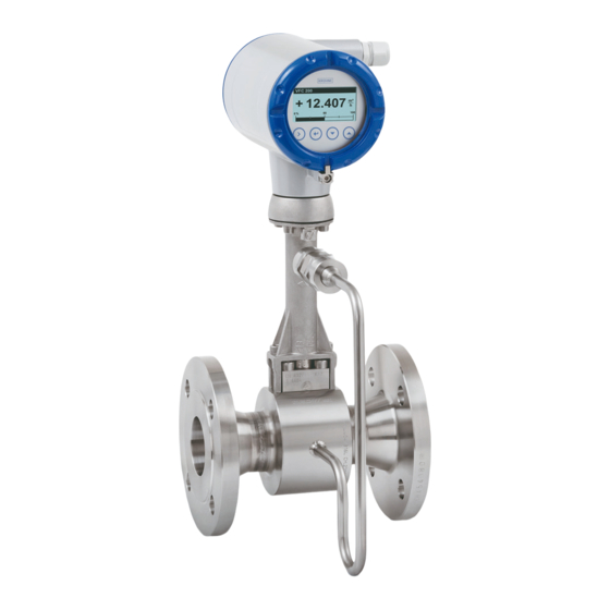
1 Standard version 2.2.6 Device description Figure 2-5: Device description 1 Signal converter 2 Cable feed through 3 Pressure sensor, optional 4 Shut-off valve, optional 5 Measuring sensor 6 Centering ring www.krohne.com 08/2015 — 4003930801 — MA OPTISWIRL 4200 R01 en…
-
Page 17: Free Air Delivery Measurement — Fad (Optional)
FAD measurement is an optional feature which can be unlocked in menu item C6.3 «Extras». Please contact the manufacturer to obtain the four-digit code required to enable this feature. Programming example: refer to Settings for free air delivery measurement — FAD on page 81 08/2015 — 4003930801 — MA OPTISWIRL 4200 R01 en www.krohne.com…
-
Page 18: Gross Heat Quantity Calculation (Optional)
Gross heat quantity calculation is an optional feature, which can be unlocked in menu item C6.3 «Extras». Please contact the manufacturer to obtain the four-digit code required to enable this feature. Programming example: refer to Gross Heat Measurement on page 82 www.krohne.com 08/2015 — 4003930801 — MA OPTISWIRL 4200 R01 en…
-
Page 19: Net Heat Quantity Calculation (Optional)
Net heat quantity calculation is an optional feature which can be unlocked in menu item C6.3 «Extras». Please contact KROHNE to obtain the four-digit code required to enable this feature. Programming example: refer to Net Heat Measurement on page 83 08/2015 — 4003930801 — MA OPTISWIRL 4200 R01 en www.krohne.com…
-
Page 20: Dual Seal
Even though there is no reason to expect the seal to fail, regular visual checks should still be carried out to detect any possible leak as early as possible. In the event of a leak, contact the manufacturer’s service department to service or replace the device. www.krohne.com 08/2015 — 4003930801 — MA OPTISWIRL 4200 R01 en…
-
Page 21: Nameplate
9 Tag no. — Measuring point identifier 10 Manufacturer’s website Figure 2-9: Example of nameplate 1 Serial number 2 Order number 3 Production order number 4 Type code 5 Item number 08/2015 — 4003930801 — MA OPTISWIRL 4200 R01 en www.krohne.com…
-
Page 22: Installation
Non-secured devices can pose risk of injury. The centre of mass of the device is often higher than the point at which the lifting straps are attached. Prevent the measuring device from sliding or rotating accidentally. www.krohne.com 08/2015 — 4003930801 — MA OPTISWIRL 4200 R01 en…
-
Page 23: Installation Conditions
Suitable measures must be taken to avoid water cavitation if it is a possible risk. Sunshades Figure 3-2: Installation recommendations 1 Horizontal mounting 2 Vertical mounting The meter MUST be protected from strong sunlight. A sunshade is available from the manufacturer as an option. 08/2015 — 4003930801 — MA OPTISWIRL 4200 R01 en www.krohne.com…
-
Page 24: Prohibited Installation When Measuring Liquids
Figure 3-4: Downstream pipe and outlet CAUTION! Installing the device in a downstream pipe 3 or upstream pipe of an outlet 4. There is the risk of partially filled pipes leading to inaccurate measurements. www.krohne.com 08/2015 — 4003930801 — MA OPTISWIRL 4200 R01 en…
-
Page 25: Prohibited Installation When Measuring Vapours And Gases
1 Recommended: installing the device before the control valve at a distance of ≥ 5 DN 2 Not recommended: Installing the flowmeter directly downstream of control valves, due to vortex formation. 08/2015 — 4003930801 — MA OPTISWIRL 4200 R01 en www.krohne.com…
-
Page 26: Preferred Mounting Position
3 On a vertical pipe 4 Horizontal pipeline with signal converter-orientation 90° to the side INFORMATION! Depending on the installation position, you may have to rotate the display and/or the connection housing. www.krohne.com 08/2015 — 4003930801 — MA OPTISWIRL 4200 R01 en…
-
Page 27: Minimum Inlet Sections
The nominal diameter of the flange is significant for the determination of the minimum inlet and outlet sections for the nominal diameter reduced versions of Vortex flowmeter F1R and F2R. 08/2015 — 4003930801 — MA OPTISWIRL 4200 R01 en www.krohne.com…
-
Page 28: Minimum Outlet Sections
1 Straight inlet section upstream of straightener ≥ 2 DN 2 Flow straightener 3 Straight pipe run between flow straightener and device ≥ 8 DN 4 Minimum straight outlet section ≥ 5 DN www.krohne.com 08/2015 — 4003930801 — MA OPTISWIRL 4200 R01 en…
-
Page 29: Installation
Figure 3-11: Inner diameter 1 Inner diameter of connection pipe 2 Inner diameter of flange and gasket 3 Inner diameter of measuring sensor 08/2015 — 4003930801 — MA OPTISWIRL 4200 R01 en www.krohne.com…
-
Page 30: Installing Devices In Sandwich Design
• Turn the centring ring 2 in a counter-clockwise direction and align the device. • Check that the gaskets 5 are concentric; they must not protrude into the pipe cross-section. • Now tighten all nuts bit by bit alternately across the diagonal. www.krohne.com 08/2015 — 4003930801 — MA OPTISWIRL 4200 R01 en…
-
Page 31: Installing Devices In Flange Design
• Install the gasket, bolts and fastening nuts on the other side of the flange. • Align the measuring device and the gaskets so they are concentric. • Now tighten all nuts bit by bit alternately across the diagonal. 08/2015 — 4003930801 — MA OPTISWIRL 4200 R01 en www.krohne.com…
-
Page 32: Mounting The Field Housing, Remote Version
Converters with a wall mounting rack have to be mounted with screws (ø 8mm), or with U- brackets (ø 8mm) in case of pole installation. In case of mounting directly to the wall, a mounting system suitable for the background has to be applied. www.krohne.com 08/2015 — 4003930801 — MA OPTISWIRL 4200 R01 en…
-
Page 33: Heat Insulation
2 Max. thickness of the insulation up to the bend of the pressure pipe 3 Insulation CAUTION! The heat insulation 3 may only extend as far as the bend of the pressure sensing line 2. 08/2015 — 4003930801 — MA OPTISWIRL 4200 R01 en www.krohne.com…
-
Page 34: Turning The Connection Housing
• Loosen the M4 hexagon socket screw 1 on the side of the connection housing. • Rotate the connection housing to the desired position (0…<360°). • Tighten the hexagon socket screw 1 again. www.krohne.com 08/2015 — 4003930801 — MA OPTISWIRL 4200 R01 en…
-
Page 35: Turning The Display
• Turn the cover with gasket 5 back onto the housing and tighten it by hand. INFORMATION! Before closing the housing cover refer to Maintaining the O-Rings on page 91 08/2015 — 4003930801 — MA OPTISWIRL 4200 R01 en www.krohne.com…
-
Page 36: Electrical Connections
INFORMATION! Check the device nameplate to ensure that the device is delivered according to your order. Check for the correct supply voltage printed on the nameplate. www.krohne.com 08/2015 — 4003930801 — MA OPTISWIRL 4200 R01 en…
-
Page 37: Connecting The Signal Converter
• Turn the housing cover and gasket back onto the housing and tighten it by hand. INFORMATION! Ensure that the housing gasket is properly fitted, clean and undamaged. Before closing the housing cover refer to Maintaining the O-Rings on page 91 08/2015 — 4003930801 — MA OPTISWIRL 4200 R01 en www.krohne.com…
-
Page 38: Electrical Connections
Connect current loop 4..20mA to terminals C1+ and C2-. When connection cables are long, a shielded or twisted cable may be necessary. The cable shield may only be grounded at one place (e.g. on the power supply unit). www.krohne.com 08/2015 — 4003930801 — MA OPTISWIRL 4200 R01 en…
-
Page 39: Current Input
The binary output is electrically separated from the current output and must be supplied with power separately. 4.3.5 Limit switch output Figure 4-4: Connection binary output 1 Power supply U ext. 2 Isolated switching amplifier 08/2015 — 4003930801 — MA OPTISWIRL 4200 R01 en www.krohne.com…
-
Page 40
The upper limit of the signal current must not be exceeded as this may damage the transistor output. For selection of measurement variable and adjustable data of the limit switch please refer to chapter 6.7.6 Menu Description C, menu item C2.2.5 Limit Switch and appropriate sub-menus. www.krohne.com 08/2015 — 4003930801 — MA OPTISWIRL 4200 R01 en… -
Page 41: Pulse Output / Frequency Output
6.7.6 Menu Description C, menu item C2.2.2 Pulse Output or menu item C2.2.3 Frequency Output and appropriate sub-menus. INFORMATION! Make sure the pulse width is in line with the pulse rate. 08/2015 — 4003930801 — MA OPTISWIRL 4200 R01 en www.krohne.com…
-
Page 42: Status Output
4.4 Connection of remote version The connections in the sensor and wall mount bracket connection boxes are identical in construction. Connection cable strand colour Terminals Strand colour blue black grey yellow green gnye Shielding www.krohne.com 08/2015 — 4003930801 — MA OPTISWIRL 4200 R01 en…
-
Page 43
CAUTION! Please ensure that the shielding 4 has been properly connected to both terminals 3 and 5. The exterior shielding of the cable must not be connected to any terminal. 08/2015 — 4003930801 — MA OPTISWIRL 4200 R01 en www.krohne.com… -
Page 44: Grounding Connections
1 Electrical grounding connection on measuring sensor 2 Electrical grounding connection on signal converter housing INFORMATION! In the remote version, the sensor as well as the signal converter must be grounded. www.krohne.com 08/2015 — 4003930801 — MA OPTISWIRL 4200 R01 en…
-
Page 45: Ingress Protection
• Align the measuring device so that the cable feedthrough is never facing up 3. • Close any unused cable feedthroughs using blind plugs 4 suitable for the protection category. • Do not remove the required cable bushing from the cable feedthrough. 08/2015 — 4003930801 — MA OPTISWIRL 4200 R01 en www.krohne.com…
-
Page 46: Start-Up
5.2 Operation INFORMATION! The measuring device is largely maintenance-free. Observe the application limits in respect of temperature and medium. www.krohne.com 08/2015 — 4003930801 — MA OPTISWIRL 4200 R01 en…
-
Page 47: Operation
4 1st measured variable in large representation 5 Indicates when a key has been pressed 6 Tag number (just shown if entered previously by the operator) 7 Indicates a possible status message in the status list 08/2015 — 4003930801 — MA OPTISWIRL 4200 R01 en www.krohne.com…
-
Page 48: Display For Selection Of Submenu And Functions, 3 Lines
(_ _ _ signalise in this line the end of the list) 6 Current menu(s), submenu or function 7 Previous menu(s), submenu or function (_ _ _ signalise in this line the beginning of the list) www.krohne.com 08/2015 — 4003930801 — MA OPTISWIRL 4200 R01 en…
-
Page 49: Display When Setting Parameters, 4 Lines
3 Denotes a changed parameter (simple check of changed data when browsing through lists) 4 Next parameter 5 Currently set data from 6 6 Current parameter (for selection press key >; then see previous chapter) 7 Factory setting of parameter 08/2015 — 4003930801 — MA OPTISWIRL 4200 R01 en www.krohne.com…
-
Page 50: Basic Principles Of Operation
• Press the ^ button to save the settings, or to reject them. • Before returning to measuring mode, you are prompted «Save config? Yes». Switch between «Yes», «Back» and «No» by pressing the ↑ or ↓ keys. www.krohne.com 08/2015 — 4003930801 — MA OPTISWIRL 4200 R01 en…
-
Page 51: Character Selection In Change Mode
Volume Flow 6.2.4 Character selection in change mode Depending on the menu function, the following characters are available: Numbers Lower case letters Upper case letters Special characters ..08/2015 — 4003930801 — MA OPTISWIRL 4200 R01 en www.krohne.com…
-
Page 52: Units, Figures And Factors
Access Levels Access Levels Access Levels The OPTISWIRL 4200 features a multi-level security concept, which helps to prevent accidental or unauthorized configuration changes. To gain a specific access level you need to log into the device by entering a four-digit hexadecimal password associated with that access level (see menu C6.2 “Security”).
-
Page 53
“Reset Passwords” command available in the C6.2.3 submenu. However to prevent unauthorized use this command itself is protected by a non-changeable unique password available by contacting KROHNE. 08/2015 — 4003930801 — MA OPTISWIRL 4200 R01 en www.krohne.com… -
Page 54: Overview Of The Most Important Functions And Units
Francais in preparation: Italiano Portugues Nederlands Espanol Svensk Russian Norwegian Finnish Slovenian Czech Hungarian Slovak Albanian Bulgarian Romanian Moldavian Danish Polish Lithuanian Chinese Estonian Latvian Turkish Table 6-4: Menu languages www.krohne.com 08/2015 — 4003930801 — MA OPTISWIRL 4200 R01 en…
-
Page 55: Gas Options For Gas Measurement
↑. Change between the digits by pressing the rightwards button →. After reaching the last digit the cursor will jump again to the first digit. 08/2015 — 4003930801 — MA OPTISWIRL 4200 R01 en www.krohne.com…
-
Page 56: Units
Units for standard volume flow Units for standard volume flow Units for standard volume flow Liquids, vapours, gases /min Customised standard volume flow Table 6-6: Flow measurements and their units www.krohne.com 08/2015 — 4003930801 — MA OPTISWIRL 4200 R01 en…
-
Page 57
Mcal g/ml kg/cm temperature Mcal/h lb/gal g/cm torr Btu/h Customised lb/ft energy Mbtu/s lb/in psi (abs) Mbtu/h Customised density Mbtu/d b/ft Customised power Customised pressure Table 6-9: Units additional measurements 08/2015 — 4003930801 — MA OPTISWIRL 4200 R01 en www.krohne.com… -
Page 58: Menu Structure
A9.21 Density A9.22 Cst. Density A10 Meter Type A11 Application A11.1 Liquids assistant A11.2 Saturated Steam A11.3 Superheated Steam A11.4 Heat Measurement A11.5 Gas A11.6 FAD A12 Cluster Cluster 1…12 Checks www.krohne.com 08/2015 — 4003930801 — MA OPTISWIRL 4200 R01 en…
-
Page 59: Menu Overview B — Test
B2.4 Mass Flow B2.5 Gross Power B2.6 Net Power B2.7 FAD B2.8 Volume B2.9 Norm. Volume B2.10 Mass B2.11 Gross Energy B2.12 Net Energy B2.13 Density B2.14 Temperature1 B2.15 Temperature2 08/2015 — 4003930801 — MA OPTISWIRL 4200 R01 en www.krohne.com…
-
Page 60: Menu Overview C — Setup
C1.6.1 Temp. Source1 C1.6.2 Temp. Source2 C1.7 Pressure Sensor C1.8 Time Constant C1.9 Low Flow Cutoff C1.10 Operating C1.10.1 Oper. Temperature Values C1.10.2 Oper. Pressure C1.10.3 Oper. Density C1.10.4 Min/Max Oper. Dens. www.krohne.com 08/2015 — 4003930801 — MA OPTISWIRL 4200 R01 en…
-
Page 61
C4.1.4 Set Value C4.1.5 Start Totalizer? C4.1.6 Stop Totalizer? C4.1.7 Information C4.2 Energy C4.2.1 Measurement C4.2.2 Preset Value C4.2.3 Reset Totalizer? C4.2.4 Set Value C4.2.5 Start Totalizer? C4.2.6 Stop Totalizer? C4.2.7 Information 08/2015 — 4003930801 — MA OPTISWIRL 4200 R01 en www.krohne.com… -
Page 62
C6.1.9 Device Revision C6.1.10 Software Revision C6.1.11 Hardware Revision C6.1.12 Electronic Serial No. C6.1.13 CG-Number C6.1.14 Production Date C6.1.15 Calibration Date C6.2 Security C6.2.1 Login C6.2.2 Change Password C6.2.3 Reset Passwords www.krohne.com 08/2015 — 4003930801 — MA OPTISWIRL 4200 R01 en… -
Page 63
C6.6 Factory Default C6.6.1 Reset to Fact. Def.? 1 All even-numbered menu items e.g. C6.5.2 are appropriate customised units. It is followed by submenu items with prompts for text, offset and factor. 08/2015 — 4003930801 — MA OPTISWIRL 4200 R01 en www.krohne.com… -
Page 64: Menu Description A — Quick Setup
FAD functionality Application Assistant Details see next tables Plausibility Checks Menu A12 Cluster Checks refer to on page 89 www.krohne.com 08/2015 — 4003930801 — MA OPTISWIRL 4200 R01 en…
-
Page 65
OPTISWIRL 4200 A11 Application Assistant The factory settings of your OPTISWIRL 4200 have been made in accordance with your order specifications. Nonetheless it can be necessary to make additional settings for the use of some functionalities. For an easy operation the device is equipped with an application assistant for each type of application. -
Page 66
One Value / Two Values / Three Values / One Value & Bargraph / Two values & Bargraph 2. Meas. Page One Value / Two Values / Three Values / One Value & Bargraph / Two values & Bargraph www.krohne.com 08/2015 — 4003930801 — MA OPTISWIRL 4200 R01 en… -
Page 67
Flow Totalizer Same options as in A11.1.11 Energy Totalizer Same options as in A11.1.12 1. Meas. Page Same options as in A11.1.13 2. Meas. Page Same options as in A11.1.14 08/2015 — 4003930801 — MA OPTISWIRL 4200 R01 en www.krohne.com… -
Page 68
Flow Totalizer Same options as in A11.1.11 Energy Totalizer Same options as in A11.1.12 1. Meas. Page Same options as in A11.1.13 2. Meas. Page Same options as in A11.1.14 www.krohne.com 08/2015 — 4003930801 — MA OPTISWIRL 4200 R01 en… -
Page 69
Same options as in A11.1.8 Status Output Same options as in A11.1.9 Limit Switch Same options as in A11.1.10 Flow Totalizer Same options as in A11.1.11 Energy Totalizer Same options as in A11.1.12 08/2015 — 4003930801 — MA OPTISWIRL 4200 R01 en www.krohne.com… -
Page 70
Same options as in A11.1.6 Pulse Output Same options as in A11.1.7 Frequency Output Same options as in A11.1.8 Status Output Same options as in A11.1.9 Limit Switch Same options as in A11.1.10 www.krohne.com 08/2015 — 4003930801 — MA OPTISWIRL 4200 R01 en… -
Page 71
Same options as in A11.1.6 Pulse Output Same options as in A11.1.7 Frequency Output Same options as in A11.1.8 Status Output Same options as in A11.1.9 Limit Switch Same options as in A11.1.10 08/2015 — 4003930801 — MA OPTISWIRL 4200 R01 en www.krohne.com… -
Page 72: Menu Description B — Test
Enter gas mixture as percentage share of gas options refer to Gas options for gas measurement on page 55 C1.3.2 Relative Humidity This menu item is available if fluid = Wet Gas. Enter 0…100% www.krohne.com 08/2015 — 4003930801 — MA OPTISWIRL 4200 R01 en…
-
Page 73
C1.10.4.1 Function Select: On / Off If function = On, min./max. operating density can be defined in C1.10.4.2 and C1.10.4.3 08/2015 — 4003930801 — MA OPTISWIRL 4200 R01 en www.krohne.com… -
Page 74
Enter measured value for 20 mA point. Reset to 20 mA restores the factory calibration. Binary output C2.2 Binary Output For possible functions of the binary output refer to on page 39 www.krohne.com 08/2015 — 4003930801 — MA OPTISWIRL 4200 R01 en… -
Page 75
Value defines the sensitivity of transition detection. Enter value between -1.0 (to decrease sensitivity) and +1.0 (to increase sensitivity). C2.2.5 Limit Switch Only available, if Limit Switch is selected in C2.2.1 08/2015 — 4003930801 — MA OPTISWIRL 4200 R01 en www.krohne.com… -
Page 76
Primary HART variable; identical with current output measurement variable C3.1.4.2 Frequency Out. Meas. Secondary HART variable; identical with frequency output measurement variable C3.1.4.3 Current Input Meas. Tertiary HART variable; identical with current input measurement variable www.krohne.com 08/2015 — 4003930801 — MA OPTISWIRL 4200 R01 en… -
Page 77
Enter current value in selected unit. Start value has to be confirmed with ‘Yes’ or refused with ‘No’. C4.2.5 Start Totalizer? Select: Yes / No C4.2.6 Stop Totalizer? Select: Yes / No 08/2015 — 4003930801 — MA OPTISWIRL 4200 R01 en www.krohne.com… -
Page 78
Display of meter type as activated in A10 or C6.3.2 — C6.3.4. (read-only) C6.1.4 Serial number Individual device ID (read-only) C6.1.5 Manufacturer ID HART Manufacturer ID = 00069 [KROHNE] (read-only) www.krohne.com 08/2015 — 4003930801 — MA OPTISWIRL 4200 R01 en… -
Page 79
Heat & Dens. & FAD C6.4 Errors C6.4.1 Message View Display of NAMUR messages F S M C I Status messages and diagnostic information Explanations: refer to on page 84 C6.5 Units 08/2015 — 4003930801 — MA OPTISWIRL 4200 R01 en www.krohne.com… -
Page 80
Press → and confirm reset to factory default with `Yes’ or refuse with ‘No’. 1 In all even numbered menu items C6.5.2 to .22 Cst. Units (Custom Units) there is a sub menu with the prompt for «Text», «Offset» and «Factor». www.krohne.com 08/2015 — 4003930801 — MA OPTISWIRL 4200 R01 en… -
Page 81: Setting Examples
C5.3.3 / 4 0% / 100% Range Enter bargraph range limits (0% / 100%) in selected unit INFORMATION! This is an example setup for basic FAD measurement. Other setup options are feasible. 08/2015 — 4003930801 — MA OPTISWIRL 4200 R01 en www.krohne.com…
-
Page 82: Gross Heat Measurement
Two Values C5.3.2 Measurement 1. Line Gross Power C5.3.6 Measurement 2. Line Gross Energy INFORMATION! This is an example setup for basic gross heat measurement. Other setup options are feasible. www.krohne.com 08/2015 — 4003930801 — MA OPTISWIRL 4200 R01 en…
-
Page 83: Net Heat Measurement
Two Values C5.3.2 Measurement 1. Net Power Line C5.3.6 Measurement 2. Net Energy Line INFORMATION! This is an example setup for basic net heat measurement. Other setup options are feasible. 08/2015 — 4003930801 — MA OPTISWIRL 4200 R01 en www.krohne.com…
-
Page 84: Status Messages And Diagnostic Information
Check the connection of the available or invalid pressure sensor. Perform a communication hard reset. If the message recurs, contact KROHNE. Corrupt Sensor Sensor parameters are Check sensor parameters. inconsistent www.krohne.com 08/2015 — 4003930801 — MA OPTISWIRL 4200 R01 en…
-
Page 85
Perform a hard reset. If the parameter memory message recurs, contact KROHNE. Disp. NVRAM Layout Error Incompatible data after Perform a hard reset. If the firmware update message recurs, contact KROHNE. 08/2015 — 4003930801 — MA OPTISWIRL 4200 R01 en www.krohne.com… -
Page 86
Make sure that the device is pressure sensor out of operated within the specification permissable temperature range. Elec. Temp. Out Of Spec. The electronic temperature of the sensor module is out of specification. www.krohne.com 08/2015 — 4003930801 — MA OPTISWIRL 4200 R01 en… -
Page 87
(maintenance the SIL mode according to mode 2) has to be performed the instructions of the safety by the operator. manual and confirm the correctness with the SIL jumper. 08/2015 — 4003930801 — MA OPTISWIRL 4200 R01 en www.krohne.com… -
Page 88
Failed Piezo Test The continuous self test of Perform a hard reset. If the the sensor electronic failed. message recurs, contact Failed Sensor Input Test KROHNE. Failed Sensor MCU Test www.krohne.com 08/2015 — 4003930801 — MA OPTISWIRL 4200 R01 en… -
Page 89: Plausibility Checks Menu A12
100%. HART Catch If temperature or pressure data input is provided by HART, the device checks if the «Slot Variable Number“ fits in with the «Capture Command“. (Temperature / Pressure) 08/2015 — 4003930801 — MA OPTISWIRL 4200 R01 en www.krohne.com…
-
Page 90: Service
• Tighten the two screws 6. • Attach the measuring sensor cable 5 • Attach display 1 in desired position, apply even pressure to the entire surface. • Screw on cover by hand. www.krohne.com 08/2015 — 4003930801 — MA OPTISWIRL 4200 R01 en…
-
Page 91: Maintaining The O-Rings
Operational temperature range (-30 C …130 C at permanent lubrication) • ° ° Free from silicone • Good adhesive capability • • Lithium saponified Water resistant • Compatible with material of O-ring • 08/2015 — 4003930801 — MA OPTISWIRL 4200 R01 en www.krohne.com…
-
Page 92: Spare Parts Availability
• such dangerous substances, to enclose a certificate with the device confirming that is safe to handle and stating the • product used. www.krohne.com 08/2015 — 4003930801 — MA OPTISWIRL 4200 R01 en…
-
Page 93: Form (For Copying) To Accompany A Returned Device
The user must dispose of the WEEE to a designated collection point for the recycling of WEEE or send them back to our local organisation or authorised representative. 08/2015 — 4003930801 — MA OPTISWIRL 4200 R01 en www.krohne.com…
-
Page 94: Technical Data
: S . v The vortex frequency is recorded at the sensor and evaluated at the converter. Figure 8-1: Functional principle www.krohne.com 08/2015 — 4003930801 — MA OPTISWIRL 4200 R01 en…
-
Page 95: Technical Data
Flange version with double reduction of nominal diameter, measuring sensor: F2R Display and user interface Local display Graphic display Interface and display languages German, English, French, 23 further languages in preparation 08/2015 — 4003930801 — MA OPTISWIRL 4200 R01 en www.krohne.com…
-
Page 96
Gases and vapours 2.0…80 m/s / 6.6…262.5 ft/s DN15: 3.0…45 m/s / 9.8…148 ft/s; DN25: 2.0…70 m/s / 6.6…230 ft/s Intended use For further information refer to on page 7. www.krohne.com 08/2015 — 4003930801 — MA OPTISWIRL 4200 R01 en… -
Page 97
All inputs and outputs are electrically isolated from one another. Time constant The time constant corresponds to 63% of the elapsed time of a processor procedure. 0…100 s (rounded up to 0.1 s) 08/2015 — 4003930801 — MA OPTISWIRL 4200 R01 en www.krohne.com… -
Page 98
VDI/VDE 2188 (category 2) Temperature coefficient 50 ppm/K Residual current < 0.2 mA at 32 V (Ri = 180 kOhm) Pulse width 0.5…2000 ms www.krohne.com 08/2015 — 4003930801 — MA OPTISWIRL 4200 R01 en… -
Page 99: Pulse Output
QPS IS Class I Div 1 — in preparation QPS XP Class I Div 1 — in preparation QPS NI Class I Div 2 — in preparation QPS DIP Class II, III Div 1 — in preparation 08/2015 — 4003930801 — MA OPTISWIRL 4200 R01 en www.krohne.com…
-
Page 100: Dimensions And Weights
380.3 380.3 368.3 169.3 169.5 169.5 396.8 380.3 380.3 171.5 169.3 169.5 396.8 380.3 380.3 171.5 169.3 169.5 396.8 396.8 380.3 171.5 169.3 169.5 396.8 396.8 380.3 171.5 169.3 169.5 www.krohne.com 08/2015 — 4003930801 — MA OPTISWIRL 4200 R01 en…
-
Page 101
492.8 468.8 468.8 229.5 202.8 492.8 468.8 468.8 229.5 202.8 492.8 492.8 468.8 229.5 202.8 492.8 492.8 468.8 229.5 202.8 1 F1R — single reduction 2 F2R — double reduction 08/2015 — 4003930801 — MA OPTISWIRL 4200 R01 en www.krohne.com… -
Page 102
128.1 127.5 132.0 131.4 143.2 142.6 Weight specifications for version with two signal converters + 3.2 kg / 7.05 lb 1 F1R — single reduction 2 F2R — double reduction www.krohne.com 08/2015 — 4003930801 — MA OPTISWIRL 4200 R01 en… -
Page 103
396.8 380.3 368.3 171.5 169.3 169.5 396.8 380.3 368.3 171.5 169.3 169.5 416.3 396.8 380.3 191.5 171.1 169.3 416.3 396.8 380.3 191.5 171.1 169.3 416.3 396.8 380.3 191.5 171.1 169.3 08/2015 — 4003930801 — MA OPTISWIRL 4200 R01 en www.krohne.com… -
Page 104
75.4 74.8 72.2 71.6 78.1 77.5 75.0 74.4 75.2 74.6 73.9 73.3 107.0 106.4 112.4 111.8 113.5 112.9 107.0 106.4 109.8 109.2 120.4 119.8 152.0 151.4 165.4 155.8 171.7 171.1 www.krohne.com 08/2015 — 4003930801 — MA OPTISWIRL 4200 R01 en… -
Page 105
15.7 15.0 14.5 6.76 6.67 6.67 15.7 15.0 14.5 6.76 6.67 6.67 16.4 15.6 15.0 7.54 6.76 6.67 16.4 15.6 15.0 7.54 6.76 6.67 16.4 15.6 15.0 7.54 6.76 6.67 08/2015 — 4003930801 — MA OPTISWIRL 4200 R01 en www.krohne.com… -
Page 106
166.3 165.0 159.2 157.9 172.2 171.0 165.4 164.1 165.9 164.5 163.0 161.7 236.0 234.7 247.9 246.6 250.3 249.0 236.0 234.7 242.2 240.8 265.5 264.2 335.2 333.9 364.8 343.6 378.7 377.4 www.krohne.com 08/2015 — 4003930801 — MA OPTISWIRL 4200 R01 en… -
Page 107: Sandwich Version
Specified weight + 2.8 kg / 6.2 lb Sandwich version EN Nominal size Pressure Dimensions [mm] Weight [kg] rating with without Pressure sensor 174.25 174.25 174.5 174.5 174.25 176.5 10.1 08/2015 — 4003930801 — MA OPTISWIRL 4200 R01 en www.krohne.com…
-
Page 108
19.4 18.08 2.91 5.31 2.56 11.42 6.82 19.4 18.08 3.82 6.22 2.56 12.21 6.95 22.27 20.94 3.82 6.22 2.56 12.21 6.95 22.27 20.94 3.82 6.22 2.56 12.21 6.95 22.27 20.94 www.krohne.com 08/2015 — 4003930801 — MA OPTISWIRL 4200 R01 en… -
Page 109: Dimensions Of Remote Version
1 F1R — single reduction — 2 F2R — double reduction Dimensions b…n b…n b…n b…n [mm] [«] 5.46 4.25 10.9 7.53 4.14 3.82 2.84 4.25 0.35 2.84 3.82 8.90 08/2015 — 4003930801 — MA OPTISWIRL 4200 R01 en www.krohne.com…
-
Page 110: Flow Tables
1086 14478 286870 3824929 1577 21028 416638 5555167 Values based on air at 20°C / 68°F and 1.013 bar abs / 14.696 psig and density 1.204 kg/m / 0.0751 lb/ft www.krohne.com 08/2015 — 4003930801 — MA OPTISWIRL 4200 R01 en…
-
Page 111
1093 31715 1210 35334 1288 37737 1808 52054 2053 59574 2273 66371 2419 70884 2890 83215 3282 95237 3634 106102 3867 113318 4197 120858 4767 138318 5279 154099 5617 164578 08/2015 — 4003930801 — MA OPTISWIRL 4200 R01 en www.krohne.com… -
Page 112
2424 70309 2687 78419 2799 82006 4011 115455 4553 132068 5048 147302 5258 154041 6412 184569 7279 211127 8069 235481 8406 246254 9313 268060 10571 306632 11720 342002 12209 357649 www.krohne.com 08/2015 — 4003930801 — MA OPTISWIRL 4200 R01 en… -
Page 113: Notes
NOTES OPTISWIRL 4200 08/2015 — 4003930801 — MA OPTISWIRL 4200 R01 en www.krohne.com…
-
Page 114
NOTES OPTISWIRL 4200 www.krohne.com 08/2015 — 4003930801 — MA OPTISWIRL 4200 R01 en… -
Page 115
NOTES OPTISWIRL 4200 08/2015 — 4003930801 — MA OPTISWIRL 4200 R01 en www.krohne.com… -
Page 116
• Process Analysis • Services Head Office KROHNE Messtechnik GmbH Ludwig-Krohne-Str. 5 47058 Duisburg (Germany) Tel.: +49 203 301 0 Fax: +49 203 301 10389 info@krohne.com The current list of all KROHNE contacts and addresses can be found at: www.krohne.com…
 Loading…
![]()

 OPTISWIRL 4200 Handbook
Vortex flowmeter
Electronic revision: ER 1.0.6_
© KROHNE 08/2016 — 4003930803 — MA OPTISWIRL 4200 R03 en
:IMPRINT :::::::::::::::::::::::::::::::::::::::
All rights reserved. It is prohibited to reproduce this documentation, or any part thereof, without the prior written authorisation of KROHNE Messtechnik GmbH.
Subject to change without notice.
Copyright 2016 by
KROHNE Messtechnik GmbH — Ludwig-Krohne-Str. 5 — 47058 Duisburg (Germany)
|
2 |
www.krohne.com |
08/2016 — 4003930803 — MA OPTISWIRL 4200 R03 en |

|
CONTENTS |
|||||
|
OPTISWIRL 4200 |
|||||
|
1 Safety instructions |
6 |
||||
|
1.1 |
Software history ………………………………………………………………………………………………… |
6 |
|||
|
1.2 |
Intended use ……………………………………………………………………………………………………… |
7 |
|||
|
1.3 |
Certifications …………………………………………………………………………………………………….. |
9 |
|||
|
1.4 |
Safety instructions from the manufacturer …………………………………………………………. |
10 |
|
1.4.1 Copyright and data protection …………………………………………………………………………………. |
10 |
||
|
1.4.2 Disclaimer …………………………………………………………………………………………………………….. |
10 |
||
|
1.4.3 Product liability and warranty …………………………………………………………………………………. |
11 |
||
|
1.4.4 Information concerning the documentation………………………………………………………………. |
11 |
||
|
1.4.5 Warnings and symbols used……………………………………………………………………………………. |
12 |
||
|
1.5 |
Safety instructions for the operator……………………………………………………………………. |
12 |
|
|
2 Device description |
13 |
||
|
2.1 |
Scope of delivery………………………………………………………………………………………………. |
13 |
|
|
2.2 |
Device versions………………………………………………………………………………………………… |
13 |
|
|
2.2.1 Devices with connection flange ……………………………………………………………………………….. |
14 |
||
|
2.2.2 Devices in sandwich version ……………………………………………………………………………………. |
14 |
||
|
2.2.3 |
Dual version and twofold reliability ………………………………………………………………………….. |
15 |
|
|
2.2.4 Remote version ……………………………………………………………………………………………………… |
15 |
||
|
2.2.5 Devices with integrated nominal diameter reduction…………………………………………………. |
16 |
||
|
2.2.6 Device description………………………………………………………………………………………………….. |
16 |
||
|
2.2.7 Free air delivery measurement — FAD (optional) ……………………………………………………….. |
17 |
||
|
2.2.8 |
Gross heat quantity calculation (optional)…………………………………………………………………. |
18 |
|
|
2.2.9 |
Net heat quantity calculation (optional) ……………………………………………………………………. |
19 |
|
|
2.2.10 Dual seal……………………………………………………………………………………………………………… |
20 |
||
|
2.3 |
Nameplate ………………………………………………………………………………………………………. |
21 |
|
|
3 Installation |
22 |
||
|
3.1 |
General notes on installation …………………………………………………………………………….. |
22 |
|
|
3.2 |
Storage …………………………………………………………………………………………………………… |
22 |
|
|
3.3 |
Transport ………………………………………………………………………………………………………… |
22 |
|
|
3.4 |
Installation conditions ………………………………………………………………………………………. |
23 |
|
|
3.4.1 Prohibited installation when measuring liquids ………………………………………………………… |
24 |
||
|
3.4.2 Prohibited installation when measuring steam and gases………………………………………….. |
25 |
||
|
3.4.3 |
Pipelines with control valve…………………………………………………………………………………….. |
25 |
|
|
3.4.4 Preferred mounting position …………………………………………………………………………………… |
26 |
||
|
3.5 |
Minimum inlet sections …………………………………………………………………………………….. |
27 |
|
|
3.6 |
Minimum outlet sections…………………………………………………………………………………… |
28 |
|
|
3.7 |
Flow straightener …………………………………………………………………………………………….. |
28 |
|
|
3.8 |
Installation………………………………………………………………………………………………………. |
29 |
|
|
3.8.1 |
General installation notes……………………………………………………………………………………….. |
29 |
|
|
3.8.2 Installing devices in sandwich design ………………………………………………………………………. |
30 |
||
|
3.8.3 |
Installing devices in flange design …………………………………………………………………………… |
31 |
|
|
3.8.4 Mounting the field housing, remote version ……………………………………………………………… |
32 |
||
|
3.9 |
Heat insulation…………………………………………………………………………………………………. |
33 |
|
|
3.10 Turning the connection housing……………………………………………………………………….. |
34 |
||
|
3.11 Turning the display …………………………………………………………………………………………. |
35 |
|
08/2016 — 4003930803 — MA OPTISWIRL 4200 R03 en |
www.krohne.com |
3 |

|
4 Electrical connections |
36 |
|
|
4.1 |
Safety instructions……………………………………………………………………………………………. |
36 |
|
4.2 |
Connecting the signal converter ………………………………………………………………………… |
37 |
|
4.3 |
Electrical connections ………………………………………………………………………………………. |
38 |
|
4.3.1 Power supply…………………………………………………………………………………………………………. |
38 |
|
|
4.3.2 Current output ………………………………………………………………………………………………………. |
38 |
|
|
4.3.3 Current input…………………………………………………………………………………………………………. |
39 |
|
|
4.3.4 Binary output…………………………………………………………………………………………………………. |
39 |
|
|
4.3.5 Limit switch output ………………………………………………………………………………………………… |
40 |
|
|
4.3.6 Pulse output / Frequency output ……………………………………………………………………………… |
42 |
|
|
4.3.7 Status output…………………………………………………………………………………………………………. |
43 |
|
|
4.4 |
Connection of remote version ……………………………………………………………………………. |
43 |
|
4.5 |
Grounding connections……………………………………………………………………………………… |
45 |
|
4.6 |
Ingress protection ……………………………………………………………………………………………. |
46 |
|
5 Start-up |
47 |
|
|
5.1 |
Start-up screen ……………………………………………………………………………………………….. |
47 |
|
5.2 |
Operation ………………………………………………………………………………………………………… |
47 |
|
6 Operation |
48 |
|
|
6.1 |
Display and operating elements ………………………………………………………………………… |
48 |
|
6.1.1 Display for selection of submenu and functions, 3 lines …………………………………………….. |
49 |
|
|
6.1.2 Display when setting parameters, 4 lines …………………………………………………………………. |
50 |
|
|
6.1.3 Display when previewing parameters, 4 lines……………………………………………………………. |
50 |
|
|
6.2 |
Basic principles of operation……………………………………………………………………………… |
51 |
|
6.2.1 Functional description of the keys……………………………………………………………………………. |
51 |
|
|
6.2.2 Switch from measuring mode to menu mode……………………………………………………………. |
51 |
|
|
6.2.3 Change the settings in the menu……………………………………………………………………………… |
51 |
|
|
6.2.4 Character selection in change mode………………………………………………………………………… |
52 |
|
|
6.2.5 Units, figures and factors ……………………………………………………………………………………….. |
53 |
|
|
6.2.6 Security and permissions ……………………………………………………………………………………….. |
53 |
|
|
6.3 |
Overview of the most important functions and units…………………………………………….. |
55 |
|
6.4 |
Menu languages ………………………………………………………………………………………………. |
55 |
|
6.5 |
Gas options for gas measurement……………………………………………………………………… |
56 |
|
6.6 |
Units……………………………………………………………………………………………………………….. |
57 |
|
6.7 |
Menu structure………………………………………………………………………………………………… |
60 |
|
6.7.1 Menu overview «A Quick Setup»……………………………………………………………………………….. |
60 |
|
|
6.7.2 Menu overview «B Test»………………………………………………………………………………………….. |
61 |
|
|
6.7.3 Menu overview «C Setup»………………………………………………………………………………………… |
62 |
|
|
6.7.4 Menu description «A Quick Setup»……………………………………………………………………………. |
66 |
|
|
6.7.5 Menu description «B Test»………………………………………………………………………………………. |
74 |
|
|
6.7.6 Menu description «C Setup»…………………………………………………………………………………….. |
74 |
|
|
6.8 |
Setting examples……………………………………………………………………………………………… |
83 |
|
6.8.1 Settings for free air delivery measurement — FAD……………………………………………………… |
83 |
|
|
6.8.2 Gross heat measurement ……………………………………………………………………………………….. |
84 |
|
|
6.8.3 Net heat measurement…………………………………………………………………………………………… |
85 |
|
|
6.9 |
Status messages and diagnostic information………………………………………………………. |
86 |
|
6.10 A12 plausibility checks ……………………………………………………………………………………. |
91 |
|
4 |
www.krohne.com |
08/2016 — 4003930803 — MA OPTISWIRL 4200 R03 en |

|
OPTISWIRL 4200 |
CONTENTS |
|
|
7 Service |
92 |
|
|
7.1 |
Replacing signal converter / LC display ……………………………………………………………… |
92 |
|
7.2 |
Maintaining the O-rings…………………………………………………………………………………….. |
93 |
|
7.3 |
Spare parts availability……………………………………………………………………………………… |
94 |
|
7.4 |
Availability of services ………………………………………………………………………………………. |
94 |
|
7.5 |
Returning the device to the manufacturer…………………………………………………………… |
94 |
|
7.5.1 General information……………………………………………………………………………………………….. |
94 |
|
|
7.5.2 Form (for copying) to accompany a returned device…………………………………………………… |
95 |
|
|
7.6 |
Disposal ………………………………………………………………………………………………………….. |
95 |
|
8 Technical data |
96 |
|
|
8.1 |
Functional principle………………………………………………………………………………………….. |
96 |
|
8.2 |
Technical data………………………………………………………………………………………………….. |
97 |
|
8.3 |
Dimensions and weights …………………………………………………………………………………. |
102 |
|
8.3.1 Flange versions……………………………………………………………………………………………………. |
102 |
|
|
8.3.2 Sandwich version …………………………………………………………………………………………………. |
109 |
|
|
8.3.3 Dimensions of remote version……………………………………………………………………………….. |
111 |
|
|
8.4 |
Flow tables ……………………………………………………………………………………………………. |
112 |
|
9 Notes |
115 |
|
08/2016 — 4003930803 — MA OPTISWIRL 4200 R03 en |
www.krohne.com |
5 |

1 SAFETY INSTRUCTIONS
1.1 Software history
OPTISWIRL 4200 
The «Electronic Revision» (ER) is consulted to document the revision status of electronic equipment according to NE 53 for all devices. It is easy to see from the ER whether troubleshooting or larger changes in the electronic equipment have taken place and how that has affected the compatibility.
Changes and effect on compatibility
1Downwards compatible changes and fault repair with no effect on operation (e.g. spelling mistakes on display)
|
2-_ |
Downwards compatible hardware and/or software change of interfaces: |
|
|
H |
HART® |
|
|
P |
Profibus |
|
|
F |
Foundation Fieldbus |
|
|
3-_ |
Downwards compatible hardware and/or software change of inputs and outputs: |
|
|
CO |
Current output |
|
|
FO, |
Frequency output / pulse output |
|
|
PO |
||
|
SO |
Status output |
|
|
LS |
Limit switch |
|
|
CI |
Current input |
|
|
D |
Display |
|
|
Release date |
Electronic revision |
Changes and compatibility |
Documentation |
|
2014-12-10 |
ER 1.0.0_ |
— |
MA OPTISWIRL 4200 R01 |
|
2015-01-07 |
ER 1.0.1_ |
1; 2-H |
MA OPTISWIRL 4200 R01 |
|
2015-02-04 |
ER 1.0.2_ |
1; 3-PO |
MA OPTISWIRL 4200 R01 |
|
2015-03-04 |
ER 1.0.3_ |
1; 2-H; 3-CO; 3-PO; 3-CI; 3-D |
MA OPTISWIRL 4200 R01 |
|
2015-09-07 |
ER 1.0.4_ |
1; 2-H; 3-D |
MA OPTISWIRL 4200 R01 |
|
2016-04-18 |
ER 1.0.5_ |
1; 3-PO; 3-SO |
MA OPTISWIRL 4200 R02 |
|
2016-08-19 |
ER 1.0.6_ |
1; 3-D |
MA OPTISWIRL 4200 R03 |
|
6 |
www.krohne.com |
08/2016 — 4003930803 — MA OPTISWIRL 4200 R03 en |

OPTISWIRL 4200
SAFETY INSTRUCTIONS 1
1.2 Intended use
CAUTION!
Responsibility for the use of the measuring devices with regard to suitability, intended use and corrosion resistance of the used materials against the measured fluid lies solely with the operator.
INFORMATION!
This device is a Group 1, Class A device as specified within CISPR11:2009. It is intended for use in industrial environment. There may be potential difficulties in ensuring electromagnetic compatibility in other environments, due to conducted as well as radiated disturbances.
INFORMATION!
The manufacturer is not liable for any damage resulting from improper use or use for other than the intended purpose.
The vortex flowmeters are used for flow measurement of gases, vapours and liquids.
The devices are particularly suitable for the measurement of:
•Clean liquids with low viscosity (< 10 cP)
•Hydrocarbons with low viscosity (< 10 cP)
•Water
•Chemicals with low corrosiveness
•Saturated steam
•Superheated steam, including CIP and SIP applications in the food industry
•The flow sensors are made from stainless steel 316 L (1.4404) or Hastelloy® C22.
•In your project planning, please observe the data given in the corrosion tables.
•The pressure-bearing parts have been designed and rated for stationary operation taking into account the maximum pressure and temperature.
•Observe the data indicated on the nameplate for PS, TS and PT (PED 97/23/EC).
•External forces and moments, caused e.g. by pipe stresses, have not been taken into account.
Primarily, volumetric flow and temperature are measured, with pressure measurement as an option. From these parameters the measuring device calculates the mass flow or standard volumetric flow using pre-programmed density data and then exports the measured values via various communication interfaces.
|
08/2016 — 4003930803 — MA OPTISWIRL 4200 R03 en |
www.krohne.com |
7 |

|
1 SAFETY INSTRUCTIONS |
||
|
OPTISWIRL 4200 |
||
The devices are rated for the following flow velocities:
|
Liquids: |
Vmin: 0.25 m/s |
0.8 ft/s |
1 |
||
|
DN15…DN300 |
|||||
|
Vmax: 10 m/s |
32 ft/s |
2 |
|||
|
Gases and |
DN15 |
Vmin: 3 m/s |
10 ft/s |
1 |
|
|
steam: |
|||||
|
Vmax: 45 m/s |
147 ft/s |
2 |
|||
|
DN15C |
Vmin: 3 m/s |
10 ft/s |
1 |
||
|
Vmax: 55 m/s |
180 ft/s |
2 |
|||
|
DN25 |
Vmin: 2 m/s |
6.6 ft/s |
1 |
||
|
Vmax: 70 m/s |
229 ft/s |
2 |
|||
|
DN25C |
Vmin: 2 m/s |
6.6 ft/s |
1 |
||
|
Vmax: 80 m/s |
262 ft/s |
2 |
|||
|
DN40… |
Vmin: 2 m/s |
6.6 ft/s |
1 |
||
|
DN300 |
|||||
|
Vmax: 80 m/s |
262 ft/s |
2 |
|||
1Use the larger value, according to the amount.
2Use the smaller value, according to the amount.
INFORMATION!
DN15C and DN25C have a robust flow sensor (signal pick-up) for harsh measuring conditions and higher maximum velocity compared to the standard version.
|
8 |
www.krohne.com |
08/2016 — 4003930803 — MA OPTISWIRL 4200 R03 en |

OPTISWIRL 4200
SAFETY INSTRUCTIONS 1
1.3 Certifications
CE marking
The device fulfils the statutory requirements of the following EU directives:
•Pressure equipment directive
•EMC directive
•Devices for use in hazardous areas: ATEX directive
as well as
•EN 61010
•NAMUR recommendations NE 21 and NE 43
The manufacturer certifies successful testing of the product by applying the CE marking. A CE declaration of conformity regarding the directives in question and the associated harmonised standards can be downloaded from our internet site.
DANGER!
For devices used in hazardous areas, additional safety notes apply; please refer to the Ex documentation.
|
08/2016 — 4003930803 — MA OPTISWIRL 4200 R03 en |
www.krohne.com |
9 |

|
1 SAFETY INSTRUCTIONS |
||
|
OPTISWIRL 4200 |
||
1.4 Safety instructions from the manufacturer
1.4.1 Copyright and data protection
The contents of this document have been created with great care. Nevertheless, we provide no guarantee that the contents are correct, complete or up-to-date.
The contents and works in this document are subject to copyright. Contributions from third parties are identified as such. Reproduction, processing, dissemination and any type of use beyond what is permitted under copyright requires written authorisation from the respective author and/or the manufacturer.
The manufacturer tries always to observe the copyrights of others, and to draw on works created in-house or works in the public domain.
The collection of personal data (such as names, street addresses or e-mail addresses) in the manufacturer’s documents is always on a voluntary basis whenever possible. Whenever feasible, it is always possible to make use of the offerings and services without providing any personal data.
We draw your attention to the fact that data transmission over the Internet (e.g. when communicating by e-mail) may involve gaps in security. It is not possible to protect such data completely against access by third parties.
We hereby expressly prohibit the use of the contact data published as part of our duty to publish an imprint for the purpose of sending us any advertising or informational materials that we have not expressly requested.
1.4.2 Disclaimer
The manufacturer will not be liable for any damage of any kind by using its product, including, but not limited to direct, indirect or incidental and consequential damages.
This disclaimer does not apply in case the manufacturer has acted on purpose or with gross negligence. In the event any applicable law does not allow such limitations on implied warranties or the exclusion of limitation of certain damages, you may, if such law applies to you, not be subject to some or all of the above disclaimer, exclusions or limitations.
Any product purchased from the manufacturer is warranted in accordance with the relevant product documentation and our Terms and Conditions of Sale.
The manufacturer reserves the right to alter the content of its documents, including this disclaimer in any way, at any time, for any reason, without prior notification, and will not be liable in any way for possible consequences of such changes.
|
10 |
www.krohne.com |
08/2016 — 4003930803 — MA OPTISWIRL 4200 R03 en |
![]()
OPTISWIRL 4200
SAFETY INSTRUCTIONS 1
1.4.3 Product liability and warranty
The operator shall bear responsibility for the suitability of the device for the specific purpose. The manufacturer accepts no liability for the consequences of misuse by the operator. Improper installation or operation of the devices (systems) will cause the warranty to be void. The respective «Standard Terms and Conditions» which form the basis for the sales contract shall also apply.
1.4.4 Information concerning the documentation
To prevent any injury to the user or damage to the device it is essential that you read the information in this document and observe applicable national standards, safety requirements and accident prevention regulations.
If this document is not in your native language and if you have any problems understanding the text, we advise you to contact your local office for assistance. The manufacturer can not accept responsibility for any damage or injury caused by misunderstanding of the information in this document.
This document is provided to help you establish operating conditions, which will permit safe and efficient use of this device. Special considerations and precautions are also described in the document, which appear in the form of icons as shown below.
|
08/2016 — 4003930803 — MA OPTISWIRL 4200 R03 en |
www.krohne.com |
11 |

|
1 SAFETY INSTRUCTIONS |
||
|
OPTISWIRL 4200 |
||
1.4.5 Warnings and symbols used
Safety warnings are indicated by the following symbols.
DANGER!
This warning refers to the immediate danger when working with electricity.
DANGER!
This warning refers to the immediate danger of burns caused by heat or hot surfaces.
DANGER!
This warning refers to the immediate danger when using this device in a hazardous atmosphere.
DANGER!
These warnings must be observed without fail. Even partial disregard of this warning can lead to serious health problems and even death. There is also the risk of seriously damaging the device or parts of the operator’s plant.
WARNING!
Disregarding this safety warning, even if only in part, poses the risk of serious health problems. There is also the risk of damaging the device or parts of the operator’s plant.
CAUTION!
Disregarding these instructions can result in damage to the device or to parts of the operator’s plant.
INFORMATION!
These instructions contain important information for the handling of the device.
LEGAL NOTICE!
This note contains information on statutory directives and standards.
• HANDLING
This symbol designates all instructions for actions to be carried out by the operator in the specified sequence.
iRESULT
This symbol refers to all important consequences of the previous actions.
1.5Safety instructions for the operator
WARNING!
In general, devices from the manufacturer may only be installed, commissioned, operated and maintained by properly trained and authorized personnel.
This document is provided to help you establish operating conditions, which will permit safe and efficient use of this device.
|
12 |
www.krohne.com |
08/2016 — 4003930803 — MA OPTISWIRL 4200 R03 en |

|
DEVICE DESCRIPTION 2 |
||
|
OPTISWIRL 4200 |
||
2.1 Scope of delivery
INFORMATION!
Inspect the packaging carefully for damages or signs of rough handling. Report damage to the carrier and to the local office of the manufacturer.
INFORMATION!
Do a check of the packing list to make sure that you have all the elements given in the order.
INFORMATION!
Look at the device nameplate to ensure that the device is delivered according to your order. Check for the correct supply voltage printed on the nameplate.
Figure 2-1: Scope of delivery
1Measuring device in ordered version
2Product documentation
3Certificates, calibration report and parameter data sheet
4CD with complete documentation
5Bar magnet
6Centering rings (only for sandwich devices)
7Handle to pull off the display
8Key for opening the front and rear cover
2.2Device versions
The devices are delivered in the following variants:
•Signal converter with display
•Flow sensor in flanged design, flow sensor F
•Flow sensor in sandwich design, flow sensor S
•Remote version — Flow sensor with separated remote signal converter
•Dual version with two flow sensors and two signal converters
The following designs are available as options:
•With pressure sensor — with or without shut-off valve
•Flange version, flow sensor with single reduction F1R
•Flange version, flow sensor with double reduction F2R
|
08/2016 — 4003930803 — MA OPTISWIRL 4200 R03 en |
www.krohne.com |
13 |

|
2 DEVICE DESCRIPTION |
OPTISWIRL 4200 |
|
|
2.2.1 Devices with connection flange |
Figure 2-2: Flanged devices with display
1Version with temperature sensor
2Version with temperature sensor and optional pressure sensor
3Version with temperature sensor, optional pressure sensor and shut-off valve
4Version with temperature sensor, flow sensor with integrated reducer
2.2.2Devices in sandwich version
The sandwich version features 2 centering rings to aid with installation.
Figure 2-3: Sandwich versions with display
1Version with temperature sensor
2Version with temperature sensor and optional pressure sensor
3Version with temperature sensor, optional pressure sensor and shut-off valve
|
14 |
www.krohne.com |
08/2016 — 4003930803 — MA OPTISWIRL 4200 R03 en |

|
DEVICE DESCRIPTION 2 |
||
|
OPTISWIRL 4200 |
||
2.2.3 Dual version and twofold reliability
This is a genuine redundant system with two independent flow sensors and two signal converters.
This provides twofold functional reliability and availability of the measurement. This variant is ideally suited for measurements in multiproduct pipelines. In such pipelines, two different products are moved through one after the other. One signal converter can be programmed for one product, and the other signal converter for the other product.
2.2.4 Remote version
Figure 2-4: Remote version
1Flow sensor connection box
2Flow sensor
3Signal converter
4Wall mount bracket connection box
With the remote version, the flow sensor and signal converter are installed separately in different places. The 6-pin, shielded connection cable is available with a length up to 50 m / 164 ft.
|
08/2016 — 4003930803 — MA OPTISWIRL 4200 R03 en |
www.krohne.com |
15 |

|
2 DEVICE DESCRIPTION |
OPTISWIRL 4200 |
2.2.5 Devices with integrated nominal diameter reduction
The device versions F1R and F2R offer an integrated nominal diameter reduction up to two nominal diameter sizes to assure best results in accuracy and optimum measuring ranges; even in pipelines with large diameters, which have been designed for a low pressure loss.
|
Nominal |
Nominal size of process connections |
|||||||||
|
diameter of flow |
||||||||||
|
sensor |
||||||||||
|
DN15 |
DN25 |
DN40 |
DN50 |
DN80 |
DN100 |
DN150 |
DN200 |
DN250 |
DN300 |
|
|
DN15 |
StV 1 |
F1R |
F2R |
— |
— |
— |
— |
— |
— |
— |
|
DN25 |
— |
StV 1 |
F1R |
F2R |
— |
— |
— |
— |
— |
— |
|
DN40 |
— |
— |
StV 1 |
F1R |
F2R |
— |
— |
— |
— |
— |
|
DN50 |
— |
— |
— |
StV 1 |
F1R |
F2R |
— |
— |
— |
— |
|
DN80 |
— |
— |
— |
— |
StV 1 |
F1R |
F2R |
— |
— |
— |
|
DN100 |
— |
— |
— |
— |
— |
StV 1 |
F1R |
F2R |
— |
— |
|
DN150 |
— |
— |
— |
— |
— |
— |
StV 1 |
F1R |
F2R |
— |
|
DN200 |
— |
— |
— |
— |
— |
— |
— |
StV 1 |
F1R |
F2R |
|
DN250 |
— |
— |
— |
— |
— |
— |
— |
— |
StV 1 |
F1R |
|
DN300 |
— |
— |
— |
— |
— |
— |
— |
— |
— |
StV 1 |
1 Standard version
2.2.6 Device description
Figure 2-5: Device description
1Signal converter
2Cable feed through
3Pressure sensor, optional
4Shut-off valve, optional
5Flow sensor
6Centering ring
|
16 |
www.krohne.com |
08/2016 — 4003930803 — MA OPTISWIRL 4200 R03 en |

|
DEVICE DESCRIPTION 2 |
||
|
OPTISWIRL 4200 |
||
2.2.7 Free air delivery measurement — FAD (optional)
To create compressed air, a compressor draws in air from the ambient atmosphere, compresses it and delivers it at the required pressure. Since the ambient atmosphere also contains water vapour, what the compressor draws in is a mixture of air and water vapour. In addition to the moisture in the air, the ambient temperature and pressure conditions on the inlet side and the process conditions on the outlet side also influence compressor capacity.
That is why most manufacturers specify compressor capacity as free air delivery at standard intake conditions. To compare the capacity of different compressors or to compare the capacity of a compressor at different points in time, the measurement of the air conveyed by the compressor must be purged of the influences of the process and of the environment and converted to these standardised suction conditions.
The vortex flowmeter with optional FAD function (FAD — Free Air Delivery) can measure the free air delivery online, regardless of its function as standard flowmeter. For this the device needs the process and ambient conditions, as well as the compressor data. When installed on the outlet side, it measures the air volume generated by the compressor and the process conditions. The menu-driven, user-friendly software prompts the operator to enter the following values:
•Ambient temperature (inlet)
•Atmospheric pressure (inlet)
•Air humidity (inlet and outlet)
•Motor speed (rated speed and actual speed)
•Pressure loss of the air filter
The FAD value is calculated from the measured and entered parameters using the vapour and compressibility tables stored in the measuring device.
INFORMATION!
FAD measurement is an optional feature which can be unlocked in menu «C6.3 Extras». Please contact the manufacturer to obtain the four digit code required to enable this feature.
For programming example refer to Settings for free air delivery measurement — FAD on page 83.
|
08/2016 — 4003930803 — MA OPTISWIRL 4200 R03 en |
www.krohne.com |
17 |

|
2 DEVICE DESCRIPTION |
OPTISWIRL 4200 |
2.2.8 Gross heat quantity calculation (optional)
This feature enables the calculation of the heat flow volume in systems where hot water, saturated or superheated steam is used for heating.
The determination of gross heat is based on the relation between the temperature-dependent enthalpy of steam and mass flow. The enthalpy tables are permanently programmed in the device memory.
The calculated density-compensated mass flow is multiplied by the correct enthalpy in order to obtain gross heat flow.
Gross power [QH] = mass flow [Qm] x enthalpy [H]
The absolute hot water and steam consumption, as well as the energy, can be monitored internally via a totalizer, which enables an integration of the measured heat flow over time.
INFORMATION!
Gross heat quantity calculation is an optional feature, which can be unlocked in menu «C6.3 Extras». Please contact the manufacturer to obtain the four digit code required to enable this feature.
For programming example refer to Gross heat measurement on page 84.
|
18 |
www.krohne.com |
08/2016 — 4003930803 — MA OPTISWIRL 4200 R03 en |

|
DEVICE DESCRIPTION 2 |
||
|
OPTISWIRL 4200 |
||
2.2.9 Net heat quantity calculation (optional)
When measuring the net heat, the energy consumption of steam and hot water can be exactly determined. To do this, the vortex flowmeter is built into the inlet run of the plant component to be measured. An additional temperature sensor is installed in the return flow and then
connected to the signal converter, either via an additional current input or via HART®.
Figure 2-6: Measuring heat difference
1Flowmeter with built-in temperature sensor
2Temperature sensor
3Heat exchanger
4Heat flow
The measuring device can now determine the gross heat and measure the net heat from the temperature difference determined by the second temperature sensor.
INFORMATION!
Net heat quantity calculation is an optional feature which can be unlocked in menu «C6.3 Extras». Please contact the manufacturer to obtain the four digit code required to enable this feature. For programming examples refer to Net heat measurement on page 85.
|
08/2016 — 4003930803 — MA OPTISWIRL 4200 R03 en |
www.krohne.com |
19 |

|
2 DEVICE DESCRIPTION |
OPTISWIRL 4200 |
2.2.10 Dual seal
To comply with the requirements of ANSI/ISA 12.27.01 «Requirements for Process Sealing Between Electrical Systems and Flammable or Combustible Process Fluids», a membrane vent is integrated in the neck of the device. This vent is located between the primary seal (process) and the secondary seal (electronics compartment) and works to prevent pressure build-up in the device neck, thus preventing product from penetrating the electronics compartment in the unlikely event of a leak in the primary seal.
Figure 2-7: Dual Seal
1 Membrane vent
The seal between the pick-up and the measuring tube is considered as the primary seal. The material used for this is always the same as that used for the measuring tube itself (e.g.
1.4435/316L for measuring tube made of stainless steel 1.4404/316L or Hastelloy® C276 for
measuring tube made of Hastelloy® C22). When selecting the material, corrosion resistance depending on process parameters (product, temperature) must be taken into account.
By using the membrane vent, all requirements for a «DUAL SEAL» version in terms of the above mentioned standards are met.
•It protects the electronics from the process media.
•Any leak in the primary seal can be detected.
Even though there is no reason to expect the seal to fail, regular visual checks should still be carried out to detect any possible leak as early as possible.
In the event of a leak, contact the manufacturer’s service department to service or replace the device.
|
20 |
www.krohne.com |
08/2016 — 4003930803 — MA OPTISWIRL 4200 R03 en |

|
DEVICE DESCRIPTION 2 |
||
|
OPTISWIRL 4200 |
||
2.3 Nameplate
INFORMATION!
Check the device nameplate to ensure that the device is delivered according to your order. Check for the correct supply voltage printed on the nameplate.
Figure 2-8: Example of nameplate
1Meter type
2Manufacturer
3Flow sensor S — Sandwich F — Flange
F1R — Flange, single reduction F2R — Flange, double reduction
4Notified bodies for PED & ATEX (only available if this option was ordered)
5Connection data: nominal diameter and pressure rating
6PED data
7Ex data (only available if this option was ordered)
8Electrical connection data
9Tag no. — Measuring point identifier
Figure 2-9: Example of nameplate
1Serial number
2Order number
3Production order number
4Type code
5Article code
|
08/2016 — 4003930803 — MA OPTISWIRL 4200 R03 en |
www.krohne.com |
21 |

|
3 INSTALLATION |
OPTISWIRL 4200 |
3.1 General notes on installation
INFORMATION!
Inspect the packaging carefully for damages or signs of rough handling. Report damage to the carrier and to the local office of the manufacturer.
INFORMATION!
Do a check of the packing list to make sure that you have all the elements given in the order.
3.2Storage
•Store the device in a dry, dust-free location.
•Avoid extended direct exposure to the sun.
•Store the device in the original packaging.
•The permissible storage temperature for standard devices is -40…+85°C / -40…+185°F.
3.3Transport
•Use lifting straps wrapped around both process connections for transport.
•Do not lift measuring devices by the signal converter housing for transport.
•Never lift the measuring device by the pressure sensor.
•Do not use lifting chains as they may damage the housing.
Figure 3-1: Transport instructions
CAUTION!
Non-secured devices can pose risk of injury. The centre of mass of the device is often higher than the point at which the lifting straps are attached.
Prevent the measuring device from sliding or rotating accidentally.
|
22 |
www.krohne.com |
08/2016 — 4003930803 — MA OPTISWIRL 4200 R03 en |

|
INSTALLATION 3 |
||
|
OPTISWIRL 4200 |
||
3.4 Installation conditions
INFORMATION!
For accurate volumetric flow measurement the measuring device needs a completely filled pipe and a fully developed flow profile.
CAUTION!
Any vibration will distort the measuring result. That is why any vibrations in the pipeline must be prevented through suitable measures.
CAUTION!
Procedures to carry out before installing the device:
•Nominal diameter of connection pipe flange = nominal flange diameter of pipe!
•Use flanges with smooth holes, e.g. welding neck flanges.
•Align carefully the holes of the connecting flange and the flowmeter flange.
•Check the compatibility of the gasket material with the process product.
•Make sure that the gaskets are arranged concentrically. The flange gaskets must not project into the pipe cross-section.
•The flanges have to be concentric.
•There must not be any pipe bends, valves, flaps or other internals in the immediate inlet run.
•Devices in sandwich version may only be installed using centering rings.
•Never install the device directly behind piston compressors or rotary piston meters.
•Do not lay signal cables directly next to cables for the power supply.
•At product temperatures or ambient temperatures >+65°C / +149°F, a connection cable and cable glands with a minimum service temperature of +80°C / +176°F must be used.
INFORMATION!
If there is a risk of water hammers in steam networks, appropriate condensate separators must be installed. Suitable measures must be taken to avoid water cavitation if it is a possible risk.
Sunshades
Figure 3-2: Installation recommendations
1Horizontal mounting
2Vertical mounting
The meter MUST be protected from strong sunlight.
A sunshade is available from the manufacturer as an option.
|
08/2016 — 4003930803 — MA OPTISWIRL 4200 R03 en |
www.krohne.com |
23 |

|
3 INSTALLATION |
OPTISWIRL 4200 |
3.4.1 Prohibited installation when measuring liquids
Figure 3-3: Upper pipe bend
CAUTION!
Prohibited: Installing the device in an upper pipe bend 1, because there is a risk of gas bubbles 2 forming. Gas bubbles can lead to pressure surges and inaccurate measurement.
Figure 3-4: Downstream pipe and outlet
CAUTION!
Installing the device in a downstream pipe 3 or upstream pipe of an outlet 4. There is the risk of partially filled pipes leading to inaccurate measurements.
|
24 |
www.krohne.com |
08/2016 — 4003930803 — MA OPTISWIRL 4200 R03 en |

|
INSTALLATION 3 |
||
|
OPTISWIRL 4200 |
||
3.4.2 Prohibited installation when measuring steam and gases
1Lower pipe bends
2Condensate
DANGER!
Prohibited: Installing the device in a lower pipe bend 1, because there is a risk of condensate forming 2.
Condensate can lead to cavitation and inaccurate measurement. Under certain circumstances the device can be destroyed and the measured medium can leak.
3.4.3 Pipelines with control valve
INFORMATION!
To ensure smooth and correct measurement, the manufacturer recommends not installing the measuring device downstream from a control valve. This would run the risk of vortex formation, which would distort the measuring result.
Figure 3-5: Pipeline with control valve
1Recommended: installing the device before the control valve at a distance of ≥ 5 DN
2Not recommended: Installing the flowmeter directly downstream of control valves, due to vortex formation.
|
08/2016 — 4003930803 — MA OPTISWIRL 4200 R03 en |
www.krohne.com |
25 |

|
3 INSTALLATION |
OPTISWIRL 4200 |
3.4.4 Preferred mounting position
Preferred mounting position
Figure 3-6: Mountig position
1Above a horizontal pipe
2Underneath a horizontal pipe (not permitted with lines at risk of condensate forming)
3On a vertical pipe
4Horizontal pipeline with signal converter-orientation 90° to the side
INFORMATION!
Depending on the installation position, you may have to rotate the display and/or the connection housing.
|
26 |
www.krohne.com |
08/2016 — 4003930803 — MA OPTISWIRL 4200 R03 en |

|
INSTALLATION 3 |
||
|
OPTISWIRL 4200 |
||
3.5 Minimum inlet sections
Figure 3-7: Inlet sections
1General inlet section without disturbing flow ≥ 15 DN
2After a control valve ≥ 50 DN
3After a pipe diameter reduction ≥ 20 DN
4After a single bend 90° ≥ 20 DN
5After a double bend 2×90° ≥ 30 DN
6After a double three-dimensional bend 2×90° ≥ 40 DN
7Outlet section: >5 DN
INFORMATION!
The nominal diameter of the flange is significant for the determination of the minimum inlet and outlet sections for the nominal diameter reduced versions of vortex flowmeter versions F1R and F2R.
|
08/2016 — 4003930803 — MA OPTISWIRL 4200 R03 en |
www.krohne.com |
27 |

3 INSTALLATION
3.6 Minimum outlet sections
OPTISWIRL 4200 
Figure 3-8: Minimum outlet sections
1Upstream of pipe expanders, pipe bends, control valves, etc. ≥ 5 DN
2Upstream of measuring points ≥ 5 DN
INFORMATION!
The interior of the pipe at the metering points must be free of burrs and other flow impediments. The measuring device has an internal temperature sensor. The distance from external temperature measuring points must be ≥ 5 DN. Use flow sensors that are as short as possible to avoid disturbances of the flow profile.
3.7 Flow straightener
If, due to the type of installation, the required inlet sections are not available, the manufacturer recommends using flow straighteners. Flow straighteners are installed between two flanges upstream of the device and shorten the required inlet section.
Figure 3-9: Flow straightener
1Straight inlet section upstream of straightener ≥ 2 DN
2Flow straightener
3Straight pipe run between flow straightener and device ≥ 8 DN
4Minimum straight outlet section ≥ 5 DN
|
28 |
www.krohne.com |
08/2016 — 4003930803 — MA OPTISWIRL 4200 R03 en |

|
INSTALLATION 3 |
||
|
OPTISWIRL 4200 |
||
3.8 Installation
3.8.1 General installation notes
CAUTION!
Installation, assembly, start-up and maintenance may only be performed by appropriately trained personnel. The regional occupational health and safety directives must always be observed.
The following procedures have to be carried out before installing the device:
•Ensure that the gaskets have the same diameter as the pipelines.
•Note the correct flow direction for the device. This is indicated by an arrow on the neck of the flow sensor.
•On measuring points with varying thermal loads, the devices have to be mounted with stress bolts (DIN 2510).
•Stress bolts or bolts and nuts are not included in the scope of delivery.
•Ensure that the measuring flange is concentrically fitted.
•Note the exact installation length of the measuring device when preparing the measuring point.
Figure 3-10: Preparing the metering point
1 Installation length of measuring device + thickness of gaskets.
CAUTION!
The internal diameter of the pipelines, the flow sensor and the gaskets must match. The gaskets may not protrude into the flow.
Figure 3-11: Inner diameter
1Inner diameter of connection pipe
2Inner diameter of flange and gasket
3Inner diameter of flow sensor
|
08/2016 — 4003930803 — MA OPTISWIRL 4200 R03 en |
www.krohne.com |
29 |

|
3 INSTALLATION |
OPTISWIRL 4200 |
3.8.2 Installing devices in sandwich design
Figure 3-12: Installation using centering ring
1Flow sensor
2Centering ring
3Bolts with fixing nuts
4Drill hole
5Sealing
• Push the first bolt 3 through the hole 4 of both flanges.
•Screw on the nuts and washers to both ends of the bolt 3 but do not tighten them.
•Install the second bolt through the holes 4.
•Place the flow sensor 1 between the two flanges.
•Insert the gaskets 5 between flow sensor 1 and flanges and align them.
•Check that the flange is concentric.
•Install the remaining bolts, washers and nuts. Do not yet tighten the nuts.
•Turn the centring ring 2 in a counter-clockwise direction and align the device.
•Check that the gaskets 5 are concentric; they must not protrude into the pipe cross-section.
•Now tighten all nuts bit by bit alternately across the diagonal.
|
30 |
www.krohne.com |
08/2016 — 4003930803 — MA OPTISWIRL 4200 R03 en |
![]()
|
INSTALLATION 3 |
||
|
OPTISWIRL 4200 |
||
3.8.3 Installing devices in flange design
Figure 3-13: Installing devices in flange design
1Sealing
2Bolts with fastening nuts
• Use bolts and fastening nuts 2 to attach the measuring device to one side of the flange.
•While doing so, insert the gaskets 1 between flow sensor and flange and align them.
•Check that the gasket is concentric and that it is not protruding into the pipe cross-section.
•Install the gasket, bolts and fastening nuts on the other side of the flange.
•Align the measuring device and the gaskets so they are concentric.
•Now tighten all nuts bit by bit alternately across the diagonal.
|
08/2016 — 4003930803 — MA OPTISWIRL 4200 R03 en |
www.krohne.com |
31 |

|
3 INSTALLATION |
OPTISWIRL 4200 |
3.8.4 Mounting the field housing, remote version
INFORMATION!
Assembly materials and tools are not part of the delivery. Use the assembly materials and tools in compliance with the applicable occupational health and safety directives.
Pipe mounting
Figure 3-14: Pipe mounting of the field housing
1 Fix the signal converter to the pipe.
2Fasten the signal converter using standard U-bolts and washers.
3Tighten the nuts.
Wall mounting
Figure 3-15: Wall mounting of the field housing
1 Prepare the holes with the aid of the mounting plate.
2Use the mounting material and tools in compliance with the applicable occupational health and safety directives.
3Fasten the housing securely to the wall.
INFORMATION!
Signal converters with a wall mounting rack have to be mounted with screws (Ø8 mm / 0.3″) or with U-brackets (Ø8 mm / 0.3″) in case of pole installation. In case of mounting directly to the wall, a mounting system with a minimum load force of 0.1 kN (for example FISCHER type UX10) suitable for the background has to be applied.
|
32 |
www.krohne.com |
08/2016 — 4003930803 — MA OPTISWIRL 4200 R03 en |

|
INSTALLATION 3 |
||
|
OPTISWIRL 4200 |
||
3.9 Heat insulation
CAUTION!
For applications with medium temperatures above +160°C / +320°F an insulation of the pipeline in accordance to the insulation guideline is suggested. Avoid higher electronic temperatures than +80°C / +176°F.
The area above the signal converter support must not be heat-insulated.
The heat insulation 3 may only extend to the maximum height 1 shown below.
Figure 3-16: Installation heat insulation
1Max. height of the insulation up to the marking on the neck of the flow sensor
2Max. thickness of the insulation up to the bend of the pressure pipe
3Insulation
CAUTION!
The heat insulation 3 may only extend as far as the bend of the pressure sensing line 2.
|
08/2016 — 4003930803 — MA OPTISWIRL 4200 R03 en |
www.krohne.com |
33 |

|
3 INSTALLATION |
OPTISWIRL 4200 |
3.10 Turning the connection housing
DANGER!
All work on the device electronics may only be carried out by appropriately trained personnel. The regional occupational health and safety directives must always be observed.
Figure 3-17: Turning the connection housing
1 M4 Allen screw on connection housing
• Loosen the M4 Allen screw 1 on the side of the connection housing.
•Rotate the connection housing to the desired position (0…<360°).
•Tighten the M4 Allen screw 1 again.
|
34 |
www.krohne.com |
08/2016 — 4003930803 — MA OPTISWIRL 4200 R03 en |

|
INSTALLATION 3 |
||
|
OPTISWIRL 4200 |
||
3.11 Turning the display
DANGER!
All work on the device electronics may only be carried out by appropriately trained personnel. The regional occupational health and safety directives must always be observed.
INFORMATION!
If the measuring device is installed in a vertical pipe, you will have to turn the display by 90°; if installed below a pipe, turn 180°.
INFORMATION!
The display can be turned in increments of 90° to four positions.
Figure 3-18: Turning the display
Turn the display as follows:
•Disconnect the power supply from the measuring device.
•Unscrew the housing cover with the key 1.
•Please use the handle to pull out the display module.
•First put the handle on side «a» and then on side «b» of the display, and then pull out the display 2 carefully. Turn it into the favoured position 3.
•Disconnect the display from the handle first on side «a» and then on side «b».
•Press the display onto the spacer pins 4, until it clicks.
•Turn the cover with gasket 5 back onto the housing and tighten it by hand.
INFORMATION!
Before closing the housing cover refer to Maintaining the O-rings on page 93.
|
08/2016 — 4003930803 — MA OPTISWIRL 4200 R03 en |
www.krohne.com |
35 |

|
4 ELECTRICAL CONNECTIONS |
||
|
OPTISWIRL 4200 |
||
4.1 Safety instructions
DANGER!
All work on the electrical connections may only be carried out with the power disconnected. Take note of the voltage data on the nameplate (for details refer to Nameplate on page 21).
DANGER!
Observe the national regulations for electrical installations!
DANGER!
For devices used in hazardous areas, additional safety notes apply; please refer to the Ex documentation.
WARNING!
Observe without fail the local occupational health and safety regulations. Any work done on the electrical components of the measuring device may only be carried out by properly trained specialists.
INFORMATION!
Check the device nameplate to ensure that the device is delivered according to your order. Check for the correct supply voltage printed on the nameplate.
|
36 |
www.krohne.com |
08/2016 — 4003930803 — MA OPTISWIRL 4200 R03 en |
KROHNE OPTISWIRL 4200 Series: Available Instructions
Note for Owners:
Guidesimo.com webproject is not a service center of KROHNE trademark and does not carries out works for diagnosis and repair of faulty KROHNE OPTISWIRL 4200 Series equipment. For quality services, please contact an official service center of KROHNE company. On our website you can read and download documentation for your KROHNE OPTISWIRL 4200 Series device for free and familiarize yourself with the technical specifications of device.
-
ATP Instrumentation SL-8851
SL-8851 USB Logging Sound Level Meter Manual Introduction. This digital logging Sound Level meter is a precision instrument used to meet IEC61672-1 Class 2 Regulations. It measures sound levels and gives the facility of being able to record and store measured values. When not in use the instrument should be kept in the carry case to protect it from damage. Features. 3 Measuring Ranges wit …
SL-8851 Measuring Instruments, 9
-
Aqualytic AL100
Photometer AL100Harnstoff • Urea • Urée • Urea • Ureia Seite 4–19Page 20–35Page 36–51Pagina 52–67Página 68–83Página 84–99Instruction ManualDEGBFRITESBedienungsanleitungIstruzioni d’usoMode d’emploiInstruccionesInstruções de ServiçoPT …
AL100 Measuring Instruments, 100
-
F&F WN-711
— 1 -WN-711Voltage indicator,1-phaseThe WN-711 voltage indicator is designed for continuous measu-rement and optical visualization of the voltage value in a single—phase network.The indicated voltage range is 180÷270 V with a reading accura-cy of 10 V. The switched on LED light indicates the voltage value described on its height. The voltage value between 190 V and 260 V is indicated by the gree …
WN-711 Measuring Instruments, 4
-
DARLEY FireHUD BioTrac Device
• You should also receive a welcome emailfrom the FireHUD team. If you do notreceive a welcome email you can reach outto [email protected]• Before using the system, ensure that allusers have been associated to devices inthe kit. Devices should then be distributedto users.• For proper function, the BioTrac Deviceshould be worn on the upper arm, in thearea between the bicep and triceps. Theel …
FireHUD BioTrac Device Measuring Instruments, 2
-
bluelab Multimedia pHMeter
Care and Use Guide.Probe cable length: 2 metres / 6.6 feetContents pageFeatures 2Bluelab® Multimedia pH Meter 2Introduction 3Preparing for use 3Calibration 4Information about measuring the pH of soils/media 6Measuring the pH value 8Measuring soil solution pH value 8Battery replacement 9Cleaning the Bluelab® Leap™ pH Probe 9Hydrating the Leap™ pH Probe 10Storing the Bluelab® Multi …
Multimedia pHMeter Measuring Instruments, 15
-
Fluke OptiFiber Pro HDR
PN 4980783 August 2018 ©2018 Fluke Corporation All product names are trademarks of their respective companies.OptiFiber® Pro HDROTDR Getting Started GuideThe OptiFiber Pro HDR (High Dynamic Range) Optical Time Domain Reflectometer (OTDR) module attaches to a Versiv™ or Versiv 2 main unit to make a rugged, hand-held tester that lets you locate, identify, and measure reflective and loss events …
OptiFiber Pro HDR Test Equipment, 10
-
Siemens 3WX3642-2 0 Series
13WN6Betriebsanleitung/Operating Instructions Bestell-Nr./Order No.: 3ZX1812-0WX36-2DA1 / 9239 9792 422 0AStromwandler austauschen 3WX3642-2…0Replacing current transformerRemplacement de transformateurs de courantCambiar el transformador de intensidadSostituzione del trasformatore amperometricoByte av strömtransformatorAlle Rechte vorbehalten. All rights reserved. Tous droits réservés. Reserv …
3WX3642-2 0 Series Transformer, 20
-
Johnson & Johnson ASP STERRAD VELOCITY BI
Adlib Express Watermark114101-02 page 1 of 9233 Technology Drive, Irvine, CA 92618STERRAD VELOCITY™ Biological IndicatorREF 43210EnglishArabicFrenchGermanItalianJapanesePolishPortugueseSpanishTurkishBulgarianCroatianCzechDanishDutchEstonianFinnishGreekHungarianLatvianLithuanianNorwegianRomanianRussianSlovakSlovenianSwedishTraditional ChineseIndonesianVietnamese®33 Technology Drive, Irvine, CA …
ASP STERRAD VELOCITY BI Measuring Instruments, 92
Popular Measuring Instruments User Guides:
- Manuals
- Brands
- KROHNE Manuals
- Measuring Instruments
- OPTISWIRL 4200 C PA i Ex