-
Contents
-
Table of Contents
-
Bookmarks
Quick Links
Flow
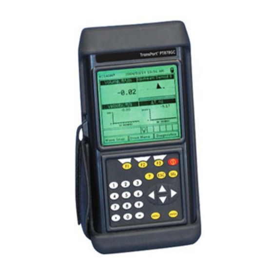
TransPort™ PT878GC
Portable Gas Flowmeter
Instruction Manual
910-229 B3
panametrics.com
August 2021
Related Manuals for Panametrics TransPort PT878GC
Summary of Contents for Panametrics TransPort PT878GC
-
Page 1
Flow TransPort™ PT878GC Portable Gas Flowmeter Instruction Manual 910-229 B3 panametrics.com August 2021… -
Page 3
User’s Manual 910-229 B3 August 2021 panametrics.com Copyright 2021 Baker Hughes company. This material contains one or more registered trademarks of Baker Hughes Company and its subsidiaries in one or more countries. All third-party product and company names are trademarks of their respective… -
Page 4
[no content intended for this page]… -
Page 5: Table Of Contents
Contents Features and Capabilities ………………1 1.1.1 Overview .
-
Page 6
Contents 4.1.9.1 Entering General-Purpose Analog Inputs …………61 4.1.9.2 Entering Analog Inputs in Standard Volume or Mass Flow Option . -
Page 7
Contents Logging Data ………………..121 8.1.1 Entering the Logging Menu . -
Page 8
Contents 9.1.10.7 Testing the Battery …………….167 9.1.11 Resetting to Factory Default Parameters . -
Page 9
Contents 11.1.4.3 Pipe Materials ………………185 11.1.4.4 Accuracy. -
Page 10
Contents viii TransPort™ PT878GC User’s Manual… -
Page 11: Features And Capabilities
Chapter 1. Chapter 1. Features and Capabilities ® The TransPort Model PT878GC is a transit-time clamp-on gas flowmeter which combines all the features of a full-size gas flowmeter with the advantages of a portable instrument. This section describes the TransPort features and general system, and explains the theory of operation. 1.1.1 Overview The PT878GC is available in two models.
-
Page 12: System Description
Chapter 1. 1.1.2 System Description The TransPort is only one part of the flowmeter system. The other part of the system is the flowcell, which consists of the pipe and the transducers. 1.1.2.1 The Flowcell The flowcell is that part of the system that uses ultrasonic pulses to interrogate the flow. It consists of the flowcell pipe and the transducers.
-
Page 13: Electronics Package
Chapter 1. 1.1.2.2 Electronics Package The TransPort consists of circuits that generate, receive, and measure the travel time of the ultrasonic pulses. It also contains a microcomputer that controls operation and calculates flow measurement parameters. Specific circuits function as follows: TRANSMIT SIGNAL GENERATOR — The transmit signal generator, under control of the microcomputer and timing circuit, synthesizes the signal that drives the transmitter.
-
Page 14: Theory Of Operation
Chapter 1. 1.1.3 Theory of Operation The TransPort is a transit-time ultrasonic flowmeter. When ultrasonic pulses are transmitted through a moving liquid or gas, the pulses that travel in the same direction as the fluid flow (downstream) travel slightly faster than the pulses that travel against the flow (upstream).
-
Page 15: Initial Setup
Chapter 2. Chapter 2. Initial Setup Before making measurements, you must prepare the TransPort for operation. This includes the following procedures: • Making Electrical Connections • Charging and/or Replacing Batteries • Powering On and Off • Using the Screen and Keypad •…
-
Page 16
Chapter 2. Figure 3: Connection Locations TransPort™ PT878GC User’s Manual… -
Page 17: Power Connections
Chapter 2. 2.1.1.1 Power Connections The PT878GC is powered by either a 100-120/200-260 VAC wall mount plug-in module, or by 5 internal C -size NiCad high-energy rechargeable batteries or by a pack of 3.0 Ahr NiMH batteries. (An optional power supplement, part #703-1283, uses 6 AA alkaline batteries.) When you receive the PT878GC, the batteries are not charged;…
-
Page 18: Charging And/Or Replacing Batteries
-size NiCad high energy rechargeable batteries (Panametrics Sensing Part Number 200-058) or 3.0 Ahr NiMH batteries (part number 200-081). To replace the batteries, remove the rubber boot, open the panel located on the back of the PT878GC unit, disconnect the batteries, and replace with new ones (see Figure 4 below).
-
Page 19: Powering On And Off
PT878GC emits a short beep and displays a “PCI Loader” message. It then validates the instrument programming, and then displays the Panametrics Sensing logo and the software version and emits a long beep. If the meter fails any of these tests, contact Panametrics Sensing.
-
Page 20
Chapter 2. ABC.SIT 2004/11/30 09:53 AM Velocity, ft/s Signal, dB 0.00 Volume, l/s Delta-T, ns 0.10 E0: No Errors Figure 5: Screen After Powering On To turn the PT878GC off, press the red key for 3 seconds. The screen now appears similar to Figure 6 below. Velocity, ft/s Signal, dB SHUTDOWN: Meter OFF… -
Page 21: Using The Screen And Keypad
Chapter 2. 2.1.4 Using the Screen and Keypad The essential features for operating the TransPort are the screen and keypad. Although these features are common on portable instruments, the PT878GC design offers unique features to simplify and speed operation. 2.1.4.1 Screen The primary function of the screen is to display information in order for you to accurately and easily take measurements.
-
Page 22
Chapter 2. Table 3: Icons in the System Tray Icon Function Meaning Stopwatch Calibration Gate Operation: Watch is stopped when the gate is closed, or runs when it is open. (See page 3-46.) Snapshot Indicates that the Snapshot (To file) function has been activated, so users can take screen (To Printer) -
Page 23: Keypad
[ESC] — enables you to exit menus or menu options at any time; cancels numeric entry. • Red key [ ] turns the power on or off, and toggles the backlight on or off. Figure 8: The TransPort PT878GC Keypad TransPort™ PT878GC User’s Manual…
-
Page 24: Obtaining On-Line Help
Chapter 2. 2.1.5 Obtaining On-Line Help The TransPort offers on-line help screens that describe various features. You can access on-line help at any time by pressing the [?] key. The screen appears similar to Figure 9 below. Help Velocity, ft/s Signal, dB Table of Contents Use the arrows and the enter key to…
-
Page 25: Installing The Dampening Material, Transducers And Fixtures
Since the PT878GC is specifically designed for gas measurement with clamp-on transducers, it requires the use of specially designed fixtures and dampening material to maintain the highest possible measurement accuracy. Panametrics Sensing supplies the CFG series of fixtures: • The V1 clamping fixture for pipes with diameters between 0.75 and 1.25 in.
-
Page 26
Chapter 3. CFG-V1 CFG-V8 Layout Wrap PI Fixture Dummy Block Chain Strap Figure 10: The V Series and PI Fixtures Choosing the transducer installation locations on the pipe is an important aspect of proper flow measurement. Specifications assume a fully developed flow profile typically requiring 20 diameters upstream and 10 diameters downstream of straight pipe run. -
Page 27: Application Requirements
Chapter 3. 3.1.1 Application Requirements Before you begin to use the PT878GC, you should ensure that your meter can handle the frequencies required for your particular application. To check the capabilities of your particular PT878GC, refer to the back label of the PT878GC, shown in Figure 11 below.
-
Page 28
Chapter 3. Table 4: PT878GC Installation Requirements for Air, Nitrogen, Oxygen or Argon Maximum Velocity, ft/s (m/s) Min. Single Dual Four Pipe Size ANSI Pipe Wall Inches Transducer Pressure Travers Travers Triple Travers Five (DIN) (mm) psig (bar) Traverse Traverse 3/4 (20) <0.07 (1.8) 60 (5.1) -
Page 29
Chapter 3. Table 4: PT878GC Installation Requirements for Air, Nitrogen, Oxygen or Argon Maximum Velocity, ft/s (m/s) Min. Single Dual Four Pipe Size ANSI Pipe Wall Inches Transducer Pressure Travers Travers Triple Travers Five (DIN) (mm) psig (bar) Traverse Traverse 10 (250) <0.37 (9.4) 60 (5.1) -
Page 30
Chapter 3. Table 5: PT878GC Installation Requirements for Natural Gas Maximum Velocity, ft/s (m/s) Min. Pipe Size ANSI Pipe Wall Transduce Pressure Dual Triple Four (DIN) Inches (mm) r MHz psig (bar) Single Traverse Traverse Traverse Traverse 2 (50) <0.16 (4.1) 200 (14.8) 110 (33.5) 88 (26.8) -
Page 31
Chapter 3. Table 6: PT878GC Installation Requirements for Steam Maximum Flow Velocity Pipe Wall Min. ft/s (m/s) Pipe Size Inches Transducer Pressure Single in. (mm) (mm) (MHz) psig (bar) Traverse 3 (80) <0.22 (5.6) 110 (8.6) 120 (36.6) <0.3 (7.6) 200 (14.8) 4 (100) <0.24 (6.1) -
Page 32: Preparing The Pipe
Chapter 3. 3.1.2 Preparing the Pipe Locate a transducer measurement point with 20 diameters of upstream straight run pipe and 10 diameters of downstream straight run pipe. In addition, the point should be at least 10 diameters from any butt welds or flanges.
-
Page 33: Performing A Pipe Survey
Chapter 3. 3.1.2.1 Performing a Pipe Survey Finding a location where the pipe is concentric is important for optimum accuracy and performance. If possible, perform a pipe survey with an ultrasonic thickness gauge to find the best location. Clear rust or loose paint and measure the wall thickness at five points along the pipe axis at 25 mm (1-in.) intervals using an ultrasonic thickness gauge, as shown in Figure 13 below.
-
Page 34: Obtaining The Transducer Spacing
Chapter 3. 3.1.2.2 Obtaining the Transducer Spacing Using the measured OD and the pipe wall thickness, program the PT878GC (discussed in Chapter 4, Programming Site Data) to determine the required transducer spacing. To determine the PT878GC correction factor, calculate the mean inside pipe diameter (ID) and the pipe ID at the transducer locations.
-
Page 35: Installing The V Series Clamping Fixture And Transducers
Note: If you are using a V4 fixture with a 1.5 to 2-in. pipe, Panametrics Sensing suggests removing the set screws and the mounting bracket, rotating them and the transducer yoke 180°, and replacing the bracket, yoke and screws for a more secure fit.
-
Page 36
Chapter 3. The two fixture halves have measuring scales; ensure that the scales are on the same side of the fixture, so that both zeros start at the same origin, as shown in Figure 17 below. Figure 17: Fixture with Scale Origins Properly Aligned Install the four nuts onto the threaded rods with the convex side of the nut facing the fixture. -
Page 37: Installing The Transducers
Chapter 3. 3.1.3.2 Installing the Transducers Apply a bead of couplant 6 mm (0.25 in.) wide along the entire length of each transducer face, as shown in Figure 19 below. Figure 19: Couplant on Transducer Face Note: Do not slide the transducer with couplant along the surface of the pipe when mounting the transducer. Set the first mounting block (either left edge or right edge) at a convenient number on the scale, such as 1 in.
-
Page 38: Installing The Pi Fixture And Transducers
The PI clamping fixture holds transducers on pipes from 8 to 24 in. in diameter. It comes with either a chain or strap, depending on the selection made with the initial order from Panametrics Sensing. To install the fixture and transducers, complete the following steps: 3.1.4.1…
-
Page 39
Chapter 3. Figure 23: Marking the 3 o’Clock Position To find the coinciding point on the opposite site of the pipe (180° away from each other), divide the measured circumference by 2 and measure this distance along the circumferential lines from the zero point, as shown in Figure 24 below. -
Page 40: Installing The First Bracket With A Chain Or Strap
Chapter 3. 3.1.4.2 Installing the First Bracket with a Chain or Strap The following steps describe how to install the PI fixture with a supplied chain or strap. Carefully wrap the chain or strap around the pipe, taking care not to twist it. Loosen the wing nuts up to the end of the J-hooks.
-
Page 41: Installing The Transducers
Chapter 3. Line up the other edge of the CFG-PI holder bracket with the scribe line and tighten the chain or strap, as shown in Figure 29 below. Mark on Opposite Scribe Line Rear Edge of Second Block Figure 29: Lining up the Rear Edge of the Bracket with the 180° Scribe Line The spacing should now appear similar to that shown in Figure 30 below.
-
Page 42
Chapter 3. With one hand, mount one transducer into the PI fixture. With the other hand, tighten the transducer hold down screw, gradually pushing the transducer down to the pipe surface. Use a wrench to tighten the backing nut to prevent loosening due to vibration and thermal expansion. -
Page 43: Installing Dampening Material
• The DMP-3 is a clay-like compound for all temperature applications. If the temperature is over 150°F, the PDJ pipe dampening jacket (available from Panametrics Sensing with preapplied DMP-3) must be used with the material. At a minimum, you should consider applying dampening material if you have any of the following conditions: •…
-
Page 44: Installing Dmp-1 Dampening Material
Chapter 3. 3.1.5.1 Installing DMP-1 Dampening Material Be sure the CFG-V clamping fixture is installed on the pipe with the transducers as described in the section Installing the V Series Clamping Fixture and Transducers on page 25. With a marker, mark scribe lines on the inside edges of the brackets onto the pipe.
-
Page 45
Chapter 3. Figure 34: DMP-1 Material with Transducer Footprint Cut Out To remove any residual adhesive, clean the cut-out area with a rag or a piece of sandpaper, or use varnish remover. 10. Reinstall the fixture and transducers on the pipe. Lay the second strip of dampening material flat. -
Page 46: Installing Dmp-1 Dampening Material With Pi Fixture
Chapter 3. 3.1.5.2 Installing DMP-1 Dampening Material with PI Fixture Be sure the PI clamping fixture is installed onto the pipe with the transducers as described in the section Installing the PI Fixture and Transducers on page 28. Approximate the axial distance from one transducer face to the other transducer face, as shown in Figure 36 below.
-
Page 47: Installing Dmp-3 Compound With All Fixtures
Chapter 3. 3.1.5.3 Installing DMP-3 Compound with All Fixtures Be sure the fixture and transducers are installed on the pipe as described in the previous sections of this chapter. Remove the fixture and transducers, but be sure to mark the approximate area of installation. Remove any loose paint or rust with a file or emery cloth, as shown in Figure 38a below.
-
Page 48: Installing The Pdj Dampening Jacket
Chapter 3. Figure 41: Clearing DMP-3 from the Transducer Location (a) and Installing the Transducers (b) Apply the couplant to the transducers, and install the transducers onto the pipe. Note: If the measurement point is near a flange or weld, apply DMP-3 between that structure and the fixture as well.
-
Page 49
Chapter 3. WARNING! The pipe and the dripping fluid will cause severe burns upon contact with bare skin. Also, be sure not to inhale the fumes generated during the DMP-3 curing cycle. Install the fixture over the jacket, adjusting the spacing to match the prestamped transducer holes and PT878GC spacing calculations. -
Page 50
Chapter 3. TransPort™ PT878GC User’s Manual… -
Page 51: Programming Site Data
Chapter 4. Chapter 4. Programming Site Data On the PT878GC, a Program Menu (part of the Main Menu) enables you to enter information that is specific to each site: • Transducer types and paths • Pipe materials and linings • Fluid types •…
-
Page 52: Entering Transducer Parameters
Press [ENTER] or [SEL] to confirm the choice. IMPORTANT: While wetted transducers are listed as a choice, the PT878GC is designed for use with Shear wave clamp-on transducers. Consult Panametrics before selecting wetted transducers. Note: The choices made earlier in the Transducer and Pipe options determine the prompts available later. If the PT878GC does not scroll to a particular parameter, it is not necessary for that transducer or pipe type.
-
Page 53: Parameters For Special Transducers
From the Wedge Temp prompt, press the [ ] key to reach the Wedge SS prompt, and press Use the numeric keys to enter the Panametrics Sensing-supplied wedge sound speed (in ft/sec or m/sec) and press [ENTER]. Pressing the [] key returns the meter to the Transducer tab at the top.
-
Page 54: Entering Pipe Parameters
Chapter 4. 4.1.3 Entering Pipe Parameters To enter the Pipe option, scroll to the Pipe entry on the Program Menu and press [ENTER]. (From the Transducer window, you can scroll back up to the Transducer tab and press the [ ] arrow key to reach the Pipe window and …
-
Page 55
Chapter 4. The first prompt asks you to select the pipe material. [ENTER] Press to enter the material prompt. A drop-down list of materials opens. Table 7 below lists the available preprogrammed materials on the list. Press the [ ] or [ ] keys to scroll to the appropriate material, or scroll to “Other”… -
Page 56
Chapter 4. Note: The measurement units shown depend on the choices you have made in the English/Metric window of the Meter menu. If you select a material that has the Schedule option: [ENTER] The prompt asks if you wish to apply DIN (the DIN schedule). Press to select (or deselect) the DIN box. -
Page 57: Entering Pipe Lining Parameters
Press [ENTER] to confirm your choice. Note: If your pipe lining is not on the drop-down list, consult Panametrics Sensing for further information. The program follows one of two paths: If you have selected a preprogrammed material, the PT878GC automatically supplies the correct sound speed, and you proceed to step 3.
-
Page 58: Entering Fluid Types And Speeds
Chapter 4. 4.1.5 Entering Fluid Types and Speeds To access the Fluid option, scroll to the Fluid entry on the Program Menu and press [ENTER]. (If you are already in the Transducer/Pipe form, press the [] arrow key to reach the Fluid window, and press [ENTER].) The screen appears similar to Figure 48 below.
-
Page 59: Entering The Signal Path Parameters
Chapter 4. 4.1.6 Entering the Signal Path Parameters To enter the Path option, scroll to the Path entry on the Program Menu and press [ENTER]. (From the Lining window, you can scroll back up to the Lining tab and press the [] arrow key to reach the Path window, and press [ENTER].) The screen appears similar to Figure 49 below.
-
Page 60: Path Parameters For Clamp-On Transducers
[ENTER] to confirm the entry. If you enter an invalid entry, the PT878GC rejects the entry and displays an error message. Note: Panametrics Sensing does not recommend using a spacing other than the one calculated by the PT878GC. After you enter the spacing, pressing the [ ] key returns the prompt to the Traverses box, and then to the Path tab at the top of the screen.
-
Page 61
Chapter 4. The first prompt asks if you want to disable or enable the Standard Volume option. Use the [ ] and [ ] keys to scroll to the appropriate radio button. Press [ENTER] to confirm your selection. Note: If you select “Disabled,”… -
Page 62: Entering Inputs In The Standard Volume Option
Chapter 4. 4.1.7.1 Entering Inputs in the Standard Volume Option To enter input parameters in the Standard Volume/Mass Flow option, return to the Settings tab at the top of the Standard Volume window. Press the [] arrow key and [ENTER] to open the Inputs window. The screen appears similar to Figure 51 below.
-
Page 63
Chapter 4. The next prompt appears if you have selected a fixed pressure. The PT878GC asks for the fixed pressure value. [ENTER] Press to open the text box. Use the numeric keys to enter the known pressure. Press [ENTER] to confirm the entry. Whether you have selected a fixed or an active supply, the PT878GC asks for the desired input. -
Page 64: Entering Mass Flow Parameters
Chapter 4. 4.1.7.2 Entering Mass Flow Parameters To enter mass flow parameters in the Standard Volume/Mass Flow option, press the [] arrow key until you reach the Mass Flow tab, and then press [ENTER] to open the Mass Flow window. The screen appears similar to Figure 52 below. To step through each parameter, press the [] key.
-
Page 65: Entering Skan/Measure Parameters
M>S Switch value. The default value is 5.0 µsec and values from 0 to 250 µsec are acceptable. Note: Do not change this value without consulting Panametrics Sensing. If you wish to use Skan only, set the M/S Switch to a value of 0.
-
Page 66
Chapter 4. The program now asks if you wish to Limit the Measurement Delta. (The default is unchecked or off.) [ENTER] Press to enter the text box. Use the numeric keys to enter the recommended value in µsec. Press [ENTER] to confirm the entry. Pressing the [] key highlights the Advanced prompt. -
Page 67: Entering Skan/Measure Integrate Parameters
Chapter 4. 4.1.8.1 Entering Skan/Measure Integrate Parameters To enter parameters for the Skan/Measure Integrate mode in the Skan/Measure option, press the [] arrow key once to reach the Integrate tab. Then press [ENTER] to open the Integrate window, which appears similar to Figure 55 below.
-
Page 68: Entering Skan/Measure Count Parameters
Chapter 4. 4.1.8.2 Entering Skan/Measure Count Parameters To open the Skan/Measure Count window in the Skan/Measure option, press the [] arrow key twice (from the All tab) to reach the Count tab. Press [ENTER], and the screen appears similar to Figure 56 below. Skan/Measure Integrate Count…
-
Page 69: Entering Skan/Correlation Parameters
Chapter 4. 4.1.8.3 Entering Skan/Correlation Parameters To open the Skan/Correlation window in the Skan/Measure option, press the [] arrow key three times (from the All tab) to reach the Correlate tab, and press [ENTER]. The screen appears similar to Figure 57 below. Skan/Measure Integrate Count…
-
Page 70
Chapter 4. Repeat step 1 to enter the maximum percentage of peak. The next prompt asks for the Percent of Peak, which is used to calculate the transit times and Delta-T. [ENTER] Press to enter the text box. Use the numeric keys to enter the desired value. Press [ENTER] to confirm the entry. -
Page 71: Entering Analog Inputs
Chapter 4. 4.1.9 Entering Analog Inputs The Analog Inputs option enables you to specify parameters for general purpose or standard volume inputs. To enter the Analog Inputs option, scroll to the Analog Inputs entry on the Program Menu and press [ENTER]. If you have not enabled the Standard Volume Option (see page 4-18), the screen appears similar to Figure 58 below.
-
Page 72
Chapter 4. Use the four arrow keys to scroll to the desired letter or symbol, and press [ENTER] to add the letter to the label. Note: Pressing [SEL] causes the screen to alternate between a set of upper-case (capital) letters, a set of lower-case letters, and a set of symbols. -
Page 73: Entering Analog Inputs In Standard Volume
Chapter 4. 4.1.9.2 Entering Analog Inputs in Standard Volume or Mass Flow Option If you have enabled the Standard Volume or Mass Flow options, the screen displays different options, as shown in Figure 60 below. Analog Input Input A Input B Pressure Function Label…
-
Page 74: Entering The Analog Output
Chapter 4. 4.1.10 Entering the Analog Output The Analog Output option enables you to enter information to set up output parameters. To enter the option, scroll to the Analog Output entry on the Program Menu and press [ENTER]. The screen appears similar to Figure 61 below. To step through each parameter, press the [] key.
-
Page 75
Chapter 4. [ENTER] Press to open the window. Scroll to the desired output type. Press [SEL] to confirm your selection. The prompt then moves to a list of unit types. (The available units depend on the selection made at the Data Source prompt.) Scroll to the desired output unit. -
Page 76: Entering The Digital Output
Chapter 4. 4.1.11 Entering the Digital Output While resembling the Analog Output option, the Digital Output option enables you to set up parameters necessary for a digital output. To enter the option, scroll to the Digital Output entry on the Program Menu and press [ENTER]. The screen appears similar to Figure 63 below.
-
Page 77
Chapter 4. • Temperature • Volume • User Function • Skan/Measure • Mass Flow [ENTER] Press to open the data source selection window, shown in Figure 62. Scroll to the desired source. Press [SEL] to confirm your selection. The prompt then moves to a list of unit types. (The available units depend on the selection made at the Data Source prompt.) Scroll to the desired output unit. -
Page 78: Entering User Functions
Chapter 4. [ENTER] Press to open the drop-down menu. Scroll to the required mode. Press [ENTER] to confirm your selection. Stopwatch Totalizer Through the Gate Input option, you can implement the Stopwatch Totalizer function to measure totals manually. To set up the Totalizer function: At the Gate Active prompt, select Contact Closed.
-
Page 79
Chapter 4. “ ‘ < > Cancel Delete Figure 65: The Text Creation Window Use the four arrow keys to scroll to the desired letter or symbol, and press [ENTER] to add the letter to the label. Note: Pressing [SEL] causes the screen to alternate between a set of upper-case (capital) letters, a set of lower-case letters, and a set of symbols. -
Page 80: Entering Correction Factors
When you have completed entering the function, press [F3] (OK) to confirm the entry and return to the User Function window. Panametrics Sensing recommends pressing [F2] (Check) to test the validity of the function. The PT878GC displays either “OK” or a message such as “Syntax Error.”…
-
Page 81: Entering Reynolds Correction
Chapter 4. Correction Factors Calibration Factor Reynolds Correction Inputs Re Correction K/V Factors Single Table K/V x 10 Data Source Edit Table Cancel Figure 67: Reynolds Correction Window 4.1.13.1 Entering Reynolds Correction The first prompt asks if you want to enable the Reynolds Correction factor, a number based on the Kinematic Viscosity and flow rate of the gas.
-
Page 82: Entering A Calibration Factor
Chapter 4. The prompt then asks if you wish to edit the Reynolds Correction table. [ENTER] Press to open the table, which appears similar to Figure 68 below. Edit Reynolds Table Inputs Data Source Cancel Figure 68: Window for Reynolds Correction Table Use the numeric keys to enter the first value for the data source, and press [ENTER] to confirm the entry.
-
Page 83
Chapter 4. Correction Factors Reynolds Correction Calibration Factor Inputs Calibration Factor K Factor Single Table Meter K-Factor 1.0000 Data Source Edit Table Edit Table Cancel Figure 69: The Calibration Factor Window The first prompt asks if you wish to enable the calibration factor. … -
Page 84
Chapter 4. Edit KFactor Table Inputs KFactor Data Source Cancel Figure 70: The KFactor Table Use the numeric keys to enter the first value for the data source, and press [ENTER] to confirm the entry. Press the [ ] key to move to the KFactor column. Use the numeric keys to enter the corresponding value, and press [ENTER] to confirm the entry. -
Page 85: Creating And Managing Sites
Chapter 5. Chapter 5. Creating and Managing Sites The PT878GC can store site data in files for current and future access. (To learn how to program setup data, refer to Chapter 4, Programming Site Data.) After you answer the necessary questions, simply save the information to a site file.
-
Page 86
Chapter 5. Site Manager File Site Sort Info: DEFAULT:SIT DEFAULT New Site **CURRENT SITE** 03/04/04 14:51:10 5111 bytes 118272 bytes free Refresh Exit Figure 72: The Site Manager Window Note: Each PT878GC comes preprogrammed with a basic site, Default, which serves as a basis for saving data and creating other sites. -
Page 87: Creating A New Site
Chapter 5. • To open an existing site (thus replacing the current site), go to page 79. • To save a current site, go to page 79. • To refresh site information, go to page 81. • To rename a site, go to page 81. •…
-
Page 88
Chapter 5. New Site New Site Use the selected site ‘DEFAULT.SIT’ as a template? Figure 75: Template Confirmation Window The meter returns to Operate Mode, with the new site name displayed in the upper left corner of the screen. TransPort™ PT878GC User’s Manual… -
Page 89: Opening An Existing Site
Chapter 5. 5.1.1.2 Opening an Existing Site If you want to return to a second site that you have previously saved, first highlight the replacement site in the left window of the Site Manager. Then press [MENU] to open the File Menu. Scroll to the Open option, and press [ENTER]. The screen appears similar to Figure 76 below.
-
Page 90
Chapter 5. Save Site Save the current site (DEFAULT.SIT)? Figure 77: The Save Current Site Window • Press [F2] (No) to cancel saving the site, or • Press [F3] (Yes) to save the site. The PT878GC remains in the current window (Operate Mode or Site Manager), with the current site saved. TransPort™… -
Page 91: Saving A Site With A Different Name
Chapter 5. 5.1.1.4 Saving a Site with a Different Name If you want to save the current site with a different name, open the Site Manager, press [MENU] to open the File Menu, scroll to the Save As option, and press [ENTER]. The screen appears similar to Figure 78 below. Save Current Site Delete Cancel…
-
Page 92: Deleting A Site
Chapter 5. Rename Site DEFAULT Delete Cancel Figure 79: The Rename Site Window Use the four arrow keys to scroll to the desired letter or number, and press [ENTER]. Repeat this procedure until you have created the desired site name. (Press [F1], Delete, to remove any unwanted letters or numbers.) When you have finished, •…
-
Page 93: Creating A Site Message
Chapter 5. 5.1.1.8 Creating a Site Message The Site Message option allows you to add an explanatory message (with up to 30 characters or spaces) for any given site. To create a site message: Press [MENU] to enter the File Menu. Then press the [] arrow key once to scroll from the File Menu to the Site Menu.
-
Page 94
Chapter 5. Use the four arrow keys to scroll to the desired letter or symbol, and press [ENTER] to add the letter to the message. Note: Pressing [SEL] causes the screen to alternate between a set of upper-case (capital) letters, a set of lower-case letters, and a set of symbols. -
Page 95: Printing A File
Chapter 5. 5.1.1.9 Printing a File To print a file from the Site Manager, press [MENU] to enter the File Menu, press the [] arrow key once, scroll to the Print option, and press [ENTER]. The PT878GC shows a message indicating that its infrared scanner is looking for a receiving device.
-
Page 96: Transferring A File From A Pc To The Pt878Gc
Chapter 5. 5.1.1.12 Transferring a File from a PC to the PT878GC Once you have stored site or meter files to a PC, you can then transfer them back to the PT878GC over the IR interface. The PT878GC only accepts files with a .sit (site) or .met (meter) extension. If you rename another type of file with one of these extensions and transfer it, it will be transferred, but will not function if you open it.
-
Page 97: Listing Files By Name
Chapter 5. 5.1.1.13 Listing Files by Name If you want to list your files alphabetically by site name within the Site Manager, press [MENU] to open the File Menu. Then press the [] arrow key twice to scroll from the File Menu to the Sort Menu, shown in Figure 85 below. Press [ENTER].
-
Page 98
Chapter 5. TransPort™ PT878GC User’s Manual… -
Page 99: Displaying And Configuring Data
Chapter 6. Chapter 6. Displaying and Configuring Data The PT878GC allows you to view from one to four different measurement parameters simultaneously. The screen can show these parameters not only in numeric format, but as line or bar graphs as well. You can configure any given measurement for your particular requirements.
-
Page 100
Chapter 6. Number Format Programming Fixed Decimal Format Decimal Places Cancel Figure 87: The Number Format Window The first entry, Format, asks you to select the numeric format from three choices: fixed decimal, default and scientific. Default provides the default resolution, while Fixed Decimal allows users to override the standard resolution. -
Page 101: The View Option
Chapter 6. 6.1.2 The View Option The second option, View, allows you to select the presentation of a parameter in one of three formats: numeric, line graph or bar graph. From the Display Menu, press the [] key once to reach the View option, and then press [ENTER]. A drop-down menu shows the three formats.
-
Page 102: The Limits Option
Chapter 6. 6.1.3 The Limits Option Once you have configured a parameter as a line or bar graph, you might need to change its presentation or values. The Limits option (replacing the Format option for line and bar graphs) enables you to program the minimum or maximum values displayed, the time interval and the display of the average value.
-
Page 103: The Measurement Option
Chapter 6. 6.1.4 The Measurement Option On occasion, you might need to change the actual parameter measured in a given window.The Measurement option enables you to reconfigure the window with one of five categories of data source (velocity, volume, forward or reverse totalizer, or diagnostics) and appropriate English or metric measurement units.
-
Page 104: Customizing The Display Screen
Chapter 6. 6.1.5 Customizing the Display Screen You might wish to display one or two parameters, or customize the soft keys to quickly access particular menus. The Site Menu enables you to make more comprehensive changes in your display screen. To enter the Site Menu, press the [MENU] key at the lower right of the PT878GC keypad.
-
Page 105: Specifying The Number Of Displayed Parameters
Chapter 6. 6.1.5.1 Specifying the Number of Displayed Parameters As mentioned earlier, the PT878GC can display one to four different measurement parameters simultaneously. However, sometimes you might wish to display only one or two parameters. To change the number of open display windows: Press [MENU].
-
Page 106: Customizing Softkeys
Chapter 6. 6.1.5.2 Customizing Softkeys When the screen is in Operate mode, you might wish to access a particular submenu frequently without the trouble of scrolling through menus. Customizing the softkeys (the function keys —[F1], [F2] and [F3]) allows you to access up to three submenus by pressing the associated softkey.
-
Page 107
Chapter 6. Press [ENTER] to confirm the entry, and press [F3] (OK) to confirm the entry and close the window. (Press [F2] (Cancel) to close the window without changing the key.) The screen now appears similar to Figure 6-10 on the next page, with the [F1] window displaying “Contrast.” Pressing [F1] opens the Contrast window. -
Page 108: Managing Files — The Drive Manager
Chapter 6. 6.1.6 Managing Files — The Drive Manager On occasion, you might want to review, print or transfer some or all of the files in the PT878GC. The Drive Manager allows you to view all the files stored in the meter. To open the Drive Manager: Press [MENU].
-
Page 109
Chapter 6. The window on the left lists all the meter, site and log files in the PT878GC, while the window on the right displays information on the file highlighted in the left window. File Manager File Sort Transfer Info: SYSLOG.MET SYSLOG. -
Page 110: Refreshing A File
Chapter 6. 6.1.6.1 Refreshing a File You can refresh a file (updating the display with the most current information) in one of two ways: • Press [F2], Refresh, to refresh the highlighted file. • From the File Menu, scroll to the Refresh option and press [ENTER]. The updated information on the highlighted file appears in the window on the right.
-
Page 111
Chapter 6. Note: For Windows NT 4.0, check that the QuickBeam software (available through the path C:Program FilesQuickBeam Suite) is running, and that the IR beam on the PT878GC has clear access to the IR sensor connected to the PC port. You can send the file in one of two ways: •… -
Page 112: Deleting A File
Chapter 6. 6.1.6.4 Deleting a File To delete a file in the File Manager, first be sure you have highlighted that site in the left window of the File Manager. Then press [MENU], scroll to the Delete option, and press [ENTER]. The screen appears similar to Figure 100 below. File Manager Delete Confirmation File…
-
Page 113: Listing Files By Name
Chapter 6. 6.1.6.5 Listing Files by Name If you want to list your files alphabetically by site name within the File Manager, press [MENU] to open the File Menu. Then press the [] arrow key to scroll from the File Menu to the Sort Menu, shown in Figure 101 below. Press [ENTER]. The File Manager screen refreshes, with the sites listed in alphabetical order.
-
Page 114: Accessing Meter Data -The About Option
While the window normally appears briefly at startup, users might want to access the information for a longer period. To open the About window, scroll to the About option on the Site Menu and press [ENTER]. The screen appears similar to Figure 102 below. Panametrics Sensing PT878GC Portable Flowmeter Copyright ©2002 Baker Hughes All rights reserved.
-
Page 115: Programming Meter Settings
Chapter 7. Chapter 7. Programming Meter Settings Along with display formats and site data, PT878GC users can program global settings for the meter that suit their individual preferences. The global settings include: • English or Metric measurement units • Battery power •…
-
Page 116: Entering The Meter Menu
Chapter 7. 7.1.1 Entering the Meter Menu To enter the Meter Menu, press the [MENU] key at the lower right of the PT878GC keypad. The Main Menu replaces the Status Bar at the top of the screen. Press the [ ] arrow key twice to scroll from the Site Menu to the Meter Menu.
-
Page 117
Chapter 7. Meter Settings Units English Metric Pressure Units: Date: Bars 2000/11/1 Time: 10:08:53 AM Cancel Figure 104: The Meter Settings Window At the Units prompt, use the [ ] and [ ] keys to scroll between English and Metric units. Press [ENTER] to confirm the choice. -
Page 118: The Battery Charger
Chapter 7. 7.1.3 The Battery Charger The Battery option allows you to monitor the current run time and status of the internal rechargeable batteries, as well as to condition NiCad batteries to maintain the maximum life possible. Conditioning NiCad batteries (a process that can take up to 12 hours for a fully charged pack) discharges the pack completely and then performs a fast charge.
-
Page 119: Entering Date And Time
Chapter 7. 7.1.4 Entering Date and Time In Operate mode, the Status Bar displays the current date and time above the measurements in the upper right corner of the screen. The Date/Time option allows you to set the date or time, which are required for correct data logging operation.
-
Page 120: Changing Date And Time Appearance (Locale)
Chapter 7. 7.1.5 Changing Date and Time Appearance (Locale) In addition to setting the correct date and time, you can also change its presentation to suit local preferences. You can select a time display of AM/PM or 24-hour time To alter the time and date display: From the Meter menu, scroll to the Locale entry and press [ENTER].
-
Page 121
Chapter 7. The PT878GC now asks you to select whether you want the time presented in a 12-hour format (for example, 11:53:23 PM) or in a 24-hour format (23:53:23). [ENTER] Press to open the drop-down menu. Use the [ ] or [ ] arrow keys to scroll to the 12-hour or 24-hour entry. -
Page 122: Adjusting The Contrast
Chapter 7. 7.1.6 Adjusting the Contrast For more comfortable viewing in a particular environment, the PT878GC enables you to adjust the screen contrast. To adjust the screen contrast: From the Meter menu, scroll to the Contrast entry and press [ENTER]. The Display Options window opens on the …
-
Page 123: Setting Backlight Timeout
Chapter 7. 7.1.7 Setting Backlight Timeout By using the Backlight Timeout option, you can set a specified time that the PT878GC backlight will remain on before turning itself off. Automatic turnoff enables the PT878GC to conserve battery power. To set the backlight timeout: From the Meter menu, scroll to the Backlight entry and press [ENTER].
-
Page 124: Changing Communications Parameters
Cancel Figure 108: The Communications Window The first prompt asks for the node identification number, which can be any number from 1 to 240. IMPORTANT: Do NOT change the node ID unless instructed by Panametrics Sensing. [ENTER] Press to open the text box.
-
Page 125
Chapter 7. [ENTER] Press to open the drop-down menu. Use the [ ] or [ ] arrow keys to scroll to the desired parity. Press [ENTER] to confirm the entry. The next prompt asks you to select either one or two stop bits.The default number is one. Use the [ ] and [ keys to scroll to the desired number, and press [ENTER]. -
Page 126: Resetting Forward And Reverse Totals
Chapter 7. 7.1.9 Resetting Forward and Reverse Totals On occasion, it might be necessary to clear and reset the forward and reverse totals computed by the Forward and Reverse Totalizers. To reset the totals: From the Meter menu, scroll to the Totals entry and press [ENTER]. The window now appears similar to Figure 109 below.
-
Page 127: Setting Up User Tables
Chapter 7. 7.1.10 Setting Up User Tables When you program user functions (see page 68), you can also support them with up to six user tables of non-linear or empirical data. To program one or more user tables: From the Meter menu, scroll to the User Tables entry and press [ENTER]. The window now appears similar to Figure 110 below.
-
Page 128
Chapter 7. UserTable1 “ ‘ < > Delete Cancel Figure 111: The Text Creation Window Use the four arrow keys to scroll to the desired letter or symbol, and press [ENTER] to add the letter to the label. Note: Pressing [SEL] causes the screen to alternate between a set of upper-case (capital) letters and a set of symbols. -
Page 129
Chapter 7. Use the four arrow keys to move to the desired entry in the table. Press [ENTER]. Then use the numeric keys to enter the desired data, which appears in the right corner of the window above the table. Press [ENTER] to confirm the data, which then appears in the appropriate slot in the table. -
Page 130: Taking A Bitmap Capture Of A Current Screen
Chapter 7. 7.1.11 Taking a Bitmap Capture of a Current Screen The Snapshot option enables you to take a “screen capture” of the current screen in bitmap format (.bmp) for display or storage in a Windows-based PC. To take a “snapshot” of the screen: From the Meter menu, scroll to the Snapshot entry and press [ENTER].
-
Page 131: Logging Data
Chapter 8. Chapter 8. Logging Data A powerful and flexible feature of the PT878GC is data logging. The meter enables you to choose up to 12 parameters to log. You can also select the start time and date, end time and date, and time interval. Logs can run one at a time or simultaneously.
-
Page 132: Entering The Logging Menu
Chapter 8. 8.1.1 Entering the Logging Menu To enter the Logging Menu, press the [MENU] key at the lower right of the PT878GC keypad. The Main Menu replaces the Status Bar at the top of the screen. Press the [ ] arrow key three times to scroll from the Site Menu to the Logging Menu.
-
Page 133
Chapter 8. Log Manager File View Sort Info: AAA.LOG State: Finished S:03/01/04 13:13:41 E:03/01/04 13:23:41 Interval: 10 Seconds Records:51 03/01/04 13:23:21 1216 bytes 109568 bytes free Refresh Exit Figure 114: The Log Manager Window To access the menu for the Log Manager, press the [MENU] key. The cursor highlights the File Menu in the upper left … -
Page 134: The File Menu
Chapter 8. 8.1.3 The File Menu The File Menu allows you, not only to create new logs, but also to copy, rename or delete logs, as well as to print them or transfer them to a PC. To open the File menu from the Log Manager, press the [MENU] key and then [ENTER]. The screen appears similar to Figure 115 below.
-
Page 135: Setting Up A New Log
Chapter 8. 8.1.3.1 Setting up a New Log The New Log option enables you to create and set up parameters for a new log. You can access this option in two ways: • by scrolling to the New Log option in the Logging Menu (as shown in Figure 8-1 on page 8-2) and pressing [ENTER], or •…
-
Page 136
Chapter 8. General Measurements Log Name 10SEC.LOG Format Circular Linear Type Error Standard Start Date/Time 01:38:08 2004/11/01 End Date/Time 09:38:08 2004/11/01 Logging Interval secs Activate Cancel Figure 117: The General Log Format Window To step through each parameter, press the [] key. The first prompt asks you to choose between a linear or circular format for the log. -
Page 137
Chapter 8. Finally, press the [ ] key to move to the Measurements tab, and press [ENTER]. The Measurements window appears similar to Figure 118. General Measurements NO UNIT NO UNIT NO UNIT NO UNIT NO UNIT NO UNIT NO UNIT NO UNIT NO UNIT… -
Page 138: Copying (Cloning) A Selected Log
Chapter 8. The prompt then moves to a list of unit types. (The available units depend on the selection made at the Data Source prompt.) Scroll to the desired output unit. Press [F3] (OK) to confirm your selection. You can repeat this procedure for up to 12 different parameters. When you have finished, press [F2] (Cancel) to cancel the entries, or [F3] (Activate) to confirm the entries and start the log.
-
Page 139: Deleting All Logs
Chapter 8. Log Manager File Delete Programming Info:DEFAULT DEFAULT Delete Log ‘555.LOG?’ GLOBAL 1 View Figure 120: The Delete Confirmation Window 8.1.3.5 Deleting All Logs To clear the Log Manager and memory of all logs, open the File menu, scroll to the Delete All Logs option, and press [ENTER].
-
Page 140: The Log Menu
Chapter 8. message indicating that it is uploading the log. (The meter also displays a message if the upload fails.) When the upload is complete, the meter returns to the Log Manager. The PC holds the transferred log in a CIr_Inbox folder (C:Ir_Inbox for Windows NT, C:My Received Files for Windows 98, or Desktop for Windows 2000).
-
Page 141: Pausing All Logs
Chapter 8. The PT878GC returns to the Log Manager, which displays the highlighted log with a status of “Finished.” The space not used by the finished log is freed for reuse. Note: You cannot restart a finished log. You must create a new log with the same parameters. 8.1.4.4 Pausing All Logs To pause all logs that are currently pending or running, open the Log menu, scroll to the Pause All Logs option, and…
-
Page 142: The View Menu
Chapter 8. 8.1.5 The View Menu Through the View menu, you can view the data of individual logs in graphical or spreadsheet formats. To open the View menu from the Log Manager, press [MENU]. Scroll to the View menu, and press [ENTER]. The screen appears similar to Figure 122 below.
-
Page 143: Displaying Log Details
Chapter 8. 8.1.5.1 Displaying Log Details To view details of a given log, be sure the log is highlighted in the left window of the Log Manager. Then scroll to the View menu and press [ENTER]. Scroll to the Details option and press [ENTER]. The screen now appears similar to Figure 123 below.
-
Page 144: Displaying Log Data In Graphical Form
Chapter 8. 8.1.5.2 Displaying Log Data in Graphical Form To view a log in graphical form, be sure the log is highlighted in the left window of the Log Manager. Scroll to the View menu and press [ENTER]. Scroll to the Graph option and press [ENTER]. The “Select Measurement”…
-
Page 145
Chapter 8. The Y-Axis window allows you to specify whether the Y axis on the graph extends to the maximum value (Max), over the entire range (Range) or between certain specified values (Set). Use the [ ] and [ ] keys to scroll to the desired limit type. -
Page 146: Displaying Log Data In Spreadsheet Form
Chapter 8. 8.1.5.3 Displaying Log Data in Spreadsheet Form To view a log in spreadsheet form, be sure the log is highlighted in the left window of the Log Manager. Then scroll to the View menu and press [ENTER]. Scroll to the Spreadsheet option and press [ENTER]. The screen now appears similar to Figure 127 below.
-
Page 147: The Sort Menu
Chapter 8. 8.1.6 The Sort Menu The Sort Menu within the Log Manager allows you to arrange your log list either alphabetically (By Name) or chronologically (By Date). Log Manager Sort File View By Name Info: AAA.LOG State: Finished By Date S:03/01/04 13:13:41 E:03/01/04 13:23:41…
-
Page 148
Chapter 8. TransPort™ PT878GC User’s Manual… -
Page 149: Servicing The Pt878Gc
Chapter 9. Chapter 9. Servicing the PT878GC For user convenience, the PT878GC offers a Service Menu. This menu enables users to perform a variety of functions that they might occasionally require: • print out reports • calibrate the PT878GC • run diagnostics •…
-
Page 150: Entering The Service Menu
Chapter 9. 9.1.1 Entering the Service Menu To enter the Service Menu, press the [MENU] key at the lower right of the PT878GC keypad. The Main Menu replaces the Status Bar at the top of the screen. Press the [ ] arrow key four times to scroll from the Site Menu to the Service Menu.
-
Page 151
Chapter 9. Reports Reports Drive Contents Current Site Global Settings User Functions User Tables All User Settings Menu Commands All Reports Exit Print Figure 130: The Reports Window Press [ENTER] to open the drop-down list of available reports, as shown in Figure 130 above. Press the [ ]or [ arrow keys to scroll to the desired reports, and press [ENTER]. -
Page 152
Chapter 9. Figure 131: Printout of a Typical Drive Report TransPort™ PT878GC User’s Manual… -
Page 153: Setting Up The Thickness Gauge
Chapter 9. 9.1.3 Setting up the Thickness Gauge For greatest accuracy in flow applications, the PT878GC can measure pipe wall thickness using an optional thickness gauge transducer, instead of relying on the nominal pipe wall thickness. In Thickness Gauge mode, the PT878GC does not measure flow, but it can determine the thickness of most standard metal and plastic pipe materials over a range from 0.05 to 3 in.
-
Page 154: Measuring Pipe Wall Thickness
Measuring Pipe Wall Thickness 9.1.4.1 Entering the Material and Sound Speed IMPORTANT: Panametrics Sensing recommends calibrating the thickness gauge periodically (as discussed on page 148) before measuring thickness. To enter the Thickness Gauge Display option, scroll to the T-Gauge Display entry on the Service Menu and press [ENTER]. The screen appears similar to Figure 133 below.
-
Page 155: Measuring Thickness In Numeric Format
Chapter 9. 9.1.4.2 Measuring Thickness in Numeric Format To measure the actual thickness of a pipe, apply couplant to the calibrated thickness gauge transducer and hold the transducer steady against the pipe. Then press the [ ] or [ ] arrow key until you reach the Display tab and press [ENTER].
-
Page 156: Displaying The Receive Signal In Graphical Format
Chapter 9. 9.1.4.3 Displaying the Receive Signal in Graphical Format Used chiefly for diagnostic purposes, the Graph option helps to determine why the thickness gauge is not working if you suspect a problem. The graph shows an image of the acoustic signal. If the display does not show a signal image similar to Figure 9-7 below, you may have a problem with the transducer, couplant, or the programmed ®…
-
Page 157
Chapter 9. Thickness Gauge Measure Display Material Velocity Graph Zero Signal Display Figure 136: The Graph Window in Zoom Format • Press [F1] (In) to zoom in to magnify screen details. • Press [F2] (Out) to zoom out fully. • Press [F3] to toggle between the left and right cursors. … -
Page 158: Calibrating The Thickness Gauge Transducer
See Appendix C for more information. The next prompt asks you to enter the length of Block 1. (If you are using a Panametrics Sensing-supplied test block, the length is printed on the block.) Press [ENTER] to open the text box.
-
Page 159: Calculating Velocity (Pipe Material Sound Speed)
Chapter 9. • Press the [ ] or [ ] arrow key to move to another tab to take readings or perform a velocity calibration. • Press [F2] (Cancel) to return to Operate Mode without confirming the sound speed value. •…
-
Page 160
Chapter 9. Thickness Gauge Measure Display Velocity Graph Zero Material Block Length Press Set to Commit Value Current Calculated 22129. 74733. Cancel Figure 139: The Velocity Window, Displaying the Calculated and Current Values The “Calculated” box shows the thickness value measured. The PT878GC asks for confirmation of the calculated and current values. -
Page 161: Programming The Thickness Gauge
Noise Threshold • Detection Threshold IMPORTANT: The thickness gauge programming settings are entered at the factory. You should not change them unless instructed by Panametrics Sensing. The Programming window appears similar to Figure 140 below. Thickness Gauge Setup Programming Low Signal Thresh Transducer Delay µs…
-
Page 162
Chapter 9. Signal inversion should be on, unless you have received other instructions. To change its status, use the [ ] and [ arrow keys to move to the appropriate radio button and press [ENTER]. To enter the noise threshold: [ENTER] Press to open the text box. -
Page 163: Displaying Diagnostic Parameters
Chapter 9. 9.1.6 Displaying Diagnostic Parameters The Diagnostics option enables you to view current diagnostic parameters without having to open a display window in Operate Mode. To enter the option, scroll to the Diagnostics entry on the Service Menu and press [ENTER]. The screen appears similar to Figure 141 below.
-
Page 164: Calibrating The Analog Output And Inputs
Chapter 9. 9.1.7 Calibrating the Analog Output and Inputs The Calibration option allows you to calibrate the analog output and inputs. To enter the option, scroll to the Calibrate entry on the Service Menu and press [ENTER]. The screen appears similar to Figure 142 below. Calibrate/Test I/O Analog Input Analog Output…
-
Page 165: Calibrating Inputs
Chapter 9. 9.1.7.2 Calibrating Inputs To open the Inputs window, press the [ ] arrow key and press [ENTER]. The screen appears similar to Figure 143 below. Note: Calibrating the analog inputs requires use of a current source. Calibrate/Test I/O Analog Input Analog Output Input#…
-
Page 166: Setting Up Signal Parameters
The first prompt asks for the Delta-T offset. Delta-T is the difference between the upstream and downstream transit times of the transducers. The Delta-T offset should normally be set to zero. Note: Consult Panametrics Sensing before performing this step. [ENTER] Press to open the text box.
-
Page 167
The next prompt, the transmitter sample size, is the number of pulses each transmitter (upstream and downstream) emits. It is set to 8 by default. Note: Consult Panametrics Sensing before performing this step. [ENTER] Press to open the drop-down list. -
Page 168: Setting Up The Measurement Mode
Skan/Correlation mode, is used primarily for liquid flow measurement. Note: Do not change the measurement mode or values unless recommended by Panametrics Sensing. From the Signal Parameter tab, press the [] arrow key to move to the Meas Mode tab. The window appears similar to Figure 145 below.
-
Page 169: Setting Up Pulse/Code Parameters
Chapter 9. 9.1.8.2 Setting Up Pulse/Code Parameters When you select the Skan detection method, you must also choose what type of signal to send to the transducers: either a coded signal at 1, 2, 4, 11 or Twin bits, or a specific number of pulses to be sent. From the Meas Mode tab, press …
-
Page 170: Setting Error Limits
Chapter 9. 9.1.9 Setting Error Limits The Error Limits option enables you to set limits for an incoming signal. When the signal falls outside the programmed limits, an error indication appears. To enter this option, scroll to the Error Limits entry on the Service Menu and press [ENTER].
-
Page 171
Chapter 9. Use the numeric keys to enter the desired speed. Press [ENTER] to confirm your entry. Note: For the velocity and acceleration boxes, the F1 softkey toggles between English and metric measurements. Thus, the key will always display the opposite measurement from that which is currently active. Press [F1] to display the measurement in the alternate format. -
Page 172: The Test Option
Chapter 9. 9.1.10 The Test Option Within the Service Menu, the Test option includes seven tests to ensure that the PT878GC is performing properly: Test Screen, Test Keys, Watchdog Test, Impulse Response, Wave Snapshot, Simulate and Battery Test.To enter this option, scroll to the Test entry on the Service Menu and press [ENTER].
-
Page 173: Testing The Screen
Pressing a key two more times should result in two more checkerboard patterns, followed by a series of dark and light screens. Pressing the key through this sequence should return the PT878GC to Operate Mode. If the test does not proceed according to this sequence, please consult Panametrics Sensing. TransPort™ PT878GC User’s Manual…
-
Page 174: Testing The Keys
Figure 150: The Test Keys Window Pressing the [F3] key returns the meter to the Operate Mode. If any key does not appear on the screen or does not darken when pressed, contact Panametrics Sensing. Note: The power key does not appear in this test.
-
Page 175: Testing The Watchdog Timer Circuit
Press [F2] (No) to cancel the test and return to the Menu screen, or press [F3] (Yes) to start the test. The PT878GC should go blank for a few seconds, and then restart. If it does not follow this sequence, consult Panametrics Sensing.
-
Page 176: Setting Impulse Response
Chapter 9. 9.1.10.4 Setting Impulse Response The Impulse Response option enables you to force the meter to transmit in one direction only, without changing the AGC setting. You can then diagnose problems with transducer, pipe, or fluid configurations. To enter the option, scroll down to the Impulse Response entry in the Service Menu and press [ENTER].
-
Page 177: Applying A Stored Signal For Diagnosis
Chapter 9. 9.1.10.6 Applying a Stored Signal for Diagnosis The Simulate option places the PT878GC in a mode in which it uses a stored signal (instead of the live signal from the transducers) to make flow calculations for diagnostic purposes. On the PC, you must rename a Wavexx.met file as Wave.met and send it back to the PT878GC over the IR link.
-
Page 178
• IrCOMM, an infrared standard supported by certain Microsoft operating systems. Panametrics Sensing recommends updating software via the IrOBEX standard; however, the IrCOMM standard is available for users who have problems with IrOBEX. This section covers procedures for both standards. -
Page 179
• Press [F3] (OK) to confirm that you wish to erase the program. The meter asks for confirmation. Repeat the options shown in Step 1 above. After the PT878GC reboots, the screen appears similar to Figure 156 below. Panametrics Sensing PCI Loader v3.0 2/26/04 [HW Rev3+]… -
Page 180
Chapter 9. 9.1.12.2 Updating Software Via IrCOMM Note: While Windows 95/98/98SE and NT (with QuickBeam) support IrCOMM, Windows 2000 and XP do not. Refer to Appendix B. Before you install new coding, you must be sure that the PC has the correct protocols to transmit the software to the meter. -
Page 181
• Press [F3] (OK) to confirm that you wish to erase the program. The meter asks for confirmation. Repeat the options shown in Step 1 above. The screen on both the PC and the PT878GC now appears similar to Figure 159 below. Panametrics Sensing PCI Loader v3.0 2/26/04 [HW Rev3+]… -
Page 182
Chapter 9. In the Hyperterminal window, pull down the Transfer menu and click Send File. A window opens similar to Figure 160 below. Figure 160: The Send File Window in the Transfer Menu Click on the replacement software (designated by a .cod extension) from the folder where it has been stored. From the Protocol drop-down menu, select Xmodem. -
Page 183
Diagnostics and Troubleshooting The TransPort PT878GC is a reliable instrument that is easy to maintain. It will provide accurate flow measurement readings as long as it is operated as described in this manual. If problems do arise with the electronics, transducers or the flowcell, the TransPort displays an error message specifying the possible problem. -
Page 184
“Error.”The Error Code messages are only general descriptions of the possible problems. Use Table 8 to isolate and remedy the problem. If you are unable to remedy the problem, contact Panametrics Sensing. Note: We suggest that, in order to isolate the indicated problem more easily, you obtain a test flowcell. -
Page 185
Chapter 10. Table 8: Error Messages Error Message Problem Possible Cause Action No error. Displays briefly after the None required. Measurement is valid. display of another error message Low Signal — Poor ultrasonic Broken cable. Flowcell problem. Check transducer cable. See Flowcell signal strength. -
Page 186
Chapter 10. 10.1.2 Displaying Diagnostic Parameters As part of its measurement menu, the PT878GC offers a list of diagnostic parameters to aid in troubleshooting in the event of flowcell, transducer, or electrical problems. You can select any diagnostic parameter for display as a measurement as discussed in The Measurement Option. -
Page 187
Chapter 10. Table 9: Diagnostic Parameters Diagnostic Parameter Displays Good Signal up Displays the signal strength for the upstream 50-80 <50 transducer. Signal dn Displays the signal strength for the 50-80 <50 downstream transducer. Displays the signal quality for the upstream ±300 or higher between ±100 transducer. -
Page 188
Pipe Problems Improper pipe conditions and/or flowcell installation can cause problems with measurement of the gas flow. Contact Panametrics Sensing if you cannot solve pipe-related problems. By far, the most common pipe problems are the following THE COLLECTION OF MATERIAL AT THE TRANSDUCER LOCATION(S). Accumulated debris at the transducer location(s) will interfere with transmission of the ultrasound signals. -
Page 189
If corrosion is suspected, remove the transducer from the flowcell and carefully inspect the electrical connector and the transducer surface for roughness and/or pitting. Any transducer damaged in this manner must be replaced. Contact Panametrics Sensing for information on transducers in materials suitable for the application. -
Page 190
Chapter 10. TransPort™ PT878GC User’s Manual… -
Page 191
Chapter 11. Chapter 11. 11.1 Specifications This section contains specifications for the following: • Operations and Performance • Electronics • Clamp-on Transducers • Thickness Gauge Option • Additional Options TransPort™ PT878GC User’s Manual… -
Page 192
Pressure Requirements, Steam See Table 6. 11.1.1.12 Pressure Requirements, Other Gases Dependent upon gas composition, and pipe size and material. Consult Panametrics Sensing. 11.1.1.13 Measurement Parameters Standard and actual volumetric flow, flow velocity and mass flow. TransPort™ PT878GC User’s Manual… -
Page 193
Chapter 11. 11.1.2 Electronics 11.1.2.1 Flow Measurement Patented Correlation Transit-Time mode 11.1.2.2 Enclosures Submersible IP67 11.1.2.3 Dimensions Weight: 3 lb (1.36 kg) Size: (h x w x d) 9.4 x 5.5 x 1.5 in. (238 x 138 x 38 mm) 11.1.2.4 Display 240- x 200-pixel backlit LCD graphic display… -
Page 194
Chapter 11. 11.1.2.16 European Compliance Battery-powered system complies with EMC Directive 89/336/EEC, and transducers comply with PED 97/23/EC for DN<25. 11.1.3 Clamp-On Ultrasonic Flow Transducers 11.1.3.1 Temperature Range(s) Standard: –40° to 130°C (–40° to 266°F) Optional (overall range): –40° to 230°C (–40° to 446°F) 11.1.3.2 Transducer Materials Stainless steel and plastic… -
Page 195: Pipe Materials
Chapter 11. 11.1.4 Thickness Gauge Option 11.1.4.1 Transducer Panametrics Sensing dual element transducer 11.1.4.2 Pipe Thickness Range 0.05 to 3 in. (1.3 to 76.2 mm) 11.1.4.3 Pipe Materials Most standard metal and plastic pipe materials 11.1.4.4 Accuracy ±1% typical or ±0.002 in. (±0.05 mm) 11.1.4.5…
-
Page 196
Chapter 11. TransPort™ PT878GC User’s Manual… -
Page 197: Menu Maps
Appendix A. Appendix A. Menu Maps Figure 162: The Main Menu TransPort™ PT878GC User’s Manual…
-
Page 198
Appendix A. TransPort™ PT878GC User’s Manual… -
Page 199
Appendix A TransPort™ PT878GC User’s Manual… -
Page 200
Appendix A TransPort™ PT878GC User’s Manual… -
Page 201
Appendix A TransPort™ PT878GC User’s Manual… -
Page 202
Appendix A TransPort™ PT878GC User’s Manual… -
Page 203
Appendix A TransPort™ PT878GC User’s Manual… -
Page 204
Appendix A TransPort™ PT878GC User’s Manual… -
Page 205
Appendix A TransPort™ PT878GC User’s Manual… -
Page 206
Appendix A Figure -169: The Logging Menu Figure -170: The Service Menu TransPort™ PT878GC User’s Manual… -
Page 207: Establishing Ir Communications With The Pt878Gc
IrDA compatibility and either a built-in IR port (available on most laptops) or an IR dongle (IR to RS232 adapter for PCs without a built-in IR port). If your PC does not have an IR dongle, Panametrics Sensing recommends the ActiSys ACT-IR220L+ infrared to RS-232 adapter, which has been tested for compatibility with the PT878GC.
-
Page 208: Windows Nt4.0
Appendix B. B.1.0.2 Windows NT4.0 For IR use, Windows NT4.0 requires installation of QuickBeam software from Extended Systems (www.extendedsystems.com). Desktop PCs and laptops without built-in IR ports also require adding an IR dongle. While laptops with a built-in IR port normally do not require a dongle, its addition might be necessary in some cases. B.1.0.3 Windows Me/98SE/98/95 The Windows 98SE and Me operating systems include IR drivers.
-
Page 209: Ultrasonic Thickness Gauge Theory Of Operation
Appendix C. Appendix C. Ultrasonic Thickness Gauge Theory of Operation All ultrasonic thickness gauging involves timing the round trip of a sound pulse in a test material. Because solid metal has an acoustic impedance that differs from that of gases, liquids, or corrosion products such as scale or rust, the sound pulse will reflect from the far surface of the remaining metal.
-
Page 210
Appendix C. Transducer Figure 171: Proper Alignment of Transducers for Cylindrical Surfaces While firm hand pressure on the transducer is necessary for good readings, the probe should never be scraped along or twisted against a rough metal surface. This will scratch the face of the transducer and eventually degrade performance. -
Page 211
Material Safety Data Sheets for Couplants A variety of couplants are available for use with Panametrics Sensing transducers. To obtain a material safety data sheet (MSDS) for any couplant Panametrics Sensing supplies, go to the Panametrics Sensing web site and enter the Technical Support portal. -
Page 212
Appendix D. TransPort™ PT878GC User’s Manual… -
Page 213
Index Connections ……….5 About Option . -
Page 214
Index Electronics ……….183 Input/Output Connections. -
Page 215
Index Pipe Sizes ……….182 M>S Switch. -
Page 216
Index Site Steam Deleting a ……….82 Installation Requirements for . -
Page 217
Index Transducers ……….2 Area Classifications . -
Page 218
Index TransPort™ PT878GC User’s Manual… -
Page 219
Panametrics Limited Shannon Industrial Estate Shannon, County Clare Ireland declare under our sole responsibility that the TransPort PT878 Portable Ultrasonic Flowmeter TransPort PT878GC Clamp-On Portable Ultrasonic Flowmeter to which this declaration relates, are in conformity with the following standards: •… -
Page 220
<Doc Tittle> <Manual Type>… -
Page 221
Notify Panametrics Sensing, giving full details of the problem, and provide the model number and serial number of the instrument. If the nature of the problem indicates the need for factory service, Panametrics will issue a RETURN AUTHORIZATION NUMBER (RAN), and shipping instructions for the return of the instrument to a service center will be provided. -
Page 222
Warranty [no content intended for this page] TransPort™ PT878GC User’s Manual… -
Page 224
Customer Support Centers U.S.A. The Boston Center 1100 Technology Park Drive Billerica, MA 01821 U.S.A. Tel: 800 833 9438 (toll-free) 978 437 1000 E-mail: mstechsupport@bakerhughes.com Ireland Sensing House Shannon Free Zone East Shannon, County Clare Ireland Tel: +353 (0)61 470291 E-mail: mstechsupport@bakerhughes.com Copyright 2021 Baker Hughes company.
Расходомер с накладными датчиками
РТ878 — это времяимпульсный ультразвуковой расходомер, который объединяет в себе характеристики стационарного расходомера с преимуществами портативного прибора. Расходомер измеряет акустически проводящие однофазные жидкости, в которых возможно наличие второй фазы. К ним относятся большинство чистых жидкостей, сточные воды, некоторые суспензии и водонефтяные смеси, жидкости с небольшим содержанием растворенных газовых пузырьков. Прибор имеет два входа для подключения температурных датчиков с целью измерения энергии теплового потока, переносимого жидкостями. Энергия теплового потока может быть вычислена для воды, гликоля и водно-гликолевой смеси.
Области применения
Расходомер TransPort PT878 – это полностью укомплектованная портативная ультразвуковая система измерения расхода жидкостей:
- Питьевая вода.
- Сточные воды.
- Вода систем охлаждения и нагрева.
- Сверхчистая вода и жидкости.
- Растворы вода/гликоль.
- Сырая нефть.
- Очищенные углеводороды.
- Дизельное топливо.
- Смазочные масла.
- Химикаты.
- Напитки.
- Другие жидкости.
Основные характеристики
- Легкий, небольшого размера и простой в использовании расходомер.
- Бесконтактное измерение расхода с помощью накладных ультразвуковых (УЗ) преобразователей
- Определение скорости, объемного расхода и энергии.
- Данные по суммарному расходу и трендам.
- Большой ЖК-дисплей с подсветкой.
- Алфавитно-цифровой и графический форматы представления данных.
- Многоязычный интерфейс пользователя.
- Блок подзаряжаемых батарей.
- Запись до 100000 точек данных по расходу.
- Исполнение, допускающее погружение в воду.
- Сохранение данных о 32 объектах измерения.
- Дополнительно – функция измерения толщины стенки трубы.
- Дополнительно – функция определения энергии теплового потока.
- Расходомер применим для большинства размеров и материалов труб, включая трубы с покрытием.
Универсальный портативный расходомер
Расходомер TransPort PT878 – это универсальная, автономная, портативная система, основанная на времяимпульсном методе измерения и имеющая все необходимые опции и дополнительные принадлежности для измерения расхода жидкостей. Небольшие раз-меры и вес, встроенный блок аккумуляторов и универсальное зарядное устройство обеспечивают высокую гибкость применения этого расходомера, практически, в любых задачах измерения расхода жидких сред.
Высокая точность измерения расхода двухфазных и чистых жидкостей
Запатентованная корреляционная времяимпульсная технология измерения расхода Correlation Transit-Time™ и цифровая обработка сигналов, реализованные в TransPort PT878, значительно увеличивают отношение сигнал-шум, обеспечивая точное, без дрейфа нуля измерение расхода жидкостей, которые содержат вторую фазу – захваченные потоком частицы или газовые пузырьки. Расходомер TransPort надежно работает в этих и других сложных условиях, где традиционные расходомеры не действуют. Расходомер TransPort PT878 также позволяет точно измерять расход в идеально чистых жидкостях, не содержащих «отражатели», где Допплеровские расходомеры работать не могут. Расходомер TransPort пригоден для использования, как в случае обычных задач применения времяимпульсного метода, так и в большинстве других задач, где традиционные время-импульсные расходомеры «встречаются» со значительными трудностями.
Простота и легкость использования
Возможность выполнения первых измерений расхода в пределах нескольких минут после открытия упаковки говорит о легкости использования расходомера TransPort. Просто введите параметры объекта, прикрепите УЗ преобразователи на трубу, установите расстояние между ними, и «процесс пошел». При этом нет необходимости в дополнительном оборудовании, а также во врезке в трубопровод. Опытный пользователь может выполнить множество различных измерений за один рабочий день. Расходомер TransPort PT878 – это идеальное средство для всех видов обследований, связанных с измерением расхода.
PC совместимый программный интерфейс
Обмен информацией Transport РТ878 с РС осуществляется с помощью USB-интерфейса и операционной системы Windows. Обращайтесь к руководству по эксплуатации, где приведена подробная информация о введении данных об объектах, выполнении записей и других операциях с PC.
УЗ преобразователи и зажимные приспособления
С помощью накладных УЗ преобразователей расходомер TransPort PT878 позволяет измерять расход через металлические, пластиковые или даже покрытые цементом трубы без врезки в стенку трубы. Расходомер TransPort PT878 обеспечивает стабильную точность измерения расхода без загрязнения и утечек измеряемой среды. Расходомер TransPort PT878 не имеет движущихся деталей, которые подвержены износу, или сужений, приводящих к засорению трубы, и не требует регулярного технического обслуживания. Для удовлетворения жестким требованиям промышленного применения доступен широкий спектр УЗ преобразователей с различными рабочими частота-ми, материалами конструкции, рабочими температурами и размерами. Для обеспечения контакта накладных УЗ преобразователей с трубой доступны различные зажимные приспособления для разных труб и размеров УЗ преобразователей. Эти зажимные приспособления реализуют различные способы крепления к трубе, включая цепи, металлические ленты, ленты Velcro® и магнитные зажимы.
Алфавитно-цифровой и графический ЖК-дисплей завершает картину
Большой многофункциональный ЖК-дисплей позволяет представлять измеренные данные, как в алфавитно-цифровом, так и в графическом формате. Кроме того, он помогает легко выполнять программирование, представляя меню программы, которое обеспечивает ввод данных и выбор функций. Стандартные функции представления данных в буквенно-цифровом формате включают в себя отображение скорости потока, объемного расхода и энергии теплового потока, а также суммарного количества в английских или метрических единицах измерения. В графическом режиме ЖК-дисплей показывает, как данные в реальном масштабе времени, так и записанные данные. При этом справа на дисплее воспроизводится график, который полезен для просмотра данных и наблюдения за трендами на объекте.
Прочный корпус, допускающий погружение в воду
Ваши инвестиции в этот расходомер надежно защищены от ежедневной тяжелой его эксплуатации в жестких промышленных условиях. Расходомер TransPort PT878 имеет резиновый чехол, который обеспечивает защиту от вибраций и ударов. Полностью герметизированный корпус и порты соответствуют требованиям IP67, что позволяет погружать прибор в воду на глубину до 1 м в течение ограниченного периода времени. Он будет продолжать безопасно функционировать, даже если упадет в воду. Полностью укомплектованная система измерения расхода TransPort PT878 размещается в компактном кейсе для переноски.
Дополнительная возможность измерения энергии теплового потока
Расходомер TransPort PT878 соединяет в себе возможности измерения расхода ультразвуковым методом и точные измерения температуры термометром сопротивления для определения энергии теплового потока в системах нагрева и охлаждения жидкостью. При наличии этой опции, расходомер TransPort поставляется с встроенными датчиками температуры (термометры сопротивления) с питанием по токовой петле, а также со всеми схемами и программным обеспечением для выполнения измерения энергии. В комплект опции измерения энергии входят два равноценных платиновых термометра сопротивления градуировки Pt1000 для поверхностного монтажа и кабель длиной 9 м для подключения к расходомеру PT878.
Дополнительный УЗ преобразователь для измерения толщины стенки трубы
Толщина стенки трубы является очень важным параметром, используемым в расходомере TransPort при измерении расхода накладными УЗ преобразователями. Эта опция позволяет точно измерить толщину стенки снаружи трубы.
USB-порт
Расходомер TransPort PT878 имеет USB-порт для связи с PC.
Экономически эффективное решение
Для того чтобы быть действительно полезным, портативный расходомер должен быть экономически выгодным для владельца и работать в любых полевых условиях. Расходомер TransPort PT878 разработан так, чтобы оставаться в эксплуатации в течение многих лет. Это устройство, полностью изготовленное из твердотельных элементов, практически не изнашивается или не нуждается в сервисе, обеспечивая минимальное время простоя и низкие затраты на техническое обслуживание.
Расходомер TransPort PT878 реализует времяимпульсный метод измерения расхода
При использовании этого метода, два УЗ преобразователя служат по очереди как генераторы и приемники УЗ сигналов. После установки их на трубе, они акустически связаны друг с другом, т.е. один из УЗ преобразователей может принимать УЗ сигналы, переданные другим УЗ преобразователем, и наоборот. Во время работы каждый из УЗ преобразователей функционирует как генератор, генерируя определенное число акустических импульсов, а затем как приемник такого же числа импульсов. Интервал времени между подачей и приемом УЗ сигналов измеряется в обоих направлениях. Когда жидкость в трубе неподвижна, время распространения этих сигналов по потоку равно времени распространения сигналов против потока. Когда жидкость течет по трубе, время распространения сигналов по потоку меньше времени распространения сигналов против потока. Разность этих времен распространения пропорциональна скорости потока жидкости, а ее знак указывает направление потока.
Предложите, как улучшить StudyLib
(Для жалоб на нарушения авторских прав, используйте
другую форму
)
Ваш е-мэйл
Заполните, если хотите получить ответ
Оцените наш проект
1
2
3
4
5