- Manuals
- Brands
- Panasonic Manuals
- Controller
- FPG-C24R2H
Manuals and User Guides for Panasonic FPG-C24R2H. We have 2 Panasonic FPG-C24R2H manuals available for free PDF download: User Manual, Specifications
Panasonic FPG-C24R2H User Manual (440 pages)
Brand: Panasonic
|
Category: Controller
|
Size: 39.59 MB
Table of Contents
-
Table of Contents
3
-
Before You Start
9
-
Programming Tool Restrictions
11
-
When Changing Ladder Program from 12K Type to 32K Type
12
-
Compatibility with FP0
15
-
1 Functions and Restrictions of the Unit
17
-
Features and Functions of the Unit
18
-
Unit Types
22
-
FPΣ Control Unit
22
-
FPΣ Expansion Unit
23
-
FP0 Expansion Unit
24
-
Communication Cassette
24
-
-
Restrictions on Unit Combinations
25
-
Restrictions on FP0 Expansion Unit
25
-
-
Programming Tools
27
-
Tools Needed for Programming
27
-
Software Environment and Suitable Cable
27
-
-
-
2 Specifications and Functions of the Unit
29
-
Parts and Functions
30
-
Input and Output Specifications
34
-
Input Specifications
34
-
Output Specifications
36
-
-
Terminal Layout Diagram
39
-
Control Unit (for C32)
39
-
Control Unit (for C28)
40
-
Control Unit (for C24)
40
-
-
Analog Potentiometer
41
-
Overview of Analog Potentiometer
41
-
-
Thermister Input (Only for TM Type)
42
-
Overview of Thermister Input
42
-
Loading of Thermister Temperature Data
44
-
-
Calendar Timer
45
-
Area for Clock/Calendar Function
45
-
Setting of Clock/Calendar Function
45
-
Example Showing the Clock/Calendar Being Used
46
-
30-Second Compensation Sample Program
47
-
-
-
3 Expansion
49
-
Type of Expansion Unit
50
-
Expansion Method of Units for FP0 and FPΣ
51
-
Expansion Method of FPΣ Expansion Unit
52
-
Specifications of FPΣ Expansion Unit
53
-
FPΣ Expansion Unit
53
-
FPΣ Expansion Data Memory Unit
57
-
Other Expansion Units
60
-
-
-
4 I/O Allocation
61
-
I/O Allocation
62
-
Allocation of FPΣ Control Unit
63
-
Allocation of FPΣ Expansion Unit
64
-
I/O Numbers of FPΣ Expansion Unit
64
-
-
Allocation of FP0 Expansion Unit
65
-
I/O Numbers of FP0 Expansion Unit
65
-
-
-
5 Installation and Wiring
67
-
Installation
68
-
Installation Environment and Space
68
-
Installation Using the Optional Mounting Plate
71
-
-
Wiring of Power Supply
74
-
Grounding
76
-
-
Wiring of Input and Output
77
-
Input Wiring
77
-
Output Wiring
79
-
Precautions Regarding Input and Output Wirings
80
-
-
Wiring of MIL Connector Type
81
-
Wiring of Terminal Block Type
83
-
Safety Measures
85
-
Momentary Power Failures
85
-
Protection of Power Supply and Output Sections
86
-
-
Installation and Setting of Backup Battery
87
-
Installation of Backup Battery
87
-
System Register Setting
88
-
Time for Replacement of Backup Battery
88
-
Lifetime of Backup Battery
89
-
-
-
6 High-Speed Counter, Pulse Output and PWM Output Functions
91
-
Overview of each Functions
92
-
Three Functions that Use Built-In High-Speed Counter
92
-
Performance of Built-In High-Speed Counter
93
-
Specifications
94
-
Functions Used and Restrictions
96
-
Booting Time
99
-
-
High-Speed Counter Function
100
-
Overview of High-Speed Counter Function
100
-
Input Modes and Count
100
-
Minimum Input Pulse Width
101
-
I/O Allocation
102
-
Instructions Used with High-Speed Counter Function
102
-
Sample Program
105
-
-
Pulse Output Function
108
-
Overview of Pulse Output Function
108
-
Types of Pulse Output Method and Operation Modes
109
-
I/O Allocation
111
-
Pulse Output Control Instructions (F0) (F1)
112
-
Positioning Control Instruction F171 — Trapezoidal Control (Common to Transistor Type)
115
-
Positioning Control Instruction F171 — Home Return (Common to Transistor Type)
120
-
Pulse Output Instruction F172 — JOG Operation (Common to Transistor Type)
126
-
Positioning Control Instruction F174 — Data Table Contro
130
-
Action of the Flag Concerning Linear Interpolation and Circular Interpolation
132
-
Pulse Output Instruction F175 — Linear Interpolation (Only for C32T2, C28P2, C32T2H and C28P2H)
138
-
Pulse Output Instruction F176 — Circular Interpolation (Only for C32T2, C28P2, C32T2H and C28P2H)
140
-
-
PWM Output Function
149
-
Overview
149
-
PWM Output Instruction F173
149
-
-
-
7 Communication Cassette
151
-
Functions and Types
152
-
Functions of Communication Cassette
152
-
Types of Communication Cassette
156
-
Names and Principle Applications of the Ports
159
-
Setting of AFPG806 Switch
159
-
-
Communication Specifications
160
-
Precaution When Using RS485 Port
162
-
-
Installation and Wiring
164
-
Installation of Communication Cassette
164
-
Wiring
165
-
Cables
167
-
-
Communication Function 1: Computer Link
168
-
Computer Link
168
-
1:1 Communication (Computer Link)
176
-
1:N Communication (Computer Link)
179
-
MEWTOCOL Master (Sample Program) (Available for 32K Type Only)
184
-
-
Communication Function: General-Purpose Serial Communication
186
-
General-Purpose Serial Communication
186
-
Communication with External Devices
189
-
Connection with 1:1 Communication (General-Purpose Serial Communication)
199
-
1:N Communication (General-Purpose Serial Communication)
211
-
-
Communication Function 3: PC(PLC) Link
212
-
PC(PLC) Link
212
-
Setting Communication Parameters
214
-
Monitoring
223
-
Connection Example of PC(PLC) Link
224
-
PC(PLC) Link Response Time
228
-
-
Communication Function 4: MODBUS RTU Communication
232
-
MODBUS RTU Communication
232
-
-
-
8 Self-Diagnostic and Troubleshooting
239
-
Self-Diagnostic Function
240
-
LED Display for Status Condition
240
-
Operation on Error
240
-
-
Troubleshooting
241
-
If ERROR/ALARM LED Is Flashing
241
-
If ERROR/ALARM LED Is on
242
-
ALL Leds Are off
243
-
Diagnosing Output Malfunction
244
-
A Protect Error Message Appears
245
-
PROG Mode Does Not Change to RUN
245
-
A Transmission Error Has Occurred through RS485
246
-
No Communication Is Available through RS232C
246
-
-
-
9 Precautions During Programming
249
-
Use of Duplicated Output
250
-
Duplicated Output
250
-
When Output Is Repeated with an OT, KP, SET or RST Instruction
250
-
-
Handling BCD Data
252
-
BCD Data
252
-
Handling BCD Data in the PLC
252
-
-
Handling Index Registers
253
-
Index Registers
253
-
Memory Areas Which Can be Modified with Index Registers
253
-
Example of Using an Index Register
254
-
-
Operation Errors
255
-
Outline of Operation Errors
255
-
Operation Mode When an Operation Error Occurs
255
-
Dealing with Operation Errors
255
-
Points to Check in Program
256
-
-
Instruction of Leading Edge Detection Method
257
-
Instructions of Leading Edge Detection Method
257
-
Operation and Precautions When RUN Starts
258
-
Precautions When Using a Control Instruction
259
-
-
Precautions for Programming
261
-
Rewrite Function During RUN
262
-
Operation of Rewrite During RUN
262
-
Cases Where Rewriting During Run Is Not Possible
263
-
Procedures and Operation of Rewrite During RUN
265
-
-
Processing During Forced Input and Output
267
-
Processing When Forced Input/Output Is Initiated During RUN
267
-
-
-
10 Specifications
269
-
Table of Specifications
270
-
General Specifications
270
-
Performance Specifications
273
-
-
I/O No. Allocation
280
-
Relays, Memory Areas and Constants
282
-
-
11 Dimensions
287
-
Dimensions
288
-
Control Unit (Transistor Output Type)
288
-
Control Unit (Relay Output Type)
289
-
Expansion Unit
290
-
-
Connection Diagram with Motor Driver
291
-
Matsushita Electric Industrial Co., Ltd. MINAS A-Series, AIII-Series
291
-
Matsushita Electric Industrial Co., Ltd. MINAS Sseries, E-Series
291
-
Power Supply Specification
292
-
-
-
12 Appendix
293
-
System Registers / Special Internal Relays / Special Data Registers
295
-
Table of System Registers for FPΣ
298
-
Table of Special Internal Relays for FPΣ
304
-
Table of Special Data Registers for FPΣ
313
-
Table of Basic Instructions
327
-
Table of High-Level Instructions
361
-
Table of Error Codes
421
-
MEWTOCOL-COM Communication Commands
435
-
Hexadecimal/Binary/Bcd
436
-
ASCII Codes
437
-
Advertisement

Panasonic FPG-C24R2H Specifications (21 pages)
FPΣ (Sigma) Programmable Controller
Brand: Panasonic
|
Category: Controller
|
Size: 1.9 MB
Table of Contents
-
Communication
2
-
Positioning
2
-
Temperature Control
2
-
High Expansion Capability
3
-
Wide Variety of Expansion Units
4
-
Digital I/O Units
5
-
Analogue I/O Units
5
-
Temperature Control Units
5
-
AC Power Supply
5
-
Masterless Communication Method
6
-
Use of Insulated RS485
6
-
Pulse Output Max. 100Khz
8
-
Rapid 0.02Ms Start (When JOG Operation Controls Are Executed)
8
-
Linear Interpolation and Circular Interpolation Are Built in (FPG-C32T2H and FPG-C28P2H)
8
-
Programming with Convenient and Easy-To-Understand Instructions
9
-
Selectable Home Return Mode
9
-
Home Position Return
9
-
JOG Operation
9
-
Features
10
-
The Control Unit with Thermistor Inputs Enables Temperature Control at Low Cost
11
-
Four- and Eight-Channel Type Thermocouple Input Expansion Unit
11
-
Optimised Temperature Control with PID and PWM Instruction
11
-
Network Enhancement
12
-
Security Enhancement
12
-
Debugging Performance Enhancement
12
-
Programming Tool FPWINGR/FPWIN Pro
13
-
Specifications
14
-
Control FPWIN Pro
16
Advertisement
Related Products
-
Panasonic FPG-C28P2H
-
Panasonic FPG-C28P2HTM
-
Panasonic FPG-C24R2HTM
-
Panasonic FPG-C24R2
-
Panasonic FPG-C28P2
-
Panasonic FPG-C28P2TM
-
Panasonic FPG-C24R2TM
-
Panasonic FPG-C24R2H-A
-
Panasonic FPG-C28P2H-A
-
Panasonic FPG-C32T2
Panasonic Categories
![]()
Camcorder
![]()
Air Conditioner
![]()
TV
![]()
Digital Camera
![]()
Cordless Telephone
More Panasonic Manuals
- Manuals
- Brands
- Panasonic Manuals
- Controller
- FPG-C24R2HTM
Manuals and User Guides for Panasonic FPG-C24R2HTM. We have 3 Panasonic FPG-C24R2HTM manuals available for free PDF download: User Manual, Specifications
Panasonic FPG-C24R2HTM User Manual (440 pages)
Brand: Panasonic
|
Category: Controller
|
Size: 39.59 MB
Table of Contents
-
Table of Contents
3
-
Before You Start
9
-
Programming Tool Restrictions
11
-
When Changing Ladder Program from 12K Type to 32K Type
12
-
Compatibility with FP0
15
-
1 Functions and Restrictions of the Unit
17
-
Features and Functions of the Unit
18
-
Unit Types
22
-
FPΣ Control Unit
22
-
FPΣ Expansion Unit
23
-
FP0 Expansion Unit
24
-
Communication Cassette
24
-
-
Restrictions on Unit Combinations
25
-
Restrictions on FP0 Expansion Unit
25
-
-
Programming Tools
27
-
Tools Needed for Programming
27
-
Software Environment and Suitable Cable
27
-
-
-
2 Specifications and Functions of the Unit
29
-
Parts and Functions
30
-
Input and Output Specifications
34
-
Input Specifications
34
-
Output Specifications
36
-
-
Terminal Layout Diagram
39
-
Control Unit (for C32)
39
-
Control Unit (for C28)
40
-
Control Unit (for C24)
40
-
-
Analog Potentiometer
41
-
Overview of Analog Potentiometer
41
-
-
Thermister Input (Only for TM Type)
42
-
Overview of Thermister Input
42
-
Loading of Thermister Temperature Data
44
-
-
Calendar Timer
45
-
Area for Clock/Calendar Function
45
-
Setting of Clock/Calendar Function
45
-
Example Showing the Clock/Calendar Being Used
46
-
30-Second Compensation Sample Program
47
-
-
-
3 Expansion
49
-
Type of Expansion Unit
50
-
Expansion Method of Units for FP0 and FPΣ
51
-
Expansion Method of FPΣ Expansion Unit
52
-
Specifications of FPΣ Expansion Unit
53
-
FPΣ Expansion Unit
53
-
FPΣ Expansion Data Memory Unit
57
-
Other Expansion Units
60
-
-
-
4 I/O Allocation
61
-
I/O Allocation
62
-
Allocation of FPΣ Control Unit
63
-
Allocation of FPΣ Expansion Unit
64
-
I/O Numbers of FPΣ Expansion Unit
64
-
-
Allocation of FP0 Expansion Unit
65
-
I/O Numbers of FP0 Expansion Unit
65
-
-
-
5 Installation and Wiring
67
-
Installation
68
-
Installation Environment and Space
68
-
Installation Using the Optional Mounting Plate
71
-
-
Wiring of Power Supply
74
-
Grounding
76
-
-
Wiring of Input and Output
77
-
Input Wiring
77
-
Output Wiring
79
-
Precautions Regarding Input and Output Wirings
80
-
-
Wiring of MIL Connector Type
81
-
Wiring of Terminal Block Type
83
-
Safety Measures
85
-
Momentary Power Failures
85
-
Protection of Power Supply and Output Sections
86
-
-
Installation and Setting of Backup Battery
87
-
Installation of Backup Battery
87
-
System Register Setting
88
-
Time for Replacement of Backup Battery
88
-
Lifetime of Backup Battery
89
-
-
-
6 High-Speed Counter, Pulse Output and PWM Output Functions
91
-
Overview of each Functions
92
-
Three Functions that Use Built-In High-Speed Counter
92
-
Performance of Built-In High-Speed Counter
93
-
Specifications
94
-
Functions Used and Restrictions
96
-
Booting Time
99
-
-
High-Speed Counter Function
100
-
Overview of High-Speed Counter Function
100
-
Input Modes and Count
100
-
Minimum Input Pulse Width
101
-
I/O Allocation
102
-
Instructions Used with High-Speed Counter Function
102
-
Sample Program
105
-
-
Pulse Output Function
108
-
Overview of Pulse Output Function
108
-
Types of Pulse Output Method and Operation Modes
109
-
I/O Allocation
111
-
Pulse Output Control Instructions (F0) (F1)
112
-
Positioning Control Instruction F171 — Trapezoidal Control (Common to Transistor Type)
115
-
Positioning Control Instruction F171 — Home Return (Common to Transistor Type)
120
-
Pulse Output Instruction F172 — JOG Operation (Common to Transistor Type)
126
-
Positioning Control Instruction F174 — Data Table Contro
130
-
Action of the Flag Concerning Linear Interpolation and Circular Interpolation
132
-
Pulse Output Instruction F175 — Linear Interpolation (Only for C32T2, C28P2, C32T2H and C28P2H)
138
-
Pulse Output Instruction F176 — Circular Interpolation (Only for C32T2, C28P2, C32T2H and C28P2H)
140
-
-
PWM Output Function
149
-
Overview
149
-
PWM Output Instruction F173
149
-
-
-
7 Communication Cassette
151
-
Functions and Types
152
-
Functions of Communication Cassette
152
-
Types of Communication Cassette
156
-
Names and Principle Applications of the Ports
159
-
Setting of AFPG806 Switch
159
-
-
Communication Specifications
160
-
Precaution When Using RS485 Port
162
-
-
Installation and Wiring
164
-
Installation of Communication Cassette
164
-
Wiring
165
-
Cables
167
-
-
Communication Function 1: Computer Link
168
-
Computer Link
168
-
1:1 Communication (Computer Link)
176
-
1:N Communication (Computer Link)
179
-
MEWTOCOL Master (Sample Program) (Available for 32K Type Only)
184
-
-
Communication Function: General-Purpose Serial Communication
186
-
General-Purpose Serial Communication
186
-
Communication with External Devices
189
-
Connection with 1:1 Communication (General-Purpose Serial Communication)
199
-
1:N Communication (General-Purpose Serial Communication)
211
-
-
Communication Function 3: PC(PLC) Link
212
-
PC(PLC) Link
212
-
Setting Communication Parameters
214
-
Monitoring
223
-
Connection Example of PC(PLC) Link
224
-
PC(PLC) Link Response Time
228
-
-
Communication Function 4: MODBUS RTU Communication
232
-
MODBUS RTU Communication
232
-
-
-
8 Self-Diagnostic and Troubleshooting
239
-
Self-Diagnostic Function
240
-
LED Display for Status Condition
240
-
Operation on Error
240
-
-
Troubleshooting
241
-
If ERROR/ALARM LED Is Flashing
241
-
If ERROR/ALARM LED Is on
242
-
ALL Leds Are off
243
-
Diagnosing Output Malfunction
244
-
A Protect Error Message Appears
245
-
PROG Mode Does Not Change to RUN
245
-
A Transmission Error Has Occurred through RS485
246
-
No Communication Is Available through RS232C
246
-
-
-
9 Precautions During Programming
249
-
Use of Duplicated Output
250
-
Duplicated Output
250
-
When Output Is Repeated with an OT, KP, SET or RST Instruction
250
-
-
Handling BCD Data
252
-
BCD Data
252
-
Handling BCD Data in the PLC
252
-
-
Handling Index Registers
253
-
Index Registers
253
-
Memory Areas Which Can be Modified with Index Registers
253
-
Example of Using an Index Register
254
-
-
Operation Errors
255
-
Outline of Operation Errors
255
-
Operation Mode When an Operation Error Occurs
255
-
Dealing with Operation Errors
255
-
Points to Check in Program
256
-
-
Instruction of Leading Edge Detection Method
257
-
Instructions of Leading Edge Detection Method
257
-
Operation and Precautions When RUN Starts
258
-
Precautions When Using a Control Instruction
259
-
-
Precautions for Programming
261
-
Rewrite Function During RUN
262
-
Operation of Rewrite During RUN
262
-
Cases Where Rewriting During Run Is Not Possible
263
-
Procedures and Operation of Rewrite During RUN
265
-
-
Processing During Forced Input and Output
267
-
Processing When Forced Input/Output Is Initiated During RUN
267
-
-
-
10 Specifications
269
-
Table of Specifications
270
-
General Specifications
270
-
Performance Specifications
273
-
-
I/O No. Allocation
280
-
Relays, Memory Areas and Constants
282
-
-
11 Dimensions
287
-
Dimensions
288
-
Control Unit (Transistor Output Type)
288
-
Control Unit (Relay Output Type)
289
-
Expansion Unit
290
-
-
Connection Diagram with Motor Driver
291
-
Matsushita Electric Industrial Co., Ltd. MINAS A-Series, AIII-Series
291
-
Matsushita Electric Industrial Co., Ltd. MINAS Sseries, E-Series
291
-
Power Supply Specification
292
-
-
-
12 Appendix
293
-
System Registers / Special Internal Relays / Special Data Registers
295
-
Table of System Registers for FPΣ
298
-
Table of Special Internal Relays for FPΣ
304
-
Table of Special Data Registers for FPΣ
313
-
Table of Basic Instructions
327
-
Table of High-Level Instructions
361
-
Table of Error Codes
421
-
MEWTOCOL-COM Communication Commands
435
-
Hexadecimal/Binary/Bcd
436
-
ASCII Codes
437
-
Advertisement
Panasonic FPG-C24R2HTM User Manual (332 pages)
Brand: Panasonic
|
Category: Controller
|
Size: 25.4 MB
Table of Contents
-
Table of Contents
8
-
1 Safety Measures
18
-
Safety Measures
19
-
-
2 Overview
22
-
Features
23
-
Unit Types
26
-
Cpu
26
-
FPΣ Expansion Units
26
-
Communication Cassettes
26
-
Units for FP0 and FPΣ
27
-
Accessories
27
-
-
Restrictions on Unit Combinations
28
-
FP0 Expansion Units
28
-
FPΣ Expansion Units
29
-
-
Programming Tools
30
-
FP0 Program Compatibility
31
-
-
3 CPU Types
32
-
Parts and Functions
33
-
Input and Output Specifications
37
-
Input Specifications
37
-
Output Specifications
39
-
-
Terminal Layout
43
-
C32 Cpu
43
-
C28 Cpu
44
-
C24 Cpu
45
-
-
Analog Potentiometer
46
-
Thermistor Input Functions
48
-
Loading Thermistor Temperature Data
49
-
-
Clock/Calendar Function
52
-
Memory Area for Clock/Calendar Function
52
-
Settings for Clock/Calendar Function
52
-
Sample Program for Fixed Schedule and Automatic Start
54
-
Sample Program for 30-Second Compensation
54
-
-
-
4 Expansion
58
-
Expansion Methods
59
-
FPΣ I/O Expansion Units
60
-
Parts and Functions
60
-
Input and Output Specifications
61
-
Terminal Layout
64
-
-
FPΣ Memory Expansion Unit
65
-
Data Organization
66
-
Accessing the Memory Expansion Unit
67
-
F150_READ Instruction
68
-
F151_WRT Instruction
69
-
-
Battery Error
70
-
-
Other FPΣ Expansion Units
71
-
Communication Cassettes
72
-
-
5 I/O Allocation
74
-
General
75
-
Fpσ Cpu
77
-
FPΣ Expansion Units
78
-
FP0 Expansion Units
79
-
-
6 Installation and Wiring
82
-
Installation
83
-
Installation Environment and Space
83
-
Using DIN Rails
85
-
Using Optional Mounting Plates
86
-
Slim Type and FPΣ Mounting Plates
86
-
Flat Type Mounting Plate
88
-
-
Connecting FPΣ Expansion Units
90
-
Connecting FP0 Expansion Units
91
-
Installing Communication Cassettes
92
-
-
Safety Instructions for Wiring
93
-
Wiring the Power Supply
95
-
Grounding
97
-
-
Input and Output Wiring
99
-
Input Wiring
99
-
Output Wiring
102
-
Protective Circuit for Inductive Loads
103
-
Protective Circuit for Capacitive Loads
103
-
-
-
Wiring the MIL Connector
105
-
Wiring the Terminal Block
107
-
Wiring the Communication Cassette
109
-
Transmission Cables
111
-
-
Backup Battery
112
-
Installing the Backup Battery
113
-
Setting the Battery Error Alarm
113
-
Specifying Hold Areas
114
-
Lifetime of the Backup Battery
114
-
-
-
7 High-Speed Counter and Pulse Output
116
-
Overview
117
-
Function Specifications and Restrictions
119
-
High-Speed Counter Function
119
-
Pulse Output Function
120
-
PWM Output Function
121
-
Restrictions
122
-
Booting Time
123
-
-
High-Speed Counter Function
124
-
Count Input Modes
124
-
Minimum Input Pulse Width
126
-
I/O Allocation
126
-
Instructions and System Variables
127
-
Writing the High-Speed Counter Control Code
128
-
Writing and Reading the Elapsed Value for the High-Speed Counter
130
-
F166_Highspeedcounter_Set, Target Value Match on
131
-
F167_Highspeedcounter_Reset, Target Value Match off
132
-
-
Sample Programs
132
-
Positioning Operations with a Single-Speed Inverter
133
-
Positioning Operations with a Double-Speed Inverter
135
-
-
-
Pulse Output Function
137
-
Pulse Output Methods and Position Control Modes
137
-
I/O Allocation
140
-
Instructions and System Variables
141
-
Writing the Pulse Output Control Code
143
-
Writing and Reading the Elapsed Value of the Pulse Output
145
-
F171_Pulseoutput_Trapezoidal, Trapezoidal Control
146
-
F171_Pulseoutput_Home, Home Return
146
-
F172_Pulseoutput_Jog, JOG Operation
148
-
F174_Pulseoutput_Datatable, Data Table Control
149
-
F175_Pulseoutput_Linear, Linear Interpolation
150
-
F176_Pulseoutput_Center, Circular Interpolation (Center Position)
151
-
F176_Pulseoutput_Pass, Circular Interpolation (Pass Position)
152
-
-
Sample Programs
153
-
Example 1: Trapezoidal Control
156
-
Example 2: Home Return in a Backward Direction
159
-
Example 3: Home Return in a Forward Direction (+)
160
-
Example 4: Home Return in a Backward Direction (-) with 2 Axes
162
-
Example 5: JOG Operation
165
-
Example 6: Linear and Circular Interpolation Control
165
-
Example 7: Circular Interpolation, Continue Mode
166
-
-
-
PWM Output Function
168
-
-
8 Communication
170
-
Communication Modes
171
-
Terminology in FPWIN Pro and FPWIN GR
171
-
Ports: Names and Principle Applications
172
-
MEWTOCOL-COM Master/Slave
172
-
Program Controlled Communication
173
-
PLC Link
174
-
Modbus RTU Master/Slave
175
-
-
Communication Cassettes
176
-
Communication Status Leds
176
-
FPG-COM1: 1-Channel RS232C Type
176
-
FPG-COM2: 2-Channel RS232C Type
177
-
FPG-COM3: 1-Channel RS485 Type
177
-
FPG-COM4: 1-Channel RS485 and 1-Channel RS232C Combination Type
178
-
DIP Switch Setting on FPG-COM4
179
-
-
Difference of Dimensions
179
-
-
Communication Specifications
180
-
Communication Parameters
182
-
Setting System Registers in PROG Mode
182
-
Setting Station Numbers
184
-
Changing Communication Mode in RUN Mode
186
-
Adjusting the Response Time
186
-
-
Mewtocol-Com
188
-
Operation Outline for MEWTOCOL-COM Slave
190
-
Command and Response Format
191
-
Commands
193
-
Setting Communication Parameters
194
-
1:1 Slave Communication
194
-
1:1 Communication with Computer
195
-
1:1 Communication with Programmable Displays of GT Series
197
-
-
1:N Slave Communication
199
-
Wiring
201
-
-
Sample Program for Master Communication
202
-
-
Program Controlled Communication
204
-
Setting Communication Parameters
205
-
Sending Data to External Devices
206
-
Receiving Data from External Devices
210
-
Data Format
214
-
Flag Operation in Program Controlled Communication
215
-
Start Code: No-STX; End Code: CR
217
-
Start Code: STX; End Code: ETX
218
-
-
1:1 Communication
220
-
1:1 Communication with Micro-Imagechecker
221
-
1:1 Communication with FP Series PLC
228
-
-
1:N Communication
238
-
-
PLC Link
240
-
Setting Communication Parameters
241
-
Link Area Allocation
242
-
Example for PLC Link 0
244
-
Example for PLC Link 1
245
-
Partial Use of Link Areas
246
-
Precautions for Allocating Link Areas
248
-
-
Setting the Highest Station Number for a PLC Link
249
-
PLC Link 0 and 1 Allocation Setting
249
-
Monitoring
250
-
Connection Example
252
-
PLC Link Response Time
256
-
Reducing Transmission Cycle Times
259
-
Error Detection Time for Transmission Assurance Relays
260
-
-
-
Modbus RTU Communication
261
-
Setting Communication Parameters
264
-
Sample Program for Master Communication
264
-
-
-
-
9 Security Functions
266
-
Security Function Types
267
-
Security Settings in FPWIN Pro
268
-
Upload Protection
268
-
PLC Protection (Password Protection)
269
-
-
FP Memory Loader
270
-
Upload Protection
270
-
Download Protection
271
-
-
-
10 Other Functions
274
-
F-ROM Backup (P13_EPWT)
275
-
Sampling Trace
276
-
-
11 Troubleshooting
278
-
LED Display for Status Condition
279
-
Operation on Error
280
-
ERROR/ALARM LED Is Flashing
281
-
ERROR/ALARM LED Is on
282
-
All Leds Are off
283
-
Diagnosing Output Malfunction
284
-
Password Protection Error Message
285
-
PROG Mode Does Not Change to RUN
286
-
No RS485 Communication
287
-
No RS232C Communication
288
-
-
12 Appendix
290
-
General Specifications
291
-
Weight
292
-
Current Consumption
292
-
-
Performance Specifications
294
-
High-Speed Counter, Pulse Output and PWM Output Specifications
296
-
Maximum Counting Speed and Output Frequency
297
-
-
Communication Specifications
299
-
-
I/O Allocation
301
-
Dimensions
303
-
Transistor Output Type CPU
303
-
Relay Output Type CPU
304
-
Expansion Unit
305
-
Communication Cassettes
306
-
-
Relays and Memory Areas
307
-
System Registers
309
-
Precautions When Setting System Registers
309
-
Types of System Registers
309
-
Checking and Changing System Registers
310
-
Table of System Registers
310
-
-
Error Codes
316
-
Error Codes E1 to E8
316
-
Self-Diagnostic Error Codes
317
-
MEWTOCOL-COM Error Codes
318
-
-
MEWTOCOL-COM Communication Commands
320
-
Data Types
321
-
Hexadecimal/Binary/Bcd
322
-
ASCII Codes
323
-
-
13 Index
324
Panasonic FPG-C24R2HTM Specifications (21 pages)
FPΣ (Sigma) Programmable Controller
Brand: Panasonic
|
Category: Controller
|
Size: 1.9 MB
Table of Contents
-
Communication
2
-
Positioning
2
-
Temperature Control
2
-
High Expansion Capability
3
-
Wide Variety of Expansion Units
4
-
Digital I/O Units
5
-
Analogue I/O Units
5
-
Temperature Control Units
5
-
AC Power Supply
5
-
Masterless Communication Method
6
-
Use of Insulated RS485
6
-
Pulse Output Max. 100Khz
8
-
Rapid 0.02Ms Start (When JOG Operation Controls Are Executed)
8
-
Linear Interpolation and Circular Interpolation Are Built in (FPG-C32T2H and FPG-C28P2H)
8
-
Programming with Convenient and Easy-To-Understand Instructions
9
-
Selectable Home Return Mode
9
-
Home Position Return
9
-
JOG Operation
9
-
Features
10
-
The Control Unit with Thermistor Inputs Enables Temperature Control at Low Cost
11
-
Four- and Eight-Channel Type Thermocouple Input Expansion Unit
11
-
Optimised Temperature Control with PID and PWM Instruction
11
-
Network Enhancement
12
-
Security Enhancement
12
-
Debugging Performance Enhancement
12
-
Programming Tool FPWINGR/FPWIN Pro
13
-
Specifications
14
-
Control FPWIN Pro
16
Advertisement
Advertisement
Related Products
-
Panasonic FPG-C28P2H
-
Panasonic FPG-C24R2H
-
Panasonic FPG-C28P2HTM
-
Panasonic FPG-C24R2
-
Panasonic FPG-C28P2
-
Panasonic FPG-C28P2TM
-
Panasonic FPG-C24R2TM
-
Panasonic FPG-C24R2H-A
-
Panasonic FPG-C28P2H-A
-
Panasonic FPG-COM2
Panasonic Categories
![]()
Camcorder
![]()
Air Conditioner
![]()
TV
![]()
Digital Camera
![]()
Cordless Telephone
More Panasonic Manuals
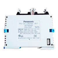
CONTROL LOGIC 16IN 8Out 24V
The FP Sigma is the state of the art PLC technology in the most compact size. With 2-axis motion control of up to 100 kHz. 4 high-speed counters of up to 50 kHz. 32K step program memory, RTC capability and a variety of communication cassettes, the FP Sigma is one of the most flexible PLC on the market.
- .
- *Features:**
* High-Speed 0.32 μsec/Instruction
* 32K Step Program Memory
* 4 Channels of High-Speed Counters
* 2-Axis Motion Control (1Ch — 100 kHz/2-Ch — 60 kHz Each)
* New EZPID Instruction/Auto-Tuning
* Total of 3 Communication Ports Possible
* Modbus RTU Master/Slave Support
* PC-Link Support
* Floating Point Calculation
* 4-8 Character Security Password
* Adaptable to FPO Expansion Units

* Изображение является ознакомительным. Точные технические характеристики следует изучить в техническом паспорте изделия.
-
Артикул:
FPG-C24R2H
-
Производитель:
-
Описание:
HELLERMANNTYTON — FPG — GROMMET STRIP, PE, NATURAL
-
К сравнению
В сравнение
-
В закладках
В закладки
- Печать
Выбрать все
Характеристики
Минимальная цена FPG-C24R2H на данный момент составляет 26897.67 руб.
Стоимость позиции зависит от количества заказываемых электронных компонентов. Минимально можно купить FPG-C24R2H от шт.
«ЭИК» — Cамый большой в России ассортимент электронных компонентов

Ассортимент
Всегда в наличии более
100 000 наименований
электронных компонентов

Сертификаты
Система управления качеством
по стандарту ИСО 9001:2008

Доставка
Экспресс доставка электронных
компонентов из США, Азии и Европы
от 5 дней

Эффективность
Быстрый ответ на ваши запросы,
снизим затраты вашей компании
на закупки электронных компонентов