PENTAIR 5600SXT Series Water Softener

How To Use This Manual
This installation manual is designed to guide the installer through the process of installing and starting the 5600 SXT softener.
This manual is a reference and will not include every system installation situation. The person installing this equipment should have:
- Knowledge in the water softener installation
- Basic plumbing skills
Icons That Appear In This Manual
WARNING: Failure to follow this instruction can result in personal injury or damage to the equipment.
NOTE: This will make the process easier if followed.
Inspection
Inspect the unit for damage or missing parts.
PARTS INCLUDED
The Water Softening System should have the following parts:
- Softener Tank with Valve and Power Transformer
- Salt Tank with Cover
- Bypass Valve
- Drain Line Fitting
- Brine Line Tubing with End Inserts (shipped inside the Brine Well #8)
- Tubing Clamp
- Instruction Manual
- Brine Well


Before starting to assemble the system, check that all the parts are present and not damaged. The plumbing pieces needed to connect the water system and softener salt are not included. If any parts are missing or damaged, contact Customer Service at: 262-547-3866 or 1-800-670-SOFT (7638).
EQUIPMENT INSTALLATION
General Warnings And Safety Information Electrical
There are no user-serviceable parts in the AC adapter, motor, or controller. In the event of a failure, these should be replaced.
- All electrical connections must be completed according to local codes.
- Use only the power AC adapter that is supplied. If the AC adapter is replaced use a Class II, 12 volt, 150 mA supply.
- The power outlet must be grounded and always on.
- To disconnect power, unplug the AC adapter from its power source.
- Install an appropriate grounding strap across the inlet and outlet piping of the water system to ensure proper grounding is maintained.
Mechanical
- Do not use petroleum based lubricants such as Vaseline, oils, or hydrocarbon based lubricants. Use only 100% silicone lubricants.
- All plastic connections should be hand tightened. Plumber tape should be used on connections that do not use an
O- ring seal. Do not use pliers or pipe wrenches. - All plumbing must be completed according to local codes.
- Soldering of the plumbing should be done before connecting to the valve. Excessive heat will cause interior damage to the valve.
- Observe drain line requirements.
- Do not use lead-based solder for sweat solder connections.
- The drain line must be a minimum of 1/2-inch diameter. Use 3/4-inch pipe if the pipe length is greater than 20 feet (6 m).
- Do not support the weight of the system on the control valve fittings, plumbing, or the bypass.
- It is not recommended to use sealants on the threads. Use plumber tape on all NPT threads.
General
- Observe all warnings that appear in this manual.
- This system is not intended to be used for treating water that is microbiologically unsafe or of unknown quality without adequate disinfection before or after the system.
- Keep the unit in the upright position. Do not turn on side, upside down, or drop. Turning the tank upside down will cause media to enter the valve.
- Operating ambient temperature is between 34°F (1°C) and 120°F (49°C).
- Operating water temperature is between 35°F (1°F) and 100°F (38°C).
- Working water pressure range is 20 to 125 psi
(1.38 to 8.61 bar). In Canada the acceptable working water pressure range is 20 to 100 psi (1.38 to 6.89 bar). - Use only salts designed for water softening. Acceptable salt type is sodium chloride pellet salt.
- Follow state and local codes for water testing. Do not use water that is microbiologically unsafe or of unknown quality.
- When filling media tank, do not open water valve completely. Fill tank slowly to prevent media from exiting the tank.
- Always make modifications to house plumbing first. Connect to valve last.
- Plastic parts and O-rings may be damaged by heat and solvents. When constructing plumbing connections allow heated parts to cool and protect parts from solvents.
System Recharge Cycles Service (Downflow):
Untreated water is directed down through the resin bed and up through the riser tube. The hardness ions attach themselves to the resin and are removed from the water. The water is conditioned as it passes through the resin bed.
When a recharge cycle starts, the softener goes through five cycles. During the recharge cycle the softener will allow untreated water to bypass into the building.
- Backwash 1 (Up flow):
The flow of water is reversed by the control valve and directed down the riser tube and up through the resin bed. During the backwash cycle, the bed is expanded and debris is flushed to the drain. - Brine Draw (Downflow):
The brine draw cycle takes place during the slow rinse cycle. The control directs water through the brine injector and brine is drawn from the salt tank. Brine draw is completed when the air check in the salt tank closes.
Slow Rinse (Downflow):
The brine is directed down through the resin bed and up through the riser tube to the drain. The hardness ions are displaced by sodium ions and are sent to the drain. The resin is recharged during the brine cycle. - Depressurize Cycle (Hard Water Bypass Flapper Open):
This cycle closes the flappers for a short time to allow the air and water to hydraulically balance in the valve before continuing the recharge. - Fast Rinse 1 (Downflow):
The control directs water down through the resin bed and up through the riser tube to the drain. Any remaining brine residual is rinsed from the resin bed. - Brine Refill:
Water is directed to the salt tank at a controlled rate, to create brine for the next recharge.
Location Selection
Location of a water treatment system is important.
The following conditions are required:
- Level platform or floor.
- Ambient temperatures over 34°F (1°C) and below 120°F (49°C).
- Water pressure below 125 psi (8.61 bar) and above 20 psi (1.4 bar).
- In Canada the water pressure must be below 100 psi (6.89 bar).
- Constant electrical supply to operate the controller.
- Total minimum pipe run to water heater of ten feet (three meters) to prevent backup of hot water into system.
- Local drain or tub for discharge as close as possible.
- Water line connections with shutoff or bypass valves.
- Must meet any local and state codes for site of installation.
- Valve is designed for minor plumbing misalignments. Do not support weight of system on the plumbing.
- Be sure all soldered pipes are fully cooled before attaching plastic valve to the plumbing.
- Room to access equipment for maintenance and adding salt to tank.

Resin Tank Size 1 cu ft 9″ x 48″ 1.5 cu ft 10″ x 54″ 2 cu ft 12″ x 52″ A 51.5 in (130.8 cm) 55.5 in (141 cm) 59.5 in (151.13 cm) B 45.22 in (114.8 cm) 49.22 in (125 cm) 53.22 in (135.18 cm) Brine Tank Size Square C 14 in (35.56 cm) D 34 in (86.36 cm)

Outdoor Locations
It is recommended that the system be installed indoors. When the water conditioning system must be installed outdoors, several items must be considered.
- Moisture — The valve and controller are rated for NEMA 3 locations. Falling water should not affect performance. The system is not designed to withstand extreme humidity or water spray from below. Examples are: constant heavy mist, near corrosive environment, upwards spray from sprinkler.
- Direct Sunlight — The materials used will fade or discolor over time in direct sunlight. The integrity of the materials will not degrade to cause system failures.
- Temperature — Extreme hot or cold temperatures may cause damage to the valve or controller.
Freezing temperatures will freeze the water in the valve. This will cause physical damage to the internal parts as well as the plumbing. - Insects — The controller and valve have been designed to keep all but the smallest insects out of the critical areas.
Inspection
The system is shipped with several parts unassembled. When parts are removed from the packing, they should be inspected for damage. If any parts are damaged or missing, contact your supplier.
WARNING: When handling the media tank do not turn it upside down or drop on its side.
When the carton is first opened, the softener will be standing upright.
To assemble the system, remove the salt tank components (cover, tank and brine tube assembly) from the shipping container.
- Remove the brine well, parts box and brine line.
- Lift the brine tank off unit
- Tilt the brine tank forward and slowly lift free. The media tank can now be removed.
To Assemble the Salt Tank:
- Stand the salt tank up and in position. Level as needed. The tank has two ports that will be connected. One to a drain and one to the valve.
- Remove the overflow fitting from the brine tube. Place the brine tube in position. Align the large hole in the brine well with the hole in the brine tank. Install the overflow fitting in this hole to secure well to tank. Lay cover aside for now.
To Assemble the Media Tank:
- Stand the tank up and in position.
- If the floor under the media tank is uneven, level as needed.
WARNING: The media tank contains loose particles that will shift. If the tank is turned upside down or laid back quickly, the particles may enter the valve. If this happens, the valve may need to be disassembled and cleaned.


Grounding the Plumbing
It is important that the plumbing system be electrically grounded. When a water softener is installed a non-metallic bypass valve may interrupt the grounding. To maintain continuity, a grounding strap can be purchased at a hardware store. When it is installed the strap will connect the plumbing into the softener to the plumbing out of the softener.
If you have other water treating equipment such as; chlorinator, sediment filter, neutralizer, iron filter, or taste & odor filter they should be installed upstream of the water softener.
You may wish to consult a water professional if additional water treating equipment is to be installed.
Valve Layout

Water Line Connection
- A bypass valve system is included and will be installed on the water conditioning system. Bypass valves isolate the softener from the water system and allow unconditioned water to be used.
- Service or routine maintenance procedures may also require that the system is bypassed.
- Once you have selected your location check the direction of the water flow in the main pipe.
- Bypass can be used to plan the new plumbing assembly.
- Inspect the main water pipe. Write down the type of pipe (copper, plastic, galvanized etc.). Record the size of the pipe. Plastic style pipes usually have the size printed on the outside. Other pipes can be measured for the outside diameter and converted into the pipe size at the store. Do not use pipe that is smaller than the main water pipe.
- If the main plumbing is galvanized pipe and you are installing copper pipe, then you must use dielectric insulating connectors between the two styles of pipe.
- Place the two tanks in position. The design of the tank does not allow for bad alignment of the connections. Ask your supply store
about flexible connections. - Take measurements and create a drawing of your installation. Include pipe lengths and elbows that are needed. If the water flow is from right to left you will need to cross the plumbing to the softener.
- Take the drawing to your plumbing supply store. Consult with their expert for installation ideas and suggestions. Assemble the plumbing.
WARNING: If pipes will be sweat soldered, do not connect adapters to the bypass until the pipes have cooled.

WARNING:
- The inlet water must be connected to the inlet port of the valve. When replacing existing water valves, it is possible that the inlet and outlet plumbing is installed in a reversed position.
- Be certain the inlet connection on the valve is connected to the incoming water fitting from the water supply. Do not solder pipes with lead-based solder.
- Do not use petroleum grease on gaskets when connecting bypass plumbing. Use only 100% silicone grease products when installing any plastic valve. Non-silicone grease may cause plastic components to fail over time.
NOTE: Before turning on the water to the valve, rotate the two handles on the bypass valve 2-3 times. This will help seat O-rings and prevent leaking.
Drain Line Connection
NOTE: Standard commercial practices are expressed here. Local codes may require changes to the following suggestions. Check with local authorities before installing a system.
- The unit should be above and not more than 20 feet (6.1 m) from the drain. Use an appropriate adapter fitting to connect 1/2-inch (1.3 cm) plastic tubing to the drain line connection of the control valve.

- The drain line may be elevated up to 6 feet (1.8 m) providing the run does not exceed 15 feet (4.6 m) and water pressure at the softener is not less than 40 psi (2.76 bar). Elevation can increase by 2 feet (61 cm) for each additional 10 psi (.69 bar) of water pressure at the drain connector.
- Where the drain line is elevated but empties into a drain below the level of the control valve, form a 7-inch (18-cm) loop at the far end of the line so that the bottom of the loop is level with the drain line connection. This will provide an adequate siphon trap.
Where the drain empties into an overhead sewer line, a sink-type trap must be used. - Use pliers to expand a clamp. Slide the clamp up one end of the longer length drain line tubing about 1-2 inches and release.
- Push the tubing over the ribbed drain line fitting.
- Expand the clamp and move it up the tube to pinch the tube to the fitting.
- Secure the discharge end of the drain line to prevent it from moving.


NOTE: Waste connections or drain outlet shall be designed and constructed to provide for connection to the sanitary waste system through an air-gap of 2 pipe diameters or 1 inch (22 mm) whichever is larger.
WARNING: Never insert drain line directly into a drain, sewer line, or trap (Figure 6 Drain Line Connection). Always allow an air gap between the drain line and the wastewater to prevent the possibility of sewage being back-siphoned into the softener.
Overflow Line Connection (Optional)
In the event of a malfunction, the salt TANK OVERFLOW will direct “overflow” to the drain instead of spilling on the floor. This fitting should be on the side of the cabinet.
To connect the overflow line, locate the tubing connector on the side of the tank .
Attach length of 1/2-inch (1.3-cm) I.D. tubing to fitting and run to drain. Do not elevate overflow line higher than overflow fitting.
Do not tie into drain line of control unit. Overflow line must be a direct, separate line from overflow fitting to drain, sewer or tub.
Allow an air gap as per drain line instructions.
Salt Line Connection
The salt line from the brine tube connects to the valve. Make certain the connections are hand tightened. Be sure that the salt line is secure and free from air leaks. Even a small leak may cause the salt line to drain out, and the softener will not draw salt from the tank. This may also introduce air into the valve causing problems with valve operation.
To install the brine line:
- Inside the salt tank, remove the cap from the large cylinder to gain access to the connection.
- Be sure the brass insert is in the end of the brine tubing. Insert the tubing through the opening in the tank.
- Push the tubing into the plastic nut. Slowly unscrew the nut until the tubing moves into the connection. The tubing will hit bottom.
 NOTE: Once the tubing has been pushed into the nut it cannot be pulled out. The nut will need to be removed.
 - Hand tighten the nut until the connection is tight.
- Slide the plastic nut onto the tubing followed by the ferrule.

- Insert the brass fitting inside the tube. Then place the spacer in position.
- Locate the salt line connection on the valve. Push the tubing into the opening until it stops.
- Slide the nut forward and hand tighten.
 NOTE: Once the tubing has been pushed into the nut it cannot be pulled out. The nut will need to be removed.
Electrical Connection
WARNING: This valve and control are for dry location use only unless used with a Listed Class 2 power supply suitable for outdoor use.
The controller operates on 12-volt alternating current power supply. This requires use of the supplied AC adapter included with your system.
120 Vac Adapters:
Make sure power source matches the rating printed on the AC adapter.
NOTE: The power source should be constant. Be certain the AC adapter is not on a switched outlet. Power interruptions longer than 8 hours may cause the controller to lose the time setting. When power is restored, the time setting must then be re-entered.
START-UP INSTRUCTIONS
The water softener should be installed with the inlet, outlet, and drain connections made in accordance with the manufacturer’s recommendations, and to meet applicable plumbing codes.
To start the system for the first time a manually cycled regeneration is used.
- With the control plugged in, and bypass valve set to In Service, press and hold the Extra Cycle button for 5 seconds.
- Advance the valve to backwash. Ensure the drain line flow remains steady for 10 minutes or until the water runs clear
(see above). - Advance the valve to the brine / slow rinse position. Ensure the unit is drawing water from the brine tank (this step may need to be repeated).
- Advance the valve to the rapid rinse position. Check the drain line flow, and run for 5 minutes or until the water runs clear.
- Advance the valve to the start of the brine tank fill cycle. Ensure water goes into the brine tank at the desired rate. The brine valve drive cam will hold the valve in this position to fill the brine tank for the first regeneration.
- Replace control box cover.
- Put salt in the brine tank.
NOTE: Do not use rock salt.
TIMER FEATURES

Features of the SXT:
- Power backup that continues to keep time and the passage of days for a minimum of 48 hours in the event of power failure. During a power outage, the control goes into a power-saving mode. It does not monitor water usage during a power failure, but it does store the volume remaining at the time of power failure.
- Settings for both valve (basic system) and control type (method used to trigger a regeneration).
- Day-of-the-Week controls.
- While in service, the display alternates between time of day, volume remaining or days to regeneration, and tank in service (twin tank systems only).
- The Flow Indicator flashes when outlet flow is detected.
- The Service Icon flashes if a regeneration cycle has been queued.
- The Parameter Display displays the current Cycle Step (BW, BF, RR, etc) during regeneration, and the data display counts down the time remaining for that cycle step. While the valve is transferring to a new cycle step, the display will flash. The parameter display will identify the destination cycle step (BW, BF, RR, etc) and the data display will read “—-”. Once the valve reaches the cycle step, the display will stop flashing and the data display will change to the time remaining. During regeneration, the user can force the control to advance to the next cycle step immediately by pressing the extra cycle button.
Setting the Time of Day
- Press and hold either the Up or Down buttons until the programming icon replaces the service icon and the parameter display reads DO.
- Adjust the displayed time with the Up and Down buttons.
- When the desired time is set, press the Extra Cycle button to resume normal operation. The unit will also return to normal operation after 5 seconds if no buttons are pressed.


Queueing a Regeneration
- Press the Extra Cycle button. The service icon will flash to indicate that a regeneration is queued.
- To cancel a queued regeneration, press the Extra Cycle button.
Regenerating Immediately
Press and hold the Extra Cycle button for five seconds.
TIMER OPERATION
Meter Immediate Control
A meter immediate control measures water usage and regenerates the system as soon as the calculated system capacity is depleted. The control calculates the system capacity by dividing the unit capacity (typically expressed in grains/unit volume) by the feedwater hardness and subtracting the reserve. Meter Immediate systems generally do not use a reserve volume. However, in twin tank systems with soft-water regeneration, the reserve capacity should be set to the volume of water used during regeneration to prevent hard water break-through. A Meter Immediate control will also start a regeneration cycle at the programmed regeneration time if a number of days equal to the regeneration day override pass before water usage depletes the calculated system capacity.
Meter Delayed Control
A Meter Delayed Control measures water usage and regenerates the system at the programmed regeneration time after the calculated system capacity is depleted. As with Meter Immediate systems, the control calculates the system capacity by dividing the unit capacity by the feedwater hardness and subtracting the reserve. The reserve should be set to insure that the system delivers treated water between the time the system capacity is depleted and the actual regeneration time. A Meter Delayed control will also start a regeneration cycle at the programmed regeneration time if a number of days equal to the regeneration day override pass before water usage depletes the calculated system capacity.
Time Clock Delayed Control
A Time Clock Delayed Control regenerates the system on a timed interval. The control will initiate a regeneration cycle at the programmed regeneration time when the number of days since the last regeneration equals the regeneration day override value.
Day of the Week Control
This control regenerates the system on a weekly schedule. The schedule is defined in Master Programming by setting each day to either “off” or “on.” The control will initiates a regeneration cycle on days that have been set to “on” at the specified regeneration time.
Control Operation During Regeneration
During regeneration, the control displays a special regeneration display. In this display, the control shows the current regeneration step number the valve is advancing to, or has reached, and the time remaining in that step. The step number that displays flashes until the valve completes driving to this regeneration step position. Once all regeneration steps are complete the valve returns to service and resumes normal operation.
Pressing the Extra Cycle button during a regeneration cycle immediately advances the valve to the next cycle step position and resumes normal step timing.
Control Operation During Programming
The control only enters the Program Mode with the valve in service. While in the Program Mode, the control continues to operate normally monitoring water usage and keeping all displays up to date. Control programming is stored in memory permanently, eliminating the need for battery backup power.
Manually Initiating a Regeneration
- When timer is in service, press the Extra Cycle button for 5 seconds on the main screen.
- The timer advances to Regeneration Cycle Step #1 (backwash), and begins programmed time count down.
- Press the Extra Cycle button once to advance valve to Regeneration Cycle Step #2 (brine draw & slow rinse).
- Press the Extra Cycle button once to advance valve to Regeneration Cycle Step #3 (rapid rinse).
- Press the Extra Cycle button once to advance valve to Regeneration Cycle Step #4 (brine refill).
- Press the Extra Cycle button once more to advance the valve back to in service.
NOTE: If the unit is a filter or up flow, the cycle step order may change.
NOTE: A queued regeneration can be initiated by pressing the Extra Cycle button. To clear a queued regeneration, press the Extra Cycle button again to cancel. If regeneration occurs for any reason prior to the delayed regeneration time, the manual regeneration request shall be cleared.
Control Operation During A Power Failure
The SXT includes integral power backup. In the event of power failure, the control shifts into a power-saving mode. The control stops monitoring water usage, and the display and motor shut down, but it continues to keep track of the time and day for a minimum of 48 hours.
The system configuration settings are stored in a non-volatile memory and are stored indefinitely with or without line power. The Time of Day flashes when there has been a power failure. Press any button to stop the Time of Day from flashing.
If power fails while the unit is in regeneration, the control will save the current valve position before it shuts down. When power is restored, the control will resume the regeneration cycle from the point where power failed. If power fails during a regeneration cycle, the valve will remain in it’s current position until power is restored. The valve system should include all required safety components to prevent overflows resulting from a power failure during regeneration.
The control will not start a new regeneration cycle without line power. If the valve misses a scheduled regeneration due to a power failure, it will queue a regeneration. Once power is restored, the control will initiate a regeneration cycle the next time that the Time of Day equals the programmed regeneration time. Typically, this means that the valve will regenerate one day after it was originally scheduled. If the treated water output is important and power interruptions are expected, the system should be setup with a sufficient reserve capacity to compensate for regeneration delays.
USER PROGRAMMING MODE
| User Programming Mode Options | ||
| Abbreviation | Parameter | Description |
| DO | Day Override | The timer’s day override setting |
| RT | Regeneration Time | The time of day that the system will regenerate (meter delayed, time clock, and day-of-week systems) |
| H | Feed Water Hardness | The hardness of the inlet water used to calculate system capacity for metered systems |
| RC or SF | Reserve Capacity | The fixed reserve capacity |
| CD | Current Day | The current day of week |
NOTE: Some items may not be shown depending on timer configuration. The timer will discard any changes and exit User Mode if any button is not pressed for sixty seconds.
User Programming Mode Steps
- Press the Up and Down buttons for five seconds while in service, and the time of day is NOT set to 12:01 PM.
- Use this display to adjust the Day Override. This option setting is identified by “DO” in the upper left hand corner of the screen.

- Press the Extra Cycle button. Use this display to adjust the Regeneration Time. This option setting is identified by “RT” in the upper left hand corner of the screen.

- Press the Extra Cycle button. Use this display to adjust the Feed Water Hardness. This option setting is identified by “H” in the upper left hand corner of the screen.
 Range: 1-199 hardness
 - Press the Extra Cycle button. Use this display to adjust the Fixed Reserve Capacity. This option setting is identified by “RC” or “SF” in the upper left-hand Corner of the screen.

- Press the Extra Cycle button. Use this display to set the Current Day of the Week. This option setting is identified by “CD” in the upper left hand corner of the screen.

- Press the Extra Cycle button to end User Programming Mode.


 Range: 1-199 hardness

MASTER PROGRAMMING MODE CHART
Caution: Before entering Master Programming, please contact your local professional water dealer.
| Master Programming Options | |||
| Abbreviation | Parameter | Option Abbreviation | Options |
| DF | Display Format | GAL | Gallons |
| Ltr | Liters | ||
| VT | Valve Type | dF1b | Standard Downflow/Up flow Single Backwash |
| dF2b | Standard Downflow/Up flow Double Backwash | ||
| Filtr | Filter | ||
| UFbd | Up flow Brine First | ||
| UFT | Up flow Filter | ||
| Other | Other | ||
| CT | Control Type | Fd | Meter (Flow) Delayed |
| FI | Meter (Flow) Immediate | ||
| tc | Time Clock | ||
| day | Day of Week | ||
| NT | Number of Tanks | 1 | Single Tank System |
| 2 | Two Tank System | ||
| TS | Tank in Service | U1 | Tank 1 in Service |
| U2 | Tank 2 in Service | ||
| C | Unit Capacity | Unit Capacity (Grains) | |
| H | Feedwater Hardness | Hardness of Inlet Water | |
|
RS |
Reserve Selection | SF | Percentage Safety Factor |
| rc | Fixed Reserve Capacity | ||
| SF | Safety Factor | Percentage of the system capacity to be used as a reserve | |
| RC | Fixed Reserve Capacity | Fixed volume to be used as a reserve | |
| DO | Day Override | The system’s day override setting | |
| RT | Regen Time | The time of day the system will regenerate | |
| BW, BD, RR, BF | Regen Cycle Step Times | The time duration for each regeneration step. Adjustable from OFF and 0-199 minutes. NOTE: If “Other” is chosen under “Valve Type”, then R1, R2, R3, etc, will be displayed instead |
|
| D1, D2, D3, D4, D5, D6, & D7 | Day of Week Settings | Regeneration setting (On or OFF) for each day of the week on day-of-week systems | |
| CD | Current Day | The Current day of the week | |
| FM | Flow Meter Type | t0.7 | 3/4″ Turbine Meter – Not Used |
| P0.7 | 3/4″ Paddle Wheel Meter – Not Used | ||
| t1.0 | 1″ Turbine Meter | ||
| P1.0 | 1″ Paddle Wheel Meter – Not Used | ||
| t1.5 | 1.5″ Turbine Meter – Not Used | ||
| P1.5 | 1.5″ Paddle Wheel Meter – Not Used | ||
| P2.0 | 2″ Paddle Wheel Meter – Not Used | ||
| Gen | Generic or Other Meter | ||
| K | Meter Pulse Setting | Meter pulses per gallon for generic/other flow meter |
NOTES: Some items may not be shown depending on timer configuration. The timer will discard any changes and exit Master Programming Mode if any button is not pressed for sixty seconds.
MASTER PROGRAMMING MODE
When the Master Programming Mode is entered, all available option setting displays may be viewed and set as needed. Depending on current option settings, some parameters cannot be viewed or set.
Setting the Time of Day
- Press and hold either the Up or Down buttons until the programming icon replaces the service icon and the parameter display reads TD.
- Adjust the displayed time with the Up and Down buttons.
- When the desired time is set, press the Extra Cycle button to resume normal operation. The unit will also return to normal operation after 5 seconds if no buttons are pressed.


Entering Master Programming Mode
Set the Time Of Day display to 12:01 P.M. Press the Extra Cycle button (to exit Setting Time of Day mode). Then press and hold the Up and Down buttons together until the programming icon replaces the service icon and the Display Format screen appears.
Exiting Master Programming Mode
Press the Extra Cycle button to accept the displayed settings and cycle to the next parameter. Press the Extra Cycle button
at the last parameter to save all settings and return to normal operation. The control will automatically disregard any programming changes and return to normal operation if it is left in Master Programming mode for five minutes without any keypad input.
Resets
Soft Reset: Press and hold the Extra Cycle and Down buttons for 25 seconds while in normal Service mode. This resets all parameters to the system default values, except the volume remaining in meter immediate or meter delayed systems and days since regeneration in the time clock system.
Master Reset: Hold the Extra Cycle button while powering up the unit. This resets all of the parameters in the unit. Check and verify the choices selected in Master Programming Mode.
- Display Format (Display Code DF)
This is the first screen that appears when entering Master Programming Mode. The Display Format setting specifies the unit of measure that will be used for volume and how the control will display the Time of Day. This option setting is identified by “DF” in the upper left hand corner of the screen. There are three possible settings:
Display Format Setting Unit of Volume Time Display GAL U.S. Gallons 12-Hour AM/PM Ltr Liters 24-Hour 
- Valve Type (Display Code VT)
Press the Extra Cycle button. Use this display to set the Valve Type. The Valve Type setting specifies the type of cycle that the valve follows during regeneration. Note that some valve types require that the valve be built with specific subcomponents. Ensure the valve is configured properly before changing the Valve Type setting. This option setting is identified by “VT” in the upper left hand corner of the screen. There are 6 possible settings:
Abbreviation Parameter dF1b Standard Downflow/Up flow, Single Backwash dF2b Standard Downflow/Up flow, Double Backwash Filtr Filter UFbd Up flow Brine First UFtr Up flow Filter Other Other 
- Control Type (Display Code CT)
Press the Extra Cycle button. Use this display to set the Control Type. This specifies how the control determines when to trigger a regeneration. For details on how the various options function, refer to the “Timer Operation” section of this service manual. This option setting is identified by “CT” in the upper left hand corner of the screen. There are four possible settings:- Meter Delayed: Fd.
- Meter Immediate: FI
- Time Clock: tc
- Day of Week: day

- Number of Tanks (Display Code NT)
Press the Extra Cycle button. Use this display to set the Number of Tanks in your system. This option setting is identified by “NT” in the upper left hand corner of the screen. There are two possible settings:- Single Tank System: 1
- Two-Tank System: 2

- Tank in Service (Display Code TS)
Press the Extra Cycle button. Use this display to set whether tank one or tank two is in service. This option setting is identified by “TS” in the upper left hand corner of the screen. This parameter is only available if the number of tanks has been set to 2. There are two possible settings:- Tank One in Service: U1
- Tank Two in Service: U2

- Unit Capacity (Display Code C)
Press the Extra Cycle button. Use this display to set the Unit Capacity. This setting specifies the treatment capacity of the system media. Enter the capacity of the media bed in grains of hardness when configuring a softener system, and in the desired volume capacity when configuring a filter system. This option setting is identified by “C” in the upper left hand corner of the screen. The Unit Capacity parameter is only available if the control type has been set to one of the metered options. Use the Up and Down buttons to adjust the value as needed. Range: 1-999,900 gallons (100-9,999,000 Liters)
 - Feedwater Hardness (Display Code H)
Press the Extra Cycle button. Use this display to set the Feedwater Hardness. Enter the feedwater hardness in grains per unit volume for softener systems, or 1 for filter systems. This option setting is identified by “H” in the upper left hand corner of the screen. The feedwater hardness parameter is only available if the control type has been set to one of the metered options. Use the Up and Down buttons to adjust the value as needed.Range: 1-199 hardness - Reserve Selection (Display Code RS)
Press the Extra Cycle button. Use this display to set the Safety Factor. Use this display to select the type of reserve to be used in your system. This setting is identified by “RS” in the upper left-hand corner of the screen. The reserve selection parameter is only available if the control type has been set to one of the metered options. There are two possible settings.
Display Format Setting Unit of Volume Time Display GAL U.S. Gallons 12-Hour AM/PM Ltr Liters 24-Hour 
- Safety Factor (Display Code SF)
Press the Extra Cycle button. Use this display to set the Safety Factor. This setting specifies what percentage of the system capacity will be held as a reserve. Since this value is expressed as a percentage, any change to the unit capacity or feedwater hardness that changes the calculated system capacity will result in a corresponding change to the reserve volume. This option setting is identified by “SF” in the upper left hand corner of the screen. Use the Up and Down buttons to adjust the value from 0 to 50% as needed. Range: 0-50%
 - Fixed Reserve Capacity (Display Code RC)
Press the Extra Cycle button. Use this display to set the Reserve Capacity. This setting specifies a fixed volume that will be held as a reserve. The reserve capacity cannot be set to a value greater than one-half of the calculated system capacity. The reserve capacity is a fixed volume and does not change if the unit capacity or feedwater hardness are changed. This option setting is identified by “RC” in the upper left-hand corner of the screen. Use the Up and Down buttons to adjust the value as needed. Range: 0-half the calculated capacity
 - Day Override (Display Code DO)
Press the Extra Cycle button. Use this display to set the Day Override. This setting specifies the maximum number of days between regeneration cycles. If the system is set to a timer-type control, the day override setting determines how often the system will regenerate. A metered system will regenerate regardless of usage if the days since last regeneration cycle equal the day override setting. Setting the day override value to “OFF” disables this function. This option setting is identified by “DO” in the upper left hand corner of the screen. Use the Up and Down buttons to adjust the value as needed. Range: Off-99 days
 - Regeneration Time
Press the Extra Cycle button. Use this display to set the Regeneration Time. This setting specifies the time of day the control will initiate a delayed, manually queued, or day override triggered regeneration. This option setting is identified by “RT” in the upper left hand corner of the screen. Use the Up and Down buttons to adjust the value as needed.
- Regeneration Cycle Step Times
Press the Extra Cycle button. Use this display to set the Regeneration Cycle Step Times. The different regeneration cycles are listed in sequence based on the valve type selected for the system, and are identified by an abbreviation in the upper left-hand corner of the screen. The abbreviations used are listed below. If the system has been configured with the “OTHER” valve type, the regeneration cycles will be identified as R1, R2, R3, R4, R5, and R6. Each cycle step time can be set from 0 to 199 minutes. Setting a cycle step time to 0 will cause the control to skip that step during regeneration, but keeps the following steps available. Use the Up and Down buttons to adjust the value as needed. Press the Extra Cycle button to accept the current setting and move to the next parameter.
Abbreviation Cycle Step BD Brine Draw BF Brine Fill BW Backwash RR Rapid Rinse SV Service  Range: 0-199 minutes
 - Day of Week Settings
Press the Extra Cycle button. Use this display to set the regeneration schedule for a system configured as a Day of Week control. The different days of the week are identified as D1, D2, D3, D4, D5, D6, and D7 in the upper left-hand corner of the display. Set the value to “ON” to schedule a regeneration or “OFF”
to skip regeneration for each day. Use the Up and Down buttons to adjust the setting as needed. Press the Extra Cycle button to accept the setting and move to the next day. Note that the control requires at least one day to be set to “ON.” If all 7 days are set to “OFF”, the unit will return to Day One until one or more days are set to “ON.” - Current Day (Display Code CD)
Press the Extra Cycle button. Use this display to set the current day on systems that have been configured as Day of Week controls. This setting is identified by “CD” in the upper left-hand corner of the screen. Use the Up and Down buttons to select from Day 1 through Day 7.
- Flow Meter Type (Display Code FM)
Press the Extra Cycle button. Use this display to set the type of flow meter connected to the control. This option setting is identified by “FM” in the upper left-hand corner of the screen. Use the Up and Down buttons to select one of the 7 available settings.
t0.7 Fleck 3/4″ Turbine Meter P0.7 Fleck 3/4″ Paddle Wheel Meter t1.0 Fleck 1″ Turbine Meter P1.0 Fleck 1″ Paddle Wheel Meter t1.5 Fleck 1 1/2″ Turbine Meter P1.5 Fleck 1 1/2″ Paddle Wheel Meter P2.0 Fleck 2″ Paddle Wheel Meter GEn Generic/Other Meter 
- Meter Pulse Setting (Display Code K)
Press the Extra Cycle button. Use this display to specify the meter pulse setting for a non-standard flow meter. This option setting is identified by “K” in the upper left-hand corner of the screen. Use the Up and Down buttons to enter the meter constant in pulses per unit volume.
- End of Master Programming Mode
Press the Extra Cycle button to save all settings and exit Master Programming Mode.


 Range: 1-999,900 gallons (100-9,999,000 Liters)
 Range: 1-199 hardness
 Range: 0-50%
 Range: 0-half the calculated capacity
 Range: Off-99 days
 Range: 0-199 minutes


DIAGNOSTIC PROGRAMMING MODE
| Diagnostic Programming Mode Options | ||
| Abbreviation | Parameter | Description |
| FR | Flow Rate | Displays the current outlet flow rate |
| PF | Peak Flow Rate | Displays the highest flow rate measured since the last regeneration |
| HR | Hours in Service | Displays the total hours that the unit has been in service |
| VU | Volume Used | Displays the total volume of water treated by the unit |
| RC | Reserve Capacity | Displays the system’s reserve capacity calculated from the system capacity, feedwater hardness, and safety factor |
| SV | Software Version | Displays the software version installed on the controller |
NOTE: Some items may not be shown depending on timer configuration. The timer will exit Diagnostic Mode after 60 seconds if no buttons are pressed. Press the Extra Cycle button to exit Diagnostic Mode at any time.
Diagnostic Programming Mode Steps
- Press the Up and Extra Cycle buttons for five seconds while in service.
- Use this display to view the current Flow Rate. This option setting is identified by “FR” in the upper left hand corner of the screen.

- Press the Up button. Use this display to view the Peak Flow Rate since the last regeneration cycle. This option setting is identified by “PF” in the upper left hand corner of the screen.
- Press the Up button. Use this display to view the Hours in Service since the last regeneration cycle. This option setting is identified by “HR” in the upper left hand corner of the screen.

- Press the Up button. Use this display to view the Volume Used since the last regeneration cycle. This option setting is identified by “VU” in the upper left hand corner of the screen.
- Press the Up button. Use this display to view the Reserve Capacity. This option setting is identified by “RC” in the upper left hand corner of the screen.

- Press the Up button. Use this display to view the Software Version. This option setting is identified by “SV” in the upper left hand corner of the screen.

- Press the Extra Cycle button to end Diagnostic Programming Mode.


SYSTEM DISINFECTION
Disinfection Of Water Softeners
The materials of construction of the modern water softener will not support bacterial growth, nor will these materials contaminate a water supply. During normal use, a softener may become fouled with organic matter, or in some cases with bacteria from the water supply. This may result in an off-taste or odor in the water.
Some softeners may need to be disinfected after installation and some softeners will require periodic disinfection during their normal life.
Depending upon the conditions of use, the style of softener, the type of ion exchanger, and the disinfectant available, a choice can be made among the following methods.
Sodium or Calcium Hypochlorite
Application
These materials are satisfactory for use with polystyrene resins, synthetic gel zeolite, greensand and bentonites.
5.25% Sodium Hypochlorite
These solutions are available by various sellers of household bleach. If stronger solutions are used, such as those sold for commercial laundries, adjust the dosage accordingly.
- Dosage
- Polystyrene resin; 1.2 fluid ounce (35.5 ml) per cubic foot.
- Non-resinous exchangers; 0.8 fluid ounce (23.7 ml) per cubic foot.
- Salt tank softeners
- Backwash the softener and add the required amount of hypochlorite solution to the well of the salt tank. The salt tank should have water in it to permit the solution to be carried into the softener.
- Proceed with the normal recharge.
Calcium Hypochlorite
Calcium hypochlorite, 70% available chlorine, is available in several forms including tablets and granules. These solid materials may be used directly without dissolving before use.
- Dosage
- Two grains (approximately 0.1 ounce [3 ml]) per cubic foot.
- Salt tank softeners
- Backwash the softener and add the required amount of hypochlorite to the well of the salt tank. The salt tank should have water in it to permit the chlorine solution to be carried into the softener.
- Proceed with the normal recharge.
INSTALLATION CHECKLIST
- Read the owner’s/installation manual?
- Follow all safety guidelines in the manual?
- If metal pipe was used, did you restore the electrical ground?
- Securely install both drain hoses to an approved drain?
- Perform a leak test?
- Move the bypass valve to service?
- Sanitize the softener?
- Add salt pellets to the salt storage tank?
- Program the control correctly to meet your needs?
- Start a recharge?
CARE AND USE OF YOUR BRINE TANK
Each time the softener recharges, salty water (brine) is needed to recondition the media in the water tank. The brine is pulled from the salt tank at a controlled amount. If the salt tank does not contain enough salt, the brine is weak, the media will not fully recondition and untreated water will pass through.
You must keep salt in the tank.
The salt tank operates best when the salt level is below half-full.
If the tank is filled more than that the salt pellets may “bridge”.
The salt pellets wedge against each other and do not fall into the water at the bottom. Bridging will eventually provide no salt to make brine. The softener will recharge but not recondition the media. A salt bridge can be broken up using a broom handle or similar rod. Carefully pound it into the salt and the pellets will collapse. After loosening the salt pellets wait 2 hours and start a regeneration. A second recharge may be needed to fully recondition the media.
You should only use sodium chloride pellet salt for water softeners. Other types of salt (rock or snow melting) will contain dirt and chemicals that will affect your water softener.
Keep the brine tank covered.
Empty and clean the tank every three years.
CONTROL VALVE ASSEMBLY


SYSTEM ASSEMBLY


BRINE WELL ASSEMBLY


VALVE POWERHEAD ASSEMBLY

TROUBLESHOOTING
| Problem | Cause | Correction |
| Water conditioner fails to regenerate. | Electrical service to unit has been interrupted | Assure permanent electrical service (check fuse, plug, pull chain, or switch) |
| Controller is defective. | Replace controller. | |
| Power failure. | Reset time of day. | |
| Hard water. | By-pass valve is open. | Close by-pass valve. |
| No salt is in brine tank. | Add salt to brine tank and maintain salt level above water level. | |
| Injector screen plugged. | Clean injector screen. | |
| Insufficient water flowing into brine tank. | Check brine tank fill time and clean brine line flow control
if plugged. |
|
| Hot water tank hardness. | Repeated flushing’s of the hot water tank with treated
water is required. |
|
| Leak at distributor tube. | Make sure distributor tube is not cracked. Check O-ring and tube pilot. | |
| Internal valve leak. | Replace seals and spacers and/or piston. | |
| Unit used too much salt. | Improper salt setting. | Check salt usage and salt setting. |
| Excessive water in brine tank. | See “Excessive water in brine tank”. | |
| Loss of water pressure. | Iron buildup in line to water conditioner. | Clean line to water conditioner. |
| Iron buildup in water conditioner. | Clean control and add mineral cleaner to mineral bed. Increase frequency of regeneration. | |
| Inlet of control plugged due to foreign material broken loose from pipes by recent work done on plumbing system. | Remove piston and clean control. | |
| Loss of mineral through drain line. | Air in water system. | Assure that well system has proper air eliminator control. Check for dry well condition. |
| Improperly sized drain line flow control. | Check for proper drain rate. | |
| Iron in conditioned water. | Fouled mineral bed. | Check backwash, brine draw, and brine tank fill. Increase frequency of regeneration. Increase backwash time. |
| Excessive water in brine tank. | Plugged drain line flow control. | Clean flow control. |
| Plugged injector system. | Clean injector and screen. | |
| Timer not cycling. | Replace timer. | |
| Foreign material in brine valve. | Replace brine valve seat and clean valve. | |
| Foreign material in brine line flow control. | Clean brine line flow control. | |
| Softener fails to draw brine. | Drain line flow control is plugged. | Clean drain line flow control. |
| Injector is plugged. | Clean injector | |
| Injector screen plugged. | Clean screen. | |
| Line pressure is too low. | Increase line pressure to 20 psi | |
| Internal control leak | Change seals, spacers, and piston assembly. | |
| Service adapter did not cycle. | Check drive motor and switches. | |
| Control cycles continuously. | Misadjusted, broken, or shorted switch. | Determine if switch or timer is faulty and replace it, or replace complete power head. |
| Drain flows continuously. | Powerhead is not completing the regen cycle. | Check timer positioning of control. Replace power head assembly if not positioning properly. |
| Foreign material in control. | Remove power head assembly and inspect bore. Remove foreign material and check control in various regeneration positions. | |
| Internal control leak. | Replace seals and piston assembly. |
Error Codes
NOTE: Error codes appear on the In Service display.
| Error Code | Error Type | Cause | Reset and Recovery |
| 0 | Cam Sense Error | The valve drive took longer than 6 minutes to advance to the next regeneration position | Unplug the unit and examine the powerhead. Verify that all cam switches are connected to the circuit board and functioning properly. Verify that the motor and drive train components are in good condition and assembled properly. Check the valve and verify that the piston travels freely. Replace/reassemble the various components as necessary. Plug the unit back in and observe its behavior. The unit should cycle to the next valve position and stop. If the error reoccurs, unplug the unit and contact technical support. |
| 1 | Cycle Step Error | The control experienced an unexpected cycle input | Unplug the unit and examine the powerhead. Verify that all cam switches are connected to the circuit board and functioning properly. Enter Master Programming mode and verify that the valve type and system type are set correctly with regard to the unit itself. Step the unit through a manual regeneration and verify that it functions correctly. If the error reoccurs unplug the unit and contact technical support. |
| 2 | Regen Failure | The system has not regenerated for more than 99 days (or 7 days if the Control Type has been set to Day- of-Week) | Perform a Manual Regeneration to reset the error code. If the system is metered, verify that it is measuring flow by running service water and watching for the flow indicator on the display. If the unit does not measure flow, verify that the meter cable is connected properly and that the meter is functioning properly. Enter a Master Programming Mode and verify that the unit is configured properly. As appropriate for the valve configuration, check that the correct system capacity has been selected, that the day override is set properly, and that meter is identified correctly. If the unit is configured as a Day-of-Week system, verify that at least one day is set ON. Correct the settings as necessary. |
| 3 | Memory Error | Control board memory failure | Perform a Master Reset and reconfigure the system via Master Programming Mode. After reconfiguring the system, step the valve through a manual regeneration. If the error reoccurs unplug the unit and contact technical support. |
| UD | Upper Drive Sync | Power failure install programming change | Valve will automatically recover. |
WATER CONDITIONER FLOW DIAGRAMS
| Single Backwash Positions Black Cycle Cam (Part Number 17438)x |
| Service Position |
| 1. Backwash Position |
| 2. Brine/Slow Rinse Position |
| 3. Rapid Rinse Position |
| 4. Brine Tank Fill Position |
| Service Position |
WIRING DIAGRAM

SERVICE INSTRUCTIONS
Replacing Brine Valve, Injectors and Screen
- Turn off water supply to conditioner: If the conditioner installation has a “three valve” bypass system, first open the valve in the bypass line, then close the valves at the conditioner inlet and outlet. If the conditioner has an integral bypass valve, put it in the Bypass position. If there is only a shut-off valve near the conditioner inlet, close it.
- Relieve water pressure in the conditioner by stepping the control into the Backwash position momentarily. Return the control to the In Service position.
- Unplug electrical cord from outlet.
- Disconnect brine tube and drain line connections at the injector body.
- Remove the two injector body mounting screws. The injector and brine module can now be removed from the control valve. Remove and discard brine body O-rings.
Brine Valve Replacement
- Pull brine valve from injector body. Also remove and discard O- ring at bottom of brine valve hole.
- Apply silicone lubricant to new O-ring and reinstall at bottom of brine valve hole.
- Apply silicone lubricant to O-ring on new valve assembly and press into brine valve hole. Be sure shoulder on bushing is flush with injector body.
Injectors/Screen Replacement
- Remove injector cap and screen, discard O-ring. Unscrew injector nozzle and throat from injector body.
- Screw in new injector throat and nozzle, be sure they are sealed tightly. Install a new screen.
- Apply silicone lubricant to new O-ring and install around oval extension on injector cap.
- Apply silicone lubricant to three new O-rings and install over three bosses on injector body.
- Insert screws thorough injector cap and injector. Place this assembly thorough hole in timer housing and into mating holes in the valve body. Tighten screws.
- Reconnect brine tube and drain line.
- Return bypass or inlet valve to normal In Service position. Water pressure automatically builds in the conditioner NOTE: Be sure to shut off any bypass line.
- Check for leaks at all seal areas. Check drain seal with the control in the Backwash position.
- Plug electrical cord into outlet.
- Set Time Of Day and cycle the control valve manually to assure proper function. Make sure control valve is returned to the In Service position.
- Be sure there is enough salt in the brine tank.
- Start regeneration cycle manually if water is hard.
Timer Replacement
To replace timer refer to Replacing Brine Valve, Injectors and Screen, steps 1–3.
- Remove the control valve back cover. Remove the control valve front cover. Disconnect the meter dome signal wire from the front cover and feed it back through the control.
- Remove screw and washer at drive yoke. Remove timer mounting screws. The entire timer assembly then lifts off easily.
- Put new timer on top of valve. Be sure drive pin on main gear engages slot in drive yoke.
- Replace timer mounting screws. Replace screw and washer at drive yoke. Replace meter signal wire.
- Return bypass or inlet valve to normal In Service position. Water pressure automatically builds in the conditioner. NOTE: Be sure to shut off any bypass line.
- Replace the control valve back cover.
- Follow Injectors/Screen Replacement, steps 9–12.
Piston Assembly Replacement
To replace piston assembly refer to Replacing Brine Valve, Injectors and Screen, steps 1–3.
- Remove the control valve back cover. Remove the control valve front cover. Disconnect the meter dome signal wire from the front cover and feed it back through the control.
- Remove screw and washer at drive yoke. Remove timer mounting screws. The entire timer assembly will now lift off easily. Remove end plug retainer plate.
- Pull upward on end of piston yoke until assembly is out of valve.
- Inspect the inside of the valve to make sure that all spacers and seals are in place, and that there is no foreign matter that would interfere with the valve operation.
- Take new piston assembly as furnished and push piston into valve by means of the end plug. Twist yoke carefully in a clockwise direction to properly align it with drive gear. Replace end plug retainer plate.
- Place timer on top of valve. Be sure drive pin on main gear engages slot in drive yoke.
- Replace timer mounting screws. Replace screw and washer at drive yoke.
- Return bypass or inlet valve to normal In Service position. Water pressure automatically builds in the conditioner NOTE: Be sure to shut off any bypass line.
- Replace the control valve back cover.
- Follow Injectors/Screen Replacement, steps 9–12.
Seal and Spacer Replacement
To replace seals and spacers, refer to Replacing Brine Valve, Injectors and Screen, steps 1–3.
- Remove the control valve back cover. Remove the control valve front cover. Disconnect the meter dome signal wire from the front cover and feed it back through the control.
- Remove screw and washer at drive yoke. Remove timer mounting screws. The entire timer assembly will now lift off easily. Remove end plug retainer plate.
- Pull upward on end of piston rod yoke until assembly is out of valve. Remove and replace seals and spacers.
- Take piston assembly and push piston into valve by means of the end plug. Twist yoke carefully in a clockwise direction to properly align it with drive gear. Replace end plug retainer plate.
- Place timer on top of valve. Be sure drive pin on main gear engages slot in drive yoke.
- Replace timer mounting screws. Replace screw and washer at drive yoke.
- Return bypass or inlet valve to normal In Service position. Water pressure automatically builds in the conditioner. NOTE: Be sure to shut off any bypass line.
- Replace the control valve back cover.
- Follow Injectors/Screen Replacement, steps 9–12.
Meter Replacement
To replace meter refer to Replacing Brine Valve, Injectors and Screen, steps 1–3.
- Remove two screws and clips at bypass valve or yoke. Pull resin tank away from plumbing connections.
- Pull meter module out of control valve.
- Remove signal wire from meter module, (snap tab on end opposite wire cable).
- Apply silicone lubricant to four new O-rings and assemble to four ports on new meter module.
- Install signal wire into new meter module.
- Assemble meter to control valve.
NOTE: meter portion of module must be assembled at valve outlet. - Push resin tank back to the plumbing connections and engage meter ports with bypass valve or yoke.
- Attach two clips and screws at bypass valve or yoke. Be sure clip legs are firmly engaged with lugs.
- Return bypass or inlet valve to normal In Service position. Water pressure automatically builds in the conditioner. NOTE: Be sure to shut off any bypass line.
- Check for leaks at all seal areas.
- Follow Injectors/Screen Replacement, steps 9–12.
PERFORMANCE DATA SHEET
| 5600SXT Water Softener System Performance Data Sheet | |||
| Model | VT-11-01 | VT-17-01 | VT-23-01 |
| Rated Service Flow – (gpm | 10.0 | 10.8 | 12.0 |
| Pressure Drop at Rated Service Flow Rate (psid) | 15 | 14 | 14 |
| Rated Capacity (grains @ lb of salt) | 11,900 @ 3.0 31,100 @ 9.0 35,400 @ 15.0 |
17,900 @ 4.5 46,600 @ 13.5 53,100 @ 22.5 | 23,900 @ 6.0 62,200 @ 18.0 70,700 @ 30.0 |
| Rated Efficiency (grains/lb salt @ lb of salt) | 4,400/lb salt @ 3.0 lbs | 4,400/lb salt @ 4.5 lbs | 4,400/lb salt @ 6.0 lbs |
| Maximum Flow Rate During Regeneration (gpm) | 2.0 | 2.4 | 3.5 |
| General Technologies C108DQ(Na) 8% cross linked ion exchange resin (cu ft) | 1.0 | 1.5 | 2.0 |
| Tank Size | 9″ x 48″ | 10″ x 54″ | 12″ x 52″ |
| Backwash – gpm | 2.0 | 2.4 | 3.5 |
| Rapid Rinse/Purge – gpm | 2.0 | 2.4 | 3.5 |
| Operating Pressure: 20 -125 psi or 1.4 – 8.8 kg/Centimeter2, Operating Temperature: 34 – 100° F or 1.1 – 38° C Acceptable Salt Type: Sodium Chloride – Pellet or solar salt water softeners | |||
| All Systems above tested at 35 psi +/- 5 psi, pH of 7.5 +/- 0.5, Capacity Testing Flow Rate = 50% of the rated service flow rate for the various size systems. | |||
| PENTAIR Residential Filtration, LLC 13845 Bishops Drive Suite 200 Brookfield, WI 53005 PHONE: (262) 238-4400 |
For Pentair Product Warranties visit: pentair.com/assets/residential-filtration-warranty
Documents / Resources
References

Pentair

- Manuals
- Brands
- Pentair Manuals
- Water Dispenser
- FLECK 5600SXT
- Service manual
-
Contents
-
Table of Contents
-
Troubleshooting
-
Bookmarks
Quick Links
FLECK 5600SXT DOWNFLOW
SERVICE MANUAL
www.pentairaqua.com
Related Manuals for Pentair FLECK 5600SXT
Summary of Contents for Pentair FLECK 5600SXT
-
Page 1
FLECK 5600SXT DOWNFLOW SERVICE MANUAL www.pentairaqua.com… -
Page 2: Table Of Contents
TABLE OF CONTENTS JOB SPECIFICATION SHEET JOB SPECIFICATION SHEET ……….2 Job Number: ______________________________________________ INSTALLATION …………..3 Model Number: ____________________________________________ START-UP INSTRUCTIONS……….3 Water Hardness: __________________________________ ppm or gpg TIMER FEATURES …………..4 Capacity Per Unit: __________________________________________ TIMER OPERATION …………..5 Mineral Tank Size: ___________ Diameter: ________Height: ________ MASTER PROGRAMMING MODE CHART ……6 Salt Setting per Regeneration: ________________________________ MASTER PROGRAMMING MODE ………7…
-
Page 3: Installation
INSTALLATION 10. On units with a by-pass, place in bypass position. Turn on the main water supply. Open a cold soft water tap nearby and let run a few minutes or until the system is free from Water Pressure foreign material (usually solder) that may have resulted A minimum of 20 pounds (1.4 bar) of water pressure is from the installation.
-
Page 4: Timer Features
STARTUP INSTRUCTIONS CONTINUED Setting the Time of Day 1. Press and hold either the Up or Down buttons until the 5. Position the valve to the start of the brine tank fill cycle. programming icon replaces the service icon and the Ensure water goes into the brine tank at the desired parameter display reads TD.
-
Page 5: Timer Operation
TIMER OPERATION Manually Initiating a Regeneration 1. When timer is in service, press the Extra Cycle button for 5 Meter Immediate Control seconds on the main screen. A meter immediate control measures water usage and 2. The timer advances to Regeneration Cycle Step #1 (rapid regenerates the system as soon as the calculated system rinse), and begins programmed time count down.
-
Page 6: Master Programming Mode Chart
MASTER PROGRAMMING MODE CHART Before entering Master Programming, please contact your local professional water dealer. To enter CAUTION Master Programming, set time to 12:01 PM. Master Programming Options Abbreviation Parameter Option Options Abbreviation Gallons Display Format Liters dF1b Downflow/Upflow Single Backwash dF2b Downflow Double Backwash Fltr…
-
Page 7: Master Programming Mode
MASTER PROGRAMMING MODE 2. Valve Type (Display Code VT) Press the Extra Cycle button. Use this display to set the Valve When the Master Programming Mode is entered, all available Type. The Valve Type setting specifies the type of cycle that the option setting displays may be viewed and set as needed.
-
Page 8
MASTER PROGRAMMING MODE CONTINUED 9. Safety Factor (Display Code SF) Press the Extra Cycle button. Use this display to set the Safety 5. Tank in Service (Display Code TS) Factor. This setting specifies what percentage of the system Press the Extra Cycle button. Use this display to set whether capacity will be held as a reserve. -
Page 9
MASTER PROGRAMMING MODE CONTINUED 16. Flow Meter Type (Display Code FM) Press the Extra Cycle button. Use this display to set the type 13. Regeneration Cycle Step Times of flow meter connected to the control. This option setting is Press the Extra Cycle button. Use this display to set the identified by “FM”… -
Page 10: User Programming Mode
USER PROGRAMMING MODE 6. Press the Extra Cycle button. Use this display to set the Current Day of the Week. This option setting is identified by “CD” in the upper left hand corner of the screen. User Programming Mode Options Abbreviation Parameter Description…
-
Page 11
DIAGNOSTIC PROGRAMMING MODE CONTINUED 4. Press the Up button. Use this display to view the Hours in Service since the last regeneration cycle. This option setting is identified by “HR” in the upper left hand corner of the screen. 5. Press the Up button. Use this display to view the Volume Used since the last regeneration cycle. -
Page 12: Control Valve Assembly
CONTROL VALVE ASSEMBLY 61500-56SE Rev A 12 • FLECK 5600SXT Downflow Service Manual…
-
Page 13
CONTROL VALVE ASSEMBLY CONTINUED Item No. Part No. Description Item No. Part No. Description 6 ….1 ..13546 ….Retainer, End Plug 1 ….1 ..61400-12 ..Valve Body Assy, 5600, Downflow, w/TOT O-ring 7 ….1 ..13296 ….Screw, Hex Washer, 6-20 x 1/2 1 .. -
Page 14: Valve Powerhead Assembly
VALVE POWERHEAD ASSEMBLY 61501-56SXT Rev C Item No. Part No. Description Item No. Part No. Description Residential Valves 1 ….1 ..14448-100 ..Drive Housing Assy, with Pin, 56SXT ..41475 ….Transformer, 24V, 9.6VA, European 2 ….2 ..12473 ….Screw, Hex Wsh 10-24 x 5/8 19 ….1 ..
-
Page 15: 3/4-Inch Turbine Meter Assembly
3/4-INCH PLASTIC PADDLE METER 3/4-INCH TURBINE METER ASSEMBLY ASSEMBLY BR60626 Item No. Part No. Description 1 ….1 ..19797 ….Meter Assy, 3/4″ Dual Port, 2 ….2 ..19569 ….Clip, Flow Meter 3 ….2 ..13314 ….Screw, Slot Ind Hex, 8-18 x 0.60 4 ….1 ..
-
Page 16: Bypass Valve Assembly (Plastic)
BYPASS VALVE ASSEMBLY (PLASTIC) 60049 Rev G Item No. Part No. Description 1 ….2 ..13305 ….O-ring, -119 2 ….2 ..13255 ….Clip, Mounting 3 ….2 ..13314 ….Screw, Hex Washer Head, 8-18 x 5/8 4A ….1 ..18706 ….Yoke, Plastic, 1-inch NPT ..
-
Page 17: Bypass Valve Assembly (Metal)
BYPASS VALVE ASSEMBLY (METAL) 60040SS Rev R 60041SS Rev T Item No. Part No. Description 1 ….1 ..17290 ….Bypass Valve Body, 3/4-inch ..17290NP ..Bypass Valve Body, 3/4-inch Nickel Plated ..13399 ….Bypass Valve Body, 1-inch ..13399NP ..Bypass Valve Body, 1-inch, Nickel Plated 2 ….1 ..
-
Page 18: 2300 Safety Brine Valve
2300 SAFETY BRINE VALVE 60027 Rev D Item No. Part No. Description 1 ….1 ..11942 ….Brine Valve Body 1/4-inch 2 ….1 ..10138 ….Ball, 3/8-inch 3 ….1 ..11566 ….Bull Stop 4 ….1 ..10328 ….Elbow, 1/4-inch x 1/4-inch T 5 ….2 ..
-
Page 19: 2310 Safety Brine Valve
2310 SAFETY BRINE VALVE Item No. Part No. Description 1 ….1 ..19645 ….Safety Brine Valve Body 2 ….1 ..19803 ….Safety Brine Valve Arm Assembly 3 ….1 ..19804 ….Stud, 10-24 4 ….1 ..19805 ….Nut, 10-24 5 ….1 ..19652-01 ..Poppet and Seal 6 ….1 ..
-
Page 20: Troubleshooting
TROUBLESHOOTING Problem Cause Correction Water conditioner fails to Electrical service to unit has been Assure permanent electrical service (check fuse, regenerate. interrupted plug, pull chain, or switch) Timer is defective. Replace timer. Power failure. Reset time of day. Hard water. By-pass valve is open.
-
Page 21
TROUBLESHOOTING CONTINUED Error Codes NOTE: Error codes appear on the In Service display. Error Error Type Cause Reset and Recovery Code Cam Sense The valve drive took longer Unplug the unit and examine the powerhead. Verify that all cam Error than 6 minutes to advance to switches are connected to the circuit board and functioning the next regeneration position… -
Page 22: Water Conditioner Flow Diagrams
WATER CONDITIONER FLOW DIAGRAMS Single Backwash Positions Double Backwash Positions Black Cycle Cam Blue Cycle Cam Second Backwash Position (Double Backwash Units Only) (Part Number 17438) (Part Number 40609) Service Position Service Position 1. Backwash Position 1. First Backwash Position 2.
-
Page 23: Wiring Diagram
WIRING DIAGRAM FLECK • 23 5600SXT Downflow Service Manual…
-
Page 24: Service Instructions
SERVICE INSTRUCTIONS Timer Replacement To replace timer refer to Replacing Brine Valve, Injectors and Replacing Brine Valve, Injectors and Screen Screen, steps 1–3. 1. Turn off water supply to conditioner: 1. Remove the control valve back cover. Remove the control If the conditioner installation has a “three valve”…
-
Page 25
SERVICE INSTRUCTIONS CONTINUED Seal and Spacer Replacement To replace seals and spacers, refer to Replacing Brine Valve, Injectors and Screen, steps 1–3. 1. Remove the control valve back cover. Remove the control valve front cover. Disconnect the meter dome signal wire from the front cover and feed it back through the control. -
Page 26: Flow Data & Injector Draw Rates
FLOW DATA & INJECTOR DRAW RATES 26 • FLECK 5600SXT Downflow Service Manual…
-
Page 27: Service Assemblies
SERVICE ASSEMBLIES Air Check Meter 60002-34 …..Air Check #500 34-inch 60626 ……5600SXT Meter Assembly Brine Line Flow Controls Piston Assembly 60022-12 …..BLFC .125 gpm 60102-71 …..5600SXT Piston Assembly, Downflow 60022-25 …..BLFC .25 gpm 60022-50 …..BLFC .50 gpm Safety Brine Valves 60022-100 ….BLFC 1.0 gpm 60027-FFA ….Safety Brine Valve Body 2300 Fitting Facing Arm…
-
Page 28
For a detailed list of where Pentair trademarks are registered, please visit waterpurification.pentair.com/brands. § Pentair trademarks and logos are owned by Pentair plc or its affiliates. Third party registered and unregistered trademarks and logos are the property of their respective owners.
Описание
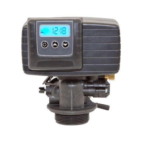
Простой и удобный в программировании клапан Fleck 5600 имеет высокие эксплуатационные характеристики и используется в системах умягчения воды.
Преимущества
- Простота и надежность
- Не восприимчив к коррозии
- Полностью программируемые стадии регенерации
- Оптимальная цена
Цена по запросу
В наличии
Краткие технические характеристики INFO
| Материал | Норил |
| Рабочее давление | 1,4 — 8,5 бар |
| Рабочая температура | 1 — 43 °С |
| Сервисная производительность | 4,4 м3/ч |
| Обратная промывка | 1,6 м3/ч |
| Вход/выход | 3,4″ или 1″ |
| Посадочное отверстие | 2,5″ |
| Рекомендуемые диаметры фильтров | 6 — 13″ |
| Опции | Upflow, Байпас |
Документация PDF
Управляющий клапан Fleck 5600/1600 SXT — реагентный управляющий клапан, устанавливается на установки умягчения. Тип работы — периодический (процесс сервиса сменяется процессом регенерации). Оснащен контроллером SXT, имеет встроенный расходомер (турбина 3/4″). Выход на регенерацию — по счетчику/таймеру. Материал проточной части — норил. Диаметр посадочной резьбы — 2,5″. Вход/выход — 1″. Дренажная линия — 1/2″. Тип регенерации — поток вниз/вверх. Реагентная линия — 3/8″. Солевая система — 1600. Наполнение бака происходит очищенной водой.
Технические характеристики для блок управления 5600/1600 SXT:
— Производительность, м3/ч 4,5;
— Количество циклов — 5
— Корпус выполнен из норила;
— Диаметры присоединений: 25/25/15 мм (вход/ выход/ дренаж);
— LCD дисплей с подсветкой;
— Солевая система 1600 позволяет использовать клапан для работы с корпусами диаметром от 8 до 12 дюймов;
— Регенерация по объему очищенной воды;
— Подходит для корпуса 12×52
-
Бренд
Fleck
-
Гарантийный срок
1 год
-
Артикул
130311_5600/1600 SXT 1″
-
Базовая единица
шт
-
Производитель
Fleck (Pentair Water)
-
Присоединительный размер, дюйм
вход/выход 1″; дренаж 3/4″
-
Присоединение к баллону, дюйм
2,5
-
Тип клапана
умягчение по расходомеру
-
Максимальное рабочее давление, бар
8
-
Страна производства
США
-
Производительность, м3/ч
4.5
-
Вес, кг
11
-
Высота, мм
500
-
Ширина, мм
500
-
Глубина, мм
450
|
Инструкции по эксплуатации аппаратов очистки воды Блоки управление и контроллеры FLECK:
|