- Manuals
- Brands
- Perkins Manuals
- Engine
- 1104
Manuals and User Guides for Perkins 1104. We have 4 Perkins 1104 manuals available for free PDF download: Operation And Maintenance Manual, Workshop Manual
Perkins 1104 Operation And Maintenance Manual (85 pages)
Brand: Perkins
|
Category: Engine
|
Size: 24.02 MB
Table of Contents
-
Important Safety Information
4
-
Warning
4
-
Table of Contents
5
-
Literature Information
6
-
Maintenance Intervals
6
-
Safety
6
-
Operation
6
-
Foreword
6
-
Safety Section
7
-
Safety Messages
7
-
General Hazard Information
7
-
Containing Fluid Spillage
8
-
Pressure Air and Water
8
-
Fluid Penetration
8
-
Coolant
9
-
Oils
9
-
-
Burn Prevention
9
-
Fire Prevention and Explosion Prevention
9
-
Fire Extinguisher
10
-
Lines, Tubes and Hoses
11
-
-
Crushing Prevention and Cutting Prevention
11
-
Mounting and Dismounting
11
-
Before Starting Engine
11
-
Engine Starting
12
-
Engine Stopping
12
-
Electrical System
12
-
Grounding Practices
13
-
Product Information Section
14
-
Model Views
14
-
Engine Description
17
-
Engine Specifications
17
-
Industrial Engine Specifications
18
-
Genset Specifications
18
-
Engine Service Life
19
-
Engine Cooling and Lubrication
19
-
Engine Identification
20
-
Reference Numbers
20
-
-
Product Identification Information
20
-
Engine Lifting
23
-
Engine Storage
23
-
-
Operation Section
23
-
Lifting and Storage
23
-
Exhaust System
24
-
Induction System
24
-
Cooling System
24
-
General Items
25
-
Engine Oil Pressure
26
-
Jacket Water Coolant Temperature
26
-
Tachometer
26
-
-
Gauges and Indicators
26
-
Engine Starting
27
-
Starting the Engine
28
-
Cold Weather Starting
28
-
After Starting Engine
29
-
Starting with Jump Start Cables
29
-
Fuel Conservation Practices
30
-
Engine Warm up
30
-
-
Engine Operation
30
-
Stopping the Engine
31
-
After Stopping Engine
31
-
Emergency Stopping
31
-
Viscosity of the Engine Lubrication Oil
32
-
Recommendations for the Coolant
32
-
Hints for Cold Weather Operation
32
-
-
Cold Weather Operation
32
-
Engine Block Heaters
33
-
Idling the Engine
33
-
Recommendations for Coolant Warm up
33
-
Insulating the Air Inlet and Engine Compartment
34
-
Fuel and the Effect from Cold Weather
34
-
Fuel Tanks
35
-
Fuel Filters
35
-
Fuel Heaters
35
-
Lubrication System
36
-
-
Maintenance Section
36
-
Refill Capacities
36
-
API Oils
37
-
Fluid Recommendations
37
-
General Lubricant Information
37
-
Engine Oil
38
-
Commercial Oils
38
-
Synthetic Base Stock Oils
39
-
Engine Oil Viscosity
39
-
SOS Oil Analysis
40
-
Re-Refined Base Stock Oils
40
-
Aftermarket Oil Additives
40
-
Lubricants for Cold Weather
40
-
Fuel Specifications
41
-
Fuel Recommendations
41
-
Cooling System Specifications
44
-
General Coolant Information
44
-
Additives
44
-
Water
44
-
Coolant Recommendations
45
-
Glycol
45
-
ELC Cooling System Maintenance
46
-
Extended Life Coolant
46
-
Correct Additions to the Extended Life Coolant
46
-
Perkins ELC Extender
46
-
ELC Cooling System Cleaning
47
-
Changing to Perkins ELC
47
-
ELC Cooling System Contamination
47
-
Commercial Heavy-Duty Coolant/Antifreeze and SCA
48
-
Adding the SCA to Heavy-Duty Coolant at the Initial Fill
48
-
Cleaning the System of Heavy-Duty Coolant/Antifreeze
49
-
-
Maintenance Interval Schedule
50
-
Aftercooler Core — Clean/Test
51
-
Aftercooler Core — Inspect
51
-
Alternator — Inspect
52
-
Alternator and Fan Belts
52
-
Battery — Replace
53
-
Battery Electrolyte Level Check
53
-
Battery or Battery Cable — Disconnect
54
-
Cooling System Coolant
54
-
Cooling System Coolant — Change
56
-
Cooling System Coolant Level — Check
58
-
Engines with a Coolant Recovery Tank
58
-
Engines Without a Coolant Recovery Tank
58
-
Engine Clean
59
-
Driver Equipment — Check
59
-
Engine Air Cleaner Element — Clean/Replace
60
-
Servicing the Air Cleaner Elements
60
-
Dual Element Air Cleaners
60
-
Inspecting the Primary Air Cleaner Elements
61
-
Pressurized Air
61
-
Vacuum Cleaning
61
-
Cleaning the Primary Air Cleaner Elements
61
-
Engine Air Cleaner Element
62
-
Engine Air Cleaner Service Indicator
62
-
Test the Service Indicator
62
-
Engine Ground — Inspect/Clean
63
-
Engine Mounts — Inspect
63
-
Engine Oil Level — Check
63
-
Engine Oil Sample — Obtain
63
-
Engine Oil and Filter Change
64
-
Drain the Engine Oil
64
-
Obtain the Sample and the Analysis
64
-
Replace the Spin-On Oil Filter
65
-
Replace the Element for the Oil Filter
65
-
Engine Valve Lash
66
-
Fill the Engine Crankcase
66
-
Fuel Injector — Test/Change
66
-
Removal and Installation of the Fuel Injectors
67
-
Fuel System — Prime
67
-
Fuel System Primary Filter/Water Separator
68
-
Fuel System Primary Filter Element
69
-
Element Filter
70
-
Fuel System Secondary Filter
70
-
Spin-On Filter
71
-
Fuel Tank
72
-
Drain the Water and the Sediment
72
-
Fuel Storage Tanks
72
-
Hoses and Clamps
73
-
Replace the Hoses and the Clamps
73
-
Radiator Clean
74
-
Severe Servo Application
74
-
Starting Motor
75
-
Environmental Factors
75
-
Incorrect Operating Procedures
75
-
Turbocharger Inspect
75
-
Wall-Around Inspection
76
-
Inspect the Engine for Leaks and for Loose Connections
76
-
Water Pump Inspect
77
-
-
Warranty Section
78
-
Warranty Information
78
-
Index
79
Advertisement
Perkins 1104 Operation And Maintenance Manual (92 pages)
Brand: Perkins
|
Category: Engine
|
Size: 2.06 MB
Table of Contents
-
Table of Contents
3
-
Foreword
4
-
Safety Section
5
-
Safety Messages
5
-
General Hazard Information
6
-
Burn Prevention
8
-
Fire Prevention and Explosion Prevention
9
-
Crushing Prevention and Cutting Prevention
10
-
Mounting and Dismounting
11
-
Before Starting Engine
11
-
Engine Starting
11
-
Engine Stopping
12
-
Electrical System
12
-
Product Information Section
13
-
Model Views
13
-
Product Identification Information
19
-
Lifting and Storage
23
-
Operation Section
23
-
Gauges and Indicators
25
-
Engine Starting
26
-
Engine Operation
29
-
Engine Stopping
30
-
Cold Weather Operation
31
-
Maintenance Section
35
-
Refill Capacities
35
-
-
Maintenance Interval Schedule
52
-
Aftercooler Core — Clean/Test
52
-
Aftercooler Core — Inspect
53
-
Alternator — Inspect
54
-
Battery — Replace
55
-
Battery Electrolyte Level — Check
55
-
Battery or Battery Cable — Disconnect
56
-
Cooling System Coolant (Commercial Heavy-Duty) — Change
56
-
Cooling System Coolant (ELC) — Change
58
-
Cooling System Coolant — Change
60
-
Cooling System Coolant Extender (ELC) — Add
60
-
Cooling System Coolant Level — Check
60
-
Driven Equipment — Check
62
-
Engine — Clean
62
-
Engine Air Cleaner Element (Dual Element) — Clean/Replace
63
-
Engine Air Cleaner Element (Single Element)
63
-
Replace
63
-
Engine Air Cleaner Element (Single Element) — Inspect/Replace
65
-
Engine Air Cleaner Service Indicator — Inspect
65
-
Inspect/Replace
65
-
Engine Ground — Inspect/Clean
66
-
Engine Mounts — Inspect
66
-
Engine Oil Level — Check
66
-
Engine Oil and Filter — Change
67
-
Engine Oil Sample — Obtain
67
-
Engine Valve Lash — Inspect/Adjust
69
-
Fuel Injector — Test/Change
69
-
Fuel System — Prime
71
-
Element — Replace
73
-
Fuel System Primary Filter (Water Separator)
73
-
Fuel System Primary Filter/Water Separator
75
-
Fuel System Secondary Filter/Water Separator — Drain
76
-
Fuel System Secondary Filter — Replace
77
-
Fuel Tank Water and Sediment — Drain
80
-
Hoses and Clamps — Inspect/Replace
80
-
Radiator — Clean
81
-
Severe Service Application — Check
82
-
Starting Motor — Inspect
83
-
Turbocharger — Inspect
83
-
Walk-Around Inspection
84
-
Water Pump — Inspect
84
-
Warranty Information
86
-
Warranty Section
86
-
Index
87
-
Perkins 1104 Workshop Manual (54 pages)
Brand: Perkins
|
Category: Engine
|
Size: 2.17 MB
Table of Contents
-
Table of Contents
4
-
Fuel System Fuel System
10
-
Basic Engine Basic Engine
18
-
Fuel System — Inspect
23
-
Air in Fuel — Test
23
-
Finding Top Center Position for No. 1 Piston
24
-
Fuel Injection Pump Timing — Check
25
-
Fuel Injection Pump Timing — Adjust
26
-
Fuel Quality — Fuel Quality — T T Est Est
28
-
Fuel System — Prime
28
-
Fuel System Pressure — Test
29
-
Air Inlet and Exhaust System
30
-
Air Inlet and Exhaust System — Inspect
30
-
Wastegate — T T Est Wastegate — Est
30
-
Compression — T T Est Compression — Est
31
-
Engine Valve las Engine Valve Lash — Inspect/Adjust H — Inspect/Adjust
31
-
Inspect
34
-
Lubrication System
36
-
Engine Oil Pressure — Test
36
-
Engine Oil Pump — Inspect
36
-
Excessive Bearing Wear — Inspect
37
-
Excessive Engine Oil Consumption — Inspect
37
-
Increased Engine Oil T Increased Engine Oil Temperature — Inspect Emperature — Inspect
38
-
Cooling System
39
-
Cooling System — Check (Overheating)
39
-
Cooling System — Inspect
40
-
Cooling System — Cooling System — T T Est Est
40
-
Engine Oil Cooler — Inspect
42
-
Water Temperature Regulator — Test
43
-
Basic Engine
44
-
Piston Ring Groove — Inspect
44
-
Connecting Rod — Inspect
44
-
Connecting Rod Bearings — Inspect
45
-
Main Bearings — Inspect
45
-
Cylinder Block — Inspect
45
-
Cylinder Head — Inspect
46
-
Piston Height — Inspect Piston Height — Inspect
46
-
Flywheel — Inspect Flywheel — Inspect
47
-
Gear Group — Inspect
48
-
Electrical System
49
-
Alternator — T T Est Alternator — Est
49
-
Battery — Test Battery — Test
49
-
Electric Starting System — Test
50
-
Test
52
-
V-Belt — — T T Est V-Belt Est
53
-
Index
54
Advertisement
Perkins 1104 Operation And Maintenance Manual (84 pages)
Industrial Engines
Brand: Perkins
|
Category: Engine
|
Size: 2.12 MB
Advertisement
Related Products
-
Perkins 1104D-E44TA
-
Perkins 1104D-E44T
-
Perkins 1104E Series
-
Perkins 1104D
-
Perkins 1104D NH1
-
Perkins 1104D NJ1
-
Perkins 1104AA-44TG
-
Perkins 1106A-70T
-
Perkins 1106C Genset
-
Perkins 1103AA-33G
Perkins Categories
Engine
Lifting Systems
Personal Care Products
Inverter
Analytical Instruments
More Perkins Manuals
Section 2 • Specifications
SPECIFICATIONS
GTH-636, GTH-644, GTH-842 and GTH-844
Displacement
Number of cylinders
Bore and stroke
Horsepower
Firing order
Compression ratio
Low idle
Frequency
High idle
Frequency
Valve clearance, cold
Intake
Exhaust
Lubrication system
Oil pressure at high idle, minimum
Oil capacity
(including filter)
Oil viscosity requirements
Units ship with 15W-40.
Extreme operating temperatures may require the use of
alternative engine oils. For oil requirements, refer to the
Engine Operation and Maintenance Manual on your
machine.
2 — 10
GTH-636 • GTH-644 • GTH-842 • GTH-844 • GTH-1048 • GTH-1056
269 cu in
4.4 liters
4
4.133 x 5 inches
105 x 127 mm
99.9 @ 2500 rpm
74.5 kW @ 2500 rpm
1 — 3 — 4 — 2
18.2:1
1000 rpm
200 Hz
2520 rpm
504 Hz
0.008 in
0.2 mm
0.018 in
0.45 mm
43 psi
3 bar
7 quarts
6.5 liters
Injection system
Injection pump make
Injector pressure, minimum
Lift pump pressure
Fuel requirement
For fuel requirements, refer to the engine Operation
Manual on your machine.
Engine coolant
Capacity
Alternator
Output
Fan belt tension (new belt / used belt)
Battery
Type
Group
Quantity
Cold cranking ampere @ 0°F
Reserve capacity @ 25A rate
Continuous improvement of our products is a
Genie policy. Product specifications are
subject to change without notice.
June 2007
REV D
Delphi
4380 psi
302 bar
4.5 to 9.5 psi
0.31 to 0.66 bar
4.75 gallons
18 liters
85 A, 14V DC
120 / 80 lbf
535 / 355 N
12V DC
C31
1
1000A
200 minutes
Part No. 97487

Perkins Service and Parts Information System содержит каталоги запасных частей, руководства по диагностике, обслуживанию и ремонту двигателей Perkins общего и промышленного назначения, а так же двигателей для дизельных электростанций.
- Актуальность: 2018
- Система: Windows
- Интерфейс: Многоязычный (русский отсутствует)
- Формат: ISO
- Размер: 5,0 Gb
Руководство на английском языке по техническому обслуживанию и ремонту автомобильных двигателей Perkins Phaser и промышленных двигателей Perkins 1000-й серии.
- Автор: —
- Издательство: Perkins Engines Ltd.
- Год издания: 2002
- Страниц: 440
- Формат: PDF
- Размер: 27,7 Mb
Руководство на английском языке по техническому обслуживанию и ремонту автомобильных дизельных двигателей Perkins моделей 4.99/4.107/4.108.
- Автор: —
- Издательство: Perkins Engines Ltd.
- Год издания: 1983
- Страниц: 114
- Формат: PDF
- Размер: 5,3 Mb
Справочник на английском языке с техническими данными двигателей Perkins объемом до 8,85 л.
- Автор: —
- Издательство: Perkins Engines Ltd.
- Год издания: 1997
- Страниц: 66
- Формат: PDF
- Размер: 1,5 Mb
Руководство на английском языке по техническому обслуживанию и ремонту автомобильных дизельных двигателей Perkins моделей 4.99M/4.107M/4.108M.
- Автор: —
- Издательство: Perkins Engines Ltd.
- Год издания: 1978
- Страниц: 134
- Формат: PDF
- Размер: 9,2 Mb
Руководство по техническому обслуживанию и ремонту двигателя Perkins модели 1104D-E44TA.
- Автор: —
- Издательство: Терция
- Год издания: —
- Страниц: 110
- Формат: —
- Размер: —

Скидки от справочной
При упоминании АСС вы можете получить скидки на запчасти и услуги
 Loading…
![]()
SEBU7833-04
January 2015
Operation and
Maintenance
Manual
1103 and 1104 Industrial Engines
DC(Engine)
DD(Engine)
DJ (Engine)
DK (Engine)
RE (Engine)
RG (Engine)
RJ(Engine)
RR(Engine)
RS(Engine)
RT(Engine)
DF(Engine)
DG (Engine)

Important Safety Information
Most accidents that involve product operation, maintenance and repair are caused by failure to observe basic safety rules or precautions. An accident can often be avoided by recognizing potentially hazardous situations before an accident occurs. A person must be alert to potential hazards. This person should also have the necessary training, skills and tools to perform these functions properly.
Improper operation, lubrication, maintenance or repair of this product can be dangerous and could result in injury or death.
Do not operate or perform any lubrication, maintenance or repair on this product, until you have read and understood the operation, lubrication, maintenance and repair information.
Safety precautions and warnings are provided in this manual and on the product. If these hazard warnings are not heeded, bodily injury or death could occur to you or to other persons.
The hazards are identified by the “Safety Alert Symbol” and followed by a “Signal Word” such as “DANGER”, “WARNING” or “CAUTION”. The Safety Alert “WARNING” label is shown below.
The meaning of this safety alert symbol is as follows:
Attention! Become Alert! Your Safety is Involved.
The message that appears under the warning explains the hazard and can be either written or pictorially presented.
Operations that may cause product damage are identified by “NOTICE” labels on the product and in this publication.
Perkins cannot anticipate every possible circumstance that might involve a potential hazard. The warnings in this publication and on the product are, therefore, not all inclusive. If a tool, procedure, work method or operating technique that is not specifically recommended by Perkins is used,
you must satisfy yourself that it is safe for you and for others. You should also ensure that the product will not be damaged or be made unsafe by the operation, lubrication, maintenance or repair procedures that you choose.
The information, specifications, and illustrations in this publication are on the basis of information that was available at the time that the publication was written. The specifications, torques, pressures, measurements, adjustments, illustrations, and other items can change at any time. These changes can affect the service that is given to the product. Obtain the complete and most current information before you start any job. Perkins dealers or Perkins distributors have the most current information available.
When replacement parts are required for this product Perkins recommends using Perkins replacement parts.
Failure to heed this warning can lead to premature failures, product damage, personal injury or death.

|
Table of Contents |
|
|
Foreword………………………… ……………………….. |
4 |
|
Safety Section |
|
|
Safety Messages………………….. ………………….. |
5 |
|
General Hazard Information…………… ………….. |
6 |
|
Burn Prevention…………………… …………………… |
8 |
|
Fire Prevention and Explosion Prevention …. … |
9 |
|
Crushing Prevention and Cutting Prevention . 10 |
|
|
Mounting and Dismounting…………… …………… |
11 |
|
Before Starting Engine ……………… ……………… |
11 |
|
Engine Starting…………………… …………………… |
11 |
|
Engine Stopping ………………….. …………………. |
12 |
|
Electrical System…………………. …………………. |
12 |
|
Product Information Section |
|
|
Model Views …………………….. ……………………. |
13 |
|
Product Identification Information………. ……… |
19 |
|
Operation Section |
|
|
Lifting and Storage………………… ………………… |
23 |
|
Gauges and Indicators ……………… …………….. |
25 |
|
Engine Starting…………………… ………………….. |
26 |
|
Engine Operation…………………. …………………. |
29 |
|
Engine Stopping ………………….. …………………. |
30 |
|
Cold Weather Operation…………….. ……………. |
31 |
|
Maintenance Section |
|
Warranty Section |
|
|
Warranty Information………………. ………………. |
86 |
|
Index Section |
|
|
Index………………………….. …………………………. |
87 |
|
Refill Capacities………………….. ………………….. |
35 |
|
Maintenance Interval Schedule……….. ……….. |
52 |

4
Foreword
Foreword
Literature Information
This manual contains safety, operation instructions,
lubrication and maintenance information. This manual should be stored in or near the engine area in a
literature holder or literature storage area. Read, study and keep it with the literature and engine information.
English is the primary language for all Perkins publications. The English used facilitates translation and consistency.
Some photographs or illustrations in this manual show details or attachments that may be different from your engine. Guards and covers may have been removed for illustrative purposes. Continuing improvement and advancement of product design may have caused changes to your engine which are not included in this manual. Whenever a question arises regarding your engine, or this manual, please consult with your Perkins dealer or your Perkins distributor for the latest available information.
Safety
This safety section lists basic safety precautions. In addition, this section identifies hazardous, warning
situations. Read and understand the basic precautions listed in the safety section before
operating or performing lubrication, maintenance and repair on this product.
Operation
Operating techniques outlined in this manual are basic. They assist with developing the skills and techniques required to operate the engine more efficiently and economically. Skill and techniques develop as the operator gains knowledge of the engine and its capabilities.
The operation section is a reference for operators. Photographs and illustrations guide the operator through procedures of inspecting, starting, operating and stopping the engine. This section also includes a discussion of electronic diagnostic information.
Maintenance
The maintenance section is a guide to engine care. The illustrated, step-by-step instructions are grouped by service hours and/or calendar time maintenance
intervals. Items in the maintenance schedule are referenced to detailed instructions that follow.
SEBU7833
Recommended service should be performed at the appropriate intervals as indicated in the Maintenance Interval Schedule. The actual operating environment of the engine also governs the Maintenance Interval Schedule. Therefore, under extremely severe, dusty, wet or freezing cold operating conditions, more frequent lubrication and maintenance than is specified in the Maintenance Interval Schedule may be necessary.
The maintenance schedule items are organized for a preventive maintenance management program. If the preventive maintenance program is followed, a periodic tune-up is not required. The implementation of a preventive maintenance management program should minimize operating costs through cost avoidances resulting from reductions in unscheduled downtime and failures.
Maintenance Intervals
Perform maintenance on items at multiples of the original requirement. We recommend that the maintenance schedules be reproduced and displayed near the engine as a convenient reminder. We also
recommend that a maintenance record be maintained as part of the engine’s permanent record.
Your authorized Perkins dealer or your Perkins distributor can assist you in adjusting your maintenance schedule to meet the needs of your operating environment.
Overhaul
Major engine overhaul details are not covered in the Operation and Maintenance Manual except for the
interval and the maintenance items in that interval. Major repairs should only be carried out by Perkins
authorized personnel. Your Perkins dealer or your Perkins distributor offers a variety of options regarding overhaul programs. If you experience a major engine failure, there are also numerous after failure overhaul options available. Consult with your Perkins dealer or your Perkins distributor for information regarding these options.
California Proposition 65 Warning
Diesel engine exhaust and some of its constituents
are known to the State of California to cause cancer, birth defects, and other reproductive harm. Battery
posts, terminals and related accessories contain lead and lead compounds. Wash hands after handling.

SEBU7833
Safety Section
i05898546
Safety Messages
There may be several specific warning signs on an engine. The exact location of the hazards and the description of the hazards are reviewed in this section. Become familiar with all warning signs.
Ensure that all of the warning signs are legible. Clean the warning signs or replace the warning signs if the words cannot be read or if the pictures are not visible. When the warning signs are cleaned, use a cloth, water, and soap. Do not use solvent, gasoline, or other harsh chemicals to clean the warning signs. Solvents, gasoline, or harsh chemicals could loosen the adhesive that secures the warning signs. The warning signs that are loosened could drop off the engine.
Replace any damaged warning signs or missing warning signs. If a warning sign is attached to a part of the engine that is replaced, install a new warning sign on the replacement part. Perkins dealers or Perkins distributors can provide new warning signs.
Do not work on the engine and do not operate the engine unless the instructions and warnings in the Operation and Maintenance Manual are understood. Correct care is your responsibility. Failure to follow the instructions or failure to heed the warnings could result in injury or in death.
(1) Universal Warning
Do not operate or work on this equipment unless you have read and understand the instructions and warnings in the Operation and Maintenance Manuals. Failure to follow the instructions or heed the warnings could result in serious injury or death.
5
Safety Section
Safety Messages
Typical example
The Universal Warning label (1) will be located on the valve mechanism cover. Refer to illustration 2 .
Note: The location of this label will depend on the application of the engine.
Typical example of a four cylinder engine
(2) Ether
Do not use aerosol types of starting aids such as ether. Such use could result in an explosion and personal injury.
Safety Section
General Hazard Information
The ether warning label (2) is located on the cover of the inlet manifold. Refer to illustration 2 .
3 Cylinder Engine.
(1) Universal Warning Label
(2) Ether Warning Label
The universal warning label (1) is located at the rear of the valve mechanism cover on the three cylinder engine. The ether warning label (2) is located at the
front of the valve mechanism cover on the three cylinder engine.
i05875556
General Hazard Information
Typical example of a four cylinder engine
Attach a “Do Not Operate” warning tag or a similar warning tag to the start switch or to the controls before you service the equipment or before you repair the equipment.
Safety Section
General Hazard Information
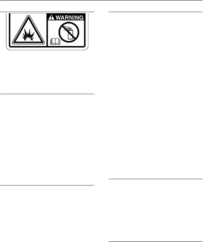
Wear a hard hat, protective glasses, and other protective equipment, as required.
Do not wear loose clothing or jewelry that can snag on controls or on other parts of the engine.
Make sure that all protective guards and all covers are secured in place on the engine.
Keep the engine free from foreign material. Remove
debris, oil, tools, and other items from the deck, from walkways, and from steps.
Never put maintenance fluids into glass containers. Drain all liquids into a suitable container.
Obey all local regulations for the disposal of liquids.
Use all cleaning solutions with care.
Report all necessary repairs.
Do not allow unauthorized personnel on the equipment.
Disconnect the batteries when maintenance is performed or when the electrical system is serviced.
Disconnect the battery ground leads. Tape the leads in order to help prevent sparks. If equipped, allow the diesel exhaust fluid to be purged before disconnecting the battery.
Perform maintenance on the engine with the equipment in the servicing position. Refer to the OEM information for the procedure for placing the equipment in the servicing position.
Do not attempt any repairs that are not understood. Use the proper tools. Replace any equipment that is damaged or repair the equipment.
For initial start-up of a new engine or for starting an engine that has been serviced, make provisions to stop the engine if an overspeed occurs. The stopping of the engine may be accomplished by shutting off the fuel supply and/or the air supply to the engine. Ensure that only the fuel supply line is shut off. Ensure that the fuel return line is open.
Start the engine from the operators station (cab). Never short across the starting motor terminals or the batteries. This action could bypass the engine neutral start system and/or the electrical system could be damaged.
Engine exhaust contains products of combustion which may be harmful to your health. Always start the engine and operate the engine in a ventilated area. If the engine is in an enclosed area, vent the engine exhaust to the outside.
Use caution when cover plates are removed. Gradually loosen, but do not remove the last two bolts or nuts that are located at opposite ends of the cover plate or the device. Before removing the last two bolts or nuts, pry the cover loose in order to relieve any spring pressure or other pressure.
Pressure Air and Water
Pressurized air and/or water can cause debris and/or hot water to be blown out. This action could result in personal injury.
The direct application of pressurized air or pressurized water to the body could result in personal injury.
When pressurized air and/or water is used for cleaning, wear protective clothing, protective shoes, and eye protection. Eye protection includes goggles or a protective face shield.
The maximum air pressure for cleaning purposes must be below 205 kPa (30 psi). The maximum water pressure for cleaning purposes must be below
275 kPa (40 psi).
Fluid Penetration
Pressure can be trapped in the hydraulic circuit long after the engine has been stopped. The pressure can cause hydraulic fluid or items such as pipe plugs to escape rapidly if the pressure is not relieved correctly.
Do not remove any hydraulic components or parts until pressure has been relieved or personal injury may occur. Do not disassemble any hydraulic components or parts until pressure has been relieved or personal injury may occur. Refer to the OEM information for any procedures that are required to relieve the hydraulic pressure.
Safety Section
Burn Prevention
Always use a board or cardboard when you check for a leak. Leaking fluid that is under pressure can penetrate body tissue. Fluid penetration can cause serious injury and possible death. A pin hole leak can cause severe injury. If fluid is injected into your skin, you must get treatment immediately. Seek treatment from a doctor that is familiar with this type of injury.
Containing Fluid Spillage
Care must be taken in order to ensure that fluids are contained during performance of inspection,
maintenance, testing, adjusting, and repair of the engine. Make provision to collect the fluid with a suitable container before any compartment is opened or before any component is disassembled.
•Only use the tools that are suitable for collecting fluids and equipment that is suitable for collecting fluids.
•Only use the tools that are suitable for containing fluids and equipment that is suitable for containing fluids.
Obey all local regulations for the disposal of liquids.
i05875580
Burn Prevention
Do not touch any part of an operating engine. Allow the engine to cool before any maintenance is performed on the engine. Relieve all pressure in the air system, in the hydraulic system, in the lubrication system, in the fuel system, or in the cooling system before any lines, fittings, or related items are disconnected.
Coolant
When the engine is at operating temperature, the engine coolant is hot. The coolant is also under pressure. The radiator and all lines to the heaters or to the engine contain hot coolant.
Any contact with hot coolant or with steam can cause severe burns. Allow cooling system components to cool before the cooling system is drained.
Check that the coolant level after the engine has stopped and the engine has been allowed to cool.
Ensure that the filler cap is cool before removing the filler cap. The filler cap must be cool enough to touch with a bare hand. Remove the filler cap slowly in order to relieve pressure.
Cooling system conditioner contains alkali. Alkali can cause personal injury. Do not allow alkali to contact the skin, the eyes, or the mouth.
Oils
Skin may be irritated following repeated or prolonged exposure to mineral and synthetic base oils. Refer to your suppliers Material Safety Data Sheets for detailed information. Hot oil and lubricating components can cause personal injury. Do not allow hot oil to contact the skin. Appropriate personal protective equipment should be used.
Diesel Fuel
Diesel may be irritating to the eyes, respiratory system, and skin. Prolonged exposure to diesel may cause various skin conditions. Appropriate personal protective equipment should be used. Refer to supplier Material safety Data sheets for detailed information.
Batteries
Electrolyte is an acid. Electrolyte can cause personal injury. Do not allow electrolyte to contact the skin or the eyes. Always wear protective glasses for servicing batteries. Wash hands after touching the batteries and connectors. Use of gloves is recommended.

SEBU7833
i05875630
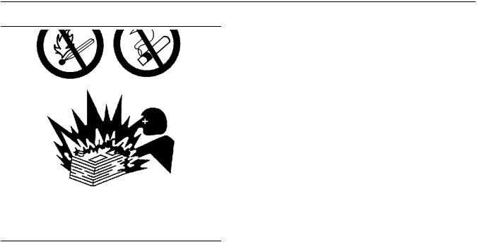
Fire Prevention and Explosion
Prevention
All fuels, most lubricants, and some coolant mixtures are flammable.
Flammable fluids that are leaking or spilled onto hot surfaces or onto electrical components can cause a fire. Fire may cause personal injury and property damage.
A flash fire may result if the covers for the engine
crankcase are removed within 15 minutes after an emergency shutdown.
Determine whether the engine will be operated in an environment that allows combustible gases to be drawn into the air inlet system. These gases could cause the engine to overspeed. Personal injury, property damage, or engine damage could result.
If the application involves the presence of combustible gases, consult your Perkins dealer and/ or your Perkins distributor for additional information about suitable protection devices.
Remove all flammable combustible materials or conductive materials such as fuel, oil, and debris from the engine. Do not allow any flammable combustible
materials or conductive materials to accumulate on the engine.
Store fuels and lubricants in correctly marked containers away from unauthorized persons. Store oily rags and any flammable materials in protective
containers. Do not smoke in areas that are used for storing flammable materials.
Do not expose the engine to any flame.
Exhaust shields (if equipped) protect hot exhaust components from oil or fuel spray in case of a line, a
tube, or a seal failure. Exhaust shields must be installed correctly.
9
Safety Section
Fire Prevention and Explosion Prevention
Do not weld on lines or tanks that contain flammable fluids. Do not flame cut lines or tanks that contain flammable fluid. Clean any such lines or tanks
thoroughly with a nonflammable solvent prior to welding or flame cutting.
Wiring must be kept in good condition. Ensure that all electrical wires are correctly installed and securely attached. Check all electrical wires daily. Repair any wires that are loose or frayed before you operate the engine. Clean all electrical connections and tighten all electrical connections.
Eliminate all wiring that is unattached or unnecessary. Do not use any wires or cables that are smaller than the recommended gauge. Do not bypass any fuses and/or circuit breakers.
Arcing or sparking could cause a fire. Secure connections, recommended wiring, and correctly maintained battery cables will help to prevent arcing or sparking.
Inspect all lines and hoses for wear or for deterioration. The hoses must be correctly routed. The lines and hoses must have adequate support and secure clamps. Tighten all connections to the recommended torque. Leaks can cause fires.
Oil filters and fuel filters must be correctly installed. The filter housings must be tightened to the correct torque.
|
Illustration 10 |
g00704059 |
Use caution when you are refueling an engine. Do not smoke while you are refueling an engine. Do not refuel an engine near open flames or sparks. Always stop the engine before refueling.
10
Safety Section
Crushing Prevention and Cutting Prevention
|
Illustration 11 |
g00704135 |
Gases from a battery can explode. Keep any open flames or sparks away from the top of a battery. Do not smoke in battery charging areas.
Never check the battery charge by placing a metal object across the terminal posts. Use a voltmeter or a hydrometer.
Incorrect jumper cable connections can cause an explosion that can result in injury. Refer to the Operation Section of this manual for specific instructions.
Do not charge a frozen battery. This action may cause an explosion.
The batteries must be kept clean. The covers (if equipped) must be kept on the cells. Use the recommended cables, connections, and battery box covers when the engine is operated.
Fire Extinguisher
Make sure that a fire extinguisher is available. Be familiar with the operation of the fire extinguisher. Inspect the fire extinguisher and service the fire extinguisher regularly. Obey the recommendations on the instruction plate.
Ether
Ether is flammable and poisonous.
Do not smoke while you are replacing an ether cylinder or while you are using an ether spray.
Do not store ether cylinders in living areas or in the engine compartment. Do not store ether cylinders in direct sunlight or in temperatures above 49° C (120° F). Keep ether cylinders away from open flames or sparks.
SEBU7833
Lines, Tubes, and Hoses
Do not bend high-pressure lines. Do not strike highpressure lines. Do not install any lines that are bent or damaged. Do not clip any other items to the highpressure lines.
Repair any lines that are loose or damaged. Leaks can cause fires. Consult your Perkins dealer or your Perkins distributor for repair or for replacement parts.
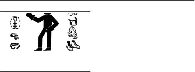
Check lines, tubes, and hoses carefully. Do not use your bare hand to check for leaks. Use a board or cardboard to check for leaks. Tighten all connections to the recommended torque.
Replace the parts if any of the following conditions are present:
•End fittings are damaged or leaking.
•Outer coverings are chafed or cut.
•Wires are exposed.
•Outer coverings are ballooning.
•Flexible parts of the hoses are kinked.
•Outer covers have embedded armoring.
•End fittings are displaced.
Make sure that all clamps, guards, and heat shields are installed correctly. During engine operation, correct installation will help to prevent vibration, rubbing against other parts, and excessive heat.
i02143194
Crushing Prevention and
Cutting Prevention
Support the component correctly when work beneath the component is performed.
Unless other maintenance instructions are provided, never attempt adjustments while the engine is running.
Stay clear of all rotating parts and of all moving parts. Leave the guards in place until maintenance is performed. After the maintenance is performed, reinstall the guards.
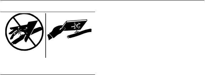
Keep objects away from moving fan blades. The fan blades will throw objects or cut objects.
When objects are struck, wear protective glasses in order to avoid injury to the eyes.
Chips or other debris may fly off objects when objects are struck. Before objects are struck, ensure that no one will be injured by flying debris.
![]()
SEBU7833
i05875651
Mounting and Dismounting
Do not climb on the engine. The engine has not been designed with mounting or dismounting locations.
Refer to the OEM for the location of foot and hand holds for your specific application.
i05874054
Before Starting Engine
NOTICE
For initial start-up of a new or rebuilt engine, and for start-up of an engine that has been serviced, make provision to shut the engine off should an overspeed occur. This may be accomplished by shutting off the air and/or fuel supply to the engine.
Engine exhaust contains products of combustion which may be harmful to your health. Always start and operate the engine in a well ventilated area and, if in an enclosed area, vent the exhaust to the outside.
Inspect the engine for potential hazards.
Do not start the engine or move any of the controls if there is a “DO NOT OPERATE” warning tag or similar warning tag attached to the start switch or to the controls.
Before starting the engine, ensure that no one is on, underneath, or close to the engine. Ensure that the area is free of personnel.
If equipped, ensure that the lighting system for the engine is suitable for the conditions. Ensure that all lights work properly, if equipped.
All protective guards and all protective covers must be installed if the engine must be started in order to perform service procedures. To help prevent an accident that is caused by parts in rotation, work around the parts carefully.
Do not bypass the automatic shutoff circuits. Do not
disable the automatic shutoff circuits. The circuits are provided in order to help prevent personal injury. The
circuits are also provided in order to help prevent engine damage.
See the Service Manual for repairs and for adjustments.
11
Safety Section
Mounting and Dismounting
i02207232
Engine Starting
Do not use aerosol types of starting aids such as ether. Such use could result in an explosion and personal injury.
If a warning tag is attached to the engine start switch or to the controls, DO NOTstart the engine or move the controls. Consult with the person that attached the warning tag before the engine is started.
All protective guards and all protective covers must be installed if the engine must be started in order to perform service procedures. To help prevent an accident that is caused by parts in rotation, work around the parts carefully.
Start the engine from the operator’s compartment or from the engine start switch.
Always start the engine according to the procedure that is described in the Operation and Maintenance Manual, “Engine Starting” topic in the Operation Section. Knowing the correct procedure will help to prevent major damage to the engine components. Knowing the procedure will also help to prevent personal injury.
To ensure that the jacket water heater (if equipped) and/or the lube oil heater (if equipped) is working correctly, check the water temperature gauge and the oil temperature gauge during the heater operation.
Engine exhaust contains products of combustion which can be harmful to your health. Always start the engine and operate the engine in a well ventilated area. If the engine is started in an enclosed area, vent the engine exhaust to the outside.
Note: The engine is equipped with an automatic device for cold starting for normal conditions of operation. If the engine will be operated in very cold conditions, then an extra cold starting aid may be required. Normally, the engine will be equipped with the correct type of starting aid for your region of operation.
The engines are equipped with a glow plug starting aid in each individual cylinder that heats the intake air in order to improve starting.

12
Safety Section
Engine Stopping
i01928905
Engine Stopping
Stop the engine according to the procedure in the Operation and Maintenance Manual, “Engine Stopping (Operation Section)” in order to avoid overheating of the engine and accelerated wear of the engine components.
Use the Emergency Stop Button (if equipped) ONLY in an emergency situation. Do not use the Emergency Stop Button for normal engine stopping. After an emergency stop, DO NOTstart the engine until the problem that caused the emergency stop has been corrected.
Stop the engine if an overspeed condition occurs during the initial start-up of a new engine or an engine that has been overhauled. This may be accomplished by shutting off the fuel supply to the engine and/or shutting off the air supply to the engine.
i02176668
Electrical System
Never disconnect any charging unit circuit or battery circuit cable from the battery when the charging unit is operating. A spark can cause the combustible gases that are produced by some batteries to ignite.
To help prevent sparks from igniting combustible gases that are produced by some batteries, the negative “−” jump start cable should be connected last from the external power source to the negative “−” terminal of the starting motor. If the starting motor is not equipped with a negative “−” terminal, connect the jump start cable to the engine block.
Check the electrical wires daily for wires that are loose or frayed. Tighten all loose electrical wires before the engine is started. Repair all frayed electrical wires before the engine is started. See the Operation and Maintenance Manual for specific starting instructions.
Grounding Practices
Correct grounding for the engine electrical system is necessary for optimum engine performance and reliability. Incorrect grounding will result in uncontrolled electrical circuit paths and in unreliable electrical circuit paths.
Uncontrolled electrical circuit paths can result in damage to main bearings, to crankshaft bearing journal surfaces, and to aluminum components.
Engines that are installed without engine-to-frame ground straps can be damaged by electrical discharge.
SEBU7833
To ensure that the engine and the engine electrical systems function correctly, an engine-to-frame ground strap with a direct path to the battery must be used. This path may be provided by way of a direct engine ground to the frame.
All grounds should be tight and free of corrosion. The engine alternator must be grounded to the negative “-” battery terminal with a wire that is adequate to handle the full charging current of the alternator.
Product Information Section
Model View Illustrations
Product Information
Section
Model Views
i05874119
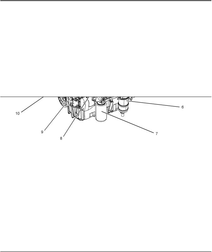
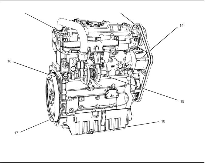
Model View Illustrations
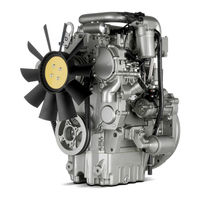
The following model views show typical features of the engine. Due to individual applications, your engine may appear different from the illustrations.
1104 Engine Model Views
|
Illustration 12 |
g03706445 |
|||
|
Typical example |
||||
|
(1) Coolant outlet |
(5) Oil gauge (Dipstick) |
(9) Coolant intake |
||
|
(2) |
Oil filler |
(6) |
Primary fuel filter |
(10) Water pump |
|
(3) |
Secondary fuel filter |
(7) |
Oil filter |
(11) Belts |
|
(4) |
Starting motor |
(8) |
Oil filler (Lower position if installed) |
Model Views
Model View Illustrations
|
Illustration 13 |
g03706446 |
|
|
Typical example |
||
|
(12) Rear lifting eye |
(15) Turbocharger |
(18) Coolant drain |
|
(13) Front lifting eye |
(16) Oil drain plug |
|
|
(14) Alternator |
(17) Flywheel |

Model Views
Model View Illustrations
1103 Engine Model Views
|
Illustration 14 |
g03705844 |
|||
|
Typical example |
||||
|
(1) Coolant out let |
(6) Oil gauge (Dipstick) |
(11) Coolant intake |
||
|
(2) Secondary fuel filter |
(7) Primary fuel filter |
(12) Water pump |
||
|
(3) |
Fuel injector |
(8) |
Oil filter |
(13) Belt |
|
(4) |
Oil cooler |
(9) |
Oil drain plug |
|
|
(5) |
Open breather |
(10) Oil filler |
Model Views
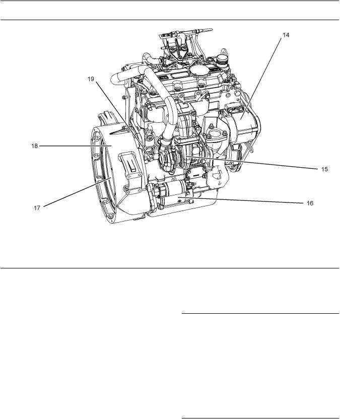
Engine Description
|
Illustration 15 |
g03705848 |
|
|
Typical example |
||
|
(14) Alternator |
(16) Starting motor |
(18) Flywheel housing |
|
(15) Turbocharger |
(17) Flywheel |
(19) Coolant drain plug |
|
i05899588 |
Engine Description
•Turbocharged aftercooled
•Turbocharged
•Naturally aspirated
Engine Specifications
Note: The front end of the engine is opposite the flywheel end of the engine. The left and the right sides of the engine are determined from the flywheel end. The number 1 cylinder is the front cylinder.
|
Illustration 16 |
g00984281 |
A typical example of the layout of the valves
(A)Inlet valves
(B)Exhaust valves

SEBU7833
Table 1
1104 Industrial Engine Specifications
|
Number of Cylinders |
4 In-Line |
|
Bore |
105 mm (4.134 inch) |
|
Stroke |
127 mm (5.0 inch) |
|
Aspiration |
Turbocharged aftercooled |
|
Turbocharged |
|
|
Naturally aspirated |
|
|
Compression Ratio |
NA 19.25:1 NA |
|
T 18.23:1 T, TA |
|
|
Displacement |
4.4 L (268 in 3) |
|
Firing Order |
1 3 4 2 |
|
Rotation (flywheel end) |
Counterclockwise |
|
Valve Lash Setting (Inlet) |
0.20 mm (0.008 inch) |
|
Valve Lash Setting (Exhaust) |
0.45 mm (0.018 inch) |
Table 2
1103 Industrial Engine Specifications
|
Number of Cylinders |
3 In-Line |
|
Bore |
105 mm (4.134 inch) |
|
Stroke |
127 mm (5.0 inch) |
|
Aspiration |
Turbocharged |
|
Naturally aspirated |
|
|
Compression Ratio |
NA 19.25:1 |
|
T 18.25:1 |
|
|
Displacement |
3.3 L (201 in3) |
|
Firing Order |
1 2 3 |
|
Rotation (flywheel end) |
Counterclockwise |
|
Valve Lash Setting (Inlet) |
0.20 mm (0.008 inch) |
|
Valve Lash Setting (Exhaust) |
0.45 mm (0.018 inch) |
Table 3
1104 Constance Speed Specifications
|
Number of Cylinders |
4 In-Line |
|
Bore |
105 mm (4.134 inch) |
|
Stroke |
127 mm (5.0 inch) |
|
Aspiration |
Turbocharged aftercooled |
|
Turbocharged |
|
|
Naturally aspirated |
|
|
Compression Ratios |
NA 19.25:1 |
|
T 17.25:1, T 18.23:1, TA 18.23:1 |
|
|
Displacement |
4.4 L (268 in 3) |
17
Model Views
Engine Description
|
(Table 3, contd) |
||
|
Firing Order |
1 |
3 4 2 |
|
Rotation (flywheel end) |
Counterclockwise |
|
|
Valve Lash Setting (Inlet) |
0.20 mm (0.008 inch) |
|
|
Valve Lash Setting (Exhaust) |
0.45 mm |
(0.018 inch) |
Table 4
1103 Constance Speed Specifications
|
Number of Cylinders |
3 In-Line |
|
Bore |
105 mm (4.134 inch) |
|
Stroke |
127 mm (5.0 inch) |
|
Aspiration |
Turbocharged |
|
Naturally aspirated |
|
|
Compression Ratio |
NA 19.25:1 |
|
T 17.25:1 |
|
|
Displacement |
3.3 L (201 in3) |
|
Firing Order |
1 2 3 |
|
Rotation (flywheel end) |
Counterclockwise |
|
Valve Lash Setting (Inlet) |
0.20 mm (0.008 inch) |
|
Valve Lash Setting (Exhaust) |
0.45 mm (0.018 inch) |
Engine Cooling and Lubrication
The cooling system consists of the following components:
•Gear-driven centrifugal water pump
•Water temperature regulator which regulates the engine coolant temperature
•Gear-driven oil pump (gear type)
•Oil cooler
The engine lubricating oil is supplied by a gear type pump. The engine lubricating oil is cooled and the engine lubricating oil is filtered. Bypass valves provide unrestricted flow of lubrication oil to the engine parts when oil viscosity is high. Bypass valves can also provide unrestricted flow of lubrication oil to the engine parts if the oil cooler should become plugged or if the oil filter element should become plugged.
Engine efficiency, efficiency of emission controls, and engine performance depend on adherence to proper operation and maintenance recommendations.
Engine performance and efficiency also depend on
the use of recommended fuels, lubrication oils, and coolants. Refer to the Operation and Maintenance
Manual, “Maintenance Interval Schedule” for more information on maintenance items.
(continued)

Model Views
Engine Description
Engine Service Life
Engine efficiency and maximum utilization of engine performance depend on the adherence to proper operation and maintenance recommendations. In
addition, use recommended fuels, coolants, and lubricants. Use the Operation and Maintenance
Manual as a guide for required engine maintenance.
Expected engine life is generally predicted by the average power that is demanded. The average power that is demanded is based on fuel consumption of the engine over time. Reduced hours of operation at full throttle and/or operating at reduced throttle settings result in a lower average power demand. Reduced hours of operation will increase the length of operating time before an engine overhaul is required.

SEBU7833
Product Identification
Information
i02280116
Engine Identification
Perkins engines are identified by a serial number. This number is shown on a serial number plate that is mounted on the left hand side of the engine block.
An example of an engine number is
RE12345U090001H.
|
RE |
Type of engine |
|
RE12345 |
Engine List Number |
|
U |
Built in the United Kingdom |
|
090001 |
Engine Serial Number |
|
H |
Year of Manufacture |
Perkins dealers need these numbers in order to determine the components that were included with
the engine. This permits accurate identification of replacement part numbers.
19
Product Identification Information
Engine Identification
i01940474
Serial Number Plate
|
Illustration 17 |
g00994966 |
Typical serial number plate
(1)Temporary Parts List number
(2)Type
(3)Serial number
(4)List number
The Serial Number Plate is located on the left side of the cylinder block behind the high pressure pipes of
the Fuel injection pump.
The following information is stamped on the Serial Number Plate: Engine serial number, Model and Arrangement number.
i02164876
Reference Numbers
Information for the following items may be needed to order parts. Locate the information for your engine. Record the information in the appropriate space. Make a copy of this list for a record. Keep the information for future reference.
Record for Reference
Engine Model
Engine Serial number
Engine Low Idle rpm
Engine Full Load rpm

|
20 |
SEBU7833 |
|
Product Identification Information |
|
|
Emissions Certification Film |
|
|
Primary Fuel Filter |
|
|
Water Separator Element |
|
|
Secondary Fuel Filter Element |
|
|
Lubrication Oil Filter Element |
|
|
Auxiliary Oil Filter Element |
|
|
Total Lubrication System Capacity |
|
|
Total Cooling System Capacity |
|
|
Air Cleaner Element |
|
|
Fan Drive Belt |
|
|
Alternator Belt |
|
|
i02758852 |
Emissions Certification Film
Label for compliant engines
Typical examples of emissions labels
|
Illustration 18 |
g01173630 |
This typical example of a label is installed on engines that have electronic fuel injection systems and installed on engines that have electronic fuel injection pumps.
![]()
Product Identification Information
Emissions Certification Film
|
Illustration 19 |
g01156733 |
This typical example of a label is installed on engines that have mechanical fuel injection pumps.
Label for engines that comply with
MSHA emissions
|
Illustration 20 |
g01381316 |
Typical example
The label that is shown in illustration 20 is for engines that operate in underground coal mines in
North America. The label is installed on engines that comply with the Mine Safety and Health Administration (MSHA) emissions. Approved diesel engines shall be identified by an approved mark that is legible and permanent. The approved mark is scribed with the approved MSHA number. The label should be securely attached to the diesel engine.

Product Identification Information
Emissions Certification Film
Label for engines that do not comply with emissions
|
Illustration 21 |
g01156734 |
This typical example of a label is installed on engines that do not comply with emissions.
|
Illustration 22 |
g01157127 |
This typical example of a label is installed on engines that are stationary engines.

SEBU7833
Operation Section
Lifting and Storage
i05933416
Engine Lifting
|
Illustration 23 |
g03729078 |
Typical example of the four cylinder lifting eyes
|
Illustration 24 |
g03791046 |
23
Operation Section
Engine Lifting
|
Illustration 25 |
g03791033 |
The configuration of the lifting eyes in certain three cylinder applications may be installed as shown in illustration 25 .
(1) Lifting eyes
NOTICE
Never bend the eyebolts and the brackets. Only load the eyebolts and the brackets under tension. Remember that the capacity of an eyebolt is less as the angle between the supporting members and the object becomes less than 90 degrees.
When it is necessary to remove a component at an angle, only use a link bracket that is properly rated for the weight.
Use a hoist to remove heavy components. Use an adjustable lifting beam to lift the engine. All supporting members (chains and cables) should be parallel to each other. The chains and cables should be perpendicular to the top of the object that is being lifted.
Some removals require lifting the fixtures in order to obtain correct balance and safety.
To remove the engine ONLY, use the lifting eyes that are on the engine.
Lifting eyes are designed and installed for specific engine arrangements. Alterations to the lifting eyes and/or the engine make the lifting eyes and the lifting
fixtures obsolete. If alterations are made, ensure that correct lifting devices are provided. Consult your
Perkins dealer or your Perkins distributor for information regarding fixtures for correct engine lifting.
Typical example of the three cylinder lifting eyes

24
Lifting and Storage
Engine Storage
i05876583
Engine Storage
Perkins are not responsible for damage which may occur when an engine is in storage after a period in service.
Your Perkins dealer or your Perkins distributor can assist in preparing the engine for extended storage periods.
Condition for Storage
The engine must be stored in a water proof building. The building must be kept at a constant temperature. Engines that are filled with Perkins ELC will have coolant protection to an ambient temperature of −36° C (−32.8° F). The engine must not be subjected to extreme variations in temperature and humidity.
Storage Period
An engine can be stored for up to 6 months provided all the recommendation are adhered to.
Storage Procedure
Keep a record of the procedure that has been completed on the engine.
Note: Do not store an engine that has biodiesel in the fuel system.
1.Ensure that the engine is clean and dry.
a.If the engine has been operated using biodiesel, the system must be drained and new filters installed. The fuel tank will require flushing.
b.Fill the fuel system with an acceptable fuel. For more information on acceptable fuels refer to this Operation and Maintenance Manual, “Fluid recommendations”. Operate the engine for 15 minutes in order to remove all biodiesel from the system.
2.Drain any water from the primary filter water separator. Ensure that the fuel tank is full.
3.The engine oil will not need to be drained in order to store the engine. Provided the correct specification of engine oil is used the engine can be stored for up to 6 months. For the correct specification of engine oil refer to this Operation and Maintenance Manual, “Fluid recommendations”.
4.Remove the drive belt from the engine.
SEBU7833
Sealed Coolant System
Ensure that the cooling system is filled with Perkins
ELC, or an antifreeze that meets “ASTM D6210” specification.
Open Cooling System
Ensure that all cooling drain plugs have been opened. Allow the coolant to drain. Install the drain plugs. Place a vapor phase inhibitor into the system. The coolant system must be sealed once the vapor phase inhibitor has been introduced. The effect of the vapor phase inhibitor will be lost if the cooling system is open to the atmosphere.
For maintenance procedures refer to this Operation and Maintenance Manual.
Monthly Checks
The crankshaft must be rotated in order to change the spring loading on the valve train. Rotate the crankshaft more than 180 degrees. Visibly check for damage or corrosion to the engine.
Ensure that the engine is covered completely before storage. Log the procedure in the record for the engine.

SEBU7833
Gauges and Indicators
i02164190
Gauges and Indicators
Your engine may not have the same gauges or all of the gauges that are described. For more information about the gauge package, see the OEM information.
Gauges provide indications of engine performance. Ensure that the gauges are in good working order. Determine the normal operating range by observing the gauges over a period of time.
Noticeable changes in gauge readings indicate potential gauge or engine problems. Problems may also be indicated by gauge readings that change even if the readings are within specifications. Determine and correct the cause of any significant change in the readings. Consult your Perkins dealer or your Perkins distributor for assistance.
NOTICE
If no oil pressure is indicated, STOP the engine. If maximum coolant temperature is exceeded, STOP the engine. Engine damage can result.
Engine Oil Pressure – The oil pressure should be greatest after a cold engine is started. The typical engine oil pressure
with SAE10W30 is 207 to 413 kPa (30 to 60 psi) at rated rpm.
A lower oil pressure is normal at low idle. If the load is stable and the gauge reading changes, perform the following procedure:
1.Remove the load.
2.Reduce engine speed to low idle.
3.Check and maintain the oil level.
Jacket Water Coolant Temperature – Typical temperature range is 71 to 96°C (160 to 205°F). The maximum allowable
temperature with the pressurized cooling system at 48 kPa (7 psi) is 110°C (230°F). Higher temperatures may occur under certain conditions. The water temperature reading may vary according to load. The reading should never exceed the boiling point for the pressurized system that is being used.
If the engine is operating above the normal range and steam becomes apparent, perform the following procedure:
1. Reduce the load and the engine rpm.
25
Gauges and Indicators
Gauges and Indicators
2.Inspect the cooling system for leaks.
3.Determine if the engine must be shut down immediately or if the engine can be cooled by reducing the load.
Tachometer – This gauge indicates engine speed (rpm). When the throttle control lever is moved to the full throttle
position without load, the engine is running at high idle. The engine is running at the full load rpm when the throttle control lever is at the full throttle position with maximum rated load.
NOTICE
To help prevent engine damage, never exceed the high idle rpm. Overspeeding can result in serious damage to the engine. The engine can be operated at high idle without damage, but should never be allowed to exceed high idle rpm.
Ammeter – This gauge indicates the amount of charge or discharge in the battery charging circuit. Operation of the
indicator should be to the right side of ““0”” (zero).
Fuel Level – This gauge indicates the fuel level in the fuel tank. The fuel level gauge operates when the ““START/
STOP”” switch is in the ““ON”” position.
Service Hour Meter – The gauge indicates operating time of the engine.

26
Engine Starting
Before Starting Engine
Engine Starting
i02194223
Before Starting Engine
Before the engine is started, perform the required daily maintenance and any other periodic maintenance that is due. Refer to the Operation and
Maintenance Manual, “Maintenance Interval Schedule” for more information.
•For the maximum service life of the engine, make a thorough inspection within the engine compartment before the engine is started. Look for the following items: oil leaks, coolant leaks, loose bolts and excessive dirt and/or grease. Remove any excess dirt and/or grease buildup. Repair any faults that were identified during the inspection.
•Inspect the cooling system hoses for cracks and for loose clamps.
•Inspect the alternator and accessory drive belts for cracks, breaks, and other damage.
•Inspect the wiring for loose connections and for worn wires or frayed wires.
•Check the fuel supply. Drain water from the water separator (if equipped). Open the fuel supply valve (if equipped).
NOTICE
All valves in the fuel return line must be open before and during engine operation to help prevent high fuel pressure. High fuel pressure may cause filter housing failure or other damage.
If the engine has not been started for several weeks, fuel may have drained from the fuel system. Air may have entered the filter housing. Also, when fuel filters have been changed, some air pockets will be trapped in the engine. In these instances, prime the fuel system. Refer to the Operation and Maintenance Manual, “Fuel System — Prime” for more information on priming the fuel system.
Engine exhaust contains products of combustion which may be harmful to your health. Always start and operate the engine in a well ventilated area and, if in an enclosed area, vent the exhaust to the outside.
SEBU7833
•Do not start the engine or move any of the controls if there is a “DO NOT OPERATE” warning tag or similar warning tag attached to the start switch or to the controls.
•Ensure that the areas around the rotating parts are clear.
•All of the guards must be put in place. Check for damaged guards or for missing guards. Repair any damaged guards. Replace damaged guards and/ or missing guards.
•Disconnect any battery chargers that are not protected against the high current drain that is created when the electric starting motor is engaged. Check electrical cables and check the battery for poor connections and for corrosion.
•Reset all of the shutoffs or alarm components (if equipped).
•Check the engine lubrication oil level. Maintain the oil level between the “ADD” mark and the “FULL” mark on the engine oil level gauge.
•Check the coolant level. Observe the coolant level in the header tank (if equipped). Maintain the coolant level to the “FULL” mark on the header tank.
•If the engine is not equipped with a header tank maintain the coolant level within 13 mm (0.5 inch) of the bottom of the filler pipe. If the engine is equipped with a sight glass, maintain the coolant level in the sight glass.
•Observe the air cleaner service indicator (if equipped). Service the air cleaner when the yellow diaphragm enters the red zone, or when the red piston locks in the visible position.
•Ensure that any equipment that is driven by the engine has been disengaged from the engine. Minimize electrical loads or remove any electrical loads.
i02198348
Starting the Engine
Do not use aerosol types of starting aids such as ether. Such use could result in an explosion and personal injury.
Refer to the OMM for your type of controls. Use the following procedure to start the engine.

SEBU7833
1.If equipped, move the throttle lever to the full throttle position before you start the engine.
NOTICE
Do not crank the engine for more than 30 seconds. Allow the electric starting motor to cool for two minutes before cranking the engine again.
2.Turn the engine start switch to the START position. Hold the engine start switch in the START position and crank the engine.
3.When the engine starts, release the engine start switch.
4.If equipped, slowly move the throttle lever to the low idle position and allow the engine to idle. Refer to the Operation and Maintenance Manual, “After Starting Engine” topic.
5.If the engine does not start, release the engine start switch and allow the electric starting motor to cool. Then, repeat steps 2 through step 4.
6.Turn the engine start switch to the OFF position in order to stop the engine.
i05927255
Cold Weather Starting
Do not use aerosol types of starting aids such as ether. Such use could result in an explosion and personal injury.
Startability will be improved at temperatures below −18 °C (0 °F) from the use of a jacket water heater or extra battery capacity.
The following items provide a means of minimizing starting problems and fuel problems in cold weather: engine oil pan heaters, jacket water heaters, fuel heaters and fuel line insulation.
Use the procedure that follows for cold weather starting.
1.If equipped, move the throttle lever to the full throttle position before you start the engine.
27
Engine Starting
Cold Weather Starting
2.If equipped, turn the engine start switch to the HEAT position. Hold the engine start switch in the HEAT position for 6 seconds until the glow plug indicator light illuminates. This action will activate the glow plugs and aid in the starting of the engine.
NOTICE
Do not crank the engine for more than 30 seconds. Allow the electric starting motor to cool for two minutes before cranking the engine again.
3.While the glow plug indicator light is illuminated, turn the engine start switch to the START position and crank the engine.
Note: If the glow plug indicator light illuminates rapidly for 2 to 3 seconds, or if the glow plug indicator light fails to illuminate, a malfunction exists in the cold start system. Do not use ether or other starting fluids to start the engine.
4.When the engine starts, release the engine start switch key.
5.If the engine does not start, release the engine start switch and allow the starter motor to cool. Then, repeat steps 2 through step 4.
6.If the engine is equipped with a throttle allow the engine to idle for 3 to 5 minutes, or allow the engine to idle until the water temperature indicator begins to rise. The engine should run at low idle smoothly until speed is gradually increased to high idle. Allow the white smoke to disperse before proceeding with normal operation.
7.Operate the engine at low load until all systems reach operating temperature. Check the gauges during the warm-up period.
8.Turn the engine start switch to the OFF position in order to stop the engine.

28
Engine Starting
Starting with Jump Start Cables
i02177935
Starting with Jump Start Cables
Improper jump start cable connections can cause an explosion resulting in personal injury.
Prevent sparks near the batteries. Sparks could cause vapors to explode. Do not allow jump start
cable ends to contact each other or the engine.
Note: If it is possible, first diagnose the reason for the starting failure. Make any necessary repairs. If the engine will not start only due to the condition of the battery, either charge the battery, or start the engine with jump start cables.
The condition of the battery can be rechecked after the engine has been switched OFF.
NOTICE
Using a battery source with the same voltage as the electric starting motor. Use ONLY equal voltage for jump starting. The use of higher voltage will damage the electrical system.
Do not reverse the battery cables. The alternator can be damaged. Attach ground cable last and remove first.
When using an external electrical source to start the engine, turn the generator set control switch to the “OFF” position. Turn all electrical accessories OFF before attaching the jump start cables.
Ensure that the main power switch is in the OFF position before attaching the jump start cables to the engine being started.
1.Turn the start switch to the OFF position. Turn off all the engine’s accessories.
2.Connect one positive end of the jump start cable to the positive cable terminal of the discharged battery. Connect the other positive end of the jump start cable to the positive cable terminal of the electrical source.
3.Connect one negative end of the jump start cable to the negative cable terminal of the electrical source. Connect the other negative end of the jump start cable to the engine block or to the chassis ground. This procedure helps to prevent potential sparks from igniting the combustible gases that are produced by some batteries.
SEBU7833
4.Start the engine.
5.Immediately after the stalled engine is started, disconnect the jump start cables in reverse order.
After jump starting, the alternator may not be able to fully recharge batteries that are severely discharged. The batteries must be replaced or charged to the correct voltage with a battery charger after the engine is stopped. Many batteries which are considered unusable are still rechargeable. Refer to Operation and Maintenance Manual, “Battery — Replace” and Testing and Adjusting Manual, “Battery — Test”.
i01903609
After Starting Engine
Note: In temperatures from 0 to 60°C (32 to 140°F), the warm-up time is approximately three minutes. In temperatures below 0°C (32°F), additional warm-up time may be required.
When the engine idles during warm-up, observe the following conditions:
•Check for any fluid or for any air leaks at idle rpm and at one-half full rpm (no load on the engine) before operating the engine under load. This is not possible in some applications.
•Operate the engine at low idle until all systems achieve operating temperatures. Check all gauges during the warm-up period.
Note: Gauge readings should be observed and the data should be recorded frequently while the engine is operating. Comparing the data over time will help to determine normal readings for each gauge. Comparing data over time will also help detect abnormal operating developments. Significant changes in the readings should be investigated.
Фотоотчет о сборке PERKINS 1104С-44Т RG81374
Одна из самых распространенных моделей двигателя PERKINS серии 1104. Этот тип моторов можно повстречать на экскаваторах и погрузчиках, таких как VINIERI, TEREX, JCB, JON DEER, MANITOU, ТВЭКС.
Начнем с того, что мотор разобран, отдефектован, отмыт.
Смазываем и устанавливаем толкатели клапанов.
Ставим распредвал.
Монтируем маслофорсунки.
Еще раз чистим, протираем постель коленвала и устанавливаем коренные вкладыши. Мажем маслом вкладыши, укладываем коленчатый вал в блок.
Не забываем смазывать и ставить верхние упорные полукольца проточками к коленвалу.
Ставим нижние коренные вкладыши в крышки коренных подшипников, мажем маслом, ставим крышки строго на свои места замок к замку. Важно не перепутать первую и пятую крышку.
Пятая крышка имеет характерный прилив.
В третью крышку вкладываем пару нижних упорных полуколец и ставим в блок.
Смазываем крепежные болты чистым моторным маслом по резьбе и под шляпкой, закручиваем согласно карте моментов затяжки.
Проверяем плавность и легкость вращения коленчатого вала после притяжки каждого бугеля, начинаем от центра.
Над пятым бугелем крепим планку – нижнюю опору заднего сальника коленвала.
Заполняем герметиком полость стыковки.
Монтируем витоновый сальник.
Далее переворачиваем блок передней частью вверх, монтируем корпус блока шестерен.
Ось паразитной шестерни ставим так, чтобы совпали масляные каналы.
Одеваем на коленвал передний шкив, центрируем корпус шестерен по сальнику. Затем затягиваем крепеж корпуса шестерен.
Одеваем шестерню распредвала, выставляем вал по штифту. Положение соответствует ВМТ такта сжатия в первом цилиндре.
Выставляем коленвал в положение ВМТ первого цилиндра, фиксируем вторым штифтом. Устанавливаем паразитную шестерню, проверяем положения валов по штифтам.
Одеваем поршневые кольца согласно инструкции.
Укладываем беззамковые шатунные вкладыши в свои места.
Следует отметить, что поршни имеют угловатый прилив, который ориентирован в переднюю часть мотора. Шатун имеет выпуклый прилив, он тоже должен быть направлен к переду мотора.
Крышка шатуна тоже отмечена приливом.
Оправкой стягиваем поршневые кольца.
Устанавливаем поршни с шатунами в цилиндры, важно проконтролировать движение шатуна на выходе из цилиндра, чтобы не сломать носик масляной форсунки.
Закрываем крышки шатунов, затягиваем согласно карты моментов, проверяем плавность и легкость вращения шатунных подшипников.
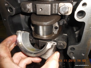
Произведем монтаж ТНВД. Коленвал с распредвалом зафиксированы штифтами. Вал ТНВД должен быть неподвижно зажат фиксирующим болтом.
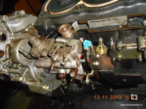
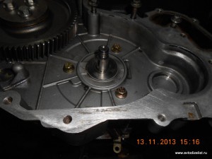
Затягиваем крепеж ТНВД, притягиваем шестерню соответствующим моментом. Вынимаем штифты, распускаем стопор вала ТНВД. Закрываем переднюю крышку, крепим помпу.
Монтируем маслонасос, закрываем масляный поддон, переворачиваем мотор в нормальное положение.
Собираем ГБЦ.
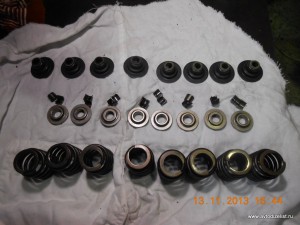
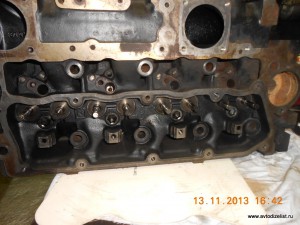
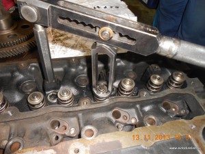
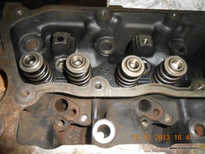
Кладем прокладку и монтируем ГБЦ.
Устанавливаем штанги, ось коромысел. Регулируем тепловой зазор клапанов.
Монтируем свечи накала, топливные форсунки.
Прикручиваем навесное оборудование.
Подсоединяем топливопроводы, запитываем насосы, крутим стартером. Меряем давление масла в системе, прокачиваем топливную аппаратуру, делаем первый запуск.
Специнструменты для демонтажа ТНВД.
Mr Gluhov