-
Contents
-
Table of Contents
-
Bookmarks
Quick Links
Operation and
Maintenance
Manual
4006-23 and 4008-30 Industrial Engines
SD8 (Engine)
SD6 (Engine)
DGBH (Engine)
SEBU9077-01 (en-us)
September 2016
Related Manuals for Perkins 4006-23
Summary of Contents for Perkins 4006-23
-
Page 1
SEBU9077-01 (en-us) September 2016 Operation and Maintenance Manual 4006-23 and 4008-30 Industrial Engines SD8 (Engine) SD6 (Engine) DGBH (Engine) -
Page 2
These changes can affect the service that is given to the product. Obtain the complete and most current information before you start any job. Perkins dealers or Perkins distributors have the most current information available. When replacement parts are required for this product Perkins recommends using Perkins replacement parts. -
Page 3: Table Of Contents
SEBU9077-01 Table of Contents Table of Contents Warranty Section Warranty Information……..83 Foreword …………4 Index Section Safety Section Index…………..84 Safety Messages……….5 General Hazard Information……9 Burn Prevention……….12 Fire Prevention and Explosion Prevention..13 Crushing Prevention and Cutting Prevention.. 15 Mounting and Dismounting ……
-
Page 4: Foreword
Operation Operation and Maintenance Manual except for the interval and the maintenance items in that interval. Major repairs should only be carried out by Perkins Operating techniques outlined in this manual are authorized personnel. Your Perkins dealer or your basic. They assist with developing the skills and…
-
Page 5: Safety Section
Replace any warning sign that is damaged or missing. If a warning sign is attached to a part of the engine that is replaced, install a new warning sign on the replacement part. Your Perkins distributor can provide new warning signs. Illustration 1…
-
Page 6
SEBU9077-01 Safety Section Safety Messages Illustration 2 g06093786 (1) Universal warning label location (6) Rotating shaft hand crush hazard label (3) Hot surface label location location 1 Universal Warning Do not operate or work on this equipment unless you have read and understand the instructions and warnings in the Operation and Maintenance Manuals. -
Page 7
SEBU9077-01 Safety Section Safety Messages The hot surface warning labels (2) are located in two locations. The oil cooler and heat shield of the coolant rail. 4 Hot Fluid Under Pressure Illustration 4 g01393287 Do not use this surface as a step or platform. This surface may not support additional weight or may be slippery. -
Page 8
Ether warning label (4) is on the support bracket for positions. One label is on the end cover of the oil the air cleaners. cooler. Perkins recommends that the other hot fluid under pressure label is installed on the radiator, next 6 Rotating Shaft Hand Crush to the coolant filler cap. -
Page 9: General Hazard Information
SEBU9077-01 Safety Section General Hazard Information The rotating shaft hand crush hazard label (5) is on • Never put maintenance fluids into glass the cover of the crankshaft vibration damper. containers. Glass containers can break. • Use all cleaning solutions with care. i06106934 General Hazard Information •…
-
Page 10
SEBU9077-01 Safety Section General Hazard Information Cautiously remove the following parts. To help • Disconnect the batteries when maintenance is prevent spraying or splashing of pressurized fluids, performed or when the electrical system is hold a rag over the part that is being removed. serviced. -
Page 11
Perkins equipment and replacement parts that are shipped from Perkins engine company limited are The removal of sulfur and other compounds in ultra- asbestos free. Perkins recommends the use of only low sulfur diesel fuel (ULSD fuel) decreases the genuine Perkins replacement parts. Use the following… -
Page 12: Burn Prevention
SEBU9077-01 Safety Section Burn Prevention • Avoid brushing materials that contain asbestos. Always use leakproof containers when you drain fluids. Do not pour waste onto the ground, down a • Avoid grinding materials that contain asbestos. drain, or into any source of water. •…
-
Page 13: Fire Prevention And Explosion Prevention
Personal injury, property damage, or engine damage could result. If the application involves the presence of combustible gases, consult your Perkins dealer and/ or your Perkins distributor for additional information about suitable protection devices. Remove all flammable combustible materials or conductive materials such as fuel, oil, and debris from the engine.
-
Page 14
SEBU9077-01 Safety Section Fire Prevention and Explosion Prevention Illustration 15 g00704059 Illustration 16 g00704135 Use caution when you are refueling an engine. Do Gases from a battery can explode. Keep any open not smoke whilst you are refueling an engine. Do not flames or sparks away from the top of a battery. -
Page 15: Crushing Prevention And Cutting Prevention
Do not install any lines that are damaged. i04257031 Leaks can cause fires. Consult your Perkins distributor for replacement parts. Before Starting Engine Replace the parts if any of the following conditions are present: •…
-
Page 16: Engine Starting
SEBU9077-01 Safety Section Engine Starting Use the Emergency Stop Button (if equipped) ONLY i06545901 in an emergency situation. Do not use the Engine Starting Emergency Stop Button for normal engine stopping. After an emergency stop, DO NOT start the engine until the problem that caused the emergency stop has been corrected.
-
Page 17: Engine Electronics
The laptop computer is connected to the governor via an interface cable. The operating parameters for the governor should only be modified by a trained Perkins representative. Refer to the Special Instruction, “Pandoras Digital Governor” for more information.
-
Page 18: Product Information Section
SEBU9077-01 Product Information Section Model Views Product Information Section Model Views i06681533 Model View Illustrations (Engine Views for the Six and Eight Cylinder 4000 Series Engines) The following model views show typical features of the engine. Due to individual applications, your engine may appear different from the illustrations.
-
Page 19
SEBU9077-01 Product Information Section Engine Views for the Six and Eight Cylinder 4000 Series Engines 4006-23 Engine Views Illustration 17 g06072657 Typical example (1) Twin air cleaners (3) Adjustment housing (5) Belts (2) Crankcase breather (4) Fan hub pulley The major engine differences on six cylinder engine to an eight cylinder engine are shown in illustration 17 . -
Page 20
SEBU9077-01 Product Information Section Engine Views for the Six and Eight Cylinder 4000 Series Engines 4006-23 Radiator Illustration 18 g06072687 Typical example (1) Radiator lifting eyes (3) Radiator (5) Fuel cooler (2) Radiator pressurized filler cap (4) Radiator drain (6) Air charge cooler… -
Page 21
SEBU9077-01 Product Information Section Engine Views for the Six and Eight Cylinder 4000 Series Engines 4008-30 Engine Views Illustration 19 g06004723 Typical example (1) Twin air cleaners (7) Stop solenoid (13) Oil drain location (2) Electronic governor control unit (8) Oil filler cap (14) Oil filters (3) Oil cooler (9) Coolant pump… -
Page 22
SEBU9077-01 Product Information Section Engine Views for the Six and Eight Cylinder 4000 Series Engines Illustration 20 g06004738 Typical example (17) Twin turbochargers (19) Left side rear lifting eye (18) Right side rear lifting eye (20) Crankcase breather… -
Page 23
(3) Radiator (6) Fan belts (9) Fuel cooler i06681623 Engine Description The 4006-23 and the 4008-30 engines are available with turbocharged aftercooled aspiration. The 4006- 23 and the 4008-30 industrial engines are designed as a constant speed engine. Engine Specifications The front end of the engine is opposite the flywheel end of the engine. -
Page 24
SEBU9077-01 Product Information Section Engine Description Table 1 4006-23 Engine Specifications Engine efficiency, efficiency of emission controls, and engine performance depend on adherence to proper Number of cylinders In-line 6 cylinder operation and maintenance recommendations. Engine performance and efficiency also depend on Bore 160 mm (6.29920 inch) -
Page 25: Product Identification Information
Illustration 24 g06016214 Typical example (1) Engine serial number plate Your Perkins distributor needs all the number from the plate when service information is required. Emission Label The emission label (2) is installed on the inlet manifold of the engine.
-
Page 26: Operation Section
Alterations to the lifting eyes and/or the engine make the lifting eyes and the lifting fixtures obsolete. If alterations are made, ensure that correct lifting devices are provided. Consult your Perkins distributor for information regarding fixtures for correct engine lifting.
-
Page 27
SEBU9077-01 Operation Section 4006-23 and 4008-30 Engines Illustration 25 g06006861 Typical example (1) Rear lifting eye (2) Rear lifting eye (3) Front lifting eye Radiator Lifting Only Illustration 26 g06006867 Typical example (1) Radiator lifting eye (2) Radiator lifting eye… -
Page 28
Operation Section Engine Storage i03781209 Engine Storage Refer to Perkins Engine Company Limited, Stafford, ST16 3UB for information on engine storage. There are three different levels of engine storage. Level “A, B and C” . Level “ “ A ” ”… -
Page 29: Features And Controls
SEBU9077-01 Operation Section Features and Controls Features and Controls i06518677 Monitoring System The engine is equipped with sensors or switches to monitor the following parameters: • Coolant temperature • Oil pressure • Intake manifold boost pressure • Engine speed • Engine overspeed The throttle control is also monitored and controlled.
-
Page 30
SEBU9077-01 Operation Section Sensors and Electrical Components Illustration 27 g06006910 Typical example (1) Coolant temperature switch (4) Oil pressure switch (7) Inlet manifold air pressure sensor (2) Stop solenoid (5) Starter relay (8) Electronic governor control unit (3) Alternator (6) Starting motor… -
Page 31
SEBU9077-01 Operation Section Sensors and Electrical Components Illustration 28 g06006921 Typical example (9) Oil pressure switch (10) Overspeed sensor… -
Page 32: Engine Starting
SEBU9077-01 Operation Section Engine Starting Engine Starting The engine is now ready to run. i06521690 i06520585 Starting the Engine Before Starting Engine Normal Engine Starting Procedure Before the engine is started, perform the required daily maintenance and any other periodic maintenance that is due.
-
Page 33: Engine Operation
Fuel Conservation Practices The efficiency of the engine can affect the fuel economy. Perkins design and technology in manufacturing provides maximum fuel efficiency in all applications. Follow the recommended procedures in order to attain optimum performance for the life of the engine.
-
Page 34: Engine Stopping
SEBU9077-01 Operation Section Engine Stopping Engine Stopping • Check the crankcase oil level. Maintain the oil level between the “MIN” mark and the “MAX” mark on the engine oil level gauge. i02415227 • If necessary, perform minor adjustments. Repair Stopping the Engine any leaks from the low pressure fuel system and from the cooling, lubrication or air systems.
-
Page 35: Maintenance Section
• Overheating of the engine Cooling System • Foaming of the coolant Table 4 NOTICE 4006-23 Engine and Engine with Radiator Never operate an engine without water temperature regulators in the cooling system. Water temperature Engine Only 36 L (9.5 US gal) regulators help to maintain the engine coolant at the proper operating temperature.
-
Page 36
Table 6 • Cavitation of the water pump Table 6 For optimum performance, Perkins recommends a 1:1 mixture of a water/glycol solution. Acceptable Water Note: Use a mixture that will provide protection… -
Page 37
Extended Life Coolant contains organic corrosion inhibitors and antifoam • SCA Supplement Coolant Additive agents with low amounts of nitrite. Perkins ELC has been formulated with the correct amount of these additives to provide superior corrosion protection for • ASTM American Society for Testing and all metals in engine cooling systems. -
Page 38
Check the antifreeze (glycol concentration) to ensure adequate protection against boiling or freezing. 6. Fill the cooling system with the Perkins Premixed Perkins recommends the use of a refractometer for checking the glycol concentration. A hydrometer ELC. Operate the engine. Ensure that all coolant should not be used. -
Page 39
Table 13 is an example for using the equation that is in Table 12 . NOTICE Every attempt is made to provide accurate, up-to- date information. By use of this document you agree that Perkins Engines Company Limited is not respon- sible for errors or omissions. -
Page 40
The fuel must meet the minimum requirements that are stated in Table 14 . NOTICE The footnotes are a key part of the Perkins Specifica- tion for Distillate Diesel Fuel Table. Read ALL of the footnotes. Table 14… -
Page 41
Note: The owner and the operator of the engine has NOTICE the responsibility of using the fuel that is prescribed Operating with fuels that do not meet the Perkins rec- by the Environmental Protection Agency (EPA) and ommendations can cause the following effects: Start- other appropriate regulatory agencies. -
Page 42
15 °C (59 °F). NOTICE The fuels system has been qualified with fuel having Perkins recommends a value of density of 841 kg/m3 lubricity up to 0.46 mm (0.01811 inch) wear scar di- to obtain the correct power output. Lighter fuels are ameter as tested by “ISO 12156-1”. -
Page 43
• “MIL-DTL-38219 (USAF) (JP7)” requirement appropriate lubricity additive can be • “NATO XF63” used to enhance the lubricity of the fuel. Perkins Diesel Fuel Conditioner is the approved additive refer • “ASTM D1655 JET A” to “Perkins Diesel Fuel Conditioner”. -
Page 44
Protection Agency (EPA) and European Certification biodiesel or biodiesel blends is related to the fuels. Perkins does not certify engines on any other typically lower volatility of biodiesel. In cylinder fuel. The user of the engine has the responsibility of… -
Page 45
If biodiesel or biodiesel blends of fuel are to be used, fuels. Perkins require the use of Perkins fuel cleaner. For more information on the use of biodiesel and biodiesel blends refer to “Biodiesel Fuel”. -
Page 46
500 ppm water or less. • Perkins recommends the use of bulk fuel filter / coalescer units which clean the fuel of both particulate contamination and water in a single… -
Page 47
“EMA Recommended Guideline on Diesel Engine promotes the delivery of clean fuel. Fuel filtration Oil”. In addition to Perkins definitions, there are other can be installed at each transport stage to keep definitions that will be of assistance in purchasing the fuel clean. -
Page 48
SEBU9077-01 Maintenance Section Engine Oil Specification Table 15 Minimum Oil Specification for 4008-30 and the 4006-23 Industrial Engines Preferred Oil Specification API CI-4 ECF-2 Minimum Oil Specification API CH-4 ECF 1 Lubricant Viscosity Recommendations Aftermarket Oil Additives for Direct Injection (DI) Diesel Engines Perkins does not recommend the use of aftermarket additives in oil. -
Page 49
SEBU9077-01 Maintenance Section Engine Oil Specification • The Wear Rate Analysis monitors the wear of the engines metals. The amount of wear metal and type of wear metal that is in the oil is analyzed. The increase in the rate of engine wear metal in the oil is as important as the quantity of engine wear metal in the oil. -
Page 50: Maintenance Interval Schedule
SEBU9077-01 Maintenance Section Maintenance Interval Schedule “ Belts — Inspect/Adjust/Replace”….55 i06682467 Maintenance Interval Schedule “ Belts — Inspect/Adjust/Replace”….56 “…
-
Page 51: Alternator Pulley — Check
Make repairs, if necessary. i02322311 Alternator — Inspect Perkins recommends a scheduled inspection of the alternator. Inspect the alternator for loose connections and correct battery charging. Check the ammeter (if equipped) during engine operation in order to ensure correct battery performance and/or correct performance of the electrical system.
-
Page 52: Battery — Replace
SEBU9077-01 Maintenance Section Battery — Replace i02322315 i02747977 Battery — Replace Battery Electrolyte Level — Check When the engine is not run for long periods of time or when the engine is run for short periods, the batteries Batteries give off combustible gases which can explode.
-
Page 53: Battery Or Battery Cable — Disconnect
SEBU9077-01 Maintenance Section Battery or Battery Cable — Disconnect Inspection i02323088 Battery or Battery Cable — 1. Isolate the electrical supply to the engine. Disconnect 2. Visible inspect fan guards for ware or damage. Repair as necessary. The battery cables or the batteries should not be removed with the battery cover in place.
-
Page 54
SEBU9077-01 Maintenance Section Fan Drive Belts for 4008-30 Only 4. Inspect the belts (1) for cracks. Inspect the belts 5. Ensure that the electrical supply to the engine is for contamination. If necessary, replace the belts. isolated. Install the guards. Refer to “Replacement”… -
Page 55: Belts — Inspect/Adjust/Replace
Repair as necessary. Remove the fan guards (1). Belts — Inspect/Adjust/Replace 3. Inspect the belts for cracks, splits, glazing, grease, displacement of the cord and evidence of fluid (4006-23 Engine Only) contamination. If necessary, replace the belts, refer to “Replace” for more information. S/N: SD61–Up…
-
Page 56: Belts — Inspect/Adjust/Replace
SEBU9077-01 Maintenance Section Belts — Inspect/Adjust/Replace 8. Install guards (1) and restore electrical power to the engine. Replace Refer to “Disassembly and Assembly Manual”V-Belts (Fan Drive V-Belts) — Remove and Install for more information. i06729752 Belts — Inspect/Adjust/Replace (Alternator Belt) Inspection 1.
-
Page 57
SEBU9077-01 Maintenance Section Alternator Belt Illustration 40 g01239310 4. Apply 15.6 N (3.5 lb) of pressure at point (X). The total deflection should not exceed 1.5 mm (0.06 inch). Replace the belt if the total deflection exceeds Illustration 41 g06018464 1.5 mm (0.06 inch). -
Page 58: Cooling System Coolant (Elc) — Change
SEBU9077-01 Maintenance Section Cooling System Coolant (ELC) — Change Drain 5. Install the guards and restore the electrical supply to the engine. i06729765 Pressurized System: Hot coolant can cause seri- Cooling System Coolant (ELC) ous burns. To open the cooling system filler cap, stop the engine and wait until the cooling system — Change components are cool.
-
Page 59
The full distil- 2. Fill the cooling system with Perkins (ELC). Refer to lation procedure is the only method acceptable by the Operation and Maintenance Manual, “Fluid Perkins to reclaim the coolant. -
Page 60: Cooling System Coolant Level — Check
2. Maintain the coolant level within 25 mm (1.0 inch) of the bottom of the filler pipe. Cooling System Coolant Extender (ELC) — Add For Perkins ELC to achieve 12000 hours an extender must be added at 6000 hours. For a suitable extender, contact your Perkins distributor. i02415245…
-
Page 61: Engine — Clean
SEBU9077-01 Maintenance Section Driven Equipment — Check Inspect the dampers for signs of damage, fluid NOTICE leakage, or heat discoloration. Failure to protect some engine components from washing may make your engine warranty invalid. Al- For more information on inspection the vibration low the engine to cool for 1 hour before washing the dampers, refer to Systems Operation Testing and engine.
-
Page 62: Engine Air Cleaner Service Indicator — Inspect
Illustration 49 g06073787 4008-30 1. Both the end caps (6) on the 4006-23 engine are secured by one central nut (5). Ensure that both 1. Isolate the electrical supply to the engine. filter elements (not shown) are replaced at the 2.
-
Page 63: Engine Crankcase Breather — Clean
If the service indicator does not reset easily, the service indicator should be replaced. Note: The service indicator may need to be replaced frequently in environments that are severely dusty. i06682477 Engine Crankcase Breather — Clean (4006-23 Engine Only) S/N: SD61–Up…
-
Page 64: Engine Crankcase Breather — Clean
Maintenance Section Engine Crankcase Breather — Clean Note: The maintenance and maintenance period for i06682626 the 4006-23 engine is different from the maintenance Engine Crankcase Breather — and maintenance period for the 4008-30 engine. Clean 1. Isolate the electrical supply to the engine.
-
Page 65: Engine Oil Level — Check
SEBU9077-01 Maintenance Section Engine Mounts — Inspect i02415257 Engine Mounts — Inspect Misalignment of the engine and the driven equipment will cause extensive damage. Excessive vibration can lead to misalignment. Excessive vibration of the engine and the driven equipment can be caused by the following conditions: •…
-
Page 66: Engine Oil Sample — Obtain
Hot oil and hot components can cause personal develop a service program for the engine. injury. Do not allow hot oil or hot components to contact the skin. Note: Perkins Engines Stafford must agree to the maintenance schedule. NOTICE Obtain the Sample and the…
-
Page 67
SEBU9077-01 Maintenance Section Engine Oil and Filter — Change Failure to follow this recommended procedure will 3. Install a new sealing washer to the drain plug (3). cause the waste particles to be recirculated through Install the drain plug to the engine oil pan. Tighten the engine lubrication system with the new oil. -
Page 68: Engine Valve Lash — Inspect/Adjust
Refer to the Service Manual or your au- oil level. Maintain the oil level between the “MIN” thorized Perkins dealer or your Perkins distributor for and “MAX” marks on the engine oil level gauge. the complete valve lash adjustment procedure.
-
Page 69: Fuel System — Prime
Perkins distributor for the complete proce- dure in order to inspect or adjust the fuel injectors. Operation of Perkins engines with fuel injectors that have not been inspected or adjusted can reduce en- gine efficiency, and also reduce engine component life.
-
Page 70: Fuel System Filter — Replace
SEBU9077-01 Maintenance Section Fuel System Filter — Replace Illustration 61 g06010017 1. Ensure that there is an adequate level of fuel in the NOTICE fuel tank. If equipped, ensure that the fuel supply Ensure that the engine is stopped and the battery is valve is in the ON position.
-
Page 71: Fuel Tank Water And Sediment — Drain
SEBU9077-01 Maintenance Section Fuel System Primary Filter/Water Separator — Drain NOTICE Ensure that the engine is stopped before any servic- ing or repair is performed. NOTICE The water separator can be under suction during nor- mal engine operation. Ensure that the drain valve is tightened securely to help prevent air from entering the fuel system.
-
Page 72: Fuel Transfer Pump (Lift Pump) — Inspect
SEBU9077-01 Maintenance Section Fuel Transfer Pump (Lift Pump) — Inspect Fuel Tank If a bulk storage tank has been refilled or moved recently, allow adequate time for the sediment to Fuel quality is critical to the performance and to the settle before filling the engine fuel tank.
-
Page 73: Hoses And Clamps — Inspect/Replace
The coolant system and the hoses for the coolant Contact with high pressure fuel may cause fluid system are not usually supplied by Perkins. The penetration and burn hazards. High pressure fuel following text describes a typical method of replacing spray may cause a fire hazard.
-
Page 74
SEBU9077-01 Maintenance Section Hoses and Clamps — Inspect/Replace Pressurized System: Hot coolant can cause seri- ous burns. To open the cooling system filler cap, stop the engine and wait until the cooling system components are cool. Loosen the cooling system pressure cap slowly in order to relieve the pressure. -
Page 75
SEBU9077-01 Maintenance Section Hoses and Clamps — Inspect/Replace 10. Start the engine. Inspect the cooling system for leaks. Clamps and V-Band Locations Illustration 65 g06117407 (1) Clamp torque 7 N·m (62 lb in) -
Page 76
SEBU9077-01 Maintenance Section Hoses and Clamps — Inspect/Replace Illustration 66 g06117430 (1) Clamp torque 7 N·m (62 lb in) (2) Clamp torque 9 N·m (79 lb in) (3) Clamp torque 10 N·m (88 lb in) -
Page 77: Overhaul (Major)
Monitor the engine as the engine accumulates Scheduling a Major Overhaul service hours. Consult Perkins Engines Stafford about scheduling a major overhaul. The need for a major overhaul is determined by several factors: •…
-
Page 78: Overhaul (Top End)
SEBU9077-01 Maintenance Section Overhaul (Top End) Note: The driven equipment may also require service Note: Generally, cylinder heads wear out at different when the engine is overhauled. Refer to the literature rates. Sometimes, servicing the cylinder heads at that is provided by the OEM of the driven equipment. different times may be the most economic decision.
-
Page 79: Severe Service Application — Check
Hold the nozzle approximately 6 mm service life. (0.25 inch) away from the radiator fins. Slowly move Perkins engines are unable to identify all the factors the air nozzle in a direction that is parallel with the which can contribute to severe service operation, due radiator tube assembly.
-
Page 80: Speed Sensor — Clean/Inspect
SEBU9077-01 Maintenance Section Speed Sensor — Clean/Inspect cold temperatures. Extremely hot intake air reduces 1. Isolate the electrical supply to the engine. engine performance. Quality of the air – The engine may be exposed to extended operation in an environment that is dirty or dusty, unless the equipment is cleaned regularly.
-
Page 81: Walk-Around Inspection
SEBU9077-01 Maintenance Section Starting Motor — Inspect Inspect the starting motors for proper operation. Listen for grinding when the engine is started. Inspect the teeth of the starting motor pinions and the flywheel ring gear. Look for patterns of wear on the teeth.
-
Page 82: Water Pump — Inspect
Excessive coolant leakage may indicate the need to replace a water pump. Refer to Operation and Maintenance Manual, “Water Pump — Inspect” for more information. If necessary, consult your Perkins dealer or your Perkins distributor. • Inspect the lubrication system for leaks at the front crankshaft seal, the rear crankshaft seal, the oil pan, the oil filters and the rocker cover.
-
Page 83: Warranty Section
This engine may be covered by an Emissions Warranty. Consult your authorized Perkins dealer or distributor to determine if your engine is emissions certified and if your engine is subject to an Emissions…
-
Page 84: Index
Engine Specifications ……..23 Adjustment……….. 57 Engine Electronics……….. 17 Inspection ………… 56 System Description……..17 Replacement……….57 Engine Lifting (4006-23 and 4008-30 Belts — Inspect/Adjust/Replace (Fan Drive Engines) …………26 Belts for 4008-30 Only)……..53 Engine Lifting Only……..26 Adjustment……….. 54 Radiator Lifting Only ……..
-
Page 85
Six and Eight Cylinder 4000 Series Fuel Tank Water and Sediment — Drain … 71 Engines) …………18 Drain the Water and the Sediment ….72 4006-23 Engine Views……… 19 Fuel Storage Tanks……..72 4008-30 Engine Views……… 21 Fuel Tank …………. 72 4008-30 Radiator ……… -
Page 86
SEBU9077-01 Index Section Scheduling a Major Overhaul …… 77 Water Pump — Inspect……..82 Overhaul (Top End) ……… 78 Scheduling a Top End Overhaul ….78 Top End Overhaul Information….. 78 Plate Locations and Film Locations ….25 Emission Label ……….25 Product Identification Information …. -
Page 87
Product and Dealer Information Note: For product identification plate locations, see the section “Product Identification Information” in the Operation and Maintenance Manual. Delivery Date: Product Information Model: Product Identification Number: Engine Serial Number: Transmission Serial Number: Generator Serial Number: Attachment Serial Numbers: Attachment Information: Customer Equipment Number: Dealer Equipment Number:… -
Page 88
©2016 Perkins Engines Compony Limited All Rights Reserved September 2016…
This manual is also suitable for:
4008-30
1 Основная мощность (Prime power) – номинальная мощность (при 1500 об./м) для непрерывной работы дизельного двигателя Perkins 4006-23TAG3A при различных нагрузках в соответствии с ISO 8528-1. Maкс. средний фактор нагрузки — 80% от указанной основной мощности за каждый 24-х часовой интервал. 1 час в течение каждого 12 часового интервала допускается нагрузка до 110% основной мощности.
2 Резервная мощность (Stand-by power) — для работы дизельного двигателя Perkins 4006-23TAG3A при нормальном изменении нагрузки в течение перерыва подачи электроэнергии в соответствии с ISO 8528-1. Годовая наработка не должна превышать 500 моточасов, 300 из которых ДЭС может использоваться в непрерывном режиме. Перегрузки недопустимы.
3 Удельный расход топлива указан при плотности дизельного топлива 0,84 кг/л.
4 Объем системы жидкостного охлаждения двигателя Perkins 4006-23TAG3A указан с учетом радиатора, патрубков и расширительного бачка.
5 Период замены моторного масла в зависимости от условий эксплуатации двигателя Perkins 4006-23TAG3A (например, при повышенной загрязненности окружающего воздуха) может снижаться – обязательно проверяйте рекомендации производителя двигателя по периодичности проведения ТО.
6 Оборудование дизельного двигателя Perkins 4006-23TAG3A приводится в объеме, устанавливаемом ООО «Компания Дизель» в составе готовой дизельной электростанции. Комплектация двигателя Perkins 4006-23TAG3A, поставляемого производителем, может отличаться.

Характеристики
Двигатель
Кол-во и расположение цилиндров
6-рядное
Рабочие характеристики
Расход топлива при 50% мощности
90 л/ч
Расход топлива при 75% мощности
130 л/ч
Расход топлива при 100% мощности
172 л/ч
Стационарная электростанция MGE Perkins предназначена для обеспечения электричеством крупных промышленных объектов. Подходит для питания заводов, складских помещений и офисных зданий. Поставляется в открытом исполнении. Отличается высокой производительностью и крепкой конструкцией.
Модель работает от дизельного шестицилиндрового двигателя мощностью 640 кВт. Имеет электрический запуск. Синхронный альтернатор Stamford вырабатывает ток 220/380 В 50 Гц. Заправлена антифризом и маслом с завода. Контроллер DSE 7320 с ЖК дисплеем позволяет детально настроить работу системы.
Особенности
Экономичный и надежный двигатель Perkins
Трёхфазный синхронный генератор Stamford
Мультиязычный контроллер
Технические характеристики MGE Perkins 4006-23TAG3A 640 кВт откр.
Двигатель
Кол-во и расположение цилиндров
6-рядное
Рабочие характеристики
Расход топлива при 50% мощности
90 л/ч
Расход топлива при 75% мощности
130 л/ч
Расход топлива при 100% мощности
172 л/ч
Отзывы на Дизельный генератор MGE Perkins 4006-23TAG3A 640 кВт откр.
 Loading…
![]()
Perkins 4000 Series
4006-23 TAG1A, TAG2A and TAG3A Inline diesel engine
WORKSHOP MANUAL
6 cylinder turbo charged diesel engine for electric power applications
Publication TPD 1511E, Issue 1.
© Proprietary information of Perkins Engines Company Limited, all rights reserved. The information is correct at the time of print.
Published in September 2004 by Technical Publications.
Perkins Engine Company Limited, Peterborough PE1 5NA England
i

This publication is written in
Perkins Approved Clear English
Chapters
1General information
2Specifications
3Cylinder head assembly
4Piston and connecting rod assemblies
5Crankshaft assembly
6Timing case and drive assembly
7Cylinder block assembly
8Engine timing
9Aspiration system
10Lubrication system
11Fuel system
12Cooling system
13Flywheel and housing
14Electrical equipment
15Auxiliary equipment
16Special tools
The following pages contain a detailed table of contents
ii

4000 Series
Contents
1 General information
Introduction .. … … … … … … … … … … … … … … … … … … … … … … … … … … … … … … … … … … … 1
Engine views … … … … … … … … … … … … … … … … … … … … … … … … … … … … … … … … … … … 2
Engine identification . … … … … … … … … … … … … … … … … … … … … … … … … … … … … … … … 3
General safety precautions … … … … … … … … … … … … … … … … … … … … … … … … … … … … 4
Viton seals . … … … … … … … … … … … … … … … … … … … … … … … … … … … … … … … … … … … … 5
Engine lift equipment … … … … … … … … … … … … … … … … … … … … … … … … … … … … … … … 6
POWERPART recommended consumable products … … … … … … … … … … … … … … … … 7
2 Specifications
Basic engine data . … … … … … … … … … … … … … … … … … … … … … … … … … … … … … … … … 9
Data and dimensions … … … … … … … … … … … … … … … … … … … … … … … … … … … … … … .. 10
3 Cylinder head assembly
General description … … … … … … … … … … … … … … … … … … … … … … … … … … … … … … … .. 17
Rocker box and valve gear
Operation 3-1 To remove and fit the rocker box and valve gear … … … … … … … … … … … .. 18
Valve gear
Operation 3-2 To inspect rockers, bridge pieces and rocker shaft … … … … … … … … … … .. 20
|
Workshop Manual, TPD 1511E, issue 1 |
iii |

4000 Series
Operation 3-3 To replace the bridge piece pressure pad .. … … … … … … … … … … … … … … 21
Cylinder head
Operation 3-4 To remove and fit the cylinder head . … … … … … … … … … … … … … … … … … 22
Valves and springs
Operation 3-5 To remove and fit the valve and the valve springs .. … … … … … … … … … … 24
Operation 3-6 To inspect . … … … … … … … … … … … … … … … … … … … … … … … … … … … … … 26
Valves seats
Operation 3-7 To remove and fit, and reface the valve seats .. … … … … … … … … … … … … 27
Valves guides
Operation 3-8 To remove and fit the valve guides … … … … … … … … … … … … … … … … … … 28
Fuel injector bush
Operation 3-9 To remove and fit a fuel injector bush .. … … … … … … … … … … … … … … … … 29
Cylinder head
Operation 3-10 To inspect and pressure test … … … … … … … … … … … … … … … … … … … … 33
Manifolds
Operation 3-11 To remove and fit the induction manifold . … … … … … … … … … … … … … … 34
Operation 3-12 To remove and fit the exhaust manifold … … … … … … … … … … … … … … … 35
4 Piston and connecting rod assemblies
General description . … … … … … … … … … … … … … … … … … … … … … … … … … … … … … … … 39
Piston and connecting rod
Operation 4-1 To remove … … … … … … … … … … … … … … … … … … … … … … … … … … … … … 40 Operation 4-2 To fit … … … … … … … … … … … … … … … … … … … … … … … … … … … … … … … … 43
Piston rings
Operation 4-3 To remove … … … … … … … … … … … … … … … … … … … … … … … … … … … … … 45 Operation 4-4 To fit … … … … … … … … … … … … … … … … … … … … … … … … … … … … … … … … 46
Piston and connecting rod assembly
Operation 4-5 To dismantle Operation 4-6 To assemble
… … … … … … … … … … … … … … … … … … … … … … … … … … … … 47
… … … … … … … … … … … … … … … … … … … … … … … … … … … … 47
Piston and piston rings
Operation 4-7 To inspect . … … … … … … … … … … … … … … … … … … … … … … … … … … … … … 49
Connecting rod
Operation 4-8 To inspect . … … … … … … … … … … … … … … … … … … … … … … … … … … … … … 50
|
iv |
Workshop Manual, TPD 1511E, issue 1 |

4000 Series
Small end bush
Operation 4-9 To inspect .. … … … … … … … … … … … … … … … … … … … … … … … … … … … … .. 51 Operation 4-10 To remove and fit .. … … … … … … … … … … … … … … … … … … … … … … … … .. 51
Piston cooling jets
Operation 4-11 To remove .. … … … … … … … … … … … … … … … … … … … … … … … … … … … .. 52 Operation 4-12 To fit .. … … … … … … … … … … … … … … … … … … … … … … … … … … … … … … .. 53
5 Crankshaft assembly
General description … … … … … … … … … … … … … … … … … … … … … … … … … … … … … … … .. 55
Crankshaft pulley and adaptor
Operation 5-1 To remove .. … … … … … … … … … … … … … … … … … … … … … … … … … … … … .. 56 Operation 5-2 To fit . … … … … … … … … … … … … … … … … … … … … … … … … … … … … … … … .. 57
Crankshaft vibration damper assembly
Operation 5-3 To remove .. … … … … … … … … … … … … … … … … … … … … … … … … … … … … .. 58 Operation 5-4 To fit . … … … … … … … … … … … … … … … … … … … … … … … … … … … … … … … .. 59
Crankshaft
Operation 5-5 To remove … … … … … … … … … … … … … … … … … … … … … … … … … … … … .. 60 Operation 5-6 To fit . … … … … … … … … … … … … … … … … … … … … … … … … … … … … … … … .. 61 Operation 5-7 To check the crankshaft end float … … … … … … … … … … … … … … … … … … .. 63
6 Gearcase and drive assembly
General description … … … … … … … … … … … … … … … … … … … … … … … … … … … … … … … .. 65
Gearcase
Operation 6-1 To remove .. … … … … … … … … … … … … … … … … … … … … … … … … … … … … .. 66 Operation 6-2 To fit . … … … … … … … … … … … … … … … … … … … … … … … … … … … … … … … .. 67
Front oil seal
Operation 6-3 To remove .. … … … … … … … … … … … … … … … … … … … … … … … … … … … … .. 68 Operation 6-4 To fit . … … … … … … … … … … … … … … … … … … … … … … … … … … … … … … … .. 68
Camshaft gear
Operation 6-5 To remove .. … … … … … … … … … … … … … … … … … … … … … … … … … … … … .. 69 Operation 6-6 To fit . … … … … … … … … … … … … … … … … … … … … … … … … … … … … … … … .. 70
Idler gear
Operation 6-7 To remove .. … … … … … … … … … … … … … … … … … … … … … … … … … … … … .. 71 Operation 6-8 To fit . … … … … … … … … … … … … … … … … … … … … … … … … … … … … … … … .. 72
Operation 6-9 To check the hub and renew the idler gear bush … … … … … … … … … … … .. 73
|
Workshop Manual, TPD 1511E, issue 1 |
v |

4000 Series
Cam followers
Operation 6-10 To remove and fit . … … … … … … … … … … … … … … … … … … … … … … … … … 74 Operation 6-11 To check … … … … … … … … … … … … … … … … … … … … … … … … … … … … … 75
Camshaft
Operation 6-12 To remove .. … … … … … … … … … … … … … … … … … … … … … … … … … … … … 76 Operation 6-13 To check the camshaft .. … … … … … … … … … … … … … … … … … … … … … … 77 Operation 6-14 To fit . … … … … … … … … … … … … … … … … … … … … … … … … … … … … … … … 78 Operation 6-15 To remove and fit the camshaft bush … … … … … … … … … … … … … … … … 79
Crankshaft gear
Operation 6-16 To remove .. … … … … … … … … … … … … … … … … … … … … … … … … … … … … 80 Operation 6-17 To fit . … … … … … … … … … … … … … … … … … … … … … … … … … … … … … … … 81
Back Plate
Operation 6-18 To remove .. … … … … … … … … … … … … … … … … … … … … … … … … … … … … 82 Operation 6-19 To fit . … … … … … … … … … … … … … … … … … … … … … … … … … … … … … … … 83
7 Crankcase
General Description . … … … … … … … … … … … … … … … … … … … … … … … … … … … … … … … 85
Crankcase
Operation 7-1 To remove … … … … … … … … … … … … … … … … … … … … … … … … … … … … … 86 Operation 7-2 To fit … … … … … … … … … … … … … … … … … … … … … … … … … … … … … … … … 87 Operation 7-3 To inspect . … … … … … … … … … … … … … … … … … … … … … … … … … … … … … 87
Cylinder Liner
Operation 7-4 To inspect . … … … … … … … … … … … … … … … … … … … … … … … … … … … … … 88 Operation 7-5 To remove … … … … … … … … … … … … … … … … … … … … … … … … … … … … … 89 Operation 7-6 To fit liner .. … … … … … … … … … … … … … … … … … … … … … … … … … … … … … 90
8 Engine timing
Operation 8-1 To set number 1 piston to Top Dead Centre (TDC) … … … … … … … … … … 91
Operation 8-2 Calibrating fuel injectors .. … … … … … … … … … … … … … … … … … … … … … … 92 Operation 8-3 Setting governor on zero fuel . … … … … … … … … … … … … … … … … … … … … 94 Operation 8-4 Applying pressure to the timing pin .. … … … … … … … … … … … … … … … … … 95 Operation 8-5 Timing the fuel injectors … … … … … … … … … … … … … … … … … … … … … … … 96
9 Aspiration system
General description . … … … … … … … … … … … … … … … … … … … … … … … … … … … … … … … 99
|
vi |
Workshop Manual, TPD 1511E, issue 1 |

4000 Series
How to check the air restriction indicator
Operation 9-1 To check and reset . … … … … … … … … … … … … … … … … … … … … … … … … 100
Air filter element
|
Operation 9-2 To remove and fit … … … … … … … … … … … … … … … … … … … … … … … … … |
101 |
Air filter and pipe connection
Operation 9-3 To remove .. … … … … … … … … … … … … … … … … … … … … … … … … … … … … 102 Operation 9-4 To fit . … … … … … … … … … … … … … … … … … … … … … … … … … … … … … … … 103
Air filter bracket
Operation 9-5 To remove .. … … … … … … … … … … … … … … … … … … … … … … … … … … … … 104 Operation 9-6 To fit . … … … … … … … … … … … … … … … … … … … … … … … … … … … … … … … 104
|
Turbocharger |
… |
… … … … … … … … … … … … … … … … … … … … … … … … … … … … … … … … … |
105 |
|
Operation 9-7 |
To remove … … … … … … … … … … … … … … … … … … … … … … … … … … … … |
106 |
|
|
Operation 9-8 |
To fit … … … … … … … … … … … … … … … … … … … … … … … … … … … … … … … |
108 |
|
|
Air pipe connection |
|||
|
Operation 9-9 |
To remove … … … … … … … … … … … … … … … … … … … … … … … … … … … … |
110 |
|
|
Operation 9-10 |
To fit . … … … … … … … … … … … … … … … … … … … … … … … … … … … … … … |
111 |
|
|
Engine breather |
|||
|
Operation 9-11 |
To remove breather system … … … … … … … … … … … … … … … … … … … … |
112 |
|
|
Operation 9-12 |
To fit the breather system … … … … … … … … … … … … … … … … … … … … … |
113 |
10 Lubrication system
|
General Description .. … … … … … … … … … … … … … … … … … … … … … … … … … … … … … … |
115 |
Filter Canister
Operation 10-1 To renew .. … … … … … … … … … … … … … … … … … … … … … … … … … … … … 117
Filter head
Operation 10-2 To remove and to fit . … … … … … … … … … … … … … … … … … … … … … … … 118
|
Lubricating oil sump |
||
|
Operation 10-3 |
To remove … … … … … … … … … … … … … … … … … … … … … … … … … … … … |
119 |
|
Operation 10-4 |
To fit .. … … … … … … … … … … … … … … … … … … … … … … … … … … … … … … |
120 |
|
Dipstick tube |
||
|
Operation 10-5 |
To remove and to fit . … … … … … … … … … … … … … … … … … … … … … … … |
121 |
Oil strainer and suction pipe
Operation 10-6 To remove and to fit . … … … … … … … … … … … … … … … … … … … … … … … 122
|
Workshop Manual, TPD 1511E, issue 1 |
vii |

4000 Series
Lubricating oil pump
Operation 10-7 To remove .. … … … … … … … … … … … … … … … … … … … … … … … … … … … .. 123 Operation 10-8 To fit . … … … … … … … … … … … … … … … … … … … … … … … … … … … … … … ..124 Operation 10-9 To dismantle . … … … … … … … … … … … … … … … … … … … … … … … … … … ..125 Operation 10-10 To assemble … … … … … … … … … … … … … … … … … … … … … … … … … … .. 126 Operation 10-11 To inspect … … … … … … … … … … … … … … … … … … … … … … … … … … … .. 128
Relief Valve
Operation 10-12 To dismantle and to assemble .. … … … … … … … … … … … … … … … … … .. 129 Operation 10-13 To inspect … … … … … … … … … … … … … … … … … … … … … … … … … … … .. 130
Fuel lift pump drive unit
Operation 10-14 To renew .. … … … … … … … … … … … … … … … … … … … … … … … … … … … .. 131
Rotor end float
Operation 10-15 To inspect … … … … … … … … … … … … … … … … … … … … … … … … … … … .. 132
Drive shaft bearings
Operation 10-16 To remove and to fit . … … … … … … … … … … … … … … … … … … … … … … .. 133
11 Fuel system
General description . … … … … … … … … … … … … … … … … … … … … … … … … … … … … … … ..135
Fuel filter
Operation 11-1 To remove and fit . … … … … … … … … … … … … … … … … … … … … … … … … ..136
Fuel injector unit
Operation 11-2 To remove the fuel injector unit .. … … … … … … … … … … … … … … … … … .. 137
Operation 11-3 To disassemble and to check a fuel injector unit … … … … … … … … … … .. 139
Operation 11-4 To assemble the fuel injector unit … … … … … … … … … … … … … … … … … ..143
To test and set the fuel injector
Operation 11-5 To test and set … … … … … … … … … … … … … … … … … … … … … … … … … ..146 Operation 11-6 To fit a fuel injector .. … … … … … … … … … … … … … … … … … … … … … … … .. 151
Fuel Lift pump
Operation 11-7 To remove and to fit … … … … … … … … … … … … … … … … … … … … … … … ..152
Fuel control shaft
Operation 11-8 To remove .. … … … … … … … … … … … … … … … … … … … … … … … … … … … .. 153 Operation 11-9 To inspect .. … … … … … … … … … … … … … … … … … … … … … … … … … … … .. 154 Operation 11-10 To fit .. … … … … … … … … … … … … … … … … … … … … … … … … … … … … … ..155
|
viii |
Workshop Manual, TPD 1511E, issue 1 |

4000 Series
12 Cooling system
Coolant pipework
Operation 12-1 To remove and fit the coolant pipework . … … … … … … … … … … … … … … 158
|
Thermostat |
||
|
Operation 12-2 |
To remove the thermostat .. … … … … … … … … … … … … … … … … … … … … |
159 |
|
Operation 12-3 |
To fit the thermostat . … … … … … … … … … … … … … … … … … … … … … … … |
160 |
|
Operation 12-4 |
To test . … … … … … … … … … … … … … … … … … … … … … … … … … … … … … |
161 |
Thermostat housing
Operation 12-5 To remove and fit the thermostat housing . … … … … … … … … … … … … … 162
Coolant pump
Operation 12-6 To remove the coolant pump . … … … … … … … … … … … … … … … … … … … 164 Operation 12-7 To fit the coolant pump … … … … … … … … … … … … … … … … … … … … … … 166 Operation 12-8 To disassemble the coolant pump … … … … … … … … … … … … … … … … … 168 Operation 12-9 To assemble the coolant pump . … … … … … … … … … … … … … … … … … … 169
Fan Guards
Operation 12-10 To remove and fit
Fan
Operation 12-11 To remove and fit
… … … … … … … … … … … … … … … … … … … … … … … … 171
… … … … … … … … … … … … … … … … … … … … … … … … 171
Fan drive belts
Operation 12-12 To check the fan drive belts . … … … … … … … … … … … … … … … … … … … 172 Operation 12-13 To adjust the fan drive belts … … … … … … … … … … … … … … … … … … … 172 Operation 12-14 To remove and fit the drive belts … … … … … … … … … … … … … … … … … 173
|
Fan drive |
|
|
Operation 12-15 To remove and fit … … … … … … … … … … … … … … … … … … … … … … … … |
174 |
|
Lubricating oil cooler |
|
|
Operation 12-16 To remove … … … … … … … … … … … … … … … … … … … … … … … … … … … |
176 |
|
Operation 12-17 To fit … … … … … … … … … … … … … … … … … … … … … … … … … … … … … … |
177 |
|
Operation 12-18 To disassemble and clean the oil cooler tube stack . … … … … … … … … |
178 |
|
Operation 12-19 To assemble the oil cooler tube stack .. … … … … … … … … … … … … … … |
179 |
|
Operation 12-20 To pressure test the oil cooler … … … … … … … … … … … … … … … … … … |
180 |
|
Radiator |
|
|
Operation 12-21 To remove … … … … … … … … … … … … … … … … … … … … … … … … … … … |
181 |
|
Operation 12-22 To fit … … … … … … … … … … … … … … … … … … … … … … … … … … … … … … |
182 |
|
Workshop Manual, TPD 1511E, issue 1 |
ix |

4000 Series
13 Flywheel and housing
General description . … … … … … … … … … … … … … … … … … … … … … … … … … … … … … … ..183
Flywheel
Operation 13-1 To remove and to fit the flywheel … … … … … … … … … … … … … … … … … .. 184
Gear ring
Operation 13-2 To remove and to fit the gear ring .. … … … … … … … … … … … … … … … … ..186
Flywheel Housing
Operation 13-3 To remove and to fit the flywheel housing … … … … … … … … … … … … … .. 187
Flywheel housing oil seal
Operation 13-4 To remove and to fit the flywheel housing oil seal . … … … … … … … … … .. 189
14 Electrical equipment
General description . … … … … … … … … … … … … … … … … … … … … … … … … … … … … … … ..191
Alternator . … … … … … … … … … … … … … … … … … … … … … … … … … … … … … … … … … … … .. 192
Operation 14-1 To check the drive belts . … … … … … … … … … … … … … … … … … … … … … ..192 Operation 14-2 To adjust the drive belt tension … … … … … … … … … … … … … … … … … … ..193 Operation 14-3 To remove the alternator … … … … … … … … … … … … … … … … … … … … … ..193 Operation 14-4 Remove the alternator drive pulley … … … … … … … … … … … … … … … … ..194 Operation 14-5 To fit the alternator drive pulley … … … … … … … … … … … … … … … … … … ..195 Operation 14-6 To fit the alternator .. … … … … … … … … … … … … … … … … … … … … … … … .. 196 Operation 14-7 To maintain … … … … … … … … … … … … … … … … … … … … … … … … … … … .. 196
Starter motor .. … … … … … … … … … … … … … … … … … … … … … … … … … … … … … … … … … .. 197
Operation 14-8 To remove … … … … … … … … … … … … … … … … … … … … … … … … … … … .. 197 Operation 14-9 To Fit .. … … … … … … … … … … … … … … … … … … … … … … … … … … … … … ..197
The air starter motor system … … … … … … … … … … … … … … … … … … … … … … … … … … .. 198
Operation 14-10 To remove .. … … … … … … … … … … … … … … … … … … … … … … … … … … .. 201 Operation 14-11 To fit . … … … … … … … … … … … … … … … … … … … … … … … … … … … … … .. 201
Stop solenoid
Operation 14-12 To remove .. … … … … … … … … … … … … … … … … … … … … … … … … … … .. 202 Operation 14-13 To fit . … … … … … … … … … … … … … … … … … … … … … … … … … … … … … .. 202
Digital Electronic Governor . … … … … … … … … … … … … … … … … … … … … … … … … … … ..203
Description of System … … … … … … … … … … … … … … … … … … … … … … … … … … … … … .. 206
Block diagram of the governor system … … … … … … … … … … … … … … … … … … … … … ..207
|
x |
Workshop Manual, TPD 1511E, issue 1 |
![]()
|
4000 Series |
||
|
Magnetic pick-up |
||
|
Operation 14-14 To clean the magnetic pick-up … … … … … … … … … … … … … … … … … … |
208 |
|
|
Operation 14-15 To remove the actuator . … … … … … … … … … … … … … … … … … … … … … |
209 |
|
|
Operation 14-16 To fit … … … … … … … … … … … … … … … … … … … … … … … … … … … … … … |
210 |
|
|
Specification of Governor system … … … … … … … … … … … … … … … … … … … … … … … … |
211 |
|
|
Operation 14-17 |
To remove the digital control box … … … … … … … … … … … … … … … … … |
211 |
|
Operation 14-18 |
To Fit the digital control box … … … … … … … … … … … … … … … … … … … |
211 |
Feedback Setting
Operation 14-19 To adjust … … … … … … … … … … … … … … … … … … … … … … … … … … … … 212
Configuration … … … … … … … … … … … … … … … … … … … … … … … … … … … … … … … … … … 216
|
External Speed Control Input … … … … … … … … … … … … … … … … … … … … … … … … … … |
216 |
|
Changing the governor configuration … … … … … … … … … … … … … … … … … … … … … … |
217 |
|
Operation 14-20 To adjust … … … … … … … … … … … … … … … … … … … … … … … … … … … … |
217 |
|
Single/Parallel Generator (Non Heinzmann Load Sharing) |
|
|
Operation 14-21 To adjust … … … … … … … … … … … … … … … … … … … … … … … … … … … … |
218 |
|
Single/Parallel Generator with Droop |
|
|
Operation 14-22 To adjust … … … … … … … … … … … … … … … … … … … … … … … … … … … … |
219 |
|
Parallel Generator Heinzmann (SyG02/LMG10-01) |
|
|
Operation 14-23 To adjust … … … … … … … … … … … … … … … … … … … … … … … … … … … … |
220 |
|
Parallel Generator Heinzmann Digital Theseus |
|
|
Operation 14-24 To adjust … … … … … … … … … … … … … … … … … … … … … … … … … … … … |
221 |
|
Parallel Generator Variable Speed in Droop Range |
|
|
Operation 14-25 To adjust … … … … … … … … … … … … … … … … … … … … … … … … … … … … |
222 |
|
Other settings |
|
|
Operation 14-26 Load Control Settings … … … … … … … … … … … … … … … … … … … … … … |
223 |
PID parameters
Operation 14-27 To adjust … … … … … … … … … … … … … … … … … … … … … … … … … … … … 226
PID Maps
Operation 14-28 To adjust … … … … … … … … … … … … … … … … … … … … … … … … … … … … 227
Speed Ramps … … … … … … … … … … … … … … … … … … … … … … … … … … … … … … … … … … 228
Sectional Speed Ramp
Operation 14-29 To adjust … … … … … … … … … … … … … … … … … … … … … … … … … … … … 229
|
Workshop Manual, TPD 1511E, issue 1 |
xi |

. … … … … … … … … … … … … … … … … … … … … … … … … … … … … … … … … … … .. 239
… … … … … … … … … … … … … … … … … … … … … ..242
… … … … … … … … … … … … … … … … … … … … … … … … … … … … … … … … … … ..237
… … … … … ..236
. … … … … … … … … … … … … … … … .. 235
… … … … … … … … … … … … … … … … … ..234
4000 Series
External connections – Control box connector
Alternative Connections for Speed Setting Inputs
Wiring detail, digital control box in IP enclosure – production engines Fault Tracing
Error Codes
Low oil High water temperature switch
Operation 14-30 To remove … … … … … … … … … … … … … … … … … … … … … … … … … … … ..242 Operation 14-31 To fit .. … … … … … … … … … … … … … … … … … … … … … … … … … … … … … ..242
Switch connections
Operation 14-32 To remove and fit .. … … … … … … … … … … … … … … … … … … … … … … … .. 243
Switch setting … … … … … … … … … … … … … … … … … … … … … … … … … … … … … … … … … .. 243
15 Auxiliary equipment
Operation 15-1 To remove .. … … … … … … … … … … … … … … … … … … … … … … … … … … … .. 246 Operation 15-2 To fit . … … … … … … … … … … … … … … … … … … … … … … … … … … … … … … ..247 Operation 15-3 To remove .. … … … … … … … … … … … … … … … … … … … … … … … … … … … .. 249 Operation 15-4 To fit . … … … … … … … … … … … … … … … … … … … … … … … … … … … … … … ..250
16 Special tools
List of special tools … … … … … … … … … … … … … … … … … … … … … … … … … … … … … … .. 252
|
xii |
Workshop Manual, TPD 1511E, issue 1 |

4000 Series
1
General information
Introduction
This Workshop Manual has been written to provide assistance in the service and overhaul of
Perkins 4006-23, TAG1A, TAG2A and TAG3A engines. It should be used in conjunction with normal workshop practise and information contained in current service bulletins. Mention of certain accepted practices therefore, has been purposely omitted in order to avoid repetition. For overhaul procedures the assumption is made that the engine is removed from the application.
The engine conforms with USA (EPA/CARB) stage 2 and EEC stage 2 emissions legislation for agriculture, construction and industrial applications.
Most of the general information which is included in the relevant User’s Handbook has not been repeated in this workshop manual and the two publications should be used together.
Where the information applies only to certain engine types, this is indicated in the text.
When reference is made to the «left» or «right» side of the engine, this is as seen from the flywheel end of the engine.
When not working on the engine, ensure that all covers, blank flanges, doors, etc., are refitted to openings to
prevent the ingress of dirt, etc.
Please quote the engine type and serial number with all your enquiries. This will help us to help you. The type
and serial number are on a plate fitted to the crankcase.
If any doubt exists regarding the installation, use or application of the engine, the Installation Manual should
be consulted for further advice contact Applications Department at Perkins Engines (Stafford) Ltd.
Oil change intervals may be changed according to operating experience by agreement with Perkins Engines
(Stafford) Limited and subject to oil analysis being carried out at regular intervals.
Special tools have been made available and a list of these is given in Chapter 16, Special tools. Reference to the relevant special tools is also made at the beginning of each operation.
POWERPART recommended consumable products are listed under «POWERPART recommended consumable products» on page 7. Reference to the relevant consumable products is also made at the beginning of each operation.
Data and dimensions are included in Chapter 2, Specifications.
Read and remember the «General safety precautions» on page 4. They are given for your protection and must be used at all times.
Danger is indicated in the text by two methods:
Warning! This indicates that there is a possible danger to the person.
Caution: This indicates that there is a possible danger to the engine.
Note: Is used where the information is important, but there is not a danger.
|
Workshop Manual, TPD 1511E, issue 1 |
1 |

|
2 |
Workshop Manual, TPD 1511E, issue 1 |
|
4000 Series |
1 |
|
Engine identification |
The 4006-23 engine consists of a range of six cylinder engines. This range has three basic engine types, TAG1A, TAG2A and TAG3A.
The different engines are identified by their engine number and their type as shown below:
A typical example of an engine number: DGB 060081 U0017 B
|
Engine number identification |
|
|
D |
Made in Stafford |
|
G |
Application code |
|
B |
Engine type |
|
06 |
Number of cylinders |
|
0081 |
Fixed build number |
|
U |
United Kingdom |
|
0017 |
Number of engines built |
|
B |
Year that the engine was built |
|
Engine type |
|
|
A |
4006-23TAG1A |
|
B |
4006-23TAG2A |
|
D |
4006-23TAG3A |
The position of the plate for the engine number (A1).
1
|
Workshop Manual, TPD 1511E, issue 1 |
3 |

|
1 |
4000 Series |
|
General safety precautions |
These safety precautions are important. You must refer also to the local regulations in the country of use. Some items only refer to specific applications.
Only use these engines in the type of application for which they have been designed.
Do not change the specification of the engine.
Do not smoke when you put fuel in the tank.
Clean away fuel which has been spilt. Material which has been contaminated by fuel must be moved to a safe place.
Do not put fuel in the tank while the engine runs (unless it is absolutely necessary).
Do not allow sparks or fire near the batteries (especially when the batteries are on charge) because the gases from the electrolyte are highly flammable. The battery fluid is dangerous to the skin and especially to the eyes.
Do not smoke when you are in the working area of the engine.
Isolate the engine and disconnect the battery before a repair is made to the electrical system.
Do not clean, add lubricating oil, or adjust the engine while it runs (unless you have had the correct training, even then extreme care must be used to prevent injury).
Do not make adjustments that you do not understand.
Ensure that the engine does not run in a location where it can cause a concentration of toxic emissions.
Ensure that the exhaust system from the engine is supported.
Other persons must be kept at a safe distance while the engine or auxiliary equipment is in operation.
Do not permit loose clothing or long hair near moving parts.
Keep away from moving parts during engine operation.
Warning! Some moving parts cannot be seen clearly while the engine runs.
Do not operate the engine if a safety guard has been removed.
Do not remove the filler cap or any component of the cooling system while the engine is hot and while the coolant is under pressure, because dangerous hot coolant can be discharged.
Only one person must control the engine.
Ensure that the engine is operated only from the control panel or from the operator’s position.
If your skin comes into contact with high-pressure fuel, obtain medical assistance immediately.
Diesel fuel and lubricating oil (especially used lubricating oil) can damage the skin of certain persons. Protect your hands with gloves or a special solution to protect the skin.
Ensure that all personal protection equipment for your head, ears, eyes and feet etc, are used when you are in the working area of the engine.
Do not wear clothing which is contaminated by lubricating oil. Do not put material which is contaminated with oil into the pockets of clothing.
Discard used lubricating oil in accordance with local regulations to prevent contamination.
Ensure that the control lever of the transmission drive is in the «out-of-drive» position before the engine is started.
Use extreme care if emergency repairs must be made in adverse conditions.
The combustible material of some components of the engine (for example certain seals) can become extremely dangerous if it is burned. Never allow this burnt material to come into contact with the skin or with the eyes.
Always use a safety cage to protect the operator when a component is to be pressure tested in a container of water. Fit safety wires to secure the plugs which seal the hose connections of a component which is to be pressure tested.
Continued
|
4 |
Workshop Manual, TPD 1511E, issue 1 |

Do not allow compressed air to contact your skin. If compressed air enters your skin, obtain medical help immediately.
Turbochargers operate at high speed and at high temperatures. Keep fingers, tools and debris away from the inlet and outlet ports of the turbocharger and prevent contact with hot surfaces.
Fit only genuine Perkins parts, failure to do so can damage the engine and may effect the warranty.
Do not wash an engine while it runs or while it is hot. If cold cleaning fluids are applied to a hot engine, certain components on the engine could be damaged.
Always use lift equipment of the approved type and of the correct capacity to lift heavy engine components. Never work alone when you operate lift equipment.
Viton seals
Viton is used by many manufacturers and is a safe material under normal conditions of operation.
Some seals used in engines and in components fitted to these engines are made of Viton.
If Viton is burned, a product of this burnt material is an acid which is extremely dangerous. Never allow this burnt material to come into contact with the skin or with the eyes.
If it is necessary to come into contact with components which have been burnt, ensure that the precautions which follow are used:
Ensure that the components have cooled.
Use neoprene gloves and discard the gloves safely after use.
Wash the area with calcium hydroxide solution and then with clean water.
Disposal of components and gloves which are contaminated must be in accordance with local regulations.
If there is contamination of the skin or eyes, wash the affected area with a continuous supply of clean water or with calcium hydroxide solution for 15 to 60 minutes. Obtain immediate medical attention.
Safety cautions when an engine is cleaned
Care should be taken, when an engine is cleaned with a high pressure cleaning system.
Cautions:
Do not wash an engine while it runs or while it is hot. If cold cleaning fluids are applied to a hot engine, certain components on the engine could be damaged.
Leave the engine to cool for at least one hour and disconnect the battery connections before cleaning.
Do not wash any part of the fuel injection pump (FIP), cold start device, electrical shut off solenoid (ESOS) or electrical connectors.
Ensure that the alternator, starter motor and any other electrical components are shielded and not directly cleaned by the high pressure cleaning system.
If these cautions are ignored, the engine or certain components could be damaged, fail to operate and also make the manufacturer’s warranty invalid.
|
Workshop Manual, TPD 1511E, issue 1 |
5 |
|
1 |
4000 Series |
|
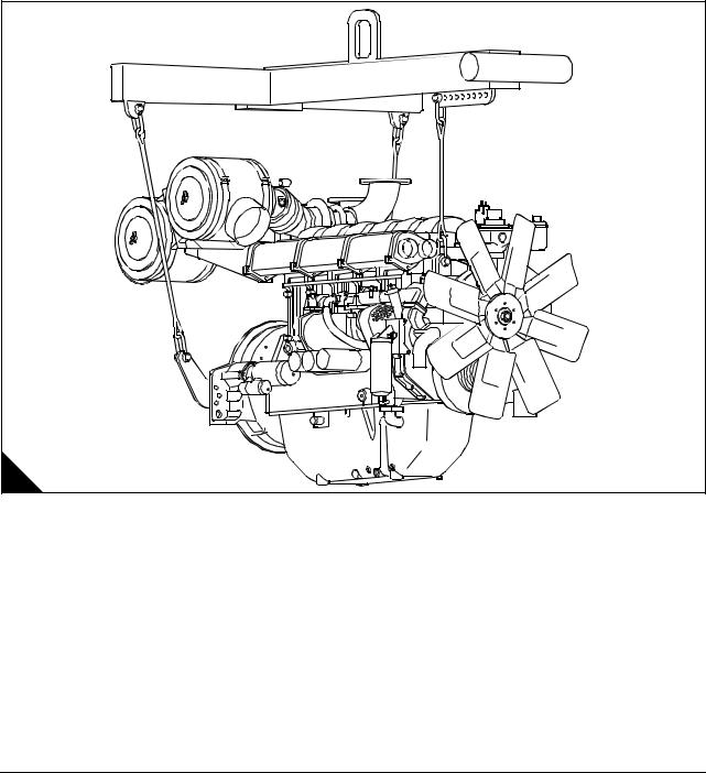
Engine lift equipment |
When lifting engine or generating sets, special lifting equipment is required. It is recommended that a spreader lifting beam of the correct lifting load capacity is used and that chains, hooks, shackles and eye bolts etc. are checked that they are well within their safe working loads. The load should be secure, stable and balanced when lifting.
The lifting chains etc must be firmly secured to the load by means of hooks etc on to the purpose-designed lifting points, and that included angle is not exceeded (A).
In order to accommodate the chains for lifting it may be necessary to have to remove engine components such as air filters etc to prevent damage, but this should be avoided where the chains can be clear by nondetrimental means.
Warning! Lifting equipment should be used by trained personnel only. Generating sets must be lifted using the lifting lugs on the engine frame and a spreader lifting beam. The engine lifting brackets and alternator lifting lugs must not be used.
|
6 |
Workshop Manual, TPD 1511E, issue 1 |

|
4000 Series |
1 |
|
POWERPART recommended consumable products |
Perkins have made available the products recommended below in order to assist in the correct operation, service and maintenance of your engine and your machine. The instructions for the use of each product are given on the outside of each container. These products are available from your Perkins distributor.
POWERPART ELC (Extended Life Coolant).
ELC is pre-mixed and protects the cooling system against frost and corrosion. Part number 21820181.(1)
POWERPART Easy flush
Cleans the cooling system. Part number 21825001.
POWERPART Gasket and flange sealant
To seal flat faces of components where no joint is used. Especially suitable for aluminium components. Part number 21820518.
POWERPART Gasket remover
An aerosol for the removal of sealants and adhesives. Part number 21820116.
POWERPART Griptite
To improve the grip of worn tools and fasteners. Part number 21820129.
POWERPART Hydraulic threadseal
To retain and seal pipe connections with fine threads. Especially suitable for hydraulic and pneumatic systems. Part number 21820121.
POWERPART Industrial grade super glue
Instant adhesive designed for metals, plastics and rubbers. Part number 21820125.
POWERPART Lay-Up 1
A diesel fuel additive for protection against corrosion. Part number 1772204.
POWERPART Lay-Up 2
Protects the inside of the engine and of other closed systems. Part number 1762811.
POWERPART Lay-Up 3
Protects outside metal parts. Part number 1734115.
POWERPART Metal repair putty
Designed for external repair of metal and plastic. Part number 21820126.
POWERPART Pipe sealant and sealant primer
To retain and seal pipe connections with coarse threads. Pressure systems can be used immediately. Part number 21820122.
Continued
|
Workshop Manual, TPD 1511E, issue 1 |
7 |

POWERPART Radiator stop leak
For the repair of radiator leaks. Part number 21820127.
POWERPART Retainer (high strength)
To retain components which have an interference fit. Part number 21820638.
POWERPART Retainer (oil tolerant)
To retain components which have an interference fit, but are in contact with oil. Part number 21820608.
POWERPART Safety cleaner
General cleaner in an aerosol container. Part number 21820128.
POWERPART Silicone adhesive
An RTV silicone adhesive for application where low pressure tests occur before the adhesive sets. Used for sealing flange where oil resistance is needed and movement of the joint occurs. Part number 21826038. (2)
POWERPART Silicone RTV sealing and jointing compound
Silicone rubber sealant which prevents leakage through gaps. Part number 1861108. (2)
POWERPART Stud and bearing lock
To provide a heavy duty seal to components that have a light interference fit. Part number 21820119 or 21820120.
POWERPART Threadlock and nutlock
To retain small fasteners where easy removal is necessary. Part number 21820117 or 21820118.
POWERPART Universal jointing compound
Universal jointing compound which seals joints. Part number 1861117.(2)
(1)Powerpart (ELC) is not recommended for the 1300 Series.
(2)These product must not be used for the 4006-23 engine.
|
8 |
Workshop Manual, TPD 1511E, issue 1 |
![]()
4000 Series
2
Specifications
Basic engine data
Number of cylinders. … … … … … … … … … … … … … … … … … … … … … … … … … … … … … … … … … … 6 Cylinder arrangement .. … … … … … … … … … … … … … … … … … … … … … … … … … … … …Vertical, in-line Cycle … … … … … … … … … … … … … … … … … … … … … … … … … … … … … … … … … … … … Four stroke Induction system.. … … … … … … … … … … … … … … … .Turbocharged, air cooled C.A. in radiator (air to air) Combustion system . … … … … … … … … … … … … … … … … … … … … … … … … … … … … …Direct injection Nominal bore … … … … … … … … … … … … … … … … … … … … … … … … … … … … … … … … … … . 160 mm Nominal stroke. … … … … … … … … … … … … … … … … … … … … … … … … … … … … … … … … … . 190 mm Compression ratio … … … … … … … … … … … … … … … … … … … … … … … … … … … … … … … … … … 13:1 Cubic capacity . … … … … … … … … … … … … … … … … … … … … … … … … … … … … … … … … .22,92 litres Firing order .. … … … … … … … … … … … … … … … … … … … … … … … … … … … … … … … … 1, 5, 3, 6, 2, 4 Direction of rotation . … … … … … … … … … … … … … … … … … … … … … Anti-clockwise viewed on flywheel
Lubricating oil capacity:
Total system … … … … … … … … … … … … … … … … … … … … … … … … … … … … . 122,7 litres (27 gallons) Sump maximum… … … … … … … … … … … … … … … … … … … … … … … … … … … . 113,7 litres (25 gallons) Sump minimum … … … … … … … … … … … … … … … … … … … … … … … … … … … …90,9 litres (20 gallons)
Lubricating oil pressure:
At rated speed (Min) … … … … … … … … … … … … … … … … … … … … … … … … … … … 200 kPa (29 lb/in2) Typical coolant capacity of engine… … … … … … … … … … … … … … … … … … … … … … 36 litres (8 gallons) Typical coolant capacity of engine and radiator .. … … … … … … … … … … … … … … … 105 litres (23 gallons)
|
Workshop Manual, TPD 1511E, issue 1 |
9 |

Data and dimensions
Rocker assembly
Rocker shaft diameter … … … … … … … … … … … … … … … … … … … … … … … … … … 39,975 / 39,950 mm Valve rocker lever bore .. … … … … … … … … … … … … … … … … … … … … … … … … … 40,025 / 40,000 mm Clearance between valve rocker levers and shaft . … … … … … … … … … … … … … … … ..0,025 to 0,075 mm Unit fuel injector rocker lever bore . … … … … … … … … … … … … … … … … … … … … … 40,025 / 40,000 mm
Valves
Diameter of valve stem .. … … … … … … … … … … … … … … … … … … … … … … … … 11,0236 / 11,0109 mm
Diameter of valve head:
Inlet valve… … … … … … … … … … … … … … … … … … … … … … … … … … … … … … … … 52,12 / 52,00 mm Exhaust valve. … … … … … … … … … … … … … … … … … … … … … … … … … … … … … … 52,12 / 52,00 mm
Angle of face of valve:
Inlet valve… … … … … … … … … … … … … … … … … … … … … … … … … … … … … … … … … 30°30’ / 30°00’ Exhaust valve. … … … … … … … … … … … … … … … … … … … … … … … … … … … … … … … 30°30’ / 30°00’
Thickness of valve lip:
Inlet valve and exhaust valve. … … … … … … … … … … … … … … … … … … … … … … … … … … 2,1 / 1,9 mm Exhaust valve and inlet valve minimum “outside diameter: land” thickness .. … … … … … … … … … … … 1 mm
Length of valve:
Inlet … … … … … … … … … … … … … … … … … … … … … … … … … … … … … … … … … … 170,0 / 169,5 mm Exhaust .. … … … … … … … … … … … … … … … … … … … … … … … … … … … … … … … … 170,0 / 169,5 mm
Valve guides
Bore of valve guide when installed … … … … … … … … … … … … … … … … … … … … … 11,118 / 11,082 mm
Do not use a combination of a valve and valve guide which have a difference of 0,20 mm or more.
Height from cylinder head to top of valve guide. … … … … … … … … … … … … … … … … … … … … … … 9 mm
Valve springs
Assembled length .. … … … … … … … … … … … … … … … … … … … … … … … … … … … … … … .. 42,545 mm Load at assembled length.. … … … … … … … … … … … … … … … … … … … … … … … … … … … … … 399,6 N Minimum operating length.. … … … … … … … … … … … … … … … … … … … … … … … … … … … .. 31,369 mm Load at minimum operating length. … … … … … … … … … … … … … … … … … … … … … … … … … … 695,1 N Free length after test.. … … … … … … … … … … … … … … … … … … … … … … … … … … … … … ..57,658 mm Outside diameter … … … … … … … … … … … … … … … … … … … … … … … … … … … … … … … .. 33,934 mm Minimum free length .. … … … … … … … … … … … … … … … … … … … … … … … … … … … … … … ..55,6 mm
|
10 |
Workshop Manual, TPD 1511E, issue 1 |
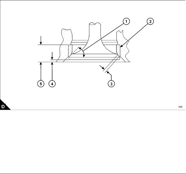
Valve seat inserts
Depth of bore in cylinder head for valve seat insert (A5):
Inlet valve … … … … … … … … … … … … … … … … … … … … … … … … … … … … … … … .. 11,10 / 11,00 mm Exhaust valve .. … … … … … … … … … … … … … … … … … … … … … … … … … … … … … .. 11,10 / 11,00 mm
Diameter of valve seat insert (A2):
Inlet valve … … … … … … … … … … … … … … … … … … … … … … … … … … … … … … .. 56,119 / 56,094 mm Exhaust valve .. … … … … … … … … … … … … … … … … … … … … … … … … … … … … .. 56,620 / 56,595 mm
Bore in cylinder head for valve seat insert (A2):
Inlet valve … … … … … … … … … … … … … … … … … … … … … … … … … … … … … … … … … … ..56 mm H7 Exhaust valve .. … … … … … … … … … … … … … … … … … … … … … … … … … … … … … … … .56,50 mm H7
Angle of face of valve seat insert (A1):
Inlet valve insert… … … … … … … … … … … … … … … … … … … … … … … … … … … … … … …30°30’ / 30°00’ Exhaust valve insert … … … … … … … … … … … … … … … … … … … … … … … … … … … … …30°30’ / 30°00’
Valve recess (A4):
Inlet valve (new parts) . … … … … … … … … … … … … … … … … … … … … … … … … … … … … … … … . Flush Exhaust valve (new parts) … … … … … … … … … … … … … … … … … … … … … … … … … … … … … … . Flush Inlet valve … … … … … … … … … … … … … … … … … … … … … … … … … … … … … … … … Maximum: 1 mm Exhaust valve .. … … … … … … … … … … … … … … … … … … … … … … … … … … … … … … Maximum: 1 mm
|
Workshop Manual, TPD 1511E, issue 1 |
11 |
Cylinder head
Thickness of cylinder head (new) .. … … … … … … … … … … … … … … … … … … … … 140,075 / 139,925 mm Minimum thickness for a used cylinder head . … … … … … … … … … … … … … … … … … … … … 139,773 mm
Flatness of cylinder head: The cylinder head flame face must be flat within a maximum of 0,03 mm (0.001 in) with the rocker box face parallel within 0,076 mm.
Piston and connecting rod
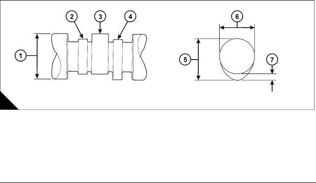
Piston ring gaps measured with the ring fitted in a new liner with a bore size: 160,025 / 160,000 mm
Top piston ring … … … … … … … … … … … … … … … … … … … … … … … 0,80 mm, maximum worn 1,05 mm Intermediate ring (second) . … … … … … … … … … … … … … … … … … … 0,60 mm, maximum worn 0,85 mm Oil control ring … … … … … … … … … … … … … … … … … … … … … … … 0,60 mm, maximum worn 0,85 mm Width of groove for oil control ring in new piston … … … … … … … … … … … … … … … … … 6,065 / 6,040 mm Thickness of a new oil control ring. … … … … … … … … … … … … … … … … … … … … … … 5,990 / 5,975 mm Clearance between piston ring groove and new oil control ring … … … … … … … … … … … … … … … … … …
Maximum permissible clearance between piston
ring groove and a used oil control ring… … … … … … … … … … … … … … … … … … … … … … … … 0,254 mm Piston gudgeon pin bore … … … … … … … … … … … … … … … … … … … … … … … … … 63.525 / 63,515 mm Gudgeon pin diameter … … … … … … … … … … … … … … … … … … … … … … … … … … 63,500 / 63,492 mm Length of gudgeon pin … … … … … … … … … … … … … … … … … … … … … … … … … … 135,00 / 134,75 mm Bore in connecting rod for small end bearing … … … … … … … … … … … … … … … … … 71,450 / 71,425 mm Bore of connecting rod small end bearing . … … … … … … … … … … … … … … … … … … 63,576 / 63,551 mm Bore in connecting rod for big end bearing shells.. … … … … … … … … … … … … … … 123,025 / 123,000 mm Distance between centres of big and small end bearings.. … … … … … … … … … … … … 336,06 / 335,94 mm Maximum worn clearance small end.. … … … … … … … … … … … … … … … … … … … … … … … … .. 0,15 mm Conrod end float … … … … … … … … … … … … … … … … … … … … … … … … … … … … … … 0,16 / 0,36 mm
Camshaft and bearings
Diameter of camshaft journal (A3) . … … … … … … … … … … … … … … … … … … … … … 91,960 / 91,933 mm Exhaust cam height (A5) … … … … … … … … … … … … … … … … … … … … 78,58 mm, service limit 78,1 mm Inlet cam height (A5).. … … … … … … … … … … … … … … … … … … … … … 78,58 mm, service limit 78,1 mm Injector cam height. … … … … … … … … … … … … … … … … … … … … … … 78,88 mm, service limit 78,4 mm Maximum: worn clearance cam journal / bearing .. … … … … … … … … … … … … … … … … … … … ..0,25 mm Camshaft end float. … … … … … … … … … … … … … … .0,10 / 0,25 mm, maximum: worn clearance 0,30 mm Cam follower lever assembly:
followers, pivot shaft / arms / shims end float … … … … … … … … … … … … … … … … … … … 0,50 / 0,25 mm
|
12 |
Workshop Manual, TPD 1511E, issue 1 |
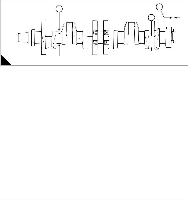
Crankshaft, main bearings and flywheel
Diameter of main bearing journal (A3). … … … … … … … … … … … … … … … … … … … .. 120,59 / 120,57 mm Undersize bearings by . … … … … … … … … … … … … … … … … … … … … … … … … … … … … … .. 0,254 mm Undersize bearings by . … … … … … … … … … … … … … … … … … … … … … … … … … … … … … .. 0,508 mm Clearance between a new bearing and the journal . … … … … … … … … … … … … … … … .. 0,152 / 0,089 mm Maximum permissible clearance between the
bearing and journal.. … … … … … … … … … … … … … … … … … … … … … … … … … … … … … … .. 0,203 mm Diameter of main bearing bore … … … … … … … … … … … … … … … … … … … … … .. 120,726 / 120,675 mm Diameter of connecting rod journal (A2).. … … … … … … … … … … … … … … … … … .. 118,013 / 117,993 mm Undersize bearings by . … … … … … … … … … … … … … … … … … … … … … … … .. 0,254 mm and 0.508 mm Clearance between a new bearing and the journal . … … … … … … … … … … … … … … … .. 0,127 / 0,073 mm Maximum permissible clearance between the
bearing and journal.. … … … … … … … … … … … … … … … … … … … … … … … … … … … … … … .. 0,203 mm End-float of crankshaft. … … … … … … … … … … … … … … … … … … … … … … … … … … … .. 0,48 / 0,13 mm Maximum permissible end-float (with used bearings) . … … … … … … … … … … … … … … … … … … 0,53 mm Protrusion of dowel (A1) .. … … … … … … … … … … … … … … … … … … … … … … … … … … … … … … 10 mm
|
3 |
1 |
|
|
2 |
||
|
A |
D1364 |
Crankcase and cylinder liners
Distance from top of crankcase to centre of main
bearing bore … … … … … … … … … … … … … … … … … … … … … … … … … … … … … .. 540,15 / 540,00 mm Block cylinder bore depth (for liner flange) .. … … … … … … … … … … … … … … … … … … .. 15,20 / 15,12 mm Distance from bottom of crankcase to centre of main
bearing bore … … … … … … … … … … … … … … … … … … … … … … … … … … … … .. 152,425 / 152,375 mm Bore in new cylinder liner … … … … … … … … … … … … … … … … … … … … … … … .. 160,025 / 160,000 mm Thickness of liner flange.. … … … … … … … … … … … … … … … … … … … … … … … … … .. 13,05 / 13,00 mm
|
Workshop Manual, TPD 1511E, issue 1 |
13 |

Lubricating oil pump
Diameter of shaft … … … … … … … … … … … … … … … … … … … … … … … … … … … … 41,913 / 41,888 mm Diameter of bores in bearing bushes for shaft … … … … … … … … … … … … … … … … … 42,039 / 41,974 mm Length of rotors.. … … … … … … … … … … … … … … … … … … … … … … … … … … … … 50,800 / 50,775 mm Depth of bores for rotors … … … … … … … … … … … … … … … … … … … … … … … … … … 50,76 / 50,72 mm Joint O.P. body to cover. … … … … … … … … … … … … … … … … … … … … … … … … … … … … … .. 0,25 mm
Spring:
Spring rate . … … … … … … … … … … … … … … … … … … … … … … … … … … … … … … … … … . 1,32 kg/mm Load at 51 mm length … … … … … … … … … … … … … … … … … … … … … … … … … … … … … … … … 30 kg Load under 30 mm comp: to assembly length … … … … … … … … … … … … … … … … … … … … … … 39,6 kg Free length. … … … … … … … … … … … … … … … … … … … … … … … … … … … … … … … … … … ..73,6 mm Outside diameter … … … … … … … … … … … … … … … … … … … … … … … … … … … … … … … … ..24,6 mm Spring plunger bore … … … … … … … … … … … … … … … … … … … … … … … … … … … … … … … ..25,4 mm
Coolant pump
Shaft diameter at the position of the coolant seal .. … … … … … … … … … … … … … … … 25,095 / 25,087 mm
Gear train
Idler gear end float . … … … … … … … … … … … … … … … … … … … … … … … … … … … … … … 0,2 / 0,1 mm Idler gear maximum: worn . … … … … … … … … … … … … … … … … … … … … … … … … … … … … ..0,25 mm
Backlash:
Idler, camshaft, oil pump gears.. … … … … … … … … … … … … … … … … … … … … … … … 0,375 / 0,125 mm Maximum: worn.. … … … … … … … … … … … … … … … … … … … … … … … … … … … … … … … … … 0,5 mm
Water pump gear in mesh.. … … … … … … … … … … … … … … … … … … … … … … … … … 0,294 / 0,152 mm
|
14 |
Workshop Manual, TPD 1511E, issue 1 |

|
4000 Series |
2 |
||||
|
Torque data |
|||||
|
Description |
Thread size |
Torque |
|||
|
Nm |
lbf ft |
kgf m |
|||
|
Crankcase and crankshaft |
|||||
|
Sump bolts into crankcase |
M10 |
54 |
40 |
5,5 |
|
|
Sump bolts into gearcase (aluminium) |
M10 |
40 |
30 |
4 |
|
|
Main bearing cap bolts |
See Operation 5-6 |
||||
|
Main bearing cap side capscrews |
M16 |
n/a |
n/a |
n/a |
|
|
Oil feed block bolts |
M10 |
27 |
20 |
2,7 |
|
|
Connecting rod bolts |
See Operation 4-2 |
||||
|
Piston cooling jet bolts |
M10 |
27 |
20 |
2,7 |
|
|
Camshaft |
|||||
|
Camshaft gear bolts |
M12 |
150 |
110 |
15,2 |
|
|
Camshaft thrust plate bolts |
M10 |
50 |
35 |
5,1 |
|
|
Idler gear hub bolts |
M10 |
50 |
35 |
5,1 |
|
|
Engine feet bolts |
M10 |
50 |
35 |
5,1 |
|
|
Cylinder head |
|||||
|
Cylinder head bolts (Factory Fitted) |
175 + 120° |
130 + |
17,8 + 120° |
||
|
120° |
|||||
|
Cylinder head bolts (Waisted) — head marked ‘W’ |
M24 |
720 |
530 |
73,4 |
|
|
General |
|||||
|
M20 — Grade 8.8 steel bolts to BS3692 |
M20 |
400 |
290 |
40,7 |
|
|
M16 — Grade 8.8 steel bolts to BS3692 |
M16 |
210 |
150 |
21,4 |
|
|
M12 — Grade 8.8 steel bolts to BS3692 |
M12 |
85 |
60 |
8,6 |
|
|
M10 — Grade 12.9 steel bolts to BS3692 |
M10 |
70 |
50 |
7,1 |
|
|
M10 — Grade 8.8 steel bolts to BS3692 |
M10 |
50 |
35 |
5,1 |
|
|
M8 — Grade 8.8 steel bolts to BS3692 |
M8 |
25 |
18 |
2,5 |
|
|
M6 — Grade 8.8 steel bolts to BS3692 |
M6 |
10 |
7 |
1,0 |
|
|
M6 — Grade 12.9 steel capscrews to BS4168: Part 1 |
M6 |
16 |
12 |
1,6 |
|
|
M5 — Grade 12.9 steel capscrew to BS4168: Part 1 |
M5 |
13 |
10 |
1,3 |
|
|
3/8” UNF |
40 |
30 |
4 |
||
|
5/8” UNF |
200 |
150 |
20,3 |
||
|
1/2” UNC |
90 |
68 |
9,1 |
||
|
7/16” UNF |
66 |
50 |
6,7 |
||
|
5/16” UNF |
22 |
16 |
2,2 |
||
|
Starter motors |
M12 |
95 |
70 |
7,1 |
|
|
Alternator nut |
M24 |
75 |
55 |
7,6 |
|
|
Taper lockbush |
M8 |
20 |
15 |
2 |
|
|
Fuel pipes |
50 |
35 |
5,1 |
||
|
Workshop Manual, TPD 1511E, issue 1 |
15 |

|
2 |
4000 Series |
||||
|
Main build |
|||||
|
Description |
Thread size |
Torque |
|||
|
Nm |
lbf ft |
kgf m |
|||
|
Camshaft |
|||||
|
Cam follower housing bolts |
M10 |
50 |
35 |
5,1 |
|
|
Cylinder head |
|||||
|
Rocker box bolts-graphite joint |
M10 |
70 |
50 |
7,1 |
|
|
Exhaust manifold to head bolts (Durlock) |
M10 |
70 |
50 |
7,1 |
|
|
Bridge piece adjuster nubs |
M10 |
35 |
25 |
3,5 |
|
|
Fuel injector clamp capscrews |
M12 |
95 |
70 |
9,6 |
|
|
Rocker shaft capscrew/nuts |
M16 |
240 |
180 |
24,9 |
|
|
Rocker adjuster nuts |
M12 |
50 |
35 |
5,1 |
|
|
Unit-fuel injector rocker adjuster nuts |
M14 |
70 |
50 |
7,1 |
|
|
Rocker cover — plastic |
M10 |
4 |
3 |
0,4 |
|
|
Water pump and oil pump |
|||||
|
Water pump to gearcase bolts |
M10 |
50 |
35 |
5,1 |
|
|
Water header to oil cooler bolts |
M10 |
50 |
35 |
5,1 |
|
|
Crankcase and crankshaft |
|||||
|
Flywheel bolts (Final torque) |
See Chapter 13, Flywheel and housing |
||||
|
T.V. damper bolts (Final torque) |
See Chapter 13, Flywheel and housing |
||||
|
Front crankshaft pulley assembly |
M16 |
340 |
250 |
34,6 |
|
|
Unit-fuel injector control linkage |
|||||
|
Capscrews, unit-fuel injector control lever |
M5 |
8 |
6 |
0,8 |
|
|
Locknut — control linkage |
M5 |
8 |
6 |
0,8 |
|
|
Exhaust bellows |
|||||
|
Bolts / locknuts (torque prevailing) |
M10 |
58 |
43 |
||
|
Durlock bolts / locknuts |
M10 |
70 |
50 |
||
|
Setscrews |
M10 |
50 |
35 |
5,1 |
|
|
Unitfuel injectors |
|||||
|
Nuts, fuel injector nozzle to nozzle holder |
M27 |
205 |
150 |
5,9 |
|
|
Capscrews, fuel injector clamp to cylinder head |
M12 |
95 |
70 |
9,6 |
|
|
Clips and clamps |
|||||
|
Hose clips |
5 |
3,5 |
0,5 |
||
|
V-band clamps (Mitsubishi) |
9,5 |
7 |
0,96 |
||
|
16 |
Workshop Manual, TPD 1511E, issue 1 |

4000 Series
3
Cylinder head assembly
General description
Note: In the event of failure, valve or valve seat recession reaching the recommended limit, or when the engine is being overhauled, service exchange cylinder heads supplied by your Perkins Dealer/Distributor are recommended. The specialised equipment and liquid nitrogen are not generally available
The cast iron cylinder heads are fastened to the crankcase by flange head bolts and hardened washers. The cylinder head gasket to crankcase consists of a stainless steel flame ring. The individual inlet and exhaust ports are designed to assist and improve air flow. The ports for the inlet are on the right hand side of the engine and the ports for the exhaust are on the left hand side of the engine.
The cylinder head assembly has four overhead valves for each cylinder. Each valve is held in place by a single coil spring, cap and two collets. The cylinder head has valve seat inserts fitted for both the intake and the exhaust. The intake valve seats are made from high speed steel casting and the exhaust valve seats are made from Pleuco PL12 MV400 which both can be renewed. The valves move in cast iron ferrite nitro carburised valve guides which also can be renewed.
The overhead valves are operated by a rocker shaft assembly in the rocker box. The forged steel rocker levers are operated by forged push rods with hardened ball and sockets ends. The rockers and valve gear are lubricated by oil from the drillings in the rocker shaft that receives oil flow from the extruded fuel/oil rail. Tappet adjustment is achieved by adjustment screws and locknuts at the push rod end of each rocker lever.
In a diesel engine there is little carbon deposit and for this reason the number of hours run is no indication of when to overhaul a cylinder head assembly. The factors which indicate when an overhaul is necessary are how easily the engine starts and its general performance.
|
Workshop Manual, TPD 1511E, issue 1 |
17 |
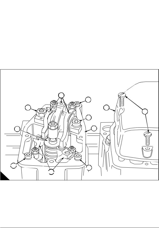
|
3 |
4000 Series |
||
|
Rocker box and valve gear |
|||
|
To remove and fit the rocker box and valve gear |
Operation 3-1 |
||
|
Special requirements |
|||
|
Consumable products |
|||
|
Description |
Part number |
||
|
POWERPART Hydraulic threadseal |
21820121 |
||
To remove
1Remove the retaining screws (A5) and lift off the rocker cover (A4). Remove the rocker cover joint and discard.
2Remove the nut (A11) and the Allen screw (A3) then lift off the rocker assembly (A1), the cup pad (A10), the bridge pieces (A8) and the push rods.
3Remove the retaining Allen screw (A2, A7, A9) and remove the rocker box (A6).
4A light blow with a hide mallet may be needed to free the rocker box from its joint.
|
1 |
|
|
2 |
|
|
11 |
4 |
|
5 |
|
|
3 |
|
|
10 |
6 |
 9
9 
 7
7
 8
8 
A
Continued
|
18 |
Workshop Manual, TPD 1511E, issue 1 |
![]()
To fit
Note: If water is found to be leaking from the rocker shaft stud, apply POWERPART Threadlock and nutlock.
1Fit the rocker box (A6) using a new joint and ‘O’ ring, locating it on the two dowel pegs in the cylinder head face.
2Lubricate the threads of the retaining Allen screw (A2,A7, A9) with clean engine oil then torque to 70 Nm (50 lbf ft) 7,1 kgf m.
3Lubricate all valve gear bearing surfaces with clean engine oil then fit each item to its original position.
4Lubricate the thread of the nut (A11) and the Allen screw (A3) with clean engine oil then torque to 250 Nm (180 lbf ft) 25,5 kgf m.
Note: Ensure that the rocker shaft is pulled squarely onto the rocker box.
5Set bridge piece and valve clearances, refer to the relevant User Handbook, Chapter 4, page 33.
6Fit a new joint to the rocker cover (A4), tighten the retaining screws (A5) to a torque of
4 Nm (3 lbf ft) 0.4 kgf m.
|
1 |
|
|
2 |
|
|
11 |
4 |
|
5 |
|
|
3 |
|
|
10 |
6 |
 9
9 
 7
7
 8
8 
A
|
Workshop Manual, TPD 1511E, issue 1 |
19 |

|
3 |
4000 Series |
|
Valve gear |
|
|
To inspect rockers, bridge pieces and rocker shaft |
Operation 3-2 |
1Check the push rods (A13) are straight, the cup end (A15) and the spherical end (A12) smooth surfaced and concentric.
2Clean the bore and top surface on the bridge piece.
3Check the adjuster screws and locknuts (A16) are undamaged.
4Check the clearance between the bridge pieces (A5) and their guide pillars in the cylinder head. For the maximum clearance, refer to the Data and dimensions for «Rocker assembly» on page 10.
5Check the valve contact patch (A6) is not indented or chipped.
Note: A small indent on the bridge piece pressure pad can be removed with an oil stone.
6Check the bridge piece pressure pad (A7) for indentation.
7Check the rocker shaft (A11) for wear and the oil galleries (A9) are clear.
|
1 |
2 |
3 |
|
16
|
4 |
|
|
8 |
|
|
15 |
7 |
|
14 |
5 |
|
10 |
|
|
11 |
|
|
13 |
|
|
6 |
|
|
12 |
9 |
|
A |
D135600000 |
|
20 |
Workshop Manual, TPD 1511E, issue 1 |
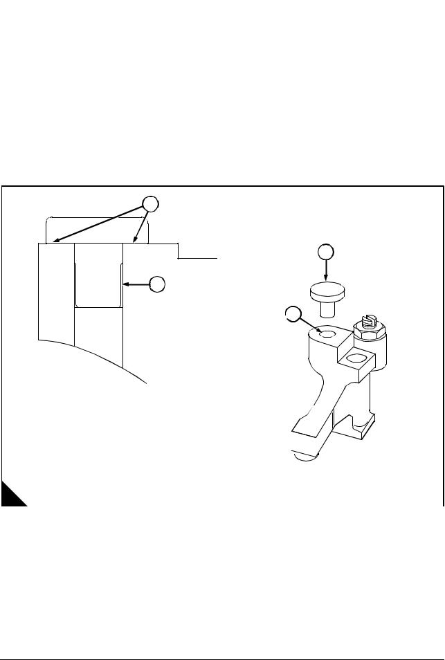
|
4000 Series |
3 |
|
|
To replace the bridge piece pressure pad |
Operation 3-3 |
|
|
Special requirements |
||
|
Consumable products |
||
|
Description |
Part number |
|
|
POWERPART Retainer (oil tolerant) |
21820603 |
|
1 Remove the pressure pad (A2) from the bore of the bridge piece.
Caution: There must be no POWERPART under the pressure pad area (A1).
2Check the surfaces (A4) on each bridge piece.
3Apply Loctite activator ‘T’ to the pressure pad stem and the bridge piece, allow to dry.
4Apply POWERPART retainer (oil tolerant) to the bridge piece bore (A3).
5Fit the pressure pad, then stand the assembly upright and allow to cure for two hours.
1
2
4
 3
3
|
A |
D1357 |
|||
|
Workshop Manual, TPD 1511E, issue 1 |
21 |

|
3 |
4000 Series |
|
|
Cylinder head |
||
|
To remove and fit the cylinder head |
Operation 3-4 |
|
|
Special requirements |
||
|
Special tools |
||
|
Description |
Part number |
|
|
Cylinder head lifting tool |
T6253/237 |
|
To remove
1 Remove the rocker box and the valve gear, see Operation 3-1, then remove the fuel injector, see Operation 11-2 and the brake-back lever.
Note: The cylinder head bolts can only be used twice. Before removal, mark each bolt head with a centre punch dot (A5). Bolts showing two dots must be replaced.
2Fit the cylinder head lifting tool (A2) then remove the head bolts in sequence shown (A14, A1, A15, A3). Use a suitable hoist to remove the cylinder head from the crankcase.
3Discard the ‘O’ rings (A6, A9, A10, A12), the flame ring (A13) and the push rod tunnel insert and ‘O’ ring (A4) in the cylinder head, clean the surface of the crankcase.
5
4
x
2  3
3
16 
6
13
 15
15 


12
 10
10
|
22 |
Workshop Manual, TPD 1511E, issue 1 |
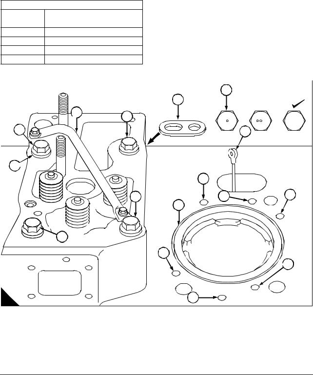
To fit
1Fit the cylinder head lifting tool (A2). Locate the insert and joint (A4) into the cylinder head combustion face secure it in position with suitable petroleum jelly.
2Fit the flame ring (A13) to the liner flange then fit the ‘O’ rings (A6, A9, A10, A12) secure them in position with petroleum jelly.
3Use suitable lift equipment in order to lift the cylinder head into position. Ensure that the dowels (A8 and A11) are aligned. Also ensure that (A7) is in the push rod tunnel. Remove the lifting tool (A2).
4Using a suitable PBC grease (poly butyl cuprysil) apply one stripe to the bolt thread and coat both sides of the head bolt washers. Fit the bolts and washers hand tight.
Cylinder head bolt torque stages
|
Stage |
Torque |
|
1 |
Hand tight |
2135 Nm (100 lbf ft) 13,7 kgf m
3270 Nm (200 lbf ft) 27,5 kgf m
4540 Nm (400 lbf ft) 55,0 kgf m
5715 Nm (530 lbf ft) 73,9 kgf m
5 Torque the cylinder head bolts in the stages given, and in the same diagonal sequence (A14, A1, A15, A3).
5
4
x
2  3
3
16 
 15
15 


12
 10
10
|
Workshop Manual, TPD 1511E, issue 1 |
23 |
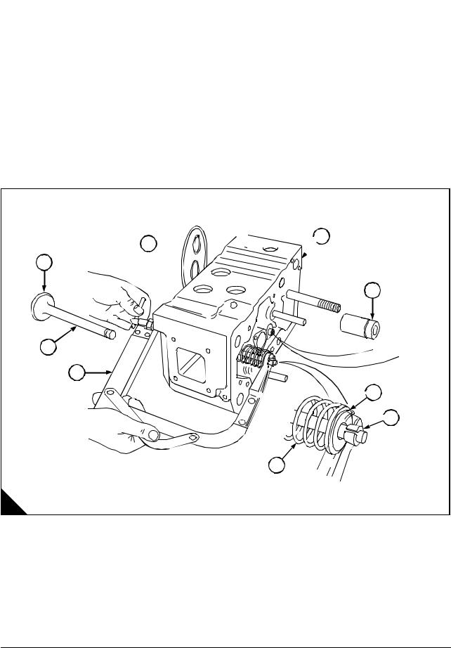
|
3 |
4000 Series |
||
|
Valves and springs |
|||
|
To remove and fit the valve and the valve springs |
Operation 3-5 |
||
|
Special requirements |
|||
|
Special tools |
|||
|
Description |
Part number |
||
|
Valve spring compressor |
T6253/243 |
||
Warning! Wear eye protection during this operation.
To remove
1Carefully turn the cylinder head on its side (A2) and remove the push rod ‘O’ ring and insert (A1).
2Using the spring compressor (A7), compress a valve spring and remove the split collets (A5) then release the spring (A6) and retaining collar (A4) then pull the valve (A9) out of the cylinder head.
3Mark valves for correct assembly and keep all valves together.


 2 1
2 1 


9
3
8
7
 4
4
 5
5
6
A
Continued
|
24 |
Workshop Manual, TPD 1511E, issue 1 |
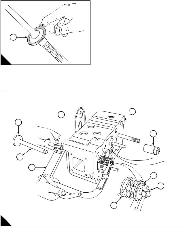
To fit
1Fit the appropriate valve to a universal sucker type tool and apply a medium carborundum paste, evenly around the valve seat (A1)
2Fit the valve guides (B3).
3Push the valve into its guide and use a semi rotary motion lap the valve onto its seat.
4The seat of the valve and on the cylinder head must have a grey continuous line of contact.
5Remove all traces of the carborundum paste from the cylinder head and valve seat.
1
6 Lubricate the valve stem and fit the valve (B8) into the cylinder head.
Caution: Ensure that the valve springs (B6) are compressed squarely or the valve stem can be damaged.
7 Fit the valve spring and retaining collar onto the valve stem, compress the valve spring and fit the split collets (A6) then slowly release the compressed valve spring, check the collets have seated in the retaining collar.


 2 1
2 1 


9
3
8
7
 4
4
 5
5
6 
B
|
Workshop Manual, TPD 1511E, issue 1 |
25 |
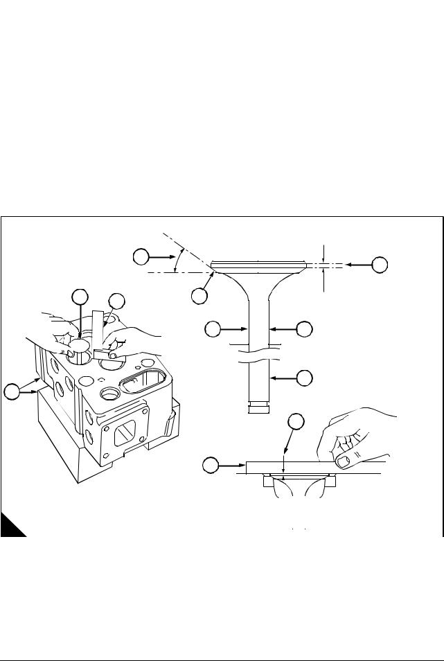
|
3 |
4000 Series |
|
To inspect |
Operation 3-6 |
1Visually examine the valve seating face (A2) for pitting or burning. Examine the valve stem (A4) for score marks or a wear ridge near the collet groove (A5).
2Check the valve stem dimension (A4), refer to the Data and dimensions for «Valves» on page 10.
3If the valve is within service limits but with some pitting on the valve seating face (A2), it can be re-faced at an angle of 30° (A1).
Caution: If the dimension (A3) is less than 1mm after re-facing the valve should be discarded.
4Fit a valve into the cylinder head and using a straight edge (A7), check the valve depth. If the depth exceeds 1mm (A6) the valve must be replaced.
5Support the cylinder head on two blocks of wood (A8). Fit the appropriate valve into the cylinder head, and hold the valve seat so it protudes 10mm from the surface of the cylinder head. Use an engineer square as a datum (A10) and check the clearance between the valve and valve guide. If the clearance exceeds 0.5mm (0,0196 in) the valve guide must be replaced, see Operation 3-8.
6Check the valve spring free length. If less than 55.6mm (2,188 in), the valve spring must be replaced, see Operation 3-5.
1
|
3 |
|||
|
9 |
10 |
2 |
|
|
4 |
4 |
5
8
6
|
A |
D1360 |
||
|
26 |
Workshop Manual, TPD 1511E, issue 1 |

|
4000 Series |
3 |
|
|
Valves seats |
||
|
To remove and fit, and reface the valve seats |
Operation 3-7 |
|
|
Special requirements |
||
|
Special tools |
||
|
Description |
Part number |
|
|
Valve seat fitting tool |
T85002/4 |
|
|
Valve seat grinding equipment |
T6253/240 |
|
Warning! Wear eye protection during this operation.
To remove
1Machine down a valve head until it just fits inside a valve seat.
2Using an electrical welding source, tack weld the valve to the seat in three evenly spaced positions.
3Allow time for the valve and seat to cool, then using a soft faced hammer, knock the valve and seat out of the cylinder head.
To fit
1Check that the valve seat bore is free from burrs, and that the valve guide bore is free from carbon.
2Immerse the valve seat in liquid nitrogen for 2 minutes to get the necessary contraction. This makes the seat a light tap fit into the cylinder head using the fitting tool (A1).
Caution: The valve seats are made from a very hard material and the valve seat angle can only be cut with the use of specialist valve grinding equipment (B) and the grinding kit (C) for the stone (B4). Refer to page 10 of data and dimensions for the correct seat angle.
 1
1 
|
2 |
||
|
3 |
||
|
1 |
||
|
4 |
||
|
A |
D1242 B |
D1244 |
|
C |
D1245 |
|
Workshop Manual, TPD 1511E, issue 1 |
27 |
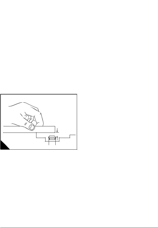
|
3 |
4000 Series |
||||
|
Valves guides |
|||||
|
To remove and fit the valve guides |
Operation 3-8 |
||||
|
Special requirements |
|||||
|
Special tools |
|||||
|
Description |
Part number |
Description |
Part number |
||
|
Valve guide removal tool |
T6253/307 |
Valve guide fitting tool |
T85090/2 |
||
Warning! Wear eye protection during this operation.
Note: When fitting new valve guides the valve seats must be re-cut or re-ground.
To remove
1 Locate the valve guide removal tool into valve guide, using a suitable press push the valve guide out of the cylinder head from the valve spring side.
To fit
1 Check that the valve bore is free from burrs and carbon.
Caution: Do not use a hammer to locate or to fit the valve guide.
2Align the valve guide with its bore.
3Set the fitting tool on top of the valve guide. Using a suitable press, push the valve guide into the cylinder head until valve guide is 9 mm (0.3543 in) (A) below the face of the cylinder head.
|
28 |
Workshop Manual, TPD 1511E, issue 1 |
![]()
|
4000 Series |
3 |
|||
|
Fuel injector bush |
||||
|
To remove and fit a fuel injector bush |
Operation 3-9 |
|||
|
Special requirements |
||||
|
Special tools |
||||
|
Description |
Part number |
Description |
Part number |
|
|
Bush insertion tool |
T85002/2 |
Bush swaging tool |
T6253/156 |
|
|
Bush expanding tool lower |
T85002/6 |
Facing cutter |
T85002/7 |
|
|
Bush expanding tool upper |
T85002/58 |
Depth gauge |
T85002/14B |
|
Warning! Wear eye protection during this operation.
Note: If coolant is found to be leaking from between the cylinder and the fuel injector, or if the fuel injector bush is damaged, the fuel injector bush must be replaced.
To remove
1Use a 22 mm (0.8661) drill with a 60 degree angle (A) to drill the swaging of the fuel injector bush.
2Use a suitable tool (B) from the combustion side of the cylinder head to remove the remaining fuel injector bush. Remove the “O” ring and discard (C).
22 mm
|
Workshop Manual, TPD 1511E, issue 1 |
29 |
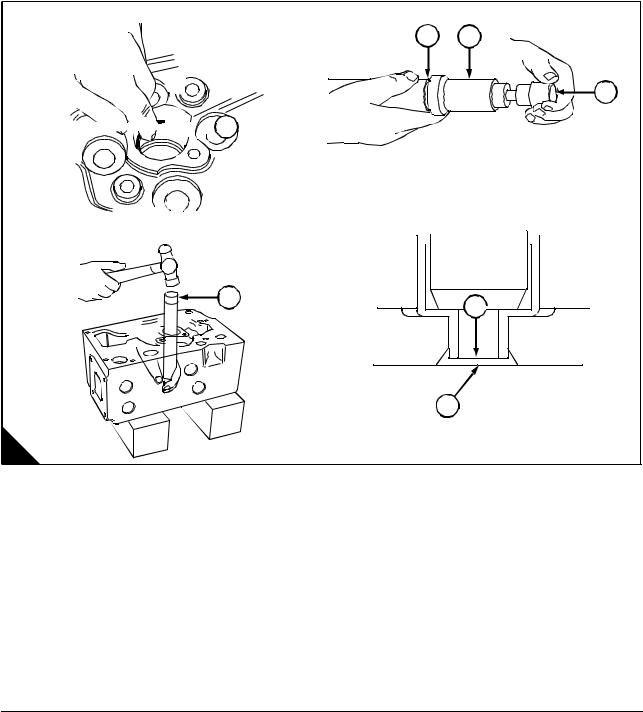
To fit
Note: When using the fuel injector bush expander tools, the pressure on the bush is automatically controlled by the tools as they rotate.
1Apply a suitable lubricant to the new ‘O’ ring, then fit the ‘O’ ring into the recess in the fuel injector bush aperture.
2Slide the fuel injector bush (A3) onto the insertion tool (A2) then fit the locating pin (A4) into the tool and the fuel injector bush.
3Carefully locate the fuel injector bush into the cylinder head, ensuring that the ‘O’ ring (A1) is still correctly positioned.
4When the fuel injector bush has located in the combustion side of the cylinder head, carefully force the bush into position.
5With the fuel injector bush in the correct position, check that the end of the bush (A5) is 1.5mm (0.0590 in) from the cylinder head face (A6).
2 3
4


 1
1
7
5 
Continued
|
30 |
Workshop Manual, TPD 1511E, issue 1 |
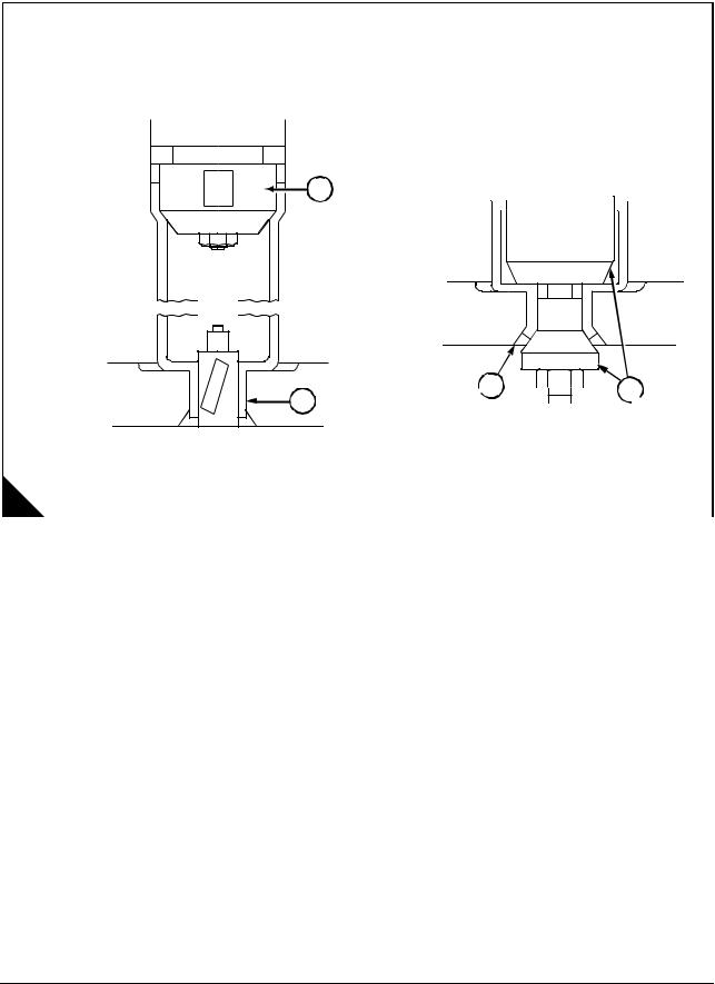
6Using the expander tools, first expand the lower section bush (combustion side) (B4) then the upper section bush (valve spring side) (B1).
7Fit the coning tool (B2) to the combustion side of the bush, then torque the nut to 55 Nm (40 lb/ft)
5,6 kgf m to swage the bush into the chamfer (B3) in the combustion face of the cylinder head.
1
 3
3 


 2 4
2 4 


Continued
|
Workshop Manual, TPD 1511E, issue 1 |
31 |
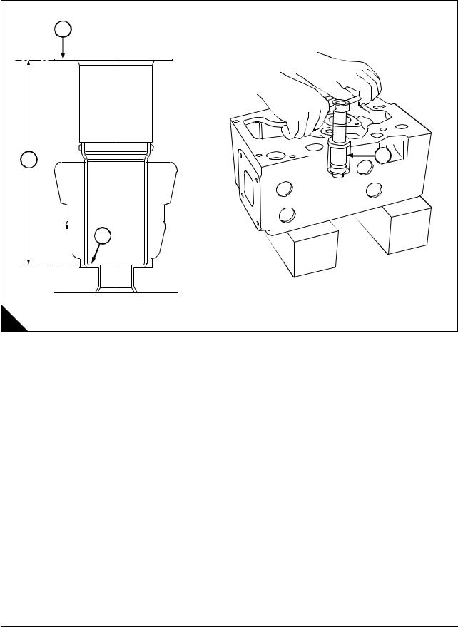
8Check the distance between the fuel injector seating face (C3) and the cylinder head face (C1) with a depth gauge. The finished dimension (C4) is 122,6 ±0.105 mm (4.827 ± 0.004 in.).
9If necessary, use the face cutter (C2) to set the dimension correctly.
10Remove all debris.
1
4
3
C
|
32 |
Workshop Manual, TPD 1511E, issue 1 |

|
4000 Series |
3 |
|
Cylinder head |
|
|
To inspect and pressure test |
Operation 3-10 |
Warning! Wear eye protection during this operation.
1 Remove the valves and springs, see Operation 3-5.
Note: Do not scratch any machined surface on the cylinder head.
2Clean the carbon deposits from the combustion face and the ports of the cylinder head.
3Wash the cylinder head with a special solvent which must be used in accordance with the manufacturer’s instructions. Dry the cylinder head using compressed air.
4Test the cylinder head for leaks, refer to the Data and dimensions for «Cylinder head» on page 12.
5When the cylinder head is thoroughly clean, check it for cracks. Inspect carefully the areas around the valve seats and around the hole for the fuel injector.
|
Workshop Manual, TPD 1511E, issue 1 |
33 |

|
3 |
4000 Series |
|
Manifolds |
|
|
To remove and fit the induction manifold |
Operation 3-11 |
To remove
Note: The induction manifold can be removed as individual sections or as a complete assembly.
1Remove the digital govenor control unit, see Operation 14-17.
2Remove the air filter bracket, see Operation 9-5.
3Loosen the hose clips from the induction manifold pipes. Remove the links and setscrews that secure both pipes. Remove the hoses from the induction manifold pipes.
4Remove the inlet manifold to cylinder head setscrews (A1), then remove the inlet manifold. Discard the joints.
To fit
1Fit new joints to the induction manifold. Tighten the setscrews to the induction manifold, gradually and evenly to a torque of 50 Nm (37 lbf ft) 5,1 kgf m.
2Fit the hoses from the induction manifold pipes, and tighten the hose clips to the radiator pipes and the induction manifold pipes.
3Fit the links and setscrews that secure both pipes, and tighten the setscrews to torque of 25 Nm
(18,4 lbf ft) 2.5 kgf m.
4Fit the air filter bracket, see Operation 9-6
5Fit the digital govenor control unit, see Operation 14-18.
1
|
34 |
Workshop Manual, TPD 1511E, issue 1 |

|
4000 Series |
3 |
|
To remove and fit the exhaust manifold |
Operation 3-12 |
Cautions:
The exhaust manifolds (A7) and (A8) must be removed as separate items. Damage may be caused to the expansion bellows (A6) if the exhaust manifolds are removed as an assembly.
Ensure that the turbochargers are supported before the exhaust manifolds are removed.
To remove
1Remove the 4 nuts and bolts (A3) and remove the 12 setscrews (A1).
2Remove the front section of the exhaust manifold (A8). Discard all the old gaskets.
3Remove the 4 nuts and bolts (A4) and the 4 nuts and bolts (A5).
|
3 |
4 |
||
|
1 |
2 |
||
|
5 |
|||
|
6 |
|||
|
7 |
|||
|
8 |
|||
|
A |
D1331/1 |
4Remove the 12 setscrews (A2) and remove the rear exhaust manifold (A7). Discard all the old gaskets.
5If necessary remove the rest of the nuts and bolts on the expansion bellows (A6) and remove the expansion bellows. Discard the old gasket.
6Ensure that dirt or fluid can not enter the exhaust system.
|
Workshop Manual, TPD 1511E, issue 1 |
35 |

To fit
1Ensure that all contact surfaces are clean and dry.
2Align the new gaskets (A1) to both turbochargers and align the 3 new gaskets for the rear exhaust manifold (B7) to the cylinder head.
 1
1 
A
3Fit loosely the 4 bolts and nuts (B4) and (B5).
4Fit loosely the 12 setscrews (B2).
|
3 |
4 |
||
|
1 |
2 |
||
|
5 |
|||
|
6 |
|||
|
7 |
|||
|
8 |
|||
|
B |
D1331/1 |
Caution: Ensure that the arrow marked on the expansion bellow points towards the turbochargers. The arrow indicates the direction that the exhaust gas must flow.
5 If removed fit the expansion bellows (B6) complete with a new gasket to the rear exhaust manifold (B7). Tighten the 4 nuts and bolts to 58 Nm (42.8 lbf ft) 5,9 kgf m.
Continued
|
36 |
Workshop Manual, TPD 1511E, issue 1 |

6Align the front exhaust manifold (B8) to the expansion bellows (B6) and a new gasket. Also align the front manifold (B8) to the cylinder head and with 3 new gaskets.
7Fit loosely fit the 12 setscrews (B1) and the 4 bolts and nuts (B3).
8Tighten the 12 rear setscrews (B2) evenly to a torque of 70 Nm (52 lbf ft) 7,1 kgf m.
9Tighten the 12 front setscrews (B1) evenly to a torque of 70 Nm (52 lbf ft) 7,1 kgf m.
10Tighten the nuts and bolts (B4), (B5) and (B3) to a torque of 58 Nm (42.8 lbf ft) 5,9 kgf m.
|
Workshop Manual, TPD 1511E, issue 1 |
37 |
This page is intentionally blank

#ПСМ
ТАКОЙ УВЛЕКАТЕЛЬНЫЙ ДЕНЬ
Сегодня вторую половину дня, как и собирался, провёл на выставке Нефтегаз-2023
Делюсь главными впечатлениями:
1. 70 % участников выставки — китайцы ????????.
2. Запомнилась история китайского завода. Не буду тыкать здесь известного российского производителя бурового оборудования, но часто производство даже у бывших советских заводов полного цикла выглядит именно так: китайский завод попросили российскими буквами нанести название и логотип.
3. У нас основная тема сегодня — это производители буровых насосов. Сейчас доля китайцев на рынке в России близка к 100 %. Задача правильно выбрать китайцев.
4. Американский CAT просит китайцев не продавать двигатели в Россию. Так что хочешь купить мотор, возьми у нагрузки китайский суповой набор.
5. Ключевые компоненты много какого китайского оборудования американские (автоматические трансмиссии, механизмы отбора мощности, контроллеры и т.д.).
6. В Китае 30-40 производителей. От шильдиковтирателей до огромных завод полного цикла.
7. Производителей из других дружественных стран — Турция, Иран на выставке 0.0…1 % условно.
8. Все китайцы просят после встречи сфоткаться. Видно нужен отчёт что не зря съездили.
9. Все взяли русских переводчиков, но, блин, они ничего не понимают в предмете разговора. Так что наша тактика на найм собственного «китайца» точно оправдана.
10. Каждый раз смотришь сайт и ролик за день до выставки и думаешь: «Почему мы решили не участвовать ????♂️». Выходишь с выставки и думаешь, что участие в выставках — это ????
24.04.2023 07:27:14

#ПСМ
НЕФТЕГАЗ-2023
Завтра (один день) планирую быть на выставке в Экспоцентре. Пишите, кто хочет пересечься.
Андрей Медведев
23.04.2023 11:10:15

#БИЗНЕС
ЗОЛОТАЯ КОНУРА vs. ЗАВОД
Ради интереса решил погуглить стоимость этого помещения конкрного типа на Остоженке рядом с Храмом Христа Спасителя в Москве (начало так называемой «Золотой Мили»). Оказалась, что мы примерно за такую же стоимость собираемся построить новый завод ПСМ Прайм 2.
Думаю для большинства инвесторов в России выбор очевиден.
Андрей Медведев
23.04.2023 05:40:53

#БИЗНЕС
ДЕЛО МОЕЙ ЖИЗНИ
В четверг к нам приезжал очень важный клиент и спросил моего коллегу (сам я был в Москве и Питере в этот день): «Зачем Андрей занимается этим бизнесом. Его же в десятки раз не масштабируешь и в Forbes так не попадешь».
Вот кратко мой ответ:
1. Я горжусь, чем я занимаюсь. И это все же про быть, а не про казаться. Очень рад, что я продаю не воздух, а крутое железо. И с каждым годом мы делаем всё более сложный и качественный продукт.
2. Я кайфую от того, что я делаю. У нас крутая команда и люди, с которыми приятно каждый день общаться, иногда 24/7. Классные офисы и заводы, где рад проводить большую часть своего жизненного времени.
3. Я каждый день развиваюсь. Новые проекты, новые навыки, новое общение, новые путешествия и т.д. И всё это в огромном количестве каждый день.
4. Я за почти 18 лет абсолютно не устал это делать, а наоборот, иногда даже жалко, что время летит так быстро.
5. Я уверен, что если ты каждый день херачишь, как сумасшедший с головой, то в один прекрасный момент ты вытащишь лотерейный билет на несколько десятков, а может и сотен миллиардов (ставки с каждым годом растут, и это не может не радовать). И это будет заслуженно.
P.S. В Forbes я обязательно попаду. Иначе зачем всё это ????????
Андрей Медведев
22.04.2023 10:07:24

#ПСМ
ИНЖИНИРИНГОВЫЙ ЦЕНТР
В итоге выбрали такой вариант. Дальше разработаем свою уникальную картинку на стену в виде кода (ASCII-графика, например).
Отвечаю на замечания из предыдущего поста на эту тему:
1. Что open space (в ПСМ, как я писал, это не обсуждается).
2. Также у нас принципиальная позиция, что инженеры должны быть в близком контакте с производством, а не в изолированном мире.
Андрей Медведев
21.04.2023 04:34:32
#БИЗНЕС
УРОВЕНЬ ОБЩЕНИЯ
Почему-то принято считать, что чем человек занимает более высокий пост, тем он более надменный и пафосный индюк ????. Возможно, так иногда и бывает, но из моего опыта в большинстве случаев всё наоборот.
У некоторых заказчиков мы общаемся на уровне собственников, первых и вторых лиц. И в 90 % случаях в крупных компаниях вице-президенты, генеральные директора — крайне адекватные люди, с хорошим культурным уровнем. Всё по делу, с взаимоуважением и интересом к теме.
Помню обратную ситуацию в Новом Уренгое, когда механик мне, генеральному директору системообразующей компании России в области Энергетического Машиностроения, который специально приехал вместе с продажником к нему на Север на встречу, говорит: «Э, ну давай там быстрее вещай, чё там тебе надо от меня».
Или ещё более забавную ситуацию на заводе шампанских вин в Питере. Меня одного продажник попросила заехать на встречу, а там сидит энергетик и заявляет: «У тебя есть 15 минут, продавай мне скорее, а то таких как ты у меня дохе***».
Андрей Медведев
20.04.2023 12:06:34
#ПРОМЫШЛЕННОСТЬ
ВСЁ ХОРОШО, НО НАДОЛГО ЛИ
Удивительная вещь, конечно, встречаюсь с многими производителями оборудования, и все загружены сейчас работой по самое не балуйся. Т.е. в моменте у многих всё очень хорошо, при этом никто не знает, что будет дальше. Это краткосрочный всплеск, а дальше медленное угасание или как?
К сожалению, такая неопределенность сказывается на инвестиционном настроения бизнеса. Казалось бы, пока ушли крупные мировые производители, есть уникальная возможность воспользоваться шансом и построить новые заводы и пароходы. Но любые вложения в долгую без стабильности мало кто рискует делать.
Поэтому нужны промышленности государственные деньги, гарантии, проекты и, главное, диалог про будущее.
Андрей Медведев
19.04.2023 09:25:01

#ПСМ
НАШИ НОВЫЕ ДРУЗЬЯ ????????
Вчера за ужином наши китайские партнеры сказали (правда после нескольких настоек и пару бокалов пива) что Си Цзиньпин, когда вернулся со встречи с Путиным в России, собрал крупнейшие китайские государственные компании производителей двигателей. На этом собрании он сказал, что надо помочь нашим российским партнерам, а им параллельно захватить российский рынок.
Мы активно строим работу сейчас с китайскими партнерами, и у меня запланировано 2 визита туда — в мае и в июне. Меня только несколько беспокоит их понимание, что деваться нам здесь некуда и надо использовать ситуацию по полной.
Например, российско-китайскому СП Волжский индустриальный двигатель, когда только всё начиналось, китайская сторона неплохо подняла цены. И сейчас китайский газовый Baudouin на 500 кВт стоит почти как раньше немецкий MAN.
Главное всё же сейчас — выстроить ВЗАИМОВЫГОДНОЕ сотрудничество ???????? ???????? win-win ????????????, а так я за дружбу и жвачку.
Андрей Медведев
18.04.2023 09:00:49

#ПСМ
ИНЖИНИРИНГ
Одним из главных фундаментов бизнеса ПСМ несомненно является инжиниринг. В нашей структуре есть Управление Главного Конструктора, в котором работает около 30 человек. Они находятся на одной из наших производственных площадок — ПСМ Красный Бор.
Наша задача существенно нарастить свои компетенции в этом блоке бизнеса (новые группы и специалисты), чтобы мы как в производственных возможностях были не досягаемы для конкурентов. ????
Кроме того, я уже транслировал на годовом собрании сотрудникам компании важную вещь. За 2 года мы должны достичь такой среды в компании, что не важно, где человек работает — в офисе ПСМ Сити в Башне Федерация или на производстве в Тутаеве или Ярославле, условия труда должны быть одинаковые.
В этом году у нас в плане инвестиций куча всего, но дизайн-проекта и ремонта Инжинирингового центра не было. Но в январе мы решили, что надо это сделать как можно быстрее за счет других статей расходов.
Сейчас план такой: в апреле утвердить визуализацию, дальше рабочая документация и в июне начать ремонт, чтобы край в августе сдать коллегам новое, красивое и современное рабочее пространство.
У нас было в работе 4 таких варианта. Угадайте, на каком мы остановились и уже прорабатываем детали.
МЫ РАЗВИВАЕМ РОССИЙСКОЕ ЭНЕРГЕТИЧЕСКОЕ МАШИНОСТРОЕНИЕ И ДЕЛАЕМ ЭТО КРАСИВО ????
Андрей Медведев
16.04.2023 01:22:24

#ЖИЗНЬ
БАСКЕТБОЛ ⛹️
До сегодня я один раз в жизни был на баскетболе и это был плей-офф НБА Вашингтон Уизардс — Бостон Селтикс. Это было топ-шоу ????, пример мощнейшей коммерциализации спорта и звезда.
Сегодня тоже была довольно эмоционально и постарались сделать шоу (Баста исполнил гимн ЦСКА).
Что удивительно и тогда Айзея Томас и сегодня Каспер Уэйр самые маленькие игроки (175 и 177 см) на площадке набрали больше всего очков и сделали игру. Сегодня вообще интересно у ЦСКА были лучшими самый маленький американец ???????? и самый высокий серб ???????? (213 см).
Не все так просто в этом мире: маленькие и большие, американцы, русские и сербы бьются за одну победу.
Андрей Медведев
15.04.2023 08:21:20
Содержание
- Руководства по эксплуатации, обслуживанию и ремонту Perkins
- Workshop Manual Perkins 4.108/4.107/4.99 diesel engines.
- Perkins Service Data Booklet.
- Workshop Manual Perkins 4.108M/4.107M/4.99M diesel engines.
- Ремонт и техобслуживание двигателей Perkins 1104D-E44TA.
- Perkins Engine Service Repair Manuals PDF
- Related Posts:
- Perkins Engine Repair Manuals and Parts Manuals in PDF free download
- Perkins Engine Service Manuals PDF
- Perkins Engine Spare Parts Catalogs
Руководства по эксплуатации, обслуживанию и ремонту Perkins
Руководство на английском языке по техническому обслуживанию и ремонту автомобильных двигателей Perkins Phaser и промышленных двигателей Perkins 1000-й серии.
- Автор: —
- Издательство: Perkins Engines Ltd.
- Год издания: 2002
- Страниц: 440
- Формат: PDF
- Размер: 27,7 Mb
Workshop Manual Perkins 4.108/4.107/4.99 diesel engines.
Руководство на английском языке по техническому обслуживанию и ремонту автомобильных дизельных двигателей Perkins моделей 4.99/4.107/4.108.
- Автор: —
- Издательство: Perkins Engines Ltd.
- Год издания: 1983
- Страниц: 114
- Формат: PDF
- Размер: 5,3 Mb
Perkins Service Data Booklet.
Справочник на английском языке с техническими данными двигателей Perkins объемом до 8,85 л.
- Автор: —
- Издательство: Perkins Engines Ltd.
- Год издания: 1997
- Страниц: 66
- Формат: PDF
- Размер: 1,5 Mb
Workshop Manual Perkins 4.108M/4.107M/4.99M diesel engines.
Руководство на английском языке по техническому обслуживанию и ремонту автомобильных дизельных двигателей Perkins моделей 4.99M/4.107M/4.108M.
- Автор: —
- Издательство: Perkins Engines Ltd.
- Год издания: 1978
- Страниц: 134
- Формат: PDF
- Размер: 9,2 Mb
Ремонт и техобслуживание двигателей Perkins 1104D-E44TA.
Руководство по техническому обслуживанию и ремонту двигателя Perkins модели 1104D-E44TA.
- Автор: —
- Издательство: Терция
- Год издания: —
- Страниц: 110
- Формат: —
- Размер: —
Perkins Engine Service Repair Manuals PDF
Perkins Engine Repair Manuals and Parts Manuals in PDF free download
Service and Repair Manuals for Perkins engines are in PDF and are available for free. Also these manuals contain:
- Operation and Maintenance Manual for variate Perkins engine, such as: diesel or gas engine; generator; ganset ant etc.
- User’s Handbook;
- Troubleshooting manuals
- Detailed instructions for repair of Perkins engine;
- Manuals for Disassembly and Assembly;
- Industrial engine;
- Wiring diagrams;
- Perkins engine and generatorfault codes (or diagnostic trouble codes) in PDF manual
Perkins Engine Service Manuals PDF
| Title | File Size | Download Link |
| Perkins 4012 and 4016 Gas Engine – PDF Service Manual.pdf | 1.3Mb | Download |
| Perkins 1000 Series – PDF Service Manual.pdf | 3.3Mb | Download |
| Perkins 1000 Series New (Models AJ to AS and YG to YK) Workshop Manual.pdf | 18Mb | Download |
| Perkins 1100 Series 4 cylinder diesel engines workshop manual.pdf | 13.5Mb | Download |
| Perkins 1103 & 1104 Series Workshop Manual.pdf | 2.6Mb | Download |
| Perkins 1103 and 1104 Industrial Engine – PDF Service Manual.pdf | 2.4Mb | Download |
| Perkins 1103 and 1104 Industrial Engine – Operation and Maintenance PDF manual.pdf | 2.4Mb | Download |
| Perkins 1103 and 1104 Industrial Engines – PDF Service Manual.pdf | 2.4Mb | Download |
| Perkins 1103D Industrial Engines – PDF Service Manual.pdf | 4.7Mb | Download |
| Perkins 1104 Series Workshop Manual – Troubleshooting.pdf | 1.5Mb | Download |
| Perkins 1104D (Mech) Industrial Engine – PDF Service Manual.pdf | 943.1kb | Download |
| Perkins 1104D EURO 3 – 80CV – 100CV Repair Manual.pdf | 3.6Mb | Download |
| Perkins 1104D Industrial Engine – PDF Service Manual.pdf | 1.6Mb | Download |
| Perkins 1104D-E44T and 1104D-E44TA Industrial Engine – PDF Service Manual.pdf | 2.8Mb | Download |
| Perkins 1106A-70T, 1106A-70TA, 1106C-70TA and 1106D-70TA Industrial Engine – PDF Service Manual.pdf | 1.3Mb | Download |
| Perkins 1106C Genset – PDF Service Manual.pdf | 1.4Mb | Download |
| Perkins 1106C-E70TA and 1106D-E70TA Industrial Engine – PDF Service Manual.pdf | 2Mb | Download |
| Perkins 1106D Electric Power Generation(EPG) Troubleshooting Manual PDF.pdf | 1.8Mb | Download |
| Perkins 1106D Industrial Engine – PDF Service Manual.pdf | 3.6Mb | Download |
| Perkins 1204E-E44TA and 1204E-E44TTA Industrial Engine – PDF Service Manual.pdf | 2Mb | Download |
| Perkins 1206E-E66TA Industrial Engine – Operation and Maintenance PDF manual.pdf | 2.3Mb | Download |
| Perkins 1206E-E70TTA Industrial Engine – Operation and Maintenance PDF manual.pdf | 2.1Mb | Download |
| Perkins 1206F-E70TA and 1206F-E70TTA Industrial Engine – Operation and Maintenance PDF manual.pdf | 3.4Mb | Download |
| Perkins 12oo Series Marine Auxiliar Engines Troubleshoting Guide.pdf | 1.8Mb | Download |
| Perkins 1300 Edi Series Electronic Engine Training.pdf | 4.5Mb | Download |
| Perkins 1300 Series EDi (Models WK to WN) User’s Handbook.pdf | 441.9kb | Download |
| Perkins 1300 Series EDi Engine – PDF Service Manual.pdf | 1.4Mb | Download |
| Perkins 1300 Series Electronic Engine Training.pps | 2.8Mb | Download |
| Perkins 1506A-E88TA, 1506C-E88TA and 1506DE88TA Industrial Engine – PDF Service Manual.pdf | 2.3Mb | Download |
| Perkins 1600 Series Industrial Engines – PDF Service Manual.pdf | 1.8Mb | Download |
| Perkins 2206-E13 Industrial Engine – PDF Service Manual.pdf | 1.2Mb | Download |
| Perkins 2206D-E13TA Industrial Engine – PDF Service Manual.pdf | 1.8Mb | Download |
| Perkins 2206F-E13TA Industrial Engine – PDF Service Manual.pdf | 3Mb | Download |
| Perkins 2300 Series (Model 2306C-E14) Workshop Manual.pdf | 2.5Mb | Download |
| Perkins 2506-15 Industrial Engine – PDF Service Manual.pdf | 860kb | Download |
| Perkins 2506D-E15TA Industrial Engine – PDF Service Manual.pdf | 1.4Mb | Download |
| Perkins 2800 Series (Model 2806C-E16) DIAGNOSTIC MANUAL.pdf | 1.1Mb | Download |
| Perkins 2800 Series Engine – PDF Service Manual.pdf | 2.8Mb | Download |
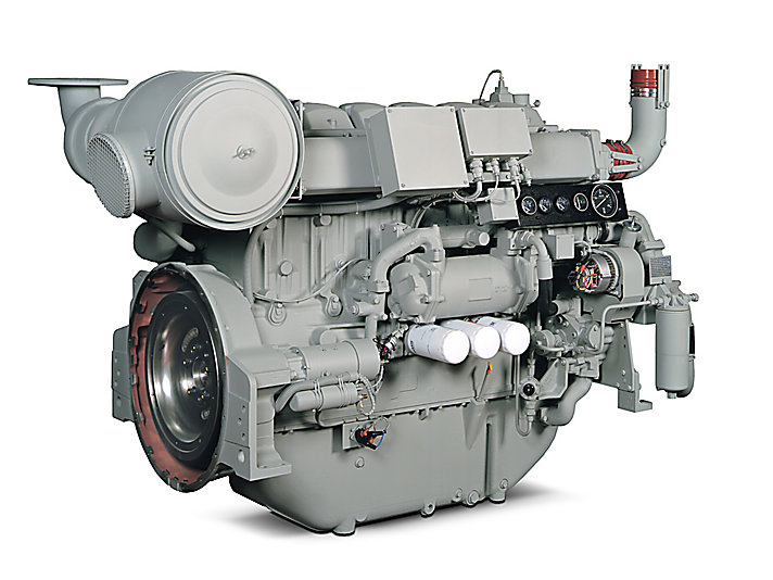
Perkins 4006-23TAG Diesel Engine
| Perkins 2806D-E18TA Industrial Engine – PDF Service Manual.pdf | 1.4Mb | Download |
| Perkins 2806F-E18TA Industrial Engine – PDF Service Manual.pdf | 2.1Mb | Download |
| PERKINS 4-108 SHOP MANUAL.pdf | 8.8Mb | Download |
| Perkins 400 Series 4016-E61TRS (Models 403C-11, 403C-15, 404C-22 and 404C-22T) Workshop Manual.pdf | 10.9Mb | Download |
| Perkins 4000 Series (4006-23 TAG1A, TAG2A and TAG3A Inline diesel engine) Workshop Manual.pdf | 6.7Mb | Download |
| Perkins 4000 Series Diesel Engine – PDF Service Manual.pdf | 1.3Mb | Download |
| Perkins 4000 Series Inline diesel engine – PDF Service Manual.pdf | 4.2Mb | Download |
| Perkins 4006 and 4008 Diesel engine – PDF Service Manual.pdf | 854.2kb | Download |
| Perkins 4006 and 4008 Diesel Engine – PDF Service Manual.pdf | 854.2kb | Download |
| Perkins 4006 TRS Gas and 4008 TRS Gas Industrial Engines – PDF Service Manual.pdf | 877.3kb | Download |
| Perkins 4006 TRS Gas and 4008 TRS GasIndustrial Engines Workshop Manual.pdf | 987kb | Download |
| Perkins 4006-23 and 4008-30 Industrial Engine – PDF Service Manual.pdf | 2.1Mb | Download |
| Perkins 400A and 400D Industrial Engine – PDF Service Manual.pdf | 1.1Mb | Download |
| Perkins 4012-46A Industrial Engine – PDF Service Manual.pdf | 1005.4kb | Download |
| Perkins 4016-61 TRG Industrial Engine – PDF Service Manual.pdf | 1.3Mb | Download |
| Perkins 4016-61TRS1 and 4016-61TRS2 Gas Engines – PDF Service Manual.pdf | 1Mb | Download |
| Perkins 402D-403D-404D Industrial Engine Disassembly and Assembly Manual.pdf | 1.7Mb | Download |
| Perkins 402D-403D-404D Industrial Engine PDF Service manual.pdf | 1.2Mb | Download |
| Perkins 402F-05, 403F-07, 403F-11, and 403F-15 Industrial Engines – PDF Service Manual.pdf | 3.2Mb | Download |
| Perkins 403F-15T, 404F-22 and 404F-22T Industrial Engines – PDF Service Manual.pdf | 4Mb | Download |
| Perkins 404A-22SG1 Gas Industrial Engine – PDF Service Manual.pdf | 1.4Mb | Download |
| Perkins 404F-E22T, 404F-E22TA and 403F-E17T Industrial Engines – PDF Service Manual.pdf | 2.4Mb | Download |
| Perkins 800D Series Industrial Engines – PDF Service Manual.pdf | 998.2kb | Download |
| Perkins 854E-E34TA and 854F-E34T Industrial Engine – PDF Service Manual.pdf | 2.1Mb | Download |
| Perkins 854F-E34TA Industrial Engine – PDF Service Manual.pdf | 1.9Mb | Download |
| Perkins DIAG1300 User manual.pdf | 609.4kb | Download |
| Perkins Diesel Engine 4-154 Workshop Manual.pdf | 3.1Mb | Download |
| Perkins Engine Fault Finding Guide.pdf | 1.3Mb | Download |
| Perkins Engine Number Guide.pdf | 76.6kb | Download |
| Perkins Phaser 4 – and 6-cylinder Workshop Manual.pdf | 27.7Mb | Download |
| PERKINS TIER2 DIESEL ENGINES 1100 (VK) Workshop Manual.pdf | 7.4Mb | Download |
| Perkins TPD1352 – PDF Service Manual.pdf | 1.4Mb | Download |
| The codes refer to the model range of engines Perkins.pdf | 177.9kb | Download |
| Workshop Manual for Perkins 4.108, 4.107 and 4.99 diesel engines.pdf | 5.3Mb | Download |
| Workshop Manual for Perkins 4.108M, 4.107M and 4.99M diesel engines.pdf | 9.2Mb | Download |
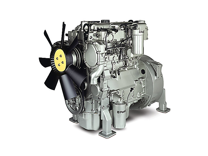
Perkins 1104C-44T Industrial Diesel Engine
Perkins Engine Spare Parts Catalogs
| Title | File Size | Download Link |
| Parts Book Part1 4008TAG2.pdf | 489.5kb | Download |
| Perkins 1104D Parts Manual.pdf | 8Mb | Download |
| Perkins 4 Cyl Engine Parts list.pdf | 94.3kb | Download |
| PERKINS 4-108 PARTS BREAKDOWN.pdf | 1.6Mb | Download |
| Perkins 6354 Fase IV Catalogue.pdf | 8.1Mb | Download |
| Perkins Diesel Engines Powered Product Catalogue 2011 – Parts&Service.pdf | 9.7Mb | Download |
| Perkins Engine Number Guide (UK).pdf | 81.4kb | Download |
| Perkins Gauges, Switches and Senders – Parts Catalogue.pdf | 886.7kb | Download |
| Perkins Parts Book.pdf | 3.6Mb | Download |
| Perkins Service Data Booklet.pdf | 1.5Mb | Download |
Perkins Engines Company Ltd is a British manufacturer of diesel engines for agricultural and construction equipment, as well as diesel generators, formed in 1932. The company’s headquarters is located in Peterborough, UK.
Currently Perkins Engines Company Ltd is a subsidiary of Caterpillar Inc.
The company was founded by Frank Perkins and Charles Chapman, who in 1932 set themselves the task of creating a powerful diesel engine in no way inferior to a gasoline engine. The result was the first diesel engine Vixen.
In 1969, the company was sold to Massey Ferguson Ltd, which later became part of LucasVarity PLC, after which development continued and new models appeared.
In the 1970s, the Company was bought by Caterpillar Inc for $ 1.335 billion.
At the moment, the company has manufacturing facilities in the UK, USA, Brazil, China and a joint venture with Ishikawajima-Shibaura-Machinery Company in Japan.
The result of the work was 18 million units of equipment around the world working with Perkins diesel engines.