
39
16
Апр 09
#1
vostochka93 пишет:
Такой ветки вроде бы не было еще, есть знающие данный продукт люди?? готовые помочь новичкам в их глупых вопросах??
Спрашивайте — ответим 

2092
14
Апр 09
#2
Tim Taller пишет:
Спрашивайте — ответим
может кто нить выложить в скриншотах как правильно забить композиционную модель кнденсатной скважины с обводненностью 1%, чтоб там был не только С.H…, но и фракции разгонки?? а то может я че то не то делаю, но с водой ошибка постоянно вылазиет
![]()
567
14
Апр 09
#3
vostochka93 пишет:
может кто нить выложить в скриншотах как правильно забить композиционную модель кнденсатной скважины с обводненностью 1%, чтоб там был не только С.H…, но и фракции разгонки?? а то может я че то не то делаю, но с водой ошибка постоянно вылазиет
Господа, вам необходимо в вашем составе убрать последние 7 фракций. В них, видимо, есть ошибка.
2092
14
Апр 09
#4
Alexey S пишет:
Господа, вам необходимо в вашем составе убрать последние 7 фракций. В них, видимо, есть ошибка.
Спасибо Алексей Я просто хотел еще от кого-нить что -нить услышать, а то кроме тебя тут похоже в данной программе не бельмясем
![]()
567
14
Апр 09
#5
vostochka93 пишет:
Спасибо Алексей
Я просто хотел еще от кого-нить что -нить услышать, а то кроме тебя тут похоже в данной программе не бельмясем
Я вроде это в письме тебе писал, которое последнее с скриншотом?
2092
14
Апр 09
#6
Alexey S пишет:
Я вроде это в письме тебе писал, которое последнее с скриншотом?
 ну надоже поддерживать активность темы
![]()
567
14
Май 09
#7
Уважаемые коллеги,
во вложенном файле находится небольшое руководство, которое позволяет задавать и, соответственно, моделировать в PIPESIM максимальное насыщение водой газа при пластовых условиях. Это актуально для газовых месторождений, где вода уже подошла к перфорациям.
Gas_saturation.pdf
2092
14
Май 09
#8
Alexey S пишет:
Уважаемые коллеги,
во вложенном файле находится небольшое руководство, которое позволяет задавать и, соответственно, моделировать в PIPESIM максимальное насыщение водой газа при пластовых условиях. Это актуально для газовых месторождений, где вода уже подошла к перфорациям.
спасибо
![]()
567
14
Май 09
#9
Уважаемые коллеги.
На сайте youtube, по адресу http://www.youtube.com/sisrussia мы выложили мувик по использованию Pipesim для оптимизации системы сбора и нахождения оптимального режима работы скважин. Возможно, это будет полезно для тех, кто работает с газом и газоконденсатом.
P.S. Данный мувик будет не единственный. Мы планируем создать серию коротких фильмов по использованию Pipesim для решения различных задач.
![]()
341
16
В Pipesim можно построить график зависимости GLR на приеме насоса от забойного давления, после Well-Flow тяжко освоиться 
![]()
567
14
Lyric пишет:
В Pipesim можно построить график зависимости GLR на приеме насоса от забойного давления, после Well-Flow тяжко освоиться
Конечно можно. Алгоритм построения зависимости находится в приложенном файле. Надеюсь — этот маленький туториал вам поможет быстрее освоиться с Pipesim.Pipesim_answer.doc
![]()
567
14
Уважаемые коллеги!
Некоторые из вас очень часто борятся с подбором ЭЦН. Рад вам предложить небольшой туториал-напоминалку по подбору ЭЦН в программе PIPESIM. В данном файлике описываются шаги, при помощи которых можно сделать анализ работы скважины и подобрать оптимальный насос. Основной плюс, как вы помните, в PIPESIM возможен анализ работы скважины не только в одиночном режиме, но и с учетом работы всей сети сбора.ESP_PIPESIM_sec.pdf
2092
14
Никаких больше обучалок не появилось?
![]()
7
16
Alexey S пишет:
Уважаемые коллеги,
во вложенном файле находится небольшое руководство, которое позволяет задавать и, соответственно, моделировать в PIPESIM максимальное насыщение водой газа при пластовых условиях. Это актуально для газовых месторождений, где вода уже подошла к перфорациям.
В новой версии PipeSim’a (2008) появился новый инструмент Flash Type «Separation». Можно по нему разъяснить поподробнее в таком же ключе?
![]()
341
16
Не подскажете как построить модель газонагнетательной скважины в Pipesim?
2092
14
я бы тоже хотел посмотреть кто нить в пдфе может скрины скинуть?
![]()
567
14
Lyric пишет:
Не подскажете как построить модель газонагнетательной скважины в Pipesim?
Модель строится также, как и добывающая. Единственное, если вы работаете в сетевом режиме, то выбирайте модель нагнетательной скважины (желтая иконка), а не добывающей (голубая иконка). Модели, в сетевом режиме, находятся на левой панели объектов.
![]()
341
16
Alexey S пишет:
Модель строится также, как и добывающая. Единственное, если вы работаете в сетевом режиме, то выбирайте модель нагнетательной скважины (желтая иконка), а не добывающей (голубая иконка). Модели, в сетевом режиме, находятся на левой панели объектов.
Ну тогда переформулируем: как построить нагнетательную скважинку не в сетевом режиме.
Такую казалось бы простую вещь у нас никто не строил.
Необходимо оценить потери на трение и гидростатику при закачке газа.
Может у вас есть готовая модель?
ЗЫ посчитал по «инструкции по комплексному изучению газовых скважин», теперь хочу сравнить с Pipesim’ом
![]()
567
14
Lyric пишет:
Ну тогда переформулируем: как построить нагнетательную скважинку не в сетевом режиме.
Такую казалось бы простую вещь у нас никто не строил.
Необходимо оценить потери на трение и гидростатику при закачке газа.
Может у вас есть готовая модель?ЗЫ посчитал по «инструкции по комплексному изучению газовых скважин», теперь хочу сравнить с Pipesim’ом
Это делается еще проще.
На устье скважины установите источник, направленный в скважину, и все, скважина из добывающей превращается в нагнетательную .
Моделька во вложении.
P.S. Моделька только для версий Pipesim 2009 и выше.Injection_Well.zip
![]()
341
16
Alexey S пишет:
Это делается еще проще.
На устье скважины установите источник, направленный в скважину, и все, скважина из добывающей превращается в нагнетательную
Моделька во вложении.
P.S. Моделька только для версий Pipesim 2009 и выше.
Слона то я и не заметил=)
Данке.
![]()
567
14
vostochka93 пишет:
Никаких больше обучалок не появилось?
Напиши, что хочешь увидеть. Постараемся нарисовать.
2092
14
Подскажите люди с чего начинать адаптацию сетевой модели. Насколько я понимаю надо сначала добиться реального забойного, потом буферного и затем линейного даволений. А какими параметрами нужно манипулировать и в каких пределах. ??
![]()
567
14
vostochka93 пишет:
Подскажите люди с чего начинать адаптацию сетевой модели. Насколько я понимаю надо сначала добиться реального забойного, потом буферного и затем линейного даволений. А какими параметрами нужно манипулировать и в каких пределах. ??
Адаптацию нужно начинать со скважин. Сначала идет работа с кривыми притока, затем с составом (или наоборот, в зависимости от времени проведения ГДИ) и только после этого с сетью сбора. На скважины тратится 90% времени. Стандартного рецепта для этого нет. Все зависит от типа флюида (нефть, газ, конденсат), набора имеющихся данных и параметров неопределенности.
Если скважины «сведены» правильно, то сеть сбора адаптировать, как правило, нет смысла. Все и так посчитается хорошо.
![]()
74
14
Здравствуйте!
Надеюсь на Вашу помощь.
Почему в файле отчета и итоговом файле размерности величин представленны в еденицах измерения EUROSi (я задаю свои единицы измерения)? Возможно ли это исправить?
Хотелось бы использовать свои ну или просто СИ.
И еще вопрос. Имеется трубопровод (транспортируемая среда — газ+мало воды), источник и сток. Можно ли узнать состав продукта на выходе из трубопровода(мольный, массовый)?
![]()
567
14
![]()
567
14
ShavedFish пишет:
В новой версии PipeSim’a (2008) появился новый инструмент Flash Type «Separation». Можно по нему разъяснить поподробнее в таком же ключе?
ShavedFish, во вложенном файле находится ответ на ваш вопрос. Как вы и просили, в картинках .Pipesim_answer_3.doc
2092
14
Alexey S пишет:
ShavedFish, во вложенном файле находится ответ на ваш вопрос. Как вы и просили, в картинках
Алексей, спасибо за помощь. С наступающим тебя
![]()
567
14
vostochka93 пишет:
Алексей, спасибо за помощь. С наступающим тебя
vostochka93, спасибо большое за поздравление. И тебя тоже с наступающим. Пусть в этом году сбудется твоя самая желаемая мечта . Удачи тебе.
![]()
74
14
Alexey S пишет:
ViDoCQ, ответы на ваши вопросы во вложенном файле.
Спасибо большое!
![]()
74
14
Возник еще один вопрос…
По условию задачи имеем следующую картину. Два источника. Один дает нефть (Qн=165т/час), другой газ(Qг=37782м3/час). Все это идет по одному трубопроводу длиной 101 км и диаметром 325х10. Проблема в том что расчет не проходит. В окне PipeSim Net Engine идет расчет. Величина ошибок не уменьшается, а остается постоянной. И после каждой итерации присутствует надпись: ERROR NOT REDUCING! — Check problem specification.
Подозрения вызывает диаметр трубопровода. Так как при увеличении до 600 мм расчет проходит на ура… Загвоздка в том, что данный трубопровод уже 3 года как эксплуатируют…(((
Что еще может влиять на невыполнение расчета?
![]()
567
14
ViDoCQ пишет:
Возник еще один вопрос…
…………………………..
Что еще может влиять на невыполнение расчета?
Ну, это как диагноз ставить на расстоянии.
ПО ругается на граничные условия. Чего-то там не то. Проверяем это.
Стандартно проверяем вязкости и методику расчета. Методику выставьте Beggs and Brill Revised.
Без модели сказать, думаю, не получится.
На какой версии ПО работаете?
![]()
74
14
Работаю в 2003 версии…
Спасибо!=)разобрался…как раз проблема была с граничными условиями=)
![]()
74
14
Форумчане!
Пожалуйста помогите! Кто может поделиться данными по скважинам, их расположению, выкидным линиям? Данная информация нужна для написания диплома. На бакалавре данные использовались «с потолка». Для магистерской работы руководитель требует реальные данные, которые мне достать практически не реально  Я понимаю, что информация такого рода запрещена к распростарнению… Но я все равно надеюсь на вашу помощь…
ЗЫ: можно не писать какое месторождение и кто с ним работает. можно как и нефтяные, так и газовые.
Заранее спасибо большое!!!
![]()
567
14
ViDoCQ пишет:
Работаю в 2003 версии…
Спасибо!=)разобрался…как раз проблема была с граничными условиями=)
А чего на такой старой ломаной версии работаете?
Удачи в дальнейших расчетах, Иршат . Пишите, если что-то непонятное опять возникнет.
![]()
74
14
Alexey S
Спасибо большое!=) Возможность достать версию по новее отсутствует… Денег нет)))
ЗЫ: Предыдущее мое сообщение все еще в силе=) Это я про данные…
![]()
74
14
Неужели ни кто не может помочь?
![]()
567
14
ViDoCQ пишет:
Неужели ни кто не может помочь?
ViDoCQ, в вашем городе есть, по крайней мере, 3 конторы где можно взять необходимые вам данные. Причем там их завались, на любой вкус и цвет. Необходимо только устроится туда на преддипломную практику.
![]()
74
14
Alexey S
Проблема в том, что я уже работаю…
А там данные по скважинам достать проблематично… я бы даже сказал нереально…потому что по роду своей деятельности контора ни как не связанна со скважинами…
И все же прошу хоть какой нибудь информаци…
![]()
567
14
ViDoCQ пишет:
Alexey S
Проблема в том, что я уже работаю…
А там данные по скважинам достать проблематично… я бы даже сказал нереально…потому что по роду своей деятельности контора ни как не связанна со скважинами…
Простите, а зачем вам тогда все эти расчеты и прочее, если ваша работа никак не связана с нефтью/газом?
![]()
74
14
Alexey S
Закономерный вопрос
Контора связана с нефтью и газом, но они не работают конкретно со скважинами…Хотелось бы продолжить бакалаворскую работу, начатую 2 года назад, есть наработки, методики, теоретический материал. Только для практической части нет ничего
ЗЫ: возник вопрос…в случае если скважины эксплуатируется ШГН, каким образом можно отобразить сей факт в моделе скважины?
![]()
567
14
ViDoCQ пишет:
возник вопрос…в случае если скважины эксплуатируется ШГН, каким образом можно отобразить сей факт в моделе скважины?
ViDoCQ, в версии 2003 никак . Только стоком, как так насос объемного типа.
![]()
74
14
Alexey S, тогда скажите пожалуйста, предоставляет ли Шлюмберже какую нибудь триал версию или демо версию Pipesim’а?
Желательно практически полный функционал и лицензия где то на 2-3 месяца… 
![]()
567
14
ViDoCQ пишет:
Alexey S, тогда скажите пожалуйста, предоставляет ли Шлюмберже какую нибудь триал версию или демо версию Pipesim’а?
Желательно практически полный функционал и лицензия где то на 2-3 месяца…
ViDoCQ, на физическое лицо лицензию получить практически невозможно. Можно на юридическое. Также есть такая штука, как лицензии для учебных заведений. В Томске, например, есть учебные лицензии Шлюмовского софта у ХВ.
![]()
74
14
Alexey S, ясна…
Цитата
лицензии для учебных заведений. В Томске, например, есть учебные лицензии Шлюмовского софта у ХВ.
Я сомневась, что меня туда пустят
И вряд ли они проводят политику раздачи бесплатных лицензий 
Похоже придеться искать данные по скважинам без ШГНов…
![]()
74
14
И снова Вас беспокою 
Цитата
Возник еще один вопрос…
По условию задачи имеем следующую картину. Два источника. Один дает нефть (Qн=165т/час), другой газ(Qг=37782м3/час). Все это идет по одному трубопроводу длиной 101 км и диаметром 325х10
По указанному выше вопросу возникла проблема… Возможно ли в Pipesim’е определить оптимальное место установки насосно-компресорной станции? Или нужно действовать методом проб и ошибок?
2092
14
ViDoCQ пишет:
И снова Вас беспокою
По указанному выше вопросу возникла проблема… Возможно ли в Pipesim’е определить оптимальное место установки насосно-компресорной станции? Или нужно действовать методом проб и ошибок?
Мне кажетсЯ надо просто посмотреть на каком километраже давление будет такое низкое, чтобы вставить туда дкс. Т.е. Смысл в том, что во первых ДКС имеет свое минимальное входное и максимальное выходное, вот и сориентируйся там по профилю давления
![]()
74
14
Цитата
Мне кажетсЯ надо просто посмотреть на каком километраже давление будет такое низкое, чтобы вставить туда дкс. Т.е. Смысл в том, что во первых ДКС имеет свое минимальное входное и максимальное выходное, вот и сориентируйся там по профилю давления
Мы сейчас так и делаем
Но начальство хочет чтобы было быстро и на компе Поэтому и интересуюсь, нет ли возможности провернуть операцию на ПК?
![]()
567
14
ViDoCQ пишет:
Но начальство хочет чтобы было быстро и на компе
Почему же нельзя? Если сильно хочется, то можно . Здесь, на мой взгляд все просто. В Pipesim’е есть технология OpenLink, позволяющая автоматизировать множество операций и расчетов. Делается это очень быстро, например через Excel.
В вашем случае можно написать небольшой алгоритм в виде скрипта или маленькой программы, которая будет рассчитывать оптимальную точку установки КС для модели Pipesim. Этот алгоритм «вешается» на кнопку и все будет так, как хочет ваше руководство .
P.S. Тут, конечно, есть нюансы в виде ограничений по помпажу, рабочим кривым, оборотам и так далее, но все это возможно предусмотреть и использовать.
![]()
74
14
Появился еще один вопрос…
Касается он теплообмена в параметрах труб. На выбор предлагается 2 варианта: Ввести значение U и Расчитать значение U.
Вопросы такие:
1. Расчет будет производиться только в том режиме который активен, то есть выбран нами?
2. Если я выбираю один режим, то для другого данные забивать уже не нужно?
![]()
567
14
ViDoCQ пишет:
Появился еще один вопрос…
Касается он теплообмена в параметрах труб. На выбор предлагается 2 варианта: Ввести значение U и Расчитать значение U.
Вопросы такие:
1. Расчет будет производиться только в том режиме который активен, то есть выбран нами?
2. Если я выбираю один режим, то для другого данные забивать уже не нужно?
ViDoCQ, вы сами ответили на свои вопросы. Какой вы интересный собеседник .
Страницы
- 1
- 2
- 3
- 4
- 5
- следующая ›
- последняя »
Сейчас Вы — Гость на форумах «Проектант». Гости не могут писать сообщения и создавать новые темы.
Преодолейте несложную формальность — зарегистрируйтесь! И у Вас появится много больше возможностей на форумах «Проектант».
Последние сообщения на Технологическом форуме
18 Апреля 2023 года, 09:28
18 Апреля 2023 года, 09:27
17 Апреля 2023 года, 06:43
12 Апреля 2023 года, 13:41
12 Апреля 2023 года, 11:49
11 Апреля 2023 года, 15:31
11 Апреля 2023 года, 15:21
10 Апреля 2023 года, 11:24
07 Апреля 2023 года, 12:24
07 Апреля 2023 года, 10:36
06 Апреля 2023 года, 08:04
04 Апреля 2023 года, 17:36
31 Марта 2023 года, 20:20
30 Марта 2023 года, 13:49

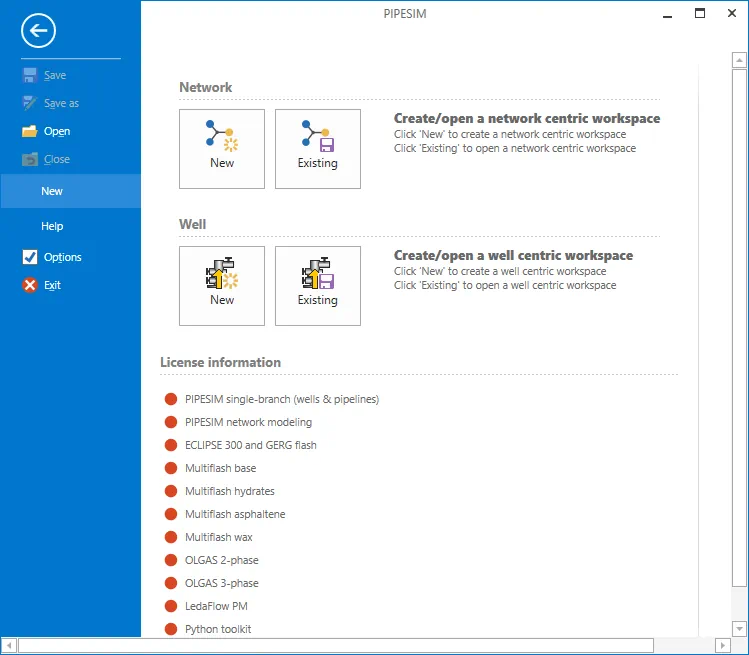
PIPESIM – это программный комплекс, при помощи которого можно проектировать процесс добычи каких-то веществ, имеющих жидкое состояние.
Описание программы
Русского языка тут нет. Низкого порога входа тоже. Для того чтобы разобраться с программой вам нужно, либо быть специалистом, либо просмотреть нескольких обучающих роликов на YouTube.
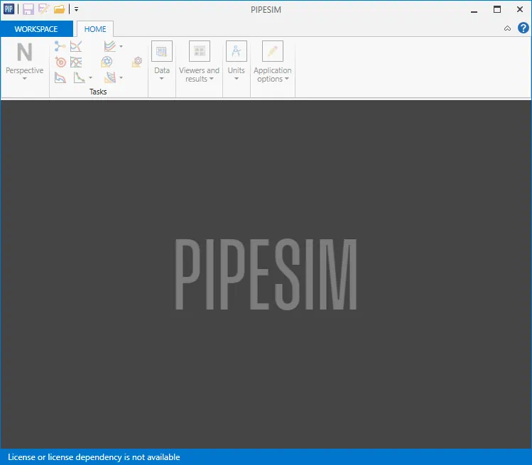
Данное приложение распространяется в уже крякнутом виде и не требует активации сразу после установки.
Как установить
Для полноты картины давайте разберём процесс правильной инсталляции ПО:
- Перейдите к разделу загрузки, а затем, воспользовавшись торрент-раздачей, скачайте новейшую версию софта.
- Делаем двойную левый клик на исполняемом файле, а затем в появившемся окне выбираем кнопку «Install Products».
- Ждём завершения процесса копирования файлов по своим местам.
Как пользоваться
Приложение установлено. Теперь мы можем переходить к его использованию. В первую очередь нужно создать новый проект, дать название, указать параметры и так далее. Дальше при помощи инструментов, которые находятся в верхней части окна, производится расчёт добычи веществ.
Достоинства и недостатки
Обязательно разберём положительные, а также отрицательные свойства PIPESIM.
Плюсы:
- набор уникальных инструментов.
Минусы:
- нет русского языка;
- сложность освоения и использования.
Скачать
Приложение весит достаточно много. Скачивание предусматривается через торрент.
| Язык: | Английский |
| Активация: | Крякнутый |
| Платформа: | Windows XP, 7, 8, 10, 11 |
PIPESIM 2021.1.687
-
PIPESIM
Open Link
-
Schlumberger 2 Open Link
Copyright 2008 Schlumberger. All rights reserved.
No part of this manual may be reproduced, stored in a retrieval
system, or translated in any form or by any means, electronic or
mechanical, including photocopying and recording, without the prior
written permission of Schlumberger Information Solutions, 5599 San
Felipe, Suite 1700, Houston, TX 77056-2722, USA.
Use of this product is governed by the License Agreement.
Schlumberger makes no warranties, express, implied, or statutory,
with respect to the product described herein and disclaims without
limitation anywarranties of merchantability or fitness for a particular
purpose. Schlumberger reserves the right to revise the information
in this manual at any time without notice.PIPESIM
-
Schlumberger 3 Open Link
Table of Contents Open Link Reference Manual
………………………………………………………………………………………………………………
5Overview
…………………………………………………………………………………………………………………………………
5 Modules and Interfaces
……………………………………………………………………………………………………………
6Quick Start Tutorial
…………………………………………………………………………………………………………………………….
7 Loading and running an existing model
……………………………………………………………………………………
7 Getting results
…………………………………………………………………………………………………………………………
9 Changing BlackOil fluid parameters
…………………………………………………………………………………………
9 Changing a choke property
………………………………………………………………………………………………………
9 Saving the
changes…………………………………………………………………………………………………………………..
9Case Study 1 Building a Well Model from Excel
………………………………………………………………………………
11 Problem Outline
…………………………………………………………………………………………………………………….
11
Requirements…………………………………………………………………………………………………………………………
11
Procedure………………………………………………………………………………………………………………………………
11 Step by step
tutorial……………………………………………………………………………………………………………….
11Case Study 2 — Nodal
Analysis…………………………………………………………………………………………………………….
21 Problem Outline
…………………………………………………………………………………………………………………….
21
Requirements…………………………………………………………………………………………………………………………
21
Procedure………………………………………………………………………………………………………………………………
21 Step by Step Tutorial
……………………………………………………………………………………………………………..
21Modules and Interfaces
……………………………………………………………………………………………………………………..
27 ISingleBranchModel
Interface………………………………………………………………………………………………..
27 IObjectProperties Interface
……………………………………………………………………………………………………
31 ITubing
Interface……………………………………………………………………………………………………………………
32 IVertCompObj Interface
…………………………………………………………………………………………………………
34 IFlowlineObj Interface
…………………………………………………………………………………………………………..
35 IHeatTransfer
Interface………………………………………………………………………………………………………….
35 IFluid
Interface………………………………………………………………………………………………………………………
36 IProjectInfo Interface
…………………………………………………………………………………………………………….
37 IErosionCorrosion
Interface…………………………………………………………………………………………………..
37 INetModel
Interface……………………………………………………………………………………………………………….
38 ModelBuilder object
………………………………………………………………………………………………………………
43 IBlackOil
object……………………………………………………………………………………………………………………..
43 ISinglePointCalib
object…………………………………………………………………………………………………………
44 IMultiPointCalib object
………………………………………………………………………………………………………….
45 IViscosityData
object……………………………………………………………………………………………………………..
46 IThermal object
……………………………………………………………………………………………………………………..
47 ICompositional object
……………………………………………………………………………………………………………
48 FlowCorrelations
Interface…………………………………………………………………………………………………….
51 Single Branch
Operations……………………………………………………………………………………………………….
52 Systems Analysis
……………………………………………………………………………………………………………………
52 Pressure and Temperature Profiles
………………………………………………………………………………………..
54 Flow Correlation Matching
…………………………………………………………………………………………………….
55 Nodal Analysis
……………………………………………………………………………………………………………………….
56 Wax Deposition
……………………………………………………………………………………………………………………..
58 Single Branch Operations: Supporting
Interfaces……………………………………………………………………
59 IBoundaryProps
Interface………………………………………………………………………………………………………
59 IEngineOptions Interface
……………………………………………………………………………………………………….
59 Gas Lift Diagnostics COM
Object……………………………………………………………………………………………
59 GLWell Interface and
Object…………………………………………………………………………………………………..
59 IGLDesign Object
…………………………………………………………………………………………………………………..
66 IDesignParams Object
……………………………………………………………………………………………………………
69 IDesignBias
Object…………………………………………………………………………………………………………………
69 IGLValveSystem Object
………………………………………………………………………………………………………….
70 Single Branch Output Reader COM
………………………………………………………………………………………..
71 PerformCurve
Object……………………………………………………………………………………………………………..
75PIPESIM
-
Schlumberger 4 Open Link
PNSReaderCOM
…………………………………………………………………………………………………………………….
77 Inflow Performance Calculator COM
……………………………………………………………………………………..
83 Units Library
………………………………………………………………………………………………………………………….
85Defined constants and strings
……………………………………………………………………………………………………………
87 Object Type Identifiers
…………………………………………………………………………………………………………..
87 Object Properties
…………………………………………………………………………………………………………………..
87 Tubing objects properties
……………………………………………………………………………………………………..
91 Artificial
Lift…………………………………………………………………………………………………………………………..
93 Completion
Options……………………………………………………………………………………………………………….
93 IPR Types
(Vertical)……………………………………………………………………………………………………………….
93 IPR Types
(Horizontal)…………………………………………………………………………………………………………..
94 IPR Options (Horizontal)
……………………………………………………………………………………………………….
94 Fluid Types
……………………………………………………………………………………………………………………………
94 Pipe Flow
Types…………………………………………………………………………………………………………………….
94 Rate
Types……………………………………………………………………………………………………………………………..
94 Separator Types
…………………………………………………………………………………………………………………….
94 Single Branch
Operations……………………………………………………………………………………………………….
94Unit
System……………………………………………………………………………………………………………………………………….
96 Case
Studies………………………………………………………………………………………………………………………………………
99Detailed explanation of
routine………………………………………………………………………………………………
99PIPESIM
-
Schlumberger 5 Open Link
Open Link Reference Manual Overview This guide is designed to
explain how to use Open Link to interface with PIPESIM from
external applications. An overview of the functionality of Open
Link is provided along with the necessary interface functions and
arguments. This allows you to load both network and single branch
PIPESIM models, query them (equipment configuration, gas lift
injection, etc.), and perform simulations. Basic Functions The
functions described in this document fall into the following
categories; Get functions — Get the results after a simulation or
query an item for its current data value,such as obtaining the choke bean size. Set functions — Set a
valve to be used in subsequent simulation, such as setting the
reservoirpressure. Operation functions — Perform an operation on a model,
such as running a simulation. Potential Usage The Open Link
functionality could be used in the following cases: Running PIPESIM
in batch mode with a number of scenarios Creating custom reports
Importing production data from a database and populating the models
Running PIPESIM in-conjunction with other Engineering applications.
Hyprotech have alreadyused this functionality to link Hysys and PIPESIM. Utilizing
Open Link The Open Link functions can be called from any of the
following: VBA macro. This could be written in Excel, Access, etc.
Visual Basic programs. C++ programs Supported Interfaces INetModel:
for network models and network operations ISingleBranchModel: for
single branch models and operations Dependency MAP Open Link can be
used to access PIPESIM functionality from external programs. The
programs that can automate PIPESIM simulations are those that are
defined as automation clients according to Microsoft standards, and
in the same way, Open Link is an automation server. Typical
examples of automation clients include VBA (Visual Basic for
Applications) macros, which can be written from programs such as
Excel or Access, C++ and Visual Basic. Open Link provides therefore
an open architecture where you control and automate PIPESIM
simulation models through custom programs or macros without having
to manually enter the data or view the results using the graphical
interface. It is assumed you are familiar with both PIPESIM and the
chosen program or programming language in which the automation code
is to be written. Those new to VBA are recommended to closely
follow the Quick Start Tutorial and the Case Studies. The Open Link
functionality is distributed with the PIPESIM installation and is
included in a number of library files. The main file is
Net32COM.DLL, which normally resides in the programs directory
andprovides the framework and main entry points into both networks
and single branch simulation models. Net32COM.DLL must be copied to
the PIPESIM programs directory and registered.There are other files that support Net32COM, for instance
FluidModelCOM.DLL and FlowCorrelationCOM, which provide access to
properties defined in the fluid models and flow correlations
respectively.Each library file, in turn, defines at least one interface,
which is a logical entry point into a well-defined area of
functionality. Each interface includes a number of public access
functions that set or get a specified property or just perform
operations (that is run a simulation). As an example the
FluidModelCOM library defines two interfaces: IBlackOil, for black
oil models and ICompositional, to deal with compositional models.
IBlackOil defines property functionsPIPESIM
-
Schlumberger 6 Open Link
such as API, Watercut or GasSG. These properties can be set
(assigned) to a model prior to a simulation run or they can be get
(retrieved) and copied into an Excel cell.The Modules and Interfaces section lists the modules and
interfaces that are part of Open Link. This document contains
further details of the modules and interfaces, together with some
code samples. Highlighted items represent information that is new,
previously unpublished or amended from the previous PIPESIM
release. The present reference guide applies to the release version
2008.Modules and Interfaces Module Name Interfaces Remarks
Net32COM.DLL INetModelISingleBranchModel IObjectProperties TubingObj InjectorObj
VertCompObj FlowlineObj ErosionCorrosion HeatTransferNetwork models and operations Single branch models and
operations Generic equipment properties Tubing specific properties
and operations Injector specific properties Vertical completion
specific properties Flowline specific properties and operations
Erosion and corrosion settings Heat transfer propertiesPSOpSystems.DLL IISystemsAnalysis IIPTProfile IICorrMatching
Systems Analysis operation Pressure/Temp Profiles operation Flow
Correlation Matching operationNodalOp.DLL IINodalAnal Nodal Analysis Operation
FluidModelCOM.DLL IBlackOilICompositional SinglePointCalib MultiPointCalib ViscosityData
ThermalBlack Oil model properties Compositional model properties BO
single point calibration properties BO multipoint calibration
properties BO viscosity properties BO thermal propertiesFlowCorrelationCOM.DLL CIFlowCorrelation Vertical and horizontal
flow correlation propertiesUnitsCOM.DLL IUnitSystem General unit conversions GLDiagn.DLL
GLWell Gas lifted well model for diagnostics WaxOp.DLL IWaxOp Wax
deposition operationPIPESIM
-
Schlumberger 7 Open Link
Quick Start Tutorial This quick start guide shows macro code
written in VBA using Microsoft Excel. Even though each language
implements its own particular syntax, the basic logic to write an
Open Link code or macro will be identical. A number of case studies
along with VBA code using Excel are provided under the ..Case
StudiesOpen Link directory. 1. Before you start — you must let VBA
know about the Open Link interfaces. To do this, clickon Tools | References from the main menu in the VBA window. You
should now see a dialog box like the one below.2. Scroll down the list of available references until you find
the Net32COM 1.0 Type Library.Check the box to the left of the reference. 3. Now do the same
for the FluidModelCOM 1.0 Type Library and for PNSReader 1.0 type
library. 4. Click on OK to close the References window. Loading and
running an existing model 1. Load the existing network model: Small
Network.bpn, which is shipped with the PIPESIMinstallation and normally located in: C:Program
FilesSchlumbergerPIPESIMCase StudiesNetwork AnalysisSmall
NetworkIf the model were opened from the PIPESIM graphical interface it
would look like the picture below:PIPESIM
-
Schlumberger 8 Open Link
2. Using the VisualBasic editor (you can quickly open it from
Excel using the shortcut Alt+F11)create a variable of the type INetModel to perform the basic
interaction with the network model. We will call it NetModel: Dim
NetModel As New NET32COMLib.INetModel3. Open the model: NetModel.OpenModel C:Program
FilesSchlumbergerPIPESIMCase StudiesNetwork AnalysisSmall
NetworkSmall Network.bpn4. Run the model (asynchronously): NetModel.RunNetwork2 False,
«-B»The first argument, in this case False tells the calculation
engine not to use a restart file and the second argument -B is an
engine switch that instructs the engine to run in batch mode. For
more information on engine commands please refer to the PIPESIM
help. When executing this macro you should see the calculation
engine running in the background. This process is run
asynchronously which means that the macro will continue its
execution without waiting for the simulation run to finish. If you
want your macro to stop until the engine terminates in order to,
say, display a result,then you can replace the line above by the following code:
NetModel.RunNetwork2 False, «-B» bRunning =
NetModel.GetIsModelRunning While bRunning = True bRunning =
NetModel.GetIsModelRunning newHour = Hour(Now()) newMinute =
Minute(Now()) newSecond = Second(Now()) + 1 waitTime =
TimeSerial(newHour, newMinute, newSecond) Application.Wait waitTime
Wend MsgBox «Finished…»This code will run the simulation synchronously. It starts the
simulation and then waits until it is finished. It checks every one
second for the engine status through a call to GetIsModelRunning.
When GetIsModelRunning it returns False indicating that the
simulation run is finished, the macro code displays a message
box.PIPESIM
-
Schlumberger 9 Open Link
Getting results We would like to display some results from the
simulation. The library that reads the results file is PNSReader
and we must create a variable of the type PNSCom in order to
extract data from the simulation output. The public access
functions available in PNSReader are detailed in PNSReaderCOM. 1.
Create a PNSCom variable, lets call it results:Dim results As New PNSREADERLib.PNSCom 2. Read the results file.
This file is located in the same directory as the model file and
has thesame file name but with the extension .pns:
results.ReadPnsFile(C:Program FilesSchlumbergerPIPESIMCase
StudiesNetwork AnalysisSmall NetworkSmall Network.pns)3. Get the pressure and temperature at the sink Sink_1 (see
model picture above) Dim index as Long Dim pressure as Double Dim
temperature as Double index = results.GetNodeIndex(Sink_1) pressure
= results.GetNodeVariableValue (index, «Pressure») temperature =
results.GetNodeVariableValue (index, «Temperature «)In the same way variables such as LiquidRate, GasRate, MassRate,
GLR or WaterCut can be obtained for Sink_1 or any other node in the
network.Changing BlackOil fluid parameters So far, we have opened, run
and obtained results for a network model as it was originally
defined within the PIPESIM graphical interface. In this step, we
will change some parameters to the opened model. Here is where the
true power of Open Link starts to show, the Excel spreadsheet may
define a range of values to be tested in the context of a what if
scenario and multiple simulation jobs may be set up to compare
results for a range of input values for one or more properties. 1.
Create a BlackOil variable:Dim BlackOil As New FLUIDMODELCOMLib.IblackOil 2. Get the
BlackOil model from the networkSet BlackOil = NetModel.BlackOilDefault The BlackOil variable
has been filled with the values defined in the blackoil model in
NetModel. You can corroborate this by adding a watch with the VBA
debugging tool and inspecting the different variable fields. 3. Set
a Watercut value of 15%:BlackOil.Watercut = 15 4. Set an API value of 27.5:
BlackOil.API = 27.5 5. Set this BlackOil with a modified
watercut and API back into the network:NetModel.BlackOilDefault = BlackOil 6. You can now re-run the
model with this new values, get the new results, display them in
anExcel cell or plot, etc.
Changing a choke property 1. The following piece of code sets a
new value for the choke bean size in Choke which isdefined in the single branch model that corresponds to the
production well Well_1. NetModel. SetPropertyVal (Choke, Well_1,
«Bean Size», 3.5, «inches»)The above line sets bean size = 3.5 inches to Choke in Well_1.
.Saving the changes 1. Any changes made to a single branch or
network model can be saved simply by calling theSaveModel() function. Dim bOK as Boolean bOK =
NetModel.SaveModel(C:MyOpenLinkModelsNetwork.bpn)PIPESIM
-
Schlumberger 10 Open Link
The argument is the full path to the file where the model will
be saved. It can also be re-saved to the original model file. 2.
bOK will be TRUE (1) or FALSE (0) depending on whether the save
operation succeeded ornot. As with all Open Link function calls that return a
TRUE/FALSE state, a FALSE value indicates that some kind of error
condition occurred and an error description can be obtained by
calling GetLastError(): Dim Error as String If bOK = False Then
NetModel.GetLastError Error MsgBox errorStr End IfPIPESIM
-
Schlumberger 11 Open Link
Case Study 1 Building a Well Model from Excel Problem Outline It
is often desired to build PIPESIM well models from a corporate
database. The problem can be solved by: 1. Pasting the wells data
in excel. 2. Using a VBA routine containing Open Link statements to
automate the Bps files creation. This case study illustrates the
resolution of such a problem.Requirements It is assumed that the reader is familiar with the
basics of building models in PIPESIM. No prior knowledge of VBA
(Visual Basic For Application) is required. VBA is a programming
language that is accessed from Microsoft Excel. VBA statements can
be used to interact with Microsoft Applications. These statements
cannot interact with PIPESIM. Open Link is the name given to a
group of statements that can be used in VBA to interact with
PIPESIM.Procedure 1. Create a Well Model Template. (That is build a well
model in PIPESIM but do not fill any ofthe objects that make up the model with values). Save the well
model template with the name template.bps.2. Organize the wells data in tabular form in Excel. 3. Write
the VBA routine that will create a Bps file for each well of the
spreadsheet. (The routinewill make use of the model template.bps as will be shown further
down in the text). 4. Run the routine The Bps are created and
stored in a directory specified in the routine. Step by step
tutorial Create a Well Model Template 1. Open PIPESIM Open a new
well performance analysis window as shown below.2. Create the following Well Model in the opened window. 3. Save
the model with the simple model description selected in both the
tubing object and theflow line object. This is done by double-clicking on both the
flowline_1 and tubing_1 object, selecting simple model in each user
form and pressing on the button OK.PIPESIM
-
Schlumberger 12 Open Link
4. Save the well model under the name template.bps with the
following path:D:/OpenLink/template/template.bps Create a table of wells data
in Excel (2 vertical gas wells) 1. Open Excel. 2. In the Opened
workbook, select sheet 1 (the sheet should be selected by default).
3. Create the following table in Excel (4 Rows 24 Columns).4. Start the table at the cell $A$4 and finish at the cell $X$7.
5. List of the 24 columns (A to X in order) (The values are given
for each column):A: General Data:
Index. (1,2) Field. (Field1, Field2) Well Number (435,436)
Gathering Station (Man1,Man2) B: Black Oil Data:Gas Gravity (lbs/cu.ft gas sc) /(lbs/cu.ft air sc). (62,62) Oil
API (Field1, Field2) GOR scf/bbl (800000,900000) Water Cut %
(10,20) C: Completion Data:Pws Psia (Static pressure of the reservoir). (1800,3000)
Temperature F (200,200) PI mmscf/d/psi2 (1.5053E-08,1.7427E-7) D:
Tubing Data:Perforation MD m (2104,2104) Perforation TVD m (2104,2102)
Tubing 1 MD m (2054,2052) Tubing 1 ID (2.44,2.44)PIPESIM
-
Schlumberger 13 Open Link
Tubing 2 MD (Casing MD) (2104,2104) Tubing 2 ID (Casing TVD)
(5.5,5.5) E: Flow line Data:Flow line elevation (m) (0,0) Flow line ID (3,3) Flow line
Length km (4.305,1.212) F:Choke Data:Choke Size 1/64th. (95,95) G: Production Data:
Gas Rate mmscf/d (0.041,1.39) Well Head Pressure psia (195,250)
Pressure at the end of the flow line. psia (150,440)6. In cell $A$8 write the template path:
D:/OpenLink/template/template.bps 7. In cell $A$9 write the path in
which the Bps files are to be stored:D:/OpenLink/ 8. In cell $D$11 write the surface temperature: 90
F. 9. Save the current workbook under the name Openlink.xls with
the following path:D:/OpenLink/Excel/Openlink.xls Preliminary steps 1. Enable
Macros in your workbook. 2. Select the Menu tools Sub Menu Macro
Security as shown below.PIPESIM
-
Schlumberger 14 Open Link
The following user form should appear:
3. Select Medium. High does not let the user run any unsigned
Macros. 4. Insert a Button in the workbook that will launch the
routine. First, display the ControlToolbox Toolbars.
PIPESIM
-
Schlumberger 15 Open Link
5. Then insert a button in the spreadsheet by clicking on the
Command Button Icon in the Control Toolbox; and clicking and
dragging the button in the spreadsheet. This is shown below:Design Mode Icon.
Command Button Icon.
The default name of the button is CommandButton1. Note: Clicking
on the Command Button icon activates the design mode that allows
you to place buttons and other types of controls in the
spreadsheet. You will need to deactivate the design mode manually
when you want the routine associated with the button to be executed
when you click on it.PIPESIM
-
Schlumberger 16 Open Link
6. Next change the name of the button by right-clicking on the
button CommandButton1 the following menu should appear:7. Click on CommandButton Object Submenu Edit. You can now
change the caption of thebutton CommandButton1 to: Create Well Model. 8. Open the VBA
Editor Windows. As the design mode is activated, it is possible to
open the VBAeditor windows by double-clicking on the button CommandButton1.
The following window should then appear: Private Sub
CommandButton1_Click() End SubThe window that contains the statements is called the Code
window. You write VBA routines in the Code window. The word Sub in
the first line indicates to the computer that it is the beginning
of a new routine. (In effect, several routines can be written in
the same Code window). The word CommandButton1_Click in the first
line indicates to the computer that the routine following can only
be executed by clicking on the button CommandButton_1. The
statement End Sub indicates to the computer that this is the end of
the routine. Any routine must finish with this statement.
Activating the Open Link statements Libraries. In order to be able
to write our routine using Open Link statements we need to indicate
to the computer that we are going to use those statements. We need
to activate those statements so that they can be understood by VBA.
1. We can activate the Open Link statements by clicking on the menu
Tools, submenuReferences.
PIPESIM
-
Schlumberger 17 Open Link
You should now see a dialog box like the one below:
2. Scroll down the list of available references until you find
the FluidModelCOM 1.0 Type Library.Check the box to the left of the reference. 3. Now do the same
for Net32COM 1.0 Type Library and NODALOPLib.INodalAnal. 4. Click
on OK to close the reference window. Each of the three library
activated is a group of Open Link statements that can be used in
VBA to communicate with PIPESIM. These libraries will be available
from Excel after having installed PIPESIM. They need to be
activated before they can be used while programming. Note: If a
routine is passed from one computer to another, and it does not
work on the receiving computer, it is because the Open Link
Libraries have not been activated. Write the VBA routine using Open
Link Statements: 1. Write the following routine: The actual
workings of the routine will be explained in Case Studies.PIPESIM
-
Schlumberger 18 Open Link
PIPESIM
-
Schlumberger 19 Open Link
PIPESIM
-
Schlumberger 20 Open Link
Run the routine 1. Go back to Excel and select the two wells
with the mouse (by highlighting the correspondingrows) you will have created two .bps files corresponding to the
two wells of the spreadsheet. The directory Open Link will contain
the two .bps Files (shown below).PIPESIM
-
Schlumberger 21 Open Link
Case Study 2 — Nodal Analysis Problem Outline It is required to
see if our production data is consistent with what the model
predicts the flow rate should be. We will run a nodal analysis on
each of the wells. The boundary conditions of the problem are the
reservoir static pressure and the outlet pressure of the model
(i.e. the downstream end of the flow line). The Stock tank gas flow
rate at the operation point will be compared to the Gas flow rate
given in the production data.Requirements It is assumed that the reader is familiar with the
PIPESIM Nodal Analysis User Form.Procedure You will write a VBA-Open Link routine that uses the
table built in the previous case study. The routine fills in a
Nodal Analysis operation interface using the static pressure,
tubing ID and Outlet Pressure stored in Excel and then assigns this
Nodal Analysis operation interface to the Well Models created in
Case study 1. Each of the models is then run. A Nodal Analysis plot
(system plot_.plt) is produced for each well. You can then check on
the graphs if the stock tank flow rates at the operation points are
consistent with the production data.Step by Step Tutorial 1. Open the Excel File (OpenLink.xls)
D:/OpenLink/Excel/Openlink.xls 2. Insert a second button in the
Spreadsheet. This is done using the control toolbox as in CaseStudy 1. The default name of the button will be
CommandButton2.3. Open the VBA editor. This is done as in Case Study 1 by
double clicking on the buttonCommandButton2. The code written for the previous case study
will be visible. Private Sub CommandButton2_Click() End SubPIPESIM
-
Schlumberger 22 Open Link
At the end of the code, from the previous case study, the
statements are visible. This is shown below:Write the VBA routine using Open Link statements 1. Write the
routine: The workings of the routine are explained in Case
Studies.PIPESIM
-
Schlumberger 23 Open Link
PIPESIM
-
Schlumberger 24 Open Link
PIPESIM
-
Schlumberger 25 Open Link
Run the routine 1. Go back to Excel and select the two wells (by
highlighting the corresponding rows). 2. Press the button
CommandButton_2. This runs a nodal analysis on the two .bps
filesproduced in Case Study 1. The contents of folder Open Link after
having run the routine is shown below:. plt Files.
3. Clicking on the .plt files will display the following
graphs:.
Plot of Man1_435
PIPESIM
-
Schlumberger 26 Open Link
Plot of Man2_436
PIPESIM
-
Schlumberger 27 Open Link
Modules and Interfaces NOTE: 1. Values returned as -7777 mean
‘UNSET’ or could not calculate do to missing data or has notbeen calculated. 2. For all modules and interfaces, where
applicable, required methods in are shown in RED andthose conditionally required in GREEN.
ISingleBranchModel Interface ISingleBranchModel object — Get
Methods GetNameList (ObjectType As Long,pNameArray, Count As Long) Returns in pNameArray an array of
String with the names of objects of the given type (ObjectType).
The number of objects found is returned in Count. ObjectType can be
any value of: 10 — Generic Source 11 — Vertical Completion 12 —
Horizontal Completion 13 — Flowline 14 — Riser 15 — Zero length
connector 16 — Tubing 17 — Generic Node 18 — Choke 19 — Compressor
20 — Expander 21 — Heat Exchanger 22 — Centrifugal Pump 23 —
Multiphase Booster 24 — Injection Point 25 — Separator 26 — Report
tool 27 — Adder/Multiplier 28 — Nodal Analysis Point 29 — Engine
Keyword Tool 30 Reinjector 32 SSSV 33 Gas Lift Valve 34 Black
BoxGetEquipmentInfo (EquipmentType As Long, ParentType As Long,
ParentObject As String, EquipmentNames, Count As Long)If ParentObject string is empty, the function is the same as
GetNameList (). See GetNameList () for a map to EquipmentType
options. Otherwise it returns in EquipmentNames array of String
with the names of child objects of the given type (ObjectType) for
specified ParentObject of ParentTypeGetHasArtificialLift (ObjectType As Long, ObjectName As String,
Lift As Long)Returns 0: no artificial lift 1: gas lift injection 2: ESP -1:
Object not found ObjectType must be Tubing type (16) ObjectName the
name of the tubingGetStartBoundaryObject (ObjectType As Long, ObjectName As
String)Returns the ObjectType (See GetNameList ()) and its name of the
upstream-most object in the single branch model.PIPESIM
-
Schlumberger 28 Open Link
GetCountObjectsInProfile (Count As Long)
Returns the number of objects in the single branch model
GetObjectAtIndex (Index As Long, ObjectType As Long, ObjectName
As String)Returns the object’s type and name at the specified zero-based
index. Index must between zero and the number returned by
GetCountObjectsInProfile () minus 1.GetLastError (ErrorStr As String) Returns the last error message
produced by the interface.GetIsModelRunning () As Boolean Returns Boolean value True if
the simulation process is activeGetOperationInterface (pIOperation As Object)
Returns the operation object
GetOperationType () As Long Returns Long value as the operation
defined for the model. See Defined constants and stringsGetPropertyNames (ObjectName As String, PropNames) as Long
Returns in PropNames the list of properties defined for the
object ObjectName. Returns the number of properties as functions
return valueGetPropertyVal (ObjectName As String, PropName As String, pValue
As Double, pUnitStr As String) As BooleanFor specified property (PropName) in the specified object
(ObjectName) function gets a property value in Value and the units
in UnitStr. Return value is True if the property was retrieved
successfully, otherwise False. For implemented PropNames see
Defined constants and strings.GetPropertyValAtObjectIndex (ObjectName As String, PropName As
String, pValue As Double, pUnitStr As String, SubObjectType As
Long, Index As Long) As BooleanGets a specified property value. This function extends the
functionality of GetPropertyVal by allowing you to retrieve a
property from a specified sub-component within an object. A typical
use of this is when for instance it is required to get a gas lift
flowrate (PropName) from the top (Index = 0) gas lift injection
point (SubObjectType) in the tubing Tubing_1 (ObjectName). For
available options see Defined constants and stringsGetPropertyStringAtObjectIndex (ObjectName As String, PropName
As String, pValue As String, Index As Long) As BooleanThe function is similar to GetPropertyValAtObjectIndex but for
properties defined as stringGetPropertyType (ObjectName As String, PropName As String) As
LongReturns the property type: UNDEFINED -1 REAL 0 (value in strict
SI units) INT 1 DOUBLE 2 STR 3GetSensitivityInfo (ObjectType As Long, ObjectName As String,
VariableNames, ItemReference)Returns the list of variable names upon which a sensitivity
analysis can be performed for the given object (defined by its type
and name). See GetNameList () for object type values. ItemReference
holds additional binary information about the sensitivity that is
required by some operation module interfaces (such as the
Artificial Lift COM interface)GetSensitivityVariables (ObjectName As String, VariableNames,
StdQtyNames) As LongRequests the list of variable names and their measurements upon
which a sensitivity analysis can be performed for the given object
(defined by name). The return value holds number of the
variablesPIPESIM
-
Schlumberger 29 Open Link
ISingleBranchModel object — Set Methods SetOperationInterface
(pIOperation AsUnknown) pIOperation: The interface instance to an operation
object. This function assigns the given operation to the opened
single branch modelSetOperationType (OperationType As Long)
Sets the operation type for the single branch model. See Defined
constants and stringsSetPropertyVal (ObjectName As String, PropName As String, value
As Double, UnitStr As String) As BooleanSets the specified property (PropName) in the specified object
(ObjectName) to the value given in Value in the given units
(UnitStr). Function returns True if the property was set
successfully, otherwise False. Implemented PropNames: see Defined
constants and strings.SetPropertyStringAtObjectIndex (ObjectName As String, PropName
As String, value As String, Index As Long) As BooleanAs SetPropertyValAtObjectIndex () but for properties defined as
stringSetPropertyValAtObjectIndex (ObjectName As String, PropName As
String, value As Double, UnitStr As String, SubObjectType As Long,
Index As Long) As BooleanThis function extends the functionality of SetPropertyVal by
allowing you to set a property to a specified sub-component within
an object. A typical use of this is when for instance it is
required to set a gas lift flowrate (PropName) through the top
(Index = 0) gas lift injection point (SubObjectType) in the tubing
Tubing_1 (ObjectName). For available options see Defined constants
and strings.SetPVTFile (bstrPVTFilename As String) Sets the compositional
file (.pvt) to be used as the main fluid in the simulationsSetUnitManager (p_VarUnitManager) Sets the Unit Manager object
ISingleBranchModel object — Properties BlackOil As Object Gets/sets
the Black Oil fluid definition object Composition As Object
Gets/sets the fluid composition object FlowCorrelation As Object
Gets/sets the Flow Correlation object Fluid As FluidModel Gets/sets
the FluidModel object (SeeIFlowlineObj Interface) FluidModelType As Long Gets/sets the
fluid type (0: black oil, 1:compositional, 2: PVT file, 3: MFL file) GasLiftDesign As Object
Gets/sets the Gas Lift Design object GasLiftSystemProps As Object
Gets/sets the Gas Lift System Properties object ObjectProperties
(ObjectName As String)As ProfileObj Sets/returns a ProfileObject (See
IObjectProperties Interface). Depending on the object type of
ObjectName this interface can be set to the specific object type
interface. For instance a tubing object returns a ProfileObject,
which can be set to a TubingObj object. The TubingObj (See ITubing
Interface) contains properties and methods to define or obtain
information from a detailed tubing object.ProjectInfo As ProjectInfo Returns the ProjectInfo object to
access project specific dataProjectPath As String Sets full path name to the model file
FieldSurvey As Object Gets/sets the FieldSurvey object
ErosionCorrosion As Object Gets/sets the ErosionCorrosion object
Keywords As String Gets/sets the additional engine keywordsPIPESIM
-
Schlumberger 30 Open Link
ISingleBranchModel object — Operations ExportEngineFiles () This
function generates an ASCII file (.psm) in thePIPESIM engine keyword language that corresponds to the opened
model. This file can then be used with PIPESIM expert mode.ExportEngineFiles2 (operationfile As String) As String
In addition to ExportEngineFiles (), this function returns the
full pathname to the exported file (.psm) and its associated
operation file (.inc)ExportEngineFiles3 (nExpertMode As Long)
This function is similar to ExportEngineFiles function but it
allows to specify the format for exported files in nExpertMode
parameter: 0 default format, 1 with expert extensions 2 for ESP
design 3 same as for 1 but warning is displayed if files existKillSimulationProcess () Terminates the simulation process
NewModel (bstrModelFileName As String,ProfileTypesList, ProfileNamesList) As Boolean
Creates a new PIPESIM model. bstrModelFileName: full path to the
file where the new model is to be saved. ProfileTypesList: a list
of object type identifiers (integer numbers) that describe the
object connectivity in the model see Defined constants and strings
for ids map. ProfileNamesList: a list of object names for each one
of the elements of ProfileTypesList. This variant may be empty in
which case default names will be assigned. The method returns True
if operation was successful, False otherwiseOpenModel (bstrModelFileName As String)
Opens the given single branch model. Filename must be a valid
PIPESIM single branch model file (.bps). This function must be
called first when using this interface.RunSingleBranchModel (bRestart As Boolean)
Runs the currently opened model by calling the calculation
engine program as specified in the PIPESIM installation. If
bRestart is True the simulation will load any previously restart
files (.rst files) as its initial conditions. Return value is True
for successful engine start, False otherwise.RunSingleBranchModel2 (bRestart As Boolean, EngSwitches As
String, DynamicPlot As Boolean)Similar to SetOperationInterface, it also accepts one or more
switches to be passed to the simulation engine and turns dynamic
plotting on/off.RunSingleBranchModel3 (bRestart As Boolean, EngSwitches As
String, DynamicPlot As Boolean, ExpertExtensions As Boolean)Similar to SetOperationInterface2, it also allows using of the
Expert extensionsSaveModel (bstrPathName As String) As Boolean
Saves the currently opened model to a file given by
bstrPathName. Function returns True if model is saved, otherwise
the return value is False.ValidateTubingConfiguration(MaxInjTVD As Double) As Boolean
This function checks the tubing configuration above the
injection point to verify that all dimensions are properly set. If
function fails the error message is available using the
GetLastError function.PIPESIM
-
Schlumberger 31 Open Link
SetOutpoutUnits(nUnits As Integer) As Boolean
This function forces the output to be written in specified units
(0 models default units, 1 Eng units and 2 SI units).ISingleBranchModel object Examples VBA Sample Code Dim
SingleBranchObj As New NET32COMLib.ISingleBranchModel Dim
equipnames As Variant Dim sensvarnames As Variant Dim objref As
Variant Dim count As Long ‘Open the model SingleBranchObj.OpenModel
C:Program FilesSchlumbergerPipesimCase StudiesOpen LinkGas
Lift Performance.bps ‘Export Psm file Dim ExportFile As String Dim
OperationFile As String ExportFile =
SingleBranchObj.ExportEngineFiles2(OperationFile) ‘Get object
information Dim count As Long Dim objtype As Long Dim objname As
String SingleBranchObj.GetCountObjectsInProfile count ‘Write to the
spreadsheet the list of objects in the single branch model For indx
= 0 To count — 1 SingleBranchObj.GetObjectAtIndex indx, objtype,
objname Cells(indx + 1, 1) = objname Cells(indx + 1, 2) = objtype
Next ‘Get Sensitivity Information for the tubing (type = 16) with
identifier Tub_1 SingleBranchObj.GetSensitivityInfo 16, Tub_1,
sensvarnames, objref ‘Write the list of sensitivity variables to
the spreadsheet Dim name As Variant For Each name In sensvarnames
r.Cells(i, 1) = name i = i + 1 Next IObjectProperties Interface
ProfileObj object — Properties Fluid As FluidModel Gets a
FluidModel interface object (seedescription below) ProfileObj object — Get Methods GetLastError
() As String Returns an error description GetPropertyNames
(PropNames) AsLong Returns in PropNames the array of properties defined for
the object. Functions return value is the number of propertiesPIPESIM
-
Schlumberger 32 Open Link
GetValue (PropName As String, pValue, pUnitStr As String, Index
As Long) As BooleanGets the specified property (PropName) value in Value in the
given units (UnitStr). Return value is True if the property was set
successfully, otherwise False. Implemented PropNames: see Defined
constants and strings. Index is a reserved argument, set it to
1.ProfileObj object — Set Methods SetValue (PropName As String,
value,UnitStr As String, Index As Long) As Boolean
Sets the specified property (PropName) value in Value in the
given units (UnitStr). Return value is True if the property was set
successfully, otherwise False. Implemented PropNames: see Defined
constants and strings. Index is a reserved argument, set it to
1.ITubing Interface TubingObj Object — Get Methods
GetCountDownholeEquipment (TypeAs Long) As Long Returns the number of items specified in the
detailed tubing model of a given type of equipment Type: any of 16
Tubing section 18 — Choke 22 — Centrifugal Pump 24 — Injection
Point 25 — Separator 32 SSSV 33 Gas Lift Valve (See Object Type
Identifiers)GetCountTubingSection () As Long Similar to
GetCountDownholeEquipment, but specific to tubing sectionsGetDeviationSurvey_SI (Type As Long) As Variant
Returns in a Variant the matrix of doubles defined as two
columns and a variable number of rows. The variable in each column
depends in the requested Type. Type: 0 = md vs. tvd, 1 = md vs.
angle, 2 = tvd vs. angle All values are in strict SI unitsGetDownholeEquipment (Type As Long, Index As Long, label As
String) As DoubleReturns the md (as functions return value) and the label of a
given Type of downhole equipment and at given Index. Type: any of
16 Tubing section 18 — Choke 22 — Centrifugal Pump 24 — Injection
Point 25 — Separator 32 SSSV 33 Gas Lift Valve Index: the 0 based
positional index of the item. Index = 0 refers to the top-most item
closest to the wellhead.GetDownholeEquipmentAtIndex (Index As Long, Type As Long, label
As String) As DoubleReturns the equipment type, label and md (as functions return
value) in strict SI units at a given Index. See
GetDownholeEquipment for definition of IndexPIPESIM
-
Schlumberger 33 Open Link
GetGeothermalSurvey_SI (vbIsTVD As Boolean) As Variant
Returns the geothermal survey in Variant matrix of doubles
defined as three columns and a variable number of rows. The columns
are defined as Depth vs. Ambient Temperature vs. U value. Depth is
TVD if vbIsTVD = true, otherwise MDGetTubingSection (Index As Long, label As String) As Double
Similar to GetDownholeEquipment, but specific to tubing
sectionsGetMDatTVD_SI (tvd As Double) As Double
Returns the md given the tvd based on the deviation survey
GetTVDatMD_SI (md As Double) As Double
Returns the tvd given the md based on the deviation survey
GetInputOK (info As String) As Boolean
Validates the tubing data and returns True if configuration is
correct, otherwise the function returns False and info contains the
error messageTubingObj Object -Set Methods SetDeviationSurvey_SI (Type As
Long, Survey) As Boolean Sets a deviation survey to a detailed
tubing model. See GetDeviationSurvey_SI for available types. Survey
must be a variant matrix of double values specified as a two-column
table with any number of rows (minimum 2).SetGeothermalSurvey_SI (vbIsTVD As Boolean, Survey) As
BooleanSets a geothermal survey to a detailed tubing model. See
GetGeothermalSurvey_SI for definition of Survey and vbIsTVD.TubingObj Object -Properties InjectionPointFluid (Index As
Long)As FluidModel Gets/sets the FluidModel object for the injection
point at a given index. This function is only applicable for
compositional models. See ISinglePointCalib object.RemedialCoiledTubingEnabled As Boolean
Enables/disables Remedial Coiled Tubing option in
configurationTubingObj Object — Operations AddDownholeEquipment (Type As
Long, md_SI As Double, label As String) As Long
Adds an equipment item to the detailed tubing Type: any of 22 —
Centrifugal Pump 24 — Injection Point 25 — Separator 32 SSSV 33 Gas
Lift Valve label: the items label Function returns the 0 based
positional index of the added item. Index = 0 refers to the
top-most item closest to the wellheadAddGasLiftValve_SI (md As Double, manuf As String, series As
String, portName As String, portSize As Double, mode As String,
ptro As Double, Ap As Double, Ab As Double, nomOD As Double, cv As
Double, dpfo As Double) As LongAdds a gas lift valve to the tubing object. Returns the
zero-based index corresponding to the valve position with index of
the topmost valve equal to 0.PIPESIM
-
Schlumberger 34 Open Link
AddTubingSection (BottomMD_SI As Double, label As String) As
LongAdds a section of tubing BottomMD_SI: the bottom md of the
section in strict SI units label: the items label Function returns
the 0 based positional index of the added sectionClearGasLiftValves () Removes all gas lift valves from the
tubing RemoveDownholeEquipment (TypeAs Long, Index As Long) Removes a piece of equipment of a given
type and at the given Index. Type: any of 22 — Centrifugal Pump 24
— Injection Point 25 — Separator 32 SSSV 33 Gas Lift Valve Index:
the 0 based positional index of the item. Index = 0 refers to the
top-most item closest to the wellheadRemoveTubingSection (Index As Long)
Similar to RemoveDownholeEquipment but applicable to tubing
sectionsDisplayDialog (p_VarUnitManager, fluidtype As Integer) As
BooleanFunction invokes tubing configuration dialog and returns True if
OK button was clicked, False otherwise. p_VarUnitManager is a Units
Manager object and fluidtype can be one of the following values: 0:
black oil 1: composition 2: PVT file 3: MFL fileIVertCompObj Interface VertCompObj Object — Get Methods
GetInputOK (info As String) AsBoolean Validates the flowline data and returns True if
configuration is correct, otherwise the function returns False and
info contains the error messageVertCompObj Object — Set Methods SetMultipoint(value As Long)
AsBoolean Set either multipoint=1 or isochronal=0 type of IPR data
tableSetIPRFluidType(Type As Long) As Boolean
Set fluid type for IPR: type_liquid=0, type_gas=1
SetIPRTable_SI(QPPoints) As Boolean Sets the IPR table values.
QPPoints is a 3-column array of Doubles, where first column
contains Flowrate values, second column contans Pwf values and the
third one contains Pws values. All values are in strict SI
unitsGetConingTableData(IsUsed As Boolean, ConedGasSG As Double,
Flowrate, GOR, WCut) As BooleanReturns the coning table data for the vertical completion.
IsUsed is TRUE if it is set and FALSE otherwise, ConedGasSG
contains a value for coned gas specific gravity, Flowrate, GOR and
WCut are the one-column arrays of Doubles containing flowrate, GOR
and watercut values respectively. All values are in Eng unitsVertCompObj Object — Operations CalculateIPR() As Boolean
PIPESIM
-
Schlumberger 35 Open Link
DisplayDialog (p_VarUnitManager) As Boolean
Function invokes Vertical Completion configuration dialog and
returns True if OK button was clicked, False otherwise. Pass a Null
variant as the arguments value.IFlowlineObj Interface FlowlineObj Object — Properties
HeatTransfer As Object Gets/sets HeatTransfer object FlowlineObj
Object — Get Methods GetInputOK (info As String) AsBoolean Validates the flowline data and returns True if
configuration is correct, otherwise the function returns False and
info contains the error messageFlowlineObj Object — Operations AddProfileNode_SI (distance
AsDouble, elevation As Double, ambientT As Double, uValue As
Double, label As String)Adds a node to the flowline detailed node description. All
values must be given in strict SI units.ClearDetailedProfile () Deletes all nodes in the flowline
detailed profile UseDetailedProfile (UseDetailed AsBoolean) UseDetailed = True: instructs the flowline to use the
detailed profile description. UseDetailed = False: use the
flowlines simple description, detailed nodes will be generated
automatically.DisplayDialog (p_VarUnitManager) As Boolean
Function invokes flowline configuration dialog and returns True
if OK button was clicked, False otherwise. Pass a Null variant as
the arguments value.GetNodesCount () As Long Function returns a number of nodes
defined in a detailed profileGetPipeOD (od as Double, units as String)
Function calculates pipes OD based on coating properties
IHeatTransfer Interface HeatTransfer Object — Properties
UValueType As Long Gets/sets U Value type. Possible values are 0
forcalculated, 1 for insulated, 2 for coated, 3 for bare in air, 4
for bare in water and 5 for user-specifiedIsIFCIncluded As Boolean Gets/sets a Boolean value for inside
filem coefficient. True if IFC is included in U Value and False if
it is calculated separately.AmbientFluidType As Long Gets/sets an ambient fluid type. 0 for
air and 1 for water.HeatTransfer Object — Get Methods GetUValue (uVal as Double,
units asString) Returns U Value and units string. Fails if UValueType is
set to calculatedGetPipeConductivity (dblVal as Double, units as String)
Returns pipe conductivity value and units string. Fails if
UValueType is not calculatedGetAmbientFluidVelosity (dblVal as Double, units as String)
Returns ambient fluid velocity value and units string. Fails if
UValueType is not calculatedGetBurialDepth (dblVal as Double, units as String)
Returns pipe burial depth value and units string. Fails if
UValueType is not calculatedGetGroundConductivity (dblVal as Double, units as String)
Returns ground conductivity value and units string. Fails if
UValueType is not calculatedPIPESIM
-
Schlumberger 36 Open Link
GetCoatingData_SI (varData) Returns a pipe coating data array.
First column containts layer-specific conductivity values and a
second column containts layer thicknesses. Fails if UValueType is
not calculatedHeatTransfer Object — Set Methods SetUValue (uVal as Double,
units asString) Sets U Value in specified units. Fails if UValueType is
set to calculatedSetPipeConductivity (dblVal as Double, units as String)
Sets pipe conductivity value in specified units. Fails if
UValueType is not calculatedSetAmbientFluidVelosity (dblVal as Double, units as String)
Sets ambient fluid velocity value in specified units. Fails if
UValueType is not calculatedSetBurialDepth (dblVal as Double, units as String)
Sets pipe burial depth value in specified units. Fails if
UValueType is not calculatedSetGroundConductivity (dblVal as Double, units as String)
Sets ground conductivity value in specified units. Fails if
UValueType is not calculatedSetCoatingData_SI (varData) Sets a pipe coating data. Data has
to be passed as an array where first column containts
layer-specific conductivity values and a second column containts
layer thicknesses. Fails if UValueType is not calculatedIFluid Interface FluidModel Object — Properties Composition As
Object Accesses the ICompositional object (SeeISinglePointCalib object) BlackOil As Object Accesses the
IBlackOil object (Ref IBlackOil ) FluidModelType As Long Retrieves
the fluid model type: 0: BlackOil, 1:Compositional, 2 PVT File, 3 MFL File OverrideValues As Boolean
Sets/gets whether Wcut/GOR values are overriddenfrom the values defined in the fluid model. WCutoverride_SI As
Double Accesses the watercut override value GORoverride_SI As
Double Accesses the GOR override value OGRoverride_SI As Double
Accesses the OGR override value LGRoverride_SI As Double Accesses
the LGR override value GLRoverride_SI As Double Accesses the GLR
override value GORoverride_Type As Integer Accesses which GOR type
is being overridden(0=GLR, 1=GOR, 2=LGR, 3=OGR) IsLocalFluid As Boolean Sets/gets
whether the object is using a local fluidmodel CompositionType As Long Sets/gets whether the local
composition is a PVTfile or a defined PIPESIM composition or local MFL file
FluidName As String Sets/gets a fluid name FluidModel Object —
Get Methods GetInputOK (info As String) AsBoolean Validates the fluid model data and returns True if
configuration is correct, otherwise the function returns False and
info contains the error messageFluidModel Object — Operations DisplayDialog (p_VarUnitManager)
AsBoolean Function invokes fluid configuration dialog and returns
True if OK button was clicked, False otherwise. Pass a Null variant
as the arguments value.PIPESIM
-
Schlumberger 37 Open Link
IProjectInfo Interface ProjectInfo Object — Properties
Description As String Gets/sets string property User As String
Gets/sets string property Job As String Gets/sets string property
Company As String Gets/sets string property Manager As String
Gets/sets string property Remarks As String Gets/sets string
property Date As String Gets/sets string property Field As String
Gets/sets string property WellNumber As String Gets/sets string
property Lease As String Gets/sets string property Country As
String Gets/sets string property Address As String Gets/sets string
property Email As String Gets/sets string property Phone As String
Gets/sets string property Fax As String Gets/sets string property
IErosionCorrosion Interface ErosionCorrosion Object — Properties
CalculatePH As Long Gets/sets value for Actual pH property (1calculate value, 0 use user-defined pH value)
CorrosionEfficiency As Double Gets/sets corrosion efficiency value
CorrosionModel As Long Gets/sets value for Corrosion Model property
(0none, 1 use de Waard (1995) model ) ErosionEfficiency As Double
Gets/sets erosion efficiency value ErosionModel As Long Gets/sets
value for Erosion Model property (0API 14e model, 1- SALAMA (2000)) ErosionRate_Eng As Double
Gets/sets acceptable erosion rate value ErosionVelocityConst As
Double Gets/sets erosion velocity constant value GeometryConstant
As Double Gets/sets geometry constant value SandGrainSize_Eng As
Double Gets/sets sand grain size value SandProdRatio As Double
Gets/sets sand production ratio value UserDefinedPH As Double
Gets/sets user-defined pH value ProjectInfo Object Example VBA
Sample Code Dim SingleBranchObj As New
NET32COMLib.ISingleBranchModel Dim equipnames As Variant Dim
sensvarnames As Variant Dim objref As Variant Dim count As Long
‘Open the model SingleBranchObj.OpenModel C:Program
FilesSchlumbergerPIPESIMCase StudiesOpen LinkGas Lift
Performance.bps ‘Export Psm file Dim ExportFile As String Dim
OperationFile As String ExportFile =
SingleBranchObj.ExportEngineFiles2(OperationFile) ‘Get object
informationPIPESIM
-
Schlumberger 38 Open Link
Dim count As Long Dim objtype As Long Dim objname As String
SingleBranchObj.GetCountObjectsInProfile count ‘Write to the
spreadsheet the list of objects in the single branch model For indx
= 0 To count — 1 SingleBranchObj.GetObjectAtIndex indx, objtype,
objname Cells(indx + 1, 1) = objname Cells(indx + 1, 2) = objtype
Next ‘Get Sensitivity Information for the tubing (type = 16) with
identifier Tub_1 SingleBranchObj.GetSensitivityInfo 16, Tub_1,
sensvarnames, objref ‘Write the list of sensitivity variables to
the spreadsheet Dim name As Variant For Each name In sensvarnames
r.Cells(i, 1) = name i = i + 1 Next INetModel Interface INetModel
Interface — Get Methods DoesCustomKeyExists (KeyNameas String) as Boolean Returns true if custom data has been
stored against the KeyName stringGetNameList (ObjectType As Long, pNameArray, Count As Long)
Returns in pNameArray an array of String with the names of
objects of the given type (ObjectType). The number of objects found
is returned in Count. ObjectType can be any of: 1 — Folder 2 —
Source 3 — Sink 4 — Junction 5 — Branch 6 — Text Object 7 —
Production Well 8 Injection WellGetHasArtificialLift (ObjectType As Long, ObjectName As String,
Lift As Long)Returns: 0: no artificial lift 1: gas lift injection 2: ESP -1:
Object not found ObjectType must be Tubing type (16) ObjectName the
name of the tubingGetEquipmentInfo (EquipmentType As Long, ParentType As Long,
ParentObject As String, EquipmentNames, Count As Long)Returns the names of equipment of type EquipmentType (See
GetNameList () for the ISingleBranch object for available types),
which are part of the single branch model of object ParentObject of
type ParentType. ParentType should be ProductionWell (7),
InjectionWell (8), or Branch (5)PIPESIM
-
Schlumberger 39 Open Link
GetLastError (ErrorStr As String) Returns the last error message
produced by the interfaceGetBoundaryProperties (ObjectName As String, Pressure As Double,
Temperature As Double, Fluidrate As Double, Fluidtype As Long)Returns the boundary properties set in the model for object with
identifier ObjectName. ObjectName must be a boundary object
(Source, Sink, Production Well or Injection Well) Pressures in psia
Temperatures in F Fluidtype = 0 (liquid rate), Fluidrate in STB/D
Fluidtype = 1 (gas rate), Fluidrate in mmscf/d Fluidtype = 2 (mass
rate), Fluidrate in lb/sGetBoundaryProperties_SI (ObjectName As String, Pressure As
Double, Temperature As Double, Fluidrate As Double, fluidtype As
Long)Similar to GetBoundaryProperties except that this function
returns the properties in strict SI units.GetBoundaryBlackOil (ObjectName As String, BlackOil As Object)
As BooleanGets the BlackOil object used by the source with identifier
ObjectName. Only applicable for BlackOil models. The function
returns True in case of success and False otherwiseGetBoundaryComposition (ObjectName As String, Composition As
Object) As BooleanGets the Compositional object used by the source with identifier
ObjectName. Only applicable for compositional models, The function
returns True in case of success and False otherwiseGetBoundaryCompositionType (ObjectName As String, Type As
Long)Returns the composition model location used by the ObjectName
source object: 0: object is using a locally defined composition 1:
object is using a locally defined PVT file 2: object is using the
models globally defined composition or PVT file 3: object is using
a locally defined MFL fileGetBoundaryPVTFile (ObjectName As String, PVTFilename As String)
As BooleanGets the PVT file used by the source with identifier ObjectName.
Only applicable for Compositional/PVT modelsGetBoundaryType (ObjectName As String, Type As Long, CurveOption
As Long)Returns the boundary condition type specified for the ObjectName
source: Type = 0 pressure and/or flowrate specified Type = 1 PQ
curve specified If Type = 1 then CurveOption returns: CurveOption =
0 create curve when required CurveOption = 1 create curve at every
engine run CurveOption = 2 use a specified PQ curve fileGetCountObjectsInProfile (NetObjectName As String) As Long
Returns the number of objects in the single branch model defined
for NetObjectName.GetIsModelRunning () As Boolean Returns True if simulation is
running GetPropertyNames (ObjectName AsString, ParentName As String, PropNames) As Long
Returns in PropNames the list of properties defined for the
object ObjectName. If ObjectName is defined at the single branch
level then ParentName must be the identifier for its parent Network
object. Return value is the number of propertiesGetPropertyVal (ObjectName As String, ParentName As String,
PropName As String, pValue As Double, pUnitStr As String) As
BooleanFor specified property (PropName) in the specified object
(ObjectName) function gets a property value in Value and the units
in UnitStr. Return value is True if the property was retrieved
successfully, otherwise False. ParentName is the object at the
network level and should define ObjectName in its single branch
model. Implemented PropNames: see DefinedPIPESIM
-
Schlumberger 40 Open Link
constants and strings GetPropertyValAtObjectIndex
(ObjectName As String, ParentName As String, PropName As String,
pValue As Double, pUnitStr As String, SubObjectType As Long, Index
As Long) As BooleanGets a specified property value. This function extends the
functionality of GetPropertyVal by allowing you to retrieve a
property from a specified sub-component within an object. A typical
use of this is when for instance it is required to get a gas lift
flowrate (PropName) from the top (Index = 0) gas lift injection
point (SubObjectType) in the tubing Tubing_1 (ObjectName).
ParentName is the object at the network level and should define
ObjectName in its single branch model. For available options see
Defined constants and stringsGetPropertyStringAtObjectIndex (ObjectName As String, ParentName
As String, PropName As String, pValue As String, Index As Long) As
BooleanThe function is similar to GetPropertyValAtObjectIndex () but
for properties defined as stringGetSingleBranchModel (NetObjectName As String) As
ISingleBranchModelReturns the ISingleBranchModel object for the NetObjectName
specifiedGetNamesInFolder(FolderName As String, ObjectType As Long,
pNameArray, Count As Long)Returns in pNameArray an array of String with the names of
objects of the given type (ObjectType). The number of objects found
is returned in Count. All allowed ObjectType values are described
for GetNameList functionGetNodeCooordinates(ObjectName As String, pCoordArray) As
BooleanReturns the array of coordinates for GUI element with name in
ObjectName parameter. Values are central point X, central point Y,
left, top, right, and bottomGetConnectionInfo(pBranchArray, pSNodeArray, pENodeArray) As
BooleanReturns the array of all branch names, the array of starting
nodes and the array of ending nodes for those branchesGetBoundaryCurveFile(ObjectName As String) As String
Returns the offline curve file name for the specified well
nameGetCustomData(KeyName As String, pValue) As Boolean
Returns a variant byte array of the custom data that has been
stored against the supplied KeyName stringGetCustomKeys(pKeyNameArray) As Boolean
Returns an array of the KeyNames strings for which custom data
has been storedGetFlowrateLimits_SI(ObjectName as String) As Variant
Returns a two-column array of Doubles for specified branch.
First column contains lower limits for mass flowrate, liquid
flowrate, water flowrate, oil flowrate and gas flowrate. The second
one contains upper limits for the same rates.INetModel Interface — Set Methods SetBoundaryBlackOil
(ObjectNameAs String, BlackOil As Object) As Boolean
Sets a BlackOil object to a given source. The function returns
True in case of success and False otherwiseSetBoundaryComposition (ObjectName As String, Composition As
Object) As BooleanSets a compositional object to a source with identifier
ObjectName. Only applicable for compositional models. The function
returns True in case of success and False otherwiseSetBoundaryCurveFile (ObjectName As String, CurveFileName As
String) As BooleanSets the source boundary condition as defined by the curve in
file CurveFileName. The format of the file must be that of a plot
file revision C or later. One way to generate a boundary file is
using the Well Performance Curves operation in PIPESIM. ThePIPESIM
-
Schlumberger 41 Open Link
object identified by ObjectName must be a Production Well.
SetBoundaryFluidrate (ObjectName As String, Fluidtype As Long,
value As Double, UnitStr As String)Sets the given value in the given units as fluidrate boundary
condition for source object ObjectName. Fluidtype can be any of: 0
= liquid rate, 1 = gas rate, 2 = mass rateSetBoundaryPressure (ObjectName As String, value As Double,
UnitStr As String)Sets the given value in the given units as pressure boundary
condition for source object ObjectName.SetBoundaryPVTFile (ObjectName As String, PVTFilename As String)
As BooleanSets a PVT file to a given source. PVTFilename must contain the
full path to a PVT fileSetBoundarySourcePQPoints (ObjectName As String, PQPoints,
fluidtype As Long, PressureUnits As String, FlowrateUnits As
String) As BooleanSets a number of pressure and flowrate pairs as a boundary
condition to the referred ObjectName. PQPoints is a 2-dimensional
array of pressure/temperature values. The object must be of the
type generic source. Number of data points cannot exceed 30.SetBoundaryTemperature (ObjectName As String, value As Double,
UnitStr As String)Sets the given value in the given units as temperature boundary
condition for source object ObjectName.SetBoundaryType (ObjectName As String, Type As Long, CurveOption
As Long)Sets the type of boundary condition for source object
ObjectName. Type = 0 for pressure and flowrate boundary condition
Type = 1 for curve If the Type is curve (1) AND the source object
is a Production Well then CurveOption controls how the
wells-offline file is created or used: CurveOption = 0 create
automatically when required CurveOption = 1 create automatically
every time engine is run CurveOption = 2 use file (See
SetBoundaryCurveFile ())SetPropertyVal (ObjectName As String, ParentName As String,
PropName As String, value As Double, UnitStr As String) As
BooleanSets the specified property (PropName) in the specified object
(ObjectName) to the value given in Value in the given units
(UnitStr). Function returns True if the property was set
successfully, otherwise False. ParentName is the object at the
network level and should define ObjectName in its single branch
model. Implemented PropNames: see Defined constants and
strings.SetPropertyValAtObjectIndex (ObjectName As String, ParentName As
String, PropName As String, value As Double, UnitStr As String,
SubObjectType As Long, Index As Long) As BooleanThis function extends the functionality of SetPropertyVal by
allowing you to set a property to a specified sub-component within
an object. A typical use of this is when for instance it is
required to set a gas lift flowrate (PropName) through the top
(Index = 0) gas lift injection point (SubObjectType) in the tubing
Tubing_1 (ObjectName) which is defined for Well_1 (ParentName). For
available options see Defined constants and strings.SetPropertyStringAtObjectIndex (ObjectName As String, ParentName
As String, PropName As String, value As String, Index As Long) As
BooleanSimilar to SetPropertyValAtObjectIndex () except that PropName
is a string type property.SetPVTFile (bstrPVTFilename As Sets the compositional file
(.pvt) to be used as thePIPESIM
-
Schlumberger 42 Open Link
String) main fluid in the simulations SetSingleBranchModel
(NetObjectName As String, filename As String) As Boolean
Sets the underlying single branch model by way of its associated
.bps file to a network object.SetCustomData(KeyName As String, pValue) As Boolean
Stores a variant array of byte data against a KeyName string.
This can be used to persist additional custom data, and can later
be retrieved by specifying the KeyNameSetFlowrateLimits_SI(ObjectName as String, Limits)
Sets flowrate limits for specified branch passing a two-column
array of Doubles. First column contains lower limits for mass
flowrate, liquid flowrate, water flowrate, oil flowrate and gas
flowrate. The second one contains upper limits for the same
rates.INetModel Interface — Properties BlackOilDefault As Object
Gets/sets the default BlackOil model to/from aBlackOil object CompositionDefault As Object Gets/sets the
default composition to/from aComposition object FlowCorrelation As Object Gets/sets the flow
correlation properties to/from aFlowCorrelation object FluidModelType As Long 0: BlackOil, 1:
Compositional, 2: PVT File, 3: MFL File LocalFluid (ObjectName As
String) AsFluidModel Gets/sets the Fluid object for the specified object
(ObjectName)ModelFileName As String Returns the file path of the current
model ModelBuilder As ModelBuilder Returns a ModelBuilder object —
see ModelBuilder ProjectInfo As ProjectInfo Get the ProjectInfo
object to access project specificdata ErosionCorrosion As Object Gets/sets the ErosionCorrosion
object UseNetErCorrSettings As Long Gets/sets the flag value to use
network erosion &corrosion settings over local branches settings (if = 1) or to
use local settings overwiseBottomKeywords As String Gets/sets the network engine keywords
to be added at bottom of tnt fileTopKeywords As String Gets/sets the network engine keywords to
be added on top of tnt fileAppVersion As String Gets the version of PIPESIM INetModel
Interface — Operations ExportEngineFiles () This function generates
an ASCII file ( .tnt) and anumber of ASCII files (.pst) in the PIPESIM engine keyword
language that is used as input by the calculation engine. This .tnt
file can then be used with PIPESIM expert mode.KillSimulationProcess () Terminates the simulation process
OpenModel (bstrModelFileName AsString) Opens the given network model. Filename must be a valid
PIPESIM network model file (.bpn) This function must be called
first when using this object.PIPESIM
-
Schlumberger 43 Open Link
RunNetwork (bRestart As Boolean) Runs the currently opened model
by calling the calculation engine program as specified in the
PIPESIM installation. If bRestart is True the simulation will load
any previously restart files (.rst files) as its initial
conditions.RunNetwork2 (bRestart As Boolean, EngSwitches As String)
Similar to RunNetwork and also accepts one or more switches to
be passed to the simulation engine.SaveModel (bstrPathName As String) As Boolean
Saves the currently opened model to a file given by
bstrPathNameResetLocalErCorrSettings() As Boolean
Overrides all local erosion and corrosion settings with the
global onesModelBuilder object SetNodeCoordinates (NodeName As
String, X As Long, Y As Long) Sets the node coordinates for node
object NodeName to X, Y coordinatesTopLeftCoordinate_X As Long Sets/returns the top left X
coordinate of the graphical panel. SetNodeCoordinates values are
passed in relation to TopLeftCoordinate_X and
TopLeftCoordinate_YTopLeftCoordinate_Y As Long As above for the Y coordinate
BottomRightCoordinate_X As Long Returns the bottom right X
coordinate of thegraphical panel (this is a read-only property)
BottomRightCoordinate_Y As Long As above for the Y coordinate
GetNodeCoordinates (NodeName AsString, X As Long, Y As Long) Gets the node X, Y coordinates for
node object NodeNameGetLastError () As String Returns the last error message
produced by the objectIBlackOil object IBlackOil object — Properties API As Double API
value ConingEnabled As Boolean True/False ConingGasSG As Double
Coning gas specific gravity ConingRateType As Long 0: liquid, 1:
gas, 2: mass ConingTable_SI As Variant A 3-column array with rate,
gor/glr, wcut values, usestrict SI units GasSG As Double Black oil specific gravity
GLR_SI As Double Gas/Liquid Ratio use strict SI units GOR_SI As
Double Gas/Oil Ratio use strict SI units GOR_Type As Integer
(0=GLR, 1=GOR, 2=LGR, 3=OGR) LGR_SI As Double Liquid/Gas Ratio use
strict SI units OGR_SI As Double Oil/Gas Ratio use strict SI units
SolutionGasCorrelation As Long 0 = Lasater, 1 = Standing, 2 =
Vazquez and Beggs, 3 =Glaso, 4 = Kartoatmodjo Watercut As Double Water Cut WaterSG As
Double Water specific gravity Name As String Name of the fluid
Comment As String String containing the text in the comments field
Calibration As Long Calibration type: 0 no calibration, 1 single
pointand 2 — multipoint SinglePointCalib As Object Single point
calibration data object MultiPointCalib As Object Multipoint
calibration data objectPIPESIM
-
Schlumberger 44 Open Link
Viscosity As Object String containing the text in the comments
field ThermalData As Object String containing the text in the
comments field Contaminants As Variant Array of Doubles for
contaminant values in afollowing order: CO2, H2S, N2, H2 and CO IBlackOil object —
Methods SetBubblePointCalibration(SatGas_SI As Double, Pressure_SI As Double, Temperature_SI As
Double)Sets the bubble point data
GetBubblePointCalibration (Pressure_SI As Double, Temperature_SI
As Double) As DoubleGets the bubble point data. Return value is a Saturation Gas
correlation : 0 for Lasater, 1 for Standing, 2 for Vazquez and
Beggs, 3 for Glaso, 4 for Kartoatmodjo, 5 for De Ghetto at al or 6
for Petrosky-FarshadIBlackOil object — Operations SetBlob (sBlob As String) Sets
data for the required fluidsBlob = String containing black oil information
ISinglePointCalib object ISinglePointCalib object Get Methods
GetCalibrationAtBubblePoint(Pressure_SI As Double, Temperature_SI As Double, SatGas_SI As
Double) as LongFunction gets calibration data at bubble point. The return value
is Saturation Gas correlation: 0 for Lasater, 1 for Standing, 2 for
Vazquez and Beggs, 3 for Glaso, 4 for Kartoatmodjo, 5 for De Ghetto
et al. or 6 for Petrosky-FarshadGetCalibrationAboveBubblePoint (OFVF As Double, Density_SI as
Double, Compressibility_SI as Double, Pressure_SI As Double,
Temperature_SI As Double) as LongFunction gets calibration data above bubble point. The return
value is density type: 0 for Density, 1 for OFVF or 3 for
CompressibilityGetCalibrationBelowBubblePoint (OFVF As Double, Density_SI as
Double, Pressure_SI As Double, Temperature_SI As Double) as
LongFunction gets calibration data below bubble point. The return
value is density type: 0 for Density or 1 for OFVFGetLiveOilViscBelowBubblePoint (Pressure_SI As Double,
Temperature_SI As Double, LiveOilVisc_SI) as LongFunction gets live oil viscosity data below bubble point. The
return value is Live Oil Viscosity Correlation: 0 for Beggs &
Robinson, 1 for Chew & Connally, 2 for Kartoatmodjo, 3 for
Khan, 4 for De Ghetto et al., 5 for Hossain, 6 for Elsharkawyor 7
for Petrosky-FarshadGetGasViscBelowBubblePoint (Pressure_SI As Double,
Temperature_SI As Double) as DoubleFunction gets gas viscosity data below bubble point. The return
value is gas viscosity.GetGasZBelowBubblePoint (GasZ as Double, Pressure_SI As Double,
Temperature_SI As Double) as LongFunction gets gas Z data below bubble point. The return value is
gas Z correlation: 0 for Standing, 1 for Hall Yarborough or 2 for
Robinson et al.ISinglePointCalib object Set Methods
SetCalibrationAtBubblePoint(SolGasCorr as Long, Pressure_SI As Double, Temperature_SI As
Double, SatGas_SI As Double)Function sets calibration data at bubble point. The acceptable
values for Saturation Gas correlation are: 0 for Lasater, 1 for
Standing, 2 for Vazquez and Beggs, 3 for Glaso, 4 for Kartoatmodjo,
5 for De Ghetto et al. or 6 for Petrosky-FarshadSetCalibrationAboveBubblePoint (DensType as Long, OFVF As
Double, Density_SI as Double, Compressibility_SI as Double,Function sets calibration data above bubble point. The
acceptable values for density type are: 0 for Density, 1 for OFVF
or 3 for CompressibilityPIPESIM
-
Schlumberger 45 Open Link
Pressure_SI As Double, Temperature_SI As Double)
SetCalibrationBelowBubblePoint (DensType as Long, OFVF As
Double, Density_SI as Double, Pressure_SI As Double, Temperature_SI
As Double)Function sets calibration data above bubble point. The
acceptable values for density type are: 0 for Density or 1 for
OFVFSetLiveOilViscBelowBubblePoint (LiveOilCorr as Long, Pressure_SI
As Double, Temperature_SI As Double, LiveOilVisc_SI)Function sets live oil viscosity data below bubble point. The
acceptable values for Live Oil Viscosity Correlation are: 0 for
Beggs & Robinson, 1 for Chew & Connally, 2 for
Kartoatmodjo, 3 for Khan, 4 for De Ghetto et al., 5 for Hossain, 6
for Elsharkawyor 7 for Petrosky-FarshadSetGasViscBelowBubblePoint (Pressure_SI As Double,
Temperature_SI As Double, GasVisc_SI as Double)Function sets gas viscosity data below bubble point.
SetGasZBelowBubblePoint (GasZCorr as Long, GasZ as Double,
Pressure_SI As Double, Temperature_SI As Double)Function sets gas Z data below bubble point. The acceptable
values for gas Z correlation are: 0 for Standing, 1 for Hall
Yarborough or 2 for Robinson et al.IMultiPointCalib object IMultiPointCalib object Properties OFVF
as Boolean True for Oil FVF or False for Oil Density
IMultiPointCalib object Get Methods GetCalibUnits (UnitsArray)
Function returns an array of Strings containing unitsfor Pressure, Solution Gas GOR, Oil Density, Oil Viscosity and
Gas ViscosityGetCorrelations (CorrArray) Function returns an array of Longs
containing correlations for Solution Gas, OFVF, Oil Viscosity, Gas
Z factor and Gas Viscosity. Available values for each correlation
are the same as for ISinglePointCalib methodsGetTemperature (Value As Double, Units as String)
Function returns a calibration temperature and units.
GetCalibrationAtBubblePoint (CalibData)
Function gets calibration data at bubble point as an array of
Doubles. It contains values for Pressure, Solution Gas, OFVF or
Density, Oil Viscosity, Gas Z factor and Gas Viscosity. All values
are in units supplied by GetCalibUnits methodGetCalibrationAboveBubblePoint (CalibData)
Function gets calibration data above bubble point as a
two-dimensional array of Doubles. Each row contains values for
Pressure, Solution Gas, OFVF or Density, Oil Viscosity, Gas Z
factor and Gas Viscosity. All values are in units supplied by
GetCalibUnits methodGetCalibrationBelowBubblePoint (CalibData)
Function gets calibration data below bubble point as a
two-dimensional array of Doubles. Each row contains values for
Pressure, Solution Gas, OFVF or Density, Oil Viscosity, Gas Z
factor and Gas Viscosity. All values are in units supplied by
GetCalibUnits methodIMultiPointCalib object Set Methods SetCalibUnits (UnitsArray)
Function sets units for Pressure, Solution Gas GOR,Oil Density, Oil Viscosity and Gas Viscosity supplied as an
array of StringsPIPESIM
-
Schlumberger 46 Open Link
SetCorrelations (CorrArray) Function sets correlations for
Solution Gas, OFVF, Oil Viscosity, Gas Z factor and Gas Viscosity
supplied as an array of Longs. Available values for each
correlation are the same as for ISinglePointCalib methodsSetTemperature (Value As Double Units as String)
Function sets a calibration temperature in specified units.
SetCalibrationAtBubblePoint (CalibData)
Function sets calibration data at bubble point passed as an
array of Doubles. It must contain values for Pressure, Solution
Gas, OFVF or Density, Oil Viscosity, Gas Z factor and Gas
Viscosity. All values are in units supplied by GetCalibUnits
methodSetCalibrationAboveBubblePoint (CalibData)
Function sets calibration data above bubble point passed as a
two-dimensional array of Doubles. Each row must contain values for
Pressure, Solution Gas, OFVF or Density, Oil Viscosity, Gas Z
factor and Gas Viscosity. All values are in units supplied by
GetCalibUnits methodSetCalibrationBelowBubblePoint (CalibData)
Function sets calibration data below bubble point passe
|
|
|


Подборка по базе: 3 сынып 2019-2020ж.docx, Математическое моделирование как метод познания.docx, Мониторинг показателей фондов НАПФ за 2019 год.pdf, !+А.1 (сентябрь 2019г.) Тесты с ссылками.docx, сценарий 1 сентября 2019.docx, Конспект урока по ИЗО на тему (Объемное моделирование и конструи, декларация макароны 2019 год (2).pdf, план работы 2019 — 2020 г.doc, Метод указания — ВКР — 2019.docx, Аттестация 2019 (Автосохраненный).docx
PIPESIM позволяет:
• Проектировать лучшую конструкцию скважины, трубопровода и оборудования для всей системы
• Выявлять узкие места и ограничения
• Оптимизировать добычу в сложных сетях
PIPESIM МОДЕЛИРОВАНИЕ СТАЦИОНАРНОГО МНОГОФАЗНОГО ПОТОКА 29
Типичные примеры сетевого моделирования
• Проектирование и управление системами
сбора нефти и газа с учетом ограничений системы
• Быстрое определение мест в системе, которые наиболее подвержены проблемам
обеспечения бесперебойности потока, таким как эрозия, коррозия и образование гидратов
• Определение преимуществ добавления новых скважин, компрессоров, трубопроводов и т.д.
• Определение оптимального размещения
насосов и компрессоров
• Проектирование и контроль за сетями
закачки газа или воды
• Анализ сотен переменных, таких как давление, температура и параметры обеспечения бесперебойного потока в сложных траекториях течения
• Оценка преимуществ кольцевых
трубопроводов и пересечений для уменьшения противодавления
• Расчет полной пропускной способности
месторождения
для обеспечения заданных уровней добычи
Сетевое моделирование и оптимизация в PIPESIM
Ключевые
особенности
• Решение для неопределённых граничных условий (давление и/или расход)
• Масштабируемость сети до 10,000 скважин и источников
• Алгоритм оптимизации добычи частично распараллелен для расчёта на нескольких ядрах процессора
• Поддержка множественных ограничений дебита
• Гибкая функциональность построения графиков с возможностью выбора сотен потенциальных переменных и нескольких осей Y
• Интерактивные таблицы результатов моделирования сети
• Цветовая градация результатов вычислений на GIS-картах
• Сводные и подробные выходные отчеты
• Оптимайзер сети
30 PIPESIM МОДЕЛИРОВАНИЕ СТАЦИОНАРНОГО МНОГОФАЗНОГО ПОТОКА
Быстрое сетевое моделирование с использованием GIS-карт; данные о возвышении легко получить из
веб-сервисов в рамках PIPESIM.
Расширение возможностей
Начиная с версии PIPESIM 2017.1, представлена возможность использования набора инструментов разработчика Python Toolkit. Использование скриптов Python через SDK (комплект разработки программного обеспечения) позволяет автоматизировать рабочие процессы PIPESIM. Такой подход позволяет быстро выполнять множество функций, начиная от построения модели и калибровки до запуска моделирования, не открывая пользовательский интерфейс PIPESIM. Особенный эффект виден при выполнении повторяющихся действий, например, обновление множества моделей и пакетного запуска расчётов. Набор инструментов Python заменяет API на базе Microsoft COM под названием Open Link, присутствующий в PIPESIM 2012 и более ранних версиях.
Кроме того, используя свободно распространяемые пакеты Python, инженеры могут использовать последние достижения в областях обработки и анализа данных, машинного обучения и других областях, интегрируя эти решения в PIPESIM.
PIPESIM МОДЕЛИРОВАНИЕ СТАЦИОНАРНОГО МНОГОФАЗНОГО ПОТОКА 31
Набор инструментов Python Toolkit включает дистрибутив Enthought Canopy Python 3.5 со множеством инженерных библиотек. Эта интегрированная среда разработки (IDE) позволит быстро создавать и отлаживать скрипты Python, в то время как Canopy Package Manager упростит установку дополнительных пакетов.
Python Toolkit включает интеграцию с Microsoft Excel.
С помощью вкладки ленты «PIPESIM» в Excel возможно встроить и редактировать сценарии Python, которые обеспечивают функциональность аналогичную скриптам VBА. Интеграция с Excel также поддерживает определенные пользователем функции и отладочные сообщения.
Python Toolkit может быть использован для автоматического расчета сети, профиля
Температуры/Давления и Узлового анализа.
Оптимайзер Сети
PIPESIM 2019 – первая версия нового поколения, имеющая оптимизатор сети. Оптимизатор способен выполнять подбор газлифта, рабочей частоты ЭЦН или винтовых насосов и подбор диаметров штуцеров в процессе поиска максимума или минимума целевой функции. Решение задачи может выполняться с учётом различных глобальных и/или локальных ограничений, таких как: ограничения на скважины, трубопроводы, терминальные узлы. При этом ограничения могут иметь как индивидуальный характер, так и применяться к группе объектов. Алгоритм оптимизации разработан исследовательским центром Schlumberger Doll-Research (Cambridge, MA) и успешно применён для оптимизации сети с ограничениями на тысячи скважин.
32 PIPESIM МОДЕЛИРОВАНИЕ СТАЦИОНАРНОГО МНОГОФАЗНОГО ПОТОКА
Оптимизатор сети Network Optimizer Task является частью PIPESIM Network Analysis (NET) и использует лицензии NETENGINE/PIPESIM-NET. Таким образом данный функционал не требует отдельного лицензирования.
Планирование разработки месторождений
IAM* — программное обеспечение для планирования разработки месторождений и управления добычей. Является наиболее полной и гибкой платформой для принятия решений по модернизации производственных активов и их эксплуатации на протяжении всего жизненного цикла. ПО IAM позволяет интегрировать отдельные узкоспециализированные модели (пласта, сети сбора, переработки и экономики) в единую модель для принятия решений на уровне предприятия.
Объединение моделей PIPESIM и IAM позволяет:
• Получать более точные прогнозы, учитывая взаимодействие ФЕС свойств подземной части с ограничениями противодавлений наземной инфраструктуры.
• Оптимизировать использование механизированной добычи, вторичных методов добычи
(EOR), коэффициента извлечения нефти заводнением (IOR).
• Планировать объемы газохранилищ на основе прогноза производительности и оптимизации установки компрессора.
• Формировать стратегии разработки месторождения для оптимизации прибыли с учетом капитальных затрат и операционных расходов.
• Обеспечивать мультидисциплинарный рабочий процесс за счет применения современных целевых моделей, охватывающих весь путь углеводородов- от пласта до системы подготовки.
Типичные примеры использования IAM*
• Динамическое соединение с моделями пласта, включая отраслевой стандарт гидродинамический симулятор ECLIPSE*, гидродинамический симулятор высокого разрешения
INTERSECT*, модель материального баланса MBX и кривые снижения добычи, для прогноза дальнейшей разработки месторождения.
• Динамическое соединение с моделями подготовки (Symmetry*, HYSYS, UniSim,
PetroSim) для учета ограничений объекта.
• Связь с экономическими моделями, включая
Microsoft Excel, Merak* Peep, для расчета базовых экономических параметров, таких как финансовый поток и NPV.
• Контроль расписания прогнозных событий с использованием правил и логических ограничений (например, если дебит газа меньше целевого, то бурим новую скважину)
• Управление объёмом добычи на уровне скважин и объектов наземной инфраструктуры на протяжении всего временного цикла.
• Задание плана бурения скважин для достижения целевого дебита.
• Оценка рисков, связанных с обеспечением стабильности потока со временем.
• Применение экономических пределов
(например, если обводненность >95%, то закрыть скважину).
• Контроль оборудования наземной сети, включая компрессоры и насосы для оптимизации добычи со временем.
IAM 2017 поддерживает MBX – модель материального баланса от компании Schlumberger. MBX позволяет быстро и упрощённо смоделировать пласт для случаев, когда детальное моделирование не требуется или невозможно.
PIPESIM МОДЕЛИРОВАНИЕ СТАЦИОНАРНОГО МНОГОФАЗНОГО ПОТОКА 33
Функциональные возможности MBX:
• Прогнозирование нефтяных или газовых пластов без/с водопритока/ом
• Настройка модели на историю разработки.
• Модель черной нефти или композиционный флюид.
• Модель нагнетания газа и воды.
• Расчет вытеснения за счет вторичных методов увеличения нефтеотдачи, таких как заводнение.
• Описание геометрии пласта (цилиндрической или по глубине).
• Расчет запасов на основе аналитического метода Havlena-Odeh.
• Оценка глубин контактов фаз на протяжении всего расчетного периода.
• Анализ механизмов вытеснения (например, с помощью графиков природы энергии вытеснения).
• Моделирование связи между моделями пласта MBX для учета разломов и перетоков.
• Расчет газо-нефтяного отношения (GOR) и обводненности на основе нескольких моделей относительных фазовых проницаемостей.
34 PIPESIM МОДЕЛИРОВАНИЕ СТАЦИОНАРНОГО МНОГОФАЗНОГО ПОТОКА
ИНТЕГРАЦИЯ
Через интеграцию PIPESIM* с другим программным обеспечением компании Schlumberger (например,
ECLIPSE*, Symmetry*) или со сторонним софтом (например, HYSYS, UniSim) возможно создание полностью интегрированной модели всего актива, объединяющей пласт и процесс разработки, в том числе в режиме реального времени.
— Модуль Petrel* Well Deliverability использует PIPESIM* для создания таблиц VFP и выполнения узлового анализа на платформе Petrel*.
— Программное обеспечение Avocet* – платформа по учету продукции и управления эксплуатационными данными компании Schlumberger. Использует модель PIPESIM для мониторинга и оптимизации. Модели скважин, созданные в PIPESIM, могут быть запущены в среде Avocet*.
— IAM* — интеграционная платформа, объединяющая симулятор установившегося многофазного потока PIPESIM*, гидродинамические симуляторы ECLIPSE* и INTERSECT*, модель материального баланса MBX*, Symmetry*, HYSYS, симуляторы UniSim, PetroSim и программы, предназначенные для экономического анализа, такие как Merak* Peep или Microsoft Excel, для моделирования и оптимизации всех активов, включая ограничения на каждом уровне.
— OLGA* является лидером в моделировании неустановившегося многофазного потока. PIPESIM* содержит утилиты, позволяющие конвертировать модель в формат OLGA*.
PIPESIM МОДЕЛИРОВАНИЕ СТАЦИОНАРНОГО МНОГОФАЗНОГО ПОТОКА 35
Модули PIPESIM
1 уровень модулей 2 уровень модулей 3 уровень модулей
(требуется подключение (требуется подключение уровня 1) уровней 1 и 2)
†
версия Multiflash Linux
предполагает наличие
модуля Linux
Computation Engines
36 PIPESIM МОДЕЛИРОВАНИЕ СТАЦИОНАРНОГО МНОГОФАЗНОГО ПОТОКА
1 уровень модулей
Краткое описание
Требования
PIPESIM Network Analysis
(NET)
Предназначен для расчетов сетей сбора и нагнетания, включая добывающие и нагнетательные скважины, источники, кольцевые участки. Позволяет выполнять:
• детальные расчеты по гидравлическому распределению в сети с учетом свойств флюида;
• детальный расчет теплообмена;
• подбор различного оборудования в условиях работы сети сбора и нагнетания;
• расчет сложных сетей сбора, включая лупинги, параллельные трубопроводы.
• оптимизацию сети.
Оптимизатор выполняет подбор газлифта, рабочей частоты
ЭЦН или винтовых насосов и подбор диаметров штуцеров в процессе поиска максимума или минимума целевой функции.
Решение задачи может выполняться с учётом различных глобальных и/или локальных ограничений, таких как: ограничения на скважины, трубопроводы, терминальные узлы. При этом ограничения могут иметь как индивидуальный характер, так и применяться к группе объектов. Работа со всеми параметрами задачи оптимизации происходит из одного окна.
Базовая система
PIPESIM
ECLIPSE 300 Flash Package
Базовый модуль для моделирования композиционного состава флюида. Включает следующие пакеты:
• Schlumberger E300 flash с уравнениями
Peng Robinson Corrected (1978) и Soave-
Redlich-Kwong (1972)
• GERG с уравнением GERG-2008
В отличии от Multiflash не включает уравнения
Peng-Robinson advanced (1976), CSMA, Cubic Plus
Association (CPA) и Benedict-Webb-Rubin-Starling
(BWRS), а также не позволяет строить фазовые диаграммы и не предполагает расчётов рисков гидратообразования и образования парафинов.
Данные опции доступны только в пакете Multiflash.
Базовая система
PIPESIM
PIPESIM Multiflash Package
Данный пакет позволяет создать фазовую диаграмму (ФД), отображать линии качества на ФД, моделировать тяжелые фракции как нефтей, так и газов, и конденсатов.
Multiflash может использовать для расчета фазового состояния
(ФС) как кубические, так и некубические уравнения
Базовая система
PIPESIM
PIPESIM МОДЕЛИРОВАНИЕ СТАЦИОНАРНОГО МНОГОФАЗНОГО ПОТОКА 37 состояния.
Дополнительно данный модуль содержит некубические уравнения состояния – модель
CSMA (Corresponding States Model Advanced).
Данная модель включает набор точных уравнений состояния для распространенных веществ
(аммиак, гелий, аргон, изобутан, CO, CO2, этан, этилен и др.). Плотность, тепловые свойства, состояние парожидкостного равновесия рассчитываются из экспериментально полученных уравнений. Данная модель может применяться для описания свойств флюида при моделировании процесса закачки кислот, транспортировки природного газа, транспортировки CO2 и подземного хранения CO2.
OLGAS Steady-State Flow
Model
Версия установившегося потока трёхфазной механистической модели потока, используемой в симуляторе неустановившихся режимов течения
OLGA (включает двухфазный вариант)
Базовая система
PIPESIM
Leda Flow Point Model
Версия установившегося потока трёхфазной механистической модели от Kongsberg
(стороннего производителя), разработчиков симулятора неустановившегося потока LedaFlow
(включает двухфазный вариант)
Базовая система
PIPESIM
38 PIPESIM МОДЕЛИРОВАНИЕ СТАЦИОНАРНОГО МНОГОФАЗНОГО ПОТОКА
2 уровень модулей Краткое описание
Требования
LINUX Computation
Engines
Дополнительный модуль для PIPESIM Network analysis, включающий вычислительные алгоритмы для сетей и одиночных ветвей для работы в Linux (используется только с IAM* для объединения модели PIPESIM и
ECLIPSE, запущенных на платформе Linux).
— Базовая система
PIPESIM
— Уровень 1:
PIPESIM Network
Analysis (NET)
Multiflash Hydrates
Дополнительный модуль для пакета Multiflash, позволяющий проводить анализ гидратов.
— Базовая система
PIPESIM
— Уровень 1: пакет
PIPESIM Multiflash
Multiflash Wax
Thermodynamics
Дополнительный модуль для пакета Multiflash package для термодинамического прогнозирования парафинов.
— Базовая система
PIPESIM
— Уровень 1: пакет
PIPESIM Multiflash
Multiflash Asphaltene
Дополнительный модуль для пакета Multiflash для прогнозирования образования асфальтенов.
— Базовая система
PIPESIM
— Уровень 1: пакет
PIPESIM Multiflash
3 уровень модулей Краткое описание
Требования
Multiflash Package
LINUX Engine
Пакет PVT анализа MultiFlash для LINUX. Используется только для расчётов PIPESIM на ОС LINUX.
— Базовая система
PIPESIM
— Уровень 1:
PIPESIM Network
Analysis (NET)
— Уровень 2: пакет
PIPESIM Multiflash
-
Author
doannhi -
View
241 -
Download
6
Embed Size (px)
Text of Pipesim руководство · PDF filePipesim древесина облегающее…
-
Pipesim .doc
http://redir.jokke.ru/url.php?sid=1&tds-topic=pipesim%20%D1%80%D1%83%D0%BA%D0%BE%D0%B2%D0%BE%D0%B4%D1%81%D1%82%D0%B2%D0%BE.dochttp://redir.jokke.ru/url.php?sid=1&tds-topic=pipesim%20%D1%80%D1%83%D0%BA%D0%BE%D0%B2%D0%BE%D0%B4%D1%81%D1%82%D0%B2%D0%BE.doc
-
. , . , , . .
pipesim .doc
. . — . , . 100500, pipesim . , .
http://redir.jokke.ru/url.php?sid=1&tds-topic=pipesim%20%D1%80%D1%83%D0%BA%D0%BE%D0%B2%D0%BE%D0%B4%D1%81%D1%82%D0%B2%D0%BE.dochttp://redir.jokke.ru/url.php?sid=1&tds-topic=pipesim%20%D1%80%D1%83%D0%BA%D0%BE%D0%B2%D0%BE%D0%B4%D1%81%D1%82%D0%B2%D0%BE.dochttp://redir.jokke.ru/url.php?sid=1&tds-topic=pipesim%20%D1%80%D1%83%D0%BA%D0%BE%D0%B2%D0%BE%D0%B4%D1%81%D1%82%D0%B2%D0%BE.dochttp://redir.jokke.ru/url.php?sid=1&tds-topic=pipesim%20%D1%80%D1%83%D0%BA%D0%BE%D0%B2%D0%BE%D0%B4%D1%81%D1%82%D0%B2%D0%BE.dochttp://redir.jokke.ru/url.php?sid=1&tds-topic=pipesim%20%D1%80%D1%83%D0%BA%D0%BE%D0%B2%D0%BE%D0%B4%D1%81%D1%82%D0%B2%D0%BE.doc
-
, .
, .doc. , , . Pipesim .doc , .