-
Contents
-
Table of Contents
-
Bookmarks
Quick Links
PNOZ s4
Safety relays
Operating Manual21396EN13
Related Manuals for Pilz PNOZ s4
Summary of Contents for Pilz PNOZ s4
-
Page 1
PNOZ s4 Safety relays Operating Manual21396EN13… -
Page 2
Preface This document is a translation of the original document. All rights to this documentation are reserved by Pilz GmbH & Co. KG. Copies may be made for internal purposes. Suggestions and comments for improving this documentation will be gratefully received. Pilz®, PIT®, PMI®, PNOZ®, Primo®, PSEN®, PSS®, PVIS®, SafetyBUS p®, SafetyEYE®, SafetyNET p®, the spirit of safety® are registered and protected trademarks of Pilz GmbH & Co. KG in some countries. SD means Secure Digital… -
Page 3: Table Of Contents
Content Introduction Validity of documentation Retaining the documentation Definition of symbols PNOZ s4 safety relay For your safety Unit features Safety features Block diagram/terminal configuration Function description Installation Wiring Preparing for operation Operating modes Set operating modes Connection Operation Status indicators Error indicators Faults malfunctions Service life graph Technical details Safety characteristic data Order reference EC declaration of conformity Operating Manual PNOZ s4 21396EN13…
-
Page 4: Introduction
PNOZ s4 Introduction Validity of documentation This documentation is valid for the product PNOZ s4. It is valid until new documentation is published. This operating manual explains the function and operation, describes the installation and provides guidelines on how to connect the product. Retaining the documentation This documentation is intended for instruction and should be retained for future reference. Definition of symbols Information that is particularly important is identified as follows: DANGER! This warning must be heeded! It warns of a hazardous situation that poses an immediate threat of serious injury and death and indicates preventive measures that can be taken. WARNING! This warning must be heeded! It warns of a hazardous situation that could lead to serious injury and death and indicates preventive measures that can be taken. CAUTION! This refers to a hazard that can lead to a less serious or minor injury plus material damage, and also provides information on preventive measures that can be taken. NOTICE This describes a situation in which the product or devices could be dam aged and also provides information on preventive measures that can be taken. It also highlights areas within the text that are of particular import ance. Operating Manual PNOZ s4 21396EN13…
-
Page 5: Pnoz S4 Safety Relay
PNOZ s4 INFORMATION This gives advice on applications and provides information on special fea tures. PNOZ s4 safety relay The safety relay provides a safetyrelated interruption of a safety circuit. The safety relay meets the requirements of EN 6094751, EN 602041 and VDE 01131 and may be used in applications with ESTOP pushbuttons Safety gates Light beam devices Units with the following order numbers can be used as a safety component for lifts in ac cordance with Annex IV of the directive 95/16/EC and EN 811: 750 104 751 104 750 134 751 134 For your safety Only install and commission the unit if you have read and understood these operating instructions and are familiar with the applicable regulations for health and safety at work and accident prevention. Ensure VDE and local regulations are met, especially those relating to safety. Any guarantee is rendered invalid if the housing is opened or unauthorised modifica tions are carried out. With railway applications in accordance with EN 50155: The unit may only be access ible for maintenance and repair and not during operation. Unit features Positiveguided relay outputs: – 3 safety contacts (N/O), instantaneous – 1 auxiliary contact (N/C), instantaneous 1 semiconductor output Connection options for: – ESTOP pushbutton – Safety gate limit switch – Start button –…
-
Page 6: Safety Features
PNOZ s4 A connector can be used to connect 1 PNOZsigma contact expansion module Operating modes can be set via rotary switch LED indicator for: – Supply voltage – Input status, channel 1 – Input status, channel 2 – Switch status of the safety contacts – Start circuit – Errors Plugin connection terminals (either springloaded terminal or screw terminal) Safety features The relay meets the following safety requirements: The circuit is redundant with builtin selfmonitoring. The safety function remains effective in the case of a component failure. The correct opening and closing of the safety function relays is tested automatically in each onoff cycle. The unit has an electronic fuse. Block diagram/terminal configuration A1 A2 S11 S12 S21 S22 13 23 33 Input Input Power Reset/ Start 24 34 Fig.: Rotary cam arrangement monitoring Front view with cover, right: Front view without cover Grey highlighted area: Applies only with U = 48 – 240 V AC/DC…
-
Page 7: Function Description
PNOZ s4 Function description In2+ Singlechannel operation: no redundancy in the input circuit, earth faults in the start circuit and input circuit are detected. Dualchannel operation without detection of shorts across contacts: redundant input cir cuit, detects – earth faults in the start and input circuit, – short circuits in the input circuit and, with a monitored start, in the start circuit too. In2- Dualchannel operation with detection of shorts across contacts: redundant input cir cuit, detects – earth faults in the start and input circuit, – short circuits in the input circuit and, with a monitored start, in the start circuit too, – shorts between contacts in the input circuit. Automatic start: Unit is active once the input circuit has been closed. Manual start: Unit is active once the input circuit is closed and then the start circuit is closed. Monitored start with falling edge: Unit is active once – the input circuit is closed and then the start circuit is closed and opened again. – the start circuit is closed and then opened again once the input circuit is closed. Monitored start with rising edge: Unit is active once the input circuit is closed and once the start circuit is closed after the waiting period has elapsed (see technical de tails). Start with startup test: The unit checks whether safety gates that are closed are opened and then closed again when supply voltage is applied. Increase in the number of available instantaneous safety contacts by connecting con tact expander modules or external contactors/relays; A connector can be used to connect 1 PNOZsigma contact expander module. Installation Install base unit without contact expansion module: Ensure that the plug terminator is inserted at the side of the unit. Connect base unit and PNOZsigma contact expansion module: Remove the plug terminator at the side of the base unit and at the contact expansion module.
-
Page 8: Wiring
PNOZ s4 Push the device upwards or downwards before lifting it from the DIN rail. Wiring Please note: Information given in the «Technical details» must be followed. Outputs 1314, 2324, 3334 are safety contacts; output 4142 is an auxiliary contact (e.g. for display). Auxiliary contact 4142 and semiconductor output Y32 should not be used for safety circuits! To prevent contact welding, a fuse should be connected before the output contacts (see technical details). Calculation of the max. cable length l in the input circuit: lmax / km = max. overall cable resistance (see technical details) lmax / km = cable resistance/km Use copper wire that can withstand 60/75 °C. Sufficient fuse protection must be provided on all output contacts with capacitive and in ductive loads. With U 48 – 240 VAC/DC: Connect S21 to the protective earth system When connecting magnetically operated, reed proximity switches, ensure that the max. peak inrush current (on the input circuit) does not overload the proximity switch. Preparing for operation Operating modes The operating mode is set via the rotary switch on the unit. You can do this by opening the cover on the front of the unit. NOTICE Do not adjust the rotary switch during operation, otherwise an error mes sage will appear, the safety contacts will open and the unit will not be ready for operation until the supply voltage has been switched off and then on again. Set operating modes Switch off supply voltage. Select operating mode via the operating mode selector switch «mode». If the operating mode selector switch «mode» is in its start position (vertical position), an error message will appear. Operating Manual PNOZ s4 21396EN13…
-
Page 9: Connection
PNOZ s4 Operating mode Automatic/ Monitored start Monitored start Automatic start selector switch manual start rising edge falling edge with startup test «mode» Without detec In2+ In2- In2+ In2- In2+ In2- In2+ In2- tion of shorts across contacts With detection of In2+ In2- In2+ In2- In2+ In2- In2+ In2- shorts across contacts Connection Supply voltage Supply voltage Input circuit Input circuit Singlechannel Dualchannel ESTOP without detection of shorts…
-
Page 10
PNOZ s4 Light beam device or safety 24 V DC switch with detection of shorts across contacts via ESPE (only when U = 24 VDC) NOTICE When used as a safety component in accordance with EN 811: – The switch that is used must be designed as a safety switch in ac cordance with 14.1.2.2 of EN 811, so that a failure to open when en ergised is excluded. – The supply lines to the safety switch must be laid in accordance with 13.5 of EN 811 so that short circuits that would bridge the contacts in the switch can be excluded. Reset circuit/feedback loop Reset circuit/feedback loop Reset circuit Feedback loop Automatic reset 13 (23,33) 14 (24,34) Manual/monitored reset 13 (23,33) 14 (24,34) Semiconductor output 24 VDC 48 240 VAC/DC *Connect together the 0V connections on all the external power supplies Legend S1/S2: ESTOP/safety gate switch S3: Start button : Switch operated… -
Page 11: Operation
PNOZ s4 Operation The unit is ready for operation when the Power LED is permanently lit. LEDs indicate the status and errors during operation: LED on LED flashes INFORMATION Status indicators and error indicators may occur independently. In the case of an error display, the «Fault» LED will light or flash (exception: «Supply voltage too low»). An LED that is also flashing indicates the potential cause of the error. An LED that is lit and is static indicates a normal operating status. Several status indicators and error indicators may occur simultan eously. Status indicators Power Supply voltage is present. In1 Input circuit at S12 is closed. In2 Input circuit at S22 is closed. Safety contacts are closed and semiconductor output Y32 carries a high signal. Reset 24 V DC is present at S34. Error indicators All LEDs off Diagnostics: Short across contacts/earth fault; unit switched off Remedy: Rectify short across contacts/earth fault, switch off supply voltage for 1 min. Fault Diagnostics: Plug terminator not connected Remedy: Insert plug terminator, switch supply voltage off and then on again. Operating Manual PNOZ s4 21396EN13…
-
Page 12
PNOZ s4 Fault Diagnostics: Internal error, unit defective Remedy: Switch supply voltage off and then on again, change unit if neces sary. Power Diagnostics: Supply voltage too low Remedy: Check the supply voltage. In1, In2 alternately Fault Diagnostics: Short detected between S12 and S22 Remedy: Rectify short across contacts, switch supply voltage off and then on again. Fault Diagnostics: Powerup blocked due to shortterm interruption at S12; input cir cuits not operated simultaneously Remedy: Open both input circuits, S12 and S22, simultaneously and then close again. Fault Diagnostics: Powerup blocked due to shortterm interruption at S22; input cir cuits not operated simultaneously Remedy: Open both input circuits, S12 and S22, simultaneously and then close again. Reset Fault Diagnostics: Position of rotary switch is not permitted or rotary switch was ad justed during operation. Remedy: Switch supply voltage off and then on again. Operating Manual PNOZ s4 21396EN13… -
Page 13: Faults Malfunctions
PNOZ s4 Power, In1, In2, Out, Reset, Fault Diagnostics: The operating mode selector switch «mode» is in its start position (vertical position) Remedy: Switch off the supply voltage and set the required operating mode on operating mode selector switch «mode». Faults malfunctions Contact malfunctions: If the contacts have welded, reactivation will not be possible after the input circuit has opened. Service life graph The service life graphs indicate the number of cycles from which failures due to wear must be expected. The wear is mainly caused by the electrical load; the mechanical load is negli gible. 24 VDC Example Inductive load: 0,2 A Utilisation category: AC15 Contact service life: 2,000,000 cycles Provided the application requires fewer than 2,000,000 cycles, the PFH value (see tech nical details) can be used in the calculation. To increase the service life, sufficient spark suppression must be provided on all output contacts. With capacitive loads, any power surges that occur must be noted. With contact ors, use freewheel diodes for spark suppression. Operating Manual PNOZ s4 21396EN13…
-
Page 14
PNOZ s4 48240 VAC/DC Example Inductive load: 0,2 A Utilisation category: AC15 Contact service life: 1,000,000 cycles Provided the application requires fewer than 1,000,000 cycles, the PFH value (see tech nical details) can be used in the calculation. To increase the service life, sufficient spark suppression must be provided on all output contacts. With capacitive loads, any power surges that occur must be noted. With contact ors, use freewheel diodes for spark suppression. Operating Manual PNOZ s4 21396EN13… -
Page 15: Technical Details
PNOZ s4 Technical details Order no. 750104 ─ 751104 See below for more order numbers General 750104 750134 751104 CCC, CE, EAC (Euras CCC, CE, EAC (Euras CCC, CE, EAC (Euras ian), KOSHA, TÜV, ian), KOSHA, TÜV, ian), KOSHA, TÜV, Approvals cULus Listed cULus Listed cULus Listed Electrical data 750104 750134 751104 Supply voltage Voltage 24 V 48 240 V 24 V Kind AC/DC Voltage tolerance 15 %/+10 % 15 %/+10 % 15 %/+10 % Output of external power supply (AC) – 5,0 VA – Output of external power supply (DC) 2,5 W 2,5 W 2,5 W…
-
Page 16
PNOZ s4 Electrical data 750104 750134 751104 Max. overall cable resist ance Rlmax Singlechannel at UB 30 Ohm 30 Ohm 30 Ohm Singlechannel at UB – 30 Ohm – Dualchannel without detection of shorts across contacts at UB 60 Ohm 30 Ohm 60 Ohm Dualchannel without detection of shorts across contacts at UB – 30 Ohm – Dualchannel with de tection of shorts across contacts at UB DC 30 Ohm 30 Ohm 30 Ohm Dualchannel with de tection of shorts across contacts at UB AC – 30 Ohm – Min. input resistance at poweron 110 Ohm 110 Ohm… -
Page 17
PNOZ s4 Relay outputs 750104 750134 751104 Utilisation category In accordance with the standard EN 6094741 EN 6094741 EN 6094741 Auxiliary contacts, AC1 240 V 240 V 240 V Min. current 0,01 A 0,01 A 0,01 A Max. current 6,0 A 6,0 A 6,0 A Max. power 1500 VA 1500 VA 1500 VA Auxiliary contacts, DC1 24 V 24 V 24 V Min. current 0,01 A 0,01 A 0,01 A Max. current 6,0 A 6,0 A 6,0 A Max. power 150 W 150 W 150 W… -
Page 18
PNOZ s4 Relay outputs 750104 750134 751104 Contact fuse protection external, auxiliary con tacts Blowout fuse, quick 10 A 6 A 10 A Blowout fuse, slow 6 A 4 A 6 A Circuit breaker, 24 V AC/DC, character istic B/C 6 A 4 A 6 A Contact material AgCuNi + 0,2 µm Au AgCuNi + 0,2 µm Au AgCuNi + 0,2 µm Au Conventional thermal 750104 750134 751104 current while loading several contacts Ith per contact at UB AC Conv. therm. current with 1 contact – 6,00 A – Conv. therm. current with 2 contacts –… -
Page 19
PNOZ s4 Times 750104 750134 751104 Delayon deenergisation With ESTOP typ. 10 ms 10 ms 10 ms With ESTOP max. 20 ms 20 ms 20 ms With power failure typ. 40 ms 40 ms 40 ms With power failure max. 80 ms 80 ms 80 ms Recovery time at max. switching frequency 1/s After ESTOP 100 ms 50 ms 100 ms After power failure 100 ms 100 ms 100 ms Waiting period with a monitored start With rising edge 120 ms 120 ms 120 ms With falling edge 250 ms 150 ms 250 ms Min. start pulse duration… -
Page 20
PNOZ s4 Environmental data 750104 750134 751104 Protection type Mounting area (e.g. control cabinet) IP54 IP54 IP54 Housing IP40 IP40 IP40 Terminals IP20 IP20 IP20 Mechanical data 750104 750134 751104 Mounting position Mechanical life 10,000,000 cycles 10,000,000 cycles 10,000,000 cycles Material Bottom Front Conductor cross section with screw terminals 1 core flexible 0,25 2,50 mm², 24 12 0,25 2,50 mm², 24 12 – 2 core with the same cross section, flexible with crimp connectors, 0,25 1,00 mm², 24 16 0,25 1,00 mm², 24 16 no plastic sleeve… -
Page 21
PNOZ s4 Electrical data 751134 751184 Supply voltage Voltage 48 240 V 24 V Kind AC/DC Voltage tolerance 15 %/+10 % 15 %/+10 % Output of external power supply (AC) 5,0 VA – Output of external power supply (DC) 2,5 W 2,5 W Frequency range AC 50 60 Hz – Residual ripple DC 160 % 20 % Continuous duty 100 % 100 % Max. inrush current impulse Current pulse, A1 – 0,50 A Pulse duration, A1 – 5,0000 ms Current pulse, input circuit 0,20 A 0,20 A Pulse duration, input circuit 100,0 ms 100,0 ms… -
Page 22
PNOZ s4 Inputs 751134 751184 Number Semiconductor outputs 751134 751184 Number Voltage 24,0 V 24,0 V Current 20 mA 20 mA Relay outputs 751134 751184 Max. short circuit current IK 1 kA 1 kA Utilisation category In accordance with the standard EN 6094741 EN 6094741 Auxiliary contacts, AC1 at 240 V 240 V Min. current 0,01 A 0,01 A Max. current 6,0 A 6,0 A Max. power 1500 VA 1500 VA Auxiliary contacts, DC1 at 24 V 24 V Min. current 0,01 A 0,01 A… -
Page 23
PNOZ s4 Relay outputs 751134 751184 Contact fuse protection external, auxiliary contacts Blowout fuse, quick 6 A 10 A Blowout fuse, slow 4 A 6 A Circuit breaker, 24 V AC/DC, characteristic B/C 4 A 6 A Contact material AgCuNi + 0,2 µm Au AgCuNi + 0,2 µm Au Conventional thermal current 751134 751184 while loading several contacts Ith per contact at UB AC Conv. therm. current with 1 con tact 6,00 A – Conv. therm. current with 2 con tacts 6,00 A – Conv. therm. current with 3 con tacts 4,50 A – Ith per contact at UB DC Conv. therm. current with 1 con tact 6,00 A 6,00 A Conv. therm. current with 2 con… -
Page 24
PNOZ s4 Times 751134 751184 Waiting period with a monitored start With rising edge 120 ms 120 ms With falling edge 150 ms 250 ms Min. start pulse duration with a monitored start With rising edge 30 ms 30 ms With falling edge 100 ms 100 ms Supply interruption before deener gisation 20 ms 20 ms Simultaneity, channel 1 and 2 ∞ ∞ Environmental data 751134 751184 Climatic suitability EN 60068278 EN 60068278 Ambient temperature Temperature range 10 55 °C 25 55 °C Storage temperature Temperature range 40 85 °C 40 85 °C Condensation during operation Not permitted… -
Page 25: Safety Characteristic Data
PNOZ s4 Mechanical data 751134 751184 Conductor cross section with springloaded terminals: Flexible with/without crimp connector 0,20 2,50 mm², 24 12 AWG 0,20 2,50 mm², 24 12 AWG Springloaded terminals: Terminal points per connection Stripping length 9 mm 9 mm Dimensions Height 100,0 mm 100,0 mm Width 22,5 mm 22,5 mm Depth 120,0 mm 120,0 mm Weight 210 g 190 g The standards current on 200912 apply. Safety characteristic data Operating EN ISO EN ISO EN IEC EN IEC IEC 61511 IEC 61511 EN ISO mode 138491: 138491: 62061 62061 138491:…
-
Page 26: Order Reference
PNOZ s4 Order reference Order Product type Features Terminals PNOZ s4 24 V DC Screw terminals 750 104 PNOZ s4 48 – 240 V AC/DC Screw terminals 750 134 PNOZ s4 C 24 V DC Springloaded terminals 751 104 PNOZ s4 C 48 – 240 V AC/DC Springloaded terminals 751 134 PNOZ s4 C 24 V DC Springloaded terminals 751 184 Coated EC declaration of conformity This product/these products meet the requirements of the directive 2006/42/EC for ma chinery of the European Parliament and of the Council. The complete EC Declaration of Conformity is available on the Internet at www.pilz.com/downloads. Representative: Norbert Fröhlich, Pilz GmbH & Co. KG, FelixWankelStr. 2, 73760 Ost fildern, Germany Operating Manual PNOZ s4 21396EN13…
-
Page 27
Back cover Support Technical support is available from Pilz round the clock. Americas Australia Scandinavia Brazil +61 3 95446300 +45 74436332 +55 11 97569-2804 Spain Canada Europe +34 938497433 Switzerland +1 888-315-PILZ (315-7459) Austria +43 1 7986263-0 +41 62 88979-30 Mexico…
| Согласования: | CE, cULus Listed, TÜV, KOSHA, CCC |
| Опции применения: | Мониторинг предохранительного шлюза, Мониторинг мгновенного E-STOP, Предельное реле, Мониторинг сменного модуля. Тип 4, Мониторинг сменного модуля. Тип 2 без тп, Мониторинг сменного модуля. Тип 2 с тп |
| Режимы работы: | Один канал, Автоматический сброс, Двухканальный, Сброс вручную, Обнаружение КЗ на контактах, Тестирование запуска, Ручной сброс с мониторингом, без обнаружения КЗ на контактах, Самотестирование |
| Товарный стандарт: | EN 60947-5-1 |
| Стандарты: | EN 60204-1, EN 62061, EN ISO 13849-1, VDE 0113-1 |
| Напряжение питания (V): | 24,0 |
| Тип питающего напряжения: | DC |
| Тип клеммы: | Плагин |
| Тип клеммы: | Винтовая клемма |
| Мгновенные предохранительные контакты: | 3 |
| Предохр.контак. с задерж.на срабатывание: | 0 |
| Число дополнительных контактов: | 1 |
| Количество полупроводниковых выходов: | 1 |
| Категория останова: | 0 |
| Макс. ток на DC13 I (6 циклов/мин): | 5.0 A |
| Макс. ток на AC15: | 5.0 A |
| Размер по ширине: | 22.5 mm |
| Размер по высоте: | 98.0 mm |
| Размер по глубине: | 120.0 mm |
| Вес брутто: | 195 g |
| Вес нетто: | 185 g |
| Окружающая температура: | -10 — 55 °C |
Защитное реле (автономное) PNOZsigma, входы: одно- или двухканальные с обнаружением короткого замыкания между контактами и без него, с запуском вручную/автоматически, выходы: 3 Н/Р, 1 Н/З, 1 полупроводниковый,напряжение питания: 24 В пост. тока, ширина: 22,5 мм, съемные винтовые клеммы, контроль аварийного останова, защитных ограждений,световых завес.
Preface
This document is a translation of the original document.
All rights to this documentation are reserved by Pilz GmbH & Co. KG. Copies may be made
for internal purposes. Suggestions and comments for improving this documentation will be
gratefully received.
Pilz®, PIT®, PMI®, PNOZ®, Primo®, PSEN®, PSS®, PVIS®, SafetyBUS p®,
SafetyEYE®, SafetyNET p®, the spirit of safety® are registered and protected trademarks
of Pilz GmbH & Co. KG in some countries.
SD means Secure Digital
S4 Safety Relay
The PNOZ s4 is a safety relay designed to provide a reliable and
safe solution for controlling and monitoring safety functions in
machines and systems. The relay is equipped with multiple safety
features to ensure safe operation.
Unit Features
- Secure Digital (SD) technology
- Multiple safety features
- Block diagram/terminal configuration
- Function description and timing diagram
- Installation guidelines and wiring instructions
- Status and error indicators
Safety Features
- Monitoring for emergency stop, safety gates, light curtains,
two-hand control, and more - Safe monitoring of contactors, motor starters, and other
control elements - Self-monitoring functions to detect faults and prevent
dangerous situations
Installation
Before installation, read and understand the operating manual
provided with the product.
- Mount the relay in a safe location, away from heat sources and
vibration. - Connect the power supply according to the specified voltage
range (24 VDC or 48-240 VAC/DC). - Connect the safety devices (emergency stop, safety gates, light
curtains, etc.) to the appropriate input terminals. - Connect the output terminals to the control elements
(contactors, motor starters, etc.) that need to be monitored. - Check all wiring for correct connections and insulation.
Usage
Before using the relay, make sure that all safety devices are
properly connected and functioning correctly. Follow these steps
for safe operation:
- Apply power to the relay within the specified voltage
range. - The relay will perform a self-test and check for any faults or
errors. - If no errors are detected, the status indicator will show a
green light and the relay is ready for operation. - If an error is detected, the error indicator will show a red
light and the relay will not operate until the error is
resolved. - When a safety device is activated, the relay will immediately
interrupt the control circuit and stop the machine or system. - After the safety device is released, the relay will reset
itself and allow the control circuit to be re-energized.
PNOZ s4
} Safety relays
Operating Manual-21396-EN-18
Preface This document is the original document. All rights to this documentation are reserved by Pilz GmbH & Co. KG. Copies may be made for the user’s internal purposes. Suggestions and comments for improving this documentation will be gratefully received. Pilz®, PIT®, PMI®, PNOZ®, Primo®, PSEN®, PSS®, PVIS®, SafetyBUS p®, SafetyEYE®, SafetyNET p®, the spirit of safety® are registered and protected trademarks of Pilz GmbH & Co. KG in some countries.
SD means Secure Digital
Contents
Introduction ……………………………………………………………………………………………………………. 5 Validity of documentation……………………………………………………………………………………………. 5 Using the documentation ……………………………………………………………………………………………. 5 Definition of symbols………………………………………………………………………………………………….. 5
Safety …………………………………………………………………………………………………………………….. 6 Intended use …………………………………………………………………………………………………………….. 6 Safety regulations ……………………………………………………………………………………………………… 7 Safety assessment ……………………………………………………………………………………………………. 7 Use of qualified personnel ………………………………………………………………………………………….. 7 Warranty and liability …………………………………………………………………………………………………. 7 Disposal …………………………………………………………………………………………………………………… 7 For your safety ………………………………………………………………………………………………………….. 8
Unit features …………………………………………………………………………………………………………… 8
Safety features ……………………………………………………………………………………………………….. 8
Block diagram/terminal configuration ……………………………………………………………………… 9 Unit types with UB 24 VDC …………………………………………………………………………………………. 9 Unit types with UB 48 – 240 VAC/DC……………………………………………………………………………. 9
Function description ………………………………………………………………………………………………. 10 Timing diagram …………………………………………………………………………………………………………. 11
Installation ……………………………………………………………………………………………………………… 11
Wiring …………………………………………………………………………………………………………………….. 12
Preparing for operation …………………………………………………………………………………………… 13 Operating modes ………………………………………………………………………………………………………. 13 Set operating modes………………………………………………………………………………………………….. 13 Connection……………………………………………………………………………………………………………….. 14
Application examples ……………………………………………………………………………………………… 16
Operation ……………………………………………………………………………………………………………….. 19 Status indicators ……………………………………………………………………………………………………….. 19 Error indicators …………………………………………………………………………………………………………. 20
Operating Manual PNOZ s4
| 3
21396-EN-18
Contents
Faults – malfunctions ………………………………………………………………………………………………. 21 Dimensions in mm ………………………………………………………………………………………………….. 21 Technical details Order no. 750104, 750134, 751104 …………………………………………………. 22 Technical details Order no. 751134, 751184 ……………………………………………………………… 29 Safety characteristic data ……………………………………………………………………………………….. 35 Classification according to ZVEI, CB24I …………………………………………………………………… 36 Supplementary data ……………………………………………………………………………………………….. 37 Service life graph ………………………………………………………………………………………………………. 37 Permitted operating height………………………………………………………………………………………….. 41 Remove plug-in terminals ……………………………………………………………………………………….. 42 Order reference ………………………………………………………………………………………………………. 42 EC declaration of conformity …………………………………………………………………………………… 42
Operating Manual PNOZ s4
| 4
21396-EN-18
PNOZ s4
Introduction
Validity of documentation This documentation is valid for the product PNOZ s4. It is valid until new documentation is published. This operating manual explains the function and operation, describes the installation and provides guidelines on how to connect the product.
Using the documentation This document is intended for instruction. Only install and commission the product if you have read and understood this document. The document should be retained for future reference.
Definition of symbols Information that is particularly important is identified as follows:
DANGER! This warning must be heeded! It warns of a hazardous situation that poses an immediate threat of serious injury and death and indicates preventive measures that can be taken.
WARNING! This warning must be heeded! It warns of a hazardous situation that could lead to serious injury and death and indicates preventive measures that can be taken.
CAUTION! This refers to a hazard that can lead to a less serious or minor injury plus material damage, and also provides information on preventive measures that can be taken.
NOTICE This describes a situation in which the product or devices could be damaged and also provides information on preventive measures that can be taken. It also highlights areas within the text that are of particular importance.
Operating Manual PNOZ s4
| 5
21396-EN-18
PNOZ s4
INFORMATION
This gives advice on applications and provides information on special features.
Safety
Intended use The safety relay provides a safety-related interruption of a safety circuit.
The safety relay meets the requirements of EN 60947-5-1 and EN 60204-1 and may be used in applications with: } E-STOP pushbuttons } Safety gates } Light grids and safety switches with detection of shorts across contacts
The following is deemed improper use in particular } Any component, technical or electrical modification to the product, } Use of the product outside the areas described in this operating manual, } Use of the product outside the technical details (see Technical details [
22]).
NOTICE
EMC-compliant electrical installation
The product is designed for use in an industrial environment. The product may cause interference if installed in other environments. If installed in other environments, measures should be taken to comply with the applicable standards and directives for the respective installation site with regard to interference.
Operating Manual PNOZ s4
| 6
21396-EN-18
PNOZ s4
Safety regulations
Safety assessment Before using a device, a safety assessment in accordance with the Machinery Directive is required. The product as an individual component fulfils the functional safety requirements in accordance with EN ISO 13849 and EN 62061. However, this does not guarantee the functional safety of the overall plant/machine. To achieve the relevant safety level of the overall plant/ machine’s required safety functions, each safety function needs to be considered separately.
Use of qualified personnel The products may only be assembled, installed, programmed, commissioned, operated, maintained and decommissioned by persons who are competent to do so. A competent person is a qualified and knowledgeable person who, because of their training, experience and current professional activity, has the specialist knowledge required. To be able to inspect, assess and operate devices, systems and machines, the person has to be informed of the state of the art and the applicable national, European and international laws, directives and standards. It is the company’s responsibility only to employ personnel who } Are familiar with the basic regulations concerning health and safety / accident prevention, } Have read and understood the information provided in the section entitled Safety } Have a good knowledge of the generic and specialist standards applicable to the specific
application.
Warranty and liability All claims to warranty and liability will be rendered invalid if } The product was used contrary to the purpose for which it is intended, } Damage can be attributed to not having followed the guidelines in the manual, } Operating personnel are not suitably qualified, } Any type of modification has been made (e.g. exchanging components on the PCB
boards, soldering work etc.).
Disposal } In safety-related applications, please comply with the mission time TM in the safety-related
characteristic data. } When decommissioning, please comply with local regulations regarding the disposal of
electronic devices (e.g. Electrical and Electronic Equipment Act).
Operating Manual PNOZ s4
| 7
21396-EN-18
PNOZ s4
For your safety The unit meets all the necessary conditions for safe operation. However, please note the following: } Note for overvoltage category III: If voltages higher than low voltage (>50 VAC or >120
VDC) are present on the unit, connected control elements and sensors must have a rated insulation voltage of at least 250 V.
Unit features
} Positive-guided relay outputs: 3 safety contacts (N/O), instantaneous 1 auxiliary contact (N/C), instantaneous
} 1 semiconductor output } Connection options for:
E-STOP pushbuttons Safety gate limit switches Start buttons Light grids and safety switches with detection of shorts across contacts } A connector can be used to connect 1 PNOZsigma contact expansion module } Operating modes can be set via rotary switch } LED indicator for: Supply voltage Input status, channel 1 Input status, channel 2 Switch status of the safety contacts Start circuit Errors } Plug-in connection terminals (either spring-loaded terminal or screw terminal) } See order reference for unit types
Safety features
The safety relay meets the following safety requirements: } The circuit is redundant with built-in self-monitoring. } The safety function remains effective in the case of a component failure. } The correct opening and closing of the safety function relays is tested automatically in
each on-off cycle.
Operating Manual PNOZ s4
| 8
21396-EN-18
PNOZ s4
Block diagram/terminal configuration
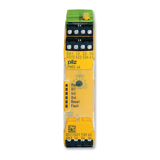
Unit types with UB 24 VDC } UB: 24 VDC; Order no. 750104, 751104, 751184
*
Fig.: Centre: Front view with cover, right: Front view without cover
*Insulation between the non-marked area and the relay contacts: Basic insulation (overvoltage category III), Protective separation (overvoltage category II)
Unit types with UB 48 – 240 VAC/DC } UB: 48 – 240 VAC/DC; Order no. 750134, 751134
*
*
Fig.: Centre: Front view with cover, right: Front view without cover
*Insulation between the non-marked area and the relay contacts: Basic insulation (overvoltage category III), Protective separation (overvoltage category II)
Operating Manual PNOZ s4
| 9
21396-EN-18
PNOZ s4
Function description
} In2+ Single-channel operation: no redundancy in the input circuit, earth faults in the start circuit and input circuit are detected.
} Dual-channel operation without detection of shorts across contacts: Redundant input circuit, detects PNOZ s4 earth faults in the start and input circuit, short circuits in the input circuit and, with a monitored start, in the start circuit too.
} In2- Dual-channel operation with detection of shorts across contacts: Redundant input circuit, detects PNOZ s4 earth faults in the start and input circuit, Short circuits in the input circuit and, with a monitored start, in the start circuit too, Shorts across contacts in the input circuit.
} Automatic start: Unit is active once the input circuit has been closed. } Manual start Unit is active once the input circuit and the start circuit are closed. } Monitored start with falling edge: Unit is active once
the input circuit is closed and then the start circuit is closed and opened again. the start circuit is closed and then opened again once the input circuit is closed. } Monitored start with rising edge: Unit is active once the input circuit is closed and once the start circuit is closed after the waiting period has elapsed (see technical details). } Start with start-up test: The unit checks whether safety gates that are closed are opened and then closed again when supply voltage is applied. } Increase in the number of available instantaneous safety contacts by connecting contact expander modules or external contactors/relays; A connector can be used to connect 1 PNOZsigma contact expansion module.
Operating Manual PNOZ s4
| 10
21396-EN-18
PNOZ s4
Timing diagram
[1]
[2]
[3]
[4]
Legend } POWER: Supply voltage } Start: Start circuit } Input: Input circuits } Output safe: Safety contacts } Output aux: Auxiliary contacts } Out semi: Semiconductor output } [1]: Automatic start } [2]: Manual start } [3]: Monitored start with rising edge } [4]: Monitored start with falling edge } a: Input circuit closes before start circuit } b: Start circuit closes before input circuit } t1: Switch-on delay } t2: Delay-on de-energisation } t3: Waiting period with a monitored start } t4: Min. start pulse duration with a monitored start
Installation
Install base unit without contact expansion module: } Ensure that the plug terminator is inserted at the side of the unit.
Connect base unit and PNOZsigma contact expansion module: } Remove the plug terminator at the side of the base unit and at the contact expansion
module. } Connect the base unit and the contact expansion module to the supplied connector be-
fore mounting the units to the DIN rail.
Installation in control cabinet } The safety relay should be installed in a control cabinet with a protection type of at least
IP54. } Use the notch on the rear of the unit to attach it to a DIN rail (35 mm).
Operating Manual PNOZ s4
| 11
21396-EN-18
PNOZ s4
} When installed vertically: Secure the unit by using a fixing element (e.g. retaining bracket or end angle).
} Push the device upwards or downwards before lifting it from the DIN rail.
Wiring
Please note: } Information given in the “Technical details [ 22]” must be followed. } Outputs 13-14, 23-24, 33-34 are safety contacts; output 41-42 is an auxiliary contact (e.g.
for display). } Auxiliary contact 41-42 and semiconductor output Y32 should not be used for safety cir-
cuits! } To prevent contact welding, a fuse should be connected before the output contacts (see
Technical details [ 22]). } Calculation of the max. cable length lmax in the input circuit:
Rlmax I= max Rl / km
Rlmax = max. overall cable resistance (see Technical details [ 22]) Rl / km = cable resistance/km } Use copper wiring with a temperature stability of 75 °C. } To prevent EMC interferences (particularly common-mode interferences) the measures described in EN 60204-1 must be executed. This includes the separate routing of cables of the control circuits (input, start and feedback loop) from other cables for energy transmission or the shielding of cables, for example. } Adequate protection must be provided on all output contacts with capacitive and inductive loads. } With UB 48 240 VAC/DC: Connect S21 to the functional earth. } When connecting magnetically operated, reed proximity switches, ensure that the max. peak inrush current (on the input circuit) does not overload the proximity switch. } On 24 VDC devices: The power supply must comply with the regulations for extra low voltages with protective electrical separation (SELV, PELV) in accordance with VDE 0100, Part 410.
NOTICE If you connect contact expansion modules to a base unit with a universal power supply, you will need to limit the conventional thermal current at the contact expansion modules’ safety contacts to 70 % of the stated current (see technical details for contact expansion module).
Operating Manual PNOZ s4
| 12
21396-EN-18
PNOZ s4
Preparing for operation
Operating modes The operating mode is set via the rotary switch on the unit. You can do this by opening the cover on the front of the unit.
NOTICE Do not adjust the rotary switch during operation, otherwise an error message will appear, the safety contacts will open and the unit will not be ready for operation until the supply voltage has been switched off and then on again.
Set operating modes } Switch off supply voltage. } Select operating mode via the operating mode selector switch “mode”. } If the operating mode selector switch “mode” is in its start position (vertical position), an
error message will appear.
Operating mode Automatic or selector switch manual start “mode”
Without detec-
In2+ In2-
tion of shorts
across contacts
With detection of
In2+ In2-
shorts across
contacts
Monitored start Monitored start Automatic start
rising edge
falling edge
with start-up test
In2+ In2-
In2+ In2-
In2+ In2-
In2+ In2-
In2+ In2-
In2+ In2-
Operating Manual PNOZ s4
| 13
21396-EN-18
PNOZ s4
Connection Supply voltage
Unit types with UB 24 VDC
A1
A2
Unit types with UB 48 – 240 VAC/DC
L+
L-
Input circuit
Single-channel
Emergency stop
without detection of shorts across contacts
S1 S11
S12
S22
Dual-channel
S1 S11
S12 S22
Emergency stop with detection of shorts across contacts
Safety gate without detection of shorts across contacts
Safety gate with detection of shorts across contacts
Light beam device or safety switch, detection of shorts across contacts via ESPE, operating mode selector switch in the position “without detection of shorts across contacts” (only for unit types with UB = 24 VDC)
S1 S11
S12
S22
S1 S11 S21
S22 S12
S11
S1
S2
S12 S22
S11
S1 S12
S2
S21
S22
24 V DC A1
A2
S12
S22
GND
NOTICE
With single-channel wiring the safety level of your machine/plant may be lower than the safety level of the unit (see Safety characteristic data [ 35]).
Operating Manual PNOZ s4
| 14
21396-EN-18
PNOZ s4
NOTICE
When operated with a light grid or sensor
It must not be possible to switch off the supply voltage for the PNOZsigma separately from the supply voltage for the light grid or safety switch.
The operating mode selector switch must be set to “Without detection of shorts across contacts”, as shorts across contacts are detected by the ESPE.
Start circuit/feedback loop Without feedback loop monitoring
Automatic start
with feedback loop monitoring
S12 S34 13 (23,33) 14 (24,34)
K5 K6
L1 K5 N K6
Monitored, manual start/restart
S3 S12
S34
S12 S34 13 (23,33) 14 (24,34)
S3 K5 K6
L1 K5 N K6
NOTICE
In the event of an automatic start or manual start with bridged start contact (fault):
The unit starts up automatically when the safeguard is reset, e.g. when the E-STOP pushbutton is released. Use external circuit measures to prevent an unexpected restart.
Unit types with UB 24 VDC
Unit types with UB 48 – 240 VAC/DC
*Connect together the 0V connections on all the external power supplies
Legend } S1/S2: E-STOP/safety gate switch } S3: Reset button } : Switch operated
Operating Manual PNOZ s4
| 15
21396-EN-18
PNOZ s4
} : Gate open } : Gate closed
Application examples
Emergency stop } Dual-channel } with detection of shorts across contacts } Monitored start } falling edge with feedback loop monitoring
9’&
6
; ;
;
$
6
6
6
6
312= V & 9’& QR QF
$
;
3RZHU ,Q ,Q 2XW 6WDUW )DXOW
,Q ,Q
$
$
PRGH
<
;
9
6
6WDUW
)HHGEDFN /RRS
6
3,/= 312= V & 9’& QR QF
Operating Manual PNOZ s4
| 16
21396-EN-18
PNOZ s4
Safety gate } Dual-channel } with detection of shorts across contacts } Monitored start } falling edge with feedback loop monitoring
9’&
6
6
; ;
;
$
6
6
6
6
312= V & 9’& QR QF
$
;
3RZHU ,Q ,Q 2XW 6WDUW )DXOW
,Q ,Q
$
$
PRGH
<
;
9
6
6WDUW
)HHGEDFN /RRS
6
3,/= 312= V & 9’& QR QF
Operating Manual PNOZ s4
| 17
21396-EN-18
PNOZ s4
OSSD signals } Dual-channel } without detection of shorts across contacts of PNOZ – detection of shorts across contacts
by sensor technology } Automatic start } with feedback loop monitoring
9’&
6
$
$
266′
266′
; ;
;
$
6
6
6
6
312= V & 9’& QR QF
$
;
3RZHU ,Q ,Q 2XW 6WDUW )DXOW
,Q ,Q
$
$
PRGH
<
;
9
)HHGEDFN /RRS
6
3,/= 312= V & 9’& QR QF
Operating Manual PNOZ s4
| 18
21396-EN-18
PNOZ s4
Operation
When the relay outputs are switched on, the mechanical contact on the relay cannot be tested automatically. Depending on the operational environment, measures to detect the non-opening of switching elements may be required under some circumstances. When the product is used in accordance with the European Machinery Directive, a check must be carried out to ensure that the safety contacts on the relay outputs open correctly. Open the safety contacts (switch off output) and start the device again, so that the internal diagnostics can check that the safety contacts open correctly } for SIL CL 3/PL e at least 1x per month } for SIL CL 2/PL d at least 1x per year
NOTICE The safety function should be checked after initial commissioning and each time the plant/machine is changed. The safety functions may only be checked by qualified personnel.
The unit is ready for operation when the Power LED is permanently lit. LEDs indicate the status and errors during operation:
LED on LED flashes LED off
INFORMATION Status indicators and error indicators may occur independently. In the case of an error display, the “Fault” LED will light or flash (exception: “Supply voltage too low”). An LED that is also flashing indicates the potential cause of the error. An LED that is lit and is static indicates a normal operating status. Several status indicators and error indicators may occur simultaneously.
Status indicators
POWER Supply voltage is present.
IN1 Input circuit at S12 is closed.
IN2 Input circuit at S22 is closed.
OUT Safety contacts are closed and semiconductor output Y32 carries a high signal.
START 24 VDC is present at S34.
Operating Manual PNOZ s4
| 19
21396-EN-18
PNOZ s4
Error indicators
All LEDs off
Diagnostics: Short across contacts/earth fault; unit switched off } Remedy: Rectify short across contacts/earth fault, switch off supply voltage
for 1 min.
FAULT
Diagnostics: Plug terminator not connected } Remedy: Insert plug terminator, switch supply voltage off and then on again.
FAULT
Diagnostics: Internal error, unit defective } Remedy: Switch supply voltage off and then on again, change unit if neces-
sary.
POWER
Diagnostics: Supply voltage too low } Remedy: Check supply voltage and increase if necessary.
IN1, IN2 alternately
FAULT
Diagnostics: Connection error (possibly: cable resistance in the input circuit is too high) or short detected between S12 and S22
} Remedy: Rectify connection error or short across contacts, switch supply
voltage off and then on again.
IN1
FAULT
Diagnostics: Power-up blocked due to short-term interruption at S12; input circuits not operated simultaneously
} Remedy: Open both input circuits, S12 and S22, simultaneously and then
close again.
IN2
FAULT
Diagnostics: Power-up blocked due to short-term interruption at S22; input circuits not operated simultaneously
} Remedy: Open both input circuits, S12 and S22, simultaneously and then
close again.
Operating Manual PNOZ s4
| 20
21396-EN-18
PNOZ s4
START
FAULT
Diagnostics: Position of rotary switch is not permitted or rotary switch was adjusted during operation.
} Remedy: Switch supply voltage off and then on again.
POWER, IN1, IN2, OUT, START, FAULT Diagnostics: The operating mode selector switch “mode” is in its start position (vertical position) } Remedy: Switch off the supply voltage and set the required operating mode
on operating mode selector switch “mode”.
Faults – malfunctions
} Contact malfunctions: If the contacts have welded, reactivation will not be possible after the input circuit has opened.
Dimensions in mm
*with spring-loaded terminals
Operating Manual PNOZ s4
| 21
21396-EN-18
PNOZ s4
Technical details Order no. 750104, 750134, 751104
General
750104
750134
751104
Certifications
CCC, CE, EAC, KOSHA, CCC, CE, EAC, KOSHA, CCC, CE, EAC, KOSHA,
TÜV, cULus Listed
TÜV, cULus Listed
TÜV, cULus Listed
Electrical data
750104
750134
751104
Supply voltage
Voltage Kind Voltage tolerance Output of external power supply (AC) Output of external power supply (DC) Frequency range AC Residual ripple DC
24 V DC -15 %/+10 %
2,5 W 20 %
48 – 240 V AC/DC -15 %/+10 %
5 VA
2,5 W 50 – 60 Hz 160 %
24 V DC -15 %/+10 %
2,5 W 20 %
Duty cycle
100 %
100 %
100 %
Max. inrush current impulse
Current pulse, A1
0,5 A
Pulse duration, A1
5 ms
0,5 A 5 ms
Inputs
750104
750134
751104
Number
2
2
2
Voltage at
Input circuit DC Start circuit DC Feedback loop DC
24 V 24 V 24 V
24 V 24 V 24 V
24 V 24 V 24 V
Current at
Input circuit DC Start circuit DC Feedback loop DC
50 mA 50 mA 50 mA
50 mA 50 mA 50 mA
50 mA 50 mA 50 mA
Max. inrush current impulse
Current pulse, input cir-
cuit
0,2 A
Pulse duration, input
circuit
100 ms
Current pulse, feedback loop
0,2 A
Pulse duration, feed-
back loop
15 ms
Current pulse, start cir-
cuit
0,2 A
Pulse duration, start
circuit
15 ms
0,2 A 100 ms 0,2 A 15 ms 0,2 A 15 ms
0,2 A 100 ms 0,2 A 15 ms 0,2 A 15 ms
Min. input resistance at
power-on
110 Ohm
110 Ohm
110 Ohm
Operating Manual PNOZ s4
| 22
21396-EN-18
PNOZ s4
Inputs
750104
Max. overall cable resistance Rlmax
Single-channel at UB DC
Single-channel at UB AC
30 Ohm
Dual-channel without detection of shorts across contacts at UB DC
Dual-channel without detection of shorts across contacts at UB AC
60 Ohm
Dual-channel with de-
tection of shorts across
contacts at UB DC
30 Ohm
Dual-channel with de-
tection of shorts across
contacts at UB AC
Semiconductor outputs 750104
Number
1
Voltage
24 V
Current
20 mA
Residual current at “0” signal
0,1 mA
Max. internal voltage drop 5 V
Conditional rated short cir-
cuit current
100 A
Lowest operating current 0 mA
Utilisation category in ac-
cordance with EN
60947-1
DC-12
Relay outputs
750104
Number of output contacts
Safety contacts (N/O),
instantaneous
3
Auxiliary contacts (N/C) 1
Max. short circuit current
IK
1 kA
Utilisation category
In accordance with the
standard
EN 60947-4-1
750134
30 Ohm 30 Ohm
30 Ohm
30 Ohm
30 Ohm
30 Ohm 750134 1 24 V 20 mA 0,1 mA 100 A 0 mA
DC-12 750134
3 1 1 kA
EN 60947-4-1
751104
30 Ohm
60 Ohm
30 Ohm
751104 1 24 V 20 mA 0,1 mA 5 V 100 A 0 mA
DC-12 751104
3 1 1 kA
EN 60947-4-1
Operating Manual PNOZ s4
| 23
21396-EN-18
PNOZ s4
Relay outputs
750104
750134
751104
Utilisation category of safety contacts
AC1 at Min. current Max. current Min. output Max. power DC1 at Min. current Max. current Min. output Max. power
240 V 0,003 A 6 A 0,04 VA 1500 VA 24 V 0,003 A 6 A 0,04 W 150 W
240 V 0,003 A 6 A 0,04 VA 1500 VA 24 V 0,003 A 6 A 0,04 W 150 W
240 V 0,003 A 6 A 0,04 VA 1500 VA 24 V 0,003 A 6 A 0,04 W 150 W
Utilisation category of auxiliary contacts
AC1 at Min. current Max. current Min. output Max. power DC1 at Min. current Max. current Min. output Max. power
240 V 0,003 A 6 A 0,04 VA 1500 VA 24 V 0,003 A 6 A 0,04 W 150 W
240 V 0,003 A 6 A 0,04 VA 1500 VA 24 V 0,003 A 6 A 0,04 W 150 W
240 V 0,003 A 6 A 0,04 VA 1500 VA 24 V 0,003 A 6 A 0,04 W 150 W
Utilisation category
In accordance with the
standard
EN 60947-5-1
EN 60947-5-1
EN 60947-5-1
Utilisation category of safety contacts
AC15 at
230 V
Max. current
5 A
DC13 (6 cycles/min) at 24 V
Max. current
5 A
230 V 3 A 24 V 4 A
230 V 5 A 24 V 5 A
Utilisation category of auxiliary contacts
AC15 at
230 V
Max. current
5 A
DC13 (6 cycles/min) at 24 V
Max. current
5 A
230 V 3 A 24 V 4 A
230 V 5 A 24 V 5 A
Utilisation category in accordance with UL
Voltage
With current Voltage With current
240 V AC G.U. (same po- 240 V AC G.U. (same po- 240 V AC G.U. (same po-
larity)
larity)
larity)
6 A
6 A
6 A
24 V DC G. U.
24 V DC G. U.
24 V DC G. U.
6 A
6 A
6 A
Operating Manual PNOZ s4
| 24
21396-EN-18
PNOZ s4
Relay outputs
750104
External contact fuse protection, safety contacts
In accordance with the
standard
EN 60947-5-1
Max. melting integral 260 A²s
Blow-out fuse, quick 10 A
Blow-out fuse, slow 6 A
Blow-out fuse, gG
10 A
Circuit breaker 24V
AC/DC, characteristic
B/C
6 A
External contact fuse protection, auxiliary contacts
Max. melting integral
Blow-out fuse, quick
Blow-out fuse, slow
Blow-out fuse, gG
Circuit breaker 24 V AC/DC, characteristic B/C
160 A²s 10 A 6 A 6 A
6 A
Contact material
AgCuNi + 0,2 µm Au
Conventional thermal current while loading several contacts
750104
Ith per contact at UB AC; AC1: 240 V, DC1: 24 V
Conv. therm. current
with 1 contact
Conv. therm. current
with 2 contacts
Conv. therm. current
with 3 contacts
Ith per contact at UB DC; AC1: 240 V, DC1: 24 V
Conv. therm. current
with 1 contact
6 A
Conv. therm. current
with 2 contacts
6 A
Conv. therm. current
with 3 contacts
5 A
750134
EN 60947-5-1 66 A²s 6 A 4 A 6 A
4 A
66 A²s 6 A 4 A 6 A
4 A AgCuNi + 0,2 µm Au 750134
6 A 6 A 4,5 A
6 A 6 A 4,5 A
751104
EN 60947-5-1 260 A²s 10 A 6 A 10 A
6 A
160 A²s 10 A 6 A 6 A
6 A AgCuNi + 0,2 µm Au 751104
6 A 6 A 5 A
Operating Manual PNOZ s4
| 25
21396-EN-18
PNOZ s4
Times
750104
Switch-on delay
With automatic start typ.
170 ms
With automatic start max.
300 ms
With automatic start after power on typ.
350 ms
With automatic start after power on max.
600 ms
With manual start typ. 40 ms
With manual start max. 300 ms
With monitored start with rising edge typ. 35 ms
With monitored start with rising edge max. 50 ms
With monitored start with falling edge typ. 55 ms
With monitored start with falling edge max. 70 ms
Delay-on de-energisation
With E-STOP typ.
10 ms
With E-STOP max. 20 ms
With power failure typ. 40 ms
With power failure max. 80 ms
Recovery time at max. switching frequency 1/s
After E-STOP After power failure
100 ms 100 ms
Waiting period with a monitored start
With rising edge With falling edge
120 ms 250 ms
Min. start pulse duration with a monitored start
With falling edge With rising edge
100 ms 30 ms
Supply interruption before
de-energisation
20 ms
Simultaneity, channel 1
and 2 max.
Environmental data
750104
Climatic suitability
EN 60068-2-78
Ambient temperature
Temperature range -10 – 55 °C
Storage temperature
Temperature range -40 – 85 °C
750134
170 ms 300 ms 350 ms 600 ms 40 ms 35 ms 50 ms 55 ms 70 ms
10 ms 20 ms 40 ms
50 ms 100 ms
120 ms 150 ms
100 ms 30 ms 20 ms 750134 EN 60068-2-78
-10 – 55 °C
-40 – 85 °C
751104
170 ms 300 ms 350 ms 600 ms 40 ms 300 ms 35 ms 50 ms 55 ms 70 ms
10 ms 20 ms 40 ms 80 ms
100 ms 100 ms
120 ms 250 ms
100 ms 30 ms 20 ms 751104 EN 60068-2-78
-10 – 55 °C
-40 – 85 °C
Operating Manual PNOZ s4
| 26
21396-EN-18
PNOZ s4
Environmental data
750104
750134
751104
Climatic suitability
Humidity
93 % r. h. at 40 °C
93 % r. h. at 40 °C
93 % r. h. at 40 °C
Condensation during op-
eration
Not permitted
Not permitted
Not permitted
EMC
EN 60947-5-1, EN
EN 60947-5-1, EN
EN 60947-5-1, EN
61000-6-2, EN 61000-6-4, 61000-6-2, EN 61000-6-4, 61000-6-2, EN 61000-6-4,
EN 61326-3-1
EN 61326-3-1
EN 61326-3-1
Vibration
In accordance with the
standard
EN 60068-2-6
Frequency
10 – 55 Hz
Amplitude
0,35 mm
EN 60068-2-6 10 – 55 Hz 0,35 mm
EN 60068-2-6 10 – 55 Hz 0,35 mm
Airgap creepage
In accordance with the
standard
EN 60947-1
Overvoltage category III / II
Pollution degree
2
EN 60947-1 III / II 2
EN 60947-1 III / II 2
Rated insulation voltage 250 V
250 V
250 V
Rated impulse withstand
voltage
4 kV
4 kV
4 kV
Protection type
Housing
Terminals
Mounting area (e.g. control cabinet)
IP40 IP20
IP54
IP40 IP20
IP54
IP40 IP20
IP54
Mechanical data
750104
750134
751104
Mounting position
Any
Any
Any
Mechanical life
10,000,000 cycles
10,000,000 cycles
10,000,000 cycles
Material
Bottom
PC
PC
PC
Front
PC
PC
PC
Top
PC
PC
PC
Connection type
Screw terminal
Screw terminal
Spring-loaded terminal
Mounting type
plug-in
plug-in
plug-in
Conductor cross section with screw terminals
1 core flexible
0,25 – 2,5 mm², 24 – 12 0,25 – 2,5 mm², 24 – 12
AWG
AWG
2 core with the same
cross section, flexible
with crimp connectors, 0,25 – 1 mm², 24 – 16
0,25 – 1 mm², 24 – 16
no plastic sleeve
AWG
AWG
2 core with the same
cross section, flexible
without crimp connect-
ors or with TWIN crimp 0,2 – 1,5 mm², 24 – 16 0,2 – 1,5 mm², 24 – 16
connectors
AWG
AWG
Operating Manual PNOZ s4
| 27
21396-EN-18
PNOZ s4
Mechanical data
750104
Torque setting with screw
terminals
0,5 Nm
Stripping length with screw terminals
8 mm
Conductor cross section
with spring-loaded termin-
als: Flexible with/without
crimp connector
Spring-loaded terminals:
Terminal points per con-
nection
Stripping length with spring-loaded terminals
Dimensions
Height Width Depth Weight
98 mm 22,5 mm 120 mm 185 g
750134 0,5 Nm 8 mm
98 mm 22,5 mm 120 mm 210 g
751104
0,2 – 2,5 mm², 24 – 12 AWG
2 9 mm
100 mm 22,5 mm 120 mm 185 g
Where standards are undated, the 2020-07 latest editions shall apply.
Operating Manual PNOZ s4
| 28
21396-EN-18
PNOZ s4
Technical details Order no. 751134, 751184
General
751134
Certifications
CCC, CE, EAC, KOSHA, TÜV, cULus Listed
Electrical data
751134
Supply voltage
Voltage
48 – 240 V
Kind
AC/DC
Voltage tolerance
-15 %/+10 %
Output of external power supply
(AC)
5 VA
Output of external power supply
(DC)
2,5 W
Frequency range AC
50 – 60 Hz
Residual ripple DC
160 %
Duty cycle
100 %
Max. inrush current impulse
Current pulse, A1
Pulse duration, A1
Inputs
751134
Number
2
Voltage at
Input circuit DC Start circuit DC Feedback loop DC
24 V 24 V 24 V
Current at
Input circuit DC Start circuit DC Feedback loop DC
50 mA 50 mA 50 mA
Max. inrush current impulse
Current pulse, input circuit Pulse duration, input circuit Current pulse, feedback loop Pulse duration, feedback loop Current pulse, start circuit Pulse duration, start circuit
0,2 A 100 ms 0,2 A 15 ms 0,2 A 15 ms
Min. input resistance at power-on 110 Ohm
751184 CCC, CE, EAC, KOSHA, TÜV, cULus Listed 751184
24 V DC -15 %/+10 %
2,5 W 20 % 100 %
0,5 A 5 ms 751184 2
24 V 24 V 24 V
50 mA 50 mA 50 mA
0,2 A 100 ms 0,2 A 15 ms 0,2 A 15 ms 110 Ohm
Operating Manual PNOZ s4
| 29
21396-EN-18
PNOZ s4
Inputs
751134
Max. overall cable resistance Rlmax
Single-channel at UB DC
30 Ohm
Single-channel at UB AC
30 Ohm
Dual-channel without detection
of shorts across contacts at UB
DC
30 Ohm
Dual-channel without detection
of shorts across contacts at UB
AC
30 Ohm
Dual-channel with detection of shorts across contacts at UB DC 30 Ohm
Dual-channel with detection of shorts across contacts at UB AC 30 Ohm
Semiconductor outputs
751134
Number
1
Voltage
24 V
Current
20 mA
Residual current at “0” signal
0,1 mA
Max. internal voltage drop
Conditional rated short circuit cur-
rent
100 A
Lowest operating current
0 mA
Utilisation category in accordance
with EN 60947-1
DC-12
Relay outputs
751134
Number of output contacts
Safety contacts (N/O), instant-
aneous
3
Auxiliary contacts (N/C)
1
Max. short circuit current IK
1 kA
Utilisation category
In accordance with the standard EN 60947-4-1
Utilisation category of safety contacts
AC1 at Min. current Max. current Min. output Max. power DC1 at Min. current Max. current Min. output Max. power
240 V 0,003 A 6 A 0,04 VA 1500 VA 24 V 0,003 A 6 A 0,04 W 150 W
Operating Manual PNOZ s4 21396-EN-18
751184
30 Ohm
60 Ohm
30 Ohm
751184 1 24 V 20 mA 0,1 mA 5 V
100 A 0 mA
DC-12 751184
3 1 1 kA
EN 60947-4-1
240 V 0,003 A 6 A 0,04 VA 1500 VA 24 V 0,003 A 6 A 0,04 W 150 W
| 30
PNOZ s4
Relay outputs
751134
Utilisation category of auxiliary contacts
AC1 at Min. current Max. current Min. output Max. power DC1 at Min. current Max. current Min. output Max. power
240 V 0,003 A 6 A 0,04 VA 1500 VA 24 V 0,003 A 6 A 0,04 W 150 W
Utilisation category
In accordance with the standard EN 60947-5-1
Utilisation category of safety contacts
AC15 at Max. current DC13 (6 cycles/min) at Max. current
230 V 3 A 24 V 4 A
Utilisation category of auxiliary contacts
AC15 at Max. current DC13 (6 cycles/min) at Max. current
230 V 3 A 24 V 4 A
Utilisation category in accordance with UL
Voltage With current Voltage With current
240 V AC G.U. (same polarity) 6 A 24 V DC G. U. 6 A
External contact fuse protection, safety contacts
In accordance with the standard EN 60947-5-1
Max. melting integral
66 A²s
Blow-out fuse, quick
6 A
Blow-out fuse, slow
4 A
Blow-out fuse, gG
6 A
Circuit breaker 24V AC/DC,
characteristic B/C
4 A
751184
240 V 0,003 A 6 A 0,04 VA 1500 VA 24 V 0,003 A 6 A 0,04 W 150 W
EN 60947-5-1
230 V 5 A 24 V 5 A
230 V 5 A 24 V 5 A
240 V AC G.U. (same polarity) 6 A 24 V DC G. U. 6 A
EN 60947-5-1 260 A²s 10 A 6 A 10 A
6 A
Operating Manual PNOZ s4
| 31
21396-EN-18
PNOZ s4
Relay outputs
751134
External contact fuse protection, auxiliary contacts
Max. melting integral Blow-out fuse, quick Blow-out fuse, slow Blow-out fuse, gG Circuit breaker 24 V AC/DC, characteristic B/C Contact material
66 A²s 6 A 4 A 6 A
4 A AgCuNi + 0,2 µm Au
Conventional thermal current 751134 while loading several contacts
Ith per contact at UB AC; AC1: 240 V, DC1: 24 V
Conv. therm. current with 1 con-
tact
6 A
Conv. therm. current with 2 con-
tacts
6 A
Conv. therm. current with 3 con-
tacts
4,5 A
Ith per contact at UB DC; AC1: 240 V, DC1: 24 V
Conv. therm. current with 1 con-
tact
6 A
Conv. therm. current with 2 con-
tacts
6 A
Conv. therm. current with 3 con-
tacts
4,5 A
Times
751134
Switch-on delay
With automatic start typ.
170 ms
With automatic start max.
300 ms
With automatic start after power
on typ.
350 ms
With automatic start after power
on max.
600 ms
With manual start typ.
40 ms
With manual start max.
With monitored start with rising
edge typ.
35 ms
With monitored start with rising
edge max.
50 ms
With monitored start with falling
edge typ.
55 ms
With monitored start with falling
edge max.
70 ms
751184
160 A²s 10 A 6 A 6 A 6 A AgCuNi + 0,2 µm Au 751184
6 A 6 A 5 A 751184
170 ms 300 ms 350 ms 600 ms 40 ms 300 ms 35 ms 50 ms 55 ms 70 ms
Operating Manual PNOZ s4
| 32
21396-EN-18
PNOZ s4
Times
751134
Delay-on de-energisation
With E-STOP typ. With E-STOP max. With power failure typ. With power failure max.
10 ms 20 ms 40 ms 80 ms
Recovery time at max. switching frequency 1/s
After E-STOP After power failure
50 ms 100 ms
Waiting period with a monitored start
With rising edge With falling edge
120 ms 150 ms
Min. start pulse duration with a monitored start
With falling edge With rising edge
100 ms 30 ms
Supply interruption before de-ener-
gisation
20 ms
Simultaneity, channel 1 and 2 max.
Environmental data
751134
Climatic suitability
EN 60068-2-78
Ambient temperature
Temperature range
-10 – 55 °C
Storage temperature
Temperature range
-40 – 85 °C
Climatic suitability
Humidity
93 % r. h. at 40 °C
Condensation during operation Not permitted
EMC
EN 60947-5-1, EN 61000-6-2, EN 61000-6-4, EN 61326-3-1
Vibration
In accordance with the standard EN 60068-2-6
Frequency
10 – 55 Hz
Amplitude
0,35 mm
Airgap creepage
In accordance with the standard EN 60947-1
Overvoltage category
III / II
Pollution degree
2
Rated insulation voltage
250 V
Rated impulse withstand voltage 4 kV
Protection type
Housing
IP40
Terminals
IP20
Mounting area (e.g. control cab-
inet)
IP54
751184
10 ms 20 ms 40 ms 80 ms
100 ms 100 ms
120 ms 250 ms
100 ms 30 ms
20 ms 751184 EN 60068-2-78
-25 – 55 °C
-40 – 85 °C
93 % r. h. at 40 °C Not permitted EN 60947-5-1, EN 61000-6-2, EN 61000-6-4, EN 61326-3-1
EN 60068-2-6 10 – 55 Hz 0,35 mm
EN 60947-1 III / II 2 250 V 4 kV
IP40 IP20
IP54
Operating Manual PNOZ s4
| 33
21396-EN-18
PNOZ s4
Mechanical data
751134
Mounting position
Any
Mechanical life
10,000,000 cycles
Material
Bottom
PC
Front
PC
Top
PC
Connection type
Spring-loaded terminal
Mounting type
plug-in
Conductor cross section with spring-loaded terminals: Flexible with/without crimp connector
0,2 – 2,5 mm², 24 – 12 AWG
Spring-loaded terminals: Terminal
points per connection
2
Stripping length with spring-loaded
terminals
9 mm
Dimensions
Height Width Depth Weight
100 mm 22,5 mm 120 mm 210 g
751184 Any 10,000,000 cycles
PC PC PC Spring-loaded terminal plug-in
0,2 – 2,5 mm², 24 – 12 AWG
2
9 mm
100 mm 22,5 mm 120 mm 190 g
Where standards are undated, the 2020-07 latest editions shall apply.
Operating Manual PNOZ s4
| 34
21396-EN-18
PNOZ s4
Safety characteristic data
NOTICE
You must comply with the safety characteristic data in order to achieve the required safety level for your plant/machine.
Operating mode
EN ISO 13849-1: 2015
EN ISO 13849-1: 2015
EN 62061 SIL CL
EN 62061 PFHD [1/h]
IEC 61511 SIL
IEC 61511 PFD
EN ISO 13849-1: 2015
PL
Safety contacts, instantaneous PL e
Category
Cat. 4
SIL CL 3 2,31E-09 SIL 3
TM [year] 2,03E-06 20
Explanatory notes for the safety-related characteristic data: } The SIL CL value in accordance with EN 62061 corresponds to the SIL value in accord-
ance with EN 61508. } TM is the maximum mission time in accordance with EN ISO 13849-1. The value also ap-
plies as the retest interval in accordance with EN 61508-6 and IEC 61511 and as the proof test interval and mission time in accordance with EN 62061.
All the units used within a safety function must be considered when calculating the safety characteristic data.
INFORMATION
A safety function’s SIL/PL values are not identical to the SIL/PL values of the units that are used and may be different. We recommend that you use the PAScal software tool to calculate the safety function’s SIL/PL values.
Operating Manual PNOZ s4
| 35
21396-EN-18
PNOZ s4
Classification according to ZVEI, CB24I
The following tables describe the classes and specific values of the product interface and the classes of interfaces compatible with it. The classification is described in the ZVEI position paper “Classification of Binary 24 V Interfaces – Functional Safety aspects covered by dynamic testing”.
Input
Interfaces Drain
Interface Class Source Interface Class
Drain parameters Max. test pulse duration Min. input resistance Max. capacitive load
Module C0
Sensor C1, C2, C3
2 ms 0,5 kOhm 10 nF
Relay outputs
Interfaces Source
Interface Class Drain Interface Class
Source parameters Min. switching voltage Max. switching voltage Min. switching current Max. switching current Potential isolation
Module A
Actuator A
12 V 250 V 0,003 A 6 A yes
Operating Manual PNOZ s4
| 36
21396-EN-18
PNOZ s4
Supplementary data
CAUTION! It is essential to consider the relay’s service life graphs. The relay outputs’ safety-related characteristic data is only valid if the values in the service life graphs are met.
The PFH value depends on the switch frequency and the load of the relay output. If the service life graphs are not accessible, the stated PFH value can be used irrespective of the switch frequency and the load, as the PFH value already considers the relay’s B10d value as well as the failure rates of the other components.
Service life graph The service life graphs indicate the number of cycles from which failures due to wear must be expected. The wear is mainly caused by the electrical load; the mechanical load is negligible. Unit types with UB 24 VDC } UB: 24 VDC; Order no. 750104, 751104, 751184
Cycles x 1000
Switching current (A) Fig.: Service life graphs at 24 V DC and 230 V AC
Operating Manual PNOZ s4
| 37
21396-EN-18
Cycles x 1000
PNOZ s4
Switching current (A) Fig.: Service life graphs at 110 V DC Example } Inductive load: 0.2 A } Utilisation category: AC15 } Contact service life: 2 000 000 cycles Provided the application to be implemented requires fewer than 2 000 000 cycles, the PFH value (see Technical details [ 22]) can be used in the calculation. To increase the service life, sufficient spark suppression must be provided on all output contacts. With capacitive loads, any power surges that occur must be noted. With DC contactors, use flywheel diodes for spark suppression.
Operating Manual PNOZ s4
| 38
21396-EN-18
PNOZ s4
Unit types with UB 48-240 VAC/DC } UB: 48 240 VAC/DC; Order no. 750134, 751134
10000 5000
Number of operating cycles x 1000
1000 500
100 50
10 0,1
DC-1: 24V AC-1: 230V AC-15: 230V DC-13: 24V
0,5 1 2
Switching current (A)
3 4 5 6 8 10
Fig.: Service life graphs at 24 VDC and 230 VAC
Number of cycles x 1000
Fig.: Service life graphs at 110 VDC
Switching current (A)
Operating Manual PNOZ s4
| 39
21396-EN-18
PNOZ s4
Example } Inductive load: 0.2 A } Utilisation category: AC15 } Contact service life: 1 000 000 cycles Provided the application to be implemented requires fewer than 1 000 000 cycles, the PFH value (see Technical details [ 22]) can be used in the calculation. To increase the service life, sufficient spark suppression must be provided on all relay contacts. With capacitive loads, any power surges that occur must be noted. With DC contactors, use flywheel diodes for spark suppression.
Operating Manual PNOZ s4
| 40
21396-EN-18
PNOZ s4
Permitted operating height
The values stated in the technical details apply to the use of the device in operating heights up to max. 2000 m above sea level. When used in greater heights, constraints have to be taken into account: } Permitted maximum operating height 5000 m } Only device versions with UB 24 V DC are permitted (order no. 750104, 751104, 751184) } Reduction of rated insulation voltage and rated impulse withstand voltage for applications
with safe separation:
Maximum operation height 3000 m
4000 m
5000 m
Rated insulation voltage 150 V 100 V 150 V 100 V 100 V 24 V
Overvoltage category
II III II III II III
Max. rated impulse withstand voltage 2.5 kV 2.5 kV 2.5 kV 2.5 kV 1.5 kV 0.8 kV
} Reduction of rated insulation voltage and rated impulse withstand voltage for applications with basic insulation:
Maximum operation height 3000 m
4000 m
5000 m
Rated insulation voltage Overvoltage category
250 V
II
150 V
III
250 V
II
150 V
III
150 V
II
100 V
III
Max. rated impulse withstand voltage 2.5 kV 2.5 kV 2.5 kV 2.5 kV 1.5 kV 1.5 kV
} From an operating height of 2000 m the max. permitted ambient temperature is reduced by 0.5 °C/100 m
Operating height 3000 m 4000 m 5000 m
Permitted ambient temperature 50 °C 45 °C 40 °C
Operating Manual PNOZ s4
| 41
21396-EN-18
PNOZ s4
Remove plug-in terminals
Procedure: Insert the screwdriver into the housing recess behind the terminal and lever the terminal out. Do not remove the terminals by pulling the cables!
Order reference
Product type
PNOZ s4 PNOZ s4 PNOZ s4 C PNOZ s4 C PNOZ s4 C Coated
Features 24 V DC 48 240 VAC/DC 24 V DC 48 240 VAC/DC 24 V DC
Connection type Screw terminals Screw terminals Spring-loaded terminals Spring-loaded terminals Spring-loaded terminals
Order no. 750104 750134 751104 751134 751184
EC declaration of conformity
This product/these products meet the requirements of the directive 2006/42/EC for machinery of the European Parliament and of the Council. The complete EC Declaration of Conformity is available on the Internet at www.pilz.com/downloads. Authorised representative: Norbert Fröhlich, Pilz GmbH & Co. KG, Felix-Wankel-Str. 2, 73760 Ostfildern, Germany
Operating Manual PNOZ s4
| 42
21396-EN-18
1800XXXX-en-0X, 2021-01 Printed in Germany 21396-EN-18, 20©21Pi-lz07GPmribntHe&d iCno.GeKrG,ma2n0y21 © Pilz GmbH & Co. KG, 2019
CECE®, CHRE®, CMSE®, InduraNET p®, Leansafe®, Master of Safety®, Master of Security®, PAS4000®, PAScal®, PASconfig®, Pilz®, PIT®, PLID®, PMCprimo®, PMCprotego®, PMCtendo®, PMD®, PMI®, PNOZ®, PRBT®, PRCM®, Primo®, PRTM®, PSEN®, PSS®, PVIS®, SafetyBUS p®, SafetyEYE®, SafetyNET p®, THE SPIRIT OF SAFETY® are registered and protected trademarks of Pilz GmbH & Co. KG in some countries. We would point out that product features may vary from the details stated in this document, depending on the status at the time of publication and the scope of the equipment. We accept no responsibility for the validity, accuracy and entirety of the text and graphics presented in this information. Please contact our Technical Support if you have any questions.
Back cover
Support
Technical support is available from Pilz round the clock.
Americas Brazil +55 11 97569-2804 Canada +1 888 315 7459 Mexico +52 55 5572 1300 USA (toll-free) +1 877-PILZUSA (745-9872)
Asia China +86 21 60880878-216 Japan +81 45 471-2281 South Korea +82 31 778 3300
Australia and Oceania Australia +61 3 95600621 New Zealand +64 9 6345350
Europe Austria +43 1 7986263-0 Belgium, Luxembourg +32 9 3217570 France +33 3 88104003 Germany +49 711 3409-444 Ireland +353 21 4804983 Italy, Malta +39 0362 1826711
Pilz develops environmentally-friendly products using ecological materials and energy-saving technologies. Offices and production facilities are ecologically designed, environmentally-aware and energy-saving. So Pilz offers sustainability, plus the security of using energy-efficient products and environmentally-friendly solutions.
Scandinavia +45 74436332 Spain +34 938497433 Switzerland +41 62 88979-32 The Netherlands +31 347 320477 Turkey +90 216 5775552 United Kingdom +44 1536 462203
You can reach our international hotline on: +49 711 3409-222 support@pilz.com
We are represented internationally. Please refer to our homepage www.pilz.com for further details or contact our headquarters.
Headquarters: Pilz GmbH & Co. KG, Felix-Wankel-Straße 2, 73760 Ostfildern, Germany Telephone: +49 711 3409-0, Telefax: +49 711 3409-133, E-Mail: info@pilz.com, Internet: www.pilz.com
Documents / Resources
References

Реле
безопасности
Sick
Статья
является
логическим
продолжением
другой
моей
статьи
про
контрольные
цепи
в
промышленном
оборудовании.
Рекомендую
ознакомиться
сначала
с
контрольными
цепями,
а
затем
с
данной
статьёй.
Реле
безопасности
в
настоящее
время
являются
неотъемлемым
компонентом
любой
промышленной
аппаратуры.
Если
у
вас
на
предприятии
есть
некитайская
электронная
техника
возрастом
менее
10
лет,
тот
там
обязательно
будут
такие
реле
безопасности
(safety
relay).
Такие
реле
сейчас
ставятся
во
всё
оборудование,
где
есть
электродвигатели.
Кнопки
«Аварийный
останов»,
как
раньше,
по
современным
правилам
безопасности
уже
не
хватает.
По
современным
стандартам
реле
безопасности
устанавливается
везде,
где
имеется
малейшая
вероятность
повреждения
оборудования
или
травмирования
персонала.
Иногда
доходит,
казалось
бы,
до
маразма
–
одна
и
та
же
кнопка
«Аварийный
останов»
имеет
два
НЗ
контакта,
которые
входят
в
разные
последовательно
соединенные
схемы
безопасности.
И
на
той
же
кнопке
–
НО
контакт,
дающий
информацию
на
контроллер.
Но,
как
я
писал
в
предыдущей
статье,
эти
решения
приняты
оторванными
головами,
эти
правила
писаны
оторванными
руками.
И
сейчас
такое
построение
схемы
–
стандарт.
Если
хотите
обратиться
к
официальным
стандартам,
ознакомьтесь
с
ГОСТ
Р
МЭК
60204-1-2007.
Безопасность
машин.
Электрооборудование
машин
и
механизмов.
А
также
ГОСТ
ISO
13849-1-2014. Безопасность
оборудования. Элементы
систем
управления,
связанные
с
безопасностью.
Надо
заметить,
такие
электронные
блоки
существенно
снижают
вероятность
опасности
при
работе
оборудования.
Логика
их
работы
и
схемы
включения
построены
на
основе
многолетнего
опыта
схемотехников
и
анализа
причин
аварий.
Пионерами
реле
безопасности
я
считаю
фирмы
Pilz
и
Dold.
Сейчас
за
ними
подтягиваются
другие
фирмы,
такие
как
Sick,
Omron,
Leuze
и
другие.
Принцип
работы реле
безопасности
Чтобы
было
сразу
всё
понятно,
рассмотрим
работу
реальных
блоков
безопасности
в
реальных
схемах
включения.
Как
обычно,
от
теории
–
к
практике,
от
простого
–
к
сложному.
Принципы
работы
реле
безопасности
основаны
на
невозможности
включения
силовых
цепей
оборудования
в
случае
каких-либо
неисправностей.
При
этом
происходит
двойное
,
четверное
и
т.д.
дублирование.
Питание
силовых
частей
станка
идёт
через
1,
2,
3
или
даже
4
ряда
последовательно
соединенных
контакторов.
И
в
случае
чего
они
отключат
питание
и
предотвратят
неприятность.
Если
любой
из
этих
контакторов
окажется
неисправен,
например
–
залипли
контакты
или
он
застрял
(заклинил)
во
включенном
положении,
станок
никак
не
включится.
А
я
такие
неисправности
встречал.
Они
бывают
или
из-за
механической
неисправности
контакторов
безопасности,
или
из-за
залипания
контактов
вследствие
замыкания
или
перегрузки
в
последующей
схеме,
или
из-за
человеческого
фактора.
Во
внутреннюю
схему
реле
безопасности
входят
обычно
два
реле
(К1
и
К2),
через
последовательные
контакты
которых
включаются
силовые
контакторы
(КМ1
и
КМ2).
Обойти
такую
схему
бывает
очень
сложно,
и
это
к
лучшему.
Рассмотрим
простейшую
схему
применения
реле
безопасности
OMRON
G9SB.
Вот
как
это
реле
выглядит
в
реале,
по
центру,
красненькое:

Omron
G9SB.
Слева
от
него
–
контактор
безопасности,
которым
управляет
реле
безопасности
и
через
который
питается
вся
силовая
часть
схемы.
Сразу
даю
схему
реле
безопасности
OMRON
G9SB.

Omron
G9SB
внутренняя
схема
Для
примера
рассмотрим
схему
цепей
безопасности,
которая
применяется
в
паковочном
станке.
Станок
содержит
3
двигателя
и
4
контакта
безопасности
(3
кнопки
и
1
концевой
защитного
кожуха).

Omron
G9SB
–
реальная
схема
включения
Питание
на
входы
реле
А1
и
А2
подается
непосредственно
с
блока
питания
24В
(постоянное
напряжение).
Когда
аварийная
цепь
замкнута
(собрана),
для
включения
и
нормальной
работы
станка
необходимо
нажать
кнопку
Пуск
(её
часто
называют
Сброс,
Reset).
Этих
кнопки
в
данном
станке
две
(S33,
S34),
можно
нажимать
на
любую,
как
удобно
оператору.
Однако,
включение
внутренних
реле
К1
и
К2
произойдёт,
только
если
линейный
контактор
безопасности
будет
во
время
нажатия
кнопки
“Сброс”
выключен.
Это
гарантирует
защиту
от
залипания
контактов
и
неисправности
этого
контактора.
Через
этот
контактор
идёт
питание
на
все
силовые
части
схемы.
Двуступенчатая
схема
включения
реле
безопасности
Рассмотрим
схему
посложнее.
Это
перерабатывающая
линия,
тут
вероятность
получить
травму
гораздо
выше,
поэтому
и
меры
безопасности
соответствующие.
Тут
реализовано
двухступенчатое
включение
цепей
безопасности.
Сначала
через
кнопку
«Сброс»,
как
в
первой
схеме,
а
потом
через
«Пуск».
Применяются
два
модуля.
Первый
собирает
свою
цепь,
второй
собирается
первым
и
другими
цепями.

Omron
G9SA-1.
Двуступенчатея
схема
безопасности.
Первая
ступень
Тут
три
кнопки
сброса
аварии,
просто
они
установлены
в
разных
частях
машины.
Аварийные
цепи
–
это
три
кнопки
“Аварийный
останов”,
соединенные
последовательно.
Причём,
каждая
кнопка
содержит
по
2
НЗ
контакта,
каждый
из
которых
входит
в
свою
независимую
цепь
безопасности
–
1.1
и
1.2.
Создание
двух
цепей
значительно
повышает
надежность
и
вероятность
правильной
работы
схемы.
Если
у
тебе
скажут
–
вероятность
того,
что
оборудование
будет
работать
10
лет
без
несчастных
случаев
с
такой
схемой
–
99%,
а
с
другой
–
99,9%,
какую
схему
ты
выберешь?
Кроме
того,
пока
не
включится
первый
модуль
безопасности,
на
второй
не
поступит
даже
питание.
Вторая
ступень:

Omron
G9SA-2.
Двуступенчатая
схема
безопасности.
Вторая
ступень
Во
вторую
аварийную
цепь
(обозначена
как
Авария
2)
входит
первая
цепь
(провода
13410
и
13411),
концевые
защитных
барьеров
(SQ11,
SQ12)
и
световые
барьеры,
которые
можно
замутировать
байпасом
(провода
1523,
1524).
Кнопка
“Сброс”
тут
названа
“Пуск”,
т.к.
фактически
(логически)
это
так.
Первый
“Сброс”
–
это
как
предварительный
пуск,
второй
“Сброс”
–
поехали!
Если
тут
всё
собирается,
контроллер
информируется
об
этом,
и
питание
(0V)
подается
на
контакторы
силовых
цепей.
А
как
же
тепловые
цепи?
В
современной
аппаратуре
считается,
что
контроллер
в
состоянии
надёжно
отследить
срабатывание
мотор-автоматов
и
остановить
машину,
если
это
заложено
в
программе.
Хотя,
бывает
и
так,
что
тепловая
цепь
заводится
в
аварийную,
далее
по
схеме.
Ещё
пример
схемы
на
реле
безопасности
Pilz
Pnoz
Тема
обширная,
поэтому
даю
ещё
схемку
простейшего
реле
безопасности
Pnoz
X7:

Реле
безопасности
Pilz
Pnoz
Через
аварийную
цепь
подается
питание
на
А1,
А2.
Пуск
–
на
Y1,
Y2.
Через
последовательные
контакты
–
питание
на
защищаемую
схему.
Обновление,
июнь
2015:
По
просьбе
моего
любознательного
читателя
Артура
даю
типовую
(классическую)
схему
включения
реле
безопасности
Pnoz
Pilz.

PILZ
Pnoz.
Типовая
схема
включения.
Кто
читал
эту
статью,
разберется,
что
к
чему,
но
хоть
пару
слов:
Через
аварийную
цепь
(АЦ
–
кнопки
“Аварийный
стоп”,
кожухи
безопасности,
двери,
и
т.п.)
и
тепловую
цепь
(ТЦ
–
тепловые
реле,
мотор-автоматы,
аварийные
выходы
преобразователей
частоты,
и
т.п.)
питание
подается
на
реле
безопасности.
То
есть,
если
АЦ
и
ТЦ
не
в
порядке,
то
реле
безопасности
не
включится,
не
говоря
уж
о
дальнейшей
схеме.
Далее,
если
питание
подано
(А1,
А2),
то
на
сцену
выходит
пусковая
цепь,
состоящая
из
НЗ
контактов
КМ1,
КМ2,
и
кнопки
“Сброс”.
Если
контакторы
безопасности
выключены,
то
нажатие
кнопки
S0
возымеет
своё
действие,
и
контакторы
безопасности
включатся.
И
подадут
питание
(вверху
справа
на
схеме)
на
схему
управления.
Только
после
этого
у
различных
контакторов
и
частотников,
входящих
в
схему
станка,
появится
шанс
запуститься
и
привести
станок
в
движение.
И
то,
если
того
возжелает
контроллер)
Контроллер
любит
знать,
что
происходит
в
станке,
которым
он
управляет
(контролировать
означает
управлять).
Поэтому
часто
с
различных
участков
схемы
на
него
подают
сигналы.
В
данной
схеме
это:
АЦ
–
всё
ОК,
или
разорвана.
ТЦ
–
всё
ОК,
или
произошёл
перегруз
или
перегрев.
КМ1,
КМ2
–
контрольная
цепь
в
норме,
станок
готов
к
работе.
Все
эти
сигналы
подаются
на
входы
контроллера,
и
обрабатываются
по
желанию
программиста-электронщика.
Стоит
сказать,
что
продолжение
темы
–
это
контроллеры
безопасности,
применяемые
в
последние
годы.
В
них
программируются
все
входы,
выходы,
можно
задать
логику
работы,
обеспечить
связь
между
блоками
в
разных
частях
машины.
Обновление
от
15
июня
2017
г:
Схема
на
реле
Pilz
с
таймером

Pilz
с
таймером,
реальное
промышленное
оборудование
Схема
в
данном
случае
выглядит
так:

Электрическая
схема
на
реле
безопасности
Pilz
с
реле
времени
Добавлена
временная
задержка
включения
для
дополнительной
защиты.
Пишите,
задавайте
вопросы,
делитесь
опытом!
Фото
реле
безопасности
PILZ
Читатель
прислал
несколько
фото
PILZ,
и
спросил,
могу
ли
я
ему
выслать
такие
реле.
Я
ответил,
что
ничего
(из
комплектующих)
не
продаю,
и
добавил:
такие
реле
выходят
из
строя
крайне
редко.
В
99%
проблема
в
обвязке
этого
реле.
Как
правило,
это
НЗ
контакты
кнопок
безопасности
и
линейных
контакторов.
Немаловажен
и
человеческий
фактор,
а
также
питание.

Фото
реле
безопасности
PILZ
1

Фото
реле
безопасности
PILZ
2

Фото
реле
безопасности
PILZ
3
Скачать
Литературы
по
этой
теме
мало,
вот,
что
есть:
•
ГОСТ
Р
МЭК
60204-1-2007.
Безопасность
машин
/
Официальным
языком
—
про
безопасность,
pdf,
1.1
MB,
скачан:
2045
раз./
www.pilz.com/mam/pilz/content/editors_mm/safety_compendium_en_2017_12_low.pdf#page=142
Понравилось?
Поставьте
оценку,
и
почитайте
другие
статьи
блога!
Загрузка…
Внимание!
Автор
блога
не
гарантирует,
что
всё
написанное
на
этой
странице
—
истина.
За
ваши
действия
и
за
вашу
безопасность
ответственны
только
вы!