-
Contents
-
Table of Contents
-
Troubleshooting
-
Bookmarks
Quick Links
®
Dräger Polytron
8000 Series
Explosion proof instrument (Ex d) Instrument for increased safety (Ex e)
Technical Manual
WARNING
To properly use this product, read and comply with
these instructions for use.
®
Dräger Polytron
8000 Series
Related Manuals for Dräger Polytron 8000 Series
Summary of Contents for Dräger Polytron 8000 Series
-
Page 1
® Dräger Polytron 8000 Series Explosion proof instrument (Ex d) Instrument for increased safety (Ex e) Technical Manual WARNING To properly use this product, read and comply with these instructions for use. ® Dräger Polytron 8000 Series… -
Page 2
This page has been left blank intentionally. ® Technical Manual Dräger Polytron 8000 Series… -
Page 3: Table Of Contents
Contents Contents ® Dräger Polytron Explosion proof instrument (Ex d) Instrument for increased safety (Ex e) 8000 Series Introduction ………………..Target group ………………. Safety-related information …………… Safety statements …………….Operating area and conditions…………Mechanical installation…………..Electrical installation …………… Commissioning …………….2.5.1 Calibration …………….
-
Page 4
Contents Remote sensors ………………® 8200 CAT ……….Cable lengths Polytron 6.1.1 Cable lengths of catalytic remote sensors……® 6.1.2 Cable lengths for remote sensor connection of Polytron 8200 CAT DQ …………..® 6.1.3 Cable lengths for remote sensor connection of Polytron 8200 CAT LC………….. -
Page 5
Contents 10 Troubleshooting ………………10.1 Faults ………………..10.2 Warnings………………11 Maintenance………………..11.1 Performing a bump test …………..11.1.1 Checking response time (t90)……….. 11.2 Sensor replacement……………. ® 11.2.1 8100 EC …………Polytron ® 11.2.2 8200 CAT, 8310 IR, 87×0 IR ……Polytron 11.3 Performing display test ………….. -
Page 6
Contents 13.1.8 Setting static maintenance current ……..13.1.9 Setting analog offset…………13.1.10 Setting analog span…………13.1.11 Testing the analog interface ……….13.1.12 Beam block…………… ® 13.2 interface …………….HART 13.2.1 Setting Polling Adress …………13.2.2 Display HART address (Unique Identifier)……13.2.3 Setting HART Tag ………… -
Page 7
Contents 17.3 Cable specifications……………. 17.4 Power supply and relays…………..17.5 General specifications …………..17.6 Environmental parameters………….. 17.7 Tightening torque…………….18 Further product documentation………….. ® 18.1 8xx0 …………….Polytron ® 18.2 8100 EC …………….. Polytron ® 18.3 8200 CAT …………… Polytron ®… -
Page 8: Introduction
Introduction Introduction This document is a supplement to the instructions for use for the following gas detectors: ® – Polytron 8100 EC ® – Polytron 8200 CAT ® – Polytron 8310 IR ® – Polytron 87×0 IR ® – Polytron 8700 IR ®…
-
Page 9: Safety-Related Information
Safety-related information Safety-related information Before using this product, carefully read the associated instructions for use. This document does not replace the instructions for use. Safety statements – Before using this product, carefully read these Instructions for Use and those of the associated products.
-
Page 10: Mechanical Installation
Safety-related information – Observe the specifications and restrictions in the Instructions for Use and/ or data sheets for the sensors. – CAUTION Risk of ignition of flammable or explosive atmospheres! Not tested in oxygen enriched atmospheres (>21% O – Using the product in areas subject to explosion hazards: Instruments or components for use in explosion-hazard areas which have been tested and approved according to national, European or international Explosion Protection Regulations may only be used under the conditions specified in the approval…
-
Page 11
Safety-related information – The instrument may be equipped with a dust plug at the conduit entry. This plug is not explosion proof nor meant to be watertight, and must be removed before connecting the instrument to a sealed conduit or installation of a flameproof cable gland. -
Page 12: Electrical Installation
Safety-related information Electrical installation – Strict compliance must be given to the electrical codes that govern the routing and connection of electrical power and signal cables to gas monitoring equipment. – Ferrules must be used. – The conductors for the power supply must have an adequately low resistance to ensure the correct supply voltage at the instrument.
-
Page 13: Calibration
Safety-related information 2.5.1 Calibration – For proper operation, never adjust the span before completing zero adjustment. Performing these operations out of order will cause the calibration to be faulty. – If the intended operation is at high altitudes, the reading will be lower than the reading at sea level (reduced partial pressure).
-
Page 14: Conventions In This Document
Conventions in this document Conventions in this document Meaning of the warnings The following warnings are used in this document to alert the user to potential dangers. A definition of the meaning of each warning is as follows: Alert icon Signal word Warning classification WARNING…
-
Page 15: Description
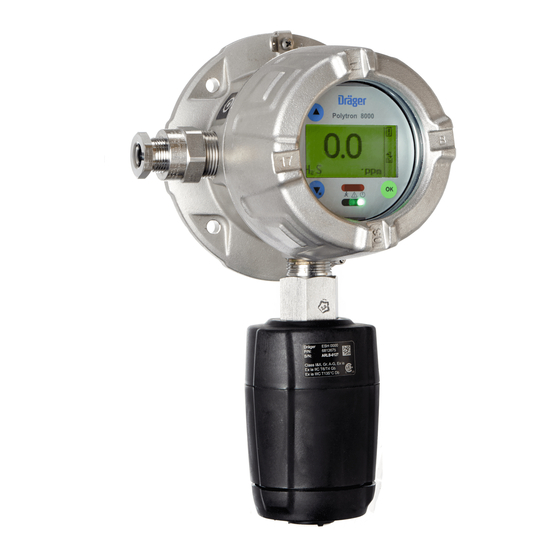
Description Description Product overview explosion proof instrument (Ex d) Fig. 1 Product overview of the explosion proof instrument, no sensor attached Enclosure lid Set screw (2 mm Allen screw) Handle PCB unit (and optional relay) Enclosure bottom Port for Sensor Explosion proof instrument A 11 Explosion proof instrument to be extended with mounting spacer for Poly-…
-
Page 16: Feature Description
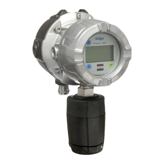
Description Polytron 8200 CAT Polytron 8100 EC Polytron 8310 IR Polytron 87×0 IR ® Fig. 2 Polytron 8xx0 versions ® Polytron 8100 EC ® Sensor dongle connection (only Polytron 8100 EC) ® Polytron 8200 CAT ® Polytron 8310 IR ® Polytron 87×0 IR with splash guard ®…
-
Page 17: Configuration Possibilities
Description Navigation through the menu is done by taping a magnetic wand on the glass at the appropriate indicator. The instrument can be configured, calibrated and maintained non-intrusively without declassifying the area. The instrument can be operated as current source or sink. ®…
-
Page 18: Intended Use
Description Intended use ® The instruments of the Polytron 8xx0 family are intended for continuous monitoring of the ambient air. With the optionally integrated relay module, the instrument can be operated without a control unit (with additional local alarm signaling). With a sealed conduit or approved cable gland, the instrument can be connected to a Dräger control unit or a Programmable Logic Controller (PLC).
-
Page 19: Approvals
Description Approvals 4.5.1 ATEX, IECEx, UL, CSA See the following sample of an approval label. There is also a printout of the approval label inside the shipping box of the instrument. Part No: XXXXXXX II 2G Polytron Xxx0 Serial No: XXXX-XXXX II 2D XTR 0XXX 0158…
-
Page 20: Installation
Installation Installation Mechanical installation The instrument can be mounted for measuring gases in ambient air or inside of a duct/pipe. 1. Use M6 (1/4’’) bolts with hex socket caps to mount the enclosure to one of the following options. Option Accessory Mounting on a flat surface Drilling template: 4544299…
-
Page 21: Electrical Installation
Installation Dimensions of the duct – Wall thickness ≤ 4 mm / 0.15’’ – Diameter ≥ 100 mm / 4’’ ® 5.1.2.2 Duct Mount Kit Polytron 87×0 IR For installation instructions refer to 9033236. Dimensions of the duct – Diameter ≥ 200 mm / 8’’ –…
-
Page 22: 8200 Cat
Installation ® 5.2.1 Cable lengths Polytron 8200 CAT 5.2.1.1 Cable lengths of the 4 to 20 mA signal connection The maximum cable length between instrument and control unit depends on different factors. The following factors are key factors to determine the cable length for a certain application.
-
Page 23
Installation ® 5.2.1.3 Cable lengths for 4 to 20 mA signal connection of Polytron 8200 CAT LC Tinned copper wire, class 5/6 according to IEC 60228 / VDE 0295 Values include a safety margin of 10%. Operating voltage: 24 V 0.75 122°F feet… -
Page 24
Installation ® 5-pin connector for 4-20 mA and HART connections Galvanic separation of a separate power supply and analog signal output is not possible (pin 2 and 3 are connected within the 5-pin connector). 1 — PWR+ 2 — PWR- 3 — PWR- 4 — 4-20mA 5 — PE… -
Page 25: Terminal Connections Digital Interface
Installation Mark Relay Normally Open Common Normally Closed 9-pin connector for relay connections 7 — A1 — NO 8 — A1 — COM 9 — A1 — NC Wiring figure Relay connector Common Normally Open NC, C, NO = default state (normally energized) with power on 5.2.3…
-
Page 26: Preparing The Electrical Installation
Installation 4-pin connector for digital interface connection 4 — Shield 3 — N.C. / GND 2 — Data-B 1 — Data-A 2-pin power supply connector for digital interface versions 1 — PWR+ 2 — PWR- Wiring figures Modbus RTU Foundation Fieldbus / ®…
-
Page 27: Connecting The Instrument As Stand-Alone
Installation 5.2.5 Connecting the instrument as stand-alone 1. Pull off the 5-pin connector. 2. Connect the wires for power to the appropriate terminal, see wiring figures 3. Bridge pin 3 and 4 of the 5-pin connector. 4. Connect the relay wires, see The relay labels (NO, COM, NC) represent the default state (normally energized) of all relays while the instrument is powered.
-
Page 28: Closing The Instrument
Installation 1. Ground the enclosure of the instrument locally at the grounding lug, see the following figure. 2. Connect the shield of the wires only to the instrument earth ground of the controller (e g. chassis, ground busbar, etc.). Unless special measures are taken (e. g. capacitive earthing), the shield must only be connected at one end.
-
Page 29
Installation 2. Loosen set-screw, 2mm Allen screw. 3. Unscrew bayonet ring and remove blank or old sensor. 4. Insert sensor into the opening. The Dräger logo on the sensor must point to the mark on the sensing head housing. 5. Lock sensor with bayonet ring. 6. -
Page 30: Remote Sensors
Remote sensors Remote sensors Remote versions with explosion protection «explosion proof (Ex d)» Transmitter Sensing head IFU part numbers EC sensing head remote (9033247) ® Polytron 8100 EC Junction Box stainless steel or alumi- ® Polytron 8200 CAT num (4544286) ®…
-
Page 31: Cable Lengths For Remote Sensor Connection Of Polytron ® 8200 Cat Dq
Remote sensors Type of cable The cable lengths are calculated for 2 standardized cables of different quality. – Tinned copper wire, class 5/6 according to IEC 60228 / VDE 0295 Characteristic cable resistance: 41 Ohms/km at 20 °C (134514 Ohms/feet at 68 °F) –…
-
Page 32: Installation Of Ec Remote Sensors
Remote sensors Bare copper wire, class 2 according to IEC 60228 / VDE 0295 Values include a safety margin of 10%. 0.75 122°F feet 50°C 68°F feet 20°C Installation of EC remote sensors 6.2.1 Installation 1. Insert the EC sensor in the remote sensor enclosure. 2.
-
Page 33
Remote sensors 90 33 247 Fig. 7 Overview of Wall Mount Bracket assembly Duct Adapter 90 33 246 35 mm ±1mm / 1.38 » ±0.04″ 94 mm ±1mm/ 3.7 » ±0.04″ Fig. 8 Overview of Duct Adapter assembly ® Technical Manual Dräger Polytron 8000 Series… -
Page 34
Remote sensors Bolts are not included. Use M6 (1/4’’) bolts to mount the duct adapter. a 47 mm / 1.85‘‘ b 74 mm / 2.91‘‘ c 56 mm / 2.2‘‘ d 6,2 mm / 0.25‘‘ e 30 mm / 1.18‘‘ Fig. -
Page 35: Connecting The Ec Sensing Head To The Transmitter
Remote sensors 6.2.2 Connecting the EC sensing head to the transmitter Fig. 11 Connection of EC sensing head remote cable Fig. 12 Grounding of EC sensing head remote Observe control drawing included in annex. Installation of remote sensors (except EC sensors) A remote wiring kit connects the Junction Box Ex d with the transmitter.
-
Page 36: Installation
Remote sensors NOTICE Bridges are necessary for 3-core field wiring ► Install bridges at terminals 1a/1b and 3a/3b 6.3.1 Installation The sensor must be removed from the transmitter and inserted into the Junction Box Ex d. NOTICE Sensor damage ® Polytron 87×0 IR must not be operated with 3-core field wiring.
-
Page 37: Connecting The Junction Box Ex D To Polytron Transmitters
Remote sensors In case of 3-core field wiring: ● Install screw bridges between contacts 1a/1b and 3a/3b of the terminals. (Fig. C). 8. Attach the lid and tighten it (≥44 LB IN. / ≥5 Nm) (Fig. E). 9. Tighten the set screw (≥ 8 LB IN. / ≥0.7 Nm) (Fig. E). 10.Close unused housing openings with screw plugs.
-
Page 38
Remote sensors 3-core field wiring Polytron 5200 / 8200 CAT Junction Box Ex d Polytron 5310 / 8310 IR Without relay: ≥ ≥ ≥ 266 LB IN / 30 Nm Without relay: 1a 1b 2 3a 3b 1a 1b 2 3a 3b Brown 3-core cable Yellow… -
Page 39
Remote sensors 5-core field wiring Polytron 5200 / 8200 CAT Polytron 5310 / 8310 IR Junction Box Ex d Polytron 5700 / 8700 IR Polytron 5720 / 8720 IR Without relay: ≥ ≥ ≥ 266 LB IN / 30 Nm Without relay: 1a 1b 2 3a 3b 1a 1b 2 3a 3b… -
Page 40: Commissioning Of The Instrument
Commissioning of the instrument Commissioning of the instrument 1. Switch power supply on. The display shows that the sensor will be ready for measurement in hh:mm:ss (countdown) and the instrument transmits the maintenance signal. The fault relay is activated. …
-
Page 41: Operation
Operation Operation Display, analog interface and relay status ® The following display examples show Polytron 8100 EC. ® ® For Polytron 8200 CAT and Polytron 8310 IR gas names are not predefined. Gas names must be entered via DrägerPolysoft PC software. 8.1.1 Measuring mode Display example…
-
Page 42
Operation Display example Description Value is under measuring range The gas concentration is beyond the measuring range of the sensor. Analog interface: Drift below zero Relays: Fault relay switches Vol.% Fault indication symbol is displayed on the right side of the display. -
Page 43: Ending Special States
Operation 8.1.3 Ending special states Fault / warning indication Faults and warnings are non-latching. If the fault or warning condition clears, the message disappears. To solve warning and fault conditions, display the error code or warning message (see «Displaying Information», page 46) and begin troubleshooting (see «Troubleshooting», page 54).
-
Page 44: Definitions Of Indicators In The Display
Operation LED status – When the first alarm (pre alarm) has been triggered the red LED flashes in single mode – When the second alarm (main alarm) has been triggered the red LED flashes in double mode – When an alarm is acknowledged before the alarm condition clears, the red LED is lit continuously to indicate the present alarm condition.
-
Page 45: Info Mode And Function Key
Operation Button Function Different functions depending on the type of menu Info mode and function key 8.5.1 Activating info mode The Info mode is used to show instrument relevant information. This does not interrupt the normal operation of the instrument. ●…
-
Page 46: Entering The Menu
Operation 8.6.3 Entering the menu ● To directly enter the Information menu: a. Tap and hold for 1 second in the measuring mode. ● To enter the Calibration menu: a. Tap and hold for 3 seconds in measuring mode b. Select Enter password c.
-
Page 47: Calibration
Calibration Calibration Obey the safety statements mentioned in 2.5 Commissioning! A calibration checks and adjusts the measurement accuracy with a known test gas concentration. First the zero point of the sensor and then the sensor span is calibrated. Calibrations have to be performed on a regular basis. The length of calibration intervals depends on the ambient conditions in which the sensor is operated.
-
Page 48: Preparation Of Calibration
Calibration Preparation of Calibration WARNING Health hazard due to test gas Inhaling test gas may risk health or lead to death. ► Do not inhale test gas. ► Observe risks and security statements related to the test gas (Refer to data sheets and instructions figuring on calibration devices).
-
Page 49: Gas Flow For Calibrations
Calibration This does not apply for duct mount applications or if the process adapter number is used (see installation instructions for PIR 7×00 accessories). 3. Make sure that the sealing surfaces around the openings of the splash guard are clean. The insect guard does not have to be removed. 4.
-
Page 50: Performing Zero Calibration
Calibration WARNING Calibration fault at zero calibration Insufficient ambient air flow may cause calibration errors. ► Make sure that the ambient air flow to the sensor is sufficient. ® Polytron 8100 EC-specific: For Oxygen (O ) sensors a zero calibration does not change any value in the firmware or sensor.
-
Page 51: Span Calibration
Calibration 6. Turn off gas flow and remove the calibration adapter from the sensor or disconnect tubing. If the current value is not within the alarm range: 7. Select Next and confirm. The instrument returns to the calibration menu. Span calibration ®…
-
Page 52: Automatic Calibration
Calibration e. Select Conc. and confirm. f. Set the concentration of the calibration gas. 3. If settings are correct: a. Select Next and confirm. A message like Gas flow ON H S is displayed. 4. Apply calibration gas. a. Set gas flow corresponding to the sensor used (see «Enter the menu, see 8.6.3 Entering the menu», page 49) 5.
-
Page 53
Calibration 2. Select Calibration > Auto calibration and confirm. The message please wait… is displayed and the instrument automatically performs the zero calibration. In case of an O sensor Fresh air cal. is displayed. The Maintenance signal is transmitted by the analog interface, no alarm or fault relays are switched and the symbol is displayed. -
Page 54: Troubleshooting
Troubleshooting Troubleshooting 10.1 Faults Fault number Cause Remedy 001, Serious instrument fault, Have the instrument checked by 003 — 005, various causes. DrägerService. 011 — 014, 020 — 024, 043, 060, 067 002, Serious data error in the Reset the instrument to factory 025 — 027, instrument, various default settings.
-
Page 55: Warnings
Troubleshooting Fault number Cause Remedy 094, 095 Data error in the instru- Reset the sensor to factory default ment. settings. If this fault occurs again: Have the instrument checked by DrägerService. SIL password does not Enter password again. match with PIR 7×00. 10.2 Warnings Warning…
-
Page 56
Troubleshooting Warning Cause Remedy number Zero drift too high. Perform zero calibration PIR 7×00 optics dirty. Clean PIR 7×00 optics. Zero calibration expired for Perform zero calibration span calibration Auto calibration not possi- Perform new zero and span calibra- ble with PIR 7200. tion ®… -
Page 57: Maintenance
Maintenance Maintenance – The maintenance intervals must be established for each individual installation. Depending on safety considerations and application specific conditions the instrument is used in, these might need to be shortened. Every 6 months – Inspection by trained service personnel. –…
-
Page 58: Polytron ® 8200 Cat, 8310 Ir, 87X0 Ir
Maintenance Sensor lock function If a sensor of the same type (same part number) was previously installed, the instrument specific configuration is retained (gas type, measuring range, test gas, calibration interval, etc.) Otherwise the factory default settings of the new sensor are uploaded and will overwrite the instrument specific configuration.
-
Page 59: Performing Display Test
Maintenance 3. Loosen set-screw and unscrew lid from instrument. 4. Pull out the PCB unit. 5. Turn PCB unit over and pull off the sensor connector. 6. Unscrew the sensor. 7. Insert the sensor wires through the threaded port of the enclosure. WARNING Explosion hazard! The enclosure openings must be sealed to prevent ignition of hazardous…
-
Page 60: Instrument Settings
Instrument settings Instrument settings 12.1 Setting passwords 1. Select Settings > Instrument > Passwords the desired password and confirm. Calibration PWD Access to zero and span calibration Settings PWD Access to all configuration parameters 2. Select the line for editing the password and confirm. 3.
-
Page 61: Changing The Display Contrast
Instrument settings 12.6 Changing the display contrast 1. Select Settings > Instrument > Display > Display contrast and confirm. 2. Change the contrast and confirm. 12.7 Changing the display mode 1. Select Settings > Instrument > Display > Display mode and confirm. 2.
-
Page 62: Switching Triggering Mode On Or Off
Instrument settings Peak The maximum value (if monitoring falling concentrations, the minimum value) of the measured concentrations within the selected sampling time is stored. Average The average value of all the measured concentrations within the selected sam- pling time is stored 12.8.6 Switching triggering mode on or off This function allows storing values from a certain value on.
-
Page 63: Spdt Relays
Instrument settings The relay labels (NO, COM, NC) represent the default state (normally energized) of all relays while the instrument is powered 12.9.1 SPDT Relays Single Pole Double Throw (SPDT) relays switch the terminal (COM = Common) between 2 contacts (NO = Normally Open and NC = Normally Closed). If the relay coil is energized, the terminal connects with the Normally Open contact.
-
Page 64: Examples For Relay Contacts And Configuration
Instrument settings Relay configuration: Normally energized Contact Alarm indicator status and fault indication by the alarm indicator Alarm triggered Transmitter-spe- Field wiring fault cific fault Normally Closed indicated not indicated Normally Open indicated indicated Relay configuration: Energized on alarm Contact Alarm indicator status and fault indication by the alarm indicator Alarm triggered…
-
Page 65
Instrument settings Relay contact Normally Open (NO) and configuration Normally Energized This is the Dräger standard setting for relay operation. The alarm indicator is connected to the Normally Open relay contact. The relay is energized during operation and connects the Common terminal with the Normally Open contact. -
Page 66
Instrument settings Relay contact Normally Closed (NC) and configuration Normally Energized The alarm indicator is connected to the Normally Closed relay contact. The relay is energized during operation and connects the Common terminal with the Normally Open contact. The electric circuit is open and no current flows to the alarm indicator. -
Page 67: Setting Fault Relay Warm-Up 1
Instrument settings 12.9.4 Setting fault relay warm-up 1 This function is used to set operation of the fault relay during warm-up 1 to indicate the warm-up 1 state on the relay output. 1. Select Settings > Instrument > Alarm> Fault warm up the desired option and confirm.
-
Page 68: Alarm Configuration
Instrument settings 12.10 Alarm configuration 12.10.1 Switching the alarms on or off 1. Select Settings > Instrument > Alarm > Alarm on/off. Enable Alarm signaling is on. Disable Alarm signaling is off. LEDs, relays and interfaces do not indicate an alarm condition. The 4-20mA interface transmits the maintenance signal.
-
Page 69: Testing Alarms/Relays
Instrument settings e. Set the hysteresis mode. The hysteresis function defines an interval where a triggered relay maintains its status until the gas concentration is outside the defined interval. Example: Alarm threshold is set to 40 ppm and hysteresis to 3 ppm The alarm stays active until the value falls below 37 ppm.
-
Page 70: Interface Settings
Interface settings Interface settings For further information regarding the configuration of other interfaces consult the relevant documents. Interface Document ® ® PROFIBUS Technical PROFIBUS Handbook 9033782 Technical Fieldbus Handbook Foundation Fieldbus FF 9033783 Modbus RTU Technical Modbus Handbook 9033781 13.1 4-20mA interface The current output of the instrument during normal operation is between 4 and 20 mA and is proportional to the detected gas concentration.
-
Page 71: Setting Fault Current
Interface settings The following table shows the correlation between Display indication, relays and analog interface output depending on assumed values. Assumed values: LC sensor (measuring range: 5-10% LEL), A1 = 8% LEL, A2 = 9% LEL, FSD = 7% LEL. Gas Concentra- Relays Display…
-
Page 72: Switching The Warning Signal On Or Off
Interface settings Time intervals and the warning current are configurable. [mA] 13.1.4 Switching the warning signal on or off 1. Select Settings > Communication > Analog interface > Warning and confirm. 2. Select Enable or Disable and confirm. 13.1.5 Setting warning interval 1.
-
Page 73: Setting Analog Offset
Interface settings 13.1.9 Setting analog offset This function adds an offset to the analog output at 4 mA. The offset adjusts the current at 4 mA without affecting the 20 mA set point. 1. Select Settings > Communication > Analog interface >Analog offset and confirm.
-
Page 74: Beam Block
Interface settings Set concentr. out / This function sets the preset measure- set current out ment value or current test value. During the test, the maintenance sym- is displayed. concentration off / This function aborts the transmission current off of the preset test value. 7.
-
Page 75: Hart ® Interface
Interface settings Beamblock limit. This function defines the maximum limit if the beam block signal will be transmitted on the analog interface. 2. Select the current line for editing the current and confirm. 3. Set the current and confirm. The setting for the beam block current is displayed. 4.
-
Page 76: Sensor Settings Polytron ® 8Xx0
® Sensor settings Polytron 8xx0 ® Sensor settings Polytron 8xx0 14.1 Switching automatic calibration on or off 1. Select Settings > Sensor > Auto calibration and confirm. 2. Select Enable or Disable confirm with [OK]. 14.2 Capture range The capture range blanks out measurement fluctuations. Measurement fluctuations are minor variations in measured values (such as signal noise, variations in concentration).
-
Page 77: Setting Calibration Interval
® Sensor settings Polytron 8xx0 14.4 Setting calibration interval After the calibration interval expires, the instrument will issue a warning that the calibration is past due. 1. Select Settings > Sensor > Cal. interval and confirm. 2. Set the calibration interval and confirm with [OK]. 14.5 Setting sensor lock ®…
-
Page 78: Sensor Settings Polytron 8100 Ec
® Sensor settings Polytron 8xx0 ® 14.7 Sensor settings Polytron 8100 EC 14.7.1 Sensor test This function is only active if the sensor test or diagnostics dongle is installed. If the sensor does not pass the self-test, a warning or fault message is issued. Setting periodic sensor test This function periodically initiates the sensor self-test.
-
Page 79: Gas Settings
® Sensor settings Polytron 8xx0 2. Select the sensor type and confirm. 14.8.2 Gas settings This function sets the unit of measurement. For LC sensors, this function also sets the full scale deflection. 1. Select Settings > Sensor > Gas setting and confirm. 2.
-
Page 80: Sensor Settings Polytron ® 87X0 Ir
® Sensor settings Polytron 8xx0 ® 14.9 Sensor settings Polytron 87×0 IR 14.9.1 Gas settings This function sets the gas type, measuring range and units of measurement. Only certain sensors support these settings. 1. Select Settings > Sensor > Gas setting and confirm. …
-
Page 81: Factory Default Settings
Factory default settings Factory default settings 15.1 Fixed settings for relays, LED and alarm Setting Fault relay Energized / Normally Open Yellow Fault LED Lit if a fault message is available Red Alarm LED Single blink if A1 condition is present. Double blink if A2 condi- tion is present.
-
Page 82: Sensor-Specific Values
Factory default settings Interface Default setting Range Fault current 1.2 mA 0 to 3.5 mA Warning On / Off Warning current 3.0 mA 0 to 3.5 mA Warning cycle 10 sec 5 to 60 sec interval T1 Warning cycle 1 sec 1 to (T1-1) sec interval T2 (warning current)
-
Page 83: Polytron ® 8100 Ec
Factory default settings Range Default value Sensor Part number Min. Default Max. Hydride SC 6809980 6809650 HCN LC 6813200 6809655 6813205 6809660 6809665 6809705 6809675 1000 4000 7000 2800 6809685 1000 3000 COCI2 6809930 Hydrazin 6810180 HCI SC 6809640 6810595 PH3/AsH3 6809695 NH3 HC…
-
Page 84: Polytron ® 8200 Cat Drägersensor ® Dq
Factory default settings ® ® 15.3.3 Polytron 8200 CAT DrägerSensor Menu Default setting Range A1 Alarm 20 % LEL 1 to 100 %LEL A2 Alarm 40 % LEL Hysteresis for A1 1 % LEL 0 to A1 alarm at direc- tion rising Hysteresis for A2 1 % LEL…
-
Page 85: Polytron ® 8310 Ir
Factory default settings Range Default value% LEL Partnum- Sensor Min. Default Max. PR DD/DQ 68 12 380 ® 15.3.6 Polytron 8310 IR Menu Default setting Range A1 Alarm 20 % LEL 1 to 100 % LEL A2 Alarm 40 % LEL Hysteresis for A1 1 % LEL 0 to A1…
-
Page 86
Factory default settings Menu Default setting Range Calibration inter- 0 to 720 [days] Response Normal Normal / Fast Display capture The absolute values of the display capture offset must be inside these limits: -1000 to 2200 ppm Display capture -750 ppm (methane Type 334) (methane) -850 to 850 ppm… -
Page 87: Polytron ® 8720 Ir
Factory default settings Menu Default setting Range Display capture The absolute values of the display capture offset must be inside these limits: -850 to 425 ppm Display capture -750 ppm (propane Type 340) (methane) -1800 to 2200 ppm -85 ppm (methane Type 340) (propane) Display capture…
-
Page 88: Disposal
Disposal Disposal This product must not be disposed of as household waste. This is indicated by the adjacent icon. You can return this product to Dräger free of charge. For information please contact the national marketing organisations and Dräger. Disposal of electrochemical sensors WARNING Danger of explosions and risk of chemical burns! Sensor fluids may leak out and can cause acid burns.
-
Page 89: Technical Data
Technical data Technical data 17.1 Measuring ranges Sensor Measuring range Depending on the sensor ® ® Polytron 8100 EC with DrägerSensor 0 to 100 %LEL ® Polytron 8200 CAT with DrägerSen- ® ® Polytron 8200 CAT with DrägerSen- 0 to 10 %LEL ®…
-
Page 90: Cable Specifications
Technical data Impedance of the signal loop Operating mode Impedance range of Supply voltage range the signal loop Operation without 0 to 230 Ω at 10 V DC ® Rising linearly with the 10 to 18 V DC HART communi- supply voltage from: cation 0 to 230 Ω…
-
Page 91: General Specifications
Technical data Relay rating SPDT 0.1 A (minimum) — 5 A 30 V , resistive load ® 1) For safety-related applications (SIL 2), the maximum contact rating is reduced (see Polytron 8xx0 Safety Manual). 2) Single pole, double throw, (changeover electrical contacts) ®…
-
Page 92: Environmental Parameters
Technical data 17.6 Environmental parameters See sensor data sheet for sensor specifications and influences. ® Polytron 8xx0 Pressure (performance approval) 20.7 to 38.4 in. Hg (700 to 1300 hPa) Pressure (explosion protection) 23.6 to 32.5 in. Hg (800 to 1100 hPa) Humidity 0 to 100%RH, non-condensing Temperature…
-
Page 93: Further Product Documentation
Further product documentation Further product documentation ® This chapter gives an overview of further documentation on the Polytron 8xx0 family and assembly instructions of accessories. The list only indicates part numbers for documents with English content, language-neutral content or language clusters containing English content.
-
Page 94: Accessories And Spare Parts
Accessories and spare parts Accessories and spare parts This chapter gives an overview of the main parts that are covered by the BVS 13 ATEX G 001 X and PFG 14 G 001 X type examination. For other parts refer to the spare parts list or contact DrägerService.
-
Page 95: Sensors
Accessories and spare parts Description Part Number Calibration adapter PE, Europe 6806978 Remote Calibration Adapter DQ 6812480 6812482 Remote Calibration Adapter LC 1) Remote Calibration Adapter LC is not covered by performance approval. 19.3.1 Sensors Description Part number DrägerSensor DQ NPT 6814150 DrägerSensor LC NPT 6810675…
-
Page 96: Sensors
Accessories and spare parts Description Part Number Process cuvette PIR 7000 Stainless 6811415 Steel Process adapter PIR 7000 SGR 6813219 Status Indicator PIR 7000 / 7200 6811625 / 6811920 Splash Guard PIR 7000 / 7200 6811911 / 6811912 Flow Cell PIR 7000 / 7200 6811490 / 6811910 Bump Test Adapter PIR 7000 / 7200 6811630 / 6811930…
-
Page 97: Performance Approvals
Performance Approvals Performance Approvals ® In combination with certain sensors, Polytron 8xx0 is performance approved by the following standards: – EU- and Type Examination Certificates in line with EN 60079-29-1, EN 50104, EN 45544. Issued by DEKRA Testing and Certification GmbH, Handwerkstr. 15, D-70565 Stuttgart.
-
Page 98: Deviations From Operating Conditions With Drägersensor O And Ls
Performance Approvals ® – Remote sensor (except Polytron 8100 EC) Not approved are fieldbus interface and data logger. 20.3 Deviations from operating conditions with DrägerSensor O and O sensor cross sensitivities There are no known cross sensitivities against interfering gases with a concentration up to 100 ppm.
-
Page 99
Performance Approvals 3) For operation-temperatures outside -5 °C to 40 °C a calibration at operation temperature must be performed. Response time 0…20 0…90 0-5 Vol% O ≤ 33 seconds ≤ 15 seconds 0-25 Vol% O ≤ 10 seconds ≤ 26 seconds 1) At temperatures below -5 °C, the response time may increase. -
Page 100
Performance Approvals Influence of environmental parameters Zero point Span Humidity No influence Relative deviation from read- ing at 50 % r.H.: < 2.5 % of measurement value NOTICE Sensor failure The sensor cannot be used for Oxygen measurements in the presence of Helium! ►… -
Page 101: S Lc
Performance Approvals DrägerSensor H S (6810435) Temperature -40/+65°C (-40/149°F) Storage temperature 0/+40°C (32/104°F) IP 65/66/67 Enclosure protection Range 0-100ppm Accuracy (whichever is measurement uncertainly (of meas. value) ≤ ±3 % greater) or minimum ≤ ±0.5ppm Accessories Dust filter 6812223 Adapter kit 6810536 Standard ANSI/ISA-92.00.01FM6340…
-
Page 102: Menu Tree
Menu tree Menu tree The following menu trees are English. Further languages are selectable in the transmitter. For the menu trees of those languages, contact Dräger. ® Technical Manual Dräger Polytron 8000 Series…
-
Page 103
Back to measuring Information Instrument Warnings Sensor Fault Calibration Datalogger Device flags Modules Settings Last cal. date Next cal. date Vitality Alarm on/off Zero calibration Sensor temp. Relay A1 Span calibration Relay A2 Auto Calibration Logger status Alarm A1 Graph Alarm A2 SIL activation Fault warm-up… -
Page 104
Menu overview Back to measure Information Instrument Warnings Sensor Faults Calibration Data logger Device flags Modules Settings Last cal. date Zero calibration Next cal. date Span calibration Alarm on/off Auto calibration Logger status Relay A1 Graph Relay A2 SIL activation Alarm A1 Instrument Alarm &… -
Page 105
Back to measure Information Instrument Warnings Sensor Faults Calibration Data logger Device flags Modules Settings Last cal. date Zero calibration Next cal. date Span calibration Alarm on/off Auto calibration Logger status Relay A1 Graph Relay A2 SIL activation Alarm A1 Instrument Alarm &… -
Page 106
Dimensions Ex e Versions (approx.) DrägerSensor DQ DrägerSensor LC PIR 7×00 300 mm DrägerSensor IR DrägerSensor EC 190 mm 11.7 » 7.4 » Stainless Steel 316L Aluminum Stainless Steel 316L Aluminum Weight Ex e versions: 11.9 lbs 7.7 lbs 15.6 lbs 11.5 lbs 3.5 kg 7.1 kg… -
Page 110
Manufacturer Dräger Safety AG & Co. KGaA Revalstraße 1 D-23560 Lübeck Germany +49 451 8 82-0 9033848 – 4683.601 enUS © Dräger Safety AG & Co. KGaA Edition: 4 – 2020-01 (Edition: 1 – 2018-01) Subject to alterations Á9033848tÈ www.draeger.com…
Главная / Каталог / Drager / Стационарные газоанализаторы / Снятое с производства оборудование / Газоанализатор электрохимический Polytron 8000
Оформить заявку
К сравнению
Dräger Polytron 8000 — взрывозащищенный газоанализатор для постоянного мониторинга концентрации токсичных газов или кислорода в окружающем воздухе в зависимости от установленного сенсора.
Конструктивно газоанализатор состоит из металлического корпуса, крышки, сенсорного блока и сенсора. Draеger Polytron 8000 имеет дисплей большего размера и символы управления на лицевой панели. Концентрация газа, сообщения о состоянии газоанализатора и пункты меню выводятся на ЖК дисплей. Трехцветные светодиоды служат для индикации подачи электропитания, появления неисправности или активации тревоги. В корпусе датчика “d”- исполнения имеются три отверстия с резьбой ¾» NPT, предназначенные для установки сенсора и кабельных вводов. В случае „e“- исполнения используется „e“- распределительная коробка.
Сертификаты
Тематический материал
Файлы
Характеристики
- ТипВзрывобезопасный ‘d’ или комбинированный датчик газов повышенной безопасности ‘de’
- Измеряемые газыТоксичные газы и кислород
- Принцип измеренияЭлектрохимический
- Диапазон измеренияРегулируются пользователем (см. спецификацию сенсора)
- ДисплейГрафический ЖК-дисплей с подсветкой
- Статусный индикатор3 светодиодных индикатора состояния: зеленый/желтый/красный
- Выходные сигналыАналоговый 4-20 mA, HART, 3 реле (опция)
- Параметры реле2 сигнальных реле, 1 реле неисправности, 1-полюсн. контакт на 2 направления: 5 A при 230 VAC / 30 VDC, активная нагрузка
- Напряжение питания10–30 В пост. тока, 3-проводной кабель
- Условия окружающей среды для датчика газов (для сенсоров см. отдельную спецификацию сенсора)
- Температура–60 … +65 °С (согласно сертификату соответствия ТР ТС и его приложениям)
- Давление700–1300 мбар
- Влажность0–100 % отн. влажности, без конденсации
- Корпус датчика газовСплав алюминия, не содержащий меди, с эпоксидным покрытием или нержавеющая сталь 316L
- Корпус сенсораПолиамид
- Класс защиты корпусаNEMA 4X & 7, IP 65/66/67
- Кабельный вводРезьбовое отверстие под ¾» NТР кабелепровод или кабельный уплотнитель M20 (с e-Box)
- Размер (ДхШхГ, приблизительно)280 x 150 x 130 мм (без e-Box); 280 x 180 x 190 мм (с e-Box)
- Масса (приблизительно)3.0 кг (без e-Box, алюминий); 5.0 кг (без e-Box, нерж. сталь 316); 6.5 кг с e-Box, нерж. сталь 316
- Маркировка взрывозащиты (Таможенный союз)1 Ex d IIC T6/T4 X, -60°C ≤ Ta ≤ +65°C
- 1 Ex de IIC T6/T4 X, -60°C ≤ Ta ≤ +65°C
- Спецификацию заказа см. в кратком описании или руководстве по эксплуатации.
- Manuals
- Brands
- Dräger Manuals
- Transmitter
- Polytron 8000
- Instructions for use manual
-
Contents
-
Table of Contents
-
Troubleshooting
-
Bookmarks
Quick Links
Dräger Polytron 8000
Instructions for Use
WARNING
!
Strictly follow the Instructions for Use.
The user must fully understand and strictly observe the
instructions. Use the product only for the purposes specified
in the Intended use section of this document.
i
Related Manuals for Dräger Polytron 8000
Summary of Contents for Dräger Polytron 8000
-
Page 1
Dräger Polytron 8000 Instructions for Use WARNING Strictly follow the Instructions for Use. The user must fully understand and strictly observe the instructions. Use the product only for the purposes specified in the Intended use section of this document. -
Page 3: Table Of Contents
13.1 Dräger Polytron 8000 ….. . . 34 Installation ……. .7 13.2…
-
Page 4: For Your Safety
Sections 1.5.5, 1.5.6 and 1.5.7 of Directive 94/9/EC is not covered at present. Exchanging components may compromise the intrinsic safety. This only applies if the device is intrinsically safe. Only operate the product within the framework of a risk- based alarm signaling concept. Dräger Polytron 8000…
-
Page 5: Description
3 Enclosure with main electronics (and optional relay) 3 Enclosure with main electronics (and optional relay) 4 Lower part of housing 4 Lower part of housing 5 Sensor 5 Sensor 6 Assembled device 6 Feed through cable 7 e-Box 8 Assembled device Dräger Polytron 8000…
-
Page 6: Functional Description
Approvals Intended use The Dräger Polytron 8000 is an explosion-proof device for continuous monitoring of toxic gases or oxygen in the ambient air, corresponding to the integrated DrägerSensor. The housing…
-
Page 7: Installation
500 Ω for ≥ 16 V DC currents and environmental conditions. HART Multidrop 230 to 500 Ω When stranded conductors are used, an end ferrule must operation 11 to 30 V DC also be used. Dräger Polytron 8000…
-
Page 8: Mechanical Installation
(see chapter 4.6 on page 14). 4. Fit the plug back in the socket and tighten the screws. 5. Fit the enclosed protective cover over the plug and secure it with cable ties if necessary. Dräger Polytron 8000…
-
Page 9: Electrical Installation With E-Box
As soon as the installation is ready for commissioning, the device is connected to the NOTICE e-Box and put into operation. This prevents the device from being damaged during the construction phase. The EC sensing head is automatically recognized by the transmitter. Dräger Polytron 8000…
-
Page 10: Installation Of Ec Sensing Head Remote
The gas inlet area of the sensor must be protected from water, dust and mechanical damage and kept Connecting to the Polytron 8000 clear of dirt. Do not allow paint to block the gas inlet if painting is conducted in the area.
-
Page 11: Connecting The Device To A Dräger Control Unit
Installation 3.10 Connecting the device to a Dräger 3.13 Installing software dongles control unit The following SW dongles are available for the Polytron 8000: Sensor test dongle Activates the sensor test NOTICE 83 17 619 (for certain sensors only) Information on connection can be found in the…
-
Page 12: Operation
For functions that can be selected and activated, the activation is initiated by touching » «. List closed above / complete There are no further functions, menus or sub-menus listed above. List can be scrolled upwards There are further functions, menus or sub-menus listed above. Dräger Polytron 8000…
-
Page 13: Activating The Info Mode
A1 Alarm limit and measurement units the LED stops flashing and is lit continuously instead until A2 Alarm limit and measurement units the alarm condition is no longer present. The corresponding relay is deactivated. 1 Only displayed when relay is configured. Dräger Polytron 8000…
-
Page 14: Switching To The Quick Menu Mode
This conforms to the NAMUR NE43 recommendation. The 4 to 20 mA interface on the device can be customized and configured to individual requirements. The device is provided with suitable standard settings factory default (see chapter 12.3 on page 32). Dräger Polytron 8000…
-
Page 15: Calibration
1. Select Calibration > Zero Calibration and confirm. The Maintenance signal is transmitted. The message Apply zero gas appears. 2. Apply zero gas (synthetic air or nitrogen) to the sensor. 3. Select Next and confirm. The current measured value is displayed. Dräger Polytron 8000…
-
Page 16: Performing Auto Calibration
6. When the value is stable, shut off the test gas and wait until the measurement is below any possible alarm thresholds again. The calibration is performed again with Redo. Complete the calibration with Accept value The device returns to the measurement mode. Dräger Polytron 8000…
-
Page 17: Menu Overview
Calibration interval Maintenance signal page 24 page 23 Set sensor test Maintenance current page 23 Analog offset page 23 Set current signal page 23 Set concentr. page 23 Set fault page 23 Set warning page 24 Set mainten. Dräger Polytron 8000…
-
Page 18: Information Menu
Select Information > Instrument > Modules and confirm. A list of all possible modules is displayed. The installed modules are identified by a , those not installed by a Mark a module and request detailed information with Dräger Polytron 8000…
-
Page 19: Settings Menu
If the alarm is inactive, the alarm state will not be The settings for the A1 alarm are now complete. issued by the LEDs or the relay interface! A warning message will be shown on the display! Dräger Polytron 8000…
-
Page 20
NOTICE When the function Set fault is exited in the menu, Latching and The alarm must be acknowledged the Polytron 8000 reverts automatically to measurement acknowledgeable manually. The alarm can be mode. acknowledged when the alarm condition is still present. -
Page 21: Communication Settings
Changing the display mode The display of measured values can be turned on or off with this function. 1. Select Settings > Instrument > Display > Display mode and confirm. 2. Select Standard or Non display and confirm. Dräger Polytron 8000…
-
Page 22
This function sets the type of signal used on the analog 4. Select Confirm and confirm. interface for the maintenance signal. 1. Select Settings > Communication > Analog interface > Maint. signal and confirm. 2. Select static or dynamic signal type and confirm. Dräger Polytron 8000… -
Page 23
2. Select On or Off and confirm. The current for the warning signal will be transmitted on the Alarms in the central controller may be triggered by these functions! If necessary, the alarms in the central analog interface. controller must be disabled beforehand. Dräger Polytron 8000… -
Page 24: Sensor Settings
4. Set the full scale reading and confirm. The setting for the full scale reading is displayed. 5. Select Next and confirm. an overview of the new gas settings is displayed. Return to the previous view with Previous or confirm the settings with Confirm. Dräger Polytron 8000…
-
Page 25
Settings menu Information about measurement units The Polytron 8000 represents the measured value in various optional units. The following are available: ubar ug/L vol. % mbar ug/m %LEL mg/L uL/L %LIE mg/m uL/m %UEG mL/L mL/m The Polytron 8000 automatically calculates the correct value. -
Page 26: Datalogger
The average value of all the concentrations measured within the selected sampling time is stored. 8.5.3 Clearing the datalogger 1. Select Settings > Datalogger > Clear Datalogr. and confirm. 2. To clear the datalogger, select Confirm and confirm. Dräger Polytron 8000…
-
Page 27: Troubleshooting
Have the device checked by DrägerService. #105 Device fault. Have the device checked by DrägerService. #137 Device fault. Restart. If this fault occurs again: Have device checked by DrägerService. ® DrägerService is a registered trademark of Dräger. Dräger Polytron 8000…
-
Page 28: Warning Reference
Enable alarms (see chapter 8.2.1 on page 19). #164 Sensor warm-up phase has not ended yet. Wait until the sensor has warmed up. #165 Increased measurement error must be expected. #167 Calibration interval expired. Recalibrate the device (see chapter 5.1 on page 15). #170 Dräger Polytron 8000…
-
Page 29: Maintenance
(gas type, measurement range, test gas, calibration interval). Otherwise the preset values of the sensor (see Instructions for Use for the sensor) are uploaded from the transmitter if the sensor lock function (see chapter 8.4.4 on page 24) is deactivated. Dräger Polytron 8000…
-
Page 30: Changing The Main Electronics
Danger of explosions! Do not dispose of in fire, risk of chemical burns! Do not open with force. Observe the applicable local waste disposal regulations. For information consult your local environmental agency, local government offices or appropriate waste disposal companies. Dräger Polytron 8000…
-
Page 31: Technical Data
Specifications for the sensor: see sensor data sheet Pressure 700 to 1300 hPa (20.7 to 38.4 in. Hg) Humidity 0 to 100 % R. H., non-condensing Temperature –40 to +65 °C (–40 to 149 °F) Environmental influences See respective sensor data sheets. Dräger Polytron 8000…
-
Page 32: Torques
Technical data 12.1 Torques 12.3 Factory settings (The torques are valid for the aluminum and stainless steel 12.3.1 Alterable settings for the Polytron 8000 316 variants) Menu Standard setting Part Torque Lb. In. Torque Nm A1 Alarm Housing cover min. 266 min.
-
Page 33
A2 is not and the gas concentration is so high that A1 and A2 are triggered, an acknowledgement results in the A1 relay dropping out. However the red LED continues to give double flashes as long as the A2 condition exists. Dräger Polytron 8000… -
Page 34: Order List
68 12 695 Dräger Polytron 8000 EC d A 4-20/HART 4544403 IR connection kit, 5000/8000 45 44 197 Dräger Polytron 8000 EC d A 4-20/HART relay 4544404 Dräger PolySoft 8000 83 23 406 Dräger PolySoft 8000 Premium 83 23 412 Dräger Polytron 8000 EC d S 4-20/HART…
-
Page 35: Declaration Of Conformity
Declaration of conformity Declaration of conformity Dräger Polytron 8000…
-
Page 36: Dräger Polytron
Dräger Polytron 8000…
-
Page 37
Dräger Polytron 8000…
Назначение
Датчики газов электрохимические Drager Polytron 8000 ETR, Drager Polytron 8100 ETR (далее — датчики) предназначены для автоматического непрерывного измерения объемной доли или массовой концентрации вредных газов и паров, объемной доли кислорода и водорода в воздушных средах.
Описание
Принцип действия датчиков — электрохимический, основан на применении химически активных измерительных элементов (электрохимических сенсоров), на электродах которых протекает окислительно-восстановительная реакция определяемого вещества. Значение возникающего при этом потенциала зависит от концентрации вещества.
Датчики являются стационарными приборами непрерывного действия, выполнены в прочном взрывонепроницаемом корпусе из нержавеющей стали или алюминиевого сплава. Взрывозащищенный корпус прибора может быть выполнен с распределительной коробкой повышенной безопасности (стыковочным узлом). В корпусе предусмотрены отверстия, которые можно использовать для полевой проводки, прямого крепления сенсора или проводки выносного сенсора. Приборы могут устанавливаться как внутри, так и вне помещений, на трубопроводах или внутри труб.
Датчики имеют сменные электрохимические сенсоры (на любой из указанных в таблице 2 компонентов) со встроенной памятью данных. После установки сенсора электронная часть измерительной головки автоматически настраивается на рабочие параметры сенсора.
Опционально датчики могут иметь встроенные блок электроники, релейную плату и дисплей для непрерывного отображения концентрации компонента непосредственно на месте измерения и выдачи предупреждающих сигналов или сигналов неисправности.
Навигация в меню, настройка и корректировка показаний могут проводиться на месте установки датчиков без вскрытия корпуса, при помощи магнитного ключа касанием по стеклу в месте расположения соответствующего индикатора.
При наличии встроенного релейного модуля прибор может работать без контроллера, с дополнительной локальной аварийной сигнализацией.
Выходные сигналы:
— аналоговый (4-20) мА, сухой контакт (опционально), цифровой: HART (Drager Polytron 8000 ETR),
— аналоговый (4-20) мА (опционально), сухой контакт (опционально), цифровые: HART (опционально), Profibus (опционально), Fieldbus (опционально), Modbus (опционально) (Drager Polytron 8100 ETR).
Приборы снабжены устройствами сигнализации двух регулируемых порогов срабатывания с выдачей светодиодной индикации. Сигнальная функция доступна только при использовании опционального релейного модуля (только в 3-проводной конфигурации).
Отдельно поставляемый комплект ИК коммуникационного интерфейса предназначен для связи между датчиком и ПК с использованием программного обеспечения PolySoft (опция).
Способ отбора проб — диффузионный.
Датчики применяются в качестве самостоятельных измерительных приборов или в составе систем измерительных Polytron-Regard, выпускаемых фирмой Drager Safety AG & Co.KGaA, Германия, а также в составе других измерительных систем, допущенных к применению на территории РФ.
Ограничение доступа к внутренним элементам датчиков возможно с помощью опломбирования винтов крепления крышки корпуса.
Внешний вид датчика, места пломбировки от несанкционированного доступа и место нанесения знака поверки представлены на рисунке 1.
Рисунок 1 — Общий вид датчика газов электрохимического Drager Polytron 8000 ETR,
Drager Polytron 8100 ETR
Программное обеспечение
Датчики имеют встроенное программное обеспечение (ПО).
Программное обеспечение осуществляет функции:
— расчет содержания определяемого компонента,
— отображение результатов измерений на дисплее,
— формирование выходного аналогового сигнала (4-20) мА,
— передачу результатов измерений по интерфейсу цифровой связи;
— контроль целостности программных кодов ПО, настроечных и калибровочных констант,
— контроль общих неисправностей (связь, конфигурация),
— контроль внешней цифровой связи.
Уровень защиты в соответствии с Р 50.2.077-2014 — «средний».
Влияние программного обеспечения системы учтено при нормировании метрологических характеристик.
Идентификационные данные программного обеспечения приведены в таблице 1.
Таблица 1 — Идентификационные данные ПО
|
Идентификационные данные (признаки) |
Значение |
|
Идентификационное наименование ПО |
firmware Polytron 8000 firmware Polytron 8100 |
|
Номер версии (идентификационный номер) ПО |
1.1 (8321648) 1.1 (8321648) |
|
Цифровой идентификатор ПО |
CRC: 0xF221 CRC: 0xF221 |
|
Лист № 3 |
|
|
Всего листов 12 |
|
|
Идентификационные данные (признаки) |
Значение |
|
Алгоритм вычисления цифрового идентификатора |
16 bit CRC |
|
ПО |
|
|
Примечания: |
|
|
1. Номер версии ПО должен быть не ниже указанного в таблице. |
|
|
2. Значение контрольной суммы, указанное в таблице, относится только к встроенному ПО |
|
|
указанной версии. |
Метрологические и технически характеристики
1. Основные метрологические характеристики датчиков приведены в таблицах 2 — 4.
Таблица 2 — Метрологические характеристики датчиков
|
Опреде ляемый компонент |
Обозначение сенсора |
Диапазон измерений |
Пределы допускаемой основной погрешности, % |
T0,63, с 6) |
Назна чение |
||
|
приве денной (Y) |
относи тельной (5) |
||||||
|
объемной доли, млн-1 (ppm) |
массовой концентрации, мг/м3 |
||||||
|
Оксид углерода |
DragerSen sor СО |
от 0 до 15 включ. |
от 0 до 18 включ. |
±15 |
— |
15 |
К, А |
|
св.15 до 50 |
св.18 до 58 |
— |
±15 |
||||
|
от 0 до 300 |
от 0 до 350 |
±10 |
— |
||||
|
от 0 до 1000 |
от 0 до 1160 |
±10 |
— |
||||
|
DragerSen sor СО LS |
от 0 до 200 |
от 0 до 230 |
±10 |
— |
20 |
А |
|
|
от 0 до 1000 |
от 0 до 1160 |
±10 |
— |
||||
|
от 0 до 5000 |
от 0 до 5800 |
±10 |
— |
||||
|
DragerSen sor CO LH |
от 0 до 300 |
от 0 до 340 |
±10 |
— |
30 |
А |
|
|
Оксид азота |
DragerSen sor NO LC |
от 0 до 4 включ. |
от 0 до 5 включ. |
±15 |
— |
20 |
К, А |
|
св.4 до 30 |
св.5 до 37 |
— |
±15 |
||||
|
от 0 до 50 |
от 0 до 62 |
±15 |
— |
||||
|
от 0 до 200. |
от 0 до 250. |
±15 |
— |
||||
|
Диоксид азота |
DragerSen sor NO2 |
от 0 до 1 включ. |
от 0 до 2 включ. |
±15 |
— |
15 |
К, А |
|
св.1 до 5 |
св.2 до 5 |
— |
±15 |
||||
|
от 0 до 10 |
от 0 до 20 |
±15 |
— |
||||
|
от 0 до 100. |
от 0 до 190 |
±15 |
— |
||||
|
DragerSen sor NO2 LC |
от 0 до 1 |
от 0 до 2 |
±15 |
— |
К К А |
||
|
от 0 до 1 включ. |
от 0 до 2 включ. |
±15 |
— |
||||
|
св. 1 до 10 |
св. 2 до 20 |
— |
±15 |
||||
|
от 0 до 20 |
от 0 до 38. |
±15 |
— |
||||
|
Диоксид серы |
DragerSen sor SO2 |
от 0 до 3 включ. |
от 0 до 8 включ. |
±15 |
— |
15 |
К, А |
|
св.3 до 5 |
св.8 до 13 |
— |
±15 |
||||
|
от 0 до 10 |
от 0 до 26 |
±20 |
— |
||||
|
от 0 до 100 |
от 0 до 260 |
±15 |
— |
|
1 |
2 |
3 |
4 |
5 |
6 |
7 |
8 |
|
DragerSen |
от 0 до 30 включ. |
от 0 до 20 включ. |
±15 |
— |
|||
|
sor NH3 |
св.30 до 300 |
св.20 до 210 |
— |
±15 |
20 |
К, А |
|
|
НС |
от 0 до 1000 |
от 0 до 710 |
±15 |
— |
|||
|
DragerSen |
от 0 до 30 включ. |
от 0 до 20 включ. |
±15 |
— |
|||
|
sor NH3 LC 1 |
св.30 до 100 |
св.20 до 70 |
— |
±15 |
15 |
К, А |
|
|
от 0 до 50 |
от 0 до 35 |
±15 |
— |
А |
|||
|
Аммиак |
DragerSen |
от 0 до 30 включ. |
от 0 до 20 включ. |
±15 |
— |
||
|
sor NH3 |
св. 30 до 100 |
св. 20 до 70 |
— |
±15 |
25 |
К |
|
|
TL 1 |
от 0 до 30 включ. |
от 0 до 20 включ. |
±15 |
— |
|||
|
св. 30 до 300 |
св. 20 до 210 |
— |
±15 |
К |
|||
|
от 0 до 50 |
от 0 до 35 |
±15 |
— |
A |
|||
|
DragerSen |
от 0 до 30 включ. |
от 0 до 20 включ. |
±15 |
— |
|||
|
sor NH3 |
св. 30 до 100 |
св. 20 до 70 |
— |
±15 |
25 |
К |
|
|
FL 1} |
от 0 до 30 включ. |
от 0 до 20 включ. |
±15 |
— |
|||
|
св. 30 до 300 |
св. 20 до 210 |
— |
±15 |
К |
|||
|
DragerSen sor CI2 1 |
от 0 до 0,3 включ. |
от 0 до 1 включ. |
±15 |
— |
К, |
||
|
Хлор |
св.0,3 до 1 |
св.1 до 3 |
— |
±15 |
15 |
||
|
от 0 до 10 |
от 0 до 30 |
±15 |
— |
А |
|||
|
от 0 до 50 |
от 0 до 147 |
±15 |
— |
||||
|
от 0 до 7 включ. |
от 0 до 10 включ. |
±15 |
— |
||||
|
DragerSen sor H2S LC 1}, H2S |
св.7 до 10 |
св.10 до 14 |
— |
±15 |
К, |
||
|
Серово дород |
от 0 до 7 включ. |
от 0 до 10 включ. |
±15 |
— |
|||
|
св.7 до 20 |
св.10 до 28 |
— |
±15 |
20 |
|||
|
от 0 до 7 включ. |
от 0 до 10 включ. |
±15 |
— |
||||
|
св.7 до 50 |
св.10 до 70 |
— |
±15 |
А |
|||
|
от 0 до 100 |
от 0 до 140 |
±10 |
— |
||||
|
Серово дород |
DragerSen |
от 0 до 100 |
от 0 до 140 |
±10 |
— |
||
|
sor H2S |
от 0 до 500 |
от 0 до 700 |
±10 |
— |
30 |
А |
|
|
HC |
от 0 до 1000 |
от 0 до 1400 |
±10 |
— |
|||
|
Хлористый водород |
от 0 до 3 включ. |
от 0 до 5 включ. |
±15 |
— |
К, |
||
|
DragerSen |
св.3 до 20 |
св.5 до 30 |
— |
±15 |
20 |
||
|
sor HCI |
от 0 до 30 |
от 0 до 45 |
±15 |
— |
А |
||
|
от 0 до 100 |
от 0 до 150 |
±15 |
— |
||||
|
Drager- |
от 0 до 0,1 включ. |
от 0 до 0,14 включ. |
±20 |
— |
|||
|
Sensor |
св.0,1 до 0,3 |
св.0,14 до 0,4 |
— |
±20 |
|||
|
Hydride 1) |
от 0 до 0,3 включ. |
от 0 до 0,4 включ. |
±15 |
— |
К |
||
|
(РНз/АНз); |
св.0,3 до 1 |
св.0,4 до 1,4 |
— |
±15 |
|||
|
Фосфин, арсин |
PH3/AsH3 |
А |
|||||
|
LC 1) (РНз) |
от 0 до 20 |
от 0 до 28 |
±15 |
— |
15 |
||
|
Hydride 1) |
от 0 до 0,05 включ. |
от 0 до 0,15 включ. |
±20 |
— |
|||
|
(РНз/АзНз); |
св.0,05 до 0,3 |
св.0,15 до 1 |
— |
±20 |
К |
||
|
PH3/AsH3 |
от 0 до 0,3 включ. |
от 0 до 1 включ. |
±15 |
— |
|||
|
LC 1) |
св.0,3 до 1 |
св.1 до 3 |
— |
±15 |
А |
||
|
(AsH3) |
от 0 до 20 |
от 0 до 65 |
±15 |
— |
|
1 |
2 |
3 |
4 |
5 |
6 |
7 |
8 |
|
Фосфин, арсин |
DragerSen sor Hydride SC 1 (РНз) |
от 0 до 0,1 включ. |
от 0 до 0,14 включ. |
±20 |
— |
20 |
К А |
|
св.0,1 до 0,3 |
св.0,14 до 0,4 |
— |
±20 |
||||
|
от 0 до 0,3 включ. |
от 0 до 0,4 включ. |
±15 |
— |
||||
|
св.0,3 до 1 |
св.0,4 до 1,4 |
— |
±15 |
||||
|
DragerSen sor Hydride SC 1) (AsH3) |
от 0 до 0,05 включ. |
от 0 до 0,15 включ. |
±20 |
— |
К А |
||
|
св.0,05 до 0,3включ. |
св.0,15 до 1 включ. |
— |
±20 |
||||
|
от 0 до 0,3 включ. |
от 0 до 1 включ. |
±15 |
— |
||||
|
св.0,3 до 1 |
св.1 до 3 |
— |
±15 |
||||
|
Кисло род |
DragerSen sor О2 2) |
от 0 до 5 % (об.) включ. |
— |
±5 |
— |
20 |
В |
|
св.5 до 25 % (об.) |
— |
±5 |
|||||
|
от 0 до 100 % (об.) |
— |
±1 |
— |
||||
|
DragerSen sor O2LS 2) |
от 0 до 5 % (об.) включ. |
— |
±5 |
— |
15 |
В |
|
|
св.5 до 25 % (об.) |
— |
— |
±5 |
||||
|
Цианистый водород |
DragerSen sor HCN |
от 0 до 10 |
от 0 до 11 |
±15 |
— |
15 |
А |
|
от 0 до 10 включ. |
от 0 до 11 включ. |
±15 |
— |
||||
|
св.10 до 50 |
св.11 до 55 |
— |
±15 |
||||
|
DragerSen sor HCN LC |
от 0 до 0,3 включ. |
от 0 до 0,33 включ. |
±20 |
— |
30 |
К |
|
|
св. 0,3 до 5 |
св.0,33 до 5,5 |
— |
±20 |
||||
|
от 0 до 50 |
от 0 до 55 |
±15 |
— |
А |
|||
|
Фосген |
DragerSen sor COCI2 |
от 0 до 0,1 включ. |
от 0 до 0,4 включ. |
±15 |
— |
40 |
К, А |
|
св.0,1 до 0,5 |
св.0,4 до 2 |
— |
±15 |
||||
|
от 0 до 1 |
от 0 до 4 |
±15 |
— |
||||
|
Водород |
DragerSen sor H2 |
от 0 до 500 |
от 0 до 40 |
±10 |
— |
15 |
В |
|
от 0 до 1000 |
от 0 до 80 |
±10 |
— |
||||
|
от 0 до 3000. |
от 0 до 240 |
±10 |
— |
||||
|
Фторис тый водород |
DragerSen sor AC 1) |
от 0 до 0,5 включ. |
от 0 до 0,4 включ. |
±20 |
— |
60 |
К, А |
|
св. 0,5 до 3 |
св. 0,4 до 2,5 |
— |
±20 |
||||
|
от 0 до 10 |
от 0 до 8 |
±15 |
— |
||||
|
от 0 до 30 |
от 0 до 25 |
±15 |
— |
||||
|
Хлорис тый водород |
DragerSen sor AC 1) |
от 0 до 0,5 включ. |
от 0 до 0,8 включ. |
±20 |
— |
60 |
К, А |
|
св. 0,5 до 3 |
св. 0,8 до 4,5 |
— |
±20 |
||||
|
от 0 до 10 |
от 0 до 15 |
±15 |
— |
||||
|
от 0 до 30 |
от 0 до 45 |
±15 |
— |
||||
|
Уксус ная кислота |
DragerSen sor AC 1) |
от 0 до 10 |
от 0 до 25 |
±15 |
— |
60 |
А |
|
от 0 до 30 |
от 0 до 75 |
±15 |
— |
||||
|
Этилен |
DragerSen sor Organic Vapors 3) (OV1) |
от 0 до 20 |
от 0 до 23 |
±15 |
— |
35 |
К |
|
от 0 до 50 включ. |
от 0 до 58 включ. |
±15 |
— |
||||
|
св. 50 до 100 |
св. 58 до 110 |
— |
±15 |
||||
|
Ацети лен |
DragerSen-sor Organic Vapors (OV1) 1) |
от 0 до 20 |
от 0 до 22 |
±15 |
— |
35 |
В |
|
от 0 до 50 |
от 0 до 54 |
±15 |
— |
||||
|
от 0 до 100 |
от 0 до 108 |
±15 |
— |
|
1 |
2 |
3 |
4 |
5 |
6 |
7 |
8 |
|
Пропи лен |
DragerSensor Organic Vapors (OV1) 1 |
от 0 до 30 |
от 0 до 52 |
±15 |
— |
35 |
К |
|
от 0 до 50 включ. |
от 0 до 87 включ. |
±15 |
— |
||||
|
св. 50 до 100 |
св. 87 до 175 |
— |
±15 |
||||
|
1,3- Бутади ен |
DragerSensor Organic Vapors (OV1) 1 |
от 0 до 20 |
от 0 до 45 |
±15 |
— |
35 |
К |
|
от 0 до 50 включ. |
от 0 до 112 включ. |
±15 |
— |
||||
|
св. 50 до 200 |
св.112 до 450 |
— |
±15 |
||||
|
Винил- ацетат |
DragerSensor Organic Vapors (OV1) 1) |
от 0 до 20 |
от 0 до 72 |
±15 |
— |
35 |
А |
|
от 0 до 50 |
от 0 до 180. |
±15 |
— |
||||
|
от 0 до 100. |
от 0 до 358 |
±15 |
— |
||||
|
Винил- хлорид |
DragerSensor Organic Vapors 3) (OV1) |
от 0 до 20 |
от 0 до 52 |
±15 |
— |
35 |
А |
|
от 0 до 50 |
от 0 до 130 |
±15 |
— |
||||
|
от 0 до 100. |
от 0 до 260 |
±15 |
— |
||||
|
Метанол |
DragerSensor Organic Vapors 3) (OV1) |
от 0 до 20 |
от 0 до 27 |
±15 |
— |
100 |
А |
|
от 0 до 50 |
от 0 до 66 |
±15 |
|||||
|
от 0 до 200 |
от 0 до 200 |
±15 |
|||||
|
Этанол |
DragerSensor Organic Vapors 3) (OV1) |
от 0 до 100 |
от 0 до 190 |
±15 |
— |
100 |
Конт роль 0,5 ПД К |
|
от 0 до 20 |
от 0 до 38 |
±15 |
— |
||||
|
от 0 до 300 |
от 0 до 570 |
±15 |
— |
||||
|
Аце- тальде- гид |
DragerSensor Organic Vapors 3) (OV1) |
от 0 до 50 |
от 0 до 90 |
±15 |
— |
35 |
А |
|
от 0 до 100 |
от 0 до 180 |
±15 |
— |
||||
|
от 0 до 200 |
от 0 до 360. |
±15 |
— |
||||
|
Фор мальде гид |
DragerSen-sor Organic Vapors 3) (OV1) |
от 0 до 20 |
от 0 до 25 |
±15 |
— |
35 |
А |
|
от 0 до 50 |
от 0 до 62 |
±15 |
— |
||||
|
Изопро пиловый спирт |
DragerSensor Organic Vapors 3) (OV1) |
от 0 до 100 |
от 0 до 250 |
±15 |
— |
100 |
А |
|
от 0 до 200 |
от 0 до 500 |
±15 |
— |
||||
|
Диэти- ловый эфир |
DragerSensor Organic Vapors 3) (OV1) |
от 0 до 50 включ. |
от 0 до 155 включ. |
±15 |
— |
100 |
К, А |
|
св.50 до 200 |
св.155 до 620 |
— |
±15 |
||||
|
Метил- метак рилат |
DragerSen-sor Organic Vapors 3) (OV2) |
от 0 до 50 |
от 0 до 210 |
±15 |
— |
100 |
А |
|
от 0 до 100 |
от 0 до 420 |
±15 |
— |
||||
|
Стирол |
DragerSen-sor Organic Vapors 3) (OV2) |
от 0 до 100 |
от 0 до 430 |
±15 |
— |
100 |
А |
|
1 |
2 |
3 |
4 |
5 |
6 |
7 |
8 |
|
от 0 до 20 |
от 0 до 36 |
±15 |
— |
||||
|
Оксид этилена |
DragerSen-sor Organic Vapors ) (OV2) |
от 0 до 50 (от 0 до 20 включ. св.20 до 50) |
от 0 до 90 (от 0 до 36 включ. св.36 до 90) |
±15 |
±15 |
45 |
А |
|
от 0 до 100 (от 0 до 20 включ. св.20 до 100) |
от 0 до 180 (от 0 до 36 включ. св.36 до 180) |
±15 |
±15 |
||||
|
от 0 до 20 |
от 0 до 36 |
±15 |
— |
||||
|
Оксид этилена |
DragerSen-sor Organic Vapors 3) (OV1) |
от 0 до 50 (от 0 до 20 включ. св. 20 до 50) |
от 0 до 90 (от 0 до 36 включ. св. 36 до 90) |
±15 |
±15 |
100 |
А |
|
от 0 до 200 (от 0 до 20 включ. св. 20 до 200) |
от 0 до 360 (от 0 до 36 включ. св. 36 до 360) |
±15 |
±15 |
||||
|
Эпихлор гидрин |
DragerSen-sor Organic Vapors 3) (OV2) |
от 0 до 20 |
от 0 до 75 |
±15 |
— |
150 |
А |
|
Акрило- нитрил |
DragerSen-sor Organic Vapors 3) (OV2) |
от 0 до 20 |
от 0 до 44 |
±15 |
— |
35 |
А |
|
DragerSen-sor О3 |
от 0 до 0,5 |
от 0 до 1 |
±15 |
||||
|
Озон |
от 0 до 1 включ. |
от 0 до 2 включ. |
±15 |
— |
30 |
А |
|
|
св.1 до 5 |
св.2 до 10 |
— |
±15 |
||||
|
от 0 до 0,1 включ. |
от 0 до 0,13 включ. |
±20 |
— |
К, |
|||
|
Г идра- |
DragerSensor |
св. 0,1 до 0,3 |
св. 0,13 до 0,4 |
— |
±20 |
60 |
|
|
зин |
Hydrazin 1) |
от 0 до 1 |
от 0 до 1,3 |
±20 |
— |
А |
|
|
от 0 до 5 |
от 0 до 6,6 |
±20 |
— |
||||
|
1,1- |
от 0 до 1 |
от 0 до 2,5 |
±20 |
— |
|||
|
Диме- тилгид- разин (НДМГ) |
DragerSensor Hydrazin 1) |
от 0 до 5 |
от 0 до 12 |
±20 |
— |
— « — |
А |
|
Drager |
от 0 до 5 |
от 0 до 6,5 |
±15 |
— |
|||
|
Sensor |
от 0 до 30 |
от 0 до 40 |
±15 |
— |
|||
|
Моно- |
Hydride 1) |
от 0 до 50 |
от 0 до 65 |
±15 |
— |
15 |
В |
|
силан |
Drager-Sensor Hydride SC |
от 0 до 1 |
от 0 до 1,3 |
±20 |
— |
||
|
DragerSen sor CI2 1) |
от 0 до 1 |
от 0 до 1,5 |
±20 |
— |
|||
|
Фтор |
от 0 до 10 |
от 0 до 15 |
±20 |
— |
15 |
А |
|
|
от 0 до 50 |
от 0 до 80 |
±15 |
— |
Продолжение таблицы 2_
Примечания:
1. При условии загазованности контролируемой воздушной среды источниками, выделяющими только один определяемый компонент, и наличия градуировки на каждый компонент.
2. Измерение кислорода более 21 % (об.) проводится при отсутствии горючих газов.
3. Определение содержания вредных газов при условии загазованности контролируемой воздушной среды источниками, выделяющими только один определяемый компонент, наличия градуировки на каждый компонент и при отсутствии СО.
4. При контроле в воздухе рабочей зоны компонентов, указанных в документации фирмы «Drager Safety AG & Co.KGaA», но не приведенных в таблице 1, датчики применяются
в качестве индикаторов для предварительной оценки содержания компонентов с последующим анализом по методикам выполнения измерений (МИ), разработанным и аттестованным в соответствии с ГОСТ Р 8.563-2009.
5. В графе «Назначение» указаны: К-контроль ПДК воздуха рабочей зоны; А-контроль при аварийных ситуациях; В-определение компонента в воздухе рабочей зоны (при отсутствии ПДК).
1 3
Пересчет значений объемной доли Х, млн , в массовую концентрацию С, мг/м , проводят по формуле: С=ХМ/УШ, где С — массовая концентрация компонента, мг/м3; M — молярная масса компонента, г/моль; Vm — молярный объем газа-разбавителя — азота или воздуха, равный 24,04 или 24,06, соответственно, при условиях (20 оС и 101,3 кПа по ГОСТ 12.1.005-88), дм3/моль.
6. T0,63, с — предел допускаемого времени установления показаний.
7. Сенсор DragerSensor NH3 FL применяется только с датчиками Drager Polytron 8100 ETR .
2. Метрологические и технические характеристики датчиков приведены в таблице 3.
Таблица 3 — Метрологические и технические характеристики датчиков
|
Параметр |
Значение |
|
Номинальная цена единицы наименьшего разряда цифрового дисплея (в зависимости типа сенсора и диапазона измерений) составляет: для токсичных газов и водорода для кислорода |
от 0,01 до 1 млн- 1(ppm), 0,1 % (об.) |
|
Предел допускаемой вариации показаний, в долях от предела допускаемой основной погрешности |
0,5 |
|
Пределы допускаемой дополнительной погрешности от влияния изменения температуры окружающей среды от +20 0С в пределах рабочих условий на каждые 10 0С, в долях от предела допускаемой основной погрешности |
±0,5 |
|
Пределы допускаемой дополнительной погрешности от влияния изменения относительной влажности окружающей среды от 5 до 60 % и от 60 до 95 %, в долях от предела допускаемой основной погрешности |
±0,4 |
|
Пределы допускаемой дополнительной погрешности от влияния изменения атмосферного давления в пределах рабочий условий, на каждые 3,3 кПа, в долях от предела допускаемой основной погрешности |
±0,3 |
|
Пределы допускаемой дополнительной погрешности от влияния неизмеряемых компонентов, перечень и содержание в воздухе которых указан в Руководстве по эксплуатации на электрохимические сенсоры, и содержание которых < 0,5 ПДК по ГОСТ 12.1.005 — 88 или ГН 2.1.6.1338, в долях от предела допускаемой основной погрешности |
±0,6 |
|
Параметр |
Значение |
|
Предел допускаемого изменения показаний за 24 часа непрерывной работы, в долях от предела допускаемой основной погрешности |
0,2 |
|
Время прогрева (в зависимости от типа сенсора) |
от 5 мин до 12 ч |
|
Электрическое питание датчиков: напряжение постоянного тока, В, |
от 10 до 30 |
|
Номинальное напряжение питания для датчиков всех модификаций, В, |
24 |
|
Средний срок службы датчиков (исключая сенсор), лет, не менее: |
15 |
|
Полный срок службы сенсоров, лет, |
от 3 до 5 |
|
Средняя наработка на отказ (при доверительной вероятности Р=0,95), ч |
24000 |
|
Маркировка взрывозащиты |
1Exd[ia Ga]IICT4/T6 Gb X 1Exde[ia Ga]IICT4/T6 Gb X |
|
Степень защиты от внешних воздействий |
IP65, IP66, IP67 |
Таблица 4 — Пределы допускаемой суммарной относительной (приведенной) погрешности датчиков при контроле ПДКврз вредных веществ в воздухе рабочей зоны в условиях эксплуатации (в соответствии с Приказом Минздравсоцразвития РФ № 1034 от 09.09.11)
|
Концентрация вредных веществ в воздухе рабочей зоны |
Пределы допускаемой основной погрешности в соответствии с таблицей 21), % |
Пределы допускаемой суммарной погрешности, % |
Условия для выполнения требований по суммарной погрешности |
|||
|
приведен ной |
относи тельной |
приведен ной |
относи тельной |
диапазон температуры окружающего воздуха |
периодичность корректировки показаний |
|
|
От 0 до 1 ПДКврз |
±10 |
— |
±25 |
— |
В соответствии с таблицей 5 |
В соответствии с РЭ на датчики |
|
> 1 ПДКврз |
— |
±10 |
— |
±25 |
||
|
От 0 до 1 ПДКврз |
±15 |
— |
±25 |
— |
от -10 до +50 °С |
В соответствии с РЭ на датчики |
|
> 1 ПДКврз |
— |
±15 |
— |
±25 |
||
|
От 0 до 1 ПДКврз |
±20 |
— |
±25 |
— |
В соответствии с таблицей 5 |
Не реже 1-го раза в 3 мес |
|
> 1 ПДКврз |
— |
±20 |
— |
±25 |
||
|
Примечание: 1. Условия для выполнения требований по суммарной погрешности определяются по данной таблице на основании данных о пределах допускаемой основной погрешности средства измерения с конкретным сенсором в соответствии с таблицей 2 2. ПДКврз предельно-допустимая концентрация вредного вещества в воздухе рабочей зоны в соответствии с ГОСТ 12.1.005-88. |
|
Датчик |
Диапазон температуры окружающей среды, С |
Диапазон относительной влажности окружающей среды, % |
Диапазон атмосферного давления, кПа |
|
Polytron 8000 или Polytron 8100 с сенсорами H2S LC, NO LC, NO2, PH3M.sH3 LC, NH3 FL |
от -40 до +65 |
от 5 до 95 |
от 70 до 130 |
|
Polytron 8000 или Polytron 8100 с сенсором HCI, OV1, OV2 |
от -20 до +65 |
от 5 до 95 |
от 70 до 130 |
|
Polytron 8000 или Polytron 8100 с сенсором Hydride SC, О3 |
от -20 до +50 |
от 5 до 95 |
от 70 до 110 |
|
Polytron 8000 или Polytron 8100 с сенсором O2 |
от -20 до +55 |
от 10 до 95 |
от 70 до 130 |
|
Polytron 8000 или Polytron 8100 с сенсорами H2, SO2, СО02 |
от -40 до +65 |
от 10 до 95 |
от 70 до 130 |
|
Polytron 8000 или Polytron 8100 с сенсорами HСN |
от -20 до +65 |
от 10 до 95 |
от 70 до 130 |
|
Polytron 8000 или Polytron 8100 с сенсорами HСN LC |
от -40 до +55 |
от 10 до 95 |
от 70 до 130 |
|
Polytron 8000 или Polytron 8100 с сенсорами Hydrazin |
от -20 до +50 |
от 15 до 95 |
от 70 до 130 |
|
Polytron 8000 или Polytron 8100 с сенсорами NH3 HC, NH3 LC, Cl2, Hydride, NO2 LC |
от -40 до +65 |
от 15 до 95 |
от 70 до 130 |
|
Polytron 8000 или Polytron 8100 с сенсорами AC |
от -40 до +50 |
от 25 до 95 |
от 70 до 130 |
|
Polytron 8000 или Polytron 8100 с сенсорами СО LS |
от -52 до +65 |
от 5 до 95 |
от 70 до 130 |
|
Polytron 8000 или Polytron 8100 с сенсорами O2 LS, CO, CO LH, H2S HC |
от -60 до +65 |
от 5 до 95 |
от 70 до 130 |
|
Polytron 8000 или Polytron 8100 с сенсорами H2S |
от -55 до +65 |
от 5 до 95 |
от 70 до 130 |
|
Примечание: 1. Вывод данных на дисплей (при температуре выше -40 оС) или через аналоговый выход (при температуре ниже -40 оС). 2. Эксплуатация датчиков с сенсором на кислород при наличии в анализируемой среде горючих газов проводится при концентрации O2 не более 21 % (об.). 3.Согласно сертификату соответствия № ТС RU C-DE.МЕ92.В.00645 от 28.03.2016 г., выданному органом по сертификации взрывозащищенного и рудничного оборудования МОС «Сертиум», датчики допущены к эксплуатации в диапазоне температур от -60 oC до +70 oC, при этом метрологические характеристики датчиков в диапазоне температур отличных от указанных в столбце 2 настоящей таблицы, не нормированы |
5. Габаритные размеры и масса датчиков приведены в таблице 6.
Таблица 6 — Г абаритные размеры и масса датчиков
|
Наименование |
Г абаритные размеры, мм, не более |
Масса, кг, не более |
||
|
длина |
Ширина |
высота |
||
|
Polytron 8000 Polytron 8100 |
280 |
180 |
190 |
6,5 |
Знак утверждения типа
наносится типографским способом на титульный лист руководства по эксплуатации и на табличке, расположенной на задней панели датчиков.
Таблица 7 — Комплектность датчиков
|
^именование |
Количество |
|
Датчики газов электрохимические Drager Polytron 8000 ETR, Drager Polytron 8100 ETR, (с сенсорами согласно перечня таблицы 2) |
|
|
Калибровочный адаптер |
1 |
|
Ручной управляющий модуль «HART» ’ |
1 |
|
Комплект принадлежностей ’ |
1 |
|
Комплект запасных частей 2) |
1 |
|
Руководство по эксплуатации |
1 |
|
МП-242-2060-2017 «Датчики газов электрохимические Drager Polytron 8000 ETR, Drager Polytron 8100 ETR. Методика поверки» |
1 |
|
Примечания: 1) или другие устройства дистанционного управления с аналогичными функциями, указанные в документации фирмы Drager Safety AG & Сo.KGaA” и имеющие разрешение на применение во взрывоопасных зонах (в случае их использования во взрывоопасной зоне). 2) состав указанных комплектов приведен в руководстве по эксплуатации на каждую модификацию датчика. |
Поверка
осуществляется по документу МП-242-2060-2017 «Датчики газов электрохимические Drager Polytron 8000 ETR, Drager Polytron 8100 ETR. Методика поверки», утвержденному ФГУП «BHKHM им Д.И. Менделеева» 27 февраля 2017 г.
Основные средства поверки:
— генератор газовых смесей ГГС модификаций ГГС-Р, ГГС-Т, ГГС-К, ГГС-03-03 (регистрационный № 62151-15);
— источники микропотоков ИМ газов и паров формальдегида, хлора, метилметакрилата, изопропанола, акрилонитрила, ацетальдегида, диэтилового эфира (регистрационный № 15075-09);
— источники микропотоков газов и паров эпихлоргидрина ИМ-ВРЗ (регистрационный № 50363-12);
— источники микропотоков паров ИМ-РТ несимметричного диметилгидразина ЦДМГ (регистрационный № 46915-11);
— стандартные образцы состава газовых смесей: H2S/N2 (ГСО 10328-2013), CO/N2 (ГСО 10240-2013), H2/N2 (ГСО 10325-2013), O2/N2 (ГСО 10253-2013), NH3/N2 (ГСО 10326-2013), NO/N2 (ГСО 10323-2013), NO2/N2 (ГСО 10331-2013), SO2/N2 (ГСО 10342-2013), НСШ2 (ГСО 10371-2013), HF/N2 (ГСО 10375-2013),СШ2 (ГСО 10372-2013), F2/N2 (ГСО 10377-2013), HСN/N2 (ГСО 10376-2013), COCl2/N2 (ГСО 10374-2013), C2H4/N2 (ГСО 10247-2013), C2H2/N2 (ГСО 10379-2013), C3H6/N2 (ГСО 10249-2013), C4H6О2/N2 (ГСО 10534-2014), C4H6/N2 (ГСО 10388-2013), CH3OH/N2 (ГСО 10337-2013), C2H5OH/N2 (ГСО 10338-2013), C2H3Q/N2 (ГСО 10249-2013), C2H4О/N2 (ГСО 10383-2013), PH3/N2 (гСО 10546-2014), AsH3/N2 (ГСО 10546-2014), CHзCHО/N2 (ГСО 10534-2014), i-C3H7OH/N2 (ГСО 10534-2014), SiH4/N2 (гСО 10546-2014), C2H6О/N2 (ГСО 10534-2014), C3H3N/N2 (ГСО 10534-2014);
— парофазные источники газовых смесей ПИГС стирола (регистрационный № 44308-10);
— рабочий эталон 1-го разряда — калибратор газовых смесей модели 146i для получения ГС озона (регистрационный № 46818-11);
— средства измерений в соответствии с МИ 243/01-2016 «Методика измерений массовой концентрации паров гидразина (гидразин-гидрата) в газовых смесях с азотом (воздухом) фотометрическим методом»:
— спектрофотометр UV модель UV-1800 (регистрационный № 19387-08).
Допускается применение аналогичных средств поверки, обеспечивающих определение метрологических характеристик поверяемых средств измерений с требуемой точностью.
Знак поверки наносится на прибор, как указано на рисунке 1.
Сведения о методах измерений
приведены в эксплуатационном документе.
Нормативные документы
Приказ Министерства здравоохранения и социального развития Российской Федерации № 1034 от 09.09.11 «Об утверждении перечня измерений, относящихся к сфере государственного регулирования обеспечения единства измерений и производимых при выполнении работ по обеспечению безопасных условий и охраны труда, в том числе на опасных производственных объектах, и обязательных метрологических требований к ним, в том числе показателей точности».
ГОСТ 8.578-2014 ГСИ. Государственная поверочная схема для средств измерений содержания компонентов в газовых средах.
ГОСТ 13320-81 Газоанализаторы промышленные автоматические. Общие технические условия.
ГОСТ 12.1.005-88 Общие санитарно-гигиенические требования к воздуху рабочей зоны. ГОСТ Р 52350.29-1-2008 Взрывоопасные среды. Часть 29-1. Газоанализаторы. Общие технические требования и методы испытаний газоанализаторов горючих газов.
ГОСТ Р 52931-2008 Приборы контроля и регулирования технологических процессов. Общие технические условия.
Техническая документация фирмы-изготовителя «Drager Safety AG & Co.KGaA», Г ермания.
В наличии документация на медицинское оборудование фирмы Drager (в т.ч. на русском языке):
Инструкция по эксплуатации (Operation (Instruction) manual) на 8000 IC [Drager] Инкубатор
![Инструкция по эксплуатации Operation (Instruction) manual на 8000 IC [Drager]](https://medtechnic.net.ua/img_d/3838.jpg "Инструкция по эксплуатации Operation (Instruction) manual на 8000 IC [Drager]")
Техническая документация (Technical Documentation/Manual) на 8000 incl. IC/SC/NC [Drager] Инкубатор
![Техническая документация Technical Documentation/Manual на 8000 incl. IC/SC/NC [Drager]](https://medtechnic.net.ua/img_d/4178.jpg "Техническая документация Technical Documentation/Manual на 8000 incl. IC/SC/NC [Drager]")
Паспорт, инструкция по эксплуатации (Passport user manual) на Alcotest 6810 (паров этанола) [Drager] Анализаторы
![Паспорт, инструкция по эксплуатации Passport user manual на Alcotest 6810 (паров этанола) [Drager]](https://medtechnic.net.ua/img_d/1604.jpg "Паспорт, инструкция по эксплуатации Passport user manual на Alcotest 6810 (паров этанола) [Drager]")
Инструкция по эксплуатации (Operation (Instruction) manual) на Babylog 2000 [Drager] ИВЛ-Анестезия
![Инструкция по эксплуатации Operation (Instruction) manual на Babylog 2000 [Drager]](https://medtechnic.net.ua/img_d/3603.jpg "Инструкция по эксплуатации Operation (Instruction) manual на Babylog 2000 [Drager]")
Техническая документация (Technical Documentation/Manual) на Babylog 2000 [Drager] ИВЛ-Анестезия
![Техническая документация Technical Documentation/Manual на Babylog 2000 [Drager]](https://medtechnic.net.ua/img_d/4982.jpg "Техническая документация Technical Documentation/Manual на Babylog 2000 [Drager]")
Инструкция пользователя (User manual) на Babylog 2000 [Drager] ИВЛ-Анестезия
![Инструкция пользователя User manual на Babylog 2000 [Drager]](https://medtechnic.net.ua/img_d/4999.jpg "Инструкция пользователя User manual на Babylog 2000 [Drager]")
Сервисная инструкция (Service manual) на Babylog 8000 [Drager] ИВЛ-Анестезия
![Сервисная инструкция Service manual на Babylog 8000 [Drager]](https://medtechnic.net.ua/img_d/3908.jpg "Сервисная инструкция Service manual на Babylog 8000 [Drager]")
Методические материалы (Methodical materials) на Babylog 8000 [Drager] ИВЛ-Анестезия
![Методические материалы Methodical materials на Babylog 8000 [Drager]](https://medtechnic.net.ua/img_d/8883.jpg "Методические материалы Methodical materials на Babylog 8000 [Drager]")
Методические материалы (Methodical materials) на Babylog 8000 Flow Wave and Volume Monitoring [Drager] ИВЛ-Анестезия
![Методические материалы Methodical materials на Babylog 8000 Flow Wave and Volume Monitoring [Drager]](https://medtechnic.net.ua/img_d/8881.jpg "Методические материалы Methodical materials на Babylog 8000 Flow Wave and Volume Monitoring [Drager]")
Методические материалы (Methodical materials) на Babylog 8000 Guide to Pressure Waves [Drager] ИВЛ-Анестезия
![Методические материалы Methodical materials на Babylog 8000 Guide to Pressure Waves [Drager]](https://medtechnic.net.ua/img_d/8882.jpg "Методические материалы Methodical materials на Babylog 8000 Guide to Pressure Waves [Drager]")
Инструкция по эксплуатации (Operation (Instruction) manual) на Babylog 8000 Plus [Drager] ИВЛ-Анестезия
![Инструкция по эксплуатации Operation (Instruction) manual на Babylog 8000 Plus [Drager]](https://medtechnic.net.ua/img_d/3909.jpg "Инструкция по эксплуатации Operation (Instruction) manual на Babylog 8000 Plus [Drager]")
Инструкция по эксплуатации (Operation (Instruction) manual) на Babylog 8000 Plus [Drager] ИВЛ-Анестезия
![Инструкция по эксплуатации Operation (Instruction) manual на Babylog 8000 Plus [Drager]](https://medtechnic.net.ua/img_d/5058.jpg "Инструкция по эксплуатации Operation (Instruction) manual на Babylog 8000 Plus [Drager]")
Инструкция по эксплуатации (Operation (Instruction) manual) на Babylog 8000 Plus [Drager] ИВЛ-Анестезия
![Инструкция по эксплуатации Operation (Instruction) manual на Babylog 8000 Plus [Drager]](https://medtechnic.net.ua/img_d/8879.jpg "Инструкция по эксплуатации Operation (Instruction) manual на Babylog 8000 Plus [Drager]")
Инструкция по эксплуатации (Operation (Instruction) manual) на Babylog 8000 Plus (Infant) [Drager] ИВЛ-Анестезия
![Инструкция по эксплуатации Operation (Instruction) manual на Babylog 8000 Plus (Infant) [Drager]](https://medtechnic.net.ua/img_d/7070.jpg "Инструкция по эксплуатации Operation (Instruction) manual на Babylog 8000 Plus (Infant) [Drager]")
Инструкция по эксплуатации (Operation (Instruction) manual) на Babylog 8000 Plus (Neonates) [Drager] ИВЛ-Анестезия
![Инструкция по эксплуатации Operation (Instruction) manual на Babylog 8000 Plus (Neonates) [Drager]](https://medtechnic.net.ua/img_d/8877.jpg "Инструкция по эксплуатации Operation (Instruction) manual на Babylog 8000 Plus (Neonates) [Drager]")
Инструкция, руководство по ремонту (Repair Instructions) на Babylog 8000, 8000SC [Drager] ИВЛ-Анестезия
![Инструкция, руководство по ремонту Repair Instructions на Babylog 8000, 8000SC [Drager]](https://medtechnic.net.ua/img_d/8878.jpg "Инструкция, руководство по ремонту Repair Instructions на Babylog 8000, 8000SC [Drager]")
Сервисная инструкция (Service manual) на Babylog 8000, 8000SC, 8000 plus Rev. 10.0 [Drager] ИВЛ-Анестезия
![Сервисная инструкция Service manual на Babylog 8000, 8000SC, 8000 plus Rev. 10.0 [Drager]](https://medtechnic.net.ua/img_d/5371.jpg "Сервисная инструкция Service manual на Babylog 8000, 8000SC, 8000 plus Rev. 10.0 [Drager]")
Сервисная инструкция (Service manual) на Caleo [Drager] Инкубатор
![Сервисная инструкция Service manual на Caleo [Drager]](https://medtechnic.net.ua/img_d/3965.jpg "Сервисная инструкция Service manual на Caleo [Drager]")
Техническая документация (Technical Documentation/Manual) на Caleo [Drager] Инкубатор
![Техническая документация Technical Documentation/Manual на Caleo [Drager]](https://medtechnic.net.ua/img_d/9042.jpg "Техническая документация Technical Documentation/Manual на Caleo [Drager]")
Инструкция по эксплуатации (Operation (Instruction) manual) на Caleo — Software 1.n [Drager] Инкубатор
![Инструкция по эксплуатации Operation (Instruction) manual на Caleo - Software 1.n [Drager]](https://medtechnic.net.ua/img_d/3604.jpg "Инструкция по эксплуатации Operation (Instruction) manual на Caleo - Software 1.n [Drager]")
Инструкция пользователя (User manual) на Caleo — Software 2.n [Drager] Инкубатор
![Инструкция пользователя User manual на Caleo - Software 2.n [Drager]](https://medtechnic.net.ua/img_d/3964.jpg "Инструкция пользователя User manual на Caleo - Software 2.n [Drager]")
Сервисная инструкция (Service manual) на Carina — For training only! [Drager] ИВЛ-Анестезия
![Сервисная инструкция Service manual на Carina - For training only! [Drager]](https://medtechnic.net.ua/img_d/4080.jpg "Сервисная инструкция Service manual на Carina - For training only! [Drager]")
Справочные материалы (Reference manual) на Carina Ver. 3.2n [Drager] ИВЛ-Анестезия
![Справочные материалы Reference manual на Carina Ver. 3.2n [Drager]](https://medtechnic.net.ua/img_d/9832.jpg "Справочные материалы Reference manual на Carina Ver. 3.2n [Drager]")
Инструкция по эксплуатации (Operation (Instruction) manual) на Carina Ver. 3n [Drager] ИВЛ-Анестезия
![Инструкция по эксплуатации Operation (Instruction) manual на Carina Ver. 3n [Drager]](https://medtechnic.net.ua/img_d/3837.jpg "Инструкция по эксплуатации Operation (Instruction) manual на Carina Ver. 3n [Drager]")
Техническая документация (Technical Documentation/Manual) на Cicero (Integrated Anaesthesia Workplace) [Drager] ИВЛ-Анестезия
![Техническая документация Technical Documentation/Manual на Cicero (Integrated Anaesthesia Workplace) [Drager]](https://medtechnic.net.ua/img_d/654.jpg "Техническая документация Technical Documentation/Manual на Cicero (Integrated Anaesthesia Workplace) [Drager]")
Инструкция пользователя (User manual) на Cicero EM [Drager] ИВЛ-Анестезия
![Инструкция пользователя User manual на Cicero EM [Drager]](https://medtechnic.net.ua/img_d/8157.jpg "Инструкция пользователя User manual на Cicero EM [Drager]")
Техническая документация (Technical Documentation/Manual) на Cicero EM [Drager] ИВЛ-Анестезия
![Техническая документация Technical Documentation/Manual на Cicero EM [Drager]](https://medtechnic.net.ua/img_d/629.jpg "Техническая документация Technical Documentation/Manual на Cicero EM [Drager]")
Инструкция по эксплуатации (Operation (Instruction) manual) на Circle System 7a [Drager] ИВЛ-Анестезия
![Инструкция по эксплуатации Operation (Instruction) manual на Circle System 7a [Drager]](https://medtechnic.net.ua/img_d/8166.jpg "Инструкция по эксплуатации Operation (Instruction) manual на Circle System 7a [Drager]")
Техническая документация (Technical Documentation/Manual) на Circle System 9 [Drager] ИВЛ-Анестезия
![Техническая документация Technical Documentation/Manual на Circle System 9 [Drager]](https://medtechnic.net.ua/img_d/8158.jpg "Техническая документация Technical Documentation/Manual на Circle System 9 [Drager]")
Техническая документация (Technical Documentation/Manual) на EV 800 [Drager] ИВЛ-Анестезия
![Техническая документация Technical Documentation/Manual на EV 800 [Drager]](https://medtechnic.net.ua/img_d/6322.jpg "Техническая документация Technical Documentation/Manual на EV 800 [Drager]")
Техническая документация (Technical Documentation/Manual) на EV 801 [Drager] ИВЛ-Анестезия
![Техническая документация Technical Documentation/Manual на EV 801 [Drager]](https://medtechnic.net.ua/img_d/6323.jpg "Техническая документация Technical Documentation/Manual на EV 801 [Drager]")
Инструкция по обслуживанию и ремонту (Adjustment instructions) на Evita 2 dura/Evita 4 — Instructions de reparation [Drager] ИВЛ-Анестезия
![Инструкция по обслуживанию и ремонту Adjustment instructions на Evita 2 dura/Evita 4 - Instructions de reparation [Drager]](https://medtechnic.net.ua/img_d/8136.jpg "Инструкция по обслуживанию и ремонту Adjustment instructions на Evita 2 dura/Evita 4 - Instructions de reparation [Drager]")
Инструкция по обслуживанию и ремонту (Adjustment instructions) на Evita 2 dura/Evita 4 — Repair Instructions [Drager] ИВЛ-Анестезия
![Инструкция по обслуживанию и ремонту Adjustment instructions на Evita 2 dura/Evita 4 - Repair Instructions [Drager]](https://medtechnic.net.ua/img_d/9217.jpg "Инструкция по обслуживанию и ремонту Adjustment instructions на Evita 2 dura/Evita 4 - Repair Instructions [Drager]")
Инструкция по эксплуатации (Operation (Instruction) manual) на Evita 2+ / Evita 2 dura [Drager] ИВЛ-Анестезия
![Инструкция по эксплуатации Operation (Instruction) manual на Evita 2+ / Evita 2 dura [Drager]](https://medtechnic.net.ua/img_d/1792.jpg "Инструкция по эксплуатации Operation (Instruction) manual на Evita 2+ / Evita 2 dura [Drager]")
Сервисная инструкция (Service manual) на Evita 2, 2 dura, 4 [Drager] ИВЛ-Анестезия
![Сервисная инструкция Service manual на Evita 2, 2 dura, 4 [Drager]](https://medtechnic.net.ua/img_d/3884.jpg "Сервисная инструкция Service manual на Evita 2, 2 dura, 4 [Drager]")
Инструкция по эксплуатации (Operation (Instruction) manual) на Evita 4 [Drager] ИВЛ-Анестезия
![Инструкция по эксплуатации Operation (Instruction) manual на Evita 4 [Drager]](https://medtechnic.net.ua/img_d/1794.jpg "Инструкция по эксплуатации Operation (Instruction) manual на Evita 4 [Drager]")
Техническая документация (Technical Documentation/Manual) на Evita 4 (Rev.9, 2007) [Drager] ИВЛ-Анестезия
![Техническая документация Technical Documentation/Manual на Evita 4 (Rev.9, 2007) [Drager]](https://medtechnic.net.ua/img_d/9392.jpg "Техническая документация Technical Documentation/Manual на Evita 4 (Rev.9, 2007) [Drager]")
Техническая документация (Technical Documentation/Manual) на Evita XL Rev.5 [Drager] ИВЛ-Анестезия
![Техническая документация Technical Documentation/Manual на Evita XL Rev.5 [Drager]](https://medtechnic.net.ua/img_d/5259.jpg "Техническая документация Technical Documentation/Manual на Evita XL Rev.5 [Drager]")
Инструкция по эксплуатации (Operation (Instruction) manual) на Evita XL Ver. 6.1n [Drager] ИВЛ-Анестезия
![Инструкция по эксплуатации Operation (Instruction) manual на Evita XL Ver. 6.1n [Drager]](https://medtechnic.net.ua/img_d/3607.jpg "Инструкция по эксплуатации Operation (Instruction) manual на Evita XL Ver. 6.1n [Drager]")
Инструкция пользователя (User manual) на Evita XL, Evita XL Neo [Drager] ИВЛ-Анестезия
![Инструкция пользователя User manual на Evita XL, Evita XL Neo [Drager]](https://medtechnic.net.ua/img_d/6151.jpg "Инструкция пользователя User manual на Evita XL, Evita XL Neo [Drager]")
Инструкция по эксплуатации (Operation (Instruction) manual) на Fabius [Drager] ИВЛ-Анестезия
![Инструкция по эксплуатации Operation (Instruction) manual на Fabius [Drager]](https://medtechnic.net.ua/img_d/3605.jpg "Инструкция по эксплуатации Operation (Instruction) manual на Fabius [Drager]")
Техническая документация (Technical Documentation/Manual) на Fabius (205 стр.) [Drager] ИВЛ-Анестезия
![Техническая документация Technical Documentation/Manual на Fabius (205 стр.) [Drager]](https://medtechnic.net.ua/img_d/3995.jpg "Техническая документация Technical Documentation/Manual на Fabius (205 стр.) [Drager]")
Сервисная инструкция (Service manual) на Fabius (328 стр.) Rev.C [Drager] ИВЛ-Анестезия
![Сервисная инструкция Service manual на Fabius (328 стр.) Rev.C [Drager]](https://medtechnic.net.ua/img_d/5233.jpg "Сервисная инструкция Service manual на Fabius (328 стр.) Rev.C [Drager]")
Инструкция по эксплуатации (Operation (Instruction) manual) на Fabius CE [Drager] ИВЛ-Анестезия
![Инструкция по эксплуатации Operation (Instruction) manual на Fabius CE [Drager]](https://medtechnic.net.ua/img_d/3839.jpg "Инструкция по эксплуатации Operation (Instruction) manual на Fabius CE [Drager]")
Инструкция по эксплуатации (Operation (Instruction) manual) на Fabius CE [Drager] ИВЛ-Анестезия
![Инструкция по эксплуатации Operation (Instruction) manual на Fabius CE [Drager]](https://medtechnic.net.ua/img_d/8146.jpg "Инструкция по эксплуатации Operation (Instruction) manual на Fabius CE [Drager]")
Инструкция по эксплуатации (Operation (Instruction) manual) на Fabius GS [Drager] ИВЛ-Анестезия
![Инструкция по эксплуатации Operation (Instruction) manual на Fabius GS [Drager]](https://medtechnic.net.ua/img_d/5230.jpg "Инструкция по эксплуатации Operation (Instruction) manual на Fabius GS [Drager]")
Инструкция по эксплуатации (Operation (Instruction) manual) на Fabius GS [Drager] ИВЛ-Анестезия
![Инструкция по эксплуатации Operation (Instruction) manual на Fabius GS [Drager]](https://medtechnic.net.ua/img_d/5618.jpg "Инструкция по эксплуатации Operation (Instruction) manual на Fabius GS [Drager]")
Сервисная инструкция (Service manual) на Fabius GS Rev: B [Drager] ИВЛ-Анестезия
![Сервисная инструкция Service manual на Fabius GS Rev: B [Drager]](https://medtechnic.net.ua/img_d/3994.jpg "Сервисная инструкция Service manual на Fabius GS Rev: B [Drager]")
Сервисная инструкция (Service manual) на Fabius GS Rev: H [Drager] ИВЛ-Анестезия
![Сервисная инструкция Service manual на Fabius GS Rev: H [Drager]](https://medtechnic.net.ua/img_d/5232.jpg "Сервисная инструкция Service manual на Fabius GS Rev: H [Drager]")
Техническая документация (Technical Documentation/Manual) на Fabius MRI [Drager] ИВЛ-Анестезия
![Техническая документация Technical Documentation/Manual на Fabius MRI [Drager]](https://medtechnic.net.ua/img_d/4224.jpg "Техническая документация Technical Documentation/Manual на Fabius MRI [Drager]")
Инструкция по эксплуатации (Operation (Instruction) manual) на Fabius plus [Drager] ИВЛ-Анестезия
![Инструкция по эксплуатации Operation (Instruction) manual на Fabius plus [Drager]](https://medtechnic.net.ua/img_d/3840.jpg "Инструкция по эксплуатации Operation (Instruction) manual на Fabius plus [Drager]")
Инструкция оператора (Operator manual) на Fabius Tiro [Drager] ИВЛ-Анестезия
![Инструкция оператора Operator manual на Fabius Tiro [Drager]](https://medtechnic.net.ua/img_d/8140.jpg "Инструкция оператора Operator manual на Fabius Tiro [Drager]")
Инструкция оператора (Operator manual) на Fabius Tiro [Drager] ИВЛ-Анестезия
![Инструкция оператора Operator manual на Fabius Tiro [Drager]](https://medtechnic.net.ua/img_d/9830.jpg "Инструкция оператора Operator manual на Fabius Tiro [Drager]")
Сервисная инструкция (Service manual) на Gamma / Gamma XL [Drager] Мониторы
![Сервисная инструкция Service manual на Gamma / Gamma XL [Drager]](https://medtechnic.net.ua/img_d/5621.jpg "Сервисная инструкция Service manual на Gamma / Gamma XL [Drager]")
Руководство пользователя (Users guide) на Infinity Delta Series [Drager] Мониторы
![Руководство пользователя Users guide на Infinity Delta Series [Drager]](https://medtechnic.net.ua/img_d/6051.jpg "Руководство пользователя Users guide на Infinity Delta Series [Drager]")
Инструкция пользователя (User manual) на Infinity Gamma [Drager] Мониторы
![Инструкция пользователя User manual на Infinity Gamma [Drager]](https://medtechnic.net.ua/img_d/7755.jpg "Инструкция пользователя User manual на Infinity Gamma [Drager]")
Сервисная инструкция (Service manual) на Isolette C2000 — Rev. J [Drager] Инкубатор
![Сервисная инструкция Service manual на Isolette C2000 - Rev. J [Drager]](https://medtechnic.net.ua/img_d/4374.jpg "Сервисная инструкция Service manual на Isolette C2000 - Rev. J [Drager]")
Инструкция по эксплуатации (Operation (Instruction) manual) на Isolette C2000 и C2000e [Drager] Инкубатор
![Инструкция по эксплуатации Operation (Instruction) manual на Isolette C2000 и C2000e [Drager]](https://medtechnic.net.ua/img_d/3606.jpg "Инструкция по эксплуатации Operation (Instruction) manual на Isolette C2000 и C2000e [Drager]")
Техническая документация (Technical Documentation/Manual) на Isolette C2000 и C2000e [Drager] Инкубатор
![Техническая документация Technical Documentation/Manual на Isolette C2000 и C2000e [Drager]](https://medtechnic.net.ua/img_d/4373.jpg "Техническая документация Technical Documentation/Manual на Isolette C2000 и C2000e [Drager]")
Сервисная инструкция (Service manual) на Julian [Drager] ИВЛ-Анестезия
![Сервисная инструкция Service manual на Julian [Drager]](https://medtechnic.net.ua/img_d/3843.jpg "Сервисная инструкция Service manual на Julian [Drager]")
Методика настройки (Setup Methods) на Julian -Калибровка PEEP-клапана (18) [Drager] ИВЛ-Анестезия
![Методика настройки Setup Methods на Julian -Калибровка PEEP-клапана (18) [Drager]](https://medtechnic.net.ua/img_d/6179.jpg "Методика настройки Setup Methods на Julian -Калибровка PEEP-клапана (18) [Drager]")
Инструкция по эксплуатации (Operation (Instruction) manual) на Julian ПО Вер. 3.n [Drager] ИВЛ-Анестезия
![Инструкция по эксплуатации Operation (Instruction) manual на Julian ПО Вер. 3.n [Drager]](https://medtechnic.net.ua/img_d/4151.jpg "Инструкция по эксплуатации Operation (Instruction) manual на Julian ПО Вер. 3.n [Drager]")
Сервисная инструкция (Service manual) на Narkomed 2A [Drager] ИВЛ-Анестезия
![Сервисная инструкция Service manual на Narkomed 2A [Drager]](https://medtechnic.net.ua/img_d/4148.jpg "Сервисная инструкция Service manual на Narkomed 2A [Drager]")
Сервисная инструкция (Service manual) на Narkomed 2B Rev:AF [Drager] ИВЛ-Анестезия
![Сервисная инструкция Service manual на Narkomed 2B Rev:AF [Drager]](https://medtechnic.net.ua/img_d/4354.jpg "Сервисная инструкция Service manual на Narkomed 2B Rev:AF [Drager]")
Сервисная инструкция (Service manual) на Narkomed 4 [Drager] ИВЛ-Анестезия
![Сервисная инструкция Service manual на Narkomed 4 [Drager]](https://medtechnic.net.ua/img_d/6574.jpg "Сервисная инструкция Service manual на Narkomed 4 [Drager]")
Сервисная инструкция (Service manual) на Narkomed 6000 [Drager] ИВЛ-Анестезия
![Сервисная инструкция Service manual на Narkomed 6000 [Drager]](https://medtechnic.net.ua/img_d/6152.jpg "Сервисная инструкция Service manual на Narkomed 6000 [Drager]")
Инструкция по эксплуатации (Operation (Instruction) manual) на Oxylog 1000 [Drager] ИВЛ-Анестезия
![Инструкция по эксплуатации Operation (Instruction) manual на Oxylog 1000 [Drager]](https://medtechnic.net.ua/img_d/3957.jpg "Инструкция по эксплуатации Operation (Instruction) manual на Oxylog 1000 [Drager]")
Инструкция пользователя (User manual) на Oxylog 1000 [Drager] ИВЛ-Анестезия
![Инструкция пользователя User manual на Oxylog 1000 [Drager]](https://medtechnic.net.ua/img_d/8018.jpg "Инструкция пользователя User manual на Oxylog 1000 [Drager]")
Техническая документация (Technical Documentation/Manual) на Oxylog 1000 [Drager] ИВЛ-Анестезия
![Техническая документация Technical Documentation/Manual на Oxylog 1000 [Drager]](https://medtechnic.net.ua/img_d/8019.jpg "Техническая документация Technical Documentation/Manual на Oxylog 1000 [Drager]")
Инструкция по применению и обслуживанию (User and Service manual) на Oxylog 2000 [Drager] ИВЛ-Анестезия
Техническая документация (Technical Documentation/Manual) на Oxylog 2000 plus [Drager] ИВЛ-Анестезия
![Техническая документация Technical Documentation/Manual на Oxylog 2000 plus [Drager]](https://medtechnic.net.ua/img_d/6923.jpg "Техническая документация Technical Documentation/Manual на Oxylog 2000 plus [Drager]")
Инструкция пользователя (User manual) на Oxylog 2000 plus [Drager] ИВЛ-Анестезия
![Инструкция пользователя User manual на Oxylog 2000 plus [Drager]](https://medtechnic.net.ua/img_d/9244.jpg "Инструкция пользователя User manual на Oxylog 2000 plus [Drager]")
Инструкция по эксплуатации (Operation (Instruction) manual) на Oxylog 3000 [Drager] ИВЛ-Анестезия
![Инструкция по эксплуатации Operation (Instruction) manual на Oxylog 3000 [Drager]](https://medtechnic.net.ua/img_d/4081.jpg "Инструкция по эксплуатации Operation (Instruction) manual на Oxylog 3000 [Drager]")
Техническая документация (Technical Documentation/Manual) на Oxylog 3000 [Drager] ИВЛ-Анестезия
![Техническая документация Technical Documentation/Manual на Oxylog 3000 [Drager]](https://medtechnic.net.ua/img_d/4159.jpg "Техническая документация Technical Documentation/Manual на Oxylog 3000 [Drager]")
Инструкция по обслуживанию и ремонту (Adjustment instructions) на Oxylog 3000 — Training Manual [Drager] ИВЛ-Анестезия
![Инструкция по обслуживанию и ремонту Adjustment instructions на Oxylog 3000 - Training Manual [Drager]](https://medtechnic.net.ua/img_d/6902.jpg "Инструкция по обслуживанию и ремонту Adjustment instructions на Oxylog 3000 - Training Manual [Drager]")
Инструкция пользователя (User manual) на Oxylog 3000 plus [Drager] ИВЛ-Анестезия
![Инструкция пользователя User manual на Oxylog 3000 plus [Drager]](https://medtechnic.net.ua/img_d/9245.jpg "Инструкция пользователя User manual на Oxylog 3000 plus [Drager]")
Сервисная инструкция (Service manual) на Oxylog 3000 plus [Drager] ИВЛ-Анестезия
![Сервисная инструкция Service manual на Oxylog 3000 plus [Drager]](https://medtechnic.net.ua/img_d/9409.jpg "Сервисная инструкция Service manual на Oxylog 3000 plus [Drager]")
Инструкция пользователя (User manual) на Oxylog VE 300 [Drager] ИВЛ-Анестезия
![Инструкция пользователя User manual на Oxylog VE 300 [Drager]](https://medtechnic.net.ua/img_d/25.jpg "Инструкция пользователя User manual на Oxylog VE 300 [Drager]")
Сервисная инструкция (Service manual) на Primus [Drager] ИВЛ-Анестезия
![Сервисная инструкция Service manual на Primus [Drager]](https://medtechnic.net.ua/img_d/5257.jpg "Сервисная инструкция Service manual на Primus [Drager]")
Техническая документация (Technical Documentation/Manual) на Primus Rev:6.0 [Drager] ИВЛ-Анестезия
![Техническая документация Technical Documentation/Manual на Primus Rev:6.0 [Drager]](https://medtechnic.net.ua/img_d/4158.jpg "Техническая документация Technical Documentation/Manual на Primus Rev:6.0 [Drager]")
Инструкция пользователя (User manual) на Primus SW 2.n [Drager] ИВЛ-Анестезия
![Инструкция пользователя User manual на Primus SW 2.n [Drager]](https://medtechnic.net.ua/img_d/8150.jpg "Инструкция пользователя User manual на Primus SW 2.n [Drager]")
Инструкция по эксплуатации (Operation (Instruction) manual) на Primus SW 2.n (188 стр) [Drager] ИВЛ-Анестезия
![Инструкция по эксплуатации Operation (Instruction) manual на Primus SW 2.n (188 стр) [Drager]](https://medtechnic.net.ua/img_d/4152.jpg "Инструкция по эксплуатации Operation (Instruction) manual на Primus SW 2.n (188 стр) [Drager]")
Инструкция по эксплуатации (Operation (Instruction) manual) на Primus ПО 2.n (199 стр) [Drager] ИВЛ-Анестезия
![Инструкция по эксплуатации Operation (Instruction) manual на Primus ПО 2.n (199 стр) [Drager]](https://medtechnic.net.ua/img_d/2606.jpg "Инструкция по эксплуатации Operation (Instruction) manual на Primus ПО 2.n (199 стр) [Drager]")
Техническая документация (Technical Documentation/Manual) на Respi Care SW 1.n [Drager] ИВЛ-Анестезия
![Техническая документация Technical Documentation/Manual на Respi Care SW 1.n [Drager]](https://medtechnic.net.ua/img_d/701.jpg "Техническая документация Technical Documentation/Manual на Respi Care SW 1.n [Drager]")
Техническая документация (Technical Documentation/Manual) на RespiCare S, CW [Drager] ИВЛ-Анестезия
![Техническая документация Technical Documentation/Manual на RespiCare S, CW [Drager]](https://medtechnic.net.ua/img_d/703.jpg "Техническая документация Technical Documentation/Manual на RespiCare S, CW [Drager]")
Инструкция по эксплуатации (Operation (Instruction) manual) на Savina [Drager] ИВЛ-Анестезия
![Инструкция по эксплуатации Operation (Instruction) manual на Savina [Drager]](https://medtechnic.net.ua/img_d/423.jpg "Инструкция по эксплуатации Operation (Instruction) manual на Savina [Drager]")
Инструкция по эксплуатации (Operation (Instruction) manual) на Savina [Drager] ИВЛ-Анестезия
![Инструкция по эксплуатации Operation (Instruction) manual на Savina [Drager]](https://medtechnic.net.ua/img_d/2607.jpg "Инструкция по эксплуатации Operation (Instruction) manual на Savina [Drager]")
Инструкция по применению и обслуживанию (User and Service manual) на Savina [Drager] ИВЛ-Анестезия
![Инструкция по применению и обслуживанию User and Service manual на Savina [Drager]](https://medtechnic.net.ua/img_d/5258.jpg "Инструкция по применению и обслуживанию User and Service manual на Savina [Drager]")
Техническая документация (Technical Documentation/Manual) на Savina (Rev.8 2006) [Drager] ИВЛ-Анестезия
![Техническая документация Technical Documentation/Manual на Savina (Rev.8 2006) [Drager]](https://medtechnic.net.ua/img_d/699.jpg "Техническая документация Technical Documentation/Manual на Savina (Rev.8 2006) [Drager]")
Техническая документация (Technical Documentation/Manual) на Savina (Rev.9 2008) [Drager] ИВЛ-Анестезия
![Техническая документация Technical Documentation/Manual на Savina (Rev.9 2008) [Drager]](https://medtechnic.net.ua/img_d/8134.jpg "Техническая документация Technical Documentation/Manual на Savina (Rev.9 2008) [Drager]")
Инструкция по эксплуатации (Operation (Instruction) manual) на Savina (Soft 1.n) [Drager] ИВЛ-Анестезия
![Инструкция по эксплуатации Operation (Instruction) manual на Savina (Soft 1.n) [Drager]](https://medtechnic.net.ua/img_d/8137.jpg "Инструкция по эксплуатации Operation (Instruction) manual на Savina (Soft 1.n) [Drager]")
Инструкция по эксплуатации (Operation (Instruction) manual) на Savina (Soft 2.1n) [Drager] ИВЛ-Анестезия
![Инструкция по эксплуатации Operation (Instruction) manual на Savina (Soft 2.1n) [Drager]](https://medtechnic.net.ua/img_d/8138.jpg "Инструкция по эксплуатации Operation (Instruction) manual на Savina (Soft 2.1n) [Drager]")
Техническая документация (Technical Documentation/Manual) на Savina (Ver.2 2001) [Drager] ИВЛ-Анестезия
![Техническая документация Technical Documentation/Manual на Savina (Ver.2 2001) [Drager]](https://medtechnic.net.ua/img_d/552.jpg "Техническая документация Technical Documentation/Manual на Savina (Ver.2 2001) [Drager]")
Техническая документация (Technical Documentation/Manual) на Savina 300 (Rev. 3) [Drager] ИВЛ-Анестезия
![Техническая документация Technical Documentation/Manual на Savina 300 (Rev. 3) [Drager]](https://medtechnic.net.ua/img_d/700.jpg "Техническая документация Technical Documentation/Manual на Savina 300 (Rev. 3) [Drager]")
Руководство пользователя (Users guide) на SC 7000, 8000, 9000XL [Drager] Мониторы
![Руководство пользователя Users guide на SC 7000, 8000, 9000XL [Drager]](https://medtechnic.net.ua/img_d/5397.jpg "Руководство пользователя Users guide на SC 7000, 8000, 9000XL [Drager]")
Инструкция по эксплуатации (Operation (Instruction) manual) на Seneca [Drager] ИВЛ-Анестезия
![Инструкция по эксплуатации Operation (Instruction) manual на Seneca [Drager]](https://medtechnic.net.ua/img_d/8159.jpg "Инструкция по эксплуатации Operation (Instruction) manual на Seneca [Drager]")
Инструкция пользователя (User manual) на Titus [Drager] ИВЛ-Анестезия
![Инструкция пользователя User manual на Titus [Drager]](https://medtechnic.net.ua/img_d/8151.jpg "Инструкция пользователя User manual на Titus [Drager]")
Инструкция по эксплуатации (Operation (Instruction) manual) на Vamos [Drager] Мониторы
Техническая документация (Technical Documentation/Manual) на Vamos (December 2002) [Drager] Мониторы
Техническая документация (Technical Documentation/Manual) на Vamos (July 2001) [Drager] Мониторы
![Техническая документация Technical Documentation/Manual на Vamos (July 2001) [Drager]](https://medtechnic.net.ua/img_d/4079.jpg "Техническая документация Technical Documentation/Manual на Vamos (July 2001) [Drager]")
Сервисная инструкция (Service manual) на Vista [Drager] Мониторы
![Сервисная инструкция Service manual на Vista [Drager]](https://medtechnic.net.ua/img_d/4082.jpg "Сервисная инструкция Service manual на Vista [Drager]")
Сервисная инструкция (Service manual) на Vista XL [Drager] Мониторы
![Сервисная инструкция Service manual на Vista XL [Drager]](https://medtechnic.net.ua/img_d/3681.jpg "Сервисная инструкция Service manual на Vista XL [Drager]")
Инструкция пользователя (User manual) на Vista XL [Drager] Мониторы
![Инструкция пользователя User manual на Vista XL [Drager]](https://medtechnic.net.ua/img_d/7756.jpg "Инструкция пользователя User manual на Vista XL [Drager]")
Сервисная инструкция (Service manual) на Vitalert 3000 [Drager] Мониторы
![Сервисная инструкция Service manual на Vitalert 3000 [Drager]](https://medtechnic.net.ua/img_d/7758.jpg "Сервисная инструкция Service manual на Vitalert 3000 [Drager]")
Техническая документация (Technical Documentation/Manual) на Zeus Rev. 3 [Drager] ИВЛ-Анестезия
![Техническая документация Technical Documentation/Manual на Zeus Rev. 3 [Drager]](https://medtechnic.net.ua/img_d/4172.jpg "Техническая документация Technical Documentation/Manual на Zeus Rev. 3 [Drager]")
Инструкция по эксплуатации (Operation (Instruction) manual) на Испаритель ингаляционных анестетиков Vapor 2000 [Drager] ИВЛ-Анестезия
![Инструкция по эксплуатации Operation (Instruction) manual на Испаритель ингаляционных анестетиков Vapor 2000 [Drager]](https://medtechnic.net.ua/img_d/5763.jpg "Инструкция по эксплуатации Operation (Instruction) manual на Испаритель ингаляционных анестетиков Vapor 2000 [Drager]")
Техническая документация (Technical Documentation/Manual) на Испаритель ингаляционных анестетиков Vapor 2000 [Drager] ИВЛ-Анестезия
![Техническая документация Technical Documentation/Manual на Испаритель ингаляционных анестетиков Vapor 2000 [Drager]](https://medtechnic.net.ua/img_d/8156.jpg "Техническая документация Technical Documentation/Manual на Испаритель ингаляционных анестетиков Vapor 2000 [Drager]")
Методические материалы (Methodical materials) на Коды заводских номеров [Drager] ИВЛ-Анестезия
![Методические материалы Methodical materials на Коды заводских номеров [Drager]](https://medtechnic.net.ua/img_d/9347.jpg "Методические материалы Methodical materials на Коды заводских номеров [Drager]")
Инструкция по эксплуатации (Operation (Instruction) manual) на Компрессор Air Compressor 95 [Drager] ИВЛ-Анестезия
![Инструкция по эксплуатации Operation (Instruction) manual на Компрессор Air Compressor 95 [Drager]](https://medtechnic.net.ua/img_d/3912.jpg "Инструкция по эксплуатации Operation (Instruction) manual на Компрессор Air Compressor 95 [Drager]")
Техническая документация (Technical Documentation/Manual) на Компрессор Air Compressor 95 [Drager] ИВЛ-Анестезия
Техническая документация (Technical Documentation/Manual) на Компрессор Air Compressor 98 [Drager] ИВЛ-Анестезия
![Техническая документация Technical Documentation/Manual на Компрессор Air Compressor 98 [Drager]](https://medtechnic.net.ua/img_d/3910.jpg "Техническая документация Technical Documentation/Manual на Компрессор Air Compressor 98 [Drager]")
Инструкция по эксплуатации (Operation (Instruction) manual) на Компрессор Air Compressor 98 [Drager] ИВЛ-Анестезия
Инструкция по эксплуатации (Operation (Instruction) manual) на Компрессор медицинского воздуха МАС 100/200 [Drager] Разное
![Инструкция по эксплуатации Operation (Instruction) manual на Компрессор медицинского воздуха МАС 100/200 [Drager]](https://medtechnic.net.ua/img_d/6060.jpg "Инструкция по эксплуатации Operation (Instruction) manual на Компрессор медицинского воздуха МАС 100/200 [Drager]")
Сервисная инструкция (Service manual) на Кювез реанимационный Babytherm 8000 [Drager] Инкубатор
![Сервисная инструкция Service manual на Кювез реанимационный Babytherm 8000 [Drager]](https://medtechnic.net.ua/img_d/3956.jpg "Сервисная инструкция Service manual на Кювез реанимационный Babytherm 8000 [Drager]")
Инструкция пользователя (User manual) на Кювез реанимационный Babytherm 8000 [Drager] Инкубатор
![Инструкция пользователя User manual на Кювез реанимационный Babytherm 8000 [Drager]](https://medtechnic.net.ua/img_d/846.jpg "Инструкция пользователя User manual на Кювез реанимационный Babytherm 8000 [Drager]")
Инструкция по эксплуатации (Operation (Instruction) manual) на Кювез реанимационный Babytherm 8004/8010 [Drager] Инкубатор
![Инструкция по эксплуатации Operation (Instruction) manual на Кювез реанимационный Babytherm 8004/8010 [Drager]](https://medtechnic.net.ua/img_d/3836.jpg "Инструкция по эксплуатации Operation (Instruction) manual на Кювез реанимационный Babytherm 8004/8010 [Drager]")
Сервисная инструкция (Service manual) на Кювез реанимационный Babytherm 8004/8010 [Drager] Инкубатор
![Сервисная инструкция Service manual на Кювез реанимационный Babytherm 8004/8010 [Drager]](https://medtechnic.net.ua/img_d/6321.jpg "Сервисная инструкция Service manual на Кювез реанимационный Babytherm 8004/8010 [Drager]")
Техническая документация (Technical Documentation/Manual) на Кювез реанимационный Babytherm 8004/8010 [Drager] Инкубатор
![Техническая документация Technical Documentation/Manual на Кювез реанимационный Babytherm 8004/8010 [Drager]](https://medtechnic.net.ua/img_d/6347.jpg "Техническая документация Technical Documentation/Manual на Кювез реанимационный Babytherm 8004/8010 [Drager]")
Инструкция по эксплуатации (Operation (Instruction) manual) на Настенная панель для палат интенсивной терапии Linea [Drager] Разное
![Инструкция по эксплуатации Operation (Instruction) manual на Настенная панель для палат интенсивной терапии Linea [Drager]](https://medtechnic.net.ua/img_d/6061.jpg "Инструкция по эксплуатации Operation (Instruction) manual на Настенная панель для палат интенсивной терапии Linea [Drager]")
Инструкция по эксплуатации (Operation (Instruction) manual) на Обогреватель Air-Shields Resuscitaire WBR82, RW82, WMRW82 [Drager] Разное
![Инструкция по эксплуатации Operation (Instruction) manual на Обогреватель Air-Shields Resuscitaire WBR82, RW82, WMRW82 [Drager]](https://medtechnic.net.ua/img_d/8347.jpg "Инструкция по эксплуатации Operation (Instruction) manual на Обогреватель Air-Shields Resuscitaire WBR82, RW82, WMRW82 [Drager]")
Инструкция по эксплуатации (Operation (Instruction) manual) на ПО BabyVien PC Software for Babylog 8000 [Drager] ИВЛ-Анестезия
![Инструкция по эксплуатации Operation (Instruction) manual на ПО BabyVien PC Software for Babylog 8000 [Drager]](https://medtechnic.net.ua/img_d/8880.jpg "Инструкция по эксплуатации Operation (Instruction) manual на ПО BabyVien PC Software for Babylog 8000 [Drager]")
Инструкция по эксплуатации (Operation (Instruction) manual) на Подвесной реанимационный модуль Agila, Agila lift, Agila Easylift [Drager] Разное
![Инструкция по эксплуатации Operation (Instruction) manual на Подвесной реанимационный модуль Agila, Agila lift, Agila Easylift [Drager]](https://medtechnic.net.ua/img_d/6018.jpg "Инструкция по эксплуатации Operation (Instruction) manual на Подвесной реанимационный модуль Agila, Agila lift, Agila Easylift [Drager]")
Инструкция по эксплуатации (Operation (Instruction) manual) на Подвесной реанимационный модуль Movita, Movita lift [Drager] Разное
![Инструкция по эксплуатации Operation (Instruction) manual на Подвесной реанимационный модуль Movita, Movita lift [Drager]](https://medtechnic.net.ua/img_d/6029.jpg "Инструкция по эксплуатации Operation (Instruction) manual на Подвесной реанимационный модуль Movita, Movita lift [Drager]")
Инструкция по эксплуатации (Operation (Instruction) manual) на Потолочный кронштейн Movita 600X/603X [Drager] Разное
![Инструкция по эксплуатации Operation (Instruction) manual на Потолочный кронштейн Movita 600X/603X [Drager]](https://medtechnic.net.ua/img_d/6038.jpg "Инструкция по эксплуатации Operation (Instruction) manual на Потолочный кронштейн Movita 600X/603X [Drager]")
Инструкция по эксплуатации (Operation (Instruction) manual) на Прибор для контроля содержания алкоголя в выдыхаемом воздухе Alcotest 6510 [Drager] Анализаторы
![Инструкция по эксплуатации Operation (Instruction) manual на Прибор для контроля содержания алкоголя в выдыхаемом воздухе Alcotest 6510 [Drager]](https://medtechnic.net.ua/img_d/1595.jpg "Инструкция по эксплуатации Operation (Instruction) manual на Прибор для контроля содержания алкоголя в выдыхаемом воздухе Alcotest 6510 [Drager]")
Инструкция по эксплуатации (Operation (Instruction) manual) на Разъемные соединения для медицинских газов и вакуума [Drager] Разное
![Инструкция по эксплуатации Operation (Instruction) manual на Разъемные соединения для медицинских газов и вакуума [Drager]](https://medtechnic.net.ua/img_d/6020.jpg "Инструкция по эксплуатации Operation (Instruction) manual на Разъемные соединения для медицинских газов и вакуума [Drager]")
Каталог (элементов, запчастей и пр.) (Catalogue, Spare Parts list) на Сервисные наборы (цены запчастей) к аппаратам фирмы Drager [Drager] Разное
![Каталог (элементов, запчастей и пр.) Catalogue, Spare Parts list на Сервисные наборы (цены запчастей) к аппаратам фирмы Drager [Drager]](https://medtechnic.net.ua/img_d/6653.jpg "Каталог (элементов, запчастей и пр.) Catalogue, Spare Parts list на Сервисные наборы (цены запчастей) к аппаратам фирмы Drager [Drager]")
Инструкция по эксплуатации (Operation (Instruction) manual) на Система Ponta C/E/S [Drager] Разное
![Инструкция по эксплуатации Operation (Instruction) manual на Система Ponta C/E/S [Drager]](https://medtechnic.net.ua/img_d/6062.jpg "Инструкция по эксплуатации Operation (Instruction) manual на Система Ponta C/E/S [Drager]")
Инструкция по эксплуатации (Operation (Instruction) manual) на Система Ponta C/H/E/S [Drager] Разное
Инструкция по эксплуатации (Operation (Instruction) manual) на Устройство зонального контроля. Для систем распределения медицинских газов. [Drager] Разное
![Инструкция по эксплуатации Operation (Instruction) manual на Устройство зонального контроля. Для систем распределения медицинских газов. [Drager]](https://medtechnic.net.ua/img_d/6021.jpg "Инструкция по эксплуатации Operation (Instruction) manual на Устройство зонального контроля. Для систем распределения медицинских газов. [Drager]")
Инструкция по эксплуатации (Operation (Instruction) manual) на Шкаф пневматического управления. Серия DWSBM, DWSRM, DWRM [Drager] Разное
![Инструкция по эксплуатации Operation (Instruction) manual на Шкаф пневматического управления. Серия DWSBM, DWSRM, DWRM [Drager]](https://medtechnic.net.ua/img_d/6022.jpg "Инструкция по эксплуатации Operation (Instruction) manual на Шкаф пневматического управления. Серия DWSBM, DWSRM, DWRM [Drager]")
")