- Manuals
- Brands
- Seko Manuals
- Controller
- Pool Basic Pro Evo
- User manual
-
Contents
-
Table of Contents
-
Bookmarks
Quick Links
User Manual
1
0000137188
Rev. 1.0
Related Manuals for Seko Pool Basic Pro Evo

Summary of Contents for Seko Pool Basic Pro Evo
-
Page 1
User Manual 0000137188 Rev. 1.0… -
Page 2: Table Of Contents
CONTENTS 1. GENERAL INTRODUCTION ……………………..3 2. INSTALLATION PRECAUTIONS ……………………3 3. IDENTIFICATION OF COMPONENTS ……………………4 4. TECHNICAL SPECIFICATIONS ……………………..5 5. ASSEMBLY INSTRUCTIONS ……………………..6 5.1 APPLICATION EXAMPLE ……………………..7 6. DESCRIPTION OF THE CIRCUIT ……………………8 7. CALIBRATION MENU ……………………….8 7.1 C …………………………..8 ALIBRATION 8.
-
Page 3: General Introduction
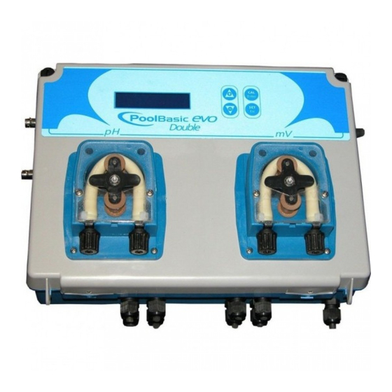
1. GENERAL INTRODUCTION The Pool Basic Pro EVO control method belongs to a new line of instruments carefully developed by the supplier for the innovative management of pools. This device is easy to use and permits continuous control of the pH.
-
Page 4: Identification Of Components
3. IDENTIFICATION OF COMPONENTS Instructions manual PH 7 PH 4 A. Pool Basic Pro EVO regulator B. Suction hose in PVC Crystal 4×6 (4 m) x 2 C. Delivery hose in PE 4X6 (5 m) x 2 D. pH Electrode model SPH-1 E.
-
Page 5: Technical Specifications
Input signal: 100÷240 Vac Level probe: pH, H Install the Pool Basic Pro EVO control device on a hard support (vertical wall) where it can be easily accessed by the operator. Attach the Pool Basic Pro EVO control device using the provided fixing bracket (distance between centre of holes: 95mm.
-
Page 6: Assembly Instructions
5. ASSEMBLY INSTRUCTIONS Max. length of cable: 6m Lunghezza massima de cavo: 6 mt * NOTA 1 *NOTE 1 Maximum pressure Pressione Massima: 1,5 bar *NOTE 1 * NOTA 2 *NOTE 1: FOR LARGE PUMPS, THE CABLE MUST PASS THROUGH AN AREA OTHER THAN THE POWER * NOTA 1: IL CAVO DEVE PASSARE IN UNA ZONA DIVERSA DA QUELLA DI ALIMENTAZIONE SUPPLY ZONE IN ORDER TO PREVENT CURRENT DISTURBANCES.
-
Page 7: Application Example
5.1 APPLICATION EXAMPLE COMPENSATION FILTER HEAT TANK INTERCHANGER RECIRCULATION PUMP Note: The linear distance of the hose between the probe and the point of injection must not be less than 60cm. 0000137188 Rev. 1.0…
-
Page 8: Description Of The Circuit
6. DESCRIPTION OF THE CIRCUIT 1) Inlet pH measurement 2) Inlet temperature probe 3) Inlet probe level for product pH 4) Inlet probe level for product H 5) Keyboard input 6) Flow (recirculation pump) 7) Relay for pH product, external pump.
 Alarm relay 9) Relay for H product, external pump.
 -
Page 9
7.1.1 Calibrating the pH probe Wash the probe Remove the probe from the probe Get some water holder Press CAL 25°C 14pH B.Solution Press and hold down the Cal button Press Cal to start calibration with a for 3 seconds Keep the probe in the buffer solution buffer solution pH 7 pH 7… -
Page 10: Programming
8. PROGRAMMING The programming menu can be accessed by simultaneously pressing the Cal and Set keys for at least 3 seconds. Upon release of the keys the display will show: Language Display Settings Press Enter and the + and – keys to change Progrma Menu the language: Language…
-
Page 11
measurement display Settings Use Enter to access the sub-menus: Hose Progrma Menu Conc. Pump Use Enter to modify the dimensions of the hose (3×7 or 6x10mm) and the system automatically calculates the flow Tube 6×10 rate with the other hose without changing any parameters (the factory-set hose is 6×10). -
Page 12
Press Esc to exit any menu and confirm the settings by pressing Enter. Display Settings Press the + and – keys to choose Save or Progrma Menu NoSave, i.e. to save the settings or not and Exit Save press Enter to confirm. DISPLAY VIEW WITH THE SYSTEM ON STAND-BY Stand-by display Operation… -
Page 13: Dosing Method
9. DOSING METHOD The control of the pumps in the pH scale is carried out through the PWM function. The proportional band is set to values pH= 0.8 pH proportional dosing The instrument allows the chemical measurement to be controlled and modified through the pH Set Point automatically;…
-
Page 14: On/Off P Hdosing
ON/OFF pH dosing The instrument allows the chemical measurement to be controlled and modified through the pH Set Point automatically; adjusting the dosing though the pH motor controlled in ON/OFF. The dosing below is obtained by setting the following parameters: …
-
Page 15: Activations
10. ACTIVATIONS Flow Function Through the recirculation pump. High voltage input 100 ÷ 240 Vac, the dosing system is switched on. High voltage input is off (the recirculation pump is switched off), the dosing system shows FLOW flashing. 11. ALARMS Lev pH= pH product level probe alarm.
-
Page 16: List Of Possible Anomalies And Relative Solutions
13. LIST OF POSSIBLE ANOMALIES AND RELATIVE SOLUTIONS ANOMALY CAUSE SOLUTION 1) Check for possible short circuits on the electrode instrument connection cable (between the cable’s core and the external instrument Problem with the cable and/or shielding). always indicates pH connector.
-
Page 17: Handling
14. HANDLING Hose replacement: Position the roller at 20 past 10, Completely release left Release the cover by pulling the turning it in the direction of the connector, holding it taut towards the left connector upward. circular arrow. outside, and turn the roller in the direction of the circular arrow so that the hose is freed up to the right connector.
-
Page 18: Storing The Pump After Use
15. STORING THE PUMP AFTER USE When the regulation device must be stored, clean water should be pumped through the hose in order to rinse it. Then position the probe holder at 7h05, turning in the direction indicated by the circular arrow.
-
Page 19: Warnings
WARNINGS PRODUCTS TO BE USED: pH Reduction: product with a sulphuric acid base, easily found on the market. pH Increase: product with an alkaline acid base PRODUCTS NOT RECOMMENDED Do not use hydrochloric acid. Ask the installer about all other products. PROBE WARNINGS …
 Alarm relay 9) Relay for H product, external pump.
 This manual is also suitable for:
Pool basic pro evo
Specifications:
|
Accompanying Data:
Seko Pool Basic Pro Evo Controller PDF Operation & User’s Manual (Updated: Sunday 12th of March 2023 10:18:34 AM)
Rating: 4.6 (rated by 49 users)
Compatible devices: VMX-Synergy Plus VMX-SGY-I-17, GVB-8-Pb-12V, PVCM40D-MPT, horiSMART AN160, F-digital 36 309, SUREFLOW 8670, ACMCB220 Series, Kontrol 800.
Recommended Documentation:
Seko Pool Basic Pro Evo: Text of Operation & User’s Manual
(Ocr-Read Version Summary of Contents, UPD: 12 March 2023)
-
11, 0000137188 Rev. 1.0 11 H 2 O 2 measurement display Settings Progrma Menu H 2 O 2 Use Enter to access the sub-menus: Hose Conc. Pump H 2 O 2 Tube 6×10 Use Enter to modify the dimensions of the hose (3×7 or 6x10mm) and the system automatically calculates the flow r…
-
3, 0000137188 Rev. 1.0 3 1. GENERAL INTRODUCTION The Pool Basic Pro EVO control method belongs to a new line of instruments carefully developed by the supplier for the innovative management of pools. This device is easy to use and permits continuous control of the pH. The peristaltic pumps have a …
-
8, 0000137188 Rev. 1.0 8 6. DESCRIPTION OF THE CIRCUIT 1) Inlet pH measurement 2) Inlet temperature probe 3) Inlet probe level for product pH 4) Inlet probe level for product H 2 O 2 5) Keyboard input 6) Flow (recirculation pump) 7) Relay for pH product, external pump.
Alarm… -
13, 0000137188 Rev. 1.0 13 9. DOSING METHOD The control of the pumps in the pH scale is carried out through the PWM function. The proportional band is set to values pH= 0.8 9.1 pH proportional dosing The instrument allows the chemical measurement to be controlled and modified through t…
-
18, 0000137188 Rev. 1.0 18 15. STORING THE PUMP AFTER USE When the regulation device must be stored, clean water should be pumped through the hose in order to rinse it. Then position the probe holder at 7h05, turning in the direction indicated by the circular arrow. These two precautions will f…
-
14, 0000137188 Rev. 1.0 14 9.2 ON/OFF pH dosing The instrument allows the chemical measurement to be controlled and modified through the pH Set Point automatically; adjusting the dosing though the pH motor controlled in ON/OFF. The dosing below is obtained by setting the following parameters: …
-
19, 0000137188 Rev. 1.0 19 WARNINGS PRODUCTS TO BE USED: pH Reduction: product with a sulphuric acid base, easily found on the market. pH Increase: product with an alkaline acid base PRODUCTS NOT RECOMMENDED Do not use hydrochloric acid. Ask the installer about all other products. PROBE WAR…
-
5, 0000137188 Rev. 1.0 5 O. Temperature sensor 4. TECHNICAL SPECIFICATIONS Power supply: 100÷240 Vac 50/60 Hz 30 watt Switch: on side of box Inlet measurements: pH, through BNC o pH scale: 0÷14.0 pH o pH precision: +/-0.1 pH Temperature Scale: 0÷100 °C (PT100 sensor) Pump flow rate with …
-
12, 0000137188 Rev. 1.0 12 Press Esc to exit any menu and confirm the settings by pressing Enter. DISPLAY VIEW WITH THE SYSTEM ON STAND-BY *If AdvancedFlow=On and during H 2 O 2 dosing, the recirculation pump stops and blocks the system dosing, when the pump restarts, the H 2 O 2 will restart the cc dosing …
-
15, 0000137188 Rev. 1.0 15 10. ACTIVATIONS Flow Function Through the recirculation pump. High voltage input 100 ÷ 240 Vac, the dosing system is switched on. High voltage input is off (the recirculation pump is switched off), the dosing system shows FLOW flashing. 11. ALARMS Lev pH= pH product le…
-
4, 0000137188 Rev. 1.0 4 3. IDENTIFICATION OF COMPONENTS PH 7 PH 4 H0 2 B C D F G M E Instructions manual K L N H I J O KEY A. Pool Basic Pro EVO regulator B. Suction hose in PVC Crystal 4×6 (4 m) x 2 C. Delivery hose in PE 4X6 (5 m) x 2 D. pH Electrode model SPH-1 E. Reducer …
-
1, 0000137188 Rev. 1.0 1 User Manual
… -
17, 0000137188 Rev. 1.0 17 14. HANDLING Hose replacement: Release the cover by pulling the left connector upward. Position the roller at 20 past 10, turning it in the direction of the circular arrow. Completely release the left connector, holding it taut towards the outside, an…
Seko Pool Basic Pro Evo: Recommended Instructions
Veriton M460G, 190-002, C27C35T, Power Fort C-2010, 34972A


-
•Connector pin assignmentTD+Signal nameRD+TD-1Pin number2312341234BUS INBUS OUTConfigurationL/A OUTL/A INDisplayST(M)PWRPWR(V)SFContentDisplays the diagnostic status of the unit.Displays the status of the power supply voltage forcontrol and input.Displays the status of the power supply voltage foroutputs.Displays the system status.BF Displays the communicati …
EX600-SPN1 1
-
SL-240 Quick Start (P/N: 2900-300728QS REV 2) P/N: 2900- 300728QS Rev: 2 Scan for full manual SL-240 Quick Start Guide This guide helps you install and use your SL-240 for the first time. Go to www.kramerav.com/downloads/SL-240 to download the latest user manual and check if firmware upgrades are available. Step 1: Check what’s in the box SL-240 Master / Room Controller …
SL-240 2
-
Merlin 1500S Gas Interlock System User & Installation Manual Rev: 03 Date: 08-01-18 1 Gas Safety Products Merlin 1500S Gas Interlock System Installation, operating and maintenance …
Merlin 1500S 8
-
SCON First Step Guide Sixth Edition Thank you for purchasing our product. Make sure to read the Safety Guide and detailed Instruction Manual (DVD) included with the product in addition to this First Step Guide to ensure correct use. This Instruction Manual is original. • Using or copying all or part of this Instruction Manual without permission is prohibited. • The co …
scon 4
-
Powermax45 Control BoardReplacement KitKit de remplacement du CI decommande du Powermax45 Field Service BulletinBulletin de service sur le terrain 805860 – Revision 1 – March, 2009Révision 1 – Mars, 2009 …
Powermax45 XP 6
-
— 0 — VERSA Beam Antenna Controller INSTRUCTION MANUAL Please keep this manual after you read for maintenance purpose Rev3.01 Jun. 2020 …
VERSA Beam 44
-
www.burkert.comWe reserve the right to make technical changes without notice.Technische Änderungen vorbehalten.Sous resérve de modification techniques. © 2007 — 2008 Bürkert Werke GmbH & Co. KG Operating Instructions 0801/03_EU-ml_00805858QuickstartPneumatische AnsteuerungPneumatic Controllerenglish2 …
8690 12
-
Thank you for purchasing this controller. Please take a few minutes to read this quick installation guide before you install the controller.ATTENTION: Perform all installation work at an electrostatic discharge (ESD)-safe workstation that meets the requirements of EIA-625, Requirements for Handling Electrostatic Discharge Sensitive Devices. You must perform all actions in acc …
MegaRAID SAS 9361-24i 6
-
Release 3.0NN47251-311Issue 02.01June 2014Installation Job Aid (English) for Avaya WLAN 8100 series- WLANAP 8120 with External AntennaHow to get helpTo access the complete range of services and support that Avaya provides, go to www.avaya.com.You can also go to www.avaya.com/support to access the following pages:• technical documentation• product training• technical supportIf …
WLAN 8100 Series 12
-
Calibration and TroubleshootingService InformationF-24419-1GENERAL INFORMATIONThe DYN1-10704 and 10724 controllers are basic controllers without an overspeed. The 10704 controller is normallyused on diesel engines and the 10724 is normally used on ignition engines.The DYN1-10714 and 10734 controllers are also basic controllers with overspeed protection 12.5% above set speed.The 10714 control …
DYN1-10704 Series 4
Additional Information:
Popular Right Now:
Operating Impressions, Questions and Answers:
1. GENERAL INTRODUCTION ……………………………………………………………………………………………………………….3
2. INSTALLATION PRECAUTIONS …………………………………………………………………………………………………………3
3. IDENTIFICATION OF COMPONENTS ………………………………………………………………………………………………….4
4. TECHNICAL SPECIFICATIONS …………………………………………………………………………………………………………..5
5. ASSEMBLY INSTRUCTIONS ………………………………………………………………………………………………………………6
5.1 APPLICATION EXAMPLE …………………………………………………………………………………………………………………7
6. DESCRIPTION OF THE CIRCUIT ………………………………………………………………………………………………………..8
7. CALIBRATION MENU ………………………………………………………………………………………………………………………..8
……………………………………………………………………………………………………………………………………..8
8. PROGRAMMING …………………………………………………………………………………………………………………………….. 10
9. DOSING METHOD ………………………………………………………………………………………………………………………….. 13
9.1
9.2
9.3
10. ACTIVATIONS ……………………………………………………………………………………………………………………………… 15
11. ALARMS ……………………………………………………………………………………………………………………………………… 15
12. PRE-DEFINED CONTROL PARAMETERS ……………………………………………………………………………………… 15
14. HANDLING …………………………………………………………………………………………………………………………………… 17
15. STORING THE PUMP AFTER USE ………………………………………………………………………………………………… 18
WARNINGS ……………………………………………………………………………………………………………………………………….. 18
0000137188
CONTENTS
…………………………………………………………………………………………………………… 13
……………………………………………………………………………………………………………………. 13
……………………………………………………………………………………………………… 14
Rev. 1.0
2