-
Contents
-
Table of Contents
-
Bookmarks
Quick Links
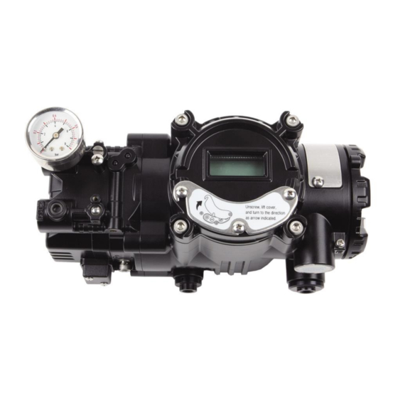
SMART POSITIONER
PRODUCT MANUAL
YT-3400 / 3450 SERIES
VERSION 1.06
Summary of Contents for Ytc YT-3400 SERIES
-
Page 1
SMART POSITIONER PRODUCT MANUAL YT-3400 / 3450 SERIES VERSION 1.06… -
Page 2: Table Of Contents
Contents 1. Introduction ……………………………………………………………………………………………… 5 1.1 General information for the users …………………………………………………………………. 5 1.2 Manufacturer Warranty …………………………………………………………………………… 1.3 Explosion Proof Warning ………………………………………………………………………. 2. Product Description ………………………………………………………………………………….. 2.1 General …………………………………………………………………………………………….. 2.2 Main Features and Functions ……………………………………………………………………. 7 2.3 Label Description ………………………………………………………………………………….. 8 2.4 Product Number ………………………………………………………………………………………
-
Page 3
6. Adjustment ………………………………………………………………………………………………. 29 6.1 Limit Switch Adjustment …………………………………………………………………………… 29 6.2 A/M switch adjustment …………………………………………………………………………… 30 6.3 Variable Orifice Adjustment ………………………………………………………………………. 30 7. Auto Calibration and PCB Operation ……………………………………………………………….. 31 7.1 Warning………………………………………………………………………………………………. 31 7.2 Button Description ………………………………………………………………………………… 31 7.3 Run Mode (RUN) ………………………………………………………………………………….. 31 7.4 Auto Calibration (AUTO CAL) ……………………………………………………………………. -
Page 4
PST Mode ……………………………………………………………………………….. 45 7.9.2 PST CFG ………………………………………………………………………………… 45 7.9.3 7.9.3.1 START PO ………………………………………………………………………….. 45 7.9.3.2 TARGET 1 ………………………………………………………………………….. 46 7.9.3.3 TARGET 2 ………………………………………………………………………….. 46 7.9.3.4 INTERVAL ………………………………………………………………………….. 46 7.9.3.5 TOL………………………………………………………………………………….. 47 7.9.3.6 LIMIT TM ………………………………………………………………………….. 47 7.9.3.7 LATENCY ………………………………………………………………………….. 47 PST RSLT ……………………………………………………………………………….. -
Page 5: Introduction
1. Introduction General Information for the users Thank you for purchasing Young Tech Co., Ltd products. Each product has been fully inspected after its production to offer you the highest quality and reliable performance. Please read the product manual carefully prior to installing and commission the product. …
-
Page 6: Explosion Proof Warning
Explosion Proof Warning Please ensure the unit is being used and installed within the explosion proof certified environment. YT-3400/3450 series are Explosion proof construction for internal pressure. For detail information, refer to “2.6 Explosion Proof Certifications” Explosion proof type of cables and gaskets should be used, when explosion gases are present at the installation site.
-
Page 7: Product Description
Hand calibration function can set Zero and Span values. It has IP66 protection grade. Epoxy polyester powder coating resists the corrosion process. (YT-3400 series only) Maintenance of the positioner is easy because of modularized inner structure. YT-3400/3450 series…
-
Page 8: Label Description
Label Description Fig. 3: YT-3400/3450 Sticker Label. Model: Indicates the model number of the positioner. Suffix: Indicates any options. Serial No.: Indicates unique serial number. Fig. 4: YT-3400/3450 Stainless steel plate Label Model: Indicates the model number of the positioner. Supply: Indicates the supply pressure range.
-
Page 9: Product Number
Product Number YT-3400 series follows suffix symbols as follows. YT-3400 1 Linear Motion Type Rotary Single Acting Acting type Double Acting Explosion Proof Ex db IIC T5/T6; Ex tb IIIC T100℃/T85℃ 10 ~ 40 mm Feedback Lever 20 ~ 70 mm…
-
Page 10: Product Specification
Product Specification Model YT-3400/3450L YT-3400/3450R Acting Type Single Double Single Double Input Signal 4~20mA DC Minimum Current Signal 3.2mA(Standard), 3.8mA(Hart Included) Supply Pressure 0.14~0.7 MPa (1.4~7 bar) Stroke 10~150 mm 0~90° Max. 450Ω @ 20mA DC Impedance Air Connection PT, NPT 1/4 Gauge Connection PT, NPT 1/8 Conduit Entry…
-
Page 11: Explosion Proof Certifications
Explosion Proof Certifications KC (Korea, YT-3400 Only) Type : Explosion proof construction for internal pressure Rating : Ex d IIC T5/T6 IP66 Certification No. : 10-KB2BO-0077 Ambient temperature : -40~+70℃(T6), -40~+85℃(T5) ATEX Type : Explosion proof construction for internal pressure Rating : II 2G Ex db IIC T5/T6, II 2D Ex tb IIIC T85℃/T100℃…
-
Page 12: Parts And Assembly
Parts and Assembly Fig. 5: YT-3400/3450 series exploded view 1. Pilot Cover 6. Potentiometer 2. Pilot Unit 7. Main Body 3. Main Cover 8. Terminal PCB 4. Main PCB 9. Terminal Cover 5. Feedback Lever 10. Manifold Drain Plug Location of drain plug according to orientation of positioner’s mounting Fig.
-
Page 13: Product Dimension
2.8 Product Dimension 2.8.1 Fig. 7: YT-3400L Fig. 8: YT-3450L 2.8.2 Fig. 9: YT-3400R (Fork lever type) Fig. 10: YT-3450R (Fork lever type) YT-3400/3450 series…
-
Page 14: Yt-3400 / 3450R (Namur Type)
2.8.3 Fig. 11: YT-3400R (Namur type) Fig. 12: YT-3450R (Namur type) YT-3400/3450 series…
-
Page 15: Yt-3400 / 3450L
3. Installation Safety When installing a positioner, please ensure to read and follow safety instructions. Any input or supply pressures to valve, actuator, and / or to other related devices must be turned off. Use bypass valve or other supportive equipment to avoid entire system “shut down”. …
-
Page 16: Installation Steps
3.3.1 Installation Steps 1. Proper bracket must be made in order to adapt the positioner on the actuator yoke. Please consider following important points when a bracket is being designed. Positioner’s feedback lever must be vertical to the valve stem at 50% of the valve stroke.
-
Page 17
6. Insert connection bar into the feedback lever. The bar should be inserted when the actuator clamp is at 50% of the total valve stroke. Fig. 16: Proper way to connect feedback lever, connection bar, and lever spring by connecting pneumatic pressure to actuator to position the valve at 50% 7. -
Page 18
9. After installing the positioner, operate the valve from 0% to 100% stroke by using direct air to the actuator. On both 0% and 100%, the feedback lever should not touch the lever stopper, which is located on the backside of the positioner. If the feedback lever touches the stopper, the positioner should be installed further away from the yoke. -
Page 19: Yt-3400/3450R Installation
YT-3400/3450R Installation YT-3400/3450R should be installed on rotary motion valve such as ball or butterfly type which uses rack and pinion, scotch yoke or other type of actuators which its stem rotates 90 degrees. Before proceeding with the installation, ensure following components are available.
-
Page 20: Bracket Information
3.4.1 Bracket information Standard bracket (included with the positioner) contains two components. The bracket can be used for both fork lever and NAMUR lever type. The bracket is designed to fit onto the actuator with 20mm, 30mm and 50mm stem height (H) according to VDI/VDE 3845 standard. Please refer to below table how to adjust the height of the bracket.
-
Page 21: Installation Steps
3.4.2 Installation Steps 1. Please check the actuator’s stem height and adjust the bracket by referring to the bracket table. 2. Attached the bracket onto the actuator. It is recommended to use spring washer so the bolts will not be loosen from vibration. 3.
-
Page 22
stem decreases the positioner’s durability due to unnecessary forces on the main shaft. Fig. 25: Main shaft center alignment (fork lever) Fig. 26: Positioner with an actuator 7. Tighten the positioner and the bracket with hexagon-headed bolts and plate washer after checking the positioner’s position. -
Page 23: Connection — Piping
4. Connection — Piping Safety Supply pressure should be clean and dry air – avoiding moisture, oil or dust. Always recommended to use air filter regulator (i.e. YT-200 series). Young Tech Co., Ltd has not tested positioner’s operation with any other gases other than clean air.
-
Page 24: Connection — Piping With Actuator
Connection – Piping with actuator 4.4.1 Single acting actuator Singe acting type positioner is set to use only OUT1 port. OUT1 port should be connected with supply pressure port from actuator when using single acting type of spring return actuator. Fig.
-
Page 25: Connection — Power
5. Connection – Power Safety When installing in hazardous and explosive gas area, conduit tube or pressure-proof packing union must be used. The compound charging box should be the flameproof type and must be sealed completely. Conduit entry connection tap is PF 1/2 or G 1/2. …
-
Page 26: Terminal Overview
Terminal Overview Fig. 32: Terminal IN +: Input Signal (+) Upper right 3 terminals: Limit switch 100% Point IN -: Input Signal (-) Lower right 3 terminals: Limit switch 0% Point F.G : Frame Gound OUT+: Feedback Signal (+) OUT-: Feedback Signal (-) 5.2.1 Input Signal Terminal…
-
Page 27: Feedback Signal Terminal
5.2.2 Feedback Signal Terminal 1. Open terminal cover and locate feedback signal terminals. 2. Locate terminal of feedback signal and connect (+) and (-) according to the polarity. Make sure to tighten bolts with 1.5 Nᆞm (15 kgfᆞcm). 3. Close the terminal cover and fasten stopper bolt using 3mm wrench. Fig.
-
Page 28: Ground
5.2.4 Ground 1. Ground must be done before operating the positioner. 2. Open terminal cover and there is a internal ground bolt on the left of terminal plate. When using internal ground, use 3mm wrench to loosen locking bolts of the terminal box cover.
-
Page 29: Adjustment
6. Adjustments Limit Switch Adjustment 1. HIGH variable resistor adjusts the sensing point of valve end-point. In case of Direct Action type, it will sense 4mA point, and for Reverse Action type, 20mA of input signal will be its sensing point. Upon sensing, red LED will be lighted. 2.
-
Page 30: A/M Switch Adjustment
A/M switch adjustment 1. On the left hand bottom of positioner, there is A/M switch (Auto/Manual). If the switch is turned clockwise (toward “A”) and it is fasten tightly, then the supply pressure will be transferred to actuator through outport by positioner control. On the other hand, if the switch is turned counter-clockwise (toward “M”), it is loosened, then the supply pressure will be directly supplied to the actuator regardless of positioner control.
-
Page 31: Auto Calibration And Pcb Operation
7. Auto calibration and PCB Operation Warning Following process will operate valve and actuator. Before proceeding with any Auto Calibration, please separate valve from the entire system by using bypass valve, so Auto Calibration will not affect entire valve process. Button Description Positioner has 4 buttons, and they enable to perform various functions.
-
Page 32: Auto Calibration (Auto Cal)
Auto Calibration (AUTO CAL) Auto Calibration (AUTO CAL) automatically calibrates the positioner. “AUTO CAL” process takes about 2~3 minutes, and the duration of the process varies upon the size of the actuator. There are 3 types of AUTO CAL. Zero End Point P, I, D RA / DA…
-
Page 33: Auto2 Calibration (Auto2)
7.4.2 AUTO2 Calibration (AUTO2) AUTO2 changes all of the parameters. It is recommended to perform AUTO2 when the positioner has been installed on the valve for the first time or the positioner has been reinstalled after dissemble from an actuator. ⇨…
-
Page 34: Parameter Mode (Param)
Parameter Mode (PARAM) AUTO CAL optimizes most of the valve actuator control values. However, in some instances, hunting or oscillation may occur when the valve actuator control values are not optimized. Hunting or oscillation can be prevented by adjusting parameter values. Once parameter values have been changed, the changed values are being affected as soon as you save the value.
-
Page 35: I Value (Ki)
7.6.3 I Value (KI) I value indicates the additional compensation signal based on the percentage of error allowance. As the value increase, it is more likely to have hunting. As the value decreases, the positioner will move slowly to the target position. ⇨…
-
Page 36: Hand Calibration Mode (Hand Cal)
Hand Calibration Mode (HAND CAL) The positioner can be manually calibrated by entering into Hand Calibration Mode. Zero-Point (PV_ZERO) and End-Point (PV_END) for Valves Zero-Point (TR_ZERO) and End-Point (TR_END) for Transmitter Normal / Reverse Feedback Signal (TR NORM / REVS) …
-
Page 37: Zero-Point (Tr_Zero) And End-Point (Tr_End) For Transmitter
7.7.2 Zero-Point (TR_ZERO) End-Point (TR_END) for Transmitter TR_ZERO adjusts the zero point of the transmitter (4-20mA feedback), TR_END adjusts the end point of the transmitter (4-20mA feedback) ⇨ ⇨ ⇨ <DOWN> <ENTER> <UP>/<DOWN> <ENTER> Zero Adjustment Match feedback signal with 4mA ⇨…
-
Page 38: Normal / Reverse Hart Signal (Ht_Norm / Revs)
7.7.4 Normal / Reverse HART Signal (HT NORM / REVS) HART signal from the positioner can be changed to normal or reverse. ⇨ ⇨ ⇨ <ENTER> <DOWN> <ENTER> 6 times ⇨ ⇨ ⇨ <DOWN> <ENTER> <ESC> 3 times YT-3400/3450 series…
-
Page 39: Valve Mode (Valve)
Valve Mode (VALVE) Acting Adjustment (ACT RA / dA) Characteristic Adjustment (CHAR) User Characteristics (USER SET) Tight Shut Open (TSHUT OP) Tight Shut Close (TSHUT CL) Split Range Mode (SPLIT) Custom Zero Setting Mode (CST ZERO) …
-
Page 40: Characteristic Adjustment (Char)
7.8.2 Characteristic Adjustment (CHAR) The valve characteristic can be set on the field’s There are 3 types of characteristics – requirement. linear (LIN), equal percentage (EQ), and quick open (QO). ⇨ ⇨ ⇨ <ENTER> <DOWN> <ENTER> ⇨ ⇨ <UP>/<DOWN> <ESC> <ENTER>…
-
Page 41: Tight Shut Open (Tshut Op)
7.8.4 Tight Shut Open (TSHUT OP) Tight Shut Open allows the valve to open completely as the input signal reaches around 20mA. ⇨ ⇨ ⇨ <ENTER> <DOWN> <ENTER> 3 times ⇨ ⇨ <UP>/<DOWN> <ESC> <ENTER> 3 times 7.8.5 Tight Shut Close (TSHUT CL) Tight Shut Close allows the valve to close completely as the input signal reaches around 4mA.
-
Page 42: Custom Zero Setting Mode (Cst Zero)
7.8.7 Custom Zero Setting Mode (CST ZERO) Custom Zero Setting Mode allows the user to set any specific point as zero position. For example, the zero point can be set at input signal of 7mA. ⇨ ⇨ ⇨ <ENTER> <ENTER> <DOWN>…
-
Page 43: Interpolation Mode (Itp Off / On)
7.8.9 Interpolation Mode (ITP OFF / ON) In case of linear positioner, if feedback lever angle is above 30 degrees, the accuracy can be reduced. During the Auto Calibration, if the positioner recognizes that the lever angel is more than 30 degrees, the positioner will turn on or off (if less than 30 degrees) ITP function automatically.
-
Page 44: Diagnostic (Diagno)
Diagnostic (dIAGNO) ⇨ ⇨ <ENTER> <DOWN> 6 seconds 5 times 7.9.1 PST Introduction TARGET 2 START PO TARGET 1 LATENCY INTERVAL When PST runs by PST NOW or SCHD, if valve position is in the range of TOL from START PO, Positioner supply or vent air until the valve reach the TARGET 1, 2.
-
Page 45: Pst Mode
7.9.2 PST Mode To run PST, select a PST mode. There are 3 mode for running PST. Mode Description Stop PST Schedule. It’s a default mode PST OFF PST SCHD Run PST immediately. After PST complete, it turns back to the previous mode PST NOW PST runs repeatedly by interval value ⇨…
-
Page 46: Target 1
7.9.3.2 TARGET 1 Sets 1st target position of PST. The position must be in between 0 and 100%, and default value is 90%. ⇨ ⇨ ⇨ <ENTER> <DOWN> <ENTER> ⇨ ⇨ <UP>/<DOWN> <ESC> <ENTER 4 times 7.9.3.3 TARGET 2 Sets 2nd target position of PST. The position must be in between 0 and 100%, and default value is nA%.
-
Page 47: Tol
7.9.3.5 TOL Tolerance level of the start position when PST runs. The value must be between 0.1 ~ 10%, and default value is 5%. ⇨ ⇨ ⇨ <DOWN> <ENTER> <ENTER> 4times ⇨ ⇨ <UP>/<DOWN> <ESC> <ENTER 4 times 7.9.3.6 LIMIT TM Limit the stroke time between start position and Target 1 and 2.
-
Page 48: Pst Rslt
7.9.4 PST RSLT It will record or memorize maximum three PST results. The longest stroke time from START PO to the TARGET 1,2 or Error messages will be recorded NAME VAULE DEFAULT PST REC1 OOT,LTO,NR,0-600(sec) PST REC2 OOT,LTO,NR, 0-600(sec) PST REC3 OOT,LTO,NR, 0-600(sec) Error Message…
-
Page 49: View Mode (View)
7.10 View Mode (VIEW) Displays information of the positioner. The user can change the valve stroke displays in percent (%) or number format. ⇨ ⇨ ⇨ <ENTER> <DOWN> <ENTER> 6 seconds 6 times ⇨ ⇨ <UP>/<DOWN> ⇨ Confirm the <ENTER> <ENTER>…
-
Page 50
VALUE I Current accumulated value of I Absolute resistance value. Temp Current Temperature When W UNLOCK, you can parameters including auto calibration W LOCK / function. When W LOCK, cannot W UNLOCK You can change it, pushing <ENTER> YT-3400/3450 series… -
Page 51: Error And Warning Code
Error and Warning Code Error code Error Code Code Description and Cause Action Positioner is improperly installed. Re-install the positioner. Positioner is not parallel to the Ensure the feedback lever does MT ERR L ground at 50% point. Lever is at not touch the lever stopper at 0% lower position than actual 50% point.
-
Page 52: Warning Code
Warning code Warning Code Description and Cause Action Code Re-install the positioner. Ensure the feedback lever does not Pv Span – Pv Zero range is below 500. touch the lever stopper at 0% and The angle of feedback lever is too small. 100%.
-
Page 53: Main Software Map
Main Software Map YT-3400/3450 series…
-
Page 54
Manufacturer: Young Tech Co., Ltd 81, Hwanggeum-ro, 89 Beon-gil, Yangchon-eup Gimpo-si, Gyeonggi-do, South Korea 10048 Tel: +82-31-986-8545 Fax: +82-31-986-2683 Email: ytc@ytc.co.kr Issued : 1’th Apr. 2016 Version. 1.06 Copyright © Young Tech Co., Ltd. All Rights Reserved. YT-3400/3450 series…
|
||||||||||||||||||||||||||||||||||||||||||||||||||||||||||||||||||||||||||||||||||||||||||||||||||||
|
Линейный пневматический позиционер Серия YT-1200LШиберные ножевые затворы с маховиком. Серия PAL
|


Smart Positioner
YT-3400 / 3450 series (New NCS type)
6.2
Variable Orifice Adjustment ………………………………………………………………………………………………… 38
7
Maintenance …………………………………………………………………………………………………………………………… 39
7.1
Supply air …………………………………………………………………………………………………………………………. 39
7.2
Seals ……………………………………………………………………………………………………………………………….. 39
8
Auto Calibration and PCB Operation ……………………………………………………………………………………….. 40
8.1
Warning ……………………………………………………………………………………………………………………………. 40
8.2
LCD display and buttons …………………………………………………………………………………………………….. 40
8.2.1
LCD display and symbols ……………………………………………………………………………………………….. 40
8.2.2
Button and function ………………………………………………………………………………………………………… 41
8.3
Menu levels ………………………………………………………………………………………………………………………. 42
8.4
Run Mode (RUN) ………………………………………………………………………………………………………………. 43
8.5
Configuration and Operation ……………………………………………………………………………………………….. 44
8.6
Calibration (CALIb) ……………………………………………………………………………………………………………. 49
8.6.1
Acting Type (SINGLE / dOUBLE) …………………………………………………………………………………….. 49
8.6.2
Auto Calibration 1 (AUTO 1) ……………………………………………………………………………………………. 50
8.6.3
Auto Calibration 2 (AUTO 2) ……………………………………………………………………………………………. 50
8.6.4
8.7
Manual Operation (MAN OPER)………………………………………………………………………………………….. 52
8.7.1
8.7.2
8.8
Control Parameters (CTL PARM) ………………………………………………………………………………………… 54
8.8.1
Dead Band (dEAdbANd) …………………………………………………………………………………………………. 54
8.8.2
8.8.3
8.8.4
8.8.5
GAP Parameter (GAP) …………………………………………………………………………………………………… 56
8.8.6
GAP P parameter (GP) …………………………………………………………………………………………………… 57
8.8.7
GAP I parameter (GI) ……………………………………………………………………………………………………… 57
8.8.8
GAP D parameter (Gd) …………………………………………………………………………………………………… 57
8.8.9
Auto Dead band Mode (AUTO db) …………………………………………………………………………………… 58
8.8.10
Performance Mode (PER) …………………………………………………………………………………………… 58
8.9
Input Configuration (IN CFG) ………………………………………………………………………………………………. 59
8.9.1
8.9.2
Split Range Mode (SPLIT) ………………………………………………………………………………………………. 60
8.9.3
8.9.4
Custom Split Range End (CST ENd) ………………………………………………………………………………… 61
8.9.5
8.9.6
8.9.7
8.9.8
Tight Shut Open (TSHUT OP) …………………………………………………………………………………………. 64
Ver. 2.06
3
Product manual
-
Page 1
SMART POSITIONER PRODUCT MANUAL YT-3300 / 3350 SERIES (PROFIBUS PA & FOUNDATION FIELDBUS) YT-3300 (PA/FF) YT-3350 (PA/FF) Rotork YTC Limited VERSION 1.00… -
Page 2: Table Of Contents
Smart Positioner YT-3300 / 3350 series (Profibus PA & Foundation Fieldbus) Product Manual Contents Introduction …………………………5 General Information for the users ………………….5 Manufacturer Warranty …………………….5 Explosion Proof Warning (Only for Intrinsic safety type positioners) …………6 Product Description ………………………7 General …………………………7 Main Features and Functions …………………..7 Label Description ……………………..8 Product Code ……………………….9…
-
Page 3
Smart Positioner YT-3300 / 3350 series (Profibus PA & Foundation Fieldbus) Product Manual Connection ……………………….29 Ground …………………………. 30 Adjustments ……………………….. 31 A/M switch adjustment ……………………31 Orifice Installment ……………………..32 Maintenance ……………………….. 33 Supply air ……………………….33 Seals …………………………33 Typical connection of YT-3300 with Profibus PA and Foundation Fieldbus …….. -
Page 4
Smart Positioner YT-3300 / 3350 series (Profibus PA & Foundation Fieldbus) Product Manual 9.8.7 Acting Type (SINGLE / dOUBLE) ………………..50 9.8.8 Lever Type (STd / AdT) ……………………. 51 Diagnostic (dIAGNO) ……………………. 52 9.9.1 Diagnosis Limit Configuration (LIMT CFG) ………………52 9.9.1.1 Deviation (dEV) …………………… -
Page 5: Introduction
Introduction General Information for the users Thank you for purchasing Rotork YTC Limited products. Each product has been fully inspected after its production to offer you the highest quality and reliable performance. Please read the product manual carefully prior to installing and commissioning the product.
-
Page 6: Explosion Proof Warning (Only For Intrinsic Safety Type Positioners)
Smart Positioner YT-3300 / 3350 series (Profibus PA & Foundation Fieldbus) Product Manual Explosion Proof Warning (Only for Intrinsic safety type positioners) Please ensure the unit is being used and installed in conformity with local, regional, and national explosion proof within the proper safety barrier environment. ➢…
-
Page 7: Product Description
Smart Positioner YT-3300 / 3350 series (Profibus PA & Foundation Fieldbus) Product Manual Product Description General YT-3300 / 3350 (PA/FF) series Smart Valve Positioner accurately controls valve stroke in response to an input signal of Communication from the controller. Built-in micro-processor optimizes the positioner’s performance and provides unique functions such as Auto-Calibration, Profibus PA or Foundation fieldbus Protocol Communications.
-
Page 8: Label Description
Smart Positioner YT-3300 / 3350 series (Profibus PA & Foundation Fieldbus) Product Manual Label Description • MODEL : Indicates the model number and additional options. • INTRINSIC SAFETY / NONINCENDIVE : Indicates intrinsic safety explosion proof grade. • INGRESS PROTECTION : Indicates enclosure protection grade. •…
-
Page 9: Product Code
Smart Positioner YT-3300 / 3350 series (Profibus PA & Foundation Fieldbus) Product Manual Product Code YT-3300 / 3350 (PA/FF) series follows suffix symbols as follows. 2.4.1 YT-3300 / 3350 1 Linear (Positioner is attached the right yoke of actuator.) Motion Type Rotary Single Acting type…
-
Page 10: Product Specification
2 kg (4.4 lb) 5.1 kg (11.2 lb) Painting Polyester Powder Coating Tested under ambient temperature of 20 °C, absolute pressure of 760 mmHg, and humidity of 65 %. Please contact Rotork YTC Limited for detailed testing specification. Ver. 1.00…
-
Page 11: Certifications
Smart Positioner YT-3300 / 3350 series (Profibus PA & Foundation Fieldbus) Product Manual Certifications ※ All certifications below are posted on Rotork YTC Limited homepage(www.ytc.co.kr). ATEX ➢ Type : Intrinsic safety Rating : II 2G Ex ia IIC T5/T6 Gb, II 2D Ex ia IIIC T100°C/T85°C Db, IP6X Certification No.
-
Page 12: Parts And Assembly
Smart Positioner YT-3300 / 3350 series (Profibus PA & Foundation Fieldbus) Product Manual Parts and Assembly Fig. 2-1: exploded view 1. Base Cover 8. Pilot Block 2. PCB Cover 9. Base body 3. Main PCB 10. Feedback Lever 4. Torque Motor 11.
-
Page 13: Product Dimension
Smart Positioner YT-3300 / 3350 series (Profibus PA & Foundation Fieldbus) Product Manual Product Dimension YT-3300 2.8.1 Fig. 2-2: YT-3300L (Standard Lever Type) Fig. 2-3: YT-3300L (Adapter Lever Type) Fig. 2-4: YT-3300R (Fork lever Type) Fig. 2-5: YT-3300 (Namur Type) Ver.
-
Page 14
Smart Positioner YT-3300 / 3350 series (Profibus PA & Foundation Fieldbus) Product Manual YT-3350 2.8.2 Fig. 2-6: YT-3350L (Standard Lever Type) Fig. 2-7: YT-3350L (Adapter Lever Type) Fig. 2-8: YT-3350R (Fork lever Type) Fig. 2-9: YT-3350R (Namur Type) Ver. 1.00… -
Page 15: Installation
Smart Positioner YT-3300 / 3350 series (Profibus PA & Foundation Fieldbus) Product Manual Installation Safety When installing a positioner, please ensure to read and follow safety instructions. ➢ Any input or supply pressures to valve, actuator, and / or to other related devices must be turned off.
-
Page 16: Linear Positioner Installation
Smart Positioner YT-3300 / 3350 series (Profibus PA & Foundation Fieldbus) Product Manual Linear positioner Installation Linear positioner should be installed on linear motion valves such as globe or gate type which uses spring return type diaphragm or piston actuators. Linear positioner Installation of Standard lever type 3.3.1 Fig.
-
Page 17: 3.3.1.2 Standard Lever Type Positioner Installation Steps
Smart Positioner YT-3300 / 3350 series (Profibus PA & Foundation Fieldbus) Product Manual 3.3.1.2 Standard lever type positioner Installation Steps 1) Assemble the positioner or remote sensor with the bracket made in previous step by fastening the bolts. Fig. 3-3: Standard Lever Type 2) Attach the positioner (or remote sensor) with the bracket to the actuator yoke –…
-
Page 18
Smart Positioner YT-3300 / 3350 series (Profibus PA & Foundation Fieldbus) Product Manual 5) Insert the connection bar between the feedback lever and lever spring. The connection bar must be located upward from the lever spring as shown below left figure. If it is located downward from the lever spring as shown below right figure, the connection bar or the lever spring will be worn out quickly because of excessive strong tension. -
Page 19
Smart Positioner YT-3300 / 3350 series (Profibus PA & Foundation Fieldbus) Product Manual 7) Check the valve stroke. The stroke numbers are engraved on the feedback lever of the positioner. Position the connection bar at the number on the feedback lever which corresponds with the desired valve stroke. -
Page 20: Installation Of Adapter Lever Type (On Tubeless Actuator)
Smart Positioner YT-3300 / 3350 series (Profibus PA & Foundation Fieldbus) Product Manual Installation of Adapter lever type (on tubeless actuator) 3.3.2 Installation of adapter lever type example Fig. 3-9: Before proceeding with the installation, ensure following components are available. ➢…
-
Page 21: 3.3.2.2 Adapter Lever Type Positioner Installation Steps
Smart Positioner YT-3300 / 3350 series (Profibus PA & Foundation Fieldbus) Product Manual 3.3.2.2 Adapter lever type positioner Installation Steps 1) Remove Out1 Plug(Fig. 3-11) on the bottom of the positioner. Plug up out1 port of gauge block with 1/4 plug using sealant. 2) Check the valve stroke.
-
Page 22
Smart Positioner YT-3300 / 3350 series (Profibus PA & Foundation Fieldbus) Product Manual Fig. 3-12: Adapter Lever Type 5) Connect Air-filter regulator to Supply port of the positioner. 6) Turn the Auto/Manual switch counterclockwise (toward “M”). Refer to 6.1 for more detail. Supply enough air pressure to the actuator in order to position the valve stroke at 50 % of the total stroke. -
Page 23: Rotary Positioner Installation
Smart Positioner YT-3300 / 3350 series (Profibus PA & Foundation Fieldbus) Product Manual Rotary positioner Installation Rotary positioner should be installed on rotary motion valve such as ball or butterfly type which uses rack and pinion, scotch yoke or other type of actuators which its stem rotates 90 degrees. Before proceeding with the installation, ensure following components are available.
-
Page 24: Rotary Bracket Information
Smart Positioner YT-3300 / 3350 series (Profibus PA & Foundation Fieldbus) Product Manual Rotary Bracket Information 3.4.2 The rotary bracket set (included with the positioner) contains two components. (but the upper brackets of Fork lever type and Namur type are different.) The bracket is designed to fit onto the actuator with 20 mm, 30 mm and 50 mm stem height (H) according to VDI/VDE 3845 standard.
-
Page 25: Rotary Positioner Installation Steps
Smart Positioner YT-3300 / 3350 series (Profibus PA & Foundation Fieldbus) Product Manual Fig. 3-16: Actuator stem Height Fig. 3-17: Exploded Brackets Rotary positioner Installation Steps 3.4.3 1) Please check the actuator’s stem height and adjust the brackets by referring to the above bracket table.
-
Page 26
Smart Positioner YT-3300 / 3350 series (Profibus PA & Foundation Fieldbus) Product Manual 5) (Only Fork lever type) After setting fork lever position, fasten lock nuts which are located on the bottom of the fork lever. Ensure to set the gap between the top of upper bracket and the top of the fork lever within 23 ~ 28 mm. -
Page 27: Connection — Air
Always recommended to use air filter regulator (i.e. YT-200 series). ➢ ➢ Rotork YTC Limited has not tested positioner’s operation with any other gases other than clean air. Please contact Rotork YTC Limited for any questions. Supply Pressure Condition ➢…
-
Page 28: Connection — Piping With Actuator
Smart Positioner YT-3300 / 3350 series (Profibus PA & Foundation Fieldbus) Product Manual Connection – Piping with actuator Single acting actuator 4.4.1 Singe acting type positioner is set to use only OUT1 port. OUT1 port of positioner should be connected with supply port of actuator when using spring return actuator of single acting type.
-
Page 29: Connection — Power
Smart Positioner YT-3300 / 3350 series (Profibus PA & Foundation Fieldbus) Product Manual Connection – Power Safety ➢ There are two conduit entries on the product. See “2.4 Product Code” for conduit entry threads. Before connecting terminal, ensure that the power is off completely. ➢…
-
Page 30: Ground
Smart Positioner YT-3300 / 3350 series (Profibus PA & Foundation Fieldbus) Product Manual Ground 1) Ground must be done before operating the positioner. 2) Open base cover and there is an internal ground “F.G” on the left hand. An external ground bolt is located next to the conduit entry. Please make sure that the resistance is less than 100 ohm.
-
Page 31: Adjustments
Smart Positioner YT-3300 / 3350 series (Profibus PA & Foundation Fieldbus) Product Manual Adjustments A/M switch adjustment 1) On the right hand bottom of positioner, there is A/M switch (Auto/Manual). A/M Switch allows the positioner to be functioned as by-pass. If the switch is turned clockwise (toward “A”) and it is fasten tightly, then the supply pressure will be transferred to actuator through outport by positioner control.
-
Page 32: Orifice Installment
Smart Positioner YT-3300 / 3350 series (Profibus PA & Foundation Fieldbus) Product Manual Orifice Installment Hunting can be occurred when the actuator’s volume is too small. In order to prevent hunting, orifice can be used. By installing the plate type orifice, the flow rate of the supply pressure to actuator can be reduced.
-
Page 33: Maintenance
Smart Positioner YT-3300 / 3350 series (Profibus PA & Foundation Fieldbus) Product Manual Maintenance Supply air If Supply air pressure is not stable or Supply air is not clean, the positioner may not function properly. Air quality and pressure should be checked regularly to see if the air is clean and pressure set is normal. Seals Once a year, it is recommended to check if there are any damaged parts of the positioner.
-
Page 34: Typical Connection Of Yt-3300 With Profibus Pa And Foundation Fieldbus
Smart Positioner YT-3300 / 3350 series (Profibus PA & Foundation Fieldbus) Product Manual Typical connection of YT-3300 with Profibus PA and Foundation Fieldbus Profibus PA The diagram below shows how to connect YT-3300 PA using EDD for Simens SIMATIC PDM. Commands from the host PC are transmitted to the DP/PA coupler through the Profibus DP interface module, and then converted into low-speed signals and transmitted to the positioner.
-
Page 35: Configurations For High Speed Solution & Low Speed Solution
Smart Positioner YT-3300 / 3350 series (Profibus PA & Foundation Fieldbus) Product Manual Configurations for high speed solution & low speed solution Fig. 8-2: High Speed solution with Profibus PA Link & Low speed solution with DP/PA coupler Foundation Fieldbus YT-3300 is connected to junction box of Foundation Fieldbus HI bus system (31.25 kbps) and its signals are transmitted to HSE (High Speed Ethernet) through Fieldbus controller (or linking device).
-
Page 36: Auto Calibration And Pcb Operation
Smart Positioner YT-3300 / 3350 series (Profibus PA & Foundation Fieldbus) Product Manual Auto Calibration and PCB Operation Warning Following process will operate valve and actuator. Before proceeding with any Auto Calibration, please separate valve from the entire system by using bypass valve, so Auto Calibration will not affect entire valve process.
-
Page 37: Auto Calibration Mode (Auto Cal)
Smart Positioner YT-3300 / 3350 series (Profibus PA & Foundation Fieldbus) Product Manual ※ By pressing <ESC> button several times from any MODES, it will return to “RUN PV” mode. Therefore, if the users have entered the wrong mode by mistake or do not wish to proceed with their current work, they could return to “RUN PV”…
-
Page 38: Auto2 Calibration (Auto2)
Smart Positioner YT-3300 / 3350 series (Profibus PA & Foundation Fieldbus) Product Manual AUTO2 Calibration (AUTO2) 9.4.2 AUTO2 changes all of the parameters. It is recommended to perform AUTO2 when the positioner has been installed on the valve for the first time or the positioner has been reinstalled after disassemble from an actuator.
-
Page 39: Manual Mode (Manual)
Smart Positioner YT-3300 / 3350 series (Profibus PA & Foundation Fieldbus) Product Manual Manual Mode (MANUAL) Manual mode is used to manually raise or lower the valve stem. In the manual mode, the positioner does not control the valve according to the electric signal inputted from the outside but the stroke of the valve can be adjusted only by the operation of <UP>…
-
Page 40: Dead-Zone (Deadzone, %)
Smart Positioner YT-3300 / 3350 series (Profibus PA & Foundation Fieldbus) Product Manual Dead-Zone (dEAdZONE, %) 9.6.1 Dead-Zone indicates the percentage of error allowance. In case of high level of packing friction, which may cause hunting, increasing the value of Dead-Zone can stable the valve operation. 3 seconds →…
-
Page 41: I Value (Ki)
Smart Positioner YT-3300 / 3350 series (Profibus PA & Foundation Fieldbus) Product Manual I Value (KI) 9.6.3 I value indicates the additional compensation signal based on the percentage of error allowance. As the value increase, it is more likely to have hunting. As the value decreases, the positioner will move slowly to the target position.
-
Page 42: Kf Up Value (Kfup)
Smart Positioner YT-3300 / 3350 series (Profibus PA & Foundation Fieldbus) Product Manual KF Up Value (KFUP) 9.6.6 KF Up control value corrects valve friction when moving from 0 % to 100 %, reducing the dead time. <UP>/<DOWN> → → →…
-
Page 43: Control Mode (Ctrl)
Smart Positioner YT-3300 / 3350 series (Profibus PA & Foundation Fieldbus) Product Manual Control mode (CTRL) 9.6.8 This function is used to select the PID tuning set that already stored corresponding to the stability or responsiveness, not in the way the user changes the KP, KI, or KD manually. •…
-
Page 44: Hand Calibration Mode (Hand Cal)
Smart Positioner YT-3300 / 3350 series (Profibus PA & Foundation Fieldbus) Product Manual Hand Calibration Mode (HAND CAL) Hand Calibration mode is used when the zero-point or end point of the valve is required to be readjusted after Auto Calibration has been performed. Zero-Point (PV ZERO) and End-Point (PV END) for Valves 9.7.1 PZ ZERO adjusts the zero point of the valve, and PV END adjusts the end point of the valve.
-
Page 45: Valve Mode (Valve)
Smart Positioner YT-3300 / 3350 series (Profibus PA & Foundation Fieldbus) Product Manual Valve Mode (VALVE) Valve mode offers useful and various function settings for operating the control valve. Below is the list of functions which could be set from Valve mode. 1) Acting Adjustment (ACT RA / dA) 2) Characteristic Adjustment (CHAR) 3) User Characteristics (USER SET)
-
Page 46: Valve Flow Characteristic Adjustment (Char)
Smart Positioner YT-3300 / 3350 series (Profibus PA & Foundation Fieldbus) Product Manual Valve flow Characteristic Adjustment (CHAR) 9.8.2 The valve flow characteristic can be set on the field’s requirement. There are 4 types of characteristics – linear (LIN), user setting (USR), quick open (QO), and equal percentage (EQ).
-
Page 47: User Defining Flow Characteristics (User Set)
Smart Positioner YT-3300 / 3350 series (Profibus PA & Foundation Fieldbus) Product Manual User defining flow Characteristics (USER SET) 9.8.3 User can make its own flow characteristic curve with this mode. USER SET can be set in two ways, 5 points and 11 points.
-
Page 48
Smart Positioner YT-3300 / 3350 series (Profibus PA & Foundation Fieldbus) Product Manual 2) 11 points setting can be set with 1mA intervals. The initial positions are P0(0 %), P1(10 %), P2(20 %), … P9(90 %) and P10(100 %) but user can change the % values to different values. User can change all 11 points or only change partially and exit the menu by pressing <ESC>… -
Page 49: Tight Shut Open (Tshut Op)
Smart Positioner YT-3300 / 3350 series (Profibus PA & Foundation Fieldbus) Product Manual Tight Shut Open (TSHUT OP) 9.8.4 Tight shut open shows the current value in percentage (%). Input current of 4 mA is 0 %, 20 mA is 100 %.
-
Page 50: Interpolation Mode (Itp On/Off, Itp User Set)
Smart Positioner YT-3300 / 3350 series (Profibus PA & Foundation Fieldbus) Product Manual Interpolation Mode (ITP ON/OFF, ITP USER SET) 9.8.6 In case of linear positioner, the error of accuracy occurs when the linear motion of actuator changes into the rotary motion of feedback lever. After the auto calibration, the positioner turns on ITP function with an appropriate value of interpolation automatically.
-
Page 51: Lever Type (Std / Adt)
Smart Positioner YT-3300 / 3350 series (Profibus PA & Foundation Fieldbus) Product Manual Lever Type (STd / AdT) 9.8.8 Displays or changes current lever type into standard type or adapter type. If the Lever type mode is set correctly, the accuracy will be worse at ITP ON than at ITP OFF. <UP>/<DOWN>…
-
Page 52: Diagnostic (Diagno)
Smart Positioner YT-3300 / 3350 series (Profibus PA & Foundation Fieldbus) Product Manual Diagnostic (dIAGNO) Below is the list of functions which could be set from Diagnostic mode. 1) Diagnosis Limit Configuration (LIMT CFG) Deviation (dEV) Deviation Time (dEV TIME) C.
-
Page 53: Deviation (Dev)
Smart Positioner YT-3300 / 3350 series (Profibus PA & Foundation Fieldbus) Product Manual 9.9.1.1 Deviation (dEV) This is used to set the deviation in % between the target position and actual position. Default is 10 %. Alarm is triggered if actual deviation greater than the preset deviation “dEV” persists longer than the preset Deviation Time “dEV TIME”.
-
Page 54: Travel Accumulator Limit (Tvla Lmt)
Smart Positioner YT-3300 / 3350 series (Profibus PA & Foundation Fieldbus) Product Manual 9.9.1.3 Travel Accumulator Limit (TVLA LMT) Travel Accumulator Alarm is triggered when total valve travel accumulated exceeds this Travel Accumulator Limit “TVLA LMT”. <UP>/<DOWN> → → → Press <UP>…
-
Page 55: Low Low Limit Alarm (Ll Alrm) And High High Limit Alarm (Hh Alrm)
Smart Positioner YT-3300 / 3350 series (Profibus PA & Foundation Fieldbus) Product Manual 9.9.1.5 Low Low Limit Alarm (LL ALRM) and High High Limit Alarm (HH ALRM) This is used to set a position to trigger Low Low Limit Alarm or High High Limit Alarm when the valve moves to the position lower than LL ALRM or higher than HH ALRM.
-
Page 56: Pst Introduction
Smart Positioner YT-3300 / 3350 series (Profibus PA & Foundation Fieldbus) Product Manual PST Introduction 9.9.2 Unlike FST (Full Stroke Test) where a valve is fully closed and opened, PST (Partial Stroke Test) is a method used to test a percentage of the possible failure of the valve by slightly closing and opening the valve.
-
Page 57: Pst Mode (Pst)
Smart Positioner YT-3300 / 3350 series (Profibus PA & Foundation Fieldbus) Product Manual PST Mode (PST) 9.9.3 To run PST, select a PST mode. There are 3 mode for running PST. Mode Description PST OFF Turn off PST. It’s a default mode Run PST once immediately.
-
Page 58: Start Position (Start Po)
Smart Positioner YT-3300 / 3350 series (Profibus PA & Foundation Fieldbus) Product Manual 9.9.4.1 Start Position (START PO) It is used to set a start position when PST initiates. The position must be in between 0 and 100 %, and default value is 100 %.
-
Page 59: Interval (Interval)
Smart Positioner YT-3300 / 3350 series (Profibus PA & Foundation Fieldbus) Product Manual 9.9.4.4 Interval (INTERVAL) Interval time (days) between 1 PST and the next PST. The value must be between 1 ~ 365, and default value is 365 (days). <UP>/<DOWN>…
-
Page 60: Latency (Latency)
Smart Positioner YT-3300 / 3350 series (Profibus PA & Foundation Fieldbus) Product Manual 9.9.4.7 Latency (LATENCY) Latency for next movement after valve move. The value must be between 1 ~ 60 sec, and default value is 10 (sec). <UP>/<DOWN> → →…
-
Page 61: View Mode (View)
Smart Positioner YT-3300 / 3350 series (Profibus PA & Foundation Fieldbus) Product Manual View Mode (VIEW) 9.10 Displays various information of the positioner. <DOWN> 3 seconds → → → Press <UP> or <DOWN> button if the above is not displayed. <DOWN>…
-
Page 62
Smart Positioner YT-3300 / 3350 series (Profibus PA & Foundation Fieldbus) Product Manual bIAS 25 BIAS value when valve position is at 25 % bIAS 75 BIAS value when valve position is at 75 % Total operation time. If the device is used for less than 1 hour, the time does not accumulate. -
Page 63: Warning / Alarm Code
Smart Positioner YT-3300 / 3350 series (Profibus PA & Foundation Fieldbus) Product Manual Warning / Alarm Code This is the status and alarm code displayed on the LCD screen when a change in the state of the product and process occurs while using the product. Please refer to the table below to check the code for the status and alarm and take the appropriate action.
-
Page 64
Smart Positioner YT-3300 / 3350 series (Profibus PA & Foundation Fieldbus) Product Manual Category Alarm Code Code Description and Cause Action ➢ Displayed when the valve does not move even though the positioner sends “Full Open” signal during ➢ Check if air pressure is Auto Calibration. -
Page 65
Smart Positioner YT-3300 / 3350 series (Profibus PA & Foundation Fieldbus) Product Manual Warning Category Code Description and Cause Action Code ➢ Warning is triggered when the actual position (PV) is lower than ➢ Make sure that the «LO setting in «LO ALARM». LO ALRM ALRM»… -
Page 66: Main Software Map
Smart Positioner YT-3300 / 3350 series (Profibus PA & Foundation Fieldbus) Product Manual Main Software Map Ver. 1.00…
-
Page 67
Product Manual Manufacturer: Rotork YTC Limited Address: 81, Hwanggeum-ro, 89 Beon-gil, Yangchon-eup, Gimpo-si, Gyeonggi-do, South Korea Postal code: 10048 Tel: +82-31-986-8545 Fax: +82-70-4170-4927 Email: ytc.sales@rotork.com Homepage : http://www.ytc.co.kr Issued : 2021-01-21 Copyright © Rotork YTC Limited. All Rights Reserved. Ver. 1.00…
-
qzn19802
- здесь недавно

- Сообщения: 7
- Зарегистрирован: 13 июл 2016, 05:14
- Имя: Нарушев Владимир Геннадьевич
- Страна: Россия
- город/регион: Нижний Новгород

Позиционер YT-3400 Очень нужно рук. по экспл. Помогите пожалуйста.
Сообщение
qzn19802 » 04 окт 2017, 09:24
Всем огромное спасибо за отклик! К сожалению позиционер так и не удается настроить. Не хочет откликаться на 4-20мА.
Отправлено спустя 19 минут 5 секунд:
Если есть возможность скиньте пожалуйста переведенные доки.